Embed Size (px)
Citation preview

JULY 1, 2014X 1, 2015
COUNTY OF ROANOKE
STORMWATER MANAGEMENT DESIGN MANUAL
JULY 1, 2014X 1, 2015
Department of Community Development 5204 Bernard Drive
Roanoke, Virginia 24018

TABLE OF CONTENTS
COUNTY OF ROANOKE TABLE OF CONTENTS 7/1/14X/1/15
i
COUNTY OF ROANOKE
STORMWATER MANAGEMENT DESIGN MANUAL
PREFACE Roanoke County’s intent is to comply with the state Stormwater Management Law and Regulations, through implementation of the Roanoke County Stormwater Management Ordinance. All BMPs proposed for use in the County must be previously approved by DEQ and they must be contained on the VA BMP Clearinghouse. This Design Manual has local requirements that aid in the implementing of the state requirements and that supplement the state requirements. This July X 1, 2014 2015 edition of the Design Manual replaces the September 11, 2007July 1, 2014 Design Manual in its entirety, as approved by the Board of Supervisors by Resolution 051314-3. Due to major changes in state regulations and stormwater management philosophy and technology, this Design Manual is significantly different from the September 11, 2007 edition. Due to the complexity of the subject, it is necessary for engineers and designers to be familiar with the information contained in all of the references listed in Section 1.8 of this manual.
Formatted: Highlight
Formatted: Highlight

TABLE OF CONTENTS
COUNTY OF ROANOKE TABLE OF CONTENTS 7/1/14X/1/15
ii
Chapter 1 – Introduction 1.1 Manual Purpose ............................................................................................... 1-1 1.2 Water Programs Regulatory Background ...................................................... 1-1 1.2.1 Erosion and Sediment Control Program ................................................. 1-2 1.2.2 Stormwater Management Program ......................................................... 1-2 1.2.3 Floodplain Management Program ........................................................... 1-2 1.2.4 Illicit Discharge Detection and Elimination Program ............................. 1-2 1.2.5 Municipal Separate Storm Sewer System (MS4) Permit ........................ 1-2 1.3 Contents of the Manual .................................................................................... 1-3 1.4 Authority ........................................................................................................... 1-4 1.5 Applicability ..................................................................................................... 1-4 1.6 Administration.................................................................................................. 1-4 1.6.1 General ................................................................................................... 1-4 1.6.2 Manual Amendments .............................................................................. 1-5 1.6.3 Exceptions .............................................................................................. 1-5 1.6.4 Appeal of Decisions ............................................................................... 1-5 1.7 Approval and Permits ...................................................................................... 1-5 1.7.1 Local Approvals and Permits .................................................................. 1-5 1.7.2 Water and Sewer Approvals and Permits................................................ 1-5 1.7.3 Joint Permit Application ......................................................................... 1-6 1.8 Reference Sources ............................................................................................ 1-6 1.8.1 County of Roanoke Code and Ordinances .............................................. 1-6 1.8.2 Virginia Law and Regulations ................................................................ 1-7 1.8.3 Virginia Manuals, Handbooks and Websites .......................................... 1-7 1.9 Acronyms and Abbreviations .......................................................................... 1-7 Appendix 1A – Roanoke County Policy on Common Plan of Development or Sale Chapter 2 Stormwater Management Plan Review and Approval 2.1 Overview of the Review and Approval Process .............................................. 2-1 2.2 Concept Stormwater Management Plan Submittal ....................................... 2-1 2.3 Stormwater Management Master Plan Submittal ......................................... 2-1 2.34 Stormwater Management Plan Submittal ...................................................... 2-1 2.45 Submittal of Stormwater Calculations ........................................................... 2-2 2.56 Changes and Modifications to an Approved Plan .......................................... 2-3 Chapter 3 Easements 3.1 General .............................................................................................................. 3-1 3.2 Drainage Easements ......................................................................................... 3-1 3.2.1 Culverts and Storm Drains ...................................................................... 3-2 3.2.2 Open Channels ....................................................................................... 3-3 3.3 Access Easements ............................................................................................. 3-4 3.4 Maintenance of Easements .............................................................................. 3-4
Commented [AG1]: This page will need to be updated once all revisions have been made.

TABLE OF CONTENTS
COUNTY OF ROANOKE TABLE OF CONTENTS 7/1/14X/1/15
iii
Appendix 3A – Standard Easement Agreements Chapter 4 Stormwater Hydrology 4.1 References ......................................................................................................... 4-1 4.2 Design Frequencies ........................................................................................... 4-1 4.2.1 General ................................................................................................... 4-1 4.2.2 Storm Drainage Systems ........................................................................ 4-1 4.2.3 Stormwater Management Facilities ........................................................ 4-2 4.3 Time of Concentration (tc) and Travel Time (Tt) ........................................... 4-2 4.3.1 General ................................................................................................... 4-2 4.3.2 Overland Flow ........................................................................................ 4-2 4.3.3 Shallow Concentrated Flow .................................................................... 4-3 4.3.4 Channelized Flow ................................................................................... 4-3 4.3.5 Pipe Flow ............................................................................................... 4-3 4.4 Selection of Methodologies ............................................................................... 4-3 4.4.1 General ................................................................................................... 4-3 4.4.2 Peak Discharge Methods for Design of Storm Drainage Systems .......... 4-4 4.4.3 Hydrograph Methods for Design of Stormwater Management Facilities 4-4 4.5 Methodologies ................................................................................................... 4-4 4.5.1 Rational Method ..................................................................................... 4-4 4.5.2 Modified Rational Method ..................................................................... 4-6 4.5.3 SCS Method ........................................................................................... 4-7 Appendix 4A – Design Aids, From Chapter 6, VDOT Drainage Manual Appendix 4B – Design Aids, From Chapter 4, VA SWM Handbook Appendix 4C – Information from VDOT Hydraulic Design Advisories Chapter 5 Open Channels 5.1 References ......................................................................................................... 5-1 5.2 Design Methodology and Criteria ................................................................... 5-1 5.2.1 Major and Minor Channels ..................................................................... 5-1 5.2.2 Design Flow ........................................................................................... 5-1 5.2.3 Hydrology .............................................................................................. 5-1 5.2.4 Channel Hydraulics ................................................................................ 5-2 5.2.5 Channel Velocity .................................................................................... 5-2 5.2.6 Channel Slope ........................................................................................ 5-3 5.2.7 Cross Sectional Area .............................................................................. 5-4 5.2.8 Channel Lining ....................................................................................... 5-5 5.2.9 Freeboard Requirements ......................................................................... 5-6 5.2.10 Calculation of Depth of Flow at Bends and Curves ................................ 5-7 5.2.11 Channel Location and Width Restrictions on Residential Lots ............... 5-7 5.3 Environmental Considerations and Fishery Protection ................................ 5-8 5.5 Maintenance Requirements ............................................................................. 5-8

TABLE OF CONTENTS
COUNTY OF ROANOKE TABLE OF CONTENTS 7/1/14X/1/15
iv
5.6 Floodplain Studies ............................................................................................ 5-8 Appendix 5A – Aids for Open Channel Design, From Chapter 7, VDOT Drainage Manual
Commented [AG2]: Revise

TABLE OF CONTENTS
COUNTY OF ROANOKE TABLE OF CONTENTS 7/1/14X/1/15
v
Chapter 6 Culverts 6.1 References ......................................................................................................... 6-1 6.2 Design Methodology and Criteria ................................................................... 6-2 6.2.1 Computation Methods ............................................................................ 6-2 6.2.2 Hydrology .............................................................................................. 6-2 6.2.3 Culvert Hydraulics.................................................................................. 6-2 6.2.4 Structural Design .................................................................................... 6-5 6.2.5 Materials ................................................................................................. 6-6 6.2.6 Culvert Sizes .......................................................................................... 6-7 6.2.7 End Conditions ....................................................................................... 6-7 6.2.8 Multiple Barrel Culverts ......................................................................... 6-8 6.2.9 Culvert Skew .......................................................................................... 6-8 6.2.10 Buoyancy ................................................................................................ 6-8 6.2.11 Debris and Trash Racks .......................................................................... 6-9 6.3 Installation ........................................................................................................ 6-9 6.3.1 Bedding Material .................................................................................... 6-9 6.3.2 Backfill ................................................................................................... 6-9 6.4 Environmental Considerations and Fishery Protection ................................ 6-9 6.5 Maintenance Requirements ........................................................................... 6-10 Appendix 6A – Aids for Stormwater Culvert Design, From Chapter 8, VDOT Drainage
Manual Chapter 7 Storm Drains 7.1 References ......................................................................................................... 7-1 7.2 Design Methodology and Criteria ................................................................... 7-1 7.2.1 Computation Methods ............................................................................ 7-1 7.2.2 Hydrology .............................................................................................. 7-2 7.2.3 Design Flows .......................................................................................... 7-2 7.2.4 Measures to Convey Stormwater Runoff to Inlets .................................. 7-2 7.2.5 Storm Drain Inlets .................................................................................. 7-3 7.2.6 Storm Drain Pipes .................................................................................. 7-5 7.2.7 Determination of Hydraulic Grade Line ................................................. 7-7 7.2.8 100-Year Conditions ............................................................................ 7-10 7.2.9 Materials ............................................................................................... 7-10 7.2.10 Structural Design .................................................................................. 7-10 7.3 Installation ...................................................................................................... 7-10 7.3.1 Bedding Material .................................................................................. 7-11 7.3.2 Backfill ................................................................................................. 7-11 7.3.3 Separation of Utilities ........................................................................... 7-11 7.4 Environmental Impacts ................................................................................. 7-11 7.5 Erosion Protection at Outfalls ....................................................................... 7-11 7.6 Maintenance Requirements ........................................................................... 7-11

TABLE OF CONTENTS
COUNTY OF ROANOKE TABLE OF CONTENTS 7/1/14X/1/15
vi
Appendix 7A – Aids for Storm Drain System Design, From Chapter 9, VDOT Drainage
Manual Appendix 7B – Installation Procedures Chapter 8 Residential Lot Drainage (RESERVED) 8.1 References ......................................................................................................... 8-1 8.2 General Lot Grading ........................................................................................ 8-1 8.3 Construction Plan Requirments ...................................................................... 8-1 Chapter 9 (NOT USED) Chapter 10 Energy Dissipation 10.1 References ....................................................................................................... 10-1 10.2 Design Methodology and Criteria ................................................................. 10-2 10.2.1 Outlet Velocity ..................................................................................... 10-2 10.2.2 Erosion Control Stone .......................................................................... 10-2 10.2.3 Riprap Outlet Basins ............................................................................. 10-2 10.2.4 Baffled Outlets ..................................................................................... 10-3 10.2.5 Energy Dissipator for Paved Areas ....................................................... 10-4 10.2.6 Additional Energy Dissipators .............................................................. 10-4 10.3 Installation Requirements .............................................................................. 10-5 10.4 Easements ....................................................................................................... 10-5 10.5 Environmental Impacts ................................................................................. 10-5 10.6 Maintenance Requirements ........................................................................... 10-5 Appendix 10A – Aids for Energy Dissipation Design, From VDOT Drainage Manual Appendix 10B – Aids for Energy Dissipation Design, From VDOT Road and Bridge
Standards Appendix 10C – Energy Dissipation Design Schematics Chapter 11 (NOT USED) Chapter 12 Environmentally Sensitive Areas 12.1 References ....................................................................................................... 12-1 12.2 Floodplains ...................................................................................................... 12-2 12.2.1 Applicant Flood Study Requirements ................................................... 12-3 12.2.2 Floodplain Delineation ......................................................................... 12-5 12.3 Steep Slopes .................................................................................................... 12-5 12.3.1 Development Restrictions ..................................................................... 12-5 12.3.2 Design Standards .................................................................................. 12-5 12.4 Stream Buffers ................................................................................................ 12-6 12.5 Critical Erosion Areas .................................................................................... 12-6

TABLE OF CONTENTS
COUNTY OF ROANOKE TABLE OF CONTENTS 7/1/14X/1/15
vii
12.6 Karst Geology ................................................................................................. 12-7 12.7 Stormwater Hot Spots .................................................................................... 12-8 12.7.1 Design Restrictions ............................................................................... 12-9 12.7.2 Golf Course Development .................................................................... 12-9 Appendix 12A – Design Aids, From Local Assistance Manual, Chesapeake Bay Local
Assistance Department Chapter 13 Geotechnical Studies (RESERVED) Chapter 14 Maintenance of Stormwater Management Facilities 14.1 Responsibility for Maintenance ..................................................................... 14-1 14.2 Maintenance Agreements .............................................................................. 14-1 14.3 Maintenance Program ................................................................................... 14-2 14.4 Additional Maintenance and Repair ............................................................. 14-5 14.5 Inspection and Maintenance Records ........................................................... 14-5 14.6 References ....................................................................................................... 14-5 Appendix 14A – Maintenance Agreements Appendix 14B – Maintaining Stormwater Systems, A Guidebook for Private Owners and Operators in Northern Virginia Chapter 15 Inspection and Enforcement 15.1 Construction Inspections ............................................................................... 15-1 15.1.1 Notifications to the County of Roanoke ............................................... 15-1 15.1.2 Periodic Inspections .............................................................................. 15-2 15.1.3 Final Inspection and As-Built Documentation ...................................... 15-2 15.2 Post-Construction Inspections and Maintenance ......................................... 15-3 15.3 Records ........................................................................................................... 15-4 15.4 Enforcement ................................................................................................... 15-4 15.4.1 Notice of Violation ............................................................................... 15-4 15.4.2 Stop Work Orders ................................................................................. 15-5 15.4.3 Restoration of Land .............................................................................. 15-5 Appendix 15A – Inspection Forms Commented [AG3]: Revise

COUNTY OF ROANOKE 7/1/14X/1/15 INTRODUCTION
1-1
Chapter 1 - Introduction 1.1 Manual Purpose
As land is developed and woodlands and pastures are converted to more intensive commercial and residential uses, the increase in impervious surfaces (pavements and buildings) and managed turf, cause adverse effects including:
Increased flooding Increased erosion and deposition of sediment in streams Less base flow in streams due to less groundwater recharge Increased runoff of pollutants (nutrients, sediment, bacteria, oil) Decreased stream biodiversity (e.g.,aquatic insects and fish) Loss of recreational uses such as swimming and fishing
The County of Roanoke stormwater management goals are to minimize these adverse effects of land development by implementing effective stormwater management Best Management Practices (BMPs) as required by the County Code for new development, and over time, by providing BMP measures to mitigate the adverse effects of past land development activities.
The County of Roanoke Stormwater Management Design Manual, hereafter called the Design Manual, contains local requirements that supplement local ordinances, state regulations and guidance, and federal regulations. In general, Direction direction and guidance from these sources is not repeated in this Design Manual. Refer to the listing of Reference Sources at the end of this chapter.
1.2 Water Programs Regulatory Background
The County of Roanoke implements, and is regulated by, several water programs as briefly described below.
Land Disturbing Activities are regulated under the erosion and sediment control, stormwater management, and floodplain management programs.
Existing Development is regulated by the illicit discharge detection and elimination program and, if the property contains a permanent BMP, by the stormwater management program.
The County of Roanoke itself is regulated by the MS4 Permit program. While the MS4 permit only directly regulates the County, it may indirectly impact anyone living in, owning property, or developing in the County of Roanoke through the impact of County actions that are required by its permit.
Formatted: Indent: Left: 0.25", First line: 0"
Formatted: Indent: Left: 0.25", First line: 0"
Formatted: Indent: Left: 0.25", First line: 0"
Formatted: Indent: Left: 0.25", First line: 0"
Formatted: Indent: Left: 0.25", First line: 0"
Formatted: Indent: Left: 0.25", First line: 0"
Formatted: Indent: Left: 0.25", First line: 0"

COUNTY OF ROANOKE 7/1/14X/1/15 INTRODUCTION
1-2
1.2.1 Erosion and Sediment Control Program
The County is the local Erosion and Sediment Control (E&SC) authority. E&SC requirements are contained in the County of Roanoke Erosion and Sediment Control Ordinance and Virginia Erosion and Sediment Control Regulations. The County administers the program under the oversight of the Virginia Department of Environmental Quality (DEQ).
1.2.2 Stormwater Management Program
The County is the local Virginia Stormwater Management Program (VSMP) authority. VSMP requirements are contained in the County of Roanoke Stormwater Management Ordinance and Virginia Stormwater Management Regulations. The County administers the program with oversight of the DEQ. The proper understanding of the meaning of “common plan of development or sale” is critical to understanding the applicability of stormwater management requirements for land disturbing activities. The County’s policy concerning common plan of development or sale is contained in Appendix 1A.
1.2.3 Floodplain Management Program
The County regulates development in the floodplain through its Zoning Ordinance. This Program was developed and is administered to comply with Federal Emergency Management Agency requirements.
1.2.4 Illicit Discharge Detection and Elimination Program
Except for specific limited exceptions, only uncontaminated stormwater may be discharged into stormwater systems. The County operates an Illicit Discharge Detection and Elimination Program in accordance with the County of Roanoke Illicit Discharge Ordinance, as required by its MS4 Permit. The DEQ provides oversight of this program.
1.2.5 Municipal Separate Storm Sewer System (MS4) Permit
The County of Roanoke is regulated under a General Permit for Small Municipal Separate Storm Sewer Systems issued by the DEQ. MS4 permits generally impact urban areas and they require the locality to implement specific Minimum Control Measures (MCM) to protect local water quality. These MCM’s generally fall into six (6) categories:
1. Public Education and Outreach on Stormwater Impacts 2. Public Involvement and Participation 3. Illicit Discharge Detection and Elimination 4. Construction Site Stormwater Runoff Control

COUNTY OF ROANOKE 7/1/14X/1/15 INTRODUCTION
1-3
5. Post Construction Stormwater Management 6. Pollution Prevention and Good Housekeeping for Municipal Operations
The MS4 Permit also requires that the locality address water impairments that are identified by a Total Maximum Daily Load (TMDL) Study where the locality has been given a Waste Load Allocation (WLA). The County of Roanoke has WLA’s for a number of its streams for impairments caused by sediment, bacteria, and PCB’s. See the Roanoke County website, Department of Community Development, Stormwater Management page for more information concerning the MS4 Permit and TMDL’s.
1.3 Contents of the Manual
The Design Manual is divided into 15 chapters. An overview of each chapter is presented below. Chapter 1 – Introduction. Chapter 1 presents the general background and purpose behind the Design Manual. The chapter documents the goals of the program, the applicable requirements for stormwater management, and the administration of the program. Chapter 2 – Stormwater Management Plan Review and Approval. Chapter 2 presents the process that the applicant and the County of Roanoke follow to assure that the requirements of the stormwater management program and the Stormwater Management Ordinance are met. Chapter 3 – Easements. Chapter 3 establishes the requirements for easements for BMPs and storm drainage systems. Chapter 4 – Stormwater Hydrology. Chapter 4 documents the hydrologic design practices used to establish design flows necessary to design storm drainage systems and BMPs. Chapter 5 – Open Channels. Chapter 5 presents the requirements for open channel hydraulics, including cross section requirements, side slopes, widths, slopes, channel linings, and calculation methods. Chapter 6 – Culverts. Chapter 6 presents the requirements for culverts, including materials, slopes, headwater and tailwater limitations, and design calculation methods. Chapter 7 – Storm Drains. Chapter 7 presents the requirements for storm drains, including storm drain piping sizes, and lengths, and storm drain inlet hydraulics. Chapter 8 – Residential Lot Drainage. (RESERVED) Chapter 8 presents the requirements for residential lot drainage by providing drainage and/or grading the land to direct surface

COUNTY OF ROANOKE 7/1/14X/1/15 INTRODUCTION
1-4
drainage away from building and toward streets, drainage conveyance structures, or sheet flow.
Chapter 9 – (NOT USED). (NOT USED)Stormwater Detention. Chapter 9 presents requirements and design criteria for stormwater storage facilities. Design criteria include location, sizing, requirements, site access, release rates, and spillway requirements. The use of stormwater facilities as best management practices for use in stormwater quality design is covered in Chapter 11. Chapter 10 – Energy Dissipation. Chapter 10 includes the requirements for velocity and energy reduction devices at the discharge from storm drains, culverts, open channels, and other stormwater management systems. Energy dissipation is required to prevent excessive velocities and erosion in downstream channels. Chapter 11 – NOT USED. Chapter 12 – Environmentally Sensitive Areas. Chapter 12 presents requirements for development of environmentally sensitive areas including floodplains, stream buffers, steep slopes, erodible soils, and stormwater pollutant hot spots. Chapter 13 – Geotechnical Studies. (RESERVED) Chapter 14 – Maintenance of Stormwater Management Facilities. Chapter 14 presents the requirements for establishing a maintenance program for stormwater management facilities, and the establishment of a maintenance agreement to assure that stormwater management facilities are properly maintained. Chapter 15 – Inspection and Enforcement. Chapter 15 presents the inspection and enforcement procedures to ensure that construction of stormwater management facilities comply with the approved plans and are properly maintained post-construction.
1.4 Authority
The Design Manual provides supplemental information to implement the provisions of the County Code as they pertain to stormwater management, including storm drainage, and land development. In the event that any part of this Design Manual is held to be illegal or void, this shall not have the effect of making illegal or void the Design Manual in its entirety, or any section thereof, which shall remain effective.
1.5 Applicability
The requirements of this Design Manual apply to all land disturbance activities requiring permits.

COUNTY OF ROANOKE 7/1/14X/1/15 INTRODUCTION
1-5
Portions of this Design Manual apply to maintenance and repair of stormwater management facilities and other best management practices after construction is completed.
1.6 Administration
1.6.1 General
The policies and procedures contained within this Design Manual shall be administered by the County of Roanoke, Director of Community Development (Director), or designee.
1.6.2 Manual Amendments
This Design Manual may be periodically amended, as recommended by the Director of Community Development, or designee, and approved by the Board of Supervisors. Amendments to this Design Manual will be posted on the County website, and will become effective on the date listed on the website. It is the manual user’s responsibility to check the website and verify that they have the latest requirements.
1.6.3 Exceptions
Requests for exceptions of any provisions of this Design Manual shall be made in writing to the County of Roanoke, Director of Community Development. The exception request shall clearly identify the Design Manual provision that is desired to be modified; the justification to support the issuance of an exception, and the alternative measures that are proposed to meet the intent of the Design Manual. All requests for an exception will receive a written response outlining the reasons for approval, or denial, after receipt of all information requested by the Director. In reviewing the request, the Director shall closely examine the proposed development and evaluate the variance request based on the conditions set forth in the Design Manual, County of Roanoke Code, Stormwater Management Ordinance; and the requirements and recommendations of the VA SWM Handbook, VDOT Drainage Manual, VA BMP Clearinghouse, and other sources.
1.6.4 Appeal of Decisions
Appeals of decisions may be filed in accordance with the procedures provided in the County of Roanoke Code, Stormwater Management Ordinance.
1.7 Approvals and Permits
The applicant is responsible for acquiring all required approvals and permits.
Formatted: Indent: Left: 0.75", First line: 0", Tab stops: 0.75", Left
Formatted: Indent: Left: 0.75", First line: 0", Tab stops: 0.75", Left
Formatted: Font: Bold

COUNTY OF ROANOKE 7/1/14X/1/15 INTRODUCTION
1-6
1.7.1 Local Approvals and Permits
The review and approval of stormwater management plans shall be an integral part of the overall review of site plans. Local permits and approvals include Erosion and Sediment Control Approval, Virginia Stormwater Management Program Permit, Land Disturbance Permit, Zoning Permit, and Building Permit. Retaining walls with a height of 2’ or greater require a building permit.
1.7.2 Water and Sewer Approvals and Permits
Public water and sewer requires approval from either the Western Virginia Water Authority (WVWA) or the Town of Vinton (, depending on the geographic location. If the site is located in the Town of Vinton or to the east of the Town of Vinton, within the Town of Vinton service area; then, Town of Vinton approval is required. If public water and/or sewer is located elsewhere in the County; then, WVWA approval is required. For areas not served by public water and sewer, local health department approval is required for wells and onsite sanitary sewage disposal.
1.7.3. Joint Permit Application
Wetlands and streams are protected under several Federal and State programs. Whenever jurisdictional wetlands or streams are impacted by land disturbing activities, a Joint Permit Application must be completed and filed with the Virginia Marine Resources Commission (VMRC). VMRC will distribute the joint permit application to The U.S. Army Corps of Engineers (COEUSACE) and the Virginia Department of Environmental Quality (DEQ). The COE USACE and DEQ will consult with other Federal and State agencies in processing the permit application. Upon receipt of an acceptable application the following permits may be issued: COE USACE Federal Section 404 Permit DEQ Water Protection Permit (VWP) VMRC Permit
Design Professional shall provide County of Roanoke a copy of the required wetland permit or written documentation that a wetland permit is not required by the USACE, DEQ, or a 3rd party professional experienced in wetland delineation. Plans shall show the surveyed wetland boundary delineation and, provide geographic location of the wetland flags, provide acreage of wetlands, and linear footage of streams. Wetlands shall be numbered and flagged in the field. Wetland delineations shall be performed in accordance with the 1987 Corps of Engineers Wetland Delineation Manual and the Regional Supplement to the Corps of Engineers Wetland Delineation Manual: Eastern Mountains and Piedmont Region.
Formatted: Indent: Left: 0.63", First line: 0"

COUNTY OF ROANOKE 7/1/14X/1/15 INTRODUCTION
1-7
1.8 Reference Sources
Managing stormwater runoff from land disturbing activities and prior developed land is a complex issue. There are a number of laws, ordinances and guidance sources that those that design land disturbance activities (land development) must follow. The requirements and recommendations of the following sources, latest editions, are incorporated into this Design Manual by reference. All of the referenced sources are readily available on the internet.
1.8.1 County of Roanoke Code and Ordinances
Design and construction of land disturbing activities shall comply with all relevant portions of the County of Roanoke Code including: Stormwater Management Ordinance Erosion and Sediment Control Ordinance Illicit Discharge Ordinance Zoning Ordinance Subdivision Ordinance
1.8.2 Virginia Law and Regulations
Design and construction of land disturbing activities shall comply with all relevant Virginia law and regulations including:
Virginia Stormwater Management Law
Virginia Erosion and Sediment Control Law
Virginia Stormwater Management Regulations
Virginia Erosion and Sediment Control Regulations
1.8.3 Virginia Manuals, Handbooks, and Websites
Virginia Stormwater Management Handbook, Hereafter throughout this Design
Manual referred to as the VA SWM Handbook.
Virginia Department of Transportation Drainage Manual. Hereafter throughout this Design Manual referred to as the VDOT Drainage Manual.

COUNTY OF ROANOKE 7/1/14X/1/15 INTRODUCTION
1-8
Virginia Department of Transportation Road and Bridge Standards. Hereafter throughout this Design Manual referred to as the VDOT Standards.
Virginia Department of Transportation Road and Bridge Specifications. Hereafter
throughout this Design Manual referred to as the VDOT Specifications.
Virginia Erosion and Sediment Control Handbook. Hereafter throughout this Design Manual referred to as the VA E&SC Handbook.
Virginia Stormwater Management BMP Clearinghouse website
(http://vwrrc.vt.edu/swc/). Hereafter throughout this Design Manual referred to as the BMP Clearinghouse.
1.9 Acronyms and Abbreviations
For clarification, the following is a listing of abbreviations, and acronyms used in stormwater management and throughout this Design Manual.
A – Drainage area, acres (stormwater hydrology) A – Cross section area, square feet (open channel or pipe hydraulics) B – VDOT rainfall coefficient, no units (stormwater hydrology) BMP – Best management practice C – Runoff coefficient, no units (stormwater hydrology) Cf – Saturation factor, no units (stormwater hydrology) CMP – Corrugated metal pipe CN – Curve Number (stormwater hydrology) COE USACE – U.S. Army Corps of Engineers D – VDOT rainfall coefficient, no units (stormwater hydrology) DCR – Virginia Department of Conservation and Recreation De – Critical duration, minutes (stormwater hydrology) DEQ – Virginia Department of Environmental Quality E – VDOT rainfall coefficient, no units (stormwater hydrology) FEMA – Federal Emergency Management Agency g – Gravity coefficient, 32.2 feet/s2 H – Height or depth of water, feet Hf, Hi, Hm, Ho, HΔ – Head losses in piping and structures, feet (storm drain hydraulics) HDPE – High density polyethylene HGL – Hydraulic grade line I – Rainfall intensity, inches per hour (stormwater hydrology) Ipost – Post-development impervious cover, percentage (water quality Simple Method calculation) Iexisting – Existing impervious cover, percentage (water quality Simple Method calculation) K, Ki, Ko – Head loss coefficients for piping, no units

COUNTY OF ROANOKE 7/1/14X/1/15 INTRODUCTION
1-9
Lpre – Pre-development pollutant loading, pounds per year (water quality Simple Method calculation) Lpost – Post-development pollutant loading, pounds per year (water quality Simple Method calculation) MS4 – Municipal Separate Storm Sewer System n – Manning’s equation roughness coefficient, no units (open channel and pipe hydraulics) NFIP – National Flood Insurance Program Q – Stormwater flow, gallons per minute (gpm) or cubic feet per second (cfs) R – Hydraulic radius, feet (open channel hydraulics) rc – Stream bend radius, center, feet (open channel hydraulics) ri – Stream bend radius, inside bank, feet (open channel hydraulics) ro – Stream bend radius, outside bank, feet (open channel hydraulics) S – Slope, feet per feet (open channel or pipe hydraulics) or as a percentage (%) SCS – Soil Conservation Service tc – Time of concentration, hours minutes (stormwater hydrology) Tp – Time to peak flow, hours minutes (stormwater hydrology) Tr – Time to recede, hours minutes (stormwater hydrology) Tt – Travel time, hours minutes (stormwater hydrology) V, Vi, Vo – Velocity, feet per second (open channel and pipe hydraulics) VA E&SC Handbook – Virginia Erosion and Sediment Control Handbook, latest version, as amended VA SWM Handbook – Virginia Stormwater Management Handbook, latest version, as amended VDOT – Virginia Department of Transportation VDOT Drainage Manual – Virginia Department of Transportation, Drainage Manual, latest version, as amended VDOT Specifications – Virginia Department of Transportation, Road and Bridge Specifications, latest version, as amended VDOT Standards – Virginia Department of Transportation, Road and Bridge Standards, latest version, as amended VMRC – Virginia Marine Resources Commission VSMP – Virginia Stormwater Management Program, as administered by DCRDEQ and Roanoke County ΔZ = Difference in water surface elevation from the inside curve to the outside curve of an open channel, feet (open channel hydraulics)

COUNTY OF ROANOKE 7/1/14 X/1/15 INTRODUCTION
1A-1
APPENDIX 1A
POLICY CONCERNING COMMON PLAN OF DEVELOPMENT OR SALE

COUNTY OF ROANOKE 7/1/14 X/1/15 INTRODUCTION
1A-2
Policy Concerning “Common Plan of Development or Sale”
1A.1 General
This policy explains how Roanoke County interprets and will apply “common plan of development or sale” in its local VSMP. In the event that this policy conflicts with any guidance issued by DEQ, DEQ guidance will govern.
All land-disturbing activities, except those specifically exempted in Section 23-1.3 of the Roanoke County Stormwater Management Ordinance, require approval from Roanoke County as the local VSMP authority and coverage under the state General Permit for Discharges of Stormwater From from Construction Activities prior to commencing land-disturbing activities.
Several exemptions apply to land-disturbing activities that disturb less than one acre of land and that are not part of a larger common plan of development or sale. In order to properly apply these exemptions, it is necessary to understand what is meant by “common plan of development or sale.”
It is critical for developers and land-owners to understand that the permitting exemption can be lost by disturbing more area on a project than planned (exceeding 1 acre land-disturbance) or by taking actions that demonstrate that a small project (less than 1 acre land-disturbance) is part of a larger common plan of development or sale.
Actions that increase land disturbance or that create a larger common plan of development after plan approval and during construction will necessitate securing a VSMP permit, may result in possible enforcement and penalty actions, and may result in additional costs and delays due to the need to redesign the site and construct or modify BMPs.
Land disturbing activities that are exempt from the requirements of the Stormwater Management Ordinance may not be exempt from the Erosion and Sediment Control stormwater management requirements. Erosion and Sediment Control regulations could still require stormwater management to address Minimum Standard 19.
1A.2 State Definition and Guidance
9VAC25-870-10 defines common plan of development or sale in the following manner: “Common plan of development or sale” means a contiguous area where separate and distinct construction activities may be taking place at different times on different schedules.
For the purposes of the VSMP regulations, individual lots within existing residential, commercial, or industrial site plans and subdivision plans that were platted prior to July 1, 2004 may be considered separate land-disturbing activities.

COUNTY OF ROANOKE 7/1/14 X/1/15 INTRODUCTION
1A-3
1A.3 Discussion and Application
1A.3.1 USEPA guidance ( http://cfpub.epa.gov/npdes/faqs.cfm?program_id=6 ) A “larger common plan of development or sale” is a contiguous area where multiple separate and distinct construction activities may be taking place at different times on different schedules under one plan. For example, if a developer buys a 20-acre lot and builds roads, installs pipes, and runs electricity with the intention of constructing homes or other structures sometime in the future, this would be considered a larger common plan of development or sale. If the land is parceled off or sold, and construction occurs on plots that are less than one acre by separate, independent builders, this activity still would be subject to stormwater permitting requirements if the smaller plots were included on the original site plan. The larger common plan of development or sale also applies to other types of land development such as industrial parks or well fields. A permit is required if one (1) or more acres of land will be disturbed, regardless of the size of any of the individually-owned or developed sites. 1A.3.2 The creation of a common plan of development or sale A common plan of development or sale comes into being when there is documentation showing plans or intent to disturb earth regardless of how many phases or how long it will take. Common documents that create a common plan of development include: (a) any announcement or documentation (marketing plans, sign, sales pitch, notice, etc.); (b) any physical demarcation (boundary signs, lot stakes) indicating construction may occur on a specific plot; (c) subdivision plats; or, (d) construction drawings. 1A.3.3 The completion of a common plan of development or sale Once a common plan of development or sale has been created, it remains in force until the contemplated development is substantially completed (less than one (1) acre remaining to be developed). There may be a time when a new developer will want to perform a land disturbing activity on an undeveloped parcel (that was created on or after July 1, 2004), and wants to know if a common plan of development or sale is still valid. In order for the new activity to not be a part of the original common plan of development or sale, it must meet 2 tests.
Test 1: Was the original plan, including modifications, ever substantially completed with less than one (1) acre of the original common plan of development or sale remaining (e.g., less than one (1) acre remains to build out)? Test 2: Has there been a clearly identifiable period of time where there is no on-going construction, including meeting criteria for final stabilization? (Roanoke County, by this policy, sets the clearly identifiable period of time at one (1) year.)
If the project meets the two tests, then it may be evaluated for permitting purposes on its individual merits. If it does not meet either of the two tests, then it remains part of the original common plan of development or sale, and it requires permit coverage.

COUNTY OF ROANOKE 7/1/14 X/1/15 INTRODUCTION
1A-4
1A.3.4 Additional development on an individual parcel after the intended construction is completed When the intended construction on a parcel that is part of a larger common plan of development or sale is completed, any subsequent development or redevelopment of that parcel is considered a new plan of development.
1A.3.5 Effect of adding property to an existing project There are 2 cases where adding land to a project could have permitting impacts.
Case 1: A common plan of development or sale has already been created and development of the common plan of development or sale is ongoing. The developer purchases additional property to incorporate into the development. The additional property would become part of the common plan of development or sale. Case 2: A developer subdivides a parcel to create a residential lot. The development of the lot will disturb less than 1 acre. No stormwater permit is required. Prior to a clearly identifiable period of time (1 year) where there is no on-going construction on the first lot, the developer creates a second lot from the original parcel (or markets additional homes prior to creating lots). The development of the second lot would disturb less than 1 acre; however, the development of the first lot and the second lot together would cumulatively disturb 1 acre or more. A larger common plan of development or sale has been created. A permit is required to cover the entire common plan of development or sale (both the construction on Lot 1 as well as Lot 2 and any subsequent lots). Construction on Lot 1 would need to halt until permitting is completed. Stormwater management requirements would need to be met for the entire common plan of development or sale.
1A.3.6 Timing for construction and ownership of BMPs for a common plan of development or sale The technical criteria for stormwater management must be applied to the entire common plan of development or sale. In some cases, portions of a common plan of development or sale may have BMPs with a higher efficiency of pollutant removal or stormwater volume or rate control than other portions of the common plan of development or sale. However, no portion of the common plan of development or sale shall be considered by the County to be completed or be allowed to be occupied until BMPs are completed and functioning that provide stormwater management for that portion of the common plan of development or sale adequate to meet minimum standards (e.g., the construction of BMPs cannot be deferred to a later phase, if the portion of the common plan of development or sale that is currently under construction does not have adequate BMPs to meet the stormwater management technical criteria).

COUNTY OF ROANOKE 7/1/14 X/1/15 INTRODUCTION
1A-5
BMPs that provide stormwater management for one individual parcel may be on the individual parcel and may be owned and maintained by the property owner of the individual parcel. At the developer’s option, BMPs that provide stormwater management for one individual parcel may be made a property association’s responsibility as described in the next paragraph. BMPs that provide stormwater management for more than one parcel must be owned and maintained by a property association, consisting of all property owners that are benefiting from the BMP. 1A.3.7 De minimus land disturbance Neither federal nor state definitions or guidance address de minimus land disturbance on a lot within a larger common plan of development or sale. It is obvious that at some point, minor land disturbing activities should not be regulated, within a larger common plan of development or sale; example – disturbance of 20 square feet, on a lot, to erect a temporary sign. For the purpose of implementing the VSMP, Roanoke County considers land disturbance of less than 2,500 square feet to be de minimus and will not fall under the VSMP regulations. If any additional land disturbance occurs on a lot, within a larger common plan of development or sale, within one (1) year of completing the original disturbance, the land disturbance area will be summed. If the summed land disturbance is greater than 2,500 square feet, then the total land disturbed must comply with the VSMP regulations.
1A.4 Examples
1A.4.1. Example 1
A residential subdivision was started after July 1, 2004. Only 60 of the 100 lots have been developed, with the remaining 40 lots constituting 1 acre or more. No development has occurred since around 2010. A developer intends to develop a vacant ½ acre lot.
This situation applies to a vacant lot in accordance with Section 1A.3.3. The residential subdivision is a common plan of development or sale. While a clearly identifiable period of time of no construction has passed (Test #2), the project was never substantially completed (Test #1). Therefore, the developer requires a VSMP permit.
1A.4.2 Example 2
A residential subdivision was constructed around 2010. About 80 of the 100 lots have been developed, with the remaining 20 lots constituting 1 acre or more. The owner of one of the constructed homes intends to construct an addition to his home that will disturb 3,000 square feet.
This situation applies to an individual parcel after intended construction has been completed in accordance with Section 1.3.4. The residential subdivision is a common plan of development or sale. However, the intended construction has been completed on this lot. Therefore, the addition is treated as a new development project. Since it disturbs less than 1 acre, no VSMP permit is required.

COUNTY OF ROANOKE 7/1/14 X/1/15 INTRODUCTION
1A-6
1A.4.3 Example 3
A regional shopping center was built in the 1990s. It is currently marketing plans to develop several additional buildings in its parking lot. It anticipates that the buildings will be constructed one at a time. The anticipated disturbed area for the construction of each building is less than 1 acre, but the anticipated disturbed area for the construction of all of the additional buildings is over an acre.
The common plan of development or sale occurred prior to July 1, 2004, and the original plan is completed. Each of the proposed buildings will disturb under 1 acre; however, since the 3 buildings are being marketed together, a new common plan of development or sale has been created and the construction of all three buildings must be considered as a single land-disturbing activity. A VSMP permit is required.
1A.4.4 Example 4
A regional shopping center was built in the 1990’s. The owner intends to construct a building expansion that will disturb 0.8 acres. Just over a year after completion of the expansion, the owner of the regional shopping center decides to construct another building in its parking lot. The building construction will disturb 0.7 acres.
The common plan of development or sale occurred prior to July 1, 2004, and the original plan is completed. The developer intends to construct a building expansion as a stand-alone project. The project will disturb less than 1 acre; therefore, no VSMP permit is required. After a distinct time period (1 year) has passed with no construction activity, the developer decides to construct another building in its parking lot. Since a distinct time period (1 year) has passed since the completion of the building addition, and since the new building is not part of the building expansion plan, and since less than 1 acre is disturbed, no common plan of development or sale is created and no VSMP permit is required.
Note – If the building expansion and additional building in the parking lot were part of an overall renovation plan that was intended to be constructed in phases, then a common plan of development or sale would have been created and a VSMP permit would have been required.
1A.4.5 Example 5
A congregation intends to build a new church in phases. Phase 1 is for a multipurpose sanctuary and parking and the construction will disturb 2 acres. Phase 2 is for a classroom expansion and its construction will disturb 0.5 acres.
The phased church construction is a common plan of development or sale. A VSMP permit will be required for Phase 1 and Phase 2.

COUNTY OF ROANOKE 7/1/14 X/1/15 INTRODUCTION
1A-7
1A.4.6 Example 6
A congregation intends to build a new wing for education use and expand the parking lot. No construction has been built for over a year. The construction will disturb 0.8 acres.
The proposed project is separate from the original church construction; therefore, it is not part of a larger common plan of development or sale. Since disturbed area is less than 1 acre, no VSMP permit is required.
1A.4.7 Example 7
A developer has a plan approved that indicates that 0.9 acres will be disturbed. During construction, the developer actually disturbs 1.2 acres.
The developer’s plan indicates that less than 1 acre will be disturbed. Therefore, no VSMP permit is was required. However, the developer actually disturbs disturbed over 1 acre. Therefore, the County issues a “Stop Work” order until a VSMP permit can be issued. A stormwater management plan meeting the stormwater management regulation technical requirements must be prepared and submitted, along with an executed and recorded maintenance agreement, revised performance security, and additional fees. The developer must ensure that an adequate SWPPP is prepared and available at the site. No further land-disturbance activities may occur until these items are completed and a VSMP permit is issued. The County may undertake other enforcement actions and penalties, depending on the circumstances.
1A.4.8 Example 8
An existing fast food restaurant is part of a partially developed commercial area. It plans a renovation that includes some parking lot changes and a small expansion to its seating area. The construction disturbed area is 0.7 acres.
The commercial area is part of an active common plan of development or sale; however, the intended construction (fast food restaurant) on this parcel has been completed. In accordance with Section 1A.3.4, the renovation is a separate land-disturbing activity. Since less than 1 acre is disturbed, no VSMP permit is required.
1A.4.9 Example 9
A developer intends to construct a subdivision in two phases. He intends to develop Phase 1 first, followed by Phase 2. Since the subdivision is a common plan of development or sale, the two phases are treated as a single land disturbance activity and the determination of whether or not adequate stormwater management is being provided is analyzed for the subdivision as a whole. Stormwater management for the subdivision will be accomplished by a combination of BMPs on individual lots, to serve the individual lots; and BMPs intended to serve multiple lots. Due to the characteristics of
Commented [AG1]: explanation

COUNTY OF ROANOKE 7/1/14 X/1/15 INTRODUCTION
1A-8
the site and the layout of the design, the overall plan indicates that the proposed BMPs for Phase 1 are not adequate to meet the pollutant removal requirements, but that with the construction of Phase 2, the overall effectiveness of the BMPs will be increased so they are adequate to meet the pollutant removal requirements for both Phase 1 and Phase 2 upon completion of Phase 2.
The proposed plan is unacceptable in accordance with Section 1.3.6. Even though it is expected that portions of the common plan of development or sale will have more effective BMPs than other portions of the common plan of development or sale, and even though the common plan of development or sale is evaluated as a single land-disturbance activity; It is not acceptable to construct a portion of the common plan of development or sale without concurrent construction of adequate BMPs such that the technical requirements of the stormwater management regulations are met as each portion of the common plan of development or sale is completed.
1A.4.10 Example 10
A land-owner owns a parcel with existing public road frontage. The current zoning and subdivision requirements would allow for the parcel to be subdivided into 8 lots without the need for any additional public infrastructure. The property owner divides the parcel to create one ¼ acre lot and constructs a single family house on it. Several years after completion of the single family house, the property owner divides the parcel again to create another ¼ acre lot and constructs another single family house.
Each project is separated by adequate time that they are independent projects and no VSMP permit is required.
1A.4.11 Example 11
A land-owner owns a 10 acre parcel with existing public road frontage. The current zoning and subdivision requirements would allow for the parcel to be subdivided into 8 lots without the need for any additional public infrastructure. The property owner divides the parcel to create one ¼ acre lot and sells the individual lot to a developer to construct a single family house on it. After the property sale, the landowner posts a sign on his property stating that “land is available for development and that the owner will subdivide”.
The owner has created a larger common plan of development or sale by marketing development on his parcel. The developer may continue with his project to construct a single family house, since the property was sold to him prior to the creation of the larger common plan of development or sale. However, any further construction on the land-owner’s parcel will require a VSMP permit.
Commented [AG2]: Does this match what we are telling Sean Horne?

STORMWATER MANAGEMENT PLAN REVIEW AND APPROVAL CHAPTER 2
COUNTY OF ROANOKE STORMWATER MANAGEMENT PLAN 7/01/14X/1/15 REVIEW AND APPROVAL
2-1
Chapter 2 – Stormwater Management Plan Review and Approval In order to maintain the character and integrity of neighborhoods, to promote excellence of development, to prevent undue traffic and environmental hazards, and to encourage the most harmonious development and use of land, a site development plan, including a storm water management plan and sediment control plan, is required for commercial and residential development and shall be submitted to the County of Roanoke’s Department of Community Development. Plans should be submitted in compliance with the Digital Plan Submission Guide policy. (http://www.roanokecountyva.gov/index.aspx?NID=317) These plans will be distributed to the appropriate departments and divisions for review and approval. When required, the applicant is also responsible for submittals to the Virginia Department of Transportation, Virginia Department of Environmental Quality, Western Virginia Water Authority, Town of Vinton, and other applicable regulatory agencies for their review and approval. When applicable, all of these entities must approve the site development plan prior to the issuance of any permits for all types of developments as required by the Zoning Ordinance, Subdivision Ordinance, Erosion and Sediment Control Ordinance, and Stormwater Management Ordinance. In cases where jurisdictional waters exist on the proposed site, the applicant may need to obtain approvals and/or permits from any or all of the following agencies: the U.S. Army Corps of Engineers (USACE), the Federal Emergency Management Agency, the Virginia Department of Environmental Quality (DEQ), and the Virginia Marine Resource Commission (VMRC). It is the responsibility of the applicant to obtain all necessary permits from USACE, DEQ, VRMC, etc and provide Roanoke County with a copy of the required permit(s). Approval of plans by Roanoke County does not alleviate the applicant’s liability of obtaining the required permit(s). 2.1 Overview of the Review and Approval Process
No application for land development, land use conversion, or land disturbance can be approved, and no permits issued, without all of the elements required for a VSMP permit, as more fully described in the County Stormwater Management Ordinance and 9VAC25-870-55. These elements generally include a permit application, erosion and sediment control plan, stormwater management plan, stormwater maintenance agreement, performance bond, fees, and executed development agreements. An agreement in lieu of a stormwater management plan may be accepted for a detached single family residence. The submittal, review, and approval of site development plans, including stormwater management plans will follow the Roanoke County Land Development Procedures. This document is available from the County of Roanoke Department of Community Development website (http://www.roanokecountyva.gov/index.aspx?NID=317).
Formatted: Indent: First line: 0"
Formatted: Indent: First line: 0"
Formatted: Indent: First line: 0"
Formatted: Font: (Default) Times New Roman, 12 pt, Fontcolor: Auto
Formatted: Font: (Default) Times New Roman, 12 pt, Fontcolor: Auto
Formatted: Font: (Default) Times New Roman, 12 pt, Fontcolor: Auto
Formatted: Font: (Default) Times New Roman, 12 pt, Fontcolor: Auto
Formatted: Font: (Default) Times New Roman, 12 pt, Fontcolor: Auto
Formatted: Font: (Default) Times New Roman, 12 pt, Fontcolor: Auto
Formatted: Font: (Default) Times New Roman, 12 pt, Fontcolor: Auto
Formatted: Font: (Default) Times New Roman, 12 pt, Fontcolor: Auto
Formatted: Font: (Default) Times New Roman, 12 pt, Fontcolor: Auto

STORMWATER MANAGEMENT PLAN REVIEW AND APPROVAL CHAPTER 2
COUNTY OF ROANOKE STORMWATER MANAGEMENT PLAN 7/01/14X/1/15 REVIEW AND APPROVAL
2-2
2.2 Concept Stormwater Management Plan Submittal
A concept site development plan, including a concept stormwater management plan, is required is strongly encouraged by the County of Roanoke when the proposed development meets any of the conditions set forth in the Roanoke County Land Development Procedures. A concept site plan or concept stormwater management plan may also be submitted for any project at the applicant’s option. If submitted, the concept site development plan, including a concept stormwater management plan, should addressed items as outlined in Roanoke County’s Land Development Procedures.
2.3 Stormwater Management Master Plan Submittal
A stormwater management master plan and calculations are required for all phased projects that are part of a common plan of development. The master plan shall address grading, stormwater conveyance, and stormwater management BMPs for the overall development. The master plan is required to be approved prior to issuance of any permits. Each phase must provide adequate stormwater treatment to address the stormwater requirements for each individual phase. The Stormwater Master Plan shall show how the Engineer will address stormwater management requirements for the entire project. At a minimum, the plans shall show the overall development, the location and type of the proposed BMPs required to treat the entire development, and contours. Additionally, the Designer shall provide applicable drainage areas to the BMPs and provide an accompanying VRRM worksheet to support the overall design. The final stormwater management master plan shall be appropriately sealed and signed by a licensed professional in adherence to all minimum standards and requirements pertaining to the practice of that profession as required in the VA Stormwater Management Regulations.
2.34 Stormwater Management Plan Submittal
An approved site development plan and a local VSMP permit, is executed agreement in lieu of a stormwater management plan, is required prior to issuance of any other permits. The final stormwater management plan shall be appropriately sealed and signed by a licensed professional in adherence to all minimum standards and requirements pertaining to the practice of that profession as required in the VA Stormwater Management Regulations.
The VSMP permit application information will be reviewed by the County of Roanoke. In addition to Roanoke County’s review, the Virginia Department of Transportation may also review the site development plan with the stormwater management plan, as appropriate. Plans for review by these entities must be submitted directly to them, when required.
Formatted: Font: Bold
Formatted: Indent: Left: 0.25", First line: 0"
Formatted: Indent: Left: 0.25", First line: 0"

STORMWATER MANAGEMENT PLAN REVIEW AND APPROVAL CHAPTER 2
COUNTY OF ROANOKE STORMWATER MANAGEMENT PLAN 7/01/14X/1/15 REVIEW AND APPROVAL
2-3
All commercial projects or sites within a common plan of development that disturb between 0.90 and 0.99 acres shall provide point(s) with northing and eastings to delineate the disturbance limits on the plans. The plans shall include a note that the disturbance limits are required to be delineated by a surveyor in the field and orange safety fence shall be installed to mark the delineation.
All plans required for single family projects that are part of a common plan of development or commercial projects shall be prepared using the State Plane Coordinates and NAVD 88. Single family projects that are not part of a common plan of development and do not require as-builts nor a flood study are not required to be tied to the State Plane Coordinate System.
2.45 Submittal of Stormwater Calculations
Calculations shall be submitted to the County of Roanoke supporting the stormwater management and storm drainage design. Calculations shall be well organized and coordinated with the design to allow for efficient review by the County. Calculations shall be bound together in a booklet or stapled together, depending on the number of pages. Each page of calculations should include the date, preparer’s initials, revision date, and unique page number. Calculations shall follow the following general format:
Cover Sheet – The cover sheet shall contain the project name, property tax parcel(s)
number(s), applicant’s name, design professional’s name, calculation date, and (for final calculations) the seal and signature of the design professional.
Table of Contents – A table of contents shall be provided where the calculations
exceeds 25 pages, or where appropriate to assist the reviewer in locating information in the calculations.
Introduction – A general description of the project providing information to assist the
reviewer in understanding the nature and scope of the project and of the storm drainage and stormwater management facilities that are proposed. This should also explain existing and proposed conditions.
Criteria and Methodology – A listing of the basic design criteria for water quality
compliance, channel protection, flood protection, and TMDL (where appropriate). References – A listing of references that are used in the calculations
Assumptions – A listing of all assumptions, and justification of the assumptions that
are used in the calculations.
Analysis – The body of the calculations clearly labeled as to what stormwater BMPs or storm drainage system the calculations are for. The calculations shall be step-by-
Formatted: Indent: Left: 0.25", First line: 0"
Formatted: Indent: Left: 0.25", First line: 0"

STORMWATER MANAGEMENT PLAN REVIEW AND APPROVAL CHAPTER 2
COUNTY OF ROANOKE STORMWATER MANAGEMENT PLAN 7/01/14X/1/15 REVIEW AND APPROVAL
2-4
step to ensure that a reviewer that is not familiar with the project can follow the progression of the calculations. If computer printouts are provided highlight the input and output information and ensure that the input information is clearly supported in the calculations, and that the output is properly evaluated in the summary and conclusions. All calculation parameters must be fully supported and documented and include the design storm frequency, intensity and duration, times of concentration maps (including segment lengths, elevations, slopes, and flow types), soil curve numbers or runoff coefficients; calculations identifying pre-and post-development peak runoff rates and total runoff volumes for each watershed area, infiltration rates (where applicable), culvert, storm drain, and open channel capacities, flow velocities, data on the increase in rate and volume of runoff for the specified design storms, pre- and post-development phosphorous runoff rates and all other calculations needed to support the proposed design.
VRRM Worksheet – A digital copy of the VRRM worksheet shall be submitted with the plan submittal. Roanoke County uses an annual rainfall of 42” for all projects located within Roanoke County and precipitation rates from the NOAA precipitation chart for the Roanoke County Airport.
Drainage Area Maps – Drainage area maps shall be provided for storm drainage inlets and BMPs. Pre and post drainage area maps shall be provided.
Summary and Conclusions – A summary of the results, preferably in tabular or chart form for each storm drain system and stormwater BMP to indicate that the land disturbing project meets County requirements and any conclusions. Provide Q1, Q2, and Q10 for pre and post conditions.
Appendices and Attachments – Any supporting information such as pre-developed
and post-developed drainage area maps, soils maps, U.S.G.S. quadrangle maps, NOAA precipitation chart, design nomographs, and computer printouts. Drainage maps must be clearly delineated and labeled to indicate the amount of area draining to each BMP and storm drainage inlet.
Storm drainage chartstable shall be provided on the grading sheet with the horizontal
layout of the pipes. The tables shall contain the structure number, rim elevation, inverts, length, pipe size and material, slope, which structure it drains to, and VDOT structure number.
Calculations that are not well organized and coordinated with the design shall be rejected and the submittal shall not be reviewed until proper calculations are submitted.
2.56 Changes and Modifications to an Approved Plan
Formatted: Underline
Formatted: Bulleted + Level: 1 + Aligned at: 0.5" + Tabafter: 0.75" + Indent at: 0.75"
Formatted: Font: Bold, Underline

STORMWATER MANAGEMENT PLAN REVIEW AND APPROVAL CHAPTER 2
COUNTY OF ROANOKE STORMWATER MANAGEMENT PLAN 7/01/14X/1/15 REVIEW AND APPROVAL
2-5
Changes to an approved subdivision or site plan, including an approved stormwater management plan, must be formally submitted for review to the County of Roanoke Department of Community Development at the counter with the Permit Technicians or via the Roanoke County’s FTP site. The County of Roanoke, upon receipt of the resubmittal of an approved development plan, shall review and approve or disapprove the resubmitted plan according to the Roanoke County Land Development Procedures. Approval or disapproval of the resubmitted plan shall be made in writing to the applicant.
Any use, arrangement, location, or construction not in compliance with the approved plan is a violation of the County Code.
Formatted: Indent: Left: 0.25", First line: 0"
Formatted: Indent: Left: 0.25", First line: 0"

EASEMENTS CHAPTER 3
COUNTY OF ROANOKE EASEMENTS 7/1/14 x/1/15
3-1
Chapter 3 - Easements 3.1 General This manual addresses three types of easements:
Private drainage easements; Public drainage easements; and Access Easements
Easements may be required as a part of a subdivision plat or site plan review. The purpose of this section is to provide policy, procedures, and guidelines for establishing easements for storm drainage and BMPs. Easements may grant certain rights and privileges to the County or other public entity such as VDOT for public easements, or to specific landowners and/or the County in the case of private easements. Proposed easements will be shown conceptually on preliminary site plans. The easements will be in final form on the submitted stormwater management plan and will be consistent with the design on final plats and site plans. Easements shall be dimensioned to allow them to be located in the field by providing dimensional ties to property corners, or centerline bearings and distances. Where easements are aligned with property lines, offset dimensions will be provided. Verification of easement locations will be required as a part of the as-built drawing requirements. If drainage or BMPs are found to have been constructed outside of the easement; then, the permittee will be responsible for vacating the original easement and recording a new easement, in the proper location, at the permittee’s expense. Easements should not split property lines. Where an open channel or storm drain system runs parallel to a property line, it should be offset from the property line an adequate amount so that the easement is totally contained on the property that contains the open channel or storm drain and not be split onto the adjacent property. This provision allows construction of fences at the property line. All easements, shall connect to public access points. Easements shall be wide enough, and shall be located to allow convenient access for inspection and repairs, regardless of the minimum widths given herein. 3.2 Drainage Easements Public drainage easements giving the County or a public entity such as VDOT the right to discharge stormwater runoff onto private property is required for all public storm drainage systems and BMPs that are located on private property. This includes open channels, culverts, inlets, storm drains, stormwater management basins, and other best management practices that are owned, operated, and maintained by the County or other public entity such as VDOT.

EASEMENTS CHAPTER 3
COUNTY OF ROANOKE EASEMENTS 7/1/14 x/1/15
3-2
Public storm drainage systems are used to convey stormwater drainage from public property, public right-of-way, or another public storm drainage system through private property. Once the stormwater is discharged into a perennial or intermittent stream, or is otherwise managed, a public drainage easement is not required. Public BMPs are used to provide appropriate stormwater management for stormwater runoff generated by land development on public property. Examples of situations where a public drainage easement is required include:
Concentrated stormwater runoff from a County or County School Board owned site discharging to private property, including any open channels leaving the property or any storm drains leaving the property.
Concentrated stormwater runoff from public streets and open channels or storm drains from the public street right-of-way which passes onto any private property.
Private drainage easements giving a private party the right to discharge concentrated stormwater runoff onto downstream private property is required whenever connection is made to a downstream private storm drainage system. No buildings, foundations, structures, fences or walls, not associated with the storm drainage system or BMP shall be located within a drainage easement. In addition, easements that contain open channels shall not be obstructed by fences or unmanaged vegetation. The closest edge of a storm drainage easement shall not be located within 10 feet of the rear wall of any individual single-family residential structure, except where the easement is required to access a BMP that is solely serving the single-family residence. Underground utility lines and structures shall be kept at least 5-feet horizontal from drainage pipes, structures, and channels, except at utility crossings. Utility crossings at drainage easements shall be at as near 90-degress as possible. Where a storm drainage system terminates or starts short of a property line, adequate drainage easements shall be dedicated to allow for maintenance and future extension of the system through the property.

EASEMENTS CHAPTER 3
COUNTY OF ROANOKE EASEMENTS 7/1/14 x/1/15
3-3
3.2.1 Culverts and Storm Drains
The minimum width of drainage easements for culverts and storm drains shall be as follows:
Pipe Size (width) Minimum Easement Width *
33Smaller than 36” 20 feet 36” – 42” 25 feet 48” – 60” 30 feet 66” – 78” 35 feet *Minimum width given above is for installations with depths of cover of 10-feet or less (measured at the top of pipe). For each additional 5-feet of cover over 10-feet (rounded up), the minimum easement width shall be increased by 10-feet. For pipes that are larger than given in the table above, and for installations that result in minimum easement widths greater than 50-feet due to installation depths, the minimum easement width shall be set by the County based on the width requirements to access the pipe in the future for repair. Drainage easements at the inlet and outlet of all culverts and storm drain inlets shall include the areas inundated by the headwater during the 100-year storm. The easement shall extend a minimum of 10 feet from culvert inlets and outlets and storm drain inlets to allow for maintenance access. Where steep slopes and/or deep fills exist, additional easement area may be required to allow for proper access. Storm drain easements shall cross private driveways at perpendicular angles to the extent practical.
3.2.2 Open Channels
The minimum width of the drainage easement required is dependent on the top width of the channel as indicated in Figure 3-1. The County may require wider easement width, if the open channel is located in rough terrain and additional width is required for access for inspection or repair.
Formatted: Font: Bold
Formatted: Font: Bold

EASEMENTS CHAPTER 3
COUNTY OF ROANOKE EASEMENTS 7/1/14 x/1/15
3-4
Figure 3-1 Minimum Easement Width for Open Channels
3.3 Access Easements Access easements giving the County the right to access private property for the purpose of inspecting, and if necessary to maintain or repair private BMPs is required for all private BMPs. This includes stormwater management basins, filter strips, bioretention trenches, underground detention areas, and all other BMP’s. All structures, pond areas, embankments, inlet and outlet channels, and access and working areas necessary to inspect, maintain, and repair the facilities shall be included in access easements. The 100-year flooding area of all stormwater basins or other holding structures shall be contained within the access easement area. In addition, all BMPs shall contain a minimum 20-foot working area around all stormwater management basins and a minimum 10-foot working area around all other BMPs and an access easement connecting to a public road. Depending on the size and location of the stormwater management facility, more than one vehicle accessible access easement connecting to a public road may be required. All stormwater structures and BMPs shall be accessible by vehicle. Areas within an access easement that are intended to be vehicle accessible shall have a maximum slope of 10 percent for unpaved surfaces and 18 percent for paved surfaces. The vehicle access shall be a minimum of 12 feet in width. The minimum width for an access easement shall be 20 feet. All access easements shall connect to a public road or right of way; unless a suitable blanket access easement is provided.

EASEMENTS CHAPTER 3
COUNTY OF ROANOKE EASEMENTS 7/1/14 x/1/15
3-5
3.4 Maintenance of Easements Ownership of land within easements shall remain with the property owner. The property owner shall have the responsibility of maintaining the easement areas free of any obstructions or use that would interfere with the rights or privileges granted by the property owner. The property owner shall not alter the existing ground elevations or in any way redirect or obstruct stormwater flow. Any alterations to easements resulting in obstruction or redirection of flow will be returned to existing elevations immediately at the cost of the property owner.

EASEMENTS APPENDIX 3A
COUNTY OF ROANOKE EASEMENTS 7/1/14 x/1/15
3A-1
APPENDIX 3A
STANDARD EASEMENT AGREEMENTS County of Roanoke – Permanent Drainage Easement Agreement

EASEMENTS APPENDIX 3A
COUNTY OF ROANOKE EASEMENTS 7/1/14 x/1/15
3A-2
Exemption Claimed: Grantee is exempted from recordation taxes and fees pursuant to § 58.1-811A(3), Code of Virginia. Prepared By: Tax Map No.: Property Owners: THIS DEED OF EASEMENT, made this _________ day of ______________, 20___, by and between _________________________ AND ___________________________ husband and wife (whether one or more, “Grantor”) and the BOARD OF SUPERVISORS OF ROANOKE COUNTY, VIRGINIA (“Grantee”). WITNESSETH: That for and in consideration of the sum of One Dollar ($1.00), paid in hand at and with the execution and delivery of this Deed of Easement, and other good and valuable consideration, the receipt, adequacy and sufficiency of which is hereby acknowledged, the Grantor does hereby GRANT and CONVEY with General Warranty and Modern English Covenants of Title unto the Grantee, its successors and assigns, the following described easement, to-wit:
A perpetual RIGHT and EASEMENT, approximately feet in width, to construct, operate, maintain, inspect and repair or replace a drainage system and related improvements including slope(s), if applicable, together with the right of ingress and egress thereto from a public road, upon, over, under, and across a tract or parcel of land belonging to the Grantor, acquired by deed dated _____________________ and recorded in the Clerk’s Office of the Circuit Court of Roanoke County, Virginia, in Deed Book _____, page _____, and designated on the Roanoke County Land Records as Tax Map No. _____ (the “Property”). The location of said easement is more particularly described on the plat attached hereto as “Exhibit A” and by this reference made a part hereof (the “Plat”), and shown traversing as shown on Exhibit A.
The Grantee agrees to restore and repair any actual damage to Grantor’s Property which may be directly caused by the construction, reconstruction, or maintenance of said project except as hereinafter provided. The Grantor agrees that the Grantee will not be expected to restore the Property to the identical original condition, but rather as near thereto as is practicable, and that the Grantor will cooperate with the Grantee in effectuating such restoration. It is expressly agreed between the parties hereto that the Grantee and its agents shall have the right to inspect the easement herein granted and to cut, clear, and remove all undergrowth, obstructions, or improvements lying within, or upon, or adjacent to said easement, that in any way endanger or interfere with the proper use of the same. The Grantor covenants that no building or structure shall be erected upon or within the easement herein granted or placed in such location as to render the said easement inaccessible. In the event that this covenant is

EASEMENTS APPENDIX 3A
COUNTY OF ROANOKE EASEMENTS 7/1/14 x/1/15
3A-3
violated, the Grantee shall not be obligated to repair, replace, or otherwise be responsible for such improvements if damaged or removed. The Grantor acknowledges that the plans for the aforesaid project as they affect the Property have been fully explained to the Grantor or Grantor’s authorized representative. The fixtures, facilities, lines, utilities, and any other improvements placed upon, under, or across the Property by the Grantee shall remain the property of the Grantee. The easement herein granted is in addition to, and not in lieu of, any easement or right-of-way now in existence or which may be acquired in the future. The Grantor covenants and aggress for themselves, and for their heirs, successors, successors in title, executors, legal representatives, and assigns that the consideration aforementioned and the covenants herein shall be in lieu of any and all claims to compensation and damages by reason of the location, construction, operation, maintenance, or reconstruction of or within the easement herein granted. The grant and provision of this Deed of Easement shall constitute a covenant running with the land for the benefit of the Grantee, its successors and assigns forever to have and hold unto the Grantee, its successors and assigns forever. , County Administrator, or his designee, of Roanoke County, Virginia, hereby joins in the execution of this instrument to signify the acceptance by said Board of Supervisors of the real estate conveyed herein pursuant to Ordinance No. ________________ adopted by the Board of Supervisors of Roanoke County, Virginia, on the ______ day of ______________, ________. WITNESS the following signatures and seals: GRANTOR: (SEAL) IN WITNESS WHEREOF, the parties hereto have caused this agreement to be executed on their behalf. GRANTOR:
_________________________________(SEAL) ______________________________(SEAL)
(Name) (Name)
GRANTOR ACKNOWLEDGMENT

EASEMENTS APPENDIX 3A
COUNTY OF ROANOKE EASEMENTS 7/1/14 x/1/15
3A-4
State of: ____________________________ County/City of: ______________________ , to wit: The foregoing instrument was acknowledged before me this____, day of __________, _______,
by: ________________________________ and _____________________________________
______________________________________ / _____________________________________ (Notary Public Signature) (Notary Public Printed Name) My Commission expires: ______________________ Registration #_______________________
BOARD OF SUPERVISORS OF ROANOKE COUNTY, VIRGINIA:
_________________________________(SEAL) (County Administrator of Roanoke County, Virginia) COUNTY ACKNOWLEDGMENT State of: ____________________________ County/City of: ______________________ , to wit:
The foregoing instrument was acknowledged before me this____, day of __________, ______,
by _____________________________, County Administrator, on behalf of the Board of
Supervisors of Roanoke County, Virginia.
_______________________________________ / ____________________________________
(Notary Public Signature) (Notary Public Printed Name) My Commission expires: ___________________________ Registration #__________________ (SEAL)

STORMWATER HYDROLOGY CHAPTER 4
COUNTY OF ROANOKE 7/1/14X/1/15 STORMWATER HYDROLOGY
4-1
Chapter 4 - Stormwater Hydrology Stormwater hydrology defines the means and methods to calculating stormwater runoff from a designated area. This section documents the hydrologic practices used to establish design flows necessary to prepare the required stormwater peak flow and storage calculations. 4.1 References
Except where more stringent requirements are presented in this Design Manual, stormwater hydrology shall comply with state requirements. The primary design references are:
VDOT Drainage Manual VA SWM Handbook BMP Clearinghouse
4.2 Design Frequencies 4.2.1 General
Design frequencies shall be selected consistent with good engineering practice and economics. The design frequency requirements given in this Design Manual are minimum, specific conditions may dictate that less frequent design frequency should be used.
4.2.2 Storm Drainage Systems
Storm drainage systems consist of manmade open channels, culverts, and storm drains. Designs shall be based on the following minimum design storm frequencies: Manmade Open Channels: Minor Channel Capacity 10-year Minor Channel Protective Lining (Drainage Area 5 acres or less) 2-year
Minor Channel Protective Lining (Drainage Area over 5 acres) 10-year Major Channel Capacity 100-year Major Channel Protective Lining 10-year (100-year if potential for catastrophic failure) Culverts: Principal Arterial Roads 25-year
Formatted: Underline
Formatted: Underline

STORMWATER HYDROLOGY CHAPTER 4
COUNTY OF ROANOKE 7/1/14X/1/15 STORMWATER HYDROLOGY
4-2
Other Roads 10-year Storm Drains 10-year
All storm drainage designs for open channels, culverts, and storm drains shall be checked for the 100-year flow condition where there is the possibility of flooding residences, commercial or industrial buildings, overtopping primary roads, experiencing significant economic loss, or catastrophic failure. Where justified by the consequences of failure, the minimum design frequency shall be increased.
4.2.3 Stormwater Management Facilities
Designs shall be in accordance with the VA SWM Handbook and BMP Clearinghouse.
4.3 Time of Concentration (tc) and Travel Time (Tt) 4.3.1 General
Time of Concentration (tc) is the length of time required for a drop of water to travel from the most hydraulically distant point in the watershed, or subwatershed to the point of analysis. Travel Time (Tt) is the length of time required for that same drop of water to travel from the study point at the bottom of the sub-watershed to the study point at the bottom of the whole watershed. The travel time is descriptive of the sub-watershed by providing its location relative to the study point of the entire watershed. Therefore Time of Concentration is the summation of Travel Time values for the various consecutive flow segments. Travel Time and Time of Concentration generally consist of four flow types- overland flow, shallow concentrated flow, channelized flow, and pipe systems. Calculations shall be reviewed for reasonableness and the results shall be revised if needed to provide a reasonable velocity and flow time that will best represent the study area. When designing a drainage system, the flow path is not necessarily the same before and after land disturbing activities have been completed. Therefore, the travel time path shall be reflective of the actual conditions both before and after the land disturbing activities. In some cases, runoff from a portion of the drainage area that is highly impervious may result in a greater peak discharge than would occur if the entire area were considered. In this case, adjustments can be made to the drainage area by disregarding those areas where flow time is too slow to add to the peak discharge.
Formatted: Underline

STORMWATER HYDROLOGY CHAPTER 4
COUNTY OF ROANOKE 7/1/14X/1/15 STORMWATER HYDROLOGY
4-3
To prevent small drainage areas from skewing the time of concentration calculation results, when establishing sub drainage areas for analysis, the largest sub drainage area shall be no greater than 5 times the area of the smallest sub drainage area. Time of concentration maps shall include segment lengths, elevations at beginning and end of segment, slopes, and flow types.
4.3.2 Overland Flow
Overland flow is flow that occurs at the upper end of a watershed, where flow is not concentrated and there are no channels. The length of overland flow shall be reflective of actual conditions and shall normally be no greater than 150 feet.
Where the overland flow does not contain any slopes exceeding 5% AND if the soils are not designated as highly erodible, a maximum length of overland flow of 200 feet may be used. Highly erodible soils are designated as United States Department of Agriculture Natural Resources Conservation Service land capability classification (LCC) classes IIIe, IVe, VI, VII, or VIII or having an erodibility index greater than or equal to 8. Overland flow shall be calculated using the Seelye chart contained in the Appendix 4A for the Rational Method or TR-55 for the SCS Method. Roughness coefficients (Manning’s n) for sheet flow can be found in the TR-55 Manual.
4.3.3 Shallow Concentrated Flow
Shallow concentrated flow is the flow that occurs when minor rivulets form just downstream from the overland flow. The maximum allowable length for shallow concentrated flow shall be 1000 feet. Shallow concentrated flow shall be calculated using the Overland Flow Velocity Chart from HEC-19 or by using the nomograph entitled “Time of Concentration of Small Drainage Basins,” developed by P.Z. Kirpich. Copies of the Kirpich chart and nomograph are contained in Appendix 4A and shall be used for the Rational Method. TR-55 shall be used for the SCS Method. Results from the Kirpich nomograph shall be multiplied by 0.2 for paved channels.
4.3.4 Channelized Flow
Channelized flow occurs where stormwater flow converges in gullies, ditches, and natural or man-made water conveyances, including storm drain pipes and culverts. Channelized flow shall be calculated by use of the nomograph entitled “Time of Concentration of Small Drainage Basins,” developed by P.Z. Kirpich. A copy of
Formatted: Underline
Formatted: Indent: Left: 1", First line: 0"

STORMWATER HYDROLOGY CHAPTER 4
COUNTY OF ROANOKE 7/1/14X/1/15 STORMWATER HYDROLOGY
4-4
the nomograph is contained in Appendix 4A and shall be used for the Rational Method. TR-55 shall be used for the SCS Method. Results from Kirpich nomographs shall be multiplied by 0.2 for paved channels.
4.3.5 Pipe Flow
Pipe flow is the flow that occurs through culverts and storm drains. Use full-flow pipe velocities, unless it may be demonstrated that the pipe will operate at partial full conditions. If it can be shown that the pipe will operate at partial full conditions, then the partial full pipe velocity may be used. Design of flow through culverts is presented in Chapter 6. Design of flow in storm drain systems is presented in Chapter 7.
4.4 Selection of Methodologies
4.4.1 General
There are a variety of widely used hydrologic methodologies. Each has its strengths and weaknesses. In the interest of standardizing hydrologic calculations, the following methodologies will be used for all projects, unless the County agrees that good engineering practice dictates the use of another method.
4.4.2 Peak Discharge Methods for Design of Storm Drainage Systems
The rational Rational method Method may be used to design storm drainage conveyance systems for drainage areas up to 200 acres. Minimum time of concentration when using the Rational Method is 5 minutes. The SCS method may be used for drainage areas up to 10 square miles. For drainage areas greater than 10 square miles, calculations shall be performed using at least two separate methods as described in the VDOT Drainage Manual (SCS method, regression equations, and/or stream gage data). The design peak flow shall be selected based on a professional evaluation of the results of the various methods.
4.4.3 Hydrograph Methods for Design of Stormwater Management Facilities
The modified rational method may be used to design stormwater management facilities where drainage areas are less than 20 acres and times of concentration are less than 20 minutes. Minimum time of concentration when using the Rational Method is 5 minutes.

STORMWATER HYDROLOGY CHAPTER 4
COUNTY OF ROANOKE 7/1/14X/1/15 STORMWATER HYDROLOGY
4-5
The SCS method may be used in all cases. The SCS method must be used where drainage areas are 20 acres or greater, or where times of concentration are 20 minutes or longer. shall be used in the design of stormwater BMPS and ponds. Minimum time of concentration when using the SCS method is 6 minutes.
4.5 Methodologies
Following is an abbreviated discussion of each method. Refer to the VDOT Drainage Manual and the VA SWM Handbook for a more complete discussion.
4.5.1 Rational Method
A. General
The Rational Method is expressed as: Q = CfCIA Where: Q = Peak flow rate of runoff, cubic feet per second (cfs) Cf = Saturation factor
C = Runoff coefficient representing a ratio of runoff to rainfall (dimensionless)
I = Average rainfall intensity for a duration equal to the time of concentration for a selected return period, inches per hour (in/hr)
A = Drainage area contributing to the design location, acres (ac)
B. Saturation Factor
The saturation factor (Cf) is an adjustment factor for modifying the runoff coefficient (C) for storms that are less frequent than a 10-year recurrence interval. The product of Cf and C should not be greater than 1.0.
Recurrence Interval (Years) Cf
2, 5, and 10 1.0 25 1.1 50 1.2 100 1.25
Where the product of Cf and C is greater than 1.0, use 1.0.
Formatted: Font: Bold
Formatted: Indent: Left: 1.5", Tab stops: 1.75", Left
Formatted: Indent: Left: 1.5"
Formatted: Indent: Left: 1"
Formatted: Font: Bold
Formatted: Indent: Left: 1.44", First line: 0.25"

STORMWATER HYDROLOGY CHAPTER 4
COUNTY OF ROANOKE 7/1/14X/1/15 STORMWATER HYDROLOGY
4-6
C. Runoff Coefficient
The runoff coefficient (C) is a variable of the Rational Method that requires significant judgment and understanding for proper selection. A range of C-values for a given land use is given in Appendix 4A.
The coefficient must account for all the factors affecting the relation of peak flow to average rainfall intensity other than area adjustment. Some of these factors include land slope, condition of cover, and antecedent moisture condition.
As the slope of the drainage basin increases, the selected C-value should also increase. The lower range of C-values should be used where the majority of the slopes are less than 2-percent. The average range of C-values should be used where the majority of slopes are 2 to 5-percent. The higher range of C-values should be used where the majority of the slopes are greater than 5-percent. The higher range of C-values should be used in clayey and other less pervious soil areas. It is often necessary to develop composite C-values based on the different land uses and other factors in a drainage basin. The C-values for residential areas, given in the charts, do not include impervious areas associated with roadways. The effects of roadways must be added.
D. Average Rainfall Intensity
See the VA SWM Handbook. An IDF curve file is located on the Roanoke County webpage for use with HydroCAD and Hydraflow at http://www.roanokecountyva.gov/index.aspx?NID=317. Cf factors are not included for Q25 and Q100 in the IDF files and should be accounted for the calculations.
E. Drainage Area
Drainage area (DA) is measured in acres and is determined from evaluating a topographic map of the area.
Formatted: Font: Bold
Formatted: Indent: Left: 1.31"
Formatted: Font: Bold
Formatted: Indent: Left: 1.25", First line: 0"
Formatted: Highlight
Formatted: Subscript, Highlight
Formatted: Highlight
Formatted: Subscript, Highlight
Formatted: Highlight
Formatted: Subscript, Highlight
Formatted: Highlight
Formatted: Font: Bold

STORMWATER HYDROLOGY CHAPTER 4
COUNTY OF ROANOKE 7/1/14X/1/15 STORMWATER HYDROLOGY
4-7
4.5.2 Modified Rational Method
A. General
The Modified Rational Method is a means to generate hydrographs for small drainage areas. The parameters for the calculation are the same as the Rational Method, except that a series of average rainfall intensities from different storms with the same frequency and different durations are computed. The hydrograph from the critical duration storm is used to design stormwater management facilities. The Modified Rational Method recognizes that the duration of a storm is often longer than the time of concentration. This longer duration storm, even though it produces a lower peak Q, can produce a larger volume of runoff than the storm duration equal to the actual time of concentration of the drainage area. In order to ensure the proper design of stormwater management facilities, the runoff for the critical storm duration shall be used.
B. Hydrograph Assumptions
The hydrograph generated by the Modified Rational Method is based on the following assumptions:
Time of Concentration (tc) = Time to Peak (Tp) = Time to Recede (Tr)
The length of the critical duration storm (De) is from 0 minutes until
the time of selected duration.
The rate of runoff is 0 at time 0 minutes. The rate of runoff increases linearly with time until the peak rate of runoff is reached at time Tp.
The peak rate of runoff is maintained from time Tp until the duration of the storm (De). The rate of runoff then decreases to 0 at time De plus Tr.
The peak rate of runoff is based on the average rainfall intensity (I) for the given storm duration.
C. Critical Duration Storm
The critical duration storm is the storm of a given frequency that has a duration that yields the greatest volume of storage in a stormwater management facility when the storm hydrograph is routed through the stormwater management facility. The critical duration storm may be
Formatted: Font: Bold
Formatted: Font: Bold
Formatted: Font: Bold

STORMWATER HYDROLOGY CHAPTER 4
COUNTY OF ROANOKE 7/1/14X/1/15 STORMWATER HYDROLOGY
4-8
estimated for preliminary purposes; however, the actual critical duration storm must be determined by routing the various duration storm hydrographs through the stormwater management facility and demonstrating which storm duration gives the greatest volume of storage.
4.5.3 SCS Method
A. General
The SCS Method may be used for computing peak flows and hydrographs for storms of selected return frequencies. This approach considers the time distribution of the rainfall, the initial rainfall losses to interception and depression storage and an infiltration rate that decreases during the course of a storm. The information required to use the SCS Method to determine the peak rate of runoff, or to develop a runoff hydrograph is:
24-hour total rainfall, and rainfall distribution type. The 24 hour
precipitation rate is based upon NOAA values at the Roanoke Airport. These values can be found on Roanoke County’s website or NOAA’s website.
Time of Concentration (tc) in minutes, rounded up to the nearest whole
minute; Curve Number (CN), which is determined by Cover Types and
Hydrologic Soils Groups; and Drainage Area (A) in acres.
If the drainage basin is over 20 acres, or if it contains areas of different land uses, the drainage basin should be divided into sub-basins. Each sub-basin should have similar land uses. When sub-basins are used, the following information is required to use the SCS Method to determine the peak rate of runoff, or to develop a runoff hydrograph:
24-hour total rainfall, and rainfall distribution type. The 24 hour
precipitation rate is based upon NOAA values at the Roanoke Airport. Time of Concentration (tc) in minutes for each sub-basin, rounded up
to the nearest whole minute; Curve Number (CN), which is determined by Cover Types and
Hydrologic Soils Groups, for each sub-basin;
Formatted: Font: Bold
Formatted: Indent: Left: 1.25", First line: 0"

STORMWATER HYDROLOGY CHAPTER 4
COUNTY OF ROANOKE 7/1/14X/1/15 STORMWATER HYDROLOGY
4-9
Drainage Area (A) in acres, for each sub-basin; and Travel Time (Tt) of the flow from each sub-basin as it flows through
downstream sub-basins.
If the SCS Method is being used to design a stormwater management facility, the following additional information is required to rout the runoff hydrograph through the facility and to generate an outflow hydrograph:
Elevation – Storage Relationship Elevation – Discharge Relationship
B. 24-hour Rainfall and Distribution
The 24-hour rainfall is determined by consulting the map for the appropriate return frequency located in Appendix 4B. The rainfall distribution type for the Roanoke Valley is Type II.NOAA precipitation amounts for Roanoke Airport.
C. Curve Number
The SCS method uses a combination of soil conditions and land use (ground cover) to assign a runoff factor to an area. These runoff factors, or runoff curve numbers (CN), indicate the runoff potential of an area. The CN requires significant judgment and understanding for proper selection. A table containing CNs for various cover types and soils conditions is contained in Appendix 4B4A. When calculating existing rates of runoff (pre-construction), assume that all cover types are in good hydrologic condition. Hydrologic Soils Groups (HSG) include types A, B, C, and D, with type A being the most permeable and type D the least permeable. Appendix 4B includes a listing of most soil names with their respective hydrologic soils types. Urban/udorthents soils shall be considered a Type D soil for design purposes. Soils maps for the Roanoke Valley may be obtained by referring to http://soils.usda.gov/USDA web soil survey. Colored soil maps with support HSG documentation shall be included in the calculations packet
Formatted: Font: Bold
Formatted: Font: Bold

STORMWATER HYDROLOGY CHAPTER 4
COUNTY OF ROANOKE 7/1/14X/1/15 STORMWATER HYDROLOGY
4-10
D. Drainage Area
Drainage areas for each sub-basin should be identified on an appropriate topographic map.
E. Elevation – Storage Relationship
When runoff hydrographs are being routed through a stormwater management facility, the relationship between the elevation (or depth) of stored water in the facility and storage volume needs to be known and input into the calculation. Often this information is obtained by determining the pond area bounded by contour lines on a grading plan. Enough data pairs (elevation – storage) must be provided to properly model conditions at transition points.
F. Elevation – Discharge Relationship
When runoff hydrographs are being routed through a stormwater management facility, the relationship between the elevation (or depth) of stored water in the facility and the discharge flow rate from the facility needs to be known and input into the calculation. The development of this relationship requires an understanding of the design conditions and underlying hydraulic principles. The hydraulic principals and equations governing the discharge rate will often change several times at varying elevations. These include weir flow, orifice flow, culvert inlet control, culvert outlet control, open channel flow, and possible effects from downstream backwater.
4.7 Drainage Area Analysis
To prevent the undersizing of stormwater management components, upstream properties conditions shall be considered in the drainage area analysis. Stream channel and improvements to any conveyance system shall be analyzed. When a project site contains or is divided by multiple drainage areas, stormwater management of each drainage area must be addressed separately. Over detention of one flow is not an effective solution to achieving water quantity goals. Improving the channel immediately downstream is not effective in controlling the actual flow release from the site being developed, nor does it reduce the impact of the flow on properties further downstream.
Formatted: Font: Bold
Formatted: Font: Bold
Formatted: Font: Bold
Formatted: Indent: Left: 1", First line: 0"

STORMWATER HYDROLOGY APPENDIX 4A
COUNTY OF ROANOKE 7/1/14X/1/15 STORMWATER HYDROLOGY
4A-1
APPENDIX 4A DESIGN AIDS FROM CHAPTER 6, VDOT DRAINAGE MANUAL Overland Flow Nomagraph – Seelye Overland Flow Velocity Time of Concentration for Small Drainage Basins – Kirpich Average Velocities for Estimating Travel Time for Shallow Concentrated Flow Rational Method Runoff Coefficients Runoff Curve Numbers for Urban Areas Runoff Curve Numbers for Cultivated Agricultural Areas Runoff Curve Numbers for Other Agricultural Areas

STORMWATER HYDROLOGY APPENDIX 4A
COUNTY OF ROANOKE 7/1/14X/1/15 STORMWATER HYDROLOGY
4A-2
OVERLAND FLOW – SEELYE

STORMWATER HYDROLOGY APPENDIX 4A
COUNTY OF ROANOKE 7/1/14X/1/15 STORMWATER HYDROLOGY
4A-3
OVERLAND FLOW VELOCITY

STORMWATER HYDROLOGY APPENDIX 4A
COUNTY OF ROANOKE 7/1/14X/1/15 STORMWATER HYDROLOGY
4A-4
TIME OF CONCENTRATION - KIRPICH (Note: Multiply Tc by 0.2 for Paved Channels)

STORMWATER HYDROLOGY APPENDIX 4A
COUNTY OF ROANOKE 7/1/14X/1/15 STORMWATER HYDROLOGY
4A-5
AVERAGE VELOCITIES FOR ESTIMATING TRAVEL TIME FOR SHALLOW CONCENTRATED FLOW

STORMWATER HYDROLOGY APPENDIX 4A
COUNTY OF ROANOKE 7/1/14X/1/15 STORMWATER HYDROLOGY
4A-6
RATIONAL METHOD – RUNOFF COEFFICIENTS Description of Area
Runoff Coefficients
Business: Industrial and Commercial 0.80-0.90 Apartments and Townhomes 0.65-0.75 Schools 0.50-0.60 Residential - Lots 10,000 sf 0.40-0.50 - Lots 12,000 sf 0.40-0.45 - Lots 17,000 sf 0.35-0.45 - Lots ≥ ½ acre 0.30-0.40 Parks, Cemeteries, and Unimproved Areas 0.20-0.35 Paved and Roof Areas 0.90 Gravel 0.90 Pervious Pavement Varies** Cultivated Areas 0.50-0.70 Pasture 0.35-0.45 Lawns 0.25-0.35 Forest 0.20-0.30 Steep Grass (2:1) * 0.40-0.70 Shoulder and Ditch Areas * 0.35-0.50
Comments: 1. The lowest range of runoff coefficients may be used for flat areas (areas where the majority of the grades and slopes are 2% and less). 2. The average range of runoff coefficients should be used for intermediate areas (areas where the majority of the grades and slopes are from 2% to 5%). 3. The highest range of runoff coefficients shall be used for steep areas (areas where the majority of the grades are greater than 5%), for cluster areas, and for development in clay soil areas. 4. The residential runoff coefficients include impervious and pervious amounts in the coefficient. * Lower runoff coefficients should be used for permanent or established conditions (post-construction), i.e. sizing stormwater management basins. * Higher runoff coefficients should be used to design roadside ditch linings (construction). The design considers the ditch lining as not yet established. ** Based upon Manufacturer’s recommendation and BMP Clearinghouse specifications.
Formatted Table
Formatted: Font: 11 pt
Formatted: Font: 12 pt

STORMWATER HYDROLOGY APPENDIX 4A
COUNTY OF ROANOKE 7/1/14X/1/15 STORMWATER HYDROLOGY
4A-7
RUNOFF CURVE NUMBERS FOR URBAN AREAS
Cover type and hydrologic condition
Soil Group A B
C D
Open space (lawns, parks, golf courses, cemeteries): Poor condition (grass cover < 50%) 68 79 86 89 Fair condition (grass cover 50% to 75%) 49 69 79 84 Good condition (grass cover > 75%) 39 61 74 80Impervious areas: Paved parking lots, roofs, driveways (excluding right-of-way) 98 98 98 98Streets and roads: Paved; curbs and storm drains (excluding right-of-way) 98 98 98 98 Paved; open ditches (including right-of-way) 83 89 92 93 Gravel (including right-of-way) 76 85 89 91 Dirt (including right-of-way) 72 82 87 89Urban districts: Commercial and business (85% average impervious area) 89 92 94 95 Industrial (72% average impervious area) 81 88 91 93Residential districts by average lot size: 0.10 or less, town houses (65% average impervious area) 77 85 90 92 ¼ acre (38% average impervious area) 61 75 83 87 1/3 acre (30% average impervious area) 57 72 81 86 ½ acre (25% average impervious area) 54 70 80 85 1 acre (20% average impervious area) 51 68 79 84 2 acre (12% average impervious area) 46 65 77 82Developing urban areas: Newly graded areas (pervious areas only, no vegetation) 77 86 91 94

STORMWATER HYDROLOGY APPENDIX 4A
COUNTY OF ROANOKE 7/1/14X/1/15 STORMWATER HYDROLOGY
4A-8
RUNOFF CURVE NUMBERS FOR CULTIVATED AGRICULTURAL AREAS
Cover type
Treatment Hydrologic condition
Soil Group A B C D
Fallow Bare soil --- 77 86 91 94 Crop residue Poor 76 85 90 93 Cover (CR) Good 74 83 88 90 Row Crops Straight Row (SR) Poor 72 81 88 91 Good 67 78 85 89 SR and CR Poor 71 80 87 90 Good 64 75 82 85 Contoured (C) Poor 70 79 84 88 Good 65 75 82 86 C and CR Poor 69 78 83 87 Good 64 74 81 85 Contoured & Terraced Poor 66 74 80 82 (C & T) Good 62 71 78 81 C&T and CR Poor 65 73 79 81 Good 61 70 77 80 Small Grain SR Poor 65 76 84 88 Good 63 75 83 87 SR and CR Poor 64 75 83 86 Good 60 72 80 84 C Poor 63 74 82 85 Good 61 73 81 84 C and CR Poor 62 73 81 84 Good 60 72 80 83 C&T Poor 61 72 79 82 Good 59 70 78 81 C&T and CR Poor 60 71 78 81 Good 58 69 77 80 Close-seeded SR Poor 66 77 85 89 or broadcast Good 58 72 81 85 Legumes or C Poor 64 75 83 85 rotation Good 55 69 78 83 Meadow C&T Poor 63 73 80 83 Good 51 67 76 80
Comments: Crop residue cover (CR) applies only if residue is on at least 5% of the surface throughout the year. Poor = Factors impair infiltration and tend to increase runoff Good = Factors encourage average and better than average infiltration and tend to decrease runoff.

STORMWATER HYDROLOGY APPENDIX 4A
COUNTY OF ROANOKE 7/1/14X/1/15 STORMWATER HYDROLOGY
4A-9
RUNOFF CURVE NUMBERS FOR OTHER AGRICULTURAL AREAS
Cover type
Hydrologic condition
Soil Group A B C D
Pasture1, grassland, or range-continuous forage for grazing
Poor 68 79 86 89Fair 49 69 79 84Good 39 61 74 80
Meadow – continuous grass, protected from grazing and generally mowed for hay
30 58 71 78
Brush2 – brush-weed-grass mixture with brush as the major element
Poor 48 67 77 83Fair 35 56 70 77Good 30 48 65 73
Woods – grass combination (orchard or tree farm)
Poor 57 73 82 86Fair 43 65 76 82Good 32 58 72 79
Woods3 Poor 45 66 77 83Fair 36 60 73 79Good 30 55 70 77
Farmsteads – buildings, lanes, driveways, and surrounding lots
59 74 92 86
Comments: Pasture Poor < 50% ground cover or heavily grazed with no mulch Fair 50% to 75% ground cover and not heavily grazed Good > 75% ground cover and lightly or only occasionally grazed Brush Poor < 50% ground cover Fair 50% to 75% ground cover Good > 75% ground cover Woods Poor – Forest litter, small trees and brush are destroyed by heavy grazing or regular burning Fair – Woods grazed but not burned, and some forest litter covers the soil Good – Woods protected from grazing, litter and brush adequately cover soil

STORMWATER HYDROLOGY APPENDIX 4B
COUNTY OF ROANOKE 7/1/14X/1/15 STORMWATER HYDROLOGY
4B-1
APPENDIX 4B DESIGN AIDS FROM CHAPTER 4, VA SWM HANDBOOK Rational Equation Coefficients for SCS Hydrological Soil Groups, Urban Land Uses Rational Equation Coefficients for SCS Hydrological Soil Groups, Rural and Agricultural Uses Roughness Coefficient “n” for Manning Equation – Sheet Flow Roughness Coefficient “n” for Manning Equation – Pipe Flow Roughness Coefficient “n” for Manning Equation – Constructed Channels Roughness Coefficient “n” for Manning Equation – Natural Stream Channels Hydrologic Soils Names in Virginia (7 sheets)
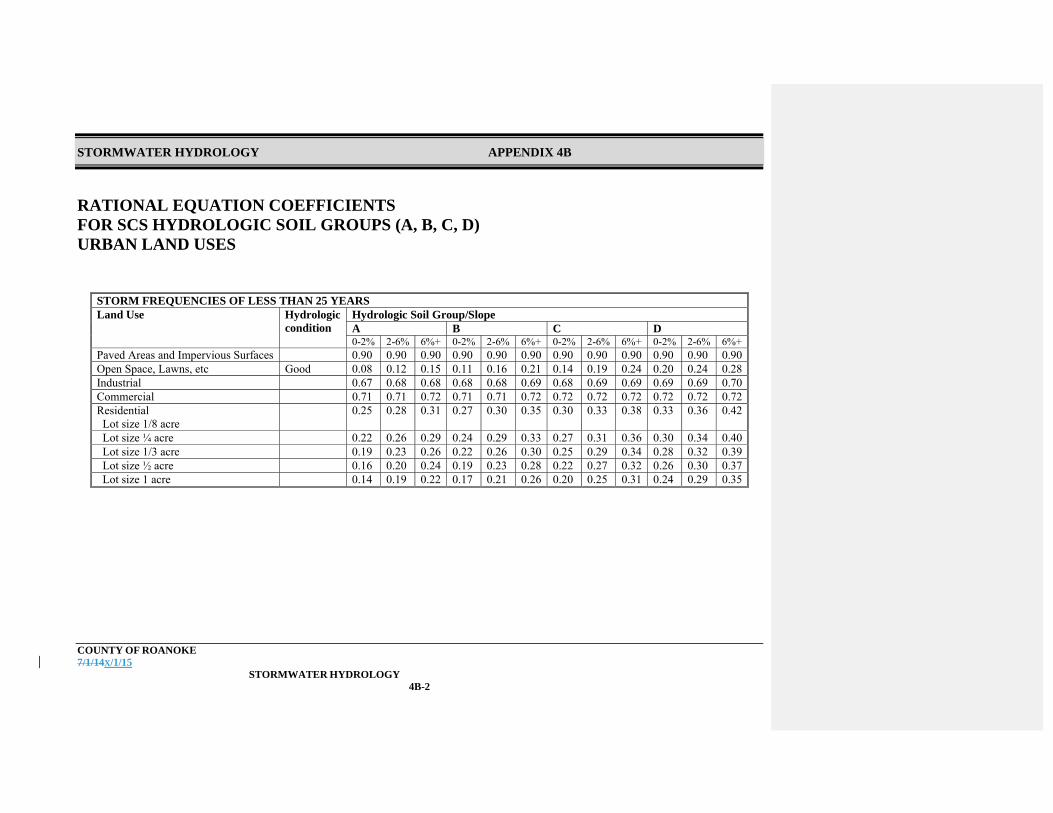
STORMWATER HYDROLOGY APPENDIX 4B
COUNTY OF ROANOKE 7/1/14X/1/15 STORMWATER HYDROLOGY
4B-2
RATIONAL EQUATION COEFFICIENTS FOR SCS HYDROLOGIC SOIL GROUPS (A, B, C, D) URBAN LAND USES
STORM FREQUENCIES OF LESS THAN 25 YEARS Land Use Hydrologic
condition Hydrologic Soil Group/Slope A B C D 0-2% 2-6% 6%+ 0-2% 2-6% 6%+ 0-2% 2-6% 6%+ 0-2% 2-6% 6%+
Paved Areas and Impervious Surfaces 0.90 0.90 0.90 0.90 0.90 0.90 0.90 0.90 0.90 0.90 0.90 0.90Open Space, Lawns, etc Good 0.08 0.12 0.15 0.11 0.16 0.21 0.14 0.19 0.24 0.20 0.24 0.28Industrial 0.67 0.68 0.68 0.68 0.68 0.69 0.68 0.69 0.69 0.69 0.69 0.70Commercial 0.71 0.71 0.72 0.71 0.71 0.72 0.72 0.72 0.72 0.72 0.72 0.72Residential Lot size 1/8 acre
0.25 0.28 0.31 0.27 0.30 0.35 0.30 0.33 0.38 0.33 0.36 0.42
Lot size ¼ acre 0.22 0.26 0.29 0.24 0.29 0.33 0.27 0.31 0.36 0.30 0.34 0.40 Lot size 1/3 acre 0.19 0.23 0.26 0.22 0.26 0.30 0.25 0.29 0.34 0.28 0.32 0.39 Lot size ½ acre 0.16 0.20 0.24 0.19 0.23 0.28 0.22 0.27 0.32 0.26 0.30 0.37 Lot size 1 acre 0.14 0.19 0.22 0.17 0.21 0.26 0.20 0.25 0.31 0.24 0.29 0.35
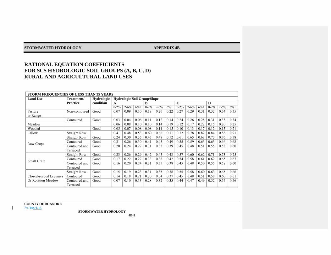
STORMWATER HYDROLOGY APPENDIX 4B
COUNTY OF ROANOKE 7/1/14X/1/15 STORMWATER HYDROLOGY
4B-3
RATIONAL EQUATION COEFFICIENTS FOR SCS HYDROLOGIC SOIL GROUPS (A, B, C, D) RURAL AND AGRICULTURAL LAND USES
STORM FREQUENCIES OF LESS THAN 25 YEARS Land Use Treatment/
Practice Hydrologiccondition
Hydrologic Soil Group/Slope A B C D 0-2% 2-6% 6%+ 0-2% 2-6% 6%+ 0-2% 2-6% 6%+ 0-2% 2-6% 6%+
Pasture or Range
Non-contoured Good 0.07 0.09 0.10 0.18 0.20 0.22 0.27 0.29 0.31 0.32 0.34 0.35
Contoured Good 0.03 0.04 0.06 0.11 0.12 0.14 0.24 0.26 0.28 0.31 0.33 0.34Meadow 0.06 0.08 0.10 0.10 0.14 0.19 0.12 0.17 0.22 0.15 0.20 0.25Wooded Good 0.05 0.07 0.08 0.08 0.11 0.15 0.10 0.13 0.17 0.12 0.15 0.21Fallow Straight Row 0.41 0.48 0.53 0.60 0.66 0.71 0.72 0.78 0.82 0.84 0.88 0.91
Row Crops
Straight Row Good 0.24 0.30 0.35 0.43 0.48 0.52 0.61 0.65 0.68 0.73 0.76 0.78Contoured Good 0.21 0.26 0.30 0.41 0.45 0.49 0.55 0.59 0.63 0.63 0.66 0.68Contoured and Terraced
Good 0.20 0.24 0.27 0.31 0.35 0.39 0.45 0.48 0.51 0.55 0.58 0.60
Small Grain
Straight Row Good 0.23 0.26 0.29 0.42 0.45 0.48 0.57 0.60 0.62 0.71 0.73 0.75Contoured Good 0.17 0.22 0.27 0.33 0.38 0.42 0.54 0.58 0.61 0.62 0.65 0.67Contoured and Terraced
Good 0.16 0.20 0.24 0.31 0.35 0.38 0.45 0.48 0.50 0.55 0.58 0.60
Closed-seeded Legumes Or Rotation Meadow
Straight Row Good 0.15 0.19 0.23 0.31 0.35 0.38 0.55 0.58 0.60 0.63 0.65 0.66Contoured Good 0.14 0.18 0.21 0.30 0.34 0.37 0.45 0.48 0.51 0.58 0.60 0.61Contoured and Terraced
Good 0.07 0.10 0.13 0.28 0.32 0.35 0.44 0.47 0.49 0.52 0.54 0.56

STORMWATER HYDROLOGY APPENDIX 4B
COUNTY OF ROANOKE 7/1/14X/1/15 STORMWATER HYDROLOGY
4B-4
ROUGHNESS COEFFICIENT “n” FOR MANNING EQUATION – SHEET FLOW
Surface Description n Smooth Surfaces (Concrete, Asphalt, Gravel, or Bare Soil)
0.011
Fallow (no residue) 0.05 Cultivated Soils: Residue Cover < 20% 0.06 Residue Cover > 20% 0.17 Grass: Short Grass Prairie 0.15 Dense Grasses 0.24 Bermuda Grass 0.41 Range (Natural) 0.13 Woods: Light Underbrush 0.40 Dense Underbrush 0.80

STORMWATER HYDROLOGY APPENDIX 4B
COUNTY OF ROANOKE 7/1/14X/1/15 STORMWATER HYDROLOGY
4B-5
ROUGHNESS COEFFICIENT “n” FOR MANNING EQUATION – PIPE FLOW
Material “n” Range From To
Coated Cast Iron 0.010 0.014 Uncoated Cast Iron 0.011 0.015 Vitrified Sewer Pipe 0.010 0.017 Concrete Pipe 0.010013 0.017 Common Clay Drainage Tile 0.011 0.017 Corrugated Metal (2 2/3 x ½) 0.023 0.026 Corrugated Metal (3x1 and 6x1) 0.026 0.029 Corrugated Metal (6x2 structural plate) HDPE
0.030 0.012
0.033

STORMWATER HYDROLOGY APPENDIX 4B
COUNTY OF ROANOKE 7/1/14X/1/15 STORMWATER HYDROLOGY
4B-6
ROUGHNESS COEFFICIENT “n” FOR MANNING EQUATION – CONSTRUCTED CHANNEL
Lining Material “n” Range From To
Concrete Lined 0.012 0.016 Cement Rubble 0.017 0.025 Earth, Straight and Uniform 0.017 0.022 Rock Cuts, Smooth and Uniform 0.025 0.033 Rock Cuts, Jagged and Irregular 0.035 0.045 Winding, Sluggish Canals 0.022 0.027 Dredged Earth Channels 0.025 0.030 Canals with Rough Stony Beds, 0.025 0.035 Weeds on Earth Banks Earth Bottom, Rubble Sides 0.028 0.033 Small Grass Channels: Long Grass – 13” 0.042 Short Grass – 3” 0.034

STORMWATER HYDROLOGY APPENDIX 4B
COUNTY OF ROANOKE 7/1/14X/1/15 STORMWATER HYDROLOGY
4B-7
ROUGHNESS COEFFICIENT “n” FOR MANNING EQUATION – NATURAL STREAM CHANNEL
Channel Lining “n” Range From To
1. Clean, Straight Bank, Full Stage 0.025 0.030 No Rifts or Deep Pools 2. Same as #1, Some Weeds and Stones 0.030 0.035 3. Winding, Some Pools and Shoals, 0.033 0.040 Clean 4. Same as #3, Lower Stages, More 0.040 0.050 Ineffective Slope and Sections 5. Same as #3, Some Weeds and Stones 0.035 0.045 6. Same as #4, Stony Sections 0.045 0.055 7. Sluggish River Reaches, Rather 0.050 0.070 Weedy with Very Deep Pools 8. Very Reedy Reaches 0.075 0.125
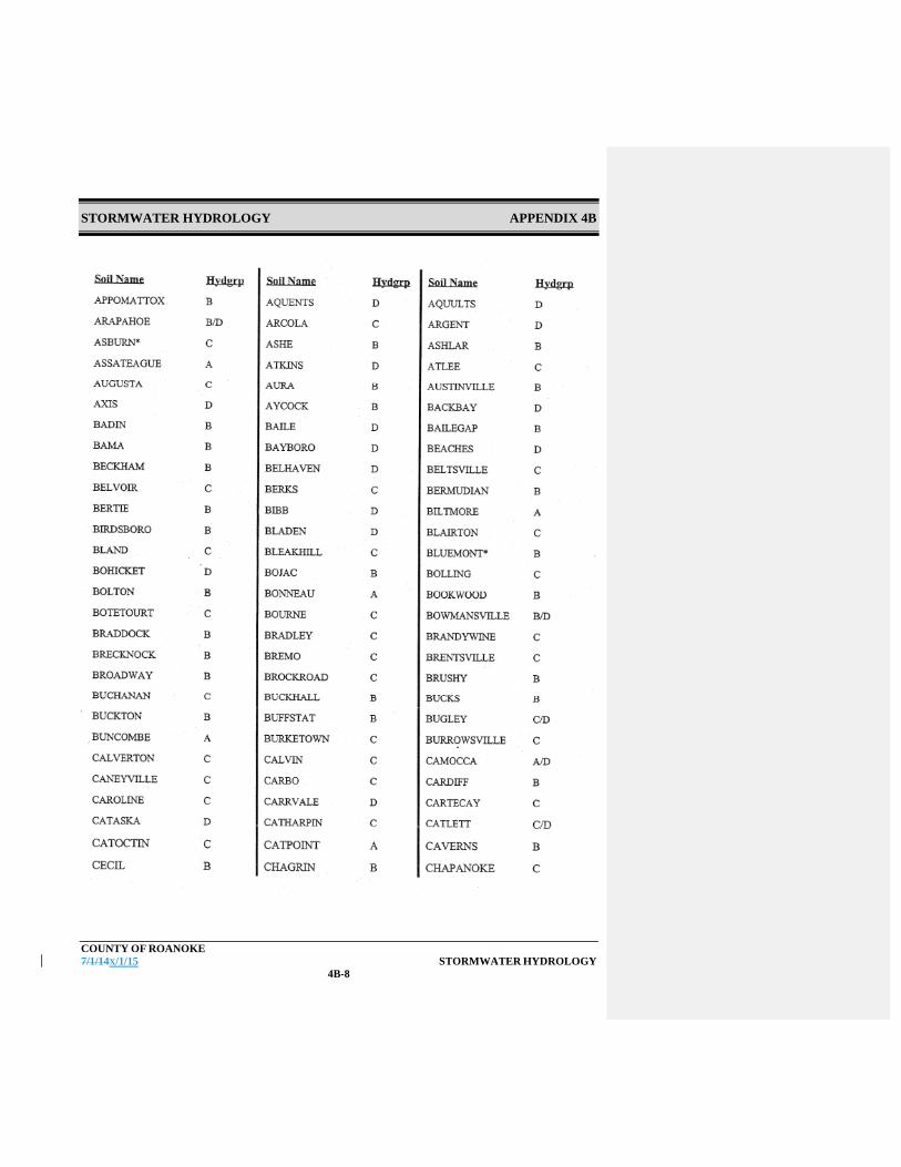
STORMWATER HYDROLOGY APPENDIX 4B
COUNTY OF ROANOKE 7/1/14X/1/15 STORMWATER HYDROLOGY
4B-8

STORMWATER HYDROLOGY APPENDIX 4B
COUNTY OF ROANOKE 7/1/14X/1/15 STORMWATER HYDROLOGY
4B-9

STORMWATER HYDROLOGY APPENDIX 4B
COUNTY OF ROANOKE 7/1/14X/1/15 STORMWATER HYDROLOGY
4B-10

STORMWATER HYDROLOGY APPENDIX 4B
COUNTY OF ROANOKE 7/1/14X/1/15 STORMWATER HYDROLOGY
4B-11

STORMWATER HYDROLOGY APPENDIX 4B
COUNTY OF ROANOKE 7/1/14X/1/15 STORMWATER HYDROLOGY
4B-12

STORMWATER HYDROLOGY APPENDIX 4B
COUNTY OF ROANOKE 7/1/14X/1/15 STORMWATER HYDROLOGY
4B-13

STORMWATER HYDROLOGY APPENDIX 4B
COUNTY OF ROANOKE 7/1/14X/1/15 STORMWATER HYDROLOGY
4B-14

STORMWATER HYDROLOGY APPENDIX 4C
COUNTY OF ROANOKE 7/1/14X/1/15 STORMWATER HYDROLOGY
4C-1
APPENDIX 4C INFORMATION FROM VDOT HYDRAULIC DESIGN ADVISORIES Rainfall Intensities (inches/hour) for the Roanoke Valley (Based on VDOT HDA 05-03)

STORMWATER HYDROLOGY APPENDIX 4C
COUNTY OF ROANOKE 7/1/14X/1/15 STORMWATER HYDROLOGY
4C-2
Note: For use with the Rational Method only. Use NOAA precipitation chart for SCS Method.
5 10 15 20 25 30 35 40 45 60 75 90 105 1202 4.39 3.51 2.94 2.54 2.24 2.01 1.82 1.67 1.54 1.26 1.07 0.94 0.83 0.75
5 5.33 4.29 3.62 3.14 2.79 2.52 2.30 2.12 1.96 1.63 1.40 1.23 1.10 1.00
10 6.04 4.91 4.18 3.66 3.26 2.96 2.71 2.51 2.34 1.96 1.69 1.50 1.35 1.23
25 6.78 5.49 4.68 4.11 3.69 3.36 3.10 2.88 2.70 2.28 2.00 1.79 1.63 1.50
50 7.37 5.96 5.09 4.49 4.04 3.70 3.42 3.19 3.00 2.56 2.26 2.04 1.87 1.73
100 8.08 6.49 5.56 4.92 4.46 4.10 3.81 3.57 3.37 2.92 2.61 2.37 2.19 2.04
Storm Duration (min)
RAINFALL INTENSITY (IN/HR)
Sto
rm R
ecur
ranc
e In
terv
al
FOR THE ROANOKE VALLEY
Table based on VDOT Hydraulic Design Advisory HAD 05-03 If = B / (tc + D)E where: If = Rainfall intensity for a given recurrence interval, f, in inches per hour tc = Watershed time of concentration (assumed to equal the storm duration), in minutes B,D,E = As taken from HDA 05-03 table for [Roanoke] [Roanoke (city)] based on the designated storm frequency.

OPEN CHANNELS CHAPTER 5
COUNTY OF ROANOKE 7/1/14X/1/15 OPEN CHANNELS
5-1
Chapter 5 – Open Channels Open channels are man-made ditches and channels and natural channels, that are used to convey stormwater flow. This section defines criteria and restrictions to be used in designing open channels. Where open channels are a part of a BMP, they shall comply with the state requirements for the purposes of water quality improvement; however, they shall also comply with this Design Manual’s requirements for water conveyance.
5.1 References
The primary design references are:
VDOT Drainage Manual VDOT Specifications VA E&SC Handbook
Hydraulic Engineering Circular Number 15 (HEC-15), Design of Roadside Channels
with Flexible Linings, Current Edition, as amended VA SWM Handbook
5.2 Design Methodology and Criteria
5.2.1 Major and Minor Manmade Open Channels
A major channel is designed to convey less frequent storm events which would have significant adverse consequences if it failed. Major channels protect buildings and other important features from flooding and catastrophic failures. A minor channel is designed to convey more frequent storm events and they include most onsite open channels and roadside ditches. These structures have less adverse consequences due to overtopping.
5.2.2 Design Flow
Design flow for manmade open channels within a development is contained in Chapter 4.2.2. Channels shall be designed to convey the 10-year flow. Additionally, all storm drainage designs for open channels, culverts, and storm drains shall be checked for the 100-year flow condition where there is the possibility of flooding residences, commercial or industrial buildings, overtopping primary roads, experiencing significant economic loss, or catastrophic failure.

OPEN CHANNELS CHAPTER 5
COUNTY OF ROANOKE 7/1/14X/1/15 OPEN CHANNELS
5-2
Where justified by the consequences of failure, the minimum design frequency shall be increased. Design flows for downstream channels and all natural channels shall comply with the VA SWM Regulations.
5.2.3 Hydrology
See Chapter 4 for methodology used to determine peak flows for a given design frequency.
5.2.4 Channel Hydraulics
Open channel design will be based on Manning’s Equation for open channel flow, unless good engineering practice dictates using HEC-RAS or other method. See the VA SWM Handbook and VDOT Drainage Manual, as appropriate. Q = A x 1.49/n x R2/3 x S1/2
Where:
Q = Flow in the open channel (cfs) A = Cross-section area of the channel (ft2) R = A/wetted perimeter (ft) S = Channel slope (ft/ft) n = Channel roughness coefficient
Nomographs have been included in Appendix 5A for use in solving Manning’s equation setting channel characteristics.
5.2.5 Channel Velocity
The lining of minor channels with drainage areas of five acres and less shall be designed to withstand the erosive effects of a 2-year storm. The lining of minor channels with drainage areas over five acres and major channels shall be designed to withstand the erosive effects of a 10-year storm. The final design shall be consistent with velocity limitations for the selected channel lining, as presented in Table 5-1. Major channels associated with dam embankment spillways or other structures where catastrophic failure could result from a lining failure may be required to be designed to withstand a more severe storm event. Where open channels receive flow from storm drains, culverts, or other open channels, or in other areas where channel velocity may cause scouring or erosion,

OPEN CHANNELS CHAPTER 5
COUNTY OF ROANOKE 7/1/14X/1/15 OPEN CHANNELS
5-3
outlet protection or energy dissipation may be necessary to reduce the potential for severe erosion. For the design of energy dissipation devices, see Chapter 10.
TABLE 5-1 Maximum Velocity Based on Channel Lining
Channel Lining Maximum Velocity
(Design Storm) Erosion Resistant
Soils1 Easily Erodible
Soils2
Vegetative Lined Channels Tall Fescue Grass Mixtures 6 fps 4 fps Kentucky Bluegrass 6 fps 4 fps Annual and Perennial Rye 4 fps 3 fps Sod 4 fps 3 fps Geosynthetic Lined Channels VDOT EC-2 4 fps VDOT EC-3, Type A 7 fps VDOT EC-3, Type B 10 fps Other Per Mfr
Recommendations Riprap (see VDOT Drainage Manual Appendix 7-D for n values)
Dependent on stone size and thickness, see HEC-15 for design of
riprap channels Concrete None
1 Erosion resistant soils include those with a high clay content and high plasticity, silty clay, sandy clay, and clay. 2 Easily erodible soils include those with a high content of fine sand or silty, lower plasticity or non-plastic, sand, silt, sandy loam, and silty loam with an erodibility factor (K) greater than 0.35. 3Soils shall be presumed to be easily erodible; unless a geotechnical investigation is performed that samples and tests the soils. 4All channels constructed in fills shall be considered to be in easily erodible soils. 5.2.6 Channel Slope
Generally the channel slope shall be established by the site topography. Open channels must be graded to drain with no standing water following a rain event. The minimum allowable grade shall generally be 2 percent for vegetated-lined and riprap-lined open channels and 1 percent for a concrete open channel.

OPEN CHANNELS CHAPTER 5
COUNTY OF ROANOKE 7/1/14X/1/15 OPEN CHANNELS
5-4
The maximum allowable grade for a stormwater channel shall be dependent on the channel lining materials and its ability to withstand erosion during the design storm.
5.2.7 Cross Sectional Area
Open channel cross-section area shall be designed based on site restrictions and channel capacity requirements. A table and detail shall be provided on the design plans that includes the channel number, bottom width, top width, slope, side slopes, total depth including freeboard, and liner. Each swale should be included in the chart and not just a worst case scenario. Additionally, Q10, Q10 water depth, freeboard provided, and V2 shall be clearly indicated in the calculations. Acceptable cross-sectional area options include:
Vee Parabolic Trapezoidal Rectangular
A. Vee
For design aids, see the VDOT Drainage Manual and the VA E&SC Handbook. Additionally computer software such as North American Green, Flowmaster, etc can be used for design aids. The maximum side slope of a vee-shape open channel is 3 horizontal to 1 vertical for vegetated channels (including reinforced vegetated) and is 2 horizontal to 1 vertical for all other linings engineered to be stable at this slope.
B. Parabolic
For design aids, see the VDOT Drainage Manual and the VA E&SC Handbook. Additionally computer software such as North American Green, Flowmaster, etc can be used for design aids.
Formatted: Subscript
Formatted: Subscript
Formatted: Subscript
Formatted: Font: Bold
Formatted: Font: Bold

OPEN CHANNELS CHAPTER 5
COUNTY OF ROANOKE 7/1/14X/1/15 OPEN CHANNELS
5-5
C. Trapezoidal
For design aids, see the VDOT Drainage Manual and the VA E&SC Handbook. Additionally computer software such as North American Green, Flowmaster, etc can be used for design aids. The maximum side slope of a trapezoidal-shape open channel is 3 horizontal to 1 vertical for vegetated channels (Including reinforced vegetated) and is 2 horizontal to 1 vertical for all other linings engineered to be stable at this slope.
D. Rectangular
Rectangular channels shall only be allowed where site restrictions prevent the installation of a vee, parabolic, or trapezoidal channel. The requirements for rectangular channels apply to any open channel with side slopes greater than 2 horizontal to 1 vertical. Rectangular channels must either be concrete or gabions. An approved safety barrier must be placed on both sides for the length of the rectangular channel, where the channel is more than 3-feet deep. Care must be taken to ensure that energy dissipation is placed at the outfall of the rectangular channel to prevent erosion at the discharge point.
5.2.8 Channel Lining
An open channel lining shall be designed based on the cross-section, slope, and channel velocity requirements. The design may be based on a consideration of either permissive velocity or tractive force as described in the VDOT Drainage Manual. The preferred method for analyzing channel linings is to compare the maximum permissible velocity for the channel lining, listed in Table 5.1 in this chapter of the Design Manual, to the design velocity computed using Manning’s equation to verify that the selected lining is adequate. As an alternative, the selected lining may be analyzed using the Tractive Force Method published in the VDOT Drainage Manual. This method analyzes sediment critical shear loading on the open channel bottom and side slope. The permissible tractive force for various soils is located in the Appendix of the VDOT Drainage Manual.
Formatted: Font: Bold
Formatted: Font: Bold

OPEN CHANNELS CHAPTER 5
COUNTY OF ROANOKE 7/1/14X/1/15 OPEN CHANNELS
5-6
Open channels may have different lining materials in different channel reaches based on velocity and potential erosion conditions. Care must be exercised to avoid erosion at open channel transition points. The open channel lining will have an impact on the design capacity in the form of the roughness coefficient. A table of generally accepted roughness coefficient (n) for various channels and linings is included in Appendix 5A.
Allowable open channel linings include the following:
A. Natural
To the maximum extent possible, natural channels shall be preserved. Design discharges from permitted land disturbing activities shall comply with the VA SWM Regulations.
B. Vegetative-Lined
Vegetated or grass-lined channels include man made channels lined with established vegetation. These channels usually include a geosynthetic mat for channel stabilization. The type of grass allowable for vegetative-lined open channels is dependant on the slope of the channel, and the peak calculated velocity. Table 5-1 details the maximum permissible velocities for various channel linings. A permanent channel stabilization geosynthetic mat should be considered for all vegetated channels. There are a wide variety of geosynthetic stabilization mat options from various manufacturers. The geosynthetic mat selected should be adequate for the slope and design flow velocities calculated for the channel. Where appropriate, VDOT Road and Bridge Standard EC-2 or EC-3 may be used. Where a permanent geosynthetic mat is used to provide channel stabilization, information on the proposed mat, in the form of manufacturer’s catalog information, shall be submitted as a part of the stormwater management plan. The catalog information shall include the manufacturer’s recommendations for maximum allowable velocity. Design drawings must state that the geosynthetic stabilization mat shall be installed in strict accordance with the manufacturer’s recommendations. Where a permanent channel stabilization geosynthetic is not used, a temporary geosynthetic lining designed to provide a measure of bank
Formatted: Font: Bold
Formatted: Font: Bold

OPEN CHANNELS CHAPTER 5
COUNTY OF ROANOKE 7/1/14X/1/15 OPEN CHANNELS
5-7
stability until such time a reasonably stable and mature stand of vegetation is established shall be provided.
C. Riprap-Lined
The use of vegetated and geosynthetic-lined open channels for gentle-sloped open channels and concrete for steep-sloped open channels is recommended. Riprap-lined channels will not be acceptable where vegetated or geosynthetic-lined open channels are feasible. However, where design flow velocities exceed the erosive capability of a natural or vegetative-lined channel, rip rap may be used as a channel liner in areas where erosion is a concern. For an extended length of high velocity channel, consideration should be given to using a concrete channel rather than rip rap. Riprap lining shall be properly embedded in accordance with VDOT standards to maintain intended ditch cross section. Where riprap is required due to velocity conditions, it shall meet VDOT Standards and VDOT Specifications. VDOT recommended 50 percent stone size (D50) and weight (W50) and recommended thickness (T) for various riprap classifications is included in Appendix 5A.
D. Concrete-Lined
Reinforced concrete shall be considered where design velocities dictate or where there is a need to provide the maximum level of erosion protection.
5.2.9 Freeboard Requirements
Manmade channels within a development shall have a minimum of 6” of freeboard above the calculated water level during the design peak flow, unless flow is supercritical. Where flow is supercritical, a minimum of 12” of freeboard is required. Flow is supercritical when: V / (32.2 x H)0.5 > 1
Where:
V = velocity (fps) H = depth of flow (feet)
At bends and curves, the freeboard shall be measured from the calculated water level, including the increased depth due to the superelevation of the water surface.
Formatted: Font: Bold
Formatted: Font: Bold

OPEN CHANNELS CHAPTER 5
COUNTY OF ROANOKE 7/1/14X/1/15 OPEN CHANNELS
5-8
5.2.10 Calculation of Depth of Flow at Bends and Curves
Increases in the depth of flow occur at bends and curves due to the superelevation of the water surface. Superelevation of the water surface at bends and curves is calculated by:
ΔZ = V2 / (32.2 x rc) x (ro – ri) where
ΔZ = difference in water surface elevation between the concave and convex banks (ft) V = average velocity (ft/s) rc = radius of the center of the stream at the bend (ft) ro = radius of the outside bank of the stream at the bend (ft) ri = radius of the inside bank of the stream at the bend (ft)
The increase in the normal stream flow depth at the outer bank of an open channel bend is one half of ΔZ.
5.2.11 Channel Location and Width Restrictions on Residential Lots
The tops of open channel banks shall be at least 20-feet from a residence. Where manmade open channels collect stormwater from more than one lot and they are located on a residential zoned lot their use shall be restricted as follows. Where all requirements cannot be met, a closed pipe storm drain system is required.
Residential lot size 1 acre or greater
o No additional restrictions.
Residential lot size 0.5 acre or greater, but less than 1 acre o Open channel top width shall be a maximum of 15 feet o Maximum drainage area passing through the open channel shall be 5 acres.
Residential lot size less than 0.5 acre
o Open channel top width shall be a maximum of 15 feet o Maximum drainage area passing through the open channel shall be 3 acres.
The above restrictions do not apply if any one of the following conditions is present:

OPEN CHANNELS CHAPTER 5
COUNTY OF ROANOKE 7/1/14X/1/15 OPEN CHANNELS
5-9
The open channel is a natural channel that has adequate capacity. The retention of natural channels is encouraged. The open channel is a perennial or intermittent stream that has adequate capacity and will remain undisturbed. It may be demonstrated that open channels are required as a part of an integrated design to obtain the necessary water quality treatment.
5.3 Environmental Considerations and Fishery Protection
Construction or modifications to open channels shall comply with all applicable laws and regulations. The applicant is responsible for procuring all necessary permits, such as US Army Corps of Engineers and VA DEQ Wetland Permits, VA DEQ VPDES Permits, etc., prior to obtaining a Land Disturbance Permit. A copy of these permits shall be submitted to Roanoke County prior to scheduling the precon meeting or the Engineer shall submit a 3rd party report to the County that supports that the permits are not required.
5.4 Maintenance Requirements
The permittee is responsible for maintenance of open channels until construction is complete, including final clean up and site stabilization, to the satisfaction of the County of Roanoke. After the completion of construction, the property owner is responsible for maintenance of open channels. Maintenance includes periodically pruning or mowing vegetation and removing debris.
5.5 Floodplain Studies
A floodplain study shall be performed for all drainage areas greater than 100 acres that do not have detailed FEMA Flood Insurance Study flood profiles or elevations. See Chapter 12 for additional information on floodplain requirements.

OPEN CHANNELS APPENDIX 5A
COUNTY OF ROANOKE 7/1/14X/1/15 OPEN CHANNELS
5A-1
APPENDIX 5A
AIDS FOR OPEN CHANNEL DESIGN
FROM CHAPTER 7, VDOT DRAINAGE MANUAL
Appendix 7B-1, LD-268, Roadside and Median Ditch Design Form Appendix 7B-3, Channel Stability Work Sheet Appendix 7B-4, Riprap Design Work Sheet for Standard VDOT Riprap Sizes Only Appendix 7B-5, Riprap Design Work Sheet for other than VDOT Standard Riprap Sizes Appendix 7C-1, Nomograph for Solution of Manning’s Equation Appendix 7C-2, Trapezoidal Channel Capacity Chart Appendix 7C-3, Nomograph for Solution of Normal Depth Appendix 7D-1, Values of Roughness Coefficient n, 2 sheets Appendix 7D-3, Standard VDOT Riprap Classifications, Weights, and Blanket Thickness Appendix 7D-5, Selection of Stability Factors Appendix 7D-6, Permissible Velocities for Erodible Linings Appendix 7E-1, Angle of Repose of Riprap in Terms of Mean Size and Shape of Stone Appendix 7E-2, Permissible Shear Stress for Non-Cohesive Soils Appendix 7E-3, Permissible Shear Stress for Cohesive Soils Appendix 7E-4, Bank Angle Correction Factor (K1) Nomograph Appendix 7E-5, Correction Factor for Riprap Size Appendix 7E-6, Riprap Size Relationship Appendix 7E-7, Channel Side Shear Stress to Bottom Shear Stress Ratio

OPEN CHANNELS APPENDIX 5A
COUNTY OF ROANOKE 7/1/14X/1/15 OPEN CHANNELS
5A-2
Appendix 7E-8, Tractive Force Ratio (K2) Appendix 7E-9, Determination of Mean Spherical Diameter

OPEN CHANNELS APPENDIX 5A
COUNTY OF ROANOKE 7/1/14X/1/15 OPEN CHANNELS
5A-3

OPEN CHANNELS APPENDIX 5A
COUNTY OF ROANOKE 7/1/14X/1/15 OPEN CHANNELS
5A-4
CHANNEL STABILITY WORKSHEET

OPEN CHANNELS APPENDIX 5A
COUNTY OF ROANOKE 7/1/14X/1/15 OPEN CHANNELS
5A-5
RIPRAP DESIGN WORKSHEET (VDOT STANDARD SIZES)

OPEN CHANNELS APPENDIX 5A
COUNTY OF ROANOKE 7/1/14X/1/15 OPEN CHANNELS
5A-6
RIPRAP DESIGN WORKSHEET (NON-VDOT STANDARD SIZES)

OPEN CHANNELS APPENDIX 5A
COUNTY OF ROANOKE 7/1/14X/1/15 OPEN CHANNELS
5A-7
NOMOGRAPH FOR SOLUTION OF MANNINGS EQUATION

OPEN CHANNELS APPENDIX 5A
COUNTY OF ROANOKE 7/1/14X/1/15 OPEN CHANNELS
5A-8
TRAPEZOIDAL CHANNEL CAPACITY CHART

OPEN CHANNELS APPENDIX 5A
COUNTY OF ROANOKE 7/1/14X/1/15 OPEN CHANNELS
5A-9
NOMOGRAPH FOR SOLUTION OF NORMAL DEPTH

OPEN CHANNELS APPENDIX 5A
COUNTY OF ROANOKE 7/1/14X/1/15 OPEN CHANNELS
5A-10
VALUES OF ROUGHNESS COEFFICIENT ‘n’ CHANNELS
Type of Channel and Description Minimum Normal Maximum LINED CHANNELS (Selected linings)
a. Concrete 1. Trowel finish 0.011 0.013 0.015 2. Float finish 0.013 0.015 0.016
3. Gunite, good section 0.016 0.019 0.023 b. Asphalt
1. Smooth 0.013 0.013 --- 2. Rough 0.016 0.016 ---
EXCAVATED OR DREDGED a. Earth, straight and uniform
1. Clean, recently completed 0.016 0.018 0.020 2. Clean, after weathering 0.018 0.022 0.025
3. Gravel, uniform section, clean 0.022 0.025 0.030 4. With short grass, few weeds 0.022 0.027 0.033
b. Earth, winding and sluggish 1. No vegetation 0.023 0.025 0.030
2. Grass, some weeds 0.025 0.030 0.035 3. Dense weeds or aquatic plants in deep channels 0.030 0.035 0.040
4. Earth bottom and rubble sides 0.025 0.030 0.035 5. Stony bottom and weedy sides 0.025 0.035 0.045 6. Cobble bottom and clean sides 0.030 0.040 0.050
c. Dragline excavated or dredged 1. No vegetation 0.025 0.028 0.033
2. Light brush on banks 0.035 0.050 0.060 d. Rock cuts
1. Smooth and uniform 0.025 0.035 0.040 2. Jagged and irregular 0.035 0.040 0.050
e. Channels not maintained, weeds and brush uncut 1. Dense weeds, high as flow depth 0.050 0.080 0.120
2. Clean bottom, brush on sides 0.040 0.050 0.080 3. Same, highest stage of flow 0.045 0.070 0.110
4. Dense brush, high stage 0.080 0.100 0.140

OPEN CHANNELS APPENDIX 5A
COUNTY OF ROANOKE 7/1/14X/1/15 OPEN CHANNELS
5A-11
VALUES OF ROUGHNESS COEFFICIENT ‘n’ NATURAL STREAMS
Type of Channel and Description Minimum Normal Maximum NATURAL STREAMS
1. Minor streams (top width at flood stage <100 ft) a. Streams on Plain
1. Clean, straight, full stage, no rifts or deep pools 0.025 0.030 0.033 2. Same as above, more stones and weeds 0.030 0.035 0.040
3. Clean, winding, some pools/shoals 0.033 0.040 0.045 4. Same as above, but some weeds and stones 0.035 0.045 0.050
5. Same as above, lower stages, more ineffective slopes and sections
0.040 0.048 0.055
6. Same as 4, but more stones 0.045 0.050 0.060 7. Sluggish reaches, weedy, deep pools 0.050 0.070 0.080
8. Very reedy reaches, deep pools or floodways with heavy stand of timber and underbrush
0.075 0.100 0.150
b. Mountain Streams (no vegetation in channel, banks usually steep, trees and brush along banks
submerged at high stages)
1. Bottom: gravels, cobbles, few boulders 0.030 0.040 0.050 2. Bottom: cobbles with large boulders 0.040 0.050 0.070
2. Floodplains a. Pasture, no brush
1. Short grass 0.025 0.030 0.035 2. High grass 0.030 0.035 0.050
b. Cultivated area 1. No crop 0.020 0.030 0.040
2. Mature row crops 0.025 0.035 0.045 3. Mature field crops 0.030 0.040 0.050
c. Brush 1. Scattered brush, heavy weeds 0.035 0.050 0.070
2. Light brush and trees, in winter 0.035 0.050 0.060 3. Light brush and trees, in summer 0.040 0.060 0.080 4. Medium to dense brush, in winter 0.045 0.070 0.110
5. Medium to dense brush, in summer 0.070 0.100 0.160 d. Trees
1. Dense willows, summer, straight 0.110 0.150 0.200 2. Cleared land with tree stumps, no sprouts 0.030 0.040 0.050
3. Same as above, but with heavy sprout growth 0.050 0.060 0.080 4. Heavy stand of timber, a few down trees, little
undergrowth, flood stage below branches 0.080 0.100 0.120
5. Same as above, but with flood stage reaching branches
0.100 0.120 0.160
3. Major Streams (top width at flood stage >100 ft) a. Regular section with no boulders or brush 0.025 --- 0.060
b. Irregular and rough section 0.035 --- 0.100 (The n value is less than that for minor streams of the same description, because banks offer less effective
resistance.)

OPEN CHANNELS APPENDIX 5A
COUNTY OF ROANOKE 7/1/14X/1/15 OPEN CHANNELS
5A-12
STANDARD VDOT RIPRAP CLASSIFICATIONS, WEIGHTS, AND BLANKET THICKNESS
Classification D50 (ft) W50 (lbs) T (in) Class AI 0.8 50 20 Class I 1.1 100 26 Class II 1.6 300 38 Class III 2.2 1000 53 Type I 2.8 2000 60 Type II 4.5 8000 97
SELECTION OF STABILITY FACTORS
Condition Stability Factor
Range Uniform flow; straight or mildly curving reach (curve radius/channel
width >30); impact from wave action and floating debris is minimal; little or no uncertainty in design parameters.
1.0 - 1.2
Gradually varying flow; moderate bend curvature (30 > curve
radius/channel width > 10); impact from waves or floating debris is moderate.
1.3 - 1.6
Approaching rapidly varying flow; sharp bend curvature (30 > curve
radius/channel > 10); significant impact from floating debris and/or ice, significant wind and/or bore generated waves (1-2 feet); high flow turbulence; mixing flow at bridge abutments; significant amount of
uncertainty in design parameters.
1.6 - 2.0
Channel bends when ratio of curve radius to channel width (R/W) > 30. 1.2
Channel bends when 30 > R/W > 10. 1.3 - 1.6
Channel bends when R/W < 10. 1.7

OPEN CHANNELS APPENDIX 5A
COUNTY OF ROANOKE 7/1/14X/1/15 OPEN CHANNELS
5A-13
PERMISSIBLE VELOCITIES FOR ERODIBLE LININGS
Soil type or lining (earth; no vegetation
Maximum permissible velocities (ft/sec) for
Clear water
Water carrying fine silts
Water carrying sand and
gravel Fine sand (non colloidal) 1.5 2.5 1.5
Sandy loam (non colloidal) 1.7 2.5 2.0 Silt loam (non colloidal) 2.0 3.0 2.0
Ordinary firm loam 2.5 3.5 2.2 Volcanic ash 2.5 3.5 2.7
Fine gravel 2.5 5.0 3.7
Stiff clay (very colloidal) 3.7 5.0 3.0 Graded, loam to cobbles (non colloidal) 3.7 5.0 5.0
Graded, silt to cobbles (colloidal) 4.0 5.5 5.0 Alluvial silts (non colloidal) 2.0 3.5 2.0
Alluvial silts (colloidal) 3.7 5.0 3.0
Coarse gravel (non colloidal) 4.0 6.0 6.5 Cobbles and shingles 5.0 5.5 6.5 Shales and hard pans 6.0 6.0 5.0

OPEN CHANNELS APPENDIX 5A
COUNTY OF ROANOKE 7/1/14X/1/15 OPEN CHANNELS
5A-14
ANGLE OF REPOSE OF RIPRAP IN TERMS OF MEAN SIZE AND SHAPE OF STONE

OPEN CHANNELS APPENDIX 5A
COUNTY OF ROANOKE 7/1/14X/1/15 OPEN CHANNELS
5A-15
PERMISSIBLE SHEAR STRESS FOR NON-COHESIVE SOILS

OPEN CHANNELS APPENDIX 5A
COUNTY OF ROANOKE 7/1/14X/1/15 OPEN CHANNELS
5A-16
PERMISSIBLE SHEAR STRESS FOR COHESIVE SOILS

OPEN CHANNELS APPENDIX 5A
COUNTY OF ROANOKE 7/1/14X/1/15 OPEN CHANNELS
5A-17
BANK ANGLE CORRECTION FACTOR (K1) NOMOGRAPH

OPEN CHANNELS APPENDIX 5A
COUNTY OF ROANOKE 7/1/14X/1/15 OPEN CHANNELS
5A-18
CORRECTION FACTOR FOR RIPRAP SIZE

OPEN CHANNELS APPENDIX 5A
COUNTY OF ROANOKE 7/1/14X/1/15 OPEN CHANNELS
5A-19
RIPRAP SIZE RELATIONSHIP

OPEN CHANNELS APPENDIX 5A
COUNTY OF ROANOKE 7/1/14X/1/15 OPEN CHANNELS
5A-20
CHANNEL SIDE SHEAR STRESS TO BOTTOM SHEAR STRESS RATIO

OPEN CHANNELS APPENDIX 5A
COUNTY OF ROANOKE 7/1/14X/1/15 OPEN CHANNELS
5A-21
TRACTIVE FORCE RATIO (K2)

OPEN CHANNELS APPENDIX 5A
COUNTY OF ROANOKE 7/1/14X/1/15 OPEN CHANNELS
5A-22
DETERMINATION OF MEAN SPHERICAL DIAMETER

CULVERTS CHAPTER 6
COUNTY OF ROANOKE 7/1/14X/1/15 6-1 CULVERTS
Chapter 6 - Culverts A culvert is a single run of storm drain pipe that conveys water or stormwater under a road, railway, embankment, sidewalk, or other obstruction. A culvert typically connects two open channels, but they may connect an open channel to a storm drain. Proper culvert design must consider many factors including:
Design Flow Inlet conditions (flow approach conditions, allowable headwater, culvert inlet
configuration) Culvert conditions (material roughness, pipe slope, and length) Tailwater depth Buoyancy potential Environmental considerations and effects on aquatic life Design loads and service life of the pipe material
Refer to the VDOT Drainage Manual, for a more through discussion of these items.
For the design of stormwater inlets and storm drains, see Chapter 7.
6.1 References
Except where more stringent requirements are presented in this Design Manual, culverts shall comply with VDOT requirements. The primary design reference is the VDOT Drainage Manual. Other appropriate references include:
VDOT Standards VDOT Specifications VA E&SC Handbook VDOT Instructional and Informational Memorandum IIM-lD-121.15, Allowable
Pipe Criteria for Culverts and Storm Sewers FHWA Hydraulic Design of Highway Culverts HDS No. 5, Pub. No. FHWA-
NHI-01-020, Current Edition, as amended FHWA Debris Control Structures Evaluation and Countermeasures HEC No. 9,
Pub. No. FHWA-IF-04-016, Current Edition, as amended

CULVERTS CHAPTER 6
COUNTY OF ROANOKE 7/1/14X/1/15 6-2 CULVERTS
6.2 Design Methodology and Criteria
6.2.1 Computation Methods
Manual computations use design equations and nomographs. Results are documented on VDOT’s Design Form LD-269. Form LD-269 is included in Appendix 6A. There are a number of computer programs available to design culverts. Any of these computer programs will be acceptable if their methodologies are based on the same equations and nomographs accepted by VDOT, and if they provide the same documentation of inputs, assumptions, and output as are contained on VDOT’s Design Form LD-269.
6.2.2 Hydrology
A. Design Flow Methodology
See Chapter 4 for methodology used to determine design flows. Generally culverts shall be designed based on the peak flow (steady state), ignoring the effects of temporary upstream storage.
B. Obstruction Allowance
An obstruction allowance shall be applied in critical areas where excessive backwater may result in property damage or be a potential safety hazard.
After using the appropriate design methodology to calculate the peak stormwater flow for a given frequency, an obstruction allowance will be added to the peak flow to establish the design flow rate through the culvert. The minimum obstruction allowance factor is intended to account for normal culvert obstructions, which may lower the actual capacity of the culvert once constructed, and is based on the size of the culvert pipe in accordance with the following tabulation:
Culvert Size Minimum Obstruction Allowance Factor 18” and less 25%
21”-24” 20% 30” 15% 36” and greater 10%
Formatted: Font: Bold
Formatted: Font: Bold

CULVERTS CHAPTER 6
COUNTY OF ROANOKE 7/1/14X/1/15 6-3 CULVERTS
6.2.3 Culvert Hydraulics
A. Design Flow
The design flow shall be the peak flow from the following frequency storm event, plus the appropriate obstruction allowance:
Roadway Storm Frequency Primary & Arterial 25-year Secondary & Other 10-year
These frequencies are minimum values. Designing for less frequent storms may be required where there is potential damage to structures, loss of human life, injury, or heavy financial loss in the event of flooding. Compliance with the National Flood Insurance Program (NFIP) is necessary for all locations where construction will encroach on a 100-year frequency flood plain. In addition, the 100-year peak flow (without the addition of the obstruction allowance) shall be routed through all culverts, determining the headwater depth behind the culvert with road overtopping, to ensure that buildings and other structures are not flooded and that adjacent roadways and adjacent properties do not suffer significantly increased damage during the 100-year storm event. Storage impacts of water behind the culvert may be considered in the calculation, but is not required.
B. Allowable Headwater
The allowable headwater is the depth of water that can be ponded at the upstream end of the culvert during the design condition, as measured from the culvert inlet invert.
The allowable headwater depth shall be limited by the following conditions:
Headwater does not cause upstream property damage; Headwater does not increase the 100-year flood elevation, as mapped by NFIP;
Formatted: Font: Bold
Formatted: Indent: Left: 1.5", First line: 0.5"
Formatted: Font: Bold

CULVERTS CHAPTER 6
COUNTY OF ROANOKE 7/1/14X/1/15 6-4 CULVERTS
During a design storm event, the water surface shall be a minimum of 18 inches below the shoulder of the road at the point where the culvert crosses under, or the low point of the road grade where the water would overtop the road; Headwater depth shall not exceed 1.5 times the diameter or height of the culvert barrel; Headwater depth shall not be such that stormwater flows to other ditches or terrain, which permits the flow to divert around the culvert. The maximum overtopping depths during an 100-year storm event for various street classifications are as follows:
Classification Max. Depth at Crown Max. Velocity Local 1 ft* 6 fps Collector 1 ft* 6 fps Arterial No Overflow No Overflow Highway No Overflow No Overflow
* Street overflow during a 100-year storm will not be allowed if the street is the only means of access for 40 or more residences. A variance to this requirement may be granted if the applicant shows that the connecting roads will be experiencing substantial overtopping during a 100-year storm and that there is no benefit to enforcing this requirement. In most instances, the roadway overtopping may be treated as a broad crested weir.
C. Tailwater Conditions
Tailwater is the water into which a culvert outfall discharges. Culvert design shall be based on tailwater conditions that could reasonably be anticipated during the design condition.
If an upstream culvert outlet is located near a downstream culvert inlet, the headwater elevation of the downstream culvert may establish the design tailwater depth at the upstream culvert. If the culvert discharges into a lake, pond, stream, or other body of water, the maximum water elevation of the body of water during the
Formatted: Font: Bold

CULVERTS CHAPTER 6
COUNTY OF ROANOKE 7/1/14X/1/15 6-5 CULVERTS
design storm may establish the design tailwater elevation at the upstream culvert.
D. Inlet and Outlet Control
Culvert hydraulic design shall consider both inlet and outlet control conditions. For a culvert operating with inlet control, the flow capacity is governed by the inlet geometry. For an outlet control culvert, the inlet geometry, barrel characteristics and tailwater elevation all impact the flow capacity.
Minimum culvert performance is determined by analyzing both inlet and outlet control for a given flow and using the highest resulting headwater.
Culvert hydraulic design shall consider both inlet and outlet control conditions.
(i) Inlet Control
The following factors are considered when calculating inlet control headwater: Inlet Area – cross sectional area of the culvert entrance face Inlet Edge – projecting, mitered, headwall, or beveled edges are common Inlet Shape – rectangular, circular, elliptical, or arch are common
The nomograph for inlet control for circular concrete, corrugated metal and corrugated HDPE culvert pipe is included in Appendix 6A. Nomographs for calculating headwater and flow capacity for other pipe geometries are contained in the VDOT Drainage Manual.
(ii) Outlet Control
The following factors are considered when calculating outlet control headwater:
Manning’s Roughness (n) – based on barrel material, for recommended n values, see the table in Appendix 6A. Barrel Area – cross section perpendicular to the flow
Formatted: Font: Bold
Formatted: Underline
Formatted: Underline

CULVERTS CHAPTER 6
COUNTY OF ROANOKE 7/1/14X/1/15 6-6 CULVERTS
Barrel Length Barrel Slope Tailwater Elevation
Outlet control affects the hydraulic grade line of the flow through the culvert. To calculate the hydraulic grade, reference the equations for velocity, velocity head, entrance losses, friction losses, and exit losses contained in the VDOT Drainage Manual. The nomograph for outlet control on circular concrete and corrugated metal pipe is included in Appendix 6A. For additional nomographs, cross sections, and pipe materials, see the VDOT Drainage Manual.
E. Culvert Velocity
Outlet velocity must be checked to assure that excessive erosion and scour problems will not occur. MS 19 from the VA E&SC Handbook requires that discharges be made to an adequate channel. Culvert outlet protection shall be provided in accordance with the standards and specifications for Outlet Protection and Riprap in the VA E&SC Handbook. Culverts under roads shall be provided with end sections or endwalls in accordance with the outlet protection requirements of the VDOT Drainage Manual. Where a special design is needed to reduce outlet velocity, it shall be designed in accordance with VDOT standards. The minimum velocity in a culvert barrel must be adequate to prevent siltation at low flow rates. At a minimum this velocity shall be 3 feet per second for a 2-year storm event.
6.2.4 Structural Design
All culverts shall be designed to withstand a HS-20 highway loading, unless it crosses under a railroad, in which case the culvert shall be designed for railroad loads. The structural design shall consider the depth of cover, trench width and condition, bedding type, backfill material, and compaction.
Formatted: Font: Bold

CULVERTS CHAPTER 6
COUNTY OF ROANOKE 7/1/14X/1/15 6-7 CULVERTS
6.2.5 Materials
Culverts, both public and private, shall be constructed of materials as follows:
Culverts in the VDOT right-of-way shall be VDOT approved materials in accordance with VDOT IIM-LD-121.15 and VDOT Standard PC-1. Minimum depths of cover are shown in the PC-1 details. Public culverts not in the VDOT right-of-way shall be:
o Reinforced concrete pipe (RCP) Class III minimum or greater as required by loading conditions/cover or box. o Aluminized corrugated metal pipe (CMP), is allowed for private systems only for sizes 36-inch diameter or smaller. Minimum gage thickness for CMP culverts shall be 16 gage for 30-inch diameter and smaller. Minimum gage thickness for 36-inch diameter CMP culverts shall be 14 gage. Trench design for CMP culverts shall meet ASTM or AASHTO standards. o Special CMP culverts including diameters greater than 36-inch, elliptical, and arch designs will be considered on a case-by-case basis by the County of Roanoke for use as culvert pipe material in private storm drain systems.
Private culverts not in the VDOT right-of-way may be:
o Reinforced concrete pipe (RCP) Class III minimum or greater as required by loading conditions/cover or or box. o Aluminized corrugated metal pipe (CMP), for sizes 36-inch diameter or smaller. Minimum gage thickness for CMP culverts shall be 16 gage for 30-inch diameter and smaller. Minimum gage thickness for 36-inch diameter CMP culverts shall be 14 gage. Trench design for CMP culverts shall meet ASTM or AASHTO standards. o Special CMP culverts including diameters greater than 36-inch, elliptical, and arch designs will be considered on a case-by-case basis o Corrugated high-density polyethylene (HDPE) with an integrally formed smooth interior is allowed for sizes 48-inch diameter or smaller. HDPE culvert pipe minimum cover must be in accordance with the County of Roanoke Inspection Specifications for HDPE Pipe contained in Chapter 7-B-11.

CULVERTS CHAPTER 6
COUNTY OF ROANOKE 7/1/14X/1/15 6-8 CULVERTS
6.2.6 Culvert Sizes
The minimum culvert size shall be 18-inch diameter, except that culverts under private entrance roads or driveways may be 15-inch diameter if it meets all design flow conditions. Culverts shall meet all cover conditions required. Where the site conditions preclude the use of a single culvert barrel to meet the design flow conditions, multiple barrel culverts are acceptable. The maximum length of a culvert shall be 300 feet. A culvert longer than 300 feet shall have manholes or junction boxes and shall fall under the requirements of Chapter 7.
6.2.7 End Conditions
End sections and headwalls shall normally be required on inlets and outlets, as described below.
A. Prefabricated End Sections
Prefabricated end sections, or flared end sections, provide for a better flow path, improving the design flow and headwater conditions. Prefabricated end sections shall be provided for culverts 18-inch to 36-inch diameter, except:
No end section is required for 15-inch or 18-inch diameter driveway culverts. Where culvert alignment exceeds 20 feet in vertical elevation change or culvert slope exceeds a 2:1 slope, a standard concrete headwall shall be provided instead of a prefabricated end section. Where a concrete headwall is provided.
B. Concrete Headwalls and Structures
Precast concrete headwalls shall be provided at all culvert inlets and outlets, unless other end conditions are allowed, as stated above. Precast
Formatted: Font: Bold
Formatted: Font: Bold

CULVERTS CHAPTER 6
COUNTY OF ROANOKE 7/1/14X/1/15 6-9 CULVERTS
concrete headwalls shall meet the requirements of the VDOT Standards and VDOT Specifications.
Wingwalls may be required in conjunction with headwalls. Culvert pipes 48” or larger in diameter shall have concrete wingwalls. Wingwalls are generally used where the culvert is skewed to the normal channel flow or where the side slopes of the channel or roadway are unstable. Wingwalls shall meet the requirements of the VDOT Standards and VDOT Specifications. Wing walls shall be set at an angle between 30 degrees and 60 degrees from the headwall. Concrete aprons may be used at the entrance or the exit of culvert. Aprons are typically used where high velocities or headwater conditions may cause erosion upstream or downstream of the culvert. An apron shall not protrude above the normal stream bed elevation. Special design concrete slab end treatment, per VDOT Standards, may be used as a concrete end section.
6.2.8 Multiple Barrel Culverts
Multiple barrel culverts shall be allowed where single culverts cannot handle the design flow while meeting the required cover or headwater condition requirements. The design of multiple barrels should avoid the need for excessive widening of the upstream or downstream receiving channels. The minimum spacing between culverts in a multiple barrel culvert design shall be that required to provide adequate lateral support and allow proper compaction of bedding material under the pipe haunches.
6.2.9 Culvert Skew
Where possible, culverts shall be installed parallel to the flow path. The maximum allowable skew shall be 45 degrees as measured from the line perpendicular to the roadway centerline.
6.2.10 Buoyancy
Verify that culvert pipe, end sections, and concrete end wall structures will not fail under hydrostatic uplift conditions. Buoyancy force consists of the weight of water displaced by the pipe and fill material that is over the pipe (below the headwater depth). The force resisting

CULVERTS CHAPTER 6
COUNTY OF ROANOKE 7/1/14X/1/15 6-10 CULVERTS
buoyancy includes the weight of the pipe, weight of the water within the pipe, and the weight of fill material over the pipe. Buoyancy is more likely to be a problem where:
Lightweight pipe is used Pipe is on a steep slope (usually inlet control with the pipe flowing partially full) There is little weight on the end of the pipe (flat embankment slopes, minimum cover, and/or no endwalls) High headwater depths (HW/D>1.0)
Suitable cover, footings, or anchor blocks may be required to ensure the culvert’s integrity during design conditions.
6.2.11 Debris and Trash Racks
In general, trash racks or debris deflectors shall not be used where other site modifications may be made to prevent excessive trash or debris from entering the culvert. However, they may be required at specific locations, by the County of Roanoke, where large amounts of storm debris may be anticipated.
6.3 Installation
All culvert pipe, headwalls, end sections, outlets, and other peripheral structures shall be installed in accordance with VDOT requirements and the manufacturer’s recommendations. The characteristics of the trench, bedding, and pipe material all impact the structural strength of the pipe system. The installed culvert conditions shall comply with the design assumptions and calculations. HDPE pipe installation shall comply with the County of Roanoke’s Inspection Specifications for HDPE Pipe. A copy of this installation guide is provided in Chapter 7. 6.3.1 Bedding Material
Bedding material and installation shall comply with the requirements of the VDOT Specifications.
6.3.2 Backfill

CULVERTS CHAPTER 6
COUNTY OF ROANOKE 7/1/14X/1/15 6-11 CULVERTS
Backfill shall be suitable material and shall be placed and compacted in accordance with VDOT Specifications.
A minimum of 12” backfill shall be placed over the top of a HDPE or CMP culvert prior to placing pavement or other surface treatment.
6.4 Environmental Considerations and Fishery Protection
Where compatible with good hydraulic engineering, a culvert shall be located in “dry” conditions. Where this is not possible, the culvert shall be located to minimize impacts to streams or wetlands. When a culvert is set in a perennial stream the invert of the culvert shall be set below the normal flow line of the stream as required in the VDOT Drainage Manual. The grade of the culvert shall not exceed the grade of the natural stream in the area. Where construction requires other environmental permits, the applicant shall be responsible for obtaining all necessary environmental permits and complying with their requirements.
6.5 Maintenance Requirements
The permittee is responsible for maintenance of culverts until construction is complete, including final clean up and site stabilization, to the satisfaction of the County of Roanoke. After the completion of construction, the property owner or responsible party is responsible for maintenance of all culverts not located in public easements. No one shall modify culverts in any way that impairs or restricts flow. The property owner shall periodically remove silt and sediment from the pipe and prune vegetation around the pipe entrance to avoid restricting flow capacity and shall correct erosion damage as necessary. All removed silt and sediment shall be properly disposed of away from storm drainage pipes and open channels and shall be properly stabilized with vegetation.
Formatted: Indent: Left: 1", First line: 0"

CULVERTS APPENDIX 6A
COUNTY OF ROANOKE 7/1/14X/1/15 6A-1 CULVERTS
APPENDIX 6A
AIDS FOR STORMWATER CULVERT DESIGN
FROM CHAPTER 8, VDOT DRAINAGE MANUAL Appendix 8B-1, Culvert Design Form LD-269 Appendix 8C-1, Nomograph for Inlet Control for Circular Concrete Pipe Appendix 8C-2, Nomograph for Inlet Control for Corrugated Metal Pipe Nomograph for Inlet Control for Corrugated HDPE Pipe Note: This table is not from the VDOT Drainage Manual. Appendix 8C-4, Nomograph for Critical Depth, Circular Pipe Appendix 8C-5, Nomograph for Outlet Control for Circular Concrete Pipe Appendix 8C-6, Nomograph for Outlet Control for Corrugated Metal Pipe Appendix 8D-1, Recommended Manning’s n-Values Note: This table has been modified from VDOT’s standard to include additional pipe materials. Appendix 8D-2, Entrance Loss Coefficients (Ke), Outlet Control, Full or Partly Full

CULVERTS APPENDIX 6A
COUNTY OF ROANOKE 7/1/14X/1/15 6A-2 CULVERTS
CULVERT DESIGN FORM (VDOT LD-269)

CULVERTS APPENDIX 6A
COUNTY OF ROANOKE 7/1/14X/1/15 6A-3 CULVERTS
INLET CONTROL, CIRCULAR CONCRETE PIPE

CULVERTS APPENDIX 6A
COUNTY OF ROANOKE 7/1/14X/1/15 6A-4 CULVERTS
INLET CONTROL, CIRCULAR CORRUGATED METAL PIPE
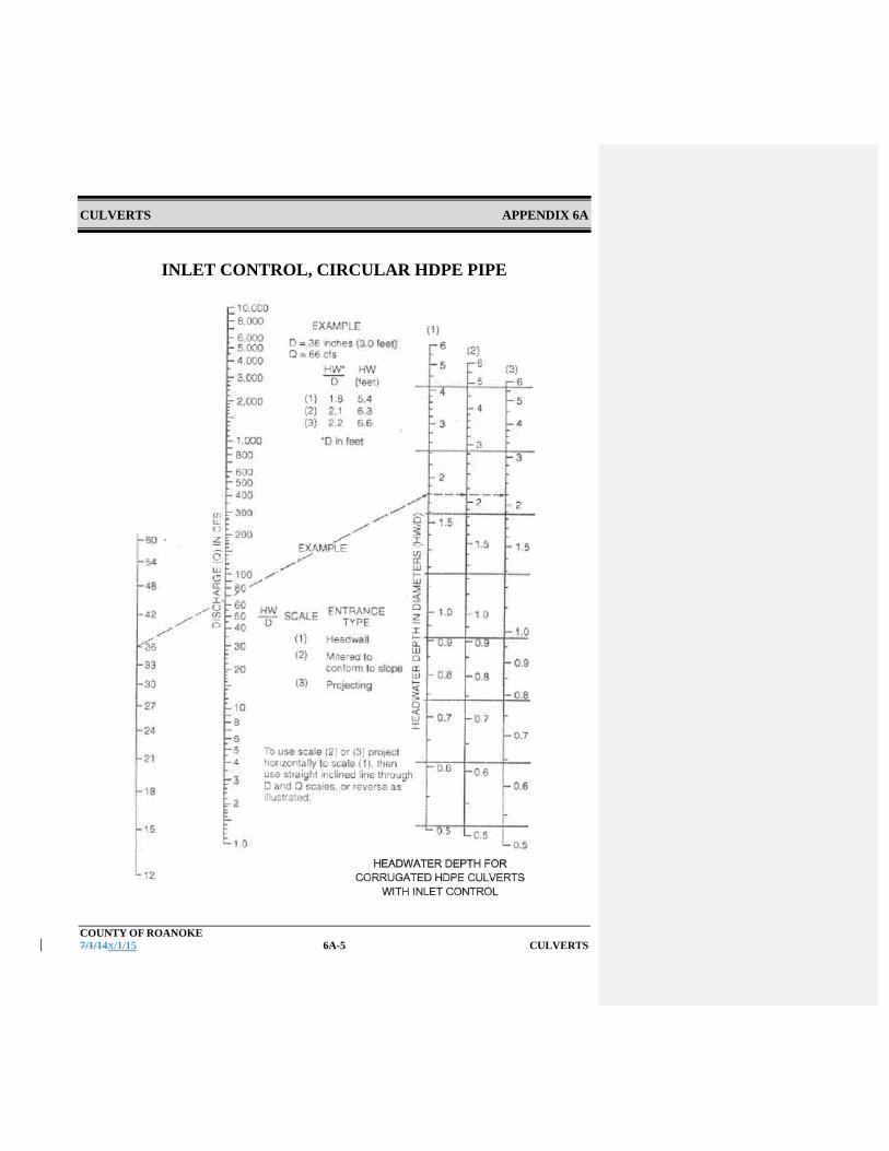
CULVERTS APPENDIX 6A
COUNTY OF ROANOKE 7/1/14X/1/15 6A-5 CULVERTS
INLET CONTROL, CIRCULAR HDPE PIPE

CULVERTS APPENDIX 6A
COUNTY OF ROANOKE 7/1/14X/1/15 6A-6 CULVERTS
CRITCAL DEPTH, CIRCULAR PIPE
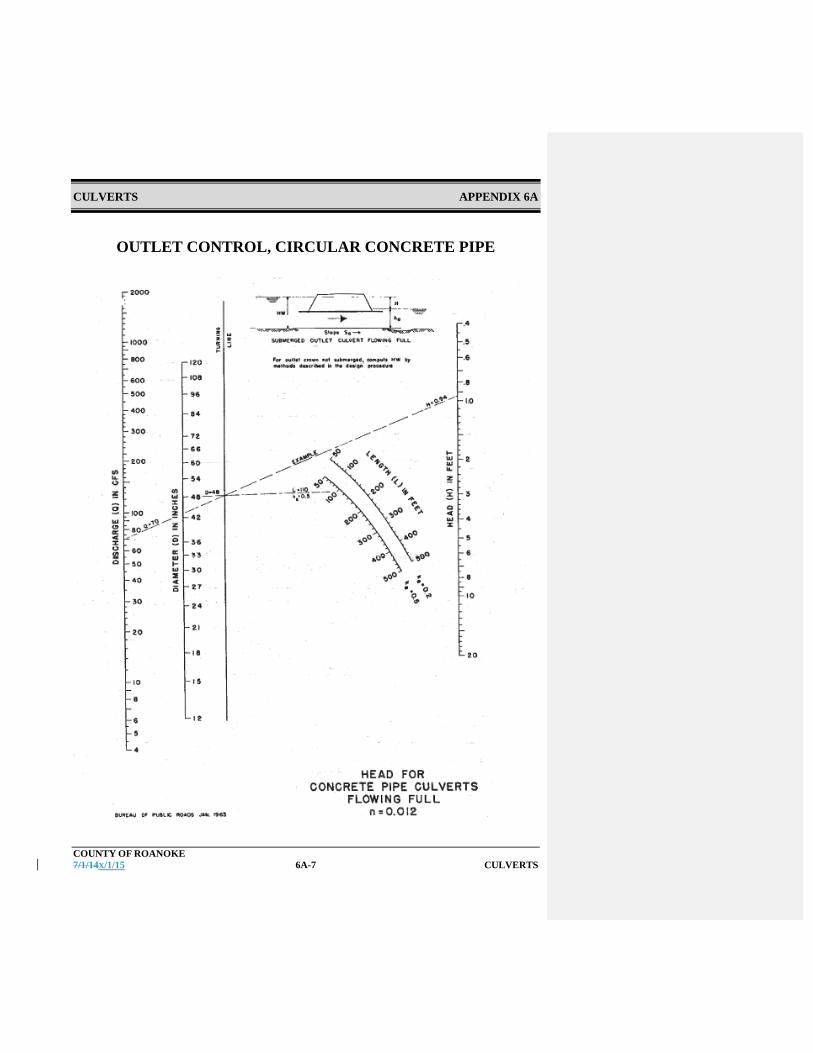
CULVERTS APPENDIX 6A
COUNTY OF ROANOKE 7/1/14X/1/15 6A-7 CULVERTS
OUTLET CONTROL, CIRCULAR CONCRETE PIPE

CULVERTS APPENDIX 6A
COUNTY OF ROANOKE 7/1/14X/1/15 6A-8 CULVERTS
OUTLET CONTROL, CIRCULAR CORRUGATED METAL PIPE

CULVERTS APPENDIX 6A
COUNTY OF ROANOKE 7/1/14X/1/15 6A-9 CULVERTS
OUTLET CONTROL, CIRCULAR CONCRETE PIPE
RECOMMENDED MANNING’S n-VALUES
Type of Conduit Wall Description Manning’s n Concrete Pipe Smooth walls 0.010 - 0.013 Concrete Boxes Smooth walls 0.012 - 0.015 Corrugated Metal Pipes and Boxes, Annular or Helical Pipe
2 2/3 by ½ inch corrugations
0.022 - 0.027
6 by 1 inch corrugations
0.022 - 0.025
5 by 1 inch corrugations
0.025 - 0.026
3 by 1 inch corrugations
0.027 - 0.028
6 by 2 inch structural plate
0.033 - 0.035
9 by 2 ½ inch structural plate
0.033 - 0.037
Corrugated Metal Pipe
2 2/3 by ½ inch corrugations 0.012 - 0.024
Spiral Rib Metal (Steel or Alum.)
Smooth walls 0.012-0.013
PVC Smooth interior 0.010 - 0.012 Polyethylene (PE or HDPE) Smooth interior 0.011 - 0.013 Corrugated PE or HDPE Corrugated interior 0.022 - 0.026
Note 1: The values indicated in this table are recommended Manning’s “n” design values. Actual field values may vary depending on the effects of abrasion, corrosion, deflection, and joint conditions. Concrete pipe with poor joints and deteriorated walls may have “n” values of 0.014 to 0.018. Corrugated metal with join and wall problems may also have higher “n” values, and in addition, may experience shape changes which could adversely affect the general hydraulic characteristics of the culvert. Note 2: Fore further information concerning Manning n values for selected conduits consult Hydraulic Design of Highway Culverts, Federal Highway Administration, HDS No. 5, page 163.
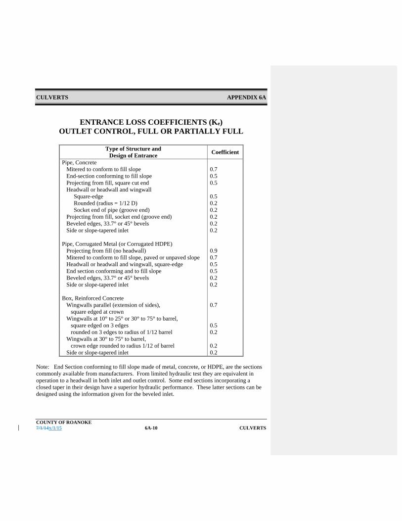
CULVERTS APPENDIX 6A
COUNTY OF ROANOKE 7/1/14X/1/15 6A-10 CULVERTS
ENTRANCE LOSS COEFFICIENTS (Ke) OUTLET CONTROL, FULL OR PARTIALLY FULL
Type of Structure and
Design of Entrance Coefficient
Pipe, Concrete Mitered to conform to fill slope 0.7 End-section conforming to fill slope 0.5 Projecting from fill, square cut end 0.5 Headwall or headwall and wingwall Square-edge 0.5 Rounded (radius = 1/12 D) 0.2 Socket end of pipe (groove end) 0.2 Projecting from fill, socket end (groove end) 0.2 Beveled edges, 33.7° or 45° bevels 0.2 Side or slope-tapered inlet 0.2 Pipe, Corrugated Metal (or Corrugated HDPE) Projecting from fill (no headwall) 0.9 Mitered to conform to fill slope, paved or unpaved slope 0.7 Headwall or headwall and wingwall, square-edge 0.5 End section conforming and to fill slope 0.5 Beveled edges, 33.7° or 45° bevels 0.2 Side or slope-tapered inlet 0.2 Box, Reinforced Concrete Wingwalls parallel (extension of sides), square edged at crown
0.7
Wingwalls at 10° to 25° or 30° to 75° to barrel, square edged on 3 edges 0.5 rounded on 3 edges to radius of 1/12 barrel 0.2 Wingwalls at 30° to 75° to barrel, crown edge rounded to radius 1/12 of barrel 0.2 Side or slope-tapered inlet 0.2
Note: End Section conforming to fill slope made of metal, concrete, or HDPE, are the sections commonly available from manufacturers. From limited hydraulic test they are equivalent in operation to a headwall in both inlet and outlet control. Some end sections incorporating a closed taper in their design have a superior hydraulic performance. These latter sections can be designed using the information given for the beveled inlet.

STORM DRAINS CHAPTER 7
COUNTY OF ROANOKE 7/1/14X/1/15 7-1 STORM DRAINS
Chapter 7 - Storm Drains A storm drain is a drainage system that conveys water or stormwater, consisting of two or more pipes in a series connected by one or more structures. Storm drains collect and transport stormwater from a site primarily through the use of a closed pipe network. For the storm water to be efficiently handled in a storm drain, the site must also have an efficient way to collect stormwater runoff and have it enter into the piped network. Once in the storm drain, the stormwater is routed to a discharge outfall. Storm drain systems include:
Measures to get stormwater runoff to inlets, Inlets, and storm Storm drain piping pipes and structures that stormwater runoff must pass
through to reach the outfall This section defines criteria and restrictions that shall be used in designing and constructing public and private storm drains. See the VDOT Drainage Manual for more in-depth information. All storm drains 12 inches in diameter and larger shall have profiles prepared and submitted to the County. A storm drainage schedule shall be included on the grading sheet in a chart that indicates the inlet number, rim, invert in, invert out, pipe length, pipe size, pipe material, and slope, and to which inlet the pipe flows to. 7.1 References
Except where more stringent requirements are presented in this Manual, storm drain collection systems shall comply with VDOT and other state requirements. The primary design reference is the VDOT Drainage Manual. Other appropriate references include:
VDOT Standards
VDOT Specifications
VA E&SC Handbook
FHWA Drainage of Highway Pavements HEC No. 12.
FHWA Urban Drainage Design Manual HEC No. 22.
VA Stormwater Management Handbook, Chapter 6 Appendix 6B (Karst Guidelines)

STORM DRAINS CHAPTER 7
COUNTY OF ROANOKE 7/1/14X/1/15 7-2 STORM DRAINS
7.2 Design Methodology and Criteria
7.2.1 Computation Methods
Manual computations use design equations and nomographs. Results are documented on VDOT work sheets. Copies of these forms are included in Appendix 7A.
Form LD-204 Stormwater Inlet Computations
Form LD-229 Storm Drain Design Computations
Form LD-347 Hydraulic Grade Line Computations
Copies of these forms are included in Appendix 7A. There are a number of computer programs available to design storm drainage systems. Any of these computer programs will be acceptable if their methodologies are based on the same equations and nomographs accepted by VDOT, and if they provide the same documentation of inputs, assumptions, and output as are contained on VDOT’s work sheets. Computation methods are explained in detail, including comprehensive design examples, in the VDOT Drainage Manual.
7.2.2 Hydrology
A. Design Flow Methodology
Calculations establishing the design flow shall be submitted with the Stormwater Management Plan. Design flows shall be based on ultimate build-out of the contributing watershed based on the current Comprehensive Plan.
7.2.3 Design Flows
The following minimum storm frequencies shall be used:
A. Inlets
Inlets shall be designed for storm frequencies and intensities consistent with the VDOT Drainage Manual. For reference, the VDOT table and its accompanying notes have been included in Appendix 7A.
Formatted: Font: Bold
Formatted: Font: Bold

STORM DRAINS CHAPTER 7
COUNTY OF ROANOKE 7/1/14X/1/15 7-3 STORM DRAINS
B. Storm Drains
Storm drains shall be designed for the storm frequencies and intensities consistent with the VDOT Drainage Manual. For reference, the VDOT table and its accompanying notes have been included in Appendix 7A. Unless otherwise specified by the VDOT Drainage Manual, a 10-year frequency design storm shall be used in developing design flows.
7.2.4 Measures to Convey Stormwater Runoff to Inlets
A. Pavement Drainage
One objective in the site design is to collect and remove stormwater runoff from critical areas as efficiently as possible. A properly designed system will ensure that roadway surfaces are free of stormwater accumulations, and will protect the public from unnecessary hazards associated with water ponding and sheet flow. Except where porous pavement is used, road pavement shall be sloped transversely to drain stormwater from the roadway. A minimum cross slope of 2 percent should be applied to all roads, both primary and secondary. Greater slope should be considered where poor drainage is anticipated. Drainage structures associated with medians, curbs, and gutters should be designed to minimize accumulation of water onto travel lanes of roadways. For additional information concerning drainage of highway pavements, refer to FHWA HEC No. 12.
B. Curb and Gutter
Curb and gutter at the edge of pavements may be used to collect stormwater runoff from roadways. Curbing captures stormwater runoff and directs it to stormwater collection inlets while protecting adjacent properties from flooding and erosion due to sheet flow runoff from the impervious roadways.
Formatted: Font: Bold
Formatted: Font: Bold
Formatted: Font: Bold

STORM DRAINS CHAPTER 7
COUNTY OF ROANOKE 7/1/14X/1/15 7-4 STORM DRAINS
A curb and gutter forms a triangular conveyance channel. When a storm occurs, the runoff from the road creates a spread of water from the curb. The curb and gutter must be designed to convey this flow and prevent the spread of water from impacting traffic. The spread width of flow is determined by using VDOT nomographs or acceptable hydrological design software. For curb and gutter flow, a Manning’s n value of 0.015 is used in the computational analysis. See Appendix 7A for width of maximum allowable spread.
Curb and gutter dimensions and design shall meet VDOT Standards.
C. Open Channels
Open channels may be used to collect site drainage and convey it to a storm drain inlet. Design requirements for open channels are covered in Chapter 5.
7.2.5 Storm Drain Inlets
A. General
Storm drain inlets are used to collect stormwater runoff from roads, walks, or low elevations during storm events and provide a method for passing the stormwater into the storm drain system. This is usually accomplished by placing storm drain inlets at regular intervals, low points, or at key locations to intercept flows and control the stormwater spread width. The design criteria for limiting the spread of water on travel lanes are contained in the VDOT Drainage Manual. The current design table and its notes have been included in Appendix 7A There are several different types of storm drain inlets which can be used to meet this purpose, and the designer shall choose the proper inlet structure based upon site conditions and design conditions to maximize the drainage efficiencies.
Curb Grate Slotted Drain/Trench Combination
Drainage and Stormwater management plans shall include a contour plan with sufficient contours shown to indicate proper drainage.
Formatted: Font: Bold
Formatted: Font: Bold

STORM DRAINS CHAPTER 7
COUNTY OF ROANOKE 7/1/14X/1/15 7-5 STORM DRAINS
B. Curb Inlets
Curb inlets are vertical openings in the curb covered by a top slab. These inlets can convey large quantities of water, but also allow for large amounts of debris to enter the storm drain system.
Curb inlets shall be used to the maximum extent possible for pavement drainage.
C. Grate Inlets
Grate inlets are horizontal grates usually used in depressed medians or other low elevations. Grate inlets are often referred to as drop inlets or DIs. Grate inlets shall be avoided in paved areas. Where they are used in pavement, inlet grates shall be bicycle safe.
D. Combination Inlets
Combination inlets combine both the vertical opening used by curb inlets and the horizontal grate used in grate inlets. These inlets are often used when the inlet chamber is required to be under the gutter or street pavement away from the sidewalk or other utilities. Combination inlets shall be avoided where possible. Where they are used, they must shall have bicycle safe grates.
E. Slotted Drain Inlets
Slotted drain inlets are a narrow slotted opening which can collect flow at a median barrier or curb. These inlets are usually located in areas of limited space and can be used to intercept sheet flow, or collect gutter flow to help reduce ponding depth or spreading at grate inlets.
F. Inlet Locations
Inlets shall be located to meet the design requirements of the VDOT Drainage Manual for maximum spread width. In addition, inlets shall be provided, regardless of contributing drainage area as follows:
Sag points in the gutter grade; Upstream of median breaks, crosswalks, and street intersections;
Formatted: Font: Bold
Formatted: Font: Bold
Formatted: Font: Bold
Formatted: Font: Bold
Formatted: Font: Bold

STORM DRAINS CHAPTER 7
COUNTY OF ROANOKE 7/1/14X/1/15 7-6 STORM DRAINS
Immediately upstream and downstream of bridges; On side streets at intersections, where flow is approaching the
main line; Behind curbs, shoulders, or sidewalks to drain low areas or
intercept concentrated flow; and Any low elevation in the grade.
Inlets shall be avoided in pathways likely to be used by pedestrians or bicyclists.
FG. Access
All inlets shall have a removable grate or manhole cover to allow access for clean out. All structures greater than 3 feet in depth shall be a minimum of 4’ feet in diameter for maintenance access.
GH. Inlet Capacities
The capacities of each inlet type are contained in the VDOT Drainage Manual. Documentation of inlet capacity shall be made on VDOT Form LD-204, Stormwater Inlet Computations or equivalent.
HI. Separation of Pipes in Inlets
Where two or more pipes enter a concrete structure at or near the same elevation, a 6” minimum horizontal clearance must be maintained between the pipes. Additional clearance between pipes shall be provided if required to protect the structural integrity of the structure.
IJ. Karst Terrain
Water tight joints are required where storm drainage pipe are located in karst terrain. Additionally, an A-lock premium gasket or boot is required for the pipe connection to the storm drainage structure to prevent water loss at the structure connection.
7.2.6 Storm Drain Pipes
Formatted: Font: Bold
Formatted: Font: Bold
Formatted: Font: Bold
Formatted: Font: Bold

STORM DRAINS CHAPTER 7
COUNTY OF ROANOKE 7/1/14X/1/15 7-7 STORM DRAINS
A. Flow Capacity
Based on the size and slope of the storm drain, the design capacity for a pipe flowing full can be determined using Manning’s equation. Q = A x 1.49/n x R2/3 x S1/2
Where: Q = Flow in the pipe (cfs) A = Area of the pipe (ft2) R = Hydraulic radius, for circular pipe R=Diameter/4 (ft) S = Storm drain slope (ft/ft) n = Pipe roughness coefficient The design flow capacity of a storm drain shall comply with the design frequencies set forth in VDOT Drainage Manual as shown in the table in Appendix 7A. In a roadway underpass, or depressed section, where ponded water can only be removed through the storm drain system, a 100-year frequency storm event shall be used to design the storm drain at the sag point. Storm drain flow capacities shall be documented on VDOT Form LD-229, Storm Drain Design Computations or equivalent form.
B. Storm Drain Slope
To deter the settling of debris and sediment in the storm drain pipe, the pipe shall be designed to ensure positive slope and maintain a minimum velocity of 3 feet per second during a 2-year frequency storm or a minimum of 0.5% slope, whichever is more restrictive. A minimum drop across the structure of 0.1’ shall be provided in all storm drainage structures. The maximum pipe velocity (Q10) in any storm drain shall be in accordance with VDOT requirements based on the storm drain material, but in no event shall it be greater than 20 fps.
Storm drains shall be sloped to meet the velocity requirement set in this chapter. Slopes greater than 16 percent shall be avoided if possible. If unavoidable, drop structures shall be utilized in steeper terrain. In addition, storm drains with slopes steeper than 16% must have anchor blocks for support.
Formatted: Font: Bold
Formatted: Font: Bold
Formatted: Subscript

STORM DRAINS CHAPTER 7
COUNTY OF ROANOKE 7/1/14X/1/15 7-8 STORM DRAINS
C. Pipe Size
All storm drains located in public easements or rights-of-way shall be a minimum of 15-inch diameter. Pipe size shall not be reduced along the direction of the flow, except as required for proper operation of stormwater management facilities.
D. Access
Regardless of pipe size, a cleanout access point, either an inlet, manhole, or junction box shall be provided at a maximum of every 300 feet of pipe. Cleanouts can be used for pipes 6” and smaller. All pipes over 6” require an inlet or manhole.
E. Joints
At a minimum, all joints shall be “soil tight”. The County strongly recommends the use of “water-tight” joints under pavements and areas that are stormwater “hotspots”. “Water-tight” joints are required for karst terrain. See Section IV and corresponding ADS detail in Appendix 7B for additional info in water tight joints.
7.2.7 Determination of Hydraulic Grade Line
A. General
The hydraulic grade line represents the free water surface elevation of water in a pipe system. Where the hydraulic grade line is above the top of a pipe, the pipe is flowing under pressure. The hydraulic grade line in a manhole or other structure is the elevation to which water will rise.
Hydraulic grade lines shall be calculated and evaluated for all storm drains. The hydraulic grade line shall be calculated using VDOT methods and equations that are fully described in the VDOT Drainage Manual. Calculations shall be documented on VDOT Form LD-347, Hydraulic Grade Line Computations, or equivalent. A copy of this form is included in Appendix 7A. Hydraulic grade lines can also be calculated with design software (ie Storm sewer, etc.)
Formatted: Font: Bold
Formatted: Font: Bold
Formatted: Font: Bold
Formatted: Font: Bold

STORM DRAINS CHAPTER 7
COUNTY OF ROANOKE 7/1/14X/1/15 7-9 STORM DRAINS
The hydraulic grade line shall not exceed any critical elevation during the design storm. Critical elevations include rising above the ground elevation at inlets or other structures, or reaching an elevation where storm flow could back-up to cause flooding damage.
The calculation of the hydraulic grade line begins at the system outfall and proceeds upstream to each structure on the system. The calculation is based on the principal of conservation of energy as shown below and includes major and minor energy losses:
HGLus = HGLds + Hf + Hm Where:
HGLus = Elevation of hydraulic grade line at the upstream structure Hm = Summation of minor head losses (junctions, bends, etc.) Hf = Pipe friction loss HGLds = Elevation of hydraulic grade line at the downstream structure
Major head losses are attributable to friction losses within the pipe. Minor head losses include losses from:
Junctions Exits Entrances Bends in Pipes Access holes Conflict pipes Plunging flow Expansions and contractions Appurtenances such as weirs, diverters, valves and meters
B. Outfall Conditions
The hydraulic grade line starts at the system outfall. At this point the hydraulic grade line shall be the actual tailwater elevation or the elevation of 0.8 times the diameter of the outlet pipe, whichever is higher. If the system discharges into a detention or retention pond, the hydraulic grade shall start at the 10 year water surface elevation.
C. Pipe Friction Losses
Formatted: Font: Bold
Formatted: Font: Bold

STORM DRAINS CHAPTER 7
COUNTY OF ROANOKE 7/1/14X/1/15 7-10 STORM DRAINS
The friction slope is the energy slope for that run of pipe. The friction slope is determined by inserting pipe information and design flow into Manning’s equation and solving for S (slope). The total friction headloss in the run of pipe is the friction slope multiplied by the length of the run.
Where the hydraulic grade line falls below the crown of the pipe, the elevation of normal flow is the hydraulic grade line.
D. Junction Losses
1. General
Junction head losses are the summation of entrance (Hi), exit (Ho), and bend losses (HΔ). When calculating junction losses it is important to use actual flow velocities. If pipes are flowing partially full, then partially full velocities are used.
2. Entrance (expansion) Losses
Entrance loss at a junction is given by: Hi = Ki (Vi
2 / 2g) Where:
Hi = Entrance head loss Ki = Entrance loss coefficient. Ki = 0.35
Vi = Velocity in the inlet pipe. Where more than one inlet pipe is present, use the velocity from the pipe that has the greatest momentum (Q*V) g = Gravitational acceleration constant, 32.2 ft/s2
3. Exit (contraction) Losses
Exit loss at a junction is given by: Ho = Ko (Vo
2 / 2g) Where: Ho = Exit head loss
Ko = Exit loss coefficient. Ko = 0.25, except that Ko = 0.3 when computing the loss leaving the initial inlet Vo = Velocity in the outlet pipe.
Formatted: Font: Bold
Formatted: Underline
Formatted: Underline
Formatted: Indent: Left: 2"
Formatted: Indent: First line: 0.5"
Formatted: Underline
Formatted: Indent: Left: 2"
Formatted: Indent: First line: 0.25"

STORM DRAINS CHAPTER 7
COUNTY OF ROANOKE 7/1/14X/1/15 7-11 STORM DRAINS
g = Gravitational acceleration constant, 32.2 ft/s2
4. Bend Losses
Bend loss at a junction are dependent on the angle between the inlet and outlet pipes. If the inlet and outlet pipe are in line with one another no bend) the angle is 0 degrees and there is no bend loss. As the angle increases towards 90 degrees, the bend loss increases. Storm drain systems should not be designed with bend angles greater than 90 degrees. The bend loss is given by:
HΔ = K (Vi
2 / 2g)
Where: HΔ = Head loss at bend
K = Bend loss coefficient. K is determined by consulting Figure 9-10 in the VDOT Drainage Manual. A copy is included in appendix 7A.
Vi = Velocity in the inlet pipe.
g = Gravitational acceleration constant, 32.2 ft/s2 5. Plunging Losses
Where surface inlet inflow is 20 percent or more of the total flow through a junction, or when a lateral pipe enters a junction with its invert elevation above the crown of the outgoing pipe and the flow in the lateral pipe is 20 percent or more of the total flow through the junction, the total headloss from the structure (Hi + Ho + HΔ) shall be multiplied by 1.3 (increased by 30 percent). This adjustment is cumulative with the adjustment for inlet shaping.
6. Inlet Shaping Inlet shaping refers to how the invert is shaped to provide smooth flow through the structure and is required in all manholes and inlets. When VDOT Standard IS-1, inlet shaping, is used in a structure the total headloss from the structure (Hi + Ho + HΔ) shall be multiplied by 0.5 (decreased by 50 percent). This adjustment is cumulative with the adjustment for plunging losses.
7.2.8 100-Year Conditions
Formatted: Underline
Formatted: Indent: Left: 1.75", First line: 0"
Formatted: Indent: Left: 1.75", First line: 0"
Formatted: Underline
Formatted: Indent: Left: 1.75", First line: 0"
Formatted: Underline
Formatted: Indent: Left: 1.75", First line: 0"

STORM DRAINS CHAPTER 7
COUNTY OF ROANOKE 7/1/14X/1/15 7-12 STORM DRAINS
Where there is the possibility of building structures flooding, conditions during the 100-year storm shall be analyzed to verify that all existing and proposed structures do not flood. Flow from the 100-year storm may be carried overland as well as by the storm drain system.
7.2.9 Materials
A. Structures
All stormwater structures (inlets, manholes, and junction boxes) located in public easements or rights-of-way shall be precast or cast-in-place concrete. All structures, frames, grates, and covers shall be in accordance with VDOT Standards and VDOT Specifications.
All storm drain structures over four (4) feet in depth must have steps.
B. Storm Drain Pipe
Storm drains in the VDOT right-of-way shall be VDOT approved materials in accordance with VDOT IIM-LD-121.15 and VDOT Standard PC-1. Storm drains not in the VDOT right-of way shall be:
o Reinforced concrete pipe (RCP). o Corrugated high-density polyethylene pipe (HDPE) with an integrally formed smooth interior is allowed for sizes 48-inch diameter or smaller. HDPE pipe is allowed for pipe slopes less than 12% and with a velocity 12 fps or less. HDPE culvert pipe cover must be in accordance with the County of Roanoke Inspection Specifications for HDPE Pipe. A copy of this document is included in Appendix 7B. o Culverts 60 inches in diameter or greater may be Corrugated Aluminized Metal Pipe (CAMP) or corrugated aluminum with a minimum 14 gauge metal.
Formatted: Indent: Left: 1", First line: 0"
Formatted: Font: Bold
Formatted: Indent: Left: 1.5", First line: 0", Bulleted +Level: 1 + Aligned at: 0.75" + Indent at: 1", Tab stops: 1.75", Left
Formatted: Indent: Left: 1", First line: 0"
Formatted: Indent: Left: 1.5", First line: 0", Bulleted +Level: 1 + Aligned at: 0.75" + Indent at: 1", Tab stops: 1.75", Left
Formatted: Font: Bold
Formatted: List Paragraph, Indent: Left: 1.81", No bulletsor numbering, Tab stops: 1.56", Left
Formatted: List Paragraph, Indent: Left: 1.81", No bulletsor numbering, Tab stops: 1.56", Left

STORM DRAINS CHAPTER 7
COUNTY OF ROANOKE 7/1/14X/1/15 7-13 STORM DRAINS
o The minimum cover for all pipes is two (2) feet measured from the final surface. Special applications for less than two (2) feet of cover will be reviewed and approved by the County Engineer individually. The maximum cover for storm drainage pipes shall at a minimum comply with the requirements of the Virginia Department of Transportation Design Manual.
7.2.10 Structural Design
All inlet structures, frames and grates; and pipes shall be designed to withstand a HS-20 loading, unless a pipe crosses a railroad, in which case the pipe shall be designed for railroad loads. The structural design shall consider the depth of cover, trench width and condition, bedding type, backfill material, and compaction.
7.3 Installation
All inlets, pipes, and associated structures shall be installed in accordance with VDOT Specifications and the manufacturer’s recommendations. The characteristics of the trench, bedding, and pipe material all impact the structural strength of the pipe system. The installed pipe conditions shall comply with the design assumptions and calculations.
HDPE pipe installation shall comply with the County of Roanoke Inspection Specifications for HDPE Pipe. A copy of this document is included in Appendix 7B.
Storm drains shall not be installed through contaminated soils or groundwater.
7.3.1 Bedding Material
Bedding material and installation shall comply with the requirements of the VDOT Specifications. Use Class I backfill (crusher run and #21) to one foot over the pipe for HDPE, up to the spring line for RCP. #57 stone is not allowed as pipe bedding.
7.3.2 Backfill
Backfill shall be suitable material and shall be placed and compacted in accordance with the VDOT Specifications (PB-1 detail). Use Class I backfill
Formatted: List Paragraph, No bullets or numbering
Formatted: Indent: First line: 0"
Formatted: Indent: First line: 0"
Formatted: Indent: Left: 0.5", First line: 0"

STORM DRAINS CHAPTER 7
COUNTY OF ROANOKE 7/1/14X/1/15 7-14 STORM DRAINS
(crusher run) to one foot over the pipe for HDPE, and up to the spring line for RCP. A minimum of 12” cover shall be placed over the top of a storm drain pipe prior to placement of pavement or other surface treatment. Additional minimum depth of cover shall be provided if recommended by the manufacturer. All pipe installed must be inspected and approved by the County’s Inspector prior to any backfill being placed. The Contractor must provide 24 hour notice to County prior to installing backfill so that County staff can be present for inspections.
7.3.3 Separation of Utilities
Where storm drains cross other utilities, at least 1-foot of vertical separation shall be provided. Where 1-foot of vertical separation cannot be provided, special provisions shall be made in the bedding and backfill to avoid settlement that could cause point loadings on the storm drain or other utility. Water lines shall not pass through a storm drain inlet or manhole.
7.4 Environmental Impacts
Construction or modifications to storm drains shall comply with all applicable laws and regulations. The applicant is responsible for procuring all necessary permits.
7.5 Erosion Protection at Outfalls
Erosion protection at storm drain outlets shall be provided in accordance with the outlet protection standards contained in the VA E&SC Handbook and the VDOT Drainage Manual.
7.6 Maintenance Requirements
The permittee is responsible for maintenance of storm drains until construction is complete, including final clean up and site stabilization, to the satisfaction of the County. After the completion of construction, the property owner is responsible for maintenance of all storm drains not located in public easements. No one shall modify inlets or other structures, pipe entrances, or pipes in any way that impairs or restricts flow. Property owners shall periodically remove silt and
Formatted: Indent: Left: 1", First line: 0"
Formatted: Indent: Left: 1", No bullets or numbering, Tabstops: 0.5", Left
Formatted: Indent: Left: 1", First line: 0"
Formatted: Indent: Left: 1", First line: 0", Tab stops: Notat 0.5"
Formatted: Indent: Left: 1", First line: 0", Tab stops: 1",Left + Not at 0.5"
Formatted: Indent: Left: 1", First line: 0", Tab stops: 1",Left + Not at 0.5"
STORM DRAINS CHAPTER 7
COUNTY OF ROANOKE 7/1/14X/1/15 7-15 STORM DRAINS
sediment from the pipes and structures, and prune vegetation from around pipe entrances and inlets to avoid restricting flow capacity and shall correct erosion damage as necessary. All removed silt and sediment shall be properly disposed of away from storm drains, open channels, streams, ponds, and BMPs and shall be properly stabilized with vegetation.

STORM DRAINS APPENDIX 7A
COUNTY OF ROANOKE 7/1/14X/1/15 7A-1 STORM DRAINS
APPENDIX 7A
AIDS FOR STORM DRAIN SYSTEM DESIGN
FROM CHAPTER 9, VDOT DRAINAGE MANUAL
Table 9-1, Criteria for Inlet Design Table 9-2, Design Frequencies for Storm Drain Conduit Notes that accompany Table 9-1 and Table 9-2 Figure 9-10, Losses in Junction due to Change in Direction of Flow Lateral Appendix 9B-1, LD 204 Stormwater Inlet Computations Appendix 9B-2, LD 229 Storm Drain Design Computations Appendix 9B-3, LD 347 Hydraulic Grade Line Computations Appendix 9C-1, Flow in Triangular Gutter Sections Appendix 9C-3, Flow Characteristic Curves (24” Gutter)- VDOT Standard Appendix 9C-23, Manning’s Solution for Flow in Storm Drains Appendix 9C-24, Nomograph for Computing Required Size of Circular Drain for Full Flow Appendix 9C-25, Concrete Pipe Flow Nomograph

STORM DRAINS APPENDIX 7A
COUNTY OF ROANOKE 7/1/14X/1/15 7A-2 STORM DRAINS
CRITERIA FOR INLET DESIGN
Roadway Classification
Design Speed (mph)
Design Storm Maximum Design Spread Width3
(ft) Frequency
(year1,2) Intensity (in/hour)
Principal Arterial
Wit
h Sh
ould
er
On Grade ≤50 10 Actual Sh. Width +3
>50 10 Actual Sh. Width
Sag Location5
All 10 Actual Sh. Width +3
Wit
hout
Sho
ulde
r On Grade ≤50 N/A4 4 ½ Driving Lane + Gutter
Width (If Any)
On Grade5 >50 10 Actual ½ Driving Lane + Gutter
Width (If Any)
Sag Location5
≤50 N/A4 4 ½ Driving Lane + Gutter
Width (If Any)
>50 50 Actual ½ Driving Lane + Gutter
Width (If Any) Minor Arterial, Collector, Local
Wit
h Sh
ould
er
On Grade ≤50 N/A4 4 Sh. Width +3 >50 N/A4 4 Sh. Width
Sag Location
All N/A4 4 Sh. Width +3
Wit
hout
Sh
ould
er
On Grade All N/A4 4 ½ Driving Lane + Gutter
Width (If Any)
Sag Location
All N/A4 4 ½ Driving Lane + Gutter
Width (If Any)
DESIGN FREQUENCIES FOR STORM DRAIN CONDUIT
Roadway Classification Design Speed
(mph) Design Storm Frequency
(year1,2) Principal Arterial
With Shoulder All 25
Without Shoulder ≤50 10 >50 25
Minor Arterial, Collector, Local
With or Without Shoulder All 10

STORM DRAINS APPENDIX 7A
COUNTY OF ROANOKE 7/1/14X/1/15 7A-3 STORM DRAINS
NOTES – CRITERIA FOR INLET DESIGN AND DESIGN FREQUENCIES FOR STORM DRAIN CONDUIT
Notes 1 through 3 are General Notes and should be applied to any functional classification roadway where the site conditions are comparable to the conditions described in each note. 1 At locations where the vertical alignment of the roadway creates a sag condition in either a depressed roadway section or a roadway section utilizing concrete barriers, and ponded water on the roadway can only be removed through the storm drain system, a 50-year storm frequency and the actual time of concentration should be used as the design criteria for both the drop inlet and the pipe system. 2 Federal Flood Insurance criteria dictate that the effects of the 100-year storm event (using the actual time of concentration) on buildings insured under the Flood Insurance Program must be investigated. Such cases should only be encountered where the roadway traverses a designated floodplain area containing insured buildings and the depth of water on the pavement is sufficient to overtop the curb and flow to the buildings. 3 The maximum design spread width may not be obtainable due to the pavement/shoulder slope and the height of the curb. In locations where the curb would be overtopped and water would escape the roadway section prior to achieving the maximum design spread with, the maximum depth of ponded water allowed adjacent to the curb for the design storm shall be curb height minus one (1) inch. Notes 4 through 5 should normally be applied to the specific locations as noted in the criteria table. 4 At location where it may be reasonably anticipated that the runoff from storm events with rainfall intensities greater than 4 inches per hour will overtax the drop inlet system to the point that excess flow will escape the roadway section and result in potential damage to the adjacent property and/or roadway right of way, the drop inlet system shall be analyzed for a check storm event with a rainfall intensity of 6.5 inches per hour. If all of the runoff from the check storm event is found to be contained within the roadway section, both at the site and down grade, or if runoff escaping the roadway section is found to not be damaging to adjacent property, the drop inlet system may be used as originally designed under the general criteria. If the drop inlet system fails to meet the check storm criteria, it must be re-designed to accommodate the runoff from the check storm event. 5 Drop inlets in these locations are prone to clogging and are often located in areas where maintenance is difficult. To compensate for partial clogging, the computed slot length value should be adjusted by multiplying by a factor of two (2). The adjusted computed slot length value should then be used to determine the slot length specified on the plans.

STORM DRAINS APPENDIX 7A
COUNTY OF ROANOKE 7/1/14X/1/15 7A-4 STORM DRAINS
LOSSES IN JUNCTION DUE TO CHANGE IN DIRECTION OF FLOW LATERAL

STORM DRAINS APPENDIX 7A
COUNTY OF ROANOKE 7/1/14X/1/15 7A-5 STORM DRAINS
STORMWATER INLET COMPUTATIONS (VDOT LD-204)

STORM DRAINS APPENDIX 7A
COUNTY OF ROANOKE 7/1/14X/1/15 7A-6 STORM DRAINS
STORM DRAIN DESIGN COMPUTATIONS (VDOT LD-229)

STORM DRAINS APPENDIX 7A
COUNTY OF ROANOKE 7/1/14X/1/15 7A-7 STORM DRAINS
HYDRAULIC GRADE LINE COMPUTATIONS (VDOT LD-347)

STORM DRAINS APPENDIX 7A
COUNTY OF ROANOKE 7/1/14X/1/15 7A-8 STORM DRAINS
FLOW IN TRIANGULAR GUTTER SECTIONS

STORM DRAINS APPENDIX 7A
COUNTY OF ROANOKE 7/1/14X/1/15 7A-9 STORM DRAINS
FLOW CHARACTERISTIC CURVES (24” GUTTER)

STORM DRAINS APPENDIX 7A
COUNTY OF ROANOKE 7/1/14X/1/15 7A-10 STORM DRAINS
MANNING’S SOLUTION FOR FLOW IN STORM DRAINS

STORM DRAINS APPENDIX 7A
COUNTY OF ROANOKE 7/1/14X/1/15 7A-11 STORM DRAINS
NOMOGRAPH FOR COMPUTING REQUIRED SIZE OF CIRCULAR DRAIN FOR FULL FLOW

STORM DRAINS APPENDIX 7A
COUNTY OF ROANOKE 7/1/14X/1/15 7A-12 STORM DRAINS
CONCRETE PIPE FLOW NOMOGRAPH

STORM DRAINS APPENDIX 7B
COUNTY OF ROANOKE 7/1/14 7B-1 STORM DRAINS
APPENDIX 7B
INSTALLATION PROCEDURES
FROM ROANOKE COUNTY Inspection Specifications Ffor HDPE PIPE

STORM DRAINS APPENDIX 7B
COUNTY OF ROANOKE 7/1/14 7B-2 STORM DRAINS

STORM DRAINS APPENDIX 7B
COUNTY OF ROANOKE 7/1/14 7B-3 STORM DRAINS

STORM DRAINS APPENDIX 7B
COUNTY OF ROANOKE 7/1/14 7B-4 STORM DRAINS

STORM DRAINS APPENDIX 7B
COUNTY OF ROANOKE 7/1/14 7B-5 STORM DRAINS
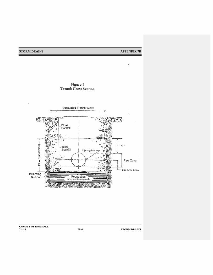
STORM DRAINS APPENDIX 7B
COUNTY OF ROANOKE 7/1/14 7B-6 STORM DRAINS

STORM DRAINS APPENDIX 7B
COUNTY OF ROANOKE 7/1/14 7B-7 STORM DRAINS

STORM DRAINS APPENDIX 7B
COUNTY OF ROANOKE 7/1/14 7B-8 STORM DRAINS
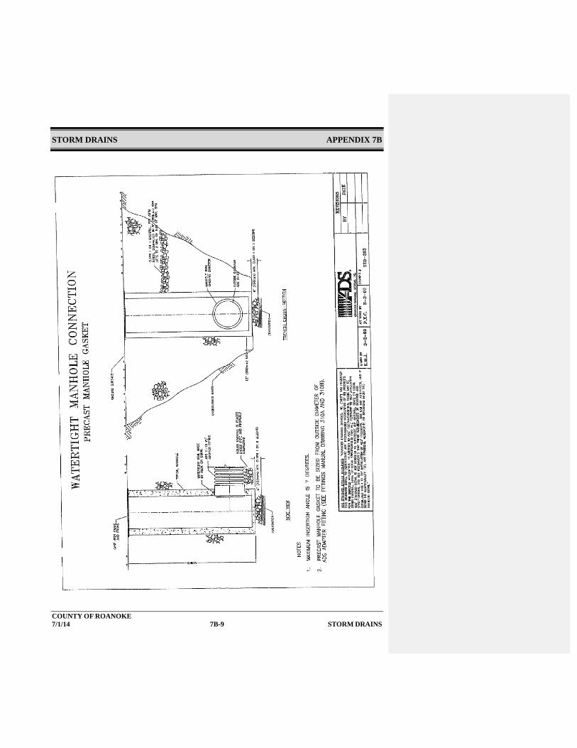
STORM DRAINS APPENDIX 7B
COUNTY OF ROANOKE 7/1/14 7B-9 STORM DRAINS

STORM DRAINS APPENDIX 7B
COUNTY OF ROANOKE 7/1/14 7B-10 STORM DRAINS

STORM DRAINS APPENDIX 7B
COUNTY OF ROANOKE 7/1/14 7B-11 STORM DRAINS

STORM DRAINS APPENDIX 7B
COUNTY OF ROANOKE 7/1/14 7B-12 STORM DRAINS

STORM DRAINS APPENDIX 7B
COUNTY OF ROANOKE 7/1/14 7B-13 STORM DRAINS

RESIDENTIAL LOT DRAINAGE CHAPTER 8
COUNTY OF ROANOKE 7/1/14X/1/15 8-1 RESIDENTIAL LOT DRAINAGE
Chapter 8 - Residential Lot Drainage (RESERVED) Residential lot drainage includes providing drainage and/or grading of the land to direct surface drainage away from building and toward streets, drainage conveyance structures, BMPs, or sheet flow. 8.1 References
Except where more stringent requirements are presented in this Design Manual, lot drainage shall comply with state requirements. The primary design references are:
VDOT Drainage Manual VA SWM Handbook VA ESC Handbook
BMP Clearinghouse State Building Code
8.2 General Lot Grading
Lot grading plans establish the grading relationships between adjacent properties, determine the drainage areas and sizing of stormwater conveyance systems and BMPs, and account for the build out of the developed lot.
8.3 Construction Plan Requirements
Individual lot grading and drainage shall be shown on the site plans and shall include the following information:
All high or low points shall be labeled on the plans.
All impervious areas shall be shown on the site plans. Additionally, all
impervious areas shall be shown on the plot plans and shall not exceed the impervious areas shown on the approved site plans. Building pads sizes shall be noted on the site plans and the plot plans. If plot plans show an increase in the impervious areas then additional stormwater BMPs and a redesigned site plan may be required. Designers are encouraged to provide an adequate building pad on the site plans in order to meet homebuilders desired pad size and prevent redesign of the plans.
Formatted: Font: Not Bold
Formatted: Font: Not Bold
Formatted: Indent: Left: 0.5", First line: 0"
Formatted: Indent: Left: 0.75", No bullets or numbering
Formatted: List Paragraph, Left, No bullets or numbering
Formatted: Bulleted + Level: 1 + Aligned at: 0.75" +Indent at: 1"
Formatted: Indent: Left: 1"
Formatted: Bulleted + Level: 1 + Aligned at: 0.75" +Indent at: 1"
Formatted: List Paragraph, No bullets or numbering

RESIDENTIAL LOT DRAINAGE CHAPTER 8
COUNTY OF ROANOKE 7/1/14X/1/15 8-2 RESIDENTIAL LOT DRAINAGE
Proposed and existing contours at two foot intervals. The proposed contours on plot plans shall conform with the intent of the approved site plan”.
All stormwater conveyance structures (drainage pipes, swales, etc.) shall be shown on the plans.
All BMPs and swales shall be shown on the plans.
A finished floor elevation (FFE) shall be provided for each building pad on the
site plan to the nearest foot. The plot plan shall show a FFE that matches conforms to the approved site plan. See Section 12.2 for lots that are located in a floodplain.
Roof drains shall be shown on plot plans and shall meet the drainage areas as
shown on the approved site plan. Rooftop disconnects used for stormwater quality shall be shown on the site plan.
i. Plot plans shall show that grading matchesconforms to the approved site plan. If
plot plans show different grades fromdoes not conform to the approved site plan then additional stormwater structures and a redesigned plan may be required.
Residential driveways shall meet VDOT specifications for driveways abutting a
public roadway and Roanoke County’s Street standards for driveways abutting a private roadway for maximum driveway grades.
Formatted: Bulleted + Level: 1 + Aligned at: 0.75" +Indent at: 1"
Formatted: Font: Not Bold
Formatted: Font: Not Bold
Formatted: Indent: Left: 1"
Formatted: Bulleted + Level: 1 + Aligned at: 0.75" +Indent at: 1"
Formatted: Font: Not Bold
Formatted: List Paragraph, No bullets or numbering
Formatted: List Paragraph, No bullets or numbering
Formatted: List Paragraph, No bullets or numbering
Formatted: Normal, Space After: 0 pt, Add space betweenparagraphs of the same style, Line spacing: single, Bulleted +Level: 1 + Aligned at: 0.75" + Indent at: 1"
Formatted: No bullets or numbering

RESIDENTIAL LOT DRAINAGE CHAPTER 8
COUNTY OF ROANOKE 7/1/14X/1/15 8-3 RESIDENTIAL LOT DRAINAGE

RESIDENTIAL LOT DRAINAGE CHAPTER 8
COUNTY OF ROANOKE 7/1/14X/1/15 8-3 RESIDENTIAL LOT DRAINAGE

STORMWATER DETENTION CHAPTER 9
COUNTY OF ROANOKE 12/1/069/11/07 FINAL DRAFTX/1/15 9-1 STORMWATER DETENTION
Chapter 9 – Stormwater Detention Stormwater detention facilities are a means of attenuating increases in peak flows caused by land development. In addition to providing flood control, stormwater detention facilities can protect downstream channels from increases in erosion and provide a measure of water quality treatment. This chapter addresses general requirements for detention facilities as they relate to attenuating peak flows. Chapter 11 addresses the use of detention facilities as water quality BMPs. When a storm event occurs, stormwater runoff enters the detention facility. The outlet structure allows a portion of the stormwater runoff to discharge from the facility and the remainder of the stormwater runoff is temporarily stored. After the end of the storm, water continues to discharge from the facility until it is empty. Stormwater detention facilities include:
Detention Basin Retention Basin Extended Detention Basin Enhanced Extended Detention Basin Underground Detention
A detention basin is a pond that is normally dry. When a storm event occurs, it temporarily stores stormwater runoff, discharging it at a controlled rate through a hydraulic outlet structure to a downstream conveyance system.
A retention basin is a stormwater pond which includes a permanent pool, even during non-rainfall periods. The pond includes storage above the normal pool elevation which temporarily stores stormwater runoff during storm events.
An extended detention basin is a pond which temporarily stores runoff for a specific time period following a storm event, discharging it at a controlled rate through a hydraulic outlet structure to a downstream conveyance system. An extended detention basin is dry during non-rainfall periods. An extended detention basin provides more protection to the downstream channel from increases in erosion than a detention basin by releasing stored runoff at a lower rate over a longer time period. A typical plan and profile for an extended detention basin are detailed in the VA SWM HandbookBMP Clearinghouse.
An enhanced extended detention basin is similar to an extended detention basin, but it also incorporates a shallow marsh in its bottom to provide additional quality treatment which is discussed in Chapter 11. .
An underground detention facility consists of pipes or manufactured underground chambers used to temporarily store stormwater runoff following a storm event, discharging it at a controlled rate
Formatted: Indent: First line: 0"
Formatted: Indent: First line: 0"
Formatted: Indent: First line: 0"
Formatted: Indent: First line: 0"
Formatted: Indent: First line: 0"
Formatted: Indent: First line: 0"

STORMWATER DETENTION CHAPTER 9
COUNTY OF ROANOKE 12/1/069/11/07 FINAL DRAFTX/1/15 9-2 STORMWATER DETENTION
through a hydraulic outlet structure to a downstream conveyance system. An underground detention facility is dry during non-rainfall periods.
In addition to detention and retention basins, the design requirements specified by this chapter and the VA BMP Clearinghouse shall apply to ponds created as private property amenity features and farm ponds.
9.1 References
Except where more stringent requirements are presented in this Manual, the design and construction of stormwater detention facilities shall comply with VDOT and DCR DEQ VA BMP Clearinghouse requirements. The primary design references are:
VA SWM Handbook
VDOT Drainage Manual
VA E&SC Handbook
VDOT Standards
VA BMP Clearinghouse 9.2 Design Methodology and Criteria
9.2.1 Hydrology
See Chapter 4 for methodology used to determine design flows. 9.2.2 Design Flows and Storage Volumes
To properly design stormwater detention facilities, a flow routing program shall be used with an appropriate elevation – discharge - storage relationship for the design storm events.
9.2.3 Minimum Contributing Drainage Area
A stormwater retention basin, which contains a permanent pool, requires at least 10 acres of watershed drainage and/or a good source of base flow to maintain the permanent pool. A minimum drainage area of 20 acres shall be used when the basin is located in an area of high visibility to prevent unsightly drying of the permanent pool. Retention basins are best suited for regional and large drainage area projects.
Formatted: Indent: First line: 0"
Formatted: Indent: Left: 0.5", First line: 0"
Formatted: List Paragraph, Indent: Left: 1", No bullets ornumbering
Formatted: Bullets and Numbering
Formatted: Indent: Left: 1", First line: 0"
Formatted: Indent: Left: 1", First line: 0"

STORMWATER DETENTION CHAPTER 9
COUNTY OF ROANOKE 12/1/069/11/07 FINAL DRAFTX/1/15 9-3 STORMWATER DETENTION
9.2.4 Detention Facility Locations
Stormwater detention facilities should not be constructed within a Federal Emergency Management Agency (FEMA) designated 100-year floodplain. If this is unavoidable, the facility shall comply with all applicable regulations under the National Flood Insurance Program, 44 CFR Part 59..
The following factors shall be addressed when siting a stormwater detention facility:
Geotechnical conditions including soil conditions; Groundwater levels and it’s potential impacts; Karst topography; Existing and proposed utilities; Aesthetics on surrounding properties; and Environmental impacts including wetlands.
Stormwater basins shall be located to minimize the aesthetic impacts to the surrounding property. Basins shall be set back from property lines a distance equal to the minimum width of the applicable required buffer yard.
Locate stormwater detention facilities to avoid collecting significant amounts of drainage from offsite areas.
Stormwater basins shall be set back at least fifty feet from a residential dwelling structure as measured from the wall of the structure to the top of the basin embankment. In proposed single family residential subdivisions, the stormwater management facility shall be located in a single non-developed lot.
9.2.5 Basin Grading
Stormwater basins shall be graded to blend into the surrounding topography with the following conditions:
Basin side slopes shall be no greater than 3:1.
Formatted: Indent: Left: 1", First line: 0"
Formatted: Indent: Left: 1", First line: 0"
Formatted: Indent: Left: 1", First line: 0"
Formatted: Indent: Left: 1", First line: 0"

STORMWATER DETENTION CHAPTER 9
COUNTY OF ROANOKE 12/1/069/11/07 FINAL DRAFTX/1/15 9-4 STORMWATER DETENTION
Provisions shall be made for the long-term maintenance of basin slopes and periodic access for maintenance of the outlet structure, emergency spillway, and removal of accumulated sediments. The maximum allowable depth of a stormwater detention basin shall be 15 feet, as measured from the top of the embankment to the lowest point in a basin. The bottom of the basin shall have a low flow or pilot channel to facilitate complete drainage. The pilot channel shall convey flows from a 2 year storm event and prevent standing water during dry-weather conditions. The pilot channel shall be sloped a minimum of 2% if it is a grass-lined channel and at a minimum of 1% if concrete-lined. In addition to the above requirements, the follow standards of practice should be used when designing a stormwater basin to the extent possible: The length-to-width ratio of a stormwater basin should be a minimum of 2:1. A 3:1 ratio is desired where possible. This prevents short-circuiting of the basin’s storage areas. To minimize cut and fill, the long dimension of a stormwater basin should run parallel to the contours.
9.2.6 Embankments and Emergency Spillways
Stormwater basin earthen embankments shall be designed and constructed to maintain structural integrity during the 100-year frequency storm event. When applicable, Virginia Dam Safety regulations shall apply. The minimum top width of an embankment shall be 10 feet. Width may be greater based on the overall height. Embankment side slopes shall be no steeper than 3:1. Embankments with an emergency spillway must provide at least one foot of freeboard from the maximum 100 year storm water surface elevation to the top of the embankment. An embankment without an emergency spillway must provide at least two feet of freeboard from the maximum 100 year storm water surface elevation to the top of the embankment. A geotechnical study shall be required for all stormwater basins with constructed embankments greater than 6 feet in height as measured from the base of the embankment. See Chapter 13 for requirements of a geotechnical report. The geotechnical study shall be performed by a licensed geotechnical engineer or licensed geologist and the report submitted to the County.
Commented [AG1]:

STORMWATER DETENTION CHAPTER 9
COUNTY OF ROANOKE 12/1/069/11/07 FINAL DRAFTX/1/15 9-5 STORMWATER DETENTION
9.2.7 Outlet Structures and Release Rates A. Stormwater Release Rates
Stormwater detention facilities shall be designed with an outlet structure to control the release rate from stormwater being held in the facility. Design release rates shall meet the requirements set forth in Chapter 4, except that extended detention facilities shall be designed based on releasing the design storm runoff volume in a prescribed time as indicated in the VA SWM HandbookBMP Clearinghouse. All stormwater detention facilities shall be empty within 72 hours following the storm event.
Farm ponds and pondsPonds created as private property amenity features, not being used as stormwater management, shall be exempt from release rate requirements.
B. Outlet Structure Criteria
Outlet structures generally include a principal spillway or outlet and an emergency overflow. An outlet structure may take the form of a drop inlet, pipe, weir, or orifice. The principal spillway or outlet is intended to release flow from the design storm events at the necessary controlled rate, without allowing flow to enter the emergency spillway or overflow. The sizing of the outlet structure shall be based on the results of the hydrologic routing calculations or model. Due to the tendency of clogging, the minimum orifice diameter shall be 3 inches. Outlets from stormwater detention facilities shall be designed to function without manual, electrical, or mechanical controls.
Where necessary, energy dissipaters shall be placed at the outfall to provide a non-erosive velocity from the facility to a channel. See Chapter 10 for the design of outfall protection.
Where a stormwater basin with an earthen embankment does not have an emergency spillway, the principal outlet or spillway shall be sized to safely pass the flow from the 100-year frequency storm without over topping the earthen embankment. In this instance, the design of the
Formatted: Font: Bold
Formatted: Indent: Left: 1.5", First line: 0"
Formatted: Indent: Left: 1.5", First line: 0"
Formatted: Indent: Left: 1.5", First line: 0"
Formatted: Font: Bold
Formatted: Indent: Left: 1.5", First line: 0"
Formatted: Indent: Left: 1.5", First line: 0"
Formatted: Indent: Left: 1.5", First line: 0"

STORMWATER DETENTION CHAPTER 9
COUNTY OF ROANOKE 12/1/069/11/07 FINAL DRAFTX/1/15 9-6 STORMWATER DETENTION
primary outlet structure shall include a 50% clogging factor during the 100-year frequency storm as a safety factor. When the primary spillway is less than 24 inches wide, it shall be considered inoperative during a 100-year frequency storm Where a stormwater basin with an earthen embankment has an emergency spillway included, two conditions must be evaluated. The routed 100-year WSEL must provide one foot of freeboard between the 100-yr WSEL and the top of the berm. Secondly, the spillway must be evaluated to show that the 100-year flow passes through the spillway without overtopping the berm. Both conditions must be evaluated and met. The ability to pass the 100-year flow through the spillway is typically evaluated by routing the flow through the spillway only with all other outlets ignored or by simply evaluating the 100-year flow through the dimensional equivalent weir using FlowMaster, similar software, or applicable weir equations.
Where a stormwater basin with an earthen embankment does not have an emergency spillway included, two conditions must be evaluated. The routed 100-year WSEL must provide two feet of freeboard between the 100-year WSEL and the top of the berm. Secondly, the principal outlet or spillway (riser weir or culvert outlet) shall be sized to safely pass the 100-year frequency storm without overtopping the berm. For this condition, the evaluation shall include a 50% clogging factor and is typically evaluated assuming a weir length (perimeter) or culvert (diameter) based on dimensions providing 50% of the design flow area. The principal spillway must be a minimum of 24 inches wide/diameter unless calculations show that the freeboard requirements and no overtopping conditions are met.
For examples of design calculations of outlet structure orifices and weirs, see the VDOT Drainage Manual and VA SWM HandbookBMP Clearinghouse. All riser structures shall be cast-in-place or precast concrete, unless a substitute material has been approved by the County. VDOT standards for riser structures may be found in the VDOT Standards. Outlet pipes shall be reinforced concrete pipe with rubber gasket watertight joints, shall have appropriate seepage control, and shall be installed on a concrete cradle from the tie of the pipe to the riser for the
Formatted: Indent: First line: 0"
Formatted: Indent: Left: 1.5", First line: 0"

STORMWATER DETENTION CHAPTER 9
COUNTY OF ROANOKE 12/1/069/11/07 FINAL DRAFTX/1/15 9-7 STORMWATER DETENTION
entire length of the outfall pipe. Concrete cradle shall be in accordance with the requirements of the VDOT Standards.
C. Adequate Channel
Outflows from stormwater detention facilities shall be discharged to an adequate channel. For adequate channel requirements, see Chapter 5.
9.2.8 Water QualityOmitted When designed appropriately, stormwater detention facilities may provide a measure of pollutant removal which can be used to meet the water quality standards in the regulations. For water quality requirements and standards, see Chapter 11.- 9.2.9 Landscaping
Stormwater basin embankments shall be vegetated. Selection and plant installation shall be in accordance with the standards of the VA SWM HandbookBMP Clearinghouse. Trees and shrubs shall not be planted within a stormwater detention basin, nor on a stormwater basin berm, dam, or emergency spillway. The VA SWM HandbookBMP Clearinghouse shall be utilized for guidance for landscaping in the marsh areas of enhanced extended detention basins. Native plants will be used to the maximum extent possible.
9.2.10 Underground Detention
A. Materials
All materials used in underground detention facilities shall be corrosion resistant consisting of reinforced concrete, aluminized corrugated metal pipe, corrugated high density polyethylene pipe, or similar approved material.
B. Slope
Underground detention facilities shall be sloped to drain at a minimum floor slope of 1 0.5 percent.
Formatted: Font: Bold
Formatted: Indent: Left: 1.5", First line: 0"
Formatted: Font: Bold
Formatted: Indent: Left: 1.5", First line: 0"
Formatted: Font: Bold
Formatted: Indent: Left: 1.5", First line: 0"

STORMWATER DETENTION CHAPTER 9
COUNTY OF ROANOKE 12/1/069/11/07 FINAL DRAFTX/1/15 9-8 STORMWATER DETENTION
C. Capacity
Underground detention facilities shall be sized such that the 100-year design storm may be routed through the facility with no damage to the surface property.
D. Accessibility and Maintainability
All underground detention facilities shall be designed to be readily accessible for periodic inspection and maintenance from the surface without the need to perform confined space entry. Providing pre-treatment to remove sediments before or at the entrance of the underground detention facility to improve water quality and/or improve maintainability should be considered during the design.
9.2.11 Trash Racks
Outlet structures shall be equipped with an appropriate trash rack. The trash rack shall be in accordance with the VA SWM HandbookBMP Clearinghouse.
9.3 Environmental Impacts
Environmental impacts shall be carefully considered when siting stormwater detention facilities. Siting basins in low lying areas with potentially environmentally sensitive areas requires careful consideration, coordination, approval, and permitting with local, state, and federal agencies to evaluate the suitability of constructing in these areas. Environmentally sensitive areas include, but are not limited to wetlands, shallow marshes, jurisdictional waters, natural watercourses, wildlife habitat, etc. and may be protected by state and/or federal laws. With careful planning, it may be possible to incorporate wetland mitigation into the basin design.
Construction of stormwater basins or modifications to existing basins shall comply with all applicable laws and regulations. The applicant is responsible for procuring all necessary permits, such as US Army Corps of Engineers and Virginia DEQ Wetland Permits, Virginia DEQ VPDES Permits, VSMP Permits, etc., prior to beginning construction. Copies of all permits shall be provided to Roanoke County prior to a land disturbing permit being issued. See Chapter 12 for more information.
Formatted: Font: Bold
Formatted: Font: Bold
Formatted: Indent: Left: 1.5", First line: 0"
Formatted: Indent: Left: 1", First line: 0"

STORMWATER DETENTION CHAPTER 9
COUNTY OF ROANOKE 12/1/069/11/07 FINAL DRAFTX/1/15 9-9 STORMWATER DETENTION
Detention facilities shall be coordinated with a watershed or regional plan for managing stormwater runoff, if available.
9.4 Maintenance Requirements
For the post-construction maintenance of stormwater detention facilities, see Chapter 14.
Formatted: Indent: Left: 1", First line: 0"
Formatted: Indent: Left: 1", First line: 0"

ENERGY DISSIPATION CHAPTER 10
COUNTY OF ROANOKE 7/1/14x/1/15 10-1 ENERGY DISSIPATION
Chapter 10 - Energy Dissipation Outlet protection for culverts, storm drains, BMP outlets, and steep open channels is essential to preventing erosion from damaging downstream channels and drainage structures. Erosion problems at culverts or at the outlet from detention basins are a common occurrence. Determination of the flow conditions, scour potential, and channel erosion resistance shall be standard procedure for all designs. Outlet protection can be a channel lining, structure, or flow barrier designed to lower excessive flow velocities and prevent erosion and scour. Outlet protection shall be employed whenever the velocity of flow at a pipe or open channel outlet exceeds the erosive velocity of the immediate downstream reach.
Energy dissipation may take the form of the following:
Erosion control stone-lined channels; Riprap outlet basins; or
Concrete baffled outlets.
10.1 References
Except where more stringent requirements are presented in this Design Manual, energy dissipators shall comply with VDOT and other state requirements. The primary design references are the VDOT Drainage Manual and the VA E&SC Handbook. Other appropriate references include:
VDOT Standards VA SWM Handbook FHWA Design of Riprap Revetment HEC No. 11 (Pub. No. FHWA-IP-89-016
1989/2000) FHWA Hydraulic Design of Energy Dissipators for Culverts and Channels HEC
No. 14 (Pub. No. FHWA-EPD-86-110 Sept. 1983 & FHWA-IF-00-02 2000) U.S. Dept. of the Interior – Bureau of Reclamation: Hydraulic Design of Stilling
Basins and Energy Dissipators (Engineering Monograph No. 25)
Formatted: Indent: First line: 0"
Formatted: Indent: First line: 0"
Formatted: Indent: Left: 0.5", First line: 0"

ENERGY DISSIPATION CHAPTER 10
COUNTY OF ROANOKE 7/1/14x/1/15 10-2 ENERGY DISSIPATION
U.S. Dept. of the Interior – Bureau of Reclamation: Design of Small Canal Structures
10.2 Design Methodology and Criteria 10.2.1 Outlet Velocity
Where the outlet velocity from culverts, storm drain outfalls, or open channels is high, and channel or pipe modifications cannot adequately reduce the velocity, energy dissipation may be necessary. See the VDOT Drainage Manual Sections 7.4.6 and 8.3.2 for methodologies to determine design outlet velocities from open channels, culverts, and storm drains. For the calculation of open channel velocity, see Chapter 5. For the calculation of exit velocity from culverts, see Chapter 6. For the calculation of exit velocity from storm drain pipes, see Chapter 7.
10.2.2 Erosion Control Stone
The most common form of energy dissipation is the use of erosion control stone at the outlet. Protection is provided primarily by having sufficient length and flare to dissipate energy by expanding the flow. The outlet velocities are computed for the VDOT design discharge. and the 25-year discharge. Whichever velocity is the highest is used for energy dissipation design. Where a pipe discharges into a channel, the apron shall extend across the channel bottom and shall extend up the bank to a depth of one foot above the maximum tailwater depth from the design storm event. The dimensional requirements of the erosion control stone apron shall be determined using the graphical curves in the VA E&SC Handbook. Generally, the use of erosion control stone for energy dissipation is limited to a maximum velocity of 19 feet per second. Alternative means of energy dissipation shall be required where the discharge velocity is greater than 19 feet per second. Alternative means include riprap outlet basins or concrete baffled outlets. The use of alternative means of energy dissipation requires the approval of VDOT when located in a VDOT right-of-way.
10.2.3 Riprap Outlet Basins

ENERGY DISSIPATION CHAPTER 10
COUNTY OF ROANOKE 7/1/14x/1/15 10-3 ENERGY DISSIPATION
A riprap basin is a depressed area of riprap placed at the outlet of a high velocity culvert, storm drain outlet or open channel. The riprap reduces the exit velocity by expanding the flow over the riprap length and width and forming a hydraulic jump. For the design of riprap basins, refer to the VDOT Drainage Manual. Dissipator geometry may also be computed using the “Energy Dissipator” module that is available in the computer program FHWA HY8, Culvert Analysis. Details of the riprap basin energy dissipator are included in Appendix 10A.
10.2.4 Baffled Outlets
A baffled outlet usually consists of a concrete box structure with a vertical hanging concrete baffle and an end sill. Several variations of concrete baffled outlets have been published by VDOT and other state and local transportation and stormwater management agencies. A typical schematic of baffled outlets are shown in Appendix 10C. Baffled outlets are usually used when very high exit velocities exist at piped or channel transitions. Baffled outlets function by dissipating energy through impact of the water hitting the baffle and through the resulting turbulence. A tailwater depth is not required for adequate energy dissipation, but will help smooth the outlet flow. This type of outlet protection may be used with outlet velocities up to 50 feet per second. Baffled outlets are not included in state guidance handbooks. Hydraulic design procedures for baffled outlets may be found in the U.S. Department of Interior, Bureau of Reclamation, Design of Small Canal Structures, 1978 and are as follows: Step 1: Determine input parameters, including: H = Energy head to be dissipated, feet (can be approximated as the difference between channel invert elevations at the inlet and outlet).
Where:
Q = Design discharge, cubic feet/second v = Theoretical discharge velocity determined from 2 g H, feet/second A = Flow area, Q / v, feet2
Formatted: Indent: Left: 1", First line: 0"
Formatted: Indent: Left: 1"

ENERGY DISSIPATION CHAPTER 10
COUNTY OF ROANOKE 7/1/14x/1/15 10-4 ENERGY DISSIPATION
d = Flow depth entering the basin, ft Fr = Froude number = v / ( g d )0.5, dimensionless g = Gravitational constant = 32.2 feet/second2
Step 2: Calculate the minimum basin width, W, in feet, using the following equation: W / d = 2.88 (Fr)0.566
Where:
W = minimum basin width, feet d = depth of incoming flow, feet Fr = Froude number = v / ( g d )0.5
The limits of the W/d ratio are from 3 to 10, which corresponds to Froude numbers 1 to 9. If the basin is much wider than W, flow will pass under the baffle and energy dissipation will not be effective.
Step 3: Calculate other basin dimensions as a function of W, Refer to the Schematic of Baffled Outlet in Appendix 10CA for other dimensions as a function of W and to identify variables that are used below in other steps. Step 4: Calculate the required protection for the transition from the baffled outlet to the natural channel based on the outlet width. A riprap apron shall be added of width W, length W (or a 5-foot minimum), and depth f (W/6). The side slopes shall be 1.5:1, and the median rock diameter shall be at least W/20. Step 5: Calculate the baffled outlet invert elevation based on the expected tailwater. The maximum distance between expected tailwater elevation and the invert should be b+f or some flow will go over the baffle with no energy dissipation. If the tailwater is known and fairly controlled, the baffled outlet invert should be a distance ( b / 2 ) + f below the calculated tailwater elevation. If tailwater is
Formatted: Indent: Left: 1"
Formatted: Indent: Left: 1"

ENERGY DISSIPATION CHAPTER 10
COUNTY OF ROANOKE 7/1/14x/1/15 10-5 ENERGY DISSIPATION
uncontrolled, the baffled outlet invert should be a distance f below the downstream channel invert. Step 6: Calculate the outlet pipe diameter entering the basin assuming a velocity of 12 fps flowing full. Step 7: If the entrance pipe slopes steeply downward, the entrance pipe shall be turned horizontal for at least 3 feet before entering the baffled outlet.
Step 8: If it is possible that both the upstream and downstream ends of the pipe will be submerged, provide an air vent approximately 1/6 of the pipe diameter near the upstream end to prevent pressure fluctuations and possible surging flow conditions.
10.2.5 Energy Dissipator for Paved Areas
For energy dissipation from velocities from paved channels or flumes, use VDOT Standards. Schematics of energy dissipators for paved flumes has been included in Appendix 10C.
10.2.6 Additional Energy Dissipators
For additional energy dissipators, refer to FHWA HEC No 14 entitled, Hydraulic Design of Energy Dissipators for Culverts and Channels.
10.3 Installation Requirements
Energy dissipators shall be installed and constructed according to all applicable FHWA, VDOT, and other state requirements and recommendations.
10.4 Easements
Where an energy dissipater will be owned by a public jurisdiction or agency, a drainage easement must encompass the entire energy dissipator, and provide an additional area 10 feet wide around the entire energy dissipator to provide for maintenance.
10.5 Environmental Impacts
Construction or modifications to energy dissipation structures shall comply with all applicable laws and regulations. The applicant is responsible for procuring all necessary permits, such as US Army Corps of Engineers and VA DEQ Wetland Permits, etc.
10.6 Maintenance Requirements
Formatted: Indent: Left: 1", First line: 0"
Formatted: Indent: Left: 0.5", First line: 0"
Formatted: Indent: Left: 0.5", First line: 0"
Formatted: Indent: Left: 0.5", First line: 0"

ENERGY DISSIPATION CHAPTER 10
COUNTY OF ROANOKE 7/1/14x/1/15 10-6 ENERGY DISSIPATION
The permittee is responsible for maintenance of energy dissipation structures until construction is complete, including final clean up and site stabilization, to the satisfaction of the County. After the completion of construction, property owners or responsible parties are responsible for maintenance of all energy dissipation structures located in private easements.
Formatted: Indent: Left: 0.5", First line: 0"

ENERGY DISSIPATION APPENDIX 10A
COUNTY OF ROANOKE 7/1/14x/1/15 10A-1 ENERGY DISSIPATION
APPENDIX 10A
AIDS FOR ENERGY DISSIPATION DESIGN
FROM VDOT DRAINAGE MANUAL L Figure 8E-1, Details of Riprap Basin Energy Dissipator r
Figure 8E-3, Riprap Basin Design Checklist
Formatted: Centered
Formatted: Left
Formatted: Centered
Formatted: Centered

ENERGY DISSIPATION APPENDIX 10A
COUNTY OF ROANOKE 7/1/14x/1/15 10A-2 ENERGY DISSIPATION

ENERGY DISSIPATION APPENDIX 10A
COUNTY OF ROANOKE 7/1/14x/1/15 10A-3 ENERGY DISSIPATION

ENERGY DISSIPATION APPENDIX 10A
COUNTY OF ROANOKE 7/1/14x/1/15 10A-4 ENERGY DISSIPATION
Commented [AG1]: illegible

ENERGY DISSIPATION APPENDIX 10A
COUNTY OF ROANOKE 7/1/14x/1/15 10A-5 ENERGY DISSIPATION

ENERGY DISSIPATION APPENDIX 10A
COUNTY OF ROANOKE 7/1/14x/1/15 10A-6 ENERGY DISSIPATION

ENERGY DISSIPATION APPENDIX 10A
COUNTY OF ROANOKE 7/1/14x/1/15 10A-7 ENERGY DISSIPATION

ENERGY DISSIPATION APPENDIX 10B
COUNTY OF ROANOKE x/1/157/1/14 10B-1 ENERGY DISSIPATION
APPENDIX 10B
AIDS FOR ENERGY DISSIPATION DESIGN
FROM VDOT ROAD AND BRIDGE STANDARDS
Standard 114.01, Stone for Erosion Control

ENERGY DISSIPATION APPENDIX 10B
COUNTY OF ROANOKE x/1/157/1/14 10B-2 ENERGY DISSIPATION

ENERGY DISSIPATION APPENDIX 10C
COUNTY OF ROANOKE 7/1/14x/1/15 10C-1 ENERGY DISSIPATION
APPENDIX 10C
ENERGY DISSIPATION DESIGN SCHEMATICS
Schematics of Baffled Outlet, from US Bureau of Reclamation, Design of Small Canal Structures (as used by the State of Georgia and State of Colorado) Standard Energy Dissipator for Use with Paved Flume, from VDOT Road and Bridge Standards Precast Energy Dissipator, from VDOT Road and Bridge Standards Level Spreader from VA DCR Stormwater Specifications Various Energy Dissipators and Stilling Basins, from City of Knoxville, TN BMP Manual

ENERGY DISSIPATION APPENDIX 10C
COUNTY OF ROANOKE 7/1/14x/1/15 10C-2 ENERGY DISSIPATION

ENERGY DISSIPATION APPENDIX 10C
COUNTY OF ROANOKE 7/1/14x/1/15 10C-3 ENERGY DISSIPATION

ENERGY DISSIPATION APPENDIX 10C
COUNTY OF ROANOKE 7/1/14x/1/15 10C-4 ENERGY DISSIPATION

ENERGY DISSIPATION APPENDIX 10C
COUNTY OF ROANOKE 7/1/14x/1/15 10C-5 ENERGY DISSIPATION

ENERGY DISSIPATION APPENDIX 10C
COUNTY OF ROANOKE 7/1/14x/1/15 10C-6 ENERGY DISSIPATION

ENERGY DISSIPATION APPENDIX 10C
COUNTY OF ROANOKE 7/1/14x/1/15 10C-7 ENERGY DISSIPATION

ENERGY DISSIPATION APPENDIX 10C
COUNTY OF ROANOKE 7/1/14x/1/15 10C-8 ENERGY DISSIPATION

ENERGY DISSIPATION APPENDIX 10C
COUNTY OF ROANOKE 7/1/14x/1/15 10C-9 ENERGY DISSIPATION

(NOT USED) CHAPTER 11
COUNTY OF ROANOKE 7/1/14 (NOT USED)
11-1
Chapter 11 – (NOT USED)

ENVIRONMENTALLY SENSITIVE AREAS CHAPTER 12
COUNTY OF ROANOKE 7/1/14X/1/15 12-1 ENVIRONMENTALLY SENSITIVE AREAS
Chapter 12 - Environmentally Sensitive Areas Stormwater discharges to areas with features identified as environmentally sensitive may be subject to additional requirements, or may need to utilize or restrict certain stormwater management practices. The following type of areas are considered to be “environmentally sensitive”:
Floodplains – Areas identified within a 100-year recurrence interval flood plain. Steep Slopes – Areas with a slope of 33 percent or greater.
Stream Buffers – Setbacks and vegetative buffers established adjacent to the Roanoke
River as required by the County of Roanoke zoning ordinance or designated conservation area buffer zones at each bank of streams, ponds, lakes, wetlands, and stormwater BMPs.
Critical Erosion Areas – Areas with potential serious erosion problems as defined in
the VA E&SC Handbook. These fall into two sub categories.
o The erosion hazard is critical if the slope length exceeds the following criteria:
0-7% slope > 300 feet 7-15% slope > 150 feet >15% slope > 75 feet
o Areas may be critical if the soils are highly erodible, as classified using the United States Department of Agriculture (USDA) Natural Resources Conservation Service (formerly Soil Conservation Service) methods, either Land Capability Classification IIIe, IVe, IV, VII, or VIII or with an erodibility index factor greater than 8.
Karst Geology – Areas where the underlying geologic conditions include caves and
crevices which allow stormwater to infiltrate and quickly migrate and transport potential pollutants.
Hot Spots – Areas where a high potential for stormwater pollution may occur due to
current or former activity on the site.
Jurisdictional Streams and/or Water – Waters regulated by U.S. Army Corps of Engineers (USACE) under Section 404 of the Clean Water Act. A jurisdictional determination (JD) is required that identifies and separates the Corps regulated areas from non-regulated areas. Disturbance in regulated areas requires a permit form USACE. JDs are typically good for 5 years after the determination has been made by
Formatted: Indent: First line: 0"
Formatted: Indent: Left: 0.75", No bullets or numbering

ENVIRONMENTALLY SENSITIVE AREAS CHAPTER 12
COUNTY OF ROANOKE 7/1/14X/1/15 12-2 ENVIRONMENTALLY SENSITIVE AREAS
the USACE. Third party reports by qualified professionals will be accepted for jurisdictional stream delineation.
Wetlands- Wetlands regulated by U.S. Army Corps of Engineers (USACE) under
Section 404 of the Clean Water Act. A jurisdictional determination (JD) is required that identifies and delineates wetlands. Disturbance in wetlands requires a permit form USACE. JDs are typically good for 5 years after the determination has been made by the USACE. Third party reports by qualified professionals will be accepted for wetland delineation.
12.1 References
The following publications may be useful in providing guidance when performing construction, establishing development limits, and developing appropriate strategies and design features to address the special concerns related to environmentally sensitive areas:
VDOT Drainage Manual VA E&SC Handbook VA SWM Handbook Virginia Department of Conservation and Recreation, Technical Bulletin No. 2,
Hydrologic Modeling and Design in Karst International Building Code The Development of the Land Capability Classification (reprinted from Readings
in the History of the Soil Conservation Service), Douglas Helms, Soil Conservation Service, 1992
Clean Water Act Section 404 River & Harbors Act of 1899 Section 10 FEMA Flood Map Service Center Flood Insurance Rate Map (FIRM)
Formatted: List Paragraph, No bullets or numbering, Adjustspace between Latin and Asian text, Adjust space betweenAsian text and numbers
Formatted: Indent: Left: 0.5", First line: 0"
Formatted: List Paragraph, Indent: Left: 0.75", Hanging: 0.25", No bullets or numbering
Formatted: List Paragraph, Indent: Left: 0.75", Hanging: 0.25", No bullets or numbering
Formatted: List Paragraph, Indent: Left: 0.75", Hanging: 0.25", No bullets or numbering
Formatted: List Paragraph, Indent: Left: 0.75", Hanging: 0.25", No bullets or numbering

ENVIRONMENTALLY SENSITIVE AREAS CHAPTER 12
COUNTY OF ROANOKE 7/1/14X/1/15 12-3 ENVIRONMENTALLY SENSITIVE AREAS
12.2 Floodplains
The purpose of floodplain management is to regulate the use of the floodplains in order to protect life and property, prevent sedimentation and pollution of water resources, and to prevent or protect against the general degradation of the environment. Floodplains and their regulatory requirements are generally based on the stream flows generated by a 100-year frequency storm and existing land development conditions. However, storms and future land development can generate flows of greater magnitude and flooding above and beyond these limits. For this reason, additional vertical and horizontal setbacks from the floodplain limits are strongly encouraged to account for future development within the upstream drainage area and to serve as a factor of safety for larger flood events. Floodplains include: Areas identified within a 100-year recurrence interval floodplain as identified by the
Federal Emergency Management Agency (FEMA). These areas have been identified as the Floodplain Overlay District by the County of Roanoke Zoning Ordinance.
Areas identified within a 100-year interval floodplain as identified by an applicant floodplain study.
Management of floodplains in Roanoke County shall be in accordance with the requirements published in the County of Roanoke Zoning Ordinance. Under no conditions, shall the land disturbance activity adversely affect the capacity of channels, floodways, ditches, or any drainage facility or system.
The lowest floor elevation of any new residential structure, as defined in the County of Roanoke Zoning Ordinance Section 30-28, shall be at least 2 feet above the base flood elevation. The lowest floor elevation of any new non-residential structure shall be at least 1 foot above the base flood elevation unless the structure is floodproofed. The elevation of the lowest floor shall be certified by a registered Registered surveyor Surveyor or professional Professional engineer Engineer on an Elevation Certificate after the lowest floor is installed.
Grading and cut and fill operations within the 100-year flood plain are discouraged and must be approved by the County of Roanoke. Activity within the floodplain must also be coordinated with other regulatory requirements and agencies. These may include erosion and sediment control, stream buffer protection, FEMA, VMRC, U.S. Army Corps of Engineers, Virginia DEQ, and others.
Formatted: Indent: First line: 0"
Formatted: Indent: Left: 0.5", First line: 0"
Formatted: Indent: Left: 0.5", First line: 0"
Formatted: Indent: Left: 0.5", First line: 0"
Formatted: Indent: Left: 0.5", First line: 0"
Formatted: Indent: Left: 0.5", First line: 0"

ENVIRONMENTALLY SENSITIVE AREAS CHAPTER 12
COUNTY OF ROANOKE 7/1/14X/1/15 12-4 ENVIRONMENTALLY SENSITIVE AREAS
Construction of stormwater management impoundment structures within a floodplain shall be avoided to the extent possible. Where this is unavoidable, all stormwater management facility construction shall be in compliance with all applicable regulations under the National Flood Insurance Program, 44 CFR Part 59, and in accordance with the County of Roanoke Zoning Ordinance. The County does not have the authority to alter or modify the flood limits and/or elevations established by FEMA. Should an applicant flood study indicate any alteration in FEMA’s limits and/or elevations, then the applicant must contact FEMA and obtain a map revision.
12.2.1 Applicant Flood Study Requirements
A flood study, prepared by a Professional Engineer, must be prepared and submitted, by the applicant, for all areas where the drainage area is greater than 100 acres or greater, and there are no detailed flood profiles or elevations from a FEMA Flood Insurance Study. There are two levels of studies. A detail study is required, if any development is proposed within the floodplain. Development includes grading and road crossings. A limited detail study is acceptable, if no development is proposed within the floodplain and the purpose of the study is to avoid the floodplain. A detail study involves a rigorous detailed hydrologic and hydraulic study of a flooding source reach. The typical riverine detail study includes the following minimum steps:
Field survey of stream and floodplain cross-sections Field survey of all hydraulic structure crossings. Collection of historical high water mark elevations and model
calibration/verification, if data is available. Detailed hydrologic & hydraulic modeling/computations Establishment of the FEMA regulatory Floodway Other tasks meeting all FEMA Guidelines and Specifications for Flood
Hazard Mapping Partners (http://www.fema.gov/pdf/fhm/frm_gsac.pdf)
A limited detail study may be performed when development is to occur adjacent to, but not in the existing floodplain. In most limited detail modeling, local regional regression equations along with a HEC-RAS hydraulic model will be developed. The major difference between the HEC-RAS models for the limited detail study and the detail study will be the amount of field survey information collected in the field and used to create the model and the amount of time spent on
Formatted: Indent: Left: 0.5", First line: 0"
Formatted: Indent: Left: 0.5", First line: 0"
Formatted: Indent: Left: 1.25", Hanging: 0.25", Tab stops: 3.1", Left

ENVIRONMENTALLY SENSITIVE AREAS CHAPTER 12
COUNTY OF ROANOKE 7/1/14X/1/15 12-5 ENVIRONMENTALLY SENSITIVE AREAS
calibration to historical flood elevations. The limited detail models typically include no field survey data, and floodways are typically not computed. The methods for limited detail study are further outlined in the FEMA Guidelines and Specifications for Flood Hazard Mapping Partners (htttp://www.fema.gov/pdf/fhm/frm_gsac.pdf) In addition, the following information and items are required when an applicant flood study is submitted to Roanoke County for review:
The flood study shall be based on the ultimate land use conditions as
published in the most recent Comprehensive Plan for upstream areas. Structure locations shall be based on the ultimate build out data.
The flood study shall be prepared by a registered Professional Engineer
licensed to practice engineering in Virginia, sealed, signed, and dated.
Assuming that sedimentation or scour may occur during the storm event is not acceptable.
The flood study shall compare pre- and post-development conditions to
verify that the proposed development will not increase the 100 year flood elevation more than 1 foot at any point.
The flood study shall consider backwater conditions, local obstructions
and, where required by the County of Roanoke Department of Community Development, the partial or complete failure of any enclosed drainage system. Consideration must be given to the overflow path, to ensure that no structures will flood in the event of system failure.
The flood study shall analyze the 100-year flood path for all new
development. A digital version of the 100-year flood limits and cross sections must be
supplied provided to the County. The study and supporting data will become property of the County.public information. The site plan digital file shall be in ACAD format and tied to the correct State Plane Coordinate.
Cross sections from the study must be indicated on the site plans
submitted as a part of the development review package.
12.2.2 Floodplain Delineation
Formatted: Font: Bold

ENVIRONMENTALLY SENSITIVE AREAS CHAPTER 12
COUNTY OF ROANOKE 7/1/14X/1/15 12-7 ENVIRONMENTALLY SENSITIVE AREAS
No land disturbance of steep slopes may occur without a geotechnical study that concludes that the land disturbance will result in a stable finished slope. For the requirements of a geotechnical study, see County of Roanoke Erosion and Sediment Control and Steep Slope Ordinance. Land disturbance of steep slopes require the preparation and submittal to the County of as-built plans showing that the finished geometry is in substantial conformity with the approved site plan. Fill materials, compaction methods, and density specifications shall be indicated on the site development plans. Fill areas intended to support structures shall also be indicated on the site development plans. Compaction test results, per VDOT standards, shall be submitted to the County. Site grading and measures required to control stormwater runoff shall collect and carry storm drainage away from the steep slope to the extent possible. If concentrated runoff is to be discharged in areas of steep slopes, adequate protection must be installed to prevent channel erosion and energy dissipation shall be used at the base of the steep slope to prevent erosion where the flow transitions to a shallower slope. The use of a closed conduit storm drain should be considered in accordance with Chapter 7.
12.4 Stream Buffers
Stream buffers are established to provide a naturally vegetated strip of land adjacent to a stream. This buffer protects the stream from encroachment by development, preserves the water, recreational, and environmental resources, protects the floodplain and floodway, retards runoff, and helps improve the water quality of stream by preventing erosion and filtering non-point source pollution from runoff. The establishment of stream buffers as a water quality measure is encouraged by the County of Roanoke. Requirements for stream buffers shall be in accordance with Section 30-75 of the County of Roanoke Zoning Ordinance- Roanoke River Conservation and Overlay District. Additionally, the development must meet the required stream setbacks as outlined in Section 30-75-5.
12.5 Critical Erosion Areas
Critical erosion areas, if cleared of vegetation and exposed to the elements of nature, may experience significant erosion and sedimentation problems, including a significant loss of topsoil. These soils tend to be located on hillsides and areas with steep slopes, and adjacent to river valleys and tributaries. Critical erosion areas include two sub categories:
Formatted: Indent: Left: 0.5", First line: 0"
ENVIRONMENTALLY SENSITIVE AREAS CHAPTER 12
COUNTY OF ROANOKE 7/1/14X/1/15 12-8 ENVIRONMENTALLY SENSITIVE AREAS
The erosion hazard is critical if the slope length exceeds the following criteria:
0-7% slope > 300 feet 7-15% slope > 150 feet >15% slope > 75 feet
Areas may be critical if the soils are highly erodible, as classified using the United
States Department of Agriculture (USDA) Natural Resources Conservation Service (formerly Soil Conservation Service) methods, either Land Capability Classification IIIe, IVe, IV, VII, or VIII or with an erodibility index factor greater than 8. Provide the soil erodibility information from the USDA web soil survey in the calculations package.
The Erodibility Index (EI) for any soil is defined as the product of the formula RKLS/T
o K is the soil susceptibility to water erosion in the surface layer (from the local soil survey)
o R is the rainfall and runoff rate, defined as 160 for Roanoke, Virginia
o LS is the combined effects of slope length and steepness (from the table in Appendix 12A)
o T is the soil loss tolerance (from the local soil survey) The current Soil Survey of Roanoke County and the Cities of Roanoke and Salem, Virginia, produced by the United States Department of Agriculture, National Resource Conservation Service shall be used to determine if a parcel is likely to have highly erodible soils, unless a more detailed geotechnical study is performed. Critical erosion areas shall be indicated on the Erosion and Sediment Control Plan. To the extent feasible, disturbance of critical erosion areas shall be avoided or minimized. Where critical erosion areas are disturbed, their protection and stabilization shall specifically be addressed by the Erosion and Sediment Control Plan and the Stormwater Management Plan.
12.6 Karst Geology
Developers and Designers are cautioned that construction in karst geology requires special care and study; and that they are responsible to ensure that all appropriate investigations are performed by licensed geotechnical engineers or geologists to ensure long-term soil stability for proposed buildings and site improvements.
Formatted: Indent: Left: 0.5", First line: 0"

ENVIRONMENTALLY SENSITIVE AREAS CHAPTER 12
COUNTY OF ROANOKE 7/1/14X/1/15 12-9 ENVIRONMENTALLY SENSITIVE AREAS
Although proper study of site conditions is the responsibility of the Developer and Designer, Roanoke County may, at its discretion, require a geotechnical investigation, prepared by a licensed geotechnical engineer or geologist, on a case by case basis. Karst is an underlying geology which is common in Roanoke County where the underlying rock is predominantly soluble limestone or dolomite creating caves, crevices, and other cavities in the rock. Stormwater may infiltrate to the karst geologic rock and quickly drain through the open cavities. In addition to providing a quick transport mechanism for potential stormwater pollutants, this may create quick erosion of the limestone, potentially causing sinkholes or other surface sloughing. Identification of karst geology shall be based on local geology and soils maps, aerial photography, and site visits by a person familiar with karst geology. Karst areas present problems with conventional hydrologic stormwater models, creating poor representation of runoff rates as most models do not have allowances for losses through sinkholes, crevices, or caves. A site investigation is may be required to identify areas impacted by karst geology on a case by case basis. Identification of karst in a land disturbance activity area shall be based on local geology and soils maps, aerial photography, and site visits by an a- individual geotechnical engineer or geologist familiar with karst geology. See DCR Technical Bulletin #2, Hydrologic Modeling and Design in Karst for additional information on identification, and modeling requirements for areas in karst geology. Recommended practices include:
Design the site to take maximum advantage of topography.
Minimize site disturbance, cuts, fills, and drainage alterations.
Minimize the impervious surface.
Stormwater conveyance structures shall be designed to dissipate overland flow over the largest areas possible. Avoid concentration of flows and ponding.
Stormwater management facilities located in karst areas shall be installed with a liner. Infiltration facilities may not be located in karst geology without a suitable geotechnical investigation performed under the supervision of a licensed geotechnical engineer, before approving unlined stormwater management facilities, or infiltration BMPs in areas that the County believes has karst geology..Only BMP structures approved for karst areas by the VA BMP Clearinghouse will be allowed for installation.
12.7 Stormwater Hot Spots

ENVIRONMENTALLY SENSITIVE AREAS CHAPTER 12
COUNTY OF ROANOKE 7/1/14X/1/15 12-10 ENVIRONMENTALLY SENSITIVE AREAS
Stormwater discharges from land uses or activities with higher potential pollutant loadings, known as “hotspots”, may require a greater level of stormwater treatment or the use of specific structural BMPs and pollution prevention practices. Greater concentrations of sediment, hydrocarbons, traces metals, pesticides, and other toxics than are found in typical stormwater runoff may qualify a site for designation as a hot spot. The following land uses and activities may be stormwater hotspots:
1. Vehicle salvage yards and recycling facilities; 1. 2. Vehicle fueling stations;
2. 3. Vehicle service and maintenance facilities; 3. 4. Vehicle and equipment cleaning facilities;
4. 5. Fleet storage areas (bus, truck, etc); 5. 6. Industrial sites (for SIC codes contact VA DEQ); 6. 7. Marinas (service and maintenance areas);
7. 8. Outdoor liquid container storage; 8. 9. Outdoor loading and unloading facilities;
9. 10. Public works storage areas; 10. 11. Facilities that generate or store hazardous materials;
11. 12. Commercial container nursery; 12. 13. Golf courses;
13. 14. Chemical storage; and 14.
Formatted: Indent: Left: 0.5", First line: 0"
Formatted: Indent: Left: 1", No bullets or numbering
Formatted: List Paragraph, No bullets or numbering, Adjustspace between Latin and Asian text, Adjust space betweenAsian text and numbers
Formatted: Indent: Left: 1", No bullets or numbering
Formatted: List Paragraph, No bullets or numbering, Adjustspace between Latin and Asian text, Adjust space betweenAsian text and numbers
Formatted: Indent: Left: 1", No bullets or numbering
Formatted: French (France)
Formatted: Indent: Left: 1", No bullets or numbering
Formatted: List Paragraph, No bullets or numbering, Adjustspace between Latin and Asian text, Adjust space betweenAsian text and numbers
Formatted: Indent: Left: 1", No bullets or numbering
Formatted: List Paragraph, No bullets or numbering, Adjustspace between Latin and Asian text, Adjust space betweenAsian text and numbers
Formatted: Indent: Left: 1", No bullets or numbering
Formatted: List Paragraph, No bullets or numbering, Adjustspace between Latin and Asian text, Adjust space betweenAsian text and numbers
Formatted: Indent: Left: 1", No bullets or numbering
Formatted: List Paragraph, No bullets or numbering, Adjustspace between Latin and Asian text, Adjust space betweenAsian text and numbers
Formatted: Indent: Left: 1", No bullets or numbering

ENVIRONMENTALLY SENSITIVE AREAS CHAPTER 12
COUNTY OF ROANOKE 7/1/14X/1/15 12-11 ENVIRONMENTALLY SENSITIVE AREAS
15. Dry cleaning operations.
12.7.1 Design Restrictions
Stormwater BMP practices having an infiltration component located in stormwater hotspot areas shall be provided with adequate pretreatment or storage areas to preclude pollutants from the infiltration area. Stormwater detention facilities shall be separated a minimum of four feet from the seasonal high groundwater table, or utilize an impermeable liner. The property owner must conform with all applicable laws and regulations relevant to any chemicals or hazardous materials used on these sites. Industrial operations shall be conducted to minimize exposure of chemical storage containers to stormwater, and contain any runoff as required by law where this can not be avoided. These sites must also meet DEQCR VSMP and DEQ VPDES permit requirements, where applicable.
12.7.2 Golf Course Development
Golf courses, while maintaining impervious area and natural buffers allow for the introduction of nutrients into stormwater through fertilizers and chemicals into stormwater through the use of pesticides and herbicides. Design of golf courses, public or private, should meet the following performance standards:
1. Managed turf should be reduced by including areas of rough devoted to
native plants, natural environments, and wildlife habitat enhancement; 2. An Integrated Pest Management and nutrient management plan should be
prepared and followed; 3. Native or naturalized landscaping should be used to the extent possible; 4. Natural vegetation and trees along streams should be retained to the
extend possible; 5. Stream crossings should be minimized;

ENVIRONMENTALLY SENSITIVE AREAS CHAPTER 12
COUNTY OF ROANOKE 7/1/14X/1/15 12-12 ENVIRONMENTALLY SENSITIVE AREAS
6. Irrigation, drainage and retention systems should be designed to provide
for efficient use of water and the protection of water quality; 7. Water reuse strategies should be employed when feasible; 8. Adherence to the “Environmental Principles of Golf Courses in the United
States” published by the Center for Resource Management is encouraged. 9. A Nutrient Management Plan should be developed by a certified Nutrient
Management Planner consistent with DCR’s Nutrient Management Training and Certification Regulations.

ENVIRONMENTALLY SENSITIVE AREAS APPENDIX 12A
COUNTY OF ROANOKE 7/1/14X/1/15 12A-1 ENVIRONMENTALLY SENSITIVE AREAS
APPENDIX 12A
DESIGN AIDS
FROM LOCAL ASSISTANCE MANUAL, CHESAPEAKE BAY LOCAL ASSISTANCE DEPARTMENT
NOVEMBER 1989 Erodibility Index, Length/Slope (LS) Factors

ENVIRONMENTALLY SENSITIVE AREAS APPENDIX 12A
COUNTY OF ROANOKE 7/1/14X/1/15 12A-2 ENVIRONMENTALLY SENSITIVE AREAS
LENGTH/SLOPE (LS) FACTORS
Slope Length in Feet %
Slope 10 20 40 60 80 100 110 120 130 140 150 160 180 200
0.2 0.04 0.05 0.06 0.07 0.08 0.08 0.08 0.09 0.09 0.09 0.09 0.09 0.10 0.10 0.3 0.04 0.05 0.07 0.08 0.08 0.09 0.09 0.09 0.09 0.10 0.10 0.10 0.10 0.11 0.4 0.05 0.06 0.07 0.08 0.09 0.09 0.10 0.10 0.10 0.10 0.11 0.11 0.11 0.11 0.5 0.05 0.06 0.08 0.08 0.09 0.10 0.10 0.10 0.11 0.11 0.11 0.11 0.12 0.121.0 0.06 0.08 0.10 0.11 0.12 0.13 0.13 0.14 0.14 0.14 0.15 0.15 0.15 0.16 2.0 0.10 0.12 0.15 0.17 0.19 0.20 0.21 0.21 0.22 0.22 0.23 0.23 0.24 0.25 3.0 0.14 0.18 0.22 0.25 0.27 0.29 0.30 0.30 0.31 0.32 0.32 0.33 0.34 0.35 4.0 0.16 0.21 0.28 0.33 0.37 0.40 0.42 0.43 0.44 0.46 0.47 0.48 0.51 0.53 5.0 0.17 0.24 0.34 0.41 0.48 0.54 0.56 0.59 0.61 0.63 0.66 0.68 0.72 0.76 6.0 0.21 0.30 0.43 0.52 0.60 0.67 0.71 0.74 0.77 0.80 0.82 0.85 0.90 0.958.0 0.31 0.44 0.63 0.77 0.89 0.99 1.04 1.09 1.13 1.17 1.21 1.25 1.33 1.40 10.0 0.43 0.61 0.87 1.06 1.23 1.37 1.44 1.50 1.56 1.62 1.68 1.73 1.84 1.94 12.0 0.57 0.81 1.14 1.40 1.61 1.80 1.89 1.98 2.06 2.14 2.21 2.28 2.42 2.55 14.0 0.73 1.30 1.45 1.78 2.05 2.29 2.41 2.51 2.62 2.72 2.81 2.90 3.08 3.25 16.0 0.90 1.27 1.80 2.20 2.54 2.84 2.98 3.11 3.24 3.36 3.48 3.59 3.81 4.01 18.0 1.09 1.54 2.17 2.66 3.07 3.43 3.60 3.76 3.92 4.06 4.21 4.34 4.61 4.8620.0 1.29 1.82 2.58 3.16 3.65 4.08 4.28 4.47 4.65 4.83 5.00 5.16 5.47 5.77 25.0 1.86 2.63 3.73 4.56 5.27 5.89 6.18 6.45 6.72 6.97 7.22 7.45 7.90 8.33 30.0 2.52 3.56 5.03 6.16 7.11 7.95 8.34 8.71 9.07 9.41 9.74 10.06 10.67 11.25 40.0 4.00 5.66 8.00 9.80 11.32 12.65 13.27 13.86 14.43 14.97 15.50 16.01 16.98 17.30 50.0 5.64 7.97 11.27 13.81 15.94 17.82 18.69 19.53 20.32 21.09 21.83 22.55 23.91 25.21 60.0 7.32 10.35 14.64 17.93 20.71 23.15 24.28 25.36 26.40 27.39 28.36 29.29 31.06 32.74
Slope Length in Feet %
Slope 300 400 500 600 700 800 900 1000 1100 1200 1300 1500 1700 2000
0.2 0.11 0.12 0.13 0.14 0.15 0.15 0.16 0.16 0.17 0.17 0.18 0.19 0.19 0.20 0.3 0.12 0.13 0.14 0.15 0.16 0.16 0.17 0.18 0.18 0.18 0.19 0.20 0.21 0.22 0.4 0.13 0.14 0.15 0.16 0.17 0.17 0.18 0.19 0.19 0.20 0.20 0.21 0.22 0.23 0.5 0.14 0.15 0.16 0.17 0.18 0.18 0.19 0.20 0.20 0.21 0.21 0.22 0.23 0.24 1.0 0.18 0.20 0.21 0.22 0.23 0.24 0.25 0.26 0.27 0.27 0.28 0.29 0.30 0.32 2.0 0.28 0.31 0.33 0.34 0.36 0.38 0.39 0.40 0.41 0.42 0.43 0.45 0.47 0.49 3.0 0.40 0.44 0.47 0.49 0.52 0.54 0.56 0.57 0.59 0.61 0.62 0.65 0.67 0.71 4.0 0.62 0.70 0.76 0.82 0.87 0.92 0.96 1.01 1.04 1.08 1.12 1.18 1.24 1.33 5.0 0.93 1.07 1.20 1.31 1.42 1.52 1.61 1.69 1.78 1.86 1.93 2.07 2.21 2.40 6.0 1.17 1.35 1.50 1.65 1.78 1.90 2.02 2.13 2.23 2.33 2.43 2.61 2.77 3.01 8.0 1.77 1.98 2.22 2.43 2.62 2.81 2.98 3.14 3.29 3.44 3.58 3.84 4.09 4.44 10.0 2.37 2.74 3.06 3.36 3.62 3.87 4.11 4.33 4.54 4.74 4.94 5.30 5.65 6.13 12.0 3.13 3.61 4.04 4.42 4.77 5.10 5.41 5.71 5.99 6.25 6.51 6.99 7.44 8.07 14.0 3.98 4.59 5.13 5.62 6.07 6.49 6.88 7.26 7.61 7.95 8.27 8.89 9.46 10.26 16.0 4.92 5.68 6.35 6.95 7.51 8.03 8.52 8.98 9.42 9.83 10.24 11.00 11.71 12.70 18.0 5.95 6.87 7.68 8.41 9.09 9.71 10.30 10.86 11.39 11.90 12.38 13.30 14.16 15.36 20.0 7.07 8.16 9.12 9.99 10.79 11.54 12.24 12.90 13.53 14.13 14.71 15.80 16.82 18.24 25.0 10.20 11.78 13.17 14.43 15.59 16.66 17.67 18.63 19.54 20.41 21.24 22.82 24.29 26.35 30.0 13.78 15.91 17.79 19.48 21.04 22.50 23.86 25.15 26.38 27.55 28.68 30.81 32.80 40.0 21.92 25.31 28.30 31.00 33.48 50.0 30.87 60.0
Source: Virginia Dept. of Conservation and Historic Resources, Division of Soil and Water Conservation
Formatted ... [1]
Formatted ... [2]
Formatted ... [3]
Formatted ... [4]
Formatted ... [5]
Formatted ... [6]
Formatted ... [7]
Formatted ... [8]
Formatted ... [9]
Formatted ... [10]
Formatted ... [11]
Formatted ... [12]
Formatted ... [13]
Formatted ... [14]
Formatted ... [15]
Formatted ... [16]
Formatted ... [17]
Formatted ... [18]
Formatted ... [19]
Formatted ... [20]
Formatted ... [21]
Formatted ... [22]
Formatted ... [23]
Formatted ... [24]
Formatted ... [25]
Formatted ... [26]
Formatted ... [27]
Formatted ... [28]
Formatted ... [29]
Formatted ... [30]
Formatted ... [31]
Formatted ... [32]
Formatted ... [33]
Formatted ... [34]
Formatted ... [35]
Formatted ... [36]
Formatted ... [37]
Formatted ... [38]
Formatted ... [39]
Formatted ... [40]
Formatted ... [41]
Formatted ... [42]
Formatted ... [43]
Formatted ... [44]
Formatted ... [45]
Formatted ... [46]
Formatted ... [47]
Formatted ... [48]
Formatted ... [49]
Formatted ... [50]
Formatted ... [51]
Formatted ... [52]

GEOTECHNICAL STUDIES CHAPTER 13
COUNTY OF ROANOKE 7/1/14 GEOTECHNICAL STUDIES
13-1
Chapter 13 - Geotechnical Studies (RESERVED)

MAINTENANCE OF STORMWATER MANAGEMENT FACILITIES CHAPTER 14
COUNTY OF ROANOKE 7/1/14X/1/15 14-1 MAINTENANCE
Chapter 14 - Maintenance of Stormwater Management Facilities Proper maintenance of stormwater management facilities is essential to ensure proper long-term operation of these systems. Possible problems which may develop without proper maintenance include:
Stormwater structures may become clogged with debris reducing flow capacity which
may cause upstream flooding; Stormwater storage facilities may fill with sediment or debris reducing storage
capacity and diminishing the ability of the facility to lower storm flows which may result in flooding downstream;
BMPs may not remove pollutants at the design levels required to meet the water
quality requirements. If vegetation is not periodically cut and removed, it may release nutrients back into the environment, negating their water quality benefit.
Stormwater management facilities include detention and retention basins, bioretention, grassed swales, and other BMPs that are intended to control stormwater runoff and change the characteristics of that runoff including, but not limited to, the quantity and quality, the period of release or the velocity of flow. Stormwater management facilities also include pipes and open channels, where the pipes and open channels are integral parts of the BMP (e.g. the pipes in a detention basin that convey flow from the outlet structure through an embankment to the discharge), and where the pipes and open channels are being used as BMPs to store or treat stormwater. Pipes (culverts and storm drains) and open channels that do not store or treat stormwater and are not an integral part of a BMP are storm drainage systems and not stormwater management facilities. Maintenance of stormwater management facilities are addressed in this Chapter. Maintenance of culverts, storm drains, and open channels that are not stormwater management facilities are addressed in their respective chapters. The maintenance guidance provided in this chapter is the routine maintenance that should be anticipated for typical nonproprietary BMPs; however, it is not meant to be all-inclusive. It is the applicant’s responsibility to provide a project specific maintenance plan and schedule as part of the maintenance agreement. Information on BMP maintenance may also be found in the VA SWM Handbook, and the BMP Clearinghouse website, and from the Manufacturer’s literature. 14.1 Responsibility for Maintenance
Formatted: Indent: First line: 0"

MAINTENANCE OF STORMWATER MANAGEMENT FACILITIES CHAPTER 14
COUNTY OF ROANOKE 7/1/14X/1/15 14-2 MAINTENANCE
Maintenance of stormwater management facilities is the responsibility of the permittee during construction until all work is completed, including final clean up and site stabilization, to the satisfaction of the County. At the completion of construction, maintenance of stormwater management facilities becomes the responsible party or land owner’s responsibility in accordance with the executed Maintenance Agreement. The County is not responsible for maintaining private stormwater management facilities.
14.2 Maintenance Agreements
A legally binding maintenance agreement specifying the parties responsible for the proper maintenance of all stormwater management facilities shall be secured prior to issuance of any permits for land disturbance activities.
Responsibility for the operation and maintenance of stormwater management facilities, after the completion of construction, shall remain with the responsible party or property owner and shall legally pass to any successor or owner. The maintenance agreement shall include a project specific appendix that lists all stormwater management facilities present on the property; the minimum frequency of inspections and maintenance, and the routine maintenance that is to be performed for each stormwater management facility. The project specific appendix to the maintenance agreement is to be prepared by the applicant and submitted to the County with the Stormwater Management Plan for review. The information contained within the VA SWM Handbook and, the VA BMP Clearinghouse, and Manufacturer literature shall be used, by the applicant, as a guide in preparing the project specific appendix to the maintenance agreement; however, the maintenance requirements shall be written to be specific to the project. When landscaping is a component of the stormwater management facility, a project specific maintenance schedule for the landscaping shall be provided that is reflective of the plant species that are used. The landscaping maintenance schedule shall contain guidance regarding methods, frequency, and time of year for landscape maintenance. The maintenance requirements shall stress the need to remove cut and remove vegetation from the BMP and the specific rate and method of fertilization, if any. A sample Maintenance Agreement is included on in Appendix 14A.Roanoke County’s website In addition, the applicant shall also establish easements for stormwater management facilities to grant the County the right of access for periodic inspections as described in Chapters 3 and 15.
14.3 Maintenance Program
Formatted: Indent: Left: 0.5", First line: 0"
Formatted: Indent: Left: 0.5", First line: 0"
Formatted: Indent: Left: 0.5", First line: 0"

MAINTENANCE OF STORMWATER MANAGEMENT FACILITIES CHAPTER 14
COUNTY OF ROANOKE 7/1/14X/1/15 14-3 MAINTENANCE
A consistent maintenance program is the best way to ensure that stormwater management facilities will continue to perform their necessary functions. The following components are common to many stormwater management facilities maintenance programs and shall be followed, where applicable.
Regular Inspections Scheduled inspections and additional inspections after major storm events are
necessary to understand the condition of the stormwater management facility and discover deficiencies so that they may be corrected.
Vegetation Management Most stormwater management facilities rely on vegetation to filter sediment from
stormwater and to stabilize the ground surface of the BMP.
o Mowing Some stormwater management facilities may have no mow zones. Do not mow areas meant to stay natural. If mowing is allowed and desired, most grasses are hardiest if maintained as an upland meadow, with a blade height of 6 to 8 inches. If a shorter lawn is desired, additional lawn care will be needed to maintain turf health. Never cut grasses below a blade height of 4 inches. Grasses on embankments should be cut at least twice in the spring growing season, once in the summer, and twice in the fall growing season. Grass clippings should be collected, removed from the BMP, and disposed of properly. Ideally grass clippings should be composted and used as fertilizer or mulch in an upland area. Grass clippings must never be dumped into streams, open channels, storm drains, ponds, or stormwater management facilities as they will release nutrients as they decay which will flow into streams.
o Fertilization One of the primary purposes of most stormwater management facilities is to remove nutrients from stormwater; therefore, it is important to not over fertilize. Often fertilization is not required, especially if grass is maintained at a height of 6 to 8 inches. Only fertilize where necessary to maintain the health of vegetation and then take care to apply only the minimum that is required.
o Pest and Weed Control Avoid unnecessary pesticide and herbicide use. When absolutely required, use pesticides and herbicides in accordance with listed instructions and
Formatted: Underline
Formatted: Underline
Formatted: Underline
Formatted: Underline
Formatted: Underline

MAINTENANCE OF STORMWATER MANAGEMENT FACILITIES CHAPTER 14
COUNTY OF ROANOKE 7/1/14X/1/15 14-4 MAINTENANCE
never allow spray to enter water as many of these chemicals are toxic to aquatic life in small concentrations.
o Removing Accumulated Sediment Vegetation surrounding stormwater management facilities is designed to trap sediment; therefore, vegetation is likely to become laden with sediment and bare spots may emerge. Bare spots should be raked, backfilled if needed, and covered with top soil. Disturbed areas should be reseeded and mulched. Excess material should be removed and may be used as a mulch or soil supplement. If the soil becomes compacted, then aeration may be necessary.
o Unwanted Vegetation Embankments must be kept clear of woody plants (trees and bushes) because their roots could cause seepage or slope failure. Consistent mowing should control any unwanted vegetation.
Slope, Embankment and Outlet Stabilization
Stable slopes and embankments are necessary to ensure that erosion does not add to water quality problems and that embankments do not breach. Maintaining a health stand of grasses on slopes and embankments and preventing the grown of deep rooted (trees and shrubs) vegetation on embankment areas are important. Animal burrows can also cause deterioration to embankments. Animal burrows should be filled in as soon as they are discovered. In some cases animal control may be needed to avoid excessive burrows. Outlet structures are particularly vulnerable to undercutting and erosion. A small problem, if it is not corrected, may quickly result in the need to replace an entire structure. Consult a professional engineer if sink holes, cracking, wet areas around the outlet pipe, pipe displacement, or rusting of the pipe is observed.
Debris and Litter Control Regular debris and litter removal will reduce the chance of clogging outlet structures, prevent damage to vegetated areas, reduce mosquito breeding habitats, improve site appearance, and reduce conditions for excessive algae growth.
Mechanical Components Some stormwater management facilities have mechanical components including valves, sluice gates, anti-vortex devices, fence gates, locks, and access hatches that require periodic maintenance.
Insect Control The simplest way to control insects, particularly mosquitoes, is to avoid stagnant water. Most stormwater management facilities are designed to be dry within a short time after a rain event. If an insect problem develops in a detention basin or
Formatted: Underline
Formatted: Underline
Formatted: Underline
Formatted: Underline
Formatted: Underline
Formatted: Underline

MAINTENANCE OF STORMWATER MANAGEMENT FACILITIES CHAPTER 14
COUNTY OF ROANOKE 7/1/14X/1/15 14-5 MAINTENANCE
infiltration facility, then there is a maintenance issue that needs to be corrected. In stormwater management facilities, such as retention basins, that are designed to have a permanent pool of water insects may be controlled by the prompt removal of floatable debris and perhaps by introducing and maintaining a fish population.
Access Road and Area Maintenance Most stormwater management facilities are designed to be accessible by heavy machinery for maintenance and repairs. Access should be maintained by periodic removal of woody vegetation and upkeep of gravel areas.
Sediment and Pollutant Removal The primary purpose of many stormwater management facilities is the removal of sediments and nutrients (which are often attached to sediments). Sediment will naturally accumulate in a stormwater management facilities and must be periodically removed. The frequency of sediment removal will vary widely depending on the stormwater management facility’s type and character of the contributing watershed. Removed sediments and pollutants should be properly disposed of in an upland area. They should be stabilized with vegetation so that they are not eroded by rainfall. Once sediment is removed, the stormwater management facility should be quickly restabilized, usually with vegetation. If maintenance operations disturb more than 5,000 square feet, an erosion and sediment control permit will be required before commencing work. Sediment and pollutant removal will usually take heavy equipment and is beyond the capabilities of most property owners without the assistance of appropriate contractors.
Component Repair or Replacement Eventually, like all infrastructure, stormwater management facilities’ components will need to be repaired or replaced. Components may include inflow and outflow devices, trash racks and anti-vortex devices, valves, orifices, pipes, concrete structures, filter or infiltration media, earthworks such as embankments and side slopes
Following completion of construction, routine maintenance shall be performed on stormwater management facilities as required and as specified in the Maintenance Agreement. If the County becomes aware that a stormwater management facility has not been adequately maintained, is not functioning properly, or has becomes a danger to public safety, public health, or the environment, the responsible party will be notified in writing. The responsible party shall then be required to address the deficiency issue within a reasonable time as identified in the written notice. Failure to address the deficiency issue may result in enforcement actions.
Formatted: Underline
Formatted: Underline
Formatted: Underline

MAINTENANCE OF STORMWATER MANAGEMENT FACILITIES CHAPTER 14
COUNTY OF ROANOKE 7/1/14X/1/15 14-6 MAINTENANCE
14.3.1 Earthen Embankments Earthen embankments are an integral part of many BMPs including detention and retention basins and constructed wetlands. For Earthen Embankments maintenance guidance, see Table 14.1.
Table 14.1 Earthen Embankments Maintenance
Required Action Maintenance Objective Frequency of Action
Inspections Inspect earthen embankments for signs of settlement, seepage, woody vegetation growth, animal burrows, and good ground cover.
Annually
Vegetation Management
Objective is to maintain a healthy grass cover free of trees and brush Mow grass on embankments to a height of 6 to 8
inches. Remove all trees and brush from embankment and
at least 25’ beyond embankment. When removing trees and brush, extract as much of the root as possible.
Fertilize, lime, or treat with pesticide or herbicide when needed to maintain grass health (do not over fertilize).
Reseed embankments as necessary to maintain vegetation.
Avoid over-fertilization.
Mow grass on embankments at least twice during both growing seasons and once during the summer.
Slope, Embankment, and Outlet Stabilization
Fill animal burrows with compacted fill. Regrade, repair, and revegetate eroded
embankments. If there are signs of seepage or embankment
slumps consult with a professional engineer.
As needed based on damage observed during routine maintenance or inspections
Debris and Litter Control
Keep the embankment clear of debris and litter During inspections or mowing
Mechanical Components
Not applicable Not applicable
Insect Control Not applicable Not applicable Access Road and Area Maintenance
Remove woody plants and maintain surface in drivable condition
Annually
Sediment and Pollutant Removal
Not applicable Not applicable
Component Repair and Replacement
Replace embankments that have major erosion, seepage, or slumping problems. Consult with a professional engineer.
Infrequent

MAINTENANCE OF STORMWATER MANAGEMENT FACILITIES CHAPTER 14
COUNTY OF ROANOKE 7/1/14X/1/15 14-7 MAINTENANCE
14.3.2 Principal Spillways
Principal Spillways are an integral part of many BMPs including detention and retention basins and constructed wetlands. Principal spillways normally consist of an outlet structure, pipe through an embankment, and outlet discharging to a downstream open channel. For guidance for the maintenance of Principal Spillways, see Table 14.2.
Table 14.2 Principal Spillways Maintenance
Required Action Maintenance Objective Frequency of Action
Inspections Inspect outlet structure for signs of cracks, spalling, broken or loose sections, or leakage, and corrosion or damage to anti-vortex device or trash rack; inspect pipe for signs of corrosion or settling; inspect outlet protection for signs of erosion or damage.
Semiannually and after every major storm event inspect the outlet structure, pipe, and outlet protection.
Vegetation Management
Not applicable Not applicable
Slope, Embankment, and Outlet Stabilization
Repair any erosion damage to outlet protection. As needed based on damage observed during routine inspections
Debris and Litter Control
Keep outlet structure clear of debris. Remove debris from the BMP and properly dispose of in an upland area.
Semiannually and after major rain events as a minimum. Debris removal may be more frequent.
Mechanical Components
If a drain valve is present, exercise the valve semiannually to insure proper function. Periodically lubricate the stem and paint exposed metal to protect from corrosion.
As noted
Insect Control Not applicable Not applicable Access Road and Area Maintenance
Remove woody plants and maintain surface in drivable condition
Annually
Sediment and Pollutant Removal
Not applicable Not applicable
Component Repair and Replacement
Repair or replace outlet structure components to correct leakage, cracks, spalling, broken or loose sections, or corrosion. Repair or replace pipe to correct settlement, leakage, or corrosion. Repair or replace outlet protection to correct erosion damage. Take care to avoid changing the BMP discharge characteristics and to avoid damage to the embankment. Repairs and replacements may require consulting a professional engineer.
Infrequently
Formatted: Outline numbered + Level: 2 + NumberingStyle: 1, 2, 3, … + Start at: 3 + Alignment: Left + Aligned at: 0.25" + Tab after: 0.75" + Indent at: 0.75"

MAINTENANCE OF STORMWATER MANAGEMENT FACILITIES CHAPTER 14
COUNTY OF ROANOKE 7/1/14X/1/15 14-8 MAINTENANCE
14.3.3 Emergency Spillway Emergency Spillways are an integral part of many BMPs including detention and retention basins and constructed wetlands. Emergency spillways normally consist of an open channel, usually trapezoidal in cross-section, which are constructed beside an embankment to carry stormwater discharge from the BMP that is too great to be carried by the principal spillway. Emergency spillways should only discharge stormwater very infrequently Emergency spillways are most often vegetated (grassed), but may be protected against erosion by rip rap or concrete. For Emergency Spillways maintenance guidance, see Table 14.3.
Table 14.3 Spillway Maintenance
Required Action Maintenance Objective Frequency of Action
Inspections Annually, and after any rain event that results in flow through the emergency spillway.
Vegetation Management
For a vegetated spillway the objective is to maintain a healthy grass cover free of trees and brush Mow grass to a height of 6 to 8 inches. Remove all trees and brush from spillway. When
removing trees and brush, extract as much of the root as possible.
Fertilize, lime, or treat with pesticide or herbicide when needed to maintain grass health (do not over fertilize).
Reseed spillway as necessary to maintain vegetation.
Avoid over-fertilization.
Mow grass at least twice during both growing seasons and once during the summer.
Slope, Embankment, and Outlet Stabilization
Repair any damage to outlet. As needed based on damage observed during routine inspections
Debris and Litter Control
Keep the emergency spillway clear of debris and litter. During inspections or mowing
Mechanical Components
Not applicable Not applicable.
Insect Control Not applicable Not applicable Access Road and Area Maintenance
Remove woody plants and maintain surface in drivable condition
Annually
Sediment and Pollutant Removal
Not applicable Not applicable
Component Repair and Replacement
Repair slopes and protective linings as needed. Infrequently

ENVIRONMENTALLY SENSITIVE AREAS CHAPTER 12
COUNTY OF ROANOKE 7/1/14X/1/15 12-6 ENVIRONMENTALLY SENSITIVE AREAS
The limits of floodplain floodways shall be staked and flagged in the field prior to any land disturbance activities and they shall remain undisturbed during construction. After the completion of construction, the limits of floodplain floodways shall be checked to verify that no unauthorized filling has taken place in the floodway. The limits shall be shown on the plan and labeled with a point number and either a northing and easting or latitude and longitude points. Place floodplain limits and floodways on the final plats submitted for each property. All subdivision plats and site plans located within the floodplain in whole or in part shall include base flood elevation data.
12.3 Steep Slopes
Special precautions and guidelines are required for development in areas having steep slopes, defined as thirty-three and one third percent (33.3%) or greater. These precautions and guidelines address the increased potential for soil erosion, sedimentation, water pollution and septic disposal problems associated with the development of areas with significant topographical relief. Unrestricted development of steep slopes may result in:
Rapid and/or large-scale movement of soil and rock; Rapid and excessive stormwater run-off;
Deposition of eroded material leading to siltation of natural and man-made
bodies of water;
Loss of aesthetic resource; and
Greater travel distance of septic effluent in the event of septic system failure.
12.3.1 Development Restrictions
Land-disturbing activities on steep slopes are regulated by Chapter 8.1 of the County Code, “Erosion and Sediment Control and Steep Slope Development Ordinance of the County of Roanoke, Virginia.” If the grade of a site is greater than 33.3%, refer to the International Building Code for steep slope development requirements.
12.3.2 Design Standards
Formatted: Indent: Left: 0.5", First line: 0"

MAINTENANCE OF STORMWATER MANAGEMENT FACILITIES CHAPTER 14
COUNTY OF ROANOKE 7/1/14X/1/15 14-9 MAINTENANCE
14.3.4 Sediment Forebay A sediment forebay is used as a pretreatment device to allow sediment to settle from the incoming stormwater runoff before it enters the balance of the BMP. A sediment forebay helps to isolate the sediment deposition in an accessible area, which facilitates BMP maintenance. For Sediment Forebay maintenance guidance, see Table 14.4.
Table 14.4 Sediment Forebay Maintenance
Required Action Maintenance Objective Frequency of Action
Inspections Observe depth of sediment deposition Annually Vegetation Management
Not applicable Not applicable
Slope, Embankment, and Outlet Stabilization
Not applicable Not applicable
Debris and Litter Control
Remove debris and litter that accumulates in the sediment forebay
During inspections or as needed intermittently
Mechanical Components
Not applicable Not applicable
Insect Control Not applicable Not applicable Access Road and Area Maintenance
Remove woody plants and maintain surface in drivable condition
Annually
Sediment and Pollutant Removal
Remove accumulated sediment. Dispose of sediments in an upland area and stabilize with vegetation. If necessary, obtain erosion and sediment control permit, prior to performing land disturbance.
Generally every 3 – 5 years or when 6 – 12 inches of sediment has accumulated.
Component Repair and Replacement
Not applicable Not applicable
Formatted: Indent: First line: 0"

MAINTENANCE OF STORMWATER MANAGEMENT FACILITIES CHAPTER 14
COUNTY OF ROANOKE 7/1/14X/1/15 14-10 MAINTENANCE
14.3.5 Landscaping Landscaping is an integral part of many BMP’s. It is important that the landscaping thrive in order for it to fully function for pollutant uptake and ground stabilization. For Landscaping maintenance guidance, see Table 14.5.
Table 14.5 Landscaping Maintenance
Required Action Maintenance Objective Frequency of Action
Inspections Observe landscaping growing conditions. If landscaping is not thriving, correct conditions by applying fertilization, pesticide, herbicide, or soil amendment.
Monthly during the first growing season. Annually, in the fall, thereafter.
Vegetation Management
Each site shall have a site specific landscape maintenance schedule, depending on the species used, that includes guidance regarding methods, frequency, and time of year for landscape maintenance and fertilization.
Varies. Different plant communities will require different levels of maintenance.
Slope, Embankment, and Outlet Stabilization
Not applicable Not applicable
Debris and Litter Control
Remove debris and litter. During inspections or as needed intermittently during vegetation management.
Mechanical Components
Not applicable Not applicable
Insect Control Not applicable Not applicable Access Road and Area Maintenance
Not applicable Not applicable
Sediment and Pollutant Removal
Not applicable Not applicable
Component Repair and Replacement
Provide reinforcement planting after the first growing season, if necessary. Thereafter, replace landscaping that dies or fails to thrive.
As needed based on observation during inspections
Formatted: Indent: First line: 0"

MAINTENANCE OF STORMWATER MANAGEMENT FACILITIES CHAPTER 14
COUNTY OF ROANOKE 7/1/14X/1/15 14-11 MAINTENANCE
14.3.6 Stormwater Detention and Retention Basins For the design of basins for stormwater quantity control see Chapter 9. For the design of basins for stormwater quality control, see Chapter 11.see VA BMP Clearinghouse specifications.
For maintenance guidance of stormwater basins, refer to the maintenance guidance for Earthen Embankments, Principal Spillways, Emergency Spillways, Sediment Forebay, and Landscaping contained in this chapter.
For additional maintenance guidance for basins, see Table 14.6.
Table 14.6 Basins Maintenance (1)
Required Action Maintenance Objective Frequency of Action
Inspections (1) (1) Vegetation Management
(1) (1)
Slope, Embankment, and Outlet Stabilization
(1) (1)
Debris and Litter Control
Keep the embankment clear of debris and litter
During inspections or mowing
Mechanical Components
(1) (1)
Insect Control (1) (1) Access Road and Area Maintenance
(1) (1)
Sediment and Pollutant Removal
(1), also remove accumulated sediment from basin area. Dispose of sediments in an upland area and stabilize with vegetation. If necessary, obtain erosion and sediment control permit, prior to performing land disturbance.
(1), Depending on the effectiveness of the sediment forebay and the condition of the watershed, sediment removal from the basin may be required every 5 – 10 years.
Component Repair and Replacement
(1) (1)
(1) Refer to the maintenance guidelines for Earthen Embankments, Principal Spillways, Emergency Spillways, Sediment Forebay, and Landscaping contained in this chapter.
Formatted: Indent: First line: 0"
Formatted: Indent: First line: 0"

MAINTENANCE OF STORMWATER MANAGEMENT FACILITIES CHAPTER 14
COUNTY OF ROANOKE 7/1/14X/1/15 14-12 MAINTENANCE
14.3.7 Constructed Wetlands For use of constructed wetlands as a BMP, see VA BMP Clearinghouse specifications.see Chapter 11. For constructed wetlands maintenance guidance, refer to the maintenance guidance for Earthen Embankments, Principal Spillways, Emergency Spillways, Sediment Forebay, and Landscaping contained in this chapter.
For additional maintenance guidance for constructed wetlands, see Table 14.7.
Table 14.7 Constructed Wetlands(1)
Required Action Maintenance Objective Frequency of Action
Inspections (1), Document plant species distribution and fatality rates and verify compliance with landscaping requirements; document sediment accumulations, water elevations, and condition of the outlet.
(1), Inspect at least semiannually for the first 3-years.
Vegetation Management
(1) (1)
Slope, Embankment, and Outlet Stabilization
(1) (1)
Debris and Litter Control
Keep the embankment clear of debris and litter
During inspections or as needed intermittently
Mechanical Components
(1) (1)
Insect Control (1) (1) Access Road and Area Maintenance
(1) (1)
Sediment and Pollutant Removal
(1), As necessary, remove accumulated sediment from constructed wetland area and re-establish vegetation. Dispose of sediments in an upland area and stabilize with vegetation. If necessary, obtain erosion and sediment control permit, prior to performing land disturbance.
(1), Depending on the effectiveness of the sediment forebay and the condition of the watershed, sediment removal from the constructed wetland may be required infrequently (every 10 years or less frequent).
Component Repair and Replacement
(1) (1)
(1) Refer to the maintenance guidelines for Earthen Embankments, Principal Spillways, Emergency Spillways, Sediment Forebay, and Landscaping contained in this chapter.
Formatted: Indent: First line: 0"
Formatted: Indent: First line: 0"

MAINTENANCE OF STORMWATER MANAGEMENT FACILITIES CHAPTER 14
COUNTY OF ROANOKE 7/1/14X/1/15 14-13 MAINTENANCE
14.3.8 Infiltration Practices For the design of infiltration basins and infiltration trenches as BMPs see VA BMP Clearinghouse specifications.for stormwater quality, see Chapter 11 of this Design Manual. 14.3.8.1 Infiltration Basin For Infiltration Basin maintenance guidance, refer to the maintenance guidance for Earthen Embankments, Principal Spillways, Emergency Spillways, Sediment Forebay, and Landscaping contained in this chapter. For additional maintenance guidance for infiltration basins, see Table 14.8A.
Table 14.8A Infiltration Basin Maintenance (1)
Required Action Maintenance Objective Frequency of Action
Inspections (1), Inspect basin to ensure that the basin functions as designed. Examine infiltration basin and outlet for clogging. Inspect for erosion, slumping, excessive sedimentation levels and vegetation overgrowth.
(1), Monthly for the first 6-months; and thereafter semiannually and after major rain events.
Vegetation Management (1) (1)Slope, Embankment, and Outlet Stabilization
(1) (1)
Debris and Litter Control
Keep the buffer area clean to reduce litter and floatables minimizing the clogging of the infiltration basin.
During inspections or mowing
Mechanical Components
Ensure no standing water remains in basin after storm events. Standing water indicates infiltration is clogged.
Repair as needed based on observation during semiannual inspection.
Insect Control Remove accumulated sediment in basin and restore filtration area. If standing water is present during dry weather, the infiltration basin has become clogged.
Remove sediment accumulation every 2 years or when infiltration basin has standing water.
Access Road and Area Maintenance
(1) (1)
Sediment and Pollutant Removal
Sediment shall be removed and disposed in an upland area and stabilized with vegetation when sediment fills the sediment reserve capacity, or when the basin loses its infiltration capacity. If necessary, obtain erosion and sediment control permit, prior to performing land disturbance. Avoid compacting the floor of the infiltration basin.
Depending on the effectiveness of the sediment forebay and the condition of the watershed, sediment removal may be required infrequently (every 10 years or less frequent).
Component Repair and Replacement
(1) (1)
(1) Refer to the maintenance guidelines for Earthen Embankments, Principal Spillways, Emergency Spillways, Sediment Forebay, and Landscaping contained in this chapter.
Formatted: Indent: First line: 0"

MAINTENANCE OF STORMWATER MANAGEMENT FACILITIES CHAPTER 14
COUNTY OF ROANOKE 7/1/14X/1/15 14-14 MAINTENANCE
14.3.8.2 Infiltration Trench
For maintenance requirements of infiltration trenches, see Table 14.8B.
Table 14.8B Infiltration Trench Maintenance
Required Action Maintenance Objective Frequency of Action
Inspections Inspect infiltration trenches to ensure that the BMP continues to function as initially intended. Examine for clogging of infiltration trench. Document depth of water in observation well or assessable pretreatment device to assess dewater capacity of the facility.
Quarterly inspection for the first year, and semiannual inspection thereafter
Vegetation Management
Buffer strips shall be mowed to 4 to 6 inches to limit unwanted vegetation. Trees shall be pruned such that the drip line does not extend over the surface trench. All trees shall be removed within the trench to prevent the puncture of filter fabric.
Cut grass twice during both growing seasons and once during the summer. Prune overhanging trees annually.
Slope, Embankment, and Outlet Stabilization
Regrade, repair, and revegetate eroded and slumped buffer strips.
As needed based on damage observed during inspections.
Debris and Litter Control
Keep the buffer area clean to reduce litter and floatables minimizing the clogging of the infiltration trench.
During inspections or mowing
Mechanical Components
Not applicable. Not applicable
Insect Control Not applicable Not applicable Access Road and Area Maintenance
Remove woody plants and maintain surface in drivable condition
Annually
Sediment and Pollutant Removal
Remove accumulated sediment in infiltration trench and restore filtration area.
Every 2 years or when sediment causes infiltration trench to have standing water.
Component Repair and Replacement
Remove and replace top 6”-12” gravel and filter cloth sediment barrier.
As needed based on observation during inspections.

MAINTENANCE OF STORMWATER MANAGEMENT FACILITIES CHAPTER 14
COUNTY OF ROANOKE 7/1/14X/1/15 14-15 MAINTENANCE
14.3.8.3 Porous Pavement For the design of porous pavement as a BMP see VA BMP Clearinghouse specifications.for stormwater quality, see Chapter 11. For maintenance requirements of porous pavement, see Table 14.8.C.
Table 14.8.C Porous Pavement Maintenance
Required Action Maintenance Objective Frequency of Action
Inspections Inspect pavement to ensure proper structural operation, and that the permeable aspect of the pavement has not become clogged with debris. Measure water depth in storage layer
Quarterly, and after every major rain events, until performance characteristics of the structure has been verified; thereafter, annually
Vegetation Management
Not applicable Not applicable
Slope, Embankment, and Outlet Stabilization
Not applicable Not applicable
Debris and Litter Control
Vacuum clean pavement surface, followed by high pressure water washing. Do not use sand or other abrasives during winter weather as they will clog the surface.
Monthly
Mechanical Components
Not applicable Not applicable
Insect Control Not applicable Not applicable Access Road and Area Maintenance
Not applicable Not applicable
Sediment and Pollutant Removal
Not applicable Not applicable
Component Repair and Replacement
No repair is possible. If pavement becomes clogged, complete replacement is required.
Depends on frequency and thoroughness of pavement cleaning

MAINTENANCE OF STORMWATER MANAGEMENT FACILITIES CHAPTER 14
COUNTY OF ROANOKE 7/1/14X/1/15 14-16 MAINTENANCE
14.3.9 Bioretention Filter
See VA BMP Clearinghouse specifications Ffor the design of bioretention filters as BMPs. for stormwater quality, see Chapter 11. For maintenance guidance for bioretention filters, see Table 14.9.
Table 14.9 Bioretention Filter Maintenance
Required Action Maintenance Objective Frequency of Action
Inspections Inspect filter to ensure that it continues to function as initially intended. Observe sedimentation, standing water, and vegetation.
Semiannually
Vegetation Management
Provide adequate fertilization, pruning, and other care for landscaping.
Varies depending on plant species
Slope, Embankment, and Outlet Stabilization
Not applicable Not applicable
Debris and Litter Control
Remove debris and litter. During inspections
Mechanical Components
Not applicable Not applicable
Insect Control Not applicable Not applicable Access Road and Area Maintenance
Not applicable Not applicable
Sediment and Pollutant Removal
Remove accumulated sediments and dispose of them in an upland location and stabilize with vegetation.
Annually
Component Repair and Replacement
Replace mulch layer. On an as needed basis replace the planting soil and vegetation to restore infiltration capacity to the underdrain.
Every 2 years for routine mulch replacement. Every 5 years for planting soil replacement.

MAINTENANCE OF STORMWATER MANAGEMENT FACILITIES CHAPTER 14
COUNTY OF ROANOKE 7/1/14X/1/15 14-17 MAINTENANCE
14.3.10 Sand Filters
See VA BMP Clearinghouse specifications for the design of sand filters. For maintenance guidance for sand filters, see Table 14.10.
Table 14.10 Sand Filter Maintenance
Required Action Maintenance Objective Frequency of Action
Inspections Monitor and document water level in filter chamber and rate of dewatering after storm events.
Quarterly and after each major rain event for the first year, semiannually and after each major rain event thereafter.
Vegetation Management
Not applicable Not applicable
Slope, Embankment, and Outlet Stabilization
Not applicable Not applicable
Debris and Litter Control
Not applicable Not applicable
Mechanical Components
Not applicable Note applicable
Insect Control Not applicable Not applicable Access Road and Area Maintenance
Remove woody plants and maintain surface in drivable condition
Annually
Sediment and Pollutant Removal
Pump out sedimentation chamber. If water has an oil skim, it should be removed by a firm specializing in oil recovery and recycling. Remove sediments and dispose of them properly in an appropriate landfill. Refill the first chamber with water to restore the water seal.
Semiannually (midway between semiannual inspection events)
Component Repair and Replacement
Remove and replace filter cloth and ballast gravel to restore filtering capacity when filter will no longer draw down within 40-hours.
Varies depending on the efficiency of the pretreatment device
Formatted: Indent: First line: 0"

MAINTENANCE OF STORMWATER MANAGEMENT FACILITIES CHAPTER 14
COUNTY OF ROANOKE 7/1/14X/1/15 14-18 MAINTENANCE
14.3.11 Grassed Swale See VA BMP Clearinghouse specifications for use of grassed swales as a BMP. For grassed swale maintenance guidance, see Table 14.11.
Table 14.11 Grassed Swale Maintenance
Required Action Maintenance Objective Frequency of Action
Inspections Check for uniformity of vegetative cover or for structural repair needed for concrete linings. Check for sediment and debris accumulation and for erosion problems or bank sloughing.
Weekly, until vegetation is established.
Thereafter, semi-annually.
In addition, inspect grassed swale for damage after major rain events.
Vegetation Management
Objective is to maintain a healthy uniform vegetative growth: Use proper mowing techniques. Mow grass to a height of 6 inches. Collect and remove grass clippings. Periodic weeding of invasive species and
weeds. Fertilize or treat with pesticide or herbicide
when needed to maintain plant health (do not over fertilize).
Reseed and mulch any bare areas.
Mow grass periodically. Reseed as necessary.
Slope, Embankment, and Outlet Stabilization
Regrade, repair, and revegetate eroded and slumped areas. Repair channel lining, outlet protection and rip rap where required.
As needed based on damage observed.
Debris and Litter Control
Keep the channel clean to reduce litter and floatables being washed downstream.
During inspections or mowing
Mechanical Components
Not applicable Not applicable
Insect Control Not applicable Not applicable Access Road and Area Maintenance
Not applicable Not applicable
Sediment and Pollutant Removal
Remove accumulated sediment in channels, behind check dams, and at outfalls and culverts to maintain flow capacity and drainage. Repair any damage that occurs during sediment removal.
Depends on site conditions perform annually at a minimum.
Component Repair and Replacement
Repair or replace check dams to maintain temporary ponding and to maintain filtered flow through check dams.
Annually or as needed
Formatted: Indent: First line: 0"

MAINTENANCE OF STORMWATER MANAGEMENT FACILITIES CHAPTER 14
COUNTY OF ROANOKE 7/1/14X/1/15 14-19 MAINTENANCE
14.3.12 Vegetated Filter Strip See VA BMP Clearinghouse specifications for use of vegetated filter strips as a BMP. For vegetated filter strip maintenance requirements, see Table 14.12.
Table 14.12 Vegetated Filter Strip
Required Action Maintenance Objective Frequency of Action
Inspections Check the vegetation for uniformity of cover, sediment and debris accumulation, and erosion. Check for proper operation of level spreader, if present.
Weekly, until vegetation is established.
Thereafter, semi-annually. In addition, inspect filter
strip for damage after major rain events.
Vegetation Management Objective is to maintain a healthy uniform vegetative growth: If the area is maintained as lawn use
proper mowing techniques. Collect and remove grass clippings.
Periodic weeding of invasive species and weeds.
Periodic pruning of woody vegetation to stimulate grown.
Fertilize, lime, or treat with pesticide or herbicide when needed to maintain plant health (do not over fertilize).
As dictated by conditions.
Slope, Embankment, and Outlet Stabilization
Regrade, repair, and revegetate eroded ground surface.
As needed based on damage observed during inspection
Debris and Litter Control
Keep the vegetated strip clean to reduce litter and floatables being washed downstream.
During inspections or mowing
Mechanical Components
Not Applicable. Not Applicable.
Insect Control Not Applicable. Not Applicable Access Road and Area Maintenance
Not Applicable. Not Applicable
Sediment and Pollutant Removal
Remove accumulated sediment and reestablish vigorous vegetation cover. Dispose of sediments in an upland area and stabilize with vegetation. If necessary, obtain erosion and sediment control permit, prior to performing land disturbance.
Depends on site conditions perform annually at a minimum.
Component Repair and Replacement
If level spreader is used, replace rigid lip when necessary.
Infrequently

MAINTENANCE OF STORMWATER MANAGEMENT FACILITIES CHAPTER 14
COUNTY OF ROANOKE 7/1/14X/1/15 14-20 MAINTENANCE
14.3.13 Manufactured BMP Systems Several manufacturers have developed filter and screening devices which are gaining acceptability from the regulators as suitable BMPs for meeting stormwater quality requirements. These devices filter debris and sediment and other pollutants, such as metals and hydrocarbons from stormwater. Specific maintenance requirements for manufactured BMPs shall be in accordance with the manufacturer’s specifications and warranty requirements. Provide the Manufacturer’s specified guidelines for maintenance activities. See Table 14.13 for general maintenance guidance.
Table 14.13 Manufactured BMP Maintenance
Required Action Maintenance Objective Frequency of Action
Inspections Inspect structure and inlets and outlets to ensure structural integrity and proper functioning of the facility.
Semiannual or as specified by the manufacturer.
Vegetation Management
Not applicable Not applicable
Slope, Embankment, and Outlet Stabilization
Not applicable Not applicable
Debris and Litter Control
Remove debris and litter that interferes with proper operation.
As needed based on impacts observed during semiannual inspection.
Mechanical Components
Provide routine maintenance to valves, sluice gates, pumps or other mechanical devices per manufacturer’s instructions.
Per manufacturer’s instructions.
Insect Control Not applicable Not applicable Access Road and Area Maintenance
Not applicable Not applicable
Sediment and Pollutant Removal
Clean manufactured screen or filter vault of debris, litter and floatable materials. Remove any sediment and pollutant build-up from the vault.
Annually or as required.
Component Repair and Replacement
Repair or replace tank or vault structure if leaks or cracks develop. Replace filtering media when necessary for proper functioning.
As recommended by the manufacturer and as needed.
Formatted: Indent: First line: 0"
Formatted: Indent: First line: 0"
Formatted: Font: Bold, Underline

MAINTENANCE OF STORMWATER MANAGEMENT FACILITIES CHAPTER 14
COUNTY OF ROANOKE 7/1/14X/1/15 14-21 MAINTENANCE
14.3.14 Conservation Areas Conservation areas are naturally vegetated areas used to provide a measure of stormwater quality control as open space or forested areas. Conservation Areas should be maintained in their natural condition or can be planted to meet the VA BMP Clearinghouse specifications. Conservation areas require an easement. For Conservation Areas maintenance guidance, see Table 14.14.
Table 14.14 Conservation Areas Maintenance
Required Action Maintenance Objective Frequency of Action
Inspections Check the vegetation for uniformity of cover and growth, sediment and debris accumulation, and erosion.
Quarterly, until vegetation is established.
Thereafter, annually. In addition, inspect area
for damage after major storm events.
Vegetation Management (1) Weed control to promote survival and rapid growth of trees and shrubs.
If establishing new vegetation, continuous over first two years until vegetation is established. Vegetation shall be undisturbed after it has become established.
Slope, Embankment, and Outlet Stabilization
(2) Regrade, repair, and revegetate eroded and slumped banks.
As needed, based on damage observed during inspections.
Debris and Litter Control
Keep the area clean to reduce litter and floatables being washed downstream.
Annually, and after major storm events, clean debris and litter which has accumulated.
Mechanical Components
Not Applicable Not applicable
Insect Control Normally not applicable. Normally not applicable. Access Road and Area Maintenance
Normally not applicable. Normally not applicable.
Sediment and Pollutant Removal
Normally not applicable. If heavy accumulations of sediment occur, then either remove sediment accumulation or stabilize sediment accumulation in place with top soil and additional vegetation plantings.
Infrequent
Component Repair and Replacement
Normally not applicable. If major areas lose trees due to fire, disease, or other cause, then replanting may be needed.
Rare
(1) Note that most herbicides are very toxic to aquatic organisms. Follow listed instructions and never allow spray to enter waterways.
(2) If maintenance work is required along the banks of jurisdictional streams or in wetlands, a permit may be required from the U.S. Army Corps of Engineers and the Virginia Department of Environmental Quality.
Formatted: Indent: First line: 0"

MAINTENANCE OF STORMWATER MANAGEMENT FACILITIES CHAPTER 14
COUNTY OF ROANOKE 7/1/14X/1/15 14-22 MAINTENANCE
14.3.15 Underground Detention Facilities Underground detention facilities are facilities that provide detention in underground pipes or chambers. For underground detention maintenance guidance, see Table 14.15.
Table 14.15 Underground Detention Maintenance
Required Action Maintenance Objective Frequency of Action
Inspections Inspect condition of storage facility, outlet structure, and presence of sediment and debris.
Semiannually
Vegetation Management
Not applicable Not applicable
Slope, Embankment, and Outlet Stabilization
Not applicable Not applicable
Debris and Litter Control
Remove debris and litter. As needed based on observations during semiannual inspection.
Mechanical Components
Not applicable Not applicable
Insect Control Not applicable Not applicable Access Road and Area Maintenance
Not applicable Not applicable
Sediment and Pollutant Removal
Remove accumulated sediments and dispose of them in an upland location and stabilize with vegetation.
Varies, depending on the effectiveness of the pretreatment device.
Component Repair and Replacement
Replace failed pipe, storage chambers, or other components.
Rare

MAINTENANCE OF STORMWATER MANAGEMENT FACILITIES CHAPTER 14
COUNTY OF ROANOKE 7/1/14X/1/15 14-23 MAINTENANCE
14.4 Additional Maintenance and Repairs The routine maintenance items listed in the Maintenance Agreement are the minimum measures. If actual conditions demonstrate that additional maintenance or repairs are necessary for proper functioning of the stormwater management systems, they shall be provided by the responsible party. 14.5 Inspection and Maintenance Records The responsible party or property owner shall maintain records of stormwater management facilities’ inspections and maintenance activities, and submit copies to the County, when requested. 14.6 References
The VA SWM Handbook and VA BMP Clearinghouse website has contain information on maintenance of all VA DEQ approved nonproprietary BMPs.
Maintaining Stormwater Systems, A Guidebook for Private Owners and Operators in Northern Virginia, Northern Virginia Regional Commission, January 2007 is a good reference for maintenance of private BMPs and this document is included in Appendix 14B.
Formatted: Indent: First line: 0"

MAINTENANCE OF STORMWATER MANAGEMENT FACILITIES APPENDIX 14A
COUNTY OF ROANOKE 7/1/14X/1/15 14A-1 MAINTENANCE
APPENDIX 14A
MAINTENANCE AGREEMENTS Stormwater Management/BMP Facilities – Sample Maintenance Agreement can be found at http://www.roanokecountyva.gov/index.aspx?NID=331 Maintenance Agreements shall be submitted to:
Department of Community Development Roanoke County Administration Center 5204 Bernard Drive P.O. Box 29800 Roanoke, VA 24018-0798
Procedures for submitting agreements:
Type all information on the agreement form. Authorized property owner must sign form in black ink. Signature must be properly notarized (black ink). Attach a check for the recordation fee. The Department of Community Development will coordinate the County
Attorney and County Executive signatures, and recordation. Maintenance agreements are required to be submitted, approved, and executed
prior to the pre-construction meeting.

MAINTENANCE OF STORMWATER MANAGEMENT FACILITIES APPENDIX 14A
COUNTY OF ROANOKE 7/1/14X/1/15 14A-2 MAINTENANCE
STORMWATER MANAGEMENT FACILITIES MAINTENANCE AGREEMENT
Roanoke County, Virginia
THIS AGREEMENT, made and entered into this ________day of _______, 20___, by and between , hereinafter called the “Landowner,” and the Board of Supervisors of Roanoke County, Virginia, hereinafter called the “County.”
WITNESSETH:
WHEREAS, the Landowner is the owner in fee simple of certain real property described on _________________________________________, as recorded by deed in the land records of
(Roanoke County Tax Map/Parcel Identification Number)
Roanoke County, Virginia, Instrument Number _______________________, hereinafter called the "Property."
WHEREAS, the Site Plan/Subdivision Plan known as ___________________________, (Name of Plan/Development)
hereinafter called the "Plan," as approved by the County and which is expressly made a part hereof, provides for the management of stormwater runoff within the confines of the property; and
WHEREAS, the Property noted above contains stormwater management facilities
(SWMFs) and their accompanying components and structures; and WHEREAS, a plat identifying such areas is attached hereto for reference; and WHEREAS, the stormwater facilities maintenance schedule for such areas is attached
hereto for reference; and
WHEREAS, the Landowner is proceeding to build on and develop the property; and WHEREAS, the County and the Landowner, its successors and assigns, including any
homeowners association, agree that the health, safety, and welfare of the residents of Roanoke County, Virginia, require that on-site stormwater management facilities be constructed and maintained on the Property; and
WHEREAS, the County requires that on-site stormwater management facilities, as
shown on the Plan, be constructed and adequately maintained by the Landowner, its successors and assigns, including any homeowners association; and

MAINTENANCE OF STORMWATER MANAGEMENT FACILITIES APPENDIX 14A
COUNTY OF ROANOKE 7/1/14X/1/15 14A-3 MAINTENANCE
WHEREAS, a maintenance schedule has been included on the plan and is attached for
reference, which details the requirements to perpetually maintain the structural integrity and the proper functioning of the SWMF and all of its components.
NOW, THEREFORE, in consideration of the foregoing premises, the mutual covenants
contained herein, and the following terms and conditions, the parties hereto agree, as follows: 1. The Landowner, its successors and assigns, shall construct the required on-site
SWMFs at its sole expense in strict accordance with the approved Plan and the associated specifications identified in the Plan, all as shown on Exhibit 1.
2. The Landowner, its successors and assigns, shall, at its sole expense, make such
changes or modifications to the SWMFs as may, in the County’s sole discretion, be determined necessary to insure that the SWMFs are properly maintained and are continuing to operate as designed and approved.
3. The Landowner, its successors and assigns, including any homeowners association, shall perpetually and adequately maintain the SWMFs. This includes all pipes and channels built to convey stormwater to or from the facilities, as well as all structures, improvements, and vegetation provided to control the quantity and quality of the stormwater. Adequate maintenance is herein defined as that which is necessary to maintain the structural integrity of the facilities and to insure good working condition so that the facilities are performing their intended design functions. The Maintenance Schedule is shown on Exhibit 2.
4. The Landowner, its successors and assigns, shall periodically inspect the SWMFs, as shown on Exhibit 4. The purpose of the inspection is to assure safe and proper functioning of the facilities. The inspection shall cover the facilities in their entirety and all related components, including but not limited to berms, outlet structure, pond areas, incoming or outgoing pipes or channels, side slopes, access roads, etc. Deficiencies shall be noted in the inspection report.
5. The Landowner, its successors and assigns, shall document all inspections,
maintenance activities, and repairs that are performed on the SWMFs. Documents shall be maintained by the Landowner, its successors and assigns, for a minimum period of five (5) years and said documents shall be made available for review by, or copies shall be provided to, the County upon request.
6. The Landowner, its successors and assigns, hereby grant to the County, its authorized agents, employees, and contractors the perpetual right of ingress and egress over the Property for the purpose of inspecting the SWMFs, as shown on Exhibit 3. Such inspections shall be conducted periodically and whenever the County deems necessary. Such inspections may be conducted for a variety of reasons, including the

MAINTENANCE OF STORMWATER MANAGEMENT FACILITIES APPENDIX 14A
COUNTY OF ROANOKE 7/1/14X/1/15 14A-4 MAINTENANCE
following: (a) to insure that the SWMF is being properly maintained and is continuing to function as designed and approved by the County, (b) to ensure that adequate maintenance is occurring, (c) to follow-up on reported deficiencies, and (d) to respond to citizen complaints. The County shall provide the Landowner, its successors and assigns, copies of the inspection findings and a directive to commence with maintenance or repairs, if necessary. The County shall specify in the directive a time frame in which the work shall be completed.
7. In the event the Landowner, its successors and assigns, fail to maintain the SWMFs in
good working condition acceptable to the County, the County may enter upon the Property to correct all deficiencies, make all repairs, and to perform all maintenance, construction, and re-construction, as deemed necessary by the County, and to charge the costs of such repairs to the Landowner, its successors and assigns, and to any or all persons or entities served by the SWMFs. This provision shall not be construed to allow the County to erect any permanent structure on the Landowner’s land outside of the easement or property wherein the SWMFs and their related components reside. It is expressly understood and agreed that the County is under no obligation to routinely maintain or repair said facilities, and in no event shall this Agreement be construed to impose any such obligation on the County.
8. The Landowner, its successors and assigns, shall perform the necessary work to
comply with the attached maintenance schedule, including sediment removal, and as otherwise required to keep the SWMFs in good working order, as appropriate.
9. In the event the County, pursuant to this Agreement, performs work of any nature, or
expends any funds in performance of said work for labor, use of equipment, supplies, materials, etc., the County may assess the Landowner, its successors and assigns, and/or all landowners served by the SWMFs for their proportionate share of the actual costs incurred by the County hereunder; such assessment may be placed on the real estate property tax bill of said properties and collected as ordinary taxes by the County. In collecting such charges, the County shall not be limited to the above remedy, but shall also have available to it all remedies accorded by law for the collection of unpaid debts.
10. The Landowner, its successors and assigns, shall indemnify, save harmless, and
defend the County against any and all claims, demands, suits, liabilities, losses, damages, and payments, including reasonable attorney fees claimed or made by persons not party to this agreement, against the County that are alleged or proved to result or arise from any construction, operation, or maintenance of the SWMFs by the Landowner, its successors and assigns.
11. This Agreement and the covenants and agreements contained herein shall run with
the title to the land and whenever the Property shall be held, sold, conveyed, or otherwise transferred, it shall be subject to the covenants, stipulations, agreements,

MAINTENANCE OF STORMWATER MANAGEMENT FACILITIES APPENDIX 14A
COUNTY OF ROANOKE 7/1/14X/1/15 14A-5 MAINTENANCE
and provisions of this Agreement which shall apply to, bind, and be obligatory upon the Landowner hereto, its administrators, executors, assigns, heirs and any other successors in interests, including any homeowners association, and it shall bind all present and subsequent owners of the Property described herein.
12. Initially, the Landowner is solely responsible for the performance of the obligations
required hereunder and, to the extent permitted under applicable law, the payment of any and all fees, fines, and penalties associated with such performance or failure to perform under this Agreement. Notwithstanding any provisions of this Agreement to the contrary, upon the recordation of a deed or other instrument of sale, transfer, or other conveyance of fee simple title to the Property or any portion thereof (a “Transfer”) to a third party (the “Transferee”), the Landowner shall be released of all its obligations and responsibilities under this Agreement accruing after the date of such Transfer to the extent such obligations and responsibilities are applicable to that portion of the Property included in such Transfer, but such release shall be expressly conditioned upon the Transferee assuming such obligations and responsibilities by recorded written agreement for the benefit of the County. Such written agreement may be included in the Transfer deed or instrument, provided that the Transferee joins in the execution of such deed or instrument. A certified copy of such deed, instrument, or agreement shall be provided to the County. The provisions of the preceding three sentences shall be applicable to the original Landowner and any successor Transferee who has assumed the obligations and responsibilities of the Landowner under this Agreement, as provided above.
13. Nothing in this Agreement shall be construed to prohibit a transfer of the Property by
the Landowner to subsequent owners and assigns. 14. Provisions of this Agreement shall be severable and if any phrase, clause, sentence, or
provision is declared unconstitutional, or the applicability thereof to Landowner held invalid, the remainder of this Agreement shall not be affected thereby.
15. This Agreement shall be recorded among the land records of Roanoke County,
Virginia, at the expense of the Landowner. 16. In the event that the County shall determine, at its sole discretion at any future time,
that the SWMFs are no longer required, the County shall, at the request of the Landowner, execute a release of this Stormwater Management Facilities Maintenance Agreement.
17. In the event of any dispute arising under the provisions of this Agreement, the laws of the Commonwealth of Virginia shall apply and jurisdiction over such dispute shall be in the Roanoke County Circuit Court.

MAINTENANCE OF STORMWATER MANAGEMENT FACILITIES APPENDIX 14A
COUNTY OF ROANOKE 7/1/14X/1/15 14A-6 MAINTENANCE
IN WITNESS WHEREOF, the parties hereto have caused this agreement to be executed on their behalf. LANDOWNER:
________________________________________
(Insert Full Name of Company/Corporation/Partnership Name) By: ________________________________________ (SEAL) (Duly Authorized Officer Signature) As: ________________________________________(TITLE) (Duly Authorized Officer Title)
LANDOWNER ACKNOWLEDGMENT
State of: ____________________________ County/City of: ______________________ , to wit: The foregoing instrument was acknowledged before me this____, day of __________, 20_____,
By: as _______________________ (Duly Authorized Officer Printed Name) (Duly Authorized Officer Printed Title) on behalf of _________________________________________ (Insert Full Name of Company/Corporation/Partnership Name)
_________________________________ / ____________________________________ (Notary Public Signature) (Notary Public Printed Name) My Commission expires: ______________________ Registration #__________________ Approved as to Content and Form: Board of Supervisors of
Roanoke County, Virginia By: (SEAL) County Attorney B. Clayton Goodman, III
County Administrator

MAINTENANCE OF STORMWATER MANAGEMENT FACILITIES APPENDIX 14A
COUNTY OF ROANOKE 7/1/14X/1/15 14A-7 MAINTENANCE
COUNTY ACKNOWLEDGMENT State of Virginia County of Roanoke, to wit:
The foregoing instrument was acknowledged before me this____, day of __________, 20_____,
by B. Clayton Goodman, III, County Administrator, on behalf of the Board of Supervisors of
Roanoke County, Virginia.
______________________________________ / ____________________________________ (Notary Public Signature) (Notary Public Printed Name) My Commission expires: ___________________________ Registration #__________________

MAINTENANCE OF STORMWATER MANAGEMENT FACILITIES APPENDIX 14A
COUNTY OF ROANOKE 7/1/14X/1/15 14A-8 MAINTENANCE
EXHIBIT 1
Plat or Plan Depicting Location of Stormwater Management Facilities
(Provide exhibit indicating specific location(s) of all Stormwater Management Facilities.)See the Stormwater Management Facilities Maintenance Agreement for requirements at http://www.roanokecountyva.gov/index.aspx?NID=331
Formatted: Left

MAINTENANCE OF STORMWATER MANAGEMENT FACILITIES APPENDIX 14A
COUNTY OF ROANOKE 7/1/14X/1/15 14A-9 MAINTENANCE
EXHIBIT 2
Listing of Stormwater Management Facilities Maintenance Schedule
See the Stormwater Management Facilities Maintenance Agreement for requirements at http://www.roanokecountyva.gov/index.aspx?NID=331(Provide specific maintenance schedule
for each stormwater management facility (Best Management Practice), based on information contained on the Virginia BMP Clearinghouse website.)
Formatted: Centered

MAINTENANCE OF STORMWATER MANAGEMENT FACILITIES APPENDIX 14A
COUNTY OF ROANOKE 7/1/14X/1/15 14A-10 MAINTENANCE
EXHIBIT 3
Plat or Plan Depicting Access Easement or Right of Entry Areas Maintenance and Inspection Schedule
See the Stormwater Management Facilities Maintenance Agreement for requirements at http://www.roanokecountyva.gov/index.aspx?NID=331(Provide exhibit indicating the area
where the County has an access easement or right of entry.)
Formatted: Centered

MAINTENANCE OF STORMWATER MANAGEMENT FACILITIES APPENDIX 14A
COUNTY OF ROANOKE 7/1/14X/1/15 14A-11 MAINTENANCE
EXHIBIT 4
Stormwater Management Facilities Inspection Schedule
(Provide specific inspection schedule for each stormwater management facility (Best Management Practice), based on information contained on the Virginia BMP Clearinghouse
website.)
Formatted: Centered, Indent: Hanging: 0.5", Tab stops: 0.38", Left + 0.75", Left + 3.25", Centered
Formatted: Centered

MAINTENANCE OF STORMWATER MANAGEMENT FACILITIES APPENDIX 14B
COUNTY OF ROANOKE 7/1/14 14B14A-1 MAINTENANCE
APPENDIX 14B
MAINTENANCE OF STORMWATER MANAGEMENT SYSTEMS
Maintaining Stormwater Systems A Guidebook for Private Owners and Operators in Northern Virginia
Northern Virginia Regional Commission
January 2007
Formatted: Adjust space between Latin and Asian text,Adjust space between Asian text and numbers
Formatted: Centered, Adjust space between Latin and Asiantext, Adjust space between Asian text and numbers
Formatted: Adjust space between Latin and Asian text,Adjust space between Asian text and numbers

INSPECTION AND ENFORCEMENT CHAPTER 15
COUNTY OF ROANOKE 7/1/14X/1/15 15-1 INSPECTION AND ENFORCEMENT
Chapter 15 - Inspection and Enforcement Inspection and enforcement can be divided into two distinct categories, construction and post post-construction. Construction inspection ensures that the storm drainage systems and stormwater management facilities are constructed and installed in accordance with the approved Stormwater Management Plan. Once construction is complete, a final inspection will be conducted, and as-built documentation will be submitted to show that the constructed project meets the requirements of the approved Stormwater Management Plan. At this point, the responsibility for the operation and maintenance of the storm drainage systems and stormwater management facilities is transferred from the permittee to the property owner or responsible party.
Where a project is constructed in phases, a final inspection shall be conducted of each completed phase as designated by the approved Stormwater Management Plan. The final inspection shall consist only of the phase being identified as complete.
After construction is complete, the property owner or responsible party is required to conduct periodic inspections and maintenance of the stormwater management facilities. Property owner inspections and maintenance activities must be documented and maintained. The County of Roanoke will also conduct periodic post-construction compliance inspections of stormwater management facilities. 15.1 Construction Inspections
Construction of storm drainage systems and stormwater management facilities shall comply with the approved final Stormwater Management Plan. Any changes to the approved design require a resubmittal to the County of Roanoke for approval. Inspections shall be performed by the permittee to ensure that construction conforms to the approved plans and specifications. Additional inspections will be performed by the County of Roanoke to confirm compliance.
15.1.1 Notifications to the County of Roanoke
The permittee shall notify the County of Roanoke in advance of the start of construction and of the construction of critical components of a stormwater management facility. The following are examples of, but not limited to, critical components:
Before the start of construction; Before installing a stormwater pond embankment; Before installing pond outlet structures;
Formatted: Indent: First line: 0"
Formatted: Indent: First line: 0"
Formatted: Indent: First line: 0"
Formatted: Indent: Left: 0.5", First line: 0"

INSPECTION AND ENFORCEMENT CHAPTER 15
COUNTY OF ROANOKE 7/1/14X/1/15 15-2 INSPECTION AND ENFORCEMENT
Before setting any concrete BMP structures, this does not include precast drop inlets or manholes;
Before installing energy dissipation structures and any outlet structure into a jurisdictional stream (perennial or intermittent flow);
Before installing any infiltration or bioretention BMP; or Any other key BMP component as determined by the County of Roanoke
15.1.2 Periodic Inspections
The permittee is responsible to perform adequate inspection of the construction activities to confirm that the site is in compliance with the Erosion and Sediment Control Ordinance requirements and that the construction of storm drainage systems and stormwater management facilities and BMPs are in conformance with the approved Stormwater Management Plan. Upon completion of construction, the permittee must provide certification from a licensed professional that the completed project is in accordance with the approved plans and specifications and must provide documentation of regular inspections sufficient to adequately support compliance. All permittee inspections shall be documented and written reports prepared that contain the following information:
The date and location of the permittee inspection; Whether construction is in compliance with the approved Stormwater
Management Plan; Variations from the approved construction specifications; Corrective actions that have been taken to correct previous violations; Any violations that exist or corrective actions that have been completed;
and The name and signature of the person who performed the inspection.
The County of Roanoke shall conduct periodic inspections during construction. During the County inspection, the permittee will provide all permittee inspections which have been conducted since the last County inspection for County observation. If the County finds any violations, the permittee shall be notified in writing of the nature of the violation and of the required corrective actions. In conjunction, the County may issue an order requiring that all or part of the land disturbing activities permitted on the site be stopped until the specified corrective measures have been taken.

INSPECTION AND ENFORCEMENT CHAPTER 15
COUNTY OF ROANOKE 7/1/14X/1/15 15-3 INSPECTION AND ENFORCEMENT
If the County of Roanoke determines that there is a repeated failure to comply with the approved plans and specifications, enforcement action may be taken.
15.1.3 Final Inspection and As-Built Documentation
Prior to final acceptance of the project the permittee is required to submit to the County of Roanoke as-built documentation, confirming that the storm drainage systems and stormwater management facilities and practices that have been constructed conform to the approved Stormwater Management Plan. In addition, once the as-built documentation has been submitted, a final inspection will be conducted by the County of Roanoke to confirm that the as-built documentation conforms to the actual construction. As-built documentation shall include the following: General:
As-built survey conducted following construction, certified sealed by a registered Registered land Land surveyor Surveyor and/or professional Professional engineerEngineer. As-built plans shall be a “redline” of the approved plans and shall be to scale and provide a north arrow.
Stormwater easements and access easements shall be shown on the plans with metes and bounds.
Certification statement, signed by the permitee and a Licensed Professional indicating conformance with the approved Stormwater Management Plan (including certification to both the storm drainage and stormwater BMPs are in compliance with the approved plans).
A supplemental digital file is required for County records and shall be provided via the FTP site or on a CD-ROM made available in an AutoCAD format shown with the layer configurations described in Section 15.1.4.
The permittee’s inspection log records with copies of all inspection test results documenting compliance with the approved Stormwater Management Plan.
Storm Drain Systems:
Formatted: Font: Bold, Underline
Formatted: Indent: Left: 1", First line: 0"
Formatted: Indent: Left: 1.5", No bullets or numbering,Tab stops: 1.5", List tab
Formatted: List Paragraph, Indent: Left: 1.5", No bullets ornumbering, Adjust space between Latin and Asian text, Adjustspace between Asian text and numbers, Tab stops: 1.5", Listtab
Formatted: Not Highlight
Formatted: Indent: Left: 1"
Formatted: No bullets or numbering

INSPECTION AND ENFORCEMENT CHAPTER 15
COUNTY OF ROANOKE 7/1/14X/1/15 15-4 INSPECTION AND ENFORCEMENT
All storm system structures identified and labeled the same as the approved plan. All structure elevations are to include an invert elevation, a top of grate (at grade) elevation and any opening elevations used for storm water intake purposes (NAVD 88). All data is to be verified to the closest hundredth of a foot (0.01).
All storm system pipes identified and labeled the same as the approved plan with upstream and downstream invert elevations (NAVD 88), the total length of the pipe run from end to end, with the calculated slope. All data is to be verified to the closest hundredth of a foot (0.01).
Maximum tolerances shall be based upon the following: 1. Does the structure function properly (i.e. is pipe capacity greater than the calculated flow, etc)? 2. Has the proper amount of cover been provided? 3. Has a minimum as-built slope of 0.40% been provided or Q2 greater than 3 fps (whichever is more restrictive).
Redline revision of approved storm drainage profiles and horizontal
layout.plans Stormwater Management Planfor as-built storm drainages structures. Place a check mark where design values agree with actual constructed values. For changed values, strike thru the design value and enter the constructed value in red..
Label plan sheet as as-built.
BMPs:
Redline revision of approved Stormwater Management Plan for BMPs.
For changed values, strike thru the design value and enter the constructed value. Provide as-built dimensions of the structures, grades, slopes, elevations, BMP components, etc on the plans to verify that the structure has been constructed correctly.
Update the BMP table on the plans and label as “as-built”. Provide
latitude and longitude of as-built BMP. Provide available Manufacturer certification that the structure was
installed correctly. Label plan sheet as as-built.
Formatted: Indent: Left: 1.25", Bulleted + Level: 1 +Aligned at: 0.75" + Indent at: 1"
Formatted: Indent: Left: 1.5", No bullets or numbering
Formatted: Indent: Left: 1.25", Bulleted + Level: 1 +Aligned at: 0.75" + Indent at: 1"
Formatted: Subscript
Formatted: Indent: Left: 1.25", Hanging: 0.25", No bulletsor numbering, Tab stops: 1.5", List tab
Formatted: Indent: Left: 1.25", Hanging: 0.25", No bulletsor numbering, Tab stops: 1.5", List tab
Formatted: Indent: Left: 0"
Formatted: Indent: Left: 1"
Formatted: List Paragraph, Indent: Left: 1.25", Hanging: 0.25", No bullets or numbering, Adjust space between Latinand Asian text, Adjust space between Asian text andnumbers, Tab stops: 1.5", List tab
Formatted: List Paragraph, Indent: Left: 1.25", Hanging: 0.25", No bullets or numbering, Adjust space between Latinand Asian text, Adjust space between Asian text andnumbers, Tab stops: 1.5", List tab
Formatted: List Paragraph, Indent: Left: 1.25", Hanging: 0.25", No bullets or numbering, Adjust space between Latinand Asian text, Adjust space between Asian text andnumbers, Tab stops: 1.5", List tab

INSPECTION AND ENFORCEMENT CHAPTER 15
COUNTY OF ROANOKE 7/1/14X/1/15 15-5 INSPECTION AND ENFORCEMENT
A supplemental digital file is required for County records and shall be provided via the FTP site or on a CD-ROM made available in an AutoCAD format shown with the layer configurations described in Section 15.1.4.
Ditch and Channel Sections:
Provide ditch/channel cross-sections plotted to scale, 300 feet maximum intervals or portion thereof, minimum of 2 per ditch, with adequate spot elevations that defines the ditch section and slope as required by the approved plan. Label distances between spot elevations on the cross sections. The Engineer shall show the location on the swale where the cross section is being provided.
Cross sections are to be shown and labeled on the plan. Maximum tolerances shall be based upon the following: 1. Does the
structure function properly (i.e. is swale capacity greater than the calculated flow, etc)? 2. Has the proper amount of depth/freeboard been provided? 3. Has a minimum as-built slope of 2.0% been provided vegetated swales or 1.0% for riprap or concrete lined channels? 4. Has the maximum allowable velocity for the channel lining been exceeded?
A supplemental digital file is required for County records and shall be
provided via the FTP site or on a CD-ROM made available in an AutoCAD format shown with the layer configurations described in Section 15.1.4.
Ponds:
The survey shall include enough information to verify that storage capacities are no less than the storage volume required by the approved Stormwater Management Plan. For retention and detention structures, a stage-storage summary table with design values and as-built values shall be included. The survey shall verify inverts and sizes of pipes, culverts, and outlet structures. Maximum tolerance shall be +/- 0.1 feet for structures and +/- 0.5 feet for finished grades.
Show location of and label elevations and width of berm.
Show location and label dimension and elevations of spillways.
Label plan sheet as as-built.
Formatted: Not Highlight
Formatted: Indent: Left: 1", No bullets or numbering
Formatted: List Paragraph, No bullets or numbering, Adjustspace between Latin and Asian text, Adjust space betweenAsian text and numbers
Formatted: Indent: Left: 1"
Formatted: Indent: Left: 1.25", Bulleted + Level: 1 +Aligned at: 0.75" + Tab after: 1" + Indent at: 1", Tabstops: 1.5", Left + 2", List tab + Not at 1"
Formatted: Indent: Left: 1.25", Bulleted + Level: 1 +Aligned at: 0.75" + Tab after: 1" + Indent at: 1", Tabstops: 1.5", Left + 2", List tab + Not at 1"
Formatted: Indent: Left: 1.25", Hanging: 0.25", No bulletsor numbering, Tab stops: 1.5", Left + 2", List tab
Formatted: Not Highlight
Formatted: Indent: Left: 1"
Formatted: Indent: Left: 1.5", No bullets or numbering,Tab stops: 1.5", List tab
Formatted: Indent: Left: 1.5", No bullets or numbering,Tab stops: 1.5", List tab
Formatted: List Paragraph, Indent: Left: 1.5", No bullets ornumbering, Adjust space between Latin and Asian text, Adjustspace between Asian text and numbers, Tab stops: 1.5", Listtab

INSPECTION AND ENFORCEMENT CHAPTER 15
COUNTY OF ROANOKE 7/1/14X/1/15 15-6 INSPECTION AND ENFORCEMENT
A supplemental digital file is required for County records and shall be
provided via the FTP site or on a CD-ROM made available in an AutoCAD format shown with the layer configurations described in Section 15.1.4.
If it is determined from the as-built documentation that the storm drainage systems and or the stormwater management BMP facilities have not been constructed in accordance with the approved Stormwater Management Plan, then corrective action will be taken to comply with the approved Plan or the permittee shall provide studies and information required by the County of Roanoke to demonstrate that the constructed systems will function equivalent to the approved Stormwater Management Plan. This includes meeting all flow, velocity, and regulatory requirements and that the approved elevation-storage requirement is maintained.
Once the as-built documentation has been accepted by the County of Roanoke, the permittee shall schedule a final inspection of the project site prior to final acceptance of the project by the County and the return of performance bonds or securities. The permittee shall provide 48 hour notice of a final inspection to the County of Roanoke.
15.1.4 ACAD Digital File Requirements
The following items shall be submitted in ACAD format with the as-builts. All items shall be tied to the State Plane Coordinate and NAVD 88. All items shall be set to an elevation of zero, unless otherwise noted.
Storm drainage pipe and structures. Structures shall be shown at their as-built location.
Stormwater BMPs shown at the as-built location. BMPs shall be labeled to match the plans. Ponds, swales, infiltration basins, etc shall provide as-built contours and have applicable elevation assigned to the line work.
Proposed Ttopographic contours inside the site property boundary for the approved project. These contours are the line work as shown on the approved plans and are not as-built contours, but line work from the CAD drawings. Elevations shall be assigned to the line work.
Easements and right-of-ways. Property lot lines. Edge of pavement. Building layout.
Formatted: List Paragraph, Indent: Left: 1.5", No bullets ornumbering, Adjust space between Latin and Asian text, Adjustspace between Asian text and numbers, Tab stops: 1.5", Listtab
Formatted: Not Highlight
Formatted: List Paragraph, No bullets or numbering, Adjustspace between Latin and Asian text, Adjust space betweenAsian text and numbers
Formatted: Font: Not Bold
Formatted: Indent: Left: 1.25", Bulleted + Level: 1 +Aligned at: 0.75" + Indent at: 1"
Formatted: Font: Not Bold
Formatted: Font: Not Bold
Formatted: Font: Not Bold
Formatted: Font: Not Bold
Formatted: Font: Not Bold

INSPECTION AND ENFORCEMENT CHAPTER 15
COUNTY OF ROANOKE 7/1/14X/1/15 15-7 INSPECTION AND ENFORCEMENT
15.2 Post-Construction Inspections and Maintenance
The property owner or responsible party is responsible for the proper operation, inspection, maintenance, and repair of stormwater management facilities, after the completion of construction, in accordance with the applicable maintenance agreement. All inspection, maintenance, and repair activities shall be documented. The responsible party shall inspect and maintain stormwater management facilities at the frequencies listed in the Maintenance Agreement,. In addition to the inspections performed by the responsible party, each stormwater management facility will be inspected periodically by the County of Roanoke. In the event that the stormwater management facility has not been maintained and/or becomes a danger to public safety, public health, or the environment, the County of Roanoke shall notify the property owner, or responsible party, by registered or certified mail and issue a Notice of Violation. The Notice shall specify the measures needed to correct the situation and shall specify the time within which such measures must be completed. If the responsible party fails or refuses to meet the requirements of the maintenance agreement, the County of Roanoke, after reasonable notice, may apply a civil or criminal penalty and may correct a violation of the design standards or maintenance needs by performing all necessary work to place the facility in proper working condition, and recover the costs from the responsible party or property owner.
15.3 Records
Parties responsible for the operation and maintenance of a stormwater management facility shall make records of the installation and of all inspections, maintenance and repairs, and shall retain the records for at least five (5) years. These records shall be made available to the County of Roanoke upon request. Examples of Iinspection records can be found on the BMP Clearinghouse website, in Appendix 15A, or obtained from Manufacturer literature.
15.4 Enforcement
Any activity that is commenced without an approved Stormwater Management Plan, or is conducted contrary to the approved Stormwater Management Plan, may be subject to the enforcement actions outlined in the County of Roanoke Stormwater Management Ordinance. A property owner or responsible party that does not properly maintain a stormwater management facility in accordance with the maintenance agreement may be subject to the enforcement actions outlined in the County of Roanoke Stormwater Management Ordinance.
Formatted: Indent: Left: 0.5", First line: 0"

INSPECTION AND ENFORCEMENT CHAPTER 15
COUNTY OF ROANOKE 7/1/14X/1/15 15-8 INSPECTION AND ENFORCEMENT
15.4.1 Notice of Violation
When a County of Roanoke inspection has noted that a construction activity or maintenance of a stormwater management facility is not in compliance with the approved Stormwater Management Plan, including all maintenance agreements, or the County of Roanoke Stormwater Management Ordinance, the County shall issue a written notice of violation delivered by registered or certified mail to the permittee or property owner.
The notice of violation shall include:
The name and address of the responsible party; The address when available or a description of the building, structure or
land upon which the violation is occurring; A statement specifying the nature of the violation; A description of the remedial measures necessary to correct the violation
and a time schedule for the completion of such remedial action; A statement of the penalty or penalties that may be assessed against the
person to whom the notice of violation is directed, should the remedial measures not be implemented;
A statement that the determination of violation may be appealed by filing
a written notice of appeal within 30 days of service of notice of violation. 15.4.2 Stop Work Orders
If a project site is under construction and receives a notice of violation, construction activities in the area where the work was found to be deficient in meeting the approved Stormwater Management Plan shall cease immediately. The stop work order will be in effect until the County of Roanoke confirms that the land disturbing activity is in compliance with the approved Stormwater Management Plan. The permittee shall address the remedial measures published with the notice of violation within the time period specified. Upon completion of the remedial measures, the County of Roanoke shall inspect the work and authorize the permittee in writing that the stop work order has been removed and work may continue in that area of the project.

INSPECTION AND ENFORCEMENT CHAPTER 15
COUNTY OF ROANOKE 7/1/14X/1/15 15-9 INSPECTION AND ENFORCEMENT
Failure to comply with a stop work order or with a notice of violation may result in the revocation of the permit and the violator shall be subject to the penalties set forth by the Stormwater Management Ordinance.
15.4.3 Restoration of Lands
Any violator may be required to restore land to its undisturbed condition in accordance with a notice of violation, stop work order, or permit requirements. In the event that restoration is not undertaken within the time specified in the notice, the County of Roanoke may take necessary corrective action, the cost of which shall be covered by the performance bond, or become a lien upon the property until paid, or both.

INSPECTION AND ENFORCEMENT APPENDIX 15A
COUNTY OF ROANOKE 7/1/14X/1/15 15A-1 INSPECTION AND ENFORCEMENT
APPENDIX 15A
INSPECTION FORMS
Stormwater Management Construction Inspection Checklist
Stormwater Management Facilities Inspection Report Form
Stormwater Management Facilities Maintenance/Repair Report Form

INSPECTION AND ENFORCEMENT APPENDIX 15A
COUNTY OF ROANOKE 7/1/14X/1/15 15A-2 INSPECTION AND ENFORCEMENT
Stormwater Management Construction Inspection Checklist
Inspector Name: __________________________ Inspection Date: _____________________ Permittee’s Name: ________________________ Permit Number: ______________________ Site Address or Location: ________________________________________________________ Watershed: ______________________________ Tax Map or Parcel ID No: ______________ Reason for Inspection: � Routine Inspection � Intensive Rainfall � Complaint � Other __________________________________ Disturbed Area (at time of inspection): ________________ Does the Site Require: � Erosion and Sediment Control Plan � Stormwater Pollution Prevention Plan � SPCC Plan (oil storage) � Other __________________________________ If required, are these plans or permits available on-site? _______________________________
Erosion and Sediment Control
Item Used Acceptable Condition
Observations and Actions Required
Completion Date
Silt Fence Y � N � Y � N �
Straw Bales Y � N � Y � N �
Inlet Protection Y � N � Y � N �
Stabilized Construction Entrance
Y � N � Y � N �
Sediment Trap/Basin Y � N � Y � N �
Check Dams Y � N � Y � N �
Seeding (Temporary or Final) Y � N � Y � N �
Other: Y � N � Y � N �
Y � N � Y � N �
Y � N � Y � N �
Y � N � Y � N �
Page 1 of 2

INSPECTION AND ENFORCEMENT APPENDIX 15A
COUNTY OF ROANOKE 7/1/14X/1/15 15A-3 INSPECTION AND ENFORCEMENT
Best Management Practices (BMPs)
Best Management Practice Constructed
as Approved? Discrepancies and Corrections Completion
Date
Y � N �
Y � N �
Y � N �
Y � N �
Y � N �
Y � N �
Y � N �
Stormwater Collection and Transport (Culverts, Storm Drains, and Inlets)
Item Constructed
as Approved? Discrepancies and Corrections Completion
Date
Y � N �
Y � N �
Y � N �
Y � N �
Y � N �
Y � N �
Y � N �
Y � N �
Discharge Outfall from Development
Adequate channel:
Y � N �
Signature of Inspector _____________________________________ Page 2 of 2

INSPECTION AND ENFORCEMENT APPENDIX 15A
COUNTY OF ROANOKE 7/1/14X/1/15 15A-4 INSPECTION AND ENFORCEMENT
Stormwater Management BMP Inspection Checklist
Inspector Name: __________________________ Inspection Date: _____________________
Site Address or Location: ________________________________________________________ Watershed: ______________________________ Tax Map or Parcel ID No: ______________
Type of Stormwater BMP or Structure
� Culvert � Pond (Permanent Pool) � Inlet and Storm Drain � Pond (Dry Pool)
� Open Channel (Vegetated/Geotextile) � Bioretention Basin � Open Channel (Concrete) � Oil/Water Separator
� Other (Describe) _____________________________________________________________
Item Inspected Checked Maintenance
Observations and Remarks Yes No Reqd. Not Req.
Open Channel and BMP Embankments Does the structure show signs of
settling, cracking, bulging, or other structural deterioration?
�� �� �� ��
Do embankments, spillways, side slopes, or inlet/outlet structures
show signs of erosion? �� �� �� ��
Is there evidence of animal burrows? �� �� �� ��
Is there woody vegetation growth that may interfere with the flow or
operation of the facility? �� �� �� ��
Do vegetated areas need mowing or is there a build up of clipping
that could clog the facility? �� �� �� ��
Are there bare areas which need seeding or sodding? �� �� �� ��
Is there standing water in inappropriate areas? �� �� �� ��
Is there an accumulation of sediment, debris, or trash? �� �� �� ��
Is there evidence of improper use of buffer areas, or construction or fill at channels or embankments which restrict flow or interfere
with the proper operation?
�� �� �� ��
Is there evidence of oil or other pollutant spills? �� �� �� ��
Page 1of 2
Formatted: Centered
Formatted: Centered
Formatted: Centered
Formatted: Centered
Formatted: Centered
Formatted: Centered
Formatted: Centered
Formatted: Centered
Formatted: Centered
Formatted: Centered
Formatted: Centered
Formatted: Centered
Formatted: Centered
Formatted: Centered
Formatted: Centered
Formatted: Centered
Formatted: Centered
Formatted: Centered
Formatted: Centered
Formatted: Centered
Formatted: Centered
Formatted: Centered
Formatted: Centered

INSPECTION AND ENFORCEMENT APPENDIX 15A
COUNTY OF ROANOKE 7/1/14X/1/15 15A-5 INSPECTION AND ENFORCEMENT
Item Inspected Checked Maintenance
Observations and Remarks Yes No Reqd. Not Req.
Culverts and Storm Drains Is the culvert or storm drain filled more than 25% with debris, sediment, or trash?
�� �� �� ��
Is there evidence of structural failure of the culvert pipe? �� �� �� ��
Is there evidence of erosion at the inlet and outlet of the culvert or at the storm drain inlet?
�� �� �� ��
Are there signs of settling, cracking, or misalignment of culverts, storm drain pipe, or concrete inlets?
�� �� �� ��
Stormwater Ponds (see also Embankments) Is the emergency spillway clear of obstructions, debris, and vegetation?
�� �� �� ��
Is the outlet structure and pipe clean of debris and sediment, free of damage, and in working order?
�� �� �� ��
Is there an accumulation of debris, litter or trash? �� �� �� ��
(For dry detention ponds) Is there standing water in the pond? �� �� �� ��
(For wet ponds) Is their excessive algae growth or other vegetation? �� �� �� ��
Is there evidence of oil or other pollutants in the pond? �� �� �� ��
Is there erosion at the discharge point? �� �� �� ��
Do any safety devices, fences, gates, or locks need repair? �� �� �� ��
Other BMPs (Infiltration, Sand Filters, and Manufactured Structures) Is there sediment, debris, litter, oil, or trash that needs to be cleared for aesthetic or functional reasons?
�� �� �� ��
Is there standing water where there should not be standing water?
�� �� �� ��
Is there structural damage to concrete structures? �� �� �� ��
Are there signs of erosion at entrance or exit? �� �� �� ��
Are valves, sluice gates, and other mechanical devices operational? �� �� �� ��
Signature of Inspector _____________________________________ Page 2 1 of 21

INSPECTION AND ENFORCEMENT APPENDIX 15A
COUNTY OF ROANOKE 7/1/14X/1/15 15A-6 INSPECTION AND ENFORCEMENT
STORMWATER MANAGEMENT BMP FACILITIES INSPECTION REPORT FORM
Inspection Requirements: See the Stormwater Management BMP Facilities Maintenance Schedule for landowner’s responsibilities for frequency of inspection and other requirements. This information is a part of the Maintenance Agreement that is recorded in the land records with the deed. Inspection Purpose: To assure safe and proper functioning of the stormwater management BMP facilities and associated structures, by providing regular observations of their conditions and operation. Retention of Records: All inspection/maintenance/repair documentation shall be retained by the landowner for a minimum of five (5) years. Submission of Records: At the end of each year, by December 31st, mail all BMP inspection and maintenance documentation to:
County of Roanoke Department of Community Development 5204 Bernard Drive Roanoke, Virginia 24018 Attention: Development Review Stormwater Program ManagerCoordinator (BMP Inspection and Maintenance Records)
NAME OF BUSINESS OR LANDOWNER: ADDRESS: INSPECTION DATE: PERFORMED BY: Facility Management Checklist
The following items should be checked for each BMP:
Formatted: Indent: First line: 0"

INSPECTION AND ENFORCEMENT APPENDIX 15A
COUNTY OF ROANOKE 7/1/14X/1/15 15A-7 INSPECTION AND ENFORCEMENT
1. Facility construction meets the requirements of the Roanoke County Stormwater
Management Design Manual, where applicable, and is adequate for the intended function.
2. The facility has been maintained properly according to the requirements of the Recorded Maintenance Agreement, BMP Maintenance Schedule, and the Roanoke County Stormwater Management Design Manual.
3. The facility is functioning adequately. 4. There have been no changes to the site conditions or area that would require
modification and/or replacement of the existing facilities. 5. Access to the facility is adequate and maintained.
Sheet 1 of

INSPECTION AND ENFORCEMENT APPENDIX 15A
COUNTY OF ROANOKE 7/1/14X/1/15 15A-8 INSPECTION AND ENFORCEMENT
STORMWATER MANAGEMENT BMP FACILITIES INSPECTION REPORT FORM
REFER TO THE RECORDED MAINTENANCE AGREEMENT BMP MAINTENANCE SCHEDULE FOR EACH BMP TYPE – COMPLETE SEPARATE FORM FOR EACH
STORMWATER MANAGEMENT BMP FACILITY
BMP Type:
BMP Location:
Authorization
Yes No
Does the facility comply adequately with all pertinent regulations and requirements?
Requirements to Meet Compliance
Additional Observations/Comments
Sheet of
Formatted: Centered
Formatted: Centered, Tab stops: -0.84", Left + -0.5", Left+ 0", Left + 0.38", Left + 0.5", Left + 0.75", Left + 1",Left + 1.5", Left
Formatted: Centered
Formatted: Centered, Indent: Left: 0", First line: 0", Tabstops: 0", Left + 0.5", Left + 1", Left + 1.5", Left

INSPECTION AND ENFORCEMENT APPENDIX 15A
COUNTY OF ROANOKE 7/1/14X/1/15 15A-9 INSPECTION AND ENFORCEMENT
STORMWATER MANAGEMENT BMP FACILITIES MAINTENANCE/REPAIR REPORT FORM
Maintenance Requirements: Refer to the site’s Stormwater Management BMP Facilities Maintenance Schedule for landowner’s responsibilities for frequency of maintenance and other requirements. This Maintenance Schedule is a guideline of minimum maintenance requirements. Additional maintenance shall be performed as necessary for the proper functioning of Stormwater Management BMP facilities. This information is a part of the Maintenance Agreement that is recorded in the land records with the deed Maintenance Purpose: To enable the proper long-term functioning of the stormwater management BMP facilities to protect the Valley’s water quality and prevent downstream flooding. Retention of Records: All inspection/maintenance/repair documentation shall be retained for a minimum of five (5) years. Submission of Records: At the end of each year, by December 31st, mail all BMP inspection and maintenance documentation to:
County of Roanoke Department of Community Development 5204 Bernard Drive Roanoke, Virginia 24018 Attention: Development ReviewStormwater Program Manager Coordinator (BMP Inspection and Maintenance Records)
NAME OF BUSINESS OR LANDOWNER: ADDRESS: MAINTENANCE/REPAIR DATE: PERFORMED BY: GENERAL COMMENTS:

INSPECTION AND ENFORCEMENT APPENDIX 15A
COUNTY OF ROANOKE 7/1/14X/1/15 15A-10 INSPECTION AND ENFORCEMENT
Sheet 1 of

INSPECTION AND ENFORCEMENT APPENDIX 15A
COUNTY OF ROANOKE 7/1/14X/1/15 15A-11 INSPECTION AND ENFORCEMENT
STORMWATER MANAGEMENT BMP FACILITIES MAINTENANCE/REPAIR REPORT FORM
REFER TO THE RECORDED MAINTENANCE AGREEMENT BMP MAINTENANCE
SCHEDULE FOR EACH BMP TYPE – COMPLETE SEPARATE FORM FOR EACH STORMWATER MANAGEMENT BMP FACILITY
BMP Type:
BMP Location:
Routine Maintenance Performed
Repairs Performed
Remarks (Are additional maintenance/repairs needed?):
Sheet of
Formatted: Tab stops: Not at -0.84" + -0.5" + 0" + 0.5"+ 1" + 1.5"
Formatted: Centered, Tab stops: Not at -0.84" + -0.5" + 0" + 0.5" + 1" + 1.5"
Formatted: Centered, Tab stops: 0.38", Left + 0.75", Left


