Embed Size (px)
Citation preview

Specification Section 23 09 23.13 22
BACnet Direct Digital Control Systems for HVAC


ENERGY EFFICIENCY IMPROVEMENTS - HADNOT POINT/FRENCH CREEK 13P1449B MCB CAMP LEJEUNE, NC EPROJECTS W.O.NO.: 1194507
Section 23 09 23.13 22 Page 1
SECTION 23 09 23.13 22
BACnet DIRECT DIGITAL CONTROL SYSTEMS FOR HVAC 09/12
PART 1 GENERAL 1.1 REFERENCES The publications listed below form a part of this specification to the extent referenced. The publications are referred to in the text by the basic designation only.
AIR MOVEMENT AND CONTROL ASSOCIATION INTERNATIONAL (AMCA)
AMCA 500-D (2012) Laboratory Methods of Testing Dampers
for Rating
AMERICAN SOCIETY OF HEATING, REFRIGERATING AND AIR-CONDITIONING ENGINEERS (ASHRAE)
ASHRAE 135 (2010; INT 1-3 2011; Addenda AD & AE 2011;
Errata 2012) BACnet—A Data Communication Protocol for Building Automation and Control Networks
ASME INTERNATIONAL (ASME)
ASME B16.34 (2009; Supp 2010) Valves - Flanged, Threaded
and Welding End ASME B16.5 (2009) Pipe Flanges and Flanged Fittings:
NPS 1/2 Through NPS 24 Metric/Inch Standard ASME B31.1 (2010) Power Piping
ASTM INTERNATIONAL (ASTM)
ASTM A126 (2004; R 2009) Standard Specification for
Gray Iron Castings for Valves, Flanges, and Pipe Fittings
ASTM B117 (2011) Standard Practice for Operating Salt
Spray (Fog) Apparatus
INSTITUTE OF ELECTRICAL AND ELECTRONICS ENGINEERS (IEEE) IEEE C62.41.1 (2002; R 2008) Guide on the Surges
Environment in Low-Voltage (1000 V and Less) AC Power Circuits
IEEE C62.41.2 (2002) Recommended Practice on
Characterization of Surges in Low-Voltage (1000 V and Less) AC Power Circuits

ENERGY EFFICIENCY IMPROVEMENTS - HADNOT POINT/FRENCH CREEK 13P1449B MCB CAMP LEJEUNE, NC EPROJECTS W.O.NO.: 1194507
Section 23 09 23.13 22 Page 2
IEEE C62.45 (2002; R 2008) Recommended Practice on Surge Testing for Equipment Connected to Low-Voltage (1000v and less)AC Power Circuits
INTERNATIONAL ORGANIZATION FOR STANDARDIZATION (ISO)
ISO 8802-3 (2000) Information Technology -
Telecommunications and Information Exchange Between Systems - Local and Metropolitan Area Networks - Specific Requirements - Part 3: Carrier Sense Multiple Access with Collision Detection (CSMA/CD)Access Method and Physical Layer Specifications
NATIONAL FIRE PROTECTION ASSOCIATION (NFPA)
NFPA 70 (2011; TIA 11-1; Errata 2011; TIA 11-2; TIA
11-3; TIA 11-4) National Electrical Code NFPA 72 (2010; TIA 10-4) National Fire Alarm and
Signaling Code NFPA 90A (2012) Standard for the Installation of Air
Conditioning and Ventilating Systems
SHEET METAL AND AIR CONDITIONING CONTRACTORS' NATIONAL ASSOCIATION (SMACNA)
SMACNA 1966 (2005) HVAC Duct Construction Standards Metal
and Flexible, 3rd Edition
UNDERWRITERS LABORATORIES (UL) UL 1449 (2006; Reprint Feb 2011) Surge Protective
Devices UL 506 (2008; Reprint Mar 2010) Specialty
Transformers UL 508A (2001; Reprint Feb 2010) Industrial Control
Panels UL 916 (2007; Reprint Mar 2012) Standard for Energy
Management Equipment
1.2 DEFINITIONS 1.2.1 ANSI/ASHRAE Standard 135 ANSI/ASHRAE Standard 135: BACnet - A Data Communication Protocol for Building Automation and Control Networks, referred to as "BACnet". ASHRAE developed BACnet to provide a method for diverse building automation devices to communicate and share data over a network.
1.2.2 BACnet

ENERGY EFFICIENCY IMPROVEMENTS - HADNOT POINT/FRENCH CREEK 13P1449B MCB CAMP LEJEUNE, NC EPROJECTS W.O.NO.: 1194507
Section 23 09 23.13 22 Page 3
Building Automation and Control Network; the common name for the communication standard ASHRAE 135. The standard defines methods and protocol for cooperating building automation devices to communicate over a variety of LAN technologies.
1.2.3 BACnet/IP An extension of BACnet, Annex J, defines this mechanism using a reserved UDP socket to transmit BACnet messages over IP networks. A BACnet/IP network is a collection of one or more IP subnetworks that share the same BACnet network number. See also "BACnet Broadcast Management Device".
1.2.4 BACnet Internetwork Two or more BACnet networks, possibly using different LAN technologies, connected with routers. In a BACnet internetwork, there exists only one message path between devices.
1.2.5 BACnet Network One or more BACnet segments that have the same network address and are interconnected by bridges at the physical and data link layers.
1.2.6 BACnet Segment One or more physical segments of BACnet devices on a BACnet network, connected at the physical layer by repeaters.
1.2.7 BBMD BACnet Broadcast Management Device (BBMD). A communications device, typically combined with a BACnet router. A BBMD forwards BACnet broadcast messages to BACnet/IP devices and other BBMDs connected to the same BACnet/IP network. Every IP subnetwork that is part of a BACnet/IP network must have only one BBMD. See also "BACnet/IP".
1.2.8 BAS Building Automation Systems, including DDC (Direct Digital Controls) used for facility automation and energy management.
1.2.9 BIBBs BACnet Interoperability Building Blocks. A collection of BACnet services used to describe supported tasks. BIBBs are often described in terms of "A" (client) and "B" (server) devices. The “A” device uses data provided by the "B" device, or requests an action from the “B” device.
1.2.10 BI BACnet International, formerly two organizations: the BACnet Manufacturers Association (BMA) and the BACnet Interest Group - North America (BIG-NA).
1.2.11 BI/BTL

ENERGY EFFICIENCY IMPROVEMENTS - HADNOT POINT/FRENCH CREEK 13P1449B MCB CAMP LEJEUNE, NC EPROJECTS W.O.NO.: 1194507
Section 23 09 23.13 22 Page 4
BACnet International/BACnet Testing Laboratories (Formerly BMA/BTL). The organization responsible for testing products for compliance with the BACnet standard, operated under the direction of BACnet International.
1.2.12 Bridge Network hardware that connects two or more network (or BACnet internetwork) segments at the physical and data link layers. A bridge may also filter messages.
1.2.13 Broadcast A message sent to all devices on a network segment.
1.2.14 DADMS DON Application and Database Management System, (DADMS) is a listing of digital applications approved for purchase and use.
1.2.15 Device Any control system component, usually a digital controller, that contains a BACnet Device Object and uses BACnet to communicate with other devices. See also "Digital Controller".
1.2.16 Device Object Every BACnet device requires one Device Object, whose properties represent the network visible properties of that device. Every Device Object requires a unique Object Identifier number on the BACnet internetwork. This number is often referred to as the device instance.
1.2.17 Device Profile A collection of BIBBs determining minimum BACnet capabilities of a device, defined in ASHRAE 135, Annex L. Standard device profiles include BACnet Operator Workstations (B-OWS), BACnet Building Controllers (B-BC), BACnet Advanced Application Controllers (B-AAC), BACnet Application Specific Controllers (B-ASC), BACnet Smart Actuator (B-SA), and BACnet Smart Sensor (B-SS). Each device used in new construction is required to have a PICS statement listing BIBBs supported and must be tested and listed by BACnet Testing Laboratory (BTL).
1.2.18 Digital Controller An electronic controller, usually with internal programming logic and digital and analog input/output capability, which performs control functions. In most cases, synonymous with a BACnet device described in this specification. See also "Device". There are different levels of controllers, with varying levels or complexity and flexibility.
1.2.18.1 Terminal Device Controllers Terminal device controllers typically are controllers with less control features, may have integrated actuators, and may be mounted directly on equipment (with enclosures).

ENERGY EFFICIENCY IMPROVEMENTS - HADNOT POINT/FRENCH CREEK 13P1449B MCB CAMP LEJEUNE, NC EPROJECTS W.O.NO.: 1194507
Section 23 09 23.13 22 Page 5
1.2.18.2 Field Controllers Field controllers typically have a greater capability for input/output and customization, do not have integral actuators, are mounted in an enclosure not on the equipment and are used for equipment such as VAV air handlers.
1.2.18.3 Plant Controllers Plant Controllers are typically used to control various equipment in mechanical rooms such as pumps, heat exchangers, and chillers.
1.2.18.4 Supervisory Controllers Supervisory Controller is used to coordinate all equipment in a building, input scheduling, and is often used as a connection point for transferring configuration files to the other controllers.
1.2.18.5 Supervisory Building Controller (SBC) Supervisory Building Controller (SBC) is used to connect the building's DDC system (MS/TP) to Camp Lejeune's EMCS (TC/IP). Depending on approvals and capabilities, the SBC and supervisory controller may be combined into the same piece of hardware.
1.2.19 Direct Digital Control (DDC) Digital controllers performing control logic. Usually the controller directly senses physical values, makes control decisions with internal programs, and outputs control signals to directly operate switches, valves, dampers, and motor controllers.
1.2.20 DDC System A distribution network of digital controllers, communication architecture, and user interfaces. A DDC system may include programming, sensors, actuators, switches, relays, factory controls, operator workstations, and various other devices, components, and attributes.
1.2.21 DITSCAP Department of Defense Information Technology Security Certification and Accreditation Process (DITSCAP). DISCAP and DIACAP are processes that approve IP base equipment that is connected and communicates on the base Ethernet network. All devices using TCP/IP or Ethernet connectivity require prior approval to be listed in the DITSCAP and SSA document.
1.2.22 EMCS Energy Management & Control System. The EMCS at Camp Lejeune is an enterprise system that actively receives energy and building condition information from multiple sources and provides load shedding, electric metering, alarming, trending, scheduling, set point adjustment and device status of all supervisory building controllers for maintenance personnel. The EMCS receives real time electrical utility pricing data and automatically manages to Camp Lejeune's energy target. The existing Camp Lejeune EMCS is manufactured by Johnson Controls and incorporates the Metasys extended architecture system that communicates over the MRAN.

ENERGY EFFICIENCY IMPROVEMENTS - HADNOT POINT/FRENCH CREEK 13P1449B MCB CAMP LEJEUNE, NC EPROJECTS W.O.NO.: 1194507
Section 23 09 23.13 22 Page 6
1.2.23 EMCS Owner The regional or local user responsible for managing all aspects of the BAS operation, including: network connections, workstation management, submittal review, technical support, control parameters, and daily operation. The BAS Owner for this project is Utility Monitoring & Control (UMAC) Director 1.2.24 Ethernet A family of local-area-network technologies providing high-speed networking features over various media. Base Telephone manages all Ethernet connections to the IP networks.
1.2.25 Firmware Software programmed into read only memory (ROM), flash memory, electrically erasable programmable read only memory (EEPROM), or erasable programmable read only memory (EPROM) chips.
1.2.26 Gateway Communication hardware connecting two or more different protocols, similar to human language translators. The Gateway translates one protocol into equivalent concepts for the other protocol. In BACnet applications, a gateway has BACnet on one side and non-BACnet (usually proprietary) protocols on the other side.
1.2.27 Half Router A device that participates as one partner in a BACnet point-to-point (PTP) connection. Two half-routers in an active PTP connection combine to form a single router.
1.2.28 Hub A common connection point for devices on a network.
1.2.29 Internet Protocol (IP, TCP/IP, UDP/IP) A communication method, the most common use is the World Wide Web. At the lowest level, it is based on Internet Protocol (IP), a method for conveying and routing packets of information over various LAN media. Two common protocols using IP are User Datagram Protocol (UDP) and Transmission Control Protocol (TCP). UDP conveys information to well-known "sockets" without confirmation of receipt. TCP establishes "sessions", which have end-to-end confirmation and guaranteed sequence of delivery.
1.2.30 Input/Output (I/O) Physical inputs and outputs to and from a device, although the term sometimes describes software, or "virtual" I/O. See also "Points".
1.2.31 I/O Expansion Unit An I/O expansion unit provides additional point capacity to a digital controller.

ENERGY EFFICIENCY IMPROVEMENTS - HADNOT POINT/FRENCH CREEK 13P1449B MCB CAMP LEJEUNE, NC EPROJECTS W.O.NO.: 1194507
Section 23 09 23.13 22 Page 7
1.2.32 IP subnet Internet protocol (IP) identifies individual devices with a 32-bit number divided into four groups from 0 to 255. Devices are often grouped and share some portion of this number. For example, one device has IP address 209.185.47.68 and another device has IP address 209.185.47.82. These two devices share Class C subnet 209.185.47.00
1.2.33 Local-Area Network (LAN) A communication network that spans a limited geographic area and uses the same basic communication technology throughout.
1.2.34 MAC Address Media Access Control address. The physical node address that identifies a device on a Local Area Network.
1.2.35 Master-Slave/Token-Passing (MS/TP) ISO 8802-3. The standard LAN for BACnet. MSTP uses twisted-pair wiring for relatively low speed and low cost communication (up to 4,000 ft at 76.8K bps).
1.2.36 Native BACnet Device A device that uses BACnet as its primary, if not only, method of communication with other BACnet devices without intermediary gateways. A system that uses native BACnet devices at all levels is a native BACnet system.
1.2.37 Network Communication technology for building network data communications. BACnet approved network types are Point to Point (PTP) Ethernet, and MS/TP. BACnet over Internet Protocol is not an approved method for building level controls.
1.2.38 Network Number A site-specific number assigned to each network segment to identify for routing. This network number must be unique throughout the BACnet internetwork.
1.2.39 Object The concept of organizing BACnet information into standard components with various associated properties. Examples include analog input objects and binary output objects.
1.2.40 Object Identifier An object property used to identify the object, including object type and instance. Object Identifiers must be unique within a device.

ENERGY EFFICIENCY IMPROVEMENTS - HADNOT POINT/FRENCH CREEK 13P1449B MCB CAMP LEJEUNE, NC EPROJECTS W.O.NO.: 1194507
Section 23 09 23.13 22 Page 8
1.2.41 Object Properties Attributes of an object. Examples include present value and high limit properties of an analog input object. Properties are defined in ASHRAE 135; some are optional and some are required. Objects are controlled by reading from and writing to object properties.
1.2.42 Peer-to-Peer Peer-to-peer refers to devices where any device can initiate and respond to communication with other devices.
1.2.43 Performance Verification Test (PVT) The procedure for determining if the installed BAS meets design criteria prior to final acceptance. The PVT is performed after installation, testing, and balancing of mechanical systems. Typically the PVT is performed by the Contractor in the presence of the Government.
1.2.44 PID Proportional, integral, and derivative control; three parameters used to control modulating equipment to maintain a setpoint. Derivative control is often not required for HVAC systems (leaving "PI" control).
1.2.45 PICS Protocol Implementation Conformance Statement (PICS), describing the BACnet capabilities of a device. See BACnet, Annex A for the standard format and content of a PICS statement.
1.2.46 Points Physical and virtual inputs and outputs. See also "Input/Output".
1.2.47 PTP Point-to-Point protocol connects individual BACnet devices or networks using serial connections.
1.2.48 Repeater A network component that connects two or more physical segments at the physical layer.
1.2.49 Router A BACnet router is a component that joins together two or more networks using different LAN technologies. Examples include joining a BACnet Ethernet LAN to a BACnet MS/TP LAN.
1.2.50 Stand-Alone Control Refers to devices performing equipment-specific and small system control without communication to other devices or computers for physical I/O, excluding outside air and other common shared conditions. Devices are located near controlled equipment, with physical input and output points

ENERGY EFFICIENCY IMPROVEMENTS - HADNOT POINT/FRENCH CREEK 13P1449B MCB CAMP LEJEUNE, NC EPROJECTS W.O.NO.: 1194507
Section 23 09 23.13 22 Page 9
limited to 64 or less per device, except for complex individual equipment or systems. Failure of any single device will not cause other network devices to fail. BACnet "Smart" actuators (B-SA profile) and sensors (B-SS profile) communicating on a network with a parent device are exempt from stand-alone requirements.
1.2.51 SSAA System Security Authorization Agreement. The SSAA is a local document authorizing the use of the IP networks on Camp Lejeune.
1.2.52 Supervisory Controller Supervisory Controller is the upper level controller on the building's MS/TP bus. It provides building wide points, scheduling, and interface with programming tools.
1.2.53 Supervisory Building Controller (SBC) The Supervisory Building Controller is the point of connection between the Camp Lejeune EMCS network (IP) and the building level control network (MS/TP). The hardware at this location, that provides the connection is referred to as the SBC. Since the EMCS network uses the Marine Air-Ground Task Force Regional Area Network (MRAM) Ethernet network using TCP/IP, any equipment connecting to the Camp Lejeune EMCS must be listed in the approved DITSCAP or DIACAP equipment list and must be Marine Corps DADMS listed and approved.
1.3 SUBCONTRACTOR SPECIAL REQUIREMENTS Perform all work in this section in accordance with the paragraph entitled "Subcontractor Special Requirements" in Section 01 30 00 ADMINISTRATIVE REQUIREMENTS. The paragraph specifies that all contract requirements of this section shall be accomplished directly by a first tier subcontractor. No work required shall be accomplished by a second tier subcontractor.
a. The controls sub-contractor for this project shall be regularly engaged in the design and installation of BACnet DDC systems (for building HVAC systems) similar to the size and scope of this project, shall have been a representative of the proposed control system manufacturer for a minimum of two years, have a staffed office within a 50-mile radius of the project location, and shall have performed design and installation of DDC systems for a minimum of 5 years.
b. The controls sub-contractor shall ensure that their installing
electricians have a copy of, read, and understand the mechanical sheets of the contract's design construction drawings, in addition to the control drawings prepared by the sub-contractor. Provide the DDC programming and graphics using Standard English units of measure, not metric.
1.4 BACNET DIRECT DIGITAL CONTROL SYSTEMS FOR HVAC DESCRIPTION
a. Provide new BACnet DDC systems including associated equipment and accessories.

ENERGY EFFICIENCY IMPROVEMENTS - HADNOT POINT/FRENCH CREEK 13P1449B MCB CAMP LEJEUNE, NC EPROJECTS W.O.NO.: 1194507
Section 23 09 23.13 22 Page 10
b. Provide a networked DDC system for stand alone control in compliance with the latest revision of the ASHRAE 135 BACnet standard. Include all programming, objects, and service required to meet the sequence of control. Provide BACnet communication between the DDC system and the native BACnet devices furnished with HVAC equipment, and plant equipment including boilers, chillers, and variable frequency drives. Devices provided shall be BACnet Testing Laboratories (BTL) product listing certified. Interface the new DDC system with Camp Lejeune's existing EMCS. Provide a Supervisory Building Controller (SBC) that shall communicate with the field DDC controllers via the MS/TP bus using BACnet, and with the EMCS via the Marine Air-Ground Task Force Regional Area Network (MRAM) Ethernet network using TCP/IP. Provide interface with the existing EMCS including graphic creation, scheduling, alarming, load management scheduling and trending.
c. Authority to Operate/Authority to Connect: Prior approval to
communicate on the base MRAN is a requirement on this project. Supervisory Building Controllers (SBC) and any other device communicating on the MRAN without being DADMS listed and approved and approval from the Designated Approving Authority based on DITSCAP or DIACAP efforts will not be permitted.
d. Only technicians authorized by the Camp Lejeune utilities department
and factory trained on Metasys extended architecture are approved to add, manage or revise data in the EMCS. Authorization shall require a unique username and password managed by the Utilities Department. All equipment listed as being part of the DDC system shall have a defined energy load value and be entered into the base load rolling program. Graphics, naming, trending and overall user views shall be added to the EMCS. All points added shall be consistent with previously installed buildings.
1.4.1 Design Requirements 1.4.1.1 Control System Drawings Title Sheet Provide a title sheet for the control system drawing set. Include the project title, project location, contract number, the controls contractor preparing the drawings, an index of the control drawings in the set, and a legend of the symbols and abbreviations used throughout the control system drawings.
1.4.1.2 List of I/O Points Also known as a Point Schedule, provide for each input and output point physically connected to a digital controller: point name, point description, point type (Analog Output (AO), Analog Input (AI), Binary Output (BO), Binary Input (BI)), point sensor range, point actuator range, point address, BACnet object, associated BIBBS (where applicable), and point connection terminal number. Typical schedules for multiple identical equipment are allowed unless otherwise requested in design or contract criteria. All points shall adhere to the Camp Lejeune standard naming conventions.
1.4.1.3 Control System Components List

ENERGY EFFICIENCY IMPROVEMENTS - HADNOT POINT/FRENCH CREEK 13P1449B MCB CAMP LEJEUNE, NC EPROJECTS W.O.NO.: 1194507
Section 23 09 23.13 22 Page 11
Provide a complete list of control system components installed on this project. Include for each controller and device: control system schematic name, control system schematic designation, device description, manufacturer, and manufacturer part number. For sensors, include point name, sensor range, and operating limits. For valves, include body style, Cv, design flow rate, pressure drop, valve characteristic (linear or equal percentage), and pipe connection size. For actuators, include point name, spring or non-spring return, modulating or two-position action, normal (power fail) position, nominal control signal operating range (0-10 volts DC or 4-20 milliamps), and operating limits.
1.4.1.4 Control System Schematics Provide control system schematics. Typical schematics for multiple identical equipment are allowed unless otherwise requested in design or contract criteria. Include the following:
a. Location of each input and output device
b. Flow diagram for each piece of HVAC equipment
c. Name or symbol for each control system component, such as V-1 for a
valve
d. Setpoints, with differential or proportional band values
e. Written sequence of operation for the HVAC equipment
f. Valve and Damper Schedules, with normal (power fail) position 1.4.1.5 HVAC Equipment Electrical Ladder Diagrams Provide HVAC equipment electrical ladder diagrams. Indicate required electrical interlocks.
1.4.1.6 Component Wiring Diagrams Provide a wiring diagram for each type of input device and output device. Indicate how each device is wired and powered; showing typical connections at the digital controller and power supply. Show for all field connected devices such as control relays, motor starters, actuators, sensors, and transmitters.
1.4.1.7 Terminal Strip Diagrams Provide a diagram of each terminal strip. Indicate the terminal strip location, termination numbers, and associated point names.
1.4.1.8 BACnet Communication Architecture Schematic Provide a schematic showing the project's entire BACnet communication network, including addressing used for LANs, LAN devices including routers and bridges, gateways, controllers, workstations, and field interface devices. If applicable, show connection to existing networks.
1.5 SUBMITTALS

ENERGY EFFICIENCY IMPROVEMENTS - HADNOT POINT/FRENCH CREEK 13P1449B MCB CAMP LEJEUNE, NC EPROJECTS W.O.NO.: 1194507
Section 23 09 23.13 22 Page 12
Submit detailed and annotated manufacturer's data, drawings, and specification sheets for each item listed, that clearly show compliance with the project specifications.
Government approval is required for submittals with a "G" designation; submittals not having a "G" designation are for Contractor Quality Control Approval. The following shall be submitted in accordance with Section 01 33 00.05 20 CONSTRUCTION SUBMITTAL PROCEDURES:
SD-02 Shop Drawings
Include the following in the project's control system drawing set:
Control system drawings title sheet; G
List of I/O Points; G
Control System Components List; G
Control system schematics; G
HVAC Equipment Electrical Ladder diagrams; G
Component wiring diagrams; G
Terminal strip diagrams; G
BACnet communication architecture schematic; G
SD-03 Product Data
Direct Digital Controllers; G
Include BACnet PICS for each controller/device type, including smart sensors (B-SS) and smart actuators (B-SA).
BACnet Gateways; G
Include BACnet and workstation display information; bi-directional communication ability; compliance with interoperability schedule; expansion capacity; handling of alarms, events, scheduling and trend data; and single device capability (not depending on multiple devices for exchanging information from either side of the gateway).
Notebook Computer; G
Sensors and Input Hardware; G
Output Hardware; G
Surge and transient protection; G
Duct smoke detectors; G
Variable frequency (motor) drives; G

ENERGY EFFICIENCY IMPROVEMENTS - HADNOT POINT/FRENCH CREEK 13P1449B MCB CAMP LEJEUNE, NC EPROJECTS W.O.NO.: 1194507
Section 23 09 23.13 22 Page 13
SD-05 Design Data
Performance Verification Testing Plan; G
Pre-Performance Verification Testing Checklist; G
SD-06 Test Reports
Performance Verification Testing Report; G
SD-07 Certificates
Contractor's Qualifications; G
SD-09 Manufacturer's Field Reports
Pre-PVT Checklist; G
SD-10 Operation and Maintenance Data
Comply with requirements for data packages in Section 01 78 23OPERATION AND MAINTENANCE DATA, except as supplemented and modified in this specification.
BACnet Direct Digital Control Systems, Data Package 4; G
Controls System Operators Manuals, Data Package 4; G
VFD Service Manuals, Data Package 4; G
SD-11 Closeout Submittals
DDC Software; G
Training documentation; G
1.6 QUALITY ASSURANCE 1.6.1 Standard Products Provide material and equipment that are standard manufacturer's products currently in production and supported by a local service organization.
1.6.2 Delivery, Storage, and Handling Handle, store, and protect equipment and materials to prevent damage before and during installation according to manufacturer's recommendations, and as approved by the Contracting Officer. Replace damaged or defective items.
1.6.3 Operating Environment Protect components from humidity and temperature variation, dust, and contaminants. If components are stored before installation, keep them within the manufacturer's limits.

ENERGY EFFICIENCY IMPROVEMENTS - HADNOT POINT/FRENCH CREEK 13P1449B MCB CAMP LEJEUNE, NC EPROJECTS W.O.NO.: 1194507
Section 23 09 23.13 22 Page 14
1.6.4 Finish of New Equipment New equipment finishing shall be factory provided. Manufacturer's standard factory finishing shall be proven to withstand 125 hours in a salt-spray fog test. Equipment located outdoors shall be proven to withstand 3000 hours in a salt-spray fog test. Salt-spray fog test shall be according to ASTM B117, with acceptance criteria as follows: immediately after completion of the test, the finish shall show no signs of degradation or loss of adhesion beyond 0.125 inch on either side of the scratch mark.
1.6.5 Verification of Dimensions The contractor shall verify all dimensions in the field, and advise the Contracting Officer of any discrepancy before performing work.
1.6.6 Contractor's Qualifications Submit documentation certifying the controls Contractor performing the work has completed at least three DDC systems installations of a similar design to this project, and programmed similar sequences of operation for at least two years. Submit the name of the technician proposed to make additions/alterations to the EMCS servers. Submit supporting documentation demonstrating their qualifications.
1.6.7 Modification of References The advisory provisions in ASME B31.1 and NFPA 70 are mandatory. Substitute "shall" for "should" wherever it appears and interpret all references to the "authority having jurisdiction" and "owner" to mean the Contracting Officer.
1.6.8 Project Sequence The control system work for this project shall proceed in the following order:
a. Submit and receive approval on the Shop Drawings, Product Data, and
Certificates specified under the paragraph entitled "SUBMITTALS."
b. Perform the control system installation work, including all field check-outs and tuning.
c. Provide support to TAB personnel as specified under the paragraph "TEST
AND BALANCE SUPPORT."
d. Submit and receive approval of the Controls System Operators Manual specified under the paragraph "CONTROLS SYSTEM OPERATORS MANUALS."
e. Submit and receive approval of the Performance Verification Testing
Plan and the Pre-PVT Checklist specified under the paragraph "PERFORMANCE VERIFICATION TESTING."
f. Perform the Performance Verification Testing.
g. Submit and receive approval on the PVT Report.

ENERGY EFFICIENCY IMPROVEMENTS - HADNOT POINT/FRENCH CREEK 13P1449B MCB CAMP LEJEUNE, NC EPROJECTS W.O.NO.: 1194507
Section 23 09 23.13 22 Page 15
h. Submit and receive approval on the Training Documentation specified under the paragraph "INSTRUCTION TO GOVERNMENT PERSONNEL". Submit at least 30 days before training.
i. Deliver the final Controls System Operators Manuals.
j. Conduct the Phase I Training.
k. Conduct the Phase II Training.
l. Submit and receive approval of Closeout Submittals.
PART 2 PRODUCTS 2.1 DDC SYSTEM Provide a networked DDC system for stand-alone control in compliance with the latest revision of the ASHRAE 135 BACnet standard. Include all programming, objects, and services required to meet the sequence of control. Provide BACnet MSTP communications between the DDC system and native BACnet devices furnished with HVAC equipment, and plant equipment such as boilers, and chillers when provided with BACnet MSTP communications. DDC controllers provided shall be certified in the BACnet Testing Laboratories (BTL) Product Listing. BACnet over IP is not permitted.
2.1.1 Supervisory Building Controller (SBC) Provide an SBC that communicates between the DDC system and the Camp Lejeune EMCS server. Provide all necessary hardware, drivers, software, material and equipment which shall allow communication and control between the SBC and the field DDC controllers using BACnet on the MS/TP bus. The SBC shall be capable of upload/download to and from the EMCS server. All SBC information shall transfer back to the EMCS system via the Ethernet TCP/IP level 1 network. All IP addresses and network drops shall be furnished by base telephone. Supervisory Building Controllers (SBC) must be listed and approved on the Marine Corps DADMS and listed in the sites DITSCAP SSAA documents. When the SBC is disconnected from the enterprise system for maintenance, access to the SBC shall be via a laptop computer with Internet Explorer and not require any proprietary licensed software or license key.
2.1.2 Direct Digital Controllers Direct digital controllers shall be UL 916 rated.
2.1.2.1 I/O Point Limitation The total number of I/O hardware points used by a single stand-alone digital controller, including I/O expansion units, shall not exceed 64. Place I/O expansion units in the same cabinet as the digital controller.
2.1.2.2 Environmental Limits Controllers shall be suitable for, or placed in protective enclosures suitable for the environment (temperature, humidity, dust, and vibration) where they are located.

ENERGY EFFICIENCY IMPROVEMENTS - HADNOT POINT/FRENCH CREEK 13P1449B MCB CAMP LEJEUNE, NC EPROJECTS W.O.NO.: 1194507
Section 23 09 23.13 22 Page 16
2.1.2.3 Stand-Alone Control Provide stand-alone digital controllers capable of meeting the complete sequence of operation with and without network connectivity (being connected to the EMCS).
2.1.2.4 Internal Clock Provide internal clocks for all BACnet Building Controllers (B-BC) and BACnet Advanced Application Controllers (B-AAC) using BACnet time synchronization services. Automatically synchronize system clocks daily from an operator-designated controller. The system shall automatically adjust for daylight saving time.
2.1.2.5 Memory Provide sufficient memory for each controller to support the required control, communication, trends, alarms, and messages. Protect programs residing in memory with EEPROM, flash memory, or by an uninterruptible power source (battery or uninterruptible power supply). The backup power source shall have capacity to maintain the memory during a 72-hour continuous power outage. Rechargeable power sources shall be constantly charged while the controller is operating under normal line power. Batteries shall be replaceable without soldering. Trend and alarm history collected during normal operation shall not be lost during power outages less than 72 hours long.
2.1.2.6 Immunity to Power Fluctuations Controllers shall operate at 90 percent to 110 percent nominal voltage rating.
2.1.2.7 Transformer The controller power supply shall be fused or current limiting and rated at 125 percent power consumption.
2.1.2.8 Wiring Terminations Use screw terminal wiring terminations for all field-installed controllers. Provide field-removable modular terminal strip or a termination card connected by a ribbon cable for all controllers other than terminal units.
2.1.2.9 Input and Output Interface Provide hard-wired input and output interface for all controllers as follows:
a. Protection: Shorting an input or output point to itself, to another
point, or to ground shall cause no controller damage. Input or output point contact with sources up to 24 volts AC or DC for any duration shall cause no controller damage.
b. Binary Inputs: Binary inputs shall monitor two state devices.

ENERGY EFFICIENCY IMPROVEMENTS - HADNOT POINT/FRENCH CREEK 13P1449B MCB CAMP LEJEUNE, NC EPROJECTS W.O.NO.: 1194507
Section 23 09 23.13 22 Page 17
c. Pulse Accumulation Inputs: Pulse accumulation inputs shall conform to binary input requirements and accumulate pulses at a resolution suitable to the application.
d. Analog Inputs: Analog inputs shall monitor low-voltage (0-10 VDC),
current (4-20 mA), or resistance (thermistor or RTD) signals.
e. Binary Outputs: Binary outputs shall have a toggle switch and send a pulsed 24 VDC low-voltage signal for modulation control, or provide a maintained open-closed position for on-off control. For HVAC equipment and plant controllers, provide for manual overrides, either with three-position (on-off-auto) override switches and status lights, or with an adjacent operator display and interface. Where appropriate, provide a method to select normally open or normally closed operation.
f. Analog Outputs: Analog outputs shall send modulating 0-10 VDC or 4-20
mA signals to control output devices.
g. Tri-State Outputs: Tri-State outputs shall provide three-point floating control of terminal unit electronic actuators.
2.1.2.10 Digital Controller Cabinet Provide each digital controller as factory mounted or in a factory fabricated cabinet enclosure. Cabinets located indoors shall protect against dust and have a minimum NEMA 1 rating, except where indicated otherwise. Cabinets located outdoors or in damp environments shall protect against all outdoor conditions and have a minimum NEMA 4 rating. Mechanical rooms that contain steam service or equipment are considered damp environments. Outdoor control panels and controllers must be able to withstand extreme ambient conditions, without malfunction or failure, whether or not the controlled equipment is running. If necessary, provide a thermostatically controlled panel heater in freezing locations, and an internal ventilating fan in locations exposed to direct sunlight. Cabinets shall have a hinged lockable door and an offset removable metal back plate, except controllers integral with terminal units, like those mounted on VAV boxes. Provide like-keyed locks for all hinged panels provided and a set of two keys at each panel, with one key inserted in the lock.
2.1.2.11 Main Power Switch and Receptacle Provide each control cabinet with a main external power on/off switch located inside the cabinet. Also provide each cabinet with a separate 120 VAC duplex receptacle.
2.1.2.12 DSL Modems DSL modems and Rate Adaptive Asymmetric Digital Subscriber Line (RADSL) modems are provided by the government. Telephone modems are not permitted for any other communication with the DDC system.
2.1.2.13 BACnet Gateways Provide gateways to connect BACnet to legacy systems, existing non-BACnet devices, and existing non-BACnet DDC controlled plant equipment, only when specifically requested and approved by the Government, and shown on the Government approved BACnet Communication Architecture Schematic.

ENERGY EFFICIENCY IMPROVEMENTS - HADNOT POINT/FRENCH CREEK 13P1449B MCB CAMP LEJEUNE, NC EPROJECTS W.O.NO.: 1194507
Section 23 09 23.13 22 Page 18
Communication shall be MS/TP. Communication using IP is not permitted. Provide with each gateway an interoperability schedule showing each point or event on the legacy side that the BACnet "client" will read, and each parameter that the BACnet network will write to. Describe this interoperability in terms of BACnet services, or Interoperability Building Blocks (BIBBS), defined in ASHRAE 135 Annex K. Provide two-year minimum warranty for each gateway, including parts and labor. The following minimum capabilities are required:
a. Gateways shall be able to read and view all readable object properties
listed in the interoperability schedule on the non-BACnet network to the BACnet network and vice versa where applicable.
b. Gateways shall be able to write to all writeable object properties
listed in the interoperability schedule on the non-BACnet network from the BACnet network and vice versa where applicable.
c. Gateways shall provide single-pass (only one protocol to BACnet without
intermediary protocols) translation from the non-BACnet protocol to BACnet and vice versa.
d. Gateways shall meet the requirements of Data Sharing Read Property (DS-
RP-B), Data Sharing Write Property (DS-WP-B), Device Management Dynamic Device Binding-B (DM-DDB-B), and Device Management Communication Control (DM-DCC-B) BIBBs, in accordance with ASHRAE 135.
e. Gateways shall include all hardware, software, software licenses, and
configuration tools for operator-to-gateway communications. Provide backup programming and parameters on CD media and the ability to modify, download, backup, and restore gateway configuration.
2.1.3 Notebook Computer Provide a notebook computer, complete with the project's installed DDC software, configuration files and, applications database, to fully troubleshoot and program the project's devices. Provide the notebook computer with ballistic nylon carrying case with shoulder strap with all necessary cables and interface hardware needed for setup and communication with the controllers and control system components. At a minimum the notebook computer shall include: Common Access Card reader, a Microsoft XP Professional operating system, processor with capability and speed required by application software, 40 giga-byte hard drive, 512 mega-byte RAM, 2 USB 2.0 ports, 10/100 network interface card, internal V.92 modem, 15-inch display, keyboard, 3-hour battery with charger, 52X internal CD-RW drive with CD creator software, and Microsoft Office bundled software. Provide all original licenses, installation media, documentation, and recovery CDs capable of restoring the original configuration. Provide the manufacturer's 3-year next business day on-site warranty with the Government listed as the warranty owner. Provide a CAC card access port.
2.1.4 DDC Software 2.1.4.1 Programming

ENERGY EFFICIENCY IMPROVEMENTS - HADNOT POINT/FRENCH CREEK 13P1449B MCB CAMP LEJEUNE, NC EPROJECTS W.O.NO.: 1194507
Section 23 09 23.13 22 Page 19
Provide programming to execute the sequence of operation indicated. Provide all programming, programming software tools, and programming hardware tools to configure and program all controllers. If the laptop computer provided elsewhere is used as a programming tool, provide all necessary accessories for full functionality. All software shall be licensed to Marine Corps Base, Camp Lejeune Complex for unrestricted use on Camp Lejeune Complex and reproduction for use on Camp Lejeune Complex. Software keys and "dongles" are not permitted. Provide sequence of operation routines in simple, easy-to-follow logic with detailed text comments describing what the logic does and how it corresponds to the project's written sequence of operation.
a. Graphic-based programming shall use a library of function blocks made
from pre-programmed code designed for BAS control. Function blocks shall be assembled with interconnecting lines, depicting the control sequence in a flowchart. If providing a computer with device programming tools as part of the project, graphic programs shall be viewable in real time showing present values and logical results from each function block.
b. Menu-based programming shall be done by entering parameters,
definitions, conditions, requirements, and constraints.
c. For line-by-line and text-based programming, declare variable types (local, global, real, integer, etc.) at the beginning of the program. Use descriptive comments frequently to describe the programming.
d. If providing a computer with device programming tools as part of the
project, provide a means for detecting program errors and testing software strategies with a simulation tool. Simulation may be inherent within the programming software suite, or provided by physical controllers mounted in a NEMA 1 test enclosure. The test enclosure shall contain one dedicated controller of each type provided under this contract, complete with power supply and relevant accessories.
2.1.4.2 Parameter Modification All writeable object properties, and all other programming parameters needed to comply with the project specification shall be adjustable for devices at any network level, including those accessible with web-browser communication, and regardless of programming methods used to create the applications.
2.1.4.3 Short Cycling Prevention Provide setpoint differentials and minimum on/off times to prevent equipment short cycling.
2.1.4.4 Equipment Status Delay Provide an adjustable delay from when equipment is commanded on or off and when the control program looks to the status input for confirmation.
2.1.4.5 Run Time Accumulation Use the Elapsed Time Property to provide re-settable run time accumulation for each Binary Output Object connected to mechanical loads greater than 1 HP, electrical loads greater than 10 KW, or wherever else specified.

ENERGY EFFICIENCY IMPROVEMENTS - HADNOT POINT/FRENCH CREEK 13P1449B MCB CAMP LEJEUNE, NC EPROJECTS W.O.NO.: 1194507
Section 23 09 23.13 22 Page 20
2.1.4.6 Timed Local Override Provide a non-cumulative adjustable override time for the push of a local override button.
2.1.4.7 Time Synchronization Provide time synchronization, including adjustments for leap years, daylight saving time, and operator time adjustments.
2.1.4.8 Scheduling Provide operating schedules as indicated, with equipment assigned to groups. Changing the schedule of a group shall change the operating schedule of all equipment in the group. Groups shall be capable of operator creation, modification, and deletion. Provide capability to view and modify schedules in a seven-day week format. Provide capability to enter holiday and override schedules one full year at a time.
2.1.4.9 Object Property Override Allow writeable object property values to accept overrides to any valid value. Where specified or required for the sequence of control, the Out Of Service property of Objects shall be modifiable using BACnet's write property service. When documented, exceptions to these requirement are allowed for life, machine, and process safeties.
2.1.4.10 Alarms and Events Alarms and events shall be capable of having programmed time delays and high-low limits. All alarms/events shall report to the EMCS server. Alarms/events shall be stored within the Site Building Controller (SBC). Provide alarms/events in agreement with the point schedule, sequence of operation, and the BAS Owner. At a minimum, provide programming to initiate alarms/events any time a piece of equipment fails to operate, a control point is outside normal range or condition shown on schedules, communication to a device is lost, a device has failed, or a controller has lost its memory.
2.1.4.11 Trending Provide BACnet trend services capable of trending all object present values set points, and other parameters indicated for trending on project schedules. Trends may be associated into groups, and a trend report may be set up for each group. Trends are stored within a device on the BACnet network, with operator selectable trend intervals from 10 seconds up to 60 minutes. The minimum number of consecutive trend values stored at one time shall be 100 per variable. When trend memory is full, the most recent data shall overwrite the oldest data. The SBC shall upload trends automatically upon reaching 3/4 of the device buffer limit (via Notification_Threshold property), by operator request, or by time schedule for archiving. Archived and real-time trend data shall be available for viewing numerically and graphically for at the workstation and connected notebook computers.

ENERGY EFFICIENCY IMPROVEMENTS - HADNOT POINT/FRENCH CREEK 13P1449B MCB CAMP LEJEUNE, NC EPROJECTS W.O.NO.: 1194507
Section 23 09 23.13 22 Page 21
2.1.4.12 Device Diagnostics Each controller shall have diagnostic LEDs for power, communication, and device fault condition. The DDC system shall recognize and report a non-responsive controller.
2.1.4.13 Power Loss Upon restoration of power, the DDC system shall perform an orderly restart and restoration of control.
2.1.4.14 Access Control Provide at least five levels of password protection for operator interfaces. The lowest level only allowing viewing of graphics. The second level allows viewing graphics and changing space temperature setpoints. The third level allows the previous level's capability, plus changing operating schedules. The fourth level allows access to all functions except passwords. The highest level provides all administrator rights and allows full access to all programming, including setting new passwords and access levels. Provide the BAS Owner with the highest level password access. Provide automatic log out if no keyboard or mouse activity is detected after a user-defined time delay.
2.1.4.15 Configuration Tool Provide the software with the manufacturer's installation CDs and licenses. Licenses shall allow unrestricted use and reproduction for use at the Camp Lejeune Complex. Software shall not require the use of software keys or "dongles" Configure the software according to the DDC system manufacturer's specifications and in agreement with BACnet standards found in ASHRAE 135, Annex L. The software shall permit complete monitoring, modification, and troubleshooting interface with the DDC system. The operator interface with the software shall be menu-driven with appropriate displays and menu commands to manipulate the DDC system's objects, point data, operating schedules, control routines, system configuration, trends, alarms, messages, graphics, and reports. Trends shall be capable of graphic display in real time, with variables plotted as functions of time. Each alarmed point shall be capable of displaying its alarm history, showing when it went into alarm, if and when it was acknowledged, and when it went out of alarm. The modification of DDC system parameters and object properties shall be accomplished with "fill in the blank" and/or "point and drag" methods. Modifications shall download to the appropriate controllers at the operator's request.
2.1.4.16 Graphics Software Provide web-based system graphics viewable on browsers compatible with MS Internet Explorer 6.X or greater using an industry-standard file format such as HTML, BMP, JPEG, or GIF. Graphics for new projects must be consistent with base standards including layout and device naming. Contractor shall install this graphics package on the EMCS Server, bind all points, and demonstrate operability.

ENERGY EFFICIENCY IMPROVEMENTS - HADNOT POINT/FRENCH CREEK 13P1449B MCB CAMP LEJEUNE, NC EPROJECTS W.O.NO.: 1194507
Section 23 09 23.13 22 Page 22
Graphic displays shall have full-screen resolution when viewed on the workstation and notebook computers. Dynamic data on graphics pages shall refresh within 10 seconds using an Internet connection, or 30 seconds using a dial-up modem connection. Graphics viewing shall not require additional "plug-in" software like Java, Shockwave and Flash applications unless the software is readily available for free over the Internet, and certified for use with Government provided personal computers. The graphics shall show the present value and object name for each of the project's I/O points on at least one graphic page. Arrange point values and names on the graphic displays in their appropriate physical locations with respect to the floor plan or equipment graphic displayed. Graphics shall allow the operator to monitor current status, view zone and equipment summaries, use point-and-click navigation between graphic pages, and edit setpoints and parameters directly from the screens. Items in alarm shall be displayed using a different color or other obvious visual indicator. Provide graphics with the following:
a. Graphic Types: Provide at least one graphic display for each piece of
HVAC equipment, building floor, and controlled zone. Indicate dynamic point values, operating statuses, alarm conditions, and control setpoints on each display. Provide summary pages where appropriate.
(1) Building Floor Plans: Provide a floor plan graphic for each of the
building's floors [and roof] with dynamic display of space temperature and other important data. If used, indicate and provide links to sub-plan areas. If possible, use the project's electronic drawing files for the graphic backgrounds. Provide clear names for important areas, such as "Main Conference Room." Include room names and numbers where applicable. Include features such as stairwells, elevators, and main entrances. Where applicable, include the mechanical room, HVAC equipment, and control component locations, with corresponding links to the equipment graphics.
(2) Sub-plan Areas: Where a building's floor plan is too large to
adequately display on the screen, sub-divide the plan into distinct areas, and provide a separate graphic display for each area. Provide same level of detail requested in building floor plan section above.
(3) HVAC Equipment: Provide a graphic display for each piece of HVAC
equipment, such as a fan coil unit, VAV terminal, or air handling unit. Equipment shall be represented by a two or three-dimensional drawing. Where multiple pieces of equipment combine to form a system, such as a central chiller plant or central heating plant, provide one graphic to depict the entire plant. Indicate the equipment, piping, ductwork, dampers, and control valves in the installed location. Include labels for equipment, piping, ductwork, dampers, and control valves. Show the direction of air and water flow. Include dynamic display of applicable object data with clear names in appropriate locations.
(4) Sequence of Operation: Provide a graphic screen displaying the
written out full sequence of operation for each piece of HVAC equipment. Provide a link to the sequence of operation displays on

ENERGY EFFICIENCY IMPROVEMENTS - HADNOT POINT/FRENCH CREEK 13P1449B MCB CAMP LEJEUNE, NC EPROJECTS W.O.NO.: 1194507
Section 23 09 23.13 22 Page 23
their respective equipment graphics.[ Include dynamic real-time data within the text for setpoints and variables.]
b. Graphic Title: Provide a prominent, descriptive title on each graphic
page.
c. Dynamic Update: When the workstation is on-line, all graphic I/O object values shall update with change-of-value services, or by operator selected discrete intervals.
d. Graphic Linking: Provide forward and backward linking between floor
plans, sub-plans, and equipment.
e. Graphic Editing: Provide installed software to create, modify, and delete the DDC graphics. Include the ability to store graphic symbols in a symbol directory and import these symbols into the graphics.
f. Dynamic Point Editing: Provide full editing capability for deleting,
adding, and modifying dynamic points on the graphics. 2.2 SENSORS AND INPUT HARDWARE Coordinate sensor types with the BAS Owner to keep them consistent with existing installations.
2.2.1 Field-Installed Temperature Sensors Where feasible, provide the same sensor type throughout the project. Avoid using transmitters unless absolutely necessary.
2.2.1.1 Thermistors Precision thermistors may be used in applications below 200 degrees F. Sensor accuracy over the application range shall be 0.36 degree F or less between 32 to 150 degrees F. Stability error of the thermistor over five years shall not exceed 0.25 degrees F cumulative. A/D conversion resolution error shall be kept to 0.1 degrees F. Total error for a thermistor circuit shall not exceed 0.5 degrees F.
2.2.1.2 Resistance Temperature Detectors (RTDs) Provide RTD sensors with platinum elements compatible with the digital controllers. Encapsulate sensors in epoxy, series 300 stainless steel, anodized aluminum, or copper. Temperature sensor accuracy shall be 0.1 percent (1 ohm) of expected ohms (1000 ohms) at 32 degrees F. Temperature sensor stability error over five years shall not exceed 0.25 degrees F cumulative. Direct connection of RTDs to digital controllers without transmitters is preferred. When RTDs are connected directly, lead resistance error shall be less than 0.25 degrees F. The total error for a RTD circuit shall not exceed 0.5 degrees F. Allow an additional 0.5 percent accuracy for averaging sensors.
2.2.1.3 Temperature Sensor Details
a. Room Type: Provide the sensing element components within a decorative protective cover suitable for surrounding decor. [Provide room temperature sensors with timed override button, setpoint adjustment

ENERGY EFFICIENCY IMPROVEMENTS - HADNOT POINT/FRENCH CREEK 13P1449B MCB CAMP LEJEUNE, NC EPROJECTS W.O.NO.: 1194507
Section 23 09 23.13 22 Page 24
lever, digital temperature display.] Provide a communication port for a portable operator interface like a notebook computer or PDA.
b. Duct Probe Type: Ensure the probe is long enough to properly sense the
air stream temperature.
c. Duct Averaging Type: Continuous averaging sensors shall be one foot in length for each 4 square feet of duct cross-sectional area, and a minimum length of 6 feet.
d. Pipe Immersion Type: Provide minimum three-inch immersion. Provide
each sensor with a corresponding pipe-mounted sensor well, unless indicated otherwise. Sensor wells shall be stainless steel when used in steel piping, and brass when used in copper piping. Provide the sensor well with a heat-sensitive transfer agent between the sensor and the well interior.
e. Outside Air Type: Provide the sensing element on the building's north
side with a protective weather shade that positions the sensor approximately 3 inches off the wall surface, does not inhibit free air flow across the sensing element, and protects the sensor from snow, ice, and rain.
2.2.2 Transmitters Provide transmitters with 4 to 20 mA or 0 to 10 VDC linear output scaled to the sensed input. Transmitters shall be matched to the respective sensor, factory calibrated, and sealed. Size transmitters for an output near 50 percent of its full-scale range at normal operating conditions. The total transmitter error shall not exceed 0.1 percent at any point across the measured span. Supply voltage shall be 12 to 24 volts AC or DC. Transmitters shall have non-interactive offset and span adjustments. For temperature sensing, transmitter drift shall not exceed 0.03 degrees F a year.
2.2.2.1 Relative Humidity Transmitters Provide transmitters with an accuracy equal to plus or minus 3 [2] [5] percent from 0 to 90 percent scale, and less than one percent drift per year. Sensing elements shall be the polymer type.
2.2.2.2 Pressure Transmitters Provide transmitters integral with the pressure transducer.
2.2.3 Current Transducers Provide current transducers to monitor motor amperage. Current switches may be used to indicate on/off status.
2.2.4 Pneumatic to Electric Transducers Pneumatic to electronic transducers shall convert a 0 to 20 psig signal to a proportional 4 to 20 mA or 0 to 10 VDC signal (operator scaleable). Supply voltage shall be 24 VDC. Accuracy and linearity shall be 1.0 percent or better.
ENERGY EFFICIENCY IMPROVEMENTS - HADNOT POINT/FRENCH CREEK 13P1449B MCB CAMP LEJEUNE, NC EPROJECTS W.O.NO.: 1194507
Section 23 09 23.13 22 Page 25
2.2.5 Air Quality Sensors Provide power supply for each sensor.
2.2.5.1 CO2 Sensors Provide photo-acoustic type CO2 sensors with integral transducers and linear output. The devices shall read CO2 concentrations between 0 and 2000 ppm with full scale accuracy of at least plus or minus 100 ppm.
2.2.5.2 Air Quality Sensors Provide full spectrum air quality sensors using a hot wire element based on the Taguchi principle. The sensor shall monitor a wide range of gaseous volatile organic components common in indoor air contaminants like paint fumes, solvents, cigarette smoke, and vehicle exhaust. The sensor shall automatically compensate for temperature and humidity, have span and calibration potentiometers, operate on 24 VDC power with output of 0-10 VDC, and have a service rating of 32 to 140 degrees F and 5 to 95 percent relative humidity.
2.2.6 Input Switches 2.2.6.1 Timed Local Overrides Provide buttons or switches to override the DDC occupancy schedule programming for each major building zone during unoccupied periods, and to return HVAC equipment to the occupied mode. This requirement is waived for zones clearly intended for 24 hour continuous operation.
2.2.7 Freeze Protection Thermostats Provide special purpose thermostats with flexible capillary elements 20 feet in length for coil face areas up to 40 square feet. Provide additional thermostats for larger coils. Provide switch contacts rated for the respective motor starter's control circuit voltage. Include auxiliary contacts for the switch's status condition. A freezing condition at any 18-inch increment along the sensing element's length shall activate the switch. The thermostat shall be equipped with a manual push-button reset switch so that when tripped, the thermostat requires manual resetting before the HVAC equipment can restart.
2.2.8 Air Flow Measurement Stations Air flow measurement stations shall have an array of velocity sensing elements and straightening vanes inside a flanged sheet metal casing. The velocity sensing elements shall be the RTD or thermistor type, traversing the ducted air in at least two directions. The air flow pressure drop across the station shall not exceed 0.1 inch water gage at a velocity of 2,000 fpm. The station shall be suitable for air flows up to 2500 fpm, and a temperature range of 0 to 140 degrees F. The station's measurement accuracy over the range of 125 to 2,500 fpm shall be plus or minus 3 percent of the measured velocity. Station transmitters shall provide a linear, temperature-compensated 4 to 20 mA or 0 to 10 VDC output. The output shall be capable of being accurately converted to a corresponding air flow rate in cubic feet per minute. Transmitters shall be a 2-wire, loop powered device.

ENERGY EFFICIENCY IMPROVEMENTS - HADNOT POINT/FRENCH CREEK 13P1449B MCB CAMP LEJEUNE, NC EPROJECTS W.O.NO.: 1194507
Section 23 09 23.13 22 Page 26
The output error of the transmitter shall not exceed 0.5 percent of the measurement.
2.2.9 Air Flow Measurement For Terminal Devices Air flow measurement for terminal devices such as variable air volume boxes, with or without fan power shall have an array of pressure sensing elements that sense total pressure and static pressure. The flow measurement shall be integral to the device controller and shall be by differential pressure sensor. The air flow shall measure flows down to 300 fpm with an accuracy of 5 percent of reading.
2.2.10 Energy Metering Provide energy meters to collect steam and water consumption, and hot water solar collector generation for the facility and report to the EMCS database.
2.2.10.1 Steam Meters Steam meters shall be the vortex type, with pressure compensation, a minimum turndown ratio of 10 to 1. Output signal shall be 4-20 ma, pulsed, or BACnet (MS/TP), all compatible with installed DDC system.
2.2.10.2 Water meters Water meters 1" and smaller shall be positive displacement nutating disk. Water meters larger than 1" shall be compound type. Output signal shall be 4-10 ma, pulse, or BACnet(MS/TP).
2.2.10.3 Hot Water Solar Collector Meters Meters for hot water solar collectors may be an integrated BTU meter with a BACnet output or may be a combination of temperature sensors and water flow meter monitored by a DDC controller with the DDC system calculating the BTU transfer. Water flow can be measured by orifice or venturi meter selected for the anticipated system flow rate. Temperature sensors shall be placed in both the supply to and the return from the solar collector array.
2.3 OUTPUT HARDWARE 2.3.1 Control Dampers Provide factory manufactured aluminum blade/galvanized steel frame dampers where indicated. Control dampers shall comply with SMACNA 1966 except as modified or supplemented by this specification. Published damper leakage rates and respective pressure drops shall have been verified by tests in compliance with AMCA 500-D requirements. Provide damper assembly frames constructed of 13 gauge minimum thickness galvanized steel channels with mitered and welded corners. Damper axles shall be 0.5 inches minimum diameter plated steel rods supported in the damper frame by stainless steel or bronze bearings. Blades mounted vertically shall be supported by thrust bearings. Dampers shall be rated for not less than 2000 fpm air velocity. The pressure drop through each damper when full-open shall not exceed 0.04 inches water gage at 1000 fpm face velocity. Damper assemblies in ductwork subject to

ENERGY EFFICIENCY IMPROVEMENTS - HADNOT POINT/FRENCH CREEK 13P1449B MCB CAMP LEJEUNE, NC EPROJECTS W.O.NO.: 1194507
Section 23 09 23.13 22 Page 27
above 3-inch water gauge static air pressure shall be constructed to meet SMACNA Seal Class "A" construction requirements. Provide the damper operating linkages outside of the air stream, including crank arms, connecting rods, and other hardware that transmits motion from the damper actuators to the dampers, shall be adjustable. Additionally, operating linkages shall be designed and constructed to have a 2 to 1 safety factor when loaded with the maximum required damper operating force. Linkages shall be brass, bronze, galvanized steel, or stainless steel. Provide access doors or panels in hard ceilings and walls for access to all concealed damper operators and damper locking setscrews. For field-installed control dampers, a single damper section shall have blades no longer than 48 inches and no higher than 72 inches. The maximum damper blade width shall be 12 inches. Larger sized dampers shall be built using a combination of sections. Frames shall be at least 2 inches wide. Flat blades shall have edges folded for rigidity. Blades shall be provided with compressible gasket seals along the full length of the blades to prevent air leakage when closed. The damper frames shall be provided with jamb seals to minimize air leakage. Seals shall be suitable for an operating temperature range of minus 40 degrees F to 200 degrees F. The leakage rate of each damper when full-closed shall be no more than 2 cfm per sq. foot of damper face area at 1.0 inches water gage static pressure.
2.3.2 Control Valves 2.3.2.1 Valve Assembly Valve bodies shall be designed for 125 psig minimum working pressure or 150 percent of the operating pressure, whichever is greater. Valve stems shall be Type 300 series stainless steel. Valve leakage ratings shall be 0.01 percent of rated Cv value. Class 125 copper alloy valve bodies and Class 150 steel or stainless steel valves shall meet the requirements of ASME B16.5. Cast iron valve components shall meet the requirements of ASTM A126 Class B or C.
2.3.2.2 Butterfly Valves Butterfly valves shall be the threaded lug type suitable for dead-end service and for modulation to the fully-closed position, with stainless steel shafts supported by bearings, non-corrosive discs geometrically interlocked with or bolted to the shaft (no pins), and EPDM seats suitable for temperatures from minus 20 degrees F to plus 250 degrees F. Valves shall have a means of manual operation independent of the actuator.
2.3.2.3 Two-Way Valves Two-way modulating valves shall have an equal percentage characteristic.
2.3.2.4 Three-Way Valves

ENERGY EFFICIENCY IMPROVEMENTS - HADNOT POINT/FRENCH CREEK 13P1449B MCB CAMP LEJEUNE, NC EPROJECTS W.O.NO.: 1194507
Section 23 09 23.13 22 Page 28
Three-way valves shall have an equal percentage characteristic. 2.3.2.5 Valves for Chilled Water, Condenser Water, and Glycol Fluid Service
a. Bodies for valves 1-1/2 inches and smaller shall be brass or bronze, with threaded or union ends. Bodies for valves from 2 inches to 3 inches inclusive shall be of brass, bronze, or iron. Bodies for 2 inch valves shall have threaded connections. Bodies for valves from 2-1/2 to 3 inches shall have flanged connections.
b. Internal valve trim shall be brass or bronze, except that valve stems
shall be stainless steel.
c. Unless indicated otherwise, provide modulating valves sized for 2 psi minimum and 4 psi maximum differential across the valve at the design flow rate.
d. Valves 4 inches and larger shall be butterfly valves, unless indicated
otherwise. 2.3.2.6 Valves for Hot Water Service Valves for hot water service below 250 Degrees F:
a. Bodies for valves 1-1/2 inches and smaller shall be brass or bronze,
with threaded or union ends. Bodies for valves from 2 inches to 3 inches inclusive shall be of brass, bronze, or iron. Bodies for 2 inch valves shall have threaded connections. Bodies for valves from 2-1/2 to 3 inches shall have flanged connections.
b. Internal trim (including seats, seat rings, modulation plugs, valve
stems, and springs) of valves controlling water above 210 degrees F shall be Type 300 series stainless steel.
c. Internal trim for valves controlling water 210 degrees F or less shall
be brass or bronze. Valve stems shall be Type 300 series stainless steel.
d. Non-metallic parts of hot water control valves shall be suitable for a
minimum continuous operating temperature of 250 degrees F or 50 degrees F above the system design temperature, whichever is higher.
e. Unless indicated otherwise, provide modulating valves sized for 2 psi
minimum and 4 psi maximum differential across the valve at the design flow rate.
f. Valves 4 inches and larger shall be butterfly valves, unless indicated
otherwise. 2.3.2.7 Valves for High Temperature Hot Water Service Valves for hot water service 250 Degrees F above:
a. Valve bodies shall conform to ASME B16.34 Class 300. Valve and
actuator combination shall be normally closed. Bodies shall be carbon steel, globe type with welded ends on valves 1 inch and larger. Valves

ENERGY EFFICIENCY IMPROVEMENTS - HADNOT POINT/FRENCH CREEK 13P1449B MCB CAMP LEJEUNE, NC EPROJECTS W.O.NO.: 1194507
Section 23 09 23.13 22 Page 29
smaller than 1 inch shall have socket-weld ends. Packing shall be virgin polytetrafluoroethylene (PTFE).
b. Internal valve trim shall be Type 300 series stainless steel.
c. Unless indicated otherwise, provide modulating valves sized for 2 psi
minimum and 4 psi maximum differential across the valve at the design flow rate.
2.3.2.8 Valves for Steam Service The entire body for valves 1-1/2 inches and smaller shall be brass or bronze, with threaded or union ends. Bodies for valves from 2 to 3 inches inclusive shall be of brass, bronze, or carbon steel. Bodies for valves 4 inches and larger shall be carbon steel. Bodies for 2 inch valves shall have threaded connections. Bodies for valves 2-1/2 inches and larger shall have flanged connections. Steam valves shall be sized for 15 psig inlet steam pressure with a maximum 13 psi differential through the valve at rated flow, except where indicated otherwise. Internal valve trim shall be Type 300 series stainless steel.
2.3.3 Actuators Provide direct-drive electric actuators for all control applications, except where indicated otherwise.
2.3.3.1 Electric Actuators Each actuator shall deliver the torque required for continuous uniform motion and shall have internal end switches to limit the travel, or be capable of withstanding continuous stalling without damage. Actuators shall function properly within 85 to 110 percent of rated line voltage. Provide actuators with hardened steel running shafts and gears of steel or copper alloy. Fiber or reinforced nylon gears may be used for torques less than 16 inch-pounds. Provide two-position actuators of single direction, spring return, or reversing type. Provide modulating actuators capable of stopping at any point in the cycle, and starting in either direction from any point. Actuators shall be equipped with a switch for reversing direction, and a button to disengage the clutch to allow manual adjustments. Provide the actuator with a hand crank for manual adjustments, as applicable. Actuators without spring-return may only be used on terminal fan coil units, terminal VAV units, convectors, and unit heaters. Spring return actuators shall be provided on all control dampers and all control valves except terminal fan coil units, terminal VAV units, convectors, and unit heaters; unless indicated otherwise. Each actuator shall have distinct markings indicating the full-open and full-closed position, and the points in-between.
2.3.4 Output Signal Conversion 2.3.4.1 Electronic-to-Pneumatic Transducers Electronic to pneumatic transducers shall convert a 4 to 20 mA or 0 to 10 VDC digital controller output signal to a proportional 0 to 20 psig pressure signal (operator scaleable). Accuracy and linearity shall be 1.0 percent or better. [ Transducers shall have feedback circuit that converts the pneumatic signal to a proportional 4 to 20 mA or 0 to 10 VDC signal.]

ENERGY EFFICIENCY IMPROVEMENTS - HADNOT POINT/FRENCH CREEK 13P1449B MCB CAMP LEJEUNE, NC EPROJECTS W.O.NO.: 1194507
Section 23 09 23.13 22 Page 30
2.3.5 Output Switches 2.3.5.1 Control Relays Field installed and DDC panel relays shall be double pole, double throw, UL listed, with contacts rated for the intended application, indicator light, and dust proof enclosure. The indicator light shall be lit when the coil is energized and off when coil is not energized. Relays shall be the socket type, plug into a fixed base, and replaceable without tools or removing wiring. Encapsulated "PAM" type relays may be used for terminal control applications.
2.4 ELECTRICAL POWER AND DISTRIBUTION 2.4.1 Transformers Transformers shall conform to UL 506. For control power other than terminal level equipment, provide a fuse or circuit breaker on the secondary side of each transformer.
2.4.2 Surge and Transient Protection Provide each digital controller with surge and transient power protection. Surge and transient protection shall consist of the following devices, installed externally to the controllers.
2.4.2.1 Power Line Surge Protection Provide surge suppressors on the incoming power at each controller or grouped terminal controllers. Surge suppressors shall be rated in accordance with UL 1449, have a fault indicating light, and conform to the following:
a. The device shall be a transient voltage surge suppressor, hard-wire
type individual equipment protector for 120 VAC/1 phase/2 wire plus ground.
b. The device shall react within 5 nanoseconds and automatically reset.
c. The voltage protection threshold, line to neutral, shall be no more
than 211 volts.
d. The device shall have an independent secondary stage equal to or greater than the primary stage joule rating.
e. The primary suppression system components shall be pure silicon
avalanche diodes.
f. The secondary suppression system components shall be silicon avalanche diodes or metal oxide varistors.
g. The device shall have an indication light to indicate the protection
components are functioning.
h. All system functions of the transient suppression system shall be individually fused and not short circuit the AC power line at any time.

ENERGY EFFICIENCY IMPROVEMENTS - HADNOT POINT/FRENCH CREEK 13P1449B MCB CAMP LEJEUNE, NC EPROJECTS W.O.NO.: 1194507
Section 23 09 23.13 22 Page 31
i. The device shall have an EMI/RFI noise filter with a minimum attenuation of 13 dB at 10 kHz to 300 MHz.
j. The device shall comply with IEEE C62.41.1 and IEEE C62.41.2, Class "B"
requirements and be tested according to IEEE C62.45.
k. The device shall be capable of operating between minus 20 degrees F and plus 122 degrees F.
2.4.3 Wiring Provide complete electrical wiring for the DDC System, including wiring to transformer primaries. Unless indicated otherwise, provide all normally visible or otherwise exposed wiring in conduit. Where conduit is required, control circuit wiring shall not run in the same conduit as power wiring over 100 volts. Run all circuits over 100 volts in conduit, metallic tubing, covered metal raceways, or armored cable. Use plenum-rated cable for circuits under 100 volts in concealed accessible spaces. Examples of these spaces include HVAC plenums, within walls, above suspended ceilings, in attics, and within ductwork. All wiring in mechanical rooms and mezzanines shall be run in conduit.
2.4.3.1 Power Wiring The following requirements are for field-installed wiring:
a. Wiring for 24 V circuits shall be insulated copper 18 AWG minimum and rated for 300 VAC service.
b. Wiring for 120 V circuits shall be insulated copper 14 AWG minimum and
rated for 600 VAC service. 2.4.3.2 Analog Signal Wiring Field-installed analog signal wiring shall be in accordance with manufacturer's installation instructions. Each cable shall be 100 percent shielded and have a 20 AWG drain wire. Each wire shall have insulation rated for 300 VAC service. Cables shall have an overall aluminum-polyester or tinned-copper cable-shield tape.
2.5 FIRE PROTECTION DEVICES 2.5.1 Duct Smoke Detectors Provide duct smoke detectors in HVAC ducts in accordance with NFPA 72 and NFPA 90A, except as indicated otherwise. Provide UL listed or FM approved detectors, designed specifically for duct installation.
2.6 VARIABLE FREQUENCY (MOTOR) DRIVES Provide variable frequency drives (VFDs) as indicated. VFDs shall convert 240 or 460 volt (plus or minus 10 percent), three phase, 60 hertz (plus or minus 2Hz), utility grade power to adjustable voltage/frequency, three phase, AC power for stepless motor control from 5 percent to 105 percent of base speed. VFDs shall be UL listed as delivered to the end user. The VFD shall meet the requirements specified in the most current National Electrical Code. Each VFD shall also meet the following:

ENERGY EFFICIENCY IMPROVEMENTS - HADNOT POINT/FRENCH CREEK 13P1449B MCB CAMP LEJEUNE, NC EPROJECTS W.O.NO.: 1194507
Section 23 09 23.13 22 Page 32
a. The VFD shall use sine coded Pulse Width Modulation (PWM) technology.
PWM calculations shall be performed by the VFD microprocessor.
b. The VFD shall be capable of automatic control by a remote 4-20 mA 0 to 10 VDC signal, BACnet interface, or manually by the VFD control panel.
2.6.1 VFD Quality Assurance VFDs shall be the manufacturer's current standard production unit with at least 10 identical units successfully operating in the field.
2.6.2 VFD Service Support
a. Warranty: Provide the VFDs with a minimum 24-month full parts and labor warranty. The warranty shall start when the contract's HVAC system is accepted by the Government. Include warranty documentation, dates, and contact information with the VFD on-site service manuals.
b. VFD Service Manuals: Provide the VFDs with all necessary installation,
operation, maintenance, troubleshooting, service, and repair manuals in English including related factory technical bulletins. Provide the documents factory bound, in sturdy 3-ring binders, or hard bound covers. Provide a title sheet on the outside of each binder indicating the project title, project location, installing contractor, contract number, and the VFD manufacturer, address, and telephone number. Each binder shall include a table of contents and tabbed dividers, with all material neatly organized. The documentation provided shall be specifically applicable to this project, shall be annotated to reflect the actual project conditions, and shall provide a complete and concise depiction of the installed work.
c. Technical Support: Provide the VFDs with manufacturer's technical
telephone support in English, readily available during normal working hours, and free of charge for the life of the equipment.
d. Initial Start-Up: Provide the VFDs with factory-trained personnel for
the on-site start-up of the HVAC equipment and associated VFD. The personnel shall be competent in the complete start-up, operation, and repair of the particular model VFD installed. The factory start-up representative shall perform the factory's complete recommended start-up procedures and check-out tests on the VFD. Include a copy of the start-up test documentation with the VFD on-site service manuals.
e. Provide the VFDs with on-site/hands-on training for the user and
maintenance personnel. Provide a capable and qualified instructor with minimum two years field experience with the operation and maintenance of similar VFDs. The training shall occur during normal working hours and last not less than 2 hours. Coordinate the training time with the Contracting Officer and the end user. The VFD service manuals shall be used during the training. The contractor shall ensure the manuals are on-site before the start of training. The training shall cover all operational aspects of the VFD.
2.6.3 VFD Features VFDs shall have the following features:

ENERGY EFFICIENCY IMPROVEMENTS - HADNOT POINT/FRENCH CREEK 13P1449B MCB CAMP LEJEUNE, NC EPROJECTS W.O.NO.: 1194507
Section 23 09 23.13 22 Page 33
a. A local operator control keypad capable of:
(1) Remote/Local operator selection with password access.
(2) Run/Stop and manual speed commands.
(3) All programming functions.
(4) Scrolling through all display functions.
b. Digital display capable of indicating:
(1) VFD status.
(2) Frequency.
(3) Motor RPM.
(4) Phase current.
(5) Fault diagnostics in descriptive text.
(6) All programmed parameters.
c. Standard PI loop controller with input terminal for controlled variable
and parameter settings.
d. User interface terminals for remote control of VFD speed, speed feedback, and an isolated form C SPDT relay, which energizes on a drive fault condition.
e. An isolated form C SPDT auxiliary relay which energizes on a run
command.
f. A metal NEMA 1 enclosure for indoors, NEMA 4 with heater for outdoors.
g. An adjustable carrier frequency with 16 KHz minimum upper limit.
h. A built in or external line reactor with 3 percent minimum impedance to protect the VFDs DC buss capacitors and rectifier section diodes.
2.6.4 Programmable Parameters VFDs shall include the following operator programmable parameters:
a. Upper and lower limit frequency.
b. Acceleration and Deceleration rate.
c. Variable torque volts per Hertz curve.
d. Starting voltage level.
e. Starting frequency level.
f. Display speed scaling.

ENERGY EFFICIENCY IMPROVEMENTS - HADNOT POINT/FRENCH CREEK 13P1449B MCB CAMP LEJEUNE, NC EPROJECTS W.O.NO.: 1194507
Section 23 09 23.13 22 Page 34
g. Enable/disable auto-restart feature.
h. Enable/disable soft stall feature.
i. Motor overload level.
j. Motor stall level.
k. Jump frequency and hysteresis band.
l. PWM carrier frequency.
2.6.5 Protective Features VFDs shall have the following protective features:
a. An electronic adjustable inverse time current limit with consideration
for additional heating of the motor at frequencies below 45Hz, for the protection of the motor.
b. An electronic adjustable soft stall feature, allowing the VFD to lower
the frequency to a point where the motor will not exceed the full-load amperage when an overload condition exists at the requested frequency. The VFD will automatically return to the requested frequency when load conditions permit.
c. A separate electronic stall at 110 percent VFD rated current, and a
separate hardware trip at 190 percent current.
d. Ground fault protection that protects the output cables and motor from grounds during both starting and continuous running conditions.
e. The ability to restart after the following faults:
(1) Overcurrent (drive or motor).
(2) Power outage.
(3) Phase loss.
(4) Over voltage/Under voltage.
f. The ability shut down if inadvertently started into a rotating load
without damaging the VFD or the motor.
g. The ability to keep a log of a minimum of four previous fault conditions, indicating the fault type and time of occurrence in descriptive text.
h. The ability to sustain 110 percent rated current for 60 seconds
i. The ability to shutdown safely or protect against and record the
following fault conditions:
(1) Over current (and an indication if the over current was during acceleration, deceleration, or running).

ENERGY EFFICIENCY IMPROVEMENTS - HADNOT POINT/FRENCH CREEK 13P1449B MCB CAMP LEJEUNE, NC EPROJECTS W.O.NO.: 1194507
Section 23 09 23.13 22 Page 35
(2) Over current internal to the drive.
(3) Motor overload at start-up.
(4) Over voltage from utility power.
(5) Motor running overload.
(6) Over voltage during deceleration.
(7) VFD over heat.
(8) Load end ground fault.
(9) Abnormal parameters or data in VFD EEPROM.
2.6.6 Minimum Operating Conditions VFDs shall be designed and constructed to operate within the following service conditions:
a. Ambient Temperature Range, 0 to 120 degrees F.
b. Non-condensing relative humidity to 90 percent.
2.6.7 Additional Features Provide VFDs with the following additional features:
a. BACnet MS/TP communication interface port
b. RFI/EMI filters
c. One spare VFD of each model provided, fully programmed and ready for
back-up operation when connected. PART 3 EXECUTION 3.1 INSTALLATION Perform the installation under the supervision of competent technicians regularly employed in the installation of DDC systems.
3.1.1 BACnet Naming and Addressing Coordinate with the EMCS Owner and provide naming and addressing consistent with existing buildings already loaded on the EMCS server. All DDC controllers shall have a Camp Lejeune unique instance number and all Site Building Controllers shall have a Camp Lejeune unique name.
a. MAC Address Every BACnet device shall have an assigned and documented MAC Address
unique to its network. For Ethernet networks, document the MAC Address assigned at its creation. For ARCNET or MS/TP, assign from 4 to 128.

ENERGY EFFICIENCY IMPROVEMENTS - HADNOT POINT/FRENCH CREEK 13P1449B MCB CAMP LEJEUNE, NC EPROJECTS W.O.NO.: 1194507
Section 23 09 23.13 22 Page 36
b. Network Numbering Assign unique numbers to each new network installed on the BACnet
internetwork. Provide ability for changing the network number; either by device switches, network computer, or field operator interface. The BACnet internetwork (all possible connected networks) can contain up to 65,534 possible unique networks.
c. Device Object Identifier Property Number Assign unique Device "Object_Identifier" property numbers or device
instances for each device on the BACnet internetwork. Provide for future modification of the device instance number; either by device switches, network computer, or field interface. BACnet allows up to 4,194,302 possible unique devices per internetwork.
d. Device Object Name Property Text The Device Object Name property field shall support 32 minimum printable
characters. Assign unique Device "Object_Name" property names with plain-English descriptive names for each device
For example, the Device Object Name for the device controlling the first floor air handler unit at Building AS4035 would be:
Name=Air Station.AS4035.First Floor.Air Handling Unit.AHU-1-A
e. Object Name Property Text (Other than Device Objects) The Object Name property field shall support 32 minimum printable
characters. Assign Object Name properties with plain-English names descriptive of the application. Examples include "Zone 1 Temperature" and "Fan Start/Stop".
f. Object Identifier Property Number (Other than Device Objects) Assign Object Identifier property numbers according to design drawings or
tables if provided. If not provided, Object Identifier property numbers may be assigned at the Contractor's discretion but must be approved by the Government. In this case they must be documented and unique for like object types within the device.
3.1.2 Minimum BACnet Object Requirements
a. Use of Standard BACnet Objects in accordance with existing Camp Lejeune standards For the following points and parameters, use standard BACnet objects, where
all relevant object properties can be read using BACnet's Read Property Service, and all relevant object properties can be modified using BACnet's Write Property Service:
all device physical inputs and outputs, all set points, all PID tuning parameters, all calculated pressures, flow rates, and consumption values, all alarms, all trends, all schedules, and all equipment and lighting circuit operating status.
b. BACnet Object Description Property

ENERGY EFFICIENCY IMPROVEMENTS - HADNOT POINT/FRENCH CREEK 13P1449B MCB CAMP LEJEUNE, NC EPROJECTS W.O.NO.: 1194507
Section 23 09 23.13 22 Page 37
The Object Description property shall support 32 minimum printable characters. For each object, complete the description property field using a brief, narrative, plain English description specific to the object and project application. For example: "HW Pump 1 Proof." Document compliance, length restrictions, and whether the description is writeable in the device PICS.
c. Analog Input, Output, and Value Objects Support and provide Description and/or Device_Type text strings matching
signal type and engineering units shown on the points list.
d. Binary Input, Output, and Value Objects Support and provide Inactive_Text and Active_Text property descriptions
matching conditions shown on the points list.
e. Calendar Object For devices with scheduling capability, provide at least one Calendar
Object with ten-entry capacity. All operators may view Calendar Objects; authorized operators may make modifications from a workstation. Enable the writeable Date List property and support all calendar entry data types.
f. Schedule Object Use Schedule Objects for all building system scheduling. All operators may
view schedule entries; authorized operators may modify schedules from a workstation.
g. Loop Object or Equal Use Loop Objects or equivalent BACnet objects in each applicable field
device for PID control. Regardless of program method or object used, allow authorized operators to adjust the Update Interval, Setpoint, Proportional Constant, Integral Constant, and Derivative Constant using BACnet read/write services.
3.1.3 Minimum BACnet Service Requirements
a. Command Priorities Use commandable BACnet objects to control machinery and systems, providing
the priority levels listed below. If the sequence of operation requires a different priority, obtain approval from the Contracting Officer.
Priority Level Application 1 Manual-Life Safety 2 Automatic-Life Safety 3 (User Defined) 4 (User Defined) 5 Critical Equipment Control 6 Minimum On/Off 7 (User Defined)

ENERGY EFFICIENCY IMPROVEMENTS - HADNOT POINT/FRENCH CREEK 13P1449B MCB CAMP LEJEUNE, NC EPROJECTS W.O.NO.: 1194507
Section 23 09 23.13 22 Page 38
8 Manual Operator 9 (User Defined) 10 (User Defined) 11 Load Shedding 12 (User Defined) 13 (User Defined) 14 (User Defined) 15 (User Defined) 16 (User Defined)
b. Alarming
(1) Alarm Priorities - Coordinate alarm and event notification with the BAS Owner.
(2) Notification Class - Enable writeable Priority, Ack Required, and
Recipient List properties of Notification Class objects.
(3) Event Notification Message Texts - Use condition specific narrative text and numerical references for alarm and event notification.
c. Updating Displayed Property Values Allow workstations to display property values at discrete polled intervals,
or based on receipt of confirmed and unconfirmed Change of Value notifications. The COV increment shall be adjustable by an operator using BACnet services, and polled intervals shall be adjustable at the operator workstation.
3.1.4 Local Area Networks Obtain Government approval before connecting new networks with existing networks. Network numbers and device instance numbers shall remain unique when joining networks. Do not change existing network addressing without Government approval. See also "BACnet Naming and Addressing".
3.1.5 BACnet Routers, Bridges, and Switches Provide the quantity of BACnet routers, bridges, and switches necessary for communications shown on the BACnet Communication Architecture schematic. Provide BACnet routers with BACnet Broadcast Message Device (BBMD) capability on each BACnet internetwork communicating across an MS/TP network. Configure each BACnet device and bridge, router, or switch to communicate on its network segment. All switches provided by the contractor shall be approved by base telephone.
3.1.6 Wiring Criteria
a. Run circuits operating at more than 100 volts in rigid or flexible conduit, metallic tubing, covered metal raceways, or armored cable.
b. Do not run binary control circuit wiring in the same conduit as power
wiring over 100 volts. Where analog signal wiring requires conduit, do not run in the same conduit with AC power circuits or control circuits operating at more than 100 volts.
c. Provide circuit and wiring protection required by NFPA 70.

ENERGY EFFICIENCY IMPROVEMENTS - HADNOT POINT/FRENCH CREEK 13P1449B MCB CAMP LEJEUNE, NC EPROJECTS W.O.NO.: 1194507
Section 23 09 23.13 22 Page 39
d. Run all wiring located inside mechanical rooms in conduit.
e. Do not bury aluminum-sheathed cable or aluminum conduit in concrete.
f. Input/output identification: Permanently label each field-installed
wire, cable, and pneumatic tube at each end with descriptive text using a commercial wire marking system that fully encircles the wire, cable, or tube. Locate the markers within 2 inches of each termination. Match the names and I/O number to the project's point list. Similarly label all power wiring serving control devices, including the word "power" in the label. Number each pneumatic tube every six feet. Label all terminal blocks with alpha/numeric labels. All wiring and the wiring methods shall be in accordance with UL 508A.
g. For controller power, provide new 120 VAC circuits, with ground, if not
defined on the electrical drawings. Provide each circuit with a dedicated breaker, and run wiring in its own conduit, separate from any control wiring. Connect the controller's ground wire to the electrical panel ground; conduit grounds are not acceptable.
h. Surge Protection: Install surge protection according to manufacturer's
instructions. Multiple controllers fed from a common power supply may be protected by a common surge protector, properly sized for the total connected devices.
i. Grounding: Ground controllers and cabinets to a good earth ground as
specified in Section 26 20 00 INTERIOR DISTRIBUTION SYSTEM. Conduit grounding is not acceptable; all grounding shall have a direct path to the building earth ground. Ground sensor drain wire shields at the controller end.
j. The Contractor shall be responsible for correcting all associated
ground loop problems.
k. Run wiring in panel enclosures in covered wire track. 3.1.7 Accessibility Install all equipment so that parts requiring periodic inspection, operation, maintenance, and repair are readily accessible. Install digital controllers, data ports, and concealed actuators, valves, dampers, and like equipment in locations freely accessible through access doors.
3.1.8 Digital Controllers
a. Install as stand alone control devices (see definitions).
b. Locate control cabinets at the locations shown on the drawings. If not shown on the drawings, install in the most accessible space, close to the controlled equipment.
3.1.9 Hand-Off-Auto Switches Wire safety controls such as smoke detectors and freeze protection thermostats to protect the equipment during both hand and auto operation.

ENERGY EFFICIENCY IMPROVEMENTS - HADNOT POINT/FRENCH CREEK 13P1449B MCB CAMP LEJEUNE, NC EPROJECTS W.O.NO.: 1194507
Section 23 09 23.13 22 Page 40
3.1.10 Temperature Sensors Install temperature sensors in locations that are accessible and provide a good representation of sensed media. Installations in dead spaces are not acceptable. Calibrate sensors according to manufacturer's instructions. Do not use sensors designed for one application in a different application.
3.1.10.1 Room Temperature Sensors Mount the sensors on interior walls to sense the average room temperature at the locations indicated. Avoid locations near heat sources such as copy machines or locations by supply air outlet drafts. Mount the center of the sensor at the heights indicated.
3.1.10.2 Duct Temperature Sensors
a. Probe Type: Provide a gasket between the sensor housing and the duct wall. Seal the duct penetration air tight. Seal the duct insulation penetration vapor tight.
b. Averaging Type (and coil freeze protection thermostats): Weave the
capillary tube sensing element in a serpentine fashion perpendicular to the flow, across the duct or air handler cross-section, using durable non-metal supports. Prevent contact between the capillary and the duct or air handler internals. Provide a duct access door at the sensor location. The access door shall be hinged on the side, factory insulated, have cam type locks, and be as large as the duct will permit, maximum 18 by 18 inches. For sensors inside air handlers, the sensors shall be fully accessible through the air handler's access doors without removing any of the air handler's internals.
3.1.10.3 Immersion Temperature Sensors Provide thermowells for sensors measuring piping, tank, or pressure vessel temperatures. Locate wells to sense continuous flow conditions. Do not install wells using extension couplings. Where piping diameters are smaller than the length of the wells, provide wells in piping at elbows to sense flow across entire area of well. Wells shall not restrict flow area to less than 70 percent of pipe area. Increase piping size as required to avoid restriction. Provide thermal conductivity material within the well to fully coat the inserted sensor.
3.1.10.4 Outside Air Temperature Sensors Provide outside air temperature sensors in weatherproof enclosures on the north side of the building, away from exhaust hoods and other areas that may affect the reading. Provide a shield to shade the sensor from direct sunlight.
3.1.11 Energy Meters Locate energy meters as indicated. Connect each meter output to the DDC system, to measure both instantaneous and accumulated energy usage.
3.1.12 Damper Actuators Where possible, mount actuators outside the air stream in accessible areas.

ENERGY EFFICIENCY IMPROVEMENTS - HADNOT POINT/FRENCH CREEK 13P1449B MCB CAMP LEJEUNE, NC EPROJECTS W.O.NO.: 1194507
Section 23 09 23.13 22 Page 41
3.1.13 Thermometers and Gages Mount devices to allow reading while standing on the floor or ground, as applicable.
3.1.14 Pressure Sensors Locate pressure sensors as indicated.
3.1.15 Component Identification Labeling Using an electronic hand-held label maker with white tape and bold black block lettering, provide an identification label on the exterior of each new control panel, control device, actuator, and sensor. Also provide labels on the exterior of each new control actuator indicating the (full) open and (full) closed positions. For labels located outdoors, use exterior grade label tape, and provide labels on both the inside and outside of the panel door or device cover. Acceptable alternatives are white plastic labels with engraved bold black block lettering permanently attached to the control panel, control device, actuator, and sensor. Have the labels and wording approved by the BAS Owner prior to installation.
3.1.16 Network and Telephone Communication Lines When telephone lines or network connections by the Government are required, provide the Contracting Officer at least 60 days advance notice of need. Provide 1 inch conduit and Cat 5 cable from the Supervisory Building controller (SBC) to the network connection (most likely in the telephone equipment room).
3.2 INTERFACE WITH EXISTING EMCS Interface the new DDC system with Camp Lejeune's existing EMCS. Obtain Government approval before connecting new DDC system to the EMCS. Any device connected directly to the EMCS must be approved by the Designated Approving Authority by following procedures listed in the DIACAP instruction. Complete installation and programming includes graphic creation, scheduling, alarming, lard management scheduling and trending. The server is located in Building 24: workstations are located at Buildings 1005, 1023, and 1202. Only Johnson Controls factory trained technicians, approved by the EMCS Engineer will be allowed to program the EMCS.
3.3 TEST AND BALANCE SUPPORT The controls contractor shall coordinate with and provide on-site support to the test and balance (TAB) personnel. This support shall include:
a. On-site operation and manipulation of control systems during the
testing and balancing.
b. Control setpoint adjustments for balancing all relevant mechanical systems, including VAV boxes.
c. Tuning control loops with setpoints and adjustments determined by TAB
personnel.

ENERGY EFFICIENCY IMPROVEMENTS - HADNOT POINT/FRENCH CREEK 13P1449B MCB CAMP LEJEUNE, NC EPROJECTS W.O.NO.: 1194507
Section 23 09 23.13 22 Page 42
3.4 CONTROLS SYSTEM OPERATORS MANUALS Provide five electronic and three printed copies of a Controls System Operators Manual. The manual shall be specific to the project, written to actual project conditions, and provide a complete and concise depiction of the installed work. Provide information in detail to clearly explain all operation requirements for the control system. Provide with each manual: CDs of the project's control system drawings, control programs, data bases, graphics, and all items listed below. Include gateway back-up data and configuration tools where applicable. Provide CDs in jewel case with printed and dated project-specific labels on both the CD and the case. For text and drawings, use Adobe Acrobat or MS Office file types. When approved by the Government, AutoCAD and Visio files are allowed. Give files descriptive English names and organize in folders. Provide printed manuals in sturdy 3-ring binders with a title sheet on the outside of each binder indicating the project title, project location, contract number, and the controls contractor name, address, and telephone number. Each binder shall include a table of contents and tabbed dividers, with all material neatly organized. Manuals shall include the following:
a. A copy of the as-built control system (shop) drawings set, with all
items specified under the paragraph "Submittals." Indicate all field changes and modifications.
b. A copy of the project's mechanical design drawings, including any
official modifications and revisions.
c. A copy of the project's approved Product Data submittals provided under the paragraph "Submittals."
d. A copy of the project's approved Performance Verification Testing Plan
and Report. Test report shall be a 48 hour trend report verifying all temperature setpoints listed in the sequence of operation. The trend report should be printed from the EMCS server. All systems (AHU's, ERV's, CHWS, HWS) should be part of this section.
e. A copy of the project's approved final TAB Report. (Added by the
Mechanical Contractor (Division 23)).
f. Printouts of all control system programs, including controller setup pages if used. Include plain-English narratives of application programs, flowcharts, and source code.
g. Printouts of all physical input and output object properties, including
tuning values, alarm limits, calibration factors, and set points.
h. A table entitled "AC Power Table" listing the electrical power source for each controller. Include the building electrical panel number, panel location, and circuit breaker number.
i. The DDC manufacturer's hardware and software manuals in both print and
CD format with printed project-specific labels. Include installation and technical manuals for all controller hardware, operator manuals for all controllers, programming manuals for all controllers, operator manuals for all workstation software, installation and technical

ENERGY EFFICIENCY IMPROVEMENTS - HADNOT POINT/FRENCH CREEK 13P1449B MCB CAMP LEJEUNE, NC EPROJECTS W.O.NO.: 1194507
Section 23 09 23.13 22 Page 43
manuals for the workstation and notebook, and programming manuals for the workstation and notebook software.
j. A list of qualified control system service organizations for the work
provided under this contract. Include their addresses and telephone numbers.
k. A written statement entitled "Technical Support" stating the control
system manufacturer or authorized representative will provide toll-free telephone technical support at no additional cost to the Government for a minimum of two years from project acceptance, will be furnished by experienced service technicians, and will be available during normal weekday working hours. Include the toll-free technical support telephone number.
l. A written statement entitled "Software Upgrades" stating software and
firmware patches and updates will be provided upon request at no additional cost to the Government for a minimum of two years from contract acceptance. Include a table of all DDC system software and firmware provided under this contract, listing the original release dates, version numbers, part numbers, and serial numbers.
3.4.1 Storage Cabinets In one project mechanical room, provide a wall-mounted metal storage cabinet with hinged doors. Provide cabinets large enough to hold the entire set of Controls System Operators Manuals, and the HVAC operation and maintenance manuals [provided under Division 23 HVAC.] Locate cabinets adjacent to DDC control panels where applicable. Have each cabinet's proposed installation site approved in advance by the Contracting Officer and the BAS Owner. Prominently label each cabinet with the wording "OPERATION AND MAINTENANCE MANUALS." Place one of the three hard copies of the Operators Manual in this cabinet. Prominently label each binder with the wording "MECHANICAL ROOM COPY - DO NOT REMOVE."
3.5 PERFORMANCE VERIFICATION TESTING (PVT) 3.5.1 General The PVT shall demonstrate compliance of the control system work with the contract requirements. The PVT shall be performed by the Contractor and witnessed and approved by the Government. If the project is phased, provide separate testing for each phase. A Pre-PVT meeting to review the Pre-PVT Checklist is required to coordinate all aspects of the PVT and shall include the Contractor's QA representative, the Contractor's PVT administrator, the Contracting Officer's representative, and the EMCS Owner.
3.5.2 Performance Verification Testing Plan Submit a detailed PVT Plan of the proposed testing for Government approval. Develop the PVT Plan specifically for the control system in this contract. The PVT Plan shall be a clear list of test items arranged in a logical sequence. Include the intended test procedure, the expected response, and the pass/fail criteria for every component tested. The plan shall clearly describe how each item is tested, indicate where assisting personnel are required (like the mechanical contractor), and

ENERGY EFFICIENCY IMPROVEMENTS - HADNOT POINT/FRENCH CREEK 13P1449B MCB CAMP LEJEUNE, NC EPROJECTS W.O.NO.: 1194507
Section 23 09 23.13 22 Page 44
include what procedures are used to simulate conditions. Include a separate column for each checked item and extra space for comments. Where sequences of operations are checked, insert each corresponding routine from the project’s sequence of operation. For each test area, include signature and date lines for the Contractor's PVT administrator, the Contractor's QA representative, the Contracting Officer's representative, and the EMCS Owner to acknowledge successful completion.
3.5.3 PVT Sample Size Test all central plant equipment, primary air handling unit controllers, and fan coil unit controllers unless otherwise directed. Use the DDC system to verify all VAV boxes are controlling as specified. The Government may require testing of like controllers beyond a statistical sample if sample controllers require retesting or do not have consistent results. The Government may witness all testing, or random samples of PVT items. When only random samples are witnessed, the Government may choose which ones.
3.5.4 Pre-Performance Verification Testing Checklist Submit the following as a list with items checked off once verified. Provide a detailed explanation for any items that are not completed or verified.
a. Verify all required mechanical installation work is successfully
completed, and all HVAC equipment is working correctly (or will be by the time the PVT is conducted).
b. Verify HVAC motors operate below full-load amperage ratings.
c. Verify all required control system components, wiring, and accessories
are installed.
d. Verify the installed control system architecture matches approved drawings.
e. Verify all control circuits operate at the proper voltage and are free
from grounds or faults.
f. Verify all required surge protection is installed.
g. Verify the A/C Power Table specified in "CONTROLS SYSTEM OPERATORS MANUALS" is accurate.
h. Verify all DDC network communications with the EMCS function properly,
including commanding set points, and load shedding.
i. Verify air handling unit and VAV box coil performance by commanding all valves 100 percent open in both heating and cooling. Record the entering and leaving air temperatures. Record the entering water temperature. This data shall be printed, stored, and saved for future reference.
j. Verify each digital controller’s programming is backed up.

ENERGY EFFICIENCY IMPROVEMENTS - HADNOT POINT/FRENCH CREEK 13P1449B MCB CAMP LEJEUNE, NC EPROJECTS W.O.NO.: 1194507
Section 23 09 23.13 22 Page 45
k. Verify all wiring, components, and panels are properly labeled.
l. Verify all required points are programmed into devices.
m. Verify all TAB work affecting controls is complete.
n. Verify all valve and actuator zero and span adjustments are set properly.
o. Verify all sensor readings are accurate and calibrated.
p. Verify each control valve and actuator goes to normal position upon
loss of power.
q. Provide 48 hours of trend data to verify all systems are functioning as specified. Trend reports will verify control set point adjustment per the temperature re-set schedules (as required by sequence of operation).
Provide the following Trends:
(1) Chilled water System: supply temperature (actual), return
temperature (actual)
(2) Hot Water System: supply temperature (actual), return temperature (actual), supply temperature set point.
(3) Air Handling Unit: discharge air temperature set point, return
air temperature set point, discharge air temperature (actual), return air temperature (actual), valve command position.
(4) VAV Box (10 percent of VAV's): room temperature set point, room
temperature (actual), associated AHU discharge air temperature (actual).
(5) Energy Recovery Unit: Wheel status, wheel discharge air
temperature (actual), wheel discharge air humidity (actual), unit discharge air temperature set point, unit discharge air temperature (actual).
(6) Fan Coil Unit: valve command position, room temperature set
point, room temperature (actual).
r. Verify each controller works properly in stand-alone mode.
s. Verify all safety controls and devices function properly, including freeze protection and interfaces with building fire alarm systems.
t. Verify all electrical interlocks work properly.
u. Verify all workstations, notebooks and maintenance personnel interface
tools are delivered, all system and database software is installed, and graphic pages are created for each device controlled by the DDC system.
v. Verify the as-built (shop) control drawings are completed.

ENERGY EFFICIENCY IMPROVEMENTS - HADNOT POINT/FRENCH CREEK 13P1449B MCB CAMP LEJEUNE, NC EPROJECTS W.O.NO.: 1194507
Section 23 09 23.13 22 Page 46
w. Verify all required alarms are identified at the EMCS server and proper notification is setup for each alarm condition.
3.5.5 Conducting Performance Verification Testing
a. Provide trend report for each HVAC system that is part of the buildings DDC system. The trend report shall include a value for each set point listed in the sequence of operation.
b. Identify any values that do not meet the sequence of operation
requirements, make repairs (re-program) and run a new trend for the system. Document each deficiency and corrective action taken.
c. If re-testing is required, follow the procedures for the initial PVT.
The Government may require re-testing of any control system components affected by the original failed test.
3.5.6 Controller Capability and Labeling Test the following for each controller:
a. Memory: Demonstrate that programmed data, parameters, and trend/ alarm
history collected during normal operation is not lost during power failure.
b. Direct Connect Interface: Demonstrate the ability to connect directly
to each type of digital controller with a portable electronic device like a notebook computer or PDA. Show that maintenance personnel interface tools perform as specified in the manufacturer's technical literature.
c. Stand Alone Ability: Demonstrate controllers provide stable and
reliable stand-alone operation using default values or other method for values normally read over the network. Building DDC system shall function to the project's specifications if connection to the EMCS server is lost.
d. Wiring and AC Power: Demonstrate the ability to disconnect any
controller safely from its power source using the AC Power Table. Demonstrate the ability to match wiring labels easily with the control drawings. Demonstrate the ability to locate a controller's location using the BACnet Communication Architecture Schematic and floor plans.
e. Nameplates and Tags: Show the nameplates and tags are accurate and
permanently attached to control panel doors, devices, sensors, and actuators.
3.5.7 EMCS Server Operation
a. Show points lists agree with naming conventions.
b. Show that graphics are complete.
c. Show the UPS operates as specified. 3.5.8 BACnet Communications and Interoperability at the EMCS Server

ENERGY EFFICIENCY IMPROVEMENTS - HADNOT POINT/FRENCH CREEK 13P1449B MCB CAMP LEJEUNE, NC EPROJECTS W.O.NO.: 1194507
Section 23 09 23.13 22 Page 47
Demonstrate proper interoperability of data sharing, alarm and event management, trending, scheduling, and device and network management. If available or required in this specification, use a BACnet protocol analyzer to assist with identifying devices, viewing network traffic, and verifying interoperability. These requirements must be met even if there is only one manufacturer of equipment installed. Testing includes the following:
a. Data Presentation: On each BACnet Operator Workstation, demonstrate
graphic display capabilities.
b. Reading of Any Property: Demonstrate the ability to read and display any used readable object property of any device on the network.
c. Setpoint and Parameter Modifications: Show the ability to modify all
setpoints and tuning parameters in the sequence of control or listed on project schedules. Modifications are made with BACnet messages and write services initiated by an operator using workstation graphics, or by completing a field in a menu with instructional text.
d. Peer-to-Peer Data Exchange: Show all BACnet devices are installed and
configured to perform BACnet read/write services directly (without the need for operator or workstation intervention), to implement the project sequence of operation, and to share global data.
e. Alarm and Event Management: Show that alarms/events are installed and
prioritized according to the BAS Owner. Demonstrate time delays and other logic is set up to avoid nuisance tripping, e.g., no status alarms during unoccupied times or high supply air during cold morning start-up. Show that operators with sufficient privilege can read and write alarm/event parameters for all standard BACnet event types. Show that operators with sufficient privilege can change routing (BACnet notification classes) for each alarm/event including the destination, priority, day of week, time of day, and the type of transition involved (TO-OFF NORMAL, TO-NORMAL, etc.).
f. Schedule Lists: Show that schedules are configured for start/stop,
mode change, occupant overrides, and night setback as defined in the sequence of operations.
g. Schedule Display and Modification: Show the ability to display any
schedule with start and stop times for the calendar year. Show that all calendar entries and schedules are modifiable from any connected workstation by an operator with sufficient privilege.
h. Archival Storage of Data: Show that data archiving is handled by the
operator workstation/server, and local trend archiving and display is accomplished with BACnet Trend Log objects.
i. Modification of Trend Log Object Parameters: Show that an operator
with sufficient privilege can change the logged data points, sampling rate, and trend duration.
j. Device and Network Management: Show the following capabilities:
(1) Display of Device Status Information
(2) Display of BACnet Object Information

ENERGY EFFICIENCY IMPROVEMENTS - HADNOT POINT/FRENCH CREEK 13P1449B MCB CAMP LEJEUNE, NC EPROJECTS W.O.NO.: 1194507
Section 23 09 23.13 22 Page 48
(3) Silencing Devices that are Transmitting Erroneous Data
(4) Time Synchronization
(5) Remote Device Reinitialization
(6) Backup and Restore Device Programming and Master Database(s)
(7) Configuration Management of Half-Routers, Routers and BBMDs
(8) Demonstrate load shed operations if commanded by the EMCS.
3.5.9 Execution of Sequence of Operation Demonstrate that the HVAC system operates properly through the complete sequence of operation. Use read/write property services to globally read and modify parameters over the internetwork.
3.5.10 Control Loop Stability and Accuracy For all control loops tested, give the Government trend graphs of the control variable over time, demonstrating that the control loop responds to a 20 percent sudden change of the control variable set point without excessive overshoot and undershoot. If the process does not allow a 20 percent set point change, use the largest change possible. Show that once the new set point is reached, it is stable and maintained. Control loop trend data shall be in real-time with the time between data points 30 seconds or less.
3.5.11 Performance Verification Testing Report Upon successful completion of the PVT, submit a PVT Report to the Government and prior to the Government taking use and possession of the facility. Do not submit the report until all problems are corrected and successfully re-tested. The report shall include the annotated PVT Plan used during the PVT. Where problems were identified, explain each problem and the corrective action taken. Include a written certification that the installation and testing of the control system is complete and meets all of the contract's requirements.
3.6 TRAINING REQUIREMENTS Provide a qualified instructor (or instructors) with two years minimum field experience with the installation and programming of similar BACnet DDC systems. Orient training to the specific systems installed. Coordinate training times with the Contracting Officer and BAS Owner after receiving approval of the training course documentation. Training shall take place at the job site and/or a nearby Government-furnished location. A training day shall occur during normal working hours, last no longer than 8 hours and include a one-hour break for lunch and two additional 15-minute breaks. The project's approved Controls System Operators Manual shall be used as the training text. The Contractor shall ensure the manuals are submitted, approved, and available to hand out to the trainees before the start of training.

ENERGY EFFICIENCY IMPROVEMENTS - HADNOT POINT/FRENCH CREEK 13P1449B MCB CAMP LEJEUNE, NC EPROJECTS W.O.NO.: 1194507
Section 23 09 23.13 22 Page 49
3.6.1 Training Documentation Submit training documentation for review 30 days minimum before training. Documentation shall include an agenda for each training day, objectives, a synopses of each lesson, and the instructor's background and qualifications. The training documentation can be submitted at the same time as the project's Controls System Operators Manual.
3.6.2 Phase I Training - Fundamentals The Phase I training session shall last one day and be conducted in a classroom environment with complete audio-visual aids provided by the contractor. Provide each trainee a printed 8.5 by 11 inch hard-copy of all visual aids used. Upon completion of the Phase I Training, each trainee should fully understand the project's DDC system fundamentals. The training session shall include the following:
a. Review of O&M Manual
1. Network Drawing 2. Equipment 3. Flow Diagram 4. Sequence of Operation 5. Wiring 6. Valve Schedule 7. Damper Schedule 8. Bill of Material
b. Network
1. Communication Equipment 2. Configuration Setup of Program 3. Backup Procedures
c. Mechanical Equipment
1. Flow Diagram 2. Wiring & Terminations 3. Hardware Interlocks 4. Sequence of Operation 5. Program Decisions and Illustrations of How Program Meets the Sequence of Operation 6. Global Programming Affecting Each Piece of Equipment
d. Building Data Base
1. Alarm Management 2. Trend Management 3. Building Global Interlocks 4. System Load Shedding & Demand Limiting 5. Utility Data (Water, Steam, Solar)
e. System Tools
1. Network Equipment 2. Supervisory Controllers 3. Equipment Controllers

ENERGY EFFICIENCY IMPROVEMENTS - HADNOT POINT/FRENCH CREEK 13P1449B MCB CAMP LEJEUNE, NC EPROJECTS W.O.NO.: 1194507
Section 23 09 23.13 22 Page 50
4. Archives 3.6.3 Phase II Training - Operation Provide Phase II Training shortly after completing Phase I Training. The Phase II training session shall last one day and be conducted at the DDC system workstation, at a notebook computer connected to the DDC system in the field, and at other site locations as necessary. Upon completion of the Phase II Training, each trainee should fully understand the project's DDC system operation. The training session shall include the following:
a. A walk-through tour of the mechanical system and the installed DDC
components (controllers, valves, dampers, surge protection, switches, thermostats, sensors, etc.)
b. Adding and removing network devices
-- End of Section --

No. Nomenclature Description
1 AHU Air Handling Unit2 B Heating Water Boiler3 B Steam Boiler4 C Chiller5 CCC Closed Circuit Cooler6 CCT Closed Circuit Tower7 COM RM Communication Room8 CP Condenser Water Pump9 CRAC Computer Room Air Conditioner
10 CT Cooling Tower11 CTP Cooling Tower Pump12 CTRL PNL Control Panel13 CU Air Cooled Condensing Unit14 CWP Chilled Water Supply Pump15 DECAHP Defense Commissary Agency HP16 DHW Domestic Hot Water17 DPR Damper18 DTS Dual Temperature System19 DWP Domestic Hot Water Pump20 ECT Evaporative Cooling Tower21 EF Exhaust Fan22 EST Elevated Storage Tank23 FCU Fan Coil Unit24 FLTR Filter25 GLBT Ground Level Booster Tank26 HP Heat Pump (On Ground)27 HWP Hot Water Pump28 HWT Hot Water Tank29 HV Heating and Ventilating Unit30 HX Steam to Hot Water Converter31 LS Lift Station32 LP-PMP Loop Pump33 MAD Mixed Air Damper34 MAU Make-up Air Unit35 MZ Multizone Unit36 OA Outside Air37 OAT Outside Air Temperature38 PACU Package Unit39 PHP Packaged Heat Pump (On Ground)40 PX Plate Exchanger41 RA Return Air42 RAF Return Air Fan43 RTHP (RTU) Packaged Rooftop Heat Pump Unit44 RTMZ Rooftop Multizone Unit45 RTU Rooftop Unit (Packaged DX)46 RVS-VLV Reversing Valve47 SA Supply Air
EMCS Equipment and Points Nomenclature for Camp Lejeune
EQUIPMENT

No. Nomenclature Description
EMCS Equipment and Points Nomenclature for Camp Lejeune
EQUIPMENT48 STP Secondary Treatment Plant49 SV Solenoid Valve/Steam Valve50 TS Temperature Sensor51 TWAC Thru-Wall Air Conditioner52 TWHP Thru-Wall Heat Pump53 UH Unit Heater54 VAV Variable Air Volume55 WAC Window Air Conditioner56 WS Work Station57 WSHP Water Source Heat Pump58 WTP Water Treatment Plant59 WP Well Pump60 ZD Zone Mixing Damper

No. Nomenclature Description
61 AHU-DHUM Air Handling Unit Dehumidifier62 AHU-OVRRD Air Handling Unit Override63 ALM-CMD Alarm Command64 ALM-HORN Alarm Horn65 ALM-RST Alarm Reset66 ALM-SIL Alarm Silence67 BLR-A Boiler Alarm68 BLR-C Boiler Command69 BLR-S Boiler Start70 BOILER-EN Boiler Enable71 BYPD-C Bypass Damper Command72 C-? Chiller Status73 CD-T Cold Deck Temperature74 CH-CMD Chiller Command75 CH-OVR Chiller Override76 CH-ALM Chiller Alarm77 CH-DP Chiller Differential Pressure78 CH-FLO-S Chiller Flow Switch79 CHILLER-EN Chiller Enable80 CHS-T Chiller Supply Temperature81 CHW-DP Chilled Water Differential Pressure82 CHW-FLOW Chilled Water Flow83 CHW-SYS ENABLE Chilled Water System Enable84 CLG-C Cooling Command85 CLGMAX Cooling Maximum86 CLG-NITE Cooling Night Set Point87 CLG-SP Cooling Set Point88 CLG-VLV Chilled Water Valve Status89 CLG-VLV Chilled Water Valve Operation90 COND1-S Condenser 1 Status91 COND2-S Condenser 2 Status92 COOL1-C Cooling Stage 1 Command93 COOL2-C Cooling Stage 2 Command94 CTFAN-C Cooling Tower Fan Command95 CTFAN-S Cooling Tower Fan Status96 CWR-T Chilled Water Return Temperature97 CWS-GPM Chilled Water Supply GPM98 CWS-T Chilled Water Supply Temperature99 DHW-SET Domestic Hot Water Set Point100 DHWS-T Domestic Hot Water Supply Temperature101 DHW-TANK Domestic Hot Water Tank Temperature102 DHW-VLV Domestic Hot Water Steam Valve103 ELEC-HEAT Electric Heat104 FLTR-DP Filter Differential Pressure105 FLTR-S Air Filter Differential106 HD-T Hot Deck Temperature107 HTG1-C Heating Stage 1 Command
POINTS
EMCS Equipment and Points Nomenclature for Camp Lejeune

No. Nomenclature Description
POINTS
EMCS Equipment and Points Nomenclature for Camp Lejeune
108 HTG2-C Heating Stage 2 Command109 HTGMAX Heating Maximum Set Point110 HTG-NITE Heating Night Set Point111 HTG-SP Heating Set Point112 HTGV-CMD Heating Command113 HTG-VLV Heating Valve114 HUM-SPT Humidity Set Point115 HW-ENA Hot Water Enable116 HWP-1-C Hot Water Pump 1 Command117 HWP-SPT Hot Water Pump Set Point118 HWP-SS Hot Water Pump Status119 HWR-T Hot Water Return Temperature120 HW-SET Hot Water Reset Set Point121 HWS-FL Hot Water Supply Flow122 HWS-P Hot Water Supply Pressure123 HWS-SPT Hot Water Supply Set Point124 HWS-T Hot Water Supply Temperature125 HW-SYS ENABLE Hot Water System Enable126 HWVLV-C Hot Water Valve Command127 HX-VLV Heat Exchanger Valve128 IA-H Indoor Humidity Sensor129 INST-DMD Instantaneous Demand130 INTV-DMD Interval Demand131 LOOPR-T Loop Return Temperature132 LOOPS-T Loop Supply Temperature133 LPMP-1-C Loop Pump 1 Command134 MAD-CMD Mixed Air Damper Command135 MA-T Mixed Air Temperature136 MAX-CLG Maximum Cooling Set Point137 MAX-HTG Maximum Heating Set Point138 MIN-HTG Minimum Heating Set Point139 MIN-OAD Minimum Outside Air Damper140 OA-CFM Outside Air Cubic Feet Per Minute141 OAD-C Outside Air Damper Position142 OAD-SET Outside Air Damper Set Point143 OAF-C Outside Air Fan Command144 OAF-S Outside Air Fan Status145 OA-H Outside Humidity Sensor146 OA-RH Outside Air Relative Humidity147 OA-T Outside Air Temperature148 OCC-CLG Occupied Cooling149 OCC-HTG Occupied Heating150 OCCTIME Occupied Time (Schedule)151 OCCTIMER Occupied Timer (Schedule)152 OCLG-SP Occupied Cooling Set Point153 OHTG-SP] Occupied Heating Set Point154 OHWP-SPT Occupied Hot Water Sump Set Point

No. Nomenclature Description
POINTS
EMCS Equipment and Points Nomenclature for Camp Lejeune
155 PH-LEV PH Level156 PH-SET PH Set Point157 PWR-FAIL Power Fail158 PWR-MTR Power Meter159 RAD-C Return Air Damper Position160 RAF-C Return Air Fan Command161 RAF-S Return Air Fan Status162 RA-T Return Air Temperature163 REV-VLV Reversing Valve164 RM-T Room Temperature165 SA-SMKD-C Smoke Detector Command166 SA-SMK-S Smoke Detector Status167 SA-SP Supply Air Set Point168 SA-T Supply Air Temperature169 SETPNT1 Set Point 1170 SETPNT2 Set Point 2171 SF-C Supply Fan Command172 SF-S Supply Fan Status173 SF-VFD Supply Fan Variable Frequency Drive174 SHDN-CMD Shutdown Command175 SMK-S Duct Smoke Detector176 STM-C Steam Command177 STM-S Steam Pressure178 STM-T Steam Temperature179 STM-VLV Steam Valve Operation180 STM-VLV Steam Valve Status181 SUMMER Summer Mode182 SUMWIN-C Summer/Winter Command183 TANK-L-A Tank Level184 TOTAL-KW Total Kilowatt (kW)185 TOTLFLOW Total Flow186 TRIPLOCK Trip Lock Out187 TWR-CMD Tower Command188 UH-ENA Unit Heater Enable189 UH-SPT Unit Heater Set Point190 UNOCC-CLG Unoccupied Cooling191 UNOCC-HTG Unoccupied Heating192 VFD-S Variable Frequency Drive Status193 WINDO-AC Window Air Conditioner194 WINTER Winter Mode195 WSHP-SPT Water Source Heat Pump Set Point196 ZNHTG-SP Zone Heating Set Point197 ZN-T Space/Zone Temperature


Energy Audit
Reports


BUILDING H13 PAGE 1 OF 3
MCB Camp Lejeune Building H13
General Description Building Function Trainer Building
Location Hadnot Pt
Year Built 1990
Major Renovations ---
Square Footage 14,060
Energy Usage Intensity 108 MBtu/KSF
Building Occupancy 13 Duty Personnel & 40-100 Transient Occupants
Building Operational Hours Mon-Fri 0730-1600 hrs
Date and Time of Audit Start 11/14/2011, 1445 hrs
Observed Outside Air Temperature and Conditions
80°F, 50RH
Building Envelope
Surface Construction Detail Insulation or Wall/Roof Assembly Thickness (inches) Height per Floor (feet)
Wall – Exterior Steel frame, CMU fill, with brick veneer
2" R-13 18'
Roof Bituminous Built-up, painted white R-30 N/A
Floor Carpet, vinyl, tile N/A N/A
Ceiling Acoustical ceiling tile throughout N/A 9'
Windows Size Approximate % Glazing Shading
No Windows N/A 0% N/A
Utilities
Type Present Yes or No
Metered Yes or No
Electric Yes Yes
Natural Gas No No
Propane No No
No. 2 Fuel Oil No No
Type Present Yes or No
Metered Yes or No
Diesel No No
District Steam Yes Yes
Water Yes No
Sewer Yes No

ENERGY AUDIT, MARINE CORPS BASE CAMP LEJEUNE APPENDIX F, BUILDING SUMMARIES
BUILDING H13 PAGE 2 OF 3
HVAC Systems HVAC System Description The HVAC system consists of one central variable air volume (VAV) air-handling unit (AHU) that utilizes variable frequency drive (VFD) fan motor control and chilled water (CHW) coils and heating hot water (HHW) coils to condition the building. The CHW is supplied by a 60-ton air-cooled chiller and constant volume CHW pump. The HHW system includes a steam to HHW heat exchanger (HX) and constant volume HHW pump. The AHU supplies conditioned air to terminal VAV boxes. Exhaust fans (EFs) provide restroom and general building exhaust air relief. The building also uses terminal one HHW unit heater (UH) in the mechanical room and HHW finned coil heaters in the restrooms. The AHU, terminal units, HHW system, CHW system, and EFs are controlled by a pneumatic control system.
Chilled Water System (Including Pumping) Chiller Data
Tag Location Year Installed Manufacturer Model Chiller Type Compressor Type Capacity (Tons)
--- Outside Mech Rm 2007 York YCAL0061EC17XDBBXT Air-cooled --- 60
Chilled Water System Pump Data
Tag Description Location Manufacturer Model Year Installed Constant or Variable Flow Head GPM
P-1 CHW Pump Mech Rm Taco --- --- -- --- ---
Chilled System Pump Motor Data
Tag Description Location Manufacturer Model Year Installed HP Voltage, Phase, Hertz, RLA RPM
P-1 CHW Pump Motor
Mech Rm Baldor --- --- 3 208-230/240V,3ph,60hz 1725
Heating Hot Water or Steam System (Including Pumping) HHW is produced by a steam to hot water heat exchanger.
Hot Water System Pump Data
Tag Description Location Manufacturer Model Year Installed Constant or Variable Flow Head GPM
P-2 HHW Pump Mech Rm Taco --- 1989 --- --- ---
Hot Water System Pump Motor Data
Tag Description Location Manufacturer Model Year Installed HP Voltage, Phase, Hertz, RLA RPM
P-2 HHW Pump Motor Mech Rm Baldor --- --- 2 208-230/460V,3ph,60hz 1725

ENERGY AUDIT, MARINE CORPS BASE CAMP LEJEUNE APPENDIX F, BUILDING SUMMARIES
BUILDING H13 PAGE 3 OF 3
Air-Handling System Air Handling Units
Tag Location Year Installed
Manufacturer (Model)
System Type
Cooling Method
Heating Method Economizer Max
CFM
Total Cooling Capacity (MBH)
Heating Capacity (MBH)
AHU-1 Mech Rm --- McQuay, LSL 128 DH VAV CHW HHW --- --- --- ---
Air Handling Units (cont’d)
Tag
Supply Fan Motor Return Fan Motor
Year Installed Manufacturer HP Efficiency Control Type Year
Installed Manufacturer HP Efficiency Control Type
AHU-1 --- --- --- --- VFD N/A N/A N/A N/A N/A
Terminal Units
Terminal Units
Equipment Type/Description (FCU, UH, VAV) Qty Cooling Method Heating Method
HHW UH, manual TSTAT, mech room 1 N/A HHW
HHW Finned Convection Coil Unit, restrooms 2 N/A HHW
Controls and Operational Characteristics Type of Controls (DDC, Electric, Pneumatic, Timelocks) Pneumatic
Manufacturer/Vendor Barber Coleman
Connected to Basewide EMCS --
Building Occupancy Scheduling --
Plumbing
Fixture Type Quantity Flow (gpf or gpm)
Toilets 5 1.6 gpf
Urinals 3 1.0 gpf
Lavatories 1 2.0 gpm
Faucets 1 2.2 gpm
Showers 0 N/A
Domestic Hot Water System
Type Manufacturer (Model)
Year Manufactured
Capacity Rating Btu/Hr or kW
Gallon Storage Capacity Setpoint (°F) Circulation Pumps
Electric A.O. Smith -- 4500 W 40 130 N
Lighting Magnetic ballasts with T12 lamps are used throughout the building. The exterior lights are controlled by a timer.


BUILDING H14 PAGE 1 OF 3
MCB Camp Lejeune Building H14
General Description Building Function BEQ E1/E4
Location Hadnot Point
Year Built 1942
Major Renovations 2006
Square Footage 33,250
Energy Usage Intensity 75 MBtu/KSF
Building Occupancy 77 Occupants
Building Operational Hours 24 hours, 7 days a week
Date and Time of Audit Start 01/19/2012, 1300 hrs
Observed Outside Air Temperature and Conditions
65°F, 43% RH
Building Envelope
Surface Construction Detail Insulation or Wall/Roof Assembly Thickness (Inches) Height per Floor (feet)
Wall – Exterior Precast concrete frame, CMU with brick veneer
R13 10'
Roof Hipped-shingled roof with 3:12 pitch R30 N/A
Floor Carpet, Vinyl Composite Tile N/A N/A
Ceiling Exposed to underside of concrete N/A 10'
Window Panes Size % Glazing Shading
Double pane; operable 3'×5' 20% No interior; No exterior
Utilities
Type Present Yes or No
Metered Yes or No
Electric Yes Yes
Natural Gas No No
Propane No No
No. 2 Fuel Oil No No
Type Present Yes or No
Metered Yes or No
Diesel No No
District Steam Yes No
Water Yes No
Sewer Yes No

ENERGY AUDIT, MARINE CORPS BASE CAMP LEJEUNE APPENDIX F, BUILDING SUMMARIES
BUILDING H14 PAGE 2 OF 3
HVAC Systems HVAC System Description The HVAC system uses terminal dual-temperature water (DTW) fan coil units (FCUs) to condition the building rooms and heating hot water (HHW) radiator heaters to heat the restroom areas of the building. The DTW coils within the FCUs use chilled water (CHW) or HHW, depending on the season, and share a common constant volume pump. The CHW is supplied by a 60-ton air-cooled chiller. The HHW system includes a steam-to-HHW heat exchanger (HX). The HHW radiators are supplied HHW with a separate pumping loop. The fitness area of the building uses a mini-split air conditioner. Exhaust fans (EFs) provide general building exhaust air relief. The chiller, HHW HX, and associated distribution systems are controlled by an electronic control system. The FCUs, radiator heaters, and EFs are locally controlled by manual thermostats or switches.
Chilled Water System (Including Pumping) Chiller Data
Tag Location Year Installed Manufacturer Model Chiller Type Compressor Type Capacity (Tons)
Outside SW Bldg. 2003 Trane CGAFC60EAHA1 Air-cooled 60
Chilled Water System Pump Data
Tag Description Location Manufacturer Model Year Installed Constant or Variable Flow Head GPM
DTW Pump Mech. Room Armstrong -- -- Constant -- --
Chilled System Pump Motor Data
Tag Description Location Manufacturer Model Year Installed HP Voltage, Phase, Hertz, RLA RPM
DTW Pump Motor Mech. Room Century -- -- 7.5 30
Heating Hot Water or Steam System (Including Pumping) HHW is produced by a steam to hot water HX.
Hot Water System Pump Data
Tag Description Location Manufacturer Model Year Installed Constant or Variable Flow Head GPM
DTW Pump Mech. Room Armstrong -- -- Constant -- --
HHW Pump Mech. Room Bell & Gossett -- -- Constant -- --
Hot Water System Pump Motor Data
Tag Description Location Manufacturer Model Year Installed HP Voltage, Phase, Hertz, RLA RPM
DTW Pump Motor Mech. Room Century -- -- 7.5 -- --
HHW Pump Motor Mech. Room Century -- -- 1.5 -- --

ENERGY AUDIT, MARINE CORPS BASE CAMP LEJEUNE APPENDIX F, BUILDING SUMMARIES
BUILDING H14 PAGE 3 OF 3
Terminal Units
Terminal Units
Equipment Type/Description (FCU, UH, VAV) Qty Cooling Method Heating Method
FCU, manual Tstat fan speed control ~ 97 DTW DTW
Radiator (HHW) with Temperature Control Valves ~ 56 N/A HHW
Electric Base Board Heater 1 N/A Electricity
Controls and Operational Characteristics Type of Controls (DDC, Electric, Pneumatic, Timelocks) Electric
Manufacturer/Vendor Johnson Controls
Connected to Basewide EMCS No
Building Occupancy Scheduling No
Plumbing
Fixture Type Quantity Flow (gpf or gpm)
Toilets 41 1.6 gpf
Urinals 1 1.0 gpf
Lavatories 52 2.2 gpm
Faucets 1 2.2 gpm
Showers 42 2.5 gpm
Domestic Hot Water System The domestic hot water is provided by a steam to HX circulated by a fractional circulation pump. A 1,000-gallon storage tank is used to store excess domestic hot water.
Lighting The building has T8 32-Watt lamps throughout the interior spaces. Exterior lighting is provided by high-intensity discharge fixtures.


BUILDING H17 PAGE 1 OF 3
MCB Camp Lejeune Building H17
General Description Building Function Academic Instruction
Location Hadnot Pt
Year Built 1943
Major Renovations 2004, 2010
Square Footage 26,960
Energy Usage Intensity 72 MBtu/KSF
Building Occupancy 18 Duty Personnel 80 Transient Occupants
Building Operational Hours Mon-Fri 0730-1630 hrs
Date and Time of Audit Start 11/14/2011, 1315 hrs
Observed Outside Air Temperature and Conditions
80°F, 52% RH 445 ppm
Building Envelope
Surface Construction Detail Insulation or Wall/Roof Assembly Thickness (inches) Height per Floor (feet)
Wall – Exterior Pre-cast frame with CMU brick veneer
50% of building insulated 10'
Roof Flat asphalt -- N/A
Floor Carpet, tile, and vinyl N/A N/A
Ceiling Acoustical tile, storage areas exposed to concrete deck
N/A 9'-10'
Windows Size Approximate % Glazing Shading
Single and double pane; fixed and operable
2'x3', 4'x3', and 5'x7' 2% Blinds; No exterior shading
Utilities
Type Present Yes or No
Metered Yes or No
Electric Yes No
Natural Gas No No
Propane No No
No. 2 Fuel Oil No No
Type Present Yes or No
Metered Yes or No
Diesel No No
District Steam Yes No
Water Yes No
Sewer Yes No

ENERGY AUDIT, MARINE CORPS BASE CAMP LEJEUNE APPENDIX F, BUILDING SUMMARIES
BUILDING H17 PAGE 2 OF 3
HVAC Systems HVAC System Description The HVAC system consists of six split-system heat pumps with electric emergency heat, two split-system air conditioners utilizing steam for heating, one mini-split heat pump, and two steam unit heaters. Exhaust fans (EFs) provide restroom and general building exhaust air relief. Three of the six split-system heat pumps are controlled by programmable thermostats, two use manual-type thermostats, and one is controlled by direct digital control (DDC). The split-system air conditioners with steam as heat use manual thermostats. The other systems are controlled by local thermostats in the areas served by the system.
Air-Handling System Split-System AHUs or Package Units (DX Equipment)
Tag Location Year Installed
Manufacturer (Model) System Type Total Cooling
Capacity (MBH) Heating Method /
Capacity (MBH) Economizer
HP-1 East classroom, ceiling 2009 York Split heat pump 36 (3-ton) Heat pump, -- No
HP-2 East instructor room, ceiling 2009 York Split heat pump 36 (3-ton) Heat pump, -- No
HP-3 East classroom, ceiling 2009 York Split heat pump 36 (3-ton) Heat pump, -- No
HP-4 East server room 2009 Mitsubishi (MSZ-A09NA)
Mini-split heat pump 9 (3/4-ton) Heat pump, -- No
East center classroom, closet
2005 Trane (TWE090A300EL)
Split multi-zone heat pump 90 (7.5-ton) Heat pump with
electric heat, 18.7 kW --
AHU-1 Center Bldg, closet
2004 Rudd (UBHC-14J06NFA) Split heat pump 24 (2-ton) Heat pump with
electric heat, 3.7 kW No
-- Center Bldg, closet
2004 Rudd (UBHC-17J11NFA) split heat pump 36 (3-ton) Heat pump with
electric heat, 7.3 kW No
AHU-1 West, admin area closet
1994 Trane (TWE060A100BB) Split AC 60 (5-ton) Steam No
AHU-2 West, admin area closet
1994 Trane (TWE060A100BB) Split AC 60 (5-ton) Steam No
Condensing Unit
Tag Location Serves AHU Year Installed Manufacturer Model SEER
HP-1 Roof York FCU in ceiling 2009 York THGD36S43S1A --
HP-2 Roof York FCU in ceiling 2009 York THGD36S43S1A --
HP-3 Roof York FCU in ceiling 2009 York THGD36S43S1A --
HP-4 Roof Mini-split IU 2009 Mitsubishi MUZ-A09NA --
-- Roof Trane split HP 2005 Trane -- --
-- Roof Rudd 2004 Rudd UPMD-024JAZ --
-- Roof Rudd 2004 Rudd UPMD-036JAZ --
ACCU1 Roof Trane split AC 1994 Trane TTR060C100A2 --
ACCU2 Roof Trane split AC 1994 Trane TTR060C100A2 --

ENERGY AUDIT, MARINE CORPS BASE CAMP LEJEUNE APPENDIX F, BUILDING SUMMARIES
BUILDING H17 PAGE 3 OF 3
Terminal Units
Terminal Units
Equipment Type/Description (FCU, UH, VAV) Qty Cooling Method Heating Method
Steam UH, warehouse, manual T-Stat 2 N/A steam
Controls and Operational Characteristics Type of Controls (DDC, Electric, Pneumatic, Timelocks) DDC and Pneumatic
Manufacturer/Vendor --
Connected to Basewide EMCS --
Building Occupancy Scheduling --
Plumbing
Fixture Type Quantity Flow (gpf or gpm)
Toilets 3 (2) 1.28, (1) 1.6 gpf
Urinals 0 N/A
Lavatories 3 2.2 gpm
Faucets 1 2.5 gpm
Showers 1 2.5 gpm
Domestic Hot Water System
Type Manufacturer (Model)
Year Manufactured
Capacity Rating Btu/Hr or kW
Gallon Storage Capacity Setpoint (°F)
Circulation Pumps
Electric State Select -- 4,500 W 50 -- Fractional
Electric Rheem -- 4,500 W 40 -- --
Electric Could not evaluate during site visit (above ceiling) -- -- -- -- --
Lighting Magnetic and electric ballasts with either T12 or T8 lamps are used throughout the building. The exterior lights are controlled by a daylight sensor.


BUILDING H21 PAGE 1 OF 2
MCB Camp Lejeune Building H21
General Description Building Function General Purpose Warehouse
Location Hadnot Point
Year Built 1943
Major Renovations 2002
Square Footage 11,904
Energy Usage Intensity 41 MBtu/KSF
Building Occupancy 15 Occupants
Building Operational Hours Mon-Fri 0730-1500 hrs
Date and Time of Audit Start 01/17/2012, 1515 hrs
Observed Outside Air Temperature and Conditions
70°F, 52% RH
Building Envelope
Surface Construction Detail Insulation or Wall/Roof Assembly Thickness (inches) Height per Floor (feet)
Wall – Exterior Precast concrete frame, CMU with brick veneer
R13 14'7" to 21'
Roof Asphalt roof (not accesible) R30 N/A
Floor Carpet, tile, and concrete N/A N/A
Ceiling Exposed to the underside of concrete deck
N/A 14'7” to 21'
Window Panes Size % Glazing Shading
Double pane; operable 3'×5' 35% Curtains; No exterior
Utilities
Type Present Yes or No
Metered Yes or No
Electric Yes Yes
Natural Gas No No
Propane No No
No. 2 Fuel Oil No No
Type Present Yes or No
Metered Yes or No
Diesel No No
District Steam Yes No
Water Yes No
Sewer Yes No

ENERGY AUDIT, MARINE CORPS BASE CAMP LEJEUNE APPENDIX F, BUILDING SUMMARIES
BUILDING H21 PAGE 2 OF 2
HVAC Systems HVAC System Description The HVAC system consists of multiple terminal steam unit heaters (UHs) for heating the warehouse and office spaces. Administrative areas use packaged terminal air conditioners (PTACs) and packaged terminal heat pumps (PTHPs) for conditioning the spaces. The building uses multiple exhaust fans for ventilation of the warehouse area. HVAC systems are controlled locally by manual thermostats or switches.
Terminal Units
Terminal Units
Equipment Type/Description (FCU, UH, VAV) Qty Cooling Method Heating Method
PTAC 7 2 – 18 MBH 5 – 12 MBH
NA
PTHP 1 12 MBH 10.7 MBH
Steam UHs with Fan – Various Sizes 17 N/A Steam
Controls and Operational Characteristics Type of Controls (DDC, Electric, Pneumatic, Timelocks) Manual
Manufacturer/Vendor --
Connected to Basewide EMCS No
Building Occupancy Scheduling No
Plumbing
Fixture Type Quantity Flow (gpf or gpm)
Toilets 1 1.6 gpf
Urinals 2 1.0 gpf
Lavatories 3 2.2 gpm
Faucets 0 N/A
Showers 1 2.5 gpm
Domestic Hot Water System
Type Manufacturer (Model) Year
Manufactured Capacity Rating Btu/Hr or kW
Gallon Storage Capacity Set point (°F) Circulation Pumps
Electric RUUD -- -- 65 -- No
Lighting The building has T8 32-Watt lamps throughout the interior spaces, with the exception of the restrooms, which have 17-Watt lamps. Exterior lighting is provided by high-intensity discharge and compact fluorescent fixtures controlled by photocell.

BUILDING H23 PAGE 1 OF 4
MCB Camp Lejeune Building H23
General Description Building Function Administration
Location Hadnot Pt
Year Built 1942
Major Renovations 1997
Square Footage 19,733
Energy Usage Intensity 107 MBtu/KSF
Building Occupancy 50-60 Occupants
Building Operational Hours Mon-Fri 0500-1900 hrs
Date and Time of Audit Start 11/15/2011, 1330 hrs
Observed Outside Air Temperature and Conditions
79.5°F, 376 ppm
Building Envelope
Surface Construction Detail Insulation or Wall/Roof Assembly Thickness (inches) Height per Floor (feet)
Wall – Exterior CMU brick veneer 12" wall 10'-12'
Roof Asphalt shingles -- N/A
Floor Vinyl N/A N/A
Ceiling Acoustical tile to concrete deck N/A --
Windows Size Approximate % Glazing Shading
Double pane; operable 3'x5' 75% Blinds; No exterior shading
Utilities
Type Present Yes or No
Metered Yes or No
Electric Yes Yes
Natural Gas No No
Propane No No
No. 2 Fuel Oil No No
Type Present Yes or No
Metered Yes or No
Diesel No No
District Steam No No
Water Yes No
Sewer Yes No

ENERGY AUDIT, MARINE CORPS BASE CAMP LEJEUNE APPENDIX F, BUILDING SUMMARIES
BUILDING H23 PAGE 2 OF 4
HVAC Systems HVAC System Description The HVAC consist of four central variable air volume (VAV) air-handling units (AHUs) that utilize chilled (CHW) coils and heating hot water (HHW) coil to condition the building. In addition, dual-temperature terminal fan coil units provide cooling and heating in common areas. The AHUs supply air to the terminal VAV boxes with HHW reheat coils. The AHU supply and return fan motor nameplates were inaccessible at the time of the audit. The chilled water is provided by a 52-ton packaged air-cooled chiller and constant-volume CHW pump. The HHW system includes a steam-to-HHW heat exchanger (HX) and constant-volume HHW pump. Exhaust fans provide restrooms with exhaust air relief. The AHUs are controlled by a direct digital control (DDC) system and the VAV boxes with reheat coils are controlled by pneumatic thermostats.
Chilled Water System (Including Pumping) Chiller Data
Tag Location Year Installed Manufacturer Model Chiller Type Compressor Type Capacity (Tons)
-- East Side -- Trane CGAM052A Package air cooled chiller Scroll 52
Chilled Water System Pump Data
Tag Description Location Manufacturer Model Year Installed Constant or Variable Flow Head GPM
-- Centrifugal Mechanical Room Bell & Gossett -- -- Constant -- --
-- Centrifugal Mechanical Room Bell & Gossett -- -- Constant -- --
Chilled System Pump Motor Data
Tag Description Location Manufacturer Model Year Installed HP Voltage, Phase, Hertz, RLA RPM
-- CHW pump Mechanical Room Marathon 1JV145TTDR -- 2 208-230/460V,PH 3, 60Hz 1740
-- CHW pump Mechanical Room Rotom 56T17DN53A -- 1 208-230/460V,PH 3, 60Hz 1725
Heating Hot Water or Steam System (Including Pumping) HHW is produced by a steam-to-hot water HX. The nameplate for the HX was inaccessible during the audit.
Hot Water System Pump Data
Tag Description Location Manufacturer Model Year Installed Constant or Variable Flow Head GPM
-- Centrifugal Mechanical Room -- -- -- Constant -- --
Hot Water System Pump Motor Data
Tag Description Location Manufacturer Model Year Installed HP Voltage, Phase, Hertz, RLA RPM
-- HHW Pump Mechanical Room Bell & Gossett -- -- 1.5 208-230/460V,PH 3, 60Hz 1730

ENERGY AUDIT, MARINE CORPS BASE CAMP LEJEUNE APPENDIX F, BUILDING SUMMARIES
BUILDING H23 PAGE 3 OF 4
Air-Handling System Air Handling Units
Tag Location Year Installed
Manufacturer (Model)
System Type
Cooling Method
Heating Method Economizer Max
CFM
Total Cooling Capacity (MBH)
Heating Capacity (MBH)
AHU-1 Mechanical Room East wing 1st floor --
Trane (MCCA008GAK)
VAV CHW coil HHW coil No -- -- --
AHU-2 Mechanical room North wing 1st floor --
Trane (MCCA008GAK)
VAV CHW coil HHW coil No -- -- --
AHU-3 Mechanical room East wing 2nd floor --
Trane (MCCA008GAK)
VAV CHW coil HHW coil No -- -- --
AHU-4 Mechanical room West wing 2nd floor --
Trane (MCCA008GAK)
VAV CHW coil HHW coil No -- -- --
Terminal Units
Terminal Units
Equipment Type/Description (FCU, UH, VAV) Qty Cooling Method Heating Method
FCU/Dual temperature CHW/HHW coil unit 10 CHW coil HHW coil
Controls and Operational Characteristics Type of Controls (DDC, Electric, Pneumatic, Timelocks) DDC and Pneumatic
Manufacturer/Vendor Ademco
Connected to Basewide EMCS Yes
Building Occupancy Scheduling --
Plumbing
Fixture Type Quantity Flow (gpf or gpm)
Toilets 18 1.6 gpf
Urinals 12 1.0 gpf
Lavatories 28 2.0 gpm
Faucets 2 2.5 gpm
Showers 15 2.5 gpm
Domestic Hot Water System
Type Manufacturer (Model)
Year Manufactured
Capacity Rating Btu/Hr or kW
Gallon Storage Capacity Setpoint (°F) Circulation Pumps
Electric (2) Rheem -- -- 80 (1) 87, (1) 96 Y

ENERGY AUDIT, MARINE CORPS BASE CAMP LEJEUNE APPENDIX F, BUILDING SUMMARIES
BUILDING H23 PAGE 4 OF 4
Lighting The building has T8 32-Watt lamps throughout the majority of the interior spaces. There are compact fluorescents located in closet spaces. Exterior lighting is provided by high-pressure sodium and high-intensity discharge lamps and that are controlled by a timer.

BUILDING H24 PAGE 1 OF 4
MCB Camp Lejeune Building H24
General Description Building Function Administration
Location Hadnot Pt
Year Built 1942
Major Renovations 2006
Square Footage 19,733
Energy Usage Intensity 100 MBtu/KSF
Building Occupancy 80+ Occupants
Building Operational Hours Mon-Fri 0730-1630 hrs Duty personnel Occupants 24 hrs/day
Date and Time of Audit Start 11/15/2011, 1045 hrs
Observed Outside Air Temperature and Conditions
75.5°F, 380 ppm
Building Envelope
Surface Construction Detail Insulation or Wall/Roof Assembly Thickness (inches) Height per Floor (feet)
Wall – Exterior CMU brick veneer 12" wall 10'
Roof Asphalt shingles -- N/A
Floor Vinyl N/A N/A
Ceiling Acoustical tile to concrete deck N/A --
Windows Size Approximate % Glazing Shading
Double-pane; operable 3'x5' 40% Blinds; No exterior shading
Utilities
Type Present Yes or No
Metered Yes or No
Electric Yes Yes
Natural Gas No No
Propane No No
No. 2 Fuel Oil No No
Type Present Yes or No
Metered Yes or No
Diesel No No
District Steam No No
Water Yes No
Sewer Yes No

ENERGY AUDIT, MARINE CORPS BASE CAMP LEJEUNE APPENDIX F, BUILDING SUMMARIES
BUILDING H24 PAGE 2 OF 4
HVAC Systems HVAC System Description The HVAC consist of four central variable air volume (VAV) air-handling units (AHU) utilizing chilled water (CHW) coils and heating hot water (HHW) coil to condition the building. Also, dual temperature terminal fan coil units provide cooling and heating in common areas. The AHUs supply air to terminal VAV boxes with HHW reheat coils. The CHW is provided by a 52-ton packaged air-cooled chiller and constant volumes CHW pump. The HHW system includes a steam to HHW heat exchanger (HX) and constant volume HHW pump. Exhaust fans provide restrooms with exhaust air relief. The AHUs are controlled by a direct digital control (DDC) system and the VAV boxes with reheat coils are controlled by pneumatic thermostats.
Chilled Water System (Including Pumping) Chiller Data
Tag Location Year Installed Manufacturer Model Chiller Type Compressor Type Capacity (Tons)
C-1 West side -- Trane CGAFC50EAKA Package Air cooled chiller Scroll 50
Chilled Water System Pump Data
Tag Description Location Manufacturer Model Year Installed Constant or Variable Flow Head GPM
-- Centrifugal Mechanical room 1st floor Bell & Gossett 80 -- Constant 62 142
Chilled System Pump Motor Data
Tag Description Location Manufacturer Model Year Installed HP Voltage, Phase, Hertz, RLA RPM
-- CHW pump Mechanical room, 1st floor U.S Electrical Motors -- -- 7.5 208-230/460V,Ph 3, 60Hz 1740
Heating Hot Water or Steam System (Including Pumping) HHW is provided by a steam to hot water heat exchanger. The nameplate for the HX was inaccessible during the audit.
Air-Handling System Air Handling Units
Tag Location Year Installed
Manufacturer (Model)
System Type
Cooling Method
Heating Method Economizer Max
CFM
Total Cooling Capacity (MBH)
Heating Capacity (MBH)
AHU 1 Mechanical room 1st floor 1998 McQuay
(LSL106CH) VAV CHW
coil HHW coil No -- -- --
AHU 2 Mechanical room 1st floor 1998 McQuay
(LSL106CH) VAV CHW
coil HHW coil No -- -- --
AHU 3 Mechanical room 2nd floor 1998 McQuay
(LSL106CH) VAV CHW
coil HHW coil No -- -- --
AHU 2 Mechanical room 2nd floor 1998 McQuay
(LSL106CH) VAV CHW
coil HHW coil No -- -- --

ENERGY AUDIT, MARINE CORPS BASE CAMP LEJEUNE APPENDIX F, BUILDING SUMMARIES
BUILDING H24 PAGE 3 OF 4
Air Handling Units
Tag Location Year Installed
Manufacturer (Model)
System Type
Cooling Method
Heating Method Economizer Max
CFM
Total Cooling Capacity (MBH)
Heating Capacity (MBH)
Air Handling Units (cont’d)
Tag
Supply Fan Motor Return Fan Motor
Year Installed Manufacturer HP Efficiency Control Type Year
Installed Manufacturer HP Efficiency Control Type
-- 1998 Baldor 3 89.5 VFD N/A N/A N/A N/A N/A
-- 1998 Baldor 3 89.5 VFD N/A N/A N/A N/A N/A
-- 1998 A.O Smith 3 86.5 VFD N/A N/A N/A N/A N/A
-- 1998 Baldor 3 89.5 VFD N/A N/A N/A N/A N/A
Terminal Units
Terminal Units
Equipment Type/Description (FCU, UH, VAV) Qty Cooling Method Heating Method
FCU/Dual temperature CHW/HHW coil unit 8 CHW HHW
Controls and Operational Characteristics Type of Controls (DDC, Electric, Pneumatic, Timelocks) DDC and Pneumatic
Manufacturer/Vendor Johnson Controls
Connected to Basewide EMCS Yes
Building Occupancy Scheduling --
Plumbing
Fixture Type Quantity Flow (gpf or gpm)
Toilets 22 1.6 gpf
Urinals 12 1.0 gpf
Lavatories 30 2.0 gpm
Faucets 2 3.0 gpm
Showers 18 2.5 gpm
Domestic Hot Water System
Type Manufacturer (Model)
Year Manufactured
Capacity Rating Btu/Hr or kW
Gallon Storage Capacity Setpoint (°F) Circulation Pumps
Electric (2) Rheem -- 4.5 kW 80 100 Y

ENERGY AUDIT, MARINE CORPS BASE CAMP LEJEUNE APPENDIX F, BUILDING SUMMARIES
BUILDING H24 PAGE 4 OF 4
Lighting The building has T8 32-Watt lamps throughout the majority of the interior spaces. There are compact fluorescents located in closet spaces. Exterior lighting is provided by high-pressure sodium and high-intensity discharge lamps and that are controlled by a timer.

GFI011013043257ATL PAGE 1 OF 4
Camp Lejeune Building 1 General Description
Building Name Base Headquarters
Building Function Administration
Year Built 1942
Major Renovations 2005
Square Footage 36,832
Energy Usage Intensity 85
Building Occupancy 70‐80 Occupants
Building Operational Hours 0600‐1700, Mon‐Fri
Date and Time of Audit Start 25 Sept 2012, 0800 hrs
Observed Outside Air Temperature and Conditions
64F, 50% RH
Building Envelope Surface Construction Detail
Insulation or Wall/Roof Assembly Thickness (inches)
Height per Floor (feet)
Wall – Exterior CMU with brick veneer 8” CMU 12'
Roof Asphalt shingles 6" N/A
Floor Concrete, carpet, and vinyl composite tile
N/A N/A
Ceiling Acoustic ceiling tile N/A 9'
Window Type Frame Type Size Operable or Fixed % Glazing of Exterior Wall Tint Shading
Double pane Aluminum 3' x 4' Operable 25 Tinted Interior ‐ Blinds
Utilities Type
Present (Yes or No)
Metered (Yes or No)
Electric Yes No
Natural Gas No No
Propane No No
Diesel/No. 2 Fuel Oil No No
Type Present
(Yes or No) Metered (Yes or No)
District Steam Yes No
Water Yes No
Sewer Yes No

MARINE CORPS BASE CAMP LEJEUNE BUILDING 1
GFI011013043257ATL PAGE 2 OF 4
Lighting Interior Systems The building has T8 32‐Watt (W) lamps throughout the majority of interior spaces. The foyer area has reflective lighting and compact fluorescent 24W lamps. All lighting is manually controlled.
Exterior Systems Metal halide 100W and 150W lamps, controlled by time clock, provide exterior lighting.
Plumbing Fixture Type Quantity
Flow (gpf or gpm)
Notes
Toilets 19 1.6 gpf
Urinals 8 0.6 gpf
Lavatories 17 2.0 gpm
Faucets 1 2.5 gpm
Showers 4 2.5 gpm
Other ‐‐
Domestic Hot Water System Type Manufacturer/Model
Year Manufactured
Capacity Rating (Btu/Hr or kW)
Storage Capacity (Gallons)
Setpoint
(F) Circulation Pumps
Electric Tank Rheem/81X400B ‐‐ 4.5kW 40 ‐‐ 1
HVAC Systems The heating, ventilation, and air conditioning (HVAC) system consists of five multi‐zone air‐handling units (AHUs)
that condition a majority of the building. The AHUs have dual‐temperature coils that cool or heat the air
depending on the season. An air‐cooled chiller provides chilled water (CHW) to the AHUs and a steam‐to‐hot
water heat exchanger provides heating hot water (HHW). A single base‐mounted end suction pump distributes
the CHW or HHW from the primary system loop to the AHUs. Multiple ductless split‐system (DSS) and split
system (SS) units condition the basement offices and other various spaces. The HVAC system is controlled
pneumatically. Exhaust fans (EFs) provide restroom and general building exhaust.
Chilled Water System (Including Pumping) Chiller Data
Tag Year
Installed Manufacturer/Model Serial No.
Chiller Type
Compressor Type
Capacity (tons)
CH 2005 Trane/RTAA100AYR01A300GKMB U05H03377 Air Cooled Screw (2) 100
Heating Hot Water or Steam System (Including Pumping) HHW is provided by a steam‐to‐hot water heat exchanger.

MARINE CORPS BASE CAMP LEJEUNE BUILDING 1
GFI011013043257ATL PAGE 3 OF 4
Air-Handling System Air Handling Units
Tag Year
Installed Manufacturer/Model Serial No. System Type
Cooling Method
Heating Method
Economizer
MZ‐1 1989 Trane/CCBB06AE0H0 K89E14519 Multi‐Zone CHW HHW ‐‐
MZ‐3 1989 Trane/CCBB10AE0H0 K89E14521 Multi‐Zone CHW HHW ‐‐
MZ‐4 1989 Trane/CCBB12AE0H0 ‐‐ Multi‐Zone CHW HHW ‐‐
MZ‐5 1989 Trane/CCBB08AE0H0 K89E14523 Multi‐Zone CHW HHW ‐‐
MZ‐2 1989 Trane/CCBB06AE0H0 K89E14520 Multi‐Zone CHW HHW ‐‐
Split‐System AHUs or Package Units (DX Equipment)
Tag Year
Installed Manufacturer /Model Serial No. System Type
Total Cooling Capacity (MBH)
Heating Method and Capacity (MBH/kW)
3 ‐‐ GE/8RB005V43K 199126 SS 180 ‐‐
1 ‐‐ York/F4FP060H06T2CA AOC7542663 SS 60 Elec/15kW
2 ‐‐ York/F4FP042H06T2AA AON6325351 SS 36 Elec/11.3kW
AHU‐1 2006 Trane/2TEC3F2A1000AA 6282CJE1V SS 24 Elec/3.6 kW
4 ‐‐ Trane/4TEC3F60B1000AA 104510R71V SS ‐‐ Elec/10kW
DSS‐1 Indoor Mitsubishi/MSH15EN (Typ of 4) ‐‐ DSS 14.2 Elec/14.5 MBH
DSS‐2 Indoor Quietside/QSHE091 ‐‐ DSS 9 Elec/9MBH
DSS‐3 Indoor Mitsubishi/‐ ‐‐ DSS ‐‐ ‐‐
DSS‐4 Indoor Quietside/QSHE181 ‐‐ DSS 18 Elec/17 MBH
DSS‐5 Indoor Daikin/‐ ‐‐ DSS 18 Elec/20 MBH
DSS‐6 Indoor Fujitsu/ASU36CLX ‐‐ DSS 33.1 ‐‐
DSS‐7 Indoor Mitsubishi/MSH09EW (Typ of
3) ‐‐ DSS 9 Elec
Condensing Units
Tag Serves AHU
Year Installed
Manufacturer/Model Serial No. Type
CU‐1 1 ‐‐ York/E1RD060525B ‐‐ ‐‐
CU‐2 2 ‐‐ York/E1RD036525B W0E7821307 ‐‐
CU‐3 3 1993 Trane/TWA180B300BA H16198879 Heat Pump
ACCU‐1 AHU‐1 2006 Trane/2TTB3024A1000AA ‐‐ Cooling Only
DSS‐1 ‐‐ ‐‐ Mitsubishi/MUH15EN (Typ of 4) ‐‐ Heat Pump
DSS‐2 ‐‐ ‐‐ Quietside/QSHC091 ‐‐ Heat Pump
DSS‐3 ‐‐ ‐‐ Mitsubishi/PU18EK ‐‐ Cooling Only
DSS‐4 ‐‐ ‐‐ Quietside/QSHC181 ‐‐ Heat Pump
DSS‐5 ‐‐ 2011 Daikin/RZQ18PUJUS A000691 Heat Pump
DSS‐6 ‐‐ ‐‐ Fujitsu/AOU36CLX ‐‐ Heat Pump

MARINE CORPS BASE CAMP LEJEUNE BUILDING 1
GFI011013043257ATL PAGE 4 OF 4
Condensing Units
Tag Serves AHU
Year Installed
Manufacturer/Model Serial No. Type
DSS‐7 ‐‐ ‐‐ Mitsubishi/MUH09EW (Typ of 3) ‐‐ Heat Pump
CU‐4 4 ‐‐ Trane ‐‐ ‐‐
Controls and Operational Characteristics Type of Controls (DDC, Electric, Pneumatic, Time Clocks, Etc) Pneumatic
Manufacturer/Vendor Trane (Various Others)

GFI011013043257ATL PAGE 1 OF 4
Camp Lejeune Building 2
General Description Building Name MLG HDQTRS
Building Function Administration
Year Built 1942
Major Renovations 2005
Square Footage 20,290
Energy Usage Intensity 110.5
Building Occupancy 150-200 Occupants
Building Operational Hours 0600-1800, Mon-Fri
Date and Time of Audit Start 25 Sep 2012, 1100 hrs
Observed Outside Air Temperature and Conditions
60°F
Building Envelope
Surface Construction Detail Insulation or Wall/Roof Assembly Thickness (inches) Height per Floor (feet)
Wall – Exterior CMU with brick veneer 8” CMU 12'
Roof Asphalt shingles 6" N/A
Floor Carpet N/A N/A
Ceiling Acoustic ceiling tile N/A 9'
Window Type Frame Type Size Operable or Fixed % Glazing of Exterior Wall Tint Shading
Double Pane Aluminum 3' x 4' Operable 30 Tinted Interior -Blinds
Utilities
Type Present (Yes or No)
Metered (Yes or No)
Electric Yes Yes
Natural Gas No No
Propane No No
Diesel/No. 2 Fuel Oil No No
Type Present (Yes or No)
Metered (Yes or No)
District Steam Yes No
Water Yes No
Sewer Yes No
Lighting Interior Systems The building has 32-Watt (W) T8 lamps throughout the facility. All lighting is manually controlled.
Exterior Systems High intensity discharge (HID) 100W lamps, controlled by time clock, provide exterior lighting.

MARINE CORPS BASE CAMP LEJEUNE BUILDING 2
GFI011013043257ATL PAGE 2 OF 4
Plumbing
Fixture Type Quantity Flow (gpf or gpm) Notes
Toilets 6 1.6 gpf
Urinals 2 1 gpf
Lavatories 10 2.0 gpm
Faucets 2 2.5 gpm
Showers 4 2.5 gpm
Other --
Domestic Hot Water System
Type Manufacturer/Model Year Manufactured
Capacity Rating (Btu/Hr or kW)
Storage Capacity (Gallons)
Setpoint (°F)
Circulation Pumps
Electric Tank State/P66620RT2 -- 4.5 66 -- No
HVAC Systems HVAC System Description The heating, ventilation, and air conditioning (HVAC) system consists of four variable air volume (VAV) air-handling units (AHUs) with associated VAV boxes. The AHUs have chilled water (CHW) and heating hot water (HHW) coils to condition the air and a variable-speed supply fan to distribute it. The CHW is produced by an air-cooled chiller and is distributed through the building by a constant volume pump. The HHW is produced by a steam-to-hot water heat exchanger (HX) and is distributed by a constant volume pump. The HVAC system is controlled by a direct digital control (DDC) system. General exhaust for the building is provided by inline and ceiling exhaust fans controlled by either a speed controller or a wall switch.
Chilled Water System (Including Pumping) Chiller Data
Tag Year Installed Manufacturer/Model Serial No. Chiller
Type Compressor
Type Capacity (tons)
CH -- McQuay/AGZ065CHSNN-ER10 STNU101100100 Air Cooled Scroll (4) 65
Chilled Water System Pump Data
Tag Description Manufacturer/Model Constant or Variable Flow
Flow
(gpm)
Head
(ft)
CHP Base mounted end suction Bell & Gossett/1510-2BC Constant 134 60

MARINE CORPS BASE CAMP LEJEUNE BUILDING 2
GFI011013043257ATL PAGE 3 OF 4
Heating Hot Water or Steam System (Including Pumping) HHW is provided by a steam to hot water heat exchanger.
Hot Water System Pump Data
Tag Description Manufacturer/Model Constant or Variable Flow
Flow
(gpm)
Head
(ft)
HWP Base mounted end suction Bell & Gossett/1510-1.5BC Constant 69 55
Hot Water System Pump Motor Data
Tag Manufacturer/Model Frame Type HP Efficiency Voltage/Phase RPM
HWP Baldor/M3211T 182T 3 86.5 460/3 1725
Air-Handling System Air Handling Units
Tag Year Installed Manufacturer/ Model Serial No. System Type Cooling
Method Heating Method Economizer
AHU-1 1999 Enviro-Tec/VV-ARR-2 -- VAV CHW HHW --
AHU-2 1999 Enviro-Tec/VV-ARR-2 -- VAV CHW HHW --
AHU-3 1999 Enviro-Tec/VV-ARR-2 -- VAV CHW HHW --
AHU-4 1999 Enviro-Tec/VV-ARR-2 -- VAV CHW HHW --
Terminal Units
Terminal Units
Equipment Type/Description Qty Cooling Method Heating Method
VAV Box ~30 -- HHW
Controls and Operational Characteristics Type of Controls (DDC, Electric, Pneumatic, Time Clocks, Etc) DDC
Manufacturer/Vendor Johnson Controls

MARINE CORPS BASE CAMP LEJEUNE BUILDING 2
GFI011013043257ATL PAGE 4 OF 4
This page is intentionally left blank.

BUILDING 3 PAGE 1 OF 3
MCB Camp Lejeune Building 3
General Description Building Function Police Station
Location Hadnot Point
Year Built 1986
Major Renovations 1997
Square Footage 19,468
Energy Usage Intensity 85 MBtu/KSF
Building Occupancy 30 Occupants
Building Operational Hours 24 hours/7 days a week
Date and Time of Audit Start 1/23/2012, 1440 hrs
Observed Outside Air Temperature and Conditions
67°F
Building Envelope
Surface Construction Detail Insulation or Wall/Roof Assembly Thickness (inches) Height per Floor (feet)
Wall – Exterior CMU brick veneer -- 12'
Roof Asphalt shingles, sloped, medium-colored
RL9 N/A
Floor Vinyl tile and concrete N/A N/A
Ceiling Acoustical tile N/A 9'
Window Panes Size % Glazing Shading
Double-pane; operable 3' × 4' and 3' × 6' 20% Tinting and blinds; No exterior
Utilities
Type Present Yes or No
Metered Yes or No
Electric Yes Yes
Natural Gas No No
Propane No No
No. 2 Fuel Oil No No
Type Present Yes or No
Metered Yes or No
Diesel N No
District Steam Yes No
Water Yes No
Sewer Yes No

ENERGY AUDIT, MARINE CORPS BASE CAMP LEJEUNE APPENDIX F, BUILDING SUMMARIES
BUILDING 3 PAGE 2 OF 3
HVAC Systems HVAC System Description The HVAC system consists of four-pipe fan coil units located throughout the buildings. Chilled water (CHW) is provided by an air-cooled chiller with a constant volume primary/secondary loop. Heating hot water (HHW) is produced by a steam-to-hot water heat exchanger (HX) with a constant volume circulation pump. There is one outside air make-up unit with chilled water and hot water coils located on the second floor mechanical room that provides general ventilation air to the facility. There is one inline exhaust fan located in the second floor mechanical room for restroom exhaust.
Chilled Water System (Including Pumping) Chiller Data
Tag Location Year Installed Manufacturer Model Chiller Type Compressor Type Capacity (Tons)
CH-1 Outdoors 2008 Trane RTAA 0704 YT01 23C0 KM8 Air-cooled Scroll 70
Chilled Water System Pump Data
Tag Description Location Manufacturer Model Year Installed Constant or Variable Flow Head GPM
CWP-1 Primary Pump Mech Room Bell & Gossett 1510 L2.5ABx5.125 2008 Constant 35 120
CWP-2 Primary Pump Mech Room Bell & Gossett 1510 L2.5ABx5.125 2008 Constant 35 120
CWP-3 Secondary Pump Mech Room Bell & Gossett 1510 L2.5ABx5.125 2008 Constant 35 120
Chilled System Pump Motor Data
Tag Description Location Manufacturer Model Year Installed HP Voltage, Phase, Hertz, RLA RPM
CWP-1 Primary Pump Mech Room Baldor M3211TT 2008 3 208/3/60 1725
CWP-2 Primary Pump Mech Room Baldor M3211TT 2008 3 208/3/60 1725
CWP-3 Secondary Pump Mech Room Baldor M3211TT 2008 3 208/3/60 1725
Heating Hot Water or Steam System (Including Pumping) HHW is produced by a steam-to-hot water heat exchanger located in the mechanical room.
Hot Water System Pump Data
Tag Description Location Manufacturer Model Year Installed Constant or Variable Flow Head GPM
HWP-1 Hot water pump Mech Room Bell & Gossett Series 90 13Tx4.375 2000 Constant 70 65
HWP-2 Hot water pump Mech Room Bell & Gossett Series 90 13Tx4.375 2000 Constant 70 65
Hot Water System Pump Motor Data
Tag Description Location Manufacturer Model Year Installed HP Voltage, Phase, Hertz, RLA RPM
HWP-1 Hot water pump Mech Room No nameplate -- -- -- -- --
HWP-2 Hot water pump Mech Room No nameplate -- -- -- -- --

ENERGY AUDIT, MARINE CORPS BASE CAMP LEJEUNE APPENDIX F, BUILDING SUMMARIES
BUILDING 3 PAGE 3 OF 3
Air-Handling System Air-Handling Units
Tag Location Year Installed
Manufacturer (Model) System Type Cooling
Method Heating Method Economizer Max
CFM
Total Cooling Capacity (MBH)
Heating Capacity (MBH)
MAU-1 2nd Fl Mech Room 2008 Trane M-Series Make-up Air CHW HHW No -- Not listed Not listed
Air-Handling Units: Supply Fan Motor
Tag Year Installed Manufacturer HP Efficiency Control Type
MAU-1 2008 Not accessible -- -- Constant Volume
Terminal Units
Terminal Units
Equipment Type/Description (FCU, UH, VAV) Qty Cooling Method Heating Method
4-Pipe FCUs 1 or 2 per room CHW HHW
Controls and Operational Characteristics Type of Controls (DDC, Electric, Pneumatic, Timelocks) DDC, programmable thermostats
Manufacturer/Vendor Johnson Controls
Connected to Basewide EMCS No
Building Occupancy Scheduling No
Plumbing Fixture Type Quantity Flow (gpf or gpm)
Toilets 10 1.6 gpf
Urinals 4 1.0 gpf
Lavatories 11 2.0 gpm
Faucets 0 N/A
Showers 6 2.6 gpm
Domestic Hot Water System The building has a steam-to-hot water HX with circulation pumps; the system was inaccessible during the site visit.
Lighting The building has T8 32-Watt lamps throughout the interior spaces. Exterior lighting is provided by high intensity discharge fixtures.


GFI011013043257ATL PAGE 1 OF 4
Camp Lejeune Building 14 General Description
Building Name Battalion‐Squadron HQ MARCOR
Building Function Administration
Year Built 1943
Major Renovations 1993
Square Footage 18,308
Energy Usage Intensity 91.1
Building Occupancy 2‐50 Occupants
Building Operational Hours 0630‐1700, Mon‐Fri
0000‐2400, Sat‐Sun
Date and Time of Audit Start 24 Sept 2012, 1300 hrs
Observed Outside Air Temperature and Conditions
73F, 30%RH
Building Envelope Surface Construction Detail
Insulation or Wall/Roof Assembly Thickness (inches)
Height per Floor (feet)
Wall – Exterior CMU with brick veneer 8” CMU 12'
Roof Asphalt shingles 6" N/A
Floor Carpet and vinyl composite tile N/A N/A
Ceiling Acoustic ceiling tile N/A 9'
Window Type Frame Type Size Operable or Fixed % Glazing of Exterior Wall Tint Shading
Double pane Aluminum 3' x 4' Operable 15 Tinted Interior ‐ blinds
Utilities Type
Present (Yes or No)
Metered (Yes or No)
Electric Yes Yes
Natural Gas No No
Propane No No
Diesel/No. 2 Fuel Oil No No
Type Present
(Yes or No) Metered (Yes or No)
District Steam Yes No
Water Yes No
Sewer Yes No
Lighting Interior Systems Lighting is primarily provided by 32‐Watt (W) T8 lamps. The majority of the building utilizes a combination of four‐lamp and two‐lamp fixtures. Some areas have two‐lamp 17W bi‐pole lamps. All lighting is manually controlled.

MARINE CORPS BASE CAMP LEJEUNE BUILDING 14
GFI011013043257ATL PAGE 2 OF 4
Exterior Systems Exterior lighting consists of 100W metal halide fixtures that are controlled via time clock.
Plumbing Fixture Type Quantity
Flow (gpf or gpm)
Notes
Toilets 13 1.6 gpf
Urinals 3 1 gpf
Lavatories 10 2.0 gpm
Faucets 3 2.5 gpm
Showers ‐‐
Other ‐‐
Domestic Hot Water System The domestic hot water heater was not accessible at the time of the audit.
HVAC Systems HVAC System Description The heating, ventilation, and air conditioning (HVAC) system consists of six variable air volume (VAV) air handling units (AHUs) with chilled water (CHW) and heating hot water (HHW) coils. The CHW is produced by an air‐cooled chiller. The HHW is produced by a steam to hot water heat exchanger. The CHW and HHW pumps were not located during the audit, but assumed to be under the building adjacent to the steam pit. Two ductless split systems provide supplemental cooling to additional spaces. The HVAC system is controlled by a direct digital control (DDC) system. Exhaust fans provide restroom exhaust.
Chilled Water System (Including Pumping) Chiller Data
Tag Year
Installed Manufacturer/Model Serial Number
Chiller Type
Compressor Type
Capacity (tons)
ACC 2004 York/YCAL0044EC17XCAS SENM‐395750 Air Scroll (4) 44
Heating Hot Water or Steam System (Including Pumping) HHW is produced by a steam‐to‐hot water heat exchanger.
Air-Handling System Air Handling Units
Tag Year
Installed Manufacturer/ Model Serial No System Type
Cooling Method
Heating Method
Economizer
AHU‐1 ‐‐ Location not found ‐‐ ‐‐ ‐‐ ‐‐ ‐‐
AHU‐2 ‐‐ York/AP60 FS‐VC‐FM CDNM 23069D VAV CHW HHW ‐‐
AHU‐3 ‐‐ York/AP35 FS‐VC‐FM CDNM 23070D VAV CHW HHW ‐‐
AHU‐4 ‐‐ York/AP35 FS‐VC‐FM CDNM 23071D VAV CHW HHW ‐‐
AHU‐5 ‐‐ York/AP35 FS‐VC‐FM CDNM 23072D VAV CHW HHW ‐‐
AHU‐6 ‐‐ York/AP60 FS‐VC‐FM CDNM 23073D VAV CHW HHW ‐‐

MARINE CORPS BASE CAMP LEJEUNE BUILDING 14
GFI011013043257ATL PAGE 3 OF 4
Split‐System AHUs or Package Units (DX Equipment)
Tag Year
Installed Manufacturer / Model Serial No. System Type
Total Cooling Capacity (MBH)
Heating Method and Capacity (MBH/kW)
‐‐ ‐‐ EM1 ‐‐ DSS 12 ‐‐
‐‐ ‐‐ EM1 ‐‐ DSS 12 ‐‐
Condensing Units
Tag Serves AHU
Year Installed
Manufacturer/Model Serial Number Type
CU‐1 ‐‐ ‐‐ EM1/SCC12DA0000AA0A 1‐04‐D‐9230‐19 Cooling Only
CU‐2 ‐‐ ‐‐ EM1/SCC12DA0000AA0A 1‐04‐D‐9231‐19 Cooling Only
Controls and Operational Characteristics Type of Controls (DDC, Electric, Pneumatic, Time Clocks, Etc) DDC
Manufacturer/Vendor JCI Metasys

MARINE CORPS BASE CAMP LEJEUNE BUILDING 14
GFI011013043257ATL PAGE 4 OF 4
This page is intentionally left blank.

GFI011013043257ATL PAGE 1 OF 4
Camp Lejeune Building 18 General Description
Building Name FIRE STATION (18 & 18A)
Building Function Fire Station
Year Built 1942
Major Renovations 2004
Square Footage 11,783
Energy Usage Intensity 116.3
Building Occupancy 12 Occupants
Building Operational Hours 24/7 Mon‐Fri
Date and Time of Audit Start 26 Sept 2012, 0800 hrs
Observed Outside Air Temperature and Conditions
66F, 50% RH
Building Envelope Surface Construction Detail
Insulation or Wall/Roof Assembly Thickness (inches)
Height per Floor (feet)
Wall – Exterior CMU with brick veneer 8” CMU 12'
Roof Asphalt shingles 6" N/A
Floor Concrete and carpet N/A N/A
Ceiling Acoustic ceiling tiles and wood N/A 9'
Window Type Frame Type Size Operable or Fixed % Glazing of Exterior Wall Tint Shading
Double Pane Aluminum 3' x 4' Operable 20 Tinted Interior‐Blinds
Utilities Type
Present (Yes or No)
Metered (Yes or No)
Electric Yes Yes
Natural Gas No No
Propane No No
Diesel/No. 2 Fuel Oil No No
Type Present
(Yes or No) Metered (Yes or No)
District Steam Yes No
Water Yes No
Sewer Yes No
Lighting Interior Systems The building has 32‐Watt (W) T8 lamps throughout the majority of the facility. Some areas have 26W quad‐pole lamps. All lighting is manually controlled.
Exterior Systems High pressure sodium (HPS) 150W lamps, controlled via time clock, provide exterior lighting.

MARINE CORPS BASE CAMP LEJEUNE BUILDING 18
GFI011013043257ATL PAGE 2 OF 4
Plumbing Fixture Type Quantity
Flow (gpf or gpm)
Notes
Toilets 8 3.0 gpf
Urinals 4 1 gpf
Lavatories 8 2.0 gpm
Faucets ‐‐ ‐‐
Showers 5 2.5 gpm
Other ‐‐
Domestic Hot Water System
Type Manufacturer/Model Year
Manufactured Capacity Rating (Btu/Hr or kW)
Storage Capacity (Gallons)
Setpoint
(F) Circulation Pumps
Electric Tank Ruud/PE66‐2 ‐‐ 4.5kW 65 ‐‐ No
Storage Tank ‐‐ ‐‐ ‐‐ ~80 ‐‐ ‐‐
HVAC Systems HVAC System Description The HVAC system consists of three split system direct expansion (DX) heat pumps with supplemental heat and multiple two‐pipe fan coil units (FCUs). The FCUs are served by a dual temperature system. An air‐cooled chiller provides chilled water (CHW) and a steam to hot water heat exchanger (HX) provides the heating hot water (HHW) for the dual temperature loop. Two inline pumps controlled in a lead/standby configuration distribute the CHW and HHW throughout the building. The pumps are located within a confined space and were not accessible. Hot water unit heaters provide heating to the vehicle bay areas and a few additional spaces. Two packaged terminal air conditioner (PTAC) units condition the weight room space. Two additional PTACs condition a few spaces located in the new expansion. General exhaust for the building is via roof and ceiling mounted fans controlled by wall switches. The two vehicle bay areas each contain a vehicle exhaust system.
Chilled Water System (Including Pumping) Chiller Data
Tag Year
Installed Manufacturer/Model Serial No.
Chiller Type
Compressor Type
Capacity (tons)
ACWC‐1 2008 Trane/CGAFC20EAP1 C08K10427 Air Cooled Scroll (2) 20
Heating Hot Water or Steam System (Including Pumping) HHW is provided by a steam to hot water heat exchanger.
Air-Handling System Split‐System AHUs or Package Units (DX Equipment)
Tag Year
Installed Manufacturer / Model Serial No. System Type
Total Cooling Capacity (MBH)
Heating Method and Capacity (MBH/kW)
AHU‐1 ‐‐ Ruud/UBHA‐21C07NUCA TM1395 5608 Split System ‐‐ Electric 7.0 kW
AHU‐2 ‐‐ Ruud/UBHA‐21C07NUCA TM1395 5607 Split System ‐‐ Electric 7.0 kW
AHU‐3 ‐‐ ‐‐ ‐‐ Split System 24 ‐‐

MARINE CORPS BASE CAMP LEJEUNE BUILDING 18
GFI011013043257ATL PAGE 3 OF 4
Condensing Units
Tag Serves AHU
Year Installed
Manufacturer/Model Serial No. Type
AC‐1 AHU‐1 2006 Goodman/GSH130483AC 0609723246 Heat Pump
AC‐2 AHU‐2 2007 Ducane/2HP13B60T‐1B 4607G22924 Heat Pump
AC‐3 AHU‐3 2008 Trane/2TWB3024A 84420RA4F Heat Pump
Terminal Units Terminal Units
Equipment Type/Description Qty Cooling Method Heating Method
FCU ~14 CHW HHW
PTAC 4 Electric Electric
Baseboard Heater 1 ‐‐ HHW
Baseboard Heater 1 ‐‐ Electric
Ventilation Systems (Hood, MAUs, etc.) The two vehicle bays use a vehicle exhaust system that connects to the vehicle’s exhaust tailpipe.
Special Equipment Exhaust Fans
Tag Manufacturer/Model HP Efficiency (%) Control Type
Vehicle Exh Plymovent/Model OS‐2 ‐‐ ‐‐ Manual
Vehicle Exh Plymovent/Model OS‐3 ‐‐ ‐‐ Manual
Controls and Operational Characteristics Type of Controls (DDC, Electric, Pneumatic, Time Clocks, Etc) Thermostat
Manufacturer/Vendor Varies

MARINE CORPS BASE CAMP LEJEUNE BUILDING 18
GFI011013043257ATL PAGE 4 OF 4
This page is intentionally left blank.

GFI011013043257ATL PAGE 1 OF 4
Camp Lejeune Building 19 General Description
Building Name BASE THEATER
Building Function Theater
Year Built 1943
Major Renovations ‐‐
Square Footage 29,563
Energy Usage Intensity 125.9
Building Occupancy 3‐11 Occupants
Building Operational Hours 0630‐1600, Mon‐Fri
0330‐1130, Tues‐Thurs
Date and Time of Audit Start 26 Sept 2012, 0900 hrs
Observed Outside Air Temperature and Conditions
66F, 50% RH
Building Envelope Surface Construction Detail
Insulation or Wall/Roof Assembly Thickness (inches)
Height per Floor (feet)
Wall – Exterior CMU with brick veneer 8” CMU 12'‐40'
Roof Built‐up roof 6" N/A
Floor Carpet and vinyl composite tile N/A N/A
Ceiling Acoustic ceiling tile and gypsum board
N/A 12' ‐ 40'
Window Type Frame Type Size Operable or Fixed % Glazing of Exterior Wall Tint Shading
Double pane Aluminum 2' x 3' Operable 15 Tinted Interior ‐Blinds
Utilities Type
Present (Yes or No)
Metered (Yes or No)
Electric Yes Yes
Natural Gas No No
Propane No No
Diesel/No. 2 Fuel Oil No No
Type Present
(Yes or No) Metered (Yes or No)
District Steam Yes No
Water Yes No
Sewer Yes No
Lighting Interior Systems The building has primarily 32‐Watt (W) T8 lamps. Some areas have 24W compact fluorescent lamps (CFLs). The dressing rooms have 40W incandescent lamps around the vanities. All lighting is manually controlled.

MARINE CORPS BASE CAMP LEJEUNE BUILDING 19
GFI011013043257ATL PAGE 2 OF 4
Exterior Systems High‐intensity discharge (HID) 150W fixtures, controlled by time clock, provide exterior lighting.
Plumbing Fixture Type Quantity
Flow (gpf or gpm)
Notes
Toilets 25 1.6 gpf
Urinals 8 1 gpf
Lavatories 17 0.5/2.0 gpm
Faucets ‐‐ ‐‐
Showers 12 2.5 gpm
Other ‐‐
Domestic Hot Water System
Type Manufacturer/Model Year
Manufactured Capacity Rating (Btu/Hr or kW)
Storage Capacity (Gallons)
Setpoint
(F) Circulation Pumps
Steam to Hot Water Heat Exchanger with Storage Tank
Lochinvar Storage Tank/RJS080
‐‐ ‐‐ 80 ‐‐ ‐‐
Tank State/E562050MSK ‐‐ 1.65 kW 19 ‐‐ No
Tank ‐‐ ‐‐ 4.5kW 30 ‐‐ No
HVAC Systems HVAC System Description The heating, ventilation, and air conditioning (HVAC) system consists of two single zone constant air volume (CAV) air handling units (AHUs) with chilled water (CHW) and heating hot water (HHW) coils. Two rooftop outdoor air units (OAUs) provide ventilation to the building and have CHW and HHW coils. The AHUs are controlled by a direct digital control (DDC) system. Six split system heat pumps condition the administration and dressing areas. The split systems are controlled by programmable thermostats. A third AHU was located in the basement below the storage but was inaccessible. The CHW is produced by an air‐cooled chiller and is distributed through the building by two inline pumps controlled in a lead/standby configuration. The HHW is produced by a steam to hot water heat exchanger (HX) and distributed through the building by two inline pumps also controlled in a lead/standby configuration. Exhaust fans (EFs) provide general exhaust to the building.
Chilled Water System (Including Pumping) Chiller Data
Tag Year
Installed Manufacturer/Model Serial No.
Chiller Type
Compressor Type
Capacity (tons)
CH 2005 Trane/RTAA1254A3D0GKMBC U05H03616 Air Cooled Screw (2) 125

MARINE CORPS BASE CAMP LEJEUNE BUILDING 19
GFI011013043257ATL PAGE 3 OF 4
Chilled Water System Pump Data
Tag Description Manufacturer/Model Constant or Variable Flow
Flow
(gpm)
Head
(ft)
P‐1 Inline Covered by insulation Constant ‐‐ ‐‐
P‐1A Inline Covered by insulation Constant ‐‐ ‐‐
Chilled Water System Pump Motor Data
Tag Manufacturer/Model Frame Type
HP Efficiency Voltage/Phase RPM
P‐1 Baldor/JMM3311T 213JM 7.5 85.5% 460/3 1735
P‐1A Baldor/JMM3311T 213JM 7.5 85.5% 460/3 1735
Heating Hot Water or Steam System (Including Pumping) Boiler Data
Tag Year
Installed Manufacturer/ Model Serial No. Fuel
Steam/Hot Water
Boiler Type Input (MBH)
Output (MBH)
B ‐‐ Thermaflo Covered by insulation
‐‐ HHW ‐‐ ‐‐ ‐‐
Hot Water System Pump Data
Tag Description Manufacturer/Model Constant or Variable Flow
Flow
(gpm)
Head
(ft)
P‐2 Inline Bell & Gossett/Series 80 2.5x2.5x7.75 Constant ‐‐ ‐‐
P‐2A Inline Bell & Gossett/Series 80 2.5x2.5x7.75 Constant ‐‐ ‐‐
Hot Water System Pump Motor Data
Tag Manufacturer/Model Frame Type HP Efficiency Voltage/Phase RPM
P‐2 Baldor/JMM3218T 184JM 5 82.5% 460/3 1740
P‐2A Baldor/JMM3218T 184JM 5 82.5% 460/3 1740
Air-Handling System Air Handling Units
Tag Year
Installed Manufacturer/ Model Serial Number System Type
Cooling Method
Heating Method
Economizer
AHU‐7 2009 McQuay/CAH017GDDC FB0U91200338 CAV CHW HHW ‐‐
AHU‐8 2009 McQuay/CAH035GDDC FB0U91101820 CAV CHW HHW ‐‐
OAU‐1 Inaccessible (on roof)
McQuay ‐‐ CAV CHW HHW ‐‐
OAU‐2 Inaccessible (on roof)
McQuay ‐‐ CAV CHW HHW ‐‐

MARINE CORPS BASE CAMP LEJEUNE BUILDING 19
GFI011013043257ATL PAGE 4 OF 4
Split‐System AHUs or Package Units (DX Equipment)
Tag Year
Installed Manufacturer / Model Serial No. System Type
Total Cooling Capacity (MBH)
Heating Method and Capacity (MBH/kW)
AHU‐1 ‐‐ Lennox/CBX27UH‐018‐230‐6‐02 5809K05702 Split System 18 ‐‐
AHU‐2 ‐‐ Lennox/CBX72UH‐030‐230‐6‐02 5809M01267 Split System 30 ‐‐
AHU‐3 ‐‐ Lennox/CBX27UH‐030‐230‐6‐02 ‐‐ Split System 30 ‐‐
AHU‐4 ‐‐ Lennox/CBX27UH‐018‐230‐6‐02 5809K05705 Split System 18 ‐‐
AHU‐5 ‐‐ Lennox/CBX27UH‐030‐230‐6‐02 5809K01265 Split System 30 ‐‐
AHU‐6 ‐‐ Lennox/CBX27UH‐030‐230‐6‐02 5809M01264 Split System 30 ‐‐
Condensing Units
Tag Serves AHU Year Installed Manufacturer/Model Serial No. Type
HP‐1 AHU‐1 ‐‐ Lennox/14HPX‐018‐230‐10 1909L11695 Heat Pump
HP‐2 AHU‐2 ‐‐ Lennox/14HPX‐030‐230‐10 1909L07621 Heat Pump
HP‐3 AHU‐3 ‐‐ Lennox/14HPX‐030‐230‐10 1909K15175 Heat Pump
HP‐4 AHU‐4 ‐‐ Lennox/14HPX‐018‐230‐10 1909L14010 Heat Pump
HP‐5 AHU‐5 ‐‐ Lennox/14HPX‐030‐230‐10 1909K15172 Heat Pump
HP‐6 AHU‐6 ‐‐ Lennox/14HPX‐030‐230‐10 1909L07622 Heat Pump
Terminal Units Terminal Units
Equipment Type/Description Qty Cooling Method Heating Method
Unit Heaters 2 ‐‐ HHW
Controls and Operational Characteristics Type of Controls (DDC, Electric, Pneumatic, Time Clocks, Etc) DDC, and Programmable Thermostats
Manufacturer/Vendor ‐‐

GFI011013043257ATL PAGE 1 OF 4
Camp Lejeune Building 54 General Description
Building Name RANGE CTRL/DEVELOPMENT BLDG
Building Function Administration
Year Built 1943
Major Renovations 2005
Square Footage 24,435
Energy Usage Intensity 96.2
Building Occupancy 60 Occupants (Mon‐Fri)
3 Occupants (Sat‐Sun)
Building Operational Hours 0700‐1500, Mon‐Fri
Some areas 24 hrs, Sat‐Sun
Date and Time of Audit Start 25 Sept 2012, 1400 hrs
Observed Outside Air Temperature and Conditions
65F, 44% RH
Building Envelope Surface Construction Detail
Insulation or Wall/Roof Assembly Thickness (inches)
Height per Floor (feet)
Wall – Exterior CMU with brick veneer 8” CMU 12'
Roof Asphalt shingles 6" N/A
Floor Carpet N/A N/A
Ceiling Gypsum board; open to structure N/A 9'
Window Type Frame Type Size Operable or Fixed % Glazing of Exterior Wall Tint Shading
Double pane Aluminum 3' x 4' Operable 5 Tinted Interior ‐ blinds
Utilities Type
Present (Yes or No)
Metered (Yes or No)
Electric Yes Yes
Natural Gas No No
Propane No No
Diesel/No. 2 Fuel Oil No No
Type Present
(Yes or No) Metered (Yes or No)
District Steam Yes No
Water Yes No
Sewer Yes No
Lighting Interior Systems The building has 32‐Watt (W) T8 lamps throughout the majority of interior spaces. Some areas have 150W halogen flood lamps. All lighting is manually controlled.

MARINE CORPS BASE CAMP LEJEUNE BUILDING 54
GFI011013043257ATL PAGE 2 OF 4
Exterior Systems High‐intensity discharge (HID) 150W lamps, controlled by time clock, provide exterior lighting.
Plumbing Fixture Type Quantity
Flow (gpf or gpm)
Notes
Toilets 4 1.6 gpf
Urinals 2 1 gpf
Lavatories 6 2.0 gpm
Faucets 3 2.2 gpm
Showers 2 2.5 gpm
Other ‐‐
Domestic Hot Water System The domestic hot water is produced by a steam‐to‐hot‐water heat exchanger with a storage tank.
HVAC Systems HVAC System Description The heating, ventilation, and air conditioning (HVAC) system consists of eight constant air volume (CAV) air‐handling units (AHUs) with direct expansion (DX) cooling coils and steam heating coils. A packaged DX unit serves the photo lab. Multiple ductless split systems provide supplemental cooling and heating to select spaces, such as the server rooms. Several window air conditioning units are used to further cool areas. The HVAC system is controlled by thermostats. General exhaust for the building is via powered roof ventilators (PRVs) and sidewall exhaust fans.
Air-Handling System Air Handling Units
Tag Year
Installed Manufacturer/ Model Serial No. System Type
Cooling Method
Heating Method
Economizer
AHU‐1 1990 Trane ‐‐ CAV DX Steam ‐‐
AHU‐2 1990 Trane ‐‐ CAV DX Steam ‐‐
AHU‐3 1990 Trane/CCDB06AUBN K90K30888 CAV DX Steam ‐‐
AHU‐4 1990 Trane/CCDB03AUBN K90K30891 CAV DX Steam ‐‐
AHU‐5 1990 Trane/CCDB06A8BN K90K30887 CAV DX Steam ‐‐
AHU‐6 1990 Trane/CCDB03AUBM K90K30890 CAV DX Steam ‐‐
AHU‐7 1990 Trane ‐‐ CAV DX Steam ‐‐
AHU‐8 1990 Trane/CCDB08AUBN K90K30886 CAV DX Steam ‐‐

MARINE CORPS BASE CAMP LEJEUNE BUILDING 54
GFI011013043257ATL PAGE 3 OF 4
Split‐System AHUs or Package Units (DX Equipment)
Tag Year
Installed Manufacturer / Model Serial No System Type
Total Cooling Capacity (MBH)
Heating Method and Capacity (MBH/kW)
AHU‐9 ‐‐ Mitsubishi/MS09EW ‐‐ Split System 9 ‐‐
AHU‐10 ‐‐ (No nameplate) ‐‐ ‐‐ ‐‐ ‐‐
‐‐ ‐‐ Fujitsu ‐‐ Split System 24.2 Electric
‐‐ ‐‐ Fujitsu ‐‐ Split System 30.7 ‐‐
‐‐ ‐‐ Fujitsu ‐‐ Split System 24.2 Electric
‐‐ ‐‐ Fujitsu/AOU24PLX CTN004560 Split System 11.4 11.4
‐‐ ‐‐ Carrier ‐‐ Split System ‐‐ ‐‐
‐‐ ‐‐ Mitsubishi/MS09EW ‐‐ Split System 9 ‐‐
Condensing Units
Tag Serves AHU
Year Installed
Manufacturer/Model Serial Number Type
CU‐1 AHU‐1 2000 Trane/TTA180B300BA R303126AH Cooling Only
CU‐2 AHU‐2 2011 Nordyne/GS3BM‐120C GSF051170071 Cooling Only
CU‐3 AHU‐3 2007 Goodman/GSC100903AB 070775273 Cooling Only
CU‐4 AHU‐4 2011 Grandaire/WCA3302GKR1 X112360439 Cooling Only
CU‐5 AHU‐5 2007 Goodman/GSC100903AB 0708637447 Cooling Only
CU‐6 AHU‐6 1990 Trane/TTA090A300 E23191126 Cooling Only
CU‐7 AHU‐7 2007 Goodman/GSC100903A6 0704250528 Cooling Only
CU‐8 AHU‐8 2003 Goodman/CKL120‐3 0301425306 Cooling Only
AC‐9 ‐‐ ‐‐ Mitsubishi/MU09EW ‐‐ Cooling Only
AC‐10 ‐‐ ‐‐ Manufacturer not readable/542EJ024 1984025911 ‐‐
‐‐ ‐‐ ‐‐ Fujitsu/AOU24RLX CTN004560 HP
‐‐ ‐‐ ‐‐ Fujitsu/AOU30CLX DEN005086 Cooling Only
‐‐ ‐‐ ‐‐ Fujitsu/AOU24RLX CTN003481 HP
‐‐ ‐‐ ‐‐ Fujitsu/AOU24L BDN015911 Cooling Only
‐‐ ‐‐ ‐‐ Carrier (Could not Read) ‐‐ ‐‐
‐‐ ‐‐ ‐‐ Mitsubishi/MU09EW ‐‐ Cooling Only
Terminal Units Terminal Units
Equipment Type/Description Qty Cooling Method Heating Method
Window Units 10 DX ‐‐
Controls and Operational Characteristics Type of Controls (DDC, Electric, Pneumatic, Time Clocks, Etc) Electric Thermostat
Manufacturer/Vendor ‐‐

MARINE CORPS BASE CAMP LEJEUNE BUILDING 54
GFI011013043257ATL PAGE 4 OF 4
This page is intentionally left blank.

GFI011013043257ATL PAGE 1 OF 4
Camp Lejeune Building 58 General Description
Building Name ADMIN OFFICE
Building Function Administration
Year Built 1943
Major Renovations 2005
Square Footage 31,043
Energy Usage Intensity 75.1
Building Occupancy 10‐47 Occupants
Building Operational Hours 0730‐1600, Mon‐Fri
24/7, 911 Area
Date and Time of Audit Start 25 Sept 2012, 0830 hrs
Observed Outside Air Temperature and Conditions
70F, 65% RH
Building Envelope Surface Construction Detail
Insulation or Wall/Roof Assembly Thickness (inches)
Height per Floor (feet)
Wall – Exterior CMU with brick veneer 8" CMU 10'
Roof Wood trusses with asphalt shingles ‐‐ N/A
Floor Concrete and carpet N/A N/A
Ceiling Acoustic ceiling tile N/A 10'
Window Type Frame Type Size Operable or Fixed % Glazing of Exterior Wall Tint Shading
Double Pane Aluminum 3' x 6' Operable 30 Tinted Interior ‐ Blinds
Utilities Type
Present (Yes or No)
Metered (Yes or No)
Electric Yes Yes
Natural Gas No No
Propane No No
Diesel/No. 2 Fuel Oil No No
Type Present
(Yes or No) Metered (Yes or No)
District Steam Yes No
Water Yes No
Sewer Yes No
Lighting Interior Systems The building has 34‐Watt (W) T12 lamps throughout the majority of the interior spaces. All lighting is manually controlled.

MARINE CORPS BASE CAMP LEJEUNE BUILDING 58
GFI011013043257ATL PAGE 2 OF 4
Exterior Systems High‐intensity discharge (HID) 100W lamps, controlled by time clock, provide exterior lighting.
Plumbing Fixture Type Quantity
Flow (gpf or gpm)
Notes
Toilets 5 1 gpf
Urinals 2 1 gpf
Lavatories 3 2.0 gpm
Faucets ‐‐ ‐‐
Showers 4 2.5 gpm
Other ‐‐
Domestic Hot Water System
Type Manufacturer/Model Year
Manufactured Capacity Rating (Btu/Hr or kW)
Storage Capacity (Gallons)
Setpoint
(F) Circulation Pumps
Electric Ruud/PE66‐2B ‐‐ 5230 Btu/Hr 71 ‐‐ ‐‐
HVAC Systems HVAC System Description The heating, ventilation, and air conditioning (HVAC) system consists of seven variable air volume (VAV) air‐handling units (AHUs) with associated terminal VAV boxes to condition the majority of the building. The AHUs have inlet vanes to control air volume. Some smaller split direct expansion (DX) systems are used to condition critical areas with high cooling loads.
The HVAC system is served by a dual‐temperature water (DTW) system (two‐pipe system) for heating hot water (HHW) or chilled water (CHW), depending on the season. CHW is provided by an air‐cooled chiller and HHW is produced by a steam to hot water heat exchanger (HX). Both the CHW and HHW loop have constant‐volume pumping. The HVAC system is controlled by pneumatic controls.
Chilled Water System (Including Pumping) Chiller Data
Tag Year
Installed Manufacturer/Model Serial No.
Chiller Type
Compressor Type
Capacity (tons)
CHLR‐1 1997 Trane/RTAA0804Xh01A300K U97DB1129 Air Cooled ‐ 80
Chilled Water System Pump Data
Tag Description Manufacturer/Model Constant or Variable Flow
Flow (gpm)
Head (ft)
P‐2 Inline Inaccessible Constant ‐‐ ‐‐

MARINE CORPS BASE CAMP LEJEUNE BUILDING 58
GFI011013043257ATL PAGE 3 OF 4
Chilled Water System Pump Motor Data
Tag Manufacturer/Model Frame Type
HP Efficiency Voltage/Phase RPM
P‐2 Marathon Electric/4VA182TTDR7350AT 182JMV 3 81.5 460/3 1730
Air-Handling System Air Handling Units
Tag Year
Installed Manufacturer/ Model Serial Number System Type
Cooling Method
Heating Method
Economizer
AHU‐1 1997 Trane/K97D38659 MCCA010 VAV CHW HHW ‐‐
AHU‐2 1997 Trane/K97D38665 MCCA008 VAV CHW HHW ‐‐
AHU‐3 1997 Trane/K97D38834 MCCA0106 VAV CHW HHW ‐‐
AHU‐4 1997 Trane/K97D38647 MCCA008 VAV CHW HHW ‐‐
AHU‐5 1997 Trane/K97D38073 MCCA006 VAV CHW HHW ‐‐
AHU‐6 1997 Trane/K97338656 MCCA006 VAV CHW HHW ‐‐
AHU‐7 1997 Trane/K97D88779 MCCA008 VAV CHW HHW ‐‐
Split‐System AHUs or Package Units (DX Equipment)
Tag Year
Installed Manufacturer / Model Serial No. System Type
Total Cooling Capacity (MBH)
Heating Method and Capacity (MBH/kW)
Indoor HP‐1 1997 Trane/TWV018B140A1 ‐‐ Split System 18 HP
#1 1996 Trane/TWR018C100A2 L4935D8CF ‐‐ ‐‐ ‐‐
Condensing Units
Tag Serves AHU
Year Installed Manufacturer/Model Serial No. Type
ACCU‐2 #2 2006 Trane/TTA120B300EA 62527WEAD Cooling Only
ACCU‐2 ‐‐ ‐‐ York/E1RC0305066 W0N4291670 Cooling Only
AC‐1 ‐‐ ‐‐ Goodman/CK18‐1B 9607111851 Cooling Only
ACC‐1 2003 Unit in secure area,
no access Trane/TWA090A400F4 3434OUYAD Cooling Only
ACCU‐3 ‐‐ Unit in secure area,
no access Stulzats/SCO060H22G 250660‐01 01 804 ‐‐
Controls and Operational Characteristics Type of Controls (DDC, Electric, Pneumatic, Time Clocks, Etc) Pneumatic
Manufacturer/Vendor Johnson Controls

MARINE CORPS BASE CAMP LEJEUNE BUILDING 58
GFI011013043257ATL PAGE 4 OF 4
This page is intentionally left blank.

BUILDING 62 PAGE 1 OF 3
MCB Camp Lejeune Building 62
General Description Building Function Recreation Center
Location Hadnot Point
Year Built 2007
Major Renovations 1996
Square Footage 16,426
Energy Usage Intensity 69 MBtu/KSF
Building Occupancy 8 Duty Personnel Transients Vary
Building Operational Hours Sun-Sat 1100-2200 hrs
Date and Time of Audit Start 1/23/2012, 1320 hrs
Observed Outside Air Temperature and Conditions
66°F
Building Envelope
Surface Construction Detail Insulation or Wall/Roof Assembly Thickness (inches) Height per Floor (feet)
Wall – Exterior CMU brick veneer 8" insulation 10'
Roof Asphalt shingles, sloped, medium-colored
-- N/A
Floor Vinyl tile and carpet N/A N/A
Ceiling Drop ceiling N/A 9'
Window Panes Size % Glazing Shading
Double-pane; operable 3' × 6' 10% Tinting and blinds; No exterior
Utilities
Type Present Yes or No
Metered Yes or No
Electric Yes Yes
Natural Gas No No
Propane No No
No. 2 Fuel Oil No No
Type Present Yes or No
Metered Yes or No
Diesel No No
District Steam Yes No
Water Yes No
Sewer Yes No

ENERGY AUDIT, MARINE CORPS BASE CAMP LEJEUNE APPENDIX F, BUILDING SUMMARIES
BUILDING 62 PAGE 2 OF 3
HVAC Systems HVAC System Description An air-cooled chiller located on the roof provides chilled water to two air-handling units (AHUs). Each AHU has a steam coil for heating. General restroom exhaust is through small roof-mounted exhaust fans. The domestic hot water (DHW) is produced by a steam-to-hot water heat exchanger (HX) located in the basement. The café‘s kitchen area has large refrigerator coolers that use direct expansion (DX) condensing units for cooling.
Chilled Water System (Including Pumping) Chiller Data
Tag Location Year Installed Manufacturer Model Chiller Type Compressor Type Capacity (Tons)
CH-1 Roof 2006 Trane RTUA 070A YH01 R3C0 Air-cooled Scroll 70
Chilled Water System Pump Data
Tag Description Location Manufacturer Model Year Installed Constant or Variable Flow Head GPM
CHP CHW Pump Mech Room Taco -- -- Constant 170 62
Chilled System Pump Motor Data
Tag Description Location Manufacturer Model Year Installed HP Voltage, Phase, Hertz, RLA RPM
CHP CHW Pump Mech Rm AO Smith Century E-Plus SOP3701 -- 5 208/3/60 1745
Air-Handling System Air Handling Units
Tag Location Year Installed
Manufacturer (Model)
System Type
Cooling Method
Heating Method Economizer Max
CFM
Total Cooling Capacity (MBH)
Heating Capacity (MBH)
AHU-4 2nd Fl Mech Rm Centralaire 0815F2-VMC CAV CHW HHW No -- -- --
AHU-2 1st Fl Mech Rm Centralaire 0815F2-VMC CAV CHW HHW No -- -- --
Air Handling Units - Supply Fan Motor
Tag Year Installed Manufacturer HP Efficiency Control Type
AHU-4 -- No access -- -- CAV
AHU-2 -- No access -- -- CAV
Controls and Operational Characteristics Type of Controls (DDC, Electric, Pneumatic, Timelocks) Pneumatic
Manufacturer/Vendor --
Connected to Basewide EMCS No
Building Occupancy Scheduling No

ENERGY AUDIT, MARINE CORPS BASE CAMP LEJEUNE APPENDIX F, BUILDING SUMMARIES
BUILDING 62 PAGE 3 OF 3
Plumbing Fixture Type Quantity Flow (gpf or gpm)
Toilets 9 3 gpf
Urinals 3 1.0 gpf
Lavatories 6 2.0 gpm
Faucets 0 N/A
Showers 0 N/A
Domestic Hot Water System The building has a steam-to-hot water HX , which was inaccessible during the site visit.
Lighting The building has T8 32-Watt lamps throughout the majority of the interior spaces. There are incandescent 60- to 100-Watt located throughout the building in small areas. Exterior lighting is provided by high-intensity discharge fixtures controlled by a photocell.


GFI011013043257ATL PAGE 1 OF 4
Camp Lejeune Building 66 General Description
Building Name ADMIN OFFICE
Building Function Administration
Year Built 1944
Major Renovations 2004
Square Footage 18,377
Energy Usage Intensity 72.6
Building Occupancy 30 Occupants
Building Operational Hours 0700‐1600, Mon‐Fri
Date and Time of Audit Start 25 Sept 2012, 1500 hrs
Observed Outside Air Temperature and Conditions
66F, 65% RH
Building Envelope Surface Construction Detail
Insulation or Wall/Roof Assembly Thickness (inches)
Height per Floor (feet)
Wall – Exterior CMU with brick veneer 8” CMU 12'
Roof Asphalt shingles 6" N/A
Floor Carpet and vinyl composite tile N/A N/A
Ceiling Acoustic ceiling tile, and gypsum board
N/A 9'
Window Type Frame Type Size Operable or Fixed % Glazing of Exterior Wall Tint Shading
Double pane Aluminum 3' x 4' Operable 25 Tinted Interior ‐ blinds
Utilities Type
Present (Yes or No)
Metered (Yes or No)
Electric Yes Yes
Natural Gas No No
Propane No No
Diesel/No. 2 Fuel Oil No No
Type Present
(Yes or No) Metered (Yes or No)
District Steam Yes No
Water Yes No
Sewer Yes No
Lighting Interior Systems The building has 32‐Watt (W) T8 lamps throughout the majority of interior spaces. Most of the offices utilize zonal switching. All lighting is manually controlled.

MARINE CORPS BASE CAMP LEJEUNE BUILDING 66
GFI011013043257ATL PAGE 2 OF 4
Exterior Systems High‐intensity discharge (HID) 100W fixtures, controlled by time clock, provide exterior lighting.
Plumbing Fixture Type Quantity
Flow (gpf or gpm)
Notes
Toilets 6 1.6 gpf
Urinals 1 1.0 gpf
Lavatories 7 2.0 gpm
Faucets 1 2.2 gpm
Showers 2 2.5 gpm
Other ‐‐
Domestic Hot Water System The domestic hot water is provided by a steam‐to‐hot water heat exchanger.
HVAC Systems HVAC System Description The heating, ventilation, and air conditioning (HVAC) system consists of two variable air volume (VAV) air‐handling units (AHUs) and fan coil units (FCUs) to condition the building. The ventilation air for the AHUs is modulated by carbon dioxide sensors that are located within the return‐air stream. The systems are served by a four‐pipe chilled water (CHW) and heating hot water (HHW) system. The CHW is produced by an air‐cooled chiller and is distributed throughout the building by a constant volume inline pump. The HHW is produced by a steam‐to‐hot water heat exchanger (HX) and is also distributed by a constant volume inline pump. The HVAC system is controlled by a direct digital control (DDC) system. General exhaust for the building is provided by ceiling exhaust fans.
Chilled Water System (Including Pumping) Chiller Data
Tag Year
Installed Manufacturer/Model Serial No.
Chiller Type
Compressor Type
Capacity (tons)
‐‐ ‐‐ McQuay/AGZ050B512 STNUJ040300099 Air Cooled Scroll (4) 50
Chilled Water System Pump Data
Tag Description Manufacturer/Model Constant or Variable Flow
Flow (gpm)
Head (ft)
‐‐ Inline Bell & Gossett Constant ‐‐ ‐‐
Chilled Water System Pump Motor Data
Tag Manufacturer/Model Frame Type
HP Efficiency Voltage/Phase RPM
‐‐ Marathon/8VB182TCDR7074DTL 182JM 2 72 460/3 1740

MARINE CORPS BASE CAMP LEJEUNE BUILDING 66
GFI011013043257ATL PAGE 3 OF 4
Heating Hot Water or Steam System (Including Pumping) HHW is produced using a steam‐to‐hot water heat exchanger.
Hot Water System Pump Data
Tag Description Manufacturer/Model Constant or Variable Flow
Flow (gpm)
Head (ft)
‐‐ Inline Bell & Gossett Series 60 2.5 x 7 Constant 87 48
Hot Water System Pump Motor Data
Tag Manufacturer/Model Frame Type HP Efficiency Voltage/Phase RPM
‐‐ Marathon ‐‐ 2 72% 460/3 ‐‐
Air-Handling System Air Handling Units
Tag Year
Installed Manufacturer/ Model Serial No. System Type
Cooling Method
Heating Method
Economizer
AHU‐1 2004 McQuay/CAH017FDAC FB0U040200345 VAV CHW HHW ‐‐
AHU‐2 2004 McQuay/CAH017FDAC FB0U040200346 VAV CHW HHW ‐‐
Terminal Units Terminal Units
Equipment Type/Description Qty Cooling Method Heating Method
FCU ~47 CHW HHW
Controls and Operational Characteristics Type of Controls (DDC, Electric, Pneumatic, Time Clocks, Etc) DDC
Manufacturer/Vendor Johnson Controls

MARINE CORPS BASE CAMP LEJEUNE BUILDING 66
GFI011013043257ATL PAGE 4 OF 4
This page is intentionally left blank.

GFI011013043257ATL PAGE 1 OF 4
Camp Lejeune Building 67 General Description
Building Name ADMIN OFFICE/CHAPEL
Building Function Administration
Year Built 1943
Major Renovations 1993
Square Footage 29,643
Energy Usage Intensity 104.7
Building Occupancy 50 to 60 Occupants
Building Operational Hours 0600‐1800, Mon‐Fri
Date and Time of Audit Start 26 Sept 2012, 1300 hrs
Observed Outside Air Temperature and Conditions
82F, 55% RH
Building Envelope Surface Construction Detail
Insulation or Wall/Roof Assembly Thickness (inches)
Height per Floor (feet)
Wall – Exterior CMU with brick veneer 1' 12'
Roof Asphalt shingles 6" N/A
Floor Carpet N/A N/A
Ceiling Acoustic ceiling tile N/A 9'
Window Type Frame Type Size Operable or Fixed % Glazing of Exterior Wall Tint Shading
Double pane Aluminum 3' x 4' Operable 20 Tinted Interior ‐ blinds
Utilities Type
Present (Yes or No)
Metered (Yes or No)
Electric Yes Yes
Natural Gas No No
Propane No No
Diesel/No. 2 Fuel Oil No No
Type Present
(Yes or No) Metered (Yes or No)
District Steam Yes No
Water Yes No
Sewer Yes No
Lighting Interior Systems The building has 32‐Watt (W) T8 lamps throughout the majority of the interior spaces. A few areas have 75W halogen flood lamps. All lighting is manually controlled.

MARINE CORPS BASE CAMP LEJEUNE BUILDING 67
GFI011013043257ATL PAGE 2 OF 4
Exterior Systems High‐intensity discharge (HID) 100W lamps, controlled by time clock, provide exterior lighting.
Plumbing Fixture Type Quantity
Flow (gpf or gpm)
Notes
Toilets 12 1.6 gpf
Urinals 8 1 gpf
Lavatories 12 2.0 gpm
Faucets ‐‐ ‐‐
Showers 5 2.5 gpm
Other
Domestic Hot Water System
Type Manufacturer/Model Year
Manufactured Capacity Rating (Btu/Hr or kW)
Storage Capacity (Gallons)
Setpoint
(F) Circulation Pumps
Electric Tank AO Smith/EES 66 913 ‐‐ 4.5 kW 66 ‐‐ ‐‐
Electric Tank AO Smith ‐‐ 4.5 kW 66 ‐‐ 1
HVAC Systems HVAC System Description The heating, ventilation, and air conditioning (HVAC) system consists of four variable air volume (VAV) air‐handling units (AHUs) with associated VAV boxes to condition the majority of the building. The AHUs use a dual‐temperature water (DTW) coil for cooling and heating. A fifth VAV AHU with associated VAV boxes serves a portion of the first floor. This unit has a direct expansion (DX) coil for cooling and a dual‐temperature coil for heating. The chilled water (CHW) is produced by an air‐cooled chiller, and heating hot water (HHW) is produced by a steam‐to‐hot water heat exchanger. Both the CHW and HHW systems have primary inline pumps. A secondary DTW pump distributes DTW to the coils throughout the building. Two split‐system air conditioning (AC) units serve the chapel area. Two ductless split systems provide cooling to spaces with high heat gain. The HVAC systems are controlled by pneumatic controls. General exhaust for the building is by ceiling‐mounted fans controlled by wall switches.
Chilled Water System (Including Pumping) Chiller Data
Tag Year
Installed Manufacturer/Model Serial No.
Chiller Type
Compressor Type
Capacity (tons)
CH 2006 York/YCAL0061EC46 RGRM015514 Air Cooled Scroll (4) 61
Chilled Water System Pump Data
Tag Description Manufacturer/Model Constant or Variable Flow
Flow (gpm)
Head (ft)
P‐2 CHW No nameplate Constant ‐‐ ‐‐

MARINE CORPS BASE CAMP LEJEUNE BUILDING 67
GFI011013043257ATL PAGE 3 OF 4
Chilled Water System Pump Motor Data
Tag Manufacturer/Model Frame Type
HP Efficiency Voltage/Phase RPM
P2 Marathon/WYZ145TTDR5346AB 145JM‐70 1.5 80 460/3 1735
Heating Hot Water or Steam System (Including Pumping) HHW is provided by a steam‐to‐hot water heat exchanger.
Hot Water System Pump Data
Tag Description Manufacturer/Model Constant or Variable Flow
Flow (gpm)
Head (ft)
P‐1 Dual Temp Peerless Pump/C820AM‐BF ‐‐ ‐‐ ‐‐
P‐3 HHW ‐‐ ‐‐ ‐‐ ‐‐
Hot Water System Pump Motor Data
Tag Manufacturer/Model Frame Type HP Efficiency Voltage/Phase RPM
P‐1 ‐‐ ‐‐ ‐‐ ‐‐ ‐‐ ‐‐
P‐3 Century‐AO Smith ‐‐ 1.5 ‐‐ ‐‐ ‐‐
Air-Handling System Air Handling Units
Tag Year
Installed Manufacturer/ Model Serial No. System Type
Cooling Method
Heating Method
Economizer
AHU‐1 1991 Carrier/39ED11 3091T32284 VAV CHW HHW ‐‐
AHU‐2 1991 Carrier/39LD2062GA6121‐L 2991T17893 VAV CHW HHW ‐‐
AHU‐3 1991 Carrier/39ED08 3091IT32285 VAV CHW HHW ‐‐
AHU‐4 1991 Carrier/39ED11 3091IT32286 VAV CHW HHW ‐‐
AHU‐5 1991 Carrier/39ED11 3091T32287 VAV CHW HHW ‐‐
Split‐System AHUs or Package Units (DX Equipment)
Tag Year
Installed Manufacturer / Model Serial No. System Type
Total Cooling Capacity (MBH)
Heating Method and Capacity (MBH/kW)
‐‐ ‐‐ Inaccessible ‐‐ Split System 30 ‐‐
‐‐ ‐‐ Inaccessible ‐‐ Split System 30 ‐‐
‐‐ ‐‐ Sanyo/KS2432A ‐‐ Ductless Split System 24 ‐‐
‐‐ ‐‐ Sanyo/KS2432A ‐‐ Ductless Split System 24 ‐‐
Condensing Units
Tag Serves AHU
Year Installed
Manufacturer/Model Serial No. Type
AC1 ‐‐ ‐‐ Goodman/CE301GB 92030912SS Cooling Only
AC2 ‐‐ ‐‐ Goodman ‐‐ Cooling Only
DSS1 ‐‐ ‐‐ Sanyo/CL2432A 0093744 Cooling Only

MARINE CORPS BASE CAMP LEJEUNE BUILDING 67
GFI011013043257ATL PAGE 4 OF 4
Condensing Units
Tag Serves AHU
Year Installed
Manufacturer/Model Serial No. Type
DSS2 ‐‐ ‐‐ Sanyo/CL2432A 0093444 Cooling Only
AC3 AHU‐2 ‐‐ Carrier ‐‐ Cooling Only
Terminal Units Terminal Units
Equipment Type/Description Qty Cooling Method Heating Method
VAV Chart states 30; number of T‐stats is 19 ‐‐ HHW
Controls and Operational Characteristics Type of Controls (DDC, Electric, Pneumatic, Time Clocks, Etc) Pneumatic
Manufacturer/Vendor ‐‐

GFI011013043257ATL PAGE 1 OF 4
Camp Lejeune Building 115 General Description
Building Name Multi‐purpose Recreation Building
Building Function Recreation Center
Year Built 1943
Major Renovations 1999
Square Footage 12,402
Energy Usage Intensity 138.1
Building Occupancy Varies
Building Operational Hours 0530‐2000, Mon‐Sun
Date and Time of Audit Start 26 Sept 2012, 1400 hrs
Observed Outside Air Temperature and Conditions
82F, 55% RH
Building Envelope Surface Construction Detail
Insulation or Wall/Roof Assembly Thickness (inches)
Height per Floor (feet)
Wall – Exterior CMU with brick veneer 8” CMU 12'‐30'
Roof Asphalt shingles 6" N/A
Floor Wood (basketball court) N/A N/A
Ceiling Acoustic ceiling tile and gypsum board
N/A 9'‐30'
Window Type Frame Type Size Operable or Fixed % Glazing of Exterior Wall Tint Shading
Double pane Aluminum 3' x 4' Operable <5 Tinted Frost
Utilities Type
Present (Yes or No)
Metered (Yes or No)
Electric Yes Yes
Natural Gas No No
Propane No No
Diesel/No. 2 Fuel Oil No No
Type Present
(Yes or No) Metered (Yes or No)
District Steam Yes No
Water Yes No
Sewer Yes No
Lighting Interior Systems The building has metal halide 250‐Watt (W) lamps throughout most of the interior spaces and the gymnasium. The administration and locker rooms have 32W T8 lamps. All lighting is manually controlled.

MARINE CORPS BASE CAMP LEJEUNE BUILDING 115
GFI011013043257ATL PAGE 2 OF 4
Exterior Systems High intensity discharge (HID) 150W lamps, controlled by time clock, provide exterior lighting.
Plumbing Fixture Type Quantity
Flow (gpf or gpm)
Notes
Toilets 7 1.6 gpf
Urinals 3 1 gpf
Lavatories 10 2.0 gpm
Faucets ‐‐ ‐‐
Showers 4 2.5 gpm
Other ‐‐
Domestic Hot Water System The domestic hot water system is provided by a Cemline steam‐to‐hot water heat exchanger.
HVAC Systems HVAC System Description The heating, ventilation, and air conditioning (HVAC) system consists of one variable air volume (VAV) air‐handling unit (AHU) with associated fan‐powered VAV units to condition the building. The AHUs have chilled water (CHW) and heating hot water (HHW) coils and the VAV boxes have a HHW reheat coil. The HVAC system is served by a four‐pipe CHW and HHW system. The CHW is produced by an air‐cooled chiller and is distributed to the AHU by a dual‐pump package located adjacent to the chiller. The HHW system consists of a steam‐to‐hot water heat exchanger and is distributed throughout the building by two HHW pumps controlled in a lead/standby configuration. The HVAC system is controlled by a direct digital control (DDC) system. Sidewall and inline exhaust fans provide general exhaust for the building.
Chilled Water System (Including Pumping) Chiller Data
Tag Year
Installed Manufacturer/Model Serial No.
Chiller Type
Compressor Type
Capacity (tons)
CH‐1 2008 Trane/CGAFC60EANA C08K10316 Air Cooled Scroll (4) 60
Chilled Water System Pump Data
Tag Description Manufacturer/Model Constant or Variable Flow
Flow
(gpm)
Head
(ft)
P‐1 CHW No nameplate Constant ‐‐ ‐‐
P‐2 CHW No nameplate Constant ‐‐ ‐‐
Chilled Water System Pump Motor Data
Tag Manufacturer/Model Frame Type
HP Efficiency Voltage/Phase RPM
P‐1 Baldor/JMM3615T 184JM 5 85.5% 460/3 1725
P‐2 Baldor/JMM3615T 184JM 5 85.5% 460/3 1725

MARINE CORPS BASE CAMP LEJEUNE BUILDING 115
GFI011013043257ATL PAGE 3 OF 4
Heating Hot Water or Steam System (Including Pumping) HHW is provided by a steam to hot water heat exchanger.
Chilled Water System Pump Data
Tag Description Manufacturer/Model Constant or Variable Flow
Flow
(gpm)
Head
(ft)
P‐1 HHW No nameplate Constant ‐‐ ‐‐
P‐2 HHW No nameplate Constant ‐‐ ‐‐
Hot Water System Pump Motor Data
Tag Manufacturer/Model Frame Type HP Efficiency
% Voltage/Phase RPM
P‐1 Baldor/VM3116 56C 1 78.5 460/3 1725
P‐2 Baldor/VM3116 56C 1 78.5 460/3 1725
Air-Handling System Air Handling Units
Tag Year
Installed Manufacturer/ Model Serial No. System Type
Cooling Method
Heating Method
Economizer
AHU‐1 2008 Trane/MCCB021UA0A0UA K08K17885A VAV CHW HHW ‐‐
Terminal Units Terminal Units
Equipment Type/Description Qty Cooling Method Heating Method
Fan‐powered VAV Box 8 ‐‐ HHW
Controls and Operational Characteristics Type of Controls (DDC, Electric, Pneumatic, Time Clocks, Etc) DDC
Manufacturer/Vendor JCI

MARINE CORPS BASE CAMP LEJEUNE BUILDING 115
GFI011013043257ATL PAGE 4 OF 4
This page is intentionally left blank.

GFI011013043257ATL PAGE 1 OF 2
Camp Lejeune Building 123 General Description
Building Name REG Headquarters
Building Function Administration
Year Built 1942
Major Renovations 2001
Square Footage 6,468
Energy Usage Intensity 52.6
Building Occupancy 21 Mon‐Fri
Building Operational Hours 0730‐1700, Mon‐Fri
Date and Time of Audit Start 13 Dec 2012, 0900 hrs
Observed Outside Air Temperature and Conditions
54F, 60 RH
Building Envelope Surface Construction Detail
Insulation or Wall/Roof Assembly Thickness (inches)
Height per Floor (feet)
Wall – Exterior CMU with brick 1' 12'
Roof Asphalt shingles 6" N/A
Floor Carpet, and vinyl composite tile N/A N/A
Ceiling Acoustic ceiling tile N/A 9'
Window Type Frame Type Size Operable or Fixed % Glazing of Exterior Wall Tint Shading
Double pane Aluminum 3'x5' Operable 15 No Blinds
Utilities Type
Present (Yes or No)
Metered (Yes or No)
Electric Yes Yes
Natural Gas No No
Propane No No
Diesel/No. 2 Fuel Oil No No
Type Present
(Yes or No) Metered (Yes or No)
District Steam Yes No
Water Yes No
Sewer Yes No
Lighting Interior Systems Lighting is provided through 32 Watt (W) T8 lighting. Most lighting is manually controlled; the restrooms are controlled via occupancy sensors.
Exterior Systems Exterior lighting is provided by 150W high‐intensity discharge (HID) lighting that is controlled via time clock.

MARINE CORPS BASE CAMP LEJEUNE BUILDING 123
GFI011013043257ATL PAGE 2 OF 2
Plumbing Fixture Type Quantity
Flow (gpf or gpm)
Notes
Toilets 4 1.6 gpf
Urinals 2 1.0 gpf
Lavatories 6 2.2 gpm
Faucets 1 2.5 gpm
Showers 2 2.5 gpm
Other ‐‐
Domestic Hot Water System
Type Manufacturer/Model Year
Manufactured Capacity Rating (Btu/Hr or kW)
Storage Capacity (Gallons)
Setpoint
(F) Circulation Pumps
Electric Tank Rudd/No nameplate 1980s 4.5 kW 80 ‐‐ No
HVAC Systems HVAC System Description The heating, ventilation, and air conditioning (HVAC) system consists of three direct expansion (DX) split systems. The indoor units are located above the ceiling and were not observed during the audit. Controls are digital programmable thermostats. Exhaust fans provide restroom exhaust air relief.
Air-Handling System Condensing Units
Tag Serves AHU
Year Installed
Manufacturer/Model Serial No. Type
CU‐1 ‐‐ 2010 Goodman/GSC100903AD ‐‐ Cooling
CU‐2 ‐‐ 90’s Rudd/Not accessible ‐‐ Cooling
CU‐3 ‐‐ 2010 Goodman/GSC100903AD ‐‐ Cooling
Controls and Operational Characteristics Type of Controls (DDC, Electric, Pneumatic, Time Clocks, Etc) Programmable Thermostat
Manufacturer/Vendor White Rodgers

BUILDING 125 PAGE 1 OF 3
MCB Camp Lejeune Building 125
General Description Building Function Command Headquarters
Location Hadnot Point
Year Built 1943
Major Renovations 2001
Square Footage 16,407
Energy Usage Intensity 76 MBtu/KSF
Building Occupancy Varies
Building Operational Hours 24/7
Date and Time of Audit Start 1/24/2012, 1150 hrs
Observed Outside Air Temperature and Conditions
71°F, 75% RH
Building Envelope
Surface Construction Detail Insulation or Wall/Roof Assembly Thickness (inches) Height per Floor (feet)
Wall – Exterior CMU brick veneer 8" 10'
Roof Asphalt shingles, sloped R19 N/A
Floor Concrete N/A N/A
Ceiling Acoustical tile N/A 8'
Window Panes Size % Glazing Shading
Double-pane; operable 2.5' × 4' 20% Tinting; No exterior
Utilities
Type Present Yes or No
Metered Yes or No
Electric Yes Yes
Natural Gas No No
Propane No No
No. 2 Fuel Oil No No
Type Present Yes or No
Metered Yes or No
Diesel No No
District Steam Yes No
Water Yes No
Sewer Yes No
HVAC Systems HVAC System Description The HVAC system is a variable air volume (VAV) system consisting of one central air-handling unit (AHU) with 20 parallel fan powered VAV units with reheat located throughout the space. The AHU has a chilled water (CHW)

ENERGY AUDIT, MARINE CORPS BASE CAMP LEJEUNE APPENDIX F, BUILDING SUMMARIES
BUILDING 125 PAGE 2 OF 3
coil and a heating hot water (HHW) preheat coil. Chilled water is provided by an air-cooled chiller and HHW is produced by a steam-to-hot water heat exchanger. Both the CHW and HHW loops have constant volume pumping.
Chilled Water System (Including Pumping) Chiller Data
Tag Location Year Installed Manufacturer Model Chiller Type Compressor Type Capacity (Tons)
CH-1 Outdoors 2001 Trane CGAFC60EADA1 Air-cooled Scroll 60
Chilled Water System Pump Data
Tag Description Location Manufacturer Model Year Installed Constant or Variable Flow Head GPM
P1 CHW Pump Mech Rm Bell & Gossett 1510 2001 Constant 59 141
Chilled System Pump Motor Data
Tag Description Location Manufacturer Model Year Installed HP Voltage, Phase, Hertz, RLA RPM
P1 CHW Pump Mech Rm AO Smith -- 2001 5 208/3/60 1745
Heating Hot Water or Steam System (Including Pumping) HHW is produced by a steam-to-hot water heat exchanger (HX) located in the mechanical room. HX was installed in 2001.
Hot Water System Pump Data
Tag Description Location Manufacturer Model Year Installed Constant or Variable Flow Head GPM
P-2 HHW Pump Mech Rm Bell & Gossett 1530 2001 Constant 66 82
Hot Water System Pump Motor Data
Tag Description Location Manufacturer Model Year Installed HP Voltage, Phase, Hertz, RLA RPM
P-2 HHW Pump Mech Rm AO Smith -- 2001 3 208/3/60 1765
Air-Handling System Air Handling Units
Tag Location Year Installed
Manufacturer (Model)
System Type
Cooling Method
Heating Method Economizer Max
CFM
Total Cooling Capacity (MBH)
Heating Capacity (MBH)
AHU-1 Mech Room 2001 Trane MCCA025 HBE VAV CHW HHW No -- Not listed Not listed
Air Handling Units (cont’d) Supply Fan Motor
Tag Year Installed Manufacturer HP Efficiency Control Type
AHU-1 2001 -- 15 No access VFD

ENERGY AUDIT, MARINE CORPS BASE CAMP LEJEUNE APPENDIX F, BUILDING SUMMARIES
BUILDING 125 PAGE 3 OF 3
Terminal Units
Terminal Units
Equipment Type/Description (FCU, UH, VAV) Qty Cooling Method Heating Method
Parallel fan-powered VAV boxes with hot water reheat 20 None HHW reheat
Controls and Operational Characteristics Type of Controls (DDC, Electric, Pneumatic, Timelocks) DDC
Manufacturer/Vendor Johnson Controls
Connected to Basewide EMCS No
Building Occupancy Scheduling No
Plumbing Fixture Type Quantity Flow (gpf or gpm)
Toilets 6 1.6 gpf
Urinals 2 1.0 gpf
Lavatories 8 2.2 gpm
Faucets 0 N/A
Showers 2 2.0 gpm
Domestic Hot Water System The building has a steam-to-hot water HX, which was inaccessible at the time of the site visit.
Lighting All lighting in the building is T8 32-Watt lamps throughout interior spaces. Exterior lighting is provided by high-intensity discharge fixtures controlled by photocells.


GFI011013043257ATL PAGE 1 OF 4
Camp Lejeune Building 201 General Description
Building Name INDOOR PHYSICAL FIT CTR
Building Function Recreation Center
Year Built 1943
Major Renovations 2000
Square Footage 13,722
Energy Usage Intensity 166.0
Building Occupancy 2‐3 Permanent Occupants
1,000‐2,000 Transients
Building Operational Hours
0400‐2300, Mon‐Thurs
0400‐2100, Fri
1000‐2000, Sat‐Sun
Date and Time of Audit Start 24 Sept 2012, 1500 hrs
Observed Outside Air Temperature and Conditions
75F, 30% RH
Building Envelope Surface Construction Detail
Insulation or Wall/Roof Assembly Thickness (inches)
Height per Floor (feet)
Wall – Exterior CMU with brick veneer 8” CMU 9'‐20'
Roof Asphalt shingles 6" N/A
Floor Concrete N/A N/A
Ceiling Gypsum board N/A 9'‐20'
Window Type Frame Type Size Operable or Fixed % Glazing of Exterior Wall Tint Shading
Double pane Aluminum 3' x 4' Operable 5 Tinted Windows frosted
Utilities Type
Present (Yes or No)
Metered (Yes or No)
Electric Yes Yes
Natural Gas No No
Propane No No
Diesel/No. 2 Fuel Oil No No
Type Present
(Yes or No) Metered (Yes or No)
District Steam Yes No
Water Yes No
Sewer Yes No

MARINE CORPS BASE CAMP LEJEUNE BUILDING 201
GFI011013043257ATL PAGE 2 OF 4
Lighting Interior Systems The building has primarily 250‐Watt (W) metal halide lamps throughout the majority of the interior spaces except for the administration and locker room areas, which have 32W T8 lamps. All lighting is manually controlled.
Exterior Systems High‐intensity discharge (HID) 150W lamps, controlled by time clock, provide exterior lighting.
Plumbing Fixture Type Quantity
Flow (gpf or gpm)
Notes
Toilets 7 1.6 gpf
Urinals 1 1 gpf
Lavatories 4 2.0 gpm
Faucets ‐‐ ‐‐
Showers 5 2.5 gpm
Other ‐‐
Domestic Hot Water System
Type Manufacturer/Model Year
Manufactured Capacity Rating (Btu/Hr or kW)
Storage Capacity (Gallons)
Setpoint
(F) Circulation Pumps
Steam to Hot Water Generator
Aerco/B 03EC 2007 ‐‐ ‐‐ ‐‐ Yes
HVAC Systems HVAC System Description The heating, ventilation, and air conditioning (HVAC) system consists of a single zone constant air volume (CAV) air handling unit (AHU) with a wrap around preheat coil (PHC), reheat coil (RHC), chilled water (CHW) coil, and heating hot water (HHW) coil. CHW is produced by an air‐cooled chiller and distributed to the AHU by a constant volume pump. HHW is provided by a steam‐to‐hot water heat exchanger and is distributed to the AHU and perimeter fan coil units (FCUs) by two inline pumps that are controlled in a lead/standby configuration. A direct expansion (DX) split system provides conditioned air to the upper level administration area. The locker rooms are exhausted by inline exhaust fans. The HVAC system is controlled by a direct digital control (DDC) system.
Chilled Water System (Including Pumping) Chiller Data
Tag Year
Installed Manufacturer/Model Serial No.
Chiller Type
Compressor Type
Capacity (tons)
ACC 1997 Trane/CGAEC60GACA1RTV J97E81690 Air Cooled Scroll 60

MARINE CORPS BASE CAMP LEJEUNE BUILDING 201
GFI011013043257ATL PAGE 3 OF 4
Chilled Water System Pump Data
Tag Description Manufacturer/Model Constant or Variable Flow
Flow (gpm)
Head (ft)
CH Pump Inline Bell & Gossett/Series 80 3x3x6 Constant 141 40
Chilled Water System Pump Motor Data
Tag Manufacturer/Model Frame Type
HP Efficiency Voltage/Phase RPM
CH Pump Marathon/4VL182TTDR7355ATL 182JM 3 81.5% 208/3 1730
Heating Hot Water or Steam System (Including Pumping) HHW is provided by a steam to hot water heat exchanger.
Hot Water System Pump Data
Tag Description Manufacturer/Model Constant or Variable Flow
Flow (gpm)
Head (ft)
P1 Inline Bell & Gossett/Series 80 1.5 x 9.5 Constant 75 90
P2 Inline Bell & Gossett/Series 80 1.5 x 9.5 Constant 75 90
P‐2 Inline
(Preheat/Reheat Loop) Bell & Gossett ‐‐ ‐‐ ‐‐
Air-Handling System Air Handling Units
Tag Year
Installed Manufacturer/ Model Serial No. System Type
Cooling Method
Heating Method
Economizer
AHU‐1A 1997 Trane/MCCA030GAP0AB K97G82614 CAV CHW HW ‐‐
Split‐System AHUs or Package Units (DX Equipment)
Tag Year
Installed Manufacturer / Model Serial No. System Type
Total Cooling Capacity (MBH)
Heating Method and Capacity (MBH/kW)
AHU‐2 1997 Trane/TWE090A300CA M201MDP5H DX ‐‐ ‐‐
Condensing Units
Tag Serves AHU
Year Installed
Manufacturer/Model Serial No. Type
CU‐1 AHU‐2 ‐‐ Trane/TTA072C300A0 ‐‐ Cooling Only
Controls and Operational Characteristics Type of Controls (DDC, Electric, Pneumatic, Time Clocks, Etc) DDC, Electric, Integral
Manufacturer/Vendor JCI‐Metasys

MARINE CORPS BASE CAMP LEJEUNE BUILDING 201
GFI011013043257ATL PAGE 4 OF 4
This page is intentionally left blank.

GFI011013043257ATL PAGE 1 OF 4
Camp Lejeune Building 225 General Description
Building Name ADMIN OFFICE
Building Function Administration
Year Built 1943
Major Renovations 1993
Square Footage 17,217
Energy Usage Intensity 91.6
Building Occupancy 100 Occupants
Building Operational Hours 0700‐1700, Mon‐Fri
Date and Time of Audit Start 29 Sept 2012, 0900 hrs
Observed Outside Air Temperature and Conditions
56F, 35% RH
Building Envelope Surface Construction Detail
Insulation or Wall/Roof Assembly Thickness (inches)
Height per Floor (feet)
Wall – Exterior CMU with brick veneer 8” CMU 12'
Roof Asphalt shingles 6" N/A
Floor Vinyl composite tile N/A N/A
Ceiling Acoustic ceiling tile N/A 9'
Window Type Frame Type Size Operable or Fixed % Glazing of Exterior Wall Tint Shading
Double pane Aluminum 3' x 4' Fixed 20 Tinted Interior ‐ blinds
Utilities Type
Present (Yes or No)
Metered (Yes or No)
Electric Yes Yes
Natural Gas No No
Propane No No
Diesel/No. 2 Fuel Oil No No
Type Present
(Yes or No) Metered (Yes or No)
District Steam Yes No
Water Yes No
Sewer Yes No
Lighting Interior Systems The building has 32‐Watt (W) T8 lamps throughout the majority of interior spaces; a few locations have 34W T12 lamps. All lighting is manually controlled.

MARINE CORPS BASE CAMP LEJEUNE BUILDING 225
GFI011013043257ATL PAGE 2 OF 4
Exterior Systems High‐intensity discharge (HID) 100W lamps, controlled by time clock, provide exterior lighting.
Plumbing Fixture Type Quantity
Flow (gpf or gpm)
Notes
Toilets 4 1.6 gpf
Urinals 2 1 gpf
Lavatories 7 2.5 gpm
Faucets ‐‐ ‐‐
Showers 3 2.5 gpm
Other ‐‐
Domestic Hot Water System The domestic hot water is provided by a steam‐to‐hot water heat exchanger.
HVAC Systems HVAC System Description The heating, ventilation, and air conditioning (HVAC) system consists of four constant air volume (CAV) air handling units (AHUs) with dual‐temperature water (DTW) coils. The chilled water (CHW) is produced by an air‐cooled chiller during the summer season and is circulated around the primary CHW loop by an inline pump. The heating hot water (HHW) is produced by a steam to hot water heat exchanger during the winter season. The HVAC system is controlled by a direct digital control (DDC) system. Exhaust fans provide general building and restroom exhaust air relief.
Chilled Water System (Including Pumping) Chiller Data
Tag Year
Installed Manufacturer/Model Serial Number
Chiller Type
Compressor Type
Capacity (tons)
CH ‐‐ McQuay/AGZ050B527‐ER11 STNU050200169 Air Cooled Scroll (4) 50
Chilled Water System Pump Data
Tag Description Manufacturer/Model Constant or Variable Flow
Flow
(gpm)
Head
(ft)
P Inline Taco Constant ‐‐ ‐‐
Heating Hot Water or Steam System (Including Pumping) HHW is provided by a steam to hot water heat exchanger.
Hot Water System Pump Data
Tag Description Manufacturer/Model Constant or Variable Flow
Flow
(gpm)
Head
(ft)
P Inline (Dual Temperature
System Pump) Taco Constant ‐‐ ‐‐

MARINE CORPS BASE CAMP LEJEUNE BUILDING 225
GFI011013043257ATL PAGE 3 OF 4
Air-Handling System Air Handling Units
Tag Year
Installed Manufacturer/ Model Serial Number System Type
Cooling Method
Heating Method
Economizer
AHU‐1 ‐‐ Carrier/39LF2083AB1132‐R 2992T25286 CAV CHW HHW ‐‐
AHU‐2 ‐‐ Carrier/39LD1122AB1131‐R 2992T25287 CAV CHW HHW ‐‐
AHU‐3 ‐‐ Carrier/39LD1122AB1131‐S 2992T25288 CAV CHW HHW ‐‐
AHU‐4 ‐‐ Carrier/39LD1082AR1131‐I 2992T25289 CAV CHW HHW ‐‐
Controls and Operational Characteristics Type of Controls (DDC, Electric, Pneumatic, Time Clocks, Etc) DDC
Manufacturer/Vendor JCI

MARINE CORPS BASE CAMP LEJEUNE BUILDING 225
GFI011013043257ATL PAGE 4 OF 4
This page is intentionally left blank.

GFI011013043257ATL PAGE 1 OF 2
Camp Lejeune Building 300 General Description
Building Name GYMNASIUM
Building Function Gym
Year Built 1943
Major Renovations 2001
Square Footage 12,402
Energy Usage Intensity 158.0
Building Occupancy 15 Occupants
Building Operational Hours 0700‐1100, Mon‐Fri
Date and Time of Audit Start 25 Sept 2012, 1300 hrs
Observed Outside Air Temperature and Conditions
65F
Building Envelope Surface Construction Detail
Insulation or Wall/Roof Assembly Thickness (inches)
Height per Floor (feet)
Wall – Exterior CMU with brick veneer 8” CMU 12'‐25'
Roof Asphalt shingles 6" N/A
Floor Concrete (Locker Rooms), carpet (Offices)
N/A N/A
Ceiling Acoustic ceiling tile, open to structure (Locker Rooms)
N/A 9'‐25'
Window Type Frame Type Size Operable or Fixed % Glazing of Exterior Wall Tint Shading
Double pane Aluminum 3' x 4' Fixed 10 Tinted Interior ‐ blinds
Utilities Type
Present (Yes or No)
Metered (Yes or No)
Electric Yes Yes
Natural Gas No No
Propane No No
Diesel/No. 2 Fuel Oil No No
Type Present
(Yes or No) Metered (Yes or No)
District Steam Yes No
Water Yes No
Sewer Yes No
Lighting Interior Systems The building has 250‐Watt (W) metal halide lamps throughout the majority of interior spaces. The administrative and locker room areas have 32W T8 lamps. All lighting is manually controlled.

MARINE CORPS BASE CAMP LEJEUNE BUILDING 300
GFI011013043257ATL PAGE 2 OF 2
Exterior Systems High‐intensity discharge (HID) 150W lamps, controlled by time clock, provide exterior lighting.
Plumbing Fixture Type Quantity
Flow (gpf or gpm)
Notes
Toilets 4 1.6 gpf
Urinals ‐‐ ‐‐
Lavatories 8 2.0 gpm
Faucets ‐‐ ‐‐
Showers 4 2.5 gpm
Other ‐‐
Domestic Hot Water System The domestic hot water heater was not accessible at the time of the audit.
HVAC Systems HVAC System Description The heating, ventilation, and air conditioning (HVAC) system consists of a single zone constant air volume (CAV) heating only air‐handling unit (AHU). The AHU has a heating hot water (HHW) coil. HHW is provided by a steam‐to‐hot water heat exchanger. The AHU is controlled by pneumatic thermostat. Fan coil units (FCUs) provide additional heating throughout the building using HHW as the heating medium. Two window air conditioners are used to condition the upper level offices. An exhaust fan (EF) provides general building exhaust air relief.
Heating Hot Water or Steam System (Including Pumping) HHW is provided by a steam‐to‐hot water heat exchanger.
Air-Handling System Air Handling Units
Tag Year
Installed Manufacturer/ Model Serial Number System Type
Cooling Method
Heating Method
Economizer
AHU ‐‐ McQuay/LHD122DH 3XG00120‐04 Single Zone ‐‐ HHW ‐‐
Terminal Units Terminal Units
Equipment Type/Description Qty Cooling Method Heating Method
FCUs (floor mounted) ~8 ‐‐ HHW
Window Air Conditioners 2 Electric ‐‐
Controls and Operational Characteristics Type of Controls (DDC, Electric, Pneumatic, Time Clocks, Etc) Pneumatic, Integral Thermostat
Manufacturer/Vendor ‐‐

GFI011013043257ATL PAGE 1 OF 2
Camp Lejeune Building 320 General Description
Building Name BN SQDRN HQ
Building Function Administration
Year Built 1942
Major Renovations 1992
Square Footage 6,540
Energy Usage Intensity 78.8
Building Occupancy 35 Occupants
Building Operational Hours 0600‐1700, Mon‐Fri
Date and Time of Audit Start 29 Sept 2012, 1100 hrs
Observed Outside Air Temperature and Conditions
74F, 55% RH
Building Envelope Surface Construction Detail
Insulation or Wall/Roof Assembly Thickness (inches)
Height per Floor (feet)
Wall – Exterior CMU with brick veneer 8” CMU 12'
Roof Asphalt shingles 6" N/A
Floor Carpet N/A N/A
Ceiling Acoustic ceiling tile N/A 9'
Window Type Frame Type Size Operable or Fixed % Glazing of Exterior Wall Tint Shading
Double pane Aluminum 3' x 4' Operable 20 Tinted Interior ‐blinds
Utilities Type
Present (Yes or No)
Metered (Yes or No)
Electric Yes Yes
Natural Gas No No
Propane No No
Diesel/No. 2 Fuel Oil No No
Type Present
(Yes or No) Metered (Yes or No)
District Steam No No
Water Yes No
Sewer Yes No
Lighting Interior Systems The building has 32‐Watt (W) T8 lamps throughout the interior spaces. All lighting is manually controlled.
Exterior Systems High‐intensity discharge (HID) 100W lamps, controlled by time clock, provide exterior lighting.

MARINE CORPS BASE CAMP LEJEUNE BUILDING 320
GFI011013043257ATL PAGE 2 OF 2
Plumbing Fixture Type Quantity
Flow (gpf or gpm)
Notes
Toilets 4 1.6 gpf
Urinals 1 1 gpf
Lavatories 6 2.0 gpm
Faucets ‐‐ ‐‐
Showers 2 2.5 gpm
Other ‐‐
Domestic Hot Water System
Type Manufacturer/Model Year
Manufactured Capacity Rating (Btu/Hr or kW)
Storage Capacity (Gallons)
Setpoint
(F) Circulation Pumps
Electric Rudd ‐‐ 3 kW 50 130 ‐‐
HVAC Systems HVAC System Description The heating, ventilation, and air conditioning (HVAC) system consists of three direct expansion (DX) split‐system units. The indoor units were not accessible during the audit due to their location. The split system units are controlled by programmable thermostats. Two window air conditioning (AC) units provide supplemental air conditioning to some of the office area. The window units are manually controlled. Restrooms are exhausted by ceiling‐mounted exhaust fans that are controlled by wall switches.
Air-Handling System Condensing Units
Tag Serves AHU
Year Installed
Manufacturer/Model Serial No. Type
ACC1 ‐‐ ‐‐ Goodman/CKL090‐3L 0601071966 Cooling Only
ACC2 ‐‐ ‐‐ Concord/2AC1386CT‐1B 460TH58292 Cooling Only
ACC3 ‐‐ ‐‐ Goodman/CKL090‐3L 0601071976 Cooling Only
Terminal Units Terminal Units
Equipment Type/Description Qty Cooling Method Heating Method
Window AC 2 DX ‐‐
Controls and Operational Characteristics Type of Controls (DDC, Electric, Pneumatic, Time Clocks, Etc) Programmable Thermostats
Manufacturer/Vendor ‐‐

GFI011013043257ATL PAGE 1 OF 4
Camp Lejeune Building 322 General Description
Building Name BN SQDRN HQ
Building Function Administration
Year Built 1942
Major Renovations 2005
Square Footage 20,931
Energy Usage Intensity 93.4
Building Occupancy 150‐200 Occupants
Building Operational Hours 0700‐1700, Mon‐Fri
Date and Time of Audit Start 29 Sept 2012, 1100 hrs
Observed Outside Air Temperature and Conditions
78F, 55% RH
Building Envelope Surface Construction Detail
Insulation or Wall/Roof Assembly Thickness (inches)
Height per Floor (feet)
Wall – Exterior CMU with brick veneer 8” CMU 12'
Roof Asphalt shingles 6" N/A
Floor Vinyl composite tile N/A N/A
Ceiling Acoustic ceiling tile N/A 9'
Window Type Frame Type Size Operable or Fixed % Glazing of Exterior Wall Tint Shading
Double pane Aluminum 3' x 4' Operable 5 Tinted Interior ‐ blinds
Utilities Type
Present (Yes or No)
Metered (Yes or No)
Electric Yes Yes
Natural Gas No No
Propane No No
Diesel/No. 2 Fuel Oil No No
Type Present
(Yes or No) Metered (Yes or No)
District Steam Yes No
Water Yes No
Sewer Yes No
Lighting Interior Systems The building has 32‐Watt (W) T8 lamps throughout the majority of interior spaces. Some areas have bi‐pole 24W lamps. All lighting is manually controlled.
Exterior Systems High‐intensity discharge (HID) 100W lamps, controlled by time clocks, provide exterior lighting.

MARINE CORPS BASE CAMP LEJEUNE BUILDING 322
GFI011013043257ATL PAGE 2 OF 4
Plumbing Fixture Type Quantity
Flow (gpf or gpm)
Notes
Toilets 7 1.6 gpf
Urinals 5 1 gpf
Lavatories 7 2.2 gpm
Faucets 2 2.5 gpm
Showers 3 2.5 gpm
Other ‐‐
Domestic Hot Water System The domestic hot water is produced by a steam‐to‐hot‐water heat exchanger.
HVAC Systems HVAC System Description The HVAC system consists of two constant air volume (CAV) air‐handling units (AHUs) with chilled water (CHW) cooling and steam heating. The CHW is produced by an air‐cooled chiller and distributed to the AHUs by a constant flow pump. The AHU systems are controlled by direct digital control (DDC) system. Packaged and split‐system units provide additional heating and cooling to various spaces throughout the building and are controlled by thermostats. Two packaged terminal air conditioning (PTAC) units provide cooling to small areas. General exhaust for the building is provided by sidewall exhaust fans (EFs) controlled by wall switches.
Chilled Water System (Including Pumping) Chiller Data
Tag Year
Installed Manufacturer/Model Serial No.
Chiller Type
Compressor Type
Capacity (tons)
‐‐ 2009 Trane/CGAM052A2A02 U09J12024 Air Cooled Scroll (4) 52
Chilled Water System Pump Data
Tag Description Manufacturer/Model Constant or Variable Flow
Flow (gpm)
Head (ft)
P Base Mounted End Suction Bell & Gossett/Series 1510 ‐ 2BC Constant 120 60
Chilled Water System Pump Motor Data
Tag Manufacturer/Model Frame Type
HP Efficiency
% Voltage/Phase RPM
P Baldor/M3218T 184T 5 81.5 208/3 1725
Air-Handling System Air Handling Units
Tag Year
Installed Manufacturer/ Model Serial No. System Type
Cooling Method
Heating Method
Economizer
AHU‐1 1997 Trane/MCCA010CAG0B0D0A K97D45791 CAV CHW Steam ‐‐
AHU‐2 1997 Trane/MCCA010CAG0B0C0A K97D45885 CAV CHW Steam ‐‐

MARINE CORPS BASE CAMP LEJEUNE BUILDING 322
GFI011013043257ATL PAGE 3 OF 4
Split‐System AHUs or Package Units (DX Equipment)
Tag Year
Installed Manufacturer / Model Serial Number System Type
Total Cooling Capacity (MBH)
Heating Method and Capacity (MBH/kW)
AH‐1 2002 Trane/TWE090A300DA 2022LPT5H Split System 72 Steam
AH‐2 ‐‐ Inaccessible ‐‐ ‐‐ ‐‐ ‐‐
HP‐3 ‐‐ Inaccessible ‐‐ Packaged Ground
‐‐ ‐‐
HP‐4 1997 Rheem/RJKA‐A060CL 5581F059712399 Packaged Ground
60 Electric
Vault ‐‐ Inaccessible ‐‐ ‐‐ ‐‐ ‐‐
Condensing Units
Tag Serves AHU
Year Installed
Manufacturer/Model Serial Number Type
HP1 AHU‐1 2002 Trane/TTA072D300A0 Z503W7X1F Cooling Only
HP2 ‐‐ 2002 Trane/TTA060D300A1 Z504TP62F Cooling Only
HP3 ‐‐ ‐‐ Unreadable ‐‐ ‐‐
HP4 ‐‐ ‐‐ Unreadable ‐‐ Heat Pump
HP Vault AHU ‐‐ No Manufacturer Listed/EASE‐F0368A EED1204094 Heat Pump
Terminal Units Terminal Units
Equipment Type/Description Qty Cooling Method Heating Method
PTAC 2 DX ‐‐
Controls and Operational Characteristics Type of Controls (DDC, Electric, Pneumatic, Time Clocks, Etc) DDC and Thermostat
Manufacturer/Vendor Controlled Systems International

MARINE CORPS BASE CAMP LEJEUNE BUILDING 322
GFI011013043257ATL PAGE 4 OF 4
This page is intentionally left blank.

GFI011013043257ATL PAGE 1 OF 2
Camp Lejeune Building 324 General Description
Building Name MLG ANNEX
Building Function Administration
Year Built 1943
Major Renovations ‐‐
Square Footage 3,663
Energy Usage Intensity 93.4
Building Occupancy 112 Occupants
Building Operational Hours 0700‐1700, Mon‐Fri
Date and Time of Audit Start 29 Sept 2012, 1300 hrs
Observed Outside Air Temperature and Conditions
81F, 55% RH
Building Envelope Surface Construction Detail
Insulation or Wall/Roof Assembly Thickness (inches)
Height per Floor (feet)
Wall – Exterior CMU with brick veneer 8” CMU 12'
Roof Asphalt shingles 6" N/A
Floor Carpet N/A N/A
Ceiling Acoustic ceiling tile N/A 9'
Window Type Frame Type Size Operable or Fixed % Glazing of Exterior Wall Tint Shading
Double Pane Aluminum 3' x 4'; 4' x 4' Fixed 15 Tinted Interior ‐ Blinds
Utilities Type
Present (Yes or No)
Metered (Yes or No)
Electric Yes Yes
Natural Gas No No
Propane No No
Diesel/No. 2 Fuel Oil No No
Type Present
(Yes or No) Metered (Yes or No)
District Steam Yes No
Water Yes No
Sewer Yes No
Lighting Interior Systems The building has 34‐Watt (W) T12 lamps throughout the interior spaces. All lighting is manually controlled.
Exterior Systems High‐intensity discharge (HID) 100W lamps, controlled by time clock, provide exterior lighting.

MARINE CORPS BASE CAMP LEJEUNE BUILDING 324
GFI011013043257ATL PAGE 2 OF 2
Plumbing Fixture Type Quantity
Flow (gpf or gpm)
Notes
Toilets 2 1.6 gpf
Urinals 1 1 gpf
Lavatories 2 2.0 gpm
Faucets ‐‐ ‐‐
Showers 2 2.5 gpm
Other ‐‐
Domestic Hot Water System
Type Manufacturer/Model Year
Manufactured Capacity Rating (Btu/Hr or kW)
Storage Capacity (Gallons)
Setpoint
(F) Circulation Pumps
Electric Tank Rudd ‐‐ 3 kW 50 ‐‐ ‐‐
HVAC Systems The heating, ventilation, and air conditioning (HVAC) system consists of a split system unit. The indoor unit has a direct expansion (DX) cooling coil and steam heating coil. A ductless split system is used to provide supplemental cooling to the building. The restrooms are exhausted by ceiling‐mounted exhaust fans (EFs) controlled by a wall switch.
Air-Handling System Split‐System AHUs or Package Units (DX Equipment)
Tag Year
Installed Manufacturer / Model Serial Number System Type
Total Cooling Capacity (MBH)
Heating Method and Capacity (MBH/kW)
AHU 1990 Trane/CCDB12A90M K90K30384 Split System 180 Steam
AHU ‐‐ Fujitsu ‐‐ Split System 18 ‐‐
Condensing Units
Tag Serves AHU
Year Installed
Manufacturer/Model Serial Number Type
CU ‐‐ 2004 Trane/TTA180B300FA 4242P6MAD Cooling Only
CU ‐‐ ‐‐ Fujitsu/AOU18C1 T001067 Cooling Only
Controls and Operational Characteristics Type of Controls (DDC, Electric, Pneumatic, Time Clocks, Etc) Thermostats
Manufacturer/Vendor Barber Coleman
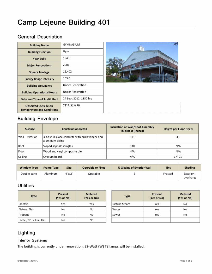
GFI011013043257ATL PAGE 1 OF 2
Camp Lejeune Building 401 General Description
Building Name GYMNASIUM
Building Function Gym
Year Built 1943
Major Renovations 2001
Square Footage 12,402
Energy Usage Intensity 163.6
Building Occupancy Under Renovation
Building Operational Hours Under Renovation
Date and Time of Audit Start 24 Sept 2012, 1330 hrs
Observed Outside Air Temperature and Conditions
78F, 31% RH
Building Envelope Surface Construction Detail
Insulation or Wall/Roof Assembly Thickness (inches)
Height per Floor (feet)
Wall – Exterior 3’ Cast‐in‐place concrete with brick veneer and aluminum siding
R11 33'
Roof Sloped asphalt shingles R30 N/A
Floor Wood and vinyl composite tile N/A N/A
Ceiling Gypsum board N/A 17'‐21'
Window Type Frame Type Size Operable or Fixed % Glazing of Exterior Wall Tint Shading
Double pane Aluminum 4' x 3' Operable 5 Frosted Exterior ‐ overhang
Utilities Type
Present (Yes or No)
Metered (Yes or No)
Electric Yes Yes
Natural Gas No No
Propane No No
Diesel/No. 2 Fuel Oil No No
Type Present
(Yes or No) Metered (Yes or No)
District Steam Yes No
Water Yes No
Sewer Yes No
Lighting Interior Systems The building is currently under renovation; 32‐Watt (W) T8 lamps will be installed.

MARINE CORPS BASE CAMP LEJEUNE BUILDING 401
GFI011013043257ATL PAGE 2 OF 2
Exterior Systems Compact fluorescent 26W lamps provide exterior lighting.
Plumbing The plumbing within the building is currently being installed during the renovation.
Domestic Hot Water System
Type Manufacturer/Model Year
Manufactured Capacity Rating (Btu/Hr or kW)
Storage Capacity (Gallons)
Setpoint
(F) Circulation Pumps
Electric Tank AO Smith/DSE 65 2005 18 kW 65 ‐‐ No
HVAC Systems HVAC System Description The heating, ventilation, and air conditioning (HVAC) systems were being completely replaced at the time of the audit.
The new systems will continue to utilize steam for building heating with a new steam‐to‐hot water heat exchanger (HX) and pump. The primary system will be a built‐up air‐handling unit (AHU) with heating hot water (HHW) coils and modulating outside air (OSA) ventilation. Perimeter zones and restrooms will have HHW baseboard heaters. No provisions were observed for cooling within the building. The HVAC system will be controlled by a direct digital control (DDC) system.
Controls and Operational Characteristics Type of Controls (DDC, Electric, Pneumatic, Time Clocks, Etc) DDC to be installed
Manufacturer/Vendor N/A

GFI011013043257ATL PAGE 1 OF 4
Camp Lejeune Building 423 General Description
Building Name REG/GROUP HDQ
Building Function Administration
Year Built 1942
Major Renovations 1989
Square Footage 8,418
Energy Usage Intensity 71.3
Building Occupancy 20 Occupants
Building Operational Hours 0800‐1600, Mon‐Fri
Date and Time of Audit Start 25 Sept 2012, 0800 hrs
Observed Outside Air Temperature and Conditions
68F, 55% RH
Building Envelope Surface Construction Detail
Insulation or Wall/Roof Assembly Thickness (inches)
Height per Floor (feet)
Wall – Exterior 3' Cast‐in‐place wall with brick veneer R‐11 10'
Roof Sloped asphalt shingles R‐30 N/A
Floor Vinyl composite tile N/A N/A
Ceiling Acoustic ceiling tile N/A 8'
Window Type Frame Type Size Operable or Fixed % Glazing of Exterior Wall Tint Shading
Double pane Aluminum 3' x 5' Operable 20 No tinting
Interior ‐ blinds
Utilities Type
Present (Yes or No)
Metered (Yes or No)
Electric Yes No
Natural Gas No No
Propane No No
Diesel/No. 2 Fuel Oil No No
Type Present
(Yes or No) Metered (Yes or No)
District Steam Yes No
Water Yes No
Sewer Yes No
Lighting Interior Systems The building has 32‐Watt (W) T8 lamps throughout the interior spaces. All lighting is manually controlled.
Exterior Systems Compact fluorescent lamps provide exterior lighting.

MARINE CORPS BASE CAMP LEJEUNE BUILDING 423
GFI011013043257ATL PAGE 2 OF 4
Plumbing Fixture Type Quantity
Flow (gpf or gpm)
Notes
Toilets 3 1.28 gpf
Urinals 2 1 gpf
Lavatories 6 2.2 gpm
Faucets 1 5 gpm
Showers 2 2.5 gpm
Other ‐‐
Domestic Hot Water System
Type Manufacturer/Model Year
Manufactured Capacity Rating (Btu/Hr or kW)
Storage Capacity (Gallons)
Setpoint
(F) Circulation Pumps
Tank State Select 2000 3.5 kW 66 ‐‐ No
HVAC Systems HVAC System Description The heating, ventilation, and air conditioning (HVAC) system has three split‐system heat‐pump units with associated interior units. A single packaged terminal air conditioner (PTAC) conditions the secured storage area. The split systems are controlled by digital, programmable thermostats. Exhaust fans (EFs) provide restroom exhaust air relief.
Air-Handling System Split‐System AHUs or Package Units (DX Equipment)
Tag Year
Installed Manufacturer / Model Serial No. System Type
Total Cooling Capacity (MBH)
Heating Method and Capacity (MBH/kW)
1 ‐‐ Not observed –in the ceiling ‐‐ Split System 60 Electric
2 ‐‐ Not observed –in the ceiling ‐‐ Split System 60 Electric
3 ‐‐ Not observed –in the ceiling ‐‐ Split System 60 Electric
Condensing Units
Tag Serves AHU
Year Installed
Manufacturer/Model Serial No. Type
1 ‐‐ 2008 Goodman/GSC130603AC 0808643656 Cooling Only
2 ‐‐ 2008 Goodman/GSC130603AC 0808736328 Cooling Only
3 ‐‐ 2000 Grandaire/ GS3BA‐060CA GSD030507740 Cooling Only

MARINE CORPS BASE CAMP LEJEUNE BUILDING 423
GFI011013043257ATL PAGE 3 OF 4
Terminal Units Terminal Units
Equipment Type/Description Qty Cooling Method Heating Method
PTAC 1 DX ‐‐
Controls and Operational Characteristics Type of Controls (DDC, Electric, Pneumatic, Time Clocks, Etc) Thermostat
Manufacturer/Vendor White Rodgers

MARINE CORPS BASE CAMP LEJEUNE BUILDING 423
GFI011013043257ATL PAGE 4 OF 4
This page is intentionally left blank.

GFI011013043257ATL PAGE 1 OF 4
Camp Lejeune Building 500 General Description
Building Name GYMNASIUM
Building Function Gym
Year Built 1943
Major Renovations 2001
Square Footage 12,402
Energy Usage Intensity 107.5
Building Occupancy 15 Occupants
15 Transient
Building Operational Hours 0900‐1100; 1400‐1600, Mon‐Fri
0900‐1100, Sat‐Sun
Date and Time of Audit Start 24 Sept 2012, 1430 hrs
Observed Outside Air Temperature and Conditions
81F, 35% RH
Building Envelope Surface Construction Detail
Insulation or Wall/Roof Assembly Thickness (inches)
Height per Floor (feet)
Wall – Exterior 3' Concrete cast‐in‐place; cmu with brick veneer and aluminum panels
8” CMU 20'
Roof Sloped, asphalt shingles Batt Insulation N/A
Floor Wood, vinyl composite tile N/A N/A
Ceiling Gypsum board N/A 17'‐21' (bay); 9' (mezzaine)
Window Type Frame Type Size Operable or Fixed % Glazing of Exterior Wall Tint Shading
Double pane Aluminum 4' x 3'; 7' x 3'; 3' x 2'
Operable and Fixed 5 Some windows frosted
Exterior‐overhang
Utilities Type
Present (Yes or No)
Metered (Yes or No)
Electric Yes Yes
Natural Gas No No
Propane No No
Diesel/No. 2 Fuel Oil No No
Type Present
(Yes or No) Metered (Yes or No)
District Steam Yes No
Water Yes No
Sewer Yes No

MARINE CORPS BASE CAMP LEJEUNE BUILDING 500
GFI011013043257ATL PAGE 2 OF 4
Lighting Interior Systems The building has 32‐Watt (W) T8 lamps throughout the majority of interior spaces with the exception of the gymnasium, which has 250W high‐intensity discharge (HID) lamps. Lighting is controlled by manual switching.
Exterior Systems HID lamps provide exterior lighting.
Plumbing Fixture Type Quantity
Flow (gpf or gpm)
Notes
Toilets 6 3.5 gpf
Urinals 3 1 gpf
Lavatories 13 2.5 gpm
Faucets 1 5 gpm
Showers 5 2.5 gpm
Other ‐‐
Domestic Hot Water System The domestic hot water system is provided by a steam‐to‐hot water heat exchanger located beneath the building.
HVAC Systems HVAC System Description The heating, ventilation, and air conditioning (HVAC) system consists of a constant air volume (CAV) heating‐only, built‐up air‐handling unit (AHU) with a heating hot water (HHW) coil and modulating outside air (OA) ventilation, HHW baseboard heating and four packaged terminal air conditioners (PTAC). HHW is provided by the steam‐to‐hot water heat exchanger located beneath the building. The HVAC system is controlled by analog thermostats. Baseboard heaters have independent thermostatic control valves (TCV). Exhaust fans provide restroom and locker facilities exhaust air relief.
Heating Hot Water or Steam System (Including Pumping) HHW is provided by the steam‐to‐hot water heat exchanger located beneath the building.
Air-Handling System Air Handling Units
Tag Year
Installed Manufacturer/ Model Serial Number System Type
Cooling Method
Heating Method
Economizer
AHU‐1 1970s McQuay ‐‐ CAV ‐‐ HHW ‐‐

MARINE CORPS BASE CAMP LEJEUNE BUILDING 500
GFI011013043257ATL PAGE 3 OF 4
Terminal Units Terminal Units
Equipment Type/Description Qty Cooling Method Heating Method
PTACs 4 DX ‐‐
Baseboard ‐‐ N/A HHW
Controls and Operational Characteristics Type of Controls (DDC, Electric, Pneumatic, Time Clocks, Etc) Thermostat
Manufacturer/Vendor ‐‐

MARINE CORPS BASE CAMP LEJEUNE BUILDING 500
GFI011013043257ATL PAGE 4 OF 4
This page is intentionally left blank.

GFI011013043257ATL PAGE 1 OF 4
Camp Lejeune Building 522 General Description
Building Name REGT HQTRS
Building Function Administration
Year Built 1943
Major Renovations 1995
Square Footage 8,418
Energy Usage Intensity 74.2
Building Occupancy
30 Occupants Permanent
20 Transients
3 Duty Personnel
Building Operational Hours 0630‐1800, Mon‐Fri
24/7 Duty Personnel Desk
Date and Time of Audit Start 25 Sept 2012, 0900 hrs
Observed Outside Air Temperature and Conditions
71F, 53% RH
Building Envelope Surface Construction Detail
Insulation or Wall/Roof Assembly Thickness (inches)
Height per Floor (feet)
Wall – Exterior 4' Cast‐in‐place concrete below brick veneer R11 12'
Roof Sloped asphalt shingles R30 N/A
Floor Carpet and vinyl composite tile N/A N/A
Ceiling Acoustic ceiling tile N/A 8'
Window Type Frame Type Size Operable or Fixed % Glazing of Exterior Wall Tint Shading
Double pane Aluminum 3' x 5' Opereable 30 No Tinting
Interior – blinds and curtains
Utilities Type
Present (Yes or No)
Metered (Yes or No)
Electric Yes No
Natural Gas No No
Propane No No
Diesel/No. 2 Fuel Oil No No
Type Present
(Yes or No) Metered (Yes or No)
District Steam No No
Water Yes No
Sewer Yes No

MARINE CORPS BASE CAMP LEJEUNE BUILDING 522
GFI011013043257ATL PAGE 2 OF 4
Lighting Interior Systems The building has 32‐Watt (W) T8 lamps throughout the interior spaces. Lighting is controlled by manual switching.
Exterior Systems Compact fluorescent lamps provide exterior lighting.
Plumbing Fixture Type Quantity
Flow (gpf or gpm)
Notes
Toilets 4 3 gpf
Urinals 1 1 gpf
Lavatories 6 2.5 gpm
Faucets 1 5 gpm
Showers 2 2.5 gpm
Other ‐‐
Domestic Hot Water System
Type Manufacturer/Model Year
Manufactured Capacity Rating (Btu/Hr or kW)
Storage Capacity (Gallons)
Setpoint
(F) Circulation Pumps
Electric Tank Rheem/PE 30‐2 ‐‐ 3 kW 30 ‐‐ ‐‐
HVAC Systems HVAC System Description The heating, ventilation, and air conditioning (HVAC) system serving this building consists of three split‐system heat‐pump units. The indoor sections are installed above the lay‐in tile ceiling and were not observed. Controls are two digital programmable thermostats and one an analog‐type thermostat. Exhaust fans provide restroom exhaust air relief.
Air-Handling System Split‐System AHUs or Package Units (DX Equipment)
Tag Year
Installed Manufacturer / Model Serial Number System Type
Total Cooling Capacity (MBH)
Heating Method and Capacity (MBH/kW)
AC‐1 ‐‐ Inaccessible – in the ceiling ‐‐ ‐‐ 90 ‐‐
AC‐2 ‐‐ Inaccessible – in the ceiling ‐‐ ‐‐ 90 ‐‐
AC‐3 ‐‐ Inaccessible – in the ceiling ‐‐ ‐‐ 90 ‐‐

MARINE CORPS BASE CAMP LEJEUNE BUILDING 522
GFI011013043257ATL PAGE 3 OF 4
Condensing Units
Tag Serves AHU
Year Installed
Manufacturer/Model Serial Number Type
ACC‐1 AC‐1 2010 Goodman/GSC100903AD ‐‐ Cooling Only
ACC‐2 AC‐2 2006 Goodman/GSC100903AD ‐‐ Cooling Only
ACC‐3 AC‐3 2006 Goodman/GSC100903AD ‐‐ Cooling Only
Controls and Operational Characteristics Type of Controls (DDC, Electric, Pneumatic, Time Clocks, Etc) Programmable and Non‐Programmable Thermostat
Manufacturer/Vendor Honeywell

MARINE CORPS BASE CAMP LEJEUNE BUILDING 522
GFI011013043257ATL PAGE 4 OF 4
This page is intentionally left blank.

GFI011013043257ATL PAGE 1 OF 4
Camp Lejeune Building 524 General Description
Building Name WORK FORCE LEARNING CENTER
Building Function Classroom
Year Built 1943
Major Renovations 2001
Square Footage 18,104
Energy Usage Intensity 106.1
Building Occupancy 6 Occupants
200 Transients
Building Operational Hours 0800‐1630, Mon‐Fri
Date and Time of Audit Start 25 Sept 2012, 1000 hrs
Observed Outside Air Temperature and Conditions
72F, 55% RH
Building Envelope Surface Construction Detail
Insulation or Wall/Roof Assembly Thickness (inches)
Height per Floor (feet)
Wall – Exterior 3' Cast‐in‐place concrete below brick veneer R11 14'‐25'
Roof Sloped asphalt shingles R30 N/A
Floor Vinyl composite tile N/A N/A
Ceiling Acoustic ceiling tile N/A 9'
Window Type Frame Type Size Operable or Fixed % Glazing of Exterior Wall Tint Shading
Double pane Aluminum 4' x 6' Operable 30 No Interior ‐ blinds
Utilities Type
Present (Yes or No)
Metered (Yes or No)
Electric Yes Yes
Natural Gas No No
Propane No No
Diesel/No. 2 Fuel Oil No No
Type Present
(Yes or No) Metered (Yes or No)
District Steam Yes No
Water Yes No
Sewer Yes No
Lighting Interior Systems The building has 32‐Watt (W) T8 lamps throughout the interior spaces. Lighting is controlled by manual switching.

MARINE CORPS BASE CAMP LEJEUNE BUILDING 524
GFI011013043257ATL PAGE 2 OF 4
Exterior Systems Exterior lighting is provided by 60W incandescent lamps.
Plumbing Fixture Type Quantity
Flow (gpf or gpm)
Notes
Toilets 6 3.0 gpf
Urinals 4 1.0 gpf
Lavatories 8 2.0 gpm
Faucets 1 5.0 gpm
Showers 2 2.5 gpm
Other ‐‐
Domestic Hot Water System
Type Manufacturer/Model Year
Manufactured Capacity Rating (Btu/Hr or kW)
Storage Capacity (Gallons)
Setpoint
(F) Circulation Pumps
Electric Tank State Select/CD64220RTV 2000 4.5 kw 50 ‐‐ No
HVAC Systems HVAC System Description The heating, ventilation, and air conditioning (HVAC) system consists of six constant air volume (CAV) air‐handling units (AHUs) with modulating outside air (OSA) ventilation. Each unit has chilled water (CHW) and heating hot water (HHW) coils. CHW is produced by an air‐cooled chiller and HHW is produced by a steam‐to‐hot‐water heat exchanger; both are circulated using a three pump arrangement with the third pump in stand‐by for either system. A single split‐system air conditioning unit provides supplemental cooling to a computer classroom. The HVAC system was controlled by a direct digital control (DDC) system. Exhaust fans provide restroom exhaust air relief.
Chilled Water System (Including Pumping) Chiller Data
Tag Year
Installed Manufacturer/Model Serial No.
Chiller Type
Compressor Type
Capacity (tons)
CH1 90’s Trane/CGAFC60EADA1 CooK29315 Air Cooled Scroll 60
Chilled Water System Pump Data
Tag Description Manufacturer/Model Constant or Variable Flow
Flow (gpm)
Head (ft)
CWP‐1 CHW Bell & Gossett/2BG Constant 119 63
Chilled Water System Pump Motor Data
Tag Manufacturer/Model Frame Type
HP Efficiency Voltage/Phase RPM
CWP‐1 Marathon/7VJ184TDR4027EX 184T 5 ‐‐ 208/3 1745

MARINE CORPS BASE CAMP LEJEUNE BUILDING 524
GFI011013043257ATL PAGE 3 OF 4
Heating Hot Water or Steam System (Including Pumping) Hot water is produced by a steam‐to‐hot water heat exchanger (Bell & Gossett/69997).
Hot Water System Pump Data
Tag Description Manufacturer/Model Constant or Variable Flow
Flow (gpm)
Head (ft)
HWP1 HHW Bell & Gossett/2BC 8 BE Constant 119 63
Hot Water System Pump Motor Data
Tag Manufacturer/Model Frame Type HP Efficiency Voltage/Phase RPM
HWP1 Marathon/TVJ184TTDR4027EK 184T 5 ‐‐ 208/3 1745
Air-Handling System Air Handling Units
Tag Year
Installed Manufacturer/ Model Serial No. System Type
Cooling Method
Heating Method
Economizer
AHU‐1 1990s Trane/MCCK99M066630 ‐‐ Modular CHW HHW ‐‐
AHU‐2 1990s Trane/MCCK00K59514A ‐‐ Modular CHW HHW ‐‐
AHU‐3 1990s Trane/MCCK00K59514A KOOK59514A Modular CHW HHW ‐‐
AHU‐4 1990s Trane/K00k5953A KOOK59540A Modular CHW HHW ‐‐
AHU‐5 1990s Trane/K00K5953A ‐‐ Modular CHW HHW ‐‐
AHU‐6 1990s Trane/K99M066890 ‐‐ Modular CHW HHW ‐‐
Split‐System AHUs or Package Units (DX Equipment)
Tag Year
Installed Manufacturer / Model Serial No. System Type
Total Cooling Capacity (MBH)
Heating Method and Capacity (MBH/kW)
AC1 2006 Fujitsu ‐‐ Wall 24 ‐‐
Condensing Units
Tag Serves AHU
Year Installed
Manufacturer/Model Serial No. Type
MSCU‐1 AC1 2006 Fujitsu/A0U24CL DDN011965 Cooling Only
Controls and Operational Characteristics Type of Controls (DDC, Electric, Pneumatic, Time Clocks, Etc) DDC
Manufacturer/Vendor JCI

MARINE CORPS BASE CAMP LEJEUNE BUILDING 524
GFI011013043257ATL PAGE 4 OF 4
This page is intentionally left blank.

GFI011013043257ATL PAGE 1 OF 2
Camp Lejeune Building 751 General Description
Building Name FIELD HSE GOETTGE MEMORIAL
Building Function Miscellaneous
Year Built 1950
Major Renovations 2004
Square Footage 54,529
Energy Usage Intensity 177.7
Building Occupancy 9 Occupants
Special Events ~ 3,000
Building Operational Hours
Aquatic ‐ 1000‐1800, Mon‐Fri
Youth Sports ‐ 0830‐1700, Mon‐Fri
Special Events
Date and Time of Audit Start 25 Sept 2012, 1430 hrs
Observed Outside Air Temperature and Conditions
84F, 44% RH
Building Envelope Surface Construction Detail
Insulation or Wall/Roof Assembly Thickness (inches)
Height per Floor (feet)
Wall – Exterior Brick veneer 8" Concrete Masonry Unit 25'‐38'
Roof Metal sloped ‐‐ N/A
Floor Carpet, concrete, and wood N/A N/A
Ceiling Exposed and acoustic ceiling tile N/A 8' Offices; 38' gym
Window Type Frame Type Size Operable or Fixed % Glazing of Exterior Wall Tint Shading
Double pane Aluminum 5'x4', 10'x3', 5'x2', and 6'x4'
Operable and Fixed 35% Some frosted
Interior‐ blinds
Utilities Type
Present (Yes or No)
Metered (Yes or No)
Electric Yes No
Natural Gas No No
Propane No No
Diesel/No. 2 Fuel Oil No No
Type Present
(Yes or No) Metered (Yes or No)
District Steam Yes No
Water Yes No
Sewer Yes No
Lighting Interior Systems The building has 32‐Watt (W) T8 lamps throughout the interior administration spaces, restrooms, and hallways. High‐intensity discharge lighting is used in the gymnasium. Lighting is controlled by occupancy sensors in restrooms and by manual switches in all other spaces.
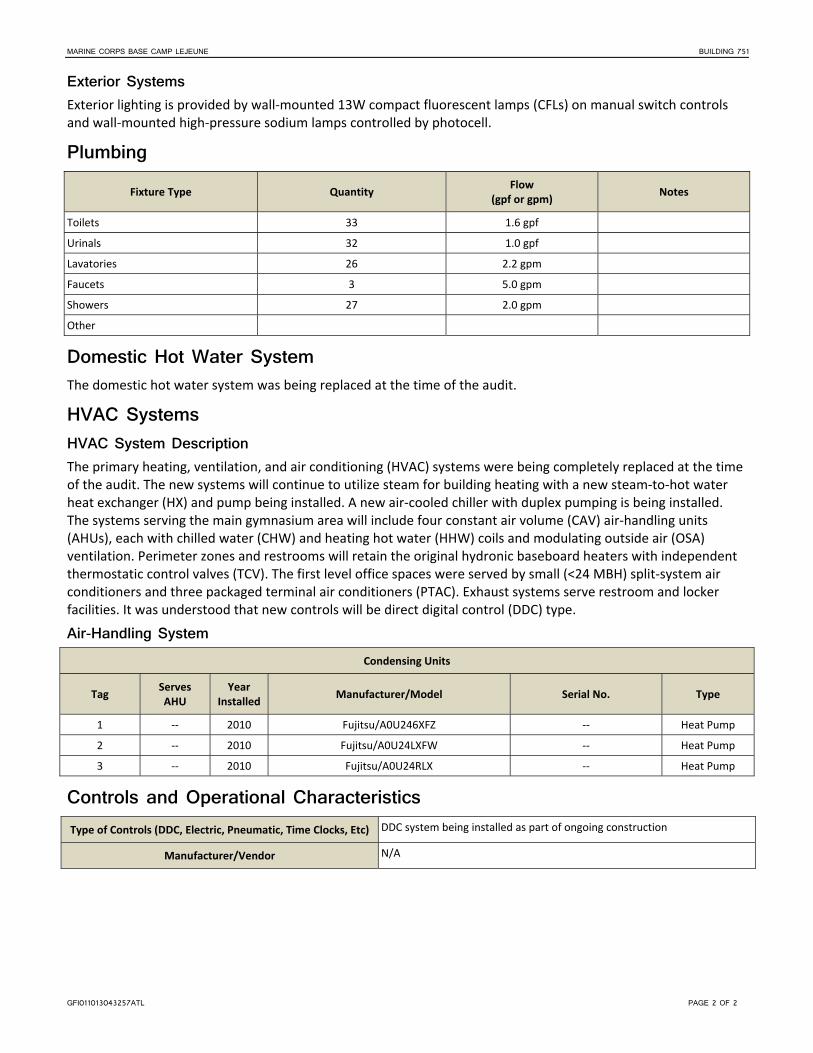
MARINE CORPS BASE CAMP LEJEUNE BUILDING 751
GFI011013043257ATL PAGE 2 OF 2
Exterior Systems Exterior lighting is provided by wall‐mounted 13W compact fluorescent lamps (CFLs) on manual switch controls and wall‐mounted high‐pressure sodium lamps controlled by photocell.
Plumbing Fixture Type Quantity
Flow (gpf or gpm)
Notes
Toilets 33 1.6 gpf
Urinals 32 1.0 gpf
Lavatories 26 2.2 gpm
Faucets 3 5.0 gpm
Showers 27 2.0 gpm
Other
Domestic Hot Water System The domestic hot water system was being replaced at the time of the audit.
HVAC Systems HVAC System Description The primary heating, ventilation, and air conditioning (HVAC) systems were being completely replaced at the time of the audit. The new systems will continue to utilize steam for building heating with a new steam‐to‐hot water heat exchanger (HX) and pump being installed. A new air‐cooled chiller with duplex pumping is being installed. The systems serving the main gymnasium area will include four constant air volume (CAV) air‐handling units (AHUs), each with chilled water (CHW) and heating hot water (HHW) coils and modulating outside air (OSA) ventilation. Perimeter zones and restrooms will retain the original hydronic baseboard heaters with independent thermostatic control valves (TCV). The first level office spaces were served by small (<24 MBH) split‐system air conditioners and three packaged terminal air conditioners (PTAC). Exhaust systems serve restroom and locker facilities. It was understood that new controls will be direct digital control (DDC) type.
Air-Handling System Condensing Units
Tag Serves AHU
Year Installed
Manufacturer/Model Serial No. Type
1 ‐‐ 2010 Fujitsu/A0U246XFZ ‐‐ Heat Pump
2 ‐‐ 2010 Fujitsu/A0U24LXFW ‐‐ Heat Pump
3 ‐‐ 2010 Fujitsu/A0U24RLX ‐‐ Heat Pump
Controls and Operational Characteristics Type of Controls (DDC, Electric, Pneumatic, Time Clocks, Etc) DDC system being installed as part of ongoing construction
Manufacturer/Vendor N/A

BUILDING 898 PAGE 1 OF 3
MCB Camp Lejeune Buildings 896, 897, 898
General Description Building Function Hotel
Location Hadnot Point
Year Built 1972
Major Renovations 2000
Square Footage 27,547
Energy Usage Intensity 72 MBtu/KSF
Building Occupancy Varies Mon-Sun (90 Guest Rooms)
Building Operational Hours 24/7 Mon-Sun
Date and Time of Audit Start 1/24/2012, 1030 hrs
Observed Outside Air Temperature and Conditions
70°F, 75% RH
Building Envelope
Surface Construction Detail Insulation or Wall/Roof Assembly Thickness (inches) Height per Floor (feet)
Wall – Exterior CMU brick veneer 8'
Roof Asphalt shingles, sloped N/A
Floor Concrete, vinyl, and carpet N/A N/A
Ceiling Exposed N/A 8'
Window Panes Size % Glazing Shading
Double-pane; fixed 7' × 5' 70% Tinting and shades; No exterior
Utilities
Type Present Yes or No
Metered Yes or No
Electric Yes Yes
Natural Gas No No
Propane No No
No. 2 Fuel Oil No No
Type Present Yes or No
Metered Yes or No
Diesel No No
District Steam Yes No
Water Yes No
Sewer Yes No

ENERGY AUDIT, MARINE CORPS BASE CAMP LEJEUNE APPENDIX F, BUILDING SUMMARIES
BUILDING 898 PAGE 2 OF 3
HVAC Systems HVAC System Description The HVAC system for the hotel consists of packaged through-wall air conditioning units (PTACs) with supplemental electric heat that serve each guest room. Two small mini-split units serve the vending machine rooms. The service areas, such as laundry and maintenance rooms, have heating hot water (HWH) unit heaters. The HHW is produced by a steam-to-hot water heat exchanger (HX) located in the mechanical room. The reception building is served by a split-system heat pump with auxiliary electric heat.
Heating Hot Water or Steam System (Including Pumping) Hot Water System Pump Data
Tag Description Location Manufacturer Model Year Installed Constant or Variable Flow Head GPM
HWP HHW Pump Mech Room (151) Bell & Gossett 1510 -- Constant 50 15
Hot Water System Pump Motor Data
Tag Description Location Manufacturer Model Year Installed HP Voltage, Phase, Hertz, RLA RPM
HWP HHW Pump Mech Room (151) Marathon 5J143TT -- 1 208/3/60 1750
Air-Handling System Split-System AHUs or Package Units (DX Equipment)
Tag Location Year Installed Manufacturer Model System
Type
Total Cooling Capacity (MBH)
Heating Method and Capacity
(MBH) Economizer
HP-3 Recept Mech Room 1998 Lennox -- Split DX -- HP with Aux. electric - 60 No
Condensing Unit
Tag Location Serves AHU Year Installed Manufacturer Model SEER
CU-3 Outdoors HP-3 1998 Lennox HP26-060-7P --
Terminal Units
Terminal Units
Equipment Type/Description (FCU, UH, VAV) Qty Cooling Method Heating Method
PTACs One per guest room (90) DX Heat pump
Controls and Operational Characteristics Type of Controls (DDC, Electric, Pneumatic, Timelocks) Electric
Manufacturer/Vendor --
Connected to Basewide EMCS No
Building Occupancy Scheduling No

ENERGY AUDIT, MARINE CORPS BASE CAMP LEJEUNE APPENDIX F, BUILDING SUMMARIES
BUILDING 898 PAGE 3 OF 3
Plumbing Fixture Type Quantity Flow (gpf or gpm)
Toilets – Flush Valve 2 1.6 gpf
Toilets – Tank (Guest Rooms) 90 3.0 gpf
Urinals 0 N/A
Lavatories 92 2.0 gpm
Faucets 90 2.0 gpm
Showers 90 2.5 gpm
Domestic Hot Water System
Type Manufacturer (Model) Year Manufactured
Capacity Rating Btu/Hr or kW
Gallon Storage Capacity Setpoint (°F)
Circulation Pumps
Steam to Hot Water -- -- -- -- -- 3/4 hp
Lighting The buildings have T8 32-Watt lamps throughout the interior spaces. Exterior lighting is provided by high-intensity discharge fixtures.


GFI011013043257ATL PAGE 1 OF 4
Camp Lejeune Building 1005 General Description
Building Name Administrative Office
Building Function Administration
Year Built 1943
Major Renovations 2005
Square Footage 38,063
Energy Usage Intensity 86.8
Building Occupancy 300 Occupants
Building Operational Hours 0700‐1600, Mon‐Fri
Date and Time of Audit Start 26 Sept 2012, 1315 hrs
Observed Outside Air Temperature and Conditions
80F, 40% RH
Building Envelope Surface Construction Detail
Insulation or Wall/Roof Assembly Thickness (inches)
Height per Floor (feet)
Wall – Exterior Clay Tile with stucco 8‐10" some insulation firred out, 1” rigid board
9'
Roof Pitched with asphalt shingle None observed N/A
Floor Carpet, vinyl tile N/A N/A
Ceiling Acoustic ceilng tile N/A 7'6"
Window Type Frame Type Size Operable or Fixed % Glazing of Exterior Wall Tint Shading
Double and single pane Aluminum;, and wood
2' x 4', 4' x 4'6" Operable and Fixed 10% No Some have interior blinds
Utilities Type
Present (Yes or No)
Metered (Yes or No)
Electric Yes Yes
Natural Gas Yes No
Propane No No
Diesel/No. 2 Fuel Oil No No
Type Present
(Yes or No) Metered (Yes or No)
District Steam Yes No
Water Yes No
Sewer Yes No

MARINE CORPS BASE CAMP LEJEUNE BUILDING 1005
GFI011013043257ATL PAGE 2 OF 4
Lighting Interior Systems Interior lighting is provided primarily by T8 32‐Watt (W) lamps with electronic ballasts on manual switch controls. Some areas have occupancy sensor controls. Two offices within the building are testing dimmable light‐emitting diode (LED) lamps.
Exterior Systems Compact fluorescent 13W lamps provide exterior lighting.
Plumbing Fixture Type Quantity
Flow (gpf or gpm)
Notes
Toilets 12 1.6 gpf
Urinals 4 1.3 gpf
Lavatories 14 1.5 gpm
Faucets 4 5.0 gpm
Showers 10 2.0 gpm
Other ‐‐ ‐‐
Domestic Hot Water System Domestic hot water for the building is provided by a steam‐to‐hot water heat exchanger.
HVAC Systems HVAC System Description The primary heating, ventilation and cooling (HVAC) system in the building consists of six variable air volume (VAV) air‐handling units (AHUs) with chilled water (CHW) coils. Heating is provided by heating hot water (HHW) coils located in the terminal VAV units. CHW is produced by an air cooled chiller and HHW is provided by a steam‐to‐hot‐water heat exchanger. Three direct‐expansion (DX) split system units provide additional conditioning to areas. The HVAC system is controlled by a direct digital control (DDC) system.
Chilled Water System (Including Pumping) Chiller Data
Tag Year
Installed Manufacturer/Model Serial No.
Chiller Type
Compressor Type
Capacity (tons)
2011 Airstack/ASP20A J112‐011 Air Cooled ‐‐ ‐‐
Chilled Water System Pump Data
Tag Description Manufacturer/Model Constant or Variable Flow
Flow
(gpm)
Head
(ft)
P1 Scroll Bell & Gossett Variable 240 116

MARINE CORPS BASE CAMP LEJEUNE BUILDING 1005
GFI011013043257ATL PAGE 3 OF 4
Chilled Water System Pump Motor Data
Tag Manufacturer/Model Frame Type
HP Efficiency Voltage/Phase RPM
P1 Marathon 254SP 15 87.5 208‐230/460,3 1745
Heating Hot Water or Steam System (Including Pumping) Heating hot water (HHW) is produced by a steam to hot water heat exchanger (Armstrong/ Model WS‐12‐2‐1).
Hot Water System Pump Data
Tag Description Manufacturer/Model Constant or Variable Flow
Flow (gpm)
Head (ft)
P1 Inline Armstrong/2D4380 Constant 69 48
P2 Inline Armstrong/2D4380 Constant 69 48
Hot Water System Pump Motor Data
Tag Manufacturer/Model Frame Type HP Efficiency Voltage/Phase RPM
P1 Marathon/M310 1455M 2 81.5 208‐230/460,3 1740
P2 Marathon/M310 1455M 2 81.5 208‐230/460,3 1740
Air-Handling System Air Handling Units
Tag Year
Installed Manufacturer/ Model Serial No. System Type
Cooling Method
Heating Method
Economizer
AHU‐1 ‐‐ McQuay/CAH018GDAM FB0U81101199 AHU CHW ‐‐ ‐‐
AHU‐2 ‐‐ McQuay/CAH014GDAM FB0081101198 AHU CHW ‐‐ ‐‐
AHU‐3 ‐‐ McQuay/CAH014GDAM FB0081101198 AHU CHW ‐‐ ‐‐
AHU‐4 ‐‐ McQuay/CAH012FDAC B0U021200500 AHU CHW ‐‐ ‐‐
AHU‐5 ‐‐ McQuay/CAH010FAC FB00021200501 AHU CHW ‐‐ ‐‐
AHU‐6 ‐‐ ‐‐ ‐‐ AHU CHW ‐‐ ‐‐
Split‐System AHUs or Package Units (DX Equipment)
Tag Year
Installed Manufacturer / Model Serial No. System Type
Total Cooling Capacity (MBH)
Heating Method and Capacity (MBH/kW)
AHU‐7 ‐‐ Trane/2TEEF49A1000AA 6451H752V Split 48 ‐‐
AHU‐8 ‐‐ Trane/2TEE340A1000AA 7452ALW2V Split 42 ‐‐
Condensing Units
Tag Serves AHU
Year Installed
Manufacturer/Model Serial No. Type
ACCU1 AHU‐7 2007 Trane/2TWB3048A1000AA ‐‐ Heat Pump
‐‐ ‐‐ 2007 Trane/2TWB3042A1000AA 71428R14F Heat Pump
‐‐ ‐‐ ‐‐ United Technologies/38QR108C831 2702X28161 Cooling Only
‐‐ ‐‐ ‐‐ Fujitsu/A0U18RLQ GWN004854 Cooling Only

MARINE CORPS BASE CAMP LEJEUNE BUILDING 1005
GFI011013043257ATL PAGE 4 OF 4
Terminal Units Terminal Units
Equipment Type/Description Qty Cooling Method Heating Method
VAVs ‐‐ ‐‐ HHW
Controls and Operational Characteristics Type of Controls (DDC, Electric, Pneumatic, Time Clocks, Etc) DDC
Manufacturer/Vendor Honeywell

GFI011013043257ATL PAGE 1 OF 2
Camp Lejeune Building 1015 General Description
Building Name Exchange Maintenance Shop
Building Function Maintenance
Year Built 1955
Major Renovations 2002
Square Footage 8,465
Energy Usage Intensity 56.2
Building Occupancy Variable
Building Operational Hours Variable
Date and Time of Audit Start 25 Sept 2012, 0840 hrs
Observed Outside Air Temperature and Conditions
69F, 52% RH
Building Envelope Surface Construction Detail
Insulation or Wall/Roof Assembly Thickness (inches)
Height per Floor (feet)
Wall – Exterior Concrete masonry unit block with smoothed over concrete and stucco veneer
8" 12'
Roof Concrete decking with built up roof ‐‐ N/A
Floor Concrete N/A N/A
Ceiling Open to structure N/A 12'
Window Type Frame Type Size Operable or Fixed % Glazing of Exterior Wall Tint Shading
Single pane Aluminum 4' x 5' Operable 10 None None
Utilities Type
Present (Yes or No)
Metered (Yes or No)
Electric Yes No
Natural Gas No No
Propane No No
Diesel/No. 2 Fuel Oil No No
Type Present
(Yes or No) Metered (Yes or No)
District Steam Yes No
Water Yes No
Sewer Yes No
Lighting Interior Systems The building has 32‐Watt (W) and 59W T8 lamps throughout the majority of interior spaces. There are 13W compact fluorescent lamps (CFLs) used in the restrooms. All lighting is controlled by manual switching.

MARINE CORPS BASE CAMP LEJEUNE BUILDING 1015
GFI011013043257ATL PAGE 2 OF 2
Exterior Systems The exterior lighting is mainly provided by 13W CFLs with one 150W incandescent fixture.
Plumbing Fixture Type Quantity
Flow (gpf or gpm)
Notes
Toilets 2 1.6 gpf
Urinals ‐‐ ‐‐
Lavatories 2 1.0 gpm (1), 2.0 gpm (1)
Faucets ‐‐ ‐‐
Showers ‐‐ ‐‐
Other ‐‐ ‐‐
Domestic Hot Water System The domestic hot water system for the building is fueled by seasonal steam supply.
HVAC Systems HVAC System Description The heating, ventilation, and air conditioning (HVAC) system in the wood shop consists of two window air conditioning (AC) units for cooling and radiator units for heating. The radiator units use steam as a heating medium and are operated seasonally. There is no mechanical heating or cooling in the storage area. An exhaust fan provides general building exhaust air relief.
Terminal Units Terminal Units
Equipment Type/Description Qty Cooling Method Heating Method
Window AC Units 2 12 MBH ‐‐
Radiators ‐ N/A Steam
Controls and Operational Characteristics Type of Controls (DDC, Electric, Pneumatic, Time Clocks, Etc) None
Manufacturer/Vendor ‐

GFI011013043257ATL PAGE 1 OF 4
Camp Lejeune Building 1042 General Description
Building Name Bachelor Enlisted Quarters
Building Function Residential
Year Built 1974
Major Renovations ‐‐
Square Footage 34,002
Energy Usage Intensity 110.3
Building Occupancy 66 occupants
Building Operational Hours 24/7
Date and Time of Audit Start 24 Sept 2012, 1337 hrs
Observed Outside Air Temperature and Conditions
77F, 39% RH
Building Envelope Surface Construction Detail
Insulation or Wall/Roof Assembly Thickness (inches)
Height per Floor (feet)
Wall – Exterior Concrete masonry unit block with brick veneer
8" 8'6"
Roof Flat concrete with built up roof, asphalt with gravel shingle
None observed N/A
Floor Vinyl composite tile with carpet over tile in bathrooms
N/A N/A
Ceiling Concrete N/A 8'6"
Window Type Frame Type Size Operable or Fixed % Glazing of Exterior Wall Tint Shading
Single pane Aluminum 5' x 5' Operable 25 No Interior blinds and exterior overhang
Utilities Type
Present (Yes or No)
Metered (Yes or No)
Electric Yes Yes
Natural Gas No No
Propane No No
Diesel/No. 2 Fuel Oil No No
Type Present
(Yes or No) Metered (Yes or No)
District Steam Yes No
Water Yes No
Sewer Yes No

MARINE CORPS BASE CAMP LEJEUNE BUILDING 1042
GFI011013043257ATL PAGE 2 OF 4
Lighting Interior Systems The majority of the interior lighting consists of T8 32‐Watt (W) lamps controlled by manual switches. Each room has an additional incandescent 100W floor lamp. Laundry rooms have 13W compact fluorescent lamps (CFLs), which are controlled using manual switches. One of the mechanical rooms contains T5 lamps.
Exterior Systems Exterior lighting is provided by wall‐mounted high pressure sodium lamps and 13W CFLs. Exterior lamps are controlled by photocell, but many were observed to be on at the time of the audit.
Plumbing Fixture Type Quantity
Flow (gpf or gpm)
Notes
Toilets 66 3.0 gpf
Urinals ‐‐ ‐‐
Lavatories 66 2.0 gpm
Faucets 3 5.0 gpm
Showers 66 2.0 gpm
Other Washers (6) ‐‐
Domestic Hot Water System
Type Manufacturer/Model Year
Manufactured Capacity Rating (Btu/Hr or kW)
Storage Capacity (Gallons)
Setpoint
(F) Circulation Pumps
Heat Exchanger/Storage
Tank Stone Steel/V300 SWH82Y ‐‐ ‐‐ 300 ‐‐ Yes, ½ hp
HVAC Systems HVAC System Description The primary heating, ventilation, and air conditioning (HVAC) system includes six air handling units (AHUs) with dual‐temperature water (DTW) coils and associated variable air volume (VAV) boxes. The AHU supply fan airflow is modulated by inlet dampers. An air‐cooled chiller provides chilled water (CHW). The heating hot water (HHW) is through a steam‐to‐hot water heat exchanger (HX). The entire system is served by three pumps: primary pumps for the CHW and HHW, and one secondary DTW pump. Each room VAV ceiling unit is controlled by a thermostat. Exhaust fans provide general building and restroom exhaust air relief. Restroom exhaust fans are interlocked with the light switch.

MARINE CORPS BASE CAMP LEJEUNE BUILDING 1042
GFI011013043257ATL PAGE 3 OF 4
Chilled Water System (Including Pumping) Chiller Data
Tag Year
Installed Manufacturer/Model Serial Number
Chiller Type
Compressor Type
Capacity (tons)
‐‐ ‐‐ McQuay/AGR060AS12 58C8134501 Air Cooled Scroll 60
Chilled Water System Pump Data
Tag Description Manufacturer/Model Constant or Variable Flow
Flow
(gpm)
Head
(ft)
P1 CHW Bell & Gossett/‐‐ Constant 80 30
P2 DTW Not legible Constant ‐‐ ‐‐
Chilled Water System Pump Motor Data
Tag Manufacturer/Model Frame Type
HP Efficiency Voltage/Phase RPM
P1 Marathon Electric/4VK145TTDR5633AD 145T‐90 2 84.0 200/3 1735
P2 Marathon Electric/4VK184TTDR4027DJ ‐‐ 5 87.5 200/3 1750
Heating Hot Water or Steam System (Including Pumping) HHW is produced by a steam to hot water heat exchanger (Bell & Gossett/Model 5‐260‐06‐048‐001)
Hot Water System Pump Data
Tag Description Manufacturer/Model Constant or Variable Flow
Flow
(gpm)
Head
(ft)
‐‐ HHW No nameplate Constant ‐‐ ‐‐
Hot Water System Pump Motor Data
Tag Manufacturer/Model Frame Type HP Efficiency Voltage/Phase RPM
‐‐ Bell & Gossett ‐‐ 1/3 ‐‐ ‐‐ 1425
Air-Handling System Air Handling Units
Tag Year
Installed Manufacturer/ Model Serial Number System Type
Cooling Method
Heating Method
Economizer
AHU‐2 2006 McQuay/LSL106CH 38B00317‐06 AHU CHW HHW ‐‐
AHU‐1 2006 McQuay/LSL106CH ‐‐ AHU CHW HHW ‐‐
AHU‐3 2006 McQuay/LSL106CH ‐‐ AHU CHW HHW ‐‐
AHU‐4 2006 McQuay/LSL106CH ‐‐ AHU CHW HHW ‐‐
AHU‐5 2006 McQuay/LSL106CH ‐‐ AHU CHW HHW ‐‐
AHU‐6 2006 McQuay/LSL106CH ‐‐ AHU CHW HHW ‐‐

MARINE CORPS BASE CAMP LEJEUNE BUILDING 1042
GFI011013043257ATL PAGE 4 OF 4
Terminal Units Terminal Units
Equipment Type/Description Qty Cooling Method Heating Method
VAVs 66 ‐‐ ‐‐
Controls and Operational Characteristics Type of Controls (DDC, Electric, Pneumatic, Time Clocks, Etc) Thermostat
Manufacturer/Vendor Alerton

GFI011013043257ATL PAGE 1 OF 2
Camp Lejeune Building 1120 General Description
Building Name MWR Equipment Maintenance Shop
Building Function Maintenance
Year Built 1956
Major Renovations 2010
Square Footage 11,143
Energy Usage Intensity 63.6
Building Occupancy 2 Occupants
Building Operational Hours 0700‐1500, Mon‐Fri
Date and Time of Audit Start 26 Sept 2012, 1215 hrs
Observed Outside Air Temperature and Conditions
80F, 32% RH
Building Envelope Surface Construction Detail
Insulation or Wall/Roof Assembly Thickness (inches)
Height per Floor (feet)
Wall – Exterior CMU block 8” CMU 12'
Roof Pitched asphalt shingles None N/A
Floor Concrete N/A N/A
Ceiling Open to structure N/A 11'
Window Type Frame Type Size Operable or Fixed % Glazing of Exterior Wall Tint Shading
Single pane Aluminum 3' x 4', 4' x 4' Fixed 20 No No
Utilities Type
Present (Yes or No)
Metered (Yes or No)
Electric Yes Yes
Natural Gas No No
Propane No No
Diesel/No. 2 Fuel Oil No No
Type Present
(Yes or No) Metered (Yes or No)
District Steam Yes No
Water Yes No
Sewer Yes No
Lighting Interior Systems The majority of the lighting in the work space has been upgraded to 59‐Watt (W) T8 lamps and 32W T8 lamps, but a few 34W T12 and 75W lamps remain in use. Areas not in use or used infrequently contain 75W T12 lamps. Restrooms contain incandescent 60W bulbs. All lighting is switch controlled.

MARINE CORPS BASE CAMP LEJEUNE BUILDING 1120
GFI011013043257ATL PAGE 2 OF 2
Exterior Systems Exterior lighting is provided by wall‐mounted halogen lamps that are timer controlled.
Plumbing Fixture Type Quantity
Flow (gpf or gpm)
Notes
Toilets 1 1.6 gpf
Urinals 1 2.0 gpf
Lavatories 1 2.0 gpm
Faucets 1 5.0 gpm
Showers ‐‐ ‐‐
Other ‐‐ ‐‐
Domestic Hot Water System
Type Manufacturer/Model Year
Manufactured Capacity Rating (Btu/Hr or kW)
Storage Capacity (Gallons)
Setpoint
(F) Circulation Pumps
Tank Ruud/PEP02‐1 ‐‐ 2kW 20 ‐‐ None
HVAC Systems HVAC System Description The building is used mainly for storage purposes and is largely unoccupied, requiring little space conditioning. The heating, ventilation, and air conditioning (HVAC) system consists of individual units used for space conditioning. The maintenance shop is cooled by two window air conditioning (AC) units and uses steam‐fueled unit heaters for heating. All units are controlled manually.
Terminal Units Terminal Units
Equipment Type/Description Qty Cooling Method Heating Method
Trane steam unit heater 10 ‐‐ Steam
Window AC Units 2 Electric ‐‐
Modine steam unit heater 4 ‐‐ ‐‐
Controls and Operational Characteristics Type of Controls (DDC, Electric, Pneumatic, Time Clocks, Etc) Manual
Manufacturer/Vendor ‐‐

GFI011013043257ATL PAGE 1 OF 4
Camp Lejeune Building 1140 General Description
Building Name Bachelor Enlisted Quarters
Building Function Residence
Year Built 1976
Major Renovations 2002
Square Footage 39,690
Energy Usage Intensity 83.9
Building Occupancy 86 Residents
4 Occupants (Office)
Building Operational Hours 24/7
0700‐1600 (Office) Mon‐Fri
Date and Time of Audit Start 25 Sept 2012, 1220 hrs
Observed Outside Air Temperature and Conditions
80F, 37% RH
Building Envelope Surface Construction Detail
Insulation or Wall/Roof Assembly Thickness (inches)
Height per Floor (feet)
Wall – Exterior Concrete masonry unit with brick veneer
8” CMU 9'
Roof Pitched asphalt shingles None N/A
Floor Carpet and vinyl composite tile N/A N/A
Ceiling Acoustic ceiling tile with a concrete deck
N/A 8'
Window Type Frame Type Size Operable or Fixed % Glazing of Exterior Wall Tint Shading
Double and single pane Aluminum 2 ’x 3’, 4 ’x 5’ Operable 5 Light tint on some
Interior – blinds/curtains;
exterior ‐ overhang
Utilities Type
Present (Yes or No)
Metered (Yes or No)
Electric Yes Yes
Natural Gas No No
Propane No No
Diesel/No. 2 Fuel Oil No No
Type Present
(Yes or No) Metered (Yes or No)
District Steam Yes No
Water Yes No
Sewer Yes No

MARINE CORPS BASE CAMP LEJEUNE BUILDING 1140
GFI011013043257ATL PAGE 2 OF 4
Lighting Interior Systems The lighting in the majority of the building is provided by 32‐Watt (W) T8 lamps which are switch controlled. Several lamps in the supply office and in the rest rooms are on occupancy sensor. Each room has 32W T8 lamps which are switch controls.
Exterior Systems High intensity discharge lamps provide exterior lighting.
Plumbing Fixture Type Quantity
Flow (gpf or gpm)
Notes
Toilets 88 3.0 gpf
Urinals 1 2.0 gpf
Lavatories 88 2.0 gpm (87) 2.2 gpm (1)
Faucets 7 5.0 gpm
Showers 86 2.0 gpm
Other ‐‐ ‐‐
Domestic Hot Water System Domestic hot water (DHW) is produced through a steam‐to‐hot water heat exchanger with two storage tanks. One of the tank systems includes circulation pumps, which feed the dual‐temperature piping.
HVAC Systems HVAC System Description The primary heating, ventilation, and air conditioning (HVAC) system includes six variable air volume (VAV) air‐handling units (AHUs). The AHUs have dual temperature water (DTW) coils that use chilled water (CHW) or heating hot water (HHW) depending on the season. CHW is produced by an air‐cooled water chiller. Heating hot water (HHW) is provided through a steam‐to‐hot water heat exchanger (HX). Two make‐up air units (MUA) provide ventilation in the building. The entire system is served by three pumps: one for CHW, one for HHW, and one for the DTW loop. Each room has a variable air volume (VAV) system that is controlled by an individual direct digital control (DDC) thermostat.
Chilled Water System (Including Pumping) Chiller Data
Tag Year
Installed Manufacturer/Model Serial No.
Chiller Type
Compressor Type
Capacity (tons)
AC1 ‐‐ McQuay/AGZ065AS27‐ER10 STNU010600022 Air Cooled ‐‐ 65
Hot Water System Pump Data
Tag Description Manufacturer/Model Constant or Variable Flow
Flow (gpm)
Head (ft)
CP1 CHW Pump No nameplate Constant ‐‐ ‐‐
BP1 DTW Pump No nameplate Constant ‐‐ ‐‐

MARINE CORPS BASE CAMP LEJEUNE BUILDING SUMMARY
GFI011013043257ATL PAGE 3 OF 4
Chilled Water System Pump Motor Data
Tag Manufacturer/Model Frame Type
HP Efficiency Voltage/Phase RPM
CP1 Baldor/SPEC# 35M019T034E7 145JM 2 86.5 460/3 1740
BP1 Baldor/SPEC # 36M017T031E7 184JM 5 90.2 460/3 1750
Heating Hot Water or Steam System (Including Pumping) HHW is provided by a steam to hot water heat exchanger.
Hot Water System Pump Data
Tag Description Manufacturer/Model Constant or Variable Flow
Flow (gpm)
Head (ft)
HWP1 Inline Baldor/2x2x7 Constant 60 20
Hot Water System Pump Motor Data
Tag Manufacturer/Model Frame Type HP Efficiency Voltage/Phase RPM
HWP1 Baldor/SPEC# 35M013S33089 143JM 1 86.5 460/3 1750
Air-Handling System Air Handling Units
Tag Year
Installed Manufacturer/ Model Serial No. System Type
Cooling Method
Heating Method
Economizer
AHU‐1 ‐‐ Enviro‐tec/HMV_Arr_1 ‐‐ AHU CHW HHW ‐‐
AHU‐2 ‐‐ Enviro‐tec/HMV_Arr_1 ‐‐ AHU CHW HHW ‐‐
AHU‐3 ‐‐ Enviro‐tec/HMV_Arr_1 ‐‐ AHU CHW HHW ‐‐
AHU‐4 ‐‐ Enviro‐tec/HMV_Arr_1 ‐‐ AHU CHW HHW ‐‐
AHU‐5 ‐‐ Enviro‐tec/HMV_Arr_1 ‐‐ AHU CHW HHW ‐‐
AHU‐6 ‐‐ Enviro‐tec/HMV_Arr_1 ‐‐ AHU CHW HHW ‐‐
MAU‐1 ‐‐ ‐‐ ‐‐ AHU CHW HHW ‐‐
MAU‐2 ‐‐ ‐‐ ‐‐ AHU CHW HHW ‐‐
Terminal Units Terminal Units
Equipment Type/Description Qty Cooling Method Heating Method
VAV 86 ‐‐ ‐‐
Controls and Operational Characteristics Type of Controls (DDC, Electric, Pneumatic, Time Clocks, Etc) DDC
Manufacturer/Vendor JCI

MARINE CORPS BASE CAMP LEJEUNE BUILDING SUMMARY
GFI011013043257ATL PAGE 4 OF 4
This page is intentionally left blank.

GFI011013043257ATL PAGE 1 OF 2
Camp Lejeune Building 1201 General Description
Building Name General Warehouse MC
Building Function Warehouse
Year Built 1942
Major Renovations 2002
Square Footage 66,800
Energy Usage Intensity 50.4
Building Occupancy 60
Building Operational Hours 0600‐1630, Mon‐Fri
Date and Time of Audit Start 26 Sept 2012, 0750 hrs
Observed Outside Air Temperature and Conditions
66F, 69% RH
Building Envelope Surface Construction Detail
Insulation or Wall/Roof Assembly Thickness (inches)
Height per Floor (feet)
Wall – Exterior Poured concrete 12" 17'
Roof Concrete deck with built up roof None N/A
Floor Concrete N/A N/A
Ceiling Acoustic ceiling tile, open to structure N/A 8'‐17'
Window Type Frame Type Size Operable or Fixed % Glazing of Exterior Wall Tint Shading
Double and single pane Aluminum 2' x 2', 5' x 6', 5' x 4'
Operable <5 No Interior blinds on some
Utilities Type
Present (Yes or No)
Metered (Yes or No)
Electric Yes Yes
Natural Gas No No
Propane No No
Diesel/No. 2 Fuel Oil No No
Type Present
(Yes or No) Metered (Yes or No)
District Steam Yes No
Water Yes No
Sewer Yes No
Lighting Interior Systems Lighting in restrooms and office spaces is upgraded to 32‐Watt (W) T8 lamps with electronic ballasts. The warehouse areas have 100W to 150W high‐pressure sodium fixtures. All lighting is switch controlled.
Exterior Systems Exterior lighting is provided by wall‐mounted 150W metal halide fixtures controlled by either photocells or timers.

MARINE CORPS BASE CAMP LEJEUNE BUILDING 1201
GFI011013043257ATL PAGE 2 OF 2
Plumbing Fixture Type Quantity
Flow (gpf or gpm)
Notes
Toilets 7 1.28 gpf (3), 1.3 gpf (4)
Urinals 2 2.0 gpf
Lavatories 4 2.0 gpm (2), 0.5 gpm (2)
Faucets 1 5.0 gpm
Showers ‐‐ ‐‐
Other ‐‐ ‐‐
Domestic Hot Water System Type Manufacturer/Model
Year Manufactured
Capacity Rating (Btu/Hr or kW)
Storage Capacity (Gallons)
Setpoint
(F) Circulation Pumps
Electric Tank State Select/ES650DORS ‐‐ 4.5kW 50 ‐‐ No
Electric Tank ‐‐ ‐‐ ‐‐ 19 ‐‐ No
HVAC Systems HVAC System Description The building has two independent heating, ventilation, and air conditioning (HVAC) systems, one for each side of the facility. Both building halves include both office space and a warehouse section. The office section is cooled and heated by a single packaged air conditioning (AC) unit and the warehouse space contains steam unit heaters for heating and exhaust fans for ventilation. The second half of the building uses in‐wall AC units for climate control in the office space and steam unit heaters in the warehouse. The HVAC units are controlled manually.
Air-Handling System Split‐System AHUs or Package Units (DX Equipment)
Tag Year
Installed Manufacturer / Model Serial No. System Type
Total Cooling Capacity (MBH)
Heating Method and Capacity (MBH/kW)
‐‐ 2012 International
Comfort/PHJ330000 TP0A2 C121595100 Packaged DX 30 Heat Pump
Terminal Units Terminal Units
Equipment Type/Description Qty Cooling Method Heating Method
Steam Unit Heaters 10 ‐‐ Steam
Frigidaire Window AC Units 2 Electric (12,000 Btu) ‐‐
Amana Wall AC Unit 1 Electric ‐‐
Wall AC Unit 4 Electric ‐‐
Controls and Operational Characteristics Type of Controls (DDC, Electric, Pneumatic, Time Clocks, Etc) Manual
Manufacturer/Vendor Johnson Controls

GFI011013043257ATL PAGE 1 OF 4
Camp Lejeune Building 1202 General Description
Building Name Public Works Shop
Building Function Maintenance
Year Built 1942
Major Renovations 2002
Square Footage 51,134
Energy Usage Intensity 68.7
Building Occupancy 120 Occupants
Building Operational Hours 0600‐1700, Mon‐Fri
Date and Time of Audit Start 26 Sept 2012, 0850 hrs
Observed Outside Air Temperature and Conditions
71F, 64% RH
Building Envelope Surface Construction Detail
Insulation or Wall/Roof Assembly Thickness (inches)
Height per Floor (feet)
Wall – Exterior Concrete and clay tile with smooth concrete veneer
10" 14'‐17'
Roof Concrete deck with membrane None N/A
Floor Concrete, vinyl composite tile N/A N/A
Ceiling Acoustic ceiling tile, open to structure
N/A 8 1/2'
Window Type Frame Type Size Operable or Fixed % Glazing of Exterior Wall Tint Shading
Double pane Aluminum 3' x 3', 3' x 5' Operable 10 No Interior ‐ blinds
Utilities Type
Present (Yes or No)
Metered (Yes or No)
Electric Yes Yes
Natural Gas No No
Propane No No
Diesel/No. 2 Fuel Oil No No
Type Present
(Yes or No) Metered (Yes or No)
District Steam Yes No
Water Yes No
Sewer Yes No

MARINE CORPS BASE CAMP LEJEUNE BUILDING 1202
GFI011013043257ATL PAGE 2 OF 4
Lighting Interior Systems Lighting has been upgraded to 32‐Watt (W) T8 lamps with electronic ballasts throughout the building, with the exception of the plumbing and pipe fitting area and a few fixtures near the IDIQ area that still have T‐12 fixtures with magnetic ballasts. Incandescent lamps are also used in shop areas. All lighting is switch controlled.
Exterior Systems Exterior lighting is provided by wall‐mounted high‐intensity discharge lamps that are controlled by photocell.
Plumbing Fixture Type Quantity
Flow (gpf or gpm)
Notes
Toilets 7 3.0 gpf
Urinals 5 2.0 gpf
Lavatories 9 2.2 gpm
Faucets 3 5.0 gpm
Showers 5 2.0 gpm
Other ‐‐ ‐‐
Domestic Hot Water System The domestic hot water system was inaccessible at the time of the audit.
HVAC Systems HVAC System Description The primary heating, ventilation, and air conditioning (HVAC) system consists of direct expansion (DX) split‐system units and packaged units. Many of the indoor units are ceiling‐mounted and were inaccessible during the audit. Most of the condensers and packaged units are installed on the roof. The packaged systems are each operated by non‐programmable energy management controls placed directly on each unit. Some condensers are located on the ground outside the rooms they serve. The shop areas use steam unit heaters for heating and exhaust fans for ventilation.
Air-Handling System Air Handling Units
Tag Year
Installed Manufacturer/ Model Serial No. System Type
Cooling Method
Heating Method
Economizer
AHU‐1 ‐‐ Snyder General/LSL1066U 3YC61421‐06 AHU DX Steam ‐‐
‐‐ ‐‐ Snyder General/LSL1066U 3&C014220A AHU DX Steam ‐‐

MARINE CORPS BASE CAMP LEJEUNE BUILDING 1202
GFI011013043257ATL PAGE 3 OF 4
Split‐System AHUs or Package Units (DX Equipment)
Tag Year
Installed Manufacturer / Model Serial No. System Type
Total Cooling Capacity (MBH)
Heating Method and Capacity (MBH/kW)
‐‐ ‐‐ Payne
H&C/PA12BA060000ABAA 3002641160 Packaged DX ‐‐ Electric
‐‐ ‐‐ AAC Commercial/HS29‐09‐34 5604H05506 Packaged DX ‐‐ ‐‐
‐‐ ‐‐ York/BP090C00N2AAA4A N0A9543418 Packaged DX 90 ‐‐
‐‐ ‐‐ York/B1HA060A258 NOK7293015 Packaged DX 60 ‐‐
‐‐ ‐‐ Carrier/40RR012430 G893551 Split System ‐‐ ‐‐
‐‐ ‐‐ Ruud/UBHA‐14305NUUCA TM269796966 Split System ‐‐ ‐‐
Condensing Units
Tag Serves AHU
Year Installed
Manufacturer/Model Serial No. Type
ACCU1 ‐‐ ‐‐ Janitrol/GPK31811 9605003906 ‐‐
ACCU2 ‐‐ ‐‐ Goodman/CKL49‐1L 0511058931 Cooling Only
‐‐ ‐‐ ‐‐ Carrier/50HE‐024‐311 2394G40504 Cooling Only
‐‐ AHU1/2 ‐‐ Goodman/CE090‐3A 9908546732 Cooling Only
‐‐ ‐‐ ‐‐ Goodman/HS29‐090‐34 5604H05506 Cooling Only
‐‐ ‐‐ ‐‐ Goodman/CPK324‐1A 9812420132 Cooling Only
‐‐ ‐‐ ‐‐ Bard Manufacturing/PH1060‐B 154K011654833‐1 Cooling Only
‐‐ ‐‐ 1996 Trane/TWR018C100A2 L254627CF Cooling Only
‐‐ ‐‐ ‐‐ Concord/R010A24A‐1A 8496G10203 Cooling Only
‐‐ ‐‐ ‐‐ Concord/RC10A30A‐1A 8496H37243 Cooling Only
Terminal Units Terminal Units
Equipment Type/Description Qty Cooling Method Heating Method
Unit Heaters 5 ‐‐ Steam
Frigidaire Window AC Units 3 12 MBH ‐‐
Controls and Operational Characteristics Type of Controls (DDC, Electric, Pneumatic, Time Clocks, Etc) Thermostat
Manufacturer/Vendor Honeywell
MARINE CORPS BASE CAMP LEJEUNE BUILDING 1202
GFI011013043257ATL PAGE 4 OF 4
This page is intentionally left blank.

GFI011013043257ATL PAGE 1 OF 4
Camp Lejeune Building 1220 General Description
Building Name Base Library/Burger King
Building Function Library, Restaurant
Year Built 1979
Major Renovations 2005
Square Footage 28,766
Energy Usage Intensity 133.9
Building Occupancy
Library:17 FTE; 400 Transients
Burger King: 6 to 10 FTE; 800 Transients
Building Operational Hours
Library 0800‐2100 Mon‐Thu
0800‐1900 hrs Fri
1000‐1800 Sat‐Sun
Burger King 0500‐2400 Mon‐Thu
0500‐0200 Fri
0600‐0200 Sat‐Sun
Date and Time of Audit Start 26 Sept 2012, 1310 hrs
Observed Outside Air Temperature and Conditions
82F, 46% RH
Building Envelope Surface Construction Detail
Insulation or Wall/Roof Assembly Thickness (inches)
Height per Floor (feet)
Wall – Exterior Concrete masonry unit block with brick veneer
10" 12'
Roof Flat concrete deck built up roof membrane
None N/A
Floor Carpet, laminate N/A N/A
Ceiling Acoustic ceiling tile, gypsum board N/A 8'‐12'
Window Type Frame Type Size Operable or Fixed % Glazing of Exterior Wall Tint Shading
Single pane Aluminum 7'6"x 5' Fixed 15 Light Exterior ‐overhang

MARINE CORPS BASE CAMP LEJEUNE BUILDING 1220
GFI011013043257ATL PAGE 2 OF 4
Utilities Type
Present (Yes or No)
Metered (Yes or No)
Electric Yes Yes
Natural Gas No No
Propane Yes No
Diesel/No. 2 Fuel Oil No No
Type Present
(Yes or No) Metered (Yes or No)
District Steam Yes No
Water Yes No
Sewer Yes No
Lighting Interior Systems Lighting has been upgraded to 32‐Watt (W) T8, and 25W lamps with electronic ballasts throughout the building with a few task 60W incandescent and T12, circle tubes. The Burger King side also has 13W compact fluorescent lamps (CFLs) as task lighting. All lighting is switch controlled.
Exterior Systems Fluorescent exterior lighting is present near the Burger King drive‐thru and at the entrance to the library.
Plumbing Fixture Type Quantity
Flow (gpf or gpm)
Notes
Toilets 13 3.0 gpf
Urinals 3 2.0 gpf
Lavatories 11 2.0 gpm
Faucets 1 5.0 gpm
Showers ‐‐ ‐‐
Other ‐‐ ‐‐
Domestic Hot Water System The domestic hot water system for the building consists of a storage tank and a heat exchanger.
HVAC Systems HVAC System Description The heating, ventilation, and air conditioning (HVAC) systems serving the library side of the building consists of three variable air volume (VAV) air‐handling units (AHUs) with chilled water (CHW) coils. The AHU VAV systems provide heating through hot water (HHW) reheat coils in the terminal units. HHW is from a steam‐to‐hot‐water heat exchanger and is circulated using constant volume pumps. CHW is produced by a water cooled chiller and circulated using constant volume pumps. The Burger King portion of the building is served by four rooftop direct expansion (DX) packaged units with electric heat. Rooftop exhaust fans are used for building ventilation, including kitchen hood exhaust.

MARINE CORPS BASE CAMP LEJEUNE BUILDING 1220
GFI011013043257ATL PAGE 3 OF 4
Chilled Water System (Including Pumping) Chiller Data
Tag Year
Installed Manufacturer/Model Serial No.
Chiller Type
Compressor Type
Capacity (tons)
AC1 ‐‐ Multistack/MS08T1H2W1‐R134A Not Listed Water Cooled
Scroll 81
Chilled Water System Pump Data
Tag Description Manufacturer/Model Constant or Variable Flow
Flow (gpm)
Head (ft)
CHP CHW Bell & Gossett/3CB‐10‐3/4‐BF Constant 288 100
CHP CONDP CHW Bell & Gossett/3E‐XX‐BF‐10‐250‐D89 Constant 288 100
COND PUMP Condenser Water Bell & Gossett/185611 Constant 100 50
Chilled Water System Pump Motor Data
Tag Manufacturer/Model Frame Type HP Efficiency Voltage/Phase RPM
CHP Marathon/254TTDB4026BB 254T 15 91 460/3 1765
CHP COND Baldor/M25137 254T 15 91 460/3 1760
COND PUMP Bell & Gossett 254T 7.5 ‐‐ 460/3 1735
Heating Hot Water or Steam System (Including Pumping) Hot Water System Pump Data
Tag Description Manufacturer/Model Constant or Variable Flow
Flow (gpm)
Head (ft)
HWP1 HHW Bell & Gossett/1 1/2BB 9 1/2BF Constant 130 90
HWP2 HHW Bell & Gossett Constant 130 90
Hot Water System Pump Motor Data
Tag Manufacturer/Model Frame Type HP Efficiency Voltage/Phase RPM
HWP1 Trivolt/3N572B 213T 7.5 86.5 460/3 1760
HWP2 Magnetek/7‐850102‐01‐OJ S213T 7.5 81.5 460/3 1740
Air-Handling System Air Handling Units
Tag Year
Installed Manufacturer/ Model Serial No. System Type
Cooling Method
Heating Method
Economizer
AHU1 ‐‐ Temptrol/WF‐RD14 72480 VAV CHW ‐‐ Yes
AHU2 ‐‐ Temptrol/WF‐RD20 72481 VAV CHW ‐‐ Yes
AHU3 ‐‐ Temptrol/WF‐RD20 72482 VAV CHW ‐‐ Yes

MARINE CORPS BASE CAMP LEJEUNE BUILDING 1220
GFI011013043257ATL PAGE 4 OF 4
Split‐System AHUs or Package Units (DX Equipment)
Tag Year
Installed Manufacturer / Model Serial No. System Type
Total Cooling Capacity (MBH)
Heating Method and Capacity (MBH/kW)
‐‐ ‐‐ Carrier/50TFF004‐A‐511 5104G30236 Packaged DX ‐‐ ‐‐
‐‐ ‐‐ Illegible ‐‐ ‐‐ ‐‐ ‐‐
‐‐ ‐‐ Carrier/50TM‐016‐611AA 2505F17240 Packaged DX ‐‐ Electric
‐‐ ‐‐ Carrier/50TC‐D16A2A6A0A0A 2912G40268 Packaged DX ‐‐ Electric
Controls and Operational Characteristics Type of Controls (DDC, Electric, Pneumatic, Time Clocks, Etc) DDC
Manufacturer/Vendor JCI

GFI011013043257ATL PAGE 1 OF 4
Camp Lejeune Building 1340 General Description
Building Name Batchelor Enlisted Quarters
Building Function Lodging
Year Built 1977
Major Renovations 2002
Square Footage 39,690
Energy Usage Intensity 83.1
Building Occupancy 88 Occupants
Building Operational Hours 24/7
Date and Time of Audit Start 26 Sept 2012, 1030 hrs
Observed Outside Air Temperature and Conditions
79F, 54% RH
Building Envelope Surface Construction Detail
Insulation or Wall/Roof Assembly Thickness (inches)
Height per Floor (feet)
Wall – Exterior Concrete with brick veneer 8‐10" 9'
Roof pitched asphalt shingles, hipped None N/A
Floor Carpet, vinyl composite tile N/A N/A
Ceiling Acoustic ceiling tile, open to structure
N/A 8'
Window Type Frame Type
Size Operable or Fixed % Glazing of Exterior Wall
Tint Shading
Double and single pane Aluminum 3' x 4,; 5' x 6' Operable 5% Light Interior – blinds/curtains;
Exterior ‐ overhang
Utilities Type
Present (Yes or No)
Metered (Yes or No)
Electric Yes Yes
Natural Gas No No
Propane No No
Diesel/No. 2 Fuel Oil NO No
Type Present
(Yes or No) Metered (Yes or No)
District Steam Yes No
Water Yes No
Sewer Yes No

MARINE CORPS BASE CAMP LEJEUNE BUILDING 1340
GFI011013043257ATL PAGE 2 OF 4
Lighting Interior Systems Lighting has been upgraded to 32‐Watt (W) T8 lamps with electronic ballasts throughout the barracks in addition to the circle‐tube 32W lighting in each of the individual bathrooms
Exterior Systems Exterior lighting is provided by wall‐mounted 13W compact fluorescent lamps (CFLs).
Plumbing Fixture Type Quantity
Flow (gpf or gpm)
Notes
Toilets 88 3.0 gpf
Urinals ‐‐ ‐‐
Lavatories 88 2.0 gpm
Faucets 3 5.0 gpm
Showers 88 2.0 gpm
Other ‐‐ ‐‐
Domestic Hot Water System Domestic hot water is provided by a steam‐to‐hot‐water heat exchanger with a storage tank.
HVAC Systems HVAC System Description The primary heating, ventilation, and air conditioning (HVAC) system includes six variable air volume (VAV) air‐handling units (AHUs). The AHUs have dual temperature water (DTW) coils that use chilled water (CHW) or heating hot water (HHW) depending on the season. CHW is produced by an air‐cooled water chiller. Heating hot water (HHW) is provided through a steam‐to‐hot water heat exchanger (HX). Two make‐up air units (MUAs) provide ventilation in the building. The entire system is served by three pumps: one for CHW, one for HHW, and one for the DTW loop. Each room has a variable air volume (VAV) system that is controlled by an individual direct digital control (DDC) thermostat.
Chilled Water System (Including Pumping) Chiller Data
Tag Year
Installed Manufacturer/Model Serial No.
Chiller Type
Compressor Type
Capacity (tons)
‐‐ ‐‐ McQuay/AG2065AS42‐ER10 STNU010600024 Air Cooled ‐‐ 65
Chilled Water System Pump Data
Tag Description Manufacturer/Model Constant or Variable Flow
Flow
(gpm)
Head
(ft)
CHP1 Inline Bell & Gossett/2x2x7 Constant 68 20
BP1 Inline Bell & Gossett Constant 135 75

MARINE CORPS BASE CAMP LEJEUNE BUILDING 1340
GFI011013043257ATL PAGE 3 OF 4
Chilled Water System Pump Motor Data
Tag Manufacturer/Model Frame Type HP Efficiency Voltage/Phase RPM
CHP1 Baldor/JMM3558T 1455M 2 82.5 460/3 1725
BP1 Baldor 1943M 5 90 460/3 1750
Heating Hot Water or Steam System (Including Pumping) HHW is produced by a steam‐to‐hot‐water heat exchanger.
Hot Water System Pump Data
Tag Description Manufacturer/Model Constant or Variable Flow
Flow (gpm)
Head (ft)
P1 Inline Not Listed Constant 68 20
Hot Water System Pump Motor Data
Tag Manufacturer/Model Frame Type HP Efficiency Voltage/Phase RPM
P1 Baldor 143JM 1 86.5 208/3 1750
Air-Handling System Air Handling Units
Tag Year
Installed Manufacturer/ Model Serial No. System Type
Cooling Method
Heating Method
Economizer
1 ‐‐ Envirotech/HMV_ARR_1 CO#
AHU010409‐04 VAV CHW HHW ‐‐
2 ‐‐ Envirotech/HMV_ARR_1 ‐‐ VAV CHW HHW ‐‐
3 ‐‐ Envirotech/HMV_ARR_1 ‐‐ VAV CHW HHW ‐‐
4 ‐‐ Envirotech/HMV_ARR_1 ‐‐ VAV CHW HHW ‐‐
5 ‐‐ Envirotech/HMV_ARR_1 ‐‐ VAV CHW HHW ‐‐
6 ‐‐ Envirotech/HMV_ARR_1 ‐‐ VAV CHW HHW ‐‐
MUA1 ‐‐ Not Listed ‐‐ ‐‐ ‐‐ ‐‐ ‐‐
MUA2 ‐‐ Not Listed ‐‐ ‐‐ ‐‐ ‐‐ ‐‐
Terminal Units Terminal Units
Equipment Type/Description Qty Cooling Method Heating Method
VAVs 88 ‐‐ HHW
Controls and Operational Characteristics Type of Controls (DDC, Electric, Pneumatic, Time Clocks, Etc) DDC
Manufacturer/Vendor JCI

MARINE CORPS BASE CAMP LEJEUNE BUILDING 1340
GFI011013043257ATL PAGE 4 OF 4
This page is intentionally left blank.

GFI011013043257ATL PAGE 1 OF 4
Camp Lejeune Building 1400 General Description
Building Name Fire Station
Building Function Administration
Year Built 1942
Major Renovations 2004
Square Footage 5,127
Energy Usage Intensity 106.5
Building Occupancy 6 Occupants
Building Operational Hours 0700‐1530, Mon‐Fri
Date and Time of Audit Start 27 Sept 2012, 1005 hrs
Observed Outside Air Temperature and Conditions
79F, 55% RH
Building Envelope Surface Construction Detail
Insulation or Wall/Roof Assembly Thickness (inches)
Height per Floor (feet)
Wall – Exterior Concrete masonry unit with brick veneer Firred out/unknown 10'
Roof Hipped asphalt shingles None N/A
Floor Carpet N/A N/A
Ceiling Acoustic ceiling tile, open to structure N/A 8'‐14'
Window Type Frame Type Size Operable or Fixed % Glazing of Exterior Wall Tint Shading
Double pane Aluminum 2' x 5' Operable 10 No Interior ‐blinds
Utilities Type
Present (Yes or No)
Metered (Yes or No)
Electric Yes No
Natural Gas No No
Propane No No
Diesel/No. 2 Fuel Oil No No
Type Present
(Yes or No) Metered (Yes or No)
District Steam Yes No
Water Yes No
Sewer Yes No
Lighting Interior Systems Lighting in the garage bays has been upgraded to 54‐Watt (W) T5HO lamps. All other interior space is still 34W T12 lamps with magnetic ballasts. All lighting is switch controlled.

MARINE CORPS BASE CAMP LEJEUNE BUILDING 1400
GFI011013043257ATL PAGE 2 OF 4
Exterior Systems Exterior lighting is provided by 150W metal halide fixtures that are controlled via photocells.
Plumbing Fixture Type Quantity
Flow (gpf or gpm)
Notes
Toilets 3 3.0 gpf
Urinals 2 2.0 gpf
Lavatories 4 2.0 gpm
Faucets 1 5.0 gpm
Showers 3 2.0 gpm
Other ‐‐ ‐‐
Domestic Hot Water System
Type Manufacturer/Model Year
Manufactured Capacity Rating (Btu/Hr or kW)
Storage Capacity (Gallons)
Setpoint
(F) Circulation Pumps
Tank type AO Smith/EE580917 1998 4500 kW 80 ‐‐ None
HVAC Systems HVAC System Description The primary heating, ventilation, and air conditioning (HVAC) system consists of a direct expansion (DX) split‐system unit for heating and cooling the third‐floor office spaces. The first and second floor bay spaces use two heating hot water (HHW) unit heaters. The kitchen and restrooms have wall‐mounted HHW baseboard heaters for heating and wall‐mounted air conditioning units that provide cooling. HHW is provided by a steam‐to‐hot water heat exchanger. The HVAC system is controlled by thermostats. Switch‐controlled and constant‐flow exhaust fans (EFs) in the restrooms provide ventilation.
Air-Handling System Split‐System AHUs or Package Units (DX Equipment)
Tag Year
Installed Manufacturer / Model Serial No. System Type
Total Cooling Capacity (MBH)
Heating Method and Capacity (MBH/kW)
AHU1 ‐‐ Goodman/ARUF486016AB 0704232263 Split 60 ‐‐
Condensing Units
Tag Serves AHU
Year Installed
Manufacturer/Model Serial No. Type
ACCU1 AHU1 2006 Goodman/GSC130601BC 0706135516 Cooling Only

MARINE CORPS BASE CAMP LEJEUNE BUILDING 1400
GFI011013043257ATL PAGE 3 OF 4
Terminal Units Terminal Units
Equipment Type/Description Qty Cooling Method Heating Method
Unit Heaters 2 ‐‐ HHW
Radiator Wall Heater 4 ‐‐ HHW
In Wall AC Unit 2 DX ‐‐
Controls and Operational Characteristics Type of Controls (DDC, Electric, Pneumatic, Time Clocks, Etc) Thermotat
Manufacturer/Vendor Honeywell

MARINE CORPS BASE CAMP LEJEUNE BUILDING 1400
GFI011013043257ATL PAGE 4 OF 4
This page is intentionally left blank.

GFI011013043257ATL PAGE 1 OF 4
Camp Lejeune Building 1401 General Description
Building Name Administration ‐ MWR Personnel
Building Function Administration
Year Built 1942
Major Renovations 2003
Square Footage 22,184
Energy Usage Intensity 109.8
Building Occupancy 63 Occupants
Building Operational Hours 0730‐1500, Mon‐Fri
Date and Time of Audit Start 27 Sep 2012, 1105 hrs
Observed Outside Air Temperature and Conditions
86F, 49 RH
Building Envelope Surface Construction Detail
Insulation or Wall/Roof Assembly Thickness (inches)
Height per Floor (feet)
Wall – Exterior CMU with smooth finish 8" 16'
Roof Concrete deck with BUR None N/A
Floor Vinyl composite tile N/A N/A
Ceiling Acoustic ceiling tile, and gypsum board N/A 8'‐10'
Window Type Frame Type Size Operable or Fixed % Glazing of Exterior Wall Tint Shading
Double Pane Aluminum 3' x 3'; 6' x 5' Operable 5 Light No
Utilities Type
Present (Yes or No)
Metered (Yes or No)
Electric Yes No
Natural Gas No No
Propane No No
Diesel/No. 2 Fuel Oil No No
Type Present
(Yes or No) Metered (Yes or No)
District Steam Yes No
Water Yes No
Sewer Yes No
Lighting Interior Systems Lighting has been upgraded to 32‐Watt (W) T8 lamps throughout the building with the exception of the 59W T8 lamps in the laundry, storage, and mechanical areas.

MARINE CORPS BASE CAMP LEJEUNE BUILDING 1401
GFI011013043257ATL PAGE 2 OF 4
Exterior Systems High intensity discharge (HID) lamps provide exterior lighting.
Plumbing Fixture Type Quantity
Flow (gpf or gpm)
Notes
Toilets 6 1.6 gpf
Urinals 1 1 gpf
Lavatories 4 2.0 gpm
Faucets 1 5 gpm
Showers 0 0 gpm
Other ‐‐
Domestic Hot Water System
Type Manufacturer/Model Year
Manufactured Capacity Rating (Btu/Hr or kW)
Storage Capacity (Gallons)
Setpoint
(F) Circulation Pumps
Electric Tank Mor‐Flo Industries/ ER12STR ‐‐ 1.5 kW 12 ‐‐ No
HVAC Systems HVAC System Description The heating, ventilation, and air conditioning (HVAC) system consists of two direct expansion (DX) package units and one air‐handling unit (AHU) with a direct expansion (DX) condenser, and one split system unit. Each package unit has a steam coil for heat. Heating is provided to the bay area by steam unit heaters. The HVAC system is controlled by thermostats.
Air-Handling System Air Handling Units
Tag Year
Installed Manufacturer/ Model Serial No. System Type
Cooling Method
Heating Method
Economizer
AHU‐4 ‐‐ Carrier – not accessible ‐‐ CAV DX Steam ‐‐
Split‐System AHUs or Package Units (DX Equipment)
Tag Year
Installed Manufacturer / Model Serial No. System Type
Total Cooling Capacity (MBH)
Heating Method and Capacity (MBH/kW)
AHU‐1 2005 Trane/TSC120A3E0A1P0000000 5311014642 Packaged DX 10 Steam
AHU‐2 ‐‐ Trane/TSC090A3E0A0TA000 251101523L Packaged DX 7.5 Steam
AHU‐3 ‐‐ Goodman/AR32‐1 0109499669 Split System 2.5 ‐‐
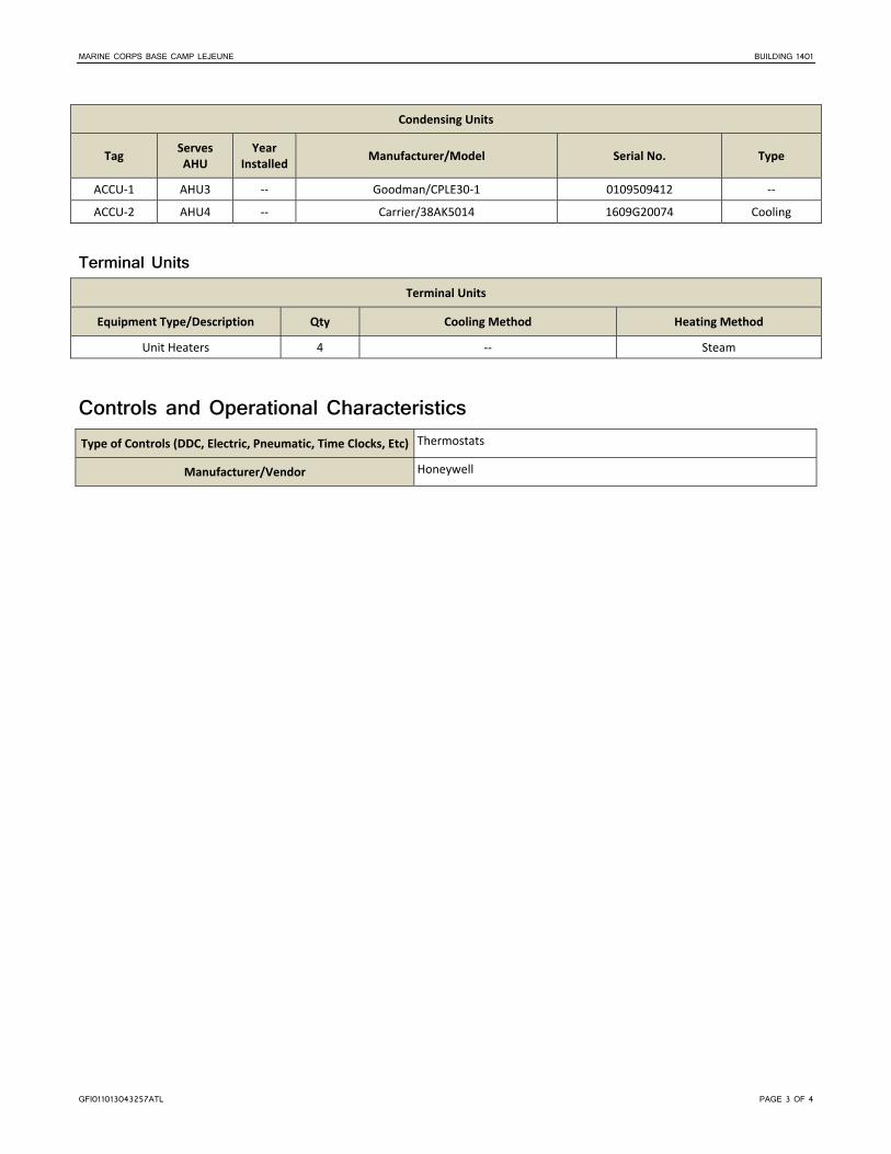
MARINE CORPS BASE CAMP LEJEUNE BUILDING 1401
GFI011013043257ATL PAGE 3 OF 4
Condensing Units
Tag Serves AHU
Year Installed
Manufacturer/Model Serial No. Type
ACCU‐1 AHU3 ‐‐ Goodman/CPLE30‐1 0109509412 ‐‐
ACCU‐2 AHU4 ‐‐ Carrier/38AK5014 1609G20074 Cooling
Terminal Units Terminal Units
Equipment Type/Description Qty Cooling Method Heating Method
Unit Heaters 4 ‐‐ Steam
Controls and Operational Characteristics Type of Controls (DDC, Electric, Pneumatic, Time Clocks, Etc) Thermostats
Manufacturer/Vendor Honeywell

MARINE CORPS BASE CAMP LEJEUNE BUILDING 1401
GFI011013043257ATL PAGE 4 OF 4
This page is intentionally left blank.

GFI011013043257ATL PAGE 1 OF 4
Camp Lejeune Building 1403 General Description
Building Name STRG MAR CORPS
Building Function Administration
Year Built 1942
Major Renovations 1993
Square Footage 11,325
Energy Usage Intensity 70.9
Building Occupancy 5 Occupants
Building Operational Hours 0800‐1600, Mon‐Fri
Drill weekends
Date and Time of Audit Start 27 Sept 2012, 0745 hrs
Observed Outside Air Temperature and Conditions
67F, 74% RH
Building Envelope Surface Construction Detail
Insulation or Wall/Roof Assembly Thickness (inches)
Height per Floor (feet)
Wall – Exterior Concrete 12" 14'6"
Roof Concrete deck with built up roof None N/A
Floor Concrete, vinyl composite tile N/A N/A
Ceiling Acoustic ceiling tile, open to structure N/A 8'6"‐14'6"
Window Type Frame Type Size Operable or Fixed % Glazing of Exterior Wall Tint Shading
Double pane Aluminum 2' 5" x 7' Operable 15 Light Interior blinds
Utilities Type
Present (Yes or No)
Metered (Yes or No)
Electric Yes Yes
Natural Gas No No
Propane No No
Diesel/No. 2 Fuel Oil No No
Type Present
(Yes or No) Metered (Yes or No)
District Steam Yes No
Water Yes No
Sewer Yes No
Lighting Interior Systems Lighting has been upgraded to 32‐Watt (W) T8 lamps throughout the building; the fixtures are controlled by manual switches. The warehouse area includes 32W T8 lamps with reflective bases that are controlled by timers.

MARINE CORPS BASE CAMP LEJEUNE BUILDING SUMMARY
GFI011013043257ATL PAGE 2 OF 4
Exterior Systems Exterior lighting is provided by wall‐mounted high‐intensity discharge lighting controlled by photocell.
Plumbing Fixture Type Quantity
Flow (gpf or gpm)
Notes
Toilets 2 3.0 gpf
Urinals ‐‐ ‐‐
Lavatories 2 5.0 gpm (1) 2.0 gpm (1)
Faucets ‐‐ ‐‐
Showers 2 2.0 gpm
Other ‐‐ ‐‐
Domestic Hot Water System
Type Manufacturer/Model Year
Manufactured Capacity Rating (Btu/Hr or kW)
Storage Capacity (Gallons)
Setpoint
(F) Circulation Pumps
Electric Tank Rheem/81V40D 2005 4.5 kW 40 ‐‐ No
HVAC Systems HVAC System Description The heating, ventilation, and air conditioning (HVAC) system consists of a direct expansion (DX) split system unit for heating and cooling the office spaces. The indoor unit has a steam coil for heating. The warehouse areas use five steam unit heaters for heating purposes. Exhaust fans are controlled by switches in bathrooms. The HVAC system is controlled by thermostats.
Air-Handling System Split‐System AHUs or Package Units (DX Equipment)
Tag Year
Installed Manufacturer / Model Serial Number System Type
Total Cooling Capacity (MBH)
Heating Method and Capacity (MBH/kW)
AHU1 ‐‐ York/K2EV060A06A SNNMY5017791 Split 60 Steam
Condensing Units
Tag Serves AHU
Year Installed
Manufacturer/Model Serial Number Type
ACCU1 AHU1 ‐‐ York/H2CB060S06C MGYM225434 Cooling Only

MARINE CORPS BASE CAMP LEJEUNE BUILDING SUMMARY
GFI011013043257ATL PAGE 3 OF 4
Terminal Units Terminal Units
Equipment Type/Description Qty Cooling Method Heating Method
Unit Heaters 5 ‐‐ Steam
Controls and Operational Characteristics Type of Controls (DDC, Electric, Pneumatic, Time Clocks, Etc) Thermostat
Manufacturer/Vendor ‐‐

MARINE CORPS BASE CAMP LEJEUNE BUILDING SUMMARY
GFI011013043257ATL PAGE 4 OF 4
This page is intentionally left blank.

GFI011013043257ATL PAGE 1 OF 4
Camp Lejeune Building 1404 General Description
Building Name RANGE OPER CEN
Building Function Administration
Year Built 1952
Major Renovations 1993
Square Footage 10,050
Energy Usage Intensity 112.0
Building Occupancy 13 Occupants
Building Operational Hours 24/7 Mon‐Fri
Date and Time of Audit Start 27 Sept 2012, 0830 hrs
Observed Outside Air Temperature and Conditions
72F, 66% RH
Building Envelope Surface Construction Detail
Insulation or Wall/Roof Assembly Thickness (inches)
Height per Floor (feet)
Wall – Exterior Concrete 10" 15'
Roof Concrete deck None N/A
Floor Concrete N/A N/A
Ceiling Acoustic ceiling tile, open to structure N/A 15'
Window Type Frame Type Size Operable or Fixed % Glazing of Exterior Wall Tint Shading
Double pane Aluminum 5' x 7', 2' x 7' Fixed 15 Light No
Utilities Type
Present (Yes or No)
Metered (Yes or No)
Electric Yes Yes
Natural Gas No No
Propane No No
Diesel/No. 2 Fuel Oil No No
Type Present
(Yes or No) Metered (Yes or No)
District Steam Yes No
Water Yes No
Sewer Yes No
Lighting Interior Systems Lighting has been upgraded to 32‐Watt (W) T8 lamps throughout the building. Lighting is controlled by manual switches.
Exterior Systems Exterior lighting is provided by wall‐mounted high intensity discharge (HID) lighting controlled by a photocell.

MARINE CORPS BASE CAMP LEJEUNE BUILDING 1404
GFI011013043257ATL PAGE 2 OF 4
Plumbing Fixture Type Quantity
Flow (gpf or gpm)
Notes
Toilets 4 1.6 gpf
Urinals 2 1.0 gpf
Lavatories 4 0.5 gpm
Faucets 1 5.0 gpm
Showers 2 2.2 gpm
Ice Machine 1 ‐‐
Drinking Fountains 2 ‐‐
Domestic Hot Water System Domestic hot water (DHW) is provided by an electric fueled tank‐type system with a steam‐to‐hot water heat exchanger (HX). A supplementary thermal expansion controller is used for the absorption of expanded domestic potable water.
Type Manufacturer/Model Year
Manufactured Capacity Rating (Btu/Hr or kW)
Storage Capacity (Gallons)
Setpoint
(F) Circulation Pumps
Tank Rheem/ELD66‐b 2008 4500 65 ‐‐ ‐‐
Expansion Tank Term‐X‐Trol/ST‐5 2007 40 2 200 ‐‐
HVAC Systems HVAC System Description The heating, ventilation, and air conditioning (HVAC) system consists of one variable air volume (VAV) air‐handling unit (AHU) that uses a direct expansion (DX) air‐cooled condenser for cooling and heating hot water (HHW) for heating. HHW is provided by a steam‐to‐hot water heat exchanger. The terminal VAV boxes have HHW reheat coils for zone control. The HVAC system is controlled by a direct digital control (DDC) system.
Heating Hot Water or Steam System (Including Pumping) HHW is produced by a steam‐to‐hot‐water heat exchanger.
Hot Water System Pump Motor Data
Tag Manufacturer/Model Frame Type HP Efficiency Voltage/Phase RPM
‐‐ Marathon Electric/M99084 56CZ‐80 2 ‐‐ 460/3/60 1725
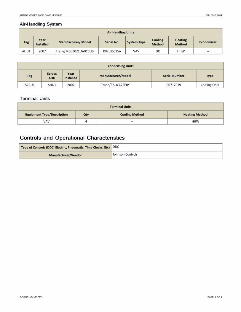
MARINE CORPS BASE CAMP LEJEUNE BUILDING 1404
GFI011013043257ATL PAGE 3 OF 4
Air-Handling System Air Handling Units
Tag Year
Installed Manufacturer/ Model Serial No. System Type
Cooling Method
Heating Method
Economizer
AHU1 2007 Trane/MCCB021UA0C0UB K07L36615A VAV DX HHW ‐‐
Condensing Units
Tag Serves AHU
Year Installed
Manufacturer/Model Serial Number Type
ACCU1 AHU1 2007 Trane/RAUCC25EBY C0712019 Cooling Only
Terminal Units Terminal Units
Equipment Type/Description Qty Cooling Method Heating Method
VAV 4 ‐‐ HHW
Controls and Operational Characteristics Type of Controls (DDC, Electric, Pneumatic, Time Clocks, Etc) DDC
Manufacturer/Vendor Johnson Controls

MARINE CORPS BASE CAMP LEJEUNE BUILDING 1404
GFI011013043257ATL PAGE 4 OF 4
This page is intentionally left blank.

GFI011013043257ATL PAGE 1 OF 4
Camp Lejeune Building 1450 General Description
Building Name AUTO ORGTL SHOP
Building Function Maintenance
Year Built 1981
Major Renovations 1997
Square Footage 19,053
Energy Usage Intensity 127.9
Building Occupancy 20 Occupants
75 Transients
Building Operational Hours 0600‐1600, Mon‐Fri
Date and Time of Audit Start 27 Sept 2012, 0806 hrs
Observed Outside Air Temperature and Conditions
72F, 65% RH
Building Envelope Surface Construction Detail
Insulation or Wall/Roof Assembly Thickness (inches)
Height per Floor (feet)
Wall – Exterior Brick veneer below metal panels 8" CMU 8'‐24'
Roof Rolled asphalt membrane Batt insulation N/A
Floor Concrete, and vinyl composite tile N/A N/A
Ceiling Acoustic ceiling tile, and open to structure N/A 8'‐21'
Window Type Frame Type Size Operable or Fixed % Glazing of Exterior Wall Tint Shading
Double pane Aluminum 3' x 3' Operable 20 No Interior ‐blinds
Utilities Type
Present (Yes or No)
Metered (Yes or No)
Electric Yes Yes
Natural Gas No No
Propane No No
Diesel/No. 2 Fuel Oil No No
Type Present
(Yes or No) Metered (Yes or No)
District Steam Yes No
Water Yes No
Sewer Yes No
Lighting Interior Systems The building has a mixture of 17‐Watt (W), 26W, and 28W T8 lamps throughout the interior spaces. Lighting is controlled by manual switches.

MARINE CORPS BASE CAMP LEJEUNE BUILDING 1450
GFI011013043257ATL PAGE 2 OF 4
Exterior Systems High intensity discharge (HID) lamps, with photocells, provide exterior lighting.
Plumbing Fixture Type Quantity
Flow (gpf or gpm)
Notes
Toilets 6 3.0 gpf
Urinals 1 1.0 gpf
Lavatories 6 2.2 gpm
Faucets 2 5.0 gpm
Showers 3 1.5 gpm
Other ‐‐ ‐‐
Domestic Hot Water System Domestic hot water is provided by a steam‐to‐hot water heat exchanger.
HVAC Systems HVAC System Description The primary heating, ventilation, and air conditioning (HVAC) systems serving the office portions consist of two packaged roof‐top units for cooling. Four portable spot coolers are used for additional cooling. The perimeter zones and restroom heating is provided by heating hot water (HHW) baseboard heaters. The heating and ventilation systems in the maintenance shop areas of the building are HHW unit heaters and exhaust fans. HHW for the facility is produced by steam‐to‐hot water heat exchanger and a circulated using a constant volume pump. Exhaust systems are switch operated and provide bay ventilation with separate fans for vehicle exhaust removal. Controls are mostly pneumatic‐type. Baseboard heaters had independent thermostatic control valves (TCV).
Heating Hot Water or Steam System (Including Pumping) HHW is provided by a steam to hot water heat exchanger.
Hot Water System Pump Data
Tag Description Manufacturer/Model Constant or Variable Flow
Flow (gpm)
Head (ft)
HWP‐1 Inline Bell & Gossett/Series 100 B1 Constant ‐‐ ‐‐
Air-Handling System Split‐System AHUs or Package Units (DX Equipment)
Tag Year
Installed Manufacturer / Model Serial Number System Type
Total Cooling Capacity (MBH)
Heating Method and Capacity (MBH/kW)
RTU‐1 1980’s Goettz/SC605‐T3 ‐‐ DX 36 ‐‐
RTU‐2 2006 Goodman/GPC1336M43AA 1005614173 DX 36 ‐‐

MARINE CORPS BASE CAMP LEJEUNE BUILDING 1450
GFI011013043257ATL PAGE 3 OF 4
Terminal Units Terminal Units
Equipment Type/Description Qty Cooling Method Heating Method
Baseboard radiators 6 ‐‐ HHW
Fan powered unit heaters 6 ‐‐ HHW (30 MBH)
Controls and Operational Characteristics Type of Controls (DDC, Electric, Pneumatic, Time Clocks, Etc) Pneumatic
Manufacturer/Vendor Allen Bradley, Honeywell

MARINE CORPS BASE CAMP LEJEUNE BUILDING 1450
GFI011013043257ATL PAGE 4 OF 4
This page is intentionally left blank.

GFI011013043257ATL PAGE 1 OF 4
Camp Lejeune Building 1500 General Description
Building Name Warehouse
Building Function Administration/Warehouse
Year Built 1942
Major Renovations 2004
Square Footage 36,452
Energy Usage Intensity 46.1
Building Occupancy 60 Occupants
Building Operational Hours 0700‐1500, Mon‐Fri
Date and Time of Audit Start 27 Sept 2012, 1030 hrs
Observed Outside Air Temperature and Conditions
84F, 56% RH
Building Envelope Surface Construction Detail
Insulation or Wall/Roof Assembly Thickness (inches)
Height per Floor (feet)
Wall – Exterior Stucco 8" CMU 20'
Roof Flat asphalt membrane Unobserved N/A
Floor Concrete, and vinyl composite tile N/A N/A
Ceiling Acoustic ceiling tile, and open to structure N/A 19' Bays
Window Type Frame Type Size Operable or Fixed % Glazing of Exterior Wall Tint Shading
Double pane Aluminum Various Operable and Fixed 20 No Blinds
Utilities Type
Present (Yes or No)
Metered (Yes or No)
Electric Yes No
Natural Gas No No
Propane No No
Diesel/No. 2 Fuel Oil No No
Type Present
(Yes or No) Metered (Yes or No)
District Steam Yes No
Water Yes No
Sewer Yes No
Lighting Interior Systems The building has 32‐Watt (W) T8 lamps throughout the interior administration spaces and 250W metal halide lighting in the warehouse. Lighting is controlled by manual switches.
Exterior Systems Exterior lighting is provided by 100W high pressure sodium (HPS) lamps controlled with photocells.

MARINE CORPS BASE CAMP LEJEUNE BUILDING 1500
GFI011013043257ATL PAGE 2 OF 4
Plumbing Fixture Type Quantity
Flow (gpf or gpm)
Notes
Toilets 9 1.6 gpf
Urinals 2 1.0 gpf
Lavatories 8 2.0 gpm
Faucets ‐‐ ‐‐
Showers ‐‐ ‐‐
Other ‐‐ ‐‐
Domestic Hot Water System The domestic hot water system was inaccessible during the time of the audit.
HVAC Systems HVAC System Description The primary heating, ventilation, and air conditioning (HVAC) systems serving the office portions consist of two built‐up air‐handling units (AHUs), each with direct expansion (DX) split‐system cooling, heating hot water (HHW) coils, and modulating outside air (OA) ventilation. The perimeter zones and restroom heating was provided by HHW baseboard heaters. HHW for the facility is produced by a steam‐to‐hot water heat exchanger and circulated using constant volume pumps. There are five small split‐system heat pump units, with additional cooling within the occupied warehouse via military portable field HVAC units. The heating and ventilation systems in the maintenance shop areas of the building were HHW unit heaters and exhaust fans. Exhaust systems are switch operated and provide bay ventilation. The newer split‐system units have local programmable thermostats.
Heating Hot Water or Steam System (Including Pumping) HHW is provided by a steam to hot water heat exchanger.
Hot Water System Pump Data
Tag Description Manufacturer/Model Constant or Variable Flow
Flow (gpm)
Head (ft)
1 Inline Bell & Gossett/ Series 90 Constant ‐‐ ‐‐
2 Inline Bell & Gossett/ Series 90 Constant ‐‐ ‐‐

MARINE CORPS BASE CAMP LEJEUNE BUILDING 1500
GFI011013043257ATL PAGE 3 OF 4
Air-Handling System Air Handling Units
Tag Year
Installed Manufacturer/ Model Serial Number System Type
Cooling Method
Heating Method
Economizer
AH 1997 Carrier ‐‐ CAV DX HHW ‐‐
AHU2 1997 Carrier/40RM007B300HC ‐‐ CAV DX HHW ‐‐
Split‐System AHUs or Package Units (DX Equipment)
Tag Year
Installed Manufacturer / Model Serial Number System Type
Total Cooling Capacity (MBH)
Heating Method and Capacity (MBH/kW)
AC‐1 1990’s Fujitsu ‐‐ Split System 18 Heat Pump
AC‐2 2010 Fujitsu ‐‐ Split System 18 Heat Pump
Condensing Units
Tag Serves AHU
Year Installed
Manufacturer/Model Serial Number Type
CU‐2 AHU‐2 1997 Carrier/38AKS008 3797G00004 Cooling Only
CU ‐‐ 1997 Carrie/38CKC060 3497E15171 Cooling Only
3 AC‐1 1990’s Fujitsu/AOU2101 T001040 Heat Pump
CU‐1 AHU‐1 2006 Goodman/GSC130603A 0604546522 ‐‐
5 AC‐2 2010 Fujitsu/AOU24RLXQ GYN 006564 Heat Pump
Terminal Units Terminal Units
Equipment Type/Description Qty Cooling Method Heating Method
Hydronic unit heaters 30 ‐‐ HHW (30 MBH)
PTAC 6 DX (18MBH) Heat Pump
Controls and Operational Characteristics Type of Controls (DDC, Electric, Pneumatic, Time Clocks, Etc) Analog
Manufacturer/Vendor Carrier, White Rodgers

MARINE CORPS BASE CAMP LEJEUNE BUILDING 1500
GFI011013043257ATL PAGE 4 OF 4
This page is intentionally left blank.

GFI011013043257ATL PAGE 1 OF 4
Camp Lejeune Building 1770 General Description
Building Name POST OFFICE
Building Function Post Office
Year Built 1972
Major Renovations 1992
Square Footage 14,514
Energy Usage Intensity 109.6
Building Occupancy 40 Occupants
50 to 80 Transients
Building Operational Hours
0830‐1630, Mon‐Fri
Lobby 24 hours, 7 days a week
Date and Time of Audit Start 25 Sept 2012, 1340 hrs
Observed Outside Air Temperature and Conditions
81F, 39% RH
Building Envelope Surface Construction Detail
Insulation or Wall/Roof Assembly Thickness (inches)
Height per Floor (feet)
Wall – Exterior CMU under brick veneer below 6' aluminum panels
8" CMU 21'
Roof Flat rolled asphalt membrane ‐‐ N/A
Floor Rubber floor, and tile N/A N/A
Ceiling Acoustic ceiling tile N/A 10'‐18'
Window Type Frame Type Size Operable or Fixed % Glazing of Exterior Wall Tint Shading
Single pane Aluminum Various Fixed 5 No No
Utilities Type
Present (Yes or No)
Metered (Yes or No)
Electric Yes Yes
Natural Gas No No
Propane No No
Diesel/No. 2 Fuel Oil No No
Type Present
(Yes or No) Metered (Yes or No)
District Steam Yes No
Water Yes No
Sewer Yes No

MARINE CORPS BASE CAMP LEJEUNE BUILDING 1770
GFI011013043257ATL PAGE 2 OF 4
Lighting Interior Systems The Building has 32‐Watt (W) T8 lamps throughout the interior administration spaces. Lighting is controlled by manual switches.
Exterior Systems High‐intensity discharge (HID) 150W metal halide and recessed can lamps provide exterior lighting. Pole‐mounted 250W lamps are used for parking area lighting.
Plumbing Fixture Type Quantity
Flow (gpf or gpm)
Notes
Toilets 6 3.0 gpf (4), 1.6 gpf (2)
Urinals 2 1.0 gpf
Lavatories 4 2.5 gpm
Faucets 1 5.0 gpm
Showers 1 2.5 gpm
Other ‐‐ ‐‐
Domestic Hot Water System The domestic hot water system is provided by a shell‐and‐tube type steam to hot‐water heat exchanger.
HVAC Systems HVAC System Description The heating, ventilation, and air conditioning (HVAC) system consists of an air‐handling unit (AHU) and a large direct expansion (DX) packaged roof‐top unit. The AHU has DX cooling with a remote condenser, heating hot water (HHW) coil, and modulating outside air (OSA) ventilation. HHW is provided by a steam‐to‐hot water heat exchanger using a constant volume pump. Exhaust fans provided restroom exhaust. Controls are self‐contained direct digital control (DDC) with room sensors.
Heating Hot Water or Steam System (Including Pumping) HHW is provided by steam‐to‐hot water heat exchanger.
Hot Water System Pump Data
Tag Description Manufacturer/Model Constant or Variable Flow
Flow (gpm)
Head (ft)
HWP‐1 Inline Bell & Gossett/Series 80 2.5 x 7 Constant 47 48
Hot Water System Pump Motor Data
Tag Manufacturer/Model Frame Type HP Efficiency Voltage/Phase RPM
HWP‐1 Marathon/ALV145TCDR5328AE 145JM 1.5 77% 230/3 1725

MARINE CORPS BASE CAMP LEJEUNE BUILDING 1770
GFI011013043257ATL PAGE 3 OF 4
Air-Handling System Air Handling Units
Tag Year
Installed Manufacturer/ Model Serial No. System Type
Cooling Method
Heating Method
Economizer
AHU‐1 1990’s York CCNM225020 Modular DX HHW Yes
Split‐System AHUs or Package Units (DX Equipment)
Tag Year
Installed Manufacturer / Model Serial No. System Type
Total Cooling Capacity (MBH)
Heating Method and Capacity (MBH/kW)
RTU‐1 1990’s York/Y12AW12A9JDNDBF NBNM014482 Packaged DX ‐‐ HHW
Condensing Units
Tag Serves AHU
Year Installed
Manufacturer/Model Serial No. Type
CU‐1 AHU‐1 1990’s York/HA300COOA2CAC2B ‐‐ Cooling
Terminal Units
Equipment Type/Description Qty Cooling Method Heating Method
Hydronic unit heaters 2 ‐‐ HHW
Controls and Operational Characteristics Type of Controls (DDC, Electric, Pneumatic, Time Clocks, Etc) DDC ‐ self contained
Manufacturer/Vendor ‐‐

MARINE CORPS BASE CAMP LEJEUNE BUILDING 1770
GFI011013043257ATL PAGE 4 OF 4
This page is intentionally left blank.

GFI011013043257ATL PAGE 1 OF 4
Camp Lejeune Building 1771 General Description
Building Name COMBAT VEH MAINT SHOP
Building Function Maintenance
Year Built 1972
Major Renovations 1989
Square Footage 14,920
Energy Usage Intensity 105,5
Building Occupancy 20 Occupants
Building Operational Hours 0800‐1630, Mon‐Fri
Date and Time of Audit Start 26 Sept 2012, 0740 hrs
Observed Outside Air Temperature and Conditions
64F, 72% RH
Building Envelope Surface Construction Detail
Insulation or Wall/Roof Assembly Thickness (inches)
Height per Floor (feet)
Wall – Exterior CMU with brick veneer below metal panels
8" CMU 22'
Roof Modified bitumen with solex coating 2" Pliyisocyanurate insulation N/A
Floor Concrete and vinyl composite tile N/A N/A
Ceiling Acoustic ceiling tile, and open to structure N/A 8'‐12'
Window Type Frame Type Size Operable or Fixed % Glazing of Exterior Wall Tint Shading
Double pane Aluminum 4' x 8', 4' x 5' Operable 5 No Interior‐ Blinds
Utilities Type
Present (Yes or No)
Metered (Yes or No)
Electric Yes Yes
Natural Gas No No
Propane No No
Diesel/No. 2 Fuel Oil No No
Type Present
(Yes or No) Metered (Yes or No)
District Steam Yes No
Water Yes No
Sewer Yes No
Lighting Interior Systems The building has 28‐Watt (W) and 32W T8 lamps throughout the majority of interior spaces. A few areas have 60W incandescent lamps and compact fluorescent lamps (CFLs). Lighting is controlled by manual switches.

MARINE CORPS BASE CAMP LEJEUNE BUILDING 1771
GFI011013043257ATL PAGE 2 OF 4
Exterior Systems High intensity discharge 100W lamps, with photocells, provide exterior lighting.
Plumbing Fixture Type Quantity
Flow (gpf or gpm)
Notes
Toilets 3 1.6 gpf
Urinals 3 1.0 gpf
Lavatories 4 0.5 gpm
Faucets 1 5.0 gpm Janitor
Showers 1 1.5 gpm
Other ‐‐ ‐‐
Domestic Hot Water System The domestic hot water system is provided by a steam‐to‐hot water heat exchanger.
HVAC Systems HVAC System Description The primary heating, ventilation, and air conditioning (HVAC) system consists of a variable air volume (VAV) air‐handling unit (AHU), with direct expansion (DX) split‐system cooling, heating hot water (HHW) coil, and modulating outside air (OSA) ventilation. The AHU is controlled by a variable frequency drive (VFD) controller. Terminal VAV zone dampers throughout; an estimated eight zones are provided. The units are concealed above ceilings and were not observed. One packaged terminal air conditioner (PTAC) unit is used to condition the training room. The perimeter zones and restroom heating are provided by HHW baseboard heaters. HHW for the facility is produced by steam‐to‐hot water heat exchanger and is distributed using a constant volume pump. The heating and ventilation systems in the shop areas of the building are HHW unit heaters and exhaust fans. Exhaust systems are switch operated and provide bay ventilation. Controls are direct digital control (DDC).
Heating Hot Water or Steam System (Including Pumping) HHW for the facility is produced by steam‐to‐hot water heat exchanger.
Hot Water System Pump Data
Tag Description Manufacturer/Model Constant or Variable Flow
Flow (gpm)
Head (ft)
HWP Inline Taco Simplex Constant ‐‐ ‐‐
Hot Water System Pump Motor Data
Tag Manufacturer/Model Frame Type HP Efficiency Voltage/Phase RPM
‐‐ Baldor 182T 3 86.5 460/3 1725
‐‐ Baldor 58E 2 78.5 460/3 1725

MARINE CORPS BASE CAMP LEJEUNE BUILDING 1771
GFI011013043257ATL PAGE 3 OF 4
Air-Handling System Split‐System AHUs or Package Units (DX Equipment)
Tag Year
Installed Manufacturer/ Model Serial No. System Type
Total Cooling Capacity (MBH)
Heating Method and Capacity (MBH/kW)
AHU‐1 2009 Trane/TWE180B300EL 9241UUTHD Split System 180 HHW
Condensing Units
Tag Serves AHU
Year Installed
Manufacturer/Model Serial No. Type
CU‐1 AHU‐1 2009 Trane/TTA180B300FA 90615Y2AD Heat Pump
Terminal Units Terminal Units
Equipment Type/Description Qty Cooling Method Heating Method
Unit Heater with propeller fan 9 ‐‐ HHW (30MBH)
Baseboard Heaters 2 ‐‐ HHW
PTAC 1 DX ‐‐
Controls and Operational Characteristics Type of Controls (DDC, Electric, Pneumatic, Time Clocks, Etc) Analog Thermostat for unit heaters, DDC for air handling zone dampers
Manufacturer/Vendor Johnson Controls

MARINE CORPS BASE CAMP LEJEUNE BUILDING 1771
GFI011013043257ATL PAGE 4 OF 4
This page is intentionally left blank.

GFI011013043257ATL PAGE 1 OF 4
Camp Lejeune Building 1775 General Description
Building Name AUTO ORGTL SHOP
Building Function Maintenance
Year Built 1980
Major Renovations 2002
Square Footage 35,352
Energy Usage Intensity 71.7
Building Occupancy 30 Occupants
2 Transients
Building Operational Hours 0800‐1800, Mon‐Fri
Date and Time of Audit Start 26 Sept 2012, 1040 hrs
Observed Outside Air Temperature and Conditions
84F, 44% RH
Building Envelope Surface Construction Detail
Insulation or Wall/Roof Assembly Thickness (inches)
Height per Floor (feet)
Wall – Exterior Brick veneer below metal panels 8" CMU 8'‐17'
Roof Thermoplastic Polyolefin, Flat ‐‐ N/A
Floor Concrete, and vinyl composite tile N/A N/A
Ceiling Acoustic ceiling tile, and open to structure N/A 8'‐17'
Window Type Frame Type Size Operable or Fixed % Glazing of Exterior Wall Tint Shading
Double pane Aluminum 3' x 3' Operable >5 No Interior‐Curtains
Utilities Type
Present (Yes or No)
Metered (Yes or No)
Electric Yes No
Natural Gas No No
Propane No No
Diesel/No. 2 Fuel Oil Yes No
Type Present
(Yes or No) Metered (Yes or No)
District Steam Yes No
Water Yes No
Sewer Yes No
Lighting Interior Systems The building has 28‐Watt (W), 32W, and 54W T8 lamps throughout the interior spaces. Some additional spaces use 23W compact fluorescent lights (CFL). Lighting is controlled by manual switches.

MARINE CORPS BASE CAMP LEJEUNE BUILDING 1775
GFI011013043257ATL PAGE 2 OF 4
Exterior Systems Exterior lighting is provided by high pressure sodium (HPS) lamps with photocell control.
Plumbing Fixture Type Quantity
Flow (gpf or gpm)
Notes
Toilets 15 3.0 gpf
Urinals 6 1.0 gpf
Lavatories 18 2.2 gpm
Faucets 3 5.0 gpm
Showers 9 2.0 gpm
Other ‐‐ ‐‐
Domestic Hot Water System The domestic hot water system is provided by a two steam to hot water heat exchangers with circulation pumps, with a 100 gallon storage tank.
HVAC Systems HVAC System Description The primary heating, ventilation, and air conditioning (HVAC) systems serving the office portions of this building consist of six cooling‐only roof‐top direct expansion (DX) packaged units. There are numerous window‐type air conditioning units located throughout the building. The perimeter zones and restroom heating is provided by heating hot water (HHW) in‐wall radiator heaters. HHW is produced in two similar locations by steam‐to‐hot water heat exchangers (HX) and distributed by circulation pumps. The heating and ventilation systems in the maintenance shop areas of the building are HHW unit heaters and exhaust fans. Exhaust systems are switch operated and provided bay ventilation. Controls are mostly analog, with a couple digital, programmable thermostats found at replacement roof‐top unit zone locations.
Heating Hot Water or Steam System (Including Pumping) HHW for the facility was produced in two similar locations by steam‐to‐hot water heat exchangers.
Air-Handling System Split‐System AHUs or Package Units (DX Equipment)
Tag Year
Installed Manufacturer / Model Serial Number System Type
Total Cooling Capacity (MBH)
Heating Method and Capacity (MBH/kW)
RTU Type 1 2002 Trane/WCH036B100BC 2332TMB3H Packaged DX 36 ‐‐
RTU Type 1 2004 Trane/WCH036B100BC 4432JXS3H Packaged DX 36 ‐‐
RTU Type 1 2002 Trane/WCH036B100BC 2222NX73H Packaged DX 36 ‐‐
RTU Type 2 1982 Goettl/SC365J‐3 8230076 Packaged DX 36 ‐‐
RTU Type 2 1982 Goettl/SC365J‐3 8230079 Packaged DX 36 ‐‐
RTU Type 3 1997 Carrier/50SS‐036‐‐‐501AA 2297G40557 Packaged DX 36 ‐
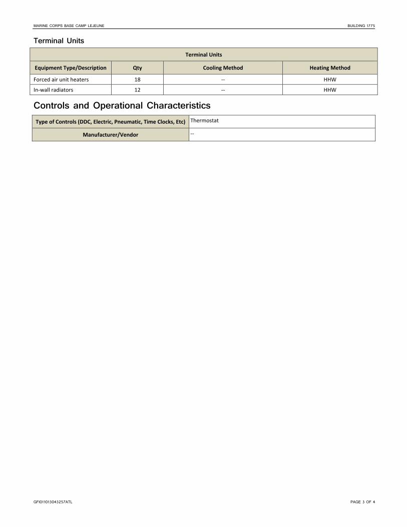
MARINE CORPS BASE CAMP LEJEUNE BUILDING 1775
GFI011013043257ATL PAGE 3 OF 4
Terminal Units Terminal Units
Equipment Type/Description Qty Cooling Method Heating Method
Forced air unit heaters 18 ‐‐ HHW
In‐wall radiators 12 ‐‐ HHW
Controls and Operational Characteristics Type of Controls (DDC, Electric, Pneumatic, Time Clocks, Etc) Thermostat
Manufacturer/Vendor ‐‐

MARINE CORPS BASE CAMP LEJEUNE BUILDING 1775
GFI011013043257ATL PAGE 4 OF 4
This page is intentionally left blank.

GFI011013043257ATL PAGE 1 OF 4
Camp Lejeune Building 1829 General Description
Building Name AUTO ORGTL SHOP
Building Function Maintenance
Year Built 1991
Major Renovations 1997
Square Footage 30,516
Energy Usage Intensity 83.1
Building Occupancy 21 Occupants
100 Transients
Building Operational Hours 0700‐1630, Mon‐Fri
Date and Time of Audit Start 26 Sept 2012, 0916 hrs
Observed Outside Air Temperature and Conditions
80F, 61% RH
Building Envelope Surface Construction Detail
Insulation or Wall/Roof Assembly Thickness (inches)
Height per Floor (feet)
Wall – Exterior CMU with brick veneer 8" CMU 24'‐30'
Roof Single‐ply CSPE membrane 3 1/2" polyisocyanurate N/A
Floor Concrete, and vinyl composite tile N/A N/A
Ceiling Acoustic ceiling tile, and open to structure N/A 8'‐35'
Window Type Frame Type Size Operable or Fixed % Glazing of Exterior Wall Tint Shading
Double pane Aluminum 5' x 10'; 2' x 3' Operable and Fixed <5 No Interior‐ blinds
Utilities Type
Present (Yes or No)
Metered (Yes or No)
Electric Yes No
Natural Gas No No
Propane No No
Diesel/No. 2 Fuel Oil No No
Type Present
(Yes or No) Metered (Yes or No)
District Steam Yes No
Water Yes No
Sewer Yes No
Lighting Interior Systems The building has 32‐Watt (W) and 54W T8 lamps throughout the interior spaces. Lighting is controlled by manual switching.
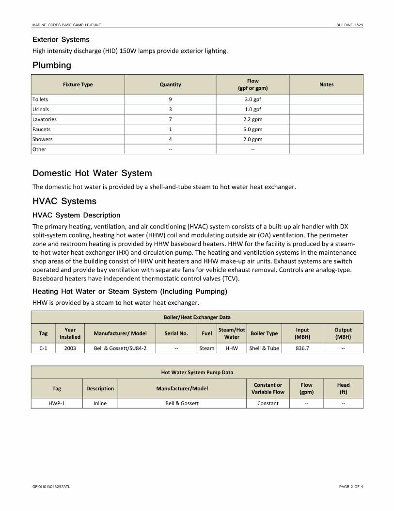
MARINE CORPS BASE CAMP LEJEUNE BUILDING 1829
GFI011013043257ATL PAGE 2 OF 4
Exterior Systems High intensity discharge (HID) 150W lamps provide exterior lighting.
Plumbing Fixture Type Quantity
Flow (gpf or gpm)
Notes
Toilets 9 3.0 gpf
Urinals 3 1.0 gpf
Lavatories 7 2.2 gpm
Faucets 1 5.0 gpm
Showers 4 2.0 gpm
Other ‐‐ ‐‐
Domestic Hot Water System The domestic hot water is provided by a shell‐and‐tube steam to hot water heat exchanger.
HVAC Systems HVAC System Description The primary heating, ventilation, and air conditioning (HVAC) system consists of a built‐up air handler with DX split‐system cooling, heating hot water (HHW) coil and modulating outside air (OA) ventilation. The perimeter zone and restroom heating is provided by HHW baseboard heaters. HHW for the facility is produced by a steam‐to‐hot water heat exchanger (HX) and circulation pump. The heating and ventilation systems in the maintenance shop areas of the building consist of HHW unit heaters and HHW make‐up air units. Exhaust systems are switch operated and provide bay ventilation with separate fans for vehicle exhaust removal. Controls are analog‐type. Baseboard heaters have independent thermostatic control valves (TCV).
Heating Hot Water or Steam System (Including Pumping) HHW is provided by a steam to hot water heat exchanger.
Boiler/Heat Exchanger Data
Tag Year
Installed Manufacturer/ Model Serial No. Fuel
Steam/Hot Water
Boiler Type Input (MBH)
Output (MBH)
C‐1 2003 Bell & Gossett/SU84‐2 ‐‐ Steam HHW Shell & Tube 836.7 ‐‐
Hot Water System Pump Data
Tag Description Manufacturer/Model Constant or Variable Flow
Flow (gpm)
Head (ft)
HWP‐1 Inline Bell & Gossett Constant ‐‐ ‐‐

MARINE CORPS BASE CAMP LEJEUNE BUILDING 1829
GFI011013043257ATL PAGE 3 OF 4
Air-Handling System Air Handling Units
Tag Year
Installed Manufacturer/ Model Serial No. System Type
Cooling Method
Heating Method
Economizer
AHU‐1 1980s Trane/10AMZCLCH ‐‐ Modular Split
DX HHW ‐‐
Condensing Units
Tag Serves AHU
Year Installed
Manufacturer/Model Serial No. Type
CU‐1 AHU‐1 1990s Trane/TTA120B400EA 4061S2CAD Cooling Only
Terminal Units Terminal Units
Equipment Type/Description Qty Cooling Method Heating Method
Baseboard Heaters 8 ‐‐ HHW
Unit Heaters 3 ‐‐ HHW
Controls and Operational Characteristics Type of Controls (DDC, Electric, Pneumatic, Time Clocks, Etc) Pneumatic at air handler
Manufacturer/Vendor Honeywell

MARINE CORPS BASE CAMP LEJEUNE BUILDING 1829
GFI011013043257ATL PAGE 4 OF 4
This page is intentionally left blank.

GFI011013043257ATL Page 1 of 4
Camp Lejeune Building 1880 General Description
Building Name COMBAT VEH MAINT SHOP
Building Function Maintenance
Year Built 1984
Major Renovations 1989
Square Footage 28,275
Energy Usage Intensity 75.9
Building Occupancy 80 to 100 Occupants
Building Operational Hours 0700‐1630, Mon‐Fri
Special Missions Only
Date and Time of Audit Start 26 Sept 2012, 1317 hrs
Observed Outside Air Temperature and Conditions
90F, 39% RH
Building Envelope Surface Construction Detail
Insulation or Wall/Roof Assembly Thickness (inches)
Height per Floor (feet)
Wall – Exterior Brick veneer with 6' metal siding 8" CMU 8'‐24'
Roof Built up gravel ‐‐ N/A
Floor Concrete, and vinyl composite tile N/A N/A
Ceiling Acoustic ceiling tile, and open to structure
N/A 8'‐22'
Window Type Frame Type Size Operable or Fixed % Glazing of Exterior Wall Tint Shading
Double pane Aluminum 4' x 6' Operable 20 No Interior‐ Blinds
Utilities Type
Present (Yes or No)
Metered (Yes or No)
Electric Yes Yes
Natural Gas No No
Propane No No
Diesel/No. 2 Fuel Oil Yes No
Type Present
(Yes or No) Metered (Yes or No)
District Steam Yes No
Water Yes No
Sewer Yes No
Lighting Interior Systems The building has 32‐Watt (W) T8 and 30W and 60W T12 lamps throughout the interior spaces. The bay areas have high pressure sodium (HPS) lighting. Lighting is controlled by manual switching.

MARINE CORPS BASE CAMP LEJEUNE BUILDING 1880
GFI011013043257ATL PAGE 2 OF 4
Exterior Systems Metal halide 100W lamps, with photocell, provide exterior lighting.
Plumbing Fixture Type Quantity
Flow (gpf or gpm)
Notes
Toilets 9 3.0 gpf
Urinals 4 1.0 gpf
Lavatories 9 2.2 gpm
Faucets 2 5.0 gpm
Showers 4 2.5 gpm
Other ‐‐ ‐‐
Domestic Hot Water System The domestic hot water (DHW) is provided by a steam‐to‐hot water heat exchanger with a 300‐gallon storage tank as well as several under‐sink instant DHW installations under lavatories.
HVAC Systems HVAC System Description The primary heating, ventilation, and air conditioning (HVAC) systems serving the office portions consist of two cooling‐only roof‐top direct expansion (DX) packaged units. There is a single packaged terminal air conditioning unit (PTAC) at one office location and three movable “Porta‐cool”‐type air conditioning units throughout. The perimeter zones and restroom heating is provided by heating hot water (HHW) baseboard heaters. The heating and ventilation systems in the maintenance shop areas of the building are HHW unit heaters and exhaust fans. Centrifugal exhaust systems are switch operated and provide bay ventilation. HHW for the facility is produced by steam‐to‐hot water heat exchangers (HX) and circulated using a constant volume pump. Controls are mostly analog, with a couple digital, programmable thermostats found at replacement roof‐top unit zone locations. Heating Hot Water or Steam System (Including Pumping) HHW is provided by a steam to hot water heat exchanger.
Hot Water System Pump Data
Tag Description Manufacturer/Model Constant or Variable Flow
Flow (gpm)
Head (ft)
HWP‐1 Split Coupled Bell & Gossett/2AC5‐3/4 Constant 90 28
Hot Water System Pump Motor Data
Tag Manufacturer/Model Frame Type HP Efficiency Voltage/Phase RPM
HWP‐1 Baldor/CP3584T 145T 1.5 Low 460/3 1725

MARINE CORPS BASE CAMP LEJEUNE BUILDING 1880
GFI011013043257ATL PAGE 3 OF 4
Air-Handling System Split‐System AHUs or Package Units (DX Equipment)
Tag Year
Installed Manufacturer / Model Serial No. System Type
Total Cooling Capacity (MBH)
Heating Method and Capacity (MBH/kW)
RTU‐1 1990’s Trane/TCD120C400AB R40101593D Packaged DX 120 ‐‐
RTU‐2 2006 Trane/TSC060E4R0A16 113212116L Packaged DX 60 ‐‐
Terminal Units Terminal Units
Equipment Type/Description Qty Cooling Method Heating Method
Unit Heaters 16 ‐‐ HHW (30 MBH)
Baseboard 8 ‐‐ HHW
PTAC 1 DX (12 MBH) ‐‐
Controls and Operational Characteristics Type of Controls (DDC, Electric, Pneumatic, Time Clocks, Etc) Analog, and Programmable Thermostats
Manufacturer/Vendor Multiple
MARINE CORPS BASE CAMP LEJEUNE BUILDING 1880
GFI011013043257ATL PAGE 4 OF 4
This page is intentionally left blank.

HP51_BEQ PAGE 1 OF 4
Building HP51 – Bachelor Enlisted Quarters (BEQ) (E6 – E9) General Description This three‐floor building is used as a BEQ and temporary lodging facility (TLF) for transient troops. Of the 74 rooms, 29 are TLF units. The remaining 45 are reserved for more permanent residents. Each floor has several individual rooms, two mechanical rooms, and a lounge area. The first floor also includes an office area for the TLF. The building’s individual rooms are occupied during all times of day. The permanent residence generally has an occupancy rate of 50 percent; TLF rooms generally have an occupancy rate of approximately 90 percent. This building is served from the Building HP52 Utility Plant.
Building Function BEQ / TLF
Year Built /
Major Renovations
1976
Renovated 2002
Square Footage 35,566 SF
Energy Usage Intensity 23.5 MMBtu/kSF
Building Occupancy 74 Rooms
Building Operational Hours 24 / 7
Date
Time of Audit Start
12 Jul 2011
15:00
Observed Outside
Air Temperature
and Conditions
96°F
76.5% RH
Partly cloudy
Observed Interior Building Condition Measurements
(Room 119)
79°F / 64% RH
Average CO2: 447 ppm
Average Light Level: 40 FC
(Room 115) 79°F / 61% RH
Average CO2: 770 ppm
Average Light Level: 40 FC
Building Envelope Surface Construction Detail
Insulation/ Approx. Wall Thickness (inches)
Approx.% Glazing
Approx. Height per Floor (feet)
Wall – Exterior Concrete frame, CMU fill, with brick cladding 8 in 5% 9 ft
Wall – Interior Exposed concrete masonry unit 8 in 0% 9 ft
Roof Hipped shingle roof supported by wood trusses with insulation placed over existing built‐up roof
R‐38
Floor Coated concrete, carpet and tile
Ceiling ‐ Rooms Exposed concrete deck above ‐ ‐ 9 ft
Ceiling – Common Area Acoustical ceiling tile ‐ ‐ 8 ft
Building HP51

ENERGY AUDIT, MARINE CORPS BASE CAMP LEJEUNE APPENDIX A, BUILDING SUMMARIES
HP51_BEQ PAGE 2 OF 4
Windows The windows have aluminum frames and double panes and are operable. The windows are not tinted, but are fitted with both curtains and blinds. The walkways also provide 5 feet of additional shading.
Utilities Type
Present Yes or No
Metered Yes or No
Electric Y Y
Natural Gas N N
Water Y N
HVAC Systems HVAC System Description The heating, ventilation, and air conditioning (HVAC) system consists of six variable air volume (VAV) air‐handling units (AHUs) with associated terminal VAV units to condition the majority of the building. Fan coil units (FCUs) are used to condition some of the core spaces. Most of the HVAC equipment appears to be in fair operating condition.
The HVAC system is served by a dual‐temperature water (DTW) system (two‐pipe system) for heating hot water (HHW) or chilled water (CHW) depending on the season. The DTW loop is supplied through Building HP56. The DTW system serves the AHUs, FCUs, and unit heaters.
Chilled Water System CHW is produced at a central chiller plant located in Building HP52. The chilled water serves each AHU through the DTW system.
Heating Hot Water System HHW is provided by a steam to hot water heat exchanger located in Building HP52. The HHW serves each AHU through the DTW system.
Air-Handling System One VAV AHU is located within each of the six mechanical rooms (two per floor). Each AHU serves VAV terminal boxes located in individual rooms. The AHUs provide heating and cooling through a DTW coil. The DTW coils use three‐way control valves. A variable frequency drive (VFD) controls the speed of each AHU supply fan. Most VFD controllers were found to be operating at 100 percent at the time of the site visit.
Outside air is brought into the building through outside air dampers on each AHU. The dampers are automatically controlled to determine a percentage of outside air. The dampers were found to be 100 percent open at the time of the site visit.
AHU Info. Design
Tag Location Year
Installed Mfr.
Model No.
System Type
Cooling Method
Heating Method
EconomizerMax CFM
Cooling Capacity (MBH)
Heating Capacity (MBH)
AHU1 Mech 1 1998 ‐‐ ‐‐ Variable Volume
CHW HHW No 3,960 113 230
AHU2 Mech 2 1998 ‐‐ ‐‐ Variable Volume
CHW HHW No 2,475 76 150
AHU3 Mech 3 1998 ‐‐ ‐‐ Variable Volume
CHW HHW No 3,915 112 225

ENERGY AUDIT, MARINE CORPS BASE CAMP LEJEUNE APPENDIX A, BUILDING SUMMARIES
HP51_BEQ PAGE 3 OF 4
AHU Info. Design
Tag Location Year
Installed Mfr.
Model No.
System Type
Cooling Method
Heating Method
EconomizerMax CFM
Cooling Capacity (MBH)
Heating Capacity (MBH)
AHU4 Mech 4 1998 ‐‐ ‐‐ Variable Volume
CHW HHW No 2,475 76 150
AHU5 Mech 5 1998 ‐‐ ‐‐ Variable Volume
CHW HHW No 3,960 118 225
AHU6 Mech 6 1998 ‐‐ ‐‐ Variable Volume
CHW HHW No 2,475 80 150
Tag Supply Fan Motor
Year Installed Mfr. HP Efficiency Control Type
AHU1 1998 Century 5 87.5% VFD
AHU2 1998 Century 3 86.5% VFD
AHU3 1998 Century 5 87.5% VFD
AHU4 1998 Century 3 86.5% VFD
AHU5 1998 Century 5 87.5% VFD
AHU6 1998 Century 3 86.5% VFD
Terminal Units VAV Boxes The series fan‐powered terminal VAV boxes are air valves only and do not have reheat capability. One VAV box is provided for each BEQ room as well as the first floor office and the lounge areas.. Each VAV box is controlled by a Johnson Controls temperature sensor thermostat.
FCUs The small office in the first floor common area and the laundry rooms on each floor utilize floor‐mounted DTW FCUs to provide heating and cooling.
Exhaust Fans The lavatories in the building are served by continuously operated constant‐volume exhaust fans located in the attic.
Controls and Operational Characteristics The building systems are controlled with a direct digital control (DDC) system, but the DDC system is not currently connected to the Base‐wide energy management and control system (EMCS). The DDC controls operate to control the VFD on each AHU, the automatic dampers on supply, mixed, and outside air to each AHU, the three‐way valve on the coil, and each the damper on each VAV box in the space. The two‐pipe system in the building requires manual changeover. The building does not currently use schedules of occupancy.
Plumbing Fixture Type Quantity Flow (gpf or gpm)
Toilets 78 1.6
Urinals 0 ‐
Lavatories 79 2.2

ENERGY AUDIT, MARINE CORPS BASE CAMP LEJEUNE APPENDIX A, BUILDING SUMMARIES
HP51_BEQ PAGE 4 OF 4
Fixture Type Quantity Flow (gpf or gpm)
Service Sinks 3 >2.5
Showers 74 2.5
Washing Machines 9 ‐
Dryers 9 ‐
Domestic Hot Water System Domestic hot water is provided through a steam‐to‐hot‐water‐heat exchanger in Building HP56
Electrical Systems A pad‐mounted transformer is located near the building. This transformer provides 208Y/120V, three‐phase, four‐wire service routed underground to the Main Distribution Panelboard (MDP) located in a first floor mechanical room. The MDP main circuit breaker is rated at 600‐ampere (A) with 10,000A interrupt capacity. The MDP contains six 200A circuit breakers and one 225A circuit breaker, which are connected to distribution panelboards. There is a 200A distribution panelboard located in each mechanical room (two per floor, three floors). The 225A circuit breaker powers a panelboard located in the office on the first floor. These panelboards provide 120/208V power to HVAC, lighting, and receptacle loads located near the panelboards.
Lighting Interior Systems The typical room has one 4‐lamp fixture in the living room, a 2‐lamp fixture in the sink area, a circular compact fluorescent lamp (CFL) in the bathroom, and one floor lamp using a CFL bulb. The remaining office and common areas have a combination of 4‐, 3‐, and 2‐lamp fixtures, as well as CFLs. The stairwell lights and some corridor lights are used for emergency egress and are wired to stay on continuously. The exit signs use light‐emitting diode (LED) lamps. Battery powered emergency lighting for emergency egress is provided in the interior corridors.
Fixture Type Fixture Size Lamps Controls FC Measurement
4‐Lamp 4 ft × 2 ft 32W T8 Manual 40 – 100
3‐Lamp 4 ft × 2 ft 32W T8 Manual 40
2‐Lamp 4 ft × 2 ft 32W T8 Manual 40
CFL 1‐ft Diameter 22W CFL Manual 10
CFL Screw‐in 13W CFL Manual 10
CFL 1 ft 26W CFL Always On 10
Exterior Systems Fixture Type Fixture Size Lamps Controls Qty
CFL 1‐ft Diameter 24W CFL Timer 72
T8 2‐lamp, 4 ft 2F32T8 Timer 4

HP53_BEQ PAGE 1 OF 4
Building HP53 – Bachelor Enlisted Quarters (BEQ) (E1 – E4) General Description This building has approximately 72 rooms with three Marines housed in each room. In addition to the individual rooms, each floor has two mechanical rooms, a lounge, and common area. The first floor also offers an office area. The building’s individual rooms are occupied during all times of day. The building is occupied at approximately 98 percent of its capacity year‐round. This building is served from the Building HP52 Utility Plant.
Building Function BEQ
Year Built /
Major Renovations
1976
Renovated 2002
Square Footage 35,566 SF
Energy Usage Intensity 23.5 MMBtu/kSF
Building Occupancy 72 Rooms
Building Operational Hours 24 / 7
Date
Time of Audit Start
12 Jul 2011
14:00
Observed Outside
Air Temperature
and Conditions
95°F
70% RH
Partly cloudy
Observed Interior Building Condition Measurements
(Room 213)
86°F / 56% RH
Average CO2: 680 ppm
Average Light Level: 40 FC
(Room 214) 81°F / 61% RH
Average CO2: 514 ppm
Average Light Level: 40 FC
Building Envelope Surface Construction Detail
Insulation/ Approx. Wall Thickness (inches)
Approx.% Glazing
Approx. Height per Floor (feet)
Wall – Exterior Concrete frame, CMU fill, with brick cladding 8 in 5% 9 ft
Wall – Interior Exposed CMU 8 in 0% 9 ft
Roof Hipped shingle roof supported by wood trusses with insulation placed over existing built‐up roof
R‐38
Floor Coated concrete, carpet, and tile1
Ceiling ‐ Rooms Exposed concrete deck above ‐ ‐ 9 ft
Ceiling – Common Area Acoustical ceiling tile ‐ ‐ 8 ft 1Being replaced in common areas
Building HP53

ENERGY AUDIT, MARINE CORPS BASE CAMP LEJEUNE APPENDIX A, BUILDING SUMMARIES
HP53_BEQ PAGE 2 OF 4
Windows The windows have aluminum frames and double panes and are operable. The windows are not tinted, but are fitted with both curtains and blinds. The walkways also provide 5 feet of additional shading.
Utilities Type
Present Yes or No
Metered Yes or No
Electric Y Y
Natural Gas N N
Water Y N
HVAC Systems HVAC System Description The heating, ventilation, and air conditioning (HVAC) system consists of six variable air volume (VAV) air‐handling units (AHUs) with associated terminal VAV units to condition the majority of the building. Fan coil units (FCUs) are used to condition some of the core spaces. Most of the HVAC equipment appears to be in fair condition.
The HVAC system is served by a dual‐temperature water (DTW) system (two‐pipe system) for heating hot water (HHW) or chilled water (CHW) depending on the season. The DTW loop is supplied through Building HP56. The DTW system serves the AHUs, FCUs, and unit heaters.
Chilled Water System CHW is produced at a central chiller plant located in Building HP52. The chilled water serves each AHU through the DTW system.
Heating Hot Water System HHW is provided by a steam‐to‐hot‐water heat exchanger located in Building HP52. The HHW serves each AHU through the DTW system.
Air-Handling System One VAV AHU is located within each of the six mechanical rooms (two per floor). Each AHU serves VAV terminal boxes located in individual rooms. The AHUs provide heating and cooling through a DTW coil. The DTW coils use three‐way control valves. Each AHU supply fan uses a variable frequency drive (VFD) to control the fan speed. Most VFD controllers were found to be operating at 100 percent at the time of the site visit.
Outside air is brought into the building through outside air dampers on each AHU. The dampers are automatically controlled to determine a percentage of outside air. The dampers were found to be 100 percent open at the time of the site visit.
AHU Info. Design
Tag Location Year
Installed Mfr.
Model No.
System Type
Cooling Method
Heating Method
EconomizerMax CFM
Cooling Capacity (MBH)
Heating Capacity (MBH)
AHU1 Mech 1 1998 ‐‐ ‐‐ Variable Volume
CHW HHW No 3,960 113 230
AHU2 Mech 2 1998 ‐‐ ‐‐ Variable Volume
CHW HHW No 2,475 76 150
AHU3 Mech 3 1998 ‐‐ ‐‐ Variable Volume
CHW HHW No 3,915 112 225

ENERGY AUDIT, MARINE CORPS BASE CAMP LEJEUNE APPENDIX A, BUILDING SUMMARIES
HP53_BEQ PAGE 3 OF 4
AHU Info. Design
Tag Location Year
Installed Mfr.
Model No.
System Type
Cooling Method
Heating Method
EconomizerMax CFM
Cooling Capacity (MBH)
Heating Capacity (MBH)
AHU4 Mech 4 1998 ‐‐ ‐‐ Variable Volume
CHW HHW No 2,475 76 150
AHU5 Mech 5 1998 ‐‐ ‐‐ Variable Volume
CHW HHW No 3,960 118 225
AHU6 Mech 6 1998 ‐‐ ‐‐ Variable Volume
CHW HHW No 2,475 80 150
Tag
Supply Fan Motor
Year Installed
Mfr. HP Efficiency Control Type
AHU1 1998 Century 5 87.5% VFD
AHU2 1998 Century 3 86.5% VFD
AHU3 1998 Century 5 87.5% VFD
AHU4 1998 Century 3 86.5% VFD
AHU5 1998 Century 5 87.5% VFD
AHU6 1998 Century 3 86.5% VFD
Terminal Units VAV Boxes The series fan‐powered terminal VAV boxes are air valves only and do not have reheat capability. One VAV box is provided for each BEQ room as well as for the first floor Duty Office and the lounge areas. Each VAV box is controlled by a Johnson Controls temperature sensor thermostat.
FCUs The small office area in the first floor common area and the laundry rooms on each floor use floor‐mounted DTW FCU to provide heating and cooling.
Exhaust Fans The lavatories are served by continuously operated constant‐volume exhaust fans located in the attic.
Controls and Operational Characteristics The building systems are controlled with a direct digital control (DDC) system, but the DDC system is not currently connected to the base‐wide energy management and control system (EMCS). The DDC controls operate to control the VFD on each AHU, the automatic dampers on supply, mixed, and outside air to each AHU, the three‐way valve on the coil, and each damper on each VAV box in the space. The two‐pipe system in the building requires manual changeover. The building does not currently use schedules of occupancy.
Plumbing Fixture Type Quantity Flow (gpf or gpm)
Toilets 77 > 3
Urinals 1 2
Lavatories 77 2.2

ENERGY AUDIT, MARINE CORPS BASE CAMP LEJEUNE APPENDIX A, BUILDING SUMMARIES
HP53_BEQ PAGE 4 OF 4
Fixture Type Quantity Flow (gpf or gpm)
Service Sinks 3 > 2.5
Showers 73 2.5
Washing Machines 9 ‐
Dryers 9 ‐
Domestic Hot Water System Domestic hot water is provided through a steam to hot water heat exchanger in Building HP56.
Electrical Systems A pad‐mounted transformer is located near the building. This transformer provides 208Y/120V, three‐phase, four‐wire service routed underground to the Main Distribution Panelboard (MDP) located in a first floor mechanical room. The MDP main circuit breaker is rated at 600‐ampere (A) with 10,000A interrupt capacity. The MDP contains six 200A circuit breakers and one 225A circuit breaker, which are connected to distribution panelboards. There is a 200A distribution panelboard located in each mechanical room: two per floor, three floors. The 225A circuit breaker powers a panelboard located in the Duty Office on the first floor. The panelboards provide 120/208V power to HVAC, lighting, and receptacle loads located near the panelboards.
Lighting Interior Systems The typical room has one 4‐lamp fixture in the living room, a 2‐lamp fixture in the sink area, one circular compact fluorescent lamp (CFL) in the bathroom, and one floor lamp that uses a CFL bulb. The remaining office and common areas have a combination of 4‐, 3‐, and 2‐lamp fixtures, as well as CFLs. The stairwell lights and some corridor lights are used for emergency egress and are wired to stay on continuously. The exit signs use light‐emitting diode (LED) lamps. Battery‐powered emergency lighting for emergency egress is provided in the interior corridors.
Fixture Type Fixture Size Lamps Controls FC Measurement
4‐Lamp 4 ft × 2 ft 32W T8 Manual 40–100
3‐Lamp 4 ft × 2 ft 32W T8 Manual 40
2‐Lamp 4 ft × 2 ft 32W T8 Manual 40
CFL 1‐ft Diameter 22W CFL Manual 10
CFL Screw‐in 13W CFL Manual 10
CFL 1 ft 26W CFL Always On 10
Exterior Systems Fixture Type Fixture Size Lamps Controls Qty
CFL 1‐ft Diameter 26W CFL Timer 72
2‐Lamp 4 ft × 2 ft 32W T8 Always On 6

HP55_BEQ PAGE 1 OF 4
Building HP55 – Bachelor Enlisted Quarters (BEQ) (E1 – E4) General Description This building has approximately 74 rooms with two to three Marines housed in each room. In addition to the individual rooms, each floor has two mechanical rooms, a lounge, and common area. The first floor also offers an office area. The building’s individual rooms are occupied during all times of day. The building was occupied at 50 percent at the time of the audit. This building is served from the Building HP56 Utility Plant.
Building Function BEQ
Year Built /
Major Renovations
1976
Renovated 2002
Square Footage 39,909 SF
Energy Usage Intensity 23.5 MMBtu/kSF
Building Occupancy 74 Rooms
Building Operational Hours 24 / 7
Date
Time of Audit Start
12 Jul 2011
09:30
Observed Outside
Air Temperature
and Conditions
84°F
66% RH
Partly cloudy
Observed Interior Building Condition Measurements
(Room 117)
78°F / 70% RH
Average CO2: 700 ppm
Average Light Level: 35 FC
(Room 120) 78°F / 70% RH
Average CO2: 700 ppm
Average Light Level: 30 FC
Building Envelope Surface Construction Detail
Insulation/ Approx. Wall Thickness (inches)
Approx.% Glazing
Approx. Height per Floor (feet)
Wall – Exterior Concrete frame, CMU fill, with brick cladding 8 in 5% 9 ft
Wall – Interior Exposed CMU 8 in 0% 9 ft
Roof Hipped shingle roof supported by wood trusses with insulation placed over existing built‐up roof
R‐38
Floor Coated concrete, carpet and tile
Ceiling ‐ Rooms Exposed concrete deck above ‐ ‐ 9 ft
Ceiling – Common Area Acoustical ceiling tile ‐ ‐ 8 ft
Building HP55

ENERGY AUDIT, MARINE CORPS BASE CAMP LEJEUNE APPENDIX A, BUILDING SUMMARIES
HP55_BEQ PAGE 2 OF 4
Windows The windows have aluminum frames and double panes and are operable. The windows are not tinted, but are fitted with both curtains and blinds. The walkways also provide 5 feet of additional shading.
Utilities Type
Present Yes or No
Metered Yes or No
Electric Y Y
Natural Gas N N
Water Y N
HVAC Systems HVAC System Description The heating, ventilation, and air conditioning (HVAC) system consists of six variable air volume (VAV) air‐handling units (AHUs) with associated terminal VAV units to condition the majority of the building. Fan coil units (FCUs) are used to condition some of the core spaces. Most of the HVAC equipment appears to be in fair operating condition.
The HVAC system is served by a dual‐temperature water (DTW) system (two‐pipe system) for heating hot water (HHW) or chilled water (CHW), depending on the season. The DTW loop is supplied through Building HP52. The DTW system serves the AHUs, FCUs, and unit heaters.
Chilled Water System CHW is produced at a central chiller plant located in Building HP52. The chilled water serves each AHU through the DTW system.
Heating Hot Water or Steam System HHW is provided by a steam to hot water heat exchanger located in Building HP52. The HHW serves each AHU through the DTW system.
Air-Handling System One VAV AHU is located within each of the six mechanical rooms (two per floor). Each AHU serves VAV terminal boxes located in individual rooms. The AHUs provide heating and cooling through a DTW coil. The DTW coils utilize three‐way control valves. Each AHU supply fan uses a variable frequency drive (VFD) to control the fan speed. Most VFD controllers were found to be operating at 100 percent at the time of the site visit.
Outside air is brought into the building through outside air dampers on each AHU. The dampers are automatically controlled to determine a percentage of outside air. The dampers were found to be 100 percent open at the time of the site visit.
AHU Info. Design
Tag Location Year
Installed Mfr.
Model No.
System Type
Cooling Method
Heating Method
Economizer Max CFM Cooling Capacity (MBH)
Heating Capacity (MBH)
AHU1 Mech 1 1998 ‐‐ ‐‐ Variable Volume
CHW HHW No 3,960 113 230
AHU2 Mech 2 1998 ‐‐ ‐‐ Variable Volume
CHW HHW No 3,375 103 205
AHU3 Mech 3 1998 ‐‐ ‐‐ Variable Volume
CHW HHW No 3,915 112 225

ENERGY AUDIT, MARINE CORPS BASE CAMP LEJEUNE APPENDIX A, BUILDING SUMMARIES
HP55_BEQ PAGE 3 OF 4
AHU Info. Design
Tag Location Year
Installed Mfr.
Model No.
System Type
Cooling Method
Heating Method
Economizer Max CFM Cooling Capacity (MBH)
Heating Capacity (MBH)
AHU4 Mech 4 1998 ‐‐ ‐‐ Variable Volume
CHW HHW No 3,375 103 205
AHU5 Mech 5 1998 ‐‐ ‐‐ Variable Volume
CHW HHW No 3,960 118 225
AHU6 Mech 6 1998 ‐‐ ‐‐ Variable Volume
CHW HHW No 3,375 108 220
Tag
Supply Fan Motor
Year Installed
Mfr. HP Efficiency Control Type
AHU1 1998 Century 5 87.5% VFD
AHU2 1998 Century 5 86.5% VFD
AHU3 1998 Century 5 87.5% VFD
AHU4 1998 Century 5 86.5% VFD
AHU5 1998 Century 5 87.5% VFD
AHU6 1998 Century 5 86.5% VFD
Terminal Units VAV Boxes The series fan‐powered terminal VAV boxes are air valves only and do not have reheat capability. One VAV box is provided for each BEQ room as well as for the first floor Duty Office and the lounge areas. Each VAV box is controlled by a Johnson Controls temperature sensor thermostat.
FCUs The small office area in the first floor common area and the laundry rooms on each floor use a floor‐mounted DTW FCU to provide heating and cooling.
Exhaust Fans The lavatories are served by continuously operated constant‐volume exhaust fans located in the attic.
Controls and Operational Characteristics The building systems are controlled with a direct digital control (DDC) system, but the DDC system is not currently connected to the base‐wide energy management and control system (EMCS). The DDC controls operate to control the VFD on each AHU, the automatic dampers on supply, mixed, and outside air to each AHU, the three‐way valve on the coil, and each the damper on each VAV box in the space. The two‐pipe system in the building requires manual changeover. The building does not currently use schedules of occupancy.
Plumbing Fixture Type Quantity Flow (gpf or gpm)
Toilets 79 2.5
Urinals 1 2.5

ENERGY AUDIT, MARINE CORPS BASE CAMP LEJEUNE APPENDIX A, BUILDING SUMMARIES
HP55_BEQ PAGE 4 OF 4
Fixture Type Quantity Flow (gpf or gpm)
Lavatories 79 2.0
Service Sinks 3 > 2.5
Showers 75 2.5
Washing Machines 9 ‐
Dryers 9 ‐
Domestic Hot Water System Domestic hot water is provided through a steam‐to‐hot‐water heat exchanger in Building HP56.
Electrical Systems A pad‐mounted transformer is located near the building. This transformer provides 208Y/120V, three‐phase, four‐wire service routed underground to the Main Distribution Panelboard (MDP) located in a first floor mechanical room. The MDP main circuit breaker is rated at 600‐ampere (A) with 10,000A interrupt capacity. The MDP contains six 200A circuit breakers and one 225A circuit breaker, which are connected to distribution panelboards. There is a 200A distribution panelboard located in each mechanical room: two per floor, three floors. The 225A circuit breaker powers a panelboard located in the Duty Office on the first floor. The panelboards provide 120/208V power to HVAC, lighting, and receptacle loads located near the panelboards.
Lighting Interior Systems The typical room has one 4‐lamp fixture in the living room, a 2‐lamp fixture in the sink area, one circular compact fluorescent lamp (CFL) in the bathroom, and one floor lamp using a CFL bulb. The remaining office and common areas have a combination of 4‐, 3‐, and 2‐lamp fixtures, as well as CFLs. The stairwell lights and some corridor lights are used for emergency egress and are wired to stay on continuously. The exit signs use light‐emitting diode (LED) lamps. Battery‐powered emergency lighting for emergency egress is provided in the interior corridors.
Fixture Type Fixture Size Lamps Controls FC Measurement
4‐Lamp 4 ft × 2 ft 32W T8 Manual 40 – 100
3‐Lamp 4 ft × 2 ft 32W T8 Manual 40
2‐Lamp 4 ft × 2 ft 32W T8 Manual 40
CFL 1‐ft Diameter 22W CFL Manual 10
CFL Screw‐in 13W CFL Manual 10
CFL 1 ft 26W CFL Always On 10
Exterior Systems Fixture Type Fixture Size Lamps Controls Qty
CFL 1 ft 26W CFL Photocell 72
2‐Lamp 4 ft × 2 ft 32W T8 Always On 6

HP57_BEQ PAGE 1 OF 4
Building HP57 – Bachelor Enlisted Quarters (BEQ) (E1 – E4) General Description This building has approximately 74 rooms with two to three Marines housed in each room. In addition to the individual rooms, each floor has two mechanical rooms, a lounge, and common area. The first floor also includes an office area. The building’s individual rooms are occupied during all times of day. The building is occupied at 40 percent of capacity year‐round. This building is served from the Building HP56 Utility Plant.
Building Function BEQ
Year Built /
Major Renovations
1976
Renovated 2002
Square Footage 35,566 SF
Energy Usage Intensity 23.5 MMBtu/kSF
Building Occupancy 74 Rooms
Building Operational Hours 24 / 7
Date
Time of Audit Start
12 Jul 2011
12:30
Observed Outside
Air Temperature
and Conditions
96°F
76.5% RH
Partly cloudy
Observed Interior Building Condition Measurements
(Room 102)
80°F / 69% RH
Average CO2: 508 ppm
Average Light Level: 40 FC
(Room 104) 79°F / 62% RH
Average CO2: 569 ppm
Average Light Level: 40 FC
Building Envelope Surface Construction Detail
Insulation/ Approx. Wall Thickness (inches)
Approx.% Glazing
Approx. Height per Floor (feet)
Wall – Exterior Concrete frame, CMU fill, with brick cladding 8 in 5% 9 ft
Wall – Interior Exposed CMU 8 in 0% 9 ft
Roof Hipped shingle roof supported by wood trusses with insulation placed over existing built‐up roof
R‐38
Floor Coated concrete, carpet and tile
Ceiling ‐ Rooms Exposed concrete deck above ‐ ‐ 9 ft
Ceiling – Common Area Acoustical ceiling tile ‐ ‐ 8 ft
Building HP57

ENERGY AUDIT, MARINE CORPS BASE CAMP LEJEUNE APPENDIX A, BUILDING SUMMARIES
HP57_BEQ PAGE 2 OF 4
Windows The windows have aluminum frames and double panes and are operable. The windows are not tinted but are fitted with both curtains and blinds. The walkways also provide 5 feet of additional shading.
Utilities Type
Present Yes or No
Metered Yes or No
Electric Y Y
Natural Gas N N
Water Y N
HVAC Systems HVAC System Description The heating, ventilation, and air conditioning (HVAC) system consists of six variable air volume (VAV) air‐handling units (AHUs) with associated terminal VAV units to condition the majority of the building. Fan coil units (FCUs) are used to condition some of the core spaces. Most of the HVAC equipment appears to be in fair condition.
The HVAC system is served by a dual‐temperature water (DTW) system (two‐pipe system) for heating hot water (HHW) or chilled water (CHW) depending on the season. The DTW loop is supplied through Building HP56. The DTW system serves the AHUs, FCUs, and unit heaters.
Chilled Water System CHW is produced at a central chiller plant located in Building HP56. The chilled water serves each AHU through the DTW system.
Heating Hot Water or Steam System HHW is provided by a steam to hot water heat exchanger located in Building HP56. The HHW serves each AHU through the DTW system.
Air-Handling System One VAV AHU is located within each of the six mechanical rooms (two per floor). Each AHU serves VAV terminal boxes located in individual rooms. The AHUs provide heating and cooling through a DTW coil. The DTW coils utilize three‐way control valves. A variable frequency drive (VFD) controls the speed of each AHU supply fan. Most VFD controllers were found to be operating at 100 percent at the time of the site visit.
Outside air is brought into the building through outside air dampers on each AHU. The dampers are automatically controlled to determine a percentage of outside air. The dampers were found to be 100 percent open at the time of the site visit.
AHU Info. Design
Tag Location Year
Installed Mfr. and Model No.
System Type
Cooling Method
Heating Method
Economizer Max CFM Cooling Capacity
(MBH) Heating Capacity
(MBH)
AHU1 Mech 1 1998 ‐‐ Variable Volume
CHW HHW No 3,960 113 230
AHU2 Mech 2 1998 ‐‐ Variable Volume
CHW HHW No 2,475 76 150
AHU3 Mech 3 1998 ‐‐ Variable Volume
CHW HHW No 3,915 112 225
AHU4 Mech 4 1998 ‐‐ Variable CHW HHW No 2,475 76 150

ENERGY AUDIT, MARINE CORPS BASE CAMP LEJEUNE APPENDIX A, BUILDING SUMMARIES
HP57_BEQ PAGE 3 OF 4
AHU Info. Design
Tag Location Year
Installed Mfr. and Model No.
System Type
Cooling Method
Heating Method
Economizer Max CFM Cooling Capacity
(MBH) Heating Capacity
(MBH)
Volume
AHU5 Mech 5 1998 ‐‐ Variable Volume
CHW HHW No 3,960 118 225
AHU6 Mech 6 1998 ‐‐ Variable Volume
CHW HHW No 2,475 80 150
Tag
Supply Fan Motor
Year Installed
Mfr. HP Efficiency Control Type
AHU1 1998 Century 5 87.5% VFD
AHU2 1998 Century 3 86.5% VFD
AHU3 1998 Century 5 87.5% VFD
AHU4 1998 Century 3 86.5% VFD
AHU5 1998 Century 5 87.5% VFD
AHU6 1998 Century 3 86.5% VFD
Terminal Units VAV Boxes The series fan‐powered terminal VAV boxes are air valves only and do not have reheat capability. One VAV box is provided for each BEQ room as well as the first floor Duty Office and the lounge areas. Each VAV box is controlled by a Johnson Controls temperature sensor thermostat.
FCUs The Duty Office in the first floor common area and the laundry rooms on each floor use a floor‐mounted DTW FCU to provide heating and cooling.
Exhaust Fans The bathrooms in the building are served by continuously operated constant‐volume exhaust fans located in the attic.
Controls and Operational Characteristics The building systems are controlled with a direct digital control (DDC) system, but the DDC system is not currently connected to the Base‐wide energy management and control system (EMCS). The DDC controls operate to control the VFD on each AHU, the automatic dampers on supply, mixed, and outside air to each AHU, the three‐way valve on the coil, and each the damper on each VAV box in the space. The two pipe system in the building requires manual changeover. The building does not currently use schedules of occupancy.
Plumbing Fixture Type Quantity Flow (gpf or gpm)
Toilets 79 3
Urinals 1 2

ENERGY AUDIT, MARINE CORPS BASE CAMP LEJEUNE APPENDIX A, BUILDING SUMMARIES
HP57_BEQ PAGE 4 OF 4
Fixture Type Quantity Flow (gpf or gpm)
Lavatories 79 2.2
Service Sinks 3 > 2.5
Showers 75 2.5
Washing Machines 9 ‐
Dryers 9 ‐
Domestic Hot Water System Domestic hot water is provided through a steam to hot water heat exchanger in Building HP56.
Electrical Systems A pad‐mounted transformer is located near the building. This transformer provides 208Y/120V, three‐phase, four‐wire service routed underground to the Main Distribution Panelboard (MDP) located in a first floor mechanical room. The MDP main circuit breaker is rated at 600‐ampere (A) with 10,000A interrupt capacity. The MDP contains six 200A circuit breakers and one 225A circuit breaker, which are connected to distribution panelboards. There is a 200A distribution panelboard located in each mechanical room: two per floor, three floors. The 225A circuit breaker powers a panelboard located in the Duty Office on the first floor. The panelboards provide 120/208V power to HVAC, lighting, and receptacle loads located near the panelboards.
Lighting Interior Systems The typical room has one 4‐lamp fixture in the living room, a 2‐lamp fixture in the sink area, a circular compact fluorescent lamp (CFL) in the bathroom, and one floor lamp using a CFL bulb. The remaining office and common areas have a combination of 4‐, 3‐ and 2‐lamp fixtures, as well as CFLs. The stairwell lights and some corridor lights are used for emergency egress and are wired to stay on continuously. The exit signs use light‐emitting diode (LED) lamps. Battery‐powered emergency lighting for emergency egress is provided in the interior corridors.
Fixture Type Fixture Size Lamps Controls FC Measurement
4‐Lamp 4 ft × 2 ft 32W T8 Manual 40–100
3‐Lamp 4 ft × 2 ft 32W T8 Manual 40
2‐Lamp 4 ft × 2 ft 32W T8 Manual 40
CFL 1‐ft Diameter 22W CFL Manual 10
CFL Screw‐in 13W CFL Manual 10
CFL 1 ft 26W CFL Always On 10
Exterior Systems Fixture Type Fixture Size Lamps Controls Qty
CFL 1 ft 26W CFL Photocell 72
2‐Lamp 4 ft × 2 ft 32W T8 Always On 6

HP100_VEHICLE_MAINT_SHOP PAGE 1 OF 4
Building HP100 – Vehicle Maintenance Shop General Description The facility is two stories and is used for vehicle maintenance and classroom training. It consists of office areas, a classroom, storage rooms, and six vehicle maintenance bays.
Building Function Vehicle Maintenance
Year Built /
Major Renovations
1983, renovated in 1990
Square Footage 25,305 SF
Energy Usage Intensity MMBtu/kSF
Building Occupancy 10
Building Operational Hours M‐F 08:00‐16:00
Date
Time of Audit Start
13 Jul 2011
08:05
Observed Outside
Air Temperature
and Conditions
95°F
78% RH
Sunny
Building Envelope Surface Construction Detail
Insulation/ Approx. Wall Thickness (inches)
Approx.% Glazing
Approx. Height per Floor (feet)
Wall – Exterior Concrete frame, CMU fill, with brick cladding 8 in 5% 20 ft
Wall – Interior Exposed CMU 8 in 0% 20 ft
Roof Membrane CSPE 0.045 in, aluminum flashing, slope ⅛ to 12 in
4.6 in polyisocyanurate ‐
Floor Coated concrete ‐ ‐
Ceiling – Maint and Storage Exposed to underside of roof deck ‐ ‐ 20 ft
Ceiling – Office Areas Acoustical ceiling tile ‐ ‐ 8 ft
Windows The windows have aluminum frames and double panes and are operable. The glazing is a light grey tint, and there is no internal or external shading.
Utilities Type
Present Yes or No
Metered Yes or No
Meter Type
Electric Y Y Digital
Natural Gas N N ‐
Water Y N ‐
Building HP100

ENERGY AUDIT, MARINE CORPS BASE CAMP LEJEUNE APPENDIX A, BUILDING SUMMARIES
HP100_VEHICLE_MAINT_SHOP PAGE 2 OF 4
HVAC Systems HVAC System Description The heating, ventilation, and air conditioning (HVAC) system consists of two direct exchange (DX) air conditioning systems, general exhaust fans, heating hot water (HHW) fan coil units (FCUs), and HW unit heaters (UHs).
Heating Hot Water or Steam System Steam is used to produce HHW in the mechanical room; the HHW, which is used throughout the building, provides motive energy for the condensate receiver pump.
The HHW for the building is produced using a steam‐to‐HHW shell‐and‐tube heat exchanger (HX). Steam to the HX is controlled using a two‐way modulating control valve based on the HHW supply and return temperatures. The HHW is circulated through the system using a constant‐volume HHW pump. The pump nameplate data was illegible. The HHW is used in all the HVAC equipment coils as well as for the domestic hot water (DHW) tank, which is an immersion‐style HX for producing DHW. The HHW system is controlled by a direct digital control (DDC) system.
Air-Handling System There are two 7.5‐ton DX air‐handling units (AHUs) located in the second floor mechanical room that serve the office areas of the building. The AHUs provide heating and cooling through separate HHW and refrigerant coils. The associated air‐cooled condensing units are located outside the first floor mechanical room. Outside air is brought into each unit through control dampers located in the mechanical room.
AHU Info. Design
Tag Location Year
Installed Mfr. and Model
System Type
Cooling Method
Heating Method
EconomizerMax CFM
Cooling Capacity (MBH)
Heating Capacity (MBH)
AHU‐1 Mech. Room 1990 Trane
CCDB06ABNC CAV R22 coil HHW coil No ‐‐ ‐‐ ‐‐
AHU‐2 Mech. Room 1990 Trane
CCDB06ABNC CAV R22 coil HHW coil No ‐‐ ‐‐ ‐‐
Tag
Supply Fan Motor Return Fan Motor
Year Installed
Mfr. HP Efficiency Control Type Year Installed Mfr. HP Efficiency Control Type
AHU‐1 1990 Magnetek 2 ‐‐ MS ‐‐ ‐‐ ‐‐ ‐‐ ‐‐
AHU‐2 1990 Magnetek 2 ‐‐ MS ‐‐ ‐‐ ‐‐ ‐‐ ‐‐
Condensing Unit
Tag Location Year
Installed Mfr. and Model
Capacity (Tons)
SEER
CU‐1 Outside Mech. Room 1990 York HDHB‐T090AC 7.5 ‐‐
CU‐2 Outside Mech. Room 1990 ‐‐ 7.5 ‐‐
Note: Nameplate of CU‐2 was not legible
Terminal Units FCUs The building has three HW FCUs located in each of the stairwells. The FCUs are in good condition.

ENERGY AUDIT, MARINE CORPS BASE CAMP LEJEUNE APPENDIX A, BUILDING SUMMARIES
HP100_VEHICLE_MAINT_SHOP PAGE 3 OF 4
Unit Heaters There are several ceiling‐mounted HHW UHs located in the maintenance and storage areas. The UHs are in good condition.
Exhaust Fans There are 11 roof‐mounted EFs serving the building, according to another data source. Because not all areas of the building were accessible during the energy audit, no EFs were observed during the energy audit. However, the occupants indicated that they had no ventilation in the maintenance bays.
Controls and Operational Characteristics A DDC system appears to control the HHW HX and AHUs. The sequence of operation or control set points for equipment was not identified. There are no user adjustments available at the controller.
Plumbing Fixture Type Quantity Flow (gpf or gpm)
Toilets 4 3.5
Urinals 2 1.6
Lavatories 4 2.2
Service Sinks 2 > 2.5
Showers 3 2.5
Domestic Hot Water System DHW is produced in a 150‐gallon Lochinvar immersion‐style HX DHW storage tank system located in the mechanical room. The HX/ DHW storage tank system uses HHW to produce DHW. The HHW to the HX is controlled using a control valve based on the DHW set point temperature. The DHW system includes a fractional horsepower pump that circulates the DHW in the storage tank. The system is in good condition.
Electrical Systems A pad‐mounted transformer is located near the building. This transformer provides 208Y/120V, three‐phase, four‐wire service routed underground to the Main Distribution Panelboard (MDP) located in the electrical room. The MDP main circuit breaker is rated at 600‐ampere (A) with 10,000A interrupt capacity. Additional panel boards provide 120/208V power to HVAC, lighting, and receptacle loads in the building.
Lighting Interior Systems Most areas of the building have a combination of 4‐, 3‐, and 2‐lamp fixtures. The maintenance areas have high‐pressure sodium (HPS) fixtures. Battery‐powered emergency lighting for emergency egress is provided in the interior corridors.
Fixture Type Fixture Size Lamps Controls FC Measurement
4‐Lamp 4 ft × 2 ft 32W T8 Manual 60
3‐Lamp 4 ft × 2 ft 32W T8 Manual 60
2‐Lamp 4 ft × 2 ft 32W T8 Manual 60
HPS 2‐ft diameter 200W HPS Manual 20

ENERGY AUDIT, MARINE CORPS BASE CAMP LEJEUNE APPENDIX A, BUILDING SUMMARIES
HP100_VEHICLE_MAINT_SHOP PAGE 4 OF 4
Exterior Systems Fixture Type Fixture Size Lamps Controls Qty
CFL 1‐ft Diameter 24W CFL Timer 12

BUILDING HP104 PAGE 1 OF 3
MCB Camp Lejeune Building HP104
General Description Building Function Elec/Comm. Shop
Location Hadnot Point
Year Built 1988
Major Renovations 1991
Square Footage 29,880
Energy Usage Intensity 44 MBtu/KSF
Building Occupancy 200 Occupants
Building Operational Hours Mon-Fri 0400-1830 hrs
Date and Time of Audit Start 01/18/2012, 1245 hrs
Observed Outside Air Temperature and Conditions
65°F, 80% RH
Building Envelope
Surface Construction Detail Insulation or Wall/Roof Assembly Thickness (inches) Height per Floor (feet)
Wall – Exterior Steel frame, CMU with brick veneer R13 18'
Roof Asphalt roof with gravel top R30 N/A
Floor Vinyl in offices, exposed in bay areas N/A N/A
Ceiling Acoustical ceiling tile, exposed in bay areas N/A 17'6" bay areas
Window Panes Size % Glazing Shading
Double pane; fixed 4'x8' 2% Tinting and blinds; No exterior
Utilities
Type Present Yes or No
Metered Yes or No
Electric Yes Yes
Natural Gas No No
Propane No No
No. 2 Fuel Oil No No
Type Present Yes or No
Metered Yes or No
Diesel No No
District Steam Yes Yes
Water Yes No
Sewer Yes No

ENERGY AUDIT, MARINE CORPS BASE CAMP LEJEUNE APPENDIX F, BUILDING SUMMARIES
BUILDING HP104 PAGE 2 OF 3
HVAC Systems HVAC System Description The HVAC system consists of one central split system air-handling unit (AHU) utilizing direct exchange (DX) coils and a condensing unit for air conditioning and heating hot water (HHW) coils for heat to condition administrative rooms of the building. The building also utilizes five AHUs utilizing HHW coils to heat the air supplied to the maintenance bays with additional HHW reheat for specific spaces, six HHW unit heaters (UHs) and three HHW fan coil units (FCUs) units provide heat in other spaces. The AHUs supply and return fan data indicates installation in 1988, but no other data was accessible. The HHW is produced in the mechanical room using a steam to HHW heat exchanger (HX) and circulated through the building with a constant volume HHW pump. Exhaust fans (EFs) provide restroom and general building exhaust air relief. Additional EFs are used in the maintenance bay areas for vehicle exhaust. The HVAC systems use pneumatic controls. The other systems are controlled by local thermostats in the areas served by the system.
Heating Hot Water or Steam System (Including Pumping) The HHW is produced by a steam to hot water heat exchanger.
Hot Water System Pump Data
Tag Description Location Manufacturer Model Year Installed Constant or Variable Flow Head GPM
P – 1 HHW Pump Mech. Room 1 Armstrong -- 1988 Constant -- --
Hot Water System Pump Motor Data
Tag Description Location Manufacturer Model Year Installed HP Voltage, Phase, Hertz, RLA RPM
P – 1 HHW Pump Mech. Room 1 Marathon -- 1988 7.5 208-230/460, 3, 60 --
Air-Handling System Air Handling Units
Tag Location Year Installed
Manufacturer (Model)
System Type
Cooling Method
Heating Method Economizer Max
CFM
Total Cooling Capacity (MBH)
Heating Capacity (MBH)
AHU – 6 Wire Bay 1988 Trane CAV N/A HHW No -- -- --
AHU – 5 See Floor Plan 1988 Trane CAV N/A HHW No -- -- --
AHU – 4 -- 1988 Trane CAV N/A HHW No -- -- --
AHU – 2 -- 1988 Trane CAV N/A HHW No -- -- --
AHU – 3 -- 1988 Trane CAV N/A HHW No -- -- --
AHU – 1 Mech. Room 1 1988 Trane: CCDB12ANBG CAV DX HHW -- -- -- --
Condensing Unit
Tag Location Serves AHU Year Installed Manufacturer Model SEER
-- Outside AHU – 1 2004 Carrier -- --
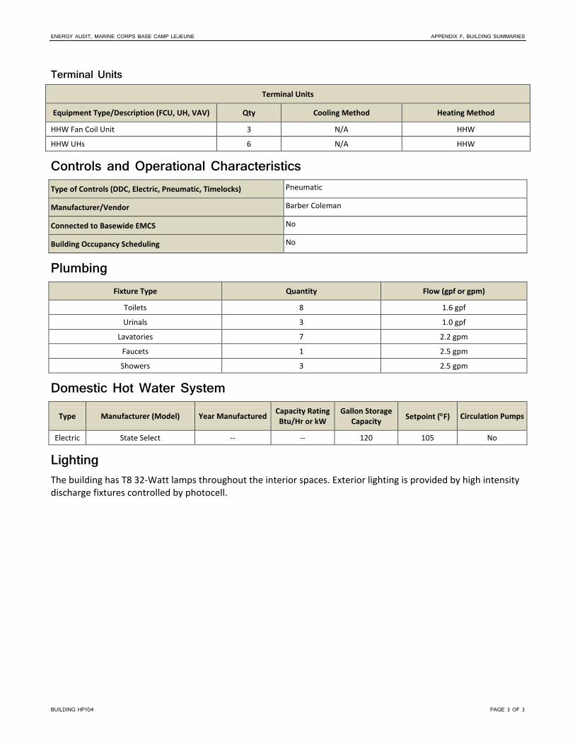
ENERGY AUDIT, MARINE CORPS BASE CAMP LEJEUNE APPENDIX F, BUILDING SUMMARIES
BUILDING HP104 PAGE 3 OF 3
Terminal Units
Terminal Units
Equipment Type/Description (FCU, UH, VAV) Qty Cooling Method Heating Method
HHW Fan Coil Unit 3 N/A HHW
HHW UHs 6 N/A HHW
Controls and Operational Characteristics Type of Controls (DDC, Electric, Pneumatic, Timelocks) Pneumatic
Manufacturer/Vendor Barber Coleman
Connected to Basewide EMCS No
Building Occupancy Scheduling No
Plumbing Fixture Type Quantity Flow (gpf or gpm)
Toilets 8 1.6 gpf
Urinals 3 1.0 gpf
Lavatories 7 2.2 gpm
Faucets 1 2.5 gpm
Showers 3 2.5 gpm
Domestic Hot Water System
Type Manufacturer (Model) Year Manufactured Capacity Rating Btu/Hr or kW
Gallon Storage Capacity Setpoint (°F) Circulation Pumps
Electric State Select -- -- 120 105 No
Lighting The building has T8 32-Watt lamps throughout the interior spaces. Exterior lighting is provided by high intensity discharge fixtures controlled by photocell.


BUILDING HP131 PAGE 1 OF 3
MCB Camp Lejeune Building HP131
General Description Building Function Armory
Location Hadnot Pt
Year Built 2003
Major Renovations
Square Footage 19,227
Energy Usage Intensity 83 MBtu/KSF
Building Occupancy 30 Occupants
Building Operational Hours Mon-Fri 0800-1700 hrs
Date and Time of Audit Start 11/8/2011, 1530 hrs
Observed Outside Air Temperature and Conditions
72°F, 50% RH
Building Envelope
Surface Construction Detail Insulation or Wall/Roof Assembly Thickness (inches) Height per Floor (feet)
Wall – Exterior CMU brick veneer 2" insulation 12'
Roof Built up, membrane 2" insulation N/A
Floor Concrete N/A N/A
Ceiling Exposed to concrete deck N/A 12'
Windows Size Approximate % Glazing Shading
Single pane; operable 1'x3' 5% No interior or exterior shading
Utilities
Type Present Yes or No
Metered Yes or No
Electric Yes Yes
Natural Gas No No
Propane No No
No. 2 Fuel Oil No No
Type Present Yes or No
Metered Yes or No
Diesel No No
District Steam No No
Water Yes No
Sewer Yes No

ENERGY AUDIT, MARINE CORPS BASE CAMP LEJEUNE APPENDIX F, BUILDING SUMMARIES
BUILDING HP131 PAGE 2 OF 3
HVAC Systems HVAC System Description The HVAC system consists of one central variable air volume (VAV) air-handling unit (AHU) utilizing variable frequency drive (VFD) fan motor control and direct expansion (DX) coils. The unit does not contain heating coils. The AHU is paired with two 20-ton DX air-cooled condensing units. The AHU supply fan motor nameplate was inaccessible at the time of the audit. A steam-to-hot water heat exchanger (HE-1) supplies the HHW system. The HHW system utilizes constant volume primary and secondary HHW pumps. The AHU supplies conditioned air to terminal VAV boxes with HHW reheat coils. The AHU, terminal units, HHW system, and exhaust fans (EFs) are controlled by a direct digital control (DDC) system.
Heating Hot Water or Steam System (Including Pumping) Boiler/Heat Exchanger Data
Tag Location Year Installed Manufacturer Model Fuel Steam/Hot
Water Steam Pressure
(psig) Boiler Type Input (MBH)
Output (MBH)
HE-1 Mech -- -- -- -- -- -- -- -- --
Hot Water System Pump Data
Tag Description Location Manufacturer Model Year Installed Constant or Variable Flow Head GPM
P-1 HW Primary Mech
P-2 HW Secondary Mech
Hot Water System Pump Motor Data
Tag Description Location Manufacturer Model Year Installed HP Voltage, Phase, Hertz, RLA RPM
P-1 HW Primary Mech
P-2 HW Secondary Mech
Air-Handling System Split-System AHUs or Package Units (DX Equipment)
Tag Location Year Installed Manufacturer Model System Type Heating Method MBH Economizer
AHU-1 Mech -- Trane TWE240B VAV None 240 No
Condensing Unit
Tag Location Serves AHU Year Installed Manufacturer Model SEER
CU-1 Outdoors AHU-1 Trane TTA240B30GEA
CU-2 Outdoors AHU-1 Trane TTA240B30GEA

ENERGY AUDIT, MARINE CORPS BASE CAMP LEJEUNE APPENDIX F, BUILDING SUMMARIES
BUILDING HP131 PAGE 3 OF 3
Terminal Units
Terminal Units
Equipment Type/Description (FCU, UH, VAV) Qty Cooling Method Heating Method
VAV boxes with reheat coils 4 -- HW
Controls and Operational Characteristics Type of Controls (DDC, Electric, Pneumatic, Timelocks) DDC
Manufacturer/Vendor --
Connected to Basewide EMCS --
Building Occupancy Scheduling --
Plumbing
Fixture Type Quantity Flow (gpf or gpm)
Toilets 3 1.6 gpf
Urinals 1 1.0 gpf
Lavatories 4 2.2 gpm
Faucets 1 3.0 gpm
Showers 2 2.5 gpm
Domestic Hot Water System
Type Manufacturer (Model)
Year Manufactured
Capacity Rating Btu/Hr or kW
Gallon Storage Capacity Setpoint (°F) Circulation Pumps
Electric Rheem -- 4,500 W 50 -- N
Lighting The building has T8 32-Watt lamps throughout the interior spaces. Exterior lighting is provided by switch-controlled T8 32-Watt lamps.


BUILDING HP413 PAGE 1 OF 3
MCB Camp Lejeune Building HP413
General Description Building Function Armory
Location Hadnot Pt
Year Built 2003
Major Renovations
Square Footage 19,227
Energy Usage Intensity 83 MBtu/KSF
Building Occupancy 20 Occupants
Building Operational Hours Mon-Fri 0800-1600 hrs
Date and Time of Audit Start 11/9/2011, 0915 hrs
Observed Outside Air Temperature and Conditions
65°F, 56% RH
Building Envelope
Surface Construction Detail Insulation or Wall/Roof Assembly Thickness (inches) Height per Floor (feet)
Wall – Exterior CMU brick veneer No insulation 12" wall 12"
Roof Built up, membrane -- N/A
Floor Concrete N/A N/A
Ceiling Exposed to concrete deck N/A 12'
Windows Size Approximate % Glazing Shading
Single pane; fixed 1'x3' 5% No interior shading; Closed shutters
Utilities
Type Present Yes or No
Metered Yes or No
Electric Yes Yes
Natural Gas No No
Propane No No
No. 2 Fuel Oil No No
Type Present Yes or No
Metered Yes or No
Diesel No No
District Steam No No
Water Yes No
Sewer Yes No

ENERGY AUDIT, MARINE CORPS BASE CAMP LEJEUNE APPENDIX F, BUILDING SUMMARIES
BUILDING HP413 PAGE 2 OF 3
HVAC Systems HVAC System Description The HVAC system consists of one central variable air volume (VAV) air-handling unit (AHU) utilizing variable frequency drive (VFD) fan motor control and direct expansion (DX) coils. The unit does not contain heating coils. The AHU is paired with a 35-ton DX air-cooled condensing unit. The heating hot water (HHW) system includes a steam heat exchanger and constant volume distribution pumps. The HHW pump and motor nameplates were inaccessible at the time of the audit. The AHU supplies conditioned air to terminal VAV boxes with HHW reheat coils. The AHU, terminal units, HHW system, and exhaust fans (EFs) are controlled by an electronic control system.
Heating Hot Water or Steam System (Including Pumping) HHW is produced by a steam-to-hot water heat exchanger.
Hot Water System Pump Data
Tag Description Location Manufacturer Model Year Installed Constant or Variable Flow Head GPM
P-1 & 2 Inline Mech Bell & Gossett Constant
Hot Water System Pump Motor Data
Tag Description Location Manufacturer Model Year Installed HP Voltage, Phase, Hertz, RLA RPM
P-1 & 2 motors Mech Marathon AVA56T17D5531B P 1 460/3/60 1725
Air-Handling System Split-System AHUs or Package Units (DX Equipment)
Tag Location Year Installed Manufacturer Model System Type Heating Method MBH Economizer
AHU-1 Mech Trane MCCB025 Split DX VAV None 420 No
Condensing Unit
Tag Location Serves AHU Year Installed Manufacturer Model SEER
CU-1 Outdoors AHU-1 Trane TTA240B300FB 11.1 EER
CU-2 Outdoors AHU-1 Trane TTA180B300EA 11.1 EER
Terminal Units
Terminal Units
Equipment Type/Description (FCU, UH, VAV) Qty Cooling Method Heating Method
VAV boxes w/ HW reheat HW

ENERGY AUDIT, MARINE CORPS BASE CAMP LEJEUNE APPENDIX F, BUILDING SUMMARIES
BUILDING HP413 PAGE 3 OF 3
Controls and Operational Characteristics Type of Controls (DDC, Electric, Pneumatic, Timelocks) Electric
Manufacturer/Vendor --
Connected to Basewide EMCS No
Building Occupancy Scheduling No
Plumbing
Fixture Type Quantity Flow (gpf or gpm)
Toilets 3 1.6 gpf
Urinals 2 1.0 gpf
Lavatories 4 2.2 gpm
Faucets 1 3.0 gpm
Showers 2 2.5 gpm
Domestic Hot Water System
Type Manufacturer (Model)
Year Manufactured
Capacity Rating Btu/Hr or kW
Gallon Storage Capacity Setpoint (°F) Circulation Pumps
Electric Rheem/RUUD -- 4,500 W 50 -- N
Lighting The building has T8 32-Watt lamps throughout the interior spaces. Exterior lighting is provided by switch-controlled T8 32-Watt lamps.


HP550_BEQ PAGE 1 OF 5
Building HP550 – Bachelor Enlisted Quarters (BEQ) (E1 – E4) General Description This building has 80 individual rooms that can house up to three Marines each. Each floor has a lounge area, a laundry room, a common head, and two mechanical rooms. The first floor also offers an office area. The building’s individual rooms are occupied during all times of day. While 90 percent of the individual rooms were occupied at the time of the audit, occupancy fluctuates depending on when the Marines are deployed. This building is served from the Building HP561 Utility Plant.
Building Function BEQ
Year Built /
Major Renovations
1978
Renovated 1991
Square Footage 46,656 SF
Energy Usage Intensity 30.9 MMBtu/kSF
Building Occupancy 80 Rooms
Building Operational Hours 24 / 7
Date
Time of Audit Start
14 Jul 2011
13:00
Observed Outside
Air Temperature
and Conditions
90°F
65% RH
Partly cloudy
Observed Interior Building Condition Measurements
(Room 111)
79°F / 63% RH
Average CO2: 559 ppm
Average Light Level: 40 FC
(Room 100) 81°F / 55% RH
Average CO2: 481 ppm
Average Light Level: 40 FC
Building Envelope Surface Construction Detail
Insulation/ Approx. Wall Thickness (inches)
Approx.% Glazing
Approx. Height per Floor (feet)
Wall – Exterior Concrete frame, CMU fill, with brick cladding 8 in. 5% 9 ft
Wall – Interior Exposed CMU mainly and brick cladding on first floor common area
8 in 0% 9 ft
Roof Hipped and shingled roof supported by wood trusses R‐38
Floor Coated concrete, carpet and tile
Ceiling ‐ Rooms Exposed concrete deck above ‐ ‐ 9 ft
Ceiling – Common Area
Acoustical ceiling tile ‐ ‐ 9 ft
Building HP550

ENERGY AUDIT, MARINE CORPS BASE CAMP LEJEUNE APPENDIX A, BUILDING SUMMARIES
HP550_BEQ PAGE 2 OF 5
Windows The windows have aluminum frames and double panes and are operable. The windows were not tinted but were fitted with curtains and blinds. The walkways also provide 5 feet of additional shading.
Utilities Type
Present Yes or No
Metered Yes or No
Electric Y Y
Natural Gas N N
Water Y N
HVAC Systems HVAC System Description The heating, ventilation, and air conditioning (HVAC) system consists of six variable air volume (VAV) air‐handling units (AHUs) with associated terminal VAV units and two ERVs to condition the majority of the building. Fan coil units (FCUs) are used to condition some of the core spaces. Most of the HVAC equipment appears to be in good operating condition.
The HVAC system is served by a dual‐temperature water (DTW) system (two‐pipe system) for heating hot water (HHW) or chilled water (CHW) depending on the season. The DTW loop is supplied through Building HP561. The DTW system serves the AHUs, ERVs, FCUs, and unit heaters.
Chilled Water System CHW is produced at a central chiller plant located in Building HP561. The chilled water serves each AHU through the DTW system.
Heating Hot Water or Steam System HHW is provided by a steam to hot water heat exchanger located in Building HP561. The HHW serves each AHU through the DTW system.
Air-Handling System One VAV AHU is located within each of the six mechanical rooms (two per floor). Each AHU serves VAV terminal boxes located in individual rooms. The AHUs provide heating and cooling through a DTW coil. The DTW coils use three‐way control valves. A variable frequency drive (VFD) controls the speed of each AHU supply fan. Most VFD controllers were found to be operating at 75 percent at the time of the site visit.
Outside air is brought into the building through one of two ERVs located in the attic space. The outside air is then directly ducted to each AHU, each of which has its own actuated outside air damper for control of air to the unit. Each ERV serves three AHUs. Each ERV includes a heat wheel, a DTW coil, an exhaust fan, and a supply air fan. The ERVs also serve as general exhaust for the building.
AHU Info. Design
Tag Location Year
Installed Mfr. and Model No. System Type
Cooling Method
Heating Method Economizer
Max CFM
Cooling Capacity (MBH)
Heating Capacity (MBH)
AHU1 Mech 1 1995 Trane
MCCA010 Variable Volume CHW HHW No 4,600 188 ‐‐
AHU2 Mech 2 1995 Trane
MCCA010 Variable Volume CHW HHW No 4,400 176 ‐‐

ENERGY AUDIT, MARINE CORPS BASE CAMP LEJEUNE APPENDIX A, BUILDING SUMMARIES
HP550_BEQ PAGE 3 OF 5
AHU Info. Design
Tag Location Year
Installed Mfr. and Model No. System Type
Cooling Method
Heating Method Economizer
Max CFM
Cooling Capacity (MBH)
Heating Capacity (MBH)
AHU3 Mech 3 1995 Trane
MCCA010 Variable Volume CHW HHW No 4,600 189 ‐‐
AHU4 Mech 4 1995 Trane
MCCA010 Variable Volume CHW HHW No 3,700 157 ‐‐
AHU5 Mech 5 1995 Trane
MCCA010 Variable Volume CHW HHW No 5,500 211 ‐‐
AHU6 Mech 6 1995 Trane
MCCA010 Variable Volume CHW HHW No 4,400 175 ‐‐
ERV1 Attic 2005 ‐‐ Variable Volume CHW HHW No ‐‐ ‐‐ ‐‐
ERV2 Attic 2005 ‐‐ Variable Volume CHW HHW No ‐‐ ‐‐ ‐‐
Tag
Supply Fan Motor
Year Installed Mfr. HP Efficiency Control Type
AHU1 1995 ‐‐ 5 ‐‐ VFD
AHU2 1995 ‐‐ 5 ‐‐ VFD
AHU3 1995 ‐‐ 3 ‐‐ VFD
AHU4 1995 ‐‐ 5 ‐‐ VFD
AHU5 1995 ‐‐ 5 ‐‐ VFD
AHU6 1995 ‐‐ 5 ‐‐ VFD
ERV‐1 2005 ‐‐ ‐‐ ‐‐ ‐‐
ERV‐2 2005 ‐‐ ‐‐ ‐‐ ‐‐
Terminal Units VAV Boxes The series fan‐powered terminal VAV boxes are air valves only and do not have reheat capability. One VAV box is provided for each BEQ room. Each VAV box is controlled by a Johnson Controls temperature sensor thermostat.
FCUs The Duty Office uses a floor‐mounted DTW FCU to provide heating and cooling. The recreational/lounge rooms located on each floor use ceiling‐mounted DTW FCUs.
Unit Heaters Each laundry room, with the exception of the large one on the first floor, has a UH which is connected to the DTW loop. The UH valve is designed to be closed in the summer months.
Exhaust Fans The main building exhaust is through the two ERVs located in the attic. Each laundry room has a small wall‐mounted exhaust fan for heat relief. The laundry room EFs are controlled by wall‐mounted manual thermostats. The EFs appeared in fair condition.

ENERGY AUDIT, MARINE CORPS BASE CAMP LEJEUNE APPENDIX A, BUILDING SUMMARIES
HP550_BEQ PAGE 4 OF 5
Controls and Operational Characteristics The building systems are controlled with a direct digital control (DDC) system, but the DDC system is not currently connected to the basewide energy management and control system (EMCS). The DDC controls operate to control the VFD on each AHU, the automatic dampers on supply, mixed, and outside air to each AHU, the three‐way valve on the coil, and each the damper on each VAV box in the space. The two‐pipe system in the building requires manual changeover. The building does not currently use schedules of occupancy.
Plumbing Fixture Type Quantity Flow (gpf or gpm)
Toilets 87 1.6
Urinals 0 ‐
Lavatories 87 2.0
Service Sinks 3 > 2.5
Showers 80 2.5
Washing Machines 16 ‐
Dryers 24 ‐
Domestic Hot Water System Domestic hot water is provided through a steam to hot water heat exchanger in Building HP561.
Electrical Systems A pad‐mounted transformer is located near the building. This transformer provides 208Y/120‐V, three‐phase, four‐wire service routed underground to the Main Distribution Panelboard (MDP) located in a first floor mechanical room. The MDP main circuit breaker is rated at 600‐ampere (A) with 10,000‐A interrupt capacity. The MDP contains six 200‐A circuit breakers and one 225‐A circuit breaker, which are connected to distribution panelboards. There is a 200‐A distribution panelboard located in each mechanical room: two per floor, three floors. The 225‐A circuit breaker powers a panelboard located in the duty NCO office on the first floor. The panelboards provide 120/208‐V power to HVAC, lighting, and receptacle loads located near the panelboards.
Lighting Interior Systems The typical room has a 2‐lamp fixture in the living room, sink area, and bathroom, as well as one floor lamp that uses an incandescent bulb. The remaining common areas have a variety of 3‐lamp and 2‐lamp fixtures as well as compact fluorescent lamps (CFLs). Half of the corridor lights are used for emergency egress and are wired to stay on continuously (the interior stairway lights are switch operated). The exit signs use light‐emitting diode (LED) lamps. Battery‐powered emergency lighting for emergency egress is provided in the interior corridors.
Fixture Type Fixture Size Lamps Controls FC Measurement
2‐Lamp 4 ft × 2 ft 32W T8 Manual 30
2‐Lamp 4 ft × 1 ft 32W T8 Manual; Always On 20
2‐Lamp 2 ft × ½ ft 17W T8 Manual 15
Incand Screw‐in 60W Manual 10
CFL 1 ft 26W CFL Manual 10
CFL 1 ft 13W CFL Manual 10

ENERGY AUDIT, MARINE CORPS BASE CAMP LEJEUNE APPENDIX A, BUILDING SUMMARIES
HP550_BEQ PAGE 5 OF 5
Exterior Systems Fixture Type Fixture Size Lamps Controls Qty
CFL1 1 ft Diameter 24W CFL Timer 75


HP560_BEQ PAGE 1 OF 4
Building HP560 – Bachelor Enlisted Quarters (BEQ) (E1 – E4) General Description This building has 82 individual rooms that can house up to three Marines each. Each floor has a lounge area, a laundry room, a common head, and two mechanical rooms. The first floor also offers an office area. The building’s individual rooms are occupied during all times of day. The individual rooms are generally occupied 90 percent of the year. This building is served from the Building HP561 Utility Plant.
Building Function BEQ
Year Built /
Major Renovations
1978
Renovated 2003, 2010
Square Footage 46,656 SF
Energy Usage Intensity 30.9 MMBtu/kSF
Building Occupancy 82 Rooms
Building Operational Hours 24 / 7
Date
Time of Audit Start
14 Jul 2011
10:00
Observed Outside
Air Temperature
and Conditions
85°F
65% RH
Partly cloudy
Observed Interior Building Condition Measurements
(Room 112)
78°F / 59% RH
Average CO2: 1020 ppm
Average Light Level: 40 FC
Building Envelope Surface Construction Detail
Insulation/ Approx. Wall Thickness (inches)
Approx.% Glazing
Approx. Height per Floor (feet)
Wall – Exterior Concrete frame, CMU fill, with brick cladding 8in. 5% 9 ft
Wall – Interior Exposed CMU mainly and brick cladding on first floor common area
8 in. 0% 9 ft
Roof Hipped and shingled roof supported by wood trusses R‐38
Floor Coated concrete, carpet, and tile
Ceiling ‐ Rooms Exposed concrete deck above ‐ ‐ 9 ft
Ceiling – Common Area Acoustical ceiling tile ‐ ‐ 8 ft
Windows The windows have aluminum frames and double panes and are operable. The windows were not tinted but were fitted with curtains and blinds. The walkways also provide 5 feet of additional shading.
Building HP560

ENERGY AUDIT, MARINE CORPS BASE CAMP LEJEUNE APPENDIX A, BUILDING SUMMARIES
HP560_BEQ PAGE 2 OF 4
Utilities Type
Present Yes or No
Metered Yes or No
Electric Y Y
Natural Gas N N
Water Y N
HVAC Systems HVAC System Description The heating, ventilation, and air conditioning (HVAC) system consists of six variable air volume (VAV) air‐handling units (AHUs) with associated terminal VAV units and two ERVs to condition the majority of the building. Fan coil units (FCUs) are used to condition some of the core spaces. Most of the HVAC equipment appears to be in good operating condition.
The HVAC system is served by a dual‐temperature water (DTW) system (two‐pipe system) for heating hot water (HHW) or chilled water (CHW) depending on the season. The DTW loop is supplied through Building HP561. The DTW system serves the AHUs, ERVs, FCUs, and unit heaters.
Chilled Water System CHW is produced at a central chiller plant located in Building HP561. The chilled water serves each AHU through the DTW system.
Heating Hot Water System HHW is provided by a steam to hot water heat exchanger located in Building HP561. The HHW serves each AHU through the DTW system.
Air-Handling System One VAV AHU is located within each of the six mechanical rooms (two per floor). Each AHU serves VAV terminal boxes located in individual rooms. The AHUs provide heating and cooling through a DTW coil. The DTW coils use three‐way control valves. Each AHU supply fan uses a variable frequency drive (VFD) to control the fan speed. Most VFD controllers were found to be operating at 75 percent at the time of the site visit.
Outside air is brought into the building through one of two ERVs located in the attic space. The outside air is then directly ducted to each AHU, each of which has its own actuated outside air damper for control of air to the unit. Each ERV serves three AHUs. Each ERV includes a heat wheel, a DTW coil, an exhaust fan and a supply air fan. The ERVs also serve as general exhaust for the building.
AHU Info. Design
Tag Location Year
Installed Mfr. and Model No. System Type
Cooling Method
Heating Method Economizer Max CFM
Cooling Capacity (MBH)
Heating Capacity (MBH)
AHU1 Mech 1 1994 Trane
MCCA010 Variable Volume CHW HHW No 4,400 182 ‐‐
AHU2 Mech 2 1994 Trane
MCCA010 Variable Volume CHW HHW No 3,700 156 ‐‐
AHU3 Mech 3 1994 Trane
MCCA010 Variable Volume CHW HHW No 4,700 192 ‐‐
AHU4 Mech 4 1994 Trane
MCCA010 Variable Volume CHW HHW No 3,700 155 ‐‐

ENERGY AUDIT, MARINE CORPS BASE CAMP LEJEUNE APPENDIX A, BUILDING SUMMARIES
HP560_BEQ PAGE 3 OF 4
AHU Info. Design
Tag Location Year
Installed Mfr. and Model No. System Type
Cooling Method
Heating Method Economizer Max CFM
Cooling Capacity (MBH)
Heating Capacity (MBH)
AHU5 Mech 5 1994 Trane
MCCA010 Variable Volume CHW HHW No 5,500 211 ‐‐
AHU6 Mech 6 1994 Trane
MCCA010 Variable Volume CHW HHW No 4,400 175 ‐‐
ERV1 Attic 2005 ‐‐ Variable Volume CHW HHW No ‐‐ ‐‐ ‐‐
ERV2 Attic 2005 ‐‐ Variable Volume CHW HHW No ‐‐ ‐‐ ‐‐
Tag
Supply Fan Motor
Year Installed Mfr. HP Efficiency Control Type
AHU1 1994 ‐‐ 5 ‐‐ VFD
AHU2 1994 ‐‐ 3 ‐‐ VFD
AHU3 1994 ‐‐ 5 ‐‐ VFD
AHU4 1994 ‐‐ 3 ‐‐ VFD
AHU5 1994 ‐‐ 5 ‐‐ VFD
AHU6 1994 ‐‐ 5 ‐‐ VFD
ERV1 2005 ‐‐ ‐‐ ‐‐ ‐‐
ERV2 2005 ‐‐ ‐‐ ‐‐ ‐‐
Terminal Units VAV Boxes The series fan‐powered terminal VAV boxes are air valves only and do not have reheat capability. One VAV box is provided for each BEQ room. Each VAV box is controlled by a Johnson Controls temperature sensor thermostat.
FCUs The Duty Office uses a floor‐mounted DTW FCU to provide heating and cooling. The recreational/lounge rooms located on each floor use ceiling‐mounted DTW FCUs.
Unit Heaters Each laundry room, with the exception of the large one on the first floor, has a UH that is connected to the DTW loop. The UH valve is designed to be closed in the summer months.
Exhaust Fans The main building exhaust is through the two ERVs located in the attic. Each laundry room has a small wall‐mounted exhaust fan (EF) for heat relief. The laundry room EFs are controlled by wall‐mounted manual thermostats. The EFs appeared in fair condition.
Controls and Operational Characteristics The buildings is controlled through DDC controls, but not currently connected to the basewide EMCS. The DDC controls operate to control the VFD on each AHU, the automatic dampers on supply, mixed, and outside air to each AHU, the three‐way valve on the coil, and each the damper on each VAV box in the space. The two‐pipe system in the building requires manual changeover. The building does not currently use schedules of occupancy.

ENERGY AUDIT, MARINE CORPS BASE CAMP LEJEUNE APPENDIX A, BUILDING SUMMARIES
HP560_BEQ PAGE 4 OF 4
Plumbing Fixture Type Quantity Flow (gpf or gpm)
Toilets 90 1.6
Urinals 0 ‐
Lavatories 90 2.0
Service Sinks 3 > 2.5
Showers 82 2.5
Washing Machines 16 ‐
Dryers 24 ‐
Domestic Hot Water System Domestic hot water is provided through a steam to hot water heat exchanger in Building HP561.
Electrical Systems A pad‐mounted transformer is located near the building. This transformer provides 208Y/120‐V, three‐phase, four‐wire service routed underground to the Main Distribution Panelboard (MDP) located in a first floor mechanical room. The MDP main circuit breaker is rated at 600‐ampere (A) with 10,000‐A interrupt capacity. The MDP contains six 200‐A circuit breakers and one 225‐A circuit breaker, which are connected to distribution panelboards. There is a 200‐A distribution panelboard located in each mechanical room: two per floor, three floors. The 225‐A circuit breaker powers a panelboard located in the Duty Office on the first floor. These panelboards provide 120/208‐V power to HVAC, lighting, and receptacle loads located near the panelboards.
Lighting Interior Systems The typical room has a 2‐lamp fixture in the living room, sink area, and bathroom, as well as one floor lamp that uses an incandescent bulb. The remaining common areas have a variety of 3‐lamp and 2‐lamp fixtures as well as compact fluorescent lamps (CFLs). Half of the corridor lights are used for emergency egress and are wired to stay on continuously (the interior stairway lights are switch operated). The exit signs use light‐emitting diode (LED) lamps. Battery‐powered emergency lighting for emergency egress is provided in the interior corridors.
Fixture Type Fixture Size Lamps Controls FC Measurement
2‐Lamp 4 ft × 2 ft 32W T8 Manual 30
2‐Lamp 4 ft × 1 ft 32W T8 Manual; Always On 20
2‐Lamp 2 ft × ½ ft 17W T8 Manual 15
Incand Screw‐in 60W Manual 10
CFL 1 ft 26W CFL Manual 10
CFL 1 ft 13W CFL Manual 10
Exterior Systems Fixture Type Fixture Size Lamps Controls Qty
CFL 1 ft diameter 24W CFL Timer 75

BUILDING HP576 PAGE 1 OF 3
MCB Camp Lejeune Building HP576
General Description Building Function Armory
Location Hadnot Pt
Year Built 2007
Major Renovations
Square Footage 8,737
Energy Usage Intensity 81 MBtu/KSF
Building Occupancy 20 Occupants
Building Operational Hours Mon-Fri 0730-1600 hrs
Date and Time of Audit Start 11/15/2011, 1330 hrs
Observed Outside Air Temperature and Conditions
78°F, 50% RH
Building Envelope
Surface Construction Detail Insulation or Wall/Roof Assembly Thickness (inches) Height per Floor (feet)
Wall – Exterior CMU brick veneer 12" wall with insulation 12'
Roof Built up, membrane Insulated N/A
Floor Concrete N/A N/A
Ceiling Exposed to concrete deck N/A 12'
Windows Size Approximate % Glazing Shading
Single pane: fixed 1'x3' 2% No interior shading; Closed shutters
Utilities
Type Present Yes or No
Metered Yes or No
Electric Yes No
Natural Gas No No
Propane No No
No. 2 Fuel Oil No No
Type Present Yes or No
Metered Yes or No
Diesel No No
District Steam No No
Water Yes No
Sewer Yes No

ENERGY AUDIT, MARINE CORPS BASE CAMP LEJEUNE APPENDIX F, BUILDING SUMMARIES
BUILDING HP576 PAGE 2 OF 3
HVAC Systems HVAC System Description The HVAC system consists of one central variable air volume (VAV) air-handling unit (AHU) utilizing variable frequency drive (VFD) fan motor control and direct expansion (DX) coils. Unit does not contain heating coils. The AHU is paired with a 16-ton DX air-cooled condensing unit. The heating hot water (HHW) system includes a steam heat exchanger and constant volume distribution pumps. The HHW pump nameplate was inaccessible at the time of the audit. The AHU supplies conditioned air to terminal VAV boxes with HHW reheat coils. The AHU, terminal units, HHW system, and exhaust fans (EFs) are controlled by a direct digital control (DDC) system.
Heating Hot Water or Steam System (Including Pumping) HHW is produced by a steam to hot water heat exchanger.
Hot Water System Pump Data
Tag Description Location Manufacturer Model Year Installed Constant or Variable Flow Head GPM
HWP-1 Inline Mech No access Constant
Hot Water System Pump Motor Data
Tag Description Location Manufacturer Model Year Installed HP Voltage, Phase, Hertz, RLA RPM
HWP-1 motor Mech Marathon CQF 56C17D5537E P 3/4 115/1/60 1725
Air-Handling System Split-System AHUs or Package Units (DX Equipment)
Tag Location Year Installed Manufacturer Model System Type Heating Method MBH Economizer
AHU-1 Mech McQuay DX VAV AHU HW preheat 185 No
AC-2 Indoors Mitsubishi Ductless Split AC N/A 9 No
AC-3 Indoors Mitsubishi Ductless Split AC N/A 9 No
Condensing Unit
Tag Location Serves AHU Year Installed Manufacturer Model SEER
CU-1 Outdoors AHU-1 McQuay ACZ016ACS12 11.3 EER
DSCU-2 Outdoors AC-2 Mitsubishi MUA09WA 13 SEER
DSCU-3 Outdoors AC-3 Mitsubishi MUA09WA 13 SEER
Terminal Units
Terminal Units
Equipment Type/Description (FCU, UH, VAV) Qty Cooling Method Heating Method
VAV boxes w/ HW reheat HW

ENERGY AUDIT, MARINE CORPS BASE CAMP LEJEUNE APPENDIX F, BUILDING SUMMARIES
BUILDING HP576 PAGE 3 OF 3
Controls and Operational Characteristics Type of Controls (DDC, Electric, Pneumatic, Timelocks) Electric
Manufacturer/Vendor --
Connected to Basewide EMCS No
Building Occupancy Scheduling No
Plumbing
Fixture Type Quantity Flow (gpf or gpm)
Toilets 2 1.6 gpf
Urinals 1 1.0 gpf
Lavatories 2 2.0 gpm
Faucets 1 2.5 gpm
Showers 0 N/A
Domestic Hot Water System
Type Manufacturer (Model)
Year Manufactured
Capacity Rating Btu/Hr or kW
Gallon Storage Capacity Setpoint (°F) Circulation Pumps
Electric State Select -- 4,500 W 50 -- N
Lighting The building has T8 32-Watt lamps throughout the interior spaces. Exterior lighting is provided by switch-controlled T8 32-Watt lamps.


GFI011013043257ATL PAGE 1 OF 4
Camp Lejeune Building HP1017 General Description
Building Name EXC INSTALL WAREHOUSE
Building Function Warehouse
Year Built 1992
Major Renovations 2003
Square Footage 16,856
Energy Usage Intensity 97.2
Building Occupancy 15‐20 Occupants
Building Operational Hours 0700‐1600, Mon‐Fri
Date and Time of Audit Start 25 Sept 2012, 1015 hrs
Observed Outside Air Temperature and Conditions
80F, 36% RH
Building Envelope Surface Construction Detail
Insulation or Wall/Roof Assembly Thickness (inches)
Height per Floor (feet)
Wall – Exterior Office ‐ CMU with stucco veneer
Warehouse ‐ Steel girder with metal siding
Insulated panels 21'
Roof Standing seam metal Insulated panels N/A
Floor Office – Vinyl tile and carpet
Warehouse ‐ Concrete
N/A N/A
Ceiling Office – Acoustic ceiling tile
Warehouse ‐ Open to structure
N/A Office ‐ 8.5'
Warehouse ‐ 23'
Window Type Frame Type Size Operable or Fixed % Glazing of Exterior Wall Tint Shading
Double and single pane Aluminum 2' x 2', 4' x 3', 4' x 5'
Operable and fixed 5 No Interior –blinds;
Exterior ‐overhangs
Utilities Type
Present (Yes or No)
Metered (Yes or No)
Electric Yes No
Natural Gas No No
Propane No No
Diesel/No. 2 Fuel Oil No No
Type Present
(Yes or No) Metered (Yes or No)
District Steam No No
Water Yes No
Sewer Yes No

MARINE CORPS BASE CAMP LEJEUNE BUILDING HP1017
GFI011013043257ATL PAGE 2 OF 4
Lighting Interior Systems Lighting in the majority of the building, in both office and warehouse mezzanine spaces, is provided by 34‐Watt (W) T12 lamps. A few lamps have been changed out to 32W T8 lamps. The warehouse area has a combination of 150W high‐pressure sodium (HPS) and 150W metal halide fixtures. All lighting is switch controlled.
Exterior Systems Exterior lighting is provided by 150W HPS fixtures that are photocell controlled.
Plumbing Fixture Type Quantity
Flow (gpf or gpm)
Notes
Toilets 4 3.0 gpf
Urinals 2 2.0 gpf
Lavatories 4 2.0 gpm
Showers 1 2.0 gpm
Janitor/Service Sink 1 5.0 gpm
Other Drinking Fountains (2)
Domestic Hot Water System
Type Manufacturer/Model Year
Manufactured Capacity Rating (Btu/Hr or kW)
Storage Capacity (Gallons)
Setpoint
(F) Circulation Pumps
Electric Tank Rheem/8IV‐30D ‐‐ 4.5 kW 30 ‐‐ ‐‐
HVAC Systems HVAC System Description The office spaces are served by one air‐handling unit (AHU) that uses a direct expansion (DX) condenser and heating hot water (HHW). HHW is produced from a steam‐to‐hot water heat exchanger. The warehouse area is served by eight steam unit heaters. The heating, ventilation, and air conditioning (HVAC) system is controlled by thermostats. Exhaust fans provide restroom exhaust air relief.
Air-Handling System Split‐System AHUs or Package Units (DX Equipment)
Tag Year
Installed Manufacturer / Model Serial No. System Type
Total Cooling Capacity (MBH)
Heating Method and Capacity (MBH/kW)
AHU1 1991 Intercity Products/ B08003 R91490094 Split System 60 ‐
Condensing Units
Tag Serves AHU
Year Installed
Manufacturer/Model Serial No. Type
Accc1 AHU1 1992 Inter City Products/C080G0 R012050034 Heat Pump

MARINE CORPS BASE CAMP LEJEUNE BUILDING HP1017
GFI011013043257ATL PAGE 3 OF 4
Terminal Units Terminal Units
Equipment Type/Description Qty Cooling Method Heating Method
Steam Unit Heaters 8 ‐‐ Steam
Window AC Units 2 Electric (12 MBH) ‐
Controls and Operational Characteristics Type of Controls (DDC, Electric, Pneumatic, Time Clocks, Etc) Thermostat
Manufacturer/Vendor Honeywell

MARINE CORPS BASE CAMP LEJEUNE BUILDING HP1017
GFI011013043257ATL PAGE 4 OF 4
This page is intentionally left blank.

BUILDING FC40 PAGE 1 OF 2
MCB Camp Lejeune Building FC40
General Description Building Function Auto Shop
Location French Creek
Year Built 1986
Major Renovations
Square Footage 11,960
Energy Usage Intensity 44 MBtu/KSF
Building Occupancy 60 Occupants
Building Operational Hours Mon-Fri 0730-1630 hrs
Date and Time of Audit Start 1/18/2012, 1400 hrs
Observed Outside Air Temperature and Conditions
56°F, 52% RH
Building Envelope
Surface Construction Detail Insulation or Wall/Roof Assembly Thickness (inches) Height per Floor (feet)
Wall – Exterior CMU brick veneer R12 10'
Roof Flat with EPDM membrane 3" insulation N/A
Floor Tile and concrete N/A N/A
Ceiling Acoustical tile N/A 8'
Window Panes Size % Glazing Shading
Double pane; operable 3'x3' 10% Tinting; No exterior
Utilities
Type Present Yes or No
Metered Yes or No
Electric Yes No
Natural Gas No No
Propane No No
No. 2 Fuel Oil No No
Type Present Yes or No
Metered Yes or No
Diesel No No
District Steam No No
Water Yes No
Sewer Yes No

ENERGY AUDIT, MARINE CORPS BASE CAMP LEJEUNE APPENDIX F, BUILDING SUMMARIES
BUILDING FC40 PAGE 2 OF 2
HVAC Systems HVAC System Description The HVAC system consists of two rooftop units (RTUs) that serve the administration and office areas. The bay areas are heated by hot water unit heaters (HWUHs). The heating hot water (HHW) system includes a steam-to-HHW heat exchanger (HX). The nameplate for the HHW system was inaccessible during the site visit. Exhaust fans (EFs) provide restroom and general building exhaust air relief. The RTUs are controlled with electric thermostats.
Air-Handling System Split-System AHUs or Package Units (DX Equipment)
Tag Location Year Installed Manufacturer Model System Type
Total Cooling Capacity (MBH)
Heating Method and
Capacity (MBH) Economizer
RTU-1 Roof -- Goodman PH13048-3 Package -- HP No
RTU-2 Roof -- Bard P1136A1-B Package -- HP – 5 kW No
Terminal Units
Terminal Units
Equipment Type/Description (FCU, UH, VAV) Qty Cooling Method and Capacity (MBH)
Heating Method and Capacity (MBH)
Hot Water Unit Heaters 10~ -- HW
Controls and Operational Characteristics Type of Controls (DDC, Electric, Pneumatic, Timelocks) Electric
Manufacturer/Vendor --
Connected to Basewide EMCS No
Building Occupancy Scheduling No
Plumbing Fixture Type Quantity Flow (gpf or gpm)
Toilets 5 3.0 gpf
Urinals 2 2.0 gpf
Lavatories 5 2.0 gpm
Faucets 2 2.0 gpm
Showers 3 3.0 gpm
Domestic Hot Water System The nameplate for the HX was inaccessible during the site visit.
Lighting The building has T8 32-Watt lamps through the interior spaces. The large bay has 150-Watt high-pressure sodium lighting throughout the area. Exterior lighting is provided by high-intensity discharge lamps that are controlled by a photocell.

BUILDING FC45 PAGE 1 OF 2
MCB Camp Lejeune Building FC45
General Description Building Function Construction/Weight Hand Shop
Location French Creek
Year Built 1990
Major Renovations 1997
Square Footage 19,320
Energy Usage Intensity 41 MBtu/KSF
Building Occupancy 45 Occupants
Building Operational Hours Mon-Fri 0700-1630 hrs
Date and Time of Audit Start 1/19/2012, 1245 hrs
Observed Outside Air Temperature and Conditions
50°F
Building Envelope
Surface Construction Detail Insulation or Wall/Roof Assembly Thickness (inches) Height per Floor (feet)
Wall – Exterior CMU brick veneer and stucco R12 12'
Roof Flat with EPDM membrane R20 N/A
Floor Concrete N/A N/A
Ceiling Exposed in bay areas, acoustical in office areas
N/A 8'
Window Panes Size % Glazing Shading
Double pane; operable 2'x3' 10% Tinting and blinds; No exterior
Utilities
Type Present Yes or No
Metered Yes or No
Electric Yes Yes
Natural Gas No No
Propane No No
No. 2 Fuel Oil No No
Type Present Yes or No
Metered Yes or No
Diesel No No
District Steam Yes No
Water Yes No
Sewer Yes No

ENERGY AUDIT, MARINE CORPS BASE CAMP LEJEUNE APPENDIX F, BUILDING SUMMARIES
BUILDING FC45 PAGE 2 OF 2
HVAC Systems HVAC System Description The HVAC system consists of two rooftop units (RTUs) that serve the administration and office areas. The bay areas are heated by hot water unit heaters (HWUHs). The heating hot water (HHW) system includes a steam-to-HHW heat exchanger (HX). Exhaust fans (EFs) provide restroom and general building exhaust air relief. The RTUs are controlled with electric thermostats. The nameplates for the HX and HHW pump were inaccessible at the time of the site visit.
Heating Hot Water or Steam System (Including Pumping) Boiler/Heat Exchanger Data
Hot Water System Pump Motor Data
Tag Description Location Manufacturer Model Year Installed HP Voltage, Phase, Hertz, RLA RPM
HWP-1 -- -- -- -- -- ½ 120 V/3 phase 1725
Air-Handling System Split-System AHUs or Package Units (DX Equipment)
Tag Location Year Installed Manufacturer Model System
Type Total Cooling
Capacity (MBH) Heating Method
and Capacity (MBH) Economizer
RTU-1 Roof -- Trane -- Package -- HP No
Controls and Operational Characteristics Type of Controls (DDC, Electric, Pneumatic, Timelocks) Electric
Manufacturer/Vendor --
Connected to Basewide EMCS No
Building Occupancy Scheduling No
Plumbing Fixture Type Quantity Flow (gpf or gpm)
Toilets 5 3 gpf
Urinals 2 1.0 gpf
Lavatories 6 2 gpm
Faucets 2 2.5 gpm
Showers 5 2.5 gpm
Domestic Hot Water System The steam-to-HHW HX was inaccessible during the site visit.
Lighting The building has T8 32-Watt lamps throughout the interior spaces. Exterior lighting is provided by high-intensity discharge fixtures.

BUILDING FC51 PAGE 1 OF 3
MCB Camp Lejeune Building FC51
General Description
Building Function ElecNX/Comm Maintenance Shop
Location French Creek
Year Built 1993
Major Renovations 2004
Square Footage 19,912
Energy Usage Intensity 66 MBtu/KSF
Building Occupancy 70 Occupants
Building Operational Hours Mon-Fri 0700-1700 hrs
Date and Time of Audit Start 1/19/2012, 1400 hrs
Observed Outside Air Temperature and Conditions
63°F, 35% RH
Building Envelope
Surface Construction Detail Insulation or Wall/Roof Assembly Thickness (inches) Height per Floor (feet)
Wall – Exterior CMU brick veneer R12 16'
Roof Flat with EPDM membrane R20 N/A
Floor Tile and concrete N/A N/A
Ceiling Exposed in bay areas, acoustical tile in office areas
N/A 9'
Window Panes Size % Glazing Shading
Double pane; operable 4'x4' 10% Tinting and blinds; No exterior
Utilities
Type Present Yes or No
Metered Yes or No
Electric Yes Yes
Natural Gas No No
Propane No No
No. 2 Fuel Oil No No
Type Present Yes or No
Metered Yes or No
Diesel No No
District Steam Yes No
Water Yes No
Sewer Yes No

ENERGY AUDIT, MARINE CORPS BASE CAMP LEJEUNE APPENDIX F, BUILDING SUMMARIES
BUILDING FC51 PAGE 2 OF 3
HVAC Systems HVAC System Description The HVAC system consists of three central constant air volume (CAV) and one multi-zone (MZ) air-handling units (AHUs). The supply air is conditioned by dual temperature water (DTW) coils within the AHU utilizing chilled water (CHW) or heating hot water (HHW) depending on the season. The CHW is supplied by an 80-ton air-cooled chiller and constant volume CHW pump. The HHW system includes a steam-to-HHW heat exchanger (HX) and constant volume HHW pump. Exhaust fans (EFs) provide restroom and general building exhaust air relief. The AHUs are controlled by an electric control system.
Chilled Water System (Including Pumping) Chiller Data
Tag Location Year Installed Manufacturer Model Chiller Type Compressor Type Capacity (Tons)
Chiiler Outside -- Trane CGAM0802A02 Air-cooled -- 80
Chilled Water System Pump Data
Tag Description Location Manufacturer Model Year Installed Constant or Variable Flow Head GPM
P1 CHWP Mech. Taco -- -- Constant -- --
P2 Dual Pump Mech. -- -- -- Constant -- --
Chilled System Pump Motor Data
Tag Description Location Manufacturer Model Year Installed HP Voltage, Phase, Hertz, RLA RPM
P1 Mech. -- -- -- -- -- --
P2 Mech. Baldor -- -- 5 200/3/60 1725
Heating Hot Water or Steam System (Including Pumping) The HHW system was inaccessible at the time of the site visit.
Air-Handling System Air Handling Units
Tag Location Year Installed
Manufacturer (Model)
System Type
Cooling Method
Heating Method Economizer Max
CFM
Total Cooling Capacity (MBH)
Heating Capacity (MBH)
AHU – 1 Mech. Room Trane CAV CHW HW No -- -- --
AHU – 2 Mech. Room Trane CAV CHW HW No -- -- --
AHU – 3 Mech. Room Trane CAV CHW HW No -- -- --
AHU – 4 Mech. Room Trane MZ CHW HW No -- -- --

ENERGY AUDIT, MARINE CORPS BASE CAMP LEJEUNE APPENDIX F, BUILDING SUMMARIES
BUILDING FC51 PAGE 3 OF 3
Controls and Operational Characteristics Type of Controls (DDC, Electric, Pneumatic, Timelocks) Electric
Manufacturer/Vendor --
Connected to Basewide EMCS No
Building Occupancy Scheduling No
Plumbing
Fixture Type Quantity Flow (gpf or gpm)
Toilets 7 3 gpf
Urinals 4 1.0 gpf
Lavatories 6 2.2 gpm
Faucets 2 2.5 gpm
Showers 5 3.0 gpm
Domestic Hot Water System The steam-to-HHW HX was inaccessible at the time of the site visit.
Lighting The building has T8 fixtures with a mixture of 17-Watt and 32-Watt lamps throughout the interior spaces. Exterior lighting is provided by high-intensity discharge fixtures.


BUILDING FC100 PAGE 1 OF 3
MCB Camp Lejeune Building FC100
General Description Building Function Auto Shop
Location French Creek
Year Built 1965
Major Renovations 2006
Square Footage 31,160
Energy Usage Intensity 43 MBtu/KSF
Building Occupancy 50 Occupants
Building Operational Hours Mon-Fri 0700-1600 hrs
Date and Time of Audit Start 1/17/2012, 0730 hrs
Observed Outside Air Temperature and Conditions
39°F, 65% RH
Building Envelope
Surface Construction Detail Insulation or Wall/Roof Assembly Thickness (inches) Height per Floor (feet)
Wall – Exterior Precast concrete frame, CMU with brick veneer
R13 14' to 19'6"
Roof Built-up Roof, painted white R30 N/A
Floor Exposed concrete throughout N/A N/A
Ceiling Acoustical ceiling tile in corridors, exposed in all other areas
N/A 9'
Window Panes Size % Glazing Shading
Double pane; operable 5'x5' 5% Tinting and Curtains; No exterior
Utilities
Type Present Yes or No
Metered Yes or No
Electric Yes Yes
Natural Gas No No
Propane No No
No. 2 Fuel Oil No No
Type Present Yes or No
Metered Yes or No
Diesel No No
District Steam Yes No
Water Yes No
Sewer Yes No

ENERGY AUDIT, MARINE CORPS BASE CAMP LEJEUNE APPENDIX F, BUILDING SUMMARIES
BUILDING FC100 PAGE 2 OF 3
HVAC Systems HVAC System Description The HVAC system consists of four split-system air-handling units (AHUs) that utilize direct expansion (DX) coils and condensing units for air conditioning, and heating hot water (HHW) coils for heat to condition administrative rooms of the building. HHW unit heaters (UHs) provide heat to the maintenance areas of the building. HHW is produced in the mechanical room using a steam-to-HHW heat exchanger (HX); from there, the HHW is circulated through the building with a constant volume HHW pump. Exhaust fans (EFs) provide restroom and general building exhaust air relief. Additional EFs are used in the maintenance bay areas for vehicle exhaust. The split-system AHUs are controlled by programmable thermostats. The other systems are controlled by local thermostats in the areas served by the system.
Heating Hot Water or Steam System (Including Pumping) HHW is produced by a steam-to-hot water heat exchanger.
Hot Water System Pump Data
Tag Description Location Manufacturer Model Year Installed Constant or Variable Flow Head GPM
HHW Pump Mech. East -- -- -- Constant -- --
Hot Water System Pump Motor Data
Tag Description Location Manufacturer Model Year Installed HP Voltage, Phase, Hertz, RLA RPM
HHW Pump Motor Mech. East -- -- -- -- -- --
Air-Handling System Split-System AHUs or Package Units (DX Equipment)
Tag Location Year Installed Manufacturer Model System
Type
Total Cooling Capacity (MBH)
Heating Method and
Capacity (MBH)
Economizer
AHU – 1 Mech. – Room 134 2002 Trane TWE240B300CA Split 20 ton HHW No
AHU – 2 Mech. – Room 135 2002 Trane TWE090A300DA Split 7.5 ton HHW No
AHU – 3 Mech. – Room 132 2002 Trane TWE180B300CA Split 15 ton HHW No
AHU – 4 Mech. – Room 132 2002 Trane TWE180B300CA Split 15 ton HHW No
Condensing Unit
Tag Location Serves AHU Year Installed Manufacturer Model SEER
CU – 1 Exterior – NW Corner AHU – 1 2002 Trane TTA240B300EA --
CU – 2 Exterior – N Center AHU – 2 2002 Trane TTA072D300A0 --
CU – 3 Exterior – NE Corner AHU – 3 2002 Trane TTA150B300DA --
CU – 4 Exterior – NE Corner AHU – 4 2002 Trane TTA150B300DA --

ENERGY AUDIT, MARINE CORPS BASE CAMP LEJEUNE APPENDIX F, BUILDING SUMMARIES
BUILDING FC100 PAGE 3 OF 3
Terminal Units
Terminal Units
Equipment Type/Description (FCU, UH, VAV) Qty Cooling Method Heating Method
UH, HHW Fan Powered 14 N/A HHW
Controls and Operational Characteristics Type of Controls (DDC, Electric, Pneumatic, Timelocks) Electric, programable TSTAT
Manufacturer/Vendor --
Connected to Basewide EMCS No
Building Occupancy Scheduling No
Plumbing Fixture Type Quantity Flow (gpf or gpm)
Toilets 12 1.6 gpf
Urinals 4 1.0 gpf
Lavatories 9 2.2 gpm
Faucets 0 N/A
Showers 4 2.5 gpm
Domestic Hot Water System
Type Manufacturer (Model)
Year Manufactured
Capacity Rating Btu/Hr or kW
Gallon Storage Capacity Setpoint (°F) Circulation Pumps
Electric State Select P64020RSX -- 4.5 kW 40 115 --
Lighting The building has T8 32-Watt lamps throughout the building including office and bay areas. The exterior lights are high-intensity discharge fixtures controlled by an exterior photocell.

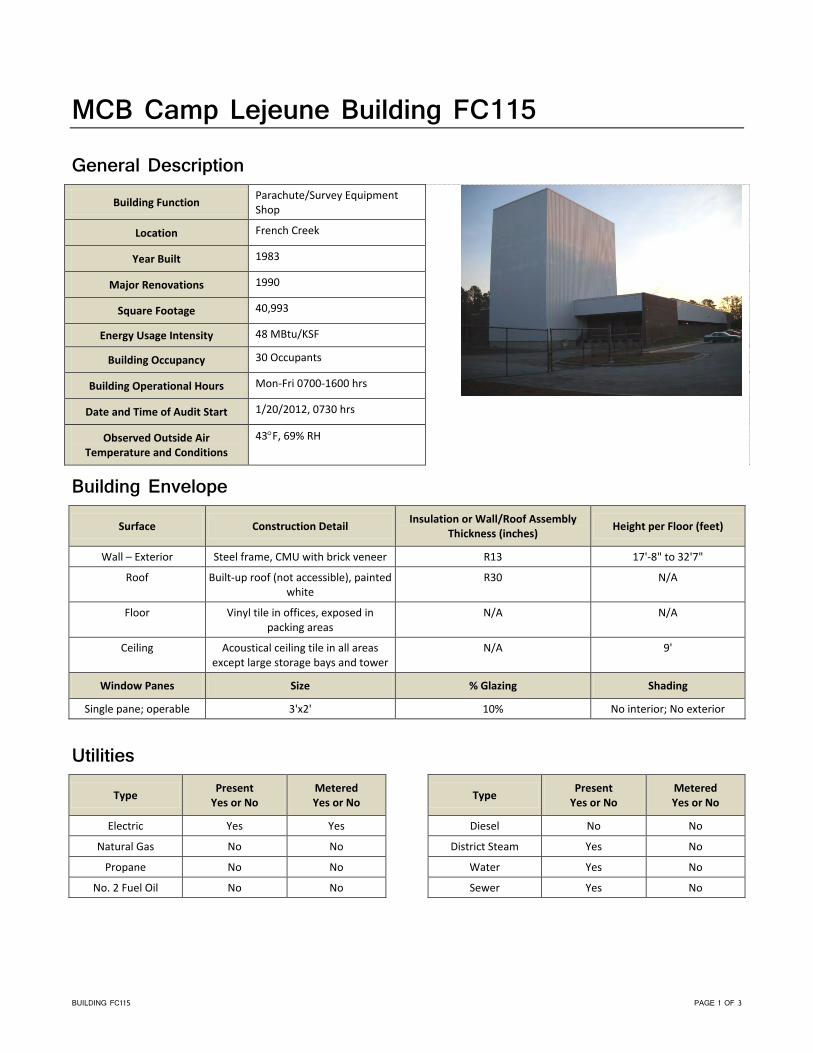
BUILDING FC115 PAGE 1 OF 3
MCB Camp Lejeune Building FC115
General Description
Building Function Parachute/Survey Equipment Shop
Location French Creek
Year Built 1983
Major Renovations 1990
Square Footage 40,993
Energy Usage Intensity 48 MBtu/KSF
Building Occupancy 30 Occupants
Building Operational Hours Mon-Fri 0700-1600 hrs
Date and Time of Audit Start 1/20/2012, 0730 hrs
Observed Outside Air Temperature and Conditions
43°F, 69% RH
Building Envelope
Surface Construction Detail Insulation or Wall/Roof Assembly Thickness (inches) Height per Floor (feet)
Wall – Exterior Steel frame, CMU with brick veneer R13 17'-8" to 32'7"
Roof Built-up roof (not accessible), painted white
R30 N/A
Floor Vinyl tile in offices, exposed in packing areas
N/A N/A
Ceiling Acoustical ceiling tile in all areas except large storage bays and tower
N/A 9'
Window Panes Size % Glazing Shading
Single pane; operable 3'x2' 10% No interior; No exterior
Utilities
Type Present Yes or No
Metered Yes or No
Electric Yes Yes
Natural Gas No No
Propane No No
No. 2 Fuel Oil No No
Type Present Yes or No
Metered Yes or No
Diesel No No
District Steam Yes No
Water Yes No
Sewer Yes No
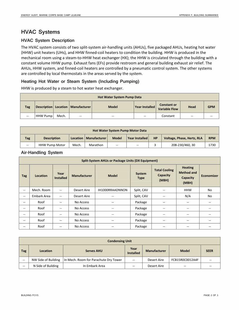
ENERGY AUDIT, MARINE CORPS BASE CAMP LEJEUNE APPENDIX F, BUILDING SUMMARIES
BUILDING FC115 PAGE 2 OF 3
HVAC Systems HVAC System Description The HVAC system consists of two split-system air-handling units (AHUs), five packaged AHUs, heating hot water (HHW) unit heaters (UHs), and HHW finned-coil heaters to condition the building. HHW is produced in the mechanical room using a steam-to-HHW heat exchanger (HX); the HHW is circulated through the building with a constant volume HHW pump. Exhaust fans (EFs) provide restroom and general building exhaust air relief. The AHUs, HHW system, and finned-coil heaters are controlled by a pneumatic control system. The other systems are controlled by local thermostats in the areas served by the system.
Heating Hot Water or Steam System (Including Pumping) HHW is produced by a steam to hot water heat exchanger.
Hot Water System Pump Data
Tag Description Location Manufacturer Model Year Installed Constant or Variable Flow Head GPM
-- HHW Pump Mech. -- -- -- Constant -- --
Hot Water System Pump Motor Data
Tag Description Location Manufacturer Model Year Installed HP Voltage, Phase, Hertz, RLA RPM
-- HHW Pump Motor Mech. Marathon -- -- 3 208-230/460, 30 1730
Air-Handling System Split-System AHUs or Package Units (DX Equipment)
Tag Location Year Installed Manufacturer Model System
Type
Total Cooling Capacity (MBH)
Heating Method and
Capacity (MBH)
Economizer
-- Mech. Room -- Desert Aire IH1000RRAADNNON Split, CAV -- HHW No
-- Embark Area -- Desert Aire -- Split, CAV -- N/A No
-- Roof -- No Access -- Package -- -- --
-- Roof -- No Access -- Package -- -- --
-- Roof -- No Access -- Package -- -- --
-- Roof -- No Access -- Package -- -- --
-- Roof -- No Access -- Package -- -- --
Condensing Unit
Tag Location Serves AHU Year Installed Manufacturer Model SEER
-- NW Side of Building In Mech. Room for Parachute Dry Tower -- Desert Aire FCB15R0C0012A4F --
-- N Side of Building In Embark Area -- Desert Aire -- --

ENERGY AUDIT, MARINE CORPS BASE CAMP LEJEUNE APPENDIX F, BUILDING SUMMARIES
BUILDING FC115 PAGE 3 OF 3
Terminal Units
Terminal Units
Equipment Type/Description (FCU, UH, VAV) Qty Cooling Method Heating Method
HHW UHs ~ 11 N/A HHW
HHW, fin-coiled, wall-mounted 4 N/A HHW
Controls and Operational Characteristics Type of Controls (DDC, Electric, Pneumatic, Timelocks) Electric and Pneumatic
Manufacturer/Vendor Honeywell
Connected to Basewide EMCS No
Building Occupancy Scheduling No
Plumbing Fixture Type Quantity Flow (gpf or gpm)
Toilets 4 3.0 gpf
Urinals 2 1.0 gpf
Lavatories 6 2.2 gpm
Faucets 0 N/A
Showers 3 2.5 gpm
Domestic Hot Water System
Type Manufacturer (Model)
Year Manufactured
Capacity Rating Btu/Hr or kW
Gallon Storage Capacity Setpoint (°F) Circulation Pumps
Steam heat exchanger/ Tank -- -- -- 200 140 Yes
Lighting The building has T8 32-Watt lamps throughout the majority of the interior spaces. Within the parachute packing area, there are T5 54-Watt lamps. In the dry tower, there were high-intensity discharge fixtures and high-pressure sodium wallpacks. There are T12 40-Watt lamps throughout the MR1 room. Exterior lighting is provided by high-intensity discharge fixtures.


BUILDING FC120 PAGE 1 OF 4
MCB Camp Lejeune Building FC120
General Description Building Function Auto Shop
Location French Creek
Year Built 1984
Major Renovations 2002
Square Footage 17,350
Energy Usage Intensity 47 MBtu/KSF
Building Occupancy 50 Occupants
Building Operational Hours Mon-Fri 0700-1600 hrs
Date and Time of Audit Start 1/20/2012, 0945 hrs
Observed Outside Air Temperature and Conditions
45°F, 69% RH
Building Envelope
Surface Construction Detail Insulation or Wall/Roof Assembly Thickness (inches) Height per Floor (feet)
Wall – Exterior Steel frame with CMU fill, brick veneer
R13 20'5"
Roof Built-up roof, painted white R30 N/A
Floor Exposed concrete throughout N/A N/A
Ceiling Acoustical ceiling tile in office areas, exposed in bay areas
N/A 9'
Window Panes Size % Glazing Shading
Single pane; half are operable
5'x5' 2% No interior; No exterior
Utilities
Type Present Yes or No
Metered Yes or No
Electric Yes No
Natural Gas No No
Propane No No
No. 2 Fuel Oil No No
Type Present Yes or No
Metered Yes or No
Diesel No No
District Steam Yes No
Water Yes No
Sewer Yes No

ENERGY AUDIT, MARINE CORPS BASE CAMP LEJEUNE APPENDIX F, BUILDING SUMMARIES
BUILDING FC120 PAGE 2 OF 4
HVAC Systems HVAC System Description The HVAC system consists of three constant air volume (CAV) air-handling units (AHUs). The supply air is conditioned by dual temperature water (DTW) coils within the AHU that utilize chilled water (CHW) or heating hot water (HHW) depending on the season; the DTW coils share common constant volume distribution pumps. The CHW is supplied by an air-cooled split-system chiller. The HHW system includes a steam-to-HHW heat exchanger (HX). The building also utilizes DTW fan-coil units (FCUs), HHW unit heaters (UHs), and finned-coil heaters. Exhaust fans (EFs) provide restroom and general building exhaust air relief. Additional EFs are used in the maintenance bay areas for vehicle exhaust. The HVAC systems are controlled by direct digital control (DDC) and electronic control systems.
Chilled Water System (Including Pumping) Chiller Data
Tag Location Year Installed Manufacturer Model Chiller Type Compressor
Type Capacity
(Tons)
Mech. Room -- AirStack ASR10X6A1A0 Split Chiller/Air Cooled Condensing Unit -- --
Chilled Water System Pump Data
Tag Description Location Manufacturer Model Year Installed Constant or Variable Flow Head GPM
-- DTW Pumpa Mech. Room Bell & Gossett -- -- Constant -- --
-- DTW Pumpa Mech. Room Taco -- -- Constant -- --
-- DTW Pumpa Mech. Room Taco -- -- Constant -- --
-- DTW Pumpa Mech. Room Taco -- -- Constant -- -- aDTW pump is used for CHW and HHW depending on seasonal operation.
Chilled System Pump Motor Data
Tag Description Location Manufacturer Model Year Installed HP Voltage, Phase, Hertz, RLA RPM
-- DTW Pump Motor Mech. Room Baldor -- -- 3 230/460 1755
-- DTW Pump Motor Mech. Room Emerson -- -- 1 230/460 1725
-- DTW Pump Motor Mech. Room Emerson -- -- 1 230/460 1725
-- DTW Pump Motor Mech. Room Emerson -- -- 1 230/460 1725
Heating Hot Water or Steam System (Including Pumping) HHW is produced by a steam to hot water heat exchanger.
Hot Water System Pump Data
Tag Description Location Manufacturer Model Year Installed Constant or Variable Flow Head GPM
-- DTW Pumpa Mech. Room Bell & Gossett -- -- Constant -- --
-- DTW Pumpa Mech. Room Taco -- -- Constant -- --
-- DTW Pumpa Mech. Room Taco -- -- Constant -- --
-- DTW Pumpa Mech. Room Taco -- -- Constant -- -- aDTW pump is used for CHW and HHW depending on seasonal operation.

ENERGY AUDIT, MARINE CORPS BASE CAMP LEJEUNE APPENDIX F, BUILDING SUMMARIES
BUILDING FC120 PAGE 3 OF 4
Hot Water System Pump Motor Data
Tag Description Location Manufacturer Model Year Installed HP Voltage, Phase, Hertz, RLA RPM
-- DTW Pump Motor Mech. Room Baldor -- -- 3 230/460 1755
-- DTW Pump Motor Mech. Room Emerson -- -- 1 230/460 1725
-- DTW Pump Motor Mech. Room Emerson -- -- 1 230/460 1725
-- DTW Pump Motor Mech. Room Emerson -- -- 1 230/460 1725
Air-Handling System Air Handling Units
Tag Location Year Installed Manufacturer (Model) System
Type Cooling Method
Heating Method Economizer Max
CFM
Total Cooling Capacity (MBH)
Heating Capacity (MBH)
AHU-3 1984 Trane MN: CCD65AN0C CAV CHW HHW No -- -- --
AHU-1 Tool Room 1984 Trane CAV CHW HHW No -- -- --
AHU-2 1984 Trane CAV CHW HHW No -- -- --
Air Handling Units (cont’d)
Tag
Supply Fan Motor Return Fan Motor
Year Installed Manufacturer HP Efficiency Control Type Year
Installed Manufacturer HP Efficiency Control Type
AHU-3 -- N/A .5 -- HOA -- -- -- -- --
AHU-1 -- Baldor 1 77% HOA -- -- -- -- --
AHU-2 -- -- -- -- HOA -- -- -- -- --
Condensing Unit
Tag Location Serves AHU Year Installed Manufacturer Model SEER
Roof Split Air-Cooled Chiller in Mech. Room -- AirStack WSS040T1003504 --
Terminal Units
Terminal Units
Equipment Type/Description (FCU, UH, VAV) Qty Cooling Method Heating Method
HHW UHs, w/Fan TSTAT & Swith Controlled 11 N/A HHW
FCU 4 DTW DTW
HHW Finned-Coil Heater 2 N/A HHW
Controls and Operational Characteristics Type of Controls (DDC, Electric, Pneumatic, Timelocks) Electric and DDC
Manufacturer/Vendor Johnson Control (DDC)
Connected to Basewide EMCS --
Building Occupancy Scheduling --

ENERGY AUDIT, MARINE CORPS BASE CAMP LEJEUNE APPENDIX F, BUILDING SUMMARIES
BUILDING FC120 PAGE 4 OF 4
Plumbing Fixture Type Quantity Flow (gpf or gpm)
Toilets 6 3.0 gpf
Urinals 3 1.0 gpf
Lavatories 7 2.2 gpm
Faucets 2 5.0 gpm
Showers 5 2.5 gpm
Domestic Hot Water System
Type Manufacturer (Model)
Year Manufactured
Capacity Rating Btu/Hr or kW
Gallon Storage Capacity Setpoint (°F) Circulation Pumps
Steam HX/ Tank -- -- -- 1,000 120 --
Lighting The building has T8 32-Watt lamps throughout the interior spaces. Exterior lighting is provided by high intensity discharge fixtures.

BUILDING FC200 PAGE 1 OF 3
MCB Camp Lejeune Building FC200
General Description Building Function FLD Maintenance Shop
Location French Creek
Year Built 1965
Major Renovations 2005
Square Footage 17,400
Energy Usage Intensity 38 MBtu/KSF
Building Occupancy 90 Occupants
Building Operational Hours Mon-Fri 0700-1600 hrs
Date and Time of Audit Start 1/19/2012, 1030 hrs
Observed Outside Air Temperature and Conditions
43°F, 67% RH
Building Envelope
Surface Construction Detail Insulation or Wall/Roof Assembly Thickness (inches) Height per Floor (feet)
Wall – Exterior Precast concrete frame, CMU with brick veneer
R13 14' to 19'6"
Roof Built-up roof, painted white -- N/A
Floor Vinyl tile in offices, exposed in bay areas
N/A N/A
Ceiling Acoustical ceiling tile in office areas, exposed in bay areas
N/A 9'
Window Panes Size % Glazing Shading
Double pane; operable 5'x5' and 5'x7' 5% No interior; No exterior
Utilities
Type Present Yes or No
Metered Yes or No
Electric Yes Yes
Natural Gas No No
Propane No No
No. 2 Fuel Oil No No
Type Present Yes or No
Metered Yes or No
Diesel No No
District Steam Yes No
Water Yes No
Sewer Yes No

ENERGY AUDIT, MARINE CORPS BASE CAMP LEJEUNE APPENDIX F, BUILDING SUMMARIES
BUILDING FC200 PAGE 2 OF 3
HVAC Systems HVAC System Description The HVAC system consists of two split-system air-handling units (AHUs) utilizing direct expansion (DX) coils and condensing units for air conditioning and heating hot water (HHW) coils for heat to condition administrative rooms of the building. HHW unit heaters (UHs) provide heat to the maintenance areas of the building. The HHW is produced in the mechanical room using a steam-to-HHW heat exchanger (HX) and circulated through the building with two constant-volume HHW pumps; the nameplates for the HHW pumps and pump motors were inaccessible during the site visit. Exhaust fans (EFs) provide restroom and general building exhaust air relief. Additional EFs are used for vehicle exhaust in the maintenance bay areas. The AHUs and HHW system are controlled by an electronic control system. The other systems are controlled by local thermostats in the areas served by the system.
Air-Handling System Split-System AHUs or Package Units (DX Equipment)
Tag Location Year Installed Manufacturer Model System
Type
Total Cooling Capacity (MBH)
Heating Method and
Capacity (MBH)
Economizer
-- S. Front Room 2005 Trane TWE036C14OB0 Split 3 ton HHW No
-- Tool Room 2005 Trane TWE060A100EL Split 5 ton HHW No
Condensing Unit
Tag Location Serves AHU Year Installed Manufacturer Model SEER
-- Outside S. Center S. Front Room 2005 Trane 2A7C0036A3000AA --
-- Outside N. Center Tool Room 2005 Trane 2A7C0060A3000AA --
Terminal Units
Terminal Units
Equipment Type/Description (FCU, UH, VAV) Qty Cooling Method Heating Method
UHs, HHW w/Fan 12 N/A HHW
Controls and Operational Characteristics Type of Controls (DDC, Electric, Pneumatic, Timelocks) Electric
Manufacturer/Vendor Delta
Connected to Basewide EMCS No
Building Occupancy Scheduling No

ENERGY AUDIT, MARINE CORPS BASE CAMP LEJEUNE APPENDIX F, BUILDING SUMMARIES
BUILDING FC200 PAGE 3 OF 3
Plumbing Fixture Type Quantity Flow (gpf or gpm)
Toilets 4 1.6 gpf
Urinals 3 1.0 gpf
Lavatories 3 2.2 gpm
Faucets 1 5.0 gpm
Showers 3 2.5 gpm
Domestic Hot Water System
Type Manufacturer (Model)
Year Manufactured
Capacity Rating Btu/Hr or kW
Gallon Storage Capacity Setpoint (°F) Circulation Pumps
Electric State Select -- 3.5 kW 50 -- --
Lighting The building has T8 32-Watt lamps throughout the office areas. Metal halide lamps are used throughout the bay areas. Exterior lighting is provided by high-intensity-discharge fixtures that are controlled by photocells.


GFI011013043257ATL PAGE 1 OF 4
Camp Lejeune Building FC230 General Description
Building Name AUTO ORGTL SHOP
Building Function Maintenance
Year Built 1989
Major Renovations 2005
Square Footage 29,128
Energy Usage Intensity 94.6
Building Occupancy 90‐100 Occupants
Building Operational Hours 0630‐1630, Mon‐Fri
Date and Time of Audit Start 27 Sept 2012, 1350 hrs
Observed Outside Air Temperature and Conditions
90F, 40% RH
Building Envelope Surface Construction Detail
Insulation or Wall/Roof Assembly Thickness (inches)
Height per Floor (feet)
Wall – Exterior Brick veneer with 4' metal panels 8" CMU 8'‐23'
Roof Thermoplastic polyolefin Poly Isocyanurate N/A
Floor Concrete N/A N/A
Ceiling Open to structure N/A 8'‐21'
Window Type Frame Type Size Operable or Fixed % Glazing of Exterior Wall Tint Shading
Double pane Aluminum 3' x 5' Operable 5 Yes No
Utilities Type
Present (Yes or No)
Metered (Yes or No)
Electric Yes Yes
Natural Gas No No
Propane No No
Diesel/No. 2 Fuel Oil No No
Type Present
(Yes or No) Metered (Yes or No)
District Steam Yes No
Water Yes No
Sewer Yes No
Lighting Interior Systems The building has 32‐Watt (W) and 54W T8 lamps throughout the interior spaces. T8 lighting was being installed in the areas that were currently under renovation. Lighting is controlled by occupancy sensors and manual switches.
Exterior Systems Exterior lighting is provided by wall‐mounted 100W high‐pressure sodium lamps with photocells.

MARINE CORPS BASE CAMP LEJEUNE BUILDING FC230
GFI011013043257ATL PAGE 2 OF 4
Plumbing Fixture Type Quantity
Flow (gpf or gpm)
Notes
Toilets 7 1.6 gpf
Urinals 3 1.0 gpf
Lavatories 5 0.5 gpm
Faucets 1 5.0 gpm
Showers 5 2.5 gpm
Other ‐‐ ‐‐
Domestic Hot Water System A new domestic hot water system was being installed at the time of the audit. The new system will consist of a steam‐to‐hot water heat exchanger.
HVAC Systems HVAC System Description The primary heating, ventilation, and air conditioning (HVAC) systems serving the office portions of this building were being completely replaced at the time of this observation, with the work being about 90 percent complete. The new systems will continue to utilize steam for building heating with new steam‐to‐hot water heat exchanger (HX) and pump being installed. A new air‐cooled chiller with pump was being installed for the cooling system. The system will consist of ceiling‐mounted heat pumps that will work in conjunction with a roof‐mounted energy recovery ventilator (ERV). New controls for these systems will be a programmable direct digital control (DDC) system. The heating and ventilation systems in the maintenance shop areas of the building are not a part of the remodel and consist of roof structure‐mounted forced air HHW unit heaters and HHW make‐up air units. Exhaust systems are switch‐operated and provide bay ventilation; separate fans provide vehicle exhaust removal.
Chilled Water System (Including Pumping) Chiller Data
Tag Year
Installed Manufacturer/Model Serial No.
Chiller Type
Compressor Type
Capacity (tons)
CH‐1 2012 Trane/CGAM040F2A02AXD2 U09J12015 Air Cooled Scroll 10
Heating Hot Water or Steam System (Including Pumping) HHW will be provided by a shell and tube‐style steam‐to‐hot water HX. The pumps and motors used in this system were newly installed and were inaccessible at the time of the audit.
Air-Handling System Split‐System AHUs or Package Units (DX Equipment)
Tag Year
Installed Manufacturer / Model Serial No. System Type
Total Cooling Capacity (MBH)
Heating Method and Capacity (MBH/kW)
HP 2012 Inaccessible ‐‐ Hydronic Heat
Pump 18 Heat Pump/18 MBH

MARINE CORPS BASE CAMP LEJEUNE BUILDING FC230
GFI011013043257ATL PAGE 3 OF 4
Condensing Units
Tag Serves AHU
Year Installed
Manufacturer/Model Serial No. Type
CU‐6 HP‐6 2012 Lennox/TPA036H4N42G 5811G08225 Heat Pump
CU‐8 HP‐8 2012 Lennox/TPA036H4N42G 5811G08224 Heat Pump
CU‐1 HP‐1 2012 Daikin/RXN09KEVJU C000668 Heat Pump
CU‐9 HP‐9 2012 United Coolair Corp/B5G4A5HA 1201018 Heat Pump
Terminal Units Terminal Units
Equipment Type/Description Qty Cooling Method Heating Method
Energy Recovery Unit 2 Wheel ‐‐
Unit Heater 4 ‐‐ HHW (30 MBH)
Make‐Up Air Unit 2 ‐‐ HHW (200 MBH)
Controls and Operational Characteristics The DDC system for the newly installed HVAC equipment had not been fully commissioned at the time of the audit. No information is available at this time.

MARINE CORPS BASE CAMP LEJEUNE BUILDING FC230
GFI011013043257ATL PAGE 4 OF 4
This page is intentionally left blank.

BUILDING FC241 PAGE 1 OF 3
MCB Camp Lejeune Building FC241
General Description Building Function Auto Shop
Location French Creek
Year Built 1981
Major Renovations 2002
Square Footage 11,480
Energy Usage Intensity 45 MBtu/KSF
Building Occupancy 40 Occupants
Building Operational Hours Mon-Fri 0700-1600 hrs
Date and Time of Audit Start 1/20/2012, 1500 hrs
Observed Outside Air Temperature and Conditions
61°F
Building Envelope
Surface Construction Detail Insulation or Wall/Roof Assembly Thickness (inches) Height per Floor (feet)
Wall – Exterior Steel frame with CMU fill, brick veneer and metal siding
R13 12' to 21'8"
Roof Built-up roof R30 N/A
Floor Vinyl in offices, concrete in bay areas N/A N/A
Ceiling Acoustical ceiling tile in office areas, exposed in bay areas
N/A 9'
Window Panes Size % Glazing Shading
Single pane; operable 6'x3' and 10'x3' 2% No interior; No exterior
Utilities
Type Present Yes or No
Metered Yes or No
Electric Yes Yes
Natural Gas No No
Propane No No
No. 2 Fuel Oil No No
Type Present Yes or No
Metered Yes or No
Diesel No No
District Steam No No
Water Yes No
Sewer Yes No

ENERGY AUDIT, MARINE CORPS BASE CAMP LEJEUNE APPENDIX F, BUILDING SUMMARIES
BUILDING FC241 PAGE 2 OF 3
HVAC Systems HVAC System Description The HVAC system consists of two package air-handling units (AHUs) utilizing direct expansion (DX) coils for air conditioning to condition administrative rooms of the building. Heating hot water (HHW) unit heaters (UHs) provide heat to the maintenance areas of the building. The HHW is produced in the mechanical room using a steam-to-HHW heat exchanger (HX) and is circulated through the building with a constant-volume HHW pump. The HHW pump is located in the Mechanical Room, but the nameplates for the pump and the pump motor were inaccessible during the site visit. Exhaust fans (EFs) provide restroom and general building exhaust air relief. Additional EFs are used for vehicle exhaust in the maintenance bay areas. The HHW system is controlled by a pneumatic control system. The other systems are controlled by local thermostats in the areas served by the system.
Air-Handling System Split-System AHUs or Package Units (DX Equipment)
Tag Location Year Installed Manufacturer Model System
Type
Total Cooling Capacity (MBH)
Heating Method and
Capacity (MBH)
Economizer
-- Roof 1996 Inter-City Products Corp. PAB036N7HA Package 3 Ton -- No
-- Roof -- Carrier -- Package -- -- No
Terminal Units
Terminal Units
Equipment Type/Description (FCU, UH, VAV) Qty Cooling Method Heating Method
UHs, HHW For Bay Area 3 N/A HHW
UH, HHW, Engr. Operations Bay 2 N/A HHW
Finned-Coil Heaters, HHW 6 N/A HHW
Controls and Operational Characteristics Type of Controls (DDC, Electric, Pneumatic, Timelocks) Pneumatic
Manufacturer/Vendor Johnson Controls
Connected to Basewide EMCS --
Building Occupancy Scheduling --
Plumbing Fixture Type Quantity Flow (gpf or gpm)
Toilets 5 3.0 gpf
Urinals 2 1.0 gpf
Lavatories 5 2.2 gpm
Faucets 2 2.2 gpm
Showers 3 2.5 gpm

ENERGY AUDIT, MARINE CORPS BASE CAMP LEJEUNE APPENDIX F, BUILDING SUMMARIES
BUILDING FC241 PAGE 3 OF 3
Domestic Hot Water System
Type Manufacturer (Model)
Year Manufactured
Capacity Rating Btu/Hr or kW
Gallon Storage Capacity Setpoint (°F) Circulation Pumps
Electric State Select -- 4.5 kW 80 -- No
Lighting The building has a mixture of T12 34-Watt and T8 32-Watt lamps throughout the interior spaces. The janitor’s closet has a T12 20-Watt lamp. Exterior lighting is provided by high-intensity-discharge fixtures that are controlled by photocells.


BUILDING FC251 PAGE 1 OF 3
MCB Camp Lejeune Building FC251
General Description Building Function Auto Shop
Location French Creek
Year Built 1978
Major Renovations 2004
Square Footage 14,484
Energy Usage Intensity 41 MBtu/KSF
Building Occupancy 95 Occupants
Building Operational Hours Mon-Fri 0700-1600 hrs
Date and Time of Audit Start 1/24/2012, 1330 hrs
Observed Outside Air Temperature and Conditions
68°F
Building Envelope
Surface Construction Detail Insulation or Wall/Roof Assembly Thickness (inches) Height per Floor (feet)
Wall – Exterior Steel frame with CMU fill and metal siding above 8.5 ft
R13 20'
Roof Built-up roof, painted white R30 N/A
Floor Vinyl in offices, concrete in work area N/A N/A
Ceiling Acoutical ceiling tile in offies, exposed to underside of metal deck
in work areas
N/A 9'2"
Window Panes Size % Glazing Shading
Single pane; operable 3'x5' 10% Tinting and blinds; No exterior
Utilities
Type Present Yes or No
Metered Yes or No
Electric Yes No
Natural Gas No No
Propane No No
No. 2 Fuel Oil No No
Type Present Yes or No
Metered Yes or No
Diesel No No
District Steam Yes No
Water Yes No
Sewer Yes No

ENERGY AUDIT, MARINE CORPS BASE CAMP LEJEUNE APPENDIX F, BUILDING SUMMARIES
BUILDING FC251 PAGE 2 OF 3
HVAC Systems HVAC System Description The HVAC system consists of four package air-handling units (AHUs) utilizing direct expansion (DX) air conditioning coils to condition the building’s administrative rooms of the building. Steam unit heaters (UHs) provide heat to the maintenance areas of the building. Exhaust fans (EFs) provide restroom and general building exhaust air relief. Additional EFs are used for vehicle exhaust in the maintenance bay areas. The HVAC systems are controlled by local thermostats in the areas served by the system.
Air-Handling System Split-System AHUs or Package Units (DX Equipment)
Tag Location Year Installed Manufacturer Model System
Type
Total Cooling Capacity (MBH)
Heating Method and
Capacity (MBH)
Economizer
-- Roof (SW 1) 1996 Carrier 50HS – 030 – 311 SN: 1296G10102
Package 2.5 Ton -- No
-- Roof (NW 1) 1996 Carrier 50HS 030 – 311
SN: 0796G40626 Package 2.5 Ton -- No
-- Roof (W Ctr.) 1997 Carrier 50SS – 036 501AA SN: 2297G40557
Package 3 Ton -- No
-- Roof (E.) 1999 Carrier 50HS – 036
SN: 4199G41143 Package 3 Ton -- No
Terminal Units
Terminal Units
Equipment Type/Description (FCU, UH, VAV) Qty Cooling Method Heating Method
Steam UH ~ 14
Through – Wall PTAC 1
Controls and Operational Characteristics Type of Controls (DDC, Electric, Pneumatic, Timelocks) Pneumatic
Manufacturer/Vendor --
Connected to Basewide EMCS --
Building Occupancy Scheduling --
Plumbing Fixture Type Quantity Flow (gpf or gpm)
Toilets 3 1.6 gpf
Urinals 2 1.0 gpf
Lavatories 4 2.2 gpm
Faucets 0 N/A

ENERGY AUDIT, MARINE CORPS BASE CAMP LEJEUNE APPENDIX F, BUILDING SUMMARIES
BUILDING FC251 PAGE 3 OF 3
Fixture Type Quantity Flow (gpf or gpm)
Showers 2 2.5 gpm
Domestic Hot Water System
Type Manufacturer (Model)
Year Manufactured
Capacity Rating Btu/Hr or kW
Gallon Storage Capacity Setpoint (°F) Circulation Pumps
Electric RUUD -- 2 kW 65 -- No
Lighting The building has T8 32-Watt lamps throughout some of the interior spaces. The common area rooms have T8 59-Watt lamps. Exterior lighting is provided by high-intensity-discharge fixtures.


BUILDING FC255 PAGE 1 OF 3
MCB Camp Lejeune Building FC255
General Description Building Function Auto Shop
Location French Creek
Year Built 1987
Major Renovations 1989
Square Footage 25,800
Energy Usage Intensity 55 MBtu/KSF
Building Occupancy 150 Occupants
Building Operational Hours Mon-Fri 0700-1600 hrs
Date and Time of Audit Start 1/24/2012, 1000 hrs
Observed Outside Air Temperature and Conditions
63°F
Building Envelope
Surface Construction Detail Insulation or Wall/Roof Assembly Thickness (inches) Height per Floor (feet)
Wall – Exterior Steel frame with CMU fill, brick veneer
R13 11' to 24'
Roof Asphalt roof with gravel top R30 N/A
Floor Vinyl tile in office areas, exposed in bay areas
N/A N/A
Ceiling Acoustical ceiling tile in office areas, exposed in bay areas
N/A 9'
Window Panes Size % Glazing Shading
Double pane; operable 2'x6' and 5'x5' 2% Blinds; No exterior
Utilities
Type Present Yes or No
Metered Yes or No
Electric Yes Yes
Natural Gas No No
Propane No No
No. 2 Fuel Oil No No
Type Present Yes or No
Metered Yes or No
Diesel No No
District Steam Yes No
Water Yes No
Sewer Yes No

ENERGY AUDIT, MARINE CORPS BASE CAMP LEJEUNE APPENDIX F, BUILDING SUMMARIES
BUILDING FC255 PAGE 2 OF 3
HVAC Systems HVAC System Description The HVAC system consists of two split-system air-handling units (AHUs) utilizing direct expansion (DX) coils and condensing units for air conditioning and heating hot water (HHW) coils for heat to condition the building’s administrative rooms. One packaged AHU and two makeup-air AHUs utilizing HHW coils are used to heat the air supplied to the maintenance bays while the vehicle exhaust system is in operation. HHW unit heaters (UHs) provide heat to the maintenance areas of the building and HHW fan coil units (FCUs) and HHW finned-coil units provide heat in other spaces. The HHW is produced in the mechanical room using a steam-to-HHW heat exchanger (HX) and is circulated through the building with two constant volume HHW pumps. Exhaust fans (EFs) provide restroom and general building exhaust air relief. Additional EFs are used for vehicle exhaust in the maintenance bay areas. The HVAC systems use pneumatic controls. The other systems are controlled by local thermostats in the areas served by the system.
Heating Hot Water or Steam System (Including Pumping) Hot Water System Pump Data
Tag Description Location Manufacturer Model Year Installed Constant or Variable Flow Head GPM
-- HHW Pump Mech. Room Taco -- 1986 Constant 65 45
-- HHW Pump Mech. Room Bell & Gossett -- -- Constant -- --
Hot Water System Pump Motor Data
Tag Description Location Manufacturer Model Year Installed HP Voltage, Phase, Hertz, RLA RPM
-- HHW Pump Motor Mech. Room Century -- -- 2 230/460, 30 1745
-- HHW Pump Motor Mech. Room Baldor -- -- 5 208-230/460, 30 --
Air-Handling System Air Handling Units
Tag Location Year Installed
Manufacturer (Model)
System Type
Cooling Method
Heating Method Economizer Max
CFM
Total Cooling Capacity (MBH)
Heating Capacity (MBH)
AHU-1a Ceiling by Bay -- -- CAV N/A HHW No -- -- --
AHU-2a Ceiling by Bay -- -- CAV N/A HHW No -- -- -- a AHUs are interconnected with vehicle exhaust fans and are utilized as makeup air AHUs while vehicle exhaust fans are in operation.
Split-System AHUs or Package Units (DX Equipment)
Tag Location Year Installed Manufacturer Model System
Type
Total Cooling Capacity (MBH)
Heating Method and
Capacity (MBH)
Economizer
-- Low Roof NE 2008 Trane THC033A4E0A15 Package -- -- No
AHU-1 2nd Floor Center 1986 -- -- Split 3 ton HHW No
AHU-2 2nd Floor Center 2004 -- -- Split 4 ton HHW No

ENERGY AUDIT, MARINE CORPS BASE CAMP LEJEUNE APPENDIX F, BUILDING SUMMARIES
BUILDING FC255 PAGE 3 OF 3
Condensing Unit
Tag Location Serves AHU Year Installed Manufacturer Model SEER
CU-1 Outside (S. Center) AHU-1 1986 Trane BTA036D400A0 SN: S25285463
--
CU-2 Outside (S. Center) AHU-2 2004 Armstrong Air Cond. SCU10B48C – 3 SN: 1604H01687
--
Terminal Units
Terminal Units
Equipment Type/Description (FCU, UH, VAV) Qty Cooling Method Heating Method
Floor Mount FCUs, HHW only 4 N/A HHW
HHW UH, High Bay 10 N/A HHW
HHW UH, Other Maint. Areas ~ 4 N/A HHW
HHW Finned-Coil Unit ~2 N/A HHW
FCU, Horizontal Ceiling Mount (HHW) 5 N/A HHW
Controls and Operational Characteristics Type of Controls (DDC, Electric, Pneumatic, Timelocks) Pneumatic
Manufacturer/Vendor --
Connected to Basewide EMCS --
Building Occupancy Scheduling --
Plumbing
Fixture Type Quantity Flow (gpf or gpm)
Toilets 7 1.6 gpf
Urinals 4 1.0 gpf
Lavatories 8 2.2 gpm
Faucets 3 5.0 gpm
Showers 5 2.5 gpm
Domestic Hot Water System
Type Manufacturer (Model)
Year Manufactured
Capacity Rating Btu/Hr or kW
Gallon Storage Capacity Setpoint (°F) Circulation Pumps
Steam Heat Exchanger ACE -- -- -- 140 Two, 1/2 hp
Lighting The building has T12 60-Watt lamps throughout the bay area. There are T12 34-Watt lamps throughout the majority of the common areas. The remaining areas have T8 32-Watt or 59-Watt lamps. Exterior lighting is provided by high-intensity-discharge fixtures.


BUILDING FC263 PAGE 1 OF 3
MCB Camp Lejeune Building FC263
General Description Building Function Auto Shop
Location French Creek
Year Built 1986
Major Renovations
Square Footage 18,940
Energy Usage Intensity 43 MBtu/KSF
Building Occupancy 60 Occupants
Building Operational Hours Mon-Fri 0700-1600 hrs
Date and Time of Audit Start 1/24/2012, 0800 hrs
Observed Outside Air Temperature and Conditions
65°F, 78% RH
Building Envelope
Surface Construction Detail Insulation or Wall/Roof Assembly Thickness (inches) Height per Floor (feet)
Wall – Exterior Steel frame with CMU fill, brick veneer
R13 9'8"
Roof Built-up Roof, painted white R30 N/A
Floor Vinyl tile in office areas, exposed in bay areas
N/A N/A
Ceiling Acoustical ceiling tile in office areas, exposed in bay areas
N/A 7'1"
Window Panes Size % Glazing Shading
Double pane; operable 3'x4' 5% No interior; No exterior
Utilities
Type Present Yes or No
Metered Yes or No
Electric Yes Yes
Natural Gas No No
Propane No No
No. 2 Fuel Oil No No
Type Present Yes or No
Metered Yes or No
Diesel No No
District Steam Yes No
Water Yes No
Sewer Yes No

ENERGY AUDIT, MARINE CORPS BASE CAMP LEJEUNE APPENDIX F, BUILDING SUMMARIES
BUILDING FC263 PAGE 2 OF 3
HVAC Systems HVAC System Description The HVAC system consists of four packaged air-handling units (AHUs) utilizing direct expansion (DX) coils to provide air conditioning to the building’s administrative rooms. Heating hot water (HHW) unit heaters (UHs) provide heat to the maintenance areas of the building and finned-coil heaters provide heat to other rooms and passage ways. The HHW is produced in the mechanical room using a steam-to-HHW heat exchanger (HX); the HHW is circulated through the building with a constant volume HHW pump. Exhaust fans (EFs) provide restroom and general building exhaust air relief. Additional EFs are used for vehicle exhaust in the maintenance bay areas. The HVAC systems are controlled pneumatic and direct digital control (DDC) systems. The terminal units and other systems are controlled by local thermostats or switches in the areas served by the systems.
Heating Hot Water or Steam System (Including Pumping) Hot Water System Pump Data
Tag Description Location Manufacturer Model Year Installed Constant or Variable Flow Head GPM
-- HHW Pump Mech. Room 2 -- -- -- Constant -- --
Hot Water System Pump Motor Data
Tag Description Location Manufacturer Model Year Installed HP Voltage, Phase, Hertz, RLA RPM
-- HHW Pump Motor Mech. Room 2 Emerson -- 2 230/460, 3-phase 1725
Air-Handling System Split-System AHUs or Package Units (DX Equipment)
Tag Location Year Installed Manufacturer Model System Type
Total Cooling Capacity (MBH)
Heating Method and
Capacity (MBH)
Economizer
-- Roof 1999 Carrier 50H-042-311 SN: 2099G43172
Package Roof AC w/ HHW Reheat
3.5 Tons -- No
-- Roof 2004 Trane TCC036F300BD SN: 4504NLE1H
Package Roof AC w/ HHW Reheat
3 Tons -- No
-- Roof 1998 Carrier 50SH-030-311 SN: 3798G43012
Package Roof AC w/ HHW Reheat
2.5 Tons -- No
-- Roof 1998 Carrier 50SH-030-311 SN: 3798G43012
Package Roof AC w/ HHW Reheat
2.5 Tons -- No
Terminal Units
Terminal Units
Equipment Type/Description (FCU, UH, VAV) Qty Cooling Method Heating Method
HHW UHs, High Bay, Man TSTAT 12 N/A HHW
HHW UHs, Other Maint. Areas ~ 4+ N/A HHW
HHW Convector Coil Units ~ 16 N/A HHW
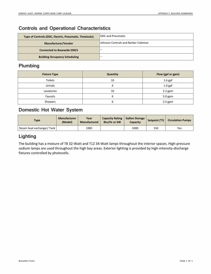
ENERGY AUDIT, MARINE CORPS BASE CAMP LEJEUNE APPENDIX F, BUILDING SUMMARIES
BUILDING FC263 PAGE 3 OF 3
Controls and Operational Characteristics Type of Controls (DDC, Electric, Pneumatic, Timelocks) DDC and Pneumatic
Manufacturer/Vendor Johnson Controls and Barber Coleman
Connected to Basewide EMCS --
Building Occupancy Scheduling --
Plumbing Fixture Type Quantity Flow (gpf or gpm)
Toilets 10 1.6 gpf
Urinals 4 1.0 gpf
Lavatories 10 2.2 gpm
Faucets 6 5.0 gpm
Showers 6 2.5 gpm
Domestic Hot Water System
Type Manufacturer (Model)
Year Manufactured
Capacity Rating Btu/Hr or kW
Gallon Storage Capacity Setpoint (°F) Circulation Pumps
Steam heat exchanger/ Tank 1985 1000 150 Yes
Lighting The building has a mixture of T8 32-Watt and T12 34-Watt lamps throughout the interior spaces. High-pressure sodium lamps are used throughout the high bay areas. Exterior lighting is provided by high-intensity-discharge fixtures controlled by photocells.


BUILDING FC270 PAGE 1 OF 3
MCB Camp Lejeune Building FC270
General Description Building Function Auto Shop
Location French Creek
Year Built 1988
Major Renovations 2004
Square Footage 19,880
Energy Usage Intensity 51 MBtu/KSF
Building Occupancy 30 Occupants
Building Operational Hours Mon-Fri 0530-1600 hrs
Date and Time of Audit Start 1/20/2012, 1300 hrs
Observed Outside Air Temperature and Conditions
61°F
Building Envelope
Surface Construction Detail Insulation or Wall/Roof Assembly Thickness (inches) Height per Floor (feet)
Wall – Exterior Steel frame with CMU fill, brick veneer
R13 22'
Roof Asphalt roof with gravel stone topping
R30 N/A
Floor Vinyl tile in offices, concrete in bay areas
N/A N/A
Ceiling Acoustical ceiling tile in office areas, exposed in bay areas
N/A 9'
Window Panes Size % Glazing Shading
Double pane; operable 3'x5' and 5'x5' 2% Blinds; No exterior
Utilities
Type Present Yes or No
Metered Yes or No
Electric Yes Yes
Natural Gas No No
Propane No No
No. 2 Fuel Oil No No
Type Present Yes or No
Metered Yes or No
Diesel No No
District Steam Yes No
Water Yes No
Sewer Yes No

ENERGY AUDIT, MARINE CORPS BASE CAMP LEJEUNE APPENDIX F, BUILDING SUMMARIES
BUILDING FC270 PAGE 2 OF 3
HVAC Systems HVAC System Description The HVAC system consists of three split-system air-handling units (AHUs) utilizing direct expansion (DX) coils and condensing units for air conditioning and heating hot water (HHW) coils for heat in the building’s administrative rooms. Two makeup-air AHUs utilize HHW coils to heat the air supplied to the maintenance bays while the vehicle exhaust system is in operation. HHW unit heaters (UHs) and HHW finned-coil units provide heat in other spaces. The HHW is produced in the mechanical room using a steam-to-HHW heat exchanger (HX); the HHW is circulated through the building with a constant volume HHW pump. Exhaust fans (EFs) provide restroom and general building exhaust air relief. Additional EFs are used for vehicle exhaust in the maintenance bay areas. The HVAC systems use pneumatic controls. The other systems are controlled by local thermostats in the areas served by the system.
Heating Hot Water or Steam System (Including Pumping) Hot Water System Pump Data
Tag Description Location Manufacturer Model Year Installed Constant or Variable Flow Head GPM
-- HHW Pump Mech. Room Taco -- Constant -- --
Hot Water System Pump Motor Data
Tag Description Location Manufacturer Model Year Installed HP Voltage, Phase, Hertz,
RLA RPM
-- HHW Pump Motor Mech. Room Marathon -- -- 5 208-230/460, 3 phase 1740
Air-Handling System Air Handling Units
Tag Location Year Installed
Manufacturer (Model)
System Type
Cooling Method
Heating Method Economizer Max
CFM
Total Cooling Capacity (MBH)
Heating Capacity (MBH)
a West Bay Ceiling -- Trane CAV N/A HHW -- -- N/A -- a East Bay Ceiling -- Trane CAV N/A HHW -- -- N/A --
a AHUs are interconnected with vehicle exhaust fans and are utilized as makeup-air AHUs while vehicle exhaust fans are in operation.
Split-System AHUs or Package Units (DX Equipment)
Tag Location Year Installed Manufacturer Model System
Type Total Cooling
Capacity (MBH)
Heating Method and Capacity
(MBH) Economizer
AHU-2 2nd Floor Mech. 1987 Trane CCDB06A5BG
SN: K87C08474 CAV 5 Tons HHW No
AHU-3 2nd Floor Mech. 1987 Trane CCDB03A5BG CAV 3 Tons HHW No
AHU-1 Ceiling East End No Access. - - - 3 Tons - No

ENERGY AUDIT, MARINE CORPS BASE CAMP LEJEUNE APPENDIX F, BUILDING SUMMARIES
BUILDING FC270 PAGE 3 OF 3
Condensing Unit
Tag Location Serves AHU Year Installed Manufacturer Model SEER
CU – 2 Outside Center AHU-2 2005 Trane 2TTR1060A1000AA
SN: 50966G72F --
CU – 3 Outside Center AHU-3 -- Goodman GSC130361AA
SN: 0605098422 13.0
CU – 1 Outside East AHU-1 1999 Trane TWR036C100A3 SN: P32257XCF
--
Terminal Units
Terminal Units
Equipment Type/Description (FCU, UH, VAV) Qty Cooling Method Heating Method
PTAC (Through – Wall) 1 Est. 1 Ton N/A
HHW UHs ~ 19 N/A HHW
HHW Convector Coil Units (CCU) ~ 8 N/A HHW
Controls and Operational Characteristics Type of Controls (DDC, Electric, Pneumatic, Timelocks) Pneumatic
Manufacturer/Vendor --
Connected to Basewide EMCS --
Building Occupancy Scheduling --
Plumbing
Fixture Type Quantity Flow (gpf or gpm)
Toilets 6 3.0 gpf
Urinals 2 1.0 gpf
Lavatories 5 2.2 gpm
Faucets 4 5.0 gpm
Showers 4 2.5 gpm
Domestic Hot Water System
Type Manufacturer (Model)
Year Manufactured
Capacity Rating Btu/Hr or kW
Gallon Storage Capacity Setpoint (°F)
Circulation Pumps
Steam HX / Tank -- 1987 -- 400 120 1/8 hp
Lighting The building has T8 32-Watt lamps throughout most of the interior spaces, with the exception of a few T8 59-Watt lamps. There are a mixture of 175-Watt to 250-Watt metal halide and 400-Watt high-pressure sodium lamps within the high-bay areas. Exterior lighting is provided by high-intensity-discharge fixtures controlled by photocells.


BUILDING FC280 PAGE 1 OF 3
MCB Camp Lejeune Building FC280
General Description Building Function FLD Maintenance Shop
Location French Creek
Year Built 1989
Major Renovations 2003
Square Footage 46,519
Energy Usage Intensity 28 MBtu/KSF
Building Occupancy 127 Mon-Fri
Building Operational Hours 0700-1630 hrs Mon-Fri
Date and Time of Audit Start 1/19/2012, 0750 hrs
Observed Outside Air Temperature and Conditions
35°F
Building Envelope
Surface Construction Detail Insulation or Wall/Roof Assembly Thickness (inches) Height per Floor (feet)
Wall – Exterior CMU brick veneer R12 20'
Roof Flat with EPDM membrane, cool roof R30 N/A
Floor Concrete N/A N/A
Ceiling Exposed in bay areas, acoustical tile in others
N/A 9'
Window Panes Size % Glazing Shading
Double pane; operable 3'x3' 10% Tinting; No exterior
Utilities
Type Present Yes or No
Metered Yes or No
Electric Yes Yes
Natural Gas No No
Propane Yes No
No. 2 Fuel Oil No No
Type Present Yes or No
Metered Yes or No
Diesel Yes No
District Steam Yes No
Water Yes No
Sewer Yes No

ENERGY AUDIT, MARINE CORPS BASE CAMP LEJEUNE APPENDIX F, BUILDING SUMMARIES
BUILDING FC280 PAGE 2 OF 3
HVAC Systems HVAC System Description The HVAC system consists of two split-system air-handling units (AHUs) and one packaged air conditioner. The paint booth has one makeup air unit (MAU) with several exhaust fans (EFs) to provide exhaust air relief. Hot water heating unit heaters (HWUHs) serve all the bay areas, while fan-coiled units are used in the hallway. The AHUs are serviced by two condensing units (CUs) located outside of the building. The heating hot water (HHW) system includes a steam-to-HHW heat exchanger (HX) and constant volume HHW pump, the nameplates for which were inaccessible during the site visit. Electric controls are used.
Air-Handling System Split-System AHUs or Package Units (DX Equipment)
Tag Location Year Installed Manufacturer Model System
Type Total Cooling
Capacity (MBH)
Heating Method and Capacity
(MBH) Economizer
AHU-1 Mezz. -- Trane Split -- Steam --
AHU-2 Mezz. -- Trane Split -- Steam – 18 --
AC-1 Roof -- Trane Package -- HP – 90 --
MAU-1 Roof -- Trane Package -- HP --
Condensing Unit
Tag Location Serves AHU Year Installed Manufacturer Model SEER
CU-1 Roof AHU-1 -- Trane -- --
CU-2 Roof AHU-2 -- Trane -- --
Terminal Units
Terminal Units
Equipment Type/Description (FCU, UH, VAV) Qty Cooling Method and Capacity (MBH)
Heating Method and Capacity (MBH)
HWUH, large 7 -- HW
HWUH, small 3 -- HW
FCU 2 Fan – N/A HW –
Controls and Operational Characteristics Type of Controls (DDC, Electric, Pneumatic, Timelocks) Electric
Manufacturer/Vendor --
Connected to Basewide EMCS No
Building Occupancy Scheduling No

ENERGY AUDIT, MARINE CORPS BASE CAMP LEJEUNE APPENDIX F, BUILDING SUMMARIES
BUILDING FC280 PAGE 3 OF 3
Plumbing Fixture Type Quantity Flow (gpf or gpm)
Toilets 9 (7) 1.6 gpf; (2) 3.0 gpf
Urinals 4 1.0 gpf
Lavatories 8 2 gpm
Faucets 2 2.5 gpm
Showers 0 N/A
Domestic Hot Water System The steam HX was inaccessible during the site visit.
Type Manufacturer (Model)
Year Manufactured
Capacity Rating Btu/Hr or kW
Gallon Storage Capacity Setpoint (°F) Circulation Pumps
Steam HX -- -- -- -- -- --
Lighting The building has T8 32-Watt lamps throughout the interior spaces. Exterior lighting is provided by high-intensity discharge fixtures.


BUILDING FC281 PAGE 1 OF 2
MCB Camp Lejeune Building FC281
General Description Building Function Maintenance
Location French Creek
Year Built 1989
Major Renovations
Square Footage 7,500
Energy Usage Intensity 42 MBtu/KSF
Building Occupancy 40 Occupants
Building Operational Hours Mon-Fri 0700-1600 hrs
Date and Time of Audit Start 1/25/2012, 1000 hrs
Observed Outside Air Temperature and Conditions
55°F, 60% RH
Building Envelope
Surface Construction Detail Insulation or Wall/Roof Assembly Thickness (inches) Height per Floor (feet)
Wall – Exterior Steel frame with CMU fill and brick veneer
-- 20'
Roof Built-up Roof, painted white -- N/A
Floor Vinyl tile in office areas, exposed in bay areas
N/A N/A
Ceiling Acoustical ceiling tile in office areas, exposed in bay areas
N/A 8'
Window Panes Size % Glazing Shading
Double pane; operable 4'x3' 1% No interior; No exterior
Utilities
Type Present Yes or No
Metered Yes or No
Electric Yes Yes
Natural Gas No No
Propane No No
No. 2 Fuel Oil No No
Type Present Yes or No
Metered Yes or No
Diesel No No
District Steam Yes No
Water Yes No
Sewer Yes No

ENERGY AUDIT, MARINE CORPS BASE CAMP LEJEUNE APPENDIX F, BUILDING SUMMARIES
BUILDING FC281 PAGE 2 OF 2
HVAC Systems HVAC System Description The HVAC system consists of four heating hot water (HHW) unit heaters (UHs) located in the high bay area, two fin-coiled heaters in the restrooms and a packaged terminal air conditioner in the office. The HHW is produced in the mechanical room using a steam-to-HHW heat exchanger (HX). The HHW is circulated through the building with two-constant volume HHW pumps. Due to a steam leak in the mechanical room during the site visit, the nameplates for the equipment were inaccessible. Exhaust fans (EFs) provide restroom and general building exhaust air relief. The HHW system is controlled by a pneumatic control system and the terminal heating units are controlled by local thermostats.
Terminal Units
Terminal Units
Equipment Type/Description (FCU, UH, VAV) Qty Cooling Method Heating Method
HHW UHs 4 N/A HHW
HHW Coil Heaters 2 N/A HHW
PTAC, Office Area 1 DX N/A
Controls and Operational Characteristics Type of Controls (DDC, Electric, Pneumatic, Timelocks) Pneumatic
Manufacturer/Vendor --
Connected to Basewide EMCS --
Building Occupancy Scheduling --
Plumbing Fixture Type Quantity Flow (gpf or gpm)
Toilets 2 1.6 gpf
Urinals 1 1.0 gpf
Lavatories 4 2.2 gpm
Faucets 2 5.0 gpm
Showers 2 2.5 gpm
Domestic Hot Water System
Type Manufacturer (Model)
Year Manufactured
Capacity Rating Btu/Hr or kW
Gallon Storage Capacity Setpoint (°F) Circulation Pumps
Steam HX/ Tank -- -- -- -- 125 Fractional
Lighting The building has T12 34-Watt lamps throughout the majority of interior spaces. There are 400-Watt high-pressure sodium lamps throughout the high-bay areas. Exterior lighting is provided by high-intensity-discharge fixtures controlled by a timer.

BUILDING FC285 PAGE 1 OF 3
MCB Camp Lejeune Building FC285
General Description Building Function FLD Maintenance Shop
Location French Creek
Year Built 1990
Major Renovations 2004
Square Footage 43,934
Energy Usage Intensity 32 MBtu/KSF
Building Occupancy 37 Occupants
Building Operational Hours Mon-Fri 0600-1630 hrs
Date and Time of Audit Start 1/19/2012, 0945 hrs
Observed Outside Air Temperature and Conditions
45°F, 53% RH
Building Envelope
Surface Construction Detail Insulation or Wall/Roof Assembly Thickness (inches) Height per Floor (feet)
Wall – Exterior CMU brick veneer R15 22'
Roof Flat with EPDM membrane R20 N/A
Floor Concrete and carpet N/A N/A
Ceiling Exposed and acoustical tile N/A 8'
Window Panes Size % Glazing Shading
Double pane; fixed 3'x3' 10% Tinting and blinds; No exterior
Utilities
Type Present Yes or No
Metered Yes or No
Electric Yes No
Natural Gas No No
Propane No No
No. 2 Fuel Oil No No
Type Present Yes or No
Metered Yes or No
Diesel No No
District Steam Yes No
Water Yes No
Sewer Yes No

ENERGY AUDIT, MARINE CORPS BASE CAMP LEJEUNE APPENDIX F, BUILDING SUMMARIES
BUILDING FC285 PAGE 2 OF 3
HVAC Systems HVAC System Description The HVAC system consists of seven packaged rooftop air conditioners (RTUs). The bay areas are served by hot water heating unit heaters (HWUHs) and 100 percent make-up air units (MAUs) with heating hot water (HHW) coils. The HHW system includes a steam-to-HHW heat exchanger (HX) and constant volume HHW pump, the nameplates for which were inaccessible during the site visit. Electric controls are used.
Air-Handling System Split-System AHUs or Package Units (DX Equipment)
Tag Location Year Installed Manufacturer Model System
Type Total Cooling
Capacity (MBH) Heating Method
and Capacity (MBH) Economizer
RTU – 1 Roof -- Trane -- Package 60 HP No
RTU – 2 Roof -- Trane -- Package 120 HP No
RTU – 3 Roof -- Trane -- Package 48 HP No
RTU – 4 Roof -- Trane -- Package 60 HP No
RTU – 5 Roof -- Trane -- Package 48 HP No
RTU – 6 Roof -- Trane -- Package 120 HP No
RTU – 7 Roof -- Trane -- Package 60 HP No
Terminal Units
Terminal Units
Equipment Type/Description (FCU, UH, VAV) Qty Cooling Method Heating Method
HWUH – 1 34 -- Small – HW
HWUH – 1 10 -- Large – HW
Controls and Operational Characteristics Type of Controls (DDC, Electric, Pneumatic, Timelocks) Electric
Manufacturer/Vendor --
Connected to Basewide EMCS No
Building Occupancy Scheduling No
Plumbing Fixture Type Quantity Flow (gpf or gpm)
Toilets 5 3 gpf
Urinals 2 1.6 gpf
Lavatories 5 2.2 gpm
Faucets 1 2.5 gpm
Showers 0 N/A

ENERGY AUDIT, MARINE CORPS BASE CAMP LEJEUNE APPENDIX F, BUILDING SUMMARIES
BUILDING FC285 PAGE 3 OF 3
Domestic Hot Water System The steam-to-HHW HX was inaccessible during the site visit.
Type Manufacturer (Model)
Year Manufactured
Capacity Rating Btu/Hr or kW
Gallon Storage Capacity Setpoint (°F) Circulation Pumps
Steam HX -- -- -- -- -- Yes
Lighting The building has T8 32-Watt lamps throughout the majority of interior spaces. The remaining areas have 150-Watt to 250-Watt high-pressure sodium lamps and 400-Watt metal halide lamps. High-pressure and metal halide fixtures were both present in high bay area. Exterior lighting is provided by high-intensity-discharge fixtures.


BUILDING FC300 PAGE 1 OF 4
MCB Camp Lejeune Building FC300
General Description Building Function Administration
Location French Creek
Year Built 1951
Major Renovations ---
Square Footage 22,372
Energy Usage Intensity 85 MBtu/KSF
Building Occupancy 85-100 Occupants
Building Operational Hours Mon-Fri 0700-1600 hrs
Date and Time of Audit Start 11/14/2011, 0745 hrs
Observed Outside Air Temperature and Conditions
65°F, 71% RH
Building Envelope
Surface Construction Detail Insulation or Wall/Roof Assembly Thickness (inches) Height per Floor (feet)
Wall – Exterior Precast Concrete Frame, CMUfill, with brick veneer
R-13, 14" wall 11' 7"
Roof Standing seam over existing built up R-30 N/A
Floor Carpet, tile, and vinyl N/A N/A
Ceiling Acoustical ceiling tile N/A 9'
Windows Size Approximate % Glazing Shading
Double pane; operable 4'x6' 40% Tinting and blinds; No exterior shading
Utilities
Type Present Yes or No
Metered Yes or No
Electric Yes Yes
Natural Gas No No
Propane No No
No. 2 Fuel Oil No No
Type Present Yes or No
Metered Yes or No
Diesel Yes No
District Steam Yes No
Water Yes No
Sewer Yes No

ENERGY AUDIT, MARINE CORPS BASE CAMP LEJEUNE APPENDIX F, BUILDING SUMMARIES
BUILDING FC300 PAGE 2 OF 4
HVAC Systems HVAC System Description The HVAC system consists of four central variable air volume (VAV) air-handling units (AHUs) that utilize variable frequency drive (VFD) fan motor control and chilled water (CHW) coils and heating hot water (HHW) coils to condition the core areas of the building and four mini-split air conditioners for various rooms. The CHW is supplied by an 80-ton air-cooled chiller and constant volume CHW pump. The HHW system includes a steam to HHW heat exchanger (HX) and constant volume HHW pump. The HHW pump and motor data was inaccessible at the time of the audit. The AHUs supply conditioned air to terminal VAV boxes with HHW reheat coils. Exhaust fans (EFs) provide restroom and general building exhaust air relief. The AHU, terminal units, HHW system, CHW system, and EFs are controlled by a direct digital control system.
Chilled Water System (Including Pumping) Chiller Data
Tag Location Year Installed Manufacturer Model Chiller Type Compressor Type Capacity
(Tons)
--- Outside 2000 Trane RTAA0804XL01B3C0BGK Air-Cooled --- 80
Chilled Water System Pump Data
Tag Description Location Manufacturer Model Year Installed
Constant or Variable Flow Head GPM
--- CHW Pump Mech Rm Bell & Gossett --- --- Constant --- ---
Chilled System Pump Motor Data
Tag Description Location Manufacturer Model Year Installed HP Voltage, Phase, Hertz, RLA RPM
CHW Pump Motor Mech Rm Baldor --- --- 7.5 208-230/460V,3ph,60Hz 1750
Heating Hot Water or Steam System (Including Pumping) HHW is produced by a steam-to-hot-water heat exchanger.
Air-Handling System Air Handling Units
Tag Location Year Installed
Manufacturer (Model)
System Type
Cooling Method
Heating Method Economizer Max
CFM
Total Cooling Capacity (MBH)
Heating Capacity (MBH)
AHU-2 Mech 3 2008 McQuay CAH012GDAC VAV CHW HHW --- --- --- ---
AHU-1 Mech Rm 2008 McQuay CAH014GDAC VAV CHW HHW --- --- --- ---
AHU-3 Mech Rm 2008 McQuay CAH012GDAC VAV CHW HHW --- --- --- ---
AHU-4 Mech Rm 2008 McQuay CAH012GDAC VAV CHW HHW --- --- --- ---

ENERGY AUDIT, MARINE CORPS BASE CAMP LEJEUNE APPENDIX F, BUILDING SUMMARIES
BUILDING FC300 PAGE 3 OF 4
Air Handling Units (cont’d)
Tag
Supply Fan Motor Return Fan Motor
Year Installed Manufacturer HP Efficiency Control Type Year
Installed Manufacturer HP Efficiency Control Type
AHU-2 2008 Baldor 7.5 --- VFD N/A N/A N/A N/A N/A
AHU-1 2008 Baldor 7.5 --- VFD N/A N/A N/A N/A N/A
AHU-3 2008 Baldor 7.5 --- VFD N/A N/A N/A N/A N/A
AHU-4 2008 Baldor 7.5 --- VFD N/A N/A N/A N/A N/A
Split-System AHUs or Package Units (DX Equipment)
Tag Location Year Installed Manufacturer Model System Type
Total Cooling Capacity (MBH)
Heating Method and
Capacity (MBH)
Economizer
--- ***Inside Bldg --- Mitsubishi --- Mini-split 18 (1.5-ton) --- No
--- ***Inside Bldg --- Friedrich --- Mini-split 24 (2-ton) --- No
--- ***Inside Bldg --- EMI --- Mini-split 40 (~3.5-ton) --- No
--- ***Inside Bldg --- EMI --- Mini-split 60 (5-ton) --- No
*** Rooms that have the mini-split indoor units (IUs) could not be accessed during the assessment. The IUs are assumed to match the associated condensing units.
Condensing Unit
Tag Location Serves AHU Year Installed Manufacturer Model SEER
1 Exterior --- --- Mitsubishi PU18EK1 ---
2 A/C Exterior --- --- Friedrich MR24C3C ---
3 Exterior --- --- EMI S1HA4000D10 ---
4 Exterior --- --- EMI S1CA6000D00 ---
Terminal Units
Terminal Units
Equipment Type/Description (FCU, UH, VAV) Qty Cooling Method Heating Method
Terminal VAVs w/HHW, Reheat --- N/A HHW
Controls and Operational Characteristics Type of Controls (DDC, Electric, Pneumatic, Timelocks) DDC
Manufacturer/Vendor Alerton
Connected to Basewide EMCS --
Building Occupancy Scheduling --

ENERGY AUDIT, MARINE CORPS BASE CAMP LEJEUNE APPENDIX F, BUILDING SUMMARIES
BUILDING FC300 PAGE 4 OF 4
Plumbing
Fixture Type Quantity Flow (gpf or gpm)
Toilets 12 (4) 1.6 gpf, (8) 1.28 gpf
Urinals 4 (1) 1.0 gpf, (3) 0.13 gpf
Lavatories 10 2.2 gpm
Faucets (Jan sink) 3 3.0 gpm
Showers 12 2.5 gpm
Domestic Hot Water System
Type Manufacturer (Model)
Year Manufactured
Capacity Rating Btu/Hr or kW
Gallon Storage Capacity Setpoint (°F) Circulation Pumps
Electric Rheem -- 6,000 W 120 -- Fractional
Electric Rheem -- 6,000 W 120 -- Fractional
Electric Rheem -- 6,000 W 120 -- Fractional
Lighting Electric ballasts with T8 lamps are used throughout the building’s office spaces and common areas.

GFI011013043257ATL PAGE 1 OF 4
Camp Lejeune Building FC303 General Description
Building Name EM DINING FAC
Building Function Dining
Year Built 1968
Major Renovations 2002
Square Footage 17,278
Energy Usage Intensity 165.3
Building Occupancy 32 Occupants
Transients Vary with Meal
Building Operational Hours
0630‐800, Mon‐Fri
1100‐1300, Mon‐Fri
1630‐1830, Mon‐Fri
Date and Time of Audit Start 27 Sept 2012, 1500 hrs
Observed Outside Air Temperature and Conditions
85F, 46% RH
Building Envelope Surface Construction Detail
Insulation or Wall/Roof Assembly Thickness (inches)
Height per Floor (feet)
Wall – Exterior Brick veneer R‐12 13'‐20'
Roof Asphalt membrane, flat R‐30 N/A
Floor Concrete N/A N/A
Ceiling Acoustic ceiling tile, and open to structure
N/A 9'‐16'
Window Type Frame Type Size Operable or Fixed % Glazing of Exterior Wall Tint Shading
Single pane Aluminum Various Operable 50 Yes Interior‐ blinds, Exterior‐ overhang
Utilities Type
Present (Yes or No)
Metered (Yes or No)
Electric Yes No
Natural Gas No No
Propane No No
Diesel/No. 2 Fuel Oil No No
Type Present
(Yes or No) Metered (Yes or No)
District Steam Yes No
Water Yes No
Sewer Yes No

MARINE CORPS BASE CAMP LEJEUNE BUILDING FC303
GFI011013043257ATL PAGE 2 OF 4
Lighting Interior Systems The building has 32‐Watt (W) T8 and 34W T12 lamps throughout the interior spaces. Lighting is controlled by manual switches.
Exterior Systems Metal halide 100W lamps with photocells provide exterior lighting.
Plumbing Fixture Type Quantity
Flow (gpf or gpm)
Notes
Toilets 5 1.6 gpf (1), 3.0 gpf (4)
Urinals 2 1.0 gpf
Lavatories 5 2.2 gpm
Faucets 13 5.0 gpm
Showers ‐‐ ‐‐
Other ‐‐
Domestic Hot Water System The domestic hot water is provided by a steam‐to‐hot water heat exchanger.
HVAC Systems HVAC System Description The primary heating, ventilation, and air conditioning (HVAC) system consists of a built‐up air‐handling unit (AHU) with direct expansion (DX) split‐system cooling, heating hot water (HHW) coil, and modulating outside air (OA) ventilation. A separate built‐up make‐up air unit (MAU) also includes a HHW coil. HHW for the facility is produced by steam‐to‐hot water heat exchanger (HX) and circulation pump. The outdoor air‐cooled DX chiller is a recent replacement that operates on R‐22 refrigerant. Control is provided by a direct digital control (DDC) system with room sensors. There are three packaged terminal air conditioning (PTAC) units at perimeter office locations.
The main function of the building is a Mess Hall and most roof equipment was expressly provided for Type I and II hood operations. The controls found in the kitchen prep spaces indicate an On/Off function for each hood and its related fan(s). Liquefied petroleum gas (LPG) is available onsite, but at the time of the audit it appeared to be used for cooking equipment only.
Chilled Water System (Including Pumping) Chiller Data
Tag Year
Installed Manufacturer/Model Serial Number
Chiller Type
Compressor Type
Capacity (tons)
1 2009 York/YCUL0076EC46CBSDXXL 50S JiA SH5EVM‐321560 Air Cooled Scroll ‐‐

MARINE CORPS BASE CAMP LEJEUNE BUILDING FC303
GFI011013043257ATL PAGE 3 OF 4
Heating Hot Water or Steam System (Including Pumping) HHW is provided by a steam‐to‐hot water heat exchanger.
Hot Water System Pump Data
Tag Description Manufacturer/Model Constant or Variable Flow
Flow (gpm)
Head (ft)
‐‐ Base end suction Bell & Gossett Constant 96 50
Hot Water System Pump Motor Data
Tag Manufacturer/Model Frame Type HP Efficiency Voltage/Phase RPM
P‐1 General Electric ‐‐ 3 82.5 460/3 1750
Air-Handling System Air Handling Units
Tag Year
Installed Manufacturer/ Model Serial No. System Type
Cooling Method
Heating Method
Economizer
AHU‐1 1980s Trane/CCBB315ALLO K90E15453 Built‐up
modular AHUDX HHW ‐‐
AHU‐2, EQMT# 10522
1980s Trane/TVDB63DLVH50LLO2 K90F17217 Built‐up
modular AHUDX Steam ‐‐
‐‐ ‐‐ Agon ‐‐ DX RTU DX LPG ‐‐
‐‐ 2009 Greenheck Captive Air/
NRTP.B‐A2‐D ‐‐ MAU ‐‐ LPG ‐‐
‐‐ 2009 Greenheck Captive Air/
NRTP.B‐A2‐D ‐‐ MAU ‐‐ LPG ‐‐
Condensing Units
Tag Serves AHU Year
Installed Manufacturer/Model Serial No. Type
‐‐ Refrigeration
System 2009 Bally/BESA020L6‐HT3A‐F 050106565
Cooling Only
‐‐ Refrigeration
System 2009 Bally/BESA020L6‐HT3A‐F 050405652
Cooling Only
‐‐ Refrigeration
System ‐‐ Bally ‐‐
Cooling Only
‐‐ Refrigeration
System 2009 Bally/BESA021MG‐HT3A‐B 062201084
Cooling Only
‐‐ Refrigeration
System 2009 Bally/BESA021MG‐HT3A‐B 062201083
Cooling Only

MARINE CORPS BASE CAMP LEJEUNE BUILDING FC303
GFI011013043257ATL PAGE 4 OF 4
Terminal Units Terminal Units
Equipment Type/Description Qty Cooling Method Heating Method
Air curtains at Exterior Doors 8 N/A N/A
PTAC 3 DX ‐
Controls and Operational Characteristics Type of Controls (DDC, Electric, Pneumatic, Time Clocks, Etc) DDC
Manufacturer/Vendor Johnson Controls

BUILDING FC304 PAGE 1 OF 3
MCB Camp Lejeune Building FC304
General Description Building Function BEQ
Location French Creek
Year Built 1968
Major Renovations 2005
Square Footage 33,163
Energy Usage Intensity 69 MBtu/KSF
Building Occupancy 124 Occupants
Building Operational Hours 24 hours, 7 days a week
Date and Time of Audit Start 1/20/2012, 0900 hrs
Observed Outside Air Temperature and Conditions
63°F, 47% RH
Building Envelope
Surface Construction Detail Insulation or Wall/Roof Assembly Thickness (inches) Height per Floor (feet)
Wall – Exterior CMU brick veneer R12 12'
Roof Metal standing seam R20 N/A
Floor Tile and concrete N/A N/A
Ceiling Exposed N/A 9'
Window Panes Size % Glazing Shading
Double pane; operable 3'x5' and 6'x8' 40% Tinting, curtains, and blinds; No exterior
Utilities
Type Present Yes or No
Metered Yes or No
Electric Yes Yes
Natural Gas No No
Propane No No
No. 2 Fuel Oil No No
Type Present Yes or No
Metered Yes or No
Diesel No No
District Steam Yes No
Water Yes No
Sewer Yes No

ENERGY AUDIT, MARINE CORPS BASE CAMP LEJEUNE APPENDIX F, BUILDING SUMMARIES
BUILDING FC304 PAGE 2 OF 3
HVAC Systems HVAC System Description The HVAC system consists of four central constant air volume (CAV) air-handling units (AHUs) utilizing chilled water (CHW) and heating hot water (HHW) coils to condition the building. The CHW is supplied by a 60-ton air-cooled chiller and constant volume CHW pump; CHW pump motor data were inaccessible during the site visit. The HHW system includes a steam-to-HHW heat exchanger (HX) and constant volume HHW pump. The AHUs supply conditioned outside air to the individual dormitory rooms. Packaged terminal air conditioners (PTAC) are used to condition each room and fan-coil units (FCU) are used to condition some common areas. One AHU supplies conditioned air to terminal VAV boxes with HHW reheat coils for conditioning of the office spaces. All of the controls are direct digital controls (DDC).
Chilled Water System (Including Pumping) Chiller Data
Tag Location Year Installed Manufacturer Model Chiller Type Compressor Type Capacity (Tons)
Chiller Exterior -- Trane CGAFC60EAFA1 Air-cooled -- 60
Chilled Water System Pump Data
Tag Description Location Manufacturer Model Year Installed Constant or Variable Flow Head GPM
CHWP1 -- Mech. 2 Taco -- -- Constant -- --
Chilled System Pump Motor Data
Tag Description Location Manufacturer Model Year Installed HP Voltage, Phase, Hertz, RLA RPM
CHWP1 I/A -- Baldor -- -- -- -- --
Heating Hot Water or Steam System (Including Pumping) Boiler/Heat Exchanger Data
Tag Location Year Installed Manufacturer Model Fuel Steam/Hot
Water Steam Pressure
(psig) Boiler Type Input (MBH)
Output (MBH)
HE-1 Mech. 2 -- -- -- -- Steam -- -- -- --
Hot Water System Pump Data
Tag Description Location Manufacturer Model Year Installed Constant or Variable Flow Head GPM
HWP2 -- Mech. 2 Taco -- -- Constant -- --
Hot Water System Pump Motor Data
Tag Description Location Manufacturer Model Year Installed HP Voltage, Phase, Hertz, RLA RPM
HWP2 -- -- Baldor -- -- 3/4 -- 1725

ENERGY AUDIT, MARINE CORPS BASE CAMP LEJEUNE APPENDIX F, BUILDING SUMMARIES
BUILDING FC304 PAGE 3 OF 3
Air-Handling System Air Handling Units
Tag Location Year Installed
Manufacturer (Model)
System Type
Cooling Method
Heating Method
Economizer
Max CFM
Total Cooling Capacity (MBH)
Heating Capacity (MBH)
AHU – 1 Mech. 4 -- Trane CAV CHW HW No -- -- --
AHU – 2 Mech. 5 -- Trane CAV CHW HW No -- -- --
AHU – 3 Mech. 3 -- Trane CAV CHW HW No -- -- --
AHU – 4 Mech.1 -- Trane CAV CHW HW No -- -- --
Terminal Units
Terminal Units
Equipment Type/Description (FCU, UH, VAV) Qty Cooling Method Heating Method
FCU 5 -- --
PTAC 60 -- --
Controls and Operational Characteristics Type of Controls (DDC, Electric, Pneumatic, Timelocks) DDC and Electric
Manufacturer/Vendor Johnson Control
Connected to Basewide EMCS --
Building Occupancy Scheduling --
Plumbing Fixture Type Quantity Flow (gpf or gpm)
Toilets 27 1.6 gpf
Urinals 20 1.0 gpf
Lavatories 37 2.2 gpm
Faucets 5 2.5 gpm
Showers 21 2.5 gpm
Domestic Hot Water System The nameplate for the steam HX was inaccessible at the time of the site visit.
Lighting The building has T8 32-Watt lamps throughout the interior spaces, with the exception of the shower areas, which have T5 40-Watt circular lamps. Exterior lighting is provided by high-intensity discharge fixtures.


BUILDING FC305 PAGE 1 OF 3
MCB Camp Lejeune Building FC305
General Description Building Function BEQ
Location French Creek
Year Built 1970
Major Renovations 2005
Square Footage 33,163
Energy Usage Intensity 69 MBtu/KSF
Building Occupancy 124 Occupants
Building Operational Hours 24 hours, 7 days a week
Date and Time of Audit Start 1/20/2012, 0930 hrs
Observed Outside Air Temperature and Conditions
65°F, 47% RH
Building Envelope
Surface Construction Detail Insulation or Wall/Roof Assembly Thickness (inches) Height per Floor (feet)
Wall – Exterior CMU brick veneer R12 12'
Roof Metal standing seam R20 N/A
Floor Tile and concrete N/A N/A
Ceiling Exposed N/A 9'
Window Panes Size % Glazing Shading
Double pane; operable 3'x5' and 6'x8' 40% Tinting, curtains, and blinds; No exterior
Utilities
Type Present Yes or No
Metered Yes or No
Electric Yes Yes
Natural Gas No No
Propane No No
No. 2 Fuel Oil No No
Type Present Yes or No
Metered Yes or No
Diesel No No
District Steam Yes No
Water Yes No
Sewer Yes No

ENERGY AUDIT, MARINE CORPS BASE CAMP LEJEUNE APPENDIX F, BUILDING SUMMARIES
BUILDING FC305 PAGE 2 OF 3
HVAC Systems HVAC System Description The HVAC system consists of four central constant air volume (CAV) air-handling units (AHUs) utilizing chilled water (CHW) and heating hot water (HHW) coils to condition the building. The CHW is supplied by a 60-ton air-cooled chiller and constant volume CHW pump. The HHW system includes a steam to HHW heat exchanger (HX) and constant volume HHW pump. The AHUs supply conditioned outside air to the individual dorm rooms. Packaged terminal air conditioners (PTAC) are used to condition each room and fan-coil units (FCU) are used to condition some common areas. One AHU supplies conditioned air to terminal VAV boxes with HHW reheat coils for conditioning of the office spaces. All of the controls are direct digital controls (DDC). Because of the building’s layout, all the piping is located at ceiling height. Nameplate data for the HX and pumps was inaccessible. The HX did not have any visible information for recording.
Chilled Water System (Including Pumping) Chiller Data
Tag Location Year Installed Manufacturer Model Chiller Type Compressor Type Capacity (Tons)
Chiller Exterior -- Trane CGAFC60EAFA1 Air Cooled -- 60
Chilled Water System Pump Data
Tag Description Location Manufacturer Model Year Installed Constant or Variable Flow Head GPM
CHWP1 -- Mech. 2 Taco -- -- Constant -- --
Heating Hot Water or Steam System (Including Pumping) Hot Water System Pump Data
Tag Description Location Manufacturer Model Year Installed Constant or Variable Flow Head GPM
HWP2 -- Mech. 2 Taco -- -- Constant -- --
Hot Water System Pump Motor Data
Tag Description Location Manufacturer Model Year Installed HP Voltage, Phase, Hertz, RLA RPM
HWP2 -- -- Baldor -- -- 3/4 -- 1725
Air-Handling System Air Handling Units
Tag Location Year Installed
Manufacturer (Model)
System Type
Cooling Method
Heating Method Economizer Max
CFM
Total Cooling Capacity (MBH)
Heating Capacity (MBH)
AHU – 1 Mech. 4 -- Trane CAV CHW HW No -- -- --
AHU – 2 Mech. 5 -- Trane CAV CHW HW No -- -- --
AHU – 3 Mech. 3 -- Trane CAV CHW HW No -- -- --
AHU – 4 Mech.1 -- Trane CAV CHW HW No -- -- --

ENERGY AUDIT, MARINE CORPS BASE CAMP LEJEUNE APPENDIX F, BUILDING SUMMARIES
BUILDING FC305 PAGE 3 OF 3
Terminal Units
Terminal Units
Equipment Type/Description (FCU, UH, VAV) Qty Cooling Method Heating Method
FCU 5 -- --
PTAC 60 -- --
Controls and Operational Characteristics Type of Controls (DDC, Electric, Pneumatic, Timelocks) DDC and Electric
Manufacturer/Vendor Honeywell
Connected to Basewide EMCS --
Building Occupancy Scheduling --
Plumbing Fixture Type Quantity Flow (gpf or gpm)
Toilets 27 1.6 gpf
Urinals 20 1.0 gpf
Lavatories 37 2.2 gpm
Faucets 5 2.5 gpm
Showers 21 2.5 gpm
Domestic Hot Water System The nameplate for the steam HX was inaccessible at the time of the site visit.
Lighting The building has T8 32-Watt lamps throughout the interior spaces, with the exception of the shower areas, which have T5 40-Watt circular lamps. Exterior lighting is provided by high-intensity discharge fixtures.


BUILDING FC306 PAGE 1 OF 3
MCB Camp Lejeune Building FC306
General Description Building Function BEQ
Location French Creek
Year Built 1970
Major Renovations 2003
Square Footage 33,163
Energy Usage Intensity 69 MBtu/KSF
Building Occupancy 150 Occupants
Building Operational Hours 24 hours, 7 days a week
Date and Time of Audit Start 1/20/2012, 0740 hrs
Observed Outside Air Temperature and Conditions
57°F, 47% RH
Building Envelope
Surface Construction Detail Insulation or Wall/Roof Assembly Thickness (inches) Height per Floor (feet)
Wall – Exterior CMU brick veneer R12 12'
Roof Metal standing seam R20 N/A
Floor Tile and concrete N/A N/A
Ceiling Exposed N/A 9'
Window Panes Size % Glazing Shading
Double pane; operable and fixed
3'x5' and 6'x8' 40% Tinting, curtains, and blinds; No exterior
Utilities
Type Present Yes or No
Metered Yes or No
Electric Yes Yes
Natural Gas No No
Propane No No
No. 2 Fuel Oil No No
Type Present Yes or No
Metered Yes or No
Diesel No No
District Steam Yes No
Water Yes No
Sewer Yes No

ENERGY AUDIT, MARINE CORPS BASE CAMP LEJEUNE APPENDIX F, BUILDING SUMMARIES
BUILDING FC306 PAGE 2 OF 3
HVAC Systems HVAC System Description The HVAC system consists of four central constant air volume (CAV) air handling units (AHUs) utilizing chilled water (CHW) coils and heating hot water (HHW) coils to condition the building. The CHW is supplied by a 60-ton air-cooled chiller and constant volume CHW pump. The HHW system includes a steam to HHW heat exchanger (HX) and constant volume HHW pump. The AHUs supply conditioned outside air to the individual dorm rooms. Packaged terminal air conditioners (PTAC) are used to condition each room and fan coiled units (FCU) are used to condition some common areas. One AHU supplies conditioned air to terminal VAV boxes with HHW reheat coils for conditioning of the office spaces. All of the controls are direct digital controls (DDC). Because of the building’s layout, all the piping is located at ceiling height. Nameplate data for the HX and pumps was inaccessible. The HX did not have any visible information for recording.
Chilled Water System (Including Pumping) Chiller Data
Tag Location Year Installed Manufacturer Model Chiller Type Compressor Type Capacity (Tons)
Chiller Exterior -- Trane CGAFC60EAFA1 Air Cooled -- 60
Chilled Water System Pump Data
Tag Description Location Manufacturer Model Year Installed Constant or Variable Flow Head GPM
CHWP1 -- Mech. 2 Bell & Gossett -- -- Constant -- --
Heating Hot Water or Steam System (Including Pumping) Hot Water System Pump Data
Tag Description Location Manufacturer Model Year Installed Constant or Variable Flow Head GPM
HWP2 -- Mech. 2 Bell & Gossett -- -- Constant -- --
Hot Water System Pump Motor Data
Tag Description Location Manufacturer Model Year Installed HP Voltage, Phase, Hertz, RLA RPM
HWP2 -- -- -- -- -- 3/4 -- 1725

ENERGY AUDIT, MARINE CORPS BASE CAMP LEJEUNE APPENDIX F, BUILDING SUMMARIES
BUILDING FC306 PAGE 3 OF 3
Air-Handling System Air Handling Units
Tag Location Year Installed
Manufacturer (Model No.)
System Type
Cooling Method
Heating Method
Economizer
Max CFM
Total Cooling Capacity (MBH)
Heating Capacity (MBH)
AHU – 1 Mech. 4 -- Trane CAV CHW HW No -- -- --
AHU – 2 Mech. 5 -- Trane CAV CHW HW No -- -- --
AHU – 3 Mech. 3 -- Trane CAV CHW HW No -- -- --
AHU – 4 Mech.1 -- Trane CAV CHW HW No -- -- --
Terminal Units
Terminal Units
Equipment Type/Description (FCU, UH, VAV) Qty Cooling Method Heating Method
FCU 5 -- --
PTAC 60 -- --
Controls and Operational Characteristics Type of Controls (DDC, Electric, Pneumatic, Timelocks) DDC and Electric
Manufacturer/Vendor Johnson Controls
Connected to Basewide EMCS --
Building Occupancy Scheduling --
Plumbing
Fixture Type Quantity Flow (gpf or gpm)
Toilets 27 1.6 gpf
Urinals 20 1.0 gpf
Lavatories 37 2.2 gpm
Faucets 5 2.5 gpm
Showers 21 2.5 gpm
Domestic Hot Water System The nameplate for the steam HX was inaccessible at the time of the site visit.
Lighting The building has T8 32-Watt lamps throughout the interior spaces, with the exception of the shower areas, which have T5 40-Watt circular lamps. Exterior lighting is provided by high-intensity discharge fixtures.


BUILDING FC309 PAGE 1 OF 3
MCB Camp Lejeune Building FC309
General Description Building Function Troop Emergency Housing
Location French Creek
Year Built 1968
Major Renovations 2003
Square Footage 33,163
Energy Usage Intensity 69 MBtu/KSF
Building Occupancy 8 Duty Personnel 70 Occupants
Building Operational Hours
Mon-Fri 0730-1630 hrs Duty Personnel 24 hours, 7 days a week Occupants
Date and Time of Audit Start 1/18/2012, 1030 hrs
Observed Outside Air Temperature and Conditions
56°F, 88% RH
Building Envelope
Surface Construction Detail Insulation or Wall/Roof Assembly Thickness (inches) Height per Floor (feet)
Wall – Exterior CMU brick veneer R12 12'
Roof Metal standing seam R20 N/A
Floor Tile and concrete N/A N/A
Ceiling Exposed N/A 8'
Window Panes Size % Glazing Shading
Double pane; operable and fixed
3'x5' and 6'x8' 40% Tinting; No exterior
Utilities
Type Present Yes or No
Metered Yes or No
Electric Yes Yes
Natural Gas No No
Propane No No
No. 2 Fuel Oil No No
Type Present Yes or No
Metered Yes or No
Diesel No No
District Steam Yes No
Water Yes No
Sewer Yes No

ENERGY AUDIT, MARINE CORPS BASE CAMP LEJEUNE APPENDIX F, BUILDING SUMMARIES
BUILDING FC309 PAGE 2 OF 3
HVAC Systems HVAC System Description The HVAC system consists of three central constant air volume (CAV) and one variable air volume (VAV) air -handling units (AHUs) that use chilled water (CHW) and heating hot water (HHW) coils to condition the building. The CHW is supplied by a 60-ton air-cooled chiller and constant volume CHW pump. The HHW system includes a steam-to-HHW heat exchanger (HX) and constant volume HHW pump. The three CAV AHUs serve make up air MUA individual rooms and the one VAV AH serves the office area. Packaged terminal air conditioners (PTAC) are used to condition each room and fan-coil units (FCU) are used to condition common areas and the laundry room. All of the controls are direct digital controls (DDC). Because of the building’s layout, all the piping is located at ceiling height. Nameplate data for the HX and pumps was inaccessible. The HX did not have any visible information for recording.
Chilled Water System (Including Pumping) Chiller Data
Tag Location Year Installed Manufacturer Model Chiller Type Compressor Type Capacity (Tons)
Chiller Exterior -- McQuay AGZ060AS42 Air-cooled -- 60
Chilled System Pump Motor Data
Tag Description Location Manufacturer Model Year Installed HP Voltage, Phase, Hertz, RLA RPM
CHWP – 1
-- Mech. 5 Baldor -- -- 3 -- --
Heating Hot Water or Steam System (Including Pumping) Hot Water System Pump Motor Data
Tag Description Location Manufacturer Model Year Installed HP Voltage, Phase, Hertz, RLA RPM
HWP – 1 -- Mech. 5 Baldor -- -- 3 -- --
Air-Handling System Air Handling Units
Tag Location Year Installed
Manufacturer (Model)
System Type
Cooling Method
Heating Method Economizer Max
CFM
Total Cooling Capacity (MBH)
Heating Capacity (MBH)
AHU – 1 Mech. 2 -- -- CAV CHW HW No -- -- --
AHU – 2 Mech. 1 -- -- CAV CHW HW No -- -- --
AHU – 3 Mech. 3 -- -- CAV CHW HW No -- -- --
AHU – 4 Mech. 4 -- -- VAV CHW HW No -- -- --
Terminal Units
Terminal Units
Equipment Type/Description (FCU, UH, VAV) Qty Cooling Method Heating Method
FCU 5 CHW --
VAV 4 -- HW

ENERGY AUDIT, MARINE CORPS BASE CAMP LEJEUNE APPENDIX F, BUILDING SUMMARIES
BUILDING FC309 PAGE 3 OF 3
Controls and Operational Characteristics Type of Controls (DDC, Electric, Pneumatic, Timelocks) DDC
Manufacturer/Vendor Johnson Controls
Connected to Basewide EMCS --
Building Occupancy Scheduling --
Plumbing Fixture Type Quantity Flow (gpf or gpm)
Toilets 27 1.6 gpf
Urinals 20 1.0 gpf
Lavatories 37 2 gpm
Faucets 3 2.5 gpm
Showers 21 2.5 gpm
Domestic Hot Water System The nameplate for the steam HX was inaccessible at the time of the site visit.
Lighting The building has T8 32-Watt lamps throughout the interior spaces. Exterior lighting is provided by high-intensity discharge fixtures.


BUILDING FC310 PAGE 1 OF 3
MCB Camp Lejeune Building FC310
General Description Building Function Troop Emergency Housing
Location French Creek
Year Built 1968
Major Renovations 2003
Square Footage 33,163
Energy Usage Intensity 69 MBtu/KSF
Building Occupancy 8 Duty Personnel 70 Occupants
Building Operational Hours
Mon-Fri 0730-1630 hrs Duty Personnel 24 hours, 7 days a week Occupants
Date and Time of Audit Start 1/18/2012, 0815 hrs
Observed Outside Air Temperature and Conditions
56°F, 88% RH
Building Envelope
Surface Construction Detail Insulation or Wall/Roof Assembly Thickness (inches) Height per Floor (feet)
Wall – Exterior CMU brick veneer R12 12'
Roof Metal standing seam R20 N/A
Floor Tile N/A N/A
Ceiling Exposed N/A 8'
Window Panes Size % Glazing Shading
Double pane; operable and fixed
3'x5' and 6'x8' 40% Tinting; No exterior
Utilities
Type Present Yes or No
Metered Yes or No
Electric Yes Yes
Natural Gas No No
Propane No No
No. 2 Fuel Oil No No
Type Present Yes or No
Metered Yes or No
Diesel No No
District Steam Yes No
Water Yes No
Sewer Yes No

ENERGY AUDIT, MARINE CORPS BASE CAMP LEJEUNE APPENDIX F, BUILDING SUMMARIES
BUILDING FC310 PAGE 2 OF 3
HVAC Systems HVAC System Description The HVAC system consists of three central constant air volume (CAV) and one variable air volume (VAV) air-handling units (AHUs) that use chilled water (CHW) and heating hot water (HHW) coils to condition the building. The CHW is supplied by a 60-ton air-cooled chiller and 3 horsepower (hp) constant volume CHW pump. The HHW system includes a steam to HHW heat exchanger (HX) and 3-hp constant volume HHW pump. The three CAV AHUs serve make up air MUA individual rooms and the one VAV AHU serves the office area. Packaged terminal air conditioners (PTAC) are used to condition each room and fan coiled units (FCU) are used to condition common areas and the laundry room. All of the controls are direct digital controls (DDC).
Chilled Water System (Including Pumping) Chiller Data
Tag Location Year Installed Manufacturer Model Chiller Type Compressor Type Capacity (Tons)
Chiller Exterior -- McQuay AGZ060AS42 Air-cooled -- 60
Heating Hot Water or Steam System (Including Pumping) Boiler/Heat Exchanger Data
Tag Location Year Installed Manufacturer Model Fuel Steam/Hot
Water Steam Pressure
(psig) Boiler Type Input (MBH)
Output (MBH)
HE – 1 Mech. 5 -- -- -- -- Steam -- -- -- --
Hot Water System Pump Data
Tag Description Location Manufacturer Model Year Installed Constant or Variable Flow Head GPM
HWP – 1 -- Mech. 5 -- -- -- -- -- --
Hot Water System Pump Motor Data
Tag Description Location Manufacturer Model Year Installed HP Voltage, Phase, Hertz, RLA RPM
HWP – 1 -- Mech. 5 Baldor I/A 3 -- --
Air-Handling System Air Handling Units
Tag Location Year Installed
Manufacturer (Model)
System Type
Cooling Method
Heating Method Economizer Max
CFM
Total Cooling Capacity (MBH)
Heating Capacity (MBH)
AHU – 1 Mech. 2 -- -- CAV CHW HW No -- -- --
AHU – 2 Mech. 1 -- -- CAV CHW HW No -- -- --
AHU – 3 Mech. 3 -- -- CAV CHW HW No -- -- --
AHU – 4 Mech. 4 -- -- VAV CHW HW No -- -- --

ENERGY AUDIT, MARINE CORPS BASE CAMP LEJEUNE APPENDIX F, BUILDING SUMMARIES
BUILDING FC310 PAGE 3 OF 3
Terminal Units
Terminal Units
Equipment Type/Description (FCU, UH, VAV) Qty Cooling Method Heating Method
FCU 5 CHW --
VAV 4 -- HW
Controls and Operational Characteristics Type of Controls (DDC, Electric, Pneumatic, Timelocks) DDC
Manufacturer/Vendor Johnson Controls
Connected to Basewide EMCS --
Building Occupancy Scheduling --
Plumbing Fixture Type Quantity Flow (gpf or gpm)
Toilets 27 1.6 gpf
Urinals 20 1.0 gpf
Lavatories 37 2 gpm
Faucets 3 2.5 gpm
Showers 21 2.5 gpm
Domestic Hot Water System The nameplate for the HX was inaccessible at the time of the site visit.
Lighting The building has T8 32-Watt lamps throughout the interior spaces. Exterior lighting is provided by high-intensity-discharge fixtures.


BUILDING FC311 PAGE 1 OF 3
MCB Camp Lejeune Building FC311
General Description Building Function Housing
Location French Creek
Year Built 1968
Major Renovations 2003
Square Footage 33,163
Energy Usage Intensity 76 MBtu/KSF
Building Occupancy 300 Occupants
Building Operational Hours 24 hours/7 days a week
Date and Time of Audit Start 11/14/2011, 0815 hrs
Observed Outside Air Temperature and Conditions
63.6°F, 398 ppm
Building Envelope
Surface Construction Detail Insulation or Wall/Roof Assembly Thickness (inches) Height per Floor (feet)
Wall – Exterior CMU brick veneer 12" wall 11'
Roof Metal, white -- N/A
Floor carpet and vinyl N/A N/A
Ceiling Acoustical tile to concrete deck N/A --
Windows Size Approximate % Glazing Shading
Double pane;operable 3'6"x5', 4'x5', 4'x2', 5'x5', and 5'x2' 30% Blinds; No exterior shading
Utilities
Type Present Yes or No
Metered Yes or No
Electric Yes Yes
Natural Gas No No
Propane No No
No. 2 Fuel Oil No No
Type Present Yes or No
Metered Yes or No
Diesel No No
District Steam Yes No
Water Yes No
Sewer Yes No

ENERGY AUDIT, MARINE CORPS BASE CAMP LEJEUNE APPENDIX F, BUILDING SUMMARIES
BUILDING FC311 PAGE 2 OF 3
HVAC Systems HVAC System Description The HVAC consist of four central variable air volume (VAV) air-handling units (AHUs) that utilize variable frequency drive (VFD) fan motor control and chilled (CHW) coils and heating hot water (HHW) coils to condition the building hallways. The AHU supply and return fan motor nameplates were inaccessible at the time of the audit. The chilled water is provided by a 60 tons package air cooled chiller and constant volume centrifugal CHW pump. The CHW pump nameplate was inaccessible at the time of the audit. The HHW system includes a steam-to-HHW heat exchanger (HX) and constant volume HHW pump. The HHW pump nameplate was inaccessible at the time of the audit. Cooling and heating in common areas is provided through fan coil units and in the bedrooms by package terminal heat pump units. Exhaust fans provide restrooms with exhaust air relief. The direct digital control (DDC) system provides climate control for the AHUs. The fan coil and package terminal heat pump units are controlled by standalone programmable thermostats.
Chilled Water System (Including Pumping) Chiller Data
Tag Location Year Installed Manufacturer Model Chiller Type Compressor Type Capacity
(Tons)
-- West Side 2001 McQuay AGZ060AS42-ER10 Package Air cooled chiller Scroll 60
Chilled System Pump Motor Data
Tag Description Location Manufacturer Model Year Installed HP Voltage, Phase, Hertz, RLA RPM
-- CHW pump West Mechanical Room Baldor VJMM36IIT -- 3 208-230/460V, 3PH, 60Hz 1725
Heating Hot Water or Steam System (Including Pumping) Hot Water System Pump Motor Data
Tag Description Location Manufacturer Model Year Installed HP Voltage, Phase, Hertz, RLA RPM
-- HHW pump West Mechanical Room Baldor VJMM36IIT -- 3 208-230/460V, 3PH, 60Hz 1725
Air-Handling System Air Handling Units
Tag Location Year Installed
Manufacturer (Model)
System Type
Cooling Method
Heating Method Economizer Max
CFM
Total Cooling Capacity (MBH)
Heating Capacity (MBH)
AHU-1 Mechanical Room 2000 ENVIRO-TEC (HV-Arr-1)
VAV CHW coil HHW coil No -- -- --
AHU-2 Mechanical Room 2000 ENVIRO-TEC (HV-Arr-1)
VAV CHW coil HHW coil No -- -- --
AHU-3 Mechanical Room 2000 ENVIRO-TEC (HV-Arr-1)
VAV CHW coil HHW coil No -- -- --
AHU-4 Mechanical Room 2000 ENVIRO-TEC (HV-Arr-2)
VAV CHW coil HHW coil No -- -- --

ENERGY AUDIT, MARINE CORPS BASE CAMP LEJEUNE APPENDIX F, BUILDING SUMMARIES
BUILDING FC311 PAGE 3 OF 3
Terminal Units
Terminal Units
Equipment Type/Description (FCU, UH, VAV) Qty Cooling Method Heating Method
FCU/ CHW/HHW coil fan units 4 CHW coil HHW coil
Package terminal Heat Pumps One per room Direct Expansion (DX) Direct expansion (DX)
Controls and Operational Characteristics Type of Controls (DDC, Electric, Pneumatic, Timelocks) DDC
Manufacturer/Vendor --
Connected to Basewide EMCS --
Building Occupancy Scheduling --
Plumbing
Fixture Type Quantity Flow (gpf or gpm)
Toilets 27 1.6 gpf
Urinals 20 1.0 gpf
Lavatories 37 2.0 gpm
Faucets 4 3.0 gpm
Showers 21 2.5 gpm
Domestic Hot Water System
Type Manufacturer (Model)
Year Manufactured
Capacity Rating Btu/Hr or kW
Gallon Storage Capacity Setpoint (°F)
Circulation Pumps
Steam-to-HHW HX No manufacturer plate -- -- -- 184 1.5 hp
Lighting The building has T8 32-Watt lamps throughout the majority of interior spaces. Janitor closets and the shower areas use 13-Watt compact fluorescent magnetic ballasts. Exterior lighting and exterior stairway exits use high-pressure sodium lighting.


BUILDING FC312 PAGE 1 OF 3
MCB Camp Lejeune Building FC312
General Description Building Function Classroom & Postal Service
Location French Creek
Year Built 1968
Major Renovations 2004
Square Footage 10,006
Energy Usage Intensity 75 MBtu/KSF
Building Occupancy 20 Occupants
Building Operational Hours Mon-Fri 0700-1630 hrs
Date and Time of Audit Start 11/10/2011, 1045 hrs
Observed Outside Air Temperature and Conditions
75.8°F, 380 ppm
Building Envelope
Surface Construction Detail Insulation or Wall/Roof Assembly Thickness (inches) Height per Floor (feet)
Wall – Exterior CMU brick veneer 12" wall 14'
Roof Flat roof -- N/A
Floor Vinyl N/A N/A
Ceiling Acoustical tile & Gypsum in bathrooms to concrete deck
N/A --
Windows Size Approximate % Glazing Shading
Single pane and double pane; fixed and operable
3'6"x7' and 4'x6' 60% Blinds; No exterior shading
Utilities
Type Present Yes or No
Metered Yes or No
Electric Yes No
Natural Gas No No
Propane No No
No. 2 Fuel Oil No No
Type Present Yes or No
Metered Yes or No
Diesel No No
District Steam Yes No
Water Yes No
Sewer Yes No

ENERGY AUDIT, MARINE CORPS BASE CAMP LEJEUNE APPENDIX F, BUILDING SUMMARIES
BUILDING FC312 PAGE 2 OF 3
HVAC Systems HVAC System Description The HVAC consist of a central variable air volume (VAV) air-handling unit (AHU) that utilizes variable frequency drive (VFD) fan motor control and direct expansion (DX) coil and heating hot water (HHW) coil to condition the building. The AHU supplies air to terminal VAV boxes with HHW reheat coils. The AHU is paired with a 30-ton DX air-cooled condensing unit. The HHW system includes a steam to HHW heat exchanger (HX) and constant volume HHW pumps. Exhaust fans provide restrooms with exhaust air relief. A direct digital control (DDC) system provides climate control in the building.
Heating Hot Water or Steam System (Including Pumping) HHW provided by a steam to hot water heat exchanger.
Hot Water System Pump Data
Tag Description Location Manufacturer Model Year Installed Constant or Variable Flow Head GPM
1 Centrifugal Mech 1 TACO -- 2007 Variable -- --
2 Centrifugal Mech 1 TACO -- 2007 Variable -- --
Hot Water System Pump Motor Data
Tag Description Location Manufacturer Model Year Installed HP Voltage, Phase, Hertz, RLA RPM
1 HHW pump Mech 1 Baldor VM3157 2007 2 208-230/460V, PH 3, 60Hz 1725
1 HHW pump Mech 1 Baldor VM3157 2007 2 208-230/460V, PH 3, 60Hz 1725
Air-Handling System Air Handling Units
Tag Location Year Installed
Manufacturer (Model)
System Type
Cooling Method
Heating Method Economizer Max
CFM
Total Cooling Capacity (MBH)
Heating Capacity (MBH)
AH-1 Mech-1 2007 Trane VAV DX HHW coil No -- 360 --
Air Handling Units (cont’d)
Tag
Supply Fan Motor Return Fan Motor
Year Installed Manufacturer HP Efficiency Control Type Year
Installed Manufacturer HP Efficiency Control Type
-- 2007 -- 7.5 -- VFD 2007 -- 7.5 -- VFD
Condensing Unit
Tag Location Serves AHU Year Installed Manufacturer Model SEER
CH-1 South side AH-1 2007 Trane RAUCC30EBY030BD --

ENERGY AUDIT, MARINE CORPS BASE CAMP LEJEUNE APPENDIX F, BUILDING SUMMARIES
BUILDING FC312 PAGE 3 OF 3
Terminal Units
Terminal Units
Equipment Type/Description (FCU, UH, VAV) Qty Cooling Method Heating Method
VAV/VAV boxes with hot water reheat coil -- -- HHW
Controls and Operational Characteristics Type of Controls (DDC, Electric, Pneumatic, Timelocks) DDC
Manufacturer/Vendor Johnson Controls
Connected to Basewide EMCS No
Building Occupancy Scheduling --
Plumbing
Fixture Type Quantity Flow (gpf or gpm)
Toilets 6 3.0 gpf
Urinals 6 1.0 gpf
Lavatories 8 2.2 gpm
Faucets 1 3.0 gpm
Showers 1 2.5 gpm
Domestic Hot Water System
Type Manufacturer (Model)
Year Manufactured
Capacity Rating Btu/Hr or kW
Gallon Storage Capacity Setpoint (°F) Circulation Pumps
Electric State Select ES640DORT 2007 4,500 W 40 -- N
Lighting The building has T8 32-Watt lamps throughout the majority of interior spaces; T8 28-Watt lamps exist throughout the corridors. Storage and lobby spaces are comprised of compact fluorescent biax lamps. The women’s restroom and equipment room use incandescent lamps. Exterior lighting is provided by compact fluorescent and high-intensity discharge lamps.


BUILDING FC330 PAGE 1 OF 3
MCB Camp Lejeune Building FC330
General Description Building Function Fitness Center & Retail
Location French Creek
Year Built 1983
Major Renovations 2002
Square Footage 15,958
Energy Usage Intensity 188 MBtu/KSF
Building Occupancy 19 Duty Personnel 1,300 Transient Occupants
Building Operational Hours Mon-Thurs: 0900-2400 hrs Fri: 1100-2400 hrs Sat: 100-2130 hrs
Date and Time of Audit Start 11/10/2011, 1315 hrs
Observed Outside Air Temperature and Conditions
88°F, 380 ppm
Building Envelope
Surface Construction Detail Insulation or Wall/Roof Assembly Thickness (inches) Height per Floor (feet)
Wall – Exterior CMU brick veneer 12" wall 15'
Roof Flat, PVC mebrane, white -- N/A
Floor Carpet, tile, and vinyl N/A N/A
Ceiling Acoustical tile to concrete deck N/A --
Windows Size Approximate % Glazing Shading
Double pane; fixed 12'x9' 3% No interior shading; Awnings
Utilities
Type Present Yes or No
Metered Yes or No
Electric Yes Yes
Natural Gas No No
Propane Yes No
No. 2 Fuel Oil No No
Type Present Yes or No
Metered Yes or No
Diesel No No
District Steam Yes Yes
Water Yes No
Sewer Yes No

ENERGY AUDIT, MARINE CORPS BASE CAMP LEJEUNE APPENDIX F, BUILDING SUMMARIES
BUILDING FC330 PAGE 2 OF 3
HVAC Systems HVAC System Description The HVAC system consists of a variable air volume (VAV) 50-ton rooftop package unit that provides cooling in the building. Heating is provided by a steam coil in the main ductwork and by terminal VAV boxes with HHW reheat coils. The HHW system includes a steam to HHW heat exchanger (HX) and constant-volume HHW pumps. Exhaust fans provide restrooms and general building exhaust air relief. A direct digital control (DDC) system provides climate control in the building.
Heating Hot Water or Steam System (Including Pumping) HHW is produced by a steam-to-hot-water heat exchanger.
Hot Water System Pump Data
Tag Description Location Manufacturer Model Year Installed Constant or Variable Flow Head GPM
-- Centrifugal Mech 1 Bell & Gossett -- -- Constant -- --
Hot Water System Pump Motor Data
Tag Description Location Manufacturer Model Year Installed HP Voltage, Phase, Hertz, RLA RPM
-- HHW pump Mech 1 Bell & Gossett -- -- 1/3 208-230/460V, PH 3,60Hz 1750
Air-Handling System Split-System AHUs or Package Units (DX Equipment)
Tag Location Year Installed Manufacturer Model System Type Heating Method MBH Economizer
RTU Roof -- Trane TCD600AEOU1A4NC VAV -- 600 Yes
Terminal Units
Terminal Units
Equipment Type/Description (FCU, UH, VAV) Qty Cooling Method Heating Method
VAV/VAV boxes with HHW reheat coil -- -- HHW coil
UH/ Overhead door electric heater 1 N/A Electric
Steam coil in main ductwork 1 N/A Steam
Controls and Operational Characteristics Type of Controls (DDC, Electric, Pneumatic, Timelocks) DDC
Manufacturer/Vendor Johnson Controls
Connected to Basewide EMCS No
Building Occupancy Scheduling --

ENERGY AUDIT, MARINE CORPS BASE CAMP LEJEUNE APPENDIX F, BUILDING SUMMARIES
BUILDING FC330 PAGE 3 OF 3
Plumbing
Fixture Type Quantity Flow (gpf or gpm)
Toilets 12 (2) 1.6 gpf, (10) 3.0 gpf
Urinals 3 1.0 gpf
Lavatories 13 2.0 gpm
Faucets 2 3.0 gpm
Showers 0 N/A
Domestic Hot Water System
Type Manufacturer (Model)
Year Manufactured
Capacity Rating Btu/Hr or kW
Gallon Storage Capacity
Setpoint (°F)
Circulation Pumps
Heat exchanger RECO -- -- -- -- 1.5 hp/1725 rpm
Lighting The building’s restrooms are self-ballast compact fluorescent lamps. The pool tables have 13-Watt self ballast compact fluorescent lamps. Throughout the pool hall and dining hall, lighting is comprised mostly of 6-inch dimmable incandescent recessed can lamps and 6-inch and 8-inch compact fluorescent recessed can lamps. All other areas are comprised of T8 32-Watt lamps. Exterior lighting is provided by high-intensity lighting.


BUILDING FC332 PAGE 1 OF 4
MCB Camp Lejeune Building FC332
General Description Building Function Fitness Center
Location French Creek
Year Built 1989
Major Renovations 2005
Square Footage 33,450
Energy Usage Intensity 99 MBtu/KSF
Building Occupancy 2-5 Duty Personnel & 2,100 Transient Occupants
Building Operational Hours Mon-Fri 0400-2200 hrs; 0800-1800 hrs Sat; 1000-1800 hrs Sun
Date and Time of Audit Start 11/12/2011, 0945 hrs
Observed Outside Air Temperature and Conditions
53.8°F, 380 ppm
Building Envelope
Surface Construction Detail Insulation or Wall/Roof Assembly Thickness (inches) Height per Floor (feet)
Wall – Exterior Steel frame with CMU brick veneer R-13 32' gymnasium, 15' other
Roof 3 tier; two sections cool roof and one section EPDM membrane
-- N/A
Floor Concrete and vinyl N/A N/A
Ceiling Acoustical tile to concrete deck N/A --
Windows Size Approximate % Glazing Shading
Double pane; fixed 26'x6' 5% Blinds; Vegetation on exterior for shading
Utilities
Type Present Yes or No
Metered Yes or No
Electric Yes No
Natural Gas No No
Propane Yes No
No. 2 Fuel Oil No No
Type Present Yes or No
Metered Yes or No
Diesel No No
District Steam Yes No
Water Yes No
Sewer Yes No

ENERGY AUDIT, MARINE CORPS BASE CAMP LEJEUNE APPENDIX F, BUILDING SUMMARIES
BUILDING FC332 PAGE 2 OF 4
HVAC Systems HVAC System Description The HVAC system consists of two central variable air volume (VAV) air-handling units (AHU) that utilize variable frequency drive (VFD) fan motor control and direct expansion (DX) coils and heating hot water (HHW) coils, six roof-top package air conditioning units, a heat pump, and an energy-recovery unit. Also, heating is provided by terminal VAV boxes with HHW reheat coils. The AHUs are paired with DX air-cooled condensing units. The HHW system includes two steam-to-HHW heat exchangers (HXs) and constant-volume HHW pumps. Exhaust fans provide restrooms with exhaust air relief. The climate control in the building is provided by a direct digital control (DDC) system and stand alone programmable thermostats.
Heating Hot Water or Steam System (Including Pumping) Hot Water System Pump Data
Tag Description Location Manufacturer Model Year Installed Constant or Variable Flow Head GPM
-- Centrifugal Mech Room TACO EE1508E2F1E2L0A 1998 Constant 58 45
-- Centrifugal Woman’s Locker Room -- -- -- Constant -- --
Hot Water System Pump Motor Data
Tag Description Location Manufacturer Model Year Installed HP Voltage, Phase, Hertz,
RLA RPM
-- HHW pump Mech Room Baldor M3157T 1998 2 208-230/460V,PH 3, 60Hz 1725
-- HHW pump Woman’s Locker Room -- -- -- -- -- --
Air-Handling System Air Handling Units
Tag Location Year Installed
Manufacturer (Model)
System Type Cooling Method Heating
Method Economizer Max CFM
Total Cooling Capacity (MBH)
Heating Capacity (MBH)
AHU-1 Mech Room -- Carrier VAV DX coil HHW coil No -- 169 --
AHU-2 Mech room -- -- VAV DX coil HHW coil No -- 60 --
Air Handling Units (cont’d)
Tag
Supply Fan Motor Return Fan Motor
Year Installed Manufacturer HP Efficiency Control Type Year
Installed Manufacturer HP Efficiency Control Type
-- -- Baldor 3.7 -- VFD N/A N/A N/A N/A N/A
-- -- Baldor 1.5 78.5 VFD N/A N/A N/A N/A N/A

ENERGY AUDIT, MARINE CORPS BASE CAMP LEJEUNE APPENDIX F, BUILDING SUMMARIES
BUILDING FC332 PAGE 3 OF 4
Split-System AHUs or Package Units (DX Equipment)
Tag Location Year Installed Manufacturer Model System
Type Heating Method MBH Economizer
RTU-1 Roof -- Carrier 50TJ-028-B600YA CAV HHW coil in ductwork 300 Yes
RTU-2 Roof -- Carrier 50TJ-028-B600YA CAV HHW coil in ductwork 300 Yes
RTU-3 Roof -- Carrier 50TM 006 A 601 -- N/A 60 Yes
RTU-4 Roof 2009 Trane TCD210C300EA -- N/A 210 No
RTU-5 Roof 2006 Trane TCD360AE0UoA -- N/A 360 No
RTU-6 Roof 2009 Trane TCH180B300HB -- N/A 180 No
-- Room 103 -- Friedrich -- CAV DX heat pump -- No
Condensing Unit
Tag Location Serves AHU Year Installed Manufacturer Model SEER
CU-1 North side AHU-1 -- Carrier 38AKS016 --
-- North side AHU-2 -- Goodman GSC130601BC 13
HP-1 North side -- -- Friedrich MR12Y3D --
Terminal Units
Terminal Units
Equipment Type/Description (FCU, UH, VAV) Qty Cooling Method Heating Method
UH/ HHW coil unit heaters 2 N/A HHW
Energy recovery unit 1 N/A N/A
Controls and Operational Characteristics Type of Controls (DDC, Electric, Pneumatic, Timelocks) DDC
Manufacturer/Vendor --
Connected to Basewide EMCS No
Building Occupancy Scheduling No
Plumbing
Fixture Type Quantity Flow (gpf or gpm)
Toilets 12 1.6 gpf
Urinals 4 1.0 gpf
Lavatories 9 2.0 gpm
Faucets 1 3.0 gpm
Showers 18 2.5 gpm

ENERGY AUDIT, MARINE CORPS BASE CAMP LEJEUNE APPENDIX F, BUILDING SUMMARIES
BUILDING FC332 PAGE 4 OF 4
Domestic Hot Water System
Type Manufacturer (Model)
Year Manufactured
Capacity Rating Btu/Hr or kW
Gallon Storage Capacity Setpoint (°F) Circulation Pumps
(1) Heat Exchanger, (2) Electric (2) State Select (1) 1998,
(2) 2009 -- (2) 119 (2) 120 1.5 hp
Lighting The building has T8 32-Watt and T8 59-Watt lamps throughout the majority of the building. The gymnasium lighting is comprised of 400-Watt metal halide lamps. The saunas, janitor closet, and main entrance have compact fluorescent lamps. Exterior lighting is comprised of high-intensity discharge lamps.

BUILDING FC360 PAGE 1 OF 3
MCB Camp Lejeune Building FC360
General Description Building Function BEQ E1/E4
Location French Creek
Year Built 1979
Major Renovations 2005
Square Footage 47,838
Energy Usage Intensity 72 MBtu/KSF
Building Occupancy 270 Occupants
Building Operational Hours 24 hours 7 days a week
Date and Time of Audit Start 1/20/2012, 1030 hrs
Observed Outside Air Temperature and Conditions
60°F, 39% RH
Building Envelope
Surface Construction Detail Insulation or Wall/Roof Assembly Thickness (inches) Height per Floor (feet)
Wall – Exterior CMU brick veneer R12 10’
Roof Metal standing seam R12 N/A
Floor Tile and concrete N/A N/A
Ceiling Exposed N/A 8'
Window Panes Size % Glazing Shading
Double pane; operable 3'x4' 20% Tinting and blinds; Overhang
Utilities
Type Present Yes or No
Metered Yes or No
Electric Yes No
Natural Gas No No
Propane No No
No. 2 Fuel Oil No No
Type Present Yes or No
Metered Yes or No
Diesel No No
District Steam Yes No
Water Yes No
Sewer Yes No

ENERGY AUDIT, MARINE CORPS BASE CAMP LEJEUNE APPENDIX F, BUILDING SUMMARIES
BUILDING FC360 PAGE 2 OF 3
HVAC Systems HVAC System Description The HVAC system consists of six central variable air volume (VAV) air-handling units (AHUs) that use variable frequency drives (VFDs) for fan motor control. The supply air is conditioned by dual-temperature water (DTW) coils within the AHUs, which use chilled water (CHW) or heating hot water (HHW) depending on the season. Each AHU uses a three-way control valve to control the DTW flow. The AHUs supply conditioned air to terminal fan-powered VAV boxes. The AHU supply and return fan motor data were inaccessible. The DTW is supplied from an adjacent utility building (FC361). The CHW and HHW motor and pump data was inaccessible. Outside air (OA) to the building and general exhaust from the building is through two energy-recovery ventilators (ERVs). The OA is preconditioned in the ERV with a DTW coil and by exchanging energy with the exhaust air and is supplied to each AHU through a VAV Box. The building utilizes HHW unit heaters (UHs) in the laundry rooms. Exhaust fans are used in the laundry rooms, AHU mechanical rooms, and in the common restrooms on each floor. The AHUs, ERVs, terminal VAVs, and DTW system are controlled by a direct digital control (DDC) system. The UHs and other EFs are locally controlled by manual thermostats or switches.
Air-Handling System Air Handling Units
Tag Location Year Installed
Manufacturer (Model No.)
System Type
Cooling Method
Heating Method Economizer Max
CFM
Total Cooling Capacity (MBH)
Heating Capacity (MBH)
AHU – 1 Mech. 1 -- York CS115SHFCV15X11 VAV CHW HW No -- -- --
AHU – 2 Mech. 2 -- York CS115SHFCV15X11 VAV CHW HW No -- -- --
AHU – 3 Mech. 3 -- York CS115SHFCV15X11 VAV CHW HW No -- -- --
AHU – 4 Mech. 4 -- York CS115SHFCV15X11 VAV CHW HW No -- -- --
AHU – 5 Mech. 5 -- York CS115SHFCV15X11 VAV CHW HW No -- -- --
AHU – 6 Mech. 6 -- York CS115SHFCV15X11 VAV CHW HW No -- -- --
Air Handling Units – Supply Fan Motor
Tag Year Installed Manufacturer HP Efficiency Control Type
AHU – 1 -- Century 3 81.5 HOA
AHU – 2 -- Century 3 81.5 HOA
AHU – 3 -- Century 3 81.5 HOA
AHU – 4 -- Century 3 81.5 HOA
AHU – 5 -- Century 3 81.5 HOA
AHU – 6 -- Century 3 81.5 HOA
Terminal Units
Terminal Units
Equipment Type/Description (FCU, UH, VAV) Qty Cooling Method Heating Method
VAV 110 (~) N/A N/A
FCU 4 N/A N/A

ENERGY AUDIT, MARINE CORPS BASE CAMP LEJEUNE APPENDIX F, BUILDING SUMMARIES
BUILDING FC360 PAGE 3 OF 3
Controls and Operational Characteristics Type of Controls (DDC, Electric, Pneumatic, Timelocks) DDC
Manufacturer/Vendor Johnson Controls
Connected to Basewide EMCS --
Building Occupancy Scheduling --
Plumbing
Fixture Type Quantity Flow (gpf or gpm)
Toilets 115 3 gpf
Urinals 0 N/A
Lavatories 115 2.2 gpm
Faucets 3 2.5 gpm
Showers 110 2.5 gpm
Domestic Hot Water System Domestic hot water is supplied from the adjacent utility building (FC361) through a steam-to-hot-water heat exchanger.
Lighting The building has T8 32-Watt lamps throughout the majority of interior spaces. T8 40-Watt lamps are used in the laundry areas. Exterior lighting is provided by high-intensity-discharge fixtures.


BUILDING FC364 PAGE 1 OF 4
MCB Camp Lejeune Building FC364
General Description Building Function Communications
Location French Creek
Year Built 1981
Major Renovations 2002
Square Footage 15,627
Energy Usage Intensity 114 MBtu/KSF
Building Occupancy 30-40 Occupants
Building Operational Hours 24 hours 7 days a week
Date and Time of Audit Start 11/14/2011, 1100 hrs
Observed Outside Air Temperature and Conditions
78.5°F, 404 ppm
Building Envelope
Surface Construction Detail Insulation or Wall/Roof Assembly Thickness (inches) Height per Floor (feet)
Wall – Exterior CMU brick veneer 12" wall 14'
Roof Flat roof (no access) -- N/A
Floor Carpet and vinyl N/A N/A
Ceiling Acoustical tile to concrete deck N/A --
Windows Size Approximate % Glazing Shading
No windows N/A 0% N/A
Utilities
Type Present Yes or No
Metered Yes or No
Electric Yes Yes
Natural Gas No No
Propane No No
No. 2 Fuel Oil No No
Type Present Yes or No
Metered Yes or No
Diesel No No
District Steam Yes No
Water Yes No
Sewer Yes No

ENERGY AUDIT, MARINE CORPS BASE CAMP LEJEUNE APPENDIX F, BUILDING SUMMARIES
BUILDING FC364 PAGE 2 OF 4
HVAC Systems HVAC System Description The HVAC system consists of one central constant air volume (CAV) air-handling unit (AHU) that utilizes chilled water (CHW) coil and a roof-top package air conditioning unit to provide cooling in the building. The chilled water is provided by the adjacent building (FC365) chiller and a constant-volume CHW pump. Heating is provided by hot water through baseboard fin tubes. The HHW system includes a steam-to-HHW heat exchanger (HX) and constant-volume HHW pumps. Nameplates for the majority of equipment were inaccessible at the time of the audit. Exhaust fans provide restrooms with exhaust air relief. The systems are controlled by a pneumatic climate control system.
Chilled Water System (Including Pumping) Chilled Water System Pump Data
Tag Description Location Manufacturer Model Year Installed Constant or Variable Flow Head GPM
-- Centrifugal Mechanical Room TACO -- -- Constant -- --
Chilled System Pump Motor Data
Tag Description Location Manufacturer Model Year Installed HP Voltage, Phase, Hertz, RLA RPM
-- CHW pump Mechanical Room -- -- -- -- -- --
Heating Hot Water or Steam System (Including Pumping) HHW is produced by a steam to hot water heat exchanger.
Hot Water System Pump Data
Tag Description Location Manufacturer Model Year Installed Constant or Variable Flow Head GPM
-- Centrifugal Mechanical Room TACO -- -- Constant -- --
Hot Water System Pump Motor Data
Tag Description Location Manufacturer Model Year Installed HP Voltage, Phase, Hertz, RLA RPM
-- HHW Pump Mechanical Room -- -- -- 2 -- 750
Air-Handling System Air Handling Units
Tag Location Year Installed
Manufacturer (Model)
System Type
Cooling Method
Heating Method Economizer Max
CFM
Total Cooling Capacity (MBH)
Heating Capacity (MBH)
AHU-1 Mechanical Room -- -- CAV CHW coil N/A No -- -- --

ENERGY AUDIT, MARINE CORPS BASE CAMP LEJEUNE APPENDIX F, BUILDING SUMMARIES
BUILDING FC364 PAGE 3 OF 4
Air Handling Units (cont’d)
Tag
Supply Fan Motor Return Fan Motor
Year Installed Manufacturer HP Efficiency Control Type Year
Installed Manufacturer HP Efficiency Control Type
-- -- -- -- -- Motor starter N/A N/A N/A N/A N/A
Split-System AHUs or Package Units (DX Equipment)
Tag Location Year Installed Manufacturer Model System Type Heating
Method MBH Economizer
-- Roof -- -- -- CAV N/A -- --
-- Room 219 -- -- -- CAV N/A -- --
Condensing Unit
Tag Location Serves AHU Year Installed Manufacturer Model SEER
-- Outside Mechanical Room AHU in Room 219 -- -- -- --
Terminal Units
Terminal Units
Equipment Type/Description (FCU, UH, VAV) Qty Cooling Method Heating Method
Baseboard fin tubes -- N/A HHW
Controls and Operational Characteristics Type of Controls (DDC, Electric, Pneumatic, Timelocks) Pneumatic
Manufacturer/Vendor --
Connected to Basewide EMCS No
Building Occupancy Scheduling No
Plumbing
Fixture Type Quantity Flow (gpf or gpm)
Toilets 5 1.6 gpf
Urinals 2 1.0 gpf
Lavatories 5 2.0 gpm
Faucets 1 3.0 gpm
Showers 0 N/A

ENERGY AUDIT, MARINE CORPS BASE CAMP LEJEUNE APPENDIX F, BUILDING SUMMARIES
BUILDING FC364 PAGE 4 OF 4
Domestic Hot Water System
Type Manufacturer (Model)
Year Manufactured
Capacity Rating Btu/Hr or kW
Gallon Storage Capacity
Setpoint (°F)
Circulation Pumps
Heat exchanger No manufacturer plate -- -- -- -- 1/25 hp
Lighting The building has T12 34-Watt lamps throughout the majority of the interior spaces. The first floor janitor closet and one room have 60-Watt incandescent lamps. One room space has dimmable recessed halogen lamps. Exterior lighting is provided by high intensity discharge lighting and is controlled by a timer.

CO Detection
Guidance


CO Detection Guidance
24 APR 2013
Purpose: The purpose of this “guidance” to assist engineers/designers/contractors with meeting the
requirements of UFC 3‐600‐01 §5‐9. Refer to the applicable UFC’s and/or referenced and applicable
standards for additional requirements. This guidance is expected to evolve over time, but is however,
considered to be mandatory/required unless directed otherwise.
1. Provide carbon monoxide (CO) detection for all rooms or spaces containing fossil fuel burning
equipment and install per requirements and recommendations of NFPA 720 and the
manufacturer.
2. Provide fire and/or smoke separations of mechanical rooms as required by NFPA 101. Treat
existing buildings as new buildings where CO sources are added to an existing building.
3. Provide wall‐mounted detection in unfinished rooms or spaces or in such a manner to allow for
convenient inspection, maintenance and replacement.
4. Combination smoke/CO alarms or detectors are not permitted.
5. New Buildings
a. For new buildings requiring a fire alarm system:
i. Provide CO detection and notification coverage where required by NFPA 101 and NFPA
720.
ii. Provide audible notification using voice message.
iii. Transmit supervisory signal to central station.
b. For new buildings not requiring a fire alarm system:
i. Provide CO alarms in the room or space having CO equipment, any normally occupied
adjacent rooms or spaces, where required by NFPA 101, and for each HVAC zone in
accordance with NFPA 720.
ii. Provide audible and visual notification coverage in the room or space of CO source,
adjacent normally occupied rooms or spaces and at a constantly attended on‐site
location when the building is normally occupied.
iii. Provide dedicated circuit for CO alarms.
iv. Voice message notification is preferred.
v. Provide notification to Regional Operations Center via alarm relay/contacts for those
buildings where monitoring is provided for mechanical systems.
6. Existing Buildings
a. For existing buildings with an existing fire alarm system:
i. Provide CO alarms or detectors in the rooms or spaces having CO equipment, any
normally occupied adjacent rooms or spaces, where required by NFPA 101 for new
construction, and for each HVAC zone in accordance with NFPA 720.
ii. Provide new CO alert voice message for buildings with existing voice evacuation systems
and unique tone or voice for buildings not having an existing voice evacuation system.
iii. For existing fire alarm systems without visual notification, provide visual notification
coverage in the room or space of CO source, normally occupied adjacent rooms or
spaces, at a constantly attended on‐site location.

iv. Voice message notification is preferred.
v. Transmit supervisory signal to central station.
b. For existing buildings without an existing (or planned) fire alarm system:
i. Provide CO alarms in the rooms or spaces having CO equipment, any normally occupied
adjacent rooms or spaces, and for each HVAC zone in accordance with NFPA 720.
ii. Provide a fire alarm system with CO detectors to provide CO detection coverage for
existing buildings where required by NFPA 101 for new construction.
iii. Provide audible and visual notification coverage in the room or space of CO source,
normally occupied adjacent rooms or spaces, and at a constantly attended on‐site
location when the building is normally occupied.
iv. Voice message notification is preferred.
v. Provide notification to Regional Operations Center via alarm relay/contacts for those
buildings where monitoring is provided for mechanical systems.
7. CO Alarm (Hardwired AC) Systems
a. Visual notification is not required for private offices.
b. Systems are to be installed as multi‐station with battery backup.
c. Combination smoke/CO alarms are not permitted.
d. Detection alarms are to be hardwired with battery backup for detectors.
e. Detection alarms shall be tamper resistant.
f. Mount alarms above highest door opening of room or space.

Chapter F
Not Used


Chapter G
Not Used


Chapter H
Not Used

Chapter I
Forms


Permits Record of Decision
(PROD)


PERMITS RECORD OF DECISION (PROD)
PERMIT PROJECT TITLE: WORK ORDER NUMBER:
REQUIRED LOCATION: (Check Box) GOVERNMENT PROJECT MANAGER:
**Use referenced notes where additional space required. Air Quality PERMIT: Construction Date Obtained: Date Closed:
Basis of Decision (Yes/No):** Issuing Agency: Special Provisions and Requirements:**
Air Quality PERMIT: Operating Date Obtained: Date Closed:
Basis of Decision (Yes/No):** Issuing Agency: Special Provisions and Requirements:**
Air Quality PERMIT: Asbestos Demolition & Removal Date Obtained: Date Closed:
Basis of Decision (Yes/No):** Issuing Agency: Special Provisions and Requirements:**
Air Quality PERMIT: Other Date Obtained: Date Closed:
Basis of Decision (Yes/No):** Issuing Agency: Special Provisions and Requirements:**

PERMITS RECORD OF DECISION (PROD)
PERMIT PROJECT TITLE: WORK ORDER NUMBER:
REQUIRED LOCATION: (Check Box) GOVERNMENT PROJECT MANAGER:
Water Pollution PERMIT: Wastewater Collection System Date Obtained: Date Closed:
Basis of Decision (Yes/No):** Issuing Agency: Special Provisions and Requirements:**
Water Pollution PERMIT: Wastewater Pump Station Date Obtained: Date Closed:
Basis of Decision (Yes/No):** Issuing Agency Special Provisions and Requirements:
Water Pollution PERMIT: Wastewater Treatment Plant Date Obtained: Date Closed:
Basis of Decision (Yes/No):** Issuing Agency: Special Provisions and Requirements:**
Water Pollution PERMIT: Pretreatment, i.e. Oil/Water Separator Date Obtained: Date Closed:
Basis of Decision (Yes/No):** Issuing Agency: Special Provisions and Requirements:**

PERMITS RECORD OF DECISION (PROD)
PERMIT PROJECT TITLE: WORK ORDER NUMBER:
REQUIRED LOCATION: (Check Box) GOVERNMENT PROJECT MANAGER:
Water Pollution PERMIT: Septic System Date Obtained: Date Closed:
Basis of Decision (Yes/No):** Issuing Agency: Special Provisions and Requirements:**
Water Pollution PERMIT: Erosion & Sediment Control Date Obtained: Date Closed:
Basis of Decision (Yes/No):** Issuing Agency: Special Provisions and Requirements:**
Water Pollution PERMIT: Stormwater Management Date Obtained: Date Closed:
Basis of Decision (Yes/No):** Issuing Agency: Special Provisions and Requirements:**
Water Pollution PERMIT: Other Date Obtained: Date Closed:
Basis of Decision (Yes/No):**
Issuing Agency: Special Provisions and Requirements:**

PERMITS RECORD OF DECISION (PROD)
PERMIT PROJECT TITLE: WORK ORDER NUMBER:
REQUIRED LOCATION: (Check Box) GOVERNMENT PROJECT MANAGER:
Discharge Permit PERMIT: New or Increased Capacity NPDES Date Obtained: Date Closed:
Basis of Decision (Yes/No):** Issuing Agency: Special Provisions and Requirements:**
Discharge Permit PERMIT: General NPDES (≥1 Acre Land Disturbance)
Date Obtained: Date Closed:
Basis of Decision (Yes/No):** Issuing Agency: Special Provisions and Requirements:**
Discharge Permit PERMIT: Other Date Obtained: Date Closed:
Basis of Decision (Yes/No):** Issuing Agency: Special Provisions and Requirements:**
Drinking Water PERMIT: Water Distribution System Date Obtained: Date Closed:
Basis of Decision (Yes/No):** Issuing Agency: Special Provisions and Requirements:**

PERMITS RECORD OF DECISION (PROD)
PERMIT PROJECT TITLE: WORK ORDER NUMBER:
REQUIRED LOCATION: (Check Box) GOVERNMENT PROJECT MANAGER:
Drinking Water PERMIT: Water Treatment Plant Date Obtained: Date Closed:
Basis of Decision (Yes/No):** Issuing Agency: Special Provisions and Requirements:**
Drinking Water PERMIT: Well Construction Date Obtained: Date Closed:
Basis of Decision (Yes/No):** Issuing Agency: Special Provisions and Requirements:**
Drinking Water PERMIT: Underground Injection Date Obtained: Date Closed:
Basis of Decision (Yes/No):** Issuing Agency: Special Provisions and Requirements:**
Drinking Water PERMIT: Other Date Obtained: Date Closed:
Basis of Decision (Yes/No):** Issuing Agency: Special Provisions and Requirements:**

PERMITS RECORD OF DECISION (PROD)
PERMIT PROJECT TITLE: WORK ORDER NUMBER:
REQUIRED LOCATION: (Check Box) GOVERNMENT PROJECT MANAGER:
Fuel Tanks PERMIT: Underground Storage Tank Construction
Date Obtained: Date Closed:
Basis of Decision (Yes/No):** Issuing Agency: Special Provisions and Requirements:**
Fuel Tanks PERMIT: Underground Storage Tank Operating
Basis of Decision (Yes/No):** Issuing Agency: Special Provisions and Requirements:**
Fuel Tanks PERMIT: Other Date Obtained: Date Closed:
Basis of Decision (Yes/No):** Issuing Agency: Special Provisions, and Requirements:
Solid and Hazardous Waste
PERMIT: Hazardous Waste Treatment, Storage, Disposal, Handling
Date Obtained: Date Closed:
Basis of Decision (Yes/No):** Issuing Agency: Special Provisions and Requirements:**

PERMITS RECORD OF DECISION (PROD)
PERMIT PROJECT TITLE: WORK ORDER NUMBER:
REQUIRED LOCATION: (Check Box) GOVERNMENT PROJECT MANAGER:
Solid and Hazardous Waste
PERMIT: Landfill Date Obtained: Date Closed:
Basis of Decision (Yes/No):** Issuing Agency: Special Provisions and Requirements:**
Solid and Hazardous Waste
PERMIT: Used Oil Collection Center, Aggregation Point, Transporter & Transfer Facility
Date Obtained: Date Closed:
Basis of Decision (Yes/No):** Issuing Agency: Special Provisions and Requirements:**
Solid and Hazardous Waste
PERMIT: Other Date Obtained: Date Closed:
Basis of Decision (Yes/No):** Issuing Agency: Special Provisions and Requirements:**
Coastal Management Permit
PERMIT: Coastal Consistency Determination Authorization
Date Obtained: Date Closed:
Basis of Decision (Yes/No):** Issuing Agency: Special Provisions and Requirements:**

PERMITS RECORD OF DECISION (PROD)
PERMIT PROJECT TITLE: WORK ORDER NUMBER:
REQUIRED LOCATION: (Check Box) GOVERNMENT PROJECT MANAGER:
Coastal Management Permit
PERMIT: Coastal Barrier Date Obtained: Date Closed:
Basis of Decision (Yes/No):** Issuing Agency: Special Provisions and Requirements:**
Coastal Management Permit
PERMIT: Floodplain Management Date Obtained: Date Closed:
Basis of Decision (Yes/No):** Issuing Agency: Special Provisions and Requirements:**
Coastal Management Permit
PERMIT: Other Date Obtained: Date Closed:
Basis of Decision (Yes/No):** Issuing Agency: Special Provisions and Requirements:**
Other Permits PERMIT: Work in Navigable Waters Date Obtained: Date Closed:
Basis of Decision (Yes/No):** Issuing Agency: Special Provisions and Requirements:**

PERMITS RECORD OF DECISION (PROD)
PERMIT PROJECT TITLE: WORK ORDER NUMBER:
REQUIRED LOCATION: (Check Box) GOVERNMENT PROJECT MANAGER:
Other Permits PERMIT: Dredging Date Obtained: Date Closed:
Basis of Decision (Yes/No):** Issuing Agency: Special Provisions and Requirements:**
Other Permits PERMIT: Clearing Date Obtained: Date Closed:
Basis of Decision (Yes/No):** Issuing Agency: Special Provisions and Requirements:**
Other Permits PERMIT: Essential Fish Habitat Assessment Consultation
Date Obtained: Date Closed:
Basis of Decision (Yes/No):** Issuing Agency: Special Provisions and Requirements:**
Other Permits PERMIT: Marine Mammal Protection Act Date Obtained: Date Closed:
Basis of Decision (Yes/No):** Issuing Agency: Special Provisions and Requirements:**

PERMITS RECORD OF DECISION (PROD)
PERMIT PROJECT TITLE: WORK ORDER NUMBER:
REQUIRED LOCATION: (Check Box) GOVERNMENT PROJECT MANAGER:
Other Permits PERMIT: Take Permits Date Obtained: Date Closed:
Basis of Decision (Yes/No):** Issuing Agency: Special Provisions and Requirements:**
Other Permits PERMIT: Work in Wetlands Date Obtained: Date Closed:
Basis of Decision (Yes/No):** Issuing Agency: Special Provisions and Requirements:**
Other Permits PERMIT: Digging Permit Date Obtained: Date Closed:
Basis of Decision (Yes/No):** Issuing Agency: Special Provisions and Requirements:**
Other Permits PERMIT: Traffic Date Obtained: Date Closed:
Basis of Decision (Yes/No):** Issuing Agency: Special Provisions and Requirements:**

PERMITS RECORD OF DECISION (PROD)
PERMIT PROJECT TITLE: WORK ORDER NUMBER:
REQUIRED LOCATION: (Check Box) GOVERNMENT PROJECT MANAGER:
Other Permits PERMIT: Airport Hazard/Airfield Safety Clearances
Date Obtained: Date Closed:
Basis of Decision (Yes/No):** Issuing Agency: Special Provisions and Requirements:**
Other Permits PERMIT: Railroad Crossing Date Obtained: Date Closed:
Basis of Decision (Yes/No):** Issuing Agency: Special Provisions and Requirements:**
Other Permits PERMIT: Historic Preservation Date Obtained: Date Closed:
Basis of Decision (Yes/No):** Issuing Agency: Special Provisions and Requirements:**
Other Permits PERMIT: Noise Abatement Date Obtained: Date Closed:
Basis of Decision (Yes/No):** Issuing Agency: Special Provisions and Requirements:**

PERMITS RECORD OF DECISION (PROD)
PERMIT PROJECT TITLE: WORK ORDER NUMBER:
REQUIRED LOCATION: (Check Box) GOVERNMENT PROJECT MANAGER:
Other Permits PERMIT: Endangered/Species/Critical Habitat Date Obtained: Date Closed:
Basis of Decision (Yes/No):** Issuing Agency: Special Provisions and Requirements:**
Other Permits PERMIT: Other Date Obtained: Date Closed:
Basis of Decision (Yes/No):** Issuing Agency: Special Provisions and Requirements:**
___________________________________ _______________________________ Prepared by: Date

Chapter J
Metering


MCB Camp Lejeune
Advanced Metering Guide Specifications


Advanced Metering SystemMCB Camp Lejeune / MCAS New River
December 3, 2012
1. Contractor shall provide an ITRON (Model:CP1SDR3) or equivalent meter thatcan integrate into an ITRON Fixed Network 2.0 advanced meter reading system.Advanced meter shall include 900 MHz high powered ERT module which commu-nicates standard interval and consumption data messages. Meter shall be based onsolid state metering platform and provide accuracy of .3% or better. Meter shallcommunicate partial load profile including kWh usage, Demand, and Power Fac-tor. Meters shall meet modern industry standards and be equipped with standardfeatures such as an electronic LCD display, polycarbonate cover, demand resets,voltage indication, service detection, and test features. Meter shall meet or exceed- 40C to 85C temperature requirements.
2. Metering enclosures shall be NEMA Type 3R. Enclosures/sockets shall be UL listedand meet the standard metering requirements under ANSI C12.7-2005. Contractorshall provide all enclosures, instrument transformers, test switches, and fuse blocks.
3. All electric meter installations shall include test switches (ten-pole blocks) witheach meter. These switches enable a technician to take the meter in or out of themetering circuit when a test or maintenance action is performed. Test switches shallhave shorting bars which provides a closed link on the secondary CT to prevent anopen secondary condition when current switches are in the open position.
4. Fuse blocks are required for every electric meter. Connection to the meter shallbe fused in accordance with the Unified Facilities Guide Specifications (UFGS) forelectricity metering.
5. Electric metering shall include instrument transformers as described in the UFGSfor electricity metering. Each current and potential transformer will be properlysized and shall comply with the instructions of the UFGS. Contractor shall obtainedturns ratio test and burden test results from the manufacturer and provide to thegovernment.
1

6. Advanced meter labeling shall match labeling scheme provided below. Labelingshall be high quality and include CT/PT Ratio, Multiplier, ERT ID, ”Camp Leje-une”, ”AMI Meter” and Meter Model Number.
7. Contractor shall notify Public Works Energy Management via email ([email protected])the following information prior to installing the meter: CT/PT Ratio, Multiplier,ERT-ID Number, Meter Model Number, Building Location, Mount Type (Building,Rack, or Padmount).
8. Building electric meters should be placed at closest point to the facility where elec-tric service enters the facility. Alternatively, meters may be mounted to an approvedmeter rack adjacent to the padmount transformer. Meters may be mounted to thepadmount transformer only when a new transformer is being provided. Do notplace new electric meters on old or deteriorating padmount transformers. Meteringfor photovoltaic or other renewable systems shall following the same principles butshould be mounted close to the generation source. See pictures below for approvedexamples.
2

3


Chapter K
Not Used