Embed Size (px)
Citation preview
SIPREC Configuration Guide
Avaya Aura Communication Manager and Session Manager
with Sonus SBC 5210
December 2020
2 Amazon Web Services
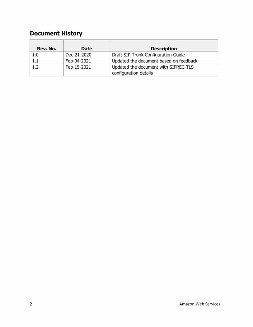
Document History
Rev. No.
Date
Description
1.0 Dec-21-2020 Draft SIP Trunk Configuration Guide
1.1 Feb-04-2021 Updated the document based on feedback
1.2 Feb-15-2021 Updated the document with SIPREC-TLS
configuration details
3 Amazon Web Services
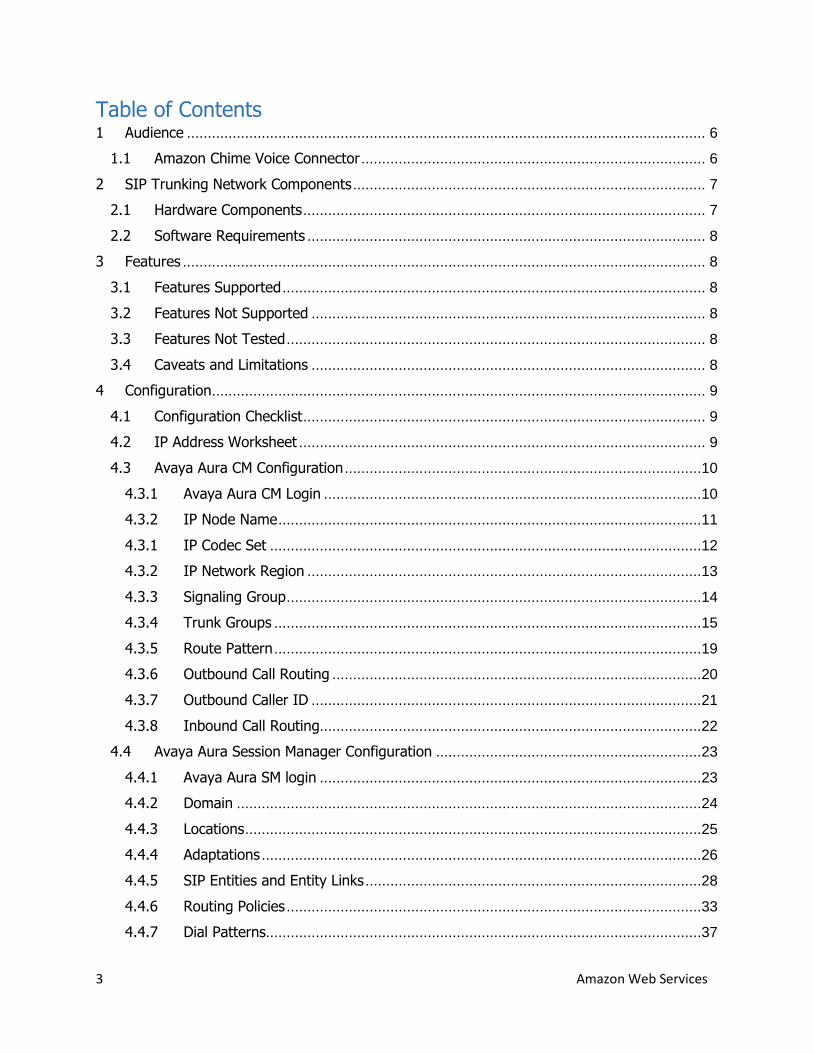
Table of Contents 1 Audience ............................................................................................................................. 6
1.1 Amazon Chime Voice Connector ................................................................................... 6
2 SIP Trunking Network Components ..................................................................................... 7
2.1 Hardware Components ................................................................................................. 7
2.2 Software Requirements ................................................................................................ 8
3 Features .............................................................................................................................. 8
3.1 Features Supported ...................................................................................................... 8
3.2 Features Not Supported ............................................................................................... 8
3.3 Features Not Tested ..................................................................................................... 8
3.4 Caveats and Limitations ............................................................................................... 8
4 Configuration ....................................................................................................................... 9
4.1 Configuration Checklist ................................................................................................. 9
4.2 IP Address Worksheet .................................................................................................. 9
4.3 Avaya Aura CM Configuration ......................................................................................10
4.3.1 Avaya Aura CM Login ...........................................................................................10
4.3.2 IP Node Name ......................................................................................................11
4.3.1 IP Codec Set ........................................................................................................12
4.3.2 IP Network Region ...............................................................................................13
4.3.3 Signaling Group ....................................................................................................14
4.3.4 Trunk Groups .......................................................................................................15
4.3.5 Route Pattern .......................................................................................................19
4.3.6 Outbound Call Routing .........................................................................................20
4.3.7 Outbound Caller ID ..............................................................................................21
4.3.8 Inbound Call Routing............................................................................................22
4.4 Avaya Aura Session Manager Configuration ................................................................23
4.4.1 Avaya Aura SM login ............................................................................................23
4.4.2 Domain ................................................................................................................24
4.4.3 Locations ..............................................................................................................25
4.4.4 Adaptations ..........................................................................................................26
4.4.5 SIP Entities and Entity Links .................................................................................28
4.4.6 Routing Policies ....................................................................................................33
4.4.7 Dial Patterns.........................................................................................................37
4 Amazon Web Services
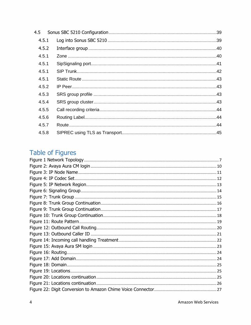
4.5 Sonus SBC 5210 Configuration ....................................................................................39
4.5.1 Log into Sonus SBC 5210 .....................................................................................39
4.5.2 Interface group ....................................................................................................40
4.5.1 Zone ....................................................................................................................40
4.5.1 SipSignaling port ..................................................................................................41
4.5.1 SIP Trunk .............................................................................................................42
4.5.1 Static Route .........................................................................................................43
4.5.2 IP Peer.................................................................................................................43
4.5.3 SRS group profile ................................................................................................43
4.5.4 SRS group cluster ................................................................................................43
4.5.5 Call recording criteria ...........................................................................................44
4.5.6 Routing Label.......................................................................................................44
4.5.7 Route ...................................................................................................................44
4.5.8 SIPREC using TLS as Transport..........................................................................45
Table of Figures Figure 1 Network Topology ....................................................................................................................... 7
Figure 2: Avaya Aura CM login ............................................................................................................... 10
Figure 3: IP Node Name .......................................................................................................................... 11
Figure 4: IP Codec Set ............................................................................................................................. 12
Figure 5: IP Network Region................................................................................................................... 13
Figure 6: Signaling Group ........................................................................................................................ 14
Figure 7: Trunk Group ............................................................................................................................. 15
Figure 8: Trunk Group Continuation ...................................................................................................... 16
Figure 9: Trunk Group Continuation ...................................................................................................... 17
Figure 10: Trunk Group Continuation .................................................................................................... 18
Figure 11: Route Pattern ......................................................................................................................... 19
Figure 12: Outbound Call Routing.......................................................................................................... 20
Figure 13: Outbound Caller ID ............................................................................................................... 21
Figure 14: Incoming call handling Treatment ...................................................................................... 22
Figure 15: Avaya Aura SM login ............................................................................................................. 23
Figure 16: Routing .................................................................................................................................... 24
Figure 17: Add Domain ............................................................................................................................ 24
Figure 18: Domain .................................................................................................................................... 25
Figure 19: Locations ................................................................................................................................. 25
Figure 20: Locations continuation .......................................................................................................... 25
Figure 21: Locations continuation .......................................................................................................... 26
Figure 22: Digit Conversion to Amazon Chime Voice Connector ....................................................... 27
5 Amazon Web Services
Figure 23: Adaptation for Amazon Chime Voice Connector ............................................................... 27
Figure 24: Adaptation for Amazon Chime Voice Connector cont.., ................................................... 27
Figure 25: SIP Entity for Avaya SM ........................................................................................................ 28
Figure 26: SIP Entity and Entity Links for Avaya CM .......................................................................... 29
Figure 27: SIP Entity and Entity Links for Avaya CM continuation ................................................... 30
Figure 28: SIP Entity and Entity Link for Avaya CM continuation ..................................................... 30
Figure 29: SIP Entity and Entity Link for Sonus SBC........................................................................... 31
Figure 30: SIP Entity and Entity Link for SonusSBC continuation ..................................................... 32
Figure 31: SIP Entity and Entity Link for Sonus SBC continuation .................................................... 32
Figure 32: Routing Policy for Avaya CM ................................................................................................ 33
Figure 33: Routing Policy for Avaya CM continuation ......................................................................... 34
Figure 34: Routing Policy for Avaya CM continuation ......................................................................... 34
Figure 35: Routing Policy for Sonus SBC .............................................................................................. 35
Figure 36: Routing Policy for Sonus SBC continuation ....................................................................... 35
Figure 37: Routing Policy for Sonus SBC continuation ....................................................................... 36
Figure 38: Dial Pattern to Avaya CM ..................................................................................................... 37
Figure 39: Dial Pattern to Amazon Chime Voice Connector via Sonus SBC .................................... 38
Figure 40: Sonus 5210 login ................................................................................................................... 39
6 Amazon Web Services
1 Audience
This document is intended for technical staff and Value Added Resellers (VAR) with installation
and operational responsibilities. This configuration guide provides steps for configuring SIPREC
using Avaya Aura Communication Manager (Avaya Aura CM), Avaya Aura Session
Manager (Avaya Aura SM) with Sonus SBC 5210 to connect to Amazon Chime Voice
Connector for Streaming media to Kinesis.
The information in this document is for informational purposes only. AWS does not guarantee
the accuracy of this document and AWS has no responsibility or liability for errors or omissions
related to this document. The document is subject to change without notice, and should not be
construed as a commitment by AWS.
1.1 Amazon Chime Voice Connector
Amazon Chime Voice Connector is a pay-as-you-go service that enables companies to make or
receive secure phone calls over the internet or AWS Direct Connect using their existing
telephone system or session border controller (SBC). The service has no upfront fees, elastically
scales based on demand, supports calling both landline and mobile phone numbers in over 100
countries, and gives customers the option to enable inbound calling, outbound calling, or both.
Amazon Chime Voice Connector uses the industry-standard Session Initiation Protocol (SIP).
Amazon Chime Voice Connector does not require dedicated data circuits. A company can use
their existing Internet connection or AWS Direct Connect public virtual interface for SIP
connectivity to AWS. Voice connectors can be configured in minutes using the AWS
Management Console or Amazon Chime API. Amazon Chime Voice Connector offers cost-
effective rates for inbound and outbound calls. Calls into Amazon Chime meetings, as well as
calls to other Amazon Chime Voice Connector customers are at no additional cost. With Amazon
Chime Voice Connector, companies can reduce their voice calling costs without having to
replace their on-premises phone system.
7 Amazon Web Services
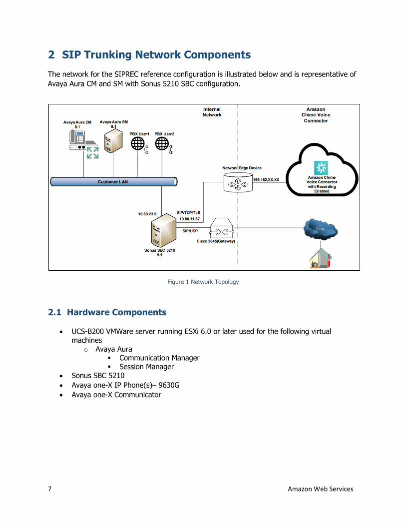
2 SIP Trunking Network Components
The network for the SIPREC reference configuration is illustrated below and is representative of
Avaya Aura CM and SM with Sonus 5210 SBC configuration.
Figure 1 Network Topology
2.1 Hardware Components
UCS-B200 VMWare server running ESXi 6.0 or later used for the following virtual machines
o Avaya Aura Communication Manager Session Manager
Sonus SBC 5210
Avaya one-X IP Phone(s)– 9630G
Avaya one-X Communicator
8 Amazon Web Services
2.2 Software Requirements
Avaya Aura
o Session Manager: 8.1.3.0
o Communication Manager: 8.1.3.0
o System Manager: 8.1.3.0
Sonus SBC 5210: 9.1
3 Features
3.1 Features Supported
SIPREC
3.2 Features Not Supported
None
3.3 Features Not Tested
None
3.4 Caveats and Limitations
None
9 Amazon Web Services
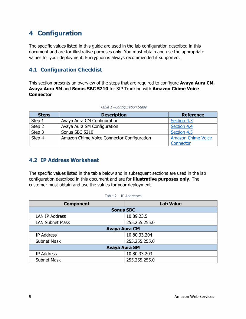
4 Configuration
The specific values listed in this guide are used in the lab configuration described in this
document and are for illustrative purposes only. You must obtain and use the appropriate
values for your deployment. Encryption is always recommended if supported.
4.1 Configuration Checklist
This section presents an overview of the steps that are required to configure Avaya Aura CM,
Avaya Aura SM and Sonus SBC 5210 for SIP Trunking with Amazon Chime Voice
Connector
Table 1 –Configuration Steps
Steps Description Reference
Step 1 Avaya Aura CM Configuration Section 4.3
Step 2 Avaya Aura SM Configuration Section 4.4
Step 3 Sonus SBC 5210 Section 4.5
Step 4 Amazon Chime Voice Connector Configuration Amazon Chime Voice Connector
4.2 IP Address Worksheet
The specific values listed in the table below and in subsequent sections are used in the lab
configuration described in this document and are for illustrative purposes only. The
customer must obtain and use the values for your deployment.
Table 2 – IP Addresses
Component Lab Value
Sonus SBC
LAN IP Address 10.89.23.5
LAN Subnet Mask 255.255.255.0
Avaya Aura CM
IP Address 10.80.33.204
Subnet Mask 255.255.255.0
Avaya Aura SM
IP Address 10.80.33.203
Subnet Mask 255.255.255.0
10 Amazon Web Services
4.3 Avaya Aura CM Configuration
This section with screen shots taken from Avaya Aura CM used for the interoperability testing
gives a general overview of the PBX configuration
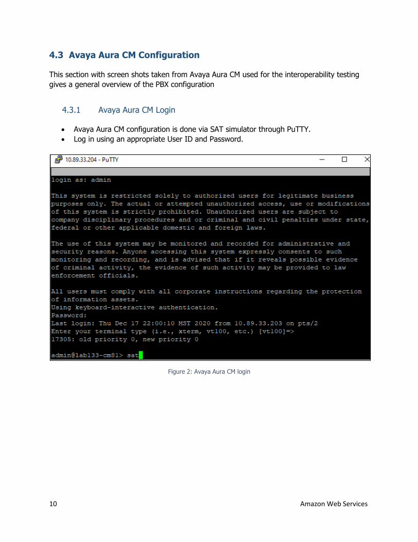
4.3.1 Avaya Aura CM Login
Avaya Aura CM configuration is done via SAT simulator through PuTTY.
Log in using an appropriate User ID and Password.
Figure 2: Avaya Aura CM login
11 Amazon Web Services
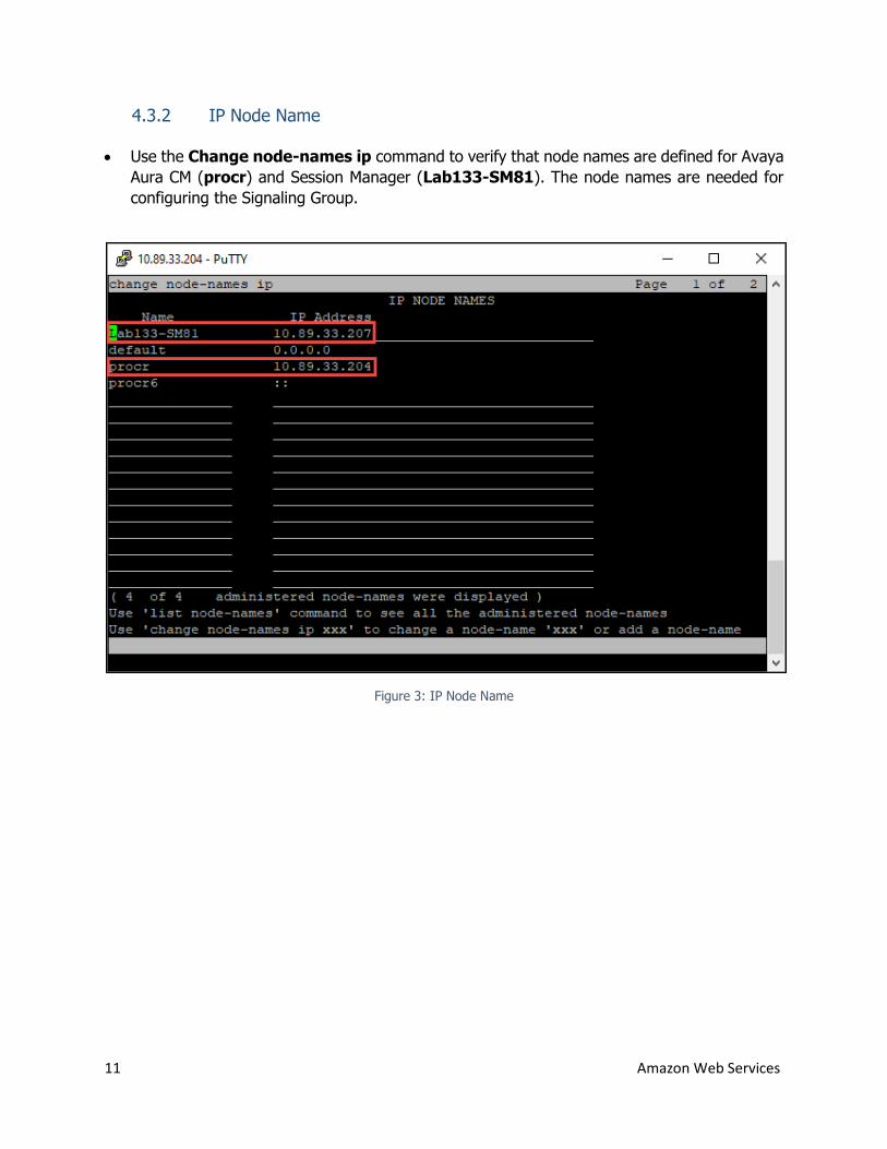
4.3.2 IP Node Name
Use the Change node-names ip command to verify that node names are defined for Avaya
Aura CM (procr) and Session Manager (Lab133-SM81). The node names are needed for
configuring the Signaling Group.
Figure 3: IP Node Name
12 Amazon Web Services
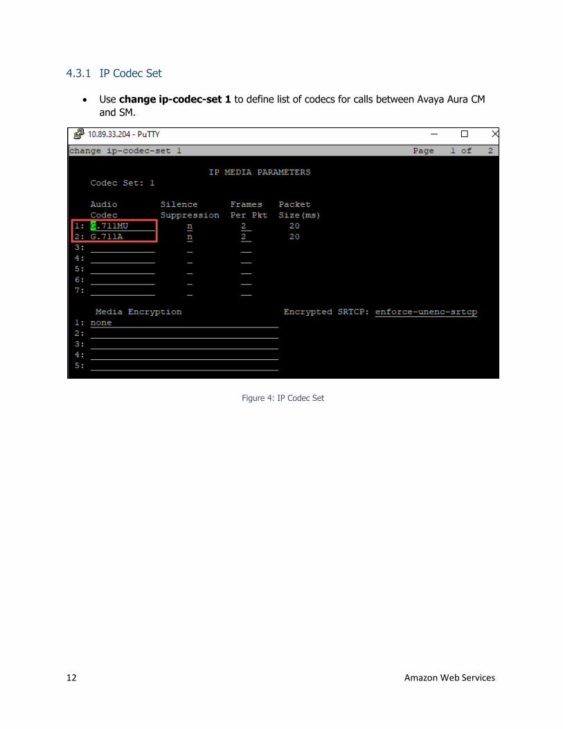
4.3.1 IP Codec Set
Use change ip-codec-set 1 to define list of codecs for calls between Avaya Aura CM
and SM.
Figure 4: IP Codec Set
13 Amazon Web Services
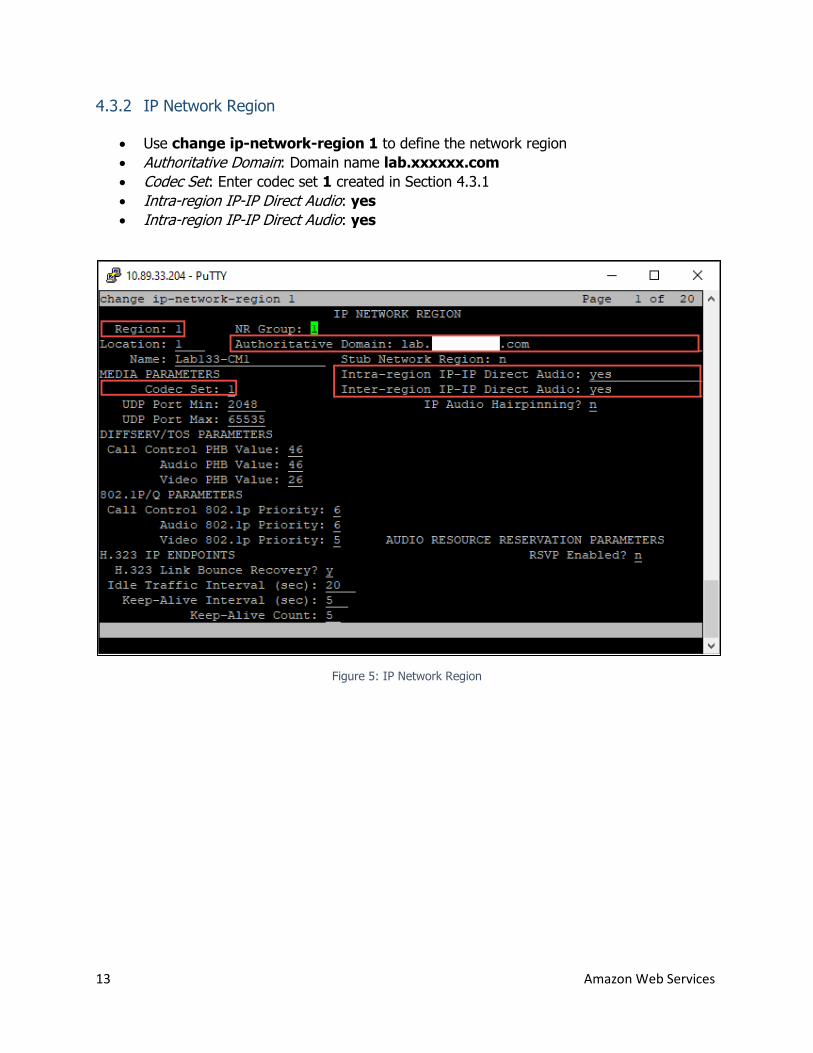
4.3.2 IP Network Region
Use change ip-network-region 1 to define the network region
Authoritative Domain: Domain name lab.xxxxxx.com
Codec Set: Enter codec set 1 created in Section 4.3.1
Intra-region IP-IP Direct Audio: yes
Intra-region IP-IP Direct Audio: yes
Figure 5: IP Network Region
14 Amazon Web Services
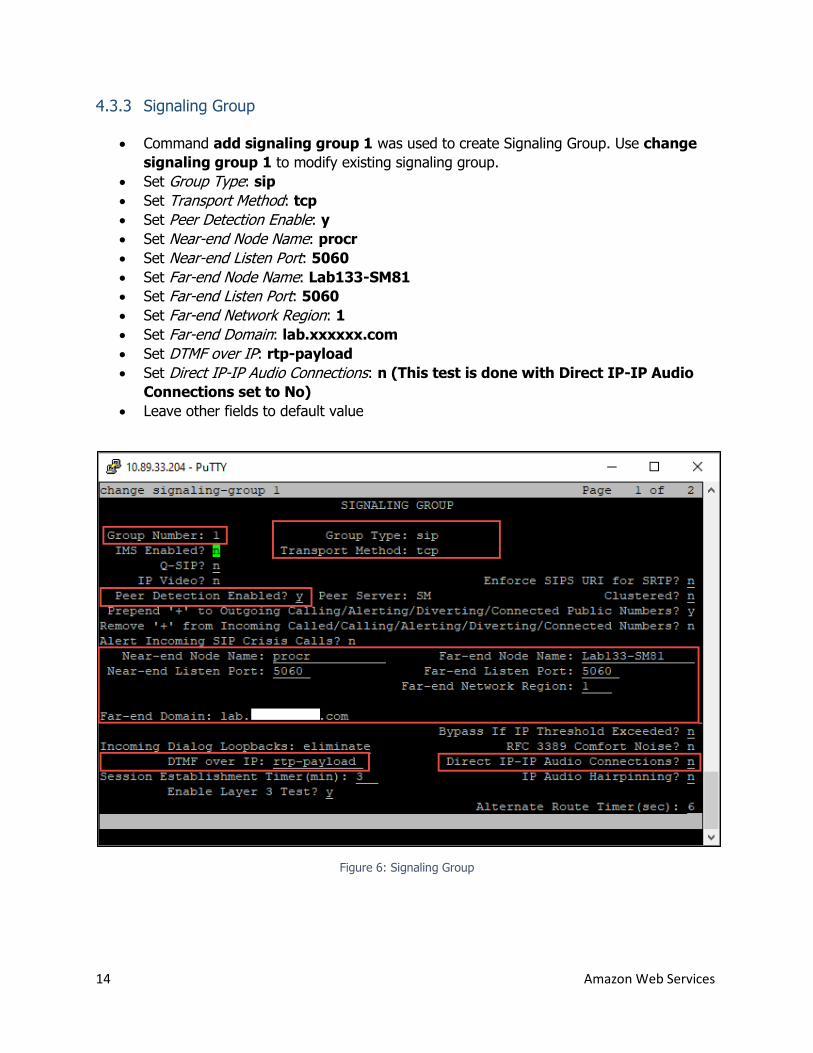
4.3.3 Signaling Group
Command add signaling group 1 was used to create Signaling Group. Use change
signaling group 1 to modify existing signaling group.
Set Group Type: sip
Set Transport Method: tcp
Set Peer Detection Enable: y
Set Near-end Node Name: procr
Set Near-end Listen Port: 5060
Set Far-end Node Name: Lab133-SM81
Set Far-end Listen Port: 5060
Set Far-end Network Region: 1
Set Far-end Domain: lab.xxxxxx.com
Set DTMF over IP: rtp-payload
Set Direct IP-IP Audio Connections: n (This test is done with Direct IP-IP Audio
Connections set to No)
Leave other fields to default value
Figure 6: Signaling Group
15 Amazon Web Services
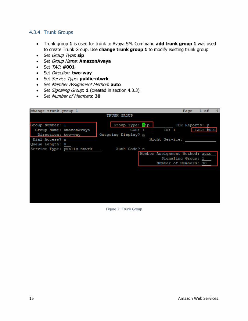
4.3.4 Trunk Groups
Trunk group 1 is used for trunk to Avaya SM. Command add trunk group 1 was used
to create Trunk Group. Use change trunk group 1 to modify existing trunk group.
Set Group Type: sip
Set Group Name: AmazonAvaya
Set TAC: #001
Set Direction: two-way
Set Service Type: public-ntwrk
Set Member Assignment Method: auto
Set Signaling Group: 1 (created in section 4.3.3)
Set Number of Members: 30
Figure 7: Trunk Group
16 Amazon Web Services
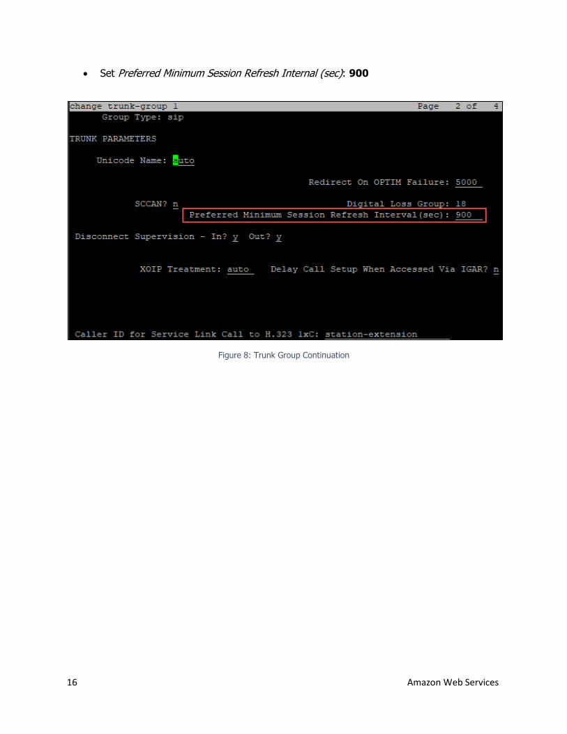
Set Preferred Minimum Session Refresh Internal (sec): 900
Figure 8: Trunk Group Continuation
17 Amazon Web Services
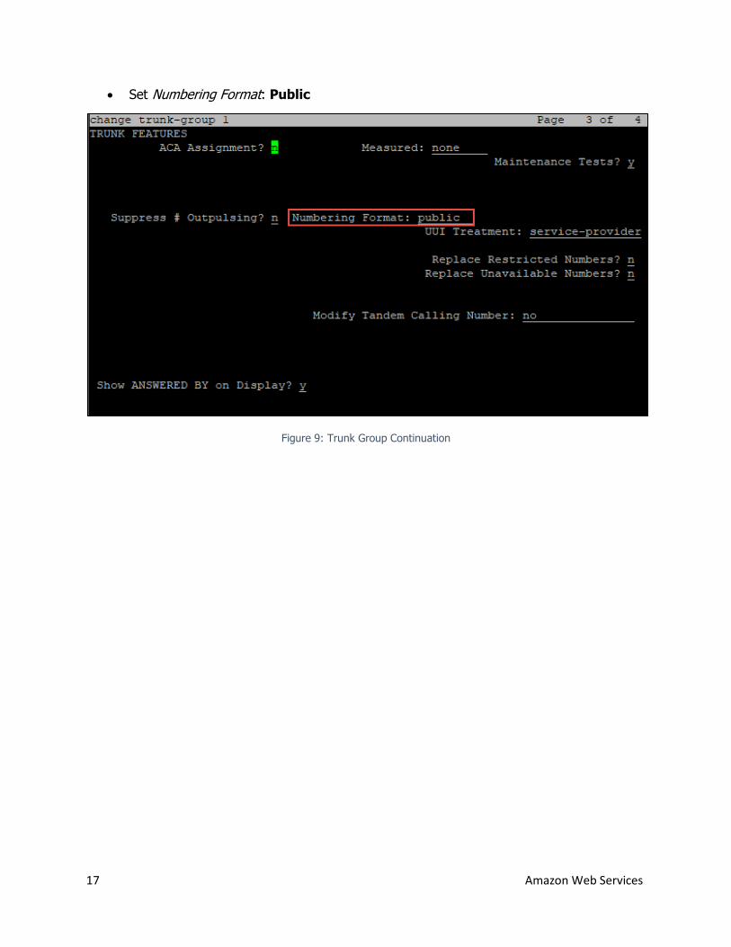
Set Numbering Format: Public
Figure 9: Trunk Group Continuation
18 Amazon Web Services
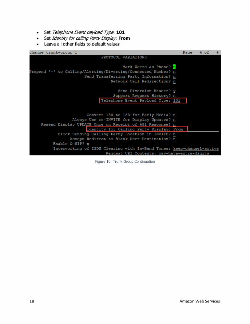
Set Telephone Event payload Type: 101
Set Identity for calling Party Display: From
Leave all other fields to default values
Figure 10: Trunk Group Continuation
19 Amazon Web Services
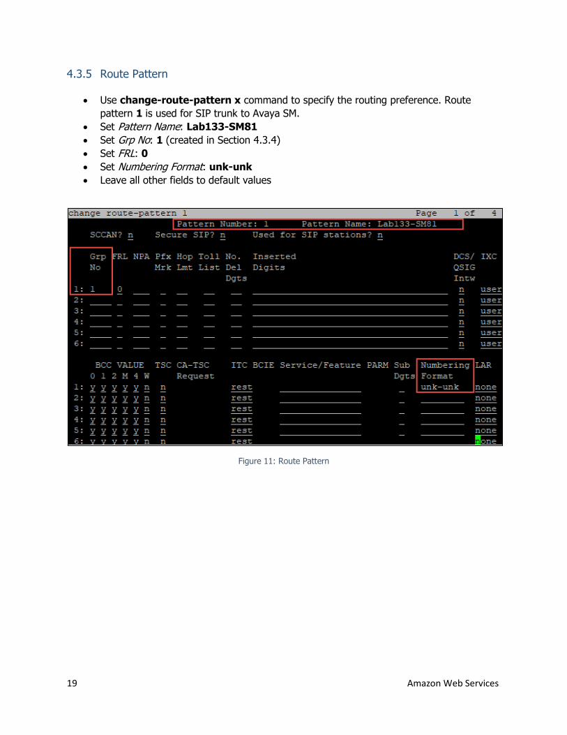
4.3.5 Route Pattern
Use change-route-pattern x command to specify the routing preference. Route
pattern 1 is used for SIP trunk to Avaya SM.
Set Pattern Name: Lab133-SM81
Set Grp No: 1 (created in Section 4.3.4)
Set FRL: 0
Set Numbering Format: unk-unk
Leave all other fields to default values
Figure 11: Route Pattern
20 Amazon Web Services
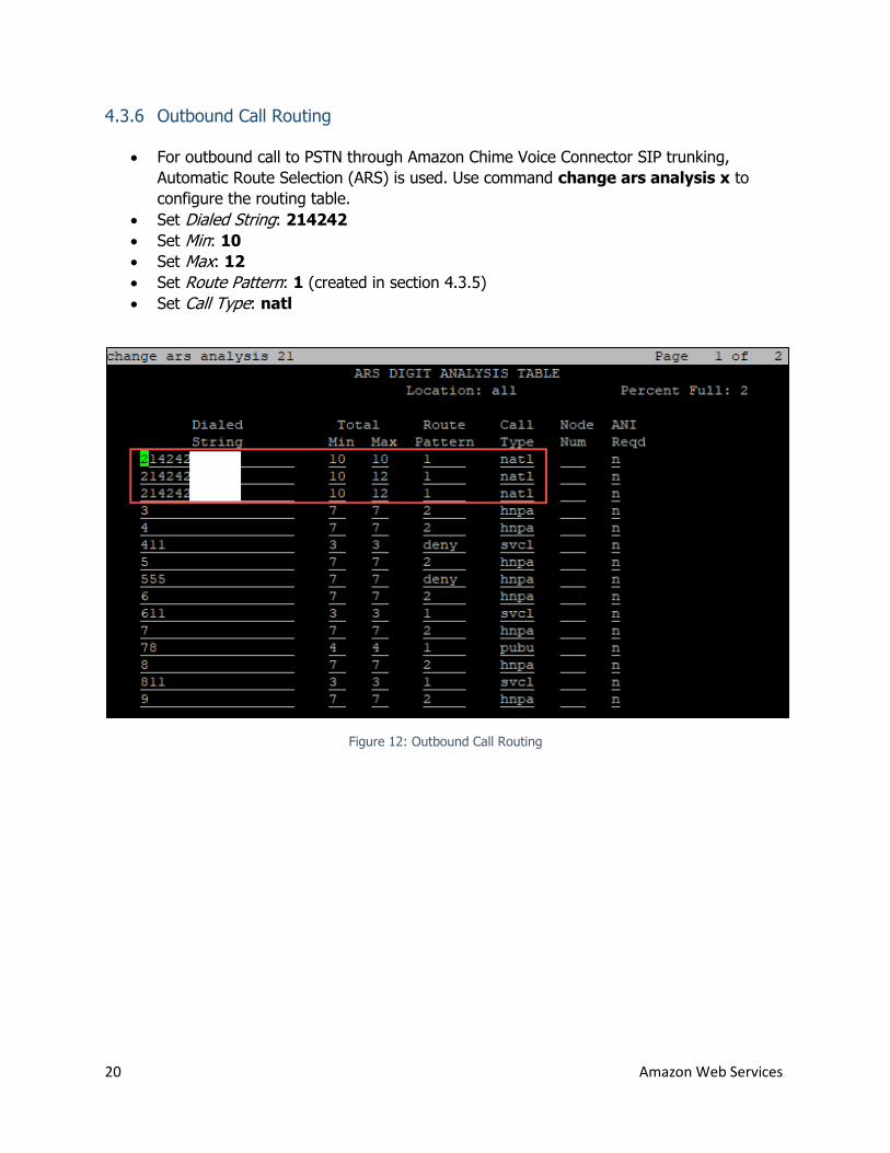
4.3.6 Outbound Call Routing
For outbound call to PSTN through Amazon Chime Voice Connector SIP trunking,
Automatic Route Selection (ARS) is used. Use command change ars analysis x to
configure the routing table.
Set Dialed String: 214242
Set Min: 10
Set Max: 12
Set Route Pattern: 1 (created in section 4.3.5)
Set Call Type: natl
Figure 12: Outbound Call Routing
21 Amazon Web Services
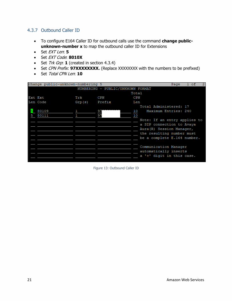
4.3.7 Outbound Caller ID
To configure E164 Caller ID for outbound calls use the command change public-
unknown-number x to map the outbound caller ID for Extensions
Set EXT Len: 5
Set EXT Code: 8010X
Set Trk Grp: 1 (created in section 4.3.4)
Set CPN Prefix: 97XXXXXXXX. (Replace XXXXXXXX with the numbers to be prefixed)
Set Total CPN Len: 10
Figure 13: Outbound Caller ID
22 Amazon Web Services
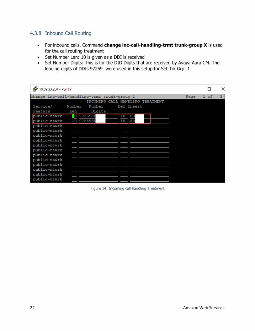
4.3.8 Inbound Call Routing
For inbound calls. Command change inc-call-handling-trmt trunk-group X is used
for the call routing treatment
Set Number Len: 10 is given as a DDI is received Set Number Digits: This is for the DID Digits that are received by Avaya Aura CM. The
leading digits of DDIs 97259 were used in this setup for Set Trk Grp: 1
Figure 14: Incoming call handling Treatment
23 Amazon Web Services
4.4 Avaya Aura Session Manager Configuration
This section with screen shots taken from Avaya Aura SM used for the interoperability testing
gives a general overview of Session Manager Configuration
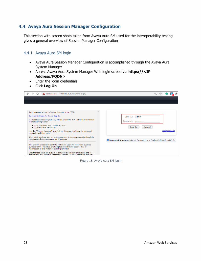
4.4.1 Avaya Aura SM login
Avaya Aura Session Manager Configuration is accomplished through the Avaya Aura
System Manager
Access Avaya Aura System Manager Web login screen via https://<IP
Address/FQDN>
Enter the login credentials
Click Log On
Figure 15: Avaya Aura SM login
24 Amazon Web Services
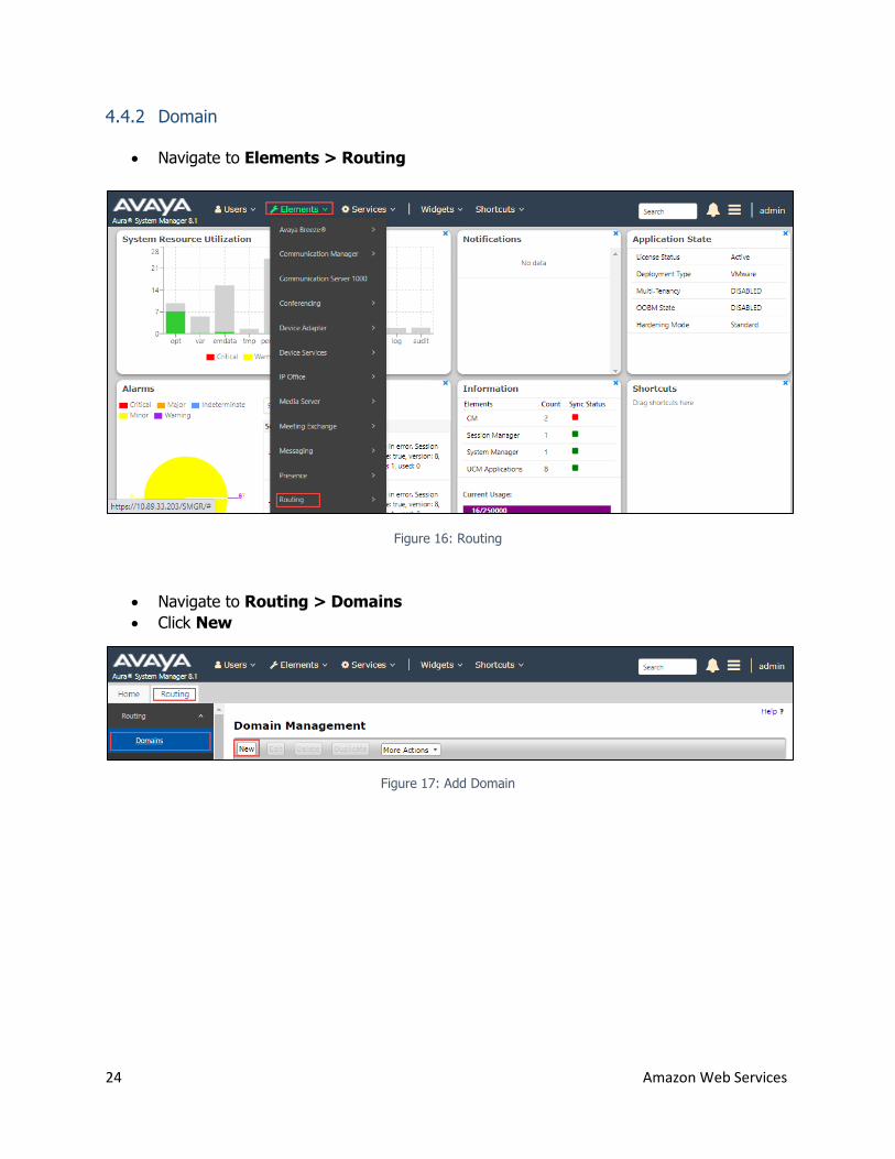
4.4.2 Domain
Navigate to Elements > Routing
Figure 16: Routing
Navigate to Routing > Domains
Click New
Figure 17: Add Domain
25 Amazon Web Services
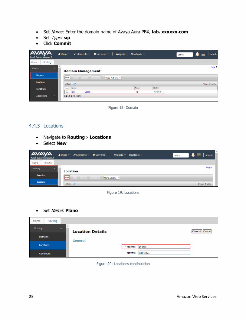
Set Name: Enter the domain name of Avaya Aura PBX, lab. xxxxxx.com
Set Type: sip
Click Commit
Figure 18: Domain
4.4.3 Locations
Navigate to Routing > Locations
Select New
Figure 19: Locations
Set Name: Plano
Figure 20: Locations continuation
26 Amazon Web Services
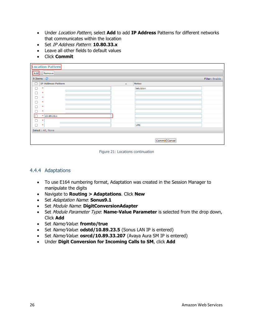
Under Location Pattern, select Add to add IP Address Patterns for different networks
that communicates within the location
Set IP Address Pattern: 10.80.33.x
Leave all other fields to default values
Click Commit
Figure 21: Locations continuation
4.4.4 Adaptations
To use E164 numbering format, Adaptation was created in the Session Manager to
manipulate the digits
Navigate to Routing > Adaptations. Click New
Set Adaptation Name: Sonus9.1
Set Module Name: DigitConversionAdapter
Set Module Parameter Type: Name-Value Parameter is selected from the drop down,
Click Add
Set Name/Value: fromto/true
Set Name/Value: odstd/10.89.23.5 (Sonus LAN IP is entered)
Set Name/Value: osrcd/10.89.33.207 (Avaya Aura SM IP is entered)
Under Digit Conversion for Incoming Calls to SM, click Add
27 Amazon Web Services
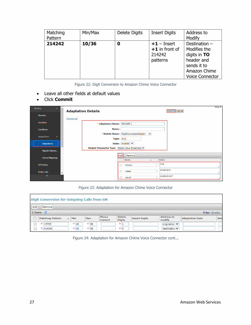
Matching Pattern
Min/Max Delete Digits Insert Digits Address to Modify
214242 10/36 0 +1 – Insert +1 in front of 214242 patterns
Destination – Modifies the digits in TO header and sends it to Amazon Chime Voice Connector
Figure 22: Digit Conversion to Amazon Chime Voice Connector
Leave all other fields at default values
Click Commit
Figure 23: Adaptation for Amazon Chime Voice Connector
Figure 24: Adaptation for Amazon Chime Voice Connector cont..,
28 Amazon Web Services
4.4.5 SIP Entities and Entity Links
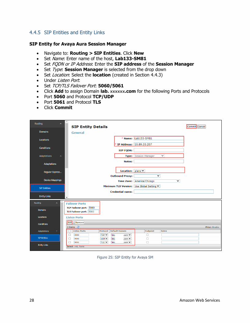
SIP Entity for Avaya Aura Session Manager
Navigate to: Routing > SIP Entities. Click New Set Name: Enter name of the host, Lab133-SM81 Set FQDN or IP Address: Enter the SIP address of the Session Manager Set Type: Session Manager is selected from the drop down Set Location: Select the location (created in Section 4.4.3) Under Listen Port: Set TCP/TLS Failover Port: 5060/5061 Click Add to assign Domain lab. xxxxxx.com for the following Ports and Protocols Port 5060 and Protocol TCP/UDP Port 5061 and Protocol TLS Click Commit
Figure 25: SIP Entity for Avaya SM
29 Amazon Web Services
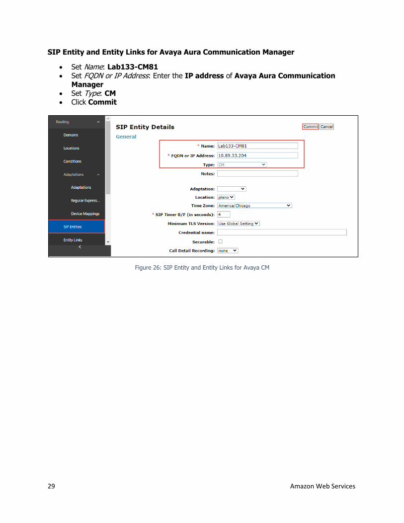
SIP Entity and Entity Links for Avaya Aura Communication Manager
Set Name: Lab133-CM81 Set FQDN or IP Address: Enter the IP address of Avaya Aura Communication
Manager Set Type: CM Click Commit
Figure 26: SIP Entity and Entity Links for Avaya CM
30 Amazon Web Services
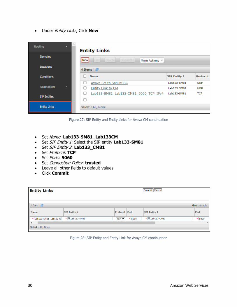
Under Entity Links, Click New
Figure 27: SIP Entity and Entity Links for Avaya CM continuation
Set Name: Lab133-SM81_Lab133CM Set SIP Entity 1: Select the SIP entity Lab133-SM81
Set SIP Entity 2: Lab133_CM81 Set Protocol: TCP Set Ports: 5060 Set Connection Policy: trusted Leave all other fields to default values Click Commit
Figure 28: SIP Entity and Entity Link for Avaya CM continuation
31 Amazon Web Services
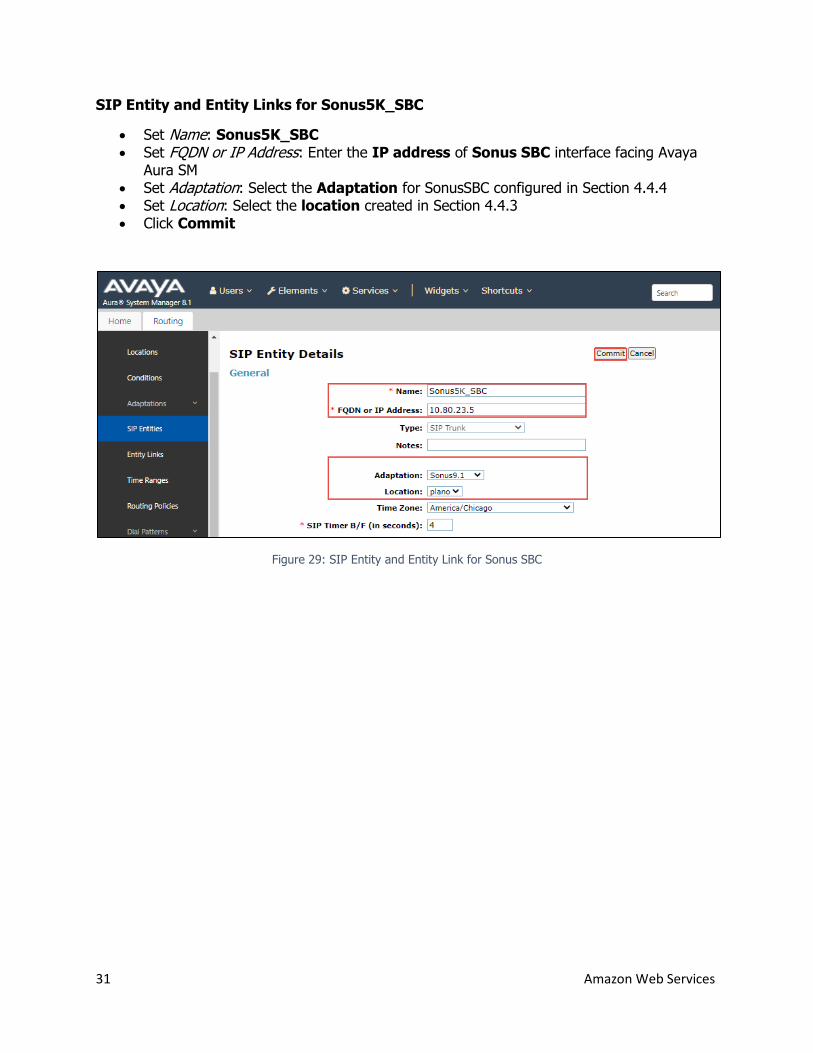
SIP Entity and Entity Links for Sonus5K_SBC
Set Name: Sonus5K_SBC Set FQDN or IP Address: Enter the IP address of Sonus SBC interface facing Avaya
Aura SM Set Adaptation: Select the Adaptation for SonusSBC configured in Section 4.4.4 Set Location: Select the location created in Section 4.4.3 Click Commit
Figure 29: SIP Entity and Entity Link for Sonus SBC
32 Amazon Web Services
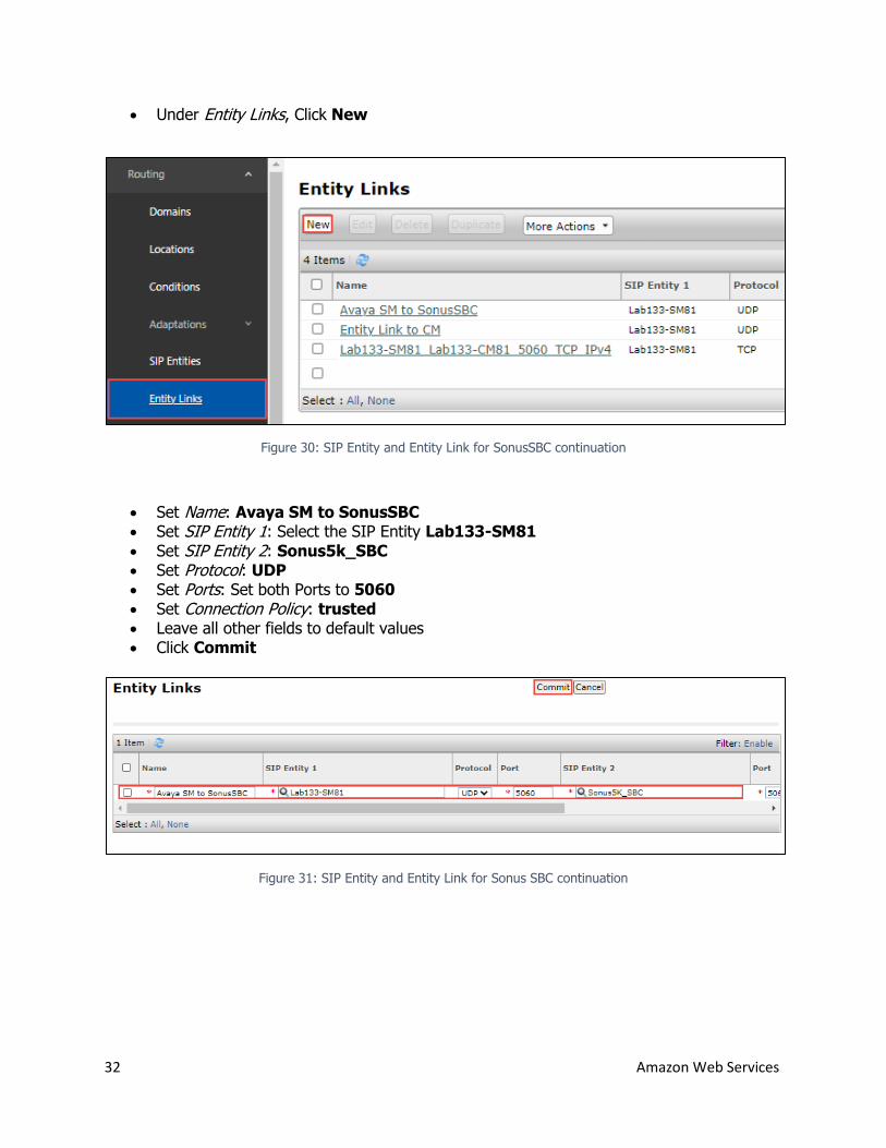
Under Entity Links, Click New
Figure 30: SIP Entity and Entity Link for SonusSBC continuation
Set Name: Avaya SM to SonusSBC Set SIP Entity 1: Select the SIP Entity Lab133-SM81
Set SIP Entity 2: Sonus5k_SBC Set Protocol: UDP Set Ports: Set both Ports to 5060 Set Connection Policy: trusted Leave all other fields to default values Click Commit
Figure 31: SIP Entity and Entity Link for Sonus SBC continuation
33 Amazon Web Services
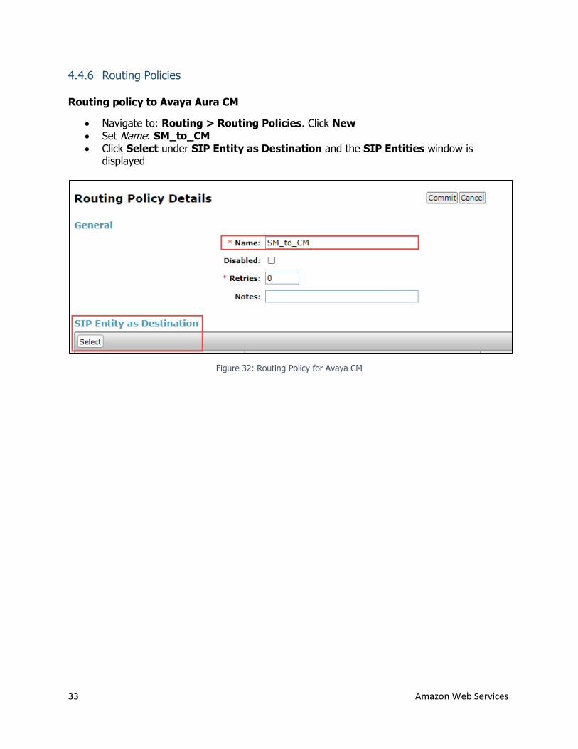
4.4.6 Routing Policies
Routing policy to Avaya Aura CM
Navigate to: Routing > Routing Policies. Click New Set Name: SM_to_CM Click Select under SIP Entity as Destination and the SIP Entities window is
displayed
Figure 32: Routing Policy for Avaya CM
34 Amazon Web Services
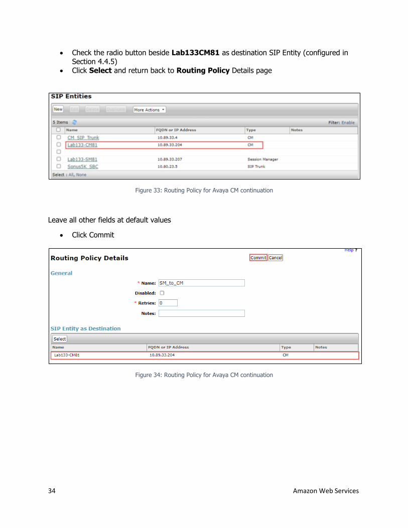
Check the radio button beside Lab133CM81 as destination SIP Entity (configured in Section 4.4.5)
Click Select and return back to Routing Policy Details page
Figure 33: Routing Policy for Avaya CM continuation
Leave all other fields at default values
Click Commit
Figure 34: Routing Policy for Avaya CM continuation
35 Amazon Web Services
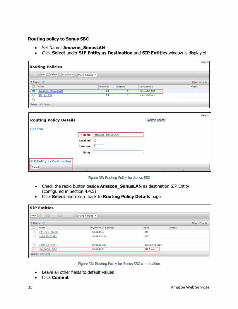
Routing policy to Sonus SBC
Set Name: Amazon_SonusLAN Click Select under SIP Entity as Destination and SIP Entities window is displayed.
Figure 35: Routing Policy for Sonus SBC
Check the radio button beside Amazon_SonusLAN as destination SIP Entity (configured in Section 4.4.5)
Click Select and return back to Routing Policy Details page
Figure 36: Routing Policy for Sonus SBC continuation
Leave all other fields to default values Click Commit
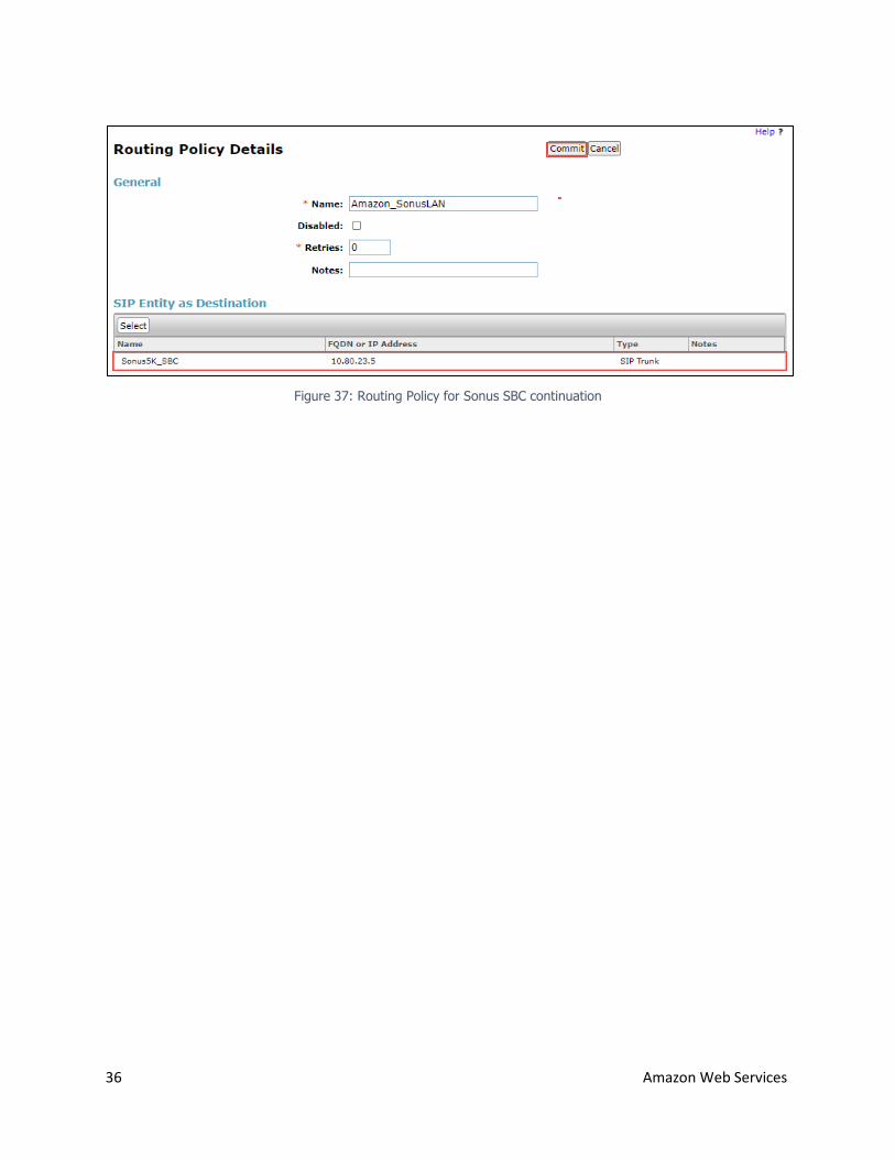
36 Amazon Web Services
Figure 37: Routing Policy for Sonus SBC continuation
37 Amazon Web Services
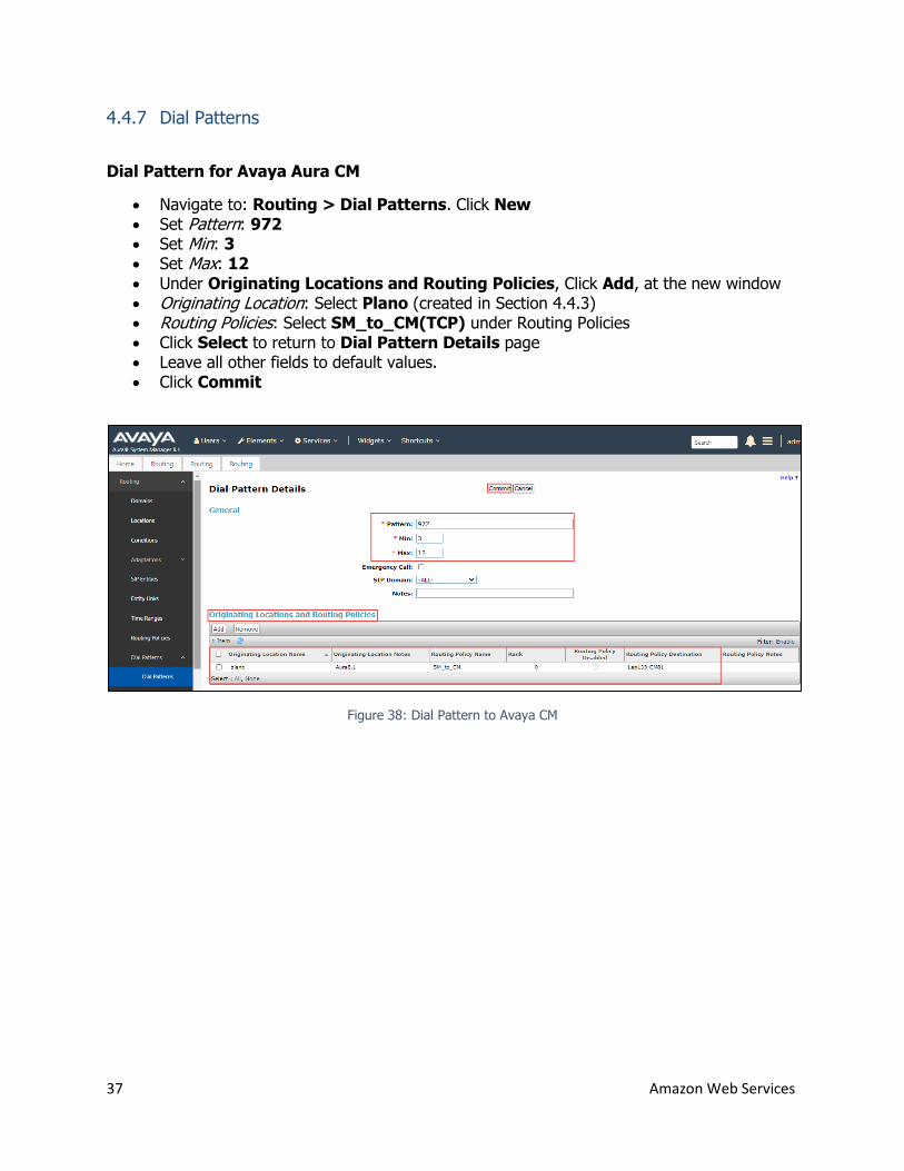
4.4.7 Dial Patterns
Dial Pattern for Avaya Aura CM
Navigate to: Routing > Dial Patterns. Click New Set Pattern: 972 Set Min: 3 Set Max: 12
Under Originating Locations and Routing Policies, Click Add, at the new window Originating Location: Select Plano (created in Section 4.4.3) Routing Policies: Select SM_to_CM(TCP) under Routing Policies Click Select to return to Dial Pattern Details page Leave all other fields to default values. Click Commit
Figure 38: Dial Pattern to Avaya CM
38 Amazon Web Services
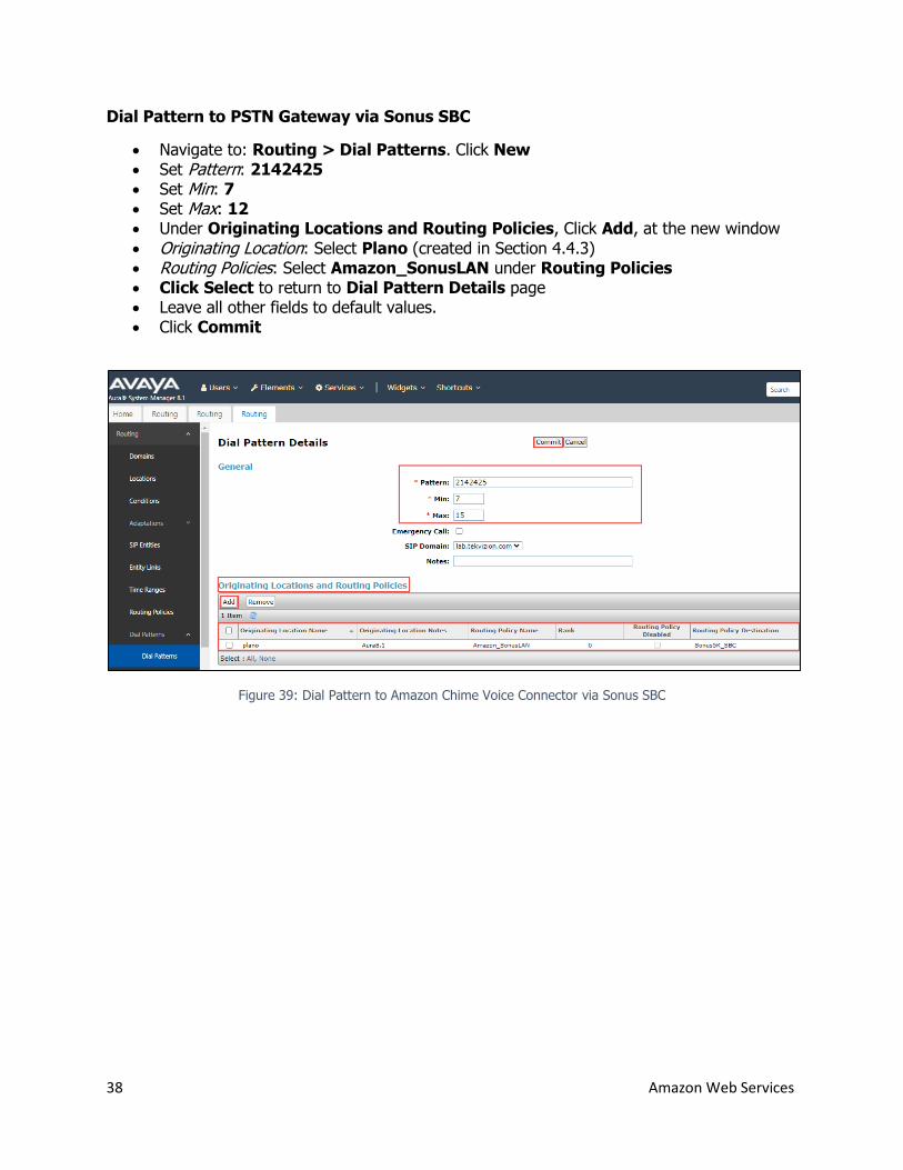
Dial Pattern to PSTN Gateway via Sonus SBC
Navigate to: Routing > Dial Patterns. Click New Set Pattern: 2142425 Set Min: 7 Set Max: 12 Under Originating Locations and Routing Policies, Click Add, at the new window
Originating Location: Select Plano (created in Section 4.4.3) Routing Policies: Select Amazon_SonusLAN under Routing Policies Click Select to return to Dial Pattern Details page Leave all other fields to default values. Click Commit
Figure 39: Dial Pattern to Amazon Chime Voice Connector via Sonus SBC
39 Amazon Web Services
4.5 Sonus SBC 5210 Configuration
This section provides a general overview of the configuration along with SIPREC based
configuration with Amazon Chime Voice Connector that needs to be performed in Sonus SBC
5210
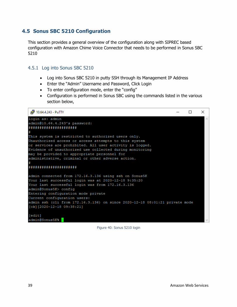
4.5.1 Log into Sonus SBC 5210
Log into Sonus SBC 5210 in putty SSH through its Management IP Address
Enter the “Admin” Username and Password, Click Login
To enter configuration mode, enter the “config”
Configuration is performed in Sonus SBC using the commands listed in the various
section below,
Figure 40: Sonus 5210 login
40 Amazon Web Services
4.5.2 Interface group
Sonus LAN:
set addressContext default ipInterfaceGroup LIF4 ipInterface PKT0_V4 ceName Sonus LAN portName pkt0
set addressContext default ipInterfaceGroup LIF4 ipInterface PKT0_V4 ipAddress 10.80.23.5 prefix 24
set addressContext default ipInterfaceGroup LIF4 ipInterface PKT0_V4 mode inService state enabled
commit Sonus WAN:
set addressContext default ipInterfaceGroup LIF4 ipInterface PKT1_V4 ceName Sonus LAN portName pkt1
set addressContext default ipInterfaceGroup LIF4 ipInterface PKT1_V4 ipAddress 10.80.11.67 prefix 24
set addressContext default ipInterfaceGroup LIF4 ipInterface PKT1_V4 mode inService state enabled
commit
4.5.1 Zone
Avaya SM:
set addressContext default zone Avaya id 401
commit
Amazon Chime Voice Connector:
set addressContext default zone AWS_Zone id 303
commit
PSTN Gateway:
set addressContext default zone PSTN_Zone id 302
commit
41 Amazon Web Services
4.5.1 SipSignaling port
Avaya SM:
set addressContext default zone Avaya sipSigPort 7 ipInterfaceGroupName LIF1 set addressContext default zone Avaya sipSigPort 7 ipAddressV4 10.80.23.5 set addressContext default zone Avaya sipSigPort 7 portNumber 5060
set addressContext default zone Avaya sipSigPort 7 mode inService set addressContext default zone Avaya sipSigPort 7 state enabled set addressContext default zone Avaya sipSigPort 7 transportProtocolsAllowed sip-udp,
sip-tcp commit
Amazon Chime Voice Connector:
set addressContext default zone AWS_Zone sipSigPort 5 ipInterfaceGroupName LIF4
set addressContext default zone AWS_Zone ipAddress 10.80.11.67
set addressContext default zone AWS_Zone ipPort 5062
set addressContext default zone AWS_Zone transportProtocolsAllowed sip-udp, sip-tcp
set addressContext default zone AWS_Zone siprec enabled
set addressContext default zone AWS_Zone mode inService
commit
PSTN Gateway:
set addressContext default zone PSTN_Zone sipSigPort 9 ipInterfaceGroupName LIF4
set addressContext default zone PSTN_Zone ipAddress 10.80.11.67
set addressContext default zone PSTN_Zone ipPort 5060
set addressContext default zone PSTN_Zone transportProtocolsAllowed sip-udp, sip-tcp
set addressContext default zone PSTN_Zone siprec enabled
set addressContext default zone PSTN_Zone mode inService
commit
42 Amazon Web Services
4.5.1 SIP Trunk
Avaya SM:
set addressContext default zone Avaya sipTrunkGroup Avaya_TG state enabled set addressContext default zone Avaya sipTrunkGroup Avaya_TG mode inService set addressContext default zone Avaya sipTrunkGroup Avaya_TG policy disabled set addressContext default zone Avaya sipTrunkGroup Avaya_TG policy callRouting
elementRoutingPriority DEFAULT_IP set addressContext default zone Avaya sipTrunkGroup Avaya_TG policy media
packetServiceProfile DEFAULT set addressContext default zone Avaya sipTrunkGroup Avaya_TG policy signaling
ipSignalingProfile Avaya_IPSP commit
Amazon Chime Voice Connector:
set addressContext default zone AWS_Zone sipTrunkGroup AWS_TG state enabled
set addressContext default zone AWS_Zone sipTrunkGroup AWS_TG mode inService
set addressContext default zone AWS_Zone sipTrunkGroup AWS_TG policy disabled
set addressContext default zone AWS_Zone sipTrunkGroup AWS_TG policy callRouting
elementRoutingPriority DEFAULT_IP set addressContext default zone AWS_Zone sipTrunkGroup AWS_TG policy media
packetServiceProfile DEFAULT set addressContext default zone AWS_Zone sipTrunkGroup AWS_TG policy signaling
ipSignalingProfile Amazon_IPSP commit
PSTN Gateway:
set addressContext default zone PSTN_Zone sipTrunkGroup PSTN_TG state enabled
set addressContext default zone PSTN_Zone sipTrunkGroup PSTN_TG mode inService
set addressContext default zone PSTN_Zone sipTrunkGroup PSTN_TG policy disabled
set addressContext default zone PSTN_Zone sipTrunkGroup PSTN_TG policy callRouting
elementRoutingPriority DEFAULT_IP set addressContext default zone PSTN_Zone sipTrunkGroup PSTN_TG policy media
packetServiceProfile DEFAULT set addressContext default zone PSTN_Zone sipTrunkGroup PSTN_TG policy signaling
ipSignalingProfile PSTN_IPSP commit
43 Amazon Web Services
4.5.1 Static Route
set addressContext default staticRoute 0.0.0.0 0 10.80.11.1 LIF4 PKT1_V4 set addressContext default staticRoute 10.89.33.207 10.80.23.1 LIF1 PKT0_V4 commit
4.5.2 IP Peer
Avaya SM
set addressContext default zone Avaya ipPeer Avaya_Aura ipAddress 10.89.33.207 set addressContext default zone Avaya ipPeer Avaya_Aura ipPort 5060
PSTN Gateway:
set addressContext default zone PSTN_Zone ipPeer PSTN_IPP ipAddress 10.64.1.72 set addressContext default zone PSTN_Zone ipPeer PSTN_IPP ipPort 5060
4.5.3 SRS group profile
set global servers srsGroupProfile SRSGROUP loadDistribution sequence set global servers srsGroupProfile SRSGROUP transport tcp set global servers srsGroupProfile SRSGROUP fqdn dtxxxxx.voiceconnector.chime.aws set global servers srsGroupProfile SRSGROUP fqdnPort 5060 set global servers srsGroupProfile SRSGROUP ipTGId AWS_TG set global servers srsGroupProfile SRSGROUP srtp disable
commit
4.5.4 SRS group cluster
set global servers srsGroupCluster SRSGRP1 srsGroupClusterData 0 srsGroupId SRSGROUP
commit
44 Amazon Web Services
4.5.5 Call recording criteria
set global servers callRecordingCriteria srsGroupClusterId SRSGRP1 set global servers callRecordingCriteria recordingType allLegs set global servers callRecordingCriteria recorderType SIPRec
set global servers callRecordingCriteria criteriaState enable commit
4.5.6 Routing Label
Avaya SM:
set global callRouting routingLabel Avaya_RL routingLabelRoute 2 trunkGroup Avaya_TG set global callRouting routingLabel Avaya_RL routingLabelRoute 2 inService inService
PSTN Gateway:
set global callRouting routingLabel PSTN_RL routingLabelRoute 1 trunkGroup PSTN_TG
set global callRouting routingLabel PSTN_RL routingLabelRoute 1 inService inService
4.5.7 Route
Avaya SM:
set global callRouting route none Sonus_NULL Sonus_NULL standard 972 1 all all ALL none Sonus_NULL routingLabel Avaya_RL
set global callRouting route none Sonus_NULL Sonus_NULL standard 972 Sonus_NULL all all ALL none Sonus_NULL routingLabel Avaya_RL
PSTN Gateway:
set global callRouting route none Sonus_NULL Sonus_NULL standard 214 1 all all ALL none Sonus_NULL routingLabel PSTN_RL
set global callRouting route none Sonus_NULL Sonus_NULL standard 214 Sonus_NULL all all ALL none Sonus_NULL routingLabel PSTN_RL
45 Amazon Web Services
4.5.8 SIPREC using TLS as Transport
4.5.8.1 Import Public CA Root Certificate
The uploaded Trust certificate was provided by Amazon and the certificate can be downloaded
from the Amazon Chime Voice Connector console
set system security pki certificate Amazon_CA_Cert state enabled set system security pki certificate Amazon_CA_Cert fileName Amazon_CA.der set system security pki certificate Amazon_CA_Cert type remote Commit
4.5.8.2 Create TLS Profile
set profiles security tlsProfile TLS_Prof_Amazon cipherSuite2 rsa-with-aes-128-cbc-sha-
256 set profiles security tlsProfile TLS_Prof_Amazon cipherSuite3 rsa-with-aes-256-cbc-sha-
256 set profiles security tlsProfile TLS_Prof_Amazon allowedRoles clientandserver set profiles security tlsProfile TLS_Prof_Amazon authClient false set profiles security tlsProfile TLS_Prof_Amazon clientCertName Amazon_CA_cert set profiles security tlsProfile TLS_Prof_Amazon serverCertName Amazon_CA_cert set profiles security tlsProfile TLS_Prof_Amazon acceptableCertValidationErrors
invalidPurpose Commit
4.5.8.3 SipSignaling port
set addressContext default zone AWS_Zone sipSigPort 5 ipInterfaceGroupName LIF4 set addressContext default zone AWS_Zone ipAddress 10.80.11.67 set addressContext default zone AWS_Zone ipPort 5062 set addressContext default zone AWS_Zone transportProtocolsAllowed sip-tls-tcp set addressContext default zone AWS_ZONE sipSigPort 5 tlsProfileName
TLS_prof_Amazon set addressContext default zone AWS_Zone siprec enabled set addressContext default zone AWS_Zone mode inService commit
46 Amazon Web Services
4.5.8.4 SIP Trunk
set addressContext default zone AWS_Zone sipTrunkGroup AWS_TG state enabled set addressContext default zone AWS_Zone sipTrunkGroup AWS_TG mode inService set addressContext default zone AWS_Zone sipTrunkGroup AWS_TG policy disabled set addressContext default zone AWS_Zone sipTrunkGroup AWS_TG policy callRouting
elementRoutingPriority DEFAULT_IP set addressContext default zone AWS_Zone sipTrunkGroup AWS_TG policy media
packetServiceProfile Amazon_PSP set addressContext default zone AWS_Zone sipTrunkGroup AWS_TG policy signaling
ipSignalingProfile Amazon_IPSP commit
4.5.8.5 SRS group profile
set global servers srsGroupProfile SRSGROUP loadDistribution sequence set global servers srsGroupProfile SRSGROUP transport tls set global servers srsGroupProfile SRSGROUP fqdn dtxxxxx.voiceconnector.chime.aws set global servers srsGroupProfile SRSGROUP fqdnPort 5060 set global servers srsGroupProfile SRSGROUP ipTGId AWS_TG set global servers srsGroupProfile SRSGROUP srtp disable commit
4.5.8.6 SRS group cluster
set global servers srsGroupCluster SRSGRP1 srsGroupClusterData 0 srsGroupId SRSGROUP
commit
4.5.8.7 Call recording criteria
set global servers callRecordingCriteria srsGroupClusterId SRSGRP1 set global servers callRecordingCriteria recordingType allLegs set global servers callRecordingCriteria recorderType SIPRec set global servers callRecordingCriteria criteriaState enable commit