Embed Size (px)
Citation preview
Converting Avaya Servers and Gateways
Release 6.303-602884
Issue 1June 2015
© 2015 Avaya Inc.
All Rights Reserved.
NoticeWhile reasonable efforts have been made to ensure that theinformation in this document is complete and accurate at the time ofprinting, Avaya assumes no liability for any errors. Avaya reservesthe right to make changes and corrections to the information in thisdocument without the obligation to notify any person or organizationof such changes.
WarrantyAvaya provides a limited warranty on Avaya hardware and software.Refer to your sales agreement to establish the terms of the limitedwarranty. In addition, Avaya’s standard warranty language, as well asinformation regarding support for this product while under warranty isavailable to Avaya customers and other parties through the AvayaSupport website: http://support.avaya.com or such successor site asdesignated by Avaya. Please note that if You acquired the product(s)from an authorized Avaya Channel Partner outside of the UnitedStates and Canada, the warranty is provided to You by said AvayaChannel Partner and not by Avaya.
Third Party Components“Third Party Components” mean certain software programs orportions thereof included in the Software or Hosted Service maycontain software (including open source software) distributed underthird party agreements (“Third Party Components”), which containterms regarding the rights to use certain portions of the Software(“Third Party Terms”). As required, information regarding distributedLinux OS source code (for those products that have distributed LinuxOS source code) and identifying the copyright holders of the ThirdParty Components and the Third Party Terms that apply is availablein the products, Documentation or on Avaya’s website at: http://support.avaya.com/Copyright or such successor site as designatedby Avaya. You agree to the Third Party Terms for any such ThirdParty Components.
Preventing Toll Fraud“Toll Fraud” is the unauthorized use of your telecommunicationssystem by an unauthorized party (for example, a person who is not acorporate employee, agent, subcontractor, or is not working on yourcompany's behalf). Be aware that there can be a risk of Toll Fraudassociated with your system and that, if Toll Fraud occurs, it canresult in substantial additional charges for your telecommunicationsservices.
Avaya Toll Fraud interventionIf You suspect that You are being victimized by Toll Fraud and Youneed technical assistance or support, call Technical Service CenterToll Fraud Intervention Hotline at +1-800-643-2353 for the UnitedStates and Canada. For additional support telephone numbers, seethe Avaya Support website: http://support.avaya.com or suchsuccessor site as designated by Avaya. Suspected securityvulnerabilities with Avaya products should be reported to Avaya bysending mail to: [email protected].
Documentation disclaimer“Documentation” means information published by Avaya in varyingmediums which may include product information, operatinginstructions and performance specifications that Avaya may generallymake available to users of its products and Hosted Services.Documentation does not include marketing materials. Avaya shall notbe responsible for any modifications, additions, or deletions to theoriginal published version of documentation unless suchmodifications, additions, or deletions were performed by Avaya. EndUser agrees to indemnify and hold harmless Avaya, Avaya's agents,servants and employees against all claims, lawsuits, demands andjudgments arising out of, or in connection with, subsequentmodifications, additions or deletions to this documentation, to theextent made by End User.
Link disclaimerAvaya is not responsible for the contents or reliability of any linkedwebsites referenced within this site or documentation provided byAvaya. Avaya is not responsible for the accuracy of any information,statement or content provided on these sites and does not
necessarily endorse the products, services, or information describedor offered within them. Avaya does not guarantee that these links willwork all the time and has no control over the availability of the linkedpages.
LicensesTHE SOFTWARE LICENSE TERMS AVAILABLE ON THE AVAYAWEBSITE, HTTP://SUPPORT.AVAYA.COM/LICENSEINFO ORSUCH SUCCESSOR SITE AS DESIGNATED BY AVAYA, AREAPPLICABLE TO ANYONE WHO DOWNLOADS, USES AND/ORINSTALLS AVAYA SOFTWARE, PURCHASED FROM AVAYA INC.,ANY AVAYA AFFILIATE, OR AN AVAYA CHANNEL PARTNER (ASAPPLICABLE) UNDER A COMMERCIAL AGREEMENT WITHAVAYA OR AN AVAYA CHANNEL PARTNER. UNLESSOTHERWISE AGREED TO BY AVAYA IN WRITING, AVAYA DOESNOT EXTEND THIS LICENSE IF THE SOFTWARE WASOBTAINED FROM ANYONE OTHER THAN AVAYA, AN AVAYAAFFILIATE OR AN AVAYA CHANNEL PARTNER; AVAYARESERVES THE RIGHT TO TAKE LEGAL ACTION AGAINST YOUAND ANYONE ELSE USING OR SELLING THE SOFTWAREWITHOUT A LICENSE. BY INSTALLING, DOWNLOADING ORUSING THE SOFTWARE, OR AUTHORIZING OTHERS TO DO SO,YOU, ON BEHALF OF YOURSELF AND THE ENTITY FOR WHOMYOU ARE INSTALLING, DOWNLOADING OR USING THESOFTWARE (HEREINAFTER REFERRED TOINTERCHANGEABLY AS “YOU” AND “END USER”), AGREE TOTHESE TERMS AND CONDITIONS AND CREATE A BINDINGCONTRACT BETWEEN YOU AND AVAYA INC. OR THEAPPLICABLE AVAYA AFFILIATE (“AVAYA”).
Avaya grants You a license within the scope of the license typesdescribed below, with the exception of Heritage Nortel Software, forwhich the scope of the license is detailed below. Where the orderdocumentation does not expressly identify a license type, theapplicable license will be a Designated System License. Theapplicable number of licenses and units of capacity for which thelicense is granted will be one (1), unless a different number oflicenses or units of capacity is specified in the documentation or othermaterials available to You. “Software” means computer programs inobject code, provided by Avaya or an Avaya Channel Partner,whether as stand-alone products, pre-installed on hardware products,and any upgrades, updates, patches, bug fixes, or modified versionsthereto. “Designated Processor” means a single stand-alonecomputing device. “Server” means a Designated Processor thathosts a software application to be accessed by multiple users.“Instance” means a single copy of the Software executing at aparticular time: (i) on one physical machine; or (ii) on one deployedsoftware virtual machine (“VM”) or similar deployment.
License types
• Designated System(s) License (DS). End User may install anduse each copy or an Instance of the Software only on anumber of Designated Processors up to the number indicatedin the order. Avaya may require the Designated Processor(s)to be identified in the order by type, serial number, featurekey, Instance, location or other specific designation, or to beprovided by End User to Avaya through electronic meansestablished by Avaya specifically for this purpose.
• Concurrent User License (CU). End User may install and usethe Software on multiple Designated Processors or one ormore Servers, so long as only the licensed number of Unitsare accessing and using the Software at any given time. A“Unit” means the unit on which Avaya, at its sole discretion,bases the pricing of its licenses and can be, without limitation,an agent, port or user, an e-mail or voice mail account in thename of a person or corporate function (e.g., webmaster orhelpdesk), or a directory entry in the administrative databaseutilized by the Software that permits one user to interface withthe Software. Units may be linked to a specific, identifiedServer or an Instance of the Software.
• Database License (DL). End User may install and use eachcopy or an Instance of the Software on one Server or onmultiple Servers provided that each of the Servers on whichthe Software is installed communicates with no more than anInstance of the same database.
• CPU License (CP). End User may install and use each copyor Instance of the Software on a number of Servers up to thenumber indicated in the order provided that the performance
capacity of the Server(s) does not exceed the performancecapacity specified for the Software. End User may not re-install or operate the Software on Server(s) with a largerperformance capacity without Avaya’s prior consent andpayment of an upgrade fee.
• Named User License (NU). You may: (i) install and use theSoftware on a single Designated Processor or Server perauthorized Named User (defined below); or (ii) install and usethe Software on a Server so long as only authorized NamedUsers access and use the Software. “Named User”, means auser or device that has been expressly authorized by Avaya toaccess and use the Software. At Avaya’s sole discretion, a“Named User” may be, without limitation, designated by name,corporate function (e.g., webmaster or helpdesk), an e-mail orvoice mail account in the name of a person or corporatefunction, or a directory entry in the administrative databaseutilized by the Software that permits one user to interface withthe Software.
• Shrinkwrap License (SR). You may install and use theSoftware in accordance with the terms and conditions of theapplicable license agreements, such as “shrinkwrap” or“clickthrough” license accompanying or applicable to theSoftware (“Shrinkwrap License”).
Heritage Nortel Software“Heritage Nortel Software” means the software that was acquired byAvaya as part of its purchase of the Nortel Enterprise SolutionsBusiness in December 2009. The Heritage Nortel Software currentlyavailable for license from Avaya is the software contained within thelist of Heritage Nortel Products located at http://support.avaya.com/LicenseInfo under the link “Heritage Nortel Products” or suchsuccessor site as designated by Avaya. For Heritage NortelSoftware, Avaya grants You a license to use Heritage NortelSoftware provided hereunder solely to the extent of the authorizedactivation or authorized usage level, solely for the purpose specifiedin the Documentation, and solely as embedded in, for execution on,or for communication with Avaya equipment. Charges for HeritageNortel Software may be based on extent of activation or useauthorized as specified in an order or invoice.
CopyrightExcept where expressly stated otherwise, no use should be made ofmaterials on this site, the Documentation, Software, Hosted Service,or hardware provided by Avaya. All content on this site, thedocumentation, Hosted Service, and the product provided by Avayaincluding the selection, arrangement and design of the content isowned either by Avaya or its licensors and is protected by copyrightand other intellectual property laws including the sui generis rightsrelating to the protection of databases. You may not modify, copy,reproduce, republish, upload, post, transmit or distribute in any wayany content, in whole or in part, including any code and softwareunless expressly authorized by Avaya. Unauthorized reproduction,transmission, dissemination, storage, and or use without the expresswritten consent of Avaya can be a criminal, as well as a civil offenseunder the applicable law.
VirtualizationEach product has its own ordering code and license types. Note thateach Instance of a product must be separately licensed and ordered.For example, if the end user customer or Avaya Channel Partnerwould like to install two Instances of the same type of products, thentwo products of that type must be ordered.
How to Get HelpFor additional support telephone numbers, go to the Avaya supportWebsite: http://www.avaya.com/support. If you are:
• Within the United States, click the Escalation Contacts linkthat is located under the Support Tools heading. Then clickthe appropriate link for the type of support that you need.
• Outside the United States, click the Escalation Contacts linkthat is located under the Support Tools heading. Then clickthe International Services link that includes telephonenumbers for the international Centers of Excellence.
Providing Telecommunications SecurityTelecommunications security (of voice, data, and/or videocommunications) is the prevention of any type of intrusion to (that is,
either unauthorized or malicious access to or use of) your company'stelecommunications equipment by some party.
Your company's “telecommunications equipment” includes both thisAvaya product and any other voice/data/video equipment that couldbe accessed via this Avaya product (that is, “networked equipment”).
An “outside party” is anyone who is not a corporate employee, agent,subcontractor, or is not working on your company's behalf. Whereas,a “malicious party” is anyone (including someone who may beotherwise authorized) who accesses your telecommunicationsequipment with either malicious or mischievous intent.
Such intrusions may be either to/through synchronous (time-multiplexed and/or circuit-based), or asynchronous (character-,message-, or packet-based) equipment, or interfaces for reasons of:
• Utilization (of capabilities special to the accessed equipment)
• Theft (such as, of intellectual property, financial assets, or tollfacility access)
• Eavesdropping (privacy invasions to humans)
• Mischief (troubling, but apparently innocuous, tampering)
• Harm (such as harmful tampering, data loss or alteration,regardless of motive or intent)
Be aware that there may be a risk of unauthorized intrusionsassociated with your system and/or its networked equipment. Alsorealize that, if such an intrusion should occur, it could result in avariety of losses to your company (including but not limited to,human/data privacy, intellectual property, material assets, financialresources, labor costs, and/or legal costs).
Responsibility for Your Company’s TelecommunicationsSecurityThe final responsibility for securing both this system and itsnetworked equipment rests with you - Avaya’s customer systemadministrator, your telecommunications peers, and your managers.Base the fulfillment of your responsibility on acquired knowledge andresources from a variety of sources including but not limited to:
• Installation documents
• System administration documents
• Security documents
• Hardware-/software-based security tools
• Shared information between you and your peers
• Telecommunications security experts
To prevent intrusions to your telecommunications equipment, youand your peers should carefully program and configure:
• Your Avaya-provided telecommunications systems and theirinterfaces
• Your Avaya-provided software applications, as well as theirunderlying hardware/software platforms and interfaces
• Any other equipment networked to your Avaya products
TCP/IP FacilitiesCustomers may experience differences in product performance,reliability and security depending upon network configurations/designand topologies, even when the product performs as warranted.
Product Safety StandardsThis product complies with and conforms to the followinginternational Product Safety standards as applicable:
• IEC 60950-1 latest edition, including all relevant nationaldeviations as listed in the IECEE Bulletin—Product CategoryOFF: IT and Office Equipment.
• CAN/CSA-C22.2 No. 60950-1 / UL 60950-1 latest edition.
This product may contain Class 1 laser devices.
• Class 1 Laser Product
• Luokan 1 Laserlaite
• Klass 1 Laser Apparat
Electromagnetic Compatibility (EMC) StandardsThis product complies with and conforms to the followinginternational EMC standards, as applicable:
• CISPR 22, including all national standards based on CISPR22.
• CISPR 24, including all national standards based on CISPR24.
• IEC 61000-3-2 and IEC 61000-3-3.
Avaya Inc. is not responsible for any radio or television interferencecaused by unauthorized modifications of this equipment or thesubstitution or attachment of connecting cables and equipment otherthan those specified by Avaya Inc. The correction of interferencecaused by such unauthorized modifications, substitution orattachment will be the responsibility of the user. Pursuant to Part 15of the Federal Communications Commission (FCC) Rules, the user iscautioned that changes or modifications not expressly approved byAvaya Inc. could void the user’s authority to operate this equipment.
Federal Communications Commission Part 15 Statement:For a Class A digital device or peripheral:
Note:This equipment has been tested and found to comply with thelimits for a Class A digital device, pursuant to Part 15 of theFCC Rules. These limits are designed to provide reasonableprotection against harmful interference when the equipment isoperated in a commercial environment. This equipmentgenerates, uses, and can radiate radio frequency energy and, ifnot installed and used in accordance with the instructionmanual, may cause harmful interference to radiocommunications. Operation of this equipment in a residentialarea is likely to cause harmful interference in which case theuser will be required to correct the interference at his ownexpense.
For a Class B digital device or peripheral:
Note:This equipment has been tested and found to comply with thelimits for a Class B digital device, pursuant to Part 15 of theFCC Rules. These limits are designed to provide reasonableprotection against harmful interference in a residentialinstallation. This equipment generates, uses, and can radiateradio frequency energy and, if not installed and used inaccordance with the instruction manual, may cause harmfulinterference to radio communications. However, there is noguarantee that interference will not occur in a particularinstallation. If this equipment does cause harmful interferenceto radio or television reception, which can be determined byturning the equipment off and on, the user is encouraged to tryto correct the interference by one or more of the followingmeasures:
• Reorient or relocate the receiving antenna.
• Increase the separation between the equipment andreceiver.
• Connect the equipment into an outlet on a circuitdifferent from that to which the receiver is connected.
• Consult the dealer or an experienced radio/TVtechnician for help.
Equipment With Direct Inward Dialing (“DID”):Allowing this equipment to be operated in such a manner as to notprovide proper answer supervision is a violation of Part 68 of theFCC’s rules.
Proper Answer Supervision is when:
1. This equipment returns answer supervision to the publicswitched telephone network (PSTN) when DID calls are:
• answered by the called station,
• answered by the attendant,
• routed to a recorded announcement that can beadministered by the customer premises equipment(CPE) user
• routed to a dial prompt
2. This equipment returns answer supervision signals on all(DID) calls forwarded back to the PSTN.
Permissible exceptions are:
• A call is unanswered
• A busy tone is received
• A reorder tone is received
Avaya attests that this registered equipment is capable of providingusers access to interstate providers of operator services through theuse of access codes. Modification of this equipment by callaggregators to block access dialing codes is a violation of theTelephone Operator Consumers Act of 1990.
Automatic Dialers:When programming emergency numbers and (or) making test calls toemergency numbers:
• Remain on the line and briefly explain to the dispatcher thereason for the call.
• Perform such activities in the off-peak hours, such as earlymorning or late evenings.
Toll Restriction and least Cost Routing Equipment:The software contained in this equipment to allow user access to thenetwork must be upgraded to recognize newly established networkarea codes and exchange codes as they are placed into service.
Failure to upgrade the premises systems or peripheral equipment torecognize the new codes as they are established will restrict thecustomer and the customer’s employees from gaining access to thenetwork and to these codes.
For equipment approved prior to July 23, 2001:This equipment complies with Part 68 of the FCC rules. On either therear or inside the front cover of this equipment is a label thatcontains, among other information, the FCC registration number, andringer equivalence number (REN) for this equipment. If requested,this information must be provided to the telephone company.
For equipment approved after July 23, 2001:This equipment complies with Part 68 of the FCC rules and therequirements adopted by the Administrative Council on TerminalAttachments (ACTA). On the rear of this equipment is a label thatcontains, among other information, a product identifier in the formatUS:AAAEQ##TXXX. If requested, this number must be provided tothe telephone company.
The REN is used to determine the quantity of devices that may beconnected to the telephone line. Excessive RENs on the telephoneline may result in devices not ringing in response to an incoming call.In most, but not all areas, the sum of RENs should not exceed 5.0.
L’indice d’équivalence de la sonnerie (IES) sert à indiquer le nombremaximal de terminaux qui peuvent être raccordés à une interfacetéléphonique. La terminaison d’une interface peut consister en unecombinaison quelconque de dispositifs, à la seule condition que lasomme d’indices d’équivalence de la sonnerie de tous les dispositifsn’excède pas cinq.
To be certain of the number of devices that may be connected to aline, as determined by the total RENs, contact the local telephonecompany. For products approved after July 23, 2001, the REN forthis product is part of the product identifier that has the formatUS:AAAEQ##TXXX. The digits represented by ## are the RENwithout a decimal point (for example, 03 is a REN of 0.3). For earlierproducts, the REN is separately shown on the label.
Means of Connection:Connection of this equipment to the telephone network is shown inthe following table:
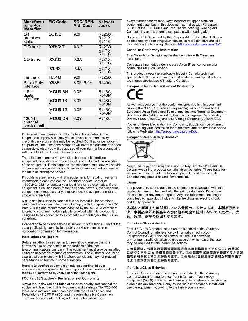
Manufacturer’s PortIdentifier
FIC Code SOC/ REN/A.S. Code
NetworkJacks
Offpremisesstation
OL13C 9.0F RJ2GX,RJ21X,RJ11C
DID trunk 02RV2.T AS.2 RJ2GX,RJ21X,RJ11C
CO trunk 02GS2 0.3A RJ21X,RJ11C
02LS2 0.3A RJ21X,RJ11C
Tie trunk TL31M 9.0F RJ2GXBasic RateInterface
02IS5 6.0F, 6.0Y RJ49C
1.544digitalinterface
04DU9.BN 6.0F RJ48C,RJ48M
04DU9.1KN
6.0F RJ48C,RJ48M
04DU9.1SN
6.0F RJ48C,RJ48M
120A4channelservice unit
04DU9.DN 6.0Y RJ48C
If this equipment causes harm to the telephone network, thetelephone company will notify you in advance that temporarydiscontinuance of service may be required. But if advance notice isnot practical, the telephone company will notify the customer as soonas possible. Also, you will be advised of your right to file a complaintwith the FCC if you believe it is necessary.
The telephone company may make changes in its facilities,equipment, operations or procedures that could affect the operationof the equipment. If this happens, the telephone company will provideadvance notice in order for you to make necessary modifications tomaintain uninterrupted service.
If trouble is experienced with this equipment, for repair or warrantyinformation, please contact the Technical Service Center at1-800-242- 2121 or contact your local Avaya representative. If theequipment is causing harm to the telephone network, the telephonecompany may request that you disconnect the equipment until theproblem is resolved.
A plug and jack used to connect this equipment to the premiseswiring and telephone network must comply with the applicable FCCPart 68 rules and requirements adopted by the ACTA. A complianttelephone cord and modular plug is provided with this product. It isdesigned to be connected to a compatible modular jack that is alsocompliant.
Connection to party line service is subject to state tariffs. Contact thestate public utility commission, public service commission orcorporation commission for information.
Installation and RepairsBefore installing this equipment, users should ensure that it ispermissible to be connected to the facilities of the localtelecommunications company. The equipment must also be installedusing an acceptable method of connection. The customer should beaware that compliance with the above conditions may not preventdegradation of service in some situations.
Repairs to certified equipment should be coordinated by arepresentative designated by the supplier. It is recommended thatrepairs be performed by Avaya certified technicians.
FCC Part 68 Supplier’s Declarations of ConformityAvaya Inc. in the United States of America hereby certifies that theequipment described in this document and bearing a TIA TSB-168label identification number complies with the FCC’s Rules andRegulations 47 CFR Part 68, and the Administrative Council onTerminal Attachments (ACTA) adopted technical criteria.
Avaya further asserts that Avaya handset-equipped terminalequipment described in this document complies with Paragraph68.316 of the FCC Rules and Regulations defining Hearing AidCompatibility and is deemed compatible with hearing aids.
Copies of SDoCs signed by the Responsible Party in the U. S. canbe obtained by contacting your local sales representative and areavailable on the following Web site: http://support.avaya.com/DoC.
Canadian Conformity InformationThis Class A (or B) digital apparatus complies with CanadianICES-003.
Cet appareil numérique de la classe A (ou B) est conforme à lanorme NMB-003 du Canada.
This product meets the applicable Industry Canada technicalspecifications/Le présent materiel est conforme aux specificationstechniques applicables d’Industrie Canada.
European Union Declarations of Conformity
Avaya Inc. declares that the equipment specified in this documentbearing the "CE" (Conformité Europeénne) mark conforms to theEuropean Union Radio and Telecommunications Terminal EquipmentDirective (1999/5/EC), including the Electromagnetic CompatibilityDirective (2004/108/EC) and Low Voltage Directive (2006/95/EC).
Copies of these Declarations of Conformity (DoCs) can be obtainedby contacting your local sales representative and are available on thefollowing Web site: http://support.avaya.com/DoC.
European Union Battery Directive
Avaya Inc. supports European Union Battery Directive 2006/66/EC.Certain Avaya Inc. products contain lithium batteries. These batteriesare not customer or field replaceable parts. Do not disassemble.Batteries may pose a hazard if mishandled.
JapanThe power cord set included in the shipment or associated with theproduct is meant to be used with the said product only. Do not usethe cord set for any other purpose. Any non-recommended usagecould lead to hazardous incidents like fire disaster, electric shock,and faulty operation.
If this is a Class A device:This is a Class A product based on the standard of the VoluntaryControl Council for Interference by Information TechnologyEquipment (VCCI). If this equipment is used in a domesticenvironment, radio disturbance may occur, in which case, the usermay be required to take corrective actions.
If this is a Class B device:This is a Class B product based on the standard of the VoluntaryControl Council for Interference from Information TechnologyEquipment (VCCI). If this is used near a radio or television receiver ina domestic environment, it may cause radio interference. Install anduse the equipment according to the instruction manual.
TrademarksThe trademarks, logos and service marks (“Marks”) displayed in thissite, the Documentation, Hosted Service(s), and product(s) providedby Avaya are the registered or unregistered Marks of Avaya, itsaffiliates, or other third parties. Users are not permitted to use suchMarks without prior written consent from Avaya or such third partywhich may own the Mark. Nothing contained in this site, theDocumentation, Hosted Service(s) and product(s) should beconstrued as granting, by implication, estoppel, or otherwise, anylicense or right in and to the Marks without the express writtenpermission of Avaya or the applicable third party.
Avaya is a registered trademark of Avaya Inc.
All non-Avaya trademarks are the property of their respective owners.Linux® is the registered trademark of Linus Torvalds in the U.S. andother countries.
Downloading DocumentationFor the most current versions of Documentation, see the AvayaSupport website: http://support.avaya.com, or such successor site asdesignated by Avaya.
Contact Avaya SupportSee the Avaya Support website: http://support.avaya.com for productor Hosted Service notices and articles, or to report a problem withyour Avaya product or Hosted Service. For a list of support telephonenumbers and contact addresses, go to the Avaya Support website: http://support.avaya.com (or such successor site as designated byAvaya), scroll to the bottom of the page, and select Contact AvayaSupport.
Contents
Chapter 1: Introduction.......................................................................................................... 12Purpose................................................................................................................................ 12Intended audience................................................................................................................. 12Related resources................................................................................................................. 12
Documentation................................................................................................................ 12Training.......................................................................................................................... 14Avaya Mentor videos....................................................................................................... 14
Support................................................................................................................................ 15Warranty............................................................................................................................... 15
Chapter 2: Avaya servers and gateway conversion overview............................................ 16Avaya servers and gateway conversion overview..................................................................... 16Presite checklist.................................................................................................................... 16Requirements....................................................................................................................... 17Configuring the network......................................................................................................... 18Connecting the browser to the server...................................................................................... 19Connecting the browser remotely through the network............................................................. 20Electronic Preinstallation Worksheet....................................................................................... 20License and authentication files.............................................................................................. 21Preconversion tasks checklist................................................................................................. 21Redesigning the networks...................................................................................................... 21Obtaining the postconversion service pack file......................................................................... 22Reliability and availability....................................................................................................... 22Reliability and availability table............................................................................................... 23
Chapter 3: Conversion of S8300D main server mode to S8300D survivable remoteserver mode............................................................................................................................. 25
Conversion of S8300D main server mode to S8300D survivable remote server mode................. 25Converting S8300D main server to S8300D survivable remote server....................................... 25Administering the main server that the survivable remote server will use after conversion........... 27Administering the gateway while converting S8300D survivable remote server mode toS8300D main server mode..................................................................................................... 27Reassigning endpoints from the main server to this main server................................................ 28Changing the controller list of gateway while converting S8300D survivable remote servermode to S8300D main server mode........................................................................................ 28Verifying gateway registration with the main server.................................................................. 29Configuring the main server and survivable remote server........................................................ 29Verifying survivable remote server status................................................................................ 30Invoking translation synchronization while converting S8300D survivable remote server modeto S8300D main server mode................................................................................................. 30Performing postconversion tasks to convert S8300D main server mode to S8300D survivableremote server mode.............................................................................................................. 31
June 2015 Converting Avaya Servers and Gateways 7Comments on this document? [email protected]
Chapter 4: Conversion of S8300D survivable remote server mode to S8300D mainserver mode............................................................................................................................. 32
Conversion of S8300D survivable remote server mode to S8300D main server mode................. 32Converting S8300D survivable remote server to S8300D main server....................................... 32Administering the main server to which the survivable remote server was formerly assigned....... 34Administering the gateway..................................................................................................... 34Reassigning endpoints from the main server to this main server................................................ 34Changing the controller list of Gateway................................................................................... 35Configuring the survivable remote server to be converted......................................................... 35Verifying gateway registration with the main server.................................................................. 36Configuring the main server and the survivable remote server to convert S8300D survivableremote server to S8300D main server..................................................................................... 37Verifying survivable remote server status................................................................................ 37Invoking translation synchronization........................................................................................ 38Performing postconversion tasks to convert S8300D survivable remote server to S8300D mainserver................................................................................................................................... 38
Chapter 5: Conversion of S8300E main server mode to S8300E survivable remoteserver mode............................................................................................................................. 39
S8300E server...................................................................................................................... 39Requirements....................................................................................................................... 39Checklist for converting S8300E main server mode to S8300E survivable remote server mode... 40
Administering the main server.......................................................................................... 41Administering the gateway............................................................................................... 41Changing the controller list of gateway.............................................................................. 41Configuring the main server and the survivable remote server............................................ 42Invoking translation synchronization.................................................................................. 42
Chapter 6: Conversion of S8300E survivable remote server mode to S8300E mainserver mode............................................................................................................................. 44
S8300E server...................................................................................................................... 44Requirements....................................................................................................................... 44Checklist for converting S8300E survivable remote server mode to S8300E main server mode... 45
Obtaining the postconversion service pack file................................................................... 46Administering the main server ......................................................................................... 46Administering the gateway............................................................................................... 46Reassigning endpoints to the main server......................................................................... 47Changing the controller list of gateway.............................................................................. 47Configuring the survivable remote server........................................................................... 47Verifying the gateway registration..................................................................................... 49Verifying survivable remote server status.......................................................................... 49Invoking translation synchronization.................................................................................. 50
Chapter 7: Conversion of S8510 S8800 main server mode to S8510 S8800 survivableremote server mode (_Simplex Template)............................................................................ 51
Contents
8 Converting Avaya Servers and Gateways June 2015Comments on this document? [email protected]
Conversion of S8510/S8800 Server/HP DL360 G7/Dell R610 main server mode to S8510/S8800 Server/HP DL360 G7/Dell R610 survivable remote server mode (CM_Simplextemplate).............................................................................................................................. 51Converting of S8510/S8800 Server/HP DL360 G7/Dell R610 main server mode to S8510/S8800 Server/HP DL360 G7/Dell R610 survivable remote server mode (CM_Simplextemplate).............................................................................................................................. 51Administering the main server to which the survivable remote server was formerly assigned....... 53Administering the gateway..................................................................................................... 54Reassigning endpoints from the main server to this main server................................................ 54Changing the controller list of Gateway................................................................................... 54Converting S8510/S8800 Server/HP DL360 G7/Dell R610 main server mode to S8510/S8800Server/HP DL360 G7/Dell R610 survivable remote server mode (CM_Simplex Template)........... 54Verifying survivable remote server status................................................................................ 55Invoking translation synchronization........................................................................................ 56Performing postconversion tasks to convert S8510/S8800 Server/HP DL360 G7/Dell R610main server mode to S8510/S8800 Server/HP DL360 G7/Dell R610 survivable remote servermode (CM_Simplex Template)............................................................................................... 56
Chapter 8: Conversion of S8510 S8800 survivable remote server mode to S8510S8800 main server mode (_Simplex template)..................................................................... 57
Conversion of S8510/S8800 Server/HP DL360 G7/Dell R610 survivable remote server modeto S8510/S8800 Server/HP DL360 G7/Dell R610 main server mode (CM_Simplex template)...... 57Converting S8510/S8800 Server/HP DL360 G7/Dell R610 survivable remote server mode toS8510/S8800 Server/HP DL360 G7/Dell R610 main server mode (CM_Simplex template).......... 57Administering the main server to which the survivable remote server was formerly assigned....... 59Administering the gateway..................................................................................................... 59Reassigning endpoints from the main server to this main server................................................ 59Changing the controller list of Gateway................................................................................... 60Configuring the main server and the survivable remote server to convert S8510/S8800Server/HP DL360 G7/Dell R610 survivable remote server mode to S8510/S8800 Server/HPDL360 G7/Dell R610 main server mode (CM_Simplex template)............................................... 60
Chapter 9: Conversion of S8510 S8800 survivable remote server mode to S8510S8800 main server mode (_SurvRemote to _Simplex)........................................................ 62
Conversion of S8510/S8800 Server/HP DL360 G7/Dell R610 survivable remote server modeto S8510/S8800 Server/HP DL360 G7/Dell R610 main server mode (CM_SurvRemote toCM_Simplex)........................................................................................................................ 62Converting S8510/S8800 Server/HP DL360 G7/Dell R610 survivable remote server mode toS8510/S8800 Server/HP DL360 G7/Dell R610 main server mode (CM_SurvRemote toCM_Simplex)........................................................................................................................ 63Administering the main server to which the survivable remote server was formerly assigned....... 64Administering the gateway..................................................................................................... 64Reassigning endpoints from the main server to this main server................................................ 65Changing the controller list of Gateway................................................................................... 65
Contents
June 2015 Converting Avaya Servers and Gateways 9Comments on this document? [email protected]
Configuring the main server and the survivable remote server to convert S8510/S8800Server/HP DL360 G7/Dell R610 survivable remote server mode to S8510/S8800 Server/HPDL360 G7/Dell R610 main server mode (CM_SurvRemote to CM_Simplex).............................. 65
Chapter 10: Converting IP-PNC port networks from simplex control to duplicatedcontrol...................................................................................................................................... 68
Converting IP-PNC port networks from simplex control to duplicated control.............................. 68Checklist to convert IP-PNC port networks from simplex control to duplicated control................. 69Installing and cabling a second Ethernet switch....................................................................... 70Performing preconfiguration of the SNMP subagent in an Avaya Ethernet switch....................... 71Configuring the SNMP subagent in the Avaya Ethernet switch.................................................. 72Enabling firewall settings........................................................................................................ 73Accessing Communication Manager System Management Interface......................................... 74Designating the slot for the duplicated IPSI circuit pack............................................................ 74IPSI slot locations table.......................................................................................................... 74Duplicated IPSI circuit pack installation................................................................................... 75
Installing a duplicated IPSI circuit pack for G650 Media Gateway........................................ 76Installing duplicated IPSI circuit pack for MCC1 Gateway................................................... 76Installing duplicated IPSI circuit pack for SCC1 Gateway.................................................... 77Ribbon Cable Connector.................................................................................................. 78Removing ground plate and upper and lower rear covers................................................... 78High/Critical Reliability Ribbon Cable Connection............................................................... 79Placing ribbon cable using the pass through tool................................................................ 80Connecting High/Critical Ribbon Cable.............................................................................. 81Replacing rear covers and ground plates........................................................................... 82Routing a Cable through the TDM slot............................................................................... 83
Adding control network cabling for the new circuit pack............................................................ 84Verifying the IPSI circuit packs are inserted properly................................................................ 85Programming the duplicated IPSI circuit pack.......................................................................... 85
Setting VLAN and diffserv parameters............................................................................... 86Administering the duplicated IPSI circuit pack on the server...................................................... 87Starting a SAT session.......................................................................................................... 87Verifying IPSI translations...................................................................................................... 87Upgrading IPSI firmware........................................................................................................ 88
Chapter 11: Conversion of IP-PNC port networks from simplex bearer to duplicatedbearer....................................................................................................................................... 89
Conversion of IP-PNC port networks from simplex bearer to duplicated bearer........................... 89Duplicated control network..................................................................................................... 89Overflow with coresident TN2302AP circuit packs.................................................................... 90Reduced channels with duplicated TN2602AP circuit packs...................................................... 90Performing preconversion tasks to convert IP-PNC port networks from simplex to duplicatedbearer.................................................................................................................................. 90Disabling an existing TN2602AP circuit pack or TN2302 circuit packs........................................ 92Converting IP-PNC port networks from simplex bearer to duplicated bearer............................... 92
Contents
10 Converting Avaya Servers and Gateways June 2015Comments on this document? [email protected]

Checklist to convert IP-PNC port networks from simplex bearer to duplicated bearer.................. 92Hardware components........................................................................................................... 94Checking the shipment.......................................................................................................... 94Accessing Communication Manager System Management Interface......................................... 95Accessing the server command line interface with ssh protocol................................................. 96Checking the software release................................................................................................ 97Determining the existence and location of TN2302 and TN2602APcircuit packs......................... 97Upgrading firmware on the existing TN2602AP circuit packs..................................................... 98Disabling an existing TN2602AP circuit pack or TN2302 circuit packs........................................ 99Removing the TN2302 circuit pack hardware........................................................................... 99Connecting the cables to TN2602AP circuit packs.................................................................. 100
Media Resource 320 Adapter......................................................................................... 100Installing the TN2602AP circuit packs................................................................................... 101Installing the TN771DP Maintenance Test circuit pack........................................................... 101Verifying installation and voice channels............................................................................... 102Upgrade firmware on the new TN2602AP circuit packs........................................................... 103Administering the node name for the TN2602AP circuit pack.................................................. 103Administering the IP interface for the TN2602AP circuit packs................................................ 104Testing the external connection to the LAN............................................................................ 106Verifying active call status.................................................................................................... 107
Appendix A: Accessing the server...................................................................................... 109Service laptop and server connection.................................................................................... 109
Connecting a services laptop to an S8300D Server.......................................................... 109Connecting a services laptop to an S8510 Server............................................................ 110Connecting a services laptop to an S8800 Server............................................................ 111Connecting a services laptop to an HP DL360 G7 Server................................................. 112Connecting a services laptop to an Dell R610 Server....................................................... 113
Server administration........................................................................................................... 114Finding the IP address of the active server in a configuration with duplicated servers.......... 114Disabling the start timeout of the SAMP adapter.............................................................. 115Accessing System Management Interface....................................................................... 116Accessing the server command line interface with ssh protocol......................................... 116Accessing the command line interface with terminal emulation.......................................... 118
Logins................................................................................................................................ 118
Contents
June 2015 Converting Avaya Servers and Gateways 11Comments on this document? [email protected]
Chapter 1: Introduction
PurposeThis document describes procedures for conversions of Avaya telecommunication products that useAvaya Aura® Communication Manager.
Intended audienceThe intended audience of this document are telecommunications managers and telephonyadministrators.
Related resources
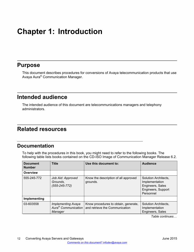
DocumentationTo help with the procedures in this book, you might need to refer to the following books. Thefollowing table lists books contained on the CD-ISO Image of Communication Manager Release 6.2.
DocumentNumber
Title Use this document to: Audience
Overview555-245-772 Job Aid: Approved
Grounds,(555-245-772)
Know the description of all approvedgrounds.
Solution Architects,ImplementationEngineers, SalesEngineers, SupportPersonnel
Implementing03-603558 Implementing Avaya
Aura® CommunicationManager
Know procedures to obtain, generate,and retrieve the Communication
Solution Architects,ImplementationEngineers, Sales
Table continues…
12 Converting Avaya Servers and Gateways June 2015Comments on this document? [email protected]
DocumentNumber
Title Use this document to: Audience
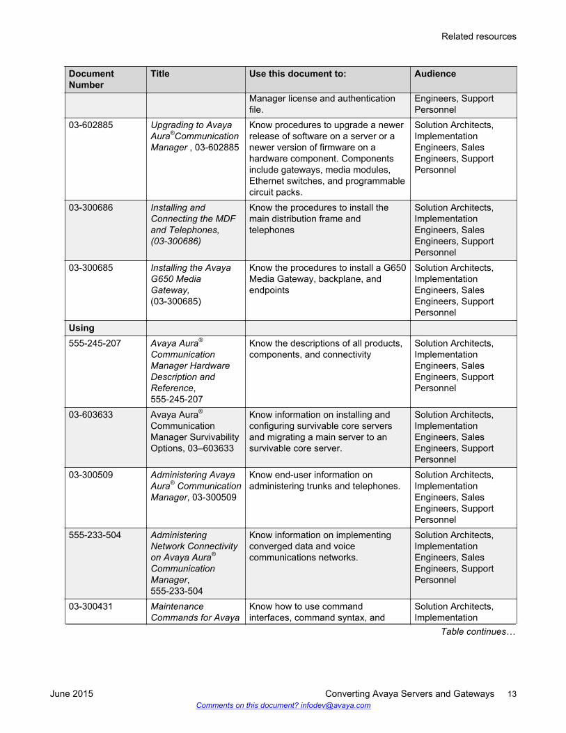
Manager license and authenticationfile.
Engineers, SupportPersonnel
03-602885 Upgrading to AvayaAura®CommunicationManager , 03-602885
Know procedures to upgrade a newerrelease of software on a server or anewer version of firmware on ahardware component. Componentsinclude gateways, media modules,Ethernet switches, and programmablecircuit packs.
Solution Architects,ImplementationEngineers, SalesEngineers, SupportPersonnel
03-300686 Installing andConnecting the MDFand Telephones,(03-300686)
Know the procedures to install themain distribution frame andtelephones
Solution Architects,ImplementationEngineers, SalesEngineers, SupportPersonnel
03-300685 Installing the AvayaG650 MediaGateway,(03-300685)
Know the procedures to install a G650Media Gateway, backplane, andendpoints
Solution Architects,ImplementationEngineers, SalesEngineers, SupportPersonnel
Using555-245-207 Avaya Aura®
CommunicationManager HardwareDescription andReference,555-245-207
Know the descriptions of all products,components, and connectivity
Solution Architects,ImplementationEngineers, SalesEngineers, SupportPersonnel
03-603633 Avaya Aura®
CommunicationManager SurvivabilityOptions, 03–603633
Know information on installing andconfiguring survivable core serversand migrating a main server to ansurvivable core server.
Solution Architects,ImplementationEngineers, SalesEngineers, SupportPersonnel
03-300509 Administering AvayaAura® CommunicationManager, 03-300509
Know end-user information onadministering trunks and telephones.
Solution Architects,ImplementationEngineers, SalesEngineers, SupportPersonnel
555-233-504 AdministeringNetwork Connectivityon Avaya Aura®
CommunicationManager,555-233-504
Know information on implementingconverged data and voicecommunications networks.
Solution Architects,ImplementationEngineers, SalesEngineers, SupportPersonnel
03-300431 MaintenanceCommands for Avaya
Know how to use commandinterfaces, command syntax, and
Solution Architects,Implementation
Table continues…
Related resources
June 2015 Converting Avaya Servers and Gateways 13Comments on this document? [email protected]
DocumentNumber
Title Use this document to: Audience
Aura® CommunicationManager, BranchGateway andServers, 03-300431
output from maintenance-relatedcommands.
Engineers, SalesEngineers, SupportPersonnel
03-300430 Maintenance Alarmsfor Avaya Aura®
CommunicationManager, BranchGateways Servers,03-300430
Know how to use alarms, error codes,and tests to diagnose and repairproblems.
Solution Architects,ImplementationEngineers, SalesEngineers, SupportPersonnel
03-300432 MaintenanceProcedures for AvayaAura® CommunicationManager, BranchGateways andServers, 03-300432
Know how to troubleshoot andreplace various components.
Solution Architects,ImplementationEngineers, SalesEngineers, SupportPersonnel
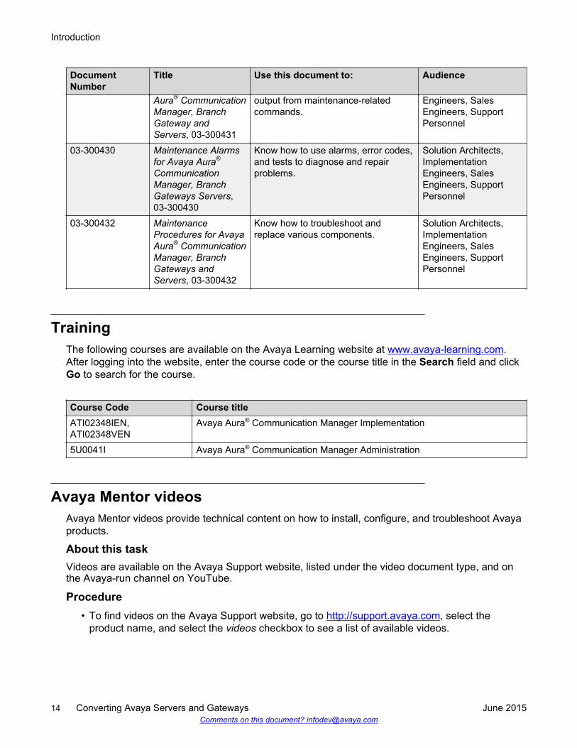
TrainingThe following courses are available on the Avaya Learning website at www.avaya-learning.com.After logging into the website, enter the course code or the course title in the Search field and clickGo to search for the course.
Course Code Course titleATI02348IEN,ATI02348VEN
Avaya Aura® Communication Manager Implementation
5U0041I Avaya Aura® Communication Manager Administration
Avaya Mentor videosAvaya Mentor videos provide technical content on how to install, configure, and troubleshoot Avayaproducts.
About this taskVideos are available on the Avaya Support website, listed under the video document type, and onthe Avaya-run channel on YouTube.
Procedure• To find videos on the Avaya Support website, go to http://support.avaya.com, select the
product name, and select the videos checkbox to see a list of available videos.
Introduction
14 Converting Avaya Servers and Gateways June 2015Comments on this document? [email protected]
• To find the Avaya Mentor videos on YouTube, go to http://www.youtube.com/AvayaMentor andperform one of the following actions:
- Enter a key word or key words in the Search Channel to search for a specific product ortopic.
- Scroll down Playlists, and click the name of a topic to see the available list of videos postedon the site.
Note:
Videos are not available for all products.
SupportVisit the Avaya Support website at http://support.avaya.com for the most up-to-date documentation,product notices, and knowledge articles. You can also search for release notes, downloads, andresolutions to issues. Use the online service request system to create a service request. Chat withlive agents to get answers to questions, or request an agent to connect you to a support team if anissue requires additional expertise.
WarrantyAvaya provides a 90-day limited warranty on Communication Manager. To understand the terms ofthe limited warranty, see the sales agreement or other applicable documentation. In addition, thestandard warranty of Avaya and the details regarding support for Communication Manager in thewarranty period is available on the Avaya Support website at http://support.avaya.com/ under Help& Policies > Policies & Legal > Warranty & Product Lifecycle. See also Help & Policies >Policies & Legal > License Terms.
Support
June 2015 Converting Avaya Servers and Gateways 15Comments on this document? [email protected]
Chapter 2: Avaya servers and gatewayconversion overview
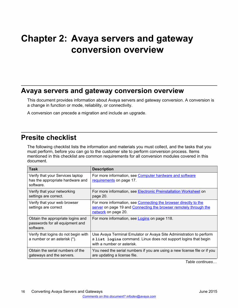
Avaya servers and gateway conversion overviewThis document provides information about Avaya servers and gateway conversion. A conversion isa change in function or mode, reliability, or connectivity.
A conversion can precede a migration and include an upgrade.
Presite checklistThe following checklist lists the information and materials you must collect, and the tasks that youmust perform, before you can go to the customer site to perform conversion process. Itemsmentioned in this checklist are common requirements for all conversion modules covered in thisdocument.
Task DescriptionVerify that your Services laptophas the appropriate hardware andsoftware.
For more information, see Computer hardware and softwarerequirements on page 17.
Verify that your networkingsettings are correct.
For more information, see Electronic Preinstallation Worksheet onpage 20.
Verify that your web browsersettings are correct
For more information, see Connecting the browser directly to theserver on page 19 and Connecting the browser remotely through thenetwork on page 20.
Obtain the appropriate logins andpasswords for all equipment andsoftware.
For more information, see Logins on page 118.
Verify that logins do not begin witha number or an asterisk (*).
Use Avaya Terminal Emulator or Avaya Site Administration to performa list logins command. Linux does not support logins that beginwith a number or asterisk.
Obtain the serial numbers of thegateways and the servers.
You need the serial numbers if you are using a new license file or if youare updating a license file.
Table continues…
16 Converting Avaya Servers and Gateways June 2015Comments on this document? [email protected]
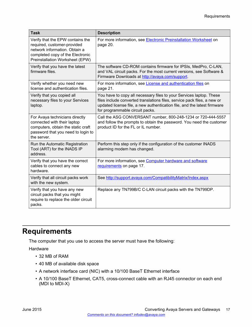
Task DescriptionVerify that the EPW contains therequired, customer-providednetwork information. Obtain acompleted copy of the ElectronicPreinstallation Worksheet (EPW)
For more information, see Electronic Preinstallation Worksheet onpage 20.
Verify that you have the latestfirmware files.
The software CD-ROM contains firmware for IPSIs, MedPro, C-LAN,and VAL circuit packs. For the most current versions, see Software &Firmware Downloads at http://avaya.com/support.
Verify whether you need newlicense and authentication files.
For more information, see License and authentication files onpage 21.
Verify that you copied allnecessary files to your Serviceslaptop.
You have to copy all necessary files to your Services laptop. Thesefiles include converted translations files, service pack files, a new orupdated license file, a new authentication file, and the latest firmwarefor programmable circuit packs.
For Avaya technicians directlyconnected with their laptopcomputers, obtain the static craftpassword that you need to login tothe server.
Call the ASG CONVERSANT number, 800-248-1234 or 720-444-5557and follow the prompts to obtain the password. You need the customerproduct ID for the FL or IL number.
Run the Automatic RegistrationTool (ART) for the INADS IPaddress.
Perform this step only if the configuration of the customer INADSalarming modem has changed.
Verify that you have the correctcables to connect any newhardware.
For more information, see Computer hardware and softwarerequirements on page 17.
Verify that all circuit packs workwith the new system.
See http://support.avaya.com/CompatibilityMatrix/Index.aspx
Verify that you have any newcircuit packs that you mightrequire to replace the older circuitpacks.
Replace any TN799B/C C-LAN circuit packs with the TN799DP.
RequirementsThe computer that you use to access the server must have the following:
Hardware• 32 MB of RAM• 40 MB of available disk space• A network interface card (NIC) with a 10/100 BaseT Ethernet interface• A 10/100 BaseT Ethernet, CAT5, cross-connect cable with an RJ45 connector on each end
(MDI to MDI-X)
Requirements
June 2015 Converting Avaya Servers and Gateways 17Comments on this document? [email protected]
• CD-ROM drive• Crossover Ethernet cables• Direct Ethernet cable• Serial cable and adapter• RS-232 port connector• TN2312BP (IPSI) connection to the Ethernet switches• TN2302 or TN2306 connection to the LAN
Software• Windows 2000 or Windows XP operating system• HyperTerminal or other terminal emulation program• TCP/IP networking software with Windows operating system• Microsoft Internet Explorer 7.0 or later, or Firefox 3.6 or later
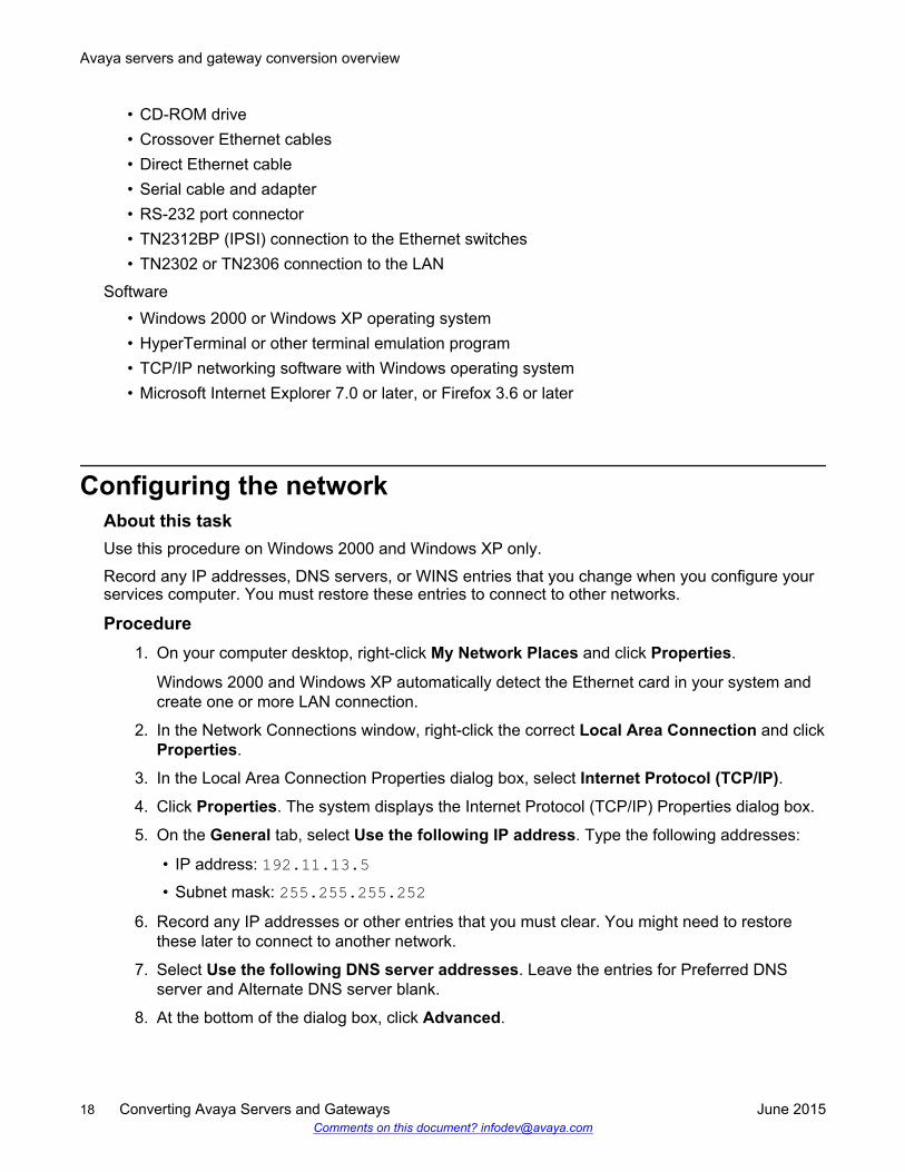
Configuring the networkAbout this taskUse this procedure on Windows 2000 and Windows XP only.
Record any IP addresses, DNS servers, or WINS entries that you change when you configure yourservices computer. You must restore these entries to connect to other networks.
Procedure1. On your computer desktop, right-click My Network Places and click Properties.
Windows 2000 and Windows XP automatically detect the Ethernet card in your system andcreate one or more LAN connection.
2. In the Network Connections window, right-click the correct Local Area Connection and clickProperties.
3. In the Local Area Connection Properties dialog box, select Internet Protocol (TCP/IP).
4. Click Properties. The system displays the Internet Protocol (TCP/IP) Properties dialog box.
5. On the General tab, select Use the following IP address. Type the following addresses:
• IP address: 192.11.13.5• Subnet mask: 255.255.255.252
6. Record any IP addresses or other entries that you must clear. You might need to restorethese later to connect to another network.
7. Select Use the following DNS server addresses. Leave the entries for Preferred DNSserver and Alternate DNS server blank.
8. At the bottom of the dialog box, click Advanced.
Avaya servers and gateway conversion overview
18 Converting Avaya Servers and Gateways June 2015Comments on this document? [email protected]
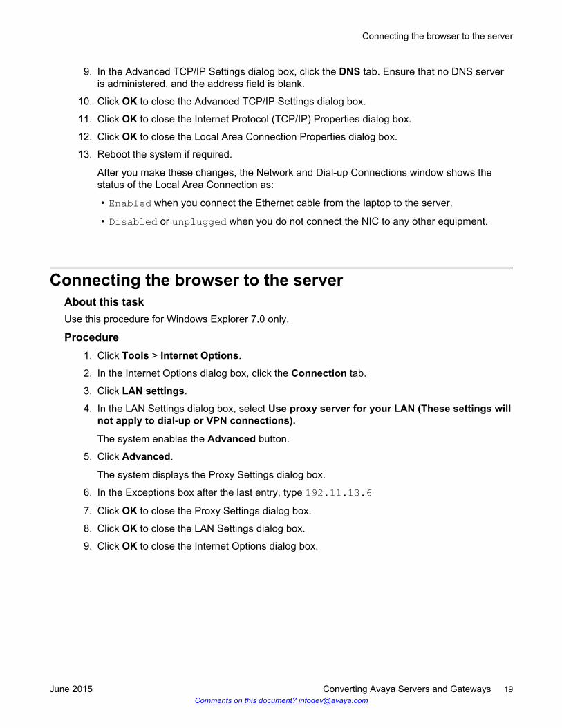
9. In the Advanced TCP/IP Settings dialog box, click the DNS tab. Ensure that no DNS serveris administered, and the address field is blank.
10. Click OK to close the Advanced TCP/IP Settings dialog box.
11. Click OK to close the Internet Protocol (TCP/IP) Properties dialog box.
12. Click OK to close the Local Area Connection Properties dialog box.
13. Reboot the system if required.
After you make these changes, the Network and Dial-up Connections window shows thestatus of the Local Area Connection as:
• Enabled when you connect the Ethernet cable from the laptop to the server.
• Disabled or unplugged when you do not connect the NIC to any other equipment.
Connecting the browser to the serverAbout this taskUse this procedure for Windows Explorer 7.0 only.
Procedure1. Click Tools > Internet Options.
2. In the Internet Options dialog box, click the Connection tab.
3. Click LAN settings.
4. In the LAN Settings dialog box, select Use proxy server for your LAN (These settings willnot apply to dial-up or VPN connections).
The system enables the Advanced button.
5. Click Advanced.
The system displays the Proxy Settings dialog box.
6. In the Exceptions box after the last entry, type 192.11.13.67. Click OK to close the Proxy Settings dialog box.
8. Click OK to close the LAN Settings dialog box.
9. Click OK to close the Internet Options dialog box.
Connecting the browser to the server
June 2015 Converting Avaya Servers and Gateways 19Comments on this document? [email protected]
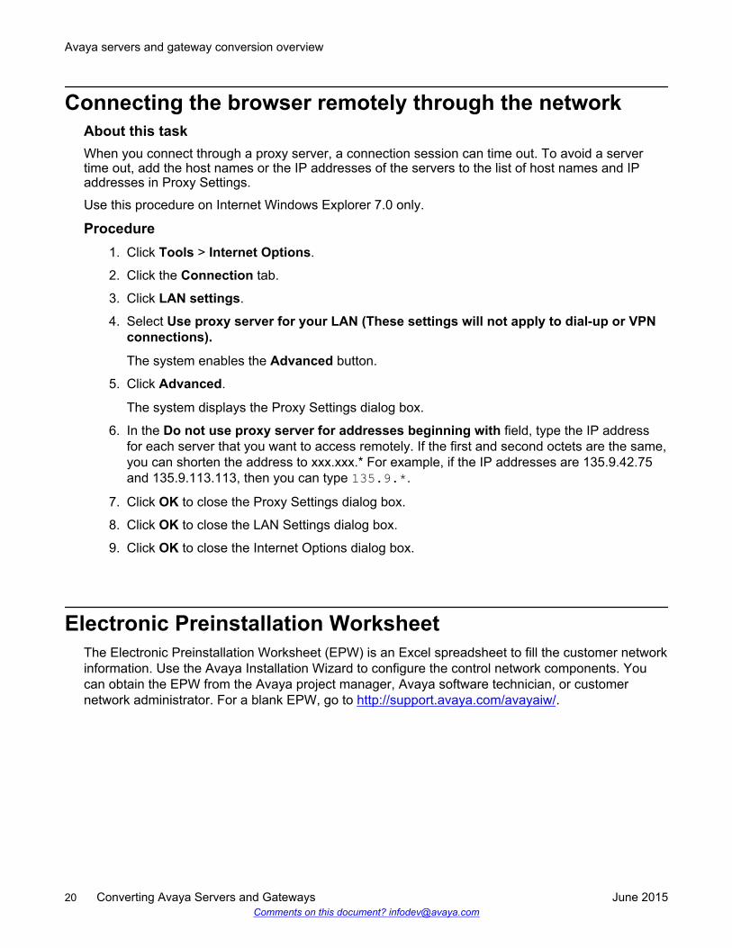
Connecting the browser remotely through the networkAbout this taskWhen you connect through a proxy server, a connection session can time out. To avoid a servertime out, add the host names or the IP addresses of the servers to the list of host names and IPaddresses in Proxy Settings.
Use this procedure on Internet Windows Explorer 7.0 only.
Procedure1. Click Tools > Internet Options.
2. Click the Connection tab.
3. Click LAN settings.
4. Select Use proxy server for your LAN (These settings will not apply to dial-up or VPNconnections).
The system enables the Advanced button.
5. Click Advanced.
The system displays the Proxy Settings dialog box.
6. In the Do not use proxy server for addresses beginning with field, type the IP addressfor each server that you want to access remotely. If the first and second octets are the same,you can shorten the address to xxx.xxx.* For example, if the IP addresses are 135.9.42.75and 135.9.113.113, then you can type 135.9.*.
7. Click OK to close the Proxy Settings dialog box.
8. Click OK to close the LAN Settings dialog box.
9. Click OK to close the Internet Options dialog box.
Electronic Preinstallation WorksheetThe Electronic Preinstallation Worksheet (EPW) is an Excel spreadsheet to fill the customer networkinformation. Use the Avaya Installation Wizard to configure the control network components. Youcan obtain the EPW from the Avaya project manager, Avaya software technician, or customernetwork administrator. For a blank EPW, go to http://support.avaya.com/avayaiw/.
Avaya servers and gateway conversion overview
20 Converting Avaya Servers and Gateways June 2015Comments on this document? [email protected]
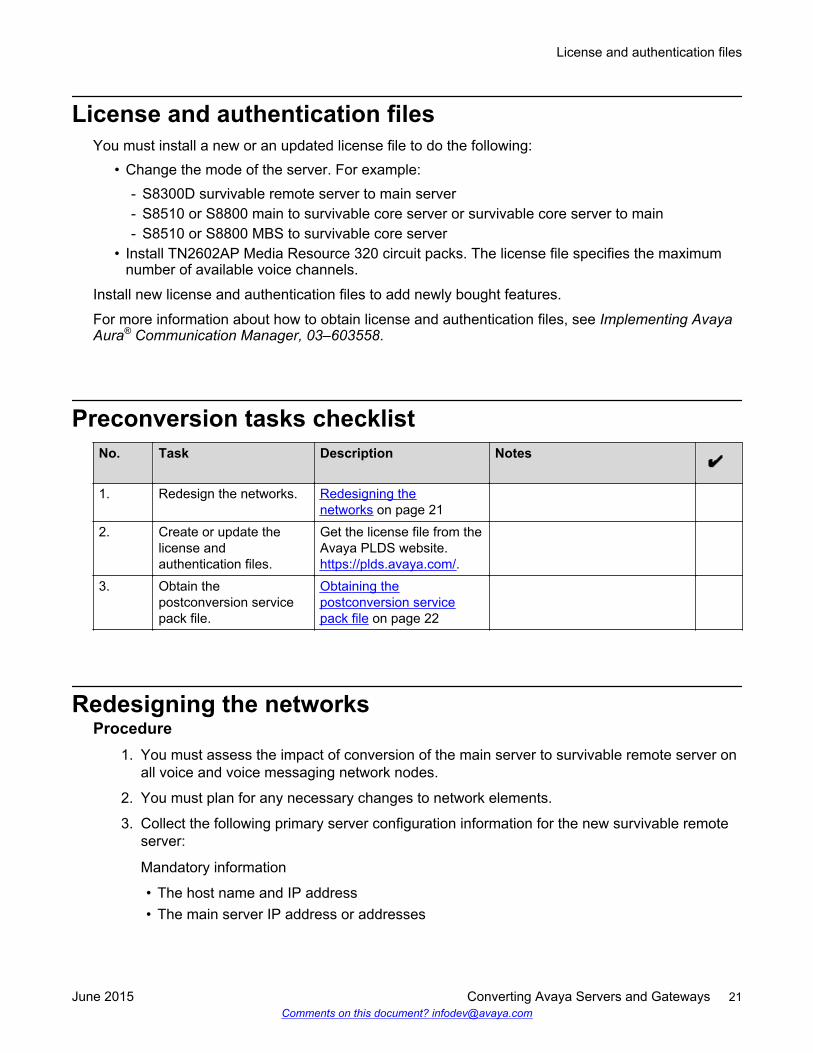
License and authentication filesYou must install a new or an updated license file to do the following:
• Change the mode of the server. For example:- S8300D survivable remote server to main server- S8510 or S8800 main to survivable core server or survivable core server to main- S8510 or S8800 MBS to survivable core server
• Install TN2602AP Media Resource 320 circuit packs. The license file specifies the maximumnumber of available voice channels.
Install new license and authentication files to add newly bought features.
For more information about how to obtain license and authentication files, see Implementing AvayaAura® Communication Manager, 03–603558.
Preconversion tasks checklistNo. Task Description Notes
1. Redesign the networks. Redesigning thenetworks on page 21
2. Create or update thelicense andauthentication files.
Get the license file from theAvaya PLDS website. https://plds.avaya.com/.
3. Obtain thepostconversion servicepack file.
Obtaining thepostconversion servicepack file on page 22
Redesigning the networksProcedure
1. You must assess the impact of conversion of the main server to survivable remote server onall voice and voice messaging network nodes.
2. You must plan for any necessary changes to network elements.
3. Collect the following primary server configuration information for the new survivable remoteserver:
Mandatory information
• The host name and IP address• The main server IP address or addresses
License and authentication files
June 2015 Converting Avaya Servers and Gateways 21Comments on this document? [email protected]
• Time server data
Optional information
• DNS IP addresses
• UPS IP addresses
• Static routes data
• Modem return route data if supported by Avaya Services
Obtaining the postconversion service pack fileProcedure
1. Go to http://support.avaya.com.
2. Click Downloads to determine if a service pack file is available for the CommunicationManager release that you are currently running.
For example, release 6.2, load 628.0.
3. If a service pack file is available, download the service pack. Take the service pack to thecustomer site.
Reliability and availabilityThe extent of duplication of certain components defines the reliability of a telecommunicationssystem.
For Linux-based servers, the standard reliability level includes the following servers:
• Single Server:
- S8510 Server
- S8800 Server
- HP DL360 G7 Server
- Dell R610 Server
• Duplicated Server:
- S8800 Server
- HP DL360 G7 Server
- Dell R610 Server
The availability of a telecommunications system is the time that the system is ready and able toprocess calls for some part of the scheduled time. Availability depends on reliability.
Avaya servers and gateway conversion overview
22 Converting Avaya Servers and Gateways June 2015Comments on this document? [email protected]
The standard feature can combine types of port network connectivity (PNC) and apply reliabilitydesignations to the IP-PNC part of the system.
Each port network defines the reliability level of the IP-PNC part. Therefore, combined PNC systemscan have combined reliabilities. For pure IP-PNC configurations, the reliability designation is foreach port network.
To an IP-PNC port network, the standard feature can add duplicated bearer reliability in addition toduplicated control reliability, which together constitute critical reliability.
The reliability and availability table summarizes reliability levels for systems with Linux-basedservers. Reliability definitions for pre-Linux based CSI switch are unchanged.
The terms control and bearer mean control network and bearer network, respectively.
For more information about reliability levels, including the circuit packs involved, see Avaya Aura®
Communication Manager Hardware Description and Reference, 555-245-207.
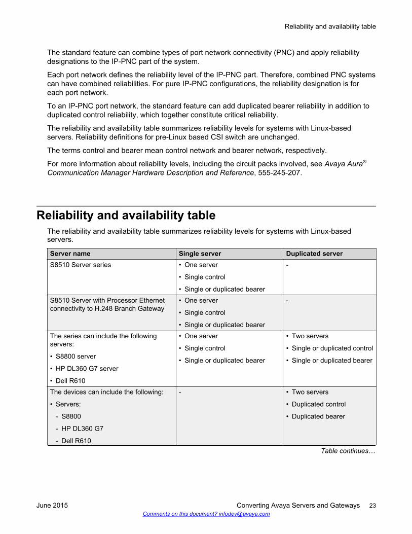
Reliability and availability tableThe reliability and availability table summarizes reliability levels for systems with Linux-basedservers.
Server name Single server Duplicated serverS8510 Server series • One server
• Single control
• Single or duplicated bearer
-
S8510 Server with Processor Ethernetconnectivity to H.248 Branch Gateway
• One server
• Single control
• Single or duplicated bearer
-
The series can include the followingservers:
• S8800 server
• HP DL360 G7 server
• Dell R610
• One server
• Single control
• Single or duplicated bearer
• Two servers
• Single or duplicated control
• Single or duplicated bearer
The devices can include the following:
• Servers:
- S8800
- HP DL360 G7
- Dell R610
- • Two servers
• Duplicated control
• Duplicated bearer
Table continues…
Reliability and availability table
June 2015 Converting Avaya Servers and Gateways 23Comments on this document? [email protected]
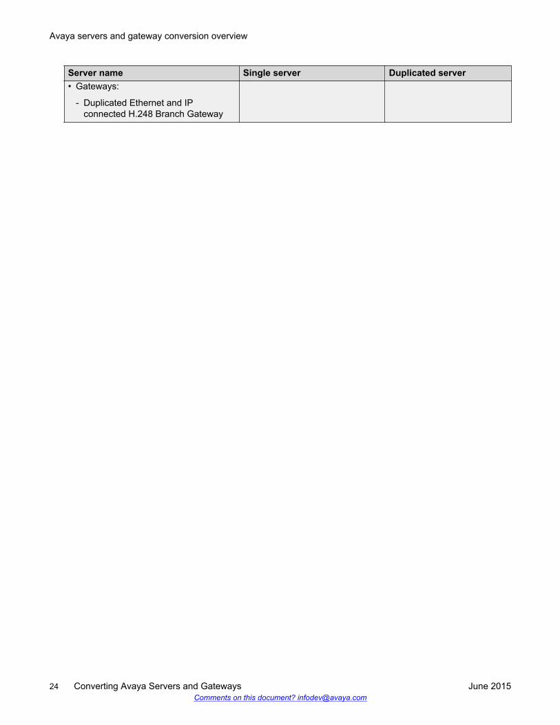
Server name Single server Duplicated server• Gateways:
- Duplicated Ethernet and IPconnected H.248 Branch Gateway
Avaya servers and gateway conversion overview
24 Converting Avaya Servers and Gateways June 2015Comments on this document? [email protected]
Chapter 3: Conversion of S8300D mainserver mode to S8300Dsurvivable remote server mode
Conversion of S8300D main server mode to S8300Dsurvivable remote server mode
This chapter provides a high-level list of tasks required to convert S8300D Server, configured as amain server, to S8300D Server in the survivable remote server mode. To ensure a completeconversion, you must change the Communication Manager template. For example, during theprocess of conversion, you must remove the CM_onlyEmbed template, and install theCM_SurvRemote template.
To complete these tasks, see Deploying Avaya Aura® Communication Manager, 03–603558.
Converting S8300D main server to S8300D survivableremote server
Before you beginYou must complete the preconversion task checklist.
See Preconversion task checklist.
About this taskUse this procedure to convert S8300D Server, configured as the main server, to S8300D Server inthe survivable remote server mode.
You can perform the tasks on one of the following:• Servers:
- On the main S8300D Server- On the survivable remote S8300D Server- On the main S8300D Server for the survivable remote S8300D Server- On a DHCP server
June 2015 Converting Avaya Servers and Gateways 25Comments on this document? [email protected]
• Gateways:
- On the gateway processor (MGP)
Procedure1. On the main server of the new survivable remote server, do the following:
a. Administer the main server that the survivable remote server must use after conversion.
See Administering the main server that the survivable remote server must use afterconversion.
b. Administer the gateway.
See Administering the gateway.
c. Reassign endpoints from the main server to this main server.
See Reassigning endpoints from the main server to this main server.
2. On the DHCP server, update the alternate controller list on the DHCP server.
3. On the MGP of the gateway, go to the MGP command prompt, and change the controller listof the gateway.
See Changing the gateway's controller list.
4. On the main server of the survivable remote server, verify that the gateway has registeredwith the main server.
See Verifying gateway registration with the main server.
5. On the main server, and survivable remote server, do the following:
a. Configure the main server.
See Configuring the main server and survivable remote server.
b. Configure the survivable remote server.
See Configuring the main server and survivable remote server.
6. On the main server of the survivable remote server, do the following:
a. Verify the status of the survivable remote server.
See Verifying survivable remote server status.
b. If the translations of the survivable remote server have not synchronized with the mainserver, run the translation synchronization.
See Invoking translation synchronization.
Related LinksPreconversion tasks checklist on page 21
Conversion of S8300D main server mode to S8300D survivable remote server mode
26 Converting Avaya Servers and Gateways June 2015Comments on this document? [email protected]
Administering the main server that the survivable remoteserver will use after conversion
About this taskUse this procedure to administer the main S8300D Server that the survivable remote S8300DServer must use after the conversion is successful.
For more information, see Administering Avaya Aura® Communication Manager, 03-300509.
Procedure1. Assign node names.
2. Administer network regions.
3. Associate survivable remote server with a network region.
4. Administer IP interfaces.
5. Identify survivable remote servers to the main server.
Administering the gateway while converting S8300Dsurvivable remote server mode to S8300D main servermode
About this taskThis topic is about administering the gateway when you convert S8300D Server, configured as asurvivable remote server, to S8300D Server in the main server mode.
For more information, see Administering Avaya Aura® Communication Manager, 03-300509.
Procedure1. Add gateway.
2. Repeat for each gateway controlled by the current main server.
3. In this scenario, the gateway does not automatically register with the main server. Skip thesubtasks, verify changes, and save translations in this section.
4. When the gateway is registered, the media modules must automatically populate, unless youperform Administration Without Hardware (AWOH). In this case, you must enter the mediamodule types for each slot.
Administering the main server that the survivable remote server will use after conversion
June 2015 Converting Avaya Servers and Gateways 27Comments on this document? [email protected]
Reassigning endpoints from the main server to this mainserver
About this taskYou must reassigning endpoints from the main server to this main server.
For more information, see Administering Avaya Aura® Communication Manager, 03-300509.
Procedure1. To update translations, add stations, and trunks.
a. If the main server is a new installation, use the Avaya Installation Wizard, and theElectronic Preinstallation Worksheet (EPW).
b. Use SAT commands.
2. Make test calls to verify.
3. Reassign Communication Manager Messaging users to the messaging system used by thismain server. Enter test messages to verify.
Changing the controller list of gateway while convertingS8300D survivable remote server mode to S8300D mainserver mode
About this taskUse this task to change the controller list of the gateway to S8300D Server, configured as a mainserver, to the survivable remote S8300D Server mode.
For more information, see Administering Avaya Aura® Communication Manager, 03-300509.
Procedure1. Clear the controller list of the gateway.
2. Enter the IP addresses of the main server, and up to three alternate controllers.
3. Set the survivable remote server transition points.
4. To start the gateway, run the command copy running-config startup-config.
5. Reset MGP.
Conversion of S8300D main server mode to S8300D survivable remote server mode
28 Converting Avaya Servers and Gateways June 2015Comments on this document? [email protected]
Verifying gateway registration with the main serverAbout this taskThis topic is about verifying the gateway registration with the main server.
Procedure1. Open a SAT session and enter list media-gateway, and verify that the Registered field
(Reg?) is set to y.
2. Make a test call.
Configuring the main server and survivable remote serverAbout this taskThis topic is about configuring the main server, and survivable remote server.
Procedure1. If you install Communication Manager Messaging, get the Communication Manager
Messaging data, and stop Communication Manager Messaging.
2. Record configuration information.
a. In the Record Configuration Information task, record all configuration information.
b. Re-enter some of this information after the conversion.
3. Remove CM_onlyEmbed template.
4. Install CM_SurvRemoteEmbed template.
5. Set time, date, and time zone.
Set the time of the survivable remote server to the same time zone as the main server. Thesurvivable remote server, and main server can have different time zone locations.
6. Install postconversion service pack file, if any.
7. Install the new authentication file, if required.
8. Configure server.
a. Complete all fields on the Server Configuration screen with the available data for thesurvivable remote server.
Some of the configuration data is the same as that for the main server.
b. On the Server Role window, select the button option, indicating the server is not a mainserver.
9. Restart the survivable remote server.
a. Open a SAT session, and enter reset system 4.
Verifying gateway registration with the main server
June 2015 Converting Avaya Servers and Gateways 29Comments on this document? [email protected]
b. After the restart is complete, the survivable remote server registers with the mainserver, and in a few minutes translations begin synchronization.
Verifying survivable remote server statusAbout this taskThis topic is about verifying the status of the survivable remote server.
Procedure1. At the SAT command prompt do one of the following:
• Enter list survivable-processor for Avaya Aura® Communication Manager R3.1
• Enter list lsp for Avaya Aura® Communication Manager R2.x.
The survivable remote server name, and IP address must be listed.
2. To view the translations dates, and times of the main server, enter list configurationsoftware-version.
3. Ensure that the Translations Updated date, and time matches that of the translations, on themain server.
Invoking translation synchronization while convertingS8300D survivable remote server mode to S8300D mainserver mode
About this taskTo convert S8300D Server, configured as a survivable remote server, to S8300D Server in the mainserver mode. You must run translation synchronization.
Procedure1. On the main server, enter the Linux command filesync -a ipaddress, where ipaddress is
the IP address of the survivable remote server.
2. Ensure that the translation synchronization is successful. The translation synchronizationtakes several minutes to complete.
3. Check the time stamp of the survivable remote server translation files with the SATcommand list survivable-processor or list lsp on the main server.
Conversion of S8300D main server mode to S8300D survivable remote server mode
30 Converting Avaya Servers and Gateways June 2015Comments on this document? [email protected]
Performing postconversion tasks to convert S8300D mainserver mode to S8300D survivable remote server mode
About this taskAfter you convert S8300D Server, configured as the main S8300D Server, to the survivable remoteS8300D Server mode, you must perform these postconversion tasks.
Procedure1. Implement design changes to one of the following networks:
• Voice network
• Voice messaging networks
• Voice and voice messaging networks
2. Re-register the S8300D Server as a survivable remote server with the Avaya remoteservicing center.
Performing postconversion tasks to convert S8300D main server mode to S8300D survivable remote server mode
June 2015 Converting Avaya Servers and Gateways 31Comments on this document? [email protected]
Chapter 4: Conversion of S8300Dsurvivable remote server modeto S8300D main server mode
Conversion of S8300D survivable remote server mode toS8300D main server mode
This chapter provides a high-level list of tasks required to convert S8300D Server, configured as asurvivable remote server, to S8300D Server in the main server mode. To ensure a completeconversion, you must change the Communication Manager template. For example, during theprocess of conversion, you must remove the CM_onlyEmbed template, and install theCM_SurvRemote template of the 6.2 version.
To complete these tasks, see Deploying Avaya Aura® Communication Manager, 03–603558.
Converting S8300D survivable remote server to S8300Dmain server
Before you beginComplete the preconversion task checklist.
See Preconversion task checklist.
About this taskUse this procedure to convert S8300D Server, configured as the survivable remote server, toS8300D Server in the main server mode at the customer site.
You can perform the tasks on one of the following:• Servers:
- On the main S8300D Server- On the survivable remote S8300D Server- On the main S8300D Server for the survivable remote S8300D Server- On a DHCP server
32 Converting Avaya Servers and Gateways June 2015Comments on this document? [email protected]
• Gateways:
- On the gateway processor (MGP)
Procedure1. On the main server of the new survivable remote server, do the following:
a. Administer the main server to the former survivable remote server you had assigned.
See Administering the main server to which the survivable remote server was formerlyassigned.
b. Administer the gateway.
See Administering the gateway.
c. Reassign endpoints from the main server to this main server.
See Reassigning endpoints from the main server to this main server.
2. On the DHCP server, update the alternate controller list on the DHCP server.
3. On the MGP of the gateway, go to the MGP command prompt, and change the gateway'scontroller list.
See Changing the gateway's controller list.
4. Configure the parameters on the survivable remote server that you are converting.
See Configuring the survivable remote server to be converted.
5. On the main server of the survivable remote server, remove endpoints that the new mainserver uses for control.
6. On the new main server, verify that the gateway has registered with the main server.
See Verifying gateway registration with the main server.
7. (Optional) On survivable remote servers of the new main server, do the following:
a. Restart the survivable remote servers.
See Rebooting survivable remote servers.
b. Verify survivable remote server translations date and time.
See Verifying survivable remote server translations date and time.
8. On the main server, do the following:
a. Verify the status of the survivable remote server.
See Verifying survivable remote server status.
b. If the translations of the survivable remote server have not synchronized with the mainserver, run the translation synchronization.
See Invoking translation synchronization.
Related LinksPreconversion tasks checklist on page 21
Converting S8300D survivable remote server to S8300D main server
June 2015 Converting Avaya Servers and Gateways 33Comments on this document? [email protected]
Administering the main server to which the survivableremote server was formerly assigned
Procedure1. Remove the survivable remote server node name with the change node-names ip
command.
2. Disassociate the survivable remote server from the network regions with the change ip-network-region number command.
3. Remove the survivable remote server from the survivable remote server screen with theremove survivable-processor node-name command.
4. Repeat Steps 1 through Step 3 for every survivable remote server to be controlled by thenew main server.
Administering the gatewayProcedure
1. Use the remove media-gateway number command to remove the gateway.
2. For each gateway to be controlled by the converted survivable remote server, repeat Step 1.
Reassigning endpoints from the main server to this mainserver
About this taskYou must reassigning endpoints from the main server to this main server.
For more information, see Administering Avaya Aura® Communication Manager, 03-300509.
Procedure1. To update translations, add stations, and trunks.
a. If the main server is a new installation, use the Avaya Installation Wizard, and theElectronic Preinstallation Worksheet (EPW).
b. Use SAT commands.
2. Make test calls to verify.
3. Reassign Communication Manager Messaging users to the messaging system used by thismain server. Enter test messages to verify.
Conversion of S8300D survivable remote server mode to S8300D main server mode
34 Converting Avaya Servers and Gateways June 2015Comments on this document? [email protected]
Changing the controller list of GatewayProcedure
1. Clear the controller list of the gateway.
2. Enter the IP addresses of the new main server and up to three alternate controllers.
3. Run the command copy running-config startup-config to start the gateway.
4. Reset the gateway processor.
Configuring the survivable remote server to be convertedAbout this taskTo configure the survivable remote server to be converted.
Procedure1. Backup all system files as follows:
• Translations• Operating system• Security backup sets
These backup sets will not be restored on the S8300D server. They should be backed up incase it is necessary to revert to the original configuration.
2. Record configuration information.
If you have not already done so, in the Record Configuration Information task, record all theconfiguration information. Re-enter some of this information after the conversion.
3. Remove the CM_SurvRemoteEmbed template
4. Install the CM_onlyEmbed template.
5. (Optional) Enable Communication Manager Messaging.
6. Set time, date, and time zone.
You have to set the time zone of the new main server. All survivable remote servers underthe control of the main server must be set to the time zone of the new main server.
7. (Optional) Install postconversion service pack file.
8. Install the new main server license file.
9. (Optional) Install the new authentication file.
10. Configure server.
a. Fill in each Server Configuration screen with data for the main server. Some of theconfiguration data will be the same as that for the survivable remote server.
Changing the controller list of Gateway
June 2015 Converting Avaya Servers and Gateways 35Comments on this document? [email protected]
b. On the Server Role screen, select the option that indicates this is NOT a survivableremote server.
11. Administer the new main server.
a. Assign node names.
b. Administer network regions.
c. (Optional) Associate other survivable remote servers with a network region.
d. Add IP interfaces.
e. Identify survivable remote servers to the main server.
12. Administer the gateway.
a. Add gateway.
b. Repeat for each gateway to be controlled by the new main server.
c. For this scenario, the gateway will not automatically register with the main server at thispoint. Skip the subtasks, Verify Changes and Save Translations in this section.
d. When the gateway finally registers, the media modules will automatically populate,unless you are doing administration without hardware (AWOH). In this case, you willhave to enter the media module types for each slot.
13. Reassign endpoints from the current main server to the standalone main server.
a. Update translations by adding stations, and trunks
• Using the Avaya Installation Wizard and the Electronic Preinstallation Worksheet(EPW) is recommended.
• Also, use SAT commands.
b. Make test calls to verify.
c. Reassign messaging system users of the current main server to the messaging systemused by the new main server. Enter test messages to verify.
14. Reboot the main server.
Verifying gateway registration with the main serverAbout this taskThis topic is about verifying the gateway registration with the main server.
Procedure1. Open a SAT session and enter list media-gateway, and verify that the Registered field
(Reg?) is set to y.
2. Make a test call.
Conversion of S8300D survivable remote server mode to S8300D main server mode
36 Converting Avaya Servers and Gateways June 2015Comments on this document? [email protected]
Configuring the main server and the survivable remoteserver to convert S8300D survivable remote server toS8300D main server
About this taskTo configure the main server and survivable remote server to convert S8300D survivable remoteserver to S8300D main server.
Procedure1. If Communication Manager Messaging is installed, get Communication Manager Messaging
data and stop Communication Manager Messaging.
2. Record configuration information.
a. If you have not already done so, in the Record Configuration Information task, record allthe configuration information.
b. Re-enter some of this information after the conversion.
3. Remove CM_onlyEmbed template.
4. Install CM_SurvRemoteEmbed template.
5. Set time, date, and time zone.
The time of the survivable remote server must be set to the same time zone as its mainserver, even if the survivable remote server is physically located in a different time zone.
6. Install postconversion service pack file, if any.
7. Install the new authentication file, if required.
8. Configure server.
a. Fill in each Server Configuration screen with data for the survivable remote server.Some of the configuration data will be the same as that for the main server.
b. On the Server Role window, select the option that indicates this is NOT a main server.
9. Reboot the survivable remote server.
a. Open a SAT session and enter reset system 4.
b. After the restart, the survivable remote server must be registered with the main serverand in a few minutes translations must be synchronized.
Verifying survivable remote server statusAbout this taskThis topic is about verifying the status of the survivable remote server.
Configuring the main server and the survivable remote server to convert S8300D survivable remote server to S8300D mainserver
June 2015 Converting Avaya Servers and Gateways 37Comments on this document? [email protected]
Procedure1. At the SAT command prompt do one of the following:
• Enter list survivable-processor for Avaya Aura® Communication Manager R3.1
• Enter list lsp for Avaya Aura® Communication Manager R2.x.
The survivable remote server name, and IP address must be listed.
2. To view the translations dates, and times of the main server, enter list configurationsoftware-version.
3. Ensure that the Translations Updated date, and time matches that of the translations, on themain server.
Invoking translation synchronizationAbout this taskTo run translation synchronization.
Procedure1. On the main server, enter the Linux command filesync -a trans.
2. Ensure that the translation synchronization completed successfully. Wait several minutes.
3. Check the time stamp of the survivable remote server translation files with the SATcommand list survivable-processor or list lsp on the main server.
Performing postconversion tasks to convert S8300Dsurvivable remote server to S8300D main server
About this taskAfter you convert S8300D Server, configured as the survivable remote S8300D Server, to the mainS8300D Server mode, you must perform these postconversion tasks.
ProcedureImplement design changes to one of the following networks:
• Voice network
• Voice messaging networks
• Voice and voice messaging networks
Conversion of S8300D survivable remote server mode to S8300D main server mode
38 Converting Avaya Servers and Gateways June 2015Comments on this document? [email protected]
Chapter 5: Conversion of S8300E mainserver mode to S8300Esurvivable remote server mode
S8300E serverThe S8300E server is based on a 2.0 GHz, dual core Intel Ivy Bridge processor. The S8300E serveris supported in the G430 Branch Gateway and G450 Media Gateway. The S8300E server supportsSystem Platform Release 6.3.7, and Communication Manager Release 6.3.8 and later. The S8300Eserver is certified by VMware as VMware Ready.
Requirements• Host name• Host IP address• Main server IP address• DNS IP address• UPS IP address• Static routes data• Time server data• Modem return route data
June 2015 Converting Avaya Servers and Gateways 39Comments on this document? [email protected]
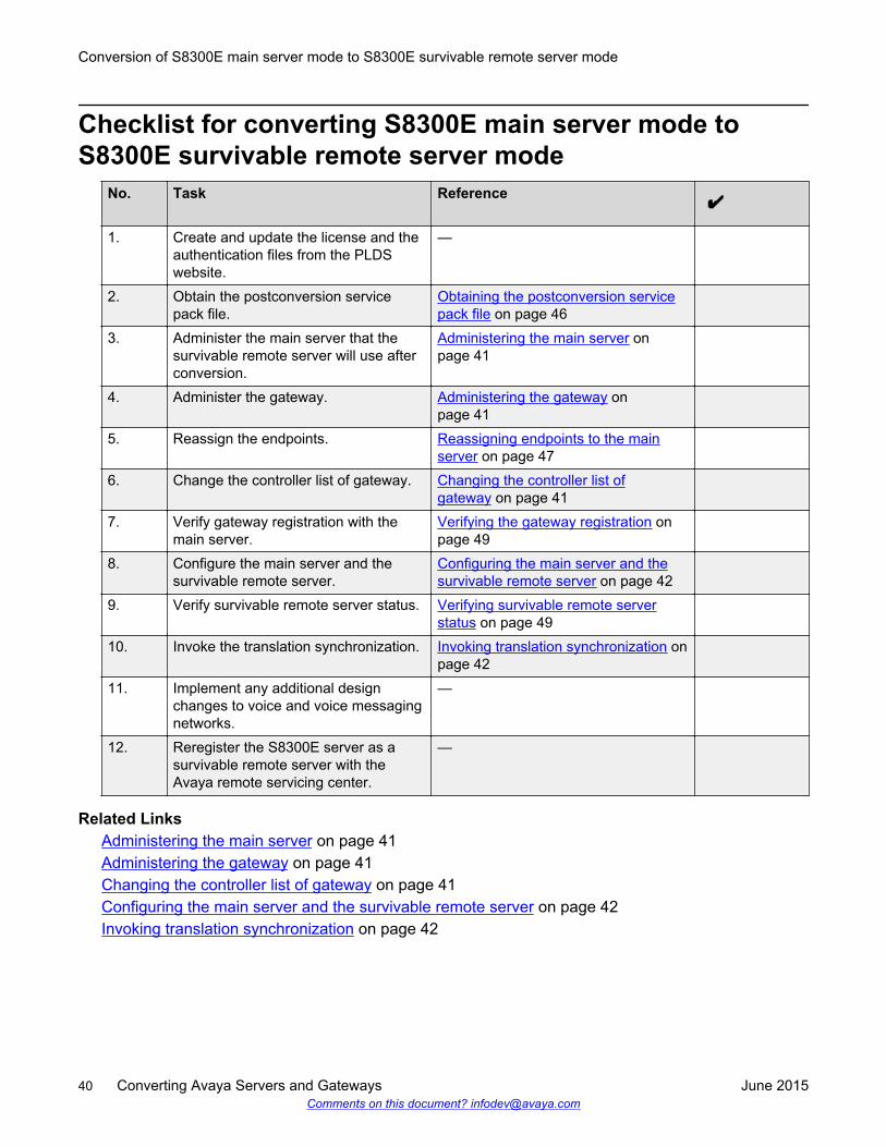
Checklist for converting S8300E main server mode toS8300E survivable remote server mode
No. Task Reference
1. Create and update the license and theauthentication files from the PLDSwebsite.
—
2. Obtain the postconversion servicepack file.
Obtaining the postconversion servicepack file on page 46
3. Administer the main server that thesurvivable remote server will use afterconversion.
Administering the main server onpage 41
4. Administer the gateway. Administering the gateway onpage 41
5. Reassign the endpoints. Reassigning endpoints to the mainserver on page 47
6. Change the controller list of gateway. Changing the controller list ofgateway on page 41
7. Verify gateway registration with themain server.
Verifying the gateway registration onpage 49
8. Configure the main server and thesurvivable remote server.
Configuring the main server and thesurvivable remote server on page 42
9. Verify survivable remote server status. Verifying survivable remote serverstatus on page 49
10. Invoke the translation synchronization. Invoking translation synchronization onpage 42
11. Implement any additional designchanges to voice and voice messagingnetworks.
—
12. Reregister the S8300E server as asurvivable remote server with theAvaya remote servicing center.
—
Related LinksAdministering the main server on page 41Administering the gateway on page 41Changing the controller list of gateway on page 41Configuring the main server and the survivable remote server on page 42Invoking translation synchronization on page 42
Conversion of S8300E main server mode to S8300E survivable remote server mode
40 Converting Avaya Servers and Gateways June 2015Comments on this document? [email protected]
Administering the main serverProcedure
1. Assign node names.
2. Administer network regions.
3. Associate survivable remote server with a network region.
4. Administer IP interfaces.
5. Identify survivable remote servers to the main server.
Related LinksChecklist for converting S8300E main server mode to S8300E survivable remote server mode onpage 40
Administering the gatewayProcedureFor each gateway controlled by the current main server:
a. Type the add media-gateway number command.
b. Press EnterRelated Links
Checklist for converting S8300E main server mode to S8300E survivable remote server mode onpage 40
Changing the controller list of gatewayProcedure
1. Clear the controller list of the gateway.
2. Enter the IP addresses of the main server and up to three alternate controllers.
3. Set the survivable remote server transition points.
4. To start the gateway, run the command copy running-config startupconfig.
5. Reset Media Gateway Processor.
Related LinksChecklist for converting S8300E main server mode to S8300E survivable remote server mode onpage 40
Checklist for converting S8300E main server mode to S8300E survivable remote server mode
June 2015 Converting Avaya Servers and Gateways 41Comments on this document? [email protected]
Configuring the main server and the survivable remote serverProcedure
1. If Communication Manager Messaging is installed, get Communication Manager Messagingdata and stop Communication Manager Messaging.
2. Record configuration information.
3. Remove CM_onlyEmbed template.
4. Install CM_SurvRemoteEmbed template.
5. Set time, date, and time zone.
Note:
The time of the survivable remote server must be set to the same time zone as its mainserver, even if the survivable remote server is physically located in a different time zone.
6. Install postconversion service pack file.
7. Install the new authentication file.
8. Configure server.
a. Fill in the data for each Server Configuration screen of the survivable remote server.
b. On the Server Role window, select the radio button to indicate that the server is not amain server.
9. Reboot the survivable remote server.
a. Type reset system 4.
b. Press Enter.
The survivable remote server should be registered with the main server and in a fewminutes translations should be synchronized.
Related LinksChecklist for converting S8300E main server mode to S8300E survivable remote server mode onpage 40
Invoking translation synchronizationProcedure
1. On the main server, type filesync -a ipaddress, where ipaddress is the IP address ofthe survivable remote server.
2. Press Enter.
3. Ensure that the translation synchronization completed successfully.
Conversion of S8300E main server mode to S8300E survivable remote server mode
42 Converting Avaya Servers and Gateways June 2015Comments on this document? [email protected]
4. To check the timestamp of the survivable remote server translation files, type listsurvivable-processor.
Related LinksChecklist for converting S8300E main server mode to S8300E survivable remote server mode onpage 40
Checklist for converting S8300E main server mode to S8300E survivable remote server mode
June 2015 Converting Avaya Servers and Gateways 43Comments on this document? [email protected]
Chapter 6: Conversion of S8300Esurvivable remote server modeto S8300E main server mode
S8300E serverThe S8300E server is based on a 2.0 GHz, dual core Intel Ivy Bridge processor. The S8300E serveris supported in the G430 Branch Gateway and G450 Media Gateway. The S8300E server supportsSystem Platform Release 6.3.7, and Communication Manager Release 6.3.8 and later. The S8300Eserver is certified by VMware as VMware Ready.
Requirements• Host name• Host IP address• Main server IP address• DNS IP address• UPS IP address• Static routes data• Time server data• Modem return route data
44 Converting Avaya Servers and Gateways June 2015Comments on this document? [email protected]
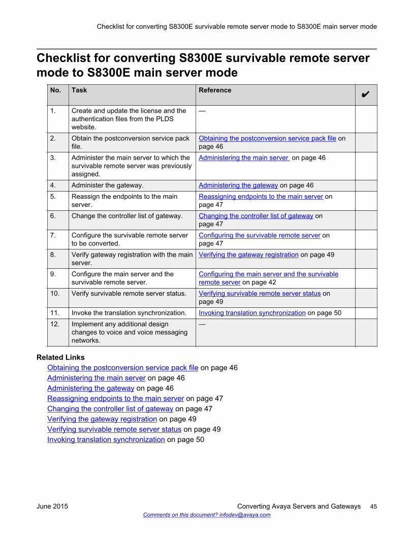
Checklist for converting S8300E survivable remote servermode to S8300E main server mode
No. Task Reference
1. Create and update the license and theauthentication files from the PLDSwebsite.
—
2. Obtain the postconversion service packfile.
Obtaining the postconversion service pack file onpage 46
3. Administer the main server to which thesurvivable remote server was previouslyassigned.
Administering the main server on page 46
4. Administer the gateway. Administering the gateway on page 465. Reassign the endpoints to the main
server.Reassigning endpoints to the main server onpage 47
6. Change the controller list of gateway. Changing the controller list of gateway onpage 47
7. Configure the survivable remote serverto be converted.
Configuring the survivable remote server onpage 47
8. Verify gateway registration with the mainserver.
Verifying the gateway registration on page 49
9. Configure the main server and thesurvivable remote server.
Configuring the main server and the survivableremote server on page 42
10. Verify survivable remote server status. Verifying survivable remote server status onpage 49
11. Invoke the translation synchronization. Invoking translation synchronization on page 5012. Implement any additional design
changes to voice and voice messagingnetworks.
—
Related LinksObtaining the postconversion service pack file on page 46Administering the main server on page 46Administering the gateway on page 46Reassigning endpoints to the main server on page 47Changing the controller list of gateway on page 47Verifying the gateway registration on page 49Verifying survivable remote server status on page 49Invoking translation synchronization on page 50
Checklist for converting S8300E survivable remote server mode to S8300E main server mode
June 2015 Converting Avaya Servers and Gateways 45Comments on this document? [email protected]
Obtaining the postconversion service pack fileProcedure
1. Go to https://support.avaya.com.
2. Click Downloads.
3. Download the service pack file.
Related LinksChecklist for converting S8300E survivable remote server mode to S8300E main server mode onpage 45
Administering the main serverProcedure
1. Type the change node-names-ip command, and press Enter.
2. From the list, delete the survivable remote server node name.
3. Save the changes and return to the command prompt.
4. Type the change ipnetwork-region number command, and press Enter.
5. Delete the survivable remote server from the network regions.
6. Save the changes and return to the command prompt.
7. Type the remove survivable-processor node-name command, and press Enter.
8. Repeat Step 1 to Step 7 for every survivable remote server to be controlled by the new mainserver.
Related LinksChecklist for converting S8300E survivable remote server mode to S8300E main server mode onpage 45
Administering the gatewayProcedureFor each gateway to be controlled by the survivable remote server, perform the following steps:
a. Type the remove media-gateway number command.
b. Press Enter.
Related LinksChecklist for converting S8300E survivable remote server mode to S8300E main server mode onpage 45
Conversion of S8300E survivable remote server mode to S8300E main server mode
46 Converting Avaya Servers and Gateways June 2015Comments on this document? [email protected]
Reassigning endpoints to the main serverProcedure
1. Add new stations.
2. Add new trunks.
3. Make test calls.
4. Reassign Communication Manager Messaging users to the messaging system used by themain server.
5. Enter test messages.
Related LinksChecklist for converting S8300E survivable remote server mode to S8300E main server mode onpage 45
Changing the controller list of gatewayProcedure
1. Clear the controller list of the gateway.
2. Enter the IP addresses of the new main server and up to three alternate controllers.
3. To start the gateway, run the copy running-config startupconfig command.
4. Reset Media Gateway Processor.
Related LinksChecklist for converting S8300E survivable remote server mode to S8300E main server mode onpage 45
Configuring the survivable remote serverProcedure
1. Back up the translations, Operating System, and security backup sets.
These backup sets will not be restored on the S8300Eserver. They should be backed up incase it is necessary to revert to the original configuration.
2. Record configuration information.
3. Remove the CM_SurvRemoteEmbed template.
4. Install the CM_onlyEmbed template.
5. Enable Communication Manager Messaging, if required.
6. Set time, date, and time zone.
Checklist for converting S8300E survivable remote server mode to S8300E main server mode
June 2015 Converting Avaya Servers and Gateways 47Comments on this document? [email protected]
7. Install postconversion service pack file, if any.
8. Install the new main server license file.
9. Install the new authentication file, if required.
10. Configure server.
a. Fill in the data for each Server Configuration screen with data of the main server.
b. On the Server Role screen, select the radio button to indicate that the server is not asurvivable remote server.
11. Administer the new main server.
12. Administer the gateway.
13. Reassign endpoints from the current main server to the standalone main server.
14. Reboot the main server.
Related LinksChecklist for converting S8300E survivable remote server mode to S8300E main server mode onpage 45Administering the main server on page 41Administering the gateway on page 41Reassigning endpoints to the main server on page 47
Administering the main serverProcedure
1. Assign node names.
2. Administer network regions.
3. Associate survivable remote server with a network region.
4. Administer IP interfaces.
5. Identify survivable remote servers to the main server.
Related LinksChecklist for converting S8300E main server mode to S8300E survivable remote server mode onpage 40
Administering the gatewayProcedureFor each gateway controlled by the current main server:
a. Type the add media-gateway number command.
b. Press EnterRelated Links
Conversion of S8300E survivable remote server mode to S8300E main server mode
48 Converting Avaya Servers and Gateways June 2015Comments on this document? [email protected]
Checklist for converting S8300E main server mode to S8300E survivable remote server mode onpage 40
Reassigning endpoints to the main serverProcedure
1. Add new stations.
2. Add new trunks.
3. Make test calls.
4. Reassign Communication Manager Messaging users to the messaging system used by themain server.
5. Enter test messages.
Related LinksChecklist for converting S8300E survivable remote server mode to S8300E main server mode onpage 45
Verifying the gateway registrationProcedure
1. Type list media-gateway, and press Enter.
2. Verify that the Registered field is set to y.
3. Place a test call.
Related LinksChecklist for converting S8300E survivable remote server mode to S8300E main server mode onpage 45
Verifying survivable remote server statusProcedure
1. Type list survivable-processor, and press Enter.
2. To view the translations dates and times of the main server, type list configurationsoftware-version.
3. Ensure that the Translations Updated date and time matches with the translations date andtime on the main server.
Related LinksChecklist for converting S8300E survivable remote server mode to S8300E main server mode onpage 45
Checklist for converting S8300E survivable remote server mode to S8300E main server mode
June 2015 Converting Avaya Servers and Gateways 49Comments on this document? [email protected]
Invoking translation synchronizationProcedure
1. On the main server, type filesync -a trans, and press Enter.
2. Ensure that the translation synchronization completed successfully.
3. To check the timestamp of the survivable remote server translation files, type listsurvivable-processor, and press Enter.
Related LinksChecklist for converting S8300E survivable remote server mode to S8300E main server mode onpage 45
Conversion of S8300E survivable remote server mode to S8300E main server mode
50 Converting Avaya Servers and Gateways June 2015Comments on this document? [email protected]
Chapter 7: Conversion of S8510 S8800main server mode to S8510S8800 survivable remote servermode (_Simplex Template)
Conversion of S8510/S8800 Server/HP DL360 G7/Dell R610main server mode to S8510/S8800 Server/HP DL360 G7/Dell R610 survivable remote server mode (CM_Simplextemplate)
This chapter provides a high-level list of tasks required to convert a configured main server to aserver in the survivable remote server mode. To ensure a complete conversion, you must changethe Communication Manager template. For example, during the process of conversion, you mustremove the previous template and install the CM_Simplex template of the 6.2 version.
For more information about completing these tasks, see Implementing Avaya Aura® CommunicationManager, 03–603558.
You can convert the following main servers to the survivable remote server mode forCommunication Manager Release 6.2:
• S8510
• S8800 Server
• HP DL360 G7
• Dell R610
Converting of S8510/S8800 Server/HP DL360 G7/Dell R610main server mode to S8510/S8800 Server/HP DL360 G7/
June 2015 Converting Avaya Servers and Gateways 51Comments on this document? [email protected]
Dell R610 survivable remote server mode (CM_Simplextemplate)
Before you beginComplete the preconversion task checklist.
See Preconversion task checklist.
About this taskUse this procedure to convert a server, configured as a main server mode, to a server in thesurvivable remote server mode. To ensure a complete conversion, you must change theCommunication Manager template. For example, during the process of conversion, you mustremove the previous template and install the CM_Simplex template of the 6.2 version.
You can convert the following main servers to the survivable remote server mode forCommunication Manager Release 6.2:
• S8510• S8800 Server• HP DL360 G7• Dell R610
You can perform the tasks on one of the following:• Servers:
- On the main server- On the survivable remote server- On the main server for the survivable remote server- On a DHCP server
• Gateways:
- On the gateway processor (MGP)
Procedure1. On the main server of the new survivable remote server, do the following:
a. Administer the main server to the former survivable remote server you had assigned.
See Administering the main server to which the survivable remote server was formerlyassigned.
b. Administer the gateway.
See Administering the gateway.
c. Reassign endpoints from the main server to this main server.
See Reassigning endpoints from the main server to this main server.
2. On the DHCP server, update the alternate controller list on the DHCP server.
Conversion of S8510 S8800 main server mode to S8510 S8800 survivable remote server mode (_Simplex Template)
52 Converting Avaya Servers and Gateways June 2015Comments on this document? [email protected]
3. On the MGP of the gateway, go to the MGP command prompt, and change the gateway'scontroller list.
See Changing the gateway's controller list.
4. On the survivable remote server that you are converting, ensure you have backup of files asfollows:
• Translations
• Operating system
• Security backup sets
If you have to revert to the original configuration, you must backup all system files. Bydefault, after the conversion the system does not backup sets on the server.
5. On the main server or survivable remote server, configure the parameters.
See Configuring the main server and the survivable remote server.
6. On the main server, do the following:
a. Verify the status of the survivable remote server.
See Verifying survivable remote server status.
b. If the translations of the survivable remote server have not synchronized with the mainserver, run the translation synchronization.
See Invoking translation synchronization.
Related LinksPreconversion tasks checklist on page 21
Administering the main server to which the survivableremote server was formerly assigned
Procedure1. Remove the survivable remote server node name with the change node-names ip
command.
2. Disassociate the survivable remote server from the network regions with the change ip-network-region number command.
3. Remove the survivable remote server from the survivable remote server screen with theremove survivable-processor node-name command.
4. Repeat Steps 1 through Step 3 for every survivable remote server to be controlled by thenew main server.
Administering the main server to which the survivable remote server was formerly assigned
June 2015 Converting Avaya Servers and Gateways 53Comments on this document? [email protected]
Administering the gatewayProcedure
1. Use the remove media-gateway number command to remove the gateway.
2. For each gateway to be controlled by the converted survivable remote server, repeat Step 1.
Reassigning endpoints from the main server to this mainserver
About this taskYou must reassigning endpoints from the main server to this main server.
For more information, see Administering Avaya Aura® Communication Manager, 03-300509.
Procedure1. To update translations, add stations, and trunks.
a. If the main server is a new installation, use the Avaya Installation Wizard, and theElectronic Preinstallation Worksheet (EPW).
b. Use SAT commands.
2. Make test calls to verify.
3. Reassign Communication Manager Messaging users to the messaging system used by thismain server. Enter test messages to verify.
Changing the controller list of GatewayProcedure
1. Clear the controller list of the gateway.
2. Enter the IP addresses of the new main server and up to three alternate controllers.
3. Run the command copy running-config startup-config to start the gateway.
4. Reset the gateway processor.
Converting S8510/S8800 Server/HP DL360 G7/Dell R610main server mode to S8510/S8800 Server/HP DL360 G7/
Conversion of S8510 S8800 main server mode to S8510 S8800 survivable remote server mode (_Simplex Template)
54 Converting Avaya Servers and Gateways June 2015Comments on this document? [email protected]
Dell R610 survivable remote server mode (CM_SimplexTemplate)
Procedure1. If Communication Manager Messaging is installed, get Communication Manager Messaging
data and stop Communication Manager Messaging.
2. Record the configuration information.
a. In the Record Configuration Information task, record all configuration information.
b. Re-enter some of the Record Configuration Information task information after theconversion.
3. Change the server role to survivable remote server.
a. On the System Management Interface, click Administration > Server (Maintenance).
b. In the Server Configuration field, click Server Role.
c. Select the option that indicates Survivable Remote Server.
The Survivable Remote Server can be called Local Survivable Processor or LSP.
4. Install the CM_SurvRemoteEmbed template.
5. Set the time, date, and time zone.
The time of the survivable remote server must be set to the same time zone as the mainserver of the survivable remote server. The survivable remote server and the main server ofthe survivable remote server might be physically located in different time zones.
6. Install the postconversion service pack file.
7. Install the new authentication file.
8. Reboot the survivable remote server.
a. Open a SAT session and type reset system 4.
b. After the reboot, register the survivable remote server with the main server andsynchronize the translation within a few minutes.
Verifying survivable remote server statusAbout this taskThis topic is about verifying the status of the survivable remote server.
Procedure1. At the SAT command prompt do one of the following:
• Enter list survivable-processor for Avaya Aura® Communication Manager R3.1
Verifying survivable remote server status
June 2015 Converting Avaya Servers and Gateways 55Comments on this document? [email protected]
• Enter list lsp for Avaya Aura® Communication Manager R2.x.
The survivable remote server name, and IP address must be listed.
2. To view the translations dates, and times of the main server, enter list configurationsoftware-version.
3. Ensure that the Translations Updated date, and time matches that of the translations, on themain server.
Invoking translation synchronizationAbout this taskTo run translation synchronization.
Procedure1. On the main server, enter the Linux command filesync -a trans.
2. Ensure that the translation synchronization completed successfully. Wait several minutes.
3. Check the time stamp of the survivable remote server translation files with the SATcommand list survivable-processor or list lsp on the main server.
Performing postconversion tasks to convert S8510/S8800Server/HP DL360 G7/Dell R610 main server mode to S8510/S8800 Server/HP DL360 G7/Dell R610 survivable remoteserver mode (CM_Simplex Template)
About this taskAfter conversion, you need to carry out the following tasks:
Procedure1. Implement any additional design changes to voice and/or voice messaging networks.
2. Reregister the new survivable remote server with the Avaya remote servicing center.
Conversion of S8510 S8800 main server mode to S8510 S8800 survivable remote server mode (_Simplex Template)
56 Converting Avaya Servers and Gateways June 2015Comments on this document? [email protected]
Chapter 8: Conversion of S8510 S8800survivable remote server modeto S8510 S8800 main servermode (_Simplex template)
Conversion of S8510/S8800 Server/HP DL360 G7/Dell R610survivable remote server mode to S8510/S8800 Server/HPDL360 G7/Dell R610 main server mode (CM_Simplextemplate)
This chapter provides a high-level list of tasks required to convert a configured survivable remoteserver to a server in the main server mode. To ensure a complete conversion, you must not changethe Communication Manager template. For example, during the process of conversion, you mustuse the CM_Simplex template of the 6.2 version.
For more information about completing these tasks, see Implementing Avaya Aura® CommunicationManager, 03–603558.
You can convert the following survivable remote servers to the main server mode forCommunication Manager Release 6.2:
• S8510• S8800 Server• HP DL360 G7• Dell R610
For the installation and conversion procedures in this chapter, use the System ManagementInterface (SMI) for Communication Manager Release 6.2. You can automate some tasks by usingthe Avaya Installation Wizard with the Electronic Preinstallation Worksheet (EPW).
Converting S8510/S8800 Server/HP DL360 G7/Dell R610survivable remote server mode to S8510/S8800 Server/HP
June 2015 Converting Avaya Servers and Gateways 57Comments on this document? [email protected]
DL360 G7/Dell R610 main server mode (CM_Simplextemplate)
Before you begin
Ensure that you have followed all the necessary steps mentioned in BROKEN LINK:#unique_67.
About this taskTo convert the S8510/S8800 Server/HP DL360 G7/Dell R610 main server mode to S8510/S8800Server/HP DL360 G7/Dell R610 survivable remote server mode (CM_Simplex Template), performthe following tasks at the customer site.
Note:It is important to note where the task is performed. Most of the tasks are done on a server orgateway — on the main server/survivable remote server, on the main server for the survivableremote server, on a DHCP server, or on the gateway processor (MGP).
Procedure1. On the main server of the new survivable remote server, do the following:
a. Administer the main server to which the survivable remote server was formerlyassigned. See Administering the main server to which the survivable remote server wasformerly assigned.
b. Administer the gateway. See Administering the gateway.
c. Reassign endpoints from the main server to this main server. See Reassigningendpoints from the main server to this main server.
2. On the DHCP server, update the alternate controller list on the DHCP server.
3. On the MGP of the gateway, go to the MGP command prompt and change the gateway'scontroller list. See Changing the gateway's controller list.
4. On the survivable remote server to be converted, take a backup all system files: translations,OS, and security backup sets.
Note:
These backup sets will not be restored on the S8510/S8800 Server/HP DL360 G7/DellR610. They should be backed up in case it is necessary to revert to the originalconfiguration.
5. On the main server/survivable remote server, configure the parameters. See Configuring themain server and the survivable remote server.
Conversion of S8510 S8800 survivable remote server mode to S8510 S8800 main server mode (_Simplex template)
58 Converting Avaya Servers and Gateways June 2015Comments on this document? [email protected]
Administering the main server to which the survivableremote server was formerly assigned
Procedure1. Remove the survivable remote server node name with the change node-names ip
command.
2. Disassociate the survivable remote server from the network regions with the change ip-network-region number command.
3. Remove the survivable remote server from the survivable remote server screen with theremove survivable-processor node-name command.
4. Repeat Steps 1 through Step 3 for every survivable remote server to be controlled by thenew main server.
Administering the gatewayProcedure
1. Use the remove media-gateway number command to remove the gateway.
2. For each gateway to be controlled by the converted survivable remote server, repeat Step 1.
Reassigning endpoints from the main server to this mainserver
About this taskYou must reassigning endpoints from the main server to this main server.
For more information, see Administering Avaya Aura® Communication Manager, 03-300509.
Procedure1. To update translations, add stations, and trunks.
a. If the main server is a new installation, use the Avaya Installation Wizard, and theElectronic Preinstallation Worksheet (EPW).
b. Use SAT commands.
2. Make test calls to verify.
3. Reassign Communication Manager Messaging users to the messaging system used by thismain server. Enter test messages to verify.
Administering the main server to which the survivable remote server was formerly assigned
June 2015 Converting Avaya Servers and Gateways 59Comments on this document? [email protected]
Changing the controller list of GatewayProcedure
1. Clear the controller list of the gateway.
2. Enter the IP addresses of the new main server and up to three alternate controllers.
3. Run the command copy running-config startup-config to start the gateway.
4. Reset the gateway processor.
Configuring the main server and the survivable remoteserver to convert S8510/S8800 Server/HP DL360 G7/DellR610 survivable remote server mode to S8510/S8800Server/HP DL360 G7/Dell R610 main server mode(CM_Simplex template)
About this taskTo configure the main server and survivable remote server, perform the following steps:
Procedure1. Record configuration information.
a. If you have not already done so, in the Record Configuration Information task, record allof the configuration information.
b. Reenter some of this information after the conversion.
2. Change the server role to main server.
a. On the System Management Interface (SMI), go to Administration, and then clickServer (Maintenance).
b. Under Server Configuration, click Server Role, and then select the radio button thatindicates this is the main server.
c. Fill in each Server Configuration screen with data for the main server. Some of theconfiguration data will be the same as that for the survivable remote server.
3. Enable Communication Manager Messaging, if required.
4. Set time, date, and time zone.
Note:
The time of the survivable remote server must be set to the same time zone as its mainserver, even if the survivable remote server is physically located in a different time zone.
5. Install postconversion service pack file, if any.
Conversion of S8510 S8800 survivable remote server mode to S8510 S8800 main server mode (_Simplex template)
60 Converting Avaya Servers and Gateways June 2015Comments on this document? [email protected]
6. Install the new main server license file.
7. Install the new authentication file, if required.
8. Administer the new main server.
a. Assign node names.
b. Administer network regions.
c. Associate other survivable remote servers (if any) with a network region.
d. Add IP interfaces.
e. Identify survivable remote servers to the main server.
9. Administer the gateway.
a. Add gateway.
b. Repeat for each gateway to be controlled by the new main server.
c. For this scenario, the gateway will not automatically register with the main server at thispoint. Skip the subtasks, Verify Changes and Save Translations in this section.
d. When the gateway finally registers, the media modules will automatically populate,unless you are doing administration without hardware (AWOH). In this case, you willhave to enter the media module types for each slot.
10. Reassign endpoints from the current main server to the standalone main server.
a. Update translations — add stations and trunks
• Using the Avaya Installation Wizard and the Electronic Preinstallation Worksheet(EPW) is recommended.
• Alternatively, use SAT commands.
b. Place test calls to verify.
c. Reassign messaging system users of the current main server to the messaging systemused by the new main server. Enter test messages to verify.
11. Reboot the survivable remote server.
a. Open a SAT session and enter reset system 4.
b. After the reboot, the survivable remote server should be registered with the main serverand in a few minutes translations should be synchronized.
Configuring the main server and the survivable remote server to convert S8510/S8800 Server/HP DL360 G7/Dell R610survivable remote server mode to S8510/S8800 Server/HP DL360 G7/Dell R610 main server mode (CM_Simplex template)
June 2015 Converting Avaya Servers and Gateways 61Comments on this document? [email protected]
Chapter 9: Conversion of S8510 S8800survivable remote server modeto S8510 S8800 main servermode (_SurvRemote to_Simplex)
Conversion of S8510/S8800 Server/HP DL360 G7/Dell R610survivable remote server mode to S8510/S8800 Server/HPDL360 G7/Dell R610 main server mode (CM_SurvRemoteto CM_Simplex)
This chapter provides a high-level list of tasks required to convert a configured survivable remoteserver to a server in the main server mode. To ensure a complete conversion, you must change theCommunication Manager template. For example, during the process of conversion, you mustremove the CM_SurvRemote template and install the CM_Simplex template of the 6.2 version.
For more information about completing these tasks, see Implementing Avaya Aura® CommunicationManager, 03–603558.
You can convert the following survivable remote servers to the main server mode forCommunication Manager Release 6.2:
• S8510
• S8800 Server
• HP DL360 G7
• Dell R610
For the installation and conversion procedures in this chapter, use the System ManagementInterface (SMI) for Communication Manager Release 6.2. You can automate some tasks by usingthe Avaya Installation Wizard with the Electronic Preinstallation Worksheet (EPW).
62 Converting Avaya Servers and Gateways June 2015Comments on this document? [email protected]
Converting S8510/S8800 Server/HP DL360 G7/Dell R610survivable remote server mode to S8510/S8800 Server/HPDL360 G7/Dell R610 main server mode (CM_SurvRemoteto CM_Simplex)
Before you begin
Perform the BROKEN LINK: preconversion tasks checklist.
About this taskUse this procedure to convert a server, configured as the survivable remote server, to a server inthe main server mode.
The survivable remote servers that you can covert are as follows:• S8510• S8800 Server• HP DL360 G7• Dell R610
To ensure a complete conversion, you must change the Communication Manager template. Forexample, during the process of conversion, you must remove the CM_SurvRemote template andinstall the CM_Simplex template of the 6.2 version.
Important:Note where the task is performed. You can perform the tasks on one of the following:
• Servers:
- On the main server- On the survivable remote server- On the main server for the survivable remote server- On a DHCP server
• Gateways:
- On the gateway processor (MGP)
Procedure1. On the main server of the new survivable remote server, do the following:
a. Administer the main server that the survivable remote server must use after conversion.
See Administering the main server to which the survivable remote server was formerlyassigned.
b. Administer the gateway.
See Administering the gateway.c. Reassign endpoints from the main server to this main server.
Converting S8510/S8800 Server/HP DL360 G7/Dell R610 survivable remote server mode to S8510/S8800 Server/HP DL360G7/Dell R610 main server mode (CM_SurvRemote to CM_Simplex)
June 2015 Converting Avaya Servers and Gateways 63Comments on this document? [email protected]
See Reassigning endpoints from the main server to this main server.
2. On the DHCP server, update the alternate controller list on the DHCP server.
3. On the MGP of the gateway, go to the MGP command prompt and change the gatewaycontroller list.
4. On the survivable remote server to be converted, take a backup of all system files.
The system files can include the following:
• Translations backup sets
• Operating software backup sets
• Security backup sets
The backup sets are not restored on the survivable remote server to be converted.Therefore, to revert to the original 25 configurations, the survivable remote server to beconverted must have back up.
5. On the main server, or the survivable remote server, configure the parameters.
See Configuring the main server and the survivable remote server.
Administering the main server to which the survivableremote server was formerly assigned
Procedure1. Remove the survivable remote server node name with the change node-names ip
command.
2. Disassociate the survivable remote server from the network regions with the change ip-network-region number command.
3. Remove the survivable remote server from the survivable remote server screen with theremove survivable-processor node-name command.
4. Repeat Steps 1 through Step 3 for every survivable remote server to be controlled by thenew main server.
Administering the gatewayProcedure
1. Use the remove media-gateway number command to remove the gateway.
2. For each gateway to be controlled by the converted survivable remote server, repeat Step 1.
Conversion of S8510 S8800 survivable remote server mode to S8510 S8800 main server mode (_SurvRemote to _Simplex)
64 Converting Avaya Servers and Gateways June 2015Comments on this document? [email protected]
Reassigning endpoints from the main server to this mainserver
About this taskYou must reassigning endpoints from the main server to this main server.
For more information, see Administering Avaya Aura® Communication Manager, 03-300509.
Procedure1. To update translations, add stations, and trunks.
a. If the main server is a new installation, use the Avaya Installation Wizard, and theElectronic Preinstallation Worksheet (EPW).
b. Use SAT commands.
2. Make test calls to verify.
3. Reassign Communication Manager Messaging users to the messaging system used by thismain server. Enter test messages to verify.
Changing the controller list of GatewayProcedure
1. Clear the controller list of the gateway.
2. Enter the IP addresses of the new main server and up to three alternate controllers.
3. Run the command copy running-config startup-config to start the gateway.
4. Reset the gateway processor.
Configuring the main server and the survivable remoteserver to convert S8510/S8800 Server/HP DL360 G7/DellR610 survivable remote server mode to S8510/S8800Server/HP DL360 G7/Dell R610 main server mode(CM_SurvRemote to CM_Simplex)
About this taskTo configure the main server and survivable remote server, perform the following steps:
Reassigning endpoints from the main server to this main server
June 2015 Converting Avaya Servers and Gateways 65Comments on this document? [email protected]
Procedure1. Record configuration information.
a. If you have not already done so, in the Record Configuration Information task, record allof the configuration information.
b. Reenter some of this information after the conversion.
2. Remove the CM_SurvRemote template.
3. Install the CM_Simplex template.
4. Change the server role to main server.
a. On the System Management Interface (SMI), go to Administration, and then clickServer (Maintenance).
b. Under Server Configuration, click Server Role, and then select the radio button thatindicates this is the Main server.
c. Fill in each Server Configuration screen with data for the main server. Some of theconfiguration data will be the same as that for the survivable remote server.
5. Enable Communication Manager Messaging, if required.
6. Set time, date, and time zone.
Note:
The time of the survivable remote server must be set to the same time zone as its mainserver, even if the survivable remote server is physically located in a different time zone.
7. Install postconversion service pack file, if any.
8. Install the new main server license file.
9. Install the new authentication file, if required.
10. Administer the new main server.
a. Assign node names.
b. Administer network regions.
c. Associate other survivable remote servers with a network region.
d. Add IP interfaces.
e. Identify survivable remote servers to the main server.
11. Administer the gateway.
a. Add gateway.
b. Repeat for each gateway to be controlled by the new main server.
c. For this scenario, the gateway will not automatically register with the main server at thispoint. Skip the subtasks, Verify Changes and Save Translations in this section.
Conversion of S8510 S8800 survivable remote server mode to S8510 S8800 main server mode (_SurvRemote to _Simplex)
66 Converting Avaya Servers and Gateways June 2015Comments on this document? [email protected]
d. When the gateway finally registers, the media modules will automatically populate,unless you are doing administration without hardware (AWOH). In this case, you willhave to enter the media module types for each slot.
12. Reassign endpoints from the current main server to the standalone main server.
a. Update translations — add stations and trunks
• Using the Avaya Installation Wizard and the Electronic Preinstallation Worksheet(EPW) is recommended.
• Alternatively, use SAT commands.
b. Place test calls to verify.
c. Reassign messaging system users of the current main server to the messaging systemused by the new main server. Enter test messages to verify.
13. Reboot the survivable remote server.
a. Open a SAT session and enter reset system 4.
b. After the reboot, the survivable remote server should be registered with the main serverand in a few minutes translations should be synchronized.
Configuring the main server and the survivable remote server to convert S8510/S8800 Server/HP DL360 G7/Dell R610survivable remote server mode to S8510/S8800 Server/HP DL360 G7/Dell R610 main server mode (CM_SurvRemote to
CM_Simplex)
June 2015 Converting Avaya Servers and Gateways 67Comments on this document? [email protected]
Chapter 10: Converting IP-PNC portnetworks from simplex controlto duplicated control
Converting IP-PNC port networks from simplex control toduplicated control
Before you beginBefore you go to the customer site:
• Perform all the tasks mentioned in Presite checklist on page 16.• Perform all the tasks mentioned in BROKEN LINK: Performing preconversion tasks.
• Upgrade the system to Communication Manager release 6.2.
About this taskTo convert an IP-PNC port network from a simplex control network to a duplicated control network,perform the following tasks:
Procedure1. Install and cable a second Ethernet switch, if necessary. See Installing and cabling a second
Ethernet switch.
2. Configure the SNMP subagent in the Avaya Ethernet switch, if used. See Configuring theSNMP subagent in the Avaya Ethernet switch.
3. Enable firewall settings, if necessary. See Enabling firewall settings.
4. Access the System Management Interface. See Accessing the System ManagementInterface.
5. Designate the slot for the duplicated IPSI circuit pack. See Designating the slot for theduplicated IPSI circuit pack.
6. Install the duplicated IPSI circuit pack. See Installing the duplicated IPSI circuit pack.
7. Add control network cabling for the new circuit pack. See Adding control network cabling forthe new circuit pack.
8. Verify the IPSI circuit packs are inserted properly. See Verifying insertion of IPSI circuitpacks.
68 Converting Avaya Servers and Gateways June 2015Comments on this document? [email protected]
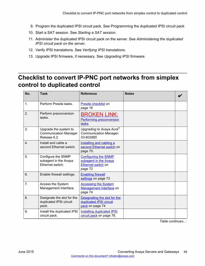
9. Program the duplicated IPSI circuit pack. See Programming the duplicated IPSI circuit pack
10. Start a SAT session. See Starting a SAT session.
11. Administer the duplicated IPSI circuit pack on the server. See Administering the duplicatedIPSI circuit pack on the server.
12. Verify IPSI translations. See Verifying IPSI translations.
13. Upgrade IPSI firmware, if necessary. See Upgrading IPSI firmware.
Checklist to convert IP-PNC port networks from simplexcontrol to duplicated control
No. Task Reference Notes
1. Perform Presite tasks. Presite checklist onpage 16
2. Perform preconversiontasks.
BROKEN LINK:Performing preconversiontasks
3. Upgrade the system toCommunication ManagerRelease 6.2.
Upgrading to Avaya Aura®
Communication Manager,03-602885
4. Install and cable asecond Ethernet switch.
Installing and cabling asecond Ethernet switch onpage 70.
5. Configure the SNMPsubagent in the AvayaEthernet switch.
Configuring the SNMPsubagent in the AvayaEthernet switch onpage 72
6. Enable firewall settings. Enabling firewallsettings on page 73
7. Access the SystemManagement Interface.
Accessing the SystemManagement Interface onpage 74
8. Designate the slot for theduplicated IPSI circuitpack.
Designating the slot for theduplicated IPSI circuitpack on page 74
9. Install the duplicated IPSIcircuit pack.
Installing duplicated IPSIcircuit pack on page 76.
Table continues…
Checklist to convert IP-PNC port networks from simplex control to duplicated control
June 2015 Converting Avaya Servers and Gateways 69Comments on this document? [email protected]
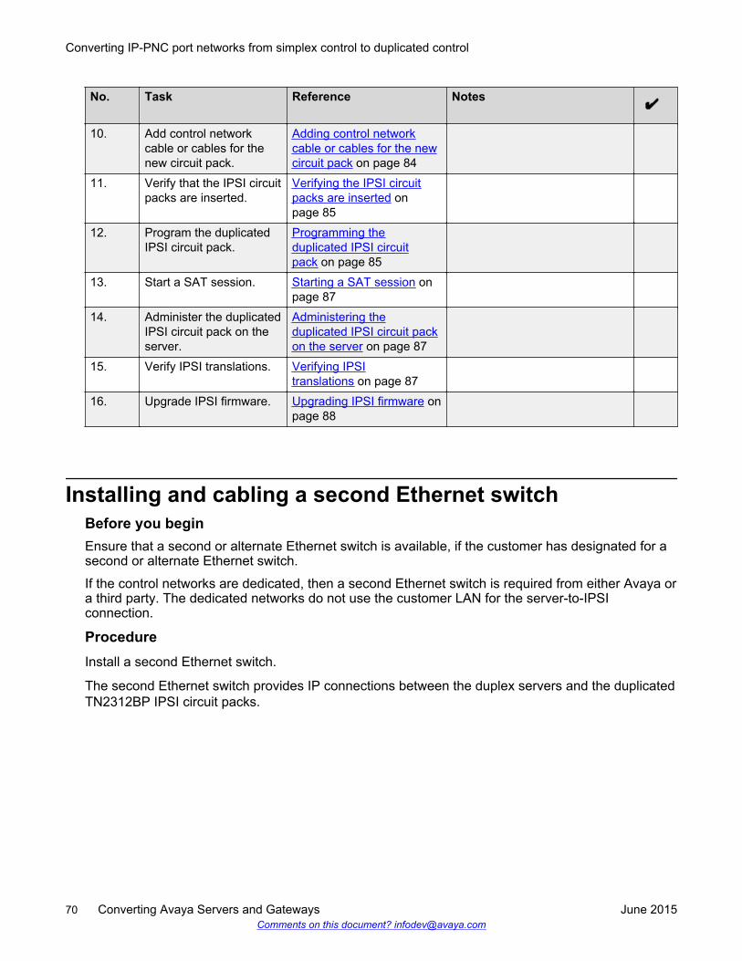
No. Task Reference Notes
10. Add control networkcable or cables for thenew circuit pack.
Adding control networkcable or cables for the newcircuit pack on page 84
11. Verify that the IPSI circuitpacks are inserted.
Verifying the IPSI circuitpacks are inserted onpage 85
12. Program the duplicatedIPSI circuit pack.
Programming theduplicated IPSI circuitpack on page 85
13. Start a SAT session. Starting a SAT session onpage 87
14. Administer the duplicatedIPSI circuit pack on theserver.
Administering theduplicated IPSI circuit packon the server on page 87
15. Verify IPSI translations. Verifying IPSItranslations on page 87
16. Upgrade IPSI firmware. Upgrading IPSI firmware onpage 88
Installing and cabling a second Ethernet switchBefore you beginEnsure that a second or alternate Ethernet switch is available, if the customer has designated for asecond or alternate Ethernet switch.
If the control networks are dedicated, then a second Ethernet switch is required from either Avaya ora third party. The dedicated networks do not use the customer LAN for the server-to-IPSIconnection.
ProcedureInstall a second Ethernet switch.
The second Ethernet switch provides IP connections between the duplex servers and the duplicatedTN2312BP IPSI circuit packs.
Converting IP-PNC port networks from simplex control to duplicated control
70 Converting Avaya Servers and Gateways June 2015Comments on this document? [email protected]
Performing preconfiguration of the SNMP subagent in anAvaya Ethernet switch
Before you beginEnsure that you are not using these procedures to set traps on a non Avaya provided Ethernetswitch. These instruction apply only to a new Avaya Ethernet switch.
Procedure1. See the documentation that comes with the Avaya Ethernet switch. The specific Avaya
Ethernet switch model and firmware load shipped with a communication system can changeover time. Therefore, this document is not specific on how to configure the SNMP subagent.
2. If the control network is nondedicated, ensure that the 162 or udp port for input to server isenabled. By default, the 162 or udp port for input to server is disabled. Therefore, the trapsfrom one or more UPS units cannot be received. Nondedicated control networks arenetworks that go over the customer network.
3. Administer the SNMP subagent in the Avaya Ethernet switch so that the SNMP subagentcan report alarms to the server when the hardware has problems.
4. Each Avaya Ethernet switch requires a unique IP address, which can be customer providedor the default address by Avaya. Configure the following:
• IP address
Each Ethernet switch requires one IP address.
• Subnet mask
• Trap receiver IP address
• Community string
The community string for get, set, trap can include the following:
• Spanning tree version
• Ethernet port speed
5. For the Ethernet switch to report alarms, configure the IP address or addresses for theEthernet switch or switches.
6. Access the default user ID, password, and configuration command.
See the Basic Configuration section of the Quick Start Guide and the documentation CD-ROM that comes with the Ethernet switch.
Performing preconfiguration of the SNMP subagent in an Avaya Ethernet switch
June 2015 Converting Avaya Servers and Gateways 71Comments on this document? [email protected]
Configuring the SNMP subagent in the Avaya Ethernetswitch
Before you beginRead Performing preconfiguration of the SNMP subagent in the Avaya Ethernet switch.
Procedure1. Plug the Ethernet switch power cord into the back of the switch and the back of an UPS.
• For a single control network, connect Ethernet switch 1 for Control Network A (CNA) intoUPS 1.
• For a duplicated control network, connect Ethernet switch 1 for CNA into UPS 1 andconnect Ethernet switch 2 for CNB into UPS 2.
2. Connect the services laptop computer using the RS-232 serial port labeled Console on thefront of Ethernet switch 1 for Control Network A with the flat cable supplied with the AvayaEthernet switch.
3. On the services laptop, start a VT-100 terminal emulation session.
4. Administer the terminal emulation port settings as follows:
• 9600 baud
• No parity
• 8 data bits
• 1 stop bit
5. Follow the instructions in the Quick Start Guide.
6. Set the following parameters:
a. IP address and subnet mask of the Ethernet switches
• For Ethernet switch for CNA, the defaults are 198.152.254.240, 255.255.0.0.
• For Ethernet switch for CNB, the defaults are 198.152.255.240, 255.255.0.0.
b. IP address of the trap receiver.
Do not use the Active Server IP address.
• For Ethernet switch for CNA, the default IP address of server 1 is 198.152.254.200.
• For Ethernet switch for CNB, the default IP address of server 2 is 198.152.255.200.
c. SNMP community string for Get, Set, and Trap. See the section on SNMP commandson the documentation CD-ROM that comes with the Avaya Ethernet switch.
Converting IP-PNC port networks from simplex control to duplicated control
72 Converting Avaya Servers and Gateways June 2015Comments on this document? [email protected]
Security alert:
The Get and Set community name strings are usually configured with defaultvalues of Public and Private, respectively. The community name strings function aspasswords for the respective SNMP operation. Change the default values.
If a Network Management Station is in operation on the network, the NMSadministrator must know about the change of strings.
A serious security issue can occur if the default strings are left unadministered. Forexample, the default Set community name string, with the value of Private, can beused to reconfigure the Ethernet switch through SNMP message.
7. Use the command set spantree enabled to verify that spanning tree is enabled.
8. Use the command set spantree version rapid-spanning-tree to set spanningtree version to rapid-spanning-tree.
The set spantree version rapid-spanning-tree command is available on AvayaP363 Ethernet switches having firmware version 4.0 or later. You must update the firmwareto this version to use the command.
For more information about the Spanning Tree CLI commands, see Installation andConfiguration Guide, Avaya C360 and Reference Guide, Avaya C360 available at the AvayaSupport website http://www.avaya.com/support.
9. For IP-PNC, ensure all appropriate ports on the Ethernet switch are locked to 100 speed withfull duplex.
10. When completed, disconnect the services laptop computer from the Ethernet switch.
11. For two Ethernet switches that are present for CNA, repeat Step 1 through Step 7 for thesecond switch.
12. For a duplicated control network, repeat Step 1 through Step 9 for the remaining Ethernetswitch or switches.
Enabling firewall settingsBefore you beginFor the server to receive SNMP traps from the UPS and Avaya Ethernet switch, you must enablethe 162 or udp port used by SNMP. By default, the setting is disabled.
Procedure1. On the Server Administration Interface, click Security > Firewall.
2. On the bottom of the Firewall screen, click Advanced Settings.
3. Scroll down and find the SNMP port 162 or udp.
4. Select the check boxes in both the Input to Server and Output to Server columns.
Enabling firewall settings
June 2015 Converting Avaya Servers and Gateways 73Comments on this document? [email protected]
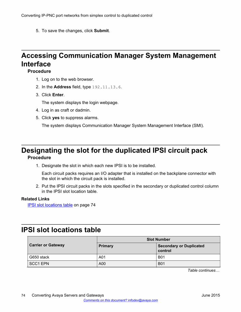
5. To save the changes, click Submit.
Accessing Communication Manager System ManagementInterface
Procedure1. Log on to the web browser.
2. In the Address field, type 192.11.13.6.
3. Click Enter.
The system displays the login webpage.
4. Log in as craft or dadmin.
5. Click yes to suppress alarms.
The system displays Communication Manager System Management Interface (SMI).
Designating the slot for the duplicated IPSI circuit packProcedure
1. Designate the slot in which each new IPSI is to be installed.
Each circuit packs requires an I/O adapter that is installed on the backplane connector withthe slot in which the circuit pack is installed.
2. Put the IPSI circuit packs in the slots specified in the secondary or duplicated control columnin the IPSI slot location table.
Related LinksIPSI slot locations table on page 74
IPSI slot locations table
Carrier or GatewaySlot Number
Primary Secondary or Duplicatedcontrol
G650 stack A01 B01SCC1 EPN A00 B01
Table continues…
Converting IP-PNC port networks from simplex control to duplicated control
74 Converting Avaya Servers and Gateways June 2015Comments on this document? [email protected]
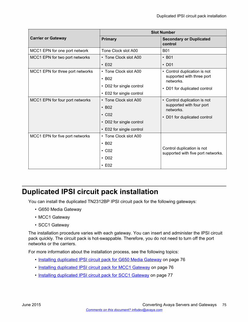
Carrier or GatewaySlot Number
Primary Secondary or Duplicatedcontrol
MCC1 EPN for one port network Tone Clock slot A00 B01MCC1 EPN for two port networks • Tone Clock slot A00
• E02
• B01
• D01MCC1 EPN for three port networks • Tone Clock slot A00
• B02
• D02 for single control
• E02 for single control
• Control duplication is notsupported with three portnetworks.
• D01 for duplicated control
MCC1 EPN for four port networks • Tone Clock slot A00
• B02
• C02
• D02 for single control
• E02 for single control
• Control duplication is notsupported with four portnetworks.
• D01 for duplicated control
MCC1 EPN for five port networks • Tone Clock slot A00
• B02
• C02
• D02
• E02
Control duplication is notsupported with five port networks.
Duplicated IPSI circuit pack installationYou can install the duplicated TN2312BP IPSI circuit pack for the following gateways:
• G650 Media Gateway
• MCC1 Gateway
• SCC1 Gateway
The installation procedure varies with each gateway. You can insert and administer the IPSI circuitpack quickly. The circuit pack is hot-swappable. Therefore, you do not need to turn off the portnetworks or the carriers.
For more information about the installation process, see the following topics:
• Installing duplicated IPSI circuit pack for G650 Media Gateway on page 76
• Installing duplicated IPSI circuit pack for MCC1 Gateway on page 76
• Installing duplicated IPSI circuit pack for SCC1 Gateway on page 77
Duplicated IPSI circuit pack installation
June 2015 Converting Avaya Servers and Gateways 75Comments on this document? [email protected]
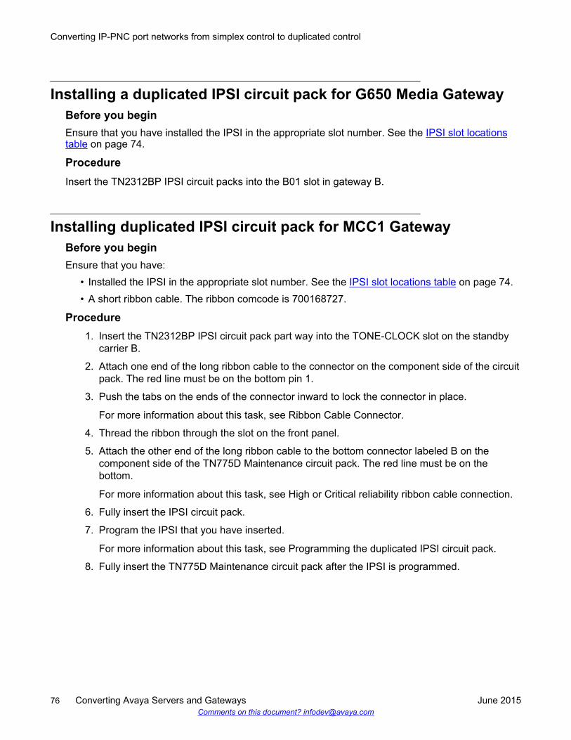
Installing a duplicated IPSI circuit pack for G650 Media GatewayBefore you beginEnsure that you have installed the IPSI in the appropriate slot number. See the IPSI slot locationstable on page 74.
ProcedureInsert the TN2312BP IPSI circuit packs into the B01 slot in gateway B.
Installing duplicated IPSI circuit pack for MCC1 GatewayBefore you beginEnsure that you have:
• Installed the IPSI in the appropriate slot number. See the IPSI slot locations table on page 74.• A short ribbon cable. The ribbon comcode is 700168727.
Procedure1. Insert the TN2312BP IPSI circuit pack part way into the TONE-CLOCK slot on the standby
carrier B.
2. Attach one end of the long ribbon cable to the connector on the component side of the circuitpack. The red line must be on the bottom pin 1.
3. Push the tabs on the ends of the connector inward to lock the connector in place.
For more information about this task, see Ribbon Cable Connector.
4. Thread the ribbon through the slot on the front panel.
5. Attach the other end of the long ribbon cable to the bottom connector labeled B on thecomponent side of the TN775D Maintenance circuit pack. The red line must be on thebottom.
For more information about this task, see High or Critical reliability ribbon cable connection.
6. Fully insert the IPSI circuit pack.
7. Program the IPSI that you have inserted.
For more information about this task, see Programming the duplicated IPSI circuit pack.
8. Fully insert the TN775D Maintenance circuit pack after the IPSI is programmed.
Converting IP-PNC port networks from simplex control to duplicated control
76 Converting Avaya Servers and Gateways June 2015Comments on this document? [email protected]
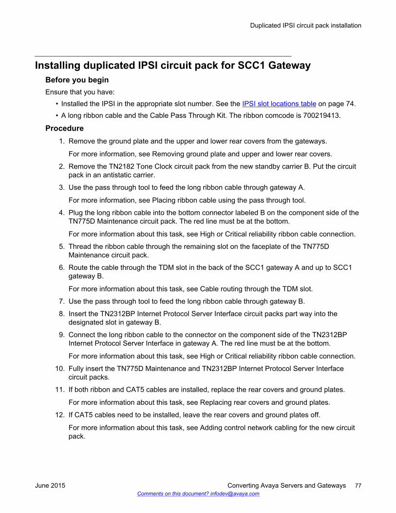
Installing duplicated IPSI circuit pack for SCC1 GatewayBefore you beginEnsure that you have:
• Installed the IPSI in the appropriate slot number. See the IPSI slot locations table on page 74.• A long ribbon cable and the Cable Pass Through Kit. The ribbon comcode is 700219413.
Procedure1. Remove the ground plate and the upper and lower rear covers from the gateways.
For more information, see Removing ground plate and upper and lower rear covers.
2. Remove the TN2182 Tone Clock circuit pack from the new standby carrier B. Put the circuitpack in an antistatic carrier.
3. Use the pass through tool to feed the long ribbon cable through gateway A.
For more information, see Placing ribbon cable using the pass through tool.
4. Plug the long ribbon cable into the bottom connector labeled B on the component side of theTN775D Maintenance circuit pack. The red line must be at the bottom.
For more information about this task, see High or Critical reliability ribbon cable connection.
5. Thread the ribbon cable through the remaining slot on the faceplate of the TN775DMaintenance circuit pack.
6. Route the cable through the TDM slot in the back of the SCC1 gateway A and up to SCC1gateway B.
For more information about this task, see Cable routing through the TDM slot.
7. Use the pass through tool to feed the long ribbon cable through gateway B.
8. Insert the TN2312BP Internet Protocol Server Interface circuit packs part way into thedesignated slot in gateway B.
9. Connect the long ribbon cable to the connector on the component side of the TN2312BPInternet Protocol Server Interface in gateway A. The red line must be at the bottom.
For more information about this task, see High or Critical reliability ribbon cable connection.
10. Fully insert the TN775D Maintenance and TN2312BP Internet Protocol Server Interfacecircuit packs.
11. If both ribbon and CAT5 cables are installed, replace the rear covers and ground plates.
For more information about this task, see Replacing rear covers and ground plates.
12. If CAT5 cables need to be installed, leave the rear covers and ground plates off.
For more information about this task, see Adding control network cabling for the new circuitpack.
Duplicated IPSI circuit pack installation
June 2015 Converting Avaya Servers and Gateways 77Comments on this document? [email protected]
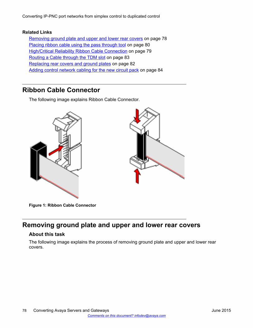
Related LinksRemoving ground plate and upper and lower rear covers on page 78Placing ribbon cable using the pass through tool on page 80High/Critical Reliability Ribbon Cable Connection on page 79Routing a Cable through the TDM slot on page 83Replacing rear covers and ground plates on page 82Adding control network cabling for the new circuit pack on page 84
Ribbon Cable ConnectorThe following image explains Ribbon Cable Connector.
Figure 1: Ribbon Cable Connector
Removing ground plate and upper and lower rear coversAbout this taskThe following image explains the process of removing ground plate and upper and lower rearcovers.
Converting IP-PNC port networks from simplex control to duplicated control
78 Converting Avaya Servers and Gateways June 2015Comments on this document? [email protected]
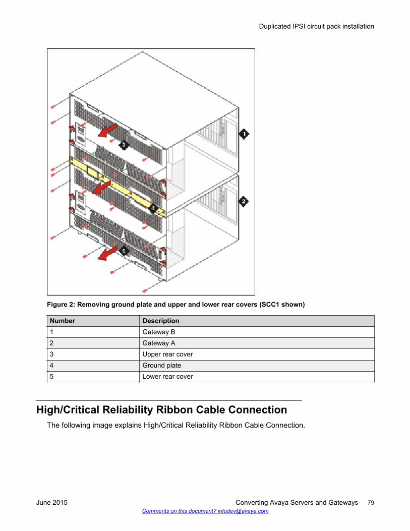
Figure 2: Removing ground plate and upper and lower rear covers (SCC1 shown)
Number Description1 Gateway B2 Gateway A3 Upper rear cover4 Ground plate5 Lower rear cover
High/Critical Reliability Ribbon Cable ConnectionThe following image explains High/Critical Reliability Ribbon Cable Connection.
Duplicated IPSI circuit pack installation
June 2015 Converting Avaya Servers and Gateways 79Comments on this document? [email protected]
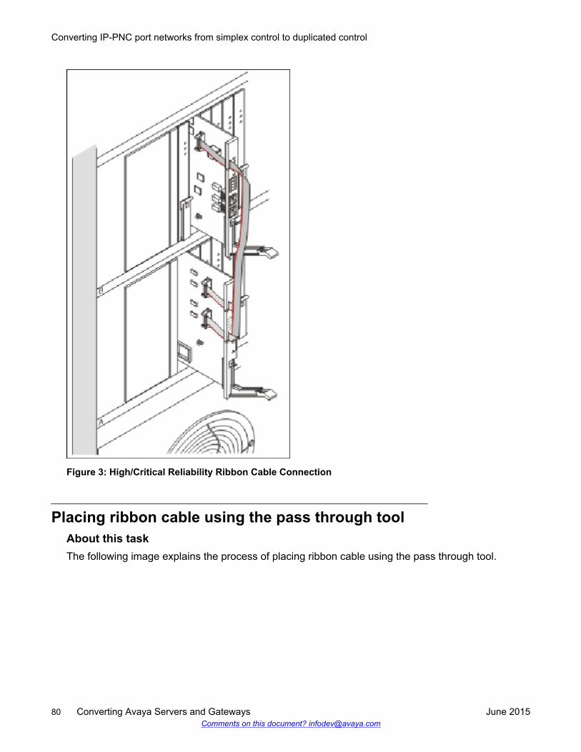
Figure 3: High/Critical Reliability Ribbon Cable Connection
Placing ribbon cable using the pass through toolAbout this taskThe following image explains the process of placing ribbon cable using the pass through tool.
Converting IP-PNC port networks from simplex control to duplicated control
80 Converting Avaya Servers and Gateways June 2015Comments on this document? [email protected]
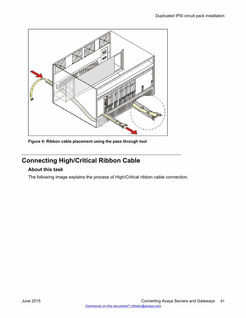
Figure 4: Ribbon cable placement using the pass through tool
Connecting High/Critical Ribbon CableAbout this taskThe following image explains the process of High/Critical ribbon cable connection.
Duplicated IPSI circuit pack installation
June 2015 Converting Avaya Servers and Gateways 81Comments on this document? [email protected]
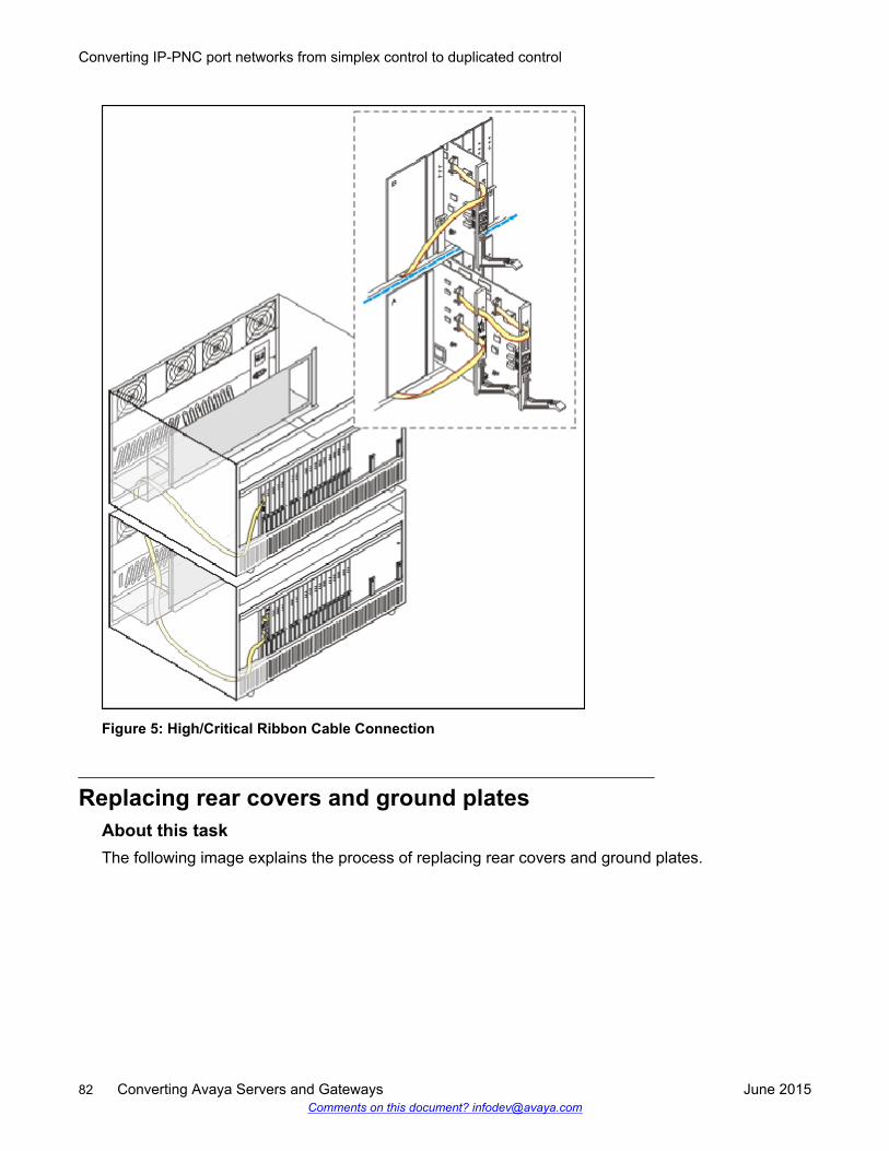
Figure 5: High/Critical Ribbon Cable Connection
Replacing rear covers and ground platesAbout this taskThe following image explains the process of replacing rear covers and ground plates.
Converting IP-PNC port networks from simplex control to duplicated control
82 Converting Avaya Servers and Gateways June 2015Comments on this document? [email protected]
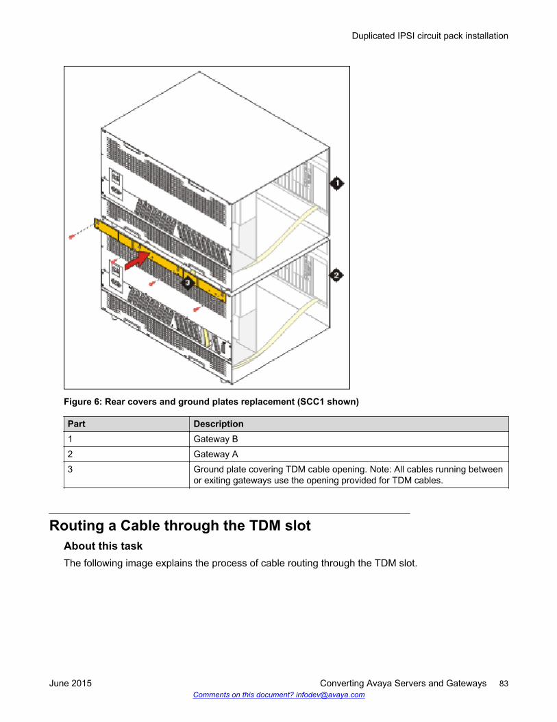
Figure 6: Rear covers and ground plates replacement (SCC1 shown)
Part Description1 Gateway B2 Gateway A3 Ground plate covering TDM cable opening. Note: All cables running between
or exiting gateways use the opening provided for TDM cables.
Routing a Cable through the TDM slotAbout this taskThe following image explains the process of cable routing through the TDM slot.
Duplicated IPSI circuit pack installation
June 2015 Converting Avaya Servers and Gateways 83Comments on this document? [email protected]
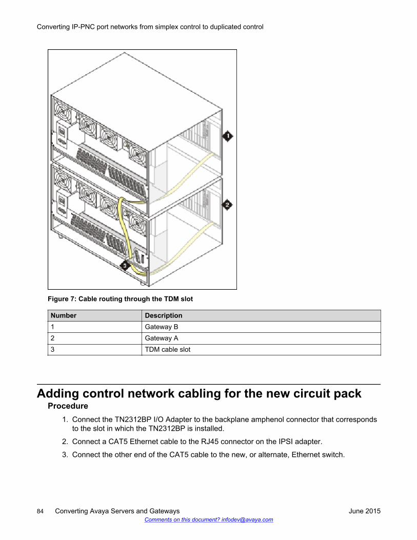
Figure 7: Cable routing through the TDM slot
Number Description1 Gateway B2 Gateway A3 TDM cable slot
Adding control network cabling for the new circuit packProcedure
1. Connect the TN2312BP I/O Adapter to the backplane amphenol connector that correspondsto the slot in which the TN2312BP is installed.
2. Connect a CAT5 Ethernet cable to the RJ45 connector on the IPSI adapter.
3. Connect the other end of the CAT5 cable to the new, or alternate, Ethernet switch.
Converting IP-PNC port networks from simplex control to duplicated control
84 Converting Avaya Servers and Gateways June 2015Comments on this document? [email protected]
Verifying the IPSI circuit packs are inserted properlyAbout this taskTo check that the IPSI circuit packs are inserted properly,
Procedure1. Enter display circuit-pack cabinet number to open the SAT Circuit Packs window,
after one minute.
2. Verify that the TN2312B circuit packs are shown in the appropriate slots.
Programming the duplicated IPSI circuit packProcedure
1. Ensure that you clear the ARP cache on the computer.
2. For static addressing with nondedicated control networks, at the Windows command prompt,type arp -d 192.11.13.6.
3. For static addressing instead of DHCP, perform the following steps:
a. Connect the services laptop to the services port on the IPSI faceplate.
b. Type telnet 192.11.13.6 to telnet IPSI.
c. At the IPSI prompt, type ipsilogin to log in to the IPSI IP Admin Tool.
d. Log in with craft and the IPSI password.
e. Type set control interface ipaddr netmask to enter the static IP addressand netmask.
f. Type quit to save the changes and exit the IPSI session.
g. Use telnet to 192.11.13.6 and log in.
h. Type show control interface.
The system displays the IP address, subnet mask, and default gateway information.
4. To verify the information, do the following:
a. If a default gateway is used, enter set control gateway gatewayaddr.
gatewayaddr is the customer-provided IP address of the customer gateway.
b. Type quit to save the changes and exit the IPSI session.
c. Use telnet to 192.11.13.6 and log in.
d. Use show control interface to verify the administration.
e. Type quit.
Verifying the IPSI circuit packs are inserted properly
June 2015 Converting Avaya Servers and Gateways 85Comments on this document? [email protected]
f. Type reset.
g. Type y.
5. Set VLAN and diffserv parameters.
See Setting VLAN and diffserv parameters.
Setting VLAN and diffserv parametersProcedure
1. Log back in to the new IPSI.
2. Enter show qos to display the quality of service values.
3. If necessary, use the following commands to set the VLAN and diffserv parameters to therecommended values shown:
Note:
Use Help to obtain syntax guidelines for these commands.
• Enter set vlan priority 6• Enter set diffserv 46• Enter set vlan tag on• Enter set port negotiation 1 disable
• Enter set port duplex 1 full
• Enter set port speed 1 100
4. Enter show qos to check the administered values.
5. Enter quit to exit.
Important:
Ensure that the port settings on the Ethernet switches are set to the same values as inthe set port commands.
6. Telnet to the IPSI and log in.
7. Enter reset.
Enter y in response to the warning.
8. Disconnect the laptop from the IPSI.
9. Verify that the LED display on the IPSI faceplate contains I P and a filled-in V at the bottom.
Converting IP-PNC port networks from simplex control to duplicated control
86 Converting Avaya Servers and Gateways June 2015Comments on this document? [email protected]
Administering the duplicated IPSI circuit pack on theserver
Procedure1. On the SAT command line interface, do the following:
a. Type change system-parameters duplication, and click Enter.
b. Set Enable Operation of IPSI Duplication to y.
For all IPSI, you must complete Step 1 one time.
2. Type add ipserver-interface n.
n is the port network number to add the new IPSI.
For each duplicated IPSI that you add, repeat Step 2.
Starting a SAT sessionProcedure
1. Open a terminal emulation program. For example, MS HyperTerminal.
2. On the MS HyperTerminal, type 192.11.13.6 5023, and click Enter.
3. Log in as craft or dadmin.
4. Suppress alarm origination.
Verifying IPSI translationsProcedure
1. On the SAT command line interface, type list ipserver-interface, click Enter.
2. Verify that the ISPI circuit pack or packs are translated.
The State of Health - C P E G column shows 0.0.0.0 for each healthy IPSI. If a 1 shows inany position, you must troubleshoot the problem.
The pattern 0.1.1.0 usually means that a cabinet type is administered incorrectly or aconnectivity problem exists, such as an incorrectly terminated cable.
Administering the duplicated IPSI circuit pack on the server
June 2015 Converting Avaya Servers and Gateways 87Comments on this document? [email protected]
Upgrading IPSI firmwareAbout this taskTo upgrade firmware on the IPSIs, perform the following steps:
Procedure1. For Prerelease 5.2 use the Maintenance Web Interface.
2. Copy IPSI firmware to the media processor hard drive. Use Download Files underMiscellaneous.
3. Determine which IPSIs you need to upgrade, with IPSI Version under IPSI FirmwareUpgrades.
4. Download the new firmware to the IPSIs. Use Download IPSI Firmware.
5. Use Activate IPSI Upgrade to activate the new firmware.
6. When the IPSIs are recovered, use IPSI Version to verify the firmware versions.
For more information about upgrading the IPSI firmware, see Upgrading Avaya Aura®
Communication Manager, 03-603560.
Converting IP-PNC port networks from simplex control to duplicated control
88 Converting Avaya Servers and Gateways June 2015Comments on this document? [email protected]
Chapter 11: Conversion of IP-PNC portnetworks from simplex bearerto duplicated bearer
Conversion of IP-PNC port networks from simplex bearerto duplicated bearer
This chapter describes the procedures to convert an Internet Protocol port network connectivity (IP-PNC) configuration from simplex bearer reliability to duplicated bearer reliability. Duplex serverscontrol the port networks (PNs). All voice and data transmission between the port network that youare converting and other port networks occurs over the customer network. The customer networkcan include the LAN or WAN of the customer.
If the active media processor connections or the active media processor fails, the active connectionsfailover to the standby media processor and remain active.
If failure occurs, the duplication prevents calls from being dropped.
Each port network has two TN2602AP circuit packs.
Caution:
The 4606, 4612, and 4624 telephones do not support the bearer duplication feature of theTN2602AP circuit pack. If you use these telephones when an interchange process from activeto standby media processor is in process, calls might drop.
Duplicated control networkAvaya recommends that a duplicated control network be configured before or with the conversion toduplicated bearer. Although connections can continue during most failures to the port networks, youcannot make new connections if the control network is part of the failure.
June 2015 Converting Avaya Servers and Gateways 89Comments on this document? [email protected]
Overflow with coresident TN2302AP circuit packsIf you anticipate that at peak traffic periods, traffic on the PN will exceed the maximum administeredVoIP channels, 80 or 320, of the TN2602AP circuit pack, a TN2302 may becoresident.Communication Manager must pass excess traffic over the TN2302 at peak traffic periods, but thesecalls might not be supported by the duplicated reliability.
Reduced channels with duplicated TN2602AP circuitpacks
If a pair of TN2602AP circuit packs previously used for load balancing are readministered to be usedfor bearer duplication, only the voice channels of whichever circuit pack is active can be used. Forexample,
• If you have two TN2602 AP circuit packs in a load balancing configuration, each with 80 voicechannels, and you readminister the circuit packs to be in bearer duplication mode, you willhave 80 (not 160) channels available.
• If you have two TN2602 AP circuit packs in a load balancing configuration, each with 320 voicechannels, and you readminister the circuit packs to be in bearer duplication mode, you willhave 320 (not 484) channels available.
When two TN2602AP circuit packs, each with 320 voice channels, are used for load balancingwithin a PN, the total number of voice channels available is 484, not 640, because 484 is themaximum number of time slots available for connections within a PN.
Performing preconversion tasks to convert IP-PNC portnetworks from simplex to duplicated bearer
Before you begin• You must ensure that other port networks have no fiber links.
- For fibre links, convert the port network from fiber-PNC to IP-PNC.- See Converting from fiber port networks to IP-PNC in Upgrading to Avaya Aura®
Communication Manager, 03-603560.• Ensure that you have the latest and appropriate firmware for the duplicated TN2602AP circuit
packs.- You must upgrade the firmware on the circuit packs if you do not have the recent and
appropriate firmware.- Ensure that the firmware you have is for duplicated TN2602AP circuit packs. The non-
duplicated TN2602AP firmware is different from the duplicated TN2602AP firmware.
Conversion of IP-PNC port networks from simplex bearer to duplicated bearer
90 Converting Avaya Servers and Gateways June 2015Comments on this document? [email protected]
Procedure1. Install a TN771DP maintenance test circuit pack in each IP-PNC PN that has both duplicated
control and duplicated bearer.
2. Perform all tasks mentioned in Presite checklist.
3. Ensure that you have IP addresses, node names, and slots for the TN2602AP IP MediaResource 320 circuit packs.
You cannot ensure that you have IP addresses, node names, and slots for the TN2602AP IPMedia Resource 320 circuit packs in the following scenarios:
• Replacing TN2302 circuit packs with the TN2602AP circuit packs. Then you cannot reusethe TN2302 IP addresses, node names, and slots.
• Reusing load-balanced TN2602AP circuit packs that are already installed in the PN.
4. Ensure that you have the subnet mask and the default gateway IP address.
Get this information from the project manager, or the network administrator of the customer.
5. Ensure that the Communication Manager license file has at least two entries. The values areeither VALUE_2602_80VC, or VALUE_2602_320VC with the same number of VoIPchannels, and can include either both 80 or both 320.
6. (Optional) Install a second Ethernet switch to connect the duplicated TN2602AP circuitpacks to the network. Adding a second Ethernet switch adds reliability to the duplicatedbearer network. If the failure occurs in the Ethernet switch or in the connection, the standbyTN2602AP circuit pack can handle traffic through an alternate Ethernet switch. Theconnection includes the Ethernet switch and the TN2602AP circuit pack.
You do not need a second Ethernet switch if already two Ethernet switches for duplicatecontrol are in use and are connected to the customer LAN.
7. (Optional) Install a second UPS to support the second Ethernet switch if you have installeda second Ethernet switch.
Caution:
If a failure occurs on an active TN2602AP circuit pack during the setup, andadministration of duplication of the TN2602AP circuit pack. The active calls that arecarried on the circuit pack are dropped. Using MEDPRO-C maintenance object, you cantrack both, TN2602AP call processing, and interchange activity.
For more information, see Maintenance Alarms for Avaya Aura® CommunicationManager, Branch Gateways Servers, 03-300430.
Performing preconversion tasks to convert IP-PNC port networks from simplex to duplicated bearer
June 2015 Converting Avaya Servers and Gateways 91Comments on this document? [email protected]
Disabling an existing TN2602AP circuit pack or TN2302circuit packs
About this taskUse this procedure to disable the TN2302 or TN2602AP circuit packs.
You must disable the TN2302 or TN2602AP circuit packs for the following scenarios:• To reuse the slots on TN2302 or TN2602AP circuit packs.• To convert TN2602AP circuit pack from a load-balancing circuit pack to a standby duplicated
bearer circuit pack.
Disabling the TN2302 circuit packs is optional. However, the active TN2602AP circuit pack handlesall bearer traffic, unless all channels are busy. The remaining TN2302 circuit packs handle anyoverflow in traffic.
Procedure1. Enter campon-busyout media-processor UUCSS, where UUCSS is the location of a
TN2302 circuit pack you are replacing or the TN2602AP you are converting.
2. Wait until all calls the circuit pack is carrying have ended.
3. Enter change ip-interface UUCSS, where UUCSS is the location of a TN2302 circuitpack you are replacing or the TN2602AP circuit pack you are converting.
4. Enter n in the Enable Ethernet Port field.
5. Enter remove ip-interface UUCSS to remove the TN2302 or TN2602AP circuit packfrom Communication Manager software.
6. Repeat steps 1 through 5, for any more TN2302 circuit packs you are removing.
Converting IP-PNC port networks from simplex bearer toduplicated bearer
Checklist to convert IP-PNC port networks from simplexbearer to duplicated bearer
This checklist describes the process for converting a port network to duplicated TN2602AP IP MediaResource 320 circuit packs.
You must perform this checklist for installing and converting IP-PNC port networks from simplexbearer to duplicated bearer.
Conversion of IP-PNC port networks from simplex bearer to duplicated bearer
92 Converting Avaya Servers and Gateways June 2015Comments on this document? [email protected]
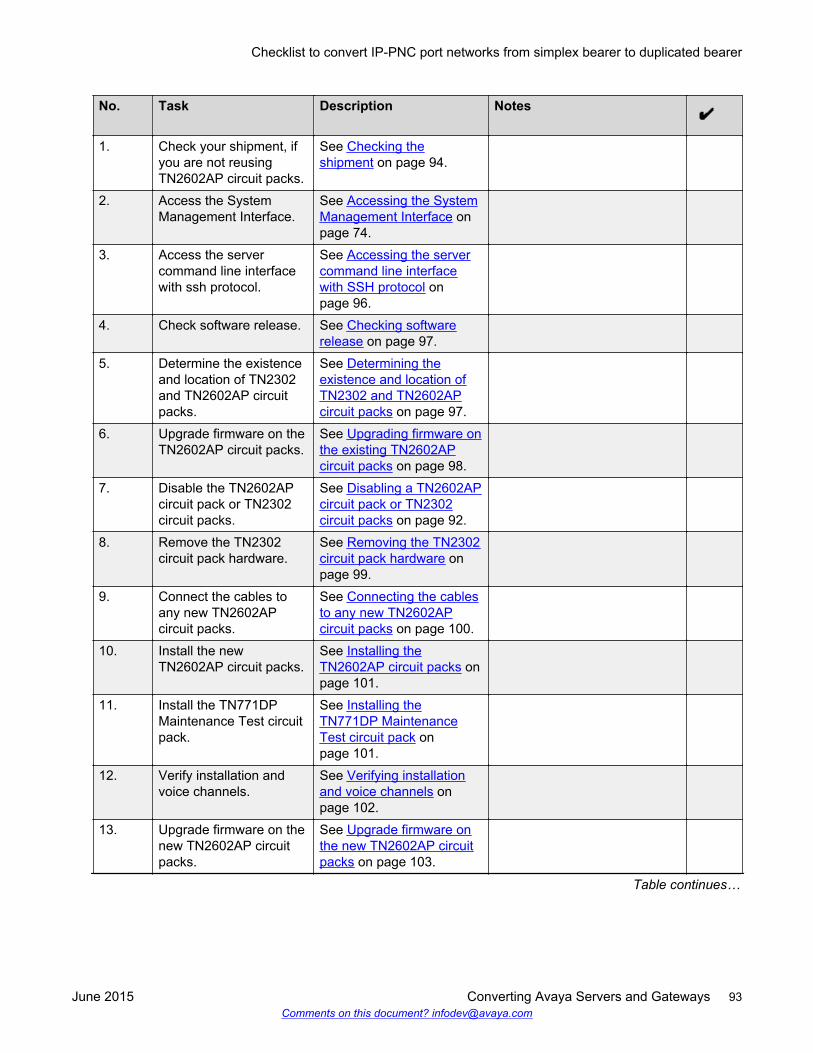
No. Task Description Notes
1. Check your shipment, ifyou are not reusingTN2602AP circuit packs.
See Checking theshipment on page 94.
2. Access the SystemManagement Interface.
See Accessing the SystemManagement Interface onpage 74.
3. Access the servercommand line interfacewith ssh protocol.
See Accessing the servercommand line interfacewith SSH protocol onpage 96.
4. Check software release. See Checking softwarerelease on page 97.
5. Determine the existenceand location of TN2302and TN2602AP circuitpacks.
See Determining theexistence and location ofTN2302 and TN2602APcircuit packs on page 97.
6. Upgrade firmware on theTN2602AP circuit packs.
See Upgrading firmware onthe existing TN2602APcircuit packs on page 98.
7. Disable the TN2602APcircuit pack or TN2302circuit packs.
See Disabling a TN2602APcircuit pack or TN2302circuit packs on page 92.
8. Remove the TN2302circuit pack hardware.
See Removing the TN2302circuit pack hardware onpage 99.
9. Connect the cables toany new TN2602APcircuit packs.
See Connecting the cablesto any new TN2602APcircuit packs on page 100.
10. Install the newTN2602AP circuit packs.
See Installing theTN2602AP circuit packs onpage 101.
11. Install the TN771DPMaintenance Test circuitpack.
See Installing theTN771DP MaintenanceTest circuit pack onpage 101.
12. Verify installation andvoice channels.
See Verifying installationand voice channels onpage 102.
13. Upgrade firmware on thenew TN2602AP circuitpacks.
See Upgrade firmware onthe new TN2602AP circuitpacks on page 103.
Table continues…
Checklist to convert IP-PNC port networks from simplex bearer to duplicated bearer
June 2015 Converting Avaya Servers and Gateways 93Comments on this document? [email protected]
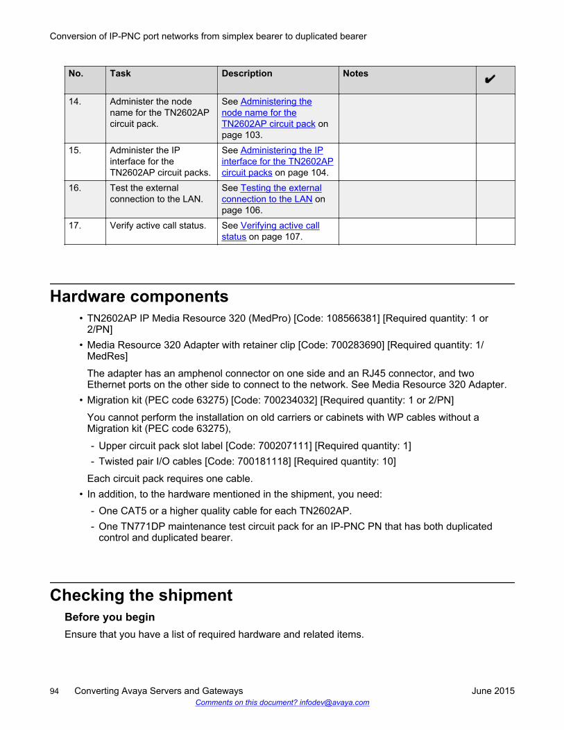
No. Task Description Notes
14. Administer the nodename for the TN2602APcircuit pack.
See Administering thenode name for theTN2602AP circuit pack onpage 103.
15. Administer the IPinterface for theTN2602AP circuit packs.
See Administering the IPinterface for the TN2602APcircuit packs on page 104.
16. Test the externalconnection to the LAN.
See Testing the externalconnection to the LAN onpage 106.
17. Verify active call status. See Verifying active callstatus on page 107.
Hardware components• TN2602AP IP Media Resource 320 (MedPro) [Code: 108566381] [Required quantity: 1 or
2/PN]• Media Resource 320 Adapter with retainer clip [Code: 700283690] [Required quantity: 1/
MedRes]
The adapter has an amphenol connector on one side and an RJ45 connector, and twoEthernet ports on the other side to connect to the network. See Media Resource 320 Adapter.
• Migration kit (PEC code 63275) [Code: 700234032] [Required quantity: 1 or 2/PN]
You cannot perform the installation on old carriers or cabinets with WP cables without aMigration kit (PEC code 63275),
- Upper circuit pack slot label [Code: 700207111] [Required quantity: 1]- Twisted pair I/O cables [Code: 700181118] [Required quantity: 10]
Each circuit pack requires one cable.• In addition, to the hardware mentioned in the shipment, you need:
- One CAT5 or a higher quality cable for each TN2602AP.- One TN771DP maintenance test circuit pack for an IP-PNC PN that has both duplicated
control and duplicated bearer.
Checking the shipmentBefore you beginEnsure that you have a list of required hardware and related items.
Conversion of IP-PNC port networks from simplex bearer to duplicated bearer
94 Converting Avaya Servers and Gateways June 2015Comments on this document? [email protected]
See the Required Hardware section.
About this taskUse this procedure to verify the status of the shipment.
Procedure1. Inspect the shipping carton for damage before opening it.
• If the box is damaged:
- Do not open the shipment.
- Inform the shipping company.
- Ask for instructions about filing a claim.
• If the box is intact:
- Check the contents against the packing slip.
- Check the condition of each component.
- Note any damage or shortages on the packing slip.
The carton must contain the items for each TN2602AP IP Media Resource 320 circuitpack mentioned in the Required Hardware section.
2. Read and follow any directions provided in the package by the factory.
Accessing Communication Manager System ManagementInterface
Procedure1. Log on to the web browser.
2. In the Address field, type 192.11.13.6.
3. Click Enter.
The system displays the login webpage.
4. Log in as craft or dadmin.
5. Click yes to suppress alarms.
The system displays Communication Manager System Management Interface (SMI).
Accessing Communication Manager System Management Interface
June 2015 Converting Avaya Servers and Gateways 95Comments on this document? [email protected]
Accessing the server command line interface with sshprotocol
Before you beginYou must ensure to connect a laptop cable to the services port and do the following:
• Configure your laptop for the network connection.• Install a third-party SSH client on your computer. For example, PuTTY.
To download PuTTY, go to http://www.putty.nl/download.html.
A version of PuTTY that is the default for an SSH server access is available for Avaya servicespersonnel only. In this version, the procedure contains some preselected values.
Caution:While many Avaya products support access using SSH, Avaya does not support third-partyclients used for SSH access. When using an SSH client such as PuTTY, the user or the SSHclient vendor must ensure there are no problems .
About this taskUse this procedure to log in to the server command line interface using PuTTY with SSH protocol.
Procedure1. On your computer, do one of the following:
• Click the PuTTY desktop link.
• Select Start > Programs > PuTTY > PuTTY.
2. To get access, do one of the following:
• In the Host Name or IP address field, type 192.11.13.6 to connect to the services port.
• Type the Host Name, or IP address of the server that you must access over the LAN orWAN network.
3. In the Port field, type 22. The SAT is 5022.
4. In the Protocol field, select SSH.
5. In the PuTTY menu on the left, click Connection > SSH.
The system displays theOptions controlling SSH connections dialog box.
6. In the Preferred SSH protocol version field, select 2.
7. In the Encryption options window, use the up and down arrows to set AES (SSH-2) as thefirst option and 3DES as the second option.
You can save the PuTTY settings and customize the PuTTY tool with other settings, such ascolor.
For more information about PuTTY, see http://www.putty.nl/docs.html.
8. In the PuTTY menu on the left, click Terminal > Keyboard.
Conversion of IP-PNC port networks from simplex bearer to duplicated bearer
96 Converting Avaya Servers and Gateways June 2015Comments on this document? [email protected]
The system displays the Options controlling the effects of keys dialog box.
9. In the Backspace key area, select Control-H.
The backspace key becomes active while you are using the SAT.
10. Click Open.
If you have not connected to this server previously, SSH prompts you to accept the serverhost key. When you save the key, PuTTY does not prompt you the next time you connect tothis server.
When connecting through the services laptop interface on the server, if you save the hostkey, the host identification is 192.11.13.6. If you later connect to a different server throughthe laptop interface of that server, the new host displays as 192.11.13.6, but has a differentkey. You get a prompt in this case because the system displays that the host key haschanged.
11. Click Yes to accept the server host key.
12. Log in to the server.
Checking the software releaseAbout this taskUse this procedure to verify the software version that you use.
Procedure1. In the Server tab, click Software Version.
2. View the Reports as field to verify that the new software is running correctly.
If the software is running correctly, you can view the next steps.
Determining the existence and location of TN2302 andTN2602APcircuit packs
About this taskUse this procedure to determine the location of TN2302and TN2602AP IP Media Processor circuitpacks.
Procedure1. Enter display circuit-packs port network #, where port network # is the PN in which
you are adding duplicated TN2602AP circuit packs.
Checking the software release
June 2015 Converting Avaya Servers and Gateways 97Comments on this document? [email protected]
A list of circuit packs is displayed.
2. Find and record the location of the TN2602AP circuit packs, if any.
3. If one, or no TN2602AP circuit packs are available, find one, or two TN2302 circuit packs forreplacement with TN2602AP circuit packs.
Important:
Avaya recommends that you install duplicated TN2602AP circuit packs in differentcarriers or cabinets when possible. Doing so adds reliability if carrier, or cabinet failure.
4. Enter display ip-interface UUCSS for each TN2302 circuit packs that you replace, orinstall TN2602AP circuit packs.
5. Record the administrative data.
You can use the same node names, and IP addresses as those formerly used by theTN2302 circuit packs.
Upgrading firmware on the existing TN2602AP circuitpacks
About this taskUse this procedure to upgrade the firmware on TN2602AP circuit packs.
Procedure1. On the SAT command line interface, enter campon-busyout media-processor UUCSS,
where UUCSS is the location of a TN2602AP circuit pack that you are converting.
2. You must wait until all calls that the circuit pack is carrying have ended.
3. Upgrade the firmware.
See Upgrading Avaya Aura® Communication Manager, 03-603560.
4. After you install the firmware, on the SAT command line interface, type release boardUUCSS.
5. Repeat Step 1 through Step 4 for the other TN2602AP circuit pack.
Conversion of IP-PNC port networks from simplex bearer to duplicated bearer
98 Converting Avaya Servers and Gateways June 2015Comments on this document? [email protected]
Disabling an existing TN2602AP circuit pack or TN2302circuit packs
About this taskUse this procedure to disable the TN2302 or TN2602AP circuit packs.
You must disable the TN2302 or TN2602AP circuit packs for the following scenarios:• To reuse the slots on TN2302 or TN2602AP circuit packs.• To convert TN2602AP circuit pack from a load-balancing circuit pack to a standby duplicated
bearer circuit pack.
Disabling the TN2302 circuit packs is optional. However, the active TN2602AP circuit pack handlesall bearer traffic, unless all channels are busy. The remaining TN2302 circuit packs handle anyoverflow in traffic.
Procedure1. Enter campon-busyout media-processor UUCSS, where UUCSS is the location of a
TN2302 circuit pack you are replacing or the TN2602AP you are converting.
2. Wait until all calls the circuit pack is carrying have ended.
3. Enter change ip-interface UUCSS, where UUCSS is the location of a TN2302 circuitpack you are replacing or the TN2602AP circuit pack you are converting.
4. Enter n in the Enable Ethernet Port field.
5. Enter remove ip-interface UUCSS to remove the TN2302 or TN2602AP circuit packfrom Communication Manager software.
6. Repeat steps 1 through 5, for any more TN2302 circuit packs you are removing.
Removing the TN2302 circuit pack hardwareProcedure
1. Unseat the TN2302 circuit pack from the slot.
2. Disconnect the network cable or cables to the Ethernet connector on the TN2302APbackplane adapter or adapters.
3. Disconnect the amphenol connector on the adapter from the amphenol connectorcorresponding to each TN2302AP slot.
4. Repeat Step 1 through Step 3 for the next TN2302 circuit pack.
Disabling an existing TN2602AP circuit pack or TN2302 circuit packs
June 2015 Converting Avaya Servers and Gateways 99Comments on this document? [email protected]
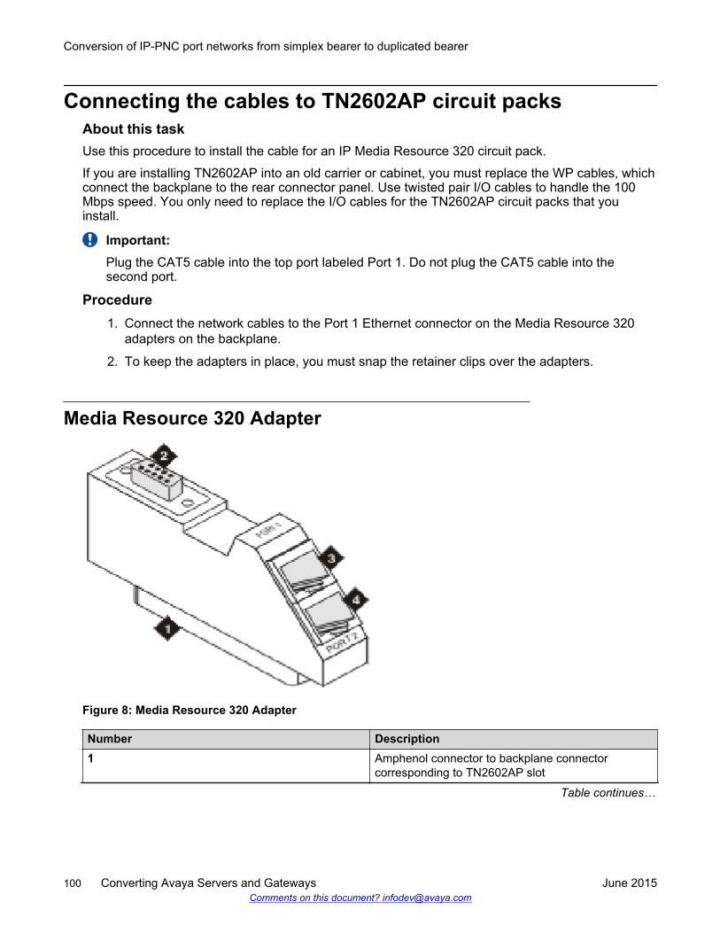
Connecting the cables to TN2602AP circuit packsAbout this taskUse this procedure to install the cable for an IP Media Resource 320 circuit pack.
If you are installing TN2602AP into an old carrier or cabinet, you must replace the WP cables, whichconnect the backplane to the rear connector panel. Use twisted pair I/O cables to handle the 100Mbps speed. You only need to replace the I/O cables for the TN2602AP circuit packs that youinstall.
Important:Plug the CAT5 cable into the top port labeled Port 1. Do not plug the CAT5 cable into thesecond port.
Procedure1. Connect the network cables to the Port 1 Ethernet connector on the Media Resource 320
adapters on the backplane.
2. To keep the adapters in place, you must snap the retainer clips over the adapters.
Media Resource 320 Adapter
Figure 8: Media Resource 320 Adapter
Number Description1 Amphenol connector to backplane connector
corresponding to TN2602AP slot
Table continues…
Conversion of IP-PNC port networks from simplex bearer to duplicated bearer
100 Converting Avaya Servers and Gateways June 2015Comments on this document? [email protected]
Number Description2 RS-232 connector for services3 Port 1: RJ45 LAN cable connection for 100 Mbps
CAT5 cable4 Port 2: RJ45 LAN connection for future use, do not
use this port.
Installing the TN2602AP circuit packsBefore you begin
Caution:When adding or replacing any hardware, ensure that you protect yourself from electrostaticdischarge (ESD) by wearing a grounded wrist strap.
About this taskUse this procedure to install the TN2602AP circuit packs.
The TN2602AP circuit packs are hot-swappable. Therefore, you do not need to turn off the gatewayto install the TN2602AP circuit packs.
Procedure1. Insert the TN2602AP circuit pack into the reserved port slot.
2. Ensure to seat the TN2602AP circuit pack by pushing firmly on the front of the faceplate untilthe latch reaches the bottom rail of the carrier. When the latch engages completely, close thelatch.
3. Plug in the TN2602AP circuit pack to start booting the TN2602AP circuit pack.
The red LED stays on until the onboard firmware is operational.
Installing the TN771DP Maintenance Test circuit packProcedureIf the PN has both duplicated control, and duplicated bearer, install a TN771DP circuit pack.
Installing the TN2602AP circuit packs
June 2015 Converting Avaya Servers and Gateways 101Comments on this document? [email protected]
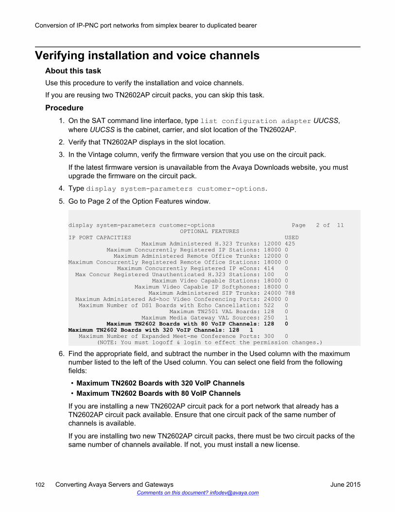
Verifying installation and voice channelsAbout this taskUse this procedure to verify the installation and voice channels.
If you are reusing two TN2602AP circuit packs, you can skip this task.
Procedure1. On the SAT command line interface, type list configuration adapter UUCSS,
where UUCSS is the cabinet, carrier, and slot location of the TN2602AP.
2. Verify that TN2602AP displays in the slot location.
3. In the Vintage column, verify the firmware version that you use on the circuit pack.
If the latest firmware version is unavailable from the Avaya Downloads website, you mustupgrade the firmware on the circuit pack.
4. Type display system-parameters customer-options.
5. Go to Page 2 of the Option Features window.
display system-parameters customer-options Page 2 of 11 OPTIONAL FEATURESIP PORT CAPACITIES USED Maximum Administered H.323 Trunks: 12000 425 Maximum Concurrently Registered IP Stations: 18000 0 Maximum Administered Remote Office Trunks: 12000 0Maximum Concurrently Registered Remote Office Stations: 18000 0 Maximum Concurrently Registered IP eCons: 414 0 Max Concur Registered Unauthenticated H.323 Stations: 100 0 Maximum Video Capable Stations: 18000 0 Maximum Video Capable IP Softphones: 18000 0 Maximum Administered SIP Trunks: 24000 788 Maximum Administered Ad-hoc Video Conferencing Ports: 24000 0 Maximum Number of DS1 Boards with Echo Cancellation: 522 0 Maximum TN2501 VAL Boards: 128 0 Maximum Media Gateway VAL Sources: 250 1 Maximum TN2602 Boards with 80 VoIP Channels: 128 0 Maximum TN2602 Boards with 320 VoIP Channels: 128 1 Maximum Number of Expanded Meet-me Conference Ports: 300 0 (NOTE: You must logoff & login to effect the permission changes.)
6. Find the appropriate field, and subtract the number in the Used column with the maximumnumber listed to the left of the Used column. You can select one field from the followingfields:
• Maximum TN2602 Boards with 320 VoIP Channels• Maximum TN2602 Boards with 80 VoIP Channels
If you are installing a new TN2602AP circuit pack for a port network that already has aTN2602AP circuit pack available. Ensure that one circuit pack of the same number ofchannels is available.
If you are installing two new TN2602AP circuit packs, there must be two circuit packs of thesame number of channels available. If not, you must install a new license.
Conversion of IP-PNC port networks from simplex bearer to duplicated bearer
102 Converting Avaya Servers and Gateways June 2015Comments on this document? [email protected]
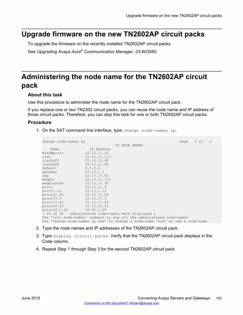
Upgrade firmware on the new TN2602AP circuit packsTo upgrade the firmware on the recently installed TN2602AP circuit packs.
See Upgrading Avaya Aura® Communication Manager, 03-603560.
Administering the node name for the TN2602AP circuitpack
About this taskUse this procedure to administer the node name for the TN2602AP circuit pack.
If you replace one or two TN2302 circuit packs, you can reuse the node name and IP address ofthose circuit packs. Therefore, you can skip this task for one or both TN2602AP circuit packs.
Procedure1. On the SAT command line interface, type change node-names ip.
change node-names ip Page 1 of 2 IP NODE NAMES Name IP AddressBikCMprocr 10.13.11.22clan 10.13.11.113clan2a02 10.13.15.92clan2a06 10.13.15.96default 0.0.0.0gateway 10.13.1.1lsp 10.13.17.63medpro 10.13.11.114medpro2a08 10.13.15.95procr 10.13.11.6procr1.12 10.13.1.12procr11.26 10.13.11.26procr17.3 10.13.17.3procr17.43 10.13.17.43procr20.23 10.13.20.23procr32.1.20 10.32.1.20( 16 of 26 administered node-names were displayed )Use 'list node-names' command to see all the administered node-namesUse 'change node-names ip xxx' to change a node-name 'xxx' or add a node-name
2. Type the node names and IP addresses of the TN2602AP circuit pack.
3. Type display circuit-packs. Verify that the TN2602AP circuit pack displays in theCode column.
4. Repeat Step 1 through Step 3 for the second TN2602AP circuit pack.
Upgrade firmware on the new TN2602AP circuit packs
June 2015 Converting Avaya Servers and Gateways 103Comments on this document? [email protected]
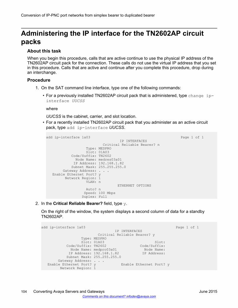
Administering the IP interface for the TN2602AP circuitpacks
About this taskWhen you begin this procedure, calls that are active continue to use the physical IP address of theTN2602AP circuit pack for the connection. These calls do not use the virtual IP address that you setin this procedure. Calls that are active and continue after you complete this procedure, drop duringan interchange.
Procedure1. On the SAT command line interface, type one of the following commands:
• For a previously installed TN2602AP circuit pack that is administered, type change ip-interface UUCSSwhere
UUCSS is the cabinet, carrier, and slot location.• For a recently installed TN2602AP circuit pack that you administer as an active circuit
pack, type add ip-interface UUCSS.
add ip-interface 1a03 Page 1 of 1 IP INTERFACES Critical Reliable Bearer? n Type: MEDPRO Slot: 01A03 Code/Suffix: TN2602 Node Name: medres03a01 IP Address: 192.168.1.82 Subnet Mask: 255.255.255.0 Gateway Address: . . . Enable Ethernet Port? y Network Region: 1 VLAN: n ETHERNET OPTIONS Auto? n Speed: 100 Mbps Duplex: Full
2. In the Critical Reliable Bearer? field, type y.
On the right of the window, the system displays a second column of data for a standbyTN2602AP.
add ip-interface 1a03 Page 1 of 1 IP INTERFACES Critical Reliable Bearer? y Type: MEDPRO Slot: 01A03 Slot: Code/Suffix: TN2602 Code/Suffix: Node Name: medpro03a01 Node Name: IP Address: 192.168.1.82 IP Address: Subnet Mask: 255.255.255.0 Gateway Address: . . . Enable Ethernet Port? y Enable Ethernet Port? y Network Region: 1
Conversion of IP-PNC port networks from simplex bearer to duplicated bearer
104 Converting Avaya Servers and Gateways June 2015Comments on this document? [email protected]
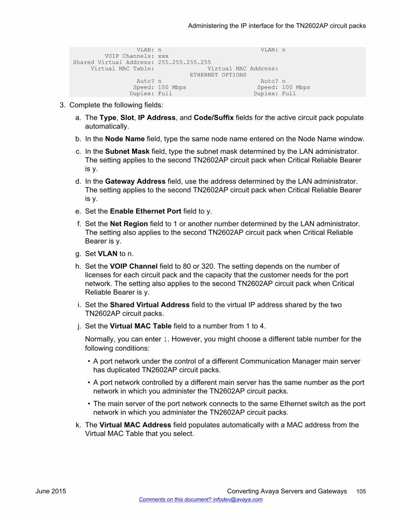
VLAN: n VLAN: n VOIP Channels: xxx Shared Virtual Address: 255.255.255.255 Virtual MAC Table: Virtual MAC Address: ETHERNET OPTIONS Auto? n Auto? n Speed: 100 Mbps Speed: 100 Mbps Duplex: Full Duplex: Full
3. Complete the following fields:
a. The Type, Slot, IP Address, and Code/Suffix fields for the active circuit pack populateautomatically.
b. In the Node Name field, type the same node name entered on the Node Name window.
c. In the Subnet Mask field, type the subnet mask determined by the LAN administrator.The setting applies to the second TN2602AP circuit pack when Critical Reliable Beareris y.
d. In the Gateway Address field, use the address determined by the LAN administrator.The setting applies to the second TN2602AP circuit pack when Critical Reliable Beareris y.
e. Set the Enable Ethernet Port field to y.
f. Set the Net Region field to 1 or another number determined by the LAN administrator.The setting also applies to the second TN2602AP circuit pack when Critical ReliableBearer is y.
g. Set VLAN to n.
h. Set the VOIP Channel field to 80 or 320. The setting depends on the number oflicenses for each circuit pack and the capacity that the customer needs for the portnetwork. The setting also applies to the second TN2602AP circuit pack when CriticalReliable Bearer is y.
i. Set the Shared Virtual Address field to the virtual IP address shared by the twoTN2602AP circuit packs.
j. Set the Virtual MAC Table field to a number from 1 to 4.
Normally, you can enter 1. However, you might choose a different table number for thefollowing conditions:
• A port network under the control of a different Communication Manager main serverhas duplicated TN2602AP circuit packs.
• A port network controlled by a different main server has the same number as the portnetwork in which you administer the TN2602AP circuit packs.
• The main server of the port network connects to the same Ethernet switch as the portnetwork in which you administer the TN2602AP circuit packs.
k. The Virtual MAC Address field populates automatically with a MAC address from theVirtual MAC Table that you select.
Administering the IP interface for the TN2602AP circuit packs
June 2015 Converting Avaya Servers and Gateways 105Comments on this document? [email protected]
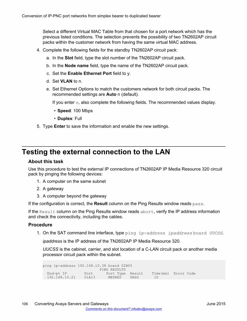
Select a different Virtual MAC Table from that chosen for a port network which has theprevious listed conditions. The selection prevents the possibility of two TN2602AP circuitpacks within the customer network from having the same virtual MAC address.
4. Complete the following fields for the standby TN2602AP circuit pack:
a. In the Slot field, type the slot number of the TN2602AP circuit pack.
b. In the Node name field, type the name of the TN2602AP circuit pack.
c. Set the Enable Ethernet Port field to y.
d. Set VLAN to n.
e. Set Ethernet Options to match the customers network for both circuit packs. Therecommended settings are Auto n (default).
If you enter n, also complete the following fields. The recommended values display.
• Speed: 100 Mbps
• Duplex: Full
5. Type Enter to save the information and enable the new settings.
Testing the external connection to the LANAbout this taskUse this procedure to test the external IP connections of TN2602AP IP Media Resource 320 circuitpack by pinging the following devices:
1. A computer on the same subnet2. A gateway3. A computer beyond the gateway
If the configuration is correct, the Result column on the Ping Results window reads pass.
If the Result column on the Ping Results window reads abort, verify the IP address informationand check the connectivity, including the cables.
Procedure1. On the SAT command line interface, type ping ip-address ipaddress board UUCSS.
ipaddress is the IP address of the TN2602AP IP Media Resource 320.
UUCSS is the cabinet, carrier, and slot location of a C-LAN circuit pack or another mediaprocessor circuit pack within the subnet.
ping ip-address 192.168.10.38 board 02B05 PING RESULTS End-pt IP Port Port Type Result Time(ms) Error Code 192.168.10.21 01A13 MEDRES PASS 10
Conversion of IP-PNC port networks from simplex bearer to duplicated bearer
106 Converting Avaya Servers and Gateways June 2015Comments on this document? [email protected]
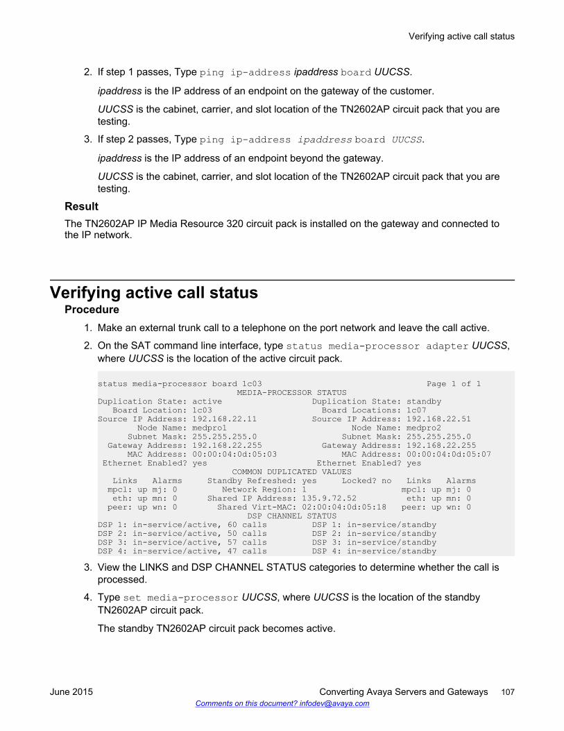
2. If step 1 passes, Type ping ip-address ipaddress board UUCSS.
ipaddress is the IP address of an endpoint on the gateway of the customer.
UUCSS is the cabinet, carrier, and slot location of the TN2602AP circuit pack that you aretesting.
3. If step 2 passes, Type ping ip-address ipaddress board UUCSS.
ipaddress is the IP address of an endpoint beyond the gateway.
UUCSS is the cabinet, carrier, and slot location of the TN2602AP circuit pack that you aretesting.
ResultThe TN2602AP IP Media Resource 320 circuit pack is installed on the gateway and connected tothe IP network.
Verifying active call statusProcedure
1. Make an external trunk call to a telephone on the port network and leave the call active.
2. On the SAT command line interface, type status media-processor adapter UUCSS,where UUCSS is the location of the active circuit pack.
status media-processor board 1c03 Page 1 of 1 MEDIA-PROCESSOR STATUSDuplication State: active Duplication State: standby Board Location: 1c03 Board Locations: 1c07Source IP Address: 192.168.22.11 Source IP Address: 192.168.22.51 Node Name: medpro1 Node Name: medpro2 Subnet Mask: 255.255.255.0 Subnet Mask: 255.255.255.0 Gateway Address: 192.168.22.255 Gateway Address: 192.168.22.255 MAC Address: 00:00:04:0d:05:03 MAC Address: 00:00:04:0d:05:07 Ethernet Enabled? yes Ethernet Enabled? yes COMMON DUPLICATED VALUES Links Alarms Standby Refreshed: yes Locked? no Links Alarms mpcl: up mj: 0 Network Region: 1 mpcl: up mj: 0 eth: up mn: 0 Shared IP Address: 135.9.72.52 eth: up mn: 0 peer: up wn: 0 Shared Virt-MAC: 02:00:04:0d:05:18 peer: up wn: 0 DSP CHANNEL STATUSDSP 1: in-service/active, 60 calls DSP 1: in-service/standbyDSP 2: in-service/active, 50 calls DSP 2: in-service/standbyDSP 3: in-service/active, 57 calls DSP 3: in-service/standbyDSP 4: in-service/active, 47 calls DSP 4: in-service/standby
3. View the LINKS and DSP CHANNEL STATUS categories to determine whether the call isprocessed.
4. Type set media-processor UUCSS, where UUCSS is the location of the standbyTN2602AP circuit pack.
The standby TN2602AP circuit pack becomes active.
Verifying active call status
June 2015 Converting Avaya Servers and Gateways 107Comments on this document? [email protected]
5. Type status media processor adapter UUCSS, where UUCSS is the location of thenew active circuit pack.
The system displays the Media Processor Status window. In the DSP CHANNEL STATUS,the test call moves to the column for the new active TN2602AP circuit pack.
TN2602AP call processing and interchange activity is tracked through the MEDPRO-Cmaintenance object. See Maintenance Alarms for Avaya Aura® Communication Manager,Branch Gateways Servers, 03-300430.
Conversion of IP-PNC port networks from simplex bearer to duplicated bearer
108 Converting Avaya Servers and Gateways June 2015Comments on this document? [email protected]
Appendix A: Accessing the server
You must have access to the server for administration. The following computers and software arethe supported access points for accessing the server for initial configuration, aftermarket additions,and continuing maintenance:
• Personal computers
• Services laptop computers equipped with a network interface card (NIC)
• Terminal emulation program
• Web browser
You can access the server either directly or remotely over the customer network or over a modem.Connecting directly and remotely over the customer network are the preferred methods. Remoteaccess over a modem is for Avaya maintenance access only.
Service laptop and server connectionYou can connect a service laptop into the services port of a server to access the server directly. Youcan connect a service laptop directly to different servers, like S8300D, S8510, S8800, HP DL360G7, and Dell R610. The diagrams in the following section illustrate the process for connecting theserver laptop to the supported servers.
Connecting a services laptop to an S8300D ServerAbout this taskThe following figure shows connection between a service laptop and the S8300D Server.
June 2015 Converting Avaya Servers and Gateways 109Comments on this document? [email protected]
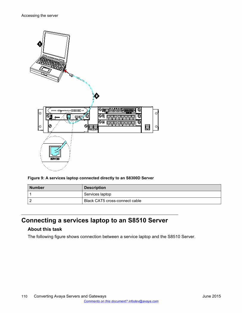
Figure 9: A services laptop connected directly to an S8300D Server
Number Description1 Services laptop2 Black CAT5 cross-connect cable
Connecting a services laptop to an S8510 ServerAbout this taskThe following figure shows connection between a service laptop and the S8510 Server.
Accessing the server
110 Converting Avaya Servers and Gateways June 2015Comments on this document? [email protected]
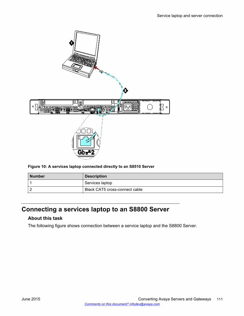
Figure 10: A services laptop connected directly to an S8510 Server
Number Description1 Services laptop2 Black CAT5 cross-connect cable
Connecting a services laptop to an S8800 ServerAbout this taskThe following figure shows connection between a service laptop and the S8800 Server.
Service laptop and server connection
June 2015 Converting Avaya Servers and Gateways 111Comments on this document? [email protected]
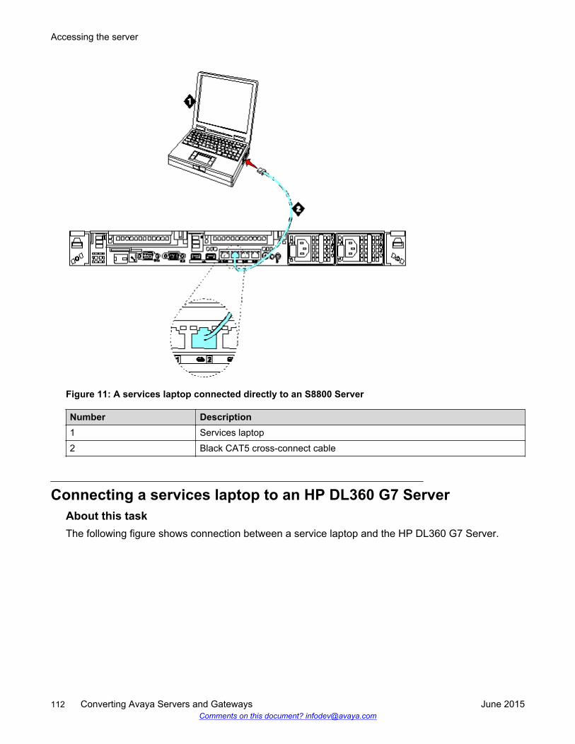
Figure 11: A services laptop connected directly to an S8800 Server
Number Description1 Services laptop2 Black CAT5 cross-connect cable
Connecting a services laptop to an HP DL360 G7 ServerAbout this taskThe following figure shows connection between a service laptop and the HP DL360 G7 Server.
Accessing the server
112 Converting Avaya Servers and Gateways June 2015Comments on this document? [email protected]
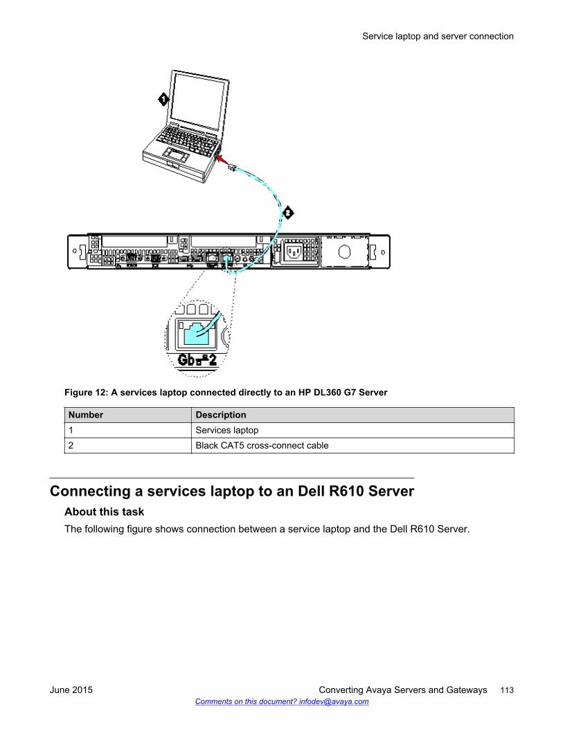
Figure 12: A services laptop connected directly to an HP DL360 G7 Server
Number Description1 Services laptop2 Black CAT5 cross-connect cable
Connecting a services laptop to an Dell R610 ServerAbout this taskThe following figure shows connection between a service laptop and the Dell R610 Server.
Service laptop and server connection
June 2015 Converting Avaya Servers and Gateways 113Comments on this document? [email protected]
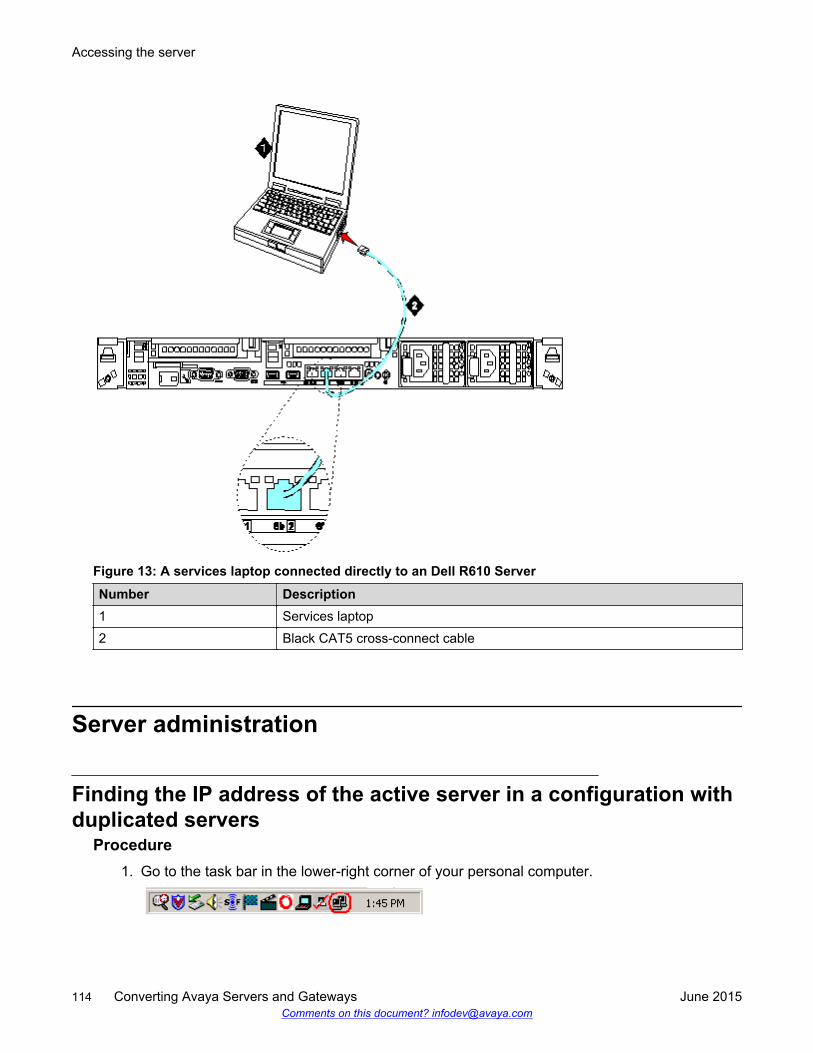
Figure 13: A services laptop connected directly to an Dell R610 ServerNumber Description1 Services laptop2 Black CAT5 cross-connect cable
Server administration
Finding the IP address of the active server in a configuration withduplicated servers
Procedure1. Go to the task bar in the lower-right corner of your personal computer.
Accessing the server
114 Converting Avaya Servers and Gateways June 2015Comments on this document? [email protected]
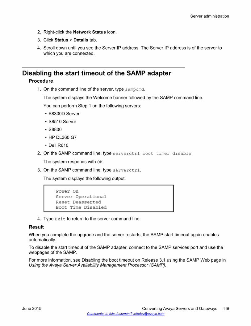
2. Right-click the Network Status icon.
3. Click Status > Details tab.
4. Scroll down until you see the Server IP address. The Server IP address is of the server towhich you are connected.
Disabling the start timeout of the SAMP adapterProcedure
1. On the command line of the server, type sampcmd.
The system displays the Welcome banner followed by the SAMP command line.
You can perform Step 1 on the following servers:
• S8300D Server
• S8510 Server
• S8800
• HP DL360 G7
• Dell R610
2. On the SAMP command line, type serverctrl boot timer disable.
The system responds with OK.
3. On the SAMP command line, type serverctrl.
The system displays the following output:
4. Type Exit to return to the server command line.
ResultWhen you complete the upgrade and the server restarts, the SAMP start timeout again enablesautomatically.
To disable the start timeout of the SAMP adapter, connect to the SAMP services port and use thewebpages of the SAMP.
For more information, see Disabling the boot timeout on Release 3.1 using the SAMP Web page inUsing the Avaya Server Availability Management Processor (SAMP).
Server administration
June 2015 Converting Avaya Servers and Gateways 115Comments on this document? [email protected]
Accessing System Management InterfaceAbout this taskTo access System Management Interface directly, you can either connect:
• To the services port on the server. See Service laptop and server connection missing period onpage 109.
• Over the customer network.
The supported browsers are as follows:• Microsoft Internet Explorer 7.0 or later• FireFox 3.6 or later
When you connect directly to the server, you must disable all proxy servers. For more information,see the following:
• Connecting the browser directly to the server on page 19• Connecting the browser remotely through the network on page 20
Procedure1. Open the Microsoft Internet Explorer or FireFox web browser.
2. Perform one of the following:
• To connect directly, in the Address field, type 192.11.13.6.
• To connect remotely, in the Address field, type the IP address or the DNS host name ofthe server.
3. When prompted, log in.
For Release before 5.2, use the Maintenance Web Interface.
For Release 5.2, use the System Management Interface.
Accessing the server command line interface with ssh protocolBefore you beginYou must ensure to connect a laptop cable to the services port and do the following:
• Configure your laptop for the network connection.• Install a third-party SSH client on your computer. For example, PuTTY.
To download PuTTY, go to http://www.putty.nl/download.html.
A version of PuTTY that is the default for an SSH server access is available for Avaya servicespersonnel only. In this version, the procedure contains some preselected values.
Accessing the server
116 Converting Avaya Servers and Gateways June 2015Comments on this document? [email protected]
Caution:While many Avaya products support access using SSH, Avaya does not support third-partyclients used for SSH access. When using an SSH client such as PuTTY, the user or the SSHclient vendor must ensure there are no problems .
About this taskUse this procedure to log in to the server command line interface using PuTTY with SSH protocol.
Procedure1. On your computer, do one of the following:
• Click the PuTTY desktop link.
• Select Start > Programs > PuTTY > PuTTY.
2. To get access, do one of the following:
• In the Host Name or IP address field, type 192.11.13.6 to connect to the services port.
• Type the Host Name, or IP address of the server that you must access over the LAN orWAN network.
3. In the Port field, type 22. The SAT is 5022.
4. In the Protocol field, select SSH.
5. In the PuTTY menu on the left, click Connection > SSH.
The system displays theOptions controlling SSH connections dialog box.
6. In the Preferred SSH protocol version field, select 2.
7. In the Encryption options window, use the up and down arrows to set AES (SSH-2) as thefirst option and 3DES as the second option.
You can save the PuTTY settings and customize the PuTTY tool with other settings, such ascolor.
For more information about PuTTY, see http://www.putty.nl/docs.html.
8. In the PuTTY menu on the left, click Terminal > Keyboard.
The system displays the Options controlling the effects of keys dialog box.
9. In the Backspace key area, select Control-H.
The backspace key becomes active while you are using the SAT.
10. Click Open.
If you have not connected to this server previously, SSH prompts you to accept the serverhost key. When you save the key, PuTTY does not prompt you the next time you connect tothis server.
When connecting through the services laptop interface on the server, if you save the hostkey, the host identification is 192.11.13.6. If you later connect to a different server throughthe laptop interface of that server, the new host displays as 192.11.13.6, but has a different
Server administration
June 2015 Converting Avaya Servers and Gateways 117Comments on this document? [email protected]
key. You get a prompt in this case because the system displays that the host key haschanged.
11. Click Yes to accept the server host key.
12. Log in to the server.
Accessing the command line interface with terminal emulationAbout this taskFor this procedure, use the following supported terminal emulation programs:
• Avaya Native Configuration Manager• Avaya Terminal Emulation• HyperTerminal
Procedure1. Open your terminal emulation program.
2. Ensure that the port settings of the terminal emulation program are configured as follows:
• 115200 baud
• No parity
• 8 data bits
• 1 stop bit
• No flow control
3. Establish a network connection to the server with either the IP address or the DNS hostname. Use port 5023 to establish a network connection.
4. When prompted, log in.
LoginsInitial configuration and upgrades by an Avaya technical support representative or an AvayaBusiness Partner requires a services login, such as craft or dadmin. Avaya technical supportrepresentatives can also use a unique password that is assigned to that customer system.
When you finish installing the Avaya authentication file, Communication Manager has a passwordfor the craft login. This password is unique to the server of the customer. You can use the passwordthe next time that you log in as craft, if you access the server through the Services port. Every othermeans of craft access still requires an ASG challenge/response. RFA records the revised password.ASG Interactive Response provides this password at 1-800-248-1234 or 1-720-444-5557.
Accessing the server
118 Converting Avaya Servers and Gateways June 2015Comments on this document? [email protected]
You have to obtain logins and passwords for the following components:
• Server
• Gateway
• IPSI
• auxiliary equipment
• Communication Manager
Customers can set up their own logins to access Avaya servers. For more information, see theAdministering Avaya Aura® Communication Manager, 03-300509. You must have superuserpermission to create or change logins and passwords.
Important:
When you assign login IDs, do not start the logins with a number.
Logins
June 2015 Converting Avaya Servers and Gateways 119Comments on this document? [email protected]
Index
Aaccessing .....................................................................96, 116
server ..........................................................................109Accessing .......................................................................... 118active ................................................................................. 107active server ...................................................................... 114adapter
media resource 320 ....................................................100adapter for TN2602AP .......................................................100administer
gateway ........................................................................ 27administering ..................................................... 34, 54, 59, 64
conversion .................................................................... 27Administering ............................... 34, 53, 59, 64, 87, 103, 104Administering the gateway .............................................41, 48authentication files ............................................................... 21availability ...................................................................... 22, 23
Bboot timeout ....................................................................... 115
Ccables
connecting to TN2602AP ............................................100cabling ................................................................................. 70call status ...........................................................................107campon-busyout media-processor command ..........92, 98, 99changing .............................................................................. 28Changing ........................................................... 35, 54, 60, 65channels, reduced with TN2602AP ..................................... 90check shipment
guidelines ..................................................................... 94circuit pack .........................................74–77, 85, 87, 101, 103circuit packs ............................................................... 103, 104CM_Simplex template
convert survivable remote server mode to main servermode .............................................................................57
command line interface ........................................96, 116, 118accessing with SSH ....................................................116
commands ........................................................................... 97campon-busyout media-processor ................... 92, 98, 99release board ................................................................98
Communication Manager Messaging .................................. 47components ......................................................................... 94configuration ...................................................................... 114configure
main server ...................................................................29network ......................................................................... 18
configuringmain server and survivable remote server ............. 37, 65
survivable remote server .............................................. 35Configuring .................................................................... 54, 72
main server ...................................................................42survivable remote server .............................................. 42
connectinghigh/critical reliability ribbon cable ................................ 79High/Critical Ribbon Cable ........................................... 81
connecting browser to server ...............................................19connecting services laptop
Dell R610 server .........................................................113HP DL360 G7 server .................................................. 112S8300D server ............................................................109S8510 server .............................................................. 110S8800 server .............................................................. 111
connecting the browser remotely .........................................20connection ......................................................................... 106connect service laptop ....................................................... 109control .................................................................................. 84controller ...................................................... 28, 35, 54, 60, 65controller list ...................................................................41, 47control network .................................................................... 89convert ..................................................................... 51, 62, 69
converting ..................................................................... 25main server ...................................................................31post conversion tasks ................................................... 31survivable remote server .............................................. 31
converting .......................................................... 25, 57, 63, 89from LSP mode to ICC mode ....................................... 32
converting main serverS8510, S8800, HP DL360 G7, or Dell R610 ................ 51
converting main server to survivable remote server ............ 51converting main server to survivable remote server using asimplex template ..................................................................51convert IP-PNC port network
simplex control to duplicated control ............................ 68convert main server mode to survivable remote server mode
postconversion tasks .................................................... 56convert S8300D survivable remote server to main server
postconversion tasks .................................................... 38
DDell R610 ............................................................................. 63Dell R610 server
connecting services laptop ......................................... 113Designating ..........................................................................74diffserv parameters for the IPSI ........................................... 86direct connection ......................................................74, 92, 95direct connection to server......................................71, 74, 85, 86, 88, 92, 95, 97–99, 101Disabling ............................................................................ 115display circuit packs .............................................................97documentation ..................................................................... 12
120 Converting Avaya Servers and Gateways June 2015Comments on this document? [email protected]
duplicated .................................................... 74–77, 85, 87, 89duplicated bearer ................................................................. 89duplicated bearer and control
TN771DP circuit pack requirement ...............................90duplicated control .................................................................69duplicated control and bearer
TN771DP circuit pack requirement ...............................90duplicated servers ..............................................................114duplicated UPS .................................................................... 90duplication ............................................................................89
EElectronic Preinstallation Worksheet ................................... 20Enabling ...............................................................................73EPW .....................................................................................20Ethernet ......................................................................... 70, 72external .............................................................................. 106
FFinding ............................................................................... 114Firewall ................................................................................ 73firmware ............................................................................. 103firmware upgrade
IPSI ...............................................................................88TN2602AP .................................................................... 98
GG650 .................................................................................... 76gateway ................................................. 29, 34, 36, 54, 59, 64
administering ................................................................ 27Gateway .......................................................35, 54, 60, 65, 77gateway registration .............................................................49ground plate and upper and lower rear covers
remove ..........................................................................78
Hhardware ..............................................................................94hardware components ......................................................... 94hardware requirements ........................................................17high/critical reliability ribbon cable
connect ......................................................................... 79High/Critical Ribbon Cable
connect ......................................................................... 81HP DL360 G7 ...................................................................... 63HP DL360 G7 server
connecting services laptop ......................................... 112
IICC
converting to ................................................................. 32installation ....................................................................94, 102
installing .........................................................................75, 76TN771DP Maintenance Test circuit pack ................... 101
Installing .................................................................70, 77, 101invoke .................................................................................. 30
translation synchronization ..................................... 38, 56invoking ................................................................................30Invoking ............................................................................... 42IP address ..........................................................................114IP interface .........................................................................104IP-PNC port network ............................................................69IPSI .............................................................. 74–77, 84, 85, 87
setting VLAN and diffser parameters ............................86upgrading firmware .......................................................88
LLAN ....................................................................................106laptop connection to server......................................71, 74, 85, 86, 88, 92, 95, 97–99, 101legal notice ...............................................................................license
TN2602AP .................................................................... 90licenses ................................................................................21list ................................................................ 28, 35, 54, 60, 65locations ...............................................................................74LSP
converting to ICC ..........................................................32
Mmain ................................................. 28, 34, 53, 54, 59, 64, 65main server .................................................. 25, 27, 41, 47–49main server and survivable remote server
configuring .................................................................... 65main server mode .............................................. 51, 57, 62, 63
main server ...................................................................54maintenance test circuit pack
installing ......................................................................101MCC1 gateway .................................................................... 76media gateway
administering ................................................................ 46Media Gateway ....................................................................76media processor
checking location .......................................................... 97disabling ................................................................. 92, 99removing .......................................................................99
media resource 320 ........................................................... 100
Nnetwork .......................................................................... 84, 89
configuring .................................................................... 18node name .........................................................................103
Index
June 2015 Converting Avaya Servers and Gateways 121Comments on this document? [email protected]
Ooverflow ............................................................................... 90
Ppassword ........................................................................... 118placing
ribbon cable using the pass through tool ......................80PNC ..................................................................................... 89postconversion service pack file
obtaining ....................................................................... 22preconversion tasks .............................................................21Programming ....................................................................... 85
Rrear covers and ground plates
replace ..........................................................................82reassign
endpoints .............................................. 28, 34, 54, 59, 65reassigning endpoints ....................................................47, 49redesign networks ................................................................21registration ..................................................................... 29, 36release board command ...................................................... 98reliability .........................................................................22, 23removing
ground plate and upper and lower rear covers .............78replacing
rear covers and ground plates ......................................82requirements ..................................................................39, 44ribbon cable connector
using ............................................................................. 78ribbon cable using the pass through tool
place ............................................................................. 80routing cable
TDM slot ....................................................................... 83
SS8300 .................................................................................. 25
converting LSP to ICC mode ........................................ 32S8300D ................................................................................25
convert survivable remote server to main server ..........32S8300D server
connecting services laptop ......................................... 109S8300E .................................................................... 40, 45, 47
main server mode .........................................................40survivable remote server mode .................................... 40
S8300E server ............................................................... 39, 44S8510 .................................................................................. 63S8510 server
connecting services laptop ......................................... 110S8800 .................................................................................. 63S8800 server
connecting services laptop ......................................... 111
SAMP board ...................................................................... 115SAT ......................................................................................87SCC1 ................................................................................... 77second ................................................................................. 70server ...............................................28, 34, 53, 54, 59, 64, 65
access ........................................................................ 109command line interface .............................................. 116
server command line interface with ssh protocol .........96, 116servers ..................................................................... 74, 92, 95
direct connection .............. 71, 85, 86, 88, 92, 97–99, 101servers and gateway conversion
overview ....................................................................... 16service pack file ................................................................... 46services logins ................................................................... 118session .................................................................................87settings ................................................................................ 73simplex bearer ..................................................................... 89simplex control .....................................................................69slot ....................................................................................... 74slots ..................................................................................... 74SNMP .................................................................................. 72software requirements ......................................................... 17software version
verifying ........................................................................ 97Software version web page ................................................. 97ssh ............................................................................... 96, 116ssh protocol ................................................................. 96, 116Starting ................................................................................ 87starting Maintenance Web pages .................................. 74, 95status ....................................................................... 30, 37, 55subagent .............................................................................. 72support
contact .......................................................................... 15survivable remote server ........... 25, 27, 30, 37, 41, 47–49, 55
administering ................................................................ 46configuring .................................................................... 29
Survivable Remote Server ...................................................25survivable remote server mode ......................... 51, 57, 62, 63
survivable remote server .............................................. 54switch .............................................................................70, 72
Ttable ..................................................................................... 23terminal emulation ..................................................... 116, 118Testing ............................................................................... 106TN2302 ................................................................................ 90TN2302 circuit pack ............................................................. 90
checking location .......................................................... 97disabling ................................................................. 92, 99removing .......................................................................99
TN2602AP ............................................. 89, 90, 101, 103, 104TN2602AP circuit pack ........................................................ 89
adapter for cables .......................................................100channel reduction ......................................................... 90checking location .......................................................... 97connecting cables .......................................................100
Index
122 Converting Avaya Servers and Gateways June 2015Comments on this document? [email protected]
TN2602AP circuit pack (continued)disabling ................................................................. 92, 99license .......................................................................... 90overflow with TN2302 ................................................... 90
TN771DP circuit packinstalling ......................................................................101
translations .......................................................................... 87translation synchronization ...................................... 30, 42, 50
synchronizing ..........................................................38, 56
UUpgrade ............................................................................. 103upgrading
TN2602AP firmware ..................................................... 98UPS
duplicated ..................................................................... 90using
ribbon cable connector ................................................. 78
Vverify .............................................................................. 29, 36verifying ....................................................................... 49, 107
verify ................................................................. 30, 37, 55Verifying .......................................................................87, 102videos .................................................................................. 14visiting customer site
checklist ........................................................................16VLAN parameters for the IPSI ............................................. 86voice channels ................................................................... 102
WWarranty .............................................................................. 15web pages
software version ........................................................... 97
Index
June 2015 Converting Avaya Servers and Gateways 123Comments on this document? [email protected]


