Embed Size (px)
Citation preview

FEBRUARY 2013 MCI (P) 051/02/2013
The Magazine Of The Institution Of Engineers, Singapore
www.ies.org.sg
SINGAPORE ENGINEERSINGAPORE ENGINEER SINGAPORE ENGINEERSINGAPORE ENGINEER
FEATURES: Health & Safety Engineering • Project Application • Sustainability
COVER STORY:
CIVIL & STRUCTURAL ENGINEERINGCliveden at Grange
THESINGAPORE ENGINEER

01February 2013 THE SINGAPORE ENGINEER
FEATURES
12 CIVIL & STRUCTURAL ENGINEERING: Cover Story: Cliveden at GrangeThe residential project received recognition also for its emphasis on design and engineering safety.
16 INTERVIEW: SIT moves ahead with broadened portfolio and higher student intakeSingapore Institute of Technology is proactively responding to the challenges and opportunities in tertiary education.
18 HEALTH & SAFETY ENGINEERING:Ergonomics at the construction sitesPoor working conditions could lead to serious problems for workers over time.
30 HEALTH & SAFETY ENGINEERING: Proper fi tting of hearing protection devicesThere is a need to eliminate problems for workers due to excessive noise.
32 PROJECT APPLICATION: Two Liebherr internal climbing tower cranes build designer homes in IndiaThe machines performed well in spite of the site constraints.
34 PROJECT APPLICATION:The expansion of Panama CanalMapei is supplying high performance admixtures for the production of concrete required for this major construction project.
38 PROJECT APPLICATION: Potain and Grove cranes work at the Panama CanalLifting and installation duties are being carried out round-the-clock.
40 SUSTAINABILITY: Global phosphorus and the case for phosphorus recoveryThe depletion of this important resource is cause for worry.
REGULAR SECTIONS
02 IES UPDATE
39 PRODUCTS & SOLUTIONS
44 NEWS
CONTENTS
Chief EditorT Bhaskaran
Director, MarketingRoland Ang
Marketing & Publications ExecutiveJeremy Chia
CEOAngie Ng
Publications ManagerDesmond Teo
Published byThe Institution Of Engineers, Singapore
70 Bukit Tinggi RoadSingapore 289758
Tel: 6469 5000 Fax: 6467 1108
Cover designed by Irin KuahCover image by City Developments Limited.
The Singapore Engineer is published
monthly by The Institution of Engineers,
Singapore (IES). The publication is
distributed free-of-charge to IES members
and affi liates. Views expressed in this
publication do not necessarily refl ect those
of the Editor or IES. All rights reserved. No
part of this magazine shall be reproduced,
mechanically or electronically, without the
prior consent of IES. Whilst every care is
taken to ensure accuracy of the content
at press time, IES will not be liable for any
discrepancies. Unsolicited contributions
are welcome but their inclusion in the
magazine is at the discretion of the Editor.
Design & layout by 2EZ Asia Pte Ltd
Printed by Print & Print Pte Ltd.
02 THE SINGAPORE ENGINEER February 2013
Message from the PresidentIES COUNCIL MEMBERS
2012/2013
PresidentProf Chou Siaw Kiang
Vice PresidentsEr. Chong Kee Sen
Er. Edwin KhewDr Kwok Wai Onn, Richard
Mr Neo Kok BengEr. Ong Geok Soo
Er. Ong See Ho
Honorary SecretaryDr Boh Jaw Woei
Honorary TreasurerMr Kang Choon Seng
Assistant Honorary SecretaryEr. Koh Beng Thong
Assistant Honorary TreasurerEr. Seow Kang Seng
Immediate Past PresidentEr. Ho Siong Hin
Past PresidentsEr. Dr Lee Bee WahEr. Tan Seng Chuan
Honorary Council MemberEr. Ong Ser Huan
Council MembersProf Chau Fook Siong
Er. Dr Chew Soon HoeMs Fam Meiling
Er. Dr Ho Kwong MengDr Ho Teck Tuak
Mr Lee Kwok WengMr Lim Horng Leong
Mr Ng Sing ChanMr Oh Boon Chye, Jason
Er. Tan Shu Min, Emily Mr Tan Boon Leng, MarkEr. Toh Siaw Hui, Joseph
Er. Wong Fee Min, AlfredDr Zhou Yi
IES UPDATE
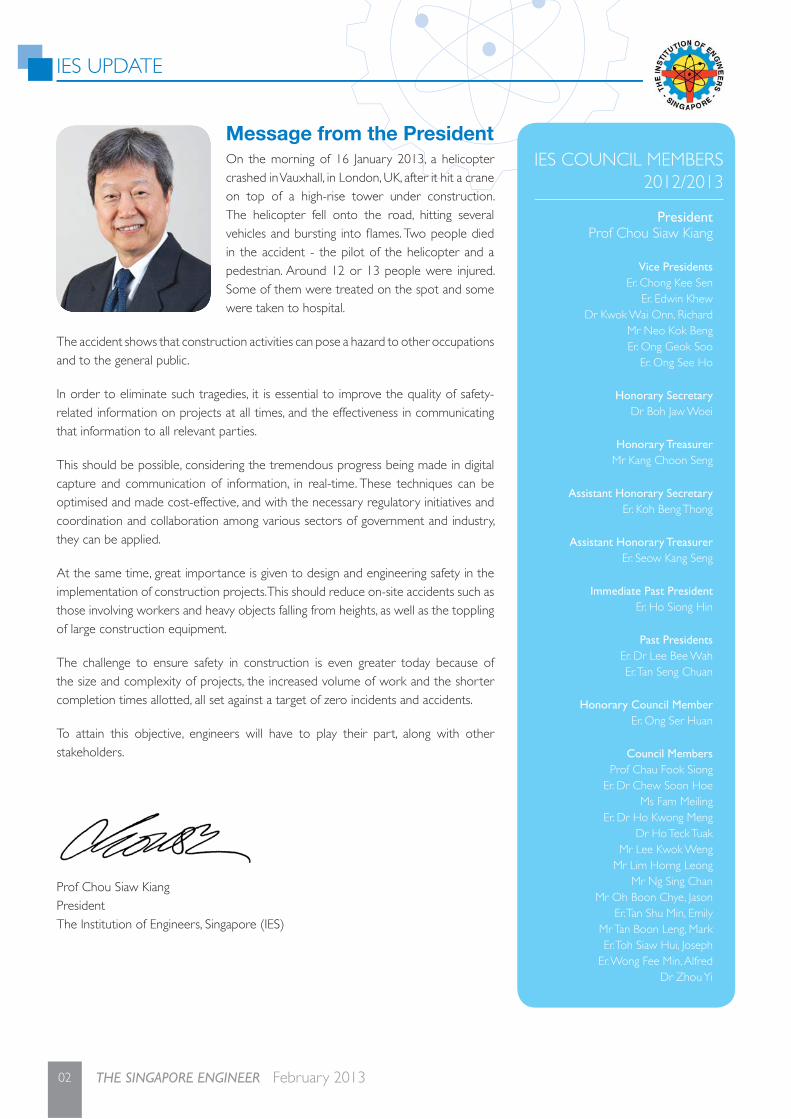
On the morning of 16 January 2013, a helicopter crashed in Vauxhall, in London, UK, after it hit a crane on top of a high-rise tower under construction. The helicopter fell onto the road, hitting several vehicles and bursting into fl ames. Two people died in the accident - the pilot of the helicopter and a pedestrian. Around 12 or 13 people were injured. Some of them were treated on the spot and some were taken to hospital.
The accident shows that construction activities can pose a hazard to other occupations and to the general public.
In order to eliminate such tragedies, it is essential to improve the quality of safety-related information on projects at all times, and the effectiveness in communicating that information to all relevant parties.
This should be possible, considering the tremendous progress being made in digital capture and communication of information, in real-time. These techniques can be optimised and made cost-effective, and with the necessary regulatory initiatives and coordination and collaboration among various sectors of government and industry, they can be applied.
At the same time, great importance is given to design and engineering safety in the implementation of construction projects. This should reduce on-site accidents such as those involving workers and heavy objects falling from heights, as well as the toppling of large construction equipment.
The challenge to ensure safety in construction is even greater today because of the size and complexity of projects, the increased volume of work and the shorter completion times allotted, all set against a target of zero incidents and accidents.
To attain this objective, engineers will have to play their part, along with other stakeholders.
Prof Chou Siaw KiangPresidentThe Institution of Engineers, Singapore (IES)
IES UPDATE
04 THE SINGAPORE ENGINEER February 2013
IES 12th CTO Forum generates new innovative ideas
Courtesy Visit by delegation from China Association for Science & Technology
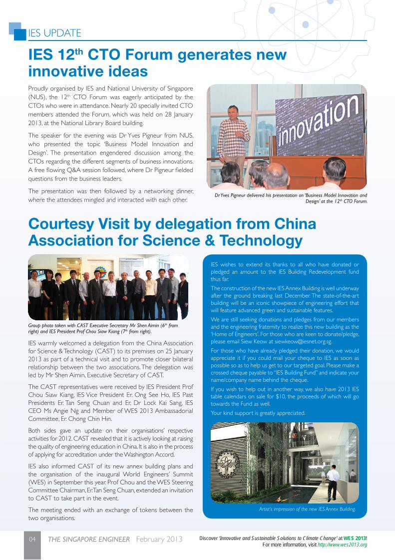
Proudly organised by IES and National University of Singapore (NUS), the 12th CTO Forum was eagerly anticipated by the CTOs who were in attendance. Nearly 20 specially invited CTO members attended the Forum, which was held on 28 January 2013, at the National Library Board building.
The speaker for the evening was Dr Yves Pigneur from NUS, who presented the topic ‘Business Model Innovation and Design’. The presentation engendered discussion among the CTOs regarding the different segments of business innovations. A free fl owing Q&A session followed, where Dr Pigneur fi elded questions from the business leaders.
The presentation was then followed by a networking dinner, where the attendees mingled and interacted with each other.
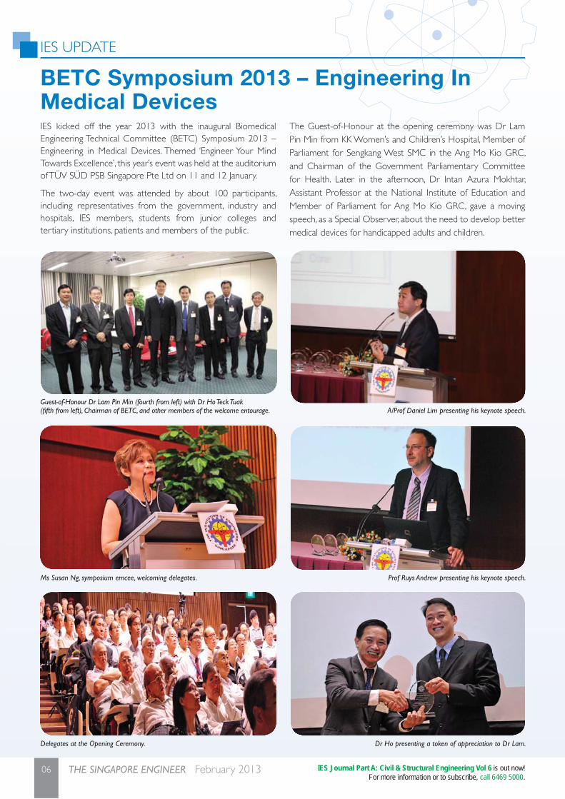
IES warmly welcomed a delegation from the China Association for Science & Technology (CAST) to its premises on 25 January 2013 as part of a technical visit and to promote closer bilateral relationship between the two associations. The delegation was led by Mr Shen Aimin, Executive Secretary of CAST.
The CAST representatives were received by IES President Prof Chou Siaw Kiang, IES Vice President Er. Ong See Ho, IES Past Presidents Er. Tan Seng Chuan and Er. Dr Lock Kai Sang, IES CEO Ms Angie Ng and Member of WES 2013 Ambassadorial Committee, Er. Chong Chin Hin.
Both sides gave an update on their organisations’ respective activities for 2012. CAST revealed that it is actively looking at raising the quality of engineering education in China. It is also in the process of applying for accreditation under the Washington Accord.
IES also informed CAST of its new annex building plans and the organisation of the inaugural World Engineers’ Summit (WES) in September this year. Prof Chou and the WES Steering Committee Chairman, Er. Tan Seng Chuan, extended an invitation to CAST to take part in the event.
The meeting ended with an exchange of tokens between the two organisations.
Dr Yves Pigneur delivered his presentation on ‘Business Model Innovation and Design’ at the 12th CTO Forum.
Group photo taken with CAST Executive Secretary Mr Shen Aimin (6th from right) and IES President Prof Chou Siaw Kiang (7th from right).
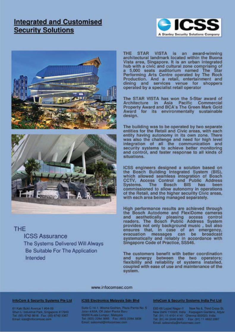
Artist’s impression of the new IES Annex Building.
IES wishes to extend its thanks to all who have donated or pledged an amount to the IES Building Redevelopment fund thus far.
The construction of the new IES Annex Building is well underway after the ground breaking last December. The state-of-the-art building will be an iconic showpiece of engineering effort that will feature advanced green and sustainable features.
We are still seeking donations and pledges from our members and the engineering fraternity to realize this new building as the ‘Home of Engineers’. For those who are keen to donate/pledge, please email Siew Keow at [email protected].
For those who have already pledged their donation, we would appreciate it if you could mail your cheque to IES as soon as possible so as to help us get to our targeted goal. Please make a crossed cheque payable to “IES Building Fund” and indicate your name/company name behind the cheque.
If you wish to help out in another way, we also have 2013 IES table calendars on sale for $10, the proceeds of which will go towards the Fund as well.
Your kind support is greatly appreciated.
Discover ‘Innovative and Sustainable Solutions to Climate Change’ at WES 2013! For more information, visit http://www.wes2013.org

05February 2013 THE SINGAPORE ENGINEER
IES UPDATE
06 THE SINGAPORE ENGINEER February 2013
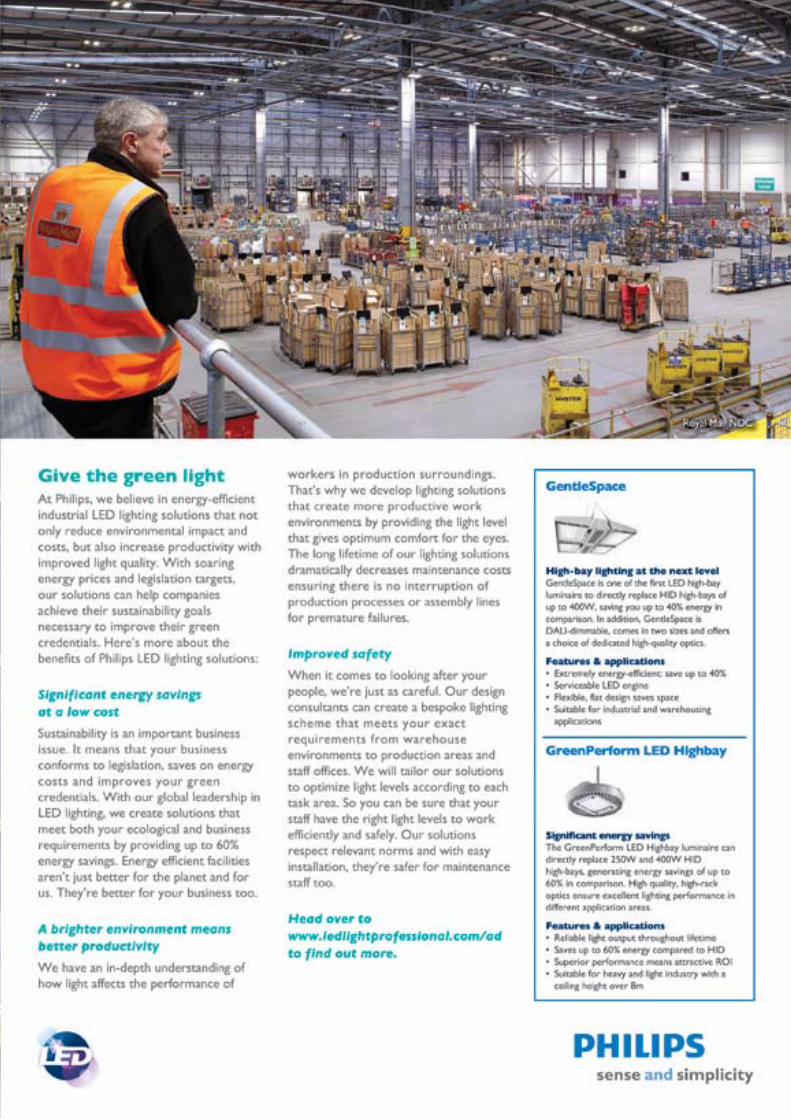
BETC Symposium 2013 – Engineering In Medical DevicesIES kicked off the year 2013 with the inaugural Biomedical Engineering Technical Committee (BETC) Symposium 2013 – Engineering in Medical Devices. Themed ‘Engineer Your Mind Towards Excellence’, this year’s event was held at the auditorium of TÜV SÜD PSB Singapore Pte Ltd on 11 and 12 January.
The two-day event was attended by about 100 participants, including representatives from the government, industry and hospitals, IES members, students from junior colleges and tertiary institutions, patients and members of the public.
The Guest-of-Honour at the opening ceremony was Dr Lam Pin Min from KK Women’s and Children’s Hospital, Member of Parliament for Sengkang West SMC in the Ang Mo Kio GRC, and Chairman of the Government Parliamentary Committee for Health. Later in the afternoon, Dr Intan Azura Mokhtar, Assistant Professor at the National Institute of Education and Member of Parliament for Ang Mo Kio GRC, gave a moving speech, as a Special Observer, about the need to develop better medical devices for handicapped adults and children.
Guest-of-Honour Dr Lam Pin Min (fourth from left) with Dr Ho Teck Tuak (fi fth from left), Chairman of BETC, and other members of the welcome entourage.
Ms Susan Ng, symposium emcee, welcoming delegates.
Delegates at the Opening Ceremony.
A/Prof Daniel Lim presenting his keynote speech.
Prof Ruys Andrew presenting his keynote speech.
Dr Ho presenting a token of appreciation to Dr Lam.
IES Journal Part A: Civil & Structural Engineering Vol 6 is out now!For more information or to subscribe, call 6469 5000.

07February 2013 THE SINGAPORE ENGINEER

IES UPDATE
08 THE SINGAPORE ENGINEER February 2013
Talk on Singapore BIM Guide and BCA BIM Funding
At the symposium, two keynote speakers and twelve plenary speakers from key players in the medical device industry including the Agency for Science, Technology & Research (A*STAR), the Health Sciences Authority (HSA), IES, Nanyang Technological University (NTU), National University of Singapore (NUS), Stryker Singapore, TÜV SÜD PSB Singapore, University of Sydney (Australia), WongPartnership, and 3M Singapore presented on a variety of topics on the latest issues, challenges and solutions in medical device technology. Apart from the symposium, attendees got a rare opportunity to participate in site visits to TÜV SÜD PSB secured laboratories.
The symposium was supported by the Singapore Medical Association, the Singapore Manufacturing Federation and sponsored by ANSYS (The Finite Element Method Solution), and TÜV SÜD PSB Singapore.
Besides being treated to healthy and sumptuous lunches and tea breaks featuring local delights, participants also received goodie bags jointly sponsored by TÜV SÜD PSB Singapore, WongPartnership and IES as well as symposium booklets as mementoes.
The BETC Committee welcomes everyone to the next BETC event which will take place in the near future.
On 22 January 2013, at the IES Auditorium, the IES Environment Engineering Technical Committee Chairman, Er. Alfred Wong, brought together three speakers from different industries to share their experiences in using Building Information Modelling (BIM).
One hundred participants from various industries attended the evening talk to fi nd out more about the Singapore BIM Guide and BIM funding from Mr Sonny Andalis, a technical consultant and BIM specialist from the BCA Centre for Construction IT (CCIT). Ms Christina Koh, Technical Director from Beca Carter
Hollings & Ferner, talked about the pros and cons of using BIM in Civil & Structural Engineering projects in Singapore while the representative from CPG Consultants, Mr Tan Guoyi, a Senior Architectural Associate, explained how BIM was implemented at the new SAFRA Toa Payoh Clubhouse.
The Singapore BIM Guide, a reference that outlines the roles and responsibilities of project members at different stages of a project, is available at http://www.corenet.gov.sg/integrated_submission/bim/BIM_Guide.htm
Dr Ho showing Dr Intan products of the Finite Element Method at the ANSYS exhibition booth
Dr Ho presenting a token of appreciation to Dr Intan.
After the talk, Er. Ong Ser Huan gave out Tokens of Appreciation to the speakers.
From left, Ms Christina Koh from Beca Carter Hollings & Ferner, Mr Sonny Andalis from BCA, Q&A panel moderator Er. Tsang Pui Sum, Mr Tan Guoyi from CPGConsultants, and IES Environmental Engineering Technical Committee Chairman Er. Alfred Wong.
Discover ‘Innovative and Sustainable Solutions to Climate Change’ at WES 2013! For more information, visit http://www.wes2013.org

10 THE SINGAPORE ENGINEER February 2013
11February 2013 THE SINGAPORE ENGINEER

COVER STORY
12 THE SINGAPORE ENGINEER February 2013
INTRODUCTIONThe BCA Design and Engineering Safety Excellence Awards were instituted as part of the efforts by BCA (Building and Construction Authority) to ensure high safety standards in the built environment and inculcate a strong safety culture in the building industry. The Award gives recognition to the efforts taken by the Qualifi ed Person for Structural Works [QP (ST)], his or her fi rm and the project team, for ingenious design processes and solutions for overcoming project challenges and ensuring safety in the design, construction, and maintenance, of building and civil engineering projects, in Singapore and overseas.
Through this Award, BCA hopes to encourage industry professionals to make a more concerted effort to create a safe built environment for all.
The assessment criteria cover two key aspects - safety in design, and safety in construction.
Project overviewCliveden at Grange is nestled in a high-class residential area along Grange Road in the downtown district. Located on a 12,857.4 m2 site, the development consists of four tower blocks, 24-storey high, with 110 units including three-bedroom, four-bedroom and penthouse units; as well as a basement carpark, and a swimming pool and communal facilities on the 1st storey.
The project was implemented over a period of 42 months.
Three of the blocks are single tower blocks and are similar in layout, with the staircase and lift core walls in each of them located at the side of the building, while the fourth block is a twin tower block with its staircase and lift core walls at the centre of the building. The buildings are unique, with conical staircases, circular lift cores and curved external walls. This made it a challenge in terms of design and construction.
Innovative solutions and features adopted to overcome the challenges in this project include the use of the jack-in piling system, precast structures including curved walls, prefabricated toilets, steel mullions and up-stand drop panels.
Design processes and solutions that emphasise safetyThe site on which Cliveden at Grange stands is in front of a row of landed properties. There is also a 3.1 m wide drain culvert cutting across the development.
The jack-in piling system was adopted as it is environment-friendly and ensures good on-site working conditions. Jack-in piling eliminates vibration and reduces dust and noise to the surrounding environment, which was important especially since the site is surrounded by both high-rise and landed housing.
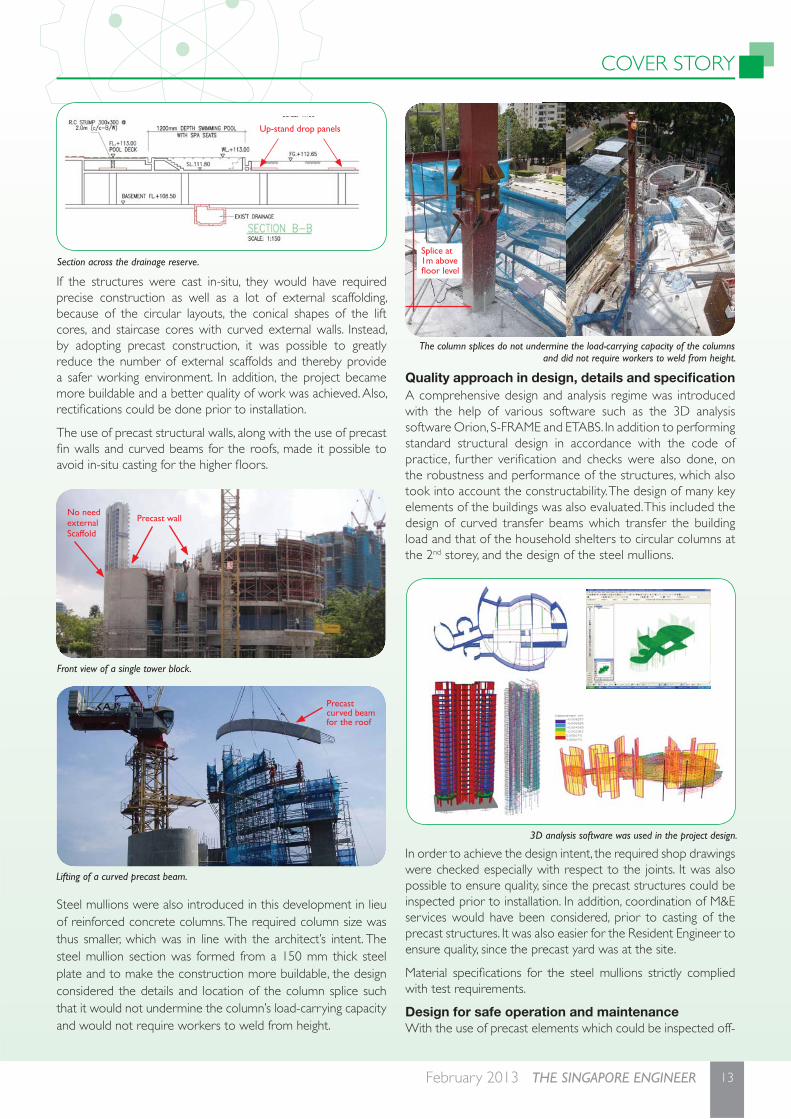
Cutting across the site is a 6.1 m drainage reserve that requires a 3 m headroom clearance above it. To make sure this is met, a fl at slab post-tensioning system with up-stand drop panels was provided. The up-stand drop panels also served to increase the buildability of the 1st storey slab.
Cliveden at GrangeAt BCA AWARDS 2012, the project received a Design and Engineering Safety Excellence Award. It also won a Construction Productivity Award (Platinum) and a Universal Design Award (Silver).
Artist’s impression of Cliveden at Grange.
Jack-in piling in progress.
COVER STORY
13February 2013 THE SINGAPORE ENGINEER
If the structures were cast in-situ, they would have required precise construction as well as a lot of external scaffolding, because of the circular layouts, the conical shapes of the lift cores, and staircase cores with curved external walls. Instead, by adopting precast construction, it was possible to greatly reduce the number of external scaffolds and thereby provide a safer working environment. In addition, the project became more buildable and a better quality of work was achieved. Also, rectifi cations could be done prior to installation.
The use of precast structural walls, along with the use of precast fi n walls and curved beams for the roofs, made it possible to avoid in-situ casting for the higher fl oors.
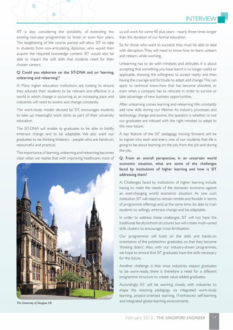
Steel mullions were also introduced in this development in lieu of reinforced concrete columns. The required column size was thus smaller, which was in line with the architect’s intent. The steel mullion section was formed from a 150 mm thick steel plate and to make the construction more buildable, the design considered the details and location of the column splice such that it would not undermine the column’s load-carrying capacity and would not require workers to weld from height.
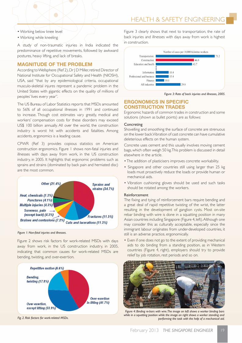
Quality approach in design, details and specifi cationA comprehensive design and analysis regime was introduced with the help of various software such as the 3D analysis software Orion, S-FRAME and ETABS. In addition to performing standard structural design in accordance with the code of practice, further verifi cation and checks were also done, on the robustness and performance of the structures, which also took into account the constructability. The design of many key elements of the buildings was also evaluated. This included the design of curved transfer beams which transfer the building load and that of the household shelters to circular columns at the 2nd storey, and the design of the steel mullions.
In order to achieve the design intent, the required shop drawings were checked especially with respect to the joints. It was also possible to ensure quality, since the precast structures could be inspected prior to installation. In addition, coordination of M&E services would have been considered, prior to casting of the precast structures. It was also easier for the Resident Engineer to ensure quality, since the precast yard was at the site.
Material specifi cations for the steel mullions strictly complied with test requirements.
Design for safe operation and maintenanceWith the use of precast elements which could be inspected off-
Section across the drainage reserve.
Up-stand drop panels
The column splices do not undermine the load-carrying capacity of the columns and did not require workers to weld from height.
Splice at 1m above fl oor level
3D analysis software was used in the project design.
Lifting of a curved precast beam.
Front view of a single tower block.
Precast curved beam for the roof
Precast wallNo need external Scaffold

COVER STORY
14 THE SINGAPORE ENGINEER February 2013
site, inspection and coordination work were made easier. Also, rectifi cation works could be done prior to installation, thereby contributing to safer operation. In addition, in-situ casting, especially for external walls, was avoided and external formwork and scaffolding were not required, thereby providing a safer work environment without the risk of scaffold overloading and working from height.
Cast off-site, prefabricated toilets are well-coordinated and offer better quality and greater durability.
Construction quality and safe construction processesThe site was managed effi ciently with safety as a main concern and with active participation from the Resident Engineer and Site Engineers. Bi-weekly reports by the Resident Engineer, that monitored the quality and site safety, in addition to structural works, ensured smooth and safe construction. The presence of a precast yard on-site enabled better supervision and monitoring and thereby facilitated good quality control.
Approval of shop drawings for the precast structures, prior to construction, ensured that all joints are workable and in accordance with the design, thereby contributing to speedier construction and fewer site issues. The use of prefabricated toilets contributed to higher quality assurance and increased buildability.
Approval of the concrete body plan, prior to construction, resulted in higher accuracy and better coordination, resulting in fewer abortive works and minimum wastage.
The test requirements to determine the quality of steel mullions, which are a key element, ensured that the design intent was achieved. Since these requirements were specifi ed at an
early stage of construction, there was suffi cient lead time for procurement and preparation.
Public safety considerationsConstruction of Cliveden at Grange, by conventional means, would have caused disturbance to neighbouring developments. However, the design adopted measures and approaches to make sure that the impact would be minimised. Due to the use of jack-in piling, noise and vibrations were greatly reduced.
Prior to the start of work on Cliveden at Grange, contractors informed the owners and occupants of neighbouring developments of the work schedule, provided key contact numbers and briefed them about the main disturbances like vibration and noise. The dust and noise levels at the construction site were monitored every month, particularly to make sure that machinery noise levels were within limits. In addition, the Resident Engineer constantly highlighted and reported any substandard practice, so that all activities on site were safe.
Activities at the precast yard.
Installation of prefabricated toilets on-site.
PROJECT CREDITSQualifi ed PersonEr. Lauw Su WeeC&S ConsultantsLSW Consulting Engineers Pte LtdBuilderKajima Overseas Asia Pte LtdDeveloperCity Developments LimitedArchitectural ConsultantsADDP Architects LLP


INTERVIEW
16 THE SINGAPORE ENGINEER February 2013
SIT moves ahead with broadened portfolio and higher student intakeProf Tan Thiam Soon, President, Singapore Institute of Technology (SIT), highlights some of SIT’s initiatives and achievements recorded last year and explains how the institution is addressing the challenge to produce value-added, work-ready graduates.
Question: How would you summarise the activities of SIT in 2012? What are some of the highlights of last year, especially in terms of new programmes, student enrolment, facilities, scholarships and sponsorships, and employment opportunities?
Firstly, I would like to mention that in partnership with universities in the UK, USA and Ireland, SIT launched seven new degree programmes last year. They are:
• Bachelor of Engineering with Honours in Aeronautical Engineering, and Bachelor of Engineering with Honours in Aerospace Systems, from University of Glasgow, UK.
• Bachelor in Science (Physiotherapy), and Bachelor in Science (Occupational Therapy), awarded by Trinity College Dublin, Ireland.
• Bachelor of Arts with Honours in Communication Design, and Bachelor of Arts with Honours in Interior Design, from The Glasgow School of Art, UK.
• Bachelor of Science in Early Childhood Education, awarded by Wheelock College, Boston, Massachusetts, USA
We were also able to increase our total student intake for all our academic programmes, which now total 26, from 950 to 1,300.
A particular highlight during the year was the unveiling of the designs of the satellite campuses in April 2012 and the subsequent ground-breaking ceremonies held at each of the polytechnics, between July 2012 and January 2013.
We are also happy to state that the fi rst batch of students from Newcastle University’s Marine / Offshore Engineering programmes graduated in 2012, and that 92% of them have already secured jobs - mostly in related fi elds. Ten percent of these graduates received company sponsorships / scholarships during their course.
Q: What are some of the specifi c programmes and activities in SIT, in 2013, that you would like to mention?
A: SIT is offering two new degree programmes for Academic Year 2013. One leads to the degree of Bachelor of Engineering with Honours in Electrical Power Engineering, conferred by the University of Newcastle upon Tyne, UK, while the other is the degree of Bachelor of Science with Honours in Computing Science, from the University of Glasgow.
Further, SIT is preparing to transit into an autonomous university, offering SIT’s own degree programmes. The key feature of the SIT degree programmes will be the integrated work-study programme which will require students to alternate study semesters with work attachments. Through this programme, SIT hopes to instill the SIT-DNA in every student, making them adaptable and capable of ‘learning, unlearning and relearning’.
Prof Tan Thiam Soon.
The fi rst batch of students from Newcastle University’s marine / offshore engineering programmes graduated in 2012.
The University of Newcastle upon Tyne, UK.
INTERVIEW
17February 2013 THE SINGAPORE ENGINEER
SIT is also considering the possibility of extending the existing two-year programmes to three or even four years. The lengthening of the course period will allow SIT to take in students from non-articulating diplomas, who would then acquire the required knowledge content. SIT would also be able to impart the soft skills that students need for their chosen careers.
Q: Could you elaborate on the SIT-DNA and on ‘learning, unlearning and relearning’?
A: Many higher education institutions are looking to ensure they educate their students to be relevant and effective in a world in which change is occurring at an increasing pace and industries will need to evolve and change constantly.
The work-study model, devised by SIT, encourages students to take up meaningful work stints as part of their university education.
The SIT-DNA will enable its graduates to be able to boldly embrace change and to be adaptable. We also want our graduates to be thinking tinkerers - people who are hands-on, resourceful and practical.
The importance of learning, unlearning and relearning becomes clear when we realise that with improving healthcare, most of
us will work for some 40 plus years - nearly three times longer than the duration of our formal education.
So for those who want to succeed, they must be able to deal with disruption. They will need to know how to learn, unlearn and relearn, while working.
Unlearning has to do with mindsets and attitudes. It is about accepting that something you have learnt is no longer useful or applicable, showing the willingness to accept reality and then having the courage and fortitude to adapt and change. This can apply to technical know-how that has become obsolete, or even when a company has to relocate in order to survive or take advantage of new business opportunities.
After unlearning comes learning and relearning. We constantly add new skills during our lifetime. As industry, processes and technology change and evolve, the question is whether or not our graduates are imbued with the right mindset to adapt to this new future.
A key feature of the SIT pedagogy, moving forward, will be to ingrain into each and every one of our students that life is going to be about learning on the job, from the job and during the job.
Q: From an overall perspective, in an uncertain world economic situation, what are some of the challenges faced by institutions of higher learning and how is SIT addressing them?
A: Challenges faced by institutions of higher learning include having to meet the needs of the domestic economy against an ever-changing world economic situation. As one such institution, SIT will need to remain nimble and fl exible in terms of programme offerings and, at the same time, be able to train students to willingly embrace change and be adaptable.
In order to address these challenges, SIT will not have the traditional faculty/school structures but will create multi-varied skills clusters to encourage cross-fertilisation.
Our programmes will build on the skills and hands-on orientation of the polytechnic graduates, so that they become ‘thinking doers’. Also, with our industry-driven programmes, we hope to ensure that SIT graduates have the skills necessary for the future.
Another challenge is that since industries expect graduates to be work-ready, there is therefore a need for a different programme structure to create value-added graduates.
Accordingly, SIT will be working closely with industries to shape the teaching pedagogy via integrated work-study learning, project-oriented learning, IT-enhanced self-learning, and integrated global learning environments.The University of Glasgow, UK.

HEALTH & SAFETY ENGINEERING
18 THE SINGAPORE ENGINEER February 2013
Ergonomics at the construction sitesby Dr N Krishnamurthy, Safety Consultant and Trainer, Singapore
The right working conditions should be created, in order to prevent workers from suffering pain and injury.
INTRODUCTIONMost fatalities and injuries at construction sites can be traced to the worker not working in a safe position, using the wrong tool for the job, or using the right tool the wrong way. Workers are provided Personal Protective Equipment (PPE) of various types for different hazardous tasks, but inadequate understanding and unsafe conditions result in workers adopting wrong work postures. The article discusses the contributing factors to workplace ergonomic problems in relation to Singapore’s Workplace Safety and Health Act of 2006; identifi cation, assessment and management of Work-related Musculo-Skeletal Disorders (WMSDs); the benefi ts of a pro-active approach to ergonomics planning; and feasible solutions. Examples and case studies of ergonomic improvements in construction engineering, and safety gear are presented. The focus is on construction workplace ergonomic issues such as manual handling, and consequences of PPE misuse.
ERGONOMICSThe word ‘ergonomics’ is derived from two Greek words - ‘ergon’, meaning work, and ‘nomos’, meaning natural laws. Today, the word is used to describe the science of ‘designing the job to fi t the worker, not forcing the worker to fi t the job - thus the science of adapting work and working conditions to suit the worker’, according to Rwamamara and Smallwood (Ref 1), whose comments on ergonomic problems and solution recommendations in industrially developing countries are cited frequently in this article.
Employees’ abilities to perform physical tasks may depend on age, physical condition, strength, gender, stature etc. The science of ergonomics examines how to improve the fi t between physical demands of the workplace and employees who perform the work, or in other words, how to protect the workers from strain.
Effective and successful fi tting of the workplace conditions to the capabilities of the workforce assures high productivity, avoidance of illness and injury risks, and increased satisfaction among the workforce. Although the scope of ergonomics is much broader, the term here refers to assessing those work-related factors that may pose a risk of Musculo-Skeletal Disorders (MSDs) and recommendations to alleviate them.
Common examples of ergonomic risk factors are found in jobs requiring repetitive, forceful, or prolonged exertions of the hands; frequent or heavy lifting, pushing, pulling, or carrying of heavy objects; and prolonged awkward postures. Vibration and excessive heat or cold may also add risk to these work
conditions. The level of risk depends on the intensity, frequency, and duration of the exposure to these conditions.
Ergonomic problems may also be culture- and technology- related. For instance, repetitive movements are more likely in a country which makes predominant use of masonry materials for walls, than in a country that makes use of prefabricated framing and panels such as the USA, and recently Singapore. Climbing and descending are more likely problems in a country which makes limited use, if any, of vertical transportation of people with the help of personnel hoists, than in a country that does. Presently, squatting on the fl oor or ground for many hours may not be a problem in many Asian countries, but modern youth may not retain such habits for long.
CONSTRUCTION ERGONOMICSConstruction, by its very nature, is a problem for ergonomists, as it requires work above shoulder level and below knee height. Materials may also be heavy and/or inconveniently sized and shaped, thus presenting manual material handling problems.
Numerous construction tasks pose signifi cant risks to workers. To eliminate or mitigate the risks, it would be necessary to identify work risks in construction and assess the impact of even minimal ergonomics on the construction process.
The most important safety-, health-, and ergonomics- related problems involving construction tools, leading to construction accidents, have been identifi ed as follows:• Manual handling, lifting, and carrying• Tripping and falling• Noise• Vibration• Dust exposure • Poor design of tool interfaces
Of the job factors which caused major ergonomics-related problems, the following were assessed in a 2003 US study, to be the top four:• Bending or twisting the back• Staying in the same position for long periods• Working in the same position for long periods• Handling heavy materials or equipment
Certain problems peculiar to Asian (and certain African nations) may be highlighted, in addition to bending and twisting of the body:• Reaching away from the body and reaching overhead• Working in awkward positions• Lifting and manually handling heavy and irregularly sized and shaped materials and components
Dr N Krishnamurthy
HEALTH & SAFETY ENGINEERING
19February 2013 THE SINGAPORE ENGINEER
• Working below knee level
• Working while kneeling
A study of non-traumatic injuries in India indicated the predominance of repetitive movements, followed by awkward postures, heavy lifting, and lack of breaks.
MAGNITUDE OF THE PROBLEMAccording to Wellsphere (Ref 2), Dr J D Miller, retired Director of National Institute for Occupational Safety and Health (NIOSH), USA, said “that by any epidemiological criteria, occupational musculo-skeletal injures represent a pandemic problem in the United States with gigantic effects on the quality of millions of peoples’ lives every year”.
The US Bureau of Labor Statistics reports that MSDs amounted to 56% of all occupational illnesses in 1991 and continued to increase. Though cost estimates vary greatly, medical and workers’ compensation costs for these disorders may exceed US$ 100 billion annually. All over the world, the construction industry is worst hit with accidents and fatalities. Among accidents, ergonomics is a leading cause.
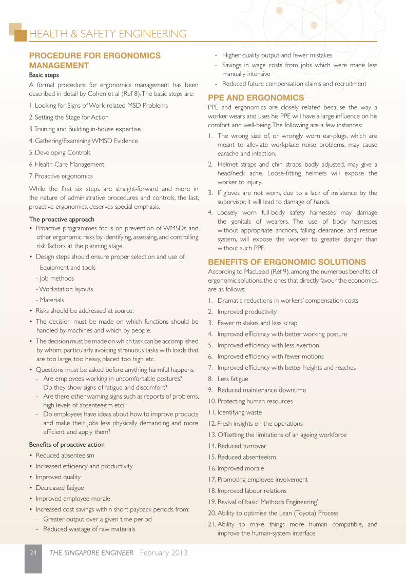
CPWR (Ref 3) provides copious statistics on American construction ergonomics. Figure 1 shows non-fatal injuries and illnesses with days away from work, in the US construction industry, in 2005. It highlights that ergonomic problems such as sprains and strains (dominated by back pain and herniated disc) are the most common.
Figure 2 shows risk factors for work-related MSDs with days away from work, in the US construction industry, in 2005, indicating that common causes for work-related MSDs are bending, twisting, and over-exertion.
Figure 3 clearly shows that next to transportation, the rate of back injuries and illnesses with days away from work is highest in construction.
ERGONOMICS IN SPECIFIC CONSTRUCTION TRADESErgonomic hazards of common trades in construction and some solutions (shown as bullet points) are as follows:
ConcretingShovelling and smoothing the surface of concrete are strenuous on the lower back. Vibration of cast concrete can have cumulative deleterious effects on the human system.
Concrete uses cement and this usually involves moving cement bags, which often weigh 50 kg. This problem is discussed in detail elsewhere in the article.
• The addition of plasticisers improves concrete workability.
• Singapore and other countries still using larger than 25 kg loads must proactively reduce the loads or provide human or mechanical aids.
• Vibration cushioning gloves should be used and such tasks should be rotated among the workers.
ReinforcementThe fi xing and tying of reinforcement bars require bending and a great deal of rapid repetitive twisting of the wrist, the latter resulting in the development of ganglion cysts. Most on-site rebar binding with wire is done in a squatting position in many Asian countries including Singapore (Figure 4, left). Although one may consider this as culturally acceptable, especially since the immigrant labour originates from under-developed countries, it still is an adverse practice, ergonomically.
• Even if one does not go to the extent of providing mechanical aids to do binding from a standing position, as in Western countries (Figure 4, right), employers should try to provide relief by job rotation, rest periods and so on.
Figure 1: Non-fatal injuries and illnesses.
Figure 3: Rate of back injuries and illnesses, 2005.
Fig. 2. Risk factors for work-related MSDs.
Figure 4: Binding re-bars with wire. The image on left shows a worker binding bars while in a squatting position while the image on right shows a worker standing and
performing the task with the help of a mechanical aid.

HEALTH & SAFETY ENGINEERING
20 THE SINGAPORE ENGINEER February 2013
Steel is heavy. A 15 m long, 32 mm diameter bar will weigh 95 kg and it is not unusual to see two workers carry it. If done on a regular basis, this would be an invitation to MSDs.
• More workers may not always help because of the uneven distribution of the continuous load on a number of workers of unequal height (and enthusiasm!) Mechanical aids are a must in this context.
• The use of fabric, in lieu of bar reinforcement, reduces the amount of time spent fi xing and tying reinforcement for each concrete element, and reduces the amount of bending and rapid repetitive twisting of the wrist.
• Using trestles also enables steel fi xers to fi x cages at ‘worktop’ level.
FormworkThe erection and striking of falsework (support structure) and formwork require large amounts of bending, twisting, and use of body force.
• Designers can facilitate the use of composite systems through the simplifi cation of design, table forms, and wall forms which can be handled by craneage, thereby reducing the manual aspect of the activity.
• The use of precast concrete also reduces the amount of falsework and formwork as well as on-site fi xing and tying of reinforcement required. Prestressed concrete elements, particularly slabs, also reduce the amount of reinforcement bars.
Structural steelworkProblems with steel erection include awkward postures, occasional high force requirements, static postures, repetitive movements, use of pneumatic tools, and lifting. The high risk nature of the activity which entails straddling beams several metres in the air while aligning and bolting them to columns compounds the problems.
• Pre-assembly, simple joints, and integral safety features can reduce hazards.
MasonryBlock- and brick- laying represent major work hazards in building. Lifting an average of 1000 bricks a day is equivalent to lifting 2300 kg to 4000 kg, and 1000 trunk-twist fl exions.
• A suitable intervention may be provision of waist-high material platforms.
• Design improvements include the incorporation of hand-holds in blocks to facilitate lifting.
• Alternative wall systems such as drywalls constitute the optimum solution.
Roofi ngRoofi ng poses many different hazards due to minimal ergonomic input, but the prime one is material handling. Of the three types of roofi ng (unit and sheet materials and waterproofi ng membranes), unit materials require considerably more bending, twisting, and handling of mass per square metre of covered area, than sheet materials.
• Use of ‘ladder type’ tile lifts facilitates the lifting of unit materials to roof level.
Building facadesDiffering systems and materials pose differing problems. Concrete surface fi nishes such as bush-hammering present a risk of hand-arm vibration and health problems such as silicosis. Natural stone claddings require a lot of lifting and hoisting of heavy panels as well as adopting of awkward postures and hand-arm vibration as a result of fi xing. These present a risk of back injury and hand/wrist problems.
• Design alternatives include light-weight sheet metal claddings and prefabricated, unitised curtain walling, which will minimise the risk factors.
Plumbing and drainage/pipe-fi ttingPiping is often laid at odd angles and in cramped spaces. Specifi c piping materials have specifi c jointing methods, not all of which are complementary to basic ergonomic principles. A number of installations are suspended and require extensive overhead work. The fi xing of the suspension hangers results in substantial stretching and twisting, and consequently a high level of stress on the neck and shoulders of workers.
• Designers should consider the ergonomic implications of jointing methods when specifying materials, the feasibility of prefabricated stacks, and horizontal and vertical service ducts for piping.
Electrical workElectricians often work in cramped postures and their work entails a large amount of wrist action, resulting in stress on the arms and shoulders. Making connections requires extensive use of hand-tools, often in cramped spaces such as ceilings above and between ducting and other piping.
• Designers should make adequate provision for access during both design and coordination of services during design.
Floor fi nishesAll fl oor fi nishes require constant kneeling and bending. Ceramic and similar tile and terrazzo work entail additional risk. Often the weight of the tiles to be set can be substantial, particularly in the case of natural stone. Terrazzo and similar fi nishes require considerable hand and wrist motion.
• When specifying fi nishes, designers should consider the nature of the pertaining processes.
• Using trestle type work benches reduces the need for tilers to cut at fl oor level.
Suspended ceilingsMost suspended ceilings require signifi cant overhead work although the components are not particularly heavy. It is necessary to suspend primary tracks from hangers and secondary tracks between the primary tracks. Screw-up suspended ceilings require considerably more overhead work than lay-in tile ceilings.
• Consequently, designers should specify lay-in tile ceilings where possible.

HEALTH & SAFETY ENGINEERING
21February 2013 THE SINGAPORE ENGINEER
• The use of mobile tower scaffolds with full work platforms is more complementary to ergonomics than the use of ladders.
Painting and decoratingOverhead painting of ceilings places considerable stress on the arms and shoulders, as well as the neck.
• Designers should consider self-fi nishes where possible.
Paving and other external workBrick paving requires work similar to that of tiling. In addition, pavers often have to be cut with an electrically powered masonry saw which requires working at ground level, and consequently requires the workers to bend a great deal.
• The use of work-bench type masonry saws does reduce the hazard. Although asphalt paving exposes workers to whole-body and hand-arm vibration, workers are not exposed to the volume of repetitive movements and other work-related postures as in the case of brick paving.
CAUSES AND IMPACTSEnvironmental factors associated with the workplace can cause many workplace problems. Below are some examples:
• Extreme high temperatures can increase fatigue rate.
• Exposure of hands and feet to cold can decrease blood fl ow, muscle strength etc.
• Excessive or awkward grip force for tool handles or objects can cause injuries.
• Exhaust cold or hot air directly from tools or equipment can cause discomfort.
• Inadequate or too bright lighting in a workplace causes employees to assume awkward postures to accomplish work tasks, resulting in a loss of product quality.
Other sources of ergonomic problems in a construction project are:
1. Contractor’s awareness of ergonomics
2. Standard of site house-keeping
3. Degree of planning by contractor
4. Amount of work during project
5. Degree of mechanisation
6. Format of materials
7. Specifi cations
8. Details
9. Type of procurement system
10. General design
Rwamamara and Smallwood (Ref 1) list the impact of ergonomics on various stages of a building construction project, as shown below, in decreasing order of importance:
1. Structural steel structure
2. Reinforced concrete structure
3. Installation of services (structure)
4. Roof
5. External works
6. Ceilings
7. Cladding/external fabric
8. Site clearance and earthworks
9. Finishes
10. Walling/partitions
MANUAL HANDLINGThe problemAlmost all construction activities involve lifting and shifting objects by hand, which can lead to many ergonomic problems, mostly MSDs, causing considerable human misery and costing massive amounts of money for compensation and cure. Manual handling thus rates a special focus.
More than a third of all over-three-day injuries reported each year to the Health and Safety Executive (HSE) and local authorities, in the UK, are caused by manual handling - the transporting or supporting of loads by hand or by bodily force. The pie chart (Figure 5) from HSE (Ref 4), shows the pattern for over-three-day injuries reported in 2001/2002. In the US, over-exertion, when lifting, caused 42% of the WMSDs with days away from work in construction as already shown in Figure 2.
This is the single most vexing and most costly defi ciency in worksites, although many nations might not have identifi ed it or addressed it as such.
The biomechanics of manual lifting is very simple but worrisome. The simple fact is that when a person bends down and picks up 1 kg, his vertebral column (backbone) experiences a compression force of 10 kg to 15 kg [Figure 6 (Ref 5)].
It may be shown from principles of simple mechanics that, allowing for the pressure from the weight of the person’s torso, the limit for the weight that an Asian male can bend and lift routinely is slightly less than 25 kg. Canada recommends 23 kg as the limit (Ref 6). Lifting anything larger than that, except occasionally, will affect the spine adversely, leading to chronic back pain and irreversible damage. In the construction industry, workers often carry routinely much more than 25 kg.
Figure 5: Accidents causing over-three-day injuries.

HEALTH & SAFETY ENGINEERING
22 THE SINGAPORE ENGINEER February 2013
The problem does not end there. While 25 kg may be the upper load limit for normal carrying of a load straight up and down in front, any twisting of the torso with respect to the hips worsens the stress on the backbone and reduces the safe weight that can be carried. For instance, rotating the body 45° can reduce the carrying limit by about 15%.
Frequent lifting and carrying of 50 kg cement bags will lead to permanent spinal injuries. Only some countries like Australia and UK have mandated worker maximum loads to 20 kg to 25 kg.
Singapore has recommended that worker loads be limited to 25 kg, in CP92 (replaced with SS 569), BOWEC, Construction Regulations (Jan 2008) etc. The limit is mentioned as desirable in risk control for hazardous industries, and in design for safety, DO2RAS, CONQUAS, and other documents issued by authorities.
But in the present safety culture context, many simply do not know that there are guidelines on this topic, and even those who know may not adopt the recommendations because they are not mandatory.
The solution right now
1. Highlighting existing guidelines through publicity materials, advisories etc. WSHC (Workplace Safety and Health Council) and MOM (Ministry of Manpower) have recently been doing a lot in this regard.
2. Educating stakeholders on the real dangers to workers handling heavy loads, and how in the long run, they can affect the health of workers. This means:
(a) Educating the worker on why he should not carry heavy loads.
(b) Educating the supervisor on how and why he should watch out for workers impulsively handling heavy loads. - Safety offi cers and supervisors must avoid this risk, through (i) imparting training for proper lifting, and (ii) adopting mechanical assist devices.
(c) Educating the management so that it understands that adverse impact on workers can reduce productivity and cause a lot of compensation claims and court cases, thereby affecting business.
(d) Educating inspectors on what to watch out for, and how to deal with violations.
(e) Educating the public so that it does not expect or allow workers to carry heavy loads, and will be on the lookout for, and report, violations of these guidelines.
3. Doing what can be done at workplaces, within the existing system, to alleviate the problem. Trying the standard hierarchy of controls put forward by Krishnamurthy (Ref 7), as shown below:
(a) Elimination: Just not letting people handle loads. Using mechanical aids to move everything, if more than, say, 5 kg. This may not be easy.
(b) Substitution: Substituting with loads smaller than 25 kg. Either getting smaller weight packages, absorbing the extra cost as insurance against health impacts, or, breaking up the larger loads delivered to site into smaller packages for shifting.
(c) Engineering Controls: Providing mechanical aids operated by the workers, to ease their load, such as push carts, lever grips, hand-operated dollies, etc. The author once proposed a simple, low-cost swing arm mechanical device, to eliminate repetitive twisting by the worker, by letting the device do the twisting, leaving the worker to do only the pushing, as in Figure 7 (Ref 5).
(d) Administrative Controls: With low wages being paid, immigrant construction labour is cheap. The simple expedient of putting two people to carry loads from 25 kg to 50 kg, and proportionately more workers for heavier loads, will be adequate in the short term. This will require a little more supervision, and a little smarter management to ensure that the workers share the load nearly equally.
(e) PPE: Although PPE will not reduce the load, gloves and safety shoes will protect hands and feet in gripping the load and if the load should fall.
Figure 6: Forces on the vertebral column..
Figure 7: Case study of an ergonomic intervention.

23February 2013 THE SINGAPORE ENGINEER
The IES Journal Part A: Civil & Structural Engineering Vol. 6 is fi nally available with new cover design!
Early Bird Promotion: 10–15% Off!
Dear Members
Now indexed by SCOPUS and Compendex, the IES Journal is written by world renowned researchers and practitioners. Th e Journal provides a forum for the dissemination of original research and developments in civil & structural engineering. Th e papers cover a wide range of engineering issues in structural, geotechnical, water resources, environmental and infrastructural fi elds, and off er a focused, vibrant and timely communication tool for researchers, consultants and industry practitioners.
From now till 28 June 2013, subscribe to the IES Journal Part A: Civil and Structural Engineering Vol. 6 and get 10% off for one year‘s subscription (S$72) and 15% off for two years‘ subscription (S$136). Th e usual price for a year‘s subscription is S$80.
Th e 2013 volume of the IES Journal Part A is published on a quarterly basis. Visit the publisher’s website at http://www.tandf.co.uk/journals/tiea for more information as well as a sample copy.
Call 64695000 for any further queries!
Email [email protected] for the order form.
The IES Journal Part A: Civil & Structural Engineering
Volume 6, N
umber 1, February 2013
EDITOR-IN-CHIEFC. M. Wang
National University of Singapore
THE IES JOURNAL PART ATHE IES JOURNAL PART A: Civil & Structural Engineering
Civil & Structural Engineering
ContentsTechnical papersEffects of coordinated crowd motion on dynamic responses of composite floors
in buildings
Arash Behnia, Hwa Kian Chai, Navid Ranjbar, Nima Behnia, Amir Fateh and Nima Mehrabi 1
Anti-seismic reliability analysis of continuous rigid-frame bridge based on numerical
simulations
Z.H. Li, Y.L. Jin, Y.F. Chen and R. Chen 18
Analogy of TE waveguide and vibrating plate with sliding edge condition
and exact solutions
C.M. Wang, C.Y. Wang and Z.Y. Tay 32
Geothermal desalination in Singapore
Lee Siu Zhi Michelle, Andrew Palmer, Grahame Oliver and Hendrik Tjiawi 42
Buckling and vibration of stepped rectangular plates by element-based differential
transform method
S. Rajasekaran 51
EssaySupreme structures: reflections on the IStructE structural awards
David A. Nethercot 65
Volume 6, Number 1, February 2013 ISSN: 1937-3260Volume 6, Number 1, February 2013 ISSN: 1937-3260
TIEA_06_01-Cover.indd 1 1/17/13 10:26:37 PM
HEALTH & SAFETY ENGINEERING
24 THE SINGAPORE ENGINEER February 2013
PROCEDURE FOR ERGONOMICS MANAGEMENTBasic stepsA formal procedure for ergonomics management has been described in detail by Cohen et al (Ref 8). The basic steps are:
1. Looking for Signs of Work-related MSD Problems
2. Setting the Stage for Action
3. Training and Building in-house expertise
4. Gathering/Examining WMSD Evidence
5. Developing Controls
6. Health Care Management
7. Proactive ergonomics
While the fi rst six steps are straight-forward and more in the nature of administrative procedures and controls, the last, proactive ergonomics, deserves special emphasis.
The proactive approach• Proactive programmes focus on prevention of WMSDs and
other ergonomic risks by identifying, assessing, and controlling risk factors at the planning stage.
• Design steps should ensure proper selection and use of:
- Equipment and tools
- Job methods
- Workstation layouts
- Materials
• Risks should be addressed at source.
• The decision must be made on which functions should be handled by machines and which by people.
• The decision must be made on which task can be accomplished by whom, particularly avoiding strenuous tasks with loads that are too large, too heavy, placed too high etc.
• Questions must be asked before anything harmful happens: - Are employees working in uncomfortable postures? - Do they show signs of fatigue and discomfort? - Are there other warning signs such as reports of problems,
high levels of absenteeism etc? - Do employees have ideas about how to improve products
and make their jobs less physically demanding and more effi cient, and apply them?
Benefi ts of proactive action
• Reduced absenteeism
• Increased effi ciency and productivity
• Improved quality
• Decreased fatigue
• Improved employee morale
• Increased cost savings within short payback periods from:
- Greater output over a given time period
- Reduced wastage of raw materials
- Higher quality output and fewer mistakes
- Savings in wage costs from jobs which were made less manually intensive
- Reduced future compensation claims and recruitment
PPE AND ERGONOMICSPPE and ergonomics are closely related because the way a worker wears and uses his PPE will have a large infl uence on his comfort and well-being. The following are a few instances:
1. The wrong size of, or wrongly worn ear-plugs, which are meant to alleviate workplace noise problems, may cause earache and infection.
2. Helmet straps and chin straps, badly adjusted, may give a head/neck ache. Loose-fi tting helmets will expose the worker to injury.
3. If gloves are not worn, due to a lack of insistence by the supervisor, it will lead to damage of hands.
4. Loosely worn full-body safety harnesses may damage the genitals of wearers. The use of body harnesses without appropriate anchors, falling clearance, and rescue system, will expose the worker to greater danger than without such PPE.
BENEFITS OF ERGONOMIC SOLUTIONSAccording to MacLeod (Ref 9), among the numerous benefi ts of ergonomic solutions, the ones that directly favour the economics, are as follows:
1. Dramatic reductions in workers’ compensation costs
2. Improved productivity
3. Fewer mistakes and less scrap
4. Improved effi ciency with better working posture
5. Improved effi ciency with less exertion
6. Improved effi ciency with fewer motions
7. Improved effi ciency with better heights and reaches
8. Less fatigue
9. Reduced maintenance downtime
10. Protecting human resources
11. Identifying waste
12. Fresh insights on the operations
13. Offsetting the limitations of an ageing workforce
14. Reduced turnover
15. Reduced absenteeism
16. Improved morale
17. Promoting employee involvement
18. Improved labour relations
19. Revival of basic ‘Methods Engineering’
20. Ability to optimise the Lean (Toyota) Process
21. Ability to make things more human compatible, and improve the human-system interface

25February 2013 THE SINGAPORE ENGINEER
HEALTH & SAFETY ENGINEERING
26 THE SINGAPORE ENGINEER February 2013
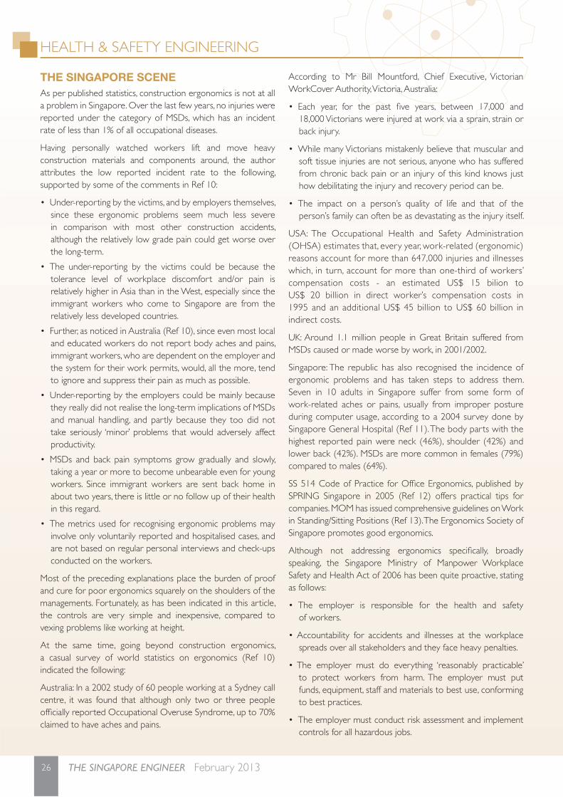
THE SINGAPORE SCENEAs per published statistics, construction ergonomics is not at all a problem in Singapore. Over the last few years, no injuries were reported under the category of MSDs, which has an incident rate of less than 1% of all occupational diseases.
Having personally watched workers lift and move heavy construction materials and components around, the author attributes the low reported incident rate to the following, supported by some of the comments in Ref 10:
• Under-reporting by the victims, and by employers themselves, since these ergonomic problems seem much less severe in comparison with most other construction accidents, although the relatively low grade pain could get worse over the long-term.
• The under-reporting by the victims could be because the tolerance level of workplace discomfort and/or pain is relatively higher in Asia than in the West, especially since the immigrant workers who come to Singapore are from the relatively less developed countries.
• Further, as noticed in Australia (Ref 10), since even most local and educated workers do not report body aches and pains, immigrant workers, who are dependent on the employer and the system for their work permits, would, all the more, tend to ignore and suppress their pain as much as possible.
• Under-reporting by the employers could be mainly because they really did not realise the long-term implications of MSDs and manual handling, and partly because they too did not take seriously ‘minor’ problems that would adversely affect productivity.
• MSDs and back pain symptoms grow gradually and slowly, taking a year or more to become unbearable even for young workers. Since immigrant workers are sent back home in about two years, there is little or no follow up of their health in this regard.
• The metrics used for recognising ergonomic problems may involve only voluntarily reported and hospitalised cases, and are not based on regular personal interviews and check-ups conducted on the workers.
Most of the preceding explanations place the burden of proof and cure for poor ergonomics squarely on the shoulders of the managements. Fortunately, as has been indicated in this article, the controls are very simple and inexpensive, compared to vexing problems like working at height.
At the same time, going beyond construction ergonomics, a casual survey of world statistics on ergonomics (Ref 10) indicated the following:
Australia: In a 2002 study of 60 people working at a Sydney call centre, it was found that although only two or three people offi cially reported Occupational Overuse Syndrome, up to 70% claimed to have aches and pains.
According to Mr Bill Mountford, Chief Executive, Victorian WorkCover Authority, Victoria, Australia:
• Each year, for the past fi ve years, between 17,000 and 18,000 Victorians were injured at work via a sprain, strain or back injury.
• While many Victorians mistakenly believe that muscular and soft tissue injuries are not serious, anyone who has suffered from chronic back pain or an injury of this kind knows just how debilitating the injury and recovery period can be.
• The impact on a person’s quality of life and that of the person’s family can often be as devastating as the injury itself.
USA: The Occupational Health and Safety Administration (OHSA) estimates that, every year, work-related (ergonomic) reasons account for more than 647,000 injuries and illnesses which, in turn, account for more than one-third of workers’ compensation costs - an estimated US$ 15 bilion to US$ 20 billion in direct worker’s compensation costs in 1995 and an additional US$ 45 billion to US$ 60 billion in indirect costs.
UK: Around 1.1 million people in Great Britain suffered from MSDs caused or made worse by work, in 2001/2002.
Singapore: The republic has also recognised the incidence of ergonomic problems and has taken steps to address them. Seven in 10 adults in Singapore suffer from some form of work-related aches or pains, usually from improper posture during computer usage, according to a 2004 survey done by Singapore General Hospital (Ref 11). The body parts with the highest reported pain were neck (46%), shoulder (42%) and lower back (42%). MSDs are more common in females (79%) compared to males (64%).
SS 514 Code of Practice for Offi ce Ergonomics, published by SPRING Singapore in 2005 (Ref 12) offers practical tips for companies. MOM has issued comprehensive guidelines on Work in Standing/Sitting Positions (Ref 13). The Ergonomics Society of Singapore promotes good ergonomics.
Although not addressing ergonomics specifi cally, broadly speaking, the Singapore Ministry of Manpower Workplace Safety and Health Act of 2006 has been quite proactive, stating as follows:
• The employer is responsible for the health and safety of workers.
• Accountability for accidents and illnesses at the workplace spreads over all stakeholders and they face heavy penalties.
• The employer must do everything ‘reasonably practicable’ to protect workers from harm. The employer must put funds, equipment, staff and materials to best use, conforming to best practices.
• The employer must conduct risk assessment and implement controls for all hazardous jobs.

27February 2013 THE SINGAPORE ENGINEER
HEALTH & SAFETY ENGINEERING
28 THE SINGAPORE ENGINEER February 2013
• The employer must keep records for three years, meaning causes of worker strain and long-term injury may be tracked back to poor ergonomics at the workplace.
• The employer must reduce risk at source, that is, before the worker starts doing the assigned task, so that it does not affect him.
CONCLUSIONProactive Singapore will be doing well by focussing on ergonomic problems in construction, before they escalate into a national safety and legal problem. The problems and solutions to eliminate or alleviate their effects are well-known and implementation framework well established. All that is needed is concerted action along the lines of the recent approach to noise-induced deafness.
• Knowledge on long-term effects of poor ergonomics should be disseminated more extensively to the industry, workers and other stakeholders.
• The metrics for ergonomic statistics should be reviewed and redefi ned.
• The necessary medical checks and controls should be implemented, including fi rm enforcement of regulations and codes, especially on manual handling.
REFERENCES1. Rwamamara R A and John J Smallwood: ‘Ergonomics in
Construction, Specifi cally in IDCs’ (2009), Chapter 19, Ergonomics in Developing Regions. Scott P A (ed), Boca Raton, CRC Press, Taylor & Francis Group p 307-322. 16 p. http://pure.ltu.se/portal/fi les/3109669/My_Chapter_19.pdf
2. Wellsphere (2009): ‘Ergonomic Statistics that may surprise you’.http://www.wellsphere.com/workplace-health-article/ergonomic-statistics-that-may-surprise-you/805601
3. CPWR - Center for Construction Research and Training: ‘The Construction Chart Book - The US Construction Industry and its Workers, 4th Edition’ (2008), Silver Spring, MD, USA.
4. HSE, UK: ‘Getting to Grips with Manual Handling - A Short Guide’ (2003). 20 p.
5. Krishnamurthy N: ‘Risk Analysis of Manual Lifting’, The Singapore Engineer, Aug 2006, p 20-23, The Institution of Engineers, Singapore.
6. Human Resources and Social Development Canada: ‘Protect your back!’ Retrievable from: http://www.hrsdc.gc.ca/eng/labour/publications/health_safety/back/page00.shtml
7. Krishnamurthy N: ‘Introduction to Risk Management’ (2007). 86 p.
8. Cohen A L, Gjessing C C, Fine L J, Bernard B P, and McGlothlin J D: ‘Elements of Ergonomics Programs: A Primer Based on
Workplace Evaluations of Musculoskeletal Disorders’ (1997), NIOSH, US Department of Health and Human Services. 133 p.
9. MacLeod D: ‘25 Ways Ergonomics Can Save You Money’ (2006), USA. Retrievable from: http://www.danmacleod.com/Articles/PDFs/25 Ways Ergonomics Can Save You Money.pdf
10. ‘Ergonomics Now’. Retrievable from: http://www.ergonomicsnow.com.au/resources/statistics
11. Tan Yi Hui: ‘Pain? Sit up and listen’, The Straits Times, Wed, Jun 18, 2008.
12. SPRING Singapore: ‘SS 514:2005, Code of Practice for Offi ce Ergonomics’.
13. Ministry of Manpower, Guidelines on Work in Standing/Sitting Positions, retrievable from: http://www.mom.gov.sg/Documents/safety-health/factsheets-circulars/Guidelines on Work in Standing and Sitting Positions.pdf
[This article is adapted and expanded from an invited talk on the same title, presented by the author at the ‘Construction Safety Summit’ organised by IES on 10 September 2012, as part of the CIB-W099 International Conference on ‘Modelling and Building Health and Safety’, held on 10 and 11 September 2012, hosted by the National University of Singapore. Additional information relating to the article may be obtained from the author (Email: [email protected] and Website: www.profkrishna.com)].
Singapore Standard on manual handling Launched in 2012, Singapore Standards - SS 569: 2011 on the Code of Practice for Manual Handling, seeks to improve safety and health as well as help reduce the number of injuries at the workplace. This standard is a revision of the Codes of Practice, CP 92.
Manual handling is an essential activity in most workplaces. Musculoskeletal injuries and disorders, most commonly associated with manual handling, may be avoided by implementing the SS 569.
The SS 569 covers the identifi cation and risk assessment of manual handling hazards as well as helps to put in place appropriate risk control measures. It also provides guidance on the planning and implementation of an ergonomics programme for manual handling operations. In the SS 569, the risk assessment checklist has been updated and expanded to include the latest practices in helping workers avoid injuries arising from manual handling activities.

29February 2013 THE SINGAPORE ENGINEER
HEALTH & SAFETY ENGINEERING
30 THE SINGAPORE ENGINEER February 2013
Proper fi tting of hearing protection devicesby Albert Khoo, Business Development Manager, 3M Occupational Health and Environmental Safety Division
It is important to prevent noise-induced problems for workers.
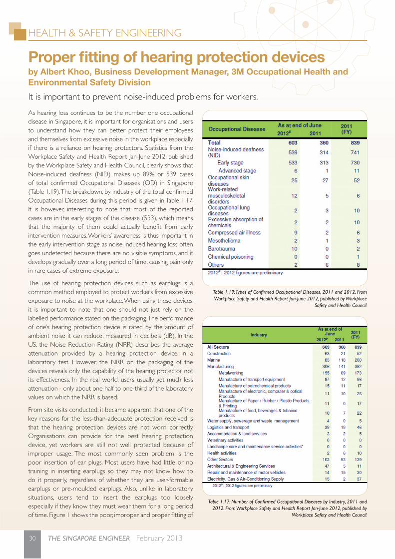
As hearing loss continues to be the number one occupational disease in Singapore, it is important for organisations and users to understand how they can better protect their employees and themselves from excessive noise in the workplace especially if there is a reliance on hearing protectors. Statistics from the Workplace Safety and Health Report Jan-June 2012, published by the Workplace Safety and Health Council, clearly shows that Noise-induced deafness (NID) makes up 89% or 539 cases of total confi rmed Occupational Diseases (OD) in Singapore (Table 1.19). The breakdown, by industry of the total confi rmed Occupational Diseases during this period is given in Table 1.17. It is however, interesting to note that most of the reported cases are in the early stages of the disease (533), which means that the majority of them could actually benefi t from early intervention measures. Workers’ awareness is thus important in the early intervention stage as noise-induced hearing loss often goes undetected because there are no visible symptoms, and it develops gradually over a long period of time, causing pain only in rare cases of extreme exposure.
The use of hearing protection devices such as earplugs is a common method employed to protect workers from excessive exposure to noise at the workplace. When using these devices, it is important to note that one should not just rely on the labelled performance stated on the packaging. The performance of one’s hearing protection device is rated by the amount of ambient noise it can reduce, measured in decibels (dB). In the US, the Noise Reduction Rating (NRR) describes the average attenuation provided by a hearing protection device in a laboratory test. However, the NRR on the packaging of the devices reveals only the capability of the hearing protector, not its effectiveness. In the real world, users usually get much less attenuation - only about one-half to one-third of the laboratory values on which the NRR is based.
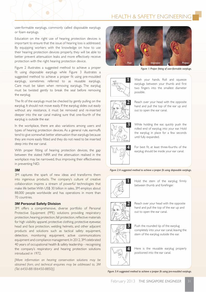
From site visits conducted, it became apparent that one of the key reasons for the less-than-adequate protection received is that the hearing protection devices are not worn correctly. Organisations can provide for the best hearing protection device, yet workers are still not well protected because of improper usage. The most commonly seen problem is the poor insertion of ear plugs. Most users have had little or no training in inserting earplugs so they may not know how to do it properly, regardless of whether they are user-formable earplugs or pre-moulded earplugs. Also, unlike in laboratory situations, users tend to insert the earplugs too loosely especially if they know they must wear them for a long period of time. Figure 1 shows the poor, improper and proper fi tting of
Table 1.19: Types of Confi rmed Occupational Diseases, 2011 and 2012. From Workplace Safety and Health Report Jan-June 2012, published by Workplace
Safety and Health Council.
Table 1.17: Number of Confi rmed Occupational Diseases by Industry, 2011 and 2012. From Workplace Safety and Health Report Jan-June 2012, published by
Workplace Safety and Health Council.
HEALTH & SAFETY ENGINEERING
31February 2013 THE SINGAPORE ENGINEER
user-formable earplugs, commonly called disposable earplugs or foam earplugs.
Education on the right use of hearing protection devices is important to ensure that the issue of hearing loss is addressed. By equipping workers with the knowledge on how to use their hearing protection devices properly, they will be able to better prevent attenuation leaks and more effectively receive protection with the right hearing protection device.
Figure 2 illustrates a suggested method to achieve a proper fi t using disposable earplugs while Figure 3 illustrates a suggested method to achieve a proper fi t using pre-moulded earplugs, sometimes referred to as reusable earplugs.Care must be taken when removing earplugs. The earplug must be twisted gently to break the seal before removing the earplug.
The fi t of the earplugs must be checked by gently pulling on the earplug. It should not move easily. If the earplug slides out easily without any resistance, it must be removed and re-inserted deeper into the ear canal making sure that one-fourth of the earplug is outside the ear.
In the workplace, there are also variations among users and types of hearing protection devices. As a general rule, earmuffs tend to give somewhat better attenuation than earplugs because they are more easily fi tted and they do not need to be inserted deep into the ear canal.
With proper fi tting of hearing protection devices, the gap between the stated NRR and the attenuation realised in the workplace may be narrowed, thus improving their effectiveness in preventing NID.
3M3M captures the spark of new ideas and transforms them into ingenious products. The company’s culture of creative collaboration inspires a stream of powerful technologies that make life better. With US$ 30 billion in sales, 3M employs about 88,000 people worldwide and has operations in more than 70 countries.
3M Personal Safety Division3M offers a comprehensive, diverse portfolio of Personal Protective Equipment (PPE) solutions providing respiratory protection, hearing protection, fall protection, refl ective materials for high visibility apparel, protective clothing, protective eyewear, head and face protection, welding helmets, and other adjacent products and solutions such as tactical safety equipment, detection, monitoring equipment, active communications equipment and compliance management. In 2012, 3M celebrated 40 years of occupational health & safety leadership - recognising the company’s respiratory and hearing protection solutions introduced in 1972.
[More information on hearing conservation solutions may be obtained from, and technical enquiries may be addressed to, 3M (Tel: 6450-8818/6450-8850)].
Figure 1: Proper fi tting of user-formable earplugs.
Wash your hands. Roll and squeeze earplugs between your thumb and fi rst two fi ngers into the smallest diameter possible.
Reach over your head with the opposite hand and pull the top of the ear up and out to open the ear canal.
While holding the ear, quickly push the rolled end of earplug into your ear. Hold the earplug in place for a few seconds until fully expanded.
For best fi t, at least three-fourths of the earplug should be inside your ear canal.
Figure 2: A suggested method to achieve a proper fi t using disposable earplugs.
Hold the stem of the earplug fi rmly between thumb and forefi nger.
Reach over your head with the oppositehand and pull the top of the ear up andout to open the ear canal.
Push the rounded tip of the earplugcompletely into your ear canal, leaving thestem of the earplug outside the ear.
Here is the reusable earplug properly positioned into the ear canal.
Figure 3: A suggested method to achieve a proper fi t using pre-moulded earplugs.
Poor Improper Proper
PROJECT APPLICATION
32 THE SINGAPORE ENGINEER February 2013
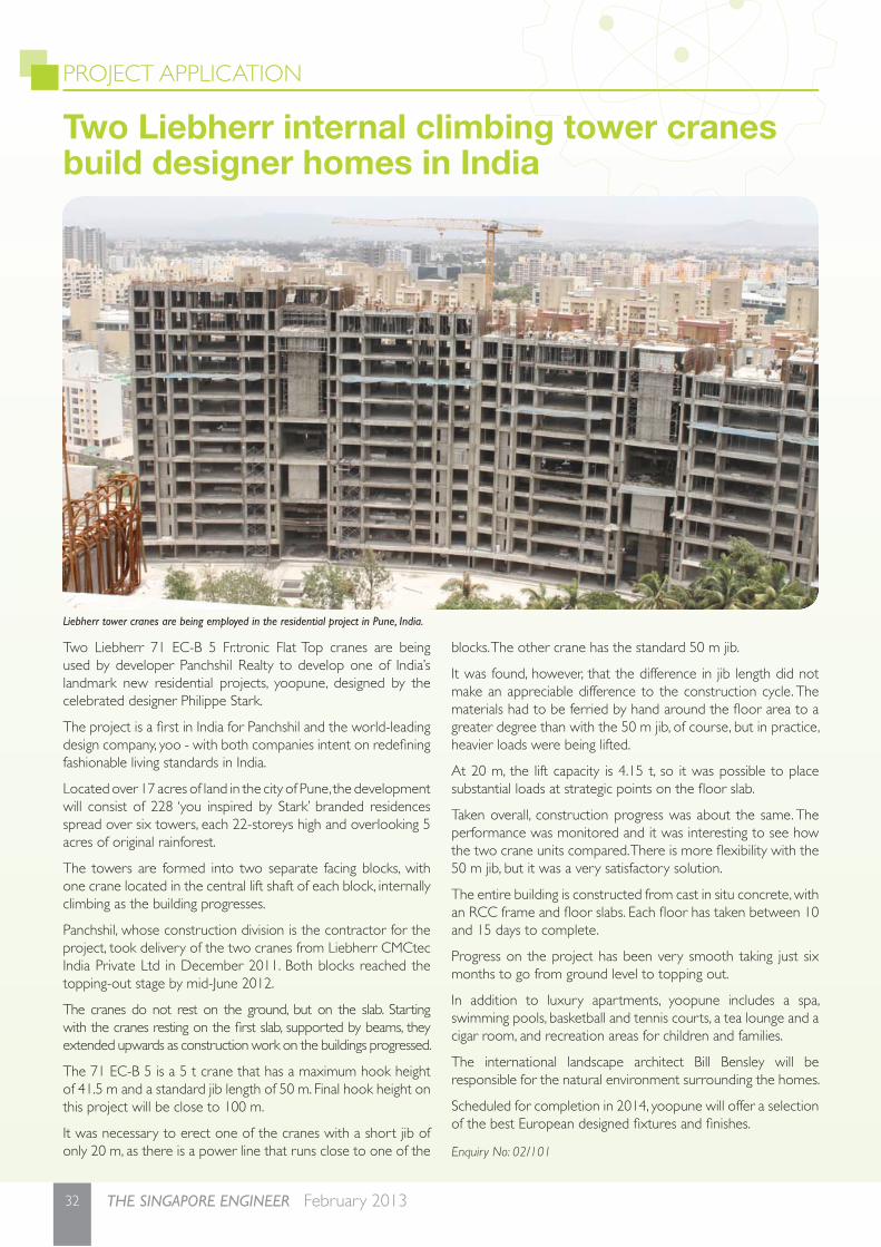
Two Liebherr 71 EC-B 5 Fr.tronic Flat Top cranes are being used by developer Panchshil Realty to develop one of India’s landmark new residential projects, yoopune, designed by the celebrated designer Philippe Stark.
The project is a fi rst in India for Panchshil and the world-leading design company, yoo - with both companies intent on redefi ning fashionable living standards in India.
Located over 17 acres of land in the city of Pune, the development will consist of 228 ‘you inspired by Stark’ branded residences spread over six towers, each 22-storeys high and overlooking 5 acres of original rainforest.
The towers are formed into two separate facing blocks, with one crane located in the central lift shaft of each block, internally climbing as the building progresses.
Panchshil, whose construction division is the contractor for the project, took delivery of the two cranes from Liebherr CMCtec India Private Ltd in December 2011. Both blocks reached the topping-out stage by mid-June 2012.
The cranes do not rest on the ground, but on the slab. Starting with the cranes resting on the fi rst slab, supported by beams, they extended upwards as construction work on the buildings progressed.
The 71 EC-B 5 is a 5 t crane that has a maximum hook height of 41.5 m and a standard jib length of 50 m. Final hook height on this project will be close to 100 m.
It was necessary to erect one of the cranes with a short jib of only 20 m, as there is a power line that runs close to one of the
blocks. The other crane has the standard 50 m jib.
It was found, however, that the difference in jib length did not make an appreciable difference to the construction cycle. The materials had to be ferried by hand around the fl oor area to a greater degree than with the 50 m jib, of course, but in practice, heavier loads were being lifted.
At 20 m, the lift capacity is 4.15 t, so it was possible to place substantial loads at strategic points on the fl oor slab.
Taken overall, construction progress was about the same. The performance was monitored and it was interesting to see how the two crane units compared. There is more fl exibility with the 50 m jib, but it was a very satisfactory solution.
The entire building is constructed from cast in situ concrete, with an RCC frame and fl oor slabs. Each fl oor has taken between 10 and 15 days to complete.
Progress on the project has been very smooth taking just six months to go from ground level to topping out.
In addition to luxury apartments, yoopune includes a spa, swimming pools, basketball and tennis courts, a tea lounge and a cigar room, and recreation areas for children and families.
The international landscape architect Bill Bensley will be responsible for the natural environment surrounding the homes.
Scheduled for completion in 2014, yoopune will offer a selection of the best European designed fi xtures and fi nishes.
Enquiry No: 02/101
Two Liebherr internal climbing tower cranes build designer homes in India
Liebherr tower cranes are being employed in the residential project in Pune, India.
33February 2013 THE SINGAPORE ENGINEER
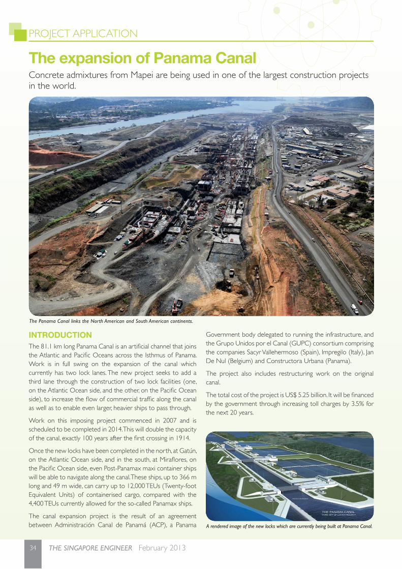
PROJECT APPLICATION
34 THE SINGAPORE ENGINEER February 2013
The expansion of Panama Canal Concrete admixtures from Mapei are being used in one of the largest construction projects in the world.
INTRODUCTIONThe 81.1 km long Panama Canal is an artifi cial channel that joins the Atlantic and Pacifi c Oceans across the Isthmus of Panama. Work is in full swing on the expansion of the canal which currently has two lock lanes. The new project seeks to add a third lane through the construction of two lock facilities (one, on the Atlantic Ocean side, and the other, on the Pacifi c Ocean side), to increase the fl ow of commercial traffi c along the canal as well as to enable even larger, heavier ships to pass through.
Work on this imposing project commenced in 2007 and is scheduled to be completed in 2014. This will double the capacity of the canal, exactly 100 years after the fi rst crossing in 1914.
Once the new locks have been completed in the north, at Gatún, on the Atlantic Ocean side, and in the south, at Mirafl ores, on the Pacifi c Ocean side, even Post-Panamax maxi container ships will be able to navigate along the canal. These ships, up to 366 m long and 49 m wide, can carry up to 12,000 TEUs (Twenty-foot Equivalent Units) of containerised cargo, compared with the 4,400 TEUs currently allowed for the so-called Panamax ships.
The canal expansion project is the result of an agreement between Administración Canal de Panamá (ACP), a Panama
Government body delegated to running the infrastructure, and the Grupo Unidos por el Canal (GUPC) consortium comprising the companies Sacyr Vallehermoso (Spain), Impregilo (Italy), Jan De Nul (Belgium) and Constructora Urbana (Panama).
The project also includes restructuring work on the original canal.
The total cost of the project is US$ 5.25 billion. It will be fi nanced by the government through increasing toll charges by 3.5% for the next 20 years.
A rendered image of the new locks which are currently being built at Panama Canal.
The Panama Canal links the North American and South American continents.
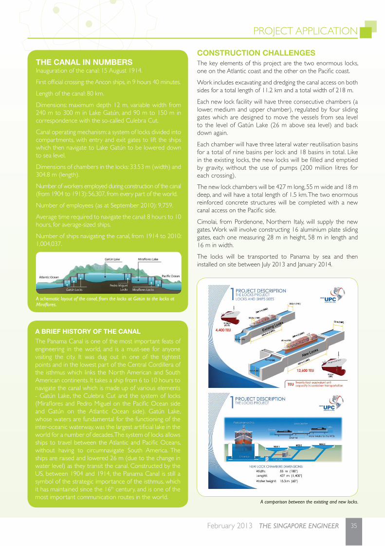
PROJECT APPLICATION
35February 2013 THE SINGAPORE ENGINEER
CONSTRUCTION CHALLENGESThe key elements of this project are the two enormous locks, one on the Atlantic coast and the other on the Pacifi c coast.
Work includes excavating and dredging the canal access on both sides for a total length of 11.2 km and a total width of 218 m.
Each new lock facility will have three consecutive chambers (a lower, medium and upper chamber), regulated by four sliding gates which are designed to move the vessels from sea level to the level of Gatún Lake (26 m above sea level) and back down again.
Each chamber will have three lateral water reutilisation basins for a total of nine basins per lock and 18 basins in total. Like in the existing locks, the new locks will be fi lled and emptied by gravity, without the use of pumps (200 million litres for each crossing).
The new lock chambers will be 427 m long, 55 m wide and 18 m deep, and will have a total length of 1.5 km. The two enormous reinforced concrete structures will be completed with a new canal access on the Pacifi c side.
Cimolai, from Pordenone, Northern Italy, will supply the new gates. Work will involve constructing 16 aluminium plate sliding gates, each one measuring 28 m in height, 58 m in length and 16 m in width.
The locks will be transported to Panama by sea and then installed on site between July 2013 and January 2014.
A BRIEF HISTORY OF THE CANALThe Panama Canal is one of the most important feats of engineering in the world, and is a must-see for anyone visiting the city. It was dug out in one of the tightest points and in the lowest part of the Central Cordillera of the isthmus which links the North American and South American continents. It takes a ship from 6 to 10 hours to navigate the canal which is made up of various elements - Gatún Lake, the Culebra Cut and the system of locks (Mirafl ores and Pedro Miguel on the Pacifi c Ocean side and Gatún on the Atlantic Ocean side). Gatún Lake, whose waters are fundamental for the functioning of the inter-oceanic waterway, was the largest artifi cial lake in the world for a number of decades. The system of locks allows ships to travel between the Atlantic and Pacifi c Oceans, without having to circumnavigate South America. The ships are raised and lowered 26 m (due to the change in water level) as they transit the canal. Constructed by the US, between 1904 and 1914, the Panama Canal is still a symbol of the strategic importance of the isthmus, which it has maintained since the 16th century, and is one of the most important communication routes in the world.
THE CANAL IN NUMBERSInauguration of the canal: 15 August 1914.
First offi cial crossing: the Ancon ships, in 9 hours 40 minutes.
Length of the canal: 80 km.
Dimensions: maximum depth 12 m, variable width from 240 m to 300 m in Lake Gatún, and 90 m to 150 m in correspondence with the so-called Culebra Cut.
Canal operating mechanism: a system of locks divided into compartments, with entry and exit gates to lift the ships which then navigate to Lake Gatún to be lowered down to sea level.
Dimensions of chambers in the locks: 33.53 m (width) and 304.8 m (length).
Number of workers employed during construction of the canal (from 1904 to 1913): 56,307, from every part of the world.
Number of employees (as at September 2010): 9,759.
Average time required to navigate the canal: 8 hours to 10 hours, for average-sized ships.
Number of ships navigating the canal, from 1914 to 2010: 1,004,037.
A schematic layout of the canal, from the locks at Gatún to the locks at Mirafl ores.
A comparison between the existing and new locks.

PROJECT APPLICATION
36 THE SINGAPORE ENGINEER February 2013
The two locks are currently being built, one on the Atlantic Ocean side and the other on the Pacifi c Ocean side.
ADMIXTURES FOR CONCRETEMapei admixtures were selected for all the concrete for the structures, including the mass concrete for the external sides of the concrete locks and the marine concrete for the internal sides of the locks.
The latest generation of admixture technology will be used to produce 5,500,000 m3 of concrete required for this grand structure.
The aim is to ensure, through special tests on the concrete, that the structure will last 100 years. The fi rst tests, carried out at the GUPC consortium site laboratory, started in Panama in September 2010.
Cement paste samples were tested to verify the compatibility and to fi nd the best plasticising capacity of various samples of admixture in combination with the types of cement scheduled to be used on the structure (CEMEX cement, type II ASTM and Panama cement, type II ASTM).
In the fi rst phase of testing, to overcome problems which arise when using complex raw materials (basaltic aggregates and basaltic pozzolan), several admixtures were evaluated. The results showed that DYNAMON XP2, from Mapei, is the most suitable admixture, for use with the materials that had actually been chosen and which will be used in future on both the Atlantic Ocean side, where they are using Panama cement, and on the Pacifi c Ocean side, where they are using CEMEX cement. This led to Mapei’s winning the short-term supply contract.
In early 2011, after starting production of the concrete and aggregates, several serious problems such as considerable loss of mechanical strength and durability in the concrete were solved, thanks to the contribution of Mapei. In this phase, Mapei’s support was concentrated on various activities - a study and new
chemical and mineralogical characterisation of the raw materials used (fi ne sand, pozzolan and cement); technical suggestions and advice to help make a correct choice of the fl occulating and coagulating materials used to treat the water required for cleaning the aggregates; and chemical and petrographic analysis and control of the pozzolanic activity of the fi ne basalt sand to reduce or optimise its content of natural pozzolan.
Following a request from the client, Mapei then started to develop a new product which could work well with the new mix designs being verifi ed at the GUPC laboratory. Mapei technicians designed a new, highly-evolved admixture called DYNAMON XP2 EVOLUTION 1, with the name chosen to give a sense of continuity to the enormous amount of work previously carried out on the old admixture. This product featured better maintenance of workability and application properties, even in small dosages.
Mapei also contributed to renovation and consolidation work on the Gatún Lock, located approximately 30 m below ground and considered to be one of the most imposing reinforced concrete structure ever constructed. This project uses a special type of concrete and Mapei has supplied admixtures to make it - PLANITOP 15, an inorganic powder product added to the concrete cast into formwork, and the liquid admixture MAPECURE SRA, specially formulated to reduce the formation of cracks caused by hygrometric shrinkage in normal and self-compacting concrete.
Mapei’s fi nal contract in the new Panama Canal project was signed on 21 December 2011. The company’s success in winning the contract is the fruit of teamwork, the ability to provide constant technical assistance to solve both large and small problems, and the decisive support of the Mapei Research & Development laboratories in fi nding the most advanced technological solutions to make the best products.
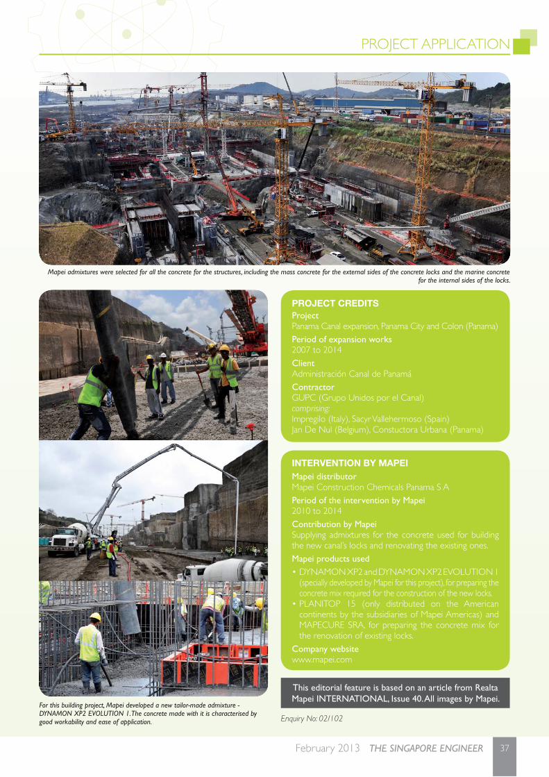
PROJECT APPLICATION
37February 2013 THE SINGAPORE ENGINEER
For this building project, Mapei developed a new tailor-made admixture - DYNAMON XP2 EVOLUTION 1. The concrete made with it is characterised by good workability and ease of application.
Mapei admixtures were selected for all the concrete for the structures, including the mass concrete for the external sides of the concrete locks and the marine concrete for the internal sides of the locks.
This editorial feature is based on an article from Realta Mapei INTERNATIONAL, Issue 40. All images by Mapei.
Enquiry No: 02/102
INTERVENTION BY MAPEIMapei distributorMapei Construction Chemicals Panama S APeriod of the intervention by Mapei 2010 to 2014Contribution by MapeiSupplying admixtures for the concrete used for building the new canal’s locks and renovating the existing ones.Mapei products used• DYNAMON XP2 and DYNAMON XP2 EVOLUTION 1
(specially developed by Mapei for this project), for preparing the concrete mix required for the construction of the new locks.
• PLANITOP 15 (only distributed on the American continents by the subsidiaries of Mapei Americas) and MAPECURE SRA, for preparing the concrete mix for the renovation of existing locks.
Company websitewww.mapei.com
PROJECT CREDITSProjectPanama Canal expansion, Panama City and Colon (Panama)Period of expansion works2007 to 2014ClientAdministración Canal de PanamáContractorGUPC (Grupo Unidos por el Canal)comprising:Impregilo (Italy), Sacyr Vallehermoso (Spain)Jan De Nul (Belgium), Constuctora Urbana (Panama)
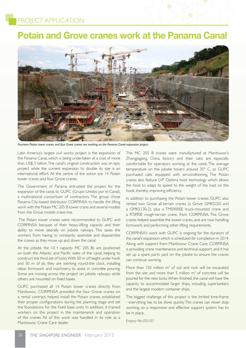
PROJECT APPLICATION
38 THE SINGAPORE ENGINEER February 2013
Potain and Grove cranes work at the Panama Canal
Fourteen Potain tower cranes and four Grove cranes are working on the Panama Canal expansion project.
Latin America’s largest civil works project is the expansion of the Panama Canal, which is being undertaken at a cost of more than US$ 5 billion. The canal’s original construction was an epic project while the current expansion to double its size is an international effort. At the centre of the action are 14 Potain tower cranes and four Grove cranes.
The Government of Panama entrusted the project for the expansion of the canal, to GUPC (Grupo Unidos por el Canal), a multinational consortium of contractors. The group chose Panama City-based distributor CORPINSA to handle the lifting work with the Potain MC 205 B tower crane and several models from the Grove mobile crane line.
The Potain tower cranes were recommended to GUPC and CORPINSA because of their heavy-lifting capacity and their ability to move laterally on jobsite railways. This saves the workers from having to constantly assemble and disassemble the cranes as they move up and down the canal.
At the jobsite, the 10 t capacity MC 205 Bs are positioned on both the Atlantic and Pacifi c sides of the canal, helping to construct the third set of locks. With 50 m of height under hook and 50 m of jib, they are working round-the clock, installing rebar, formwork and machinery, to assist in concrete pouring. Some are moving across the project on jobsite railways, while others are mounted on fi xed bases.
GUPC purchased all 14 Potain tower cranes directly from Manitowoc. CORPINSA provided the four Grove cranes on a rental contract, helped install the Potain cranes, established their proper confi gurations during the planning stage and set the foundations for the fi xed base units. In addition, it trained workers on the project in the maintenance and operation of the cranes. All of this work was handled in its role as a Manitowoc Crane Care dealer.
The MC 205 B cranes were manufactured at Manitowoc’s Zhangjiagang, China, factory and their cabs are especially comfortable for operators working at the canal. The average temperature on the jobsite hovers around 35° C, so GUPC purchased cabs equipped with air-conditioning. The Potain cranes also feature LVF Optima hoist technology which allows the hoist to adapt its speed to the weight of the load on the hook, thereby improving effi ciency.
In addition to purchasing the Potain tower cranes, GUPC also rented two Grove all-terrain cranes (a Grove GMK5220 and a GMK5130-2), plus a TMS9000E truck-mounted crane and a RT890E rough-terrain crane, from CORPINSA. The Grove cranes helped assemble the tower cranes, and are now handling formwork and performing other lifting requirements.
CORPINSA’s work with GUPC is ongoing for the duration of the canal’s expansion which is scheduled for completion in 2014. Along with support from Manitowoc Crane Care, CORPINSA is providing crane maintenance and technical support, and it has set up a spare parts yard on the jobsite to ensure the cranes can continue working.
More than 150 million m3 of soil and rock will be excavated from the site and more than 5 million m3 of concrete will be poured for the new locks. When fi nished, the canal will have the capacity to accommodate larger ships, including supertankers and the largest modern container ships.
The biggest challenge of this project is the limited time-frame - everything has to be done quickly. The cranes can never stop working, so a responsive and effective support system has to be in place.
Enquiry No: 02/103
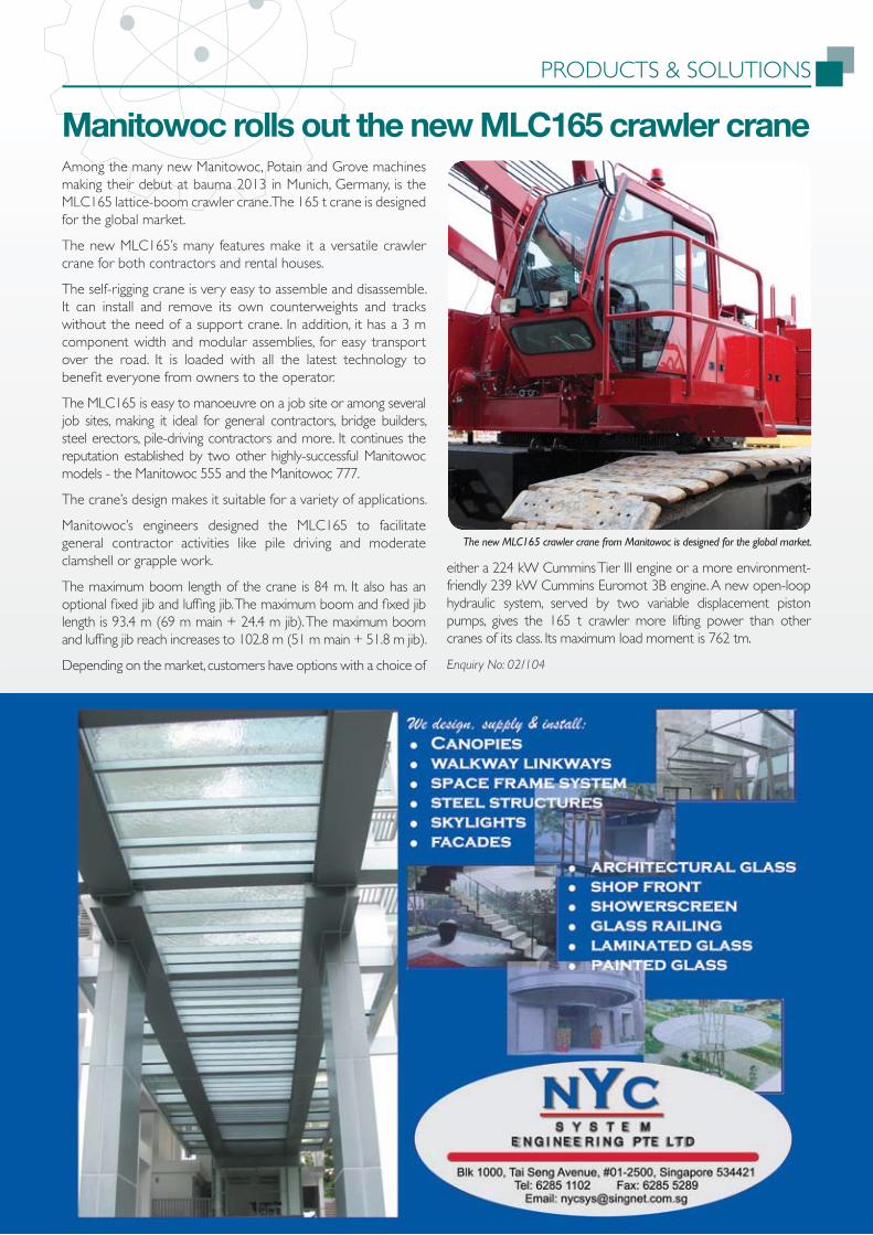
PRODUCTS & SOLUTIONS
39February 2013 THE SINGAPORE ENGINEER
Among the many new Manitowoc, Potain and Grove machines making their debut at bauma 2013 in Munich, Germany, is the MLC165 lattice-boom crawler crane. The 165 t crane is designed for the global market.
The new MLC165’s many features make it a versatile crawler crane for both contractors and rental houses.
The self-rigging crane is very easy to assemble and disassemble. It can install and remove its own counterweights and tracks without the need of a support crane. In addition, it has a 3 m component width and modular assemblies, for easy transport over the road. It is loaded with all the latest technology to benefi t everyone from owners to the operator.
The MLC165 is easy to manoeuvre on a job site or among several job sites, making it ideal for general contractors, bridge builders, steel erectors, pile-driving contractors and more. It continues the reputation established by two other highly-successful Manitowoc models - the Manitowoc 555 and the Manitowoc 777.
The crane’s design makes it suitable for a variety of applications.
Manitowoc’s engineers designed the MLC165 to facilitate general contractor activities like pile driving and moderate clamshell or grapple work.
The maximum boom length of the crane is 84 m. It also has an optional fi xed jib and luffi ng jib. The maximum boom and fi xed jib length is 93.4 m (69 m main + 24.4 m jib). The maximum boom and luffi ng jib reach increases to 102.8 m (51 m main + 51.8 m jib).
Depending on the market, customers have options with a choice of
either a 224 kW Cummins Tier III engine or a more environment-friendly 239 kW Cummins Euromot 3B engine. A new open-loop hydraulic system, served by two variable displacement piston pumps, gives the 165 t crawler more lifting power than other cranes of its class. Its maximum load moment is 762 tm.
Enquiry No: 02/104
Manitowoc rolls out the new MLC165 crawler crane
The new MLC165 crawler crane from Manitowoc is designed for the global market.

SUSTAINABILITY
40 THE SINGAPORE ENGINEER February 2013
IntroductionPhosphorus is obtained primarily through surface mining (about 75%) of phosphate rock. The vast majority (more than 80%) is mined from sedimentary formations, in which the phosphate content ranges from 5% to 40% as the P2O5 apatite form. As more and more of these formations are mined, the quantity of phosphate recovered is in decline, and because sedimentary rock contains heavy metals (such as cadmium), the quality of the phosphates being recovered is also in decline. Today, for every tonne of phosphate rock processed, 5 tonnes of a waste product, known as phosphogypsum, is created. This waste product is not easily disposed of because it is a radioactive hazardous waste due to its high levels of radium. As a result, large stockpiles of waste phosphogypsum are accumulating worldwide.
Phosphorus is the 11th-most abundant mineral in the earth’s lithosphere. The estimated global presence of the phosphate resource is in the range of 4000 billion metric tonnes. But much of the resource is currently inaccessible. In fact, the estimated accessible reserves range from 30 billion metric tonnes to 40 billion metric tonnes. These are currently being extracted at rates estimated at 167 million metric tonnes per year, though current global production capacity exceeds 6,300 million metric tonnes. Reserves are estimated based on the economics of accessibility. A reserve is considered countable if it can be profi tably extracted. In the case of phosphates, this has historically been about US$ 40/tonne. Obviously, as economic trends change, they affect profi tability and therefore reserve estimates also change.
Despite the apparently large phosphorus resource base, there are indications that the known accessible reserves could be depleted by the end of the 21st century. The reason lies in the phosphorus cycle. Once phosphorus is mined, it enters the human use cycle (for example, in supporting food production). That phosphorus eventually (that is, over decades) returns to the soil or water environments as a component of the waste products from human activity. Once in these environments, though some can be reused (through re-uptakes in new terrestrial and aquatic biotic growth), much remains ‘bound’ and re-enters the geologic cycle (through sedimentation) which spans millions of years before it can be mined and used again. Once phosphorus re-enters the geologic cycle, it is, for all intents and purposes, forever lost for fur ther benefi cial use. This is illustrated in Figure 1.
Estimates show that since just 1950, the phosphorus lost to the geologic cycle exceeds 25% of all the phosphorus mined to-date. Unless phosphorus is prevented from re-entering the geologic cycle, there is a point in the future when the extractable reserves will be depleted, as mentioned above. This is expected to carry dire consequences for human existence as one knows it today. Therefore, whether or not phosphorus depletion becomes a global reality depends much on managing global demand for phosphorus with remaining available supply.
Global demand Though the phosphorus mineral was fi rst discovered in the late 1600s, it was not until more than 200 years later that its highly benefi cial use as a fer tiliser (for enhancing food production) was fi rst realised. Today, fer tiliser is by far the dominant use for phosphorus (more than 90% of mined phosphates are used in producing agricultural fer tilisers for food production). Due to its large agricultural sector, the US accounts for nearly one-quarter of the world’s total demand for phosphorus, while China/Asia accounts for about one-fi fth, due to both agricultural and industrial expansion.
The global demand for phosphate-based fer tilisers continually grows, and without doubt, it remains the fundamental pillar in the world’s capacity to support its expanding population. Not surprisingly, because of its direct link to food production, demand for phosphate-based fer tilisers (and hence its price) is heavily infl uenced by the agricultural sector’s capacity to produce enough food to support continued population expansion. It has been estimated that food production must increase between 50% to 70% in order to meet the food needs for the estimated 9.2 billion population in 2050. The greatest infl uence on the demand for phosphorus for fer tiliser production is the energy input required for producing phosphate-based fer tilisers, and historically the
Global phosphorus and the case for phosphorus recoveryby Dr Art Umble, MWH Global
The need to manage the demand and supply of this important resource has become crucial.
Figure 1: Fate of phosphorus.
Fate of Phosphorus in the Human Cycle Fate of Phosphorus
in the Geologic Cycle
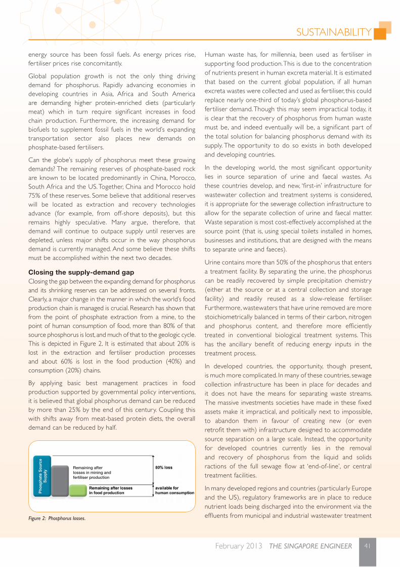
SUSTAINABILITY
41February 2013 THE SINGAPORE ENGINEER
energy source has been fossil fuels. As energy prices rise, fer tiliser prices rise concomitantly.
Global population growth is not the only thing driving demand for phosphorus. Rapidly advancing economies in developing countries in Asia, Africa and South America are demanding higher protein-enriched diets (particularly meat) which in turn require signifi cant increases in food chain production. Furthermore, the increasing demand for biofuels to supplement fossil fuels in the world’s expanding transportation sector also places new demands on phosphate-based fer tilisers.
Can the globe’s supply of phosphorus meet these growing demands? The remaining reserves of phosphate-based rock are known to be located predominantly in China, Morocco, South Africa and the US. Together, China and Morocco hold 75% of these reserves. Some believe that additional reserves will be located as extraction and recovery technologies advance (for example, from off-shore deposits), but this remains highly speculative. Many argue, therefore, that demand will continue to outpace supply until reserves are depleted, unless major shifts occur in the way phosphorus demand is currently managed. And some believe these shifts must be accomplished within the next two decades.
Closing the supply-demand gap Closing the gap between the expanding demand for phosphorus and its shrinking reserves can be addressed on several fronts. Clearly, a major change in the manner in which the world’s food production chain is managed is crucial. Research has shown that from the point of phosphate extraction from a mine, to the point of human consumption of food, more than 80% of that source phosphorus is lost, and much of that to the geologic cycle. This is depicted in Figure 2. It is estimated that about 20% is lost in the extraction and fertiliser production processes and about 60% is lost in the food production (40%) and consumption (20%) chains.
By applying basic best management practices in food production supported by governmental policy interventions, it is believed that global phosphorus demand can be reduced by more than 25% by the end of this century. Coupling this with shifts away from meat-based protein diets, the overall demand can be reduced by half.
Human waste has, for millennia, been used as fer tiliser in supporting food production. This is due to the concentration of nutrients present in human excreta material. It is estimated that based on the current global population, if all human excreta wastes were collected and used as fer tiliser, this could replace nearly one-third of today’s global phosphorus-based fer tiliser demand. Though this may seem impractical today, it is clear that the recovery of phosphorus from human waste must be, and indeed eventually will be, a signifi cant part of the total solution for balancing phosphorus demand with its supply. The opportunity to do so exists in both developed and developing countries.
In the developing world, the most signifi cant opportunity lies in source separation of urine and faecal wastes. As these countries develop, and new, ‘fi rst-in’ infrastructure for wastewater collection and treatment systems is considered, it is appropriate for the sewerage collection infrastructure to allow for the separate collection of urine and faecal matter. Waste separation is most cost-effectively accomplished at the source point (that is, using special toilets installed in homes, businesses and institutions, that are designed with the means to separate urine and faeces).
Urine contains more than 50% of the phosphorus that enters a treatment facility. By separating the urine, the phosphorus can be readily recovered by simple precipitation chemistry (either at the source or at a central collection and storage facility) and readily reused as a slow-release fer tiliser. Furthermore, wastewaters that have urine removed are more stoichiometrically balanced in terms of their carbon, nitrogen and phosphorus content, and therefore more effi ciently treated in conventional biological treatment systems. This has the ancillary benefi t of reducing energy inputs in the treatment process.
In developed countries, the opportunity, though present, is much more complicated. In many of these countries, sewage collection infrastructure has been in place for decades and it does not have the means for separating waste streams. The massive investments societies have made in these fi xed assets make it impractical, and politically next to impossible, to abandon them in favour of creating new (or even retrofi t them with) infrastructure designed to accommodate source separation on a large scale. Instead, the opportunity for developed countries currently lies in the removal and recovery of phosphorus from the liquid and solids ractions of the full sewage fl ow at ‘end-of-line’, or central treatment facilities.
In many developed regions and countries (particularly Europe and the US), regulatory frameworks are in place to reduce nutrient loads being discharged into the environment via the effl uents from municipal and industrial wastewater treatment Figure 2: Phosphorus losses.
Remaining after
losses in mining and
fertiliser production
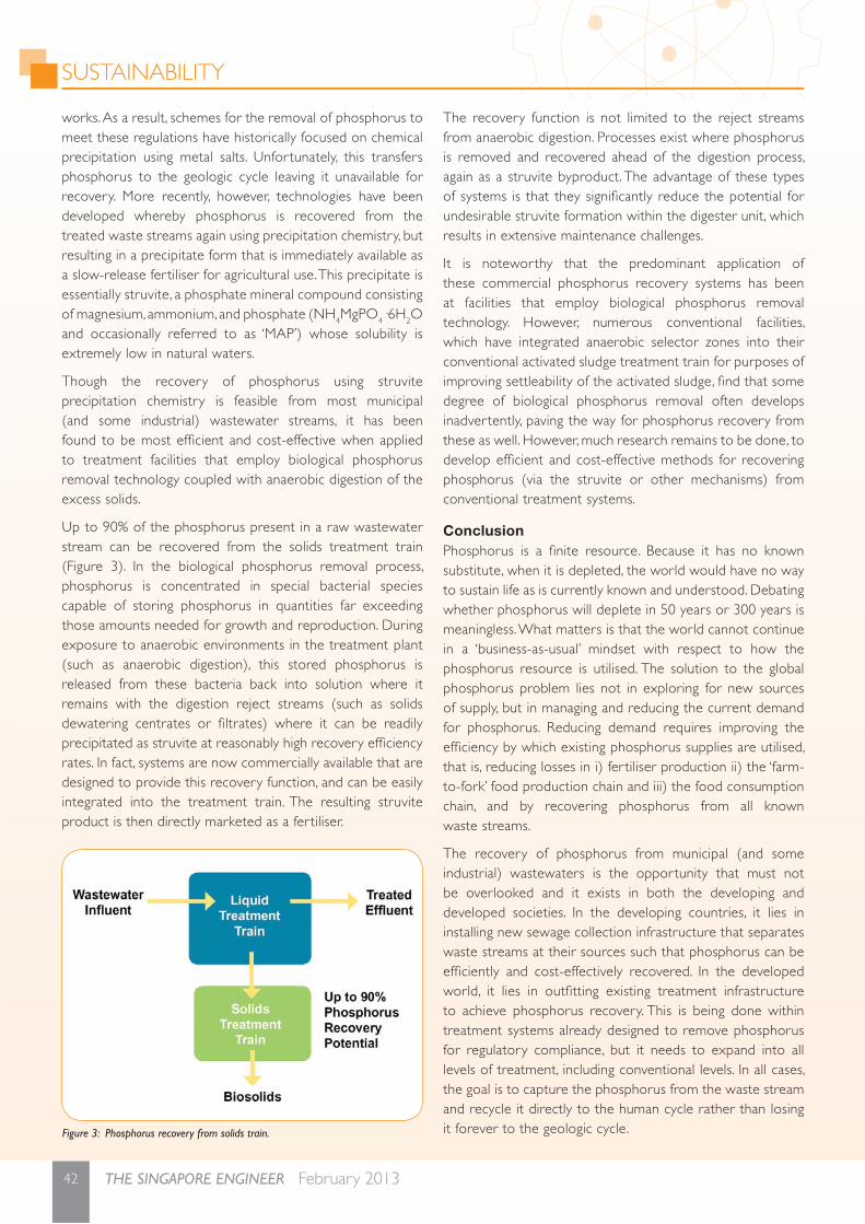
SUSTAINABILITY
42 THE SINGAPORE ENGINEER February 2013
works. As a result, schemes for the removal of phosphorus to meet these regulations have historically focused on chemical precipitation using metal salts. Unfortunately, this transfers phosphorus to the geologic cycle leaving it unavailable for recovery. More recently, however, technologies have been developed whereby phosphorus is recovered from the treated waste streams again using precipitation chemistry, but resulting in a precipitate form that is immediately available as a slow-release fer tiliser for agricultural use. This precipitate is essentially struvite, a phosphate mineral compound consisting of magnesium, ammonium, and phosphate (NH4MgPO4·6H2O and occasionally referred to as ‘MAP’) whose solubility is extremely low in natural waters.
Though the recovery of phosphorus using struvite precipitation chemistry is feasible from most municipal (and some industrial) wastewater streams, it has been found to be most effi cient and cost-effective when applied to treatment facilities that employ biological phosphorus removal technology coupled with anaerobic digestion of the excess solids.
Up to 90% of the phosphorus present in a raw wastewater stream can be recovered from the solids treatment train (Figure 3). In the biological phosphorus removal process, phosphorus is concentrated in special bacterial species capable of storing phosphorus in quantities far exceeding those amounts needed for growth and reproduction. During exposure to anaerobic environments in the treatment plant (such as anaerobic digestion), this stored phosphorus is released from these bacteria back into solution where it remains with the digestion reject streams (such as solids dewatering centrates or fi ltrates) where it can be readily precipitated as struvite at reasonably high recovery effi ciency rates. In fact, systems are now commercially available that are designed to provide this recovery function, and can be easily integrated into the treatment train. The resulting struvite product is then directly marketed as a fer tiliser.
The recovery function is not limited to the reject streams from anaerobic digestion. Processes exist where phosphorus is removed and recovered ahead of the digestion process, again as a struvite byproduct. The advantage of these types of systems is that they signifi cantly reduce the potential for undesirable struvite formation within the digester unit, which results in extensive maintenance challenges.
It is noteworthy that the predominant application of these commercial phosphorus recovery systems has been at facilities that employ biological phosphorus removal technology. However, numerous conventional facilities, which have integrated anaerobic selector zones into their conventional activated sludge treatment train for purposes of improving settleability of the activated sludge, fi nd that some degree of biological phosphorus removal often develops inadvertently, paving the way for phosphorus recovery from these as well. However, much research remains to be done, to develop effi cient and cost-effective methods for recoveringphosphorus (via the struvite or other mechanisms) from conventional treatment systems.
ConclusionPhosphorus is a fi nite resource. Because it has no known substitute, when it is depleted, the world would have no way to sustain life as is currently known and understood. Debating whether phosphorus will deplete in 50 years or 300 years is meaningless. What matters is that the world cannot continue in a ‘business-as-usual’ mindset with respect to how the phosphorus resource is utilised. The solution to the global phosphorus problem lies not in exploring for new sources of supply, but in managing and reducing the current demand for phosphorus. Reducing demand requires improving the effi ciency by which existing phosphorus supplies are utilised, that is, reducing losses in i) fer tiliser production ii) the ‘farm-to-fork’ food production chain and iii) the food consumption chain, and by recovering phosphorus from all known waste streams.
The recovery of phosphorus from municipal (and some industrial) wastewaters is the opportunity that must not be overlooked and it exists in both the developing and developed societies. In the developing countries, it lies in installing new sewage collection infrastructure that separates waste streams at their sources such that phosphorus can be effi ciently and cost-effectively recovered. In the developed world, it lies in outfi tting existing treatment infrastructure to achieve phosphorus recovery. This is being done within treatment systems already designed to remove phosphorus for regulatory compliance, but it needs to expand into all levels of treatment, including conventional levels. In all cases, the goal is to capture the phosphorus from the waste stream and recycle it directly to the human cycle rather than losing it forever to the geologic cycle. Figure 3: Phosphorus recovery from solids train.

43February 2013 THE SINGAPORE ENGINEER
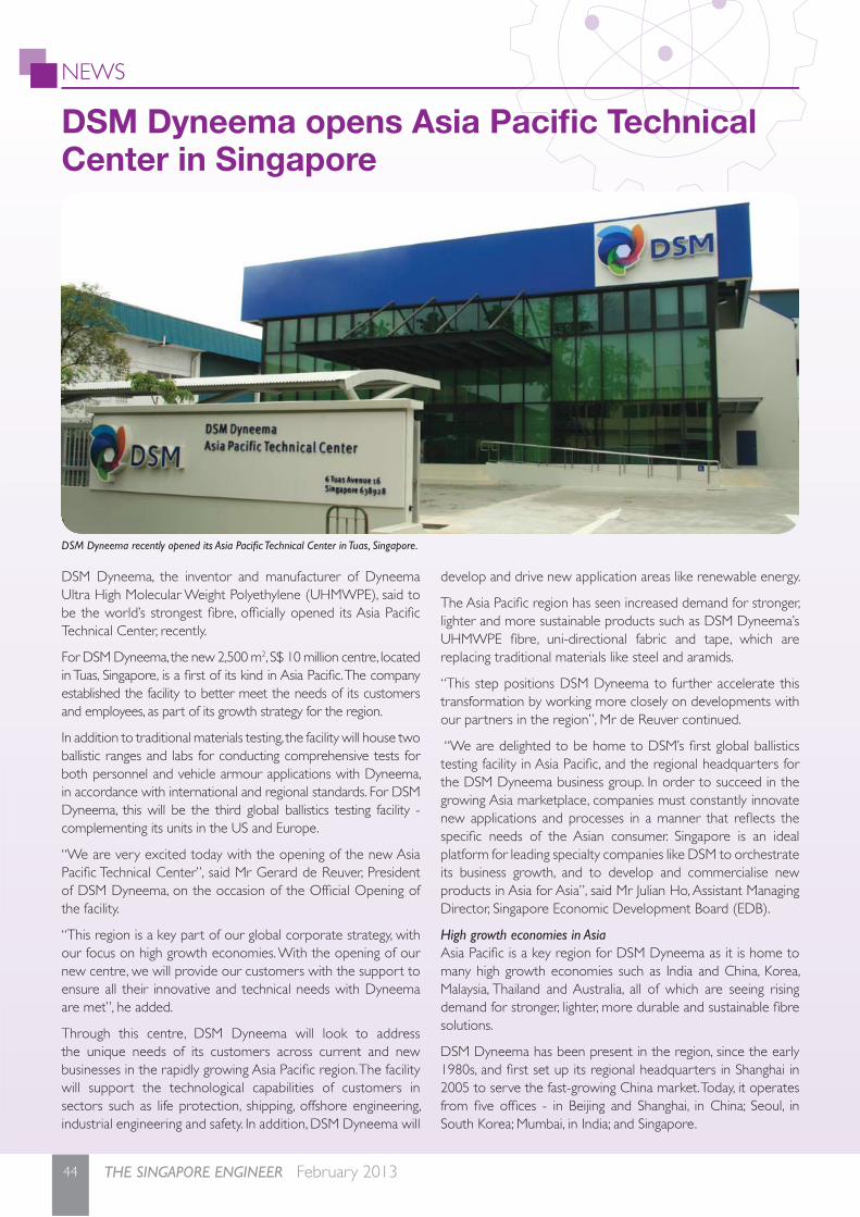
NEWS
44 THE SINGAPORE ENGINEER February 2013
DSM Dyneema, the inventor and manufacturer of Dyneema Ultra High Molecular Weight Polyethylene (UHMWPE), said to be the world’s strongest fi bre, offi cially opened its Asia Pacifi c Technical Center, recently.
For DSM Dyneema, the new 2,500 m2, S$ 10 million centre, located in Tuas, Singapore, is a fi rst of its kind in Asia Pacifi c. The company established the facility to better meet the needs of its customers and employees, as part of its growth strategy for the region.
In addition to traditional materials testing, the facility will house two ballistic ranges and labs for conducting comprehensive tests for both personnel and vehicle armour applications with Dyneema, in accordance with international and regional standards. For DSM Dyneema, this will be the third global ballistics testing facility - complementing its units in the US and Europe.
“We are very excited today with the opening of the new Asia Pacifi c Technical Center”, said Mr Gerard de Reuver, President of DSM Dyneema, on the occasion of the Offi cial Opening of the facility.
“This region is a key part of our global corporate strategy, with our focus on high growth economies. With the opening of our new centre, we will provide our customers with the support to ensure all their innovative and technical needs with Dyneema are met”, he added.
Through this centre, DSM Dyneema will look to address the unique needs of its customers across current and new businesses in the rapidly growing Asia Pacifi c region. The facility will support the technological capabilities of customers in sectors such as life protection, shipping, offshore engineering, industrial engineering and safety. In addition, DSM Dyneema will
develop and drive new application areas like renewable energy.
The Asia Pacifi c region has seen increased demand for stronger, lighter and more sustainable products such as DSM Dyneema’s UHMWPE fi bre, uni-directional fabric and tape, which are replacing traditional materials like steel and aramids.
“This step positions DSM Dyneema to further accelerate this transformation by working more closely on developments with our partners in the region”, Mr de Reuver continued.
“We are delighted to be home to DSM’s fi rst global ballistics testing facility in Asia Pacifi c, and the regional headquarters for the DSM Dyneema business group. In order to succeed in the growing Asia marketplace, companies must constantly innovate new applications and processes in a manner that refl ects the specifi c needs of the Asian consumer. Singapore is an ideal platform for leading specialty companies like DSM to orchestrate its business growth, and to develop and commercialise new products in Asia for Asia”, said Mr Julian Ho, Assistant Managing Director, Singapore Economic Development Board (EDB).
High growth economies in AsiaAsia Pacifi c is a key region for DSM Dyneema as it is home to many high growth economies such as India and China, Korea, Malaysia, Thailand and Australia, all of which are seeing rising demand for stronger, lighter, more durable and sustainable fi bre solutions.
DSM Dyneema has been present in the region, since the early 1980s, and fi rst set up its regional headquarters in Shanghai in 2005 to serve the fast-growing China market. Today, it operates from fi ve offi ces - in Beijing and Shanghai, in China; Seoul, in South Korea; Mumbai, in India; and Singapore.
DSM Dyneema recently opened its Asia Pacifi c Technical Center in Tuas, Singapore.
DSM Dyneema opens Asia Pacifi c Technical Center in Singapore
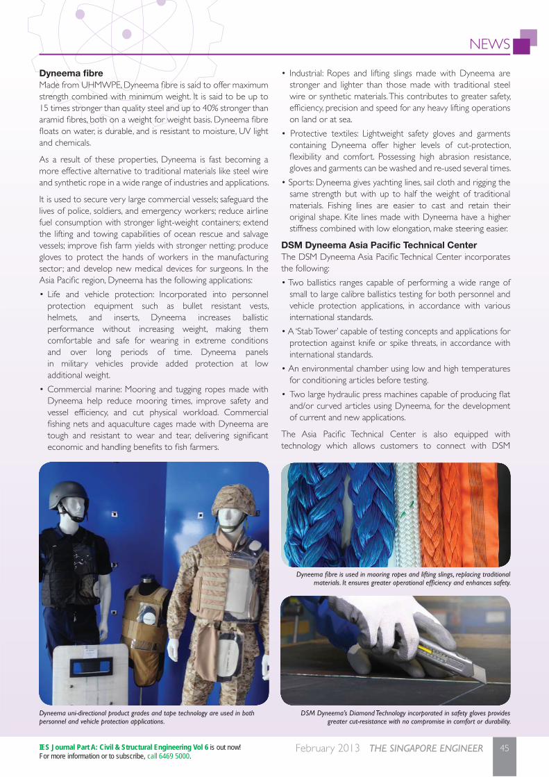
NEWS
45February 2013 THE SINGAPORE ENGINEER
Dyneema fi breMade from UHMWPE, Dyneema fi bre is said to offer maximum strength combined with minimum weight. It is said to be up to 15 times stronger than quality steel and up to 40% stronger than aramid fi bres, both on a weight for weight basis. Dyneema fi bre fl oats on water, is durable, and is resistant to moisture, UV light and chemicals.
As a result of these properties, Dyneema is fast becoming a more effective alternative to traditional materials like steel wire and synthetic rope in a wide range of industries and applications.
It is used to secure very large commercial vessels; safeguard the lives of police, soldiers, and emergency workers; reduce airline fuel consumption with stronger light-weight containers; extend the lifting and towing capabilities of ocean rescue and salvage vessels; improve fi sh farm yields with stronger netting; produce gloves to protect the hands of workers in the manufacturing sector; and develop new medical devices for surgeons. In the Asia Pacifi c region, Dyneema has the following applications:
• Life and vehicle protection: Incorporated into personnel protection equipment such as bullet resistant vests, helmets, and inserts, Dyneema increases ballistic performance without increasing weight, making them comfortable and safe for wearing in extreme conditions and over long periods of time. Dyneema panels in military vehicles provide added protection at low additional weight.
• Commercial marine: Mooring and tugging ropes made with Dyneema help reduce mooring times, improve safety and vessel effi ciency, and cut physical workload. Commercial fi shing nets and aquaculture cages made with Dyneema are tough and resistant to wear and tear, delivering signifi cant economic and handling benefi ts to fi sh farmers.
• Industrial: Ropes and lifting slings made with Dyneema are stronger and lighter than those made with traditional steel wire or synthetic materials. This contributes to greater safety, effi ciency, precision and speed for any heavy lifting operations on land or at sea.
• Protective textiles: Lightweight safety gloves and garments containing Dyneema offer higher levels of cut-protection, fl exibility and comfort. Possessing high abrasion resistance, gloves and garments can be washed and re-used several times.
• Sports: Dyneema gives yachting lines, sail cloth and rigging the same strength but with up to half the weight of traditional materials. Fishing lines are easier to cast and retain their original shape. Kite lines made with Dyneema have a higher stiffness combined with low elongation, make steering easier.
DSM Dyneema Asia Pacifi c Technical Center The DSM Dyneema Asia Pacifi c Technical Center incorporates the following:
• Two ballistics ranges capable of performing a wide range of small to large calibre ballistics testing for both personnel and vehicle protection applications, in accordance with various international standards.
• A ‘Stab Tower’ capable of testing concepts and applications for protection against knife or spike threats, in accordance with international standards.
• An environmental chamber using low and high temperatures for conditioning articles before testing.
• Two large hydraulic press machines capable of producing fl at and/or curved articles using Dyneema, for the development of current and new applications.
The Asia Pacifi c Technical Center is also equipped with technology which allows customers to connect with DSM
Dyneema fi bre is used in mooring ropes and lifting slings, replacing traditional materials. It ensures greater operational effi ciency and enhances safety.
DSM Dyneema’s Diamond Technology incorporated in safety gloves provides greater cut-resistance with no compromise in comfort or durability.
Dyneema uni-directional product grades and tape technology are used in both personnel and vehicle protection applications.
IES Journal Part A: Civil & Structural Engineering Vol 6 is out now!For more information or to subscribe, call 6469 5000.

NEWS
46 THE SINGAPORE ENGINEER February 2013
Dyneema to view their test results at their convenience and in a secure manner.
Customers in this region will be able to leverage on Dyneema’s global expertise, as this centre is connected to the company’s technical centres in the US and Europe.
DSM DyneemaWith a global staff strength of approximately 700 employees, DSM Dyneema is headquartered in Urmond, the Netherlands, and has manufacturing plants in Heerlen, the Netherlands; Greenville, North Carolina, USA; and Laiwu City, Shandong Province, China; as well as a manufacturing joint-venture with Toyobo in Japan. The gel-spinning technology that forms the basis of Dyneema was fi rst invented in 1979, while the name itself is a combination of two Greek words, ‘dynamis’ and ‘neema’ which translates, respectively, into strength and fi bre.
A culture of innovationInnovation is an essential core value of DSM Dyneema, and the business has been built entirely on an initial breakthrough in materials science, that enabled the company to successfully spin fi bres from UHMWPE. DSM Dyneema continuously evaluates new initiatives, looking for ways to improve its business and the business of its partners and customers. Today, the company has a dedicated Innovation Group and a policy of Open Innovation to ensure its materials play a leading role.
DSM Dyneema maintains extensive product specifi cations and testing data, that are made available to customers and partners. In addition, it shares technological and scientifi c developments across labs with partners, to leverage skills and create maximum value quickly. As a result, DSM Dyneema has established a track record of long-term collaborations with manufacturers, government ministries, scientifi c and research communities, and academia, that have created true ‘win-win’ situations. Globally, DSM Dyneema owns a patent portfolio of approximately 150 patent families and 600 individual patents and this continues to grow.
With the addition of the new Asia Pacifi c Technical Center, DSM Dyneema expects to further expand and reinforce its global R&D leadership in high-strength, low weight materials through local collaboration. It will bring the company closer to its Asia Pacifi c customers, and speed up delivery of innovative and high-end solutions to meet local needs.
DSM Royal DSM is a global science-based company active in health, nutrition and materials. The company offers innovative solutions in areas such as food and dietary supplements, personal care, feeds, pharmaceuticals, medical devices, automotive, paints, electrical engineering and electronics, life protection, alternative energy and bio-based materials.
DSM’s 22,000 employees deliver annual net sales of about € 9 billion.
Sustainable solutionsDSM is again among the leaders from the chemical industry
sector in the Dow Jones Sustainability World Index 2012. Since 2004, the company has been ranked three times among the very top leaders in the sector. DSM’s corporate strategy aims to create and support sustainable growth with solutions and services based on three main pillars - climate & energy, health & wellness, and functionality & performance.
Dyneema in nets and ropes can help reduce the fuel consumption of a typical trawler by up to 10%, compared to the fuel consumption when traditional materials are used, and brings the benefi ts of reduced weight and easier handling to trawlermen. Another example is in the area of renewable energy, with SkySails, a kite-based system that is tethered to ship decks via towing ropes made with Dyneema. The kite captures wind energy that propels the ship. Under optimal wind conditions, the system can cut fuel consumption by up to 35%.
Further exemplifying the company’s commitment to sustainability, DSM Dyneema’s Asia Pacifi c Technical Center received the Green Mark GoldPlus certifi cation from Singapore’s Building and Construction Authority (BCA).
The Singapore EngineerProducts & Solutions Enquiry Form
Product InformationI wish to receive more information on the following products that were featured in this issue of ‘The Singapore Engineer’ magazine.
Please list the enquiry number(s) of the product(s) that you are interested in. (Information is provided free-of-charge to all readers)
________________________________________________
Full Name: (Dr/Mr/Mrs/Ms/Er) ________________________
Designation (Job title): ______________________________
IES Membership no. (if applicable): _____________________
Name of Organisation: ______________________________
Address: _________________________________________
________________________________________________
State/City: __________________ Postal Code: ___________
Country: _________________________________________
Tel: ___________________ Fax: ______________________
Email: ___________________________________________
Activity of Organisation: _____________________________
Please complete the enquiry form and fax to 6467 1108 or email [email protected].
Discover ‘Innovative and Sustainable Solutions to Climate Change’ at WES 2013! For more information, visit http://www.wes2013.org
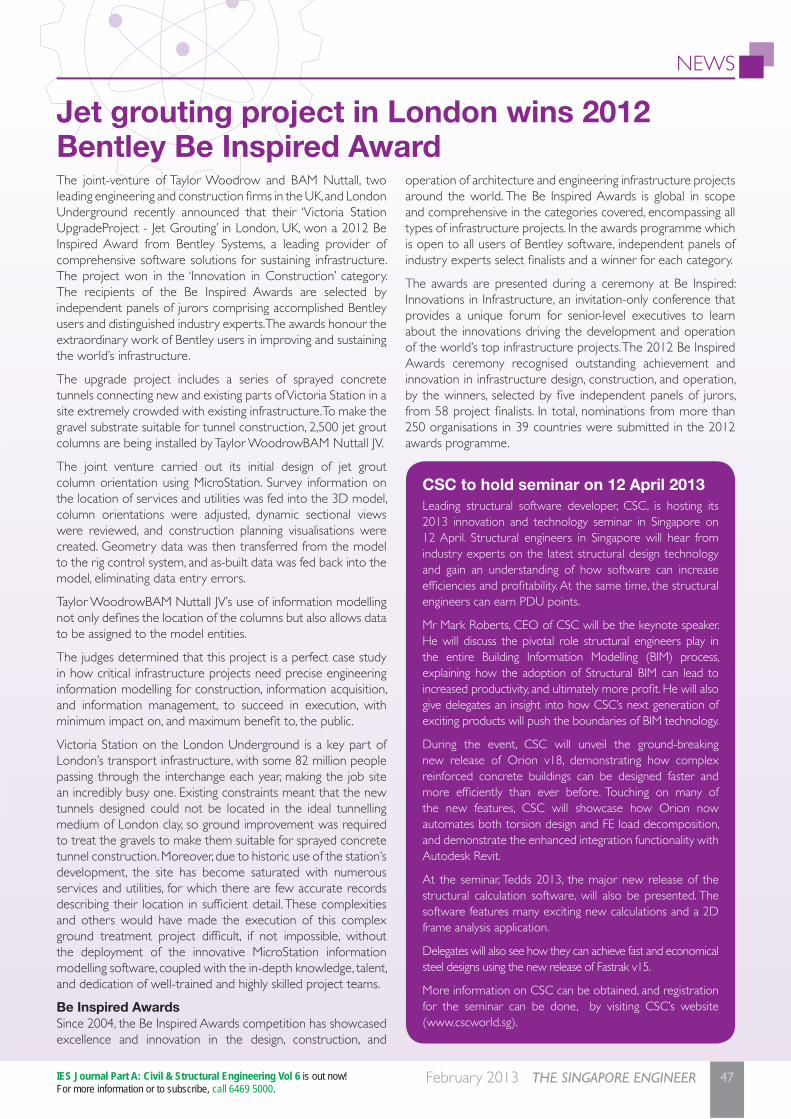
NEWS
47February 2013 THE SINGAPORE ENGINEER
Jet grouting project in London wins 2012 Bentley Be Inspired AwardThe joint-venture of Taylor Woodrow and BAM Nuttall, two leading engineering and construction fi rms in the UK, and London Underground recently announced that their ‘Victoria Station UpgradeProject - Jet Grouting’ in London, UK, won a 2012 Be Inspired Award from Bentley Systems, a leading provider of comprehensive software solutions for sustaining infrastructure. The project won in the ‘Innovation in Construction’ category. The recipients of the Be Inspired Awards are selected by independent panels of jurors comprising accomplished Bentley users and distinguished industry experts. The awards honour the extraordinary work of Bentley users in improving and sustaining the world’s infrastructure.
The upgrade project includes a series of sprayed concrete tunnels connecting new and existing parts of Victoria Station in a site extremely crowded with existing infrastructure. To make the gravel substrate suitable for tunnel construction, 2,500 jet grout columns are being installed by Taylor WoodrowBAM Nuttall JV.
The joint venture carried out its initial design of jet grout column orientation using MicroStation. Survey information on the location of services and utilities was fed into the 3D model, column orientations were adjusted, dynamic sectional views were reviewed, and construction planning visualisations were created. Geometry data was then transferred from the model to the rig control system, and as-built data was fed back into the model, eliminating data entry errors.
Taylor WoodrowBAM Nuttall JV’s use of information modelling not only defi nes the location of the columns but also allows data to be assigned to the model entities.
The judges determined that this project is a perfect case study in how critical infrastructure projects need precise engineering information modelling for construction, information acquisition, and information management, to succeed in execution, with minimum impact on, and maximum benefi t to, the public.
Victoria Station on the London Underground is a key part of London’s transport infrastructure, with some 82 million people passing through the interchange each year, making the job site an incredibly busy one. Existing constraints meant that the new tunnels designed could not be located in the ideal tunnelling medium of London clay, so ground improvement was required to treat the gravels to make them suitable for sprayed concrete tunnel construction. Moreover, due to historic use of the station’s development, the site has become saturated with numerous services and utilities, for which there are few accurate records describing their location in suffi cient detail. These complexities and others would have made the execution of this complex ground treatment project diffi cult, if not impossible, without the deployment of the innovative MicroStation information modelling software, coupled with the in-depth knowledge, talent, and dedication of well-trained and highly skilled project teams.
Be Inspired Awards Since 2004, the Be Inspired Awards competition has showcased excellence and innovation in the design, construction, and
operation of architecture and engineering infrastructure projects around the world. The Be Inspired Awards is global in scope and comprehensive in the categories covered, encompassing all types of infrastructure projects. In the awards programme which is open to all users of Bentley software, independent panels of industry experts select fi nalists and a winner for each category.
The awards are presented during a ceremony at Be Inspired: Innovations in Infrastructure, an invitation-only conference that provides a unique forum for senior-level executives to learn about the innovations driving the development and operation of the world’s top infrastructure projects. The 2012 Be Inspired Awards ceremony recognised outstanding achievement and innovation in infrastructure design, construction, and operation, by the winners, selected by fi ve independent panels of jurors, from 58 project fi nalists. In total, nominations from more than 250 organisations in 39 countries were submitted in the 2012 awards programme.
CSC to hold seminar on 12 April 2013Leading structural software developer, CSC, is hosting its 2013 innovation and technology seminar in Singapore on 12 April. Structural engineers in Singapore will hear from industry experts on the latest structural design technology and gain an understanding of how software can increase effi ciencies and profi tability. At the same time, the structural engineers can earn PDU points.
Mr Mark Roberts, CEO of CSC will be the keynote speaker. He will discuss the pivotal role structural engineers play in the entire Building Information Modelling (BIM) process, explaining how the adoption of Structural BIM can lead to increased productivity, and ultimately more profi t. He will also give delegates an insight into how CSC’s next generation of exciting products will push the boundaries of BIM technology.
During the event, CSC will unveil the ground-breaking new release of Orion v18, demonstrating how complex reinforced concrete buildings can be designed faster and more effi ciently than ever before. Touching on many of the new features, CSC will showcase how Orion now automates both torsion design and FE load decomposition, and demonstrate the enhanced integration functionality with Autodesk Revit.
At the seminar, Tedds 2013, the major new release of the structural calculation software, will also be presented. The software features many exciting new calculations and a 2D frame analysis application.
Delegates will also see how they can achieve fast and economical steel designs using the new release of Fastrak v15.
More information on CSC can be obtained, and registration for the seminar can be done, by visiting CSC’s website (www.cscworld.sg).
IES Journal Part A: Civil & Structural Engineering Vol 6 is out now!For more information or to subscribe, call 6469 5000.
NEWS
48 THE SINGAPORE ENGINEER February 2013
The Building and Construction Authority (BCA) projects a strong construction demand of between S$ 26 billion and S$ 32 billion for 2013, anchored by public sector projects. This comes on the heels of the sector’s strong performance in 2012, where total construction demand was sustained at a healthy S$ 28.1 billion. The projected demand of S$ 26 billion to S$ 32 billion for 2013 also refl ects a continued and sustained level of workload for the next few years.
Outlook for 2013Public sector demand is expected to strengthen signifi cantly this year, contributing about 53% of the industry demand, or S$ 14 billion to S$ 17 billion, boosted by stronger public housing and infrastructure construction works. The higher public sector demand is due to the continued ramping up of public housing and rail construction. Other than public housing projects, major public sector projects likely to be awarded in 2013 include:
• Nanyang Technological University’s Undergraduate Halls of Residence at Nanyang Avenue/Crescent.
• Energy Market Authority’s fourth storage tank at the liquefi ed natural gas (LNG) terminal in Jurong Island.
• JTC’s very large fl oating structure (VLFS) at Pulau Sebarok.
• Land Transport Authority’s various construction contracts for the Thomson MRT Line.
• Land Transport Authority’s expansion of Kallang Paya Lebar Expressway (KPE) / Tampines Expressway (TPE) Interchange.
Private sector demand for 2013BCA expects private sector construction demand to moderate to S$ 12 billion to S$ 15 billion in 2013, in light of slower domestic economic growth and continued global economic uncertainties. The private sector is likely to take a more cautious stance in terms of new construction investments. Private residential construction demand is projected to continue softening in view of the anticipated continued slow economic growth in 2013, coupled with the signifi cant supply of completed housing units over the next few years.
Forecast for 2014 and 2015For 2014 and 2015, the average construction demand is projected to be S$ 20 billion to S$ 28 billion per annum. Demand forecast beyond the immediate one year will be done on a rolling basis, to take into account subsequent changes in economic outlook and other pertinent factors.
Barring any unforeseen circumstances, this projection is plausible in view of the strong pipeline of housing and infrastructure construction projects planned by the government to meet the needs of the population, despite the anticipated lower economic growth rate in the coming years.
Total preliminary construction output (progress payments made for work done) is estimated to be about S$ 31 billion in 2012,
about 7% higher than the volume in 2011 and comparable to 2009’s record high volume. Construction output is measured by total value of certifi ed progress payments.
The high level of contracts awarded in 2011 and the sustained levels of demand in 2012-2013 are expected to translate into a lot of on-site construction activities at least over the next one to two years. Total construction output is projected to rise to S$ 31 billion to S$ 33 billion in 2013 before moderating to S$ 22 billion to S$ 30 billion per year in 2014-2015.
New manpower development programmes Given the robust outlook for the built environment sector, BCA is partnering the industry to initiate programmes for developing the manpower required to meet the strong construction demand. In addition to the current BCA-Industry undergraduate scholarship, diploma scholarship and sponsorship and apprenticeship programmes, BCA is rolling out two new manpower development programmes - the full-time undergraduate sponsorship programme and the ITE scholarship programme.
The new undergraduate sponsorship programme is open to local undergraduates taking full-time built environment degree courses. A student under this new programme will receive an attractive sponsorship sum of S$ 10,000 per year.
On the technical education front, full-time students studying at ITEs can benefi t from the new ITE scholarship programme. The scholarship will cover the full course fees and provide a monthly allowance of S$ 500 - an attractive sum for the students.
Public sector projects to boost construction demand in 2013
ADVERTISERS’ INDEXCRESTRON ––––––––––––––––––––––––––––––– PAGE 7
ICHEME ––––––––––––––––––––––––––––––––– PAGE 43
INFOCOM & SECURITY SYSTEMS –––––––––––– PAGE 9
MANCHESTER –––––––––––––– OUTSIDE BACK COVERBUSINESS SCHOOL
MAPEI FAR EAST ––––––––––––––––––––––––– PAGE 33
MDIS –––––––––––––––––––––––––––––––––––– PAGE 5
NEWCASTLE ––––––––––––––– INSIDE BACK COVERUNIVERSITY
NYC SYSTEM ENGINEERING –––––––––––––– PAGE 39
PHILIPS ELECTRONICS –––––––– INSIDE FRONT COVER
PHILIPS ELECTRONICS ––––––––––––––––– PAGE 10 & 11
SAA GLOBAL EDUCATION CENTRE ––––––––– PAGE 3
SINGAPORE INSTITUTE OF TECHNOLOGY ––– PAGE 15
TAYLOR & FRANCIS ––––––––––––––––– PAGE 25 & 27
WORLD ENGINEERS’ SUMMIT 2013 ––––––––– PAGE 29