Embed Size (px)
Citation preview
OF
E
N
E
R
G
I
J
O
3 5556 031 020480
Environmental ImpactStatement
2013
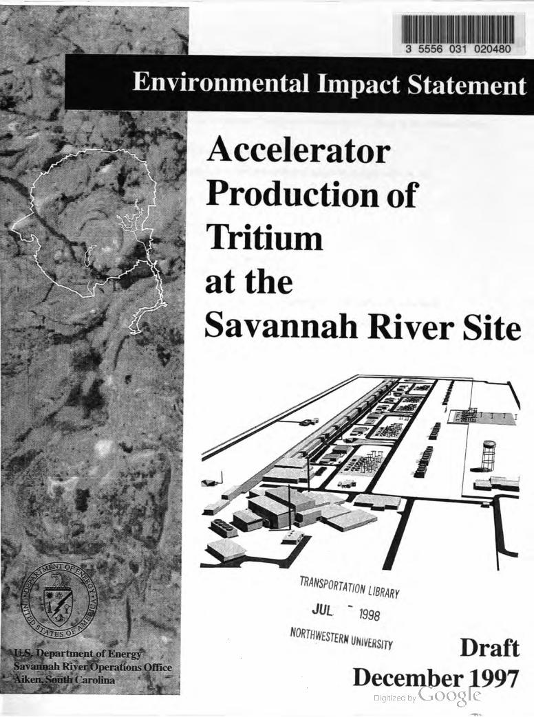
Accelerator
Production of
Tritium
at the
Savannah River Site
OPARTM
TRANSPORTATIONLIBRARY
JUL1998
STATES
NORTHWESTERN
UNIVERSITY
U.S.Department of Energy
Savannah River OperationsOffice
Aiken , South Carolina
Draft
December 1997

DOE /EIS -0270D
DRAFT, December 1997 Cover Sheet
COVER SHEET
RESPONSIBLE AGENCY: U.S. Departmentof Energy (DOE)
TITLE: Draft Environmental Impact Statement: Accelerator Production of Tritium at the Savannah River
Site (DOE /EIS-0270D )
LOCATION : Aiken and Barnwell Counties, South Carolina
CONTACT: For additional information on this environmentalimpact statement, write or call:
Andrew R. Grainger
NEPA Compliance Officer
U.S. Departmentof Energy
Savannah River OperationsOffice
Building 773-42A ,Room 212
Aiken , South Carolina 29802
Attention : Accelerator Production of Tritium EIS
Local andNationwide Telephone: (800) 881-7292
E -mail: [email protected]
The EIS is also available on the internet at: http://www.srs.gov/general/sci-tech/apt/index.html
For general information on the DOENational Environmental Policy Act (NEPA) process, write or call:
CarolM.Borgstrom , Director
Office ofNEPA Policy and Assistance, EH -42
U.S. Department of Energy
1000 Independence Avenue, S.W.
Washington, D.C. 20585
Telephone: (202) 586-4600, or leave a message at (800) 472-2756 .
ABSTRACT: The purpose of the action proposed in this environmental impact statement (EIS) is to
construct and operate a linear accelerator that would produce tritium ,which is a gaseous radioactive isotope
of hydrogen essential to the operation of the weapons in the nation's nuclear arsenal. This EIS is tiered
(linked ) to the Final Programmatic EnvironmentalImpact Statement for Tritium Supply and Recycling (DOE /EIS -0161;
October 1995), from which DOE determined that it would produce tritium either in an accelerator as
described in this EIS or in a commercial light-water reactor as described in a separate EIS . This EIS
evaluates the alternatives for the siting, construction , and operation ofan accelerator on the Savannah River
Site and the impacts of those alternatives on the Site's physical and manmade environment, its human and
biological environment, and the regional economic and social environment.
PUBLIC COMMENTS: In preparing this Draft EIS , DOE considered comments received by letter and
voice mail, and in comments given at public meetings in Savannah,Georgia, and Aiken , South Carolina, on
December 3 and 5 , 1996 , respectively. (NOTE : These were jointmeetings held by DOE to discuss the
scopes of two related EISs: this one for the accelerator production of tritium and a proposed EIS for the
construction and operation of a Tritium Extraction Facility at the Savannah River Site.) A summary ofpublic
comments was made available on April 28 , 1997,and may be obtained by contacting Andrew R. Grainger as
shown above.
A 45-day commentperiod on this Draft APT EIS begins with publication of a Notice of Availability in the
Federal Register. Comments on the Draft EIS must be received by February 2, 1998. A public meeting to
discuss and receive comments on the Draft EIS will be held on January 13, 1998 , at the North Augusta
Community Center, 101 Brookside Drive, North Augusta, South Carolina. Comments may also be
submitted by voice, e-mail, or regularmailat the address provided above.
ii

DOE /EIS -0270D
DRAFT,December 1997
TABLE OF CONTENTS
SectionPage
SUMMARY S - 1
1 BACKGROUND AND PURPOSE AND NEED FOR ACTION ........... 1-1
1-11.1Background..............
1.2 Review ofthe Final Programmatic Environmental Impact Statement for
Tritium Supply and Recycling ..
1.3 Purpose and Need ...........
1.4 SRS Role in Tritium Supply
1.5Related Department of Energy Actions
1.6 Nonproliferation.....
1.7 Medical Isotope Production.......
1.8 Stakeholder Participation ..
1.9 Organization of the EIS....
References .....
1-3
1-4
1-4
1-4
1-7
1-7
1-8
1-9
1-10
2 PROPOSED ACTION AND ALTERNATIVES.......... 2-1
2.1 The Proposed Action and No Action Alternative.....
2.2 APT Overview .
2.3 APT Design Features and Technology Alternatives ......
2.3.1 Radiofrequency Power Alternatives ....
2.3.2 Operating Temperature Alternatives.........
2.3.3 Feedstock Material Alternatives .......
2.3.4 Cooling Water System Alternatives.
2.3.5 APT Site Location Alternatives
2.3.6 Electric Power Supply Alternatives ....
2.4 Activities Associated with the Proposed Action and Alternatives .
2.4.1 Construction and Operation ofNew Facilities ......
2.4.2 Use ofExisting SRS Facilities to SupportAPT Operations
2.5APT Design Variations.....
2.5.1 Modular or Staged Accelerator Configuration .....
2.5.2 Increasing Tritium Production ....
2.5.3 Combining Tritium Extraction Facilities......
2.6 Cost and Schedule
2.7 Comparison ofEnvironmental Impacts Among Alternatives
References ....
2-1
2-2
2-5
2-5
2-6
2-7
2-8
2-13
2-16
2-18
2-18
2-21
2-21
2-21
2-22
2-23
2-25
2-26
2-40
3 AFFECTED ENVIRONMENT ... 3-1
3.1
3.2
3.3
Location of Proposed Actions
Exposure Pathways
Physical and Manmade Environment
3.3.1 Landforms, Soils, and Geology
3.3.2 Water Resources
3-1
3-3
3-6
3-6
3-18

DOE /EIS-0270D
DRAFT, December 1997
TABLE OF CONTENTS (continued )
SectionsPage
3.3.3 Climate ....
3.3.4 Air Resources
3.3.5 Historic and Archaeological Resources
3.3.6 Site Land Use and Infrastructure
3.3.7 VisualResources and Noise .....
3.4 Human and BiologicalEnvironment
3.4.1 Human Health ....
3.4.2 Terrestrial Ecology
3.4.3 Aquatic Ecology
3.4.4 Wetland Ecology ....
3.4.5 Threatened and Endangered Species .....
3.5 The Regional Economic and Social Environment.
3.5.1 Current Economic Conditions
3.5.2 Current Social Conditions..........
3.5.3 Projected Economic and Population Conditions........
References
3-27
3-28
3-30
3-31
3-38
3-39
3-39
3-43
3-46
3-52
3-54
3-55
3-55
3-56
3-59
3-65
4 ENVIRONMENTAL IMPACTS 4-1
4.1 Impacts on the Physical and Manmade Environment...
4.1.1 Landforms, Soils,Geology, and Hydrology
4.1.2 Surface Water Resources......
4.1.3 Air Resources .
4.1.4 Land Use and Infrastructure.
4.1.5Waste Management ................
4.1.6 Visual Resources and Noise
4.2 Impacts on Human and BiologicalEnvironment
4.2.1 Human Health ...,
4.2.2 Ecology ....
4.3 Socioeconomics
4.3.1 Preferred Alternative...
4.3.2 APTWith Superconducting Alternative .........
4.3.3 APT With Lithium -6 Feedstock .......
4.3.4 APTWith K -Area Cooling Tower and APT With Once -Through
Cooling...........
4.3.5 Environmental Justice .
4.4 Impacts of Electric Power Supply
4.4.1 Electricity from Existing Capacity and Through Market Transactions
4.4.2 Construction and Operation of New Electricity Generating Plant...........
4.4.3 Comparison ofPower Supply Alternatives and Powerplant Options
References
4-3
4-3
4-5
4-11
4-22
4-23
4-29
4-32
4-32
4-44
4-56
4-57
4-59
4-62
4-63
4-63
4-66
4-68
4-69
4-79
4-82
vi
DOE /EIS -0270D
DRAFT,December 1997
TABLE OF CONTENTS (continued )
Sections Page
ол
CUMULATIVE IMPACTS ......... 5-1
5.1 Water Resources
5.2 Air Resources
5.3 Waste Generation
5.4 Utilities and Energy ...
5.5 Public and Worker Health ....
5.6 Ecological Resources
5.7 Socioeconomics
References
5-2
5-3
5-4
5-6
5-8
5-8
5-10
5-12
6 RESOURCE COMMITMENTS ............ 6-1
6.1 Unavoidable Adverse Impacts.
6.2 Short- Term Uses Versus Long- Term Productivity ....
6.3 Irreversible And Irretrievable Resource Commitments
6.4 Waste Minimization , Pollution Prevention ,and Energy Conservation
References ...........
6-1
6-1
6-2
6-3
6-5
7APPLICABLE LAWS,REGULATIONS, AND OTHER REQUIREMENTS
7-1................
7-1
7-3
7-6
7.1 Statutes and Regulations Requiring Permits or Consultations .......
7.1.1 EnvironmentalProtection Permits .........
7.1.2 Protection ofBiological, Historic,and Archaeological Resources ........
7.2 Statutes and Regulations Related to Emergency Planning ,Worker Safety, and
Protection of Public Health and the Environment.
7.2.1 Environmental Protection .....
7.2.2 Emergency Planning and Response
7.3 Executive Orders .....
7.4DOE Regulationsand Orders.........
References
7-8
7-8
7-9
7-11
7-12
7-15
LIST OF PREPARERS
GLOSSARY
APPENDIX A - FACILITY AND PROCESS DESCRIPTIONS
APPENDIX B - ACCIDENTS
APPENDIX C - LIST OF PLANTS AND ANIMALSMENTIONED IN THE APT EIS
vii
DOE /EIS-0270D
DRAFT, December 1997
TABLE OF CONTENTS (continued )
List of Tables
Tables Page
S - 1
2-1
2-2
2-3
3-1
3-2
3-3
S - 9
2-15
2-22
2-28
3-10
3-12
3-13
3-4
3-14
3-5
3-21
3-223-6
3-7
3-26
3-8
3-29
3-9
3-30
3-10
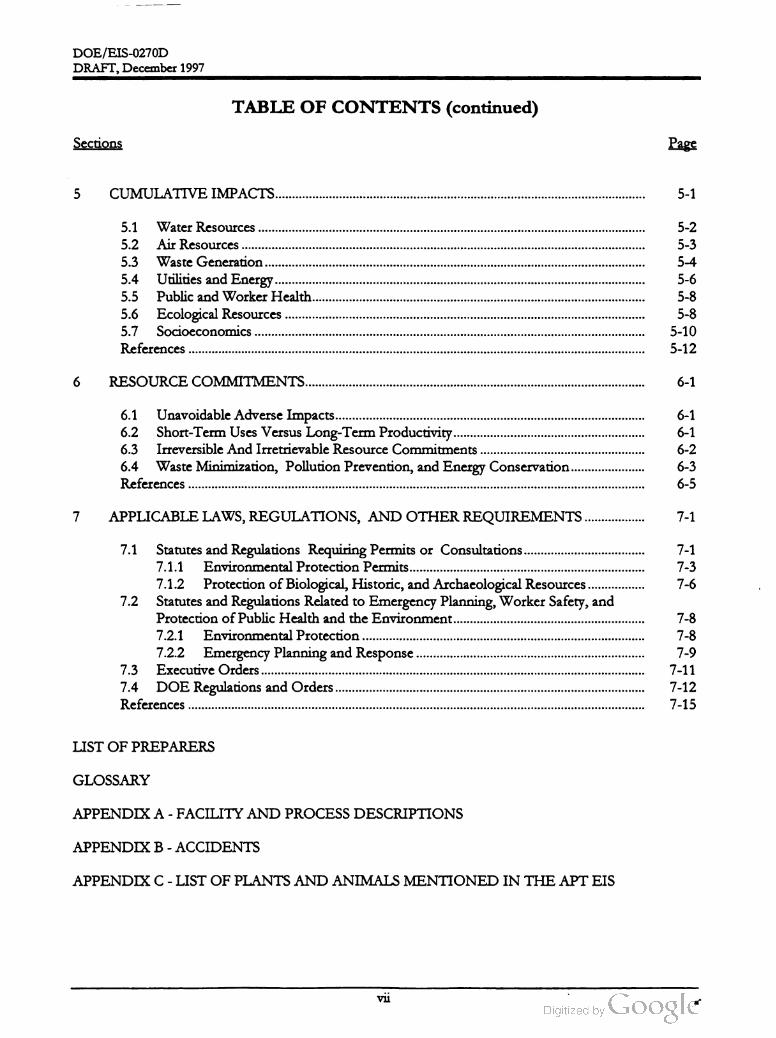
Comparison of impacts among alternatives
APT site selection criteria...........
APT Functions that could be located on the APT site or M -Area
Comparison of impacts among alternatives
Summary of soils covering the APT sites ...
Hydrogeologic units and associated geologic formations at preferred APTsite......
Water-bearing characteristics of the hydrogeologic units beneath the preferred APT
site ........
Water-bearing characteristics of the hydrogeologic units beneath the alternate APT
site .......
Water quality in the Savannah River upstream and downstream from SRS (calendar
year 1995).....
Water quality in SRS streamsand Par Pond...............
Summary ofradiological groundwater quality and field sampling results beneath the
preferred APT Site ....
Radioactivity in air at the SRS boundary , at the 25 -mile radius,and at the 100 -mile
radius during 1995 (picocuries per cubic meter)....
Estimated ambient concentration contributions of air pollutants from existing SRS
sources and sources planned for construction or operation through 1995
(micrograms percubic meter of air) ....
Doses to maximally exposed individualduring 1995 and comparison to DOE limits
(millirem per year)
SRS annual individual and collective radiation doses
Comparison of 1996 rates for SRS construction subcontractors and SRS
construction to 1995 rates for general industry construction ..........
Comparison of 1996 rates for SRS operations to 1995 incidence rates for private
industry and manufacturing.
PotentialOccupational Safety and Health Hazards and Associated Exposure Limits....
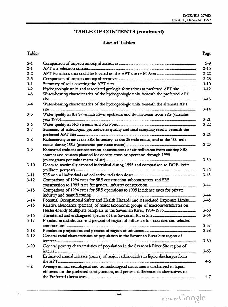
Relative abundance (percent) ofmajor taxonomic groups ofmacroinvertebrateson
Hester-Dendy Multiplate Samplers in the Savannah River, 1984-1985..
Threatened and endangered species of the Savannah River Site ........
Population distribution and percentofregion of influence for counties and selected
communities. ........
Population projections and percentofregion ofinfluence ......
General racial characteristics ofpopulation in the Savannah River Site region of
interest ...
General poverty characteristics of population in the Savannah River Site region of
interest.............
Estimated annual releases (curies) ofmajor radionuclides in liquid discharges from
the APT..............
Average annual radiological and nonradiological constituents discharged in liquid
effluents for thepreferred configuration,and percent differences in alternatives to
the Preferred alternatives........
3-42
3-433-11
3-12
3-44
3-13
3-44
3-453-14
3-15
3-50
3-543-16
3-17
3-57
3-583-18
3-19
3-60
3-20
3-63
4-1
4-6
4-2
4-7
viii
DOE /EIS -0270D
DRAFT, December 1997
TABLE OF CONTENTS (continued )
List of Tables
Tables Page
4-84-3
4-4
4-5
4-6
4-7
4-9
4-10
4-12
4-14
4-8
4-15
4-164-9
4-10
4-17
4-11
4-12
4-13
4-14
4-15
4-18
4-20
4-21
4-24
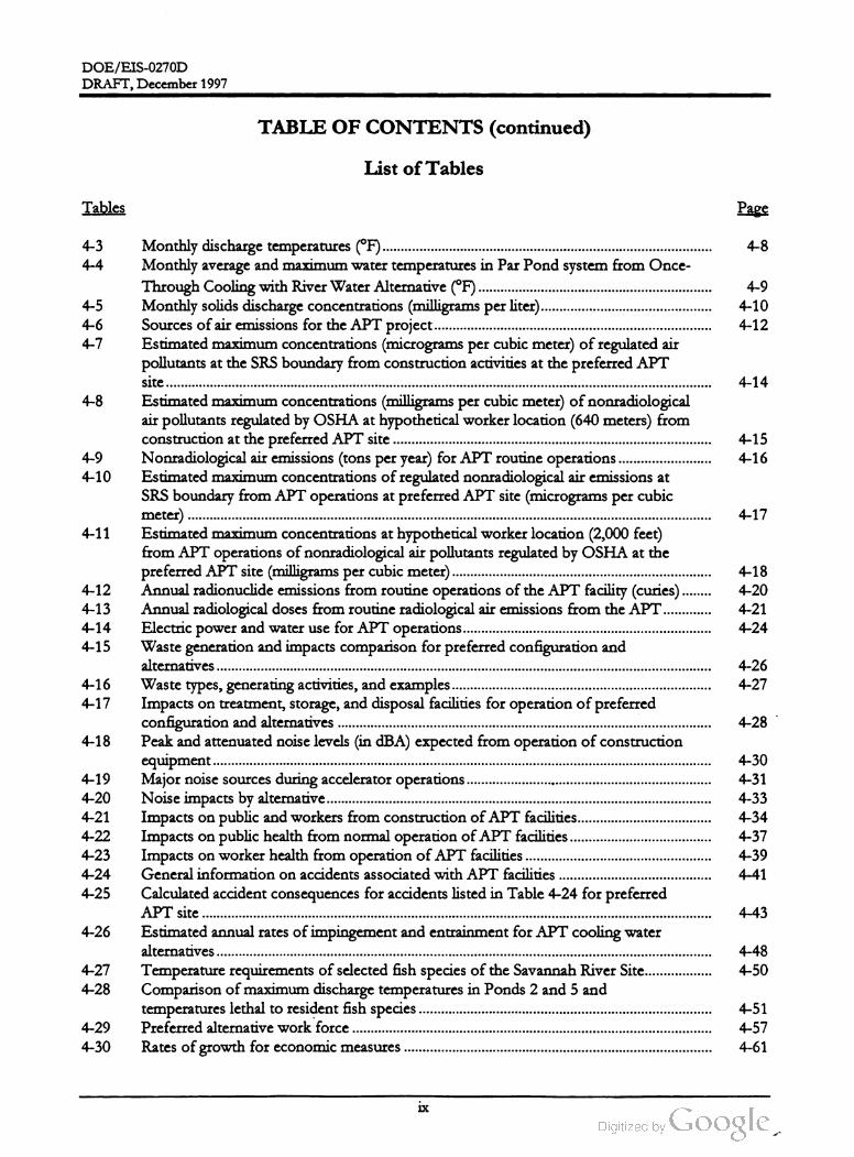
Monthly discharge temperatures (°F )
Monthly average and maximum water temperatures in Par Pond system from Once
Through Cooling with River Water Alternative (° F )
Monthly solids discharge concentrations (milligramsper liter).
Sources of air emissions for the APT project......
Estimated maximum concentrations (microgramsper cubic meter) of regulated air
pollutants at the SRS boundary from construction activities at the preferred APT
site ..........
Estimated maximum concentrations (milligramsper cubic meter) ofnonradiological
air pollutants regulated by OSHA at hypotheticalworker location (640 meters) from
construction at the preferred APT site ......
Nonradiologicalair emissions (tonsper year) for APT routine operations
Estimated maximum concentrations of regulated nonradiological air emissions at
SRS boundary from APT operations at preferred APT site (micrograms per cubic
meter) ....
Estimated maximum concentrations at hypothetical worker location (2,000 feet)
from APT operations ofnonradiological air pollutants regulated by OSHA at the
preferred APT site (milligramsper cubic meter)
Annual radionuclide emissions from routine operations of the APT facility (curies) .
Annualradiological doses from routine radiological air emissions from the APT.
Electric power and water use for APT operations...
Waste generation and impacts comparison for preferred configuration and
alternatives
Waste types, generating activities,and examples .............
Impacts on treatment, storage,and disposal facilities for operation of preferred
configuration and alternatives
Peak and attenuated noise levels in dBA ) expected from operation ofconstruction
equipment
Majornoise sources during accelerator operations
Noise impacts by alternative....
Impacts on public and workers from construction ofAPT facilities.......
Impacts on public health from normal operation of APT facilities
Impacts on worker health from operation of APT facilities.....
General information on accidents associated with APT facilities
Calculated accident consequences for accidents listed in Table 4-24 for preferred
APT site ....
Estimated annual rates ofimpingementand entrainmentfor APT coolingwater
alternatives......
Temperature requirements ofselected fish species ofthe Savannah River Site .........
Comparison ofmaximum discharge temperatures in Ponds 2 and 5 and
temperatures lethal to resident fish species
Preferred alternative work force
Rates of growth for economic measures
4-26
4-274-16
4-17
4-28
4-18
4-19
4-20
4-21
4-22
4-23
4-24
4-25
4-30
4-31
4-33
4-34
4-37
4-39
4-41
4-43
4-26
4-48
4-504-27
4-28
4-29
4-30
4-51
4-57
4-61
ix
DOE /EIS-0270D
DRAFT, December 1997
TABLE OF CONTENTS (continued )
List of Tables
Tables Page
4-31
4-32
4-33
4-34
4-35
4-36
4-37
4-62
4-65
4-67
4-69
4-71
4-72
4-38
4-39
4-40
4-41
4-42
5-1
4-72
4-74
4-75
4-79
4-80
4-81
Workforce by alternative.....
Annular sector factors for local dose evaluations
Estimated per capita annual dose for identified communities in 50-mile region
Comparison ofrated capacities.....
Water requirements and operating parameters.
Estimated powerplant emission rates (poundsper hour)
Estimated air quality impacts for coal- and natural-gas-fired powerplants at the
Savannah River Site .........
Estimated coal- fired solid waste generation.
Coal-fired electricity generating plantwork force.......
Natural gas-fired electricity generating plant work force .......
Projected environmental impacts for APT electric power supply alternatives .......
Projected resource consumption for APT electric powerplant options......
Estimated average annualcumulative radiological doses and resulting health effects
to offsite population from liquid releases..
Estimated maximum nonradiological cumulative ground-level concentrations of
criteria and toxic pollutants (microgramsper cubicmeter) at SRS boundary
Estimated average annual cumulative radiological doses and resulting health effects
to offsite population from airborne releases
Estimated cumulative waste generation from SRS operations (cubic meters). .....
Estimated average annual cumulative electrical consumption
Estimated average annual cumulative radiological doses and resulting health effects
to offsite population and facility workers ..........
Cumulative economic and population measure.
Estimated amounts ofmaterials required for construction and operation of an
accelerator at the Savannah River Site ...........
Environmental permits and consultations required by regulation ..
DOE Orders andNotices relevant to the accelerator production of tritium .
5-3
5-2
5-4
5-3
5-4
5-5
5-6
5-5
5-5
5-7
5-9
5-115-7
6-1
7-1
7-2
6-3
7-2
7-13
х
DOE / EIS -0270D
DRAFT,December 1997
TABLE OF CONTENTS (continued)
List of Figures
Figures Page
1-1
1-2
1-3
2-1
2-2
2-3
1-2
1-6
2-3
2-3
2-4
2-4
2-9
2-5
2-10
2-6
2-11
2-7
2-12
2-142-8
2-9
Savannah River Site ..........
Estimated tritium inventory and reserve requirements.
NEPA documentation for related DOE actions...
Major steps in the APT process
Accelerator schematic....
A pictorial representation oftritium production using neutrons generated by
spallation. Theproton strikes the target atom , which breaks into multiple fragments
with the emission of neutrons. The neutrons then strike atoms(3He or 6L1),
producing tritium and a by-product atom (1H or 4He)
Schematic diagram of the cooling water system alternatives for APT components
with approximate water flows. This drawing assumes that the componentto be
cooled has the potential for radioactive contamination. For nonradioactive systems,
the illustrated secondary coolantsystem would not be present and the final cooling
water system would be linked to the primary coolant loop.
Map of the SRS showing existing features that could be used to provide cooling
water for the accelerator...
An example ofmechanical-draft cooling towers at the SRS. This cooling tower is
located in A - Area and has four exhaust areas on top .....
Photograph of the K -Area natural-draft cooling tower that was constructed in the
early 1990s butnever operated.............
Preferred and alternate sites for the APT.
Alternatives for supplying electricity to the APT. Existing transmission lines would
be used and DOE would obtain power from existing plants and through market
transactions or would obtain electricity from a new coal-fired or natural gas-fired
plant.....
Conceptual layoutofAPT facilities and structure (LANL 1997) ...
Staging with extended linac tunnel
Themodular configuration and possible stagesof expansion
M -Area (toward the southeast)
H - Area tritium facilities ...
Common exposure pathways for radioactive effluents to reach members of the
public ...
Land forms,topography, and 100-year floodplain of the preferred and alternate
sites
Soil types at the preferred and alternate APT sites
Water table elevations and groundwater flow in the water table aquifer at the
preferred and alternate sites...
Savannah River Site, showing seismic fault lines and locations of onsite earthquakes
and their dates of occurrence
Regional epicenters of seismic activity
Savannah River Site, showing 100-year floodplain and major stream systems..........
Location of groundwater contamination and waste sites at the Savannah River Site
Principal SRS facilities, roads, and railroads........
2-10
2-11
2-12
3-1
3-2
3-3
2-17
2-19
2-23
2-24
3-2
3-4
3-5
3-4
3-7
3-93-5
3-6
3-15
3-7
3-8
3-9
3-10
3-11
3-17
3-19
3-20
3-25
3-33
xi

DOE / EIS -0270D
DRAFT, December 1997
TABLE OF CONTENTS (continued)
List of Figures
Figures Page
3-12
3-13
3-14
3-15
3-16
3-17
3-18
3-19
3-20
3-21
3-22
3-34
3-36
3-37
3-41
3-47
3-48
3-61
3-62
3-63
3-64
4-1
4-2
4-3
4-4
4-5
4-6
Electrical distribution system at the Savannah River Site
Domestic water distribution system at the Savannah River Site
Wastewater collection system at the Savannah River Site........
Major sources of radiation exposure in the vicinity of the Savannah River Site
Forest cover ofpreferred APT site .......
Forest cover of alternate APT site .........
Distribution ofminority population by census tracts in the SRS region of analysis
Low -income census tracts in the SRS region of analysis
Projected Regional Employment
Projected Regional Population ......
Projected Regional Total Personal Income,Gross Regional Product, and State and
LocalGovernment Expenditures
An accident resulting in a release of material..........
Regional employment differences greater than No Action alternative
Regional population differences greater than No Action alternative..
Regional total personal income differences greater than No Action alternative........
Gross regional product differences greater than No Action alternative..........
State and local government expenditures differences greater than No Action
alternative ..............
Annular sectors around the Savannah River Site .......
Community impacts from a unit population dose
Employment differences for electricity generating and APT Preferred alternatives
from No Action alternative .....
Population differences for electricity generating and APT Preferred alternatives
from No Action alternative...
Total personal income differences for electricity generating and APT Preferred
alternatives from No Action alternative
Gross regional product differences for electricity generating and APT Preferred
alternatives from No Action alternative
State and local government expenditure differences for electricity generating and
APT Preferred alternatives from No Action alternative....
3-64
4-40
4-58
4-58
4-60
4-60
4-7
4-8
4-9
4-61
4-64
4-67
4-76
4-10
4-77
4-11
4-77
4-12
4-78
4-13
4-78
xü

DOE / EIS -0270D
DRAFT,December 1997 Acronyms and Abbreviations
ACRONYMSAND ABBREVIATIONS
AAQS
ALARA
Ambient Air Quality Standard
as low as reasonably achievable
AcademyofNatural Sciences ofPhiladelphia
Accelerator Production of Tritium
ANSP
APT
AWQC
BA
ambientwater quality criteria
Biological Assessment
Bureau of Labor StatisticsBLS
CEQ
CFR
Council on Environmental Quality
Code ofFederal Regulations
commerciallight-water reactor
carbon monoxide
CLWR
CO
CSRA Central Savannah River Area
CTM Critical ThermalMaxima
dBAA -weighted decibel
decibeldB
DOE
DOT
EIS
EMF
EPA
FONSI
FR
GRP
HVAC
U.S. DepartmentofEnergy
U.S. Departmentof Transportation
environmental impact statement
electromagnetic field
U.S. EnvironmentalProtection Agency
Finding ofNo Significant Impact
Federal Register
Gross Regional Product
heating, ventilation, and air conditioning
International Commission on Radiological Protection
maximally exposed individual
National Ambient Air Quality Standard
NationalEnvironmental Policy Act
Notice of Intent
oxides of nitrogen
National Pollutant Discharge Elimination System
NuclearWeapons StockpileMemorandum
ICRP
MEI
NAAQS
NEPA
NOI
NOX
NPDES
NWSM
O3 Ozone
OSHA Occupational Safety and Health Administration
xiii

DOE / EIS -0270D
DRAFT, December 1997Acronymsand Abbreviations
PEIS
PEL
PM10
PSD
RCRA
Programmatic Environmental Impact Statement
Permissible Exposure Limit
particulate matter smaller than 10 microns
Prevention of SignificantDeterioration
Resource Conservation and Recovery Act
Record ofDecision
South Carolina Department of Health and Environmental Control
South Carolina Electric andGas Company
State Historic Preservation Officer
ROD
SCDHEC
SCE & G
SHPO
SO2 sulfur dioxide
SO sulfur oxides
SRS Savannah River Site
STARTStrategic ArmsReduction Treaty
total dissolved solidsTDS
TEF
TSP
TWA
Tritium Extraction Facility
total suspended particulates
time-weighted average
United States Code
U.S. Geological Survey
volatile organic compound
USC
USGS
VOC
xiv

DOE /EIS-0270D
DRAFT,December 1997 Acronyms and Abbreviations
Metric Conversion Chart
To convert into metric
Multiply by
To convert out ofmetric
Multiply byTo get If you know To getIf you know
Length
inches
feet
feet
yards
miles
Area
2.54
30.48
0.3048
0.9144
1.60934
centimeters centimeters
centimeters centimeters
meters meters
meters meters
kilometers kilometers
0.3937
0.0328
3.281
1.0936
0.6214
inches
feet
feet
yards
miles
sq. inchessq. inches
sq. feet
sq.yards
sq .feet
6.4516
0.092903
0.8361
0.0040469
2.58999
sq. centimeters sq . centimeters
sq .meters sq .meters
sq. meters sq. meters
sq. kilometers sq . kilometers
sq.kilometers sq. kilometers
0.155
10.7639
1.196
247.1
0.3861
sq. yards
acres acres
sq .miles sq . miles
Volume
fluid ounces
gallons
cubic feet
cubic yards
Weight
29.574
3.7854
0.028317
0.76455
milliliters milliliters
liters liters
cubic meters cubic meters
cubic meters cubic meters
0.0338
0.26417
35.315
1.308
fluid ounces
gallons
cubic feet
cubic yards
ounces 28.3495
0.4536
0.90718
grams grams
kilograms kilograms
metric tons metric tons
0.03527
2.2046
1.1023
ounces
pounds
short tons
pounds
short tons
Temperature
Fahrenheit Celsius Celsius FahrenheitSubtract 32 then
multiply by 5 / 9ths
Multiply by 9 /5ths,
then add 32
Metric Prefixes
Prefix Symbol
Eexa
petaР
tera T 1012
Multiplication Factor
1 000 000 000 000 000 000 = 1018
1 000 000 000 000 000 = 1015
1 000 000 000 000 =
1 000 000 000 = 109
1 000 000 = 106
1 000 =
0.01 = 10-2
giga G
Mmega
kilo k 103
cent с
milli m 0.001 = 10-3
10-6micro u 0.000 001 =
nano 10-9
рpico
femto
0.000 000 001 =
0.000 000 000 001 = 10-12
0.000 000 000 000 001 = 10-15
0.000 000 000 000 000 001
f
atto a 10-18
XV

一

Summary

DOE / EIS -0270D
TobaccoRoad
SavannahRiver
Norfolk
Southern
County
78
North
Augusta
Summary
78
South
Aiken
232
Te
Atlanta
39
The
Savannah
River
Site
has
anarea
ofabout
ngtield
300
square
miles
.Itisabout
25miles
CQ
southeast
of
Augusta
,Georgia
,and
20
miles
Unit
3
south
ofAiken
,South
Carolina
.
20
(278
)(302
)19
Columbia
County
Richmond
County
520
Augusta
10
12178
278
10 121
(125
)Beech
Island
Barnwell
New
Ellenton
UpperThree
(278
)(781
)
Jones
,Williston
spur
56
56
Bush
Field
conn
56
(278
)39
NORTH
57
(125
)
Jackson
Fort
Gordon
Military
Reservation
Spirit
78
Blackville
4
Creek
Georgia
South
Carolina
137
488
278
)
3Savannah
River
Site
-
Salkehatchie
Snelling
64
Barnwell
Par
Pond
(125
Branch
CSX
(abandoned
)River
CSX
SOUTH
CAROLINA
Savannah
64
L-Lake
Lowe
.
SRS
pen
3
Vogtle
Electric
Generating
Plant
Three
GEORGIA
River
(278
)
Steel
Suns
Barnwell
Allendale
County
County
(125
)
cst
KILOMETERS
050
100
150
200
100
50
MILES
Burke
County Screven
County
Miles
012345678910
DRAFT, December 1997
Kilometers
0246
8101214
16
PK68
-Z1
-PC

DOE/ EIS -0270D
DRAFT,December 1997 Summary
SUMMARY
that it would pursue a dual-track approach to
the two most promising alternatives:
The U.S. Department of Energy (DOE) is re
sponsible for ensuring that the nation has a
supply of materials for the operation of its
stockpile of nuclear weapons even though a
series of treaties has reduced that stockpile to a
fraction of what it was during the Cold War.
One of these materials is tritium -- a gaseous
isotope of hydrogen that increases the yield of
nuclear weapons. None of the weapons in the
nuclear arsenal would function as designed
without tritium .
To initiate the purchase of an existing
commercial light-water reactor (operating or
partially complete) for conversion to a de
fense facility , or the purchase of irradiation
services with an option to purchase the re
actor
To design, build , and test critical compo
nents of an accelerator system for tritium
productionIn other words, as long as the United States
chooses to maintain a nuclear deterrent -- of
any size -- it will need tritium .WHAT IS TRITIUM ?
There are two issues related to the United
States' need for tritium : The first is that it no
longer has operating facilities to produce this
material. DOE has shut down the reactors that
irradiated the base material from which the gas
was derived and will not restart them .
Tritium is a radioactive isotope of hydrogen
that occurs naturally in small quantities. It
must be manmade to obtain useful quanti
ties. It is an essential component of every
warhead in the current and projected U.S.
nuclear weapons stockpile . These war
heads depend on tritium so they can per
form as designed . Tritium decays at about
5.5 percent per year and , therefore , requires
periodic replacement.
The second issue related to tritium is that it de
cays at a rate of about 5.5 percent per year.
This means that present supplies will be cut in
half before 2010, and that the United States will
run out in about 2040 . 1995
100 %
Tritium
Decay
Over
TimeTherefore, it is essential that the United States
needs a new source of tritium .
2000
75 %
2007
50 %
2019
25 % PK68-12035
10 %
Remaining
For the past several years DOE has been
studying how to obtain such a source. Follow
ing the requirements of the National Environ
mental Policy Act (NEPA), the Department
took its first step toward a solution with a
document titled Final Programmatic Environmental
Impact Statement for Tritium Supply and Recycling
(Tritium Supply PEIS ), which evaluated both
the need for a new tritium source and the alter
natives to provide that source. Continuing the
NEPA process, on December 12, 1995 , DOE
published a Record of Decision (ROD ; 60 FR
63878) for the programmatic environmental
impact statement (EIS), in which it announced
The Record of Decision committed DOE to ,
within 3 years (by late 1998), selecting one of
these approaches to be the primary source of
tritium . In addition, the Department would, if
possible, continue to develop the other alterna
tive as a backup tritium source. Further, the
ROD announced DOE's selection of the Sa
vannah River Site (SRS) in South Carolina as the
location for an accelerator, if the Department
decided to build one, and its decision to up
S - 1
DOE /EIS-0270D
DRAFT, December 1997Summary
PURPOSE AND NEED FOR ACTIONgrade and consolidate the existing SRS tritium
recycling facilities and to construct a Tritium
Extraction Facility at the SRS to support either
dual- track alternative.
As a continuation of its NEPA process, DOE
developed the following strategy : (1)make de
cisions on the alternatives described and evalu
ated in the Tritium Supply PEIS , and (2) tier
(link) the Tritium Supply PEIS with site-specific
assessments that implement those decisions.
Thus, the Department is preparing three docu
ments tiered to the programmatic EIS: this EIS
on the construction and operation of an Accel
erator for the Production of Tritium (APT), an
EIS on the construction and operation of a
Tritium Extraction Facility at the SRS, and an
EIS on the use of a Commercial Light-Water
Reactor to produce tritium .
The purpose and need for the Department's
action is described in the Programmatic Environ
mental Impact Statement for Tritium Supply and Re
cycling. The Tritium Supply PEIS identified the
1994 Nuclear Weapons Stockpile Plan as the
guidance document the Department must fol
low . Since the issuance of the Tritium Supply
PEIS , the President has approved the 1996
Nuclear Weapons Stockpile Plan which is based
on START I stockpile levels. The change be
tween the two Nuclear Weapons Stockpile
Plans is to change the projection of when a new
tritium source is needed from approximately
2011 used in the PEIS to 2005 to 2007 in the
1996 Nuclear Weapons Stockpile Plan. How
ever, the need for tritium for the nuclear weap
ons stockpile, as discussed in the Tritium Sup
ply PEIS, remains unchanged.
PROPOSED ACTION AND ALTERNA
TIVES
On September 5 , 1996 , DOE published the
“ Notice ofIntent To Prepare an Environmental
Impact Statement for the Construction and Op
eration ofan Accelerator for the Production of
Tritium at the Savannah River Site" (61 FR
46787). As stated in the Notice of Intent, the
purpose of this EIS is to evaluate technology
and site options for the use of an accelerator for
the production of tritium , and to assess the im
pacts of accelerator construction and operation
at the SRS.
DOE proposes to design, build , and operate a
linear accelerator at the Savannah River Site.
The Department will use the EIS and the
NEPA process to inform decision makers about
the potential environmental impacts of the pro
posed action and alternatives (the estimated im
pacts of constructing and operating an accelera
tor to produce tritium are summarized in
Table S- 1 at the end of this Summary).
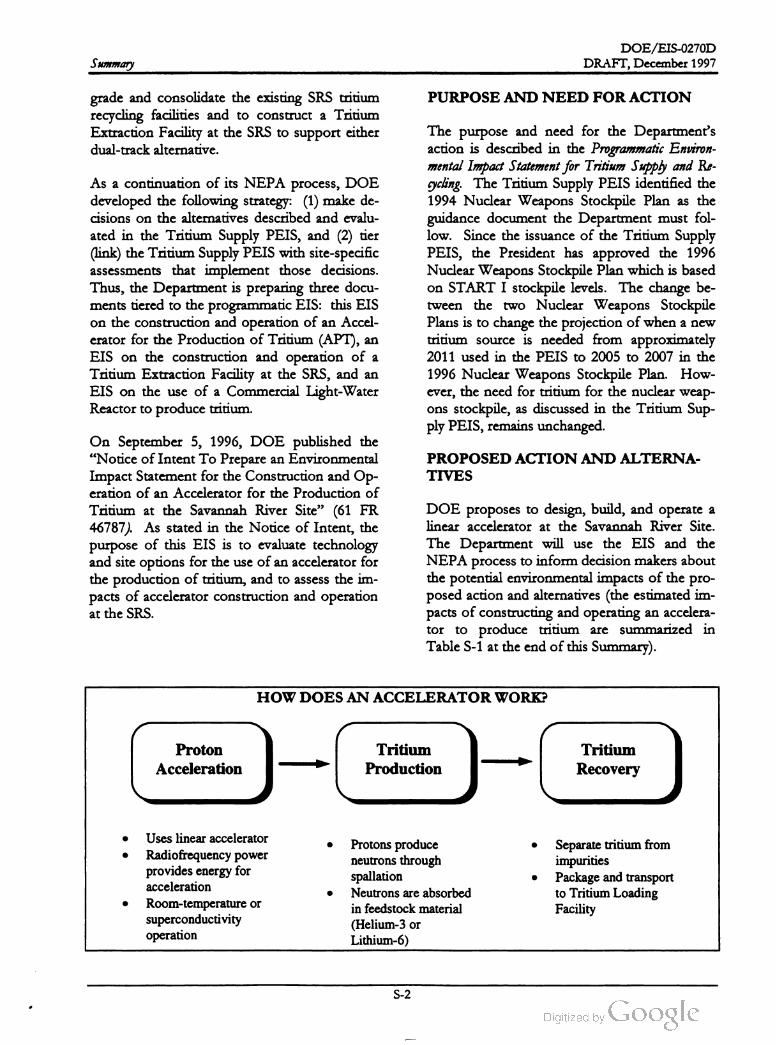
HOW DOES AN ACCELERATOR WORK?
Proton
Acceleration
-
Tritium
Production
-C
Tritium
Recovery
Uses linear accelerator
Radiofrequency power
provides energy for
acceleration
Room -temperature or
superconductivity
operation
Protons produce
neutrons through
spallation
Neutrons are absorbed
in feedstock material
(Helium -3 or
Lithium -6 )
Separate tritium from
impurities
Package and transport
to Tritium Loading
Facility
S - 2

DOE /EIS -0270D
DRAFT, December 1997 Summary
Preferred Alternative. Based on the research
and development it has performed, DOE pro
poses the following preferred design and sup
port features for the APT:
• Klystron radiofrequency power tubes
Superconducting operation of accelerator
structures
No Action Alternative. In compliance with
the regulations of the Council on Environ
mental Quality (CEQ) for implementing NEPA
(40 CFR Part 1500), this EIS also assesses a No
Action alternative, under which DOE would
defer indefinitely any decision on the final se
lection ofAPT design features and would place
the research and development information
completed at the time it made its decision in an
archive. If DOE chose No Action , it would
have to meet its tritium production require
ments through othermethods, or it would not
be able to support the long-term defense poli
cies of the United States, which is not accept
able .
Helium -3 feedstock material
Mechanical-draft cooling towers with river
water makeup
Construction of the APT on a site 3 miles
northeast ofthe Tritium Loading Facility
Purchase of electricity from existing capac
ity and market transactions
Under the No Action alternative, SRS recycling
and loading activities related to tritium would
continue. In addition, other actions determined
in the Record of Decision for the Tritium Sup
ply PEIS -- the potential construction and
WHATWOULD AN ACCELERATOR LOOK LIKE ?
13
13
13
15 18
113
2 .
13
12
111
16 14
17
10LEGEND:
1 Accelerator tunnel 10 Operations building
2 RF gallery 11 Maintenance building
3 Target blanketbuilding 12 RF tube maintenance facility
4 Tritium sep.fac. building 13 Mechanical supportbuildings (6)
5 Beamstop building 14 Simulator & training building
6 Radwaste facility 15 Fire pumphouse & water storage
7 Administration building 16 Demineralizer building
8 Access control building 17 Security building
9 Backup power facility 18 Electric substation
PK68-Z1-PC
S - 3
DOE /EIS-0270D
DRAFT, December 1997Summary
operation of a Tritium Extraction Facility and
the potential modernization and consolidation
of existing SRS tritium facilities --
ceed as planned.
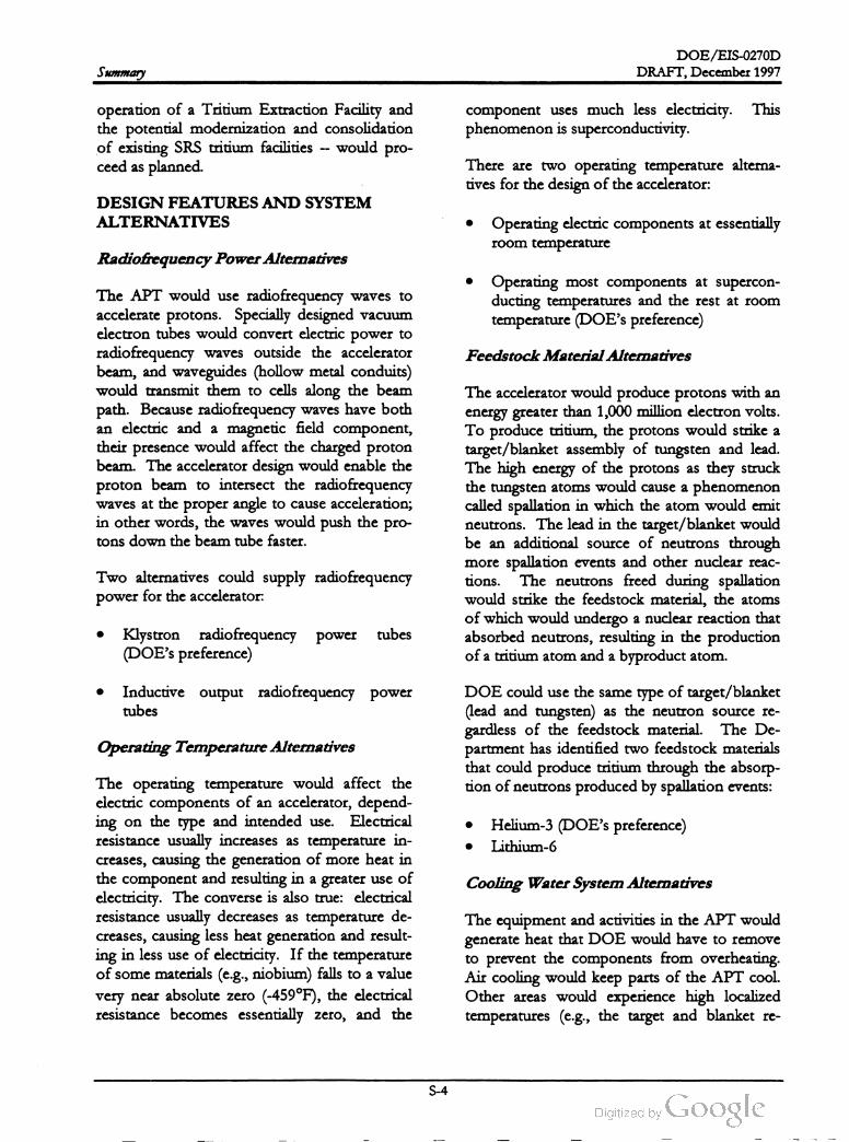
component uses much less electricity . This
phenomenon is superconductivity.
would pro
There are two operating temperature alterna
tives for the design of the accelerator:
DESIGN FEATURES AND SYSTEM
ALTERNATIVESOperating electric components at essentially
room temperature
Radiofrequency Power Alternatives
Operating most components at supercon
ducting temperatures and the rest at room
temperature (DOE's preference)
Feedstock Material Alternatives
The APT would use radiofrequency waves to
accelerate protons. Specially designed vacuum
electron tubes would convert electric power to
radiofrequency waves outside the accelerator
beam , and waveguides (hollow metal conduits)
would transmit them to cells along the beam
path. Because radiofrequency waves have both
an electric and a magnetic field component,
their presence would affect the charged proton
beam . The accelerator design would enable the
proton beam to intersect the radiofrequency
waves at the proper angle to cause acceleration ;
in other words, the waves would push the pro
tons down the beam tube faster.
The accelerator would produce protons with an
energy greater than 1,000 million electron volts.
To produce tritium , the protons would strike a
target /blanket assembly of tungsten and lead .
The high energy of the protons as they struck
the tungsten atoms would cause a phenomenon
called spallation in which the atom would emit
neutrons. The lead in the target/ blanket would
be an additional source of neutrons through
more spallation events and other nuclear reac
tions. The neutrons freed during spallation
would strike the feedstock material, the atoms
of which would undergo a nuclear reaction that
absorbed neutrons, resulting in the production
of a tritium atom and a byproduct atom .
Two alternatives could supply radiofrequency
power for the accelerator:
tubesKlystron radiofrequency power
(DOE's preference)
Inductive output radiofrequency power
tubes
Operating Temperature Alternatives
DOE could use the same type of target/blanket
(lead and tungsten) as the neutron source re
gardless of the feedstock material. The De
partment has identified two feedstock materials
that could produce tritium through the absorp
tion ofneutronsproduced by spallation events:
Helium -3 (DOE's preference)
Lithium - 6
Cooling Water System Alternatives
The operating temperature would affect the
electric components of an accelerator, depend
ing on the type and intended use. Electrical
resistance usually increases as temperature in
creases, causing the generation of more heat in
the componentand resulting in a greater use of
electricity. The converse is also true: electrical
resistance usually decreases as temperature de
creases, causing less heat generation and result
ing in less use of electricity . If the temperature
of somematerials (e.g., niobium ) falls to a value
very near absolute zero (-459° F ), the electrical
resistance becomes essentially zero , and the
The equipment and activities in the APT would
generate heat that DOE would have to remove
to prevent the components from overheating.
Air cooling would keep parts of the APT cool.
Other areas would experience high localized
temperatures (e.g., the target and blanket re
S - 4
DOE /EIS -0270D
DRAFT,December 1997 Summary
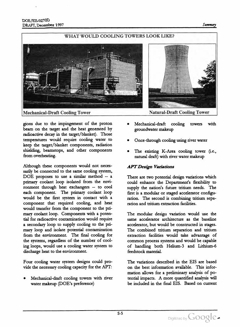
WHATWOULD COOLING TOWERS LOOK LIKE ?
Mechanical-Draft Cooling Tower Natural-Draft Cooling Tower
towers withMechanical-draft cooling
groundwatermakeup
gions due to the impingement of the proton
beam on the target and the heat generated by
radioactive decay in the target /blanket). Those
temperatures would require cooling water to
keep the target /blanket components, radiation
shielding, beamstops, and other components
from overheating.
Once-through cooling using river water
The existing K -Area cooling tower (i.e.,
natural draft) with river watermakeup
APT Design Variations
There are two potential design variations which
could enhance the Department's flexibility to
supply the nation's future tritium needs. The
first is a modular or staged accelerator configu
ration. The second is combining tritium sepa
ration and tritium extraction facilities.
Although these components would not neces
sarily be connected to the same cooling system ,
DOE proposes to use a similar method -- a
primary coolant loop isolated from the envi
ronment through heat exchangersto cool
each component. The primary coolant loop
would be the first system in contact with a
component that required cooling , and heat
would transfer from the component
to the pri
mary coolant loop. Components with a poten
tial for radioactive contamin
ationwould require
a secondary loop to supply cooling to the pri
mary loop and isolate potential
contamination
from the environment
. The final cooling for
the systems, regardless of the number of cool
ing loops,would use a cooling water system to
dischargeheat to the environ
ment.
The modular design variation would use the
same accelerator architecture as the baseline
accelerator, but would be constructed in stages.
The combined tritium separation and tritium
extraction facilities would take advantage of
common process systems and would be capable
of handling both Helium -3 and Lithium -6
feedstock material.
Four cooling water system designs could pro
vide the necessary cooling capacity for the APT:
The variations described in the EIS are based
on the best information available. This infor
mation allows for a preliminary analysis of po
tential impacts. A more quantified analysis will
be included in the final EIS . Based on current
Mechanical-draft cooling towers with river
water makeup (DOE's preference)
S - 5

DOE/EIS -0270D
DRAFT, December 1997Summary
AFFECTED ENVIRONMENTdesign information , DOE believes potential
impacts ofthe design variationswould vary little
from those identified for the baseline accelera
tor.
APT Site Alternatives
DOE conducted a screening process to select
potentially suitable sites for the APT. This
multiple-phase process identified areas with a
set of suitable features and minimal conflicts
with onsite resources and operational areas.
DOE would locate the APT on one of two SRS
sites. The preferred site is located approxi
mately 3 miles northeast of the existing Tritium
Loading Facility, about 6.5 miles from the SRS
boundary. The alternate site is located ap
proximately 2 miles northwest of the Tritium
Loading Facility, about 4 miles from the SRS
boundary . Both sites are 250 -acre forested
tracts largely dominated by stands of loblolly
and slash pine. No threatened or endangered
species occur at either site.
Based on a weighing and balancing of the crite
ria ,DOE selected two sites for further analysis :
The preferred site 3 miles northeast of the
Tritium Loading Facility , and approximately
6.5 miles from theSRS boundary
Mostsupport
activities not located at the APT
site would be in M-or H -Area. The following
sections describe the proposed APT sites,
M -Area, and H -Area.
The alternate site 2 miles northwest of the
Tritium Loading Facility, and approximately
4 miles from the SRS boundary
Electric Power Supply Alternatives
The APT will require large amounts of electric
ity (a peak load as high as 600 megawatts
electric for the room temperature alternative) to
operate. At present, the SRS obtains its electric
power from South Carolina Electric and Gas
Company (SCE & G ) through existing transmis
sion lines and substations. Both the preferred
and alternate APT sites are close to existing
electric power supply lines. Due to the pro
jected magnitude of the electrical power usage;
however,DOE is studying alternatives for the
source of electricity for the APT, and has iden
tified the following two:
APT Sites. As previously mentioned, DOE
used a multiphase screening process to find
suitable sites for the APT. Thisprocess
identi
fied areas with suitable features and minimal
conflicts with onsite resources and operational
areas .
Obtain electricity from existing commercial
capacity and through market transactions
(DOE's preference)
The first phase involved the identification of
land requirements based on the sizes of the
proposed facilities. Next came the development
of exclusionary criteria to identify areas that
could present operational or environmental
conflicts with the APT (e.g., locations of threat
ened or endangered species or seismic faults ).
Obtain electricity from the construction and
operation of a new coal- fired or a natural
gas- fired generating plant
S - 6

DOE /EIS -0270D
DRAFT,December 1997 Summary
The third phase involved a more detailed com
parison, weighing and balancing the sites in four
categories: ecology, geology and hydrology,
human health , and engineering. DOE evaluated
each site against the exclusionary criteria using
either quantitative analyses or, if quantitative
information was not available, the professional
judgmentofexperts. The site screening process
led DOE to the selection of the preferred and
alternate sites.
struction and startup) is a third -generation facil
ity that becameoperational in 1994. Operations
in this building include unloading gases from
reservoirs returned from the Department of
Defense, separating and purifying useful hydro
gen isotopes, mixing the gases to exact specifi
cations, and loading the reservoirs.
Comparison of Environmental
Impacts Among Alternatives
Table S-1 presents a comparison of the envi
ronmental impacts associated with construction
and operation of the baseline APT as a function
of alternative. For each technical discipline, the
impacts of the Preferred alternative are dis
cussed. The Preferred alternative is composed
of the following:
Klystron radiofrequency power tubes
Superconducting operation of accelerator
structures
Helium - 3 feedstock material
Mechanical-draft cooling towers with river
water makeup
• Electricity from existing capacity and mar
ket transactions
Use of the Preferred APT site
M -Area. M - Area, an industrialized area on the
SRS, is the proposed host for a number of APT
support functions. DOE has declared that sev
eral M -Area facilities are surplus and available
for new uses. Historically, the Department used
M -Area to fabricate fuel, special targets, and
components for irradiation in the SRS produc
tion reactors. The facilities contain furnaces,
extrusion presses, lathes, handling equipment,
and storage racks for melting, casting , and
shapingmetal.
Differences in impacts that could occur if dif
ferent alternatives were implemented are also
presented.
H -Area. H -Area is also an industrialized area.
At present, the H -Area tritium facilities consist
of fourbuildings , three ofwhich have been part
of the historic SRS tritium mission and are sec
ond-generation tritium structures. The fourth
building, the Tritium Loading Facility (called the
Replacement Tritium Facility during its con
Based on current design information , most of
the potential environmental impacts of the two
design variations (the modular APT design and
combining tritium extraction facilities) are
bounded by the baseline APT. In the case of
the modular APT design , more land would be
required and potential socioeconomic impacts
would occur over a greater timeperiod than for
the baseline accelerator.
S - 7

DOE/ EIS -0270D
DRAFT,December 1997Summary
In the case of the modular APT design, how
ever,more land could be required . The poten
tial socioeconomic impacts would initially be
less. If themodular APT is expanded to 3 kilo
grams/year, socioeconomic impacts could ex
tend beyond the construction period assumed
for the baseline APT.
about 125,000 gallons per minute of river water
and discharge of heated water to the Par Pond
system during operation.Thermal impacts
would be restricted to the upperportions of the
ParPond system and would not affect Par Pond
discharges to Lower Three Runs. There would
be a small increase in Lower Three Runs flows,
however. The implementationof the Mechani
cal-Draft Cooling Towers with Groundwater
Makeup alternative would result in the with
drawal of 6,000 gallons per minute of ground
Total groundwater withdrawal at the
SRS could therefore exceed the estimated
groundwater production capacity of the aquifer.
This could affect groundwater flow to site
water.
In general, DOE considers the expected im
pacts on the biological, human, and socioeco
nomic environment of construction and opera
tion of an accelerator for production of tritium
at the SRS to beminor and consistent with what
might be expected for any industrial facility.
Construction and operation of the Preferred
alternative would result in the loss of about
250 acres of mixed pine /hardwood upland for
est. Waste would be generated during both the
construction and operation phases but in
quantities thatwould have negligible impacts on
SRS waste management facilities. No high-level
waste or transuranic waste would be generated
during construction or operation .
streams.
The Preferred alternative includes buying elec
tricity from the commercial grid to support
APT operation . In the case of commercial
electricity purchases, the environmental impacts
attributed to the APT load would be decentral
ized. In the case of the construction of a new
electricity generating plant to support the APT,
the environmental impacts would be localized at
the site selected for the plant. Construction and
operation of such a facility could require about
290 acres for a coal-fired plant and about 110
acres for a gas -fired plant.
Some small impacts from discharge of cooling
water to SRS streams and reservoirs and from
nonradiological emissions to air and water
would occur. Radiological releases during nor
mal operation of the facility are expected to re
sult in no latent cancer fatalities in workers or
the public. Because no high or adverse impacts
are expected, no disproportionately high or ad
verse impacts on minority or low -income com
munities are expected.
Implementation of certain of the technology
alternatives could result in impacts different
from those resulting from construction and op
eration of the Preferred alternative. Most no
table would be the impacts from implementa
tion of cooling water system alternatives and
electric power supply alternatives. Once
Through Cooling Using River Water would re
sult in withdrawal from the Savannah River of
Should the Department select the No Action
alternative, design work on the APT would be
concluded and the information archived . The
APT would not be constructed at the preferred
site and the 250 acres of land would revert to
forestry or other uses. On-going SRS missions
would continue. Incremental amounts ofwaste
generation and electricity consumption that
would have been attributable to the APT would
not occur. Employment would be a function of
on - goingmissions and funding levels.
-
S - 8

DOE /EIS -0270D
DRAFT,December 1997
Table
S-1.Comparison
of
impacts
among
alternatives
.
Operating
Feedstock
Radio
frequency
temperature
material
Site
location
Electric
power
Preferred
alternative
power
alternative
alternative
alternative
Cooling
water
system
alternatives
alternative
supply
alternative
Described
in text
Inductive
output
Room
Lithium
-6 Once
-through
Mechanical
K-Area
cooling
Alternate
site
Construct
new
tube
temperature
using
river
draft
using
tower
using
plant
water
as
groundwater
as
river
water
as
makeup
makeup
makeup
Impacts
from
Construction
onLandforms
,Soils
,Geology
,and
Hydrology
Negligible
impacts
.No
change
No
change
No
change
No
change
No
change
No
change
Watcr
table
is
Impacts
would
estimated
from
estimated
from
estimated
from
cstimated
from
cstimated
from
cstimated
from
dccpcr
and
depend
upon
thc
Somc
250
acres
of
land
Preferred
Preferred
Preferred
Preferred
Preferred
Preferred
would
require
specific
location
of
awould
be
graded
or
leveled
.
alternative
alternative
alternative
alternative
alternative
alternative
less
dewatering
;new
facility
.Could
require
about
110
No
gcologically
significant
changes
acres
for
natural
gas
formations
or
soils
occur
.
cstimated
from
or290
acres
for
Dewatering
necessary
.No
Preferred
coal
.surface
faulting
on
site
.
alternative
.Sites
for
clectricity
gcncration
exist
.
no
other
No
impacts
No
change
cstimated
from
No
dewatering
required
for
Preferred
operations
.alternative
Impacts
from
Operation
onLandforms
,Soils
,Geology
,and
Hydrology
No
change
No
change
No
change
Removal
of
6,000
No
change
estimated
from
cstimated
from
cstimated
from
spm
on
acstimated
from
Preferred
Preferred
Preferred
sustained
basis
Prcfcrred
alternative
alternative
alternative
could
impact
alternative
groundwater
flow
tostrcams
and
compact
clay
layers
No
change
Impacts
would
estimated
from
depend
upon
the
Preferred
specific
location
of
a
alternative
new
facility
Ncgligible
impacts
.
Dewatering
of
construction
sitc
could
result
inshort
-
term
incrcascs
insolids
to
the
receiving
water
bodics
.
No
change
estimated
from
Preferred
alternative
No
change
cstimated
from
Preferred
alternative
Impacts
from
Construction
on
Surface
Water
No
change
No
change
No
change
cstimated
from
estimated
from
cstimated
from
Prcfcrrcd
Prcfcrrcd
Preferred
alternative
alternative
alternative
No
change
No
change
Impacts
would
cstimated
from
cstimated
from
depend
upon
the
Preferred
Preferred
specific
location
of
a
alternative
alternative
ncw
facility
Summary
S - 9

DOE /EIS -0270D
Summary
Table
S- 1.(Continued
).
Operating
Feedstock
Radio
frequency
temperature
material
Site
location
Electric
power
Preferred
alternative
power
alternative
alternative
alternative
Cooling
water
system
alternatives
alternative
supply
alternative
Described
intext
Inductive
output
Room
Lithium
-6Once
-through
Mechanical
K-Area
cooling
Alternate
site
Construct
new
tube
temperature
using
river
draft
using
tower
using
plant
water
as
groundwater
as river
water
as
makeup
makeup
makeup
Impacts
from
Operation
on
Surface
Water
Blowdown
rates
(about
Would
require
7 %Would
require
No
change
Blowdown
rates
No
change
No
change
No
change
Discharges
would
2,000
gpm
) would
cause
less
cooling
water
33
%morc
cooling
cstimated
from
(about
125,000
cstimated
from
cstimated
from
estimated
from
bc
similar
tothe
negligiblc
impact
on
surface
than
Prcfcrrcd
duc
water
than
Prcfcrrcd
gpm
)would
Preferred
Preferred
Prcfcrrcd
Preferred
water
levels
;using
Par
Pond
tolower
wastc
hcat
Preferred
;noalternative
result
in higher
alternative
alternative
alternative
alternative
,although
asdischarge
point
for
gcncration
;no
other
changes
tcmpcratures
to
concentrations
cooling
water
.Temperatures
other
changes
from
Preferred
water
bodies
would
vary
and
be
would
not
cxcccd
90
°F.cstimated
from
alternative
(about
100
°1' ).localized
.
Contaminated
scdiments
Preferred
Aslight
incrcasc
would
be
resuspended
inalternative
in“pre
-cooler
"
addition
toradiological
pond
water
levels
relcases
from
APT
.would
occur
. No
other
changes
Listimated
fatal
cancers
:cstimated
from
0.00007
Preferred
alternative
.
Impacts
from
Construction
onNonradiological
Air
Emissions
Air
cmissions
(fugitive
dust
No
change
No
change
No
change
No
change
No
change
No
change
No
change
Emission
typcs and
cxhaust
cmissions
)cstimated
from
estimated
from
cstimated
from
estimated
from
cstimated
from
cstimated
from
cstimated
from
would
be
similar
to
Preferred
would
be
ncgligible
,well
Preferred
Preferred
l'rcfcrrcd
Preferred
Preferred
Preferred
thc
Prcfcrrcd
below
the
applicable
alternative
alternative
alternative
alternative
alternative
alternative
alternative
alternativc
,although
concentrations
regulatory
standards
,
clectricity
purchases
,for
would
vary
and
bc
impacts
would
be
dispersed
.localized
.
:"Impacts
from
Operation
onNonradiological
Air
Emissions
No
radiological
cmissions
No
change
No
change
No
change
No
change
No
change
No
change
No
change
Nonradiological
would
be
well
within
the
cstimated
from
estimated
from
cstimated
from
cstimated
from
cstimated
from
cstimated
from
cstimated
from
cmissions
would
be
Preferred
applicable
regulatory
Preferred
Prcfcrrcd
Prcfcrrcd
Prcfcrred
Preferred
Preferred
well
within
alternative
alternative
standards
.Operations
alternative
alternative
alternative
alternative
alternative
applicable
regulatory
standards
.would
result
insmall amounts
of
salt
deposition
and
plumes
from
cooling
towcr
operations
.
DRAFT,December 1997
S -10

DOE /EIS -0270D
Table
S-1.(Continued
)
Operating
Feedstock
Radio
frequency
temperature
material
Site
location
Electric
power
Preferred
alternative
power
alternative
alternative
alternative
Cooling
water
system
alternatives
alternative
supply
alternative
Described
intext
Inductive
output
Room
Lithium
-6 Once
-through
Mechanical
K-Area
cooling
Alternate
site
Construct
new
tube
temperature
using
river
draft
using
tower
using
plant
water
as
groundwater
as
river
water
as
makeup
makeup
makeup
Impacts
from
Construction
on
Radiological
Air
Emissions
No
impacts
;no
radioactive
No
change
No
change
No
change
No
change
No
change
No
change
No
change
No
change
materials
stored
during
cstimated
from
estimated
from
estimated
from
cstimated
from
cstimated
from
cstimated
from
cstimated
from
cstimated
from
construction
.Preferred
Preferred
Prcfcrrcd
Preferred
Preferred
Preferred
Preferred
Preferred
alternative
alternative
alternative
alternative
alternative
alternative
alternative
alternative
DRAFT,December 1997
Negligible
impacts
from
radioactive
airborne
cffluents
No
change
estimated
from
Preferred
altcrnative
Impacts
from
Operation
on
Radiological
Air
Emissions
No
change
Rcduced
doscs
No
change
No
change
cstimated
from
from
airbornc
cstimated
from
cstimated
from
Preferred
Preferred
Preferred
alternative
alternative
alternative
ICI's
expected
:
0.00029
cmissions
Latent
Cancer
l'atalitics
(I.CI's
expected
:0.0006
No
change
Higher
doses
Impacts
would
cstimated
from
from
airborne
depend
upon
the
Preferred
cmissions
duc
tospecific
location
of
a
alternative
closer
distance
new
facility
.
toSRS
Ilowever
,the
dosc
boundary
from
radioactive
cffluents
would
be
LCP's
expected
:ncgligiblc
.
0.00065
Conversion
of
250
acres
ofNo
change
forcstcd
land
toindustrial
estimated
from
usc
.Additional
roads
, Preferred
bridge
upgrades
,rail
lincs
alternative
and
utility
upgrades
would
be
required
.
Impacts
from
Construction
onLand
Use
and
Infrastructure
No
change
No
change
No
change
No
change
cstimated
from
cstimated
from
cstimated
from
estimated
from
Preferred
Preferred
Preferred
Preferred
alternative
alternative
alternative
alternativc
Additional
No
change
Impacts
would
cooling
water
estimated
from
depend
upon
the
piping
to
K-arca
Preferred
specific
location
of
a
nccdcd
.alternative
new
facility
.Could
rcquirc
conversion
ofup
to290
acres
to
industrial
usc
.
Summary
S -11
DOE /EIS -0270D
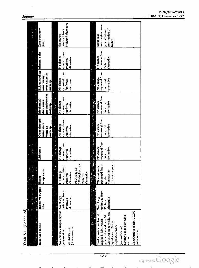
Table
S-1. (Continued
Summary
Radio
frequency
power
alternative
Preferred
alternative
Described
intext
Electric
power
supply
alternative
Construct
new
plant
Inductive
output
tube
Operating
Feedstock
temperature
material
Site
location
alternative
alternative
Cooling
water
system
alternatives
alternative
Room
Lithium
-6 Oncc
-through
Mechanical
K-Area
cooling
Alternate
site
temperature
using
river
draft
using
tower
using
water
as
groundwater
as
river
water
as
makeup
makeup
makeup
Impacts
from
Operation
onLand
Use
and
Infrastructure
No
change
No
change
No
change
No
change
No
change
cstimated
from
cstimatcd
from
cstimated
from
cstimated
from
cstimatcd
from
cstimated
from
Prcfcrrcd
Prcfcrrcd
Prcfcrrcd
Preferred
Preferred
Prcfcrrcd
alternative
altcrnative
alternative
alternative
alternative
alternative
No
change
No
land
usc
changes
beyond
No
change
construction
.estimated
from
Preferred
1 :lectricity
use
:alternative
3.1
tcrawatt
-hrs
No
change
cstimated
from
Prcfcrrcd
altcrnative
lilcctricity
usc 23
%higher
than
Prcfcrrcd
alternative
Impacts
from
Construction
onWaste
Management
9%morc
wastc
No
change
No
change
No
change
generated
duc
to cstimated
from
cstimated
from
cstimated
from
grcator
Preferred
Prcfcrrcd
Preferred
construction
alternative
alternative
alternative
activitics
required
.
No
change
cstimated
from
Prcfcrrcd
altcrnative
Small
construction
landfill
No
change
required
.Most
waste
cstimated
from
gencratcd
would
be
solid
Prcfcrrcd
waste
and
sanitary
solid
and
alternative
liquid
waste
.Wastc
disposcd
atSRS
. (Annual
Values
)
Sanitary
solid
:560
cubic
mctcrs
No
change
cstimated
from
Prcfcrrcd
alternative
Additional
construction
wastc
gcncratcd
from
construction
of
facility
Construction
debris
:30,000
cubic
meters
DRAFT,December 1997
S - 12
DOE /EIS -0270D
DRAFT, December 1997
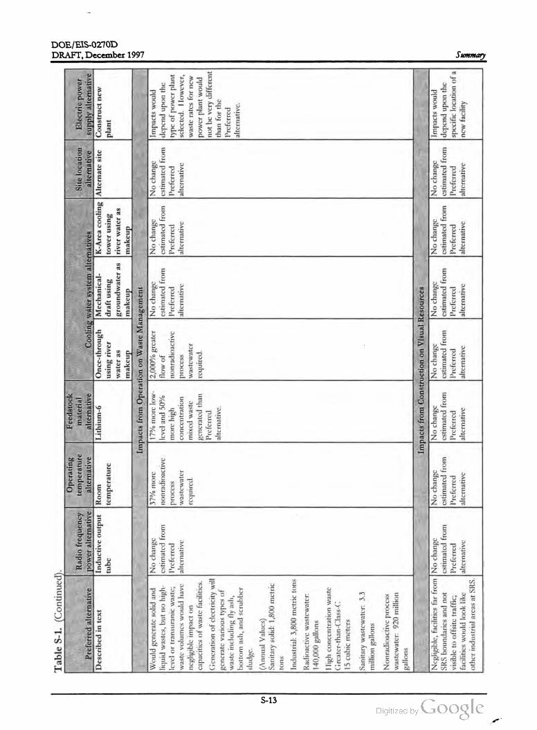
Table
S -1.(Continued
).
Operating
Feedstock
Radio
frequency
temperature
material
Site
location
Electric
power
Preferred
alternative
power
alternative
alternative
alternative
Cooling
water
system
alternatives
alternative
supply
alternative
Described
intext
Inductive
output
Room
Lithium
-6Once
-through
Mechanical
K-Area
cooling
Alternate
site
Construct
new
tube
temperature
using
river
draft
using
tower
using
plant
water
as
groundwater
as
river
water
as
makeup
makeup
makeup
Impacts
from
Operation
on
Waste
Management
Would
gencratc
solid
and
No
change
37
% morc
17
%more
low
2,000
% grcater
No
change
No
change
No
change
Impacts
would
liquid
wastes
,but
no
high
cstimated
from
nonradioactive
level
and
50
% flow
of
cstimated
from
cstimated
from
cstimated
from
depend
upon
the
level
or
transuranic
wastc
;Preferred
process
more
high
nonradioactive
Preferred
Preferred
Preferred
type
of
power
plant
waste
volumes
would
have
alternative
wastewater
concentration
process
alternative
alternative
alternative
sclccted
.However
,
ncgligible
impact
on
required
.mixed
waste
wastewater
waste
rates
for
now
capacitics
of
waste
facilities
.generated
than
required
.power
plant
would
Preferred
not
be
very
different
Generation
of
clectricity
will
alternative
.gcncratc
various
types
of
than
for
the
Preferred
waste
including
fly
ash
,
alternative
.
bottom
ash
,and
scrubber
sludge
.
(Annual
Values
)
Sanitary
solid
:1,800
metric
tons
Industrial
:3,800
mctric
tons
Radioactive
wastcwatcr
:
140,000
gallons
High
concentration
waste
Greater
-than
-Class
-C
15cubic
mcters
Sanitary
wastewater
:3.3
million
gallons
Nonradioactive
process
wastewater
:920
million
gallons
Negligiblc
,facilities
far
from
No
change
SRS
boundaries
and
not
cstimated
from
visible
to
offsite
traffic
;Prcfcrrcd
facilities
would
look
like
alternative
other
industrial
arcas
atSRS
.
No
change
cstimated
from
Prcfcrrcd
alternative
Impacts
from
Construction
onVisual
Resources
No
change
No
change
No
change
estimated
from
cstimated
from
cstimated
from
Preferred
Preferred
Preferred
alternative
alternative
alternative
No
change
No
change
Impacts
would
cstimated
from
cstimated
from
dcpend
upon
the
Preferred
Preferred
specific
location
of
a
alternative
alternative
new
facility
Summary
S -13
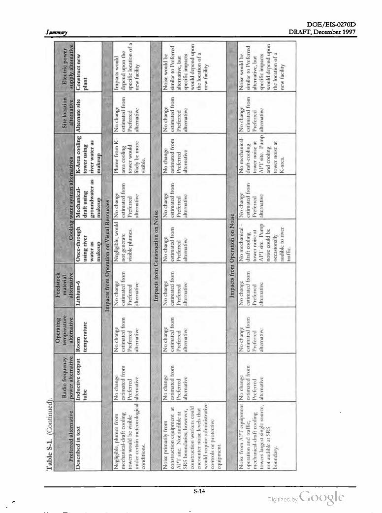
DOE /EIS-0270D
Summary
Table
S-1 .(Continued
).
Operating
Radio
frequency
temperature
Preferred
alternative
power
alternative
alternative
Described
intext
Inductive
output
Room
tube
temperature
Feedstock
material
Site
location
Electric
power
alternative
Cooling
water
system
alternatives
alternative
supply
alternative
Lithium
- 6Once
-through
Mechanical
K-Area
cooling
Alternate
site
Construct
new
using
river
draft
using
tower
using
plant
water
as
groundwater
as
river
water
as
makeup
makeup
makeup
Impacts
from
Operation
on
Visual
Resources
No
change
Negligible
,would
No
change
Plume
from
K-No
change
Impacts
would
estimated
from
not
gencratc
cstimated
from
arca
cooling
cstimated
from
depend
upon
the
Prcfcrrcd
visiblc
plumes
.Preferred
tower
would
Preferred
spccific
location
of
a
alternative
alternative
likely
bemore
alternative
new
facility
visiblc
.
Negligiblc
,plumes
from
No
change
mechanical
-draft
cooling
estimated
from
towers
would
be
visible
Preferred
under
certain
mctcorological
alternative
conditions
.
No
change
cstimated
from
Preferred
alternative
No
change
cstimated
from
Preferred
alternative
Impacts
from
Construction
on
Noise
No
change
No
change
No
change
cstimated
from
cstimated
from
cstimated
from
Preferred
Preferred
Preferred
alternative
alternative
alternative
Noisc
primarily
from
No
change
construction
cquipment
atcstimated
from
APT
sitc
.Not
audible
at
Preferred
SRS
boundaries
;however
,alternative
construction
workers
could
cncounter
noise
levels
that
would
require
administrative
controls
or
protective
cquipment
.
No
change
No
change
Noise
would
be
cstimated
from
cstimated
from
similar
toPreferred
Preferred
Prcfcrrcd
alternative
,but
alternative
alternative
specific
impacts
would
depend
upon
the
location
of
a
new
facility
Noise
from
APT
cquipment
No
change
operation
and
traffic
; cstimated
from
mechanical
-draft
cooling
Preferred
towers
largest
single
source
,alternative
not
audiblc
atSRS
boundary
.
No
change
cstimated
from
Preferred
alternative
towcr
noisc
at
Impacts
from
Operation
onNoise
No
change
No
mechanical
- No
change
estimated
from
draft
cooling
cstimated
from
Preferred
tower
noise
at
Preferred
alternative
APT
'site
. Pump
alternative
noisc
could
be
occasionally
audible
toriver
traffic
.
No
mechanical-
No
change
Noisc
would
be
draft
-cooling
estimated
from
similar
toPreferred
Preferred
alternativc
,but
APT
site
.Pump
alternative
specific
impacts
and
cooling
would
depend
upon
towcr
noisc
at
the
location
of
a
K -arca
.new
facility
DRAFT, December 1997
-
S -14

DOE/EIS -0270D
DRAFT, December 1997
Table
S-1.(Continued
).
Operating
Feedstock
Radio
frequency
temperature
material
Site
location
Electric
power
Preferred
alternative
power
alternative
alternative
alternative
Cooling
water
system
alternatives
alternative
supply
alternative
Described
intext
Inductive
output
Room
Lithium
-6Oncc
-through
Mechanical
K-Area
cooling
Alternate
site
Construct
new
tube
temperature
using
river
draft
using
tower
using
plant
water
as
groundwater
asriver
water
as
makeup
makeup
makeup
Impacts
from
Construction
onHuman
Health
Concentrations
of
No
change
Occupational
No
change
No
change
No
change
No
change
No
change
Impacts
would
be nonradiological
constituents
cstimated
from
injurics
6%less
cstimated
from
cstimated
from
cstimated
from
cstimated
from
cstimated
from
similar
toPreferred
would
be
less
than
Prcfcrrcd
than
Prcfcrrcd
Prcfcrrcd
Prcfcrrcd
Prcfcrrcd
Prcfcrrcd
Preferred
alternative
,but
applicable
limits
for
workers
alternative
alternative
alternative
alternative
altcrnative
alternative
alternative
specific
impacts
and
public
.Traffic
-related
would
depend
upon
Traffic
fatalitics
accidents
resulting
inabout
the
location
of
a
20
%less
than
2fatalitics
tothe
public
and
new
facility
Preferred
workers
duc
toincrcascd
alternative
local
traffic
would
be reduced
with
finish
of
construction
.Occupational
injuries
toworkers
would
be
duc
toindustrial
activitics
and
would
have
the
following
impacts
for
the
construction
period
:
Number
rcquiring
l'irst
Aid
:
1,100
Number
requiring
mcdical
attention
:280
Number
resulting
inlost
work
timc
:93
Summary
S - 15
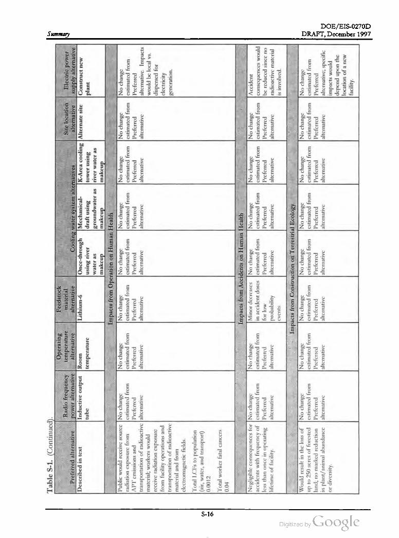
DOE /EIS -0270D
Table
S-1 .(Continued
).
Operating
Radio
frequency
temperature
Preferred
alternative
power
alternative
alternative
Described
intext
Inductive
output
Room
temperature
Summary
tube
Feedstock
material
Site
location
Electric
power
alternative
Cooling
water
system
alternatives
alternative
supply
alternative
Lithium
-6 Once
-through
Mechanical
K-Area
cooling
Alternate
site
Construct
new
using
river
draft
using
tower
using
plant
water
as
groundwater
as
river
water
as
makeup
makeup
makeup
Impacts
from
Operation
onHuman
Health
No
change
No
change
No
change
No
change
No
change
No
change
cstimated
from
estimated
from
cstimated
from
cstimated
from
cstimated
from
cstimated
from
Preferred
Preferred
Preferred
Preferred
Preferred
Preferred
alternative
alternative
alternative
alternative
alternative
alternativc
.Impacts
would
be
local
vs.
dispersed
for
clectricity
gcncration
.
Public
would
receive
source
No
change
radiation
exposure
from
cstimated
from
APT
cmissions
and
Prcfcrrcd
transportation
of
radioactive
alternative
material
;workers
would
reccive
radiation
exposure
from
facility
operations
and
transportation
of
radioactive
matcrial
and
from
clcctromagnctic
fields
.
Total
LCI's
topopulation
(air
,water
,and
transport
)
0.0012
No
change
cstimated
from
Prcfcrrcd
alternative
Total
worker
fatal
cancers
0.04
Negligible
consequences
for
No
change
accidents
with
frequency
of
cstimated
from
less
than
once
inoperating
Preferred
lifetime
of
facility
.alternative
No
change
cstimated
from
Preferred
altcrnative
Impacts
from
Accidents
onHuman
Health
Minor
decreases
No
change
No
change
inaccident
doses
estimated
from
cstimated
from
for
low
Preferred
Prcfcrrcd
probability
alternative
alternative
No
change
No
change
Accident
cstimated
from
cstimated
from
consequences
would
Preferred
Preferred
be
reduced
since
no
alternative
alternative
radioactive
matcrial
isinvolved
cvents
.
Would
result
inthe
loss
of
No
change
up
to250
acres
of
forested
cstimated
from
land
;no
marked
reduction
Preferred
inplant
/animal
abundance
alternative
or
diversity
.
Impacts
from
Construction
on
Terrestrial
Ecology
No
change
No
change
No
change
No
change
cstimated
from
cstimated
from
cstimated
from
cstimated
from
Preferred
Preferred
Prcfcrrcd
Preferred
alternative
alternative
alternative
alternative
No
change
No
change
No
change
cstimated
from
cstimated
from
cstimated
from
Preferred
Preferred
Preferred
alternative
alternative
alternativc
;specific
impacts
would
dcpend
upon
the
location
of
anew
facility
.
DRAFT, December 1997
S - 16

DOE /EIS -0270D
DRAFT, December 1997Table
S- 1.(Continued
).
Operating
Feedstock
Radio
frequency
temperature
material
Site
location
Electric
power
Preferred
alternative
power
alternative
alternative
alternative
Cooling
water
system
alternatives
alternative
supply
alternative
Described
intext
Inductive
output
Room
Lithium
-6 Once
-through
Mechanical
K-Area
cooling
Alternate
site
Construct
new
tube
temperature
using
river
draft
using
tower
using
plant
water
as
groundwater
asriver
water
as
makeup
makeup
makeup
Impacts
from
Operation
on
Terrestrial
Ecology
Negligible
impacts
.No
change
No
change
No
change
No
change
No
change
No
change
No
change
Specific
impacts
Mechanical
-draft
cooling
cstimated
from
estimated
from
estimated
from
cstimated
from
cstimated
from
estimated
from
cstimated
from
would
depend
upon
towers
would
result
insalt
Preferred
Preferred
Preferred
Preferred
Preferred
Preferred
Preferred
thc
location
of
a
alternative
alternative
deposition
on
vegetation
;alternative
alternative
alternative
alternative
alternative
ncw
facility
however
,maximum
rates
(60
lb/acrcs
/yr)arc
bclow
threshold
levels
(180
lb/acrcs
/yr).
Impacts
from
Construction
onWetlands
Ecology
No
impacts
are
projected
No
change
No
change
No
change
No
change
No
change
No
change
No
change
Specific
impacts
from
construction
activities
.cstimated
from
cstimated
from
estimated
from
cstimated
from
cstimated
from
estimated
from
cstimated
from
would
depend
upon
Preferred
Preferred
Preferred
Preferred
Preferred
Prcfcrrcd
Preferred
the
location
of
a
alternative
alternativc
alternative
alternative
alternative
alternative
alternative
new
facility
No
change
cstimated
from
Preferred
alternative
No
change
estimated
from
Preferred
alternative
Impacts
from
Operation
onWetlands
Ecology
No
change
Would
raise
water
No
change
cstimated
from
level
inPonds
2estimated
from
Preferred
and
5by
1.5
fcct
,Preferred
alternative
possibly
affecting
alternative
wetland
plant
communities
.
Would
result
inminor
impacts
towetlands
. Temperature
of
the blowdown
would
be
marginally
higher
than
the
ambicnt
maximum
temperaturc
.During
cooler
months
the
warmth
could
have
apositive
impact
by
lengthening
the
growing
scason
for
somc
aquatic
vegctation
.
No
change
No
change
Specific
impacts
estimated
from
cstimated
from
would
depend
upon
Preferred
Preferred
the
location
of
a
alternative
alternative
new
facility
Summary
S - 17
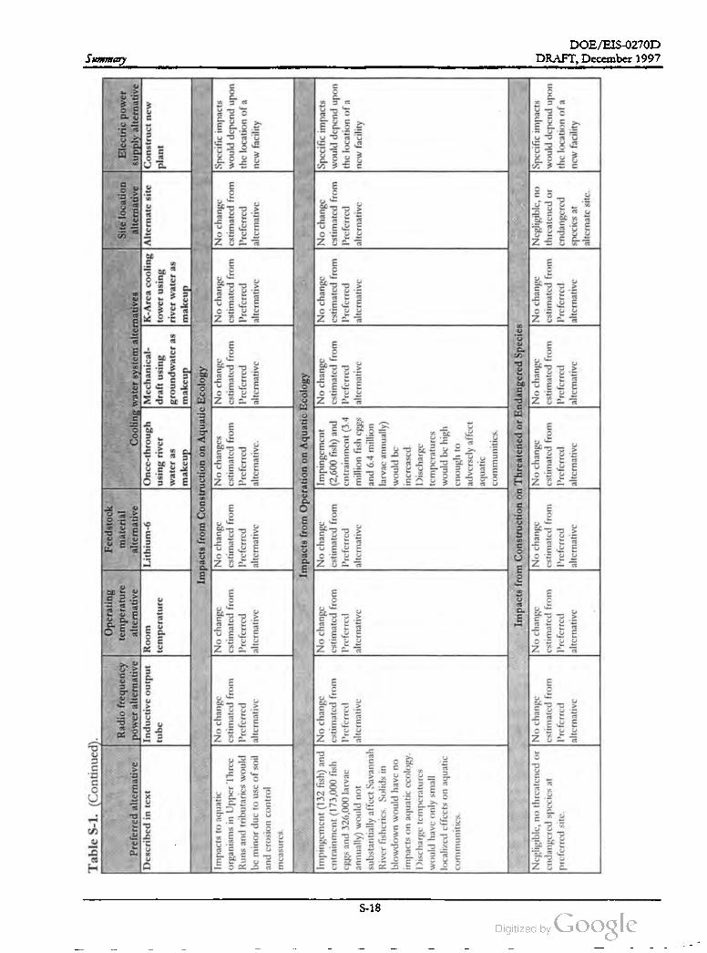
DOE /EIS -0270D
Summary
-
Table
S-1 .(Continued
).
Operating
Feedstock
Radio
frequency
temperature
material
Site
location
Electric
power
Preferred
alternative
power
alternative
alternative
alternative
Cooling
water
system
alternatives
alternative
supply
alternative
Described
intext
Inductive
output
Room
Lithium
-6Once
-through
Mechanical
K-Area
cooling
Alternate
site
Construct
new
tube
temperature
using
river
draft
using
tower
using
plant
water
as
groundwater
as
river
water
as
makeup
makeup
makeup
Impacts
from
Construction
onAquatic
Ecology
Impacts
toaquatic
No
change
No
change
No
change
No
changes
No
change
No
change
No
change
Specific
impacts
organisms
inUpper
Threc
cstimated
from
cstimated
from
cstimated
from
cstimated
from
cstimated
from
cstimated
from
cstimated
from
would
depend
upon
Runs
and
tributarics
would
Preferred
Prcfcrred
Prcfcrrcd
Preferred
Preferred
Preferred
Preferred
the
location
of
a
bcminor
duc
touse
of
soil
alternative
alternative
alternative
alternative
. alternative
alternative
alternative
new
facility
and
crosion
control
mcasures
.
No
change
cstimated
from
Preferred
alternative
No
change
No
change
Specific
impacts
cstimated
from
cstimated
from
would
depend
upon
Preferred
Preferred
the
location
of
a
alternative
alternative
new
facility
Impingement
(132
fish
)and
No
change
cntrainment
(173,000
fish
estimated
from
cggs
and
326,000
larvac
Preferred
annually
)would
not
alternative
substantially
affect
Savannah
River
fishcrics
.Solids
in blowdown
would
have
no impacts
on
aquatic
ccology
.
Discharge
temperatures
would
have
only
small localized
cffects
on
aquatic
communities
.
Impacts
from
Operation
onAquatic
Ecology
No
change
Impingement
No
change
cstimated
from
|(2,600
fish
)and
cstimated
from
Preferred
cntrainment
(3.4
Preferred
alternative
million
fish
cggs
alternative
and
6.4
million
larvac
annually
)
would
be
increascd
.
Discharge
temperatures
would
be
high
cnough
to
advcrscly
affect
aquatic communitics
.
Negligible
,no
thrcatcncd
orNo
change
cndangered
spccics
atcstimated
from
preferred
site
.Preferred
alternative
Impacts
from
Construction
onThreatened
orEndangered
Species
No
change
No
change
No
change
No
change
No
change
Negligible
,no
cstimated
from
cstimated
from
cstimated
from
cstimated
from
cstimated
from
threatened
or
Preferred
Preferred
Preferred
Preferred
Preferred
cndangered
alternative
alternative
alternative
alternative
alternative
spccics
at
alternate
sitc
.
Specific
impacts
would
depend
upon
the
location
of
a
new
facility
DRAFT, December 1997
S - 18
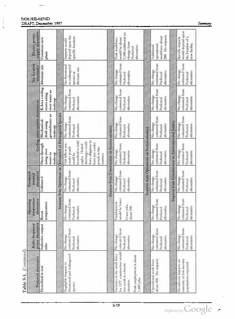
DOE /EIS -0270D
DRAFT,December 1997
draft
using
Table
S-1 .(Continued
) .
Operating
Feedstock
Radio
frequency
temperature
material
Site
location
Electric
power
Preferred
alternative
power
alternative
alternative
alternative
Cooling
water
system
alternatives
alternative
supply
alternative
Described
intext
Inductive
output
Room
Lithium
-6 Once
-through
Mechanical
K-Area
cooling
Alternate
site
Construct
new
tube
temperature
using
river
tower
using
plant
water
as
groundwater
as
river
water
as
makeup
makeup
makeup
Impacts
from
Operation
onThreatened
orEndangered
Species
Negligible
impacts
toNo
change
No
change
No
change
lish
kills
inpre-
No
change
No
change
No
thrcatcncd
Impacts
would
thrcatened
and
cndangered
cstimated
from
cstimated
from
cstimated
from
cooler
ponds
cstimated
from
cstimated
from
or
endangered
depend
upon
the
spccics
.Prcfcrrcd
Prcfcrrcd
Preferred
could
bc
Preferred
Preferred
spccics
at
specific
location
.
alternative
alternative
alternative
beneficial
tobald
alternative
alternative
altcrnatc
sitc
.
cagles
.IIcated
discharges
could
force
alligators
to
Icave
pre
-cooler
ponds
inlate
summer
.
Increases
inthe
work
force
No
change
for
APT
construction
would
cstimated
from
not
result
inaboom
Preferred
situation
.alternative
Impacts
from
Construction
onSocioeconomics
limployment
No
change
No
change
No
change
would
be
lower
.estimated
from
cstimated
from
cstimated
from
Prcfcrrcd
Prcfcrrcd
Preferred
lewer
jobs
-alternative
alternative
alternative
about
100
.
No
change
cstimated
from
Preferred
alternative
No
change
Pcak
workforce
cstimated
from
would
be
about
Preferred
1,100
additional
no
alternative
change
form
Preferred
alternative
.Peak
employment
isabout
1,400
jobs
.
Operational
work
force
about
500.
No
impacts
.
No
change
cstimated
from
Preferred
alternative
No
change
estimated
from
Preferred
alternative
Impacts
from
Operations
onSocioeconomics
No
change
No
change
No
change
cstimated
from
cstimated
from
cstimated
from
Prcfcrrcd
Preferred
Preferred
alternative
alternative
alternative
No
change
cstimated
from
Preferred
alternative
No
change
Additional
cstimated
from
operational
Preferred
workforce
about
alternative
200.
No
impacts
.
No
advcrsc
impacts
on minority
orlow
-income
populations
expected
.
No
change
cstimated
from
Preferred
alternative
Impacts
from
Construction
on
Environmental
Justice
No
change
No
change
No
change
No
change
cstimated
from
cstimated
from
estimated
from
estimated
from
Preferred
Preferred
Preferred
Prcfcrred
alternative
alternative
alternative
alternative
No
change
No
change
Specific
impacts
estimated
from
cstimated
from
would
depend
upon
Preferred
Preferred
the
location
of
a
alternative
alternative
new
facility
.
Summary
S -19

DOE /EIS -0270D
Summary
Table
S-1. (Continued
) .
Operating
Feedstock
Radio
frequency
temperature
material
Site
location
Electric
power
Preferred
alternative
power
alternative
alternative
alternative
Cooling
water
system
alternatives
alternative
supply
alternative
Described
intext
Inductive
output
Room
Lithium
-6Once
-through
Mechanical
K-Area
cooling
Alternate
site
Construct
new
tube
temperature
using
river
draft
using
tower
using
plant
water
as
groundwater
as
river
water
as
makeup
makeup
makeup
Impacts
from
Operations
onEnvironmental
Justice
No
adverse
impact
on
No
change
No
change
No
change
No
change
No
change
No
change
No
change
Specific
impacts
minority
or
low
-income
cstimated
from
estimated
from
cstimated
from
estimated
from
cstimated
from
cstimated
from
cstimated
from
would
depend
upon
Preferred
populations
cxpccted
.Preferred
Prcfcrrcd
Prcfcrrcd
Preferred
Preferred
Preferred
the
location
of
a
alternative
alternative
alternative
alternative
alternative
alternative
alternative
new
facility
---
DRAFT,December 1997
S - 20

Chapter 1
Background and Purpose and Need for Action

DOE /EIS -0270D
ITobacco
Road
Southern
County
78
Worth
Augusta
78
Aiken
South
232
)
To
Atlanta
39
Norfolk
20
The
Savannah
River
Site
has
an
area
ofabout
300
square
miles
.Itisabout
25miles
southeast
ofAugusta
,Georgia
,and
20miles
south
ofAiken
, South
Carolina
.
ngfied
00
Units
1278
)
(302
)19
Columbia
County
Richmond
County
520
Augusta
10
1211578
(278
10 121
(125
Background and Purpose and Need for Action
756
Beech
Island
A
New
Ellenton
Upper
Three
Barnwell
(278
)(781
Jones
Ap
spur
56
56
Bush
Field
conny
56
(278
)39
57
(125
)
Jackson
1
Williston
NORTH
78
Blackville
37
Fort
Gordon
Military
Reservation
Spirit
4
Creek
South
Carolina
488
(278
)
Georgia
Savannah
River
Site
3
Salkehatchie
Snelling
64
Branch
Par
Pond
(125
Barnwell
CSX (abandoned
)
Savannah
SOUTH
CAROLINA
CSX
River64
L-Lake
Lowe
SRS
Pen
3Vogtle
Electric
Generating
Plant
Creek
Three
GEORGIA
River
278
Steel
Runs
Savannah
(125
Barnwell
Allendale
County
County
River
KILOMETERS
50
100
150
0200
100
50
MILES
Burke
County
Screven
County
Miles
0123 4567 8910
Kilometers
024 681012
14
16
DRAFT, December 1997
PK68
-Z1
-PC
Figure
1-1
.Savannah
River
Site
.
J

DOE / EIS -0270D
DRAFT,December 1997 Background and Purpose and Need for Action
CHAPTER 1. BACKGROUND AND PURPOSE
AND NEED FOR ACTION
The Department of Energy (DOE) is designing, building, and testing critical components of an accel
erator for the production of tritium . If the Department decides to build a production accelerator, it will
do so at the Savannah River Site in South Carolina (Figure 1-1). This chapter describes activities that
have led to the Proposed Action and Alternatives evaluated in this environmental impact statement. It
evaluates the purpose and Need for this action, and how the capability to produce tritium in an accel
erator relates to other ongoing and planned missions at the Savannah River Site .
1.1 Background
Since nuclear weapons came into existence in
1945 , a nuclear deterrent has been a cornerstone
of the Nation's defense policy and national se
curity. President Clinton reiterated this princi
ple in his July 3, 1993, radio address to the
Nation . U.S. strategic nuclear systemsare based
on designs that use tritium , which enhances the
yield of nuclear weapons. Because tritium de
cays over time, new tritium is required to main
tain theNation's nuclear weapons stockpile.
tritium in nuclear weapons to ensure that they
can function as designed . Over the yearsDOE
built and operated 14 reactors around the
country to produce tritium and other nuclear
materials. None of the reactors is currently op
erational, and DOE has not produced tritium
since 1988. However, according to the Atomic
Energy Act of 1954, DOE is responsible for
developing and maintaining the capability to
produce nuclear materials such as tritium for the
defense of the United States.
Tritium is a radioactive isotope of hydrogen
that occurs naturally in small quantities. It
must be manmade to obtain useful quanti
ties. It is an essential component of every
warhead in the current and projected U.S.
nuclear weapons stockpile . These war
heads depend on tritium so they can per
form as designed. Tritium decays at about
5.5 percentper year and, therefore, requires
periodic replacement.
Until a new tritium supply source is operational,
DOE will continue to support requirements by
recycling tritium from weapons retired from the
Nation's stockpile. However, because of the
tritium decay rate (about 5.5 percent per year),
recycling can only meet the tritium demands for
a limited time, even with the reduction in
stockpile requirements and no identified need
for new weapons. Current projections, derived
from classified projections of future stockpile
scenarios, indicate that recycled tritium will
support the Nation's nuclear weapons stockpile
adequately until approximately 2005 (see Fig
ure 1-2 ).
1995
100 %
Tritium
Decay
Over
Time2000
75 %
2007
50 %
The United States will need a new produc
tion source of tritium by 2005. The APT
could be available for production in 2007
which means tritium reserves could be util
ized in the interim .
2019
25 % PK68-12035
10 %
Remaining
The Nation needs tritium to ensure that each
weapon remaining in the stockpile operates as
designed. Tritium has a relatively short radio
active half-life of 12.3 years. This rapid decay
rate necessitates the periodic replenishment of
Without a new supply source, after 2005 the
United Stateswould have to use its strategic re
serve, which maintains tritium for emergencies
and contingencies, to maintain the readiness of
the nuclear weapons stockpile.In such a
1-1

DOE /EIS -0270D
Background and Purpose and Need for Action DRAFT,December 1997
Tritium
inventory
without
production
Tritium inventory with production
beginning in 2005 at nominal rate
Required reserve
for 1996 NWSM
1996 NWSM
Stockpile
Tritium
quantity
START 11
Stockpile
2005 2010 2016PK68-Z1-PC
START: Strategic ArmsReduction Treaty
NWSM : Nuclear Weapons Stockpile Memorandum .
Note : Graph has no scale or proportion.
Source: DOE (1997a).
Figure 1-2 . Estimated tritium inventory and reserve requirements .
scenario , the depletion of the strategic reserve
would degrade U.S. nuclear deterrent capability
(based on current designs which require tritium )
because some weapons in the stockpile would
not be able to function as designed. Eventually,
the United States would lose its nuclear deter
To initiate the purchase of an existing
commercial reactor (operating or partially
complete) for conversion to a defense facil
ity, or the purchase of irradiation services
with an option to purchase the reactor
rent.
In its Final Programmatic Environmental Impact
Statement for Tritium Supply and Recycling (Tritium
Supply PEIS) (DOE 1995), the U.S. Depart
ment of Energy evaluated the need for a new
tritium source. DOE published a Record of
Decision (ROD ) for that Programmatic Envi
ronment Impact Statement on December 12,
1995 (60 FR 63878). Based on the findings in
the Tritium Supply PEIS and on other techni
cal, cost, and schedule evaluations, DOE an
nounced the decision to pursue a dual-track
approach to the two most promising alterna
tives for supplying tritium :
In the Record of Decision, DOE committed
that it would , within a 3 -year period (by late
1998), select one of these approaches to be the
primary source of tritium . If feasible, it would
continue to develop the other alternative as a
backup tritium source. In the interim , testing of
critical accelerator components would be per
formed at the Los Alamos National Laboratory .
Further,DOE selected the Savannah River Site
(SRS) as the location for an accelerator, if it de
cides to build one, and decided to upgrade and
consolidate the tritium recycling facilities at the
SRS and to construct a Tritium Extraction Fa
cility at the SRS to support both dual-track al
ternatives.
To design , build , and test critical compo
nents of an accelerator system for tritium
production
The DOE strategy for compliance with the Na
tional Environmental Policy Act (NEPA) has
been to (1) make decisions on programmatic
1-2
DOE /EIS -0270D
DRAFT,December 1997 Background and Purpose and Need for Action
DOE has prepared this EIS in accordance with
Section 102(2)(c) of NEPA as amended
(42 USC et seq.) and implemented by the CEQ
regulations (40 CFR 1500-1508) and the DOE
NEPA regulations (10 CFR 1021).
alternatives as described and evaluated in the
Tritium Supply PEIS , and (2) follow (tier from
the Tritium Supply PEIS) with site-specific as
sessments that implement the selected pro
grammatic decisions. Following this strategy ,
DOE is preparing this EIS on the Accelerator
for the Production of Tritium (APT), an EIS on
the Tritium Extraction Facility , and a Commer
cial LightWater Reactor EIS. On September 5,
1996 , the Department published the “Notice of
Intent To Prepare an Environmental Impact
Statement for the Construction and Operation
ofan Accelerator for the Production of Tritium
at the Savannah River Site" (61 FR 46787).
This EIS evaluates specific technology and site
options for the use of an accelerator for the
production of tritium at the SRS, and assesses
the impacts of accelerator construction and op
eration.
DOE has placed copies of the Final Pro
grammatic Environmental Impact Statement
for Tritium Supply and Recycling in its Public
Reading Rooms. The reading room for the
Savannah River Site is at the Gregg
Graniteville Library , University of South
Carolina -Aiken Campus, Aiken , South Caro
lina 29801, 803-641-3465. Interested per
sons can obtain copies by calling 1-800-881
7292 or writing to : Andrew R.Grainger, U.S.
Department of Energy, Savannah River Op
erations Office, Aiken , South Carolina 29802 .
1.2 Review of the Final
Programmatic Environmental
Impact Statement for Tritium
Supply and Recycling
To support this analysis,DOE is completing an
engineering development and demonstration
program that will increase technical confidence
in those parts of the facility where uncertainties
still exist. The descriptions and analyses in this
EIS contain the information from this program
as it affects the design and anticipated operating
parameters of the APT facilities.
DOE proposes specific technology options
for an accelerator to be used for the produc
tion of tritium at the Savannah River Site .
In the Tritium Supply PEIS , DOE evaluated
facilities that will safely and reliably fulfill future
national defense requirements for tritium . As
used in the title, “ Supply "means the production
of new tritium in either a reactor or an accelera
tor (by irradiating target materials with neu
trons) and the subsequent extraction of the
tritium in pure form for use in weapons.
“ Recycling” means recovering residual tritium
from weapons components, purifying it, and
refilling the components with both recovered
and new tritium (when it becomes available).
Also , on September 5, 1996 , DOE published a
Notice of Intent for the Construction and Op
eration of a Tritium Extraction Facility at SRS
(61 FR 46790 ). This proposed facility would be
able to support either an accelerator or a com
mercial light-water reactor (CLWR).
The Tritium Supply PEIS is the upper tier
document that established the proposed actions
described in this follow -up EIS and for the
other actions described in Section 1.5 , with the
exception ofthe proposed shutdown of the SRS
River Water System . This EIS has been pre
pared consistent with the regulations promul
gated by the Council on Environmental Quality
(CEQ; see 40 CFR Parts 1502 - 1508 ). Further,
DOE evaluated four tritium supply technologies
for new tritium supply facilities: a Heavy-Water
Reactor, a Modular High - Temperature Gas
Cooled Reactor, an Advanced Light-Water Re
actor, and an accelerator. The Tritium Supply
PEIS included a commercial light water reactor
option that evaluated existing commercial light
water reactors for irradiation services or for
purchase and conversion to tritium production.
The Tritium Supply PEIS also addressed the
impacts of a reactor used for themultiple pur
poses of producing tritium , burning plutonium ,
1-3
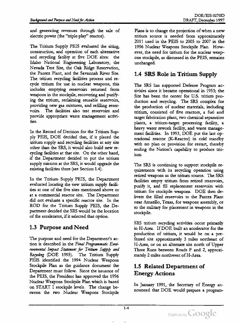
DOE /EIS-0270D
Background and Purpose and Need for Action DRAFT,December 1997
and generating revenues through the sale of
electricpower (the " triple-play” reactor).
Plans is to change the projection ofwhen a new
tritium source is needed from approximately
2011 used in the PEIS to 2005 to 2007 in the
1996 Nuclear Weapons Stockpile Plan . How
ever, the need for tritium for the nuclearweap
ons stockpile, as discussed in the PEIS, remains
unchanged.
1.4 SRS Role in Tritium Supply
The Tritium Supply PEIS evaluated the siting,
construction , and operation of each alternative
and recycling facility at five DOE sites: the
Idaho National Engineering Laboratory , the
Nevada Test Site , the Oak Ridge Reservation,
the Pantex Plant, and the Savannah River Site.
The tritium recycling facilities process and re
cycle tritium for use in nuclear weapons; this
includes emptying reservoirs returned from
weapons in the stockpile, recovering and purify
ing the tritium , reclaiming reusable reservoirs,
providing new gas mixtures, and refilling reser
voirs. The facilities also test reservoirs and
provide appropriate waste management activi
ties .
The SRS has supported Defense Program ac
tivities since it became operational in 1953; the
Site has been the center for U.S. tritium pro
duction and recycling. The SRS complex for
the production of nuclear materials, including
tritium , consisted of five reactors , a fuel and
target fabrication plant, two chemical separation
plants, a tritium -target processing facility, a
heavy water rework facility , and waste manage
ment facilities. In 1993,DOE put the last op
erational reactor (K -Reactor) in cold standby
with no plan or provision for restart, thereby
ending the Nation's capability to produce trit
ium .
In the Record ofDecision for the Tritium Sup
ply PEIS , DOE decided that, if it placed the
tritium supply and recycling facilities at any site
other than the SRS, it would also build new re
cycling facilities at that site. On the other hand,
if the Department decided to put the tritium
supply mission at the SRS, it would upgrade the
existing facilities there (see Section 1.4 ).
In the Tritium Supply PEIS, the Department
evaluated locating the new tritium supply facili
ties at one of the five sites mentioned above or
at a commercial reactor site. The Department
did not evaluate a specific reactor site. In the
ROD for the Tritium Supply PEIS , the De
partment decided the SRS would be the location
of the accelerator, if it selected that option .
The SRS is continuing to support stockpile re
quirements with its recycling operation using
retired weapons as the tritium source. The SRS
facilities empty tritium from retired reservoirs,
purify it, and fill replacement reservoirs with
tritium for stockpile weapons. DOE then de
livers the filled reservoirs to the Pantex Plant
near Amarillo , Texas, for weapons assembly, or
to the military for placement in weapons in the
stockpile.
1.3 Purpose and Need
SRS tritium recycling activities occur primarily
in H -Area. If DOE built an accelerator for the
production of tritium , it would be on a pre
ferred site approximately 3 miles northeast of
H -Area, or on an alternate site north of Upper
Three Runs between Roads F and 2 , approxi
mately 2 miles northwest of H -Area.
The purpose and need for the Department's ac
tion is described in the Final Programmatic Envi
ronmental Impact Statement for Tritium Supply and
Recycling (DOE 1995). The Tritium Supply
PEIS identified the 1994 Nuclear Weapons
Stockpile Plan as the guidance document the
Department must follow . Since the issuance of
the PEIS, the President has approved the 1996
NuclearWeapons Stockpile Plan which is based
on START I stockpile levels. The change be
tween the two Nuclear Weapons Stockpile
1.5 Related Department of
Energy Actions
In January 1991, the Secretary of Energy an
nounced that DOE would prepare a program
1-4
DOE /EIS -0270D
DRAFT,December 1997 Background and Purpose and Need for Action
matic EIS to examine alternatives for the re
configuration of the Nation's Nuclear Weapons
Complex . The Department described the
framework for that EIS in its Nuclear Weapons
Complex Reconfiguration Study (DOE 1991), a de
tailed examination of alternatives for the pro
posed Complex
(TEF). An additional alternative to those dis
cussed in the TEF EIS would modify the APT
to include the equipment needed for TEF op
erations in the APT. This alternative is de
scribed in Section 2.5.3 of this EIS .
DOE proposes to make one ormore records of
decision to select technology alternatives and a
site for the APT. These decisions would be
based on the environmental analysis contained
in this EIS and policy, technical, cost, and
schedule information .
Due to significant changes since January 1991,
especially in relation to projected requirements
for the U.S. nuclear weapons stockpile, the
framework described in the NuclearWeapons Re
configuration Studyno longer exists. To keep pace
with the changes, DOE separated the Recon
figuration Programmatic EIS into the Final Pro
grammatic Environmental Impact Statement for
Tritium Supply and Recycling ( Tritium Supply
PEIS) (DOE 1995 ) and the Stockpile Stewardship
and Management Programmatic EIS (DOE 1996a).
Chapter 1 of the Tritium Supply PEIS discusses
the evolution of thisprogram .
A separate record of decision would select the
TEF alternative and would be based on the en
vironmental analysis in the TEF EIS and the
environmental analysis on combining the TEF
facilities into the APT presented in this EIS.
Policy, technical, cost,and schedule information
would also be used in this decision .
As mentioned in Section 1.1, the Record of
Decision supported by the Tritium Supply PEIS
has resulted in a series of actions by DOE
which require site-specific evaluation under the
National Environmental Policy Act. These ac
tions are the APT described in this EIS, the
purchase or use of a commercial light water re
actor to make tritium , the construction of a new
tritium extraction facility at SRS, and the up
grade and consolidation of SRS tritium facilities .
In addition, the shutdown of the river water
system at SRS is related to cooling water alter
natives in this EIS. Because of the relationships
of these various proposed actions to tritium
supply and recycling DOE is closely coordinat
ing the range ofproposed actions.
DOE will prepare an EIS for the commercial
light water reactor and has prepared an EIS for
the shutdown of the river water system . DOE
proposes to make one ormore records of deci
sion based on each of these EISs. The upgrade
and consolidation of tritium facilities will be
evaluated in an environmental assessment fol
lowed by a finding of no significant impact or
an EIS. The key milestones and status of each
of these documents is presented in Figure 1-3.
The following sections describe the DOE
NEPA implementation strategy including the
NEPA documents which it intends to prepare.
Commercial Light Water Reactor( s) . As it is
for this document, the Tritium Supply PEIS is
also the upper -tier document for the EIS that
DOE will prepare on the potential use of a
commercial reactor as the primary source of
tritium production . The CLWR EIS will assess
the environmental differences of producing
tritium in commercial reactors. Among its al
ternatives, that EIS will consider the purchase
of an existing or partially completed reactor and
the purchase of irradiation services. Further,
the Record of Decision for the Tritium Supply
and Recycling Programmatic EIS provides guid
ance for DOE in the preparation of the CLWR
EIS and this APT EIS .
NEPA Implementation Strategy: Chapter 2
presents the Proposed Action and Alternatives
for the APT. These alternatives focus on vari
ous technologies and site locations on the Sa
vannah River Site. In a separate environmental
impact statement, the DOE is evaluating alter
natives for a new tritium extraction facility
If the Secretary selects the commercial light
water reactor option ,DOE would transport the
1-5

DOE /EIS -0270D
DRAFT, December 1997Background and Purpose and Need for Action
Task Name
Tritium Supply and
Recycling EIS
1996 1997 1998
JFMAMJJASONDJFMAMJJASONDJFMAMJJASONDJ
ROD
Dec 1995
Accelerator Production of
Tritium EIS
NOI
Sept 1996
Dratt EIS
Dec 1997
ROD
Final EIS
Summer 1998
Tritium Extraction Facility
EIS
NOI
Sept 1996
Draft EIS
Feb 1998ROD
Final EIS
August 1998
Commercial Light Water
Reactor EIS
NOI
Late 1997
Draft
Apr 1998
Final
Fall 1998
ROD -TBD
Shutdown of the River
Water System EIS
NOI
Jun 1996
Draft EIS
Nov 1996
Final
May 1997
Upgrade and Consolidate
Tritium Facility EANotice to States
Indian Nations
Draft Final EA/FONSI
EA or NOI
Dec 1997
NOI = Notice of Intent
ROD = Record of Decision
EA = Environmental Assessment
FONSI = Finding ofNo Significant Impact
Figure 1-3 . NEPA documentation for related DOE actions.
target material from the reactors to the SRS for
tritium extraction .
approximately one mile east of the SRS in
Barnwell, SC .
Tritium Extraction . On September 5 , 1996 ,
DOE issued a "Notice of Intent to Prepare the
Construction and Operation of a Tritium Ex
traction Facility at the Savannah River Site En
vironmental Impact Statement” (61 FR 4670).
As currently planned, that EIS will evaluate the
environmental impacts of facility construction
and operation for two tritium extraction scenar
ios:
As with the APT and CLWR EISs, the upper
tier document for the tritium extraction EIS is
the Tritium Supply and Recycling Programmatic
EIS. The scheduled completion date for that
EIS is August 1998 .
The construction and operation of a new
extraction facility that would provide the
capability to process irradiatedtarget
rods
from a commercial light water reactor, re
move the impurity gases , and deliver weap
ons quality tritium to the existing Tritium
Loading Facility (formerly known as the
Replacement Tritium Facility ). The extrac
tion facility would be capable of extracting
tritium from Lithium targets ifDOE selects
them for use in the accelerator.
Upgrade and Consolidate SRS Tritium Fa
cilities. The Department is preparing an envi
ronmental assessment (EA) on the upgrade and
consolidation of the SRS Tritium Facilities
scheduled for completion in December 1997.
In the Record ofDecision for the Tritium Sup
ply PEIS , DOE decided that the consolidated
upgrade would result in closing one building
(232-H ) and transferring its functions to two
other buildings in H -Area. The Department
would upgrade four buildings in H -Area to
meet environmental, health , and safety require
ments and one other building to accept the
transferred activities.
The upgrade and use of the existing Allied
General Nuclear Services facility located
Shutdown of the River Water System at the
Savannah River Site. DOE built the River
Water System to pump large quantities of cool
ing water from the Savannah River to the SRS
1-6

DOE /EIS-0270D
DRAFT,December 1997 Background and Purpose and Need for Action
nuclear reactors. Because the Department has
shut the reactors down, no cooling water is cur
rently required and the SRS Strategic Plan (DOE
1996b) has identified the system as potential
surplus infrastructure. However, if the De
partment decides to build the APT, cooling
water would be needed and may require parts of
the existing cooling water system .
tion sharing. The APT is the first known accel
erator proposed for a mission to produce
weapons materials in a sustained production
operatingmode.
Nuclear weapon's proliferation concerns arise
when a technology is used to develop special
nuclear materials. Using an accelerator to pro
duce special nuclear materials in quantities
which could be a proliferation concern requires
a particle beam power of approximately
1 megawatt or greater. Research accelerators
with beam powers in the 1 megawatt range have
been viable for at least 20 years.
In May 1997, the Department issued its Final
Environmental Impact Statement: Shutdown of the
River Water System at the Savannah River Site (DOE
1997b). That document proposes to shut down
the River Water System and place all or part of
the system in a standby condition. Under the
preferred " standby” alternative, DOE could
place portions of the system in several different
conditions; for example, surplus portions of the
system could be shut down and deactivated.
The deactivated portionswould not be capable
of restart. Other portions could be placed in a
" layup” condition so they could support poten
tial future missions such as an accelerator for
the production of tritium . To attain the layup
condition, DOE would shut the equipment
down but would preserve it for future restart if
necessary . As an alternative, DOE could place
someportions of the system in a higher state of
readiness than layup that would allow restart in
a relatively short time.
The APT brings together different pieces ofac
celerator technology which increase efficiency,
and will be sufficiently large so production can
meet the current and projected requirements of
tritium . Since this is a change in the historic
application of accelerator technology , the De
partment is reviewing how it controls the export
ofaccelerator technology .
Currently, Section 57b. of the Atomic Energy
Act requires that “ persons” subject to U.S. ju
risdiction who engage directly or indirectly in
the production of special nuclear material out
side of the United States must be authorized to
do so by the Secretary of Energy. This re
quirement is implemented by DOE's regula
tions in 10 CFR Part 810, “Assistance to
Foreign Atomic Energy Activities.”
1.6 Nonproliferation
Accelerator technology has been in use for
more than 75 years. During this time they have
been constructed in many different types and
sizes, with power ranging from a few watts to
approximately onemegawatt. The possibility of
producing special nuclear material (i.e., pluto
nium ) using an accelerator was recognized sev
eral decades ago. However, using this option
for large scale production wasmore costly than
production in nuclear reactors. Therefore, spe
cial nuclear material production using an accel
erator was not pursued by the nuclear weapons
states, and basic science research became the
primary use of accelerators . This research mis
sion is promoted by the International Atomic
Energy Agency through a program of informa
In implementing these requirements, the De
partment has determined they implicitly cover
exports of accelerator technology to produce
special nuclear materials. The Department is
now in the process of determining whether to
make this implicit coverage explicit. A pro
posed rulemaking amending the Part 810 regu
lations to this effect is under consideration.
1.7 Medical Isotope Production
With the high beam current and energy, the
APT facilities could produce a reliable supply of
medical radionuclides. Themotivating force for
the production of such radionuclides is the ag
ing ofexisting U.S. production facilities and the
1-7

DOE /EIS -0270D
DRAFT,December 1997Background and Purpose and Need for Action
increasing reliance on foreign suppliers. A sin
gle foreign company supplies the medical nu
clide most used in the United States
(technetium - 99m ). A number of other nuclides
used for treatment diagnosis, or research either
are not available or are expensive due to short
supply . The APT capability to produce radi
onuclides could meet present needs and adapt
to future demands.
meetings were held on December 3 and De
cember 5, 1996 , in Savannah , Georgia, and
Aiken, South Carolina, respectively. These
meetings were attended by 63 members of the
public. In addition, the Department received
approximately 24 mail and phone comments on
the scope of this EIS.
As a result of the scoping process for the APT
and TEF EISs, theDepartment identified about
90 separate comments. The following is a brief
summary of comments pertaining to APT issues
or concerns being addressed in the EIS :
• Type of target material to be used The
Department is evaluating both Helium - 3
and Lithium -6 feedstock material.
DOE could make medical isotopes in several
areas of the accelerator. For example, it could
extract some isotopes from the window cooling
system , target, target cooling system , and the
blanket region without modifying the current
APT design. DOE could modify the design by
installing devices to divert packets of protons at
differentenergy
levels radionuclide
producing targets, or by modifying the blanket
surrounding the target to inserttargets
for radi
onuclide production . If it decides to produce
medical isotopes, DOE would build an isotope
production facility or modify existing SRS fa
cilities for that purpose.
to
Benefits of using the existing river water
system -- The potential use by the river wa
ter system to provide cooling water to the
APT is an alternative being considered .
Human health issues related to tritium pro
duction and the emissions from a new coal
or gas- fired power plant that may be re
quired -- The Department is considering the
health impacts of its actions from both trit
ium production and a coal/ gas -fired power
plant.
The Department is considering the feasibility of
using the accelerator, if it decides to build one,
formedical isotope production . A preliminary
feasibility study is under way. If that study re
sults in a decision to proceed,DOE would have
to perform additional conceptual design work .
Because the design information will not be
available for some time, this EIS does not dis
cuss the use of the APT facilities to produce
medical isotopes. DOE will complete a sepa
rate National Environmental Policy Act evalua
tion if it decides to proceed with a proposal to
make medical isotopes in the APT facilities.
Impacts on surface water and groundwater
Both surface water and groundwater im
pacts are being considered.
1.8 Stakeholder Participation
Several issues brought forth in scoping are not
specifically being addressed in the APT EIS but
are being considered by the Department in
other forums, or were considered in the PEIS
on Tritium Supply : most notably the potential
impacts from commercial light water reactors,
siting at the DOE complex sites, the use of
other technologies, and cost and schedule .
DOE conducted a public comment period to
solicit input on the scope of this EIS. The pub
lic scoping period extended from September 5 ,
1996 , to December 20, 1996. Public scoping
1-8

DOE /EIS-0270D
DRAFT,December 1997 Background and Purpose and Need for Action
Interested persons can review a summary of
the comments received during the public
scoping period and how they influenced the
scope of the Draft EIS at the Department of
Energy Public Reading Rooms, or can ob
tain a copy of this summary by phoning
1-800-881-7292, by contacting Andrew R.
Grainger, U.S. Department of Energy, Sa
vannah River Operations Office, Building
773-42A, Rm . 212, Aiken , South Carolina
29802; or by sending E -mail to
nepa @ SRS.gov.
Chapter 2 describes the Proposed Action and
Alternatives for the accelerator. Chapter 3 dis
cusses the SRS and the Central Savannah River
Area in terms of the environment that the alter
natives could impact and environmental fea
tures that could influence the construction and
operation of the accelerator. Chapter 4 presents
the estimated impacts for the construction and
operation of the APT. Chapter 5 discusses cu
mulative impacts. Chapter 6 presents resource
commitments. Chapter 7 discusses applicable
laws, regulations, and permit requirements.
1.9 Organization of the EIS
This EIS has seven chapters, supported by three
appendixes, and discusses the important tech
nology alternatives, including:
1. Type of accelerator technology
2. Type of feedstock material used to produce
tritium
This EIS also contains 3 appendixes. Appen
dix A contains a description of facilities and
processes. Appendix B provides information
on accident scenarios. Appendix C is a list of
plants and animals mentioned in this EIS . To
aid readability , common names are used in the
body of the text for plant and animal species.
Scientific names are included in Appendix C for
additional clarification. Throughout the text,
the units of measurement utilized are those
commonly employed for a particular parameter.
A conversion table is included on page xix .
3. Water source and cooling technology
4. Type of radiofrequency amplifiers
5. Sources of electricity
6. APT site location on the SRS
7. Tritium extraction and modular or staged
design option
1-9
DOE /EIS -0270D
Background and Purpose and Need for Action DRAFT,December 1997
References
DOE (U.S. Department of Energy), 1991, Nuclear Weapons Complex Reconfiguration Study, Washington ,
D.C.
DOE (U.S. Department of Energy), 1995 , Final Programmatic Environmental Impact Statement for Tritium
Supply and Recycling,DOE /EIS-0161, Office of Reconfiguration,Washington, D.C.
DOE (U.S. Department of Energy ), 1996a, Final Programmatic Environmental Impact Statement for Stockpile
Stewardship and Management,DOE /EIS -0236 ,Washington, D.C.
DOE (U.S. Department of Energy), 1996b, Savannah River Site Strategic Plan, Savannah River Operations
Office, Aiken, South Carolina.
DOE (U.S. Department of Energy), 1997a, Section II , Chapter 11, Tritium Supply: Critical Sciences,
Technologies and Capabilities for Stockpile Stewardship and Management,Washington,D.C.
DOE (U.S. Department of Energy), 1997b, Final Environmental Impact Statement: Shutdown of the River
Water System at the Savannah River Site, DOE /EIS-268 , Savannah River Operations Office, Aiken ,
South Carolina.
1-10

Chapter 2
Proposed Action and Alternatives

DOE /EIS -0270D
Proposed Action and Alternatives DRAFT, December 1997
Electricity Power
SupplyAPT Site Location
CoolingWater
Operating Temperature
APT
Alternatives
Radiofrequency
Power Feedstock Material
No Action
DOE is considering alternative design features for an accelerator at the Savannah River Site:
how the acceleratorwould be supplied electricity ;which of two sites on the SRS would be
used; how the accelerator would be cooled; the operating temperature to be used;which
feedstock material(Helium - 3 or Lithium -6 ) to be used for tritium production ; and the types of
radiofrequency amplifiers. Additionally, two design variations are under consideration: the
construction of a modular accelerator that could be expanded if tritium stockpile requirements
increase, and a tritium extraction facility within the accelerator that could extract tritium from
Lithium -6 feedstock material.

DOE /EIS -0270D
DRAFT, December 1997 Proposed Action and Alternatives
CHAPTER 2. PROPOSED ACTION AND ALTERNATIVES
Chapter 1 describes the dual-track strategy the Department of Energy developed to ensure the pro
duction of tritium for the Nation's defense needs in the 21st Century . Part of the strategy calls for
DOE to evaluate the construction and operation of the APT to produce tritium and to propose different
design features for the APT. This chapter describes alternative design features and support systems.
It discusses operating temperatures , target configurations, radiofrequency power supplies, cooling
water scenarios, electricity options, and facility location. It also compares potential environmental im
pacts associated with each design feature. Additionally, the chapter considers design variationswhich
could enhance DOE's ability to meet changing requirements for tritium .
The regulations of the Council on Environ
mental Quality (CEQ ; 40 CFR Parts 1500-1508)
direct Federal agencies to use the process estab
lished by the National Environmental Policy
Act (NEPA) to identify and assess reasonable
alternatives, including a “No Action” alterna
ve, to proposed actions that could have effects
on the quality of the human environment.
erator initially designed to produce 1.5 kilo
grams per year of tritium could be expanded in
stages to meet higher production levels; sec
ondly, the proposed Tritium Extraction Facility,
required to separate tritium from targets irradi
ated in commercial light water reactors, could
be incorporated into the APT design
2.1 The Proposed Action and No
Action Alternative
Following the discussion of the proposed APT
baseline configuration and alternatives (see Sec
tion 2.3), the two design variations are discussed
in Section 2.5 of this chapter. This section also
compares how tritium production levels could
be increased in the proposed baseline configu
ration and in the modular design . Section 2.4
describes other actions that could occur regard
less of the design alternatives selected.
The Nation's need for new production of trit
ium , in termsofboth the quantity required and
the date by which it must be available , has
changed substantially in the past several years
and is likely to continue to change. DOE's
tritium production program must, therefore, be
sufficiently flexible to respond to a variety of
potential production requirements. This re
quirement for programmatic flexibility is driven
by the range of possible outcomes of nuclear
weapons treaty negotiation and ratification ac
tivities, and the annual Federal budget and ap
proval process (WSRC 1997) .
Based on its research and development activi
ties, DOE proposes the following Preferred al
ternative design and support features for the
baseline APT:
Klystron radiofrequency power tubes
Superconducting operation of accelerator
structures
Helium - 3 feedstock material
Mechanical-draft cooling towers with river
water makeup
The Proposed Action . In responding to this
need, the Department is developing a baseline
APT design thatwould be capable ofproducing
3 kilograms per year of tritium by 2007. The
Proposed Action is to design,build ,and operate
a linear accelerator at the Savannah River Site
with specific design features as discussed below .
Development work is ongoing, however, on
two design variations that could enhance the
flexibility and cost efficiency of supplying the
nation's tritium need . The first would utilize a
modular or staged approach whereby an accel
Construction of the APT on a 250 -acre site
3 miles northeast of the Tritium Loading
Facility
2-1
DOE /EIS-0270D
DRAFT, December 1997Proposed Action and Alternatives
Purchase of electricity from existing capac
ity and market transactions
In addition , DOE has identified the following
alternative design features and supportsystems:
Under the No Action alternative, other SRS op
erations related to tritium , specifically recycling
and loading activities, would continue. Other
actions that DOE determined in its Record of
Decision for the Final Programmatic Environmental
Impact Statement for Tritium Supply and Recycling
(DOE 1995) the potential construction and
operation of a new Tritium Extraction Facility
and the potential modernization and consolida
tion of existing SRS tritium facilities -- would
proceed as planned.
Inductive output radiofrequency power
tubes
Room -temperature operation of some elec
tricalcomponents
Lithium -6 feedstock material 2.2 APT Overview
Once-through cooling using river water;
mechanical- draft cooling towers with
groundwatermakeup; K -Area cooling tower
with river water makeup
The design of an accelerator facility depends
heavily on its purpose. The APT would be
about 4,000 feet long and could provide about
1.5-3.0 kilograms of tritium a year. For the
analyses in this EIS, DOE assumed that the
APT would produce 3 kilograms of tritium a
year. Section 2.5.1 describes the how DOE
could increase tritium production levels from a
goal quantity of 1.5 kilograms of tritium per
year.
Construction of the APT on a site 2 miles
northwest of the Tritium Loading Facility
OConstruction of a new generating plant for
electricity
Section 2.3 describes the proposed and alterna
tive design features and support systems. In
addition , if DOE constructed and operated the
APT, it would conduct activities at specific lo
cations on the Site that would not depend on
selected design features or support systems.
Section 2.4 describes activities that are inde
pendent of the alternatives (exceptNo Action).
Appendix A provides more detailed facility de
scriptions.
Themany
individual systems and components
of the APT are used to perform one of two
functions: production of tritium or support for
the production. This section discusses the
overall approach to producing and recovering
tritium in the APT. Support facilities are de
scribed in more detail in Section 2.4 and Sec
tion A.5 .
No Action Alternative. In compliance with
CEQ regulations (40 CFR Part 1502), this envi
ronmental impact statement (EIS) assesses a No
Action alternative, under which DOE would
defer indefinitely any decision related to the fi
nal selection of APT design features and would
place the research and development information
completed at the timeitmade its decision in an
archive. As a result of this alternative, DOE
would have to meet its tritium production re
quirements through other methods, or it would
not be able to support the long-term defense
policies of the United States.
Figure 2-1 shows themajor steps of the process
used at the APT to produce and recover tritium .
As shown in the figure, the first step is to accel
erate protons to high energies. Figure 2-2
shows the relationship of the major APT
structures. The second step in producing trit
ium involves using the protons to produce neu
trons through spallation (see Figure 2-3) and the
production of tritium by allowing feedstock
material to absorb the neutrons. The final step
is to recover the tritium from the feedstock
material and purify it for eventual use.
2-2
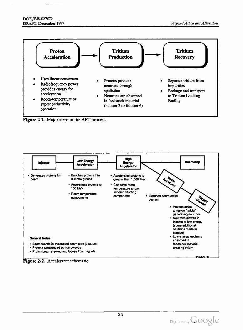
DOE /EIS -0270D
DRAFT, December 1997 Proposed Action and Alternatives
Proton
Acceleration
-
Tritium
Production
-C
Tritium
Recovery
Uses linear accelerator
Radiofrequency power
provides energy for
acceleration
Room -temperature or
superconductivity
operation
Protons produce
neutrons through
spallation
Neutrons are absorbed
in feedstock material
(helium -3 or lithium - 6 )
Separate tritium from
impurities
Package and transport
to Tritium Loading
Facility
Figure 2-1. Major steps in the APT process.
InjectorLow Energy
Accelerator
High
Energy
Accelerator
Beamstop
• Generates protons for
beam
Beam
Expander
• Bunches protons into
discrete groups
• Accelerates protons to
100 MeV
• Room temperature
components
• Accelerates protons to
greater than 1,000 Mev
• Can have room
temperature and/or
superconducting
components.Expands beam cross
section
Target
Blanket
• Protons strike
tungsten " ladder"
generating neutrons
• Neutrons slowed in
blanket to low energy
(some additional
neutronsmade in
blanket)
• Low -energy neutrons
absorbed in
feedstock material
creating tritium
GeneralNotes :
• Beam travels in evacuated beam tube (vacuum )
• Protons accelerated by microwaves
• Proton beam steered and focused bymagnets
PK68.ZUPC
Figure 2-2. Accelerator schematic.
2-3
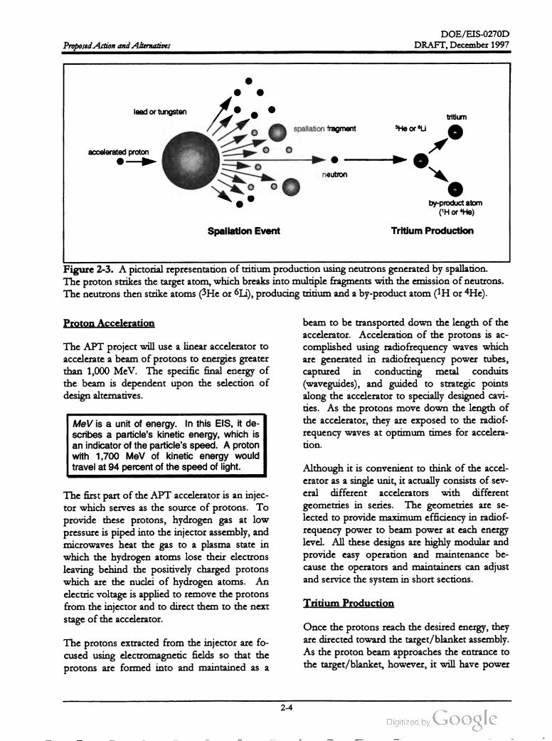
DOE /EIS -0270D
DRAFT, December 1997Proposed Action and Alternatives
lead or tungsten
tritium
spallation fragment 3He or Li
accelerated proton
neutron
by-product atom
('H or He)
Spallation Event Tritium Production
Figure 2-3. A pictorial representation of tritium production using neutrons generated by spallation.
The proton strikes the target atom ,which breaks into multiple fragments with the emission ofneutrons.
The neutrons then strike atoms(3Heor Li), producing tritium and a by-product atom (1H or 4He).
Proton Acceleration
The APT project will use a linear accelerator to
accelerate a beam of protons to energies greater
than 1,000 MeV. The specific final energy of
the beam is dependent upon the selection of
design alternatives.
beam to be transported down the length of the
accelerator. Acceleration of the protons is ac
complished using radiofrequency waves which
are generated in radiofrequency power tubes,
captured in conducting metal conduits
(waveguides), and guided to strategic points
along the accelerator to specially designed cavi
ties. As the protons move down the length of
the accelerator, they are exposed to the radiof
requency waves at optimum times for accelera
tion .
MeV is a unit of energy . In this EIS , it de
scribes a particle's kinetic energy, which is
an indicator of the particle's speed . A proton
with 1,700 MeV of kinetic energy would
travel at 94 percent of the speed oflight.
The first part of the APT accelerator is an injec
tor which serves as the source of protons. To
provide these protons, hydrogen gas at low
pressure is piped into the injector assembly, and
microwaves heat the gas to a plasma state in
which the hydrogen atoms lose their electrons
leaving behind the positively charged protons
which are the nuclei of hydrogen atoms. An
electric voltage is applied to remove the protons
from the injectorand to direct them to the next
stage of the accelerator.
Although it is convenient to think of the accel
erator as a single unit, it actually consists of sev
eral different accelerators with different
geometries in series. The geometries are se
lected to providemaximum efficiency in radiof
requency power to beam power at each energy
level. All these designs are highly modular and
provide easy operation and maintenance be
cause the operators and maintainers can adjust
and service the system in short sections.
Tritium Production
The protons extracted from the injector are fo
cused using electromagnetic fields so that the
protons are formed into and maintained as a
Once the protons reach the desired energy, they
are directed toward the target /blanket assembly.
Asthe proton beam approaches the entrance to
the target /blanket, however, it will have power
2-4

DOE / EIS -0270D
DRAFT,December 1997 Proposed Action and Alternatives
in excess of 100 megawatts, much of which
would be converted to heat in the tar
get/ blanket assembly. To prevent a highly lo
calized heating of the target/blanket, a beam
expander will be used. This device will increase
the cross- sectional area of the beam using mag
nets and create a more uniform distribution of
protons to generate the maximum useful neu
tron flux and to allow the engineered heat re
moval systems for the target/blanket to better
dissipate the heat.
feedstock , recovering the tritium involves ex
tracting the tritium from a solid aluminum ma
trix through melting of the rods and then
separating it from other isotopes of hydrogen
and Helium . In both cases, the tritium recov
ered from the feedstock material would be
transported to the Tritium Loading Facility at
the Savannah River Site .
2.3 APT Design Features and
Technology Alternatives
2.3.1 RADIOFREQUENCY POWER
ALTERNATIVES
After passing through the beam expander, the
proton beam would be directed to the tungsten
target (heavy water cooled) and blanket mod
ules. The high energy of the protons as they
strike the tungsten target causes the nuclei of
the atomsin the target to break into fragments,
ejecting neutrons and secondary particles in all
directions; this process is called spallation . The
number of neutrons produced by high - energy
spallation processes can be considerable. For
example, in an ideal thick tungsten or lead tar
get, approximately 31 neutrons are produced
per incident 1,000 MeV proton, and approxi
mately 58 at 1,700 MeV .
As discussed in Section 2.2 , the APT would ac
celerate protons by the use of radiofrequency
(RF) waves. Specially designed vacuum electron
tubes would convert electric power to RF waves
in a separate building, and waveguides (hollow
metal conduits) would transmit them to cells
along the beam path . Because radiofrequency
waves have an electric and magnetic field com
ponent,their
presence would affect the charged
proton beam . The accelerator design would en
able the proton beam to be exposed to the ra
diofrequency waves at the properorientation to
cause acceleration .
The target is surrounded by blanket modules
which contain lead, feedstock (Helium -3 or
Lithium -6), and a lightwater moderator coolant.
The neutrons are moderated (slowed down) by
D20 (heavy water) and H2O to an energy low
enough to be efficiently absorbed by the trit
ium -production feedstock . Thus, tritium is
produced through a series of nuclear reactions.
First, the protons are used to produce neutrons
through spallation ; then the neutrons are ab
sorbed in a feedstock material to form tritium .
Because the protons get their energy from
the radiofrequency waves, the electron
tubes that generate thewaves are the larg
est electrical load in the APT.
Tritium Recovery
Once the tritium is produced in the feedstock
material, itmust be recovered and purified. The
exact method for recovering the material de
pends on the type of feedstock material being
used (as discussed in Section 2.3). For the case
of the Helium -3 feedstock , recovering the trit
ium is a matter of separating the tritium from
the other isotopes of hydrogen and Helium in a
gaseous mixture. For the case of Lithium -6
DOE has identified two alternatives klystrons
and inductive output tubes -- that could supply
radiofrequency power for the accelerator. Re
gardless of the type of tube selected, approxi
mately 240 would be needed to provide enough
power to accelerate the protons. Several tubes
are expected to fail each month . If DOE de
cides to build the APT, it would construct a
facility atthe APT site to rebuild damaged tubes
and provide replacement tubes. This would
permit the rapid replacement of damaged tubes
and increase the operational availability of the
accelerator. The following sections describe the
two potential radiofrequency power alternatives
-- klystronsand inductive output tubes.
2-5
DOE/EIS-0270D
DRAFT, December 1997Proposed Action and Alternatives
their electrical resistance becomes essentially
zero, and the component will use much less
electricity. This phenomenon is referred to as
superconductivity.
DOE has identified two operating temperature
alternatives for the design of the accelerator:
Klystron. The klystron is an established tech
nology that radar installations and television
broadcast stations have used for years to gen
erate broadcast signals. The klystron is an elec
tron tube that uses a beam of electrons to
amplify a microwave signal. In principle, the
electron beam is directed to a relatively weak
microwave field inside the tube. The presence
of the electromagnetic fields in the microwave
signal causes modulation of the electron beam
into “ packets” of electrons. The beam then
passes through a cavity tuned to the same fre
quency as the input signal, and the electrons in
duce a microwave signal that is an amplified
version of the originalsignal.
Operation of accelerator structures at es
sentially room temperature
Operation ofmost of the accelerator struc
tures at superconducting temperatures and
the remaining components at room tem
perature
Room Temperature Operation . Under this
alternative, DOE would provide necessary
cooling to ensure the maintenance of electric
components of the accelerator at approximately
room temperature. The Department would use
either air or water cooling of the components to
prevent overheating
Inductive Output Tube. The inductive out
put tube was developed in the 1930s and has
been used extensively since the 1970s in televi
sion transmitters. As with the klystron , its pur
pose is to amplify microwaves, but it does so in
a differentway. The inductive output tube also
extracts large amounts ofRF power from a high
current electron beam that is modulated into
electron “ packets.” However, in contrast to the
klystron, the modulation is produced directly in
the electron beam by using the input signal to
control emission of electrons. Inductive output
tubes are typically smaller than radiofrequency
power tubes and have greater efficiency , thereby
providing the same microwave amplification
with less input power and smaller energy losses.
Superconducting Operation . Under this al
ternative,DOE would divide the linear accelera
tor into two subsystems, the low -energy and
high- energy accelerator systems. The low
energy system would operate at room tempera
ture ; the cells of the high -energy system , re
sponsible for accelerating protons from about
200 to 1,700 MeV , would be superconducting.
This alternative would supply liquid Helium to
accelerating cavities of niobium and maintain
the cavities at approximately -456 °F, which
would ensure superconductivity. Other elec
tronic components would operate at room tem
perature, as described above.
2.3.2 OPERATING TEMPERATURE
ALTERNATIVES
Accelerator structures would be affected by the
temperatures at which they operate, depending
on the type and intended use. Electrical resis
tance usually increases as temperature increases,
which causes more heat generation in the com
ponent and results in a greater use of electricity.
The converse is also true: that is, electrical re
sistance usually decreases as temperature de
creases, causing less heat generation and
resulting in less electricity use. If the tempera
ture of somematerials (e.g., niobium ) is reduced
to a very low value near absolute zero (-456 ° F ),
If DOE implements this alternative, it would
build a refrigerator and liquid Helium distribu
tion system to serve the accelerator. This facil
ity , which the Department would build on the
same site as the accelerator,would produce liq
uid Helium by compressing Helium gas stored
in tanks. DOE would maintain enough liquid
Helium to cool the accelerator components in
the event of a power loss.
2-6

DOE /EIS-0270D
DRAFT,December 1997 Proposed Action and Alternatives
The temperature of the niobium cavities in
the accelerator would be about -456 ° F ,
which is about 4 ° F above absolute zero , the
coldest possible temperature that can exist.
burg, Ohio . Thus, DOE could ensure a supply
ofHelium -3 for immediate use in the APT if it
selected this alternative.
2.3.3 FEEDSTOCK MATERIAL
ALTERNATIVES
Under this alternative, the Helium -3 would be
contained in aluminum tubes within the tar
get/blanket assembly. Helium reacting with a
neutron would be converted to tritium produc
ing a mixture of tritium and other atoms as
shown in Figure 2-3. The Helium - 3 and tritium
mixture would be continuously transported via
piping to the Tritium Separation Facility (TSF)
in close proximity to the Target / Blanket Build
ing
The accelerator would produce protons with an
energy greater than 1,000 MeV. To produce
tritium , the proton beam would be expanded
from its relatively small size (a diameter of ap
proximately 0.079 inch ) in the accelerator to a
rectangular beam that would be 6.3 inches wide
and 63 inches tall. The protons would strike a
target /blanket assembly of tungsten and lead .
The high energy of the protons as they im
pacted the tungsten atoms would cause spalla
tion events, as described in Section 2.2 , with the
emission of neutrons. The lead in the blanket
modules would further increase the number of
neutrons through additional reactions. The
neutrons would strike the tritium feedstock
material, the atoms of which would undergo a
nuclear reaction that absorbed neutrons, result
ing in the production of a tritium atom and an
other byproduct atom (Figure 2-3).
A series of devices would be used to remove
impurities and spallation products from the He
lium - 3 stream before it is sent to the TSF
building. Extraction of the hydrogen isotopes
from Helium - 3 would be performed with pal
ladium -silver permeators, which allow hydrogen
isotopes, but not Helium -3, to permeate. He
lium - 3 would be recirculated back to blanket
modules. Then, tritium would be separated
from the other hydrogen isotopes by using
cryogenic distillation (separate from the cryo
genic system that would be used in the super
conductive alternative). The purified tritium
product would be stored in the TSF and loaded
into shipping containers for transportation to
SRS tritium facilities .
DOE has identified two possible feedstock
materials that would produce tritium through
the absorption of neutrons produced by spalla
tion events. In addition, the Department has
concluded that it could use the same type of
target/blanket (lead and tungsten ) as the neu
tron source regardless of the feedstock material
used. The following sections describe the two
potential feedstock materials
lium - 3 and solid Lithium -6 .
The Helium - 3 blanket system would permit the
continuous extraction of tritium as it was pro
duced, thereby limiting the inventory of tritium
in the blanket area at any time.
gaseous He
Additional information regarding TSF and its
operation is provided in Section A.4 of Appen
dix A. A brief description of TEF functions is
provided in Section A.6.2 of Appendix A.
Helium - 3 Feedstock Material. Helium - 3 is a
nonradioactive gas that exists naturally in small
quantities in the atmosphere . It is also pro
duced through the radioactive decay of tritium .
It has been used for many years to make radia
tion detectors for neutrons, and its chemical
and physical properties are well understood.
Helium -3 is available for use at the SRS from
past operations of the Tritium Loading Facility
and from the DOE Mound Facility in Miamis
Lithium -6 Feedstock Material. This alterna
tive would incorporate Lithium -6 into a solid
aluminum matrix and form it into rods that
DOE would place in the blanket area of the ac
celerator. While not identical to the rods DOE
used when it operated the SRS tritium produc
tion reactors, the rods would produce tritium in
a similar fashion .
2-7

DOE /EIS -0270D
Proposed Action and AlternativesDRAFT, December 1997
isolated from the environment through heat ex
changers to cool each component. The primary
coolant loop would be the first system in con
tact with a component that required cooling,
and heat would transfer from the component to
the primary coolant loop .
For this alternative, the Lithium -6 rods would
be in the form of aluminum -Lithium alloy rods
clad in aluminum . The rods would be placed in
the target/blanket assembly to be irradiated by
neutrons. After irradiation, DOE would shut
down the accelerator and replace the irradiated
rods with new unirradiated rods. After the rods
cool enough to handle safely, DOE would
transport them to the proposed Tritium Ex
traction Facility (61 FR 46790), which would
remove tritium from Lithium rods using proc
esses similar to those DOE used in SRS Tritium
Facilities. The Lithium rods would be cut into
pieces, placed in large crucibles, and heated in a
furnace to melt the aluminum and drive the
tritium from the matrix. The TEF would col
lect and purify the gaseous tritium and send it to
the Tritium Loading Facility. See also Sec
tion 2.5.3 regarding the potential of combining
the TEF with the APT TSF.
A heat exchanger allows heat to pass from
one system to another without mixing the
contents of the systems. For example, a car
radiator is an air -cooled heat exchangerbe
cause it permits heat from the primary cool
ant (the antifreeze/water mixture) to
dissipate by passing air over the cooling fins
of the radiator.
Because the Lithium must be incorporated in a
solid rod matrix , the Lithium feedstock alterna
tive would require batch production of tritium
instead of continuous extraction . The accelera
tor would operate during the irradiation , and
would be in shutdown mode during the removal
of the irradiated rods and the insertion of the
new rods into the target/blanket assembly .
For components with the potential for radioac
tive contamination, a secondary coolant loop
would cool the primary loop through water
cooled heat exchangers and would be isolated
from the environment in a manner similar to
the primary coolant loop . For these systems, a
tertiary coolant system would cool the secon
dary loop through water-cooled heat exchang
ers, and would be the principal point of heat
discharge to the environment. The tertiary sys
tem would be a “ clean ” system ; that is, it likely
would not release more than extremely small
amounts of contamination to the environment.
For components with little or no potential for
radioactive contamination, the final cooling
water system would be linked to the primary
coolant loop
2.3.4 COOLING WATER SYSTEM
ALTERNATIVES
The equipment and activities in the APT would
generate heat that would have to be removed to
prevent overheating of components. Air cool
ing would be sufficient to keep some parts of
the APT cool. Other areas would be subject to
high localized temperatures (e.g., the target and
blanket regions due to the impingement of the
protonbeam on the
targetand the heat gener
ated by radioactive decay in the target/ blanket).
Cooling water would be required to keep the
target /blanket components, radiation shielding,
beamstops, and other APT componentsfrom
overheating
DOE has considered both surface and ground
water sources for the cooling water system . If
DOE selects surface water, it would be drawn
from the Savannah River using portions of the
existing River Water System (WSRC 1996a) up
graded as necessary to support APT operation.
If DOE selects groundwater, new wells would
be drilled near the APT site.
DOE has identified four designs for the tertiary
coolant system to provide the necessary cooling
capacity for theaccelerator:
Although these components would not neces
sarily be connected to the same cooling system ,
DOE proposes to use a primary coolant loop
Mechanical-draft cooling towers with river
watermakeup
2-8

DOE / EIS -0270D
DRAFT,December 1997 Proposed Action and Alternatives
towers withMechanical-draft cooling
groundwater makeup
Once -through cooling using river water
K -Area natural-draft cooling tower with
river water makeup
In assessing the cooling water system alterna
tives, DOE considered existing structures and
systems to the extent possible. Figure 2-5
shows these systems and structures, notable
among which are the River Water System ,
which has lines throughout the SRS; Par Pond,
which could receive cooling wateror blowdown
via the “pre -cooler" ponds (Ponds 2 , 5 and C );
K -Area, which contains a natural-draft cooling
tower that discharges to Indian Grave Branch
and Pen Branch; and the preferred and alternate
accelerator sites. Information related to the
cooling water alternatives described in the fol
lowing sections was derived from the APT
Cooling Water Supply Makeup Trade Study
(WSRC 1996a).
Figure 2-4 is a schematic diagram of the cool
ing-water alternatives this EIS analyzes; itshows
how DOE could implement these alternatives.
The figure is drawn assuming that the compo
nent to be cooled has the potential for radiation
contamination and, thus, has a primary and sec
ondary loop. For nonradioactive systems, the
illustrated secondary coolant system would not
be present and the cooling water system would
be linked to the primary coolant loop .
Groundwater Makeup
(6000 gpm )
Blowdown 10
ParPond
(2000 gpm ) Input Water from
RiverWater System
(125,000 gpm )
Discharge to
Par Pond
(125,000 gpm )Mechanical
Draft
CoolingTowers
Heat Exchanger
Heat Exchanger
RiverWaterMakeup
(6000 gpm )
Blowdown to
ParPond
(2000 opm )
Makeup Water from
River Water System
(6000 gpm )
Blowdown to
K -Area Outtall
(2000 gpm)
Selected
Tertiary
Coolant
System
JE
Mechanical
Draft
Cooling
Towers
Heat ExchangerHeat Exchanger
Closed
Secondary
Coolant
Loop
Heat Exchanger
Closed
Primary
Coolant
Loop
Mechanical-Draft Cooling Tower/
RiverWaterMakeup
Mechanical-Draft Cooling Tower/
GroundwaterMakeup
Once-Through Using River Water
K -Area Natural-DraftCooling TowerComponent
to be Cooled
PK68 -Z1-PC
Figure 2-4. Schematic diagram ofthe cooling water system alternatives for APT components with ap
proximate water flows. This drawing assumes that the component to be cooled has the potential for ra
dioactive contamination. For nonradioactive systems, the illustrated secondary coolant system would
notbe present and the final cooling water system would be linked to the primary coolant loop.
2-9
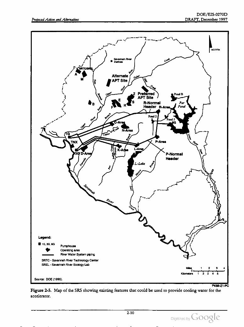
DOE /EIS-0270D
DRAFT, December 1997Proposed Action and Alternatives
NORTH
Savannah River
Institute
Creek
SRTCISREL
Runs
M
Alternate
APT Site
Tinker
Tims
Creek
Three
Upper
Pond B
Branch
E
z Preferred
APT Site
SR -Normal
Header R -Area .
BH
Par
PondRuns
Pond 2
Branch
Three
C -Area
Pond 5
6G
Upper
Screek
N -Area
IG Castor
Branch
Lower
TNX P -Area
Three
K -AreaL -AreaB
ranch
3G D -Area
Indian
Grave
Runs
P -Normal
HeaderFourmile
L.- Lake
Branch
Pen
Meyers
Savannah
Steel
River
Creek
Legend :
1G , 3G , 6GPumphouse
Operating area
River Water System piping
SRTC - Savannah River Technology Center
SREL - Savannah River Ecology Lab
Miles 2 3 4
Kilometers
1
2 . 3 4 5
Source: DOE (1995).
PK68 -Z1-PC
Figure 2-5. Map of the SRS showing existing features that could be used to provide cooling water for the
accelerator.
2-10

DOE /EIS-0270D
DRAFT, December 1997 Proposed Action and Alternatives
would pass from the heat exchanger to the
cooling towers, where ambient air would cool
the water, resulting in a release of heat to the
atmosphere. The cooled water would pass to
the heat exchanger again to receive heat from
the secondary coolant loop.
Mechanical-Draft Cooling Towers with
River Water Makeup. A mechanical- draft
cooling tower uses forced air to cool water that
circulates through it. In principle, cool water
from the tower circulates through a piece of
equipment that requires cooling. The water
heats as it cools the equipment, and circulates
back to the cooling tower. The heated water
flows into the cooling tower and is dispersed in
the tower as small droplets. Large fans at the
top of the tower draw in ambient air, which
evaporates some of the heated water and cools
the rest. Finally , the cooled water collects in a
basin in the bottom of the tower and recircu
lates back to cool the equipment. Figure 2-6 is
a photograph of a typical mechanical-draft
cooling tower.
Over time, the water in the cooling tower sys
tem would require replenishment because the
water:
Evaporates from the system
Leaves the system as water droplets to the
atmosphere (drift)
Leaks from the system
Is discharged intentionally from the system
(as blowdown) because of relatively high
concentrations of salts
This alternative would involve the construction
ofmechanical-draft cooling towers with recircu
lating cooling water (i.e.,most of the water that
flows through the cooling tower would circulate
continuously to provide cooling). Water from
the towers (at a flow rate of approximately
125,000 gallons perminute) would pass through
a heat exchanger that would transfer heat from
the secondary coolant loop of the accelerator.
The heated water (as illustrated in Figure 2-4 )
Makeup water (i.e., water to replenish these
losses) for the cooling tower would come from
the SRS River Water System (see Figure 2-5 )
after somemodification. DOE originally used
this system to provide cooling for the onsite re
Figure 2-6 . An example ofmechanical-draft cooling towers at the SRS. This cooling tower is located in
A -Area and has four exhaust areas on top .
2-11

DOE /EIS -0270D
Proposed Action and AlternativesDRAFT,December 1997
trated in Figure 2-4 ) and would discharge di
rectly to the Par Pond system .
actors; the system now has a capacity of about
150,000 gallons per minute. DOE estimates
that it would need about 6,000 gallons per mi
nute to keep a constant level of coolant in the
cooling tower system . DOE would upgrade the
River Water System to supply water to the APT
site . This would include installing two new
pumps in a pumphouse to handle required flow
rates, which would be lower than those histori
cally used in the River Water System ; using the
existing “ R -Normal” river water header; and
adding pipe to move the water to the APT site
and to move the continuous blowdown to the
Par Pond system .
The River Water System now has a capacity of
about 150,000 gallons per minute. DOE esti
mates that once-through cooling would use no
more than 125,000 gallons per minute. DOE
would upgrade the system by adding pipe to
transport river water to the APT site. In addi
tion , DOE would install four pumps and addi
tional pipe to transport the heated water from
the APT to Par Pond.
Mechanical-Draft Cooling Towers with
Groundwater Makeup. This alternativewould
be similar to that described above, except the
makeup water would come from groundwater
wells drilled near the accelerator site. Because
this alternative would use recirculating water in
the cooling tower loop, about 6,000 gallons per
minute, would be required to maintain a con
stant level of coolant in the system . However,
the projected capacity of a single production
well is only about 500 gallons per minute. To
supply 6,000 gallons per minute and provide
backup capacity, DOE would drill 18 wells and
route the pumped water to a central well field
tank for transfer to the APT cooling towers.
K -Area Cooling Tower with River Water
Makeup. Under this alternative, the K -Area
cooling tower (see Figure 2-7) would provide
cooling for the APT. DOE built this natural
draft cooling tower to mitigate thermal impacts
from K -Reactor operation. However, the tower
was never used because of the decision to per
manently shutdown K -Reactor. A natural-draft
cooling tower operates on the principle of water
evaporation, just as a mechanical-draft tower.
However, a natural-draft tower is designed to
use natural air currents, whereas a mechanical
draft cooling tower uses fans to generate air cur
rents. As a consequence , natural-draft cooling
towers are typically taller than mechanical-draft
towers to create more air flow through the
tower structure .
DOE would connect all 18 wells to the central
well field tank by piping. Additional pipe would
connect the tank to the cooling towers. As de
scribed above, the blowdown from this cooling
alternative would flow to the Par Pond system
(see Figure 2-5), which would require additional
pipe.
Once-Through Cooling Using River Water.
Under this alternative, the APT would not use a
cooling tower. Instead , DOE would pipe large
volumes of water from the Savannah River , us
ing the River Water System (see Figure 2-5)
with modification (i.e., replacement of pumps,
addition of pipe) to move the water from the R
Normal header to the APT site. The water
would pass through heat exchangers to remove
heat from the secondary coolant loop (as illus
Figure 2-7. Photograph of the K -Area natural
draft cooling tower thatwas constructed in the
early 1990s butnever operated.
2-12
DOE /EIS -0270D
DRAFT, December 1997 Proposed Action and Alternatives
The site is at an elevation of 300-330 feet above
mean sea level and has several streams (Mill
Creek, McQueen Branch , and Tinker Creek)
nearby. The preferred site is approximately
6.5 miles from the SRS boundary .
DOE would use the River Water System to
provide makeup water for the cooling tower
and to move the cooling water between the
tower and the APT. This would minimize the
need for new piping. As shown in Figure 2-5 ,
K -Area is some distance from the sites pro
posed for the accelerator. Severalmiles ofpipe
would supply the 125,000-gallon -per-minute
flow rate from K -Area to the APT using pumps
at the cooling tower. Much of this would use
existing river water system piping , but some
additional pipe would be required to tie into the
APT site. The return leg of the cooling loop
would require additional pumps and pipe that
would connect to the R -Normal header of the
River Water System . DOE would modify the
river water lines in R- and P -Areas to enable
flow from the R -Normalheader to a portion of
the P -Normal header. Finally, 300 feet of pipe
would connect the P -Normal header to the
K -Area Cooling Tower.
Alternate Site. The alternate site is located ap
proximately 2 miles northwest of the Tritium
Loading Facility and is southeast of the inter
section ofRoads F and 2. The alternate site is
crossed by a 115-kV power line and Deer Kill
Road and is at an elevation of 210-300 feet
above mean sea level. Upper Three Runs and
Crouch Branch are the major streams near the
alternate site to the southeast. The alternate site
is approximately 4 miles from the SRS bound
ary .
Site Selection Process. DOE conducted a
screening process to select suitable sites for the
APT. Using a process with several phases, the
Department identified areas with suitable fea
tures and minimal conflicts with onsite re
sources and operational areas.
2.3.5 APT SITE LOCATION
ALTERNATIVES
The first phase was the identification of basic
land requirements. The minimum requirements
assumed that an APT complex would include
the following components:
The Department conducted a site screening
process (described below ) to select potentially
suitable APT sites. Using a multiple phase
process, site areas exhibiting a set of suitable site
features with minimal conflicts with onsite re
sources and operational areas were identified . A
complete set of criteria used can be found in the
Site Selection for the Accelerator for Production of Trit
ium at the Savannah River Site (Wike et al. 1996).
An accelerator in a long concrete tunnel ap
proximately 40 feetbelow grade
A building to house the target/blanket as
sembly
A Tritium Separation Facility
The Department selected two sites for further
analysis, as shown in Figure 2-8. In this EIS,
the Department has chosen to designate these
sites as the preferred site and the alternate site.
A brief description of each site is included be
low , Chapter 3 describes the characteristics of
both sites in detail.
A radiofrequency tube remanufacturing and
maintenance facility
Facilities for the management of waste
streams
Administrative and infrastructure support
facilities
Preferred Site. The preferred site is located
approximately 3 miles northeast of the Tritium
Loading Facility and is northeast of the inter
section of Roads F and E. The site is bordered
on the southwest by a 115 kV transmission line,
a buried control and relay cable, and Monroe
Owens Road, a natural surface secondary road.
Cooling towers
2-13

DOE /EIS -0270D
DRAFT,December 1997Proposed Action and Alternatives
(19 To Aiken SRS boundary To Aiken
278New Ellenton
To Augusta 781
302
NORTH
2786
39
125
Savannah River
InstituteSRTC /SREL
D - 1А 8
Aiken
County
Barnwell
County
Jackson 1278
Alternate
APT Site
EPreferred
APT Site
125B
2 H R
E
N - 3
Barnwell
County
Industrial
Park
Snelling
5 B
AikenCounty
BurkeCounty
KTNX
125
A -13Barnwell
CountyAllendale
CountyVogtle Electric
Generating Plant
South
Carolina
Georgia125
125
Legend :
Site roads
100
State routes
Federal routes
Burke
County
Screven
County
MILES
1 ?
3
KILOMETERS 0
1
2 3 4 5
PK68-Z1-PC
Figure 2-8. Approximate location of preferred and alternate sites for the APT.
2-14

DOE /EIS-0270D
DRAFT,December 1997 Proposed Action and Alternatives
Electrical substations
Construction laydown yards
Based on these assumed components, DOE
determined the APT complex would require
approximately 250 acresof land with a footprint
6,560 feet long by 1,640 feet wide. The area re
quirements would not vary much with any
combination of the technology or design op
tions described in this chapter.
With the land requirements established , the next
phase of the screening process was to develop
exclusionary criteria (disqualifying conditions).
Examples of these criteria include avoiding ad
verse impacts to threatened and endangered
species, avoiding adverse impacts to wetlands
and sensitive ecosystems, and proximity to
seismic faults. Wike et al. (1996 ) contains a
complete listing of these exclusionary criteria.
Seven potential sites (numbered 1-7) were ini
tially identified. Two sites (numbered 5 and 7)
were subsequently eliminated due to the pres
ence of disqualifying conditions (proximity to
seismic faults). One site (number 8) was added
based on a request to examine a site in the vi
cinity of A- and M -Areas. Although not ex
plicitly used as exclusionary criteria , existing
industrially developed areas were not examined
as sites because of (1) the presence of existing
operating structures, (2) the presence of non
operating structures that would require exten
sive decontamination and decommissioning
(D & D ) prior to site preparation,or (3) the pres
ence of active environmental restoration activi
ties .
Table 2-1. APT site selection criteria .
Category Criterion
Ecology Terrestrial ecology
Aquatic ecology
Wetland ecology
Human health Distance to population center
Distance to SRS boundary
Existing facility incident im
pact (on APT)
Geology /Hydrology Groundwater supply
Depth to groundwater
Stability of subsurface condi
tions
Thermal capacity of soil
Engineering Distance to RTF
Distance to rail lines
Archaeology
Distance to acceptable road
Terrain (including slope)
Foundation conditions
(subsidence tolerances)
Distance to existing NPDES
discharge point
Distance to site utilities
Distance to centralized sewage
treatment plant tie- in
Disruption to site infrastruc
ture
Presence of existing waste site
Sites 6 , 8 , and 4 were ranked next. Sites 1 and 3
scored substantially lower than the other sites.
Site 6 is ranked second, with sites 8 and 4 close
in ranking. However , site 4 scored the worst in
subsurface stability and was dropped from fur
ther consideration when DOE decided that it
preferred to use site 4 for other purposes. Site
8 was the only site that has an existing waste site
located within the footprint. This left site 6 as
DOE's choice for an alternate site .
Chapter 3 summarizes the existing environment
for the preferred (site 2) and alternate (site 6 )
sites.
The next phase of the screening process was to
develop and apply a set of weighted selection
criteria to the remaining sites. The selection
criteria used are listed in Table 2-1. Each site
was evaluated against these criteria using either
quantitative analysis or the professional judge
ment of experts if quantitative information was
not available .
Because DOE has considered the preferred site
forpast missions, a considerable amount of in
formation about the site is available. The in
formation available for the alternate site is not
quite as mature. Chapter 4 compares and con
trasts the potential impacts of the constructionThe final phase of the screening process was to
examine the results. One candidate (number 2)
stood out and became DOE's preferred site.
2-15

DOE /EIS -0270D
DRAFT, December 1997Proposed Action and Alternatives
and operation of the APT at the alternate loca
tion with those for the preferred location.
2.3.6 ELECTRIC POWER SUPPLY
ALTERNATIVES
The APT will require large amounts of electric
ity (up to 600 MWe peak load). Currently, the
SRS obtains its electrical power from South
Carolina Electric and Gas Company (SCE & G )
through existing transmission lines and substa
tions. As shown in Figure 3-12, both the pre
ferred and alternate APT sites are in close
proximity to existing electrical power supply
lines.
eration capacity of SCE & G . The Department
could buy electrical power through competitive
acquisition for the APT; however, under current
State law regarding franchised service areas
(Section 8093 ofPublic Law 100-202), competi
tive acquisition of power for the APT could
only occurif SCE & G voluntarily relinquishes its
exclusive service rights, South Carolina law is
modified to accommodate a competitive ac
quisition , or federal legislation is passed specify
ing that the APT load can be competed (Exeter
1996). Because DOE believes that these actions
to enable competitive acquisition are specula
tive, the Department has assumed that it would
acquire power through SCE & G for the APT.
SCE & G could supply power either through ex
isting SCE & G capacity or through brokering
power competitively acquired . In the latter
case, SCE & G couldpass
the costs of acquiring
the power to the Department or provide DOE
with “retail wheeling services.” Regardless of
the ultimate source of electrical power (i.e.,
SCE & G or another utility who sells power to
SCE & G who in turn sells the power to the De
partment), a new power plant would not be
constructed specifically to meet the load re
quirements of theAPT.
In its consideration of electrical power sources,
DOE has identified two alternatives:
The Preferred alternative is to obtain elec
trical power from existing capacity and
through market transactions
An alternative is to obtain electrical power
from construction and operation of a new
coal-fired or natural gas -fired electricity
generating plant. Should this alternative be
selected, it could be a privatized action.
Appropriate NEPA documentation would
be tiered to this EIS .
Figure 2-9 illustrates the relationship of the
APT to each of the electrical power alternatives.
Section 4.1.4 discusses the range of possible
electrical power requirements for the APT, and
Section 4.4 discusses the impacts of providing
electricity to the APT.
Retail wheeling is a common utility practice
of accepting power from or providing power
to other utilities in times when system loads
require augmentation or create a surplus.
The receiving utility pays a negotiated price
for the power and fees for the use of trans
mission and support systems.
Construction and Operation of a New
Electricity Generating Plant
Electricity from Existing Capacity and
Through Market Transactions. Under this
alternative , the Departmentwould use existing
electrical transmission lines on the SRS to route
power to the APT site . The APT sites are near
suitable transmission lines to provide connec
tions.
The Tritium Supply PEIS identified two types
of potential electricity generating plants as rea
sonable options should a new plantbe built.
The SRS currently obtains its electrical power
from South Carolina Electric and Gas Com
pany;Section 3.3.6 contains a discussion of the
power usage on the SRS and the electricalgen
As with the previous alternative discussed
above, existing electrical transmission lines on
the SRS would be used to route power to the
APT. Under this alternative, a new electricity
generating plant would be constructed to serv
ice the APT. The plant could be on the SRS or
2-16

DOE / EIS -0270D
DRAFT, December 1997 Proposed Action and Alternatives
Electricity from Existing
Capacity and through Market Transactions
Construction and Operation of a
New Electricity Generating Plant
Existing
Electrical
Capacity
(SCE & G )
Existing
Electrical
Capacity
NationwideNew Plant
SCE & G
Selected
Electricity
Supply
Existing
Power Lines
and Substations
APT
Facilities
PK68 -Z1-PC
Figure 2-9. Alternatives forsupplying electricity to the APT. Existing transmission lines would be used
and DOE would obtain power from existing plants and through market transactions or would obtain
electricity from a new coal-fired or natural gas-fired plant.
located elsewhere. Two types of electricity gen
erating plants could be used: (1) coal- fired, or
(2) natural gas- fired .
The ultimate decision as to the type ofgenera
tion facility used requires the consideration of
many factors, including projected fuel costs,op
eration and maintenance costs, capital costs ,
engineering efficiencies, and operational re
quirements such as whether the facility should
be base-load or load following. Coal- fired
plants are historically the preferred method of
providing power to the region, especially with
the decline in the nuclear sector. The majority
of SCE &G’s existing capacity is provided by
coal power plants. Combined cycle gas-fired
power plants provide certain advantages over
coal-fired plants in terms of lower capital costs,
emission rates, and plant efficiencies. However,
the projected life cycle fuel costs associated with
natural gas is higher and more volatile than that
expected with coal (Beaman and Wade 1997).
Section 4.4 presents the impacts for a generic
coal-fired and natural gas-fired electric plant
2-17
DOE /EIS -0270D
Proposed Action and Alternatives DRAFT ,December 1997
that could supply power to the APT and for the
purpose of estimating representative impacts,
assumes SRS is the plant's location .
DOE implemented. In addition, DOE could
modify several SRS facilities to provide support
functions for the accelerator that would not de
pend on which alternative DOE implemented .
The following sections describe activities related
to the construction and operation of new facili
ties and the use of existing facilities at the SRS
that were not described in Section 2.3.
Coal-fired Electricity Generating Plant. The
major components of a coal-fired electricity
generating plant are: steam generator, turbine
generator; air emissions control system (dry
scrubber and baghouse); stack; circulating water
system for cooling, water supply; waste man
agement and disposal facilities; fuel receiving,
storage, and handling facilities. In addition to
the above components, ancillary facilities for
the plantas a whole would typically include ac
cess roads, parking areas, a railroad spur,
switchyard, warehouses, and maintenance facili
ties. Approximately 290 acres of land would be
required.
2.4.1 CONSTRUCTION AND
OPERATION OFNEW FACILITIES
Based on the alternatives described in Sec
tion 2.3, DOE would perform the following
construction activities to support one or more
alternatives:
APT Site Improvements
1. Drainage for rain water during design -basis
rainfall event
2. Tie-ins to SRS services, including roadways
and bridges, rail service, utility power lines,
sanitary sewer service, and domestic and
River Water System
NaturalGas -Fired Power Plant. The Tritium
Supply PEIS evaluated the impacts of construct
ing and operating a natural gas-fired electricity
generating plant at the SRS. The facility de
scription and summary of impacts are summa
rized in Section 4.8.2.2 of the Tritium Supply
PEIS . In general, a gas -fired plant would con
sist of combustion turbines, a natural gas supply
system , a fuel oil delivery and storage system for
backup capacity , a water supply system , a dem
ineralization system , and transmission distribu
tion equipment. Ancillary facilities for the plant
would include access roads, parking areas,
warehouses, and maintenance facilities. Ap
proximately 110 acres of land would be re
quired.
3. Buried utilities inside the APT boundary for
communications, electric power, blowdown
system , sanitary sewer, security monitoring,
and heat removal piping
4. Parking facilities for operations and support
personnel, and for visitors
2.4 Activities Associated with the
Proposed Action and Alternatives
5. Construction and operation of concrete
batch plants to support APT construction
6. Construction and operation of a landfill for
the disposal of construction waste
APT Site Facilities and Structures
Section 2.3 describes the alternatives that DOE
could implement if it decided to build an accel
erator at the SRS, and describes facilities that
DOE would construct to support specific alter
natives. However, if DOE decided to construct
an accelerator, it would construct several facili
ties in addition to those listed in Section 2.3 that
would not depend on which of the alternatives
The following subsections describe the major
facilities that would be constructed as part of
the APT. Figure 2-10 shows a conceptual illus
2-18
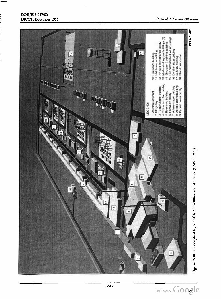
DOE /EIS -0270D
DRATF, December 1997
13
13
13
15
18
13
2
13
12
11
16
14
3
7
5
817
10
9
LEGEND
:
1Accelerator
tunnel
10
Operations
building
2 RF
gallery
11
Maintenance
building 3Target
/blanket
building
12RF
tube
maintenance
facility
4Tritium
sep
.fac
.building
13Mechanical
support
buildings
(6)
5Beamstop
building
14
Simulator
&training
building
6 Radwaste
facility
15
Fire
pumphouse
&water
storage
7 Administration
building
16Demineralizer
building
8Access
control
building
17
Security
building
9Backup
power
facility
18
Electric
substation
6
Proposed Action and Alternatives
PK68
-Z1
-PC
Figure
2-10
.Conceptual
layout
ofAPT
facilities
and
structure
(LANL
1997
).
2-19
DOE / EIS-0270D
DRAFT,December 1997Proposed Action and Alternatives
tration of the APT and the relative placementof
these facilities.
pansion, the beamstop, and associated
shielding. The second part of the building
houses the beamstop heat removal systems.
1. Accelerator Tunnel: This subterranean (less
than 40 feet below grade), rectangular, rein
forced concrete structure would house ac
celerator components, and would have
branches to the Target/ Blanket Building
and the Beamstop Building, as well as
waveguide and electrical conduit penetra
tions to connect to the RF Gallery. An
earthen berm of about 25 -foot thickness
over the main and high -energy tunnel sec
tions would provide radiation shielding.
6. Radioactive Waste Facility: This building
would provide storage for packaged radio
active waste before shipment for final dis
position, and would include monitoring
facilities and offices.
7. Administration Building: This building
would provide offices, conference rooms,
lunchrooms, and medical facilities for the
APT staff.
2. RF Gallery: This structure would extend
the length of the injector and main accel
eration tunnel sections adjacent to the tun
nel berm . It would house the klystrons
tubes or inductive output tubes and support
systems that would supply radiofrequency
power.
8. Access Control Building: This building
would provide facilities for controlling ac
cess to the Tritium Separation Facility and
the Target/ Blanket Building.
9. Backup Power Facility : This structure
would contain three diesel generators and
supporting backup power equipment.
3. Target/Blanket Building Located about
60 feet below grade, this facility would
house the target and blanket systems. It
would be of reinforced concrete and have
three floors below grade and one floor
above grade.
10. Operations Building: This building would
provide office space, conference rooms, and
a facility control room for the APT.
11. Maintenance Building This building would
provide facilities to perform maintenance,
calibration , and assembly / disassembly ac
tivities.
12. RF TubeMaintenance Facility. This facility
would provide space to repair and remanu
facture radiofrequency power tubes or in
ductive output tubes.
4. Tritium Separation Facility Building. The
TSF building houses the tritium separation
process. Itwould be located adjacent to the
T / B building to minimize the length of
piping runs. The facility would include a
process area for the separation of Helium
and tritium in a series of gloveboxes, an
analytical laboratory, shipping area,mainte
nance glovebox, local control area , support
center, and personnel areas and offices for
the facility staff. The process area would be
reinforced concrete shear wall construction
and the balance of the building would be
steel frame construction with architectural
type siding
13. Mechanical Support Buildings: These fa
cilities would include components for high
volume air conditioning (HVAC) and heat
removal. They would house circulation
pumps, heat exchangers, water chillers, ex
pansion tanks, and pressurization pumps.
5. Beamstop Building: This building would
house the beamstop and its associated
equipment. The building consists of two
parts. The first part houses the beam ex
14. Simulator and Training Building: This
building would be outside the APT security
perimeter; it would provide space for opera
tor training and evaluation and for devel
2-20

DOE /EIS-0270D
DRAFT,December 1997 Proposed Action and Alternatives
opmentof new operational procedures, and
would also serve as the visitors' center.2.5 APT Design Variations
15. Fire PumpHouse and Water Storage Tanks:
The pump house would contain fire protec
tion equipment to support APT operations.
The aboveground water storage tanks
would hold water to support the fire pro
tection system .
16. Demineralizer Building: This facility would
house fixtures and equipment for the treat
mentand supply ofmakeup water for use in
the closed-loop cooling systems.
This section describes the two potential design
variations that could enhance the Department's
flexibility to supply the nation's future tritium
needs. The accelerator's inherent operational
characteristics, hardware components, and sup
port structures described elsewhere in this
chapter, and in Appendix A , for the baseline ac
celerator design would be essentially the same as
those for a modular accelerator. Section 2.5.1
summarizes the operational characteristics of
the modular accelerator. Section 2.5.2 com
pares how tritium production could be in
creased from 1.5 to 3 kilogramsper year for the
baseline accelerator and the modular accelera
tor. The incorporation of the proposed Tritium
Extraction Facility design into the APT is also
discussed. While the specifics of the proposed
TEF, as a stand- alone facility, is not discussed in
this chapter or Appendix A , the extraction
process and design is described is Section 2.5.3 .
17. Security Building: This building would
house security personnel and facilities to
control access and monitor the APT facility.
18. Electric Substation: Transformers in this
facility would convert electric power from
the 115 -kilovolt powerlines near the APT
to the necessary voltages for the various
equipment. All APT power would come
from these power lines.
2.5.1 MODULAR OR STAGED
ACCELERATOR CONFIGURATION
2.4.2 USE OF EXISTING SRS
FACILITIES TO SUPPORT APT
OPERATIONS
In designing the APT Project,DOE identified
several areas on the SRS that contain facilities
that it could use in APT operations. The de
scriptions of the alternatives in Section 2.3
mention facilities in H -Area (the Tritium Load
ing Facility and the Tritium Extraction Facility).
DOE has also identified several functions that it
could locate in M -Area. Table 2-2 lists the
function description and the potential M -Area
location (s) identified to accommodate the func
tion (WSRC 1996b). IfDOE determines that it
should locate any of these functions in M -Area,
it could modify the appropriate facilities to ful
fill the new function . The modifications could
include such activities as changing the facility
layout, increasing the structural strength , install
ing mechanical equipment, upgrading or install
ing climate control systems, or installing safety
equipment
Themodular accelerator would be arranged in
straight line as would the baseline accelerator.
It would use the same accelerator architecture, a
normal- conducting low -energy linac injecting
into a superconducting high energy -energy linac
(see Section 2.3.2). As in the superconducting
alternative for the baseline accelerator, the
modular accelerator would require cryomodules.
The accelerator current would be 100 mA. This
level provides power for efficient operation for
tritium goal quantity of 1.5 kilograms per year
but is optimized at 3 kilograms per year The
nominal output energy for the initial stage
would be 1015 MeV (WSRC 1997).
The target/blanket building, and much of the
equipment contained therein would be sized to
accommodate the full 3 kilogramsper year pro
duction level and corresponding beam energy
and power,as would the cavity vessel. The high
energy beam stop would be designed to ac
commodate 2 % of the beam power at full pro
2-21

DOE /EIS -0270D
DRAFT, December 1997Proposed Action and Alternatives
Potential Location (s)
Table 2-2. APT Functions that could be located on the APT site or M - Area .
Function Description
Construction staging
Receipt/inspection of equipment
All facilities
320 - M 321 - M
315 - M
Storageof electrical and electronic equipment320 - M 321 -M
313 - M 315 - M
330 - M 331-M
Preoperational test verification of electrical and electronic equipment320 - M 321 - M
313- M 322-M
Helium -3 piping fabrication and test (loop between blanket and Tritium Sepa- 321-M
ration Facility )
Control room simulatora 321- M
Program Development Center (develop computer software, receive and test 320 - M 321-M
new equipment,and ensure operability of Integrated Control System )a
Magnet equipmentmaintenance 320 - M 321-M
Fabricate target/blanket components,piping assembled , steelassemblies, 320 - M 321 -M
HVAC
Preoperational testing of vacuum valves313 - M 320 - M
321- M
Training Facilitya 313 - M 320 -M
321 - M 305-1M
Target /blanket flow testing (testing for proper heat removal)a320 - M
Small-scale accelerator experiments to improve operation of APTA313 - M 320 - M
321 -M 322 - M
a . Facilities which could be located on the APT site or at other locations.
initial tritium goal quantity of 1.5 kilograms per
year (Stage 1) is increased to 3 kilograms per
year (Stage 2). In reality, however, additional
staging could be at lower production levels.
duction levels (the same as the baseline accelera
tor). The target, decoupler, and inner-blanket
modules would be designed for each production
stage to optimize tritium production at the cor
responding beam energy . The sameblanket and
shielding design would be used for all produc
tion levels. The window would be designed to
accommodate the maximum beam power. The
modular design would include a full production
capacity tritium separation facility for Helium - 3
feedstock material (WSRC 1997).
For the baseline accelerator, the linac , high
energy beam transport, and the tunnels that
house them , are in a straight line. A system de
sign for tritium production at 3 kilograms per
yeardetermines themaximum energy of the ac
celerator, the length of the tunnel and RF gal
lery, and the location and size of the target
blanket building. A staged baseline APT ap
proach beginning with lower tritium production
would be accomplished by building a lower en
ergy accelerator; only as much linac equipment
would be installed in the tunnel as needed to ac
2.5.2 INCREASING TRITIUM
PRODUCTION
In comparing upgrade configurations for the
acceleration designs, baseline and modular, an
2-22
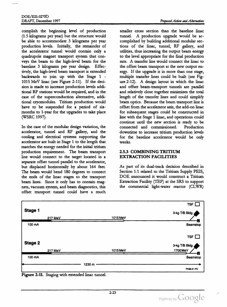
DOE /EIS -0270D
DRAFT,December 1997 Proposed Action and Alternatives
complish the beginning level of production
(1.5 kilogramsper year) but the structure would
be able to accommodate 3 kilograms per year
production levels. Initially, the remainder of
the accelerator tunnel would contain only a
quadrupole magnet transport system that con
veys the beam to the high -level beam for the
baseline 3 kilograms per year design. Effec
tively, the high-level beam transport is extended
backwards to join up with the Stage 1 -
1015 MeV linac (see Figure 2-11). If the deci
sion is made to increase production levels addi
tional RF stations would be required, and in the
case of the superconduction alternative, addi
tional cryomodules. Tritium production would
have to be suspended for a period of six
months to 1 -year for the upgrades to take place
(WSRC 1997).
smaller cross section than the baseline linac
tunnel. A production upgrade would be ac
complished by building additional modular sec
tions of the linac , tunnel, RF gallery , and
utilities, thus increasing the output beam energy
to the level appropriate for the final production
rate. A transfer line would connect the linac to
the offsetbeam transport at the new output en
ergy. If the upgrade is in more than one stage,
multiple transfer lines could be built (see Fig
ure 2-12). A design layout in which the linac
and offset beam -transport tunnels are parallel
and relatively close together minimizes the total
length of the transfer lines and could simplify
beam optics. Because the beam transport line is
offset from the accelerator axis, the add -on linac
for subsequent stages could be constructed in
line with the Stage 1 linac, and operations could
continue until the new section is ready to be
connected and commissioned . Production
downtime to increase tritium production levels
for the baseline accelerator would be only
weeks.
2.5.3 COMBINING TRITIUM
EXTRACTION FACILITIES
In the case of themodular design variation, the
accelerator, tunnel and RF gallery, and the
cooling and electrical systems supporting the
accelerator are built in Stage 1 to the length that
matches the energy needed for the initial tritium
production requirement.The beam transport
line would connect to the target located in a
separate offset tunnel parallel to the accelerator,
but displaced horizontally by about 164 feet.
The beam would bend 180 degrees to connect
the ends of the linac stages to the transport
beam lines . Since it only has to contain mag
nets, vacuum system , and beam diagnostics, this
offset transport tunnel could have a much
As part of its dual-track decision described in
Section 1.1 related to the Tritium Supply PEIS,
DOE announced it would construct a Tritium
Extraction Facility (TEF) at the SRS to support
the commercial light-water reactor (CLWR)
TSF
Stage 13-kg T /B Bldg
217 MeV 1015MeV
100mA Beamstop
TSF
Stage 2
3 -kg T /B Bldg
1700MeV217 MeV 1015 MeV
100 mA Beamstop
1230 m
PK68-Z1-PC
Figure 2-11. Staging with extended linac tunnel.
2-23

DOE /EIS -0270D
DRAFT, December 1997Proposed Action and Alternatives
Stage 1 1.5 kg/yr
217 MeV 1015MeV
100 mA
Beamstop
TSF 3 -kg T /B Bldg
Stage 2 2.0 kg /yr
217 MeV 1015MeV 1300MeVBA
100 mA
BeamstopBeam transport
3-kg T /B BldgTSF
Stage 3 2.5 kg/yr
217 MeV 1015 MeV 1300MeV 1525 MeV
100 mA
BeamstopBeam transport
TSFD 3-kg T /B Bldg
Stage 4 3.0 kg/yr
217 MeV 1015 MeV 1300 MeV 1525 MeV 1700MeV
100mA
BeamstopBeam transport
TSF3-kg T/B Bldg
1350 m
PK68 -Z1-PC
Figure 2-12 . Themodular configuration and possible stages of expansion .
proximately one mile east of the SRS near
Barnwell, South Carolina.
track, if that was the track it chose . Since that
decision , DOE issued a Notice of Intent (NOI)
to prepare an EIS for the construction and op
eration of a TEF (see Section 1.5). DOE would
build the TEF at the SRS to extract tritium from
either CLWR target rods or the Lithium -6
feedstock material from the APT.
TheNotice of Intent for the Tritium Extraction
Facility explained the proposed action of con
structing and operating a TEF thatwould be co
located with and would share common support
facilities with Building 233-H at the SRS. As
currently planned, the alternatives to the pro
posed action are : (1) not constructing and op
erating the TEF -- the No Action alternative
and (2) upgrade and use of the existing Allied
General Nuclear Services facility located ap
The process for completing the conceptual de
signs for the Accelerator for the Production of
Tritium and the Tritium Extraction Facility
identified an APT design option . This option
would place the equipment necessary for ex
tracting tritium from target rods irradiated in a
commercial reactor or the Lithium - 6 feedstock
from the APT in the APT target /blanket
building. In addition , the Tritium Separation
Facility (TSF) would be built, regardless of the
choice of feedstock material. The TSF handling
and purification equipment would then be used
to extract tritium from the CLWR or Lithium -6
rods.
2-24

DOE /EIS -0270D
DRAFT,December 1997 Proposed Action and Alternatives
Increase the width of the target/blanket
building
This is an additional option from those pre
sented in the Notice of Intent to prepare this
EIS and the TEF EIS . If the APT is selected as
the primary track for tritium supply, the De
partment would still need, in the case of a na
tional emergency, capability to extract tritium
from rods irradiated in a commercial reactor.
This capability could be provided through this
design option (i.e., combining the TEF with the
APT) or one of the alternatives described in the
TEF EIS .
Create a new Tritium Extraction Pit in the
target /blanket building and place the TEF
remote handling functions and two furnaces
in it.
Place the TEF Water Cracker Room and as
sociated equipment in the room previously
identified as the APT Tritium Gas Storage
Room ; relocate the gas storage equipment
to the new area (see above).
.
While detailed technical data on the combining
of the TEF and the TSF has not been finalized,
the operational environmental impacts from this
design option are not expected to significantly
vary from the impacts for the baseline accelera
tor discussed in Chapter 4. As described below ,
this conclusion is based on the assumptions that
the TEF and TSF will not operate at the same
time and the administrative limit for tritium
would be the same as that established for the
APT without a TEF.
Consolidate TEF requirements into the
АРТprocesses and complete appropriate
modifications to the support systems.
Design the TEF furnaces to process APT
blanket modules to recover residual tritium
implanted in the tubes (DOE 1997b).
The two processes target rod tritium extrac
tion and Helium - 3 tritium extraction -- could
not operate concurrently. Specifically, DOE
would complete the modifications listed above,
but would not operate the TEF furnaces in
parallel with the APT process.
In the event tritium is produced in a commercial
light-water reactor, DOE would ship the target
rods from the CLWR to the SRS in a transport
cask , remove the rods from the cask, and place
them in dry storage to await extraction . DOE
would prepare the rods for extraction by punc
turing the cladding and cutting off the top ends,
and then would place the rods in a double
vacuum extraction furnace that would drive off
tritium and other gases. DOE would use the
same process to purify the gases from the rods
that it would use to extract tritium from the
APT Helium - 3 feedstock (Appendix A de
scribes this process), and would move the puri
fied tritium to the Tritium Loading Facility .
Since the designed production capacity of the
combination TEF -TSF would be the same as
for the Helium - 3 feedstock alternative without
the TEF at the APT site , the expected releases
of effluents as well as waste streamswould also
be the same as described in Chapter 4, as would
be the consequences.
As a result, the radionuclide inventories used in
the effluent calculations and accident analyses
including the waste streams used in this docu
ment remain valid and encompass the com
bined facility.
If Lithium -6 feedstock is used to produce trit
ium in APT, the tritium would be extracted in
the samemanner as described in Section 2.3.3,
except that no transportation would be needed
because equipment necessary to perform the
operations would be colocated with the APT.
2.6 Cost and Schedule
To accommodate this option,DOE would have
to make the following modifications to the ac
celerator facilities:
Information on the cost and schedule for the
construction and operation of the APT can be
found in the Conceptual Design Report (LANL
1997) .
2-25
DOE /EIS -0270D
Proposed Action and Alternatives DRAFT, December 1997
2.7 Comparison of Environ
mental Impacts Among Alterna
tives
Table 2-3 presents a comparison of the envi
ronmental impacts associated with construction
and operation of the baseline APT as a function
of alternative. For each technical discipline, the
impacts of the Preferred alternative are dis
cussed . The Preferred alternative is composed
of the following:
tritium at the SRS to be minor and consistent
with whatmight be expected for anyindustrial
facility. Construction and operation of the Pre
ferred alternative would result in the loss of
about 250 acres of mixed pine/hardwood up
land forest. Waste would be generated during
both the construction and operation phases but
in quantities thatwould have negligible impacts
on SRS waste management facilities . No high
level waste or transuranic waste would be gen
erated during construction or operation .
• Klystron radiofrequency tubes
Superconducting operation of accelerator
structures
Some small impacts from discharge of cooling
water to SRS streams and from nonradiological
emissions to air and waterwould occur. Radio
logical releases during normal operation of the
facility are expected to result in no latent cancer
fatalities in workers or the public. Because no
high or adverse impacts are expected, no dis
proportionately high or adverse impacts on mi
noritylow -income communities
expected.
Helium - 3 feedstock material
or areMechanical-draft cooling towers with river
watermakeup
Electricity from existing capacity and mar
ket transactions
Use of the Preferred APT site
Differences in impacts that could occur if dif
ferent alternatives were implemented are also
presented
Based on current design information, most of
the potential environmental impacts of the two
design variations (the modular APT design and
combining tritium extraction facilities) are
bound by the baseline APT.
Implementation of certain of the technology
alternatives could result in impacts different
from those resulting from construction and op
eration of the Preferred alternative. Most no
table would be the impacts from
implementation of cooling water system alter
natives and electric power supply alternatives.
Once-Through Cooling Using River Water
would result in withdrawal from the Savannah
River of about 125,000 gallons per minute of
river water and discharge of hot water to the
Par Pond system during operation . Thermal
impacts would be restricted to the upper por
tions of the Par Pond system and would not af
fect Par Pond discharges to Lower Three Runs.
There would be a small increase in Lower Three
Runs flows, however. The implementation of
the Mechanical-Draft Cooling Towers with
Groundwater Makeup alternative would result
in the withdrawal of 6,000 gallons per minute of
groundwater. Total groundwater withdrawal at
the SRS could therefore exceed the estimated
groundwater production capacity of the aquifer.
This could affect groundwater flow to site
In the case of the modular APT design , how
ever, more land could be required. The poten
tial socioeconomic impacts would initially be
less. If themodular APT is expanded to 3 kilo
grams/year, socioeconomic impacts could ex
tend beyond the construction period assumed
for the baseline APT.
streams.
In general, DOE considers the expected im
pacts on the biological, human, and socioeco
nomic environment of construction and
operation of an accelerator for production of
2-26

DOE /EIS-0270D
DRAFT, December 1997 Proposed Action and Alternatives
The Preferred alternative includes buying elec
tricity from the commercial grid to support
APT operation. In the case of commercial
electricity purchases, the environmental impacts
attributed to the APT load would be decentral
ized . In the case of the construction of a new
electricity generating plant to support the APT,
the environmental impacts would be localized at
the site selected for the plant. Construction and
operation of such a facility could require about
290 acres for a coal-fired plant and about
110 acres for a gas- fired plant.
Should the Department select the No Action
alternative , design work on the APT would be
concluded and the information archived. The
APT would not be constructed at the preferred
site and the 250 acres of land would revert to
forestry or other uses. On -going SRS missions
would continue. Incremental amounts ofwaste
generation and electricity consumption that
would have been attributable to the APT would
not occur. Employment would be a function of
on -goingmissions and funding levels.
2-27

DOE /EIS-0270D
using
river
Proposed Action and Alternatives
Table
2-3
.Comparison
ofimpacts
among
alternatives
.
Operating
Feedstock
Radio
frequency
temperature
material
Site
location
Electric
power
Preferred
alternative
power
alternative
alternative
alternative
Cooling
water
system
alternatives
alternative
supply
alternative
Described
intext
Inductive
output
Room
Lithium
-6 Once
-through
Mechanical
K-Area
cooling
Alternate
site
Construct
new
tube
temperature
draft
using
tower
using
plant
water
as
groundwater
as
river
water
as
makeup
makeup
makeup
Impacts
from
Construction
onLandforms
,Soils
,Geology
,and
Hydrology
Negligible
impacts
.No
change
No
change
No
change
No
change
No
change
No
change
Water
table
is
Impacts
would
cstimated
from
cstimated
from
cstimated
from
estimated
from
cstimated
from
cstimated
from
deeper
and
depend
upon
the
Some
250
acres
of
land
Preferred
Preferred
Preferred
Preferred
Preferred
Preferred
specific
location
of
awould
require
would
be
graded
or
lcvclcd
.alternative
alternative
alternative
alternative
alternative
alternative
less
dewatering
;new
facility
.Could
no
other
require
about
110
No
gcologically
significant
changes
acres
for
natural
gas
formations
or
soils
occur
.estimated
from
or290
acres
for
Dewatering
nccessary
.No
Preferred
coal
.surface
faulting
on
sitc
.
alternative
.Sites
for
clcctricity
generation
cxist
.
Impacts
from
Operation
onLandforms
,Soils
,Geology
,and
Hydrology
No
change
No
impacts
No
change
No
change
No
change
Removal
of
6,000
No
change
Impacts
would
No
change
cstimated
from
cstimated
from
estimated
from
cstimated
from
estimated
from
cstimated
from
depend
upon
the
No
dewatering
required
for
Prcfcrred
Preferred
Preferred
Preferred
sustained
basis
Preferred
Preferred
specific
location
of
a
operations
.alternative
alternative
alternative
alternative
could
impact
alternative
alternative
new
facility
groundwater
flow
tostrcams
and
compact
clay
layers
8pm
on
a
1
Negligible
impacts
.
Dcwatcring
of
construction
sitc
could
result
inshort
-
term
incrcascs
insolids
to
thc
recciving
water
bodics
.
No
change
estimated
from
Preferred
alternative
No
change
cstimated
from
Preferred
alternative
Impacts
from
Construction
onSurface
Water
No
change
No
change
No
change
cstimated
from
estimated
from
cstimated
from
Preferred
Preferred
Preferred
alternative
alternative
alternative
No
change
No
change
Impacts
would
cstimated
from
cstimated
from
depend
upon
the
Preferred
Preferred
specific
location
of
a
alternative
alternative
new
facility
DRAFT, December 1997
2-28

DOE /EIS -0270D
DRAFT, December 1997
Table
2-3
.(Continued
)
Operating
Feedstock
Radio
frequency
temperature
material
Site
location
Electric
power
Preferred
alternative
power
alternative
alternative
alternative
Cooling
water
system
alternatives
alternative
supply
alternative
Described
intext
Inductive
output
Room
Lithium
-6Once
-through
Mechanical
K-Area
cooling
Alternate
site
Construct
new
tube
temperature
using
river
draft
using
tower
using
plant
water
as
groundwater
as
river
water
as
makeup
makeup
makeup
Impacts
from
Operation
on
Surface
Water
Blowdown
rates
(about
Would
require
7%Would
require
No
change
Blowdown
rates
No
change
No
change
No
change
Discharges
would
2,000
gpm
)would
cause
less
cooling
water
33
%more
cooling
estimated
from
(about
125,000
estimated
from
cstimated
from
cstimated
from
bc
similar
tothe
ncgligible
impact
on
surface
than
Preferred
duc
water
than
Prcfcrrcd
gpm
)would
Preferred
Preferred
Preferred
Preferred
water
levels
;using
Par
Pond
tolower
wastc
hcat
Preferred
;noalternative
result
in higher
alternative
alternative
alternative
alternative
,although
as
discharge
point
for
gencration
;no
other
changes
temperatures
to
concentrations
cooling
water
.Temperatures
other
changes
from
Preferred
water
bodics
would
vary
and
bc
would
not
cxcccd
90
°T.cstimated
from
alternative
(about
100
°1).localized
.
Contaminated
scdimcnts
Preferred
Aslight
increasc
would
be
resuspended
in
alternative
in“pre
-cooler
"
addition
toradiological
pond
water
levels
relcascs
from
APT
.would
occur
. No
other
changes
Estimated
fatal
cancers
:cstimated
from
0.00007
Preferred
alternative
Air
cmissions
(fugitive
dust
No
change
and
exhaust
emissions
)cstimated
from
would
bc
ncgligible
,well
Preferred
below
the
applicable
alternative
regulatory
standards
,
clectricity
purchases
,for
impacts
would
be
dispersed
.
Impacts
from
Construction
onNonradiological
Air
Emissions
No
change
No
change
No
change
No
change
cstiinated
from
estimated
from
cstimated
from
cstimated
from
Preferred
Preferred
Preferred
Preferred
alternative
alternative
alternative
alternative
No
change
No
change
limission
types estimated
from
cstimated
from
would
be
similar
to
Preferred
Preferred
the
Preferred
alternative
alternative
alternative
,although
concentrations
would
vary
and
be
localized
.
No
change
cstimated
from
Preferred
alternative
No
radiological
emissions
would
be
well
within
the
applicable
regulatory
standards
.Operations
would
result
insmall
amounts
of
salt
deposition
and
plumes
from
cooling
tower
operations
.
Impacts
from
Operation
onNonradiological
Air
Emissions
No
change
No
change
No
change
No
change
cstimated
from
estimated
from
cstimated
from
cstimated
from
Preferred
Preferred
Preferred
Preferred
alternative
alternative
alternative
alternative
No
change
No
change
Nonradiological
cstimated
from
cstimated
from
cmissions
would
be
Preferred
Preferred
well
within
alternative
alternative
applicable
regulatory
standards
.
Proposed Action and Alternatives
2-29

DOE /EIS-0270D
Electric
power
supply
alternative
Construct
new
plant
Table
2-3
.(Continued
).
Operating
Feedstock
Radio
frequency
temperature
material
Site
location
Preferred
alternative
power
alternative
alternative
alternative
Cooling
water
system
alternatives
alternative
Described
intext
Inductive
output
Room
Lithium
-6Once
-through
Mechanical
K-Area
cooling
Alternate
site
tube
temperature
using
river
draft
using
tower
using
water
as
groundwater
as
river
water
as
makeup
makeup
makeup
Impacts
from
Construction
onRadiological
Air
Emissions
No
impacts
;no
radioactive
No
change
No
change
No
change
No
change
No
change
No
change
No
change
matcrials
stored
during
estimated
from
cstimated
from
cstimated
from
cstimated
from
cstimated
from
cstimated
from
cstimated
from
construction
.Preferred
Preferred
Preferred
Prcfcrrcd
Preferred
Prcfcrrcd
Prcfcrrcd
alternative
alternative
alternative
alternative
alternative
alternative
alternative
Proposed Action and Alternatives
No
change
estimated
from
Preferred
alternative
Negligible
impacts
from
radioactive
airborne
cfflucnts
No
change
cstimated
from
Prcfcrrcd
alternative
Impacts
from
Operation
onRadiological
Air
Emissions
No
change
Reduced
doses
No
change
No
change
cstimated
from
from
airbornc
cstimated
from
cstimated
from
Preferred
cmissions
Preferred
Preferred
alternative
alternative
alternative
LCI's
expected
:
0.00029
No
change
cstimated
from
Preferred
alternative
Latent
Cancer
l'atalitics
(LCI's
)expected
:0.0006
Iligher
doses
Impacts
would
from
airborne
depend
upon
the
cmissions
duc
to
specific
location
of
a
closcr
distancc
new
facility
.
toSRS
However
,the
dosc
boundary
from
radioactive
cfflucnts
would
be
LCI's
cxpccted
:ncgligiblc
.
0.00065
Conversion
of
250
acres
ofNo
change
forested
land
toindustrial
cstimated
from
usc
.Additional
roads
,Preferred
bridge
upgrades
,rail
lincs
alternative
and
utility
upgrades
would
be
required
.
Impacts
from
Construction
onLand
Use
and
Infrastructure
No
change
No
change
No
change
No
change
cstimated
from
cstimated
from
cstimated
from
cstimated
from
Preferred
Prcfcrrcd
Preferred
Preferred
alternative
alternative
alternative
alternative
Additional
No
change
Impacts
would
cooling
water
cstimated
from
depend
upon
the
piping
toK-arca
Preferred
specific
location
of
a
nccdcd
.alternative
new
facility
.Could
rcquirc
conversion
ofup
to290
acres
to
industrial
usc
.
DRAFT,December 1997
2-30
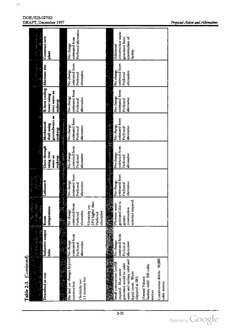
DOE /EIS-0270D
Table
2-3
.(Continued
)
Preferred
alternative
Described
intext
Radio
frequency
power
alternative
Inductive
output
tube
Electric
power
supply
alternative
Construct
new
plant
Operating
Feedstock
temperature
smaterial
Site
location
alternative
Altematve
Coolin
:water
system
alternatives
alternauye
Room
Lithium
-6Once
-through
Mechanical
K-Area
cooling
Alternate
site
temperature
draft
using
tower
using
water
as
groundwater
asriver
water
as
makeup
makeup
makeup
Impacts
from
Operation
onLand
Use
and
Infrastructure
No
change
No
change
No
change
No
change
No
change
No
change
cstimated
from
cstimated
from
cstimated
from
cstimated
from
cstimated
from
cstimated
from
Preferred
Preferred
Prcfcrrcd
Prcfcrrcd
Prcfcrrcd
Preferred
alternativc
alternative
alternative
alternative
alternative
alternativc
DRAFT, December 1997
using
river
No
land
use
changes
beyond
No
change
construction
.cstimated
from
Preferred
lilcctricity
usc
:alternative
3.1
tcrawatt
-hrs
No
change
cstimated
from
Prcfcrrcd
alternative
Electricity
use 23
%higher
than
Prcfcrred
altcrnative
Small
construction
landfill
No
change
rcquired
.Most
waste
cstimated
from
gcncratcd
would
be
solid
Prcfcrrcd
waste
and
sanitary
solid
and
alternative
liquid
wastc
.Wastc
disposcd
atSRS
.
Impacts
from
Construction
onWaste
Management
9%morc
wastc
No
change
No
change
No
change
generated
duc
tocstimated
from
cstimated
from
cstimated
from
grcator
Prcfcrrcd
Prcfcrrcd
Prcfcrrcd
construction
altcrnative
alternative
alternative
activitics
rcquired
.
No
change
cstimated
from
Prcfcrrcd
alternative
No
change
cstimated
from
Prcfcrrcd
alternative
Additional
construction
waste
gcncratcd
from
construction
of
facility
.
(Annual
Values
)
Sanitary
solid
:560
cubic
mctcrs
Construction
debris
: 30,000
cubic
mctcrs
Proposed Action and Alternatives
2-31

DOE /EIS-0270D
Proposed Action and Alternatives
Table
2-3
.(Continued
).
Operating
Feedstock
Radio
frequency
temperature
material
Site
location
Electric
power
Preferred
alternative
power
alternative
alternative
alternative
Cooling
water
system
alternatives
alternative
supply
alternative
Described
intext
Inductive
output
Room
Lithium
- 6Once
-through
Mechanical
K-Area
cooling
Alternate
site
Construct
new
tube
temperature
using
river
draft
using
tower
using
plant
water
as
groundwater
as
river
water
as
makeup
makeup
makeup
Impacts
from
Operation
onWaste
Management
Would
gcncratc
solid
andNo
change
37
% morc
17
%morc
low
2,000
%greater
No
change
No
change
No
change
Impacts
would
liquid
wastes
,but
no
high
cstimated
from
nonradioactive
level
and
50
%flow
of
cstimated
from
cstimated
from
cstimated
from
depend
upon
the
level
or
transuranic
wastc
;Preferred
process
more
high
nonradioactive
Preferred
Preferred
Preferred
type
ofpower
plant
waste
volumes
would
have
alternative
wastcwatcr
concentration
process
alternative
alternative
alternative
sclccted
.Ilowever
,
ncgligible
impact
on
required
.mixed
waste
wastcwatcr
wastc
rates
for
new
capacitics
of
waste
facilitics
.gcncratcd
than
required
.power
plant
would
Generation
of
clcctricity
will
Preferred
not
bevery
different
alternative
.than
for
the
gencratc
various
types
of
Preferred
waste
including
fly
ash
,
alternative
.bottom
ash
,and
scrubber
sludge
.
(Annual
Valucs
)
Sanitary
solid
:1,800
mctric
tons
Industrial
:3,800
mctric
tons
Radioactive
wastewater
:
140,000
gallons
Iligh
concentration
waste
Greater
-than
-Class
-C
15
cubic
mcters
Sanitary
wastewater
:3.3
million
gallons
Nonradioactive
process
wastewater
:920
million
gallons
Negligiblc
,facilitics
far
from
No
change
SRS
boundaries
and
not
cstimated
from
visible
tooffsite
traffic
;Preferred
facilitics
would
look
like
alternative
other
industrial
arcas
atSRS
.
No
change
cstimated
from
Preferred
alternative
Impacts
from
Construction
on
Visual
Resources
No
change
No
change
No
change
estimated
from
cstimated
from
cstimated
from
Preferred
Prcfcrrcd
Preferred
alternative
alternative
alternative
No
change
No
change
Impacts
would
cstimated
from
cstimated
from
depend
upon
the
Preferred
Preferred
specific
location
of
a
alternative
alternative
new
facility
DRAFT,December 1997
2-32
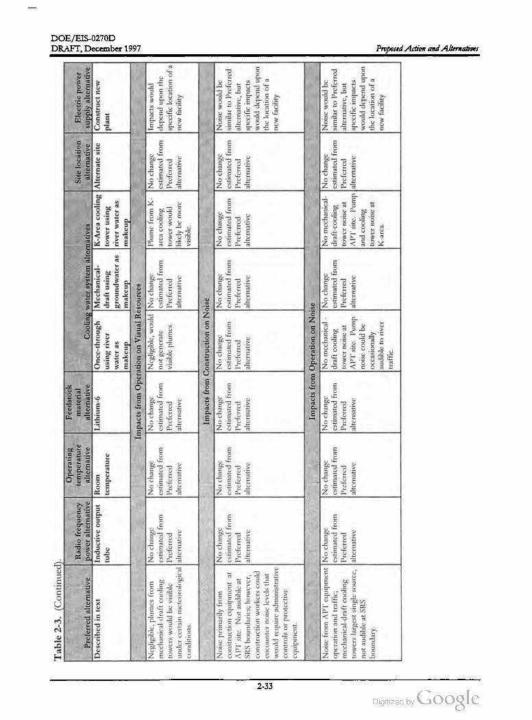
DOE/EIS-0270D
Table
2-3
.(Continued
)
Operating
Radio
frequency
temperature
Preferred
alternative
power
alternative
alternative
Described
in text
Inductive
output
Room
temperature
Electric
power
supply
alternative
Construct
new
plant
Feedstock
material
Site
location
alternative
Cooling
water
system
alternatives
alternative
Lithium
-6Once
-through
Mechanical
K-Area
cooling
Alternate
site
using
river
draft
using
tower
using
water
as
groundwater
as
river
water
as
makeup
makeup
makeup
Impacts
from
Operation
on
Visual
Resources
No
change
Negligiblc
,would
No
change
Plumc
from
K-No
change
cstimated
from
not
gcncrate
estimated
from
arca
cooling
cstimated
from
Preferred
visiblc
plumcs
.Prcfcrred
tower
would
Preferred
alternative
alternative
likely
bemore
alternative
visible
.
DRAFT, December 1997
tube
Negligible
,plumes
from
No
change
mechanical
-draft
cooling
cstimated
from
towers
would
be
visible
Preferred
under
certain
mctcorological
alternative
conditions
.
No
change
estimated
from
Preferred
alternative
Impacts
would
depend
upon
the
specific
location
of
a
new
facility
No
change
cstimated
from
Preferred
alternative
Impacts
from
Construction
on
Noise
No
change
No
change
No
change
estimated
from
cstimated
from
cstimated
from
Preferred
Preferred
Preferred
alternative
alternative
alternative
Noise
primarily
from
No
change
construction
equipment
atcstimated
from
APT
sitc
.Not
audible
at
Preferred
SRS
boundaries
;however
, alternative
construction
workers
could
cncounter
noise
levels
that
would
require
administrative
controls
or
protective
cquipment
No
change
No
change
Noisc
would
bc
estimated
from
estimated
from
similar
toPreferred
Preferred
Preferred
alternative
,but
alternative
alternative
specific
impacts
would
depend
upon
the
location
of
a
new
facility
Noise
from
APT
equipment
No
change
operation
and
traffic
;cstimated
from
mechanical
-draft
cooling
Preferred
towers
largest
single
source
,alternative
not
audible
atSRS
boundary
.
No
change
estimated
from
Preferred
alternative
Impacts
from
Operation
onNoise
No
change
No
mechanical
- No
change
cstimated
from
draft
cooling
estimated
from
Preferred
tower
noisc
atPreferred
alternative
APT
site
.Pump
alternative
noisc
could
be
occasionally
audiblc
toriver
traffic
.
No
mechanical-
No
change
draft
-cooling
cstimated
from
towcr
noisc
at
Prcfcrrcd
APT
sitc
.Pump
alternative
and
cooling
tower
noise
at
Noise
would
be
similar
toPrcfcrrcd
alternative
,but
specific
impacts
would
depend
upon
the
location
of
a
new
facility
K -arca
.
Proposed Action and Alternatives
2-33

DOE /EIS -0270D
Table
2-3
. (Continued
)
Preferred
alternative
Described
intext
Radio
frequency
power
alternative
Inductive
output
tube
Operating
Feedstock
temperature
material
Site
location
Electric
power
alternative
Alternative
Cooling
water
system
alternatives
alterative
supply
alternative
Room
Lithium
-6Once
-through
Mechanical
K-Area
cooling
Alternate
site
Construct
new
temperature
using
river
draft
using
tower
using
plant
water
as
groundwater
as
river
water
as
makeup
makeup
makeup
Impacts
from
Construction
onHuman
Health
Occupational
No
change
No
change
No
change
No
change
No
change
Impacts
would
be
injurics
6%less
cstimated
from
cstimatcd
from
cstimated
from
cstimated
from
cstimated
from
similar
toPrcfcrrcd
than
Prcfcrrcd
Prcfcrrcd
Prcfcrrcd
Prcfcrrcd
Prcfcrrcd
Prcfcrrcd
alternativc
,but
alternative
alternative
alternative
alternative
altcrnative
alternative
specific
impacts
would
depend
upon
Traffic
fatalitics
the
location
of
a
20
%lcss
than
new
facility
Prcfcrrcd
alternative
Proposed Action and Alternatives
Concentrations
of
No
change
nonradiological
constitucnts
cstimated
from
would
be
less
than
Prcfcrrcd
applicable
limits
for
workers
alternative
and
public
.Traffic
-rclated
accidents
resulting
inabout
2fatalitics
tothe
public
and
workers
due
toincreased
local
traffic
would
be reduced
with
finish
of
construction
.Occupational
injuries
toworkers
would
be
duc
toindustrial
activitics
and
would
have
the
following
impacts
for
the
construction
period
:
Number
requiring
l'irst
Aid
:
1,100
Numbcr
rcquiring
mcdical
attention
:280
Number
resulting
inlost
work
time
:93
DRAFT, December 1997
-
2-34

DOE /EIS -0270D
Table
2-3
. (Continued
).
Operating
Radio
frequency
temperature
Preferred
alternative
power
alternative
alternative
Described
intext
Inductive
output
Room
tube
temperature
Electric
power
supply
alternative
Construct
new
plant
Feedstock
material
Site
location
alternative
Cooling
water
system
alternatives
alternative
Lithium
-6 Once
-through
Mechanical
K-Area
cooling
Alternate
site
using
river
draft
using
tower
using
water
as
groundwater
as
river
water
as
makeup
makeup
makeup
Impacts
from
Operation
onHuman
Health
No
change
No
change
No
change
No
change
No
change
estimated
from
cstimated
from
estimated
from
cstimated
from
cstimated
from
Preferred
Preferred
Preferred
Prcfcrrcd
Prcfcrrcd
alternative
alternative
alternative
alternative
alternative
DRAFT, December 1997
No
change
cstimated
from
Preferred
alternative
Public
would
reccive
source
No
change
radiation
exposure
from
cstimated
from
APT
cmissions
and
Prcfcrrcd
transportation
of
radioactive
alternative
matcrial
;workers
would
reccive
radiation
exposure
from
facility
operations
and
transportation
of
radioactive
matcrial
and
from
clectromagnctic
fields
.
Total
LCI's
topopulation
(air
,water
,and
transport
)
0.0012
No
change
cstimated
from
Preferred
alternative
.Impacts
would
be
local
vs.
dispersed
for
clectricity
gcncration
.
Total
worker
fatal
cancers
0.04
Negligible
consequences
for
No
change
accidents
with
frequency
of
estimated
from
less
than
once
inoperating
Preferred
lifetime
of
facility
alternative
No
change
cstimated
from
Preferred
alternative
Impacts
from
Accidents
onHuman
Health
Minor
decrcascs
No
change
No
change
inaccident
doscs
cstimated
from
estimated
from
for
low
Preferred
Preferred
probability
alternative
alternative
cvents
.
No
change
cstimated
from
Preferred
alternative
No
change
cstimated
from
Prcfcrrcd
alternative
Accident
consequences
would
bc
reduced
since
no
radioactive
material
isinvolved
.
Would
result
inthe
loss
ofNo
change
upto250
acres
of
forested
cstimated
from
land
;nomarked
reduction
Preferred
inplant
/animal
abundance
alternative
or
diversity
Impacts
from
Construction
on
Terrestrial
Ecology
No
change
No
change
No
change
No
change
cstimated
from
cstimated
from
cstimated
from
cstimated
from
Preferred
Preferred
Preferred
Prcfcrrcd
alternative
alternative
alternative
alternative
No
change
No
change
No
change
estimated
from
cstimated
from
cstimated
from
Preferred
Preferred
Preferred
alternative
alternative
alternative
;specific
impacts
would
depend
upon
the
location
of
anew
facility
.
Proposed Action and Alternatives
2-35

DOE /EIS -0270D
Electric
power
supply
alternative
Construct
new
plant
Table
2-3
. (Continued
).
Operating
Feedstock
Radio
frequency
temperature
material
Site
location
Preferred
alternative
power
alternative
alternative
alternative
Cooling
water
system
alternatives
alternative
Described
intext
Inductive
output
Room
Lithium
- 6Once
-through
Mechanical
K-Area
cooling
Alternate
site
tube
temperature
using
river
draft
using
tower
using
water
as
groundwater
as
river
water
as
makeup
makeup
makeup
Impacts
from
Operation
on
Terrestrial
Ecology
Negligible
impacts
.No
change
No
change
No
change
No
change
No
change
No
change
No
change
Mechanical
-draft
cooling
cstimated
from
cstimated
from
cstimated
from
cstimated
from
cstimated
from
cstimated
from
cstimated
from
towers
would
result
insalt
Preferred
Preferred
Prcfcrrcd
Preferred
Preferred
Preferred
Preferred
deposition
on
vegetation
;alternative
alternative
alternative
alternative
alternative
alternative
alternative
however
,maximum
rates
(60
lb/acres
/yr
)are
below
threshold
levels
(180
lb/acres
/yr
).
Proposed Action and Alternatives
Specific
impacts
would
depend
upon
the
location
of
a
new
facility
No
impacts
are
projected
No
change
from
construction
activities
.cstimated
from
Prcfcrrcd
alternative
Impacts
from
Construction
on
Wetlands
Ecology
No
change
No
change
No
change
No
change
cstimated
from
estimated
from
cstimated
from
cstimated
from
Preferred
Preferred
Prcfcrrcd
Preferred
alternative
alternative
alternative
alternative
No
change
No
change
Specific
impacts
estimated
from
estimated
from
would
depend
upon
Prcfcrrcd
Preferred
the
location
of
a
alternative
alternative
new
facility
No
change
estimated
from
Prcfcrrcd
alternative
No
change
cstimated
from
Preferred
alternative
Impacts
from
Operation
onWetlands
Ecology
No
change
Would
raisc
water
No
change
cstimated
from
level
inPonds
2 cstimated
from
Preferred
and
5by
1.5
fcct
,Preferred
alternative
possibly
affecting
alternative
wetland
plant
communities
.
No
change
cstimated
from
Preferred
alternative
Would
result
inminor
impacts
towetlands
. Temperature
of
the
blowdown
would
be
marginally
higher
than
the
ambicnt
maximum
temperaturc
.During
cooler
months
the
warmth
could
have
a positive
impact
by
lengthening
the
growing
scason
for
some
aquatic
vegctation
.
No
change
Specific
impacts
cstimated
from
would
depend
upon
Preferred
the
location
of
a
alternative
new
facility
DRAFT, December 1997
i
2-36
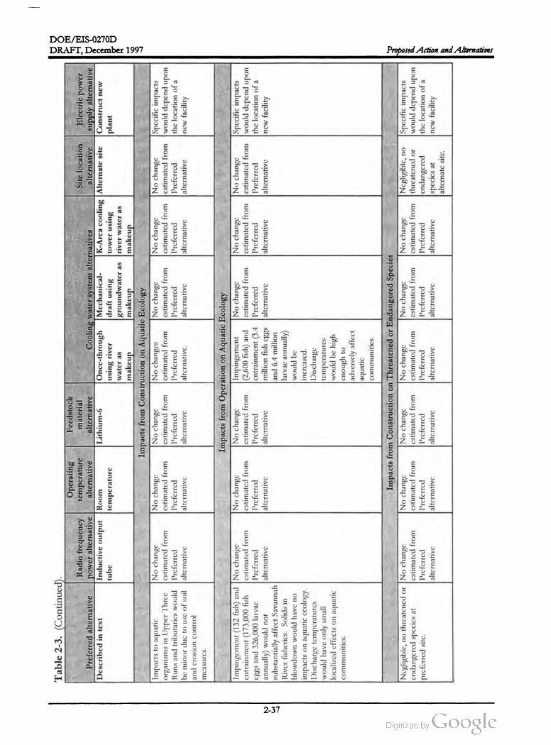
DOE /EIS-0270D
Table
2-3
. (Continued
).
Operating
Feedstock
Radio
frequency
temperature
material
Site
location
Electric
power
Preferred
alternative
power
alternative
alternative
alternative
Cooling
water
system
alternatives
alternative
supply
alternative
Described
intext
Inductive
output
Room
Lithium
- 6 Once
-through
Mechanical
K-Area
cooling
Alternate
site
Construct
new
temperature
using
river
draft
using
tower
using
plant
water
as
groundwater
as
river
water
as
makeup
makeup
makeup
Impacts
from
Construction
onAquatic
Ecology
Impacts
toaquatic
No
change
No
change
No
change
No
changes
No
change
No
change
No
change
Specific
impacts
organisms
inUpper
Three
cstimated
from
cstimated
from
cstimated
from
cstimated
from
cstimated
from
cstimated
from
cstimated
from
would
depend
upon
Runs
and
tributaries
would
Preferred
Preferred
Preferred
Preferred
Preferred
Prcfcrrcd
Preferred
the
location
of
a
beminor
duc
tousc
of
soil
alternative
alternative
alternative
alternativc
. alternative
alternative
alternative
new
facility
and
crosion
control
DRAFT,December 1997
tube
mcasures
.
No
change
cstimated
from
Preferred
alternative
No
change
No
change
Specific
impacts
cstimated
from
cstimated
from
would
depend
upon
Preferred
Preferred
the
location
of
a
alternative
alternative
ncw
facility
Impingement
(132
fish
)and
No
change
cntrainment
(173,000
fish
estimated
from
cggs
and
326,000
larvac
Preferred
annually
)would
not
alternative
substantially
affect
Savannah
River
fisherics
.Solids
in blowdown
would
have
no impacts
on
aquatic
ccology
.
Discharge
tcmpcratures
would
have
only
small localized
cffccts
on
aquatic
communities
.
Impacts
from
Operation
onAquatic
Ecology
No
change
Impingement
No
change
estimated
from
(2,600
fish
)and
cstimated
from
Prcfcrrcd
entrainment
(3.4
Preferred
alternative
million
fish
eggs
alternative
and
6.4
million
larvac
annually
)
would
be
increascd
.
Discharge
temperatures
would
be
high
cnough
to
adversely
affect
aquatic communities
.
Negligiblc
,no
thrcatened
orNo
change
cndangered
species
at cstimated
from
prcfcrred
site
.Preferred
alternative
Impacts
from
Construction
on
Threatened
orEndangered
Species
No
change
No
change
No
change
No
change
No
change
Negligible
,no
cstimated
from
cstimated
from
cstimated
from
cstimated
from
cstimated
from
thrcatcncd
or
Preferred
Preferred
Prcfcrrcd
Preferred
Preferred
endangered
alternative
alternative
alternative
alternative
alternative
spccics
at
alternate
sitc
.
Specific
impacts
would
depend
upon
the
location
of
a
new
facility
Proposed Action and Alternatives
2-37

DOE /EIS -0270D
draft
using
Table
2-3
. (Continued
) .
Operating
Feedstock
Radio
frequency
temperature
material
Site
location
Electric
power
Preferred
alternative
power
alternative
alternative
alternative
Cooling
water
system
alternatives
alternative
supply
alternative
Described
intext
Inductive
output
Room
Lithium
- 6Once
-through
Mechanical
K-Area
cooling
Alternate
site
Construct
new
tube
temperature
using
river
tower
using
plant
water
as
groundwater
as
river
water
as
makeup
makeup
makeup
Impacts
from
Operation
on
Threatened
or
Endangered
Species
Negligible
impacts
to
No
change
No
change
No
change
Tish
kills
inpre-
No
change
No
change
No
threatened
Impacts
would
thrcatened
and
endangered
cstimated
from
cstimated
from
cstimated
from
cooler
ponds
cstimated
from
cstimated
from
or
endangered
depend
upon
the
spccics
.Preferred
Preferred
Preferred
could
be
Preferred
Preferred
spccics
at
specific
location
.
alternative
alternative
alternative
bcncficial
tobald
alternative
alternative
alternate
sitc
.
cagles
.I'Icated
discharges
could
force
alligators
to
Icave
pre
-cooler
ponds
inlatc
summcr
.
Proposed Action and Alternatives
Increases
inthe
work
force
No
change
for
APT
construction
would
estimated
from
not
result
inaboom
Preferred
situation
.alternative
Impacts
from
Construction
onSocioeconomics
Employment
No
change
No
change
No
change
would
be
lower
.cstimated
from
cstimated
from
cstimated
from
Preferred
Preferred
Preferred
liewer
jobs
-alternative
alternative
alternative
about
100
.
No
change
cstimated
from
Prcfcrrcd
alternative
No
change
Pcak
workforce
cstimated
from
would
be
about
Preferred
1,100
additional
no
alternative
change
form
Prcfcrrcd
alternative
.
I'cak
cmployment
isabout
1,400
jobs
.
Operational
work
force
about
500.
No
impacts
.
No
change
cstimated
from
Prcfcrrcd
alternative
No
change
cstimated
from
Preferred
alternative
Impacts
from
Operations
on
Socioeconomics
No
change
No
change
No
change
estimated
from
cstimated
from
estimated
from
Prcfcrred
Prcfcrrcd
Prcfcrrcd
alternative
alternative
alternative
No
change
cstimated
from
Preferred
alternative
No
change
Additional
estimated
from
operational
Preferred
workforce
about
alternative
200.
No
impacts
.
No
adversc
impacts
on
minority
or
low
-income
populations
expected
.
No
change
cstimated
from
Prcfcrrcd
alternative
Impacts
from
Construction
onEnvironmental
Justice
No
change
No
change
No
change
No
change
cstimated
from
cstimated
from
estimated
from
cstimated
from
Preferred
Prcfcrrcd
Prcfcrrcd
Preferred
alternative
alternative
alternative
alternative
No
change
estimated
from
Preferred
alternative
No
change
Specific
impacts
cstimated
from
would
depend
upon
Preferred
thc
location
of
a
alternative
new
facility
DRAFT,December 1997
2-38

DOE /EIS-0270D
Electric
power
supply
alternative
Construct
new
plant
Table
2-3
.(Continued
).
Operating
Feedstock
Radio
frequency
temperature
material
Site
location
Preferred
alternative
power
alternative
alternative
alternative
Cooling
water
system
alternatives
alternative
Described
intext
Inductive
output
Room
Lithium
-6 Once
-through
Mechanical
K-Area
cooling
Alternate
site
tube
temperature
using
river
draft
using
tower
using
water
as
groundwater
as
river
water
as
makeup
makeup
makeup
Impacts
from
Operations
on
Environmental
Justice
No
advcrsc
impact
on
No
change
No
change
No
change
No
change
No
change
No
change
No
change
minority
or
low
-income
cstimated
from
cstimatcd
from
cstimated
from
cstimated
from
cstimated
from
cstimated
from
cstimated
from
Prcfcrrcd
Prcfcrrcd
populations
expected
.Prcfcrrcd
Prcfcrrcd
Prcfcrrcd
Prcfcrrcd
Prcfcrrcd
alternative
altcrnative
alternative
altcrnative
alternative
alternative
altcrnative
DRAFT,December 1997
Specific
impacts
would
depend
upon
the
location
of
a
new
facility
.
Proposed Action and Alternatives
2-39
DOE /EIS -0270D
Proposed Action and Alternatives DRAFT,December 1997
References
Fuel Costs and OtherBeaman , J. Alan and S. H. Wade, 1997 , “ Energy Equipment Choices:
Determinants,” Energy Information Administration, Washington , D.C.
DOE (U.S. Department of Energy ), 1995, Final Programmatic Environmental Impact Statement for Tritium
Supply and Recycling,DOE/EIS-0161, Office of Reconfiguration,Washington , D.C.
DOE (U.S. Department of Energy), 1997a, Final Environmental Impact Statement: Shutdown ofthe River Water
System at the Savannah River Site, DOE /EIS -0268, Savannah River Operations Office, Aiken , South
Carolina.
DOE (U.S. Departmentof Energy), 1997b , “APT /CLWR-TEF Scope Combination Study,” M -ADS-X
00003, Savannah River OperationsOffice, Aiken, South Carolina.
Exeter, 1996, "Estimated Power Supply Costs for the Accelerator Production of Tritium Project,”
Exeter Associates, Inc., Silver Springs,M.D.
LANL (Los Alamos National Laboratory) 1997, Accelerator Production of Tritium Conceptual Design
Report,LAUR97-1329, U.S. DepartmentofEnergy , Los Alamos,New Mexico , April.
Wike, L.D., D.B.Moore -Shedrow , C. B. Shedrow , 1996, Site Selection for the Accelerator for Production of
Tritium at the Savannah River Site, WSRC-TR - 96-0279, Westinghouse Savannah River Company,
Aiken, South Carolina, September.
WSRC (Westinghouse Savannah River Company), 1996a , APT Cooling Water Supply Make-up Trade
Study, Savannah River Site , Aiken, South Carolina.
WSRC (Westinghouse Savannah River Company), 1996b, “ Report on Use of Excess M -Area Facilities,”
SPM -TMD - 96-0132 , Savannah River Site , Aiken , South Carolina.
WSRC (Westinghouse Savannah River Company), 1997, “ APT Staging Comparisons,” SPM -APT-97
0129, Savannah River Site , Aiken, South Carolina.
2-40

Chapter 3
Affected Environment

DOE/EIS -0270D
DRAFT, December 1997Affected Environment
The Savannah River Site encompasses 198,000 acres in southwestern South Carolina.
Industrial areas occupy approximately 17,000 acres and the remaining 181,000 acres are
swamps and forest land inhabited by a rich array of plant and animal life.

DOE /EIS-0270D
DRAFT, December 1997 Affected Environment
CHAPTER 3. AFFECTED ENVIRONMENT
The affected environment includes the physical and natural environmentaround the potential sites for
the Accelerator Production of Tritium (APT ) and the relationship of people with that environment. The
descriptions in this chapter provide a basis for understanding the direct, indirect, and cumulative im
pacts of the proposed actions and alternatives. This chapter describes the existing situation for each
environmental resource the construction and operation of the APT could affect. The depth of the de
scriptions varies depending on the relevance of the resource to the construction and operation of the
APT.
3.1 Location ofProposed ActionsThe affected environment is the foundation or
baseline for understanding potential impacts
from the construction and operation of the
APT. The information in this chapter comes
primarily from the comprehensive environ
mental monitoring and surveillance programs
that the U.S. Department of Energy (DOE)
maintains at the Savannah River Site (SRS). In
1995, DOE performed effluent monitoring and
environmental surveillance work within
31,000 -square-milearound the SRS
(extending as far as 100 miles) that includes cit
ies , towns, and counties in Georgia and South
Carolina.
As mentioned in Chapter 1, DOE proposes to
locate the APT, if it is built, on one of two sites
on the SRS . Characterizations of the sites are
described in the remainder of this chapter. See
Section 2.3.5 for a description of the site selec
tion process. Most APT support activities not
located with the APT would be in either M- or
H -Area. This section describes both areas. The
remainder of the chapter containsmore detailed
information .
а
area
APT construction , operation , and support
activities would occur primarily in three ar
eas on the Savannah River Site:This chapter describes the following:
Land, biota, geology and soils, and cultural
features for locations on the SRS that could
hostAPT activities
Site and regional ambient conditions for air ,
surfacewater,and groundwater supplies
The APT site
The existing industrialized M -Area
The existing industrialized H -Area
The preferred APT site consists of about
250 acres of forested land north of the inter
section ofRoads F and E. The site , which is
divided by the Aiken -Barnwell County line, is
bordered on the southwest by a 115-kilovolt
transmission line , a buried super control and
relay cable , and Monroe Owens Road .
Three other secondary roads, including E -2 ,
cross the site . The alternate site consists of
about 250 acres on a forested tract north of
Upper Three Runs between Roads F and 2
(see Figure 2-8 ).
Socioeconomic conditions for the counties
and communities that comprise the SRS
region of influence ; and projections of re
gional growth and related socioeconomic
indicators
In addition , this chapter includes information
on existing facility operations and the SRS in
frastructure to provide a basis for an examina
tion of the capacity of existing systems to
handle projected waste streams, power and wa
ter requirements, and intrasite transportation.
M -Area. M -Area (see Figure 3-1), an industrial
ized area consisting of existing buildings, paved
parking lots and graveled areas, is the potential
host for a number of APT support functions,as
3-1
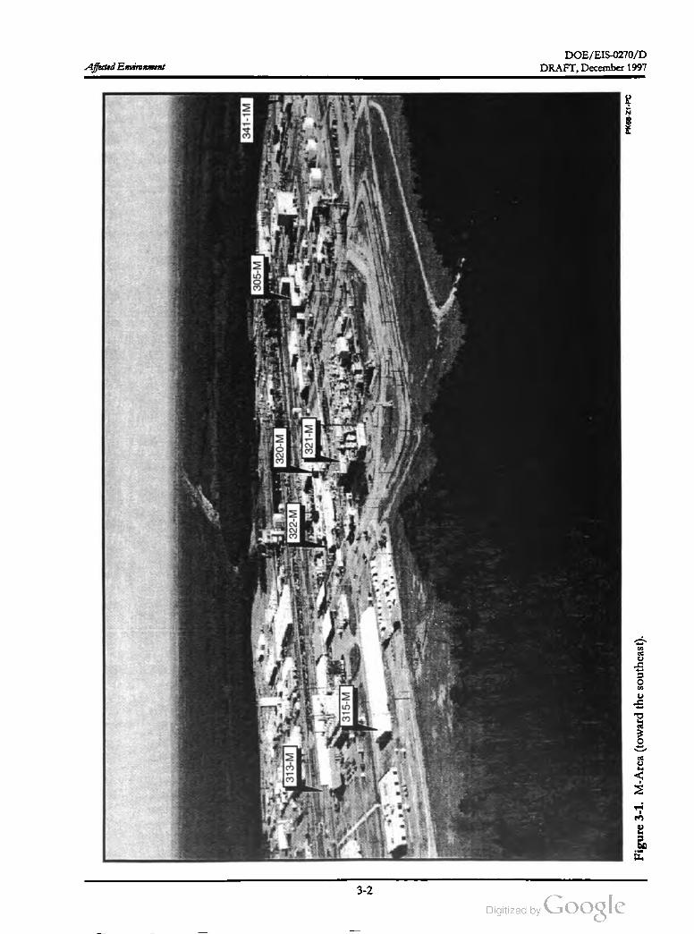
DOE /EIS -0270 / D
Affected Environment
341-1M
305
-M
320
-M
313
-M322
- M
321
-M
315
-M
3-2
DRAFT, December 1997
PK68-21
-PC
Figure
3-1
.M-Area
(toward
the
southeast
).
--
DOE / EIS -0270D
DRAFT, December 1997 Affected Environment
described in Chapter 2. A number of M -Area
facilities are surplus and available for new uses.
DOE based the selection of candidate facilities
on a feasibility study that compared the re
quirements of APT functions to features of the
M -Area facilities, and eliminated facilities that
would not be compatible with those functions
from further consideration . The buildings
identified for potential use include 305-M , 313
M , 315- M , 320- M , 321-M , 330 -M , and 331- M
(see Figure 3-1). The Report On Use of Excess M
Area Facilities (WSRC 1996a) explains the study.
Current H -Area tritium facilities consist of four
main buildings (see Figure 3-2). Three of these
-- Buildings 232-H , 234-H and 238-H -- have
been part of the historic SRS Tritium mission.
These second-generation tritium structures
house a number of key operations, including the
reclamation of previously used tritium reser
voirs; the receipt, packaging and shipping of
reservoirs; the recycling and enrichment of trit
ium gas; and several laboratory and maintenance
operations.
Historically, DOE used M -Area to fabricate
fuel, special targets, and components for irra
diation in the SRS production reactors. The
facilities contain equipment for melting, casting,
and shapingmetal, including furnaces, extrusion
presses, lathes, handling equipment, and storage
racks.
The newest structure, Building 233-H (or the
Tritium Loading Facility), is a 1-acre under
ground facility that became operational in 1994.
Operations in this building include unloading
gases from reservoirs returned from the De
partment of Defense, separating and purifying
useful hydrogen isotopes (tritium and deute
rium ), mixing the gases to exact specifications,
and loading the reservoirs.
3.2 Exposure Pathways
Buildings 313- M , 320-M , and 321-M contain
equipment used to fabricate depleted uranium
targets, tritium targets, and reactor fuel, respec
tively. Building 321- M also contains extrusion
presses and finishing equipment thatDOE used
to extrude Neptunium - 237 oxide billets into
neptunium targets, which were irradiated to
produce Plutonium -238. Deinventory of the
facility (i.e. packaging unused nuclear materials
and placing them in storage at other locations
on the SRS or returning them to their source) is
under way. DOE has completed the deinven
tory process for Buildings 313- M , 320- M , and
322- M (the Metallurgical Laboratory) and is
working to complete the deinventory of Build
ing 321-M . Building 305- M is an office building
and Buildings 315-M , 330-M , and 331-M are
warehouse and storage facilities. Modifications
orupgrades to support APT activities would be
consistent with the requirements in appropriate
DOE Orders.
Materials released from the SRS reach the envi
ronment and people in a number of ways (see
Figure 3-3). The routes that materials follow to
get from an SRS facility to the environmentand
then to people are called exposure pathways. A
person can take airborne effluents into the body
directly by inhalation or indirectly due to
deposition on crops, followed by ingestion of
the crops. Similarly, a person can ingest liquid
effluents directly from drinking water or indi
rectly from food that has absorbed the efflu
ents. Tritium can also be absorbed through the
skin .
H -Area. H -Area, like M -Area, is an industrial
ized area of the SRS. If DOE built the APT,
H -Area would receive the tritium gas and load it
in reservoirs for shipping or, for Lithium -6
rods, extract the tritium gas in a new ormodi
fied Tritium Extraction Facility.
SRS environmental monitoring and surveillance
work measures radiological and nonradiological
contaminants released from past and present
Site operations. The radiological monitoring
program collects and analyzes effluent samples
from SRS operations to quantify radiological
releases to the environment. Nonradioactive
airborne emissions of sulfur dioxide, oxides of
nitrogen , Carbon monoxide, and total particu
late matter are monitored at the stacks, and
3-3
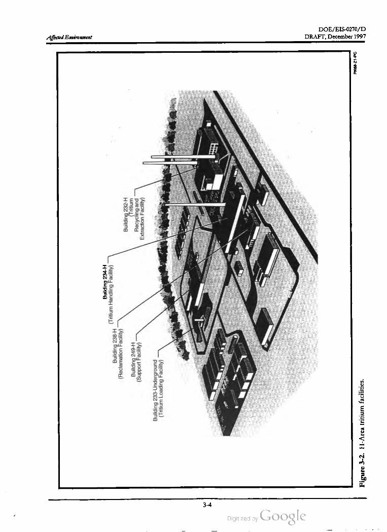
DOE /EIS -0270 / D
Affected Environment
Building
234
-H (Tritium
Handling
Facility
)
Building
238
-H (Reclamation
Facility
)
Building
249
-H (Support
Facility
)
Building
232
-H (Tritium
Recycling
and
Extraction
Facility
)
Building
233
-Underground
(Tritium
Loading
Facility
)
DRAFT, December 1997
PK68
-Z1
-PC
Figure
3-2
.H-Area
tritium
facilities
.
3-4
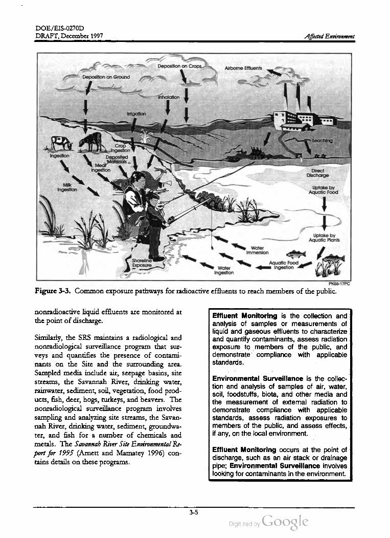
DOE/EIS-0270D
DRAFT, December 1997 Affected Environment
Deposition on Crops Airbome Effluents
Deposition on Ground
Inhalation
Imigation
Leaching
PACrop
Ingestion
Deposited
Materials
Meat
Ingestion
I
Ingestion
Direct
Discharge
Milk
IngestionUptake by
Aquatic Food
Uptake by
Aquatic Plants
Water
Immersion
Shoreline
ExposureAquatic Food
IngestionWater
Ingestion
PK68-17PC
Figure 3-3. Common exposure pathways for radioactive effluents to reach members of the public.
nonradioactive liquid effluents are monitored at
the point of discharge.
Effluent Monitoring is the collection and
analysis of samples or measurements of
liquid and gaseous effluents to characterize
and quantify contaminants, assess radiation
exposure to members of the public , and
demonstrate compliance with applicable
standards .
Similarly, the SRS maintains a radiological and
nonradiological surveillance program that sur
veys and quantifies the presence of contami
nants on the Site and the surrounding area.
Sampled media include air, seepage basins, site
streams, the Savannah River, drinking water,
rainwater, sediment, soil, vegetation , food prod
ucts, fish , deer, hogs, turkeys, and beavers. The
nonradiological surveillance program involves
sampling and analyzing site streams, the Savan
nah River, drinking water, sediment, groundwa
ter, and fish for a number of chemicals and
metals. The Savannab River Site Environmental Re
port for 1995 (Arnett and Mamatey 1996) con
tains details on these programs.
Environmental Surveillance is the collec
tion and analysis of samples of air, water,
soil, foodstuffs, biota , and other media and
the measurement of external radiation to
demonstrate compliance with applicable
standards, assess radiation exposures to
members of the public , and assess effects ,
if any, on the local environment.
Effluent Monitoring occurs at the point of
discharge, such as an air stack or drainage
pipe; Environmental Surveillance involves
looking for contaminants in the environment.
3-5

DOE /EIS -0270D
Affected Environment DRAFT, December 1997
The information in the annual environmental
report provides a picture of existing conditions
at the SRS. Chapter 4 of this EIS describes
potential impacts through each exposure path
way. A comparison of these impacts to the in
formation in this chapter indicates the level of
potential incremental effects the APT would
have on the environment.
for a mile ormore. However, 0.5 mile ormore
to the west, east, and north, the surface eleva
tions start to drop more rapidly to the low -lying
streams and headwaters prevalent in this area.
Slopes range from 10 to 40 percent along the
narrow steep-sided valleys between the upland
areas and the flat floodplains along nearby Mill
Creek , McQueen Branch , Tinker Creek , and
Upper Three Runs.
3.3 Physical and Manmade Envi
ronment
This section provides three types of informa
tion . First, it describes physical characteristics
(geology, soils, and seismic considerations) that
could influence the construction and operation
of the APT. Second, it provides baseline air and
water information because air and water are the
media through which contaminants could reach
people and animals. Third , it identifies man
made features at the SRS to provide a basis for
understanding impacts the APT could have on
the current infrastructure, as well as features
from past Site inhabitation .Site inhabitation . It also discusses
baseline noise levels from existing operations
and visual considerations.
The Upper Three Runs watershed drains both
APT sites. Tributaries of Upper Three Runs in
the area include Mill Creek and its headwaters
to the east,McQueen Branch and its headwaters
to the west, and Tinker Creek from the conflu
ence ofMill Creek to the north (see Figure 3-4 ).
Stream elevations range from about 250 feet
abovemean sea level at the headwaters to about
150 feet above mean sea level at the confluence
ofMcQueen Branch and Tinker Creek . The
watershed for the preferred APT site empties
into Upper Three Runs just past the confluence
ofMcQueen Branch and Tinker Creek. Upper
Three Runs flows to the Savannah River . Fig
ure 3-4 also shows the 100-year floodplain .
3.3.1 LANDFORMS, SOILS, AND GE
OLOGY
3.3.1.1 Landforms
Both the preferred and alternate APT sites are
on relatively flat, broad, and sandy upland areas
typical of the Aiken Plateau portion of the Sa
vannah River Site that formed in deep beds of
marine sediments (Wike et al. 1994). The orien
tation of the APT footprint on the preferred
site is from southeast to northwest; the foot
print orientation on the alternate site is from
southwest to northeast. Figure 3-4 shows the
locations of the sites and their surface features
(topography and nearby surface waters).
There is an upland Carolina bay with an area of
about 15 acres approximately 0.3 mile north of
the alternate site (WSRC 1996b). The alternate
site ranges in elevation from about 200 feet
above mean sea level at the south end to
310 feet above mean sea level at the north end
(USGS 1987). The steepest slopes of the alter
nate site occur at the south end toward Upper
Three Runs with a grade of nearly 17 percent.
The upland area extends and rises to the north
and there are low -lying wetland areas (ranging
from 140 feet to 220 feet abovemean sea level]
within 0.5 mile to the east, west, and south .
Similarly , the APT support operations proposed
for M- and H -Areas would be on level topo
graphic highs, but in existing heavily industrial
ized areas.
3.3.1.2 Soil Conditions
The elevation of the preferred APT site varies
from about 300 to 330 feet above mean sea
level (USGS 1987) with an average slope of less
than 4 percent (WSRC 1991a). The upland
ridge at the preferred site extends to the south
The surface soils at the preferred APT site are
nearly level to sloping and well-drained, with a
sandy surface and subsurface layer and a loamy
3-6
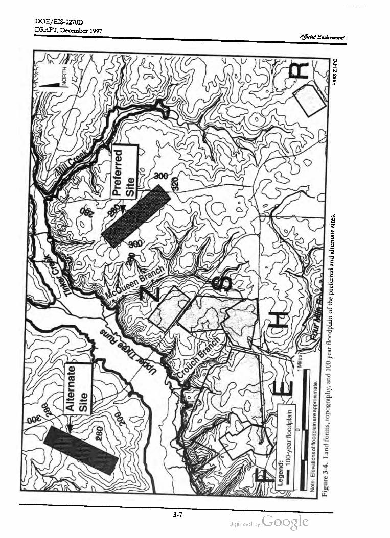
DOE /EIS-0270D
McQueen
B
H
300
༽
280
Tinker
Creek
NORTH
Alternate
Site
Mill
Creek
DRAFT,December 1997
280
200
280
Preferred
Site
Updar
Three
Runs
006
00Crouch
Branch
Legend
:
100
-year
floodplain
0
H
1Miles
Note
:Elevations
offloodplain
are
approximate
.Fourte
Affected Environment
Figure
3-4
. Land
forms
,topography
,and
100
-year
floodplain
of
the
preferred
and
alternate
sites
.PK68
-Z1
-PC
3-7

DOE /EIS -0270D
Affected Environment DRAFT, December 1997
subsoil (USDA 1990). The Fuquay sand (2 to
6 percent slopes) is the dominant soil mapping
unit on the SRS, covering about 73 percent
(about 180 acres) of the preferred site area .
Figure 3-5 , a soil survey map for the preferred
and alternate sites, shows the boundaries of the
soil mapping units. Table 3-1 lists the physical,
chemical, and engineering features of Fuquay
sand and other surface soils at the sites.
In general, the Fuquay sand, like the other soils
that occur on the SRS, is well suited as habitat
for open -land wildlife, fairly well suited as
woodland wildlife habitat, and poorly suited as
wetland wildlife habitat USDA 1990). The
slope is a moderate limitation affecting sites for
buildings, but DOE could minimize this limita
tion by grading and shaping the land. The
poorly drained Ogeechee sandy loam collects
surface water during wet periods (USDA 1990).
The seasonal wetness could be a severe limita
tion for buildings. This soil is fairly well suited
as habitat for open land and woodland wildlife .
It usually is well suited to wetland wildlife but
not after periods of low rainfall, when some or
all of the area will dry (USDA 1990).
DOE has evaluated the engineering properties
ofdeeper soils near the preferred APT site to a
depth of50 feet (WSRC 1991a). In general, the
soils from 0 to 50 feet range from silty sands to
sandy clays with Atterberg liquid limit values (an
index that is directly proportional to the com
pressibility of a soil) in the range of 50 – 10 per
cent, which indicates that these soils have
moderate to high compressibility using me
chanical compaction techniques during the
preparation of deeper soils for supporting
buildings and other structures (Sowers and
Sowers 1961). Standard Proctor values for
these soils range from approximately 101 to
107 pounds per cubic foot at 17 to 22 percent
moisture. (Proctor values determine optimum
soil moistures and maximum densities for soil
compaction during construction (Sowers and
Sowers 1961) ]. DOE has not characterized
deeper soils at the alternate site .
In general, the soils atboth APT sites range
from nearly level to sloping and well-drained
with a sandy surface and subsurface layer
and a loamy subsoil. This soil is fairly suited
to habitat for open land and woodland wild
life . It usually is well suited to wetland wild
life but not after periods of low rainfall,when
some or all of the area will dry (USDA 1990 ).
The slopes (2 to 6 percent) are moderate
limitations affecting sites for buildings.
The surface soils at the industrialized M - and H
Areas where APT support activities would oc
cur are mostly well drained; these soils were
formed from excavated areas, borrow pits, and
other areas where major land -shaping or grading
activities occurred . The soils are beside and un
der streets, sidewalks, buildings, parking lots,
and other structures. Because this material has
been moved , soil properties can vary within few
feet. In general, the slopes of soils in these ar
eas range from 0 to 10 percent with a moderate
erosion potential. Soils range from sandy to
clayey , depending on the source of the soil ma
terial (USDA 1990).
3.3.1.3 Geology,Hydrogeology, and Seis
micity
Surface soils at the alternate site are nearly iden
tical to those at the preferred location. The Fu
quay sand (2- to 6 -percent slopes) is the
dominant soil unit covering about 42 percent
(approximately 104 acres) of the site. The
physical, chemical, and engineering features and
the uses ofandmanagement concerns about the
surface soil at the alternate site are the same as
those discussed for the preferred site, except
there are no poorly drained soils within the al
ternate site boundaries (USDA, 1990).
Geology. The geology of SRS is well docu
mented in publications such as the Hydrogeologic
Framework for West Central South Carolina
(Aadland,Gellici, and Thayer 1995). DOE used
surface and deeper core borings and seismic
survey techniques to characterize the geology at
the preferred APT location and determined that
this location is typical of the SRS. DOE has not
characterized the alternate site , but based on a
3-8

DOE /EIS -0270D
DRAFT,December 1997Affected Environment
FuBNORTH
DoB
Alternate Site
LUA
Tr- B1
LUB
FuB
BaB
DoA
BaB
VaB
BaB
Preferred Site
DoB BaB
LUBTr- B
FUB
VaBDoA
(Вав
Legend:
BaB DOB
Og
BaB / VaB
BaB = Blanton sand, 0 to 6 percent slopes
DOA = Dothan sand , 0 to 2 percent slopes
DoB = Dothan sand, 2 to 6 percent slopes
FuB = Fuquay sand , 2 to 6 percent slopes
LUA = Lucy sand, 0 to 2 percent slopes
LuB = Lucy sand, 2 to 6 percentslopes
Og = Ogeechee sandy loam , ponded
TrB = Troup sand, 0 to 6 percent slopes
VaB = Vaucluse sandy loam , 2 to 6 percentslopes
FuB
DoB
Source: Modification from USDA (1990).
PK68-Z1-PC
Figure 3-5 . Soil types at the preferred and alternate APT sites.
3-9

DOE /EIS -0270D
Soil
texture
Table
3-1
.Summary
of
soils
covering
the
APT
sites.a
Relative
surface
area
at
APT
sites
(percent
)
Soil
Name
(soil
mapping
unit
designation
Preferred
Alternate
Blanton
sand
,0 to6percent
9
slopes
(BaB
)
Affected Environment
Erosion
hazard
Subsoil
Surface
Sandy
Risk
of
corrosion
Uncovered
steel
Concrete
High
High
Soil
reaction
(pH
)
4.5
-6.0
19
Slightb
Loamy
Drainage
class
Somewhat
excessively
drained
well
drainedd
86
Slight
Sandy
3.6
-6.0
Moderate
Moderate
38
Slight
Sandy
Loamy
and
clayey
Loamy
and
clayey
Loamy
Well
drained
3.6
-6.0
Moderate
Moderate
-
73
42
Slight
Sandy
Well
drained
4.5
-6.0
Low
High
05
Slight
Sandy
Well
drained
4.5
-6.0
Low
High
Loamy
and
clayey
Loamy
and
clayey
07
Slight
Sandy
Well
drained
4.5
-6.0
Low
Dothan
sand
, 0to2percent
slopes
(DOA
)
Dothan
sand
,2 to6percent
slopes
(DoB
)
Fuquay
sand
,2to6percent
slopes
(FuB
)
Lucy
sand
,0to2percent
slopes
(LuA
)
Lucy
sand
,2to6percent
slopes
(LuB
)
Ogeechee
sandy
loam
,ponded
(Og
)
Troup
sand
,0 to6 percent
slopes
(TrB
)
Vaucluse
sandy
loam
,2 to
6percent
slopes
(VaB
)
Vaucluse
-Ailey
complex
, 6to
10percent
slopes
(Vec
)
High
20
Slight
Loamy
Loamy
4.5
-5.5
High
High
Poorly
drainede
Well
drained
013
Slight
Sandy
Loamy
4.5
-6.0
Low
Moderate
50
ModeratefLoamy
Well
drained
3.6
-5.5
Low
High
Loamy
and
sandy
Sandy
,loamy
,
<
1
0Moderate
Loamy
Well
drained
3.6
-5.5
Low
High
and
clayey
a.
b.
C.
d.
Source
:USDA
1990
.
Slight
=No
particular
erosion
preventive
measures
are
needed
under
ordinary
farming
practices
.
Excessively
drained
=Water
isremoved
from
the
soil
very
rapidly
.
Well
drained
=Water
isreadily
removed
from
awell
drained
soil
, but
not
rapidly
.It
isavailable
toplants
throughout
most
of
the
growing
season
and
wetness
does
not
inhibit
growth
of
roots
for
significant
periods
during
the
growing
seasons
.
Poorly
drained
=Water
isremoved
soslowly
that
the
soil
issaturated
periodically
during
the
growing
season
orremains
wet
for
long
periods
.
Moderate
Erosion
control
measures
are
needed
for
particular
silvicultural
activities
.
e.
f.=
DRAFT, December 1997
3-10
DOE /EIS-0270D
DRAFT,December 1997 Affected Environment
review of the United States Geological Survey's
Preliminary Geologic Map of the Savannah River Site
(USGS 1994), DOE believes it is similar to the
preferred location . TheGordon Confining Unit
is thought to be thinner and less continuous lat
erally on the northern side of Upper Three
Runs Creek and hencemay be absent at that lo
cality (Aadland,Gellici,and Thayer 1995) .
site and drops to around 60 feet at the north
end (WSRC 1997). The water table aquifer ex
tends downto the top of theGordon Confining
Unit and discharges into Tinker Creek north of
the site and to the northeast toward Mill Creek ,
a tributary of Tinker Creek (WSRC 1991a ).
A hard crystalline bedrock lies about 960
feet below the surface at the preferred APT
site . Above the bedrock are several geo
logic formations comprised of layers and
mixtures of sandy clays and clayey sands,
although occasional beds of clays , silts ,
sands, gravels , or carbonate occur. In some
cases, continuous clay layers act as confin
ing units and restrict the upward or down
ward movement of groundwater below the
APT site . The closest subsurface fault to
the preferred APT site is more than 0.5 mile
to the northeast.
As shown in Figure 3-6 , the groundwater
movement of the water table aquifer to nearby
streams follows the downslope surface topogra
phy. However, the many lenses and discon
tinuous layers of clay , silt, and sandy / silty clay
in the geologic formations associated with the
aquifer affect the localmovementofgroundwa
ter. Estimated flow rates for the water table
aquifer range from 1.5 to 108 feet per year
(WSRC 1991a). Using a flow rate of 108 feet
per year, the estimated time for groundwater in
the water table aquifer beneath the preferred
APT site to reach Tinker Creek is 37 years. In
addition , isolated zones of perched water (i.e.,
surface soils saturated with water) occur above
the water table aquifer at the north and south
ends of the preferred site (WSRC 1997).
Table 3-2 summarizes the geologic formations
beneath the preferred APT site including the
composition and depths of the formations. In
addition , the information in the table is useful in
understanding the geology of the alternate site.
A hard crystalline bedrock lies approximately
960 feet below the surface of the south end of
the preferred APT site (WSRC 1997). Above
the bedrock are 11 geologic formations com
prised of layers and mixtures of sandy clays and
clayey sands, along with occasional beds of
clays, silts, sands, gravels, or carbonate. In
some cases, continuous clay layers act as confin
ing units and restrict the upward or downward
movementof groundwater below the APT site.
The Gordon Aquifer,which is the first confined
aquifer beneath the water table aquifer, is be
tween the Gordon and Crouch Branch Confin
ing Units. In the immediate vicinity of the
preferred APT site, flow within the Gordon
Aquifer is predominantly lateral with a slight
upward flow gradient (WSRC 1991a). The
Gordon Aquifer discharges, at least in part, to
Tinker Creek , and has an estimated flow rate of
13.8 feet per year (WSRC 1991a). In the vicinity
of the site, the Gordon Aquifer receives water
from overlying and underlying units (Hiergesell
1997). The regional- scale direction of Gordon
Aquifer flow at the SRS (i.e., the overall flow of
the aquifer across the Site) is toward the Savan
nah River. The deeper confined aquifers be
neath the preferred site flow southwest toward
discharge zones in the vicinity of the Savannah
River. Flow directions in these aquifers are not
appreciably influenced by Upper Three Runs,as
they are in the Gordon Aquifer. In addition,
hydrogeologic investigations indicate that the
deeper aquifers have upward flow
Hydrogeology. Tables 3-3 and 3-4 summarize
the water-bearing characteristics of the hydro
geologic units beneath the two APT sites and
their significance as sources of water supply. In
addition, the table lists typical SRS values for
the hydrogeologic parameters of these units.
The depth to the top of the water table (Upper
Three Runs Aquifer) averages 40 feet below the
surface at the south end of the preferred APT
an
3-11
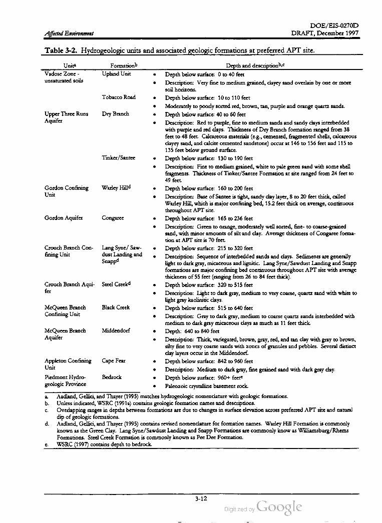
DOE /EIS -0270D
DRAFT, December 1997Affected Environment
Table 3-2 . Hydrogeologic units and associated geologic formations at preferred APT site.
.
Warley Hilld
.
.
Unita FormationbDepth and descriptionb,c
Vadose Zone - Upland Unit Depth below surface: 0 to 40 feet
unsaturated soilsDescription: Very fine to medium grained, clayey sand overlain by one ormore
soil horizons.
Tobacco Road Depth below surface: 10 to 110 feet
Moderately to poorly sorted red, brown, tan, purple and orange quartz sands.
Upper Three Runs Dry BranchDepth below surface: 40 to 60 feet
AquiferDescription : Red to purple, fine to medium sands and sandy clays interbedded
with purple and red clays. Thickness ofDry Branch formation ranged from 38
feet to 48 feet. Calcareous materials (e.g., cemented, fragmented shells, calcareous
clayey sand, and calcite cemented sandstone) occur at 146 to 156 feet and 115 to
135 feet below ground surface.
Tinker /Santee Depth below surface: 130 to 190 feet
Description: Fine tomedium grained,white to pale green sand with someshell
fragments. Thickness of Tinkes/Santee Formation at site ranged from 24 feet to
49 feet.
Gordon Confining Depth below surface : 160 to 200 feet
UnitDescription : Base of Santee is right, sandy clay layer, 8 to 20 feet thick, called
Warley Hill,which is major confining bed , 15.2 feet thick on average, continuous
throughoutAPT site.
Gordon Aquifer Congaree Depth below surface: 165 to 236 feet
Description : Green to orange,moderately well sorted , fine- to coarse-grained
sand,with minor amounts of silt and clay. Average thickness of Congaree forma
dion at APT site is 70 feet.
Crouch Branch Con Lang Syne/ Saw Depth below surface: 215 to 320 feet
fining Unit dust Landing andDescription: Sequence of interbedded sands and clays. Sediments are generally
Snappdlight to dark gray, micaceous and lignitic. Lang Syne /Sawdust Landing and Snapp
formations are major confining bed continuousthroughout APT site with average
thickness of 55 feet (ranging from 26 to 84 feetthick).
Crouch Branch Aqui- Steel Creekd Depth below surface: 320 to 515 feet
fer
Description: Lightto dark gray,medium to very coarse, quartz sand with white to
lightgray kaolinitic clays.
McQueen Branch Black CreekDepth below surface: 515 to 640 feet
Confining UnitDescription : Gray to dark gray,medium to coarse quartz sands interbedded with
medium to dark gray micaceous clays as much as 11 feet thick .
McQueen Branch Middendorf Depth : 640 to 840 feet
AquiferDescription : Thick, variegated ,brown, gray, red , and tan clay with gray to brown,
silty fine to very coarse sands with zones of granules and pebbles. Severaldistinct
clay layers occur in the Middendorf.
Appleton Confining Cape Fear Depth below surface: 842 to 960 feet
UnitDescription : Medium to dark gray, fine grained sand with dark gray clay .
Piedmont Hydro Bedrock Depth below surface: 960+ feete
geologic ProvincePaleozoic crystalline basement rock .
Aadland,Gellici, and Thayer (1995) matches hydrogeologic nomenclature with geologic formations.
b . Unless indicated ,WSRC (1991a) contains geologic formation names and descriptions.
Overlapping ranges in depths between formations are due to changes in surface elevation across preferred APT site and natural
dip of geologic formations.
d . Aadland, Gellici,and Thayer (1995) contains revised nomenclature for formation names. Warley Hill Formation is commonly
known as theGreen Clay. Lang Syne /Sawdust Landing and Snapp Formations are commonly know as Williamsburg /Rhems
Formations. Steel Creek Formation is commonly known as Pee Dee Formation.
WSRC (1997) contains depth to bedrock.
.
.
a .
C.
e .
3-12

DOE /EIS -0270D
DRAFT, December 1997
Table
3-3
.Water
-bearing
characteristics
of
the
hydrogeologic
units
beneath
the
preferred
APT
site.a
I'Iydrogeologic
unitb
I'Iydrogcologic
characteristics
Significance
aswater
supplyc
Flydrogcologic
parametersb
Vadosc
Zonc
Unsaturated
conditions
exist
cxccpt
for
isolatcd
perched
water
zoncs
atNot
applicablc
.Not
applicablc
.
the
north
and
south
ends
of
the
proposed
APT
site
(WSRC
1997
).
Upper
'lhrcc
The
Upper
Three
Runs
Aquifer
isthe
water
tablc
aquifcr
commonly
At
thc
SRS
,nowater
supply
wells
arc
Recharge
rate
:15
inches
per
ycar
Runs
Aquifer
referred
toasthe
first
unconfined
aquifer
.Discontinuous
,low
known
tobe
scrccncd
inthc
watcr
Ilydraulic
conductivity
: 0.05
to45.5
fect
per
pcrmcability
,clay
layers
arc
common
throughout
the
water
tablc
aquifer
tablc
aquifer
.Outside
of
the
day
and
thcy
can
scrvc
toconfinc
thc
groundwater
occurring
bcncath
them
,boundaries
of
the
SRS
,rural
domestic
on
alocal
basis
and
light
industrial
wells
arc
scrccncd
Transmissivity
:62
to6,300
squarc
fcct
per
day
inthcsc
aquifers
.
Gordon
This
confining
unit
iscontinuous
over
at
lcast
the
southcastern
two
Not
uscd
as
asourcc
ofwater
.Icakancc
cocfficicnt
:4.98
x10-5
per
day
Confining
Unit
thirds
ofthe
SRS
including
the
proposed
All
sitc
.Vertical
hydraulic
conductivity
:0.00002
fcct
per
day
Gordon
Aquifer
Well
yields
as
high
as660
gallons
per
minute
with
50
fcct
of
drawdown
Regionally
significant
aquifer
.The
only
Iydraulic
conductivity
:24
to41
fcct
per
day
have
been
obtaincd
ncar
the
center
ofSRS
.Throughout
the
central
drinking
water
supply
wells
scrccncd
in
Transmissivity
:1,124
to13,400
squarc
fcct
portion
of
the
SRS
,thc
Gordon
Aquifer
flows
toward
cither
Upper
thc
Congarcc
aquifer
atthc
SRS
arc
at
Thrcc
Runs
Crock
orthc
Savannah
river
,which
are
discharge
arcas
.the
Sitc
pcrimctcr
patrol
barricades
.
per
day
Not
uscd
as
asource
of
water
.Crouch
Branch
Confining
Unit
This
confining
unit
ismostly
clay
with
some
sand
intcrbcds
;usually
considered
tobe
an
aquitard
.
Regionally
significant
aquifer
and
provides
drinking
water
toalarge
geographic
arca
.
Crouch
Branch
Wells
scrccncd
inthc
Crouch
Branch
Aquifer
arc
capable
of
producing
Aquifer
500-600
gallons
per
minute
.Groundwater
at
the
SRS
from
thc
Crouch
Branch
Aquifer
flows
from
north
tosouth
/southwest
toward
the
Savannah
River
,which
isits
discharge
arca
.
McQueen
Branch
This
confining
unit
consists
of
interbedded
,silty
,often
sandy
clay
and
Confining
Unit
sand
bods
.
J.cakance
cocfficicnt
:2.82
x10-6
per
day
Vertical
hydraulic
conductivity
:0.000002
to
0.0034
fcct
per
day
Hydraulic
conductivity
:30to227
fcct
per
day
Transmissivity
: 3,000
to27,000
squarc
fcct
per
day
Not
uscd
as
asource
of
water
.
McQucen
Branch
Aquifer
Icakancc
cocfficicnt
:1.03
x10-5
per
day Vertical
hydraulic
conductivity
:0.00007
to
0.02
fcct
per
day
I-ydraulic
conductivity
: 53
to210
fect
per
day
Transmissivity
:14,000
to50,100
squarc
fcct
Aregionally
significant
aquifcr
.Wells
scrccncd
inthc
Middendorf
arc
reported
toproduce
asmuch
as 3,000
gallons
per
minute
.Thc
aquifcr
associated
with
this
formation
is
called
thc
McQucen
Branch
Aquifcr
.Groundwater
at
the
SRS
from
this
aquifcr
gencrally
flows
from
north
tosouth
and
southwest
toward
the
Savannah
River
,which
isadischarge
arca
for
the
aquifer
.
Consists
primarily
of
relatively
low
permcability
clay
and
therefore
acts
hydraulically
asaconfining
bed
.
per
day
Undifferentiated
Thc
Cape
Icar
isnot
used
asasource
of
watcr
.
Not
applicable
.
a.
b.
Scc
Tablc
3.2
for
adescription
of
the
associated
gcologic
formations
and
approximate
depths
of
these
hydrogcologic
units
.
Sourcc
of
information
for
column
was
Aadland
,Gellici
,and
Thayer
(1995
)unless
noted
.
Source
of
information
for
column
was
WSRC
(1991a
)unless
noted
.
Affected Environment
C.
3-13

DOE/EIS -0270D
I'Iydrogeologic
parametersb
Not
applicablc
.
Affected Environment
Table
3-4
.Water
-bearing
characteristics
ofthe
hydrogeologic
units
beneath
the
alternate
APT
site.a
Hydrogcologic
unitb
ITydrogeologic
characteristics
Significance
as
water
supply
Vadosc
Zone
Unsaturated
conditions
cxist
cxccpt
for
isolated
pcrched
water
zones
atNot
applicable
.
the
north
and
south
ends
of
thc
proposcd
APT
site
(WSRC
1997
).
Stocd
Pond
To
the
north
ofUpper
Thrcc
Runs
,thc
Gordon
confining
unit
becomes
The
upper
portion
of
the
aquifer
isnot
Aquifer
discontinuous
,allowing
the
Upper
Three
Runs
Aquifer
and
thc
Congarcc
suitablc
for
wells
duc
tolow
Aquifer
(as
described
inTablc
3-2
)tomerge
into
asingle
unit
known
as
production
capability
.The
lower
the
Stocd
Pond
Aquifer
(Water
Table
).The
groundwater
flow
inthe
portion
of
the
aquifer
could
bc
uscd
as
Stccd
Pond
Aquifer
istowards
Upper
Threc
Runs
with
well
yields
similar
alimited
supply
ofwater
.
tothat
ofthe
Gordon
Aquifcr
.
Crouch
Branch
This
confining
unit
ismostly
clay
with
some
sand
interbeds
and
isusually
Not
used
asasource
of
water
.
Confining
Unit
considered
tobe
an
aquitard
.
Recharge
Rate
:15inches
per
year
Hydraulic
Conductivity
:31.6
to63.1
fcct
per
day
Transmissivity
:2500
to5000
squarc
fcct
per
day
per
day
per
day
Icakancc
Cocfficicnt
:2.82
x10-6
Vertical
Hydraulic
ConductivityC
:0.000002
to
0.0034
fcct
Ilydraulic
Conductivity
:30
to227
fcct
per
day
Transmissivity
:3,000
to27,000
squarc
fcct
Crouch
Branch
Aquifer
Wells
scrccncd
in the
Crouch
Branch
Aquifcr
arc
capablc
of
producing
500-600
gallons
per
minute
.Groundwater
atthc
SRS
from
thc
Crouch
Branch
Aquifcr
flows
from
north
tosouth
/southwest
toward
the
Savannah
River
,which
is its
discharge
arca
.
This
confining
unit
consists
of
interbcddcd
,silty
,often
sandy
clay
and
sand
bcds
.
Regionally
significant
aquifer
and
provides
drinking
water
toalarge
gcographic
arca
.
per
day
McQucen
Branch
Confining
Unit
Not
uscd
as
asource
of
water
.
McQueen
Branch
Aquifer
Lcakancc
Cocfficicnt
:1.03
x10-5
per
day Vertical
Hydraulic
Conductivity
:0.00007
to
0.02
fcct
per
day
Ilydraulic
Conductivity
:53
to210
fcct
per
day
Transmissivity
: 14,000
to50,100
square
feet
Aregionally
significant
aquifer
.Wells
scrccncd
inthe
Middendorf
arc
reported
toproducc
asmuch
as 3,000
gallons
per
minuto
.Thc
aquifer
associated
with
this
formation
is
called
the
McQueen
Branch
Aquifer
.Groundwater
at
thc
SRS
from
this
aquifer
generally
flows
from
north
tosouth
and
southwest
toward
the
Savannah
River
,which
isadischarge
arca
for
the
aquifer
.
Consists
primarily
of
relatively
low
pcrmcability
clay
and
therefore
acts
hydraulically
as
aconfining
bed
.
per
day
Appleton
Confining
Unit
Thc
Capc
l'car
is not
used
as
asource
ofwater
.
Not
applicablc
.
a.
b.
Scc
Tablc
3.1
for
adescription
of
the
associated
gcologic
formations
and
approximatc
depths
of
these
hydrogeologic
units
.
Source
of
information
for
column
was
compiled
from
Aadland
,Gellici
, and
Thayer
(1995
)unless
noted
.
Sourcc
of
information
for
column
was
compiled
from
WSRC
(1991a
)unless
noted
.C.
DRAFT,December 1997
3-14

DOE / EIS- 0270 / D
(Creek
DRAFT, December 1997
200
180
NORTH
Alternate
Site
Preferred
Site
160
cQueer
Branch
Upper
Three
Runs
220
touche
eranon
20 : 1
2807
280
)
E
Hi
Legend
:220
=Groundwater
flow
Four
Mille
Branch
01Miles
280
3.00
280
Affected Environment
PK68-21
- PC
Figure
3-6
.Water
table
elevations
and
groundwater
flow
inthe
water
table
aquifer
atthe
preferred
and
alternate
sites
.
3-15
DOE /EIS -0270D
DRAFT,December 1997Affected Environment
gradient resulting in the potential for groundwa
ter flow from the deeper aquifers to the shal
lower aquifers (WSRC 1991a).
Based on the information developed to date,
none of the SRS faults discussed in this section
is capable. Thismeans that none of these faults
hasmoved at or near the ground surface within
the past 35,000 years or was associated with
another fault that had moved in the past 35,000
years . (10 CFR 100 contains a more detailed
definition of a capable fault.)
Two major earthquakes have occurred within
186 miles of the SRS:
The aquifers of interest for the alternate site in
clude the Steed Pond Aquifer (water table aqui
fer), Crouch Branch Aquifer, and theMcQueen
Branch Aquifer. The Steed Pond Aquifer (the
water table) is a merge of the Upper Three Runs
andGordon Aquifers due to the thinning or ab
sence of the Gordon as a confining unit north
of Upper Three Runs (see Table 3-4). The
Crouch Branch Confining Unit,which separates
the Steed Pond (water table aquifer) from the
lower drinking water aquifer (Crouch Branch
Aquifer), allows the migration of groundwater
down from the overlying units. North of Upper
Three Runs groundwater movement is upward
across the Crouch Branch Confining Unit. This
upward movement is due to the groundwater
flow in the water table aquifer to streams such
as Upper Three Runs. The result is an upward
flow from the Crouch Branch to the water table
aquifer that prevents the downward migration
of contaminants lower aquifer units
(Aadland, Gellici,and Thayer 1995).
The Charleston , South Carolina, earthquake
of 1886 had an estimated Richter scale
magnitude of6.8 ; it occurred about 90 miles
from the SRS area, which experienced an
estimated peak horizontal acceleration of
10 percent of gravity (URS/ Blume 1982).
The Union County, South Carolina, earth
quake of 1913, which had an estimated
Richter scale magnitude of 6.0 , occurred
about 99 miles from the SRS (Bollinger
1973)
to
The depth to water at the alternate site is ap
proximately 70 feet, 10 to 30 feet deeper than at
the preferred site. The water table aquifer dis
charges to Upper Three Runs to the south and
to two unnamed drainages to the east and west
(Shedrow 1997).
Because the earthquakes were not associated
conclusively with a specific fault, researchers
cannot determine the amount of displacement
they caused. In recent years, three earthquakes
occurred inside the SRS boundary .
On June 8, 1985, an earthquake with a local
Richter scale magnitude of 2.6 and a focal
depth of 0.59 mile; its epicenter was ap
proximately 8 miles southwest of the pre
ferred APT site .
Seismicity. There are several fault systemsun
der and near the SRS (DOE 1990) . A recent
study of geophysical evidence (Stephenson and
Stieve 1992) identified six subsurface faults
Pen Branch , Steel Creek , Advanced Tactical
Training Area, Crackerneck, Ellenton, and Up
per Three Runs -- under the SRS. Figure 3-7
shows their locations. Lines on this figure rep
resentprojections of the subsurface faults to the
ground surface; the actual faults do not reach
the surface, but stop several hundred feet be
low . The closest subsurface fault to the pre
ferred and the alternate APT sites is more than
0.5 mile away (WSRC 1996b). This deeper bed
rock fault does not cut through the overlying
unconsolidated sandy clays and clayey sands.
On August 5, 1988, an earthquake with a
local Richter scale magnitude of 2.0 and a
focal depth of 1.66 miles; its epicenter was
also more than 8 miles southwest of the
preferred APT site.
On May 17, 1997, an earthquake with a lo
cal Richter scale magnitude of 2.3 and a fo
cal depth of 3.38 miles; its epicenter was
more than 8 miles southwest of the pre
ferred APT site.
3-16
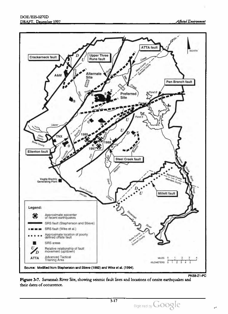
DOE /EIS -0270D
DRAFT, December 1997 Affected Environment
ATTA fault
NORTH
Crackerneck faultUpper Three
U Runs faultCreek
Branch
Runs
A & MAlternate
Site
Aiken
County
Barwell
County
Mill
Pen Branch faultCreek
Three
Pond B
Tims
ES Preferred
Site
BF Pond
Pond 5 Par
Pond
Upper
U
Branch
1985DAiken
CountyTNX
Branch
BurkeCounty 1988
к
1997
Branch
Ellenton fault Fourmile
1
0
Pen
Lake
Steel Creek fault
Lower
Meyers
Three
BarnwellCounty
AllendaleCountyVogtle Electric
Generating Plant
Steel
Runs
South
Carolina
|Creek
Georgia Millett faultCreek
Legend:
Savannah
Approximate epicenter
ofrecent earthquakes
SRS fault (Stephenson and Stieve)
SRS fault (Wike et al.)
Approximate location of poorly
defined offsite fault
River
Burke
County
SRS areas
Screven
County
D
Relative relationship of fault
movement (up/down)
Advanced Tactical
Training Area
ATTA 1 2 3 4MILES 0
KILOMETERS
11
2 3 4 5
Source: Modified from Stephenson and Stieve (1992) and Wike et al. (1994).
PK68 -Z1-PC
Figure 3-7. Savannah River Site, showing seismic fault lines and locationsof onsite earthquakes and
their dates of occurrence.
3-17
DOE /EIS -0270D
DRAFT, December 1997Affected Environment
Existing information does not relate these on
site earthquakes conclusively with known faults
on the SRS. Figure 3-7 shows the locations of
the epicenters of these earthquakes. Outside
the Site boundary , an earthquake with a Richter
scale magnitude of 3.2 occurred on August 8,
1993, approximately 10 miles east of the City of
Aiken near Couchton, South Carolina. Resi
dents reported feeling this earthquake in Aiken ,
New Ellenton (immediately north of the SRS),
and North Augusta (approximately 25 miles
northwest of the SRS), and on the Site. Fig
ure 3-8 shows regional epicenters of seismic ac
tivity
downstream from the SRS, the river supplies
domestic and industrial water needs for the
Cherokee Hill Water Treatment Plant at Port
Wentworth , Georgia, through intakes at River
Mile 29, and for Beaufort and Jasper Counties
in South Carolina through intakes at River Mile
39.2. In addition , the Vogtle Electric Generat
ing Plant, across the river from the Site, and the
Urquhart Steam Generating Station at Beech
Island, South Carolina, withdraw an average
46 cubic feet and 265 cubic feet per second, re
spectively, for cooling.
3.3.2 WATER RESOURCES
3.3.2.1 Surface Water
The South Carolina Department of Health and
Environmental Control (SCDHEC) regulates
the physical properties and concentrations of
chemicals and metals in SRS effluents under the
National Pollutant Discharge Elimination Sys
tem (NPDES) program . Thisagency
alsoregu
lates chemical and biological water quality
standards for SRS waters. Table 3-5 lists the
water quality characteristics of the Savannah
River upstream and downstream of the Site .
The Savannah River is the principal surface
water system associated with the SRS. Five of
its major tributaries drain the Site and flow to
the river. The Final Environmental Impact State
ment, Shutdown of the River Water System at the Sa
vannah River Site (DOE 1997) contains detailed
information on SRS surface waters. The follow
ing sections provide information for water
bodies that construction and operation of an
accelerator could affect. Figure 3-9 shows the
location of the Site's major water bodies and the
100 -year floodplain . A more detailed floodplain
map is found in Figure 3-4 .
Upper Three Runs. Both proposed APT sites
are in the Upper Three Runs watershed. Sur
face waters near the preferred site drain to Mill
Creek and McQueen Branch , both of which
flow to Tinker Creek and then to Upper Three
Runs; the alternate site drains directly to Upper
Three Runs. Upper Three Runs is a large, cool
(annual maximum temperature of 79°F), black
water stream in the northern portion of the
SRS. It drains an area of approximately
210 square miles and discharges directly to the
Savannah River. Upper Three Runs is ap
proximately 25miles long, with the lower
17 miles within the Site boundaries. The aver
age flow rate at Road A during the period from
1974-1995 was 245 cubic feetper
second
(Cooney et al. 1995).
Savannah River. At the Site , river flows aver
age about 10,000 cubic feet per second. River
flows range from 3,960 to 71,700 cubic feetper
second (Wike et al. 1994). Five upstream reser
voirs Jocassee, Keowee, Hartwell, Richard B.
Russell, and Strom Thurmond/ Clarks Hill)
moderate the effects of droughts and the im
pacts of low flows on downstream water quality
and fish and wildlife resources in the river
(DOE 1990).
The Savannah River supplies potable water to
severalmunicipalities. Upstream from the SRS,
the river supplies domestic and industrial water
for Augusta, Georgia, and North Augusta ,
South Carolina. Approximately 126 river miles
Upper Three Runs receives more water from
underground sources than other SRS streams
and,as a result, has low conductivity, hardness,
and pH values. It is the only major tributary on
the SRS that has not received thermal dis
3-18

DOE /EIS -0270D
DRAFT, December 1997 Affected Environment
40 °
IL IN OHMD
ILCentral Virginia
Seismic Zone
38 °
KY CO 03
9
East Tennessee
Seismic Zone
VA
CCO
.CO
8
36 °TN
NC
Latitude
20
2323
SC
34 °
Bowman Seismicity
MS
SRS Charleston Summerville
Seisoczone
ALGA
32 °
350
km
OEarlief:1 е
en centers
200 KM
FL
30 °
-88 ° -86 ° -840 -80 ° -78 ° -760-82°
LongitudePK68-Z1-PC
Modified from WSRC 1996 .
Figure 3-8 . Regional epicenters of seismic activity.
charges from onsite activities. It does receive
surface runoff and water from NPDES
permitted discharges in A-, E-, H-, M-, S-, and
Z -Areas. Monitoring studies indicate no ad
verse impacts to Upper Three Runs water qual
ity from SRS operations in these areas (Wike et
al. 1994). Table 3-6 characterizes the water
quality in Upper Three Runs atRoad A.
vannah River for about 5 miles before it enters
and mixes with the waters of Steel Creek about
0.2 mile from the mouth of Steel Creek . In its
headwaters, Pen Branch is a largely undisturbed
blackwater stream . Until K -Reactor shut down
in 1988, Indian Grave Branch received thermal
effluent from that facility. The reactor dis
charge increased flow from natural levels of
10 cubic feetper second to 400 cubic feet per
second. At present, Indian Grave Branch re
ceives nonthermal effluents of nonprocess
cooling water, ash basin effluent waters, power
house wastewater, and sanitary wastewater from
K -Area and sanitary effluent from the Central
Shops Area (Wike et al. 1994). Table 3-6 lists
the characteristics of Pen Branch at Road A - 17 .
Pen Branch and Indian Grave Branch . Pen
Branch and its tributary, Indian Grave Branch,
drain an area of about 21 square miles. Pen
Branch is approximately 15 miles long and
flows in a southwesterly direction from its
headwaters about 2 miles northeast of K - Area
to the Savannah River Swamp. After entering
the swamp, the creek flows parallel to the Sa
3-19
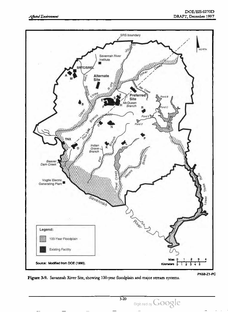
DOE /EIS- 0270D
DRAFT, December 1997Affected Environment
SRS boundary
NORTH
Savannah River
Institute HA
SRTC /SRECreer
Tinker
M
Tims Alternate
Site
'suna
Mill
Creek
Branch
Three
sPond B
Preferred
Site
McQueen
THBranch
R
B
Pond C
Upper
Pond5Branch
Par
Pong
Pond 2
N
Four
TNX Branch
D
Indian
Grave
Branch
K
Pen
Beaver
Dam Creek
Branch
Meyers
Vogtle Electric
Generating Plant
Runs
Steel
Creek
Three
Savannah
Lower
River
Legend:
100-Year Floodplain
Existing Facility
Miles 0
1
2 3
Source: Modified from DOE (1990). Kilometers 0 1 2 3 4 5
PK68 -Z1-PC
Figure 3-9. Savannah River Site, showing 100-year floodplain and major stream systems.
3-20

DOE /EIS -0270D
DRAFT,December 1997 Affected Environment
Table 3-5. Water quality in the Savannah River upstream and downstream from SRS (calendar year
1995).a ,b
Upstream Downstream
MCLd, ofUnit of
measure Minimumg
.31
ND
Parameter
Aluminum
Ammonia
Cadmium
Chemical oxygen demand
Chloride
Chromium
Copper
Dissolved oxygen
Fecal coliform
mg /L
mg/ L
mg/L
mg/L
NDk
DCGE
0.05-0.2h
Naij
0.0050
NA
250h
0.18
1.31
> 5.0m
1,000m
Maximumg
0.65
0.16
ND
ND
11
ND
0.02
10.8
3,200
ND
5
ND
ND
6.7
79
Minimum
ND
ND
ND
ND
5
ND
ND
6.0
5
Maximum
.47
0.55
ND
ND
11
ND
.01
9.4
700
mg/ L
mg/ L
ogzmg/ L
mg/ L
Colonies
per 100 ml
pCi/ L
mg/ L
mg/ L
mg/ L
mg/ L
pCi/L
150
0.0151
0.0020,e
0.10
<DLN
ND
ND
ND
0.27
5.58E - 10
0.586
ND
.0006
ND
0.45
1.2E -08
<DL
ND
ND
ND
0.27
5.1E -10
0.325
ND
.0015
ND
0.47
3.4E -09
100
50d
Gross alpha radioactivity
Lead
Mercury
Nickel
Nitrite /Nitrate (as nitrogen)
Nonvolatile (dissolved ) beta
radioactivity
pH
Phosphate
Sulfate
Suspended solids
Temperature
Total dissolved solids
Tritium
Zinc
6.0pH units
mg/ L
mg/ L
mg/ L
° F
mg/ L
pCi/ L
mg/ L
6.5-8.5h
NA
250h
NA
90P
500h
20,000d ,e
5h
ND
4
3
46
48
-7.1E -08 °
ND
7.0
ND
11
16
76
91
1E - 06
0.59
6.3
ND
5
5
47
52
4.2E -07
ND
7.1
ND
11
27
79
89
2.4E - 06
.043
a .
b .
C.
d .
Source: Amett (1996 ).
Parameters are those DOE routinelymeasures as a regulatory requirement or as part of ongoingmonitoring programs.
mg/ L = milligramsper liter; ameasure of concentration equivalent to the weight/volume ratio .
pCi/ L = picocuries per liter; a picocurie is a unit of radioactivity;one trillionth of a curie.
Maximum Contaminant Level (MCL),EPA National Primary Drinking Water Standards (40 CFR Part 141).
Maximum ContaminantLevel (MCL): SCDHEC (1976).
DOE Derived Concentration Guides (DCGs) forwater (DOE Order 5400.5 , " Radiation Protection for the Public and the Envi
ronment"). DCG values are based on committed effective dose of 100 millirem per year for consistency with drinking water
MCL of 4 millirem per year.
Minimum concentrations ofsamples. Themaximum listed concentration is the highest single result found during one sampling
e .
f.
event.
h .
i.
j .
k .
1.
Secondary Maximum Contaminant Level (SMCL). EPA National Secondary Drinking Water Regulations (40 CFR Part 143).
NA = none applicable.
Dependentupon pH and temperature.
ND = none detected .
Action level for lead and copper.
WQS = water quality standard . See glossary.
Less than (< ) indicates concentration below analytical detection limit (DL).
This value is an anomaly of sampling technique.
Shall not exceed weekly average of 90 °F after mixing nor rise more than 5° F in 1 week unless appropriate temperature criterion
mixing zone hasbeen established.
m .
n .
O.
P.
3-21

DOE /EIS-0270D
DRAFT, December 1997Affected Environment
Table 3-6 . Water quality in SRS streamsand Par Pond.a
Temperature
(° F )
62
45 - 90
pH
NA
4.7 - 8.0
Dissolved
oxygen
( mg/ L)
8.36
4.9 - 12
Specific
conductance Turbidity
(umhos/cm ) (NTU)
24.5 5.24
3.0 - 41 1.0 - 22
Total
suspended
solids (mg/ L )
10.2
20 - 97
Upper Three Runs at Road Ab Mean
Range
Pen Branch and Indian Grave Branchb Mean
Range
Lower Three Runsat Patterson Millb Mean
72
40 - 133
NA
5.7 - 7.9
8.5
4.2 - 11
69
13 - 171
6.6
1.1 - 54.1
7.7
2.0 - 42
64 NA 8.0 75 2.8 4.9
46 - 84 5.9 - 7.4 5.8 - 11 13 - 140 0.94 - 38 1 - 34Range
MeanPar Pond Near Cold Dam 65 6.33 6.01 70 NA 2.02
Range47 - 88 5.5 - 7.3 0 - 11.6 46 - 126 NA 0 - 10
a .
NA = Not available.
Source: Wike et al. 1994.
b . 1987 - 1991.
C. 1985 - 1991.
stream
Par Pond. In 1958, DOE constructed Par
Pond, a 2,500-acre reservoir, by building an
earthen dam across the upper reaches of Lower
Three Runs (Wike et al. 1994). The lake has an
average depth of 59 feet (Du Pont 1987). At
full pool, the reservoir storage volume is ap
proximately 52,800 acre -feet.
Lower Three Runs. Lower Three Runs is a
large blackwater creek draining about
177 square miles ; Par Pond is a 2,500-acre
mainstream impoundment onthis
(described in the next section ). From the Par
Pond Dam , Lower Three Runs flows about
15 miles before it enters the Savannah River
(Wike et al. 1994 ). Lower Three Runs received
heated effluent from R -Reactor through Joyce
Branch from 1953 to 1958. The construction of
the Par Pond Dam in 1958 modified flows in
the stream . Effluents from R- and P -Reactors
flowed to the Par Pond system and, therefore ,
affected Lower Three Runs until DOE shut the
reactors down in 1963 and 1988, respectively .
Historically, SRS operations caused large dis
charge fluctuations just downstream of the Par
Pond dam , but groundwater and tributary in
puts were sufficient to dampen these fluctua
tions farther downstream (Wike et al. 1994).
High flows also occurred during the drawdown
ofPar Pond in 1991. Based on 1996 water year
data , themean flow in Lower Three Runsbelow
Par Pond was 28 cubic feet per second with the
highest and lowest daily mean discharges being
82 and 6.4 cubic feet per second, respectively
(Cooney 1996). Flows are seasonal, and the
winter and spring months have the highest av
erage flow . Table 3-6 lists water quality infor
mation for Lower Three Runs.
Par Pond was a cooling water reservoir for P
and R- Reactors until 1964, when DOE sus
pended R -Reactor operations (Wilde 1985). It
continued to receive heated cooling water until
1988 when DOE suspended P -Reactor opera
tions (Paller and Wike 1996 ). During reactor
operations, recirculating water flowed through
the reactor heat exchangers, where it reached
temperatures of 150 to 165 °F , and discharged
through a series of pre-cooler ponds and canals.
Water lost from the Par Pond system due to
evaporation and seepage was replaced by
makeup water pumped from the Savannah
River. Par Pond operated as a closed -loop sys
tem with the exception of the additions of
makeup water and the overflow and seepage to
Lower Three Runs at the dam .
During a routine inspection of the Par Pond
dam in March 1991, a small depression was dis
covered in the downstream slope of the earthen
dam . DOE ordered a structural investigation
3-22

DOE /EIS-0270D
DRAFT, December 1997 Affected Environment
into the cause of the depression and simultane
ously initiated a precautionary drawdown of Par
Pond (DOE 1995a). From June through Sep
tember of 1991, Par Pond was lowered about
19 feet, from about 200 to 181 feet (mean sea
level) elevation . The drawdown reduced the
volume of the reservoir by one-third and ex
posed about 1,340 acres of lakebed (DOE
1995a).
Par Pond remained lowered at two-thirds of its
original volume for more than three years while
the dam was being repaired . Repairs included
grouting of voids around the outlet conduit, the
addition of an energy dissipation structure, and
construction of a downstream berm and filter
system at the toe of the dam (Marcy et al. 1994).
Based on these planned structural improve
ments to the dam , a Probabilistic Risk Assess
ment (PRA) was conducted (Olson 1993). The
PRA determined that once the permanent re
pairs had been completed, the probability of a
loss of human life due to the failure of the
structure (2.0 x 10⁻⁷) would be less than the
DOE guideline (4.0 x 10⁻⁷).
cury were in Par Pond water, sediments, and
biota (Newman and Messier 1994), approxi
mately half of which came from Savannah River
water and half from natural sources (i.e., soils
inundated when the reservoir was filled). The
sources ofmercury
in the river water were in
dustrial and manufacturing operations upstream
of the SRS that discharged wastes to the river.
With the implementation of the Clean Water
Act and NPDES regulations in the mid -1970s,
these industries dramatically reduced the levels
of pollutants in their permitted discharges.
Levels of mercury entering SRS water bodies
with river water showed a corresponding de
cline (Newman and Messier 1994). Recent sur
veys of Par Pond sediments (Koch, Martin , and
Friday 1996) found no elevated concentrations
of mercury. Table 3-6 lists water quality pa
rameters near the Par Pond Cold Dam and re
flect conditions since DOE stopped reactor
operations.
In 1996 , DOE stopped pumping river water
into Par Pond to allow water levels to fluctuate
naturally between 195 and 200 feet. Since then,
inflows from the watershed and groundwater
have maintained Par Pond level at 199 to 200
feet. The Final Environmental Impact Statement,
Shutdown of the River Water System at the Savannah
River Site (DOE 1997) discusses the results of a
water balance study.
The " Pre- cooler" Ponds: Ponds 2, 5, and C.
DOE built Pond C at the same time it built Par
Pond (1957-1958) to pre- cool heated effluent
from P -Reactor before it entered Par Pond.
Ponds 2 and 5 were added in 1961 to enhance
Par Pond's efficiency as a cooling reservoir.
These small impoundments and their connect
ing canals dissipated about 86 percent of the
heat in the P -Reactor effluent by the time it en
tered Par Pond (Wilde 1985). When P -Reactor
was operating, its thermal effluents caused sur
face temperatures in the immediate discharge
area of Par Pond (the “bubble up” ) to be ap
proximately 9 °F higher than those in control ar
eas in the North and South Arms of the
reservoir (Wilde and Tilly 1985).
Releases from R -Reactor (process leaks, purges,
and makeup cooling water) contaminated Par
Pond with low levels of radioactive materials,
primarily Cesium - 137. Releases (except tritium )
stopped after the shutdown of R -Reactor in
1964. Most of the Cesium -137 in Par Pond lies
in the upper 1 foot of fine sediments, primarily
in the area of the original stream corridor. An
estimated 43 curies of Cesium -137 remain
(DOE 1997) .
Since DOE shut down P -Reactor in 1988 , the
pre -cooler ponds have received no heated efflu
ents. Inputs from the River Water System
stopped in early 1996 (Cooney et al. 1996 ).
Pond 2 , which has an area of about 17 acres ,
appears to be relatively shallow , but details
about its basin morphometry are not readily
available. Pond 5 , which is actually two ponds
connected by a narrow dredged channel, has an
area of about 41 acres. Pond C has an area of
165 acres, a mean depth of 13 feet, a maximum
In the 1960s researchers found elevated levels
of mercury in Par Pond bottom sediments. In
the early 1970s, an estimated 40 pounds ofmer
3-23

DOE /EIS -0270D
DRAFT,December 1997Affected Environment
depth of 36 feet, and a shoreline length of
4.7 miles Wilde and Tilly 1985). Water in
Pond C flows to Par Pond through a culvert in
theHot Dam .
uifer (i.e., the water table aquifer), 10 were from
the underlying Gordon Aquifer, three were
from the deeper Crouch Branch Aquifer, and
one was from the deepest McQueen Branch
Aquifer. The study also recorded field data
(pH , water temperature, etc.)etc.) during the
groundwater sample collection (Table 3-7 lists
field sampling results).
3.3.2.2 Groundwater
Industrial solvents, metals, tritium , and other
chemicals used or generated on the SRS have
contaminated the shallow aquifers beneath 5 to
10 percent of the Site (Arnett, Karapatalis, and
Mamatey 1993). In general, DOE does not use
these aquifers for SRS operations or drinking
water, although there are a few low -yield wells
in the Gordon Aquifer. The shallow aquifer
units discharge to SRS streams and eventually to
the Savannah River (Arnett and Mamatey 1996).
Figure 3-10 shows the locations of major
sources and potential sources of groundwater
contamination at SRS.
Laboratory analyses of the groundwater samples
characterized aquifer geochemistry and screened
the groundwater for any potential contamina
tion . The analyses tested for the following
chemical parameters:
Metals (arsenic, barium , cadmium , calcium ,
chromium , copper, iron, lead, magnesium ,
mercury, nickel, selenium , silver, sodium )
Inorganic constituents (chlorine, fluorine,
ammonia, nitrate,sulfate, total phosphate)
Twenty - eight volatile organic constituents
Phenol (a semivolatile organic)
F- and H-Areas,more than 1 mile southwest of
the preferred APT site, are the closest sources
of contaminated groundwater. As discussed in
Section 3.3.1, the general direction of ground
water flow from the northern portions of F
and H -Areas is toward Upper Three Runs
(toward the alternate site) in thewater table aq
uifer and to the northwest in the Gordon Aqui
fer, and toward the Savannah River in the
Crouch Branch and McQueen Branch Aquifers
(Aadland,Gellici, and Thayer 1995).
Six selected pesticides and herbicides
Total organic Carbon content (indicator pa
rameter for a general group of organic
constituents) Total organic halogens con
tent (indicator parameter for a general
group of organic constituents)
Radiological testing for gross alpha, non
volatile beta, total radium , and tritium con
tent
The groundwater at the APT site has no
detectable or only minor concentrations of
organic compounds; inorganic constituents
(metals , chlorine, fluorine, nitrogen , sulfate,
etc.) occur within the range expected for re
gional aquifers. Radiological analysis of
groundwater from the water table (Upper
Three Runs) aquifer showed that gross al
pha, nonvolatile beta, total radium , and trit
ium are present in some locations beneath
the preferred APT site and are slightly above
the respective drinking water standards.
No pesticides or herbicides were detected in the
34 groundwater samples. This was similar to
the other organic constituents, of which only
phenol, total organic Carbon, and total organic
halogens had detectable concentrations. The
highest concentrations of total organic halogens
were 121 micrograms per liter in the Upper
Three Runs Aquifer, 238micrograms per liter in
the Gordon Aquifer, 24.5 micrograms per liter
in the Crouch Branch aquifer, and none in the
In January 1991 a groundwater quality study
(WSRC 1991a) at the preferred APT site col
lected samples from 34 sampling wells. Twenty
samples were from the Upper Three Runs Aq
3-24

DOE /EIS -0270D
DRAFT, December 1997 Affected Environment
NORTHLow -LevelRadioactive
Waste Disposal Facility
Creek
Runs
A /M AreaTin
ker
Alternate
Site
Preferred
SiteMill
Three
UpperF /H Area
CreekBranch
Nonradioactive
Waste Disposal
Facility
Par
Pond
Three
Upper
Branch
Castor
Creek
Branch
Branch
☆
Lower
Three
Grave
Runs
TNX Indian
Fourmile
L.-Lake
Branch
Pen
Meyers
Savannah
Steel
Georgia
River
CreekSouth Carolina
Legend:
Closed Waste Sites
☆ Inactive Waste Units
Groundwater Contamination
Remedial Action Complete or Ongoing
D & D Facilitites Miles
1
2 3 4
Kilometers 1 2 3 4 5Source : Modified from DOE 1995b .
PK68-Z1-PC
Figure 3-10. Location of groundwater contamination and waste sites atthe Savannah River Site.
3-25
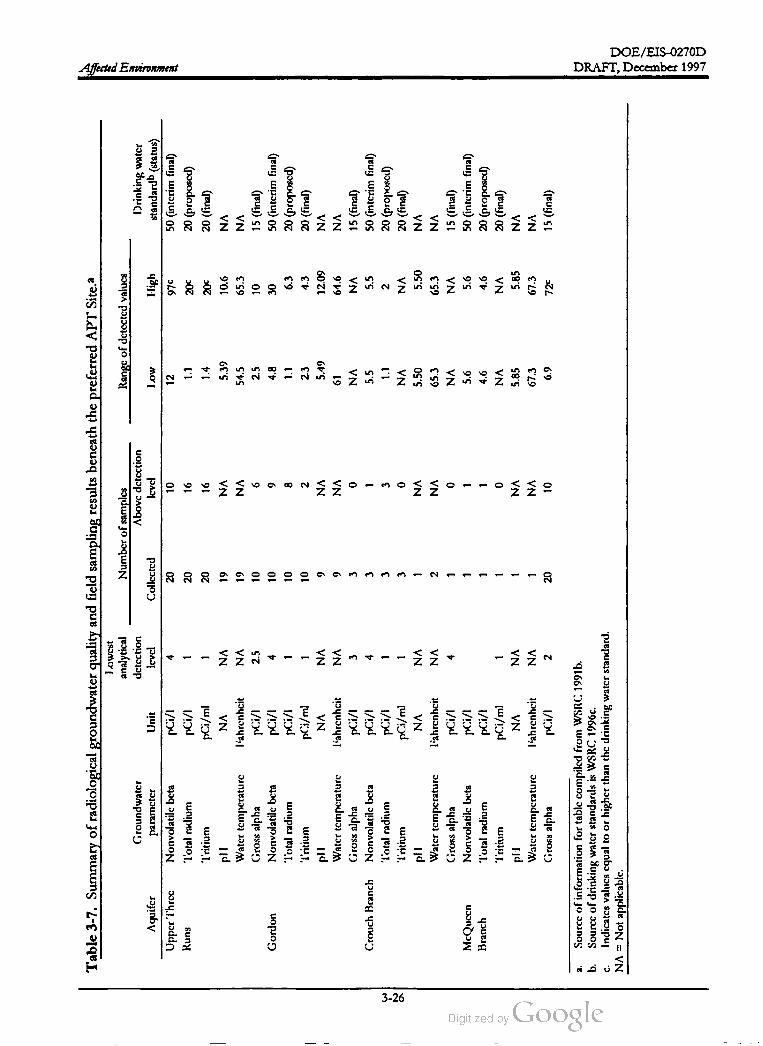
DOE/ EIS-0270D
Affected Environment
20
12
1 1
20
10
1 1
Table
3-7
.Summary
of
radiological
groundwater
quality
and
field
sampling
results
beneath
the
preferred
APT
Site.a
Lowest
analytical
Number
of
samples
Range
of
detected
valucs
Groundwater
dctcction
Abovc
dctcction
Aquifer
paramctcr
Unit
Icvcl
Collected
Icvcl
Low
I-ligh
Upper
Three
Nonvolatilc
bcta
pil
410
970
Runs
Total
radium
pCi
/l20
16
1.1
200
Tritium
pCi
/ml
16
1.4
200
pll
NA
NA
19
NA
5.39
10.6
Watcr
tcmpcrature
l'abrcnhcit
NA
19
NA
54.5
65.3
Gross
alpha
pCi
/l2.5
10
62.5
10
Gordon
Nonvolatilc
bcta
pCi
/l4
10
94.8
30
Total
radium
pCi
/l8
1.1
6.3
Tritium
pCi
/ml
10
22.3
4.3
pll
NA
NA
9NA
5.49
12.09
Watcr
tcmpcraturc
liahrenhcit
NA
9NA
61
64.6
Gross
alpha
pCi
/13
30
NA
NA
Crouch
Branch
Nonvolatilc
bcta
pCi
/14
35.5
5.5
Total
radium
pCi
/l3
32
Tritium
pCi
/ml
30
NA
NA
pll
NA
NA
NA
5.50
5.50
Watcr
temperature
Tahrcnhcit
NA
2NA
65.3
65.3
Gross
alpha
pCi
/l4
0NA
NA
McQueen
Nonvolatilc
bcta
pil
5.6
5.6
Branch
Total
radium
pCi
/l4.6
4.6
'Tritium
pCi
/ml
0NA
NA
pl
NA
NA
NA
5.85
5.85
Watcr
temperature
lahrcnhcit
NA
NA
67.3
67.3
Gross
alpha
220
10
6.9
72C
Drinking
water
standard
(status
)
50
(interim
final
)
20(proposed
)
20
(final
)
NA
NA
15
(final
)
50
(interim
final
)
20(proposed
)
20
(final
)
NA
NA
15
(final
)
50
(intcrim
final
)
20(proposed
)
20
(final
)
NA
NA
15(final
)
50
intcrim
final
)
20
(proposed
)
20
(final
)
NA
NA
15
(final
)
1
1.1
1 1
1
1 1
1 1 1 1 1 1
1
pCi
/
a.Source
of
information
for
tablc
compiled
from
WSRC
1991b
.
b.Sourcc
of
drinking
water
standards
isWSRC
1996c
.
Indicates
valucs
cqual
toor
higher
than
thc
drinking
water
standard
.
NA
=Not
applicable
.
C.
DRAFT,December 1997
3-26

DOE /EIS-0270D
DRAFT,December 1997 Affected Environment
deepest McQueen Branch Aquifer (WSRC
1991a).
mercury (2.39 micrograms per liter) that ex
ceeded the drinking water standards (50 micro
grams per liter for lead and 2 micrograms per
liter for mercury). These exceedances were
caused by the assimilation of components ofthe
drilling mud (sodium bentonite) that were still
being desorbed by sediments around the moni
toring well, indicated by the higher than normal
sodium and calcium concentrations in the same
well (WSRC 1991a).
Detected concentrations of total organic carbon
and phenols were only marginally above the
detection level of 1 milligram per liter and 5 mi
crograms per liter, respectively . Phenol was
detected in one sample from the Upper Three
Runs Aquifer at a concentration of 5.18 micro
grams per liter. The highest detected concen
trations of total organic carbon were 4.82 and
5.56 micrograms per liter in the Upper Three
Runs and Gordon Aquifers , respectively. Total
organic carbon is a gross indicator that can re
flect compounds such as natural organic acids
and organic matter. The absence ofvolatile or
ganic constituents (typical of solvents used at
the SRS) in the groundwater indicates that in
dustrial activities have not affected the ground
water (WSRC 1991a).
Radiological analyses of groundwater from the
water table aquifer (Upper Three Runs Aquifer)
showed that gross alpha, nonvolatile beta, total
radium , and tritium are present in some loca
tions under the preferred APT site at or slightly
above the drinking water standard . The analy
ses detected total radium and tritium only once
at a concentration equal to their respective
drinking water standards. All other groundwa
ter samples had either nondetectable levels of
total radium and tritium or concentrations that
were less than the drinking water standard .
Analyses of the deeper aquifers below the pre
ferred site revealed no other radiological con
stituents in excess of the drinking water
standards (WSRC 1991a). Table 3-7 summa
rizes the radiological sampling results for each
aquifer beneath the preferred site.
Air and water measurements for radioactivity
often include measurements for gross alpha ,
nonvolatile beta , and total radium content.
Gross alpha refers to the total alpha emis
sion rate of the sample and is an indicator of
the radionuclides in the sample that decay
by alpha emission . Similarly , nonvolatile
beta refers to the beta emission rate but is
limited to constituents that are not gaseous
(i.e., not capable of being volatilized). Total
radium refers to measurements of the ra
dium content in the sample ; because most
radium isotopes also emit alpha particles,
the gross alpha measurement includes a
contribution from radium isotopes. Meas
urements of gross alpha , nonvolatile beta ,
and totalradium content cannot be used by
themselves to calculate radiation dose , be
cause the specific radionuclides are not
known . However, using these measure
ments to develop trends over time can help
assess small increases in radioactive mate
rial in the environment.
DOE has not characterized the groundwater
quality at the alternate APT site for geochemical
properties or contamination. DOE would
complete characterization studies if the alternate
site is selected.
3.3.3 CLIMATE
In general, inorganic parameters were within the
ranges expected for regional aquifers, indicating
that agricultural and other human impacts to
groundwater have been negligible (WSRC
1991a ). However, one groundwater sample
from the water table aquifer showed concentra
tions of lead (126 micrograms per liter) and
The climate at the SRS is relatively mild , with an
average frost-free season of approximately 246
days. Theaverage annual rainfall, about
48 inches, is fairly evenly distributed throughout
theyear. There is no strong prevailing wind di
rection; however, there is a relatively high fre
quency of east-to -northeast winds during the
summer and fall and of south -to -northwest
winds during the late fall, winter, and spring
(Hunter 1990). The average wind speed is
8.5 miles per hour. With the exception of the
3-27

DOE /EIS -0270D
DRAFT,December 1997Affected Environment
Savannah River, no topographic features signifi
cantly influence the general climate.
monitoring stations on and around the Site to
determine concentrations of radioactive particu
lates and aerosols in the air (Arnett and Ma
matey 1996).
Tritium is the only radionuclide of SRS origin
detected routinely in offsite air samples. All
radiological releases are within regulatory
limits .
DOE uses meteorological data as input for
atmospheric transport and dose models that
estimate the dispersion of radionuclides and
emissions from various SRS facilities.
Analyses use a 5 -year average data base
rather than actual annual data because of
the difficulty of compiling, entering, and vali
dating the data in time for use in current
year calculations, and because there is little
year- to -year variation in the SRS meteorol
ogy. These measurements include disper
sion conditions observed during the 5 -year
period, ranging from unstable (considerable
turbulence, which leads to rapid dispersion ),
to very stable (very little turbulence, which
produces a narrow , undispersed plume). In
general, as the atmosphere becomes more
unstable , atmospheric dispersion of airborne
pollutants increases and ground-level con
centrations decrease . The meteorology at
the SRS is unstable about 56 percent of the
time.
Та 3-8 lists average and maximum atmos
pheric concentrations of radioactivity at the SRS
boundary, at a 25 -mile radius, and at back
ground monitoring locations (100 -mile radius)
during 1995. Tritium is the only radionuclide of
SRS origin detected routinely in offsite air sam
ples above background concentrations (Arnett
and Mamatey 1996 ). Most of the radionuclides
cannot be measured in the environment around
the Site due to their extremely low concentra
tions. However, DOE used SRS-specific com
such MAXIGASP and
POPGASP to calculate radiological doses for
members of the public for the 1995 releases
based on the amount released and the estimated
concentrations in the environment.
puter models as
3.3.4.2 Nonradiological Air Quality
The average annual temperature at the SRS is
64 °F . The average relative humidity is greatest
during the summer and lowest during the winter
and ranges from 90from 90 percent in the early morning
to about 43 percent in the afternoon (Hunter
1990). During the summer months, themaxi
mum and minimum daily average humidities
range from 98 to 41 percent, respectively .
During thewinter, the maximum andminimum
daily average humidity ranges from 89 to 36
percent, respectively.
The SRS is in a region that is designated an at
tainment area because it complies with National
Ambient Air Quality Standards (NAAQS) for
criteria pollutants. The closest nonattainment
area (an area that does not meet NAAQ stan
dards) is the Atlanta, Georgia, air quality region,
about 145 miles to the west. Attainment areas
do not have restrictions on growth that nonat
tainment areas might have. Prevention of Sig
nificant Deterioration (PSD ) regulations apply
to new ormodified sources of air pollution if a
net increase in emissions from the new or
modified source exceeds the PSD maximum
allowable increments (40 CFR 52.21).
Savannah River Site Affected Environment (Shedrow
1993) contains more detailed information on
the SRS climate, including severe weather pat
terns.
3.3.4 AIR RESOURCES
3.3.4.1 Radiological Air Quality
In the SRS region , airborne radionuclides origi
nate from natural sources (i.e., terrestrial and
cosmic ), worldwide fallout, and nuclear facility
operations. DOE maintains a network of air
DOE models the atmospheric dispersion of
both maximum potential and actual emissions
of regulated pollutants using the U.S. Environ
mental Protection Agency (EPA) Industrial Source
3-28

DOE /EIS -0270D
DRAFT, December 1997 Affected Environment
Table 3-8. Radioactivity in air at the SRS boundary, at the 25-mile radius,and at the 100-mile radius
during 1995 (picocuries per cubicmeter).a
Location Gross alpha Nonvolatile beta Tritium
Site boundary
Average0.0014 0.018 16
Maximum 0.0043 0.035 96
25 -mile radius
Average 0.0014 0.018 10
Maximum 0.0036 0.032
Background (100 -mile radius)
Average0.0016 0.018 10
Maximum 0.0041 0.032 20
42
a . Sources: Amett and Mamatey (1996); Arnett (1996 ).
DOE measures nonradiological air emis
sions from SRS facilities at their points of
discharge by direct measurement, sample
extraction and measurement, or process
knowledge. Using monitoring data and me
teorological information , DOE estimates the
concentration of certain pollutants at the Site
boundary . The Site is in compliance with
National Ambient Air Quality Standards.
The Environmental Protection Agency re
cently approved revisions to the national
ambient air quality standards for ozone and
particulate matter that will become effective
on September 16 , 1997 (62 FR 138 ). For
ozone, the current 1-hour primary standard
will be replaced with a more stringent 8 -hour
standard with a limit of 0.08 part per million .
In addition , the revision adds strict monitor
ing requirements for particulate matterwith a
diameter less than or equal to 2.5 microme
ter. According to the Clean Air Act, the next
step for EPA is to complete a periodic re
view of the new standards -- during the next
5 years for particulate matter and during the
next 3 years for ozone. In that time, EPA
will determine areas that are in nonattain
ment with the new standards. These areas
will have 3 years to develop pollution control
plans and submit them to the EPA, showing
how they will meet the new standards. Then
the areas will have 10 years to reach attain
mentwith the revised standards . In the SRS
region , Augusta -Richmond County, Georgia ,
is likely to fail the new ozone standards; it is
uncertain if the county would exceed the
new particulate matter standards.
Complex Short Term Model (EPA 1992). The
major categories of monitored emissions in
clude sulfur dioxide (SO2), Carbon monoxide
(CO ), oxides of nitrogen (NOx), particulate
matter smaller than 10 microns (PM10), volatile
organic compounds (VOCs) (ozone precursors),
and toxic air pollutants. SRS facilities that pro
duce such emissions include those associated
with diesel- engine-powered equipment, package
steam boilers, the Defense Waste Processing
Facility, the in -tank precipitation process,
groundwater air strippers, and other process
facilities. In addition, the periodic prescribed
burning of forested areas across the Site con
tributes to the release of several criteria pollut
ants (SO2, CO , NOx, PM10, ozone (O3), lead,
and gaseous fluorides) (Arnett and Mamatey
1996). Some 14,000 to 18,000 acres are pre
scribed burned annually, primarily in the spring
of the year (Myers 1997). Table 3-9 lists esti
mated ambient concentrations of these regu
lated air pollutants.
The South Carolina Department of Health and
Environmental Control has the authority to
regulate air quality over the SRS and determine
compliance based on pollutant emission rates
and estimates of concentrations at the Site
boundary based on modeling. The SRS is in
compliance with SCDHEC Regulation 61-62.5 ,
Standard 2 (Ambient Air Quality Standards) and
Standard 8 (Toxic Air Pollutants). Table 3-9
lists limits from these standards. Standard 2 sets
3-29

DOE /EIS -0270D
DRAFT, December 1997Affected Environment
365h,
80h
100h
40,000h
10,000h
Table 3-9. Estimated ambient concentration contributions of air pollutants from existing SRS sources
and sources planned for construction or operation through 1995 (microgramsper cubic meter of air).a,b
SRS maximum Concentrations Most stringent Maximum poten
potential based on actual AAQSE tial concentration
Averaging concentracion emissions (Federal or state) as a percent of
Pollutant time (ug/m3;d (ug/m3) (ug/m3) AAQSE
SO2 3 hours 1210 634 1,300hi 93
24 hours 356 185 98
Annual 18 9.5.5 23
NO2 (asNOXAnnual 30 3.8 30
CO 1 hour 3553 180 9
8 hours 819 23 8
Gaseous fluorides (as HF) 12 hours 241.2 0.62 3.78 65
24 hours 0.60 0.314 2.98 41
1 week 0.11 0.170.03 1.68 38
1 month 0.88 14
24 hours 93 56 150h 62
Annual 9.1 2.7 18
03 1 hour NAJ NA 235h NA
TSP Annual
geometric
mean 20 11 758 27
Lead Calendar
quarter
mean 0.002 0.0003 1.58 0.13
PM10
50h
a .
C.
Source: Hunter and Stewart (1994).
b . The concentrations are themaximum values at the SRS boundary .
SO2 = sulfur dioxide;NOx = nitrogen oxides; CO = carbon monoxide;HF = hydrogen fluoride; PM10 = particu
latematter < 10 microns in diameter;O3 = ozone; TSP = total suspended particulates.
d . Based on maximum potential emissions from all SRS sources permitted through July 1993; listed values are from
calculations reported to SCDHEC in September 1993.
Based on actual emissions from SRS sources plus maximum potential emission for sources permitted for construc
tion through December 1992.
AAQS = Ambient Air Quality Standard .
g . Source: SCDHEC (1976 ).
h . Source: 40 CFR Part 50 .
i. Concentration not to be exceeded more than once a year.
NA = not available .
e .
.ܝܕ
3.3.5 HISTORIC AND ARCHAEOLOGI
CAL RESOURCES
limits for the six NAAQ criteria pollutants and
two additional pollutants, gaseous fluorides and
total suspended particulates (TSP). Standard 8
regulates the emission of 257 toxic air pollut
ants. DOE has identified emission sources for
139 of these substances.
Field studies conducted since the 1970s by the
South Carolina Institute of Archaeology and
Anthropology of the University of South Caro
3-30
DOE /EIS -0270D
DRAFT, December 1997 Affected Environment
lina, under contract to DOE and in consultation
with the South Carolina State Historic Preser
vation Officer (SHPO ), have provided informa
tion about the distribution and content of
archaeological and historic sites on the SRS. By
the end of October 1996 , these studies had ex
amined about 70 percent of the Site, and had
identified 1,200 archaeological (historic and
prehistoric) sites. Of these sites, 53 are eligible
for the NationalRegister ofHistoric Places. No
SRS facilities have been nominated for the Na
tional Register, and there are no plans for
nominations at this time (Brooks 1996 ). Ar
chaeologists have divided the SRS into three
zones related to their potential for containing
sites with multiple archaeological components
or dense or diverse artifacts, and their potential
for nomination to the National Register of
Historic Places (DOE 1995b).
evaluated by the Savannah River Archaeological
Research Program (SRARP) in 1986 for a new
waste storage /disposal facility (Brooks et al.
1986). No archaeological sites were located at
the time. In June 1996 , the SRARP conducted
additional surveys for the APT site areas that
were not part of the 1986 work and to further
evaluate 20th -century homesites. The most re
cent survey resulted in the discovery of seven
archaeological sites: one site consists of a pre
historic lithic scatter; the remaining sites are late
19th- and 20th - century homesites.
The alternate site includes archaeology zones 1,
2 , and 3 , although more than half lies in Zone 3.
This site has not had a systematic survey and
evaluation , but because it is in an area with low
potential for significant prehistoric sites, the Sa
vannah River Archaeology Research Program
does not expect to find prehistoric sites that
would be eligible for nomination to the Na
tional Historic Register. There is greater poten
tial for sites of the historic period (Sassaman
Zone 1 is the zone of the highest archaeo
logical site density, with a high probability
of encountering large archaeological sites
with dense and diverse artifacts, and a high
potential for nomination to the National
Registerof Historic Places.
1997).
Zone 2 includes areas ofmoderate archaeo
logical site density . Activities in this zone
have a moderate probability of encounter
ing large sites with more than three prehis
toric components or that would be eligible
for nomination to the National Register of
Historic Places.
In 1991 DOE solicited the concerns of Native
Americans about religious rights in the Central
Savannah River Valley. During this study, three
Native American groups the Yuchi Tribal
Organization, the National Council of Musk
ogee Creek , and the Indian People's Muskogee
Tribal Town Confederacy expressed general
concerns about SRS and the Central Savannah
River Area, but did not identify specific sites as
having religious significance. The Yuchi Tribal
Organization and the National Council of
Muskogee Creek are interested in plant species
traditionally used in tribal ceremonies, such as
redroot, button snakeroot, and American gin
seng (NUS 1991a). Redroot and button snake
root occur on the SRS (Batson, Angerman, and
Jones 1985).
Zone 3 includes areas of low archaeological
site density . Activities in this zone have a
low probability of encountering archaeo
logical sites and virtually no chance of en
countering large sites with more than three
prehistoric components ;the need for site
preservation is low . Some exceptions to
this definition have been discovered in
Zone 3; some sites in the zone could be
considered eligible for nomination to the
National Register of Historic Places.
3.3.6 SITE LAND USE AND INFRA
STRUCTURE
The preferred APT site falls in archaeology
zone 3 and consists of a large portion ofa tract
SRS occupies approximately 198,000 acres in a
generally rural area in western South Carolina.
Administrative, production , and support facili
ties occupy 5 percent (approximately 17,000
3-31
DOE /EIS-0270D
Affected Environment DRAFT, December 1997
system receives sporadic limited use (Mclain
1997) .
acres) of the total SRS area. The remaining
land, approximately 181,000 acres is forest land
and swampmanaged by the U.S. Forest Service
(under an interagency agreement with DOE).
Approximately 14,000 acres of SRS have been
set aside exclusively for nondestructive envi
ronmental research (DOE 1993) in accordance
with SRS's designation as a National Environ
mentalResearch Park . Research in the set-aside
areas is coordinated by the University ofGeor
gia's Savannah River Ecology Laboratory .
Current railroad use consists of shipments of
radioactive casks of spent nuclear fuel from off
the Site or between the reactor areas and sepa
rations facilities. In addition, shipments of ra
dioactive waste destined for treatment
disposal at the SRS arrive on the Site by rail.
or
Utilities and Resource Usage
Roads and Rail
The SRS transportation infrastructure consists
ofmore than 143 miles of primary roads, 1,200
miles of unpaved roads, and 64 miles of railroad
track. These roads and railroads provide con
nections between the SRS facilities and links to
offsite transportation (see Figure 3-11) .
Electrical Power Distribution System . The
South Carolina Electric and Gas Company
(SCE & G ) supplies SRS electric power needs via
one 160-kilovolt and two 115 -kilovolt transmis
sion lines with available power of about 390
megawatts. Current Site demand is about 70
megawatts. Figure 3-12 shows the SRS electric
distribution system (Shedrow 1997). The D
Area Powerhouse , which once provided a por
tion of the Site's electricity needs, is now under
lease to SCE & G , which in turn sells electricity
to DOE.
In general, heavy traffic on roads occurs in the
early morning and late afternoon when workers
commute to and from the SRS. The Savannah
River Waste Management Final Environmental Impact
Statement (DOE 1995b) summarizes baseline
traffic flows for primary SRS roads. During
working hours official vehicles, solid waste
haulers, and logging trucks constitute most of
the traffic . The Environmental Assessment for the
Construction and Operation of the Three Rivers Solid
Waste Authority Regional Waste Management Center
at the Savannah River Site (DOE 1995c) describes
the projected traffic volume associated with
solid waste landfill operations.
The SRS rail yard, an eight-track facility east of
P -Reactor, sorts and redirects onsite rail cars.
Deliveries ofshipments to the SRS can occur at
rail stations in the former towns of Ellenton
and Dunbarton . From these stations, an SRS
engine moves rail cars to the appropriate facil
ity . Historically , the Ellenton station, which is
on the main Augusta- Yemassee line , received
coal for the D -Area Powerhouse, while the
Dunbarton station received other rail shipments
and coal for the smaller SRS Powerhouses.
However, coal is now delivered to the Site by
truck, not by rail. As a result, the SRS railroad
SCE & G also provides electric service to more
than 446,000 customers in a 15,000-square -mile
service area in the central, southern, and south
western portions of South Carolina; the area
extends into 24 of the State's 46 counties. Sys
tem -wide electric sales grew by 3.4 percent in
1990 to 15.4 billion kilowatt -hours. Residential
and commercial sales accounted for most of the
increase. The electric basegrew by 2.6 percent.
Over a 4-year period before 1990, total custom
ers and kilowatt-hour sales increased at average
annual rates of 2.4 and 3.0 percent, respectively
(SCE & G 1995). SCE & G has a combined gen
erating capacity of 4,200 megawatts. The cur
rent peak load is 3,700 megawatts; resulting in a
reserve capacity of 500 megawatts (White 1997).
In addition, SCE & G has the ability to sell
power to or purchase power frofrom companies
within the region through a common utility
practice know as" retail wheeling," when system
loads require augmenting or when the system
has excess power.
3-32
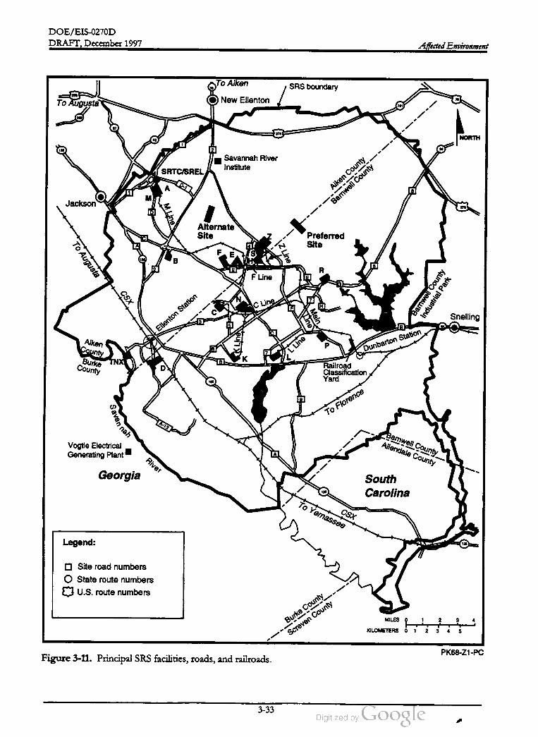
DOE /EIS -0270D
DRAFT, December 1997Affected Environment
To AikenSRS boundary
270
To AugustaNew Ellenton
302
270
NORTH
Savannah River
InstituteSRTC /SREL
D - 1А
м .
Jackson
Aiken
County
Barnwell
County
278
TW
Alternate
Site Preferred
Site
FE
To
Augusta
IZ
Line
B
R
F Line
CSX
Barnwell
County
Industrial
Park
C Line
QMain
Line Snelling
Ellenton
Station
KLine
L Line Du
nbarton
Statio
n
Aiken
County
BurkeCounty
TNXк
Railroad
Classification
Yard175
To FlorenceS
avannah
A - 13
Barnwell
CountyAllendale
CountyVogtle Electrical
Generating PlantRiver
Georgia South
Carolina
CSX
To
Yemassee
Legend:
O Site road numbers
O State route numbers
U.S. route numbers
MILES 0
1 2
3
Burke
County
Screven
County
KILOMETERS 0
1
2 3 4 5
PK68-Z1-PC
Figure 3-11. Principal SRS facilities, roads, and railroads.
3-33
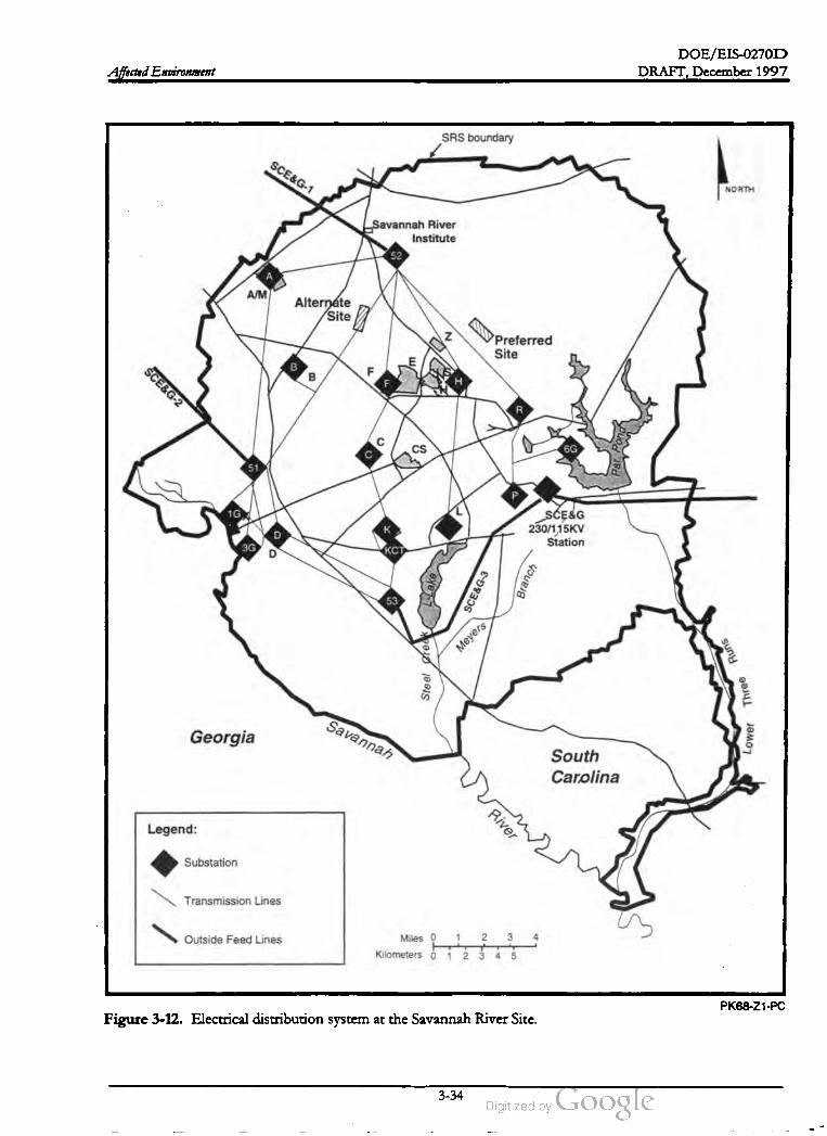
DOE /EIS-0270D
DRAFT, December 1997Affected Environment
SRS boundary
SCE & G -1
NORTH
„Savannah River
Institute
52
A /M
Alternate
Site
zPreferred
Site
BF
BF H
SCE& G -2
R
сCS 6G
51 Par
Р
1G
K
SCE & G
230 /115KV
Station
D
3GD
KCT
L-Lake
SCE
& G - 3
Branch
53
Meyers
Runs
Steel
Sree
Three
Savannah
GeorgiaLower
South
Carolina
Legend:
River
Substation
Transmission Lines
Outside Feed Lines1 2 3 4
Miles o
Kilometers • 1 2 . 3 4 5
PK68 -Z1-PC
Figure 3-12 . Electrical distribution system at the Savannah River Site.
-
3-34

DOE /EIS -0270D
DRAFT, December 1997 Affected Environment
Steam Distribution System . Steam genera
tion facilities at the SRS include coal- fired pow
erhouses at A-, D-, and H -Areas, and two
package boilers, which use number 2 fuel oil, in
K -Area. At present, steam generation occurs
continuously at the A- and D -Area facilities.
DOE has privatized the D -Area Powerhouse,
which providesmost of the steam for the SRS.
DOE leases this area to SCE & G , which in turn
produces and sells steam to DOE.
one (6G ) on Par Pond. Pumphouse 5G is also
on the Savannah River, but it is a separate pip
ing system that supplies cooling water to the
D -Area Powerhouse . Pumphouses 16 and 6G
are no longer operating, but DOE has main
tained the 16 pumphouse and system . The to
tal design capacity of the 16 and 3G
pumphouses is 400,000 gallons per minute . In
1997, DOE installed a 5,000 gallon per minute
pump in Pumphouse 3G to save energy and
costs. At present, only Pumphouse 3G is in
use, withdrawing 5,000 gallons per minute from
the Savannah River to supply SRS facilities.
Natural Gas. The Site does not have natural
gas distribution systems.
Domestic and Process Water Distribution
System . Current groundwater withdrawals at
SRS for domestic and process uses total 9 to
12 million gallons per day (Arnett and Mamatey
1996). Domestic water is supplied from
groundwater wells in several SRS areas. The
main well system supplies water to A-, M-, B-,
C-, F, and H- Areas. The outlying areas (P-, L-,
TNX) receive water from wells in those areas.
Figure 3-13 shows the SRS domestic water sys
tem ; the average current demand is about 960
gallons per minute; the peak available flow is
about3,450 gallons per minute (Shedrow 1997).
DOE prepared an environmental impact state
mentthat investigated alternatives for placing all
or parts of the River Water System in standby
[Final Environmental Impact Statement, Shutdown of
the River Water System at the Savannah River Site
(DOE 1997) ]. The alternatives included shut
ting down and deactivating the system with no
capability for restart, and placing all or parts of
the system in a layup condition to support fu
ture missions.
Waste Generation and Facilities
The Primary Sanitary Sewer Collection System
at SRS consists of 16.5 miles of force main
piping, 1 mile of gravity lines, and 12 pump sta
tions in different areas . Wastewater from this
collection system is treated at the Central Sani
tary Wastewater Treatment Facility , which dis
charges to Fourmile Branch . The facility has a
treatment capacity of 1.05 million gallons per
day and a current average daily flow of 30,000
gallons per day . In addition , there are small
satellite wastewater treatment plants in D-, K.,
L-, P-, and TNX-Areas (Shedrow 1997). Fig .
ure 3-14 shows the SRS wastewater collection
system . The total average daily wastewater
flows from these facilities (D-, K-, L-, P-, and
TNX) to SRS streams and ultimately the Savan
nah River total 26,500 gallons per day (Shedrow
1997).
SRS activities generate several types of wastes:
low -level (low and intermediate activity) radio
active waste, liquid high -level radioactive waste,
hazardous waste, mixed waste (radioactive and
hazardous combined), and transuranic waste.
The Savannah River Site Waste Management Envi
ronmental Impact Statement (DOE 1995b) dis
cusses the waste generation forecast and the
current treatment, storage, and disposal of these
wastes at the Site. As discussed in Chapter 2 ,
the APT will not generate high -level or tran
suranic waste. Therefore, this section does not
discuss the SRS facilities that handle such
wastes.
The following paragraphs discuss SRS waste
handling systems. Appendix A contains more
details on facility operations.
River Water System . The River Water System
(see Figure 2-5 ) includes three pumphouses ,
two (16 and 3G ) on the Savannah River, and
Low -Level Radioactive Waste . Low -level
radioactive waste is waste that contains radioac
tivity and is not classified as high -level waste,
3-35
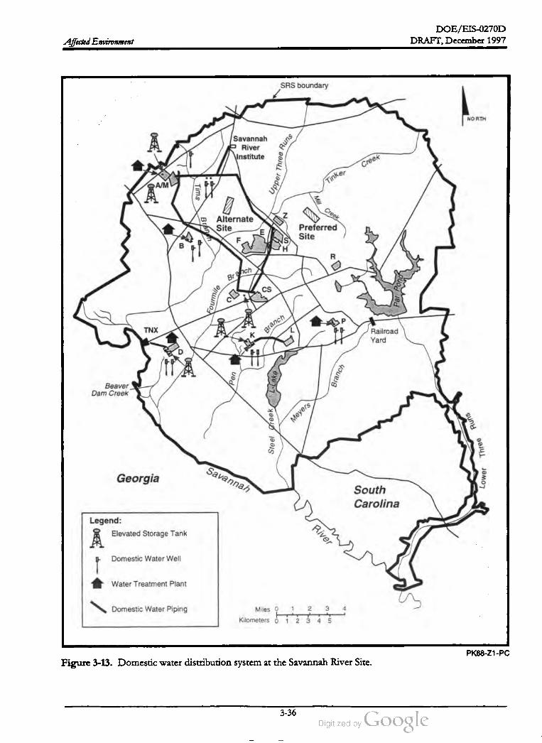
DOE / EIS -0270D
DRAFT, December 1997Affected Environment
SRS boundary
NORTH
30
Savannah
River
\Institute
Upper
Three
Runs
Creek
Tinker
See
Tims
Creek
z
Bránen Alternate
SiteE
Preferred
Site
BH
R
Branch
CSFourmile
Par
Por
P
TNX
Branch
KRailroad
Yard
Pen
L•Lake
Branch
Beaver
Dam Creek
Meyers
Steel
Greek
Runs
Three
Savannah
Georgia
Lower
South
Carolina
Legend:
Elevated Storage Tank
A
River
Domestic WaterWell
Water Treatment Plant
Domestic Water Piping1 2 3 4Miles o
Kilometers
T
1 2 3 4 5
PK68 -Z1-PC
Figure 3-13. Domestic water distribution system at the Savannah River Site.
-
3-36

DOE /EIS -0270D
DRAFT, December 1997 Affected Environment
SRS boundary
NORTH
Runs
Savannah
River
Institute Creek
Upper
Three
Tinker
A /M
Tims
Min
Creek
ZAlternate
Site
Branch
Preferred
Site
B
Central Sanitary
Wastewater
Treatment
Facility
Branch
Cs
Fourmile
Par
Pong
TNX PKB
ranch
Railroad
Yard
D
Pen Branch
Beaver
Dam Creek
Meyers
Steel
Creek
Runs
Three
Savannah
Georgia
Lower
South
Carolina
Legend:
Sanitary Wastewater
Treatment Plant Upgraded
with Ultraviolet Disinfection
Systems
River
Pump Station
Primary Sanitary Sewer
Collection System 1
2 3 4Miles 0
F
Kilometers 0
1
Biosolids Land Application Site
1
2 3 4 5
PK68 -Z1-PC
Figure 3-14 . Wastewater collection system at the Savannah River Site.
3-37

DOE /EIS -0270D
DRAFT,December 1997Affected Environment
transuranic waste, spent nuclear fuel, or by
product material. DOE packages low -level
waste for disposal in the SRS Low -Level Radio
activeWaste Disposal Facility , which consists of
a series of vaults in E -Area that began receiving
such waste in September 1994. The vaults store
low -activity, intermediate-activity, intermediate
level nontritium , and intermediate -level tritium
wastes.
posal at the Beaufort County Landfill. Further,
the Department has signed an agreement that
would allow the Three Rivers Solid Waste
Authority to construct and operate a solid waste
landfill on the SRS at the intersection ofHigh
way 125 and SRS Road 2. The Authority has
received a solid waste landfill permit from
SCDHEC to operate the landfill, which will re
ceive SRS waste and sanitary waste from a
number of counties in the area. This landfill
will begin accepting waste in mid -1998.Hazardous Waste. At the SRS, routine facility
operations and environmental restoration proj
ects can generate hazardous waste as defined by
the Resource Conservation and Recovery Act
(RCRA). DOE stores such waste in hazardous
waste storage facilities in new buildings in B
and N- Areas before shipping it to permitted
treatment, storage, and disposal facilities.
DOE also operates the BurmaRoad Landfill on
the SRS for the disposal of demolition and
construction debris. This landfill has a South
Carolina Department of Health and Environ
mental Control permit for the disposal of
wastes and uncontaminated soil, rock (stone),
concrete rubble, and inert construction debris.
DOE estimates that the landfill will reach its
permitted capacity by 2008 (DOE 1995c).
3.3.7 VISUAL RESOURCES AND NOISE
DOE began offsite shipments of hazardous
waste to treatment and disposal facilities in
1987. In 1990 the Department imposed a
moratorium on shipments of hazardous waste
from radiological materials areas or waste that
was not proven to be nonradioactive. DOE
continues to send hazardous waste that is not
subject to themoratorium (e.g., recyclable sol
vents) off the Site for recycling, treatment, or
disposal.
Visual Resources
Mixed Waste . Mixed waste contains both haz
ardous waste (as discussed above), and source,
special nuclear, or byproduct material (subject
to the Atomic Energy Act of 1954). The SRS
mixed waste program consists primarily of con
tinuing to store such wastes safely until treat
ment and disposal facilities are available. The
SRS mixed waste storage facilities are in E-, N-,
M-, S-, and A- Areas. In addition, DOE built
the Consolidated Incineration Facility in H -Area
to treatmixed, low -level,and hazardous waste.
The dominant aesthetic settings in the SRS vi
cinity are agricultural land and forest, with lim
ited residential and industrial areas. The SRS is
almost completely forested , with only about
5 percent of the total area in industrial use. The
industrial areas are primarily in the interior of
the Site, away from public access. Because of
the distance to the boundary from the indus
trialized areas, the rolling terrain , normally hazy
atmospheric conditions, and heavy vegetation,
SRS facilities are not generally visible from
roads with public access.
Noise
Sanitary Waste. Sanitary waste is solid waste
that is neither hazardous as defined by RCRA ,
nor radioactive. It consists of salvageable ma
terial and materials deposited in municipal sani
tary landfills. Sanitary waste streams include
such items as paper, glass, discarded office ma
terial, and construction debris. At present,
DOE trucks sanitary waste off the SRS for dis
SRS facilities include many noise sources,most
of which are in areas that are a considerable
distance from the Site boundary and, therefore,
result in little or no contribution to offsite
sound levels undermost conditions. Major SRS
noise sources include cooling towers , fans,
pumps, compressors, steam vents, paging sys
tems, construction equipment,material handling
3-38
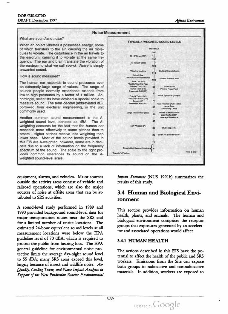
DOE /EIS -0270D
—
DRAFT, December 1997 Affected Environment
DECIBELS
140
50 HP Siren (100 )
130
120
110
Cut-off Saw
Pneumatic Poen Hammer
90
80
Noise Measurement
What are sound and noise ?
TYPICAL A -WEIGHTED SOUND LEVELS
When an object vibrates it possesses energy, some
ofwhich transfers to the air, causing the air mole
cules to vibrate . The disturbance in the air travels to
the eardrum , causing it to vibrate at the same fre
quency. The ear and brain translate the vibration ofJetTakeoft (2009)
the eardrum to what we call sound. Noise is simply
unwanted sound. *RivetingMachine Casting Shakeout Area
How is soundmeasured ?
100 Electric Fumace Area
Rock Drill (50 )The human ear responds to sound pressures over *Textile Weaving Plant
an extremely large range of values. The range ofSubway Train (20 ) Boiler Room
Dump Truck (50 ) Printing Press Plant
sounds people normally experience extends fromPneumatic Drill (50 )
low to high pressures by a factor of 1 million . Ac Freight Train ( 100 )Inside Sport Car(50mph)
cordingly , scientists have devised a special scale toVacuum Cleaner (10 )
Speech ( 1 )
measure sound. The term decibel(abbreviated dB ), Passenger Auto (50 ) Near Freeway (Auto Traffic)
Large Store
borrowed from electrical engineering, is the unit Accounting Office
commonly used .
Another common sound measurement is the A
weighted sound level, denoted as dBA . The A
weighting accounts for the fact that the human earStudio (Speech )
responds more effectively to some pitches than to
others. Higher pitches receive less weighting than
lower ones. Most of the sound levels provided in
this EIS are A -weighted; however, some are in deci
bels due to a lack of information on the frequencyThreshold ofHearing (Youths)
spectrum of the sound. The scale to the right pro
vides common references to sound on the A*Operator's Position
weighted sound-level scale.
70
60
Large Transformer (200 )50
Private Business Office
Light Traffic (100 )
Average Residence
40
Soft Whisper (5 )
30
--
20 Studio for Sound Pictures
10
PK68-Z1- Chan
Impact Statement (NUS 1991b ) summarizes the
results of this study.
equipment, alarms, and vehicles. Major sources
outside the activity areas consist of vehicle and
railroad operations, which are also the major
sources of noise at offsite areas that can be at
tributed to SRS activities.
3.4 Human and Biological Envi
ronment
This section provides information on human
health , plants, and animals. The human and
biological environment comprises the receptor
groups that exposures generated by an accelera
tor and associated operations would affect.
A sound-level study performed in 1989 and
1990 provided background sound-level data for
major transportation routes near the SRS and
for a limited number of onsite locations. The
estimated 24-hour equivalent sound levels at all
measurement locations were below the EPA
guideline level of 70 dBA, which is required to
protect the public from hearing loss. The EPA
general guideline for environmental noise pro
tection limits the average day -night sound level
to 55 dBA; many SRS areas exceed this level,
largely because of insect and wildlife noise. Air
Quality, Cooling Tower, and Noise Impact Analyses in
Support of the New Production Reactor Environmental
3.4.1 HUMAN HEALTH
The actions described in this EIS have the po
tential to affect the health of the public and SRS
workers. Emissions from the Site can expose
both groups to radioactive and nonradioactive
materials. In addition , workers are exposed to
3-39

DOE / EIS -0270D
DRAFT, December 1997Affected Environment
occupational hazards similar to the hazards at
any industrial work site .
The following paragraphs discuss current re
leases of radioactive and nonradioactive
Historic information establishes a
baseline for a comparison to the estimated im
pacts described in Chapter 4 .
Releases of radioactive material to the envi
ronment from the SRS account for less than
0.1 percent of the total annual average envi
ronmental radiation dose to individuals
within 50 miles of the Site . Natural back
ground radiation contributes about 82 per
cent of the annualdose of 360 millirem .
sources.
Public Health
Radiological. The release of radioactivemate
rial to the environment from any nuclear facility
is a sensitive issue. Because there are many
other sources of radiation in the human envi
ronment, evaluations of releases from nuclear
facilities must consider all ionizing radiation
from which people receive routine exposures.
Nuclear facilities within 50 miles of the SRS in
clude a low -level waste burial site operated by
Chem -Nuclear Systems, Inc., near the eastern
Site boundary , and the Georgia Power Com
pany Vogtle Electric Generating Plant, directly
across the Savannah River from the Site. In
addition , Carolina Metals, Inc., which is north
west of Boiling Springs in Barnwell County,
processes depleted Uranium . Based on DOE
measurements, the Chem -Nuclear and Carolina
Metals facilities do not influence radioactivity
levels in the air, precipitation , groundwater, soil,
vegetation , or external radiation (SCDHEC
1995). In 1992, releases from Plant Vogtle pro
duced an annual dose to the maximally exposed
individual of 0.11 millirem at the plant boundary
and a total population dose within a 50 -mile ra
dius of 0.045 person -rem (NRC 1996) .
Public radiation exposure in the SRS region
amounts to approximately 360 millirem per
year, consisting of natural background radiation
from cosmic, terrestrial, and internal body
sources along with radiation from medical diag
nostic and therapeutic practices; weapons test
fallout; consumer and industrial products; and
nuclear facilities. Figure 3-15 shows the relative
contributions of each type of source to people
living near the SRS. All radiation doses men
tioned in this EIS are effective dose equivalents;
internal exposures are reported as committed
effective dose equivalents .
DOE uses the dose-to - risk conversion factors
recommended by the National Council on Ra
diation Protection and Measurements (NCRP)
to estimate the number oflatent cancer fatalities
that could result from radiation exposure. No
data indicate that small radiation doses cause
cancer; to be conservative, however, the NCRP
assumes that any amount of radiation carries
some risk of inducing cancer. DOE has
adopted the NCRP factors of 0.0005 latent can
cer fatality for each person -rem of radiation
dose to the general public and 0.0004 latent
cancer fatality for each person-rem of radiation
dose to radiation workers (NCRP 1993).
In 1995 , releases of radioactive material to the
environment from SRS operations resulted in a
maximum individual dose from such releases of
0.064 millirem per year at the boundary in the
north -northwest sector around the Site, and a
maximum dose from liquid releases of0.14 mil
lirem per year, for a maximum total annual dose
at the Site boundary of 0.20 millirem . The
maximum dose to downstream consumers of
Savannah River water -- 0.053 millirem per year
occurred to users of the Port Wentworth
public water supply (Arnett 1996 ). All releases
are within the established regulatory guideline of
100 millirem for all exposure pathways. Ta
ble 3-10 lists the 1995 dose to the hypothetical
maximally exposed individual and the exposure
limits DOE has established in Order 5400.5 .
3-40
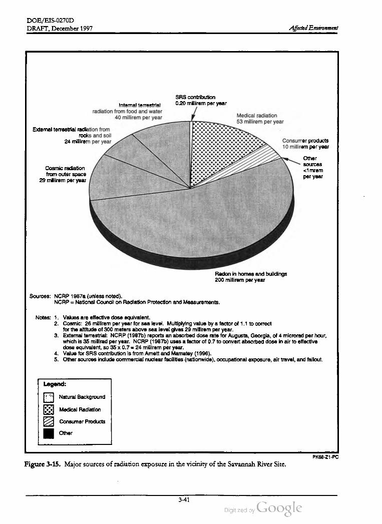
DOE /EIS -0270D
DRAFT, December 1997 Affected Environment
SRS contribution
0.20 millirem per yearIntemal terrestria !
radiation from food and water
40 millirem per year
External terrestrial radiation from
rocks and soil
24 millirem peryear
Medical radiation
53 millirem per year
Consumerproducts
10 millirem per year
Cosmic radiation
from outer space
29 millirem per year
Other
sources
< 1mrem
per year
Radon in homes and buildings
200 millirem peryear
Sources: NCRP 1987a (unless noted) .
NCRP = National Council on Radiation Protection andMeasurements.
Notes: 1. Values are effective dose equivalent.
2. Cosmic: 26 millirem per year for sea level. Multiplying value by a factor of 1.1 to correct
for the altitude of 300 meters above sea level gives 29 millirem per year.
3. External terrestrial: NCRP (1987b) reports an absorbed dose rate for Augusta , Georgia ,of 4 microrad per hour,
which is 35 millirad per year. NCRP (1987b) uses a factor of 0.7 to convert absorbed dose in air to effective
dose equivalent, so 35 x 0.7 = 24 millirem peryear.
4. Value for SRS contribution is from Arnett andMamatey (1996 ).
5. Other sources include commercial nuclear facilities (nationwide), occupational exposure ,air travel,and fallout.
Legend:
NaturalBackground
Medical Radiation
Consumer Products
Other
PK68 -Z1-PC
Figure 3-15. Major sources ofradiation exposure in the vicinity ofthe Savannah River Site.
3-41
DOE /EIS -0270D
DRAFT,December 1997Affected Environment
Table 3-10 . Doses to maximally exposed indi
vidual during 1995 and comparison to DOE
limits (millirem per year).
DOE
Source Dose standard
SRS air emissions 0.064 10
Consumption of water from Sa 0.0534
vannah River
All environmental pathways from 0.1202 100
SRS emissions
per person- rem ). Thus, the annual radiation
dose from atmospheric doses from the SRS re
sults in a calculated risk of cancer death that is
essentially zero in comparison to the over
whelming incidence of fatal cancer expected in
the same population from all causes. The 1.7
person -rem from liquid pathways similarly
could result in 0.0009 additional latent cancers .
a .This dose assumes that the sameperson receives
both the air and liquid doses, which is highly un
likely.
Themaximally exposed individual (MEI) is a
hypothetical member of the public who
would receive the highest radiation dose
from the activity being considered . In de
termining the dose to the MEI, assumptions
are made about the MEI's habits , such as
where the MEl resides; how the MEI obtains
water; and the amounts of meat, fruit, and
vegetables ingested .
Nonradiological. The hazards associated with
the alternatives described in this EIS include
exposure to nonradiological chemicals in air and
water pollution Table 3-9 lists ambient air
quality standards and concentrations for se
lected pollutants; Table 3-5 lists water quality
standards and concentrations. These standards
are designed to protect the public health . The
concentrations from SRS sources, as listed in
the tables, are lower than the established stan
dards.
Worker Health
as
Radiological. One of the major goals of the
SRS Health Protection Program is to keep
worker exposures to radiation and radioactive
material low as reasonably achievable
(ALARA). An effective ALARA program must
balance minimizing individual worker doses
with minimizing the collective dose of all work
ers in a given group .
In 1990 the population within 50 miles of the
SRS was about 620,000. In 1995 the collective
effective dose equivalent to that population (i.e.,
the total dose received by all 620,000 people)
was 3.5 person-rem from atmospheric releases.
Downstream users of the Savannah River (some
of whom might not live within 50 miles of the
SRS) received a collective dose equivalent of 1.7
person -rem from liquid pathways (e.g., drinking
water, consumption of contaminated fish and
invertebrates, and exposure during recreational
activities along the river) (Arnett 1996). Popu
lation statistics indicate that cancer caused 23.5
percent of the deaths in the United States in
1990 (CDC 1993). If this percentage of deaths
from cancer continues, 23.5 percent of the U.S.
population will contract a fatal cancer. Thus, in
the population of620,000 within 50 miles of the
Site, 145,700 personswould be likely to contract
fatal cancers from all causes. The population
dose from the SRS of 3.5 person -rem from at
mospheric pathways could result in 0.0018 ad
ditional latent cancer death expected in the
same population (based on 0.0005 cancer death
The purpose of an ALARA program is to
minimize doses from both external and internal
exposures. Such a program must evaluate both
doses with the goal to minimize the total effec
tive dose equivalent. ALARA evaluationsmust
consider individual and collective doses to en
sure the minimization of both . For example,
using many workers to perform extremely small
portions of a task would reduce the individual
worker doses to very low levels. However, the
frequent worker changes could make the work
inefficient, with the result that the total dose re
ceived by all workers could be significantly
higher than if fewer workers received slightly
higher individual doses.
3-42

DOE /EIS-0270D
DRAFT, December 1997 Affected Environment
comparison to the natural incidence of fatal
cancer.
DOE set administrative exposure guidelines
at a fraction of the exposure limits to help
enforce doses that are as low as reasonably
achievable. SRS worker doses are typically
well below the DOE guidelines. For exam
ple , the current DOE worker exposure limit
is 5 rem per year, and the current SRS ad
ministrative exposure guideline was 0.80
rem per year.
Table 3-11 lists the maximum and average indi
vidual doses and SRS collective doses from
1988 to 1995 .
Table 3-11. SRS annual individual and collec
tive radiation doses.a
Site
collective
Individual dose (rem ) dose
Year Maximum Averageb (person -rem )
1988 2.040 0.070 864
1989 1.645 0.056 754
1990 1.470 0.056 661
1991 1.025 0.038 392
1992 1.360 0.049 316
1993 0.878 0.051 263
1994 0.957 0.022 311
1995 1.335 0.018 247
1996 1.399 0.019 237
Nonradiological. A well-defined worker pro
tection program is in place at the SRS to protect
the occupational
health of DOE and contractor
employees. To prevent occupational
illnesses
and injuries and to preserve the health of the
SRS workforce, contractor
sinvolved in the
construction
and operation of Site facilities es
tablish and implement
essential health and
safety programs based on DOE Orders, DOE
prescribed
standards, and contractor
worker
protection
standards and procedures. The his
toric data in Tables 3-12 and 3-13 indicate that
the implementation
of health and safety pro
grams based on these requirements
results in
accident and injury rates lower than those that
occur in general industry. In addition, the Oc
cupational
Safety and Health Administration
(OSHA) has established
Permissible
Exposure
Limits (PELs) to regulate worker exposure to
hazardouschemicals. These limits refer to air
borne concentrations
of substancesand repre
sent conditionsunder which nearly all workers
could receive repeated exposuresday after day
withoutadverse health effects.
a . Sources: Du Pont (1989), Petty (1993),WSRC
(1991b , 1992, 1993, 1994 , 1995, 1996c).
The average dose includes only workers who re
ceived a measurable dose during the year.
Table 3-14 lists OSHA-regulated workplace
pollutants likely to be generated by the accelera
tor and its associated facilities and the applicable
OSHA limit.
b .
3.4.2 TERRESTRIAL ECOLOGY
In 1995, 13,307 SRS workers received a measur
able dose of radiation. Statistically, these work
ers would be likely to contract approximately
3,130 fatal cancers from all causes during their
lifetimes ; however, this cancer incidence rate
depends on the age and sex distribution of the
population . In 1995 this group received 247
person -rem and could experience as many as 0.1
additional cancer death due to their 1995 occu
pational exposure. Continuing operation of the
SRS could result in as many as 0.1 additional
cancer death for each year of operation , assum
ing future annual worker exposures continue at
the 1995 level. Thus, as with the public, the an
nual radiation dose to SRS workers results in a
calculated cancer risk that is extremely small in
Both the preferred and alternate APT sites are
largely forested, dominated by stands of loblolly
and slash pine. The loblolly stands on the pre
ferred site are generally larger and older (10 to
12 inches in diameter; planted in the late 1950s)
than those on the alternate site (about 10 inches
in diameter and planted from 1972 to 1982).
Younger stands of loblolly pine planted in the
late 1980s cover about 20 percent of the pre
ferred site. About 15 percent of the alternate
site is longleaf pine planted in 1992. The stands
of slash pine are generally older, dating back to
the early 1950s (SRFS 1997). Understory spe
cies common in the pine stands include black
3-43

DOE /EIS-0270D
DRAFT,December 1997Affected Environment
Table 3-12 . Comparison of 1996 rates for SRS construction subcontractors and SRS construction to
1995 rates for general industry construction.a,b
SRS Con
SRS Construction struction De Construction
Incident rate Subcontractorsa partmenta industryb
Total recordable cases 4.69 5.05 10.60
Total lost workday cases1.48 1.93 4.90
a . Source: Saban 1997 .
Source: Bureau of Labor Statistics 1995 .b .
Table 3-13. Comparison of 1996 rates for SRS operations to 1995 incidence rates for private industry
and manufacturing.a,b
Incident rate SRS operationsa Private industryb Manufacturing
Total recordable cases0.88 8.10 11.60
Total lostworkday cases0.40 3.60 5.30
a . Source: Saban 1997 .
b . Source: Bureau ofLabor Statistics 1995 .
A variety of mammals also inhabit the SRS.
White-tailed deer, feral hog, gray and red foxes ,
raccoon, gray and fox squirrels, eastern cotton
tail rabbit, and Virginia Opossum are species
that are likely to occur on the proposed accel
erator sites (Cothran et al. 1991; Imm 1997).
cherry , various oaks, and persimmon (Wike et
al. 1994). Both sites also have small pockets of
40- and 60 -year old upland hardwood stands of
white oak , red oak , and hickory ranging in size
from 8 to 12 inches in diameter (SRFS 1997).
Understory species found on the preferred site
include vacciniums (blueberries), sparkleberry ,
hickories, laurel oak, water oak , southern red
oak, sweetgum , black cherry , persimmon , sassa
fras, and winged sumac. Ground cover includes
Japanese honeysuckle, yellow jessamine, green
brier, muscadine grape, spotted wintergreen ,
various grasses, legumes, and composites (Imm
1997). Figures 3-16 and 3-17 show the forest
cover types ofeach site.
The SRS contains diverse reptile and amphibian
communities due to its physiographic character
istics, large size, climate, variety of terrestrial
and aquatic habitats, and protection from public
intrusion (Gibbons and Patterson 1978; Gib
bons and Semlitsch 1991). Thirty -six species of
snakes, 26 frogs and toads, 17 salamanders, 12
turtles, 9 lizards, and the American alligator oc
cur on the Site (Wike et al. 1994). Amphibian
and reptile species likely to occur in the pine
and upland hardwoods stands found at both
APT sites include the southern toad, eastern
fence lizard , and the black racer.
A variety of birds including migrants and per
manent residents occur in the pine forests and
open acres of the SRS and would likely be
found at both APT sites. Some 213 species of
birds have been identified on the SRS (Wike et
al. 1994). Species likely to utilize the pine
dominated forests of the preferred and alternate
sites include common native songbirds (e.g.,
Carolina wren , wood thrush, northern mock
ingbird , and rufous-sided towhee), neotropical
migrant songbirds (e.g., pine warbler, prairie
warbler, and red-eyed vireo), woodpeckers (e.g.,
red -bellied woodpecker and common yellow
shafted flicker), birds of prey (e.g., sharp
shinned hawk and common screech owl), and
upland game birds (common bobwhite and
eastern wild turkey) (Wike et al. 1994). Open
areas such as powerlines, openings and road
sides would be utilized by northern mocking
bird, mourning dove, rufous -sided towhee, and
common bobwhite (Imm 1997). Appendix D
3-44

DOE /EIS -0270D
DRAFT,December 1997 Affected Environment
O
Table 3-14 . Potential Occupational Safety andHealth Hazards and Associated Exposure Limits.a
System Hazard Limit
Water chemistry laboratory Acetic acid10 parts per
million
Acetone 1,000 parts permillion
Ammonium persulfate None established
Argon Asphyxiant
n -butyl acetate 150 parts permillion
Ethanol1,000 parts per
million
Ethylenediaminetetraacetic acid None established
Hexane 500 parts permillion
Hydrochloric acid 5 parts permillion -- ceiling
Hydrofluoric acid 3parts per
million
Methanol 200 parts per million
Nitric acid 2 parts per million
Nitrogen Asphyxiant
Oxalic acid 1 milligram per cubic meter
Pentane 1,000 parts per million
Potassium hydroxide 2 milligramsper cubic meter ceil
ing
Sulfuric acid 1 milligram per cubic meter
Xylene 100 parts per million
Demineralizer building radwaste Ammonium hydroxide 25 parts per million
reverse osmosis
Citric acid None established
1- (2 -chloroallyl)-3,5,7 -triaza -1 None established
azoniqaadamantane chloride
Hexamethylenetetraamine hydrochlo None established
ride
Nitric acid 2 parts permillion
Phosphoric acid 1 milligram per cubic meter
Sodium bicarbonate None established
Sodium hydroxide2 milligrams per
cubic meter
Tetrasodium EDTA None established
Cryogenics maintenance facility Hydrofluoric acid 3 parts per million
Nitric acid 2 parts per million
Phosphoric acid 1 milligram per cubic meter
HVAC and process chillers Hydrotreated heavy naphthentic distil 5 milligramsper cubic meter
lates
Potassium hydroxide2 milligramsper
cubic meter - ceil
ing
1 -h -benzotriazole, methyl None established
Ethane, 1,2 - dichlorotetrafluoro 1,000 parts per million
(Freon -114)
Noise 90 dBA
Water treatment facility Anionic polymer None established
5 -chloro -2 -methyl-4 0.1 milligram percubic meter
isothiazolin -3 -one
2,2 - dibromo- 3 -nitrilopropionamide2.0 milligramsper
cubic meter
manufacturer recommended limit
Hydrazine 0.1 part per million
2 -methyl-4 -isothiazolin -3 -one None established
Sodium molybdate 5 milligrams per cubic meter
Sodium nitrate None established
Sulfuric acid1 milligram per cubicmeter
Noise 90 dBA
3-45

DOE /EIS -0270D
Affected Environment DRAFT, December 1997
Table 3-14 . (continued).
System
Linear accelerator
Hazard
Electromagnetic frequencies
Ozone
Nitric acid
Lasers
Limit
Frequency dependentACGIH rec
ommendations
0.1 part per million
2 parts per million
Wavelength dependent ACGIH rec
ommendations
Wavelength dependentACGIH rec
ommendations
Visible light
a .The OSHA permissible exposure limits listed in Tables Z -1- A or Z -2 of the OSHA General Industry Air Contami
nants Standard (29 CFR 1910.1000) provided if appropriate. These limits, unless otherwise noted (e.g. , ceiling ),
must not be exceeded during any 8 -hourwork shift of a 40 -hourwork week . If the designation of “ ceiling" is asso
ciated with one ofthe limits listed in this table, the air concentration must not exceed that limit during any part of
the workday.
of the Final Environmental Impact Statement, Shut
down of the River Water System at the Savannah River
Site (DOE 1997) contains a comprehensive list
of wildlife found on the Savannah River Site .
diatom algae, and detailed surveys of attached
algae every 4 years. The annual environmental
reports published annually by DOE (e.g., Arnett
and Mamatey 1996 ) summarize the results of
the ANSP studies. The studies have generally
concluded that SRS effluents do not have an
adverse impact on the health of the Savannah
River.
3.4.3 AQUATIC ECOLOGY
The aquatic resources of the SRS have been the
subject of intensive study for more than
40 years. Research has focused on the flora and
fauna of the Savannah River, the five tributary
streams of the river that drain the Site , and two
manmade impoundments (Par Pond and
L -Lake) that DOE built to receive heated efflu
ents from nuclear production reactors. Detailed
information on SRS aquatic biota and aquatic
ecosystems appears in several monographs
(Patrick, Cairns, and Roback 1967; Bennett and
McFarlane 1983), the 8-volume Comprehensive
Cooling Water Study (Du Pont 1987), and a
number of environmental impact statements
concerned with SRS water resources (DOE
1984; 1987; 1990 ; 1997).
Periphyton - Small organisms, such as al
gae, that attach to rocks, submerged logs,
stems, and leaves of plants , and other sub
strates in streams, rivers, ponds, and lakes .
Benthic macroinvertebrates – Small ani
mals that live on the bottom of a body of
water that are visible to the naked eye and
have no vertebral column (backbone), such
as larval aquatic insects (mayflies and cad
disflies) and mollusks (clams and mussels ).
Plankton - Microscopic organisms in rivers ,
ponds, lakes, and reservoirs that are sus
pended in the water column and whose
movements and distribution are largely de
termined by winds and currents . Phyto
plankton are microscopic plants (algae);
zooplankton are microscopic animals (e.g.,
"water fleas") .
Savannah River
Ichthyoplankton - Eggs and early larvae of
fish that are carried passively with currents
in rivers and lakes.
Since 1951, DOE has sponsored continual
monitoring of periphyton or attached algae, in
the Savannah River above, below , and adjacent
to the SRS (Wike et al. 1994). These ongoing
studies, conducted by the Academy of Natural
Sciences of Philadelphia (ANSP) include semi
monthly surveys of diatom communities, quar
terly cursory studies of both diatom and non
Benthic macroinvertebrates (small, bottom
dwelling organisms) such as insect larvae were
3-46

DOE /EIS -0270D
DRAFT, December 1997
Affected Environment
NORTH
Beauford
Road
Monroe
Owens
Road
Legend:
Stand establishmentdate -
timber type
1954 , 1956 and 1958 - loblolly pine
1979 - loblolly pine
1987, 1988 and 1989 - loblolly pine
1935 - white oak, red oak , hickory
1950 - white oak, red oak, hickory
1957 and 1958 - slash pine
1944 - longleaf pine
Source: SRFS (1997).
PK68-Z1-PC
Figure 3-16 . Forest cover of preferred APT site.
3-47

DOE/EIS -0270D
DRAFT,December 1997Affected Environment
NORTH
F
D - 1
Turner
Branch
Deer
KillRoad
F - 3
Legend :Stand establishment date -
timber type
1930 - white oak , red oak, hickory
F - 1
1955 - white oak, red oak, hickory
1933, 1943 - loblolly pine, hardwood
1946 - loblolly pine
1972 - loblolly pine
1980, 1982 - loblolly pine
1955 , 1959 - slash pine
1968 - slash pine
1992 - longleaf pine
Source: SRFS (1997).
PK68 -Z1-PC
Figure 3-17 . Forest cover of alternate APT site .
3-48

DOE /EIS -0270D
DRAFT, December 1997 Affected Environment
collected monthly at nine locations in the Sa
vannah River from October 1983 through Sep
tember 1985 using artificial substrate samplers
(Wike et al. 1994). Table 3-15 summarizes the
results of the study. These same locations (plus
two additional stations) were sampled quarterly
over the same period with drift nets to deter
mine if organisms were moving from location
to location or abandoning particular areas.
that, at one point, encompassed 26 sample sta
tions in the river (plus 36 more in oxbows and
the mouths of tributary creeks) between River
Miles 18.4 and 116.3 . Specific project objec
tives were to assess entrainment rates for fish
eggs and larvae at SRS water intakes and,more
generally , the impacts ofSRS operations on fish
spawning. This study also generated informa
tion on the distribution and abundance of ich
thyoplankton (fish eggs and plankton ) in the
river.During the 2 -year study, 146 macroinvertebrate
taxa were collected from the Savannah River.
Of these, 96 taxa were collected from the mul
tiplate samplers and 50 were collected exclu
sively in the drift. Dipterans accounted for 46.5
to 73.8 percent of the organismscollected from
themultiplate samplers (Table 3-15). Themost
commonly collected dipterans included chiro
nomids and blackflies. Other common insect
groups included Trichoptera (caddisflies; 18.5 to
30.3 percent), Ephemeroptera (mayflies; 5.2 to
17.3 percent), and Plecoptera (stoneflies ; 1.2 to
3.1 percent). Oligochaetes and amphipods were
also locally abundant at one or more stations.
Over the 1983-1985 period, an average of 7,603
fish were impinged on river water pump intake
screens each year (Wike et al. 1994). Entrain
ment losses averaged 10 million eggs and 18.8
million larvae annually. Species most affected
by impingement were bluespotted sunfish and
threadfin shad. Entrainment losses were pri
marily American shad and other clupeids.
The most abundant groups of macroinverte
brates in the drift were oligochaetes (aquatic
earthworms) and chironomids (midges). Other
common taxa included nematodes, Hydracarina,
amphipods,mayflies, caddisflies, and blackflies.
Additional entrainment-related studies were
conducted during 1991 (Dames and Moore
1992). A total of 33 taxa were collected during
this study. American shad and striped bass ac
counted for 76 percent and 5 percent, respec
tively , of the fish eggs collected. Minnows and
spotted sucker comprised most of the fish lar
vae collected . These patterns were generally
similar to those observed during the earlier
studies. Four sturgeon larvae were collected ,
butit was not determined if these were larvae of
the Atlantic sturgeon or the endangered short
nose sturgeon .
Upper Three Runs
Most fisheries studies in the Savannah River can
be grouped into two categories: those empha
sizing the reproductive requirements and suc
cess of striped bass and those designed to assess
the impacts ofSRS operations on fish spawning
and the survival of fish eggs and larvae. Early
efforts concentrated on the identification of
striped bass spawning areas and the assessment
of tide-gate operations on striped bass spawning
success. Recent studies have focused on the re
production, recruitment, and habitat require
ments of striped bass (Wike et al. 1994).
At least 551 species of aquatic insects occur in
Upper Three Runs (Wike et al. 1994). A 1993
study identified 93 species of caddisflies, includ
ing three not previously found in South Caro
lina and two that were new to science. In
addition, Davis and Mulvey (1993) identified a
rare clam species in the Upper Three Runs
drainage. In 1997, the U.S. Fish and Wildlife
Service redesignated the AmericanAmerican sand
burrowing mayfly , a relatively common mayfly
in Upper Three Runs, a species of Federal con
cern from its former Category 2 species status
Programs designed to assess the impacts of SRS
operations began in 1977 with studies on the
entrainment of American shad eggs in the SRS
Savannah River intakes (Wike et al. 1994). Be
ginning in 1982, the SRS initiated a much larger
project in themidreaches of the Savannah River
3-49

DOE /EIS -0270D
DRAFT, December 1997Affected Environment
2.0
< 0.1
Table 3-15 . Relativeabundance (percent) ofmajor taxonomic groupsofmacroinvertebrates on Hester
Dendy Multiplate Samplers in the Savannah River, 1984-1985.
Station ( river mile)
Taxon 152.2 152.0 150.8 150.4 141.7 141.5 137.7 129.1 128.9
Oligochaeta (aquatic 2.40.4 0.2 < 0.1 0.2 4.2 0.8 0.3
earthworms)
Amphipoda (scuds) < 0.1< 0.1 < 0.1 < 0.1 1.4 0.2 < 0.1 < 0-1
Ephemeroptera6.0 5.6 6.1 5.2 8.5 10.2 13.4 17.3 16.3
(mayflies)
Plecoptera1.2 1.5 1.3 1.2 1.6 3.1 1.9 2.0
(stoneflies)
Trichoptera25.6 22.4 27.5 18.5 29.8 30.3 29.6 30.0 22.1
(caddisflies)
Diptera (true flies) 63.2 66.3 63.6 73.8 59.5 54.8 46.5 48.7 58.0
Othera 1.6 2.2 1.1 1.1 1.0 1.5 3.0 1.3 1.3
1.2
a .
Source: Wike at al. (1994).
Taxa that each comprised less than 1 percentof the organisms collected at a station ; these included Turbellaria,Nematoda,Hi
rudinea, Gastropoda,Pelecypoda, Hydracarina, Decapoda, Collembola, Odonata, Hemiptera, Coleoptera, and Lepidoptera.
Pen Branch and Indian Grave Branch(Fridell 1997). This species is sensitive to silta
tion , organic loading, and toxic releases (Wike et
al. 1994). Between 1987 and 1991, the density
and variety of insects collected from Upper
Three Runs decreased for unknown reasons.
Data collected more recently indicate, however,
that the insect communities mightbe recovering
(Wike et al. 1994).
Fish were sampled in Upper Three Runs in
1984-1985, 1992, and 1993. The 1984-1985
samples were part of the Comprehensive Cool
ing Water Study, and included ichthyoplankton
collections from the lower reaches of the
stream . The 1992 samples were part of an ef
fort to characterize fish assemblages on the SRS
and assess possible impacts resulting from the
outcropping of contaminated groundwater from
F- and H -Areas into Upper Three Runs (Wike
et al. 1994).
The macroinvertebrate communities of Pen
Branch were surveyed from 1983 to 1985 when
K -Reactor was discharging heated effluent to
that stream , and in 1988 and 1989 after the
K -Reactor shutdown (Wike et al. 1994). Before
the shutdown, portions of Pen Branch directly
downstream from the reactor outfall contained
few benthic macroinvertebrate taxa, while areas
farther removed from the outfall (such as the
Savannah River Swamp) had a more diverse
benthic macroinvertebrate community . The
macroinvertebrates in thermally impacted areas
were generally pollution -tolerant forms (e.g.,
chironomids, nematodes, and oligochaetes) ca
pable of surviving high temperatures and low
oxygen levels . After the K -Reactor shutdown,
macroinvertebrate communities began to re
cover, with densities and taxa richness generally
higher (86 taxa collected in 1988-1989 versus 51
in 1984-1985) . The benthos continued to be
dominated by pollution -tolerant groups (e.g.
chironomids and blackflies) after K -Reactor op
erations ended.
The fish assemblages at most Upper Three
Runs sample stations were dominated by shin
ers and sunfishes. Larger predatory and bot
tom -feeding species were typical of those found
in larger streams. The smaller tributary sample
stations were dominated by shiners, followed by
pirate perch , madtoms, and darters -- a pattern
typical of unimpacted streams on the SRS
(Paller 1994).
Aho et al. (1986) investigated the community
structure of fishes in Pen Branch , Meyers
Branch , and Steel Creek in 1984 and 1985 as
part of the Comprehensive Cooling Water
3-50

DOE /EIS -0270D
DRAFT, December 1997 Affected Environment
Study. Steel Creek had the highest diversity ,
with slightly lower values for Pen Branch and
Meyers Branch. In each stream , diversity was
highest at downstream locations.
were reduced , but species richness (diversity)
was high Wike et al. 1994). Common taxa in
cluded a number of midges, a stonefly, two
mayfly species, and a caddisfly.
Upper reaches of Pen Branch were character
ized by low species richness (11 species col
lected) and diversity: six species (mud sunfish ,
brown bullhead, dollar sunfish , chubsucker ,
redfin pickerel, and mosquito fish ) made up
more than 91 percent of all fish collected (Aho
et al. 1986). Lower reaches of Pen Branch
contained more species (27), a higher percent
age of which were small-bodied species (e.g.,
yellowfin shiners, madtoms, and darters) com
monly found in blackwater streams of the
Coastal Plain .
The macroinvertebrate community in the lower
reach of Lower Three Runs (just above its con
fluence with the Savannah River) was character
ized by relatively high densities and relatively
low diversity. Midges (chironomids) made up
84 percent of all organisms collected . Other
common organisms included a mayfly and a
caddisfly.
Flows in Lower Three Runs during the 1984
1985 study were higher than those observed in
more recent years, and the 1984-1985 com
munity characterizations might not reflect cur
rent conditions. However, general upstream -to
downstream trends likely remain the same:
relatively high densities of macroinvertebrates in
the area below the dam and at themouth of the
stream ; and highest species richness and diver
sity in middle reaches of the stream .
After the K -Reactor shutdown, fish rapidly
recolonized Pen Branch and Indian Grave
Branch (Wike et al. 1994). Yellowfin shiners,
bluehead chubs,and pirate perch were the most
common species in the upper reaches of the
stream . Largemouth bass, lake chubsucker, red
ear sunfish , and redbreast sunfish were most
abundant in the middle reaches. Brook silver
sides, coastal shiners, spotted sunfish , and lake
chubsuckers were most common in the delta .
Indian Grave Branch collections were domi
nated by four species: spotted sucker (22.2 per
cent of total), coastal shiner (18.5 percent), lake
chubsucker (14.8) percent, and redbreast sun
fish (14.8 percent).
Lower Three Runs
Surveys of fish in Lower Three Runs were con
ducted in 1990 as part of an effort to assess fish
community structure in SRS streams (Wike et al.
1994; Paller 1994). Fish communities showed
pronounced upstream -to -downstream trends.
Upstream areas where the stream is shallow and
relatively narrow were dominated by a mixed
assemblage of sunfish (primarily redbreast and
spotted sunfish ), shiners, and pirate perch .
More downstream areas, which are typically
deeper and wider, were dominated by spotted
suckers, largemouth bass , and creek chubsuck
a mixed community of
small- to -medium sized insectivorous species at
shallow , narrow stream sites and a community
of large benthic insect-eating and predatory fish
at wider, deeper sites -- was fairly typical of
southeastern coastal plain streams (Paller 1994).
ers. This pattern
The macroinvertebrate communities of Lower
Three Runswere last surveyed in 1983 and 1985
as part of the Comprehensive Cooling Water
Study (Wike et al. 1994). Themacroinvertebate
community just downstream of the Par Pond
dam was characterized by extremely high densi
ties,most notably midges (chironomids). Cad
disflies and blackflies were also abundant.
Many of these organisms are filter feeders, pre
sumably taking advantage of nutrients carried
downstream from Par Pond.
Par Pond System
DOE has not conducted a systematic survey of
the flora and fauna of Ponds 2 , 5 , and C (the
“ pre-cooler” ponds). For this EIS, the De
partment conducted a cursory field survey of
At a station roughly 16 miles downstream of the
Par Pond dam , densities of macroinvertebrates
3-51
DOE /EIS -0270D
DRAFT,December 1997Affected Environment
plants andanimals on July
July 14 ,14, 1997
(Kennemore 1997). This survey and interviews
of scientists from the Savannah River Ecology
Laboratory led to the developmentof basic in
formation on the ecological communities of
Ponds 2 and 5. Pond C was the subject of sev
eral studies of behavioral thermoregulation
in
fishes (and recurring fish kills) in the 1970s and
1980s, but little is known of its plant and inver
tebrate communities.
1985 as part of a Clean Water Act Section
316 (a) thermal effects demonstration. It found
that the reservoir supports a diverse phyto
plankton (algae) community; green algae were
most abundant, followed by diatoms and blue
green algae (Chimney, Cody, and Starkel 1985).
In terms of density, diatoms were the most
abundant algal group. In terms of primary pro
ductivity, chlorophyll-a concentrationsand algal
community composition, Par Pond was similar
to other lakes in the southeastern United States.
Protozoans and rotifers dominated the
zooplankton community ,with protozoans more
abundant in the winter and spring and rotifers
in the summer (Chimney, Cody, and Starkel
1985). Larger-bodied cladocerans (water fleas)
and copepods were most abundant in the sum
mer, indicating a lack of strong pressure from
fish predation . As with phytoplankton, the
zooplankton community in Par Pond was simi
lar to that in other southeastern lakes.
Because the pre-cooler ponds historically re
ceived water from the River Water System and
Par Pond (recirculated through Pumphouse
6G ), DOE assumes that the aquatic communi
ties of these ponds represent a less diverse sub
set of the communities in Par Pond. In
addition , DOE assumes that the pre-cooler
ponds contain periphyton (attached algae)
communities similar to those in Par Pond,
which are dominated by three major taxonomic
groups -- green algae, diatoms, and blue-green
algae (Wilde 1985; Wilde 1987) . Community
composition of the periphyton in these ponds
almost certainly changes seasonally, in response
to changes in temperature, light intensity , rain
fall, and nutrient inputs from the watershed.
Similarly , DOE assumes that the pre -cooler
ponds contain macroinvertebrate communities
numerically dominated by dipterans (" true"
flies) and oligochaetes (aquatic earthworms)
with small numbers of aquatic insects such as
odonates (dragonflies), trichopterans
(caddisflies), and ephemeropterans (mayflies)
also present Wilde 1985; Wilde 1987). The
following fish species are known to occur or
likely occur in Ponds 2, 5 , and C : gizzard shad,
redfin pickerel, golden shiner, true shiners
(Notropis spp.), lake chubsucker, bullheads
(Ameiurus spp .), pirate perch, mosquitofish ,
brook silverside, redbreast sunfish , warmouth ,
bluegill, spotted sunfish, and largemouth bass.
The relative abundance of these species is un
known, but bluegill and largemouth bass are
particularly abundant in Pond C and Par Pond
(Bennett and McFarlane 1983; Aho and Ander
son 1985).
The fishes of Par Pond have been studied in
tensively for more than 25 years; Wike et al.
(1994) lists 50 major studies (journal articles and
monographs) dealing with Par Pond fish . Most
of these studies were concerned with the effects
of thermal discharges from SRS reactors on fish
behavior, physiology, and ecology . Population
studies in the 1970s and 1980s showed large
mouth bass, bluegill, black crappie, lake chub
sucker, brook silverside, and mosquito fish to be
particularly abundant in Par Pond (Wike et al.
1994).
The 1991-1995 drawdown of Par Pond tempo
rarily affected fish populations due to reduced
spawning and nursery habitat for many species
and increased predation on small forage species
(e.g., brook silverside, golden shiner, and min
nows (Notropis species)] and young-of-the-year
sunfish that use littoral zone macrophyte beds
for escape cover.
3.4.4 WETLAND ECOLOGY
The aquatic ecology of Par Pond was studied
intensively from January 1984 through June
The SRS has extensive widely distributed wet
lands,most of which are associated with flood
plains, creeks, or impoundments. Using
3-52
DOE / EIS -0270D
DRAFT, December 1997 Affected Environment
cent), and deep water (4 percent) (Wike at al.
1994 ).
Par Pond System
information from a land cover and land use
geographic information system data base devel
oped from multidate aerial photography taken
in the late 1980s,DOE estimates that SRS wet
lands cover almost 49,000 acres (Wike et al.
1994). There are about 300 Carolina bays
(Kirkman et al. 1996), a wetland feature unique
to the southeastern United States, on the Site ;
they exhibit extremely variable hydrology with
resident plant communities ranging from herba
ceousmarshes to forested wetlands.
Savannah River
The Savannah River supports an extensive
swamp, covering about 9,400 acres of the SRS;
a natural leveeseparates
theswamp
from the
river. Predominating the forest cover in the
swamp is second-growth bald cypress, black
gum , and other hardwood species. The five
streams draining the Site have floodplains with
bottomland hardwood forests or scrub -shrub
wetlands in varying stages of succession .
Dominant species include red maple, box elder,
bald cypress, water tupelo , sweetgum , and black
willow (Wike et al. 1994).
Since the P -Reactor shutdown in 1988, the Par
Pond system has not received heated effluent.
Flow from the River Water System stopped in
early 1996 (Cooney et al. 1996 ). The canals
connecting the pre-cooler ponds are lined with
rip -rap and contain a heavy growth of alligator
weed. Zones of dense emergent vegetatios
along themargins of the ponds provide habitat
for a variety ofaquatic and semi-aquatic animals
(water snakes, frogs, turtles, and wading birds).
Cattails and burweed dominate the shoreline of
Pond 2; sedges, grasses, and bulrushes are also
present but are minor components of the emer
gentvegetation community. The Pond 5 shore
line is dominated by cattails, with arrowhead,
rushes, sedges, and bulrushes as minor compo
nents . Pond C , like Pond 5 , has a shoreline
dominated by cattail, with spike-rush and water
shield in some areas (Kennemore 1997).
Pen Branch - Indian Grave Branch
The Pen Branch - Indian Grave Branch system
would receive blowdown from the K -Area
natural-draft cooling tower, ifDOE chose it to
cool the heated water from the APT facilities.
At present, the stream receives nonthermal ef
fluents (nonprocess cooling water, ash basin ef
fluent waters, powerhouse wastewater, and
sanitary wastewater) from K -Area and sanitary
effluents from the Central Shops Area. Since
shutdown of the K -Reactor,wetlands in the Pen
Branch corridor and delta have shifted from
nonpersistent vegetation and water to
persistent vegetation and drier conditions.
Acreage in the stream corridor consists pre
dominantly of bottomland hardwood (64 per
cent) along with willow (18 percent), scrub
shrub (10 percent), deep water (9 percent), and
mud flats (6 percent). The delta is dominated
by willow (36 percent), cattails (32 percent),
shallow water (17 percent), scrub-shrub (9 per
In March 1991 DOE discovered a depression
on the downstream slope of the Par Pond dam .
While DOE was determining what repairs were
needed, it lowered the water level from 200 feet
to 181 feet. As a result, the wetlands vegetation
that developed with the fairly stable water levels
that characterized Par Pond from 1958 to 1991
were exposed to drying conditions, and exten
sive losses occurred along the shoreline (DOE
1997). In the spring of 1995, DOE restored Par
Pond to a full pool level. Shoreline aquatic
vegetation is undergoing rapid redevelopment.
Maidencane, the current dominant emergent
species, has become less abundant in deeper
water since DOE refilled the pond. Several
other species that dominated wetland areas be
fore the drawdown are increasing in abundance,
including lotus, water lily, watershield and spike
rush. Cattails are scattered throughoutmost of
Par Pond, and long beds are forming in the
Middle Arm . In 1996 lotus expanded into areas
formerly dominated by cattails. Woody species
(e.g., loblolly pine, willow , and red maple) that
colonized the edge of the reservoir during the
3-53

DOE /EIS -0270D
DRAFT, December 1997Affected Environment
drawdown, are declining in abundance since the
refill, although there is a band ofwillow and red
maple around the margin of the lake (DOE
1997).
Table 3-16 . Threatened and endangered spe
cies of the Savannah River Site.
Common name Status
Bald eagle Ta
Wood stork Eb
Red -cockaded woodpecker E
American alligator T / SAC
Shortnose sturgeon E
Smooth coneflower E
a . T - Federally threatened species.
b . E - Federally endangered species.
T /SA - Threatened due to similarity of appearance
to the endangered American crocodile.
C.
For themost part, wetlands along Lower Three
Runs downstream of Par Pond are bottomland
hardwood swamps associated with the flood
plain (DOE 1990). Bottomland hardwoods on
the SRS are typical of themixed hardwood for
ests in low wet areas of the southeastern Coastal
Plain (Workman and McLeod 1990). Common
tree species in these areas tolerate flooding of
limited depth , which is normally restricted to
late winter and early spring when the plants are
dormant (Whipple, Wellman, and Good 1981)
This includes several species of oak , sweetgum ,
cottonwood, American elm , sycamore, and red
maple. In addition, somescrub-shrub and other
emergent wetlands occur in the main channel
and tributaries of Lower Three Runs. Although
most influenced by Par Pond releases, these
bottomland areas have also been affected by
beaver activity (DOE 1990 ). Some cypress
tupelo areas are near the confluence of Lower
Three Runs and the Savannah River (DOE
1997).
The smooth coneflower is the only endangered
plant species on the SRS. The closest colony of
this plant is on Burma Road approximately
1 mile south of the intersection with Road C ,
approximately 6 miles from the preferred APT
site. A second colony is near the junctions of
SRS Roads 9 and B (LeMaster 1994). The
habitat of the smooth coneflower is open
woods, cedar barrens, roadsides, clearcuts, and
power line rights-of-way. Optimum sites are
characterized by abundant sunlight and little
competition in the herbaceous layer (FWS
1995). Suitable habitat for this species occurs
throughout the SRS, including the powerline
right-of way adjacent to the preferred APT site,
though none have been found in the vicinity of
either sites (Imm 1997) .
Mammal species found in the wetland areas in
clude beaver, otter,weasel,marsh rabbit, musk
rat, star-nosed mole ,mink, rice rat, and raccoon
(Wike et al. 1994). Extensive studies of reptile
and amphibian use of the wetlands of the SRS
have been conducted by the Savannah River
Ecology Laboratory (Gibbons and Semlitsch
1991; Schalles et al. 1989). Christmas bird
counts and ecological inventories provide in
formation on the avian species common to SRS
wetlands (Wike et al. 1994).
Wood storks feed in the Savannah River Swamp
and the lower reaches of Steel Creek, Pen
Branch , Beaver Dam Creek, and Fourmile
Branch . They foraged at Par Pond during the
drawdown in 1991 (Bryan 1992). Neither of the
APT sites contains suitable foraging habitat for
wood storks, and no storks have been reported
in these areas (Imm 1997). Bald eagles nest
near Par Pond and L -Lake and forage in these
reservoirs (USDA 1988; Bryan et al. 1996; Le
Master 1996). One bald eagle was reported
flying near the junction of SRS Roads E and 4 ,
south of H -Area , in November 1985 (Mayer,
3.4.5 THREATENED AND ENDAN
GERED SPECIES
Table 3-16 lists the threatened and endangered
species that occur on the SRS (Wike et al. 1994).
There is no designated critical habitat for any
listed threatened or endangered species on the
proposed APT sites.
3-54

DOE /EIS -0270D
DRAFT,December 1997 Affected Environment
3.5.1 CURRENT ECONOMIC CONDI
TIONS
Kennamer, and Hoppe 1986). However, nei
ther APT site contains suitable foraging habitat
for bald eagles (Imm 1997). The red-cockaded
woodpecker inhabits and uses open pine forests
with mature trees (older than 70 years for nest
ing and 30 years for foraging). While the pre
ferred site contains red -cockaded
woodpecker nesting or foraging areas in use by
the birds, it does contain unoccupied habitat
approaching suitable age (LeMaster 1997).
no
The socioeconomic region of influence for the
proposed action is a six -county area around the
SRS where the majority of Site workers reside
and where socioeconomic impacts are likely to
occur. The six counties are Aiken , Allendale ,
Barnwell and Bamberg in South Carolina, and
Columbia and Richmond in Georgia . Socioeco
nomic Characteristics of Selected Counties and Com
munities Adjacent to the Savannah River Site (HNUS
1997) contains details on the region of influ
ence, as well as most of the information dis
cussed in the following sections.
Shortnose sturgeon, typically residents of large
coastal rivers and estuaries, have not been col
lected in the tributaries of the Savannah River
that drain the SRS. Sturgeon ichthyoplankton
have been collected in the river near the Site
(Wike et al. 1994). 3.5.1.1 Regional Fiscal Conditions
The American alligator occurs in a variety of
SRS habitats, including river swamps, small
streams, abandoned farm ponds, and Par Pond
and L -Lake (Du Pont 1987). Par Pond contains
the largest concentration of alligators, with
more than 200 animals (LeMaster 1996 ). High
stream flows and temperatures from K -Reactor
operationsmademost of Pen Branch unsuitable
for alligators until 1988, but there are indica
tions that the lowest reaches of the stream are
being recolonized (Wike at al. 1994). Lower
Three Runs has historically supported a repro
ducing population of alligators, most of which
are concentrated in an area below the Par Pond
dam where they are protected from human en
croachment (Murphy 1981;Wike et al. 1994) .
The counties with the greatest potential to be
affected by activities at the Savannah River Site
are Aiken and Barnwell in South Carolina and
Richmond and Columbia in Georgia. Data
available for fiscal year 1994 for these counties
indicate that revenues exceeded expenses in all
but Columbia County . Barnwell County had
the lowest revenues at $ 8 million. Columbia,
Aiken , and Richmond Counties followed with
$20, $30, and $62million, respectively. Socioeco
nomic Characteristics of Selected Counties and Com
munities Adjacent to the Savannah River Site (HNUS
1997) contains the funding levels for the Cities
of Aiken , Barnwell, and New Ellenton , South
Carolina, and Augusta ,Georgia.
3.5.12 Employment and Income
3.5 The Regional Economic and
Social Environment
This section describes the economic and demo
graphic baseline for the area around the SRS.
The purpose of this information is to assist in
understanding the impacts accelerator construc
tion and operation could have on community
service needs and prospects for economic
growth , and any disproportionate impacts they
could have on minority and low -income neigh
borhoods.
In 1994 the total civilian labor force for the re
gion of influence was 206,518, with 6.9 percent
unemployment. The unemployment rate for
the United States for the same period was 6.1
percent. In 1994 total employment according to
Standard Industrial Code sectors ranged from
479 workers in themining sector (e.g., clay and
gravel pits) to 58,415 workers in the services
sector (e.g., health care and education). Average
per capita personal income in 1993 (adjusted to
1995 dollars) was $ 18,867, in comparison to the
U.S. figure of $21,937.
3-55
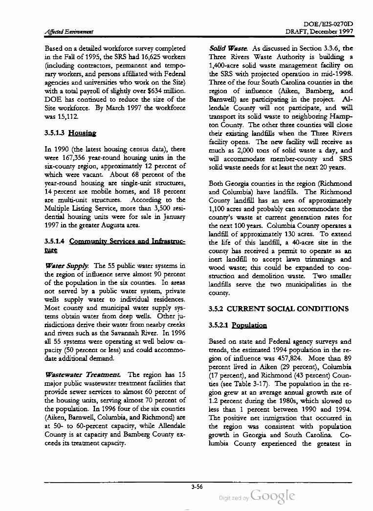
DOE /EIS -0270D
DRAFT,December 1997Affected Environment
Based on a detailed workforce survey completed
in the Fall of 1995, theSRS had 16,625 workers
(including contractors, permanent and tempo
rary workers, and persons affiliated with Federal
agencies and universities who work on the Site)
with a total payroll of slightly over $634 million.
DOE has continued to reduce the size of the
Site workforce. By March 1997 the workforce
was 15,112 .
Solid Waste. As discussed in Section 3.3.6 , the
Three Rivers Waste Authority is building a
1,400-acre solid waste management facility on
the SRS with projected operation in mid -1998.
Three of the four South Carolina counties in the
region of influence (Aiken, Bamberg, and
Barnwell) are participating in the project. Al
lendale County will not participate, and will
transport its solid waste to neighboring Hamp
ton County . The other three counties will close
their existing landfills when the Three Rivers
facility opens. The new facility will receive as
much as 2,000 tons of solid waste a day , and
will accommodate member-county and SRS
solid waste needs for at least the next 20 years.
3.5.1.3 Housing
In 1990 (the latest housing census data), there
were 167,356 year-round housing units in the
six -county region , approximately 12 percent of
which were vacant. About 68 percent of the
year-round housing are single-unit structures,
14 percent are mobile homes, and 18 percent
are multi-unit structures. According to the
Multiple Listing Service, more than 3,500 resi
dential housing units were for sale in January
1997 in the greater Augusta area .
3.5.1.4 Community Services and Infrastruc
ture
Both Georgia counties in the region (Richmond
and Columbia ) have landfills. The Richmond
County landfill has an area of approximately
1,100 acres and probably can accommodate the
county's waste at current generation rates for
the next 100 years. Columbia County operates a
landfill of approximately 130 acres. To extend
the life of this landfill, a 40-acre site in the
county has received a permit to operate as an
inert landfill to accept lawn trimmings and
wood waste; this could be expanded to con
struction and demolition waste . Two smaller
landfills serve the two municipalities in the
county .
3.5.2 CURRENTSOCIAL CONDITIONS
Water Supply. The 55 public water systems in
the region of influence serve almost 90 percent
of the population in the six counties. In areas
not served by a public water system , private
wells supply water to individual residences.
Most county and municipal water supply sys
tems obtain water from deep wells. Other ju
risdictions derive their water from nearby creeks
and rivers such as the Savannah River. In 1996
all 55 systems were operating at well below ca
pacity (50 percent or less) and could accommo
date additional demand.
3.5.2.1 Population
Wastewater Treatment. The region has 15
major public wastewater treatment facilities that
provide sewer services to almost 60 percent of
the housing units, serving almost 70 percent of
the population. In 1996 four of the six counties
(Aiken , Barnwell, Columbia, and Richmond) are
at 50- to 60-percent capacity, while Allendale
County is at capacity and Bamberg County ex
ceeds its treatment capacity.
Based on state and Federal agency surveys and
trends, the estimated 1994 population in the re
gion of influence was 457,824. More than 89
percent lived in Aiken (29 percent), Columbia
(17 percent), and Richmond (43 percent) Coun
ties (see Table 3-17). The population in the re
gion grew at an average annual growth rate of
1.2 percent during the 1980s, which slowed to
less than 1 percent between 1990 and 1994.
The positive net inmigration that occurred in
the region was consistent with population
growth in Georgia and South Carolina. Co
lumbia County experienced the greatest in
3-56
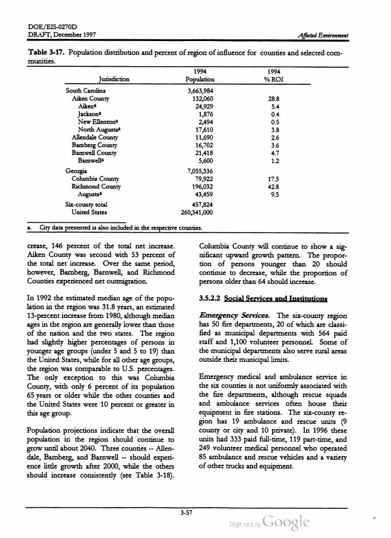
DOE /EIS -0270D
DRAFT,December 1997 Affected Environment
Table 3-17. Population distribution and percent of region ofinfluence for counties and selected com
munities.
1994
% ROIJurisdiction
South Carolina
Aiken County
Aikena
Jacksona
New Ellentona
North Augustaa
Allendale County
Bamberg County
Bamwell County
Bamwella
Georgia
Columbia County
Richmond County
Augustaa
Six -county total
United States
1994
Population
3,663,984
132,060
24,929
1,876
2,494
17,610
11,690
16,702
21,418
5,600
7,055,336
79,922
196,032
43,459
457,824
260,341,000
28.8
5.4
0.4
0.5
3.8
2.6
3.6
4.7
1.2
17.5
42.8
9.5
a .City data presented is also included in the respective counties.
crease, 146 percent of the total net increase .
Aiken County was second with 53 percent of
the total net increase. Over the same period,
however, Bamberg , Barnwell, and Richmond
Counties experienced netoutmigration.
Columbia County will continue to show a sig
nificant upward growth pattern . The propor
tion of persons younger than 20 should
continue to decrease, while the proportion of
persons older than 64 should increase.
3.5.2.2 Social Services and InstitutionsIn 1992 the estimated median age of the popu
lation in the region was 31.8 years, an estimated
13 -percentincrease from 1980, although median
ages in the region are generally lower than those
of the nation and the two states. The region
had slightly higher percentages of persons in
younger age groups (under 5 and 5 to 19) than
the United States,while for all other age groups,
the region was comparable to U.S. percentages.
The only exception to this was Columbia
County, with only 6 percent of its population
65 years or older while the other counties and
the United States were 10 percent or greater in
this age group
Emergency Services. The six -county region
has 50 fire departments, 20 of which are classi
fied as municipal departments with 564 paid
staff and 1,100 volunteer personnel. Some of
themunicipal departments also serve rural areas
outside their municipal limits.
Emergency medical and ambulance service in
the six counties is not uniformly associated with
the fire departments, although rescue squads
and ambulance services often house their
equipment in fire stations. The six -county re
gion has 19 ambulance and rescue units (9
county or city and 10 private). In 1996 these
units had 333 paid full-time, 119 part-time, and
249 volunteer medical personnel who operated
85 ambulance and rescue vehicles and a variety
of other trucks and equipment.
Population projections indicate that the overall
population in the region should continue to
grow until about 2040. Three counties -- Allen
dale, Bamberg, and Barnwell -- should experi
ence little growth after 2000, while the others
should increase consistently (see Table 3-18).
3-57

DOE / EIS -0270D
DRAFT, December 1997Affected Environment
2020
Population % ROI
Table 3-18 . Population projections and percentof region ofinfluence.a
2000 2010
Jurisdiction Population % ROI Population % ROI
South Carolina
Aiken County 133,760 26.8 145,798 26.3
Allendale County 12,965 2.6 14,131 2.6
Bamberg County 18,694 3.8 20,3763.7
Bamwell County 22,444 4.5 24,4644.4
156,587
15,177
21,884
26,274
26.2
2.5
3.7
4.4
Georgia
Columbia County
Richmond County
80,294
230,698
16.1
46.2
90,009
258,613
16.3
46.7
97,390
279,819
16.3
46.9
Six -county total 498,854 100 553,391 100 597,091 100
2030 2040
Jurisdiction Population % ROI Population % ROI
South Carolina
Aiken County
Allendale County
Bamberg County
Barnwell County
168,175
16,300
23,503
28,219
26.2
2.5
3.7
4.4
180,619
17,506
25,243
30,307
26.1
2.5
3.6
4.4
Georgia
Columbia County
Richmond County
105,376
300,526
16.4
46.8
114,017
325,169
16.5
46.9
Six -county total 642,099 100 692,861 100
a . Source: HNUS (1997).
County sheriff departments and municipal po
lice departments providemost law enforcement
services in the region . State law enforcement
agents and state troopers assigned to each
county provide additional protection. There are
26 county and municipal law enforcement de
partments in the region with 976 full-time offi
cers (1992 data ) and 788 detention facility beds.
The region has fewer officers than the South
Carolina and Georgia state averages, but it also
has a lower crime rate than the states as
whole.
mental health facilities provided a total capacity
of 342 beds. Current data on physicians and
nurses indicate the region has higher ratios than
either of the two states or the United States.
There are 3 physicians per 1,000 population
compared to 1.7 , 1.8 , and 2.4 for South Caro
lina, Georgia, and the United States, respec
tively .
3.5.2.3 Educational Services
а
Health Care. Eight hospitals that serve the
general public plus two military hospitals oper
ate in the six -county region. In 1993 these
hospitals had a combined bed capacity of 3,754.
There were 5.2 licensed beds per 1,000 popula
tion, higher than either ofthe two states and the
United States. The region had a combined
nursing home capacity of 2,208 beds, and three
In 1995 , there were 110 elementary and middle
schools, 24 high schools, and 16 post-secondary
institutions in the region . In addition, 46 pri
vate schools serve 5.5 percent of the student
population . The average number of elementary
and middle school students per teacher ranged
from a low of 14 in Allendale County to a high
of 18 in Aiken and Columbia Counties. High
school students per teacher ranged from a low
of 13 in Allendale County to a high of 21 in
3-58

DOE / EIS -0270D
DRAFT, December 1997 Affected Environment
of the SRS (see Figure 3-19). This represents
more than 169,000 persons or about 17 percent
of the total population (see Table 3-20) .
Aiken County. Recent data on school capacities
indicate that Aiken County and parts of Barn
well County are over the South Carolina state
average of 16.2; parts of the Columbia County
system are operating over capacity including all
middle schools, one elementary school, and
three high schools. Richmond County schools
are also generally over capacity; the county is in
a 4 -year construction program to build several
new schools: one high school, one middle
school, and four or five elementary schools.
3.5.3 PROJECTED ECONOMIC AND
POPULATION CONDITIONS
3.5.2.4 Environmental Justice
In 1995 DOE completed an analysis of the
economic and racial characteristics of the
population in areas affected by SRS operations
for the Environmental Impact Statement, Interim
Management of Nuclear Materials (DOE 1995d).
That EIS evaluated whether minority commu
nities or low income communities could receive
disproportionately high and adverse human
health and environmental impacts. Geographi
cally, it examined the population within a
50-mile (80-kilometer) radius plus areas down
stream of the Site that withdraw drinking water
from the Savannah River. The area encom
passes a total of 147 census tracts, resulting in a
total affected population of 993,667. Of that
population,618,000 (62 percent) are white. In
the minority population, approximately 94 per
cent are African American ; the remainder con
sists of small percentages of Asian , Hispanic,
and Native American persons (see Table 3-19) .
This section establishes the projected economic
and population baseline for the No action alter
native. The No action alternative assumes no
new missions at the Savannah River Site and a
leveling of the workforce at approximately
10,000 by 2001. To show the regional effects of
the changed workforce for the No action alter
native, a simulation using the Regional Eco
nomic Models, Inc. Economic -Demographic
Forecasting and Simulation 53-Sector Model
(REMIEDFS-53) was run (REMI 1996). The
regional model provides control and simulation
forecasts through 2035 for the eight-county re
gion under review . These counties are Aiken,
Allendale, Bamberg, Barnwell, and Edgefield in
South Carolina, and Burke, Columbia , and
Richmond in Georgia. REMI uses Bureau of
Economic Analysis regional employment, wage,
and personal incomedata, supplemented by Bu
reau of Labor Statistics (BLS) and County Busi
ness Pattern data to establish historical tables
which are the basis for the control forecasts .
Control economic projections are primarily
based on BLS moderate growth benchmark
projections. BLS labor force and Census Bu
reau projections are used to project labor force.
Occupational data are from BLS, and popula
tion data and projections are from the Census
Bureau.The analysis determined that, of the 147 census
tracts in the combined region , 80 contain
populations of 50 percent or more minorities.
An additional 50 tracts contain between 35 and
50 percent minorities. These tracts are well
distributed throughout the region, although
there are more of them toward the south and in
the immediate vicinities of Augusta and Savan
nah (see Figure 3-18 ).
Recently, Bridgestone-Firestone, Inc. an
nounced plans to construct and operate a
$435 million tire factory in Aiken County , em
ploying 800 when in full operation. However,
there has been no attempt in either this projec
tion or the Chapter 4 impacts analyses to factor
in this or other expected or potential changes in
regional employment except as described based
on the SRS scenarios. This will allow the APT
EIS to focus on a comparison of the APT alter
natives. Impacts of the Bridgestone factory will
be discussed in the cumulative impacts section.
Low income communities (25 percent or more
of the population as living in poverty (i.e., in
comeof $ 8,076 for a family oftwo)] occur in 72
census tracts distributed throughout the region
of interest, but primarily to the south and west
3-59

DOE /EIS -0270D
DRAFT, December 1997Affected Environment
Table 3-19. Generalracial characteristics of population in the Savannah River Site region of interest.
Total African Native Percent
Statepopulation White Minorities American Hispanic Asian American Other Minoritiesa
South Carolina 418,685 267,639 151,046 144,147 3,899 1,734 911 355 36.1 %
ROI
Georgia ROI 574,982 350.233 224,749 208,017 7,245 7.463 1,546 478 39.1 %
Total 993,667 617,872 375,795 352,164 11,144 9,197 2,457 833 37.8 %
a Minorities population divided by total population.
In the short term , total regional employment for
the No action alternative would be expected to
fall and in year 2 of the analysis regional em
ployment would be down by more than 2,600
from current levels . However, after the second
year of the analysis, regional employmentwould
again begin to increase, returning to current
levels in year 5. After that time, regional em
ploymentwould continue to grow at rates con
sistent with historic regional trends. Figure 3-20
shows the projected total regional employment
for the no action alternative.
alternative would decrease slightly from current
levels by approximately 0.54 percent, $70 mil
lion dollars (1996 dollars), in year 1 of the
analysis, although it would begin to grow again
in year 2. The annual growth rate for the 4
years immediately prior to the analysis period
was approximately 2.1 percent, although the
rate had slowed to less than 1.4 percent in the
last year. In the long run, the GRP would be
expected to stabilize at approximately 1.3 per
cent annual growth .
The annual rate of regional population growth
under the No action alternative for the first
4 years of the analysis would be approximately
60 percentof the rate of growth for the 4 years
prior to the period of analysis, slowing from 1.0
to 0.6 percent per year. After that period, the
rate of annual growth would be expected to re
turn to rates of approximately 0.8 percent for
the analysis period of 10 to 20 years. Fig
ure 3-21 shows the projected population for the
no action alternative.
For the analysis period years 1 through 4 , the
annual rate of growth for state and local gov
ernment expenditures will be approximately
1.4 percent, a decrease from approximately
2.4 percent from the prior four year period. In
the longer run, it is expected that the annual rate
of government expenditures will increase by ap
proximately 1.8 percent over the first 10 years
of the analysis before leveling at growth rates of
less than 1.5 percent after that.
Under the No Action alternative, the regional
economy and population will grow at a re
duced rate from recent years .Total regional personal income (annual) under
the No action alternative would continue to
grow , although at a slower pace during the early
years of the analysis than during the years im
mediately preceding the analysis period. During
years 1 to 4 of the analysis, total personal in
come would be expected to increase by ap
proximately $600 million dollars, an annual
increase of 1.4 percent, in contrast to the an
nualized increases of 2.7 percent for the 4 years
prior to the analysis period.
Figure 3-22 shows projected personal income,
GRP , and state and local government expendi
tures for the no action alternative over the
analysis period.
In summary, because the largest influence on
regional economies is the national economy
(assumed to be growing), it would be expected
that after a few years changes in the SRS work
force would be assimilated and the regional
economywill return to a steady growth stage.
Gross Regional Product (GRP, analogous to
Gross Domestic Product) under the No action
3-60

DOE /EIS -0270D
DRAFT, December 1997 Affected Environment
SOUTH
CAROLINA
NORTH
Augusta
Aiken
Savannah
River Site
BarnwellSavannah
River
GEORGIA
Legend:
County boundaries
Tractboundaries
Savannah RiverSavannah
Minorities constitute less
than 35 % of the population
Minorities constitute 35 %
to 49% of population
Minorities constitute
50 % or more ofpopulation
Source: U.S. Bureau of the Census (1990a).
PK68 -Z1-PC
Figure 3-18 . Distribution ofminority population by census tracts in the SRS region of analysis.
3-61

DOE /EIS -0270D
DRAFT,December 1997Affected Environment
SOUTH
CAROLINA
NORTH
Augusta
Aiken
BarnwellSavannah
River Site
Savannah
River
GEORGIA
Legend:
County boundaries Savannah
Tract boundaries
Savannah River
Persons living in poverty
constitute 25 % ormore of
the population
Source: U.S. Bureau of the Census (1990b).
PK68-Z1-PC
Figure 3-19 . Low income census tracts in the SRS region of analysis.
3-62

DOE /EIS-0270D
DRAFT,December 1997 Affected Environment
Table 3-20. General poverty characteristics ofpopulation in the Savannah River Site region of interest.
Area Total population Persons living in povertya Percent living in poverty
South Carolina 418,685 72,345 17.3 %
Georgia 574,982 96,672 16.8 %
Total 993,667 169,017 17.0 %
a .Familieswith incomeless than the statistical poverty threshold ,which in 1990 was 1989 income of $8,076 for a
family of two .
300
290
280
Employment
inThousands
270
260
250
0 3 6 9 12 15 18 21 24 27
30
33 36 39
Year of Analysis
Figure 3-20 . Projected Regional Employment.
3-63

DOE / EIS -0270D
DRAFT, December 1997Affected Environment
680
660
640
620
600
Population
inThousands
.: 580
560
540
520
500
0 3 6 9 12 15 18 21 24 27
30
33 36 39
Year of Analysis
Figure 3-21. Projected Regional Population.
25
20
15
Billions
of
96Dollars
10
5
1
-
0
O 3 6 9 12 15 18 21 24 27 30 33 36 39
Year of Analysis
Personal Income Gross Regional Product - State & Local Gov. Expenditures
Figure 3-22. Projected Regional Total Personal Income,Gross Regional Product, and State and Local
Government Expenditures.
3-64

DOE /EIS-0270D
DRAFT, December 1997 Affected Environment
References
Aadland, R., J. A.Gellici, and P. A. Thayer, 1995, Hydrologic Framework for West Central South Carolina,
Water Resources Division Report 5 , State of South Carolina, Department of Natural Resources,
Columbia, South Carolina.
Aho, J. M.and C. S. Anderson , 1985, Fish Populations in Pond C: Dynamics of the Fish Kills (a Preliminary
Report), SWED -85 /1209, Savannah River Ecology Laboratory , Aiken, South Carolina.
Aho,J. M., C. S. Anderson, and J. W. Terrell, 1986, Habitat suitability index models and instream flow suitability
curves: redbreast sunfish,U.S. Fish and Wildlife Service, Fort Collins, Colorado.
Arnett, M.W., 1996 , Savannah River Site Environmental Data for 1995, WSRC -TR - 96-0077, Westinghouse
Savannah River Company,Savannah River Site, Aiken , South Carolina.
Arnett,M.W., L.K.Karapatakis, and A.R. Mamatey, 1993, Savannah River Environmental Report for 1992,
WSRC-TR -93-075,Westinghouse Savannah River Company, Aiken , South Carolina.
Amnett,M.W., and A.R.Mamatey , 1996, Savannah River Site Environmental Report for 1995, WSRC-TR -96
0075,Westinghouse Savannah River Company, Savannah River Site, Aiken , South Carolina.
Batson, W. T., J. S. Angerman,and J. T. Jones, 1985, Flora of the Savannah River Plant. An Inventory of the
Vascular Plants on the Savannah River Plant, South Carolina, Savannah River Plant National
EnvironmentalResearch Park Program , Aiken , South Carolina.
Bennett, D. H.and R.W.McFarlane, 1983, The Fishes of the Savannah River Plant: National Environmental
Research Park , SRO -NERP-12, Savannah River Ecology Laboratory, Aiken, South Carolina.
Bollinger,G.A., 1973, Seismicity of the Southeastern United States, Bulletin of the Seismological Society of America ,
Volume63,No. 5 , pp. 1785-1808.
Brooks, F., 1994, “ Bald Eagle Nests on the Savannah River Site,” personal communication with
R. K. Abernethy (Halliburton NUS Corporation ), Aiken, South Carolina.
Brooks, M.J., G. T. Hanson, and R. D. Brooks, 1986, An Intensive Archaeological Survey and Testing of
Alternative, New Low -Level Radioactive and Hazardous/Mixed Waste Storage/ Disposal Facilities, Savannah
River Plant, Aiken and Barnwell Counties, South Carolina, manuscript on file with the Savannah River
Archaeological Research Program , South Carolina Institute of Archaeology and Anthropology ,
University ofSouth Carolina, Columbia , South Carolina.
Brooks, R. D., 1996 , “ Archeological and Cultural Resources Associated with Proposed APT Sites,”
personal communication with Y. F. Abernethy (Halliburton NUS Corporation), Savannah River
Archaeological Research Program , South Carolina Institute of Archaeology and Anthropology ,
University of South Carolina, Columbia, South Carolina.
Bryan , A. L., 1992 , “ Recent Work with Natural Resource Trusteeship concerning Wood Storks,”
personal communication with R. K. Abernethy (Halliburton NUS Corporation), Savannah River
Ecology Laboratory , Aiken, South Carolina.
3-65
DOE /EIS -0270D
DRAFT, December 1997Affected Environment
Bryan, A. L., T. M.Murphy, K. L. Bildstein , I. L. Brisbin ,and J. J.Mayer, 1996 , “Use of Reservoirs and
Other Artificial Impoundments by Bald Eagles in South Carolina,” in D.M. Bird (ed.), Raptors in
Human Landscapes, Academic Press, London, England, pp. 287-298 .
Bureau of Labor Statistics, 1995, Survey of Occupational Injuries and Illnesses, U.S. Department of Labor,
Washington,D.C.
CDC (Center for Disease Control and Prevention), 1993, Monthly Vital Statistics Report, Volume 1,No. 7 ,
Supplement, January 7, 1993, Advance Report of Final Mortality Statistics, 1990 , U.S. Public Health
Service,Department of Health and Human Services,Washington,D.C.
Chimney,M.J., W.R., Cody,and W ,M.Starkel, 1985, Final Report on the Water Quality, Phytoplankton, and
Zooplankton of Par Pond and Pond B : January 1984 - June 1985, Volumes I, II, III, DPST-85-789,
prepared by Environmental and Chemical Sciences, Inc., for Savannah River Laboratory,
E. I. du Pont de Nemours & Company, Savannah River Plant, Aiken, South Carolina.
Cooney, T. W., K. H. Jones, P. A. Drewes, J. W.Gissendanner, and B. W. Church , 1995, Water
Resources Data South Carolina Water Year 1995, USGS-WDR-SC -95-1, U.S.Geological Survey,
Water Resources Division , Columbia, South Carolina.
Cooney, T. W., 1996, Water Resources Data South Carolina Water Year 1996, USGS-WDR -SC - 96-1,
U.S.Geological Survey, Water Resources Division ,Columbia, South Carolina.
Cothran , E. G ,M.H.Smith , J. O.Wolff,and J. B.Gentry, 1991, Mammals of the Savannah River Site, SRO
NERP -21, Savannah River Ecology Laboratory, Aiken , South Carolina.
Dames & Moore, 1992 , Ichthyoplankton Entrainment Study at the SRS Savannah River Water Intakes, WSRC
TR -92-179,Westinghouse Savannah River Company, Savannah River Site, Aiken, South Carolina.
Davis,G.M.and M.Mulvey, 1993, Species Status ofMill Creek Elliptio, SRO -NERP-22, Savannah River
Site National Environmental Research Park , Savannah River Ecology Laboratory, Aiken , South
Carolina.
DOE (U.S. Department of Energy), 1984, Final Environmental Impact Statement, L -Reactor Operation ,
Savannah River Plant, Aiken, South Carolina, DOE /EIS -0180, Savannah River Operations Office,
Aiken , South Carolina.
DOE (U.S. Department of Energy), 1987, Final EnvironmentalImpact Statement, Waste Management Activities
for Groundwater Protection , Savannah River Plant, Aiken, South Carolina, DOE /EIS -0120, Savannah River
Operations Office, Aiken, South Carolina.
DOE (U.S. Department of Energy), 1990, Final Environmental Impact Statement, Continued Operation of K.,
L-, and P -Reactors, DOE/EIS-0147, Savannah River OperationsOffice, Aiken, South Carolina.
DOE (U.S. Department of Energy), 1993, Introduction to Natural Resources Management at the
Savannah River Site, Savannah River OperationsOffice, Aiken, South Carolina.
DOE (U.S. Department of Energy), 1995a, Environmental Assessment for the Natural Fluctuation of Water
Level in Par Pond and Reduced Water Flow in Steel Creek Below L -Lake at the Savannah River Site (DOE
EA-1070), U.S. Department of Energy ,Savannah River Operations Office, Savannah River Site.
3-66
DOE /EIS-0270D
DRAFT, December 1997 Affected Environment
DOE (U.S. Department of Energy), 1995b, Final Savannah River Site Waste Management Environmental
Impact Statement,DOE/EIS -0217,Savannah River Operations Office, Aiken, South Carolina.
DOE (U.S. Department of Energy), 1995c, Environmental Assessment for the Construction and Operation of the
Three Rivers Solid Waste Authority, RegionalWaste Management Center atthe Savannah River Site, DOE /EA
1079,Savannah River Operations Office, Aiken,South Carolina.
DOE (U.S. Department of Energy), 1995d, Environmental Impact Statement, Interim Management of Nuclear
Materials,DOE/ EIS -0220 , Savannah River Operations Office, Aiken , South Carolina.
DOE (U.S. Department of Energy), 1997, Final Environmental Impact Statement, Shutdown of the River Water
System at the Savannah River Site, DOE /EIS-0268D , Savannah River Operations Office, Aiken , South
Carolina.
du Pont (E.I. du Pont de Nemours and Company, Inc.), 1987, Comprehensive Cooling Water Study- Final
Report, Volumes I-VIII,DP-1739, Savannah River Plant, Aiken ,South Carolina.
du Pont(E. I. du Pont de Nemours and Company, Inc.), 1989, Radiation Exposure Report, Annual Report for
1988, DPSPU -89-11-1, Savannah River Plant, Aiken, South Carolina.
EPA (U.S.Environmental Protection Agency ), 1992, Industrial Source Complex (ISC) Dispersion Model User's
Guide, Second Edition (Revised ), Volume 1, II, National Technical Information Service, Springfield ,
Virginia .
Fridell, J., 1997, “ Status of Sandburrowing Mayfly,” personal communication with Y. F. Abernethy
(Halliburton NUS Corporation ), U.S. Fish and Wildlife Service , Asheville, North Carolina,
October 7 .
FWS (Fish and Wildlife Service), 1995, Smooth Coneflower Recovery Plan, Southeast Region (Region IV )
Atlanta,Georgia .
Gibbons, J. W. and K.K. Patterson , 1978, The Reptiles and Amphibians of the Savannah River Plant, SRO
NERP -2 , Savannah River Ecology Laboratory , Aiken, South Carolina.
Gibbons, J. W., and R. D. Semlitsch, 1991, Guide to the Reptiles and Amphibians of the Savannah River Site,
University ofGeorgia Press, Athens,Georgia.
Hiergesell, R., 1997, Interoffice memorandum to B. Shedrow , Westinghouse Savannah River Company,
Aiken, South Carolina, September 19 .
HNUS (Halliburton NUS Corporation), 1997, Socioeconomic Characteristics ofSelected Counties and Communities
Adjacent to the Savannah River Site, prepared for the U.S. Department of Energy , Savannah River
Operations Office, Aiken, South Carolina.
Hunter, C. H., 1990 , A Climatological Description of the Savannah River Site, WSRC -RP-89-313 ,
Westinghouse Savannah River Company, Savannah River Site, Aiken, South Carolina.
Hunter, C. H. and J. Stewart, 1994 , Air Quality Calculations for DWPF Supplemental Environmental Impact
Statement, SRT-ETS- 940891, Westinghouse Savannah River Company, Savannah River Site, Aiken,
South Carolina.
3-67
DOE /EIS -0270D
DRAFT,December 1997Affected Environment
Imm , D. W., 1997, Threatened, Endangered, and Sensitive Species Listing and Habitat Evaluation of the Proposed
APT Project, Savannah River Institute, New Ellenton, South Carolina.
Kennemore, D.E., 1997, “Site Investigation of Ponds 2 , 5, and C ,” Halliburton NUS Corporation,
Aiken, South Carolina, July.
Kirkman , L. K., R. F. Lide, G. Wein , and R. R. Sharitz , 1996 , Vegetation Changes and Land Use
Legacies of Depression Wetlands of the Western Coastal Plain of South Carolina, 1951-1992
Wetlands, Volume16,Number 4 , pages 564-576 .
Koch II, J. W., F. D. Martin , and G. P. Friday, 1996, Results of Submerged Sediment Core Sampling and
Analysis on Par Pond, Pond C, and L -Lake: July 1995 (U ), Draft WSRC-TR -96-0238, Westinghouse
Savannah River Company, Aiken, South Carolina.
LeMaster, E. T., 1994, “ Location of a Second Colony of Smooth Coneflower,” personal communication
with R.K. Abernethy (Halliburton NUS Corporation), Aiken , South Carolina.
LeMaster, E. T., 1996 , Biological Assessment- Shutdown of the RiverWater System at the Savannah River Site , U.S.
Department of Agriculture, Forest Service, Savannah River Forest Station, Aiken, South Carolina,
August.
LeMaster, E. T., 1997, “ Red -cockaded Woodpecker Survey,” personal communication with
Y. F. Abernethy (Halliburton NUS Corporation), Aiken, South Carolina.
Marcy , B. C., J. A. Bowers, J. B. Gladden, H.M.Hickey, M.P. Jones, E. A. Mackey, J. J. Mayer, and
A.C.Doswell, 1994, Remediation of a Large Contaminated Reactor Cooling Reservoir. Resolving an
Environmental/Regulatory Paradox . From proceedings of a National Association of Environmental
Professionals conference held June 12-15 , 1994 in New Orleans, Louisiana .
Mayer, J. J., R. A. Kennamer, and R. T. Hoppe, 1986, Bald and Golden Eagles of the SRP, SREL -21.
Savannah River Ecology Laboratory, Aiken, South Carolina.
Mclain , R., 1997, personal communication to P. F. Wise (Halliburton NUS Corporation), U.S.
Department of Energy, Savannah River Operations Office, Aiken , South Carolina.
Murphy, T. M., 1981, The Population Status of the American Alligator on the Savannah River Plant, South
Carolina, SRO -NERP -4 , Savannah River Ecology Laboratory , Aiken, South Carolina.
Myers, P., 1997, “ Prescribed Burning Program at SRS,” personal communication to Y. F. Abernethy
(Halliburton NUS Corporation), Savannah River Institute,New Ellenton, South Carolina.
NCRP (National Council on Radiation Protection and Measurements), 1987a, Ionizing Radiation
Exposure to the Population of the United States, ReportNo. 93,Washington, D.C.
NCRP (National Council on Radiation Protection and Measurements), 1987b, Exposure of the
Population in the United States and Canada from Natural Background Radiation, Report No. 94,
Washington ,D.C.
NCRP (National Council on Radiation Protection and Measurements), 1993, Limitation of Exposure to
Ionizing Radiation, Report Number 116 ,Washington,D.C.
3-68

DOE /EIS -0270D
DRAFT, December 1997 Affected Environment
Newman, M.C., and A.Messier, 1994,Mercury Bioaccumulation in Mosquitofish (Gambusia holbrooki) Sampled
On and Around the Savannah River Site, Savannah River Ecology Laboratory, Aiken , South Carolina.
NRC (U.S. Nuclear Regulatory Commission), 1996 , Dose Commitments Due to Radioactive Releases from
Nuclear Power Plant Sites in 1992,NUREG KR-2850, Volume 14,Washington, D.C.
NUS (NUS Corporation), 1991a, American Indian Religious Freedom Act Compliance atthe Savannah River Site,
Aiken , South Carolina.
NUS (NUS Corporation), 1991b , Air Quality, Cooling Tower, and Noise Impact Analyses in Support of the New
Production Reactor Environmental Impact Statement, Aiken, South Carolina.
Olson, R. L , 1993, Risk of Failure of the Par Pond Dam , Rev. 1 (U ), WSRC-RP -92-1355, Westinghouse
Savannah River Company, Savannah River Site, Aiken , South Carolina.
Paller, M.H., 1994, Stream Fisheries Characterization Study, WSRC -TR -94-0123, Westinghouse Savannah
River Company, Savannah River Site, Aiken, South Carolina.
Paller, M. H. and L. D.Wike, 1996 , Par Pond Fish, Water, and Sediment Chemistry, WSRC - TR -96-0208,
Revision 1,Westinghouse Savannah River Company, Savannah River Site, Aiken ,South Carolina.
Patrick , R., J. Cairns, Jr., and S. S. Roback , 1967, “ An ecosystematic study of the fauna and flora of the
Savannah River Plant,” Proceedings of the Academy of Natural Sciences of Philadelphia, Volume 118,
Number 5 , pp. 109-407.
Petty , K.R., 1993, “Health Protection Department 1992 Annual Report,” interofficememorandum to
Distribution, Westinghouse Savannah River Company, WSRC-ESH -HPD -9200-035 , Aiken , South
Carolina.
REMI, 1996 , Economic Demographic Forecasting and Simulation 53-Sector Model, Regional Economic Models,
Inc., Amherst,Massachusetts.
Saban, C. L., 1997, interoffice memorandum to W.Craig, “ SRS Occupational Injured Illness Trending
Data,” Halliburton NUS Corporation, Aiken , South Carolina, September 12.
Sassaman , K., 1997 ,memorandum to B. Shedrow (Westinghouse Savannah River Company), Savannah
River Archaeological Research Program , South Carolina Institute of Archaeology and Anthropology,
University ofSouth Carolina.
SCDHEC (South Carolina Department of Health and Environmental Control), 1976, Air Pollution
Control Regulations and Standards, South Carolina Code of Laws, Regulations 61-62, Columbia, South
Carolina.
SCDHEC (South Carolina Department of Health and Environmental Control), 1995 , South Carolina
Nuclear Facility Environmental Radiation Monitoring-1995 Annual Report, Division of Radiological
Environmental Monitoring, Bureau of Environmental Quality Control Labs, Columbia , South
Carolina
SCE & G (South Carolina Electric and Gas Company), 1995, Environmental Assessment for Cope Power Plant,
Volume 1, Columbia , South Carolina.
3-69
DOE /EIS -0270D
DRAFT, December 1997Affected Environment
Schalles, J. F., R. R. Sharitz, J. W.Gibbons, G. J. Leversee, and J. N.Knox, 1989, Carolina Bays of the
Savannah River Plant,SRO -NERP-18, Savannah River Ecology Laboratory, Aiken, South Carolina.
Shedrow , B.C., 1993,Savannah River Site Affected Environment,WSRC -TR -93-667, Westinghouse Savannah
River Company, Savannah River Site, Aiken , South Carolina.
Shedrow , B. C., 1997, Submittal of Technical Data for Preparation of APT EIS, ESH -EAP - 97-0082,
Westinghouse Savannah River Company, Aiken , South Carolina.
,
Sowers, G. B., and G. F. Sowers, 1961, Introductory Soil Mechanics and Foundations, Second Edition, The
Macmillan Company,New York ,New York .
SRFS (Savannah River Forest Station), 1997 , base maps for Timber Compartments 51 and 52, U.S.
Forest Service, New Ellenton , South Carolina.
Stephenson, D. E.,and A. L.Stieve, 1992, StructuralModel of the Basement in the Central Savannah Area, South
Carolina and Georgia, WSRC -TR -92-120 , Westinghouse Savannah River Company, Savannah River
Site, Aiken , South Carolina.
URS/Blume (URS/ Blume and Associates Engineers), 1982, Update of Seismic Criteria for the Savannah River
Plant, Volume 1: Geotechnical, DPE -3699, prepared for E. I. du Pont de Nemours and Company,
Inc., Aiken , South Carolina.
U.S. Bureau of the Census, 1990a, Summary Tape File 1B , Table P8,Washington,D.C.
U.S. Bureau of the Census, 1990b, Summary Tape File 1B, Table 117 ,Washington, D.C.
USDA (U. S. Department of Agriculture), 1988, Eagle Bay Management Plan, Savannah River Forest
Station ,New Ellenton , South Carolina.
USDA (United States Departmentof Agriculture), 1990 , Soil Survey of the Savannah River Plant Area, Parts
of Aiken , Barnwell, and Allendale Counties, South Carolina, Soil Conservation Service, Washington,D.C.
USGS (United States Geological Survey), 1987, Topographic Map of the Savannah River Plant, 10- foot
contour interval.
USGS (United States Geological Survey ), 1994, Preliminary Geologic Map of the Savannah River Site,
Aiken, Allendale , and Barnwell Counties, South Carolina, Columbia, South Carolina.
Whipple, S.A., L. H.Wellman, and B. J.Good, 1981, A Classification of Hardwood Old Swamp Forests of the
Savannah River Plant, South Carolina, SRO -NERP-6 , Savannah River Ecology Laboratory, Aiken ,
South Carolina.
White, C., 1997, “ South Carolina Electric and Gas's (SCE & G ) power generating at reserve capacity,”
personal communication with P. Wise (Halliburton NUS Corporation ), SCE & G , Columbia , South
Carolina, September 10 .
Wike, L. D , R.W. Shipley , A. L. Bryan , Jr., J. A. Bowers, C. L. Cunningham , S. R. del Carmen,
G.P. Friday, J. E. Irwin , J. J. Mayer, E. A.Nelson, M.H.Paller, V. A. Roger, W.L. Specht, and
E. Wilde, 1994, Savannah River Site Ecology Environmental Information Document, WSRC -RP-93-496 ,
Westinghouse Savannah River Company, Savannah River Site, Aiken,South Carolina.
3-70

DOE /EIS -0270D
DRAFT,December 1997 Affected Environment
Wilde, E. W., 1985, Compliance of the Savannah River Plant P-Reactor Cooling System with Environmental
Regulations, DP -1708, E. I. du Pont de Nemours and Company, Inc., Savannah River Plant, Aiken ,
South Carolina.
Wilde, E. W.and L. J. Tilly , 1985, Influence of P -Reactor Operation on the Aquatic Ecology of Par Pond: A
Literature Review , DP-1698, E. I. du Pont de Nemours and Company, Savannah River Laboratory,
Aiken , South Carolina.
Wilde, E. W., 1987, Comprehensive Cooling Water Study Final Report, Volume VII, Ecology of Par
Pond, Savannah River Plant, DP-1739-7 , E. I. DuPont de Nemars & Company, Savannah River
Laboratory, Aiken, South Carolina.
Workman , S.W.and K. W.McLeod, 1990 , Vegetation of the Savannah River Site, Major Community Types,
SRO -NERP-19, Savannah River Ecology Laboratory, Aiken, South Carolina.
WSRC (Westinghouse Savannah River Company), 1991a, Site Hydrologic/Geotechnical Characterization Report
for Site B New Municipal Solid Waste Landfill, Savannah River Site, Volume 1, WSRC-RP -91-392,
Savannah River Site, Aiken , South Carolina.
WSRC (Westinghouse Savannah River Company), 1991b, Radiation Protection and IndustrialHygiene Annual
Report, 1989, ESH -QIS -910027, Savannah River Site, Aiken, South Carolina.
WSRC (Westinghouse Savannah River Company), 1992, 1990 Health Protection Annual Report, ESH -HPD
920072, Savannah River Site, Aiken, South Carolina.
WSRC (Westinghouse Savannah Company), 1993, Radiological Control Procedure Manual, 52, Chapter 1,
Part 1 , Savannah River Site , Aiken, South Carolina.
WSRC (Westinghouse Savannah River Company), 1994, Savannah River Site Radiological Performance, 4th
Quarter 1993, ESH -PAS-94-0018, Savannah River Site, Aiken , South Carolina.
WSRC (Westinghouse Savannah River Company), 1995, Savannah River Site Radiological Performance, 4th
Quarter 1994, ESH -RCD -95-0016, Savannah River Site, Aiken, South Carolina.
WSRC (Westinghouse Savannah River Company), 1996a, Report on Use of Excess M1-Area Facilities,WSRC
SPM -TMD - 96-0132, Savannah River Site , Aiken , South Carolina.
WSRC (Westinghouse Savannah River Company), 1996b, Site Selection for the Accelerator for Production of
Tritium at the Savannah River Site,WSRC -TR - 96-0279, Savannah River Site, Aiken, South Carolina.
WSRC (Westinghouse Savannah River Company), 1996c, Savannah River Site RadiologicalPerformance,
4th Quarter 1995, ESH -RCO -96-0002 ,Savannah River Site, Aiken, South Carolina.
WSRC (Westinghouse Savannah River Company), 1997 , APT Site 2, Phase 1 Data Summary Report,
Revision 0 , Savannah River Site, Aiken , South Carolina.
3-71


Chapter 4
Environmental Impacts
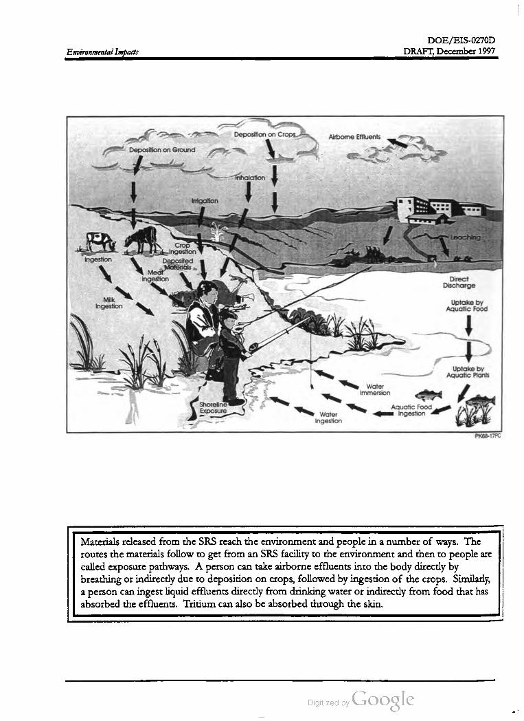
DOE /EIS -0270D
DRAFT,December 1997Environmental Impacts
Deposition on Crops Airbome Effluents
Deposition on Ground
سInhalation
Irrigation
Loaching
Ingestion
Crop
Ingestion
Deposited
Materials
Meat
Ingestion Direct
Discharge
Milk
IngestionUptake by
Aquatic Food
Uptake by
Aquatic Plants
Shoreline
Exposure
Water
Immersion
Aquatic Food
ingestionWater
Ingestion
PK68-17PC
Materials released from the SRS reach the environmentand people in a number ofways.The
routes thematerials follow to get from an SRS facility to the environment and then to people are
called exposure pathways. A person can take airborne effluents into the body directly by
breathing or indirectly due to deposition on crops, followed by ingestion of the crops. Similarly,
a person can ingest liquid effluents directly from drinking water or indirectly from food that has
absorbed the effluents. Tritium can also be absorbed through the skin .

DOE /EIS-0270D
DRAFT,December 1997 Environmental Impacts
CHAPTER 4. ENVIRONMENTAL IMPACTS
This chapter estimates the potential environmental impacts thatmight occur from the construction and
operation of the APT at the Savannah River Site . In general, analyses of potential impacts show that
the consequences of the proposed actions would be within established Federal and state guidelines.
The potential impacts of each technology alternative are compared to the Preferred APT alternative
(Superconducting Operations of Accelerator Structures , Helium - 3 Feedstock Material, Mechanical
Draft Cooling Towers with RiverWaterMakeup , construction on a site 3 miles northeast of the Tritium
loading facility, and electricity supplied from existing capacity andmarket transactions). Design varia
tions for the modular accelerator and the extraction facility for Lithium -6 feedstock materialwithin the
APT are still being developed. Current estimates indicate the potential environmental impacts asso
ciated with these design variations are bounded by the projected impacts for the APT. Themodular
design variation would require a larger site footprint. Some of the following sections in this chapter
have text boxes that summarize key differences between the impacts of the alternatives or simply in
formation the reader should note .
The U.S. Departmentof Energy (DOE) has es
timated the impacts of the alternatives described
in Chapter 2 above the baseline conditions de
scribed in Chapter 3; in other words, the im
pacts described in this chapter are in addition to
those that exist from other operations at the Sa
vannah River Site (SRS) . DOE determined
these impacts by analyzing the actions it would
complete under each alternative; assessing the
actions that could have impacts; identifying the
nature of the environmental impact; and quanti
fying ( if possible) themagnitude of the impact.
ronmental impact statement (EIS) also discusses
potential impacts of providing electricity for the
APT through market transactions or the con
struction of a new electric generating facility in
Sections 4.3 (as part of the evaluation of socio
economic impacts) and 4.4 .
In addition to the construction activities de
scribed in Chapter 2 , DOE could build two
temporary facilities-- concrete batch plants and
a construction debris landfill. DOE would ul
timately use water from existing sources of
process water on the SRS to make concrete .
The batch plants could be located near the
construction site to reduce the amount of con
struction- related traffic on roads. The con
struction and operation of the batch plants
could result in some land clearing and airborne
emissions. DOE would ensure that the batch
plants met stringent permit requirements so the
impact of operating these plants would not be a
substantial contributor to construction - related
impacts.
Most actions would occur at the preferred or
alternate Accelerator Production of Tritium
(APT) site on about 250 acres of land. Should
the Department decide to implement the
modular design option described in Section
2.5.1, additional land would be required. Prior
to expanding the footprint of either APT site ,
DOE would evaluate adjacent land for the pres
ence of threatened and endangered species , ar
chaeological sites, and other sensitive resources
such as wetlands. The primary environmental
impacts would occur at the APT site. Smaller
impacts could occur as the result of clearing and
construction activities in corridors totaling
about 30 acres on the SRS that would connect
to the Site infrastructure (e.g., existing roads,
pipelines, and outfalls). Prior to selection of
specific routes,DOE would evaluate the corri
dors for the presence of threatened and endan
gered species, archaeological sites, and other
sensitive resources, such as wetlands. This envi
DOE is currently investigating the need for a
landfill to receive debris from APT construction
activities. The landfill would require the clear
ing of land. The landfill would comply with
SCDHEC landfill requirements.
As in the case of utility corridors, prior to the
selection of sites for batch plants and a con
struction debris landfill, DOE would evaluate
the sites for the presence of threatened and en
4-1

DOE /EIS -0270D
Environmental Impacts DRAFT,December 1997
dangered species, archaeological sites, and other
sensitive resources such as Carolina bays and
wetlands.
The PMOA is the instrument for the manage
ment of cultural resources at the SRS; DOE
uses it to identify cultural resources, assess them
in terms of eligibility for the National Register
of Historic Places, and develop mitigation plans
for affected resources in consultation with the
State Historic Preservation Officer.
In addition to constructing and operating the
accelerator at the preferred or alternate site,
DOE could place support functions in M -Area.
Because these activities would involve existing
facilities in industrialized areas and the existing
SRS transportation infrastructure, DOE be
lieves there would be little or no impact on the
environment. DOE does not anticipate impacts
to ecological resources, surface water, or their
associated wetlands because activities would be
confined to developed areas. For APT- related
missions in H -Area , the proposed construction
and operation of the Tritium Extraction Facility
and the upgrade and consolidation of existing
Tritium facilities, the Department is preparing a
separate EIS and environmental assessment
(EA), respectively . However, this APT EIS in
cludes estimated emissions for the proposed
Tritium Extraction Facility for the Lithium -6
feedstock alternative.
This chapter presents construction and opera
tion impacts separately; this enables a clear dis
tinction between the one- time impacts
associated with construction activities and the
recurring impacts associated with routine op
erations. Where possible, the chapter presents
construction impacts as total impacts over the
period of construction; in some instances, how
ever, it provides construction impacts on an an
nual basis to indicate how construction effects
would vary by time.
Should the Department discover threatened,
endangered, or other sensitive resources on ei
ther potentially affected areas , avoidance or
other appropriate mitigation measures would be
taken . Likewise, the potential exists that exca
vation -related activities could result in the dis
covery of previously unknown and
undocumented hazardous, toxic, and / or radio
active material. In the event that any hazardous,
toxic, and / or radioactive material were discov
ered, DOE would remove and dispose of such
material in accordance with all applicable laws
and regulations.
This EIS presents operational impacts on an
annual basis. For some resource areas, DOE
has estimated quantitative impacts; for these ,
DOE presents the impacts of the Preferred al
ternative ( i.e., the collection of preferred design
elements described in Chapter 2) and then pres
ents the impacts for other alternatives as per
centage increases or decreases in relation to the
Preferred alternative. This approach enables a
comparison of impacts, and enables the deci
sionmaker to select any combination of alterna
tives and evaluate the impacts of combining the
relative percentage increases or decreases for
the selected alternatives. The potential impacts
associated with design alternatives ( e.g., ex
changing room temperature for superconduct
ing as one of the elements of the Preferred
alternative) do not change and are independent
of the impacts associated with the other ele
ments comprising the Preferred alternative.
IMPACTS OF THENO ACTION
ALTERNATIVE
DOE has not identified any significant cultural
resources (see Sections 3.3.5 and 7.1.2 ) that the
APT could affect. However, if DOE discov
ered such sites during the construction of the
accelerator, utility corridors, other infrastruc
ture, or on potential landfill and batch plant
sites, it would comply with the stipulations of
the Programmatic Memorandum of Agreement
(PMOA) between DOE , the South Carolina
State Historic Preservation Officer, and the
Advisory Council on Historic Preservation.
As discussed in Chapter 2 , theNo Action alter
native would result in the design, but not the
construction of the APT facilities. Therefore,
the No Action alternative would result in no in
cremental environmental impacts beyond the
current baseline for the SRS. Because DOE
4-2
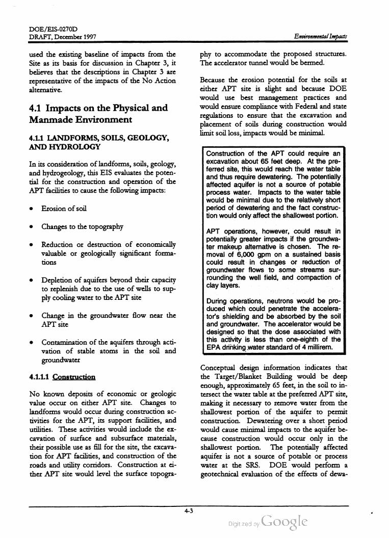
DOE / EIS -0270D
DRAFT, December 1997Environmental Impacts
phy to accommodate the proposed structures.
The accelerator tunnel would be bermed .
used the existing baseline of impacts from the
Site as its basis for discussion in Chapter 3, it
believes that the descriptions in Chapter 3 are
representative of the impacts of the No Action
alternative.
4.1 Impacts on the Physical and
Manmade Environment
Because the erosion potential for the soils at
either APT site is slight and because DOE
would use best management practices and
would ensure compliance with Federal and state
regulations to ensure that the excavation and
placement of soils during construction would
limit soil loss,impacts would be minimal.
4.1.1 LANDFORMS, SOILS,GEOLOGY,
AND HYDROLOGY
In its consideration of landforms, soils, geology,
and hydrogeology , this EIS evaluates the poten
tial for the construction and operation of the
APT facilities to cause the following impacts:
Construction of the APT could require an
excavation about 65 feet deep. At the pre
ferred site, this would reach the water table
and thus require dewatering . The potentially
affected aquifer is not a source of potable
process water . Impacts to the water table
would be minimal due to the relatively short
period of dewatering and the fact construc
tion would only affect the shallowest portion .
Erosion of soil
Changes to the topography
Reduction or destruction of economically
valuable or geologically significant forma
tions
APT operations, however, could result in
potentially greater impacts if the groundwa
ter makeup alternative is chosen . The re
moval of 6,000 gpm on a sustained basis
could result in changes or reduction of
groundwater flows to some streams sur
rounding the well field , and compaction of
clay layers .
Depletion of aquifers beyond their capacity
to replenish due to the use of wells to sup
ply cooling water to the APT site
Change in the groundwater flow near the
APT site
During operations, neutrons would be pro
duced which could penetrate the accelera
tor's shielding and be absorbed by the soil
and groundwater. The accelerator would be
designed so that the dose associated with
this activity is less than one-eighth of the
EPA drinking water standard of 4 millirem .
Contamination of the aquifers through acti
vation of stable atoms in the soil and
groundwater
4.1.1.1 Construction
No known deposits of economic or geologic
value occur on either APT site. Changes to
landforms would occur during construction ac
tivities for the APT, its support facilities, and
utilities. These activities would include the ex
cavation of surface and subsurface materials,
their possible use as fill for the site, the excava
tion for APT facilities, and construction of the
roads and utility corridors. Construction at ei
ther APT site would level the surface topogra
Conceptual design information indicates that
the Target /Blanket Building would be deep
enough , approximately 65 feet, in the soil to in
tersect the water table at the preferred APT site,
making it necessary to remove water from the
shallowest portion of the aquifer to permit
construction. Dewatering over a short period
would cause minimal impacts to the aquifer be
cause construction would occur only in the
shallowest portion. The potentially affected
aquifer is not a source of potable or process
water at the SRS. DOE would perform a
geotechnical evaluation of the effects of dewa
4-3
DOE /EIS -0270D
Environmental Impacts DRAFT,December 1997
tering on the compaction of the soils of the
water table aquifer before beginning such ac
tivities . At the alternate site the water table is
deeper and would require less dewatering than
the preferred site. Because DOE would use
existing potable water sources by extending
water lines to reach the selected APT site , there
would be no hydrogeologic impacts from this
activity .
1996 ). Based on two recent estimates, the pro
duction capacity of the aquifer ranges from 16
to 25 million gallons per day (WSRC 1996a). If
the APT groundwater makeup water require
ments (8.6 million gallons per day ) are added to
the current groundwater use (9 to 12 million
gallons per day), total groundwater withdrawals
could exceed the estimated production capacity
of the aquifer of 16 to 25 million gallons per
day . SRS groundwater usage is detailed in Sec
tion 3.3.6 .DOE does not anticipate using groundwater
near the APT site for construction activities
(process water, potable water, etc.) under any
alternative. Water for construction activities
would be brought in by tanker truck or be ob
tained from existing process water or ground
water sources. However, DOE could install
wells near the APT site to supply makeup water
for the operation of mechanical-draft cooling
towers discussed in the next section .
Because of the volume of water required ,DOE
would drill the wells into the McQueen Branch
Aquifer, a deep aquifer which is a source of
water for severalSRS facilities and could supply
the required volumes. The wide placement of
the wells pumping at this rate on a temporary
basis or on a periodic basis is likely to be mini
mal to the groundwater flow system . There is
less certainty as to the possible long-term im
pact of continuous pumping at this rate .4.1.1.2 Operations
DOE has identified two actions during opera
tions that could affect geologic resources:
Possible impacts to the groundwater flow sys
tem that might result from sustaining this ex
traction rate indefinitely might include the
following:Extraction of water from wells to supply
makeup water for the Mechanical-Draft
Cooling Towers with Groundwater Makeup
alternative
Sufficient decline in hydraulic heads in the
McQueen Branch Aquifer that horizontal
flow directions within the sub region sur
rounding the well field are significantly al
tered (Hiergesell 1997) .
Creation of radioactive material in the
groundwater due to neutron activation
As discussed in Chapter 2 , the Mechanical-Draft
Cooling Towers with Groundwater Makeup al
ternative would require about 6,000 gallons per
minute (or 8.6 million gallons per day) of water
from multiple wells near the APT site. DOE
estimates this would require the drilling of 18
wells, each capable of supplying 500 gallons per
minute; thus, 12 wells could supply the neces
sary 6,000 gallons per minute and 6 could serve
as backup water supply. Under this alternative,
a central well- field tank would collect water
from the wells and supply it to the cooling tow
ers. The APT groundwater makeup water re
quirements would approach the total current
site-wide groundwater withdrawal rate of 9 to
12 million gallons per day (Arnett and Mamatey
Propagation of the decline in hydraulic
heads in the overlying Crouch Branch and
Gordon Aquifers such that: (1) the vertical
upward flow direction from the former to
the latter is reversed in critical areas . Criti
cal areas are those locations where near
surface contaminant plumes exist; (2) a
gradual reduction in baseflow in some
streams surrounding the wellfield , and
(3) compaction of clay layers comprising the
McQueen Branch Confining Unit and the
Crouch Branch Confining Unit (Hiergesell
1997).
During accelerator operations, some neutrons
could penetrate the accelerator shielding and be
4-4
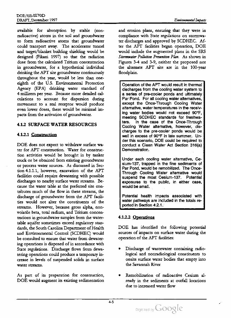
DOE / EIS-0270D
DRAFT,December 1997Environmental Impacts
available for absorption by stable (non
radioactive) atoms in the soil and groundwater
to form radioactive atoms that groundwater
could transport away. The accelerator tunnel
and target/ blanket building shielding would be
designed (Fikani 1997) so that the radiation
dose from the calculated Tritium concentration
in groundwater, for a hypothetical individual
drinking the APT site groundwater continuously
throughout the year,would be less than one
eighth of the U.S. Environmental Protection
Agency (EPA ) drinking water standard of
4 milirem per year. Because more detailed cal
culations to account for dispersion during
movement to a real receptor would produce
even lower doses, there would be minimal im
pacts from the activation of groundwater.
and erosion plans, ensuring that they were in
compliance with State regulations on stormwa
ter discharges and approved by SCDHEC. Af
ter the APT facilities began operation, DOE
would include the augmented plans in the SRS
Stormwater Pollution Prevention Plan. As shown in
Figures 3-4 and 3-9, neither the proposed nor
the alternate APT site are in the 100 -year
floodplain .
Operation of the APT would result in thermal
discharges from the cooling water system to
a series of pre-cooler ponds and ultimately
Par Pond. For all cooling water alternatives,
except the Once- Through Cooling Water
alternative,water temperatures in the receiv
ing water bodies would not exceed 90 ° F ,
meeting SCDHEC standards for freshwa
ters . In the case of the Once -Through
Cooling Water alternative, however, dis
charges to the pre -cooler ponds would be
well in excess of 90 ° F in late summer. Un
der this scenario , DOE could be required to
conduct a Clean Water Act Section 316 (a )
Demonstration .
4.1.2 SURFACE WATER RESOURCES
4.1.2.1 Construction
Under each cooling water alternative, Ce
sium - 137 , trapped in the fine sediments of
Par Pond, would be remobilized. The Once
Through Cooling Water alternative would
suspend the most Cesium - 137 . Potential
exposures to the public , in either case,
would be small.
DOE does not expect to withdraw surface wa
ter for APT construction . Water for construc
tion activities would be brought in by tanker
truck or be obtained from existing groundwater
or process water sources. As discussed in Sec
tion 4.1.1.1, however, excavation of the APT
facilities could require dewatering with possible
discharges to nearby surface water streams. Be
cause the water table at the preferred site con
tributes much of the flow in these streams, the
discharge of groundwater from the APT facili
ties would not alter the constituents of the
streams. However, because gross alpha, non
volatile beta , total radium , and Tritium concen
trations in groundwater samples from the water
table aquifer sometimes exceed regulatory stan
dards, the South Carolina Department ofHealth
and Environmental Control (SCDHEC) would
be consulted to ensure that water from dewater
ing operations is disposed of in accordance with
State regulations. Discharge flows from dewa
tering operations could produce a temporary in
crease in levels of suspended solids in surface
water streams.
Potential health impacts associated with
water pathways are included in the totals re
ported in Section 4.2.1.
4.1.2.2 Operations
DOE has identified the following potential
sources of impacts on surface water during the
operation of the APT facilities:
Discharge of wastewater containing radio
logical and nonradiological constituents to
onsite surface water bodies thatempty
into
the Savannah River
As part of its preparation for construction,
DOE would augment its existing sedimentation
Remobilization of radioactive Cesium al
ready in the sediments at outfall locations
due to increased water flow
4-5
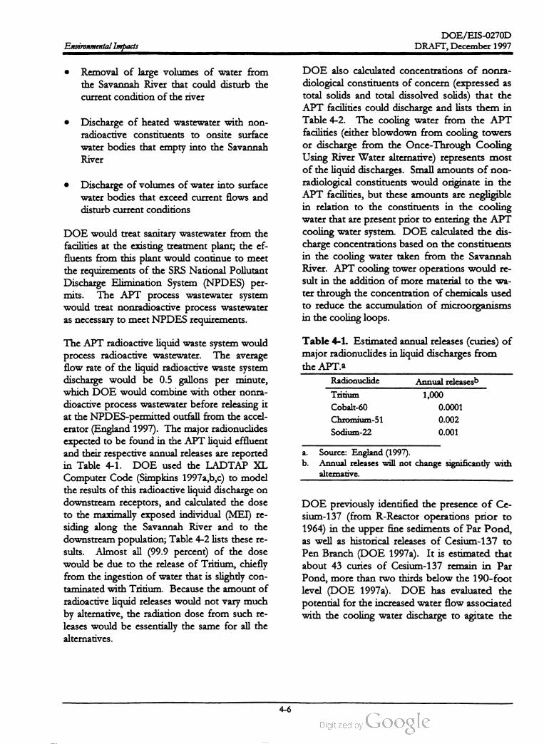
DOE /EIS -0270D
Environmental Impacts DRAFT, December 1997
Removal of large volumes of water from
the Savannah River that could disturb the
current condition of the river
• Discharge of heated wastewater with non
radioactive constituents to onsite surface
water bodies that empty into the Savannah
River
Discharge of volumes of water into surface
water bodies that exceed current flows and
disturb current conditions
DOE also calculated concentrations of nonra
diological constituents of concern (expressed as
total solids and total dissolved solids) that the
APT facilities could discharge and lists them in
Table 4-2 . The cooling water from the APT
facilities (either blowdown from cooling towers
or discharge from the Once-Through Cooling
Using River Water alternative) represents most
of the liquid discharges. Small amounts ofnon
radiological constituents would originate in the
APT facilities, but these amounts are negligible
in relation to the constituents in the cooling
water that are present prior to entering the APT
cooling water system . DOE calculated the dis
charge concentrations based on the constituents
in the cooling water taken from the Savannah
River. APT cooling tower operations would re
sult in the addition ofmore material to the wa
ter through the concentration of chemicals used
to reduce the accumulation ofmicroorganisms
in the cooling loops.
DOE would treat sanitary wastewater from the
facilities at the existing treatment plant; the ef
fluents from this plant would continue to meet
the requirements of the SRS National Pollutant
Discharge Elimination System (NPDES) per
mits.The APT process wastewater system
would treat nonradioactive process wastewater
as necessary to meet NPDES requirements.
The average
Table 4-1. Estimated annual releases (curies) of
major radionuclides in liquid discharges from
the APT.a
Radionuclide Annual releasesb
Tritium 1,000
Cobalt-60 0.0001
Chromium -51 0.002
Sodium -22 0.001
a .
b .
Source: England (1997).
Annual releases will not change significantly with
alterative.
The APT radioactive liquid waste system would
process radioactive wastewater.
flow rate of the liquid radioactive waste system
discharge would be 0.5 gallons per minute,
which DOE would combine with other nonra
dioactive process wastewater before releasing it
at theNPDES-permitted outfall from the accel
erator (England 1997). The major radionuclides
expected to be found in the APT liquid effluent
and their respective annual releases are reported
in Table 4-1. DOE used the LADTAP XL
Computer Code (Simpkins 1997a,b,c) to model
the results of this radioactive liquid discharge on
downstream receptors, and calculated the dose
to the maximally exposed individual (MEI) re
siding along the Savannah River and to the
downstream population; Table 4-2 lists these re
sults. Almost all (99.9 percent) of the dose
would be due to the release of Tritium , chiefly
from the ingestion ofwater that is slightly con
taminated with Tritium . Because the amount of
radioactive liquid releases would not vary much
by alternative, the radiation dose from such re
leases would be essentially the same for all the
alternatives.
DOE previously identified the presence of Ce
sium - 137 (from R -Reactor operations prior to
1964) in the upper fine sediments of Par Pond,
as well as historical releases of Cesium -137 to
Pen Branch (DOE 1997a). It is estimated that
about 43 curies of Cesium -137 remain in Par
Pond,more than two thirds below the 190 -foot
level (DOE 1997a). DOE has evaluated the
potential for the increased water flow associated
with the cooling water discharge to agitate the
4-6

DOE /EIS -0270D
DRAFT,December 1997
Table
4-2
.Average
annual
radiological
and
nonradiological
constituents
discharged
inliquid
effluents
for
the
preferred
configuration
,and
percent
differences
inalternatives
tothe
Preferred
alternative
.
Percentage
difference
of
results
for
alternatives Radio
Accelerator
Feedstock
frequency
Site
Cooling
water
system
technology
Material
power
location
K-Reactor
Once
Cooling
cooling
through
towers
with
tower
with
Lithium
-6Inductive
Factor
Results
for
cooling
using
groundwater
river
water
Room
aluminum
output
Alternate
preferred
alternative
river
water
makeup
makeup
temperature
alloy
tube
site
Annual
MEIa
dose
from
0.0050
millirem
NCb
NC
NC
NC
NC
NC
NC
radiological
discharges
Annual
MEI
dose
from
0.0013
millirem
+6,150
%dNC
-60
%NC
NC
NC
NC
resuspension
of
contaminated
sediments
Total
annual
MEI
dose
from
liquid
0.0063
millirem
+940
%C-9
%NC
NC
NC
NC
pathways
Annual
population
dose
from
0.14
person
-rem
NC
NC
NC
NC
NC
NC
NC
radiological
discharges
Annual
population
dose
from
0.0035
person
-r+6,150
%NC
-60
%NC
NC
NC
NC
resuspension
of
contaminated
sediments
Total
annual
population
dose
from
0.14
person
-ren
+ 104
%NC
NC
NC
NC
NC
NC
liquid
pathways
Average
annual
temperature
of 70
°F+18
°FNC
NC
NC
NC
NC
NC
liquid
discharges
Maximum
annual
temperature
of88
°F+14
°FNC
+1°FNC
NC
NC
NC
liquid
discharges
Average
annual
concentration
of
190
milligrams
per
-67
%-99
%NC
NC
NC
NC
NC
total
dissolved
solids
inliquid
liter
discharges
Average
annual
concentration
of
220
milligrams
per
-67
%-99
%NC
NC
NC
NC
NC
total
solids
inliquid
discharges
liter
MI
:I-maximally
exposcd
individual
.
b.NC
=Diffcrcncc
inresults
between
this
alternative
and
the
Prcfcrred
alternative
isless
than
5 percent
.
Results
for
this
alternative
arc
scvcral
orders
ofmagnitudo
less
than
that
for
the
Preferred
alternative
,cven
though
the
designation
“-99
%”indicates
only
two
orders
of
magnitude
diffcrcncc
.
d.0.081
millircm
. 0.066
millircm
.
f.0.22
person
-rcm
.
1-rem
a. C.
Environmental Impacts
C.
4_7

DOE / EIS-0270D
Environmental Impacts DRAFT, December 1997
contaminated sediments, resuspending them so
that they can be transported to the Savannah
River. DOE developed an upper bound esti
mate of the transportof this radioactive Cesium
based on previous DOE studies of Cesium re
mobilization from thermal discharges in site
streams (DOE 1987a). Using the discharge
rates corresponding to each alternative, DOE
calculated the amount of Cesium -137 likely to
be resuspended and estimated the correspond
ing dose to the MEI and the population down
stream of the SRS along the Savannah River.
The values reported in Table 4-2 for the dose
from this source are the estimates for the early
years of operation; subsequent years of opera
tion would result in lower doses as the Cesium
is gradually removed from the sediments.
the Savannah River are approximately equal for
all alternatives, being 0.1 percent of the river
flow at the water intake. The once-through
system , although resulting in an equivalent (to
the cooling tower systems) net removal of water
from the river, will result in approximately
2 percent of the river flow being removed at the
water intake (almost all of which is returned
further downstream ).
DOE has assessed possible impacts on the Sa
vannah River due to removal of large volumes
of water by comparing the net required volumes
of river water (representing the differences in
flow rate withdrawn from the river and the flow
rate discharged back to the river) for the cooling
water alternatives that use river water to the cur
rent flow rate of the river given in Section 3.3.2.
The net volumes of river water removed from
Discharges from the cooling water system can
affect the temperature, chemical makeup, and
flow rate of the surface water bodies that re
ceive them . These impacts would depend on
the cooling water system alternative (e.g., Me
chanical-Draft Cooling Tower with River Water
Makeup) but would not vary much with other
alternatives. Table 4-3 lists themonthly average
and maximum discharge temperatures for all
alternatives. The temperatures from the me
chanical towers and the K -Area Cooling Tower
would be essentially the same. Discharges from
the Once-Through Cooling Using River Water
alternative would be substantially warmer than
the receiving waters in the Par Pond system .
The discharge would flow first into Pond 2 , and
65 59
Table 4-3. Monthly discharge temperatures (° F ).
Mechanical-draft towersa K -Area Cooling Towerb
Month Average Maximumd Average Maximumd
January 58 54
February60 67 56 65
March 64 72 62 71
April68 76 67 77
May 82 73 83
June 78 86 78 87
July81 88 81 89
August
September 77 85 77 85
October 70 79 69 78
November 65 73 63 72
December 60 67 57 66
74
Once- through
Averagee Maximum
75 77
72 75
79 85
84 86
91 95
96 99
100 102
100 101
98 101
94 95
88 93
81 83
81 88 81 89
a .
C.
Calculated by the methods presented in DOE (1987a); applies regardless ofmakeup water source.
b . Calculated using vendor-supplied design curves.
Using long-term averagemeteorological data from Augusta ,Georgia (NWS 1994 ).
d . Using daily maximum temperature (NWS 1994).
Average monthly Savannah River (above SRS) temperature from Amett (1993, 1994 , 1995, 1996 , and 1997) plus
25 ° F .
f.Maximum monthly Savannah River (above SRS) temperature from Amett (1993 , 1994, 1995, 1996 , and 1997) plus
25 ° F .
e .
4-8
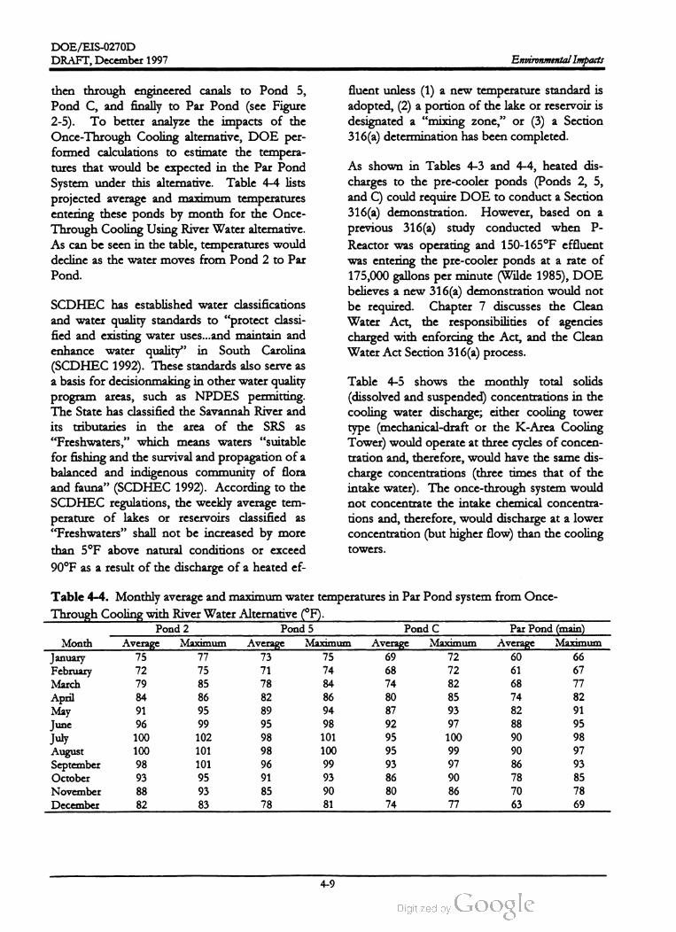
DOE /EIS -0270D
DRAFT, December 1997Environmental Impacts
fluent unless (1) a new temperature standard is
adopted, (2) a portion of the lake or reservoir is
designated a “mixing zone,” or (3) a Section
316 (a) determination has been completed.
then through engineered canals to Pond 5,
Pond C , and finally to Par Pond (see Figure
2-5). To better analyze the impacts of the
Once-Through Cooling alternative, DOE per
formed calculations to estimate the tempera
tures that would be expected in the Par Pond
System under this alternative. Table 4-4 lists
projected average and maximum temperatures
entering these ponds by month for the Once
Through Cooling Using River Water alternative.
As can be seen in the table, temperatures would
decline as the water moves from Pond 2 to Par
Pond.
As shown in Tables 4-3 and 4-4, heated dis
charges to the pre-cooler ponds (Ponds 2, 5,
and C ) could require DOE to conduct a Section
316(a) demonstration. However, based on a
previous 316(a) study conducted when P
Reactor was operating and 150-165 ° F effluent
was entering the pre-cooler ponds at a rate of
175,000 gallons per minute (Wilde 1985), DOE
believes a new 316 (a ) demonstration would not
be required. Chapter 7 discusses the Clean
Water Act, the responsibilities of agencies
charged with enforcing the Act, and the Clean
Water ActSection 316 (a ) process.
SCDHEC has established water classifications
and water quality standards to “protect classi
fied and existing water uses...and maintain and
enhance water quality ” in South Carolina
(SCDHEC 1992). These standards also serve as
a basis for decisionmaking in other water quality
program areas, such as NPDES permitting.
The State has classified the Savannah River and
its tributaries in the area of the SRS as
“ Freshwaters,” which means waters “ suitable
for fishing and the survival and propagation of a
balanced and indigenous community of flora
and fauna” (SCDHEC 1992). According to the
SCDHEC regulations, the weekly average tem
perature of lakes or reservoirs classified as
“ Freshwaters” shall not be increased by more
than 5 ° F above natural conditions or exceed
90 ° F as a result of the discharge of a heated ef
Table 4-5 shows the monthly total solids
(dissolved and suspended) concentrations in the
cooling water discharge; either cooling tower
type (mechanical-draft or the K -Area Cooling
Tower) would operate at three cycles ofconcen
tration and, therefore, would have the same dis
charge concentrations (three times that of the
intake water). The once-through system would
not concentrate the intake chemical concentra
tions and, therefore , would discharge at a lower
concentration (but higher flow ) than the cooling
towers.
75 77 73
Table 4-4. Monthly average and maximum water temperatures in Par Pond system from Once
Through Cooling with River Water Alternative (° F).
Pond 2 Pond 5 Pond C Par Pond (main )
Month Average Maximum Average Maximum Average Maximum Average Maximum
January75 69 72 60 66
February72 75 71 74 68 72 61 67
March 79 85 78 84 74 82 68 77
April 84 86 82 86 80 85 74 82
May91 95 89 94 87 93 82 91
June96 99 95 98 92 95
July100 102 98 101 95 100 90 98
August 100 101 98 100 95 99 90 97
September 98 101 96 99 93 97 86 93
October 93 95 91 93 86 90 78 85
November 8893 85 90 80 86 70 78
December 82 83 78 81 74 77 63 69
97 88
4-9

DOE /EIS -0270D
Environmental Impacts DRAFT, December 1997
Table 4-5. Monthly solids discharge concentrations (milligrams per liter).
Cooling towersaOnce through
Month Parameterb Average MaximumAverage
Maximumd
January TDS 161 177 54 59
TS 178 201 61 67
February TDS 185 255 62 85
TS 215 270 72 90
March TDS 178 204 59 68
TS 209 258 70 86
April TDS 180 213 60 71
TS 220 252 73 84
May TDS 204 273 68 91
TS 240 294 80 98
June TDS 235 258 78 86
TS 267 285 89 95
July TDS 208 249 69 83
TS 239 258 80 86
AugustTDS 205 252 68 84
TS 237 288 79 96
September TDS 180 195 60 65
TS 207 216 69 72
October TDS 185 201 62 67
TS 215 231 72 77
November TDS 200 225 67 75
TS 224 246 75 82
December TDS 157 177 52 59
TS 182 207 61 69
a .
b .
Three cycles of concentration , river water makeup . If groundwater is used as makeup, these concentrations would
be reduced by an order of magnitude. Includes mechanical-draft cooling towers and the K -Area Cooling Tower.
TDS = Total dissolved solids.
TS = Total solids (dissolved + suspended).
Average measured on Savannah River (above SRS) from Amett (1993, 1994, 1995 , 1996 , and 1997).
Maximum measured on Savannah River (above SRS) from Amett (1993, 1994, 1995, 1996, and 1997).
C.
d .
The blowdown flow from the cooling tower
discharges would be about 2,000 gallons per
minute (4.5 cubic feet per second) for both the
K -Area Cooling Tower and the Mechanical
Draft Cooling alternatives. For the K -Area
Cooling Tower alternative, the blowdown
would flow to Pen Branch via Indian Grave
Branch . The natural flow in Indian Grave
Branch is about 10 cubic feet per second;when
K -Reactor was operating, the flow was 400 cu
bic feet per second. The mean flow of Pen
Branch downstream of its confluence with In
dian Grave Branch was 56 cubic feet persecond
during water year 1995, about 10 times the pro
jected blowdown flow (Shedrow 1997a ).
Cooling water from themechanical-draft towers
would be discharged to Pond 2 and subse
quently flow to Ponds 5 , C , and Par by man
made conveyances. Since river water inputs
stopped in early 1996, rainwater and groundwa
ter seepage have been the only inputs to Ponds
2 and 5 (Pinder 1997; Cooney 1996). The flow
summary for the P -Area canal discharging to
Pond 2 (the only monitoring station associated
with Ponds 2 and 5 ), for March 1996 through
September 1996 indicated a mean discharge of
0.14 cubic feet per second and a seasonal
maximum temperature of 81° F (Cooney 1996 ).
Flows from themechanical-draft cooling towers
would increase the mean flow into the receiving
-
4-10

DOE /EIS -0270D
DRAFT,December 1997 Environmental Impacts
pond 32 fold . The 125,000 gallons perminute
discharge associated with the Once- Through
Cooling with River Water alternative represents
a 280- fold increase in flow to the system .
istics of the facilities would be the same. Simi
larly, the emissions sources listed by alternative
in Table 4-6 would apply to the alternate site.
Differences in impacts are attributable to the
distance to the site boundary; impacts would be
slightly greater for the alternate site since it is
situated closer to the SRS boundary .
Discharges resulting from the Mechanical-Draft
Cooling Tower alternative or the Once
Through Cooling alternative would eventually
flow from Par Pond to Lower Three Runs. If
the entire blowdown flow from theMechanical
Draft Cooling Tower alternative was transmit
ted to Lower Three Runs, the incremental flow
in the creek downstream of Par Pond would
represent an increase of less than 10 percent,
based on themean flow in water year 1995 (60
cubic feet per second) (Cooney et al. 1995 ).
The once-through discharge to Par Pond would
represent an almost five- fold increase in creek
flow for the same water year; when P -Reactor
was operating (its operation ended in 1988), the
discharge flow to the Par Pond-Lower Three
Runs system was about 346 cubic feet per sec
ond (Wike et al. 1994).
Air emissions for both radiological and non
radiological pollutants would be well below
applicable regulatory standards for both the
construction and operational phases of the
APT. Offsite concentrations would be
slightly higher at the alternate site because it
is closer to the SRS boundary . If DOE
chooses the modular design variation , con
struction impacts could be spread over a
longer period and eventually require the
clearing of more land. Tritium would con
tribute over 99 percent of the offsite dose,
but is still well below the 10 millirem dose
limit for SRS atmospheric releases.
Potential health impacts associated with air
pathways are included in the totals reported
in Section 4.2.1.
4.1.3 AIR RESOURCES
4.1.3.1 ConstructionDOE has determined that air impacts would
arise from two major types of activities: con
struction and operation of the APT facility .
Construction activities would include those ac
tions necessary to prepare land and erect neces
sary facilities for the alternatives evaluated in
this EIS . Routine operations would include
normal use of these facilities . This section
evaluates air emissions from both construction
and routine operations.
DOE based the amounts of air releases on es
timates of the projected actions and the operat
ing characteristics of the facilities. Table 4-6
lists by alternative the expected emission
sources thatDOE identified in its assessment of
air quality impacts. The table lists emission
sources next to the corresponding alternative
and includes the sources that would be present
regardless of the alternative.
DOE estimates it would clear about 250 acres
of land to construct facilities at the APT site in
the Preferred alternative. Construction would
take approximately 8 years (10 months of site
preparation and 7 years of construction) and
would involve the use of heavy equipment such
as graders, cranes, and scrapers to clear the land,
construct buildings, and develop the infrastruc
ture to support the facilities (e.g., pave roads
and install storm drain systems). Particulates in
the air, caused by construction activities, settle
quickly and pose minimal adverse health effects.
At present, the National Ambient Air Quality
Standards for total suspended particulates ( TSP)
are regulated as particulatematter with a diame
ter of 10 micrometers or less. DOE expects no
change in air quality impacts due to construc
tion for the various cooling water system alter
natives; the K -Area cooling tower and the River
Water System are already in place, while me
chanical-draft cooling towers would be prefab
ricated units requiringminimal site disturbance.
Air releases for the preferred APT site would be
the same as those for the alternate site because
construction activities and operating character
4-11

DOE /EIS -0270D
Environmental Impacts DRAFT,December 1997
Sourcea of air emissions
Table 4-6 . Sources of air emissions for the APT project.
Alternative
Cooling Water Alteratives
Mechanical-Draft Cooling Towers with River Water Makeup.
Mechanical-Draft Cooling Towers with Ground WaterMakeup
Construction of cooling towers
Drift from cooling towers
Construction of cooling towers
Drift from cooling towers
None
Drift from cooling tower
Once- Through Cooling Using RiverWater
K -Area Cooling Tower (Natural Draft)
Operating Temperature Alternatives
Room Temperature Operation
Superconducting Operation
None
Construction of Cryogenics Facility
Operation of Cryogenics Facility
Feedstock Material Altematives
Helium - 3 Feedstock Material
0
Construction of Tritium Separation Facility
Operation of Tritium Separation Facility
NonebLithium - 6 Feedstock Material
Electrical Power Alternativesc
Power from Existing Sources
Construction of a new ElectricalPower Station
Operation of existing power plant
Construction of new power plant
Operation of new power plant
Base sources (independentof alterative) Construction activities at APT sited
Construction activities in M -Area
Operations in M -Area
Releases from accelerator tunnel
Releases from target / blanket building
Releases from klystron gallery
Releases from beamstop building
Emergency diesel generators
0
a .This table lists only themost notable sources and is not intended to describe each possible emission source from the
APT Project.
b . Under this alterative the proposed Tritium Extraction Facility would recover Tritium from the Lithium / aluminum
rods. The construction and operation of that facility is the subjectof a separate EIS ,which will discuss impacts
arising from recovering Tritium from Lithium / aluminum rods. TEF information that pertains to cumulative im
pacts also discussed in Chapter 5 of this EIS.
Electric power impacts are discussed in Section 4.4 .
d . Construction in this instance would apply only to facilities not associated with a specific altemative.
C.
In accordance with good dust control practices
requiredby South Carolina regulations
(SCDHEC R.62.6 ), measures will be imple
mented to control fugitive particulate matter.
Bestmanagement practices would be used dur
ing construction, grading of roads, or clearing of
land to minimize airborne dust. During times
when grading activities were not occurring,
DOE would ensure the stabilization of bare
land by using compaction, vegetation , or spray
on adhesives to reduce the probability for air
dispersion. Wet or chemical dust suppressants
would reduce fugitive dust emissions by ap
proximately 50 percent (EPA 1985).
4-12
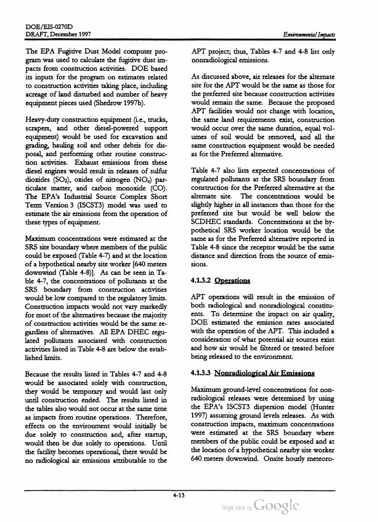
DOE /EIS -0270D
DRAFT, December 1997 Environmental Impacts
APT project; thus, Tables 4-7 and 4-8 list only
nonradiological emissions.
The EPA Fugitive DustModel computer pro
gram was used to calculate the fugitive dust im
pacts from construction activities. DOE based
its inputs for the program on estimates related
to construction activities taking place, including
acreage of land disturbed and number of heavy
equipment pieces used (Shedrow 1997b).
As discussed above, air releases for the alternate
site for the APT would be the same as those for
the preferred site because construction activities
would remain the same. Because the proposed
APT facilities would not change with location,
the same land requirements exist, construction
would occur over the same duration, equal vol
umes of soil would be removed, and all the
same construction equipment would be needed
as for the Preferred alternative.
Heavy-duty construction equipment (i.e. , trucks,
scrapers, and other diesel -powered support
equipment) would be used for excavation and
grading, hauling soil and other debris for dis
posal, and performing other routine construc
tion activities. Exhaust emissions from these
diesel engines would result in releases of sulfur
dioxides (SO2), oxides of nitrogen (NOx) par
ticulate matter, and carbon monoxide (CO ).
The EPA's Industrial Source Complex Short
Term Version 3 (ISCST3) model was used to
estimate the air emissions from the operation of
these types of equipment.
Table 4-7 also lists expected concentrations of
regulated pollutants at the SRS boundary from
construction for the Preferred alternative at the
alternate site . The concentrations would be
slightly higher in all instances than those for the
preferred site but would be well below the
SCDHEC standards. Concentrations at the hy
pothetical SRS worker location would be the
sameas for the Preferred alternative reported in
Table 4-8 since the receptor would be the same
distance and direction from the source of emis
sions.
4.1.3.2 Operations
Maximum concentrations were estimated at the
SRS site boundary where members of the public
could be exposed (Table 4-7) and at the location
of a hypothetical nearby site worker [640 meters
downwind (Table 4-8)]. As can be seen in Ta
ble 4-7, the concentrations of pollutants at the
SRS boundary from construction activities
would be low compared to the regulatory limits.
Construction impacts would not vary markedly
formost of the alternatives because the majority
of construction activities would be the same re
gardless of alternatives. All EPA DHEC regu
lated pollutants associated with construction
activities listed in Table 4-8 are below the estab
lished limits .
APT operations will result in the emission of
both radiological and nonradiological constitu
ents. To determine the impact on air quality ,
DOE estimated the emission rates associated
with the operation of the APT. This included a
consideration of what potential air sources exist
and how air would be filtered or treated before
being released to the environment.
4.1.3.3 NonradiologicalAir EmissionsBecause the results listed in Tables 4-7 and 4-8
would be associated solely with construction ,
they would be temporary and would last only
until construction ended . The results listed in
the tables also would not occur at the same time
as impacts from routine operations. Therefore,
effects on the environment would initially be
due solely to construction and, after startup ,
would then be due solely to operations. Until
the facility becomes operational, there would be
no radiological air emissions attributable to the
Maximum ground-level concentrations for non
radiological releases were determined by using
the EPA's ISCST3 dispersion model (Hunter
1997) assuming ground levels releases. As with
construction impacts, maximum concentrations
were estimated at the SRS boundary where
members of the public could be exposed and at
the location of a hypothetical nearby site worker
640 meters downwind. Onsite hourly meteoro
4-13
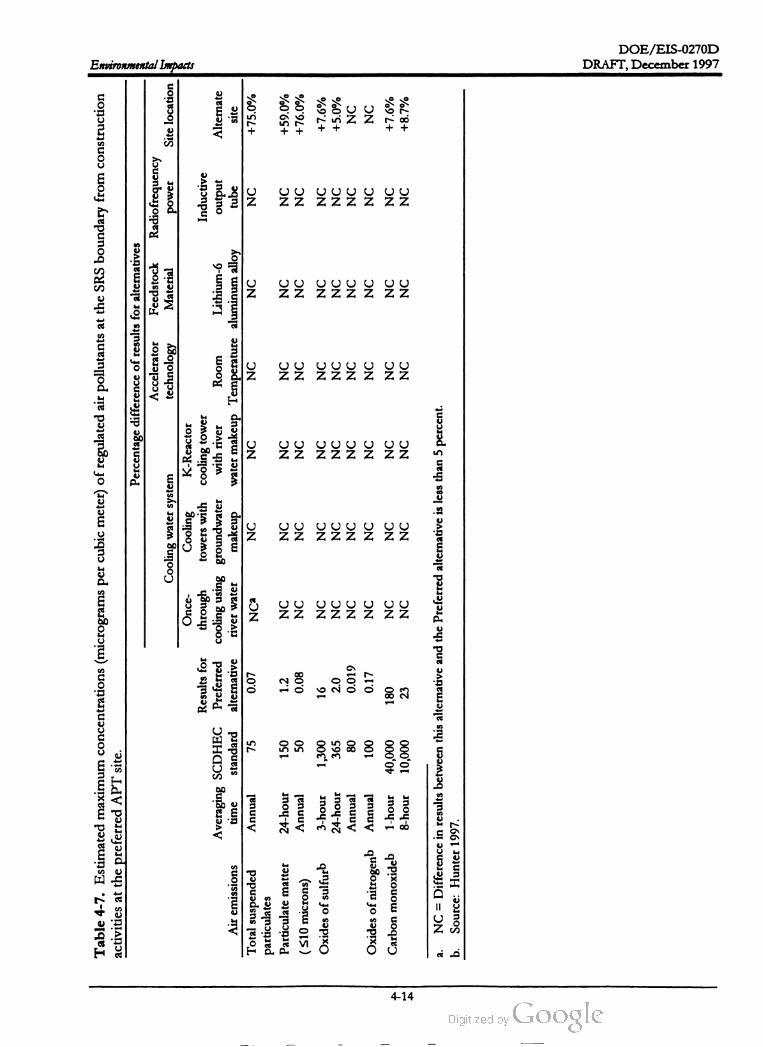
DOE /EIS -0270D
Environmental Impacts
Table
4-7
.Estimated
maximum
concentrations
(micrograms
per
cubic
meter
)of
regulated
air
pollutants
at
the
SRS
boundary
from
construction
activities
atthe
preferred
APT
site
.
Percentage
difference
of
results
for
alternatives
Accelerator
Feedstock
Radiofrequency
Cooling
water
system
technology
Material
power
Site
location
Once
Cooling
K-Reactor
Results
for
through
towers
with
cooling
tower
Inductive
Averaging
SCDHEC
Preferred
cooling
using
groundwater
with
river
Room
Lithium
-6output
Alternate
Air
emissions
time
standard
alternative
river
water
makeup
water
makeup
Temperature
aluminum
alloy
tube
site
Total
suspended
Annual
75
0.07
Nca
NC
NC
NC
NC
NC
+75.0
%
particulates
Particulate
matter
24
-hour
150
1.2
NC
NC
NC
NC
NC
NC
+59.0
%
Annual
50
0.08
NC
NC
NC
NC
NC
NC
+76.0
%( 10microns
)
Oxides
of
sulfurb
3-hour
1,300
16
NC
NC
NC
NC
NC
NC
+7.6
%
24
-hour
365
2.0
NC
NC
NC
NC
NC
NC
+5.0
%
Annual
80
0.019
NC
NC
NC
NC
NC
NC
NC
Oxides
of
nitrogenb
Annual
100
0.17
NC
NC
NC
NC
NC
NC
NC
Carbon
monoxideb
1-hour
40,000
180
NC
NC
NC
NC
NC
NC
+7.6
%
8-hour
10,000
23
NC
NC
NC
NC
NC
NC
+8.7
%
a.NC
Difference
inresults
between
this
alternative
and
the
Preferred
alternative
isless
than
5percent
.
Source
:Hunter
1997
.b.
DRAFT, December 1997
4-14
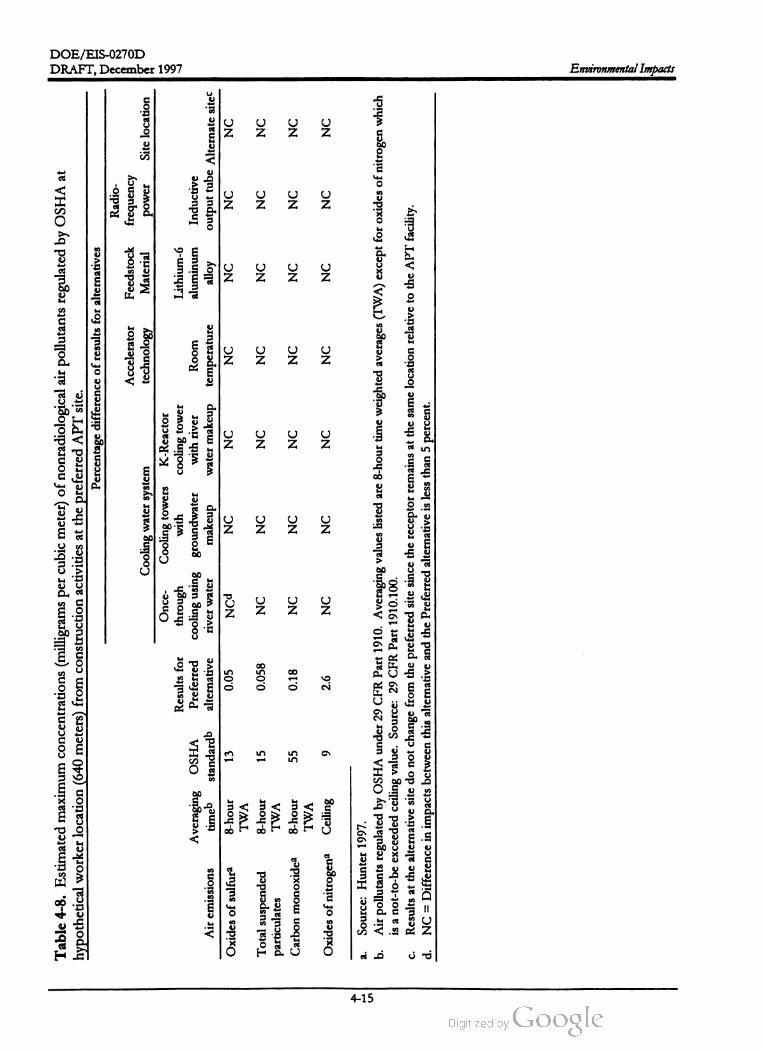
DOE /EIS-0270D
DRAFT,December 1997
Table
4-8
.Estimated
maximum
concentrations
(milligrams
per
cubic
meter
)of
nonradiological
air
pollutants
regulated
byOSHA
at
hypothetical
worker
location
(640
meters
)from
construction
activities
atthe
preferred
APT
site
.
Percentage
difference
of
results
for
alternatives
Radio
Accelerator
Feedstock
frequency
Cooling
water
system
technology
Material
power
Site
location
Once
Cooling
towers
K -Reactor
Results
for
through
with
cooling
tower
Lithium
-6
Averaging
OSHA
Preferred
cooling
using
groundwater
with
river
Room
aluminum
Inductive
Air
emissions
timeb
standardb
alternative
river
water
makeup
water
makeup
temperature
alloy
output
tube
Alternate
sitec
Oxides
of
sulfura
8 -hour
13
0.05
NCd
NC
NC
NC
NC
NC
NC
TWA
Total
suspended
8 -hour
15
0.058
NC
NC
NC
NC
NC
NC
NC
particulates
TWA
Carbon
monoxidea
8 -hour
55
0.18
NC
NC
NC
NC
NC
NC
NC
TWA
Oxides
of
nitrogena
Ceiling
92.6
NC
NC
NC
NC
NC
NC
NC
a. b.
Source
:Hunter
1997
.
Air
pollutants
regulated
byOSHA
under
29CFR
Part
1910.
Averaging
values
listed
are
8-hour
time
weighted
averages
(TWA
)except
for
oxides
of
nitrogen
which
isanot
-to-beexceeded
ceiling
value
.Source
:29CFR
Part
1910.100
.
Results
atthe
alternative
site
donot
change
from
the
preferred
site
since
the
receptor
remains
atthe
same
location
relative
tothe
APT
facility
.
NC
=Difference
inimpacts
between
this
alternative
and
the
Preferred
alternative
isless
than
5percent
C.
d .
Environmental Impacts
4-15

DOE /EIS -0270D
Environmental Impacts DRAFT,December 1997
from the threelogical data were used for the criteria pollutants
and air toxics dispersion calculations.
marily from emissions
emergency generators.
Changes in themaximum ground-level concen
trations at the SRS boundary would occur only
for the Lithium -6 Feedstock Material alterna
tive. Concentrations would decrease slightly
because this alternative would not require the
use of the proposed Tritium Separation Facility;
however, additional emissions would occur un
der this alternative from the use of the Tritium
Extraction Facility. As with the Preferred alter
native,most of the emissions would be attribut
able to the diesel generators.
For the Preferred alternative, nonradiological
emissions are expected from the accelerator
building, the Target /Blanket Building, the Trit
ium Separation Facility, and the balance of the
plant, including three emergency generators.
Nonradiological emissions (tons/year) for rou
tine operations are listed in Table 4-9. The APT
facility collectively is expected to emit 24 hours
a day , 365 days a year. The three emergency
generators are projected to operate less than
250 hours per year each . Expected emission
rates from operations are compared to the
emission rates listed in SCDHEC Standard 7 ,
Prevention of Significant Deterioration (PSD ),
to determine if the facility emissions would be
considered a significant net emissions increase.
Facilities located in attainment areas that have
any new or modified sources which exceed the
PSD “ significant increase amount are required
to obtain a PSD permit prior to construction .
However, as can be seen in Table 4-9 , all of the
expected emissions from the APT facility are
well below the PSD significant emission rates.
Table 4-11 lists air quality impacts to a hypo
thetical worker in the vicinity of the APT facili
ties. For all the regulated pollutants emitted,
exposures to this nearby worker would be be
low the permissible exposure levels defined in
29 CFR Part 1910.100 .
The maximum air concentrations at the SRS
boundary associated with the Preferred alterna
tive are listed in Table 4-10 . As the results indi
cate , all emissions are less than 1 percent of the
applicable standards. Most of the pollutants,
with the exception of ethyl alcohol and particu
late matter (TSP and PM10), would result pri
For the alternate site , Table 4-10 lists themaxi
mum air concentrations at the SRS boundary in
the last column and all the resulting emissions
would be well below the SCDHEC limits. As
the results indicate , all emissions are less than 1
percent of the applicable standards. Most of
the nonradiological emissions at the alternate
site also are attributable to the three diesel gen
erators . As with the construction activities ,
concentrations from routine emissions to the
hypothetical SRS worker located 640 meters
Table 4-9. Nonradiological air emissions (tons peryear) for APT routine operations.a
PSD Significant Net
Air emissions Diesel units APT Emissions Increase
Sulfur oxides 0.16N / Ab
100
Total suspended particulates 0.24 0.30 25
Particulate matter (< 10 um )0.16 0.15 15
Carbon monoxide 2.5 0.76 100
Ozone (as total VOC) 0.33 0.023 40
Oxidesof nitrogen 9.8 1.2 40
Lead0.0002 N / A 0.6
Beryllium 3.6x10⁻⁵ N / A 0.0004
4.4x10⁻⁵N / A 0.1
Ethyl alcohol N / A 0.02 NA
a . Source: Hunter 1997 .
b . N / A = No emissions of the regulated pollutant.
Mercury
4-16

DOE /EIS-0270D
DRAFT,December 1997
source
Table
4-10
.Estimated
maximum
concentrations
of
regulated
nonradiological
air
emissions
atSRS
boundary
from
APT
operations
at
the
preferred
APT
site
(micrograms
per
cubic
meter
).
Percentage
difference
of
results
for
alternatives
Radio
Accelerator
Feedstock
frequency
Cooling
water
system
technology
Material
Site
location
Cooling
towers
K-Reactor
Results
for
Once
-through
with
cooling
tower
Preferred
cooling
using
groundwater
with
river
water
Room
Lithium
-6 Inductive
Air
emissions
Averaging
time
alternative
river
water
makeup
makeup
temperature
aluminum
alloy
output
tube
Alternate
site
Oxides
of
sulfur
3-hour
0.13
Nca
NC
NC
NC
NC
NC
+7.7
%
24
-hour
0.016
NC
NC
NC
NC
NC
NC
+13
%
Annual
0.00014
NC
NC
NC
NC
NC
NC
+ 14
%
Total
suspended
Annual
0.00057
NC
NC
NC
NC
-32
%NC
+40
%
particulates
Particulate
matter
24
-hour
0.016
NC
NC
NC
NC
-20
%NC
+19
%
(10microns
)Annual
0.0003
NC
NC
NC
NC
-30
%NC
+40
%
Carbon
monoxide
1 -hour
6.1
NC
NC
NC
NC
NC
NC
+15
%
8-hour
0.76
NC
NC
NC
NC
-5
%NC
+16
%
Ozone
(as
total
VOC
)b1-hour
0.75
NC
NC
NC
NC
NC
NC
+15
%
Oxides
of
nitrogen
Annual
0.0091
NC
NC
NC
NC
NC
NC
+21
%
Lead
Max
.Quarter
2.4
x10-7
NC
NC
NC
NC
NC
NC
+8.3
%
Beryllium
24
-hour
3.5
x10-6
NC
NC
NC
NC
NC
NC
+17
%
Mercury
24
-hour
4.4
x10-6
NC
NC
NC
NC
NC
NC
+16
%
a.
b.
NC
=Difference
inresults
between
this
alternative
and
the
Preferred
alternative
isless
than
5percent
.
Ambient
concentrations
of
volatile
organic
compounds
are
ahighly
conservative
bounding
estimate
for
ozone
.Values
inthe
table
are
for
information
only
and
should
not
beused
for
explicit
assessments
of
compliance
with
the
ozone
standard
.
Environmental Impacts
4-17

DOE /EIS-0270D
Environmental Impacts
Table
4-11
.Estimated
maximum
concentrations
at
hypothetical
worker
location
(640
meters
)from
APT
operations
of
nonradiological
air
pollutants
regulated
byOSHA
atthe
preferred
APT
site
(milligrams
per
cubic
meter
).a
Percentage
difference
of
results
for
alternatives Radio
Accelerator
Feedstock
frequency
Cooling
water
system
technology
Material
power
Site
location
Cooling
K -Reactor
Results
for
Once
-through
towers
with
cooling
tower
Lithium
-6
Averaging
OSHA
Preferred
cooling
using
groundwater
with
river
Room
aluminum
Inductive
Air
emissions
timeb
standardb
alternative
river
water
makeup
water
makeup
temperature
alloy
output
tube
Alternate
sited
Oxides
of
sulfur
8-hour
13
0.0037
NCC
NC
NC
NC
NC
NC
NC
TWA
Total
particulates
8-hour
15
0.0058
NC
NC
NC
NC
-5
%NC
NC
TWA
Particulate
8-hour
50.0037
NC
NC
NC
NC
NC
NC
NC
matter
(510
TWA
microns
)
Carbon
8 -hour
55
0.060
NC
NC
NC
NC
NC
NC
NC
monoxide
TWA
Oxides
of
Ceiling
91.8
NC
NC
NC
NC
NC
NC
NC
nitrogen
Lead
8-hour
0.5
4.4
x10-6
NC
NC
NC
NC
NC
NC
NC
TWA
Beryllium
8-hour
0.002
8.4
x10-7
NC
NC
NC
NC
NC
NC
NC
TWA
0.005
6.7
x10-6
NC
NC
NC
NC
NC
Ceiling
Mercury
8-hour
0.1
8.4
x10-6
NC
NC
NC
NC
NC
NC
NC
TWA
Ethyl
Alcohol
8-hour
1900
6.0
x10-5
NC
NC
NC
NC
-25
%NC
NC
TWA
-
zzzzzzz
a.
b.
Source
:Hunter
(1997
).
Air
pollutants
regulated
byOSHA
under
29CFR
Part
1910.
Averaging
values
listed
are
8-hour
time
weighted
averages
(IWA
)except
those
oxides
of
nitrogen
that
are
not
-to-be
exceeded
Ceiling
Values
.Beryllium
has
both
an
8-hour
TWA
and
aceiling
limit
.Source
:29CFR
Part
1910.100
.
NC
=Difference
inresults
between
this
alternative
and
the
Preferred
alternative
isless
than
5percent
.
Results
atthe
alternate
site
do
not
change
from
the
preferred
site
since
the
receptor
remains
atthe
same
location
relative
tothe
APT
facility
.
C.
DRAFT ,December 1997
d.
4-18

DOE /EIS -0270D
DRAFT,December 1997 Environmental Impacts
from the APT facilities at the alternate site
would be essentially the same as those for the
preferred site listed in Table 4-11.
from the towers. These deposition concentra
tions assume the Savannah River would be the
source ofmakeup water; if DOE chose the op
tion of groundwater as the source of cooling
tower makeup water, the deposition concentra
tions would be 3 orders of magnitude less (the
difference in source water dissolved solids con
centration ). The impacts from the APT me
chanical-draft cooling would be
significantly less than those projected for reac
tor operation because of the decreased heat load
(i.e., reactor impacts are due to both the hot end
natural-draft tower and the mechanical-draft
towers). APT impacts would be comparable to
the mechanical-draft tower alone.
Although the various alternatives for supplying
cooling water to the APT facilities would not
contribute to the release of regulated pollutants,
those alternatives utilizing cooling towers would
have some impacts due to drift, fogging, and
solids deposition in the vicinity of the towers.
DOE has studied the environmental effects of
atmospheric releases from natural draft and me
chanical-draft cooling towers at the SRS (DOE
1987a). That study was for the purpose of
providing cooling to the SRS reactors. The heat
to be dissipated to the atmosphere from the
APT cooling towers would be approximately
one-fifth of that analyzed for the reactors. Be
cause the amount of drift, fogging, and solids
deposition is directly related to heat load, the
environmental effects from the APT would be
significantly less than those for reactor cooling.
towers
Section 4.2.2.1 discusses impacts on vegetation
or wildlife from cooling tower operation. Non
radiological impacts from cooling towers for the
alternate site would be the same as those de
scribed for the preferred site.
The recirculating cooling towers considered for
use with the reactors consisted of a hot end
natural-draft tower in series with mechanical
draft towers. The heat load on themechanical
draft portion of the system was approximately
the sameas that projected for the APT towers.
The tower system intended to cool K -Reactor
would have a calculated maximum annual fre
quency of ground-level visibility reduced to less
than 0.6 mile in any direction (fogging) ofabout
2 hours a year. The calculated maximum ice ac
cumulation on horizontal surfaces (e.g., roads)
would be no more than 0.3 inch, occurring
within 0.2 miles of the towers , and no more
than 0.04 inch beyond 0.5 miles from the tow
The maximum occurrence of visible
plumes aloft would be about 180 hours per year
at 1.2 miles from the tower.
The natural-draft tower analyzed for use with
the K -Reactor is the same tower DOE is con
sidering for the K -Area Cooling Tower alterna
tive for the APT. The tower would have a
maximum annual frequency of ground-level
visibility reduced to less than 0.6 mile in any di
rection (fogging) calculated to be less than 2
hours per year, the calculated maximum ice ac
cumulation on horizontal surfaces (e.g., roads)
would be no more than 0.4 inch . The maxi
mum occurrence of visible plumes aloft would
be 180 hours per year in the immediate vicinity
(0.2 mile) of the cooling tower and 50 hours per
year at 1.2 miles from the tower.
4.1.3.4 Radiological Air Emissions
ers .
The preferred APT cooling system would op
erate at three cycles of concentration (i.e., three
times as much solids in the blowdown as in the
makeup), the same as the towers analyzed in
1987. The maximum total solids deposition
would be about 60 pounds per acre per year,
occurring within 0.3 mile of the towers, decreas
ing to 5.7 pounds per acre per year at 1.2 miles
After determining the routine emission rates,
DOE used the computer codes MAXIGASP
and POPGASP to estimate radiological doses to
the maximally exposed individual (MEI) and to
the population surrounding the SRS.
MAXIGASP and POPGASP are both site
specific computer programs, which means that
meteorological parameters (e.g., wind speed and
direction) and population distribution parame
ters (e.g., number of people surrounding the
SRS, location of people in sectors around the
4-19

DOE /EIS -0270D
Environmental Impacts DRAFT,December 1997
Table 4-12 . Annual radionuclide emissions
from routine operations of theAPT facility
(curies).
Radionuclide Annual emissions
Tritium 10,000
site) are integrated into theprograms.
Meteor
ology gathered at the SRS for the period from
1987 through 1991 (the most recent validated
data set available) was used for the radiological
dispersion modeling. For conservatism , releases
were assumed to be ground level. The 1990
population census database was used to repre
sent the population that lives within a 50-mile
radius of the center of the SRS. For the APT
airborne releases , the MEIwould be at the SRS
boundary in the north sector.
Carbon -11 250
30Argon -41
Beryllium - 7
Iodine- 125
.02
.0027
a . Source: Shedrow 1997a .
is well below the annual dose limit of 10 mil
lirem from SRS atmospheric releases . None of
the cooling water configurations contribute to
the annual dose; likewise, using room tempera
ture operation or using inductive output tubes
does not affect the dose results . The use of
Lithium -6 feedstock material would necessitate
operation of the Tritium Extraction Facility
which would have additional radiological emis
sions. The estimated dose to theMEI for the
Lithium -6 Feedstock Material alternative is
0.014 millirem , of which 57 percent is attribut
able to the Tritium Extraction Facility .
Although a large number of radionuclides
would be emitted as a result of normal opera
tions, only a few would account for essentially
all of the potential dose. For the Preferred al
ternative, radiological emissions are expected
from the accelerator building, the target blanket
building , and the Tritium Separation Facility.
The APT facility is assumed to operate 24 hours
a day, 365 days a year. Sources of radioactive
emissions include activated air in the accelerator
tunnel which includes radionuclides such as Ar
gon -41 and Carbon -11. Operation of the Trit
ium Separation Facility accounts for
approximately 85 percent of the Tritium emitted
by the APT facilities. A majority of the radi
onuclides emitted come from the target/blanket
building, including some Tritium and Carbon
11 and all of the Beryllium -7 and Iodine-125
emissions. Emissions also can result from fugi
tive sources such as minor leaks in system pip
ing and other process leaks, as well as
maintenance activities which require systems to
be opened. Annual emissions (curies) for the
radionuclides that are the major contributors to
dose are presented in Table 4-12. Tritium
(assumed to be Tritium oxide) emissionswould
produce the highest impact to the MEI with
99.35 percent of the estimated dose, followed
by Argon -41 with 0.43 percent of the dose
(Simpkins 1997d).
Tritium is estimated to be the major contributor
to the offsite population dose with a calculated
dose of 1.2 person -rem per year for the pre
ferred configuration. The population dose as
sociated with the use of a Lithium -6 feedstock
material is 0.58 person- rem with 0.39 person
rem or 67 percent attributable to the Tritium
Extraction Facility in H -Area .
Table 4-13 also lists the onsite worker dose
(hypothetical worker 640 meters downwind) re
sulting from radiological releases. The esti
mated maximum committed effective dose
equivalent to the worker from annual Tritium
releases is 1.4 millirem for each year ofopera
tion. As with the MEI dose, using the Lithium
6 feedstock material affects the radiological im
pacts. The dose for the Lithium - 6 Feedstock
Material alternative decreases the dose from the
Preferred alternative by 77 percent. Doses
would decrease under this alternative because
Table 4-13 presents the calculated maximum
radiological doses from routine operations. Ac
cording to these results, the calculated maxi
mum committed effective dose equivalent to a
hypothetical individual at the SRS boundary is
0.036 millirem for each year of operation,which
4-20
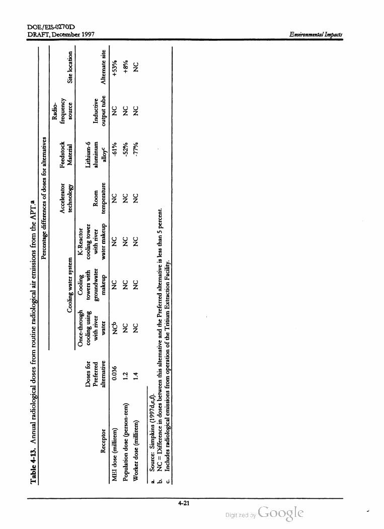
DOE /EIS -0270DTable
4-13
.Annual
radiological
doses
from
routine
radiological
air
emissions
from
the
APT.a
Percentage
differences
of
doses
for
alternatives
Accelerator
technology
Feedstock
Material
Radio
frequency
DRAFT,December 1997
source
Site
location
Doses
for
Preferred
alternative
Cooling
water
system
Once
-through
Cooling
K -Reactor
cooling
using
towers
with
cooling
tower
with
river
groundwater
with
river
water
makeup
water
makeup
Inductive
Room temperature
Lithium
-6
aluminum
alloy
-61
%
output
tube
Alternate
site
0.036
NCB
NC
NC
NC
NC
+53
%
Receptor
MEI
dose
(millirem
)
Population
dose
(person
-rem
)
Worker
dose
(millirem
)
1.2
NC
NC
NC
NC
-52
%NC
+8%
1.4
NC
NC
NC
NC
-77
%NC
NC
a.
b.
Source
:Simpkins
(1997d
,e,f).
NC
=Difference
indoses
between
this
alternative
and
the
Preferred
alternative
isless
than
5 percent
.
Includes
radiological
emissions
from
operation
of
the
Tritium
Extraction
Facility
.C.
Environmental Impacts
4-21

DOE /EIS-0270D
DRAFT, December 1997Environmental Impacts
the Tritium Extraction Facility is likely to emit
less Tritium than the Tritium Separation Facility
(5,000 curies per year versus 8,500 curies per
year) and is farther from the SRS boundary. In
the event the Tritium Separation and Tritium
Extraction Facilities are combined at the APT
site, administrative controls would limit the cu
rie content of the facilities.
facilities (e.g., liquid waste treatment facilities).
Both APT sites are designated as forest timber
units under the SRS land use system , but would
be redesignated for APT use if either became
the APT site.
Construction of the APT would result in con
verting about 250 acres (additional land
would be required for the modular design
variation ) of forested land into an industrial
ized area. New roads, bridge upgrades, and
rail lines would be required . Negligible op
erational impacts on existing site infrastruc
ture are expected.
As with the nonradiological impacts, radiologi
cal doses from the alternate site are slightly
greater due to the site's location in relation to
the SRS site boundary. The calculated commit
ted effective dose equivalent to the MEI resid
ing at the SRS boundary is 0.056 millirem for
each year of operation, which is well below the
annual dose limit of 10 millirem from SRS at
mospheric releases (Table 4-13). The offsite
population dose from APT operations at the
alternate site would be 1.3 person -rem per year.
The onsite worker dose resulting from radio
logical releases is the same as that reported in
Table 4-13 since the worker is located the same
distance (640 meters) from the APT for both
sites.
The amount of roads and railroads necessary
for APT operations would depend primarily on
the site selected . DOE would build about
8 miles of new road, upgrade bridges, and build
3.8 miles of railroad for the preferred site
(Shedrow 1997b); these lengths would be neces
sary to connect the APT site to existing SRS
roads and rail lines and to provide additional ac
cess to the APT site . The alternate site is closer
to an existing road and, therefore, would require
less roadway construction . However, the alter
nate site is farther from a rail line and would re
quire a longer rail connection than the preferred
site. In addition, the rail line to the alternate site
would require the construction of a support
trestle across Tims Branch or Upper Three
Runs, which could affect wetlands. Figure 3-10
shows the SRS network of primary roads and
the SRS railroad system in relation to the pre
ferred and alternate sites. Prior to selecting rail
spurs, DOE would evaluate corridors for the
presence of threatened and endangered species,
archaeological sites, or other sensitive resources
such as wetlands.
None of the alternatives for either the preferred
or alternate site would result in concentrations
or radiological doses that would exceed the
regulatory limits. Section 4.2 describes the po
tential health effects of these releases on mem
bers of the public and workers for the alternate
site.
4.1.4 LAND USE AND
INFRASTRUCTURE
This section evaluates potential impacts of the
construction and operation of the APT on SRS
land use and infrastructure (e.g., roads, power
lines, and piping).
Pipeline construction would be required to carry
river water to the preferred site (approximately
18,000 feet); for the alternate site about 24,600
feet would be required. The groundwater
makeup alternative would require additional
land disturbance activities to install a well sys
Construction . DOE would clear land to pro
vide the area for the APT facilities
(approximately 250 acres) in addition to land for
concrete batch plants and corridors that would
connect the site to SRS utilities, provide roads
and railroads, provide access to liquid effluent
discharge outfalls, and connect to other support
tem .
Thepreferred site would require construction of
approximately 23,000 feet of discharge line to
4-22

DOE /EIS -0270D
DRAFT,December 1997 Environmental Impacts
reach the proposed APT outfall. The alternate
site would require construction of approxi
mately 43,000 feet of discharge line (WSRC
1996b).
on an annual basis, because the largest use of
potable water would be for human consump
tion . Therefore, for most alternatives, potable
water use would not vary much ; the Lithium -6
Feedstock Material alternative would use less
water because it would not include a Tritium
Separation Facility , as discussed in Chapter 2.
DOE would provide potable water by connect
ing to existing SRS water lines, as shown in Fig
ure 3-13.
The preferred and alternate sites are relatively
close to existing transmission lines, so con
struction of connector transmission lines would
have minimal environmental impacts. The im
pact of providing additional electrical capacity
to support the APT facilities is discussed in
Section 4.4 .
DOE would pump sanitary wastewater from
the APT to the Central Sanitary Wastewater
Treatment Facility . Both the preferred and al
ternate APT sites are within about 3 miles of a
main collection system line that flows to this
facility . However, the construction of a sewer
collection line from the preferred site would
have fewer environmental impacts because
DOE would have to build the line connecting
the alternate site to the collection system in and
more sensitive areas (wetlands and
streams).
The major use of nonpotable water for APT
facilities would be as cooling water. Therefore,
the volume of nonpotable water would vary
somewhat depending primarily on the cooling
water alternative that DOE implemented and
on the heat generated by the other alternatives.
Table 4-14 lists nonpotable water requirements
by alternative. Understandably , the require
ments would be less for alternatives that in
volved cooling towers and for alternatives that
generated less heat in the facility. As discussed
in Chapter 2, DOE would supply nonpotable
water through either the existing River Water
System or new groundwater wells. The De
partment could supply nonpotable water for
uses other than cooling water (e.g., fire protec
tion) by connecting to existing SRS process
water lines. The cooling water impacts are dis
cussed in Section 4.1.2 .
across
4.1.5 WASTEMANAGEMENT
Operations. DOE analyzed the amount of
electric power necessary to operate the APT
components and estimated requirements by al
ternative, as listed in Table 4-14 (Shedrow
1997c). The table indicates that power use is
more for the Room Temperature Operation al
ternative and less for the Inductive Output
Tube alternative; the other alternatives would
use such similar equipment that their power re
quirements would be virtually the same. In
addition to the electric power listed in Ta
ble 4-14,DOE would maintain diesel generators
at the site to provide backup power when
needed, and would operate the generators on a
routine basis to ensure their operability; this
would consume 20,000 gallons of diesel fuel per
year, regardless of alternative.
DOE has determined that construction and op
eration of the APT facilities would result in
generation of several types of radioactive and
nonradioactive waste .
The generation of construction waste could
require the construction of a state -permitted
construction debris landfill on the SRS.
Sanitary solid waste would be disposed of in
the Three Rivers Regional Landfill. Opera
tional waste would bemanaged and treated
according to waste type using both SRS and
offsite facilities . Potential impacts to other
facilities are expected to be negligible due to
the relatively low volume of waste gener
ated. The potential impacts of transporting
the radioactive waste is discussed in Section
4.2.1.2 .
DOE has estimated the volumeofwater neces
sary to operate the APT facilities. To determine
total use, DOE considered both potable and
nonpotable water. DOE based its estimates of
potable water use on the projected number of
workers who would work in the APT facilities
4-23
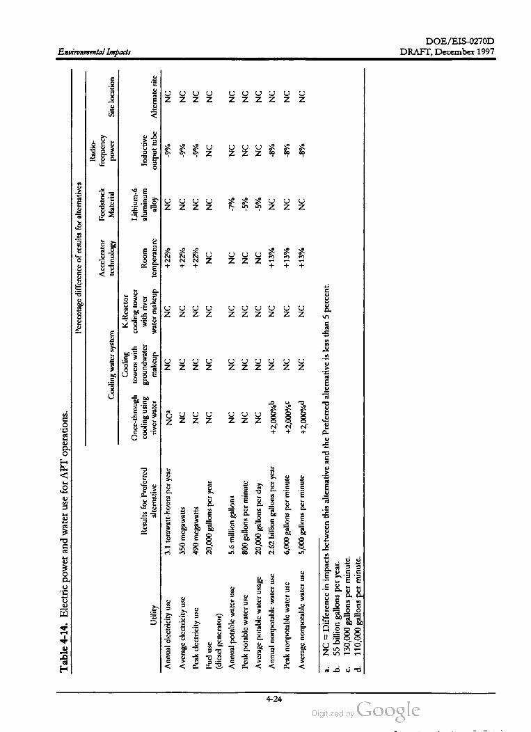
DOE /EIS -0270D
Table
4-14
.Electric
power
and
water
use
for
APT
operations
.
Percentage
difference
of
results
for
alternatives
Environmental Impacts
Accclcrator
technology
Radio
frequency
power
Fccdstock
Matcrial
Sitc
location
Inductive
Results
for
Prcfcrred
alternative
Room tcmpcraturc
Cooling
water
system
Cooling
K-Rcactor
Oncc
-through
towers
with
cooling
tower
cooling
using
groundwater
with
river
river
water
makeup
water
makcup
Nca
NC
NC
NC
NC
NC
NC
NC
NC
Lithium
- 6
aluminum
alloy
NC
output
tubc
Alternate
sitc
3.1
terawatt
-hours
per
year
+22
%-9
%
Utility
Annual
clcctricity
use
Average
clectricity
use
Peak
clectricity
use
NC
+ 22
%NC
-9
%NC
350
mcgawatts
490
mcgawatts
20,000
gallons
per
year
+22
%NC
-9
%NC
liucl
usc
NC
NC
NC
NC
NC
NC
NC
zz
NC
NC
NC
NC
-7
%NC
NC
NC
NC
NC
NC
-5
%NC
NC
(dicscl
gcncrator
)
Annual
potable
water
use
Pcak
potable
water
usc
Average
potable
water
usage
Annual
nonpotable
water
usc
Peak
nonpotable
water
usc
5.6
million
gallons
800
gallons
per
minute
20,000
gallons
per
day
2.62
billion
gallons
per
year
NC
NC
NC
NC
-5
%NC
NC
+2,000
%bNC
NC
+13
%NC
-8
%NC
6,000
gallons
per
minute
NC
NC
+13
%NC
-8
%NC
+2,000
%C
+2,000
%Average
nonpotable
water
usc
5,000
gallons
per
minute
NC
NC
+13
%NC
-8
%NC
a.NC
=Difference
inimpacts
between
this
alternative
and
the
Preferred
alternative
isless
than
5percent
.
b . 55
billion
gallons
per
year
.
130,000
gallons
per
minute
. 110,000
gallons
per
minute
.
C.
DRAFT,December 1997
4-24

DOE /EIS -0270D
DRAFT,December 1997 Environmental Impacts
Construction. The construction phase would
generate nonhazardous, nonradioactive wastes,
including sanitary solid wastes, construction de
bris (mixed rubble,metals,plastics), and sanitary
wastewater. Table 4-15 lists estimated maxi
mum annual quantities of waste for construc
tion of the Preferred alternative andcompares
it
with the other alternatives.
vation and Recovery Act hazardous and
radioactive) waste. Because APT does not in
volve fission and DOE would not use materials
with high atomic numbers in the accelerator, the
accelerator would not generate high -level radio
active or transuranic wastes . However, some of
the radioactive waste from the target /blanket
cavity would be high concentration radioactive
waste (Shedrow 1997a).
DOE could dispose of APT sanitary solid waste
at the Three Rivers Regional Landfill, an onsite
regional nonhazardous landfill. The maximum
annual volume of sanitary solid waste attribut
able to APT construction under any alternative
would be less than 1 day's contribution to the
average daily disposal rate of 900 tons at the
Three Rivers Regional Landfill. The landfill will
be operational during the projected APT con
struction and operation periods (DOE 1995a).
RCRA is the Federal statute governing the
management of hazardous waste from gen
eration to disposal. Hazardous waste in
cludes such materials as waste solvents ,
toxic metals, and industrial process waste
products.
DOE could construct a State-permitted con
struction and debris landfill on the SRS exclu
sively for APT construction wastes to dispose
of mixed rubble and other nonrecyclable con
struction debris. In addition , DOE could use
an existing SRS landfill or transfer the construc
tion waste to an offsite commercial landfill.
DOE estimates a total of 170,000 cubic meters
of construction debris for disposal during APT
construction .
The classification of radioactive wastes is
based on the concentration of short and
long-lived radionuclides. High concentration
wastes contain long-lived radionuclides.
Classes A and B include radioactive wastes
with concentrations of short-lived and per
haps some long-lived radionuclides. Be
cause high concentration radioactive wastes
contain long-lived radionuclides they require
special disposal considerations.
The wastes would be generated as part of the
production process, decontamination process,
analytical activities, and operation of supporting
facilities; they would also be generated inciden
tally as a result of failed equipment, routine
maintenance, and off-normal events. Table
4-16 lists the waste types generated by activity
and examples of items included in each waste
type.
During construction, sanitary wastewater would
bemanaged by an offsite vendor using portable
restroom facilities until DOE could buildper
manent restroom facilities at the APT site. Be
cause the vendor would be responsible for
disposing of this sanitary wastewater, it would
not affect SRS wastewater treatment facilities.
After the connection of the APT facilities to the
Central Sanitary Wastewater Treatment Facility,
the maximum annual volume attributable to
APT construction under any alternative during
construction would represent approximately 1.5
days at that facility's daily operating capacity of
about 1 million gallons.
Table 4-15 lists estimated annual waste quanti
ties from APT operations for the Preferred al
ternative and compares them to the other
alternatives. The waste estimates are based on
engineering assessments, waste forecasts, and
waste management plans.
Operations. APT operations would generate a
number of radioactive and nonradioactive waste
streams. In addition , some of the APT radioac
tive waste would be mixed (Resource Conser
The APT facilities would be able to pretreat,
treat, accumulate, handle, and package the
wastes it generated to prepare them for ship
ment to a waste treatment, storage, or disposal
facility. DOE would manage APT wastes for
4-25

DOE /EIS -0270D
Table
4-15
.Waste
generation
and
impacts
comparison
for
preferred
configuration
and
alternatives.a
Percentage
differences
of
waste
quantitics
for
alternatives
Radio
Cooling
water
Accclcrator
liccdstock
frcquency
system
technology
Matcrial
power
Cooling
K-Rcactor
Oncc
-through
towers
with
cooling
tower
Lithium
-6
Environmental
factor
Annual
waste
quantities
for
cooling
using
groundwater
with
river
Room
aluminum
Inductive
(waste
typc
)Preferred
alternative
makcup
water
makcup
temperature
alloy
Construction
wastcsa
maximum
bascd
on
construction
schedulc
Sanitary
solid
560
cubic
meters
NCE
NC
NC
-9
%NC
NC
Construction
debris
30,000
cubic
mctcrs
NC
NC
NC
NC
NC
NC
Environmental Impacts
Sitc
location
river
watcr
output
tubc
Altcrnatc
sitc
NC
NC
Sanitary
wastewater
1.5
million
gallons
NC
NC
-9
%NC
NC
NC
1,800
mctric
tons
3,800
mctric
tons
1.0
cubic
mctcr
140,000
gallons
1,400
cubic
meters
2.5
cubic
meters
1.0
cubic
mctcr
NC
NC
NC
NC
NC
NC
Operations
wastc
NC
NC
NC
NC
NC
NC
NC
NC
NC
NC
NC
NC
NC
NC
NC
NC
NC
NC
NC
+17
%
NC
NC
NC
NC
NC
NC
NC
NC
NC
NC
Sanitary
solid
Industrial
RCRA
hazardous
Radioactive
wastewater
Low
-level
wastcc
Iligh
concentration
low
-level
wastc
Mixcd
wastcc
Iligh
concentration
mixed
waste
Sanitary
wastewater
Nonradioactive
process
wastewater
NC
NC
NC
NC
NC
NC
NC
NC
NC
-11
%
NC
NC
NC
NC
12
cubic
meters
3.3
million
gallons
920
million
gallons
NC
NC
+2,000
%
NC
NC
NC
NC
NC
NC
NC
NC
+37
%
+25
%
-5
%
NC
NC
-5
%
NC
NC
NC
NC
a.Sources
:Shcdrow
(1997a
,b ).
b.NC
=Difference
inimpacts
between
this
alternative
and
the
Preferred
alternative
isless
than
5percent
.
c.Lxcluding
ligh
concentration
wastc
.
d .19
billion
gallons
.
-
1
DRAFT, December 1997
4-26

DOE /EIS -0270D
DRAFT,December 1997Environmental Impacts
Waste type
Table 4-16 . Waste types, generating activities, and examples.a
Generating activity
Sanitary solid Offices, change rooms
Industrial Production ,maintenance, housekeeping
Examples ofwaste stream items
Paper
Failed nonrecyclable equipment, ex
pired nonhazardous chemicals
Batteries
Radioactive lightwater, aqueous solu
tions
RCRA hazardous
Radioactive wastewater
Production ,maintenance, housekeeping
Cooling water systems, cooling pool, de
contamination , radiological controlana
lytical activities, pollution control
equipment
Maintenance, radiological surveys, pro
duction
Maintenance
Low -level radioactive
High concentration radioactive
Mixed
High concentration mixed
Sanitary wastewater
Nonradioactive process waste
water
Production , maintenance
Maintenance
Bathrooms
Tertiary cooling system , radiofrequency
tube cooling, rainwater and groundwater
infiltration , waste treatment secondary
wastes, groundwater monitoring
Personal protective equipment,ab
sorbentwipes, failed equipment
Target /blanket cavity vessel window
modules, tungsten neutron source
modules
Failed process equipment
Lead modules
Wastewater
Cooling waterwith tracesof salts, cor
rosion inhibitor, slimicide, dispersant;
rainwater, groundwater, wastewaters
a . Source: Shedrow (1997a).
treatmentand disposal according to waste type,
using SRS and offsite waste treatment, storage,
and disposal facilities. Table 4-17 lists the waste
types and quantities destined for treatment,
storage, and disposal facilities and the subse
quent impact to the facility , divided by preferred
configuration and alternative.
operated compactor. Atpresent, the SRS ships
such waste to an offsite vendor for compaction
(Shedrow 1997a). DOE could place an existing
onsite compactor in service in the future; Table
4-17 lists potential impacts to that compactor.
APT low -level waste treated at offsite vendor
facilities would return to the SRS for disposal in
the E -Area vaults . These vaults would also dis
pose ofAPT low -level waste not treated off the
site. Two types of vaults -- Low -Activity Waste
and Intermediate-Level Tritium -- would be
available for the disposal of APT wastes. Ta
ble 4-17 lists the impacts to each.
The SRS Consolidated Incineration Facility
(CIF) would be in operation for the first 20
years of APT operations (DOE 1995b), and
DOE would add APT incinerable waste (low
level radioactive and mixed wastes) to incoming
CIF waste volumes (Shedrow 1997c). Table
4-17 lists impacts to the CIF. When the CIF
was no longer operational, DOE would con
tinue to manage APT wastes as directed in ap
plicable Federal, state, and DOE requirements.
At present, offsite vendor facilities are available
for the volume reduction ofmany low -level ra
dioactive waste streams (Shedrow 1997a), and
DOE expects such facilities to be available
when the CIF is no longer operational.
Consistent with current practice, DOE could
dispose of APT hazardous waste at a DOE
approved commercial facility (Shedrow 1997a).
The estimated annual volume of hazardous
waste that DOE would treat and dispose of off
the Site would be low (1.0 cubic meter), and its
impact on the offsite facility would be negligi
ble .
DOE may send low -level radioactive waste suit
able for compaction to an on- oroffsite vendor
4-27

DOE /EIS-0270D
Environmental Impacts DRAFT, December 1997
Table 4-17 . Impacts on treatment, storage, and disposal facilities for operation of preferred configura
tion and alternatives.a,b
Impact for
Waste quantity Impact for Lithium -6
(Preferred Operating preferred Impact for room Feedstock
Waste facilityalternative) Waste typed capacity configuration temperature Material
CIF500 m3/yr
Incinerable LLRW , 9,500 m3/yre,f 5 percent of N / C8N / C
incinerableMWcapacity
Onsite compactor 75 m3/ yıLLRW
1,600 m3/ yr 5 percentof N / C + 80 %
capacity
E -Area LAW 33,000m3totalh LLRW , compacted 31,000 m3/ vaulte 1.1 vault N / C + 8 %
vaultLLRW , LLRW ash
E -Area ILTV 2,100 m3totalh LLRW with Tritium 5,300 m3/vaulte 0.4 vault N / C + 6 %
Storage building 600 m3 totalh MW,MW ash , high 620 m3/bldg.e 1 building N / C + 20 %
concentracion
Three Rivers 5,600 metric tons Sanitary solid , in 900 metric tons 6.2 days per N / C N / C
Landfill per year dustrial solid year
Central Sanitary 3.3 million gallons Sanitary wastewater 1 million gallons 3.3 days N / C N / C
WTF per day
Source : Shedrow (1997a).
b . Impacts for other alternatives would not vary from the Preferred alternative impacts.
Waste facilities: CIF = Consolidated Incineration Facility ; LAW = Low Activity Waste; ILTV = Intermediate Level Trit
ium Vaults;WTF = Wastewater Treatment Facility.
d. Waste types: LLRW = low -level radioactive wastes;MW = mixed waste.
Source: DOE (1995b).
f. All waste considered as solid feed.
N / C = difference within 5 percent.
h . 40-year total.
i. Source: DOE (1995a).
per dayi
a .
C.
e .
DOE would treat mixed waste that could not be
incinerated at the Consolidated Incineration
Facility at the APT and then store the treated
waste at SRS mixed waste storage pads or
buildings before disposing of it off the Site. In
addition , DOE would store stabilized APT
mixed waste ash from the CIF before disposing
of it. Similar to APT-generated hazardous
waste , the annual volume of mixed waste that
would require onsite storage and offsite treat
ment and disposal would be relatively low
(1.0 cubic meter). Table 4-17 lists the impacts
of storing APT mixed waste and high concen
tration waste (mixed and nonmixed ) in SRS
mixed -waste storage facilities. Other DOE sites
could treat and dispose of mixed waste, and the
Department has approved commercial vendors
for treating and disposing of mixed wastes
(Shedrow 1997a). DOE expects impacts on the
treatment capabilities of other facilities to be
negligible due to the low volumeofwaste.
The APT would generate several hundred cubic
meters of high concentration radioactive waste
(Greater-Than -Class- C Waste ) over its 40-year
operational life; most would be mixed waste.
DOE is investigating material substitutions that
would minimize or eliminate this waste stream ;
however, if the waste was generated, the De
partment has several potential disposal options,
each requiring more investigation . The most
likely options are the proposed Yucca Mountain
Repository in Nevada, the Hanford Site , the
Nevada Test Site, and the SRS . The SRS inven
tory of such waste (excluding APT) will be
1,500 cubic meters by 2035 (England 1997).
The operation of the APT would increase the
inventory of this waste stream by one-third .
DOE would selectively treat radioactive and
nonradioactive process wastewater in the APT
waste treatment systems described in Appen
dix A , and would discharge treated wastewater
4-28

DOE /EIS -0270D
DRAFT,December 1997 Environmental Impacts
visual resources of mechanical-draft and natu
ral-draft cooling tower emissions.
to a State-permitted outfall. The estimated an
nual discharge volumes would be 920 million
gallons for the preferred configuration
(Shedrow 1997a). Sections 4.1.2 and 4.2.2 dis
cuss the impacts of these discharges.
4.1.6.2 Noise
APT sanitary wastes and wastewaters would
have little impact on the SRS treatment and dis
posal facilities. The sanitary wastes would in
clude nonhazardous industrial solid waste such
as failed nonradioactive nonrecyclable equip
ment, and nonhazardous chemicals and bio
cides. Table 4-17 lists estimated waste volumes
and expected impacts on the Three Rivers Re
gional Landfill and the SRS Central Sanitary
Wastewater Treatment Facility.
Noise can produce adverse effects on the physi
cal, mental, and emotionalhealth of individuals.
It can also disturb wildlife, displacing animals
and interfering with normal patterns of resting,
foraging, feeding, roosting, nesting, and repro
ducing. This section examines the impacts of
noise from construction and operation of the
accelerator and its related facilities on workers
and nearby offsite residents, and provides data
for analysis ofnoise impacts on wildlife in Sec
tion 4.2.2 .
4.1.6 VISUAL RESOURCES AND NOISE
4.1.6.1 VisualResources
Impacts on visual resources would be influ
enced by the relative size (particularly height) of
the APT facilities, dissimilarity to surroundings
(shape and color), and number and frequency of
viewers.
Construction . All alternatives would produce
noise from the construction of the APT facili
ties at the preferred or alternate site, construc
tion of a rail spur to the APT facilities,
operation of concrete batch plants and other
support facilities, and traffic from construction
workers and delivery trucks. For alternatives
that would use river water cooling, the con
struction of supply and discharge pipelines
would generate noise. This noise, originating
from several locations, would occur with vary
ing intensity over the 10 -year construction pe
riod .
Noise Near the APT Site. Heavy noise from the
construction of facilities, operation of batch
plants, and construction of pipelines and rail
ways would consist ofnoise from earth -moving
equipment, trucks, air compressors, jackham
mers, and other sources listed in Table 4-18 .
The construction and operation of the APT and
associated support structures would not be
visible to ground-level observers from the SRS
boundaries at either the preferred or alternate
site. Views ofthe accelerator and its associated
buildings by visitors or employees using the SRS
road network would be limited by the forest
vegetation and rolling terrain surrounding the
sites. Most of the proposed buildings would
not exceed the height of the surrounding forest
vegetation. The tallest structures, two air emis
sion stacks and a water storage tank, would not
bemore than 200 feet high and like the K -Area
Cooling Tower (which is 490 feet high ) would
not be generally visible to ground-level observ
ers from the SRS boundaries. Site visitors and
employees observing the APT facility and sup
port structures would find the site similar to
other developed industrial areas on the SRS.
Visible plumes aloft would have a limited im
pact on visual resources . Section 4.1.3.2 dis
cusses the potential impacts to air quality and to
Construction noise at the APT site could be
higher than the limits imposed by OSHA.
However, DOE would ensure compliance
with OSHA 8 -hour noise exposure guide
lines through the use of administrative con
trols , engineering, and protective equipment.
Noise to offsite receptors would not present
a nuisance. Operational noise would be less
than construction phase noise and would
have negligible impacts to workers and the
public .
4-29

DOE /EIS -0270D
Environmental Impacts DRAFT, December 1997
88 82
85
70
Table 4-18 . Peak and attenuated noise levels (in dBA) expected from operation of construction equip
ment.a
Noise level Distance from source
Source (peak )50 feet 100 feet 200 feet 400 feet
Heavy trucks 95 84-89 78-83 72-77 66-71
Dump trucks 108 76 70
Concrete mixer 105 79 73 67
Jackhammer 108 88 82 76
Scraper93 80-89 74-82 68-77 60-71
Bulldozer 107 87-102 81-96 75-90 69-84
Generator 96 76 70 64 58
Crane 104 75-88 69-82 63-76 55-70
Loader 104 73-86 67-80 61-74 55-68
Grader 108 88-91 82-85 76-79 70-73
Dragline105 85 79 73 67
Pile driver 105 89 83 77
Forklift 100 95 77
95
89 83
a . Source : Golden et al. (1980).
The table indicates that construction noises can
be quite loud close to the sources, but rapidly
decrease with distance. During peak construc
tion times, a number of noise sources would be
distributed across the construction site . For ex
ample, DOE calculated the noise of 10 dump
trucks and 10 pile drivers at the same point; us
ing the data from Table 4-18, the noise level
would be 83 dB (A ) at 400 feet. DOE uses this
value as the sound pressure level for determin
ing ecological impacts at the edge of the con
struction site (see Section 4.2.2). Section 3.3.7
provides a scale for comparing predicted noise
with common noise levels .
from the construction site could increase along
the most frequently used routes. The most
probable routes are State Route 125 from
Augusta, Georgia, State Route 19 from Aiken ,
South Carolina, and U.S. Route 1 between
Augusta and Aiken connecting State Routes 125
and 19. In 1991 DOE commissioned a quanti
tative analysis of construction traffic noise for a
proposed new reactor at the SRS (Chun and
Rabchuk 1991) ,which concluded that construc
tion traffic noise would not result in a signifi
cant incremental noise increase. The APT
construction project would involve 66 percent
fewer construction workers than the proposed
reactor project; however, the assumed baseline
traffic volumewould be less due to decreases in
overall SRS employment since 1991.
Construction Noise at the APT Site . Workers at the
construction site(s) could encounter noises
higher than the limits imposed by the Occupa
tional Safety and Health Administration
(OSHA). However, DOE would ensure that
construction contractors complied with OSHA
noise regulations (29 CFR Part 1926.52), which
limit 8 -hour noise exposures to 90 dB ( A ).
Administrative controls, engineering controls,
or personal protective equipmentwould be used
as required to comply with OSHA limits.
Offsite Noise. The nearest SRS boundary is about
6 miles north of the preferred site and 4 miles
north of the alternate site; the nearest popula
tion centers (New Ellenton and Talatha, South
Carolina) are about 8 miles north of either site .
The land between the two sites and the popula
tion centers is heavily forested, providing
maximum noise reduction .
Construction Transportation Noise. Noise from the
transportation of workers and materials to and
Based on the following information ,DOE be
lieves that construction noise at offsite recep
4-30
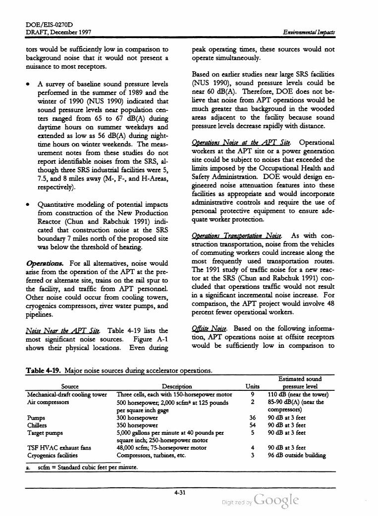
DOE/EIS -0270D
DRAFT,December 1997 Environmental Impacts
tors would be sufficiently low in comparison to
background noise that it would not present a
nuisance to most receptors.
peak operating times, these sources would not
operate simultaneously .
Based on earlier studies near large SRS facilities
(NUS 1990 ), sound pressure levels could be
near 60 dB (A ) . Therefore, DOE does not be
lieve that noise from APT operations would be
much greater than background in the wooded
areas adjacent to the facility because sound
pressure levels decrease rapidly with distance.
A survey of baseline sound pressure levels
performed in the summer of 1989 and the
winter of 1990 (NUS 1990) indicated that
sound pressure levels near population cen
ters ranged from 65 to 67 dB(A ) during
daytime hours on summer weekdays and
extended as low as 56 dB ( A ) during night
timehours on winter weekends. Themeas
urement notes from these studies do not
report identifiable noises from the SRS, al
though three SRS industrial facilities were 5 ,
7.5 , and 8 miles away (M-, F-, and H -Areas,
respectively).
Operations Noise at the APT Site. Operational
workers at the APT site or a power generation
site could be subject to noises that exceeded the
limits imposed by the Occupational Health and
Safety Administration . DOE would design en
gineered noise attenuation features into these
facilities as appropriate and would incorporate
administrative controls and require the use of
personal protective equipment to ensure ade
quate worker protection.
Quantitative modeling of potential impacts
from construction of the New Production
Reactor (Chun and Rabchuk 1991) indi
cated that construction noise at the SRS
boundary 7 miles north of the proposed site
was below the threshold ofhearing.
Operations. For all alternatives, noise would
arise from the operation of the APT at the pre
ferred or alternate site , trains on the rail spur to
the facility , and traffic from APT personnel.
Other noise could occur from cooling towers,
cryogenics compressors, riverwater pumps, and
pipelines.
Operations Transportation Noise.As with con
struction transportation, noise from the vehicles
of commuting workers could increase along the
most frequently used transportation routes.
The 1991 study of traffic noise for a new reac
tor at the SRS (Chun and Rabchuk 1991) con
cluded that operations traffic would not result
in a significant incremental noise increase. For
comparison, the APT project would involve 48
percent fewer operationalworkers.
Noise Near the APT Site. Table 4-19 lists the
most significant noise sources. Figure A -1
shows their physical locations. Even during
Offsite Noise. Based on the following informa
tion, APT operations noise at offsite receptors
would be sufficiently low in comparison to
Table 4-19 . Major noise sources during accelerator operations.
Estimated sound
pressure levelSource
Mechanical-draft cooling tower
Air compressors
Units
9
2
Description
Three cells, each with 150-horsepowermotor
500 horsepower; 2,000 scfma at 125 pounds
per square inch gage
300 horsepower
350 horsepower
5,000 gallons perminute at 40 pounds per
square inch ; 250 -horsepowermotor
48,000 scfm ; 75-horsepower motor
Compressors, turbines, etc.
110 dB (near the tower)
85-90 dB (A ) (near the
compressors)
90 dB at 3 feet
90 dB at 3 feet
90 dB at 3 feet
Pumps
Chillers
Target pumps
36
54
5
TSF HVAC exhaust fans
Cryogenics facilities
4
3
90 dB at 3 feet
96 dB outside building
a . scfm = Standard cubic feet perminute .
4-31
DOE /EIS -0270D
Environmental Impacts DRAFT,December 1997
background noise that it would not present a
nuisance.
pumps on the river would probably not be
audible except by occasional boat traffic under
certain weather conditions.
Noise Impact Summary. Table 4-20 summa
rizes noise impacts by alternative.
4.2 Impacts on Human and Bio
logical Environment
4.2.1 HUMAN HEALTH
A survey of baseline sound pressure levels
(NUS 1990) indicated that such levels at a
remote location on the SRS ranged from 30
to 43 dB (A ) in the winter and from 49 to 53
dB (A ) in the summer. (The higher summer
values indicate that much of the noise was
from insects.) Although the remote loca
tion was surrounded by fourmajor operat
ing facilities (F -Area at 3.5 miles, H -Area at
2.5 miles, K -Area at 3.5 miles, and L -Area at
3 miles), the sound pressure levels were less
than at any of the offsite survey locations.
Nevertheless, measurement notes from
these studies report some industrial noises
from SRS facilities. Given the low sound
pressure levels at this location , noise from
the APT site probably would not be detect
able at population centers 8 miles away .
Actions at the SRS affect two groups ofpeople:
site workers and the public. In its consideration
of impacts, DOE evaluated potential actions in
which the alternatives could affect each group
of people, and analyzed actions that are rea
sonably foreseeable for three conditions:
Construction
Normal operations (nonaccidentcondi
tions)
Accident conditions
Quantitative modeling of potential impacts
from construction of the proposed New
Production Reactor (Chun and Rabchuk
1991) indicated that construction noise
would be about 14 dB (A ) at the SRS
boundary 7 miles north of the proposed
site. The 1990 baseline sound pressure lev
els near population centers north of the Site
ranged from 56 to 67 dB (A ). Combining
the New Production Reactor sound pres
sure level to these levels would result in a
range from 56 to 67 dB (A ) (i.e., the noise
would be imperceptible). The noise sources
modeled for the New Production Reactor
were as loud as those at the APT site and
were more numerous (about 100 255
horsepower mechanical-draft cooling tow
ers).
DOE expects an incremental increase in oc
cupational injuries based on historic SRS
information for injuries requiring first aid , in
juries requiring medical attention , and inju
ries resulting in lost work time during the
construction phase. DOE also expects a
slight increase in the potential for traffic fa
talities .
The K -Area Cooling Tower alternative would
introduce a new noise source. A study for the
New Production Reactor (NUS 1991) predicted
offsite sound pressure levels from two natural
draft cooling towers would be less than the
threshold of hearing; the proposed site was
7 miles from the SRS boundary. Noise from
From normal operations, DOE expects the
increase of latent cancer fatalities attribut
able to the APT related radiologicalreleases
to the public to be very small. Similarly , all
concentrations for noncarcinogenic materi
als are well below all established limits and
consequently no health impacts are ex
pected . Beryllium is the only carcinogen of
concern . The incremental risk of cancer
from this material is also very small. Im
pacts would be slightly higher at the alter
nate site because it is closer to the SRS
boundary. Potential impacts to workers
would be slightly higher although in all cases
below threshold limits .
4-32

DOE /EIS -0270D
DRAFT,December 1997 Environmental Impacts
Table 4-20. Noise impacts by alternative.
Alternative
Preferred configuration
Impact
Construction: Significant near-field noise with potential to disturb
wildlife near the project boundary . Offsite impacts are not expected.
Operations: Significant near-field noise with potential to disturb
wildlife near the project boundary . Offsite impacts are not expected.
Cooling water altematives
Once-Through Cooling Using River Water Sameas Preferred alternative except there would be no mechanical
draft cooling tower noise,which constitutes a large fraction ofopera
tionalnoise
K -Area Cooling Tower with River Water
Makeup
Same as Preferred alternative except K -Area cooling tower would
provide additional noise sources remote from the project site and the
operationsnoise of the APTwould be less .
Same as the Preferred alternative exceptthere would be no riverwa
ter pump noise .
Mechanical-Draft Cooling Tower with
Groundwater Makeup
Room Temperature Operation Sameas the Preferred altemative. The APT site noise could be
slightly less with room temperature technology, because there would
be no cryogenics facilities.
Same as the Preferred alternative.Lithium - 6 Feedstock Material
Inductive Output Tube Sameas the Preferred alterative.
4.2.1.1 Construction
DOE has reviewed the activities to be com
pleted during construction and has identified
the following as the primary impacts during this
phase :
Section 4.1.3 discusses the methods used by
DOE to calculate exposure of workers and the
public to nonradiological constituents. As
shown in Tables 4-7 and 4-8, the concentrations
to which workers or the public could be ex
posed are well below regulatory limits and thus
are expected to pose no health impact. In addi
tion , these estimated concentrations do not vary
markedly by alternative.
Increased traffic -related accidents for both
the public and site workers
Increasedexposure to nonradiological
constituents for both the public and site
worker
Increased incidence of occupational injuries
to workers
DOE estimated impacts on the worker popula
tion from occupational injuries using historic in
formation at the SRS. First, DOE obtained the
normal incidence rate (the number of injuries
for a given number of work hours) of three
categories of injuries: injuries requiring first aid ,
injuries requiring medical attention, and injuries
resulting in lost work time. DOE then pro
jected the total number of person-hours to
build the APT facilities and calculated the ex
pected number of injuries using the historic in
cidence rates.
DOE used traffic statistics for public highways
near the SRS to determine the normal accident
rates for the public and site workers combined
for existing traffic patterns. DOE then esti
mated the increase in traffic from construction
activities and calculated the relative increase in
accidents that could occur due to the greater
number ofvehicles on the roadways.
Table 4-21 lists expected construction impacts
on the health of site workers and the public .
4-33

DOE /EIS -0270D
Table
4-21
.Impacts
on
public
and
workers
from
construction
ofAPT
facilities
.
Percentage
differences
of
impacts
for
alternatives
Radio
frequency
power
Environmental Impacts
Feedstock
Material
Site
location
Results
for
Preferred
alternative
Accelerator
Cooling
water
system
technology
Cooling
towers
K -Reactor
Once
-through
with
cooling
tower
cooling
with
groundwater
with
river
Room river
water
makeup
water
makeup
temperature
Nca
NC
-7
%-6
%
Lithium
-6
aluminum
alloy
Inductive
Factor
output
tube
Alternate
site
2.2
-9
%NC
-20
%
1,100
NC
NC
-7
%-0
%-9
%NC
NC
Maximum
increased
traffic
accident
fatalities
Number
of
worker
injuries
requiring
first
aid
Number
ofworker
injuries
requiring
medical
attention
Number
ofworker
injuries
resulting
inlost
work
time
280
NC
NC
-7
%-6
%-9
%NC
NC
93
NC
NC
-7
%-6
%-9
%NC
NC
a.NC
=Difference
inimpacts
between
this
alternative
and
the
Preferred
alternative
isless
than
5percent
.
DRAFT, December 1997
4-34
DOE / EIS -0270D
DRAFT,December 1997 Environmental Impacts
todiationexposure the general public and
0.0004 latent cancer fatality for each person-rem
of radiation exposure to radiation workers
(NCRP 1993).
The table lists vehicle accident and occupational
injury information for the preferred configura
tion, and changes in the impacts if DOE im
plemented other alternatives. The data in the
table indicate some changes in construction im
pacts for the Room Temperature Operation and
Lithium -6 Feedstock Material alternatives; these
changes would be due almost entirely to differ
ences in the number of workers and labor hours
spent to construct the facility .
4.2.1.2 Operations
Impacts to the Public. DOE has considered
the activities that would be performed following
construction of the APT facilities and has iden
tified potential impacts to the public in the fol
lowing areas:
Similar to radiological emissions, DOE used the
air quality and water quality data in Section 4.1.2
and 4.1.3 to evaluate potential impacts to the
public from nonradiological material. Of the
materials expected to be released from the APT
facilities, only Beryllium is a carcinogen . For
noncarcinogenic material, DOE evaluated the
material concentrations against concentration
limits set by the State or Federal government to
protect the public against other potential health
effects (e.g., irritation of the lungs). The limits
represent a conservative threshold below which
no health effects would occur. As demon
strated in Sections 4.1.2 and 4.1.3, all concen
trations for noncarcinogenic materials are well
below any regulatory limits and DOE therefore
expects no health impact.
Exposure to radiation, radioactive material,
or nonradioactive material from facility
emissions
Transportation of radioactivematerial
Exposure to increased traffic conditions on
roads near the SRS with potential increased
accident frequencies
For the special case of Beryllium emitted by the
air pathway, DOE used the EPA's Integrated
Risk Information System (IRIS ) data base to es
timate the increased risk of cancer from expo
sure to airborne Beryllium . Using the slope
factor of 0.0024 permicrogram per cubic meter,
DOE calculated a risk of an additional lifetime
latent cancer risk of 4.6X10⁻⁹ to the maximally
exposed individual for the concentration listed
in Table 4-10 . This value is well below the
0.000001 risk value that EPA typically uses as
the threshold of concern .
Exposure to electromagnetic fields (EMF)
To estimate impacts to the public from facility
emissions, DOE used water and air quality data
from Sections 4.1.2 and 4.1.3 to calculate the
radiation dose to the maximally exposed indi
vidual and the public surrounding the SRS.
To determine the potential radiation exposure
to the public from transportation of radioactive
material, DOE first identified the types of
shipments it would make as follows:
After DOE calculated the total radiation dose
to the public from all sources associated with
the accelerator, it used dose -to - risk conversion
factors established by the National Council on
Radiation Protection and Measurements
(NCRP) to estimate the number of latent cancer
fatalities that could result from the calculated
exposure. No data indicate that small radiation
doses cause cancer; to be conservative, how
ever, the NCRP assumes that any amount of
radiation carries some risk of inducing cancer.
DOE has adopted the NCRP factors of0.0005
latent cancer fatality for each person -rem of ra
1. Onsite transportation of low -level radioac
tive waste (primarily job- controlwaste)
2. Onsite transportation of Tritium (Helium -3
Feedstock Material alternative)
3. Onsite transportation of irradiated Lith
ium -6 rods (Lithium -6 Feedstock Material
alternative)
4-35
DOE /EIS -0270D
Environmental Impacts DRAFT,December 1997
4. Offsite transportation of mixed waste
(irradiated lead)
5. Offsite transportation of low -level radioac
tive waste (window modules, steel shielding,
aluminum and irradiated tungsten )
Impacts to Workers. DOE has considered the
activities that it would perform following con
struction of the APT facilities and has identified
potential impacts to workers in the following
areas:
Exposure to radiation, radioactive material,
and nonradioactive material from facility
operations
Exposure to radiation from transportation
of radioactive material
DOE analyzed onsite transportation of low
level radioactive waste in detail as part of the
SRS Waste Management EIS (DOE 1995b).
The APT will produce someradionuclides that
are different ( i.e., not beta-gamma emitting)
than those analyzed previously; however, these
radionuclides represent a small fraction (less
than 1 percent) of the total inventory. There
fore, DOE believes that the impacts presented
in the SRS Waste Management EIS for onsite
transportation of low -level radioactive waste are
representative of those from the transportation
ofwaste associated with the APT facilities.
Exposure to occupational injuries
Exposure to electromagnetic fields in the
facilities
Exposure to increased traffic conditions on
roads near the SRS with potential increased
accident frequenciesFor transportation of the other material types
listed above, DOE determined the radiation
dose rate from the various transport packages
and then used the RADTRAN computer pro
gram to estimate the consequences to the public
from incident-free transportation . DOE has
not postulated a reasonably foreseeable trans
portation accident for these materials because
they would all be transported in Type B pack
ages, which are designed to maintain their con
tents in severe accidents .
DOE based its estimates of radiation doses to
workers on historic experience at the Tritium
Facilities in H - Area . In addition, DOE re
viewed the design of the APT facilities and es
timated the likely radiation dose rates from the
components. DOE then projected the number
of workers who could be exposed to determine
the total dose to workers and the maximum
dose to an individual worker. Using the air
quality data in Section 4.1.3, DOE also calcu
lated the radiation dose to an uninvolved
worker (one not associated with APT opera
tions and not on the APT site) who receives a
dose from radiological emissions from the APT
stacks.
Similar to the methodology described for con
struction impacts, DOE calculated the antici
pated traffic accidents attributable to APT
operations by using historical information on
traffic accidents on roads near the SRS. DOE
then applied this rate to the expected traffic as
sociated with APT operations to estimate the
number oftraffic accidents.
Table 4-22 lists projected health impacts from
routine operation of the APT facilities. The ta
ble lists radiological dose information and traffic
information for the preferred configuration ; it
also list changes in the expected impacts for the
alternatives.
Based on the conceptual design of the accelera
tor,DOE does not expect workers in the facili
ties to be exposed to other than incidental
concentrations of airborne nonradioactive ma
terial, primarily in the form of cleaning agents.
Therefore, DOE did not perform a detailed
analysis ofhealth effects from exposure to non
radiological material inside the facility . How
ever, similar to the calculation of the radiologi
-
4-36

DOE /EIS-0270D
Table
4-22
.Impacts
onpublic
health
from
normal
operation
ofAPT
facilities
.
Percentage
differences
of
impacts
for
alternatives
Feedstock
Material
Radio
frequency
power
DRAFT,December 1997
Site
location
Accelerator
Cooling
water
system
technology
Once
Cooling
K-Reactor
through
towers
with
cooling
tower
cooling
using
groundwater
with
river
Room river
water
makeup
water
makeup
temperature
NC
NC
NC
NC
Impacts
for
Preferred
alternative
Lithium
-6
aluminum
alloy
Inductive
output
tube
Factor
Alternate
site
0.042
-52
%NC
+45
%
2.8x10⁻⁶
NCC
NC
NC
NC
+11
%NC
NC
0.042
NC
NC
NC
NC
-52
%NC
+45
%
1.3
+11
%NC
NC
NC
-46
%NC
+ 8%
Annual
radiation
dose
toMEI
from
APT
emissions
(millirem
/year
)a,b
Annual
radiation
dose
toMEI
from
transportation
of
radioactive
material
(millirem
/year
)
Total
annual
radiation
dose
toMEI
from
APT
operations
(millirem
/year
)
Annual
radiation
dose
topopulation
from
APT
emissions
(person
-rem
/year
)
Annual
radiation
dose
topopulation
from
transportation
of
radioactive
material
(person
-rem
/year
)
Total
annual
radiation
dose
to
population
from
APT
operations
(person
-rem
/year
)
Estimated
number
of
cancer
fatalities
from
annual
population
dose
Estimated
traffic
accident
fatalities
per
year
onroads
near
SRS
1.1
NC
NC
NC
NC
NC
NC
NC
2.4
+6 %NC
NC
NC
-25
%NC
NC
0.0012
+6%NC
NC
NC
-25
%NC
NC
0.12
NC
NC
NC
NC
NC
NC
-18
%
a.Reported
as
the
sum
ofthe
dose
from
air
emissions
and
liquid
emissions
,even
though
the
MEI
for
the
two
emissions
are
indifferent
locations
.
b.MEI
-maximally
exposed
individual
.
NC
=Difference
inimpacts
between
this
alternative
and
the
Preferred
alternative
isless
than
5percent
.C.
Environmental Impacts
4-37

DOE /EIS-0270D
DRAFT, December 1997Environmental Impacts
information coupled with expected traffic asso
ciated with APT operations. The values pre
sented in Table 4-22 are the estimated total
number of accidents attributable to APT opera
tion and reflect total accidents for workers and
the public.
cal dose to workers, DOE calculated the air
concentration an uninvolved worker, as dis
cussed above, could receive from emissions at
the APT site. Of the airborne constituents re
leased from the APT facilities, only Beryllium is
a carcinogen. DOE calculated the risk of can
cer to the uninvolved worker using the same
methodology described above for public expo
sure to Beryllium . Using the same slope factor
of 0.0024 per microgram per cubic meter, the
calculated risk to the worker would be 6.7x10⁻⁸
which is well below the threshold of 1.0x10⁻⁶ .
Table 4-23 lists estimated impacts on workers
for normal operating conditions. The table in
dicates that impacts would not vary much
among the alternatives ; however, some varia
tions would occur as a result of the size of the
work force for a particular alternative .
4.2.1.3 Accidents
To determine the impacts from transportation
of radioactive material, DOE used the meth
odology described above for determining im
pacts to the public, but it chose the receptors of
interest to be a maximally exposed worker and
the worker population. DOE calculated the
doses to these receptors for the same typesof
shipments described above and lists the results
in Table 4-23.
All accidents with a postulated frequency of
less than once during the operating life of
the accelerator (40 years ) have negligible
consequences. Only four low -probability
accidents (highest frequency = once per
2,000 years ) have offsite doses high enough
to warrant public protective actions under
the SRS Emergency Plan (1 rem at site
boundary ) (WSRC 1996c) .To estimate the number of occupational injuries
that could occur during normal APT operations,
DOE multiplied the SRS injury rate by the es
timated work -hours per year for threetypes of
injuries: those requiring first aid , those requir
ing medical attention, and those resulting in lost
work time.
This section summarizes risks to members of
the public and workers from facility accidents
associated with the operation of the APT. This
EIS defines an accident as a series of unex
pected or undesirable events possibly leading to
a release of radioactive or hazardousmaterial in
the facility or to the environment; however, not
all accidents result in a release . Each alternative
discussed in this EIS has the potential for acci
dents .
Workers could be exposed to electromagnetic
fields in and near the APT facilities. These
fields would come from such sources as power
lines, large electric motors, and radiofrequency
tubes. The primary frequencies of the sources
would be less than 1,000 megahertz , which is
lower than the frequency of visible light. At
these frequencies, electromagnetic waves have
not been shown to cause cancer (American
Cancer Society 1997). Therefore , DOE com
pared expected EMF levels to exposure limits
set by the Occupational Safety and Health Ad
ministration (10 mW / cm2 for periods of 0.1
hour ormore, 29 CFR 1910.97) and expects no
health impacts under normal operation .
All accidents have several things in common , as
shown in Figure 4-1: a hazard (radioactive ma
terial, hazardous chemicals, etc.) and an energy
source to breach protective barriers. The bar
rier to a release can be a single item or a combi
nation of many items; for example, a tank of
material inside a vault inside a storage facility
would have three barriers -- the tank wall, the
walls of the vault, and the walls of the storage
facility. In addition, the physical form of the
material can act as a barrier to its release. For
this example to have a release to the environAs discussed above, DOE calculated increased
incidents of traffic accidents based on historic
4-38

DOE /EIS-0270D
DRAFT,December 1997Table
4-23
.Impacts
onworker
health
from
operation
ofAPT
facilities
.
Percentage
of
difference
ofimpacts
for
alternatives
Radio
Accelerator
Feedstock
frequency
Cooling
water
system
technology
Material
power
Site
Location
Cooling
K -Reactor
Impacts
for
Once
-through
towers
with
cooling
tower
Lithium
-6
Preferred
cooling
using
groundwater
with
river
Room
aluminum
Inductive
Factor
alternative
river
water
makeup
water
makeup
temperature
alloy
output
tube
Alternate
site
Annual
maximum
radiological
dose
toworker
1Nca
NC
NC
NC
NC
NC
NC
from
facility
operation
(rem
)
Annual
total
radiological
dose
to
all
workers
72
NC
NC
NC
NC
-7
%NC
NC
from
APT
operation
(person
- rem
)
Annual
total
radiological
dose
toall
workers
16
NC
NC
NC
NC
+63
%NC
NC
from
transportation
of
radioactive
material
(person
-rem
)
Estimated
number
ofcancer
fatalities
from
0.04
NC
NC
NC
NC
NC
NC
NC
annual
total
dose
Number
ofworker
injuries
requiring
first
aid
19
NC
NC
NC
NC
-5
%NC
NC
(cases
per
year
)
Number
of
worker
injuries
requiring
medical
2.8
NC
NC
NC
NC
-5
%NC
NC
attention
(cases
per
year
)
Number
of
worker
injuries
resulting
inlost
1.4
NC
NC
NC
NC
-5
%NC
NC
work
time
(cases
per
year
)
Number
of
workers
exposed
to
100
NC
NC
NC
NC
NC
NC
NC
electromagnetic
fields
Magnitude
ofEMF
towhich
workers
are
1.2@350MHZ
NC
NC
NC
NC
NC
NC
NC
exposed
(mW
/cm2
)2.3@700MHZ
a.NC
=Difference
inimpacts
between
this
alternative
and
the
Preferred
alternative
isless
than
5percent
.
Environmental Impacts
4-39

DOE /EIS -0270D
Environmental Impacts DRAFT, December 1997
Energy required
to breach barrier
Material that can be
released
Barrier to Release Released material
Figure 4-1. An accident resulting in a release
ofmaterial.
DOE analyzed the hazards from the operation
of the proposed facility and the associated bar
riers to prevent release of the hazards. In addi
tion, to identify the probability for and the
magnitude of a release if it occurred, DOE
identified possible energy sources that could be
available to breach the barriers. DOE also as
sessed the likelihood of each event (probability
per unit time) based on Departmental guidance
documents. Table 4-24 summarizes potential
significant events. Appendix B describes indi
vidual accident assumptions. Among those ac
cidents postulated but not considered credible
or significant were airplane crashes and site
flooding enhanced by upstream dam failure.
The key portions of the APT are underground
and the facility is located well away from the
nearest commercial airport. As for flooding, the
APT preferred site is on a bluff over 100 feet
above the nearest flood plain .
ment, an accidentwould have to have enough
energy to breach all three barriers.
In most cases, breaching a barrier will not result
in the release of all of the hazardous material.
The nature of the accident will control the
amountofmaterial released. This analysis takes
this into account by using the estimated release
fraction, which is the fraction of material that
DOE has calculated the accident would release.
After its release to the environment, a material
undergoes dilution similar to releases from rou
tine operations.
Table 4-24 lists the information on each poten
tial accident as follows:
The purpose of accident analyses is to deter
mine two crucial pieces of information: the fre
quency (or probability) of an accident and the
consequences of that accident if it occurred.
This analysis based the estimated frequency of
an accident on calculated failures that must oc
cur for the accident to happen; that is, an acci
dent usually requires a number of events to
happen in sequence, and the overall probability
is the product of the probabilities for the inde
pendent individual events. The consequence of
the accident is usually related to the human
health of the workers and public surrounding
the facility; this analysis based its calculated con
sequences on the assumed amount of released
material and the location of workers and the
public. For radiological accidents, the analysis
first calculated consequence as a radiation dose,
and then based its determination of the health
effects on the dose. For chemical accidents, the
analysis calculated the concentration to which
people are exposed, and then determined the
health effects.
Event description : The accident identifier (i.e.,
a name for the accident). In most cases, it
is the major event in the sequence that
would lead to the release, although it is not
necessarily the first or the last event in the
sequence.
Hazard . Thematerial that could be released.
Most hazards listed are radioactive material;
however, some accidents involve the release
of chemicals. This column lists the type
and location of the hazard (e.g., target, tun
nel).
Barrier breached. The primary barrier the ac
cident would breach . Although there could
be other barriers, this column lists the first
barrier the material encounters to enable a
better understanding of the concept of ac
cident analysis.
Energy for release: The source of energy that
breaches the barrier ; that is, the circum
4-40

DOE /EIS -0270D
DRAFT, December 1997 Environmental Impacts
Table 4-24 . General information on accidents associated with APT facilities.
Dominant
Materials
Calculated
accident
frequencyBarrier Driving forceEvent Hazard
Accidents applicable to all alternatives
Target cooling pump failure Radioactive materi Cooling pipingResidual heat
NegligibleaOnce per 6 years
als in target for target from target
Loss of secondary cooling Radioactive materi Residual heat Negligible Once per 6 years
als in target from target
Cooling piping
for target
Chemical con
tainers
Chemical releases Hazardous chemi
cals
Once per 10 yearsContainer breach
assumed with
evaporation
Hydsofluoric
acid , hydrazine,
ammonium hy
droxide
Negligible Once per 100
years
Onceper
100
years
H -3 , 0-15,
C - 11, N - 13
0-15
als in target from target
Beam energy
Tunnel purge of normally acti- Activated tunnelair Air confinement Air Handling
vated air withoutdelay system System
Resin bed fire Radioactivemateri System piping Fire
als filtered from
cooling system
Cooling pipe break in target Radioactive materi Cooling piping Residual heat
for target
Full power beam /beam stop Radioactive materi Containment
interactionals in beam stop around beam
stop
Misdirection ofbeam with loss Radioactivemateri- Physical form of Beam impinge
of confinementals in accelerator material
tube wall
Target handling accident Radioactivemateri- Target cladding Residual heat in
target
Beam expander failure Radioactivemateri- Target cladding
Once per
1,000 years
Once per
10,000 years
C -11, Be-7 ,
H - 3
N -13, 0-15 ,
Ar-41, C -11
Once per
10,000 yearsment
Negligible
als in target
Once per
10,000 years
Once per
100,000 years
Beam energy Negligible
als in target
Fire H - 3 Once per 100
years
Fire H - 3 Once per
10,000 years
Once per
2,000 years
Fire and beam
tube
Thermal energy
Additional accidents forHelium - 3 Feedstock Material only
Small fire in Tritium Separation Tritium in facility Containment
Facility systems
Large fire in Tritium Separa Tritium in facility Containment
tion Facility systems
Design-basis seismic event Tritium in facility Containment
and activated air in systems
beam tunnel
Seismic event beyond design Various radioactive Containment
basis materials systems
Failure to shut down beam Various radioactive Containment
during transient materials systems
Additional accidents for Lithium -6 Feedstock Material only
Design-basis seismic event Tritium in facility Containment
and activated air in systems
beam tunnel
Seismic event beyond design Various radioactive Containment
basis materials systems
Failure to shut down beam Various radioactive Containment
during transient materials systems
H - 3, N -13,
Ar-41, 0-15 ,
C - 11
H -3 , 0-15, C -11 Less than once
per 100,000 years
Negligible Less than once
per
Beam energy
1 million years
Once perFire and beam
tube
Thermal energy
H -3 , N -13,
Ar-41, 0-15 , 2,000 years
C -11
H - 3 ,0-15, C -11 Less than once
per 100,000 years
Negligible Less than once
per 1 million years
Beam energy
"Negligible” means that DOE does not expect release of a measurable amount ofmaterial.
4-41

DOE /EIS -0270D
Environmental Impacts DRAFT,December 1997
stance that is immediately responsible for
the barrier failure.
the material through the atmosphere and the
radiation doses at selected locations. DOE cal
culated the dose to three receptors:
Dominant materials: Major components of
the released materials. For radiological re
leases, it lists major radionuclides; for
chemical releases, it identifies the chemicals
(see Appendix B ).
The offsite maximally exposed individual at
the SRSboundary
An uninvolved worker at the Savannah
River Site, not associated with APT opera
tions and at least 640 meters from the acci
dent site
Calculated accident frequency: Calculated value
for the likelihood that the accident would
occur. DOE estimated these values by
identifying events that would have to occur
for the accident to progress and then calcu
lating the frequency for each of the events.
The product of the individual frequencies is
the overall probability for the entire acci
dent.
Members of the public within 50 miles of
the facility (population = 620,000)
DOE performed accident calculations for the
preferred site (6.38 miles to the SRS boundary)
and for the alternate site (3.8 miles to the SRS
boundary). As the administrative limits for ra
dionuclide inventory are adjusted for site loca
tion , there is essentially no difference in
accident consequences between the preferred
and alternate sites. However, as the preferred
site is farther from the site boundary, the pro
jected radionuclide inventory limit could be
higher allowing greater operational flexibility.
During the analysis, DOE determined thatmost
major accidents would not depend on imple
mented alternatives; events that would lead to
releases would rely on systems and features
common to almost all alternatives. However,
the Preferred alternative for the accelerator in
cludes the Helium - 3 feedstock material, which
would require the associated Tritium Separation
Facility. For the Lithium -6 feedstock material,
DOE would not build the TSF (see Chapter 2 );
therefore , accidents that occurred in the TSF
would notbe possible if DOE implemented the
Lithium -6 feedstock material alternative. There
fore, Tables 4-24 and 4-25 list accidents that
would be unique to the Helium - 3 and Lithium -6
feedstock material alternatives separately. The
other listed accidents would be applicable to all
facility alternatives (i.e., operating temperatures,
sources of electrical power, sources of cooling
water, or radiofrequency tubes). If the TEF
were colocated with the TSF , any accidents for
the combined facility would be bound by this
analysis.
The increased number of latent cancer fatalities
to the public , as discussed in Section 4.2.1.4, is
0.0005 times the dose in person -rem for doses
less than 20 rem . For larger doses, when the
rate of exposure would be greater than 10 rads
per hour, the increased likelihood of latent can
cer fatality is doubled , assuming the body's di
minished capability to repair radiation damage.
DOE calculated the expected increase in the
number of latent cancer fatalities above those
expected for the population, and has listed these
values and other accident consequence data in
Table 4-25.
DOE analyzed each accident scenario to de
termine the quantity of hazardous material that
would be present in the facility and the amount
that would be available for release to the envi
ronment, and used these values in a computer
model that calculated the effects of transporting
In general, DOE performed dose calculations
for a 1 -year exposure period (i.e., people would
be exposed to the released materials for 1 year
following the accident). However, the SRS
Emergency Plan (1) follows the EPA Guidelines
and (2 ) recommends evacuation of affected
people when committed dose is greater than 1
Therefore, if the projected local doserem .
4-42

DOE /EIS-0270D
DRAFT,December 1997 Environmental Impacts
Table 4-25. Calculated accident consequences for accidents listed in Table 4-24 forpreferred APT site.
Population
dose Uninvolved Cancer Calculated
MEI dose (person worker dose fatalities in accident fre
Event (rem ) rem ) (rem ) population quency
Accidents applicable to all alternatives
Target coolingpump failure Negligiblea Negligible Negligible Negligible
Loss of secondary cooling Negligible Negligible Negligible Negligible every
Chemical releases Negligible Negligible Negligible Negligible
Negligible Negligible NegligibleTunnel purge ofnormally activated air with- Negligible
out delay
Resin bed fire 0.50 800 75 0.40
Once every
6 years
Once
6 years
Once every
10 years
Once every
100 years
Once every
100 years
Once every
1,000 years
Once every
10,000 years
Once every
10,000 years
Once every
10,000 years
Once every
100,000 years
Cooling pipe break in target0.03 57 2.8 0.029
Full power beam /beam stop interaction 0.0043 5.0 0.96 0.0028
Misdirection of beam with loss of confine 0.000012 0.057 0.00078 0.000029
ment
Target handling accident Negligible Negligible Negligible Negligible
Beam expander failure Negligible Negligible Negligible Negligible
Additional accidents forHelium - 3 Feedstock Materialonly
Small fire in Tritium Separation Facility 0.21 360 7.0 0.18
Large fire in Tritium Separation Facility 1.9 3,500 8.1 1.7
Once every
100 years
Once every
10,000 years
Once every
2,000 years
Design -basis seismic event2.9 5,100 150 2.6
Seismic event beyond design basis 3.0 5,500 168 2.7
Failure to shut down beam during transient Negligible Negligible Negligible Negligible
Less than
once every
100,000 years
Less than
once every
1 million
years
Additional accidents for Lithium -6 Feedstock Material only
Design -basis seismic event0.96 1,600 146 0.8
Seismic event beyond design basis 1.7 3,100 200 1.6
Once every
2,000 years
Less than
once every
100,000 years
Less than
once every
1 million
years
Failure to shut down beam during transient Negligible Negligible Negligible Negligible
a ." Negligible” means thatDOE expects no quantifiable health impact.
4-43
DOE /EIS -0270D
DRAFT, December 1997Environmental Impacts
would be greater than 1 rem , DOE calculated
the doses to the maximally exposed individual
and the uninvolved worker for 1 day of expo
sure, instead of 1 yearof exposure.
4.2.2 ECOLOGY
This section evaluates potential impacts of
construction and operation of the APT on the
ecological resources of the SRS.
Savannah River Institute (formerly known as
the Savannah River Forest Station ) would co
ordinate the removal and sale of marketable
timber; however, clearing and grading would
disturb the remaining understory vegetation. In
addition, every alternative would include the
clearing of about 30 acres for pipelines, and as
sociated facilities (substations and pumping sta
tions) and a smaller amount of land for the
construction of roads and a rail line (Shedrow
1997b). DOE has not identified any unique or
sensitive plants (or plant communities) at the
preferred or alternate site or in the probable
corridors for infrastructure expansion. There
fore, DOE does not expect a reduction in the
local or regional diversity of plants and plant
communities during construction for any alter
native. (See Section 4.2.2.4 for discussion of
threatened and endangered species.)
4.2.2.1 Terrestrial Ecology
Potential impact to terrestrial ecology would
result from the clearing of 250 acres
(additional land would be required for the
modular design variation ) of forested land at
either site . DOE does not expect, however,
that this would create a long -term reduction
in the local or regional diversity of plants and
animals. Plant stress from salt deposition
from cooling tower operations would be neg
ligible.
Construction. DOE identified the following
potential impacts on terrestrial vegetation and
wildlife in evaluating the actions it would have
to complete during construction:
Removal ofvegetation that provides wildlife
habitat
Impacts to wildlife would vary during construc
tion. As the site underwent clearing and grad
ing, disturbance and habitat loss would displace
more mobile animals (birds and larger mam
mals). Some of these animals, particularly
young individuals, could be killed by predators
and automobiles, or could be forced to occupy
less suitable habitat. Species -- including rac
coons, opossums, eastern cottontails, red - tailed
hawks, screech owls, blue jays, and common
crows that can adapt to disturbed or developed
areas would recolonize the site as construc
tion ended and site conditions became stable
(Mayer and Wike 1997). Other animals would
be displaced permanently, dispersing from the
site to the surrounding area. Species more de
pendent on forested habitat ormore sensitive to
disturbance (e.g., birds such as wood warblers
and vireos) probably would be permanently
displaced .
• Displacement ofmobile wildlife from con
struction areas
Loss of less mobile wildlife in construction
areas
Loss of wildlife from wildlife- vehicle colli
sions
The preferred and alternate sites for construc
tion are predominantly forested with stands of
loblolly and slash pine and small upland hard
wood stands of white oak, red oak, and hickory.
Construction activities would result in the
clearing, grading, or disturbance of approxi
mately 250 acres at either of these sites
(Shedrow 1997b). Construction activities would
affect virtually all vegetation in this area. The
Clearing and grading the site would result in the
loss of some individuals, primarily less mobile
animals such as toads, turtles, lizards, snakes,
mice , moles, and voles. Some small mammal
losses would also result as individuals become
more vulnerable to predation as a result of dis
placement. Because these animals are common
throughout the SRS, DOE expects negligible
4-44

DOE/EIS -0270D
DRAFT, December 1997 Environmental Impacts
reduction in their populations as a result of
construction.
of sodium chloride per acre per year can reduce
agricultural productivity (Mulchi and Arm
bruster 1981).
Increased traffic on roads during construction is
likely to result in increased wildlife-vehicle col
lisions, which would result in the loss ofmam
mals such as the gray squirrel, opossum , and
white -tailed deer, as well as reptiles and am
phibians such as snakes and toads. Because
these animals are common throughout the SRS,
DOE expects their populations to be unaffected
by these losses.
water.
Modeling results indicate that maximum total
deposition rates for solids would depend on the
cooling tower type and the source of cooling
However, the maximum reported
deposition rate for any alternative would be 60
pounds per acre per year. Even if the solids
consisted entirely of sodium chloride, this
deposition rate would be less than the amount
that would be expected to cause damage to
vegetation ; therefore, salt deposition should
cause negligible impacts on vegetation .
Operations. DOE has evaluated the following
potential impacts on terrestrial vegetation and
wildlife during operation of the APT facilities:
Stress or loss of vegetation due to salt
deposition from cooling tower operation
Displacement of wildlife near the APT site
due to noise
Loss of wildlife due to wildlife vehicle colli
sions
During operation, impacts to terrestrial vegeta
tion could result from salt deposition attribut
able to drift from mechanical- or natural-draft
cooling towers. Cooling-tower drift can cause
vegetation stress through direct deposition of
salts on foliage or through excess accumulation
of salts in the soil (NRC 1985) Salt stress in
plants can occur through a number of mecha
nisms, including (1) the increased osmotic po
tential of the soil solution, which affects the
availability ofmoisture in the soil to the plant;
(2) an alteration of the mineral nutrition balance
in plant tissues; and (3 ) toxic effects due to in
creases in specific ion concentrations in the
plants (DOE 1987a).
Every alternative would involve noise from the
operation of APT facilities, trains on the rail
spur to the facility, and vehicle traffic. In gen
eral, animals habituate to a regular predictable
noise, or one of a continuous nature, more
readily than to sporadic noise bursts (Golden et
al. 1980). The noise sources identified in Sec
tion 4.1.6.2 should have negligible impacts on
wildlife in the area around either APT site be
cause they would be relatively constant or local
to the site such that sounds would decrease be
low critical levels before they could reach the
facility boundary . Species that can adapt to
human disturbance would recolonize portions
of the site (the open grassy areas) despite the
noise level. Birds such as killdeer, common
bobwhite, and eastern meadowlark could nest in
the open fields and weedy graveled areas while
species such as mourning dove, northern
mockingbird , and eastern bluebird could forage
in the area. Predatory species such as rat snake,
red -tailed hawk, and gray fox probably could
hunt in the open grassy areas, taking advantage
of expanding small mammal populations.
Mammals such as raccoons, opossums, and
skunks would also likely frequent the area, pos
sibly establishing dens and territories in and
around the buildings (Mayer and Wike 1997).
The tolerances and susceptibilities of plants to
salt deposition are highly variable, depending on
the species and environmental conditions. In
vegetative studies, the threshold for visible salt
stress symptoms on the most sensitive species
occurred at approximately 183 pounds of so
dium chloride per acre per year (INTERA
1980). Deposition rates of about 90.4 pounds
Increased traffic on roads near the APT facili
ties probably would result in increased wildlife
vehicle collisions, which could result in the loss
ofmammals such as the gray squirrel, opossum ,
and white -tailed deer, as well as frogs, turtles,
4-45

DOE /EIS -0270D
Environmental Impacts DRAFT,December 1997
and snakes. These animals are common
throughout the SRS, and their populations
would be unaffected by these small losses.
4.2.2.2 Aquatic Ecology
tower blowdown to either Par Pond (through
Ponds 2 , 5, and C ) or Pen Branch (through In
dian Grave Branch ). The following sections
discuss potential impacts to (1) Savannah River
biota from river water withdrawal and (2 ) the
aquatic communities of the Par Pond system
(including the pre -cooler ponds) and the
Pen Branch- Indian Grave Branch system from
APT nonradioactive liquid discharges.
The withdrawal of Savannah River water for
cooling would result in the impingement of
adult fish and the entrainment of fish eggs
and larvae at the river water intake. The
Once- Through Cooling Water alternative
would result in considerably higher rates of
impingement and entrainment than the vari
ous cooling tower alternatives, but losses of
adult fish , fish eggs , and fish larvae under all
alternatives would be small relative to total
fish production in the upper and middle
reaches of the Savannah River.
Impingement and Entrainment. Section 316 (b) of
the Clean Water Act (33 USC 1326 ) directs the
Environmental Protection Agency to establish
standards that require “ ...the location , design ,
construction , and capacity of cooling water in
take structures reflect the best technology avail
able for minimizing adverse environmental
impacts....”Section 316 (b ) studies or
“ demonstrations
” assess potential impacts to
aquatic communities from impingement and
entrainment at the process or cooling water in
takes of industrial facilities and powerplants,
and are often a condition of a National Pollut
ant Discharge Elimination System (NPDES)
permit or permit renewal.
Heated effluent from the APT facility would
be discharged to either Indian Grave/Pen
Branch or the pre -cooler ponds and Par
Pond . Discharge temperatures under the
Once- Through Cooling Water alternative
would be high enough to cause limited fish
kills in the pre-cooler ponds. Fish kills in In
dian Grave/Pen Branch and the pre-cooler
ponds are unlikely under the other cooling
water alternatives.
Construction . As discussed above, surface
water impacts from construction activities
would be minor, and similar for all alternatives.
DOE would use appropriate soil and erosion
control measures to protect Upper Three Runs
and its tributaries ; such measures could include
silt fences, spray -on adhesives, and seeding ar
eas thought to be prone to erosion. As a con
sequence, impactsfrom erosion and
sedimentation to aquatic organisms in Upper
Three Runs and its tributaries would be minor,
and would not be a concern after DOE had
stabilized and revegetated disturbed areas.
As a condition of NPDES permit SC0000175,
issued in October 1976 , the Environmental
Protection Agency required DOE to conduct
Section 316 (b ) studies to evaluate the impinge
ment of juvenile and adult fish on river water
intake (trash ) screens and the entrainment of
fish eggs and larvae into the river water pump
ing system . Three of the five SRS production
reactors (P , K , and C -Reactors) operated during
most of the study period. Based on biweekly
observations of fish impinged at the river water
intake screens, an estimated 7.3 fish per day
(2,680 fish per year) were impinged at the river
water intakes (McFarlane, Frietsche, and Miracle
1978). The most commonly impinged species
were bluespotted sunfish , warmouth , channel
catfish , and yellow perch . Assuming “worst
case conditions,” an estimated 6.8 million eggs
and 19.6 million larvae were lost annually to
entrainment, representing 9.5 and 9.1 percent,
respectively, of the total number of fish eggs
and larvae moving past the cooling water in
takes during the April-May-June (peak) spawn
ing period (McFarlane, Frietsche, and Miracle
Operations. Depending on the alternative se
lected , the APT facilities would withdraw water
from the Savannah River for once-through
cooling or for cooling tower makeup water.
Chapter 2 discusses anticipated rates of with
drawal from the river for the various alterna
tives. The APT tertiary cooling water system
would discharge thermal effluent or cooling
4-46
DOE /EIS -0270D
DRAFT, December 1997Environmental Impacts
1978). American shad comprised 96 percent of
the fish eggs collected. Blueback herring and
three shad species (American , gizzard , and
threadfin ) dominated the larval fish collections,
along with large numbers of spotted sucker and
black crappie.
Since 1988 there has been a dramatic reduction
in the rates of water withdrawn from the Sa
vannah River by the SRS. By the end of 1988,
DOE had shut down the SRS production reac
tors or placed them in cold standby, and was
reviewing their future status. By 1996, all five
reactors were shut down permanently.
DOE conducted additional impingement and
entrainment studies from 1983 through 1985 to
assess potential impacts of the restart of
L -Reactor. The 1983-1985 studies showed that
an average of 7,603 fish were impinged annually
on river water intake screens (DOE 1987b) .
Entrainment losses averaged about 10 million
eggs and 18.8 million larvae annually. The spe
cies affected most by impingement were
bluespotted sunfish and threadfin shad; en
trainment losses were primarily American shad
and other clupeids. The study concluded that
“ these losses do not appear to have a significant
impact on the Savannah River fisheries, there
fore no mitigation seems justified ” (DOE
1987b).
In 1993, DOE placed Pumphouse 16 in
" layup” (unused but routinely inspected and
maintained), and in 1995 deactivated and aban
doned Pumphouse 6G (on Par Pond). In June
1996 only one of the 10 pumps in Pum
phouse 3G was operating, pumping approxi
mately 28,000 gallons per minute to maintain L
Lake water levels; auxiliary equipment cooling in
K-, L., and P -Areas; fire protection in K-, L-,
and P -Areas; and sanitary wastewater in K-, L-,
and P -Areas (DOE 1997a). In 1997,DOE in
stalled a 5,000 gallon per minutepump
in the
3G pumphouse to conserve energy and reduce
costs, and shut down the last large capacity
pump that was still in service.
In early 1988, when three production reactors
(K-, L-, and P) last operated, themaximum rate
of river water withdrawal at the 1G and 3G in
takes was about 380,000 gallons per minute, or
179,000 gallons per minute each for once
through cooling at K- and L -Reactors and
22,000 gallons per minute for makeup water at
P -Reactor. Based on the studies described
above, DOE estimated that continued opera
tion of K-, L., and P -Reactors would result in
the entrainment of an estimated 18 million fish
larvae and 9 million fish eggs annually during
the spring and summer spawning period. Clu
peid (shad and herring), centrarchid (sunfish
and crappie), and cyprinid (minnow and com
mon carp ) larvae would be entrained most of
eggs of two anadromous species,
American shad and striped bass, would be en
trained most often . The Final Environmental Im
pact Statement Continued Operation of K-, L., and P
Reactors concluded that impacts to fisheries from
entrainment of fish eggs and larvae at the SRS
would be small and limited to fish populations
in the immediate vicinity of the Site (DOE
1990).
Under the Preferred alternative, the preferred
cooling water alternative would be the Mechani
cal-Draft Cooling Tower with river water
makeup. Based on the results of the 1983-1985
impingement and entrainment studies (DOE
1987b) and assuming impingement and en
trainment rates are proportional to river water
withdrawal rates, the anticipated 6,000-gallons
perminute withdrawal of Savannah River water
under the preferred cooling water alternative
would result in the impingement of an esti
mated 132 fish and the entrainment of an esti
mated 173,000 fish eggs and 326,000 larvae
annually (Table 4-26). Impingement and en
trainment rates under the K -Area (natural-draft)
Cooling Tower alternative would be essentially
the same. Under the Once-Through Cooling
alternative, DOE would withdraw an estimated
125,000 gallons per minute for cooling in the
APT facilities . This would impinge an esti
mated 2,600 fish and entrain an estimated 3.4
million fisheggs and 6.4 million larvae annually ,
approximately one-third the rates of impinge
ment and entrainment observed during the
1983-1985 period (DOE 1987b). To put these
ten , while
4-47

DOE /EIS -0270D
EnvironmentalImpacts DRAFT,December 1997
Table 4-26 . Estimated annual rates ofimpingement and entrainment for APT cooling water alterna
tives.a
Baseline
5,000
Natural-draft
cooling tower
6,000
Mechanical-draft
cooling tower
6,000
Once-through
cooling
125,000
Factor
Rate of river water withdrawal
(gallons perminute)
Annual impingement
Annual entrainment (eggs)
Annual entrainment (larvae)
110
144,000
272,000
132
173,000
326,000
132
173,000
326,000
2,600
3,400,000
6,400,000
a .Total annual impingement and entrainment losses for each cooling water altemative would be the sum of the base
line impingement/ entrainment and the losses expected from the cooling water alternative selected .
entrainment rates in perspective, a single female
American shad can produce 200,000 to 600,000
eggs per spawning season, and a single gizzard
shad can produce asmany as 500,000 eggs per
spawning season (Scott and Crossman 1973).
Therefore, withdrawal of river water under any
of the cooling water alternatives would nothave
a significant impact on the fisheries of the Sa
vannah River.
munities of the Par Pond system , but changes in
community structure probably would be subtle
and difficult to detect outside of the immediate
area of the discharge. Under the Once-Through
Cooling alternative, discharge temperatures
would increase steadily over the summer, ulti
mately reaching 102° F in July and August in
Pond 2 , 101°F in Pond 5 , and 100° F in Pond C
(see Section 4.1.2). Temperatures of this magni
tude would favor growth and reproduction of
green and blue- green algae and would likely
displace species, such as diatoms, less tolerant
ofheated waters.
Non -radioactive Liquid Discharges.
ThermalEffects. Many blue-green algae are toler
ant of high water temperatures, preferring tem
peratures above 95° F ; a relatively large number
of green algae species grow best at temperatures
as high as 95° F; most diatoms prefer tempera
tures below 86 ° F (Patrick 1969). Therefore,
periphyton (" attached ” algae) communities
could be altered by thermal discharges under
the various cooling water alternatives. In gen
eral terms, dominance of the periphyton by a
diverse diatom community indicates good water
quality , while dominance by a few blue-green or
green algae is often associated with poor water
quality. When the SRS production reactors
were operating, thermophilic blue-green algae
(those that can grow and reproduce in warmer
waters) often dominated the algal communities
in waters that received thermal effluents
(Gibbons and Sharitz 1974).
Because the 2,000 -gallon -per-minute blowdown
from the K -Area natural-draft cooling tower is
not likely to exceed 89°F and represents only a
10-percent addition to the normal Pen Branch
flow (see Section 4.1.2), the heated discharge
probably would only affect attached algae
communities in the 1 -mile section of Indian
Grave Branch below the discharge canal. Be
yond the confluence of Pen Branch and Indian
Grave Branch, impacts would be subtle to im
perceptible.
Benthicmacroinvertebrates are bottom -dwelling
organisms (such as mollusks and insect larvae)
that live part or all of their life cycles in and on
various submerged substrates. Long-term
changes in water temperature can influence the
composition of the macroinvertebrate com
munity because these organisms are usually un
able to disperse rapidly, if at all, from areas of
thermal influence and typically live in a water
body over several seasons.
Under the Mechanical-Draft Cooling Tower al
ternative, maximum discharge temperatures to
ponds 2 and 5 would range from 65 to 88° F ,
and would behighest in July and August. These
discharges could affect the periphyton com
4-48
DOE /EIS-0270D
DRAFT, December 1997Environmental Impacts
Thermal stress tends to reduce community di
versity (the number of kinds of animals in a
body of water) by making the environment un
suitable for intolerant species or by conferring
competitive advantage to species that are able to
tolerate large temperature changes. Howell and
Gentry (1974) studied aquatic insect communi
ties on the SRS and found increasing diversity
from thermal to post-thermal to natural
streams. Two species, a corixid (backswimmer)
and a chironomid (midge larva), comprised al
most 9696 percent of individuals collected from a
thermal stream ; more stoneflies, dragonflies,
mayflies, and caddisflies were found in the natu
ral stream than the post-thermal or thermal
perature observed in the canal entering Pond 2
over the 1994-1996 period, when unheated Sa
vannah River water was pumped to Par Pond
via Ponds 2 and 5 to maintain the water level in
the reservoir, was 81° F (Cooney et al., 1995 ,
1996 ). The effect ofheated discharges on ben
thic macroinvertebrates in summer is well
documented. Temperatures higher than 86° F
have been found to reduce numbers and di
versity ofbenthos (Dahlberg and Conyers 1974;
Wiederholm 1984). Therefore, the 88 ° F maxi
mum discharge temperature to Ponds 2 and 5
would be expected to result in reduced benthic
macroinvertebrate numbers and diversity in
Ponds 2 and 5 , but would probably have no dis
cernible effect on Pond Cor Par Pond.stream .
Researchers have investigated temperature tol
erances for certain groups of benthic macroin
vertebrates, but the temperature preferences
and limits of many other groups are unknown.
Lethal temperatures for some sensitive stonefly
and mayfly species are as low as 68 ° F , while
those for some dragonfly species are as high as
105° F (Wiederholm 1984). In terms of com
munity responses, field studies have shown that
watertemperatures
above 86 ° F can cause a re
duction in species richness , abundance, bio
mass , or production (Wiederholm 1984).
Temperatures of 95 to 106 ° F eliminated virtu
ally all aquatic insects from cooling water canals
at powerplants (Durrett and Pearson 1975;
Parkin and Stahl 1981).
Under the Once- Through Cooling alternative,
discharge temperatures as high as 102°F would
occur in July and August in Ponds 2 and 5 .
Temperatures as high as 100 ° F would occur in
Pond C. Under these conditions, many benthic
macroinvertebrates (e.g., caddisflies and may
flies) probably would undergo thermal stress
and displacement by other forms, such as chi
ronomid (midge) larvae, that are less affected by
higher temperatures or reduced dissolved oxy
gen levels. Thus, community diversity would
probably be reduced in these ponds, particularly
during hot summer months. Benthic commu
nities in Par Pond probably would be affected
only near the Hot Dam , where water tempera
tures would be several degrees higher than
normal.
The sublethal effect of temperature on aquatic
macroinvertebrates might be more important
than absolute tolerance to high temperatures.
For example, increased temperatures can dis
rupt the normal seasonal emergence pattern of
aquatic insects. Insects emerging too early in
the season can be killed by low air temperatures
or rendered more vulnerable to predation . Al
tering the normal sequence of male- female
emergence can affect reproduction.
Fish are cold -blooded vertebrates with body
temperatures and physiologic functions that
fluctuate approximately with the temperature of
their environment. As environmental tempera
ture increases, most metabolic processes be
comemore rapid , up to a lethal temperature, at
which metabolism ceases rapidly . Changes in
temperature influence most physiologic proc
esses, including feeding and nutrient assimila
tion , growth, development, and reproduction.
Fish behavior is also influenced by temperature.
Within theirrange of temperature tolerance, fish
either seek or avoid heated waters.
Under the preferred cooling water alternative
(mechanical-draft cooling towers), maximum
discharge temperatures to Ponds 2 and 5 would
range from 65 ° to 88° F . The maximum tem
4-49

DOE /EIS -0270D
DRAFT, December 1997Environmental Impacts
avoidance and lethal temperatures for the im
portant species.
A number of studies have defined thermal pref
erences and tolerance limits of fish , including
many species indigenous to the Savannah River
and its tributaries. Table 4-27 summarizes op
timum spawning temperatures, temperature
preferences, upperavoidance temperatures, and
reported lethal temperatures for several impor
tant species in the middle reaches of the Savan
nah River and in SRS waters. While study
objectives, techniques, and definitions varied
among the studies cited , patterns oftemperature
tolerance are generally evident for the species.
Temperature preferences and tolerance of the
bluegill, a species that occurs in the pre -cooler
ponds of the Par Pond system , are well known
(see Table 4-27). The bluegill prefers tempera
turesbetween 81 and 91° F , and generally avoids
temperatures higher than this. Thermal prefer
ences for the largemouth bass, which is also
common in the pre -cooler ponds, are similar to
those of the bluegill (Table 4-27).
Under the preferred cooling water alternative
(mechanical-draft cooling towers), the maxi
mum temperature of discharges to Ponds 2 and
5 would be 88°F . This is high enough to pro
duce an avoidance response in some fish spe
cies, but would not be high enough to kill
resident fishes. Fish may be forced to seek out
thermal refuges in late summer, areas within the
ponds that are slightly cooler because they are
deeper, or cooled by seeps and springs, or influ
enced by one of the small streams that flow in
termittently into the ponds.
Other fish species likely to occur in the pre
cooler ponds include mosquitofish ,minnows of
the genus Notropis, bullheads, and redbreast
sunfish (Bennett andMcFarlane 1983; Aho and
Anderson 1985; Wike et al. 1994). To evaluate
the influences of the APT discharge on these
species, DOE compared projected maximum
discharge temperatures to upper avoidance and
lethal temperatures of the various species. Ta
ble 4-28 lists the projected maximum tempera
tures during the summer in relation to upper
Maximum water temperatures in Ponds 2, 5 ,
and C in late summer under the Once- Through
Cooling alternative would be higher than those
preferred by virtually all indigenous fish species,
and could be high enough to kill more sensitive
species. This is consistentwith the observations
of Aho and Anderson (1985), who studied the
relationship between reactor operations and fish
kills in Pond C. Fish kills in this cooling pond
occurred in all months of the year, but tended
to be more severe in late summer (when pond
temperatures were highest and dissolved oxygen
levels were lowest) and after extended reactor
outages (when fish had recolonized areas that
received the warmest water). Juveniles of all
species tended to bemore affected than adults.
Table 4-27. Temperature requirements of selected fish speciesof the Savannah River Site.
Temperature (° F )
SpeciesSpawning Preferred Avoidance Lethal Reference
Redbreast sunfish 68-82 68-86 Aho et al. 1986
Warmouth 70-81 77-86 McMahon et al. 1984
Bluegill88 93 97 Peterson and Shutsky 1976
63-81 82-91 97 Carlander 1977
81-90 90-95 Coutant 1977
104 Holland et al. 1974
Largemouth bass 81-90 84-93 Coutant 1977
81-90 88-91 Carlander 1977
97 Cvancara et al. 1977
101 Drew and Tilton 1970
Notropis (3 species) 93 (winter)McFarlane et al. 1976
104 (summer)
4-50

DOE /EIS -0270D
DRAFT, December 1997 Environmental Impacts
Table 4-28. Comparison ofmaximum discharge temperatures in Ponds 2 and 5 and temperatures lethal
to resident fish species.
Temperature (° F )
Ponds 2 and 5 Ponds 2 and 5
predicted maximum predicted maximum
SpeciesAvoidance Lethal
(cooling towers) (once-through )
Notropis spp.93-104 89 102
Bluegill90-95 97-104 89 102
Largemouth bass 84-93 97-101 89 102
Branch (through Indian Grave Branch ). These
discharges would contain small amounts of
chlorides, or salts.
Based on the Pond C studies (Aho and Ander
son 1985), fish kills could occur in Ponds 2 and
5 under two sets of circumstances. First, lim
ited fish kills probably would occur in late
summer when temperatures in Ponds 2 and 5
exceed known lethal limits for more sensitive
species. Second, fish kills could occur at any
time when DOE restarted the accelerator after
an extended outage and water temperatures in
the pre- cooler ponds rose suddenly .
In summary, discharge temperatures under the
Once-Through Cooling alternative would be
high enough to produce an avoidance response
in fish in the pre-cooler ponds in summer
months and could , under certain circumstances ,
result in fish kills. The severity and extent of
these kills would depend on operational factors
( e.g., timing and rate of power ascension when
the APT facility restarts after an outage),
weather (fish kills would be more likely if air
temperatures were unusually high), and biologi
cal factors (e.g., species composition of Ponds 2
and 5 fish communities, as well as age, sex, and
condition of fish ). Thermally -related fish kills
would not be likely under the cooling tower al
ternatives, because their predicted discharge
temperatures would fall within the range of
those tolerated , if not preferred, by resident fish
species.
The Environmental Protection Agency periodi
cally publishes ambient water quality criteria
(AWQC), concentrations or levels of substances
that are known to affect “ diversity , productivity ,
and stability of aquatic communities, including
" plankton, fish , shellfish , and wildlife” (EPA
1986). The purpose of these criteria is to assist
state regulatory agencies in the development of
location-specific standards to protect aquatic
life. The acute and chronic AWQC for chloride
are 860 and 230 milligrams per liter, respectively
(EPA 1991). The maximum predicted
(instantaneous) concentrations of chlorides in
once-through cooling water and cooling tower
blowdown would be 13 and 39 milligrams per
liter, respectively. Both of these values are an
order of magnitude lower than the acute and
chronic AWQC for chloride. The highest aver
age concentrations of chloride in once-through
cooling water and cooling tower blowdown
would be 9 and 27 milligrams per liter, respec
tively. In addition, chlorides in cooling water
would be diluted on discharge to the Par Pond
system or Pen Branch. Therefore, there would
be no impacts to aquatic biota in Par Pond and
Pen Branch from chlorides in once-through
cooling water or cooling tower discharges.
Chemical Effects. Under the Once- Through
Cooling alternative, 125,000 gallons per minute
of effluent from the APT facility would dis
charge to Par Pond through the pre-cooler
ponds. Under the two cooling tower alterna
tives, 2,000 gallons per minute of blowdown
would discharge continuously either to Par
Pond (through the pre-cooler ponds) or Pen
APT cooling water discharge would also contain
dissolved and suspended solids. Fish and other
aquatic life must tolerate a range of dissolved
solids concentrations to survive under natural
conditions. A study of fish in Canadian lakes
concluded that waters with dissolved solids
greater than 15,000 milligrams per liter were un
4-51

DOE /EIS-0270D
EnvironmentalImpacts DRAFT, December 1997
Moderate protection 80 milligrams
perliter
Low level of protection 400 milligrams
perliter
suitable for most freshwater species (EPA
1986). Themaximum predicted dissolved solids
concentration in once-through cooling water
would be 91 milligrams per liter in May (see
Table 4-5). The maximum predicted dissolved
solids concentration in cooling tower blowdown
would be 273 milligrams per liter, also in May.
These concentrations would also be diluted on
discharge to Par Pond or Pen Branch. There
fore, the possibility ofadverse effects on aquatic
organisms in Par Pond or Pen Branch from dis
solved solids in APT discharge water is remote .
Excess suspended solids may result in adverse
effects on fish and fish forage populations. The
four primary effects are (EPA 1986):
Total suspended solids in once-through cooling
water would range from 3 to 18 milligrams per
liter (instantaneous maximum ), while total sus
pended solids in cooling tower blowdown
would range from about 9 to 54 milligrams per
liter. These relatively low concentrations of
solids in once-through cooling water and cool
ing tower blowdown would be further diluted
on discharge to Par Pond or Pen Branch. Based
on the National Academy of Sciences recom
mendations, the levels of suspended solids ex
pected under the various cooling water
alternatives would pose little or no threat to
aquatic life in the Par Pond or Pen Branch sys
Direct effects on fish in the water column
(e.g., reduced resistance to disease)
Inhibited development of fish eggs and lar tems.
vae
Interference with natural movements and
migration
Reduction in the abundance of fish forage
In addition , suspended materials can settle and
blanket the bottom of water bodies, resulting in
effects to benthic species, blocking of gravel
spawning beds, and removal of dissolved oxy
gen from the overlying water. No ambient wa
ter quality standards are available for suspended
solids. EPA (1986) suggests that “ Settleable
and suspended solids should not reduce the
depth of the compensation point for photosyn
thetic activity bymore than 10 percent from the
seasonally established norm for aquatic life.”
The National Academy of Sciences (see Ameri
can Fisheries Society 1979) recommended the
following " settleable / suspended” solids criteria
(maximum concentrations) for the protection of
aquatic organisms:
DOE would use a number of proprietary
chemicals in the tertiary cooling water system
and cooling towers to control scale, corrosion ,
algae, and microbial organisms. These chemi
cals would control corrosion or buildup of algae
or microbial organisms. Application and dosage
rates would be recommended by the manufac
turer. Blowdown from the cooling towers,
normally 2,000 gallons perminute, would be re
duced during treatment cycles to prevent the
release of potentially toxic chemicals to the en
vironment. Once chemicals have been neutral
ized or degraded to safe levels (based on testing
or monitoring), the normal blowdown would
resume.
4.2.2.3 Wetland Ecology
Construction. DOE has identified wetlands
near the proposed APT sites and does not ex
pect any impacts to wetlands as a result of con
struction activities. Both the preferred and
alternate sites are upland locations with no wet
lands (including Carolina bays) within their
boundaries. The locations of pipelines, trans
High level ofprotection 25 milligrams
perliter
4-52

DOE /EIS -0270D
DRAFT, December 1997 Environmental Impacts
mission lines , roads, and railway lines to support
the APT facilities would be chosen so as to
minimize potential impacts to any wetlands near
the routing corridors. In addition,DOE would
protect adjacent or downgradient wetlands from
construction impacts by implementing Best
Management Practices to prevent the offsite
movement of soil or sedimentation of water
bodies, as discussed in Section 4.1.1 .
temperature, and the temperature increase
caused by the cooling water discharge would
have negligible negative impacts on wetlands
vegetation and wildlife. During cooler months,
the warmth provided by the cooling water
blowdown could have positive impacts, includ
ing a slight lengthening of the growing season
for the floating -leaved and emergent vegetation ,
amphibians, and reptiles inhabiting the stream
and its delta in the Savannah River Swamp
(Grace and Tilly 1976; Wilde and Tilly 1985;
Brisbin 1997).
Operations. DOE has identified two potential
sources of impacts on wetlands from operation
ofthe APT facilities :
• Discharging heated water from the accelera
tor cooling system to onsite surface water
bodies such that the increased temperatures
affectwetlands vegetation and wildlife
Discharging large volumes of water from
the cooling system , thereby changing the
flow and water levels in surface water bod
ies and affecting wetlands vegetation and
wildlife
Alternatives that used mechanical-draft cooling
towers would discharge blowdown to Pond 2 ,
and in turn to Pond 5 , Pond C , and Par Pond in
sequence. As indicated in Table 4-3, the maxi
mum annual discharge temperature would be
88 ° F at a flow rate of about 2,000 gallons per
minute, depending on the alternative. The
maximum ambient temperature in the canal
between P -Area and Pond 2 was 81° F from
October 1994 through September 1996
(Cooney et al. 1996). Thus the temperature in
crease caused by the cooling water discharge
would have a negligible negative impact on
wetlands vegetation and wildlife. The warmth
provided by the cooling water blowdown during
cooler months could provide positive impacts,
including a lengthening of the growing season
for the floating-leaved and emergent vegetation,
amphibians, and reptiles inhabiting the canals
and ponds (Grace and Tilly 1976 ; Wilde and
Tilly 1985; Brisbin 1997).
Heated blowdown from cooling tower opera
tions would be marginally higher than the
ambient maximum temperature . During
cooler months, the warmth provided by the
cooling water blowdown could have positive
impacts , including the lengthening of the
growing season for floating -leaved and
emergent vegetation , amphibians, and rep
tiles . Under the Once- Through Cooling
Water alternative , DOE expects the loss of
some less hardy wetland vegetation .
All alternatives for APT operation would cause
impacts to wetlands because of cooling water
discharges. The discharge of the K -Area Cool
ing Tower alternative could be as high as 89° F
at a flow rate of about 2,000 gallons perminute
into Indian Grave Branch , which flows into Pen
Branch . Recent measurements in the Pen
Branch system indicate an annual average tem
perature of 72° F (Wike et al. 1994); in 1995 the
seasonalmaximum temperature for Pen Branch
in its lower reaches was 85 ° F . Thus the maxi
mum blowdown temperature would be only
marginally higher than the ambient maximum
The Once -Through Using River Water alterna
tive would discharge water to the Par Pond
system (through Ponds 2, 5 , C , and Par Pond)
with a maximum temperature during warmer
months of about 102° F (Table 4-4). Most ac
tively growing plants cannot survive for long
periods at temperatures above about 104° F
(Wike et al. 1994). Although the cooling water
discharge would be slightly less than this
threshold , DOE expects the loss of some less
hardy wetlands vegetation , with greater impacts
in Ponds 2 and 5 , as compared to Pond C and
Par Pond. Heated effluent from the APT under
the Once -Through Cooling alternative could af
fect aquatic and semi-aquatic animals in down
4-53

DOE /EIS -0270D
Environmental Impacts DRAFT,December 1997
heated effluent during cooler months could
provide positive impacts, including a lengthen
ing of the growing season for the floating
leaved and emergent vegetation, as well as am
phibians, and reptiles (Grace and Tilly; Wilde
and Tilly 1985; Brisbin 1997).
stream wetlands.Amphibians, reptiles, and
semi-aquatic mammals (e.g., muskrats and bea
vers, if present) in the pre-cooler pond wetlands
would be most affected. Amphibians and rep
tiles, which like fish are unable to regulate their
body temperatures internally, are particularly
sensitive to changes in the thermal environ
ment. These animals regulate their body tem
peratures by selecting habitats in which
temperatures are suitable (e.g., a warmer or
cooler part of a pond) or by controlling expo
sure to the sun's radiation (seeking out shady or
sunlit areas). As a general rule, mammals are
less affected by heated discharges from indus
trial facilities, because they are larger and more
mobile . As a result, they are able to move
longer distances in response to thermal pertur
bations, and are better equipped to seek out
more favorable habitats.
As discussed in Section 3.2.2 , the natural flow
of Indian Grave Branch is about 10 cubic feet
per second. The increase in flow due to dis
charges from the K -Area Cooling Tower alter
native (about 2,000 gallons per minute,
depending on the selected alternative) would
raise the water level in the upper reaches of the
stream (an estimated 0.5 to 0.75 feet) and cause
a loss of wetlands vegetation and changes in
species composition in the stream corridor and
delta (Nelson 1997). Species less tolerant of
flooding that have become established since the
cessation of discharges from K -Reactor would
be replaced by flood-tolerant vegetation . The
ongoing forest wetland restoration activities in
Pen Branch , which are a part of the mitigation
mandated in the Record of Decision for the Fi
nal Environmental Impact Statement, Continued Op
eration of K-, L-, and P -Reactors, Savannah River Site,
Aiken, South Carolina (DOE 1990) could be ad
versely affected. Less flood -tolerant hardwoods
planted in the upper reaches of the Pen Branch
corridor could be lost (Nelson 1997).
The effects of thermal effluents on amphibians
and reptiles, which can range from elimination
of more sensitive species to subtle changes in
community structure,were intensively studied at
the Savannah River Site during the years in
which production reactors operated (Gibbons
and Sharitz 1974; Nelson 1974). For example
researchers at the SRS found that larval frogs
and toads in a reservoir (Pond C ) receiving
heated effluent from a production reactor de
veloped more rapidly and metamorphosed
sooner that those in unheated areas and had a
longer-than -normal breeding seasons. As a re
sult, frogs and toads were smaller than normal
as juveniles and adults, and were present as
young later in the season than normal. As a re
sult, they were more vulnerable to terrestrial
predators, susceptible to seasonally -related food
shortages, and exposed to adverse weather
conditions. Turtles (yellow -bellied sliders), on
the other hand, grew more rapidly, grew to
larger sizes, achieved sexual maturity sooner,
and had larger clutch sizes in areas receiving
heated effluent (Christy et al. 1974; Gibbons
and Sharitz 1974). Thus, reproductive potential
was enhanced as a indirect result of thermal al
teration .
Section 4.1.2 contains flow rates for the P -Area
canal for March through September 1996 .
Additions of about 2,000 gallons per minute of
blowdown under theMechanical-Draft Cooling
Tower alternative would increase the mean flow
coming into Pond 2 32 - fold. Additions of
125,000 gallons perminute of effluent under the
Once- Through Cooling alternative would in
crease the mean flow through the system by a
factor of 280 and could raise water levels in
Ponds 2 and 5 by 1.5 feet (Pinder 1997). Im
pacts to wetlands vegetation would be very
small under the Mechanical-Draft Cooling
Tower alternative. However, the Once
Through Cooling alternative would raise water
levels significantly, causing vegetation to move
along the hydrologic gradient in the littoral zone
around the ponds. Somevegetation would be
lost, but it would become reestablished along
In the area of Par Pond surrounding the dis
charge point, the warmth provided by the
4-54

DOE / EIS -0270D
DRAFT, December 1997 Environmental Impacts
the new shore line as water levels stabilized at
full pool.
1.5 feet at a velocity of 0.9 foot per second
(DiFiore -Smith 1997b).
4.2.2.4 Threatened or Endangered SpeciesHydrologic modeling predicts that water levels
in Par Pond would rise between 0.1 and 0.6
foot, maintaining the 200 -foot elevation (full
pool) between 5 and 8 months a year under the
Mechanical-Draft Cooling Tower alternative.
Under the Once-Through Cooling alternative ,
full poolwould bemaintained all year (DiFiore
Smith 1997a). Impacts to wetlands vegetation
in Par Pond would be minimal under both Me
chanical-Draft Cooling Tower and Once
Through Cooling alternatives. The discharges
to the system would act to stabilize water levels
and so encourage the development of stable
communities of wetlands vegetation around the
lake. The stable water levels could result in
stagnant sediments in some of the back regions
of Par Pond coves, producing areas devoid of
vegetation (DOE 1997a).
Construction . DOE has not identified any
populations of threatened or endangered plant
or animal species on the preferred or alternate
site or in the likely corridors for related trans
mission lines, pipelines, and roads. DOE will
continue to review these locations during the
design and construction of the infrastructure for
the APT to ensure there would be no adverse
impacts to threatened or endangered species.
Operation . Actions related to cooling water
withdrawal and discharge would be those most
likely to affect threatened or endangered spe
cies, especially:
The shortnose sturgeon
The American alligator
The bald eagleHydrologic modeling predicts that water levels
in Lower Three Runs would not be substantially
raised under either the Mechanical-Draft Cool
ing Tower or the Once-Through Cooling alter
natives. Themean flow in Lower Three Runs at
Road B during water years 1974 through 1992
was 37 cubic feet per second with the highest
and lowest daily mean discharges for the period
at 220 and 0.6 cubic feet per second (Bennett et.
al 1992), respectively. This translates to an es
timated average depth of flow of 1.3 feet at a
velocity of 0.83 foot per second. Assuming that
all flow in Lower Three Runs at Road B is from
Par Pond, discharge of about 2,000 gallons per
minute under the Mechanical-Draft Cooling
Tower alternative would result in an average
discharge of 0.8 cubic feet per second in Lower
Three Runs. Average annual flows ranged from
0.4 to 9.5 cubic feet per second. The estimated
average depth of flow in the stream at Road B
would be 1.31 feet at a velocity of0.84 foot per
second. Under the Once -Through Cooling al
ternative, an increase of 125,000 gallons per mi
nute would result in an average discharge of
11.6 cubic feet per second in Lower Three Runs
with the average annual flow ranging from 9.3
to 40.4 cubic feetper
second. The estimated
average depth of flow in the stream would be
No threatened or endangered species occur
within either APT site . Par Pond and the
pre-cooler ponds, however, are used by
American alligators and bald eagles. The
alligators do not breed in Ponds 2 and 5 and
would abandon the ponds if water tempera
ture exceeded their tolerance range. In Par
Pond and Pen Branch , potential effects on
alligators could be positive in that the
warmer waters could lengthen the active pe
riod for the reptiles. Bald eagles use the Par
Pond system for feeding. Potential fish kills
associated with Once -Through Cooling
Water alternative could provide the eagles
with an additional food source.
DOE evaluated impingement and entrainment
of shortnose sturgeon during withdrawals of
large volumes ofcooling water from the Savan
nah River and concluded that these operations
would not affect the continued existence of this
species in the Savannah River (Muska and
Matthews 1983; DOE 1990 ). DOE based this
conclusion in part on the facts that entrainment
was unlikely because shortnose sturgeon eggs
are demersal (sinking), adhesive, and negatively
4-55

DOE / EIS -0270D
Environmental Impacts DRAFT, December 1997
4.3 Socioeconomicsbuoyant and that impingement of healthy ju
venile and adult shortnose sturgeon on cooling
water system screening devices is highly unlikely
given their strong swimming ability. Therefore,
DOE does not expect any impact on this spe
cies from APT operations,which would require
much smaller volumes of cooling water.
Economic and demographic forecastingmodels
such as the REMI model are used to project
through simulations the effects of changes of
local economic variables (e.g., number of jobs in
a particular industry, wage rates, or increases in
capital investment) on other economic measures
such as total employment, population, or total
personal income. In this EIS ,multiple simula
tions, one for each alternative which identifies a
different level of APT employment, were run
with the REMI model. The results of these
simulations are tabulated and compared to show
the different economic effects of each of the
EIS alternatives. The REMI model holds all
other regional inputs constant, which allows the
analysis to isolate and distinguish the impacts of
changes between alternative economic scenar
ios.
The American alligator population of the Par
Pond system , including Ponds 2, 5 , and C ,
would be relatively unaffected by the discharges
of heated effluent associated with the Once
Through Cooling alternative. The species has
relatively broad temperature tolerances, with a
critical thermalmaximum of 100 ° F Wike et al.
1994). Discharges into the Par Pond system
from the APT facility would at times during the
summer season exceed this temperature slightly
and could cause the alligators in Ponds 2 and 5
to abandon the ponds. These ponds do not
have breeding populations, and alligator use of
the ponds is intermittent and transitory (Brisbin
1997). However, displacement could result in
increased incidence of intraspecific encounters
as alligators from Ponds 2 and 5 are forced into
established territories of adults in other areas.
There could be an increased likelihood of fatal
encounters with humans and automobiles as
well. Discharges associated with the other
cooling water alternatives could have a positive
impact on the alligator populations in the Par
Pond system or the Indian Grave/Pen Branch
system by lengthening the active period of the
reptiles.
The potential socioeconomic impacts asso
ciated with APT are relatively small in com
parison with historical trends and are not
expected to stress existing regional infra
structure or result in a "boom " situation .
Data for theAPT action alternatives are derived
from the APT Conceptual Design Report.
The following scenarios are analyzed .
Construction and operation of the Preferred
alternative
Construction and operation of the APT
with the following technologies:
Lithium -6 feedstock material
Bald eagles use the Par Pond system for feed
ing. Operation of the APT facilities and dis
charge of cooling water under the Once
Through Cooling Water alternative could result
in fish kills in Ponds 2 and 5. Eagles would be
able to forage on the dead fish as a food source ,
as they have in the past (Wike et al. 1994). Any
reductions in overall fish stocks in Ponds 2 and
5 would have little if any impact on eagle use of
the Par Pond system . The other alternatives
would have no negative impacts to the eagles.
Room temperature operation
Use of K -Area cooling tower; once
through cooling water;mechanical-draft
4-56
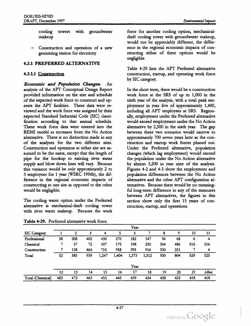
DOE /EIS -0270D
DRAFT,December 1997 Environmental Impacts
coolingtowers with groundwater
makeup
Construction and operation of a new
generating station for electricity
force for another cooling option, mechanical
draft cooling tower with groundwater makeup,
would not be appreciably different, the differ
ence in the regional economic impacts of con
structing either of these options would be
negligible.
4.3.1 PREFERRED ALTERNATIVE
4.3.1.1 Construction
Table 4-29 lists the APT Preferred alternative
construction, startup, and operating work force
category .by SIC
Economic and Population Changes. An
analysis of the APT Conceptual Design Report
provided information on the size and schedule
of the expected work force to construct and op
erate the APT facilities. These data were re
viewed and the work force was assigned by their
expected Standard Industrial Code (SIC) classi
fication according to that annual schedule.
These work force data were entered into the
REMImodel as increases from the No Action
alternative. There is no distinction made in any
of the analyses for the two different sites.
Construction and operation at either site are as
sumed to be the same, except that the length of
pipe for the hookup to existing river water
supply and blow down lines will vary . Because
this variance would be only approximately 2 to
3 employees for 1 year (WSRC 1996b), the dif
ference in the regional economic impacts of
constructing at one site as opposed to the other
would be negligible.
In the short term , there would be a construction
work force at the SRS of up to 1,000 in the
sixth year of the analysis , with a total peak em
ployment in year five of approximately 1,400,
including all APT employees at SRS. Region
ally , employment under the Preferred alternative
would exceed employment under theNo Action
alternative by 2,300 in the sixth year. The gap
between these two scenarios would narrow to
approximately 700 seven years later as the con
struction and startup work forces phased out.
Under the Preferred alternative, population
changes (which lag employment) would exceed
the population under the No Action alternative
by almost 3,200 in year nine of the analysis.
Figures 4-2 and 4-3 show the employment and
population differences between the No Action
alternative and the other APT configuration al
ternatives. Because there would be no meaning
ful long-term difference in any of themeasures
between APT alternatives, the figures in this
section show only the first 15 years of con
struction, startup,and operations.
The cooling water option under the Preferred
alternative is mechanical-draft cooling tower
with river water makeup. Because the work
Table 4-29. Preferred alternative work force.
Year
ܝܕ
2 3 4 5
6
7
8
10 119
6838 208 430 182 96 6 4
SIC Category
Professional
Chemical
Construction
Total
402
727 37
138
270
175
958
107
710
516
147
250
916
198
993
304
530
486
251
516
77 464 4
52 383 939 1,247 1,404 1,373 1,312 930 804 529 525
Year
12 13 14 15 16 17 18 19 20 21 After
418Total (Chemical) 482 472 463 453 445 439 434 428 423 418
4-57

DOE /EIS -0270D
Environmental Impacts DRAFT, December 1997
2,500
2,000
1,500
Employment
1,000
500
10
3+0 2 4 9
10
11
12
13
14
15
Year of Analysis
Preferred Room Temperature * Lithium -6 Feedstock -OK-Area Cooling Tower
Figure 4-2 Regional employment differences greater than No Action alternative.
3,500
3,000
g
2,500
2,000Population
1,500
1.000
500
0 --
3 4 9
10
11
12
13
14
15
Year of Analysis
Preferred Room Temperature -X - Lithium - 6 Feedstock -OK-Area Cooling Tower
Figure 4-3 . Regionalpopulation differences greater than No Action alternative.
4-58

DOE /EIS -0270D
DRAFT,December 1997Environmental Impacts
Personal income and GRP would show in
creases over the No Action alternative during
the construction build up. These increases of
personal income and GRP peak at $77 and $ 120
million in the sixth year, respectively . Figures
4-4 and 4-5 show the projected total personal
income and GRP differences between the No
Action alternative and the other APT alterna
tives.
Regional expenditures by state and local gov
ernments under the Preferred alternative would
be approximately $11 million higher than under
the No Action alternative by year nine of the
analysis. Figure 4-6 shows projected state and
local government expenditure differences be
tween the No Action alternative and the other
APT alternatives.
and No Action alternatives become relatively
constant for employment and population . After
operations begin , the analysis reflects the Con
ceptual Design Report assumption that there
would be increased efficiencies in operations
with consequent reductions in staff. Ten years
after startup, the operations staff would be re
duced from 342 to 265, and total staff to 418,
and would remain constant thereafter. Regional
employment under the Preferred alternative
would be greater by approximately 885 than
under the No Action alternative. Similarly, re
gional population would be greater under the
Preferred alternative by approximately 1,750.
The gaps between the Preferred and No Action
alternatives for employment and population
would gradually increase at the end of the
analysis period. During the operations phase,
total personal income and total GRP would be
approximately $46 million and $ 110 million
higher, respectively, for the Preferred alterna
tive. State and local government expenditures
would be approximately $ 7 million higher under
the Preferred alternative.
The increased work force employed under the
Preferred alternative will stimulate regional eco
nomic growth which is greater than the eco
nomic growth described in Section 3.5.3 for the
No Action alternative. However, the average
annual rates of growth for all of the analyzed
regional economic measures during the con
struction period are less than the regional rates
of growth during the 4 -year period prior to the
period of analysis and the measures do not
show an economic boom and rapid population
growth which could strain the local infrastruc
ture and services. These annual rates are shown
in Table 4-30. Instead , these economic meas
ures show an economy which on the whole is
growing slowly during the construction period.
Because infrastructure and government services
have historically expanded to meet population
and economic growth in excess of rates pro
jected during the construction phase, there is no
reason to believe that construction of the APT
Preferred alternative will adversely strain the
regional infrastructure.
During the operations phase, the analysis shows
growth of the regional economic measures
would return to rates consistent with the na
tional economy, and within historic rates of
growth for the region. Thus, the Preferred al
ternative would cause no long-term significant
impacts.
Regional economic growth under the pre
ferred APT alternative would be greater than
under the No Action alternative. However,
temporary increases in construction em
ployment and long-term operation of the ac
celeratorwould not cause a boom and would
have negligible impacts .
4.3.2 APT WITH SUPERCONDUCTING
ALTERNATIVE
4.3.1.2 Operations
4.3.2.1 Construction
In the long run , as the construction and project
managementprofessionals complete their work
and are replaced by the operations staff of 342
and 153 support employees, a total of 495 , the
differences between the Preferred alternative
Table 4-31 shows the consolidated construc
tion, startup, and operating work force for each
of the alternatives and options for APT. Dif
4-59
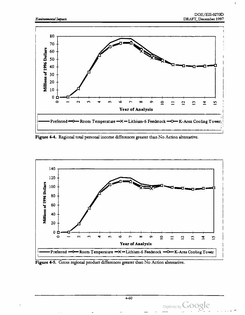
DOE /EIS-0270D
DRAFT, December 1997Environmental Impacts
80
70
60
50
40
Millions
of
1996
Dollars
30
20
10
g
0 0 a1
2 3 4 5 9
10
11
12
13
14
15
Year of Analysis
Preferred Room Temperature -X - Lithium -6 Feedstock K - Area Cooling Tower
Figure 4-4 . Regional total personal income differences greater than No Action alternative.
140
120
100
80
Millions
of
1996
Dollars
60
40
20
0
1 2
က
4 5 8 9
10
11
12
13
14
15
Year of Analysis
Preferred Room Temperature -X - Lithium -6 Feedstock -K-Area Cooling Tower
Figure 4-5 . Gross regional product differences greater than No Action alternative.
4-60
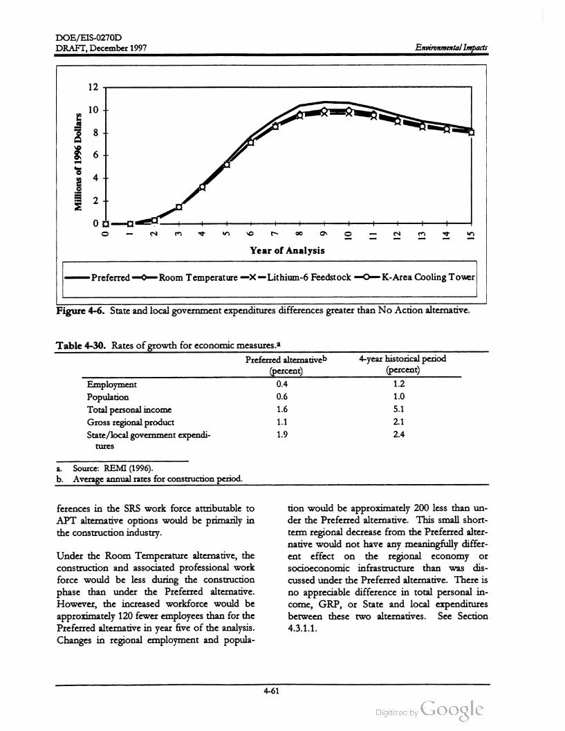
DOE /EIS -0270D
DRAFT,December 1997 EnvironmentalImpacts
12
10
8
6
Millions
of1996
Dollars
2
0
20
က
94 10
11
12
13
14
15
Year of Analysis
Preferred Room Temperature -X - Lithium -6 Feedstock OK-Area Cooling Tower
Figure 4-6 . State and local government expenditures differences greater than No Action alternative .
Table 4-30. Rates of growth for economicmeasures.a
Preferred alternativeb
(percent)
Employment0.4
Population0.6
Total personal income1.6
Gross regional product1.1
State / local government expendi1.9
tures
4 -year historical period
(percent)
1.2
1.0
5.1
2.1
2.4
a . Source: REMI (1996 ).
b . Average annual rates for construction period.
ferences in the SRS work force attributable to
APT alternative options would be primarily in
the construction industry .
on orUnder the Room Temperature alternative, the
construction and associated professional work
force would be less during the construction
phase than under the Preferred alternative.
However, the increased workforce would be
approximately 120 fewer employees than for the
Preferred alternative in year five of the analysis.
Changes in regional employment and popula
tion would be approximately 200 less than un
der the Preferred alternative. This small short
term regional decrease from the Preferred alter
native would not have any meaningfully differ
ent effect the regional economy
socioeconomic infrastructure than was dis
cussed under the Preferred alternative. There is
no appreciable difference in total personal in
come, GRP , or State and local expenditures
between these two alternatives. See Section
4.3.1.1.
4-61

DOE /EIS -0270D
DRAFT, December 1997Environmental Impacts
Table 4-31. Workforceby alternative.a
Year
Alternative 1 2 3 4 5 6 7 8 9 10 11
52 383 939 1,247 1,404 1,373 1,312 930 804 529Preferred altema
tive
525
49 369 912 875 767 529 5251,190
1,171
1,283
1,266
1,280
1,267
1,222
1,17349 365 898 807 719 529 525
Room temperature
Lithium - 6 Feed
stock
K -Area Cooling
Tower
Coal-fired powerb
Gas-fired powerb
49 369 908 1,171 1,262 1,259 1,204 865 759 529 525
49 369 974 1,599 2,282 1,545 1,059 951 713 7092,380
1,59149 369 912 1,322 1,561 1,342 985 877 639 635
Year
Alternative 12 13 14 15 16 17 18 19 20 21 After
482 472 463 453 445 439 434 428 423 418 418Preferred altema
tive
482 472 463 453 445 439 434 428 423 418 418
482 472 463 453 445 439 434 428 423 418 418
Room temperature
Lithium -6 Feed
stock
K -Area Cooling
Tower
Coal-fired powerb
Gas-fired powerb
482 472 463 453 445 439 434 428 423 418 418
666 656 647 637 629 623 618 612 607 602 602
592 582 573 563 555 549 544 538 533 528 528
a . Source: LANL (1997).
b . Includes Preferred alternative plus power plant labor.
4.3.2.2 Operations
In the longer term the differences between the
room temperature and Preferred alternative
would not be meaningful in any of the meas
ures .
The regional socioeconomic impacts under the
room temperature alternative would be the
same as for the Preferred alternative. See Sec
tion 4.3.1.2 .
be approximately 140 less than that for the Pre
ferred alternative in year 5, with a smaller or
nonexistent difference in other years. Under
the Lithium -6 Feedstock Material alternative,
annual regional employment and population
would be less than that under the Preferred al
ternative by approximately 200 and 250, respec
tively, in the short term . Total personal income
and GRP would be approximately $7 and
$ 9 million less than under the Preferred alterna
tive. There would be no appreciable difference
in state and local expenditures between either
the Lithium -6 Feedstock Material or Preferred
alternative during the construction phase .
4.3.3 APT WITH LITHIUM -6
FEEDSTOCK
4.3.3.1 Construction
Under this alternative, the APT construction
and associated professional work force would
The regional socioeconomic impacts under the
Lithium - 6 Feedstock Material alternative would
be the same as those for the Preferred alterna
tive. See Section 4.3.1.1.
4-62

DOE / EIS -0270D
DRAFT,December 1997Environmental Impacts
4.3.3.2 Operations
During the operations phase, there would be no
appreciable differences in any of the regional
measures between this alternative and the Pre
ferred alternative. The regional impacts under
this alternative are the sameas for the Preferred
alternative. See Section 4.3.1.2 .
native. There would be no appreciable differ
ence in total personal income, GRP , or State
and local expenditures between either the K
Area Cooling Tower or Preferred alternative in
either the long or short term .
The regional socioeconomic impacts under the
K -Area Cooling Tower alternative would be the
same as those for the Preferred alternative. See
Section 4.3.1.2 .4.3.4 APT WITH K -AREA COOLING
TOWER AND APT WITH ONCE
THROUGH COOLING 4.3.5 ENVIRONMENTAL JUSTICE
4.3.4.1 Construction
Under the K -Area Cooling Tower alternative,
the APT construction and associated profes
sional work force would be approximately 40
less than for the Preferred alternative in year 5 ,
with smaller or nonexistent differences in other
years. A fourth (and last) cooling option is
once-through with river water make-up. The
workforce for this option is estimated to be
close to the workforce for the K -Reactor cool
ing water tower. As such , there would not be
appreciable differences in the regional economic
impacts of these two cooling options and there
is no distinction made in the analysis between
them .
This EIS examines whether minorities or low
income communities (as defined in Section
3.5.2) could receive disproportionately high and
adverse human health and environmental im
pacts. Even though DOE expects little or no
adverse health impacts from any of the alterna
tives, it analyzed whether there would be
" disproportionately high and adverse human
health or environmental effects (of these alter
natives) on minority populations or low -income
populations” (Executive Order 12898 ). Fig
ures 3-17 and 3-18 show minorities or low
income communities, respectively, by census
tract. This section discusses predicted average
radiation doses received by individuals in those
communities and compares them to the pre
dicted per capita doses that other communities
in the 50-mile region could receive. It also dis
cusses impacts of doses that downstream com
munities could receive from liquid effluents
from all alternatives, and potential impacts from
nonradiological pollutants
Under the K -Area Cooling Tower alternative,
annual regional employment and population
would be approximately 210 and 230 less than
under the Preferred alternative.
Total personal income and GRP would be ap
proximately $ 7 and $ 9 million less than under
the Preferred alternative. There would be no
appreciable difference in state and local ex
penditures between the K -Area Cooling Tower
alternative and the Preferred alternative. The
short-term regional socioeconomic impacts of
construction would be the same as those for the
Preferred alternative . See Section 4.3.1.1.
Figure 4-7 shows a wheel with 22.5 -degree sec
tors and concentric rings from 10 to 50 miles at
10 -mile intervals. DOE calculated a fraction of
the total population dose for each sector (Table
4-32), laid the sector wheelover the census tract
map, and assigned each tract to a sector. If a
tract fell in more than one sector, the analysis
assigned it to the sectorwith the largest value.
4.3.3.2 Operations
In the longer term , there would be no appre
ciable difference in employment or population
between this alternative and the Preferred alter
DOE analyzed the impacts by comparing the
per capita dose received by each type of com
munity to the other types of communities in a
defined region . To eliminate the possibility that
4-63
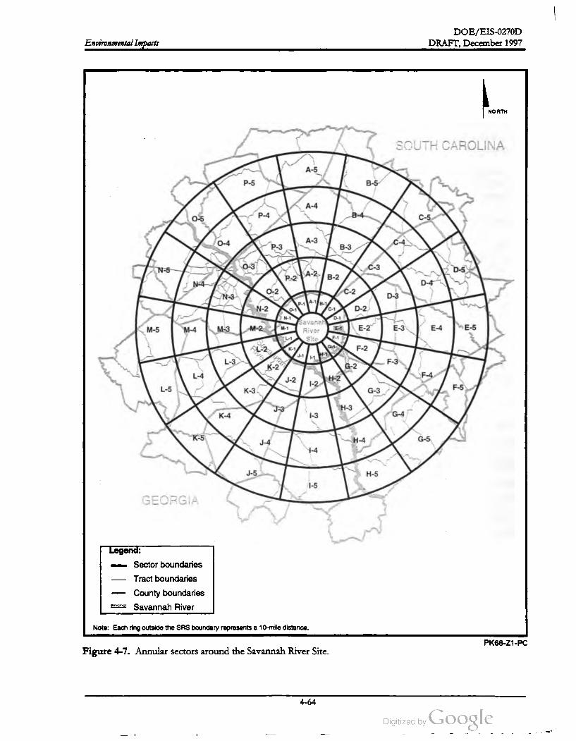
DOE/ EIS -0270D
Environmental Impacts DRAFT, December 1997
NORTH
SOUTH CAROLINA
A -5
P -5 B -5
A -4
0-5 P-4B -4
C - 5
0-4A - 3 C - 4
P - 3 B - 3
N - 5
03
C - 3D -5
A - 2P -2 B - 2
N - 4 D - 4
0-2 C - 2
N - 3 D - 3
N - 2 C - 1 D - 2
N - 1 D -1
M -5 M - 4 M - 3M - 2 M - 1
Savanah
River
Site
E - 2 E - 3 E - 4E -5
F - 1
Sorainen
K - 1 F - 2
L -3
J-1 H
Me
F -3
K - 2 G - 2
L - 4F - 4
H -2J-2 1-2
L -5K - 3 G - 3
F -5
J -3 H - 3
K - 4
1-3 G - 4
K -5J - 4 H - 4 G -5
1-4
J- 5 H -5
1-5
GEORGIA
Legend :
- Sector boundaries
Tract boundaries
County boundaries
SEITE Savannah River
Note: Each ring outside the SRS boundary represents a 10-mile distance.
PK68 -Z1-PC
Figure 4-7 . Annular sectors around the Savannah River Site.
-
4-64

DOE / EIS-0270D
Table
4-32
.Annular
sector
factors
for
local
dose
evaluations
.
Fraction
of
total
population
dose
received
byaverage
person
insector
Fraction
of
total
population
dose
insector
1
1
(5-10
mi
)
2
(10-20
mi
)
3
(20-30
mi
)
4
(30-40
mi
)
5
(40-50
mi
)
2
(10-20
mi
)
3
(20-30
mi
)
4
(30-40
mi
)
5
(40-50
mi
)
DRAFT,December 1997
Sectora
(5-10
mi
)
A( N)3.1x10⁻⁴
2.8x10⁻²
2.7x10⁻²
8.6x10⁻³
1.5x10⁻²
1.2x10⁻⁵
5.2x10⁻⁶
2.7x10⁻⁶
1.7x10⁻⁶
1.2x10⁻⁶
B (NNE
)5.9x10⁻⁵
5.8x10⁻³
4.7x10⁻³
6.5X10⁻³
1.5X10⁻²
9.8x10⁻⁶
4.4x10⁻⁶
2.3x10⁻⁶
1.5x10⁻⁶
1.0x10⁻⁶
C(NE
)1.0x10⁻⁵
1.4x10⁻²
7.0X10⁻³
8.3x10⁻³
1.18X10⁻²
1.0x10⁻⁵
4.6x10⁻⁶
2.4x10⁻⁶
1.6x10⁻⁶
1.2x10⁻⁶
D (ENE
)2.8x10⁻⁴
1.3x10⁻²
9.6x10⁻³
7.4x10⁻³
4.2x10⁻²
1.0x10⁻⁵
4.1x10⁻⁶
2.1x10⁻⁶
1.4x10⁻⁶
1.0x10⁻⁶
E(E)1.3x10⁻³
2.2x10⁻²
8.9x10⁻³
9.7x10⁻³
3.5x10⁻³
8.3x10⁻⁶
3.3x10⁻⁶
1.7x10⁻⁶
1.1x10⁻⁶
8.0X10⁻⁷
F ( ESE
)2.6x10⁻⁴
4.4x10⁻³
2.8x10⁻³
2.6X10⁻³
2.2x10⁻³
7.1x10⁻⁶
2.8x10⁻⁶
1.5x10⁻⁶
9.4x10⁻⁷
6.9x10⁻⁷
G ( SE
)1.3x10⁻⁴
1.1x10⁻³
6.8x10⁻³
4.5x10⁻³
4.3x10⁻³
5.0x10⁻⁶
2.0x10⁻⁶
1.0x10⁻⁶
6.8x10⁻⁷
5.0X10⁻⁷
H (SSE
)1.6X10⁻⁴
6.6x10⁻⁴
6.9x10⁻⁴
8.1x10⁻⁴
1.1x10⁻³
4.2x10⁻⁶
1.7x10⁻⁶
9.0x10⁻⁷
6.0x10⁻⁷
4.4x10⁻⁷
I (S)2.2x10⁻⁶
5.5
*10-4
7.2x10⁻⁴
2.7x10⁻³
9.3x10⁻⁴
2.2x10⁻⁶
9.8x10⁻⁷
5.4x10⁻⁷
3.7x10⁻⁷
2.8x10⁻⁷
J(SSW
)1.3x10⁻⁵
2.4x10⁻³
2.9x10⁻³
4.1x10⁻³
2.1x10⁻³
6.5x10⁻⁶
2.7x10⁻⁶
1.4x10⁻⁶
9.8x10⁻⁷
7.2x10⁻⁷
K ( SW
)1.9x10⁻⁴
4.2x
10-3
5.2x10⁻³
4.1x10⁻³
3.0x10⁻³
1.1x10⁻⁵
4.4x10⁻⁶
2.3x10⁻⁶
1.6x10⁻⁶
1.1x10⁻⁶
L(WW
)5.2x10⁻⁴
3.9x10⁻³
1.3x10⁻²
2.8x10⁻³
5.3x10⁻³
8.6x10⁻⁶
3.5x10⁻⁶
1.9x10⁻⁶
1.2x10⁻⁶
9.1x10⁻⁷
M ( W)3.4X10⁻⁴
8.5x10⁻³
1.1x10⁻²
7.5X10⁻³
4.6X10⁻³
6.2x10⁻⁶
2.6x10⁻⁶
1.4x10⁻⁶
9.4x10⁻⁷
6.8x10⁻⁷
N (WNW
)2.9x10⁻³
9.2x10⁻³
1.6x10⁻¹
5.0x10⁻²
8.3x10⁻³
6.4x10⁻⁶
2.7x10⁻⁶
1.5x10⁻⁶
9.9x10⁻⁷
7.2x10⁻⁷
O (NW
)2.2x10⁻³
2.1x10⁻²
1.6X10⁻¹
3.0x10⁻²
2.5x10⁻³
8.2x10⁻⁶
3.5x10⁻⁶
1.8x10⁻⁶
1.1x10⁻⁶
8.2x10⁻⁷
P (NNW
)4.0x10⁻³
8.5x10⁻²
6.3x10⁻²
9.7x10⁻³
6.3x10⁻³
1.1x10⁻⁵
4.7x10⁻⁶
2.3x10⁻⁶
1.5x10⁻⁶
1.0x10⁻⁶
a.Sector
letter
isletter
shown
on
Figure
4-1
.Letters
inparentheses
after
the
sector
letter
indicate
the
compass
direction
of
the
sector
.
Environmental Impacts
4-65

DOE / EIS -0270D
Environmental Impacts DRAFT, December 1997
impacts to a low -population community close
to the SRS with a high dose per person would
be diluted and masked by including it with a
high -population community farther from the
SRS, the analysis made comparisons within a
series of concentric circles, the radii of which
increase in 10 -mile increments.
in the areas downstream from the SRS are well
distributed, there would be no disproportionate
impacts among minority or low -income com
munities.
To determine the radiation dose received per
person in each type of community, DOE mul
tiplied the number of people in each tract by
that tract's dose value to obtain a total popula
tion dose for each tract. DOE summed these
population doses for each type of community
over each concentric circle and divided by the
total community population to obtain a com
munity per capita dose for each circular area.
Because the per capita dose for communities
(Table 4-32) would be constant for all alterna
tives, the relative differences in impacts between
any identified communities also would remain
constant for all alternatives. Thus, Figure 4-8
and Table 4-33 show the distribution of per
capita dose to types of communities within the
50-mile region. As shown in Figure 4-8 , this
analysis indicates that releases would not dis
proportionately affect minority communities
(population equal to or greater than 35 percent
of the total population) or low income (equal to
or greater than 25 percent of the total popula
tion) in the 50-mile region ; that is, when the per
capita doses are compared horizontally in Fig
ure 4-8, the per capita doses do not vary greatly.
The distribution of carcinogenic and criteria
pollutant emissions due to routine operations,
and of criteria pollutants from construction ac
tivities, would be essentially identical to those
presented for airborne radiological emissions
because distribution pathways would be the
same. As a result, minorities or low - income
communities would not be disproportionately
affected by nonradiological emissions from any
of the alternatives. Because nonradiological
pollutant emissions would have only minimal
impacts for any of the alternatives, and would
not be disproportionately distributed among
types of communities, there are no environ
mental justice concerns related to these pollut
ants for any of the alternatives .
4.4 Impacts of Electric Power
Supply
The APT will require large amounts of elec
tricity to operate. The Department is con
sidering either purchasing electricity from
existing sources and through market trans
actions, or obtaining from a new electricity
power generating plant. If a new generating
plant is required, appropriate NEPA analy
ses would be performed and tiered to this
document.
For illustrative purposes, DOE used an annual
total population dose of 1 person -rem to pre
pare Figure 4-8 and its supporting data in Table
4-33. For any other population dose, the per
capita dose for identified communities can be
determined by multiplying that population dose
by the numbers in Table 4-33.
Under the existing capacity and market
transaction scenario , assuming the pro
jected mix of electricity generation sources
for the years 2005-2007, potential incre
mental environmental impacts would in
crease by 1 to 3 percent. If a new electricity
generating plant is constructed, potential
impacts would depend upon its location .
Section 4.4.2 describes representative im
pacts, assuming SRS is the location for a
new plant. In this case, impacts would likely
be larger on a local basis than purchasing
electricity from existing capacity which would
have the effect of decentralizing the impacts .
Sections 4.1.2 and 4.1.3 discuss predicted po
tential doses to the downstream population
from exposure to water resources and to the
offsite maximally exposed individual, respec
tively. Those doses reflect people using the Sa
vannah River for drinking water, sports, and
food (fish). Because the identified communities
4-66
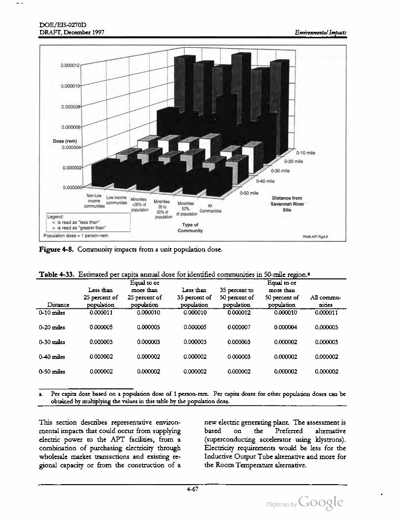
DOE /EIS -0270D
DRAFT,December 1997 Environmental Impacts
0.000012
0.000010
0.000008
0.000006
Dose (rem )
0.000004
1919
0-10 mile
0-20 mile
0.0000021
0-30 mile
0-40mile
0.000000
Non-Low0-50 mile
Low incomeincome
communities < 35% ofMinorities
communities
Minorities
35 to
50 % of
population
population
Minorities
50 %
ofpopulation
Distance from
Savannah River
Site
All
Communities
Legend:
< is read as "less than"
> is read as "greater than"
Population dose = 1 person-rem
Type of
Community
PK68-APT- Fig4-8
Figure 4-8. Community impacts from a unit population dose.
Table 4-33. Estimated per capita annual dose for identified communities in 50 -mile region.a
Equal to or Equal to or
Less than more than Less than 35 percent to more than
25 percent of 25 percentof 35 percent of 50 percent of 50 percent of All commu
Distance population population population population population nities
0-10 miles0.000011 0.000010 0.000010 0.000012 0.000010 0.000011
0-20 miles 0.000005 0.000005 0.000005 0.000007 0.000004 0.000005
0-30 miles 0.000003 0.000003 0.000003 0.000003 0.000002 0.000003
0-40 miles 0.000002 0.000002 0.000002 0.000003 0.000002 0.000002
0-50 miles 0.000002 0.000002 0.000002 0.000002 0.000002 0.000002
a . Per capita dose based on a population dose of 1 person- rem . Per capita doses for other population doses can be
obtained by multiplying the values in this table by the population dose.
on
This section describes representative environ
mental impacts that could occur from supplying
electric power to the APT facilities, from a
combination of purchasing electricity through
wholesale market transactions and existing re
gional capacity or from the construction of a
new electric generating plant. Theassessment is
based the Preferred alternative
(superconducting accelerator using klystrons).
Electricity requirements would be less for the
InductiveOutput Tube alternative and more for
the Room Temperature alternative.
4-67

DOE /EIS -0270D
DRAFT, December 1997Environmental Impacts
The analysis provides information on potential
impacts associated with the power supply alter
natives and issues that would be included in
future NEPA documents. The analysis quanti
fies impacts where appropriate and compares
the Power Purchase/Existing Capacity alterna
tive and the New Electricity Generating alter
native, along with two options for a new plant --
coal-fired and natural-gas-fired.
applied environmental impact factors that had
been developed for another Environmental Im
pact Statement (DOE 1995c). These impact
factors are the environmental releases for a va
riety of power generation sources normalized to
powerlevel and are used to calculate the envi
ronmental impact of the generation of electricity
required for the project. The environmental
impact factors were combined with energy in
formation forecasts of electrical generation
mixes for the years 2005, 2010, and 2015 (DOE
1997b).
Section 4.4.1 discusses potential environmental
impacts of the Power Purchase alternative, and
Section 4.4.2 addresses new electricity generat
ing plants. Section 4.4.3 compares the electric
power supply alternatives.
The average generation mix for the forecasted
years is assumed to be themix that would sup
ply the APT average load of 350 megawatts.
The estimated releases that could be attributable
to the accelerator and its associated facilities are
listed in Table 4-41.
4.4.1 ELECTRICITY FROM EXISTING
CAPACITY AND THROUGH MARKET
TRANSACTIONS
Under this alternative, electricity for the APT
facilities would come from a combination of
existing capacity and purchases on the whole
sale power market rather than a newly con
structed, dedicated power plant (Exeter 1996 ).
A number of generation sources would provide
this power, rather than a single dedicated gen
eration source such as the new coal- fired and
natural-gas -fired powerplant options.
DOE estimated annual air emission rates but
did notmodel concentrations because the loca
tions of the emission sources and receptors are
not known. Radiological emissions and radio
logical effluent indicate that nuclear reactors are
part of the national generation mix.
Using DOE Energy Information Administra
tion (EIA ) national, regional, and state energy
forecasts, DOE based its estimates of the rela
tive incremental impacts associated with the
APT on baseline projections for the following
geographical areas:
The Department is having discussions with the
South Carolina Electric & Gas Company
(SCE & G ) concerning acquiring the electricity
required for the APT. Currently, SCE & G has
indicated no plans to build a new electricity
generating facility to meet APT power demands.
Rather than constructing a new facility, power
could be obtained from the wholesale market.
Should SCE & G agree to serve in a wholesale
marketing role, a pilot program could be insti
tuted early in the construction phaseofthe APT
to begin wholesale types of purchases for test
ing loads. Under a marketing arrangement, ap
proximately 50-100 Mw of electricity from firm
power contracts could be supplemented with a
mixture of interruptible contracts (Toole 1997).
Region Incremental impact
South Atlantic Regiona Less than 1 percent
South Carolina and Between 1 and 2percent
Georgia
South Carolina Between 2 and 3 percent
GeorgiaBetween 1 and 2 percent
a .The South Atlantic Region Census Division in
cludes Delaware, the District of Columbia,
Florida, Georgia, Maryland, North Carolina,
South Carolina, Virginia, and West Virginia.
To assess potential environmental impacts as
sociated with acquiring electricity through exist
ing capacity and market transactions, DOE
To estimate the environmental impact of the
APT power supply on a regional scale as op
posed to the U.S., a baseline was established by
4-68

DOE /EIS -0270D
DRAFT, December 1997 Environmental Impacts
site-specific National Environmental Policy Act
documentation would consider such impacts.
applying the assumed representative generation
mix used for the U.S. assessment to the regional
power generation forecasts. These relative in
creases are independentofthe power generation
mix since the environmental impact multipliers
are applied as constants to both the baseline and
the APT-adjusted baseline. These incremental
impacts would be relatively small when com
pared to baseline projections. The estimated
impacts assume that electricity generation
(based on the applied mix ) would occur in that
region and does not account for potential shifts
in generation mix due to such factors as changes
in fuel prices.
For impact categories that are potentially more
regional in nature such as impacts on air and
water and waste generation, estimates of repre
sentative impacts are based on the representa
tive plants. For assessmentpurposes, the SRS is
the assumed location for the powerplant, con
sistent with the option from the Tritium Supply
PEIS of constructing an electric generating
plant with the APT. Where possible, this
analysis uses information obtained for the Cope
Coal-Fired Plant (SCE & G 1995) and the Polk
Gas-Fired Plant (EPA 1994) to estimate theim
pacts if a similar facility is built on the SRS.4.4.2 CONSTRUCTION AND
OPERATION OF NEW ELECTRICITY
GENERATING PLANT
The Tritium Supply PEIS (DOE 1995c) identi
fied two types of electricity generation -- coal
fired and natural-gas- fired -- as reasonable op
tions if DOE chose to construct and operate a
new plant to provide electricity for the APT
facilities. The Tritium Supply PEIS identified
these sources but indicated the uncertainties
about the type of plant that would be built if
needed. This EIS provides an assessment of
the options; however, the type, size, and loca
tion of a powerplant in consultation with com
mercial utilities through which the action could
possibly be privatized, and would perform engi
neering, technical, and detailed environmental
evaluations (appropriate NEPA tiered to this
EIS ).
The analysis used a scaling approach to deter
mine environmental impact factors based on
both megawatt capacity and plant configuration
(i.e., the number and type of operating units)
that would depend on the impact factor. For
example, the designs, processes, and impacts in
the environmental assessment for the Cope
plant (SCE & G 1995) are based on one unit
scaled to the APT peak load requirement at 490
megawatts. The EIS for the Polk Plant (EPA
1994) separates the Integrated Gasification
Combined Cycle unit from the Combined Cycle
and Combustion Turbine units with respect to
designs, processes, and impacts and were simi
larly scaled to theAPT load requirement.
Table 4-34 compares the rated capacities of the
two generic plants and fuel consumption .
The following sections address the potential
environmental impacts associated with repre
sentative coal- and natural- gas-fired plants.
They do not address impacts that would be
closely related to a specific location, such as
those on threatened and endangered species,
biological resources, floodplains and wetlands,
prime farmland, cultural resource, visual re
sources, noise, and infrastructure (e.g., roads
and rail) because candidate sites have not been
selected. Generic issues associated with land
forms, geology ,and hydrogeology are discussed
since issues would be essentially the same re
gardless of location . Future siting decisions and
Table 4-34 . Comparison of rated capacities.
Operational factor Coal-fired plant Gas-fired plant
Annual electricity 3.6 TWhrs /year 3.6 TWhrs/year
generation
capacity
Average electricity 420 MW 420 MW
generation
Peak electricity 490 MW 490 MW
generation
Fuel ( coal and gas1.6x106
4.0x10¹⁰ cubic
consumption ) tons/year feet per year
The following sections provide an estimate of
environmental impacts for each facility type.
4-69
DOE /EIS-0270D
Environmental Impacts DRAFT,December 1997
4.4.2.2 Surface Water Resources4.4.2.1 Landforms, Soils, Geology, and Hy
drogeology
would vary
Construction. The magnitude of potential im
pacts to landforms, soils, geology, and hydro
geologyvary depending on the
characteristics of the selected site. As with the
APT facilities, powerplant construction would
require shaping the site topography, which
could include excavations for below -grade coal
unloading facilities, scrubber sludge ponds, and
ash disposal areas. Impacts from these actions
could include soil erosion , disturbance of eco
nomically valuable geologic resources, loss of
farmland, and groundwater depletion through
dewatering.
Construction . Potential surface water impacts
from the construction of a coal- or gas-fired
electric generating facility would include the dis
charge of groundwater to surface streams due to
potential dewatering of excavated areas such as
foundations, stream bed scouring, flooding,
bank erosion , and sedimentation. The magni
tude of the impacts would depend on the dis
tance to receiving water bodies, the quality of
the water bodies, and the extent the constitu
ents of the discharge water differ from those of
the receiving water.
DOE used the Cope and Polk plants as the
baseline to determine the acreage requirements
for a plant to serve the APT electricity require
ments. A coal-fired plant large enough to sup
port the APT and its related facilities could
require approximately 290 acres; a natural- gas
fired plant could require about 110 acres. In
take and discharge corridors, transmission lines ,
and substations could require additional acreage.
A natural-gas fired plant would require the
construction ofgas
trunk lines. The selection of
either type of plant on the SRS or elsewhere in
the Central Savannah River Region would re
quire the commitmentof land resources and the
conversion of land from its current use. In
addition , the selection of a site outside the SRS
boundary could result in the loss of agricultural
land and displacement ofhomeowners.
Operations. Potential impacts to surface wa
ters would include the removalof large volumes
of water from the Savannah River and the dis
charge of heated water and nonradiological
constituents to surface water bodies. DOE
used the information for the Cope coal-fired
plant (SCE & G 1995) and the Polk gas- fired
plant (EPA 1994) to scale the likely impacts
from a plant of the size required to support
APT electrical needs. Table 4-35 summarizes
and compares the approximate water require
ments and operating parameters for both types
of facility.
This analysis used cooling tower design parame
ters in the Cope environmental assessment to
model thermal impacts from powerplant cool
ing water blowdown and assumed Par Pond
would be the receiving waterbody. The analysis
conservatively represents the natural-gas- fired
plant.
Operations. During operations, a coal-fired
plant could require water for scrubber ponds,
ash disposal areas, and coal piles. The impacts
would vary depending on site characteristics.
Additional impacts could occur if groundwater
is chosen as a source of cooling water. A coal
fired plant of the capacity required to support
the APT facilities would require about 5,400
gallons of makeup water per minute, while a
natural-gas-fired plant would require about
2,000 gallons perminute .
The discharge of heated water from cooling
water systems can affect the temperature,
chemical makeup, and flow rate of the surface
water bodies that receive them . The magnitude
of the impacts depend on the design of the
cooling water system , and the size, configura
tion , and capacity of receiving water bodies (i.e.,
large reservoirs versus small streams). Impacts
to surface waters at the SRS would be similar to
those described for the APT facilities in Section
4-70

DOE / EIS -0270D
DRAFT,December 1997Environmental Impacts
Table 4-35. Water requirements and operating parameters.
Parameter Coal-fired plant
Circulating water flow rate 220,000 gallons per minute
Cooling tower temperature rise 22.7 ° F
Blowdown rate 960 gallons perminute
Make-up water 5,400 gallons per minute
Blowdown stream temperaturea Average 76 ° F
Maximum 92° F
Annual potable water consumption 1.5 million gallons per year
Annual nonpotable water consumption 2.4 billion gallons per year
Annual nonpotable water usage 4.7 billion gallonsper year
Natural- gas-f-fired plant
130,000 gallons perminute
20 ° F
380 gallons per minute
2,000 gallons perminute
Average 76 ° F
Maximum 92 ° F
0.8 million gallons per year
0.7 billion gallonsper year
1.4 billion gallons peryear
a .Thermalimpactmodeling results.
4.1.2, because cooling water system designs
would be based on the parameters of both the
Savannah River, as the source of cooling water,
and Par Pond, as the receiving water body. As
discussed in Section 4.1.2 , the discharge of ad
ditional volumes ofwater to Par Pond could in
crease the chance of resuspending Cesium -137.
The level of total dissolved solids discharged by
the powerplant would depend on the numberof
concentration cycles of the cooling water sys
tem and the chemicals added to prevent corro
sion , scaling , and biological growth .
Potential air emission sources for the coal- fired
powerplant, based on the Cope design, would
include pulverized coal-fired boilers, emergency
diesel generators, ash -scrubber waste silos ,
Number 2 fuel oil storage tanks, lime unloading
from rail cars, an auxiliary boiler, coal transfer
towers, lime silos, a coal storage and handling
system , and vehicle traffic. In addition , the
handling, conveying, and storing of coal, lime,
and ash and scrubber waste would produce fu
gitive dust.
4.4.2.3 Air Resources
Construction . The construction of a new gen
erating facility could result in air quality impacts
such as fugitive dust due to site clearing and
emissions from the operation of construction
equipment. The impacts would be temporary
and would depend on the amount ofacreage to
be cleared and the type and duration of con
struction equipment operation, as discussed in
Section 4.1.3 . Other construction - related im
pacts could result from the need to build new
transmission lines and substations; discharge
corridors and outfalls; and pipelines for the
natural-gas-fired plant.
For the natural-gas-fired plant, based on the
Polk design, combustion -related air emissions
would come from combined -cycle units, com
bustion turbines, and the combustion of natural
gas or backup Number 2 fuel oil. Table 4-36
lists the emission rates and types of emissions
that would be likely from a coal- or natural-gas
fired generating facility . Table 4-37 lists the
modeled concentrations from an assumed loca
tion on the SRS.
The air quality assessment evaluates the conse
quences of pollutants associated with the coal
and natural gas-fired powerplants. DOE mod
eled powerplant emissions in compliance with
the guidelines of the Environmental Protection
Agency (EPA) Guideline on Air Quality Models
(EPA 1993) . The EPA recommended Indus
trial Source Complex Short Term Model
(Version 3) (ISCST3) as the most appropriate
Operations. The operation of either a coal- or
natural- gas-fired plant would result in air emis
sions, visible plume occurrences, and salt
deposition
4-71

DOE /EIS -0270D
Environmental Impacts DRAFT ,December 1997
Table 4-36 . Estimated powerplant emission rates (pounds per hour).
Coal- fired Natural- gas-fired
Pollutant powerplant powerplant
Carbon dioxide 970,000 640,000
Oxides of sulfur 1,700 1,700
Total suspended particulates 150 290
Particulate matter less than 10 microns 150 290
Carbon monoxide 9901,400
Volatile organic compounds 14 220
Oxides of nitrogen 1,700 1,900
Lead 0.026 0.31
Beryllium0.0006 0.017
Mercury0.066 0.28
Trace radioactive materials (curies) 1 0
Sources: Derived from SCE & G (1995), EPA (1994),DOE (1995c), and Okamoto (1984).
0.28
Table 4-37 . Estimated air quality impacts for coal- and natural-gas -fired powerplants atthe Savannah
River Site .
Concentration (microgramsper cubic meter)
Natural
Coal- fired gas- fired
AveragingSCDHEC SRS base powerplant powerplant
Pollutant time standarda lineb incremento incremento
Oxides of sulfur 3 -hour 1,300 690 87 37
24 -hour 365 220 18 11
Annual 80 16 1.2 1.0
Total suspended particulatesAnnual 75 43 0.11 0.75
Particulate matter (< 10 microns) 24 -hour 150 81 1.6 13
Annual 50 4.80 0.11 0.75
Carbon monoxide 1 -hour 40,000 5,000 69 88
8 -hour 10,000 630 24 33
Ozone (as totalVOC) 1 -hour 235d N / A 0.9 N / A
Oxides of nitrogen Annual 100 8.8 1.2 0.79
Lead Max . 1.5 < 0.01 < 0.01 < 0.01
Quarter
Beryllium 24-hour 0.01 < 0.0001 < 0.01 < 0.01
Mercury24 -hour 0.25 0.0024 < 0.01 < 0.01
a .South Carolina Ambient Air Quality Standards.
b . Source: Shedrow (1997b ). Based on 1994 SRS air emission inventory, except Beryllium and mercury, which
are from the 1990 inventory .
c. Modeling results.
d . FederalOzone standard (40 CFR 50).
N / A = Not available .e .
4-72
DOE /EIS -0270D
DRAFT,December 1997 Environmental Impacts
4.4.2.4 Waste Generationmodel to perform the air dispersion modeling
analysis because it enables the estimation of dis
persion from a combination of point, area , and
volume sources. DOE provided SRS input
data , including 1-year onsite meteorological data
that represent Site characteristics. The analysis
based source characteristics on the Cope envi
ronmental assessment (coal-fired powerplant)
and the Polk EIS (natural-gas-fired powerplant).
For unavailable source characteristics, the
analysis assumed characteristics based on similar
source configurations at other utility facilities
that use similarprocesses.
Construction . The construction of a power
generating facility would produce nonhazard
ous, nonradioactive wastes, including solid
sanitary wastes, construction debris (mixed
rubble,metals, plastics), and sanitary waste.
erate about
Operations. The operation of an electric gen
erating facility would produce a number of liq
uid and sold waste streams. Based on the Cope
design, the coal-fired plant could generate
3.2 million gallons per day of wastewater; the
natural-gas-fired plant, based on the Polk de
sign, could generate about 290,000 gallons per
day of wastewater. If a plant were built on the
SRS, processes andmanagementsystemssimilar
to those described for the APT facilities (see
Section 4.1.6.1 and Appendix A ) to dispose of
thewastewater effluent.
DOE based the emission rates on an assumed
annual operating factor of 85 percent. It con
servatively assumed that the natural-gas-fired
powerplant would burn gasand fuel oil simulta
neously .
The evaluated concentrations were the maxi
mum occurring at or beyond the SRS boundary
or public access roads. In addition, the evalua
tion assumed that the emissions for a power
plant with incomplete source characteristics
would originate from a single point source; this
assumption generally results in higher concen
trations than would actually occur because the
emission sources are commonly separated geo
graphically from one another.
The Cope environmental assessment, indicated
that the coal- fired powerplant would not pro
duce hazardous waste by burning coal to gen
erate electricity . However, such a plant would
generate some hazardous wastes, similar to
those generated at any industrial facility , as a re
sult of ancillary activities (SCE & G 1995 ). The
Polk EIS indicated that the operation ofmost
power generation and ancillary equipment does
not generate hazardous wastes, as regulated un
der Subtitle C of the Resource Conservation
and Recovery Act, although generation facilities
use process-related- chemicals and other materi
als that typically contain small amounts of haz
ardous constituents.
Another potentialimpact from the operation of
a electric power generating facility would be
visible plumes (fogging) from cooling tower op
erations. Such plumes are a function of ambi
ent temperature, ambient dew point, and
turbulent mixing. The magnitude of plume im
pacts would depend on the location of recep
tors (e.g., the surrounding population). A
comparison of representative coal- and natural
gas-fired powerplant heat loads to the assess
ment of cooling tower plumes in Section 4.1.3.3
indicates that the coal-fired generating plant
would have a greater potential for visible plume
occurrences than either the APT facilities and
the natural-gas- fired powerplant.
The Polk EIS assumed a routine hazardous
waste generation rate equivalent to a small
quantity generator (between 100 and 1000 kilo
grams per month ). However, it also indicated
that, during periods of shutdown or high main
tenance, such a facility could generate larger
quantities of hazardous wastes, greater than
1,000 kilograms per month . These projections
would also apply to a coal-fired powerplant.
4-73

DOE /EIS-0270D
Environmental Impacts DRAFT,December 1997
Waste type
Hazardous wastes from powerplant mainte
nance activities would include waste oils con
taining solvent residuals, waste paint and paint
thinner, solvents and degreasers, and some ex
pendable components of machinery and equip
ment, such as batteries.
Table 4-38 . Estimated coal- fired solid waste
generation .
Quantity
(tons peryear)
Bottom ash 26,000
Pyrites 9,600
Fly ash 110,000
Scrubber waste 150,000
Holdup basin solids 16
Total solid wastes 290,000
The combustion of pulverized coal in conven
tional coal-fired boilers results in the generation
of fly ash and bottom ash. For the coal-fired
powerplant, about 80 percent of the ash pro
duced in the coal- fired units would leave the
furnace in the flue gas stream as fly ash, leaving
about 20 percent in the form of bottom ash.
The coal-fired powerplant would produce no
hazardous solid wastes by burning coal to gen
erate electricity
matter from incomplete fuel combustion) and
electromagnetic fields.
Scrubber operations used to clean flue gases
would generate calcium sulfite and sulfate . The
combination of fly ash and calcium sulfite and
sulfate would result in a solid waste. The con
stituents of scrubber waste are about 50 percent
fly ash and 50 percent calcium sulfite and sul
fate .
Pyrites would be mixed with the bottom ash
and placed in the ash waste area. Pyrites are
materials with a high iron content separated
from coal during the pulverizing process.
Scientists have conducted significant research
on the relationship between air pollution and
health effects to humans in terms ofmortality,
hospitalization for respiratory and heart disease,
aggravation of asthma, incidence and duration
of respiratory symptoms, lung function, and re
stricted activity. While the research shows evi
dence of a statistical association between air
pollution and health effects, causal relationships
are nonconclusive (Wilson and Spingler 1996).
In general, the effects of air pollution appear to
reduce the lung function in an irreversible way.
Lung functions decline with age, and in the
presence of air pollution, pulmonary ailments
occur at an earlier age than otherwise (Wilson
1996). Applying the results of previous studies
conducted in the United States (which suggest
that 70,000 persons die early through air pollu
tion) and assuming that one-third arise from
coal-fired electricity generation produces a co
efficient of 100 deaths per gigawatt hour
(Wilson 1996). The health effects from the op
eration of a gas-fired facility would be less be
cause the gaseous and particulate emissions
would be much less than those from a coal - fired
plant. The Polk EIS (EPA 1994) discusses
health effects associated with natural-gas-fired
turbines.
The treatment of plant wastewater would also
generate solid wastes. Solids that settled in a
holdup basin would be placed in the ash storage
area. Solids that settled in a coal pile runoff ba
sin would be returned to the coal pile. Solids
that settled in the ash and scrubber waste runoff
basin would be returned to their respective ba
sins.
Table 4-38 lists estimated quantities for each
solid waste type that a coal- fired plantwould be
likely to generate.
4.4.2.5 Human Health
The other potential health effect associated with
electric power generation is exposure to elec
tromagnetic fields, potentially resulting in cer
tain types of cancer. Transmission lines create
these fields, which are a function of the amount
The two main issues related to human health ef
fects from the generation of electric power are
air pollution (the release of gases and particulate
- -
1
4-74
DOE /EIS -0270D
DRAFT,December 1997Environmental Impacts
of current carried by the line and the height of
the conductors above the ground. Some epi
demiological evidence suggests an association
between magnetic field exposure and illness but
the body of evidence is not conclusive
(American Cancer Society 1997).
work force figures are scaled from the coal- fired
plant workforce by use of a conversion factor
(DOE 1995c). These two documents provide a
planning basis for estimating impacts and are
not intended to represent actual staffing of a
specific facility. Those decisions would be
made, as necessary, by the organization respon
sible for construction and operation of the gen
erating facility.
4.4.2.6 Socioeconomics
Coal-Fired Electricity Generating Plant.
As discussed above, the Preferred alternative is
that the APT electricity demand would be met
through capacity and market transactions. This
section examines the regional socioeconomic
impacts of constructing and operating a com
mercial electricity generating plant fueled by ei
ther coal or natural gas.
Table 4-39 shows the construction, startup, and
operating work force by SIC category of the
coal-fired plant. These numbers are added to
the Preferred alternative for the economic
analysis (see Table 4-29).
The analysis does not include a review of the ef
fect of such a generating facility on regional
electric rates or other economic implications of
expanding the regional electricity generating ca
pacity . In addition , it does notaddress costs of
building a generating plant except as the effects
of expanding the work force for construction
and operation .
Work force estimates for construction and op
eration of the coal-fired electricity generating
plant are derived from the Cope environmental
assessment (SCE & G 1995) . The estimates are
for construction and operation of two of the
three units discussed in that assessment. Esti
mates for operations work force for the natural
gas- fired electricity generating plant are from
the Western Area Power Administration (DOE
1995c). Thenatural-gas-fired plant construction
Construction . The analysis showed an increase
in regional employment, population , total per
sonal income, Gross Regional Product, and
state and local expenditures over both the No
Action and Preferred alternatives. The average
annual rates of growth for employment and
population (0.44 percent and 0.67 percent, re
spectively) during the construction phase would
still be less than for the 4 years prior to the
analysis period. Similarly, annual rates of
growth for total personal income, Gross Re
gional Product, and state and local expenditures
would be 1.59 percent, 1.14 percent, and 1.88
percent, respectively, which are less than the
historic values. See Table 4-30 . The impacts
would not institute a boom and would not ad
versely strain regional infrastructure or services.
7 8 9 10 11
Table 4-39. Coal-fired electricity generating plantwork force.a
Year
SIC Category 1 2 3 4 5 6
Construction 0 0 0 77 444 1,030
Utility
0 0 0 77 444 1,030
485
75
0
149
149
0
149
149
0
149
0
149
149Totalb 560 149
Year
18 19 20 21 After
149 149 149 149 149
12 13 14 15 16 17
Total (Utility)149 149 149 149 149 149
a . Source: SCE & G 1995 .
b . Power plant work force only, does not include preferred option.
4-75
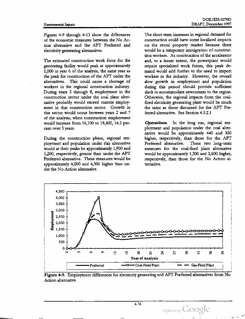
DOE /EIS -0270D
DRAFT, December 1997Environmental Impacts
Figures 4-9 through 4-13 show the differences
of the economic measures between the No Ac
tion alternative and the APT Preferred and
electricity generating alternatives.
The estimated construction work force for the
generating facility would peak at approximately
1,000 in year 6 of the analysis, the same year as
the peak for construction of the APT under the
alternatives. This could cause a shortage of
workers in the regional construction industry .
During years 5 through 8, employment in the
construction sector under the coal plant alter
native probably would exceed current employ
ment in that construction sector. Growth in
this sector would occur between years 2 and 7
of the analysis, when construction employment
would increase from 16,100 to 18,400, 14.3 per
cent over 5 years.
The short-term increases in regional demand for
construction could have some localized impacts
on the rental property market because there
would be a temporary immigration of construc
tion workers. As construction of the accelerator
and, to a lesser extent, the powerplant would
require specialized work forces, this peak de
mand would add further to the need to import
workers in the industry. However, the overall
slow growth in employment and population
during this period should provide sufficient
slack to accommodate newcomers to the region.
Otherwise, the regional impacts from the coal
fired electricity generating plant would be much
the same as those discussed for the APT Pre
ferred alternative. See Section 4.3.2.1
During the construction phase, regional em
ployment and population under this alternative
would at their peaks beapproximately 1,900 and
1,200, respectively, greater than under the APT
Preferred alternative. These measures would be
approximately 4,000 and 4,300 higher than un
der theNoAction alternative.
Operations. In the long run , regional em
ployment and population under the coal alter
native would be approximately 440 and 850
higher, respectively, than those for the APT
Preferred alternative. These two long -term
measures for the coal-fired plant alternative
would beapproximately 1,300 and 2,600 higher,
respectively , than those for the No Action al
ternative .
4,500
4,000
3,500
3,000
2,500
Employment
2,000
1,500
1,000
500
0
3 6
12
15
ñ
24
LT
30
33
36
39
Year of Analysis
Preferred Coal-Fired Plant Gas- Fired Plant
Figure 4-9. Employment differences for electricity generating and APT Preferred alternatives from No
Action alternative.
4-76

DOE /EIS -0270D
DRAFT,December 1997 Environmental Impacts
4,500
4,000
3,500
3,000
2,500Population
2,000
1,500
1,000
500
0
3 99
12
15
18
24
27
30
33
36
39
Year of Analysis
Preferred Coal-Fired Plant Gas-Fired Plant
Figure 4-10. Population differences for electricity generating and APT Preferred alternatives from No
Action alternative.
140
120
100
80
Millions
of
1996
Dollars
60 +
40
20
0
3
99
12
15
ã
24
27
30
33
36
39
Year of Analysis
Preferred Coal- Fired Plant Gas- Fired Plant
Figure 4-11. Total personal income differences for electricity generating and APT Preferred alternatives
from No Action alternative.
4-77
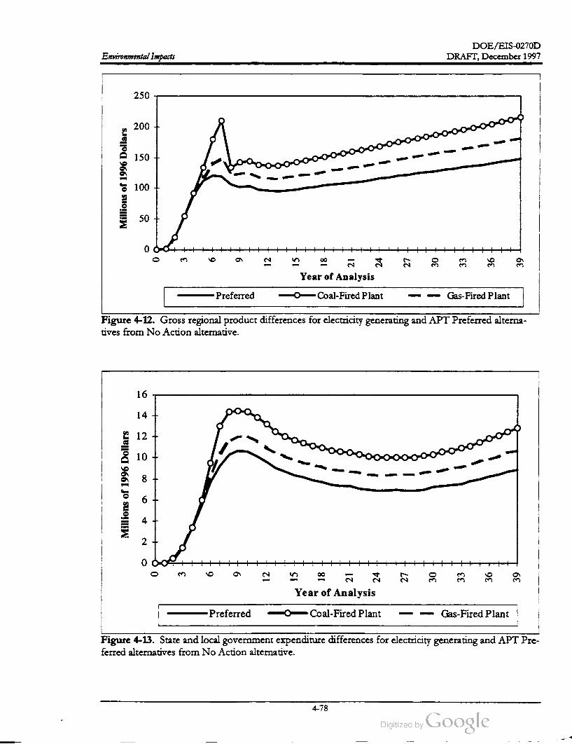
DOE /EIS-0270D
Environmental Impacts DRAFT, December 1997
250
200
150
Millions
of
1996
Dollars
100
50
0
6
a
12
15
18
5
24
27
30
33
36
39
Year ofAnalysis
Preferred Coal- Fired Plant Gas-Fired Plant
Figure 4-12 . Gross regional product differences for electricity generating and APT Preferred alterna
tives from No Action alternative .
16
14
12
10
8
Millions
of1996
Dollars
6
4
2
0
0
m
9
12
15
18
ä
24
27
30
33
36 39
Year of Analysis
Preferred Coal-Fired Plant Gas-Fired Plant
Figure 4-13 . State and local government expenditure differences for electricity generating and APT Pre
ferred alternatives from No Action alternative.
4-78

DOE /EIS -0270D
DRAFT,December 1997 Environmental Impacts
Total personal income,Gross Regional Product,
and state and local expenditures would be ap
proximately $21, $51, and $ 5 million higher, re
spectively, than for the APT Preferred
alternative at the time of APT startup. Later,
total personal income andGRP for this alterna
tive would grow slightly faster than under the
APT Preferred alternative. State and localgov
ernment expenditures would remain approxi
mately $ 3 million higher under this alternative
than under the APT Preferred alternative.
than those for the APT Preferred alternative.
Because the construction and operation work
forces of a gas-fired electricity generating plant
would be smaller than those for a coal- fired
plant, localized impacts to the construction in
dustry would be less under this alternative than
under the coal-fired plant alternative. Other
wise, the impacts would be much the same as
for the APT Preferred alternative. See Section
4.3.1.1 .
Natural Gas-Fired Generating Plant. Table
4-40 shows the construction, startup, and op
erating work force by SIC categoryof the natu
ral gas-fired electricity generating plant. These
numbers are added to the work force for the
APT Preferred alternative for the economic
analysis. See Tables 4-29 and 4-31.
Operations. Long-term effects of the gas - fired
plant would be slightly higher than for the APT
Preferred alternative. Regional employment and
population would be only approximately 200
and 380 higher, respectively, while total per
sonal income and Gross Regional Product
would be approximately $ 19 million and $25
million higher, respectively. Total state and lo
cal government expenditures would be only $ 1
million higher. The impacts would be much the
same as those for the APT Preferred alternative.
See Section 4.3.1.2.
Construction . Changes under this alternative
would be greater than those for the APT Pre
ferred alternative, but less than those for the
coal-fired plant alternative. Regional employ
ment and population under the gas- fired plant
alternative would be approximately 600 and
400, respectively , higher than those for the APT
Preferred alternative; and about 2,750 and
3,550, respectively, higher than those under the
No Action alternative. Total personal income,
Gross Regional Product, and total state and lo
cal expenditures would be only $18 million, $ 29
million , and $ 1 million, respectively, greater
4.4.3 COMPARISON OF POWER
SUPPLY ALTERNATIVES AND
POWERPLANTOPTIONS
This section compares the potential environ
mental impacts associated with the two electric
power supply options and new powerplant op
tions. Table 4-41 compares the Existing Ca
pacity and Market Transactions alternative and
1
Table 4-40. Natural gas-fired electricity generating plantwork force.a,b
Year
SIC Category 2 3 4 5 6 7
Construction 0 0 0 23 132 307 144
Utility37
Totalb 0 0 0 132 307 181
10
0
8
0
73
73
9
0
73
73
11
0
73
73
73
23 73
1312
73
2114
73
15
73
Year
17
73
16
73
18
73
19
73
20
73
After
73Total (Utility) 73 73
a .
b .
Source: DOE 1995c.
Power plantwork force only ; doesnot include Preferred alternative.
4-79

DOE /EIS -0270D
Environmental Impacts DRAFT,December 1997
Table 4-41. Projected environmentalimpacts for APT electric power supply alternatives.
Value
Existing New Powerplant alternative
Capacity /Market Coal- firedNatural- gas-fired
Transactions powerplant powerplant
Factor alternativeoptiona optiona
Air emissions (pounds per year)
Carbon dioxide 6,900,000,000 7,200,000,000 4,700,000,000
Sulfur oxides as SO2 2,200,000 12,000,000 13,000,000
Nitrogen oxides asNO2 8,100,000 12,000,000 14,000,000
Volatile organic compounds2,100,000 100,000 1,600,000
Carbon monoxide 6,700,000 7,300,000 10,000,000
Particulate matter (PM10) 1,400,000 1,100,000 2,100,000
Radioactive emissions (curies) 2,0000
Water consumption (acre -feet)2,100 11,700 1,900
Liquid radioactive effluent (curies)19,000
0 0
Solid waste (pounds per year)
Ash 32,000,000 260,000,000
Total metals 310,000 19,000,000
Nuclear solid waste 10,000 0 0
Additional land use (acres) N / A 290 110
Construction employees (work -years) N / A 1,097 308
Operations (employees per year)225 184 110
Annual values based on 85 percent capacity factor, even though APT should use only 70 percentof annual produc
tion .
N / A - Not applicable.
1
a .
the New Powerplant alternative. Table 4-42
compares the resource consumption for the
two powerplantoptions (coal and natural gas).
In general, the Existing Capacity /Market Trans
actions alternative would result in a lower level
of impacts in comparison to either new power
plant option due to the opportunity to use a mix
of existing generating capacity (e.g., the inclu
sion of some hydro which is essentially non
polluting). In addition , this alternative could
disburse environmental impacts over a number
of regions, which would decrease the relative
impact on affected environmental resources and
the public in comparison to a new powerplant
in a single location .
fired powerplantwould require the construction
of pipeline to transport fuel from the gas
transmission system ; the coal- fired plant would
use existing SRS rail capacity to transport coal.
As mentioned above, the level of the impacts
attributed to fuel transportation would depend
on the location of the site and its proximity to
accessible rail and pipeline infrastructure. The
coal-fired plant would produce higher sulfur di
oxide concentrations due to the higher sulfur
content of coal in comparison to natural gas.
The heat dissipation system at the coal- fired
plant would require more water than the gas
fired plant due to the increased heat load. The
coal plant would use steam turbines to generate
electricity and the gas -fired plant would use
steam turbines only in conjunction with the heat
recovery steam generators that recover exhaust
heat from the combustion turbines.
A coal-fired powerplant would use more land
because it would require an ash scrubber waste
area and coal storage facilities. A natural-gas
4-80

DOE /EIS -0270D
DRAFT, December 1997 Environmental Impacts
Table 4-42. Projected resource consumption for APT electric powerplantoptions.
Coal- fired Natural- gas-fired
Factor powerplant powerplant
Land (acres) 290 110
Water 4,700,000,000 1,400,000,000
(gallons per day)
Fuel 1,600,000 tons/year 4.0x10¹⁰ cubic
feet/ year
4-81
DOE /EIS -0270D
Environmental Impacts DRAFT, December 1997
References
Aho, J. M., and C. S. Anderson, 1985, Fish Population in Pond C : Dynamics of the Fish Kills (a Preliminary
Report), SWED -85 / 1209, Savannah River Ecology Laboratory, Aiken, South Carolina.
Aho, J. M., C. S. Anderson, and J. W. Terrell, 1986, Habitat Suitability Index Models and Instream Flow
Suitability Curves: Redbreast Sunfish , U.S. Fish and Wildlife Service, Fort Collins,Colorado
American Cancer Society, 1997, “ Cancer Facts & Figures - 1997: Environmental Cancer Risks,” paper
downloaded from the internet site of the American Cancer Association
http://www.cancer.org/statistics/97cff/97enviro.htmlon September 14, 1997.
at
American Fisheries Society, 1979, A Review of the EPA Red Book: Quality Criteria for Water,Water Quality
Section, American Fisheries Society, Bethesda,Maryland.
Arnett,M.W., 1993, Savannah River Site Environmental Data for 1992, WSRC -TR -93-077 , Westinghouse
Savannah River Site, Aiken, South Carolina.
Arnett,M.W., 1994, Savannah River Site Environmental Data for 1993, WSRC -TR - 94-077 , Westinghouse
Savannah River Site, Aiken , South Carolina.
Amett, M.W., 1995, Savannah River Site Environmental Data for 1994, WSRC-TR -95-077 , Westinghouse
Savannah River Site , Aiken , South Carolina.
Arnett, M.W., 1996 , Savannah River Site Environmental Data for 1995, WSRC - TR - 96-077, Westinghouse
Savannah River Site, Aiken , South Carolina.
Arnett, M. W., 1997, Savannah River Site Environmental Data for 1996 , WSRC -TR - 97-077 , Westinghouse
Savannah River Site, Aiken , South Carolina.
Arnett,M.W.and A.R.Mamatey , 1996, Savannah River Site Environmental Report for 1995 , WSRC
TR- 96-0075,Westinghouse Savannah River Company, Savannah River Site, Aiken , South Carolina .
Bennett, D.H., and R.W.McFarlane, 1983, The Fishes of the Savannah River Plant National Environmental
Research Park , SRO -NERP- 12 , Savannah River Ecology Laboratory, Aiken, South Carolina.
Brisbin, I. L., 1997, “ Impact of APT Proposed Alternatives on Par Pond Alligators,” personal
communication with Y. F. Abernethy (Halliburton NUS Corporation), Savannah River Ecology
Laboratory, Aiken,South Carolina, August 13 , 1997.
Carlander, K. D., 1969, Handbook of Freshwater Fishery Biology, Volume Two, Iowa State University Press,
Ames, Iowa, 431 pp .
Christy , E.J., J.O.Farlow , J. E.Bourque, and J. W.Gibbons, 1974, “ Enhanced Growth and Increased
Body Size of Turtles Living in Thermal and Post-Thermal Aquatic Systems,” in Thermal Ecolog ,
J.W.Gibbons and R.R. Sharitz (eds.), CONF- 130505, U.S. Atomic Energy Commission, pp. 277
284.
Chun, K. C. and J. Rabchuk, 1991, Environmental Impacts of Noise from Construction and Operation of NPR
Facilities at the Three Candidate Sites, Argonne NationalLaboratory , Argonne, Illinois.
4-82

DOE /EIS-0270D
DRAFT, December 1997 Environmental Impacts
Cooney, T.W., K. H.Jones, P. A.Drewes, J. W.Gissendanner, and B. W.Church, 1995 , Water Resources
Data South Carolina Water Year 1995, USGS-WDR -SC - 95-1, U. S. Geological Survey, Water
Resources Division , Columbia, South Carolina.
Cooney, T. W., K. H. Jones, P. A. Drewes, J. W.Gissendanner, and B. W. Church , 1996, Water
Resources Data, South Carolina Water Year 1996 , USGS-WDR-SC -96-1, U.S.Geological Survey,
Water Resource Division, Columbia,South Carolina.
Coutant, C.C., 1977 , “ Compilation of temperature preference data,” Journal of the Fisheries Research Board
of Canada , Volume 34, pages 139-745.
Cvancara, V. A., S. F. Stieber, and B. A. Cvancara, 1977,“ Summer Temperature Tolerance of Selected
Species ofMississippi River Acclimated Young of the Year Fishes,” Comparative Biochemical Physiology,
Volume56A,pages 81-85.
Dahlberg, M.D., and J. C. Conyers, 1974, “Winter fauna in a thermal discharge with observations on a
macrobenthos sample,” in Thermal Ecology, Proceedings of a symposium held at Augusta,Georgia,
May 3-5, 1973 , U.S. Atomic Energy Commission .
DiFiore-Smith , L., 1997a, Par Pond Hydrological Model: Proposed APT Process, Run 2, Savannah River
Institute, New Ellenton, South Carolina.
DiFiore -Smith , L., 1997b, Estimated Impacts on Lower Three Runs by the Proposed APT Process, Savannah River
Institute,New Ellenton , South Carolina.
DOE (U.S. Department of Energy), 1987a, Final Environmental Impact Statement, Alternative Cooling Water
Systems, DOE / EIS-0121, Savannah River Field Office, Aiken , South Carolina.
DOE (U.S. Department of Energy), 1987b , Impingement and Entrainment at the River Water Intakes of the
Savannah River Plant, Savannah River Field Office, Aiken, South Carolina.
DOE (U.S. Department of Energy), 1990, Final Environmental Impact Statement for the Continued Operation of
K-, L., and P -Reactors, Savannah River Site, Aiken , South Carolina,DOE/EIS-0147, Savannah River Field
Office, Aiken, South Carolina.
DOE (U.S. Department of Energy), 1995a, Environmental Assessment for the Construction and Operation of the
Three Rivers Solid Waste Authority, RegionalWasteManagement Center atthe Savannah River Site, DOE /EA
1079, Savannah River Operations Office, Aiken ,South Carolina.
DOE (U.S. Department of Energy), 1995b, Final Savannah River Site Waste Management Environmental
Impact Statement,DOE/ EIS -0217, Savannah River Operations Office, Aiken ,South Carolina.
DOE (U.S. Department of Energy), 1995c, Energy Planning and Management Program Environmental Impact
Statement,DOE / EIS -0182,Western Area Power Administration,Golden , Colorado.
DOE (U.S. DepartmentofEnergy), 1997a, Final Environmental Impact Statement, Shutdown of the RiverWater
System at the Savannah River Site, DOE /EIS -0268, Savannah River Operations Office, Aiken , South
Carolina .
DOE (U.S. Department of Energy), 1997b , Annual Energy Outlook 1997 with Projections to 2015,
DOE/EIA -0383(97), Energy Information Administration ,Washington, D.C.
4-83

DOE /EIS -0270D
Environmental Impacts DRAFT, December 1997>
Drew ,H.R. and J. E. Tilton, 1970, “ Thermal requirements to protect fish in Texas reservoirs,” Journal
of the Water Pollution Control Federation, Volume42, pages 562-572.
Durrett, C. W., and W.D. Pearson, 1975, “ Drift ofmacroinvertebrates in a channel carrying heated
water from a power plant,” Hydrobiologia 46 :33-43.
England, J. L., 1997, APTWasteManagementWhite Paper on APT Generation of Long-Lived Radionuclides
to IncludeGreater than Class C Low-Level Radioactive Waste Requiring Special Disposal Considerations,WSRC
TR -97-0259, Aiken, South Carolina,August 20.
EPA (U.S. Environmental Protection Agency ), 1985, Compilation of Air Pollutant Emission Factors, Volume I:
Stationary Point and Area Sources, AP -42,Washington,D.C.
EPA (U.S. Environmental Protection Agency), 1986, Quality Criteria forWater, EPA 440/5-86-001, Office
ofWater Regulations and Standards,Washington D.C.
EPA (U.S. Environmental Protection Agency), 1991, AmbientWater Quality Criteria Summary Table, Office
of Science and Technology, Health and Ecological Criteria Division,Washington, D.C.
EPA (U.S. Environmental Protection Agency), 1993, Guidelines on Air Quality Models (Revised ), Office of
Air and Radiation , Office of Air Quality Planning and Standards, Research Triangle Park , North
Carolina.
EPA (U.S. Environmental Protection Agency), 1994 , Final Environmental Impact Statement, Tampa Electric
Company - Polk Power Station, EPA 904 / 9-94-002(a),Region IV , Atlanta,Georgia.
Exeter, 1996 , Estimated Power Supply Costs for the Accelerator Production of Tritium Project, Exeter Associates,
Inc., Silver Spring, Maryland.
Fikani, M., 1997 , The Use of Concrete Shielding to Achieve Groundwater Activation Requirements,
APT-0534, internal correspondence, APT-Burns & Roe /General Atomic, September 22 .
Gibbons, J. W., and R. R. Sharitz, 1974, “ Thermal Alteration of Aquatic Ecosystems,” American Scientist,
Volume62 ,pages 660-670.
Golden, J., R. P. Ouellete, S. Saari, and P. N. Cheremisinoff, 1980, Environmental Impact Data Book, Ann
Arbor Science Publishers,Ann Arbor,Michigan .
Grace, J. B. and L.J. Tilly, 1976, “Distribution and Abundance of Submerged Macrophytes, Including
Myriophyllum Spicatum L. (Angiospermae), in a Reactor Cooling Reservoir,” Archives of Hydrobiology,
Volume 77,No. 4 , pages 475-487.
Hiergesell, R., 1997, interoffice memorandum to B.Shedrow ,Westinghouse Savannah River Company,
Aiken, South Carolina, September 19.
Holland,W.E., M.H.Smith , J. W.Gibbons, and D.H.Brown, 1974, “ Thermal tolerances of fish from
a reservoir receivingheat effluent from a nuclear reactor,” Physiological Zoology, Volume 37 , pages
110-118.
4-84

DOE/EIS -0270D
DRAFT, December 1997 Environmental Impacts
Howell, F.G., and J. B. Gentry, 1974, “ Effect of Thermal Effluents from Nuclear Reactors on Species
Diversity of Aquatic Insects,” in Thermal Ecology, J.W. Gibbons and R. R. Sharitz (eds.),CONF
730505, U.S. Atomic Energy Commission,pp. 562-571.
Hunter, C. H., 1997, “Nonradiological Air Quality Calculations for the Accelerator Production of
Tritium (APT) Environmental Impact Statement (EIS),” SRT-NTS-97-0279 (Draft), interoffice
memorandum to C. B. Shedrow , Westinghouse Savannah River Company, Aiken, South Carolina.
INTERA Environmental Consultants, Inc., 1980 , Remote Sensing for the Detection and Monitoring of Salt Stress
on Vegetation: Evaluations and Guidelines, Nuclear Regulatory Commission Report NUREG /CR-1231.
LANL (Los Alamos National Laboratory), 1997 , Accelerator Production of Tritium Conceptual Design Report,
U.S. DepartmentofEnergy, Los Alamos, New Mexico.
Mayer, J. J., and L.D.Wike, 1997, SRS Urban Wildlife: Environmental Information Document (Draft), WSRC
TR -97-0093,Westinghouse Savannah River Company, Aiken ,South Carolina.
McFarlane, R.W., R. F. Frietsche, and R.D.Miracle, 1978, Impingement and Entrainment of Fishes at the
Savannah River Plant: an NPDES 3166 Demonstration, E. I. du Pont de Nemours and Company,
Savannah River Laboratory, Aiken , South Carolina.
McMahon, T.E.,G.Gebhart,O.E.Maughan, and P. C. Nelson, 1984, Habitat Suitability Index Models and
Instream Flow Suitability Curves: Warmouth,U.S. Fish and Wildlife Service, Fort Collins, Colorado.
Mulchi, C. L.,and J. A. Armbruster, 1981, “Response of Corn and Soybean to Simulated Saline Aerosol
Drift from Brackish Water Cooling Towers,” Journal of Environmental Quality, Vol. 10, pp. 541-547 .
Muska, C. F., and R. A.Matthews, 1983, Biological Assessment for the Shortnose Sturgeon Acipenser brevirostrum
Leseur 1818 , DPST-83-754, Savannah River Laboratory, E. I. du Pont de Nemours and Company,
Aiken , South Carolina.
Nelson, D.H., 1974, “ Growth and Developmental Responses of Larval Toad Populations to Heated
Effluent in a South Carolina Reservoir,” in Thermal Ecology, J. W.Gibbons and R. R. Shartz (eds.),
CONF-730505,U. S. Atomic Energy Commission, pp. 264-276.
Nelson , E. A., 1997, “ Impact of APT Proposed Alternative on Pen Branch Restoration," personal
communication with Y. F. Abernethy (Halliburton NUS Corporation), Westinghouse Savannah
River Company, Aiken, South Carolina,September 8.
NRC (U.S. Nuclear Regulatory Commission ), 1985, Final Environmental Statement Related to the Operation of
Vogtle Electric Generating Plant Units 1 and 2, Docket Nos. 50-424 and 50-425, Georgia Power
Company,etal.,NUREG -1087, Office of Nuclear ReactorRegulation,Washington,D.C.,March .
NCRP (National Council on Radiation Protection and Measurements), 1993, Limitation of Exposure to
Ionizing Radiation , Report Number 116,Washington , D.C.
NUS (NUS Corporation), 1990 , Sound Level Characterization of the Savannah River Site, NUS-5251, Aiken ,
South Carolina.
NUS (NUS Corporation), 1991, Air Quality, Cooling Tower, and Noise Impact Analyses in Support of the New
Production Reactor Environmental Impact Statement, Aiken , South Carolina,March.
4-85

DOE /EIS -0270D
Environmental Impacts DRAFT, December 1997
NWS (National Weather Service), 1994, Local Climatological Data - Annual Summaries for 1993 - Part II,
Southern Region, National Climatic Data Center, Asheville,North Carolina.
Okamoto, K., 1984, Comments on “ Coal Energy vs. Nuclear Energy: A Comparison of the
Radiological Risk,” Health Physics, Volume 47, Number 50, Pergamon Press, New York ,
November
Parkin , R. B., and J. B. Stahl, 1981, “Chironomidae (Diptera ) of Baldwin Lake, Illinois, a cooling
reservoir,” Hydrobiologia, Volume 76, pages 119-128.
Patrick, R., 1969, “ Some Effects of Temperature on Freshwater Algae,” in Biological Aspects of Thermal
Pollution, Vanderbilt Univ . Press, pages 161-198.
Peterson , S. E., and R. M. Shutsky, 1976, “Some Relationships of Upper Thermal Tolerance to
Preference and Avoidance Responses of the Bluegill, in G. W. Esch and R.W.McFarlane (eds.),
Thermal Ecology II, Proceedings of symposium held April 2-5 , 1975, in Augusta,Georgia, pp. 148-153,
U.S. Energy Research and Development Administration, CONF-750425.
Pinder, J. E., 1997, “ Historic and Current Conditions in Ponds 2 and 5," personal communication with
D. E. Kennemore (Halliburton NUS Corporation ), Savannah River Ecology Laboratory, Aiken,
South Carolina, July 17, 1997.
REMI, 1996 , Economic Demographic Forecasting and Simulation 53-Sector Model, Regional Economic Model,
Inc., Amherst, Massachusetts .
SCDHEC (South Carolina Department ofHealth and Environmental Control, 1992 ,Water Classifications
and Standards (Regulation 61-68), Office of Environmental Quality Control, Columbia , South
Carolina.
SCE& G (South Carolina Electric and Gas Company), 1995, Environmental Assessment for Cope Power Plant,
Volume 1, Columbia , South Carolina.
Scott, W.B., and E. J. Crossman , 1973, Freshwater Fishes of Canada, Bulletin 184, Fisheries Research
Board ofCanada, Departmentof Fisheries and Oceans, Ottawa, Canada.
Shedrow , C. B., 1997a, Submittal of Technical Data for Preparation of APT EIS, ESH -EAP -97-0082,
Westinghouse Savannah River Company, Aiken , South Carolina, August 27.
Shedrow , C. B., 1997b, Submittal of Technical Data for Preparation of APT EIS, ESH -EAP -97-0048,
Westinghouse Savannah River Company, Aiken , South Carolina,May 20 .
Shedrow , C. B., 1997c, Submittal of Technical Data for Preparation of APT EIS, ESH -EAP -97-0059,
Westinghouse Savannah River Company, Aiken , South Carolina, June 16 .
Simpkins, 1997a, “APT Routine Aqueous Release Environmental Dosimetry Calculations,” SRT-EST
97-377 , interofficememorandum to C. B. Shedrow ,Westinghouse Savannah River Company, Aiken ,
South Carolina, June 25.
Simpkins, 1997b, “ APT Routine Aqueous Release Environmental Dosimetry Calculations,” SRT-EST
97-388, interoffice memorandum to C. B.Shedrow ,Westinghouse Savannah River Company, Aiken ,
South Carolina, July 24.
4-86

DOE / EIS -0270D
DRAFT, December 1997 Environmental Impacts
Simpkins, 1997c, “APT Routine Aqueous Release Environmental Dosimetry Calculations,” SRT-EST
97-395, interoffice memorandum to C.B. Shedrow ,Westinghouse Savannah River Company, Aiken ,
South Carolina, August 6 .
Simpkins, 1997), “ APT EIS Routine Release EnvironmentalDosimetry Calculations - Revised Source
Term ,” SRT-EST-97-452, interoffice memorandum to C. B. Shedrow , Westinghouse Savannah
River Company, Aiken , South Carolina, August 20 .
Simpkins, 1997e, “ APT EIS Routine Release Environmental Dosimetry Calculations - TEF Emissions,"
SRT-EST-97-400, interoffice memorandum to C. B. Shedrow , Westinghouse Savannah River
Company, Aiken, South Carolina, August 15.
Simpkins, 1997f, “ APT EIS Routine Release Environmental Dosimetry Calculations - Site # 6 Using H
Area Meteorology," SRT-ETS- 97-461, interoffice memorandum to C. B. Shedrow , Westinghouse
Savannah River Company, Aiken , South Carolina,September 26 .
Toole, G.L., 1997 , “ SCE& G discussions,” interoffice communication to R. Reynold , U.S. Department
ofEnergy, Savannah River Site , Aiken , South Carolina, October 23.
Wiederholm , T., 1984, “Responses of Aquatic Insects to Environmental Pollution,” in V.H.Resh and
D. M.Rosenberg (eds.), The Ecology of Aquatic Insects, pp. 508-557, Praeger Publishers,New York .
Wike, L. D., R. W. Shipley, A. L. Bryan , Jr., J. A. Bowers, C. L. Cunningham , R. R. del Carmen ,
G. P. Friday, J. E. Irwin , J. J. Mayer, E. A.Nelson, M.H. Paller, V. A. Rogers, W.L. Specht, and
E.Wilde, 1994, SRS Ecology: Environmental Information Document, WSRC- TR -93-496, Westinghouse
Savannah River Company, Aiken , South Carolina, September.
Wilde, E. W., 1985, Compliance of the Savannah River Plant P -Reactor Cooling System with
Environmental Regulations, DP-1708, E. I. du Pont de Nemours and Company, Inc., Savannah
River Plant, Aiken , South Carolina.
Wilde, E. W., and L. J. Tilly, 1985, Influence of P -Reactor Operation on the Aquatic Ecology of Par Pond - A
Literature Review , DP- 1698 , E. I. duPont de Nemours and Company, Savannah River Laboratory ,
Aiken , South Carolina.
Wilson, R., 1996 , “ Some Transboundary Environmental Issues of Public Concern ,” in Electricity, Health ,
and the Environment; Comparative Assessment in Support of Decisionmaking, Proceedingsofa Symposium on
International Atomic Energy Agency, Vienna, Austria, October 16-19 .
Wilson, R. and J. Spengler, 1996 , Particles in Our Air. Concentration and Health Effects, Harvard School of
Public Health, Cambridge,Massachusetts.
WSRC (Westinghouse Savannah River Company), 1996a, Savannah River Site Geology /Hydrogeology
Environmental Information Document,WSRC - TR -95-0046 .
WSRC (Westinghouse Savannah River Company), 1996b, APT CoolingWater Supply Make-Up Trade Study,
Savannah River Site, Aiken , South Carolina.
WSRC (Westinghouse Savannah River Company), 1996c, SRS Emergency Plan , SCD -7, Aiken , South
Carolina.
4-87


Chapter 5
Cumulative Impacts

DOE / EIS -0270D
DRAFT,December 1997Cumulative Impacts
Consistent with the National Environmental Policy Act, the potential impacts associated with
proposed APT Actionsmust be considered along with other past,present, and reasonable
foreseeable actions. This is done to help determine, cumulatively, if impacts will have large
and additive impacts on the environment.

DOE /EIS -0270D
DRAFT, December 1997Cumulative Impacts
CHAPTER 5. CUMULATIVE IMPACTS
Consistent with the National Environmental Policy Act, this chapter considers past, present, and rea
sonably foreseeable actions that could , along with the APT, result in cumulative impacts to the envi
ronment. It considers other ongoing Savannah River Site (SRS) operations, actions that might occur
in the future at SRS, the radiologicalimpacts of Plant Vogtle (a commercial nuclear powerplantacross
the Savannah River from the SRS ), and the consumption of electricity : With the exception of electric
ity consumption , construction and operation of the APT would nothave large additive or incremental
impacts on the environment.
lative impacts (see Section 1.6) or identified
other reasonably foreseeable actions (see Sec
tion 5.8). This analysis considers the following
NEPA documents related to the SRS:
The Council on Environmental Quality (CEO)
regulations that implement the procedural pro
visions of the National Environmental Policy
Act (NEPA) define cumulative effects as im
pacts on the environment that result from the
addition of the incrementalimpact of the action
to other past, present, and reasonably foresee
able future actions regardless of what agency
(Federal or non -Federal) or person undertakes
the other actions (40 CFR 1508.7). The U.S.
Departmentof Energy (DOE) based the cumu
lative impacts analysis in this chapter on actions
associated with the construction and operation
of a linear accelerator to produce tritium at the
Savannah River Site (SRS), other actions asso
ciated with onsite activities, and offsite activities
with the potential to cause related environ
mental impacts. This chapter describes cumu
lative impacts for: (1) public and worker health ,
(2 ) air resources, (3) water resources, (4) waste
generation, (5) utilities and energy consumption,
(6) ecological resources, and (7) socioeconomic
Savannah River Site Spent Nuclear FuelMan
agement Environmental Impact Statement on De
cember 31, 1996 (61 FR 69085); a NOIwas
issued to prepare this EIS . To date, it has
not been issued to the public. Information
used in this Chapter is based on maximum
values utilizing preliminary report data
(Young 1997). The proposed action of this
EIS is to provide additional capability at
SRS to receive and prepare spent nuclear
fuel for ultimate disposal at a Federal geo
logic repository. Specific actions needed to
accomplish this include construction and
operation of a Treatment and Storage Fa
cility, a Treatment Facility, and additional
dry storage capacity.
resources.
Radiological impacts from the operation of the
Vogtle Electric Generating Plant, a two-unit
commercial nuclear powerplant approximately
10 miles southwest of the center of the SRS
near Waynesboro , Georgia, are minimal, but
DOE has factored them into the analysis. Ra
diological impacts from the operation of the
Chem -Nuclear Services facility , a commercial
low -level waste disposal facility just east of the
SRS, are so small (SCDHEC 1992) that DOE
has not included them in this assessment.
Defense Waste Processing Facility Supplemental
Environmental Impact Statement, (DOE 1994a);
the selected alternative in the record of de
cision (ROD) is the completion of con
struction and the operation of the Defense
waste Processing Facility (DWPF) to im
mobilize high -level radioactive waste at the
SRS.
Savannah River Site Waste Management Final
Environmental Impact Statement (DOE 1995a);
the selected alternative in the ROD involves
the treatment and minimization of radioac
tive and hazardouswastes at the SRS.
In addition to this environmental impact state
ment (EIS), DOE has prepared other recent
NEPA documentation related to the SRS cumu
Programmatic Environmental Impact Statement for
Tritium Supply and Recycling (DOE 1995b);
5-1

DOE /EIS -0270D
Cumulative Impacts DRAFT, December 1997
public and site workers from radiological and
nonradiological releases on the Preferred alter
natives for the accelerator production of tritium
described in Chapter 4 .
DOE's decision is either to pursue the pur
chase of an existing commercial nuclear re
actor or irradiation services , or to build an
accelerator to produce tritium . DOE se
lected the SRS as the location for an accel
erator, if it decides to build one. In
addition, DOE would upgrade the tritium
recycling facilities to support either option.
The cumulative impact data in this chapter
is for the recycling (including upgrades)
portion of that EIS .
In addition, this analysis includes other SRS op
erations. Most SRS data are based on 1995 val
ues (Arnett and Mamatey 1996), which are the
most recentavailable .
5.1 Water Resources
Environmental Impact Statement - Interim Man
agement of Nuclear Materials (DOE 1995c);
DOE has begun implementing the selected
scenarios for most of the nuclear materials
discussed in that EIS with the exception of
selecting the “ comparative management
scenario” alternatives for H -Canyon Pluto
nium -239 solutions (process to metal),
Mark-16 and -22 fuels (process and storage
for vitrification at the Defense Waste Proc
essing Facility), and other aluminum -clad
fuel targets (processing and storage for vit
rification at DWPF).
Table 5-1 summarizes the estimated cumulative
radiological doses to human receptors from ex
posure to waterborne sources downstream from
the SRS. Liquid effluents from the Site could
contain small quantities of radionuclides that
would be released to SRS streams that are
tributaries of the Savannah River . The exposure
pathways considered in this analysis included
drinking water, fish ingestion, shoreline expo
sure, swimming, and boating. As discussed in
Section 4.1.2 , the Preferred alternative would
result in an annual radiological dose of
0.0000063 rem (or 0.0063 millirem ) to the
maximally exposed individual at the SRS
boundary from liquid releases.Environmental Impact Statement, Shutdown of the
River Water System at the Savannah River Site
(DOE 1997 ); the Preferred alternative is to
shut down and maintain the River Water
System and to place all or portions of the
system in a standby condition that would
enable restart if conditions or mission
changes required system operation .
The estimated cumulative dose from all SRS ac
tivities to themaximally exposedmember ofthe
public from liquid releases would be 0.00035
rem (or 0.35 millirem ) per year, well below the
regulatory standard of 4 millirem per year (40
CFR Part 141). Adding the population doses
associated with current and projected SRS ac
tivities would yield a cumulative annual dose of
12 person- rem from liquid sources. This trans
lates into 0.0061 latent cancer fatality for each
year of exposure of the 620,000-person popula
tion living within a 50-mile radius of the SRS.
Disposition of Surplus Highly Enriched Uranium
Final Environmental Impact Statement (DOE
1996); this cumulative impacts analysis in
corporates theMaximum Commercial Use -
Blending Disposition at SRS alternative
from that EIS.
Tritium Extraction Facility, preliminary data
for this proposed SRS facility was obtained
from DOE (1995d ) and Simpkins (1997).
At present, a number of SRS facilities discharge
treated wastewater to Upper Three Runs and its
tributaries via NPDES-permitted outfalls.
These include the F / H Area Effluent Treat
ment Facility and M -Area Liquid Effluent
Treatment Facility. Studies of water quality and
biota downstream of these outfalls suggest that
discharges from these facilities have not
This cumulative impacts analysis includes im
pacts from actions proposed in this EIS . DOE
based the calculated risks to members of the
5-2
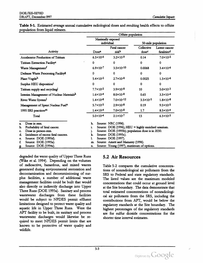
DOE /EIS -0270D
DRAFT, December 1997 Cumulative Impacts
Table 5-1. Estimated average annual cumulative radiological doses and resulting health effects to offsite
population from liquid releases.
Offsite population
Maximally exposed
individual 50-mile population
Fatal cancer Collective Latent cancer
Activity Dosea riskb dosec fatalities
Accelerator Production of Tritium 6.3x10⁻⁶ 3.2x 10⁻⁹ 0.14 7.0x10⁻⁵
Tritium Extraction Facilitye 0 0 0 0
Waste Management6.9x10-7 3.5X10⁻¹⁰ 0.0068 3.4x10⁻⁶
Defense Waste Processing Facility 0 0 0
PlantVogtleh 5.4x10⁻⁵ 2.7x10⁻⁸ 0.0025 1.3x10⁻⁶
SurplusHEU dispositioni 0 0 0 0
Tritium supply and recycling 7.7x10⁻⁵ 3.9x10⁻⁸ 10 5.0x10⁻³
Interim Management ofNuclear Materialsk 1.6x10⁻⁴ 8.0X10⁻⁸ 0.65 3.3x10⁻⁴
River Water System1.4x10-8 7.0X10⁻¹² 3.5x10⁻⁵ 1.8x10⁻⁸
Management of SpentNuclear Fuel 5.7x10⁻⁵ 2.9x10⁻⁸ 0.19 9.5x10⁻⁵
1995 SRS practices1.4x10-4 7.0X10⁻⁸ 1.7 8.5x10⁻⁴
Total5.0X10-4 2.1x10⁻⁷ 13 6.3x10⁻³
o
a .
C.
Dose in rem .
b . Probability of fatal cancer.
Dose in person - rem .
d . Incidence ofexcess fatal cancers.
Source: DOE (1995d).
f. Source: DOE (1995a).
Source: DOE (1994a).
j .1 .
h . Source: NRC (1996).
i. Source: DOE (1996);HEU = highly enriched uranium .
Source : DOE (1995b ); population dose is in 2030 .
k . Source: DOE (1995c).
Source: DOE (1997).
m . Source : Amett and Mamatey (1996 ).
Source: Young (1997),maximum of options.
e .
n .
5.2 Air Resourcesdegraded the water quality ofUpper Three Runs
(Wike et al. 1994). Depending on the volumes
of radioactive, hazardous, and mixed wastes
generated during environmental restoration and
decontamination and decommissioning of sur
plus facilities, a number of additional waste
management facilities could be built that would
also directly or indirectly discharge into Upper
Three Runs (DOE 1995a). Sanitary and process
wastewater discharges from these facilities
would be subject to NPDES permit effluent
limitations designed to protect water quality and
aquatic life in Upper Three Runs. Were the
APT facility to be built, its sanitary and process
wastewater discharges would likewise be re
quired to meet NPDES permit limits that are
known to be protective of water quality and
wildlife.
Table 5-2 compares the cumulative concentra
tions of nonradiological air pollutants from the
SRS to Federal and state regulatory standards.
The listed values are the maximum modeled
concentrations that could occur at ground level
at the Site boundary . The data demonstrate that
total estimated concentrations of nonradiologi
cal air pollutants from the SRS, including the
contributions from APT, would be below the
regulatory standards at the Site boundary. The
highest percentages of the regulatory standards
are for sulfur dioxide concentrations for the
shorter timeinterval estimates.
5-3

DOE /EIS -0270D
Cumulative Impacts DRAFT,December 1997
Table 5-2. Estimated maximum nonradiological cumulative ground -level concentrationsof criteria and
toxic pollutants (microgramsper cubic meter) at SRSboundary.a,b
Averaging Regulatory Other SRS APT Percent of
Pollutant time standardsourcesc preferred standard
Carbon monoxide 1 hour
8 hours
40,000
10,000
3,600
860
6.1
0.76
9.1
8.6
Annual 100 36 0.0091 36Nitrogen oxides
Sulfur dioxide 1,300
365
80
1,200
360
18
0.13
0.016
0.00014
94
98
23
3 hours
24 hours
Annual
Annual
24 hours
Annual
75 22 0.00057 29Total Suspended Particles
Particulate Matter
(> 10 microns)
150
50
110
25
0.016
0.0003
76
50
a .
b .
Sources: DOE (1995a,b ,c; 1996 ; 1997). Young 1997,Hunter and Stewart 1994.
The Tritium Extraction Facility would add annually 1,800 pounds of carbon monoxide,4,900 pounds of nitrogen
oxide, and 64 pounds of sulfur dioxide to the cumulative concentration of nonradiological pollutants.
All SRS sources including spent nuclear fuelmanagement, SRS waste management activities, tritium supply and re
cycling, disposition of surplus highly enriched uranium , interim managementof nuclear materials, and SRS baseline
emissions.
C.
onstrate that the addition of air emissions from
APT does not significantly affect airborne levels
of toxic pollutants or radioactivematerial.
5.3 Waste Generation
DOE also evaluated the cumulative impacts of
airborne radioactive releases in terms of dose to
a maximally exposed individual at the SRS
boundary. Table 5-3 lists the results of this
analysis, using 1995 emissions (1992 for Plant
Vogtle) as the SRS baseline. The cumulative
dose to themaximally exposed member of the
public would be 0.0027 rem (or 2.7 millirem )
per year , or about 27 percent of the regulatory
standard of 10 millirem per year (40 CFR
Part 61). Summing the doses to maximally ex
posed individuals for the 10 actions and base
line SRS operations listed in Table 5-3 is an
extremely conservative approach because it as
sumes that the maximally exposed individuals
would occupy the same location over the same
time period , which is a physical impossibility .
Table 5-4 lists cumulative volumes ofhigh -level,
low -level, transuranic, hazardous, and mixed
wastes that the SRS would generate. The values
are based on the SRS 30-year expected waste
forecast (WSRC 1994) which includes tritium
recycling waste. It also lists waste forecasts for
the APT Preferred alternative. The 30 -year
waste forecast is based on operations waste
forecast from existing generators and the fol
lowing assumptions: secondary waste from the
Defense Waste Processing Facility , In - Tank
Precipitation, and Extended Sludge Processing
operations addressed in the DWPF EIS (DOE
1994a); high-level waste volumes based on the
selected option for the F -Canyon Plutonium
Solutions EIS (DOE 1994b ) and the Interim
Management of Nuclear Materials at SRS EIS
(DOE 1995c); some investigation -derived
wastes handled as hazardous waste in compli
ance with the Resource Conservation and Re
covery Act; purge water from well sampling
Adding the population doses from current and
projected SRS activities, operation of the De
fense Waste Processing Facility, tritium supply
and recycling, and management of spentnuclear
fuel could yield a total annual cumulative dose
of 200 person- rem from airborne sources. The
total annual cumulative dose translates into 0.10
latent cancer fatality for each year of exposure
for the 620,000-person population living within
a 50 -mile radius of the SRS. These data dem
5-4

DOE /EIS -0270D
DRAFT, December 1997 Cumulative Impacts
riskb
Table 5-3 . Estimated average annual cumulative radiological doses and resulting health effects to offsite
population from airborne releases.
Offsite population
Maximally exposed individual 50-mile population
Fatal cancer Collective Latent cancer
Activity Dosea dosec fatalitiesd
Accelerator Production of Tatium3.6x10-5 1.8x10⁻⁸ 1.2 6.0X10⁻⁴
Tritium Extraction Facility 8.1x10⁻⁶ 4.1X10⁻⁹ 0.39 1.9x10⁻⁴
Waste Management 3.2x10⁻⁵ 1.6x10⁻⁸ 1.5 7.5x10⁻⁴
Defense Waste Processing Facility 1.0x10⁻⁶ 5.0x10⁻¹⁰ 0.071 3.5x10⁻⁶
Plant Vogtleh2.5x10-6 1.3x10⁻⁹ 0.04 2.1x10⁻⁵
Surplus HEU dispositioni2.0x10-5 1.0X10⁻⁸ 1.3 6.3x10⁻⁴
Tritium supply and recycling0.0020 1.0x10⁻⁶ 170 0.085
Interim Managementof Nuclear Materialsk 5.4x10⁻⁴ 2.7x10⁻⁷ 22 0.011
RiverWater System 6.9x10⁻⁶ 3.5X10⁻⁹ 0.0027 1.4x10⁻⁶
ManagementofSpentNuclearFueln1.5x10-5 7.5X10⁻⁹ 0.56 2.8x10⁻⁴
1995 SRS activities6.0x10-5 3.0x10⁻⁸ 3.5 0.0018
Total 0.0027 1.4x10⁻⁶ 200 0.10
a . h .
i.
C.
j .
Dose in rem .
b . Probability of fatal cancer.
Dose in person -rem .
d . Incidence of excess fatal cancers.
Source : DOE (1995d) and Simpkins (1997).
f. Source: DOE (1995 ) .
8 . Source : DOE (1994a).
k .
1.
Source: NRC (1996).
Source: DOE (1996 ); HEU = highly enriched uranium .
Source: DOE (1995b); population dose is for 2030.
Source: DOE (1995c).
Source: DOE (1997).
Source: Amett and Mamatey (1996 )
Source: Young (1997),maximum of options.
e .
m .
n .
Waste type
Table 5-4. Estimated cumulative waste generation from SRS operations (cubic meters).a,b
SRS operations activities APT volumed
High -levele150,750 0
Low - levelf 344,062 42,075
Hazardous/mixedg90,453 360
Transuranic 18,090 0
Total 603,355 42,435
a .
b .
Sources: WSRC (1994a); Hess (1995);DOE (1995d).
Based on a total 30-year expected forecast (excluding Environmental Restoration and Decontamination and De
commissioning activities).
Includes spentnuclear fuelmanagement, Defense Waste Processing Facility , stabilization of plutonium solutions in
F -Canyon , HB -Line operations, tritium supply and recycling, tritium extraction facility, and Naval Reactors Program
C.
waste .
e .
d . Valuesbased on estimated annualwaste quantities for the Preferred alternative (multiplied by 30 ).
The SRS operations estimate includes 131,000 cubic meters of liquid high -levelwaste currently in storage at F- and
H - Tank farms.
f. Quantity includes high concentration waste.
g . Quantity includes high concentration mixed waste.
5-5

DOE / EIS -0270D
DRAFT,December 1997Cumulative Impacts
Regional Waste Management Center is sched
uled to open in mid -1998 .
The APT would not generate large volumes of
radioactive, hazardous, or solid wastes and
would have very little impact on existing ca
pacities of SRS waste storage and /or manage
ment facilities.
handled as hazardous waste; and continued re
ceipt of small amounts of low -level waste from
other DOE facilities and Naval nuclear opera
tions. Waste generated from decontamination
and decommissioning and planned environ
mental restoration projects are not included in
the operations waste forecast. The estimated
quantity of waste from operations in this fore
cast during the next 30 years would be 600,000
cubic meters. In addition, waste associated with
environmental restoration and decontamination
and decommissioning activities would have a
30-year expected forecast of 710,000 cubic me
ters (WSRC 1994; Hess 1995) . Therefore, the
total amount of waste from SRS activities
(exclusive of APT operation) is estimated to be
approximately 1,300,000 cubic meters.
5.4 Utilities and Energy
Table 5-5 lists the cumulative consumption of
electricity from activities at the SRS. The values
are based on annual consumption estimates. Of
the SRS activities, accelerator production of
tritium would place the largest demand on elec
tricity resources. The estimated annual electric
ity use would be 3,100,000 megawatt-hours, as
discussed in Section 4.1.4 . This would be a
significant increase in cumulative electricity us
age at SRS.
As stated in Section 4.1.7.1, low -level waste
would be generated from APT maintenance,
radiological surveys, and production activities,
andmixed and hazardous waste would be gen
erated from APT maintenance activities. DOE
does not expect these activities to generate
high -level and transuranic waste . The total
30 -year waste volume associated with APT ac
tivities would be 42,000 cubic meters.
Under the Preferred alternative, to acquire elec
tricity from existing capacity and through mar
ket transactions, DOE estimates the potential
impacts of supplying the APT load through a
representative mix of generation types (see Sec
tion 4.4). Because the actual impacts would be
dispersed and the actual location of the electric
ity generation is unknown, DOE cannot esti
mate impacts in a meaningful, site -specific way.
The Three Rivers Solid Waste Authority Re
gional Waste Management Center at the Savan
nah River Site is being built for the disposal of
non-hazardous and non-radioactive solid wastes
from the SRS and eight surrounding South
Carolina counties. This municipal solid waste
landfill is intended to provide state of the art
(Subtitle D ) facilities for landfilling solid wastes
while reducing the environmental consequences
associated with construction and operation of
multiple county -level facilities (DOE 1995e). It
was designed to accommodate combined SRS
and county solid waste disposal needs for at
least 20 years, with a projected maximum op
erational life of 45 to 60 years (DOE 1995e).
The landfill is designed to handle an average of
1,000 tons per day and a maximum of 2,000
tons per day of municipal solid wastes. The
SRS and eight cooperating counties had a com
bined generation rate of 900 tons per day in
1995. The Three Rivers Solid Waste Authority
The estimated amount of water needed to op
erate the APT facilities in the Preferred alterna
tive would be about 3.2 billion gallons per year,
most ofwhich would be nonpotable water used
for makeup water for the mechanical-draft
cooling tower. In the Preferred alternative,
makeup water would be piped from the Savan
nah River using the River Water system .
At present, only one Savannah River pump
house (3G ) and one small river water pump
(installed in 1997) are in use, withdrawing 5,000
gallons per minute (2.6 billion gallons per year)
of water from the Savannah River for SRS in
dustrial facilities . If the Mechanical-Draft
Cooling Tower with River Water Makeup alter
native is implemented, an additional 6,000 gal
5-6

DOEJEIS-0270D
DRAFT,December 1997 Cumulative Impacts
Table 5-5 . Estimated average annual cumulative electrical consumption.
Electricity consumption
Activity (megawatt-hours)
Accelerator Production of Tritium 3,100,000
Tritium Extraction Facilitya 4,500
Defense Waste Processing Facility 32,000
SurplusHEU disposition 5,000
Tritium supply and recyclingd24,000
Interim Management of Nuclear Materialse 140,000
Waste Management N / Af
River Water System Shutdowng 2,500
1993 SRS usage 660,000
Management of SpentNuclear Fueli 24,000
Total 4,000,000
a .
b .
Source: DOE (1995d).
Source: DOE (1994a).
Source: DOE (1996); HEU = highly enriched uranium .
Source: DOE (1995b); includes recycling upgrades only.
Source: DOE (1995c).
f. Not available in Waste Management EIS .
Source: DOE (1997a).
h . Source : DOE (1995e).
i. Source: Young (1997).
C.
d .
e .
lons per minute of Savannah River water would
be pumped to APT facilities for cooling. If the
SRS is one of the four DOE sites chosen for
the “ blending down” of highly -enriched ura
nium (HEU ) to low -enriched uranium (LEU ),
approximately 5 million gallons per year of sur
face water would be required (DOE 1996).
Thus, the total projected surface (river) water
withdrawal over the projected APT operating
period would be about 11,000 gallons per min
ute (5.8x10⁹ gallons per year), which would
equal approximately 3 percent of the river water
withdrawn (380,000 gallons per minute) in 1988
when a full complement of SRS reactors last
operated and less than one percent of the aver
age Savannah River flow at the Site of 10,000
cubic feet per second (or 2.4x10¹² gallons per
year).
supply makeup water for APT cooling towers,
an additional 8.6 million gallons per day of
groundwater would be required. Spent nuclear
fuelmanagementactivities over the years 1998
2035 would require a small amount of ground
water, from 13,000 to 150,000 gallons per day ,
depending on the management option chosen
(Young 1997). An additional 2.5 million gallons
of groundwater could be required annually for
operation of a stand-alone Tritium Extraction
Facility (DOE 1995d). Thus, sitewide ground
water withdrawals over the projected APT op
erating period would range from about 18 to
21 million gallons per day if groundwater is used
to supplymakeup water to APT cooling towers.
This could exceed the estimated 16
25 million gallon-per-day production capacity of
theaquifer.
to
For purposes of comparison, DOE also exam
ined the cumulative impact of withdrawing
6,000 gallons per minute of groundwater for
cooling tower makeup. The current rate of
groundwater withdrawal for all uses (process
water, cooling, drinking water) at the SRS is es
timated to be 9 to 12 million gallons per day
(see Section 4.1.1). If groundwaterwere used to
The total groundwater withdrawal for county
and municipal water systems in the six -county
region of influence (ROI) is approximately
63million gallons per day, compared to an es
timated regional capacity of 167 million gallons
per day (HNUS 1997). This suggests that re
gional aquifers can accommodate additional
demand, although there are almost certainly
5-7

DOE /EIS -0270D
DRAFT, December 1997Cumulative Impacts
aquifers and areas within aquifers that are at or
near their production capacity . It should be
noted that the 63 million gallon per day with
drawal rate does not include shallow domestic
wells, nor does it include any wells for process
or potable water at industrial facilities in the six
county area , thus it slightly underestimates total
groundwater withdrawals in theROI.
ridge overlooking Upper Three Runs. The ini
tial land clearing for the landfill will involve 500
forested acres, with an additional 60 acres to be
cleared every 5 years for approximately 30 years
(DOE 1995e).
5.5 Public and Worker Health
Table 5-6 summarizes the cumulative radiologi
cal health effects of routine SRS operations
based on 1995 data and proposed DOE actions.
The EISs listed in this table describe the im
pacts resulting from proposed DOE actions. In
addition to estimated radiological doses to the
hypothetical maximally exposed individual and
the offsite population, Table 5-6 lists potential
latent cancer fatalities for the public and work
ers due to exposure to radiation . These data
demonstrate that operation of APT will mini
mally increase cumulative radiation doses to the
public and onsite workers.
On May 22, 1997 DOE announced (62 FR
28009) its intent to prepare an Environmental
Impact Statement on the disposition of the
United States' weapons-usable surplus pluto
nium . This EIS is tiered from the Storage and
Disposition of Weapons-Usable Fissile Materials Pro
grammatic EIS, for which a Record of Decision
(62 FR 3014) was issued on January 14, 1997.
Three types of plutonium -management facilities
could be built at the SRS: (1) a facility to disas
semble and convert pits into plutonium oxide
suitable for disposition, (2) a facility to immobi
lize surplus plutonium in a glass or ceramic
form for disposition in a geologic repository,
and (3 ) a facility to fabricate plutonium oxide
into mixed oxide fuel. Any of these facilities
could have an impact on SRS resources; how
ever, should any or all of these facilities be lo
cated at SRS they would likely be built in
previously disturbed or industrialized areas
(62 FR 28009).
5.6 Ecological Resources
Building the APT facility would require clearing
and grading a 250 acre forested site. Although
the preferred site contains no unique flora and
fauna and no sensitive or critical ecological
habitats, it does provide feeding, foraging,
roosting, breeding, nesting, and denning habitat
for a variety of reptiles, birds, and mammals.
Several other actions currently being carried out
or proposed by DOE could result in loss of un
developed, largely -forested land. Waste man
agement activities at the SRS are expected to
require the clearing of 107-940 additional acres
of undeveloped land by the year 2008, depend
ing on the volumes of radioactive, hazardous,
and mixed wastes generated by on -going opera
tions, environmental restoration , and decon
tamination and decommissioning of surplus
facilities (DOE 1995 ). The Three Rivers Solid
Waste Authority Regional Waste Management
Center,which includes a large landfill for non
hazardous municipal and solid wastes, is cur
rently being built between B- and D -Areas on a
Thus, if all reasonably- foreseeable actions cur
rently being considered by DOE were to be
implemented , 1,000-1,800 acres of undeveloped
SRS land could be converted to industrial uses
by the year 2008. This represents 0.6 to 1.0
percent of the 180,000 acres of undeveloped
swamp- and forestland that currently exists on
the Site. The loss of 1,000-1,800 acres ofunde
veloped and forested land could result in re
duced diversity and abundance of animal
species that require large, unbroken tracts of
forestland. However, given the fact that this
acreage represents a small portion of the avail
able undeveloped land on the site, any cumula
tive reductions in diversity and abundance of
forest-dependent animals would be small. It
should be noted that under the Preferred alter
native the APT facility would be built in the
same general area, a 45 square mile rectangle in
the center of the (310 square mile) Site, that
contains all five reactor areas, Central Stores,
5-8

DOE /EIS -0270D
DRAFT ,December 1997
cancer
cancer
0.19
Table
5-6
.Estimated
average
annual
cumulative
radiological
doses
and
resulting
health
effects
tooffsite
population
and
facility
workers
.
Maximally
exposcd
individual
Offsite
populationa
Workcrs
Collective
Collective
Dosc
from
Dosc
from
dosc
from
dosc
from
Total
Latcnt
Latcnt
airbornc
liquid
l'atal
Cancer
airbornc
liquid
collective
Collective
Activity
rclcascsb
relcascsb
Total
Doscb
riskc
relcascsd
rclcascsd
dosed
fatalitics
doscd
fatalitics
Management
ofSpent
Nuclcar
l'uclf
1.5x10⁻⁵
5.7x10⁻⁵
7.2x10⁻⁵
3.6x10⁻⁸
0.56
0.75
3.8x10⁻⁴
55
0.022
Waste
Management
3.2x10⁻⁵
6.9x10⁻⁷
3.3x10⁻⁵
1.6x10⁻⁸
1.5
0.0068
1.5
7.5x10⁻⁴
81
0.032
Defcnsc
Waste
Processing
l'acilityh
1.0x10⁻⁶
01.0x10⁻⁶
5.0
*10-10
0.071
00.071
3.5x10⁻⁵
120
0.047
Surplus
U2U
Disposition
'2.0x10⁻⁵
02.0x10⁻⁵
1.0X10⁻⁸
1.3
01.3
6.3x10⁻⁴
89
0.036
Tritium
Supply
and
Recycling
2.0x10⁻³
7.7x10⁻⁵
2.1X10⁻³
1.0x10⁻⁶
170
10
180
0.09
1.6
6.4x10⁻⁴
Interim
Mgmt
ofNuclear
Matcrialsk
5.4x10⁻⁴
1.6x10⁻⁵
5.6X10⁻⁴
2.8x10⁻⁵
22
0.065
22
0.011
140
0.056
River
Water
System
!6.9x10⁻⁶
1.4x10⁻⁸
6.9x10⁻⁶
3.5X10⁻⁹
0.0027
3.5x10⁻⁵
0.0027
1.4x10⁻⁶
0.029
1.2x10⁻⁵
Plant
Vogtlcm
2.5x10⁻⁶
5.4x10⁻⁵
5.7x10⁻⁵
2.8x10⁻⁸
0.042
0.0025
0.045
2.3x10⁻⁵
NA
NA
1995
SRS
Activiticsn
6.0x10⁻⁵
1.4x10⁻⁴
2.0x10⁻⁴
1.0x10⁻⁷
3.5
1.7
5.2
0.0026
250
0.10
Tritium
lixtraction
l'acility
"8.1x10⁻⁶
08.1x10⁻⁶
4.1X10⁻⁹
0.39
00.39
1.9x10⁻⁴
0.28
1.1x10⁻⁴
Accclcrator
Production
of
Tritium
3.6x10⁻⁵
6.3x10⁻⁶
4.2x10⁻⁵
2.1x10⁻⁸
1.2
0.14
1.3
6.7x10⁻⁴
88
4.4x10⁻²
Total
0.0027
3.5x10⁻⁴
3.1x10⁻³
1.5x10⁻⁶
200
12
210
0.11
830
0.33
a.
b .
C.
d.
c. f. h.
Collective
dosc
tothe
50
-mile
(80
-kilometer
)population
for
atmospheric
releases
and
tothe
downstrcam
users
of
thc
Savannah
River
for
liquid
relcascs
.
Dosc
inrcm
.
Probability
of
fatal
cancer
.
Dosc
inperson
- rcm
.
Incidence
of
cxccss
fatal
cancers
.
Source
:Maximum
of
options
Young
(1997
).
Source
:DOB
(1995a
). Source
:DOB
(1994a
).
Source
:DOJ
(1996
);IDU
=highly
cnriched
uraniuın
.
Source
:DON
(1995b
)Tritium
Supply
and
Recycling
data
include
recycling
upgrade
impacts
only
.
Source
:DOB
(1995c
).
Source
:DON
(1997
). Source
: NRC
(1996
) .
Source
:Arnett
and
Mamatey
(1996
).
Source
:DOE
(1995d
) and
Simpkins
(1997
).
1. k. 1.
m. n. 0.
Cumulative Impacts
-5-9
DOE /EIS -0270D
Cumulative Impacts DRAFT,December 1997
tory recently announced by Bridgestone
Firestone, Inc., which will employ 800 when
fully operational.
and F- and H -Areas. This should serve to miti
gate the site-wide effect of land clearing on
reptiles, birds, and small mammals because
substantial portions of this central area are al
ready developed. Siting additional facilities in
this industrialized central area would minimize
the cumulative effect of forest destruction and
forest fragmentation on local and regional bio
diversity . Section 4.2.2 discusses impacts asso
ciated with displacement of animals, including
increased intraspecific and interspecific com
petition , reduced reproduction, animal-vehicle
collisions, and loss of young animals to preda
tors.
During the construction period, average annual
rates of growth for the five economic and
population measures (Table 5-7) are less than
during the 4 -year historical period discussed in
Section 4.3.2.1 . The average annual growth
rates during the construction period for these
projects are 0.47 % , 0.7 % , and 1.62 % for em
ployment, population , and total personal in
come, respectively. The growth rates for GRP
and state and local government expenditures are
1.21% and 1.9 % . Potential impacts to the re
gional construction industry would be less than
discussed in Section 4.4.2.6 for the coal- fired
electricity generating plant, as the tire factory
will be completed and operational before the
SRS construction work force reaches its peak .
During the operational phase of the APT facil
ity, the growth rates for these measures would
be less than the historical rates. There would be
no significant cumulative socioeconomic im
pacts from construction or operation of the
APT.
5.7 Socioeconomics
Table 5-7 summarizes the estimated cumulative
regional economic and population changes from
construction and operation of the APT facility
(Preferred alternative), a potential $200 million
Treatment and Storage Facility that DOE could
build at the SRS to manage spent nuclear fuel
(Young 1997), and the construction and opera
tion in Aiken County of a $435 million tire fac
5-10

DOE /EIS -0270D
DRAFT,December 1997 Cumulative Impacts
Table 5-7 . Cumulative economic and population measure.a
Total
employment
Personal
incomeb
State and local
government ex
pendituresbYear Population
Gross regional
producto
4.4
74.5
ܝܕ
93 26 0.0
2 1.3
3 4.6
4
181.7
275.2
249.7
9.2
12.85
6
7
8
9
10
11
246.5
242.1
234.5
237.4
244.8
244.0
247.3
250.3
257.3
264.1
270.7
277.6
12
13
14
15
16
17
18
19
1,422
3,191
4,442
3,756
3,507
3,250
2,856
2,479
2,215
2,038
2,038
2,045
2,092
2,137
2,178
2,222
2,267
2,306
2,342
2,379
2,410
2,444
2,474
2,500
2,525
2,546
2,566
2,585
2,603
2,621
2,639
2,656
2,675
2,698
2,722
2,747
2,773
2,800
447
1,489
2,931
4,036
4,758
5,292
5,613
5,752
5,761
5,672
5,554
5,449
5,370
5,318
5,276
5,245
5,224
5,208
5,193
5,184
5,180
5,183
5,196
5,219
5,253
5,298
5,354
5,420
5,495
5,578
5,667
5,758
5,851
5,949
6,053
6,159
6,267
6,373
20
21
22
23
24
25
26
27
28
29
30
2.8
43.5
99.6
1,43.1
1,27.6
1,25.4
1,22.2
1,14.4
1,06.8
1,02.0
97.7
97.9
98.6
100.8
103.1
105.1
107.4
109.9
112.4
114.7
117.3
119.1
121.3
123.3
125.4
127.6
129.7
131.9
134.1
136.4
139.0
141.6
144.2
147.0
150.3
154.0
157.9
161.8
165.9
284.9
291.8
298.7
306.1
313.4
321.4
15.4
17.3
18.7
19.3
19.6
19.5
19.2
19.0
19.0
18.9
18.9
19.0
19.0
19.0
19.0
19.1
19.2
19.3
19.3
19.6
19.9
20.1
20.4
20.7
21.1
21.6
22.0
22.5
22.9
23.6
24.3
24.9
25.4
26.1
329.4
31
32
33
337.3
345.2
353.0
360.9
368.5
376.4
384.5
392.8
401.0
409.5
418.1
427.3
436.6
446.1
455.8
34
35
36
37
38
39
a .
b .
Source: REMI (1996).
All dollar amounts are millions of 1996 dollars .
5-11

DOE /EIS -0270D
Cumulative Impacts DRAFT,December 1997
References
Arnett,M. W.and A. R.Mamatey, 1996, Savannah River Site Environmental Data for 1995,WSRC -TR -96
075, Savannah River Site, Aiken , South Carolina.
DOE (U.S. Department of Energy), 1994a, Final DefenseWaste Processing Facility Supplemental Environmental
ImpactStatement,DOE /EIS 0082-S, Savannah River Operations Office, Aiken,South Carolina.
DOE (U.S. Department of Energy), 1994b, Final F -Canyon Plutonium Solutions Environmental Impact
Statement, DOE /EIS -0219,Savannah River OperationsOffice, Aiken, South Carolina.
DOE (U.S. Department of Energy), 1995a, Savannah River Site Waste Management Final Environmental
Impact Statement,DOE /EIS -0217 , Savannah River Operations Office, Aiken , South Carolina.
DOE (U.S. Department of Energy), 1995b, Final Programmatic Environmental Impact Statement for Tritium
Supplyand Recycling,DOE /EIS -0161, Office ofReconfiguration,Washington, D.C.
DOE (U.S. Department of Energy), 1995c, Final Environmental Impact Statement - Interim Management of
NuclearMaterials,Savannah River Operations Office, Aiken, South Carolina.
DOE (U.S. Department of Energy), 1995d, Data Report on Tritium Extraction Facility for Commercial Light
Water Reactor, Office ofReconfiguration,Washington,D.C.
DOE (U.S.Department of Energy), 1995e, Environmental Assessment for the Construction and Operation of the
Three Rivers Solid Waste Authority RegionalWaste Management Center at the Savannah River Site,DOE/EA
1079, U.S.Department of Energy Savannah River Operations Office, Savannah River Site.
DOE (U.S. Department of Energy), 1996 , Disposition of SurplusHighly Enriched Uranium Final Environmental
Impact Statement,DOE /EIS -0161, Office of Fissile Materials Disposition,Washington, D.C.
DOE (U.S. Department of Energy), 1997, Final Environmental Impact Statement, Shutdown of the River Water
System at the Savannah River Site, DOE / EIS -0268, Savannah River Operations Office, Aiken , South
Carolina.
Hess, M. L., 1995, “WSRC Data Transmittal - Summary of Changes Between Draft and Final WMEIS
Forecasts and Alternatives,” ESH -NEP -95-0084, memorandum to H.L. Pope, (U.S.Departmentof
Energy, Savannah River Operations Office) Westinghouse Savannah River Company, Aiken , South
Carolina.
HNUS (Halliburton NUS Corporation), 1997 ,Socioeconomic Characteristics of Selected Counties and Communities
Adjacent to the Savannah River Site, prepared for U.S. Department of Energy Savannah River
Operations Office, Aiken , South Carolina.
Hunter, C. H. and J. Stewart, 1994, Air Quality Calculations for DWPF Supplemental Environmental Impact
Statement, SRT-ETS-940891, Westinghouse Savannah River Company, Savannah River Site, Aiken,
South Carolina.
NRC (U.S. Nuclear Regulatory Commission ), 1996, Dose Commitments Due to Radioactive Releases from
Nuclear Power Plant Sites in 1992,NUREG /CR 2850, Vol. 14, Washington, D.C.
5-12

DOE /EIS -0270D
DRAFT,December 1997 Cumulative Impacts
REMI, 1996 , Economic Demographic Forecasting and Simulation 53-Sector Model, Regional Economic Model,
Inc., Amherst, Massachusetts .
SCDHEC (South Carolina Department of Health and Environmental Control), 1992, South Carolina
Nuclear Facility Monitoring - Annual Report 1992, Columbia, South Carolina.
Simpkins, A. A., 1997 , Westinghouse Savannah River Company, Aiken, South Carolina, interoffice
memorandum to C. B. Shedrow , APT EIS Routine Release Environmental Dosimetry Calculations -
TEF Emissions, SRT-EST- 97-400 , August 15 .
Wike, L. O., R. W. Shipley, A. L. Bryan , Jr., J. A. Bowers, C. L. Cunningham , R. R. del Carmen,
G.P. Friday, J. E. Irwin , J. J. Mayer, E. A. Nelson,M.H. Paller, V. A. Rogers, W. L. Specht, and
E.Wilde, 1994, SRS Ecology: Environmental Information Document,WSRC -TR -93-496, Westinghouse
Savannah River Company, Aiken, South Carolina.
WSRC (Westinghouse Savannah River Company), 1994, Thirty-Year Solid Waste Generation Forecast for
Facilities at SRS, Revision 3 , Volume I, WSRC-RP -94-532, Savannah River Site, Aiken, South
Carolina.
Young, P. L., 1997, Halliburton NUS, Aiken, South Carolina, interoffice memorandum to W.J. Craig,
Preliminary Environmental Impact Data for the SRS Spent Nuclear Fuel Management EIS ,
September 26 .
5-13


Chapter 6
Resource Commitments
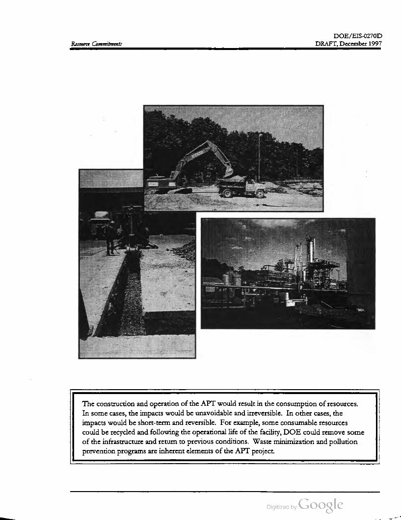
DOE / EIS -0270D
DRAFT,December 1997Resource Commitments
The construction and operation of the APT would result in theconsumption ofresources.
In somecases, the impacts would be unavoidable and irreversible. In other cases, the
impacts would be short-term and reversible. For example, some consumable resources
could be recycled and following the operational life of the facility,DOE could remove some
of the infrastructure and return to previous conditions. Waste minimization and pollution
prevention programs are inherent elements of the APT project.

DOE/EIS-0270D
DRAFT,December 1997 Resource Commitments
CHAPTER 6. RESOURCE COMMITMENTS
This chapter describes impacts of the construction and operation of an accelerator for the production
of tritium on the resource commitments in terms of unavoidable adverse impacts , short-term uses
versus long-term productivity, and irreversible or irretrievable commitments of resources. The chapter
also discusses waste minimization , pollution prevention , and energy conservation. This information is
based on the discussions in Chapter 4 .
6.1 Unavoidable Adverse Impacts Draft or the K -Area Cooling Tower alternative
would result in fewer impacts, as described in
Chapter 4 .Current operations at the SRS withdraw ap
proximately 5,000 gallons per minute of water
from the Savannah River for the maintenance
of L -Lake water levels, auxiliary equipment
cooling , fire protection , and sanitary wastewater
in K., L., and P -Areas. The implementation of
the preferred coolingwater alternative
(Mechanical-Draft Cooling Towers with River
Water Makeup) would result in negligible im
pacts to ecological resources and water use. If
DOE selected the preferred cooling water alter
native, river water withdrawals would increase
from current levels of 5,000 to 11,000 gallons
per minute. Similar increases in water use
would occur for the K -Area Cooling Tower
(natural-draft) alternative. However, implemen
tation of the Once- Through Cooling Water al
ternative would result in significantly greater
increases in water use and ecological impacts, as
described in Chapter 4 .
Every alternative for APT operation would af
fect wetlands because of cooling water dis
charges (see Section 4.2.2.3 Wetland Ecology).
The greatest impacts would occur with the op
eration of the Once- Through Cooling Water
alternative; these impacts from thermal stress
would be more pronounced in Pond 2 and less
in Ponds 5 and C and Par Pond. That alterna
cive would cause additional loss of wetlands due
to increased flows and subsequent raising of the
water levels. The Preferred alternative ofme
chanical-draft cooling towers using river water
as makeup would have the least adverse impact
on wetlands and the slight warming provided
during the coolermonths could provide positive
wetland impacts.
Unavoidable radiation exposures, which include
increased occupational exposures and exposures
to the general public from normal accelerator
operation, and possible remobilization of radio
active Cesium already in the sediments at outfall
locations due to increased water flow would be
well below regulatory limits.
Heated water discharges from the Once
Through Cooling Water alternative would raise
the temperatures in Ponds 2 , 5 , and C an aver
age of 18 ° F above their average seasonal tem
peratures, resulting in potential adverse impacts
to the aquatic community (benthic organisms
and fish). The implementation of either the
Mechanical-Draft or the K -Area Cooling Tower
alternative would result in fewer impacts, as de
scribed in Chapter 4 .
6.2 Short- Term Uses Versus
Long-Term Productivity
The implementation of the Once-Through
Cooling Water alternative would result in esti
mated annual entrainment losses of 3.4 million
fish eggs and 6.4 million fish larvae and im
pingement losses of about 2,600 fish annually.
The implementation of either the Mechanical
The current uses of the preferred and alternate
APT sites is timber production . The proposed
action would commit as much as 250 acres to a
single use for an indefinite period, possibly for
ever. Not all of the area would receive imme
diate impacts, but over the 10 -year construction
period the entire area would be deforested and
the timber would be removed. In addition, the
6-1
DOE /EIS-0270D
DRAFT,December 1997Resource Commitments
remain for the 40-year operational life of
the project.
implementation of the Preferred alternative
would result in the commitment of electric
(0.5 mile), rail (3.8 miles), road (8 miles), pipe
line (8.1 miles), and sewer (3 miles) corridors for
the life of the project. The width of the corri
dors could vary from 12 to 150 feet, resulting in
the commitment of approximately 30 acres to
infrastructure corridors for the accelerator.
Small increases in the amounts of radiologi
cal and nonradiological constituents dis
charged to National Pollutant Discharge
Elimination System -permitted outfalls and
ultimately to onsite streams.
Addition of about 100 tons ofsanitary solid
waste during construction and 2,200 tons
during the operational life of the project.
In addition to the 250 acres identified above,
construction of the APT would result in the
construction of two temporary facilities: con
crete batch plants and a construction debris
landfill. The exact acreage for these facilities is
unknown at this time; however, it is likely that
additionalacreage
above the 250 acres could be
required . Likewise, an expanded footprint re
quired for the modular APT design option
would requiremore land. At the end of the op
erational life of the temporary facilities, DOE
would close or remove infrastructure in accor
dance with permit and regulatory requirements .
Addition of 1,415 cubic meters of hazard
ous, mixed, and low -level radioactive waste
to an approved disposal facility.
Short-term employment, expenditures, and tax
revenues during the construction period would
benefit the local economy. The longer-term
operational workforce economic impacts, while
positive,would be negligible. In addition, local
governments could invest project-generated tax
revenues in infrastructure and other services to
provide for long-term economic and environ
mental productivity in the counties and cities.
Following the operational life of the accelerator,
DOE could remove some of the infrastructure
corridors and decontaminate and decommission
the accelerator under appropriate regulatory re
quirements. DOE would perform additional
NEPA reviews for these activities. At this time
there is no proposal to remove the accelerator
or its support structures .
The project-related short-term uses of the envi
ronment would include the following:
In providing these economic, social, and envi
ronmental benefits, the project would enhance
the long-term productivity and economic well
being of the states ofGeorgia and South Caro
lina in general, and the Central Savannah River
Area in particular, and would not preclude the
long-term use of much of the SRS for other
missions. Mitigation of adverse environmental
impacts would improve or enhance the long
term productivity of the Federal lands.
Use of as many as 125,000 gallons per mi
nute of water for 40 years from the Savan
nah River if DOE selects the Once
Through Cooling Water alternative. Other
cooling water alternatives would use con
siderably less water (i.e., 6,000 gallons per
minute).
6.3 Irreversible And Irretrievable
Resource Commitments
Increased vehicle traffic, noise, and air
quality impacts from activities during the
10-year construction period.
Resources that would be irreversibly and irre
trievably committed during APT construction
and operation include (1) materials that cannot
be recovered or recycled and (2) materials con
sumed or reduced to unrecoverable forms. The
National Environmental Policy Act requires an
EIS to identify irreversible and irretrievable
commitments of resources .
Operational activities resulting in increases
in vehicle and rail traffic, noise, and air
emissions from current levels and would
6-2
DOE/EIS -0270D
DRAFT,December 1997 Resource Commitments
The land requirements for the construction and
operation of the APT would represent an irre
versible commitment because DOE probably
would not remove the accelerator at the end of
the proposed life span (40 years), and the land
could not be restored to its original condition .
The landforms created by the underground
construction and above- ground berm probably
would remain , and much of the land in the im
mediate area would not be available for other
uses. However, much of the area outside the
immediate area of the accelerator and support
facilities could support other uses after closure.
tons of coal or 72 billion cubic feet of natural
gaseach year. Electrical usage under the 3 kilo
gram tritium production scenario would result
in the use of 3.1 million megawatt-hours of
electricity annually and under the 1.5 kilogram
tritium production scenario a totalof 1.6 million
megawatt-hours annually would be used. Sec
tion 4.4 provides more detailed discussion on
the impactsof supplying electricity to theAPT.
The commitment of capital, labor, material, and
energy during the construction and operation of
the accelerator and support facilities would be
irretrievable. Energy would be expended in the
forms of diesel fuel, gasoline, and oil for con
struction equipment and vehicles , and as elec
tricity , water, and raw materials for accelerator
operation. Construction of the APT would
generate nonhazardous, nonradioactive wastes,
including sanitary solid wastes, construction de
bris (e.g., mixed rubble, metals, plastics), and
sanitary wastewater.
Table 6-1. Estimated amounts ofmaterials re
quired for construction and operation of an ac
celerator at the Savannah River Site .
Material Amount
Electricity 3.1 million megawatt
hours/year
Steel 65,000 tons
Concrete 260,000 cubic meters
Crushed stone 50,000 cubic meters
Asphalt 50,000 cubic meters
Diesel fuel 20,000 gallons/ year
Water (potable ) 5.6 million gallons/ year
Water (nonpotable) 2.6 billion gallons/year
6.4 Waste Minimization ,
Pollution Prevention , and Energy
Conservation
Materials used for construction would include
wood, aggregate, plastics,metals (steel, copper,
aluminum , stainless steel), concrete, and small
amounts of other materials. Waste generation
estimates can be found in Section 4. Some of
these materials (e.g., copper, stainless steel)
could be salvaged when facilities are decon
taminated and decommissioned (see Sec
tion 6.4 ). Table 6-1 lists estimated requirements
of selected materials that would be consumed
during construction and operation .
Waste Minimization and Pollution Preven .
tion . DOE has instituted an aggressive waste
minimization program which has produced
substantial results. DOE's nuclear facilities
have reduced the sizes of radiological control
areas in order to reduce low -level radioactive
waste. Other facilities have scrap metal segre
gation programs which reduce solid waste and
allow useable material to be sold and recycled.
DOE facilities also are replacing solvents and
cleaners containing hazardous materials with
less-toxic or non -toxic materials.
Required materials and chemicals for construc
tion and operation would be readily available.
No significant use of scarce or strategic material
would be required for APT construction or op
eration .The APT facility design , consistent with this
program , would minimize the extent of radio
logical contamination areas, thereby minimizing
low -level radiological wastes (Shedrow 1997).
In addition to the materials listed in Table 6-1, a
DOE decision to construct and operate a new
coal- or gas-fired electricity plant to meet APT
needs under the 3 kilogram production scenario
could result in the consumption of 2.5 million
6-3

DOE /EIS -0270D
DRAFT, December 1997Resource Commitments
The APT would not use RCRA-regulated sol
vents, thereby minimizing the amount of mixed
waste. To further reduce mixed -waste volumes,
DOE would minimize the use of lead compo
nents (Shedrow 1997) because lead is a RCRA
regulated metal. To reduce waste volumes
during component replacement, the Depart
ment would install the components asmodules,
so when there was a need to change equipment,
it would be able to replace a component rather
than a large piece ofequipment.
DOE conducted a pollution prevention oppor
tunity assessment to identify pollution preven
tion and waste minimization opportunities, and
is investigating those opportunities it considers
promising, including materials substitution and
design changes, as appropriate (Shedrow 1997).
If possible, DOE would recycle materials rather
than dispose of them . DOE would recycle
materials to the extent possible and has esti
mated that 243,000 cubic meters would be re
cyclable. DOE would store such material for
future use or sell it to other users or salvage
vendors. However, some materials would not
be salvageable due to radioactive contamination .
Additionally, the Department could burn oil
that does not exceed certain radioactive levels
for energy recovery rather than disposing of it
as waste . Waste management practices would
include the segregation of waste to minimize
low - level radioactive and mixed -waste volumes
(Shedrow 1997 ).
Energy Conservation. Energy conservation
and efficiency are also a part of waste minimi
zation and pollution prevention in terms of in
corporating efficiencies into the design process.
For example , the Department's Preferred alter
native is superconducting operation ofaccelera
tor for structures, which would require less
electricity . DOE also has an active energy man
agement program at SRS. Recently over 40
administrative buildings have undergone energy
efficiency upgrades including replacement of
light fixtures and ballasts, with ones with more
efficiency, installation of infrared occupancy
sensors, use of diode light sticks in exit signs,
and the installation of insulating blankets on
water heaters .
6-4
DOE /EIS -0270D
DRAFT,December 1997 Resource Commitments
References
Shedrow , B. C., 1997, submittal of Technical Data for Preparation of APT EIS , ESH -EAP -97-0082,
Westinghouse Savannah River Site, Aiken, South Carolina.
6-5


Chapter 7
Applicable Laws, Regulations, and Other Requirements

DOE /EIS-0270D
DRAFT, December 1997Applicable Laws, Regulations, and Other Requirements
5820.2A
DOE
Order
Orders
11988
Executive
5480.25
DOE
Orders
Act
Clean
Air
10
CFR
835
Control
Act
Pollution
Se
Endangered
Species Act
Water
Act
Clean
12856
Order
Executive
Energy
Act
Atomic
Orders
DOE
Regulations
Federal
Laws/
Regulations
State
Laws/
Orders
Executive
The National Environmental Policy Act (NEPA) is a “procedural law that requires Federal
Agencies to consider the environmental consequences of their actions. Coupled with NEPA ,
Federaland State agencies require permits and compliance with regulations established to
protect the environment and thehealth and safety ofworkers and thepublic.

DOE /EIS-0270D
DRAFT, December 1997Applicable Laws, Regulations, and Other Requirements
CHAPTER 7. APPLICABLE LAWS,REGULATIONS,
AND OTHER REQUIREMENTS
This chapter discusses the permit requirements and summarizes the major laws, regulations, Execu
tive Orders, and DOE Orders thatmight apply to the construction and operation of the APT facilities.
It also discusses the consultations and actions required to protect natural, cultural and historical re
sources, and endangered species. DOE would obtain permits for construction and operation of new
APT drinking water system components, wastewater treatment and collection systems, new air
sources, hazardous waste treatment and storage facilities, and obtain National Pollutant Discharge
Elimination System permits for APT cooling water, process, and sanitary wastewater discharges.
Determination is pending for Federal Clean Water Act requirements to perform a Section 316 (a )
Demonstration (Thermal Effects Study) and a Section 316 (b ) Impingement Study in relation to the
APT cooling water alternatives. Determination is also pending for the requirement to obtain a permit
to constructAPT radiological air emission sources (stacks and process vents). This chapter does not
discuss potential permit requirements related to the construction and operation of a new electric gen
erating facility to supply APT powerneeds.
ronment through a series of Departmental
Orders (See Section 7.4) that are mandatory for
operating contractors ofDOE -owned facilities.
7.1 Statutes and Regulations
Requiring Permits or
Consultations
Section 7.1 discusses the major Federal and
State of South Carolina statutes and regulations
that impose environmental protection require
ments on DOE and which require DOE to
obtain a permit prior to construction and op
eration of the APT. Each of the applicable
regulations establish how potential releases of
pollutants and radioactive materials are to be
controlled or monitored and include require
ments for the issuance of permits for new op
erations or new emission sources. In addition
to environmental permit requirements, the
statutes may require consultations with various
authorities to determine if an action (such as
construction and operation of a facility such as
APT) requires a permit or the implementation
of protective or mitigative measures. Sec
tions 7.1.1 and 7.1.2 discuss the environmental
permitting process and lists the environmental
permits and consultations (see Table 7-1) appli
cable to construction and operation ofthe APT.
Environmental regulations require that the
owner or operator of a facility obtain permits
for the construction and operation of new
(water and air) emissions sources, and for new
domestic drinking water systems.To obtain
these permits, the facility operatormust apply to
the appropriate government agency for a dis
charge permit for discharges of wastewater to
the waters of the state and submit construction
plans and specifications for the new emission
sources, including new air sources. The envi
ronmental permits contain specific conditions
with which the permittee must comply during
construction and operation of a new emission
source, describe pollution abatement and pre
vention methods to be utilized for reduction of
pollutants, and contain emissions limits for
pollutants which will be emitted from the facil
ity. Section 7.1.1 discusses the environmental
statutes and regulations under which DOE will
be required to obtain permits. Table 7-1 lists
the permits (WSRC 1996).
Sections 7.2 and 7.3 address the major Federal
regulations and Executive Orders, respectively,
which address issues such as protection of pub
lic health and the environment, worker safety ,
and emergency planning. The Executive Orders
clarify issues of national policy and set guide
lines under which Federal agenciesmust act.
DOE implements its responsibilities for pro
tection of public health , safety, and the envi
7-1
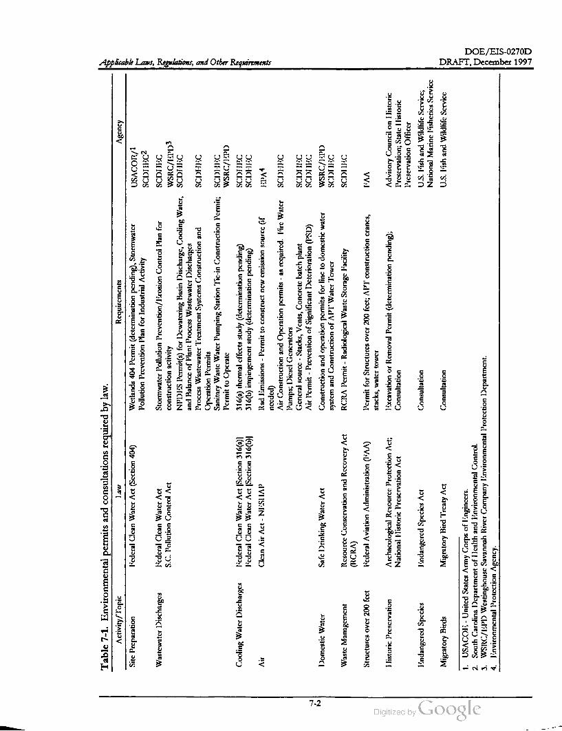
DOE /EIS -0270D
aw
Table
7-1
.Environmental
permits
and
consultations
required
by
law
.
Activity
/Topic
Requirements
Agency
Site
Preparation
l'cdcral
Clean
Water
Act
(Scction
404
)Wetlands
404
Permit
(determination
pending
),Stormwater
USACOE
/1
Pollution
Prevention
Plan
for
Industrial
Activity
SCDIEC2
Wastewater
Discharges
I'cdcral
Clcan
Water
Act
Stormwater
Pollution
Prevention
/Erosion
Control
Plan
for
SCDHEC
S.C.
Pollution
Control
Act
construction
activity
WSRC
/EPD3
NPDI'S
P'ermit
(s)for
Dcwatering
Basin
Discharge
,Cooling
Water
,SCDHC
and
Balance
ofPlant
Process
Wastcwater
Discharges
Process
Wastewater
Trcatment
Systems
Construction
and
SCDHEC
Operation
Permits
Sanitary
Waste
Water
Pumping
Station
Tic
-inConstruction
Pcrmit
;SCDHC
Permit
toOpcratc
WSRC
/EPD
Cooling
Water
Discharges
licderal
Clean
Water
Act
(Scction
316
( a)]316
(a)thermal
cffccts
study
(determination
pending
)SCDIEC
l'cdcral
Clean
Water
Act
(Scction
316
(b)] 316
(b)impingement
study
(dctcrmination
pending
)SCDHI
:C
Air
Clcan
Air
Act
-NISHAP
Rad
emissions
-Pcrmit
toconstruct
new
cmission
source
(ifEPA4
nccdcd
)
Air
Construction
and
Operation
permits
-asrequired
.l'irc
Watcr
SCDHI
:C
Pumps
;Dicscl
Gencrators
Gcncral
source
-Stacks
,Vents
,Concrete
batch
plant
SCDIILC
Air
Permit
-Prevention
of
Significant
Dctcrioration
(PSD
)SCDULC
Domestic
Watcr
Safc
Drinking
Water
Act
Construction
and
operation
permits
for
linc
todomestic
water
WSRC
/KPD
system
and
Construction
ofAPT
Water
Tower
SCDIC
Waste
Management
Resource
Conservation
and
Recovery
Act
RCRA
Permit
-Radiological
Waste
Storage
l'acility
SCDULC
(RCRA
)
Structurcs
over
200
fcct
l'cdcral
Aviation
Administration
(I^
)Permit
for
Structures
over
200
fcct
;APT
'construction
crancs
,IMA
stacks
,water
tower
IJistoric
Prescrvation
Archacological
Resource
Protection
Act
;Tixcavation
orRemoval
Permit
(determination
pending
);Advisory
Council
on
Ilistoric
National
IIistoric
Preservation
Act
Consultation
Prcscrvation
;State
Ilistoric
Preservation
Officer
Tindangered
Species
Jindangered
Spccics
Act
Consultation
U.S.
l'ish
and
Wildlifc
Scrvicc
;
National
Marinc
l'ishcrics
ServiceApplicable Laws, Regulations,and Other Requirements
Migratory
Birds
Migratory
Bird
Treaty
Act
Consultation
U.S.
l'ish
and
Wildlife
Servicc
1.USACOL
-United
States
Army
Corps
of
lingincers
.
2.
South
Carolina
Department
of
IIcalth
and
Lnvironmental
Control
.
3.WSRC
/EPD
Westinghousc
Savannah
River
Company
Environmental
Protection
Department
.
4.Tinvironmental
Protection
Agency
.
DRAFT,December 1997
7-2

DOE /EIS-0270D
DRAFT,December 1997 Applicable Laws, Regulations,and Other Requirements
7.1.1 ENVIRONMENTAL PROTEC
TION PERMITS
the regulated pollutants under the authority of
the South Carolina Pollution Control Act (48-1
10 et. seq .,) and SCDHEC Air Pollution Con
trol Regulations 61-62.Clean Air Act, as amended, (42 USC 7401 et
seq.), (40 CFR Parts 50-99); South Carolina
Pollution Control Act (Section 48-1-30 et
seq., South Carolina Department of Health
and Environmental Control (SCDHEC)
Regulation 61-62]
Construction and operation permits or exemp
dions will be required for new nonradiological
air emission sources (diesel generators, concrete
batch plants etc.) constructed and operated at
the APT facility. The permits will contain op
erating conditions and effluent limitations for
pollutants emitted from the facilities (see Ta
ble 7-1).
The Clean Air Act, as amended, is intended to
“ protect and enhance the quality of theNation's
air resources so as to promote the public health
and welfare and the productive capacity of its
population.” Section 118 of the Clean Air Act,
as amended , requires each Federal agency,such
as DOE, with jurisdiction over any property or
facility that might result in the discharge of air
pollutants, to comply with " all Federal, State,
interstate, and local requirements” with regard
to the control and abatementof air pollution .
The Act requires the U.S. Environmental Pro
tection Agency (EPA ) to establish National
Ambient Air Quality Standards as necessary to
protect public health, with an adequate margin
of safety, from any known or anticipated ad
verse effects of a regulated pollutant (42 USC
7409). The Act also requires the establishment
ofnational standards ofperformance for new or
modified stationary sources of atmospheric
pollutants (42 USC 7411) and requires specific
emission increases to be evaluated so as to pre
vent a significant deterioration in air quality (42
USC 7470). Hazardous air pollutants, including
radionuclides, are regulated separately (42 USC
7412). Air emissions are regulated by the EPA
in 40 CFR Parts 50 through 99. In particular,
radionuclide emissions are regulated under the
National Emission Standard for Hazardous Air
Pollutants Program (NESHAP) (see 40 CFR
Part 61).
DOE is currently determining if a NESHAP
permit will be required for radiological emis
sions from the APT facilities (stacks, process
vents , etc.). As described in 40 CFR Part 61.96 ,
if the effective dose equivalent caused by all
emissions from facility operations is projected
to be less than 1 percentof the 10 millirem per
year NESHAP standard, an application for ap
proval to construct under 40 CFR Part 61.07 is
not required to be filed . 40 CFR Part61.96 also
allowsDOE to use, with prior EPA approval,
methods other than EPA standard methods for
estimating the source term for use in calculating
the projected dose. DOE is currently investigat
ing methods for estimating the APT source
term in accordance with NESHAP require
ments to calculate if the APT emissions would
result in an effective dose equivalent of less than
the 0.1 millirem per year level. Based on the re
sults of this calculation, DOE will, prior to the
start of construction, request EPA approval of
the methodology for calculating the projected
dose or complete a NESHAP permit applica
tion .
Federal Clean Water Act, as amended (33
USC 1251 et seq.); SC Pollution Control Act
(SC Code Section 48-1-10 et seq., 1976)
(SCDHEC Regulation 61-9.122 et. seq.)
EPA has overall authority for the Clean Air Act;
however, it delegates primary authority to states
which have an established air pollution control
program approved by EPA . In South Carolina,
EPA has retained authority over radionuclide
emissions (40 CFR Part 61) and has delegated
to SCDHEC the responsibility for the rest of
The Federal Water Pollution Act (commonly
known as the Clean Water Act), was enacted to
“ restore andmaintain the chemical, physical and
biological integrity of the Nation's water.” The
Clean Water Act prohibits the “ discharge of
toxic pollutants in toxic amounts” to navigable
7-3

DOE /EIS -0270D
DRAFT,December 1997Applicable Laws, Regulations, and Other Requirements
waters of the United States (Section 101). Sec
tion 313 of the Clean Water Act, as amended,
requires all branches of the Federal Govern
ment engaged in any activity thatmight result in
a discharge or runoff of pollutants to surface
waters to comply with Federal, state, interstate,
and local requirements.
Plan (SWPPP) for storm water discharges at
SRS. The SRS SWPPP would need to be re
vised to include pollution prevention measures
to be implemented for operation of the APT
(See Table 7-1) if industrial activities are ex
posed to stormwater. SCDHEC has issued a
General Permit for stormwater discharges from
construction activities that are “ Associated with
Industrial Activity ” (Permit No. SCR100000).
An approved plan would be needed that in
cludes erosion control and pollution prevention
measures to be implemented for construction
activities.
In addition to setting water quality standards for
the Nation's waterways, the Clean Water Act
supplies guidelines and limitations (Sections
301-303) for effluent discharges from point
source discharges and provides authority
(Sections 401-402) for the EPA to implement
the National Pollutant Discharge Elimination
System (NPDES) permitting program pursuant
to 40 CFR Part 122 et seq .
EPA has delegated primary enforcement
authority for the Clean Water Act and the
NPDES Permitting Program to SCDHEC for
waters in South Carolina. In 1996 , SCDHEC ,
under the authority of the Pollution Control Act
(48-1-10 et seq.) and Regulation 61-9.122, issued
NPDES Permit SC0000175, which addresses
wastewater discharges to SRS streams and
NPDES permit SCG250162 which address gen
eral utility water discharges. The permit con
tains effluent limitations for physical parameters
such as flow and temperature and for chemical
pollutants with which the permittee / discharge
must comply. DOE will apply for a discharge
permit for the APT. (See Table 7-1)
Section 316 (a) of the Clean Water Act author
izes EPA's Regional Administrator to set alter
native effluent limitations on the thermal
componentof discharges if the owner / operator
demonstrates that the proposed thermal efflu
ent limitations are "more stringent than neces
sary to ensure the protection and propagation
of a balanced population of fish , shellfish, and
wildlife in or on a body of water into which the
discharge is to made.” In support of its request
for a Section 316 (a) exception, the owner/op
erator must submit with its permit application
scientific documentation showing that the ex
pected heated effluent will not result in appre
ciable harm the indigenous aquatic
community . This documentation is called a
Section 316(a) Demonstration. This satisfactory
demonstration would be made to SCDHEC if
required , as the State NPDES authority and de
cisionmaker, however, program overview is by
EPA. Under this regulation, a Section 316(a)
Demonstration may be required for the APT
cooling water alternative implemented . DOE
has initiated discussions with SCDHEC regard
ing the potential need to conduct the Section
316 (a ) Demonstration. At the timeof the writ
ing of this Draft EIS those discussions have not
been finalized.
to
In Section 402(p ) of the Clean Water Act EPA
established regulations (40 CFR Part 122.26) for
issuing permits for stormwater discharges asso
ciated with industrial activity. Accordingly,
SCDHEC has issued a General Permit for
Storm Water Discharges Associated with Indus
trial Activities (Permit No. SCR000000)
authorizing stormwater discharges to the waters
of the State of South Carolina in accordance
with effluent limitations, monitoring require
ments, and conditions as set forth in the permit.
This permit requires preparation and submittal
of a Pollution Prevention Plan for all new and
existing point source discharges associated with
industrial activity. Accordingly, DOE -SR has
developed a Storm Water Pollution Prevention
Section 316 (b ) of the Clean Water Act directs
EPA to establish standards that require that
" ... the location, design, construction, and ca
pacity of cooling water intake structures reflect
the best technology available for minimizing
adverse environmental impact....” Under this
regulation , a Section 316 (b ) Study, if required,
7-4

DOE /EIS -0270D
DRAFT,December 1997Applicable Laws, Regulations, and Other Requirements
would be to demonstrate that the cooling water
alternative implemented at APT meets the re
quirements of this section. It is not expected
that a Section 316 (b) study will be required for
construction of the APT; however, a final de
termination on the need for Section 316 (b )
study has not yetbeen made (See Table 7-1).
Other programs established by the Safe Drink
ing Water Act include the Sole Source Aquifer
Program , theWellhead Protection Program ,and
the Underground Injection Control Program .
Section 404 of the Clean Water Act requires
that a 404 Permit be issued for discharge of
dredge or fill material into the waters of the
United States. The authority to implement
these requirements has been given to the U.S.
Army Corps of Engineers. Section 401 of the
Clean Water Act requires certification that dis
charges from construction or operation of fa
cilities, including discharges of dredged and fill
material into navigable waters will comply with
applicable water standards. This certification ,
which is granted by SCDHEC, is a prerequisite
for the 404 permit. DOE does not believe that
a 404 permit will be required for construction of
the APT facilities ; however a final determina
tion has not been made. Some 404 permitting
may be required for wastewater discharge con
veyances, outfall structures, and roads and
bridges.
EPA has delegateddelegated primary enforcement
authority to SCDHEC for public water systems
in South Carolina. Under the authority of the
South Carolina Safe Drinking Water Act (44-55
10 et seq .), SCDHEC has established a drinking
water regulatory program (R.61-58). For radio
active material, the regulations specify that the
average annual concentration ofmanmade radi
onuclides in drinking water as delivered to the
user by such a system shall not produce a dose
equivalent to the total body or an internal organ
greater than four millirem per year beta-gamma
activity . Construction and operation permits
will be required for themajor new components
(e.g., the APT water tower and distribution
piping) associated with the APT. See Table 7-1.
Resource Conservation and Recovery Act,
as amended (Solid Waste Disposal Act) (42
USC 6901 et seq.); South Carolina Hazard
ous Waste Management Act, Section 44-56
30, South Carolina Hazardous Waste Man
agement Regulations (R.61-79.124 et seq.)
asFederal Safe Drinking Water Act,
amended [42 USC 300 (F ) et seq., 40 CFR
Parts 100-1497; South Carolina Safe Drink
ing Water Act ( Title 44-55-10 et seq.), State
Primary Drinking Water Regulations,
(SCDHEC R.61-58 )
The primary objective of the Safe Drinking
Water Act (42 USC 300 ), as amended , is to
protect the quality of the public water supplies
and all sources of drinking water. The imple
menting regulations, administered by the EPA
unless delegated to the States, establish stan
dards applicable to public water systems. They
promulgate maximum contaminant levels
(including those for radioactivity), in public
water systems, which are defined as water sys
tems that serve at least 15 service connections
used by year-round residents or regularly serve
at least 25 year-round residents. Safe Drinking
Water Act requirements havebeen promulgated
by the EPA in 40 CFR Parts 100 through 149.
The treatment, storage, or disposal of hazardous
and nonhazardous waste is governed by the Re
source Conservation and Recovery Act (RCRA)
and the Hazardous and Solid Waste Amend
ments of 1984. Pursuant to Section 3006 of the
Act, any state that seeks to administer and en
force a hazardous waste program pursuant to
RCRA may apply for EPA authorization of its
program . The SCDHEC has received authori
zation to implement a hazardous waste program
in the State of South Carolina. EPA and
SCDHEC regulations implementing RCRA (40
CFR Parts 260-280; R.61-79.260-280) define
hazardous wastes and specify hazardous waste
transportation ,handling, treatment, storage, and
disposal requirements. The regulations imposed
on a generator or a treatment, storage, or dis
posal facility vary according to the type and
quantity of material or waste generated , treated ,
stored , or disposed. The method of treatment,
storage, or disposal also affects the extent and
7-5
DOE /EIS -0270D
DRAFT,December 1997Applicable Laws, Regulations, and Other Requirements
Federal Aviation Act of 1958 (49 USC 1504)
Federal Aviation Administration Regula
tions (14 CFR Part 77)
complexity of the requirements. These regula
tions require that facilities which store hazard
ous waste more than 90 days onsite, or treat
hazardous waste obtain a RCRA Permit for this
activity. The APT Radiological Waste Storage
Building, which would store irradiated lead ,
would require a RCRA Permit.
The Federal Facility Compliance Act
(FFCA) (42 USC 6921 (et. seq.)
The Federal Aviation Administration requires
that a permit be issued for any structure greater
than 200 feet in height which would affect navi
gable airspace (See Table 7-1). A permit would
be required for structures at the APT site
greater than 200 feet in height. Potential APT
structures which might require a permit are
APT construction equipment (cranes), the APT
water tower, and APT stacks.
7.1.2 PROTECTION OF BIOLOGICAL,
HISTORIC , AND ARCHAEOLOGICAL
RESOURCES
The following statutes pertain to protection of
endangered and threatened animal and plants.
Actions taken by DOE to evaluate potential
APT sites in lightof the statutes follow .
Endangered Species Act, as amended ( 16
USC 1531 et seq.)
The FFCA was enacted on October 6 , 1992,
amended the Resource Conservation Recovery
Act. TheFFCA waived sovereign immunity for
fines and penalties for violations at Federal fa
cilities associated with the management of
mixed waste. However, a provision postpones
fines and penalties after 3 years formixed waste
storage prohibition violations atDOE sites and
requires DOE to prepare plans for developing
the required treatment capacity for mixed waste
stored or generated at each facility. Each plan
must be approved by the host State or theEPA ,
after consultation with other affected States ,
and a consent order must be issued by the
regulator requiring compliance with the plan .
The Federal Facility Compliance Act further
provides that DOE will not be subject to fines
and penalties for land disposal restriction stor
age prohibition violations for mixed waste as
long as it is in compliance with such an ap
proved plan and consent order and meets all
other applicable regulations. This would apply
to mixed waste generated as a result of opera
tion of the APT which are subject to require
ments of the Resource Conservation and
Recovery Act. On September 20 , 1995, the
SCDHEC approved, with modification, the Site
Treatment Plan for SRS. SCDHEC issued a
consent order, signed by DOE, requiring
compliance with the plan on September 29,
1995 . DOE would be required to notify
SCDHEC of new mixed waste streams gener
ated as result of APT operations.
The Endangered Species Act, as amended, is
intended to prevent the further decline of en
dangered and threatened species and to restore
these species and their habitats. The Act is
jointly administered by the United States De
partments of Commerce and Interior . Section 7
of the Act requires consultation with the Fish
and Wildlife Service (Interior) and the National
Marine Fisheries Service (Commerce) to de
termine if endangered and threatened species or
their critical habitats are in the vicinity of the
proposed (APT) action . DOE will comply with
the Section 7 Process.
DOE has conducted a Threatened ,Endangered,
and Sensitive Species Listing and Habitat
Evaluation of the preferred APT site. The sur
vey results indicate that no known populations
of threatened or endangered plant species are
7-6

DOE /EIS -0270D
DRAFT,December 1997 Applicable Laws, Regulations, and Other Requirements
located in the area (Imm 1997). In addition , the
survey indicated that habitat conditions, or the
potential for conditions, suitable for the estab
lishment of federally -protected (animal) species
such as the red -cockaded woodpecker, Ameri
can alligator, or bald eagle do not exist at the
site (Imm 1997).
tions are required under the Act. However, if a
particular Federal activity could impact an his
toric property resource, consultation with the
Advisory Council on Historic Preservation will
usually generate a Memorandum of Agreement,
including stipulations that must be followed to
minimize adverse impacts. Coordination with
the South Carolina State Historic Preservation
Officer (SC SHPO ) ensures the proper identifi
cation of potentially significant sites and the
implementation of appropriate mitigative ac
tions. Should the chosen APT site contain
possible historic sites or artifacts, coordination
with the State Historic Preservation Officer
would be necessary .
Migratory Bird Treaty Act, as amended (16
USC 703 et seq.)
The Migratory Bird Treaty Act, as amended, is
intended to protect birds that have common
migration patterns between the United States
and Canada, Mexico, Japan, and Russia. It
regulates the harvest of migratory birds by
specifying things such as the mode of harvest,
hunting seasons, and bag limits. The Act stipu
lates that it is unlawful at any time, by any
means, or in any manner to “ kill...any migratory
bird.” DOE would be required to consult with
the Fish and Wildlife Service regarding impacts
to migratory birds and to evaluate ways to avoid
orminimize these effects in accordance with the
Fish and Wildlife Service Mitigation Policy
during construction and operation of the APT.
The Savannah River Archaeological Research
Program (SRARP) , evaluated the preferred APT
site in 1986 for a new waste storage/disposal
facility (Brooks et al. 1986). No archaeological
sites were located during this effort. In June
1996 , SRARP conducted additional surveys for
the site that were not part of the 1986 work to
further evaluate 20th -century homesites. No
archaeological sites present on the preferred site
were eligible for nomination to the National
Registry of Historical Places. As a result,
SRARP has indicated that it would request from
the SC SHPO a determination ofno effect from
the construction of APT at the preferred site
(Sassaman 1997).
Bald and Golden Eagle Protection Act, as
amended (16 USC 668-668d )
The Bald and Golden Eagle Protection Act
makes it unlawful to take, pursue, molest, or
disturb bald and golden eagles, their nests, or
their eggs anywhere in the United States
(Sections 668, 668c). A permit must be ob
tained from the U.S. Departmentofthe Interior
to relocate a nest that interferes with resource
development or recovery operations. If neces
sary,DOE would be required to obtain a permit
for the disturbance or relocation ofany
bald or
golden eagles discovered on the chosen APT
site.
The alternate site has not been subjected to
systematic study; however, it is located in an
area with low potential for significant prehis
toric sites. The SRARP does not expect the ex
istence of prehistoric sites that would be eligible
for nomination to the National Historic Regis
ter (Sassaman 1997) .
The following statutes pertain to potential ar
chaeological sites associated with Native Ameri
can lands. Actions taken by DOE to evaluate
potential APT sites in lightof the statues follow .National Historic Preservation Act, as
amended (16 USC 470 et seq.)
Archaeological Resource Protection Act, as
amended ( 16 USC 470 et seq.)The National Historic Preservation Act, as
amended, provides that sites with significant
national historic valuebe placed on the National
Register of Historic Places. No permits or certifica
This Act requires a permit for any excavation or
removal of archaeological resources from public
7.7
DOE /EIS -0270D
DRAFT,December 1997Applicable Laws, Regulations, and Other Requirements
or Native American lands. Excavationsmust be
undertaken for the purpose of furthering ar
chaeological knowledge in the public interest,
and resources removed are to remain the prop
erty of the United States. Consentmust be ob
tained from the Indian Tribe owning lands on
which a resource is located before a permit is is
sued , and the permit must contain terms or
conditionsrequested by the Tribe.
National Council ofMuskogee Creek , and the
Indian People's Muskogee Tribal Town Con
federacy expressed general concerns about
SRS and the Central Savannah River Area, but
did not identify specific sites as possessing relig
ious significance. The Yuchi Tribal Organiza
tion and the National Council of Muskogee
Creek are interested in plant species traditionally
used in tribal ceremonies , such as redroot, but
ton snakeroot, and American ginseng (DOE
1991). Redroot and button snakeroot are
known to occur on the SRS (Batson, Angerman ,
and Jones 1985).
Native American Grave Protection and Re
patriation Actof1990 (25 USC 3001)
This law directs the Secretary of Interior to as
sume responsibilities for repatriation of Federal
archaeological collections and collections held
by museumsreceiving Federal funding that are
culturally affiliated with Native American
Tribes. Majoractions to be taken under this law
include (1) establishing a review committee with
monitoring and policy-making responsibilities,
(2) developing regulations for repatriation, in
cluding procedures for identifying lineal descent
or cultural affiliation needed for claims,
(3) overseeing museum programs designed to
meet the inventory requirements and deadlines
of this law , and (4) developing procedures to
handle unexpected discoveries of graves or
grave goods during activities on Federal or tribal
land.
In addition , the Savannah River Archaeological
Research Program (SRARP) conducted an ar
cheological survey of the preferred APT site in
March 1997. The archeological review included
potential sites associated with Native American
activities or habitat. The resulting SRARP re
port stated that no archaeological sites present
on the preferred site were eligible for nomina
tion to the National Registry of Historical
Places and further indicated that SRARP would
request from the SC SHPO a determination of
no effect from the construction of APT at the
preferred site.
7.2 Statutes and Regulations Re
lated to Emergency Planning,
Worker Safety, and Protection of
Public Health and the Environ
American Indian Religious Freedom Act of
1978 (42 USC 1996 )
ment
7.2.1 ENVIRONMENTAL PROTEC
TION
This Act reaffirms Native American religious
freedom under the First Amendment, and sets
U.S. policy to protect and preserve the inherent
and constitutional right of Native Americans to
believe, express, and exercise their traditional
religions. The Act requires that Federal actions
avoid interfering with access to sacred locations
and traditional resources that are integral to the
practice of religion .
National Environmental Policy Act (NEPA)
of 1969, as amended (42 USC 4321 et seq.)
In conjunction with 1991 studies related to the
New Production Reactor, DOE solicited the
concerns of Native Americans about religious
rights in the Central Savannah River Valley.
During this study, three Native American
groups -- the Yuchi Tribal Organization, the
NEPA establishes a national policy promoting
awareness of the environmental consequences
of human activity on the environment and con
sideration of environmental impacts during the
planning and decisionmaking stages of a project.
This Act requires Federal agencies to prepare a
detailed statement on the environmental effects
of proposed major Federal actions that might
7-8
DOE /EIS-0270D
DRAFT, December 1997Applicable Laws, Regulations, and Other Requirements
significantly affect the quality of the human en
vironment.
This EIS has been prepared in response to
NEPA requirements and policies, and in accor
dance with Council on Environmental Quality
(40 CFR Parts 1500 through 1508) and DOE
(10 CFR Part 1021) regulations for implement
ing the procedural provisions ofNEPA. It dis
cusses reasonable alternatives and their potential
environmental consequences.
expand markets for recovered materials. RCRA
Section 6002 requires that any purchasing
agency ,when using appropriated funds to pro
cure an item , shall purchase it with the highest
percentage of recovered materials practicable.
The procurement of materials to be utilized in
the construction and operation of the APT
should be conducted in accordance with these
regulations.
Toxic Substances Control Act, as amended
(USC 2601 et seq.) (40 CFR Part 700 et seq.)
Pollution Prevention Act of 1990 (42 USC
13101 et seq.)
The Pollution Prevention Act of 1990 estab
lishes a national policy for waste management
and pollution control that focuses first on
source reduction, followed sequentially by envi
ronmentally safe recycling, treatment, and dis
posal. Disposal or releases to the environment
should occur only as a last resort. In response,
DOE has committed to participation in the Su
perfund Amendments and Reauthorization Act
Section 313 , U.S. EPA 33/50 Pollution Preven
tion Program . The goal for facilities already in
volved in Section 313 compliance is to achieve
by 1997 a 33-percent reduction in the release of
17 priority chemicals from a 1993 baseline. On
August 3, 1993, President Clinton issued Ex
ecutive Order 12856, expanding the 33/50 pro
gram such that DOE must reduce its total
releases of all toxic chemicals by 50 percent by
December 31, 1999. In addition , DOE is re
quiring each of its sites to establish site-specific
goals to reduce the generation of all waste types.
The Toxic Substances Control Act regulates the
manufacture, use , treatment, storage, and dis
posal of certain toxic substances not regulated
by the Resource Conservation and Recovery
Act or other statutes, particularly polychlori
nated biphenyls (40 CFR Part 761), chloro
fluorocarbons (40 CFR Part 762), and asbestos
(40 CFR Part 763). It is expected that the use
of these materials at APT would be limited, or
not occur; however, programs and procedures
would need to be implemented to address ap
propriate management and disposal of waste
generated as a result of their use.
7.2.2 EMERGENCY PLANNING AND
RESPONSE
This section discusses the regulations which ad
dress protection of public health , worker safety,
and require the establishment of emergency
plans and the coordination with local and Fed
eral agencies related to facility operations.
DOE Orders generally set forth the programs
and procedures required to implement the re
quirements of these regulations. See Section
7.4 .
Comprehensive Guideline for Procurement
of Products Containing Recovered Materi
als (40 CFR Part 247)
Atomic Energy Act of 1954, as amended (42
USC 2011 et seq.)This regulation is issued under the authority of
Section 6002 of the Resource Conservation and
Recovery Act and Executive Order 12783,
which set forth requirements for Federal agen
cies to procure products containing recovered
materials for use in their operations using
guidelines established by the EPA. The pur
pose of these regulations is to promote recy
cling by using government purchasing to
The Atomic Energy Act of 1954 authorizes
DOE to establish standards to protect health or
minimize dangers to life or property with re
spect to activities under its jurisdiction . Sec
tion 57b of the Act, which addresses the issue
of Nuclear Nonproliferation, requires that any
persons subject to U.S. jurisdiction,who engage
7-9
DOE /EIS-0270D
Applicable Laws, Regulations,and Other Requirements DRAFT,December 1997
planning and preparedness for APT operations,
would need to prepared and implemented at
APT, in accordance with this regulation .
Emergency Planning and Community
Right-to -Know Act of 1986 (42 USC 11001 et
seq.) ( also known as " SARA Title III” )
directly or indirectly in the production of special
nuclear material be authorized to do so by the
Secretary of Energy. Although tritium is not a
special nuclear material, DOE has determined
that the Atomic Energy Act and DOE regula
tions cover exports of production accelerator
technology because the technology can be
modified and used to produce plutonium , which
is a special nuclear material. The issue of non
proliferation as related to tritium production is
discussed in more detail in Chapter 1. Through
a series of DOE Orders, DOE has established
an extensive system of standards and require
ments to ensure safe operation of its facilities.
Section 7.3 includes a discussion of the DOE
Orders which are applicable to the construction
and operation of the APT.
Atomic Energy Act of 1954, as amended (42
USC 2011 et seq.) Quantities of Radioactive
Materials Requiring Consideration of the
Need for an Emergency Plan for Respond
ing to a Release ( 10 CFR Part 30.72 Sched
The Emergency Planning and Community
Right-to-Know Actof 1986 requires emergency
planning and notice to communities and gov
ernmentagencies of the presence and release of
specific chemicals. EPA implements this Act
under regulations found at 40 CFR Parts 355 ,
370, and 372. Under Subtitle A of this Act,
Federal facilities provide various information
(such as inventories of specific chemicals used
or stored and releases that occur from these
facilities) to the State Emergency Response
Commission and the Local Emergency Planning
Committee to ensure that emergency plans are
sufficient to respond to unplanned releases of
hazardous substances. Implementation of the
provisions of this Act began voluntarily in 1987,
and inventory and annual emissions reporting
began in 1988. In addition, DOE requires
compliance with Title III as a matter of De
partmental policy. The requirements for this
Act were promulgated by EPA in 40 CFR Parts
350 through 372. The SRS submits hazardous
chemical inventory reports to the SCDHEC.
The chemical inventory could change depend
ing on the alternative(s) DOE implemented ;
however, subsequent reports would reflect any
change to the inventory.
ule C )
This list is the basis forboth the public and pri
vate sector to determine if the radiological ma
terials they deal with must have an emergency
response plan for unscheduled releases. It is
one of the threshold criteria documents for
DOE Emergency Preparedness Hazards As
sessments required by DOE Order 151.1,
“ Comprehensive Emergency Management Sys
tem .” An emergency response plan addressing
APT operations would need to promulgated in
accordance with this regulation .
Reorganization Plan No. 3 of 1978, Public
Health and Welfare (42 USC 5121 et seq.),
Emergency Management and Assistance
(44 CFR Part 1-399)
Transportation of Hazardous Materials (49
USC 5101 et seq.); Hazardous Materials
Tables & Communications, Emergency Re
sponse Information Requirements (49 CFR
Part 172)
These regulations generally include the policies,
procedures and set forth the responsibilities of
the Federal Emergency Management Agency ,
the Nuclear Regulatory Commission, and the
Department of Energy for implementing a Fed
eral Emergency Preparedness Program includ
ing radiological planning and preparedness. An
emergency response plan , including radiological
The regulatory requirements formarking, label
ing, placarding, and documenting hazardous
materials shipments are defined in this regula
tion. It also specifies the requirements for pro
viding hazardous material information and
training. Materials shipped from APT would be
required to comply with these regulations.
7-10

DOE / EIS-0270D
DRAFT,December 1997 Applicable Laws, Regulations, and Other Requirements
Comprehensive Environmental Response,
Compensation , and Liability Act of 1980, as
amended (42 USC 9601 et seq.) National Oil
and Hazardous Substance Contingency
Plan (40 CFR Part 300 et seq.)
More popularly known as “ Superfund,” the Act
and implementing regulations provide the
needed general authority for Federal and state
governments to respond directly to hazardous
substances incidents. The regulations require
reporting of spills, including radioactive, to the
National Response Center. APT operations
would be required to comply with these regula
tions in the event of spills of hazardousmateri
als at APT facilities. DOE Orders generally set
forth the programs for development of internal
procedures for implementing theregulations.
lation sets down the Occupational Safety and
Health Administration requirements for em
ployee safety in a variety of working environ
ments. It addresses employee emergency and
fire prevention plans (Section 1910.38), hazard
ous waste operations and emergency response
(Section 1910.120), and hazards communication
(Section 1910.1200) that enables employees to
be aware of the dangers they face from hazard
ous materials at their workplace. DOE places
emphasis on compliance with these regulations
at its facilities and prescribes through DOE Or
ders the Occupational Safety and Health Act
standards that contractors shall meet, as appli
cable to their work at Government-owned,
contractor-operated facilities. DOE keeps and
makes available the various records of minor
illnesses, injuries, and work-related deaths re
quired by Occupational Safety and Health Ad
ministration regulations.Occupational Safety and Health Act of 1970,
as amended (29 USC 651 et seq.); Occupa
tional Safety and Health Administration
Emergency Response, Hazardous Waste
Operations and Worker Right to Know (29
CFR Part 1910 et seq.)
Noise Control Act of 1972, as amended (42
USC 4901 et seq.)
Section 4 of the Noise Control Act of 1972, as
amended , directs all Federal agencies to carry
out “ to the fullest extentwithin their authority "
programs within their jurisdictions in a manner
that furthers a national policy of promoting an
environment free from noise that jeopardizes
health and welfare .
7.3 Executive Orders
The Occupational Safety and Health Act (29
USC 651) establishes standards to enhance safe
and healthful working conditions in places of
employment throughout the United States. The
Act is administered and enforced by the Occu
pational Safety and Health Administration , a
U.S. Department of Labor agency . While the
Occupational Safety and Health Administration
and EPA both have a mandate to reduce expo
sures to toxic substances, the Occupational
Safety and Health Administration's jurisdiction
is limited to safety and health conditions that
exist in the workplace environment. In general,
under the Act, it is the duty of each employer to
furnish all employees a place of employment
free ofrecognized hazards likely to cause death
or serious physical harm . Employees have a
duty to comply with the occupational safety and
health standards and all rules , regulations, and
orders issued under the Act. The Occupational
Safety and Health Administration regulations
(29 CFR ) establish specific standards telling
employers whatmust be done to achieve a safe
and healthful working environment. This regu
The following executive orders would be in ef
fect for the construction and operation of the
APT. DOE Orders generally set forth the pro
grams and procedures required to implement
the requirements of the orders.
Executive Order 11514 (Protection and En
hancement ofEnvironmental Quality )
Executive Order 11514 requires Federal agen
cies to monitor and control their activities con
tinually to protect and enhance the quality of
the environment and to develop procedures to
ensure the fullest practicable provision of timely
public information and understanding of Fed
7-11

DOE / EIS -0270D
Applicable Laws, Regulations, and Other Requirements DRAFT,December 1997
eral plans and programs with environmental
impact to obtain theviews of interested parties.
Executive Order 12902 (Energy Efficiency
and Water Conservation at Federal Facili
ties)
Executive Order 11988 (Floodplain Man
agement)Executive Order 12902 requires Federal agen
cies to develop and implement a program for
conservation ofenergy andwater resources.Executive Order 11988 requires Federal agen
cies to establish procedures to ensure that the
potential effects of flood hazards and floodplain
management are considered for any action un
dertaken in a floodplain and that floodplain im
pacts be avoided to the extent practicable.
7.4 DOE Regulations and Orders
Executive Order 11990 (Protection of Wet
lands)
Through the authority of the Atomic Energy
Act, DOE is responsible for establishing a
comprehensive health , safety, and environ
mental program for its facilities. The regulatory
mechanisms through which DOE manages its
facilities are the promulgation ofregulations and
the issuance of DOE Orders. Table 7-2 lists
the major DOE Orders applicable to the con
struction and operation of the APT.
Executive Order 11990 requires Government
agencies to avoid any short- and long-term ad
verse impacts on wetlands wherever there is a
practicable alternative.
Executive OrderOrder 12856 (Right-to -Know
Laws and Pollution Prevention Require
ments)
Executive Order 12856 requires all Federal
agencies to reduce the toxic chemicals entering
any waste stream . This order also requires Fed
eral agencies to report toxic chemicals entering
waste streams; improve emergency planning, re
sponse, and accident notification ; and encour
age clean technologies and testing of innovative
prevention technologies.
The DOE regulations address such areas as en
ergy conservation, administrative requirements
and procedures, nuclear safety, and classified in
formation . For the purposes of this EIS , rele
vant regulations include 10 CFR Part 820,
Procedural Rules for DOE Nuclear Facilities, 10 CFR
Part 830, Nuclear Safety Management; Contractor and
Subcontractor Activities, 10 CFR Part 835 , Occupa
tional Radiation Protection, 10 CFR Part 1021,
Compliance with NEPA; and 10 CFR Part 1022,
Compliance with Floodplains/Wetlands Environmental
Review Requirements. DOE has enacted occupa
tional radiation protection standards to protect
DOE and its contractor employees. These
standards are set forth in 10 CFR Part 835, Oc
cupational Radiation Protection , the rules in this part
establish radiation protection standards, limits,
and program requirements for protecting indi
viduals from ionizing radiation resulting from
the conduct ofDOE activities, including those
conducted by DOE contractors. The activity
may be, but is not limited to , design, construc
tion, or operation of DOE facilities. These
Executive Order 12898 (Environmental Jus
tice)
Executive Order 12898 requires Federal agen
cies to identify and address disproportionately
high and adverse human health or environ
mental effects of its programs, policies, and ac
tivities minority and low -income
populations.
on
- --
-
7-12

DOE / EIS -0270D
DRAFT,December 1997Applicable Laws, Regulations, and Other Requirements
Table 7-2 . DOE Orders and Notices relevant to the acceleratorproduction of tritium .
DOE Order
Notice Subject
151.1Comprehensive Emergency Management System
225.1 Accident Investigations
231.1Environment, Safety, and Health Reporting
232.1Occurrence Reporting and Processing of Operations Information
420.1Facility Safety
425.1 Startup and Restart of Nuclear Facilities
430.1 Life-Cycle Asset Management
440.1Worker Protection Management for DOE Federal and Contractor Employees
441.1DOE Radiological Health and Safety Policy
441.2 Extension ofDOE 441.1
451.1A National Environmental Policy Act Compliance Program
460.1APackaging and Transportation Safety
460.2Departmental Materials and Packaging Management
470.1 Safeguards and Security Program
471.1Identification and Protection of Unclassified Controlled Nuclear Information
471.2A Information Security Program
472.1BPersonnel Security Activities
1270.2BSafeguards Agreementwith the InternationalAtomic Energy Agency
1300.2ADepartment of Energy TechnicalStandards Program
1360.2B Unclassified Computer Security Program
3790.1B Federal Employee Occupational Safety and Health Program
4330.4B Maintenance Management Program
4700.1 Project Management System
5400.1 General Environmental Protection Program
5400.3 Hazardous and RadioactiveMixed Waste Program
5400.5 Radiation Protection of the Public and the Environment
5480.4Environmental Protection, Safety, and Health Protection Standards
5480.17 Site Safety Representatives
5480.19 Conduct ofOperations Requirements for DOE Facilities
5480.20A Personnel Selection , Qualification,and Training Requirements for DOE Nuclear Facilities
5480.21 Unreviewed Safety Questions
5480.22 Technical Safety Requirements
5480.23 Nuclear Safety Analysis Reports
5480.25 Safety of Accelerator Facilities
5480.27 Equipment Qualification for Reactor and NonreactorNuclear Facilities
5484.1Environmental Protection, Safety, and Health Protection Infomation Reporting Requirements
5630.12A Safeguards and Security Inspection and Evaluation Program
5632.1C Protection and Control ofSafeguards and Security Interests
5633.3B Control and Accountability of Nuclear Materials
5660.1B Managementof Nuclear Materials
5700.6C Quality Assurance
5820.2A Radioactive Waste Management
6430.1A General Design Criteria
7-13

DOE / EIS -0270D
Applicable Laws, Regulations, and Other Requirements DRAFT, December 1997
regulations would be in effect for the construc
tion and operation of any facilities associated
with the production and management of trit
ium . DOE Orders generally set forth policy
and the programs and internal procedures for
implementing those policies.
7-14

DOE /EIS-0270D
DRAFT,December 1997Applicable Laws, Regulations, and Other Requirements
References
Batson ,W.T., J. S. Angerman, and J. T. Jones, 1985, Flora of the Savannah River Plant: An Inventory of the
Vascular Plants on the Savannah River Plant, South Carolina, Savannah River Plant National
Environmental Research Park Program , Aiken , South Carolina.
Brooks, R. D.,G. T. Hanson , and R. D.Brooks, 1986, An Intensive Archaeological Survey and Testing
of Alternative, New Low -Level Radioactive and Hazardous/Mixed Waste Storage/Disposal
Facilities, Savannah River Plant, Aiken and Barnwell Counties, South Carolina, manuscript on file
with the Savannah River Archaeological Research Program , South Carolina Institute ofArchaeology
and Anthropology , University of South Carolina, Columbia, South Carolina.
DOE (U.S. Department of Energy), 1991, American Indian Religious Freedom Act Compliance at the
Savannah River Site, Savannah River OperationsOffice, Aiken, South Carolina.
Imm , D.W., 1997 , Threatened, Endangered , and Sensitive Species Listing and Habitat Evaluation for
the Proposed APT Project, U.S.D.A. Forest Service Savannah River Institute, New Ellenton,
South Carolina.
Sassaman, K., 1997, memorandum to B. C. Shedrow (Westinghouse Savannah River Company),
Savannah River Archaeological Research Program , South Carolina Institute of Archaeology and
Anthropology , University of South Carolina.
WSRC (Westinghouse Savannah River Company), 1996 , Accelerator Production of Tritium Regulatory
Roadmap , Draft Revision B , Aiken , South Carolina,May.
7-15

一
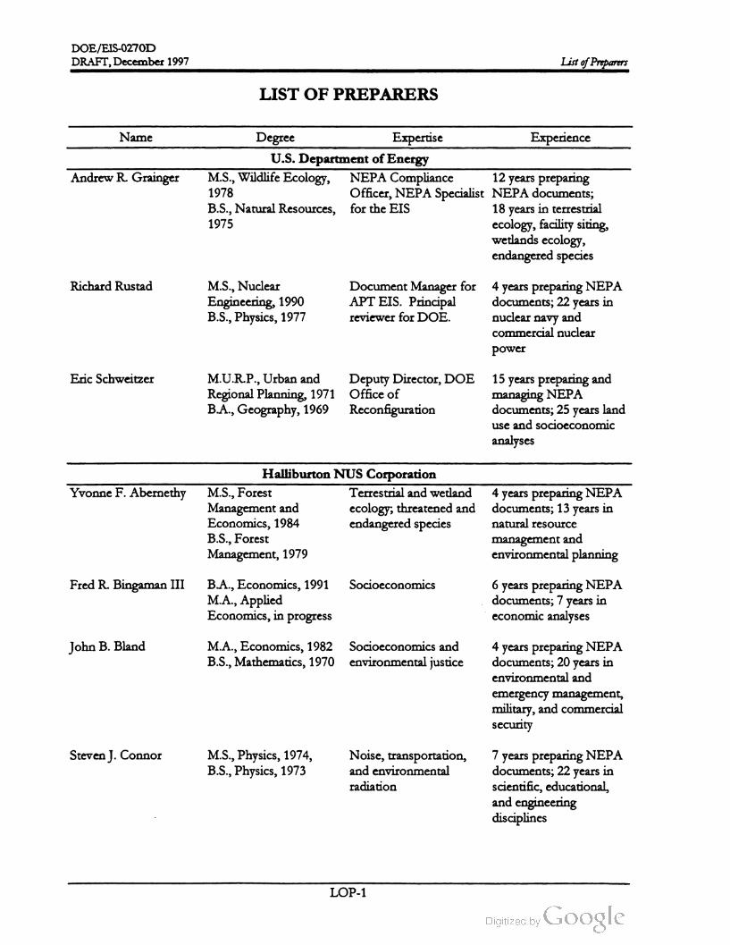
DOE /EIS-0270D
DRAFT, December 1997 List of Preparers
LIST OF PREPARERS
Name
Andrew R.Grainger
Degree Expertise Experience
U.S. Departmentof Energy
M.S., Wildlife Ecology, NEPA Compliance 12 years preparing
1978Officer, NEPA Specialist NEPA documents;
B.S.,NaturalResources, for the EIS 18 years in terrestrial
1975ecology, facility siting,
wetlands ecology,
endangered species
Richard Rustad M.S., Nuclear
Engineering, 1990
B.S., Physics, 1977
DocumentManager for
APT EIS . Principal
reviewer for DOE.
years in
4 years preparingNEPA
documents ; 22
nuclear navy and
commercial nuclear
power
Eric Schweitzer M.U.R.P., Urban and Deputy Director,DOE
Regional Planning, 1971 Office of
B.A.,Geography, 1969 Reconfiguration
15 years preparing and
managing NEPA
documents; 25 years land
use and socioeconomic
analyses
Yvonne F. Abernethy
Halliburton NUS Corporation
M.S., Forest Terrestrial and wetland
Management and ecology; threatened and
Economics, 1984 endangered species
B.S., Forest
Management, 1979
years in
4 years preparing NEPA
documents; 13
natural resource
management and
environmental planning
Fred R. Bingaman IIISocioeconomicsB.A., Economics, 1991
M.A.,Applied
Economics, in progress
6 years preparingNEPA
documents; 7 years in
economic analyses
John B. Bland M.A., Economics, 1982 Socioeconomics and
B.S.,Mathematics, 1970 environmental justice
4 years preparing NEPA
documents; 20 years in
environmental and
emergency management,
military, and commercial
security
Steven J. Connor M.S., Physics, 1974,
B.S., Physics, 1973
Noise , transportation,
and environmental
radiation
7years preparing NEPA
documents; 22 years in
scientific , educational,
and engineering
disciplines
LOP- 1

DOE/EIS -0270D
DRAFT, December 1997ListofPreparers
Name
William J. Craig
Degree
M.S., Planning, 1977
B.S., Forestry , 1972
Expertise
Project Manager for
HNUS. Land use and
natural resource
planning
Experience
10 years preparing
NEPA documents; 20
years utility fuel planning
and powerplant siting
Philip C. Fulmer, CHP Ph.D.,Nuclear
Engineering, 1993
M.S., Health Physics,
1990
B.S., Health Physics,
1989
Deputy ProjectManager; 3 years preparing NEPA
radiation protection , documents; 7 years as
internal and external health physicist for
radiation dosimetry commercial and
government nuclear
facilities
Gary L. Gunter, PG B.S.,Geology, 1984 Geology and
hydrogeology
1 year preparingNEPA
documents ; 10 years as
geologist/hydrogeologist
Mary N.HogansonWaste managementM.S., Biology , 1989
B.S., Biology , 1984
4 years preparing NEPA
documents; 12 years in
waste management and
waste minimization
Philip R.Moore Aquatic ecologyM.S.,Wildlife &
Fisheries Biology, 1983
B.A., English , 1975
8years preparing NEPA
documents ; 17 years as
fishery biologist and
aquatic ecologist
Aparajita S. Morrison B.S.,Health Physics
in
Occupational and public 1 year preparing NEPA
health documents; 11 years
environmental and
occupational protection
James L. OliverB.S.,Biology (Fisheries), Aquatic ecology ,surface 13 years preparing
1971 water, and wetlands NEPA documents; 26
years in environmental
research and impact
assessment.
Eugene M.Rollins,
CHP, CHMM
M.S.P.H., Health
Physics, 1976
B.S., Nuclear
Engineering, 1973
Occupational and public 3 years preparing NEPA
health documents ; 19 years in
radiological health
protection
LOP- 2

DOE /EIS -0270D
DRAFT,December 1997List of Preparers
Name
Cindy L. Saban , CSP ,
CHMM
Degree
M.S., 1984, Health
Physics
M.P.H., 1982, Industrial
Hygiene
B.A., 1980, Biology
Expertise Experience
Occupationalhealth and 1 yearpreparingNEPA
safetydocuments; 12 years
assessing occupational
hazards associated with
manufacturing and
research facilities
John O. Shipman B.A.,English , 1966 Technicalwriting and
editing
16 years editing and
producing NEPA
documents; 31 years
producing scientific and
technical documents
Diane S. Sinkowski,
CHMM
M.E.,Environmental
Engineering, 1994
B.S.,Nuclear
Engineering Sciences ,
1990
Air quality , human
health , and traffic and
transportation
3 years preparingNEPA
documents; 6 years in air
permitting, fate and
transport modeling,
human health impacts,
environmental
compliance, and health
physics
Seshagiri Rao Tammara M.S., Environmental
Engineering, 1976
M.S., Chemical
Engineering, 1971
B.S., Chemical
Engineering, 1968
Health assessments, risk 10 years preparing
assessments, and NEPA documents; 25
transportation years analyzing
environmental impacts,
health risk assessments
and preparing sections
for environmental
assessments and EISS
Alan L. Toblin M.S., Chemical
Engineering, 1970
B.E., Chemical
Engineering, 1968
Surface and groundwater 14 years preparing
NEPA documents; 26
years in environmental
(surface water,
groundwater,
atmospheric) transport
analyses
James S. Willison ,PE,
CHP
M.S., Nuclear
Engineering, 1982
B.S., Nuclear
Engineering, 1980
Accident analysis, health 1 year preparing NEPA
physics, atmospheric documents; 13 years of
transport,nuclear accident analyses at
physics, emergency nuclear facilities; health
preparedness physics and radiological
engineering
LOP- 3

DOE /EIS -0270D
List of Preparers DRAFT, December 1997
Name
Paul F. Wise, CEA ,
CHMM
Degree
M.S., Biology , 1984
B.S., Biology, 1982
Expertise
Environmental
regulatory compliance
Experience
2years preparing NEPA
documents; 14 years in
environmental, water
quality, waste
management, and
environmental audits
LOP- 4
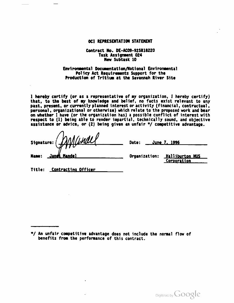
OCI REPRESENTATION STATEMENT
Contract No. DE - ACO9-92SR18220
Task Assignment 024
New Subtask 10
Environmental Documentation /National Environmental
Policy Act Requirements Support for the
Production of Tritium at the Savannah River Site
I hereby certify (or as a representative of my organization , I hereby certify )
that, to the best of my knowledge and belief, no facts exist relevant to any
past, present, or currently planned interest or activity (financial, contractual,
personal, organizational or otherwise ) which relate to the proposed work and bear
on whether I have (or the organization has) a possible conflict of interest with
respect to (1 ) being able to render impartial, technically sound , and objective
assistance or advice, or (2 ) being given an unfair * / competitive advantage.
Samanuel
$ ignature :Date : June 1 , 1996
Name : Janet MandelOrganization : Halliburton NUS
Corporation
Title : Contracting Officer
* / An unfair competitive advantage does not include the normal flow of
benefits from the performance of this contract.

一

DOE /EIS-0270D
DRAFT,December 1997 Glossary
GLOSSARY
A-weighted decibel (dBA)
A unit of weighted sound pressure level,measured by the use of a metering characteristic and
the “ A ” weighting specified by American National Standard Institute S1.4-1971(R176). (See
decibe ).
accelerator
A device that accelerates charged particles (e.g., electrons or protons) to high velocities so they have
high kinetic energy (i.e., the energy associated with motion); it focuses the charged particles into
a beam and directs them against a target.
air stripper
A device that blows air through effluent, sewage, groundwater, etc., with an aerator to remove
unwantedgas such as carbon dioxide, volatile organic compounds, or synthetic detergents.
alpha radiation
The least penetrating of the four common types of radiation (alpha, beta, gamma, and neutron).
It consists of a positively charged particle with two protons and two neutrons that is emitted from
the nucleus of certain nuclides during decay .
aquifer
A geologic formation that contains enough saturated porous material to permit movement of
groundwater and to yield groundwater to wells and springs.
aquitard
A less permanent geological unit in a stratigraphic sequence. The unit is not permeable enough
to transmit significant quantities ofwater.
atomic number
The number ofprotons in the nucleus ofan element.
attainment area
An area that complies with National Ambient Air Quality Standards (NAAQS) for criteria
pollutants;a nonattainment area does notmeet these standards.
Atterberg liquid limit value
A soil index directly proportional to the compressibility of a soil.
beam expander
A device designed to expand the proton beam in an accelerator to a larger cross-sectional area.
beamstop
A device designed to absorb the full beam of an accelerator.
bedrocke
The solid rock underlying surfacematerials (as soil).
GL- 1

DOE /EIS -0270D
DRAFT,December 1997Glossary
benthic
Associated with the bottom of a body of water (ocean, lake, river, stream ), as in “ benthic
organism ."
Best Management Practices (BMP)
A practice or combination of practices that is determined by a state (or other planning agency)
after problem assessment, examination of alternative practices, and appropriate public
participation to be the most effective, practicable means of preventing or reducing the amount
of pollution generated by nonpointsources to a level compatible with air or water quality goals.
beta radiation
Consists of an elementary particle emitted from a nucleus during radioactive decay, it is negatively
charged, is identical to an electron , and is easily stopped by a thin sheet ofmetal.
blaclewater
Water in coastal plains, creeks, swamps, and rivers that is dark or black due to naturally
occurring organic matter (tannic and humic acids) and certain minerals from soils and decaying
vegetation.
blanket
That part of an accelerator with atoms that undergo a nuclear reaction to absorb neutrons, resulting
(in the case of this EIS) in the production ofa tritium atom and another (product) atom .
blowdown
Water discharged intentionally from a cooling tower system because of relatively high
concentrations of salts.
Carolina bay
Oval-shaped , intermittently flooded ,marshy depression of a type that occurs abundantly on the
Coastal Plain of the Carolinas.
cesium
Naturally occurring element with 55 protons in its nucleus. A radioactive isotope of cesium , cesium
137, is a common fission product.
chironomid
Nonbitingmidges, most of which have aquatic larvae. These chironomid larvae are found in a
variety of aquatic habitats, including waters that are polluted and low in oxygen ..
cold standby
See standby.
commercial light-water reactor
A reactororiginally designed for the production of electricity.
committed dose equivalent
The dose equivalent calculated to be received by a tissue or organ over a 50-year period after the
intake of a radionuclide in the body.
GL-2
DOE /EIS-0270D
DRAFT,December 1997 Glossary
committed effective dose equivalent
The sum of the committed dose equivalents to various issues in the body multiplied by their
appropriate tissueweighting factor. Equivalent in effect to a uniform external dose of the same
value.
A
community (environmental justice)
group of people or a site in a specified area exposed to risks that could threaten health ,
ecology, or land values, or exposed to industry that stimulates unwanted noise, smell, industrial
traffic, particulatematter, or other unaesthetic impacts.
conceptual design
Efforts to develop a project scope that will satisfy program needs; ensure project feasibility and
attainable performance levels of the project for Congressional consideration ; develop project
criteria and design parameters for all engineering disciplines; and identify applicable codes and
standards, quality assurance requirements, environmental studies, construction materials, space
allowances, energy conservation features, health and safety safeguards, security requirements,
and other features or requirements necessary to describe the project.
conductivity
The ability to transmit a fluid or energy flow .
confining unit
A body of impermeable or distinctly less permeable material stratigraphically adjacent to one or
more aquifers.
coolant
A gas or liquid circulated through nuclear reactor or accelerator systemsto remove or transfer heat.
cooling water
Water pumped into a nuclear reactor or accelerator to cool components and prevent damage from
the intense heat generated when the reactor or accelerator is operating.
criticalbabitat
Habitat essential to the survival or reproduction of a species.
Cryogenics
The science of physical phenomena at very low temperatures,approaching absolute zero.
cumulative impacts
Additive environmental, health , or socioeconomic effects that result from a number of similar
activities in the area.
cryogenic distillation
Aprocess where differences in the boiling points of hydrogen and tritium are used to separate
the two isotopes. The process takes place at extremely cold temperatures. See also cryogenics.
decay (radioactive)
The spontaneous transformation of one nuclide into a different nuclide or into a different energy
state of the samenuclide. The process results in the emission of nuclear radiation .
GL -3

DOE /EIS -0270D
DRAFT,December 1997Glossary
decibel
A unit for measuring the relative loudness of sounds. In general, a sound doubles in loudness
forevery
increase of 10 decibels .
decisionmaker
Group or individual responsible for making a decision on constructing and operating an
accelerator to produce tritium at the Savannah River Site.
decoupler
That part of an accelerator between the high-energy neutron source and themoderating blanket
that contains feedstock material that will absorb low -energy neutronsand help protect the neutron
source.
Defense Waste Processing Facility
Savannah River Site facility that processes high-level radioactive waste into a glass form for
transport to a permanent disposal site.
deinventory
Packaging unused nuclearmaterials and placing them in storage on the SRS or at their source.
demersal
Refers to fish eggs that are relatively heavy and sink ,because their specific gravity is greater than
water.
demographic
Related to the statistical study of human populations, including size, density , distribution, and
such vital statistics as age, gender, and ethnicity.
design -basis accident
For nuclear facilities, a postulated abnormal event used to establish the performance
requirements of structures, systems, and components that are necessary to (1) maintain them in a
safe shutdown condition indefinitely or (2) prevent or mitigate the consequences of the design
basis accident so that the general public and operating staff are not exposed to radiation in
excess of appropriate guideline values. Normally, this is the accident that causes themost severe
consequences when engineered safety features function as intended.
design -basis events
Postulated disturbances in process variables that can potentially lead to design -basis accidents.
diatom
Any of a class of planktonic one-celled or colonial algae with skeletons of silica (a mineral
consisting of silicon and oxygen).
dinoflagellate
Any of an order of unicellular flagellated algae, many of which have the ability to move
spontaneously.
dipteran
A large group of insects, usually “ true” flies with one pair of wings, but also including midges,
mosquitoes, and gnats. Many dipterans have aquatic larvae.
GL- 4

DOE /EIS-0270D
DRAFT, December 1997 Glossary
dose
The energy imparted to matter by ionizing radiation. The unit of absorbed dose is the rad,which is
equal to 0.01 joule per kilogram of irradiated material in anymedium .
dose equivalent
A term used to express the amount of effective radiation when modifying factors have been
considered . It is the product of absorbed dose (rads) multiplied by a quality factor and other
modifying factors. It is measured in rem (Roentgen equivalentman).
drift
Mist or spray carried into the atmosphere with the effluent air vapor from a cooling tower.
ecosystem
The community of living things and the physical environment in which they live.
effluent
A liquid or airbornematerial released to the environment; in common usage, a liquid release.
effluentmonitoring
The collection and analysis of samples or measurements of liquid and gaseous effluents to
characterize and quantify contaminants, assess radiation exposure to members of the public, and
demonstrate compliance with applicable standards; occurs at the point of discharge, such as an
air stack or drainage pipe
EIS (environmentalimpact statement)
A legal document required by the National Environmental Policy Act (NEPA) of 1969, as
amended , for Federal actions involving significant or potentially significant environmental
impacts. A tool for decisionmaking, it describes the positive and negative impacts of the
proposed action and the alternative actions.
electron
An elementary particle with a mass of 9.107 x 10⁻²⁸ gram (or 1/1837 of a proton) and a negative
charge. Electrons surround the positively charged nucleusand determine the chemical properties
of the atom .
emission standards
Legally enforceable limits on the quantities and kinds of air contaminants thatmay be emitted to
the atmosphere.
entrainment
The capture and inclusion of organisms in the cooling water systems of such facilities as reactors
and accelerators. The organisms involved, which would depend on size of the intake screen
opening, include phyto- and zooplankton , fish eggs and larvae (ichthyoplankton), shellfish larvae,and
other formsof aquatic life.
environment
The sum of all external conditions and influences affecting the life, development,and ultimately
the survival of an organism .
GL-5
DOE / EIS -0270D
DRAFT ,December 1997Glossary
environmental justice
The fair treatmentofpeople of all races, cultures, incomes, and educationallevels with respect to
the development, implementation, and enforcement of environmental laws, regulations, and
policies. Fair treatment implies that no population of people should be forced to shoulder a
disproportionate share of the negative environmental impacts of pollution or environmental
hazards due to a lack of political or economic strength .
environmental surveillance
The collection and analysis of samples of air, water, soil, foodstuffs, biota, and other media and
the measurement of external radiation to demonstrate compliance with applicable standards,
assess radiation exposures to members of the public, and assess effects, if any, on the local
environment.
ephemeropteran
Any of a group of small terrestrial insects (mayflies) with delicate, transparent wings and large
compound eyes. They occur in the vicinity of bodies of fresh water, in which the immature
stages develop
exposure (to radiation)
The incidence of radiation on living or inanimate material by accident or intent. Background
exposure is the exposure to natural background ionizing radiation . Occupational exposure is the
exposure to ionizing radiation that occurs during a person's working hours. Population
exposure is the exposure to a number ofpersons who inhabit an area.
exposure pathway
The course a chemical or physical agent takes from the source to the exposed organism . The
pathway describes a unique mechanism by which an individual or population is exposed to
chemicals or physical agents at or originating from the site . Each exposure pathway includes a
source or release from a source, an exposure point, and an exposure route. If the exposure
point differs from the source, a transport/ exposure medium (e.g., air) is included .
extrusion press
A device in which heated or unheated material is forced through a shaping orifice to become
one continuously formed piece .
fallout
The descent to earth and deposition on the ground of particulate matter (usually radioactive) from
the atmosphere.
fault (geological)
A fracture in the earth's crust accompanied by a displacement of one side in relation to the
other.
feedstock material
Neutron-absorbing material in the target /blanket structure that is transformed by neutron
absorption into the desired product (e.g., tritium ).
floodplain
The relatively smooth valley floors adjacent to and formed by rivers subject to overflow .
GL-6

DOE /EIS-0270D
DRAFT,December 1997 Glossary
getter
A special metal placed in a vacuum tube during manufacture and vaporized after the tube is
evacuated ;when the vaporized metal condenses it absorbs residual gases. See Tritium Separation
Facility.
greater-than-Class- C waste
Radioactive waste that contains long-lived radionuclides and requires special disposal
considerations.
grid
A transmission and distribution system for electric power.
Gross RegionalProduct
The total value of the goods and services produced in a defined region during a year.
half -life (radiological)
The time in which half the atomsof a radioactive substance disintegrate to another nuclear form .
Half-lives vary from millionths of a second to billions ofyears .
hazardouswaste
Waste (solid , semisolid , or liquid ) with the characteristics of ignitability, corrosivity, toxicity, or
reactivity, as defined by the Resource Conservation and Recovery Act and identified or listed in
40 CFR 261 or the Toxic Substances Control Act.
beat exchanger
A device that transfers heat from one fluid (liquid or gas) to another. It allows heat to pass from
one system to another withoutmixing the contents of the systems.
heavy-water
Water in which the hydrogen of the water molecule consists entirely of the heavy hydrogen
isotope having a mass number of 2 ; also called deuterium oxide (D20 ).
heavywater reactor
A nuclear reactor in which heavywater serves as amoderator and sometimes as a coolant.
high -level waste
The highly radioactive liquid wastes that result from the chemical processing of spentnuclear fuel,
including liquid waste produced directly in reprocessing and any solid waste derived from the
liquid. High-level waste contains a combination of transuranic waste and fission products in
concentrations requiring permanent isolation.
high -temperature gas-cooled reactor
Atype of nuclear reactor design that uses a gas (e.g., helium ) for cooling rather than water. It
permits more efficient use of uranium and some use of thorium in its fuel cycle. It also offers
greater efficiency than light-water reactors.
icthyoplankton
The early life stages of fish (eggs and larvae) that spend part of their life cycle as free-floating
plankton .
GL-7
DOE /EIS -0270D
DRAFT, December 1997Glossary
impingement
The process by which aquatic organisms too large to pass through the screen of a water intake
system become trapped against the screens and are unable to escape.
incineration
The efficient burning of combustible solid and liquid wastes to destroy organic constituents and
reduce the volumeof thewaste. The greater the burning efficiency, the cleaner the air emission .
Incineration of radioactivematerials does not destroy the radionuclides but does significantly reduce
the volume of the waste .
inductive outputtube
A device designed to amplify microwaves in a manner different from thatin a radiofrequency power
tube. The electron beam current varies depending on the microwave signal. In addition, it is
typically smaller than a radiofrequency power tube and has greater efficiency, providing the same
microwave amplification with less energy.
infrastructure
The system of public works of a county, state , or region; also, the resources (buildings or
equipment) required for an activity .
injector
A device thatprovides protons for an accelerator by heating hydrogen gas to a plasma state in which
the hydrogen atoms lose their electrons, thereby giving the hydrogen nuclei (protons) a positive
charge. An electric voltage removes the protons from the injector.
in situ
In or at the natural or original position or location .
ion
An atom ormolecule thathas gained or lost one ormore electrons to become electrically charged.
ion exchange
Process in which a solution containing soluble ions to be removed is passed over a solid ion
exchangemedium , which removes thesoluble ionsby exchanging them with labile ions from the
surface of the medium . The process is reversible so trapped ions can be collected (eluted) and
the column regenerated.
ion-exchange medium
A substance (see resin) thatpreferentially removes certain ions from a solution.
ionizing radiation
Radiation capable of displacing electrons from atoms or molecules to produce ions.
irradiation
Exposure to radiation.
GL- 8

DOE /EIS -0270D
DRAFT,December 1997 Glossary
isotope
An atom ofa chemical element with a specific atomic number and atomic mass. Isotopes of the
same element have the same number of protons but different number of neutrons. Isotopes are
identified by the name of the element and the total number of protons and neutrons in the
nucleus. For example, plutonium -239 is a plutonium atom with 239 protons and neutrons.
klystron
An electron tubeused for the amplification ofmicrowaves (see radiofrequency power tube).
latent cancer fatalities
Deaths resulting from cancer that has become active after a latent period (i.e., a period of
inactivity ).
laydown
Area of construction site used to sort and store construction materials .
lightwater
Ordinary water containing hydrogen atomswith no neutrons in their nucleus.
light-water reactor
A nuclear reactor that uses ordinary water to cool the reactor core and to moderate (reduce the
energy of) the neutrons created in the core by fission reactions.
low -income community
A community in which 25 percent ormore ofthe population is identified as living in poverty.
low -level waste
Radioactive waste not classified as high-level waste, transuranic waste , spent nuclear fuel, or byproduct
material.
macroinvertebrate
Small animal, such as a larval aquatic insect, that is visible to the naked eye and has no vertebral
column, as in “ benthicmacroinvertebrate.”
makeup water
Replacement for water lost through drift,blowdown,or evaporation (as in a cooling tower).
maximally exposed individual
A hypothetical member of the public at the SRS boundary located to receive the maximum
possible dose equivalent from a given exposure scenario .
MeV (million electron -volts)
A unit used to quantify energy. In this EIS, it describes a particle's kinetic energy , which is an
indicator of particle speed.
millirem
One thousandth of a rem . (See rem .)
GL- 9

DOE/EIS -0270D
Glossary DRAFT, December 1997
minority communities
A population classified by the Bureau of the Census as Black, Hispanic, Asian and Pacific
Islander, American Indian , Eskimo, Aleut, and other nonwhite persons, the composition of
which is at least equal to or greater than the state minority average of a defined area or
jurisdiction.
mixed waste
Waste material that contains both hazardous waste and radioactive source , special nuclear, or
byproductmaterial (subject to the Atomic Energy Act of 1954).
Molecular sieve
Device in the Tritium Separation Facility used to separate impurities and spallation products
from the hydrogen /helium gas stream .
National Ambient Air Quality Standards
Air quality standards established by the Clean Air Act, as amended. The primary National
Ambient Air Quality Standards are intended to provide the public health with an adequate
margin of safety, and the secondary National Ambient Air Quality Standards are intended to
provide the public welfare from known or anticipated adverse impacts ofa pollutant.
National Pollutant Discharge Elimination System
Federalpermitting system required for liquid effluents regulated through the Clean Water Act,as
amended.
National Register of Historic Places
A list maintained by the Secretary of the Interior of districts, sites, buildings, structures, and
objects ofprehistoric or historic local, state, or national significance.
neutron
An uncharged elementary nuclear particle that has a mass approximately the sameas that of a
proton , it is present in all atomic nuclei except that ofhydrogen - 1. A free neutron is unstable and
decays with a half-life of about 13minutes into an electron and a proton.
nonattainment area
See attainment area.
nuclide
An atomic nucleus specified by atomic weight, atomic number, and energy state ; a radionuclide is a
radioactive nuclide.
odonate
Any of a group oflarge predatory insects (dragonflies and danselflies) with two pairs of long,
narrow wings and biting mouth parts,which are aquatic in immature (nymphal) stages.
Occupational Safety and Health Administration
Federalagency responsible for oversightand regulation ofworkplace health and safety.
off-normal event
An unexplained event that exceeds the range of normal operating parameters, but that usually
does not have a significant impact (insideor beyond the SRS boundary).
GL-10

DOE /EIS-0270D
DRAFT, December 1997 Glossary
oligochaete
A segmented worm with the same fundamental structure as an earthworm that is often found in
polluted rivers or streams.
oxides ofnitrogen (NOx)
Primarily nitrogen oxide (NO) and nitrogen dioxide (NO2), these compounds are produced in
the combustion of fossil fuels, and can constitute an air pollution problem .
ozone
A compound of oxygen in which three oxygen atoms are chemically attached to each other.
perched water
Groundwater from a restricted or a relatively small area that lies above a more extensive aquifer.
periphyton
Algae that live attached to underwater surfaces.
permeator
A device that selectively allows the passage ofhydrogen atomsand
elements. Used to separate hydrogen and tritium from helium .
preventsthe passage of other
person - rem
Themeasure of radiation dose commitment to a specific population; the sum of the individual
doses received by a population segment.
pH
A measure of the hydrogen ion concentration in aqueous (made from , with , or by water)
solution. Pure water has a pH of 7, acidic solutions have a pH less than 7, and basic solutions
have a pH greater than 7.
phytoplankton
Microscopic floating plants, such as diatoms.
prime farmland
Land that has the best combination of physical and chemical characteristics for producing food,
feed , forage, fiber, oilseed , and other crops with minimum inputs of fuel, fertilizer, pesticides,
and labor without intolerable soil erosion, as determined by the Secretary of Agriculture.
privatization
The transfer of government operations to theprivate sector.
proton
An elementary nuclear particle with a positive charge equal in magnitude to the negative charge
of the electron , it is a constituent of all atomic nuclei, and the atomic number of an element
indicates the number of protons in the nucleus ofeach atom of that element.
GL-11

DOE /EIS -0270D
Glossary DRAFT,December 1997
protozoa
Mobile, single -celled animals from five to several hundreds microns long that are found
wherever there is water. They move by cilia, flagella , or pseudopods. Most are harmless or
helpful; a few cause illness in humans. Because they are easily seen with optical microscopes,
they can be valuable indicators of water quality conditions in a lake or stream .
quantitative analysis
A form of analysis that uses defined values to determine the amount of one or more
components.
radiation
The emitted particles and photons from the nuclei of radioactive atoms; a short term for ionizing
radiation ornuclear radiation, which are different from nonionizing radiation such as microwaves,
ultraviolet rays, etc.
radioactivity
The spontaneousdecay of unstable atomic nucleiaccompanied by the emission of radiation .
radiofrequency power tube
An established technology that radar installations and television broadcast stations use to
generate broadcast signals. It uses a beam of electrons to amplify a microwave signal; the
produced electron beam current is fixed, regardless of the strength of the microwave signal. See
inductive outputtube.
radiological
Related to radiology, the science that deals with the use of ionizing radiation to diagnose and treat
disease.
radionuclide
See nuclide.
reactor
A device or apparatus in which a chain reaction of fissionable material is initiated and controlled;
a nuclear reactor.
receiving waters
Rivers, lakes, oceans, or other bodies of water into which treated or untreated waste waters are
discharged.
Record of Decision (ROD )
A document that provides a concise public record of an agency decision on a proposed action
for which it prepared an EIS. An ROD identifies the alternatives considered in reaching the
decision, the environmentally preferable alternative(s), factors the agency balanced in making the
decision , if the agency has adopted all practicable means to avoid or minimize environmental
harm and if not, why not.
recycling
For this EIS, recovering residual tritium from weapons components, purifying it, and refilling
the components with both recovered and new tritium .
GL- 12

DOE/EIS-0270D
DRAFT, December 1997 Glossary
release fraction
The calculated fraction ofmaterial that an accident could release.
rem (Roentgen equivalentman)
The unit of dose equivalent for human radiation exposure. It is equal to the product of the
absorbed dose in rads and a quality factor.
Tritium Loading Facility (also known as Replacement Tritium Facility)
Underground SRS facility in which DOE unloads gases from reservoirs returned from the
Department of Defense, separates and purifies the gases useful hydrogen isotopes (tritium and
deuterium ), mixes the gases to exact specifications, and loads the reservoirs
resin
An ion -exchange medium ; organic polymer used for the preferential removal of certain ions
from a solution.
Resource Conservation and Recovery Act
The Act that provides a " cradle to grave” program for hazardous waste, which established,
among other things, a system for managing hazardous waste from its generation until its ultimate
disposal.
Richter Scale
A scale formeasuring earthquakes with graded steps from 1 to 10. Each step is about 60 times
greater than the preceding step , adjusted for different regions of the earth .
riske
In accident analysis, the probability -weighted consequence of an accident, defined as the
accident frequency per year multiplied by the dose. Risk is also used commonly in other
applications to describe the probability of an eventoccurring.
River Water System
A system of large concrete pipes built to provide secondary cooling water to the five SRS
production reactors. The system pumped water from the Savannah River to the reactor areas,
where the water passed through heat exchangers to absorb heat from the reactor core. Heated
discharge water returned to the river in onsite streams.
totifer
Tiny aquatic and semi-aquatic animals that occur in a wide variety of habitats and include free
swimming, planktonic, and parasitic forms.
sanitary waste
Solid waste that is neither hazardous as defined by the Resource Conservation and Recovery Act nor
radioactive, sanitary waste streams include paper, glass, discarded office material, and construction
debris.
seismicity
Capacity for earth -movement events,usually earthquakes.
GL -13

DOE /EIS -0270D
DRAFT,December 1997Glossary
soil horizon
A layer of soil,approximately parallel to the surface, that differs from adjacent layers in chemical
and physicalproperties.
spallation
A nuclear reaction in which light particles are ejected as the result of bombardment (as by high
energy protons)
specialnuclear materials
Plutonium , uranium -233, uranium enriched in the isotope 233 or 235, and any other material
DOE determines to be special nuclear material.
spent nuclear fuel
Fuel that has been withdrawn from a nuclear reactor following irradiation , the constituent
elements ofwhich have notbeen separated .
standby (cold standby)
Condition under which a facility ismaintained in a protected condition to prevent deterioration
such that it can be brought back into operation .
sulfur dioxide
A heavy ,pungent, toxic gas,used as a preservative or refrigerant, that is a major air pollutant.
superconducting
Exhibiting a complete disappearance of electrical resistance in various metals at temperatures
near absolute zero .
Superfund
A trust fund established by the Comprehensive Environmental Response, Compensation, and
Liability Actand amended by the Superfund Amendment and Reauthorization Act that finances
long-term remedial action for hazardous waste sites.
supply
For this EIS, the production of tritium in a reactor or an accelerator and the subsequent
extraction of the tritium in pure form for use in weapons
switchyard
A device that determines the destination of a charged particle beam by using magnets to
influence its travel path .
target
A tube, rod, or other form containing material that, on being irradiated in a nuclear reactor or an
accelerator would produce a desired end product.
taxa (plural of taxon)
Classes or types oforganisms.
thermophilic
Related to plants and animals that thrive in heated waters.
GL - 14

DOE/ EIS-0270D
DRAFT, December 1997 Glossary
tier
To link to another in a hierarchical chain . An upper-tier document might be programmatic to
the entire DOE complex of sites; a lower-tier documentmight be specific to one site or process.
total particulate matter
Fine liquid or solid particles such as dust, smoke, mist, fumes,or smog found in air or emissions.
trichopteran
Any of a group ofsmall,moth -like insects (caddisflies) found near streams and lakes with larvae
andpupae
that are aquatic .
tritium
A radioactive isotope ofhydrogen and an essential component of every warhead in the current and
projected U.S. nuclear weapons stockpile. The tritiuin enables warheads to perform as designed.
Tritium Extraction Facility
A proposed facility at the Savannah River Site that would extract tritium from targetmaterial
irradiated in either an accelerator or a commercial light-water reactor.
Tritium Separation Facility
A proposed facility at the Savannah River Site that would separate hydrogen isotopes (protium ,
deuterium , and tritium ) from helium using metal getter beds that would absorb hydrogen while
allowing helium to pass through , and would separate tritium from the other hydrogen isotopes
using cryogenic distillation.
uninvolved worleer
For this EIS, an SRS worker who is not involved in the operation of the accelerator, and who is
assumed to beat least 640 meters from thepoint of release.
volatile organic compound
An organic compound with a vapor pressure greater than 0.44 pound per square inch at
standard temperature andpressure.
watershed
The area drained by a body ofwater.
water quality standards
Provisions of Federal or state law that consist of a designated use or uses for the waters of the
United States and water quality standards for such waters based on their uses. Water quality
standards are used to protect the public health or welfare, enhance the quality of water, and
serve the purposesof the Clean Water Act.
waveguides
Hollow metal conduits that transmit radiofrequency waves to the beam in an accelerator.
GL- 15

DOE /EIS-0270D
DRAFT, December 1997Glossary
wetlands
Land or areas exhibiting the following: hydric soil conditions, saturated or inundated soil during
some portion of the year, and plant species tolerant of such conditions; also , areas that are
inundated or saturated by surface water or groundwater at a frequency and duration sufficient to
support, and that under normal circumstances do support, a prevalence of vegetation typically
adapted for life in saturated soil conditions. Wetlands generally include swamps,marshes, bogs,
and similar areas.
zooplankton
Microscopic planktonic (floating) animals,many ofwhich serve as food for fish .
GL- 16

Appendix A
Facility and Process Descriptions

-
|
|

APPENDIX A
FACILITY AND PROCESS DESCRIPTIONS

一
-

DOE /EIS-0270D
DRAFT, December 1997 Facility and Process Descriptions
TABLE OF CONTENTS
Section Page
A.1 A - 1
A - 1
A - 3
A - 4
A - 4
A - 4
A - 7
A.2
A.3
A.4
Linear Accelerator ......
A.1.1 Accelerator Tunnel.
A.1.2 Injector System .
A.1.3 Low -Energy (up to 100 mev) Linear Accelerator System
A.1.4 High -Energy (Greater Than 100 mev ) Linear Accelerator System .
A.1.4.1 High-Energy Room Temperature Linac........
A.1.4.2 High-Energy Superconducting Radiofrequency Linac .
A.1.5 High-Energy Beam Transport System , Switchyard , and Beam Expander
System
Radiofrequency Gallery
A.2.1 Klystron Alternative for RF System
A.2.2 Inductive Output Tube Alternative for RF ............
Target/Blanket System ..
A.3.1 Target/ Blanket Structure
A.3.2 Helium - 3 Feedstock Material Alternative ......
A.3.3 Lithium -6 Feedstock Material Alternative.
A.3.4 Beamstop Systems.....
A.3.4.1 Low -Energy and Intermediate-Energy Beamstops....
A.3.4.2 High -Energy Beamstop
A.3.4.3 Removable High -Energy Beamstop .
Tritium Separation Facility...
A.4.1 Tritium Extraction System ....
A.4.2Isotope Separation System .....
A.4.3 Waste Gas Tritium Cleanup System ...
A.4.4 Helium -3 Supply System
A.4.5 Tritium Storage System ...
Support Facilities at the Accelerator Site ...........
A.5.1 APT Safety Systems
A.5.2 Administrative Building.
A.5.3 Access Control Building.
A.5.4 Backup Power Facilities
A.5.5 Operations Building.
A.5.6 Maintenance Building
A.5.7 RF TubeMaintenance Facility ....
A.5.8 Mechanical-Draft Cooling Tower Structures
A.5.9 Mechanical Services Buildings.
A.5.10 Simulator and Training Building........
A.5.11 Fire Pump House and Water Storage Tanks.....
A.5.12 Demineralizer Building
A.5.13 Security Building...
A.5.14 Cryogenics System
A.5.15 Target/Blanket Staging Building.
A - 8
A - 9
A -12
A -13
A - 15
A - 15
A - 18
A -20
A -21
A -21
A - 22
A -24
A - 25
A -25
A - 27
A - 28
A - 29
A -29
A -31
A -31
A -32
A - 32
A -32
A -33
A -33
A -33
A -34
A -34
A - 34
A - 34
A -35
A - 35
A -35
A -37
A.5
A - üü

DOE / EIS -0270D
DRAFT,December 1997Facility and Process Descriptions
TABLE OF CONTENTS (continued )
SectionPage
A.5.16 Radioactive Waste Treatment System
A.5.16.1 Solid Radioactive Waste System .......
A.5.16.2 Liquid Radioactive Waste System
A.5.16.2.1 Heavy -Water Radioactive Waste System
A.5.16.2.2 Light-Water Liquid RadioactiveWaste System
A.5.16.2.3 Process -Water Radioactive Waste System ..
A.5.16.3 Gaseous RadioactiveWaste System ........
A.5.16.4 RadioactiveWaste Building ......
A.6 Other Support Facilities and Systemsat the Savannah River Site
A.6.1 Tritium Loading Facility ...
A.6.2 Tritium Processing Facilities / Tritium Extraction Facility
A.6.3 M -Area Facilities...
A.6.4 SRSWaste Facilities
A.6.4.1 Low -Level Solid Waste ......
A.6.4.2 Low -Level Liquid Waste
A.6.4.3 Long-Lived and Intermediate -Level Waste
A.6.4.4 Hazardous andMixed Waste .....
A.6.5 RiverWater System .....
A.6.6 K -Area Cooling Tower.....
References ...
A -37
A -38
A - 38
A - 38
A -39
A - 40
A - 40
A -41
A -41
A -41
A -43
A -43
A -43
A -46
A -46
A -46
A -48
A -49
A -49
A -50
List of Tables
Table Page
A - 1
A - 2
Room Temperature Linac System
M -Area Facility functional support compatibility
A - 6
A -44
List of Figures
Figure Page
A - 1
A - 2
A - 3
A - 4
A - 5
A - 6
A - 7
A - 8
Conceptual layoutofAPT facilities and structure
Injector system (LANL 1997) .....
Configurations ofCCDTL (top 3) and CCL (lower 2) structures (LANL 1997)...............
Room - temperaturelinac
system (2 -kg production level) (LANL 1997)..
Funneled Room -Temperature Linac System (3-kg production level) (LANL 1997).
Superconducting High-Energy Linac System (3 -kg production level) (LANL 1997) ..
High-Energy Beam Transport and ExpanderSystem (LANL 1997) ...
Switchyard (LANL 1997).
A - 2
A - 3
A - 5
A -5
A - 6
A - 7
A - 8
A - 10
A - iv

DOE /EIS -0270D
DRAFT,December 1997 Facility and Process Descriptions
TABLE OF CONTENTS (continued)
List of Figures (continued )
Figure Page
A - 9
A - 10
A - 11
A - 12
A -13
A -14
A - 15
A - 16
A - 17
A -18
A - 19
A -20
A -21
A - 22
A -23
A - 24
A -25
A - 26
A -27
Block diagram ofRF Power System (LANL 1997)
Waveguidelayout in themedium ß HE linac (LANL 1997).
Schematic diagram of an inductive output tube (Badger).
Top view of Target/ Blanket Building and heat removal systems (LANL 1997)
Target/blanket assembly (LANL 1997) ...
Module layout in cavity vessel (LANL 1997) ...
Tungsten neutron source (LANL 1997).
Target and blanket vertical section (LANL 1997).
Low -energy beamstop (LANL 1997) ....
Intermediate -energy beamstop layout (LANL 1997) . .......
High-energy beamstop (LANL 1997)
Flow of Tritium Separation Facility processes (LANL 1997)
Isotope Separation System (LANL 1997).
Helium supply system (LANL 1997).
APT Cryogenics System (LANL 1997).
SRS Tritium Facilities layout.......
Savannah River Site, showing wastemanagementfacilities.........
Low -Level Radioactive Waste Disposal Facility (E -Area ).
SRS waste handling processes
A -11
A -14
A - 15
A - 16
A - 16
A - 18
A - 19
A - 20
A -22
A -23
A -24
A - 26
A - 27
A - 30
A -36
A -42
A - 45
A -47
A - 48
A - V


DOE /EIS-0270D
DRAFT ,December 1997 Facility and Process Descriptions
APPENDIX A. FACILITY AND PROCESS DESCRIPTIONS
Chapter 2 of this environmental impact state
ment describes the proposed action and alter
natives for an accelerator for the production of
tritium or major modifications of structures at
the Savannah River Site (SRS). Figure A - 1
shows a conceptual layout of the APT site;
DOE would perform some support functions at
other SRS facilities. This appendix describes in
more detail the principal facilities that would be
associated with the linear accelerator forpro
duction of tritium and existing SRS facilities that
the U.S. Department of Energy (DOE) could
use to support accelerator operations, as fol
lows:
tunnel with a length ofabout 1,300 meters. The
injector system would be at the low -energy end
of the accelerator and would provide initial
beam formation and acceleration. The main
tunnel would contain the linac system , which
would accelerate the 100-milliampere (mA)
proton beam to between 1,300 and 1,700 mil
lion electron volts (MeV). The main tunnel
would connect to the high -energy beam trans
port (HEBT) tunnel, which would consist of
the target/ blanket branch and the high -energy
beamstop branch . An earthen berm over the
main and HEBT tunnel sections would provide
radiation shielding. Personnel and vehicle ac
cess would occur at several locations along the
tunnel.
A.1.1 ACCELERATOR TUNNEL
Linear accelerator (injector, accelerator tun
nel, and high -energy beam transport appara
tus)
Radiofrequency (RF) power gallery
Target/blanket building
Tritium Separations Facility
Support facilities at the accelerator site
Othersupport facilities and systems at the
Savannah River Site
Τοprotect systems and components, the APT
site and buildings would comply with specified
performance criteria for natural phenomena
such as seismic, high wind, tornado, and flood
hazards. These facilities would also have barri
ers against the release of radioactive and haz
ardous materials from systems and equipment
located in the structure. The design includes a
provision for structural support for safety
significant equipment during accident condi
tions, and emergency access and egress during
all modes of operation. The overall structure
would be weather-sealed to protect structures,
systems, and components from the effects of
water and airborne debris .
The accelerator would be in a concrete tunnel
buried under 12 to 15 meters of earth . The in
jector building, about 28 meters by 48 meters ,
would be reinforced concrete and joined to the
main tunnel of the accelerator. The structure
would be supported by a 1.7 -meter-thick con
crete slab with 1.4 -meter-thick walls at ap
proximately 12 meters below grade. This
bottom level would join the main tunnel. A 4.6
meter-wide maintenance area would run the
length of the injector building and enable en
trance to the main tunnel through a removable
shield wall. A sloped entrance to the injector
tunnel would enable the transportation of
maintenance equipment into the building
through a 6 -meterby 6 -meter doorway.
A 5.2 -meter by 5.2-meter radiation decontami
nation area would enable personnel access be
tween the injector building and main accelerator
tunnel. The area would be surrounded by
1.4 -meter-thick concrete. An airtight door in
the injector building wall would provide an air
confinement boundary at the access point.A.1 Linear Accelerator
Theaccelerator would consist of differenttypes
of accelerating structures. These components
would be in a rectangular reinforced concrete
The main tunnel would be 6.7 meters high to
provide sufficient clearance to remove accelera
tor modules for repair. The inside clear width
A - 1
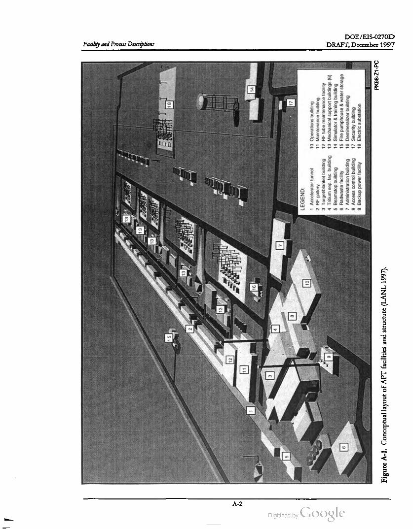
DOE/EIS-0270D
Facility and Process Descriptions
13
13
13
15
18
13
2
13
12
11
16
14
3
7
5
817
10
9
LEGEND
:
1Accelerator
tunnel
2 RF
gallery
3Target
/blanket
building
4Tritium
sep
.fac
.building
5Beamstop
building
6 Radwaste
facility 7Administration
building
8Access
control
building
9Backup
power
facility
10
Operations
building
11Maintenance
building 12RF
tube
maintenance
facility
13
Mechanical
support
buildings
(6 )
14
Simulator
&training
building
15
Fire
pumphouse
&water
storage
16
Demineralizer
building
17
Security
building
18
Electric
substation
DRAFT,December 1997
PK68
-Z1
-PC
Figure
A-1.Conceptual
layout
ofAPT
facilities
and
structure
(LANL
1997
).
A - 2

DOE/EIS-0270D
DRAFT, December 1997 Facility and Process Descriptions
of the tunnel would be 11 meters, with the ac
celerator offset 1.7 meters from the tunnel cen
terline. The total length of the main tunnel to
the high -energy beam transport structures
would be approximately 1,200 meters.
beam to the radiofrequency quadrupole (RFQ ),
the first accelerating structure of the low energy
linac system . Figure A -2 shows the injector
system with its two major subsystems: the ion
source and the low -energy beam transport de
vice. The ion source would generate a direct
current (dc) continuous or pulsed proton beam
that the low -energy beam transport device
would transport and optically match to the
RFQ .
To support the soil overburden and provide
adequate radiation shielding, the main tunnel
roof would be 1.7 meters deep and the walls
would be 1.4 meters thick . An earthen berm at
least 7 meters thick would provide the balance
of the required radiation shielding . The slab of
the main tunnel would be 1.7 meters thick .
Structural embeds at least 6.1 meters on center
would support wave guides and other equip
ment.
Injector System
Ion
Source
Low -Energy
Beam Transport
Low -Energy
Linac System
75
keVHeating, ventilation, and air conditioning
(HVAC) stations would maintain air quality in
themain tunnel. A floor drain system in the ac
celerator tunnel would collect and handle leak
age from the accelerator coolant systems and
groundwater influx.
Figure A - 2. Injector system . (LANL 1997)
The high -energy beam transport tunnel would
be a reinforced concrete structure linked to the
main tunnel and centered on the accelerator
with slab , wall, and roof thicknesses of 1.1 me
ters, 1 meter, and 1 meter, respectively. The
HEBT tunnel would have a clear opening
5 meters by 4.5 meters. A 2 -meter-wide by
3-meter-high aisle on either side of the beamline
support structure would allow component
transporter vehicle access. Five tunnel access
points would allow vehicle transport from grade
to the tunnel elevation : three points along the
length of themain accelerator tunnel, one at the
injector building, and one at the collimator in
the HEBT tunnel.
The ion source would use microwave power at a
frequency of 2.45 gigahertz (GHz) to interact
with hydrogen gas in the presence of an 875- to
900-Gauss axial magnetic field to produce a
plasma discharge, creating electrons, Hi+, H2+,
and H3+ ions, and other ionic and atomic spe
cies. The ion -source plasma chamber would be
at high voltage (75 kilovolts) with its support
systems at ground potential. The beam would
be accelerated from the plasma chamber to
ground potential in a single 75-kilovolt extrac
tion gap . An electron trap would produce an
on-axis potential reversal that would retain
electrons in the low -energy beam transport re
gion and maintain space-charge neutralization in
theproton
beam .
The tunnel would be sealed during accelerator
operation. During shutdown, the air in the tun
nel would be exhausted to the atmosphere
through a delay line and a stack .
The low -energy beam transport would be a
2.8 -meter-long beamline that would house the
beam transport elements and diagnostics for
beam tailoring and matching to theRFQ . Two
magnetic solenoid lenses would provide beam
focusing, and there would be an insertable
beamstop device between the solenoid lenses.
At the end of the low -energy beam transport
apparatus, several additional components in
cluding a vacuum valve would provide isolation
from theRFQ .
A.1.2 INJECTOR SYSTEM
The injector system would be the first section
of the accelerator. It would deliver a
75 -kiloelectron volt (keV) , 110 -mAproton
A - 3
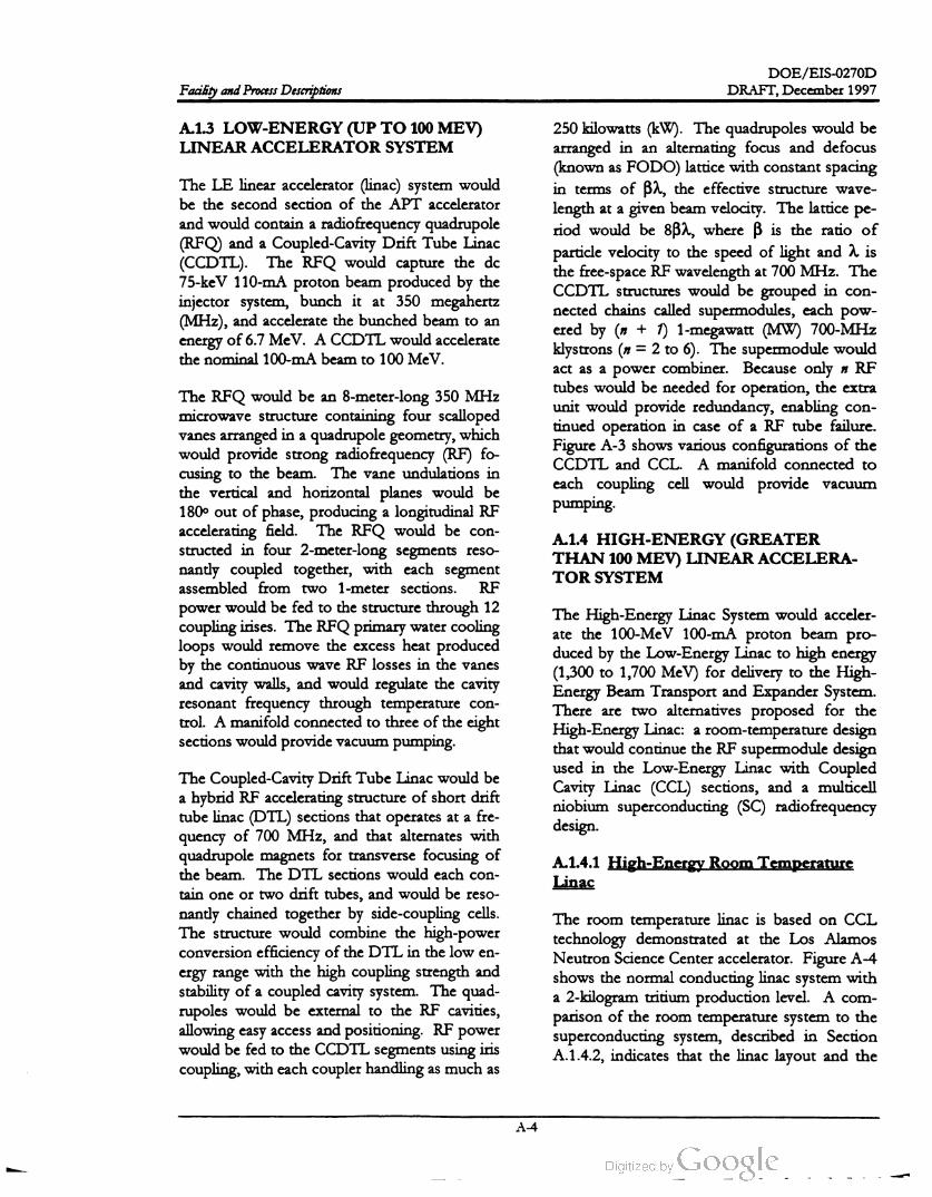
DOE /EIS -0270D
DRAFT,December 1997Facility and Process Descriptions
A.1.3 LOW -ENERGY (UP TO 100MEV)
LINEAR ACCELERATOR SYSTEM
The LE linear accelerator (linac) system would
be the second section of the APT accelerator
and would contain a radiofrequency quadrupole
(RFQ) and a Coupled -Cavity Drift Tube Linac
(CCDTL). The RFQ would capture the dc
75-keV 110 -mA proton beam produced by the
injector system , bunch it at 350 megahertz
(MHz), and accelerate the bunched beam to an
energy of 6.7 MeV . A CCDTL would accelerate
the nominal 100 -mA beam to 100 MeV .
250 kilowatts (kW ). The quadrupoles would be
arranged in an alternating focus and defocus
(known as FODO ) lattice with constant spacing
in terms of Ba, the effective structure wave
length at a given beam velocity. The lattice pe
riod would be 8B2, where ß is the ratio of
particle velocity to the speed of light and a is
the free-space RFwavelength at 700 MHz. The
CCDTL structures would be grouped in con
nected chains called supermodules, each pow
ered by (n + 1) 1 -megawatt (MW) 700-MHz
klystrons (n = 2 to 6). The supermodule would
act as a power combiner. Because only n RF
tubes would be needed for operation , the extra
unit would provide redundancy , enabling con
tinued operation in case of a RF tube failure .
Figure A -3 shows various configurations of the
CCDTL and CCL . A manifold connected to
each coupling cell would provide vacuum
pumping
The RFQ would be an 8-meter-long 350 MHz
microwave structure containing four scalloped
vanes arranged in a quadrupole geometry,which
would provide strong radiofrequency (RF) fo
cusing to the beam . The vane undulations in
the vertical and horizontal planes would be
180° out of phase, producing a longitudinal RF
accelerating field . The RFQ would be con
structed in four 2 -meter-long segments reso
nantly coupled together, with each segment
assembled from two 1 -meter sections. RF
power would be fed to the structure through 12
coupling irises. The RFQ primary water cooling
loops would remove the excess heat produced
by the continuous wave RF losses in the vanes
and cavity walls, and would regulate the cavity
resonant frequency through temperature con
trol. A manifold connected to three of the eight
sectionswould providevacuum pumping.
A.1.4 HIGH -ENERGY (GREATER
THAN 100 MEV) LINEAR ACCELERA
TOR SYSTEM
The High -Energy Linac System would acceler
ate the 100-MeV 100 -mA proton beam pro
duced by the Low -Energy Linac to high energy
(1,300 to 1,700 MeV) for delivery to the High
Energy Beam Transport and Expander System .
There are two alternatives proposed for the
High -Energy Linac: a room -temperature design
that would continue theRF supermodule design
used in the Low -Energy Linac with Coupled
Cavity Linac (CCL) sections, and a multicell
niobium superconducting (SC) radiofrequency
design .
A.1.4.1 High-Energy Room Temperature
Linac
The Coupled-Cavity Drift Tube Linac would be
a hybrid RF accelerating structure of short drift
tube linac (DTL) sections that operates at a fre
quency of 700 MHz, and that alternates with
quadrupole magnets for transverse focusing of
the beam . The DTL sections would each con
tain ne or two drift tubes, and would be reso
nantly chained together by side-coupling cells.
The structure would combine the high -power
conversion efficiency of theDTL in the low en
ergy range with the high coupling strength and
stability of a coupled cavity system . The quad
rupoles would be external to the RF cavities,
allowing easy access and positioning. RF power
would be fed to the CCDTL segments using iris
coupling, with each coupler handling asmuch as
The room temperature linac is based on CCL
technology demonstrated at the Los Alamos
Neutron Science Center accelerator. Figure A -4
shows the normal conducting linac system with
a 2-kilogram tritium production level. A com
parison of the room temperature system to the
superconducting system , described in Section
A.1.4.2 , indicates that the linac layout and the
A - 4
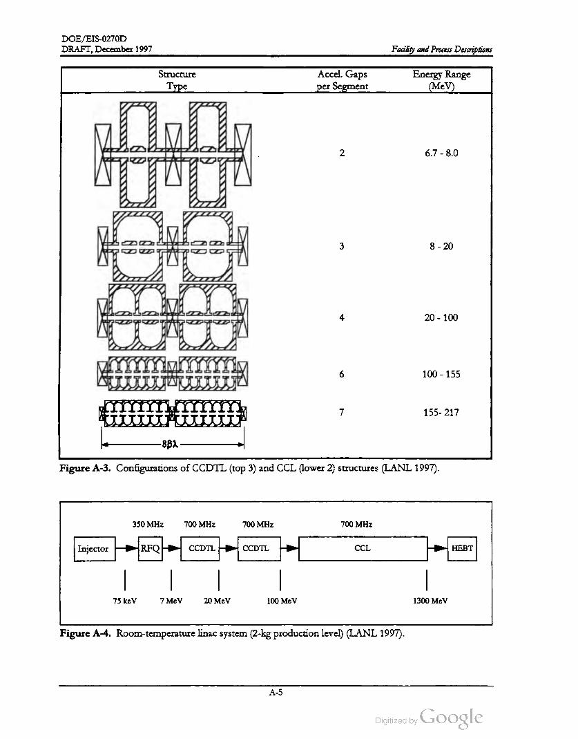
DOE /EIS -0270D
DRAFT, December 1997 Facility and Process Descriptions
Accel.GapsStructure
Type
Energy Range
(MeV)per Segment
Com
2 6.7 - 8.0
3 8 - 20
4 20 - 100
6 100 - 155
meun
7 155-217
-8B2
Figure A -3. Configurations of CCDTL (top 3) and CCL (lower 2 , structures (LANL 1997).
350 MHz 700 MHZ 700 MHz 700 MHz
Injector RFQCCDTL CCDTL
1
CCL HEBT
75 keV 7 MeV 20 MeV 100MeV 1300MeV
Figure A -4 . Room -temperature linac system (2-kg production level) (LANL 1997).
A - 5

DOE /EIS-0270D
DRAFT, December 1997Facility and Process Descriptions
structure types for the room temperature design
would be identical to the superconducting ra
diofrequency (SCRF) design , except that the
range of the last coupled-cavity linac structure
type would extend beyond 217 MeV to 1,300
MeV .
As in the CCDTL, the primary water cooling
system would carry the excess heat from RF
losses away, and would regulate the cavity fre
quency by controlling the water temperature .
Cooling passages would be machined in the
structure walls. Cavity shapes and parameters
would be optimized to minimize RF losses for
each energy region . The cavity lengths would
increase in proportion to the increasing proton
velocity . A manifold connected to each cou
pling cellwould provide vacuum pumping.
Table A - 1 summarizes the principal structures
and functions used in the Room Temperature
Linac System
The coupled cavity linac would be a conven
tional side- coupled RF linac , operating at a fre
quency of 700 MHz. The overall design
concept would include short (six to seven cells)
cavities, alternating with quadrupole magnets in
a continuation of the 8 -B2 FODO focusing lat
tice of the CCDTL . The tanks would be reso
nantly coupled in supermodule configurations
similar to the CCDTL, as shown in Figure A -3.
Five 1-megawatt (MW) klystrons would drive
each CCL supermodule; only four would be
needed to maintain operation . As in the
CCDTL , asmuch as 250 kW would be supplied
at each drive iris. The average accelerating gra
dient would reach to 1.3 megavolts per meter
(MV/m ) in the CCL.
DOE could upgrade the system to produce 3 kg
of tritium per year by beam funneling. Figure
A -5 shows a funneled layout. Each side of the
funnel would accelerate a beam of 67 mA in a
350 -MHz bunch format. The current from
both sides of the funnel would be combined at
20 MeV using an RF deflector that would
Totals
1,300
Table A - 1. Room Temperature Linac System .
Structure Type
Factor RFQ CCDTL - I CCDTL -II CCDTL -III
Final energy (MeV)6.7 8 20 100
Gaps per segment2 3 4
No. of accel. gaps 433 48 177 600
No.of segments 4 24 59 150
No. of quadrupoles 25 59 150
Section length (meters) 85.0 16
CCL- I
155
6
378
63
63
51
CCL - II
1,300
7
5,243
749
749
1,000
6,879
1,045
1,046
1,20081
67mA
Funnel
Injector RFO CCDTL
700 MHz 700 MHz 134 mA
75 keV 7 MeV CCDTL CCL HEBT
Injector RFQ CCDTL
20 MeV 100 MeV 1300 MeV67mA
Figure A -5 . Funneled Room -Temperature Linac System (3-kgproduction level) (LANL 1997).
A - 6

DOE/ EIS -0270D
DRAFT, December 1997Facility and Process Descriptions
interlace the beam bunches into a 700 -MHz
bunch format.
A.1.4.2 High -Energy Superconducting Ra
diofrequency Linac
through a nominal energy range from 217 to
469 MeV with an average accelerating gradient
ranging from 1.43 to 1.51 MV /m . The elec
tromagnetic energy would be delivered to each
cavity through two RF power couplers. The
three cavities in each cryostat would be driven
by a single 1-MW klystron through a series of
power splitters.
Figure A -6 shows the Superconducting Linac
System . The system would use a room
temperature coupled -cavity linac followed by
two superconducting sections: medium B
section with identical cavities optimized for a
velocity B = 0.64, and a high B section with
identical cavities optimized for a velocity
B = 0.82. Each superconducting section would
consist of a sequence of identical cryostats
containing super-conducting cavities for accel
eration and superconducting quadrupole mag
nets for focusing
The high ß section would consist of a periodic
array of 78 identical cryomodules, each consist
ing of a cryostat containing four five -cell super
conducting accelerating cavities optimized for a
beam velocity B = 0.82, and five superconduct
ing quadrupole focusing magnets. The warm
spaces between the cryostats would include
beamline valves, vacuum pumps, and beam di
agnostics. The high ß section accelerates the
100-mA proton beam through a nominal energy
range from 469 MeV to 1,700 MeV with an av
erage gradientof 1.89MV / m for the 3 kilogram
per year tritium production rate. The electro
magnetic energy would be delivered to each
cavity through two RF power couplers. Adja
cent pairs of cavities in each cryostat would be
driven by a single 1 -MW RF tube through a se
ries of power splitters.
The CCL would be identical in principle to the
CCL discussed in Section 1.4 , except the final
beam energy would be 217 MeV rather than
1,300 MeV . This means that the CCL for the
superconducting alternative would be shorter
and would use fewer tubes to supply RF power.
=
The medium ß section would consist of a peri
odic array of 30 identical cryomodules, each
consisting of a cryostat containing three five-cell
superconducting accelerating cavities optimized
for a beam velocity B = 0.64 , and four super
conducting quadrupole focusing magnets. The
warm spaces between the cryostats would in
clude beam -line valves, vacuum pumps, and
beam diagnostics. The medium ß section
would accelerate the 100-mA proton beam
Superconducting quadrupole magnets would be
installed between the RF cavities to provide
transverse beam focusing. The magnets would
supply the necessary integrated field gradient in
the limited axial space available in the lattice.
The fall-off of the magnetic field with distance
from the quadrupole along the beam line would
be sufficiently rapid to not interfere with the
operation ofthe superconducting RF cavities.
High -Energy Linear Accelerator System
Superconducting Accelerator System
Low -Energy
Linear Accelerator
System
Room -Temperature
Coupled -cavity
Linear Accelerator
Medium -Beta
Section
High -Beta
Section
HEBT &
Expander System
100 MeV 217 MeV 469 MeV 1700 MeV
PK68 -Z1-PC
Figure A -6 . Superconducting High -Energy Linac System (3 -kg production level) (LANL 1997).
A - 7
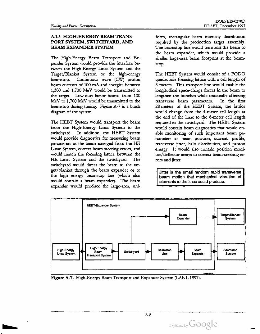
DOE /EIS -0270D
DRAFT, December 1997Facility and Process Descriptions
A.1.5 HIGH -ENERGY BEAM TRANS
PORTSYSTEM , SWITCHYARD , AND
BEAM EXPANDER SYSTEM
form , rectangular beam intensity distribution
required by the production target assembly.
The beamstop line would transport the beam to
the beam expander, which would provide a
similar large -area beam footprint at the beam
stop .
The High -Energy Beam Transport and Ex
pander System would provide the interface be
tween the High-Energy Linac System and the
Target/Blanket System or the high-energy
beamstop .Continuous wave (CW ) proton
beam currents of 100 mA and energies between
1,300 and 1,700 MeV would be transmitted to
the target. Low -duty -factor beams from 100
MeV to 1,700 MeV would be transmitted to the
beamstop during tuning. Figure A - 7 is a block
diagram of the system .
The HEBT System would consist of a FODO
quadrupole focusing lattice with a cell length of
8 meters. This transport line would enable the
longitudinal space -charge forces in the beam to
lengthen the bunches while minimally affecting
transverse beam parameters. In the first
28 nieters of the HEBT System , the lattice
would change from the 4 -meter cell length at
the end of the linac to the 8-meter cell length
required in the switchyard. The HEBT System
would contain beam diagnostics that would en
able monitoring of such important beam pa
rameters as beam position , current, profile,
transverse jitter, halo distribution , and proton
energy. It would also contain position moni
tor/deflector arrays to correct beam -steering er
rors and jitter.
The HEBT System would transport the beam
from the High -Energy Linac System to the
switchyard . In addition , the HEBT System
would provide diagnostics for measuring beam
parameters as the beam emerged from the HE
Linac System , correct beam steering errors, and
would match the focusing lattice between the
HE Linac System and the switchyard . The
switchyard would direct the beam to the tar
get/blanket through the beam expander or to
the high energy beamstop line (which also
would contain a beam expander). The beam
expander would produce the large -area, uni
Jitter is the small random rapid transverse
beam motion that mechanical vibration of
elements in the linac could produce .
HEBT/Expander System
Beam
Expander
TargetBlanket
System
High-Energy
Linac System
High Energy
Beam
Transport System
SwitchyardBeamstop
Line
Beam
Expander
Beamstop
System
PK68-Z1-PC
Figure A -7 . High-Energy Beam Transport and Expander System (LANL 1997).
A - 8
DOE /EIS -0270D
DRAFT, December 1997 Facility and Process Descriptions
The switchyard , shown in Figure A - 8, would
contain the transport beamlines serving both
the Target/Blanket assembly and the beamstop
line. The beamline to the Target/ Blanket as
sembly would begin with an achromatic bend
consisting of 5 dipoles and 10 quadrupoles in a
FODO lattice. Collimators at three locations of
maximum dispersion in the achromat would
intercept small amounts of off-momentum
beam . The bending arc would contain beam di
agnostics, including beam current monitors,
beam position monitors, and beam loss moni
tors. A vacuum valve would be installed at the
entrance of the arc . A tantalum beam plug
would be installed with downstream shield walls
and personnel fences so the beam expander
serving the target would be accessible for
maintenance when the plug was inserted and
thearc dipoleswere deenergized .
berm . The gallery would house the RF tubes
and associated support components that would
produce the radiofrequency waves to power the
accelerator. The gallery would include the con
trol panels, crowbar, high -voltage oil tank , and
silicon -controlled rectifier (SCR ) controller, and
would accommodate the controls, cabling, and
access required to operate and maintain the
systems. Firewalls would divide the gallery into
10 zones. A 4.5 -metric -ton bridge crane in each
zone would facilitate servicing the RF tubes and
associated equipment. Personnel would gain
access from the gallery to the accelerator tunnel
by elevators leading to the accelerator tunnel
ramps.
An electrical crowbar is a protective mecha
nism that quickly places a low -resistance
shunt across the output terminals of a power
supply if a preset voltage limit is exceeded
or if an uncontrolled discharge (arc /spark ) is
detected somewhere in the RF power sys
tem ; its complete title is crowbar voltage
protector.
The beam expander subsystem would include
the target beam expander and the upstream
transport elements that matched from the
8 -meter FODO cell of the achromatic bend
into the expander. The beam expander section
would contain nonlinear magnetic elements
(octopole /duodecapole) and quadrupoles that
would work together to transform the Gaus
sian -beam distribution in the transport line into
uniform rectangular distributions. Expansion
chambers downstream from the expanders
would enable the beam to enlarge to a final 16
centimeter wide by 160 -centimeter high rectan
gular footprint at the target /blanket or a 100
centimeter wide by 200-centimeter high foot
print at the beamstop.
The gallery would be a two-story structural-steel
building about 1,220 meters long. The base
ment walls would be reinforced concrete. The
above- ground building would be structural steel
with metal siding. The second floor would be a
poured-in -place concrete slab on structural steel
with a total thickness of 0.8 meter. The
waveguides would enter shafts in the basement
that would connect to the accelerator tunnel.
Shielding at the ends of each shaft would pro
tectmaintenance personnel in the gallery during
operation . The shaft size would accommodate
the removal of waveguides and equipment
handling. Waveguide shafts would be prefabri
cated , reinforced -concrete sections.
A.2 Radiofrequency Gallery
The primary function of the Radiofrequency
(RF) Power System would be to generate and
distribute 350-megahertz (MHz) and 700-MHz
RF power to the accelerating modules of the
linear accelerator systems. Figure A -9 shows
the system .
to RF
The RF System would accept alternating current
(ac) electric power from the power supply sys
tem , rectify and condition the power as direct
current (dc), convert the do power power
at 350 MHz and 700 MHz, and transmit the RF
power to the linac accelerating structures. In
addition, the system also would contain a num
ber of control loops to ensure the delivery of
The RF gallery would extend the length of the
injector and main acceleration tunnel sections
and would be located adjacent to the tunnel
A - 9

DOE /EIS -0270D
APT
HEBT
Coordinate
System
Switchyard
/Target
Blanket
Facility and Process Descriptions
Notes
:
*Total
distance
from
LFI
tothe
target
plane
All
dimensions
inmeters
atroom
temperature
unless
otherwise
noted
Detail
of
Switchyard
-Shielding
Momentum
Collimators
-Quadrupole
-Dipole
#5Gate
Valven
Last
F-Quad
Fast
Acting
Gate
Valve
283.26
*
T/BBldg
.Interface
·Tantalum
Beam
Plug
Gate
Valve
Octupole
2
Octupole
1
30.00
End
ofFODO
37.70
Arroyo
50M
47.81
Collimators
,
Beam
Steering
and
Dijitter
1.52
End
of
Linac
Switchyard
Dipole
#153.0
24.00
Beam
Stop
Bldg
.Interface
Last
SCQuad
( D)Magnet
inSCRF
Cryomodule
Beam
Stop
1.52
Gate
Valve
(2 )Matching
•Section
251.26
*
ن
Down
Stream
Face
ofWinding
32.00--47.81-30.00
Arroyo
37.70
45M
0.00
29.05
73.05
93.05
-Expansion Chamber
Typ
.2Pl
.
12:21
250.86
Beam
Expander
Typ
.2Pl
.
18.6
cm
@50
K
Linac
Functional
interface
HEBT
Coordinate
System
0.00
Accelerator
/HEBT
Interface
DRAFT, December 1997
PK68
-Z1
-PC
Figure
A-8.Switchyard
(LANL
1997
).
A - 10

DOE /EIS -0270D
DRAFT,December 1997 Facility and Process Descriptions
Silicon
Controlled
Rectifier
Controller
Transformer
Rectifier
Crowbar
RF
Control
High -Voltage Power Supply
Crowbar
Trigger
Electronics
Klystron
or
ІОТ
Modulating
Anode
Voltage
Divider
Waveguide
AC
Distribution
Magnet
Power
Supplies
Cooling
System &
Interlocks
RF
Transmission
Circulator
Vacion
Pump
Power
Supply
Solid State
Preamplifier
RF
Window
Transmitter
Electronics
Programmable
Logic
Controller
Interface
Accelerating
Cavity
PK68 -Z1-PC
Figure A - 9. Block diagram ofRF Power System (LANL 1997).
RF power to the accelerating structures with the
correct phases and amplitudes. The RF Power
System would employ a similar architecture for
all accelerating modules in the linac. There
would be three 350 -MHz RF stations, which
would power the radiofrequency quadrupole;
234 700-MHz RF stations would power the su
perconducting linac design, while 270-700-MHz
RF stations would be needed for the room tem
perature option.
Each RF power station would consist of the
following subsystems: high-voltage power
supply, RF tube, transmitter electronics, RF
transmission, and cavity field /phase controls.
The high-voltage power supply subsystem
would include a high-voltage dc power supply,
crowbar, and associated conditioning and sup
port equipment for generating the electron
beam in each RF tube. The RF tube subsystem
would include the RF tube amplifier, which
A -11
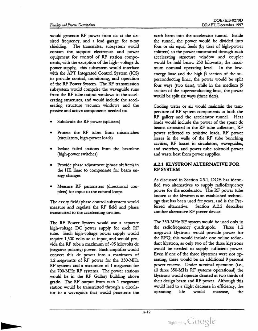
DOE /EIS -0270D
DRAFT, December 1997Facility and Process Descriptions
would generate RF power from dc at the de
sired frequency, and a leadgarage
forX -ray
shielding. The transmitter subsystem would
contain the support electronics and power
equipment for control of RF station compo
nents, with the exception of the high- voltage de
power supply; this subsystem would interface
with the APT Integrated Control System (ICS)
to provide control, monitoring, and operation
ofthe RF Power System . The RF transmission
subsystem would comprise the waveguide runs
from theRF tube output windows to the accel
erating structures, and would include the accel
erating structure vacuum windows and the
passive and active components needed to :
earth berm into the accelerator tunnel. Inside
the tunnel, the power would be divided into
four or six equal feeds (by tiers of high-power
splitters) so the power transmitted through each
accelerating structure window and coupler
would be held below 250 kilowatts , the maxi
mum nominal operating level. In the low
energy linac and the high ß section of the su
perconducting linac, the power would be split
four ways (two tiers), while in the medium B
section of the superconducting linac, the power
would be split six ways (three tiers).
Subdivide the RF power (splitters)
Protect the RF tubes from mismatches
(circulators, high-power loads)
Cooling water or air would maintain the tem
perature ofRF system components in both the
RF gallery and the accelerator tunnel. Heat
loads would include the power of the spent de
beams deposited in the RF tube collectors, RF
power reflected to resistive loads, RF power
losses in the walls of the RF tube bunching
cavities, RF losses in circulators, waveguides ,
and switches, and power tube solenoid power
and waste heat from power supplies.
Isolate failed stations from the beamline
(high -power switches)
Provide phase adjustment (phase shifters) in
the HE linac to compensate for beam en
ergy changes
A.2.1 KLYSTRON ALTERNATIVE FOR
RF SYSTEM
Measure RF parameters (directional cou
plers) for input to the control loops
As discussed in Section 2.3.1, DOE has identi
fied two alternatives to supply radiofrequency
powerfor the accelerator. The RF
powertube
known as the klystron is an established technol
ogy that has been used for years, and is the Pre
ferred alternative. Section A.2.2 describes
another alternative RF power device.
The cavity field /phase control subsystem would
measure and regulate the RF field and phase
transmitted to the accelerating cavities.
pro
The RF Power System would use a separate
high -voltage DC power supply for each RF
tube. Each high -voltage power supply would
require 1,500 volts ac as input, and would
vide the RF tube a maximum of-95 kilovolts dc
(negative polarity) power. Each amplifier would
convert this dc power into a maximum of
1.2 megawatts of RF power for the 350-MHz
RF systems and a maximum of 1 megawatt for
the 700-MHz RF systems. The power stations
would be in the RF Gallery building above
grade. The RF output from each 1 megawatt
station would be transmitted through a circula
tor to a waveguide that would penetrate the
The 350-MHz RF system would be used only in
the radiofrequency quadrupole. Three 1.2
megawatt klystrons would provide power for
the RFQ; this would include one online redun
dant klystron , as only two of the three klystrons
would be needed to supply sufficient power.
Even if one of the three klystronswere not op
erating, there would be an additional 9 percent
power reserve. Under nominal operation (i.e.,
all three 350-MHzRF systems operational) the
klystrons would operate derated at two thirds of
their design beam and RF power. Although this
would lead to a slight decrease in efficiency , the
operating life would increase, the
A -12

DOE /EIS -0270D
DRAFT, December 1997 Facility and Process Descriptions
probability of klystron arcs would decrease, and
there would be the added benefit of an online
spare.
The 700 -MHz RF systems would supply power
to the linac system , providing a final beam en
ergy as high as 1,700 MeV. The 700-MHz
klystrons would have a maximum capacity of
1 megawatt (continuous wave). DOE selected
this power level, in cooperation with klystron
manufacturers, as the maximum power capacity
achievable in a low -risk klystron development
through an extension of the existing, well
known, continuous-wave klystron design.
availability and reliability. During operation and
before an RF fault had been experienced , all
klystrons in a supermodule would operate at
six -sevenths of their maximum power output
power. If a fault was detected , the RF system
on the faulted unit would be disabled and the
corresponding waveguide switch activated. The
waveguide switch would serve two purposes: to
connect the faulted unit to an RF load for
evaluation, repair, and testing, and to reflect a
short circuit at the appropriate phase back to
the accelerating structure in order to notperturb
the accelerating fields. Once the failed system
was offline, the remaining systems would be
returned to service.
The RF power system would include transmit
ters that would contain the klystron support
electronics, RF system interlocks, interfaces to
the accelerator control system , and devices
known as circulators that would control the im
pedance that the klystron would drive, and
would provide for safe disposal of power re
flected from the accelerating cavity back to
wards the klystron . Circulators would be used
in both the 350-MHz and 700 -MHzsystems.
The supermodule concept would enable rapid
service restoration (5 minutes) in the event of
an RF system fault. The failed component
would be repaired offline and restored to serv
ice when convenient. This would enable the re
pair and test of the klystron and associated
electronics in place, which would simplify
maintenance activities and minimize the mean
time to repair.
A.2.2 INDUCTIVE OUTPUT TUBE
ALTERNATIVE FOR RF SYSTEM
The RF transmission subsystem , or power feed ,
would include the waveguides that would
transmit theRF power from the klystrons to the
accelerating cavities, as well as the circulators ,
power splitters, waveguide switches, and RF
loads. After the circulator, the power from a
single klystron would be divided into four or
more equal parts using magic tees or hybrid
waveguide power splitters. The power from the
klystron would be divided to minimize the
stress on the RF vacuum windows or on the
couplers for the superconducting cavities at the
accelerating structures. The RF power feeds
would include arc protection .
An alternative for generating RF poweris
known as an inductive output tube (IOT) system .
An IOT would replace a klystron on a one-for
one basis and would provide the same basic
output as a klystron.
The IOT has characteristics of both a klystron
and a tetrode. Commercial IOTs are used for
ultra -high -frequency (UHF) television broad
casts. The industry has developed a full line of
multiple versions of IOT amplifiers for UHF
broadcast, as well as continuous wave and pulse
devices for such applications as the linear accel
erator.
Figure A -10 is an isometric view of the
waveguide layout in the medium ß high -energy
linac portion of the accelerator tunnel for the
superconducting alternative.
The radiofrequency supermodule -- a manifold
ing of klystrons to provide redundancy -- would
be a major part of the RF system architecture
design to support the linac requirements of high
In a klystron, a continuous electron beam is ac
celerated through a high dc potential and then
converted to a bunched beam through velocity
modulation by a low -level RF signal. Electro
magnetic energy is then extracted from the
modulated beam in a resonant cavity through an
A -13
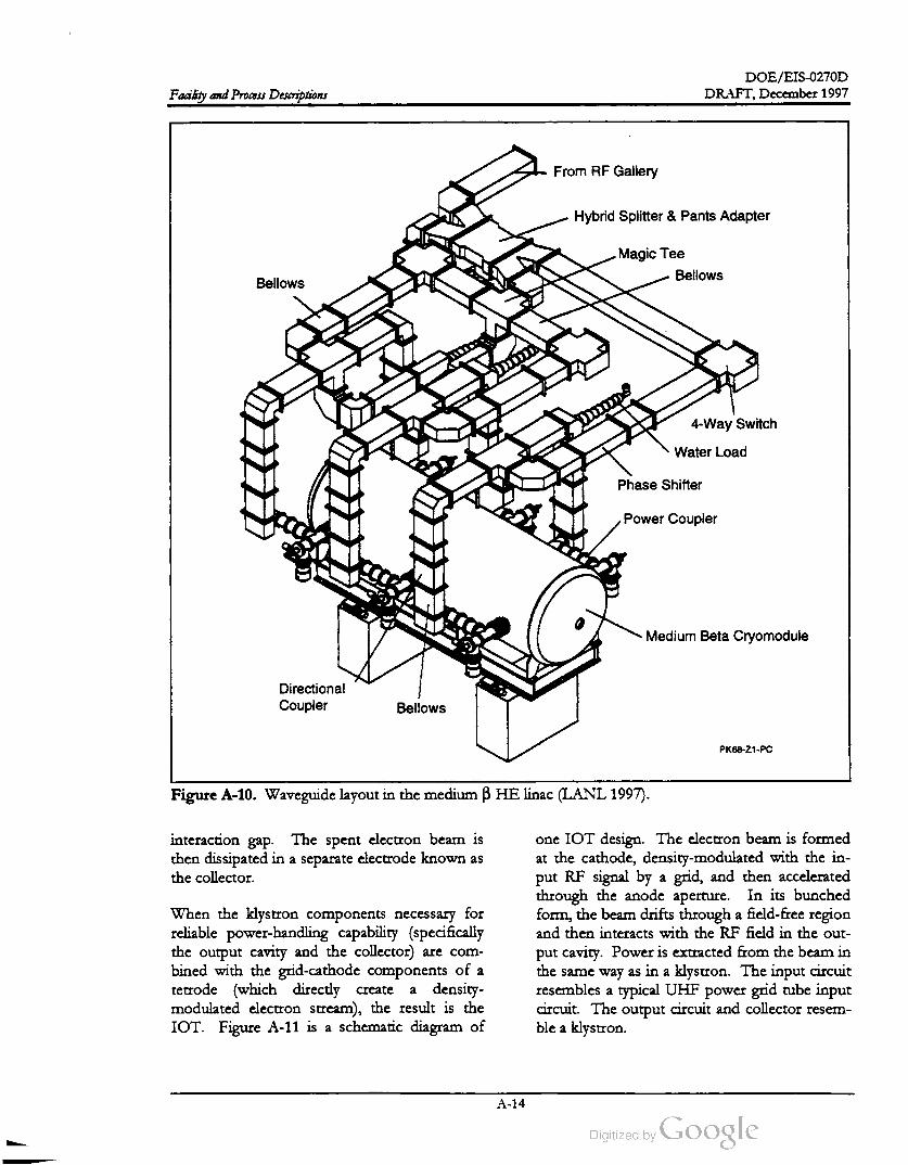
DOE /EIS-0270D
DRAFT,December 1997Facility and Process Descriptions
From RF Gallery
Hybrid Splitter & Pants Adapter
Magic Tee
Bellows
Bellows
ms
4 -Way Switch
WaterLoad
Phase Shifter
Power Coupler
Medium Beta Cryomodule
Directional
Coupler Bellows
PK68-Z1-PC
Figure A - 10 . Waveguide layout in themedium ß HE linac (LANL 1997).
interaction gap . The spent electron beam is
then dissipated in a separate electrodeknown as
the collector.
When the klystron components necessary for
reliable power-handling capability (specifically
the output cavity and the collector) are com
bined with the grid -cathode components of a
tetrode (which directly create a density
modulated electron stream ), the result is the
IOT. Figure A -11 is a schematic diagram of
one IOT design . The electron beam is formed
at the cathode, density -modulated with the in
put RF signal by a grid , and then accelerated
through the anode aperture. In its bunched
form , the beam drifts through a field -free region
and then interacts with the RF field in the out
put cavity . Power is extracted from the beam in
the sameway as in a klystron. The input circuit
resembles a typical UHF power grid tube input
circuit. The output circuit and collector resem
ble a klystron .
A -14

DOE /EIS -0270D
DRAFT,December 1997Facility and Process Descriptions
ELECTRONSGRID BIAS
HIIH
ANOOE
TAIL -PIPE
COLLECTOR
MAGNETIC
FIELD
M.V.
no
GRID
RF IN CATHODE
RF OUT
Figure A - 11. Schematic diagram of an inductive outputtube (Badger).
A.3.1 TARGET /BLANKET STRUCTURETwo IOT devices have been investigated for
use with a linear accelerator. Experience with
these tubes has demonstrated that consistently
higher (10-15 percent) efficiencies can be ob
tained while reducing the overall size of the
power tube. For example, a 250 kilowatt IOT
that is 1.2 meters long can generate the same
power as a 6.1-meter-long klystron at the same
frequency (Peters et al. 1994).
The target/blanket structure would be same for
both Helium -3 (He-3 ) and Lithium -6 (Li-6)
feedstock materials. The target /blanket assem
bly would be in a concrete cavity approximately
20 meters square. Inside the cavity would be a
large vacuum vessel that would house the tar
get /blanket assembly . Outside the vesselwould
be steel and concrete shielding to allow person
nel access to adjacent roomswhile the beam is
impacting the target. Figure A -13 is an isomet
ric view of a target/blanket assembly. The
components in the vessel would be modular ,
enabling remote and rapid replacement and
maintenance.
A.3 Target/ Blanket System
The target/blanket system would consist of the
target /blanket assembly, the attendant heat re
moval systems, and beamstop system . The tar
get /blanket assembly would produce tritium
when impacted by the high -energy proton
beam . The heat removal systems would safely
remove the heat deposited by the proton beam
during normal and off-normal conditions.
Beamstops would be used during commission
ing and occasionally during operation for beam
tuneup. Figure A - 12 shows the layout of the
target /blanket building and the location of the
heat removal systems and other major compo
nents in relation to the target/blanket station.
The target /blanket would have primary and
secondary heat removal systems and a tertiary
system that would provide the heat sink.
The proton beam window would be a double
wall Inconel structure that separates the high
vacuum beam expander from the rough vacuum
target /blanket cavity vessel. The proton beam
would lose only 0.2 percent in energy passing
through the window . At the window position
the beam spot size would be 13.4 centimeters
wide by 144 centimeters high . By the time it
reaches the tungsten neutron source 2 meters
downstream of the window , the beam spot
would expand to 16 centimeters wide by
160 centimeters high. Theheat deposited in the
A - 15
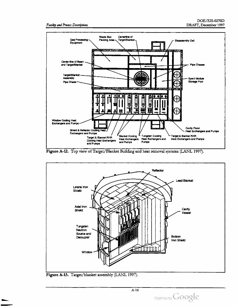
DOE /EIS -0270D
DRAFT,December 1997Facility and Process Descriptions
Gas Processing
Equipment
Waste Box Centerline of
Packing Area Target/Blanket Disassembly Cell
EL
Center-line ofBeam
and TargetBlanket Pipe Chases
TargetBlanket -
Assembly
Pipe Chase
Spent Module
Storage Pool
ir
+
Window Cooling Heat
Exchangers and Pumps
TE
EN
Shield & ReflectorCooling Heat.
Exchangers and Pumps
Target & Blanket RHR
Cooling Heat Exchangers
and Pumps
Cavity Flood
Heat Exchangers and Pumps
- Target & Blanket RHR
Heat Exchangers and Pumps
Blanket Cooling Tungsten Cooling
HeatExchangers Heat Exchangers and
and Pumps Pumps
Figure A- 12 . Top view of Target/BlanketBuilding and heat removalsystems(LANL 1997).
Reflector
Lead Blanket
Lateral Iron
Shield
Axial Iron
ShieldCavity
Vessel
IZ !
Tungsten
Neutron
Source and
DecouplerBottom
Iron Shield
Window
Figure A - 13 . Target/blanket assembly (LANL 1997).
A - 16
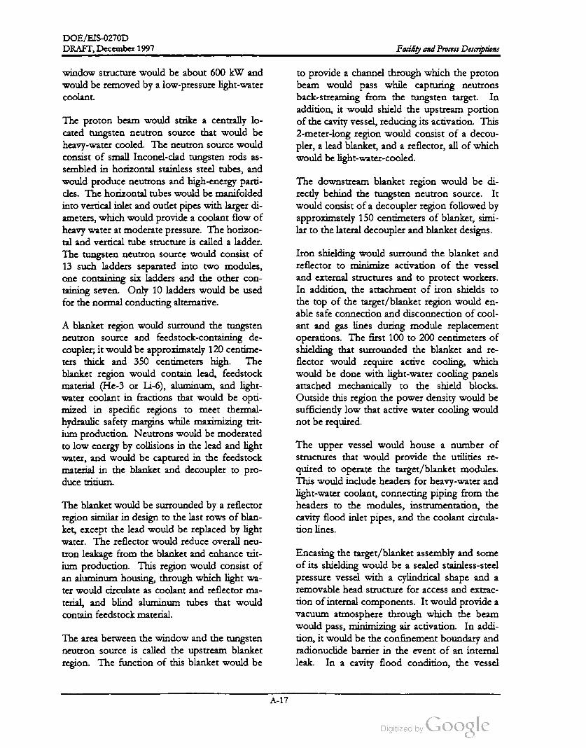
DOE /EIS -0270D
DRAFT, December 1997 Facility and Process Descriptions
window structure would be about 600 kW and
would be removed by a low -pressure light-water
coolant.
to provide a channel through which the proton
beam would pass while capturing neutrons
back -streaming from the tungsten target. In
addition, it would shield the upstream portion
of the cavity vessel, reducing its activation . This
2 -meter-long region would consist of a decou
pler, a lead blanket, and a reflector, all of which
would be light-water- cooled.
It
The proton beam would strike a centrally lo
cated tungsten neutron source that would be
heavy -water cooled. The neutron source would
consist of small Inconel-clad tungsten rods as
sembled in horizontal stainless steel tubes, and
would produce neutrons and high -energy parti
cles. The horizontal tubes would be manifolded
into vertical inlet and outlet pipes with larger di
ameters, which would provide a coolant flow of
heavy water at moderate pressure. The horizon
tal and vertical tube structure is called a ladder.
The tungsten neutron source would consist of
13 such ladders separated into two modules,
one containing six ladders and the other con
taining seven. Only 10 ladders would be used
for the normal conducting alternative.
The downstream blanket region would be di
rectly behind the tungsten neutron source.
would consist of a decoupler region followed by
approximately 150 centimeters of blanket, simi
lar to the lateral decoupler and blanket designs.
A blanket region would surround the tungsten
neutron source and feedstock -containing de
coupler; it would be approximately 120 centime
ters thick and 350 centimeters high. The
blanket region would contain lead, feedstock
material (He-3 or Li-6 ), aluminum , and light
water coolant in fractions that would be opti
mized in specific regions to meet thermal
hydraulic safety margins while maximizing trit
ium production. Neutrons would be moderated
to low energy by collisions in the lead and light
water, and would be captured in the feedstock
material in the blanket and decoupler to pro
duce tritium .
Iron shielding would surround the blanket and
reflector to minimize activation of the vessel
and external structures and to protect workers.
In addition , the attachment of iron shields to
the top of the target /blanket region would en
able safe connection and disconnection of cool
ant and gas lines during module replacement
operations. The first 100 to 200 centimeters of
shielding that surrounded the blanket and re
flector would require active cooling, which
would be done with light-water cooling panels
attached mechanically to the shield blocks.
Outside this region the power density would be
sufficiently low that active water cooling would
notbe required .
The upper vessel would house a number of
structures that would provide the utilities re
quired to operate the target /blanket modules.
This would include headers for heavy-water and
light-water coolant, connecting piping from the
headers to the modules, instrumentation, the
cavity flood inlet pipes, and the coolant circula
tion lines.
The blanket would be surrounded by a reflector
region similar in design to the last rows of blan
ket, except the lead would be replaced by light
water. The reflector would reduce overall neu
tron leakage from the blanket and enhance trit
ium production. This region would consist of
an aluminum housing, through which light wa
ter would circulate as coolant and reflectorma
terial, and blind aluminum tubes that would
contain feedstock material.
Encasing the target/blanket assembly and some
of its shielding would be a sealed stainless-steel
pressure vessel with a cylindrical shape and a
removable head structure for access and extrac
tion of internal components. It would provide a
vacuum atmosphere through which the beam
would pass, minimizing air activation. In addi
tion, it would be the confinementboundary and
radionuclide barrier in the event of an internal
leak . In a cavity flood condition , the vessel
The area between the window and the tungsten
neutron source is called the upstream blanket
region . The function of this blanket would be
4
A - 17
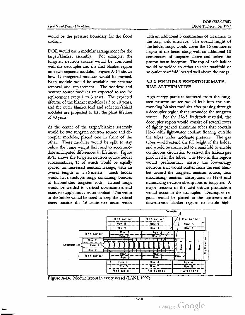
DOE /EIS -0270D
Facility and Process Descriptions DRAFT,December 1997
would be the pressure boundary for the flood
coolant.
with an additional 3 centimeters of clearance to
the rung weld interface. The overall height of
the ladder rungs would cover the 16 -centimeter
height of the beam along with an additional 10
centimeters of tungsten above and below the
proton beam footprint. The top of each ladder
would be welded to either an inlet manifold or
an outletmanifold located well above therungs.
DOE would use a modular arrangement for the
target/ blanket assembly. For example, the
tungsten neutron source would be combined
with the decoupler and the first blanket region
into two separate modules. Figure A -14 shows
how 19 integrated modules would be formed.
Each module would be available for separate
removal and replacement. The window and
neutron source modules are expected to require
replacement every 1 to 3 years. The expected
lifetime of the blanket modules is 3 to 10 years ,
and the outer blanket lead and reflector /shield
modules are projected to last the plant lifetime
A.3.2 HELIUM - 3 FEEDSTOCKMATE
RIAL ALTERNATIVE
of 40 years .
At the center of the target /blanket assembly
would be two tungsten neutron source and de
coupler modules, placed one in front of the
other. These modules would be split to stay
below the crane weight limit and to accommo
date anticipated differences in lifetimes. Figure
A - 15 shows the tungsten neutron source ladder
subassemblies, 13 of which would be equally
spaced for increased neutron leakage, with an
overall length of 3.76 meters. Each ladder
would have multiple rungs containing bundles
of Inconel-clad tungsten rods. Lateral rungs
would be welded to vertical downcomers and
risers to supply heavy -water coolant. The width
of the ladder would be sized to keep the vertical
risers outside the 16 -centimeter beam width
High -energy particles scattered from the tung
sten neutron source would leak into the sur
rounding blanket modules after passing through
a decoupler region that surrounded the tungsten
source. For the He-3 feedstock material, the
decoupler region would consist of several rows
of tightly packed aluminum tubes that contain
He-3 with light-water coolant flowing outside
the tubes under moderate pressure. The gas
tubes would extend the full height of the ladder
and would be connected to a manifold to enable
continuous circulation to extract the tritium gas
produced in the tubes. The He-3 in this region
would preferentially absorb the low -energy
neutrons that would scatter from the lead blan
ket toward the tungsten neutron source, thus
maximizing neutron absorptions in He- 3 and
minimizing neutron absorptions in tungsten . A
major fraction of the total tritium production
would occur in the decoupler. Decoupler re
gions would be placed in the upstream and
downstream blanket regions to enable high
Decoupler
Reflector Reflector Reflector
Row 5 Row 5 Row 5
Row 4Row 4 Row 4
Row 3Reflector
Row 3
Row 2Row
Row 2
Decoupler Row |
Row
Row
2 Row
3
Reflector
Row 2
Reflector
ROW 2
Row 3
Row 2
Row 3Row 2
Row 4Row 4
Row 5
Row 4
Row 5 Row 5
ReflectorReflector Reflector
Figure A - 14 . Module layout in cavity vessel (LANL 1997).
A - 18

DOE /EIS -0270D
DRAFT, December 1997 Facility and Process Descriptions
Distribution
Manifolds-376cm
Coolant
Outlet
Coolant
Inlet
308cm
180 cm
30cm
Tungsten
Rod Bundles
Figure A - 15 . Tungsten neutron source (LANL 1997).
energy particles to pass through and into the
blanket, and to absorb any back -scattered low
energy neutrons in He-3 rather than the tung
sten. Figure A - 16 shows a vertical section of
the target and blanket assembly configured for
He- 3 feedstock material.
would be assembled into aluminum housings
that formed the pressureboundary for the light
water coolant.
The blanket lead would be cast into cruciform
aluminum tubes to form rods. The He-3 would
be in blind circular aluminum tubes (closed at
one end) manifolded together at the top and
sealed off at the bottom . The rods and tubes
The Gas Handling Subsystemswould consist of
the He- 3 gas transport, cavity atmosphere, and
low -pressure He-3 recovery. He-3 gas in the
blind aluminum tubes in the decoupler, blanket,
and reflector would produce tritium through
neutron absorption. Tritium would diffuse
through the static gas to headers that connected
A - 19

DOE /EIS -0270D
DRAFT, December 1997Facility and Process Descriptions
Upstream
Blanket
Front
Target
Module
Back
Target
Module
Coolant &
Gas
Connectors Axial
Shield
Inserts
4.00 m
5.75 m
Beam .16 m
x 1.6 m
H20 Reflector
Pb BlanketRow 3
Pb BlanketRow 2
Pb Blanket Row 1
* Decoupler
Tungsten Ladder
Steel
Beam C 3.50 m
1.75 mReflector
1.30 m thick
Target Ladder
Tungsten
Neutron Source
Lower
Blanket
Decoupler
.08 m thick
Downstream
Blanket
Figure A - 16 . Target and blanket vertical section (LANL 1997).
(HEPA) filters, gas cleanup systems, a He-3 re
covery system , or the stack .
the tubes in a module. The Gas Handling Sys
tem would maintain a continuous flow of gas
through the headers. This system would trans
port the He-3 and tritium mixture to the Trit
ium Separation Facility adjacent to the
Target /Blanket Building. Gas lines would be
welded,with double-walled tubing between the
modules and the Tritium Separation Facility
gloveboxes. Gas from the modules would
contain a mixture ofHe-3, tritium , other hydro
gen isotopes, and impurities. After extraction
of the hydrogen isotopes and the removal of
impurities, pureHe- 3 would be returned to the
Target /Blanket System modules.
The third gas system would be a low pressure
He- 3 recovery system that would collect the gas
from many areas in the Target/ Blanket Building
and transport it back to the Tritium Separation
Facility at the APT site. The recovery system
would collectgases from the cavity vessel, cool
ant loops, vacuum line jackets, and gloveboxes
in the Target / Blanket Building. Gases that
could contain impurities could be processed to
separate the He-3 and hydrogen isotopes from
the contaminants to maintain a clean gas stream
to the Tritium Separation Facility .
A.3.3 LITHIUM -6 FEEDSTOCKMA
TERIAL ALTERNATIVE
A second gas subsystem in the Gas Handling
System would control the cavity atmosphere
during operation . This system would consistof
a pumping system to evacuate the air from the
vessel along with gas sensors and controls. The
evacuated gases would be monitored continu
ously for indications of water ingress, He-3 , hy
drogen, or tritium gas. Controls would direct
the gas flows to high -efficiency particulate air
Conceptually , the basic design of the Li-6 tar
get /blanket module would be the same as that
for the He-3 target/blanket assembly (Figures
A -12 through A -13) , except there would be no
need for an adjacent Tritium Separation Facility .
A - 20
DOE /EIS -0270D
DRAFT,December 1997 Facility and Process Descriptions
structure for the room -temperature alterna
tive near 200 -MeV .
Permanent High -Energy Beamstop. This
beamstop would be designed for energies
between 500 MeV and 1,700 MeV . It
would be installed at the end of the tunnel,
and would be used for final beam tuning
before plant start-up and restarts.
The same aluminum tubes in the blanket and
decoupler that contain gaseous He-3 in the
He- 3 Feedstock Material alternative would
contain a solid aluminum -lithium alloy. As the
feedstock material is solid, the accelerator would
be shutdown to remove the feedstock material;
the rods would be transported to the Tritium
Extraction Facility for tritium recovery. As the
tritium generated in the target /blanketmodule
would only be removed at the end of an operat
ing run (annually), all of the annual production
of 3 kilograms would be present in the tar
get/blanket structure. This is in comparison to
the Helium -3 feedstock alternative which would
have less than 100 grams of tritium present at
one time in the target /blanket structure. The
process for preparation of the Lithium -6 target
rods is described in Section 2.3.3 of this EIS .
Once the tritium is liberated from the lithium
aluminum matrix , the methods used to purify
the tritium product are the sameas for the He
lium -3 Feedstock Material alternative.
Removable High -Energy Beamstop. This
beamstop would be designed for energies
between 500 and 1,500 MeV. It would be
installed temporarily during construction at
different stations in the tunnel to commis
sion the high -energy portion of the linac.
This requirementcould bemet with a single
beamstop, which would be moved from
station to station, or with a separate beam
stop for each station . In either case, the
beamstop (s) would be removed from the
beamline at the end of commissioning and
stored in a shielded area in an adjacent al
cove or outside the tunnel.A.3.4 BEAMSTOP SYSTEMS
A.3.4.1 Low -Energy and Intermediate
Energy Beamstops
The Beamstop Systems would include four
types ofbeamstops,stops, which would be categorized
by energy level and as permanent or removable.
The permanent beamstops would be used dur
ing commissioning and periodically thereafter
for tuning the beam prior to full power opera
tion . The removable beamstops would be used
only for commissioning .
Permanent Low -Energy Beamstop. This
beamstop would be designed for a 20 MeV
beam energy. It would be installed in the
injector building to test the low energy por
tion of the linac, including the injector, ra
diofrequency quadrupole, and the first
section of the CCDTL .
The beamstops would be permanently installed
in the facility. The low -energy beamstop would
be used initially during the commissioning stage
to test the low -energy range of the linac. The
conceptual design for this beamstop consists of
a single graphite plate under vacuum , positioned
to intercept the proton beam .The graphite
plate would be in an aluminum vacuum vessel,
and would be supported and held in an incline
angle of 20° from horizontalby a Carbon com
posite frame. The aluminum vessel would be
30 centimeters in diameter and 120 centimeters
long. Stacked concrete blocks containing mag
netite would be used for neutron and gamma
shielding. The beamstop and shielding blocks
would be sealed inside a metal enclosure that
would be purged with Helium to avoid air acti
vation. Figure A -17 shows the layout of the
low - energy beamstop.
Permanent Intermediate-Energy Beamstop.
This beamstop would be designed for an
energy of about 200 MeV. It would be in
stalled in the tunnel at the room tempera
ture /superconducting linac interface for the
superconducting option or in the CCL
A -21

1
Facility and Process Descriptions
DOE /EIS-0270D
DRAFT, December 1997
Magnetite Concrete
Shielding WISST
Gas Barrier
All Around Graphite Plate
Beamstop
Expansion Section
Cooling Water
Expansion Magnets
Beamline
Beam Profile
Vacuum Pumps
Figure A - 17. Low -energy beamstop (LANL 1997).
metal enclosure that is purged with Helium to
avoid air activation .
The intermediate-energy beamstop would be
placed permanently in the tunnel facility, and
used extensively during commissioning. The
conceptual design consists of a series of graph
ite plates mounted in a water-cooled vacuum
enclosure .The design is similar to the low
energy beamstop but would be longer to ac
commodate asmany as 6 plates. The beam en
ergy would be absorbed in the plates and
thermally radiated to the outer vacuum enclo
sure . Figure A -18 is a cross section view of the
intermediate -energy beamstop .
For both beamstops, the vacuum vessel would
be cooled by water cooling tubing integrated in
the outer surface of the vessel. An aluminum
oxide spray coating would be applied to the in
ner surface of the vessel to increase surface
emissivity ,which would improve the absorption
of thermal radiation from the graphite. Peak
graphite temperature would range from 760° -
780° C .
A.3.4.2 High -Energy BeamstopThe plates would be at an angle to the beam to
reduce the reflection of thermal (IR ) radiation
from plate to plate and to help spread the IR
energy to the vessel walls. The plates would be
at a 45° angle to the beam with each at a 90°
angle between plates. A typical plate size would
be about 30 centimeters wide and 45 centime
ters long. Because spacing of 10 centimeters
between plates would be required , the total
length of the plate string is about 305 centime
Three key differences in the high-energy beam
stop requirements from those for the low- and
intermediate-energy beamstops significantly af
fect the conceptual design :
Proton energieswould be higher and would
require a longer target to stop thebeam
ters . The duty factorwould be 2 percent, a factor
of 20 higher
Shielding ofneutrons and gammas coming from
the beamstop would be done with stacked con
crete blocks that contain boron. The beamstop
and shielding blocks would be sealed inside a
The beam profile would have a near uni
form power density across the beamstop.
A -22

DOE /EIS-0270D
DRAFT ,December 1997 Facility and Process Descriptions
Graphite Plate
Beamstop Expansion Section
50.8cm
Nu
Water Cooled
Vacuum Chamber
304.8 cm Expansion
Magnets
PK6L-Z1-PC
100 cm Thick Magnetite Concrete
with 0.32 cm Thick Gas Barrier All Around
Figure A - 18. Intermediate-energy beamstop layout (LANL 1997).
The beamstop would consist of five graphite
modules of various lengths totaling 4.1 meters
in overall length . Themodules would be cooled
by Helium that would pass through a series of
slots in the modules running transverse to the
beam . The coolant slot widthswouldvary
from
0.85 to 1.5 centimeters, and the spacings be
tween slots would vary from 4.3 to 8.0 centime
ters. The end of module 5 has a 2.07 -meter
long section without slots because this region of
thebeamstop would not require direct cooling.
megapascal,which would be about equal to the
vessel system pressure. By maintaining a low
pressure differential between the vessel atmos
phere and beamstop coolant, the potential for
leaks from the coolant system would be mini
mized. The vesselwould have a separate bypass
vent line, as shown in Figure A -19, that could
be used for purging the Helium tank and to
monitor for leaks.
The slot widths and spacings would be set to
maintain a maximum graphite temperature of
930° C at the midplane between coolant slots.
This peak temperature would include a power
peaking factor of 2.0 , and would be considera
bly below the graphite vaporization temperature
of 1,500 °C .
A beam window would be situated within the
end wall of the pressure vessel. This window
would have to withstand the 1.05 megapascal
pressure differential and thermal loads. The
conceptual design consists of two square plates
of (aged) 718 Inconel about 30 centimeters on a
side. The two plates would each be 1.3 centi
meters thick and would be separated by 0.061
centimeter which would form a water cooling
channel.
The beamstop modules would be situated in an
aluminum cylindricalvessel 1.8 meters in diame
ter. Fitted graphite blocks would occupy the
space between the beamstop modules and the
vessel. Commercially available water-cooled
panels would be attached to the inner surface of
the vessel to absorb heat transferred from the
beamstop graphite surfaces through these
blocks.
Each module would have a separate compressor
or blower to supply coolant flow , and would
have a separate heat exchanger. Both the com
pressors or blowers and heat exchangers would
be at an accessible level well above the beam
stop .
The Helium operating pressure at the inlet
manifold inside the vessel would be set to 1.05
The specific shielding requirements, atmosphere
enclosure method, and shielding cooling re
quirements for the high -energy beamstop would
be developed in preliminary design.
A - 23

DOE /EIS -0270D
Facility and Process Descriptions DRAFT, December 1997
Helium Surge Tank
ra
Heat Exchanger
'( 1 of4 Required)
Helium
CirculatorsCompressor
( 4) 30 cm Pipe
Risers
(4 ) 30 cm Pipe
Downcomers
Bellows
Beam
Direction
30 cm Riser
Manifold
Area
He Cooling
SlotsMueller
Cooling
Panels
Beam
Window
Module 1
Module 2
Module 3
Module 4
Module 5
Graphite Blocks
183 cm O.D. Chamber
x 2.5 cm Thick Wall PK68-11PC
Figure A - 19 . High -energy beamstop (LANL 1997).
Low -energy operation would require a footprint
for the beam in the beamstop that is larger than
the one in the target. Thus, the design of the
beam expander used for the target would be
modified to give a 1 -meter-wide by 2 -meter
footprint in the beamstop. This would be done
by increasing the drift space between the last
quadrupole and the window to 30 meters and
by changing the tuning of the last two expander
quadrupoles.
ing Helium , similar in concept to that for the
permanentbeamstop. Because the beam profile
is Gaussian , there will exist a large radial power
gradient across the beamstop. This will require
lower operating temperatures than in the per
manent high -energy beamstop to achieve ac
ceptable temperature gradients and thermal
stresses.
A.3.4.3 Removable High- Energy Beamstop
The removable high -energy beamstop would be
designed for proton energy levels between 500
and 1,500 MeV . This beamstop could be in
stalled temporarily at different stations in the
tunnel, or a separate removable beamstop could
be installed at each location necessary for
commissioning tests. It is expected that this
beamstop will have a direct cooling system us
Rapid removability would be provided . The
current design would install the beamstop and
its shielding on a carriage that moves on rails
installed in the tunnel floor. For this design , the
rails would be orthogonal to the beamline so
that the beamstop could be retracted to a
shielded alcove when no longer needed. Cool
ant lines connecting to the beamstop vessel
could be routed using pipe chases incorporated
within the carriage to external connections with
the stationary support systems. Whether these
A -24
DOE/EIS-0270D
DRAFT,December 1997 Facility and Process Descriptions
lines will be rigid or flexible will be determined
in preliminary design.
through the Target/Blanket Gas Transport
System .
Section A.5 describes heat removal systems for
the Beamstop Systems.
A.4 Tritium Separation Facility
The resultant stored hydrogen isotopes would
beseparated into two product streams. Cryogenic
distillation would produce a stream of high -purity
tritium for processing and shipment to the SRS
Tritium Facilities, and a deuterium / protium
stream thatwould be less than 10 ppm in resid
ual tritium would be released to the Tritium
Separation Facility stack. Tritium emissions to
the stack would be monitored to prevent ex
ceeding environmental release limits.
The Tritium Separation Facility (TSF) would
extract and purify the tritium gas produced
from the Helium - 3 feedstock material. This
facility would be at the APT site near the Tar
get/ Blanket Building, and would perform initial
processing before shipping the tritium product
to the SRS H -Area Tritium Facilities for final
processing. For the Lithium -6 Feedstock Ma
terial alternative, tritium processing activities
would occur at the Tritium Extraction Facility
(TEF). The location of the TEF is being ana
lyzed in the separate TEF EIS (61 FR 4670),
but may include a location in H -Area or co
located with the Tritium Separation Facility.
To minimize the radiological risk to SRS per
sonnel, the public, and the environment, tritium
process equipmentwould be installed in a proc
ess confinement system that would use a recir
culating nitrogen atmosphere. Tritium and He
3 released to the nitrogen atmosphere from
process equipment or maintenance activities
would be contained in the Process Confinement
System ; tritium would be removed from the re
circulating nitrogen atmosphere and stored us
ing a metal getter system .
The He-3 target process would use seven sub
systems: the Tritium Extraction System , Iso
tope Separation System , Waste Gas Tritium
Cleanup System , Tritium Storage System , Proc
ess Confinement System , He-3 Supply System ,
and Analytical Laboratory System . Figure A -20
shows the flow of these systems.
A.4.1 TRITIUM EXTRACTION SYSTEM
The Tritium Extraction System (TES) would
separate hydrogen isotopes from the He-3
stream received from the Target / Blanket Gas
Transport System . The Tritium Supply System
would contain multiple Tritium Extraction Sys
tems which would interface with the TES net
work manifold in the Target/ Blanket Building.
Hydrogen isotopes produced in the Tar
get / Blanket System from neutron interactions
with He-3 would be transported to the Tritium
Separation Facility (TSF) through the Tar
get / Blanket Gas Transport System circulation
loops. A series of traps would remove potential
spallation and activation products from the He
3 in the circulation loops before transfer to the
TSF building After removal of spallation
products and other impurities, the gas stream
would consist of hydrogen isotopes and He-3.
Each target /blanket module would have a line
entering the glovebox, and modules would be
grouped together based on tritium production.
Valving would isolate individual modules or a
group of modules in the event of a leak . The
grouping ofmodules would minimize the num
ber of piping runs between the Target/Blanket
Building and the TSF building and the quantity
ofHe-3 at risk . A series of heated metal getter
beds and high- efficiency metal filters would re
move impurities and spallation products from
the He-3 stream for each line to the TES. One
getter bed would remain in standby condition .
The extraction of the hydrogen isotopes from
He- 3 would use a palladium -silver permeator.
Only hydrogen isotopes could permeate the
palladium -silver, and they would be stored for
further processing. He-3 could not permeate
the palladium -silver and would recirculate
A - 25
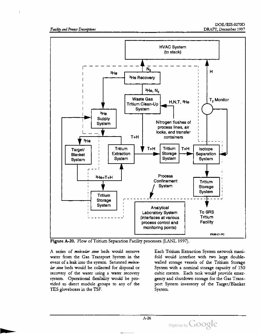
i
DOE /EIS -0270D
DRAFT,December 1997Facility and Process Descriptions
HVAC System
(to stack )
N2
3He
H
3He Recovery
3He, N2
Waste Gas
Tritium Clean -Up
System
H , N , T , 3HeT2 Monitor
3He
Supply
SystemNitrogen flushes of
process lines, air
locks, and transfer
containersT + H
3He
TH T + HTarget
Blanket
System
Tritium
Extraction
System
Tritium
Storage
System
Isotope
Separation
System
3He+ T + HProcess
Confinement
System
Tritium
Storage
System
Tritium
Storage
System
Analytical
Laboratory System
(interfaces at various
process control and
monitoring points)
To SRS
Tritium
Facility
PK68-Z1-PC
Figure A -20. Flow of Tritium Separation Facility processes (LANL 1997) .
A series of molecular sieve beds would remove
water from the Gas Transport System in the
eventof a leak into the system . Saturated molecu
lar sieve beds would be collected for disposal or
recovery of the water using a water recovery
system . Operational flexibility would be pro
vided to direct module groups to any of the
TES gloveboxes in the TSF.
Each Tritium Extraction System network mani
fold would interface with two large double
walled storage vessels of the Tritium Storage
System with a nominal storage capacity of 150
cubic meters. Each tank would provide emer
gency and shutdown storage for the Gas Trans
port System inventory of the Target/ Blanket
System .
A -26

DOE /EIS -0270D
DRAFT,December 1997 Facility and Process Descriptions
ing and then to the appropriate target/blanket
module grouping
A.4.2 ISOTOPE SEPARATION SYSTEM
The Tritium Separation Facility building would
contain the Tritium Extraction System glove
boxes for removing hydrogen isotopes from the
Gas Transport System . The He- 3 stream would
be directed through two palladium -silver mem
brane permeators in series. The palladium -silver
membranes would be operated under pressure
on the Gas Transport System side of the mem
brane and at high vacuum on the shell side.
Hydrogen isotopes would selectively permeate
through the membrane from theGas Transport
System side of the permeator to the high vac
uum side of themembrane. Hydrogen isotopes
that permeated to the shell side of the permea
tors would be pumped to metal hydride storage
beds of the Tritium Storage System . The He- 3
would be recirculated to the appropriate TES
network manifold in the Target/ Blanket Build
The Isotope Separation System would separate
a high-purity tritium stream from an isotopic
mixture of tritium , hydrogen, and deuterium ,
and would reduce the residual tritium concen
tration in the hydrogen waste stream to a level
at which it could be sent to the facility stack
without further processing. Two identical cryo
genic distillation systems, connected in parallel and
each capable ofmeeting the full facility demand,
would be installed . Each system would consist
of two ormore sequential columns in combina
tion with four catalytic equilibrators. Figure
A -21 shows the Isotope Separation System .
To Stack
Column
2
Isotope
Equilibrator
Column
1 Isotope
EquilibratorFeed from
TES/TSSWGTCSIsotope
Equilibrator
Gas Impurities
Trap
Isotope
Equilibrator
TES = Tritium Extraction System
TSS = Tritium Storage System
WGTCS = Waste Gas Tritium Cleanup System
to TSS
Tritium Product Stream
Figure A -21. Isotope Separation System (LANL 1997).
A - 27

DOE/EIS -0270D
Facility and Process Descriptions DRAFT, December 1997
streams with off-normal compositions satisfac
torily. Under off-normal conditions when the
T2 concentration exceeded 10 parts per million
(ppm ), the stream automatically would be di
verted to the Waste Gas Tritium Cleanup Sys
tem .
An anticipated gaseous stream of hydrogen,
deuterium , and tritium would be fed to the
Isotope Separation System either directly from
the Tritium Extraction System or from the
Tritium Storage System . First the feed would
pass through a molecular sieve bed to trap
gaseous impurities (e.g., nitrogen , oxygen, am
monia) that could have found their way into the
feed during off-normal operating conditions
and that would solidify and plug the distillation
columns. The purified stream would be com
bined with the bottoms product from Column 2
and passed through an isotopic equilibrator.
Each column would contain a pressure relief
valve to vent the contents to a surge tank to
protect against overpressurization. Vacuum in
the jacket would be provided by a triode ion
pump. Refrigeration to the columns would be
provided by two Helium refrigerators rated at
100 watts. The refrigerators would supply He
lium and would be plumbed to the two distilla
tion systems in a way that enabled either
refrigerator to provide cooling to either system .
An isotopic equilibrator is a room
temperature reactor, packed with a palla
dium /aluminum catalyst that would partially
convert the mixed isotopes HD (hydrogen
deuterium ), HT (hydrogen - tritium ), and DT
(deuterium -tritium ) to Hz (hydrogen ), D2
(deuterium ), and Tz (tritium ).
Stream compositions would be monitored by
appropriate instrumentation ; ion chambers for
monitoring tritium concentrations would be at
thetop
of each column. If the tritium concen
tration in the distillate from Column 2 exceeded
10 ppm , flow automatically would be diverted
from the stack to the Waste Gas Tritium
Cleanup System . Each column would contain a
pressure relief valve to vent the contents to a
surge tank when the pressure exceeded 340,000
Pascal.
From the equilibrator, the stream would flow
into Distillation Column 1, which would pro
vide the principal tritium separation function
for the Isotope Separation System , producing a
tritium product stream . In the course of normal
Column 1 operation, hydrogen would concen
trate in the top of the column, tritium at the
bottom , and HT in the center. To extract the
tritium from HT (and the small amount ofDT
also present),two side-stream isotopic equilibra
tors similar in design to that described above for
the feed stream would be used . A metal bellows
pump would circulate the vapor through the
catalytic reactor. The equilibrated vapor would
be reintroduced into the column to effectsepa
ration. The distillate produced would consist
primarily ofH2and HD , with a residual T2 con
centration .
A.4.3 WASTE GAS TRITIUM CLEANUP
SYSTEM
Distillate from Column 1 would be passed
through a fourth isotopic equilibrator and fed to
Column 2. The principal function ofColumn 2
would be to strip the residualHT, DT and T2
from the stream so the final distillate could be
sent to the facility stack without further process
ing. In addition , the second column would add
flexibility to the overall design, enabling the
Isotope Separation System to process feed
TheWaste Gas Tritium Cleanup System would
process tritium -contaminated nitrogen streams
to remove hydrogen isotopes and recover He-3
before sending the nitrogen to the HVAC ex
haust system . Tritium -contaminated nitrogen
would be generated from the nitrogen flushes of
process lines , airlocks, and transfer containers.
Contaminated nitrogen streamswould be stored
in two 2,500 -liter storage tanks. One storage
tank would be the high-tritium -concentration
receiver and would accept contaminated nitro
gen streams from the evacuation of nitrogen
flushes of process equipment. The second stor
agetank would be the low -tritium
concentration receiver and would accept con
taminated nitrogen from nitrogen flushes of
airlocks and transfer containers.
A - 28

DOE /EIS -0270D
DRAFT, December 1997Facility and Process Descriptions
Tritium -contaminated nitrogen wouldbe
pumped from the receiver storage tank through
a preheater and series of metal getter beds to
remove the low levels of oxygen , moisture,
ammonia, and methane that could be present in
the gas stream . The removal of the gaseous im
purities by the metal getter beds would be re
quired to prevent a decrease in the capacity and
efficiency of hydrogen isotope removal by the
metal hydride storage beds.
reduce tritium absorption on surfaces. Also, a
fraction of a percent of a noble gas, such as ar
gon , could be added as an online real-time trit
ium production monitor (i.e., the production of
argon -41 in the gaseous stream could be de
tected relatively easily with radiation detectors,
thereby serving as a tracer to indicate the rela
tive production rate of tritium ).
Themetal hydride storage beds of the Tritium
Storage System would remove hydrogen iso
topes from the tritium -contaminated nitrogen .
The gas stream would be cooled passively be
tween the metal getter beds and the metal hy
dride storage beds. Hydrogen isotopes would
react with the heated metal, forming a metalhy
dride, enabling the nitrogen to pass through un
reacted .
Pressure relief devices would be installed on all
He-3 cylinders. Cylinders would be attached to
the Helium Supply System manifold and se
cured in accordance with Occupational Safety
and Health Administration (OSHA) guidelines.
Check valves would prevent backflow from the
Target/Blanket Gas Transport System circula
tion loop to the supply system . A low -pressure
pump train would recover gas from the Tritium
Separation System to the He-3 Supply System
charge tank. A compressor would return recov
eredgas from the Tritium Separation System to
the Target/ BlanketGas Transport System .A flow -through ion chamber at the outlet of the
series ofmetalhydride beds would measure the
residual tritium in the gas stream . If the tritium
concentration at the outlet of the metal hydride
storage beds was sufficiently low , the gas stream
would be sent to the Tritium Separation Facility
HVAC exhaust system . However, if the outlet
tritium concentration was high, the receiver
tank and Tritium Separation Facility HVAC ex
haust system isolation valves would be closed
and the gas stream would be recycled through
the cleanup system to further decrease the trit
ium concentration. If the tritium concentration
fell below the cutoff limit, the TSF HVAC ex
haust system isolation valve could be opened
and the nitrogen sent to the exhaust system .
After a shutdown of a target /blanket gas circu
lation loop, the circulation loop He-3 would be
diverted to large, evacuated Tritium Storage
System storage tanks in the Target /Blanket
Building. The He-3 would pass through a series
ofmolecular sieve beds, getter beds, and filters
to remove potentialmoisture, spallation , or ac
tivation products prior to storage in the tanks.
The recovery of thegas would require pumping
thegas from the storage tank to a charging tank
in the Tritium Separation Facility with a scroll
pump and metal bellowspump
combination .
Makeup He-3 would be provided to the Tar
get/ Blanket Gas Transport System by the gas
cylinders. Figure A -22 shows the Helium Sup
ply SystemA.4.4 HELIUM - 3 SUPPLY SYSTEM
A.4.5 TRITIUM STORAGE SYSTEMThe Helium -3 Supply System would provide a
continuous supply of He-3 to the Tar
get/Blanket Gas Transportation Subsystem at a
constantpressure. The He-3 would be supplied
by gas cylinders in the Tritium Separation Facil
ity or from He-3 recovered from the Gas
Transport System and other Tritium Separation
Facility systems. The addition of approximately
1 percent hydrogen to the He-3 stream could
The Tritium Storage System would consist of
storage tanks for storing Hydrogen isotopes and
He-3 , and metal hydride beds for storing Hy
drogen isotopes. Storage tanks would vary in
size, depending on service function. The trit
ium stored on the metal hydride storage beds
could berecovered as a gas by heating the beds.
A -29

DOE /EIS -0270D
DRAFT,December 1997Facility and Process Descriptions
DIDO
Vent
Helium - 3 and Hydrogen Cylinders
Target/Blanket
Building
TSF
Building
Pressure Regulator
Target/BlanketAssembly
Target/Blanket Assembly
Gas Transport Subsystem
Tritium Extraction System
Charging Compressor
-Helium - 3
Storage Tank
Helium - 3
Purification
JOH
悟
Helium - 3
Charge Tank
PK68-Z1-PC
Low Pressure Pumping Train
From
Process
Confinement
System
From
Waste Gas
Tritium
Cleanup
System
Figure A -22. Helium supply system (LANL 1997).
Tank contents could be sampled for analysis by
the Analytical Laboratory System mass spec
trometers via capillaries. Metal hydride storage
beds would use an in - situ method of account
ability to determine the quantity of tritium on
each bed. In addition , the system would con
tain a manifold for loading tritium into metal
hydride transport containers for shipment to the
SRS Tritium Facilities.
ternal to the confinement system would be
double-walled vessels. Each metal hydride stor
age bed would have two temperature controllers
with automatic shutdown capability in case a
heater fails .
Storage tanks external to the process confine
ment system gloveboxes would be double
walled vessels. Storage tanks inside the con
finement system could be single-walled vessels.
The metal hydride storage beds internal or ex
The in -situ accountability method would incor
porate calorimetry of the storage bed by com
paring the tritium decay heat and equilibrium
temperature of the storage container. Mass
spectrometer analysis and pressure /volume/
temperaturemeasurements would determine gas
concentrations in the storage tanks. Storage
beds would store purified tritium product until
the product was transferred to the loading
A - 30
DOE/ EIS-0270D
DRAFT, December 1997 Facility and Process Descriptions
manifold . The gas would be transferred to a
standard volume for analysis before loading into
the storage container for shipment. A precision
pressure gauge would be used to monitor the
loading process.
control system console groupings that would be
able to operate major plant segments independ
ently, concurrently, or decoupled from each
other.
A.5 Support Facilities at the Ac
celerator Site
Several support facilities would be at or within
the accelerator site. Section A.6 describes addi
tional SRS support facilities elsewhere on the
SRS.
APT plant process systems, security systems,
and other systems that would provide plantwide
coverage, or local critical coverage, would be
integrated into the overall operation of themain
control room , but could be physically moni
tored and operated separately from the inte
grated control system . Even though operating
console groupings would be primarily dedicated
to operating a designated plant segment, all op
erating data would be accessible to anyone from
any console with appropriate access control and
security .
A.5.1 APT SAFETY SYSTEMS
Safety for the APT would be ensured because
of the small releasable inventory of radionu
clides. The APT design would provide multiple
layers of protection to prevent ormitigate the
unintended release of radioactive materials to
the environment. Inherent safety features in
clude:
The main control room would be a part of a
larger Operations Center which would be the
termination point for safety systems, security
systems,health protection and environmental
monitoring systems, and any other systems that
would provide plant-wide coverage or local
critical coverage.
Use of conservative design margins and
quality assurance
Use of successive physical barriers for pro
tection against release of radioactive mate
rial
The ICS would include several subsystems to
ensure positive control of accelerator systems.
One of these systems, the Beam Permit subsys
tem , would provide a single signal which would
enable the introduction ofthe beam into the ac
celerator. This system would be capable of
monitoring and displaying to the operator the
status of all signals forming part of the beam
permit logic and would show clearly when and
why beam would notbe permitted.
Provision of multiple means to ensure
safety functions
Use of equipment and administrative con
trols which restrict deviations from normal
operations and provide for recovery from
accidents to achieve a safe condition
• Safety systems designed to fail-safe on loss
of power ormotive force
The Integrated Control System (ICS) for the
Accelerator, Target/Blanket, Tritium Separation
Facility , and Balance of Plant would include
multiple redundant sensors and diagnostics tied
in to a central computer system . Operation of
the APT plant would be accomplished from a
centralized main control room with integrated
Complementing the Beam Permit subsystem
would be another subsystem known as the Fast
Protect subsystem . This subsystem would be
designed to protect accelerator equipment by
turning off the beam quickly (i.e., a response
time of about 5 microseconds) in response to a
number of defined events or circumstances.
This system would be independent of themain
control system , although that system would be
capable of monitoring the fast protect system ,
and, in the event of a beam trip , of identifying
the originating event, or of analyzing a sequence
of events. The result of a beam trip would be
A -31
DOE /EIS -0270D
Facility and Process Descriptions DRAFT,December 1997
to turn off the beam in the injector or low
energy beam transport section in such a way
that it could be restored as soon as the offend
ing condition was corrected.
secured area of the APT site. It would be a
medal sided prefabricated steel structure .
Offices would be provided for managers, engi
neering, licensing, environmental, and procure
ment personnel. Support facilities in the
building include a conference room , library,
document control area, and a cafeteria .
A.5.3 ACCESS CONTROL BUILDING
The Radiation Monitoring and Protection Sys
tem would consist of two main subsystems, the
Target/Blanket Beam Shutdown (TBBS) Sys
tem and the Radiation Exposure Protection
(REP) System . The TBBS System would pro
tect the plant from releases associated with the
target/ blanket and beamstop design basis acci
dents. This system would be designed to shut
down or remove the beam from the tar
get/ blanket or beamstop before damage could
occur that would result in a release above appli
cable safety evaluation guidance. The TBBS
system would also initiate Cavity Flood and Re
sidual Heat Removal systems, and would pro
vide post-accident monitoring of the target,
cavity, and residual heat removal operation.
This building would provide facilities for con
trolling access to the Tritium Separations Facil
ity building and the Target / Blanket building. It
would house facilities to provide a controlled
environment for health physics statusmonitor
ing for worker radiation protection, a badge se
curity checkpoint, a dressing areato don
anticontamination clothing, a radiation check
point, and an area for removing anticontamina
tion clothing and performing personal
decontamination
. It would also provide space
for storing health physics personal protection
clothing, clean and used.
The Radiation Exposure Protection system
would be a monitoring and entryinterlock
sys
tem designed to keep personnel out of prompt
radiation areas (e.g., the accelerator tunnel)
when there is a possibility ofmeasurable radia
tion exposure. The REP systemwould
prevent
beam transport if a beam spill were detected , or
if an entryway door/ gate were opened into a
protected area that could lead to a prompt ra
diation hazard. A key control system would en
able operationsto control the access of
personnel to protected areas.
The Access Control building would abut the
Target / Blanket Building, which would be be
tween the Tritium Separation Facility and the
Operations buildings. A passageway would link
the Access Control Building with the Opera
tions Building. An access corridor along the
back of the facility would provide controlled
entrance to the Tritium Separations Facility and
the Target /Blanket building.
A.5.4 BACKUP POWER FACILITYSimilar safety and control systems (primary and
backup functions) would be designed into each
functional part of the APT such as the low
energy and high - energy accelerators, the beam
transport and switchyard devices, theRF power
systems, the cryogenic systems for the super
conducting alternative, and various accelerator
support systems.
This structure would contain three diesel gen
erators to satisfy critical loads, uninterrupted
power supply systems, and supporting equip
Fuel tanks would have stairs to access
and facilitate filling the tanks, and the diesel fuel
area would be diked to contain spills.
A.5.2 ADMINISTRATIVE BUILDING
The Administrative Building would provide of
fices, conference rooms, lunchrooms, and
medical support for APT management and staff
personnel. This building would be inside the
One of the three generators would be rated for
Production Support (PS) and the others for
Safety Significant (SS). The facility would be a
reinforced concrete building. The diesel genera
tors would be in three separate rooms, with
3 -hour firewalls between. A 1,000 -gallon day
A -32

DOE/EIS -0270D
DRAFT,December 1997 Facility and Process Descriptions
A.5.6 MAINTENANCE BUILDINGtank would be in each room . Dikes would sur
round the day tank, fuel line, and engine; the
total volume of these dikes would be at least
1,000 gallons. The diesel and generator would
sit on a 30 -centimeter pedestal to keep spills
away from the equipment. One 5,000- gallon
storage tank would be provided for each diesel.
TheMaintenance Building would be a one-story
building. It would house elements for mainte
nance, APT instrument and equipment calibra
tion ,and assembly and disassembly activities.
A.5.5 OPERATIONSBUILDING
The Operations Building would provide office
space, secure conference rooms, and a facility
control room for the APT facility. It would in
clude facilities and offices adjacent to the con
trol room for shift supervision (first- and
second-line, system and shift engineers, work
control and document clerks.
The configuration of the facility would bebased
on the following elements: maintenance ma
chine shop; tool crib area; welding area with
loading dock access; two clean room storage ar
eas with loading dock access; instrumentation
work bench / test bed and staging area; Level B
storage;Level C storage;
electrical work
bench / test bed and staging area; computer sta
tions; conference room ; lunchroom with
kitchen area; and men's and women's locker
Office space would be provided for
maintenance supervisors.
rooms.
The main control room and the software devel
opment computer room would be reinforced
concrete structures with 0.6 -meter thick roof
and walls. There would be a raised floor system
in the control room and computer room . The
main control room ceiling height would be at
least 6.1 meters above the finished floor.
The structural system would be a preengineered
shop-fabricated rigid steel frame superstructure
with reinforced concrete footings and a rein
forced concrete slab on grade floor. There
would be a secondary structure on which to
hang the building's ceiling system and to ade
quately support doors, windows, and mechani
cal and electrical systems. Perimeter walls
would be insulated metal siding with an insu
lated standing seam metal roof.
The Operations Building would be adjacent to
the Target /Blanket and Access Control Build
ings. It would have space to accommodate the
main control room equipped with computers to
monitor the systems involved in the tritium
production process; computer software devel
opment; Integrated Control System shop and
staging; spare parts and receiving workstation;
library; conference room ; and lunchroom /
vending machines.
A.5.7 RF TUBE MAINTENANCE FA
CILITY
There would be a secured conference room for
shift turnovers. A separate work area next to
the storage/ receiving and Integrated Control
System shop areas would house a work con
trol/package release area and a printing area.
There would be offices for maintenance per
sonnel and 13 work control stations. The main
control room would have a mezzanine that
would be a viewing area to observe APT opera
tions.
The RF Tube Maintenance Facility would en
able the remanufacture of one RF tube every
two days. This building would be linked to one
end of the RF Gallery to simplify handling of
RF tubes requiring maintenance. The facility
would consist of 10 stations, each ofwhich ad
dressed a unique aspect of repair. The station
arrangementwould enable a sequential progres
sion of RF tube remanufacture and minimal
distance between stations. The facility would
have the following spaces:
RF tube receiving area, adjacent to the RF
Gallery
A -33

DOE /EIS -0270D
DRAFT,December 1997Facility and Process Descriptions
Disassembly area
Cutting area
• Inspection / cleaning area
Assembly area
Welding area
Baking area
Connections area
RF tube testing area
RF tube storage area
tion A.6.5). As discussed in Chapter 2 , DOE
has also evaluated alternatives using once
through cooling with river water from the Sa
vannah River and using the K -Area cooling
tower (see Section A.6.6) in conjunction with
the RiverWater System .
A.5.9 MECHANICAL SERVICES
BUILDINGS
There would be additional space for the super
visor's office, conference room , break room /
vending machine area, consumable storage area,
supply room ,mechanical room , electrical room ,
and restroomswith showers and changing areas.
These six facilities would house components for
HVAC and heat removal, such as circulation
pumps, heat exchangers, water chillers, expan
sion tanks, and pressurization pumps. Primary
heat exchangers of cooling water systems asso
ciated with components in the accelerator tun
nel would be enclosed in concrete structures to
provide radiation shielding. In addition, a
breathing air system would be located in one of
the mechanical services buildings .
The layout of the building would accommodate
RF tube support vehicles, which would straddle
and lift the RF tube for transport. Additional
features in the RF tube receiving, testing, and
storage areas would include bridge cranes, roll
up doors for RF tube import and export, and a
temperature-controlled environment.
A.5.10 SIMULATOR AND TRAINING
BUILDING
A.5.8 MECHANICAL DRAFT COOLING
TOWER STRUCTURES
The Simulator and Training Building would be
outside the security perimeter, at the target end
of the APT site, so new employees could re
ceive initial orientation , occupational training,
and environmental safety and health training
while awaiting site access. In addition , itwould
contain a visitor center to enable members of
the public to learn more about the APT facility .
towers.
One alternative for cooling of APT components
is through the use of mechanical-draft cooling
If this alternative were selected , the
vendor-provided fiberglass mechanical-draft
cooling tower structures would be installed over
reinforced concrete catch basins. A pumping
structure atone end of the basin would support
the circulation pumps. Cooling tower systems
would be provided for the Tritium Separations
Facility , accelerator, RF tube cooling stations 1
through 9 , cryogenics facilities 1 through 3, RF
Tube Maintenance Facility, target /blanket heat
removal, and beamstop heat removal. These
structures would be placed on the APT site near
the facilities where they would be used.
This building would have space for the simula
tor control/operator's training area, computer
software development area, classrooms, audito
rium with a movie projection screen , conference
room , training personnel offices, visitor's mez
zanine, and lobby.
A.5.11 FIRE PUMPHOUSE AND WA
TER STORAGE TANKS
Typical cooling tower structures will remove
between 10 and 60 megawatts of heat energy
using 2 or 3 cells in each cooling tower.
Makeup water for the cooling towers could
originate from groundwater on the APT site or
from the SRS River Water System (see Sec
The Fire Pump House would be a reinforced
concrete masonry structure with reinforced
concrete spread footings and slab on grade
floor. The pump house would have space for
electric and diesel-driven firepumps.
It would
be large enough to accommodate equipment
A -34
DOE /EIS-0270D
DRAFT, December 1997 Facility and Process Descriptions
and components, and provide access for main
tenance.
All necessary electrical equipment would be in
this building, with a firewall separating it from
the diesel pumps. The diesel and electric pumps
would be in areas of the building separated by a
3 -hour firewall.
maintain the high -energy linac cryomodules at
the correct operating temperature. The system
would provide liquid Helium for the five- cell
superconducting cavities, for the superconduct
ing quadrupoles and their current leads, and a
stream of Helium gas to provide thermal
shielding of these components (within the cry
ostat) from ambient temperature. Figure A -23
shows the planned cryogenic system configura
tion .Water storage tanks would be above-ground
storage designed in accordance with National
Fire Protection Association Publication 20. The
water storage tanks would be collocated with
the fire pump house.
A.5.12 DEMINERALIZER BUILDING
This would be a structural-steel building with
reinforced concrete spread footing foundations
and slab on grade floor. It would provide space
for the caustic storage tank, unloading pump,
and metering pumps; acid storage tank, unload
ing pump, and metering pumps; cation ex
changers; degasifiers; anion exchangers; mixed
bed polisher; after filters; storage tanks in diked
areas with rain cover; and a water laboratory.
The system would have a refrigeration capacity
of 15.9 kilowatts which would cover the esti
mated heat load for 1,700 -MeV linac operation
with a 50 percent margin . The cryoplantdesign
is based on the cryoplant now in operation at
the Thomas Jefferson National Accelerator
Facility in Newport News, Virginia . The APT
site would require three cryoplants, each with a
refrigeration capacity of 7.6 kilowatts. During
normal operation each cryoplant would operate
atnominal 74 percent capacity (67 percent, plus
7 percent for system stability ). In case one plant
shut down, the redundancy of the system would
enable the high -energy linac to continue opera
tion at about 1,500 MeV after a short period
(i.e., a few minutes) to retune the accelerator.
A.5.13 SECURITY BUILDING
For 1,300 MeV high-energy linac operation, two
cryoplants could supply refrigeration with about
20 percent capacity margin .
The Security Building would be a reinforced
masonry or concrete structure with heating and
ventilation facilities, located at the security fence
line at the target/blanket end of the APT site.
Facilities would be provided to control admit
tance to the plant and monitor personnel exiting
the plant. It would have space for the control
counter to monitor the security fence perimeter
and facility control points; portal monitoring
system for radiological boundary
screening prior to the APT site exit; office and
records storage area; and entrycontrol
systems
(metal detectors, etc.) required by DOE Order
5632.1C .
Because of the high costof Helium gas and the
relatively low cost of providing storage tanks,
DOE would provide sufficient capacity to store
80 percentof the operating inventory of Helium
in the gaseous state.Each of the three
cryoplants would have six 30,000- gallon pro
pane tanks for this purpose. The gaseous stor
age tanks would operate at 1,700,000 Pascal,
which would be slightly below the discharge
pressure of the warm Helium compressors,
2,000,000 Pascal. A typical large-size horizontal
propane tank in use at national laboratories
would hold 30,000 gallons, with each tank about
15.8 meters long and 2.4 meters in diameter.
The tank would be connected to the compres
sor package by control valves to enable makeup
gas to be provided as needed to the first-stage
A.5.14 CRYOGENICS SYSTEM
If DOE chose the Superconducting Operation
alternative, it would construct a cryogenic facility
at the APT site. The APT Cryogenics System
would supply the necessary cryogenic fluids to
A -35
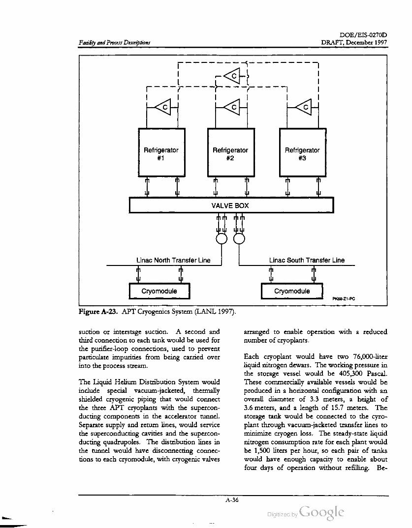
DOE /EIS-0270D
DRAFT, December 1997Facility and Process Descriptions
С
CH
a
C с
Refrigerator
# 1
Refrigerator
# 2
Refrigerator
# 3
市中
VALVE BOX
Hii Hit
Linac North Transfer Line Linac South Transfer Line
4포
Cryomodule Cryomodule
PK68 -Z1-PC
Figure A -23. APT Cryogenics System (LANL 1997).
arranged to enable operation with a reduced
number of cryoplants.
suction or interstage suction . A second and
third connection to each tank would be used for
the purifier-loop connections, used to prevent
particulate impurities from being carried over
into the process stream .
The Liquid Helium Distribution System would
include special vacuum -jacketed , thermally
shielded cryogenic piping that would connect
the three APT cryoplants with the supercon
ducting components in the accelerator tunnel.
Separate supply and return lines, would service
the superconducting cavities and the supercon
ducting quadrupoles. The distribution lines in
the tunnel would have disconnecting connec
tions to each cryomodule, with cryogenic valves
Each cryoplant would have two 76,000-liter
liquid nitrogen dewars. The working pressure in
the storage vessel would be 405,300 Pascal.
These commercially available vessels would be
produced in a horizontal configuration with an
overall diameter of 3.3 meters, a height of
3.6 meters, and a length of 15.7 meters. The
storage tank would be connected to the cyro
plant through vacuum -jacketed transfer lines to
minimize cryogen loss. The steady-state liquid
nitrogen consumption rate for each plant would
be 1,500 liters per hour, so each pair of tanks
would have enough capacity to enable about
four days of operation without refilling. Be
A - 36
DOE / EIS -0270D
DRAFT,December 1997 Facility and Process Descriptions
cause a typical liquid nitrogen delivery truck can
supply about 23,000 liters, the APT operation
would require a continual delivery of approxi
mately five trucks per day to keep up with the
liquid nitrogen demand, or the construction of
an onsite nitrogen recondenser facility.
A.5.15 TARGET /BLANKET STAGING
BUILDING
This would be a steel frame structure adjacent
to the Target/Blanket Building. The building
would have space for unloading incoming
complete target/blanket modules from a rail
spur and inspecting them upon receipt. The
building would contain pumps and test equip
ment to perform final hydrostatic tests on each
unit. Racks for the modules would be provided
to store the modules in the upright position
while awaiting transfer to the target /blanket
building. A gantry crane mounted on tracks on
the floor of the building would be used to off
load the modules and load them on the transfer
maintenance activities, and the change-out of
tungsten neutron source /decoupler modules,
blanket modules, reflector modules, shield
modules, and window modules. The primary
treatment for personal protective equipment
and job control wastes would be incineration in
the SRS Consolidated Incineration Facility
(CIF ). The tungsten neutron source/decoupler
modules and blanket modules would contain
significantamounts of lead (a Resource Conser
vation and Recovery Act (RCRA)-regulated
material), and would be contaminated with a
number of radioactive isotopes. The tar
get /blanket wastes would be placed initially in
the target pools for tritium recovery and
cooldown, and then would be treated to meet
applicable RCRA requirements and waste ac
ceptance criteria before disposal. Solid radioac
tive wastes with volumes small enough to
preclude size reduction would require only
packaging, characterization, and certification for
disposal.
cart.
A one of a kind transfer cart would be provided
on a track to move the modules from the stag
ing building to the Target/Blanket Building. An
air lock would be provided between the staging
building and the Target/Blanket Building by
double roll-up doors,with shielding provided by
blocks stacked in front of the air lock .
The Liquid Radioactive Waste System would
consist of a heavy-water system , a light-water
system , and a process-water system . The heavy
and light-water systems each would include a
resin drying system , a liquid retention system ,
and a reverse-osmosis system .
water system would include tunnel waste col
lection systems, Target/ Blanket Building waste
collection systems, oil removal systems, and re
verse-osmosis systems.
The process
A.5.16 RADIOACTIVE WASTE TREAT
MENT SYSTEM
The radioactive wastes generated by the APT
facility would be classified as low -level and
mixed waste; there would be no generation of
high -level or transuranic wastes . The APT Ra
dioactive Waste Treatment System would inter
face with and use all compatible waste facilities
at the SRS, and would include systemsto handle
solid , liquid , and gaseous radioactive waste
streams.
The Gaseous Radioactive Waste System would
receive and process waste gases from the Tar
get / Blanket Systems the Cavity Vessel and
Atmosphere System , the Gas Transport Sys
tem -- and vented gases from various balance
of-plant systems. The system would receive
gaseous effluents containing traces of spallation
products and low levels of tritium ,which would
come primarily from the Target /Blanket As
sembly System , the Target / Blanket Gas Trans
port System , and miscellaneous venting from
target/blanket and accelerator segment proc
esses. The effluent gases would be processed
through a once-through pre-HEPA filter, a
caustic scrubber, a dryer, and a HEPA filter,
and then transported to decay holding tanks be
The major sources of APT radioactive waste
would be spent resin from water treatment ion
exchangers, personal protective equipment, job
control material from routine operation and
A - 37

DOE /EIS-0270D
DRAFT, December 1997Facility and Process Descriptions
fore being exhausted to the balance-of-plant
HVAC stack .
A.5.16.1 Solid Radioactive Waste System
Most low -level waste and some mixed wastes
generated at the APT would be personal pro
tective equipment and routine job control and
maintenance wastes. These wastes would be
segregated and packaged in the appropriate
standard site containers in accordance with
waste acceptance criteria (WAC) for solid waste
management. The containers would include
55- gallon drums, B -25 boxes, and B -12 boxes.
At the point of generation, APT personnel
would segregate and package wastes. Health
physics personnel would survey the packages
prior to their transfer. Routine waste packages
would go to the APT Solid Radwaste Building
for staging and interim storage. Waste casks or
large failed equipmentmeeting WAC would go
directly to SRS solid waste management or to
offsite disposal / treatment facilities. Each waste
package would be prepared to comply with
applicable requirements for documentation ,
certification, and labeling in preparation for
transfer to the appropriate disposal facility .
Documentation would be maintained in accor
dance with SRS requirements.
A.5.16.2 Liquid Radioactive Waste System
Some failed or spent APT components could
require special casks to meet transportation and
disposal requirements because of higher levels
of radioactivity . These would include such
items as T / B cavity vessel windows and tung
sten neutron sources. Casks chosen for these
wastes would be of suitable design to meet SRS
solid waste management WAC for radiation
shielding, transportation, handling,and storage.
The liquid radwaste system would consist of
three major systems: heavy water (D20 ), light
water (H2O , deionized water), and process
water radwaste systems.
A.5.16.2.1 Heavy -Water Radioactive Waste
System
The casks for the lead components from the
target/blanket modules would have additional
requirements. They would contain RCRA
mixed wastes and would require an offsite dis
posal facility . The lids on themixed waste casks
would be welded closed with automatic equip
ment to minimize exposure to site personnel.
The weld would be verified to ensure integrity
and the cask would be inspected to ensure that
itmet the requirements for macroencapsulation
of a RCRA mixed waste. Based on the final
design of the target/blanketmodules, additional
remote handling equipment could be required
for separation of the lead components from the
modules, reduction of component size, and
placement ofmaterials into casks.
The heavy-water radwaste treatment system
would consist of a resin dewatering system , liq
uid waste retention system , and a reverse
osmosis system . It would receive spent resin
and backwash slurry from the tungsten target
heavy-water polishing loop and would perform
a liquid purification process by separation of
solid , liquid , and gas wastes for storage, reuse,
and disposal.
Resins from the liquid radwaste system would
be dewatered and sealed in high-integrity con
tainers for transfer to solid waste management.
Packaging requirements for nonroutine low
level radioactive waste that was too large or ir
regular in shape to fit in standard site containers
would be dealt with as needed with Solid Waste
Engineering and Operations.
The heavy-water resin dewatering system would
consist of a tungsten target high-integrity con
tainer (HIC), which would receive polishing
loop ion exchanger resin and filter backwash
slurry at amaximum rate of 100 gpm . The HIC
would be a DOT-certified container with inter
nal resin filters. The HIC dewatering operation
would remove the heavy water from the resin to
less than 1 percentofthe resin volume in resid
ual water. The HIC would remove the excess
water through resin filters, and the filtrate
would berouted to liquid waste holding tanks in
the liquid radwaste retention system . The dewa
tered resin would remain in the HIC . After
A - 38

DOE /EIS -0270D
DRAFT, December 1997 Facility and Process Descriptions
resin dewatering, the HIC would be character
ized and transported by an overhead crane to a
HIC concrete cask for solid waste disposal.
tank for reprocessing. After excess water was
removed from the evaporator, the slurry would
be heated by the heating coils. Vapor and gases
would be removed from top of the vessel and
routed to the gaseous radwaste system . Solids
would be collected from the bottom ofthe ves
sel for transfer to drumsas solid waste.
A.5.16.2.2 Light-Water Liquid Radioactive
Waste System
The heavy -water radwaste retention system
would consist of one 25,000-gallon liquid waste
holding tank with two transfer pumps, an agita
tor, a level switch, and control instrumentation.
The holding tank would receive filtered heavy
water from the resin dewatering HIC and leak
age of heavy water collected in the holding tank
vault. The liquid waste holding tank would be
in a stainless- steel- lined shield vault. The vault
would have a sump, a sump pump, a liquid level
detector, and control instrumentation . Two
100-percent capacity pumps in the tanks would
transfer radwaste liquid to a reverse-osmosis
system for purification.
The light-water liquid radwaste treatment sys
tem would consist of a resin drying system , a
liquid waste retention system , and a reverse
osmosis unit. The system would receive spent
resins and backwash slurry from blankets, win
dows, shields, the target storage pool, and the
closed-loop polishing systems, including leakage
from the closed - loop cooling systems, and
would perform a liquid purification process.The heavy -water reverse -osmosis system would
consist of one microfilter, a two-stage reverse
osmosis unit, three holding tanks, one filter
backwash tank, one condensate tank, one
evaporator with heating coils, feed pumps, in
strumentation , and a programmable logical
control system . The reverse-osmosis system
would purify the liquid radwaste stored in the
heavy-water radwaste holding tank .
The light-water resin drying system would con
sist of a spent resin holding tank and a packaged
high-integrity container (HIC). The spent resin
holding tank would be an intermediate receiver
to combine spent resin from the light-water
closed-loop polishing system and to filter back
wash slurry discharge to one HIC . The 3,000
gallon tank would temporarily store partial vol
umes of liquid waste generated in one ion ex
changer in the closed -loop polishing systems, if
the HIC was at a high level.
At the end of filtration , the microfilter would be
backwashed by the first-stage reverse -osmosis
feed pump using the filtrate. The filter back
washed slurry would be discharged to a back
wash tank. The first-stage reverse -osmosis unit
would be backwashed by the second -stage re
verse-osmosis feed pump using the first-stage
permeate . The backwashed slurry would be
routed to the concentrate tank . The second
stage reverse -osmosis unit would be back
washed by a condensate feed pump using con
densate water. The backwashed water would be
routed to the first-stage reverse osmosis holding
tank. Finally , the microfilter would be back
washed by the first-stage reverse-osmosis feed
pump
The light-water radwaste retention system
would consist of one liquid waste holding tank
with two transfer pumps, an agitator, a level
switch, and control instrumentation . The
holding tank would receive filtered light water
from the resin dewatering HIC and leakage
from the closed-loop light-water systems col
lected in theholding tank vault. The light-water
radwaste retention system would be similar in
design and operation to the heavy-water rad
waste retention system .
The evaporatorwould receive the backwash and
the concentrate tank slurry and would perform
the dewatering process. Excess water would be
returned to the heavy-water radwaste holding
The light-water reverse-osmosis system would
consist of two packaged reverse-osmosis sys
tems. OneOne system would be in operation and
the other would be in standby mode. The re
verse -osmosis system would process liquid
4-39
DOE /EIS-0270D
DRAFT, December 1997Facility and Process Descriptions
and instrumentation for automatic pump con
trol operation . Sump water would be pumped
to the process-water radwaste holding tank.
waste from the light-water radwaste holding
tank. The light-water reverse -osmosis system
would be similar in design and operation to the
heavy -water reverse-osmosis system , except ex
cess water from the evaporator would be re
turned to the light-water radwaste holding tank
for reprocessing
A.5.16.2.3 Process -Water Radioactive Waste
System
The process -water radwaste holding tank would
be in a shielded vault. Two 100-percent capac
ity pumps in the tanks would transfer radwaste
liquid to an oil separation system , and then to a
reverse -osmosis system for processing. Over
flow liquid from the holding tank would be
drained temporarily to the sump. When the
tank liquid level was reduced , the overflow liq
uid in the sumps would be pumped back to the
tank .
The process -water radwaste system would con
sist of a tunnel waste collection system , a tar
get /blanket building waste collection system , an
oil-separation system , and a reverse -osmosis
system . The oil separation system in the process-water
radwaste system would separate oil and water
before reverse-osmosis treatment. Wastewater
received in the process-water holding tank
could contain machine oil or grease from area
building sumps. Liquid waste would be treated
through a packaged oil separation system , which
would include prefilters, coalescing filters, air
filters, and an oil holding tank .
The tunnel waste collection system would con
sist of 20 sumps with pumps to collect leakage
from heat removal systems and fire protection
systems in the accelerator tunnel. The sumps
would be located every 61 to 67 meters along
the tunnel. The system design capacity would
be based on a 350- gallon-per-minute fire sprin
kler discharge in a designated 2,500 square feet
of fire-protected area in accordance with Na
tional Fire Protection Association (NFPA) Or
dinary Hazard, Class 1 Classification , with water
density at 0.13 gallons per minute per square
foot. The 350 gallons per minute of fire water
would be collected in two sumps and trans
ferred through a 6 -inch pipe header to a proc
ess -water radwaste holding tank. Each sump
would be lined with stainless steel. The sump
and sump pump would be able to handle 50
percent of the capacity of fire water.
switch and alarm at each sump would automati
cally control the pump operation.
The reverse -osmosis unit would consist of spi
ral-wound reverse -osmosis membranes that
would provide as much as 0.3 micron particu
late retention . The rejection rates and recovery
rate of the two-stage reverse-osmosis unit
would be 15 to 30 percent and 70 to 85 percent,
respectively. The filtration process of the re
verse -osmosis system would be sized to process
20,000 gallons of liquid waste in approximately
12 hours of continuous operation .
A.5.16.3 Gaseous Radioactive Waste System
The Target /Blanket Building waste collection
system would consist of a stainless-steel sump, a
sump pump, and a 25,000-gallon process-water
waste holding tank with an agitator, two transfer
pumps, level switches , alarms, and control in
strumentation . This system would be on the
bottom floor level and would collect floor drain
waste, leakage from closed cooling loop sys
tems, and fire sprinkler discharged water. The
sump would be stainless steel lined to prevent
leakage, and would have level switches, alarms,
Thegaseous
radwastesystem
would include the
gaseous waste handling system from the inter
faces with the effluent gases from the tar
get /blanket gas systems, the gas transport
system , the radwaste systems, and other APT
blanket gas uses to the interface with the bal
ance-of-plant HVAC target/blanket stack. It
would also include a water supply from the in
terface with the domestic water system to the
interface with the liquid radwaste system where
the water from the moisture separator dis
charged.
A -40

DOE/ EIS-0270D
DRAFT, December 1997 Facility and Process Descriptions
Storage and staging for shipping solid mixed
waste containers.
Storage and staging for shipping hazardous
radioactive solid waste.
Storage and staging of packaged dirty
clothing before transport for cleaning.
Storage of burnable packaged solid waste
before transport to the SRS Consolidated
Incineration Facility .
The gaseous radwaste system would consist of a
vacuum pump to transfer the gaseous radwaste
from various gaseous waste systems to one of
two waste gas storage tanks, in which the po
tentially radioactive gas would be monitored to
determine if it contained acid or radioactive
material. Gaseous waste that contained permit
table acid or radiation levels for discharge would
be vented directly to the balance-of-plant
HVAC target/blanket stack . Gaseous waste
containing acid or radioactivematerialwould be
transferred through a blower and through a gas
scrubber in which nitric acid would be removed ;
then itwould pass through a moisture separator
to remove entrained moisture, and then it
would be heated to a temperature above the
dew point. Gases containing no radioactivity
would then be vented to the balance-of-plant
HVAC target/blanket stack . Radioactive gases
would be passed through a HEPA filter to re
move radioactive particles. The gaseous waste
would be compressed to 20 atmospheres,
passed through a moisture separator,and stored
in holding tanks until remaining radioactive
isotopes decayed to acceptable levels for vent
ing through the stack . It would be vented
through the stack , and the tankswould be ready
to receivemore gaseous waste.
There would be space for an administrative of
fice where records would be retained. A load
ing dock would be provided for the handling of
material. Material would be handled by forklift
type equipment, with no cranes.
A.6 Other Support Facilities and
Systems at the Savannah River
Site
The Savannah River Site has a range of support
services and facilities, including onsite transpor
tation capabilities (truck and rail), hazardous
and sanitary waste processing facilities, central
engineering and maintenance functions, and
other specialized support. The following sec
tions discuss facility groups directly associated
with the APT project: the Tritium Loading
Facility (TLF), the Tritium Extraction Facility
(TEF), M -Area facilities, and waste facilities.
Accumulated water from the moisture separa
tors and wastewater from the gas scrubber
would be discharged to the liquid radwaste sys
tem .
A.5.16.4 Radioactive Waste Building A.6.1 TRITIUM LOADING FACILITY
The Radioactive Waste Building would provide
storage for packaged solid radioactive waste be
fore shipment for final disposition. The build
ing would be a steel frame building with metal
siding on reinforced concrete footings with a
slab on grade floor.
The existing SRS Tritium Facilities consist of
the Tritium Loading Facility (Building 233-H )
and associated support facilities in H -Area , as
shown in Figure A -24. The TLF (formerly
known as the Replacement Tritium Facility) was
designed for gas handling operations (filling and
emptying reservoirs), product separation, and
enrichment activities. Tritium is received in res
ervoirs returned from the field or as " fresh ”
tritium from a production facility . Reservoirs or
shipping containers are unloaded and the gases
are processed to separate hydrogen isotopes
from
The Radioactive Waste Building would have
space for the following functions:
Storage and staging for shipping low -level
radioactive solid waste packaged in site ap
proved waste containers.
A -41

DOE /EIS-0270D
Facility and Process Descriptions DRAFT, December 1997
Building 234- H
(Tritium Handling)Building 238 -H
(Reclamation Facility)
Building 249- H
(Support Facility)
Building 232-H
(Tritium
Recycling and
Extraction Facility)
Building 233-Underground
(Tritium Loading Facility)
PK68-21PC
Source : DOE 1995b .
Figure A -24 . SRS Tritium Facilities layout.
vault until they are packaged and sent to the
field for limited -life component exchange in a
weapon system or to the Pantex Plant for as
sembly into new weapon systems.
other gases, primarily Helium (He-3), which is a
byproduct of the radioactive decay of tritium .
The hydrogen isotopes can be separated into
tritium and deuterium , which are used to pre
pare a specified isotopic mixture for loading
reservoirs. The unloaded reservoirs are re
claimed, if possible, and reloaded. Reservoirs
that cannot be reclaimed are sealed and handled
as solid low -level radioactive waste . The He- 3 is
purified to remove residual tritium and other
contaminants before it is packaged as a byprod
uct.
A sample of the newly filled reservoirs is placed
in the life storage area for surveillance. As these
reservoirs age , they can be examined and tested
to confirm predicted behavior and to ensure the
integrity and function of the reservoirs in the
field . Surveillance operations include environ
mental testing, function testing, calorimetry ,
flow testing, and burst testing. These tests
evaluate the behavior of the selected reservoirs
under test conditions.
Support activities occur in the following build
ings:
The reservoirs are loaded with specified mix
tures of gases obtained by using recovered gas
of the proper specification, adding pure iso
topes to the mix of recovered gases, or blending
the pure isotopes. When the reservoirs are
loaded , they are sealed with a closure weld ,
trimmed, surface-decontaminated, leak-tested,
inspected, marked , assayed for tritium content,
and assembled in appropriate configurations, if
required. The reservoirs are placed in a storage
232-H , Tritium Extraction, Concentration ,
and Enrichment Facility
A -42
DOE /EIS -0270D
DRAFT, December 1997 Facility and Process Descriptions
232-1H , Tritium Construction Pipe Shop
and 232- H Maintenance Shop
Facility (TEF), which would replace Build
ing 232- H . The TEF would extract tritium
from either commercial light-water reactor tar
get rods or APT target rods used in the Lithium
(Li-6) target option. TEF would not be in
volved with the He-3 target option of the APT.
234- H , Tritium Reservoir Finishing, Packag
ing ,and Shipping Facility
.235- H , Office Building
236 - H , Burst Test Facility
238 - H , Reservoir Reclamation Facility
The TEF would have the capability to extract
and purify tritium from appropriate targets at a
rate that meets current and projected national
defense requirements, and to process and de
liver readily recoverable He-3 from the tritium
sources. The TEF is the subject of a separate
DOE EIS (61 FR 4670). As discussed in Sec
tion A.4, the location of the TEF has not been
decided and may include co -location with the
TSF at the APT site .
249- H , TLF Support
720-H , Central Alarm Station
A.6.2 TRITIUM PROCESSING FACILI
TIES / TRITIUM EXTRACTION FA
CILITY
A.6.3 M -AREA FACILITIES
The targets
Building 232- H was used to recover tritium
from lithium -aluminum targets.
were irradiated in the SRS reactors and trans
ported to Building 232-H , where they were
placed in crucibles in a high -temperature fur
nace. The heat caused the aluminum cladding
to melt and released the tritium from themetal
lic matrix . Gas-handling systems in the facility
recovered the gases from the furnace extraction
process and separated tritium from the other
gases. Two upgrade options have been pro
posed for the existing tritium facilities. The
first, referred to as the unconsolidated upgrade,
is designed to meet the DOE Natural Phe
Hazard Requirements affecting
Buildings 232-H , 232-1H , 238 -H , and 249-H .
These upgrades would add wall bracing and
cross bracing to beams, strengthen some exte
rior walls, and reinforce building frames. In
addition, Building 232-H would need an anchor
for the service area roof slab and an upgrade of
the radiation control and monitoring system .
Building 234- H upgrades would include highly
invulnerable encased safes for reservoir storage
to protect the tritium - filled reservoirs during a
high wind or earthquake.
Through a screening process, a number ofAPT
support functions have been identified as can
didates for location in M -Area facilities . Ta
ble A -2 lists the candidate functions in the order
of descending impact based on floor space re
quirements, along with compatible M -Area
buildings. To support some of these functions,
DOE might have to upgrade building utilities,
and, therefore, would have to determine specific
utility requirements for electricalpower, process
cooling, domestic and service water, instrument
air, process and sanitary sewer, fire protection ,
and HVAC . This will enable an accurate
evaluation of existing building utility capabilities
and could affect the feasibility of using M -Area
buildings.
nomenon
A.6.4 SRS WASTE FACILITIES
The APT site would include a sanitary liquid
waste collection system and pump station to
move sewage to a centralized SRS sanitary
sewer treatment facility . Solid sanitary waste
would be sent to an offsite or (proposed ) onsite
landfill to be operated by the Three River Solid
Waste Authority .
A proposed addition to the SRS Tritium Facili
ties in H - Area would be the Tritium Extraction
The APT Nonradioactive Waste Treatment
System would provide required storage, treat
A -43

DOE /EIS -0270D
Facility and Process Descriptions DRAFT,December 1997
Table A -2. M -Area Facility functionalsupport compatibility.a
Floor space
Function
required (m2)
9,290
929 - 9,290
3,252
Possible locations
All M -Area Buildingsb
320 -M , 321-MC, 315-M (if heated)
320- M , 321-M (partial), 313- M (partial);
with HVAC additions: 315 -M , 330- M ,
331 - M
320 -M , 321- M , 313- M (if co -located ), or
322 - M
321 - M
Construction Staging
Equipment Receipt/ Inspection
Motor ControlCenter, Circuit Breaker,
Instrument Rack, Beam Diagnostics
Storage
Circuit Breaker, Instrument Rack, Beam
Diagnostics Device Testing
He- 3/ Tritium Gas Loop Fabrica
tion / Test
ControlRoom Simulator
Program Development Center
Magnet Equipment Maintenance
Target/Blanket ComponentFabrication
Vacuum Valve Testing
Training Facility
975
929
822
790
465
372
93
93
321 -M
320 - M , 321-M
320 - M , 321- M
320 - M , 321-M
313- M , 320 -M , 321- M
313- M , 320 -M , 321- M ; 305-1M with
HVAC and fire protection
320-Md46.5Target /Blanket Component Flow Test
ing
Tritium Implantation Studies18.6
313-M , 320- M , 321- M , 322- M
a .
b .
Source: WSRC (1996 ).
Depends upon construction contract. This function cannot be located in any single M -Area building due to space
limitations.
This function may not be located in any single M -Area building due to space limitations.
Target/blanket component flow testing may be co -located with the accelerator target flow testing, which willnotbe
in M -Area .
C.
d .
Contaminated APT process wastewater would
go to a new facility built to support the APT.
ment, and packaging capabilities prior to ship
ment for treatment and disposal of APT
generated non -radioactive wastes (except do
mestic wastewater, which would flow directly
from the APT sanitary sewer system to the SRS
sanitary sewer system ). In addition to any other
non-radioactive liquid waste, this system would
handle domestic, industrial, and hazardous solid
wastes and would interface with existing and
planned SRS waste facilities.
All radioactive waste generated by the APT
would be low -level waste; no high -level or tran
suranic wastes would be generated. DOE treats
and stores wastes generated from SRS opera
tions in waste management facilities in E-, F-,
H-, N-, S-, and Z -Areas (Figure A -25 ). Major
facilities include the high -level waste tank farms,
the Low -Level Radioactive Waste Disposal Fa
cility, the F- and H -Area Effluent Treatment
Facility , the Defense Waste Processing Facility ,
and the Consolidated Incineration Facility .
Small quantities of process wastewater could be
incinerated at the Consolidated Incineration
Facility or stabilized for disposal as solid waste
in the E -Area Vaults. Most APT process
wastewater would go to a liquid effluent treat
ment facility and outfall, or directly to an outfall.
DOE stores liquid and solid wastes on the SRS.
Liquid high-level radioactive waste is stored in
A -44
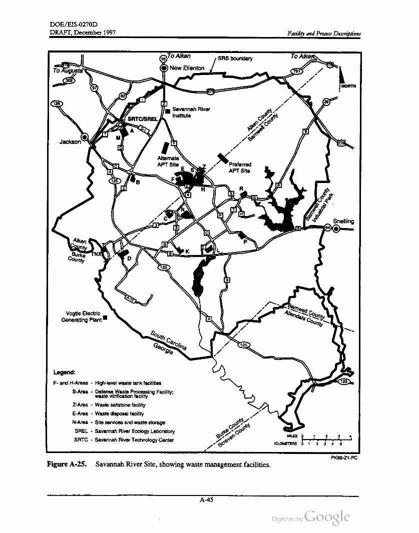
DOE/ EIS-0270D
DRAFT, December 1997 Facility and Process Descriptions
To AikenSRS boundary
To Aiken
278
To AugustaNew Ellenton
781
302
NORTH
62
39125 2
Savannah River
Institute
SRTC /SREL
0-1A
м )
Jackson
Aiken
County
Barnwell
County
278
Alternate
APT Site
ESS
Preferred
APT Site
125 FB
H R
Barnwell
County
Industrial
Park
Snelling
0
Aiken
County
BurkeCounty
KTNX
125
A - 13Barnwell
CountyAllendale
CountyVogtle Electric
Generating PlantА )
South
Carolina
Georgia125
125
Legend:
F. and H -Areas - High -levelwaste tank facilities
S - Area - Defense Waste Processing Facility;
waste vitrification facility
Z -Area - Waste saltstone facility
E -Area - Waste disposal facility
N -Area - Site services and waste storage
SREL Savannah River Ecology Laboratory
SRTC - Savannah River Technology Center
MILES 0
1
2 3 4
T
Burke
County
Screven
County
KILOMETERS 0 2 3 4 5
PK68 -Z1-PC
Figure A -25. Savannah River Site , showing waste management facilities.
A -45
DOE /EIS -0270D
DRAFT,December 1997Facility and Process Descriptions
and laboratory liquid waste. The remainder
comes from other F- and H -Area facilities.
underground storage tanks, which are managed
in accordance with Federal laws, South Carolina
Department of Health and Environmental
Control (SCDHEC) regulations, and DOE Or
ders .
A.6.4.1 Low - Level Solid Waste
The F and H -Area Effluent Treatment Facility
was built to replace the old F- and H -Area seep
age basins, which, under the 1984 Hazardous
and Solid Waste Amendments to the Resource
Conservation and Recovery Act, could not be
used after 1988. The F- and H -Area ETF began
operation in October 1988.
At the SRS, low -level waste is categorized for
onsite disposal in the Low -Level Radioactive
Waste Disposal Facility according to the waste
category and surface radiation dose. The pri
mary categories include low -level, intermediate
level, and long-lived wastes. The SRS also dis
tinguishes between wastes that have low surface
radiation doses and can be handled directly, and
those that require remote handling.
The F- and H -Area Effluent Treatment Facility
decontaminates wastewater through a series of
steps which consist of pH adjustment, submi
cron filtration, heavy-metal and organic adsorp
tion, reverse osmosis, and ion exchange. The
treatment steps concentrate contaminants in a
smaller volume of secondary waste, which is
concentrated further by evaporation . The waste
concentrate is eventually disposed of in the
Z -Area Saltstone Manufacturing and Disposal
Facility . The treated effluent is analyzed to en
sure that it has been properly decontaminated,
and then discharged to Upper Three Runs
Creek .
Low -activity waste is loaded in steel boxes and
can be shipped either to the Low -Level Radio
active Waste Disposal Facility in E -Area
(Figure A -26) or to the H -Area compactor. If
the waste is compacted, waste is added to the
steel boxes and compacted until the boxes are
full. The boxes are taken to waste disposal
vaults in E -Area for final disposal
A.6.4.3 Long-Lived and Intermediate- Level
WasteA.6.4.2 Low -Level Liquid Waste
DOE will store long-lived wastes, such as res
ins, in temporary facilities until the long-lived
waste storage building in E -Area can begin op
erations. This building will provide storage until
DOE develops treatment and disposal tech
nologies.
The F- and H -Area Effluent Treatment Facility
(ETF) decontaminates and treats low -level
process water and stormwater contaminated
with radioactive and chemical constituents.
Routine influents accepted by the ETF are pri
marily evaporator condensates from the chemi
cal separations facilities and the tank farms.
Approximately 34 percent of the influent to the
F-and H -Area ETF comes from F -Area, includ
ing the separations facility, cooling and storm
water retention basins, evaporator overheads,
and laboratory liquid waste. H -Area influents
comprise approximately 48 percentof the influ
ents and include the separations facility , cooling
and stormwater retention basins, evaporator
condensate, tritium laboratory liquid waste, wa
ter inside the In -Tank Precipitation dike (an
embankment designed to control water runoff),
To ensure improved containment the SRS de
veloped the E -Area vaults, which began receiv
ing low -level radioactive waste in November
1994. This facility ultimately will receive low
activity, intermediate-level nontritium , and trit
ium waste.
DOE packages intermediate-level wastes
cording to the waste form and disposes of them
in slit trenches . Some intermediate-level waste,
such as contaminated equipment components,
is wrapped in canvas before disposal.
A -46
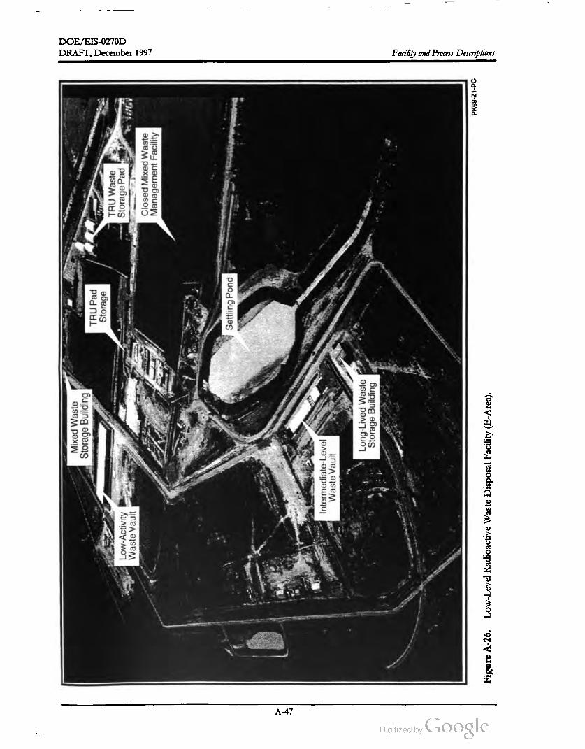
DOE/ EIS-0270D
-
Mixed
Waste
Storage
Building
TRU
Pad
Storage
DRAFT, December 1997
TRU
Waste
Storage
Pad
Low
-Activity
Waste
Vault
Closed
Mixed
Waste
Management
Facility
Settling
Pond
Intermediate
-Level
Waste
Vault
Long
-Lived
Waste
Storage
Building
Facility and Process Descriptions
PK68
-Z1
-PC
Figure
A-26.
Low
-Level
Radioactive
Waste
Disposal
Facility
(E -Area
).
A -47

DOE / EIS -0270D
DRAFT,December 1997Facility and Process Descriptions
A.6.4.4 Hazardous and Mixed Waste
or are as
Hazardous waste is defined as discarded mate
rials (both liquid and solid ) that are either char
acteristically hazardouslisted
hazardous under the Resource Conservation
and Recovery Act. Characteristically hazardous
materials are corrosive, ignitable, reactive , or
toxic. Hazardous waste includes organic liquid ,
debris, or sludges; aqueous liquid , debris, or
sludges; metal debris; glass debris; inorganic
sludges; and soils that do not contain radionu
clides. If they are contaminated with radionu
clides, they are separated as mixed waste.
its radioactive component. The primary consid
eration of the management of low -levelmixed
waste is its hazardous components, while the
primary consideration of the management of
high-level and transuranic mixed wastes is the
radioactive component. SRS mixed wastes are
stored in permitted or interim -status facilities
such as the hazardous waste storage facilities
(building and pads) and in the mixed waste stor
age buildings. Figure A -27 shows waste han
dling processes for other formsofwaste atSRS.
At the SRS, hazardous waste is stored tempo
rarily at hazardous waste storage facilities in
buildings in B- and N -Areas and on adjacent
Mixed waste is hazardous waste that contains
radioactivity; it is further classified according to
Waste Storage Transfer Waste DisposalWaste
Preparation /Processing
Hazardous
waste
Hazardous
waste storage
Offsite
treatment
Offsite
disposal
Low -level
mixed waste
Mixed
waste storage
Compactors
Solid waste
disposal
facility , later
to E -Area
vaults
Low -level
radioactive waste
Storage
Transuranic
waste
Retrievable
storage
PK68 -Z1-PC
Figure A -27. SRS waste handling processes.
A -48

DOE /EIS -0270D
DRAFT, December 1997 Facility and Process Descriptions
storage pads before shipment to offsite permit
ted treatment, storage, and disposal facilities.
DOE began offsite shipments of hazardous
wastes to treatment and disposal facilities in
1987. In 1990 DOE imposed a moratorium on
shipments of hazardous waste from radiologi
cally controlled areas or that had not been
proven to be nonradioactive. The SRS contin
ues to ship hazardous waste that is validated as
nonradioactive ( e.g., solvents) offsite for recy
cling, treatment, or disposal.
(Pumphouses 16 and 3G ) and one on Par Pond
(Pumphouse 6G ). Pumphouses 1G and 6G no
longer operate. Each pumphouse contains
10 pumps; pump capacities vary from 24,000
gallons per minute to 32,500 gallonsper minute.
Approximately 50 miles of underground con
crete piping can deliver river water from the
pumphouses to the reactor areas. When the re
actors were operating, the River Water System
delivered 174,000 gallons perminute to each re
actor area. At present, DOE operates one of
the 10 pumps in Pumphouse 3G to satisfy small
equipment cooling loads in K-, L., and P -Areas.
Pumphouse 5G is also on the Savannah River ,
but it is a separate piping system that supplies
cooling water to the D -Areas powerhouse.
A.6.5 RIVER WATER SYSTEM
Chapter 2 summarizes the options available to
transfer heat from APT activities to the envi
ronment. Three of the four alternatives use
water from the Savannah River for this cooling
function . This section describes the River Wa
ter System and modifications needed to support
the APT.
A.6.6 K -AREA COOLING TOWER
Under one of the alternatives, DOE could use
the K -Area Cooling Tower to provide cooling
water for the APT facilities. This tower was
built to provide cooling for K -Reactor but was
never used because the reactor was shut down
before the tower was completed. The con
struction and operation of the cooling tower
was analyzed in the Alternative CoolingWater Sys
tems Final Environmental Impact Statement (DOE
1987), and DOE issued the Record of Decision
in early 1988.
Figure 2-5 shows the RiverWater System which
DOE originally installed to provide cooling
water for the five SRS production reactors. The
reactors (C , K , L , P , and R ) produced and proc
essed nuclear materials for defense, research ,
and medical programs of the United States.
The RiverWater System provided cooling water
that passed through heat exchangers to absorb
heat from the reactor core. Par Pond and L
Lake are manmade reservoirs constructed in
1958 and 1984, respectively, to provide addi
tional cooling water for P , R , and L reactors .
All five reactors have been shut down: R in
1964; C in 1985; P and L in 1988 ; and K in
1993. A separate analysis (DOE 1997) docu
ments options associated with the shutdown of
the River Water System now that the reactors
have ceased operation .
The cooling tower is 140 meters high and
105 meters in diameter at the base. The system
consists of a single recirculating, gravity -flow ,
natural-draft cooling tower thatwould use water
from the Savannah River as makeup water for
leaks and evaporative losses. As designed, dis
charges from the cooling tower are combined
with water from the Savannah River (to ensure
that temperatures remain below 900 F at all
times) and released to Indian Grave Branch,
which flows into Pen Branch and eventually
into the Savannah River.
The River Water System includes three pump
houses, two on the Savannah River
A -49
DOE /EIS -0270D
Facility and Process Descriptions DRAFT, December 1997
References
Badger, George M., “ The KlystrodeTM , A New High -Efficiency UHF TV Power Amplifier,” Varian
EIMAC , San Carlos, California .
DOE (U.S. Department of Energy ), 1987, Alternative Cooling Water Systems Final Environmental Impact
Statement, Savannah River Plant, Aiken, South Carolina, DOE/EIS-0121, Savannah River Operations
Office, Aiken , South Carolina.
DOE (U.S. Department of Energy), 1995b, Final Programmatic Environmental Impact Statement for Tritium
Supply and Recycling,DOE /EIS -0161, Office of Reconfiguration,Washington, D.C.,October.
DOE (U.S. Department ofEnergy), 1997, Shutdown of the RiverWater System at the Savannah River Site Final
Environmental Impact Statement, DOE / EIS-0268, Savannah River Operations Office, Aiken, South
Carolina,May.
LANL (Los Alamos National Laboratory), 1997, Conceptual Design Report, LA -UR-97-1329, Los Alamos,
New Mexico, April 15 .
Peters, R. D., A.Haase, C. Johnson, and R.N. Tornoe, 1994, “ The Klystrode® IOT, A New , Compact,
High Efficiency Electron Tube,” Proceedings of the Materials Research Society Symposium ,
Volume 347, pp. 97-108.
WSRC (Westinghouse Savannah River Company), 1996, “ Report on Use ofExcess M -Area facilities,”
SPM -TMD - 96-0132, Savannah River Site, Aiken, South Carolina.
A -50

Appendix B
Accidents


APPENDIX B
ACCIDENTS

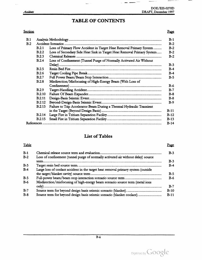
Accidents
DOE /EIS -0270D
DRAFT, December 1997
TABLE OF CONTENTS
Section Page
B - 1
B - 2
B - 2
B - 2
B - 2
B - 3
B - 4
B - 4
B - 5
B.1 Analysis Methodology .
B.2 Accident Scenarios
B.2.1 Loss ofPrimary Flow Accident in Target Heat Removal Primary System
B.2.2 Loss ofSecondary Side Heat Sink in TargetHeat Removal Primary System ....
B.2.3 Chemical Releases
B.2.4 Loss of Confinement (Tunnel Purge ofNormally Activated Air Without
Delay) .
B.2.5 Resin Bed Fire ...
B.2.6Target Cooling Pipe Break .........
B.2.7 Full Power Beam /Beam Stop Interaction .........
B.2.8 Misdirection /Misfocusing ofHigh-Energy Beam (With Loss of
Confinement).
B.2.9 Target-Handling Accident........
B.2.10 Failure OfBeam Expander..........
B.2.11 Design -Basis Seismic Event..........
B.2.12 Beyond-Design-Basis Seismic Event.
B.2.13 Failure to Trip Accelerator Beam During a Thermal Hydraulic Transient
in the Target (Beyond Design Basis) ....
B.2.14 Large Fire in Tritium Separation Facility
B.2.15 Small Fire in Tritium Separation Facility
References ....
B - 6
B - 7
B - 8
B - 8
B - 9
B -11
B - 12
B -13
B -14
List of Tables
Table Page
B - 3B - 1
B - 2
B - 3
B - 4B - 3
B -4
Chemical release source term and evaluation .......
Loss of confinement(tunnel purgeofnormally activated air without delay) source
term ........
Target resin bed source term .
Large loss of coolant accident in the target heat removal primary system (outside
the target/blanket cavity ) source term ...
Full-power beam /beam stop interaction scenario source term ..
Misdirection /misfocusing of high-energy beam scenario source term (metal ions
only ) ...
Source term forbeyond design basis seismic scenario (blanket).
Source term for beyond design basis seismic scenario (blanket coolant).
B - 5
B - 6B - 5
B - 6
B - 7
B - 8
B - 7
B - 10
B -11
B - ü


DOE/ EIS -0270D
DRAFT,December 1997 Accidents
APPENDIX B. ACCIDENTS
B.1 AnalysisMethodology
To develop the accident scenarios described in
this appendix , the U.S. Department of Energy
(DOE) used the hazard-based approach de
scribed in Departmental Standard 3009-94,
Preparation Guide for USDOE Non-Reactor Nuclear
Facility Safety Analysis Reports (DOE 1994). This
is a systematic approach to develop safety
documentation that is consistent with the level
of hazard . DOE developed accident scenarios
for the accelerator, target/blanket, Tritium
Separation Facility, and the Associated Support
Facilities. Based on this analysis, DOE has de
termined that not all scenarios would have an
impact on the environment or the public. This
appendix describes each analyzed accident sce
nario and its likelihood, source term , and con
sequences.
get/blanket structure, the tubes would remain
intact and no release would occur as long as
structural temperatures were below 1,250 °C .
However, if the target /blanket temperature ex
ceeded 1,250 ° C , DOE assumed that the mate
rial in the tubes would vaporize and become
available for release. The blanket is lead clad in
aluminum . The tritium producing elements for
both the He-3 and Li- 6 feedstock material alter
natives are also surrounded by aluminum which
melts at 660 ° C .
In general, the analysis used the computer codes
LAHET, MCNP, and CINDER90 (LANL
1989, 1993) to calculate the radionuclide inven
tory available for potential release in these pos
tulated accident scenarios. DOE developed
release fractions specifically for each scenario
that resulted in a source term , entered the
source term in the MACCS2 (Chanin and
Young 1997) code, and estimated the conse
quences using 95th -percentile meteorology for
the Savannah River Site (SRS). Chemical re
leases were modeled with ALOHA (EPA and
NOAA 1992).
All the scenarios with the exception of the Be
yond-Design -Basis Event described in Section
B.2.13 assumed the quick termination of the ac
celerator beam because the design includes re
dundant sensors and shutdown systems to
detect beam problems and terminate its opera
tion before significant damage could occur.
Sensor indications used to terminate the beam
would include increased radiation levels in the
beam tunnel, high temperature or pressure in
the target/blanket cooling system , changing
water levels in the cooling system , and beam di
agnostic readings. Multiple failures of the Beam
Shutdown System would not be credible. How
ever, DOE included this accident scenario for
completeness. All releases of tritium described
in this appendix are conservatively assumed to
be tritium oxide. Unless otherwise specified, all
references in this appendix are to Liscom
Powell 1997 .
Virtually all of the radionuclides created by the
acceleratorwould be in the focus of the beam in
the target /blanket structure. As a consequence,
most of the postulated accident scenarios focus
on the target /blanket structure and its support
equipment
Accidents for the staged design option and the
proposed inclusion of the Tritium Extraction
Facility (TEF) within the APT are not specifi
cally included in this Appendix. This is because
the consequences of the analyzed accidents
would bound the corresponding accident for
other design options. In the case of the staged
design option, the beam energy and current and
associated accident consequences would be less
than already analyzed cases. The TEF located
at the APT site would be bound by the tritium
inventory limits already analyzed in this docu
The tungsten neutron source is clad in Inconel.
which has a high resistance to oxidation . DOE
used a conservative failure temperature of
1,250 ° C in the calculation for this analysis. In
scenarios that would involve heating the tarment.
B - 1
DOE /EIS -0270D
DRAFT, December 1997Accidents
B.2 Accident Scenarios
B.2.1 LOSS OF PRIMARY FLOW
ACCIDENT IN TARGETHEAT
REMOVAL PRIMARY SYSTEM
events. As part of the scenario , the accelerator
beam would quickly terminate and other sys
temswould activate including the Residual Heat
Removal System , and if needed , the Cavity
Flood System
For this scenario, DOE postulated a loss-of
flow accident (LOFA ) in the Target Heat Re
moval Primary System (THRPS). This event
could result from a single pump failure or the
loss of both pumps. As part of this scenario ,
the accelerator beam would be terminated .
Other systems would activate including the Re
sidual Heat Removal (RHR) system , and the
Cavity Flood System if needed . The RHR pri
mary pumps would have a battery power supply
and a backup diesel generator system that is
single failure proof.
Source Term . Because of the number ofinde
pendent ways to shut off the accelerator beam
and to provide cooling to the target/blanket as
sembly (Residual Heat Removal and Cavity
Flood Systems), the target/blanket would re
main cooled for the scenario and, therefore, the
Target Heat Removal Primary System would
not release any radionuclides.
Likelihood. The estimated frequency for a
complete loss -of-heat-sink accident involving
the Target Heat Removal Primary System could
be 0.13 per year. (LANL 1997)
Consequence Estimates. Because this event
would not release radionuclides, its conse
quences would be negligible.
Source Term . Because of the number of inde
pendent ways to shut off the accelerator beam
and to provide cooling to the target /blanket as
sembly (Primary Coolant and Residual Heat
Removal Systems), the cladding temperature of
the target/blanket would remain below the fail
ure point and, therefore, the Target Heat Re
moval Primary System would not release any
radionuclides.
B.2.3 CHEMICAL RELEASES
Likelihood . The estimated frequency for a
complete loss-of-flow accident in the Target
Heat Removal Primary System could be 0.13
per year. (LANL 1997)
Scenario . DOE has determined that chemical
hazards associated with the operation of an ac
celerator would be standard industrial hazards,
such as those associated with chemicals used in
the water treatment of cooling systemsin indus
trial plants. In addition, DOE would perform
an acid etch cleaning of the radiofrequency
tubes in the Radiofrequency Tube Remanufac
turing Facility, and would use laboratory quan
tities of chemicals in the analytical laboratory.
Consequence Estimates. Because this sce
nario would not release radionuclides, its conse
quences would be negligible.
B.2.2 LOSS OF SECONDARY SIDE
HEAT SINK IN TARGETHEAT
REMOVAL PRIMARY SYSTEM
Scenario . DOE postulated the effects of a
loss-of-heat-sink (LOHS) accident for the Tar
get Heat Removal Primary System . A LOHS
would involve a loss -of-flow accident or a loss
of- coolant accident (LOCA) in the Target Heat
Removal Secondary System , resulting in a loss
of heat rejection capability from the THRPS.
This scenario bounds all postulated LOHS
A review of the typical chemical inventories
DOE could use in the accelerator indicates
three chemicals would exceed 40 CFR 302.4
Reportable Quantities -- ammonium hydroxide,
hydrofluoric acid , and hydrazine. For each
chemical, this scenario assumes the release of
the entire inventory at a single location though
not simultaneously. The analyzed chemicals
would not be stored in the vicinity of radioac
tive materials. Therefore, involvementof radio
active materials in chemical accidents is not
plausible.
B - 2

DOE / EIS -0270D
DRAFT,December 1997 Accidents
Source Term . Table B - 1 lists the types and
quantities of chemicals released .
Table B - 1 . Chemical release source term and
evaluation.
Release Concentration OSHA
quantity at 640 meters PEL OSHA
Chemical (kga) (ppm ) (ppm ) evaluation
Hydrofluoric 1501.0 3 Less than
acid PELC
Hydrazine 25 0.05 0.1 Less than
PEL
Ammonium 3,500 6.0 35 Less than
hydroxidePEL
the accelerator tunnel inventory . The analysis
assumed a 9-month , 10 nanoamperes/meter
(nA /m ), 1,700 MeV proton beam spill over the
length of the accelerator, and that no tunnel air
would exhaust until immediately after the
9 -month period. Themaximum allowable beam
spill would be 10 nA / m during normal opera
tions; this, plus the fact that the tunnel air is
continuously exhausted , provides a bounding
estimate of the inventory after 9 months. The
source term consists of about 3 curies of acti
vated air and decay products inside the accelera
tor tunnel. Table B - 2 lists the dominant
radionuclides that would contribute to the
downwind radiological doses; nuclides that are
not listed in the table constitute less than
2 percentof the released activity.
a .kg = kilograms.
b . ppm = parts permillion.
PEL = Permissible Exposure Levels.C.
Likelihood. A large chemical release could oc
cur with a frequency of 0.1 per year.
Consequence Estimate. Analysis of releases
of these quantities of chemicals shows that the
concentration at the location of the uninvolved
worker (640 meters) is significantly less than
their respective Occupational Safety and Health
Administration (OSHA) Permissible Exposure
Levels (PELs). Concentrations of these chemi
cals at even greater downwind distances (i.e., to
the MEI) would be even lower. Because the
estimated chemical concentrations would be
much less than their respective limits, the con
sequences of this scenario would benegligible.
Table B -2 . Loss ofconfinement (tunnel purge
of normally activated air without delay) source
term .
Activity
Nuclide(curies)
N - 13 1.3
Ar-41 0.46
0-15 0.44
C -11 0.32
C - 14 0.038
H - 3 0.017
Be- 7 0.013
Ar-37 0.012
Total 2.6
B.2.4 LOSS OF CONFINEMENT
(TUNNEL PURGE OF NORMALLY
ACTIVATED AIR WITHOUTDELAY)
Likelihood. Although it is unlikely that (1) a
prolonged, 10 nA /m beam spill would remain
undetected and the beam promptly terminated
and (2 ) the tunnel air would remain stagnant for
9 months, DOE assumes that the bounding
release described above
(approximately 3 curies) could occur with a fre
quency of0.01 per year.
source term
Scenario . This scenario would involve a worst
case release (purge without delay) of the acti
vated air products produced in the beam tunnel
from normal beam operation . The scenario as
sumes that the maximum quantity of radionu
clides – which would be produced by beam
interactions with tunnel air -- would be present
in the tunnel at the time of their inadvertent
purge to the environment.
Consequence Estimates. The analysis used
the source term listed in Table B - 2 to estimate
the radiological dose and risk to downwind re
ceptors. DOE used the MACCS2 code, using
SRS-specific meteorological information, to
conduct the dispersion analysis and computeSource Term . DOE used the LAHET/
MCNP /CINDER90 set of codes to estimate
B - 3

DOE /EIS -0270D
DRAFT,December 1997Accidents
downwind doses and projected latent cancer
fatalities in the surrounding population.
The calculated doses were negligible.
Consequence Estimates. The analysis used
the source term listed in Table B -3 to estimate
the radiological dose and risk to downwind re
ceptors. DOE used the MACCS2 code, using
SRS-specific meteorological information, to
conduct the dispersion analysis and compute
downwind doses and projected latent cancer
fatalities in the surrounding population .
B.2.5 RESIN BED FIRE
Scenario. This scenario involves a fire in the
resin bed of the Primary Coolant Loop Purifi
cation System . The fire would release the entire
radioactive inventory in the resin bed to the at
mosphere. Other Coolant Purification System
resin beds, (e.g. window , blanket, accelerator)
would contain less activity, as DOE would
change the resin before the radioactivity reached
quantities postulated for the primary tungsten
cooling purification resin bed. A fire involving
more than one resin bed is not a credible event.
The calculated dose to the Maximally Exposed
Individual from this scenario is 0.48 rem . The
calculated dose to the uninvolved worker at a
distance of 640 meters is 75 rem . The calcu
lated dose to the population within 50 miles
would be 800 person-rem , which is postulated
to result in 0.40 excess cancer fatalities.
B.2.6 TARGET COOLING PIPE BREAK
Source Term . The resin beds will be periodi
cally changed to limit the amount of radioactiv
ity (e.g. to reduce the risk of a fire and to limit
worker exposure). The resin loading for the ion
exchanger beds is assumed to be administra
tively limited such that the unmitigated release
of the resin bed inventory would result in con
sequences below the off site evaluation guide
lines. The inventory of the target resin bed is
shown in Table B -3 .
Scenario. This scenario postulates a large loss
of-coolant accident involving the Target Heat
Removal Primary System . As part of this sce
nario, the accelerator beam would be quickly
terminated. Other systems would activate or
trip as designed, including primary coolant
pumps (to prevent actively draining the
breached primary system ), the Residual Heat
Removal System , and if needed, the Cavity
Flood System .
Table B -3 Target resin bed source term .
Nuclide Activity (CI)
H - 3 10,000,000
0-15 4,000,000
C - 11 1,700,000
N - 13 680,000
Be-7 2,900
Cr-51 1,700
F - 18 1,400
Ar-37 83
I- 125 76
Xe-127 75
Al- 28 71
If the coolant pipe break was inside the target
cavity , the coolant water would not drain and
would still provide necessary cooling to the tar
get /blanket. As a result, the target/ blanket
cladding would not approach the failure tem
perature and this accident would not release ra
dionuclides. Therefore , this scenario concerns a
coolant pipe break outside the target cavity.
Source Term . Because of the number of inde
pendent ways to shut off the accelerator beam
and to provide cooling to the target /blanket as
sembly , the limiting credible release from this
scenario would be the entire inventory (about
70,000 liters) of water from the Target Heat
Removal Primary System into the confinement
building. Because DOE would maintain the
Likelihood. A resin bed fire that contained the
maximum administrative limit of radionuclides
could have an assumed frequency of 0.01 per
year.
B - 4

DOE /EIS -0270D
DRAFT,December 1997 Accidents
failures) that could lead to larger radiological
releases to be credible due to the redundant and
diverse systems in place to prevent overheating
of the target /blanket. The estimated frequency
of the LOCA inside the target cavity would be
0.001 per year.
THRPS water at a relatively low temperature,
energetic release of radionuclide inventory is
not likely. Nonvolatile radionuclides probably
would remain on wet or cold surfaces near the
release event. DOE assumes a complete release
of noble gases and halogens (i.e., 100-percent
release fraction, 100-percent leak path factor).
The estimated release fraction of other particu
late radionuclides in the inventory would be
0.0002 (100 percent leak path factor). In addi
tion, this scenario conservatively assumes the
release of tritium as HTO (tritium oxide). The
inventory was based on a 1,700 MeV proton
energy LAHET /MCNP /CINDER90 calcula
dion (Liscom -Powell 1997). The inventory in
cludes the direct creation of radionuclides in the
coolant, recoil atoms from the solid materials,
and corrosion products. The source term re
leased to the environment from this accident
scenario is shown in Table B -4 . This source
term is independent of the tritium feedstock .
Consequence Estimates. The analysis used
the source term listed in Table B - 4 to estimate
the radiological dose and risk to downwind re
ceptors. DOE used the MACCS2 code, using
SRS-specific meteorological information, to
conduct the dispersion analysis and compute
downwind doses and projected latent cancer
fatalities in the surrounding population .
The calculated dose to the Maximally Exposed
Individual from this scenario is 0.03 rem . The
calculated dose to the uninvolved worker at a
distance of 640 meters is 2.8 rem . The calcu
lated dose to the population within 50 miles
would be 57 person-rem , which is postulated to
result in 0.029 excess cancer fatalities .
B.2.7 FULL POWER BEAM / BEAM
STOP INTERACTION
96
Table B -4 . Large loss of coolant accident in
the target heat removal primary system (outside
the target /blanket cavity) source term .
Activity
Nuclide (Ci)
H - 3 700,000
0-15 280,000
N - 13 47,000
Kr-76 870
F - 18
C - 11 24
Ar-37 6.0
1-125 5.4
Xe-127 5.3
Be- 7 0.040
Cr-51 0.02
Al-28 0.0010
P -30 0.00051
Sc-44 0.00050
Co-58 0.00040
Co -58m 0.00027
Scenario . This accident would involve an in
advertent interaction between the full-power
beam and the final beam stop . The scenario as
sumes that an equilibrium buildup of radionu
clides in the beam stop (equivalent to 25 hours
(effective) of full rated power [3.4 megawatts]
per year for 40 years) would occurat the timeof
full-power (170 megawatts) focused beam inter
action. The scenario also assumes that the in
teraction would occur immediately after the
final 25 -hour [effective] exposure to the
3.4 -megawatt beam .
Source Term . DOE conservatively assumes
that this accident would release the entire radi
onuclide inventory in the beam stop. Table B -5
lists the source term released to the environ
Total 1,020,000
ment.
Likelihood. The estimated range of frequency
for a large loss -of-coolant accidentin the Target
Heat Removal Primary System is 0.001 per year.
DOE does not consider other accident se
quence outcomes i.e., additional safety system
Likelihood. The Beam Permit and Beam
Shutdown Systemswould have a number of in
terlocks that would prevent unanticipated beam
interactions. System and operator failures
B - 5

DOE / EIS -0270D
DRAFT, December 1997Accidents
Table B -5 . Full-powerbeam /beam stop inter
action scenario source term .
Activity
Nuclide (curies)
C -11 120,000
Li- 9 720
H - 3 520
Be- 7 590
which the beam tube and surrounding struc
tures would release, and activated air products,
which beam interaction with air in the tunnel
would produce. The accelerator would shut it
self down after a breach of the beam tube. In
addition , the scenario assumes that the beam
tunnel confinement system would fail, causing
an immediate release of radioactive material to
the environment.Total 120,000
would have to occur to cause a full-power
beam /beam stop interaction . DOE assumes
that this scenario would have an occurrence
frequency of not greater than 0.0001 per year.
Consequence Estimates. The analysis used
the source ter listed in Table B -5 to estimate
the radiological dose and risk to downwind re
ceptors. DOE used the MACCS2 code, using
SRS-specific meteorological information , to
conduct the dispersion analysis and compute
downwind doses and projected latent cancer
fatalities in the surrounding population .
Source Term . The source term for this acci
dent would consist ofmetal ions and activated
air products generated from beam impingement
and by the beam interaction with tunnel struc
tures; the source term would be a function of
several parameters, including duration, degree
of beam misdirection /misfocusing, and location
of impingement along the beam tube. The sce
nario assumes that the activated air inventory
listed in Table B - 2 would be present in the tun
nel when the beam tube breach occurred . In
addition to the activated air source term , the
scenario assumes the vaporization of a 10
centimeter section of the beam tube, which
would contribute activated metal ions to the
tem . The analysis used LA
HET/MCNP /CINDER90 to estimate the in
ventory of radionuclides in the accelerator
structures, the basis of which would be
1,700 MeV protons impinging on the structure
at 10 nA / m for 9 months. Table B -6 lists the
dominant metal ion source term this accident
would release, which the scenario assumes to be
equivalent to the fraction of the activated beam
tubevaporized by the event (1/ 10,000).
sourceThe calculated dose to the Maximally Exposed
Individual from this scenario is 0.0043 rem .
The calculated dose to the uninvolved worker at
a distance of640 meters is 0.96 rem . The calcu
lated dose to the population within 50 miles
would be 5.0 person-rem ,which is postulated to
result in 0.0028 excess cancer fatalities.
B.2.8 MISDIRECTION /MISFOCUSING
OFHIGH -ENERGY BEAM (WITH LOSS
OF CONFINEMENT)
Scenario. A worst -case beam misdirection or
misfocusing incident coincident with the loss of
the Beam Tunnel Confinement System would
be a bounding accident for the accelerator. This
scenario assumes that the accelerator beam
would impinge on the beam tube for an ex
tended period, causing an eventual breach of
the tube. The scenario also assumes that, dur
ing this time, the Radiation Monitoring and
Protection System would not detect the in
creased radiation levels and cause the beam to
shutdown. Extended beam impingement would
result in the generation ofactivated metal ions,
Likelihood. DOE believes that this event
would be less likely than the accelerator loss-of
confinement scenario described in Section B.2.4
because of the additional requirement of beam
burnthrough . For the bounding source term
release (the sum of the source terms in Tables
B -2 and B -6 is approximately 3.4 curies), DOE
assumes that this event could occur at a fre
quency of 0.0001 per year.
Consequence Estimates. The analysis used
the source terms listed in Tables B - 2 and B - 6 to
estimate the radiological dose and risk to
downwind receptors. DOE used the MACCS2
B - 6

DOE /EIS-0270D
DRAFT, December 1997 Accidents
Table B -6 . Misdirection/misfocusing of high -energy beam scenario source term (metal ionsonly).
Activity Activity Activity
Nuclide (curies) Nuclide (curies) Nuclide ( curies)
Fe- 55 0.045 V -49 0.0056 Co-55 0.0017
Mn -56 0.031 Co -56 0.0044 Cr-49 0.0017
Al- 28 0.031 Ar-37 0.0039 Ni-57 0.0016
Mn-54 0.020 V -48 0.0034 P -32 0.0014
Na-24m 0.016 Co-58m 0.0031 Sc-470.0014
H - 3 0.015 Si-31 0.0031 V -47 0.0013
Cr-51 0.013 K -42 0.0031 Fe-52 0.0013
0-15 0.0069 Ca-45 0.0025 Co-60 0.0012
Co -57 0.0068 Cu -62 0.0023 Cu -66 0.0012
Co -58 0.0064 Nb- 93m 0.0022 Sc-46 0.0011
Cu-64 0.0061 Mn-51 0.0020 Y -88 0.0011
Mn-52 0.0058 Sc -44 0.0019 Total 0.26
Total (x 3) 0.77
a .Multiplied by 3 to account for other low -activity radioisotopes in source term .
code, using SRS-specific meteorological infor
mation , to conduct the dispersion analysis and
compute downwind doses and projected latent
cancer fatalities in the surrounding population.
The calculated dose to the Maximally Exposed
Individual from this scenario is 0.000012 rem .
The calculated dose to the uninvolved worker at
a distance of 640 meters is 0.00078 rem . The
calculated dose to the population within
50 miles would be 0.057 person -rem , which is
postulated to result in 0.000029 excess cancer
fatalities.
The transfer will take place through or over a
flooded canal, or over a region that can be
flooded in the event of a dropped target mod
ule. Ifit is determined that additional cooling is
necessary to prevent excessive releases of radi
onuclides. This design is an extension of what
was presented in the conceptual design report.
In this scenario it is assumed that the transport
mechanism fails causing the target module to
fall into the flooded canal or into the cavity . It
is assumed that active cooling fails. If the target
is dropped into the flooded canal, passive cool
ing is provided to the targetmodule surfaces. If
the target is dropped within the cavity , the cav
ity flood system is activated providing surface
cooling to the dropped module.
B.2.9 TARGET-HANDLING ACCIDENT
Source Term . Analysis shows that with cool
ing of the target module external surfaces, tem
peratures remain minimal. No radionuclides are
expected to be released.
Scenario. This scenario would involve drop
ping an irradiated target module during its re
moval and transport from the cavity to the
target storage pool. DOE anticipates that retar
geting the front target module would occur an
nually , and retargeting the back module every 2
years. Only one (front or back) module would
be removed and transported at a time. For this
scenario the bounding targetmodule is the front
module which will produce the highest decay
heat. This would also bound a dropped blanket
module. Active cooling will be provided during
transfer.
Likelihood. Due to (1) the relatively infre
quent transport of irradiated target modules,
(2 ) themultiple systems that would have to fail
during transport, and (3) the use of industry
standards, practices, and procedures (e.g., com
mercial nuclear industry practices for perform
ing heavy critical load lifts), this event could
B - 7

DOE /EIS-0270D
DRAFT, December 1997Accidents
occur with a frequency of 0.0001 per year (NRC
1980).
ment HEPA filters, the consequences of this
event would be negligible.
B.2.11 DESIGN -BASIS SEISMIC EVENTConsequence Estimates. The consequences
are estimated to be negligible.
B.2.10 FAILURE OF BEAM EXPANDER
Scenario. The proton beam has a power of
170 megawatts. During normal operation the
diameter of the beam is several centimeters.
Because of the high intensity of the beam , the
beam expander spreads the power in the target.
DOE has designed the system so that a single
failure could not cause the temperature of the
target to exceed design criteria. In addition, re
dundant, independent, diverse systems would
detect system failures and cause a shutdown of
the accelerator.
A design basis seismic event is postulated to oc
cur. Thetarget/blanket building and the tritium
separation facility (He-3 feedstock material al
ternative only) are designed to withstand up to a
0.20g peak ground acceleration earthquake
(performance category 3). The accelerator tun
nel and the balance of the plant are designed to
withstand a 0.15g peak ground acceleration
earthquake (performance category 2).
The beam shutdown system , which is designed
to performance category 3 seismic criteria, will
rapidly terminate the beam . Since the beam is
extremely sensitive to any misalignment, it is
highly unlikely that the beam will not shutdown
in the case of a seismic event of this magnitude.
In addition, it is likely that off-site power will be
lost and the beam will shut down.
If all these systems failed , an accident could
cause significant damage to the target/blanket
system . The defocusing accident would cause a
rapid failure of the target cavity window . As
discussed above, the accelerator would not
function without a vacuum . The coolant re
leased into the accelerator when the window
ruptured would shut the accelerator down.
While the beam was shutting down, a local area
ofthe target could melt.
The accelerator tunnel is postulated to collapse.
The beamstop and beam stop cooling system
may be damaged, but minimal release is ex
pected. The material at risk is the activated air
in the tunnel which is postulated to be released
as a result of this event. This accident would
release the same activated air radionuclides de
scribed in Section B.2.4 .Source Term . The resulting event is a loss-of
coolant accident inside the cavity with some tar
get damage. As discussed above, the released
material would remain in the cavity and or the
target pool which would effectively contain
aerosols. In addition , the HEPA filters, which
would be intact and functioning, would collect
radioactive particluates escaping from the pool.
Likelihood An occurrence of this event would
require two or more failures in the beam ex
pander mechanism and at least one fault in the
detection system . The estimated frequency
would be 0.00001 per year.
The Target/Blanket Building willwill remain
standing. The target/blanket modules, cavity
vessel, target/blanket heat removal primary
system , target/blanket residual heat removal
systems, the cavity flood system , the beam ex
pander zone, window and window purification
system , confinement systems, electrical backup
power and target remote handling system will
not be damaged and will remain intact and
maintain integrity. The target /blanket will re
main cooled by the coolant in the headers and
later by the residual heat removal system pow
ered by the uninterruptable power supply for
thirty minutes and the backup power supply
system designed to performance category 3.
Consequence Estimates. Because of the
containment of the consequences in the Cavity
Vessel, the Retargeting Pool, and the confine
B - 8

DOE /EIS -0270D
DRAFT,December 1997 Accidents
which is postulated to result in 2.6 excess
cancer fatalities.
The Tritium Separation Facility Building, which
is designed to performance category 3 criteria,
will remain standing. However, systems and
equipment inside the buildingmay be damaged
and tritium release may occur, since the systems
and equipment are designed to lower seismic
criteria . Thematerial at risk is the tritium inven
tory in the systems.
Lithium -6 Feedstock Material alternative -
The calculated dose to the Maximally Ex
posed Individual from this scenario is
0.96 rem . The calculated dose to the unin
volved worker at a distance of640 meters is
146 rem . The calculated dose to the popu
lation within 50 miles would be
1,600 person-rem , which is postulated to re
sult in 0.8 excess cancer fatalities.
It is conservatively assumed that the entire trit
ium inventory is released and oxidized .
The balance of plant buildings may fail and
equipment damage may occur. Thematerial at
risk for the balance of plant is the radionuclides
in the resin beds and various waste systems.
B.2.12 BEYOND -DESIGN -BASIS
SEISMIC EVENT
Source Term for He- 3 Feedstock Material
alternative. The source term consists of the
accelerator activated air ( Table B - 2), the
tritium within the tritium separation facility
(4.69 kilograms, Section B.2.14), and the
resin bed radionuclides (twice the values of
Table B -2 to conservatively account for
both the target and blanket resin beds).
Scenario . DOE STD -1020 (DOE 1996) es
tablishes requirements for DOE facilities for
protection against natural phenomena hazards.
The standards implement a philosophy of plac
ing the structures, systems, and components
(SSCs) in performance categories according to
the safety function they perform and the level
of hazards they protect against. The seismic
event is one of the natural phenomena hazards
analyzed . If an earthquake occurred which is
much larger than used as a design basis signifi
The continued functioning of facilities
could not be assured. For this beyond design
basis earthquake it is assumed that extensive
damage could occur to all segments of the APT
plant. If this happened the potential for signifi
cant releases would occur in the target /blanket
and the tritium separation facility. In the analy
sis the following assumptions are made.
cant.
Source Term for Lithium -6 Feedstock Ma
terial alternative. The source term consists
of the accelerator activated air (Table B - 2 ),
and all resin bed radionuclides .
Likelihood. The occurrence frequency of a
design basis seismic event is 5E -4 per year.
Consequence Estimates. The analysis used
the source term listed above to estimate the ra
diological dose and risk to downwind receptors.
DOE used the MACCS2 code, using SRS
specific meteorological information, to conduct
the dispersion analysis and compute downwind
doses and projected latent cancer fatalities in the
surrounding population .
The tritium separation facility fails and a
facility fire releases and oxidizes all of the
tritium inventory
The target /blanket SSCs have extensive
damage and the following assumptions will
be used to evaluate the release fraction .
He-3 Feedstock Material alternative - The
calculated dose to the Maximally Exposed
Individual from this scenario is 2.9 rem .
The calculated dose to the uninvolved
worker at a distance of 640 meters is 150
rem . The calculated dose to the population
within 50 miles would be 5,100 person -rem ,
The external loop and the residual heat
removal system fails at the inlet and the
outlet.
B - 9
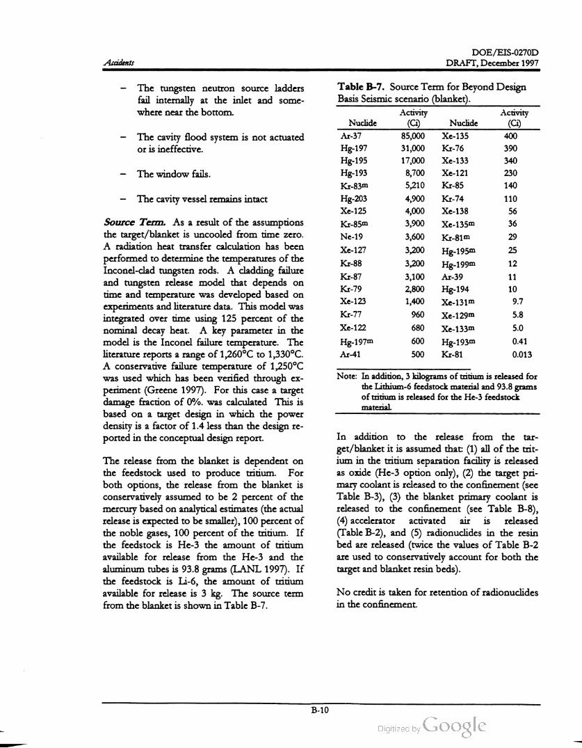
DOE /EIS-0270D
DRAFT,December 1997Accidents
The tungsten neutron source ladders
fail internally at the inlet and some
where near the bottom .
The cavity flood system is not actuated
or is ineffective.
The window fails .
The cavity vessel remains intact
Table B - 7 . Source Term for Beyond Design
Basis Seismic scenario (blanket).
Activity Activity
Nuclide (Ci) Nuclide (Ci)
Ar- 37 85,000 Xe- 135 400
Hg-197 31,000 Kr- 76 390
Hg-195 17,000 Xe-133 340
Hg-193 8,700Xe-121 230
Kr-83m 5,210 Kr- 85 140
Hg-203 4,900 Kr-74 110
Xe- 125 4,000 Xe- 138 56
Kr-85m 3,900 Xe-135m 36
Ne-19 3,600 Kr-81m 29
Xe-1273,200 Hg-1950
K1-883,200 Hg-199m
12
Kr-87 3,100 Ar-39 11
Kr-79 2,800 Hg-19410
Xe-123 1,400 Xe-131m 9.7
Kr-77 960 Xe-129m 5.8
Xe-122 680 Xe-133m 5.0
Hg-197m 600Hg-193m
0.41
Ar-41 500 Kr-81 0.013
Source Term . As a result of the assumptions
the target /blanket is uncooled from time zero.
A radiation heat transfer calculation has been
performed to determine the temperatures of the
Inconel-clad tungsten rods. A cladding failure
and tungsten release model that depends on
time and temperature was developed based on
experiments and literature data. This modelwas
integrated over time using 125 percent of the
nominal decay heat. A key parameter in the
model is the Inconel failure temperature. The
literature reports a range of 1,260 ° C to 1,330 ° C .
A conservative failure temperature of 1,250 ° C
was used which has been verified through ex
periment (Greene 1997). For this case a target
damage fraction of 0 % . was calculated This is
based on a target design in which the power
density is a factor of 1.4 less than the design re
ported in the conceptual design report.
25
Note: In addition , 3 kilogramsof tritium is released for
the Lithium -6 feedstock material and 93.8 grams
of tritium is released for theHe-3 feedstock
material.
The release from the blanket is dependent on
the feedstock used to produce tritium . For
both options, the release from the blanket is
conservatively assumed to be 2 percent of the
mercury based on analytical estimates (the actual
release is expected to besmaller), 100 percent of
the noble gases, 100 percent of the tritium . If
the feedstock is He-3 the amount of tritium
available for release from the He- 3 and the
aluminum tubes is 93.8 grams (LANL 1997). If
the feedstock is Li-6 , the amount of tritium
available for release is 3 kg. The source term
from the blanket is shown in Table B -7 .
In addition to the release from the tar
get /blanket it is assumed that: (1) all of the trit
ium in the tritium separation facility is released
as oxide (He-3 option only), (2) the target pri
mary coolant is released to the confinement (see
Table B-3), (3) the blanket primary coolant is
released to the confinement (see Table B -8 ),
(4 ) accelerator activated air is released
(Table B - 2), and (5) radionuclides in the resin
bed are released (twice the values of Table B -2
are used to conservatively account for both the
target and blanket resin beds).
No credit is taken for retention of radionuclides
in the confinement.
B - 10
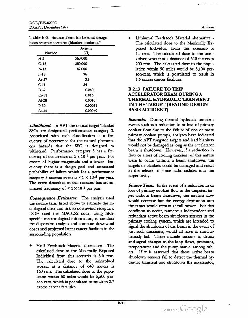
DOE /EIS -0270D
DRAFT, December 1997 Accidents
Table B -8 . Source Term for beyond design
basis seismic scenario (blanket coolant).*
Activity
Nuclide (Ci)
H - 3 360,000
0-15 280,000
N - 13 47,000
F - 18 96
Ar-37 3.9
C -11 24
Be-7 0.040
Cr-51 0.016
Al- 28 0.0010
P - 30 0.00051
Sc-44 0.00049
Lithium -6 Feedstock Material alternative -
The calculated dose to the Maximally Ex
posed Individual from this scenario is
1.7 rem . The calculated dose to the unin
volved worker at a distance of640 meters is
200 rem . The calculated dose to the popu
lation within 50 miles would be 3,100 per
son -rem , which is postulated to result in
1.6 excess cancer fatalities.
B.2.13 FAILURE TO TRIP
ACCELERATOR BEAM DURING A
THERMAL HYDRAULIC TRANSIENT
IN THE TARGET (BEYOND DESIGN
BASIS ACCIDENT)
Likelihood. In APT the critical target/blanket
SSCs are designated performance category 3.
Associated with each classification is a fre
quency of occurrence for the natural phenom
ena hazards that the SSC is designed to
withstand. Performance category 3 has a fre
quency of occurrence of 5 x 10⁻⁴
events of higher magnitude and a lower fre
quency there is a design goal and associated
probability of failure which for a performance
category 3 seismic event is < 1 x 10⁻⁴ per year.
The event described in this scenario has an es
timated frequency of < 1 x 10⁻⁵ per year.
Scenario . During thermal hydraulic transient
events such as a reduction in or loss of primary
coolant flow due to the failure of one ormore
primary coolant pumps, analyses have indicated
that the APT tungsten targets and lead blankets
would notbe damaged as long as the accelerator
beam is shutdown. However, if a reduction in
flow or a loss of cooling transient of this nature
were to occur without a beam shutdown, the
targets or blankets could be damaged and result
in the release of some radionuclides into the
target cavity .
per year. For
Consequence Estimates. The analysis used
the source term listed above to estimate the ra
diological dose and risk to downwind receptors.
DOE used the MACCS2 code, using SRS
specific meteorological information, to conduct
the dispersion analysis and compute downwind
doses and projected latent cancer fatalities in the
surrounding population .
Source Term . In the event of a reduction in or
loss of primary coolant flow in the tungsten tar
get without beam shutdown, the coolant flow
would decrease but the energy deposition into
the target would remain at full power. For this
condition to occur, numerous independent and
redundant active beam shutdown sensors in the
primary cooling system , which are intended to
signal the shutdown of the beam in the event of
just such transients, would all have to simulta
neously fail. These include sensors to detect
and signal changes in the loop flows, pressures,
temperatures and the pump status, among oth
If it is assumed that these active beam
shutdown sensors fail to detect the thermal hy
draulic transient and shutdown the accelerator,
ers .
He- 3 Feedstock Material alternative - The
calculated dose to the Maximally Exposed
Individual from this scenario is 3.0 rem .
The calculated dose to the uninvolved
worker at a distance of 640 meters is
160 rem . The calculated dose to the popu
lation within 50 miles would be 5,500 per
son-rem ,which is postulated to result in 2.7
excess cancer fatalities.
B -11

DOE /EIS-0270D
DRAFT,December 1997Accidents
necessary , the target cavity flood system could
be actuated to maintain the submergence of the
targets and the blankets and to ensure long-term
coolability . However, the cooling loops of the
blanket modules which are undamaged would
continue to operate and remove heat from the
water in the flooded cavity . As a result, the
water in the cavity could remain subcooled even
without actuation of the target cavity flood sys
tem . This would eliminate the need to vent the
target cavity ; therefore , the release of radionu
clides from the cavity into the confinement
would not be expected . Any steam generated
by the decay heat in the targets in the flooded
target cavity could be vented and scrubbed
through the nuclear air filtration system of the
confinement building or the target cavity vac
uum system , or the steam could be condensed
in the spent target pool if such a flow path is
made available. Either method would mitigate
the release of radionuclides from the target cav
ity .
the continued deposition of energyinto the tar
get would cause the critical heat flux to be ex
ceeded in the target rungs, and thetungsten
rod
bundles could soon be voided ofwater. Subse
quently, the tungsten target rods and support
structures would rapidly heat up, resulting in
structural failure of some of the target ladders.
Upon over-temperature failure of some target
ladders, a loss -of- coolant accidentwould occur
in the target primary cooling system (TPCS) in
side the target cavity which would then flood
the target cavity with heavy water from the
TPCS. For the accelerator beam to remain on
at this point, all active beam shutdown sensors
in the cavity which are intended to detect
moisture, high radiation , and pressure inside the
target cavity would have to simultaneously fail.
The pressurizer level sensors would also have to
fail to detect the decreasing water level in the
pressurizer. If all the active beam shutdown
sensors just described failed to shutdown the
accelerator beam , the next line ofdefense would
be the passive vent between the target cavity
atmosphere and the high energy beam transport
(HEBT). As the target cavity was filling with
water from the LOCA in the TPCS, a passive
(always open ) vent line between the target cavity
atmosphere and the HEBT would allow
steam /moisture from the cavity to enter the
HEBT vacuum .Once steam /moisture enters
the HEBT and is detected by the additional ac
tive beam shutdown sensors in theHEBT, fast
acting gate valves would be signaled to close,
thus isolating and protecting the accelerator
from theHEBT and the target cavity. This sig
nal would also shutdown the accelerator. If this
signal fails to shutdown the accelerator,
steam /moisture would race down the accelera
tor at sonic speed , shorting out the RF cavities
and the ion source, finally rendering the accel
erator physically incapable of further operation.
The radionuclides that were released from the
damaged target modules into the target cavity
would remain mostly contained in the target
cavity; only negligible amounts of these radi
onuclides would be transported into the accel
erator components through the HEBT-cavity
vent line. The flooding of the target cavity by
the internal LOCA would submerge the dam
aged targets and the blankets under water. If
Likelihood. The APT design includes redun
dant and diverse means to shutdown the accel
erator beam and the primary cooling loops have
multiple pumps in parallel so that the probabil
ity of such an accident would be extremely
small. An estimate of the frequency ofsuch an
event which could have the potential for an en
vironmental release is much less than 10-6 ,
placing this event into the residual risk range.
Consequence Estimates. This accident could
cause damage to the target, but the release of
radionuclides into the target cavity would be
small, probably limited to a small fraction of the
volatile spallation products in the tungsten and
someof the tritium in the heavy-water coolant.
Off-site consequences would be negligible.
B.2.14 LARGE FIRE IN TRITIUM
SEPARATION FACILITY
Scenario. This postulated event is a large fire
in the Tritium Separation Facility that involved
all the radioactive material (tritium ) in the
building. The fire could start anywhere in the
TSF and the scenario assumes that it would
B -12
DOE /EIS -0270D
DRAFT, December 1997 Accidents
spread to engulf the TSF building. The initiator
could be a small fire that spreads.
would be localized in a small area of the facility
or in an individual component, and would be
extinguished (or would not grow ) before it
could become a larger (room or facility) fire.Source Term . The scenario assumes a release
of all the tritium in the Tritium Separation Fa
cility as tritium oxide. Themaximum inventory
of tritium allowed in the TSF would be 4,690
grams. All oxidized tritium would be immedi
ately released (i.e., a release fraction 1.0) from
the building. Even though the analysis based its
evaluation of the consequences of this unmiti
gated release , the facility would have a number
of detection and mitigative features (oxygen
sensors, tritium cleanup system , nitrogen at
mosphere in the glove boxes, secondary con
finement structuresstructures (double wall piping),
radiation monitoring; fire suppression system
that would significantly reduce the probability
and consequencesof a release, etc.).
Source Term . The design requirements of the
Tritium Separation Facility would limit the
maximum inventory of tritium that could be
released and oxidized to 469 grams. This value
corresponds to the inventory of a single proc
essing system or component (single-point re
lease) and the scenario assumes that the fire
would not progress to other components or
systems. All the oxidized tritium would be im
mediately released (release fraction of 1.0) from
the building. Even though the analysis based its
evaluation of the consequences on this unmiti
gated release, the facility would have a number
of detection and mitigative features (oxygen
sensors, tritium cleanup system , nitrogen at
mosphere in the glove boxes, secondary con
finement structures (double wall piping),
radiation monitoring; fire suppression system
that would significantly reduce the probability
and consequencesof a release, etc.).
Likelihood. The estimated frequency of an
unmitigated, large fire-induced tritium release
would be 0.0001 per year .
Consequence Estimates. The analysis used
the 4,690 -gram source term to estimate the ra
diological dose and risk to downwind receptors.
DOE used the MACCS2 code, with SRS
specific meteorological information, to conduct
the dispersion analysis and compute projected
downwind doses and latent cancer fatalities to
the surrounding population .
Likelihood. The estimated frequency of an
unmitigated, small fire -induced tritium release
would be 0.01 per year.
The calculated dose to the Maximally Exposed
Individual from this scenario is 1.9 rem . The
calculated dose to the uninvolved worker at a
distance of 640 meters is 8.1 rem . The calcu
lated dose to the population within 50 miles
would be 3,500 person-rem , which is postulated
to result in 1.7 excess cancer fatalities.
Consequence/ Risk Estimates. The analysis
used the 469-gram source term to estimate the
radiological dose and risk to downwind recep
tors. DOE used the MACCS2 code, with SRS
specific meteorological information, to conduct
the dispersion analysis and compute downwind
dose and projected latent cancer fatalities to the
surrounding population .
B.2.15 SMALL FIRE IN TRITIUM
SEPARATION FACILITY
The calculated dose to the Maximally Exposed
Individual from this scenario is 0.21 rem . The
calculated dose to the uninvolved worker at a
distance of 640 meters is 7.0 rem . The calcu
lated dose to the population within 50 miles
would be 360 person -rem , which is postulated
to result in 0.18 excess cancer fatalities.
Scenario. This postulated event is a small fire
in the Tritium Separation Facility . This fire
B -13

DOE /EIS -0270D
DRAFT, December 1997Accidents
References
Chanin,D.and Young, M., 1997, CodeManual forMACCS2: Volume 1, User's Guide,SAND97-0594,
March .
DOE (U.S. Department of Energy), 1994, “ Preparation Guide for U.S. Department of Energy
NonReactor Nuclear Facility Safety Analysis Reports,” DOE-STD -3009-94, July .
DOE (U.S. Department of Energy), 1996, “Natural PhenomenaHazardsDesign and Evaluation Criteria
for Department of Energy Facilities,” DOE-STD - 1020-94, January.
EPA (U.S. Environmental Protection Agency) and NOAA (National Oceanic and Atmospheric
Administration), 1992, ALOHA (Areal Location of Hazardous Atmospheres) Users Manual, Washington,
D.C., October.
Greene, G. A., 1997, “ Oxidation of Inconel 718 in Air at High Temperatures,” BNL FormalReport (In
Preparation ).
LANL (Los Alamos National Laboratory ), 1989, User Guide to LCS: The LAHET Code System ,
LA -UR-89-3014, September.
LANL (Los Alamos National Laboratory), 1993, Accelerator Transmutation Studies atLos Alamos with
LANET,MCNP,and CINDER-90, LA -UR-93-3080, January.
LANL (Los Alamos National Laboratory), 1997, Conceptual Design Report, LA -UR -97-1329 ,
U.S. DepartmentofEnergy, Los Alamos,New Mexico, April.
Liscom -Powell, J., 1997, APT EIS Accident Consequences Calculations, SNL-9364-JLPS1997-02,
October.
B - 14

Appendix C
List of Plants and Animals Mentioned in the APT EIS


-
APPENDIX C
LISTOF PLANTS AND ANIMALS
MENTIONED IN THE APT EIS


DOE /EIS -0270D
DRAFT, December 1997 List of Plants and Animals Mentioned in the APT EIS
APPENDIX C. LIST OF PLANTS AND ANIMALS
MENTIONED IN THE APT EIS
GroupCommon name Scientific name
PlantsAlligator-weed
American elm
Alternanthera philoxeroides
Ulmus americana
Sagittaria spp.
Taxodium distichum
Arrowhead
Bald cypress
Black cherry
Black gum
Prunus serotina
Nyssa sylvatica
Black willow
Blackberry
Blueberry
Box elder
Broom sedge
Bulush
Salix nigra
Rubus spp.
Vaccinium spp .
Acer negundo
Andropogonvirginicus
Scirpus SPP
Typha spp.
Eupatoriumcapillifolium
Cornus spp
Smilax spp
Carya spp.
Ilex opaca
Cat-tail
Dog-fennel
Dogwood
Greenbrier
Hickory
Holly
Japanese honeysuckle
Lespedeza
Loblolly pine
Muscadine grape
Persimmon
Red maple
Red oak
Lonicera japonica
Lespedeza spp.
Pinus taeda
Vitis rotundifolia
Diospyros virginiana
Acer rubrum
Quercus rubra
Quercus laurifolia
Sassafras albidum
Pinus elliotti
Echinacea laevigata
Vaccinium arboreum
Laurel oak
Sassafras
Slash pine
Smooth coneflower
Eleocharis spp .
Sparkleberry
Spike- rush
Sweet-gum
Water shield
Water tupelo
White oak
Winged sumac
Liquidambar styraciflua
Brasenia schreberi
Nyssa aquatica
Quercus alba
Rhus copallina
C - 1

DOE /EIS -0270D
DRAFT,December 1997List of Plants and Animals Mentioned in the APT EIS
GroupCommon name Scientific name
Gaultheria procumbens
Gelsemium spp .
Benthic macroinvertebratesAmphipoda
Wintergreen
Yellow jessamine
Amphipods (scuds, sideswimmers)
Aquatic Insects
“ True” bugs (hemipterans)
“ True flies” and midges
(dipterans)
Backswimmers (corixids)
Beetles
Hemiptera
Diptera
Corixidae
Coleoptera
SimuliidaeBlackflies
Trichoptera
Odonata
Ephemeroptera
Chironomidae
Dolania americana
Caddisflies (trichopterans)
Dragonflies (odonates)
Mayflies (ephemeropterans)
Midges (chironomids)
Sandburrowing mayfly
Springtails
Stoneflies (plecopterans)
Clamsand mussels
Decapods (crayfishes, shrimps)
Flatworms
Collembola
Plecoptera
Pelecypoda
Decapoda
Turbellaria
Leeches Hirudinea
Nematoda
Fish
Nematodes (roundworms)
Oligochaetes (aquatic earthworms)
Snails and limpets (gastropods)
American shad
Atlantic sturgeon
Black crappie
Blueback herring
Bluegill
Bluehead chub
Bluespotted sunfish
Brook silverside
Oligochaeta
Gastropoda
Alosa sapidissima
Acipenser oxyrhynchus
Pomoxis nigromaculatus
Alosa aestivalis
Lepomis macrochirus
Nocomis leptocephalus
Enneacanthus gloriosus
Labidesthes sicculus
Brown bullhead Ameiurus nebulosus
Channel catfish
Coastal shiner
Creek chubsucker
Ictalurus punctatus
Notropis petersoni
Erimyzon oblongus
Dorosoma cepedianum
Notemigonus crysoleucas
Erimyzon sucetta
Gizzard shad
Golden shiner
Lake chubsucker
C - 2

DOE /EIS -0270D
DRAFT, December 1997List of Plants and AnimalsMentioned in the APT EIS
Group Common name
Largemouth bass
Minnows
Mosquitofish
Mud sunfish
Pirate perch
Redbreast sunfish
Redear sunfish
Shortnose sturgeon
Spotted sucker
Spotted sunfish
Striped bass
Threadfin shad
Warmouth
Yellow perch
Yellowfin Shiner
American alligator
Black racer
Scientific name
Micropterus salmoides
Notropis spp.
Gambusia bolbrooli
Acantharcbus pomotis
Aphrododerus sayanus
Lepomis auritus
Lepomis microlophus
Acipenser brevirostrum
Minytremamelanops
Lepomis punctatus
Morone saxatilis
Dorosoma petenense
Lepomis gulosus
Perca flavescens
Notropis lutipinnis
Alligator mississippiensis
Coluber constrictor
Sceloporusundulatus
Bufo terrestris
Otus asio
Colaptes auratus
Mimus polyglottos
Corvus brachyrhynchos
Haliaeetus leucocephalus
Thryothorus ludovicianus
Colinus virginianus
Sialia sialis
Zenaida macroura
Dendroica pinus
Dendroica discolor
Reptiles and amphibians
Eastern fence lizard
Birds
Southern toad
(Common) screech owl
(Common) yellow -shafted flicker
(Northern ) mockingbird
American ( common ) crow
Bald eagle
Carolina wren
Common (northern ) bobwhite
Eastern bluebird
Mourning dove
Pine warbler
Prairie warbler
Red-bellied woodpecker
Red-cockaded woodpecker
Melanerpes carolinus
Picoides borealis
Red -eyed vireo Vireo olivaceus
Red -tailed hawk
Rufous- sided towhee
Sharp -shinned hawk
Wood stork
Buteo jamaicensis
Pipilo erythrophthalmus
Accipiter striatus
Mycteria americana
Hylocichla mustelina
Castor canadensis
Wood thrush
Mammals Beaver
C -3

DOE /EIS -0270D
List of Plants and Animals Mentioned in the APT EIS DRAFT, December 1997
GroupCommon name
Eastern cottontail
Feral hog
Fox squirrel
Gray fox
Gray squirrel
Marsh rabbit
Mink
Scientific name
Sylvilagus floridanus
Sus scrofa
Sciurus niger
Urocyon cinereoargenteus
Sciurus carolinensis
Sylvilagus palustris
Mustela vison
Ondatra zibethicus
Lutra canadensis
Procyon lotor
Vulpes vulpes
Oryzomys palustris
Condylura cristata
Didelphis virginiana
O docoileus virginianus
Muskrat
Otter
Raccoon
Red fox
Rice rat
Star-nosed mole
(Virginia) opossum
White -tailed deer
C - 4


