Embed Size (px)
Citation preview
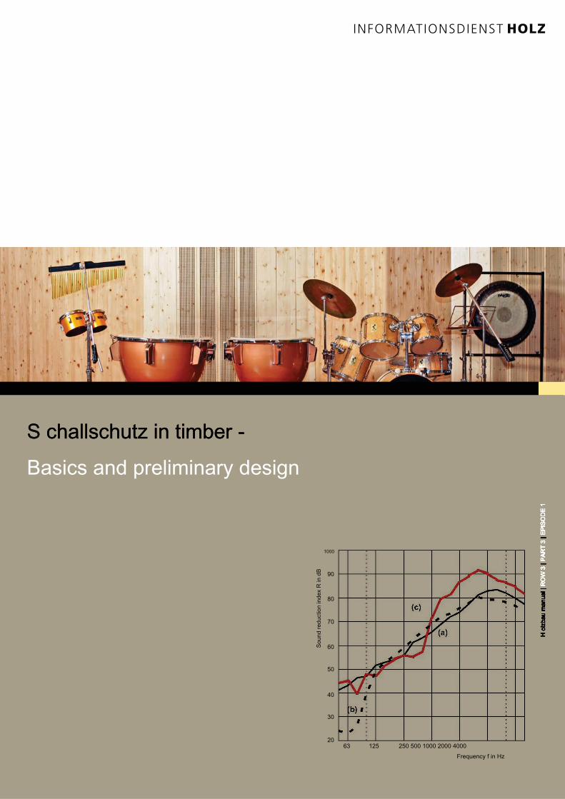
S challschutz in timber - S challschutz in timber -
Basics and preliminary design
Frequency f in Hz
63 125 250 500 1000 2000 4000
1000
90
80
70
60
50
40
30
20
H o
lzb
au
m
an
ua
l | R
OW
3
| P
AR
T 3
| E
PIS
OD
E 1
H o
lzb
au
m
an
ua
l | R
OW
3
| P
AR
T 3
| E
PIS
OD
E 1
H o
lzb
au
m
an
ua
l | R
OW
3
| P
AR
T 3
| E
PIS
OD
E 1
H o
lzb
au
m
an
ua
l | R
OW
3
| P
AR
T 3
| E
PIS
OD
E 1
H o
lzb
au
m
an
ua
l | R
OW
3
| P
AR
T 3
| E
PIS
OD
E 1
H o
lzb
au
m
an
ua
l | R
OW
3
| P
AR
T 3
| E
PIS
OD
E 1
H o
lzb
au
m
an
ua
l | R
OW
3
| P
AR
T 3
| E
PIS
OD
E 1
Sound reduction index R
in dB
NOISE CONTROL IN HOLZBAU | CONTENTNOISE CONTROL IN HOLZBAU | CONTENT
holzbau manual | ROW 3 | PART 3 | EPISODE 1holzbau manual | ROW 3 | PART 3 | EPISODE 1holzbau manual | ROW 3 | PART 3 | EPISODE 1holzbau manual | ROW 3 | PART 3 | EPISODE 1holzbau manual | ROW 3 | PART 3 | EPISODE 1holzbau manual | ROW 3 | PART 3 | EPISODE 1holzbau manual | ROW 3 | PART 3 | EPISODE 1
2
page 4 _ Imprint
5 15 1 _ Preliminary note_ Preliminary note
6 26 2 _ Basics_ Basics
6 2.16 2.1 _ The detection of sound insulation -
Procedure
8th 2.28th 2.2 _ Minimum requirements for sound
insulation
10 2.310 2.3 _ Considering low frequencies
13 2.413 2.4 _ Targets in timber
16 2.516 2.5 _ Technical basics of building acoustics
16 2.5.1 _ Mass law 18 2.5.2 _ Coincidence frequency 20 2.5.3 _ 16 2.5.1 _ Mass law 18 2.5.2 _ Coincidence frequency 20 2.5.3 _ 16 2.5.1 _ Mass law 18 2.5.2 _ Coincidence frequency 20 2.5.3 _ 16 2.5.1 _ Mass law 18 2.5.2 _ Coincidence frequency 20 2.5.3 _ 16 2.5.1 _ Mass law 18 2.5.2 _ Coincidence frequency 20 2.5.3 _ 16 2.5.1 _ Mass law 18 2.5.2 _ Coincidence frequency 20 2.5.3 _ 16 2.5.1 _ Mass law 18 2.5.2 _ Coincidence frequency 20 2.5.3 _
Plates eigenfrequency 22 2.5.4 _ Mass-spring-mass resonance Plates eigenfrequency 22 2.5.4 _ Mass-spring-mass resonance Plates eigenfrequency 22 2.5.4 _ Mass-spring-mass resonance
23 2.5.5 _ Decoupling 23 2.5.6 _ Damping / sound absorption23 2.5.5 _ Decoupling 23 2.5.6 _ Damping / sound absorption23 2.5.5 _ Decoupling 23 2.5.6 _ Damping / sound absorption23 2.5.5 _ Decoupling 23 2.5.6 _ Damping / sound absorption23 2.5.5 _ Decoupling 23 2.5.6 _ Damping / sound absorption
25 325 3 _ Design effects on soundproofing
25 3.125 3.1 _ Walls
25 3.1.1 _ Wall structures 25 3.1.1.1 _ Wood panel construction 29 3.1.1.2 _ 25 3.1.1 _ Wall structures 25 3.1.1.1 _ Wood panel construction 29 3.1.1.2 _ 25 3.1.1 _ Wall structures 25 3.1.1.1 _ Wood panel construction 29 3.1.1.2 _ 25 3.1.1 _ Wall structures 25 3.1.1.1 _ Wood panel construction 29 3.1.1.2 _ 25 3.1.1 _ Wall structures 25 3.1.1.1 _ Wood panel construction 29 3.1.1.2 _ 25 3.1.1 _ Wall structures 25 3.1.1.1 _ Wood panel construction 29 3.1.1.2 _ 25 3.1.1 _ Wall structures 25 3.1.1.1 _ Wood panel construction 29 3.1.1.2 _
Solid wood constructions 31 3.1.2 _ Outer walls 32 3.1.3 _ Building partition Solid wood constructions 31 3.1.2 _ Outer walls 32 3.1.3 _ Building partition Solid wood constructions 31 3.1.2 _ Outer walls 32 3.1.3 _ Building partition Solid wood constructions 31 3.1.2 _ Outer walls 32 3.1.3 _ Building partition Solid wood constructions 31 3.1.2 _ Outer walls 32 3.1.3 _ Building partition
walls 33 3.1.4 _ Constructive optimization of the walls 33 3.1.4.1 _ Application walls 33 3.1.4 _ Constructive optimization of the walls 33 3.1.4.1 _ Application walls 33 3.1.4 _ Constructive optimization of the walls 33 3.1.4.1 _ Application walls 33 3.1.4 _ Constructive optimization of the walls 33 3.1.4.1 _ Application walls 33 3.1.4 _ Constructive optimization of the walls 33 3.1.4.1 _ Application
for exterior walls 34 3.1.4.2 _ Application for building partition walls 35 3.2for exterior walls 34 3.1.4.2 _ Application for building partition walls 35 3.2for exterior walls 34 3.1.4.2 _ Application for building partition walls 35 3.2for exterior walls 34 3.1.4.2 _ Application for building partition walls 35 3.2
_ ceiling
36 3.2.1 _ Ceiling structures 36 3.2.2 _ Screed assemblies 38 3.2.3 _ 36 3.2.1 _ Ceiling structures 36 3.2.2 _ Screed assemblies 38 3.2.3 _ 36 3.2.1 _ Ceiling structures 36 3.2.2 _ Screed assemblies 38 3.2.3 _ 36 3.2.1 _ Ceiling structures 36 3.2.2 _ Screed assemblies 38 3.2.3 _ 36 3.2.1 _ Ceiling structures 36 3.2.2 _ Screed assemblies 38 3.2.3 _ 36 3.2.1 _ Ceiling structures 36 3.2.2 _ Screed assemblies 38 3.2.3 _ 36 3.2.1 _ Ceiling structures 36 3.2.2 _ Screed assemblies 38 3.2.3 _
Rohdeckenbeschwerungen 39 3.2.4 _ Vibration absorber 39 3.2.5 _ Rohdeckenbeschwerungen 39 3.2.4 _ Vibration absorber 39 3.2.5 _ Rohdeckenbeschwerungen 39 3.2.4 _ Vibration absorber 39 3.2.5 _ Rohdeckenbeschwerungen 39 3.2.4 _ Vibration absorber 39 3.2.5 _ Rohdeckenbeschwerungen 39 3.2.4 _ Vibration absorber 39 3.2.5 _
Supporting structure and insulation in
Bar space
40 3.2.6 _ Ceilings 41 3.2.7 _ Gehbeläge 42 3.2.8 _ Constructive optimization of 40 3.2.6 _ Ceilings 41 3.2.7 _ Gehbeläge 42 3.2.8 _ Constructive optimization of 40 3.2.6 _ Ceilings 41 3.2.7 _ Gehbeläge 42 3.2.8 _ Constructive optimization of 40 3.2.6 _ Ceilings 41 3.2.7 _ Gehbeläge 42 3.2.8 _ Constructive optimization of 40 3.2.6 _ Ceilings 41 3.2.7 _ Gehbeläge 42 3.2.8 _ Constructive optimization of 40 3.2.6 _ Ceilings 41 3.2.7 _ Gehbeläge 42 3.2.8 _ Constructive optimization of 40 3.2.6 _ Ceilings 41 3.2.7 _ Gehbeläge 42 3.2.8 _ Constructive optimization of
the ceiling 42 3.2.8.1 _ Influence of concrete structures 43 3.2.8.2 _ Influence the ceiling 42 3.2.8.1 _ Influence of concrete structures 43 3.2.8.2 _ Influence the ceiling 42 3.2.8.1 _ Influence of concrete structures 43 3.2.8.2 _ Influence the ceiling 42 3.2.8.1 _ Influence of concrete structures 43 3.2.8.2 _ Influence the ceiling 42 3.2.8.1 _ Influence of concrete structures 43 3.2.8.2 _ Influence
through Rohdeckenbeschwerung 44 3.2.8.3 _ Examples of wooden ceilings through Rohdeckenbeschwerung 44 3.2.8.3 _ Examples of wooden ceilings through Rohdeckenbeschwerung 44 3.2.8.3 _ Examples of wooden ceilings
with
improved low frequency sound
45 3.345 3.3 _ Steilddächer
45 3.3.1 _ Roof structures 46 3.3.1.1 _ Pitched roofs 45 3.3.1 _ Roof structures 46 3.3.1.1 _ Pitched roofs 45 3.3.1 _ Roof structures 46 3.3.1.1 _ Pitched roofs 45 3.3.1 _ Roof structures 46 3.3.1.1 _ Pitched roofs 45 3.3.1 _ Roof structures 46 3.3.1.1 _ Pitched roofs
with
Insulation between the rafters
47 3.3.1.2 _ Pitched roofs with 47 3.3.1.2 _ Pitched roofs with 47 3.3.1.2 _ Pitched roofs with
rafter
48 3.3.2 _ Impact of construction on the 48 3.3.2 _ Impact of construction on the 48 3.3.2 _ Impact of construction on the
Transmission sound insulation of pitched
roofs
50 3.3.3 _ Sound insulation of pitched roofs 50 3.3.3 _ Sound insulation of pitched roofs 50 3.3.3 _ Sound insulation of pitched roofs
at low frequencies
52 3.452 3.4 _ Flat roofs
52 3.4.1 _ Roof structures 52 3.4.2 _ Under ceiling and space 52 3.4.1 _ Roof structures 52 3.4.2 _ Under ceiling and space 52 3.4.1 _ Roof structures 52 3.4.2 _ Under ceiling and space 52 3.4.1 _ Roof structures 52 3.4.2 _ Under ceiling and space 52 3.4.1 _ Roof structures 52 3.4.2 _ Under ceiling and space
side
clothing
53 3.4.3 _ Insulation 53 3.4.4 _ Waterproofing, roofing and 53 3.4.3 _ Insulation 53 3.4.4 _ Waterproofing, roofing and 53 3.4.3 _ Insulation 53 3.4.4 _ Waterproofing, roofing and 53 3.4.3 _ Insulation 53 3.4.4 _ Waterproofing, roofing and 53 3.4.3 _ Insulation 53 3.4.4 _ Waterproofing, roofing and
a floor covering
content
page
3NOISE CONTROL IN HOLZBAU | CONTENTNOISE CONTROL IN HOLZBAU | CONTENT
holzbau manual | ROW 3 | PART 3 | EPISODE 1holzbau manual | ROW 3 | PART 3 | EPISODE 1holzbau manual | ROW 3 | PART 3 | EPISODE 1holzbau manual | ROW 3 | PART 3 | EPISODE 1holzbau manual | ROW 3 | PART 3 | EPISODE 1holzbau manual | ROW 3 | PART 3 | EPISODE 1holzbau manual | ROW 3 | PART 3 | EPISODE 1
120 5120 5 _ Notes for supervision
120 5.1120 5.1 _ Sound bridges in the floor
122 5.2122 5.2 _ Introduction of the wrong
Rohdeckenbeschwerung
123 5.3123 5.3 _ Open joints between roof and partition
125 5.4125 5.4 _ High pressure at roof insulation made of
pressure-resistant fiber insulation boards
125 5.5125 5.5 _ Fitted kitchens and furniture
126 6126 6 _ Component Catalog
126 6.1126 6.1 _ Component Catalog ceiling
146 6.1.1 _ Source Directory 146 6.1.1 _ Source Directory 146 6.1.1 _ Source Directory
Component Catalog ceiling
147 6.2147 6.2 _ Component Catalog flat roofs and roof
terraces
154 6.2.1 _ Source Directory Component Catalog 154 6.2.1 _ Source Directory Component Catalog 154 6.2.1 _ Source Directory Component Catalog
Flat roofs and roof terraces
155 6.3155 6.3 _ Component Catalog walls
177 6.3.1 _ Source Directory 177 6.3.1 _ Source Directory 177 6.3.1 _ Source Directory
Component Catalog walls
178 7178 7 _ Appendix A
Verbal description and calculations,
acoustic performance measures
178 A1
Verbal description of the airborne
sound insulation
182 A2
Derivation of requirements to the impact
sound
186 8th186 8th _ Bibliography
55 455 4 _ Building acoustics preliminary design of _ Building acoustics preliminary design of
timber structures
59 4.159 4.1 _ Partition ceilings
59 4.1.1 _ Vorbemessungsbeispiel for 59 4.1.1 _ Vorbemessungsbeispiel for 59 4.1.1 _ Vorbemessungsbeispiel for
Beamed ceilings
64 4.1.2 _ Vorbemessungsbeispiel for 64 4.1.2 _ Vorbemessungsbeispiel for 64 4.1.2 _ Vorbemessungsbeispiel for
Solid wood ceiling
66 4.1.3 _ Design effects on the 66 4.1.3 _ Design effects on the 66 4.1.3 _ Design effects on the
flanking transmission
69 4.269 4.2 _ Partition walls in multi-storey buildings
69 4.2.1 _ Vorbemessungsbeispiel for partition walls 78 4.2.2 _ Flanking 69 4.2.1 _ Vorbemessungsbeispiel for partition walls 78 4.2.2 _ Flanking 69 4.2.1 _ Vorbemessungsbeispiel for partition walls 78 4.2.2 _ Flanking 69 4.2.1 _ Vorbemessungsbeispiel for partition walls 78 4.2.2 _ Flanking 69 4.2.1 _ Vorbemessungsbeispiel for partition walls 78 4.2.2 _ Flanking
transmission of
Holztafelbauwänden and beamed
ceilings
82 4.2.3 _ Flanking transmission of 82 4.2.3 _ Flanking transmission of 82 4.2.3 _ Flanking transmission of
Solid wood elements
85 4.385 4.3 _ Partitions for detached and terraced
houses
86 4.3.1 _ Vorbemessungsbeispiel for Double 86 4.3.1 _ Vorbemessungsbeispiel for Double 86 4.3.1 _ Vorbemessungsbeispiel for Double
and detached partitions
89 4.3.2 _ Design effects on the 89 4.3.2 _ Design effects on the 89 4.3.2 _ Design effects on the
flanking transmission
92 4.3.3 _ Stairs in double and row houses 97 4.492 4.3.3 _ Stairs in double and row houses 97 4.492 4.3.3 _ Stairs in double and row houses 97 4.492 4.3.3 _ Stairs in double and row houses 97 4.4
_ Stairs in multi-story buildings
98 4.598 4.5 _ Apartment doors
100 4.6100 4.6 _ Walkways and roof terraces
101 4.7101 4.7 _ balconies
103 4.8103 4.8 _ House technology and sanitary articles
104 4.8.1 _ Supply and disposal lines 104 4.8.1 _ Supply and disposal lines 104 4.8.1 _ Supply and disposal lines
inside the building
106 4.8.2 _ Air conditioning systems 106 4.8.3 _ Chimneys and 106 4.8.2 _ Air conditioning systems 106 4.8.3 _ Chimneys and 106 4.8.2 _ Air conditioning systems 106 4.8.3 _ Chimneys and 106 4.8.2 _ Air conditioning systems 106 4.8.3 _ Chimneys and 106 4.8.2 _ Air conditioning systems 106 4.8.3 _ Chimneys and
wells
through living rooms
106 4.8.4 _ Elevators 110 4.9106 4.8.4 _ Elevators 110 4.9106 4.8.4 _ Elevators 110 4.9106 4.8.4 _ Elevators 110 4.9
_ External components
111 4.9.1 _ Components and fittings 112 4.9.2 _ Special 111 4.9.1 _ Components and fittings 112 4.9.2 _ Special 111 4.9.1 _ Components and fittings 112 4.9.2 _ Special 111 4.9.1 _ Components and fittings 112 4.9.2 _ Special 111 4.9.1 _ Components and fittings 112 4.9.2 _ Special
noise sources
(Heat pumps and air conditioners)
114 4.9.3 _ Preliminary design for external noise 116 4.9.4 _ 114 4.9.3 _ Preliminary design for external noise 116 4.9.4 _ 114 4.9.3 _ Preliminary design for external noise 116 4.9.4 _ 114 4.9.3 _ Preliminary design for external noise 116 4.9.4 _ 114 4.9.3 _ Preliminary design for external noise 116 4.9.4 _
Vorbemessungsbeispiel page
page

NOISE CONTROL IN HOLZBAU | IMPRINTNOISE CONTROL IN HOLZBAU | IMPRINT
holzbau manual | ROW 3 | PART 3 | EPISODE 1holzbau manual | ROW 3 | PART 3 | EPISODE 1holzbau manual | ROW 3 | PART 3 | EPISODE 1holzbau manual | ROW 3 | PART 3 | EPISODE 1holzbau manual | ROW 3 | PART 3 | EPISODE 1holzbau manual | ROW 3 | PART 3 | EPISODE 1holzbau manual | ROW 3 | PART 3 | EPISODE 1
4
Editor:
Germany Timber-Institut eV Kronenstraße 55-58
D-10117 Berlin Tel. +49 (0) 30 20314 533 Fax +49
(0) 30 20314 566 www.institut-holzbau.de
Financing project partners
Federal Association of German Prefabricated eV, Bad Honnef
German wooden prefabricated Association, Ostfildern
Timber Germany -
Association of German master carpenter in the ZDB, Berlin
and regional associations study Holzleimbau eV, Wuppertal
Funded by:
German Federal Environmental Foundation eV
1st edition 2019
Published: 03/2019 ISSN no.
0466-2114 holzbau manual
Row 3: Building physics Row 3: Building physics
Part 3: soundproofing Part 3: soundproofing
Episode 1: Sound insulation in wood construction - Fundamentals and Episode 1: Sound insulation in wood construction - Fundamentals and
preliminary design The word mark INFORMATIONSDIENST WOOD is
property of Informationsverein wood eV www.informationsvereinholz.de
authors:
Dipl.-Wirtschaftsing. (FH) Adrian Blödt M.Sc., engineers Blödt & Blödt
Holzkomplettbau GmbH, Kohlberg Prof. Dr.-Ing. Andreas Rabold,
Rosenheim RA Michael Halstenberg, Berlin
Component catalog:
Thomas Ecker, Anton Huber, Luke Huissel, Sebastian Löffler,
Michael Scheuer plow, Technical University of Rosenheim
Editorial team:
Dipl.-Ing. Arch. Arnim Seidel, Informationsverein wood eV,
Dusseldorf
M.Eng. Florian Schmidt-Hieber, Dipl.-Ing. (FH) John
Niedermeyer, timber Germany Institut eV, Berlin
Accompanying Working Group:
Dipl.-Ing. (FH) Stefan Bacher, ift Rosenheim GmbH Dipl.-Ing. (FH) Jörg Hiller,
Bauer timber, semi Village Groningen Dipl.-Ing. (FH) Martin Müller, Federal
Association of German Prefabricated eV, Bad Honnef Dipl.-Ing. (FH) Wolfgang
Schäfer,
B.Eng. (FH) Micha Trefz, German wooden prefabricated Association, Prof.
Dr. Ostfildern Ulrich Schanda, Technical University of Rosenheim Dipl. (FH)
Tim Sleik, Binderholz Bausysteme A-Hallein Dr.-Ing. Tobias Wiegand, study
Holzleimbau eV, Wuppertal
Component tests:
ift Rosenheim GmbH
Drawings:
B.Eng. Max Köhnken, timber Germany eV
Layout:
Beautiful views, Dusseldorf Oliver Iserloh,
Volker United
D ie technical information in this publication reflect the time of printing the D ie technical information in this publication reflect the time of printing the
recognized rules of technology. A liability for the content can not be accepted
despite careful processing and correction. Information on changes, additions
and errata at: [email protected]
imprint
5NOISE CONTROL IN HOLZBAU | PRELIMINARY NOTENOISE CONTROL IN HOLZBAU | PRELIMINARY NOTE
holzbau manual | ROW 3 | PART 3 | EPISODE 1holzbau manual | ROW 3 | PART 3 | EPISODE 1holzbau manual | ROW 3 | PART 3 | EPISODE 1holzbau manual | ROW 3 | PART 3 | EPISODE 1holzbau manual | ROW 3 | PART 3 | EPISODE 1holzbau manual | ROW 3 | PART 3 | EPISODE 1holzbau manual | ROW 3 | PART 3 | EPISODE 1
Furthermore, for the first time its own sound insulation class system
in timber for contractual agreement with builders was created that
contains the recommended target levels for increased comfort and
soundproofing. For this purpose, were taken into account, inter alia,
the low frequencies while airborne and impact sound of Intermediate
floor and detached partitions on spectrum adaptation terms. A
system innovation that makes the timber with clients and builders
still trustworthy and highlighting it under the construction.
With the present document "Sound insulation in timber:
fundamentals and preliminary design" a current contribution to the
better handling of sound insulation in the planning and execution of
wooden buildings was made. They will be further developed at
regular intervals. Suggestions and ideas on this can wood be
submitted to the consultation timber of the information service.
V or 4109 "Sound insulation in buildings" with its established V or 4109 "Sound insulation in buildings" with its established
minimum requirements, the new forecasting method and the key for
the timber member 33 "data for the mathematical proof of sound
insulation (component catalog) - wood, easily and drywall" the light
of the continually evolving DIN saw to develop a supplementary
guide to the practice in timber construction: the editors and authors
it at the time, with the information service timber magazine "basis
and preliminary design sound insulation in timber".
The present work was created based on years of experience from
practice and results from science. It was made possible through the
collaboration of all major timber associations and by promoting
German Environmental Foundation. The writing is the foundation of
a series of sound insulation in wood construction. Other writings for
verification of components in timber and sound insulation
refurbishment to follow.
The reader or user is using this document, in addition to the sound
insulation foundations, the concrete description of the constructive
influences Advice for the installation, orientating
Vorbemessungstabellen and a detailed component catalog, which
considers own component testing also results from the
accompanying research projects on flat roofs and insulation material
from renewable raw materials, offered.
1 _ Preliminary note1 _ Preliminary note
NOISE CONTROL IN HOLZBAU | G BASES AND PRELIMINARY NOISE CONTROL IN HOLZBAU | G BASES AND PRELIMINARY NOISE CONTROL IN HOLZBAU | G BASES AND PRELIMINARY
H olzbau manual | R eIHE 3 | T PART 3 | F OLGE 1H olzbau manual | R eIHE 3 | T PART 3 | F OLGE 1H olzbau manual | R eIHE 3 | T PART 3 | F OLGE 1H olzbau manual | R eIHE 3 | T PART 3 | F OLGE 1H olzbau manual | R eIHE 3 | T PART 3 | F OLGE 1H olzbau manual | R eIHE 3 | T PART 3 | F OLGE 1H olzbau manual | R eIHE 3 | T PART 3 | F OLGE 1H olzbau manual | R eIHE 3 | T PART 3 | F OLGE 1H olzbau manual | R eIHE 3 | T PART 3 | F OLGE 1H olzbau manual | R eIHE 3 | T PART 3 | F OLGE 1H olzbau manual | R eIHE 3 | T PART 3 | F OLGE 1
6
2.1 _ detection of sound insulation - Procedure
Sound insulation building regulation minimum requirements are set
as to all other structural areas. DIN 4109-1: 2018-01 "Sound
insulation in buildings - Part 1: Minimum requirements" [1] defines
the minimum standards for different building uses. By this standard,
the long time applicable standard DIN 4109: replaced 1989-11,
which also has implications in terms of future contractual terms, as
the new norm is state of the art, while the former noise standard was
considered obsolete. Basically, it is now necessary to clarify whether
building regulation minimum standards can be agreed as a civil
legally binding minimum. In any construction project is to be
checked, which contractual arrangements can be made specifically
regarding sound insulation or must be taken. In the basement
housing the bandwidth of users is naturally very large. A uniform
sound level of protection for all buildings would therefore not make
sense. For a luxury apartment in a prime location of the minimum
sound insulation is not the measure of things, here buyers can
expect more. but the buyer or user request is not sufficiently
explored regarding sound insulation very often. In many construction
and purchase contracts are then to find clauses such as "sound
insulation according to DIN 4109". This minimum sound insulation to
protect the residents and to maintain a certain minimum
confidentiality must always be maintained anyway. but there may be,
depending on the users claim more extensive requirements.
expect. In this context, the term "Art Generally accepted rules" falls
again and again the. These are rules that are scientifically proven
to have been proven in practice and be on the long-term
experience. Thus, minimum values are not necessarily equate with
generally accepted engineering standards.
For sound insulation in multi-storey buildings it had been proven in
the past to go at least in some areas beyond the minimum
requirements of DIN 4109-1 [1] also, as this has been carried out in
a variety of buildings and usually also the expectations of users and
buyers corresponded. Crucial was there also that necessarily the
planned construction was not decisive, but the same by all the
buildings type reached levels that thus defines the state of the
generally accepted rules of technology. To the sound protection to
agree legally binding with a client in the usual multi-storey buildings,
we recommend the following procedure:
Is in this document by soundproofing
the speech, the sound insulating effect
of individual parts and components to
the installation, however, meant no
room acoustic influences.
2 _ Basics2 _ Basics

7NOISE CONTROL IN HOLZBAU | G BASES AND PRELIMINARY NOISE CONTROL IN HOLZBAU | G BASES AND PRELIMINARY NOISE CONTROL IN HOLZBAU | G BASES AND PRELIMINARY
H olzbau manual | R eIHE 3 | T PART 3 | F OLGE 1H olzbau manual | R eIHE 3 | T PART 3 | F OLGE 1H olzbau manual | R eIHE 3 | T PART 3 | F OLGE 1H olzbau manual | R eIHE 3 | T PART 3 | F OLGE 1H olzbau manual | R eIHE 3 | T PART 3 | F OLGE 1H olzbau manual | R eIHE 3 | T PART 3 | F OLGE 1H olzbau manual | R eIHE 3 | T PART 3 | F OLGE 1H olzbau manual | R eIHE 3 | T PART 3 | F OLGE 1H olzbau manual | R eIHE 3 | T PART 3 | F OLGE 1H olzbau manual | R eIHE 3 | T PART 3 | F OLGE 1H olzbau manual | R eIHE 3 | T PART 3 | F OLGE 1
In the flow chart it is clear that we should agree as fully as possible
with the customer, the target values, if necessary, separately for
housing units. the Supreme Court has to be the target level in a
layman's language described by way of Supreme Court decisions.
Specifying dB values or references to standards are donor
unsuitable for an agreement with the order. After the agreement of
targets so the buyer or customer is to visualize what to expect this
in reality. Formulations for describing Schalldämmmaßen as "loud
speech audible but not understandable" common. On the derivation
of the descriptions and other features
the description, please refer to Appendix A of this document. For
additional help, for example, the recommendations of Section 2.4
represent "targets for the timber". These target values, the
subjective acoustic perceptions of the user are as a benchmark for
the most important separation components. This requires
consideration of spectrum adaptation values. thus it can be
achieved between the sound insulation levels targeted
improvement of the perceived sound insulation. Is desired by the
client, increased sound insulation that exceeds the usual level, a
consulting and description should be this "soundproofing debits"
and clearly in the contract work possible
e rgründen to be undertaken in sound insulation of a building with the buyer / user or investore rgründen to be undertaken in sound insulation of a building with the buyer / user or investor
S tepS tep
1
V agreemen ts of target values at which minimum values are reliably maintained and which are oriented in height and of comparable buildings V agreemen ts of target values at which minimum values are reliably maintained and which are oriented in height and of comparable buildings
(see section 2.4 targets in timber)
S tepS tep
2
B escription of the target values in a layman's language (verbal description)B escription of the target values in a layman's language (verbal description)
S tepS tep
3
A rovider of componentsA rovider of components
S tepS tep
4
P rognose of sound insulation / detection if possibleP rognose of sound insulation / detection if possible
S tepS tep
5
U IMPLEMENTATION and supervision of the construction projectU IMPLEMENTATION and supervision of the construction project
S tepS tep
6
M easurement after executionM easurement after execution
S tepS tep
7
NOISE CONTROL IN HOLZBAU | G BASES AND PRELIMINARY NOISE CONTROL IN HOLZBAU | G BASES AND PRELIMINARY NOISE CONTROL IN HOLZBAU | G BASES AND PRELIMINARY
H olzbau manual | R eIHE 3 | T PART 3 | F OLGE 1H olzbau manual | R eIHE 3 | T PART 3 | F OLGE 1H olzbau manual | R eIHE 3 | T PART 3 | F OLGE 1H olzbau manual | R eIHE 3 | T PART 3 | F OLGE 1H olzbau manual | R eIHE 3 | T PART 3 | F OLGE 1H olzbau manual | R eIHE 3 | T PART 3 | F OLGE 1H olzbau manual | R eIHE 3 | T PART 3 | F OLGE 1H olzbau manual | R eIHE 3 | T PART 3 | F OLGE 1H olzbau manual | R eIHE 3 | T PART 3 | F OLGE 1H olzbau manual | R eIHE 3 | T PART 3 | F OLGE 1H olzbau manual | R eIHE 3 | T PART 3 | F OLGE 1
8th
are committed. Here too the special characteristics are to be
considered each design to ensure that the targets agreed with the
proposed design can be achieved. This requires a fast building
acoustics preliminary design is reasonable, as presented in chapter
4.
Summary:
Before forecasts should be made in sound insulation, the target
value is agreed as precise as possible and without any room for
interpretation. This includes the safe compliance with minimum
standards. For a legally binding agreement also the explanation of
the targets in a layman's language is essential. In the timber it is
recommended to zoom to pull the target values described in
Section 2.4 as an agreement basis. Moreover, to dispense with
"promises" that suggest from the perspective of the client or user
that a higher sound insulation is due to (z. B. "comfort apartment,
the highest standards"). Such marketing can affect the due
technical level, in particular leave if the location of the object and
the requested price expected this.
2.2 _ minimum requirements for sound
insulation
Minimum requirements - even if they are not expressly agreed -
always adhered to. The building regulation minimum standard is the
entrepreneur at least assured as implied, because the client can
expect a building that meets the building regulations requirements.
The DIN 4109-1 [1] shall stipulate the values. In the scope of the
standard is to read as follows:
"Based on a basic sound level of L AF, eq = 25 dB for such rooms "Based on a basic sound level of L AF, eq = 25 dB for such rooms "Based on a basic sound level of L AF, eq = 25 dB for such rooms
requiring protection in. As apartments, residences, hotels and
hospitals following protection goals are achieved:
- health,
- Confidentiality in normal speech,
- Protection from unreasonable harassment.
It can not be expected that noise will not or perceived from the
outside or from adjacent rooms when not harassing, even if the
specified in this standard are met. ".
It thus becomes clear that it is in such demand values are
minimum values that ensure unrestricted not rest in your own
home. In the context of building regulations building acoustic
requirements are imposed on the following types of buildings:
- Multi-family dwellings
- Office building
- Mixed-use building
- Terraced and semi-detached houses
- Hotels and lodging facilities
- Hospitals and sanatoriums
- Schools and similar facilities
It is also important, the basis of protection against external noise for
all types of buildings that serve the stay of people. In DIN 4109-1 [1]
to protect against external noise is devoted a separate section. For
multi-storey buildings, the minimum values for the main components
are presented in housing in Table 1 in part.
For the construction of buildings with floor structures in
accordance with DIN 4109-33 [1] (wood ceilings) In accordance
with DIN 4109-1: 2018
9NOISE CONTROL IN HOLZBAU | G BASES AND PRELIMINARY NOISE CONTROL IN HOLZBAU | G BASES AND PRELIMINARY NOISE CONTROL IN HOLZBAU | G BASES AND PRELIMINARY
H olzbau manual | R eIHE 3 | T PART 3 | F OLGE 1H olzbau manual | R eIHE 3 | T PART 3 | F OLGE 1H olzbau manual | R eIHE 3 | T PART 3 | F OLGE 1H olzbau manual | R eIHE 3 | T PART 3 | F OLGE 1H olzbau manual | R eIHE 3 | T PART 3 | F OLGE 1H olzbau manual | R eIHE 3 | T PART 3 | F OLGE 1H olzbau manual | R eIHE 3 | T PART 3 | F OLGE 1H olzbau manual | R eIHE 3 | T PART 3 | F OLGE 1H olzbau manual | R eIHE 3 | T PART 3 | F OLGE 1H olzbau manual | R eIHE 3 | T PART 3 | F OLGE 1H olzbau manual | R eIHE 3 | T PART 3 | F OLGE 1
is again shown as minimum standards can be described verbally. In
this context it is pointed out again: Minimum values represent the
building regulation Minium to peaceful coexistence and health
imaging. That which is usually achieved with a construction, may
already be above that minimum level, becoming the benchmark of
what to expect a builder or user legitimately. Under no
circumstances may the be
a lower minimum requirement value to the impact sound. It should
be emphasized that the exemption is temporary. Here the impact
noise, the minimum value is opened up, this is likely to mean for the
explanation in Section 2.1 for the construction practice in the cases
we nigsten a relief. The list in Table 1 is not full time, but is for the
most important components partition wall and separating floor not
under- or surpassable minimum values. Section 2.4
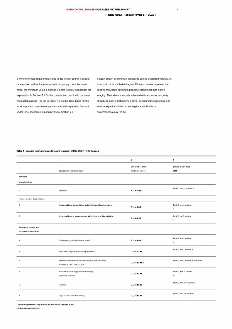
Table 1 | excerpts minimum values for sound insulation of DIN 4109-1 [1] for housingTable 1 | excerpts minimum values for sound insulation of DIN 4109-1 [1] for housing
1 2 3
Component / transmission:
DIN 4109-1: 2018
minimum values
Source in DIN 4109-1:
2018
partitions
storey buildings
1 party wall R ' w ≥ 53 dB R ' w ≥ 53 dB R ' w ≥ 53 dB
Table 2 line 13, column 3
Terraced and semi-detached houses
2 House partitions (erdberührt or not) to the lowest floor lounges 2) House partitions (erdberührt or not) to the lowest floor lounges 2)
R ' w ≥ 59 dB R ' w ≥ 59 dB R ' w ≥ 59 dB
Table 3 row 4, column
3
3 House partitions to common areas with at least one floor including 2) House partitions to common areas with at least one floor including 2)
R ' w ≥ 62 dB R ' w ≥ 62 dB R ' w ≥ 62 dB
Table 3 line 5, column
3
Separating ceilings and
horizontal components
4 Flat separating ceiling airborne sound R ' w ≥ 54 dB R ' w ≥ 54 dB R ' w ≥ 54 dB
Table 2 row 2, column
3
5 Apartment compartment floor impact sound L' n, w ≤ 50 dB L' n, w ≤ 50 dB L' n, w ≤ 50 dB
Table 2 row 2, column 4
6 Apartment compartment floor impact sound level for ceiling
according to DIN 4109-33: 2016
L' n, w ≤ 53 dB 1) L' n, w ≤ 53 dB 1) L' n, w ≤ 53 dB 1) L' n, w ≤ 53 dB 1)
Table 2 row 2, column 4, footnote b
7 Roof terraces and loggias with underlying
residential premises
L' n, w ≤ 50 dB L' n, w ≤ 50 dB L' n, w ≤ 50 dB
Table 2, row 7, column
4
8th balconies L' n, w ≤ 58 dB L' n, w ≤ 58 dB L' n, w ≤ 58 dB
Table 2, row 8.1, Column 4
9 Flight of stairs and stair landing L' n, w ≤ 53 dB L' n, w ≤ 53 dB L' n, w ≤ 53 dB
Table 2, line 12, column 4
1) Special arrangements for ceiling structures, the 4109-33 DIN: attributable 2016th1) Special arrangements for ceiling structures, the 4109-33 DIN: attributable 2016th
2) for illustration see Section 4.3.12) for illustration see Section 4.3.1
NOISE CONTROL IN HOLZBAU | G BASES AND PRELIMINARY NOISE CONTROL IN HOLZBAU | G BASES AND PRELIMINARY NOISE CONTROL IN HOLZBAU | G BASES AND PRELIMINARY
H olzbau manual | R eIHE 3 | T PART 3 | F OLGE 1H olzbau manual | R eIHE 3 | T PART 3 | F OLGE 1H olzbau manual | R eIHE 3 | T PART 3 | F OLGE 1H olzbau manual | R eIHE 3 | T PART 3 | F OLGE 1H olzbau manual | R eIHE 3 | T PART 3 | F OLGE 1H olzbau manual | R eIHE 3 | T PART 3 | F OLGE 1H olzbau manual | R eIHE 3 | T PART 3 | F OLGE 1H olzbau manual | R eIHE 3 | T PART 3 | F OLGE 1H olzbau manual | R eIHE 3 | T PART 3 | F OLGE 1H olzbau manual | R eIHE 3 | T PART 3 | F OLGE 1H olzbau manual | R eIHE 3 | T PART 3 | F OLGE 1
10
are build end level below the minimum standard. Critical
situations may arise in the planning if this minimum standard eg.
B. can not be achieved at a renovation, with a planned execution.
In such cases it is advisable to go for planners, if necessary the
design to achieve the minimum standards. Undercutting is
allowed for a fundamental reorganization not in every case. In
other cases, as part of renovations a precise legal analysis is
required. Possibly. Here again the level at the time of building
creation. For these reasons, this should be regulated by contract
specific.
Note:
If the targets are achieved above the minimum standard by certain
characteristics such. As the mass or properties of floor coverings, so
we recommend this in the agreement as necessary to represent.
Compliance with the minimum requirements by easily replaceable
component layers in the structure is not recommended. If during the
use of the exchange of these layers is to ensure that the valid
construction minimum value is reached and after the exchange. The
standard series DIN 4109 also explicitly states that minimum
requirements without soft elastic floor coverings such. B. carpeting
must be achieved.
Summary:
The minimum requirements for sound insulation for various types of
buildings are shown in DIN 4109-1 [1]. Make sure there are no
people coming by noise in the building for damage and a minimum
level is reached of confidentiality.
These standards identify a non unterschreitbare minimum. but they
do not necessarily show the required "Bausoll" because this can be
in many cases above the minimum standard depending on building
type. Usually, requirements are imposed only on vulnerable spaces
between foreign residence and use units (also two-family house or
"family house with granny flat"). you want to retain a single-family
building acoustic evaluation, this is to be regulated in the
construction contract. For the protection against external noise is to
be noted that the minimum requirements are also placed on
single-family homes, without this being separately agreed in the
construction contract.
2.3 _ considering low frequencies
In building practice in terms of low-frequency sound transmission
inside buildings and in the perception of traffic noise show with
increasing frequency complaints. The sound insulation decreases
with frequency. That is, all conventional in construction practice
constructions exhibit an increased passage of sound at low
frequencies.
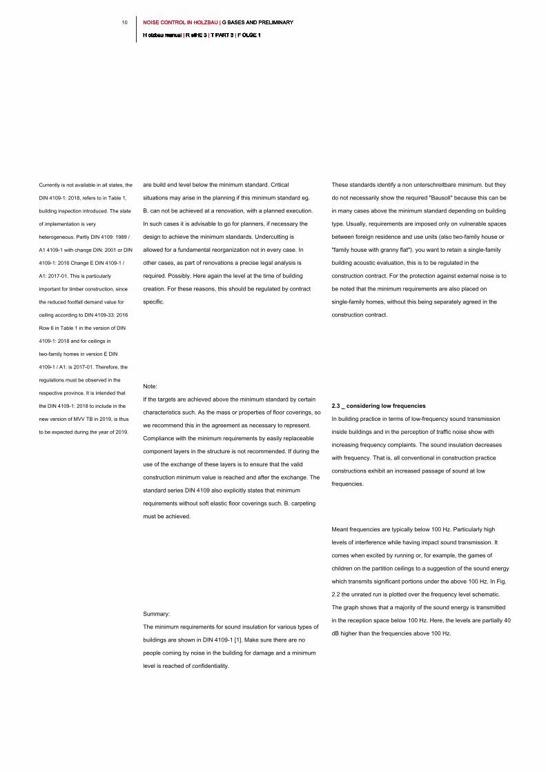
Meant frequencies are typically below 100 Hz. Particularly high
levels of interference while having impact sound transmission. It
comes when excited by running or, for example, the games of
children on the partition ceilings to a suggestion of the sound energy
which transmits significant portions under the above 100 Hz. In Fig.
2.2 the unrated run is plotted over the frequency level schematic.
The graph shows that a majority of the sound energy is transmitted
in the reception space below 100 Hz. Here, the levels are partially 40
dB higher than the frequencies above 100 Hz.
Currently is not available in all states, the
DIN 4109-1: 2018, refers to in Table 1,
building inspection introduced. The state
of implementation is very
heterogeneous. Partly DIN 4109: 1989 /
A1 4109-1 with change DIN: 2001 or DIN
4109-1: 2016 Change E DIN 4109-1 /
A1: 2017-01. This is particularly
important for timber construction, since
the reduced footfall demand value for
ceiling according to DIN 4109-33: 2016
Row 6 in Table 1 in the version of DIN
4109-1: 2018 and for ceilings in
two-family homes in version E DIN
4109-1 / A1: is 2017-01. Therefore, the
regulations must be observed in the
respective province. It is intended that
the DIN 4109-1: 2018 to include in the
new version of MVV TB in 2019, is thus
to be expected during the year of 2019.
1 11 1NOISE CONTROL IN HOLZBAU | G BASES AND PRELIMINARY NOISE CONTROL IN HOLZBAU | G BASES AND PRELIMINARY NOISE CONTROL IN HOLZBAU | G BASES AND PRELIMINARY
H olzbau manual | R eIHE 3 | T PART 3 | F OLGE 1H olzbau manual | R eIHE 3 | T PART 3 | F OLGE 1H olzbau manual | R eIHE 3 | T PART 3 | F OLGE 1H olzbau manual | R eIHE 3 | T PART 3 | F OLGE 1H olzbau manual | R eIHE 3 | T PART 3 | F OLGE 1H olzbau manual | R eIHE 3 | T PART 3 | F OLGE 1H olzbau manual | R eIHE 3 | T PART 3 | F OLGE 1H olzbau manual | R eIHE 3 | T PART 3 | F OLGE 1H olzbau manual | R eIHE 3 | T PART 3 | F OLGE 1H olzbau manual | R eIHE 3 | T PART 3 | F OLGE 1H olzbau manual | R eIHE 3 | T PART 3 | F OLGE 1
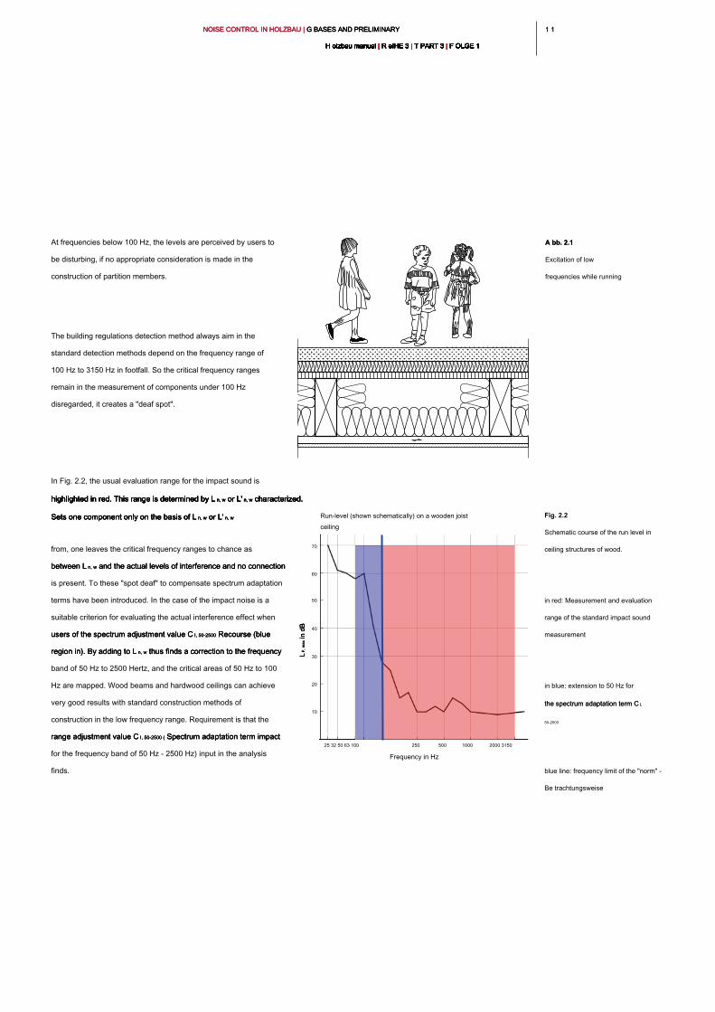
At frequencies below 100 Hz, the levels are perceived by users to
be disturbing, if no appropriate consideration is made in the
construction of partition members.
The building regulations detection method always aim in the
standard detection methods depend on the frequency range of
100 Hz to 3150 Hz in footfall. So the critical frequency ranges
remain in the measurement of components under 100 Hz
disregarded, it creates a "deaf spot".
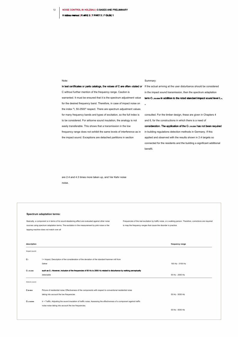
In Fig. 2.2, the usual evaluation range for the impact sound is
highlighted in red. This range is determined by L n, w or L' n, w characterized. highlighted in red. This range is determined by L n, w or L' n, w characterized. highlighted in red. This range is determined by L n, w or L' n, w characterized. highlighted in red. This range is determined by L n, w or L' n, w characterized. highlighted in red. This range is determined by L n, w or L' n, w characterized.
Sets one component only on the basis of L n, w or L' n, wSets one component only on the basis of L n, w or L' n, wSets one component only on the basis of L n, w or L' n, wSets one component only on the basis of L n, w or L' n, w
from, one leaves the critical frequency ranges to chance as
between L n, w and the actual levels of interference and no connection between L n, w and the actual levels of interference and no connection between L n, w and the actual levels of interference and no connection
is present. To these "spot deaf" to compensate spectrum adaptation
terms have been introduced. In the case of the impact noise is a
suitable criterion for evaluating the actual interference effect when
users of the spectrum adjustment value C I, 50-2500 Recourse (blue users of the spectrum adjustment value C I, 50-2500 Recourse (blue users of the spectrum adjustment value C I, 50-2500 Recourse (blue
region in). By adding to L n, w thus finds a correction to the frequency region in). By adding to L n, w thus finds a correction to the frequency region in). By adding to L n, w thus finds a correction to the frequency
band of 50 Hz to 2500 Hertz, and the critical areas of 50 Hz to 100
Hz are mapped. Wood beams and hardwood ceilings can achieve
very good results with standard construction methods of
construction in the low frequency range. Requirement is that the
range adjustment value C I, 50-2500 ( Spectrum adaptation term impact range adjustment value C I, 50-2500 ( Spectrum adaptation term impact range adjustment value C I, 50-2500 ( Spectrum adaptation term impact
for the frequency band of 50 Hz - 2500 Hz) input in the analysis
finds.
Frequency in Hz
Run-level (shown schematically) on a wooden joist
ceiling
25 32 50 63 100 250 500 1000 2000 3150
70
60
50
40
30
20
10
A bb. 2.1A bb. 2.1
Excitation of low
frequencies while running
Fig. 2.2
Schematic course of the run level in
ceiling structures of wood.
in red: Measurement and evaluation
range of the standard impact sound
measurement
in blue: extension to 50 Hz for
the spectrum adaptation term C I, the spectrum adaptation term C I,
50-2500
blue line: frequency limit of the "norm" -
Be trachtungsweise
L F
, m
ax in dB
L F
, m
ax in dB
L F
, m
ax in dB
NOISE CONTROL IN HOLZBAU | G BASES AND PRELIMINARY NOISE CONTROL IN HOLZBAU | G BASES AND PRELIMINARY NOISE CONTROL IN HOLZBAU | G BASES AND PRELIMINARY
H olzbau manual | R eIHE 3 | T PART 3 | F OLGE 1H olzbau manual | R eIHE 3 | T PART 3 | F OLGE 1H olzbau manual | R eIHE 3 | T PART 3 | F OLGE 1H olzbau manual | R eIHE 3 | T PART 3 | F OLGE 1H olzbau manual | R eIHE 3 | T PART 3 | F OLGE 1H olzbau manual | R eIHE 3 | T PART 3 | F OLGE 1H olzbau manual | R eIHE 3 | T PART 3 | F OLGE 1H olzbau manual | R eIHE 3 | T PART 3 | F OLGE 1H olzbau manual | R eIHE 3 | T PART 3 | F OLGE 1H olzbau manual | R eIHE 3 | T PART 3 | F OLGE 1H olzbau manual | R eIHE 3 | T PART 3 | F OLGE 1
12
Note:
in test certificates or parts catalogs, the values of C are often I stated or in test certificates or parts catalogs, the values of C are often I stated or in test certificates or parts catalogs, the values of C are often I stated or
C without further mention of the frequency range. Caution is
warranted. It must be ensured that it is the spectrum adjustment value
for the desired frequency band. Therefore, in case of impact noise on
the index "I, 50-2500" respect. There are spectrum adjustment values
for many frequency bands and types of excitation, so the full index is
to be considered. For airborne sound insulation, the analogy is not
easily transferable. This shows that a transmission in the low
frequency range does not exhibit the same levels of interference as in
the impact sound. Exceptions are detached partitions in section
are 2.4 and 4.3 times more taken up, and Ver Kehr noise
noise.
Summary:
If the actual arriving at the user disturbance should be considered
in the impact sound transmission, then the spectrum adaptation
term C I, 50-2500 in addition to the rated standard impact sound level L n, term C I, 50-2500 in addition to the rated standard impact sound level L n, term C I, 50-2500 in addition to the rated standard impact sound level L n, term C I, 50-2500 in addition to the rated standard impact sound level L n,
w
consulted. For the timber design, these are given in Chapters 4
and 6, for the constructions in which there is a need of
consideration. The application of the C I, 50-2500 has not been required consideration. The application of the C I, 50-2500 has not been required consideration. The application of the C I, 50-2500 has not been required
in building regulations detection methods in Germany. If this
applied and observed with the results shown in 2.4 targets so
connected for the residents and the building a significant additional
benefit.
description frequency range
Impact sound:
C IC I I = Impact; Description of the consideration of the deviation of the standard hammer mill from
Geher 100 Hz - 3150 Hz
C I, 50-2500C I, 50-2500 such as C I, However, inclusion of the frequencies of 50 Hz to 2500 Hz related to disturbance by walking perceptually such as C I, However, inclusion of the frequencies of 50 Hz to 2500 Hz related to disturbance by walking perceptually such as C I, However, inclusion of the frequencies of 50 Hz to 2500 Hz related to disturbance by walking perceptually
detectable 50 Hz - 2500 Hz
Airborne sound:
C 50-5000C 50-5000 Picture of residential noise; Effectiveness of the components with respect to conventional residential noise
taking into account the low frequencies 50 Hz - 5000 Hz
C tr, 50-5000 C tr, 50-5000 tr = Traffic; Adjusting the sound insulation of traffic noise; Assessing the effectiveness of a component against traffic
noise noise taking into account the low frequencies.
50 Hz - 5000 Hz
Spectrum adaptation terms:
Basically, a component is in terms of its sound-deadening effect are evaluated against other noise
sources using spectrum adaptation terms. The excitation in the measurement by pink noise or the
tapping machine does not match over all
Frequencies of the real excitation by traffic noise, or a walking person. Therefore, corrections are required
to map the frequency ranges that cause the disorder in practice.
1 31 3NOISE CONTROL IN HOLZBAU | G BASES AND PRELIMINARY NOISE CONTROL IN HOLZBAU | G BASES AND PRELIMINARY NOISE CONTROL IN HOLZBAU | G BASES AND PRELIMINARY
H olzbau manual | R eIHE 3 | T PART 3 | F OLGE 1H olzbau manual | R eIHE 3 | T PART 3 | F OLGE 1H olzbau manual | R eIHE 3 | T PART 3 | F OLGE 1H olzbau manual | R eIHE 3 | T PART 3 | F OLGE 1H olzbau manual | R eIHE 3 | T PART 3 | F OLGE 1H olzbau manual | R eIHE 3 | T PART 3 | F OLGE 1H olzbau manual | R eIHE 3 | T PART 3 | F OLGE 1H olzbau manual | R eIHE 3 | T PART 3 | F OLGE 1H olzbau manual | R eIHE 3 | T PART 3 | F OLGE 1H olzbau manual | R eIHE 3 | T PART 3 | F OLGE 1H olzbau manual | R eIHE 3 | T PART 3 | F OLGE 1
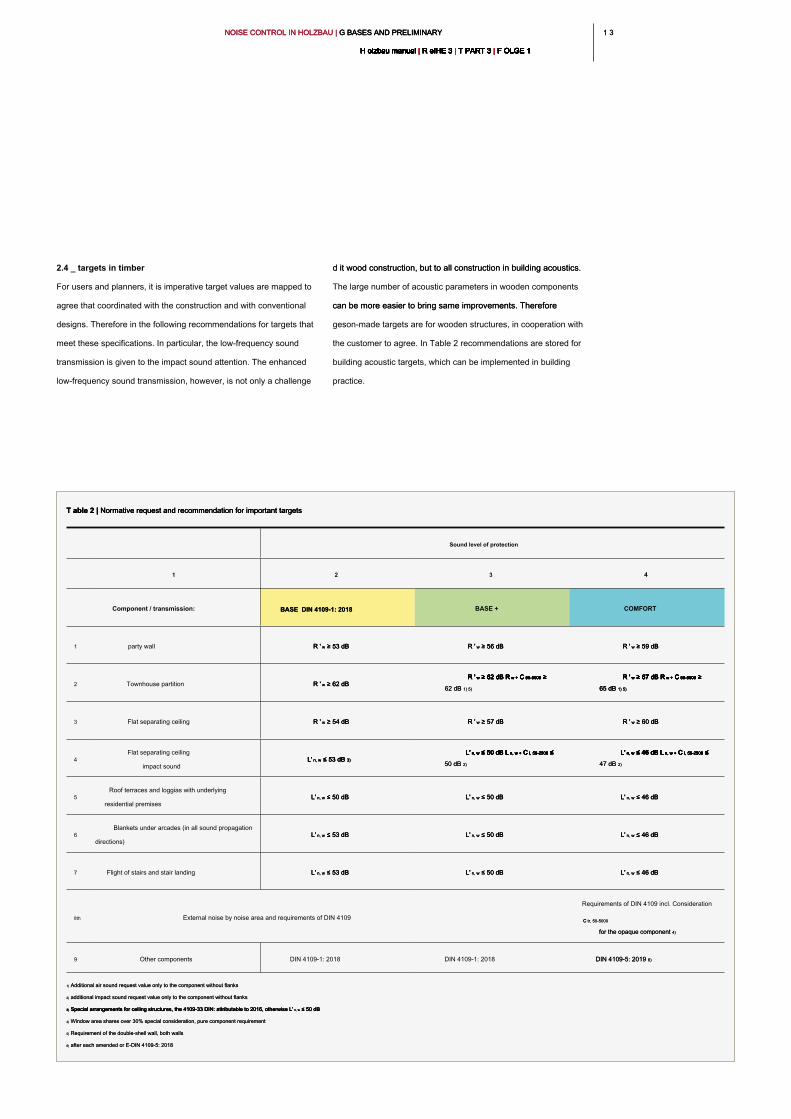
d it wood construction, but to all construction in building acoustics. d it wood construction, but to all construction in building acoustics.
The large number of acoustic parameters in wooden components
can be more easier to bring same improvements. Therefore can be more easier to bring same improvements. Therefore
geson-made targets are for wooden structures, in cooperation with
the customer to agree. In Table 2 recommendations are stored for
building acoustic targets, which can be implemented in building
practice.
2.4 _ targets in timber
For users and planners, it is imperative target values are mapped to
agree that coordinated with the construction and with conventional
designs. Therefore in the following recommendations for targets that
meet these specifications. In particular, the low-frequency sound
transmission is given to the impact sound attention. The enhanced
low-frequency sound transmission, however, is not only a challenge
T able 2 | Normative request and recommendation for important targetsT able 2 | Normative request and recommendation for important targetsT able 2 | Normative request and recommendation for important targets
Sound level of protection
1 2 3 4
Component / transmission: BASE DIN 4109-1: 2018 BASE DIN 4109-1: 2018
BASE + COMFORT
1 party wall R ' w ≥ 53 dB R ' w ≥ 53 dB R ' w ≥ 53 dB R ' w ≥ 56 dB R ' w ≥ 56 dB R ' w ≥ 56 dB R ' w ≥ 59 dBR ' w ≥ 59 dBR ' w ≥ 59 dB
2 Townhouse partition R ' w ≥ 62 dB R ' w ≥ 62 dB R ' w ≥ 62 dB
R ' w ≥ 62 dB R w + C 50-5000 ≥ R ' w ≥ 62 dB R w + C 50-5000 ≥ R ' w ≥ 62 dB R w + C 50-5000 ≥ R ' w ≥ 62 dB R w + C 50-5000 ≥ R ' w ≥ 62 dB R w + C 50-5000 ≥ R ' w ≥ 62 dB R w + C 50-5000 ≥ R ' w ≥ 62 dB R w + C 50-5000 ≥ R ' w ≥ 62 dB R w + C 50-5000 ≥
62 dB 1) 5)62 dB 1) 5)
R ' w ≥ 67 dB R w + C 50-5000 ≥ R ' w ≥ 67 dB R w + C 50-5000 ≥ R ' w ≥ 67 dB R w + C 50-5000 ≥ R ' w ≥ 67 dB R w + C 50-5000 ≥ R ' w ≥ 67 dB R w + C 50-5000 ≥ R ' w ≥ 67 dB R w + C 50-5000 ≥ R ' w ≥ 67 dB R w + C 50-5000 ≥ R ' w ≥ 67 dB R w + C 50-5000 ≥
65 dB 1) 5)65 dB 1) 5)65 dB 1) 5)
3 Flat separating ceiling R ' w ≥ 54 dB R ' w ≥ 54 dB R ' w ≥ 54 dB R ' w ≥ 57 dB R ' w ≥ 57 dB R ' w ≥ 57 dB R ' w ≥ 60 dBR ' w ≥ 60 dBR ' w ≥ 60 dB
4
Flat separating ceiling
impact sound
L' n, w ≤ 53 dB 3) L' n, w ≤ 53 dB 3) L' n, w ≤ 53 dB 3) L' n, w ≤ 53 dB 3)
L' n, w ≤ 50 dB L n, w + C I, 50-2500 ≤ L' n, w ≤ 50 dB L n, w + C I, 50-2500 ≤ L' n, w ≤ 50 dB L n, w + C I, 50-2500 ≤ L' n, w ≤ 50 dB L n, w + C I, 50-2500 ≤ L' n, w ≤ 50 dB L n, w + C I, 50-2500 ≤ L' n, w ≤ 50 dB L n, w + C I, 50-2500 ≤ L' n, w ≤ 50 dB L n, w + C I, 50-2500 ≤ L' n, w ≤ 50 dB L n, w + C I, 50-2500 ≤
50 dB 2)50 dB 2)
L' n, w ≤ 46 dB L n, w + C I, 50-2500 ≤ L' n, w ≤ 46 dB L n, w + C I, 50-2500 ≤ L' n, w ≤ 46 dB L n, w + C I, 50-2500 ≤ L' n, w ≤ 46 dB L n, w + C I, 50-2500 ≤ L' n, w ≤ 46 dB L n, w + C I, 50-2500 ≤ L' n, w ≤ 46 dB L n, w + C I, 50-2500 ≤ L' n, w ≤ 46 dB L n, w + C I, 50-2500 ≤ L' n, w ≤ 46 dB L n, w + C I, 50-2500 ≤
47 dB 2)47 dB 2)
5
Roof terraces and loggias with underlying
residential premises
L' n, w ≤ 50 dB L' n, w ≤ 50 dB L' n, w ≤ 50 dB L' n, w ≤ 50 dB L' n, w ≤ 50 dB L' n, w ≤ 50 dB L' n, w ≤ 46 dBL' n, w ≤ 46 dBL' n, w ≤ 46 dB
6
Blankets under arcades (in all sound propagation
directions)
L' n, w ≤ 53 dB L' n, w ≤ 53 dB L' n, w ≤ 53 dB L' n, w ≤ 50 dB L' n, w ≤ 50 dB L' n, w ≤ 50 dB L' n, w ≤ 46 dBL' n, w ≤ 46 dBL' n, w ≤ 46 dB
7 Flight of stairs and stair landing L' n, w ≤ 53 dB L' n, w ≤ 53 dB L' n, w ≤ 53 dB L' n, w ≤ 50 dB L' n, w ≤ 50 dB L' n, w ≤ 50 dB L' n, w ≤ 46 dBL' n, w ≤ 46 dBL' n, w ≤ 46 dB
8th External noise by noise area and requirements of DIN 4109
Requirements of DIN 4109 incl. Consideration
c tr, 50-5000c tr, 50-5000
for the opaque component 4)for the opaque component 4)
9 Other components DIN 4109-1: 2018 DIN 4109-1: 2018 DIN 4109-5: 2019 6)DIN 4109-5: 2019 6)
1) Additional air sound request value only to the component without flanks1) Additional air sound request value only to the component without flanks
2) additional impact sound request value only to the component without flanks2) additional impact sound request value only to the component without flanks
3) Special arrangements for ceiling structures, the 4109-33 DIN: attributable to 2016, otherwise L' n, w ≤ 50 dB3) Special arrangements for ceiling structures, the 4109-33 DIN: attributable to 2016, otherwise L' n, w ≤ 50 dB3) Special arrangements for ceiling structures, the 4109-33 DIN: attributable to 2016, otherwise L' n, w ≤ 50 dB3) Special arrangements for ceiling structures, the 4109-33 DIN: attributable to 2016, otherwise L' n, w ≤ 50 dB
4) Window area shares over 30% special consideration, pure component requirement4) Window area shares over 30% special consideration, pure component requirement
5) Requirement of the double-shell wall, both walls 5) Requirement of the double-shell wall, both walls
6) after each amended or E-DIN 4109-5: 20186) after each amended or E-DIN 4109-5: 2018
NOISE CONTROL IN HOLZBAU | G BASES AND PRELIMINARY NOISE CONTROL IN HOLZBAU | G BASES AND PRELIMINARY NOISE CONTROL IN HOLZBAU | G BASES AND PRELIMINARY
H olzbau manual | R eIHE 3 | T PART 3 | F OLGE 1H olzbau manual | R eIHE 3 | T PART 3 | F OLGE 1H olzbau manual | R eIHE 3 | T PART 3 | F OLGE 1H olzbau manual | R eIHE 3 | T PART 3 | F OLGE 1H olzbau manual | R eIHE 3 | T PART 3 | F OLGE 1H olzbau manual | R eIHE 3 | T PART 3 | F OLGE 1H olzbau manual | R eIHE 3 | T PART 3 | F OLGE 1H olzbau manual | R eIHE 3 | T PART 3 | F OLGE 1H olzbau manual | R eIHE 3 | T PART 3 | F OLGE 1H olzbau manual | R eIHE 3 | T PART 3 | F OLGE 1H olzbau manual | R eIHE 3 | T PART 3 | F OLGE 1
14
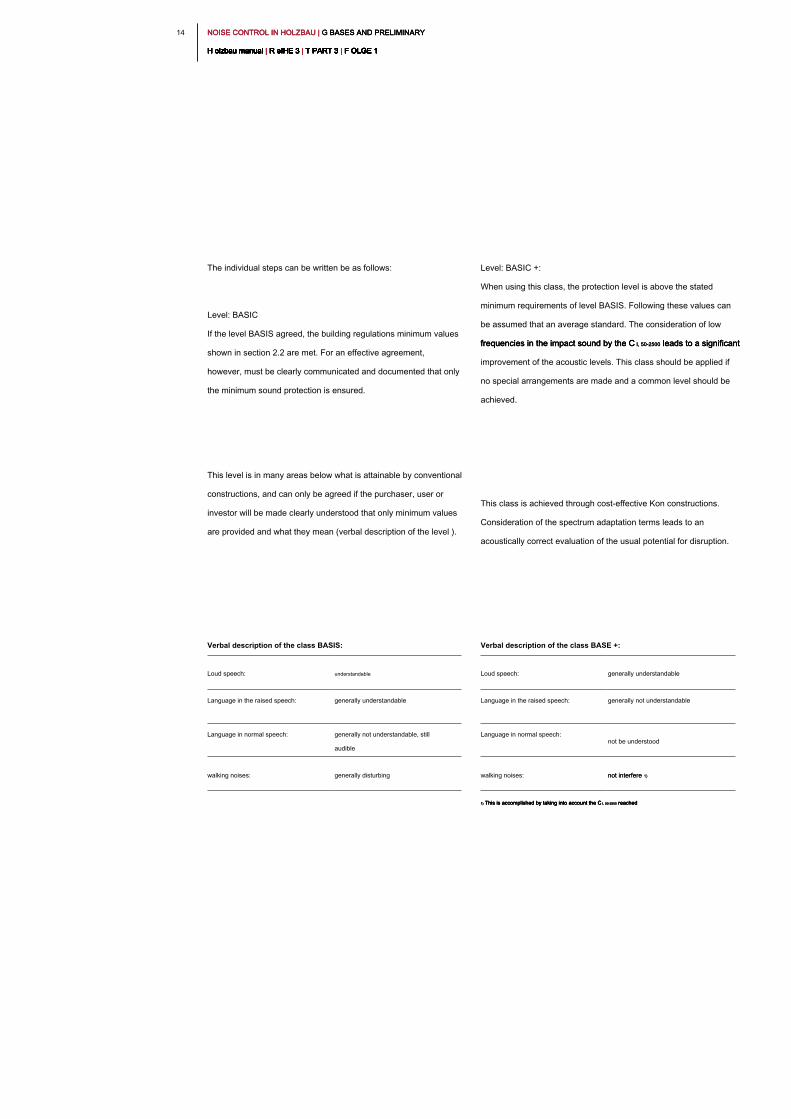
The individual steps can be written be as follows:
Level: BASIC
If the level BASIS agreed, the building regulations minimum values
shown in section 2.2 are met. For an effective agreement,
however, must be clearly communicated and documented that only
the minimum sound protection is ensured.
This level is in many areas below what is attainable by conventional
constructions, and can only be agreed if the purchaser, user or
investor will be made clearly understood that only minimum values
are provided and what they mean (verbal description of the level ).
Level: BASIC +:
When using this class, the protection level is above the stated
minimum requirements of level BASIS. Following these values can
be assumed that an average standard. The consideration of low
frequencies in the impact sound by the C I, 50-2500 leads to a significant frequencies in the impact sound by the C I, 50-2500 leads to a significant frequencies in the impact sound by the C I, 50-2500 leads to a significant
improvement of the acoustic levels. This class should be applied if
no special arrangements are made and a common level should be
achieved.
This class is achieved through cost-effective Kon constructions.
Consideration of the spectrum adaptation terms leads to an
acoustically correct evaluation of the usual potential for disruption.
Verbal description of the class BASIS:
Loud speech: understandable
Language in the raised speech: generally understandable
Language in normal speech: generally not understandable, still
audible
walking noises: generally disturbing
Verbal description of the class BASE +:
Loud speech: generally understandable
Language in the raised speech: generally not understandable
Language in normal speech:
not be understood
walking noises: not interfere 1)not interfere 1)
1) This is accomplished by taking into account the C I, 50-2500 reached1) This is accomplished by taking into account the C I, 50-2500 reached1) This is accomplished by taking into account the C I, 50-2500 reached1) This is accomplished by taking into account the C I, 50-2500 reached
1 51 5NOISE CONTROL IN HOLZBAU | G BASES AND PRELIMINARY NOISE CONTROL IN HOLZBAU | G BASES AND PRELIMINARY NOISE CONTROL IN HOLZBAU | G BASES AND PRELIMINARY
H olzbau manual | R eIHE 3 | T PART 3 | F OLGE 1H olzbau manual | R eIHE 3 | T PART 3 | F OLGE 1H olzbau manual | R eIHE 3 | T PART 3 | F OLGE 1H olzbau manual | R eIHE 3 | T PART 3 | F OLGE 1H olzbau manual | R eIHE 3 | T PART 3 | F OLGE 1H olzbau manual | R eIHE 3 | T PART 3 | F OLGE 1H olzbau manual | R eIHE 3 | T PART 3 | F OLGE 1H olzbau manual | R eIHE 3 | T PART 3 | F OLGE 1H olzbau manual | R eIHE 3 | T PART 3 | F OLGE 1H olzbau manual | R eIHE 3 | T PART 3 | F OLGE 1H olzbau manual | R eIHE 3 | T PART 3 | F OLGE 1
Specific agreement:
The classes shown must not be agreed compulsorily as a whole but
can be used for individual apartments or parts of buildings. Here the
penthouse in class COMFORT example, would be mapped and the
entire building in BASE +. The same applies to individual
components. It can from the classes BASE + and COMFORT the
individual components are assigned individually with the
requirements if they are above the level BASIS. However, the verbal
description "component as" must then be adjusted. For practice, it is
recommended to describe the class as a whole to agree and.
Note to other construction methods:
Since it is in the enhanced low-frequency sound transmission to a
fundamental physical phenomenon, the application is not limited
these classes on the timber. It should be emphasized clearly here
that this level declared agreement are applicable to all methods of
construction (including material design).
Summary:
For the most important components required values can be agreed
as target values for timber construction. The classes described can
be implemented cost-effectively with acoustically optimized designs
in wood construction. By special attention to the low-frequency
transmission, in particular the impact noise, can be realized when
soundproofing a noticeable improvement to the user.
Level COMFORT:
In this category may be assumed that increased soundproofing.
For the footfall beyond and the sound transmission in series and
double houses the spectrum adjustment values for low
frequencies greater appreciation than in the class BASIS +. In
contrast to the established processes by building the range
adjustment values are applied only to the component without
further edge considerations. Opposite the class BASIS and BASE
+ is to expect a further, clearly perceptible improvement.
The class COMFORT can be achieved through optimized and
tuned frequency compatible components. But it is also to be
expected hö heren construction costs. This he put it a
considerably increased acoustically-Nazi comfort.
Verbal description of the class COMFORT:
Loud speech:
generally not
understandable
Language in the raised speech:
not be understood
Language in normal speech:
inaudible
walking noises:
not bothersome or barely perceptible 1)not bothersome or barely perceptible 1)
1) This is accomplished by taking into account the C I, 50-2500 reached. It is assumed that the A-level is below 33 1) This is accomplished by taking into account the C I, 50-2500 reached. It is assumed that the A-level is below 33 1) This is accomplished by taking into account the C I, 50-2500 reached. It is assumed that the A-level is below 33 1) This is accomplished by taking into account the C I, 50-2500 reached. It is assumed that the A-level is below 33
dB (A) and is thus perceived only rarely.
The verification and implementation are
presented in Chapters 4 and 6. FIG. It
should be noted that the building
inspectorate the detection method of DIN
4109-2 for all three stages: 2018 [1] are
applicable.
NOISE CONTROL IN HOLZBAU | G BASES AND PRELIMINARY NOISE CONTROL IN HOLZBAU | G BASES AND PRELIMINARY NOISE CONTROL IN HOLZBAU | G BASES AND PRELIMINARY
H olzbau manual | R eIHE 3 | T PART 3 | F OLGE 1H olzbau manual | R eIHE 3 | T PART 3 | F OLGE 1H olzbau manual | R eIHE 3 | T PART 3 | F OLGE 1H olzbau manual | R eIHE 3 | T PART 3 | F OLGE 1H olzbau manual | R eIHE 3 | T PART 3 | F OLGE 1H olzbau manual | R eIHE 3 | T PART 3 | F OLGE 1H olzbau manual | R eIHE 3 | T PART 3 | F OLGE 1H olzbau manual | R eIHE 3 | T PART 3 | F OLGE 1H olzbau manual | R eIHE 3 | T PART 3 | F OLGE 1H olzbau manual | R eIHE 3 | T PART 3 | F OLGE 1H olzbau manual | R eIHE 3 | T PART 3 | F OLGE 1
16
2.5.1 _ mass law
The resistance (the impedance) of a component relative to the
excitation by a sound pressure wave increases with increasing
mass of component (inertia). For bending soft, single-shell
components from it can be a link between the sound reduction
index R and the mass per unit area m 'Derived, as was done for the index R and the mass per unit area m 'Derived, as was done for the index R and the mass per unit area m 'Derived, as was done for the index R and the mass per unit area m 'Derived, as was done for the index R and the mass per unit area m 'Derived, as was done for the
first time by Berger [4].
R ≈ 20 lg (fm ') - 47 dB (1)
f ... frequency in Hzf ... frequency in Hz
m ' ... basis weight in kg / m m ' ... basis weight in kg / m
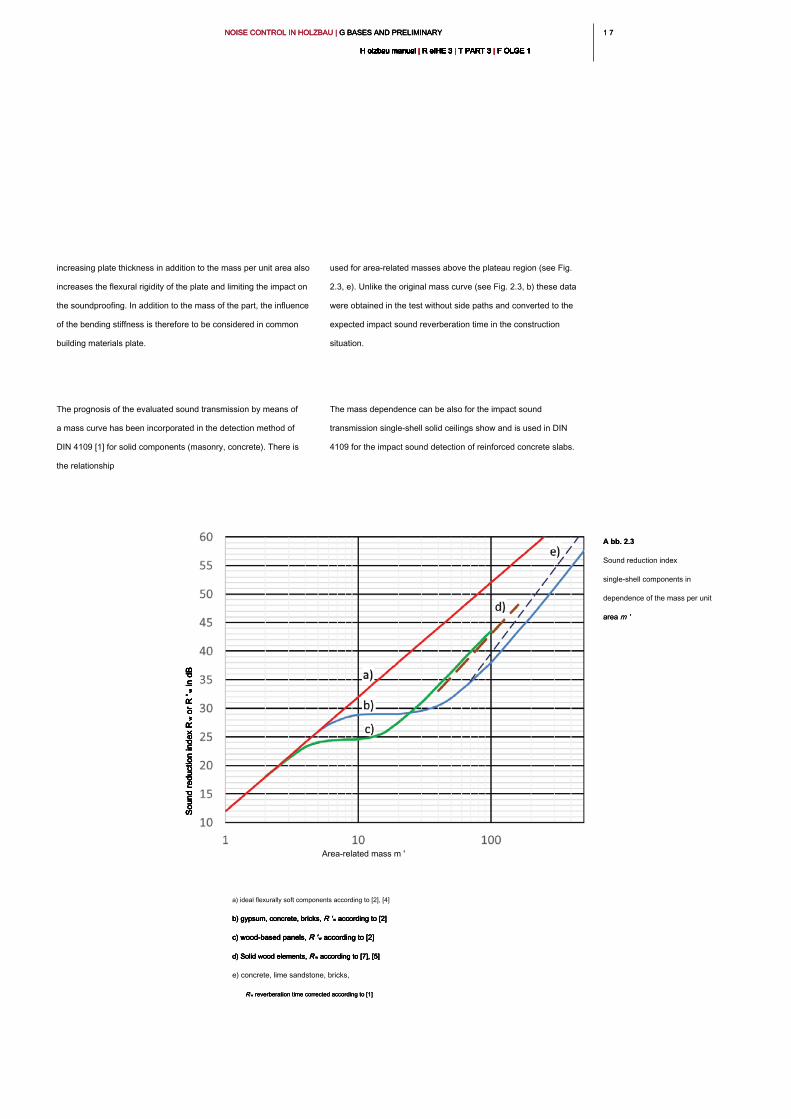
This so-called Berger's mass law can be both a function of
frequency f represent, as well as the weighted sound reduction frequency f represent, as well as the weighted sound reduction frequency f represent, as well as the weighted sound reduction
measure R w as a single value. This purpose, a composition diagram measure R w as a single value. This purpose, a composition diagram measure R w as a single value. This purpose, a composition diagram measure R w as a single value. This purpose, a composition diagram
(see Fig. 2.3), which was obtained empirically from measured data
of different materials and thicknesses plate or member [2].
In determining the airborne sound insulation index R w based on the In determining the airborne sound insulation index R w based on the In determining the airborne sound insulation index R w based on the In determining the airborne sound insulation index R w based on the
mass per unit area m ' is between the different materials - concrete, mass per unit area m ' is between the different materials - concrete, mass per unit area m ' is between the different materials - concrete,
masonry, glass, and wood and wood materials or sheets -
distinguished. While flexurally soft sheets such as thin sheets or
rubber sheets with doubling of m ' an increase in the R w show at 6 dB, rubber sheets with doubling of m ' an increase in the R w show at 6 dB, rubber sheets with doubling of m ' an increase in the R w show at 6 dB, rubber sheets with doubling of m ' an increase in the R w show at 6 dB, rubber sheets with doubling of m ' an increase in the R w show at 6 dB, rubber sheets with doubling of m ' an increase in the R w show at 6 dB,
a plateau is formed from at bie ge stiffer plates, on which the sound
hardly increases even with increasing mass. This is because with
2.5 _ Technical basics of building
acoustics
The basics of building acoustics provide an understanding of the
acoustical transfer mechanisms. For single, flat components can
these summarize the influence of grammage (mass law) and the
flexural strength (bending wave resonance or coincidence frequency
and plate natural frequencies) of the component. For multi-layered
devices, the resonances between the individual shells
(mass-spring-mass resonances) are also relevant. This can occur,
for example as a double wall, screed or ceilings resonance. Its effect
on the sound depends largely on the attenuation in the resonance
frequency can be increased by suitable insulating materials between
the component layers. The insulation reduces the transmission of
sound by its sound absorption, which is often characterized through
the longitudinal flow resistance of the products. The transmission is
also on the type of sound excitation, ie the airborne or
structure-borne or impact sound stimulus dependent.
Subsequently, these variables are introduced briefly by
examples from the timber to enable an assessment of the
structural influences on the sound insulation of components,
such as occurs in chapter 3. Here, the explanations are limited
in favor of clarity on the practical aspects. For further
explanation, see building acoustics, for example [2], [3].
1 71 7NOISE CONTROL IN HOLZBAU | G BASES AND PRELIMINARY NOISE CONTROL IN HOLZBAU | G BASES AND PRELIMINARY NOISE CONTROL IN HOLZBAU | G BASES AND PRELIMINARY
H olzbau manual | R eIHE 3 | T PART 3 | F OLGE 1H olzbau manual | R eIHE 3 | T PART 3 | F OLGE 1H olzbau manual | R eIHE 3 | T PART 3 | F OLGE 1H olzbau manual | R eIHE 3 | T PART 3 | F OLGE 1H olzbau manual | R eIHE 3 | T PART 3 | F OLGE 1H olzbau manual | R eIHE 3 | T PART 3 | F OLGE 1H olzbau manual | R eIHE 3 | T PART 3 | F OLGE 1H olzbau manual | R eIHE 3 | T PART 3 | F OLGE 1H olzbau manual | R eIHE 3 | T PART 3 | F OLGE 1H olzbau manual | R eIHE 3 | T PART 3 | F OLGE 1H olzbau manual | R eIHE 3 | T PART 3 | F OLGE 1
used for area-related masses above the plateau region (see Fig.
2.3, e). Unlike the original mass curve (see Fig. 2.3, b) these data
were obtained in the test without side paths and converted to the
expected impact sound reverberation time in the construction
situation.
The mass dependence can be also for the impact sound
transmission single-shell solid ceilings show and is used in DIN
4109 for the impact sound detection of reinforced concrete slabs.
increasing plate thickness in addition to the mass per unit area also
increases the flexural rigidity of the plate and limiting the impact on
the soundproofing. In addition to the mass of the part, the influence
of the bending stiffness is therefore to be considered in common
building materials plate.
The prognosis of the evaluated sound transmission by means of
a mass curve has been incorporated in the detection method of
DIN 4109 [1] for solid components (masonry, concrete). There is
the relationship
a) ideal flexurally soft components according to [2], [4]
b) gypsum, concrete, bricks, R ' w according to [2]b) gypsum, concrete, bricks, R ' w according to [2]b) gypsum, concrete, bricks, R ' w according to [2]b) gypsum, concrete, bricks, R ' w according to [2]
c) wood-based panels, R ' w according to [2]c) wood-based panels, R ' w according to [2]c) wood-based panels, R ' w according to [2]c) wood-based panels, R ' w according to [2]
d) Solid wood elements, R w according to [7], [5]d) Solid wood elements, R w according to [7], [5]d) Solid wood elements, R w according to [7], [5]d) Solid wood elements, R w according to [7], [5]
e) concrete, lime sandstone, bricks,
R w reverberation time corrected according to [1]R w reverberation time corrected according to [1]R w reverberation time corrected according to [1]
Area-related mass m '
A bb. 2.3A bb. 2.3
Sound reduction index
single-shell components in
dependence of the mass per unit
area m 'area m '
So
un
d re
du
ctio
n in
de
x R
w o
r R
' w in
d
BS
ou
nd
re
du
ctio
n in
de
x R
w o
r R
' w in
d
BS
ou
nd
re
du
ctio
n in
de
x R
w o
r R
' w in
d
BS
ou
nd
re
du
ctio
n in
de
x R
w o
r R
' w in
d
BS
ou
nd
re
du
ctio
n in
de
x R
w o
r R
' w in
d
B
NOISE CONTROL IN HOLZBAU | G BASES AND PRELIMINARY NOISE CONTROL IN HOLZBAU | G BASES AND PRELIMINARY NOISE CONTROL IN HOLZBAU | G BASES AND PRELIMINARY
H olzbau manual | R eIHE 3 | T PART 3 | F OLGE 1H olzbau manual | R eIHE 3 | T PART 3 | F OLGE 1H olzbau manual | R eIHE 3 | T PART 3 | F OLGE 1H olzbau manual | R eIHE 3 | T PART 3 | F OLGE 1H olzbau manual | R eIHE 3 | T PART 3 | F OLGE 1H olzbau manual | R eIHE 3 | T PART 3 | F OLGE 1H olzbau manual | R eIHE 3 | T PART 3 | F OLGE 1H olzbau manual | R eIHE 3 | T PART 3 | F OLGE 1H olzbau manual | R eIHE 3 | T PART 3 | F OLGE 1H olzbau manual | R eIHE 3 | T PART 3 | F OLGE 1H olzbau manual | R eIHE 3 | T PART 3 | F OLGE 1
18
The coincidence condition is fulfilled for all frequencies that are
greater than the coincidence frequency limit f c, which can be greater than the coincidence frequency limit f c, which can be greater than the coincidence frequency limit f c, which can be greater than the coincidence frequency limit f c, which can be
calculated according to equation (2) for the grazing incidence of
sound.
(2)
c 0 ... sound velocity (343 m / s at 20 ° C)c 0 ... sound velocity (343 m / s at 20 ° C)c 0 ... sound velocity (343 m / s at 20 ° C)
m ' ... basis weight in kg / mm ' ... basis weight in kg / m
B ' ... bending stiffness in N mB ' ... bending stiffness in N m
e ... Young's modulus in N / me ... Young's modulus in N / m
t ... Plate thickness in mt ... Plate thickness in m
μ ... Poisson's ratioμ ... Poisson's ratio
to (2) by combining the material parameters in a material constant
K can be greatly simplified to:
(3)
K ... constant of the material according to Table 3 in Hz m
t ... plate thickness in m
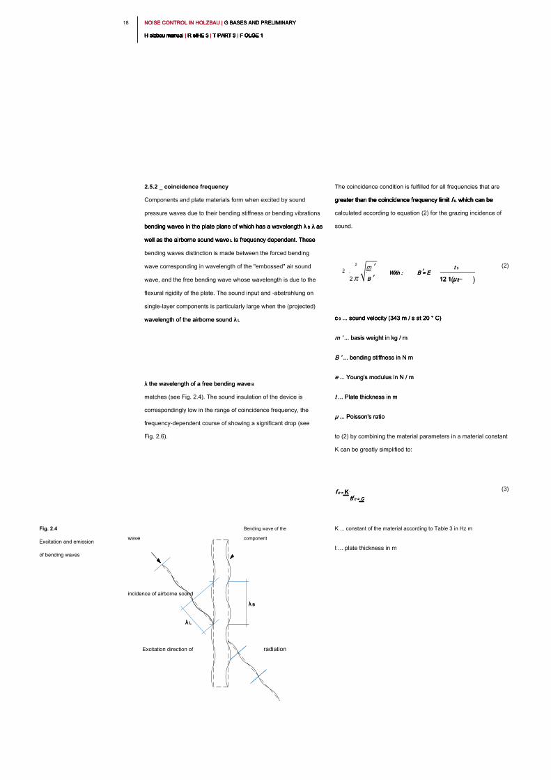
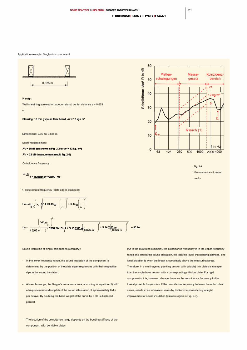
2.5.2 _ coincidence frequency
Components and plate materials form when excited by sound
pressure waves due to their bending stiffness or bending vibrations
bending waves in the plate plane of which has a wavelength λ B λ as bending waves in the plate plane of which has a wavelength λ B λ as bending waves in the plate plane of which has a wavelength λ B λ as
well as the airborne sound wave L is frequency dependent. These well as the airborne sound wave L is frequency dependent. These well as the airborne sound wave L is frequency dependent. These
bending waves distinction is made between the forced bending
wave corresponding in wavelength of the "embossed" air sound
wave, and the free bending wave whose wavelength is due to the
flexural rigidity of the plate. The sound input and -abstrahlung on
single-layer components is particularly large when the (projected)
wavelength of the airborne sound λ Lwavelength of the airborne sound λ L
λ the wavelength of a free bending wave Bλ the wavelength of a free bending wave B
matches (see Fig. 2.4). The sound insulation of the device is
correspondingly low in the range of coincidence frequency, the
frequency-dependent course of showing a significant drop (see
Fig. 2.6).
Fig. 2.4
Excitation and emission
of bending waves
radiationExcitation direction of
incidence of airborne sound
wave
Bending wave of the
component
λ Bλ B
λ Lλ L
f c = Kf c = Kf c = K
tf c = ctf c = ctf c = c
0
2
2
m
B B
With : With : With : B = E B = E B = E
t 3t 3
12 1 μ 212 1 μ 212 1 μ 2( )
1 91 9NOISE CONTROL IN HOLZBAU | G BASES AND PRELIMINARY NOISE CONTROL IN HOLZBAU | G BASES AND PRELIMINARY NOISE CONTROL IN HOLZBAU | G BASES AND PRELIMINARY
H olzbau manual | R eIHE 3 | T PART 3 | F OLGE 1H olzbau manual | R eIHE 3 | T PART 3 | F OLGE 1H olzbau manual | R eIHE 3 | T PART 3 | F OLGE 1H olzbau manual | R eIHE 3 | T PART 3 | F OLGE 1H olzbau manual | R eIHE 3 | T PART 3 | F OLGE 1H olzbau manual | R eIHE 3 | T PART 3 | F OLGE 1H olzbau manual | R eIHE 3 | T PART 3 | F OLGE 1H olzbau manual | R eIHE 3 | T PART 3 | F OLGE 1H olzbau manual | R eIHE 3 | T PART 3 | F OLGE 1H olzbau manual | R eIHE 3 | T PART 3 | F OLGE 1H olzbau manual | R eIHE 3 | T PART 3 | F OLGE 1
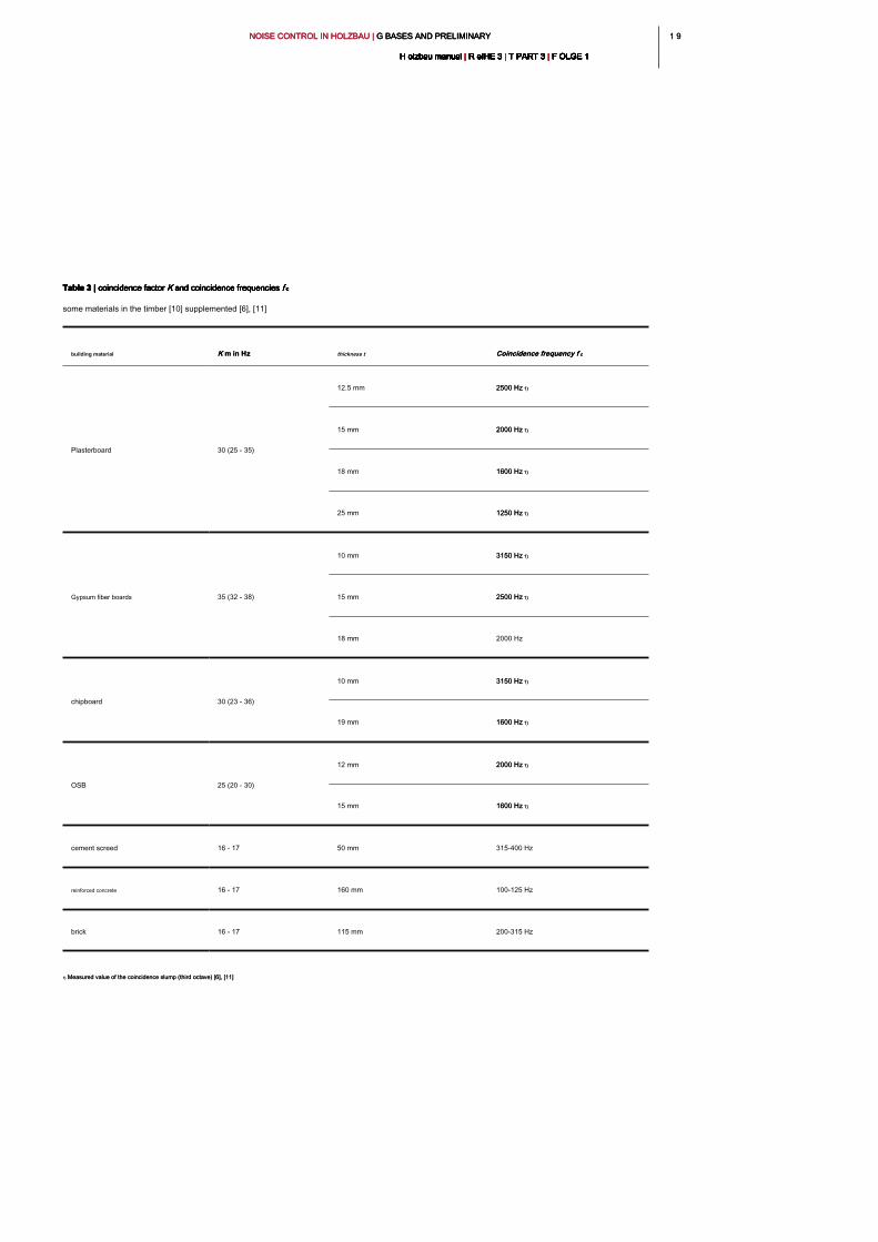
Table 3 | coincidence factor K and coincidence frequencies f cTable 3 | coincidence factor K and coincidence frequencies f cTable 3 | coincidence factor K and coincidence frequencies f cTable 3 | coincidence factor K and coincidence frequencies f cTable 3 | coincidence factor K and coincidence frequencies f cTable 3 | coincidence factor K and coincidence frequencies f c
some materials in the timber [10] supplemented [6], [11]
building material K m in HzK m in Hz thickness t Coincidence frequency f cCoincidence frequency f c
Plasterboard 30 (25 - 35)
12.5 mm 2500 Hz 1)2500 Hz 1)
15 mm 2000 Hz 1)2000 Hz 1)
18 mm 1600 Hz 1)1600 Hz 1)
25 mm 1250 Hz 1)1250 Hz 1)
Gypsum fiber boards 35 (32 - 38)
10 mm 3150 Hz 1)3150 Hz 1)
15 mm 2500 Hz 1)2500 Hz 1)
18 mm 2000 Hz
chipboard 30 (23 - 36)
10 mm 3150 Hz 1)3150 Hz 1)
19 mm 1600 Hz 1)1600 Hz 1)
OSB 25 (20 - 30)
12 mm 2000 Hz 1)2000 Hz 1)
15 mm 1600 Hz 1)1600 Hz 1)
cement screed 16 - 17 50 mm 315-400 Hz
reinforced concrete 16 - 17 160 mm 100-125 Hz
brick 16 - 17 115 mm 200-315 Hz
1) Measured value of the coincidence slump (third octave) [6], [11]1) Measured value of the coincidence slump (third octave) [6], [11]
NOISE CONTROL IN HOLZBAU | G BASES AND PRELIMINARY NOISE CONTROL IN HOLZBAU | G BASES AND PRELIMINARY NOISE CONTROL IN HOLZBAU | G BASES AND PRELIMINARY
H olzbau manual | R eIHE 3 | T PART 3 | F OLGE 1H olzbau manual | R eIHE 3 | T PART 3 | F OLGE 1H olzbau manual | R eIHE 3 | T PART 3 | F OLGE 1H olzbau manual | R eIHE 3 | T PART 3 | F OLGE 1H olzbau manual | R eIHE 3 | T PART 3 | F OLGE 1H olzbau manual | R eIHE 3 | T PART 3 | F OLGE 1H olzbau manual | R eIHE 3 | T PART 3 | F OLGE 1H olzbau manual | R eIHE 3 | T PART 3 | F OLGE 1H olzbau manual | R eIHE 3 | T PART 3 | F OLGE 1H olzbau manual | R eIHE 3 | T PART 3 | F OLGE 1H olzbau manual | R eIHE 3 | T PART 3 | F OLGE 1
20
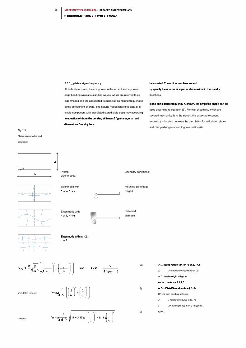
be counted. The ordinal numbers n x and be counted. The ordinal numbers n x and be counted. The ordinal numbers n x and be counted. The ordinal numbers n x and
n y specify the number of eigenmodes maxima in the x and y n y specify the number of eigenmodes maxima in the x and y n y specify the number of eigenmodes maxima in the x and y
directions.
Is the coincidence frequency f c known, the simplified shape can be Is the coincidence frequency f c known, the simplified shape can be Is the coincidence frequency f c known, the simplified shape can be Is the coincidence frequency f c known, the simplified shape can be
used according to equation (5). For wall sheathing, which are
secured mechanically to the stands, the expected resonant
frequency is located between the calculation for articulated plates
and clamped edges according to equation (6).
2.5.3 _ plates eigenfrequency
At finite dimensions, the component reflected at the component
edge bending waves to standing waves, which are referred to as
eigenmodes and the associated frequencies as natural frequencies
of the component overlap. The natural frequencies of a plate or a
single-component with articulated stored plate edge may according
to equation (4) from the bending stiffness B ' grammage m ' and to equation (4) from the bending stiffness B ' grammage m ' and to equation (4) from the bending stiffness B ' grammage m ' and to equation (4) from the bending stiffness B ' grammage m ' and to equation (4) from the bending stiffness B ' grammage m ' and
dimensions l x and l y be -dimensions l x and l y be -dimensions l x and l y be -dimensions l x and l y be -dimensions l x and l y be -dimensions l x and l y be -dimensions l x and l y be -
Fig. 2.5
Plates eigenmodes and
constraint
l xl x
Prefab
eigenmodes:
n x = 0, n y = 0n x = 0, n y = 0n x = 0, n y = 0n x = 0, n y = 0n x = 0, n y = 0
n x = 1, n y = 0n x = 1, n y = 0n x = 1, n y = 0n x = 1, n y = 0n x = 1, n y = 0
Eigenmode with n x = 2, Eigenmode with n x = 2, Eigenmode with n x = 2,
n y = 1n y = 1n y = 1
Boundary conditions:
mounted plate edge
hinged
clamped
xy
platemarkEigenmode with
eigenmode with
( 4)( 4)
(5)
(6)
f n x, n y = 2f n x, n y = 2f n x, n y = 2f n x, n y = 2f n x, n y = 2f n x, n y = 2
B
m n x + 1m n x + 1m n x + 1m n x + 1 l xl x
2
n + y + 1n + y + 1n + y + 1
l yl y
2
With : B = E With : B = E With : B = E With : B = E With : B = E
t 3t 3
12 1 μ 212 1 μ 212 1 μ 2( )
f 0.0 = c 0 f 0.0 = c 0 f 0.0 = c 0 f 0.0 = c 0
2
4 f c4 f c4 f c
1
l xl x
2
+
1
l yl y
2
f 0.0 = c 0f 0.0 = c 0f 0.0 = c 0f 0.0 = c 0
2
4 l x4 l x4 l x
2 f c2 f c2 f c2 f c
5.14 + 3.13 l x 5.14 + 3.13 l x 5.14 + 3.13 l x
l yl y
2
+ 5.14 l x5.14 l x5.14 l x
l yl y
4
c 0 ... sound velocity (343 m / s at 20 ° C) c 0 ... sound velocity (343 m / s at 20 ° C) c 0 ... sound velocity (343 m / s at 20 ° C)
f cf c ... coincidence frequency of (2)
m ' ... basis weight in kg / m m ' ... basis weight in kg / m
n x, n y ... order n = 0,1,2,3 n x, n y ... order n = 0,1,2,3 n x, n y ... order n = 0,1,2,3 n x, n y ... order n = 0,1,2,3 n x, n y ... order n = 0,1,2,3
l x, l y ... Plate Dimensions in m ( l x > l y)l x, l y ... Plate Dimensions in m ( l x > l y)l x, l y ... Plate Dimensions in m ( l x > l y)l x, l y ... Plate Dimensions in m ( l x > l y)l x, l y ... Plate Dimensions in m ( l x > l y)l x, l y ... Plate Dimensions in m ( l x > l y)l x, l y ... Plate Dimensions in m ( l x > l y)l x, l y ... Plate Dimensions in m ( l x > l y)l x, l y ... Plate Dimensions in m ( l x > l y)l x, l y ... Plate Dimensions in m ( l x > l y)
B '... N m in bending stiffness
e ... Young's modulus in N / m
t ... Plate thickness in m μ Poisson's
ratio ...
articulated manner:
clamped:
l y
l y
2 12 1NOISE CONTROL IN HOLZBAU | G BASES AND PRELIMINARY NOISE CONTROL IN HOLZBAU | G BASES AND PRELIMINARY NOISE CONTROL IN HOLZBAU | G BASES AND PRELIMINARY
H olzbau manual | R eIHE 3 | T PART 3 | F OLGE 1H olzbau manual | R eIHE 3 | T PART 3 | F OLGE 1H olzbau manual | R eIHE 3 | T PART 3 | F OLGE 1H olzbau manual | R eIHE 3 | T PART 3 | F OLGE 1H olzbau manual | R eIHE 3 | T PART 3 | F OLGE 1H olzbau manual | R eIHE 3 | T PART 3 | F OLGE 1H olzbau manual | R eIHE 3 | T PART 3 | F OLGE 1H olzbau manual | R eIHE 3 | T PART 3 | F OLGE 1H olzbau manual | R eIHE 3 | T PART 3 | F OLGE 1H olzbau manual | R eIHE 3 | T PART 3 | F OLGE 1H olzbau manual | R eIHE 3 | T PART 3 | F OLGE 1
K esign: K esign:
Wall sheathing screwed on wooden stand, center distance e = 0.625
m
Planking: 10 mm gypsum fiber board, m '= 12 kg / m² Planking: 10 mm gypsum fiber board, m '= 12 kg / m² Planking: 10 mm gypsum fiber board, m '= 12 kg / m²
Dimensions: 2.65 mx 0.625 m
Sound reduction index:
R w ≈ 30 dB (as shown in Fig. 2.3 for m '= 12 kg / m²)R w ≈ 30 dB (as shown in Fig. 2.3 for m '= 12 kg / m²)R w ≈ 30 dB (as shown in Fig. 2.3 for m '= 12 kg / m²)R w ≈ 30 dB (as shown in Fig. 2.3 for m '= 12 kg / m²)R w ≈ 30 dB (as shown in Fig. 2.3 for m '= 12 kg / m²)
R w ≈ 32 dB (measurement result, fig. 2.6) R w ≈ 32 dB (measurement result, fig. 2.6) R w ≈ 32 dB (measurement result, fig. 2.6)
Coincidence frequency:
1. plate natural frequency (plate edges clamped):
Sound insulation of single-component (summary):
- In the lower frequency range, the sound insulation of the component is
determined by the position of the plate eigenfrequencies with their respective
dips in the sound insulation.
- Above this range, the Berger's mass law shows, according to equation (1) with
a frequency-dependent pitch of the sound attenuation of approximately 6 dB
per octave. By doubling the basis weight of the curve by 6 dB is displaced
parallel.
- The location of the coincidence range depends on the bending stiffness of the
component. With bendable plates
(As in the illustrated example), the coincidence frequency is in the upper frequency
range and affects the sound insulation, the less the lower the bending stiffness. The
ideal situation is when the break is completely above the measuring range.
Therefore, in a multi-layered planking version with (pliable) thin plates is cheaper
than the single-layer version with a correspondingly thicker plate. For rigid
components, it is, however, cheaper to move the coincidence frequency to the
lowest possible frequencies. If the coincidence frequency between these two ideal
cases, results in an increase in mass by thicker components only a slight
improvement of sound insulation (plateau region in Fig. 2.3).
Application example: Single-skin component
Fig. 2.6
Measurement and forecast
results
f 0.0 = c 0f 0.0 = c 0f 0.0 = c 0f 0.0 = c 0
2
4 l x4 l x4 l x
2 f c2 f c2 f c2 f c
5.14 +3.13 l x 5.14 +3.13 l x 5.14 +3.13 l x
l yl y
2
+ 5.14 l x5.14 l x5.14 l x
l yl y
4
f c = Kf c = Kf c = K
t = 35 Hz mt = 35 Hz m0,010 m = 3500 Hz0,010 m = 3500 Hz0,010 m = 3500 Hz0,010 m = 3500 Hz
f 0.0 =f 0.0 =
343 m343 m
s
2
4 2.65 m4 2.65 m( )
2 3500 Hz 5.14 + 3.13 2.65 m2 3500 Hz 5.14 + 3.13 2.65 m2 3500 Hz 5.14 + 3.13 2.65 m2 3500 Hz 5.14 + 3.13 2.65 m2 3500 Hz 5.14 + 3.13 2.65 m2 3500 Hz 5.14 + 3.13 2.65 m
0.625 m0.625 m
2
+ 5.14 2.65 m5.14 2.65 m5.14 2.65 m
0.625 m0.625 m
4
= 50 Hz = 50 Hz = 50 Hz
0.625 m
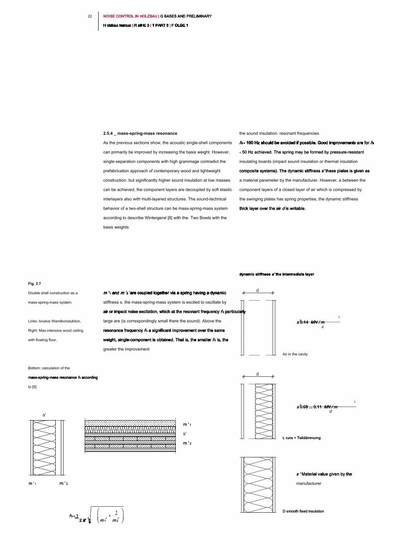
NOISE CONTROL IN HOLZBAU | G BASES AND PRELIMINARY NOISE CONTROL IN HOLZBAU | G BASES AND PRELIMINARY NOISE CONTROL IN HOLZBAU | G BASES AND PRELIMINARY
H olzbau manual | R eIHE 3 | T PART 3 | F OLGE 1H olzbau manual | R eIHE 3 | T PART 3 | F OLGE 1H olzbau manual | R eIHE 3 | T PART 3 | F OLGE 1H olzbau manual | R eIHE 3 | T PART 3 | F OLGE 1H olzbau manual | R eIHE 3 | T PART 3 | F OLGE 1H olzbau manual | R eIHE 3 | T PART 3 | F OLGE 1H olzbau manual | R eIHE 3 | T PART 3 | F OLGE 1H olzbau manual | R eIHE 3 | T PART 3 | F OLGE 1H olzbau manual | R eIHE 3 | T PART 3 | F OLGE 1H olzbau manual | R eIHE 3 | T PART 3 | F OLGE 1H olzbau manual | R eIHE 3 | T PART 3 | F OLGE 1
22
the sound insulation. resonant frequencies
f 0 > 100 Hz should be avoided if possible. Good improvements are for f 0 f 0 > 100 Hz should be avoided if possible. Good improvements are for f 0 f 0 > 100 Hz should be avoided if possible. Good improvements are for f 0 f 0 > 100 Hz should be avoided if possible. Good improvements are for f 0 f 0 > 100 Hz should be avoided if possible. Good improvements are for f 0 f 0 > 100 Hz should be avoided if possible. Good improvements are for f 0
< 50 Hz achieved. The spring may be formed by pressure-resistant < 50 Hz achieved. The spring may be formed by pressure-resistant
insulating boards (impact sound insulation or thermal insulation
composite systems). The dynamic stiffness s' these plates is given as composite systems). The dynamic stiffness s' these plates is given as composite systems). The dynamic stiffness s' these plates is given as
a material parameter by the manufacturer. However, a between the
component layers of a closed layer of air which is compressed by
the swinging plates has spring properties, the dynamic stiffness
thick layer over the air d is writable.thick layer over the air d is writable.thick layer over the air d is writable.
2.5.4 _ mass-spring-mass resonance
As the previous sections show, the acoustic single-shell components
can primarily be improved by increasing the basis weight. However,
single-separation components with high grammage contradict the
prefabrication approach of contemporary wood and lightweight
construction. but significantly higher sound insulation at low masses
can be achieved, the component layers are decoupled by soft elastic
interlayers also with multi-layered structures. The sound-technical
behavior of a two-shell structure can be mass-spring-mass system
according to describe Wintergerst [8] with the. Two Bowls with the
basis weights
m ' 1 and m ' 2 'are coupled together via a spring having a dynamic m ' 1 and m ' 2 'are coupled together via a spring having a dynamic m ' 1 and m ' 2 'are coupled together via a spring having a dynamic m ' 1 and m ' 2 'are coupled together via a spring having a dynamic m ' 1 and m ' 2 'are coupled together via a spring having a dynamic m ' 1 and m ' 2 'are coupled together via a spring having a dynamic
stiffness s. the mass-spring-mass system is excited to oscillate by
air or impact noise excitation, which at the resonant frequency f 0 particularly air or impact noise excitation, which at the resonant frequency f 0 particularly air or impact noise excitation, which at the resonant frequency f 0 particularly air or impact noise excitation, which at the resonant frequency f 0 particularly
large are (is correspondingly small there the sound). Above the
resonance frequency f 0 a significant improvement over the same resonance frequency f 0 a significant improvement over the same resonance frequency f 0 a significant improvement over the same resonance frequency f 0 a significant improvement over the same
weight, single-component is obtained. That is, the smaller f 0 is, the weight, single-component is obtained. That is, the smaller f 0 is, the weight, single-component is obtained. That is, the smaller f 0 is, the weight, single-component is obtained. That is, the smaller f 0 is, the
greater the improvement
Fig. 2.7
Double shell construction as a
mass-spring-mass system.
Links: bivalve Wandkonstuktion,
Right: Mas-intensive wood ceiling
with floating floor,
Bottom: calculation of the
mass-spring-mass resonance f 0 according mass-spring-mass resonance f 0 according mass-spring-mass resonance f 0 according mass-spring-mass resonance f 0 according
to [8]
m ' 1m ' 1
m ' 2m ' 2
s'
m ' 1 m ' 1 m ' 2m ' 2
s'
f 0 = 1f 0 = 1f 0 = 1
2 s' 12 s' 12 s' 12 s' 1 m 1m 1
+
1
m 2m 2
s ' Material value given by the s ' Material value given by the s ' Material value given by the
manufacturer
dynamic stiffness s' the intermediate layerdynamic stiffness s' the intermediate layerdynamic stiffness s' the intermediate layer
Air in the cavity
s 0.14 MN / ms 0.14 MN / ms 0.14 MN / m
d
2
d
d
L runs + TeildämmumgL runs + Teildämmumg
s 0.08 ... 0.11 MN / ms 0.08 ... 0.11 MN / ms 0.08 ... 0.11 MN / m
d
2
D smooth fixed insulationD smooth fixed insulation
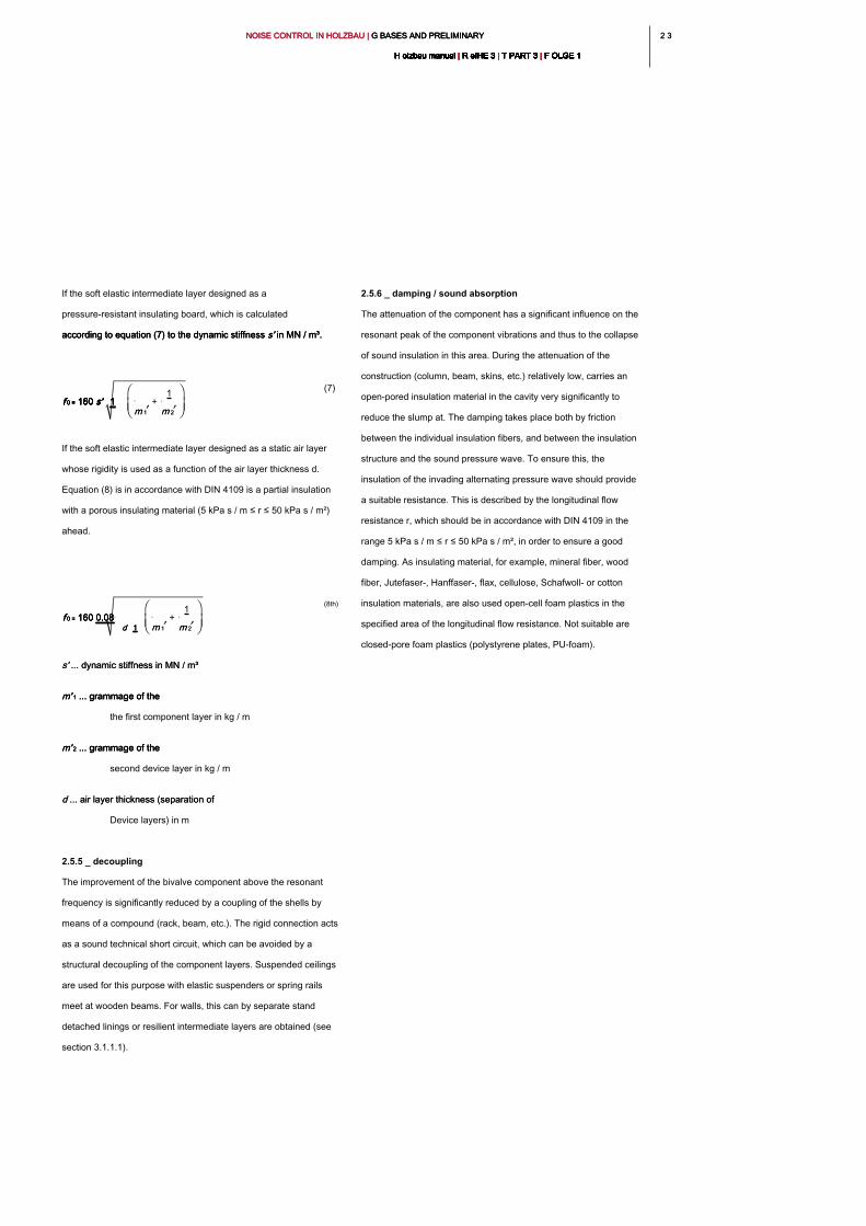
2 32 3NOISE CONTROL IN HOLZBAU | G BASES AND PRELIMINARY NOISE CONTROL IN HOLZBAU | G BASES AND PRELIMINARY NOISE CONTROL IN HOLZBAU | G BASES AND PRELIMINARY
H olzbau manual | R eIHE 3 | T PART 3 | F OLGE 1H olzbau manual | R eIHE 3 | T PART 3 | F OLGE 1H olzbau manual | R eIHE 3 | T PART 3 | F OLGE 1H olzbau manual | R eIHE 3 | T PART 3 | F OLGE 1H olzbau manual | R eIHE 3 | T PART 3 | F OLGE 1H olzbau manual | R eIHE 3 | T PART 3 | F OLGE 1H olzbau manual | R eIHE 3 | T PART 3 | F OLGE 1H olzbau manual | R eIHE 3 | T PART 3 | F OLGE 1H olzbau manual | R eIHE 3 | T PART 3 | F OLGE 1H olzbau manual | R eIHE 3 | T PART 3 | F OLGE 1H olzbau manual | R eIHE 3 | T PART 3 | F OLGE 1
2.5.6 _ damping / sound absorption
The attenuation of the component has a significant influence on the
resonant peak of the component vibrations and thus to the collapse
of sound insulation in this area. During the attenuation of the
construction (column, beam, skins, etc.) relatively low, carries an
open-pored insulation material in the cavity very significantly to
reduce the slump at. The damping takes place both by friction
between the individual insulation fibers, and between the insulation
structure and the sound pressure wave. To ensure this, the
insulation of the invading alternating pressure wave should provide
a suitable resistance. This is described by the longitudinal flow
resistance r, which should be in accordance with DIN 4109 in the
range 5 kPa s / m ≤ r ≤ 50 kPa s / m², in order to ensure a good
damping. As insulating material, for example, mineral fiber, wood
fiber, Jutefaser-, Hanffaser-, flax, cellulose, Schafwoll- or cotton
insulation materials, are also used open-cell foam plastics in the
specified area of the longitudinal flow resistance. Not suitable are
closed-pore foam plastics (polystyrene plates, PU-foam).
If the soft elastic intermediate layer designed as a
pressure-resistant insulating board, which is calculated
according to equation (7) to the dynamic stiffness s' in MN / m³. according to equation (7) to the dynamic stiffness s' in MN / m³. according to equation (7) to the dynamic stiffness s' in MN / m³.
(7)
If the soft elastic intermediate layer designed as a static air layer
whose rigidity is used as a function of the air layer thickness d.
Equation (8) is in accordance with DIN 4109 is a partial insulation
with a porous insulating material (5 kPa s / m ≤ r ≤ 50 kPa s / m²)
ahead.
(8th)
s' ... dynamic stiffness in MN / m³s' ... dynamic stiffness in MN / m³
m' 1 ... grammage of the m' 1 ... grammage of the m' 1 ... grammage of the
the first component layer in kg / m
m' 2 ... grammage of the m' 2 ... grammage of the m' 2 ... grammage of the
second device layer in kg / m
d ... air layer thickness (separation of d ... air layer thickness (separation of
Device layers) in m
2.5.5 _ decoupling
The improvement of the bivalve component above the resonant
frequency is significantly reduced by a coupling of the shells by
means of a compound (rack, beam, etc.). The rigid connection acts
as a sound technical short circuit, which can be avoided by a
structural decoupling of the component layers. Suspended ceilings
are used for this purpose with elastic suspenders or spring rails
meet at wooden beams. For walls, this can by separate stand
detached linings or resilient intermediate layers are obtained (see
section 3.1.1.1).
f 0 = 160 s' 1f 0 = 160 s' 1f 0 = 160 s' 1f 0 = 160 s' 1f 0 = 160 s' 1f 0 = 160 s' 1
m 1m 1
+
1
m 2m 2
f 0 = 160 0.08f 0 = 160 0.08f 0 = 160 0.08f 0 = 160 0.08
d 1d 1d 1 m 1m 1
+
1
m 2m 2
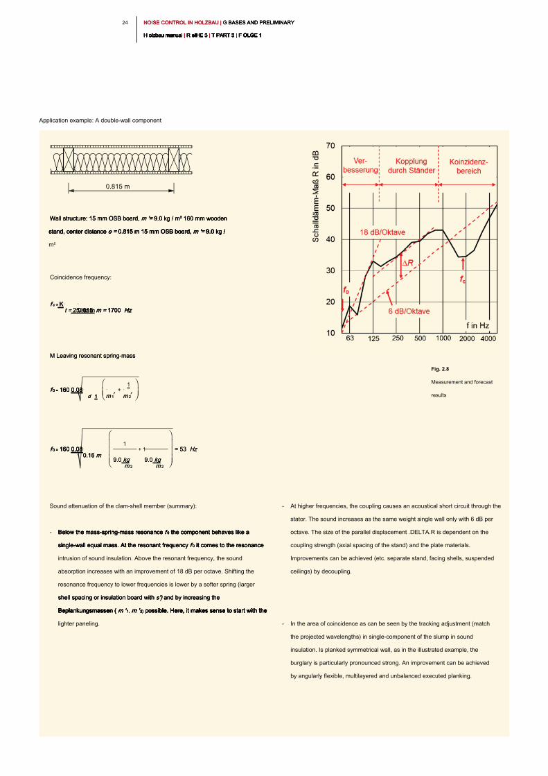
NOISE CONTROL IN HOLZBAU | G BASES AND PRELIMINARY NOISE CONTROL IN HOLZBAU | G BASES AND PRELIMINARY NOISE CONTROL IN HOLZBAU | G BASES AND PRELIMINARY
H olzbau manual | R eIHE 3 | T PART 3 | F OLGE 1H olzbau manual | R eIHE 3 | T PART 3 | F OLGE 1H olzbau manual | R eIHE 3 | T PART 3 | F OLGE 1H olzbau manual | R eIHE 3 | T PART 3 | F OLGE 1H olzbau manual | R eIHE 3 | T PART 3 | F OLGE 1H olzbau manual | R eIHE 3 | T PART 3 | F OLGE 1H olzbau manual | R eIHE 3 | T PART 3 | F OLGE 1H olzbau manual | R eIHE 3 | T PART 3 | F OLGE 1H olzbau manual | R eIHE 3 | T PART 3 | F OLGE 1H olzbau manual | R eIHE 3 | T PART 3 | F OLGE 1H olzbau manual | R eIHE 3 | T PART 3 | F OLGE 1
24
Wall structure: 15 mm OSB board, m '= 9.0 kg / m² 160 mm wooden Wall structure: 15 mm OSB board, m '= 9.0 kg / m² 160 mm wooden Wall structure: 15 mm OSB board, m '= 9.0 kg / m² 160 mm wooden
stand, center distance e = 0.815 m 15 mm OSB board, m '= 9.0 kg / stand, center distance e = 0.815 m 15 mm OSB board, m '= 9.0 kg / stand, center distance e = 0.815 m 15 mm OSB board, m '= 9.0 kg / stand, center distance e = 0.815 m 15 mm OSB board, m '= 9.0 kg / stand, center distance e = 0.815 m 15 mm OSB board, m '= 9.0 kg /
m²
Coincidence frequency:
M Leaving resonant spring-massM Leaving resonant spring-mass
Sound attenuation of the clam-shell member (summary):
- Below the mass-spring-mass resonance f 0 the component behaves like a Below the mass-spring-mass resonance f 0 the component behaves like a Below the mass-spring-mass resonance f 0 the component behaves like a Below the mass-spring-mass resonance f 0 the component behaves like a
single-wall equal mass. At the resonant frequency f 0 it comes to the resonance single-wall equal mass. At the resonant frequency f 0 it comes to the resonance single-wall equal mass. At the resonant frequency f 0 it comes to the resonance single-wall equal mass. At the resonant frequency f 0 it comes to the resonance
intrusion of sound insulation. Above the resonant frequency, the sound
absorption increases with an improvement of 18 dB per octave. Shifting the
resonance frequency to lower frequencies is lower by a softer spring (larger
shell spacing or insulation board with s') and by increasing the shell spacing or insulation board with s') and by increasing the shell spacing or insulation board with s') and by increasing the
Beplankungsmassen ( m ' 1, m ' 2) possible. Here, it makes sense to start with the Beplankungsmassen ( m ' 1, m ' 2) possible. Here, it makes sense to start with the Beplankungsmassen ( m ' 1, m ' 2) possible. Here, it makes sense to start with the Beplankungsmassen ( m ' 1, m ' 2) possible. Here, it makes sense to start with the Beplankungsmassen ( m ' 1, m ' 2) possible. Here, it makes sense to start with the Beplankungsmassen ( m ' 1, m ' 2) possible. Here, it makes sense to start with the
lighter paneling.
- At higher frequencies, the coupling causes an acoustical short circuit through the
stator. The sound increases as the same weight single wall only with 6 dB per
octave. The size of the parallel displacement .DELTA.R is dependent on the
coupling strength (axial spacing of the stand) and the plate materials.
Improvements can be achieved (etc. separate stand, facing shells, suspended
ceilings) by decoupling.
- In the area of coincidence as can be seen by the tracking adjustment (match
the projected wavelengths) in single-component of the slump in sound
insulation. Is planked symmetrical wall, as in the illustrated example, the
burglary is particularly pronounced strong. An improvement can be achieved
by angularly flexible, multilayered and unbalanced executed planking.
Application example: A double-wall component
Fig. 2.8
Measurement and forecast
results
f c = Kf c = Kf c = K
t = 25 Hz mt = 25 Hz m0,015 m = 1700 Hz0,015 m = 1700 Hz0,015 m = 1700 Hz0,015 m = 1700 Hz
f 0 = 160 0.08f 0 = 160 0.08f 0 = 160 0.08f 0 = 160 0.08
d 1d 1d 1 m 1m 1
+
1
m 2m 2
f 0 = 160 0.08f 0 = 160 0.08f 0 = 160 0.08f 0 = 160 0.08
0.16 m 0.16 m 0.16 m
1
9.0 kg9.0 kg
m 2m 2
+ 1
9.0 kg9.0 kg
m 2m 2
= 53 Hz= 53 Hz
0.815 m
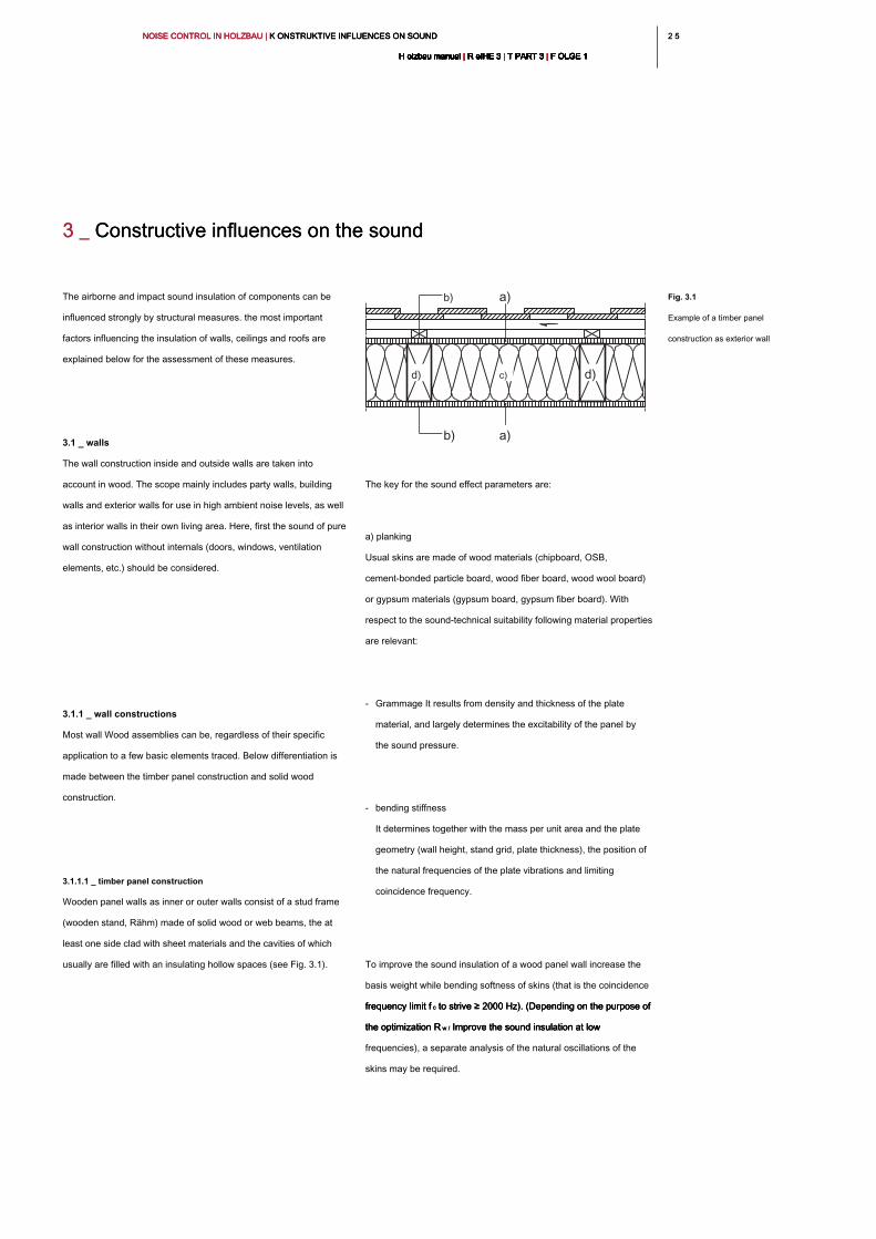
2 52 5NOISE CONTROL IN HOLZBAU | K ONSTRUKTIVE INFLUENCES ON SOUND NOISE CONTROL IN HOLZBAU | K ONSTRUKTIVE INFLUENCES ON SOUND NOISE CONTROL IN HOLZBAU | K ONSTRUKTIVE INFLUENCES ON SOUND
H olzbau manual | R eIHE 3 | T PART 3 | F OLGE 1H olzbau manual | R eIHE 3 | T PART 3 | F OLGE 1H olzbau manual | R eIHE 3 | T PART 3 | F OLGE 1H olzbau manual | R eIHE 3 | T PART 3 | F OLGE 1H olzbau manual | R eIHE 3 | T PART 3 | F OLGE 1H olzbau manual | R eIHE 3 | T PART 3 | F OLGE 1H olzbau manual | R eIHE 3 | T PART 3 | F OLGE 1H olzbau manual | R eIHE 3 | T PART 3 | F OLGE 1H olzbau manual | R eIHE 3 | T PART 3 | F OLGE 1H olzbau manual | R eIHE 3 | T PART 3 | F OLGE 1H olzbau manual | R eIHE 3 | T PART 3 | F OLGE 1
The key for the sound effect parameters are:
a) planking
Usual skins are made of wood materials (chipboard, OSB,
cement-bonded particle board, wood fiber board, wood wool board)
or gypsum materials (gypsum board, gypsum fiber board). With
respect to the sound-technical suitability following material properties
are relevant:
- Grammage It results from density and thickness of the plate
material, and largely determines the excitability of the panel by
the sound pressure.
- bending stiffness
It determines together with the mass per unit area and the plate
geometry (wall height, stand grid, plate thickness), the position of
the natural frequencies of the plate vibrations and limiting
coincidence frequency.
To improve the sound insulation of a wood panel wall increase the
basis weight while bending softness of skins (that is the coincidence
frequency limit f c to strive ≥ 2000 Hz). (Depending on the purpose of frequency limit f c to strive ≥ 2000 Hz). (Depending on the purpose of frequency limit f c to strive ≥ 2000 Hz). (Depending on the purpose of
the optimization R w / Improve the sound insulation at low the optimization R w / Improve the sound insulation at low the optimization R w / Improve the sound insulation at low
frequencies), a separate analysis of the natural oscillations of the
skins may be required.
3 _ Constructive influences on the sound3 _ Constructive influences on the sound
The airborne and impact sound insulation of components can be
influenced strongly by structural measures. the most important
factors influencing the insulation of walls, ceilings and roofs are
explained below for the assessment of these measures.
3.1 _ walls
The wall construction inside and outside walls are taken into
account in wood. The scope mainly includes party walls, building
walls and exterior walls for use in high ambient noise levels, as well
as interior walls in their own living area. Here, first the sound of pure
wall construction without internals (doors, windows, ventilation
elements, etc.) should be considered.
3.1.1 _ wall constructions
Most wall Wood assemblies can be, regardless of their specific
application to a few basic elements traced. Below differentiation is
made between the timber panel construction and solid wood
construction.
3.1.1.1 _ timber panel construction
Wooden panel walls as inner or outer walls consist of a stud frame
(wooden stand, Rähm) made of solid wood or web beams, the at
least one side clad with sheet materials and the cavities of which
usually are filled with an insulating hollow spaces (see Fig. 3.1).
Fig. 3.1
Example of a timber panel
construction as exterior wall
b) a)
a)b)
d) c) d)
NOISE CONTROL IN HOLZBAU | K ONSTRUKTIVE INFLUENCES ON SOUND NOISE CONTROL IN HOLZBAU | K ONSTRUKTIVE INFLUENCES ON SOUND NOISE CONTROL IN HOLZBAU | K ONSTRUKTIVE INFLUENCES ON SOUND
H olzbau manual | R eIHE 3 | T PART 3 | F OLGE 1H olzbau manual | R eIHE 3 | T PART 3 | F OLGE 1H olzbau manual | R eIHE 3 | T PART 3 | F OLGE 1H olzbau manual | R eIHE 3 | T PART 3 | F OLGE 1H olzbau manual | R eIHE 3 | T PART 3 | F OLGE 1H olzbau manual | R eIHE 3 | T PART 3 | F OLGE 1H olzbau manual | R eIHE 3 | T PART 3 | F OLGE 1H olzbau manual | R eIHE 3 | T PART 3 | F OLGE 1H olzbau manual | R eIHE 3 | T PART 3 | F OLGE 1H olzbau manual | R eIHE 3 | T PART 3 | F OLGE 1H olzbau manual | R eIHE 3 | T PART 3 | F OLGE 1
26
d) Effect of stud frame and screen
The upright depth has only a relatively minor effect on the sound,
depending on the type of cladding. For large series of
measurements on wood panel walls, it was found that a reduction of
the stator depth of 160 mm to 60 mm rated only a loss in the sound
reduction index R wreduction index R w
has from 0 to 4 dB result. A change in the stator raster shifts the
natural frequencies of the skins strong [9] [11]. This results in a
significant change in medium- to low-frequency range of
Schalldämmkurve. By increasing the levels rrasters is usually an
improvement in the R wimprovement in the R w
achieved. In Fig. 3.2, this is exemplified for a simple wood panel
wall. The frequency-dependent sound reduction indices clearly
show the predictable according to section 2.5 drops due to the
coincidence frequency, the mass-spring-mass resonance, and the
plate eigenfrequencies.
The influence of the planking natural frequencies of the sound
insulation is covered in Section
3.1.4.2 used for the optimization of building partitions.
b) fixing the planking
The planking act acoustically seen (compare with the "membranes"
of a microphone / speaker) as a sound pick-up or sound-emitting
surfaces. By interrupting the transmission of sound from
sound-participating schallabgebender to face the sound insulation
of the structure can be improved. Constructively this can be
achieved by a separation of the stator mill or a decoupled mounting
of the panel. The decoupling can (detached or acoustically
decoupled) also be achieved by an additional installation level as
the facing layer.
c) cavity insulation
The sound technical influence of cavity insulation is made up of the
stale labs orbie leaders and depressant effects in the hollow space,
which is why fiber insulation materials are used for this purpose
almost exclusively. In addition, the increase in mass makes for
some insulation positive impact. In pressure-resistant insulating
materials an increased noise transmission is possible through the
contact with the planking. With such materials should be taken to
ensure that they are not thicker than the stud frame, so that the
insulation does not exert any pressure on the planking. Furthermore,
should the insulation panels without lateral air gap are fitted into the
supporting frame. When using blow-in insulation should be taken to
be that no unfilled cavities form. To select the insulation material see
also section 2.5.6
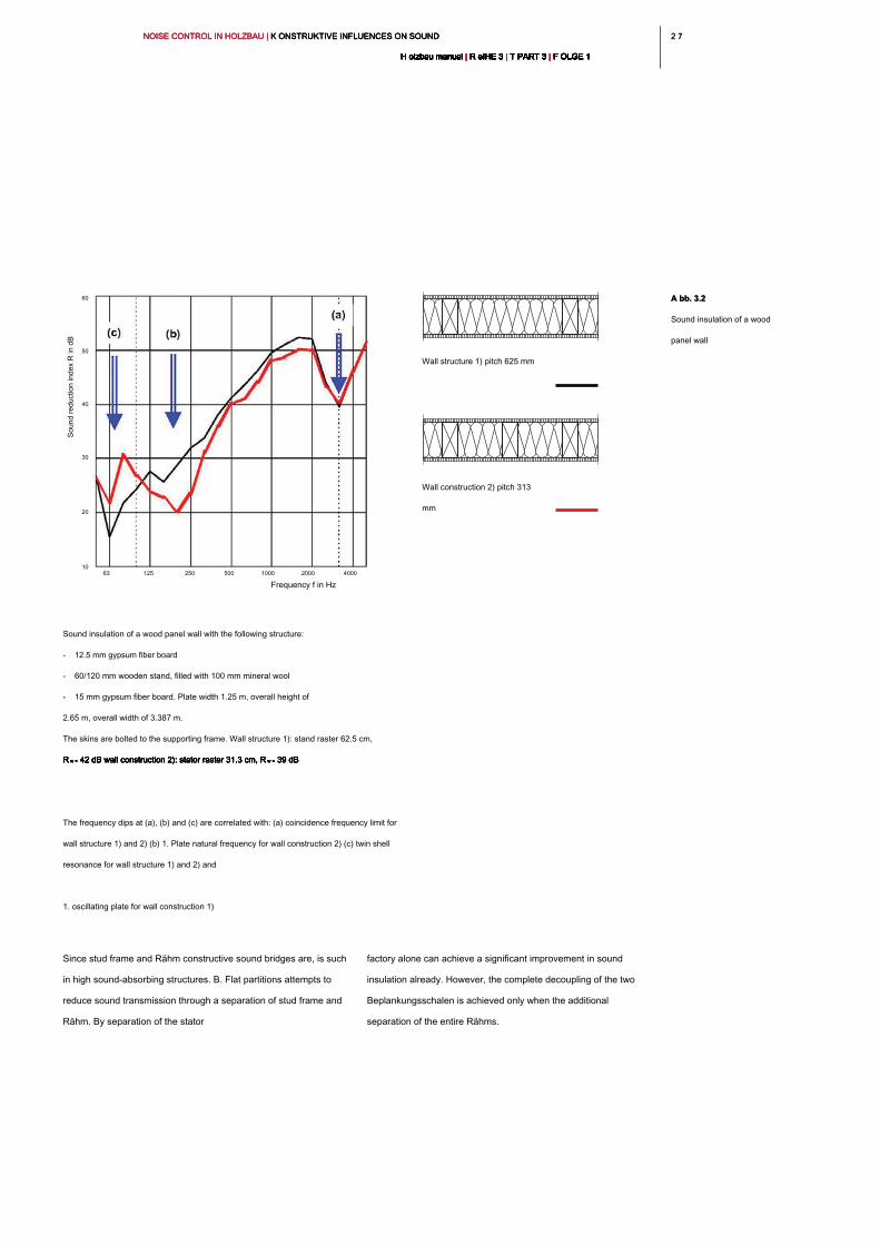
2 72 7NOISE CONTROL IN HOLZBAU | K ONSTRUKTIVE INFLUENCES ON SOUND NOISE CONTROL IN HOLZBAU | K ONSTRUKTIVE INFLUENCES ON SOUND NOISE CONTROL IN HOLZBAU | K ONSTRUKTIVE INFLUENCES ON SOUND
H olzbau manual | R eIHE 3 | T PART 3 | F OLGE 1H olzbau manual | R eIHE 3 | T PART 3 | F OLGE 1H olzbau manual | R eIHE 3 | T PART 3 | F OLGE 1H olzbau manual | R eIHE 3 | T PART 3 | F OLGE 1H olzbau manual | R eIHE 3 | T PART 3 | F OLGE 1H olzbau manual | R eIHE 3 | T PART 3 | F OLGE 1H olzbau manual | R eIHE 3 | T PART 3 | F OLGE 1H olzbau manual | R eIHE 3 | T PART 3 | F OLGE 1H olzbau manual | R eIHE 3 | T PART 3 | F OLGE 1H olzbau manual | R eIHE 3 | T PART 3 | F OLGE 1H olzbau manual | R eIHE 3 | T PART 3 | F OLGE 1
factory alone can achieve a significant improvement in sound
insulation already. However, the complete decoupling of the two
Beplankungsschalen is achieved only when the additional
separation of the entire Rähms.
Since stud frame and Rähm constructive sound bridges are, is such
in high sound-absorbing structures. B. Flat partitions attempts to
reduce sound transmission through a separation of stud frame and
Rähm. By separation of the stator
Frequency f in Hz
63 125 250 500 1000 2000 4000
60
50
40
30
20
10
A bb. 3.2A bb. 3.2
Sound insulation of a wood
panel wall
Wall structure 1) pitch 625 mm
Wall construction 2) pitch 313
mm
Sound insulation of a wood panel wall with the following structure:
- 12.5 mm gypsum fiber board
- 60/120 mm wooden stand, filled with 100 mm mineral wool
- 15 mm gypsum fiber board. Plate width 1.25 m, overall height of
2.65 m, overall width of 3.387 m.
The skins are bolted to the supporting frame. Wall structure 1): stand raster 62.5 cm,
R w = 42 dB wall construction 2): stator raster 31.3 cm, R w = 39 dBR w = 42 dB wall construction 2): stator raster 31.3 cm, R w = 39 dBR w = 42 dB wall construction 2): stator raster 31.3 cm, R w = 39 dBR w = 42 dB wall construction 2): stator raster 31.3 cm, R w = 39 dBR w = 42 dB wall construction 2): stator raster 31.3 cm, R w = 39 dB
The frequency dips at (a), (b) and (c) are correlated with: (a) coincidence frequency limit for
wall structure 1) and 2) (b) 1. Plate natural frequency for wall construction 2) (c) twin shell
resonance for wall structure 1) and 2) and
1. oscillating plate for wall construction 1)
So
un
d re
du
ctio
n in
de
x R
in
d
B
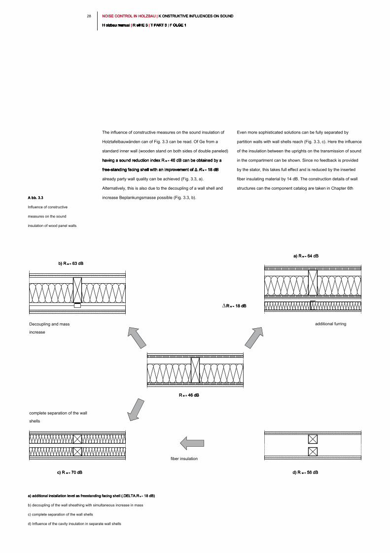
NOISE CONTROL IN HOLZBAU | K ONSTRUKTIVE INFLUENCES ON SOUND NOISE CONTROL IN HOLZBAU | K ONSTRUKTIVE INFLUENCES ON SOUND NOISE CONTROL IN HOLZBAU | K ONSTRUKTIVE INFLUENCES ON SOUND
H olzbau manual | R eIHE 3 | T PART 3 | F OLGE 1H olzbau manual | R eIHE 3 | T PART 3 | F OLGE 1H olzbau manual | R eIHE 3 | T PART 3 | F OLGE 1H olzbau manual | R eIHE 3 | T PART 3 | F OLGE 1H olzbau manual | R eIHE 3 | T PART 3 | F OLGE 1H olzbau manual | R eIHE 3 | T PART 3 | F OLGE 1H olzbau manual | R eIHE 3 | T PART 3 | F OLGE 1H olzbau manual | R eIHE 3 | T PART 3 | F OLGE 1H olzbau manual | R eIHE 3 | T PART 3 | F OLGE 1H olzbau manual | R eIHE 3 | T PART 3 | F OLGE 1H olzbau manual | R eIHE 3 | T PART 3 | F OLGE 1
28
The influence of constructive measures on the sound insulation of
Holztafelbauwänden can of Fig. 3.3 can be read. Of Ge from a
standard inner wall (wooden stand on both sides of double paneled)
having a sound reduction index R w = 46 dB can be obtained by a having a sound reduction index R w = 46 dB can be obtained by a having a sound reduction index R w = 46 dB can be obtained by a
free-standing facing shell with an improvement of Δ R w = 18 dB free-standing facing shell with an improvement of Δ R w = 18 dB free-standing facing shell with an improvement of Δ R w = 18 dB free-standing facing shell with an improvement of Δ R w = 18 dB
already party wall quality can be achieved (Fig. 3.3, a).
Alternatively, this is also due to the decoupling of a wall shell and
increase Beplankungsmasse possible (Fig. 3.3, b).
Even more sophisticated solutions can be fully separated by
partition walls with wall shells reach (Fig. 3.3, c). Here the influence
of the insulation between the uprights on the transmission of sound
in the compartment can be shown. Since no feedback is provided
by the stator, this takes full effect and is reduced by the inserted
fiber insulating material by 14 dB. The construction details of wall
structures can the component catalog are taken in Chapter 6th
a) additional installation level as freestanding facing shell (.DELTA.R w = 18 dB) a) additional installation level as freestanding facing shell (.DELTA.R w = 18 dB) a) additional installation level as freestanding facing shell (.DELTA.R w = 18 dB)
b) decoupling of the wall sheathing with simultaneous increase in mass
c) complete separation of the wall shells
d) Influence of the cavity insulation in separate wall shells
b) R w = 63 dBb) R w = 63 dBb) R w = 63 dB
a) R w = 64 dBa) R w = 64 dBa) R w = 64 dB
R w = 46 dBR w = 46 dBR w = 46 dB
c) R w = 70 dB c) R w = 70 dB c) R w = 70 dB d) R w = 56 dBd) R w = 56 dBd) R w = 56 dB
Decoupling and mass
increase
additional furring
complete separation of the wall
shells
fiber insulation
R w = 18 dBR w = 18 dBR w = 18 dB
A bb. 3.3A bb. 3.3
Influence of constructive
measures on the sound
insulation of wood panel walls
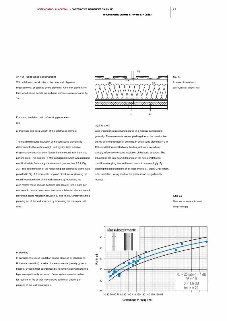
2 92 9NOISE CONTROL IN HOLZBAU | K ONSTRUKTIVE INFLUENCES ON SOUND NOISE CONTROL IN HOLZBAU | K ONSTRUKTIVE INFLUENCES ON SOUND NOISE CONTROL IN HOLZBAU | K ONSTRUKTIVE INFLUENCES ON SOUND
H olzbau manual | R eIHE 3 | T PART 3 | F OLGE 1H olzbau manual | R eIHE 3 | T PART 3 | F OLGE 1H olzbau manual | R eIHE 3 | T PART 3 | F OLGE 1H olzbau manual | R eIHE 3 | T PART 3 | F OLGE 1H olzbau manual | R eIHE 3 | T PART 3 | F OLGE 1H olzbau manual | R eIHE 3 | T PART 3 | F OLGE 1H olzbau manual | R eIHE 3 | T PART 3 | F OLGE 1H olzbau manual | R eIHE 3 | T PART 3 | F OLGE 1H olzbau manual | R eIHE 3 | T PART 3 | F OLGE 1H olzbau manual | R eIHE 3 | T PART 3 | F OLGE 1H olzbau manual | R eIHE 3 | T PART 3 | F OLGE 1
3.1.1.2 _ Solid wood constructions
With solid wood constructions, the base wall of glulam,
Brettsperrholz- or stacked board elements. Also, box elements or
thick wood-based panels are as basic elements sets (ver same fig.
3.4).
For sound insulation main influencing parameters
are:
a) thickness and basis weight of the solid wood element
The maximum sound insulation of the solid wood elements is
determined by the surface weight and rigidity. With massive
single-components can be m 'determine the sound from the mass
per unit area. This purpose, a Mas sediagramm which was obtained
empirically data from many measurement (see section 2.5.1, Fig.
2.3). The determination of the relationship for solid wood elements is
provided in Fig. 3.5 represents. improve direct mount planking the
sound reduction index of the wall structure by increasing the
area-related mass and can be taken into account in the mass per
unit area. In normal component thickness solid wood elements reach
Reviewed sound reduction between 30 and 45 dB. Directly mounted
planking act of the wall structure by increasing the mass per unit
area.
b) cladding
In principle, the sound insulation can be obtained by cladding (z.
B. thermal insulation) or skins of sheet materials (usually gypsum
board or gypsum fiber board) possibly in combination with a facing
layer are significantly increased. Some systems also be nö term
for reasons of fire or Wär meschutzes additional cladding or
planking of the wall construction.
c) joints sound
Solid wood panels are manufactured in a modular components
generally. These elements are coupled together at the construction
site via different connection systems. In small-sized elements (40 to
100 cm width) transmitted over this link joint joints sound can
strongly influence the sound insulation of the basic structure. The
influence of the joint sound depends on the actual installation
conditions (coupling joint width) and can not be sweepingly. By
cladding the base structure on at least one side (. Eg by GKBPlatten,
outer insulation, facing shell) of the joints sound is significantly
reduced.
Fig. 3.4
Example of a solid wood
construction as exterior wall
b)
c) a)
A bb. 3.5A bb. 3.5
Mass law for single solid wood
components [5]
Grammage m 'in kg / m 2Grammage m 'in kg / m 2
30 40 50 60 70 80 90 100 110 120 130 140 150 160 55
50
45
40
35
30
25
R w in
d
BR
w in
d
BR
w in
d
B
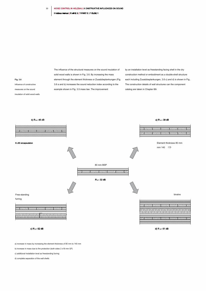
NOISE CONTROL IN HOLZBAU | K ONSTRUKTIVE INFLUENCES ON SOUND NOISE CONTROL IN HOLZBAU | K ONSTRUKTIVE INFLUENCES ON SOUND NOISE CONTROL IN HOLZBAU | K ONSTRUKTIVE INFLUENCES ON SOUND
H olzbau manual | R eIHE 3 | T PART 3 | F OLGE 1H olzbau manual | R eIHE 3 | T PART 3 | F OLGE 1H olzbau manual | R eIHE 3 | T PART 3 | F OLGE 1H olzbau manual | R eIHE 3 | T PART 3 | F OLGE 1H olzbau manual | R eIHE 3 | T PART 3 | F OLGE 1H olzbau manual | R eIHE 3 | T PART 3 | F OLGE 1H olzbau manual | R eIHE 3 | T PART 3 | F OLGE 1H olzbau manual | R eIHE 3 | T PART 3 | F OLGE 1H olzbau manual | R eIHE 3 | T PART 3 | F OLGE 1H olzbau manual | R eIHE 3 | T PART 3 | F OLGE 1H olzbau manual | R eIHE 3 | T PART 3 | F OLGE 1
30
The influence of the structural measures on the sound insulation of
solid wood walls is shown in Fig. 3.6. By increasing the mass
element through the element thickness or Zusatzbeplankungen (Fig.
3.6 a and b) increases the sound reduction index according to the
example shown in Fig. 3.5 mass law. The improvement
by an installation level as freestanding facing shell in the dry
construction method or embodiment as a double-shell structure
each including Zusatzbeplankungen, 3.6 c) and d) is shown in Fig..
The construction details of wall structures can the component
catalog are taken in Chapter 6th
Fig. 3.6
Influence of constructive
measures on the sound
insulation of solid wood walls
a) increase in mass by increasing the element thickness of 80 mm to 140 mm
b) increase in mass due to fire protection (both sides 2 x18 mm GF)
c) additional installation level as freestanding furring
d) complete separation of the wall shells
b) R w = 45 dB b) R w = 45 dB b) R w = 45 dB a) R w = 39 dBa) R w = 39 dBa) R w = 39 dB
R w = 32 dBR w = 32 dBR w = 32 dB
c) R w = 62 dB c) R w = 62 dB c) R w = 62 dB d) R w = 61 dBd) R w = 61 dBd) R w = 61 dB
K 2 60 encapsulation K 2 60 encapsulation K 2 60 encapsulation Element thickness 80 mm
mm 140
Free-standing
furring
80 mm BSP
bivalve
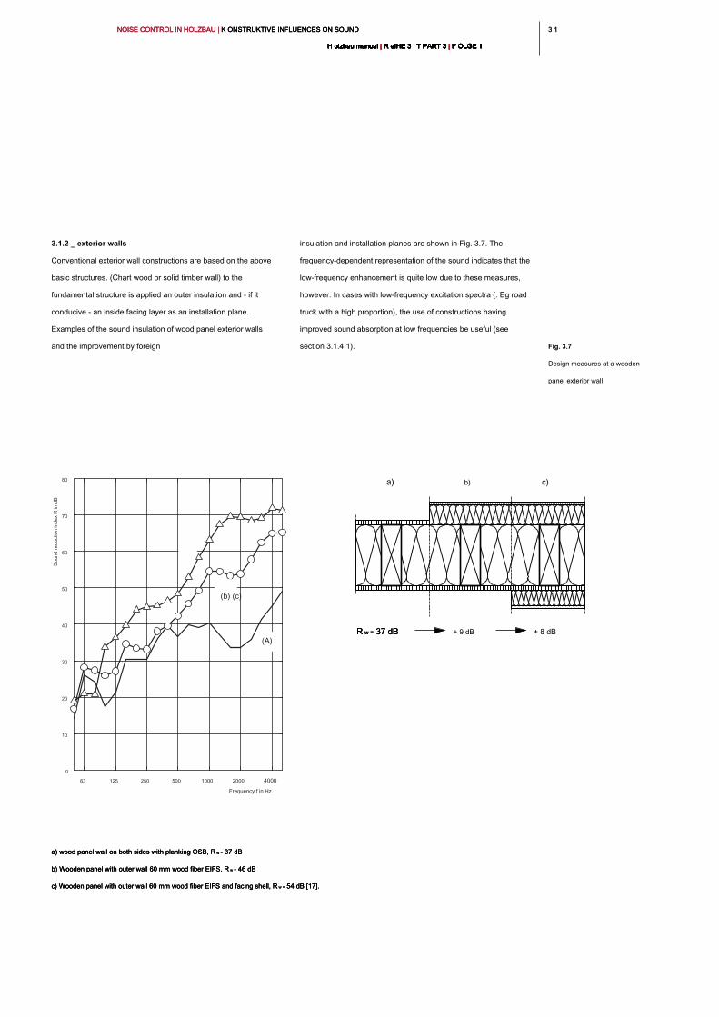
3 13 1NOISE CONTROL IN HOLZBAU | K ONSTRUKTIVE INFLUENCES ON SOUND NOISE CONTROL IN HOLZBAU | K ONSTRUKTIVE INFLUENCES ON SOUND NOISE CONTROL IN HOLZBAU | K ONSTRUKTIVE INFLUENCES ON SOUND
H olzbau manual | R eIHE 3 | T PART 3 | F OLGE 1H olzbau manual | R eIHE 3 | T PART 3 | F OLGE 1H olzbau manual | R eIHE 3 | T PART 3 | F OLGE 1H olzbau manual | R eIHE 3 | T PART 3 | F OLGE 1H olzbau manual | R eIHE 3 | T PART 3 | F OLGE 1H olzbau manual | R eIHE 3 | T PART 3 | F OLGE 1H olzbau manual | R eIHE 3 | T PART 3 | F OLGE 1H olzbau manual | R eIHE 3 | T PART 3 | F OLGE 1H olzbau manual | R eIHE 3 | T PART 3 | F OLGE 1H olzbau manual | R eIHE 3 | T PART 3 | F OLGE 1H olzbau manual | R eIHE 3 | T PART 3 | F OLGE 1
3.1.2 _ exterior walls
Conventional exterior wall constructions are based on the above
basic structures. (Chart wood or solid timber wall) to the
fundamental structure is applied an outer insulation and - if it
conducive - an inside facing layer as an installation plane.
Examples of the sound insulation of wood panel exterior walls
and the improvement by foreign
insulation and installation planes are shown in Fig. 3.7. The
frequency-dependent representation of the sound indicates that the
low-frequency enhancement is quite low due to these measures,
however. In cases with low-frequency excitation spectra (. Eg road
truck with a high proportion), the use of constructions having
improved sound absorption at low frequencies be useful (see
section 3.1.4.1). Fig. 3.7
Design measures at a wooden
panel exterior wall
a) wood panel wall on both sides with planking OSB, R w = 37 dBa) wood panel wall on both sides with planking OSB, R w = 37 dBa) wood panel wall on both sides with planking OSB, R w = 37 dB
b) Wooden panel with outer wall 60 mm wood fiber EIFS, R w = 46 dBb) Wooden panel with outer wall 60 mm wood fiber EIFS, R w = 46 dBb) Wooden panel with outer wall 60 mm wood fiber EIFS, R w = 46 dB
c) Wooden panel with outer wall 60 mm wood fiber EIFS and facing shell, R w = 54 dB [17].c) Wooden panel with outer wall 60 mm wood fiber EIFS and facing shell, R w = 54 dB [17].c) Wooden panel with outer wall 60 mm wood fiber EIFS and facing shell, R w = 54 dB [17].
Frequency f in Hz
63 125 250 500 1000 2000 4000
0
10
20
30
40
50
60
70
80
(A)
(b) (c)
R w = 37 dB R w = 37 dB R w = 37 dB + 9 dB + 8 dB
b) c)a)
So
un
d re
du
ctio
n in
de
x R
in
d
B
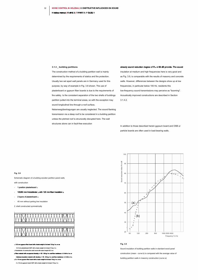
NOISE CONTROL IN HOLZBAU | K ONSTRUKTIVE INFLUENCES ON SOUND NOISE CONTROL IN HOLZBAU | K ONSTRUKTIVE INFLUENCES ON SOUND NOISE CONTROL IN HOLZBAU | K ONSTRUKTIVE INFLUENCES ON SOUND
H olzbau manual | R eIHE 3 | T PART 3 | F OLGE 1H olzbau manual | R eIHE 3 | T PART 3 | F OLGE 1H olzbau manual | R eIHE 3 | T PART 3 | F OLGE 1H olzbau manual | R eIHE 3 | T PART 3 | F OLGE 1H olzbau manual | R eIHE 3 | T PART 3 | F OLGE 1H olzbau manual | R eIHE 3 | T PART 3 | F OLGE 1H olzbau manual | R eIHE 3 | T PART 3 | F OLGE 1H olzbau manual | R eIHE 3 | T PART 3 | F OLGE 1H olzbau manual | R eIHE 3 | T PART 3 | F OLGE 1H olzbau manual | R eIHE 3 | T PART 3 | F OLGE 1H olzbau manual | R eIHE 3 | T PART 3 | F OLGE 1
32
3.1.3 _ building partitions
The construction method of a building partition wall is mainly
determined by the requirements of statics and fire protection.
Usually two set apart wall panels are in Germany used for this
purpose, by way of example in Fig. 3.8 shown. The use of
plasterboard or gypsum fiber boards is due to the requirements of
fire safety. Is the consistent separation of the two shells of buildings
partition pulled into the terminal areas, so with the exception may
sound longitudinal line through a roof surface,
Nebenwegübertragungen are usually neglected. The sound flanking
transmission via a steep roof to be considered in a building partition
unless the pitched roof is structurally disrupted here. The wall
structures alone can in fault-free execution
already sound reduction degree of R w ≥ 66 dB provide. The sound already sound reduction degree of R w ≥ 66 dB provide. The sound already sound reduction degree of R w ≥ 66 dB provide. The sound
insulation at medium and high frequencies here is very good and
as Fig. 3.9, is comparable with the results of masonry and concrete
walls. However, differences between the designs show up at low
frequencies, in particular below 100 Hz. residents this
low-frequency sound transmissions may perceive as "booming".
Acoustically improved constructions are described in Section
3.1.4.2.
In addition to those described herein gypsum board and OSB or
particle boards are often used in load-bearing walls.
Fig. 3.8
Schematic diagram of a building wooden partition panel walls
with construction
- 1 position plasterboard 1)1 position plasterboard 1)
- 120/60 mm Holzständer 2) with 120 mm fiber insulation 3)120/60 mm Holzständer 2) with 120 mm fiber insulation 3)120/60 mm Holzständer 2) with 120 mm fiber insulation 3)120/60 mm Holzständer 2) with 120 mm fiber insulation 3)
- 2 layers of plasterboard 4)2 layers of plasterboard 4)
- 45 mm without parting line insulation
2. shell constructed symmetrically
Fig. 3.9
Sound insulation of building partition walls in standard wood panel
construction (mean - curve b) is compared with the average value of
building partition walls in masonry construction (curve a)
Frequency f in Hz
63 125 250 500 1000 2000 4000
100
90
80
70
60
50
40
30
20
1 ) 12.5 mm gypsum fiber board with a basis weight of at least 15 kg / m 2 or as 1 ) 12.5 mm gypsum fiber board with a basis weight of at least 15 kg / m 2 or as 1 ) 12.5 mm gypsum fiber board with a basis weight of at least 15 kg / m 2 or as 1 ) 12.5 mm gypsum fiber board with a basis weight of at least 15 kg / m 2 or as 1 ) 12.5 mm gypsum fiber board with a basis weight of at least 15 kg / m 2 or as
12.5 mm plasterboard GKF with a basis weight of at least 10 kg / m 212.5 mm plasterboard GKF with a basis weight of at least 10 kg / m 2
2) Holzständer of constructive solid wood with stand height 62.5 cm2) Holzständer of constructive solid wood with stand height 62.5 cm
3) Fiber material with an apparent density ρ = 30 - 50 kg / m 3 and flow resistance r ≥ 5 kN s / m 4 or 3) Fiber material with an apparent density ρ = 30 - 50 kg / m 3 and flow resistance r ≥ 5 kN s / m 4 or 3) Fiber material with an apparent density ρ = 30 - 50 kg / m 3 and flow resistance r ≥ 5 kN s / m 4 or 3) Fiber material with an apparent density ρ = 30 - 50 kg / m 3 and flow resistance r ≥ 5 kN s / m 4 or 3) Fiber material with an apparent density ρ = 30 - 50 kg / m 3 and flow resistance r ≥ 5 kN s / m 4 or 3) Fiber material with an apparent density ρ = 30 - 50 kg / m 3 and flow resistance r ≥ 5 kN s / m 4 or
Cellulose insulation material with density ρ = 45 - 60 kg / m 3 and flow resistance r ≥ 5 kN s / m 4Cellulose insulation material with density ρ = 45 - 60 kg / m 3 and flow resistance r ≥ 5 kN s / m 4Cellulose insulation material with density ρ = 45 - 60 kg / m 3 and flow resistance r ≥ 5 kN s / m 4Cellulose insulation material with density ρ = 45 - 60 kg / m 3 and flow resistance r ≥ 5 kN s / m 4
4) 2 x 15 mm gypsum fiber board with a basis weight of at least 18 kg / m 2 or as 4) 2 x 15 mm gypsum fiber board with a basis weight of at least 18 kg / m 2 or as 4) 2 x 15 mm gypsum fiber board with a basis weight of at least 18 kg / m 2 or as 4) 2 x 15 mm gypsum fiber board with a basis weight of at least 18 kg / m 2 or as
2 x 18 mm gypsum board GKF with a basis weight of at least 15 kg / m 22 x 18 mm gypsum board GKF with a basis weight of at least 15 kg / m 2
So
un
d re
du
ctio
n in
de
x R
in
d
B
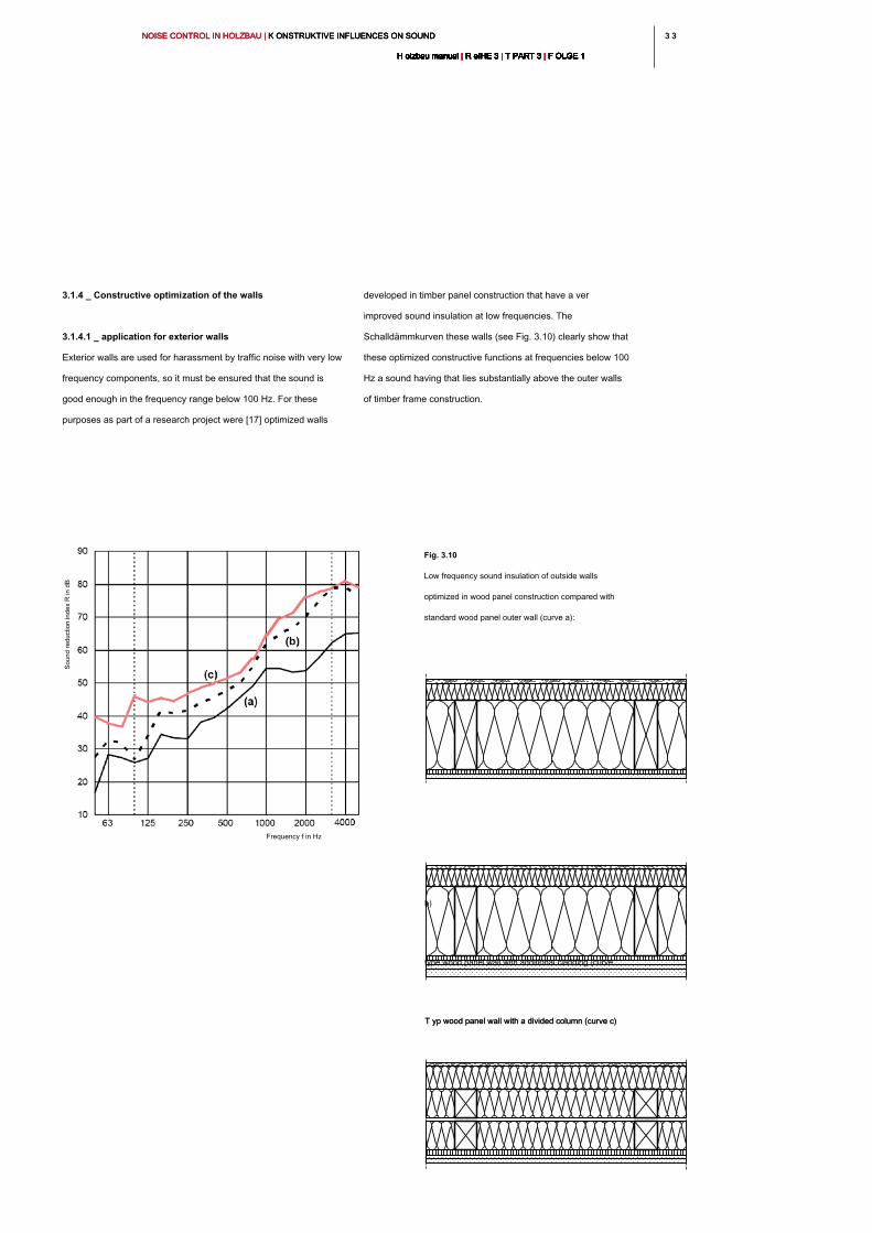
3 33 3NOISE CONTROL IN HOLZBAU | K ONSTRUKTIVE INFLUENCES ON SOUND NOISE CONTROL IN HOLZBAU | K ONSTRUKTIVE INFLUENCES ON SOUND NOISE CONTROL IN HOLZBAU | K ONSTRUKTIVE INFLUENCES ON SOUND
H olzbau manual | R eIHE 3 | T PART 3 | F OLGE 1H olzbau manual | R eIHE 3 | T PART 3 | F OLGE 1H olzbau manual | R eIHE 3 | T PART 3 | F OLGE 1H olzbau manual | R eIHE 3 | T PART 3 | F OLGE 1H olzbau manual | R eIHE 3 | T PART 3 | F OLGE 1H olzbau manual | R eIHE 3 | T PART 3 | F OLGE 1H olzbau manual | R eIHE 3 | T PART 3 | F OLGE 1H olzbau manual | R eIHE 3 | T PART 3 | F OLGE 1H olzbau manual | R eIHE 3 | T PART 3 | F OLGE 1H olzbau manual | R eIHE 3 | T PART 3 | F OLGE 1H olzbau manual | R eIHE 3 | T PART 3 | F OLGE 1
3.1.4 _ Constructive optimization of the walls
3.1.4.1 _ application for exterior walls
Exterior walls are used for harassment by traffic noise with very low
frequency components, so it must be ensured that the sound is
good enough in the frequency range below 100 Hz. For these
purposes as part of a research project were [17] optimized walls
developed in timber panel construction that have a ver
improved sound insulation at low frequencies. The
Schalldämmkurven these walls (see Fig. 3.10) clearly show that
these optimized constructive functions at frequencies below 100
Hz a sound having that lies substantially above the outer walls
of timber frame construction.
Fig. 3.10
Low frequency sound insulation of outside walls
optimized in wood panel construction compared with
standard wood panel outer wall (curve a):
Frequency f in Hz
T yp wood panel wall with a divided column (curve c) T yp wood panel wall with a divided column (curve c)
type wood panel wall with additional cladding (curve
b)
Sound reduction index R
in dB
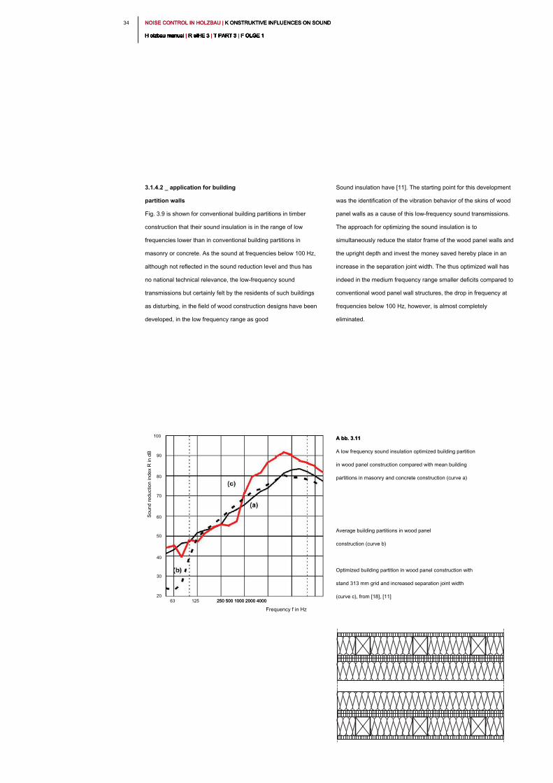
NOISE CONTROL IN HOLZBAU | K ONSTRUKTIVE INFLUENCES ON SOUND NOISE CONTROL IN HOLZBAU | K ONSTRUKTIVE INFLUENCES ON SOUND NOISE CONTROL IN HOLZBAU | K ONSTRUKTIVE INFLUENCES ON SOUND
H olzbau manual | R eIHE 3 | T PART 3 | F OLGE 1H olzbau manual | R eIHE 3 | T PART 3 | F OLGE 1H olzbau manual | R eIHE 3 | T PART 3 | F OLGE 1H olzbau manual | R eIHE 3 | T PART 3 | F OLGE 1H olzbau manual | R eIHE 3 | T PART 3 | F OLGE 1H olzbau manual | R eIHE 3 | T PART 3 | F OLGE 1H olzbau manual | R eIHE 3 | T PART 3 | F OLGE 1H olzbau manual | R eIHE 3 | T PART 3 | F OLGE 1H olzbau manual | R eIHE 3 | T PART 3 | F OLGE 1H olzbau manual | R eIHE 3 | T PART 3 | F OLGE 1H olzbau manual | R eIHE 3 | T PART 3 | F OLGE 1
34
Sound insulation have [11]. The starting point for this development
was the identification of the vibration behavior of the skins of wood
panel walls as a cause of this low-frequency sound transmissions.
The approach for optimizing the sound insulation is to
simultaneously reduce the stator frame of the wood panel walls and
the upright depth and invest the money saved hereby place in an
increase in the separation joint width. The thus optimized wall has
indeed in the medium frequency range smaller deficits compared to
conventional wood panel wall structures, the drop in frequency at
frequencies below 100 Hz, however, is almost completely
eliminated.
3.1.4.2 _ application for building
partition walls
Fig. 3.9 is shown for conventional building partitions in timber
construction that their sound insulation is in the range of low
frequencies lower than in conventional building partitions in
masonry or concrete. As the sound at frequencies below 100 Hz,
although not reflected in the sound reduction level and thus has
no national technical relevance, the low-frequency sound
transmissions but certainly felt by the residents of such buildings
as disturbing, in the field of wood construction designs have been
developed, in the low frequency range as good
Frequency f in Hz
63 125 250 500 1000 2000 4000250 500 1000 2000 4000
100
90
80
70
60
50
40
30
20
A bb. 3.11A bb. 3.11
A low frequency sound insulation optimized building partition
in wood panel construction compared with mean building
partitions in masonry and concrete construction (curve a)
Average building partitions in wood panel
construction (curve b)
Optimized building partition in wood panel construction with
stand 313 mm grid and increased separation joint width
(curve c), from [18], [11]
Sound reduction index R
in dB
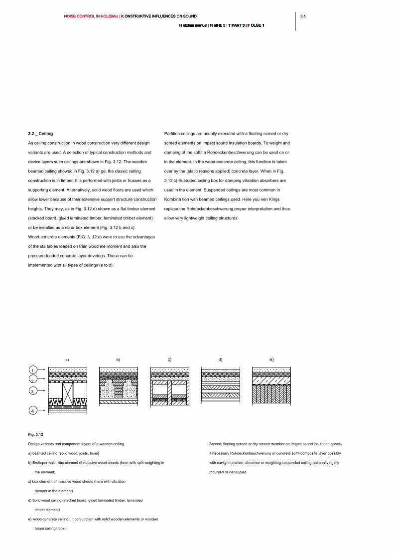
3 53 5NOISE CONTROL IN HOLZBAU | K ONSTRUKTIVE INFLUENCES ON SOUND NOISE CONTROL IN HOLZBAU | K ONSTRUKTIVE INFLUENCES ON SOUND NOISE CONTROL IN HOLZBAU | K ONSTRUKTIVE INFLUENCES ON SOUND
H olzbau manual | R eIHE 3 | T PART 3 | F OLGE 1H olzbau manual | R eIHE 3 | T PART 3 | F OLGE 1H olzbau manual | R eIHE 3 | T PART 3 | F OLGE 1H olzbau manual | R eIHE 3 | T PART 3 | F OLGE 1H olzbau manual | R eIHE 3 | T PART 3 | F OLGE 1H olzbau manual | R eIHE 3 | T PART 3 | F OLGE 1H olzbau manual | R eIHE 3 | T PART 3 | F OLGE 1H olzbau manual | R eIHE 3 | T PART 3 | F OLGE 1H olzbau manual | R eIHE 3 | T PART 3 | F OLGE 1H olzbau manual | R eIHE 3 | T PART 3 | F OLGE 1H olzbau manual | R eIHE 3 | T PART 3 | F OLGE 1
Partition ceilings are usually executed with a floating screed or dry
screed elements on impact sound insulation boards. To weight and
damping of the soffit a Rohdeckenbeschwerung can be used on or
in the element. In the wood-concrete ceiling, this function is taken
over by the (static reasons applied) concrete layer. When in Fig.
3.12 c) illustrated ceiling box for damping vibration absorbers are
used in the element. Suspended ceilings are most common in
Kombina tion with beamed ceilings used. Here you nen Kings
replace the Rohdeckenbeschwerung proper interpretation and thus
allow very lightweight ceiling structures.
3.2 _ Ceiling
As ceiling construction in wood construction very different design
variants are used. A selection of typical construction methods and
device layers such ceilings are shown in Fig. 3.12. The wooden
beamed ceiling showed in Fig. 3.12 a) ge, the classic ceiling
construction is in timber. It is performed with joists or trusses as a
supporting element. Alternatively, solid wood floors are used which
allow lower because of their extensive support structure construction
heights. They may, as in Fig. 3.12 d) shown as a flat timber element
(stacked board, glued laminated timber, laminated timber element)
or be installed as a rib or box element (Fig. 3.12 b and c).
Wood-concrete elements (FIG. 3. 12 e) were to use the advantages
of the sta tables loaded on train wood ele moment and also the
pressure-loaded concrete layer develops. These can be
implemented with all types of ceilings (a to d).
Fig. 3.12
Design variants and component layers of a wooden ceiling
a) beamed ceiling (solid wood, joists, truss)
b) Brettsperrholz- ribs element of massive wood sheets (here with split weighting in
the element)
c) box element of massive wood sheets (here with vibration
damper in the element)
d) Solid wood ceiling (stacked board, glued laminated timber, laminated
timber element)
e) wood-concrete ceiling (in conjunction with solid wooden elements or wooden
beam ceilings box)
Screed; floating screed or dry screed member on impact sound insulation panels
if necessary Rohdeckenbeschwerung or concrete soffit composite layer possibly
with cavity insulation, absorber or weighting suspended ceiling optionally rigidly
mounted or decoupled
1
2
3
4
b) c)a) d) e)
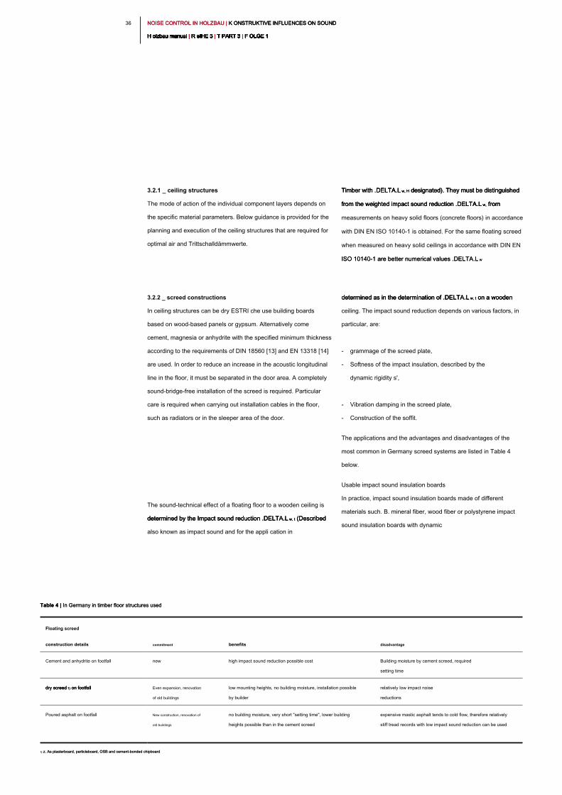
NOISE CONTROL IN HOLZBAU | K ONSTRUKTIVE INFLUENCES ON SOUND NOISE CONTROL IN HOLZBAU | K ONSTRUKTIVE INFLUENCES ON SOUND NOISE CONTROL IN HOLZBAU | K ONSTRUKTIVE INFLUENCES ON SOUND
H olzbau manual | R eIHE 3 | T PART 3 | F OLGE 1H olzbau manual | R eIHE 3 | T PART 3 | F OLGE 1H olzbau manual | R eIHE 3 | T PART 3 | F OLGE 1H olzbau manual | R eIHE 3 | T PART 3 | F OLGE 1H olzbau manual | R eIHE 3 | T PART 3 | F OLGE 1H olzbau manual | R eIHE 3 | T PART 3 | F OLGE 1H olzbau manual | R eIHE 3 | T PART 3 | F OLGE 1H olzbau manual | R eIHE 3 | T PART 3 | F OLGE 1H olzbau manual | R eIHE 3 | T PART 3 | F OLGE 1H olzbau manual | R eIHE 3 | T PART 3 | F OLGE 1H olzbau manual | R eIHE 3 | T PART 3 | F OLGE 1
36
Timber with .DELTA.L w, H designated). They must be distinguished Timber with .DELTA.L w, H designated). They must be distinguished Timber with .DELTA.L w, H designated). They must be distinguished
from the weighted impact sound reduction .DELTA.L w, from from the weighted impact sound reduction .DELTA.L w, from from the weighted impact sound reduction .DELTA.L w, from
measurements on heavy solid floors (concrete floors) in accordance
with DIN EN ISO 10140-1 is obtained. For the same floating screed
when measured on heavy solid ceilings in accordance with DIN EN
ISO 10140-1 are better numerical values .DELTA.L wISO 10140-1 are better numerical values .DELTA.L w
determined as in the determination of .DELTA.L w, t on a wooden determined as in the determination of .DELTA.L w, t on a wooden determined as in the determination of .DELTA.L w, t on a wooden
ceiling. The impact sound reduction depends on various factors, in
particular, are:
- grammage of the screed plate,
- Softness of the impact insulation, described by the
dynamic rigidity s',
- Vibration damping in the screed plate,
- Construction of the soffit.
The applications and the advantages and disadvantages of the
most common in Germany screed systems are listed in Table 4
below.
Usable impact sound insulation boards
In practice, impact sound insulation boards made of different
materials such. B. mineral fiber, wood fiber or polystyrene impact
sound insulation boards with dynamic
3.2.1 _ ceiling structures
The mode of action of the individual component layers depends on
the specific material parameters. Below guidance is provided for the
planning and execution of the ceiling structures that are required for
optimal air and Trittschalldämmwerte.
3.2.2 _ screed constructions
In ceiling structures can be dry ESTRI che use building boards
based on wood-based panels or gypsum. Alternatively come
cement, magnesia or anhydrite with the specified minimum thickness
according to the requirements of DIN 18560 [13] and EN 13318 [14]
are used. In order to reduce an increase in the acoustic longitudinal
line in the floor, it must be separated in the door area. A completely
sound-bridge-free installation of the screed is required. Particular
care is required when carrying out installation cables in the floor,
such as radiators or in the sleeper area of the door.
The sound-technical effect of a floating floor to a wooden ceiling is
determined by the Impact sound reduction .DELTA.L w, t (Described determined by the Impact sound reduction .DELTA.L w, t (Described determined by the Impact sound reduction .DELTA.L w, t (Described
also known as impact sound and for the appli cation in
Table 4 | In Germany in timber floor structures usedTable 4 | In Germany in timber floor structures used
Floating screed
construction details commitment benefits disadvantage
Cement and anhydrite on footfall new high impact sound reduction possible cost Building moisture by cement screed, required
setting time
dry screed 1) on footfalldry screed 1) on footfalldry screed 1) on footfall Even expansion, renovation
of old buildings
low mounting heights, no building moisture, installation possible
by builder
relatively low impact noise
reductions
Poured asphalt on footfall New construction, renovation of
old buildings
no building moisture, very short "setting time", lower building
heights possible than in the cement screed
expensive mastic asphalt tends to cold flow, therefore relatively
stiff tread records with low impact sound reduction can be used
1) z. As plasterboard, particleboard, OSB and cement-bonded chipboard1) z. As plasterboard, particleboard, OSB and cement-bonded chipboard
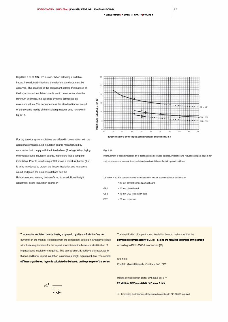
3 73 7NOISE CONTROL IN HOLZBAU | K ONSTRUKTIVE INFLUENCES ON SOUND NOISE CONTROL IN HOLZBAU | K ONSTRUKTIVE INFLUENCES ON SOUND NOISE CONTROL IN HOLZBAU | K ONSTRUKTIVE INFLUENCES ON SOUND
H olzbau manual | R eIHE 3 | T PART 3 | F OLGE 1H olzbau manual | R eIHE 3 | T PART 3 | F OLGE 1H olzbau manual | R eIHE 3 | T PART 3 | F OLGE 1H olzbau manual | R eIHE 3 | T PART 3 | F OLGE 1H olzbau manual | R eIHE 3 | T PART 3 | F OLGE 1H olzbau manual | R eIHE 3 | T PART 3 | F OLGE 1H olzbau manual | R eIHE 3 | T PART 3 | F OLGE 1H olzbau manual | R eIHE 3 | T PART 3 | F OLGE 1H olzbau manual | R eIHE 3 | T PART 3 | F OLGE 1H olzbau manual | R eIHE 3 | T PART 3 | F OLGE 1H olzbau manual | R eIHE 3 | T PART 3 | F OLGE 1
Rigidities 6 to 50 MN / m³ is used. When selecting a suitable
impact insulation admitted and the relevant standards must be
observed. The specified in the component catalog thicknesses of
the impact sound insulation boards are to be understood as the
minimum thickness, the specified dynamic stiffnesses as
maximum values. The dependence of the standard impact sound
of the dynamic rigidity of the insulating material used is shown in
fig. 3.13.
For dry screeds system solutions are offered in combination with the
appropriate impact sound insulation boards manufactured by
companies that comply with the intended use (flooring). When laying
the impact sound insulation boards, make sure that a complete
installation. Prior to introducing a Wet stroke a moisture barrier (film)
is to be introduced to protect the impact insulation and to prevent
sound bridges in the area. Installations can the
Rohdeckenbeschwerung be transferred to an additional height
adjustment board (insulation board) or.
Fig. 3.13
Improvement of sound insulation by a floating screed on wood ceilings. Impact sound reduction (impact sound) for
various screeds on mineral fiber insulation boards of different footfall dynamic stiffness.
ZE to MF = 50 mm cement screed on mineral fiber footfall sound insulation boards ZSP
= 22 mm cement-bonded particleboard
GBP = 25 mm plasterboard
OSB = 18 mm OSB installation plate
FPY = 22 mm chipboard
T rode noise insulation boards having a dynamic rigidity s ≤ 6 MN / m 'are not T rode noise insulation boards having a dynamic rigidity s ≤ 6 MN / m 'are not
currently on the market. To bodies from the component catalog in Chapter 6 realize
with these requirements for the impact sound insulation boards, a stratification of
impact sound insulation is required. This can be such. B. achieve characterized in
that an additional impact insulation is used as a height adjustment disk. The overall
stiffness s' ges the two layers is calculated to be based on the principle of the series:stiffness s' ges the two layers is calculated to be based on the principle of the series:stiffness s' ges the two layers is calculated to be based on the principle of the series:stiffness s' ges the two layers is calculated to be based on the principle of the series:
The stratification of impact sound insulation boards, make sure that the
permissible compressibility c tot = c 1 + c 2 and the required thickness of the screed permissible compressibility c tot = c 1 + c 2 and the required thickness of the screed permissible compressibility c tot = c 1 + c 2 and the required thickness of the screed permissible compressibility c tot = c 1 + c 2 and the required thickness of the screed permissible compressibility c tot = c 1 + c 2 and the required thickness of the screed permissible compressibility c tot = c 1 + c 2 and the required thickness of the screed permissible compressibility c tot = c 1 + c 2 and the required thickness of the screed permissible compressibility c tot = c 1 + c 2 and the required thickness of the screed
according to DIN 18560-2 is observed [13].
Example:
Footfall: Mineral fiber-sh, s' = 8 MN / m³, CP5
Height compensation plate: EPS DES sg, s '=
20 MN / m, CP2 s' tot = 6 MN / m³, c tot = 7 mm 20 MN / m, CP2 s' tot = 6 MN / m³, c tot = 7 mm 20 MN / m, CP2 s' tot = 6 MN / m³, c tot = 7 mm 20 MN / m, CP2 s' tot = 6 MN / m³, c tot = 7 mm 20 MN / m, CP2 s' tot = 6 MN / m³, c tot = 7 mm
- > Increasing the thickness of the screed according to DIN 18560 required
s gess ges
'= 1'= 1
1
s 1 '+ 1s 1 '+ 1s 1 '+ 1s 2 's 2 '
dynamic rigidity s' of the impact sound insulation board in MN / m 3dynamic rigidity s' of the impact sound insulation board in MN / m 3
ZE to MF
GBP / ZSP
OSB / FPY
0 5 10 15 20 25 30 35 40 45 50
30
25
20
15
10
5
0
Im
pact sound .D
ELT
A.L
w
, H in dB
Im
pact sound .D
ELT
A.L
w
, H in dB
Im
pact sound .D
ELT
A.L
w
, H in dB
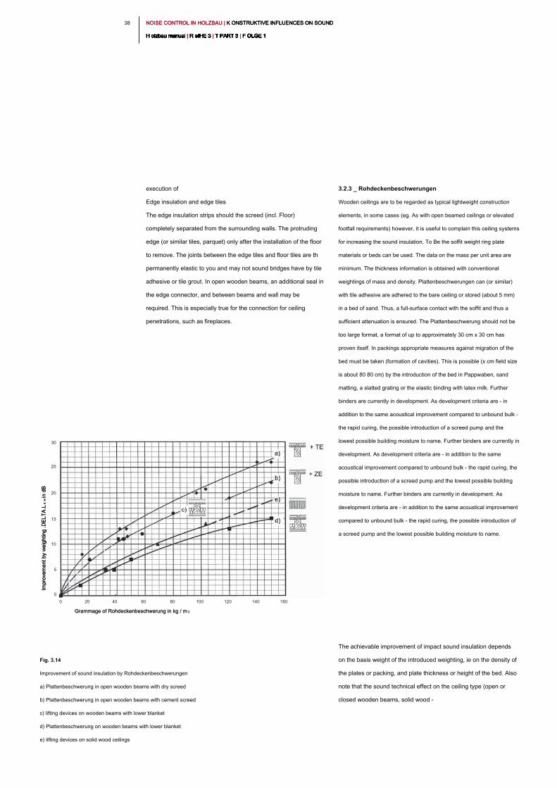
NOISE CONTROL IN HOLZBAU | K ONSTRUKTIVE INFLUENCES ON SOUND NOISE CONTROL IN HOLZBAU | K ONSTRUKTIVE INFLUENCES ON SOUND NOISE CONTROL IN HOLZBAU | K ONSTRUKTIVE INFLUENCES ON SOUND
H olzbau manual | R eIHE 3 | T PART 3 | F OLGE 1H olzbau manual | R eIHE 3 | T PART 3 | F OLGE 1H olzbau manual | R eIHE 3 | T PART 3 | F OLGE 1H olzbau manual | R eIHE 3 | T PART 3 | F OLGE 1H olzbau manual | R eIHE 3 | T PART 3 | F OLGE 1H olzbau manual | R eIHE 3 | T PART 3 | F OLGE 1H olzbau manual | R eIHE 3 | T PART 3 | F OLGE 1H olzbau manual | R eIHE 3 | T PART 3 | F OLGE 1H olzbau manual | R eIHE 3 | T PART 3 | F OLGE 1H olzbau manual | R eIHE 3 | T PART 3 | F OLGE 1H olzbau manual | R eIHE 3 | T PART 3 | F OLGE 1
38
3.2.3 _ Rohdeckenbeschwerungen
Wooden ceilings are to be regarded as typical lightweight construction
elements, in some cases (eg. As with open beamed ceilings or elevated
footfall requirements) however, it is useful to complain this ceiling systems
for increasing the sound insulation. To Be the soffit weight ring plate
materials or beds can be used. The data on the mass per unit area are
minimum. The thickness information is obtained with conventional
weightings of mass and density. Plattenbeschwerungen can (or similar)
with tile adhesive are adhered to the bare ceiling or stored (about 5 mm)
in a bed of sand. Thus, a full-surface contact with the soffit and thus a
sufficient attenuation is ensured. The Plattenbeschwerung should not be
too large format, a format of up to approximately 30 cm x 30 cm has
proven itself. In packings appropriate measures against migration of the
bed must be taken (formation of cavities). This is possible (x cm field size
is about 80 80 cm) by the introduction of the bed in Pappwaben, sand
matting, a slatted grating or the elastic binding with latex milk. Further
binders are currently in development. As development criteria are - in
addition to the same acoustical improvement compared to unbound bulk -
the rapid curing, the possible introduction of a screed pump and the
lowest possible building moisture to name. Further binders are currently in
development. As development criteria are - in addition to the same
acoustical improvement compared to unbound bulk - the rapid curing, the
possible introduction of a screed pump and the lowest possible building
moisture to name. Further binders are currently in development. As
development criteria are - in addition to the same acoustical improvement
compared to unbound bulk - the rapid curing, the possible introduction of
a screed pump and the lowest possible building moisture to name.
The achievable improvement of impact sound insulation depends
on the basis weight of the introduced weighting, ie on the density of
the plates or packing, and plate thickness or height of the bed. Also
note that the sound technical effect on the ceiling type (open or
closed wooden beams, solid wood -
execution of
Edge insulation and edge tiles
The edge insulation strips should the screed (incl. Floor)
completely separated from the surrounding walls. The protruding
edge (or similar tiles, parquet) only after the installation of the floor
to remove. The joints between the edge tiles and floor tiles are th
permanently elastic to you and may not sound bridges have by tile
adhesive or tile grout. In open wooden beams, an additional seal in
the edge connector, and between beams and wall may be
required. This is especially true for the connection for ceiling
penetrations, such as fireplaces.
Fig. 3.14
Improvement of sound insulation by Rohdeckenbeschwerungen
a) Plattenbeschwerung in open wooden beams with dry screed
b) Plattenbeschwerung in open wooden beams with cement screed
c) lifting devices on wooden beams with lower blanket
d) Plattenbeschwerung on wooden beams with lower blanket
e) lifting devices on solid wood ceilings
Grammage of Rohdeckenbeschwerung in kg / m 2Grammage of Rohdeckenbeschwerung in kg / m 2
0 20 40 60 80 100 120 140 160
30
25
20
15
10
5
0
Im
provem
ent by w
eighting .D
ELT
A.L
n
, w
in dB
Im
provem
ent by w
eighting .D
ELT
A.L
n
, w
in dB
Im
provem
ent by w
eighting .D
ELT
A.L
n
, w
in dB
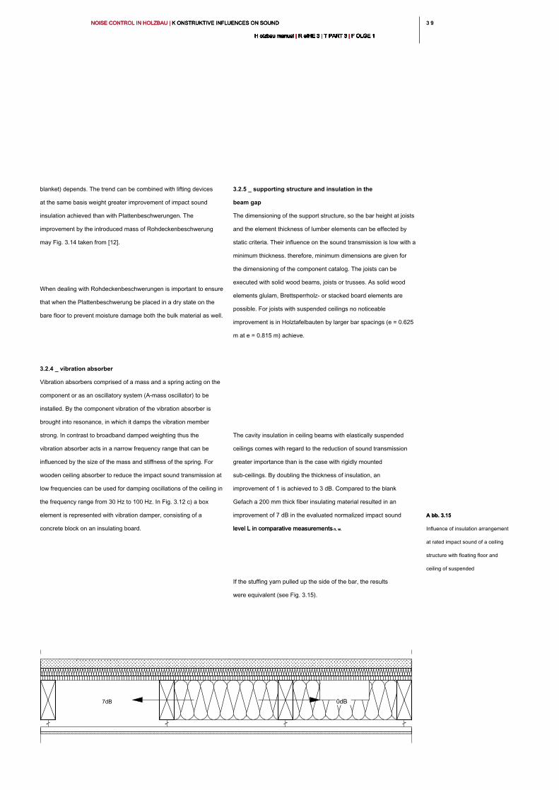
3 93 9NOISE CONTROL IN HOLZBAU | K ONSTRUKTIVE INFLUENCES ON SOUND NOISE CONTROL IN HOLZBAU | K ONSTRUKTIVE INFLUENCES ON SOUND NOISE CONTROL IN HOLZBAU | K ONSTRUKTIVE INFLUENCES ON SOUND
H olzbau manual | R eIHE 3 | T PART 3 | F OLGE 1H olzbau manual | R eIHE 3 | T PART 3 | F OLGE 1H olzbau manual | R eIHE 3 | T PART 3 | F OLGE 1H olzbau manual | R eIHE 3 | T PART 3 | F OLGE 1H olzbau manual | R eIHE 3 | T PART 3 | F OLGE 1H olzbau manual | R eIHE 3 | T PART 3 | F OLGE 1H olzbau manual | R eIHE 3 | T PART 3 | F OLGE 1H olzbau manual | R eIHE 3 | T PART 3 | F OLGE 1H olzbau manual | R eIHE 3 | T PART 3 | F OLGE 1H olzbau manual | R eIHE 3 | T PART 3 | F OLGE 1H olzbau manual | R eIHE 3 | T PART 3 | F OLGE 1
3.2.5 _ supporting structure and insulation in the
beam gap
The dimensioning of the support structure, so the bar height at joists
and the element thickness of lumber elements can be effected by
static criteria. Their influence on the sound transmission is low with a
minimum thickness. therefore, minimum dimensions are given for
the dimensioning of the component catalog. The joists can be
executed with solid wood beams, joists or trusses. As solid wood
elements glulam, Brettsperrholz- or stacked board elements are
possible. For joists with suspended ceilings no noticeable
improvement is in Holztafelbauten by larger bar spacings (e = 0.625
m at e = 0.815 m) achieve.
The cavity insulation in ceiling beams with elastically suspended
ceilings comes with regard to the reduction of sound transmission
greater importance than is the case with rigidly mounted
sub-ceilings. By doubling the thickness of insulation, an
improvement of 1 is achieved to 3 dB. Compared to the blank
Gefach a 200 mm thick fiber insulating material resulted in an
improvement of 7 dB in the evaluated normalized impact sound
level L in comparative measurements n, w.level L in comparative measurements n, w.
If the stuffing yarn pulled up the side of the bar, the results
were equivalent (see Fig. 3.15).
blanket) depends. The trend can be combined with lifting devices
at the same basis weight greater improvement of impact sound
insulation achieved than with Plattenbeschwerungen. The
improvement by the introduced mass of Rohdeckenbeschwerung
may Fig. 3.14 taken from [12].
When dealing with Rohdeckenbeschwerungen is important to ensure
that when the Plattenbeschwerung be placed in a dry state on the
bare floor to prevent moisture damage both the bulk material as well.
3.2.4 _ vibration absorber
Vibration absorbers comprised of a mass and a spring acting on the
component or as an oscillatory system (A-mass oscillator) to be
installed. By the component vibration of the vibration absorber is
brought into resonance, in which it damps the vibration member
strong. In contrast to broadband damped weighting thus the
vibration absorber acts in a narrow frequency range that can be
influenced by the size of the mass and stiffness of the spring. For
wooden ceiling absorber to reduce the impact sound transmission at
low frequencies can be used for damping oscillations of the ceiling in
the frequency range from 30 Hz to 100 Hz. In Fig. 3.12 c) a box
element is represented with vibration damper, consisting of a
concrete block on an insulating board.
7dB 0dB
A bb. 3.15A bb. 3.15
Influence of insulation arrangement
at rated impact sound of a ceiling
structure with floating floor and
ceiling of suspended
NOISE CONTROL IN HOLZBAU | K ONSTRUKTIVE INFLUENCES ON SOUND NOISE CONTROL IN HOLZBAU | K ONSTRUKTIVE INFLUENCES ON SOUND NOISE CONTROL IN HOLZBAU | K ONSTRUKTIVE INFLUENCES ON SOUND
H olzbau manual | R eIHE 3 | T PART 3 | F OLGE 1H olzbau manual | R eIHE 3 | T PART 3 | F OLGE 1H olzbau manual | R eIHE 3 | T PART 3 | F OLGE 1H olzbau manual | R eIHE 3 | T PART 3 | F OLGE 1H olzbau manual | R eIHE 3 | T PART 3 | F OLGE 1H olzbau manual | R eIHE 3 | T PART 3 | F OLGE 1H olzbau manual | R eIHE 3 | T PART 3 | F OLGE 1H olzbau manual | R eIHE 3 | T PART 3 | F OLGE 1H olzbau manual | R eIHE 3 | T PART 3 | F OLGE 1H olzbau manual | R eIHE 3 | T PART 3 | F OLGE 1H olzbau manual | R eIHE 3 | T PART 3 | F OLGE 1
40
Rigidly fixed ceilings
A standard design for wooden beams transversely fastened to a
batten layer to a beam suspended ceiling. Compared to open
beamed ceiling, the sound is improved by up to 15 dB. A double
clothing of the false ceiling (two layers of gypsum board) does not
bring any significant improvement (about 1 dB).
Decoupled mounted ceilings
By the attachment of the false ceiling by means of spring strips,
spring clips or elastic hangers good decoupling of the false ceiling
is reached. The improvements ge genüber the open beamed
ceiling must be market with suspension systems of up to 25 dB.
This is an improvement of about 10 dB with respect to the above
rigidly mounted sub-ceiling.
Evolved hangers with elastic bearings can target the hangers are
designed for the optimum natural frequency and thereby achieve
further improvements. The design is specified by the manufacturer
based on the pressure in the bearing, which results from the
distance between the hangers and the basis weight of the
suspended ceiling. As ge suitably range of this natural frequency f 0 becomessuspended ceiling. As ge suitably range of this natural frequency f 0 becomessuspended ceiling. As ge suitably range of this natural frequency f 0 becomessuspended ceiling. As ge suitably range of this natural frequency f 0 becomes
12 Hz ≤ f 0 ≤ 25 Hz12 Hz ≤ f 0 ≤ 25 Hz12 Hz ≤ f 0 ≤ 25 Hz12 Hz ≤ f 0 ≤ 25 Hz
proposed. The so balanced sub-ceiling achieved a reduction of
low-frequency impact sound transmission. In contrast to the rigidly
mounted sub-ceiling is a significant improvement, he shall submit to
the decoupled mounting by additional cladding (3 - 6 dB at mass
duplication). Here, too, several thin layers of clothing are favorable
to minimize the bending stiffness of the false ceiling.
The same applies to the type of insulation material. Improvements
to the rated impact sound by increasing the density of the insulating
material of 15 kg / m³ to 30 kg / m³ in the range of max. 1 dB. For
Einblasdämmstoffe itself has a density ≈ 40 kg / m³ found to work
well ρ. In this type of insulating material, a film and an additional
batten layer is to be inserted beneath the joists to allow the
introduction of the insulating material. A cladding is unfavorable at
this point of sound-technical point of view, because it causes an
additional mass-spring-mass resonance. To select the insulation
material see Section 2.5.6.
3.2.6 _ ceilings
The usual in timber clothing of the roof beams or the solid wood
ceilings with plasterboard (gypsum board or gypsum fiber boards)
can be of different suspended ceiling systems are designed as a
direct or clothing in form. Depending on the mounting is made of
sound-technical point of view distinguish between:
- direct cladding of the ceiling elements
- rigidly mounted ceilings (for. example, with a
batten layer)
- decoupled mounted or suspended ceilings (for example with
spring rails or elastic hangers)
Direct clothing of the ceiling elements
The direct clothes is mainly used for solid wood elements, in order to
meet the higher fire safety requirements or customer requirements
for a white sub-view. Acoustically, the direct Clothing acts by their
small masses hardly increase from. When mounting the clothing the
working of solid wood elements (sources / shrinkage) to be taken
into account.
4 14 1NOISE CONTROL IN HOLZBAU | K ONSTRUKTIVE INFLUENCES ON SOUND NOISE CONTROL IN HOLZBAU | K ONSTRUKTIVE INFLUENCES ON SOUND NOISE CONTROL IN HOLZBAU | K ONSTRUKTIVE INFLUENCES ON SOUND
H olzbau manual | R eIHE 3 | T PART 3 | F OLGE 1H olzbau manual | R eIHE 3 | T PART 3 | F OLGE 1H olzbau manual | R eIHE 3 | T PART 3 | F OLGE 1H olzbau manual | R eIHE 3 | T PART 3 | F OLGE 1H olzbau manual | R eIHE 3 | T PART 3 | F OLGE 1H olzbau manual | R eIHE 3 | T PART 3 | F OLGE 1H olzbau manual | R eIHE 3 | T PART 3 | F OLGE 1H olzbau manual | R eIHE 3 | T PART 3 | F OLGE 1H olzbau manual | R eIHE 3 | T PART 3 | F OLGE 1H olzbau manual | R eIHE 3 | T PART 3 | F OLGE 1H olzbau manual | R eIHE 3 | T PART 3 | F OLGE 1
3.2.7 _ Gehbeläge
Soft elastic Gehbeläge:
Carpeting improve the sound insulation. However, they are often
overestimated in their effect on wood-beamed ceilings. The
operation of carpets is to cushion the placement of the human foot
and to insulate a part of the sound energy already in the introduction
to the ceiling. This effect of carpets mainly affects the high-frequency
Anregun gene and is relatively low at low frequencies.
Soft elastic Gehbeläge on screed floors must not be used to detect
the minimum requirements of Intermediate floor in apartment
buildings according to DIN 4109, as the floor covering can be
replaced by subsequent users.
For practical reasons, is therefore recommended not to take into
account when planning the ceiling structures by improving soft
elastic coverings. In addition, in many homes on faces hard
flooring (tiles in kitchen, bathroom and dining room and hardwood
or stone flooring in hall, hallway and living room) lie.
Tiles and other hard, heavy coverings
Tiles are non-positively connected to the floor and thus occupy a
special position among the Gehbelägen. The increase in the total
mass (tiles + screed) causes a slight improvement in the sound at
low frequencies. By the time increment of the bending stiffness
clothes and because of the better sound input into the screed sound
insulation in the high frequencies, however deteriorated.
Both the rigid mount and the ent coupled mounted ceilings cause
by the trapped air layer has a mass-spring-mass resonance, which
results in the resonance region to amplified sound transmissions.
Since the improvements enter through the lower blanket until
above this resonance frequency is desired to move it to the lowest
possible frequencies.
Structurally this can be achieved by:
- an increase in the air layer thickness (drop height)
- an increase in mass (mass per unit area of the lower cladding)
- Hangers with a low spring rate and the greatest possible
mounting distance
These constructive sizes can be seen that a lower ceiling
subsurface ceiling elements (solid wood elements) significantly
lower improvements will bring as a wood beam ceilings. The main
cause is in the low air film thickness between the flat th elemene
and the lower ceiling. For example, a spring rail mounted with a
single layer of clothing with a solid wood ceiling, arises in relation to
the construction without suspended ceiling only an improvement of
about 4 dB in L n, w. The impact sound transmission in committing the about 4 dB in L n, w. The impact sound transmission in committing the about 4 dB in L n, w. The impact sound transmission in committing the
ceiling can even be felt by residents louder (see section 2.3).
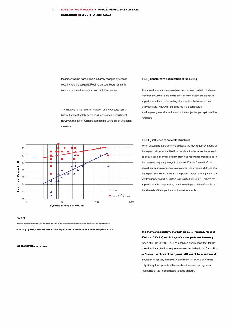
NOISE CONTROL IN HOLZBAU | K ONSTRUKTIVE INFLUENCES ON SOUND NOISE CONTROL IN HOLZBAU | K ONSTRUKTIVE INFLUENCES ON SOUND NOISE CONTROL IN HOLZBAU | K ONSTRUKTIVE INFLUENCES ON SOUND
H olzbau manual | R eIHE 3 | T PART 3 | F OLGE 1H olzbau manual | R eIHE 3 | T PART 3 | F OLGE 1H olzbau manual | R eIHE 3 | T PART 3 | F OLGE 1H olzbau manual | R eIHE 3 | T PART 3 | F OLGE 1H olzbau manual | R eIHE 3 | T PART 3 | F OLGE 1H olzbau manual | R eIHE 3 | T PART 3 | F OLGE 1H olzbau manual | R eIHE 3 | T PART 3 | F OLGE 1H olzbau manual | R eIHE 3 | T PART 3 | F OLGE 1H olzbau manual | R eIHE 3 | T PART 3 | F OLGE 1H olzbau manual | R eIHE 3 | T PART 3 | F OLGE 1H olzbau manual | R eIHE 3 | T PART 3 | F OLGE 1
42
3.2.8 _ Constructive optimization of the ceiling
The impact sound insulation of wooden ceilings is a field of intense
research activity for quite some time. In most cases, the standard
impact sound level of the ceiling structure has been studied and
analyzed here. However, the area must be considered
low-frequency sound broadcasts for the subjective perception of the
residents.
3.2.8.1 _ influence of concrete structures
When asked about parameters affecting the low-frequency sound of
the impact is to examine the floor construction because this screed
se as a mass-FederMas system often has resonance frequencies in
the relevant frequency range to the next. For the forecast of the
acoustic properties of concrete structures, the dynamic stiffness s' of
the impact sound insulation is an important factor. The impact on the
low-frequency sound insulation is illustrated in Fig. 3.16, where the
impact sound is compared by wooden ceilings, which differ only in
the strength of its impact sound insulation boards.
The analysis was performed for both the L n, w ( Frequency range of The analysis was performed for both the L n, w ( Frequency range of The analysis was performed for both the L n, w ( Frequency range of
100 Hz to 3150 Hz) and for L n, w + C I, 50-2500 ( performed frequency 100 Hz to 3150 Hz) and for L n, w + C I, 50-2500 ( performed frequency 100 Hz to 3150 Hz) and for L n, w + C I, 50-2500 ( performed frequency 100 Hz to 3150 Hz) and for L n, w + C I, 50-2500 ( performed frequency 100 Hz to 3150 Hz) and for L n, w + C I, 50-2500 ( performed frequency
range of 50 Hz to 2500 Hz). The analyzes clearly show that for the
consideration of the low frequency sound insulation in the form of L n, consideration of the low frequency sound insulation in the form of L n,
w + C I, 50-2500 the choice of the dynamic stiffness of the impact sound w + C I, 50-2500 the choice of the dynamic stiffness of the impact sound w + C I, 50-2500 the choice of the dynamic stiffness of the impact sound w + C I, 50-2500 the choice of the dynamic stiffness of the impact sound
insulation is not very decisive. A significant IMPROVE tion arises
only at very low dynamic stiffness when the mass spring-mass
resonance of the floor structure is deep enough.
the impact sound transmission is hardly changed by a wood
covering (eg. as parquet). Floating parquet floors results in
improvements in the medium and high frequencies.
The improvement in sound insulation of a wood joist ceiling
(without screed) solely by means Gehbelägen is insufficient.
However, the use of Gehbelägen can be useful as an additional
measure.
Fig. 3.16
Impact sound insulation of wooden beams with different floor structures. The screed assemblies
differ only by the dynamic stiffness s' of the impact sound insulation boards. blue: analysis with L n, wdiffer only by the dynamic stiffness s' of the impact sound insulation boards. blue: analysis with L n, w
red: analysis with L n, w + C I, 50-2500red: analysis with L n, w + C I, 50-2500red: analysis with L n, w + C I, 50-2500red: analysis with L n, w + C I, 50-2500
Dynamic sti ness s' in MN / m 3Dynamic sti ness s' in MN / m 3
1 10 100 1000
64
62
60
58
56
54
52
50
L n, w o
r L
n
, w
+ C
l, 50-2500 in
d
BL
n, w o
r L
n
, w
+ C
l, 50-2500 in
d
BL
n, w o
r L
n
, w
+ C
l, 50-2500 in
d
BL
n, w o
r L
n
, w
+ C
l, 50-2500 in
d
BL
n, w o
r L
n
, w
+ C
l, 50-2500 in
d
BL
n, w o
r L
n
, w
+ C
l, 50-2500 in
d
BL
n, w o
r L
n
, w
+ C
l, 50-2500 in
d
B
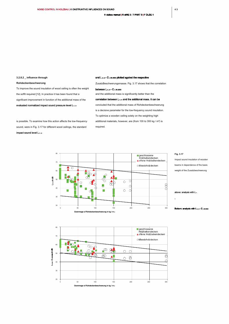
4 34 3NOISE CONTROL IN HOLZBAU | K ONSTRUKTIVE INFLUENCES ON SOUND NOISE CONTROL IN HOLZBAU | K ONSTRUKTIVE INFLUENCES ON SOUND NOISE CONTROL IN HOLZBAU | K ONSTRUKTIVE INFLUENCES ON SOUND
H olzbau manual | R eIHE 3 | T PART 3 | F OLGE 1H olzbau manual | R eIHE 3 | T PART 3 | F OLGE 1H olzbau manual | R eIHE 3 | T PART 3 | F OLGE 1H olzbau manual | R eIHE 3 | T PART 3 | F OLGE 1H olzbau manual | R eIHE 3 | T PART 3 | F OLGE 1H olzbau manual | R eIHE 3 | T PART 3 | F OLGE 1H olzbau manual | R eIHE 3 | T PART 3 | F OLGE 1H olzbau manual | R eIHE 3 | T PART 3 | F OLGE 1H olzbau manual | R eIHE 3 | T PART 3 | F OLGE 1H olzbau manual | R eIHE 3 | T PART 3 | F OLGE 1H olzbau manual | R eIHE 3 | T PART 3 | F OLGE 1
and L n, w + C I, 50-2500 plotted against the respective and L n, w + C I, 50-2500 plotted against the respective and L n, w + C I, 50-2500 plotted against the respective and L n, w + C I, 50-2500 plotted against the respective and L n, w + C I, 50-2500 plotted against the respective
ZusatzBeschwerungsmasse. Fig. 3.17 shows that the correlation
between L n, w + C I, 50-2500 between L n, w + C I, 50-2500 between L n, w + C I, 50-2500 between L n, w + C I, 50-2500
and the additional mass is significantly better than the
correlation between L n, w and the additional mass. It can be correlation between L n, w and the additional mass. It can be correlation between L n, w and the additional mass. It can be
concluded that the additional mass of Rohdeckenbeschwerung
is a decisive parameter for the low-frequency sound insulation.
To optimize a wooden ceiling solely on the weighting high
additional materials, however, are (from 100 to 300 kg / m²) is
required.
3.2.8.2 _ influence through
Rohdeckenbeschwerung
To improve the sound insulation of wood ceiling is often the weight
the soffit required [12]. In practice it has been found that a
significant improvement in function of the additional mass of the
evaluated normalized impact sound pressure level L n, wevaluated normalized impact sound pressure level L n, w
is possible. To examine how this action affects the low-frequency
sound, were in Fig. 3.17 for different wood ceilings, the standard
impact sound level L n, wimpact sound level L n, w
Fig. 3.17
Impact sound insulation of wooden
beams in dependence of the basis
weight of the Zusatzbeschwerung
above: analysis with L n, above: analysis with L n,
w
Bottom: analysis with L n, w + C I, 50-2500Bottom: analysis with L n, w + C I, 50-2500Bottom: analysis with L n, w + C I, 50-2500Bottom: analysis with L n, w + C I, 50-2500Bottom: analysis with L n, w + C I, 50-2500
Grammage of Rohdeckenbeschwerung in kg / m 2Grammage of Rohdeckenbeschwerung in kg / m 2
0 50 100 150 200 250 300
80
70
60
50
40
30
20
Grammage of Rohdeckenbeschwerung in kg / m 2Grammage of Rohdeckenbeschwerung in kg / m 2
0 50 100 150 200 250 300
80
70
60
50
40
30
20
L n
, w in dB
L n
, w in dB
L n
, w in dB
L n
, w
+ C
I, 5
0-2
50
0 in dB
L n
, w
+ C
I, 5
0-2
50
0 in dB
L n
, w
+ C
I, 5
0-2
50
0 in dB
L n
, w
+ C
I, 5
0-2
50
0 in dB
L n
, w
+ C
I, 5
0-2
50
0 in dB
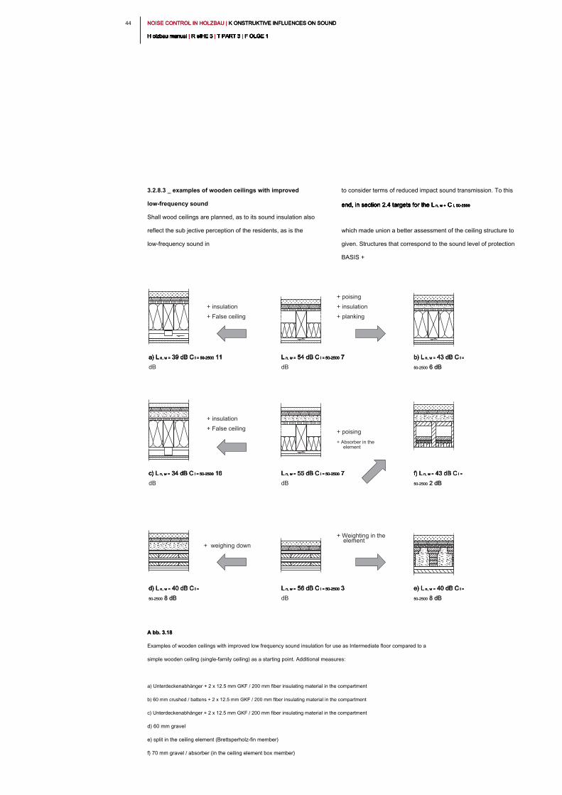
NOISE CONTROL IN HOLZBAU | K ONSTRUKTIVE INFLUENCES ON SOUND NOISE CONTROL IN HOLZBAU | K ONSTRUKTIVE INFLUENCES ON SOUND NOISE CONTROL IN HOLZBAU | K ONSTRUKTIVE INFLUENCES ON SOUND
H olzbau manual | R eIHE 3 | T PART 3 | F OLGE 1H olzbau manual | R eIHE 3 | T PART 3 | F OLGE 1H olzbau manual | R eIHE 3 | T PART 3 | F OLGE 1H olzbau manual | R eIHE 3 | T PART 3 | F OLGE 1H olzbau manual | R eIHE 3 | T PART 3 | F OLGE 1H olzbau manual | R eIHE 3 | T PART 3 | F OLGE 1H olzbau manual | R eIHE 3 | T PART 3 | F OLGE 1H olzbau manual | R eIHE 3 | T PART 3 | F OLGE 1H olzbau manual | R eIHE 3 | T PART 3 | F OLGE 1H olzbau manual | R eIHE 3 | T PART 3 | F OLGE 1H olzbau manual | R eIHE 3 | T PART 3 | F OLGE 1
44
to consider terms of reduced impact sound transmission. To this
end, in section 2.4 targets for the L n, w + C I, 50-2500end, in section 2.4 targets for the L n, w + C I, 50-2500end, in section 2.4 targets for the L n, w + C I, 50-2500end, in section 2.4 targets for the L n, w + C I, 50-2500end, in section 2.4 targets for the L n, w + C I, 50-2500
which made union a better assessment of the ceiling structure to
given. Structures that correspond to the sound level of protection
BASIS +
3.2.8.3 _ examples of wooden ceilings with improved
low-frequency sound
Shall wood ceilings are planned, as to its sound insulation also
reflect the sub jective perception of the residents, as is the
low-frequency sound in
a) L n, w = 39 dB C l = 50-2500 11 a) L n, w = 39 dB C l = 50-2500 11 a) L n, w = 39 dB C l = 50-2500 11 a) L n, w = 39 dB C l = 50-2500 11 a) L n, w = 39 dB C l = 50-2500 11
dB
+ insulation
+ False ceiling
L n, w = 54 dB C l = 50-2500 7 L n, w = 54 dB C l = 50-2500 7 L n, w = 54 dB C l = 50-2500 7 L n, w = 54 dB C l = 50-2500 7 L n, w = 54 dB C l = 50-2500 7
dB
+ poising
+ insulation
+ planking
b) L n, w = 43 dB C l = b) L n, w = 43 dB C l = b) L n, w = 43 dB C l = b) L n, w = 43 dB C l =
50-2500 6 dB50-2500 6 dB
c) L n, w = 34 dB C l = 50-2500 16 c) L n, w = 34 dB C l = 50-2500 16 c) L n, w = 34 dB C l = 50-2500 16 c) L n, w = 34 dB C l = 50-2500 16 c) L n, w = 34 dB C l = 50-2500 16
dB
+ insulation
+ False ceiling
L n, w = 55 dB C l = 50-2500 7 L n, w = 55 dB C l = 50-2500 7 L n, w = 55 dB C l = 50-2500 7 L n, w = 55 dB C l = 50-2500 7 L n, w = 55 dB C l = 50-2500 7
dB
+ poising
+ Absorber in the
element
f) L n, w = 43 dB C l = f) L n, w = 43 dB C l = f) L n, w = 43 dB C l = f) L n, w = 43 dB C l =
50-2500 2 dB50-2500 2 dB
d) L n, w = 40 dB C l = d) L n, w = 40 dB C l = d) L n, w = 40 dB C l = d) L n, w = 40 dB C l =
50-2500 8 dB50-2500 8 dB
+ weighing down
L n, w = 56 dB C l = 50-2500 3 L n, w = 56 dB C l = 50-2500 3 L n, w = 56 dB C l = 50-2500 3 L n, w = 56 dB C l = 50-2500 3 L n, w = 56 dB C l = 50-2500 3
dB
+ Weighting in the
element
e) L n, w = 40 dB C l = e) L n, w = 40 dB C l = e) L n, w = 40 dB C l = e) L n, w = 40 dB C l =
50-2500 8 dB50-2500 8 dB
A bb. 3.18A bb. 3.18
Examples of wooden ceilings with improved low frequency sound insulation for use as Intermediate floor compared to a
simple wooden ceiling (single-family ceiling) as a starting point. Additional measures:
a) Unterdeckenabhänger + 2 x 12.5 mm GKF / 200 mm fiber insulating material in the compartment
b) 60 mm crushed / battens + 2 x 12.5 mm GKF / 200 mm fiber insulating material in the compartment
c) Unterdeckenabhänger + 2 x 12.5 mm GKF / 200 mm fiber insulating material in the compartment
d) 60 mm gravel
e) split in the ceiling element (Brettsperholz-fin member)
f) 70 mm gravel / absorber (in the ceiling element box member)
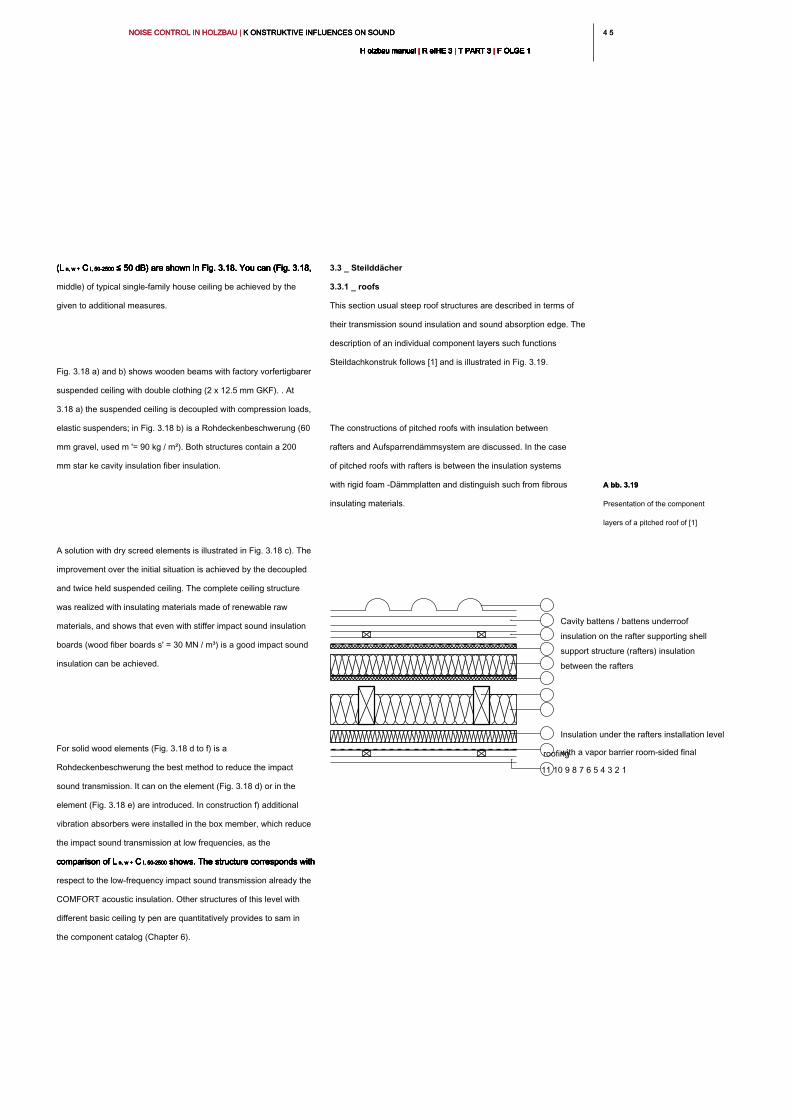
4 54 5NOISE CONTROL IN HOLZBAU | K ONSTRUKTIVE INFLUENCES ON SOUND NOISE CONTROL IN HOLZBAU | K ONSTRUKTIVE INFLUENCES ON SOUND NOISE CONTROL IN HOLZBAU | K ONSTRUKTIVE INFLUENCES ON SOUND
H olzbau manual | R eIHE 3 | T PART 3 | F OLGE 1H olzbau manual | R eIHE 3 | T PART 3 | F OLGE 1H olzbau manual | R eIHE 3 | T PART 3 | F OLGE 1H olzbau manual | R eIHE 3 | T PART 3 | F OLGE 1H olzbau manual | R eIHE 3 | T PART 3 | F OLGE 1H olzbau manual | R eIHE 3 | T PART 3 | F OLGE 1H olzbau manual | R eIHE 3 | T PART 3 | F OLGE 1H olzbau manual | R eIHE 3 | T PART 3 | F OLGE 1H olzbau manual | R eIHE 3 | T PART 3 | F OLGE 1H olzbau manual | R eIHE 3 | T PART 3 | F OLGE 1H olzbau manual | R eIHE 3 | T PART 3 | F OLGE 1
3.3 _ Steilddächer
3.3.1 _ roofs
This section usual steep roof structures are described in terms of
their transmission sound insulation and sound absorption edge. The
description of an individual component layers such functions
Steildachkonstruk follows [1] and is illustrated in Fig. 3.19.
The constructions of pitched roofs with insulation between
rafters and Aufsparrendämmsystem are discussed. In the case
of pitched roofs with rafters is between the insulation systems
with rigid foam -Dämmplatten and distinguish such from fibrous
insulating materials.
(L n, w + C I, 50-2500 ≤ 50 dB) are shown in Fig. 3.18. You can (Fig. 3.18, (L n, w + C I, 50-2500 ≤ 50 dB) are shown in Fig. 3.18. You can (Fig. 3.18, (L n, w + C I, 50-2500 ≤ 50 dB) are shown in Fig. 3.18. You can (Fig. 3.18, (L n, w + C I, 50-2500 ≤ 50 dB) are shown in Fig. 3.18. You can (Fig. 3.18, (L n, w + C I, 50-2500 ≤ 50 dB) are shown in Fig. 3.18. You can (Fig. 3.18, (L n, w + C I, 50-2500 ≤ 50 dB) are shown in Fig. 3.18. You can (Fig. 3.18,
middle) of typical single-family house ceiling be achieved by the
given to additional measures.
Fig. 3.18 a) and b) shows wooden beams with factory vorfertigbarer
suspended ceiling with double clothing (2 x 12.5 mm GKF). . At
3.18 a) the suspended ceiling is decoupled with compression loads,
elastic suspenders; in Fig. 3.18 b) is a Rohdeckenbeschwerung (60
mm gravel, used m '= 90 kg / m²). Both structures contain a 200
mm star ke cavity insulation fiber insulation.
A solution with dry screed elements is illustrated in Fig. 3.18 c). The
improvement over the initial situation is achieved by the decoupled
and twice held suspended ceiling. The complete ceiling structure
was realized with insulating materials made of renewable raw
materials, and shows that even with stiffer impact sound insulation
boards (wood fiber boards s' = 30 MN / m³) is a good impact sound
insulation can be achieved.
For solid wood elements (Fig. 3.18 d to f) is a
Rohdeckenbeschwerung the best method to reduce the impact
sound transmission. It can on the element (Fig. 3.18 d) or in the
element (Fig. 3.18 e) are introduced. In construction f) additional
vibration absorbers were installed in the box member, which reduce
the impact sound transmission at low frequencies, as the
comparison of L n, w + C I, 50-2500 shows. The structure corresponds with comparison of L n, w + C I, 50-2500 shows. The structure corresponds with comparison of L n, w + C I, 50-2500 shows. The structure corresponds with comparison of L n, w + C I, 50-2500 shows. The structure corresponds with comparison of L n, w + C I, 50-2500 shows. The structure corresponds with comparison of L n, w + C I, 50-2500 shows. The structure corresponds with
respect to the low-frequency impact sound transmission already the
COMFORT acoustic insulation. Other structures of this level with
different basic ceiling ty pen are quantitatively provides to sam in
the component catalog (Chapter 6).
11 10 9 8 7 6 5 4 3 2 1
roofing
Cavity battens / battens underroof
insulation on the rafter supporting shell
support structure (rafters) insulation
between the rafters
Insulation under the rafters installation level
with a vapor barrier room-sided final
A bb. 3.19A bb. 3.19
Presentation of the component
layers of a pitched roof of [1]
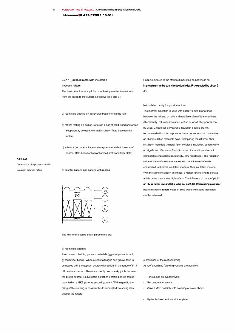
NOISE CONTROL IN HOLZBAU | K ONSTRUKTIVE INFLUENCES ON SOUND NOISE CONTROL IN HOLZBAU | K ONSTRUKTIVE INFLUENCES ON SOUND NOISE CONTROL IN HOLZBAU | K ONSTRUKTIVE INFLUENCES ON SOUND
H olzbau manual | R eIHE 3 | T PART 3 | F OLGE 1H olzbau manual | R eIHE 3 | T PART 3 | F OLGE 1H olzbau manual | R eIHE 3 | T PART 3 | F OLGE 1H olzbau manual | R eIHE 3 | T PART 3 | F OLGE 1H olzbau manual | R eIHE 3 | T PART 3 | F OLGE 1H olzbau manual | R eIHE 3 | T PART 3 | F OLGE 1H olzbau manual | R eIHE 3 | T PART 3 | F OLGE 1H olzbau manual | R eIHE 3 | T PART 3 | F OLGE 1H olzbau manual | R eIHE 3 | T PART 3 | F OLGE 1H olzbau manual | R eIHE 3 | T PART 3 | F OLGE 1H olzbau manual | R eIHE 3 | T PART 3 | F OLGE 1
46
PelN. Compared to the standard mounting on battens is an
improvement in the sound reduction index R w expected by about 2 improvement in the sound reduction index R w expected by about 2 improvement in the sound reduction index R w expected by about 2
dB.
b) insulation cavity / support structure
The thermal insulation is used with about 10 mm interference
between the rafters. Usually a Mineralfaserdämmfilz is used here.
Alternatively, cellulose insulation, cotton or wood fiber panels can
be used. Closed cell polystyrene insulation boards are not
recommended for this purpose as these poorer acoustic properties
as fiber insulation materials have. Comparing the different fiber
insulation materials (mineral fiber, cellulose insulation, cotton) were
no significant differences found in terms of sound insulation with
comparable characteristics (density, flow resistance). The reduction
value of the roof structures varies with the thickness of each
contributed to thermal insulation made of fiber insulation material.
With the same insulation thickness, a higher rafters tend to behave
a little better than a less high rafters. The influence of the roof pitch
on R w is rather low and little to be set as 2 dB. When using a cellular on R w is rather low and little to be set as 2 dB. When using a cellular on R w is rather low and little to be set as 2 dB. When using a cellular
beam instead of rafters made of solid wood-like sound insulation
can be achieved.
c) Influence of the roof sheathing
As roof sheathing following variants are possible:
- Tongue and groove formwork
- Gespundete formwork
- Waxed MDF possibly with covering of cover sheets
- Hydrophobised soft wood fiber plate
3.3.1.1 _ pitched roofs with insulation
between rafters
The basic structure of a pitched roof having a rafter insulation is
from the inside to the outside as follows (see also 0):
a) room side clothing on transverse battens or spring rails
b) rafters resting on purlins, rafters in place of solid wood and a web
support may be used, thermal insulation fitted between the
rafters
c) sub-roof (as undervoltage underlayment) or deficit (lower roof
boards, MDF-board or hydrophobised soft wood fiber plate)
d) counter battens and battens with roofing
The key for the sound effect parameters are:
a) room side cladding
Are common cladding gypsum materials (gypsum plaster board,
gypsum fiber board). When a set of a tongue and groove form is
compared with the gypsum boards with deficits in the range of 5 - 7
dB can be expected. These are mainly due to leaky joints between
the profile boards. To avoid this defect, the profile boards can be
mounted on a GKB plate as second garment. With regard to the
fixing of the clothing is possible this to decoupled via spring rails
against the rafters
dc
b
a
A bb. 3.20A bb. 3.20
Construction of a pitched roof with
insulation between rafters
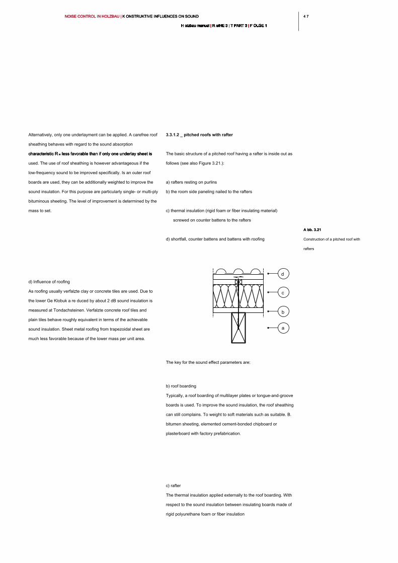
4 74 7NOISE CONTROL IN HOLZBAU | K ONSTRUKTIVE INFLUENCES ON SOUND NOISE CONTROL IN HOLZBAU | K ONSTRUKTIVE INFLUENCES ON SOUND NOISE CONTROL IN HOLZBAU | K ONSTRUKTIVE INFLUENCES ON SOUND
H olzbau manual | R eIHE 3 | T PART 3 | F OLGE 1H olzbau manual | R eIHE 3 | T PART 3 | F OLGE 1H olzbau manual | R eIHE 3 | T PART 3 | F OLGE 1H olzbau manual | R eIHE 3 | T PART 3 | F OLGE 1H olzbau manual | R eIHE 3 | T PART 3 | F OLGE 1H olzbau manual | R eIHE 3 | T PART 3 | F OLGE 1H olzbau manual | R eIHE 3 | T PART 3 | F OLGE 1H olzbau manual | R eIHE 3 | T PART 3 | F OLGE 1H olzbau manual | R eIHE 3 | T PART 3 | F OLGE 1H olzbau manual | R eIHE 3 | T PART 3 | F OLGE 1H olzbau manual | R eIHE 3 | T PART 3 | F OLGE 1
3.3.1.2 _ pitched roofs with rafter
The basic structure of a pitched roof having a rafter is inside out as
follows (see also Figure 3.21.):
a) rafters resting on purlins
b) the room side paneling nailed to the rafters
c) thermal insulation (rigid foam or fiber insulating material)
screwed on counter battens to the rafters
d) shortfall, counter battens and battens with roofing
The key for the sound effect parameters are:
b) roof boarding
Typically, a roof boarding of multilayer plates or tongue-and-groove
boards is used. To improve the sound insulation, the roof sheathing
can still complains. To weight to soft materials such as suitable. B.
bitumen sheeting, elemented cement-bonded chipboard or
plasterboard with factory prefabrication.
c) rafter
The thermal insulation applied externally to the roof boarding. With
respect to the sound insulation between insulating boards made of
rigid polyurethane foam or fiber insulation
Alternatively, only one underlayment can be applied. A carefree roof
sheathing behaves with regard to the sound absorption
characteristic R w less favorable than if only one underlay sheet is characteristic R w less favorable than if only one underlay sheet is characteristic R w less favorable than if only one underlay sheet is
used. The use of roof sheathing is however advantageous if the
low-frequency sound to be improved specifically. Is an outer roof
boards are used, they can be additionally weighted to improve the
sound insulation. For this purpose are particularly single- or multi-ply
bituminous sheeting. The level of improvement is determined by the
mass to set.
d) Influence of roofing
As roofing usually verfalzte clay or concrete tiles are used. Due to
the lower Ge Klobuk a re duced by about 2 dB sound insulation is
measured at Tondachsteinen. Verfalzte concrete roof tiles and
plain tiles behave roughly equivalent in terms of the achievable
sound insulation. Sheet metal roofing from trapezoidal sheet are
much less favorable because of the lower mass per unit area.
d
c
b
a
A bb. 3.21A bb. 3.21
Construction of a pitched roof with
rafters
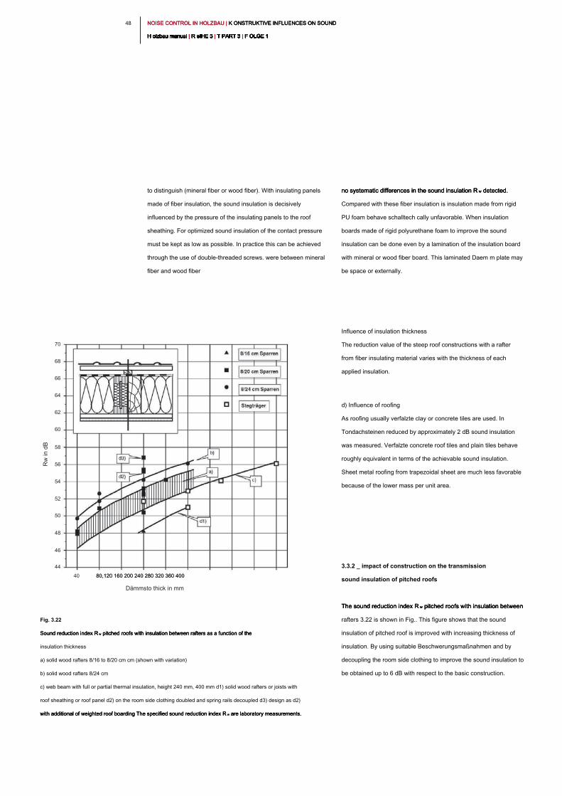
NOISE CONTROL IN HOLZBAU | K ONSTRUKTIVE INFLUENCES ON SOUND NOISE CONTROL IN HOLZBAU | K ONSTRUKTIVE INFLUENCES ON SOUND NOISE CONTROL IN HOLZBAU | K ONSTRUKTIVE INFLUENCES ON SOUND
H olzbau manual | R eIHE 3 | T PART 3 | F OLGE 1H olzbau manual | R eIHE 3 | T PART 3 | F OLGE 1H olzbau manual | R eIHE 3 | T PART 3 | F OLGE 1H olzbau manual | R eIHE 3 | T PART 3 | F OLGE 1H olzbau manual | R eIHE 3 | T PART 3 | F OLGE 1H olzbau manual | R eIHE 3 | T PART 3 | F OLGE 1H olzbau manual | R eIHE 3 | T PART 3 | F OLGE 1H olzbau manual | R eIHE 3 | T PART 3 | F OLGE 1H olzbau manual | R eIHE 3 | T PART 3 | F OLGE 1H olzbau manual | R eIHE 3 | T PART 3 | F OLGE 1H olzbau manual | R eIHE 3 | T PART 3 | F OLGE 1
48
no systematic differences in the sound insulation R w detected. no systematic differences in the sound insulation R w detected. no systematic differences in the sound insulation R w detected.
Compared with these fiber insulation is insulation made from rigid
PU foam behave schalltech cally unfavorable. When insulation
boards made of rigid polyurethane foam to improve the sound
insulation can be done even by a lamination of the insulation board
with mineral or wood fiber board. This laminated Daem m plate may
be space or externally.
Influence of insulation thickness
The reduction value of the steep roof constructions with a rafter
from fiber insulating material varies with the thickness of each
applied insulation.
d) Influence of roofing
As roofing usually verfalzte clay or concrete tiles are used. In
Tondachsteinen reduced by approximately 2 dB sound insulation
was measured. Verfalzte concrete roof tiles and plain tiles behave
roughly equivalent in terms of the achievable sound insulation.
Sheet metal roofing from trapezoidal sheet are much less favorable
because of the lower mass per unit area.
3.3.2 _ impact of construction on the transmission
sound insulation of pitched roofs
The sound reduction index R w pitched roofs with insulation between The sound reduction index R w pitched roofs with insulation between The sound reduction index R w pitched roofs with insulation between
rafters 3.22 is shown in Fig.. This figure shows that the sound
insulation of pitched roof is improved with increasing thickness of
insulation. By using suitable Beschwerungsmaßnahmen and by
decoupling the room side clothing to improve the sound insulation to
be obtained up to 6 dB with respect to the basic construction.
to distinguish (mineral fiber or wood fiber). With insulating panels
made of fiber insulation, the sound insulation is decisively
influenced by the pressure of the insulating panels to the roof
sheathing. For optimized sound insulation of the contact pressure
must be kept as low as possible. In practice this can be achieved
through the use of double-threaded screws. were between mineral
fiber and wood fiber
Fig. 3.22
Sound reduction index R w pitched roofs with insulation between rafters as a function of the Sound reduction index R w pitched roofs with insulation between rafters as a function of the Sound reduction index R w pitched roofs with insulation between rafters as a function of the
insulation thickness
a) solid wood rafters 8/16 to 8/20 cm cm (shown with variation)
b) solid wood rafters 8/24 cm
c) web beam with full or partial thermal insulation, height 240 mm, 400 mm d1) solid wood rafters or joists with
roof sheathing or roof panel d2) on the room side clothing doubled and spring rails decoupled d3) design as d2)
with additional of weighted roof boarding The specified sound reduction index R w are laboratory measurements.with additional of weighted roof boarding The specified sound reduction index R w are laboratory measurements.with additional of weighted roof boarding The specified sound reduction index R w are laboratory measurements.
Dämmsto thick in mm
40 80,120 160 200 240 280 320 360 40080,120 160 200 240 280 320 360 400
70
68
66
64
62
60
58
56
54
52
50
48
46
44
Rw
in
d
B
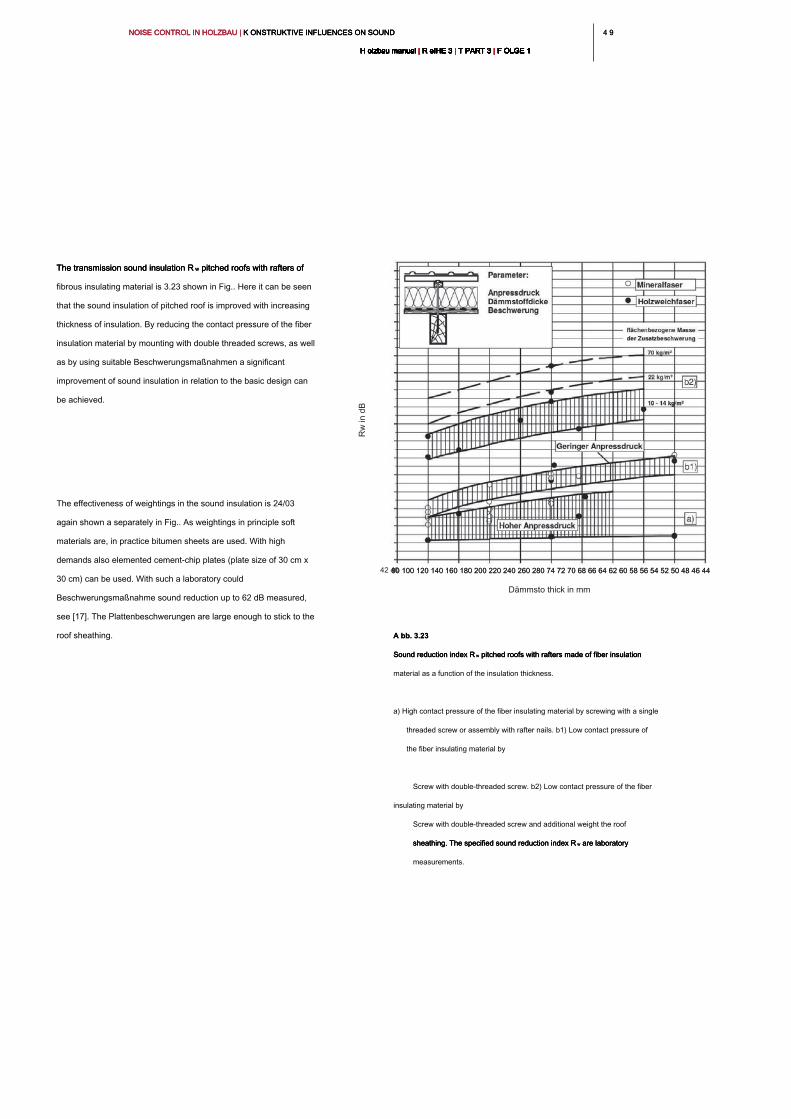
4 94 9NOISE CONTROL IN HOLZBAU | K ONSTRUKTIVE INFLUENCES ON SOUND NOISE CONTROL IN HOLZBAU | K ONSTRUKTIVE INFLUENCES ON SOUND NOISE CONTROL IN HOLZBAU | K ONSTRUKTIVE INFLUENCES ON SOUND
H olzbau manual | R eIHE 3 | T PART 3 | F OLGE 1H olzbau manual | R eIHE 3 | T PART 3 | F OLGE 1H olzbau manual | R eIHE 3 | T PART 3 | F OLGE 1H olzbau manual | R eIHE 3 | T PART 3 | F OLGE 1H olzbau manual | R eIHE 3 | T PART 3 | F OLGE 1H olzbau manual | R eIHE 3 | T PART 3 | F OLGE 1H olzbau manual | R eIHE 3 | T PART 3 | F OLGE 1H olzbau manual | R eIHE 3 | T PART 3 | F OLGE 1H olzbau manual | R eIHE 3 | T PART 3 | F OLGE 1H olzbau manual | R eIHE 3 | T PART 3 | F OLGE 1H olzbau manual | R eIHE 3 | T PART 3 | F OLGE 1
The transmission sound insulation R w pitched roofs with rafters of The transmission sound insulation R w pitched roofs with rafters of The transmission sound insulation R w pitched roofs with rafters of
fibrous insulating material is 3.23 shown in Fig.. Here it can be seen
that the sound insulation of pitched roof is improved with increasing
thickness of insulation. By reducing the contact pressure of the fiber
insulation material by mounting with double threaded screws, as well
as by using suitable Beschwerungsmaßnahmen a significant
improvement of sound insulation in relation to the basic design can
be achieved.
The effectiveness of weightings in the sound insulation is 24/03
again shown a separately in Fig.. As weightings in principle soft
materials are, in practice bitumen sheets are used. With high
demands also elemented cement-chip plates (plate size of 30 cm x
30 cm) can be used. With such a laboratory could
Beschwerungsmaßnahme sound reduction up to 62 dB measured,
see [17]. The Plattenbeschwerungen are large enough to stick to the
roof sheathing.
Dämmsto thick in mm
80 100 120 140 160 180 200 220 240 260 280 74 72 70 68 66 64 62 60 58 56 54 52 50 48 46 44 80 100 120 140 160 180 200 220 240 260 280 74 72 70 68 66 64 62 60 58 56 54 52 50 48 46 44 42 40
A bb. 3.23A bb. 3.23
Sound reduction index R w pitched roofs with rafters made of fiber insulation Sound reduction index R w pitched roofs with rafters made of fiber insulation Sound reduction index R w pitched roofs with rafters made of fiber insulation
material as a function of the insulation thickness.
a) High contact pressure of the fiber insulating material by screwing with a single
threaded screw or assembly with rafter nails. b1) Low contact pressure of
the fiber insulating material by
Screw with double-threaded screw. b2) Low contact pressure of the fiber
insulating material by
Screw with double-threaded screw and additional weight the roof
sheathing. The specified sound reduction index R w are laboratory sheathing. The specified sound reduction index R w are laboratory sheathing. The specified sound reduction index R w are laboratory
measurements.
Rw
in
d
B
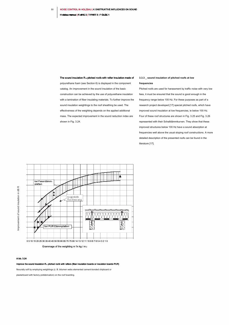
NOISE CONTROL IN HOLZBAU | K ONSTRUKTIVE INFLUENCES ON SOUND NOISE CONTROL IN HOLZBAU | K ONSTRUKTIVE INFLUENCES ON SOUND NOISE CONTROL IN HOLZBAU | K ONSTRUKTIVE INFLUENCES ON SOUND
H olzbau manual | R eIHE 3 | T PART 3 | F OLGE 1H olzbau manual | R eIHE 3 | T PART 3 | F OLGE 1H olzbau manual | R eIHE 3 | T PART 3 | F OLGE 1H olzbau manual | R eIHE 3 | T PART 3 | F OLGE 1H olzbau manual | R eIHE 3 | T PART 3 | F OLGE 1H olzbau manual | R eIHE 3 | T PART 3 | F OLGE 1H olzbau manual | R eIHE 3 | T PART 3 | F OLGE 1H olzbau manual | R eIHE 3 | T PART 3 | F OLGE 1H olzbau manual | R eIHE 3 | T PART 3 | F OLGE 1H olzbau manual | R eIHE 3 | T PART 3 | F OLGE 1H olzbau manual | R eIHE 3 | T PART 3 | F OLGE 1
50
3.3.3 _ sound insulation of pitched roofs at low
frequencies
Pitched roofs are used for harassment by traffic noise with very low
fees, it must be ensured that the sound is good enough in the
frequency range below 100 Hz. For these purposes as part of a
research project developed [17] special pitched roofs, which have
improved sound insulation at low frequencies, ie below 100 Hz.
Four of these roof structures are shown in Fig. 3.25 and Fig. 3.26
represented with their Schalldämmkurven. They show that these
improved structures below 100 Hz have a sound absorption at
frequencies well above the usual sloping roof constructions. A more
detailed description of the presented roofs can be found in the
literature [17].
The sound insulation R w pitched roofs with rafter insulation made of The sound insulation R w pitched roofs with rafter insulation made of The sound insulation R w pitched roofs with rafter insulation made of
polyurethane foam (see Section 6) is displayed in the component
catalog. An improvement in the sound insulation of the basic
construction can be achieved by the use of polyurethane insulation
with a lamination of fiber insulating materials. To further improve the
sound insulation weightings to the roof sheathing be used. The
effectiveness of the weighting depends on the applied additional
mass. The expected improvement in the sound reduction index are
shown in Fig. 3.24.
Grammage of the weighting m 'in kg / m 2Grammage of the weighting m 'in kg / m 2
0 5 10 15 20 25 30 35 40 45 50 55 60 65 70 75 80 14 13 12 11 10 9 8 7 6 5 4 3 2 1 00 5 10 15 20 25 30 35 40 45 50 55 60 65 70 75 80 14 13 12 11 10 9 8 7 6 5 4 3 2 1 0
A bb. 3.24A bb. 3.24
Improve the sound insulation R w pitched roofs with rafters (fiber insulation boards or insulation boards PUR) Improve the sound insulation R w pitched roofs with rafters (fiber insulation boards or insulation boards PUR) Improve the sound insulation R w pitched roofs with rafters (fiber insulation boards or insulation boards PUR)
flexurally soft by employing weightings (z. B. bitumen webs elemented cement-bonded chipboard or
plasterboard with factory prefabrication) on the roof boarding.
Im
pro
ve
me
nt o
f so
un
d in
su
la
tio
n in
d
B R
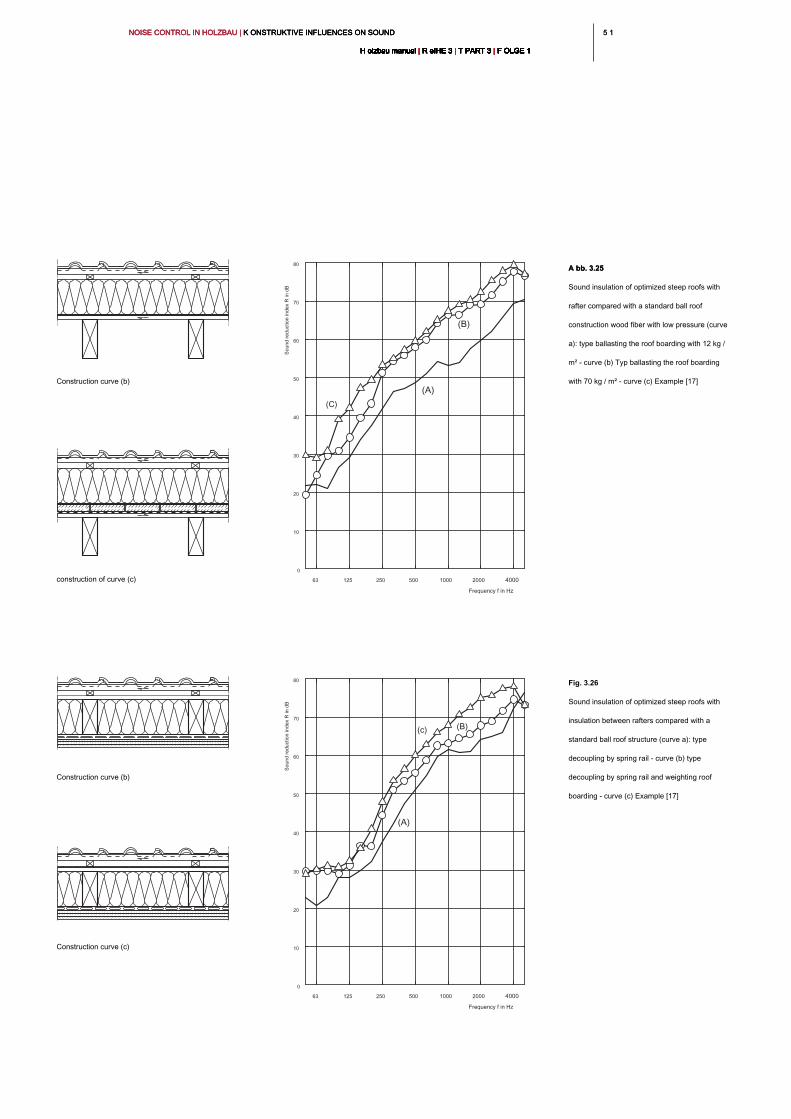
5 15 1NOISE CONTROL IN HOLZBAU | K ONSTRUKTIVE INFLUENCES ON SOUND NOISE CONTROL IN HOLZBAU | K ONSTRUKTIVE INFLUENCES ON SOUND NOISE CONTROL IN HOLZBAU | K ONSTRUKTIVE INFLUENCES ON SOUND
H olzbau manual | R eIHE 3 | T PART 3 | F OLGE 1H olzbau manual | R eIHE 3 | T PART 3 | F OLGE 1H olzbau manual | R eIHE 3 | T PART 3 | F OLGE 1H olzbau manual | R eIHE 3 | T PART 3 | F OLGE 1H olzbau manual | R eIHE 3 | T PART 3 | F OLGE 1H olzbau manual | R eIHE 3 | T PART 3 | F OLGE 1H olzbau manual | R eIHE 3 | T PART 3 | F OLGE 1H olzbau manual | R eIHE 3 | T PART 3 | F OLGE 1H olzbau manual | R eIHE 3 | T PART 3 | F OLGE 1H olzbau manual | R eIHE 3 | T PART 3 | F OLGE 1H olzbau manual | R eIHE 3 | T PART 3 | F OLGE 1
Frequency f in Hz
63 125 250 500 1000 2000 4000
0
10
20
30
40
50
60
70
80
(A)
(B)
(C)
Frequency f in Hz
63 125 250 500 1000 2000 4000
0
10
20
30
40
50
60
70
80
(A)
(B)
(c)
A bb. 3.25A bb. 3.25
Sound insulation of optimized steep roofs with
rafter compared with a standard ball roof
construction wood fiber with low pressure (curve
a): type ballasting the roof boarding with 12 kg /
m² - curve (b) Typ ballasting the roof boarding
with 70 kg / m² - curve (c) Example [17]
Fig. 3.26
Sound insulation of optimized steep roofs with
insulation between rafters compared with a
standard ball roof structure (curve a): type
decoupling by spring rail - curve (b) type
decoupling by spring rail and weighting roof
boarding - curve (c) Example [17]
Construction curve (b)
Construction curve (b)
construction of curve (c)
Construction curve (c)
Sound reduction index R
in dB
Sound reduction index R
in dB
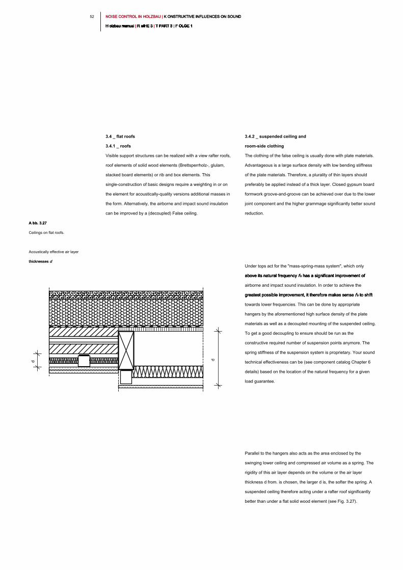
NOISE CONTROL IN HOLZBAU | K ONSTRUKTIVE INFLUENCES ON SOUND NOISE CONTROL IN HOLZBAU | K ONSTRUKTIVE INFLUENCES ON SOUND NOISE CONTROL IN HOLZBAU | K ONSTRUKTIVE INFLUENCES ON SOUND
H olzbau manual | R eIHE 3 | T PART 3 | F OLGE 1H olzbau manual | R eIHE 3 | T PART 3 | F OLGE 1H olzbau manual | R eIHE 3 | T PART 3 | F OLGE 1H olzbau manual | R eIHE 3 | T PART 3 | F OLGE 1H olzbau manual | R eIHE 3 | T PART 3 | F OLGE 1H olzbau manual | R eIHE 3 | T PART 3 | F OLGE 1H olzbau manual | R eIHE 3 | T PART 3 | F OLGE 1H olzbau manual | R eIHE 3 | T PART 3 | F OLGE 1H olzbau manual | R eIHE 3 | T PART 3 | F OLGE 1H olzbau manual | R eIHE 3 | T PART 3 | F OLGE 1H olzbau manual | R eIHE 3 | T PART 3 | F OLGE 1
52
3.4.2 _ suspended ceiling and
room-side clothing
The clothing of the false ceiling is usually done with plate materials.
Advantageous is a large surface density with low bending stiffness
of the plate materials. Therefore, a plurality of thin layers should
preferably be applied instead of a thick layer. Closed gypsum board
formwork groove-and-groove can be achieved over due to the lower
joint component and the higher grammage significantly better sound
reduction.
Under tops act for the "mass-spring-mass system", which only
above its natural frequency f 0 has a significant improvement of above its natural frequency f 0 has a significant improvement of above its natural frequency f 0 has a significant improvement of above its natural frequency f 0 has a significant improvement of
airborne and impact sound insulation. In order to achieve the
greatest possible improvement, it therefore makes sense f 0 to shift greatest possible improvement, it therefore makes sense f 0 to shift greatest possible improvement, it therefore makes sense f 0 to shift greatest possible improvement, it therefore makes sense f 0 to shift
towards lower frequencies. This can be done by appropriate
hangers by the aforementioned high surface density of the plate
materials as well as a decoupled mounting of the suspended ceiling.
To get a good decoupling to ensure should be run as the
constructive required number of suspension points anymore. The
spring stiffness of the suspension system is proprietary. Your sound
technical effectiveness can be (see component catalog Chapter 6
details) based on the location of the natural frequency for a given
load guarantee.
Parallel to the hangers also acts as the area enclosed by the
swinging lower ceiling and compressed air volume as a spring. The
rigidity of this air layer depends on the volume or the air layer
thickness d from. is chosen, the larger d is, the softer the spring. A
suspended ceiling therefore acting under a rafter roof significantly
better than under a flat solid wood element (see Fig. 3.27).
3.4 _ flat roofs
3.4.1 _ roofs
Visible support structures can be realized with a view rafter roofs,
roof elements of solid wood elements (Brettsperrholz-, glulam,
stacked board elements) or rib and box elements. This
single-construction of basic designs require a weighting in or on
the element for acoustically-quality versions additional masses in
the form. Alternatively, the airborne and impact sound insulation
can be improved by a (decoupled) False ceiling.
A bb. 3.27A bb. 3.27
Ceilings on flat roofs.
Acoustically effective air layer
thicknesses dthicknesses d
d
d
5 35 3NOISE CONTROL IN HOLZBAU | K ONSTRUKTIVE INFLUENCES ON SOUND NOISE CONTROL IN HOLZBAU | K ONSTRUKTIVE INFLUENCES ON SOUND NOISE CONTROL IN HOLZBAU | K ONSTRUKTIVE INFLUENCES ON SOUND
H olzbau manual | R eIHE 3 | T PART 3 | F OLGE 1H olzbau manual | R eIHE 3 | T PART 3 | F OLGE 1H olzbau manual | R eIHE 3 | T PART 3 | F OLGE 1H olzbau manual | R eIHE 3 | T PART 3 | F OLGE 1H olzbau manual | R eIHE 3 | T PART 3 | F OLGE 1H olzbau manual | R eIHE 3 | T PART 3 | F OLGE 1H olzbau manual | R eIHE 3 | T PART 3 | F OLGE 1H olzbau manual | R eIHE 3 | T PART 3 | F OLGE 1H olzbau manual | R eIHE 3 | T PART 3 | F OLGE 1H olzbau manual | R eIHE 3 | T PART 3 | F OLGE 1H olzbau manual | R eIHE 3 | T PART 3 | F OLGE 1
3.4.4 _ sealing, roof covering and a floor
covering
The structure above the insulating layer is varied depending on use.
For non-accessible flat roofs gravel beds, extensive green roofs or
roofing membranes are used. The version with roofing sheets
without additional mass results expected lower sound reduction.
However, previous comparative measurements [22] were
significantly lower than the same sound reduction with gravel pads
grammage for roof structures with extensive roof greening. The
cause is still to be clarified. In gravel pads or extensive roofs, the
influence is also to take into account the moisture behavior. For
slightly sloping roofs Metal roofing are used. Light roof waterproofing
and metal roofing behave total less favorable than serious, more
layers applied waterproofing membranes. In addition, with tin roofs,
the noise must be considered when heavy rain. Also because of the
moisture protection structured release liners should be used, thereby
effecting an effective reduction of noise.
As used roof terraces, accessible roofing can with concrete slabs in
the gravel, slabs on pedestals or a wood pallet to be executed. While
the concrete slabs are effective in the gravel by their mass per unit
area, an additional reduction of transmission by decoupling
measures can be achieved with pedestals and wooden grids (elastic
bearing on structural bearings). For this, the decoupling material
from
3.4.3 _ insulation
Non-pressure-loaded insulation materials between rafters and in the
false ceiling have a sound-absorbing, in the sound energy by friction
and is transformed between the insulating fibers in heat energy. For
this purpose, an open cell structure of the insulation material is
necessary on the one hand enables the sound pressure wave
penetration and on the other hand, opposes a sufficiently large
resistance. A good sound-absorbing effect is achieved by insulating
materials, whose length-related flow resistance R between 5 kPa s /
m² and 50 kPa s / m [1]. This can be both with fiber insulation
materials from renewable resources than can be achieved with
conventional insulating materials. Closed cell insulating boards (z.
B. Foam Boards) are not suitable.
Pressure-loaded roof insulation have in addition to the absorbing
effect also has the task of decoupling. For pitched roofs are used for
this purpose in roof constructions with sound insulation
requirements often fiber insulation boards. This is possible even
with flat roofs with sheet metal covering (see component catalog
Chapter 6). For flat roofs, rigid foam insulation boards are mostly
used because of the higher load. These behave initially un favorable
because of its high stiffness, low density and lack of absorption. In
connection with thin sealing systems hail or bird impact can lead to
noticeable Licher noise. A significant improvement is possible,
however, by a ge prop Neten construction above the insulation
layer.
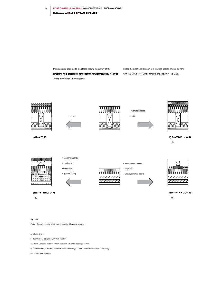
NOISE CONTROL IN HOLZBAU | K ONSTRUKTIVE INFLUENCES ON SOUND NOISE CONTROL IN HOLZBAU | K ONSTRUKTIVE INFLUENCES ON SOUND NOISE CONTROL IN HOLZBAU | K ONSTRUKTIVE INFLUENCES ON SOUND
H olzbau manual | R eIHE 3 | T PART 3 | F OLGE 1H olzbau manual | R eIHE 3 | T PART 3 | F OLGE 1H olzbau manual | R eIHE 3 | T PART 3 | F OLGE 1H olzbau manual | R eIHE 3 | T PART 3 | F OLGE 1H olzbau manual | R eIHE 3 | T PART 3 | F OLGE 1H olzbau manual | R eIHE 3 | T PART 3 | F OLGE 1H olzbau manual | R eIHE 3 | T PART 3 | F OLGE 1H olzbau manual | R eIHE 3 | T PART 3 | F OLGE 1H olzbau manual | R eIHE 3 | T PART 3 | F OLGE 1H olzbau manual | R eIHE 3 | T PART 3 | F OLGE 1H olzbau manual | R eIHE 3 | T PART 3 | F OLGE 1
54
under the additional burden of a walking person should be mm
with .DELTA.t <1.5. Embodiments are shown in Fig. 3.28.
Manufacturer adapted to a suitable natural frequency of the
structure. As a practicable range for the natural frequency f 0 = 60 to structure. As a practicable range for the natural frequency f 0 = 60 to structure. As a practicable range for the natural frequency f 0 = 60 to structure. As a practicable range for the natural frequency f 0 = 60 to
70 Hz are desired. the deflection
Fig. 3.28
Flat roofs rafter or solid wood elements with different structures:
a) 50 mm gravel
b) 40 mm Concrete plates, 30 mm crushed
c) 40 mm Concrete plates,> 40 mm pedestal, structural bearings 12 mm
d) 26 mm boards, 44 mm square timber, structural bearings 12 mm, 40 mm crushed and Betonplattung
(under structural bearings)
a) R w = 70 dBa) R w = 70 dBa) R w = 70 dB
+ gravel
+ Concrete slabs
+ split
b) R w = 70 dB L n, w = 44 b) R w = 70 dB L n, w = 44 b) R w = 70 dB L n, w = 44 b) R w = 70 dB L n, w = 44 b) R w = 70 dB L n, w = 44
dB
d) R w = 51 dB L n, w = 45 d) R w = 51 dB L n, w = 45 d) R w = 51 dB L n, w = 45 d) R w = 51 dB L n, w = 45 d) R w = 51 dB L n, w = 45
dB
c) R w = 51 dB L n, w = 38 c) R w = 51 dB L n, w = 38 c) R w = 51 dB L n, w = 38 c) R w = 51 dB L n, w = 38 c) R w = 51 dB L n, w = 38
dB
+ concrete slabs
+ pedestal
+ construction camp
+ gravel filling
+ Floorboards, timber
+ construction camp
+ Gravel, concrete blocks
5 55 5NOISE CONTROL IN HOLZBAU | B AUAKUSTISCHE PRELIMINARY OF PARTS HOLZBAU NOISE CONTROL IN HOLZBAU | B AUAKUSTISCHE PRELIMINARY OF PARTS HOLZBAU NOISE CONTROL IN HOLZBAU | B AUAKUSTISCHE PRELIMINARY OF PARTS HOLZBAU
H olzbau manual | R eIHE 3 | T PART 3 | F OLGE 1H olzbau manual | R eIHE 3 | T PART 3 | F OLGE 1H olzbau manual | R eIHE 3 | T PART 3 | F OLGE 1H olzbau manual | R eIHE 3 | T PART 3 | F OLGE 1H olzbau manual | R eIHE 3 | T PART 3 | F OLGE 1H olzbau manual | R eIHE 3 | T PART 3 | F OLGE 1H olzbau manual | R eIHE 3 | T PART 3 | F OLGE 1H olzbau manual | R eIHE 3 | T PART 3 | F OLGE 1H olzbau manual | R eIHE 3 | T PART 3 | F OLGE 1H olzbau manual | R eIHE 3 | T PART 3 | F OLGE 1H olzbau manual | R eIHE 3 | T PART 3 | F OLGE 1
can. The necessary calculation was carried out calculations
according to [30]. For a description of these calculations and the
application built the detection method for wood is made to the
progenies of this publication.
Vorbemessungsbeispiel:
As an example of the preliminary design to a Ge serve to MBO
buildings of building class. 4 this fig. 4.1 and 4.2 show the essential
information. For building acoustics preliminary design has proven
itself to first examine the partition ceilings since the building
acoustics highest demands are placed on them in the timber. then
with the definition of the ceiling structure, the edges of the further
construction in part will turn parts. This determines the structure of
this chapter.
In addition to the requirements for sound protection requirement also
features fire protection should be considered. The focus is on high
fire-retardant construction. For timber construction requirements of
building material class fire resistance, and the so-called
encapsulation of the components will be provided depending on the
state. Of particular note is the encapsulation as nonflammable here
layers mm in a total thickness of about 36 is required. This leads to
severe non-combustible Beplankungsschichten who are building
acoustics have a positive effect if properly arrangement. A respected
in tegrale, cross-disciplinary planning, fire, noise, heat insulation and
sta tic aspects alike, in the mo nen timber is essential.
4 _ Building acoustics preliminary design of timber structures4 _ Building acoustics preliminary design of timber structures
In the following sections, the building acoustics planning is
represented by a simple and lying on the safe side preliminary
design for an example situation in multi-storey timber construction.
The focus is placed on the data sources and the procedure. The
preliminary design usually takes place at an early planning stage,
so the foundation for a solid building acoustics planning can put
through a proper preliminary design and a aufwän ended
component repair can be avoided at a later date.
The following building acoustics in the planning process to the
preliminary design exact calculation in the detection method
according to DIN 4109-2 [1] results, depending on the geometric
conditions in the respective building situation, for the detection of
airborne sound in buildings of wooden panel construction same or
better results. Building of solid wood construction can not yet be
calculated according to DIN 4109-2 [1] currently. For often decisive
impact sound detection of partition ceilings, the calculation gives
the same results as per DIN 4109-2 [1], since the detection method
allows no consideration of the geometric relationships and
differently executed flanks.
In addition are therefore presented next to the
Vorbemessungsverfahren additional combination matrices for
separating ceilings and partitions that allow one hand, a quick and
safe selection of different combinations of components and on the
other hand cover component combinations that are not calculated in
accordance with DIN 4109-2 [1]
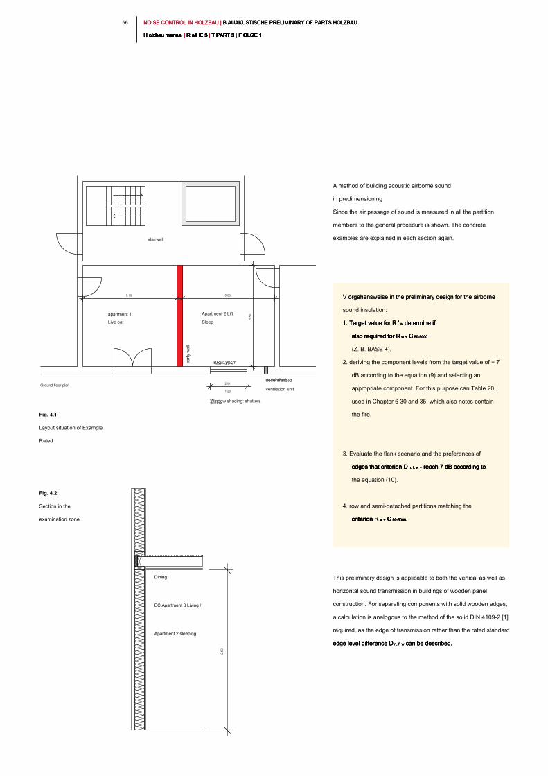
NOISE CONTROL IN HOLZBAU | B AUAKUSTISCHE PRELIMINARY OF PARTS HOLZBAU NOISE CONTROL IN HOLZBAU | B AUAKUSTISCHE PRELIMINARY OF PARTS HOLZBAU NOISE CONTROL IN HOLZBAU | B AUAKUSTISCHE PRELIMINARY OF PARTS HOLZBAU
H olzbau manual | R eIHE 3 | T PART 3 | F OLGE 1H olzbau manual | R eIHE 3 | T PART 3 | F OLGE 1H olzbau manual | R eIHE 3 | T PART 3 | F OLGE 1H olzbau manual | R eIHE 3 | T PART 3 | F OLGE 1H olzbau manual | R eIHE 3 | T PART 3 | F OLGE 1H olzbau manual | R eIHE 3 | T PART 3 | F OLGE 1H olzbau manual | R eIHE 3 | T PART 3 | F OLGE 1H olzbau manual | R eIHE 3 | T PART 3 | F OLGE 1H olzbau manual | R eIHE 3 | T PART 3 | F OLGE 1H olzbau manual | R eIHE 3 | T PART 3 | F OLGE 1H olzbau manual | R eIHE 3 | T PART 3 | F OLGE 1
56
A method of building acoustic airborne sound
in predimensioning
Since the air passage of sound is measured in all the partition
members to the general procedure is shown. The concrete
examples are explained in each section again.
This preliminary design is applicable to both the vertical as well as
horizontal sound transmission in buildings of wooden panel
construction. For separating components with solid wooden edges,
a calculation is analogous to the method of the solid DIN 4109-2 [1]
required, as the edge of transmission rather than the rated standard
edge level difference D n, f, w can be described.edge level difference D n, f, w can be described.edge level difference D n, f, w can be described.
Fig. 4.2:
Section in the
examination zone
Fig. 4.1:
Layout situation of Example
Rated
apartment 1 Apartment 2 Lift
stairwell
Live eat Sleep
decentralized
BRH: 90cm
1.26
window
Ground floor plan
decentralized
ventilation unit
BRH: 90cm
Window shading: shutters
5.10 5:00
2:01
Apartment 2 sleeping
EC Apartment 3 Living /
Dining
V orgehensweise in the preliminary design for the airborne V orgehensweise in the preliminary design for the airborne
sound insulation:
1. Target value for R ' w determine if 1. Target value for R ' w determine if 1. Target value for R ' w determine if
also required for R w + C 50-5000also required for R w + C 50-5000also required for R w + C 50-5000also required for R w + C 50-5000also required for R w + C 50-5000
(Z. B. BASE +).
2. deriving the component levels from the target value of + 7
dB according to the equation (9) and selecting an
appropriate component. For this purpose can Table 20,
used in Chapter 6 30 and 35, which also notes contain
the fire.
3. Evaluate the flank scenario and the preferences of
edges that criterion D n, f, w + reach 7 dB according to edges that criterion D n, f, w + reach 7 dB according to edges that criterion D n, f, w + reach 7 dB according to edges that criterion D n, f, w + reach 7 dB according to
the equation (10).
4. row and semi-detached partitions matching the
criterion R w + C 50-5000.criterion R w + C 50-5000.criterion R w + C 50-5000.criterion R w + C 50-5000.criterion R w + C 50-5000.
party w
all
5:5
0
2.6
0
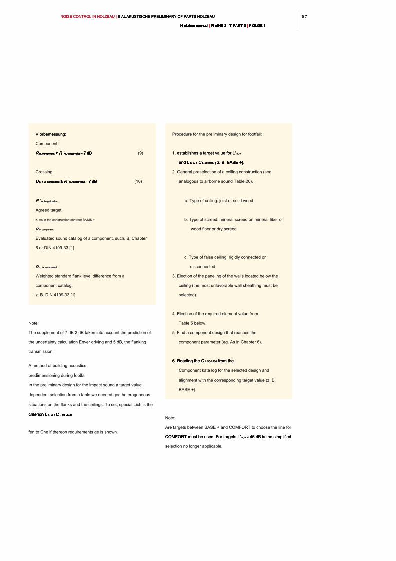
5 75 7NOISE CONTROL IN HOLZBAU | B AUAKUSTISCHE PRELIMINARY OF PARTS HOLZBAU NOISE CONTROL IN HOLZBAU | B AUAKUSTISCHE PRELIMINARY OF PARTS HOLZBAU NOISE CONTROL IN HOLZBAU | B AUAKUSTISCHE PRELIMINARY OF PARTS HOLZBAU
H olzbau manual | R eIHE 3 | T PART 3 | F OLGE 1H olzbau manual | R eIHE 3 | T PART 3 | F OLGE 1H olzbau manual | R eIHE 3 | T PART 3 | F OLGE 1H olzbau manual | R eIHE 3 | T PART 3 | F OLGE 1H olzbau manual | R eIHE 3 | T PART 3 | F OLGE 1H olzbau manual | R eIHE 3 | T PART 3 | F OLGE 1H olzbau manual | R eIHE 3 | T PART 3 | F OLGE 1H olzbau manual | R eIHE 3 | T PART 3 | F OLGE 1H olzbau manual | R eIHE 3 | T PART 3 | F OLGE 1H olzbau manual | R eIHE 3 | T PART 3 | F OLGE 1H olzbau manual | R eIHE 3 | T PART 3 | F OLGE 1
Note:
Are targets between BASE + and COMFORT to choose the line for
COMFORT must be used. For targets L' n, w < 46 dB is the simplified COMFORT must be used. For targets L' n, w < 46 dB is the simplified COMFORT must be used. For targets L' n, w < 46 dB is the simplified
selection no longer applicable.
Note:
The supplement of 7 dB 2 dB taken into account the prediction of
the uncertainty calculation Enver driving and 5 dB, the flanking
transmission.
A method of building acoustics
predimensioning during footfall
In the preliminary design for the impact sound a target value
dependent selection from a table we needed gen heterogeneous
situations on the flanks and the ceilings. To set, special Lich is the
criterion L n, w + C I, 50-2500criterion L n, w + C I, 50-2500criterion L n, w + C I, 50-2500criterion L n, w + C I, 50-2500criterion L n, w + C I, 50-2500
fen to Che if thereon requirements ge is shown.
V orbemessung: V orbemessung:
Component:
R w, component ≥ R ' w, target value + 7 dB R w, component ≥ R ' w, target value + 7 dB R w, component ≥ R ' w, target value + 7 dB R w, component ≥ R ' w, target value + 7 dB R w, component ≥ R ' w, target value + 7 dB R w, component ≥ R ' w, target value + 7 dB R w, component ≥ R ' w, target value + 7 dB (9)
Crossing:
D n, f, w, component ≥ R ' w, target value + 7 dB D n, f, w, component ≥ R ' w, target value + 7 dB D n, f, w, component ≥ R ' w, target value + 7 dB D n, f, w, component ≥ R ' w, target value + 7 dB D n, f, w, component ≥ R ' w, target value + 7 dB D n, f, w, component ≥ R ' w, target value + 7 dB D n, f, w, component ≥ R ' w, target value + 7 dB (10)
R ' w, target value:R ' w, target value:
Agreed target,
z. As in the construction contract BASIS +
R w, component:R w, component:
Evaluated sound catalog of a component, such. B. Chapter
6 or DIN 4109-33 [1]
D n, fw, component:D n, fw, component:
Weighted standard flank level difference from a
component catalog,
z. B. DIN 4109-33 [1]
Procedure for the preliminary design for footfall:
1. establishes a target value for L' n, w1. establishes a target value for L' n, w
and L n, w + C I, 50-2500 ( z. B. BASE +).and L n, w + C I, 50-2500 ( z. B. BASE +).and L n, w + C I, 50-2500 ( z. B. BASE +).and L n, w + C I, 50-2500 ( z. B. BASE +).and L n, w + C I, 50-2500 ( z. B. BASE +).and L n, w + C I, 50-2500 ( z. B. BASE +).
2. General preselection of a ceiling construction (see
analogous to airborne sound Table 20).
a. Type of ceiling: joist or solid wood
b. Type of screed: mineral screed on mineral fiber or
wood fiber or dry screed
c. Type of false ceiling: rigidly connected or
disconnected
3. Election of the paneling of the walls located below the
ceiling (the most unfavorable wall sheathing must be
selected).
4. Election of the required element value from
Table 5 below.
5. Find a component design that reaches the
component parameter (eg. As in Chapter 6).
6. Reading the C I, 50-2500 from the 6. Reading the C I, 50-2500 from the 6. Reading the C I, 50-2500 from the
Component kata log for the selected design and
alignment with the corresponding target value (z. B.
BASE +).
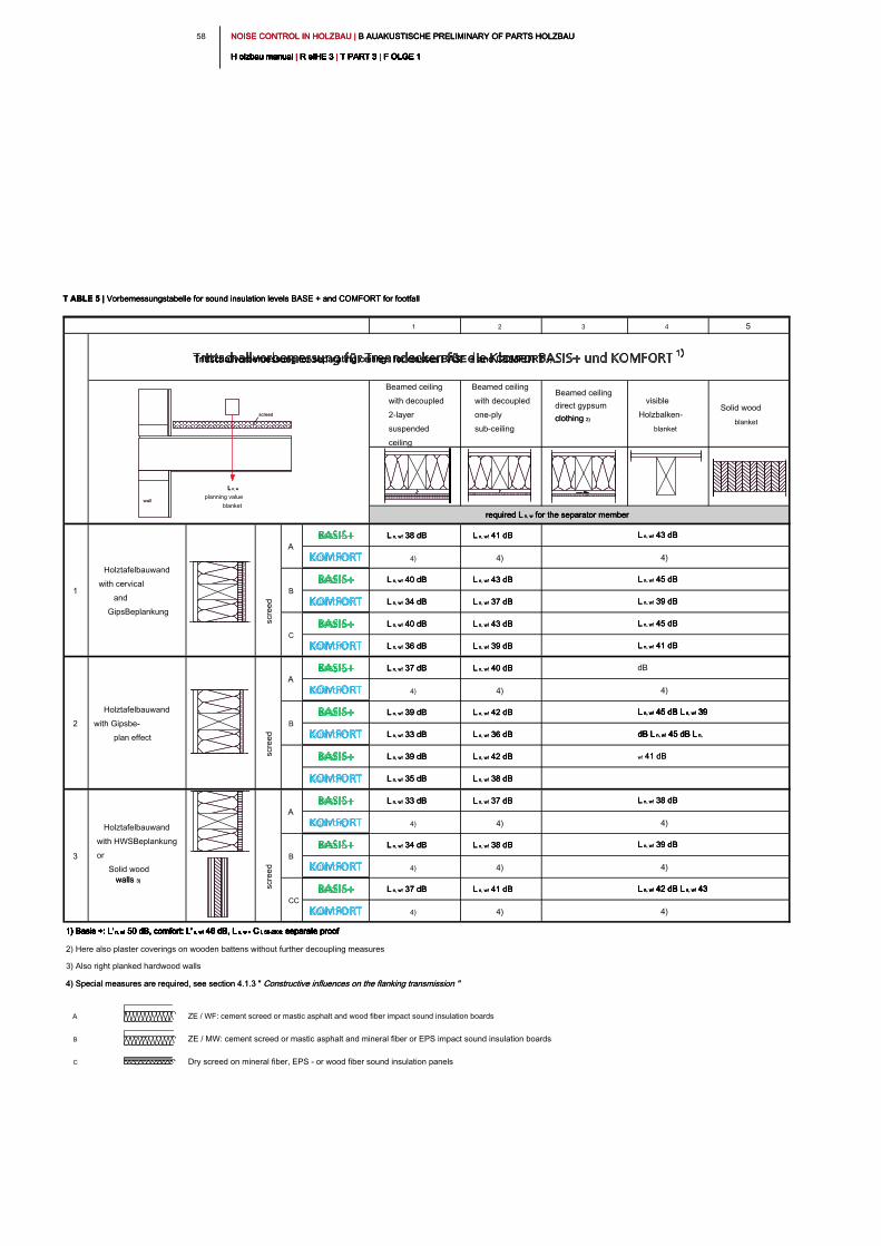
NOISE CONTROL IN HOLZBAU | B AUAKUSTISCHE PRELIMINARY OF PARTS HOLZBAU NOISE CONTROL IN HOLZBAU | B AUAKUSTISCHE PRELIMINARY OF PARTS HOLZBAU NOISE CONTROL IN HOLZBAU | B AUAKUSTISCHE PRELIMINARY OF PARTS HOLZBAU
H olzbau manual | R eIHE 3 | T PART 3 | F OLGE 1H olzbau manual | R eIHE 3 | T PART 3 | F OLGE 1H olzbau manual | R eIHE 3 | T PART 3 | F OLGE 1H olzbau manual | R eIHE 3 | T PART 3 | F OLGE 1H olzbau manual | R eIHE 3 | T PART 3 | F OLGE 1H olzbau manual | R eIHE 3 | T PART 3 | F OLGE 1H olzbau manual | R eIHE 3 | T PART 3 | F OLGE 1H olzbau manual | R eIHE 3 | T PART 3 | F OLGE 1H olzbau manual | R eIHE 3 | T PART 3 | F OLGE 1H olzbau manual | R eIHE 3 | T PART 3 | F OLGE 1H olzbau manual | R eIHE 3 | T PART 3 | F OLGE 1
58
1 2 3 4 5
Beamed ceiling
with decoupled
2-layer
suspended
ceiling
Beamed ceiling
with decoupled
one-ply
sub-ceiling
Beamed ceiling
direct gypsum
clothing 2)clothing 2)
visible
Holzbalken-
blanket
Solid wood
blanket
BASE + L n, w! 38 dB L n, w! 38 dB L n, w! 38 dB L n, w! 41 dBL n, w! 41 dBL n, w! 41 dB
COMFORT 4) 4)
BASE + L n, w! 40 dB L n, w! 40 dB L n, w! 40 dB L n, w! 43 dBL n, w! 43 dBL n, w! 43 dB
COMFORT L n, w! 34 dB L n, w! 34 dB L n, w! 34 dB L n, w! 37 dBL n, w! 37 dBL n, w! 37 dB
BASE + L n, w! 40 dB L n, w! 40 dB L n, w! 40 dB L n, w! 43 dBL n, w! 43 dBL n, w! 43 dB
COMFORT L n, w! 36 dB L n, w! 36 dB L n, w! 36 dB L n, w! 39 dBL n, w! 39 dBL n, w! 39 dB
BASE + L n, w! 37 dB L n, w! 37 dB L n, w! 37 dB L n, w! 40 dBL n, w! 40 dBL n, w! 40 dB
COMFORT 4) 4)
BASE + L n, w! 39 dB L n, w! 39 dB L n, w! 39 dB L n, w! 42 dBL n, w! 42 dBL n, w! 42 dB
COMFORT L n, w! 33 dB L n, w! 33 dB L n, w! 33 dB L n, w! 36 dBL n, w! 36 dBL n, w! 36 dB
BASE + L n, w! 39 dB L n, w! 39 dB L n, w! 39 dB L n, w! 42 dBL n, w! 42 dBL n, w! 42 dB
COMFORT L n, w! 35 dB L n, w! 35 dB L n, w! 35 dB L n, w! 38 dBL n, w! 38 dBL n, w! 38 dB
BASE + L n, w! 33 dB L n, w! 33 dB L n, w! 33 dB L n, w! 37 dBL n, w! 37 dBL n, w! 37 dB
COMFORT 4) 4)
BASE + L n, w! 34 dB L n, w! 34 dB L n, w! 34 dB L n, w! 38 dBL n, w! 38 dBL n, w! 38 dB
COMFORT 4) 4)
BASE + L n, w! 37 dB L n, w! 37 dB L n, w! 37 dB L n, w! 41 dBL n, w! 41 dBL n, w! 41 dB
COMFORT 4) 4)
1) Basis +: L' n, w! 50 dB, comfort: L' n, w! 46 dB, L n, w + C I, 50-2500: separate proof1) Basis +: L' n, w! 50 dB, comfort: L' n, w! 46 dB, L n, w + C I, 50-2500: separate proof1) Basis +: L' n, w! 50 dB, comfort: L' n, w! 46 dB, L n, w + C I, 50-2500: separate proof1) Basis +: L' n, w! 50 dB, comfort: L' n, w! 46 dB, L n, w + C I, 50-2500: separate proof1) Basis +: L' n, w! 50 dB, comfort: L' n, w! 46 dB, L n, w + C I, 50-2500: separate proof1) Basis +: L' n, w! 50 dB, comfort: L' n, w! 46 dB, L n, w + C I, 50-2500: separate proof1) Basis +: L' n, w! 50 dB, comfort: L' n, w! 46 dB, L n, w + C I, 50-2500: separate proof1) Basis +: L' n, w! 50 dB, comfort: L' n, w! 46 dB, L n, w + C I, 50-2500: separate proof1) Basis +: L' n, w! 50 dB, comfort: L' n, w! 46 dB, L n, w + C I, 50-2500: separate proof1) Basis +: L' n, w! 50 dB, comfort: L' n, w! 46 dB, L n, w + C I, 50-2500: separate proof
2) Here also plaster coverings on wooden battens without further decoupling measures
3) Also right planked hardwood walls
4) Special measures are required, see section 4.1.3 " Constructive influences on the flanking transmission "4) Special measures are required, see section 4.1.3 " Constructive influences on the flanking transmission "
A ZE / WF: cement screed or mastic asphalt and wood fiber impact sound insulation boards
B ZE / MW: cement screed or mastic asphalt and mineral fiber or EPS impact sound insulation boards
C Dry screed on mineral fiber, EPS - or wood fiber sound insulation panels
4)
L n, w! 38 dBL n, w! 38 dBL n, w! 38 dB
4)
L n, w! 39 dBL n, w! 39 dBL n, w! 39 dB
4)
L n, w! 42 dB L n, w! 43 L n, w! 42 dB L n, w! 43 L n, w! 42 dB L n, w! 43 L n, w! 42 dB L n, w! 43 L n, w! 42 dB L n, w! 43
dB
4)
1
L n, w! 43 dBL n, w! 43 dBL n, w! 43 dB
L n, w! 45 dBL n, w! 45 dBL n, w! 45 dB
L n, w! 45 dBL n, w! 45 dBL n, w! 45 dB
2
Holztafelbauwand
with Gipsbe-
plan effect
A
B
3
Holztafelbauwand
with HWSBeplankung
or
Solid wood
walls 3)walls 3)
A
B
CC
Trittschallvorbemessung for separating ceilings for classes BASE + and COMFORT 1)Trittschallvorbemessung for separating ceilings for classes BASE + and COMFORT 1)
required L n, w for the separator memberrequired L n, w for the separator memberrequired L n, w for the separator member
4)
L n, w! 39 dBL n, w! 39 dBL n, w! 39 dB
L n, w! 41 dBL n, w! 41 dBL n, w! 41 dB
A
B
C
Holztafelbauwand
with cervical
and
GipsBeplankung
L n, w! 45 dB L n, w! 39 L n, w! 45 dB L n, w! 39 L n, w! 45 dB L n, w! 39 L n, w! 45 dB L n, w! 39 L n, w! 45 dB L n, w! 39
dB L n, w! 45 dB L n, dB L n, w! 45 dB L n, dB L n, w! 45 dB L n, dB L n, w! 45 dB L n,
w! 41 dBw! 41 dB
L n, wL n, w
planning value
blanket
screed
wall
screed
wall
T ABLE 5 | Vorbemessungstabelle for sound insulation levels BASE + and COMFORT for footfallT ABLE 5 | Vorbemessungstabelle for sound insulation levels BASE + and COMFORT for footfallT ABLE 5 | Vorbemessungstabelle for sound insulation levels BASE + and COMFORT for footfall
screed
screed
screed
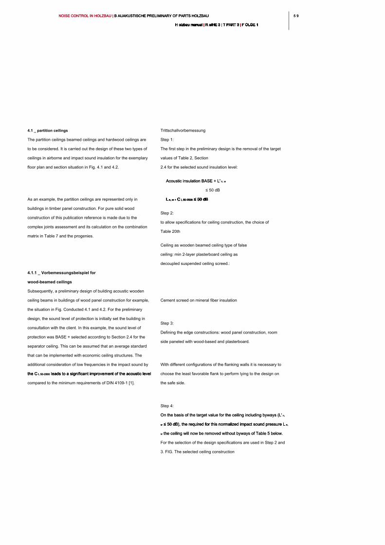
5 95 9NOISE CONTROL IN HOLZBAU | B AUAKUSTISCHE PRELIMINARY OF PARTS HOLZBAU NOISE CONTROL IN HOLZBAU | B AUAKUSTISCHE PRELIMINARY OF PARTS HOLZBAU NOISE CONTROL IN HOLZBAU | B AUAKUSTISCHE PRELIMINARY OF PARTS HOLZBAU
H olzbau manual | R eIHE 3 | T PART 3 | F OLGE 1H olzbau manual | R eIHE 3 | T PART 3 | F OLGE 1H olzbau manual | R eIHE 3 | T PART 3 | F OLGE 1H olzbau manual | R eIHE 3 | T PART 3 | F OLGE 1H olzbau manual | R eIHE 3 | T PART 3 | F OLGE 1H olzbau manual | R eIHE 3 | T PART 3 | F OLGE 1H olzbau manual | R eIHE 3 | T PART 3 | F OLGE 1H olzbau manual | R eIHE 3 | T PART 3 | F OLGE 1H olzbau manual | R eIHE 3 | T PART 3 | F OLGE 1H olzbau manual | R eIHE 3 | T PART 3 | F OLGE 1H olzbau manual | R eIHE 3 | T PART 3 | F OLGE 1
4.1 _ partition ceilings
The partition ceilings beamed ceilings and hardwood ceilings are
to be considered. It is carried out the design of these two types of
ceilings in airborne and impact sound insulation for the exemplary
floor plan and section situation in Fig. 4.1 and 4.2.
As an example, the partition ceilings are represented only in
buildings in timber panel construction. For pure solid wood
construction of this publication reference is made due to the
complex joints assessment and its calculation on the combination
matrix in Table 7 and the progenies.
4.1.1 _ Vorbemessungsbeispiel for
wood-beamed ceilings
Subsequently, a preliminary design of building acoustic wooden
ceiling beams in buildings of wood panel construction for example,
the situation in Fig. Conducted 4.1 and 4.2. For the preliminary
design, the sound level of protection is initially set the building in
consultation with the client. In this example, the sound level of
protection was BASE + selected according to Section 2.4 for the
separator ceiling. This can be assumed that an average standard
that can be implemented with economic ceiling structures. The
additional consideration of low frequencies in the impact sound by
the C I, 50-2500 leads to a significant improvement of the acoustic level the C I, 50-2500 leads to a significant improvement of the acoustic level the C I, 50-2500 leads to a significant improvement of the acoustic level
compared to the minimum requirements of DIN 4109-1 [1].
Trittschallvorbemessung
Step 1:
The first step in the preliminary design is the removal of the target
values of Table 2, Section
2.4 for the selected sound insulation level:
Acoustic insulation BASE + L' n, wAcoustic insulation BASE + L' n, w
≤ 50 dB
L n, w + C I, 50-2500 ≤ 50 dBL n, w + C I, 50-2500 ≤ 50 dBL n, w + C I, 50-2500 ≤ 50 dBL n, w + C I, 50-2500 ≤ 50 dBL n, w + C I, 50-2500 ≤ 50 dBL n, w + C I, 50-2500 ≤ 50 dB
Step 2:
to allow specifications for ceiling construction, the choice of
Table 20th
Ceiling as wooden beamed ceiling type of false
ceiling: min 2-layer plasterboard ceiling as
decoupled suspended ceiling screed.:
Cement screed on mineral fiber insulation
Step 3:
Defining the edge constructions: wood panel construction, room
side paneled with wood-based and plasterboard.
With different configurations of the flanking walls it is necessary to
choose the least favorable flank to perform lying to the design on
the safe side.
Step 4:
On the basis of the target value for the ceiling including byways (L' n, On the basis of the target value for the ceiling including byways (L' n,
w ≤ 50 dB), the required for this normalized impact sound pressure L n, w ≤ 50 dB), the required for this normalized impact sound pressure L n, w ≤ 50 dB), the required for this normalized impact sound pressure L n,
w the ceiling will now be removed without byways of Table 5 below. w the ceiling will now be removed without byways of Table 5 below.
For the selection of the design specifications are used in Step 2 and
3. FIG. The selected ceiling construction

NOISE CONTROL IN HOLZBAU | B AUAKUSTISCHE PRELIMINARY OF PARTS HOLZBAU NOISE CONTROL IN HOLZBAU | B AUAKUSTISCHE PRELIMINARY OF PARTS HOLZBAU NOISE CONTROL IN HOLZBAU | B AUAKUSTISCHE PRELIMINARY OF PARTS HOLZBAU
H olzbau manual | R eIHE 3 | T PART 3 | F OLGE 1H olzbau manual | R eIHE 3 | T PART 3 | F OLGE 1H olzbau manual | R eIHE 3 | T PART 3 | F OLGE 1H olzbau manual | R eIHE 3 | T PART 3 | F OLGE 1H olzbau manual | R eIHE 3 | T PART 3 | F OLGE 1H olzbau manual | R eIHE 3 | T PART 3 | F OLGE 1H olzbau manual | R eIHE 3 | T PART 3 | F OLGE 1H olzbau manual | R eIHE 3 | T PART 3 | F OLGE 1H olzbau manual | R eIHE 3 | T PART 3 | F OLGE 1H olzbau manual | R eIHE 3 | T PART 3 | F OLGE 1H olzbau manual | R eIHE 3 | T PART 3 | F OLGE 1
60
(Beamed ceiling with decoupled 2-layer sub-layer) results in
column 1, the selected edge construction to line 1. For a screed
type B (cement screed on mineral fiber acoustic tiles), and the
sound level of protection BASE + is there the L n, w ≤ 40 dB.sound level of protection BASE + is there the L n, w ≤ 40 dB.sound level of protection BASE + is there the L n, w ≤ 40 dB.
Step 5:
Now, from the component catalogs of the section 6 or DIN 4109-33
[1] a ceiling with L n, w To search ≤ 40 dB: [1] a ceiling with L n, w To search ≤ 40 dB: [1] a ceiling with L n, w To search ≤ 40 dB:
Selected ceiling construction according to Figure 4.3 with.:
L n, w = 37 dB <40 dB L n, w = 37 dB <40 dB L n, w = 37 dB <40 dB L n, w = 37 dB <40 dB
Step 6: Check the target value for L n, w + C I, 50-2500.Step 6: Check the target value for L n, w + C I, 50-2500.Step 6: Check the target value for L n, w + C I, 50-2500.Step 6: Check the target value for L n, w + C I, 50-2500.Step 6: Check the target value for L n, w + C I, 50-2500.
Selected ceiling construction according to Figure 4.3 with.:
L n, w + C I, 50-2500 = 37 dB + 12 dB = 49 dB <50 dB L n, w + C I, 50-2500 = 37 dB + 12 dB = 49 dB <50 dB L n, w + C I, 50-2500 = 37 dB + 12 dB = 49 dB <50 dB L n, w + C I, 50-2500 = 37 dB + 12 dB = 49 dB <50 dB L n, w + C I, 50-2500 = 37 dB + 12 dB = 49 dB <50 dB L n, w + C I, 50-2500 = 37 dB + 12 dB = 49 dB <50 dB L n, w + C I, 50-2500 = 37 dB + 12 dB = 49 dB <50 dB
Luftschallvorbemessung
Step 1:
Choice of the target value from Table 2, Section 2.4 for the selected
sound insulation level:
Sound insulation level: BASIC + R ' w ≥ 57 Sound insulation level: BASIC + R ' w ≥ 57 Sound insulation level: BASIC + R ' w ≥ 57
dB
Step 2:
Calculation of the evaluated sound transmission loss R w the Calculation of the evaluated sound transmission loss R w the Calculation of the evaluated sound transmission loss R w the
ceiling without byways, the R 'to meet the target value w ≥ 57 dB ceiling without byways, the R 'to meet the target value w ≥ 57 dB ceiling without byways, the R 'to meet the target value w ≥ 57 dB
is required:
R w ≥ R ' w + 7 dB R w ≥ 64 R w ≥ R ' w + 7 dB R w ≥ 64 R w ≥ R ' w + 7 dB R w ≥ 64 R w ≥ R ' w + 7 dB R w ≥ 64 R w ≥ R ' w + 7 dB R w ≥ 64 R w ≥ R ' w + 7 dB R w ≥ 64 R w ≥ R ' w + 7 dB R w ≥ 64 R w ≥ R ' w + 7 dB R w ≥ 64
dB
Assessment of the selected deck structure according to Fig.
4.3:
R w = 82 dB> 64 dB R w = 82 dB> 64 dB R w = 82 dB> 64 dB
Step 3:
Calculation of the required standard edge level difference D n, f, w the Calculation of the required standard edge level difference D n, f, w the Calculation of the required standard edge level difference D n, f, w the
flanking walls:
D n, f, w ≥ R ' w + 7 dB D n, f, w ≥ 64 dB (required value)D n, f, w ≥ R ' w + 7 dB D n, f, w ≥ 64 dB (required value)D n, f, w ≥ R ' w + 7 dB D n, f, w ≥ 64 dB (required value)D n, f, w ≥ R ' w + 7 dB D n, f, w ≥ 64 dB (required value)D n, f, w ≥ R ' w + 7 dB D n, f, w ≥ 64 dB (required value)D n, f, w ≥ R ' w + 7 dB D n, f, w ≥ 64 dB (required value)D n, f, w ≥ R ' w + 7 dB D n, f, w ≥ 64 dB (required value)D n, f, w ≥ R ' w + 7 dB D n, f, w ≥ 64 dB (required value)
Assessment of the selected edge in wood panel construction
according to Fig. 4.2:
The ceiling separates the wall components completely
(Plattformframing).
D n, f, w = 67 dB according to DIN 4109-33: 2016 5.1.3.2 D n, f, w = 67 dB according to DIN 4109-33: 2016 5.1.3.2 D n, f, w = 67 dB according to DIN 4109-33: 2016 5.1.3.2
D para. n, f, w = 67 dB> 64 dB D para. n, f, w = 67 dB> 64 dB D para. n, f, w = 67 dB> 64 dB
Component values: L n, w ( C I, 50-2500) = 37 dB Component values: L n, w ( C I, 50-2500) = 37 dB Component values: L n, w ( C I, 50-2500) = 37 dB Component values: L n, w ( C I, 50-2500) = 37 dB Component values: L n, w ( C I, 50-2500) = 37 dB
(12 dB) R w = 82 dB(12 dB) R w = 82 dB(12 dB) R w = 82 dB
Fire safety rating: Encapsulation: K 2 60 possible fire Fire safety rating: Encapsulation: K 2 60 possible fire Fire safety rating: Encapsulation: K 2 60 possible fire
resistance: F60-B
→ Suitable for GK 4
Fig. 4.3:
Structure of the ceiling example for
the design of Chapter 6, Table 25,
line 17
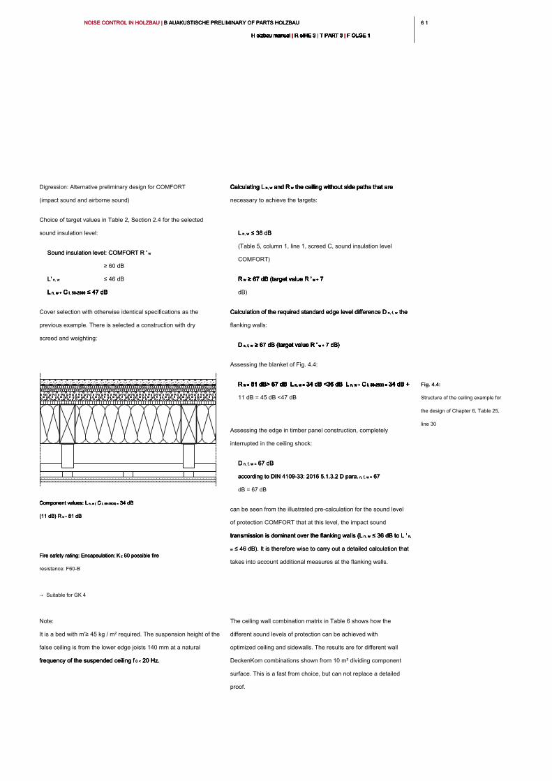
6 16 1NOISE CONTROL IN HOLZBAU | B AUAKUSTISCHE PRELIMINARY OF PARTS HOLZBAU NOISE CONTROL IN HOLZBAU | B AUAKUSTISCHE PRELIMINARY OF PARTS HOLZBAU NOISE CONTROL IN HOLZBAU | B AUAKUSTISCHE PRELIMINARY OF PARTS HOLZBAU
H olzbau manual | R eIHE 3 | T PART 3 | F OLGE 1H olzbau manual | R eIHE 3 | T PART 3 | F OLGE 1H olzbau manual | R eIHE 3 | T PART 3 | F OLGE 1H olzbau manual | R eIHE 3 | T PART 3 | F OLGE 1H olzbau manual | R eIHE 3 | T PART 3 | F OLGE 1H olzbau manual | R eIHE 3 | T PART 3 | F OLGE 1H olzbau manual | R eIHE 3 | T PART 3 | F OLGE 1H olzbau manual | R eIHE 3 | T PART 3 | F OLGE 1H olzbau manual | R eIHE 3 | T PART 3 | F OLGE 1H olzbau manual | R eIHE 3 | T PART 3 | F OLGE 1H olzbau manual | R eIHE 3 | T PART 3 | F OLGE 1
Digression: Alternative preliminary design for COMFORT
(impact sound and airborne sound)
Choice of target values in Table 2, Section 2.4 for the selected
sound insulation level:
Sound insulation level: COMFORT R ' wSound insulation level: COMFORT R ' w
≥ 60 dB
L' n, wL' n, w ≤ 46 dB
L n, w + C I, 50-2500 ≤ 47 dBL n, w + C I, 50-2500 ≤ 47 dBL n, w + C I, 50-2500 ≤ 47 dBL n, w + C I, 50-2500 ≤ 47 dBL n, w + C I, 50-2500 ≤ 47 dBL n, w + C I, 50-2500 ≤ 47 dB
Cover selection with otherwise identical specifications as the
previous example. There is selected a construction with dry
screed and weighting:
Note:
It is a bed with m'≥ 45 kg / m² required. The suspension height of the
false ceiling is from the lower edge joists 140 mm at a natural
frequency of the suspended ceiling f 0 < 20 Hz.frequency of the suspended ceiling f 0 < 20 Hz.frequency of the suspended ceiling f 0 < 20 Hz.
Calculating L n, w and R w the ceiling without side paths that are Calculating L n, w and R w the ceiling without side paths that are Calculating L n, w and R w the ceiling without side paths that are Calculating L n, w and R w the ceiling without side paths that are Calculating L n, w and R w the ceiling without side paths that are
necessary to achieve the targets:
L n, w ≤ 36 dB L n, w ≤ 36 dB L n, w ≤ 36 dB
(Table 5, column 1, line 1, screed C, sound insulation level
COMFORT)
R w ≥ 67 dB (target value R ' w + 7 R w ≥ 67 dB (target value R ' w + 7 R w ≥ 67 dB (target value R ' w + 7 R w ≥ 67 dB (target value R ' w + 7 R w ≥ 67 dB (target value R ' w + 7 R w ≥ 67 dB (target value R ' w + 7
dB)
Calculation of the required standard edge level difference D n, f, w the Calculation of the required standard edge level difference D n, f, w the Calculation of the required standard edge level difference D n, f, w the
flanking walls:
D n, f, w ≥ 67 dB (target value R ' w + 7 dB)D n, f, w ≥ 67 dB (target value R ' w + 7 dB)D n, f, w ≥ 67 dB (target value R ' w + 7 dB)D n, f, w ≥ 67 dB (target value R ' w + 7 dB)D n, f, w ≥ 67 dB (target value R ' w + 7 dB)D n, f, w ≥ 67 dB (target value R ' w + 7 dB)
Assessing the blanket of Fig. 4.4:
R w = 81 dB> 67 dB L n, w = 34 dB <36 dB L n, w + C I, 50-2500 = 34 dB + R w = 81 dB> 67 dB L n, w = 34 dB <36 dB L n, w + C I, 50-2500 = 34 dB + R w = 81 dB> 67 dB L n, w = 34 dB <36 dB L n, w + C I, 50-2500 = 34 dB + R w = 81 dB> 67 dB L n, w = 34 dB <36 dB L n, w + C I, 50-2500 = 34 dB + R w = 81 dB> 67 dB L n, w = 34 dB <36 dB L n, w + C I, 50-2500 = 34 dB + R w = 81 dB> 67 dB L n, w = 34 dB <36 dB L n, w + C I, 50-2500 = 34 dB + R w = 81 dB> 67 dB L n, w = 34 dB <36 dB L n, w + C I, 50-2500 = 34 dB + R w = 81 dB> 67 dB L n, w = 34 dB <36 dB L n, w + C I, 50-2500 = 34 dB + R w = 81 dB> 67 dB L n, w = 34 dB <36 dB L n, w + C I, 50-2500 = 34 dB + R w = 81 dB> 67 dB L n, w = 34 dB <36 dB L n, w + C I, 50-2500 = 34 dB + R w = 81 dB> 67 dB L n, w = 34 dB <36 dB L n, w + C I, 50-2500 = 34 dB + R w = 81 dB> 67 dB L n, w = 34 dB <36 dB L n, w + C I, 50-2500 = 34 dB +
11 dB = 45 dB <47 dB
Assessing the edge in timber panel construction, completely
interrupted in the ceiling shock:
D n, f, w = 67 dB D n, f, w = 67 dB D n, f, w = 67 dB
according to DIN 4109-33: 2016 5.1.3.2 D para. n, f, w = 67 according to DIN 4109-33: 2016 5.1.3.2 D para. n, f, w = 67 according to DIN 4109-33: 2016 5.1.3.2 D para. n, f, w = 67
dB = 67 dB
can be seen from the illustrated pre-calculation for the sound level
of protection COMFORT that at this level, the impact sound
transmission is dominant over the flanking walls (L n, w ≤ 36 dB to L ' n, transmission is dominant over the flanking walls (L n, w ≤ 36 dB to L ' n, transmission is dominant over the flanking walls (L n, w ≤ 36 dB to L ' n, transmission is dominant over the flanking walls (L n, w ≤ 36 dB to L ' n,
w ≤ 46 dB). It is therefore wise to carry out a detailed calculation that w ≤ 46 dB). It is therefore wise to carry out a detailed calculation that
takes into account additional measures at the flanking walls.
The ceiling wall combination matrix in Table 6 shows how the
different sound levels of protection can be achieved with
optimized ceiling and sidewalls. The results are for different wall
DeckenKom combinations shown from 10 m² dividing component
surface. This is a fast from choice, but can not replace a detailed
proof.
Fig. 4.4:
Structure of the ceiling example for
the design of Chapter 6, Table 25,
line 30
Component values: L n, w ( C I, 50-2500) = 34 dB Component values: L n, w ( C I, 50-2500) = 34 dB Component values: L n, w ( C I, 50-2500) = 34 dB Component values: L n, w ( C I, 50-2500) = 34 dB Component values: L n, w ( C I, 50-2500) = 34 dB
(11 dB) R w = 81 dB(11 dB) R w = 81 dB(11 dB) R w = 81 dB
Fire safety rating: Encapsulation: K 2 60 possible fire Fire safety rating: Encapsulation: K 2 60 possible fire Fire safety rating: Encapsulation: K 2 60 possible fire
resistance: F60-B
→ Suitable for GK 4
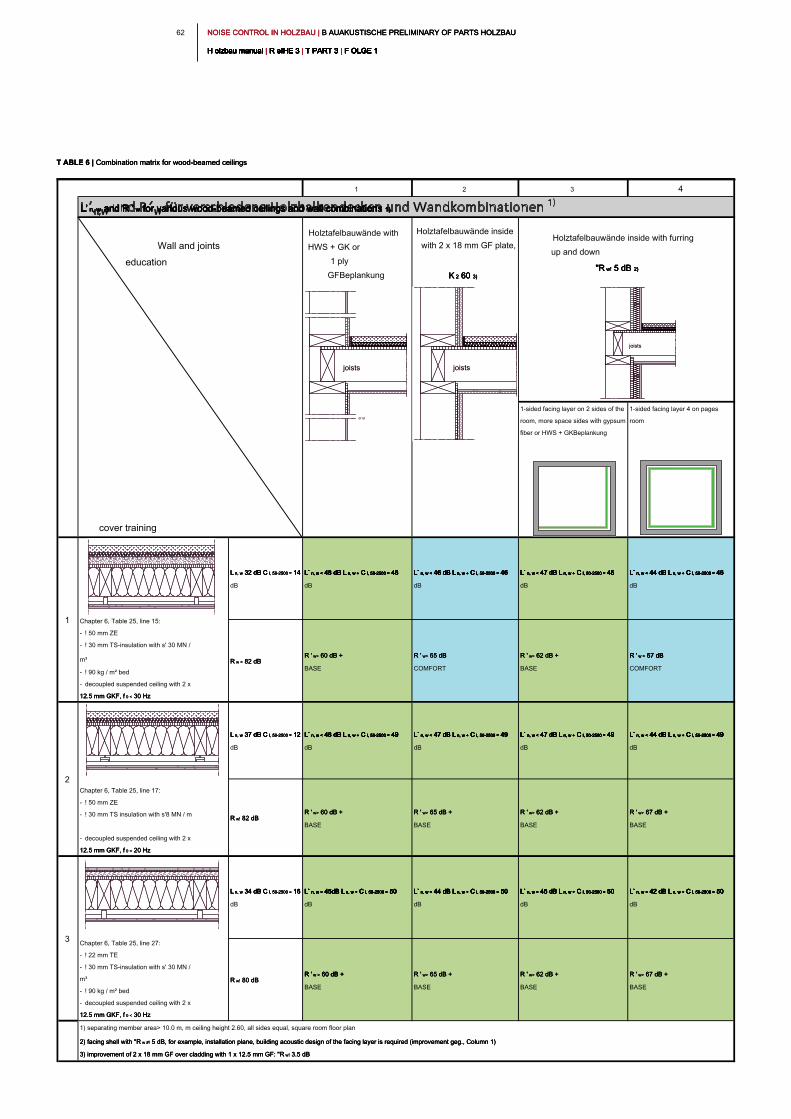
NOISE CONTROL IN HOLZBAU | B AUAKUSTISCHE PRELIMINARY OF PARTS HOLZBAU NOISE CONTROL IN HOLZBAU | B AUAKUSTISCHE PRELIMINARY OF PARTS HOLZBAU NOISE CONTROL IN HOLZBAU | B AUAKUSTISCHE PRELIMINARY OF PARTS HOLZBAU
H olzbau manual | R eIHE 3 | T PART 3 | F OLGE 1H olzbau manual | R eIHE 3 | T PART 3 | F OLGE 1H olzbau manual | R eIHE 3 | T PART 3 | F OLGE 1H olzbau manual | R eIHE 3 | T PART 3 | F OLGE 1H olzbau manual | R eIHE 3 | T PART 3 | F OLGE 1H olzbau manual | R eIHE 3 | T PART 3 | F OLGE 1H olzbau manual | R eIHE 3 | T PART 3 | F OLGE 1H olzbau manual | R eIHE 3 | T PART 3 | F OLGE 1H olzbau manual | R eIHE 3 | T PART 3 | F OLGE 1H olzbau manual | R eIHE 3 | T PART 3 | F OLGE 1H olzbau manual | R eIHE 3 | T PART 3 | F OLGE 1
62
1 2 3 4
Holztafelbauwände with
HWS + GK or
1 ply
GFBeplankung
Holztafelbauwände inside
with 2 x 18 mm GF plate,
K 2 60 3)K 2 60 3)K 2 60 3)K 2 60 3)
cover training
1-sided facing layer on 2 sides of the
room, more space sides with gypsum
fiber or HWS + GKBeplankung
1-sided facing layer 4 on pages
room
L n, w 32 dB C I, 50-2500 = 14 L n, w 32 dB C I, 50-2500 = 14 L n, w 32 dB C I, 50-2500 = 14 L n, w 32 dB C I, 50-2500 = 14 L n, w 32 dB C I, 50-2500 = 14
dB
L` n, w < 48 dB L n, w + C I, 50-2500 = 46 L` n, w < 48 dB L n, w + C I, 50-2500 = 46 L` n, w < 48 dB L n, w + C I, 50-2500 = 46 L` n, w < 48 dB L n, w + C I, 50-2500 = 46 L` n, w < 48 dB L n, w + C I, 50-2500 = 46 L` n, w < 48 dB L n, w + C I, 50-2500 = 46 L` n, w < 48 dB L n, w + C I, 50-2500 = 46 L` n, w < 48 dB L n, w + C I, 50-2500 = 46
dB
L` n, w < 46 dB L n, w + C I, 50-2500 = 46 L` n, w < 46 dB L n, w + C I, 50-2500 = 46 L` n, w < 46 dB L n, w + C I, 50-2500 = 46 L` n, w < 46 dB L n, w + C I, 50-2500 = 46 L` n, w < 46 dB L n, w + C I, 50-2500 = 46 L` n, w < 46 dB L n, w + C I, 50-2500 = 46 L` n, w < 46 dB L n, w + C I, 50-2500 = 46 L` n, w < 46 dB L n, w + C I, 50-2500 = 46
dB
L` n, w < 47 dB L n, w + C I, 50-2500 = 46 L` n, w < 47 dB L n, w + C I, 50-2500 = 46 L` n, w < 47 dB L n, w + C I, 50-2500 = 46 L` n, w < 47 dB L n, w + C I, 50-2500 = 46 L` n, w < 47 dB L n, w + C I, 50-2500 = 46 L` n, w < 47 dB L n, w + C I, 50-2500 = 46 L` n, w < 47 dB L n, w + C I, 50-2500 = 46 L` n, w < 47 dB L n, w + C I, 50-2500 = 46
dB
L` n, w < 44 dB L n, w + C I, 50-2500 = 46 L` n, w < 44 dB L n, w + C I, 50-2500 = 46 L` n, w < 44 dB L n, w + C I, 50-2500 = 46 L` n, w < 44 dB L n, w + C I, 50-2500 = 46 L` n, w < 44 dB L n, w + C I, 50-2500 = 46 L` n, w < 44 dB L n, w + C I, 50-2500 = 46 L` n, w < 44 dB L n, w + C I, 50-2500 = 46 L` n, w < 44 dB L n, w + C I, 50-2500 = 46
dB
R w = 82 dB R w = 82 dB R w = 82 dB
R ' w> 60 dB + R ' w> 60 dB + R ' w> 60 dB +
BASE
R ' w> 65 dB R ' w> 65 dB R ' w> 65 dB
COMFORT
R ' w> 62 dB + R ' w> 62 dB + R ' w> 62 dB +
BASE
R ' w > 67 dB R ' w > 67 dB R ' w > 67 dB R ' w > 67 dB
COMFORT
L n, w 37 dB C I, 50-2500 = 12 L n, w 37 dB C I, 50-2500 = 12 L n, w 37 dB C I, 50-2500 = 12 L n, w 37 dB C I, 50-2500 = 12 L n, w 37 dB C I, 50-2500 = 12
dB
L` n, w < 48 dB L n, w + C I, 50-2500 = 49 L` n, w < 48 dB L n, w + C I, 50-2500 = 49 L` n, w < 48 dB L n, w + C I, 50-2500 = 49 L` n, w < 48 dB L n, w + C I, 50-2500 = 49 L` n, w < 48 dB L n, w + C I, 50-2500 = 49 L` n, w < 48 dB L n, w + C I, 50-2500 = 49 L` n, w < 48 dB L n, w + C I, 50-2500 = 49 L` n, w < 48 dB L n, w + C I, 50-2500 = 49
dB
L` n, w < 47 dB L n, w + C I, 50-2500 = 49 L` n, w < 47 dB L n, w + C I, 50-2500 = 49 L` n, w < 47 dB L n, w + C I, 50-2500 = 49 L` n, w < 47 dB L n, w + C I, 50-2500 = 49 L` n, w < 47 dB L n, w + C I, 50-2500 = 49 L` n, w < 47 dB L n, w + C I, 50-2500 = 49 L` n, w < 47 dB L n, w + C I, 50-2500 = 49
dB
L` n, w < 47 dB L n, w + C I, 50-2500 = 49 L` n, w < 47 dB L n, w + C I, 50-2500 = 49 L` n, w < 47 dB L n, w + C I, 50-2500 = 49 L` n, w < 47 dB L n, w + C I, 50-2500 = 49 L` n, w < 47 dB L n, w + C I, 50-2500 = 49 L` n, w < 47 dB L n, w + C I, 50-2500 = 49 L` n, w < 47 dB L n, w + C I, 50-2500 = 49 L` n, w < 47 dB L n, w + C I, 50-2500 = 49
dB
L` n, w < 44 dB L n, w + C I, 50-2500 = 49 L` n, w < 44 dB L n, w + C I, 50-2500 = 49 L` n, w < 44 dB L n, w + C I, 50-2500 = 49 L` n, w < 44 dB L n, w + C I, 50-2500 = 49 L` n, w < 44 dB L n, w + C I, 50-2500 = 49 L` n, w < 44 dB L n, w + C I, 50-2500 = 49 L` n, w < 44 dB L n, w + C I, 50-2500 = 49 L` n, w < 44 dB L n, w + C I, 50-2500 = 49
dB
R w! 82 dB R w! 82 dB R w! 82 dB
R ' w> 60 dB + R ' w> 60 dB + R ' w> 60 dB +
BASE
R ' w> 65 dB + R ' w> 65 dB + R ' w> 65 dB +
BASE
R ' w> 62 dB + R ' w> 62 dB + R ' w> 62 dB +
BASE
R ' w> 67 dB + R ' w> 67 dB + R ' w> 67 dB +
BASE
L n, w 34 dB C I, 50-2500 = 16 L n, w 34 dB C I, 50-2500 = 16 L n, w 34 dB C I, 50-2500 = 16 L n, w 34 dB C I, 50-2500 = 16 L n, w 34 dB C I, 50-2500 = 16
dB
L` n, w < 45dB L n, w + C I, 50-2500 = 50 L` n, w < 45dB L n, w + C I, 50-2500 = 50 L` n, w < 45dB L n, w + C I, 50-2500 = 50 L` n, w < 45dB L n, w + C I, 50-2500 = 50 L` n, w < 45dB L n, w + C I, 50-2500 = 50 L` n, w < 45dB L n, w + C I, 50-2500 = 50 L` n, w < 45dB L n, w + C I, 50-2500 = 50 L` n, w < 45dB L n, w + C I, 50-2500 = 50
dB
L` n, w < 44 dB L n, w + C I, 50-2500 = 50 L` n, w < 44 dB L n, w + C I, 50-2500 = 50 L` n, w < 44 dB L n, w + C I, 50-2500 = 50 L` n, w < 44 dB L n, w + C I, 50-2500 = 50 L` n, w < 44 dB L n, w + C I, 50-2500 = 50 L` n, w < 44 dB L n, w + C I, 50-2500 = 50 L` n, w < 44 dB L n, w + C I, 50-2500 = 50 L` n, w < 44 dB L n, w + C I, 50-2500 = 50
dB
L` n, w < 45 dB L n, w + C I, 50-2500 = 50 L` n, w < 45 dB L n, w + C I, 50-2500 = 50 L` n, w < 45 dB L n, w + C I, 50-2500 = 50 L` n, w < 45 dB L n, w + C I, 50-2500 = 50 L` n, w < 45 dB L n, w + C I, 50-2500 = 50 L` n, w < 45 dB L n, w + C I, 50-2500 = 50 L` n, w < 45 dB L n, w + C I, 50-2500 = 50 L` n, w < 45 dB L n, w + C I, 50-2500 = 50
dB
L` n, w < 42 dB L n, w + C I, 50-2500 = 50 L` n, w < 42 dB L n, w + C I, 50-2500 = 50 L` n, w < 42 dB L n, w + C I, 50-2500 = 50 L` n, w < 42 dB L n, w + C I, 50-2500 = 50 L` n, w < 42 dB L n, w + C I, 50-2500 = 50 L` n, w < 42 dB L n, w + C I, 50-2500 = 50 L` n, w < 42 dB L n, w + C I, 50-2500 = 50 L` n, w < 42 dB L n, w + C I, 50-2500 = 50
dB
R w! 80 dB R w! 80 dB R w! 80 dB
R ' w > 60 dB + R ' w > 60 dB + R ' w > 60 dB + R ' w > 60 dB +
BASE
R ' w> 65 dB + R ' w> 65 dB + R ' w> 65 dB +
BASE
R ' w> 62 dB + R ' w> 62 dB + R ' w> 62 dB +
BASE
R ' w> 67 dB + R ' w> 67 dB + R ' w> 67 dB +
BASE
1) separating member area> 10.0 m, m ceiling height 2.60, all sides equal, square room floor plan
2) facing shell with "R w #! 5 dB, for example, installation plane, building acoustic design of the facing layer is required (improvement geg., Column 1)2) facing shell with "R w #! 5 dB, for example, installation plane, building acoustic design of the facing layer is required (improvement geg., Column 1)2) facing shell with "R w #! 5 dB, for example, installation plane, building acoustic design of the facing layer is required (improvement geg., Column 1)
3) improvement of 2 x 18 mm GF over cladding with 1 x 12.5 mm GF: "R w! 3.5 dB3) improvement of 2 x 18 mm GF over cladding with 1 x 12.5 mm GF: "R w! 3.5 dB3) improvement of 2 x 18 mm GF over cladding with 1 x 12.5 mm GF: "R w! 3.5 dB
3
L' n, w and R ' w for various wood-beamed ceilings and wall combinations 1)L' n, w and R ' w for various wood-beamed ceilings and wall combinations 1)L' n, w and R ' w for various wood-beamed ceilings and wall combinations 1)L' n, w and R ' w for various wood-beamed ceilings and wall combinations 1)L' n, w and R ' w for various wood-beamed ceilings and wall combinations 1)L' n, w and R ' w for various wood-beamed ceilings and wall combinations 1)
Wall and joints
education
Chapter 6, Table 25, line 15:
- ! 50 mm ZE
- ! 30 mm TS-insulation with s' 30 MN /
m³
- ! 90 kg / m² bed
- decoupled suspended ceiling with 2 x
12.5 mm GKF, f 0 < 30 Hz12.5 mm GKF, f 0 < 30 Hz12.5 mm GKF, f 0 < 30 Hz
Chapter 6, Table 25, line 17:
- ! 50 mm ZE
- ! 30 mm TS insulation with s'8 MN / m
- decoupled suspended ceiling with 2 x
12.5 mm GKF, f 0 < 20 Hz12.5 mm GKF, f 0 < 20 Hz12.5 mm GKF, f 0 < 20 Hz
Chapter 6, Table 25, line 27:
- ! 22 mm TE
- ! 30 mm TS-insulation with s' 30 MN /
m³
- ! 90 kg / m² bed
- decoupled suspended ceiling with 2 x
12.5 mm GKF, f 0 < 30 Hz12.5 mm GKF, f 0 < 30 Hz12.5 mm GKF, f 0 < 30 Hz
Holztafelbauwände inside with furring
up and down
"R w! 5 dB 2)"R w! 5 dB 2)"R w! 5 dB 2)"R w! 5 dB 2)
1
2
joistsjoistsjoists
or or
joists
or or
joistsjoists
T ABLE 6 | Combination matrix for wood-beamed ceilingsT ABLE 6 | Combination matrix for wood-beamed ceilingsT ABLE 6 | Combination matrix for wood-beamed ceilings
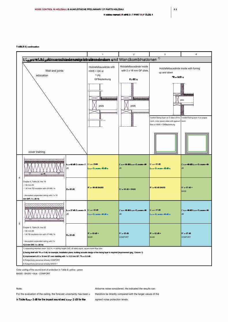
6 36 3NOISE CONTROL IN HOLZBAU | B AUAKUSTISCHE PRELIMINARY OF PARTS HOLZBAU NOISE CONTROL IN HOLZBAU | B AUAKUSTISCHE PRELIMINARY OF PARTS HOLZBAU NOISE CONTROL IN HOLZBAU | B AUAKUSTISCHE PRELIMINARY OF PARTS HOLZBAU
H olzbau manual | R eIHE 3 | T PART 3 | F OLGE 1H olzbau manual | R eIHE 3 | T PART 3 | F OLGE 1H olzbau manual | R eIHE 3 | T PART 3 | F OLGE 1H olzbau manual | R eIHE 3 | T PART 3 | F OLGE 1H olzbau manual | R eIHE 3 | T PART 3 | F OLGE 1H olzbau manual | R eIHE 3 | T PART 3 | F OLGE 1H olzbau manual | R eIHE 3 | T PART 3 | F OLGE 1H olzbau manual | R eIHE 3 | T PART 3 | F OLGE 1H olzbau manual | R eIHE 3 | T PART 3 | F OLGE 1H olzbau manual | R eIHE 3 | T PART 3 | F OLGE 1H olzbau manual | R eIHE 3 | T PART 3 | F OLGE 1
Note:
For the evaluation of the ceiling, the forecast uncertainty has been u
in Table 6 prog = 3 dB for the impact sound and u prog = 2 dB for the in Table 6 prog = 3 dB for the impact sound and u prog = 2 dB for the in Table 6 prog = 3 dB for the impact sound and u prog = 2 dB for the in Table 6 prog = 3 dB for the impact sound and u prog = 2 dB for the in Table 6 prog = 3 dB for the impact sound and u prog = 2 dB for the
Airborne noise considered. He indicated the results can
therefore be directly compared with the target values of the
agreed noise protection levels.
1 2 3 4
Holztafelbauwände with
HWS + GK or
1 ply
GFBeplankung
Holztafelbauwände inside
with 2 x 18 mm GF plate,
K 2 60 3)K 2 60 3)K 2 60 3)K 2 60 3)
cover training
1-sided facing layer on 2 sides of the
room, more space sides with gypsum
fiber or HWS + GKBeplankung
1-sided facing layer 4 on pages
room
L n, w 42 dB C I, 50-2500 = 7 L n, w 42 dB C I, 50-2500 = 7 L n, w 42 dB C I, 50-2500 = 7 L n, w 42 dB C I, 50-2500 = 7 L n, w 42 dB C I, 50-2500 = 7
dB
L` n, w < 53dBL` n, w < 53dBL` n, w < 53dB
L n, w + C I, 50-2500 = 49 dB 5)L n, w + C I, 50-2500 = 49 dB 5)L n, w + C I, 50-2500 = 49 dB 5)L n, w + C I, 50-2500 = 49 dB 5)L n, w + C I, 50-2500 = 49 dB 5)L n, w + C I, 50-2500 = 49 dB 5)L n, w + C I, 50-2500 = 49 dB 5)
L` n, w < 50 dB L n, w + C I, 50-2500 = 49 L` n, w < 50 dB L n, w + C I, 50-2500 = 49 L` n, w < 50 dB L n, w + C I, 50-2500 = 49 L` n, w < 50 dB L n, w + C I, 50-2500 = 49 L` n, w < 50 dB L n, w + C I, 50-2500 = 49 L` n, w < 50 dB L n, w + C I, 50-2500 = 49 L` n, w < 50 dB L n, w + C I, 50-2500 = 49 L` n, w < 50 dB L n, w + C I, 50-2500 = 49
dB
L` n, w < 51 dBL` n, w < 51 dBL` n, w < 51 dB
L n, w + C I, 50-2500 = 49 dB 5)L n, w + C I, 50-2500 = 49 dB 5)L n, w + C I, 50-2500 = 49 dB 5)L n, w + C I, 50-2500 = 49 dB 5)L n, w + C I, 50-2500 = 49 dB 5)L n, w + C I, 50-2500 = 49 dB 5)L n, w + C I, 50-2500 = 49 dB 5)
L` n, w < 49 dB L n, w + C I, 50-2500 = 49 L` n, w < 49 dB L n, w + C I, 50-2500 = 49 L` n, w < 49 dB L n, w + C I, 50-2500 = 49 L` n, w < 49 dB L n, w + C I, 50-2500 = 49 L` n, w < 49 dB L n, w + C I, 50-2500 = 49 L` n, w < 49 dB L n, w + C I, 50-2500 = 49 L` n, w < 49 dB L n, w + C I, 50-2500 = 49 L` n, w < 49 dB L n, w + C I, 50-2500 = 49
dB
R w! 80 dB R w! 80 dB R w! 80 dB
R ' w > 60 dB BASIS R ' w > 60 dB BASIS R ' w > 60 dB BASIS R ' w > 60 dB BASIS
R ' w> 65 dB + BASE R ' w> 65 dB + BASE R ' w> 65 dB + BASE
R ' w> 62 dB BASISR ' w> 62 dB BASISR ' w> 62 dB BASIS R ' w> 67 dB + R ' w> 67 dB + R ' w> 67 dB +
BASE
L n, w 37 dB C I, 50-2500 = 9 L n, w 37 dB C I, 50-2500 = 9 L n, w 37 dB C I, 50-2500 = 9 L n, w 37 dB C I, 50-2500 = 9 L n, w 37 dB C I, 50-2500 = 9
dB
L` n, w < 48 dBL` n, w < 48 dBL` n, w < 48 dB
L n, w + C I, 50-2500 = 46 dB 4)L n, w + C I, 50-2500 = 46 dB 4)L n, w + C I, 50-2500 = 46 dB 4)L n, w + C I, 50-2500 = 46 dB 4)L n, w + C I, 50-2500 = 46 dB 4)L n, w + C I, 50-2500 = 46 dB 4)L n, w + C I, 50-2500 = 46 dB 4)
L` n, w < 46 dB L n, w + C I, 50-2500 = 46 L` n, w < 46 dB L n, w + C I, 50-2500 = 46 L` n, w < 46 dB L n, w + C I, 50-2500 = 46 L` n, w < 46 dB L n, w + C I, 50-2500 = 46 L` n, w < 46 dB L n, w + C I, 50-2500 = 46 L` n, w < 46 dB L n, w + C I, 50-2500 = 46 L` n, w < 46 dB L n, w + C I, 50-2500 = 46 L` n, w < 46 dB L n, w + C I, 50-2500 = 46
dB
L` n, w < 47 dBL` n, w < 47 dBL` n, w < 47 dB
L n, w + C I, 50-2500 = 46 dB 4)L n, w + C I, 50-2500 = 46 dB 4)L n, w + C I, 50-2500 = 46 dB 4)L n, w + C I, 50-2500 = 46 dB 4)L n, w + C I, 50-2500 = 46 dB 4)L n, w + C I, 50-2500 = 46 dB 4)L n, w + C I, 50-2500 = 46 dB 4)
L` n, w < 46 dB L n, w + C I, 50-2500 = 46 L` n, w < 46 dB L n, w + C I, 50-2500 = 46 L` n, w < 46 dB L n, w + C I, 50-2500 = 46 L` n, w < 46 dB L n, w + C I, 50-2500 = 46 L` n, w < 46 dB L n, w + C I, 50-2500 = 46 L` n, w < 46 dB L n, w + C I, 50-2500 = 46 L` n, w < 46 dB L n, w + C I, 50-2500 = 46 L` n, w < 46 dB L n, w + C I, 50-2500 = 46
dB
R w! 83 dB R w! 83 dB R w! 83 dB
R ' w> 60 dB + R ' w> 60 dB + R ' w> 60 dB +
BASE
R ' w> 65 dB R ' w> 65 dB R ' w> 65 dB
COMFORT
R ' w> 62 dB + R ' w> 62 dB + R ' w> 62 dB +
BASE
R ' w> 67 dB R ' w> 67 dB R ' w> 67 dB
COMFORT
1) separating member area> 10.0 m, m ceiling height 2.60, all sides equal, square room floor plan
2) facing shell with "R w #! 5 dB, for example, installation plane, building acoustic design of the facing layer is required (improvement geg., Column 1)2) facing shell with "R w #! 5 dB, for example, installation plane, building acoustic design of the facing layer is required (improvement geg., Column 1)2) facing shell with "R w #! 5 dB, for example, installation plane, building acoustic design of the facing layer is required (improvement geg., Column 1)
3) improvement of 2 x 18 mm GF over cladding with 1 x 12.5 mm GF: "R w #! 3.5 dB3) improvement of 2 x 18 mm GF over cladding with 1 x 12.5 mm GF: "R w #! 3.5 dB3) improvement of 2 x 18 mm GF over cladding with 1 x 12.5 mm GF: "R w #! 3.5 dB
4) Subjectively perceived already COMFORT
5) Subjectively perceived already BASIS +
4
Chapter 6, Table 25, line 19:
- ! 50 mm ZE
- ! 30 mm TS insulation with s'8 MN / m
- decoupled suspended ceiling with 2 x 18
mm GKF, f 0 < 20 Hzmm GKF, f 0 < 20 Hzmm GKF, f 0 < 20 Hz
5
Chapter 6, Table 25, line 22:
- ! 80 mm ZE
- ! 40 TS insulation mm with s'7 MN / m
- decoupled suspended ceiling with 3 x
12.5 mm GKF, f 0 < 20 Hz12.5 mm GKF, f 0 < 20 Hz12.5 mm GKF, f 0 < 20 Hz
L' n, w and R ' w for various wood-beamed ceilings and wall combinations 1)L' n, w and R ' w for various wood-beamed ceilings and wall combinations 1)L' n, w and R ' w for various wood-beamed ceilings and wall combinations 1)L' n, w and R ' w for various wood-beamed ceilings and wall combinations 1)L' n, w and R ' w for various wood-beamed ceilings and wall combinations 1)L' n, w and R ' w for various wood-beamed ceilings and wall combinations 1)
Wall and joints
education
Holztafelbauwände inside with furring
up and down
"R w! 5dB 2)"R w! 5dB 2)"R w! 5dB 2)"R w! 5dB 2)
joistsjoistsjoists
or or
joists
or or
joistsjoists
T ABLE 6 | continuationT ABLE 6 | continuationT ABLE 6 | continuation
Color coding of the sound level of protection in Table 6: yellow - green
BASIS - BASIS + blue - COMFORT
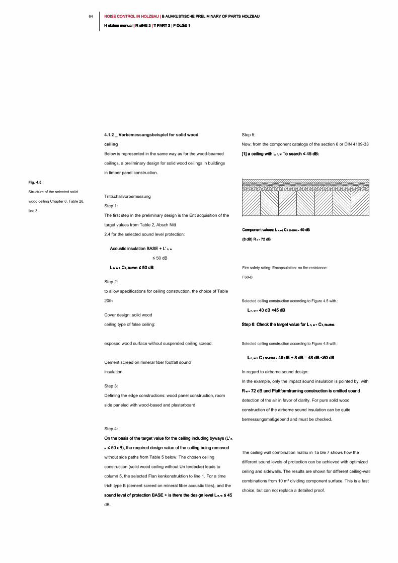
NOISE CONTROL IN HOLZBAU | B AUAKUSTISCHE PRELIMINARY OF PARTS HOLZBAU NOISE CONTROL IN HOLZBAU | B AUAKUSTISCHE PRELIMINARY OF PARTS HOLZBAU NOISE CONTROL IN HOLZBAU | B AUAKUSTISCHE PRELIMINARY OF PARTS HOLZBAU
H olzbau manual | R eIHE 3 | T PART 3 | F OLGE 1H olzbau manual | R eIHE 3 | T PART 3 | F OLGE 1H olzbau manual | R eIHE 3 | T PART 3 | F OLGE 1H olzbau manual | R eIHE 3 | T PART 3 | F OLGE 1H olzbau manual | R eIHE 3 | T PART 3 | F OLGE 1H olzbau manual | R eIHE 3 | T PART 3 | F OLGE 1H olzbau manual | R eIHE 3 | T PART 3 | F OLGE 1H olzbau manual | R eIHE 3 | T PART 3 | F OLGE 1H olzbau manual | R eIHE 3 | T PART 3 | F OLGE 1H olzbau manual | R eIHE 3 | T PART 3 | F OLGE 1H olzbau manual | R eIHE 3 | T PART 3 | F OLGE 1
64
Step 5:
Now, from the component catalogs of the section 6 or DIN 4109-33
[1] a ceiling with L n, w To search ≤ 45 dB: [1] a ceiling with L n, w To search ≤ 45 dB: [1] a ceiling with L n, w To search ≤ 45 dB:
Selected ceiling construction according to Figure 4.5 with.:
L n, w = 40 dB <45 dB L n, w = 40 dB <45 dB L n, w = 40 dB <45 dB
Step 6: Check the target value for L n, w + C I, 50-2500.Step 6: Check the target value for L n, w + C I, 50-2500.Step 6: Check the target value for L n, w + C I, 50-2500.Step 6: Check the target value for L n, w + C I, 50-2500.Step 6: Check the target value for L n, w + C I, 50-2500.
Selected ceiling construction according to Figure 4.5 with.:
L n, w + C I, 50-2500 = 40 dB + 8 dB = 48 dB <50 dB L n, w + C I, 50-2500 = 40 dB + 8 dB = 48 dB <50 dB L n, w + C I, 50-2500 = 40 dB + 8 dB = 48 dB <50 dB L n, w + C I, 50-2500 = 40 dB + 8 dB = 48 dB <50 dB L n, w + C I, 50-2500 = 40 dB + 8 dB = 48 dB <50 dB L n, w + C I, 50-2500 = 40 dB + 8 dB = 48 dB <50 dB
In regard to airborne sound design:
In the example, only the impact sound insulation is pointed by. with
R w = 72 dB and Plattformframing construction is omitted sound R w = 72 dB and Plattformframing construction is omitted sound R w = 72 dB and Plattformframing construction is omitted sound
detection of the air in favor of clarity. For pure solid wood
construction of the airborne sound insulation can be quite
bemessungsmaßgebend and must be checked.
The ceiling wall combination matrix in Ta ble 7 shows how the
different sound levels of protection can be achieved with optimized
ceiling and sidewalls. The results are shown for different ceiling-wall
combinations from 10 m² dividing component surface. This is a fast
choice, but can not replace a detailed proof.
4.1.2 _ Vorbemessungsbeispiel for solid wood
ceiling
Below is represented in the same way as for the wood-beamed
ceilings, a preliminary design for solid wood ceilings in buildings
in timber panel construction.
Trittschallvorbemessung
Step 1:
The first step in the preliminary design is the Ent acquisition of the
target values from Table 2, Absch Nitt
2.4 for the selected sound level protection:
Acoustic insulation BASE + L' n, wAcoustic insulation BASE + L' n, w
≤ 50 dB
L n, w + C I, 50-2500 ≤ 50 dBL n, w + C I, 50-2500 ≤ 50 dBL n, w + C I, 50-2500 ≤ 50 dBL n, w + C I, 50-2500 ≤ 50 dBL n, w + C I, 50-2500 ≤ 50 dBL n, w + C I, 50-2500 ≤ 50 dB
Step 2:
to allow specifications for ceiling construction, the choice of Table
20th
Cover design: solid wood
ceiling type of false ceiling:
exposed wood surface without suspended ceiling screed:
Cement screed on mineral fiber footfall sound
insulation
Step 3:
Defining the edge constructions: wood panel construction, room
side paneled with wood-based and plasterboard
Step 4:
On the basis of the target value for the ceiling including byways (L' n, On the basis of the target value for the ceiling including byways (L' n,
w ≤ 50 dB), the required design value of the ceiling being removed w ≤ 50 dB), the required design value of the ceiling being removed
without side paths from Table 5 below. The chosen ceiling
construction (solid wood ceiling without Un terdecke) leads to
column 5, the selected Flan kenkonstruktion to line 1. For a time
trich type B (cement screed on mineral fiber acoustic tiles), and the
sound level of protection BASE + is there the design level L n, w ≤ 45 sound level of protection BASE + is there the design level L n, w ≤ 45 sound level of protection BASE + is there the design level L n, w ≤ 45
dB.
Fig. 4.5:
Structure of the selected solid
wood ceiling Chapter 6, Table 26,
line 3
Component values: L n, w ( C I, 50-2500) = 40 dB Component values: L n, w ( C I, 50-2500) = 40 dB Component values: L n, w ( C I, 50-2500) = 40 dB Component values: L n, w ( C I, 50-2500) = 40 dB Component values: L n, w ( C I, 50-2500) = 40 dB
(8 dB) R w = 72 dB(8 dB) R w = 72 dB(8 dB) R w = 72 dB
Fire safety rating: Encapsulation: no fire resistance:
F60-B
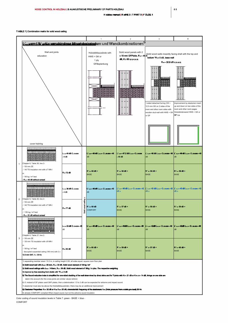
6 56 5NOISE CONTROL IN HOLZBAU | B AUAKUSTISCHE PRELIMINARY OF PARTS HOLZBAU NOISE CONTROL IN HOLZBAU | B AUAKUSTISCHE PRELIMINARY OF PARTS HOLZBAU NOISE CONTROL IN HOLZBAU | B AUAKUSTISCHE PRELIMINARY OF PARTS HOLZBAU
H olzbau manual | R eIHE 3 | T PART 3 | F OLGE 1H olzbau manual | R eIHE 3 | T PART 3 | F OLGE 1H olzbau manual | R eIHE 3 | T PART 3 | F OLGE 1H olzbau manual | R eIHE 3 | T PART 3 | F OLGE 1H olzbau manual | R eIHE 3 | T PART 3 | F OLGE 1H olzbau manual | R eIHE 3 | T PART 3 | F OLGE 1H olzbau manual | R eIHE 3 | T PART 3 | F OLGE 1H olzbau manual | R eIHE 3 | T PART 3 | F OLGE 1H olzbau manual | R eIHE 3 | T PART 3 | F OLGE 1H olzbau manual | R eIHE 3 | T PART 3 | F OLGE 1H olzbau manual | R eIHE 3 | T PART 3 | F OLGE 1
Color coding of sound insulation levels in Table 7: green - BASE + blue -
COMFORT
1 2 3 4
Holztafelbauwände with
HWS + GK or
1 ply
GFBeplankung
Solid wood panels with 2
x 18 mm GFPlatte, R w = 44.8 x 18 mm GFPlatte, R w = 44.8 x 18 mm GFPlatte, R w = 44.8
dB, K 2 60 2) 3) 4) 5) 6)dB, K 2 60 2) 3) 4) 5) 6)dB, K 2 60 2) 3) 4) 5) 6)dB, K 2 60 2) 3) 4) 5) 6)
cover training
1-sided detached furring CW +
12.5 mm GK on 2 sides of the
room and other room sides with
wooden stud wall with HWS + GK
or GF
Improvement by elastomer insert
up and down on two sides of the
room and other room pages
Holzständerwand HWS + GK or
GF 7) 8)GF 7) 8)
L n, w 40 dB C I, 50-2500 L n, w 40 dB C I, 50-2500 L n, w 40 dB C I, 50-2500 L n, w 40 dB C I, 50-2500
= 8 dB= 8 dB
L` n, w < 48 dB L n, w + C I, 50-2500 = 48 L` n, w < 48 dB L n, w + C I, 50-2500 = 48 L` n, w < 48 dB L n, w + C I, 50-2500 = 48 L` n, w < 48 dB L n, w + C I, 50-2500 = 48 L` n, w < 48 dB L n, w + C I, 50-2500 = 48 L` n, w < 48 dB L n, w + C I, 50-2500 = 48 L` n, w < 48 dB L n, w + C I, 50-2500 = 48 L` n, w < 48 dB L n, w + C I, 50-2500 = 48
dB
L` n, w < 47.2 dB L n, w + C I, 50-2500 L` n, w < 47.2 dB L n, w + C I, 50-2500 L` n, w < 47.2 dB L n, w + C I, 50-2500 L` n, w < 47.2 dB L n, w + C I, 50-2500 L` n, w < 47.2 dB L n, w + C I, 50-2500 L` n, w < 47.2 dB L n, w + C I, 50-2500 L` n, w < 47.2 dB L n, w + C I, 50-2500
= 48 dB= 48 dB
L` n, w < 46 dB L n, w + C I, 50-2500 = 48 L` n, w < 46 dB L n, w + C I, 50-2500 = 48 L` n, w < 46 dB L n, w + C I, 50-2500 = 48 L` n, w < 46 dB L n, w + C I, 50-2500 = 48 L` n, w < 46 dB L n, w + C I, 50-2500 = 48 L` n, w < 46 dB L n, w + C I, 50-2500 = 48 L` n, w < 46 dB L n, w + C I, 50-2500 = 48 L` n, w < 46 dB L n, w + C I, 50-2500 = 48
dB
R w! 72 dB R w! 72 dB R w! 72 dB
R ' w> 60 dB + R ' w> 60 dB + R ' w> 60 dB +
BASE
R ' w> 56 dB + R ' w> 56 dB + R ' w> 56 dB +
BASE
R ' w> 56 dB + R ' w> 56 dB + R ' w> 56 dB +
BASE
R ' w > 59 dB + R ' w > 59 dB + R ' w > 59 dB + R ' w > 59 dB +
BASE
L n, w 38 dB C I, 50-2500 L n, w 38 dB C I, 50-2500 L n, w 38 dB C I, 50-2500 L n, w 38 dB C I, 50-2500
= 4 dB= 4 dB
L` n, w < 46 dB L n, w + C I, 50-2500 = 42 L` n, w < 46 dB L n, w + C I, 50-2500 = 42 L` n, w < 46 dB L n, w + C I, 50-2500 = 42 L` n, w < 46 dB L n, w + C I, 50-2500 = 42 L` n, w < 46 dB L n, w + C I, 50-2500 = 42 L` n, w < 46 dB L n, w + C I, 50-2500 = 42 L` n, w < 46 dB L n, w + C I, 50-2500 = 42 L` n, w < 46 dB L n, w + C I, 50-2500 = 42
dB
L` n, w < 46 dB L n, w + C I, 50-2500 = 42 L` n, w < 46 dB L n, w + C I, 50-2500 = 42 L` n, w < 46 dB L n, w + C I, 50-2500 = 42 L` n, w < 46 dB L n, w + C I, 50-2500 = 42 L` n, w < 46 dB L n, w + C I, 50-2500 = 42 L` n, w < 46 dB L n, w + C I, 50-2500 = 42 L` n, w < 46 dB L n, w + C I, 50-2500 = 42 L` n, w < 46 dB L n, w + C I, 50-2500 = 42
dB 9)dB 9)
L` n, w < 45 dB L n, w + C I, 50-2500 = 42 L` n, w < 45 dB L n, w + C I, 50-2500 = 42 L` n, w < 45 dB L n, w + C I, 50-2500 = 42 L` n, w < 45 dB L n, w + C I, 50-2500 = 42 L` n, w < 45 dB L n, w + C I, 50-2500 = 42 L` n, w < 45 dB L n, w + C I, 50-2500 = 42 L` n, w < 45 dB L n, w + C I, 50-2500 = 42 L` n, w < 45 dB L n, w + C I, 50-2500 = 42
dB 9)dB 9)
R w! 77 dB R w! 77 dB R w! 77 dB
R ' w> 60 dB R ' w> 60 dB R ' w> 60 dB
COMFORT
R ' w> 57 dB + R ' w> 57 dB + R ' w> 57 dB +
BASE
R ' w> 58 dB + R ' w> 58 dB + R ' w> 58 dB +
BASE
R ' w> 59 dB + R ' w> 59 dB + R ' w> 59 dB +
BASE
L n, w 23 dB C I, 50-2500 = 26 L n, w 23 dB C I, 50-2500 = 26 L n, w 23 dB C I, 50-2500 = 26 L n, w 23 dB C I, 50-2500 = 26 L n, w 23 dB C I, 50-2500 = 26
dB
L` n, w < 46 dB L n, w + C I, 50-2500 = 49 L` n, w < 46 dB L n, w + C I, 50-2500 = 49 L` n, w < 46 dB L n, w + C I, 50-2500 = 49 L` n, w < 46 dB L n, w + C I, 50-2500 = 49 L` n, w < 46 dB L n, w + C I, 50-2500 = 49 L` n, w < 46 dB L n, w + C I, 50-2500 = 49 L` n, w < 46 dB L n, w + C I, 50-2500 = 49 L` n, w < 46 dB L n, w + C I, 50-2500 = 49
dB
L` n, w < 43dB L n, w + C I, 50-2500 = 49 L` n, w < 43dB L n, w + C I, 50-2500 = 49 L` n, w < 43dB L n, w + C I, 50-2500 = 49 L` n, w < 43dB L n, w + C I, 50-2500 = 49 L` n, w < 43dB L n, w + C I, 50-2500 = 49 L` n, w < 43dB L n, w + C I, 50-2500 = 49 L` n, w < 43dB L n, w + C I, 50-2500 = 49 L` n, w < 43dB L n, w + C I, 50-2500 = 49
dB
L` n, w < 42dB L n, w + C I, 50-2500 = 49 L` n, w < 42dB L n, w + C I, 50-2500 = 49 L` n, w < 42dB L n, w + C I, 50-2500 = 49 L` n, w < 42dB L n, w + C I, 50-2500 = 49 L` n, w < 42dB L n, w + C I, 50-2500 = 49 L` n, w < 42dB L n, w + C I, 50-2500 = 49 L` n, w < 42dB L n, w + C I, 50-2500 = 49 L` n, w < 42dB L n, w + C I, 50-2500 = 49
dB
R w! 82 dB R w! 82 dB R w! 82 dB
R ' w> 60 dB + R ' w> 60 dB + R ' w> 60 dB +
BASE
R ' w> 59 dB + R ' w> 59 dB + R ' w> 59 dB +
BASE
R ' w> 57 dB + R ' w> 57 dB + R ' w> 57 dB +
BASE
R ' w > 60 dB + R ' w > 60 dB + R ' w > 60 dB + R ' w > 60 dB +
BASE
1) separating member area> 10.0 m, m ceiling height 2.60, all sides equal, square room floor plan
2) Solid wood wall with d min = 80 mm, R w = 32 dB, Solid wood element s'! 36 kg / m²2) Solid wood wall with d min = 80 mm, R w = 32 dB, Solid wood element s'! 36 kg / m²2) Solid wood wall with d min = 80 mm, R w = 32 dB, Solid wood element s'! 36 kg / m²2) Solid wood wall with d min = 80 mm, R w = 32 dB, Solid wood element s'! 36 kg / m²2) Solid wood wall with d min = 80 mm, R w = 32 dB, Solid wood element s'! 36 kg / m²
3) Solid wood ceilings with d min = 140mm, R w = 39 dB, Solid wood element s'! 36kg / m plus. The respective weighting3) Solid wood ceilings with d min = 140mm, R w = 39 dB, Solid wood element s'! 36kg / m plus. The respective weighting3) Solid wood ceilings with d min = 140mm, R w = 39 dB, Solid wood element s'! 36kg / m plus. The respective weighting3) Solid wood ceilings with d min = 140mm, R w = 39 dB, Solid wood element s'! 36kg / m plus. The respective weighting3) Solid wood ceilings with d min = 140mm, R w = 39 dB, Solid wood element s'! 36kg / m plus. The respective weighting
4) improve by free-standing front shells with "R w #! 8 dB4) improve by free-standing front shells with "R w #! 8 dB4) improve by free-standing front shells with "R w #! 8 dB
5) The Sound reduction index is simplified for one-sided cladding of the wall determined by direct skins and for T-joints with K ff = 21 dB or K Fd / Df = 14 dB, linings on one side are 5) The Sound reduction index is simplified for one-sided cladding of the wall determined by direct skins and for T-joints with K ff = 21 dB or K Fd / Df = 14 dB, linings on one side are 5) The Sound reduction index is simplified for one-sided cladding of the wall determined by direct skins and for T-joints with K ff = 21 dB or K Fd / Df = 14 dB, linings on one side are 5) The Sound reduction index is simplified for one-sided cladding of the wall determined by direct skins and for T-joints with K ff = 21 dB or K Fd / Df = 14 dB, linings on one side are 5) The Sound reduction index is simplified for one-sided cladding of the wall determined by direct skins and for T-joints with K ff = 21 dB or K Fd / Df = 14 dB, linings on one side are
taken into account (for the cross-joints are similar values before)
6) If, instead of GF plates used GKF plates, then a deterioration 1.5 to 3 dB can be expected for airborne and impact sound
7) elastomer must also be above the Holztafelbauwänden, there may be an additional improvement
8) Elastomer Properties: K ff = 35 dB or K fd; K df = 22 dB, characteristic frequency of the elastomers: f 0 # (Note pressure from a static pre-load) 20 Hz8) Elastomer Properties: K ff = 35 dB or K fd; K df = 22 dB, characteristic frequency of the elastomers: f 0 # (Note pressure from a static pre-load) 20 Hz8) Elastomer Properties: K ff = 35 dB or K fd; K df = 22 dB, characteristic frequency of the elastomers: f 0 # (Note pressure from a static pre-load) 20 Hz8) Elastomer Properties: K ff = 35 dB or K fd; K df = 22 dB, characteristic frequency of the elastomers: f 0 # (Note pressure from a static pre-load) 20 Hz8) Elastomer Properties: K ff = 35 dB or K fd; K df = 22 dB, characteristic frequency of the elastomers: f 0 # (Note pressure from a static pre-load) 20 Hz8) Elastomer Properties: K ff = 35 dB or K fd; K df = 22 dB, characteristic frequency of the elastomers: f 0 # (Note pressure from a static pre-load) 20 Hz8) Elastomer Properties: K ff = 35 dB or K fd; K df = 22 dB, characteristic frequency of the elastomers: f 0 # (Note pressure from a static pre-load) 20 Hz8) Elastomer Properties: K ff = 35 dB or K fd; K df = 22 dB, characteristic frequency of the elastomers: f 0 # (Note pressure from a static pre-load) 20 Hz8) Elastomer Properties: K ff = 35 dB or K fd; K df = 22 dB, characteristic frequency of the elastomers: f 0 # (Note pressure from a static pre-load) 20 Hz
9) already COMFORT complied When impact sound, but not the airborne sound insulation
1
2
3
L' n, w and R ' w for various solid wood ceilings and wall combinations 1)L' n, w and R ' w for various solid wood ceilings and wall combinations 1)L' n, w and R ' w for various solid wood ceilings and wall combinations 1)L' n, w and R ' w for various solid wood ceilings and wall combinations 1)L' n, w and R ' w for various solid wood ceilings and wall combinations 1)L' n, w and R ' w for various solid wood ceilings and wall combinations 1)
Wall and joints
education
Solid wood walls inwardly facing shell with the top and
bottom "R w! 5 dB, base wallbottom "R w! 5 dB, base wallbottom "R w! 5 dB, base wall
R w = 32.8 dB 2) 3) 4) 5)R w = 32.8 dB 2) 3) 4) 5)R w = 32.8 dB 2) 3) 4) 5)R w = 32.8 dB 2) 3) 4) 5)
Chapter 6, Table 26, line 3:
- ! 50 mm ZE
- ! 40 TS insulation mm with s'7 MN /
m
- ! 90 kg / m² bed
- R w = 48 dB without screed- R w = 48 dB without screed- R w = 48 dB without screed
Chapter 6, Table 26, line 4:
- ! 50 mm ZE
- ! 40 TS insulation mm with s'7 MN /
m
- ! 150 kg / m² bed
- R w = 51 dB without screed- R w = 51 dB without screed- R w = 51 dB without screed
Chapter 6, Table 27, line 2:
- ! 50 mm ZE
- ! 30 mm TS insulation with s'8 MN /
m
- ! 90 kg / m² bed
- decoupled suspended ceiling (180 mm) with 2 x
12.5 mm GKF, f 0 < 30 Hz12.5 mm GKF, f 0 < 30 Hz12.5 mm GKF, f 0 < 30 Hz
or oror or
T ABLE 7 | Combination matrix for solid wood ceilingT ABLE 7 | Combination matrix for solid wood ceilingT ABLE 7 | Combination matrix for solid wood ceiling
Solid w
ood ceiling 3
)S
olid w
ood ceiling 3
)
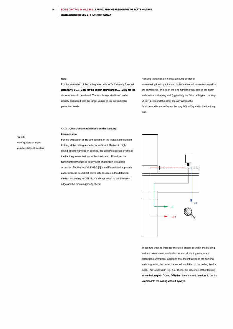
NOISE CONTROL IN HOLZBAU | B AUAKUSTISCHE PRELIMINARY OF PARTS HOLZBAU NOISE CONTROL IN HOLZBAU | B AUAKUSTISCHE PRELIMINARY OF PARTS HOLZBAU NOISE CONTROL IN HOLZBAU | B AUAKUSTISCHE PRELIMINARY OF PARTS HOLZBAU
H olzbau manual | R eIHE 3 | T PART 3 | F OLGE 1H olzbau manual | R eIHE 3 | T PART 3 | F OLGE 1H olzbau manual | R eIHE 3 | T PART 3 | F OLGE 1H olzbau manual | R eIHE 3 | T PART 3 | F OLGE 1H olzbau manual | R eIHE 3 | T PART 3 | F OLGE 1H olzbau manual | R eIHE 3 | T PART 3 | F OLGE 1H olzbau manual | R eIHE 3 | T PART 3 | F OLGE 1H olzbau manual | R eIHE 3 | T PART 3 | F OLGE 1H olzbau manual | R eIHE 3 | T PART 3 | F OLGE 1H olzbau manual | R eIHE 3 | T PART 3 | F OLGE 1H olzbau manual | R eIHE 3 | T PART 3 | F OLGE 1
66
Flanking transmission in impact sound excitation
In assessing the impact sound individual sound transmission paths
are considered. This is on the one hand the way across the beam
ends in the underlying wall (bypassing the false ceiling) on the way
Df in Fig. 4.6 and the other the way across the
Estrichranddämmstreifen on the way DFf in Fig. 4.6 in the flanking
wall.
These two ways to increase the rated impact sound in the building
and are taken into consideration when calculating a separate
correction summands. Basically, that the influence of the flanking
walls is greater, the better the sound insulation of the ceiling itself is
clear. This is shown in Fig. 4.7. There, the influence of the flanking
transmission (path Df and DFf) than the standard premium to the L n, transmission (path Df and DFf) than the standard premium to the L n,
w represents the ceiling without byways.w represents the ceiling without byways.
Note:
For the evaluation of the ceiling was belle in Ta 7 already forecast
uncertainty u prog = 3 dB for the impact sound and u prog = 2 dB for the uncertainty u prog = 3 dB for the impact sound and u prog = 2 dB for the uncertainty u prog = 3 dB for the impact sound and u prog = 2 dB for the uncertainty u prog = 3 dB for the impact sound and u prog = 2 dB for the uncertainty u prog = 3 dB for the impact sound and u prog = 2 dB for the
airborne sound considered. The results reported thus can be
directly compared with the target values of the agreed noise
protection levels.
4.1.3 _ Constructive influences on the flanking
transmission
For the evaluation of the components in the installation situation
looking at the ceiling alone is not sufficient. Rather, in high
sound-absorbing wooden ceilings, the building acoustic events of
the flanking transmission can be dominated. Therefore, the
flanking transmission is to pay a lot of attention in building
acoustics. For the footfall 4109-2 [1] is a differentiated approach
as for airborne sound not previously possible in the detection
method according to DIN. So it's always zoom to pull the worst
edge and be messungsmaßgebend.
Fig. 4.6:
Flanking paths for impact
sound excitation of a ceiling
dd
df
DFf
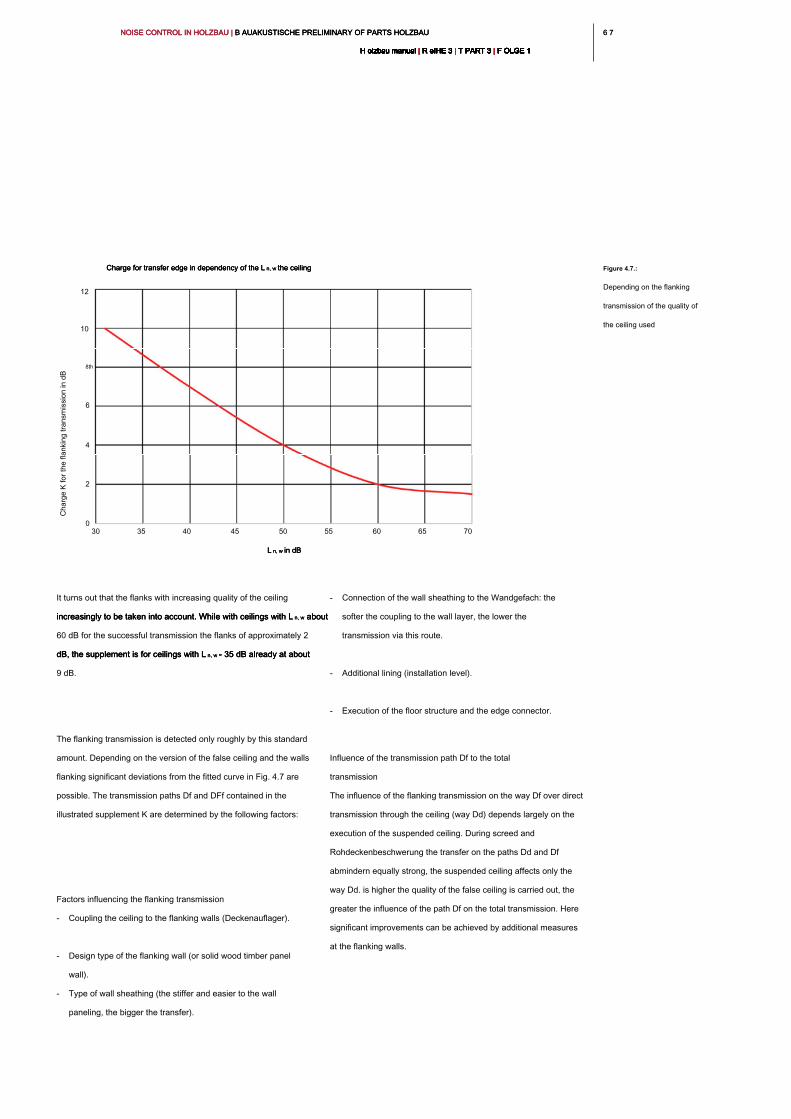
6 76 7NOISE CONTROL IN HOLZBAU | B AUAKUSTISCHE PRELIMINARY OF PARTS HOLZBAU NOISE CONTROL IN HOLZBAU | B AUAKUSTISCHE PRELIMINARY OF PARTS HOLZBAU NOISE CONTROL IN HOLZBAU | B AUAKUSTISCHE PRELIMINARY OF PARTS HOLZBAU
H olzbau manual | R eIHE 3 | T PART 3 | F OLGE 1H olzbau manual | R eIHE 3 | T PART 3 | F OLGE 1H olzbau manual | R eIHE 3 | T PART 3 | F OLGE 1H olzbau manual | R eIHE 3 | T PART 3 | F OLGE 1H olzbau manual | R eIHE 3 | T PART 3 | F OLGE 1H olzbau manual | R eIHE 3 | T PART 3 | F OLGE 1H olzbau manual | R eIHE 3 | T PART 3 | F OLGE 1H olzbau manual | R eIHE 3 | T PART 3 | F OLGE 1H olzbau manual | R eIHE 3 | T PART 3 | F OLGE 1H olzbau manual | R eIHE 3 | T PART 3 | F OLGE 1H olzbau manual | R eIHE 3 | T PART 3 | F OLGE 1
- Connection of the wall sheathing to the Wandgefach: the
softer the coupling to the wall layer, the lower the
transmission via this route.
- Additional lining (installation level).
- Execution of the floor structure and the edge connector.
Influence of the transmission path Df to the total
transmission
The influence of the flanking transmission on the way Df over direct
transmission through the ceiling (way Dd) depends largely on the
execution of the suspended ceiling. During screed and
Rohdeckenbeschwerung the transfer on the paths Dd and Df
abmindern equally strong, the suspended ceiling affects only the
way Dd. is higher the quality of the false ceiling is carried out, the
greater the influence of the path Df on the total transmission. Here
significant improvements can be achieved by additional measures
at the flanking walls.
It turns out that the flanks with increasing quality of the ceiling
increasingly to be taken into account. While with ceilings with L n, w about increasingly to be taken into account. While with ceilings with L n, w about increasingly to be taken into account. While with ceilings with L n, w about
60 dB for the successful transmission the flanks of approximately 2
dB, the supplement is for ceilings with L n, w = 35 dB already at about dB, the supplement is for ceilings with L n, w = 35 dB already at about dB, the supplement is for ceilings with L n, w = 35 dB already at about
9 dB.
The flanking transmission is detected only roughly by this standard
amount. Depending on the version of the false ceiling and the walls
flanking significant deviations from the fitted curve in Fig. 4.7 are
possible. The transmission paths Df and DFf contained in the
illustrated supplement K are determined by the following factors:
Factors influencing the flanking transmission
- Coupling the ceiling to the flanking walls (Deckenauflager).
- Design type of the flanking wall (or solid wood timber panel
wall).
- Type of wall sheathing (the stiffer and easier to the wall
paneling, the bigger the transfer).
Figure 4.7.:
Depending on the flanking
transmission of the quality of
the ceiling used
L n, w in dBL n, w in dBL n, w in dB
Charge for transfer edge in dependency of the L n, w the ceilingCharge for transfer edge in dependency of the L n, w the ceilingCharge for transfer edge in dependency of the L n, w the ceiling
30 35 40 45 50 55 60 65 70
12
10
8th
6
4
2
0
Charge K
for the flanking transm
ission in dB
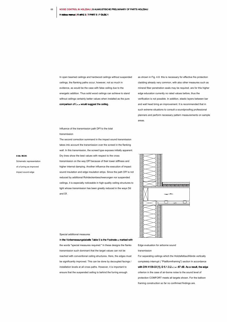
NOISE CONTROL IN HOLZBAU | B AUAKUSTISCHE PRELIMINARY OF PARTS HOLZBAU NOISE CONTROL IN HOLZBAU | B AUAKUSTISCHE PRELIMINARY OF PARTS HOLZBAU NOISE CONTROL IN HOLZBAU | B AUAKUSTISCHE PRELIMINARY OF PARTS HOLZBAU
H olzbau manual | R eIHE 3 | T PART 3 | F OLGE 1H olzbau manual | R eIHE 3 | T PART 3 | F OLGE 1H olzbau manual | R eIHE 3 | T PART 3 | F OLGE 1H olzbau manual | R eIHE 3 | T PART 3 | F OLGE 1H olzbau manual | R eIHE 3 | T PART 3 | F OLGE 1H olzbau manual | R eIHE 3 | T PART 3 | F OLGE 1H olzbau manual | R eIHE 3 | T PART 3 | F OLGE 1H olzbau manual | R eIHE 3 | T PART 3 | F OLGE 1H olzbau manual | R eIHE 3 | T PART 3 | F OLGE 1H olzbau manual | R eIHE 3 | T PART 3 | F OLGE 1H olzbau manual | R eIHE 3 | T PART 3 | F OLGE 1
68
as shown in Fig. 4.8. this is necessary for effective fire protection
cladding already very common, with also other measures such as
mineral fiber penetration seals may be required. are for this higher
edge education currently no rated values before, thus the
verification is not possible. In addition, elastic layers between bar
and wall head bring an improvement. It is recommended that in
such extreme situations to consult a soundproofing professional
planners and perform necessary pattern measurements on sample
areas.
Edge evaluation for airborne sound
transmission
For separating ceilings which the HolztafelbauWände vertically
completely interrupt ( "Plattformframing") section In accordance
with DIN 4109-33 [1], D 5.1.3.2 n, f, w = 67 dB. As a result, the edge with DIN 4109-33 [1], D 5.1.3.2 n, f, w = 67 dB. As a result, the edge with DIN 4109-33 [1], D 5.1.3.2 n, f, w = 67 dB. As a result, the edge
criterion in the case of air-borne noise to the sound level of
protection COMFORT meets all targets shown. For the balloon
framing construction so far no confirmed findings are.
In open beamed ceilings and hardwood ceilings without suspended
ceilings, the flanking paths occur, however, not so much in
evidence, as would be the case with false ceiling due to the
energetic addition. Thus solid wood ceilings can achieve to stand
without ceilings certainly better values when installed as the pure
comparison of L n, w would suggest the ceiling.comparison of L n, w would suggest the ceiling.comparison of L n, w would suggest the ceiling.
Influence of the transmission path DFf to the total
transmission
The second correction summand in the impact sound transmission
takes into account the transmission over the screed in the flanking
wall. In this transmission, the screed type exposes initially apparent.
Dry lines show the best values with respect to the cross
transmission on the way DFf because of their lower stiffness and
higher internal damping. Another influence the execution of impact
sound insulation and edge insulation strips. Since the path DFf is not
reduced by additional Rohdeckenbeschwerungen nor suspended
ceilings, it is especially noticeable in high-quality ceiling structures to
light whose transmission has been greatly reduced in the ways Dd
and Df.
Special additional measures
In the Vorbemessungstabelle Table 5 is the Footnote 4) marked with In the Vorbemessungstabelle Table 5 is the Footnote 4) marked with In the Vorbemessungstabelle Table 5 is the Footnote 4) marked with
the words "special measures required." In these designs the flanks
transmission such dominant that the target values can not be
reached with conventional ceiling structures. Here, the edges must
be significantly improved. This can be done by decoupled facings /
installation levels at all cross paths. However, it is important to
ensure that the suspended ceiling to behind the furring enough
A bb. 08.04:A bb. 08.04:
Schematic representation
of a furring as improved
impact sound edge
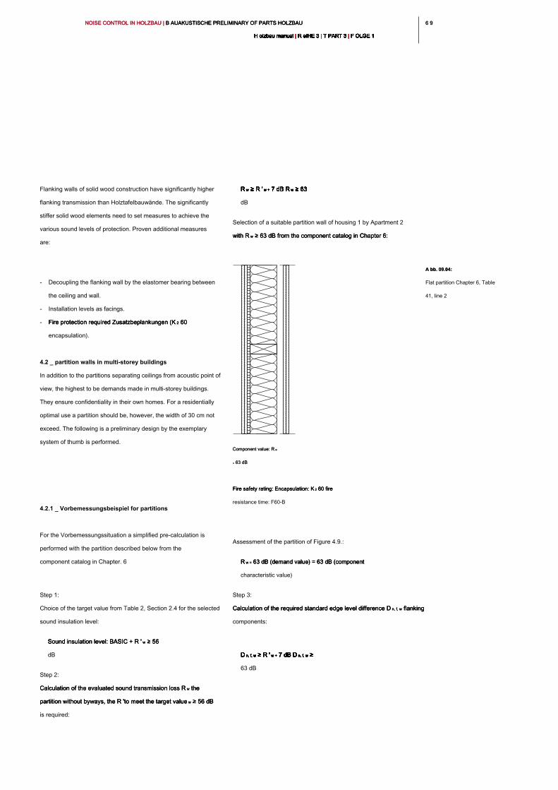
6 96 9NOISE CONTROL IN HOLZBAU | B AUAKUSTISCHE PRELIMINARY OF PARTS HOLZBAU NOISE CONTROL IN HOLZBAU | B AUAKUSTISCHE PRELIMINARY OF PARTS HOLZBAU NOISE CONTROL IN HOLZBAU | B AUAKUSTISCHE PRELIMINARY OF PARTS HOLZBAU
H olzbau manual | R eIHE 3 | T PART 3 | F OLGE 1H olzbau manual | R eIHE 3 | T PART 3 | F OLGE 1H olzbau manual | R eIHE 3 | T PART 3 | F OLGE 1H olzbau manual | R eIHE 3 | T PART 3 | F OLGE 1H olzbau manual | R eIHE 3 | T PART 3 | F OLGE 1H olzbau manual | R eIHE 3 | T PART 3 | F OLGE 1H olzbau manual | R eIHE 3 | T PART 3 | F OLGE 1H olzbau manual | R eIHE 3 | T PART 3 | F OLGE 1H olzbau manual | R eIHE 3 | T PART 3 | F OLGE 1H olzbau manual | R eIHE 3 | T PART 3 | F OLGE 1H olzbau manual | R eIHE 3 | T PART 3 | F OLGE 1
R w ≥ R ' w + 7 dB R w ≥ 63 R w ≥ R ' w + 7 dB R w ≥ 63 R w ≥ R ' w + 7 dB R w ≥ 63 R w ≥ R ' w + 7 dB R w ≥ 63 R w ≥ R ' w + 7 dB R w ≥ 63 R w ≥ R ' w + 7 dB R w ≥ 63 R w ≥ R ' w + 7 dB R w ≥ 63 R w ≥ R ' w + 7 dB R w ≥ 63
dB
Selection of a suitable partition wall of housing 1 by Apartment 2
with R w ≥ 63 dB from the component catalog in Chapter 6:with R w ≥ 63 dB from the component catalog in Chapter 6:with R w ≥ 63 dB from the component catalog in Chapter 6:
Assessment of the partition of Figure 4.9.:
R w = 63 dB (demand value) = 63 dB (component R w = 63 dB (demand value) = 63 dB (component R w = 63 dB (demand value) = 63 dB (component
characteristic value)
Step 3:
Calculation of the required standard edge level difference D n, f, w flanking Calculation of the required standard edge level difference D n, f, w flanking Calculation of the required standard edge level difference D n, f, w flanking
components:
D n, f, w ≥ R ' w + 7 dB D n, f, w ≥ D n, f, w ≥ R ' w + 7 dB D n, f, w ≥ D n, f, w ≥ R ' w + 7 dB D n, f, w ≥ D n, f, w ≥ R ' w + 7 dB D n, f, w ≥ D n, f, w ≥ R ' w + 7 dB D n, f, w ≥ D n, f, w ≥ R ' w + 7 dB D n, f, w ≥ D n, f, w ≥ R ' w + 7 dB D n, f, w ≥ D n, f, w ≥ R ' w + 7 dB D n, f, w ≥
63 dB
Flanking walls of solid wood construction have significantly higher
flanking transmission than Holztafelbauwände. The significantly
stiffer solid wood elements need to set measures to achieve the
various sound levels of protection. Proven additional measures
are:
- Decoupling the flanking wall by the elastomer bearing between
the ceiling and wall.
- Installation levels as facings.
- Fire protection required Zusatzbeplankungen (K 2 60 Fire protection required Zusatzbeplankungen (K 2 60 Fire protection required Zusatzbeplankungen (K 2 60
encapsulation).
4.2 _ partition walls in multi-storey buildings
In addition to the partitions separating ceilings from acoustic point of
view, the highest to be demands made in multi-storey buildings.
They ensure confidentiality in their own homes. For a residentially
optimal use a partition should be, however, the width of 30 cm not
exceed. The following is a preliminary design by the exemplary
system of thumb is performed.
4.2.1 _ Vorbemessungsbeispiel for partitions
For the Vorbemessungssituation a simplified pre-calculation is
performed with the partition described below from the
component catalog in Chapter. 6
Step 1:
Choice of the target value from Table 2, Section 2.4 for the selected
sound insulation level:
Sound insulation level: BASIC + R ' w ≥ 56 Sound insulation level: BASIC + R ' w ≥ 56 Sound insulation level: BASIC + R ' w ≥ 56
dB
Step 2:
Calculation of the evaluated sound transmission loss R w the Calculation of the evaluated sound transmission loss R w the Calculation of the evaluated sound transmission loss R w the
partition without byways, the R 'to meet the target value w ≥ 56 dB partition without byways, the R 'to meet the target value w ≥ 56 dB partition without byways, the R 'to meet the target value w ≥ 56 dB
is required:
A bb. 09.04:A bb. 09.04:
Flat partition Chapter 6, Table
41, line 2
Component value: R w Component value: R w
= 63 dB= 63 dB
Fire safety rating: Encapsulation: K 2 60 fire Fire safety rating: Encapsulation: K 2 60 fire Fire safety rating: Encapsulation: K 2 60 fire
resistance time: F60-B
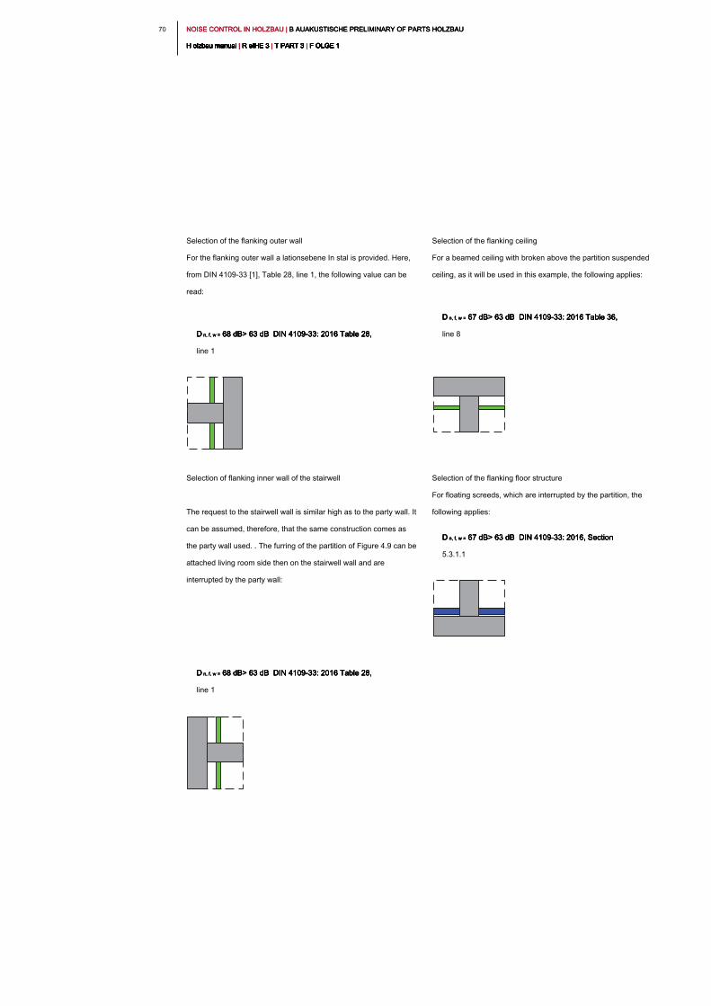
NOISE CONTROL IN HOLZBAU | B AUAKUSTISCHE PRELIMINARY OF PARTS HOLZBAU NOISE CONTROL IN HOLZBAU | B AUAKUSTISCHE PRELIMINARY OF PARTS HOLZBAU NOISE CONTROL IN HOLZBAU | B AUAKUSTISCHE PRELIMINARY OF PARTS HOLZBAU
H olzbau manual | R eIHE 3 | T PART 3 | F OLGE 1H olzbau manual | R eIHE 3 | T PART 3 | F OLGE 1H olzbau manual | R eIHE 3 | T PART 3 | F OLGE 1H olzbau manual | R eIHE 3 | T PART 3 | F OLGE 1H olzbau manual | R eIHE 3 | T PART 3 | F OLGE 1H olzbau manual | R eIHE 3 | T PART 3 | F OLGE 1H olzbau manual | R eIHE 3 | T PART 3 | F OLGE 1H olzbau manual | R eIHE 3 | T PART 3 | F OLGE 1H olzbau manual | R eIHE 3 | T PART 3 | F OLGE 1H olzbau manual | R eIHE 3 | T PART 3 | F OLGE 1H olzbau manual | R eIHE 3 | T PART 3 | F OLGE 1
70
Selection of the flanking ceiling
For a beamed ceiling with broken above the partition suspended
ceiling, as it will be used in this example, the following applies:
D n, f, w = 67 dB> 63 dB DIN 4109-33: 2016 Table 36, D n, f, w = 67 dB> 63 dB DIN 4109-33: 2016 Table 36, D n, f, w = 67 dB> 63 dB DIN 4109-33: 2016 Table 36, D n, f, w = 67 dB> 63 dB DIN 4109-33: 2016 Table 36,
line 8
Selection of the flanking floor structure
For floating screeds, which are interrupted by the partition, the
following applies:
D n, f, w = 67 dB> 63 dB DIN 4109-33: 2016, Section D n, f, w = 67 dB> 63 dB DIN 4109-33: 2016, Section D n, f, w = 67 dB> 63 dB DIN 4109-33: 2016, Section D n, f, w = 67 dB> 63 dB DIN 4109-33: 2016, Section
5.3.1.1
Selection of the flanking outer wall
For the flanking outer wall a lationsebene In stal is provided. Here,
from DIN 4109-33 [1], Table 28, line 1, the following value can be
read:
D n, f, w = 68 dB> 63 dB DIN 4109-33: 2016 Table 28, D n, f, w = 68 dB> 63 dB DIN 4109-33: 2016 Table 28, D n, f, w = 68 dB> 63 dB DIN 4109-33: 2016 Table 28, D n, f, w = 68 dB> 63 dB DIN 4109-33: 2016 Table 28,
line 1
Selection of flanking inner wall of the stairwell
The request to the stairwell wall is similar high as to the party wall. It
can be assumed, therefore, that the same construction comes as
the party wall used. . The furring of the partition of Figure 4.9 can be
attached living room side then on the stairwell wall and are
interrupted by the party wall:
D n, f, w = 68 dB> 63 dB DIN 4109-33: 2016 Table 28, D n, f, w = 68 dB> 63 dB DIN 4109-33: 2016 Table 28, D n, f, w = 68 dB> 63 dB DIN 4109-33: 2016 Table 28, D n, f, w = 68 dB> 63 dB DIN 4109-33: 2016 Table 28,
line 1

7 17 1NOISE CONTROL IN HOLZBAU | B AUAKUSTISCHE PRELIMINARY OF PARTS HOLZBAU NOISE CONTROL IN HOLZBAU | B AUAKUSTISCHE PRELIMINARY OF PARTS HOLZBAU NOISE CONTROL IN HOLZBAU | B AUAKUSTISCHE PRELIMINARY OF PARTS HOLZBAU
H olzbau manual | R eIHE 3 | T PART 3 | F OLGE 1H olzbau manual | R eIHE 3 | T PART 3 | F OLGE 1H olzbau manual | R eIHE 3 | T PART 3 | F OLGE 1H olzbau manual | R eIHE 3 | T PART 3 | F OLGE 1H olzbau manual | R eIHE 3 | T PART 3 | F OLGE 1H olzbau manual | R eIHE 3 | T PART 3 | F OLGE 1H olzbau manual | R eIHE 3 | T PART 3 | F OLGE 1H olzbau manual | R eIHE 3 | T PART 3 | F OLGE 1H olzbau manual | R eIHE 3 | T PART 3 | F OLGE 1H olzbau manual | R eIHE 3 | T PART 3 | F OLGE 1H olzbau manual | R eIHE 3 | T PART 3 | F OLGE 1
matrix created in Table 10 below. The calculations were carried out
according to [30]. Similarly, a combination matrix for pure solid wood
construction in Table 11 was created. For this combination matrices
less of a ceiling height 2.60 m has been assumed. For the calculated
results R ' w in Table 10 and 11, the Pro has already results R ' w in Table 10 and 11, the Pro has already results R ' w in Table 10 and 11, the Pro has already
gnoseunsicherheit u prog = 2 dB in accordance with DIN 4109-2 [1] gnoseunsicherheit u prog = 2 dB in accordance with DIN 4109-2 [1] gnoseunsicherheit u prog = 2 dB in accordance with DIN 4109-2 [1]
deducted. The readings can be compared so directly with the target
value of the corresponding sound levels of protection.
Summary and information on other combinations of
components
The summary of the Vorbemessungsbeispiels and a supplementary
example with accompanying massive wooden ceiling are shown in
Table. 8 and 9 For pre-calculation of DIN 4109 [1], so a partition
area of 10 m², a ceiling height of 2.80 m and a partition width of 4.50
m is assumed that the reference values. The component data are
thus to be seen directly from the parts catalogs, such as from DIN
4109-33 [1], in section 6 of this document or from test certificates.
The detailed forecast results in separation component surfaces over
10 m or ceiling heights less than 2.80 m to better results. This can
lead to a more economical structural implementation.
The preliminary design shown is only possible for flanking
components whose flanking transmission by the weighted
standard edge level difference D n, f, w can be described. standard edge level difference D n, f, w can be described. standard edge level difference D n, f, w can be described.
Accompanying solid wood components, this is not the case. In
order to provide for the combination of wood panel components
with solid wood parts planning values are available, the
combination was
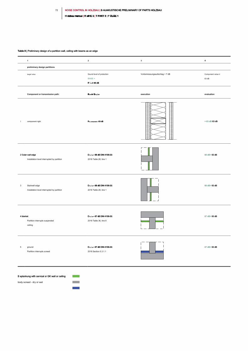
NOISE CONTROL IN HOLZBAU | B AUAKUSTISCHE PRELIMINARY OF PARTS HOLZBAU NOISE CONTROL IN HOLZBAU | B AUAKUSTISCHE PRELIMINARY OF PARTS HOLZBAU NOISE CONTROL IN HOLZBAU | B AUAKUSTISCHE PRELIMINARY OF PARTS HOLZBAU
H olzbau manual | R eIHE 3 | T PART 3 | F OLGE 1H olzbau manual | R eIHE 3 | T PART 3 | F OLGE 1H olzbau manual | R eIHE 3 | T PART 3 | F OLGE 1H olzbau manual | R eIHE 3 | T PART 3 | F OLGE 1H olzbau manual | R eIHE 3 | T PART 3 | F OLGE 1H olzbau manual | R eIHE 3 | T PART 3 | F OLGE 1H olzbau manual | R eIHE 3 | T PART 3 | F OLGE 1H olzbau manual | R eIHE 3 | T PART 3 | F OLGE 1H olzbau manual | R eIHE 3 | T PART 3 | F OLGE 1H olzbau manual | R eIHE 3 | T PART 3 | F OLGE 1H olzbau manual | R eIHE 3 | T PART 3 | F OLGE 1
72
Table 8 | Preliminary design of a partition wall, ceiling with beams as an edgeTable 8 | Preliminary design of a partition wall, ceiling with beams as an edge
1 2 3 4
preliminary design partitions
target value Sound level of protection
BASE +
R ' w ≥ 56 dBR ' w ≥ 56 dBR ' w ≥ 56 dB
Vorbemessungsaufschlag = 7 dB Component value ≥
63 dB
Component or transmission path: R w or D n, f, wR w or D n, f, wR w or D n, f, wR w or D n, f, w execution evaluation
1 component right R w, component = 63 dB R w, component = 63 dB R w, component = 63 dB = 63 dB 63 dB = 63 dB 63 dB
2 Outer wall edge 2 Outer wall edge
Installation level interrupted by partition
D n, f, w = 68 dB DIN 4109-33: D n, f, w = 68 dB DIN 4109-33: D n, f, w = 68 dB DIN 4109-33:
2016 Table 28, line 1
68 dB> 63 dB 68 dB> 63 dB
3 Stairwell edge
Installation level interrupted by partition
D n, f, w = 68 dB DIN 4109-33: D n, f, w = 68 dB DIN 4109-33: D n, f, w = 68 dB DIN 4109-33:
2016 Table 28, line 1
68 dB> 63 dB 68 dB> 63 dB
4 blanket 4 blanket
Partition interrupts suspended
ceiling
D n, f, w = 67 dB DIN 4109-33: D n, f, w = 67 dB DIN 4109-33: D n, f, w = 67 dB DIN 4109-33:
2016 Table 36, line 8
67 dB> 63 dB 67 dB> 63 dB
5 ground
Partition interrupts screed
D n, f, w = 67 dB DIN 4109-33: D n, f, w = 67 dB DIN 4109-33: D n, f, w = 67 dB DIN 4109-33:
2016 Section 5.3.1.1
67 dB> 63 dB 67 dB> 63 dB
B eplankung with cervical or GK wall or ceiling B eplankung with cervical or GK wall or ceiling
body screed - dry or wet
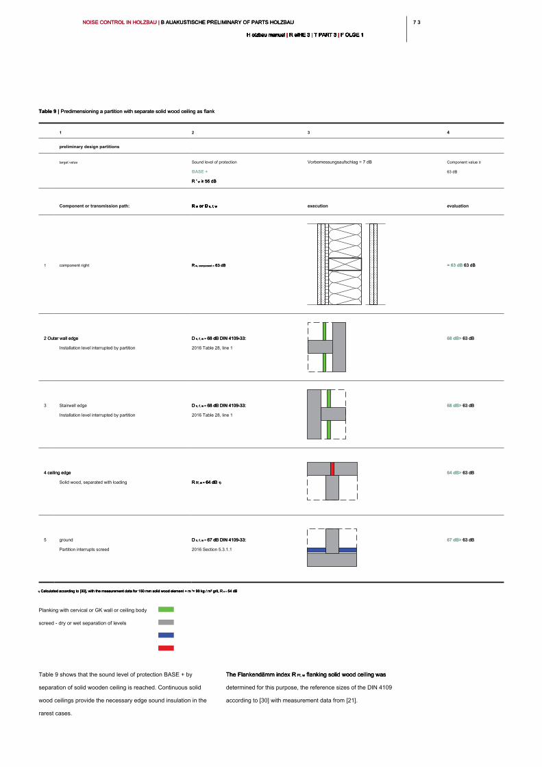
7 37 3NOISE CONTROL IN HOLZBAU | B AUAKUSTISCHE PRELIMINARY OF PARTS HOLZBAU NOISE CONTROL IN HOLZBAU | B AUAKUSTISCHE PRELIMINARY OF PARTS HOLZBAU NOISE CONTROL IN HOLZBAU | B AUAKUSTISCHE PRELIMINARY OF PARTS HOLZBAU
H olzbau manual | R eIHE 3 | T PART 3 | F OLGE 1H olzbau manual | R eIHE 3 | T PART 3 | F OLGE 1H olzbau manual | R eIHE 3 | T PART 3 | F OLGE 1H olzbau manual | R eIHE 3 | T PART 3 | F OLGE 1H olzbau manual | R eIHE 3 | T PART 3 | F OLGE 1H olzbau manual | R eIHE 3 | T PART 3 | F OLGE 1H olzbau manual | R eIHE 3 | T PART 3 | F OLGE 1H olzbau manual | R eIHE 3 | T PART 3 | F OLGE 1H olzbau manual | R eIHE 3 | T PART 3 | F OLGE 1H olzbau manual | R eIHE 3 | T PART 3 | F OLGE 1H olzbau manual | R eIHE 3 | T PART 3 | F OLGE 1
1) Calculated according to [30], with the measurement data for 160 mm solid wood element + m '= 90 kg / m² grit, R w = 54 dB1) Calculated according to [30], with the measurement data for 160 mm solid wood element + m '= 90 kg / m² grit, R w = 54 dB1) Calculated according to [30], with the measurement data for 160 mm solid wood element + m '= 90 kg / m² grit, R w = 54 dB1) Calculated according to [30], with the measurement data for 160 mm solid wood element + m '= 90 kg / m² grit, R w = 54 dB
Table 9 shows that the sound level of protection BASE + by
separation of solid wooden ceiling is reached. Continuous solid
wood ceilings provide the necessary edge sound insulation in the
rarest cases.
The Flankendämm index R Ff, w flanking solid wood ceiling was The Flankendämm index R Ff, w flanking solid wood ceiling was The Flankendämm index R Ff, w flanking solid wood ceiling was
determined for this purpose, the reference sizes of the DIN 4109
according to [30] with measurement data from [21].
Table 9 | Predimensioning a partition with separate solid wood ceiling as flankTable 9 | Predimensioning a partition with separate solid wood ceiling as flank
1 2 3 4
preliminary design partitions
target value Sound level of protection
BASE +
R ' w ≥ 56 dBR ' w ≥ 56 dBR ' w ≥ 56 dB
Vorbemessungsaufschlag = 7 dB Component value ≥
63 dB
Component or transmission path: R w or D n, f, wR w or D n, f, wR w or D n, f, wR w or D n, f, w execution evaluation
1 component right R w, component = 63 dB R w, component = 63 dB R w, component = 63 dB = 63 dB 63 dB = 63 dB 63 dB
2 Outer wall edge 2 Outer wall edge
Installation level interrupted by partition
D n, f, w = 68 dB DIN 4109-33: D n, f, w = 68 dB DIN 4109-33: D n, f, w = 68 dB DIN 4109-33:
2016 Table 28, line 1
68 dB> 63 dB 68 dB> 63 dB
3 Stairwell edge
Installation level interrupted by partition
D n, f, w = 68 dB DIN 4109-33: D n, f, w = 68 dB DIN 4109-33: D n, f, w = 68 dB DIN 4109-33:
2016 Table 28, line 1
68 dB> 63 dB 68 dB> 63 dB
4 ceiling edge 4 ceiling edge
Solid wood, separated with loading R Ff, w = 64 dB 1)R Ff, w = 64 dB 1)R Ff, w = 64 dB 1)R Ff, w = 64 dB 1)
64 dB> 63 dB 64 dB> 63 dB
5 ground
Partition interrupts screed
D n, f, w = 67 dB DIN 4109-33: D n, f, w = 67 dB DIN 4109-33: D n, f, w = 67 dB DIN 4109-33:
2016 Section 5.3.1.1
67 dB> 63 dB 67 dB> 63 dB
Planking with cervical or GK wall or ceiling body
screed - dry or wet separation of levels
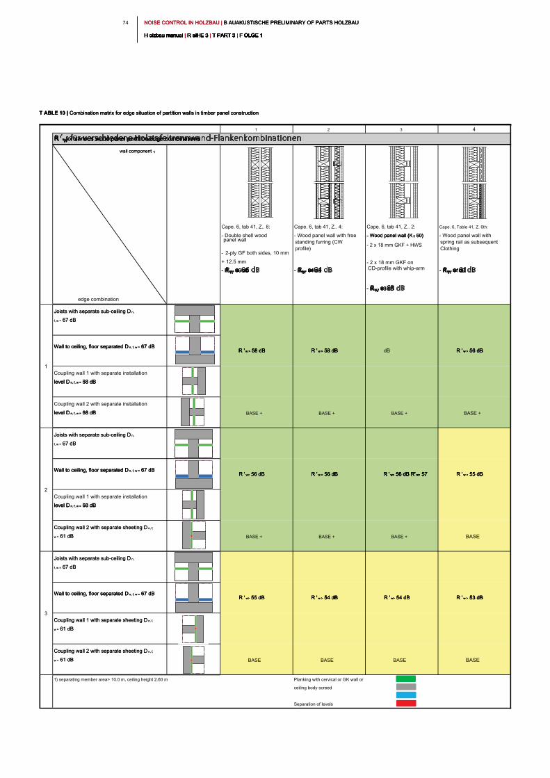
NOISE CONTROL IN HOLZBAU | B AUAKUSTISCHE PRELIMINARY OF PARTS HOLZBAU NOISE CONTROL IN HOLZBAU | B AUAKUSTISCHE PRELIMINARY OF PARTS HOLZBAU NOISE CONTROL IN HOLZBAU | B AUAKUSTISCHE PRELIMINARY OF PARTS HOLZBAU
H olzbau manual | R eIHE 3 | T PART 3 | F OLGE 1H olzbau manual | R eIHE 3 | T PART 3 | F OLGE 1H olzbau manual | R eIHE 3 | T PART 3 | F OLGE 1H olzbau manual | R eIHE 3 | T PART 3 | F OLGE 1H olzbau manual | R eIHE 3 | T PART 3 | F OLGE 1H olzbau manual | R eIHE 3 | T PART 3 | F OLGE 1H olzbau manual | R eIHE 3 | T PART 3 | F OLGE 1H olzbau manual | R eIHE 3 | T PART 3 | F OLGE 1H olzbau manual | R eIHE 3 | T PART 3 | F OLGE 1H olzbau manual | R eIHE 3 | T PART 3 | F OLGE 1H olzbau manual | R eIHE 3 | T PART 3 | F OLGE 1
74
1 2 3 4
R ' w for various wood panel partition-edge combinationsR ' w for various wood panel partition-edge combinationsR ' w for various wood panel partition-edge combinations
wall component 1)wall component 1)
edge combination
Cape. 6, tab 41, Z.. 8:
- Double shell wood
panel wall
- 2-ply GF both sides, 10 mm
+ 12.5 mm
- R w = 66 dB- R w = 66 dB- R w = 66 dB
Cape. 6, tab 41, Z.. 4:
- Wood panel wall with free
standing furring (CW
profile)
- R w = 64 dB- R w = 64 dB- R w = 64 dB
Cape. 6, tab 41, Z.. 2:
- Wood panel wall (K 2 60)- Wood panel wall (K 2 60)- Wood panel wall (K 2 60)
- 2 x 18 mm GKF + HWS
- 2 x 18 mm GKF on
CD-profile with whip-arm
- R w = 63 dB- R w = 63 dB- R w = 63 dB
Cape. 6, Table 41, Z. 6th:
- Wood panel wall with
spring rail as subsequent
Clothing
- R w = 61dB- R w = 61dB- R w = 61dB
Joists with separate sub-ceiling D n, Joists with separate sub-ceiling D n,
f, w = 67 dBf, w = 67 dB
Wall to ceiling, floor separated D n, f, w = 67 dBWall to ceiling, floor separated D n, f, w = 67 dBWall to ceiling, floor separated D n, f, w = 67 dB
Coupling wall 1 with separate installation
level D n, f, w = 68 dBlevel D n, f, w = 68 dBlevel D n, f, w = 68 dB
Coupling wall 2 with separate installation
level D n, f, w = 68 dBlevel D n, f, w = 68 dBlevel D n, f, w = 68 dB BASE + BASE + BASE + BASE +
Joists with separate sub-ceiling D n, Joists with separate sub-ceiling D n,
f, w = 67 dBf, w = 67 dB
Wall to ceiling, floor separated D n, f, w = 67 dBWall to ceiling, floor separated D n, f, w = 67 dBWall to ceiling, floor separated D n, f, w = 67 dB
Coupling wall 1 with separate installation
level D n, f, w = 68 dBlevel D n, f, w = 68 dBlevel D n, f, w = 68 dB
Coupling wall 2 with separate sheeting D n, f, Coupling wall 2 with separate sheeting D n, f,
w = 61 dBw = 61 dB BASE + BASE + BASE + BASE
Joists with separate sub-ceiling D n, Joists with separate sub-ceiling D n,
f, w = 67 dBf, w = 67 dB
Wall to ceiling, floor separated D n, f, w = 67 dBWall to ceiling, floor separated D n, f, w = 67 dBWall to ceiling, floor separated D n, f, w = 67 dB
Coupling wall 1 with separate sheeting D n, f, Coupling wall 1 with separate sheeting D n, f,
w = 61 dBw = 61 dB
Coupling wall 2 with separate sheeting D n, f, Coupling wall 2 with separate sheeting D n, f,
w = 61 dBw = 61 dB BASE BASE BASE BASE
1) separating member area> 10.0 m, ceiling height 2.60 m
Separation of levels
R ' w > 53 dBR ' w > 53 dBR ' w > 53 dBR ' w > 53 dB
R ' w > 58 dBR ' w > 58 dBR ' w > 58 dBR ' w > 58 dB
R ' w> 56 dBR ' w> 56 dBR ' w> 56 dB
R ' w> 55 dBR ' w> 55 dBR ' w> 55 dB
R ' w > 56 dBR ' w > 56 dBR ' w > 56 dBR ' w > 56 dB
R ' w > 55 dBR ' w > 55 dBR ' w > 55 dBR ' w > 55 dBR ' w> 56 dB R' w> 57 R ' w> 56 dB R' w> 57 R ' w> 56 dB R' w> 57 R ' w> 56 dB R' w> 57 R ' w> 56 dB R' w> 57
dBR ' w > 58 dBR ' w > 58 dBR ' w > 58 dBR ' w > 58 dB
R ' w > 56 dBR ' w > 56 dBR ' w > 56 dBR ' w > 56 dB
R ' w > 54 dBR ' w > 54 dBR ' w > 54 dBR ' w > 54 dB
Planking with cervical or GK wall or
ceiling body screed
1
2
3
R ' w> 54 dBR ' w> 54 dBR ' w> 54 dB
T ABLE 10 | Combination matrix for edge situation of partition walls in timber panel constructionT ABLE 10 | Combination matrix for edge situation of partition walls in timber panel constructionT ABLE 10 | Combination matrix for edge situation of partition walls in timber panel construction
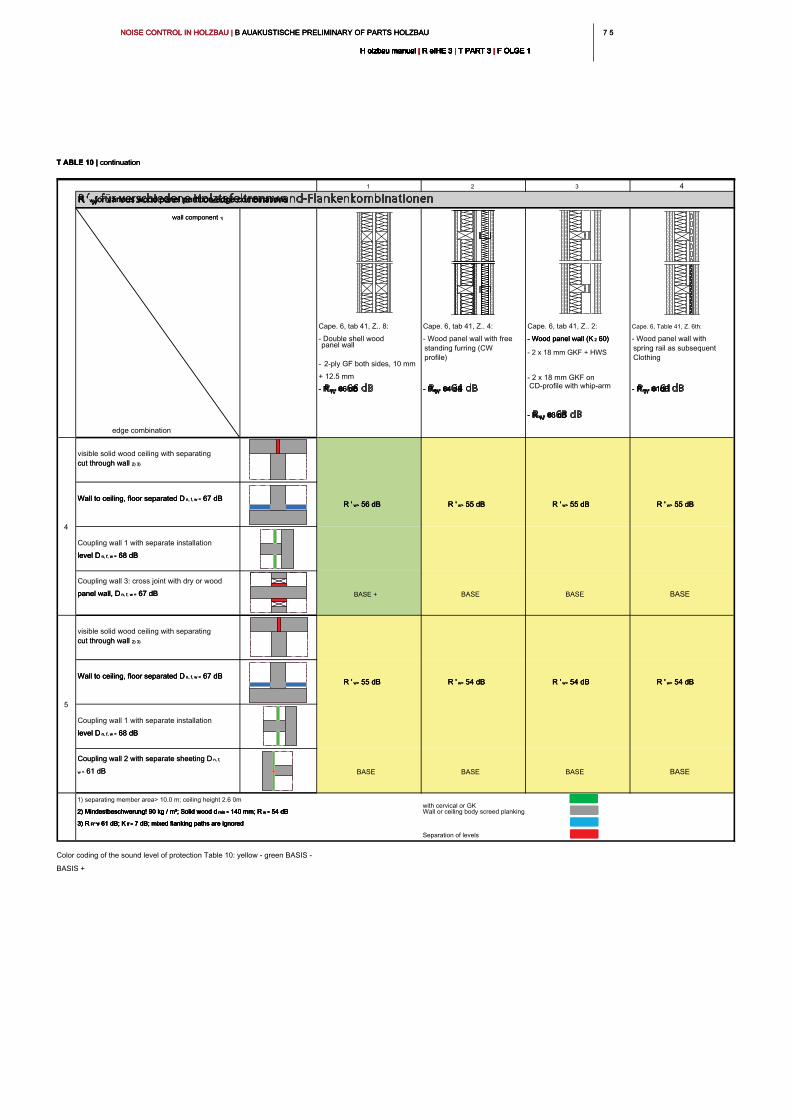
7 57 5NOISE CONTROL IN HOLZBAU | B AUAKUSTISCHE PRELIMINARY OF PARTS HOLZBAU NOISE CONTROL IN HOLZBAU | B AUAKUSTISCHE PRELIMINARY OF PARTS HOLZBAU NOISE CONTROL IN HOLZBAU | B AUAKUSTISCHE PRELIMINARY OF PARTS HOLZBAU
H olzbau manual | R eIHE 3 | T PART 3 | F OLGE 1H olzbau manual | R eIHE 3 | T PART 3 | F OLGE 1H olzbau manual | R eIHE 3 | T PART 3 | F OLGE 1H olzbau manual | R eIHE 3 | T PART 3 | F OLGE 1H olzbau manual | R eIHE 3 | T PART 3 | F OLGE 1H olzbau manual | R eIHE 3 | T PART 3 | F OLGE 1H olzbau manual | R eIHE 3 | T PART 3 | F OLGE 1H olzbau manual | R eIHE 3 | T PART 3 | F OLGE 1H olzbau manual | R eIHE 3 | T PART 3 | F OLGE 1H olzbau manual | R eIHE 3 | T PART 3 | F OLGE 1H olzbau manual | R eIHE 3 | T PART 3 | F OLGE 1
1 2 3 4
R ' w for various wood panel partition-edge combinationsR ' w for various wood panel partition-edge combinationsR ' w for various wood panel partition-edge combinations
wall component 1)wall component 1)
edge combination
Cape. 6, tab 41, Z.. 8:
- Double shell wood
panel wall
- 2-ply GF both sides, 10 mm
+ 12.5 mm
- R w = 66 dB- R w = 66 dB- R w = 66 dB
Cape. 6, tab 41, Z.. 4:
- Wood panel wall with free
standing furring (CW
profile)
- R w = 64 dB- R w = 64 dB- R w = 64 dB
Cape. 6, tab 41, Z.. 2:
- Wood panel wall (K 2 60)- Wood panel wall (K 2 60)- Wood panel wall (K 2 60)
- 2 x 18 mm GKF + HWS
- 2 x 18 mm GKF on
CD-profile with whip-arm
- R w = 63 dB- R w = 63 dB- R w = 63 dB
Cape. 6, Table 41, Z. 6th:
- Wood panel wall with
spring rail as subsequent
Clothing
- R w = 61dB- R w = 61dB- R w = 61dB
visible solid wood ceiling with separating
cut through wall 2) 3)cut through wall 2) 3)
Wall to ceiling, floor separated D n, f, w = 67 dBWall to ceiling, floor separated D n, f, w = 67 dBWall to ceiling, floor separated D n, f, w = 67 dB
Coupling wall 1 with separate installation
level D n, f, w = 68 dBlevel D n, f, w = 68 dBlevel D n, f, w = 68 dB
Coupling wall 3: cross joint with dry or wood
panel wall, D n, f, w = 67 dBpanel wall, D n, f, w = 67 dBpanel wall, D n, f, w = 67 dB BASE + BASE BASE BASE
visible solid wood ceiling with separating
cut through wall 2) 3)cut through wall 2) 3)
Wall to ceiling, floor separated D n, f, w = 67 dBWall to ceiling, floor separated D n, f, w = 67 dBWall to ceiling, floor separated D n, f, w = 67 dB
Coupling wall 1 with separate installation
level D n, f, w = 68 dBlevel D n, f, w = 68 dBlevel D n, f, w = 68 dB
Coupling wall 2 with separate sheeting D n, f, Coupling wall 2 with separate sheeting D n, f,
w = 61 dBw = 61 dB BASE BASE BASE BASE
1) separating member area> 10.0 m; ceiling height 2.6 0m
2) Mindestbeschwerung! 90 kg / m²; Solid wood d min = 140 mm; R w = 54 dB2) Mindestbeschwerung! 90 kg / m²; Solid wood d min = 140 mm; R w = 54 dB2) Mindestbeschwerung! 90 kg / m²; Solid wood d min = 140 mm; R w = 54 dB2) Mindestbeschwerung! 90 kg / m²; Solid wood d min = 140 mm; R w = 54 dB2) Mindestbeschwerung! 90 kg / m²; Solid wood d min = 140 mm; R w = 54 dB
3) R Ff "# 61 dB; K ff = 7 dB; mixed flanking paths are ignored3) R Ff "# 61 dB; K ff = 7 dB; mixed flanking paths are ignored3) R Ff "# 61 dB; K ff = 7 dB; mixed flanking paths are ignored3) R Ff "# 61 dB; K ff = 7 dB; mixed flanking paths are ignored3) R Ff "# 61 dB; K ff = 7 dB; mixed flanking paths are ignored
Separation of levels
R ' w> 55 dBR ' w> 55 dBR ' w> 55 dB
5
R ' w> 55 dB R ' w> 55 dB R ' w> 55 dB R ' w> 54 dB R ' w> 54 dB R ' w> 54 dB R ' w> 54 dB R ' w> 54 dB R ' w> 54 dB R ' w> 54 dBR ' w> 54 dBR ' w> 54 dB
Wall or ceiling body screed planking
with cervical or GK
4
R ' w> 56 dB R ' w> 56 dB R ' w> 56 dB R ' w> 55 dB R ' w> 55 dB R ' w> 55 dB R ' w> 55 dBR ' w> 55 dBR ' w> 55 dB
T ABLE 10 | continuationT ABLE 10 | continuationT ABLE 10 | continuation
Color coding of the sound level of protection Table 10: yellow - green BASIS -
BASIS +
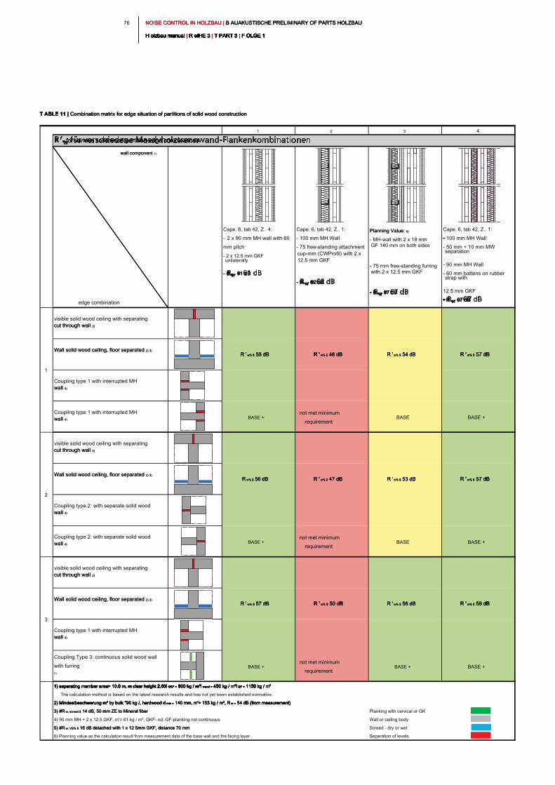
NOISE CONTROL IN HOLZBAU | B AUAKUSTISCHE PRELIMINARY OF PARTS HOLZBAU NOISE CONTROL IN HOLZBAU | B AUAKUSTISCHE PRELIMINARY OF PARTS HOLZBAU NOISE CONTROL IN HOLZBAU | B AUAKUSTISCHE PRELIMINARY OF PARTS HOLZBAU
H olzbau manual | R eIHE 3 | T PART 3 | F OLGE 1H olzbau manual | R eIHE 3 | T PART 3 | F OLGE 1H olzbau manual | R eIHE 3 | T PART 3 | F OLGE 1H olzbau manual | R eIHE 3 | T PART 3 | F OLGE 1H olzbau manual | R eIHE 3 | T PART 3 | F OLGE 1H olzbau manual | R eIHE 3 | T PART 3 | F OLGE 1H olzbau manual | R eIHE 3 | T PART 3 | F OLGE 1H olzbau manual | R eIHE 3 | T PART 3 | F OLGE 1H olzbau manual | R eIHE 3 | T PART 3 | F OLGE 1H olzbau manual | R eIHE 3 | T PART 3 | F OLGE 1H olzbau manual | R eIHE 3 | T PART 3 | F OLGE 1
76
1 2 3 4
R ' w for various solid wood partition-edge combinationsR ' w for various solid wood partition-edge combinationsR ' w for various solid wood partition-edge combinations
wall component 1)wall component 1)
edge combination
Cape. 6, tab 42, Z.. 4:
- 2 x 90 mm MH wall with 60
mm pitch
- 2 x 12.5 mm GKF
unilaterally
- R w = 61 dB- R w = 61 dB- R w = 61 dB
Cape. 6, tab 42, Z.. 1:
- 100 mm MH Wall
- 75 free-standing attachment
cup-mm (CWProfil) with 2 x
12.5 mm GKF
- R w = 62 dB- R w = 62 dB- R w = 62 dB
Planning Value: 6)Planning Value: 6)
- MH-wall with 2 x 18 mm
GF 140 mm on both sides
- 75 mm free-standing furring
with 2 x 12.5 mm GKF
- R w = 67 dB- R w = 67 dB- R w = 67 dB
Cape. 6, tab 42, Z.. 1:
- 100 mm MH Wall
- 50 mm + 10 mm MW
separation
- 90 mm MH Wall
- 60 mm battens on rubber
strap with
12.5 mm GKF
- R w = 67 dB- R w = 67 dB- R w = 67 dB
visible solid wood ceiling with separating
cut through wall 2)cut through wall 2)
Wall solid wood ceiling, floor separated 2) 3)Wall solid wood ceiling, floor separated 2) 3)
Coupling type 1 with interrupted MH
wall 4)wall 4)
Coupling type 1 with interrupted MH
wall 4) wall 4)
BASE +
not met minimum
requirement
BASE BASE +
visible solid wood ceiling with separating
cut through wall 2)cut through wall 2)
Wall solid wood ceiling, floor separated 2) 3)Wall solid wood ceiling, floor separated 2) 3)
Coupling type 2: with separate solid wood
wall 4)wall 4)
Coupling type 2: with separate solid wood
wall 4) wall 4)
BASE +
not met minimum
requirement
BASE BASE +
visible solid wood ceiling with separating
cut through wall 2)cut through wall 2)
Wall solid wood ceiling, floor separated 2) 3)Wall solid wood ceiling, floor separated 2) 3)
Coupling type 1 with interrupted MH
wall 4)wall 4)
Coupling Type 3: continuous solid wood wall
with furring
5)
BASE +
not met minimum
requirement
BASE + BASE +
1) separating member area> 10.0 m, m clear height 2.60! GKF = 800 kg / m³! wood = 450 kg / m³! GF = 1150 kg / m³1) separating member area> 10.0 m, m clear height 2.60! GKF = 800 kg / m³! wood = 450 kg / m³! GF = 1150 kg / m³1) separating member area> 10.0 m, m clear height 2.60! GKF = 800 kg / m³! wood = 450 kg / m³! GF = 1150 kg / m³1) separating member area> 10.0 m, m clear height 2.60! GKF = 800 kg / m³! wood = 450 kg / m³! GF = 1150 kg / m³1) separating member area> 10.0 m, m clear height 2.60! GKF = 800 kg / m³! wood = 450 kg / m³! GF = 1150 kg / m³1) separating member area> 10.0 m, m clear height 2.60! GKF = 800 kg / m³! wood = 450 kg / m³! GF = 1150 kg / m³1) separating member area> 10.0 m, m clear height 2.60! GKF = 800 kg / m³! wood = 450 kg / m³! GF = 1150 kg / m³
The calculation method is based on the latest research results and has not yet been established normative.
2) Mindestbeschwerung m² by bulk "90 kg /, hardwood d min = 140 mm, m'= 153 kg / m², R w = 54 dB (from measurement)2) Mindestbeschwerung m² by bulk "90 kg /, hardwood d min = 140 mm, m'= 153 kg / m², R w = 54 dB (from measurement)2) Mindestbeschwerung m² by bulk "90 kg /, hardwood d min = 140 mm, m'= 153 kg / m², R w = 54 dB (from measurement)2) Mindestbeschwerung m² by bulk "90 kg /, hardwood d min = 140 mm, m'= 153 kg / m², R w = 54 dB (from measurement)2) Mindestbeschwerung m² by bulk "90 kg /, hardwood d min = 140 mm, m'= 153 kg / m², R w = 54 dB (from measurement)
3) #R w, screed $ 14 dB, 50 mm ZE to Mineral fiber 3) #R w, screed $ 14 dB, 50 mm ZE to Mineral fiber 3) #R w, screed $ 14 dB, 50 mm ZE to Mineral fiber Planking with cervical or GK
4) 90 mm MH + 2 x 12.5 GKF, m'= 61 kg / m², GKF- od. GF-planking not continuous Wall or ceiling body
5) #R w, VS% $ 16 dB detached with 1 x 12 5mm GKF, distance 70 mm 5) #R w, VS% $ 16 dB detached with 1 x 12 5mm GKF, distance 70 mm 5) #R w, VS% $ 16 dB detached with 1 x 12 5mm GKF, distance 70 mm Screed - dry or wet
6) Planning value as the calculation result from measurement data of the base wall and the facing layer Separation of levels
R ' w% $ 56 dB R ' w% $ 56 dB R ' w% $ 56 dB R ' w% $ 59 dBR ' w% $ 59 dBR ' w% $ 59 dB
1
2
3
R ' w% $ 57 dB R ' w% $ 57 dB R ' w% $ 57 dB R ' w% $ 50 dBR ' w% $ 50 dBR ' w% $ 50 dB
R ' w% $ 56 dB R ' w% $ 56 dB R ' w% $ 56 dB R ' w% $ 48 dB R ' w% $ 48 dB R ' w% $ 48 dB R ' w% $ 54 dB R ' w% $ 54 dB R ' w% $ 54 dB R ' w% $ 57 dBR ' w% $ 57 dBR ' w% $ 57 dB
R w% $ 56 dB R w% $ 56 dB R w% $ 56 dB R ' w% $ 47 dB R ' w% $ 47 dB R ' w% $ 47 dB R ' w% $ 53 dB R ' w% $ 53 dB R ' w% $ 53 dB R ' w% $ 57 dBR ' w% $ 57 dBR ' w% $ 57 dB
T ABLE 11 | Combination matrix for edge situation of partitions of solid wood constructionT ABLE 11 | Combination matrix for edge situation of partitions of solid wood constructionT ABLE 11 | Combination matrix for edge situation of partitions of solid wood construction
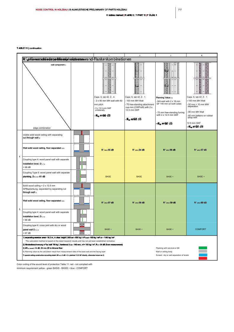
7 77 7NOISE CONTROL IN HOLZBAU | B AUAKUSTISCHE PRELIMINARY OF PARTS HOLZBAU NOISE CONTROL IN HOLZBAU | B AUAKUSTISCHE PRELIMINARY OF PARTS HOLZBAU NOISE CONTROL IN HOLZBAU | B AUAKUSTISCHE PRELIMINARY OF PARTS HOLZBAU
H olzbau manual | R eIHE 3 | T PART 3 | F OLGE 1H olzbau manual | R eIHE 3 | T PART 3 | F OLGE 1H olzbau manual | R eIHE 3 | T PART 3 | F OLGE 1H olzbau manual | R eIHE 3 | T PART 3 | F OLGE 1H olzbau manual | R eIHE 3 | T PART 3 | F OLGE 1H olzbau manual | R eIHE 3 | T PART 3 | F OLGE 1H olzbau manual | R eIHE 3 | T PART 3 | F OLGE 1H olzbau manual | R eIHE 3 | T PART 3 | F OLGE 1H olzbau manual | R eIHE 3 | T PART 3 | F OLGE 1H olzbau manual | R eIHE 3 | T PART 3 | F OLGE 1H olzbau manual | R eIHE 3 | T PART 3 | F OLGE 1
1 2 3 4
R ' w for various solid wood partition-edge combinationsR ' w for various solid wood partition-edge combinationsR ' w for various solid wood partition-edge combinations
wall component 1)wall component 1)
edge combination
Cape. 6, tab 42, Z.. 4:
- 2 x 90 mm MH wall with 60
mm pitch
- 2 x 12.5 mm GKF
unilaterally
- R w = 61 dB- R w = 61 dB- R w = 61 dB
Cape. 6, tab 42, Z.. 1:
- 100 mm MH Wall
- 75 free-standing attachment
cup-mm (CWProfil) with 2 x
12.5 mm GKF
- R w = 62 dB- R w = 62 dB- R w = 62 dB
Planning Value: 6)Planning Value: 6)
- MH-wall with 2 x 18 mm
GF 140 mm on both sides
- 75 mm free-standing furring
with 2 x 12.5 mm GKF
- R w = 67 dB- R w = 67 dB- R w = 67 dB
Cape. 6, tab 42, Z.. 1:
- 100 mm MH Wall
- 50 mm + 10 mm MW
separation
- 90 mm MH Wall
- 60 mm battens on rubber
strap with
12.5 mm GKF
- R w = 67 dB- R w = 67 dB- R w = 67 dB
visible solid wood ceiling with separating
cut through wall 2)cut through wall 2)
Wall solid wood ceiling, floor separated 2) 3)Wall solid wood ceiling, floor separated 2) 3)
Coupling type 4: wood panel wall with separate
installation level, D n, f, winstallation level, D n, f, w
= 68 dB
Coupling Type 5: wood panel wall with separate
planking, D n, f, w = 61 dBplanking, D n, f, w = 61 dBplanking, D n, f, w = 61 dB BASE BASE BASE + BASE +
Solid wood ceiling + 2 x 12.5 mm
GFBeplankung, separated by separating cut
through wall 7)through wall 7)
Wall solid wood ceiling, floor separated 2) 3)Wall solid wood ceiling, floor separated 2) 3)
Coupling type 4: wood panel wall with separate
installation level, D n, f, winstallation level, D n, f, w
= 68 dB
Coupling type 6: cross joint with dry or wood
panel wall D n, f, wpanel wall D n, f, w
= 67 dB
BASE + BASE + BASE + COMFORT
1) separating member area> 10.0 m, m clear height 2.60! GKF = 800 kg / m³! wood = 450 kg / m³! GF = 1150 kg / m³1) separating member area> 10.0 m, m clear height 2.60! GKF = 800 kg / m³! wood = 450 kg / m³! GF = 1150 kg / m³1) separating member area> 10.0 m, m clear height 2.60! GKF = 800 kg / m³! wood = 450 kg / m³! GF = 1150 kg / m³1) separating member area> 10.0 m, m clear height 2.60! GKF = 800 kg / m³! wood = 450 kg / m³! GF = 1150 kg / m³1) separating member area> 10.0 m, m clear height 2.60! GKF = 800 kg / m³! wood = 450 kg / m³! GF = 1150 kg / m³1) separating member area> 10.0 m, m clear height 2.60! GKF = 800 kg / m³! wood = 450 kg / m³! GF = 1150 kg / m³1) separating member area> 10.0 m, m clear height 2.60! GKF = 800 kg / m³! wood = 450 kg / m³! GF = 1150 kg / m³
The calculation method is based on the latest research results and has not yet been established normative.
2) Mindestbeschwerung m² by bulk "90 kg /, hardwood d min = 140 mm, m'= 153 kg / m², R w = 54 dB (from measurement)2) Mindestbeschwerung m² by bulk "90 kg /, hardwood d min = 140 mm, m'= 153 kg / m², R w = 54 dB (from measurement)2) Mindestbeschwerung m² by bulk "90 kg /, hardwood d min = 140 mm, m'= 153 kg / m², R w = 54 dB (from measurement)2) Mindestbeschwerung m² by bulk "90 kg /, hardwood d min = 140 mm, m'= 153 kg / m², R w = 54 dB (from measurement)2) Mindestbeschwerung m² by bulk "90 kg /, hardwood d min = 140 mm, m'= 153 kg / m², R w = 54 dB (from measurement)
3) #R w, screed $ 14 dB, 50 mm ZE to Mineral fiber 3) #R w, screed $ 14 dB, 50 mm ZE to Mineral fiber 3) #R w, screed $ 14 dB, 50 mm ZE to Mineral fiber Planking with cervical or GK
6) Planning value as the calculation result from measurement data of the base wall and the facing layer Wall or ceiling body
7) special ceiling construction according detail: #R w% $ 3 dB + 2 x planked 12.5 GF directly, otherwise known as 2) 7) special ceiling construction according detail: #R w% $ 3 dB + 2 x planked 12.5 GF directly, otherwise known as 2) 7) special ceiling construction according detail: #R w% $ 3 dB + 2 x planked 12.5 GF directly, otherwise known as 2) Screed - dry or wet separation of levels
R ' w% $ 60 dBR ' w% $ 60 dBR ' w% $ 60 dB
R ' w% $ 55 dB R ' w% $ 55 dB R ' w% $ 55 dB R ' w% $ 54 dB R ' w% $ 54 dB R ' w% $ 54 dB R ' w% $ 56 dB R ' w% $ 56 dB R ' w% $ 56 dB R ' w% $ 57 dBR ' w% $ 57 dBR ' w% $ 57 dB
4
5
R ' w% $ 57 dB R ' w% $ 57 dB R ' w% $ 57 dB R ' w% $ 56 dB R ' w% $ 56 dB R ' w% $ 56 dB R ' w% $ 59 dBR ' w% $ 59 dBR ' w% $ 59 dB
T ABLE 11 | continuationT ABLE 11 | continuationT ABLE 11 | continuation
Color coding of the sound level of protection Table 11: red - not complied with
minimum requirement yellow - green BASIS - BASIS + blue - COMFORT
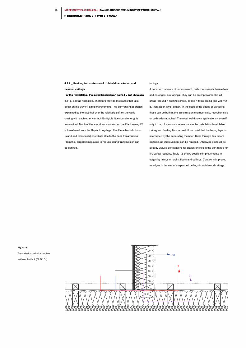
NOISE CONTROL IN HOLZBAU | B AUAKUSTISCHE PRELIMINARY OF PARTS HOLZBAU NOISE CONTROL IN HOLZBAU | B AUAKUSTISCHE PRELIMINARY OF PARTS HOLZBAU NOISE CONTROL IN HOLZBAU | B AUAKUSTISCHE PRELIMINARY OF PARTS HOLZBAU
H olzbau manual | R eIHE 3 | T PART 3 | F OLGE 1H olzbau manual | R eIHE 3 | T PART 3 | F OLGE 1H olzbau manual | R eIHE 3 | T PART 3 | F OLGE 1H olzbau manual | R eIHE 3 | T PART 3 | F OLGE 1H olzbau manual | R eIHE 3 | T PART 3 | F OLGE 1H olzbau manual | R eIHE 3 | T PART 3 | F OLGE 1H olzbau manual | R eIHE 3 | T PART 3 | F OLGE 1H olzbau manual | R eIHE 3 | T PART 3 | F OLGE 1H olzbau manual | R eIHE 3 | T PART 3 | F OLGE 1H olzbau manual | R eIHE 3 | T PART 3 | F OLGE 1H olzbau manual | R eIHE 3 | T PART 3 | F OLGE 1
78
facings
A common measure of improvement, both components themselves
and on edges, are facings. They can be an improvement in all
areas (ground = floating screed, ceiling = false ceiling and wall = z.
B. Installation level) attach. In the case of the edges of partitions,
these can be both at the transmission chamber side, reception side
or both sides attached. The most well-known applications - even if
only in part, for acoustic reasons - are the installation level, false
ceiling and floating floor screed. It is crucial that the facing layer is
interrupted by the separating member. Runs through this before
partition, no improvement can be realized. Otherwise it should be
already waived penetrations for cables or lines in the port range for
fire safety reasons. Table 12 shows possible improvements to
edges by linings on walls, floors and ceilings. Caution is improved
as edges in the use of suspended ceilings in solid wood ceilings.
4.2.2 _ flanking transmission of Holztafelbauwänden and
beamed ceilings
For the Holztafelbau the mixed transmission paths F d and D f to see For the Holztafelbau the mixed transmission paths F d and D f to see For the Holztafelbau the mixed transmission paths F d and D f to see For the Holztafelbau the mixed transmission paths F d and D f to see For the Holztafelbau the mixed transmission paths F d and D f to see
in Fig. 4.10 as negligible. Therefore provide measures that take
effect on the way Ff, a big improvement. This convenient approach
explained by the fact that over the relatively soft on the walls
closing with each other vernach läs ligible little sound energy is
transmitted. Much of the sound transmission on the Flankenweg Ff
is transferred from the Beplankungslage. The Gefachkonstruktion
(stand and thresholds) contribute little to the flank transmission.
From this, targeted measures to reduce sound transmission can
be derived.
Fig. 4.10:
Transmission paths for partition
walls on the flank (Ff, Df, Fd)
fd
ff
df
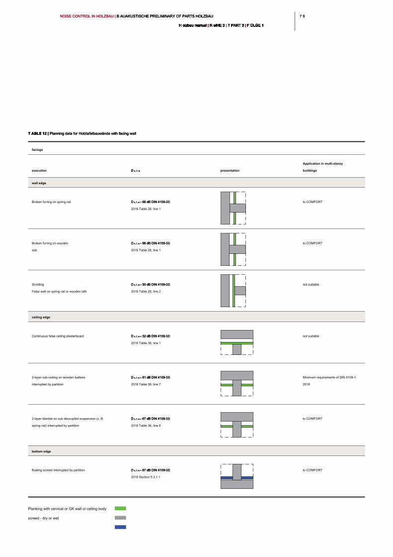
7 97 9NOISE CONTROL IN HOLZBAU | B AUAKUSTISCHE PRELIMINARY OF PARTS HOLZBAU NOISE CONTROL IN HOLZBAU | B AUAKUSTISCHE PRELIMINARY OF PARTS HOLZBAU NOISE CONTROL IN HOLZBAU | B AUAKUSTISCHE PRELIMINARY OF PARTS HOLZBAU
H olzbau manual | R eIHE 3 | T PART 3 | F OLGE 1H olzbau manual | R eIHE 3 | T PART 3 | F OLGE 1H olzbau manual | R eIHE 3 | T PART 3 | F OLGE 1H olzbau manual | R eIHE 3 | T PART 3 | F OLGE 1H olzbau manual | R eIHE 3 | T PART 3 | F OLGE 1H olzbau manual | R eIHE 3 | T PART 3 | F OLGE 1H olzbau manual | R eIHE 3 | T PART 3 | F OLGE 1H olzbau manual | R eIHE 3 | T PART 3 | F OLGE 1H olzbau manual | R eIHE 3 | T PART 3 | F OLGE 1H olzbau manual | R eIHE 3 | T PART 3 | F OLGE 1H olzbau manual | R eIHE 3 | T PART 3 | F OLGE 1
Planking with cervical or GK wall or ceiling body
screed - dry or wet
T ABLE 12 | Planning data for Holztafelbauwände with facing wallT ABLE 12 | Planning data for Holztafelbauwände with facing wallT ABLE 12 | Planning data for Holztafelbauwände with facing wall
facings
execution D n, f, wD n, f, w presentation
Application in multi-storey
buildings
wall edge
Broken furring on spring rail D n, f, w = 68 dB DIN 4109-33: D n, f, w = 68 dB DIN 4109-33: D n, f, w = 68 dB DIN 4109-33:
2016 Table 28, line 1
to COMFORT
Broken furring on wooden
slat
D n, f, w = 68 dB DIN 4109-33: D n, f, w = 68 dB DIN 4109-33: D n, f, w = 68 dB DIN 4109-33:
2016 Table 28, line 1
to COMFORT
Scrolling
False wall on spring rail or wooden lath
D n, f, w = 50 dB DIN 4109-33: D n, f, w = 50 dB DIN 4109-33: D n, f, w = 50 dB DIN 4109-33:
2016 Table 28, line 2
not suitable
ceiling edge
Continuous false ceiling plasterboard D n, f, w = 52 dB DIN 4109-33: D n, f, w = 52 dB DIN 4109-33: D n, f, w = 52 dB DIN 4109-33:
2016 Table 36, line 1
not suitable
2-layer sub-ceiling on wooden battens
interrupted by partition
D n, f, w = 61 dB DIN 4109-33: D n, f, w = 61 dB DIN 4109-33: D n, f, w = 61 dB DIN 4109-33:
2016 Table 36, line 7
Minimum requirements of DIN 4109-1:
2018
2-layer blanket on sub decoupled suspension (z. B.
spring rail) interrupted by partition
D n, f, w = 67 dB DIN 4109-33: D n, f, w = 67 dB DIN 4109-33: D n, f, w = 67 dB DIN 4109-33:
2016 Table 36, line 8
to COMFORT
bottom edge
floating screed interrupted by partition D n, f, w = 67 dB DIN 4109-33: D n, f, w = 67 dB DIN 4109-33: D n, f, w = 67 dB DIN 4109-33:
2016 Section 5.3.1.1
to COMFORT
NOISE CONTROL IN HOLZBAU | B AUAKUSTISCHE PRELIMINARY OF PARTS HOLZBAU NOISE CONTROL IN HOLZBAU | B AUAKUSTISCHE PRELIMINARY OF PARTS HOLZBAU NOISE CONTROL IN HOLZBAU | B AUAKUSTISCHE PRELIMINARY OF PARTS HOLZBAU
H olzbau manual | R eIHE 3 | T PART 3 | F OLGE 1H olzbau manual | R eIHE 3 | T PART 3 | F OLGE 1H olzbau manual | R eIHE 3 | T PART 3 | F OLGE 1H olzbau manual | R eIHE 3 | T PART 3 | F OLGE 1H olzbau manual | R eIHE 3 | T PART 3 | F OLGE 1H olzbau manual | R eIHE 3 | T PART 3 | F OLGE 1H olzbau manual | R eIHE 3 | T PART 3 | F OLGE 1H olzbau manual | R eIHE 3 | T PART 3 | F OLGE 1H olzbau manual | R eIHE 3 | T PART 3 | F OLGE 1H olzbau manual | R eIHE 3 | T PART 3 | F OLGE 1H olzbau manual | R eIHE 3 | T PART 3 | F OLGE 1
80
direct mounting
Walls are connected to flanks without further separation or facings,
a suitability of the edge is not given for the multi-storey buildings. A
"blunt" At closing without further action reaches values of D n, f, w ≈ 50 "blunt" At closing without further action reaches values of D n, f, w ≈ 50 "blunt" At closing without further action reaches values of D n, f, w ≈ 50
dB - 53 dB. is carried out according to the rule of thumb which at
least a supplement of 7 dB to the target value, passing
Beplankungsschichten are not executable without cladding for
multi-storey buildings.
separate layers no
As mentioned earlier, much of the sound energy is transmitted
through the planking. Therefore, it has proven useful to separate
layers no behind the including wall. According to Table 13, the
Beplankungslage is compared to continuous planking an
improvement at the junction of 5 dB obtained by the separation.
According to the rule of thumb for assessing this is not yet sufficient
for a reliable goal attainment. If, however, executed one of four
sides so it can in the detailed forecasting methods and component
surfaces 10 of the values sqm to adhere to BASE + come. A
complete separation of stator, threshold, and Rähm
Beplankungslage reaches values to D n, f, w = 68 dB. However, it is Beplankungslage reaches values to D n, f, w = 68 dB. However, it is Beplankungslage reaches values to D n, f, w = 68 dB. However, it is
almost impossible to implement building practice to leave wall ends
without further fittings. In the conventional screw in the area of the
stator there is a reduction of 7 dB. Also here, the aforementioned for
separate Beplankungslage: in many cases can be explained by a
detailed forecast BASE + reach the minimum values of DIN 4109-1
[1] be safely reached. The slight difference between the screw stud
frame (D n, f, w = 61 dB), and only interrupted Beplankungslage (D n, f, w = 58 frame (D n, f, w = 61 dB), and only interrupted Beplankungslage (D n, f, w = 58 frame (D n, f, w = 61 dB), and only interrupted Beplankungslage (D n, f, w = 58 frame (D n, f, w = 61 dB), and only interrupted Beplankungslage (D n, f, w = 58 frame (D n, f, w = 61 dB), and only interrupted Beplankungslage (D n, f, w = 58
dB) makes it clear that for the building practice relevant
transmission, the facing layers are relevant to the Flankenweg Ff to
a large extent (see Table 13).
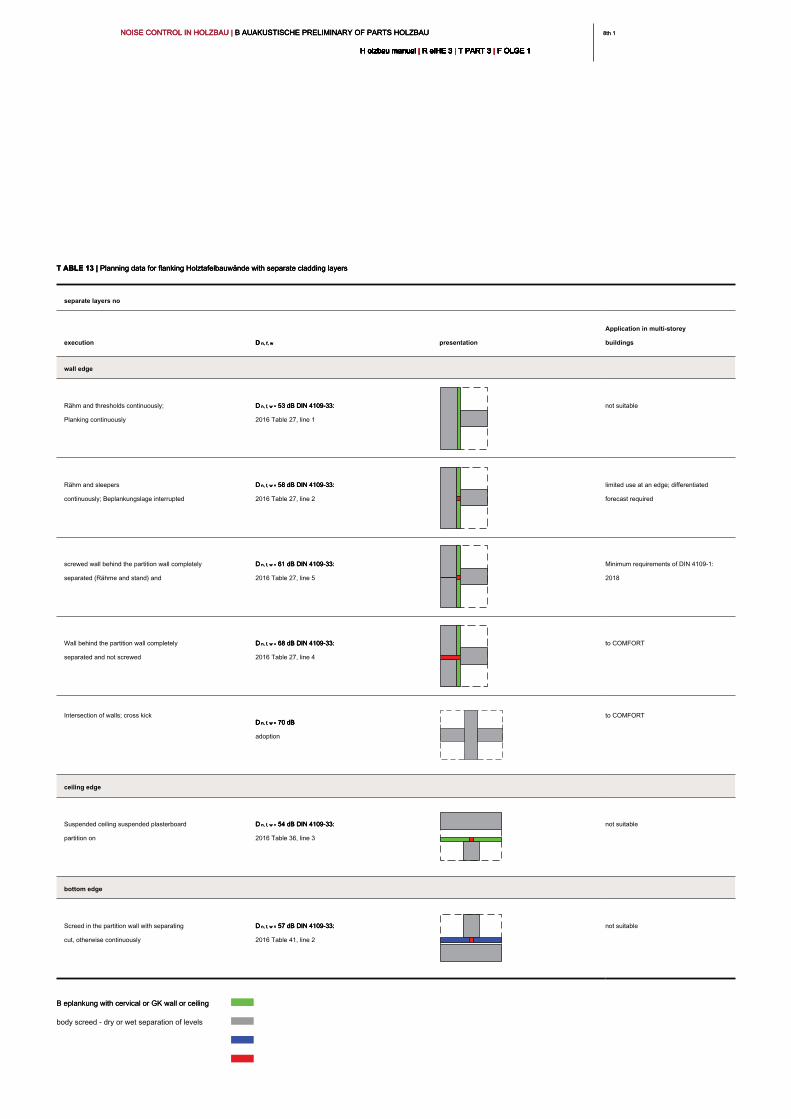
8th 18th 1NOISE CONTROL IN HOLZBAU | B AUAKUSTISCHE PRELIMINARY OF PARTS HOLZBAU NOISE CONTROL IN HOLZBAU | B AUAKUSTISCHE PRELIMINARY OF PARTS HOLZBAU NOISE CONTROL IN HOLZBAU | B AUAKUSTISCHE PRELIMINARY OF PARTS HOLZBAU
H olzbau manual | R eIHE 3 | T PART 3 | F OLGE 1H olzbau manual | R eIHE 3 | T PART 3 | F OLGE 1H olzbau manual | R eIHE 3 | T PART 3 | F OLGE 1H olzbau manual | R eIHE 3 | T PART 3 | F OLGE 1H olzbau manual | R eIHE 3 | T PART 3 | F OLGE 1H olzbau manual | R eIHE 3 | T PART 3 | F OLGE 1H olzbau manual | R eIHE 3 | T PART 3 | F OLGE 1H olzbau manual | R eIHE 3 | T PART 3 | F OLGE 1H olzbau manual | R eIHE 3 | T PART 3 | F OLGE 1H olzbau manual | R eIHE 3 | T PART 3 | F OLGE 1H olzbau manual | R eIHE 3 | T PART 3 | F OLGE 1
T ABLE 13 | Planning data for flanking Holztafelbauwände with separate cladding layersT ABLE 13 | Planning data for flanking Holztafelbauwände with separate cladding layersT ABLE 13 | Planning data for flanking Holztafelbauwände with separate cladding layers
separate layers no
execution D n, f, wD n, f, w presentation
Application in multi-storey
buildings
wall edge
Rähm and thresholds continuously;
Planking continuously
D n, f, w = 53 dB DIN 4109-33: D n, f, w = 53 dB DIN 4109-33: D n, f, w = 53 dB DIN 4109-33:
2016 Table 27, line 1
not suitable
Rähm and sleepers
continuously; Beplankungslage interrupted
D n, f, w = 58 dB DIN 4109-33: D n, f, w = 58 dB DIN 4109-33: D n, f, w = 58 dB DIN 4109-33:
2016 Table 27, line 2
limited use at an edge; differentiated
forecast required
screwed wall behind the partition wall completely
separated (Rähme and stand) and
D n, f, w = 61 dB DIN 4109-33: D n, f, w = 61 dB DIN 4109-33: D n, f, w = 61 dB DIN 4109-33:
2016 Table 27, line 5
Minimum requirements of DIN 4109-1:
2018
Wall behind the partition wall completely
separated and not screwed
D n, f, w = 68 dB DIN 4109-33: D n, f, w = 68 dB DIN 4109-33: D n, f, w = 68 dB DIN 4109-33:
2016 Table 27, line 4
to COMFORT
Intersection of walls; cross kick
D n, f, w > 70 dB D n, f, w > 70 dB D n, f, w > 70 dB D n, f, w > 70 dB
adoption
to COMFORT
ceiling edge
Suspended ceiling suspended plasterboard
partition on
D n, f, w = 54 dB DIN 4109-33: D n, f, w = 54 dB DIN 4109-33: D n, f, w = 54 dB DIN 4109-33:
2016 Table 36, line 3
not suitable
bottom edge
Screed in the partition wall with separating
cut, otherwise continuously
D n, f, w = 57 dB DIN 4109-33: D n, f, w = 57 dB DIN 4109-33: D n, f, w = 57 dB DIN 4109-33:
2016 Table 41, line 2
not suitable
B eplankung with cervical or GK wall or ceiling B eplankung with cervical or GK wall or ceiling
body screed - dry or wet separation of levels
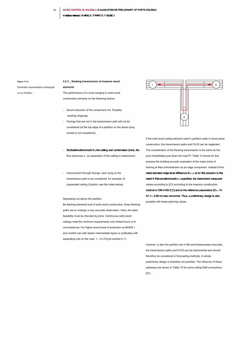
NOISE CONTROL IN HOLZBAU | B AUAKUSTISCHE PRELIMINARY OF PARTS HOLZBAU NOISE CONTROL IN HOLZBAU | B AUAKUSTISCHE PRELIMINARY OF PARTS HOLZBAU NOISE CONTROL IN HOLZBAU | B AUAKUSTISCHE PRELIMINARY OF PARTS HOLZBAU
H olzbau manual | R eIHE 3 | T PART 3 | F OLGE 1H olzbau manual | R eIHE 3 | T PART 3 | F OLGE 1H olzbau manual | R eIHE 3 | T PART 3 | F OLGE 1H olzbau manual | R eIHE 3 | T PART 3 | F OLGE 1H olzbau manual | R eIHE 3 | T PART 3 | F OLGE 1H olzbau manual | R eIHE 3 | T PART 3 | F OLGE 1H olzbau manual | R eIHE 3 | T PART 3 | F OLGE 1H olzbau manual | R eIHE 3 | T PART 3 | F OLGE 1H olzbau manual | R eIHE 3 | T PART 3 | F OLGE 1H olzbau manual | R eIHE 3 | T PART 3 | F OLGE 1H olzbau manual | R eIHE 3 | T PART 3 | F OLGE 1
82
If the solid wood ceiling element used in partition walls in wood panel
construction, the transmission paths and Fd Df can be neglected.
The consideration of the flanking transmission is the same as the
pure Holztafelbau just down the road Ff. Table 14 shows for this
purpose the building acoustic evaluation of the major joints of
training at Mas sivholzdecken as an edge component. Instead of the
rated standard edge level difference D n, f, w is for this situation to the rated standard edge level difference D n, f, w is for this situation to the rated standard edge level difference D n, f, w is for this situation to the
rated R Flankendämmmaß Ff, w specified, the determined measured rated R Flankendämmmaß Ff, w specified, the determined measured rated R Flankendämmmaß Ff, w specified, the determined measured
values according to [21] according to the masonry construction
method in DIN 4109-2 [1] and to the reference parameters (S 0 = 10 method in DIN 4109-2 [1] and to the reference parameters (S 0 = 10 method in DIN 4109-2 [1] and to the reference parameters (S 0 = 10
m², l f = 2.80 m) was converted. Thus, a preliminary design is also m², l f = 2.80 m) was converted. Thus, a preliminary design is also m², l f = 2.80 m) was converted. Thus, a preliminary design is also
possible with these planning values.
however, is also the partition are in Ma ssivholzbauweise executed,
the transmission paths and Fd Df can be instrumental and should
therefore be considered in forecasting methods. A simple
preliminary design is therefore not possible. The influence of these
pathways are shown in Table 15 for some ceiling Wall connections
[21].
4.2.3 _ flanking transmission of massive wood
elements
The performance of a cross hanging in solid wood
construction primarily on the following factors:
- Sound reduction of the component incl. Possibly
existing chippings.
- Facings that are not in the transmission path will not be
considered (at the top edge of a partition so the above lying
screed is not considered).
- Stoßstellendämmmaß K ij the ceiling wall combination (here, the Stoßstellendämmmaß K ij the ceiling wall combination (here, the Stoßstellendämmmaß K ij the ceiling wall combination (here, the
flow advances z., by separation of the ceiling or elastomers).
- Improvement through facings, each lying on the
transmission path to be considered, for example. B.
suspended ceiling (Caution: see the notes below).
Separating cut above the partition
Be flanking elements built of solid wood construction, these flanking
paths are to undergo a very accurate observation. Here, the static
feasibility must be checked by joints. Continuous solid wood
ceilings meet the minimum requirements only limited hours m th
circumstances. For higher sound level of protection as BASIS +
and comfort can with elastic intermediate layers or preferably with
separating cuts on the road. 1 - 3 in Fig be worked 4.11.
Figure 11.4.:
Schematic representation rectangular
cut on Partition
1 3
2
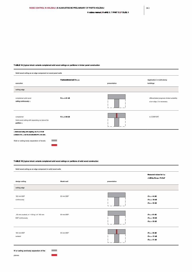
8th 38th 3NOISE CONTROL IN HOLZBAU | B AUAKUSTISCHE PRELIMINARY OF PARTS HOLZBAU NOISE CONTROL IN HOLZBAU | B AUAKUSTISCHE PRELIMINARY OF PARTS HOLZBAU NOISE CONTROL IN HOLZBAU | B AUAKUSTISCHE PRELIMINARY OF PARTS HOLZBAU
H olzbau manual | R eIHE 3 | T PART 3 | F OLGE 1H olzbau manual | R eIHE 3 | T PART 3 | F OLGE 1H olzbau manual | R eIHE 3 | T PART 3 | F OLGE 1H olzbau manual | R eIHE 3 | T PART 3 | F OLGE 1H olzbau manual | R eIHE 3 | T PART 3 | F OLGE 1H olzbau manual | R eIHE 3 | T PART 3 | F OLGE 1H olzbau manual | R eIHE 3 | T PART 3 | F OLGE 1H olzbau manual | R eIHE 3 | T PART 3 | F OLGE 1H olzbau manual | R eIHE 3 | T PART 3 | F OLGE 1H olzbau manual | R eIHE 3 | T PART 3 | F OLGE 1H olzbau manual | R eIHE 3 | T PART 3 | F OLGE 1
T ABLE 14 | typical shock variants complained solid wood ceilings on partitions in timber panel constructionT ABLE 14 | typical shock variants complained solid wood ceilings on partitions in timber panel constructionT ABLE 14 | typical shock variants complained solid wood ceilings on partitions in timber panel construction
Solid wood ceiling as an edge component on wood panel walls
execution
Flankendämmmaß R Ff, w 2) Flankendämmmaß R Ff, w 2) Flankendämmmaß R Ff, w 2)
presentation
Application in multi-storey
buildings
ceiling edge
complained solid wood
ceiling continuously 1)ceiling continuously 1)
R Ff, w ≥ 61 dB R Ff, w ≥ 61 dB R Ff, w ≥ 61 dB differentiated prognosis limited suitability
at an edge, it is necessary
complained
Solid wood ceiling with separating cut above the
partition 1)partition 1)
R Ff, w ≥ 64 dB R Ff, w ≥ 64 dB R Ff, w ≥ 64 dB to COMFORT
1 ) Solid wood ceiling with weighting, min. R w ≥ 54 dB1 ) Solid wood ceiling with weighting, min. R w ≥ 54 dB1 ) Solid wood ceiling with weighting, min. R w ≥ 54 dB1 ) Solid wood ceiling with weighting, min. R w ≥ 54 dB1 ) Solid wood ceiling with weighting, min. R w ≥ 54 dB
2) Instead of D n, f, w can for pre-calculation R Ff, w be used.2) Instead of D n, f, w can for pre-calculation R Ff, w be used.2) Instead of D n, f, w can for pre-calculation R Ff, w be used.2) Instead of D n, f, w can for pre-calculation R Ff, w be used.2) Instead of D n, f, w can for pre-calculation R Ff, w be used.2) Instead of D n, f, w can for pre-calculation R Ff, w be used.
Wall or ceiling body separation of levels
T ABLE 15 | typical shock variants complained solid wood ceilings on partitions of solid wood constructionT ABLE 15 | typical shock variants complained solid wood ceilings on partitions of solid wood constructionT ABLE 15 | typical shock variants complained solid wood ceilings on partitions of solid wood construction
Solid wood ceiling as an edge component in solid wood walls
design ceiling Model wall presentation
Measured values for l lab Measured values for l lab
= 4.30 m, S S, lab = 11.8 m²= 4.30 m, S S, lab = 11.8 m²= 4.30 m, S S, lab = 11.8 m²= 4.30 m, S S, lab = 11.8 m²
ceiling edge
160 mm BSP
continuously
80 mm BSP R Ff, w = 44 dB R Ff, w = 44 dB R Ff, w = 44 dB
R Fd, w = 50 dB R Fd, w = 50 dB R Fd, w = 50 dB
R Df, w = 50 dBR Df, w = 50 dBR Df, w = 50 dB
, 60 mm crushed, m '= 90 kg / m² 160 mm
BSP continuously
80 mm BSP R Ff, w = 61 dB R Ff, w = 61 dB R Ff, w = 61 dB
R Fd, w = 55 dB R Fd, w = 55 dB R Fd, w = 55 dB
R Df, w = 55 dBR Df, w = 55 dBR Df, w = 55 dB
160 mm BSP
isolated
80 mm BSP R Ff, w = 50 dB R Ff, w = 50 dB R Ff, w = 50 dB
R Fd, w = 51 dB R Fd, w = 51 dB R Fd, w = 51 dB
R Df, w = 51 dBR Df, w = 51 dBR Df, w = 51 dB
W or ceiling and-body separation of the W or ceiling and-body separation of the
planes
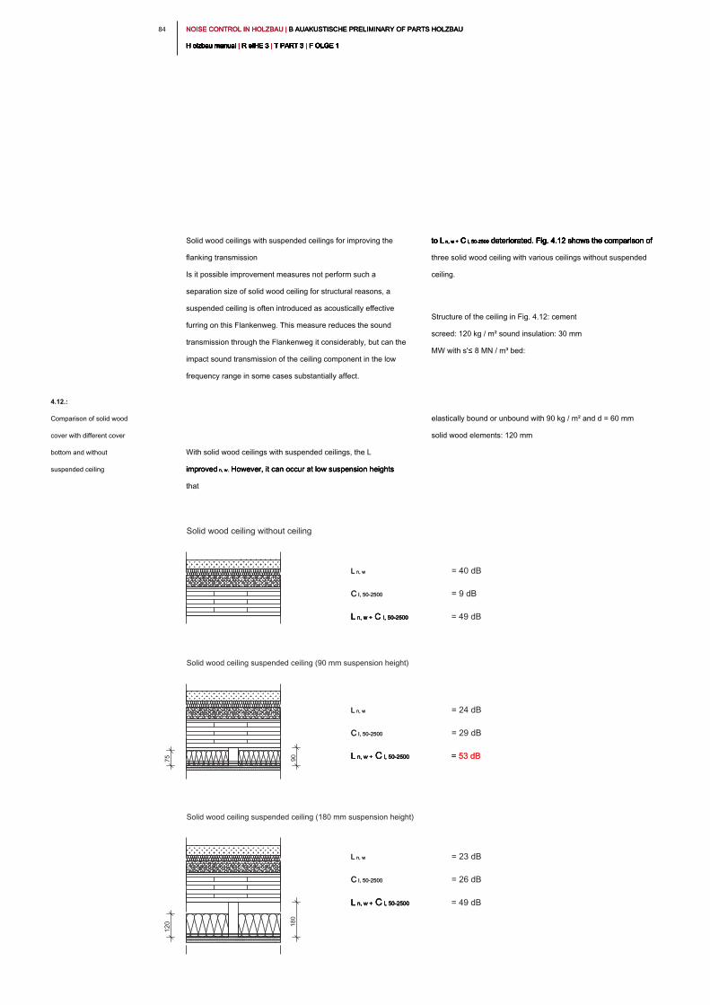
NOISE CONTROL IN HOLZBAU | B AUAKUSTISCHE PRELIMINARY OF PARTS HOLZBAU NOISE CONTROL IN HOLZBAU | B AUAKUSTISCHE PRELIMINARY OF PARTS HOLZBAU NOISE CONTROL IN HOLZBAU | B AUAKUSTISCHE PRELIMINARY OF PARTS HOLZBAU
H olzbau manual | R eIHE 3 | T PART 3 | F OLGE 1H olzbau manual | R eIHE 3 | T PART 3 | F OLGE 1H olzbau manual | R eIHE 3 | T PART 3 | F OLGE 1H olzbau manual | R eIHE 3 | T PART 3 | F OLGE 1H olzbau manual | R eIHE 3 | T PART 3 | F OLGE 1H olzbau manual | R eIHE 3 | T PART 3 | F OLGE 1H olzbau manual | R eIHE 3 | T PART 3 | F OLGE 1H olzbau manual | R eIHE 3 | T PART 3 | F OLGE 1H olzbau manual | R eIHE 3 | T PART 3 | F OLGE 1H olzbau manual | R eIHE 3 | T PART 3 | F OLGE 1H olzbau manual | R eIHE 3 | T PART 3 | F OLGE 1
84
to L n, w + C I, 50-2500 deteriorated. Fig. 4.12 shows the comparison of to L n, w + C I, 50-2500 deteriorated. Fig. 4.12 shows the comparison of to L n, w + C I, 50-2500 deteriorated. Fig. 4.12 shows the comparison of to L n, w + C I, 50-2500 deteriorated. Fig. 4.12 shows the comparison of to L n, w + C I, 50-2500 deteriorated. Fig. 4.12 shows the comparison of to L n, w + C I, 50-2500 deteriorated. Fig. 4.12 shows the comparison of
three solid wood ceiling with various ceilings without suspended
ceiling.
Structure of the ceiling in Fig. 4.12: cement
screed: 120 kg / m² sound insulation: 30 mm
MW with s'≤ 8 MN / m³ bed:
elastically bound or unbound with 90 kg / m² and d = 60 mm
solid wood elements: 120 mm
Solid wood ceilings with suspended ceilings for improving the
flanking transmission
Is it possible improvement measures not perform such a
separation size of solid wood ceiling for structural reasons, a
suspended ceiling is often introduced as acoustically effective
furring on this Flankenweg. This measure reduces the sound
transmission through the Flankenweg it considerably, but can the
impact sound transmission of the ceiling component in the low
frequency range in some cases substantially affect.
With solid wood ceilings with suspended ceilings, the L
improved n, w. However, it can occur at low suspension heights improved n, w. However, it can occur at low suspension heights improved n, w. However, it can occur at low suspension heights
that
4.12.:
Comparison of solid wood
cover with different cover
bottom and without
suspended ceiling
L n, w L n, w = 24 dB
C l, 50-2500 C l, 50-2500 = 29 dB
L n, w + C l, 50-2500L n, w + C l, 50-2500L n, w + C l, 50-2500L n, w + C l, 50-2500L n, w + C l, 50-2500 = 53 dB= 53 dB
Solid wood ceiling without ceiling
Solid wood ceiling suspended ceiling (90 mm suspension height)
Solid wood ceiling suspended ceiling (180 mm suspension height)
L n, w L n, w = 40 dB
C l, 50-2500 C l, 50-2500 = 9 dB
L n, w + C l, 50-2500L n, w + C l, 50-2500L n, w + C l, 50-2500L n, w + C l, 50-2500L n, w + C l, 50-2500 = 49 dB
L n, w L n, w = 23 dB
C l, 50-2500 C l, 50-2500 = 26 dB
L n, w + C l, 50-2500L n, w + C l, 50-2500L n, w + C l, 50-2500L n, w + C l, 50-2500L n, w + C l, 50-2500 = 49 dB
120
18
0
90
75
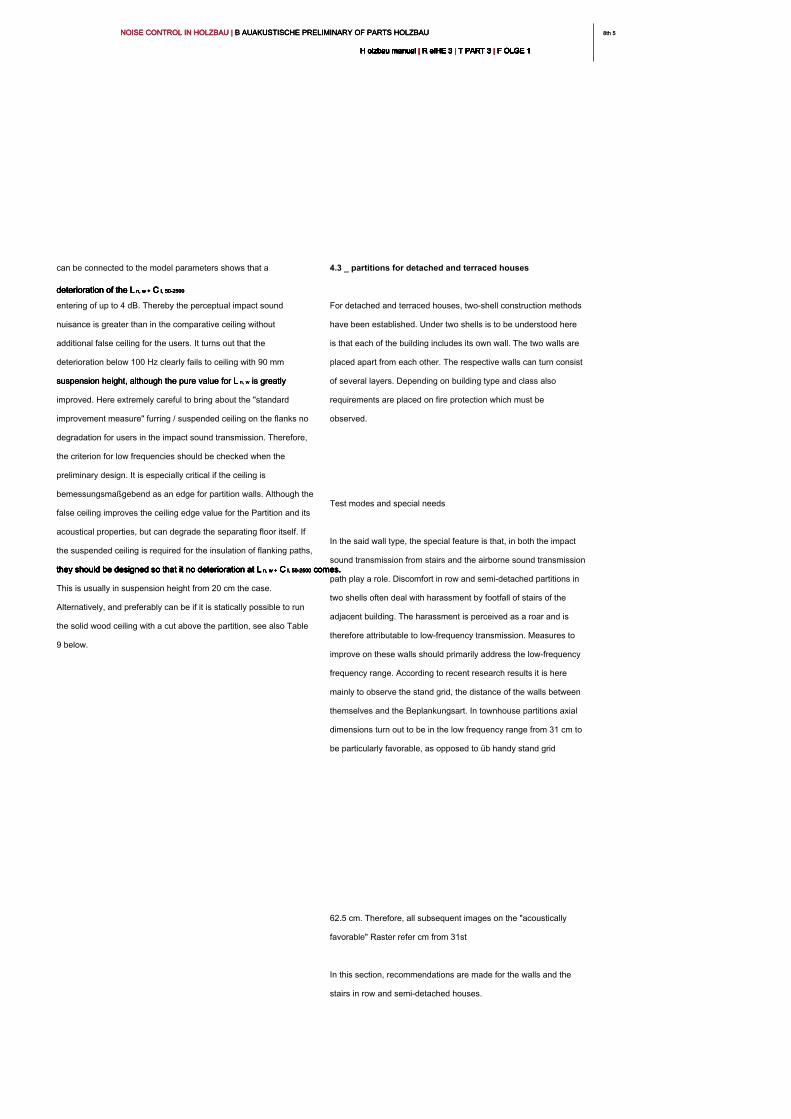
8th 58th 5NOISE CONTROL IN HOLZBAU | B AUAKUSTISCHE PRELIMINARY OF PARTS HOLZBAU NOISE CONTROL IN HOLZBAU | B AUAKUSTISCHE PRELIMINARY OF PARTS HOLZBAU NOISE CONTROL IN HOLZBAU | B AUAKUSTISCHE PRELIMINARY OF PARTS HOLZBAU
H olzbau manual | R eIHE 3 | T PART 3 | F OLGE 1H olzbau manual | R eIHE 3 | T PART 3 | F OLGE 1H olzbau manual | R eIHE 3 | T PART 3 | F OLGE 1H olzbau manual | R eIHE 3 | T PART 3 | F OLGE 1H olzbau manual | R eIHE 3 | T PART 3 | F OLGE 1H olzbau manual | R eIHE 3 | T PART 3 | F OLGE 1H olzbau manual | R eIHE 3 | T PART 3 | F OLGE 1H olzbau manual | R eIHE 3 | T PART 3 | F OLGE 1H olzbau manual | R eIHE 3 | T PART 3 | F OLGE 1H olzbau manual | R eIHE 3 | T PART 3 | F OLGE 1H olzbau manual | R eIHE 3 | T PART 3 | F OLGE 1
4.3 _ partitions for detached and terraced houses
For detached and terraced houses, two-shell construction methods
have been established. Under two shells is to be understood here
is that each of the building includes its own wall. The two walls are
placed apart from each other. The respective walls can turn consist
of several layers. Depending on building type and class also
requirements are placed on fire protection which must be
observed.
Test modes and special needs
In the said wall type, the special feature is that, in both the impact
sound transmission from stairs and the airborne sound transmission
path play a role. Discomfort in row and semi-detached partitions in
two shells often deal with harassment by footfall of stairs of the
adjacent building. The harassment is perceived as a roar and is
therefore attributable to low-frequency transmission. Measures to
improve on these walls should primarily address the low-frequency
frequency range. According to recent research results it is here
mainly to observe the stand grid, the distance of the walls between
themselves and the Beplankungsart. In townhouse partitions axial
dimensions turn out to be in the low frequency range from 31 cm to
be particularly favorable, as opposed to üb handy stand grid
62.5 cm. Therefore, all subsequent images on the "acoustically
favorable" Raster refer cm from 31st
In this section, recommendations are made for the walls and the
stairs in row and semi-detached houses.
can be connected to the model parameters shows that a
deterioration of the L n, w + C I, 50-2500deterioration of the L n, w + C I, 50-2500deterioration of the L n, w + C I, 50-2500deterioration of the L n, w + C I, 50-2500deterioration of the L n, w + C I, 50-2500
entering of up to 4 dB. Thereby the perceptual impact sound
nuisance is greater than in the comparative ceiling without
additional false ceiling for the users. It turns out that the
deterioration below 100 Hz clearly fails to ceiling with 90 mm
suspension height, although the pure value for L n, w is greatly suspension height, although the pure value for L n, w is greatly suspension height, although the pure value for L n, w is greatly
improved. Here extremely careful to bring about the "standard
improvement measure" furring / suspended ceiling on the flanks no
degradation for users in the impact sound transmission. Therefore,
the criterion for low frequencies should be checked when the
preliminary design. It is especially critical if the ceiling is
bemessungsmaßgebend as an edge for partition walls. Although the
false ceiling improves the ceiling edge value for the Partition and its
acoustical properties, but can degrade the separating floor itself. If
the suspended ceiling is required for the insulation of flanking paths,
they should be designed so that it no deterioration at L n, w + C I, 50-2500 comes. they should be designed so that it no deterioration at L n, w + C I, 50-2500 comes. they should be designed so that it no deterioration at L n, w + C I, 50-2500 comes. they should be designed so that it no deterioration at L n, w + C I, 50-2500 comes. they should be designed so that it no deterioration at L n, w + C I, 50-2500 comes. they should be designed so that it no deterioration at L n, w + C I, 50-2500 comes.
This is usually in suspension height from 20 cm the case.
Alternatively, and preferably can be if it is statically possible to run
the solid wood ceiling with a cut above the partition, see also Table
9 below.
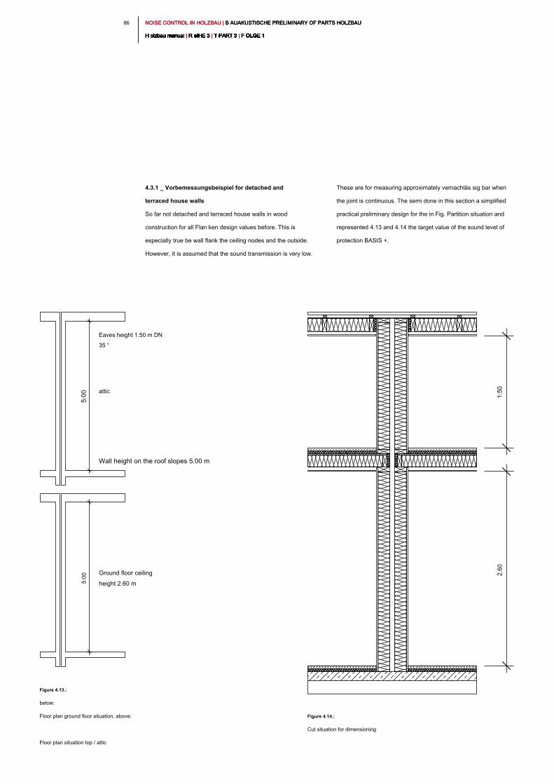
NOISE CONTROL IN HOLZBAU | B AUAKUSTISCHE PRELIMINARY OF PARTS HOLZBAU NOISE CONTROL IN HOLZBAU | B AUAKUSTISCHE PRELIMINARY OF PARTS HOLZBAU NOISE CONTROL IN HOLZBAU | B AUAKUSTISCHE PRELIMINARY OF PARTS HOLZBAU
H olzbau manual | R eIHE 3 | T PART 3 | F OLGE 1H olzbau manual | R eIHE 3 | T PART 3 | F OLGE 1H olzbau manual | R eIHE 3 | T PART 3 | F OLGE 1H olzbau manual | R eIHE 3 | T PART 3 | F OLGE 1H olzbau manual | R eIHE 3 | T PART 3 | F OLGE 1H olzbau manual | R eIHE 3 | T PART 3 | F OLGE 1H olzbau manual | R eIHE 3 | T PART 3 | F OLGE 1H olzbau manual | R eIHE 3 | T PART 3 | F OLGE 1H olzbau manual | R eIHE 3 | T PART 3 | F OLGE 1H olzbau manual | R eIHE 3 | T PART 3 | F OLGE 1H olzbau manual | R eIHE 3 | T PART 3 | F OLGE 1
86
These are for measuring approximately vernachläs sig bar when
the joint is continuous. The semi done in this section a simplified
practical preliminary design for the in Fig. Partition situation and
represented 4.13 and 4.14 the target value of the sound level of
protection BASIS +.
4.3.1 _ Vorbemessungsbeispiel for detached and
terraced house walls
So far not detached and terraced house walls in wood
construction for all Flan ken design values before. This is
especially true be wall flank the ceiling nodes and the outside.
However, it is assumed that the sound transmission is very low.
Figure 4.13.:
below:
Floor plan ground floor situation, above:
Floor plan situation top / attic
Figure 4.14.:
Cut situation for dimensioning
Eaves height 1.50 m DN
35 °
attic
Wall height on the roof slopes 5.00 m
Ground floor ceiling
height 2.60 m
5:00
5:00
2.6
0
1:50
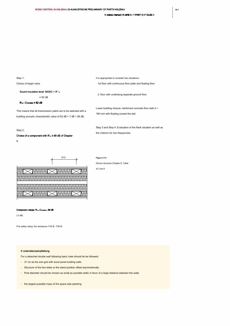
8th 78th 7NOISE CONTROL IN HOLZBAU | B AUAKUSTISCHE PRELIMINARY OF PARTS HOLZBAU NOISE CONTROL IN HOLZBAU | B AUAKUSTISCHE PRELIMINARY OF PARTS HOLZBAU NOISE CONTROL IN HOLZBAU | B AUAKUSTISCHE PRELIMINARY OF PARTS HOLZBAU
H olzbau manual | R eIHE 3 | T PART 3 | F OLGE 1H olzbau manual | R eIHE 3 | T PART 3 | F OLGE 1H olzbau manual | R eIHE 3 | T PART 3 | F OLGE 1H olzbau manual | R eIHE 3 | T PART 3 | F OLGE 1H olzbau manual | R eIHE 3 | T PART 3 | F OLGE 1H olzbau manual | R eIHE 3 | T PART 3 | F OLGE 1H olzbau manual | R eIHE 3 | T PART 3 | F OLGE 1H olzbau manual | R eIHE 3 | T PART 3 | F OLGE 1H olzbau manual | R eIHE 3 | T PART 3 | F OLGE 1H olzbau manual | R eIHE 3 | T PART 3 | F OLGE 1H olzbau manual | R eIHE 3 | T PART 3 | F OLGE 1
It is appropriate to consider two situations:
1st floor with continuous floor plate and floating floor
2. floor with underlying separate ground floor
Lower building closure: reinforced concrete floor slab d =
180 mm with floating screed the laid
Step 3 and Step 4: Evaluation of the flank situation as well as
the criterion for low frequencies.
Step 1:
Choice of target value
Sound insulation level: BASIC + R ' wSound insulation level: BASIC + R ' w
≥ 62 dB
R w + C 50-5000 ≥ 62 dB R w + C 50-5000 ≥ 62 dB R w + C 50-5000 ≥ 62 dB R w + C 50-5000 ≥ 62 dB R w + C 50-5000 ≥ 62 dB R w + C 50-5000 ≥ 62 dB
This means that all transmission paths are to be selected with a
building acoustic characteristic value of 62 dB + 7 dB = 69 dB.
Step 2:
Choice of a component with R w ≥ 69 dB of Chapter Choice of a component with R w ≥ 69 dB of Chapter Choice of a component with R w ≥ 69 dB of Chapter
6:
Component values: R w ( C 50-5000) = 69 dB Component values: R w ( C 50-5000) = 69 dB Component values: R w ( C 50-5000) = 69 dB Component values: R w ( C 50-5000) = 69 dB Component values: R w ( C 50-5000) = 69 dB
(-2 dB)
Fire safety rating: fire resistance: F30-B - F90-B
Figure 4.15.:
Device structure Chapter 6, Table
43, line 8
313
K onstruktionsempfehlung K onstruktionsempfehlung
For a detached double wall following basic rules should be be followed:
- 31 cm as the axis grid with wood panel building walls
- Structure of the two sides or the stand position offset asymmetrically
- Post diameter should be chosen as small as possible static in favor of a large distance between the walls
- the largest possible mass of the space side planking
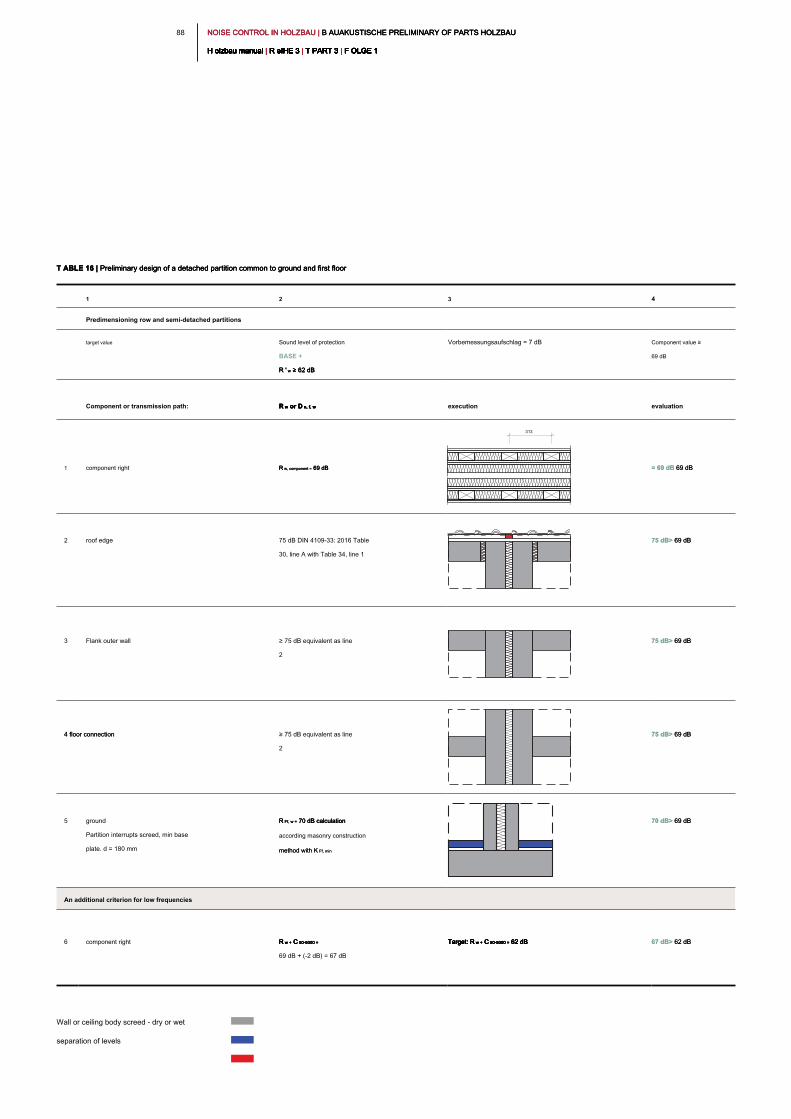
NOISE CONTROL IN HOLZBAU | B AUAKUSTISCHE PRELIMINARY OF PARTS HOLZBAU NOISE CONTROL IN HOLZBAU | B AUAKUSTISCHE PRELIMINARY OF PARTS HOLZBAU NOISE CONTROL IN HOLZBAU | B AUAKUSTISCHE PRELIMINARY OF PARTS HOLZBAU
H olzbau manual | R eIHE 3 | T PART 3 | F OLGE 1H olzbau manual | R eIHE 3 | T PART 3 | F OLGE 1H olzbau manual | R eIHE 3 | T PART 3 | F OLGE 1H olzbau manual | R eIHE 3 | T PART 3 | F OLGE 1H olzbau manual | R eIHE 3 | T PART 3 | F OLGE 1H olzbau manual | R eIHE 3 | T PART 3 | F OLGE 1H olzbau manual | R eIHE 3 | T PART 3 | F OLGE 1H olzbau manual | R eIHE 3 | T PART 3 | F OLGE 1H olzbau manual | R eIHE 3 | T PART 3 | F OLGE 1H olzbau manual | R eIHE 3 | T PART 3 | F OLGE 1H olzbau manual | R eIHE 3 | T PART 3 | F OLGE 1
88
T ABLE 16 | Preliminary design of a detached partition common to ground and first floorT ABLE 16 | Preliminary design of a detached partition common to ground and first floorT ABLE 16 | Preliminary design of a detached partition common to ground and first floor
1 2 3 4
Predimensioning row and semi-detached partitions
target value Sound level of protection
BASE +
R ' w ≥ 62 dBR ' w ≥ 62 dBR ' w ≥ 62 dB
Vorbemessungsaufschlag = 7 dB Component value ≥
69 dB
Component or transmission path: R w or D n, f, wR w or D n, f, wR w or D n, f, wR w or D n, f, w execution evaluation
1 component right R w, component = 69 dB R w, component = 69 dB R w, component = 69 dB = 69 dB 69 dB = 69 dB 69 dB
2 roof edge 75 dB DIN 4109-33: 2016 Table
30, line A with Table 34, line 1
75 dB> 69 dB 75 dB> 69 dB
3 Flank outer wall ≥ 75 dB equivalent as line
2
75 dB> 69 dB 75 dB> 69 dB
4 floor connection 4 floor connection ≥ 75 dB equivalent as line
2
75 dB> 69 dB 75 dB> 69 dB
5 ground
Partition interrupts screed, min base
plate. d = 180 mm
R Ff, w = 70 dB calculation R Ff, w = 70 dB calculation R Ff, w = 70 dB calculation
according masonry construction
method with K Ff, minmethod with K Ff, min
70 dB> 69 dB 70 dB> 69 dB
An additional criterion for low frequencies
6 component right R w + C 50-5000 =R w + C 50-5000 =R w + C 50-5000 =R w + C 50-5000 =R w + C 50-5000 =
69 dB + (-2 dB) = 67 dB
Target: R w + C 50-5000 = 62 dBTarget: R w + C 50-5000 = 62 dBTarget: R w + C 50-5000 = 62 dBTarget: R w + C 50-5000 = 62 dBTarget: R w + C 50-5000 = 62 dBTarget: R w + C 50-5000 = 62 dB 67 dB> 62 dB 67 dB> 62 dB
Wall or ceiling body screed - dry or wet
separation of levels
313
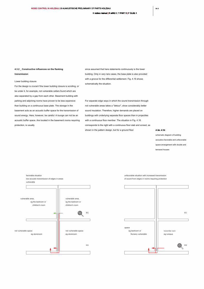
8th 98th 9NOISE CONTROL IN HOLZBAU | B AUAKUSTISCHE PRELIMINARY OF PARTS HOLZBAU NOISE CONTROL IN HOLZBAU | B AUAKUSTISCHE PRELIMINARY OF PARTS HOLZBAU NOISE CONTROL IN HOLZBAU | B AUAKUSTISCHE PRELIMINARY OF PARTS HOLZBAU
H olzbau manual | R eIHE 3 | T PART 3 | F OLGE 1H olzbau manual | R eIHE 3 | T PART 3 | F OLGE 1H olzbau manual | R eIHE 3 | T PART 3 | F OLGE 1H olzbau manual | R eIHE 3 | T PART 3 | F OLGE 1H olzbau manual | R eIHE 3 | T PART 3 | F OLGE 1H olzbau manual | R eIHE 3 | T PART 3 | F OLGE 1H olzbau manual | R eIHE 3 | T PART 3 | F OLGE 1H olzbau manual | R eIHE 3 | T PART 3 | F OLGE 1H olzbau manual | R eIHE 3 | T PART 3 | F OLGE 1H olzbau manual | R eIHE 3 | T PART 3 | F OLGE 1H olzbau manual | R eIHE 3 | T PART 3 | F OLGE 1
since assumed that here statements continuously is the lower
building. Only in very rare cases, the base plate is also provided
with a groove for the differential settlement. Fig. 4.16 shows
schematically the situation.
For separate edge ways in which the sound transmission through
not vulnerable areas takes a "detour", show considerably better
sound insulation. Therefore, higher demands are placed on
buildings with underlying separate floor spaces than in projectiles
with a continuous floor member. The situation in Fig. 4.16
corresponds to the right with a continuous floor slab and screed, as
shown in the pattern design, but for a ground floor.
4.3.2 _ Constructive influences on the flanking
transmission
Lower building closure
For the design is crucial if the lower building closure is scrolling, or
be under it, for example, not vulnerable cellars found which are
also separated by a gap from each other. Basement building with
parking and adjoining rooms have proven to be less expensive
than building on a continuous base plate. The storage in the
basement acts as an acoustic buffer space for the transmission of
sound energy. Here, however, be careful: A lounge can not be an
acoustic buffer space. Are located in the basement rooms requiring
protection, is usually
vulnerable area,
eg the bedroom or
children's room
vulnerable area,
eg the bedroom or
children's room
not vulnerable space
eg storeroom
not vulnerable space
eg storeroom
EC
KG KG
EC
transmitter room
eg rumpus
unfavorable situation with increased transmission
of sound from edges in rooms requiring protection
Nursery vulnerable
space
eg bedroom or
favorable situation
low acoustic transmission of edges in areas
vulnerable
A bb. 4:16:A bb. 4:16:
schematic diagram of building
acoustics favorable and unfavorable
space arrangement with double and
terraced houses
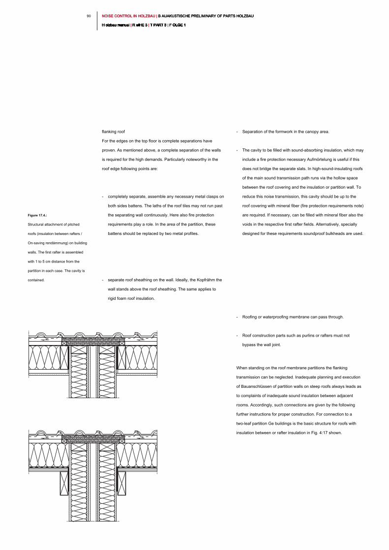
NOISE CONTROL IN HOLZBAU | B AUAKUSTISCHE PRELIMINARY OF PARTS HOLZBAU NOISE CONTROL IN HOLZBAU | B AUAKUSTISCHE PRELIMINARY OF PARTS HOLZBAU NOISE CONTROL IN HOLZBAU | B AUAKUSTISCHE PRELIMINARY OF PARTS HOLZBAU
H olzbau manual | R eIHE 3 | T PART 3 | F OLGE 1H olzbau manual | R eIHE 3 | T PART 3 | F OLGE 1H olzbau manual | R eIHE 3 | T PART 3 | F OLGE 1H olzbau manual | R eIHE 3 | T PART 3 | F OLGE 1H olzbau manual | R eIHE 3 | T PART 3 | F OLGE 1H olzbau manual | R eIHE 3 | T PART 3 | F OLGE 1H olzbau manual | R eIHE 3 | T PART 3 | F OLGE 1H olzbau manual | R eIHE 3 | T PART 3 | F OLGE 1H olzbau manual | R eIHE 3 | T PART 3 | F OLGE 1H olzbau manual | R eIHE 3 | T PART 3 | F OLGE 1H olzbau manual | R eIHE 3 | T PART 3 | F OLGE 1
90
- Separation of the formwork in the canopy area.
- The cavity to be filled with sound-absorbing insulation, which may
include a fire protection necessary Aufmörtelung is useful if this
does not bridge the separate slats. In high-sound-insulating roofs
of the main sound transmission path runs via the hollow space
between the roof covering and the insulation or partition wall. To
reduce this noise transmission, this cavity should be up to the
roof covering with mineral fiber (fire protection requirements note)
are required. If necessary, can be filled with mineral fiber also the
voids in the respective first rafter fields. Alternatively, specially
designed for these requirements soundproof bulkheads are used.
- Roofing or waterproofing membrane can pass through.
- Roof construction parts such as purlins or rafters must not
bypass the wall joint.
When standing on the roof membrane partitions the flanking
transmission can be neglected. Inadequate planning and execution
of Bauanschlüssen of partition walls on steep roofs always leads as
to complaints of inadequate sound insulation between adjacent
rooms. Accordingly, such connections are given by the following
further instructions for proper construction. For connection to a
two-leaf partition Ge buildings is the basic structure for roofs with
insulation between or rafter insulation in Fig. 4:17 shown.
flanking roof
For the edges on the top floor is complete separations have
proven. As mentioned above, a complete separation of the walls
is required for the high demands. Particularly noteworthy in the
roof edge following points are:
- completely separate, assemble any necessary metal clasps on
both sides battens. The laths of the roof tiles may not run past
the separating wall continuously. Here also fire protection
requirements play a role. In the area of the partition, these
battens should be replaced by two metal profiles.
- separate roof sheathing on the wall. Ideally, the Kopfrähm the
wall stands above the roof sheathing. The same applies to
rigid foam roof insulation.
Figure 17.4.:
Structural attachment of pitched
roofs (insulation between rafters /
On-saving rendämmung) on building
walls. The first rafter is assembled
with 1 to 5 cm distance from the
partition in each case. The cavity is
contained.
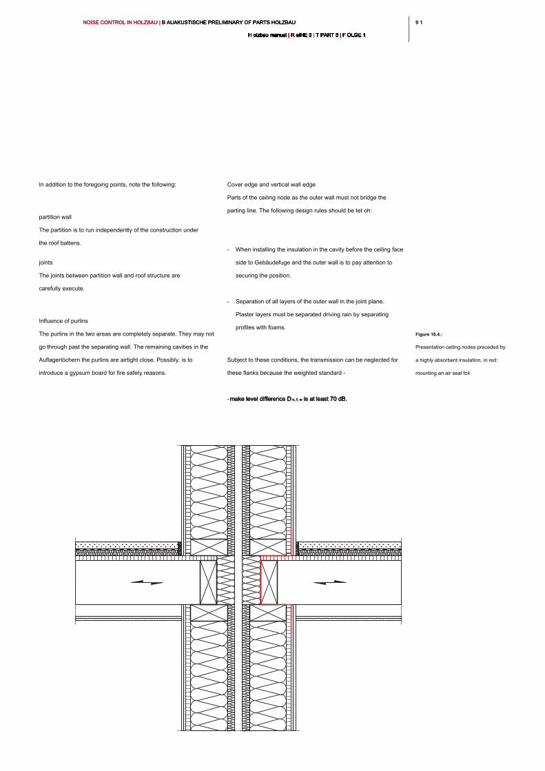
9 19 1NOISE CONTROL IN HOLZBAU | B AUAKUSTISCHE PRELIMINARY OF PARTS HOLZBAU NOISE CONTROL IN HOLZBAU | B AUAKUSTISCHE PRELIMINARY OF PARTS HOLZBAU NOISE CONTROL IN HOLZBAU | B AUAKUSTISCHE PRELIMINARY OF PARTS HOLZBAU
H olzbau manual | R eIHE 3 | T PART 3 | F OLGE 1H olzbau manual | R eIHE 3 | T PART 3 | F OLGE 1H olzbau manual | R eIHE 3 | T PART 3 | F OLGE 1H olzbau manual | R eIHE 3 | T PART 3 | F OLGE 1H olzbau manual | R eIHE 3 | T PART 3 | F OLGE 1H olzbau manual | R eIHE 3 | T PART 3 | F OLGE 1H olzbau manual | R eIHE 3 | T PART 3 | F OLGE 1H olzbau manual | R eIHE 3 | T PART 3 | F OLGE 1H olzbau manual | R eIHE 3 | T PART 3 | F OLGE 1H olzbau manual | R eIHE 3 | T PART 3 | F OLGE 1H olzbau manual | R eIHE 3 | T PART 3 | F OLGE 1
Cover edge and vertical wall edge
Parts of the ceiling node as the outer wall must not bridge the
parting line. The following design rules should be tet oh:
- When installing the insulation in the cavity before the ceiling face
side to Gebäudefuge and the outer wall is to pay attention to
securing the position.
- Separation of all layers of the outer wall in the joint plane.
Plaster layers must be separated driving rain by separating
profiles with foams.
Subject to these conditions, the transmission can be neglected for
these flanks because the weighted standard -
- make level difference D n, f, w is at least 70 dB.make level difference D n, f, w is at least 70 dB.make level difference D n, f, w is at least 70 dB.
In addition to the foregoing points, note the following:
partition wall
The partition is to run independently of the construction under
the roof battens.
joints
The joints between partition wall and roof structure are
carefully execute.
Influence of purlins
The purlins in the two areas are completely separate. They may not
go through past the separating wall. The remaining cavities in the
Auflagerlöchern the purlins are airtight close. Possibly. is to
introduce a gypsum board for fire safety reasons.
Figure 18.4.:
Presentation ceiling nodes preceded by
a highly absorbent insulation, in red:
mounting an air seal foil
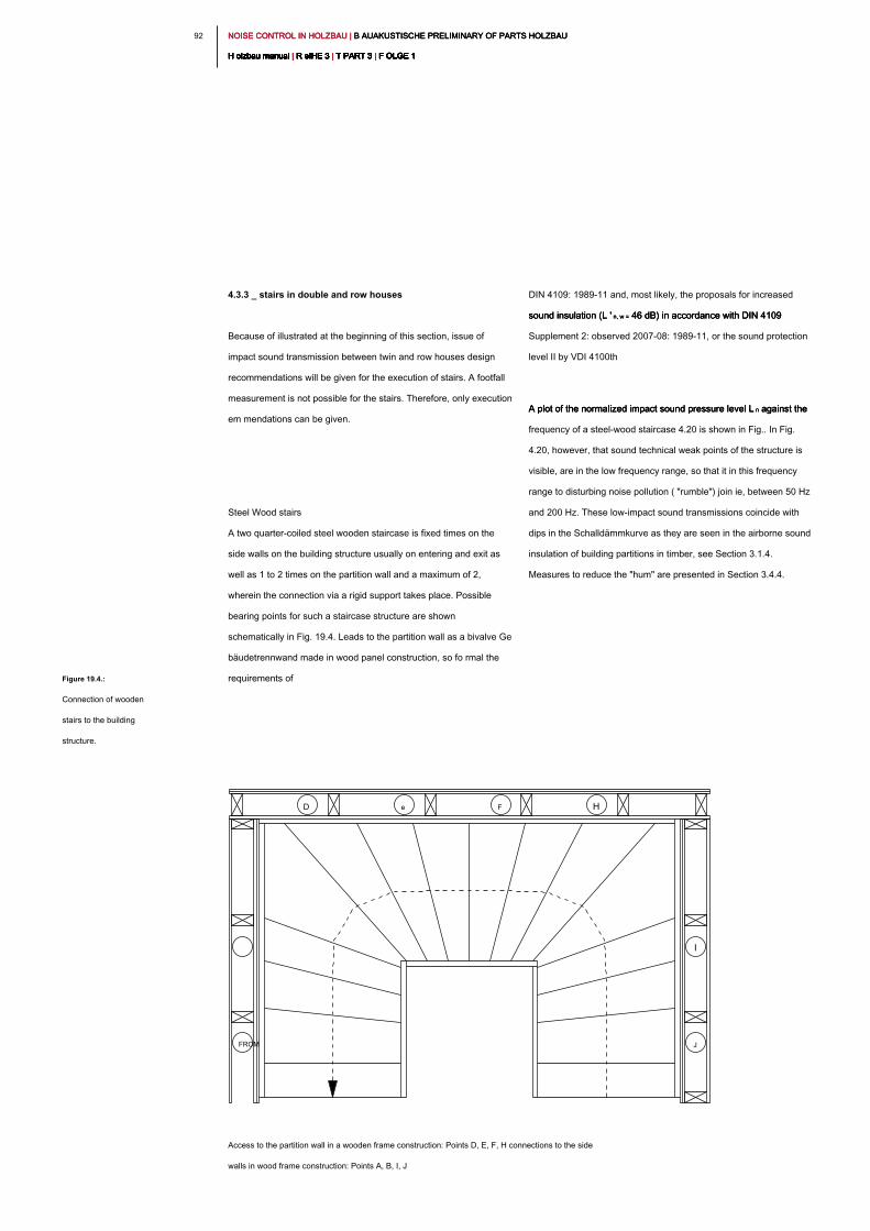
NOISE CONTROL IN HOLZBAU | B AUAKUSTISCHE PRELIMINARY OF PARTS HOLZBAU NOISE CONTROL IN HOLZBAU | B AUAKUSTISCHE PRELIMINARY OF PARTS HOLZBAU NOISE CONTROL IN HOLZBAU | B AUAKUSTISCHE PRELIMINARY OF PARTS HOLZBAU
H olzbau manual | R eIHE 3 | T PART 3 | F OLGE 1H olzbau manual | R eIHE 3 | T PART 3 | F OLGE 1H olzbau manual | R eIHE 3 | T PART 3 | F OLGE 1H olzbau manual | R eIHE 3 | T PART 3 | F OLGE 1H olzbau manual | R eIHE 3 | T PART 3 | F OLGE 1H olzbau manual | R eIHE 3 | T PART 3 | F OLGE 1H olzbau manual | R eIHE 3 | T PART 3 | F OLGE 1H olzbau manual | R eIHE 3 | T PART 3 | F OLGE 1H olzbau manual | R eIHE 3 | T PART 3 | F OLGE 1H olzbau manual | R eIHE 3 | T PART 3 | F OLGE 1H olzbau manual | R eIHE 3 | T PART 3 | F OLGE 1
92
DIN 4109: 1989-11 and, most likely, the proposals for increased
sound insulation (L ' n, w = 46 dB) in accordance with DIN 4109 sound insulation (L ' n, w = 46 dB) in accordance with DIN 4109 sound insulation (L ' n, w = 46 dB) in accordance with DIN 4109
Supplement 2: observed 2007-08: 1989-11, or the sound protection
level II by VDI 4100th
A plot of the normalized impact sound pressure level L n against the A plot of the normalized impact sound pressure level L n against the A plot of the normalized impact sound pressure level L n against the
frequency of a steel-wood staircase 4.20 is shown in Fig.. In Fig.
4.20, however, that sound technical weak points of the structure is
visible, are in the low frequency range, so that it in this frequency
range to disturbing noise pollution ( "rumble") join ie, between 50 Hz
and 200 Hz. These low-impact sound transmissions coincide with
dips in the Schalldämmkurve as they are seen in the airborne sound
insulation of building partitions in timber, see Section 3.1.4.
Measures to reduce the "hum" are presented in Section 3.4.4.
4.3.3 _ stairs in double and row houses
Because of illustrated at the beginning of this section, issue of
impact sound transmission between twin and row houses design
recommendations will be given for the execution of stairs. A footfall
measurement is not possible for the stairs. Therefore, only execution
em mendations can be given.
Steel Wood stairs
A two quarter-coiled steel wooden staircase is fixed times on the
side walls on the building structure usually on entering and exit as
well as 1 to 2 times on the partition wall and a maximum of 2,
wherein the connection via a rigid support takes place. Possible
bearing points for such a staircase structure are shown
schematically in Fig. 19.4. Leads to the partition wall as a bivalve Ge
bäudetrennwand made in wood panel construction, so fo rmal the
requirements ofFigure 19.4.:
Connection of wooden
stairs to the building
structure.
Access to the partition wall in a wooden frame construction: Points D, E, F, H connections to the side
walls in wood frame construction: Points A, B, I, J
FROM
D e F H
I
J
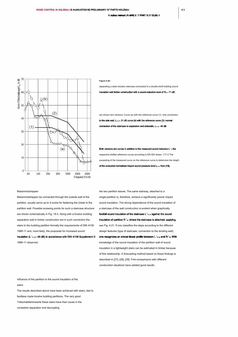
9 39 3NOISE CONTROL IN HOLZBAU | B AUAKUSTISCHE PRELIMINARY OF PARTS HOLZBAU NOISE CONTROL IN HOLZBAU | B AUAKUSTISCHE PRELIMINARY OF PARTS HOLZBAU NOISE CONTROL IN HOLZBAU | B AUAKUSTISCHE PRELIMINARY OF PARTS HOLZBAU
H olzbau manual | R eIHE 3 | T PART 3 | F OLGE 1H olzbau manual | R eIHE 3 | T PART 3 | F OLGE 1H olzbau manual | R eIHE 3 | T PART 3 | F OLGE 1H olzbau manual | R eIHE 3 | T PART 3 | F OLGE 1H olzbau manual | R eIHE 3 | T PART 3 | F OLGE 1H olzbau manual | R eIHE 3 | T PART 3 | F OLGE 1H olzbau manual | R eIHE 3 | T PART 3 | F OLGE 1H olzbau manual | R eIHE 3 | T PART 3 | F OLGE 1H olzbau manual | R eIHE 3 | T PART 3 | F OLGE 1H olzbau manual | R eIHE 3 | T PART 3 | F OLGE 1H olzbau manual | R eIHE 3 | T PART 3 | F OLGE 1
the two partition leaves. The same stairway, attached to a
single-partition is, therefore, achieve a significantly poorer impact
sound insulation. The strong dependence of the sound insulation of
a staircase of the wall construction is evident when graphically
footfall sound insulation of the staircase L ' n, w against the sound footfall sound insulation of the staircase L ' n, w against the sound footfall sound insulation of the staircase L ' n, w against the sound
insulation of partition R ' w, where the staircase is attached, applying, insulation of partition R ' w, where the staircase is attached, applying, insulation of partition R ' w, where the staircase is attached, applying,
see Fig. 4.21. If one classifies the steps according to the different
design features (type of staircase, connection to the dividing wall),
one recognizes an almost linear profile between L ' n, w and R ' w. With one recognizes an almost linear profile between L ' n, w and R ' w. With one recognizes an almost linear profile between L ' n, w and R ' w. With one recognizes an almost linear profile between L ' n, w and R ' w. With one recognizes an almost linear profile between L ' n, w and R ' w. With
knowledge of the sound insulation of the partition wall of sound
insulation in a lightweight stairs can be estimated in timber because
of this relationship. A forecasting method based on these findings is
described in [27], [28], [29]. First comparisons with different
construction situations have yielded good results.
Massivholztreppen
Massivholztreppen be connected through the outside wall of the
partition, usually serve up to 4 screw for fastening the cheek to the
partition wall. Possible screwing points for such a staircase structure
are shown schematically in Fig. 19.4. Along with a bivalve building
separation wall in timber construction are in such connection the
stairs to the building partition formally the requirements of DIN 4109:
1989-11 and, most likely, the proposals for increased sound
insulation (L ' n, w = 46 dB) in accordance with DIN 4109 Supplement 2: insulation (L ' n, w = 46 dB) in accordance with DIN 4109 Supplement 2: insulation (L ' n, w = 46 dB) in accordance with DIN 4109 Supplement 2:
1989-11 observed.
Influence of the partition to the sound insulation of the
stairs
The results described above have been achieved with stairs, tied to
faultless made bivalve building partitions. The very good
Trittschalldämmwerte these stairs have their cause in the
consistent separation and decoupling
Figure 4.20.:
separating a steel wooden staircase connected to a double-shell building sound
insulation wall timber construction with a sound reduction level of R w = 71 dB. insulation wall timber construction with a sound reduction level of R w = 71 dB. insulation wall timber construction with a sound reduction level of R w = 71 dB.
are shown two versions: Curve (a) with the reference curve (1): only connection
to the side wall, L n, w = 31 dB curve (b) with the reference curve (2): normal to the side wall, L n, w = 31 dB curve (b) with the reference curve (2): normal to the side wall, L n, w = 31 dB curve (b) with the reference curve (2): normal
connection of the staircase to separation and sidewalls, L n, w = 40 dBconnection of the staircase to separation and sidewalls, L n, w = 40 dBconnection of the staircase to separation and sidewalls, L n, w = 40 dB
Both versions are curves in addition to the measured sound reduction L ' n the Both versions are curves in addition to the measured sound reduction L ' n the Both versions are curves in addition to the measured sound reduction L ' n the
respective shifted reference curves according to EN ISO drawn. 717-2 The
exceeding of the measured curve on the reference curve to determine the height
of the evaluated normalized impact sound pressure level L n, w from [19].of the evaluated normalized impact sound pressure level L n, w from [19].of the evaluated normalized impact sound pressure level L n, w from [19].
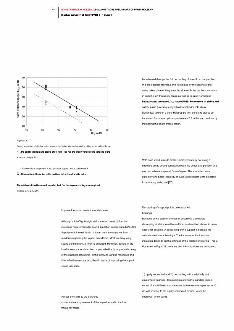
NOISE CONTROL IN HOLZBAU | B AUAKUSTISCHE PRELIMINARY OF PARTS HOLZBAU NOISE CONTROL IN HOLZBAU | B AUAKUSTISCHE PRELIMINARY OF PARTS HOLZBAU NOISE CONTROL IN HOLZBAU | B AUAKUSTISCHE PRELIMINARY OF PARTS HOLZBAU
H olzbau manual | R eIHE 3 | T PART 3 | F OLGE 1H olzbau manual | R eIHE 3 | T PART 3 | F OLGE 1H olzbau manual | R eIHE 3 | T PART 3 | F OLGE 1H olzbau manual | R eIHE 3 | T PART 3 | F OLGE 1H olzbau manual | R eIHE 3 | T PART 3 | F OLGE 1H olzbau manual | R eIHE 3 | T PART 3 | F OLGE 1H olzbau manual | R eIHE 3 | T PART 3 | F OLGE 1H olzbau manual | R eIHE 3 | T PART 3 | F OLGE 1H olzbau manual | R eIHE 3 | T PART 3 | F OLGE 1H olzbau manual | R eIHE 3 | T PART 3 | F OLGE 1H olzbau manual | R eIHE 3 | T PART 3 | F OLGE 1
94
be achieved through the full decoupling of stairs from the partition.
In a steel timber staircase, this is realized by the seating of the
stairs takes place entirely over the side walls. be the improvements
in both the low-frequency range as well as in rated normalized
impact sound pressure L ' n, w = about 8 dB. For reasons of statics and impact sound pressure L ' n, w = about 8 dB. For reasons of statics and impact sound pressure L ' n, w = about 8 dB. For reasons of statics and
safety in use (low-frequency vibration behavior, Structural
Dynamics) takes on a steel Holztrep pe this, the stairs statics be
improved. For spans up to approximately 2.2 m this can be done by
increasing the beam cross section.
With solid wood stairs to similar improvements by not using a
structure-borne sound contact between the cheek and partition and
use can achieve a special Eckauflagers. The sound-technical
suitability and basic feasibility of such Eckauflagers were detected
in laboratory tests, see [27].
Decoupling of support points on elastomeric
bearings
Because of the static or the use of security is a complete
decoupling of stairs from the partition, as described above, in many
cases not possible. A decoupling of the support is possible via
suitable elastomeric bearings. The improvement in the sound
insulation depends on the softness of the elastomer bearing. This is
illustrated in Fig. 4.22. Here are two links situations are compared:
1.) rigidly connected and 2.) decoupling with a relatively soft
elastomeric bearings. This example shows the standard impact
sound of a soft Elasto that the stairs by the use merlagers up to 10
dB with respect to the rigidly connected reduce, ie can be
improved. when using
Improve the sound insulation of staircases
Although a lot of lightweight stairs in wood construction, the
increased requirements for sound insulation according to DIN 4109
Supplement 2: meet 1989-11, it can men to complaints from
residents regarding the impact sound kom. Most low-frequency
sound transmission, a "roar" is criticized. However, deficits in the
low-frequency sound can be compensated for by appropriate design
of the staircase structures. In the following various measures and
their effectiveness are described in terms of improving the impact
sound insulation.
Access the stairs to the bulkhead
shows a clear improvement of the impact sound in the low
frequency range
Figure 21.4.:
Sound insulation of steel wooden stairs in the timber depending on the airborne sound insulation
R ' w the partition (single and double shell) from [19]. two are shown various dene versions of the R ' w the partition (single and double shell) from [19]. two are shown various dene versions of the R ' w the partition (single and double shell) from [19]. two are shown various dene versions of the
access to the partition.
- Observations: steps with 1 to 2 points of support in the partition wall.
O - Observations: Stairs tied not to partition, but only on the side walls. O - Observations: Stairs tied not to partition, but only on the side walls.
The solid and dotted lines are forward of the L ' n, w the steps according to an empirical The solid and dotted lines are forward of the L ' n, w the steps according to an empirical The solid and dotted lines are forward of the L ' n, w the steps according to an empirical
method [27], [28], [29].
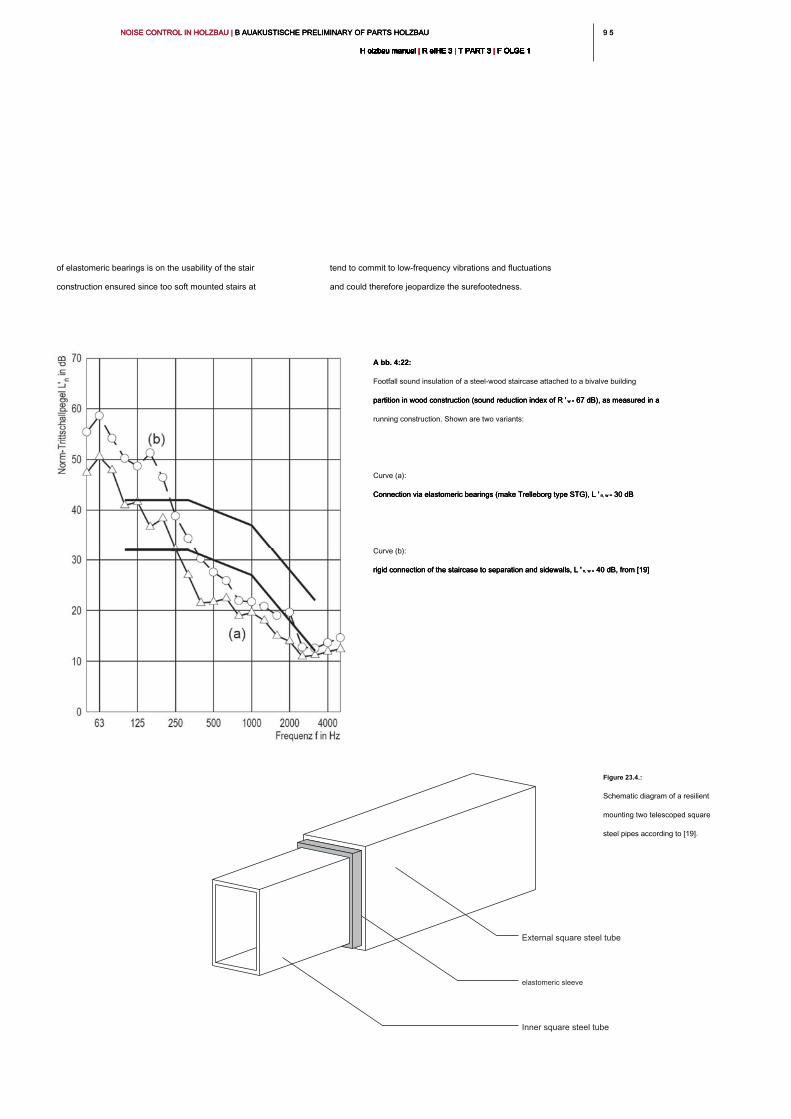
9 59 5NOISE CONTROL IN HOLZBAU | B AUAKUSTISCHE PRELIMINARY OF PARTS HOLZBAU NOISE CONTROL IN HOLZBAU | B AUAKUSTISCHE PRELIMINARY OF PARTS HOLZBAU NOISE CONTROL IN HOLZBAU | B AUAKUSTISCHE PRELIMINARY OF PARTS HOLZBAU
H olzbau manual | R eIHE 3 | T PART 3 | F OLGE 1H olzbau manual | R eIHE 3 | T PART 3 | F OLGE 1H olzbau manual | R eIHE 3 | T PART 3 | F OLGE 1H olzbau manual | R eIHE 3 | T PART 3 | F OLGE 1H olzbau manual | R eIHE 3 | T PART 3 | F OLGE 1H olzbau manual | R eIHE 3 | T PART 3 | F OLGE 1H olzbau manual | R eIHE 3 | T PART 3 | F OLGE 1H olzbau manual | R eIHE 3 | T PART 3 | F OLGE 1H olzbau manual | R eIHE 3 | T PART 3 | F OLGE 1H olzbau manual | R eIHE 3 | T PART 3 | F OLGE 1H olzbau manual | R eIHE 3 | T PART 3 | F OLGE 1
of elastomeric bearings is on the usability of the stair
construction ensured since too soft mounted stairs at
Figure 23.4.:
Schematic diagram of a resilient
mounting two telescoped square
steel pipes according to [19].
External square steel tube
elastomeric sleeve
Inner square steel tube
A bb. 4:22:A bb. 4:22:
Footfall sound insulation of a steel-wood staircase attached to a bivalve building
partition in wood construction (sound reduction index of R ' w = 67 dB), as measured in a partition in wood construction (sound reduction index of R ' w = 67 dB), as measured in a partition in wood construction (sound reduction index of R ' w = 67 dB), as measured in a
running construction. Shown are two variants:
Curve (a):
Connection via elastomeric bearings (make Trelleborg type STG), L ' n, w = 30 dB Connection via elastomeric bearings (make Trelleborg type STG), L ' n, w = 30 dB Connection via elastomeric bearings (make Trelleborg type STG), L ' n, w = 30 dB
Curve (b):
rigid connection of the staircase to separation and sidewalls, L ' n, w = 40 dB, from [19]rigid connection of the staircase to separation and sidewalls, L ' n, w = 40 dB, from [19]rigid connection of the staircase to separation and sidewalls, L ' n, w = 40 dB, from [19]
tend to commit to low-frequency vibrations and fluctuations
and could therefore jeopardize the surefootedness.
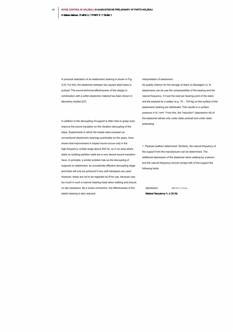
NOISE CONTROL IN HOLZBAU | B AUAKUSTISCHE PRELIMINARY OF PARTS HOLZBAU NOISE CONTROL IN HOLZBAU | B AUAKUSTISCHE PRELIMINARY OF PARTS HOLZBAU NOISE CONTROL IN HOLZBAU | B AUAKUSTISCHE PRELIMINARY OF PARTS HOLZBAU
H olzbau manual | R eIHE 3 | T PART 3 | F OLGE 1H olzbau manual | R eIHE 3 | T PART 3 | F OLGE 1H olzbau manual | R eIHE 3 | T PART 3 | F OLGE 1H olzbau manual | R eIHE 3 | T PART 3 | F OLGE 1H olzbau manual | R eIHE 3 | T PART 3 | F OLGE 1H olzbau manual | R eIHE 3 | T PART 3 | F OLGE 1H olzbau manual | R eIHE 3 | T PART 3 | F OLGE 1H olzbau manual | R eIHE 3 | T PART 3 | F OLGE 1H olzbau manual | R eIHE 3 | T PART 3 | F OLGE 1H olzbau manual | R eIHE 3 | T PART 3 | F OLGE 1H olzbau manual | R eIHE 3 | T PART 3 | F OLGE 1
96
A practical realization of an elastomeric bearing is shown in Fig.
4.23. For this, the elastomer between two square steel tubes is
pushed. The sound-technical effectiveness of this design in
combination with a softer elastomer material has been shown in
laboratory studies [27].
In addition to the decoupling of support is often tries to grasp even
improve the sound insulation on the vibration decoupling of the
steps. Experiments in which the treads were screwed via
conventional elastomeric bearings practicable on the spars, have
shown that improvement in impact sound occurs only in the
high-frequency rumble range above 400 Hz, so in an area where
stairs on building partition walls are a very decent sound insulation
have. In principle, a similar problem has as the decoupling of
supports on elastomers: an acoustically effective decoupling stage
and Holm will only be achieved if very soft interlayers are used.
However, these are not to be regarded as fit for use, because vary
too much in such a manner bearing tread when walking and ensure
no slip resistance. By a screw connection, the effectiveness of the
elastic bearing is also reduced.
Interpretation of elastomers
As quality criterion for the storage of stairs on Baulagern (z. B.
elastomers) can be use the compressibility of the bearing and the
natural frequency. It must the load per bearing point of the stairs
and the payload by a walker (e.g. 75 -. 100 kg) on the surface of the
elastomeric bearing are distributed. This results in a surface
pressure in N / mm². From this, the "reduction" (depression At) of
the elastomer allows only under static preload and under static
preloading
+ Payload (walker) determined. Similarly, the natural frequency of
the support from the manufacturer can be determined. The
additional depression of the elastomer when walking by a person
and the natural frequency should comply with of the support the
following limits:
depression .DELTA.t ≤ 1.5 mm
Natural frequency f 0 ≤ 30 HzNatural frequency f 0 ≤ 30 HzNatural frequency f 0 ≤ 30 Hz
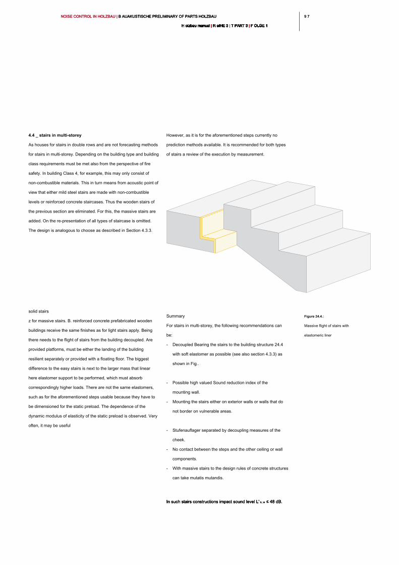
9 79 7NOISE CONTROL IN HOLZBAU | B AUAKUSTISCHE PRELIMINARY OF PARTS HOLZBAU NOISE CONTROL IN HOLZBAU | B AUAKUSTISCHE PRELIMINARY OF PARTS HOLZBAU NOISE CONTROL IN HOLZBAU | B AUAKUSTISCHE PRELIMINARY OF PARTS HOLZBAU
H olzbau manual | R eIHE 3 | T PART 3 | F OLGE 1H olzbau manual | R eIHE 3 | T PART 3 | F OLGE 1H olzbau manual | R eIHE 3 | T PART 3 | F OLGE 1H olzbau manual | R eIHE 3 | T PART 3 | F OLGE 1H olzbau manual | R eIHE 3 | T PART 3 | F OLGE 1H olzbau manual | R eIHE 3 | T PART 3 | F OLGE 1H olzbau manual | R eIHE 3 | T PART 3 | F OLGE 1H olzbau manual | R eIHE 3 | T PART 3 | F OLGE 1H olzbau manual | R eIHE 3 | T PART 3 | F OLGE 1H olzbau manual | R eIHE 3 | T PART 3 | F OLGE 1H olzbau manual | R eIHE 3 | T PART 3 | F OLGE 1
However, as it is for the aforementioned steps currently no
prediction methods available. It is recommended for both types
of stairs a review of the execution by measurement.
Summary
For stairs in multi-storey, the following recommendations can
be:
- Decoupled Bearing the stairs to the building structure 24.4
with soft elastomer as possible (see also section 4.3.3) as
shown in Fig..
- Possible high valued Sound reduction index of the
mounting wall.
- Mounting the stairs either on exterior walls or walls that do
not border on vulnerable areas.
- Stufenauflager separated by decoupling measures of the
cheek.
- No contact between the steps and the other ceiling or wall
components.
- With massive stairs to the design rules of concrete structures
can take mutatis mutandis.
In such stairs constructions impact sound level L' n, w ≤ 48 dB.In such stairs constructions impact sound level L' n, w ≤ 48 dB.In such stairs constructions impact sound level L' n, w ≤ 48 dB.
4.4 _ stairs in multi-storey
As houses for stairs in double rows and are not forecasting methods
for stairs in multi-storey. Depending on the building type and building
class requirements must be met also from the perspective of fire
safety. In building Class 4, for example, this may only consist of
non-combustible materials. This in turn means from acoustic point of
view that either mild steel stairs are made with non-combustible
levels or reinforced concrete staircases. Thus the wooden stairs of
the previous section are eliminated. For this, the massive stairs are
added. On the re-presentation of all types of staircase is omitted.
The design is analogous to choose as described in Section 4.3.3.
solid stairs
z for massive stairs. B. reinforced concrete prefabricated wooden
buildings receive the same finishes as for light stairs apply. Being
there needs to the flight of stairs from the building decoupled. Are
provided platforms, must be either the landing of the building
resilient separately or provided with a floating floor. The biggest
difference to the easy stairs is next to the larger mass that linear
here elastomer support to be performed, which must absorb
correspondingly higher loads. There are not the same elastomers,
such as for the aforementioned steps usable because they have to
be dimensioned for the static preload. The dependence of the
dynamic modulus of elasticity of the static preload is observed. Very
often, it may be useful
Figure 24.4.:
Massive flight of stairs with
elastomeric liner
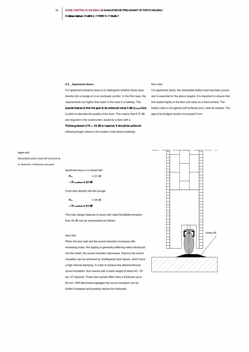
NOISE CONTROL IN HOLZBAU | B AUAKUSTISCHE PRELIMINARY OF PARTS HOLZBAU NOISE CONTROL IN HOLZBAU | B AUAKUSTISCHE PRELIMINARY OF PARTS HOLZBAU NOISE CONTROL IN HOLZBAU | B AUAKUSTISCHE PRELIMINARY OF PARTS HOLZBAU
H olzbau manual | R eIHE 3 | T PART 3 | F OLGE 1H olzbau manual | R eIHE 3 | T PART 3 | F OLGE 1H olzbau manual | R eIHE 3 | T PART 3 | F OLGE 1H olzbau manual | R eIHE 3 | T PART 3 | F OLGE 1H olzbau manual | R eIHE 3 | T PART 3 | F OLGE 1H olzbau manual | R eIHE 3 | T PART 3 | F OLGE 1H olzbau manual | R eIHE 3 | T PART 3 | F OLGE 1H olzbau manual | R eIHE 3 | T PART 3 | F OLGE 1H olzbau manual | R eIHE 3 | T PART 3 | F OLGE 1H olzbau manual | R eIHE 3 | T PART 3 | F OLGE 1H olzbau manual | R eIHE 3 | T PART 3 | F OLGE 1
98
floor seal
For apartment doors, the retractable bottom seal has been proven
and is essential for the above targets. It is important to ensure that
this sealed tightly to the floor and rests on a hard surface. The
bottom seal is not against soft surfaces such. start as carpets. The
gap to be bridged should not exceed 5 mm.
4.5 _ Apartment doors
For apartment entrance doors is to distinguish whether these open
directly into a lounge or in an enclosed corridor. In the first case, the
requirements are higher than seen in the case in a hallway. The
special feature is that the goal to be achieved value 5 dB (u prog) have special feature is that the goal to be achieved value 5 dB (u prog) have special feature is that the goal to be achieved value 5 dB (u prog) have
to pitch to describe the quality of the door. This means that if 37 dB
are required in the construction, would be a door with a
Prüfzeugniswert of R w = 42 dB is required. It should be achieved Prüfzeugniswert of R w = 42 dB is required. It should be achieved Prüfzeugniswert of R w = 42 dB is required. It should be achieved
following target values in the modern multi-storey buildings:
Apartment door in a closed hall:
R wR w ≥ 37 dB
→ R w certificate ≥ 42 dB→ R w certificate ≥ 42 dB→ R w certificate ≥ 42 dB
Front door directly into the lounge:
R wR w ≥ 38 dB
→ R w certificate ≥ 43 dB→ R w certificate ≥ 43 dB→ R w certificate ≥ 43 dB
The main design features of doors with rated Schalldämmmaßen
than 40 dB can be summarized as follows:
door leaf
When the door leaf and the sound reduction increases with
increasing mass. Are lipping or generally stiffening webs introduced
into the sheet, the sound insulation decreases. Improve the sound
insulation can be achieved by multilayered door leaves, which have
a high internal damping. In order to achieve the aforementioned
sound insulation, door leaves with a basis weight of about 40 - 50
kg / m² required. These door panels often have a thickness up to
80 mm. With Beschwerungslagen the sound insulation can be
further increased and possibly reduce the thickness.
Figure 4.25.:
Retractable bottom seal with hump sill as
an abutment, if distances are great.
hump sill
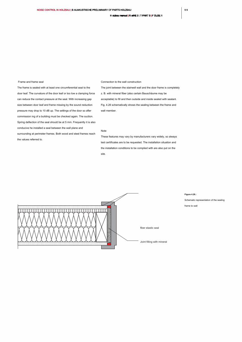
9 99 9NOISE CONTROL IN HOLZBAU | B AUAKUSTISCHE PRELIMINARY OF PARTS HOLZBAU NOISE CONTROL IN HOLZBAU | B AUAKUSTISCHE PRELIMINARY OF PARTS HOLZBAU NOISE CONTROL IN HOLZBAU | B AUAKUSTISCHE PRELIMINARY OF PARTS HOLZBAU
H olzbau manual | R eIHE 3 | T PART 3 | F OLGE 1H olzbau manual | R eIHE 3 | T PART 3 | F OLGE 1H olzbau manual | R eIHE 3 | T PART 3 | F OLGE 1H olzbau manual | R eIHE 3 | T PART 3 | F OLGE 1H olzbau manual | R eIHE 3 | T PART 3 | F OLGE 1H olzbau manual | R eIHE 3 | T PART 3 | F OLGE 1H olzbau manual | R eIHE 3 | T PART 3 | F OLGE 1H olzbau manual | R eIHE 3 | T PART 3 | F OLGE 1H olzbau manual | R eIHE 3 | T PART 3 | F OLGE 1H olzbau manual | R eIHE 3 | T PART 3 | F OLGE 1H olzbau manual | R eIHE 3 | T PART 3 | F OLGE 1
Connection to the wall construction
The joint between the stairwell wall and the door frame is completely
z. B. with mineral fiber (also certain Bauschäume may be
acceptable) to fill and then outside and inside sealed with sealant.
Fig. 4.26 schematically shows the sealing between the frame and
wall member.
Note
These features may vary by manufacturers vary widely, so always
test certificates are to be requested. The installation situation and
the installation conditions to be complied with are also put on the
site.
Frame and frame seal
The frame is sealed with at least one circumferential seal to the
door leaf. The curvature of the door leaf or too low a clamping force
can reduce the contact pressure at the seal. With increasing gap
size between door leaf and frame missing by the sound reduction
pressure may drop to 10 dB up. The settings of the door so after
commission ing of a building must be checked again. The suction.
Spring deflection of the seal should be at 5 mm. Frequently it is also
conducive he installed a seal between the wall plane and
surrounding at perimeter frames. Both wood and steel frames reach
the values referred to.
Figure 4.26.:
Schematic representation of the sealing
frame to wall
Joint filling with mineral
fiber elastic seal
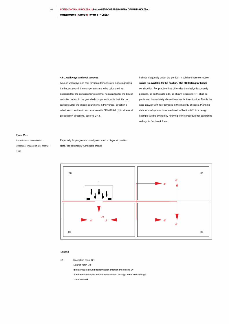
NOISE CONTROL IN HOLZBAU | B AUAKUSTISCHE PRELIMINARY OF PARTS HOLZBAU NOISE CONTROL IN HOLZBAU | B AUAKUSTISCHE PRELIMINARY OF PARTS HOLZBAU NOISE CONTROL IN HOLZBAU | B AUAKUSTISCHE PRELIMINARY OF PARTS HOLZBAU
H olzbau manual | R eIHE 3 | T PART 3 | F OLGE 1H olzbau manual | R eIHE 3 | T PART 3 | F OLGE 1H olzbau manual | R eIHE 3 | T PART 3 | F OLGE 1H olzbau manual | R eIHE 3 | T PART 3 | F OLGE 1H olzbau manual | R eIHE 3 | T PART 3 | F OLGE 1H olzbau manual | R eIHE 3 | T PART 3 | F OLGE 1H olzbau manual | R eIHE 3 | T PART 3 | F OLGE 1H olzbau manual | R eIHE 3 | T PART 3 | F OLGE 1H olzbau manual | R eIHE 3 | T PART 3 | F OLGE 1H olzbau manual | R eIHE 3 | T PART 3 | F OLGE 1H olzbau manual | R eIHE 3 | T PART 3 | F OLGE 1
100
inclined diagonally under the portico. In solid are here correction
values K T available for the position. This still lacking for timber values K T available for the position. This still lacking for timber values K T available for the position. This still lacking for timber
construction. For practice thus otherwise the design is currently
possible, as on the safe side, as shown in Section 4.1, shall be
performed immediately above the other for the situation. This is the
case anyway with roof terraces in the majority of cases. Planning
data for rooftop structures are listed in Section 6.2. In a design
example will be omitted by referring to the procedure for separating
ceilings in Section 4.1 are.
4.6 _ walkways and roof terraces
Also on walkways and roof terraces demands are made regarding
the impact sound. the components are to be calculated as
described for the corresponding external noise range for the Sound
reduction index. In the ge called components, note that it is not
carried out for the impact sound only in the vertical direction a
rated, son countries in accordance with DIN 4109-2 [1] in all sound
propagation directions, see Fig. 27.4.
Especially for pergolas is usually recorded a diagonal position.
Here, the potentially vulnerable area is
Figure 27.4.:
Impact sound transmission
directions, image 3 of DIN 4109-2:
2018
SR HE
HEHE
df
1
df
Dd
df
df
df
df
Legend
HE Reception room SR
Source room Dd
direct impact sound transmission through the ceiling Df
fl ankierende impact sound transmission through walls and ceilings 1
Hammerwerk
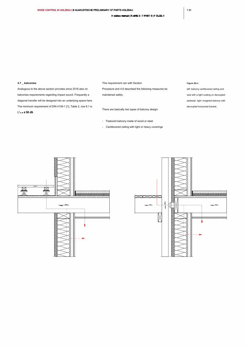
1 011 01NOISE CONTROL IN HOLZBAU | B AUAKUSTISCHE PRELIMINARY OF PARTS HOLZBAU NOISE CONTROL IN HOLZBAU | B AUAKUSTISCHE PRELIMINARY OF PARTS HOLZBAU NOISE CONTROL IN HOLZBAU | B AUAKUSTISCHE PRELIMINARY OF PARTS HOLZBAU
H olzbau manual | R eIHE 3 | T PART 3 | F OLGE 1H olzbau manual | R eIHE 3 | T PART 3 | F OLGE 1H olzbau manual | R eIHE 3 | T PART 3 | F OLGE 1H olzbau manual | R eIHE 3 | T PART 3 | F OLGE 1H olzbau manual | R eIHE 3 | T PART 3 | F OLGE 1H olzbau manual | R eIHE 3 | T PART 3 | F OLGE 1H olzbau manual | R eIHE 3 | T PART 3 | F OLGE 1H olzbau manual | R eIHE 3 | T PART 3 | F OLGE 1H olzbau manual | R eIHE 3 | T PART 3 | F OLGE 1H olzbau manual | R eIHE 3 | T PART 3 | F OLGE 1H olzbau manual | R eIHE 3 | T PART 3 | F OLGE 1
This requirement can with Section
Procedure and 4.6 described the following measures be
maintained safely.
There are basically two types of balcony design:
- Featured balcony made of wood or steel
- Cantilevered ceiling with light or heavy coverings
4.7 _ balconies
Analogous to the above section provides since 2018 also on
balconies requirements regarding impact sound. Frequently a
diagonal transfer will be designed into an underlying space here.
The minimum requirement of DIN 4109-1 [1], Table 2, row 8.1 is
L' n, w ≤ 58 dB.L' n, w ≤ 58 dB.L' n, w ≤ 58 dB.
Figure 28.4.:
left: balcony cantilevered ceiling and
seal with a light coating on decoupled
pedestal. right: imagined balcony with
decoupled horizontal bracket.
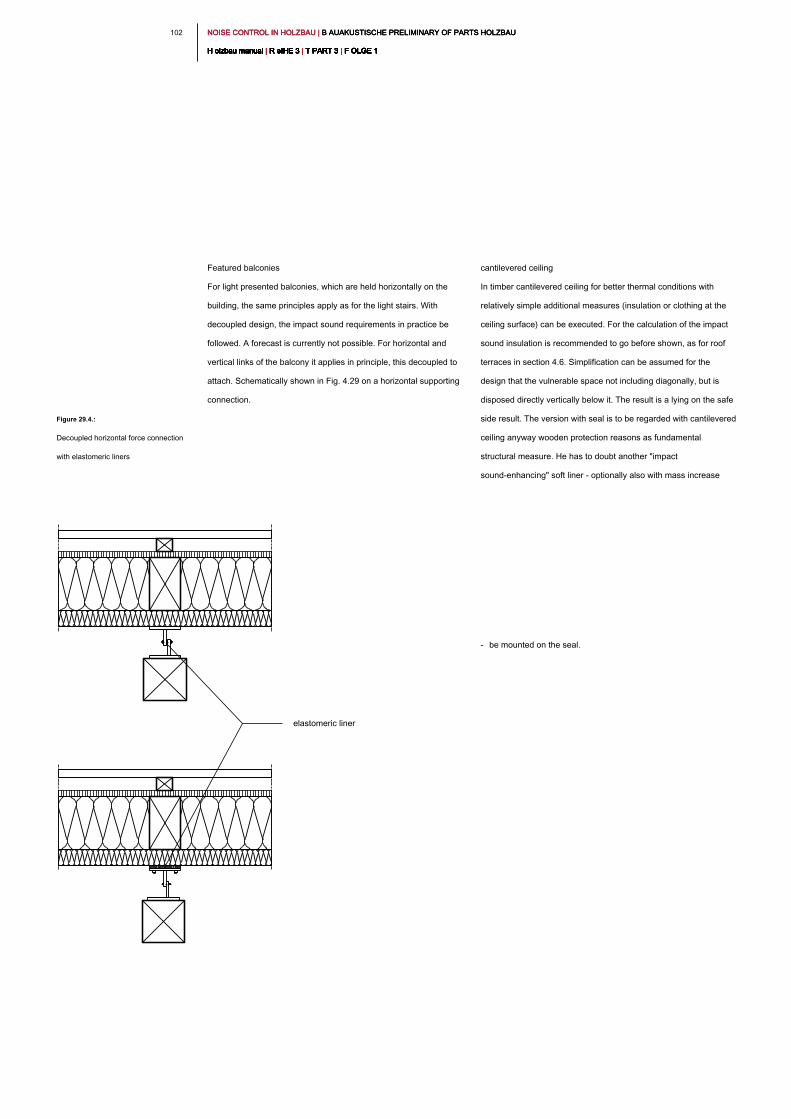
NOISE CONTROL IN HOLZBAU | B AUAKUSTISCHE PRELIMINARY OF PARTS HOLZBAU NOISE CONTROL IN HOLZBAU | B AUAKUSTISCHE PRELIMINARY OF PARTS HOLZBAU NOISE CONTROL IN HOLZBAU | B AUAKUSTISCHE PRELIMINARY OF PARTS HOLZBAU
H olzbau manual | R eIHE 3 | T PART 3 | F OLGE 1H olzbau manual | R eIHE 3 | T PART 3 | F OLGE 1H olzbau manual | R eIHE 3 | T PART 3 | F OLGE 1H olzbau manual | R eIHE 3 | T PART 3 | F OLGE 1H olzbau manual | R eIHE 3 | T PART 3 | F OLGE 1H olzbau manual | R eIHE 3 | T PART 3 | F OLGE 1H olzbau manual | R eIHE 3 | T PART 3 | F OLGE 1H olzbau manual | R eIHE 3 | T PART 3 | F OLGE 1H olzbau manual | R eIHE 3 | T PART 3 | F OLGE 1H olzbau manual | R eIHE 3 | T PART 3 | F OLGE 1H olzbau manual | R eIHE 3 | T PART 3 | F OLGE 1
102
cantilevered ceiling
In timber cantilevered ceiling for better thermal conditions with
relatively simple additional measures (insulation or clothing at the
ceiling surface) can be executed. For the calculation of the impact
sound insulation is recommended to go before shown, as for roof
terraces in section 4.6. Simplification can be assumed for the
design that the vulnerable space not including diagonally, but is
disposed directly vertically below it. The result is a lying on the safe
side result. The version with seal is to be regarded with cantilevered
ceiling anyway wooden protection reasons as fundamental
structural measure. He has to doubt another "impact
sound-enhancing" soft liner - optionally also with mass increase
- be mounted on the seal.
Featured balconies
For light presented balconies, which are held horizontally on the
building, the same principles apply as for the light stairs. With
decoupled design, the impact sound requirements in practice be
followed. A forecast is currently not possible. For horizontal and
vertical links of the balcony it applies in principle, this decoupled to
attach. Schematically shown in Fig. 4.29 on a horizontal supporting
connection.
Figure 29.4.:
Decoupled horizontal force connection
with elastomeric liners
elastomeric liner
1 031 03NOISE CONTROL IN HOLZBAU | B AUAKUSTISCHE PRELIMINARY OF PARTS HOLZBAU NOISE CONTROL IN HOLZBAU | B AUAKUSTISCHE PRELIMINARY OF PARTS HOLZBAU NOISE CONTROL IN HOLZBAU | B AUAKUSTISCHE PRELIMINARY OF PARTS HOLZBAU
H olzbau manual | R eIHE 3 | T PART 3 | F OLGE 1H olzbau manual | R eIHE 3 | T PART 3 | F OLGE 1H olzbau manual | R eIHE 3 | T PART 3 | F OLGE 1H olzbau manual | R eIHE 3 | T PART 3 | F OLGE 1H olzbau manual | R eIHE 3 | T PART 3 | F OLGE 1H olzbau manual | R eIHE 3 | T PART 3 | F OLGE 1H olzbau manual | R eIHE 3 | T PART 3 | F OLGE 1H olzbau manual | R eIHE 3 | T PART 3 | F OLGE 1H olzbau manual | R eIHE 3 | T PART 3 | F OLGE 1H olzbau manual | R eIHE 3 | T PART 3 | F OLGE 1H olzbau manual | R eIHE 3 | T PART 3 | F OLGE 1
Individual noise peaks when operating the valves are not to be
considered.
Other in-house, fixed technical sound sources of technical
equipment, supply and disposal as well as garage facilities
Minimum value: L AF, max, n ≤ 30 dB (A) DIN 4109-1: Minimum value: L AF, max, n ≤ 30 dB (A) DIN 4109-1: Minimum value: L AF, max, n ≤ 30 dB (A) DIN 4109-1:
2018 Table 9, row 2
also requirements in DIN 4109-1 [1], Table 11 are placed on fixtures
and appliances drinking water installations. For drinking water fittings
components can at this point be recommended only in principle to
choose attributable I of the acoustic group. Here, the slightest
Fließund flow noise can be reported. Also for the structure-borne
noise from building services no prediction methods are currently
available for the wood but also the concrete construction. It is
possible to give only design recommendations. Embodiments
recommendations are given for various installations.
4.8 _ building equipment and sanitary articles
Also at the level that can be expected from building services,
demands are made. These generally apply to the following
installations:
- Supply and disposal installations
- transportation equipment
- permanently installed, industrial installations
As building services as defined above also apply
- Washing facilities
- Swimming facilities, saunas etc.
- sports facilities
- central vacuum
- Garage equipment
- permanently installed, exterior motor-driven sun
protection systems and shutters
- Insta fittings and equipment of water in
- lifts
Ignore the other hand, are allowed to stay mobile machines and
appliances such as washing machines or vacuum cleaners, which
are operated in their own living area. For multi-storey residential
buildings in residential and bedrooms, the requirements can be
numerically quantified as follows:
Sanitary engineering / plumbing (water supply and sewerage
systems together)
Minimum value: L AF, max, n ≤ Minimum value: L AF, max, n ≤ Minimum value: L AF, max, n ≤
30 dB (A)
DIN 4109-1: 2018 Table 9, line 1
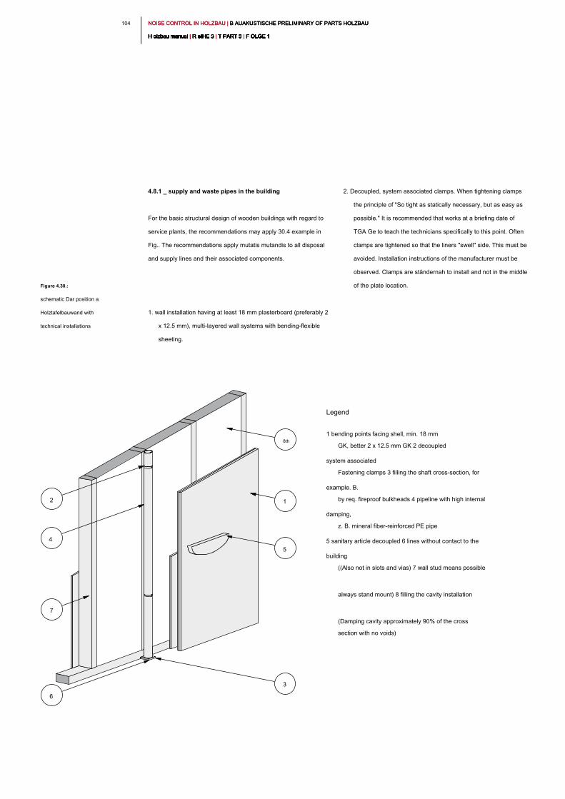
NOISE CONTROL IN HOLZBAU | B AUAKUSTISCHE PRELIMINARY OF PARTS HOLZBAU NOISE CONTROL IN HOLZBAU | B AUAKUSTISCHE PRELIMINARY OF PARTS HOLZBAU NOISE CONTROL IN HOLZBAU | B AUAKUSTISCHE PRELIMINARY OF PARTS HOLZBAU
H olzbau manual | R eIHE 3 | T PART 3 | F OLGE 1H olzbau manual | R eIHE 3 | T PART 3 | F OLGE 1H olzbau manual | R eIHE 3 | T PART 3 | F OLGE 1H olzbau manual | R eIHE 3 | T PART 3 | F OLGE 1H olzbau manual | R eIHE 3 | T PART 3 | F OLGE 1H olzbau manual | R eIHE 3 | T PART 3 | F OLGE 1H olzbau manual | R eIHE 3 | T PART 3 | F OLGE 1H olzbau manual | R eIHE 3 | T PART 3 | F OLGE 1H olzbau manual | R eIHE 3 | T PART 3 | F OLGE 1H olzbau manual | R eIHE 3 | T PART 3 | F OLGE 1H olzbau manual | R eIHE 3 | T PART 3 | F OLGE 1
104
2. Decoupled, system associated clamps. When tightening clamps
the principle of "So tight as statically necessary, but as easy as
possible." It is recommended that works at a briefing date of
TGA Ge to teach the technicians specifically to this point. Often
clamps are tightened so that the liners "swell" side. This must be
avoided. Installation instructions of the manufacturer must be
observed. Clamps are ständernah to install and not in the middle
of the plate location.
4.8.1 _ supply and waste pipes in the building
For the basic structural design of wooden buildings with regard to
service plants, the recommendations may apply 30.4 example in
Fig.. The recommendations apply mutatis mutandis to all disposal
and supply lines and their associated components.
1. wall installation having at least 18 mm plasterboard (preferably 2
x 12.5 mm), multi-layered wall systems with bending-flexible
sheeting.
Figure 4.30.:
schematic Dar position a
Holztafelbauwand with
technical installations
2
5
4
7
1
3
6
8th
Legend
1 bending points facing shell, min. 18 mm
GK, better 2 x 12.5 mm GK 2 decoupled
system associated
Fastening clamps 3 filling the shaft cross-section, for
example. B.
by req. fireproof bulkheads 4 pipeline with high internal
damping,
z. B. mineral fiber-reinforced PE pipe
5 sanitary article decoupled 6 lines without contact to the
building
((Also not in slots and vias) 7 wall stud means possible
always stand mount) 8 filling the cavity installation
(Damping cavity approximately 90% of the cross
section with no voids)
1 051 05NOISE CONTROL IN HOLZBAU | B AUAKUSTISCHE PRELIMINARY OF PARTS HOLZBAU NOISE CONTROL IN HOLZBAU | B AUAKUSTISCHE PRELIMINARY OF PARTS HOLZBAU NOISE CONTROL IN HOLZBAU | B AUAKUSTISCHE PRELIMINARY OF PARTS HOLZBAU
H olzbau manual | R eIHE 3 | T PART 3 | F OLGE 1H olzbau manual | R eIHE 3 | T PART 3 | F OLGE 1H olzbau manual | R eIHE 3 | T PART 3 | F OLGE 1H olzbau manual | R eIHE 3 | T PART 3 | F OLGE 1H olzbau manual | R eIHE 3 | T PART 3 | F OLGE 1H olzbau manual | R eIHE 3 | T PART 3 | F OLGE 1H olzbau manual | R eIHE 3 | T PART 3 | F OLGE 1H olzbau manual | R eIHE 3 | T PART 3 | F OLGE 1H olzbau manual | R eIHE 3 | T PART 3 | F OLGE 1H olzbau manual | R eIHE 3 | T PART 3 | F OLGE 1H olzbau manual | R eIHE 3 | T PART 3 | F OLGE 1
- Pipes and pipe clamps are attached to a separate substructure
of upright profiles (z. B. from stiffening UA) to be attached,
which shell or free standing and out of contact with the planking
plates were installed in the cavity.
- Reducing the flow pressure are to the minimum necessary, if
necessary, install Druckmin de rer or resting pressure at the
mixer must not exceed 0.5 MPa.
- Mounting the conduit and sanitary items in stand nearby.
- Pumps are to be equipped with pressure and suction sides
compensators such. As well as blocking masses.
- Pump switching devices or the like are also decoupled.
- In-line valves may only be used in the fully open position and
not as throttle valves.
- be allowed to fittings installed only in the flow class for which
they have been acoustically measured and valve outlet and
outlet device must flow class be in terms identical. That is, in the
hydraulic chain no element on the outlet side of a higher flow
class as the upstream elements.
- The installation instructions of the manufacturer to be mounted
on the substrate in question must be observed. Systems are
either suitable for massive installation or lightweight installation.
- Tubs and shower trays must be verified by the manufacturer
by means Musterprüfmessung.
3. filling of the shaft cross-section on the ceiling plane to line at least
with absorbent material. For a sound decoupling is hard on
building materials, the structure-borne sound bridges represent
to refrain. It is suitable for. As a necessary anyway soft firewall.
4. Mineral fiber-reinforced PE cables with sheath with high internal
damping or high basis weight.
5. Decoupled sanitary objects on the wall installation
(soundproofing sets).
6. lines must not touch the structure without separation. Avoid
sound bridges. Specifically, when laying the lines in slots should
be noted that there is no contact between the pipe and the
structure is present. This is especially true for the touch of
wood-based panels. Here it must be ensured that they have no
direct contact with lead.
7. represent routing of lines, if possible on walls that do not have
partitions to use foreign units.
8. Installation shafts inside are fully clothed with absorbent
material and to install close to the building structure.
9. 90 ° bends in the downpipes are to be avoided and z. to
replace, by 2 x 45 ° bends.
Other building acoustic design principles for the TGA installation are
shown in the following list:
- In lightweight installation walls of the CW studs (such as
described in DIN 18183-1) of the two sides of the wall tension by
means of tabs gypsum board strips or sheet metal profiles in the
amount of 1/3 and 2/3 of the wall height and pressure-proof with
one another to join.
NOISE CONTROL IN HOLZBAU | B AUAKUSTISCHE PRELIMINARY OF PARTS HOLZBAU NOISE CONTROL IN HOLZBAU | B AUAKUSTISCHE PRELIMINARY OF PARTS HOLZBAU NOISE CONTROL IN HOLZBAU | B AUAKUSTISCHE PRELIMINARY OF PARTS HOLZBAU
H olzbau manual | R eIHE 3 | T PART 3 | F OLGE 1H olzbau manual | R eIHE 3 | T PART 3 | F OLGE 1H olzbau manual | R eIHE 3 | T PART 3 | F OLGE 1H olzbau manual | R eIHE 3 | T PART 3 | F OLGE 1H olzbau manual | R eIHE 3 | T PART 3 | F OLGE 1H olzbau manual | R eIHE 3 | T PART 3 | F OLGE 1H olzbau manual | R eIHE 3 | T PART 3 | F OLGE 1H olzbau manual | R eIHE 3 | T PART 3 | F OLGE 1H olzbau manual | R eIHE 3 | T PART 3 | F OLGE 1H olzbau manual | R eIHE 3 | T PART 3 | F OLGE 1H olzbau manual | R eIHE 3 | T PART 3 | F OLGE 1
106
4.8.3 _ chimneys and shafts through living rooms
If a chimney with flue block or installation shafts (z. B. pure electric
installation shafts) through living rooms, these are sound technical
improvements through a furring due to the low mass of the mantle
rocks. The construction should be carried out as follows:
- Distance of a flexurally soft stand at least 10 mm without
contacting the shaft wall.
- Metal upright profiles at least 75 mm, at least. 60% with
absorbent material filled.
- At least a simple soft bending cladding with 15 mm
plasterboard (better 2 x 12.5 mm) high basis weight.
4.8.4 _ Lifts
Similarly as in the previous sections, no calculation method is
available for building acoustic design of lift systems. It can be made
to the construction union Through education in this section only
constructive information. The special feature of elevators is that
they both airborne noise excitation cause as well as a
structure-borne noise. Although the components and their ability
increases as the airborne sound insulation for sound insulation, but
a prediction method can not be directly derived therefrom.
4.8.2 _ Ventilation systems
be in terms of sound pressure level, to put this cause,
requirements for ventilation systems. These values apply for their
own living area.
Minimum requirement: L AF, max, n ≤ Minimum requirement: L AF, max, n ≤ Minimum requirement: L AF, max, n ≤
30 dB (A)
In addition, individual noise peaks when switching on and off
may max. be 5 dB higher, DIN 4109-1: 2018 Table 10 line. 1
The stated requirement here is independent of the design, in most
cases, if the installation instructions are complied with for the
respective construction. Which adjusting standard sound pressure
level in the room then depends on the following factors:
- Air volume flow [m³ / h]
- Flow velocity [m / s]
- Geometry of the exhaust valves
- Machine noise of the drive
In the test certificates the desired sound pressure level L are AF, In the test certificates the desired sound pressure level L are AF,
max, n given function of the air volume flow for the respective max, n given function of the air volume flow for the respective
ventilation unit. This means that the architectural acoustics is to
agree with the ventilation concept from. The air flow rates have to
be adjusted if necessary to comply with the noise protection
requirements. However, it must be considered whether
compliance with the acoustic requirements still sufficient minimum
volume flows are available.
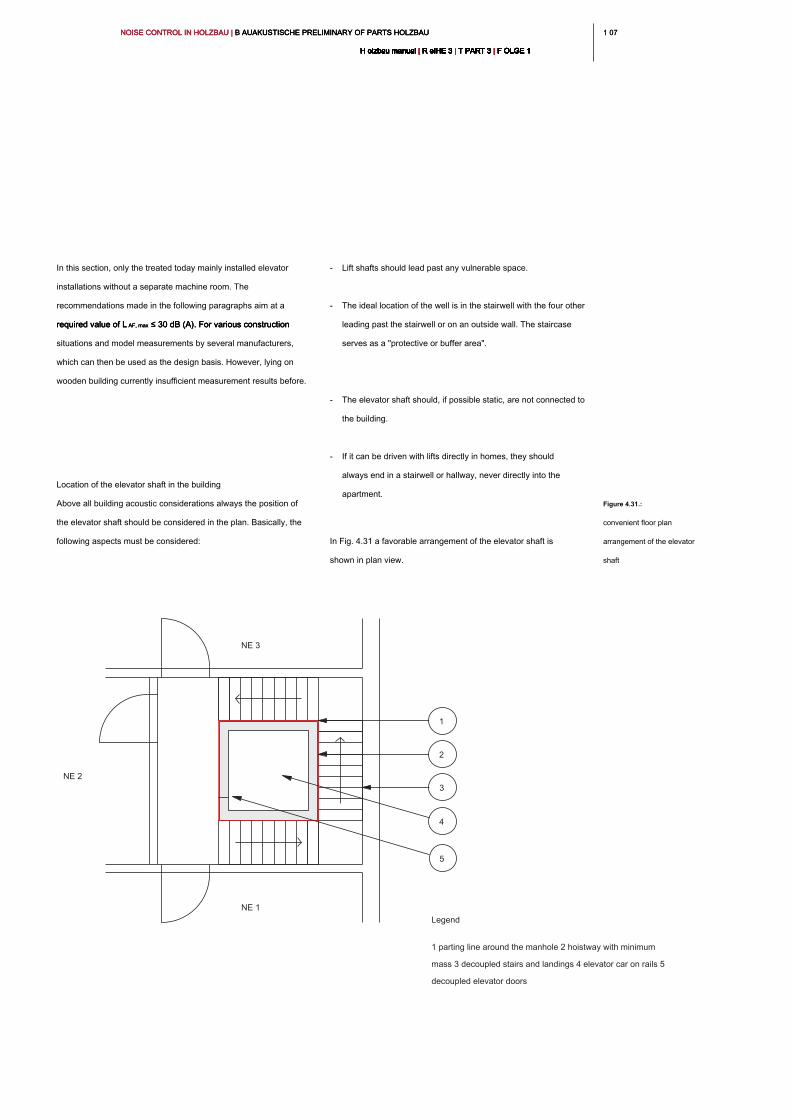
1 071 07NOISE CONTROL IN HOLZBAU | B AUAKUSTISCHE PRELIMINARY OF PARTS HOLZBAU NOISE CONTROL IN HOLZBAU | B AUAKUSTISCHE PRELIMINARY OF PARTS HOLZBAU NOISE CONTROL IN HOLZBAU | B AUAKUSTISCHE PRELIMINARY OF PARTS HOLZBAU
H olzbau manual | R eIHE 3 | T PART 3 | F OLGE 1H olzbau manual | R eIHE 3 | T PART 3 | F OLGE 1H olzbau manual | R eIHE 3 | T PART 3 | F OLGE 1H olzbau manual | R eIHE 3 | T PART 3 | F OLGE 1H olzbau manual | R eIHE 3 | T PART 3 | F OLGE 1H olzbau manual | R eIHE 3 | T PART 3 | F OLGE 1H olzbau manual | R eIHE 3 | T PART 3 | F OLGE 1H olzbau manual | R eIHE 3 | T PART 3 | F OLGE 1H olzbau manual | R eIHE 3 | T PART 3 | F OLGE 1H olzbau manual | R eIHE 3 | T PART 3 | F OLGE 1H olzbau manual | R eIHE 3 | T PART 3 | F OLGE 1
- Lift shafts should lead past any vulnerable space.
- The ideal location of the well is in the stairwell with the four other
leading past the stairwell or on an outside wall. The staircase
serves as a "protective or buffer area".
- The elevator shaft should, if possible static, are not connected to
the building.
- If it can be driven with lifts directly in homes, they should
always end in a stairwell or hallway, never directly into the
apartment.
In Fig. 4.31 a favorable arrangement of the elevator shaft is
shown in plan view.
In this section, only the treated today mainly installed elevator
installations without a separate machine room. The
recommendations made in the following paragraphs aim at a
required value of L AF, max ≤ 30 dB (A). For various construction required value of L AF, max ≤ 30 dB (A). For various construction required value of L AF, max ≤ 30 dB (A). For various construction
situations and model measurements by several manufacturers,
which can then be used as the design basis. However, lying on
wooden building currently insufficient measurement results before.
Location of the elevator shaft in the building
Above all building acoustic considerations always the position of
the elevator shaft should be considered in the plan. Basically, the
following aspects must be considered:
Figure 4.31.:
convenient floor plan
arrangement of the elevator
shaft
NE 3
NE 2
NE 1
1
2
3
4
5
Legend
1 parting line around the manhole 2 hoistway with minimum
mass 3 decoupled stairs and landings 4 elevator car on rails 5
decoupled elevator doors
NOISE CONTROL IN HOLZBAU | B AUAKUSTISCHE PRELIMINARY OF PARTS HOLZBAU NOISE CONTROL IN HOLZBAU | B AUAKUSTISCHE PRELIMINARY OF PARTS HOLZBAU NOISE CONTROL IN HOLZBAU | B AUAKUSTISCHE PRELIMINARY OF PARTS HOLZBAU
H olzbau manual | R eIHE 3 | T PART 3 | F OLGE 1H olzbau manual | R eIHE 3 | T PART 3 | F OLGE 1H olzbau manual | R eIHE 3 | T PART 3 | F OLGE 1H olzbau manual | R eIHE 3 | T PART 3 | F OLGE 1H olzbau manual | R eIHE 3 | T PART 3 | F OLGE 1H olzbau manual | R eIHE 3 | T PART 3 | F OLGE 1H olzbau manual | R eIHE 3 | T PART 3 | F OLGE 1H olzbau manual | R eIHE 3 | T PART 3 | F OLGE 1H olzbau manual | R eIHE 3 | T PART 3 | F OLGE 1H olzbau manual | R eIHE 3 | T PART 3 | F OLGE 1H olzbau manual | R eIHE 3 | T PART 3 | F OLGE 1
108
case B
Similar to Case A, the situation for lift shafts in stairwells are in
wood. To date no planning tools available for this case. Therefore,
an analogy may be prepared by the illustrated for the case A
recommendations for pre-calculation:
- Elevator shaft mass m'≥ 480 kg / m²,
R w ≈ 60.5 dB (z. B. d = 20 cm reinforced concrete)R w ≈ 60.5 dB (z. B. d = 20 cm reinforced concrete)R w ≈ 60.5 dB (z. B. d = 20 cm reinforced concrete)
- Stairwell walls in wood construction, R w ≥ 58 dB, for example. Stairwell walls in wood construction, R w ≥ 58 dB, for example. Stairwell walls in wood construction, R w ≥ 58 dB, for example.
B. Chapter 6, Table 41, line 5
- Easy elastic mounting of the lift rails EL1 according to VDI
2566, Sheet 2
- Wooden ceiling structure completely separate from the
elevator shaft
It is further to be noted that at the time of publication of this writing
there were no measurement data or planning data for this case.
Evidence is therefore always to keep in close coordination with
architectural acoustics or the manufacturer.
For wooden building two main cases can be distinguished:
A solid elevator shaft in a A solid elevator shaft in a
massive staircase
B solid elevator shaft in a B solid elevator shaft in a
Staircase in wood construction
There are other variants that are not shown separately here. For all
other cases, for example, have no budget room arrangement, the
manufacturers of elevators and construction work to be performed
acoustician. For example, the dimensions of facings to rooms
requiring protection or similar compensation measures take place
through an architectural acoustics.
case A
As in a massive building communicates with VDI 2566 Part 2 [23] a
comprehensive tool for planning of the lift available. It should, in
close cooperation with the manufacturer of the elevator, and one
architectural acoustics, the design of the elevator shaft walls and
the stairwells possibly be made.
. As reference values for the case with the A in Fig shown low
floor plan situation 31/4 following values can be used for
preliminary design:
- Elevator shaft mass m'≥ 480 kg / m²,
R w ≈ 60.5 dB (z. B. d = 20 cm reinforced concrete)R w ≈ 60.5 dB (z. B. d = 20 cm reinforced concrete)R w ≈ 60.5 dB (z. B. d = 20 cm reinforced concrete)
- Massive staircase walls and flanking components m'≥ 480 kg /
m², R w ≈ 57.5 dB m², R w ≈ 57.5 dB m², R w ≈ 57.5 dB
- Easy elastic mounting of the lift rails EL1 according to VDI
2566, Sheet 2
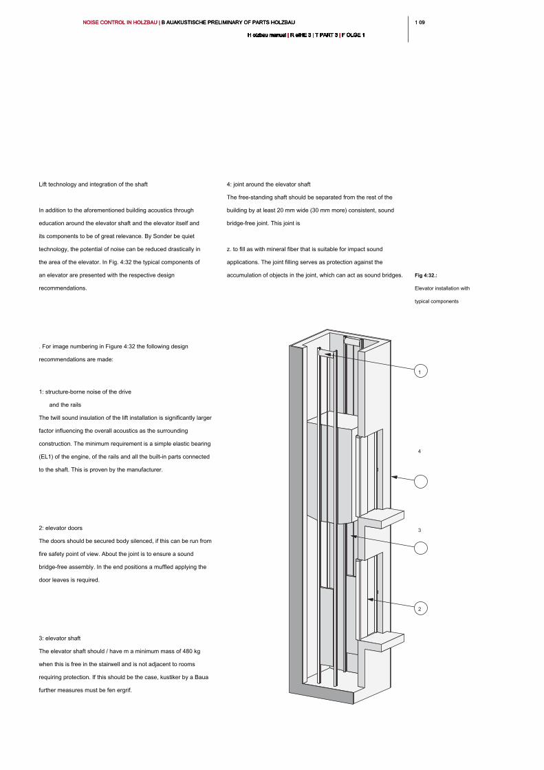
1 091 09NOISE CONTROL IN HOLZBAU | B AUAKUSTISCHE PRELIMINARY OF PARTS HOLZBAU NOISE CONTROL IN HOLZBAU | B AUAKUSTISCHE PRELIMINARY OF PARTS HOLZBAU NOISE CONTROL IN HOLZBAU | B AUAKUSTISCHE PRELIMINARY OF PARTS HOLZBAU
H olzbau manual | R eIHE 3 | T PART 3 | F OLGE 1H olzbau manual | R eIHE 3 | T PART 3 | F OLGE 1H olzbau manual | R eIHE 3 | T PART 3 | F OLGE 1H olzbau manual | R eIHE 3 | T PART 3 | F OLGE 1H olzbau manual | R eIHE 3 | T PART 3 | F OLGE 1H olzbau manual | R eIHE 3 | T PART 3 | F OLGE 1H olzbau manual | R eIHE 3 | T PART 3 | F OLGE 1H olzbau manual | R eIHE 3 | T PART 3 | F OLGE 1H olzbau manual | R eIHE 3 | T PART 3 | F OLGE 1H olzbau manual | R eIHE 3 | T PART 3 | F OLGE 1H olzbau manual | R eIHE 3 | T PART 3 | F OLGE 1
4: joint around the elevator shaft
The free-standing shaft should be separated from the rest of the
building by at least 20 mm wide (30 mm more) consistent, sound
bridge-free joint. This joint is
z. to fill as with mineral fiber that is suitable for impact sound
applications. The joint filling serves as protection against the
accumulation of objects in the joint, which can act as sound bridges.
Lift technology and integration of the shaft
In addition to the aforementioned building acoustics through
education around the elevator shaft and the elevator itself and
its components to be of great relevance. By Sonder be quiet
technology, the potential of noise can be reduced drastically in
the area of the elevator. In Fig. 4:32 the typical components of
an elevator are presented with the respective design
recommendations.
. For image numbering in Figure 4:32 the following design
recommendations are made:
1: structure-borne noise of the drive
and the rails
The twill sound insulation of the lift installation is significantly larger
factor influencing the overall acoustics as the surrounding
construction. The minimum requirement is a simple elastic bearing
(EL1) of the engine, of the rails and all the built-in parts connected
to the shaft. This is proven by the manufacturer.
2: elevator doors
The doors should be secured body silenced, if this can be run from
fire safety point of view. About the joint is to ensure a sound
bridge-free assembly. In the end positions a muffled applying the
door leaves is required.
3: elevator shaft
The elevator shaft should / have m a minimum mass of 480 kg
when this is free in the stairwell and is not adjacent to rooms
requiring protection. If this should be the case, kustiker by a Baua
further measures must be fen ergrif.
Fig 4:32.:
Elevator installation with
typical components
2
3
4
1
NOISE CONTROL IN HOLZBAU | B AUAKUSTISCHE PRELIMINARY OF PARTS HOLZBAU NOISE CONTROL IN HOLZBAU | B AUAKUSTISCHE PRELIMINARY OF PARTS HOLZBAU NOISE CONTROL IN HOLZBAU | B AUAKUSTISCHE PRELIMINARY OF PARTS HOLZBAU
H olzbau manual | R eIHE 3 | T PART 3 | F OLGE 1H olzbau manual | R eIHE 3 | T PART 3 | F OLGE 1H olzbau manual | R eIHE 3 | T PART 3 | F OLGE 1H olzbau manual | R eIHE 3 | T PART 3 | F OLGE 1H olzbau manual | R eIHE 3 | T PART 3 | F OLGE 1H olzbau manual | R eIHE 3 | T PART 3 | F OLGE 1H olzbau manual | R eIHE 3 | T PART 3 | F OLGE 1H olzbau manual | R eIHE 3 | T PART 3 | F OLGE 1H olzbau manual | R eIHE 3 | T PART 3 | F OLGE 1H olzbau manual | R eIHE 3 | T PART 3 | F OLGE 1H olzbau manual | R eIHE 3 | T PART 3 | F OLGE 1
110
value to the outdoor component. The request must be calculated
depending on the location in the noise environment for each room
or any building. , Is of crucial importance where the external noise
components are exposed to be examined space of the. Here, the
authoritative outdoor noise level L must a be quantified as exposure authoritative outdoor noise level L must a be quantified as exposure authoritative outdoor noise level L must a be quantified as exposure
size. The determination of the relevant exterior noise level is
especially when multiple noise sources such. As road and rail meet,
a task for acoustic engineers. As part of the preliminary design
excerpts in this document relevant external noise levels are shown
for certain traffic situations.
The calculation method in accordance with DIN 4109-2 [1] takes
into account the transfer of be adjacent external components and
flanking internal components. For timber construction results in the
favorable situation that these flanking transmission may be
considered in many cases outside noise impact to be negligible.
This allows a rough estimate of the required building acoustic
quality facade elements as presented in Section 4.9.3.
4.9 _ external components
In principle, the dimensioning of the external components is similarly
constructed to the external noise, as the method for the transmission
of airborne sound in the interior of buildings. Again, the contributions
of all components, the sound energy can be transferred from outside
into the interior, based on an "interface" and then energetically
added. However, in this case, the entire contaminated with noise,
seen from the inside surface (S S) a living or lounge as "release seen from the inside surface (S S) a living or lounge as "release seen from the inside surface (S S) a living or lounge as "release
surface", and the ratio for the respective component surface (S i / S S) seen surface", and the ratio for the respective component surface (S i / S S) seen surface", and the ratio for the respective component surface (S i / S S) seen surface", and the ratio for the respective component surface (S i / S S) seen surface", and the ratio for the respective component surface (S i / S S) seen
as a reference. In addition, the ratio of the base surface (S G) the as a reference. In addition, the ratio of the base surface (S G) the as a reference. In addition, the ratio of the base surface (S G) the
space in comparison to the noise component loaded outer surface
taken into consideration. Has a large outdoor space component
surfaces in relation to the base, then the demand increases for
these components to ensure the same level of protection as sound
in a room with more favorable surface conditions. This unfavorable
constellation, for example, at a loft in the corner position of the case,
the noise may face in the three sides.
When protection against external noise there as opposed to the
partition members inside the building no fixed requirement
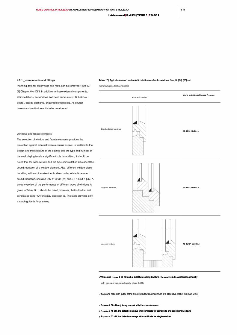
1 111 11NOISE CONTROL IN HOLZBAU | B AUAKUSTISCHE PRELIMINARY OF PARTS HOLZBAU NOISE CONTROL IN HOLZBAU | B AUAKUSTISCHE PRELIMINARY OF PARTS HOLZBAU NOISE CONTROL IN HOLZBAU | B AUAKUSTISCHE PRELIMINARY OF PARTS HOLZBAU
H olzbau manual | R eIHE 3 | T PART 3 | F OLGE 1H olzbau manual | R eIHE 3 | T PART 3 | F OLGE 1H olzbau manual | R eIHE 3 | T PART 3 | F OLGE 1H olzbau manual | R eIHE 3 | T PART 3 | F OLGE 1H olzbau manual | R eIHE 3 | T PART 3 | F OLGE 1H olzbau manual | R eIHE 3 | T PART 3 | F OLGE 1H olzbau manual | R eIHE 3 | T PART 3 | F OLGE 1H olzbau manual | R eIHE 3 | T PART 3 | F OLGE 1H olzbau manual | R eIHE 3 | T PART 3 | F OLGE 1H olzbau manual | R eIHE 3 | T PART 3 | F OLGE 1H olzbau manual | R eIHE 3 | T PART 3 | F OLGE 1
4.9.1 _ components and fittings
Planning data for outer walls and roofs can be removed 4109-33
[1] Chapter 6 or DIN. In addition to these external components,
all installations, so windows and patio doors are (z. B. balcony
doors), facade elements, shading elements (eg. As shutter
boxes) and ventilation units to be considered.
Windows and facade elements
The selection of window and facade elements provides the
protection against external noise a central aspect. In addition to the
design and the structure of the glazing and the type and number of
the seal playing levels a significant role. In addition, it should be
noted that the window size and the type of installation also affect the
sound reduction of a window element. Also, different window sizes
be sitting with an otherwise identical run under schiedliche rated
sound reduction, see also DIN 4109-35 [24] and EN 14351-1 [25]. A
broad overview of the performance of different types of windows is
given in Table 17. It should be noted, however, that individual test
certificates better Anyone may also post te. The table provides only
a rough guide is for planning.
Table 17 | Typical values of reachable Schalldämmmaßen for windows. See, B. [24], [25] and Table 17 | Typical values of reachable Schalldämmmaßen for windows. See, B. [24], [25] and
manufacturer's test certificates
schematic design
sound reduction achievable R w, windowsound reduction achievable R w, window
Simply glazed windows
30 dB to 40 dB 1) 5)30 dB to 40 dB 1) 5)
Coupled windows 35 dB to 50 dB 2), 4)35 dB to 50 dB 2), 4)
casement windows 45 dB to> 50 dB 3), 4)45 dB to> 50 dB 3), 4)
1) With slices R w, glass ≥ 50 dB and at least two sealing levels to R w, window ≈ 45 dB, accessible generally 1) With slices R w, glass ≥ 50 dB and at least two sealing levels to R w, window ≈ 45 dB, accessible generally 1) With slices R w, glass ≥ 50 dB and at least two sealing levels to R w, window ≈ 45 dB, accessible generally 1) With slices R w, glass ≥ 50 dB and at least two sealing levels to R w, window ≈ 45 dB, accessible generally 1) With slices R w, glass ≥ 50 dB and at least two sealing levels to R w, window ≈ 45 dB, accessible generally 1) With slices R w, glass ≥ 50 dB and at least two sealing levels to R w, window ≈ 45 dB, accessible generally
with panes of laminated safety glass (LSG)
2) the sound reduction index of the overall window is a maximum of 5 dB above that of the main wing2) the sound reduction index of the overall window is a maximum of 5 dB above that of the main wing
3) R w, window ≥ 50 dB only in agreement with the manufacturers 3) R w, window ≥ 50 dB only in agreement with the manufacturers 3) R w, window ≥ 50 dB only in agreement with the manufacturers 3) R w, window ≥ 50 dB only in agreement with the manufacturers
4) R w, window ≥ 45 dB, the detection always with certificate for composite and casement windows4) R w, window ≥ 45 dB, the detection always with certificate for composite and casement windows4) R w, window ≥ 45 dB, the detection always with certificate for composite and casement windows4) R w, window ≥ 45 dB, the detection always with certificate for composite and casement windows
5) R w, window ≥ 32 dB, the detection always with certificate for single window5) R w, window ≥ 32 dB, the detection always with certificate for single window5) R w, window ≥ 32 dB, the detection always with certificate for single window5) R w, window ≥ 32 dB, the detection always with certificate for single window
NOISE CONTROL IN HOLZBAU | B AUAKUSTISCHE PRELIMINARY OF PARTS HOLZBAU NOISE CONTROL IN HOLZBAU | B AUAKUSTISCHE PRELIMINARY OF PARTS HOLZBAU NOISE CONTROL IN HOLZBAU | B AUAKUSTISCHE PRELIMINARY OF PARTS HOLZBAU
H olzbau manual | R eIHE 3 | T PART 3 | F OLGE 1H olzbau manual | R eIHE 3 | T PART 3 | F OLGE 1H olzbau manual | R eIHE 3 | T PART 3 | F OLGE 1H olzbau manual | R eIHE 3 | T PART 3 | F OLGE 1H olzbau manual | R eIHE 3 | T PART 3 | F OLGE 1H olzbau manual | R eIHE 3 | T PART 3 | F OLGE 1H olzbau manual | R eIHE 3 | T PART 3 | F OLGE 1H olzbau manual | R eIHE 3 | T PART 3 | F OLGE 1H olzbau manual | R eIHE 3 | T PART 3 | F OLGE 1H olzbau manual | R eIHE 3 | T PART 3 | F OLGE 1H olzbau manual | R eIHE 3 | T PART 3 | F OLGE 1
112
volume flow has. It must therefore be considered, in which air flow
the test certificate indicating the acoustic characteristics and if so,
the desired air volume flow of the ventilation concept is maintained.
Similar issues arise with so-called Fensterfalzlüftern, here the built
number of elements are dependent on the manufacturer to consider
Reviewed sound reduction in dependency. Here, the sound
insulation of the window is indicated by the Fensterfalzlüfter as a
unit.
4.9.2 _ Special noise sources (heat pumps and
air conditioners)
The increasing use of renewable energy for heating buildings, the
proportion of heat pumps is increasing as a heating system.
Acoustically particular note are air heat pumps with external
devices. These will be built close to the building in many cases. is
critical here is that can not only lead the heat pump for their own
building to unwanted noise impact, but also the heat pump / -n
neighboring cultivations in combination with the own. This can lead
to an unfavorable accumulation of noise sources may. From an
acoustic point of view are primarily measures that focus on the
device itself beneficial. Here quieter equipment should be used and
also the devices are equipped for the night hours with a so-called.
"Whisper". Furthermore, the distance to the building and the
arrangement of building a substantial acoustic planning subject.
Here, both our own building and the neighboring buildings to be
considered. Fig. 4:33 shows favorable and rather un favorable
arrangements of air heat pumps.
shading elements
are shading devices on the weighted standard sound level
difference D n, e, wdifference D n, e, w
characterized. As a rule, must target values are specified for this
parameter in the early stages of planning, since they are heavily
dependent on the manufacturer. These characteristics are then to
prove on test certificates.
Note:
is widely used in test certificates D n, e, w, lab specified. This is widely used in test certificates D n, e, w, lab specified. This is widely used in test certificates D n, e, w, lab specified. This
characteristic value is measured in the laboratory weighted standard
sound level difference with the corresponding length of the test
specimen. the length is different from the incorporated shading
element to the "Labor length," so this value must be corrected
depending on length. As the length of the shading element and
whose sound insulating effect is reduced.
ventilation units
Fittings in wall components, such as de central ventilation units or
openings (forced ventilation) can be determined and sound
reduction are considered in detailed design method. This is for
ventilation concepts to be considered in the context particularly. In
the case of decentralized ventilation units must be taken that the
achievable sound insulation of the device or its review normalized
level difference D n, e, w a strong dependence of the conveyed airlevel difference D n, e, w a strong dependence of the conveyed airlevel difference D n, e, w a strong dependence of the conveyed air
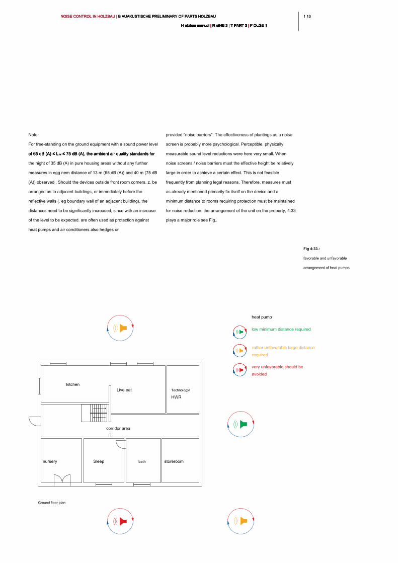
1 131 13NOISE CONTROL IN HOLZBAU | B AUAKUSTISCHE PRELIMINARY OF PARTS HOLZBAU NOISE CONTROL IN HOLZBAU | B AUAKUSTISCHE PRELIMINARY OF PARTS HOLZBAU NOISE CONTROL IN HOLZBAU | B AUAKUSTISCHE PRELIMINARY OF PARTS HOLZBAU
H olzbau manual | R eIHE 3 | T PART 3 | F OLGE 1H olzbau manual | R eIHE 3 | T PART 3 | F OLGE 1H olzbau manual | R eIHE 3 | T PART 3 | F OLGE 1H olzbau manual | R eIHE 3 | T PART 3 | F OLGE 1H olzbau manual | R eIHE 3 | T PART 3 | F OLGE 1H olzbau manual | R eIHE 3 | T PART 3 | F OLGE 1H olzbau manual | R eIHE 3 | T PART 3 | F OLGE 1H olzbau manual | R eIHE 3 | T PART 3 | F OLGE 1H olzbau manual | R eIHE 3 | T PART 3 | F OLGE 1H olzbau manual | R eIHE 3 | T PART 3 | F OLGE 1H olzbau manual | R eIHE 3 | T PART 3 | F OLGE 1
provided "noise barriers". The effectiveness of plantings as a noise
screen is probably more psychological. Perceptible, physically
measurable sound level reductions were here very small. When
noise screens / noise barriers must the effective height be relatively
large in order to achieve a certain effect. This is not feasible
frequently from planning legal reasons. Therefore, measures must
as already mentioned primarily fix itself on the device and a
minimum distance to rooms requiring protection must be maintained
for noise reduction. the arrangement of the unit on the property, 4:33
plays a major role see Fig..
Note:
For free-standing on the ground equipment with a sound power level
of 65 dB (A) ≤ L w ≤ 75 dB (A), the ambient air quality standards for of 65 dB (A) ≤ L w ≤ 75 dB (A), the ambient air quality standards for of 65 dB (A) ≤ L w ≤ 75 dB (A), the ambient air quality standards for
the night of 35 dB (A) in pure housing areas without any further
measures in egg nem distance of 13 m (65 dB (A)) and 40 m (75 dB
(A)) observed , Should the devices outside front room corners, z. be
arranged as to adjacent buildings, or immediately before the
reflective walls (. eg boundary wall of an adjacent building), the
distances need to be significantly increased, since with an increase
of the level to be expected. are often used as protection against
heat pumps and air conditioners also hedges or
Fig 4:33.:
favorable and unfavorable
arrangement of heat pumps
corridor area
Sleep bath storeroomnursery
Technology/Live eat
kitchen
Ground floor plan
low minimum distance required
rather unfavorable large distance
required
very unfavorable should be
avoided
heat pump
HWR
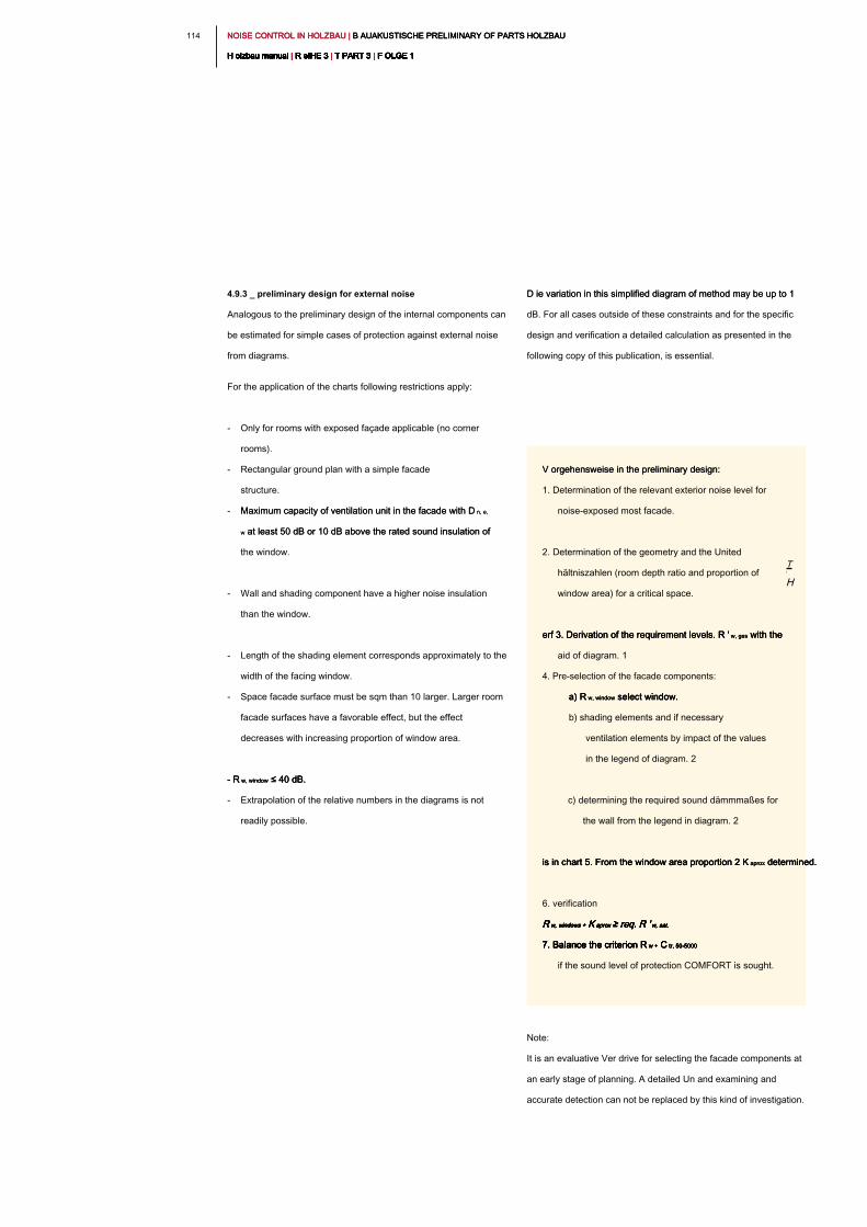
NOISE CONTROL IN HOLZBAU | B AUAKUSTISCHE PRELIMINARY OF PARTS HOLZBAU NOISE CONTROL IN HOLZBAU | B AUAKUSTISCHE PRELIMINARY OF PARTS HOLZBAU NOISE CONTROL IN HOLZBAU | B AUAKUSTISCHE PRELIMINARY OF PARTS HOLZBAU
H olzbau manual | R eIHE 3 | T PART 3 | F OLGE 1H olzbau manual | R eIHE 3 | T PART 3 | F OLGE 1H olzbau manual | R eIHE 3 | T PART 3 | F OLGE 1H olzbau manual | R eIHE 3 | T PART 3 | F OLGE 1H olzbau manual | R eIHE 3 | T PART 3 | F OLGE 1H olzbau manual | R eIHE 3 | T PART 3 | F OLGE 1H olzbau manual | R eIHE 3 | T PART 3 | F OLGE 1H olzbau manual | R eIHE 3 | T PART 3 | F OLGE 1H olzbau manual | R eIHE 3 | T PART 3 | F OLGE 1H olzbau manual | R eIHE 3 | T PART 3 | F OLGE 1H olzbau manual | R eIHE 3 | T PART 3 | F OLGE 1
114
D ie variation in this simplified diagram of method may be up to 1 D ie variation in this simplified diagram of method may be up to 1
dB. For all cases outside of these constraints and for the specific
design and verification a detailed calculation as presented in the
following copy of this publication, is essential.
Note:
It is an evaluative Ver drive for selecting the facade components at
an early stage of planning. A detailed Un and examining and
accurate detection can not be replaced by this kind of investigation.
4.9.3 _ preliminary design for external noise
Analogous to the preliminary design of the internal components can
be estimated for simple cases of protection against external noise
from diagrams.
For the application of the charts following restrictions apply:
- Only for rooms with exposed façade applicable (no corner
rooms).
- Rectangular ground plan with a simple facade
structure.
- Maximum capacity of ventilation unit in the facade with D n, e, Maximum capacity of ventilation unit in the facade with D n, e,
w at least 50 dB or 10 dB above the rated sound insulation of w at least 50 dB or 10 dB above the rated sound insulation of
the window.
- Wall and shading component have a higher noise insulation
than the window.
- Length of the shading element corresponds approximately to the
width of the facing window.
- Space facade surface must be sqm than 10 larger. Larger room
facade surfaces have a favorable effect, but the effect
decreases with increasing proportion of window area.
- R w, window ≤ 40 dB. - R w, window ≤ 40 dB. - R w, window ≤ 40 dB.
- Extrapolation of the relative numbers in the diagrams is not
readily possible.
T
H
V orgehensweise in the preliminary design:V orgehensweise in the preliminary design:
1. Determination of the relevant exterior noise level for
noise-exposed most facade.
2. Determination of the geometry and the United
hältniszahlen (room depth ratio and proportion of
window area) for a critical space.
erf 3. Derivation of the requirement levels. R ' w, ges with the erf 3. Derivation of the requirement levels. R ' w, ges with the erf 3. Derivation of the requirement levels. R ' w, ges with the
aid of diagram. 1
4. Pre-selection of the facade components:
a) R w, window select window. a) R w, window select window. a) R w, window select window.
b) shading elements and if necessary
ventilation elements by impact of the values
in the legend of diagram. 2
c) determining the required sound dämmmaßes for
the wall from the legend in diagram. 2
is in chart 5. From the window area proportion 2 K aprox determined.is in chart 5. From the window area proportion 2 K aprox determined.is in chart 5. From the window area proportion 2 K aprox determined.
6. verification
R w, windows + K aprox ≥ req. R ' w, sat.R w, windows + K aprox ≥ req. R ' w, sat.R w, windows + K aprox ≥ req. R ' w, sat.R w, windows + K aprox ≥ req. R ' w, sat.R w, windows + K aprox ≥ req. R ' w, sat.R w, windows + K aprox ≥ req. R ' w, sat.
7. Balance the criterion R w + C tr, 50-50007. Balance the criterion R w + C tr, 50-50007. Balance the criterion R w + C tr, 50-50007. Balance the criterion R w + C tr, 50-50007. Balance the criterion R w + C tr, 50-5000
if the sound level of protection COMFORT is sought.
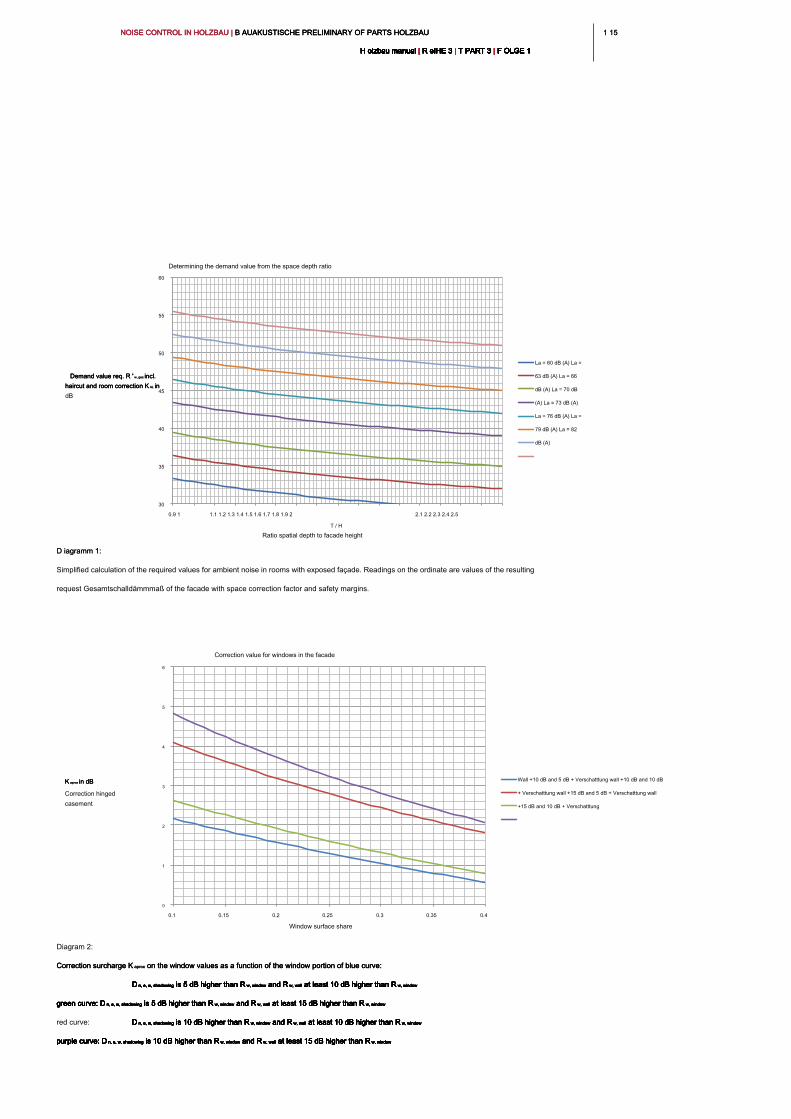
1 151 15NOISE CONTROL IN HOLZBAU | B AUAKUSTISCHE PRELIMINARY OF PARTS HOLZBAU NOISE CONTROL IN HOLZBAU | B AUAKUSTISCHE PRELIMINARY OF PARTS HOLZBAU NOISE CONTROL IN HOLZBAU | B AUAKUSTISCHE PRELIMINARY OF PARTS HOLZBAU
H olzbau manual | R eIHE 3 | T PART 3 | F OLGE 1H olzbau manual | R eIHE 3 | T PART 3 | F OLGE 1H olzbau manual | R eIHE 3 | T PART 3 | F OLGE 1H olzbau manual | R eIHE 3 | T PART 3 | F OLGE 1H olzbau manual | R eIHE 3 | T PART 3 | F OLGE 1H olzbau manual | R eIHE 3 | T PART 3 | F OLGE 1H olzbau manual | R eIHE 3 | T PART 3 | F OLGE 1H olzbau manual | R eIHE 3 | T PART 3 | F OLGE 1H olzbau manual | R eIHE 3 | T PART 3 | F OLGE 1H olzbau manual | R eIHE 3 | T PART 3 | F OLGE 1H olzbau manual | R eIHE 3 | T PART 3 | F OLGE 1
0
1
2
3
4
5
6
0.1 0.15 0.2 0.25 0.3 0.35 0.4
K aprox in dBK aprox in dBK aprox in dB
Correction hinged
casement
Window surface share
Correction value for windows in the facade
Wall +10 dB and 5 dB + Verschatttung wall +10 dB and 10 dB
+ Verschatttung wall +15 dB and 5 dB + Verschatttung wall
+15 dB and 10 dB + Verschatttung
30
35
40
45
50
55
60
0.9 1 1.1 1.2 1.3 1.4 1.5 1.6 1.7 1.8 1.9 2 2.1 2.2 2.3 2.4 2.5
Demand value req. R ' w, ges incl. Demand value req. R ' w, ges incl. Demand value req. R ' w, ges incl.
haircut and room correction K AL in haircut and room correction K AL in haircut and room correction K AL in
dB
T / H
Ratio spatial depth to facade height
Determining the demand value from the space depth ratio
La = 60 dB (A) La =
63 dB (A) La = 66
dB (A) La = 70 dB
(A) La = 73 dB (A)
La = 76 dB (A) La =
79 dB (A) La = 82
dB (A)
D iagramm 1: D iagramm 1:
Simplified calculation of the required values for ambient noise in rooms with exposed façade. Readings on the ordinate are values of the resulting
request Gesamtschalldämmmaß of the facade with space correction factor and safety margins.
Diagram 2:
Correction surcharge K aprox on the window values as a function of the window portion of blue curve: Correction surcharge K aprox on the window values as a function of the window portion of blue curve: Correction surcharge K aprox on the window values as a function of the window portion of blue curve:
D n, e, w, shadowing is 5 dB higher than R w, window and R w, wall at least 10 dB higher than R w, windowD n, e, w, shadowing is 5 dB higher than R w, window and R w, wall at least 10 dB higher than R w, windowD n, e, w, shadowing is 5 dB higher than R w, window and R w, wall at least 10 dB higher than R w, windowD n, e, w, shadowing is 5 dB higher than R w, window and R w, wall at least 10 dB higher than R w, windowD n, e, w, shadowing is 5 dB higher than R w, window and R w, wall at least 10 dB higher than R w, windowD n, e, w, shadowing is 5 dB higher than R w, window and R w, wall at least 10 dB higher than R w, windowD n, e, w, shadowing is 5 dB higher than R w, window and R w, wall at least 10 dB higher than R w, windowD n, e, w, shadowing is 5 dB higher than R w, window and R w, wall at least 10 dB higher than R w, window
green curve: D n, e, w, shadowing is 5 dB higher than R w, window and R w, wall at least 15 dB higher than R w, windowgreen curve: D n, e, w, shadowing is 5 dB higher than R w, window and R w, wall at least 15 dB higher than R w, windowgreen curve: D n, e, w, shadowing is 5 dB higher than R w, window and R w, wall at least 15 dB higher than R w, windowgreen curve: D n, e, w, shadowing is 5 dB higher than R w, window and R w, wall at least 15 dB higher than R w, windowgreen curve: D n, e, w, shadowing is 5 dB higher than R w, window and R w, wall at least 15 dB higher than R w, windowgreen curve: D n, e, w, shadowing is 5 dB higher than R w, window and R w, wall at least 15 dB higher than R w, windowgreen curve: D n, e, w, shadowing is 5 dB higher than R w, window and R w, wall at least 15 dB higher than R w, windowgreen curve: D n, e, w, shadowing is 5 dB higher than R w, window and R w, wall at least 15 dB higher than R w, window
red curve: D n, e, w, shadowing is 10 dB higher than R w, window and R w, wall at least 10 dB higher than R w, windowD n, e, w, shadowing is 10 dB higher than R w, window and R w, wall at least 10 dB higher than R w, windowD n, e, w, shadowing is 10 dB higher than R w, window and R w, wall at least 10 dB higher than R w, windowD n, e, w, shadowing is 10 dB higher than R w, window and R w, wall at least 10 dB higher than R w, windowD n, e, w, shadowing is 10 dB higher than R w, window and R w, wall at least 10 dB higher than R w, windowD n, e, w, shadowing is 10 dB higher than R w, window and R w, wall at least 10 dB higher than R w, windowD n, e, w, shadowing is 10 dB higher than R w, window and R w, wall at least 10 dB higher than R w, windowD n, e, w, shadowing is 10 dB higher than R w, window and R w, wall at least 10 dB higher than R w, window
purple curve: D n, e, w, shadowing is 10 dB higher than R w, window and R w, wall at least 15 dB higher than R w, windowpurple curve: D n, e, w, shadowing is 10 dB higher than R w, window and R w, wall at least 15 dB higher than R w, windowpurple curve: D n, e, w, shadowing is 10 dB higher than R w, window and R w, wall at least 15 dB higher than R w, windowpurple curve: D n, e, w, shadowing is 10 dB higher than R w, window and R w, wall at least 15 dB higher than R w, windowpurple curve: D n, e, w, shadowing is 10 dB higher than R w, window and R w, wall at least 15 dB higher than R w, windowpurple curve: D n, e, w, shadowing is 10 dB higher than R w, window and R w, wall at least 15 dB higher than R w, windowpurple curve: D n, e, w, shadowing is 10 dB higher than R w, window and R w, wall at least 15 dB higher than R w, windowpurple curve: D n, e, w, shadowing is 10 dB higher than R w, window and R w, wall at least 15 dB higher than R w, window
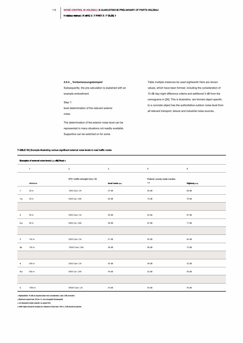
NOISE CONTROL IN HOLZBAU | B AUAKUSTISCHE PRELIMINARY OF PARTS HOLZBAU NOISE CONTROL IN HOLZBAU | B AUAKUSTISCHE PRELIMINARY OF PARTS HOLZBAU NOISE CONTROL IN HOLZBAU | B AUAKUSTISCHE PRELIMINARY OF PARTS HOLZBAU
H olzbau manual | R eIHE 3 | T PART 3 | F OLGE 1H olzbau manual | R eIHE 3 | T PART 3 | F OLGE 1H olzbau manual | R eIHE 3 | T PART 3 | F OLGE 1H olzbau manual | R eIHE 3 | T PART 3 | F OLGE 1H olzbau manual | R eIHE 3 | T PART 3 | F OLGE 1H olzbau manual | R eIHE 3 | T PART 3 | F OLGE 1H olzbau manual | R eIHE 3 | T PART 3 | F OLGE 1H olzbau manual | R eIHE 3 | T PART 3 | F OLGE 1H olzbau manual | R eIHE 3 | T PART 3 | F OLGE 1H olzbau manual | R eIHE 3 | T PART 3 | F OLGE 1H olzbau manual | R eIHE 3 | T PART 3 | F OLGE 1
116
Table multiple instances be used eighteenth Here are shown
values, which have been formed, including the consideration of
10 dB day-night difference criteria and additional 3 dB from the
nomograms in [26]. This is illustrative. are formed object specific
to a concrete object has the authoritative outdoor noise level from
all relevant transport, leisure and industrial noise sources.
4.9.4 _ Vorbemessungsbeispiel
Subsequently, the pre-calculation is explained with an
example embodiment.
Step 1:
level determination of the relevant exterior
noise.
The determination of the exterior noise level can be
represented in many situations not readily available.
Supportive can be switched on for some
T ABLE 18 | Excerpts illustrating various significant external noise levels in road traffic routesT ABLE 18 | Excerpts illustrating various significant external noise levels in road traffic routesT ABLE 18 | Excerpts illustrating various significant external noise levels in road traffic routes
Examples of external noise levels L A [ dB] Road 1)Examples of external noise levels L A [ dB] Road 1)Examples of external noise levels L A [ dB] Road 1)Examples of external noise levels L A [ dB] Road 1)
1 2 3 4 5
distance
DTV / traffic strength Cars / 24
local roads 2) 4)local roads 2) 4)
Federal, county roads Landes-
3) 4)
Highway 3) 4)Highway 3) 4)
1 25 m 1000 Cars / 24 57 dB 65 dB 69 dB
1 a 25 m 5000 Car / 24h 64 dB 72 dB 76 dB
2 50 m 2000 Cars / 24 55 dB 63 dB 67 dB
2 a 50 m 5000 Car / 24h 59 dB 67 dB 71 dB
3 100 m 2000 Cars / 24 51 dB 60 dB 64 dB
3a 100 m 10000 Cars / 24h 58 dB 66 dB 70 dB
4 500 m 2000 Cars / 24 40 dB 48 dB 52 dB
4 a 500 m 5000 Car / 24h 44 dB 52 dB 56 dB
5 1500 m 50000 Cars / 24 44 dB 50 dB 54 dB
1) Nightaddition 10 dB as required taken into consideration, also 3 dB correction1) Nightaddition 10 dB as required taken into consideration, also 3 dB correction
2) Maximum speed max. 50 km / h, not corrugated Gussaspahlt2) Maximum speed max. 50 km / h, not corrugated Gussaspahlt
3) not deseeded mastic asphalt, no speed limit3) not deseeded mastic asphalt, no speed limit
4) traffic lights should be located at a distance of less than 100 m, 2 dB should be pitched4) traffic lights should be located at a distance of less than 100 m, 2 dB should be pitched
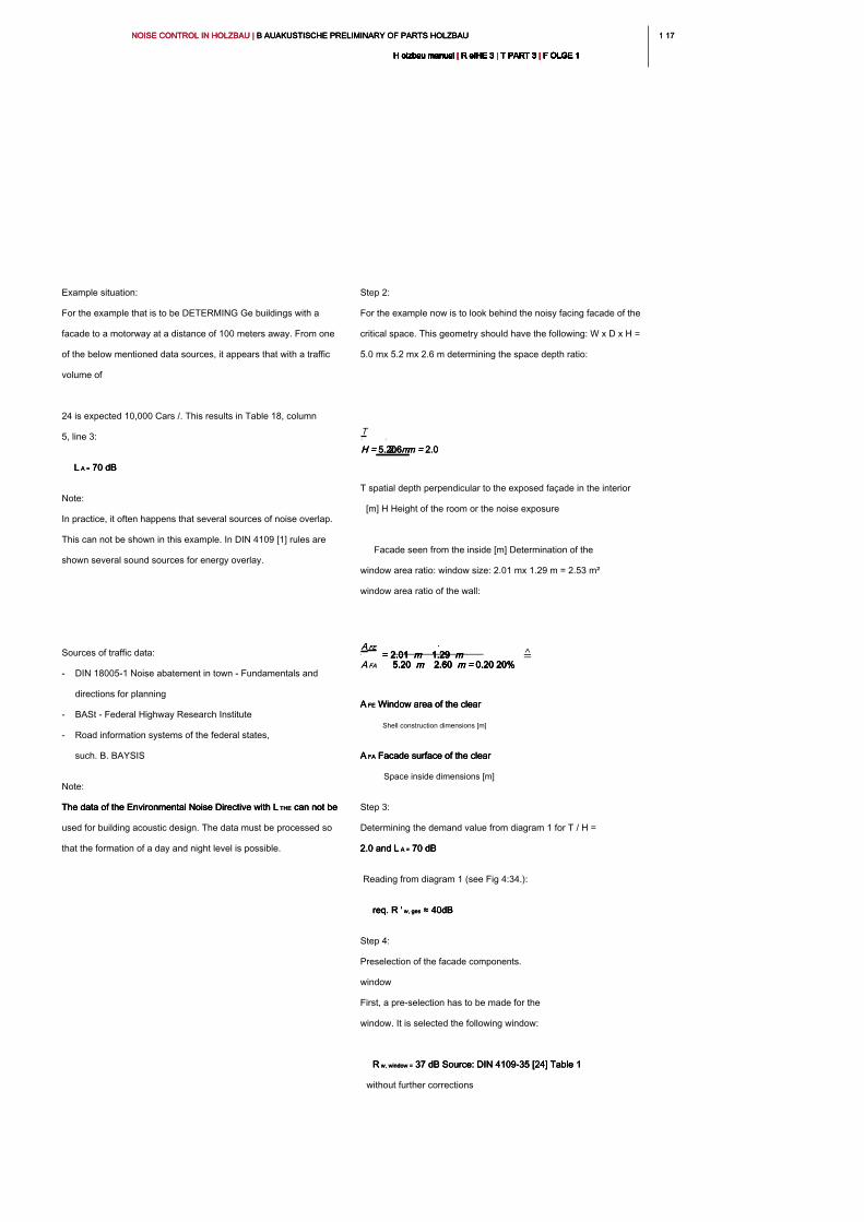
1 171 17NOISE CONTROL IN HOLZBAU | B AUAKUSTISCHE PRELIMINARY OF PARTS HOLZBAU NOISE CONTROL IN HOLZBAU | B AUAKUSTISCHE PRELIMINARY OF PARTS HOLZBAU NOISE CONTROL IN HOLZBAU | B AUAKUSTISCHE PRELIMINARY OF PARTS HOLZBAU
H olzbau manual | R eIHE 3 | T PART 3 | F OLGE 1H olzbau manual | R eIHE 3 | T PART 3 | F OLGE 1H olzbau manual | R eIHE 3 | T PART 3 | F OLGE 1H olzbau manual | R eIHE 3 | T PART 3 | F OLGE 1H olzbau manual | R eIHE 3 | T PART 3 | F OLGE 1H olzbau manual | R eIHE 3 | T PART 3 | F OLGE 1H olzbau manual | R eIHE 3 | T PART 3 | F OLGE 1H olzbau manual | R eIHE 3 | T PART 3 | F OLGE 1H olzbau manual | R eIHE 3 | T PART 3 | F OLGE 1H olzbau manual | R eIHE 3 | T PART 3 | F OLGE 1H olzbau manual | R eIHE 3 | T PART 3 | F OLGE 1
Step 2:
For the example now is to look behind the noisy facing facade of the
critical space. This geometry should have the following: W x D x H =
5.0 mx 5.2 mx 2.6 m determining the space depth ratio:
T spatial depth perpendicular to the exposed façade in the interior
[m] H Height of the room or the noise exposure
Facade seen from the inside [m] Determination of the
window area ratio: window size: 2.01 mx 1.29 m = 2.53 m²
window area ratio of the wall:
A FE Window area of the clear A FE Window area of the clear A FE Window area of the clear
Shell construction dimensions [m]
A FA Facade surface of the clear A FA Facade surface of the clear A FA Facade surface of the clear
Space inside dimensions [m]
Step 3:
Determining the demand value from diagram 1 for T / H =
2.0 and L A = 70 dB2.0 and L A = 70 dB2.0 and L A = 70 dB
Reading from diagram 1 (see Fig 4:34.):
req. R ' w, ges ≈ 40dB req. R ' w, ges ≈ 40dB req. R ' w, ges ≈ 40dB
Step 4:
Preselection of the facade components.
window
First, a pre-selection has to be made for the
window. It is selected the following window:
R w, window = 37 dB Source: DIN 4109-35 [24] Table 1 R w, window = 37 dB Source: DIN 4109-35 [24] Table 1 R w, window = 37 dB Source: DIN 4109-35 [24] Table 1
without further corrections
Example situation:
For the example that is to be DETERMING Ge buildings with a
facade to a motorway at a distance of 100 meters away. From one
of the below mentioned data sources, it appears that with a traffic
volume of
24 is expected 10,000 Cars /. This results in Table 18, column
5, line 3:
L A = 70 dBL A = 70 dBL A = 70 dB
Note:
In practice, it often happens that several sources of noise overlap.
This can not be shown in this example. In DIN 4109 [1] rules are
shown several sound sources for energy overlay.
Sources of traffic data:
- DIN 18005-1 Noise abatement in town - Fundamentals and
directions for planning
- BASt - Federal Highway Research Institute
- Road information systems of the federal states,
such. B. BAYSIS
Note:
The data of the Environmental Noise Directive with L THE can not be The data of the Environmental Noise Directive with L THE can not be The data of the Environmental Noise Directive with L THE can not be
used for building acoustic design. The data must be processed so
that the formation of a day and night level is possible.
A FEA FE
A FAA FA
= 2.01 m 1.29 m= 2.01 m 1.29 m= 2.01 m 1.29 m= 2.01 m 1.29 m= 2.01 m 1.29 m
5.20 m 2.60 m = 0.20 20%5.20 m 2.60 m = 0.20 20%5.20 m 2.60 m = 0.20 20%5.20 m 2.60 m = 0.20 20%5.20 m 2.60 m = 0.20 20%
T
H = 5.20 mH = 5.20 mH = 5.20 m2.6 m = 2.02.6 m = 2.02.6 m = 2.0
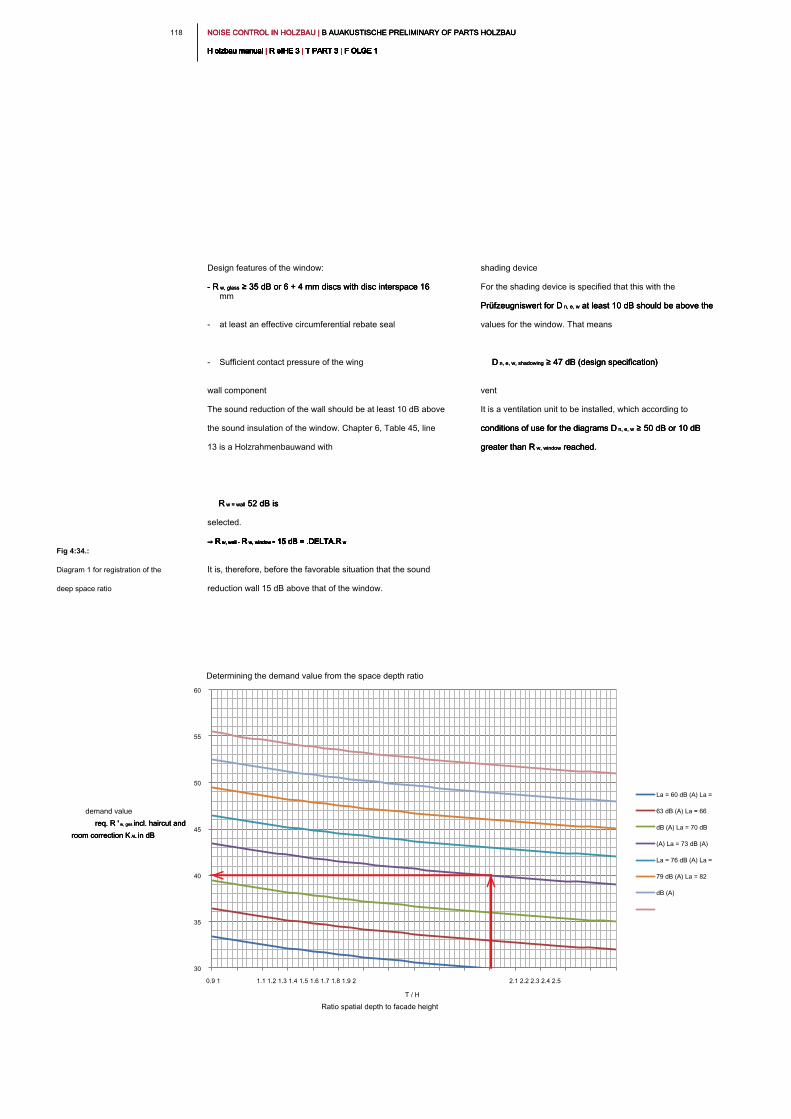
NOISE CONTROL IN HOLZBAU | B AUAKUSTISCHE PRELIMINARY OF PARTS HOLZBAU NOISE CONTROL IN HOLZBAU | B AUAKUSTISCHE PRELIMINARY OF PARTS HOLZBAU NOISE CONTROL IN HOLZBAU | B AUAKUSTISCHE PRELIMINARY OF PARTS HOLZBAU
H olzbau manual | R eIHE 3 | T PART 3 | F OLGE 1H olzbau manual | R eIHE 3 | T PART 3 | F OLGE 1H olzbau manual | R eIHE 3 | T PART 3 | F OLGE 1H olzbau manual | R eIHE 3 | T PART 3 | F OLGE 1H olzbau manual | R eIHE 3 | T PART 3 | F OLGE 1H olzbau manual | R eIHE 3 | T PART 3 | F OLGE 1H olzbau manual | R eIHE 3 | T PART 3 | F OLGE 1H olzbau manual | R eIHE 3 | T PART 3 | F OLGE 1H olzbau manual | R eIHE 3 | T PART 3 | F OLGE 1H olzbau manual | R eIHE 3 | T PART 3 | F OLGE 1H olzbau manual | R eIHE 3 | T PART 3 | F OLGE 1
118
shading device
For the shading device is specified that this with the
Prüfzeugniswert for D n, e, w at least 10 dB should be above the Prüfzeugniswert for D n, e, w at least 10 dB should be above the Prüfzeugniswert for D n, e, w at least 10 dB should be above the
values for the window. That means
D n, e, w, shadowing ≥ 47 dB (design specification)D n, e, w, shadowing ≥ 47 dB (design specification)D n, e, w, shadowing ≥ 47 dB (design specification)
vent
It is a ventilation unit to be installed, which according to
conditions of use for the diagrams D n, e, w ≥ 50 dB or 10 dB conditions of use for the diagrams D n, e, w ≥ 50 dB or 10 dB conditions of use for the diagrams D n, e, w ≥ 50 dB or 10 dB
greater than R w, window reached. greater than R w, window reached. greater than R w, window reached.
Design features of the window:
- R w, glass ≥ 35 dB or 6 + 4 mm discs with disc interspace 16 - R w, glass ≥ 35 dB or 6 + 4 mm discs with disc interspace 16 - R w, glass ≥ 35 dB or 6 + 4 mm discs with disc interspace 16
mm
- at least an effective circumferential rebate seal
- Sufficient contact pressure of the wing
wall component
The sound reduction of the wall should be at least 10 dB above
the sound insulation of the window. Chapter 6, Table 45, line
13 is a Holzrahmenbauwand with
R w = wall 52 dB is R w = wall 52 dB is R w = wall 52 dB is
selected.
→ R w, wall - R w, window = 15 dB = .DELTA.R w→ R w, wall - R w, window = 15 dB = .DELTA.R w→ R w, wall - R w, window = 15 dB = .DELTA.R w→ R w, wall - R w, window = 15 dB = .DELTA.R w→ R w, wall - R w, window = 15 dB = .DELTA.R w→ R w, wall - R w, window = 15 dB = .DELTA.R w→ R w, wall - R w, window = 15 dB = .DELTA.R w
It is, therefore, before the favorable situation that the sound
reduction wall 15 dB above that of the window.
Fig 4:34.:
Diagram 1 for registration of the
deep space ratio
30
35
40
45
50
55
60
0.9 1 1.1 1.2 1.3 1.4 1.5 1.6 1.7 1.8 1.9 2 2.1 2.2 2.3 2.4 2.5
demand value
req. R ' w, ges incl. haircut and req. R ' w, ges incl. haircut and req. R ' w, ges incl. haircut and
room correction K AL in dBroom correction K AL in dBroom correction K AL in dB
T / H
Ratio spatial depth to facade height
Determining the demand value from the space depth ratio
La = 60 dB (A) La =
63 dB (A) La = 66
dB (A) La = 70 dB
(A) La = 73 dB (A)
La = 76 dB (A) La =
79 dB (A) La = 82
dB (A)
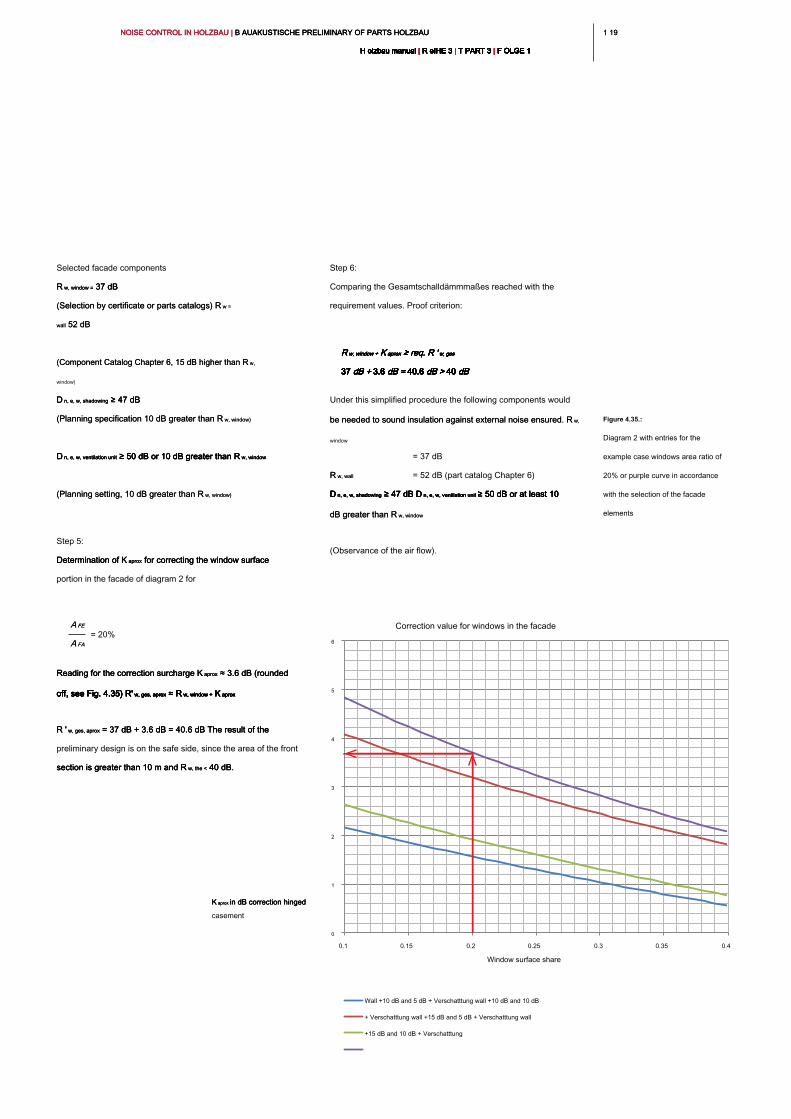
1 191 19NOISE CONTROL IN HOLZBAU | B AUAKUSTISCHE PRELIMINARY OF PARTS HOLZBAU NOISE CONTROL IN HOLZBAU | B AUAKUSTISCHE PRELIMINARY OF PARTS HOLZBAU NOISE CONTROL IN HOLZBAU | B AUAKUSTISCHE PRELIMINARY OF PARTS HOLZBAU
H olzbau manual | R eIHE 3 | T PART 3 | F OLGE 1H olzbau manual | R eIHE 3 | T PART 3 | F OLGE 1H olzbau manual | R eIHE 3 | T PART 3 | F OLGE 1H olzbau manual | R eIHE 3 | T PART 3 | F OLGE 1H olzbau manual | R eIHE 3 | T PART 3 | F OLGE 1H olzbau manual | R eIHE 3 | T PART 3 | F OLGE 1H olzbau manual | R eIHE 3 | T PART 3 | F OLGE 1H olzbau manual | R eIHE 3 | T PART 3 | F OLGE 1H olzbau manual | R eIHE 3 | T PART 3 | F OLGE 1H olzbau manual | R eIHE 3 | T PART 3 | F OLGE 1H olzbau manual | R eIHE 3 | T PART 3 | F OLGE 1
Step 6:
Comparing the Gesamtschalldämmmaßes reached with the
requirement values. Proof criterion:
R w, window + K aprox ≥ req. R ' w, gesR w, window + K aprox ≥ req. R ' w, gesR w, window + K aprox ≥ req. R ' w, gesR w, window + K aprox ≥ req. R ' w, gesR w, window + K aprox ≥ req. R ' w, gesR w, window + K aprox ≥ req. R ' w, gesR w, window + K aprox ≥ req. R ' w, ges
37 dB + 3.6 dB = 40.6 dB > 40 dB37 dB + 3.6 dB = 40.6 dB > 40 dB37 dB + 3.6 dB = 40.6 dB > 40 dB37 dB + 3.6 dB = 40.6 dB > 40 dB37 dB + 3.6 dB = 40.6 dB > 40 dB37 dB + 3.6 dB = 40.6 dB > 40 dB37 dB + 3.6 dB = 40.6 dB > 40 dB37 dB + 3.6 dB = 40.6 dB > 40 dB37 dB + 3.6 dB = 40.6 dB > 40 dB37 dB + 3.6 dB = 40.6 dB > 40 dB
Under this simplified procedure the following components would
be needed to sound insulation against external noise ensured. R w, be needed to sound insulation against external noise ensured. R w,
window
= 37 dB
R w, wallR w, wall = 52 dB (part catalog Chapter 6)
D n, e, w, shadowing ≥ 47 dB D n, e, w, ventilation unit ≥ 50 dB or at least 10 D n, e, w, shadowing ≥ 47 dB D n, e, w, ventilation unit ≥ 50 dB or at least 10 D n, e, w, shadowing ≥ 47 dB D n, e, w, ventilation unit ≥ 50 dB or at least 10 D n, e, w, shadowing ≥ 47 dB D n, e, w, ventilation unit ≥ 50 dB or at least 10 D n, e, w, shadowing ≥ 47 dB D n, e, w, ventilation unit ≥ 50 dB or at least 10
dB greater than R w, windowdB greater than R w, window
(Observance of the air flow).
Selected facade components
R w, window = 37 dB R w, window = 37 dB R w, window = 37 dB
(Selection by certificate or parts catalogs) R w = (Selection by certificate or parts catalogs) R w =
wall 52 dB wall 52 dB
(Component Catalog Chapter 6, 15 dB higher than R w, (Component Catalog Chapter 6, 15 dB higher than R w,
window)
D n, e, w, shadowing ≥ 47 dB D n, e, w, shadowing ≥ 47 dB D n, e, w, shadowing ≥ 47 dB
(Planning specification 10 dB greater than R w, window)(Planning specification 10 dB greater than R w, window)
D n, e, w, ventilation unit ≥ 50 dB or 10 dB greater than R w, windowD n, e, w, ventilation unit ≥ 50 dB or 10 dB greater than R w, windowD n, e, w, ventilation unit ≥ 50 dB or 10 dB greater than R w, windowD n, e, w, ventilation unit ≥ 50 dB or 10 dB greater than R w, window
(Planning setting, 10 dB greater than R w, window)(Planning setting, 10 dB greater than R w, window)
Step 5:
Determination of K aprox for correcting the window surface Determination of K aprox for correcting the window surface Determination of K aprox for correcting the window surface
portion in the facade of diagram 2 for
Reading for the correction surcharge K aprox ≈ 3.6 dB (rounded Reading for the correction surcharge K aprox ≈ 3.6 dB (rounded Reading for the correction surcharge K aprox ≈ 3.6 dB (rounded
off, see Fig. 4.35) R' w, ges, aprox ≈ R w, window + K aproxoff, see Fig. 4.35) R' w, ges, aprox ≈ R w, window + K aproxoff, see Fig. 4.35) R' w, ges, aprox ≈ R w, window + K aproxoff, see Fig. 4.35) R' w, ges, aprox ≈ R w, window + K aproxoff, see Fig. 4.35) R' w, ges, aprox ≈ R w, window + K aproxoff, see Fig. 4.35) R' w, ges, aprox ≈ R w, window + K aproxoff, see Fig. 4.35) R' w, ges, aprox ≈ R w, window + K aprox
R ' w, ges, aprox ≈ 37 dB + 3.6 dB ≈ 40.6 dB The result of the R ' w, ges, aprox ≈ 37 dB + 3.6 dB ≈ 40.6 dB The result of the R ' w, ges, aprox ≈ 37 dB + 3.6 dB ≈ 40.6 dB The result of the
preliminary design is on the safe side, since the area of the front
section is greater than 10 m and R w, the < 40 dB. section is greater than 10 m and R w, the < 40 dB. section is greater than 10 m and R w, the < 40 dB.
Figure 4.35.:
Diagram 2 with entries for the
example case windows area ratio of
20% or purple curve in accordance
with the selection of the facade
elements
0
1
2
3
4
5
6
0.1 0.15 0.2 0.25 0.3 0.35 0.4
Window surface share
Correction value for windows in the facade
K aprox in dB correction hinged K aprox in dB correction hinged K aprox in dB correction hinged
casement
Wall +10 dB and 5 dB + Verschatttung wall +10 dB and 10 dB
+ Verschatttung wall +15 dB and 5 dB + Verschatttung wall
+15 dB and 10 dB + Verschatttung
A FEA FE
A FAA FA
= 20%
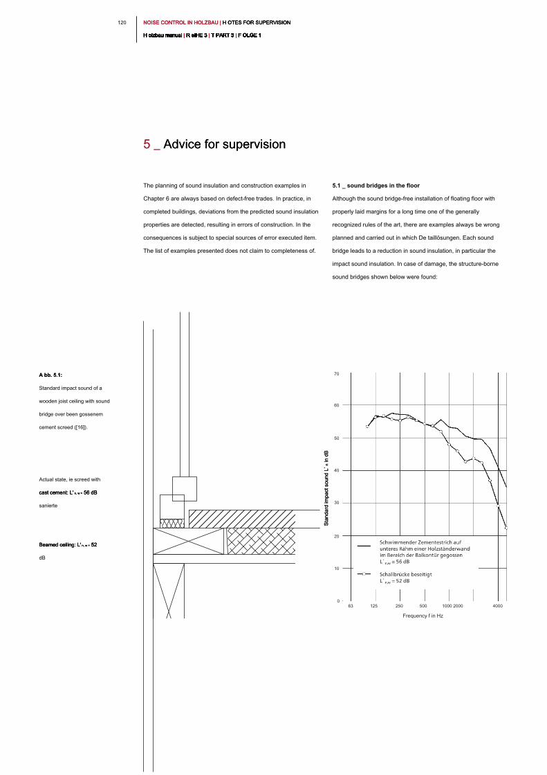
NOISE CONTROL IN HOLZBAU | H OTES FOR SUPERVISION NOISE CONTROL IN HOLZBAU | H OTES FOR SUPERVISION NOISE CONTROL IN HOLZBAU | H OTES FOR SUPERVISION
H olzbau manual | R eIHE 3 | T PART 3 | F OLGE 1H olzbau manual | R eIHE 3 | T PART 3 | F OLGE 1H olzbau manual | R eIHE 3 | T PART 3 | F OLGE 1H olzbau manual | R eIHE 3 | T PART 3 | F OLGE 1H olzbau manual | R eIHE 3 | T PART 3 | F OLGE 1H olzbau manual | R eIHE 3 | T PART 3 | F OLGE 1H olzbau manual | R eIHE 3 | T PART 3 | F OLGE 1H olzbau manual | R eIHE 3 | T PART 3 | F OLGE 1H olzbau manual | R eIHE 3 | T PART 3 | F OLGE 1H olzbau manual | R eIHE 3 | T PART 3 | F OLGE 1H olzbau manual | R eIHE 3 | T PART 3 | F OLGE 1
120
5.1 _ sound bridges in the floor
Although the sound bridge-free installation of floating floor with
properly laid margins for a long time one of the generally
recognized rules of the art, there are examples always be wrong
planned and carried out in which De taillösungen. Each sound
bridge leads to a reduction in sound insulation, in particular the
impact sound insulation. In case of damage, the structure-borne
sound bridges shown below were found:
The planning of sound insulation and construction examples in
Chapter 6 are always based on defect-free trades. In practice, in
completed buildings, deviations from the predicted sound insulation
properties are detected, resulting in errors of construction. In the
consequences is subject to special sources of error executed item.
The list of examples presented does not claim to completeness of.
5 _ Advice for supervision5 _ Advice for supervision
Frequency f in Hz
63 125 250 500 1000 2000 4000
70
60
50
40
30
20
10
0
A bb. 5.1:A bb. 5.1:
Standard impact sound of a
wooden joist ceiling with sound
bridge over been gossenem
cement screed ([16]).
Actual state, ie screed with
cast cement: L' n, w = 56 dB cast cement: L' n, w = 56 dB cast cement: L' n, w = 56 dB
sanierte
Beamed ceiling: L' n, w = 52 Beamed ceiling: L' n, w = 52 Beamed ceiling: L' n, w = 52
dB
Standard im
pact sound L` n in dB
Standard im
pact sound L` n in dB
Standard im
pact sound L` n in dB
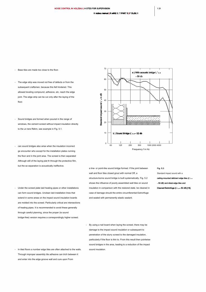
1 211 21NOISE CONTROL IN HOLZBAU | H OTES FOR SUPERVISION NOISE CONTROL IN HOLZBAU | H OTES FOR SUPERVISION NOISE CONTROL IN HOLZBAU | H OTES FOR SUPERVISION
H olzbau manual | R eIHE 3 | T PART 3 | F OLGE 1H olzbau manual | R eIHE 3 | T PART 3 | F OLGE 1H olzbau manual | R eIHE 3 | T PART 3 | F OLGE 1H olzbau manual | R eIHE 3 | T PART 3 | F OLGE 1H olzbau manual | R eIHE 3 | T PART 3 | F OLGE 1H olzbau manual | R eIHE 3 | T PART 3 | F OLGE 1H olzbau manual | R eIHE 3 | T PART 3 | F OLGE 1H olzbau manual | R eIHE 3 | T PART 3 | F OLGE 1H olzbau manual | R eIHE 3 | T PART 3 | F OLGE 1H olzbau manual | R eIHE 3 | T PART 3 | F OLGE 1H olzbau manual | R eIHE 3 | T PART 3 | F OLGE 1
a line- or point-like sound bridge formed. If the joint between
wall and floor tiles closed grout with normal Off, a
structure-borne sound bridge is built systematically. Fig. 5.2
shows the influence of poorly assembled wall tiles on sound
insulation in comparison with the restored state. be cleaned in
case of damage should the entire circumferential Estrichfuge
and sealed with permanently elastic sealant.
- By using a nail board when laying the screed, there may be
damage to the impact sound insulation or subsequent to
penetration of the slurry screed to the damaged insulation,
particularly if the floor is thin to. From this result then pointwise
sound bridges in the area, leading to a reduction of the impact
sound insulation.
- Base tiles are made too close to the floor.
- The edge strip was moved not free of defects or from the
subsequent craftsmen, because this felt hindered. This
allowed leveling compound, adhesive, etc. reach the edge
joint. The edge strip can be cut only after the laying of the
floor.
- Sound bridges are formed when poured in the range of
windows, the cement screed without impact insulation directly
to the un tere Rähm, see example in Fig. 5.1.
- can sound bridges also arise when the insulation incorrect
ge encounter who except for the installation plates running
the floor and in the joint area. The screed is then separated
Although still of the laying plat th through the protective film,
but the se separation is acoustically ineffective.
- Under the screed plate laid heating pipes or other installations
can form sound bridges. Unclean laid installation lines that
extend in some areas on the impact sound insulation boards
are molded into the screed. Particularly critical are intersections
of heating pipes. It is recommended to avoid these generally
through careful planning, since the proper (ie sound
bridge-free) version requires a correspondingly higher screed.
- In tiled floors a number edge tiles are often attached to the walls.
Through improper assembly tile adhesive can trich between it
and enter into the edge groove wall and cure upon From
Fig. 5.2:
Standard impact sound with a
ceiling-mounted deficient edge tiles (L' n, w ceiling-mounted deficient edge tiles (L' n, w
= 59 dB) and distal edge tiles and = 59 dB) and distal edge tiles and
Cleaned Estrichfuge (L' n, w = 52 dB) [16].Cleaned Estrichfuge (L' n, w = 52 dB) [16].Cleaned Estrichfuge (L' n, w = 52 dB) [16].
Frequency f in Hz
63 125 250 500 1000 2000 4000
70
60
50
40
30
20
10
0
a ) With acoustic bridge L ' n, w a ) With acoustic bridge L ' n, w a ) With acoustic bridge L ' n, w
= 59 db= 59 db
b ) Sound Bridge L' n, w = 52 dbb ) Sound Bridge L' n, w = 52 dbb ) Sound Bridge L' n, w = 52 dbb ) Sound Bridge L' n, w = 52 db
Sta
nd
ard
im
pa
ct so
un
d L
` n in
d
BS
ta
nd
ard
im
pa
ct so
un
d L
` n in
d
BS
ta
nd
ard
im
pa
ct so
un
d L
` n in
d
B
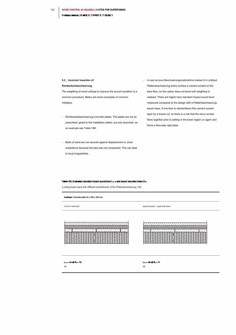
NOISE CONTROL IN HOLZBAU | H OTES FOR SUPERVISION NOISE CONTROL IN HOLZBAU | H OTES FOR SUPERVISION NOISE CONTROL IN HOLZBAU | H OTES FOR SUPERVISION
H olzbau manual | R eIHE 3 | T PART 3 | F OLGE 1H olzbau manual | R eIHE 3 | T PART 3 | F OLGE 1H olzbau manual | R eIHE 3 | T PART 3 | F OLGE 1H olzbau manual | R eIHE 3 | T PART 3 | F OLGE 1H olzbau manual | R eIHE 3 | T PART 3 | F OLGE 1H olzbau manual | R eIHE 3 | T PART 3 | F OLGE 1H olzbau manual | R eIHE 3 | T PART 3 | F OLGE 1H olzbau manual | R eIHE 3 | T PART 3 | F OLGE 1H olzbau manual | R eIHE 3 | T PART 3 | F OLGE 1H olzbau manual | R eIHE 3 | T PART 3 | F OLGE 1H olzbau manual | R eIHE 3 | T PART 3 | F OLGE 1
122
5.2 _ Incorrect insertion of
Rohdeckenbeschwerung
The weighting of wood ceilings to improve the sound insulation is a
common procedure. Below are some examples of common
mistakes:
- Rohdeckenbeschwerung concrete plates: The plates are not as
prescribed, glued to the installation plates, but only launched, as
an example see Table 19th
- Beds of sand are not secured against displacement or show
subsidence because the bed was not compacted. This can lead
to local irregularities.
- Is cast as pure Beschwerungsmaßnahme instead of a unitized
Plattenbeschwerung entire surface a cement screed on the
bare floor, so this option does not bend soft weighting is
realized. There are higher here standard impact sound level
measured compared to the design with a Plattenbeschwerung
equal mass. If one tries to elementieren this cement screed
layer by a trowel cut, so there is a risk that the slurry screed
flows together prior to setting in the lower region un again and
forms a flexurally rigid plate.
Table 19 | Evaluated standard impact sound level L n, w and sound reduction index R wTable 19 | Evaluated standard impact sound level L n, w and sound reduction index R wTable 19 | Evaluated standard impact sound level L n, w and sound reduction index R wTable 19 | Evaluated standard impact sound level L n, w and sound reduction index R wTable 19 | Evaluated standard impact sound level L n, w and sound reduction index R w
a ceiling board stack with different embodiments of the Plattenbeschwerung, [16]
loadings: Concrete slabs 40 x 300 x 300 mmloadings: Concrete slabs 40 x 300 x 300 mm
in 8 mm sand bed placed loosely - rough side down
L n, w = 44 dB R w = 73 L n, w = 44 dB R w = 73 L n, w = 44 dB R w = 73 L n, w = 44 dB R w = 73 L n, w = 44 dB R w = 73
dB
L n, w = 46 dB R w = 71 L n, w = 46 dB R w = 71 L n, w = 46 dB R w = 71 L n, w = 46 dB R w = 71 L n, w = 46 dB R w = 71
dB
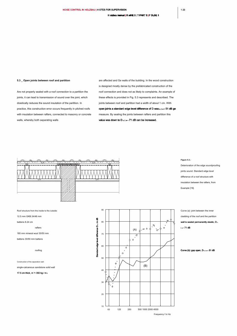
1 231 23NOISE CONTROL IN HOLZBAU | H OTES FOR SUPERVISION NOISE CONTROL IN HOLZBAU | H OTES FOR SUPERVISION NOISE CONTROL IN HOLZBAU | H OTES FOR SUPERVISION
H olzbau manual | R eIHE 3 | T PART 3 | F OLGE 1H olzbau manual | R eIHE 3 | T PART 3 | F OLGE 1H olzbau manual | R eIHE 3 | T PART 3 | F OLGE 1H olzbau manual | R eIHE 3 | T PART 3 | F OLGE 1H olzbau manual | R eIHE 3 | T PART 3 | F OLGE 1H olzbau manual | R eIHE 3 | T PART 3 | F OLGE 1H olzbau manual | R eIHE 3 | T PART 3 | F OLGE 1H olzbau manual | R eIHE 3 | T PART 3 | F OLGE 1H olzbau manual | R eIHE 3 | T PART 3 | F OLGE 1H olzbau manual | R eIHE 3 | T PART 3 | F OLGE 1H olzbau manual | R eIHE 3 | T PART 3 | F OLGE 1
5.3 _ Open joints between roof and partition
Are not properly sealed with a roof connection to a partition the
joints, it can lead to transmission of sound over the joint, which
drastically reduces the sound insulation of the partition. In
practice, this construction error occurs frequently in pitched roofs
with insulation between rafters, connected to masonry or concrete
walls, whereby both separating walls
are affected and Ge walls of the building. In the wood construction
is designed mostly dense by the prefabricated construction of the
roof connection and does not as likely to complaints. An example of
these effects is provided in Fig. 5.3 represents and described. The
joints between roof and partition had a width of about 1 cm. With
open joints a standard edge level difference of D was n, f, w = 51 dB ge open joints a standard edge level difference of D was n, f, w = 51 dB ge open joints a standard edge level difference of D was n, f, w = 51 dB ge
measure. By sealing the joints between rafters and partition this
value was down to D n, f, w = 71 dB can be increased. value was down to D n, f, w = 71 dB can be increased. value was down to D n, f, w = 71 dB can be increased.
Roof structure from the inside to the outside:
12.5 mm GKB 24/48 mm
battens 8.24 cm
rafters
160 mm mineral wool 30/50 mm
battens 30/50 mm battens
roofing
Construction of the separation wall:
single-calcareous sandstone solid wall
17.5 cm thick, m '≈ 350 kg / m 217.5 cm thick, m '≈ 350 kg / m 2
Figure 5.3.:
Deterioration of the edge soundproofing
joints sound. Standard edge level
difference of a roof structure with
insulation between the rafters, from
Example [19].
Curve (a): joint between the inner
cladding of the roof and the partition
wall is sealed permanently elastic, D n, wall is sealed permanently elastic, D n,
f, w = 71 dB f, w = 71 dB
Curve (b): gap open, D n, f, w = 51 dBCurve (b): gap open, D n, f, w = 51 dBCurve (b): gap open, D n, f, w = 51 dB
Frequency f in Hz
63 125 250 500 1000 2000 4000
10
20
30
40
50
60
70
80
90
(A)
(B)
Standard edge level difference D
n
, f in dB
Standard edge level difference D
n
, f in dB
Standard edge level difference D
n
, f in dB
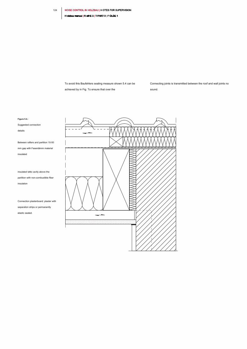
NOISE CONTROL IN HOLZBAU | H OTES FOR SUPERVISION NOISE CONTROL IN HOLZBAU | H OTES FOR SUPERVISION NOISE CONTROL IN HOLZBAU | H OTES FOR SUPERVISION
H olzbau manual | R eIHE 3 | T PART 3 | F OLGE 1H olzbau manual | R eIHE 3 | T PART 3 | F OLGE 1H olzbau manual | R eIHE 3 | T PART 3 | F OLGE 1H olzbau manual | R eIHE 3 | T PART 3 | F OLGE 1H olzbau manual | R eIHE 3 | T PART 3 | F OLGE 1H olzbau manual | R eIHE 3 | T PART 3 | F OLGE 1H olzbau manual | R eIHE 3 | T PART 3 | F OLGE 1H olzbau manual | R eIHE 3 | T PART 3 | F OLGE 1H olzbau manual | R eIHE 3 | T PART 3 | F OLGE 1H olzbau manual | R eIHE 3 | T PART 3 | F OLGE 1H olzbau manual | R eIHE 3 | T PART 3 | F OLGE 1
124
To avoid this Baufehlers sealing measure shown 5.4 can be
achieved by in Fig. To ensure that over the
Connecting joints is transmitted between the roof and wall joints no
sound.
Figure 5.4.:
Suggested connection
details:
Between rafters and partition 10-50
mm gap with Faserdämm material
insulated
insulated latte cavity above the
partition with non-combustible fiber
insulation
Connection plasterboard: plaster with
separation strips or permanently
elastic sealed.

1 251 25NOISE CONTROL IN HOLZBAU | H OTES FOR SUPERVISION NOISE CONTROL IN HOLZBAU | H OTES FOR SUPERVISION NOISE CONTROL IN HOLZBAU | H OTES FOR SUPERVISION
H olzbau manual | R eIHE 3 | T PART 3 | F OLGE 1H olzbau manual | R eIHE 3 | T PART 3 | F OLGE 1H olzbau manual | R eIHE 3 | T PART 3 | F OLGE 1H olzbau manual | R eIHE 3 | T PART 3 | F OLGE 1H olzbau manual | R eIHE 3 | T PART 3 | F OLGE 1H olzbau manual | R eIHE 3 | T PART 3 | F OLGE 1H olzbau manual | R eIHE 3 | T PART 3 | F OLGE 1H olzbau manual | R eIHE 3 | T PART 3 | F OLGE 1H olzbau manual | R eIHE 3 | T PART 3 | F OLGE 1H olzbau manual | R eIHE 3 | T PART 3 | F OLGE 1H olzbau manual | R eIHE 3 | T PART 3 | F OLGE 1
5.4 _ High pressure in roof insulation of
pressure-resistant fiber insulation boards
A too high pressure of the roof insulation resulting from the method
of mounting. If the insulation boards nailed or screwed with rafter
nails with a single threaded screw, a very high contact pressure is
automatically provided. The mounting with double threaded screw
guarantees a low contact pressure if properly handled.
As with transitory roof battens and canopy this influence is at an
increased sound insulation (R L, w, R ≥ 68 dB) is decisive. increased sound insulation (R L, w, R ≥ 68 dB) is decisive. increased sound insulation (R L, w, R ≥ 68 dB) is decisive.
Too much pressure the insulation also has an influence on the
transmission sound insulation such a roof structure. By setting a
high contact pressure as compared with a low contact pressure of
the sound insulation R w reduced by up to 9 dB, see Fig. 5.5.the sound insulation R w reduced by up to 9 dB, see Fig. 5.5.the sound insulation R w reduced by up to 9 dB, see Fig. 5.5.
5.5 _ fitted kitchens and furniture
Often for installation of furniture removing the skirting board is
required. The fixtures are then connected accordingly by the screed
directly to the wall. Thus, the edge insulation strip is bridged
acoustically. Such installation situations are to be avoided and the
preparation should be borne sound isolation. An indication shall be
inserted in the plans, therefore, to be handed over to the respective
buyers.
Frequency f in Hz
63 125 250 500 1000 2000 4000
10
20
30
40
50
60
70
80
90
(A)
(B)
A bb. 05.05:A bb. 05.05:
Influence of mounting: Simply thread -
double-threaded screw, as in [17].
Curve (a): without pressure
(double-threaded screw), R w = 51 dB(double-threaded screw), R w = 51 dB(double-threaded screw), R w = 51 dB
Curve (b): with a contact pressure
(single screw), R w = 42 dB(single screw), R w = 42 dB(single screw), R w = 42 dB
So
un
d re
du
ctio
n in
de
x in
d
B
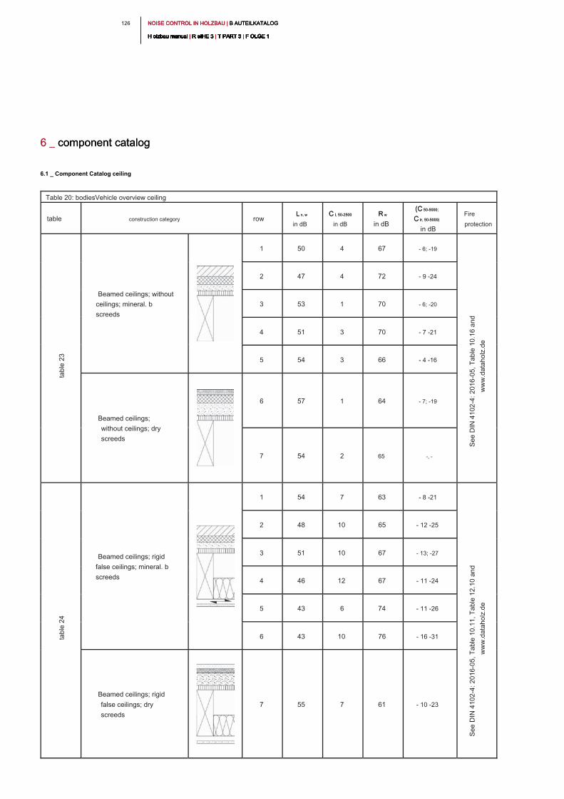
NOISE CONTROL IN HOLZBAU | B AUTEILKATALOG NOISE CONTROL IN HOLZBAU | B AUTEILKATALOG NOISE CONTROL IN HOLZBAU | B AUTEILKATALOG
H olzbau manual | R eIHE 3 | T PART 3 | F OLGE 1H olzbau manual | R eIHE 3 | T PART 3 | F OLGE 1H olzbau manual | R eIHE 3 | T PART 3 | F OLGE 1H olzbau manual | R eIHE 3 | T PART 3 | F OLGE 1H olzbau manual | R eIHE 3 | T PART 3 | F OLGE 1H olzbau manual | R eIHE 3 | T PART 3 | F OLGE 1H olzbau manual | R eIHE 3 | T PART 3 | F OLGE 1H olzbau manual | R eIHE 3 | T PART 3 | F OLGE 1H olzbau manual | R eIHE 3 | T PART 3 | F OLGE 1H olzbau manual | R eIHE 3 | T PART 3 | F OLGE 1H olzbau manual | R eIHE 3 | T PART 3 | F OLGE 1
126
6.1 _ Component Catalog ceiling
Table 20: bodiesVehicle overview ceiling
table construction category row
L n, wL n, w
in dB
C I, 50-2500C I, 50-2500
in dB
R wR w
in dB
(C 50-5000;(C 50-5000;
C tr, 50-5000)C tr, 50-5000)
in dB
Fire
protection
Beamed ceilings; without
ceilings; mineral. b
screeds
1 50 4 67 - 6; -19
2 47 4 72 - 9 -24
3 53 1 70 - 6; -20
4 51 3 70 - 7 -21
5 54 3 66 - 4 -16
Beamed ceilings;
without ceilings; dry
screeds
6 57 1 64 - 7; -19
7 54 2 65 -, -
Beamed ceilings; rigid
false ceilings; mineral. b
screeds
1 54 7 63 - 8 -21
2 48 10 65 - 12 -25
3 51 10 67 - 13; -27
4 46 12 67 - 11 -24
5 43 6 74 - 11 -26
6 43 10 76 - 16 -31
Beamed ceilings; rigid
false ceilings; dry
screeds
7 55 7 61 - 10 -23
6 _ component catalog6 _ component catalog
ta
ble
2
3
Se
e D
IN
4
10
2-4
: 2
01
6-0
5, T
ab
le
1
0.1
6 a
nd
ww
w.d
ata
ho
lz.d
e
ta
ble
2
4
Se
e D
IN
4
10
2-4
: 2
01
6-0
5, T
ab
le
1
0.1
1, T
ab
le
1
2.1
0 a
nd
ww
w.d
ata
ho
lz.d
e
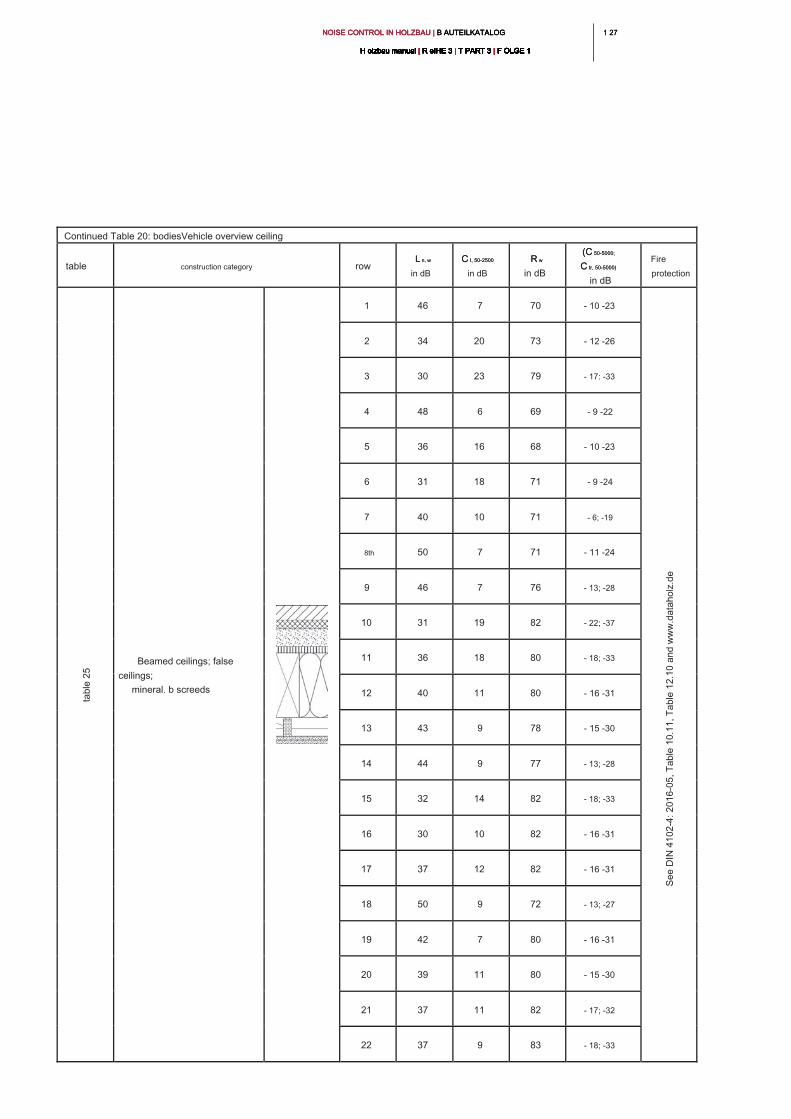
1 271 27NOISE CONTROL IN HOLZBAU | B AUTEILKATALOG NOISE CONTROL IN HOLZBAU | B AUTEILKATALOG NOISE CONTROL IN HOLZBAU | B AUTEILKATALOG
H olzbau manual | R eIHE 3 | T PART 3 | F OLGE 1H olzbau manual | R eIHE 3 | T PART 3 | F OLGE 1H olzbau manual | R eIHE 3 | T PART 3 | F OLGE 1H olzbau manual | R eIHE 3 | T PART 3 | F OLGE 1H olzbau manual | R eIHE 3 | T PART 3 | F OLGE 1H olzbau manual | R eIHE 3 | T PART 3 | F OLGE 1H olzbau manual | R eIHE 3 | T PART 3 | F OLGE 1H olzbau manual | R eIHE 3 | T PART 3 | F OLGE 1H olzbau manual | R eIHE 3 | T PART 3 | F OLGE 1H olzbau manual | R eIHE 3 | T PART 3 | F OLGE 1H olzbau manual | R eIHE 3 | T PART 3 | F OLGE 1
Continued Table 20: bodiesVehicle overview ceiling
table construction category row
L n, wL n, w
in dB
C I, 50-2500C I, 50-2500
in dB
R wR w
in dB
(C 50-5000;(C 50-5000;
C tr, 50-5000)C tr, 50-5000)
in dB
Fire
protection
Beamed ceilings; false
ceilings;
mineral. b screeds
1 46 7 70 - 10 -23
2 34 20 73 - 12 -26
3 30 23 79 - 17: -33
4 48 6 69 - 9 -22
5 36 16 68 - 10 -23
6 31 18 71 - 9 -24
7 40 10 71 - 6; -19
8th 50 7 71 - 11 -24
9 46 7 76 - 13; -28
10 31 19 82 - 22; -37
11 36 18 80 - 18; -33
12 40 11 80 - 16 -31
13 43 9 78 - 15 -30
14 44 9 77 - 13; -28
15 32 14 82 - 18; -33
16 30 10 82 - 16 -31
17 37 12 82 - 16 -31
18 50 9 72 - 13; -27
19 42 7 80 - 16 -31
20 39 11 80 - 15 -30
21 37 11 82 - 17; -32
22 37 9 83 - 18; -33
ta
ble
2
5
Se
e D
IN
4
10
2-4
: 2
01
6-0
5, T
ab
le
1
0.1
1, T
ab
le
1
2.1
0 a
nd
w
ww
.d
ata
ho
lz.d
e
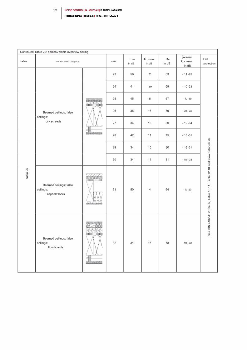
NOISE CONTROL IN HOLZBAU | B AUTEILKATALOG NOISE CONTROL IN HOLZBAU | B AUTEILKATALOG NOISE CONTROL IN HOLZBAU | B AUTEILKATALOG
H olzbau manual | R eIHE 3 | T PART 3 | F OLGE 1H olzbau manual | R eIHE 3 | T PART 3 | F OLGE 1H olzbau manual | R eIHE 3 | T PART 3 | F OLGE 1H olzbau manual | R eIHE 3 | T PART 3 | F OLGE 1H olzbau manual | R eIHE 3 | T PART 3 | F OLGE 1H olzbau manual | R eIHE 3 | T PART 3 | F OLGE 1H olzbau manual | R eIHE 3 | T PART 3 | F OLGE 1H olzbau manual | R eIHE 3 | T PART 3 | F OLGE 1H olzbau manual | R eIHE 3 | T PART 3 | F OLGE 1H olzbau manual | R eIHE 3 | T PART 3 | F OLGE 1H olzbau manual | R eIHE 3 | T PART 3 | F OLGE 1
128
Continued Table 20: bodiesVehicle overview ceiling
table construction category row
L n, wL n, w
in dB
C I, 50-2500C I, 50-2500
in dB
R wR w
in dB
(C 50-5000;(C 50-5000;
C tr, 50-5000)C tr, 50-5000)
in dB
Fire
protection
Beamed ceilings; false
ceilings;
dry screeds
23 56 2 63 - 11 -25
24 41 8th 69 - 10 -23
25 45 5 67 -7, -19
26 38 16 79 - 20; -35
27 34 16 80 - 19 -34
28 42 11 75 - 16 -31
29 34 15 80 - 16 -31
30 34 11 81 - 18; -33
Beamed ceilings; false
ceilings;
asphalt floors
31 50 4 64 - 7; -20
Beamed ceilings; false
ceilings;
floorboards
32 34 16 78 - 19; -33
ta
ble
2
5
Se
e D
IN
4
10
2-4
: 2
01
6-0
5, T
ab
le
1
0.1
1, T
ab
le
1
2.1
0 a
nd
w
ww
.d
ata
ho
lz.d
e
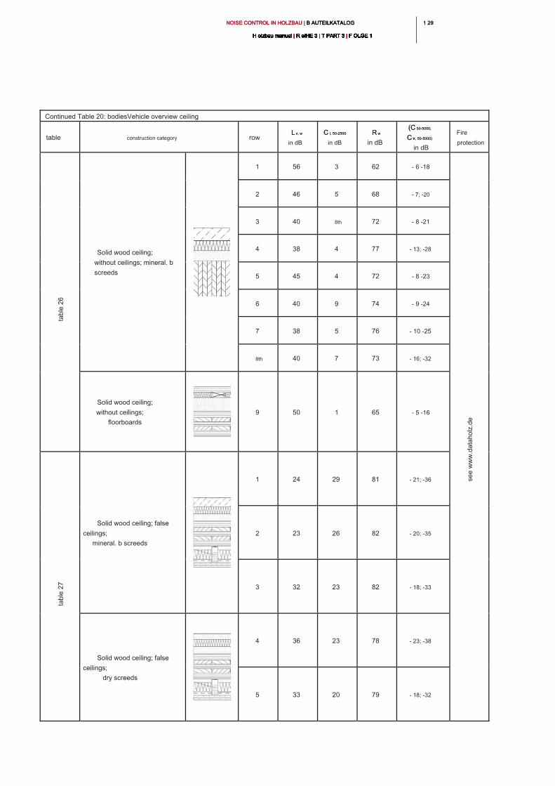
1 291 29NOISE CONTROL IN HOLZBAU | B AUTEILKATALOG NOISE CONTROL IN HOLZBAU | B AUTEILKATALOG NOISE CONTROL IN HOLZBAU | B AUTEILKATALOG
H olzbau manual | R eIHE 3 | T PART 3 | F OLGE 1H olzbau manual | R eIHE 3 | T PART 3 | F OLGE 1H olzbau manual | R eIHE 3 | T PART 3 | F OLGE 1H olzbau manual | R eIHE 3 | T PART 3 | F OLGE 1H olzbau manual | R eIHE 3 | T PART 3 | F OLGE 1H olzbau manual | R eIHE 3 | T PART 3 | F OLGE 1H olzbau manual | R eIHE 3 | T PART 3 | F OLGE 1H olzbau manual | R eIHE 3 | T PART 3 | F OLGE 1H olzbau manual | R eIHE 3 | T PART 3 | F OLGE 1H olzbau manual | R eIHE 3 | T PART 3 | F OLGE 1H olzbau manual | R eIHE 3 | T PART 3 | F OLGE 1
Continued Table 20: bodiesVehicle overview ceiling
table construction category row
L n, wL n, w
in dB
C I, 50-2500C I, 50-2500
in dB
R wR w
in dB
(C 50-5000;(C 50-5000;
C tr, 50-5000)C tr, 50-5000)
in dB
Fire
protection
Solid wood ceiling;
without ceilings; mineral. b
screeds
1 56 3 62 - 6 -18
2 46 5 68 - 7; -20
3 40 8th 72 - 8 -21
4 38 4 77 - 13; -28
5 45 4 72 - 8 -23
6 40 9 74 - 9 -24
7 38 5 76 - 10 -25
8th 40 7 73 - 16; -32
Solid wood ceiling;
without ceilings;
floorboards
9 50 1 65 - 5 -16
Solid wood ceiling; false
ceilings;
mineral. b screeds
1 24 29 81 - 21; -36
2 23 26 82 - 20; -35
3 32 23 82 - 18; -33
Solid wood ceiling; false
ceilings;
dry screeds
4 36 23 78 - 23; -38
5 33 20 79 - 18; -32
ta
ble
2
6
se
e w
ww
.d
ata
ho
lz.d
e
ta
ble
2
7
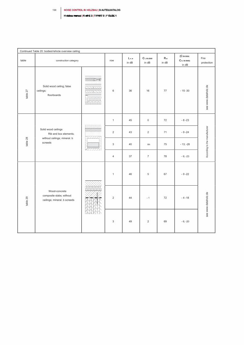
NOISE CONTROL IN HOLZBAU | B AUTEILKATALOG NOISE CONTROL IN HOLZBAU | B AUTEILKATALOG NOISE CONTROL IN HOLZBAU | B AUTEILKATALOG
H olzbau manual | R eIHE 3 | T PART 3 | F OLGE 1H olzbau manual | R eIHE 3 | T PART 3 | F OLGE 1H olzbau manual | R eIHE 3 | T PART 3 | F OLGE 1H olzbau manual | R eIHE 3 | T PART 3 | F OLGE 1H olzbau manual | R eIHE 3 | T PART 3 | F OLGE 1H olzbau manual | R eIHE 3 | T PART 3 | F OLGE 1H olzbau manual | R eIHE 3 | T PART 3 | F OLGE 1H olzbau manual | R eIHE 3 | T PART 3 | F OLGE 1H olzbau manual | R eIHE 3 | T PART 3 | F OLGE 1H olzbau manual | R eIHE 3 | T PART 3 | F OLGE 1H olzbau manual | R eIHE 3 | T PART 3 | F OLGE 1
130
Continued Table 20: bodiesVehicle overview ceiling
table construction category row
L n, wL n, w
in dB
C I, 50-2500C I, 50-2500
in dB
R wR w
in dB
(C 50-5000;(C 50-5000;
C tr, 50-5000)C tr, 50-5000)
in dB
Fire
protection
Solid wood ceiling; false
ceilings;
floorboards
6 36 16 77 - 15 -30
Solid wood ceilings
Rib and box elements;
without ceilings; mineral. b
screeds
1 45 0 72 - 8 -23
2 43 2 71 - 9 -24
3 40 8th 75 - 13; -28
4 37 7 78 - 9; -23
Wood-concrete
composite slabs; without
ceilings; mineral. b screeds
1 46 5 67 - 9 -22
2 44 - 1 72 - 4 -18
3 49 2 69 - 6; -20
ta
ble
2
7
se
e w
ww
.d
ata
ho
lz.d
e
ta
ble
2
8
Acco
rd
in
g to
th
e m
an
ufa
ctu
re
r
ta
ble
2
9
se
e w
ww
.d
ata
ho
lz.d
e
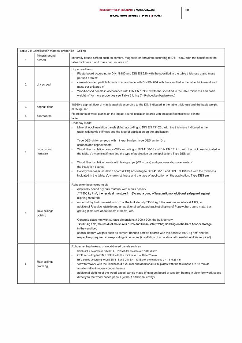
1 311 31NOISE CONTROL IN HOLZBAU | B AUTEILKATALOG NOISE CONTROL IN HOLZBAU | B AUTEILKATALOG NOISE CONTROL IN HOLZBAU | B AUTEILKATALOG
H olzbau manual | R eIHE 3 | T PART 3 | F OLGE 1H olzbau manual | R eIHE 3 | T PART 3 | F OLGE 1H olzbau manual | R eIHE 3 | T PART 3 | F OLGE 1H olzbau manual | R eIHE 3 | T PART 3 | F OLGE 1H olzbau manual | R eIHE 3 | T PART 3 | F OLGE 1H olzbau manual | R eIHE 3 | T PART 3 | F OLGE 1H olzbau manual | R eIHE 3 | T PART 3 | F OLGE 1H olzbau manual | R eIHE 3 | T PART 3 | F OLGE 1H olzbau manual | R eIHE 3 | T PART 3 | F OLGE 1H olzbau manual | R eIHE 3 | T PART 3 | F OLGE 1H olzbau manual | R eIHE 3 | T PART 3 | F OLGE 1
Table 21: Construction material properties - Ceiling
1
Mineral-bound
screed
Minerally bound screed such as cement, magnesia or anhydrite according to DIN 18560 with the specified in the
table thickness d and mass per unit area m'
2 dry screed
Dry screed from:
- Plasterboard according to DIN 18180 and DIN EN 520 with the specified in the table thickness d and mass
per unit area m'
- cement-bonded particle boards in accordance with DIN EN 634 with the specified in the table thickness d and
mass per unit area m'
- Wood-based panels in accordance with DIN EN 13986 d with the specified in the table thickness and basis
weight m'(for more properties see Table 21, line 7 - Rohdeckenbeplankung)
3 asphalt floor
18560 d asphalt floor of mastic asphalt according to the DIN indicated in the table thickness and the basis weight
m'85 kg / m²
4 floorboards
Floorboards of wood planks on the impact sound insulation boards with the specified thickness d in the
table
5
impact sound
insulation
Underlay made:
- Mineral wool insulation panels (MW) according to DIN EN 13162 d with the thickness indicated in the
table, s'dynamic stiffness and the type of application on the application:
Type DES sh for screeds with mineral binders, type DES sm for Dry
screeds and asphalt floors
- Wood fiber insulation boards (WF) according to DIN 4108-10 and DIN EN 13171 d with the thickness indicated in
the table, s'dynamic stiffness and the type of application on the application: Type DES sg
- Wood fiber insulation boards with laying strips (WF + bars) and groove-and-groove joints of
the insulation boards
- Polystyrene foam insulation board (EPS) according to DIN 4108-10 and DIN EN 13163 d with the thickness
indicated in the table, s'dynamic stiffness and the type of application on the application: Type DES sm
6
Raw ceilings
poising
Rohdeckenbeschwerung of:
- elastically bound dry bulk material with a bulk density
! " 1500 kg / m³, the residual moisture # 1.8% and a bond of latex milk (no additional safeguard against ! " 1500 kg / m³, the residual moisture # 1.8% and a bond of latex milk (no additional safeguard against
slipping required)
- unbound dry bulk material with m³ of the bulk density "1500 kg /, the residual moisture # 1.8%, an
additional Rieselschutzfolie and an additional safeguard against slipping of Pappwaben, sand mats, bar
grating (field size about 80 cm x 80 cm) etc.
- Concrete slabs mm with surface dimensions # 300 x 300, the bulk density
! 2,500 kg / m³, the residual moisture # 1.8% and Rieselschutzfolie; Bonding on the bare floor or storage ! 2,500 kg / m³, the residual moisture # 1.8% and Rieselschutzfolie; Bonding on the bare floor or storage
in the sand bed
- special bottom weights such as cement-bonded particle boards with the density! 1000 kg / m³ and the
respectively required corresponding dimensions (installation of an additional Rieselschutzfolie required)
7
Raw ceilings
planking
Rohdeckenbeplankung of wood-based panels such as:
- Chipboard in accordance with DIN EN 312 with the thickness d = 18 to 25 mm
- OSB according to DIN EN 300 with the thickness d = 18 to 25 mm
- BFU-plates according to DIN EN 315 and DIN EN 13986 with the thickness d = 18 to 25 mm
- View formwork with the thickness d = 28 mm and additional BFU-plates with the thickness d = 12 mm as
an alternative in open wooden beams
- additional clothing of the wood-based panels made of gypsum board or wooden beams in view formwork space
directly to the wood-based panels (without additional cavity)
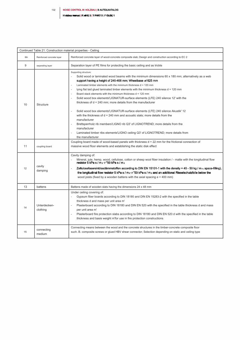
NOISE CONTROL IN HOLZBAU | B AUTEILKATALOG NOISE CONTROL IN HOLZBAU | B AUTEILKATALOG NOISE CONTROL IN HOLZBAU | B AUTEILKATALOG
H olzbau manual | R eIHE 3 | T PART 3 | F OLGE 1H olzbau manual | R eIHE 3 | T PART 3 | F OLGE 1H olzbau manual | R eIHE 3 | T PART 3 | F OLGE 1H olzbau manual | R eIHE 3 | T PART 3 | F OLGE 1H olzbau manual | R eIHE 3 | T PART 3 | F OLGE 1H olzbau manual | R eIHE 3 | T PART 3 | F OLGE 1H olzbau manual | R eIHE 3 | T PART 3 | F OLGE 1H olzbau manual | R eIHE 3 | T PART 3 | F OLGE 1H olzbau manual | R eIHE 3 | T PART 3 | F OLGE 1H olzbau manual | R eIHE 3 | T PART 3 | F OLGE 1H olzbau manual | R eIHE 3 | T PART 3 | F OLGE 1
132
Continued Table 21: Construction material properties - Ceiling
8th Reinforced concrete layer Reinforced concrete layer of wood-concrete composite slab; Design and construction according to EC 2
9 separating layer Separation layer of PE films for protecting the basic ceiling and as trickle
10 Structure
Supporting structure:
- Solid wood or laminated wood beams with the minimum dimensions 60 x 180 mm; alternatively as a web
support having a height of 240-406 mm; Wheelbase e! 625 mmsupport having a height of 240-406 mm; Wheelbase e! 625 mmsupport having a height of 240-406 mm; Wheelbase e! 625 mm
- Laminated timber elements with the minimum thickness d = 120 mm
- lying flat laid glued laminated timber elements with the minimum thickness d = 120 mm
- Board stack elements with the minimum thickness d = 120 mm
- Solid wood box elements'LIGNATUR-surface elements (LFE) 240 silence 12' with the
thickness of d = 240 mm; more details from the manufacturer
- Solid wood box elements'LIGNATUR-surface elements (LFE) 240 silence Akustik' 12
with the thickness of d = 240 mm and acoustic slats; more details from the
manufacturer
- Brettsperrholz rib members'LIGNO rib Q3' of LIGNOTREND; more details from the
manufacturer
- Laminated timber ribs elements'LIGNO ceiling Q3' of LIGNOTREND; more details from
the manufacturer
11 coupling board
Coupling board made of wood-based panels with thickness d = 22 mm for the frictional connection of
massive wood floor elements and establishing the static disk effect
12
cavity
damping
Cavity damping of:
- Mineral, jute, hemp, wood, cellulose, cotton or sheep wool fiber insulation / - matte with the longitudinal flow
resistor 5 kPa s / m 2 ' r "50 kPa s / m 2resistor 5 kPa s / m 2 ' r "50 kPa s / m 2resistor 5 kPa s / m 2 ' r "50 kPa s / m 2resistor 5 kPa s / m 2 ' r "50 kPa s / m 2
- Zellulosefasereinblasdämmstoffen according to DIN EN 15101-1 with the density = 40 - 50 kg / m 3 ( space-filling), Zellulosefasereinblasdämmstoffen according to DIN EN 15101-1 with the density = 40 - 50 kg / m 3 ( space-filling), Zellulosefasereinblasdämmstoffen according to DIN EN 15101-1 with the density = 40 - 50 kg / m 3 ( space-filling),
the longitudinal flow resistor 5 kPa s / m 2 ' r "50 kPa s / m 2 and an additional Rieselschutzfolie below the the longitudinal flow resistor 5 kPa s / m 2 ' r "50 kPa s / m 2 and an additional Rieselschutzfolie below the the longitudinal flow resistor 5 kPa s / m 2 ' r "50 kPa s / m 2 and an additional Rieselschutzfolie below the the longitudinal flow resistor 5 kPa s / m 2 ' r "50 kPa s / m 2 and an additional Rieselschutzfolie below the the longitudinal flow resistor 5 kPa s / m 2 ' r "50 kPa s / m 2 and an additional Rieselschutzfolie below the
wood joists (fixed by a wooden battens with the axial spacing e = 400 mm)
13 battens Battens made of wooden slats having the dimensions 24 x 48 mm
14
Unterdecken-
clothing
Under ceiling covering of:
- Gypsum fiber boards according to DIN 18180 and DIN EN 15283-2 with the specified in the table
thickness d and mass per unit area m'
- Plasterboard according to DIN 18180 and DIN EN 520 with the specified in the table thickness d and mass
per unit area m'
- Plasterboard fire protection slabs according to DIN 18180 and DIN EN 520 d with the specified in the table
thickness and basis weight m'for use in fire protection constructions
15
connecting
medium
Connecting means between the wood and the concrete structures in the timber-concrete composite floor
such. B. composite screws or glued HBV shear connector; Selection depending on static and ceiling type
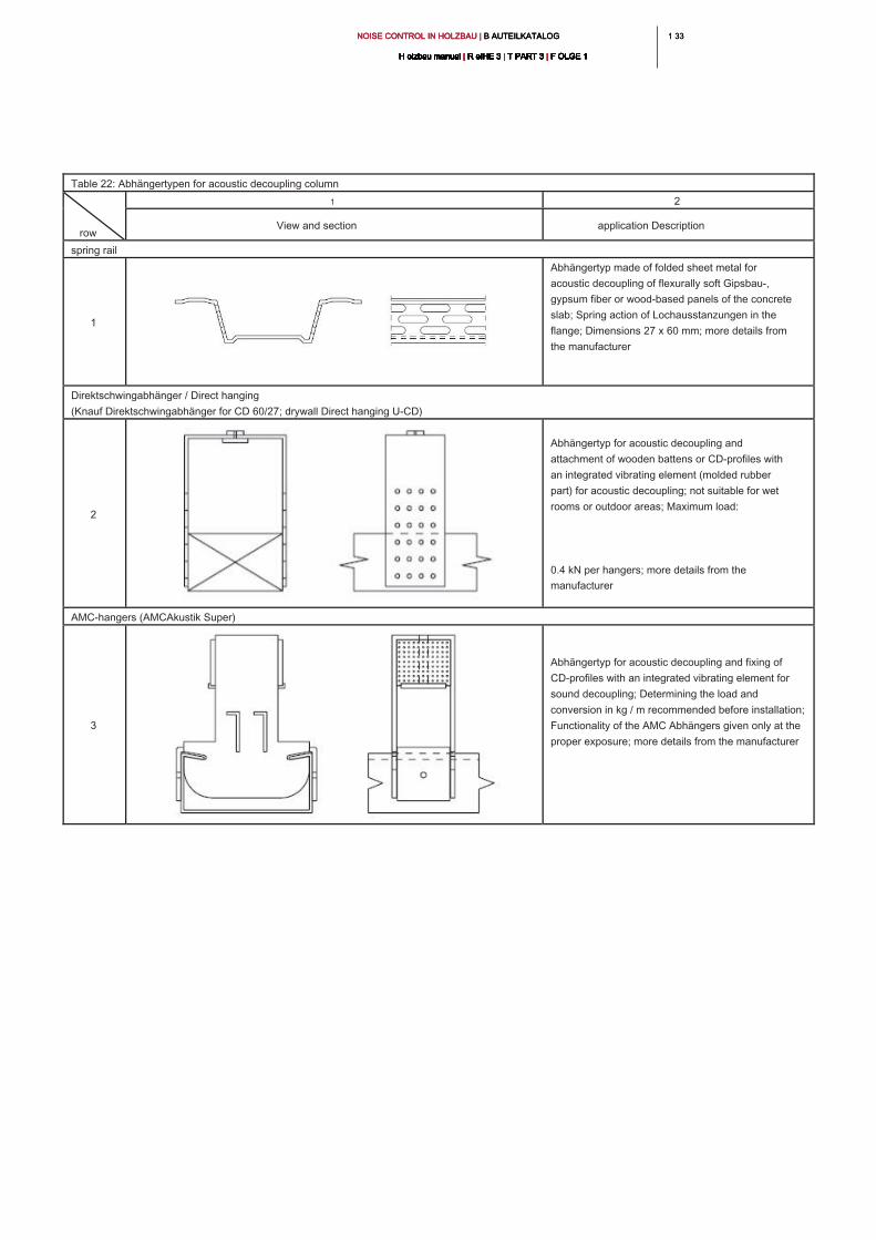
1 331 33NOISE CONTROL IN HOLZBAU | B AUTEILKATALOG NOISE CONTROL IN HOLZBAU | B AUTEILKATALOG NOISE CONTROL IN HOLZBAU | B AUTEILKATALOG
H olzbau manual | R eIHE 3 | T PART 3 | F OLGE 1H olzbau manual | R eIHE 3 | T PART 3 | F OLGE 1H olzbau manual | R eIHE 3 | T PART 3 | F OLGE 1H olzbau manual | R eIHE 3 | T PART 3 | F OLGE 1H olzbau manual | R eIHE 3 | T PART 3 | F OLGE 1H olzbau manual | R eIHE 3 | T PART 3 | F OLGE 1H olzbau manual | R eIHE 3 | T PART 3 | F OLGE 1H olzbau manual | R eIHE 3 | T PART 3 | F OLGE 1H olzbau manual | R eIHE 3 | T PART 3 | F OLGE 1H olzbau manual | R eIHE 3 | T PART 3 | F OLGE 1H olzbau manual | R eIHE 3 | T PART 3 | F OLGE 1
Table 22: Abhängertypen for acoustic decoupling column
row
1 2
View and section application Description
spring rail
1
Abhängertyp made of folded sheet metal for
acoustic decoupling of flexurally soft Gipsbau-,
gypsum fiber or wood-based panels of the concrete
slab; Spring action of Lochausstanzungen in the
flange; Dimensions 27 x 60 mm; more details from
the manufacturer
Direktschwingabhänger / Direct hanging
(Knauf Direktschwingabhänger for CD 60/27; drywall Direct hanging U-CD)
2
Abhängertyp for acoustic decoupling and
attachment of wooden battens or CD-profiles with
an integrated vibrating element (molded rubber
part) for acoustic decoupling; not suitable for wet
rooms or outdoor areas; Maximum load:
0.4 kN per hangers; more details from the
manufacturer
AMC-hangers (AMCAkustik Super)
3
Abhängertyp for acoustic decoupling and fixing of
CD-profiles with an integrated vibrating element for
sound decoupling; Determining the load and
conversion in kg / m recommended before installation;
Functionality of the AMC Abhängers given only at the
proper exposure; more details from the manufacturer
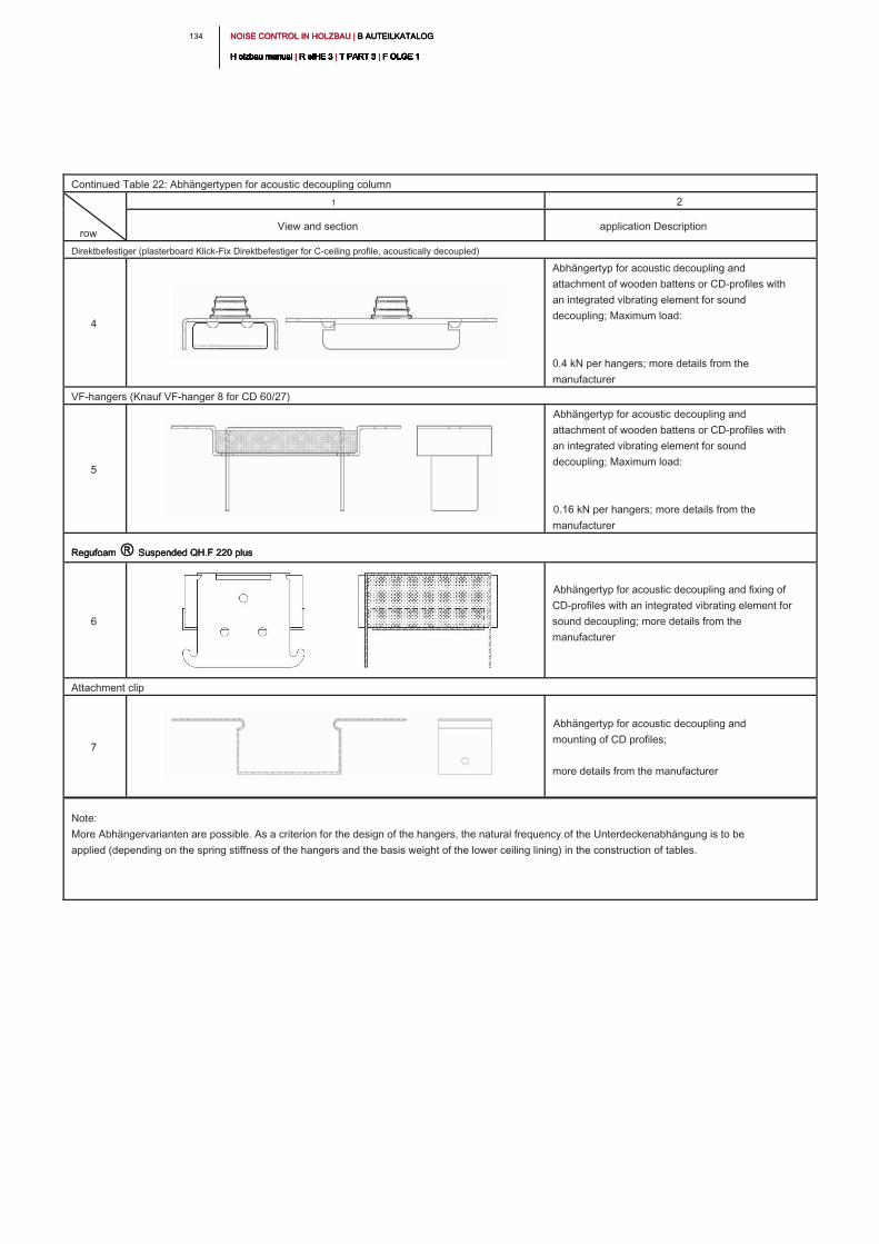
NOISE CONTROL IN HOLZBAU | B AUTEILKATALOG NOISE CONTROL IN HOLZBAU | B AUTEILKATALOG NOISE CONTROL IN HOLZBAU | B AUTEILKATALOG
H olzbau manual | R eIHE 3 | T PART 3 | F OLGE 1H olzbau manual | R eIHE 3 | T PART 3 | F OLGE 1H olzbau manual | R eIHE 3 | T PART 3 | F OLGE 1H olzbau manual | R eIHE 3 | T PART 3 | F OLGE 1H olzbau manual | R eIHE 3 | T PART 3 | F OLGE 1H olzbau manual | R eIHE 3 | T PART 3 | F OLGE 1H olzbau manual | R eIHE 3 | T PART 3 | F OLGE 1H olzbau manual | R eIHE 3 | T PART 3 | F OLGE 1H olzbau manual | R eIHE 3 | T PART 3 | F OLGE 1H olzbau manual | R eIHE 3 | T PART 3 | F OLGE 1H olzbau manual | R eIHE 3 | T PART 3 | F OLGE 1
134
Continued Table 22: Abhängertypen for acoustic decoupling column
row
1 2
View and section application Description
Direktbefestiger (plasterboard Klick-Fix Direktbefestiger for C-ceiling profile, acoustically decoupled)
4
Abhängertyp for acoustic decoupling and
attachment of wooden battens or CD-profiles with
an integrated vibrating element for sound
decoupling; Maximum load:
0.4 kN per hangers; more details from the
manufacturer
VF-hangers (Knauf VF-hanger 8 for CD 60/27)
5
Abhängertyp for acoustic decoupling and
attachment of wooden battens or CD-profiles with
an integrated vibrating element for sound
decoupling; Maximum load:
0.16 kN per hangers; more details from the
manufacturer
Regufoam ® Suspended QH.F 220 plusRegufoam ® Suspended QH.F 220 plusRegufoam ® Suspended QH.F 220 plus
6
Abhängertyp for acoustic decoupling and fixing of
CD-profiles with an integrated vibrating element for
sound decoupling; more details from the
manufacturer
Attachment clip
7
Abhängertyp for acoustic decoupling and
mounting of CD profiles;
more details from the manufacturer
Note:
More Abhängervarianten are possible. As a criterion for the design of the hangers, the natural frequency of the Unterdeckenabhängung is to be
applied (depending on the spring stiffness of the hangers and the basis weight of the lower ceiling lining) in the construction of tables.
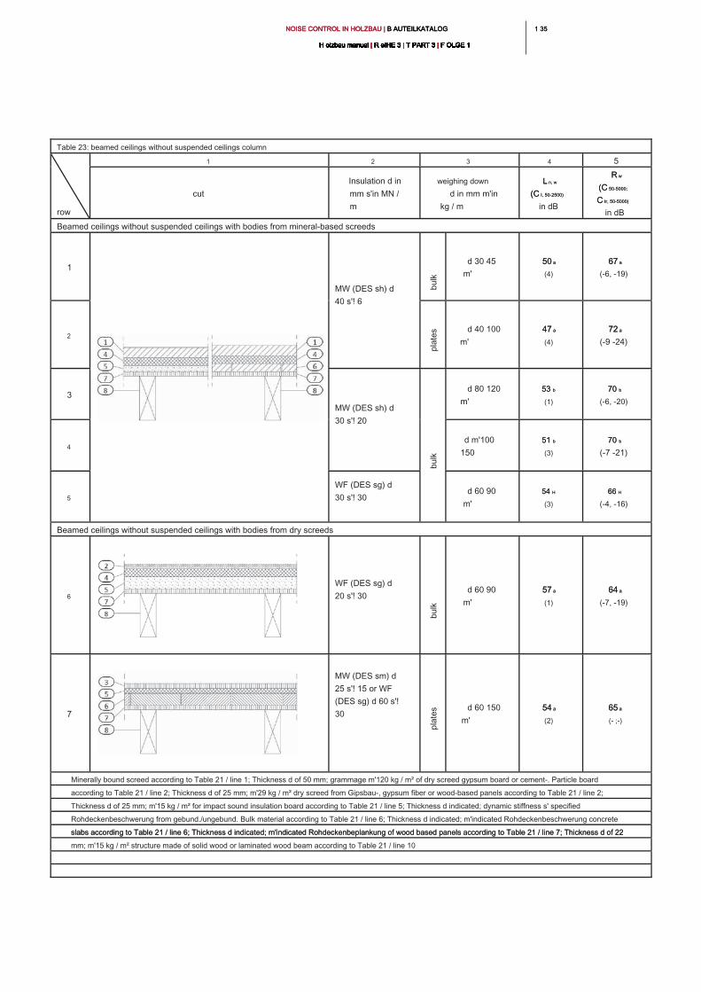
1 351 35NOISE CONTROL IN HOLZBAU | B AUTEILKATALOG NOISE CONTROL IN HOLZBAU | B AUTEILKATALOG NOISE CONTROL IN HOLZBAU | B AUTEILKATALOG
H olzbau manual | R eIHE 3 | T PART 3 | F OLGE 1H olzbau manual | R eIHE 3 | T PART 3 | F OLGE 1H olzbau manual | R eIHE 3 | T PART 3 | F OLGE 1H olzbau manual | R eIHE 3 | T PART 3 | F OLGE 1H olzbau manual | R eIHE 3 | T PART 3 | F OLGE 1H olzbau manual | R eIHE 3 | T PART 3 | F OLGE 1H olzbau manual | R eIHE 3 | T PART 3 | F OLGE 1H olzbau manual | R eIHE 3 | T PART 3 | F OLGE 1H olzbau manual | R eIHE 3 | T PART 3 | F OLGE 1H olzbau manual | R eIHE 3 | T PART 3 | F OLGE 1H olzbau manual | R eIHE 3 | T PART 3 | F OLGE 1
Table 23: beamed ceilings without suspended ceilings column
row
1 2 3 4 5
cut
Insulation d in
mm s'in MN /
m
weighing down
d in mm m'in
kg / m
L n, wL n, w
(C I, 50-2500)(C I, 50-2500)
in dB
R wR w
(C 50-5000;(C 50-5000;
C tr, 50-5000)C tr, 50-5000)
in dB
Beamed ceilings without suspended ceilings with bodies from mineral-based screeds
1
MW (DES sh) d
40 s'! 6
d 30 45
m'
50 a50 a
(4)
67 a67 a
(-6, -19)
2
d 40 100
m'
47 a47 a
(4)
72 a72 a
(-9 -24)
3
MW (DES sh) d
30 s'! 20
d 80 120
m'
53 b53 b
(1)
70 b70 b
(-6, -20)
4
d m'100
150
51 b51 b
(3)
70 b70 b
(-7 -21)
5
WF (DES sg) d
30 s'! 30
d 60 90
m'
54 H54 H
(3)
66 H66 H
(-4, -16)
Beamed ceilings without suspended ceilings with bodies from dry screeds
6
WF (DES sg) d
20 s'! 30
d 60 90
m'
57 a57 a
(1)
64 a64 a
(-7, -19)
7
MW (DES sm) d
25 s'! 15 or WF
(DES sg) d 60 s'!
30
d 60 150
m'
54 a54 a
(2)
65 a65 a
(- ;-)
Minerally bound screed according to Table 21 / line 1; Thickness d of 50 mm; grammage m'120 kg / m² of dry screed gypsum board or cement-. Particle board
according to Table 21 / line 2; Thickness d of 25 mm; m'29 kg / m² dry screed from Gipsbau-, gypsum fiber or wood-based panels according to Table 21 / line 2;
Thickness d of 25 mm; m'15 kg / m² for impact sound insulation board according to Table 21 / line 5; Thickness d indicated; dynamic stiffness s' specified
Rohdeckenbeschwerung from gebund./ungebund. Bulk material according to Table 21 / line 6; Thickness d indicated; m'indicated Rohdeckenbeschwerung concrete
slabs according to Table 21 / line 6; Thickness d indicated; m'indicated Rohdeckenbeplankung of wood based panels according to Table 21 / line 7; Thickness d of 22 slabs according to Table 21 / line 6; Thickness d indicated; m'indicated Rohdeckenbeplankung of wood based panels according to Table 21 / line 7; Thickness d of 22
mm; m'15 kg / m² structure made of solid wood or laminated wood beam according to Table 21 / line 10
bu
lk
pla
te
sb
ulk
bu
lk
pla
te
s
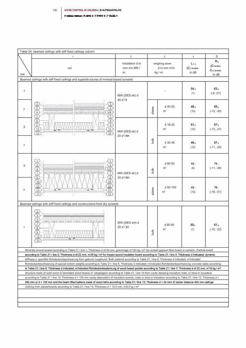
NOISE CONTROL IN HOLZBAU | B AUTEILKATALOG NOISE CONTROL IN HOLZBAU | B AUTEILKATALOG NOISE CONTROL IN HOLZBAU | B AUTEILKATALOG
H olzbau manual | R eIHE 3 | T PART 3 | F OLGE 1H olzbau manual | R eIHE 3 | T PART 3 | F OLGE 1H olzbau manual | R eIHE 3 | T PART 3 | F OLGE 1H olzbau manual | R eIHE 3 | T PART 3 | F OLGE 1H olzbau manual | R eIHE 3 | T PART 3 | F OLGE 1H olzbau manual | R eIHE 3 | T PART 3 | F OLGE 1H olzbau manual | R eIHE 3 | T PART 3 | F OLGE 1H olzbau manual | R eIHE 3 | T PART 3 | F OLGE 1H olzbau manual | R eIHE 3 | T PART 3 | F OLGE 1H olzbau manual | R eIHE 3 | T PART 3 | F OLGE 1H olzbau manual | R eIHE 3 | T PART 3 | F OLGE 1
136
Table 24: beamed ceilings with stiff fixed ceilings column
row
1 2 3 4 5
cut
Insulation d in
mm s'in MN /
m
weighing down
d in mm m'in
kg / m
L n, wL n, w
(C I, 50-2500)(C I, 50-2500)
in dB
R wR w
(C 50-5000;(C 50-5000;
C tr, 50-5000)C tr, 50-5000)
in dB
Beamed ceilings with stiff fixed ceilings and superstructures of mineral-based screeds
1
MW (DES sh) d
40 s'! 6
-
54 a54 a
(7)
63 a63 a
(-8 -21)
2
d 40 50
m'
48 a48 a
(10)
65 a65 a
(-12, -25)
3
MW (DES sh) d
20 s'! 8th
d 18 25
m'
51 a51 a
(10)
67 a67 a
(-13, -27)
4
d 30 45
m'
46 a46 a
(12)
67 a67 a
(-11, -24)
5
MW (DES sh) d
20 s'! 8th
d 60 90
m'
43 i43 i
(6)
74 i74 i
(-11, -26)
6
d 50 100
m'
43 i43 i
(10)
76 i76 i
(-16, -31)
Beamed ceilings with stiff fixed ceilings and constructions from dry screeds
7
MW (DES sm) d
20 s'! 30
d 60 90
m'
55 a55 a
(7)
61 a61 a
(-10, -23)
Minerally bound screed according to Table 21 / line 1; Thickness d of 50 mm; grammage m'120 kg / m² dry screed gypsum fiber board or cement-. Particle board
according to Table 21 / line 2; Thickness d of 22 mm; m'29 kg / m² for impact sound insulation board according to Table 21 / line 5; Thickness d indicated; dynamic according to Table 21 / line 2; Thickness d of 22 mm; m'29 kg / m² for impact sound insulation board according to Table 21 / line 5; Thickness d indicated; dynamic
stiffness s' specified Rohdeckenbeschwerung from gebund./ungebund. Bulk material according to Table 21 / line 6; Thickness d indicated; m'indicated
Rohdeckenbeschwerung of special bottom weights according to Table 21 / line 6; Thickness d indicated; m'indicated Rohdeckenbeschwerung concrete slabs according
to Table 21 / line 6; Thickness d indicated; m'indicated Rohdeckenbeplankung of wood based panels according to Table 21 / line 7; Thickness d of 22 mm; m'15 kg / m² to Table 21 / line 6; Thickness d indicated; m'indicated Rohdeckenbeplankung of wood based panels according to Table 21 / line 7; Thickness d of 22 mm; m'15 kg / m²
structure made of solid wood or laminated wood beams or -stegträgern according to Table 21 / line 10 from cavity damping insulation mats, or blow-in insulation
according to Table 21 / line 12; Thickness d = 100 mm cavity attenuation of insulation boards, mats or blow-in insulation according to Table 21 / line 12; Thickness d =
200 mm or d = 100 mm and the beam lifted battens made of wood laths according to Table 21 / line 13; Thickness d = 24 mm; E center distance 400 mm ceilings 200 mm or d = 100 mm and the beam lifted battens made of wood laths according to Table 21 / line 13; Thickness d = 24 mm; E center distance 400 mm ceilings
clothing from plasterboards according to Table 21 / line 14; Thickness d = 12.5 mm; m'8.5 kg / m²
pla
te
sb
ulk
bu
lk
pla
te
sb
ulk
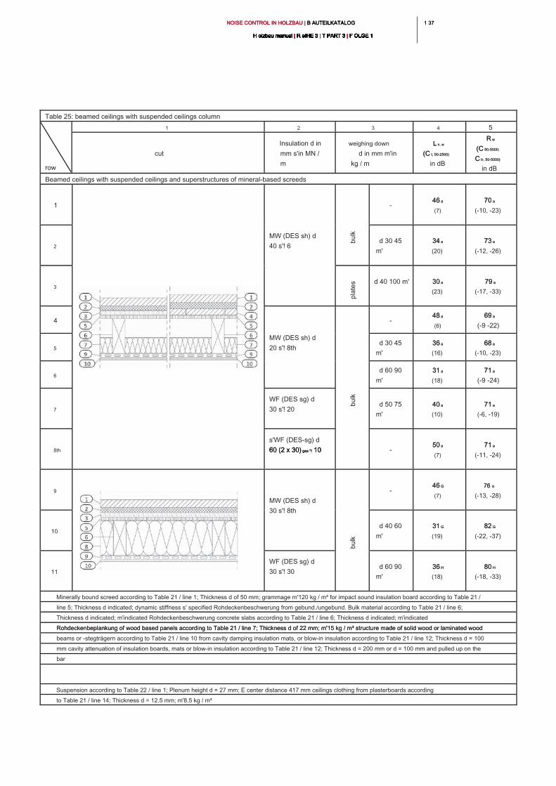
1 371 37NOISE CONTROL IN HOLZBAU | B AUTEILKATALOG NOISE CONTROL IN HOLZBAU | B AUTEILKATALOG NOISE CONTROL IN HOLZBAU | B AUTEILKATALOG
H olzbau manual | R eIHE 3 | T PART 3 | F OLGE 1H olzbau manual | R eIHE 3 | T PART 3 | F OLGE 1H olzbau manual | R eIHE 3 | T PART 3 | F OLGE 1H olzbau manual | R eIHE 3 | T PART 3 | F OLGE 1H olzbau manual | R eIHE 3 | T PART 3 | F OLGE 1H olzbau manual | R eIHE 3 | T PART 3 | F OLGE 1H olzbau manual | R eIHE 3 | T PART 3 | F OLGE 1H olzbau manual | R eIHE 3 | T PART 3 | F OLGE 1H olzbau manual | R eIHE 3 | T PART 3 | F OLGE 1H olzbau manual | R eIHE 3 | T PART 3 | F OLGE 1H olzbau manual | R eIHE 3 | T PART 3 | F OLGE 1
Table 25: beamed ceilings with suspended ceilings column
row
1 2 3 4 5
cut
Insulation d in
mm s'in MN /
m
weighing down
d in mm m'in
kg / m
L n, wL n, w
(C I, 50-2500)(C I, 50-2500)
in dB
R wR w
(C 50-5000;(C 50-5000;
C tr, 50-5000)C tr, 50-5000)
in dB
Beamed ceilings with suspended ceilings and superstructures of mineral-based screeds
1
MW (DES sh) d
40 s'! 6
-
46 a46 a
(7)
70 a70 a
(-10, -23)
2
d 30 45
m'
34 a34 a
(20)
73 a73 a
(-12, -26)
3
d 40 100 m' 30 a30 a
(23)
79 a79 a
(-17, -33)
4
MW (DES sh) d
20 s'! 8th
-
48 a48 a
(6)
69 a69 a
(-9 -22)
5
d 30 45
m'
36 a36 a
(16)
68 a68 a
(-10, -23)
6
d 60 90
m'
31 a31 a
(18)
71 a71 a
(-9 -24)
7
WF (DES sg) d
30 s'! 20
d 50 75
m'
40 a40 a
(10)
71 a71 a
(-6, -19)
8th
s'WF (DES-sg) d
60 (2 x 30) ges "! 10 60 (2 x 30) ges "! 10 60 (2 x 30) ges "! 10 -
50 a50 a
(7)
71 a71 a
(-11, -24)
9
MW (DES sh) d
30 s'! 8th
-
46 G46 G
(7)
76 G76 G
(-13, -28)
10
d 40 60
m'
31 G31 G
(19)
82 G82 G
(-22, -37)
11
WF (DES sg) d
30 s'! 30
d 60 90
m'
36 H36 H
(18)
80 H80 H
(-18, -33)
Minerally bound screed according to Table 21 / line 1; Thickness d of 50 mm; grammage m'120 kg / m² for impact sound insulation board according to Table 21 /
line 5; Thickness d indicated; dynamic stiffness s' specified Rohdeckenbeschwerung from gebund./ungebund. Bulk material according to Table 21 / line 6;
Thickness d indicated; m'indicated Rohdeckenbeschwerung concrete slabs according to Table 21 / line 6; Thickness d indicated; m'indicated
Rohdeckenbeplankung of wood based panels according to Table 21 / line 7; Thickness d of 22 mm; m'15 kg / m² structure made of solid wood or laminated wood Rohdeckenbeplankung of wood based panels according to Table 21 / line 7; Thickness d of 22 mm; m'15 kg / m² structure made of solid wood or laminated wood
beams or -stegträgern according to Table 21 / line 10 from cavity damping insulation mats, or blow-in insulation according to Table 21 / line 12; Thickness d = 100
mm cavity attenuation of insulation boards, mats or blow-in insulation according to Table 21 / line 12; Thickness d = 200 mm or d = 100 mm and pulled up on the
bar
Suspension according to Table 22 / line 1; Plenum height d = 27 mm; E center distance 417 mm ceilings clothing from plasterboards according
to Table 21 / line 14; Thickness d = 12.5 mm; m'8.5 kg / m²
bu
lk
pla
te
sb
ulk
bu
lk
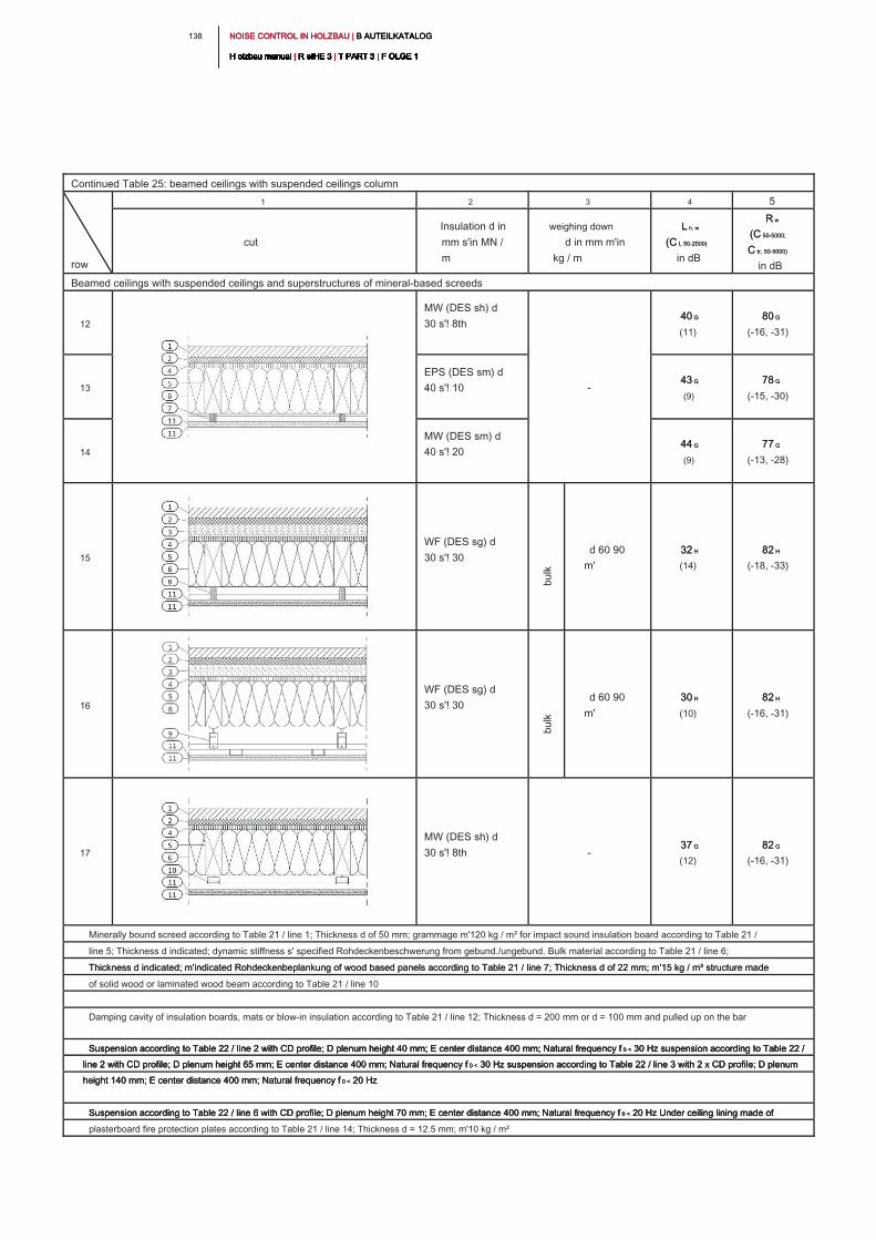
NOISE CONTROL IN HOLZBAU | B AUTEILKATALOG NOISE CONTROL IN HOLZBAU | B AUTEILKATALOG NOISE CONTROL IN HOLZBAU | B AUTEILKATALOG
H olzbau manual | R eIHE 3 | T PART 3 | F OLGE 1H olzbau manual | R eIHE 3 | T PART 3 | F OLGE 1H olzbau manual | R eIHE 3 | T PART 3 | F OLGE 1H olzbau manual | R eIHE 3 | T PART 3 | F OLGE 1H olzbau manual | R eIHE 3 | T PART 3 | F OLGE 1H olzbau manual | R eIHE 3 | T PART 3 | F OLGE 1H olzbau manual | R eIHE 3 | T PART 3 | F OLGE 1H olzbau manual | R eIHE 3 | T PART 3 | F OLGE 1H olzbau manual | R eIHE 3 | T PART 3 | F OLGE 1H olzbau manual | R eIHE 3 | T PART 3 | F OLGE 1H olzbau manual | R eIHE 3 | T PART 3 | F OLGE 1
138
Continued Table 25: beamed ceilings with suspended ceilings column
row
1 2 3 4 5
cut
Insulation d in
mm s'in MN /
m
weighing down
d in mm m'in
kg / m
L n, wL n, w
(C I, 50-2500)(C I, 50-2500)
in dB
R wR w
(C 50-5000;(C 50-5000;
C tr, 50-5000)C tr, 50-5000)
in dB
Beamed ceilings with suspended ceilings and superstructures of mineral-based screeds
12
MW (DES sh) d
30 s'! 8th
-
40 G40 G
(11)
80 G80 G
(-16, -31)
13
EPS (DES sm) d
40 s'! 10
43 G43 G
(9)
78 G78 G
(-15, -30)
14
MW (DES sm) d
40 s'! 20
44 G44 G
(9)
77 G77 G
(-13, -28)
15
WF (DES sg) d
30 s'! 30
d 60 90
m'
32 H32 H
(14)
82 H82 H
(-18, -33)
16
WF (DES sg) d
30 s'! 30
d 60 90
m'
30 H30 H
(10)
82 H82 H
(-16, -31)
17
MW (DES sh) d
30 s'! 8th -
37 G37 G
(12)
82 G82 G
(-16, -31)
Minerally bound screed according to Table 21 / line 1; Thickness d of 50 mm; grammage m'120 kg / m² for impact sound insulation board according to Table 21 /
line 5; Thickness d indicated; dynamic stiffness s' specified Rohdeckenbeschwerung from gebund./ungebund. Bulk material according to Table 21 / line 6;
Thickness d indicated; m'indicated Rohdeckenbeplankung of wood based panels according to Table 21 / line 7; Thickness d of 22 mm; m'15 kg / m² structure made Thickness d indicated; m'indicated Rohdeckenbeplankung of wood based panels according to Table 21 / line 7; Thickness d of 22 mm; m'15 kg / m² structure made
of solid wood or laminated wood beam according to Table 21 / line 10
Damping cavity of insulation boards, mats or blow-in insulation according to Table 21 / line 12; Thickness d = 200 mm or d = 100 mm and pulled up on the bar
Suspension according to Table 22 / line 2 with CD profile; D plenum height 40 mm; E center distance 400 mm; Natural frequency f 0 < 30 Hz suspension according to Table 22 / Suspension according to Table 22 / line 2 with CD profile; D plenum height 40 mm; E center distance 400 mm; Natural frequency f 0 < 30 Hz suspension according to Table 22 / Suspension according to Table 22 / line 2 with CD profile; D plenum height 40 mm; E center distance 400 mm; Natural frequency f 0 < 30 Hz suspension according to Table 22 /
line 2 with CD profile; D plenum height 65 mm; E center distance 400 mm; Natural frequency f 0 < 30 Hz suspension according to Table 22 / line 3 with 2 x CD profile; D plenum line 2 with CD profile; D plenum height 65 mm; E center distance 400 mm; Natural frequency f 0 < 30 Hz suspension according to Table 22 / line 3 with 2 x CD profile; D plenum line 2 with CD profile; D plenum height 65 mm; E center distance 400 mm; Natural frequency f 0 < 30 Hz suspension according to Table 22 / line 3 with 2 x CD profile; D plenum
height 140 mm; E center distance 400 mm; Natural frequency f 0 < 20 Hzheight 140 mm; E center distance 400 mm; Natural frequency f 0 < 20 Hzheight 140 mm; E center distance 400 mm; Natural frequency f 0 < 20 Hz
Suspension according to Table 22 / line 6 with CD profile; D plenum height 70 mm; E center distance 400 mm; Natural frequency f 0 < 20 Hz Under ceiling lining made of Suspension according to Table 22 / line 6 with CD profile; D plenum height 70 mm; E center distance 400 mm; Natural frequency f 0 < 20 Hz Under ceiling lining made of Suspension according to Table 22 / line 6 with CD profile; D plenum height 70 mm; E center distance 400 mm; Natural frequency f 0 < 20 Hz Under ceiling lining made of
plasterboard fire protection plates according to Table 21 / line 14; Thickness d = 12.5 mm; m'10 kg / m²
bu
lk
bu
lk
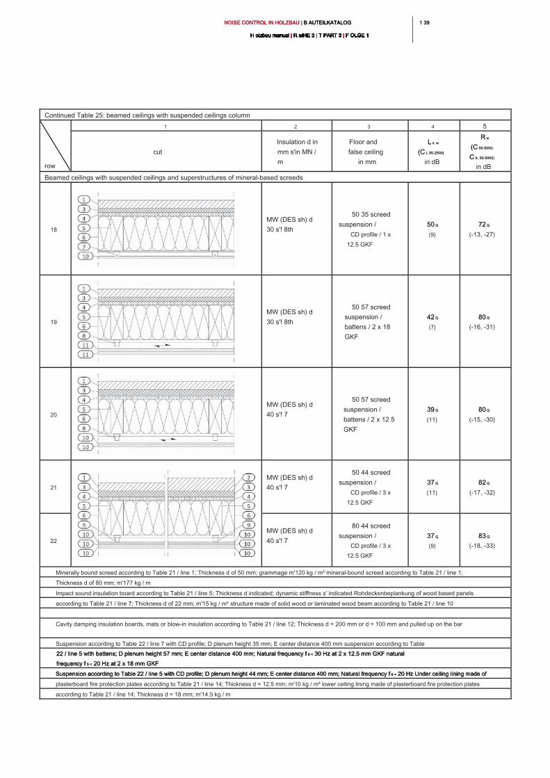
1 391 39NOISE CONTROL IN HOLZBAU | B AUTEILKATALOG NOISE CONTROL IN HOLZBAU | B AUTEILKATALOG NOISE CONTROL IN HOLZBAU | B AUTEILKATALOG
H olzbau manual | R eIHE 3 | T PART 3 | F OLGE 1H olzbau manual | R eIHE 3 | T PART 3 | F OLGE 1H olzbau manual | R eIHE 3 | T PART 3 | F OLGE 1H olzbau manual | R eIHE 3 | T PART 3 | F OLGE 1H olzbau manual | R eIHE 3 | T PART 3 | F OLGE 1H olzbau manual | R eIHE 3 | T PART 3 | F OLGE 1H olzbau manual | R eIHE 3 | T PART 3 | F OLGE 1H olzbau manual | R eIHE 3 | T PART 3 | F OLGE 1H olzbau manual | R eIHE 3 | T PART 3 | F OLGE 1H olzbau manual | R eIHE 3 | T PART 3 | F OLGE 1H olzbau manual | R eIHE 3 | T PART 3 | F OLGE 1
Continued Table 25: beamed ceilings with suspended ceilings column
row
1 2 3 4 5
cut
Insulation d in
mm s'in MN /
m
Floor and
false ceiling
in mm
L n, wL n, w
(C I, 50-2500)(C I, 50-2500)
in dB
R wR w
(C 50-5000;(C 50-5000;
C tr, 50-5000)C tr, 50-5000)
in dB
Beamed ceilings with suspended ceilings and superstructures of mineral-based screeds
18
MW (DES sh) d
30 s'! 8th
50 35 screed
suspension /
CD profile / 1 x
12.5 GKF
50 G50 G
(9)
72 G72 G
(-13, -27)
19
MW (DES sh) d
30 s'! 8th
50 57 screed
suspension /
battens / 2 x 18
GKF
42 G42 G
(7)
80 G80 G
(-16, -31)
20
MW (DES sh) d
40 s'! 7
50 57 screed
suspension /
battens / 2 x 12.5
GKF
39 G39 G
(11)
80 G80 G
(-15, -30)
21
MW (DES sh) d
40 s'! 7
50 44 screed
suspension /
CD profile / 3 x
12.5 GKF
37 G37 G
(11)
82 G82 G
(-17, -32)
22
MW (DES sh) d
40 s'! 7
80 44 screed
suspension /
CD profile / 3 x
12.5 GKF
37 G37 G
(9)
83 G83 G
(-18, -33)
Minerally bound screed according to Table 21 / line 1; Thickness d of 50 mm; grammage m'120 kg / m² mineral-bound screed according to Table 21 / line 1;
Thickness d of 80 mm; m'177 kg / m
Impact sound insulation board according to Table 21 / line 5; Thickness d indicated; dynamic stiffness s' indicated Rohdeckenbeplankung of wood based panels
according to Table 21 / line 7; Thickness d of 22 mm; m'15 kg / m² structure made of solid wood or laminated wood beam according to Table 21 / line 10
Cavity damping insulation boards, mats or blow-in insulation according to Table 21 / line 12; Thickness d = 200 mm or d = 100 mm and pulled up on the bar
Suspension according to Table 22 / line 7 with CD profile; D plenum height 35 mm; E center distance 400 mm suspension according to Table
22 / line 5 with battens; D plenum height 57 mm; E center distance 400 mm; Natural frequency f 0 < 30 Hz at 2 x 12.5 mm GKF natural 22 / line 5 with battens; D plenum height 57 mm; E center distance 400 mm; Natural frequency f 0 < 30 Hz at 2 x 12.5 mm GKF natural 22 / line 5 with battens; D plenum height 57 mm; E center distance 400 mm; Natural frequency f 0 < 30 Hz at 2 x 12.5 mm GKF natural
frequency f 0 < 20 Hz at 2 x 18 mm GKFfrequency f 0 < 20 Hz at 2 x 18 mm GKFfrequency f 0 < 20 Hz at 2 x 18 mm GKF
Suspension according to Table 22 / line 5 with CD profile; D plenum height 44 mm; E center distance 400 mm; Natural frequency f 0 < 20 Hz Under ceiling lining made of Suspension according to Table 22 / line 5 with CD profile; D plenum height 44 mm; E center distance 400 mm; Natural frequency f 0 < 20 Hz Under ceiling lining made of Suspension according to Table 22 / line 5 with CD profile; D plenum height 44 mm; E center distance 400 mm; Natural frequency f 0 < 20 Hz Under ceiling lining made of
plasterboard fire protection plates according to Table 21 / line 14; Thickness d = 12.5 mm; m'10 kg / m² lower ceiling lining made of plasterboard fire protection plates
according to Table 21 / line 14; Thickness d = 18 mm; m'14.5 kg / m
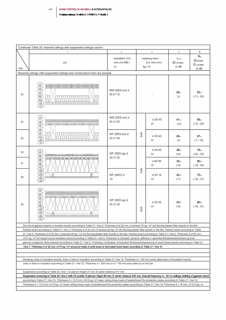
NOISE CONTROL IN HOLZBAU | B AUTEILKATALOG NOISE CONTROL IN HOLZBAU | B AUTEILKATALOG NOISE CONTROL IN HOLZBAU | B AUTEILKATALOG
H olzbau manual | R eIHE 3 | T PART 3 | F OLGE 1H olzbau manual | R eIHE 3 | T PART 3 | F OLGE 1H olzbau manual | R eIHE 3 | T PART 3 | F OLGE 1H olzbau manual | R eIHE 3 | T PART 3 | F OLGE 1H olzbau manual | R eIHE 3 | T PART 3 | F OLGE 1H olzbau manual | R eIHE 3 | T PART 3 | F OLGE 1H olzbau manual | R eIHE 3 | T PART 3 | F OLGE 1H olzbau manual | R eIHE 3 | T PART 3 | F OLGE 1H olzbau manual | R eIHE 3 | T PART 3 | F OLGE 1H olzbau manual | R eIHE 3 | T PART 3 | F OLGE 1H olzbau manual | R eIHE 3 | T PART 3 | F OLGE 1
140
Continued Table 25: beamed ceilings with suspended ceilings column
row
1 2 3 4 5
cut
Insulation d in
mm s'in MN /
m
weighing down
d in mm m'in
kg / m
L n, wL n, w
(C I, 50-2500)(C I, 50-2500)
in dB
R wR w
(C 50-5000;(C 50-5000;
C tr, 50-5000)C tr, 50-5000)
in dB
Beamed ceilings with suspended ceilings and constructions from dry screeds
23
MW (DES sm) d
25 s'! 15 -
56 a56 a
(2)
63 a63 a
(-11, -25)
24
MW (DES sm) d
20 s'! 20
d 30 45
m'
41 a41 a
(8th)
69 a69 a
(-10, -23)
25
WF (DES sm) d
20 s'! 30
d 30 45
m'
45 a45 a
(5)
67 a67 a
(-7, -19)
26
WF (DES sg) d
30 s'! 30
d 30 45
m'
38 H38 H
(16)
79 H79 H
(-20, -35)
27
d 60 90
m'
34 H34 H
(16)
80 H80 H
(-19, -34)
28
WF (DEO) d
10
d 30 12
m'
42 H42 H
(11)
75 H75 H
(-16, -31)
29
WF (DES sg) d
30 s'! 30
d 30 45
m'
34 H34 H
(15)
80 H80 H
(-16, -31)
Dry line of gypsum boards or wooden boards according to Table 21 / line 2; Thickness d of 22 mm; m'cement-15 kg / m² dry flooring plaster fiber boards or the like.
Particle board according to Table 21 / line 2; Thickness d of 22 mm; m'cement-29 kg / m² dry flooring plaster fiber boards or the like. Particle board according to Table
21 / line 2; Thickness d of 20 mm; m'cement-25 kg / m² dry flooring plaster fiber boards or the like. Particle board according to Table 21 / line 2; Thickness d of 25 mm;
m'31 kg / m² for impact sound insulation board according to Table 21 / line 5; Thickness d indicated; dynamic stiffness s' specified Rohdeckenbeschwerung from
gebund./ungebund. Bulk material according to Table 21 / line 6; Thickness d indicated; m'indicated Rohdeckenbeplankung of wood based panels according to Table 21
/ line 7; Thickness d of 22 mm; m'15 kg / m² structure made of solid wood or laminated wood beam according to Table 21 / line 10/ line 7; Thickness d of 22 mm; m'15 kg / m² structure made of solid wood or laminated wood beam according to Table 21 / line 10
Damping cavity of insulation boards, mats or blow-in insulation according to Table 21 / line 12; Thickness d = 100 mm cavity attenuation of insulation boards,
mats or blow-in insulation according to Table 21 / line 12; Thickness d = 200 mm or d = 100 mm and pulled up on the bar
Suspension according to Table 22 / line 1; D plenum height 27 mm; E center distance 417 mm
Suspension according to Table 22 / line 2 with CD profile; D plenum height 65 mm; E center distance 400 mm; Natural frequency f 0 < 30 Hz ceilings clothing of gypsum board Suspension according to Table 22 / line 2 with CD profile; D plenum height 65 mm; E center distance 400 mm; Natural frequency f 0 < 30 Hz ceilings clothing of gypsum board Suspension according to Table 22 / line 2 with CD profile; D plenum height 65 mm; E center distance 400 mm; Natural frequency f 0 < 30 Hz ceilings clothing of gypsum board
according to Table 21 / line 14; Thickness d = 12.5 mm; m'8.5 kg / m² lower ceiling lining made of plasterboard fire protection plates according to Table 21 / line 14;
Thickness d = 12.5 mm; m'10 kg / m² lower ceiling lining made of plasterboard fire protection plates according to Table 21 / line 14; Thickness d = 18 mm; m'14.5 kg / m
bu
lk
bu
lk
bu
lk
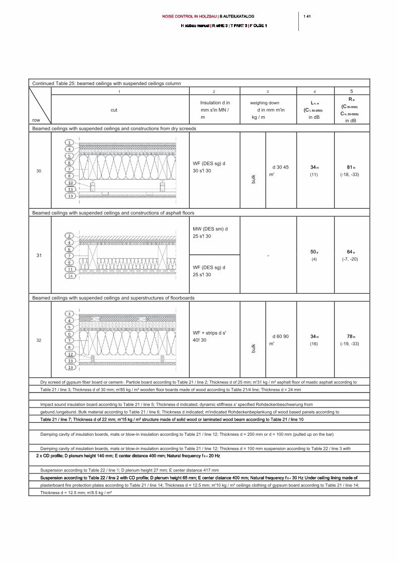
1 411 41NOISE CONTROL IN HOLZBAU | B AUTEILKATALOG NOISE CONTROL IN HOLZBAU | B AUTEILKATALOG NOISE CONTROL IN HOLZBAU | B AUTEILKATALOG
H olzbau manual | R eIHE 3 | T PART 3 | F OLGE 1H olzbau manual | R eIHE 3 | T PART 3 | F OLGE 1H olzbau manual | R eIHE 3 | T PART 3 | F OLGE 1H olzbau manual | R eIHE 3 | T PART 3 | F OLGE 1H olzbau manual | R eIHE 3 | T PART 3 | F OLGE 1H olzbau manual | R eIHE 3 | T PART 3 | F OLGE 1H olzbau manual | R eIHE 3 | T PART 3 | F OLGE 1H olzbau manual | R eIHE 3 | T PART 3 | F OLGE 1H olzbau manual | R eIHE 3 | T PART 3 | F OLGE 1H olzbau manual | R eIHE 3 | T PART 3 | F OLGE 1H olzbau manual | R eIHE 3 | T PART 3 | F OLGE 1
Continued Table 25: beamed ceilings with suspended ceilings column
row
1 2 3 4 5
cut
Insulation d in
mm s'in MN /
m
weighing down
d in mm m'in
kg / m
L n, wL n, w
(C I, 50-2500)(C I, 50-2500)
in dB
R wR w
(C 50-5000;(C 50-5000;
C tr, 50-5000)C tr, 50-5000)
in dB
Beamed ceilings with suspended ceilings and constructions from dry screeds
30
WF (DES sg) d
30 s'! 30
d 30 45
m'
34 H34 H
(11)
81 H81 H
(-18, -33)
Beamed ceilings with suspended ceilings and constructions of asphalt floors
31
MW (DES sm) d
25 s'! 30
-
50 a50 a
(4)
64 a64 a
(-7, -20)
WF (DES sg) d
25 s'! 30
Beamed ceilings with suspended ceilings and superstructures of floorboards
32
WF + strips d s'
40! 30
d 60 90
m'
34 H34 H
(16)
78 H78 H
(-19, -33)
Dry screed of gypsum fiber board or cement-. Particle board according to Table 21 / line 2; Thickness d of 25 mm; m'31 kg / m² asphalt floor of mastic asphalt according to
Table 21 / line 3; Thickness d of 30 mm; m'85 kg / m² wooden floor boards made of wood according to Table 21/4 line; Thickness d = 24 mm
Impact sound insulation board according to Table 21 / line 5; Thickness d indicated; dynamic stiffness s' specified Rohdeckenbeschwerung from
gebund./ungebund. Bulk material according to Table 21 / line 6; Thickness d indicated; m'indicated Rohdeckenbeplankung of wood based panels according to
Table 21 / line 7; Thickness d of 22 mm; m'15 kg / m² structure made of solid wood or laminated wood beam according to Table 21 / line 10Table 21 / line 7; Thickness d of 22 mm; m'15 kg / m² structure made of solid wood or laminated wood beam according to Table 21 / line 10
Damping cavity of insulation boards, mats or blow-in insulation according to Table 21 / line 12; Thickness d = 200 mm or d = 100 mm (pulled up on the bar)
Damping cavity of insulation boards, mats or blow-in insulation according to Table 21 / line 12; Thickness d = 100 mm suspension according to Table 22 / line 3 with
2 x CD profile; D plenum height 140 mm; E center distance 400 mm; Natural frequency f 0 < 20 Hz2 x CD profile; D plenum height 140 mm; E center distance 400 mm; Natural frequency f 0 < 20 Hz2 x CD profile; D plenum height 140 mm; E center distance 400 mm; Natural frequency f 0 < 20 Hz
Suspension according to Table 22 / line 1; D plenum height 27 mm; E center distance 417 mm
Suspension according to Table 22 / line 2 with CD profile; D plenum height 65 mm; E center distance 400 mm; Natural frequency f 0 < 30 Hz Under ceiling lining made of Suspension according to Table 22 / line 2 with CD profile; D plenum height 65 mm; E center distance 400 mm; Natural frequency f 0 < 30 Hz Under ceiling lining made of Suspension according to Table 22 / line 2 with CD profile; D plenum height 65 mm; E center distance 400 mm; Natural frequency f 0 < 30 Hz Under ceiling lining made of
plasterboard fire protection plates according to Table 21 / line 14; Thickness d = 12.5 mm; m'10 kg / m² ceilings clothing of gypsum board according to Table 21 / line 14;
Thickness d = 12.5 mm; m'8.5 kg / m²
bu
lk
bu
lk
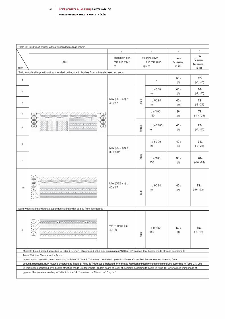
NOISE CONTROL IN HOLZBAU | B AUTEILKATALOG NOISE CONTROL IN HOLZBAU | B AUTEILKATALOG NOISE CONTROL IN HOLZBAU | B AUTEILKATALOG
H olzbau manual | R eIHE 3 | T PART 3 | F OLGE 1H olzbau manual | R eIHE 3 | T PART 3 | F OLGE 1H olzbau manual | R eIHE 3 | T PART 3 | F OLGE 1H olzbau manual | R eIHE 3 | T PART 3 | F OLGE 1H olzbau manual | R eIHE 3 | T PART 3 | F OLGE 1H olzbau manual | R eIHE 3 | T PART 3 | F OLGE 1H olzbau manual | R eIHE 3 | T PART 3 | F OLGE 1H olzbau manual | R eIHE 3 | T PART 3 | F OLGE 1H olzbau manual | R eIHE 3 | T PART 3 | F OLGE 1H olzbau manual | R eIHE 3 | T PART 3 | F OLGE 1H olzbau manual | R eIHE 3 | T PART 3 | F OLGE 1
142
Table 26: Solid wood ceilings without suspended ceilings column
row
1 2 3 4 5
cut
Insulation d in
mm s'in MN /
m
weighing down
d in mm m'in
kg / m
L n, wL n, w
(C I, 50-2500)(C I, 50-2500)
in dB
R wR w
(C 50-5000;(C 50-5000;
C tr, 50-5000)C tr, 50-5000)
in dB
Solid wood ceilings without suspended ceilings with bodies from mineral-based screeds
1
MW (DES sh) d
40 s'! 7
-
56 a56 a
(3)
62 a62 a
(-6, -18)
2
d 40 60
m'
46 a46 a
(5)
68 a68 a
(-7, -20)
3
d 60 90
m'
40 c40 c
(8th)
72 c72 c
(-8 -21)
4
d m'100
150
38 j38 j
(4)
77 j77 j
(-13, -28)
5
d 40 100
m'
45 a45 a
(4)
72 a72 a
(-8, -23)
6
MW (DES sh) d
30 s'! 8th
d 60 90
m'
40 G40 G
(9)
74 G74 G
(-9 -24)
7
d m'100
150
38 G38 G
(5)
76 G76 G
(-10, -25)
8th
MW (DES sh) d
40 s'! 7
d 60 90
m'
40 c40 c
(7)
73 c73 c
(-16, -32)
Solid wood ceilings without suspended ceilings with bodies from floorboards
9
WF + strips d s'
40! 30
d m'100
150
50 H50 H
(1)
65 H65 H
(-5, -16)
Minerally bound screed according to Table 21 / line 1; Thickness d of 50 mm; grammage m'120 kg / m² wooden floor boards made of wood according to
Table 21/4 line; Thickness d = 24 mm
Impact sound insulation board according to Table 21 / line 5; Thickness d indicated; dynamic stiffness s' specified Rohdeckenbeschwerung from
gebund./ungebund. Bulk material according to Table 21 / line 6; Thickness d indicated; m'indicated Rohdeckenbeschwerung concrete slabs according to Table 21 / Line gebund./ungebund. Bulk material according to Table 21 / line 6; Thickness d indicated; m'indicated Rohdeckenbeschwerung concrete slabs according to Table 21 / Line
6; Thickness d indicated; m'indicated structure made Brettsperrholz-, glulam board or stack of elements according to Table 21 / line 10, lower ceiling lining made of
gypsum fiber plates according to Table 21 / line 14; Thickness d = 15 mm; m'17 kg / m²
bu
lk
pla
te
sb
ulk
bu
lk
bu
lk
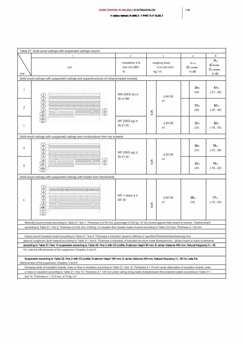
1 431 43NOISE CONTROL IN HOLZBAU | B AUTEILKATALOG NOISE CONTROL IN HOLZBAU | B AUTEILKATALOG NOISE CONTROL IN HOLZBAU | B AUTEILKATALOG
H olzbau manual | R eIHE 3 | T PART 3 | F OLGE 1H olzbau manual | R eIHE 3 | T PART 3 | F OLGE 1H olzbau manual | R eIHE 3 | T PART 3 | F OLGE 1H olzbau manual | R eIHE 3 | T PART 3 | F OLGE 1H olzbau manual | R eIHE 3 | T PART 3 | F OLGE 1H olzbau manual | R eIHE 3 | T PART 3 | F OLGE 1H olzbau manual | R eIHE 3 | T PART 3 | F OLGE 1H olzbau manual | R eIHE 3 | T PART 3 | F OLGE 1H olzbau manual | R eIHE 3 | T PART 3 | F OLGE 1H olzbau manual | R eIHE 3 | T PART 3 | F OLGE 1H olzbau manual | R eIHE 3 | T PART 3 | F OLGE 1
Table 27: Solid wood ceilings with suspended ceilings column
row
1 2 3 4 5
cut
Insulation d in
mm s'in MN /
m
weighing down
d in mm m'in
kg / m
L n, wL n, w
(C I, 50-2500)(C I, 50-2500)
in dB
R wR w
(C 50-5000;(C 50-5000;
C tr, 50-5000)C tr, 50-5000)
in dB
Solid wood ceilings with suspended ceilings and superstructures of mineral-based screeds
1
MW (DES sh) d
30 s'! 8th
d 60 90
m'
24 G24 G
(29)
81 G81 G
(-21, -36)
2
23 G23 G
(26)
82 G82 G
(-20, -35)
3
WF (DES sg) d
30 s'! 30
d 60 90
m'
32 H32 H
(23)
82 H82 H
(-18, -33)
Solid wood ceilings with suspended ceilings and constructions from dry screeds
4
WF (DES sg) d
30 s'! 30
d 60 90
m'
36 H36 H
(23)
78 H78 H
(-23, -38)
5
33 H33 H
(20)
79 H79 H
(-18, -32)
Solid wood ceilings with suspended ceilings with bodies from floorboards
6
WF + strips d s'
40! 30
d 60 90
m'
36 H36 H
(16)
77 H77 H
(-15, -30)
Minerally bound screed according to Table 21 / line 1; Thickness d of 50 mm; grammage m'120 kg / m² dry screed gypsum fiber board or cement-. Particle board
according to Table 21 / line 2; Thickness d of 22 mm; m'29 kg / m² wooden floor boards made of wood according to Table 21/4 line; Thickness d = 24 mm
Impact sound insulation board according to Table 21 / line 5; Thickness d indicated; dynamic stiffness s' specified Rohdeckenbeschwerung from
gebund./ungebund. Bulk material according to Table 21 / line 6; Thickness d indicated; m'indicated structure made Brettsperrholz-, glulam board or stack of elements
according to Table 21 / line 10 suspension according to Table 22 / line 2 with CD profile; D plenum height 90 mm; E center distance 400 mm; Natural frequency f 0 < 30 according to Table 21 / line 10 suspension according to Table 22 / line 2 with CD profile; D plenum height 90 mm; E center distance 400 mm; Natural frequency f 0 < 30 according to Table 21 / line 10 suspension according to Table 22 / line 2 with CD profile; D plenum height 90 mm; E center distance 400 mm; Natural frequency f 0 < 30
Hz; note the effectiveness of the suspension Chapters 3 and 4!
Suspension according to Table 22 / line 2 with CD profile; D plenum height 180 mm; E center distance 400 mm; Natural frequency f 0 < 30 Hz; note the Suspension according to Table 22 / line 2 with CD profile; D plenum height 180 mm; E center distance 400 mm; Natural frequency f 0 < 30 Hz; note the Suspension according to Table 22 / line 2 with CD profile; D plenum height 180 mm; E center distance 400 mm; Natural frequency f 0 < 30 Hz; note the
effectiveness of the suspension Chapters 3 and 4!
Damping cavity of insulation boards, mats or blow-in insulation according to Table 21 / line 12; Thickness d = 75 mm cavity attenuation of insulation boards, mats
or blow-in insulation according to Table 21 / line 12; Thickness d = 120 mm under ceiling lining made of plasterboard fire protection plates according to Table 21 /
line 14; Thickness d = 12.5 mm; m'10 kg / m²
bu
lk
bu
lk
bu
lk
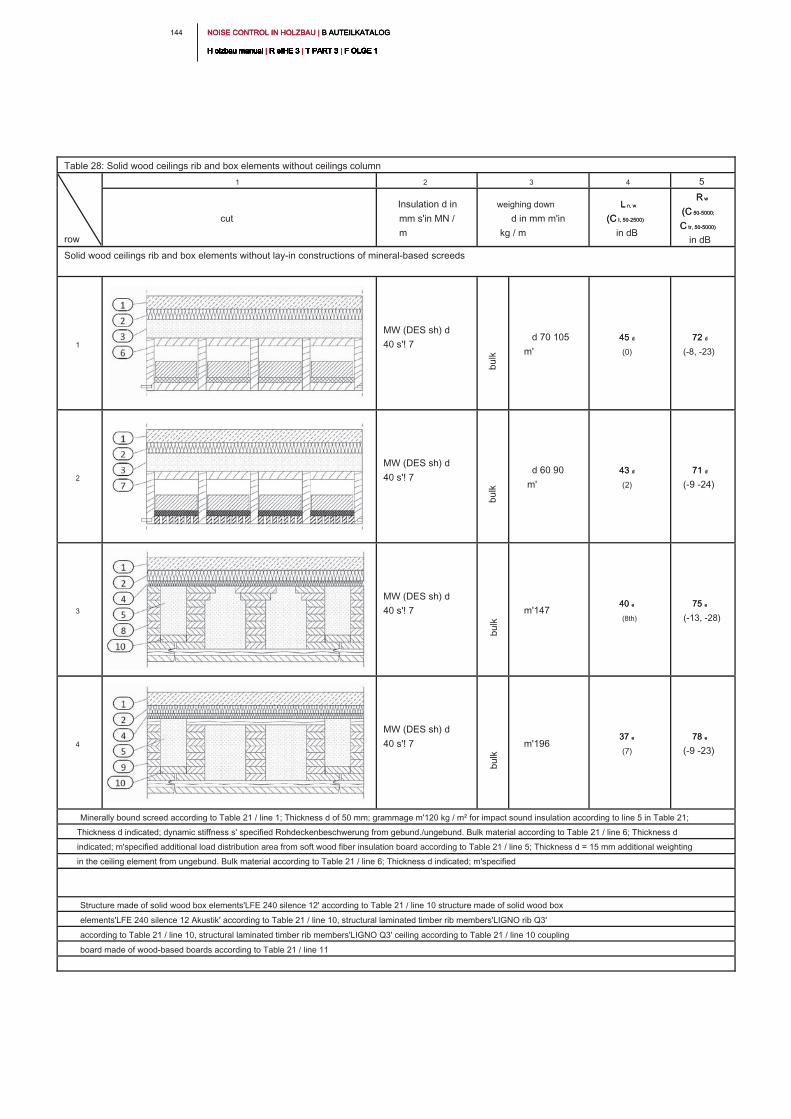
NOISE CONTROL IN HOLZBAU | B AUTEILKATALOG NOISE CONTROL IN HOLZBAU | B AUTEILKATALOG NOISE CONTROL IN HOLZBAU | B AUTEILKATALOG
H olzbau manual | R eIHE 3 | T PART 3 | F OLGE 1H olzbau manual | R eIHE 3 | T PART 3 | F OLGE 1H olzbau manual | R eIHE 3 | T PART 3 | F OLGE 1H olzbau manual | R eIHE 3 | T PART 3 | F OLGE 1H olzbau manual | R eIHE 3 | T PART 3 | F OLGE 1H olzbau manual | R eIHE 3 | T PART 3 | F OLGE 1H olzbau manual | R eIHE 3 | T PART 3 | F OLGE 1H olzbau manual | R eIHE 3 | T PART 3 | F OLGE 1H olzbau manual | R eIHE 3 | T PART 3 | F OLGE 1H olzbau manual | R eIHE 3 | T PART 3 | F OLGE 1H olzbau manual | R eIHE 3 | T PART 3 | F OLGE 1
144
Table 28: Solid wood ceilings rib and box elements without ceilings column
row
1 2 3 4 5
cut
Insulation d in
mm s'in MN /
m
weighing down
d in mm m'in
kg / m
L n, wL n, w
(C I, 50-2500)(C I, 50-2500)
in dB
R wR w
(C 50-5000;(C 50-5000;
C tr, 50-5000)C tr, 50-5000)
in dB
Solid wood ceilings rib and box elements without lay-in constructions of mineral-based screeds
1
MW (DES sh) d
40 s'! 7
d 70 105
m'
45 d45 d
(0)
72 d72 d
(-8, -23)
2
MW (DES sh) d
40 s'! 7
d 60 90
m'
43 d43 d
(2)
71 d71 d
(-9 -24)
3
MW (DES sh) d
40 s'! 7 m'147
40 e40 e
(8th)
75 e75 e
(-13, -28)
4
MW (DES sh) d
40 s'! 7 m'196
37 e37 e
(7)
78 e78 e
(-9 -23)
Minerally bound screed according to Table 21 / line 1; Thickness d of 50 mm; grammage m'120 kg / m² for impact sound insulation according to line 5 in Table 21;
Thickness d indicated; dynamic stiffness s' specified Rohdeckenbeschwerung from gebund./ungebund. Bulk material according to Table 21 / line 6; Thickness d
indicated; m'specified additional load distribution area from soft wood fiber insulation board according to Table 21 / line 5; Thickness d = 15 mm additional weighting
in the ceiling element from ungebund. Bulk material according to Table 21 / line 6; Thickness d indicated; m'specified
Structure made of solid wood box elements'LFE 240 silence 12' according to Table 21 / line 10 structure made of solid wood box
elements'LFE 240 silence 12 Akustik' according to Table 21 / line 10, structural laminated timber rib members'LIGNO rib Q3'
according to Table 21 / line 10, structural laminated timber rib members'LIGNO Q3' ceiling according to Table 21 / line 10 coupling
board made of wood-based boards according to Table 21 / line 11
bu
lk
bu
lk
bu
lk
bu
lk
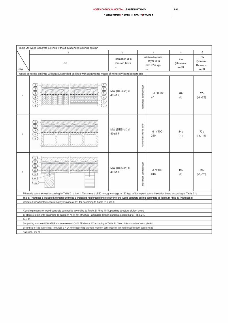
1 451 45NOISE CONTROL IN HOLZBAU | B AUTEILKATALOG NOISE CONTROL IN HOLZBAU | B AUTEILKATALOG NOISE CONTROL IN HOLZBAU | B AUTEILKATALOG
H olzbau manual | R eIHE 3 | T PART 3 | F OLGE 1H olzbau manual | R eIHE 3 | T PART 3 | F OLGE 1H olzbau manual | R eIHE 3 | T PART 3 | F OLGE 1H olzbau manual | R eIHE 3 | T PART 3 | F OLGE 1H olzbau manual | R eIHE 3 | T PART 3 | F OLGE 1H olzbau manual | R eIHE 3 | T PART 3 | F OLGE 1H olzbau manual | R eIHE 3 | T PART 3 | F OLGE 1H olzbau manual | R eIHE 3 | T PART 3 | F OLGE 1H olzbau manual | R eIHE 3 | T PART 3 | F OLGE 1H olzbau manual | R eIHE 3 | T PART 3 | F OLGE 1H olzbau manual | R eIHE 3 | T PART 3 | F OLGE 1
Table 29: wood-concrete ceilings without suspended ceilings column
row
1 2 3 4 5
cut
Insulation d in
mm s'in MN /
m
reinforced concrete
layer D in
mm m'in kg /
m
L n, wL n, w
(C I, 50-2500)(C I, 50-2500)
in dB
R wR w
(C 50-5000;(C 50-5000;
C tr, 50-5000)C tr, 50-5000)
in dB
Wood-concrete ceilings without suspended ceilings with abutments made of minerally bonded screeds
1
MW (DES sh) d
40 s'! 7
d 80 200
m'
46 i46 i
(5)
67 i67 i
(-9 -22)
2
MW (DES sh) d
40 s'! 7
d m'100
240
44 b44 b
(-1)
72 b72 b
(-4, -18)
3
MW (DES sh) d
40 s'! 7
d m'100
240
49 f49 f
(2)
69 f69 f
(-6, -20)
Minerally bound screed according to Table 21 / line 1; Thickness d of 50 mm; grammage m'120 kg / m² for impact sound insulation board according to Table 21 /
line 5; Thickness d indicated; dynamic stiffness s' indicated reinforced concrete layer of the wood-concrete ceiling according to Table 21 / line 8; Thickness d line 5; Thickness d indicated; dynamic stiffness s' indicated reinforced concrete layer of the wood-concrete ceiling according to Table 21 / line 8; Thickness d
indicated; m'indicated separating layer made of PE-foil according to Table 21 / line 9
Coupling means for wood-concrete composite according to Table 21 / line 15 Supporting structure glulam board
or stack of elements according to Table 21 / line 10, structural laminated timber elements according to Table 21 /
line 10
Supporting structure LIGNATUR-surface elements 240'LFE silence 12' according to Table 21 / line 10 floorboards of wood planks
according to Table 21/4 line; Thickness d = 24 mm supporting structure made of solid wood or laminated wood beam according to
Table 21 / line 10
Re
in
fo
rce
d co
ncre
te
la
ye
rR
ein
fo
rce
d co
ncre
te
la
ye
rR
ein
fo
rce
d co
ncre
te
la
ye
r
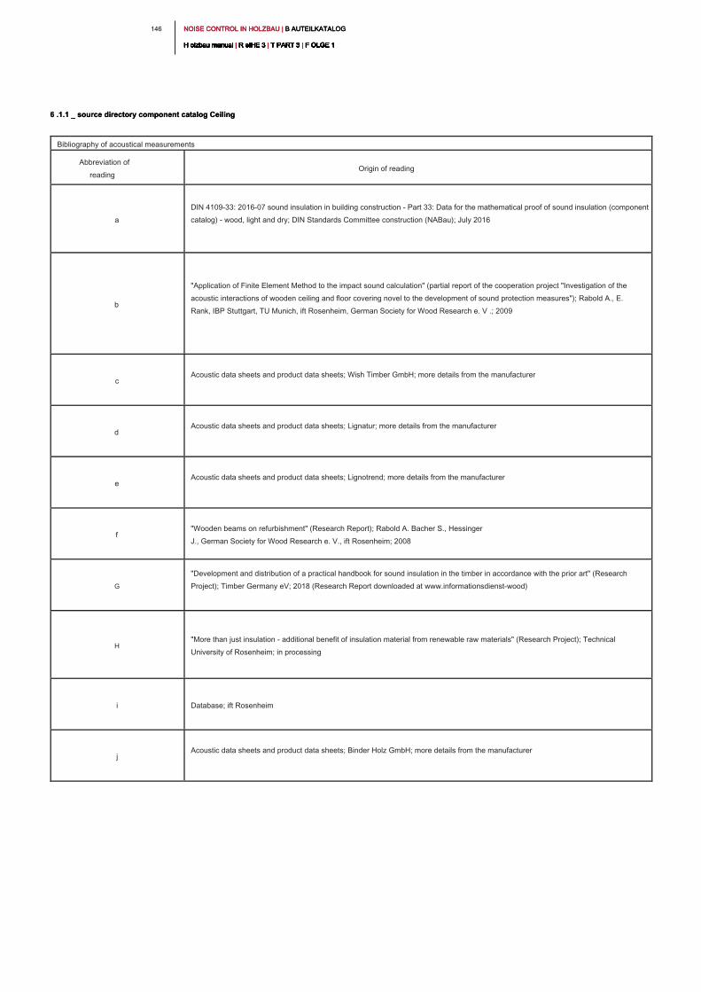
NOISE CONTROL IN HOLZBAU | B AUTEILKATALOG NOISE CONTROL IN HOLZBAU | B AUTEILKATALOG NOISE CONTROL IN HOLZBAU | B AUTEILKATALOG
H olzbau manual | R eIHE 3 | T PART 3 | F OLGE 1H olzbau manual | R eIHE 3 | T PART 3 | F OLGE 1H olzbau manual | R eIHE 3 | T PART 3 | F OLGE 1H olzbau manual | R eIHE 3 | T PART 3 | F OLGE 1H olzbau manual | R eIHE 3 | T PART 3 | F OLGE 1H olzbau manual | R eIHE 3 | T PART 3 | F OLGE 1H olzbau manual | R eIHE 3 | T PART 3 | F OLGE 1H olzbau manual | R eIHE 3 | T PART 3 | F OLGE 1H olzbau manual | R eIHE 3 | T PART 3 | F OLGE 1H olzbau manual | R eIHE 3 | T PART 3 | F OLGE 1H olzbau manual | R eIHE 3 | T PART 3 | F OLGE 1
146
Bibliography of acoustical measurements
Abbreviation of
reading
Origin of reading
a
DIN 4109-33: 2016-07 sound insulation in building construction - Part 33: Data for the mathematical proof of sound insulation (component
catalog) - wood, light and dry; DIN Standards Committee construction (NABau); July 2016
b
"Application of Finite Element Method to the impact sound calculation" (partial report of the cooperation project "Investigation of the
acoustic interactions of wooden ceiling and floor covering novel to the development of sound protection measures"); Rabold A., E.
Rank, IBP Stuttgart, TU Munich, ift Rosenheim, German Society for Wood Research e. V .; 2009
c
Acoustic data sheets and product data sheets; Wish Timber GmbH; more details from the manufacturer
d
Acoustic data sheets and product data sheets; Lignatur; more details from the manufacturer
e
Acoustic data sheets and product data sheets; Lignotrend; more details from the manufacturer
f
"Wooden beams on refurbishment" (Research Report); Rabold A. Bacher S., Hessinger
J., German Society for Wood Research e. V., ift Rosenheim; 2008
G
"Development and distribution of a practical handbook for sound insulation in the timber in accordance with the prior art" (Research
Project); Timber Germany eV; 2018 (Research Report downloaded at www.informationsdienst-wood)
H
"More than just insulation - additional benefit of insulation material from renewable raw materials" (Research Project); Technical
University of Rosenheim; in processing
i Database; ift Rosenheim
j
Acoustic data sheets and product data sheets; Binder Holz GmbH; more details from the manufacturer
6 .1.1 _ source directory component catalog Ceiling6 .1.1 _ source directory component catalog Ceiling
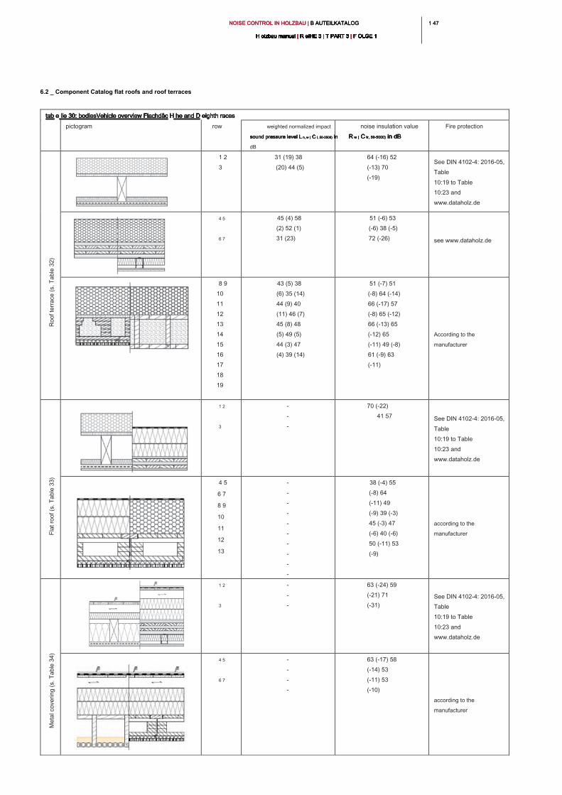
1 471 47NOISE CONTROL IN HOLZBAU | B AUTEILKATALOG NOISE CONTROL IN HOLZBAU | B AUTEILKATALOG NOISE CONTROL IN HOLZBAU | B AUTEILKATALOG
H olzbau manual | R eIHE 3 | T PART 3 | F OLGE 1H olzbau manual | R eIHE 3 | T PART 3 | F OLGE 1H olzbau manual | R eIHE 3 | T PART 3 | F OLGE 1H olzbau manual | R eIHE 3 | T PART 3 | F OLGE 1H olzbau manual | R eIHE 3 | T PART 3 | F OLGE 1H olzbau manual | R eIHE 3 | T PART 3 | F OLGE 1H olzbau manual | R eIHE 3 | T PART 3 | F OLGE 1H olzbau manual | R eIHE 3 | T PART 3 | F OLGE 1H olzbau manual | R eIHE 3 | T PART 3 | F OLGE 1H olzbau manual | R eIHE 3 | T PART 3 | F OLGE 1H olzbau manual | R eIHE 3 | T PART 3 | F OLGE 1
6.2 _ Component Catalog flat roofs and roof terraces
tab e lle 30: bodiesVehicle overview Flachdäc H he and D eighth racestab e lle 30: bodiesVehicle overview Flachdäc H he and D eighth racestab e lle 30: bodiesVehicle overview Flachdäc H he and D eighth racestab e lle 30: bodiesVehicle overview Flachdäc H he and D eighth racestab e lle 30: bodiesVehicle overview Flachdäc H he and D eighth racestab e lle 30: bodiesVehicle overview Flachdäc H he and D eighth races
pictogram row weighted normalized impact
sound pressure level L n, w ( C I, 50-2500) in sound pressure level L n, w ( C I, 50-2500) in sound pressure level L n, w ( C I, 50-2500) in sound pressure level L n, w ( C I, 50-2500) in sound pressure level L n, w ( C I, 50-2500) in
dB
noise insulation value
R w ( C tr, 50-5000) in dB R w ( C tr, 50-5000) in dB R w ( C tr, 50-5000) in dB R w ( C tr, 50-5000) in dB R w ( C tr, 50-5000) in dB
Fire protection
1 2
3
31 (19) 38
(20) 44 (5)
64 (-16) 52
(-13) 70
(-19)
See DIN 4102-4: 2016-05,
Table
10:19 to Table
10:23 and
www.dataholz.de
4 5
6 7
45 (4) 58
(2) 52 (1)
31 (23)
51 (-6) 53
(-6) 38 (-5)
72 (-26)
see www.dataholz.de
8 9
10
11
12
13
14
15
16
17
18
19
43 (5) 38
(6) 35 (14)
44 (9) 40
(11) 46 (7)
45 (8) 48
(5) 49 (5)
44 (3) 47
(4) 39 (14)
51 (-7) 51
(-8) 64 (-14)
66 (-17) 57
(-8) 65 (-12)
66 (-13) 65
(-12) 65
(-11) 49 (-8)
61 (-9) 63
(-11)
According to the
manufacturer
1 2
3
-
-
-
70 (-22)
41 57
See DIN 4102-4: 2016-05,
Table
10:19 to Table
10:23 and
www.dataholz.de
4 5
6 7
8 9
10
11
12
13
-
-
-
-
-
-
-
-
-
-
38 (-4) 55
(-8) 64
(-11) 49
(-9) 39 (-3)
45 (-3) 47
(-6) 40 (-6)
50 (-11) 53
(-9)
according to the
manufacturer
1 2
3
-
-
-
63 (-24) 59
(-21) 71
(-31)
See DIN 4102-4: 2016-05,
Table
10:19 to Table
10:23 and
www.dataholz.de
4 5
6 7
-
-
-
-
63 (-17) 58
(-14) 53
(-11) 53
(-10)
according to the
manufacturer
Ro
of te
rra
ce
(s. T
ab
le
3
2)
Fla
t ro
of (s. T
ab
le
3
3)
Me
ta
l co
ve
rin
g (s. T
ab
le
3
4)
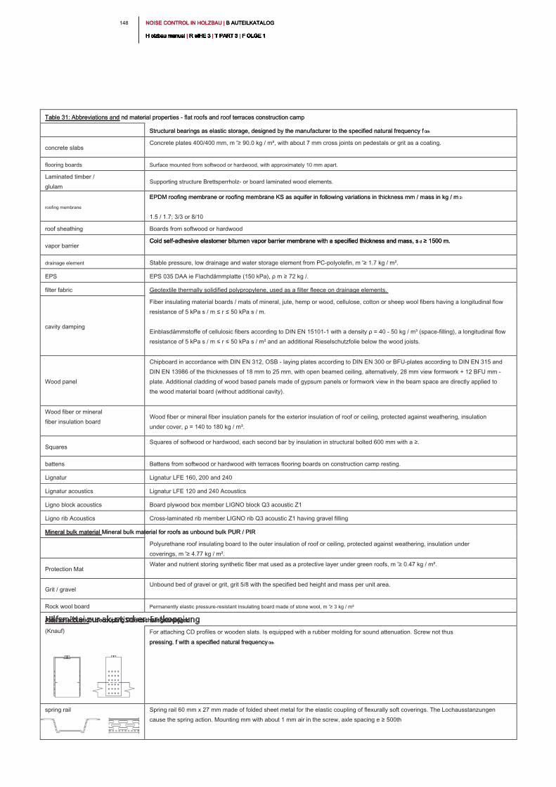
NOISE CONTROL IN HOLZBAU | B AUTEILKATALOG NOISE CONTROL IN HOLZBAU | B AUTEILKATALOG NOISE CONTROL IN HOLZBAU | B AUTEILKATALOG
H olzbau manual | R eIHE 3 | T PART 3 | F OLGE 1H olzbau manual | R eIHE 3 | T PART 3 | F OLGE 1H olzbau manual | R eIHE 3 | T PART 3 | F OLGE 1H olzbau manual | R eIHE 3 | T PART 3 | F OLGE 1H olzbau manual | R eIHE 3 | T PART 3 | F OLGE 1H olzbau manual | R eIHE 3 | T PART 3 | F OLGE 1H olzbau manual | R eIHE 3 | T PART 3 | F OLGE 1H olzbau manual | R eIHE 3 | T PART 3 | F OLGE 1H olzbau manual | R eIHE 3 | T PART 3 | F OLGE 1H olzbau manual | R eIHE 3 | T PART 3 | F OLGE 1H olzbau manual | R eIHE 3 | T PART 3 | F OLGE 1
148
Table 31: Abbreviations and nd material properties - flat roofs and roof terraces construction camp Table 31: Abbreviations and nd material properties - flat roofs and roof terraces construction camp
Structural bearings as elastic storage, designed by the manufacturer to the specified natural frequency f 0thStructural bearings as elastic storage, designed by the manufacturer to the specified natural frequency f 0th
concrete slabs
Concrete plates 400/400 mm, m '≥ 90.0 kg / m², with about 7 mm cross joints on pedestals or grit as a coating.
flooring boards Surface mounted from softwood or hardwood, with approximately 10 mm apart.
Laminated timber /
glulam
Supporting structure Brettsperrholz- or board laminated wood elements.
roofing membrane
EPDM roofing membrane or roofing membrane KS as aquifer in following variations in thickness mm / mass in kg / m 2:EPDM roofing membrane or roofing membrane KS as aquifer in following variations in thickness mm / mass in kg / m 2:
1.5 / 1.7; 3/3 or 8/10
roof sheathing Boards from softwood or hardwood
vapor barrier
Cold self-adhesive elastomer bitumen vapor barrier membrane with a specified thickness and mass, s d ≥ 1500 m. Cold self-adhesive elastomer bitumen vapor barrier membrane with a specified thickness and mass, s d ≥ 1500 m. Cold self-adhesive elastomer bitumen vapor barrier membrane with a specified thickness and mass, s d ≥ 1500 m.
drainage element Stable pressure, low drainage and water storage element from PC-polyolefin, m '≥ 1.7 kg / m².
EPS EPS 035 DAA ie Flachdämmplatte (150 kPa), ρ m ≥ 72 kg /.
filter fabric Geotextile thermally solidified polypropylene, used as a filter fleece on drainage elements.
cavity damping
Fiber insulating material boards / mats of mineral, jute, hemp or wood, cellulose, cotton or sheep wool fibers having a longitudinal flow
resistance of 5 kPa s / m ≤ r ≤ 50 kPa s / m.
Einblasdämmstoffe of cellulosic fibers according to DIN EN 15101-1 with a density ρ = 40 - 50 kg / m³ (space-filling), a longitudinal flow
resistance of 5 kPa s / m ≤ r ≤ 50 kPa s / m² and an additional Rieselschutzfolie below the wood joists.
Wood panel
Chipboard in accordance with DIN EN 312, OSB - laying plates according to DIN EN 300 or BFU-plates according to DIN EN 315 and
DIN EN 13986 of the thicknesses of 18 mm to 25 mm, with open beamed ceiling, alternatively, 28 mm view formwork + 12 BFU mm -
plate. Additional cladding of wood based panels made of gypsum panels or formwork view in the beam space are directly applied to
the wood material board (without additional cavity).
Wood fiber or mineral
fiber insulation board
Wood fiber or mineral fiber insulation panels for the exterior insulation of roof or ceiling, protected against weathering, insulation
under cover, ρ = 140 to 180 kg / m³.
Squares
Squares of softwood or hardwood, each second bar by insulation in structural bolted 600 mm with a ≥.
battens Battens from softwood or hardwood with terraces flooring boards on construction camp resting.
Lignatur Lignatur LFE 160, 200 and 240
Lignatur acoustics Lignatur LFE 120 and 240 Acoustics
Ligno block acoustics Board plywood box member LIGNO block Q3 acoustic Z1
Ligno rib Acoustics Cross-laminated rib member LIGNO rib Q3 acoustic Z1 having gravel filling
Mineral bulk material Mineral bulk material for roofs as unbound bulk PUR / PIR Mineral bulk material Mineral bulk material for roofs as unbound bulk PUR / PIR
Polyurethane roof insulating board to the outer insulation of roof or ceiling, protected against weathering, insulation under
coverings, m '≥ 4.77 kg / m².
Protection Mat
Water and nutrient storing synthetic fiber mat used as a protective layer under green roofs, m '≥ 0.47 kg / m².
Grit / gravel
Unbound bed of gravel or grit, grit 5/8 with the specified bed height and mass per unit area.
Rock wool board Permanently elastic pressure-resistant insulating board made of stone wool, m '≥ 3 kg / m²
Aids for acoustic n decoupling Direktschwingabhänger Aids for acoustic n decoupling Direktschwingabhänger
(Knauf) For attaching CD profiles or wooden slats. Is equipped with a rubber molding for sound attenuation. Screw not thus
pressing. f with a specified natural frequency 0thpressing. f with a specified natural frequency 0th
spring rail Spring rail 60 mm x 27 mm made of folded sheet metal for the elastic coupling of flexurally soft coverings. The Lochausstanzungen
cause the spring action. Mounting mm with about 1 mm air in the screw, axle spacing e ≥ 500th
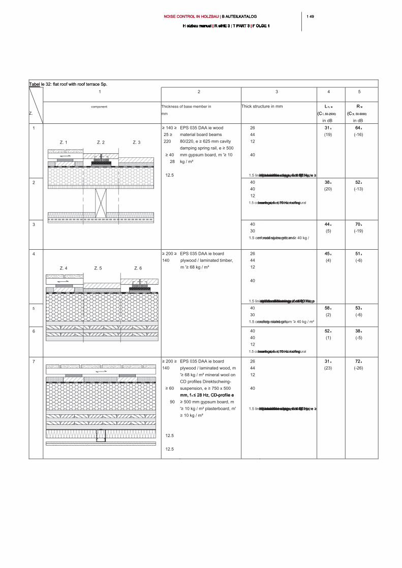
1 491 49NOISE CONTROL IN HOLZBAU | B AUTEILKATALOG NOISE CONTROL IN HOLZBAU | B AUTEILKATALOG NOISE CONTROL IN HOLZBAU | B AUTEILKATALOG
H olzbau manual | R eIHE 3 | T PART 3 | F OLGE 1H olzbau manual | R eIHE 3 | T PART 3 | F OLGE 1H olzbau manual | R eIHE 3 | T PART 3 | F OLGE 1H olzbau manual | R eIHE 3 | T PART 3 | F OLGE 1H olzbau manual | R eIHE 3 | T PART 3 | F OLGE 1H olzbau manual | R eIHE 3 | T PART 3 | F OLGE 1H olzbau manual | R eIHE 3 | T PART 3 | F OLGE 1H olzbau manual | R eIHE 3 | T PART 3 | F OLGE 1H olzbau manual | R eIHE 3 | T PART 3 | F OLGE 1H olzbau manual | R eIHE 3 | T PART 3 | F OLGE 1H olzbau manual | R eIHE 3 | T PART 3 | F OLGE 1
Tabel le 32: flat roof with roof terrace Sp. Tabel le 32: flat roof with roof terrace Sp.
Z.
1 2 3 4 5
component Thickness of base member in
mm
Thick structure in mm L n, w L n, w
(C I, 50-2500)(C I, 50-2500)
in dB
R wR w
(C tr, 50-5000)(C tr, 50-5000)
in dB
1
Z. 1 Z. 2 Z. 3
≥ 140 ≥
25 ≥
220
≥ 40
28
12.5
EPS 035 DAA ie wood
material board beams
80/220, e ≥ 625 mm cavity
damping spring rail, e ≥ 500
mm gypsum board, m '≥ 10
kg / m²
26
44
12
40
1.5 lining boards battens, e ≥ 520 mm structural bearings, f 0 ≤ 60 Hz, e ≥ structural bearings, f 0 ≤ 60 Hz, e ≥ structural bearings, f 0 ≤ 60 Hz, e ≥ 660 x 520 mm grit, m '≥ 60 kg / m² concrete slab under construction camp roofing membrane
31 a31 a
(19)
64 a64 a
(-16)
2 40
40
12
1.5 concrete slabs pedestal structural bearings, f 0 ≤ 70 Hz roofing bearings, f 0 ≤ 70 Hz roofing bearings, f 0 ≤ 70 Hz roofing membrane
38 a38 a
(20)
52 a52 a
(-13)
3 40
30
1.5 concrete slabs grit, m '≥ 40 kg / m² roofing membrane
44 a44 a
(5)
70 a70 a
(-19)
4
Z. 4 Z. 5 Z. 6
≥ 200 ≥
140
EPS 035 DAA ie board
plywood / laminated timber,
m '≥ 68 kg / m²
26
44
12
40
1.5 lining boards battens, e ≥ 520 mm structural bearings, f 0 ≤ 60 Hz, e structural bearings, f 0 ≤ 60 Hz, e structural bearings, f 0 ≤ 60 Hz, e ≥ 660 x 520 mm grit, m '≥ 60 kg / m² concrete slab under construction camp roofing membrane
45 a45 a
(4)
51 a51 a
(-6)
5 40
30
1.5 concrete slabs grit, m '≥ 40 kg / m² roofing membrane
58 a58 a
(2)
53 a53 a
(-6)
6 40
40
12
1.5 concrete slabs pedestal structural bearings, f 0 ≤ 70 Hz roofing bearings, f 0 ≤ 70 Hz roofing bearings, f 0 ≤ 70 Hz roofing membrane
52 a52 a
(1)
38 a38 a
(-5)
7 ≥ 200 ≥
140
≥ 60
90
12.5
12.5
EPS 035 DAA ie board
plywood / laminated wood, m
'≥ 68 kg / m² mineral wool on
CD profiles Direktschwing-
suspension, e ≥ 750 x 500
mm, f 0 ≤ 28 Hz, CD-profile e mm, f 0 ≤ 28 Hz, CD-profile e mm, f 0 ≤ 28 Hz, CD-profile e
≥ 500 mm gypsum board, m
'≥ 10 kg / m² plasterboard, m'
≥ 10 kg / m²
26
44
12
40
1.5 lining boards battens, e ≥ 520 mm structural bearings, f 0 ≤ 60 Hz, e ≥ structural bearings, f 0 ≤ 60 Hz, e ≥ structural bearings, f 0 ≤ 60 Hz, e ≥ 660 x 520mm grit, m '≥ 60 kg / m² concrete slab under construction camp roofing membrane
31 a31 a
(23)
72 a72 a
(-26)
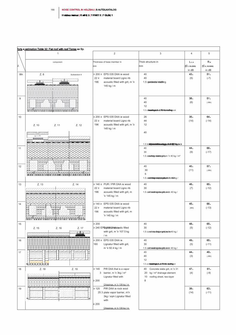
NOISE CONTROL IN HOLZBAU | B AUTEILKATALOG NOISE CONTROL IN HOLZBAU | B AUTEILKATALOG NOISE CONTROL IN HOLZBAU | B AUTEILKATALOG
H olzbau manual | R eIHE 3 | T PART 3 | F OLGE 1H olzbau manual | R eIHE 3 | T PART 3 | F OLGE 1H olzbau manual | R eIHE 3 | T PART 3 | F OLGE 1H olzbau manual | R eIHE 3 | T PART 3 | F OLGE 1H olzbau manual | R eIHE 3 | T PART 3 | F OLGE 1H olzbau manual | R eIHE 3 | T PART 3 | F OLGE 1H olzbau manual | R eIHE 3 | T PART 3 | F OLGE 1H olzbau manual | R eIHE 3 | T PART 3 | F OLGE 1H olzbau manual | R eIHE 3 | T PART 3 | F OLGE 1H olzbau manual | R eIHE 3 | T PART 3 | F OLGE 1H olzbau manual | R eIHE 3 | T PART 3 | F OLGE 1
150
forts e estimation Table 32: Flat roof with roof Terras se Sp. forts e estimation Table 32: Flat roof with roof Terras se Sp. forts e estimation Table 32: Flat roof with roof Terras se Sp. forts e estimation Table 32: Flat roof with roof Terras se Sp.
Z.
1 2 3 4 5
component Thickness of base member in
mm
Thick structure in
mm
L n, wL n, w
(C I, 50-2500)(C I, 50-2500)
in dB
R wR w
(C tr, 50-5000)(C tr, 50-5000)
in dB
8th Z. 8 Subsection 9 ≥ 200 ≥
22 ≥
196
EPS 035 DAA ie wood
material board Ligno rib
acoustic filled with grit, m '≥
145 kg / m
40
40
1.5 concrete slabs pedestal roofing
43 a43 a
(5)
51 a51 a
(-7)
9 40
40
12
1.5 concrete slabs pedestal structural bearings, f 0 ≤ 70 Hz roofing bearings, f 0 ≤ 70 Hz roofing bearings, f 0 ≤ 70 Hz roofing membrane
38 a38 a
(6)
51 a51 a
(-8th)
10
Z. 10 Z. 11 Z. 12
≥ 200 ≥
22 ≥
196
EPS 035 DAA ie wood
material board Ligno rib
acoustic filled with grit, m '≥
145 kg / m
26
44
12
40
1.5 lining boards battens, e ≥ 520 mm structural bearings, f 0 ≤ 60 Hz, e ≥ structural bearings, f 0 ≤ 60 Hz, e ≥ structural bearings, f 0 ≤ 60 Hz, e ≥ 660 x 520 mm grit, m '≥ 60 kg / m² concrete slab under construction camp roofing membrane
35 a35 a
(14)
64 a64 a
(-14)
11 40
30
1.5 concrete slabs grit, m '≥ 40 kg / m² roofing membrane
44 a44 a
(9)
66 a66 a
(-17)
12 40
30
5
1.5 concrete slabs grit, m '≥ 40 kg / m² memory protection mat roofing membrane
40 a40 a
(11)
57 a57 a
(-8th)
13 Z. 13 Z. 14 ≥ 140 ≥
22 ≥
196
PUR / PIR DAA ie wood
material board Ligno rib
acoustic filled with grit, m
'≥ 145 kg / m
40
30
1.5 concrete slabs grit, m '≥ 40 kg / m² roofing membrane
46 a46 a
(7)
65 a65 a
(-12)
14 ≥ 140 ≥
22 ≥
196
EPS 035 DAA ie wood
material board Ligno rib
acoustic filled with grit, m
'≥ 145 kg / m
45 a45 a
(8th)
66 a66 a
(-13)
15
Z. 15 Z. 16 Z. 17
≥ 200
≥ 240 EPS 035 DAA ie Lignatur acoustic filled
with grit, m '≥ 107.5 kg
/ m
40
30
1.5 concrete slabs grit, m '≥ 40 kg / m² roofing membrane
48 a48 a
(5)
65 a65 a
(-12)
16 ≥ 200 ≥
160
EPS 035 DAA ie
Lignatur filled with grit,
m '≥ 92.4 kg / m
40
30
1.5 concrete slabs grit, m '≥ 40 kg / m² roofing membrane
49 a49 a
(5)
65 a65 a
(-11)
17 40
40
12
1.5 concrete slabs pedestal structural bearings, f 0 ≤ 70 Hz roofing bearings, f 0 ≤ 70 Hz roofing bearings, f 0 ≤ 70 Hz roofing membrane
44 a44 a
(3)
49 a49 a
(-8th)
18 Z. 18 Z. 19 ≥ 140
3
≥ 200
PIR DAA that is a vapor
barrier, m '≥ 3kg / m²
Lignatur filled with
Chippings, m '≥ 139 kg / m
40
20
10
8
Concrete slabs grit, m '≥ 31
kg / m² drainage element
roofing sheet, two-layer
47 a47 a
(4)
61 a61 a
(-9)
19 ≥ 120
25 3
≥ 200
PIR DAA ie rock wool
plate vapor barrier, m'≥
3kg / sqm Lignatur filled
with
Chippings, m '≥ 139 kg / m
39 a39 a
(14)
63 a63 a
(-11)
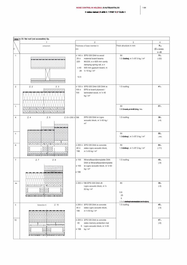
1 511 51NOISE CONTROL IN HOLZBAU | B AUTEILKATALOG NOISE CONTROL IN HOLZBAU | B AUTEILKATALOG NOISE CONTROL IN HOLZBAU | B AUTEILKATALOG
H olzbau manual | R eIHE 3 | T PART 3 | F OLGE 1H olzbau manual | R eIHE 3 | T PART 3 | F OLGE 1H olzbau manual | R eIHE 3 | T PART 3 | F OLGE 1H olzbau manual | R eIHE 3 | T PART 3 | F OLGE 1H olzbau manual | R eIHE 3 | T PART 3 | F OLGE 1H olzbau manual | R eIHE 3 | T PART 3 | F OLGE 1H olzbau manual | R eIHE 3 | T PART 3 | F OLGE 1H olzbau manual | R eIHE 3 | T PART 3 | F OLGE 1H olzbau manual | R eIHE 3 | T PART 3 | F OLGE 1H olzbau manual | R eIHE 3 | T PART 3 | F OLGE 1H olzbau manual | R eIHE 3 | T PART 3 | F OLGE 1
Tabel le 33: flat roof (not accessible) Sp. Tabel le 33: flat roof (not accessible) Sp.
Z.
1 2 3 4
component Thickness of base member in
mm
Thick structure in mm R wR w
(C tr, 50-5000)(C tr, 50-5000)
in dB
1 ≥ 140 ≥
25 ≥
220
≥ 40
28
12.5
EPS 035 DAA ie wood
material board beams
80/220, e ≥ 625 mm cavity
damping spring rail, e ≥
500 mm gypsum board, m
'≥ 10 kg / m²
50
1.5 Gravel, m '≥ 87.0 kg / m² roofing
70 a70 a
(-22)
2 Z. 2 Z. 3 ≥ 120 ≥
100 ≥
100
EPS 035 DAA 035 DAA ie
EPS ie board plywood /
laminated wood, m '≥ 45
kg / m²
1.5 roofing 41 b41 b
3 50
1.5 Gravel, m '≥ 87.0 kg / m 21.5 Gravel, m '≥ 87.0 kg / m 2roofing membrane
57 b57 b
4 Z. 4 Z. 5 Z. 6 ≥ 200 ≥ 196 EPS 035 DAA ie Ligno
acoustic block, m '≥ 63 kg /
m²
1.5 roofing 38 a38 a
(-4)
5 50
1.5 Gravel, m '≥ 87.0 kg / m² roofing
55 a55 a
(-8th)
6 ≥ 200 ≥
40 ≥
196
EPS 035 DAA ie concrete
slabs Ligno acoustic block,
m '≥ 63 kg / m²
50
1.5 Gravel, m '≥ 87.0 kg / m² roofing
64 a64 a
(-11)
7 Z. 7 Z. 8 ≥ 100
≥ 100
≥ 196
Mineralfaserdämmplatte DAA
DAA ie Mineralfaserdämmplatte
ie Ligno acoustic block, m '≥ 63
kg / m²
1.5 roofing 49 a49 a
(-9)
8th ≥ 200 ≥ 196 EPS 035 DAA dh
Ligno acoustic block, m '≥
63 kg / m²
80
0.6
25
5
1.5 of mineral bulk material, m '≥ 80 kg / m² non-woven filter drainage element memory protection mat roofing membrane
39 a39 a
(-3)
9 Subsection 9 Z. 10 ≥ 200 ≥
40 ≥
196
EPS 035 DAA ie concrete
slabs Ligno acoustic block,
m '≥ 63 kg / m²
1.5 roofing 45 a45 a
(-3)
10 ≥ 200 ≥
40
5
≥ 196
EPS 035 DAA ie concrete
slabs memory protection mat
Ligno acoustic block, m '≥ 63
kg / m²
47 a47 a
(-6)
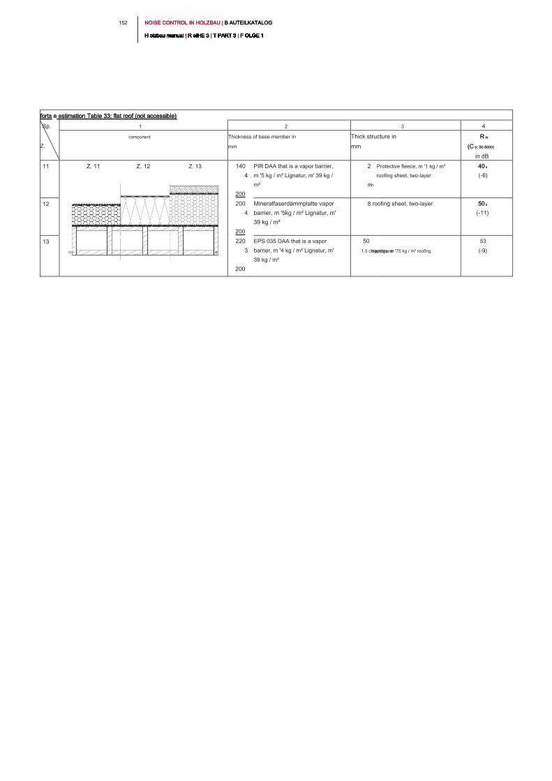
NOISE CONTROL IN HOLZBAU | B AUTEILKATALOG NOISE CONTROL IN HOLZBAU | B AUTEILKATALOG NOISE CONTROL IN HOLZBAU | B AUTEILKATALOG
H olzbau manual | R eIHE 3 | T PART 3 | F OLGE 1H olzbau manual | R eIHE 3 | T PART 3 | F OLGE 1H olzbau manual | R eIHE 3 | T PART 3 | F OLGE 1H olzbau manual | R eIHE 3 | T PART 3 | F OLGE 1H olzbau manual | R eIHE 3 | T PART 3 | F OLGE 1H olzbau manual | R eIHE 3 | T PART 3 | F OLGE 1H olzbau manual | R eIHE 3 | T PART 3 | F OLGE 1H olzbau manual | R eIHE 3 | T PART 3 | F OLGE 1H olzbau manual | R eIHE 3 | T PART 3 | F OLGE 1H olzbau manual | R eIHE 3 | T PART 3 | F OLGE 1H olzbau manual | R eIHE 3 | T PART 3 | F OLGE 1
152
forts e estimation Table 33: flat roof (not accessible)forts e estimation Table 33: flat roof (not accessible)forts e estimation Table 33: flat roof (not accessible)
Sp.
Z.
1 2 3 4
component Thickness of base member in
mm
Thick structure in
mm
R wR w
(C tr, 50-5000)(C tr, 50-5000)
in dB
11 Z. 11 Z. 12 Z. 13 140
4
200
PIR DAA that is a vapor barrier,
m '5 kg / m² Lignatur, m' 39 kg /
m²
2
8th
Protective fleece, m '1 kg / m²
roofing sheet, two-layer
40 a40 a
(-6)
12 200
4
200
Mineralfaserdämmplatte vapor
barrier, m '5kg / m² Lignatur, m'
39 kg / m²
8 roofing sheet, two-layer 50 a50 a
(-11)
13 220
3
200
EPS 035 DAA that is a vapor
barrier, m '4 kg / m² Lignatur, m'
39 kg / m²
50
1.5 chippings, m '75 kg / m² roofing membrane
53
(-9)
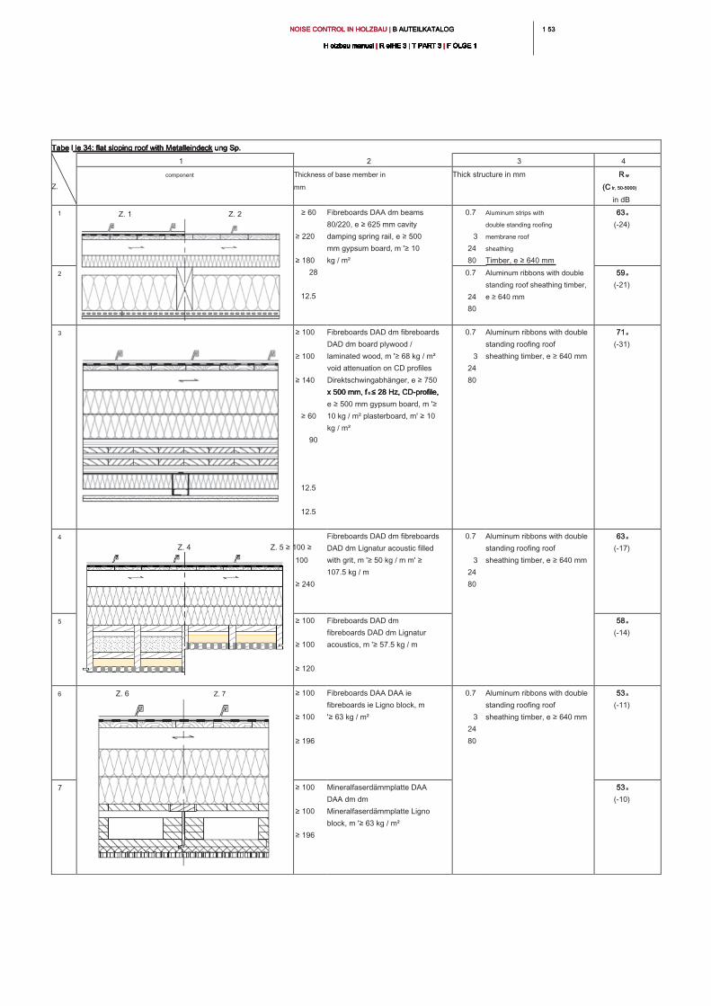
1 531 53NOISE CONTROL IN HOLZBAU | B AUTEILKATALOG NOISE CONTROL IN HOLZBAU | B AUTEILKATALOG NOISE CONTROL IN HOLZBAU | B AUTEILKATALOG
H olzbau manual | R eIHE 3 | T PART 3 | F OLGE 1H olzbau manual | R eIHE 3 | T PART 3 | F OLGE 1H olzbau manual | R eIHE 3 | T PART 3 | F OLGE 1H olzbau manual | R eIHE 3 | T PART 3 | F OLGE 1H olzbau manual | R eIHE 3 | T PART 3 | F OLGE 1H olzbau manual | R eIHE 3 | T PART 3 | F OLGE 1H olzbau manual | R eIHE 3 | T PART 3 | F OLGE 1H olzbau manual | R eIHE 3 | T PART 3 | F OLGE 1H olzbau manual | R eIHE 3 | T PART 3 | F OLGE 1H olzbau manual | R eIHE 3 | T PART 3 | F OLGE 1H olzbau manual | R eIHE 3 | T PART 3 | F OLGE 1
Tabe l le 34: flat sloping roof with Metalleindeck ung Sp. Tabe l le 34: flat sloping roof with Metalleindeck ung Sp. Tabe l le 34: flat sloping roof with Metalleindeck ung Sp. Tabe l le 34: flat sloping roof with Metalleindeck ung Sp.
Z.
1 2 3 4
component Thickness of base member in
mm
Thick structure in mm R wR w
(C tr, 50-5000)(C tr, 50-5000)
in dB
1 Z. 1 Z. 2
≥ 60
≥ 220
≥ 180
28
12.5
Fibreboards DAA dm beams
80/220, e ≥ 625 mm cavity
damping spring rail, e ≥ 500
mm gypsum board, m '≥ 10
kg / m²
0.7
3
24
80
Aluminum strips with
double standing roofing
membrane roof
sheathing
Timber, e ≥ 640 mm
63 a63 a
(-24)
2 0.7
24
80
Aluminum ribbons with double
standing roof sheathing timber,
e ≥ 640 mm
59 a59 a
(-21)
3 ≥ 100
≥ 100
≥ 140
≥ 60
90
12.5
12.5
Fibreboards DAD dm fibreboards
DAD dm board plywood /
laminated wood, m '≥ 68 kg / m²
void attenuation on CD profiles
Direktschwingabhänger, e ≥ 750
x 500 mm, f 0 ≤ 28 Hz, CD-profile, x 500 mm, f 0 ≤ 28 Hz, CD-profile, x 500 mm, f 0 ≤ 28 Hz, CD-profile,
e ≥ 500 mm gypsum board, m '≥
10 kg / m² plasterboard, m' ≥ 10
kg / m²
0.7
3
24
80
Aluminum ribbons with double
standing roofing roof
sheathing timber, e ≥ 640 mm
71 a71 a
(-31)
4
Z. 4 Z. 5 ≥ 100 ≥
100
≥ 240
Fibreboards DAD dm fibreboards
DAD dm Lignatur acoustic filled
with grit, m '≥ 50 kg / m m' ≥
107.5 kg / m
0.7
3
24
80
Aluminum ribbons with double
standing roofing roof
sheathing timber, e ≥ 640 mm
63 a63 a
(-17)
5 ≥ 100
≥ 100
≥ 120
Fibreboards DAD dm
fibreboards DAD dm Lignatur
acoustics, m '≥ 57.5 kg / m
58 a58 a
(-14)
6 Z. 6 Z. 7 ≥ 100
≥ 100
≥ 196
Fibreboards DAA DAA ie
fibreboards ie Ligno block, m
'≥ 63 kg / m²
0.7
3
24
80
Aluminum ribbons with double
standing roofing roof
sheathing timber, e ≥ 640 mm
53 a53 a
(-11)
7 ≥ 100
≥ 100
≥ 196
Mineralfaserdämmplatte DAA
DAA dm dm
Mineralfaserdämmplatte Ligno
block, m '≥ 63 kg / m²
53 a53 a
(-10)
NOISE CONTROL IN HOLZBAU | B AUTEILKATALOG NOISE CONTROL IN HOLZBAU | B AUTEILKATALOG NOISE CONTROL IN HOLZBAU | B AUTEILKATALOG
H olzbau manual | R eIHE 3 | T PART 3 | F OLGE 1H olzbau manual | R eIHE 3 | T PART 3 | F OLGE 1H olzbau manual | R eIHE 3 | T PART 3 | F OLGE 1H olzbau manual | R eIHE 3 | T PART 3 | F OLGE 1H olzbau manual | R eIHE 3 | T PART 3 | F OLGE 1H olzbau manual | R eIHE 3 | T PART 3 | F OLGE 1H olzbau manual | R eIHE 3 | T PART 3 | F OLGE 1H olzbau manual | R eIHE 3 | T PART 3 | F OLGE 1H olzbau manual | R eIHE 3 | T PART 3 | F OLGE 1H olzbau manual | R eIHE 3 | T PART 3 | F OLGE 1H olzbau manual | R eIHE 3 | T PART 3 | F OLGE 1
154
Bibliography of acoustical measurements
Designation of the
measured value
Origin of reading
a
Château Vieux-Hellwig C., Bacher S., A. Rabold, sound insulation of flat roofs in timber construction - airborne and
impact sound insulation of flat roofs and roof terraces, research project ift Rosenheim, in progress
b
Measurements on behalf of binderholz and Saint-Gobain RIGIPS Austria by accredited testing laboratories
6 .2.1 _ source directory component catalog flat roofs and roof terraces6 .2.1 _ source directory component catalog flat roofs and roof terraces
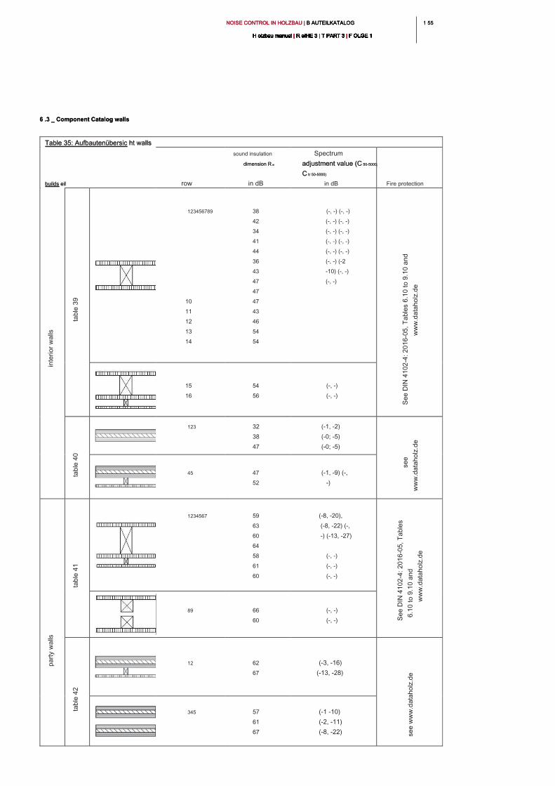
1 551 55NOISE CONTROL IN HOLZBAU | B AUTEILKATALOG NOISE CONTROL IN HOLZBAU | B AUTEILKATALOG NOISE CONTROL IN HOLZBAU | B AUTEILKATALOG
H olzbau manual | R eIHE 3 | T PART 3 | F OLGE 1H olzbau manual | R eIHE 3 | T PART 3 | F OLGE 1H olzbau manual | R eIHE 3 | T PART 3 | F OLGE 1H olzbau manual | R eIHE 3 | T PART 3 | F OLGE 1H olzbau manual | R eIHE 3 | T PART 3 | F OLGE 1H olzbau manual | R eIHE 3 | T PART 3 | F OLGE 1H olzbau manual | R eIHE 3 | T PART 3 | F OLGE 1H olzbau manual | R eIHE 3 | T PART 3 | F OLGE 1H olzbau manual | R eIHE 3 | T PART 3 | F OLGE 1H olzbau manual | R eIHE 3 | T PART 3 | F OLGE 1H olzbau manual | R eIHE 3 | T PART 3 | F OLGE 1
Table 35: Aufbautenübersic ht wallsTable 35: Aufbautenübersic ht walls
builds eil builds eil row
sound insulation
dimension R wdimension R w
in dB
Spectrum
adjustment value (C 50-5000;adjustment value (C 50-5000;
C tr 50-5000)C tr 50-5000)
in dB Fire protection
123456789
10
11
12
13
14
38
42
34
41
44
36
43
47
47
47
43
46
54
54
(-, -) (-, -)
(-, -) (-, -)
(-, -) (-, -)
(-, -) (-, -)
(-, -) (-, -)
(-, -) (-2
-10) (-, -)
(-, -)
15
16
54
56
(-, -)
(-, -)
123 32
38
47
(-1, -2)
(-0; -5)
(-0; -5)
45 47
52
(-1, -9) (-,
-)
1234567 59
63
60
64
58
61
60
(-8, -20),
(-8, -22) (-,
-) (-13, -27)
(-, -)
(-, -)
(-, -)
89 66
60
(-, -)
(-, -)
12 62
67
(-3, -16)
(-13, -28)
345 57
61
67
(-1 -10)
(-2, -11)
(-8, -22)
6 .3 _ Component Catalog walls6 .3 _ Component Catalog walls
in
te
rio
r w
alls
ta
ble
3
9
Se
e D
IN
4
10
2-4
: 2
01
6-0
5, T
ab
le
s 6
.1
0 to
9
.1
0 a
nd
ww
w.d
ata
ho
lz.d
e
ta
ble
4
0
se
e
ww
w.d
ata
ho
lz.d
e
pa
rty w
alls
ta
ble
4
1
Se
e D
IN
4
10
2-4
: 2
01
6-0
5, T
ab
le
s
6.1
0 to
9
.1
0 a
nd
ww
w.d
ata
ho
lz.d
e
ta
ble
4
2
se
e w
ww
.d
ata
ho
lz.d
e
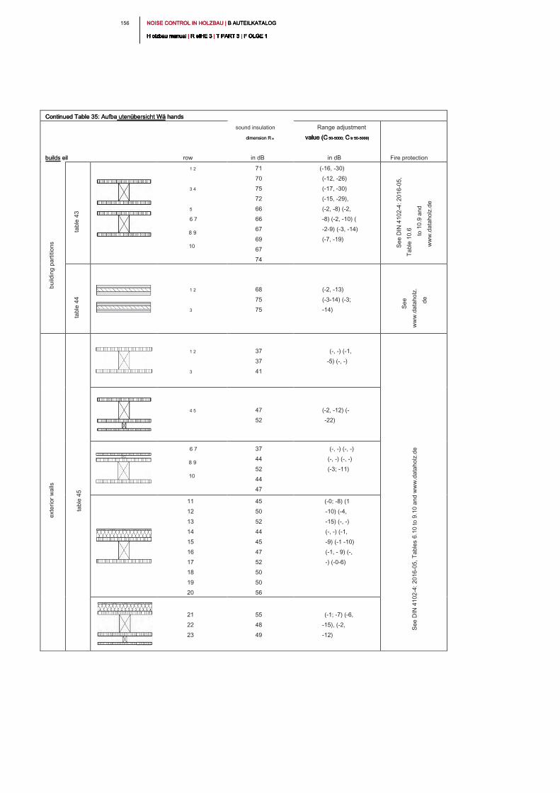
NOISE CONTROL IN HOLZBAU | B AUTEILKATALOG NOISE CONTROL IN HOLZBAU | B AUTEILKATALOG NOISE CONTROL IN HOLZBAU | B AUTEILKATALOG
H olzbau manual | R eIHE 3 | T PART 3 | F OLGE 1H olzbau manual | R eIHE 3 | T PART 3 | F OLGE 1H olzbau manual | R eIHE 3 | T PART 3 | F OLGE 1H olzbau manual | R eIHE 3 | T PART 3 | F OLGE 1H olzbau manual | R eIHE 3 | T PART 3 | F OLGE 1H olzbau manual | R eIHE 3 | T PART 3 | F OLGE 1H olzbau manual | R eIHE 3 | T PART 3 | F OLGE 1H olzbau manual | R eIHE 3 | T PART 3 | F OLGE 1H olzbau manual | R eIHE 3 | T PART 3 | F OLGE 1H olzbau manual | R eIHE 3 | T PART 3 | F OLGE 1H olzbau manual | R eIHE 3 | T PART 3 | F OLGE 1
156
Continued Table 35: Aufba utenübersicht Wä handsContinued Table 35: Aufba utenübersicht Wä handsContinued Table 35: Aufba utenübersicht Wä hands
builds eil builds eil row
sound insulation
dimension R wdimension R w
in dB
Range adjustment
value (C 50-5000; C tr 50-5000)value (C 50-5000; C tr 50-5000)value (C 50-5000; C tr 50-5000)value (C 50-5000; C tr 50-5000)
in dB Fire protection
1 2
3 4
5
6 7
8 9
10
71
70
75
72
66
66
67
69
67
74
(-16, -30)
(-12, -26)
(-17, -30)
(-15, -29),
(-2, -8) (-2,
-8) (-2, -10) (
-2-9) (-3, -14)
(-7, -19)
1 2
3
68
75
75
(-2, -13)
(-3-14) (-3;
-14)
1 2
3
37
37
41
(-, -) (-1,
-5) (-, -)
4 5 47
52
(-2, -12) (-
-22)
6 7
8 9
10
37
44
52
44
47
(-, -) (-, -)
(-, -) (-, -)
(-3; -11)
11
12
13
14
15
16
17
18
19
20
45
50
52
44
45
47
52
50
50
56
(-0; -8) (1
-10) (-4,
-15) (-, -)
(-, -) (-1,
-9) (-1 -10)
(-1, - 9) (-,
-) (-0-6)
21
22
23
55
48
49
(-1; -7) (-6,
-15), (-2,
-12)
bu
ild
in
g p
artitio
ns
ta
ble
4
3
Se
e D
IN
4
10
2-4
: 2
01
6-0
5,
Ta
ble
1
0.6
to
1
0.9
a
nd
ww
w.d
ata
ho
lz.d
e
ta
ble
4
4
Se
e
ww
w.d
ata
ho
lz.
de
exte
rio
r w
alls
ta
ble
4
5
Se
e D
IN
4
10
2-4
: 2
01
6-0
5, T
ab
le
s 6
.1
0 to
9
.1
0 a
nd
w
ww
.d
ata
ho
lz.d
e
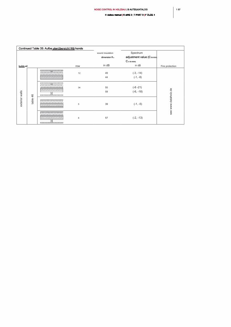
1 571 57NOISE CONTROL IN HOLZBAU | B AUTEILKATALOG NOISE CONTROL IN HOLZBAU | B AUTEILKATALOG NOISE CONTROL IN HOLZBAU | B AUTEILKATALOG
H olzbau manual | R eIHE 3 | T PART 3 | F OLGE 1H olzbau manual | R eIHE 3 | T PART 3 | F OLGE 1H olzbau manual | R eIHE 3 | T PART 3 | F OLGE 1H olzbau manual | R eIHE 3 | T PART 3 | F OLGE 1H olzbau manual | R eIHE 3 | T PART 3 | F OLGE 1H olzbau manual | R eIHE 3 | T PART 3 | F OLGE 1H olzbau manual | R eIHE 3 | T PART 3 | F OLGE 1H olzbau manual | R eIHE 3 | T PART 3 | F OLGE 1H olzbau manual | R eIHE 3 | T PART 3 | F OLGE 1H olzbau manual | R eIHE 3 | T PART 3 | F OLGE 1H olzbau manual | R eIHE 3 | T PART 3 | F OLGE 1
Continued Table 35: Aufba utenübersicht Wä handsContinued Table 35: Aufba utenübersicht Wä handsContinued Table 35: Aufba utenübersicht Wä hands
builds eil builds eil row
sound insulation
dimension R wdimension R w
in dB
Spectrum
adjustment value (C 50-5000;adjustment value (C 50-5000;
C tr 50-5000)C tr 50-5000)
in dB Fire protection
12 49
44
(-3, -14)
(-1, -8)
34 55
59
(-8 -21)
(-6, -18)
5 39 (-1, -5)
6 57 (-2, -13)
exte
rio
r w
alls
ta
ble
4
6
se
e w
ww
.d
ata
ho
lz.d
e
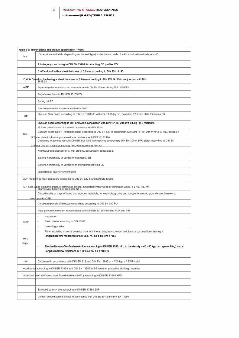
NOISE CONTROL IN HOLZBAU | B AUTEILKATALOG NOISE CONTROL IN HOLZBAU | B AUTEILKATALOG NOISE CONTROL IN HOLZBAU | B AUTEILKATALOG
H olzbau manual | R eIHE 3 | T PART 3 | F OLGE 1H olzbau manual | R eIHE 3 | T PART 3 | F OLGE 1H olzbau manual | R eIHE 3 | T PART 3 | F OLGE 1H olzbau manual | R eIHE 3 | T PART 3 | F OLGE 1H olzbau manual | R eIHE 3 | T PART 3 | F OLGE 1H olzbau manual | R eIHE 3 | T PART 3 | F OLGE 1H olzbau manual | R eIHE 3 | T PART 3 | F OLGE 1H olzbau manual | R eIHE 3 | T PART 3 | F OLGE 1H olzbau manual | R eIHE 3 | T PART 3 | F OLGE 1H olzbau manual | R eIHE 3 | T PART 3 | F OLGE 1H olzbau manual | R eIHE 3 | T PART 3 | F OLGE 1
158
table 3 6: abbreviations and product specification - Walls table 3 6: abbreviations and product specification - Walls
bra
(Dimensions and static depending on the wall type) timber frame made of solid wood, alternatively joists C
A bhängertyp according to DIN EN 13964 for attaching CD profiles CD A bhängertyp according to DIN EN 13964 for attaching CD profiles CD
C -Wandprofil with a sheet thickness of 0.6 mm according to DIN EN 14195 C -Wandprofil with a sheet thickness of 0.6 mm according to DIN EN 14195
C W is C-wall profile having a sheet thickness of 0.6 mm according to DIN EN 14195 in conjunction with DIN C W is C-wall profile having a sheet thickness of 0.6 mm according to DIN EN 14195 in conjunction with DIN
18182-1
e BP e BP Expanded perlite insulation board in accordance with DIN EN 13169 including EBP / MW EPS
Polystyrene foam to DIN EN 13163 FS
Spring rail FZ
Fiber cement board in accordance with DIN EN 12467
GF
Gypsum fiber board according to DIN EN 15283-2, with m'≥ 13.75 kg / m, based on 12.5 mm plate thickness GK
Gypsum board according to DIN EN 520 in conjunction with DIN 18180, with m'≥ 8.5 kg / m 2, related to Gypsum board according to DIN EN 520 in conjunction with DIN 18180, with m'≥ 8.5 kg / m 2, related to Gypsum board according to DIN EN 520 in conjunction with DIN 18180, with m'≥ 8.5 kg / m 2, related to
12.5 mm plate thickness, processed in accordance with DIN 18181
GKF
Gypsum board type F (Fireproof panel) according to DIN EN 520 in conjunction with DIN 18180, with m'm² ≥ 10 kg /, based on
12.5 mm plate thickness, processed in accordance with DIN 18181 HW
Chipboard in accordance with DIN EN 312, OSB laying plates according to DIN EN 300 or BFU-plates according to DIN EN
315 and DIN EN 13986; ρ ≥ 600 kg / m³, with m'≥ 9.6 kg / m² KF
Klickfix Direktbefestiger of C-wall profiles, acoustically decoupled L
Battens horizontally or vertically mounted L-SB
Battens horizontally or vertically on swing bracket fixed LS
ventilated air layer or unventilated
MDF medium density fibreboard according to DIN EN 622-5 and DIN EN 13986
MH solid wood elements made of laminated timber, laminated timber wood or laminated wood, ρ ≥ 460 kg / m³,
alternatively hollow box elements NFS
Closed molds or trays of wood and wooden materials, for example, groove and tongue formwork, ground cover formwork,
wood planks OSB
Chipboard panels of directed wood chips according to DIN EN 300 PU
Rigid polyurethane foam in accordance with DIN EN 13165 including PUR and PIR
plaster
- lime plaster
- Resin plaster according to DIN 18558
- insulating plaster
WH
WTH
- Fiber insulating material boards / mats of mineral, jute, hemp, wood, cellulose or coconut fibers having a
longitudinal flow resistance of 5 kPa s / m 2 ≤ r ≤ 50 kPa s / m 2longitudinal flow resistance of 5 kPa s / m 2 ≤ r ≤ 50 kPa s / m 2longitudinal flow resistance of 5 kPa s / m 2 ≤ r ≤ 50 kPa s / m 2longitudinal flow resistance of 5 kPa s / m 2 ≤ r ≤ 50 kPa s / m 2
- Einblasdämmstoffe of cellulosic fibers according to DIN EN 15101-1 ρ to the density = 40 - 50 kg / m 3 ( space filling) and a Einblasdämmstoffe of cellulosic fibers according to DIN EN 15101-1 ρ to the density = 40 - 50 kg / m 3 ( space filling) and a Einblasdämmstoffe of cellulosic fibers according to DIN EN 15101-1 ρ to the density = 40 - 50 kg / m 3 ( space filling) and a
longitudinal flow resistance of 5 kPa s / m 2 ≤ r ≤ 50 kPa longitudinal flow resistance of 5 kPa s / m 2 ≤ r ≤ 50 kPa longitudinal flow resistance of 5 kPa s / m 2 ≤ r ≤ 50 kPa
SP Chipboard in accordance with DIN EN 312 and DIN EN 13986 ρ, ≥ 700 kg / m³ SWP solid
wood panel according to DIN EN 13353 and DIN EN 13986 WS-S weather protective clothing / weather
protection shell WW wood wool board (formerly HWL) according to DIN EN 13168 XPS
Extruded polystyrene according to DIN EN 13164 ZSP
Cement bonded particle boards in accordance with DIN EN 634-2 and DIN EN 13986
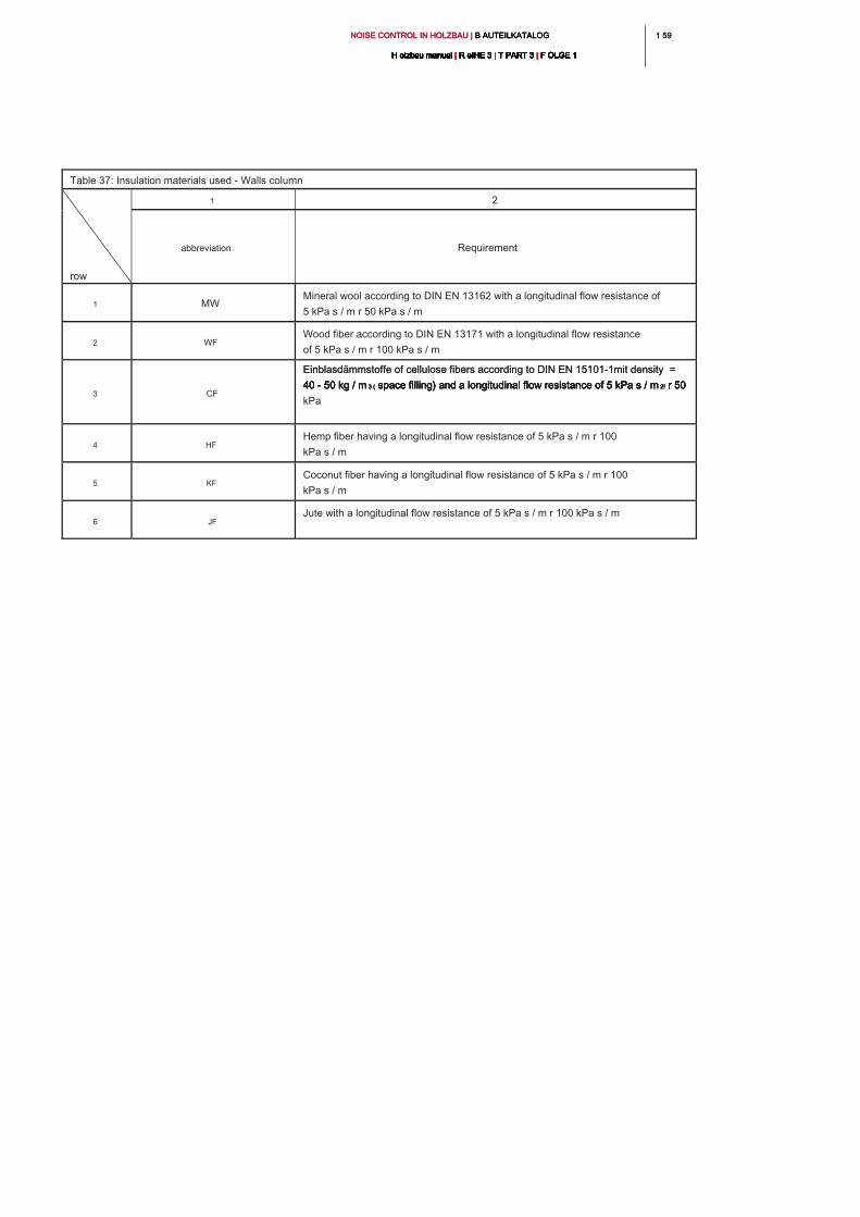
1 591 59NOISE CONTROL IN HOLZBAU | B AUTEILKATALOG NOISE CONTROL IN HOLZBAU | B AUTEILKATALOG NOISE CONTROL IN HOLZBAU | B AUTEILKATALOG
H olzbau manual | R eIHE 3 | T PART 3 | F OLGE 1H olzbau manual | R eIHE 3 | T PART 3 | F OLGE 1H olzbau manual | R eIHE 3 | T PART 3 | F OLGE 1H olzbau manual | R eIHE 3 | T PART 3 | F OLGE 1H olzbau manual | R eIHE 3 | T PART 3 | F OLGE 1H olzbau manual | R eIHE 3 | T PART 3 | F OLGE 1H olzbau manual | R eIHE 3 | T PART 3 | F OLGE 1H olzbau manual | R eIHE 3 | T PART 3 | F OLGE 1H olzbau manual | R eIHE 3 | T PART 3 | F OLGE 1H olzbau manual | R eIHE 3 | T PART 3 | F OLGE 1H olzbau manual | R eIHE 3 | T PART 3 | F OLGE 1
Table 37: Insulation materials used - Walls column
row
1 2
abbreviation Requirement
1 MW
Mineral wool according to DIN EN 13162 with a longitudinal flow resistance of
5 kPa s / m r 50 kPa s / m
2 WF
Wood fiber according to DIN EN 13171 with a longitudinal flow resistance
of 5 kPa s / m r 100 kPa s / m
3 CF
Einblasdämmstoffe of cellulose fibers according to DIN EN 15101-1mit density = Einblasdämmstoffe of cellulose fibers according to DIN EN 15101-1mit density =
40 - 50 kg / m 3 ( space filling) and a longitudinal flow resistance of 5 kPa s / m 2! r 50 40 - 50 kg / m 3 ( space filling) and a longitudinal flow resistance of 5 kPa s / m 2! r 50 40 - 50 kg / m 3 ( space filling) and a longitudinal flow resistance of 5 kPa s / m 2! r 50 40 - 50 kg / m 3 ( space filling) and a longitudinal flow resistance of 5 kPa s / m 2! r 50 40 - 50 kg / m 3 ( space filling) and a longitudinal flow resistance of 5 kPa s / m 2! r 50
kPa
4 HF
Hemp fiber having a longitudinal flow resistance of 5 kPa s / m r 100
kPa s / m
5 KF
Coconut fiber having a longitudinal flow resistance of 5 kPa s / m r 100
kPa s / m
6 JF
Jute with a longitudinal flow resistance of 5 kPa s / m r 100 kPa s / m
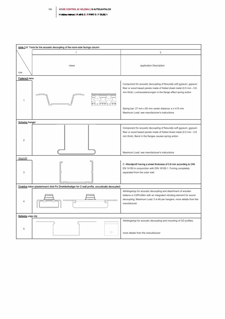
NOISE CONTROL IN HOLZBAU | B AUTEILKATALOG NOISE CONTROL IN HOLZBAU | B AUTEILKATALOG NOISE CONTROL IN HOLZBAU | B AUTEILKATALOG
H olzbau manual | R eIHE 3 | T PART 3 | F OLGE 1H olzbau manual | R eIHE 3 | T PART 3 | F OLGE 1H olzbau manual | R eIHE 3 | T PART 3 | F OLGE 1H olzbau manual | R eIHE 3 | T PART 3 | F OLGE 1H olzbau manual | R eIHE 3 | T PART 3 | F OLGE 1H olzbau manual | R eIHE 3 | T PART 3 | F OLGE 1H olzbau manual | R eIHE 3 | T PART 3 | F OLGE 1H olzbau manual | R eIHE 3 | T PART 3 | F OLGE 1H olzbau manual | R eIHE 3 | T PART 3 | F OLGE 1H olzbau manual | R eIHE 3 | T PART 3 | F OLGE 1H olzbau manual | R eIHE 3 | T PART 3 | F OLGE 1
160
table 3 8: Tools for the acoustic decoupling of the room-side facings columntable 3 8: Tools for the acoustic decoupling of the room-side facings column
row
1 2
views application Description
Federsch iene Federsch iene
1
Component for acoustic decoupling of flexurally soft gypsum, gypsum
fiber or wood based panels made of folded sheet metal (0.5 mm - 0.6
mm thick). Lochausstanzungen in the flange effect spring action.
Spring bar: 27 mm x 60 mm center distance: e ≥ 415 mm
Maximum Load: see manufacturer's instructions
Schwing hanger Schwing hanger
2
Component for acoustic decoupling of flexurally soft gypsum, gypsum
fiber or wood based panels made of folded sheet metal (0.5 mm - 0.6
mm thick). Bend in the flanges causes spring action.
Maximum Load: see manufacturer's instructions
Aluprofil
3
C -Wandprofil having a sheet thickness of 0.6 mm according to DIN C -Wandprofil having a sheet thickness of 0.6 mm according to DIN
EN 14195 in conjunction with DIN 18182-1. Furring completely
separated from the outer wall.
Direktbe lotion (plasterboard click-Fix Direktbefestiger for C-wall profile, acoustically decoupled)Direktbe lotion (plasterboard click-Fix Direktbefestiger for C-wall profile, acoustically decoupled)
4
Abhängertyp for acoustic decoupling and attachment of wooden
battens or CDProfilen with an integrated vibrating element for sound
decoupling; Maximum Load: 0.4 kN per hangers; more details from the
manufacturer
Befestig ungs clipBefestig ungs clip
5
Abhängertyp for acoustic decoupling and mounting of CD profiles;
more details from the manufacturer
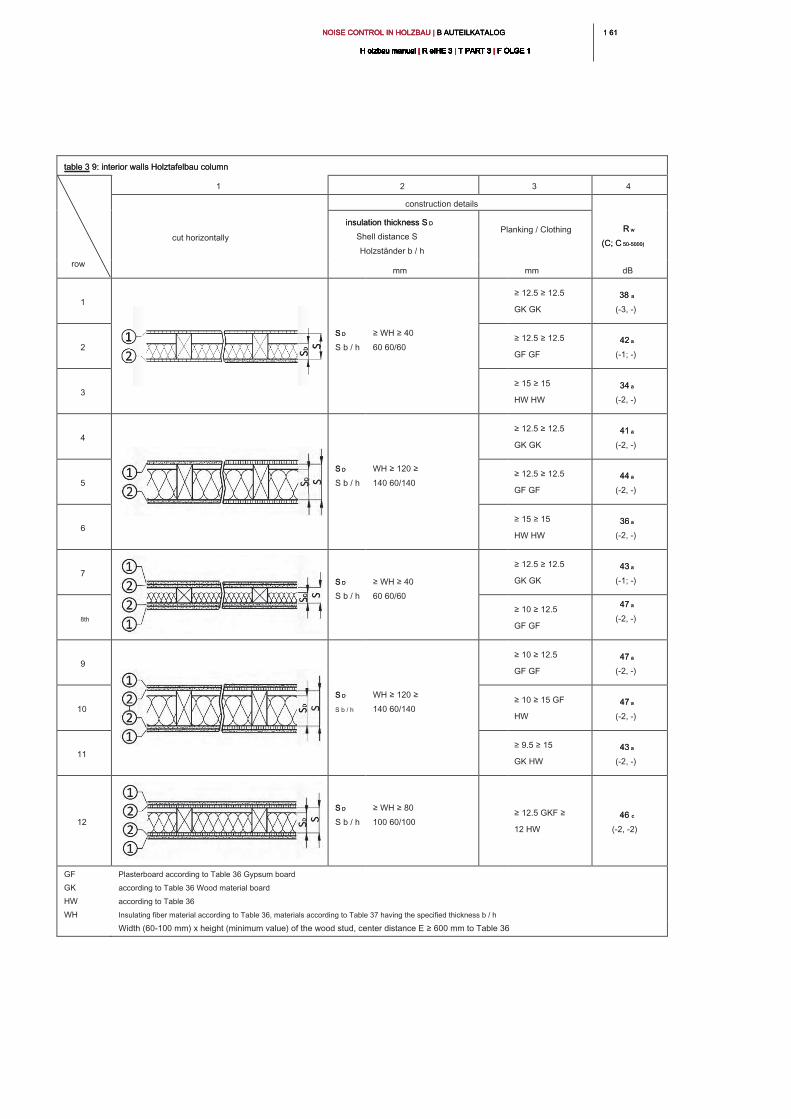
1 611 61NOISE CONTROL IN HOLZBAU | B AUTEILKATALOG NOISE CONTROL IN HOLZBAU | B AUTEILKATALOG NOISE CONTROL IN HOLZBAU | B AUTEILKATALOG
H olzbau manual | R eIHE 3 | T PART 3 | F OLGE 1H olzbau manual | R eIHE 3 | T PART 3 | F OLGE 1H olzbau manual | R eIHE 3 | T PART 3 | F OLGE 1H olzbau manual | R eIHE 3 | T PART 3 | F OLGE 1H olzbau manual | R eIHE 3 | T PART 3 | F OLGE 1H olzbau manual | R eIHE 3 | T PART 3 | F OLGE 1H olzbau manual | R eIHE 3 | T PART 3 | F OLGE 1H olzbau manual | R eIHE 3 | T PART 3 | F OLGE 1H olzbau manual | R eIHE 3 | T PART 3 | F OLGE 1H olzbau manual | R eIHE 3 | T PART 3 | F OLGE 1H olzbau manual | R eIHE 3 | T PART 3 | F OLGE 1
table 3 9: interior walls Holztafelbau column table 3 9: interior walls Holztafelbau column
row
1 2 3 4
cut horizontally
construction details
R w R w
(C; C 50-5000)(C; C 50-5000)
insulation thickness S Dinsulation thickness S D
Shell distance S
Holzständer b / h
Planking / Clothing
mm mm dB
1
S DS D
S b / h
≥ WH ≥ 40
60 60/60
≥ 12.5 ≥ 12.5
GK GK
38 a38 a
(-3, -)
2
≥ 12.5 ≥ 12.5
GF GF
42 a42 a
(-1; -)
3
≥ 15 ≥ 15
HW HW
34 a34 a
(-2, -)
4
S DS D
S b / h
WH ≥ 120 ≥
140 60/140
≥ 12.5 ≥ 12.5
GK GK
41 a41 a
(-2, -)
5
≥ 12.5 ≥ 12.5
GF GF
44 a44 a
(-2, -)
6
≥ 15 ≥ 15
HW HW
36 a36 a
(-2, -)
7
S DS D
S b / h
≥ WH ≥ 40
60 60/60
≥ 12.5 ≥ 12.5
GK GK
43 a43 a
(-1; -)
8th
≥ 10 ≥ 12.5
GF GF
47 a47 a
(-2, -)
9
S DS D
S b / h
WH ≥ 120 ≥
140 60/140
≥ 10 ≥ 12.5
GF GF
47 a47 a
(-2, -)
10
≥ 10 ≥ 15 GF
HW
47 a47 a
(-2, -)
11
≥ 9.5 ≥ 15
GK HW
43 a43 a
(-2, -)
12
S DS D
S b / h
≥ WH ≥ 80
100 60/100
≥ 12.5 GKF ≥
12 HW
46 c46 c
(-2, -2)
GF
GK
HW
WH
Plasterboard according to Table 36 Gypsum board
according to Table 36 Wood material board
according to Table 36
Insulating fiber material according to Table 36, materials according to Table 37 having the specified thickness b / h
Width (60-100 mm) x height (minimum value) of the wood stud, center distance E ≥ 600 mm to Table 36
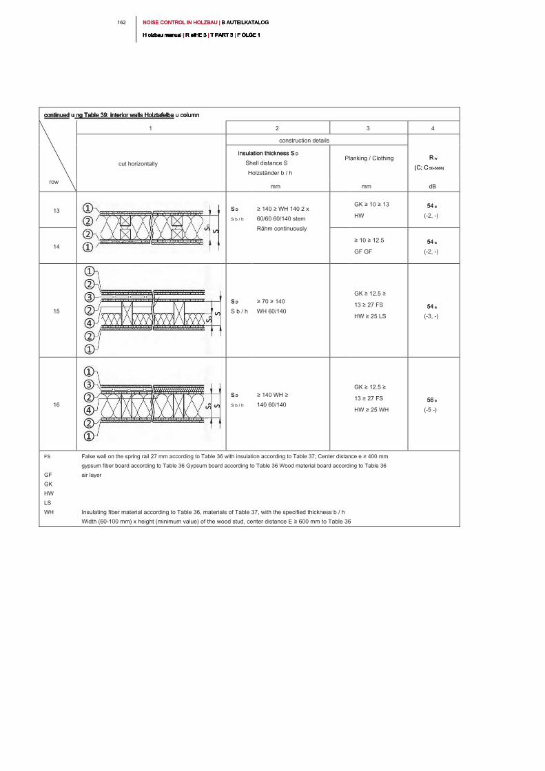
NOISE CONTROL IN HOLZBAU | B AUTEILKATALOG NOISE CONTROL IN HOLZBAU | B AUTEILKATALOG NOISE CONTROL IN HOLZBAU | B AUTEILKATALOG
H olzbau manual | R eIHE 3 | T PART 3 | F OLGE 1H olzbau manual | R eIHE 3 | T PART 3 | F OLGE 1H olzbau manual | R eIHE 3 | T PART 3 | F OLGE 1H olzbau manual | R eIHE 3 | T PART 3 | F OLGE 1H olzbau manual | R eIHE 3 | T PART 3 | F OLGE 1H olzbau manual | R eIHE 3 | T PART 3 | F OLGE 1H olzbau manual | R eIHE 3 | T PART 3 | F OLGE 1H olzbau manual | R eIHE 3 | T PART 3 | F OLGE 1H olzbau manual | R eIHE 3 | T PART 3 | F OLGE 1H olzbau manual | R eIHE 3 | T PART 3 | F OLGE 1H olzbau manual | R eIHE 3 | T PART 3 | F OLGE 1
162
continued u ng Table 39: interior walls Holztafelba u column continued u ng Table 39: interior walls Holztafelba u column continued u ng Table 39: interior walls Holztafelba u column continued u ng Table 39: interior walls Holztafelba u column
row
1 2 3 4
cut horizontally
construction details
R w R w
(C; C 50-5000)(C; C 50-5000)
insulation thickness S Dinsulation thickness S D
Shell distance S
Holzständer b / h
Planking / Clothing
mm mm dB
13
S DS D
S b / h
≥ 140 ≥ WH 140 2 x
60/60 60/140 stem
Rähm continuously
GK ≥ 10 ≥ 13
HW
54 a54 a
(-2, -)
14
≥ 10 ≥ 12.5
GF GF
54 a54 a
(-2, -)
15
S DS D
S b / h
≥ 70 ≥ 140
WH 60/140
GK ≥ 12.5 ≥
13 ≥ 27 FS
HW ≥ 25 LS
54 a54 a
(-3, -)
16
S DS D
S b / h
≥ 140 WH ≥
140 60/140
GK ≥ 12.5 ≥
13 ≥ 27 FS
HW ≥ 25 WH
56 a56 a
(-5 -)
FS
GF
GK
HW
LS
WH
False wall on the spring rail 27 mm according to Table 36 with insulation according to Table 37; Center distance e ≥ 400 mm
gypsum fiber board according to Table 36 Gypsum board according to Table 36 Wood material board according to Table 36
air layer
Insulating fiber material according to Table 36, materials of Table 37, with the specified thickness b / h
Width (60-100 mm) x height (minimum value) of the wood stud, center distance E ≥ 600 mm to Table 36
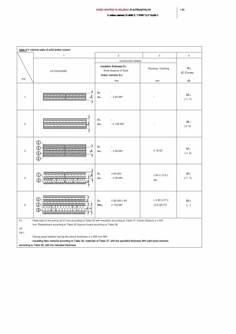
1 631 63NOISE CONTROL IN HOLZBAU | B AUTEILKATALOG NOISE CONTROL IN HOLZBAU | B AUTEILKATALOG NOISE CONTROL IN HOLZBAU | B AUTEILKATALOG
H olzbau manual | R eIHE 3 | T PART 3 | F OLGE 1H olzbau manual | R eIHE 3 | T PART 3 | F OLGE 1H olzbau manual | R eIHE 3 | T PART 3 | F OLGE 1H olzbau manual | R eIHE 3 | T PART 3 | F OLGE 1H olzbau manual | R eIHE 3 | T PART 3 | F OLGE 1H olzbau manual | R eIHE 3 | T PART 3 | F OLGE 1H olzbau manual | R eIHE 3 | T PART 3 | F OLGE 1H olzbau manual | R eIHE 3 | T PART 3 | F OLGE 1H olzbau manual | R eIHE 3 | T PART 3 | F OLGE 1H olzbau manual | R eIHE 3 | T PART 3 | F OLGE 1H olzbau manual | R eIHE 3 | T PART 3 | F OLGE 1
table 4 0: internal walls of solid timber column table 4 0: internal walls of solid timber column
row
1 2 3 4
cut horizontally
construction details
R w R w
(C; C 50-5000)(C; C 50-5000)
insulation thickness S D insulation thickness S D
Shell distance S Solid
timber member S Mtimber member S M
Planking / Clothing
mm mm dB
1
S DS D
SS MSS M
-
- ≥ 80 MH -
32 b32 b
(-1, -1)
2
S DS D
SS MSS M
-
- ≥ 140 MH -
38 n38 n
(-0 -0)
3
S DS D
SS MSS M
-
- ≥ 80 MH ≥ 18 GF
47 n47 n
(-1, 0)
4
S DS D
SS MSS M
≥ 60 WH
- ≥ 90 MH
≥ 60 ≥ 12.5 L
GK
47 k47 k
(-1, -1)
5
S DS D
SS MSS M
≥ 80 WH ≥ 80
≥ 135 MH
L ≥ 80 ≥ 27 ≥
12.5 GK FS
52 G52 G
(-, -)
FS
GF
GK L
False wall on the spring rail 27 mm according to Table 36 with insulation according to Table 37; Center distance e ≥ 400
mm; Plasterboard according to Table 36 Gypsum board according to Table 36
Facing panel battens having the above thickness, e ≥ 600 mm WH
Insulating fiber material according to Table 36, materials of Table 37, with the specified thickness MH solid wood element Insulating fiber material according to Table 36, materials of Table 37, with the specified thickness MH solid wood element
according to Table 36, with the indicated thickness according to Table 36, with the indicated thickness
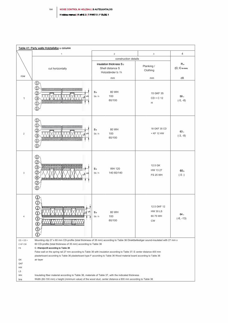
NOISE CONTROL IN HOLZBAU | B AUTEILKATALOG NOISE CONTROL IN HOLZBAU | B AUTEILKATALOG NOISE CONTROL IN HOLZBAU | B AUTEILKATALOG
H olzbau manual | R eIHE 3 | T PART 3 | F OLGE 1H olzbau manual | R eIHE 3 | T PART 3 | F OLGE 1H olzbau manual | R eIHE 3 | T PART 3 | F OLGE 1H olzbau manual | R eIHE 3 | T PART 3 | F OLGE 1H olzbau manual | R eIHE 3 | T PART 3 | F OLGE 1H olzbau manual | R eIHE 3 | T PART 3 | F OLGE 1H olzbau manual | R eIHE 3 | T PART 3 | F OLGE 1H olzbau manual | R eIHE 3 | T PART 3 | F OLGE 1H olzbau manual | R eIHE 3 | T PART 3 | F OLGE 1H olzbau manual | R eIHE 3 | T PART 3 | F OLGE 1H olzbau manual | R eIHE 3 | T PART 3 | F OLGE 1
164
Table 41: Party walls Holztafelba u columnTable 41: Party walls Holztafelba u column
row
1 2 3 4
cut horizontally
construction details
R wR w
(C; C 50-5000)(C; C 50-5000)
insulation thickness S Dinsulation thickness S D
Shell distance S
Holzständer b / h
Planking /
Clothing
mm mm dB
1
S DS D
Sb / h
80 WH
100
60/100
15 GKF 35
CD + C 12
H
59 c59 c
(-5, -8)
2
S DS D
Sb / h
80 WH
100
60/100
18 GKF 35 CD
+ KF 12 HW
63 c63 c
(-3, -8)
3
S DS D
Sb / h
WH 120
140 60/140
12.5 GK
HW 13 27
FS 25 WH
60 a60 a
(-5 -)
4
S DS D
Sb / h
80 WH
100
60/100
12.5 GKF 12
HW 30 LS
60 75 WH
CW
64 c64 c
(-8, -13)
CD + CD +
C KF CW
FS
GK
GKF
HW
LS
WH
Mounting clip 27 x 60 mm CD-profile (total thickness of 35 mm) according to Table 36 Direktbefestiger sound-insulated with 27 mm x
60 CD-profile (total thickness of 35 mm) according to Table 36
C -Wandprofil according to Table 36C -Wandprofil according to Table 36
False wall on the spring rail 27 mm according to Table 36 with insulation according to Table 37; E center distance 400 mm
plasterboard according to Table 36 plasterboard type F according to Table 36 Wood material board according to Table 36
air layer
Insulating fiber material according to Table 36, materials of Table 37, with the indicated thickness
bra Width (60-100 mm) x height (minimum value) of the wood stud, center distance e 600 mm according to Table 36
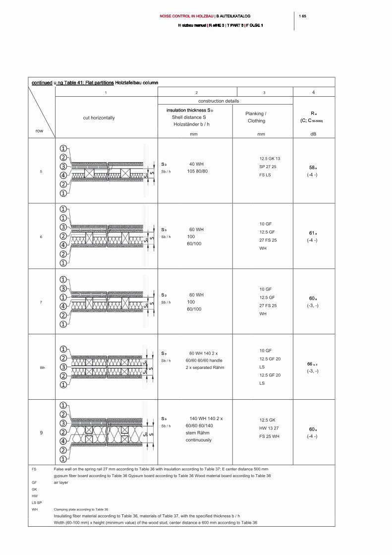
1 651 65NOISE CONTROL IN HOLZBAU | B AUTEILKATALOG NOISE CONTROL IN HOLZBAU | B AUTEILKATALOG NOISE CONTROL IN HOLZBAU | B AUTEILKATALOG
H olzbau manual | R eIHE 3 | T PART 3 | F OLGE 1H olzbau manual | R eIHE 3 | T PART 3 | F OLGE 1H olzbau manual | R eIHE 3 | T PART 3 | F OLGE 1H olzbau manual | R eIHE 3 | T PART 3 | F OLGE 1H olzbau manual | R eIHE 3 | T PART 3 | F OLGE 1H olzbau manual | R eIHE 3 | T PART 3 | F OLGE 1H olzbau manual | R eIHE 3 | T PART 3 | F OLGE 1H olzbau manual | R eIHE 3 | T PART 3 | F OLGE 1H olzbau manual | R eIHE 3 | T PART 3 | F OLGE 1H olzbau manual | R eIHE 3 | T PART 3 | F OLGE 1H olzbau manual | R eIHE 3 | T PART 3 | F OLGE 1
continued u ng Table 41: Flat partitions Holztafelbau columncontinued u ng Table 41: Flat partitions Holztafelbau columncontinued u ng Table 41: Flat partitions Holztafelbau columncontinued u ng Table 41: Flat partitions Holztafelbau column
row
1 2 3 4
cut horizontally
construction details
R wR w
(C; C 50-5000)(C; C 50-5000)
insulation thickness S Dinsulation thickness S D
Shell distance S
Holzständer b / h
Planking /
Clothing
mm mm dB
5
S DS D
Sb / h
40 WH
105 80/80
12.5 GK 13
SP 27 25
FS LS
58 a58 a
(-4 -)
6
S DS D
Sb / h
60 WH
100
60/100
10 GF
12.5 GF
27 FS 25
WH
61 a61 a
(-4 -)
7
S DS D
Sb / h
60 WH
100
60/100
10 GF
12.5 GF
27 FS 25
WH
60 a60 a
(-3, -)
8th
S DS D
Sb / h
60 WH 140 2 x
60/60 60/60 handle
2 x separated Rähm
10 GF
12.5 GF 20
LS
12.5 GF 20
LS
66 a, d66 a, d
(-3, -)
9
S DS D
Sb / h
140 WH 140 2 x
60/60 60/140
stem Rähm
continuously
12.5 GK
HW 13 27
FS 25 WH
60 a60 a
(-4 -)
FS
GF
GK
HW
LS SP
WH
False wall on the spring rail 27 mm according to Table 36 with insulation according to Table 37; E center distance 500 mm
gypsum fiber board according to Table 36 Gypsum board according to Table 36 Wood material board according to Table 36
air layer
Clamping plate according to Table 36
Insulating fiber material according to Table 36, materials of Table 37, with the specified thickness b / h
Width (60-100 mm) x height (minimum value) of the wood stud, center distance e 600 mm according to Table 36
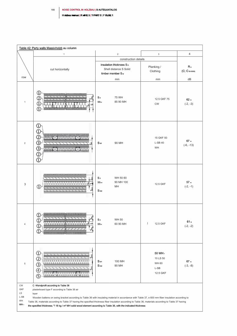
NOISE CONTROL IN HOLZBAU | B AUTEILKATALOG NOISE CONTROL IN HOLZBAU | B AUTEILKATALOG NOISE CONTROL IN HOLZBAU | B AUTEILKATALOG
H olzbau manual | R eIHE 3 | T PART 3 | F OLGE 1H olzbau manual | R eIHE 3 | T PART 3 | F OLGE 1H olzbau manual | R eIHE 3 | T PART 3 | F OLGE 1H olzbau manual | R eIHE 3 | T PART 3 | F OLGE 1H olzbau manual | R eIHE 3 | T PART 3 | F OLGE 1H olzbau manual | R eIHE 3 | T PART 3 | F OLGE 1H olzbau manual | R eIHE 3 | T PART 3 | F OLGE 1H olzbau manual | R eIHE 3 | T PART 3 | F OLGE 1H olzbau manual | R eIHE 3 | T PART 3 | F OLGE 1H olzbau manual | R eIHE 3 | T PART 3 | F OLGE 1H olzbau manual | R eIHE 3 | T PART 3 | F OLGE 1
166
Table 42: Party walls Massivholzb au columnTable 42: Party walls Massivholzb au column
row
1 2 3 4
cut horizontally
construction details
R wR w
(C; C 50-5000)(C; C 50-5000)
insulation thickness S Dinsulation thickness S D
Shell distance S Solid
timber member S Mtimber member S M
Planking /
Clothing
mm mm dB
1
S DS D
SS MSS M
75 WH
85 90 MH
12.5 GKF 75
CW
62 m62 m
(-2, -3)
2 S M!S M! 90 MH
15 GKF 50
L-SB 40
WH
67 m67 m
(-6, -13)
3
S DS D
SS M1SS M1
S M2S M2
WH 50 60
90 MH 100
MH
12.5 GKF
57 m57 m
(-2, -1)
4
S DS D
SS MSS M
WH 50
60 90 MH ! 12.5 GKF
61 m61 m
(-2, -2)
5
S M1S M1
S M2S M2
100 MH
90 MH
50 WH 150 WH 1
10 LS 50
WH 60
L-SB
12.5 GKF
67 m67 m
(-3, -8)
CW
GKF
LS
L-SB
WH
WH 1WH 1
C -Wandprofil according to Table 36 C -Wandprofil according to Table 36
plasterboard type F according to Table 36 air
layer
Wooden battens on swing bracket according to Table 36 with insulating material in accordance with Table 37, e 600 mm fiber insulation according to
Table 36, materials according to Table 37 having the specified thickness fiber insulation according to Table 36, materials according to Table 37 having
the specified thickness; "! 18 kg / m³ MH solid wood element according to Table 36, with the indicated thicknessthe specified thickness; "! 18 kg / m³ MH solid wood element according to Table 36, with the indicated thickness
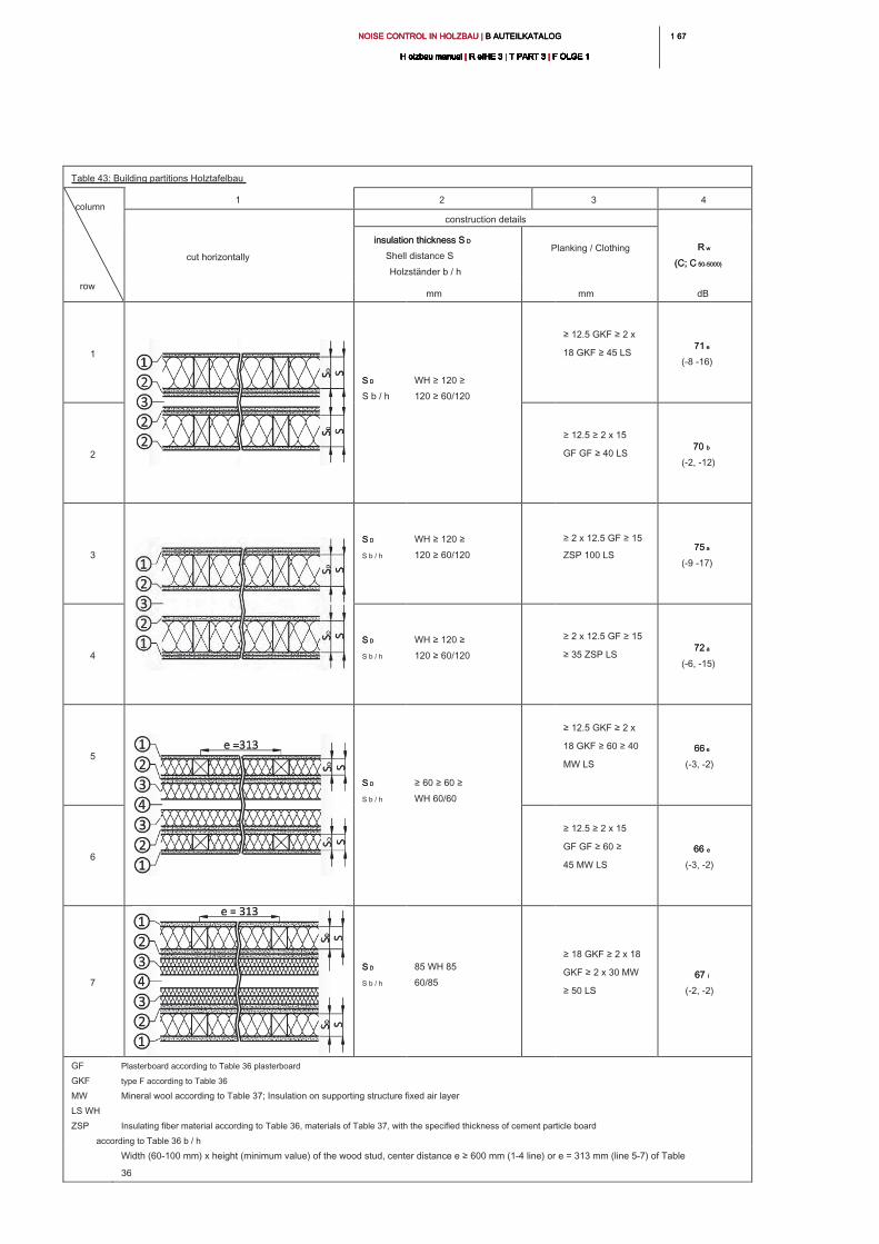
1 671 67NOISE CONTROL IN HOLZBAU | B AUTEILKATALOG NOISE CONTROL IN HOLZBAU | B AUTEILKATALOG NOISE CONTROL IN HOLZBAU | B AUTEILKATALOG
H olzbau manual | R eIHE 3 | T PART 3 | F OLGE 1H olzbau manual | R eIHE 3 | T PART 3 | F OLGE 1H olzbau manual | R eIHE 3 | T PART 3 | F OLGE 1H olzbau manual | R eIHE 3 | T PART 3 | F OLGE 1H olzbau manual | R eIHE 3 | T PART 3 | F OLGE 1H olzbau manual | R eIHE 3 | T PART 3 | F OLGE 1H olzbau manual | R eIHE 3 | T PART 3 | F OLGE 1H olzbau manual | R eIHE 3 | T PART 3 | F OLGE 1H olzbau manual | R eIHE 3 | T PART 3 | F OLGE 1H olzbau manual | R eIHE 3 | T PART 3 | F OLGE 1H olzbau manual | R eIHE 3 | T PART 3 | F OLGE 1
Table 43: Building partitions Holztafelbau
column
row
1 2 3 4
cut horizontally
construction details
R w R w
(C; C 50-5000)(C; C 50-5000)
insulation thickness S Dinsulation thickness S D
Shell distance S
Holzständer b / h
Planking / Clothing
mm mm dB
1
S DS D
S b / h
WH ≥ 120 ≥
120 ≥ 60/120
≥ 12.5 GKF ≥ 2 x
18 GKF ≥ 45 LS
71 e71 e
(-8 -16)
2
≥ 12.5 ≥ 2 x 15
GF GF ≥ 40 LS
70 b70 b
(-2, -12)
3
S DS D
S b / h
WH ≥ 120 ≥
120 ≥ 60/120
≥ 2 x 12.5 GF ≥ 15
ZSP 100 LS
75 a75 a
(-9 -17)
4
S DS D
S b / h
WH ≥ 120 ≥
120 ≥ 60/120
≥ 2 x 12.5 GF ≥ 15
≥ 35 ZSP LS
72 a72 a
(-6, -15)
5
S DS D
S b / h
≥ 60 ≥ 60 ≥
WH 60/60
≥ 12.5 GKF ≥ 2 x
18 GKF ≥ 60 ≥ 40
MW LS
66 e66 e
(-3, -2)
6
≥ 12.5 ≥ 2 x 15
GF GF ≥ 60 ≥
45 MW LS
66 e66 e
(-3, -2)
7
S DS D
S b / h
85 WH 85
60/85
≥ 18 GKF ≥ 2 x 18
GKF ≥ 2 x 30 MW
≥ 50 LS
67 i67 i
(-2, -2)
GF
GKF
MW
LS WH
ZSP
Plasterboard according to Table 36 plasterboard
type F according to Table 36
Mineral wool according to Table 37; Insulation on supporting structure fixed air layer
Insulating fiber material according to Table 36, materials of Table 37, with the specified thickness of cement particle board
according to Table 36 b / h
Width (60-100 mm) x height (minimum value) of the wood stud, center distance e ≥ 600 mm (1-4 line) or e = 313 mm (line 5-7) of Table
36
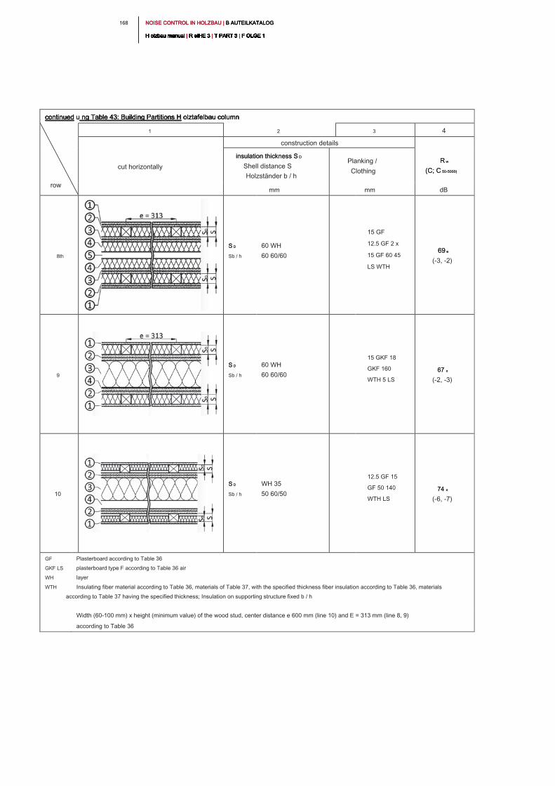
NOISE CONTROL IN HOLZBAU | B AUTEILKATALOG NOISE CONTROL IN HOLZBAU | B AUTEILKATALOG NOISE CONTROL IN HOLZBAU | B AUTEILKATALOG
H olzbau manual | R eIHE 3 | T PART 3 | F OLGE 1H olzbau manual | R eIHE 3 | T PART 3 | F OLGE 1H olzbau manual | R eIHE 3 | T PART 3 | F OLGE 1H olzbau manual | R eIHE 3 | T PART 3 | F OLGE 1H olzbau manual | R eIHE 3 | T PART 3 | F OLGE 1H olzbau manual | R eIHE 3 | T PART 3 | F OLGE 1H olzbau manual | R eIHE 3 | T PART 3 | F OLGE 1H olzbau manual | R eIHE 3 | T PART 3 | F OLGE 1H olzbau manual | R eIHE 3 | T PART 3 | F OLGE 1H olzbau manual | R eIHE 3 | T PART 3 | F OLGE 1H olzbau manual | R eIHE 3 | T PART 3 | F OLGE 1
168
continued u ng Table 43: Building Partitions H olztafelbau columncontinued u ng Table 43: Building Partitions H olztafelbau columncontinued u ng Table 43: Building Partitions H olztafelbau columncontinued u ng Table 43: Building Partitions H olztafelbau column
row
1 2 3 4
cut horizontally
construction details
R wR w
(C; C 50-5000)(C; C 50-5000)
insulation thickness S Dinsulation thickness S D
Shell distance S
Holzständer b / h
Planking /
Clothing
mm mm dB
8th
S DS D
Sb / h
60 WH
60 60/60
15 GF
12.5 GF 2 x
15 GF 60 45
LS WTH
69 e69 e
(-3, -2)
9
S DS D
Sb / h
60 WH
60 60/60
15 GKF 18
GKF 160
WTH 5 LS
67 e67 e
(-2, -3)
10
S DS D
Sb / h
WH 35
50 60/50
12.5 GF 15
GF 50 140
WTH LS
74 e74 e
(-6, -7)
GF
GKF LS
WH
WTH
Plasterboard according to Table 36
plasterboard type F according to Table 36 air
layer
Insulating fiber material according to Table 36, materials of Table 37, with the specified thickness fiber insulation according to Table 36, materials
according to Table 37 having the specified thickness; Insulation on supporting structure fixed b / h
Width (60-100 mm) x height (minimum value) of the wood stud, center distance e 600 mm (line 10) and E = 313 mm (line 8, 9)
according to Table 36
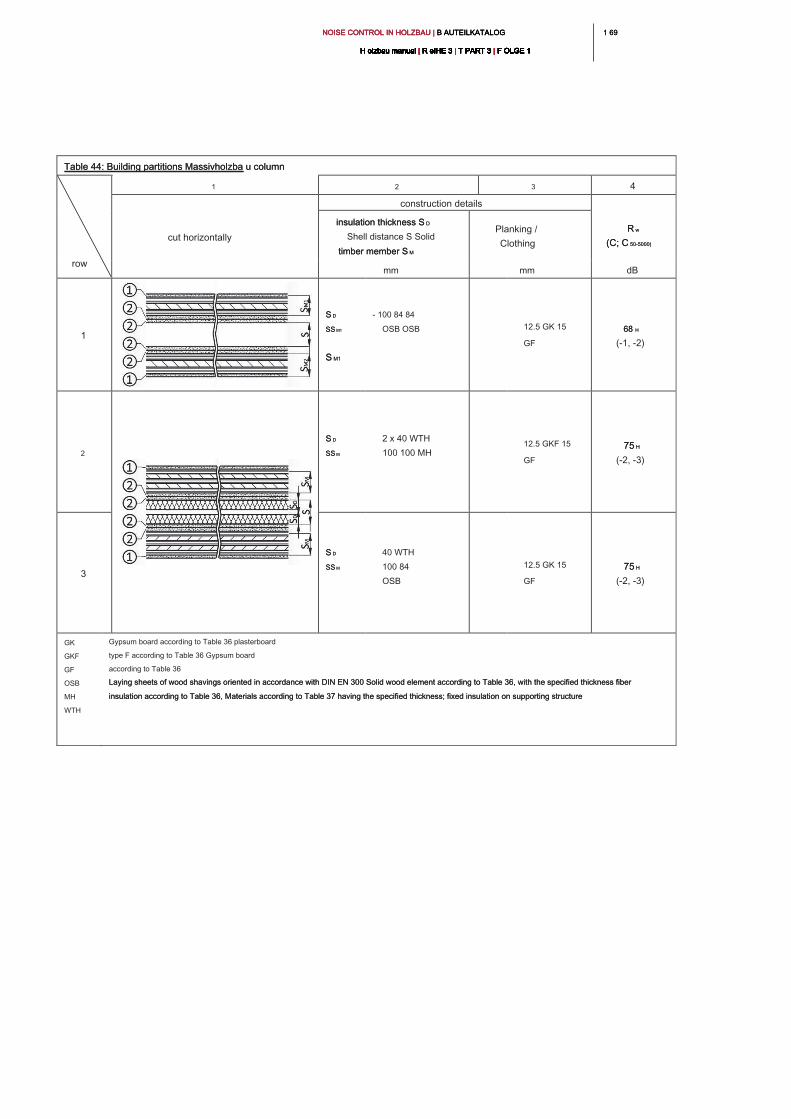
1 691 69NOISE CONTROL IN HOLZBAU | B AUTEILKATALOG NOISE CONTROL IN HOLZBAU | B AUTEILKATALOG NOISE CONTROL IN HOLZBAU | B AUTEILKATALOG
H olzbau manual | R eIHE 3 | T PART 3 | F OLGE 1H olzbau manual | R eIHE 3 | T PART 3 | F OLGE 1H olzbau manual | R eIHE 3 | T PART 3 | F OLGE 1H olzbau manual | R eIHE 3 | T PART 3 | F OLGE 1H olzbau manual | R eIHE 3 | T PART 3 | F OLGE 1H olzbau manual | R eIHE 3 | T PART 3 | F OLGE 1H olzbau manual | R eIHE 3 | T PART 3 | F OLGE 1H olzbau manual | R eIHE 3 | T PART 3 | F OLGE 1H olzbau manual | R eIHE 3 | T PART 3 | F OLGE 1H olzbau manual | R eIHE 3 | T PART 3 | F OLGE 1H olzbau manual | R eIHE 3 | T PART 3 | F OLGE 1
Table 44: Building partitions Massivholzba u columnTable 44: Building partitions Massivholzba u column
row
1 2 3 4
cut horizontally
construction details
R wR w
(C; C 50-5000)(C; C 50-5000)
insulation thickness S Dinsulation thickness S D
Shell distance S Solid
timber member S Mtimber member S M
Planking /
Clothing
mm mm dB
1
S DS D
SS M1SS M1
S M1S M1
- 100 84 84
OSB OSB12.5 GK 15
GF
68 H68 H
(-1, -2)
2
S DS D
SS MSS M
2 x 40 WTH
100 100 MH
12.5 GKF 15
GF
75 H75 H
(-2, -3)
3
S DS D
SS MSS M
40 WTH
100 84
OSB
12.5 GK 15
GF
75 H75 H
(-2, -3)
GK
GKF
GF
OSB
MH
WTH
Gypsum board according to Table 36 plasterboard
type F according to Table 36 Gypsum board
according to Table 36
Laying sheets of wood shavings oriented in accordance with DIN EN 300 Solid wood element according to Table 36, with the specified thickness fiber Laying sheets of wood shavings oriented in accordance with DIN EN 300 Solid wood element according to Table 36, with the specified thickness fiber
insulation according to Table 36, Materials according to Table 37 having the specified thickness; fixed insulation on supporting structureinsulation according to Table 36, Materials according to Table 37 having the specified thickness; fixed insulation on supporting structure
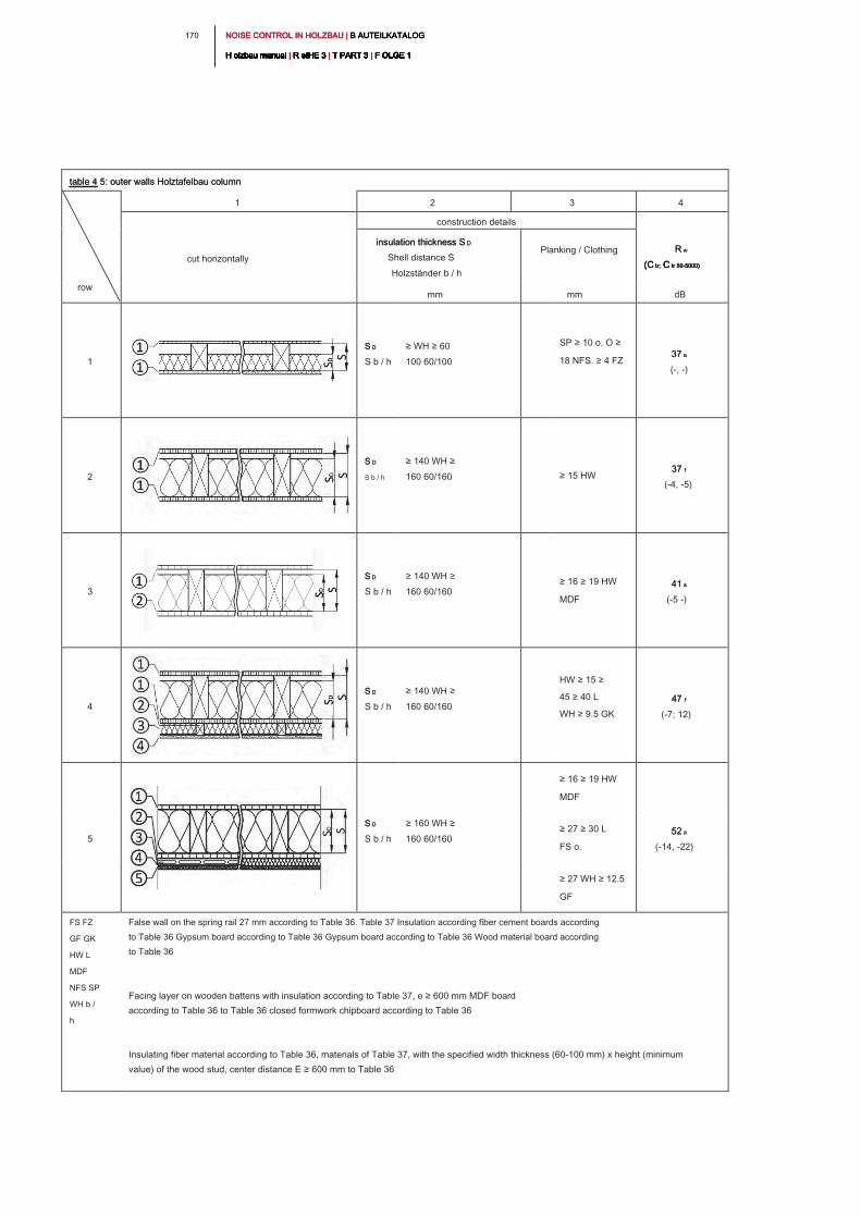
NOISE CONTROL IN HOLZBAU | B AUTEILKATALOG NOISE CONTROL IN HOLZBAU | B AUTEILKATALOG NOISE CONTROL IN HOLZBAU | B AUTEILKATALOG
H olzbau manual | R eIHE 3 | T PART 3 | F OLGE 1H olzbau manual | R eIHE 3 | T PART 3 | F OLGE 1H olzbau manual | R eIHE 3 | T PART 3 | F OLGE 1H olzbau manual | R eIHE 3 | T PART 3 | F OLGE 1H olzbau manual | R eIHE 3 | T PART 3 | F OLGE 1H olzbau manual | R eIHE 3 | T PART 3 | F OLGE 1H olzbau manual | R eIHE 3 | T PART 3 | F OLGE 1H olzbau manual | R eIHE 3 | T PART 3 | F OLGE 1H olzbau manual | R eIHE 3 | T PART 3 | F OLGE 1H olzbau manual | R eIHE 3 | T PART 3 | F OLGE 1H olzbau manual | R eIHE 3 | T PART 3 | F OLGE 1
170
table 4 5: outer walls Holztafelbau column table 4 5: outer walls Holztafelbau column
row
1 2 3 4
cut horizontally
construction details
R w R w
(C tr; C tr 50-5000)(C tr; C tr 50-5000)(C tr; C tr 50-5000)(C tr; C tr 50-5000)
insulation thickness S Dinsulation thickness S D
Shell distance S
Holzständer b / h
Planking / Clothing
mm mm dB
1
S DS D
S b / h
≥ WH ≥ 60
100 60/100
SP ≥ 10 o. O ≥
18 NFS. ≥ 4 FZ
37 a37 a
(-, -)
2
S DS D
S b / h
≥ 140 WH ≥
160 60/160 ≥ 15 HW
37 f37 f
(-4, -5)
3
S DS D
S b / h
≥ 140 WH ≥
160 60/160
≥ 16 ≥ 19 HW
MDF
41 a41 a
(-5 -)
4
S DS D
S b / h
≥ 140 WH ≥
160 60/160
HW ≥ 15 ≥
45 ≥ 40 L
WH ≥ 9.5 GK
47 f47 f
(-7; 12)
5
S DS D
S b / h
≥ 160 WH ≥
160 60/160
≥ 16 ≥ 19 HW
MDF
52 a52 a
(-14, -22)
≥ 27 ≥ 30 L
FS o.
≥ 27 WH ≥ 12.5
GF
FS FZ
GF GK
HW L
MDF
NFS SP
WH b /
h
False wall on the spring rail 27 mm according to Table 36. Table 37 Insulation according fiber cement boards according
to Table 36 Gypsum board according to Table 36 Gypsum board according to Table 36 Wood material board according
to Table 36
Facing layer on wooden battens with insulation according to Table 37, e ≥ 600 mm MDF board
according to Table 36 to Table 36 closed formwork chipboard according to Table 36
Insulating fiber material according to Table 36, materials of Table 37, with the specified width thickness (60-100 mm) x height (minimum
value) of the wood stud, center distance E ≥ 600 mm to Table 36
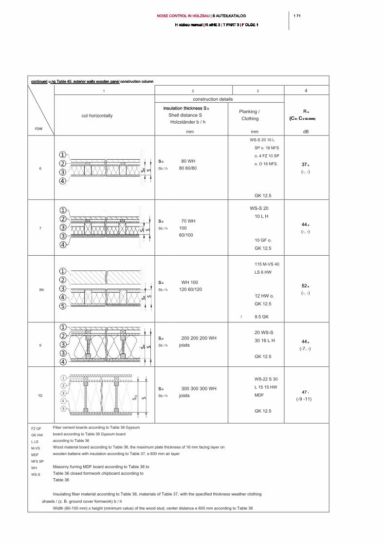
1 711 71NOISE CONTROL IN HOLZBAU | B AUTEILKATALOG NOISE CONTROL IN HOLZBAU | B AUTEILKATALOG NOISE CONTROL IN HOLZBAU | B AUTEILKATALOG
H olzbau manual | R eIHE 3 | T PART 3 | F OLGE 1H olzbau manual | R eIHE 3 | T PART 3 | F OLGE 1H olzbau manual | R eIHE 3 | T PART 3 | F OLGE 1H olzbau manual | R eIHE 3 | T PART 3 | F OLGE 1H olzbau manual | R eIHE 3 | T PART 3 | F OLGE 1H olzbau manual | R eIHE 3 | T PART 3 | F OLGE 1H olzbau manual | R eIHE 3 | T PART 3 | F OLGE 1H olzbau manual | R eIHE 3 | T PART 3 | F OLGE 1H olzbau manual | R eIHE 3 | T PART 3 | F OLGE 1H olzbau manual | R eIHE 3 | T PART 3 | F OLGE 1H olzbau manual | R eIHE 3 | T PART 3 | F OLGE 1
continued u ng Table 45: exterior walls wooden panel construction columncontinued u ng Table 45: exterior walls wooden panel construction columncontinued u ng Table 45: exterior walls wooden panel construction columncontinued u ng Table 45: exterior walls wooden panel construction column
row
1 2 3 4
cut horizontally
construction details
R wR w
(C tr; C tr 50-5000)(C tr; C tr 50-5000)(C tr; C tr 50-5000)(C tr; C tr 50-5000)
insulation thickness S Dinsulation thickness S D
Shell distance S
Holzständer b / h
Planking /
Clothing
mm mm dB
6
S DS D
Sb / h
80 WH
80 60/80
WS-S 20 10 L
SP o. 18 NFS
o. 4 FZ 10 SP
o. O 18 NFS.
GK 12.5
37 a37 a
(-, -)
7
S DS D
Sb / h
70 WH
100
60/100
WS-S 20
10 L H
44 a44 a
(-, -)
10 GF o.
GK 12.5
8th
S DS D
Sb / h
WH 100
120 60/120
115 M-VS 40
LS 6 HW
52 a52 a
(-, -)
12 HW o.
GK 12.5
! 9.5 GK
9
S DS D
Sb / h
200 200 200 WH
joists
20 WS-S
30 16 L H
GK 12.5
44 a44 a
(-7, -)
10
S DS D
Sb / h
300 300 300 WH
joists
WS-22 S 30
L 15 15 HW
MDF
GK 12.5
47 l47 l
(-9 -11)
FZ GF
GK HW
L LS
M-VS
MDF
NFS SP
WH
WS-S
Fiber cement boards according to Table 36 Gypsum
board according to Table 36 Gypsum board
according to Table 36
Wood material board according to Table 36, the maximum plate thickness of 16 mm facing layer on
wooden battens with insulation according to Table 37, e 600 mm air layer
Masonry furring MDF board according to Table 36 to
Table 36 closed formwork chipboard according to
Table 36
Insulating fiber material according to Table 36, materials of Table 37, with the specified thickness weather clothing
shawls / (z. B. ground cover formwork) b / h
Width (60-100 mm) x height (minimum value) of the wood stud, center distance e 600 mm according to Table 36
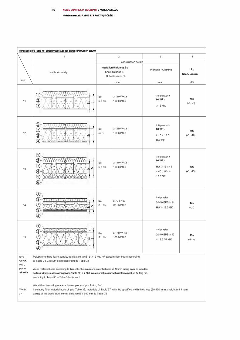
NOISE CONTROL IN HOLZBAU | B AUTEILKATALOG NOISE CONTROL IN HOLZBAU | B AUTEILKATALOG NOISE CONTROL IN HOLZBAU | B AUTEILKATALOG
H olzbau manual | R eIHE 3 | T PART 3 | F OLGE 1H olzbau manual | R eIHE 3 | T PART 3 | F OLGE 1H olzbau manual | R eIHE 3 | T PART 3 | F OLGE 1H olzbau manual | R eIHE 3 | T PART 3 | F OLGE 1H olzbau manual | R eIHE 3 | T PART 3 | F OLGE 1H olzbau manual | R eIHE 3 | T PART 3 | F OLGE 1H olzbau manual | R eIHE 3 | T PART 3 | F OLGE 1H olzbau manual | R eIHE 3 | T PART 3 | F OLGE 1H olzbau manual | R eIHE 3 | T PART 3 | F OLGE 1H olzbau manual | R eIHE 3 | T PART 3 | F OLGE 1H olzbau manual | R eIHE 3 | T PART 3 | F OLGE 1
172
continued u ng Table 45: exterior walls wooden panel construction column continued u ng Table 45: exterior walls wooden panel construction column continued u ng Table 45: exterior walls wooden panel construction column continued u ng Table 45: exterior walls wooden panel construction column
row
1 2 3 4
cut horizontally
construction details
R w R w
(C tr; C tr 50-5000)(C tr; C tr 50-5000)(C tr; C tr 50-5000)(C tr; C tr 50-5000)
insulation thickness S Dinsulation thickness S D
Shell distance S
Holzständer b / h
Planking / Clothing
mm mm dB
11
S DS D
S b / h
≥ 140 WH ≥
160 60/160
≥ 8 plaster ≥
60 WF 160 WF 1
≥ 15 HW
45 f45 f
(-6, -8)
12
S DS D
S b / h
≥ 140 WH ≥
160 60/160
≥ 8 plaster ≥
60 WF 160 WF 1
≥ 15 ≥ 12.5
HW GF
50 f50 f
(-5, -10)
13
S DS D
S b / h
≥ 140 WH ≥
160 60/160
≥ 8 plaster ≥
60 WF 160 WF 1
HW ≥ 15 ≥ 45
≥ 40 L WH ≥
12.5 GF
52 f52 f
(-5, -15)
14
S DS D
S b / h
≥ 70 ≥ 100
WH 60/100
≥ 4 plaster
20-40 EPS ≥ 14
HW ≥ 12.5 GK
44 a44 a
(-, -)
15
S DS D
S b / h
≥ 160 WH ≥
160 60/160
≥ 4 plaster
20-40 EPS ≥ 13
≥ 12.5 SP GK
45 a45 a
(-6, -)
EPS
GF GK
HW L
plaster
SP WF 1SP WF 1
WH b
/ h
Polystyrene hard foam panels, application WAB, ρ ≥ 15 kg / m³ gypsum fiber board according
to Table 36 Gypsum board according to Table 36
Wood material board according to Table 36, the maximum plate thickness of 16 mm facing layer on wooden
battens with insulation according to Table 37, e ≥ 600 mm external plaster with reinforcement, m '≥ 8 kg / m 2battens with insulation according to Table 37, e ≥ 600 mm external plaster with reinforcement, m '≥ 8 kg / m 2
according to Table 36 to Table 36 chipboard
Wood fiber insulating material by wet process; ρ = 210 kg / m³
Insulating fiber material according to Table 36, materials of Table 37, with the specified width thickness (60-100 mm) x height (minimum
value) of the wood stud, center distance E ≥ 600 mm to Table 36
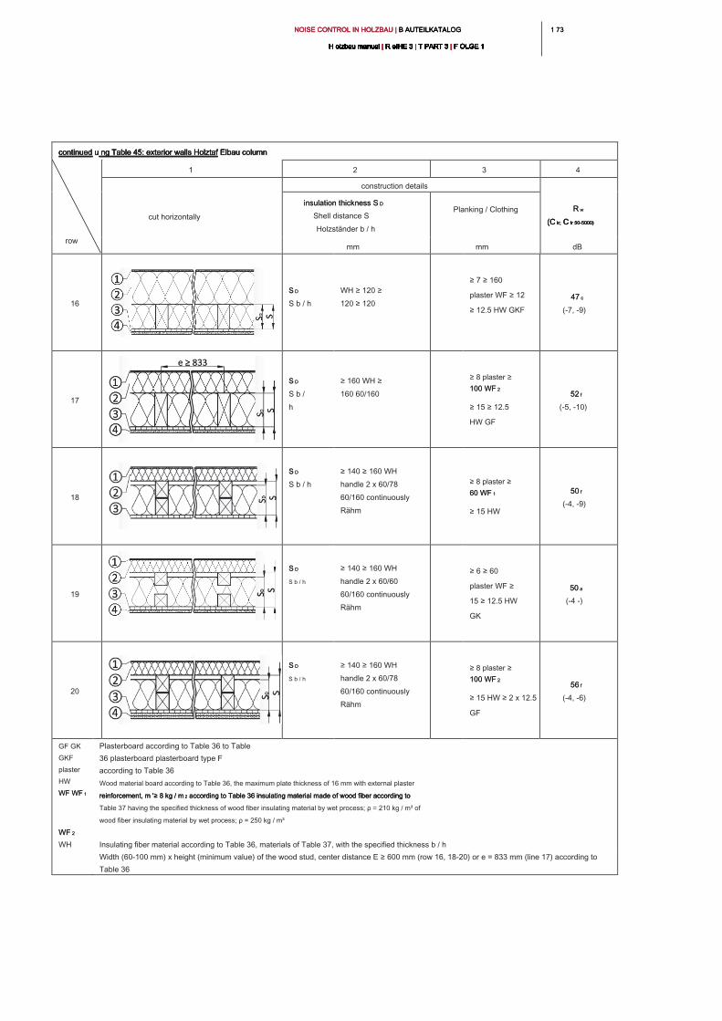
1 731 73NOISE CONTROL IN HOLZBAU | B AUTEILKATALOG NOISE CONTROL IN HOLZBAU | B AUTEILKATALOG NOISE CONTROL IN HOLZBAU | B AUTEILKATALOG
H olzbau manual | R eIHE 3 | T PART 3 | F OLGE 1H olzbau manual | R eIHE 3 | T PART 3 | F OLGE 1H olzbau manual | R eIHE 3 | T PART 3 | F OLGE 1H olzbau manual | R eIHE 3 | T PART 3 | F OLGE 1H olzbau manual | R eIHE 3 | T PART 3 | F OLGE 1H olzbau manual | R eIHE 3 | T PART 3 | F OLGE 1H olzbau manual | R eIHE 3 | T PART 3 | F OLGE 1H olzbau manual | R eIHE 3 | T PART 3 | F OLGE 1H olzbau manual | R eIHE 3 | T PART 3 | F OLGE 1H olzbau manual | R eIHE 3 | T PART 3 | F OLGE 1H olzbau manual | R eIHE 3 | T PART 3 | F OLGE 1
continued u ng Table 45: exterior walls Holztaf Elbau column continued u ng Table 45: exterior walls Holztaf Elbau column continued u ng Table 45: exterior walls Holztaf Elbau column continued u ng Table 45: exterior walls Holztaf Elbau column
row
1 2 3 4
cut horizontally
construction details
R w R w
(C tr; C tr 50-5000)(C tr; C tr 50-5000)(C tr; C tr 50-5000)(C tr; C tr 50-5000)
insulation thickness S Dinsulation thickness S D
Shell distance S
Holzständer b / h
Planking / Clothing
mm mm dB
16
S DS D
S b / h
WH ≥ 120 ≥
120 ≥ 120
≥ 7 ≥ 160
plaster WF ≥ 12
≥ 12.5 HW GKF
47 c47 c
(-7, -9)
17
S DS D
S b /
h
≥ 160 WH ≥
160 60/160
≥ 8 plaster ≥
100 WF 2100 WF 2
≥ 15 ≥ 12.5
HW GF
52 f52 f
(-5, -10)
18
S DS D
S b / h
≥ 140 ≥ 160 WH
handle 2 x 60/78
60/160 continuously
Rähm
≥ 8 plaster ≥
60 WF 160 WF 1
≥ 15 HW
50 f50 f
(-4, -9)
19
S DS D
S b / h
≥ 140 ≥ 160 WH
handle 2 x 60/60
60/160 continuously
Rähm
≥ 6 ≥ 60
plaster WF ≥
15 ≥ 12.5 HW
GK
50 a50 a
(-4 -)
20
S DS D
S b / h
≥ 140 ≥ 160 WH
handle 2 x 60/78
60/160 continuously
Rähm
≥ 8 plaster ≥
100 WF 2100 WF 2
≥ 15 HW ≥ 2 x 12.5
GF
56 f56 f
(-4, -6)
GF GK
GKF
plaster
HW
WF WF 1WF WF 1
WF 2 WF 2
WH
Plasterboard according to Table 36 to Table
36 plasterboard plasterboard type F
according to Table 36
Wood material board according to Table 36, the maximum plate thickness of 16 mm with external plaster
reinforcement, m '≥ 8 kg / m 2 according to Table 36 insulating material made of wood fiber according to reinforcement, m '≥ 8 kg / m 2 according to Table 36 insulating material made of wood fiber according to reinforcement, m '≥ 8 kg / m 2 according to Table 36 insulating material made of wood fiber according to
Table 37 having the specified thickness of wood fiber insulating material by wet process; ρ = 210 kg / m³ of
wood fiber insulating material by wet process; ρ = 250 kg / m³
Insulating fiber material according to Table 36, materials of Table 37, with the specified thickness b / h
Width (60-100 mm) x height (minimum value) of the wood stud, center distance E ≥ 600 mm (row 16, 18-20) or e = 833 mm (line 17) according to
Table 36
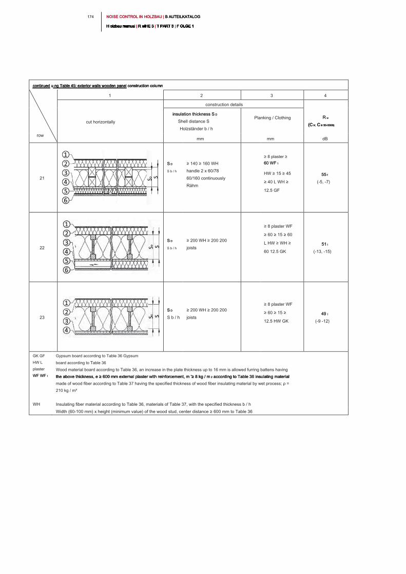
NOISE CONTROL IN HOLZBAU | B AUTEILKATALOG NOISE CONTROL IN HOLZBAU | B AUTEILKATALOG NOISE CONTROL IN HOLZBAU | B AUTEILKATALOG
H olzbau manual | R eIHE 3 | T PART 3 | F OLGE 1H olzbau manual | R eIHE 3 | T PART 3 | F OLGE 1H olzbau manual | R eIHE 3 | T PART 3 | F OLGE 1H olzbau manual | R eIHE 3 | T PART 3 | F OLGE 1H olzbau manual | R eIHE 3 | T PART 3 | F OLGE 1H olzbau manual | R eIHE 3 | T PART 3 | F OLGE 1H olzbau manual | R eIHE 3 | T PART 3 | F OLGE 1H olzbau manual | R eIHE 3 | T PART 3 | F OLGE 1H olzbau manual | R eIHE 3 | T PART 3 | F OLGE 1H olzbau manual | R eIHE 3 | T PART 3 | F OLGE 1H olzbau manual | R eIHE 3 | T PART 3 | F OLGE 1
174
continued u ng Table 45: exterior walls wooden panel construction column continued u ng Table 45: exterior walls wooden panel construction column continued u ng Table 45: exterior walls wooden panel construction column continued u ng Table 45: exterior walls wooden panel construction column
row
1 2 3 4
cut horizontally
construction details
R w R w
(C tr; C tr 50-5000)(C tr; C tr 50-5000)(C tr; C tr 50-5000)(C tr; C tr 50-5000)
insulation thickness S Dinsulation thickness S D
Shell distance S
Holzständer b / h
Planking / Clothing
mm mm dB
21
S DS D
S b / h
≥ 140 ≥ 160 WH
handle 2 x 60/78
60/160 continuously
Rähm
≥ 8 plaster ≥
60 WF 160 WF 1
HW ≥ 15 ≥ 45
≥ 40 L WH ≥
12.5 GF
55 f55 f
(-5, -7)
22
S DS D
S b / h
≥ 200 WH ≥ 200 200
joists
≥ 8 plaster WF
≥ 60 ≥ 15 ≥ 60
L HW ≥ WH ≥
60 12.5 GK
51 l51 l
(-13, -15)
23
S DS D
S b / h
≥ 200 WH ≥ 200 200
joists
≥ 8 plaster WF
≥ 60 ≥ 15 ≥
12.5 HW GK
49 l49 l
(-9 -12)
GK GF
HW L
plaster
WF WF 1WF WF 1
WH
Gypsum board according to Table 36 Gypsum
board according to Table 36
Wood material board according to Table 36, an increase in the plate thickness up to 16 mm is allowed furring battens having
the above thickness, e ≥ 600 mm external plaster with reinforcement, m '≥ 8 kg / m 2 according to Table 36 insulating material the above thickness, e ≥ 600 mm external plaster with reinforcement, m '≥ 8 kg / m 2 according to Table 36 insulating material the above thickness, e ≥ 600 mm external plaster with reinforcement, m '≥ 8 kg / m 2 according to Table 36 insulating material
made of wood fiber according to Table 37 having the specified thickness of wood fiber insulating material by wet process; ρ =
210 kg / m³
Insulating fiber material according to Table 36, materials of Table 37, with the specified thickness b / h
Width (60-100 mm) x height (minimum value) of the wood stud, center distance ≥ 600 mm to Table 36
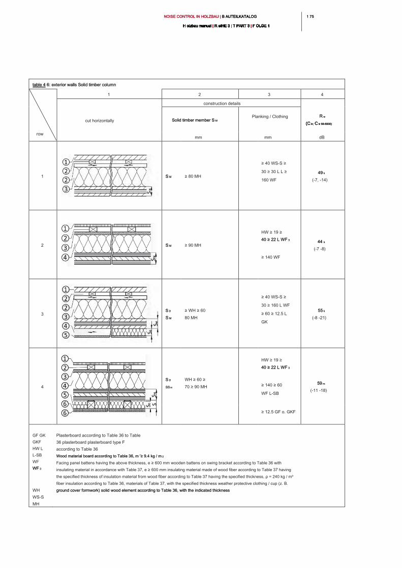
1 751 75NOISE CONTROL IN HOLZBAU | B AUTEILKATALOG NOISE CONTROL IN HOLZBAU | B AUTEILKATALOG NOISE CONTROL IN HOLZBAU | B AUTEILKATALOG
H olzbau manual | R eIHE 3 | T PART 3 | F OLGE 1H olzbau manual | R eIHE 3 | T PART 3 | F OLGE 1H olzbau manual | R eIHE 3 | T PART 3 | F OLGE 1H olzbau manual | R eIHE 3 | T PART 3 | F OLGE 1H olzbau manual | R eIHE 3 | T PART 3 | F OLGE 1H olzbau manual | R eIHE 3 | T PART 3 | F OLGE 1H olzbau manual | R eIHE 3 | T PART 3 | F OLGE 1H olzbau manual | R eIHE 3 | T PART 3 | F OLGE 1H olzbau manual | R eIHE 3 | T PART 3 | F OLGE 1H olzbau manual | R eIHE 3 | T PART 3 | F OLGE 1H olzbau manual | R eIHE 3 | T PART 3 | F OLGE 1
table 4 6: exterior walls Solid timber column table 4 6: exterior walls Solid timber column
row
1 2 3 4
cut horizontally
construction details
R w R w
(C tr; C tr 50-5000)(C tr; C tr 50-5000)(C tr; C tr 50-5000)(C tr; C tr 50-5000)
Solid timber member S M Solid timber member S M
Planking / Clothing
mm mm dB
1 S MS M ≥ 80 MH
≥ 40 WS-S ≥
30 ≥ 30 L L ≥
160 WF
49 k49 k
(-7, -14)
2 S MS M ≥ 90 MH
HW ≥ 19 ≥
40 ≥ 22 L WF 340 ≥ 22 L WF 3
≥ 140 WF
44 k44 k
(-7 -8)
3
S DS D
S M S M
≥ WH ≥ 60
80 MH
≥ 40 WS-S ≥
30 ≥ 160 L WF
≥ 60 ≥ 12.5 L
GK
55 k55 k
(-8 -21)
4
S D S D
SS MSS M
WH ≥ 60 ≥
70 ≥ 90 MH
HW ≥ 19 ≥
40 ≥ 22 L WF 340 ≥ 22 L WF 3
≥ 140 ≥ 60
WF L-SB
59 m59 m
(-11 -18)
≥ 12.5 GF o. GKF
GF GK
GKF
HW L
L-SB
WF
WF 3WF 3
WH
WS-S
MH
Plasterboard according to Table 36 to Table
36 plasterboard plasterboard type F
according to Table 36
Wood material board according to Table 36, m '≥ 9.4 kg / m 2Wood material board according to Table 36, m '≥ 9.4 kg / m 2
Facing panel battens having the above thickness, e ≥ 600 mm wooden battens on swing bracket according to Table 36 with
insulating material in accordance with Table 37, e ≥ 600 mm insulating material made of wood fiber according to Table 37 having
the specified thickness of insulation material from wood fiber according to Table 37 having the specified thickness, ρ = 240 kg / m³
fiber insulation according to Table 36, materials of Table 37, with the specified thickness weather protective clothing / cup (z. B.
ground cover formwork) solid wood element according to Table 36, with the indicated thickness ground cover formwork) solid wood element according to Table 36, with the indicated thickness
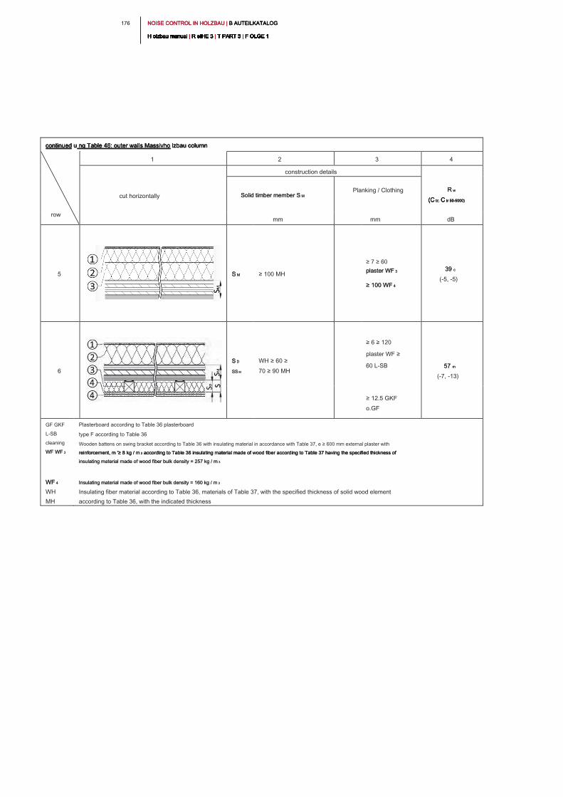
NOISE CONTROL IN HOLZBAU | B AUTEILKATALOG NOISE CONTROL IN HOLZBAU | B AUTEILKATALOG NOISE CONTROL IN HOLZBAU | B AUTEILKATALOG
H olzbau manual | R eIHE 3 | T PART 3 | F OLGE 1H olzbau manual | R eIHE 3 | T PART 3 | F OLGE 1H olzbau manual | R eIHE 3 | T PART 3 | F OLGE 1H olzbau manual | R eIHE 3 | T PART 3 | F OLGE 1H olzbau manual | R eIHE 3 | T PART 3 | F OLGE 1H olzbau manual | R eIHE 3 | T PART 3 | F OLGE 1H olzbau manual | R eIHE 3 | T PART 3 | F OLGE 1H olzbau manual | R eIHE 3 | T PART 3 | F OLGE 1H olzbau manual | R eIHE 3 | T PART 3 | F OLGE 1H olzbau manual | R eIHE 3 | T PART 3 | F OLGE 1H olzbau manual | R eIHE 3 | T PART 3 | F OLGE 1
176
continued u ng Table 46: outer walls Massivho lzbau column continued u ng Table 46: outer walls Massivho lzbau column continued u ng Table 46: outer walls Massivho lzbau column continued u ng Table 46: outer walls Massivho lzbau column
row
1 2 3 4
cut horizontally
construction details
R w R w
(C tr; C tr 50-5000)(C tr; C tr 50-5000)(C tr; C tr 50-5000)(C tr; C tr 50-5000)
Solid timber member S M Solid timber member S M
Planking / Clothing
mm mm dB
5 S MS M ≥ 100 MH
≥ 7 ≥ 60
plaster WF 3plaster WF 3
≥ 100 WF 4≥ 100 WF 4
39 c39 c
(-5, -5)
6
S D S D
SS MSS M
WH ≥ 60 ≥
70 ≥ 90 MH
≥ 6 ≥ 120
plaster WF ≥
60 L-SB 57 m57 m
(-7, -13)
≥ 12.5 GKF
o.GF
GF GKF
L-SB
cleaning
WF WF 3WF WF 3
WF 4 WF 4
WH
MH
Plasterboard according to Table 36 plasterboard
type F according to Table 36
Wooden battens on swing bracket according to Table 36 with insulating material in accordance with Table 37, e ≥ 600 mm external plaster with
reinforcement, m '≥ 8 kg / m 2 according to Table 36 insulating material made of wood fiber according to Table 37 having the specified thickness of reinforcement, m '≥ 8 kg / m 2 according to Table 36 insulating material made of wood fiber according to Table 37 having the specified thickness of reinforcement, m '≥ 8 kg / m 2 according to Table 36 insulating material made of wood fiber according to Table 37 having the specified thickness of
insulating material made of wood fiber bulk density = 257 kg / m 3insulating material made of wood fiber bulk density = 257 kg / m 3
Insulating material made of wood fiber bulk density = 160 kg / m 3Insulating material made of wood fiber bulk density = 160 kg / m 3
Insulating fiber material according to Table 36, materials of Table 37, with the specified thickness of solid wood element
according to Table 36, with the indicated thickness
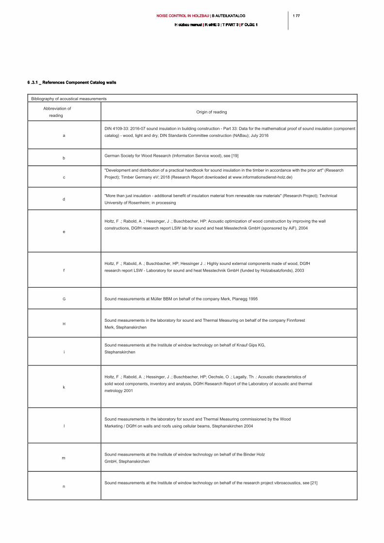
1 771 77NOISE CONTROL IN HOLZBAU | B AUTEILKATALOG NOISE CONTROL IN HOLZBAU | B AUTEILKATALOG NOISE CONTROL IN HOLZBAU | B AUTEILKATALOG
H olzbau manual | R eIHE 3 | T PART 3 | F OLGE 1H olzbau manual | R eIHE 3 | T PART 3 | F OLGE 1H olzbau manual | R eIHE 3 | T PART 3 | F OLGE 1H olzbau manual | R eIHE 3 | T PART 3 | F OLGE 1H olzbau manual | R eIHE 3 | T PART 3 | F OLGE 1H olzbau manual | R eIHE 3 | T PART 3 | F OLGE 1H olzbau manual | R eIHE 3 | T PART 3 | F OLGE 1H olzbau manual | R eIHE 3 | T PART 3 | F OLGE 1H olzbau manual | R eIHE 3 | T PART 3 | F OLGE 1H olzbau manual | R eIHE 3 | T PART 3 | F OLGE 1H olzbau manual | R eIHE 3 | T PART 3 | F OLGE 1
Bibliography of acoustical measurements
Abbreviation of
reading
Origin of reading
a
DIN 4109-33: 2016-07 sound insulation in building construction - Part 33: Data for the mathematical proof of sound insulation (component
catalog) - wood, light and dry; DIN Standards Committee construction (NABau); July 2016
b
German Society for Wood Research (Information Service wood), see [19]
c
"Development and distribution of a practical handbook for sound insulation in the timber in accordance with the prior art" (Research
Project); Timber Germany eV; 2018 (Research Report downloaded at www.informationsdienst-holz.de)
d
"More than just insulation - additional benefit of insulation material from renewable raw materials" (Research Project); Technical
University of Rosenheim; in processing
e
Holtz, F .; Rabold, A .; Hessinger, J .; Buschbacher, HP: Acoustic optimization of wood construction by improving the wall
constructions, DGfH research report LSW lab for sound and heat Messtechnik GmbH (sponsored by AiF), 2004
f
Holtz, F .; Rabold, A .; Buschbacher, HP; Hessinger J .: Highly sound external components made of wood, DGfH
research report LSW - Laboratory for sound and heat Messtechnik GmbH (funded by Holzabsatzfonds), 2003
G Sound measurements at Müller BBM on behalf of the company Merk, Planegg 1995
H
Sound measurements in the laboratory for sound and Thermal Measuring on behalf of the company Finnforest
Merk, Stephanskirchen
i
Sound measurements at the Institute of window technology on behalf of Knauf Gips KG,
Stephanskirchen
k
Holtz, F .; Rabold, A .; Hessinger, J .; Buschbacher, HP; Oechsle, O .; Lagally, Th .: Acoustic characteristics of
solid wood components, inventory and analysis, DGfH Research Report of the Laboratory of acoustic and thermal
metrology 2001
l
Sound measurements in the laboratory for sound and Thermal Measuring commissioned by the Wood
Marketing / DGfH on walls and roofs using cellular beams, Stephanskirchen 2004
m
Sound measurements at the Institute of window technology on behalf of the Binder Holz
GmbH, Stephanskirchen
n
Sound measurements at the Institute of window technology on behalf of the research project vibroacoustics, see [21]
6 .3.1 _ References Component Catalog walls6 .3.1 _ References Component Catalog walls
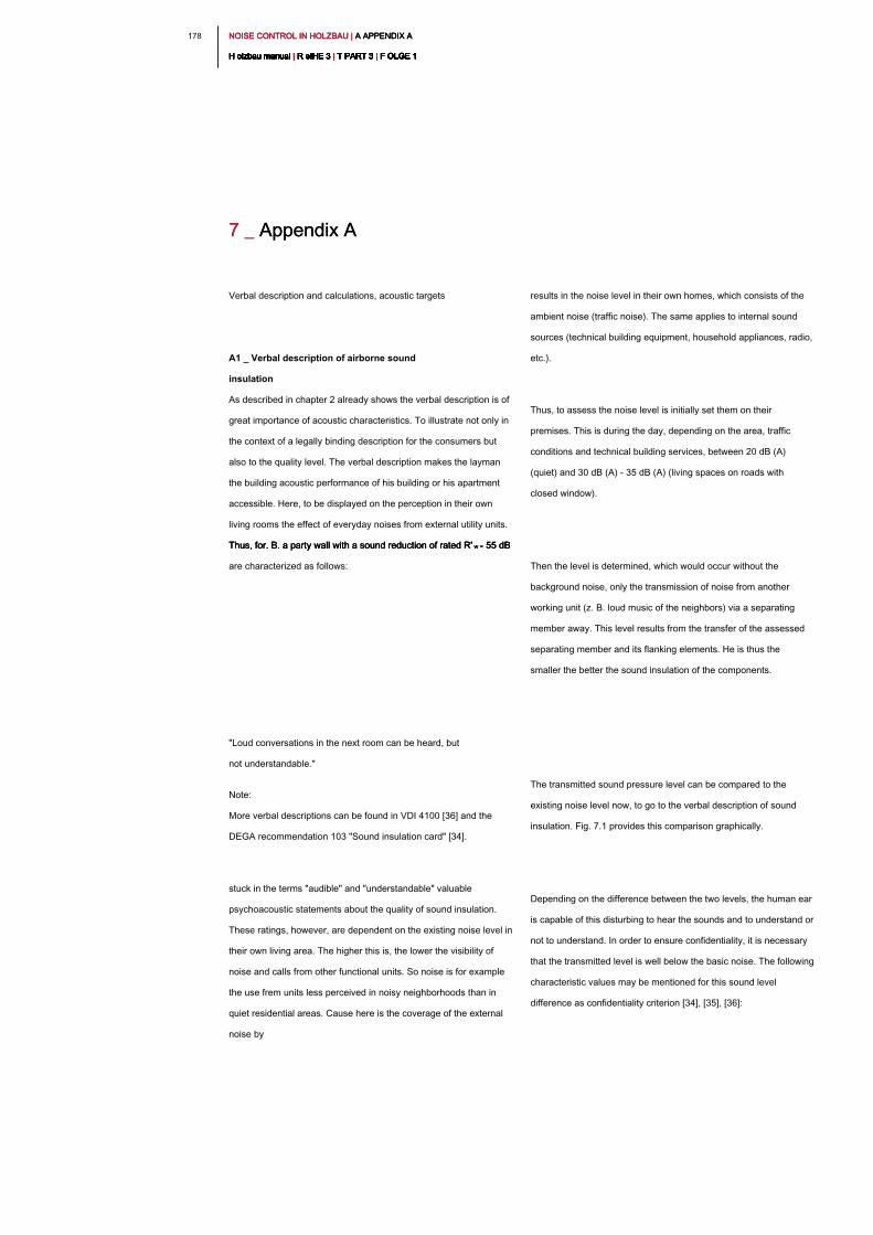
NOISE CONTROL IN HOLZBAU | A APPENDIX A NOISE CONTROL IN HOLZBAU | A APPENDIX A NOISE CONTROL IN HOLZBAU | A APPENDIX A
H olzbau manual | R eIHE 3 | T PART 3 | F OLGE 1H olzbau manual | R eIHE 3 | T PART 3 | F OLGE 1H olzbau manual | R eIHE 3 | T PART 3 | F OLGE 1H olzbau manual | R eIHE 3 | T PART 3 | F OLGE 1H olzbau manual | R eIHE 3 | T PART 3 | F OLGE 1H olzbau manual | R eIHE 3 | T PART 3 | F OLGE 1H olzbau manual | R eIHE 3 | T PART 3 | F OLGE 1H olzbau manual | R eIHE 3 | T PART 3 | F OLGE 1H olzbau manual | R eIHE 3 | T PART 3 | F OLGE 1H olzbau manual | R eIHE 3 | T PART 3 | F OLGE 1H olzbau manual | R eIHE 3 | T PART 3 | F OLGE 1
178
results in the noise level in their own homes, which consists of the
ambient noise (traffic noise). The same applies to internal sound
sources (technical building equipment, household appliances, radio,
etc.).
Thus, to assess the noise level is initially set them on their
premises. This is during the day, depending on the area, traffic
conditions and technical building services, between 20 dB (A)
(quiet) and 30 dB (A) - 35 dB (A) (living spaces on roads with
closed window).
Then the level is determined, which would occur without the
background noise, only the transmission of noise from another
working unit (z. B. loud music of the neighbors) via a separating
member away. This level results from the transfer of the assessed
separating member and its flanking elements. He is thus the
smaller the better the sound insulation of the components.
The transmitted sound pressure level can be compared to the
existing noise level now, to go to the verbal description of sound
insulation. Fig. 7.1 provides this comparison graphically.
Depending on the difference between the two levels, the human ear
is capable of this disturbing to hear the sounds and to understand or
not to understand. In order to ensure confidentiality, it is necessary
that the transmitted level is well below the basic noise. The following
characteristic values may be mentioned for this sound level
difference as confidentiality criterion [34], [35], [36]:
Verbal description and calculations, acoustic targets
A1 _ Verbal description of airborne sound
insulation
As described in chapter 2 already shows the verbal description is of
great importance of acoustic characteristics. To illustrate not only in
the context of a legally binding description for the consumers but
also to the quality level. The verbal description makes the layman
the building acoustic performance of his building or his apartment
accessible. Here, to be displayed on the perception in their own
living rooms the effect of everyday noises from external utility units.
Thus, for. B. a party wall with a sound reduction of rated R' w = 55 dB Thus, for. B. a party wall with a sound reduction of rated R' w = 55 dB Thus, for. B. a party wall with a sound reduction of rated R' w = 55 dB
are characterized as follows:
"Loud conversations in the next room can be heard, but
not understandable."
Note:
More verbal descriptions can be found in VDI 4100 [36] and the
DEGA recommendation 103 "Sound insulation card" [34].
stuck in the terms "audible" and "understandable" valuable
psychoacoustic statements about the quality of sound insulation.
These ratings, however, are dependent on the existing noise level in
their own living area. The higher this is, the lower the visibility of
noise and calls from other functional units. So noise is for example
the use frem units less perceived in noisy neighborhoods than in
quiet residential areas. Cause here is the coverage of the external
noise by
7 _ Appendix A7 _ Appendix A
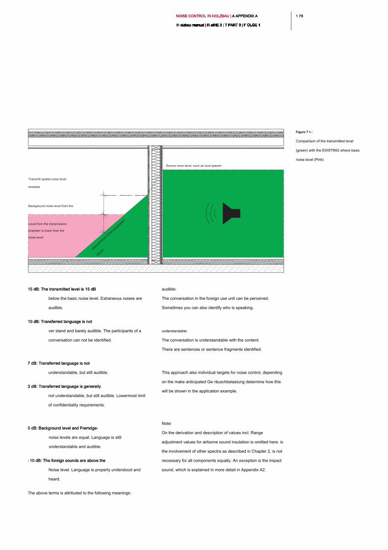
1 791 79NOISE CONTROL IN HOLZBAU | A APPENDIX A NOISE CONTROL IN HOLZBAU | A APPENDIX A NOISE CONTROL IN HOLZBAU | A APPENDIX A
H olzbau manual | R eIHE 3 | T PART 3 | F OLGE 1H olzbau manual | R eIHE 3 | T PART 3 | F OLGE 1H olzbau manual | R eIHE 3 | T PART 3 | F OLGE 1H olzbau manual | R eIHE 3 | T PART 3 | F OLGE 1H olzbau manual | R eIHE 3 | T PART 3 | F OLGE 1H olzbau manual | R eIHE 3 | T PART 3 | F OLGE 1H olzbau manual | R eIHE 3 | T PART 3 | F OLGE 1H olzbau manual | R eIHE 3 | T PART 3 | F OLGE 1H olzbau manual | R eIHE 3 | T PART 3 | F OLGE 1H olzbau manual | R eIHE 3 | T PART 3 | F OLGE 1H olzbau manual | R eIHE 3 | T PART 3 | F OLGE 1
audible:
The conversation in the foreign use unit can be perceived.
Sometimes you can also identify who is speaking.
understandable:
The conversation is understandable with the content.
There are sentences or sentence fragments identified.
This approach also individual targets for noise control, depending
on the make anticipated Ge räuschbelastung determine how this
will be shown in the application example.
Note:
On the derivation and description of values incl. Range
adjustment values for airborne sound insulation is omitted here. is
the involvement of other spectra as described in Chapter 2, is not
necessary for all components equally. An exception is the impact
sound, which is explained in more detail in Appendix A2.
15 dB: The transmitted level is 15 dB 15 dB: The transmitted level is 15 dB
below the basic noise level. Extraneous noises are
audible.
10 dB: Transferred language is not 10 dB: Transferred language is not
ver stand and barely audible. The participants of a
conversation can not be identified.
7 dB: Transferred language is not 7 dB: Transferred language is not
understandable, but still audible.
3 dB: Transferred language is generally 3 dB: Transferred language is generally
not understandable, but still audible. Lowermost limit
of confidentiality requirements.
0 dB: Background level and Fremdge-0 dB: Background level and Fremdge-
noise levels are equal. Language is still
understandable and audible.
- 10 dB: The foreign sounds are above the 10 dB: The foreign sounds are above the
Noise level. Language is properly understood and
heard.
The above terms is attributed to the following meanings:
Figure 7.1.:
Comparison of the transmitted level
(green) with the EXISTING where basic
noise level (Pink)
Source room level, such as loud speech
Background noise level from the
Transmit spatial noise level
exceeds
Level from the transmission
chamber is lower than the
noise level
in
d
u
c
e
d
le
v
e
l o
f th
e
tra
n
s
m
itte
d
s
o
u
n
d
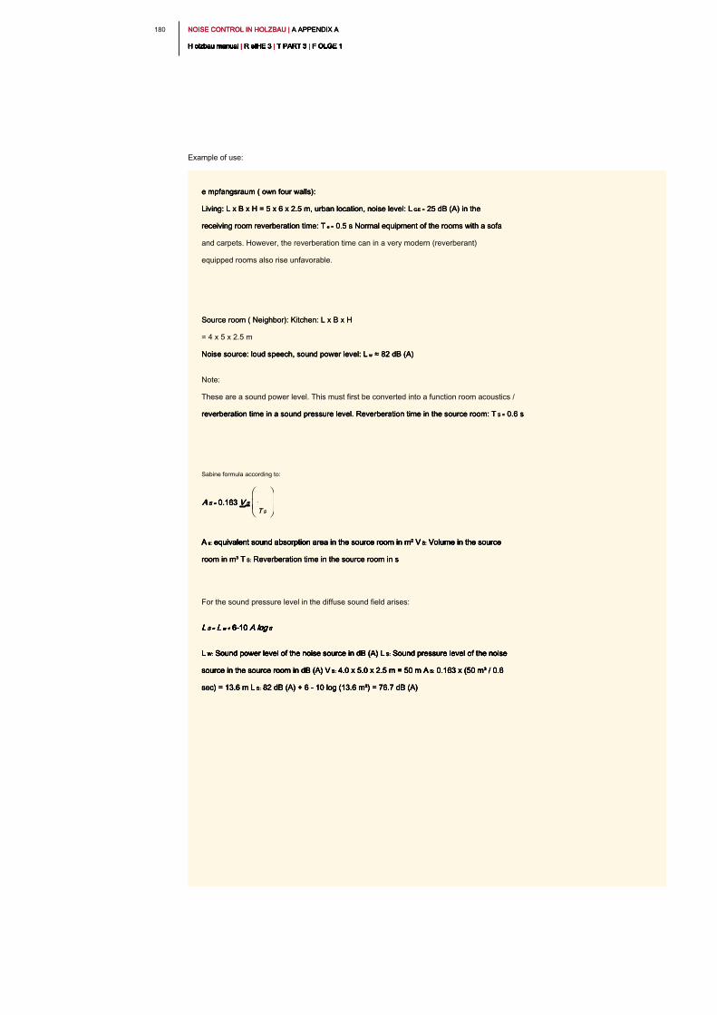
NOISE CONTROL IN HOLZBAU | A APPENDIX A NOISE CONTROL IN HOLZBAU | A APPENDIX A NOISE CONTROL IN HOLZBAU | A APPENDIX A
H olzbau manual | R eIHE 3 | T PART 3 | F OLGE 1H olzbau manual | R eIHE 3 | T PART 3 | F OLGE 1H olzbau manual | R eIHE 3 | T PART 3 | F OLGE 1H olzbau manual | R eIHE 3 | T PART 3 | F OLGE 1H olzbau manual | R eIHE 3 | T PART 3 | F OLGE 1H olzbau manual | R eIHE 3 | T PART 3 | F OLGE 1H olzbau manual | R eIHE 3 | T PART 3 | F OLGE 1H olzbau manual | R eIHE 3 | T PART 3 | F OLGE 1H olzbau manual | R eIHE 3 | T PART 3 | F OLGE 1H olzbau manual | R eIHE 3 | T PART 3 | F OLGE 1H olzbau manual | R eIHE 3 | T PART 3 | F OLGE 1
180
e mpfangsraum ( own four walls): e mpfangsraum ( own four walls): e mpfangsraum ( own four walls):
Living: L x B x H = 5 x 6 x 2.5 m, urban location, noise level: L GE = 25 dB (A) in the Living: L x B x H = 5 x 6 x 2.5 m, urban location, noise level: L GE = 25 dB (A) in the Living: L x B x H = 5 x 6 x 2.5 m, urban location, noise level: L GE = 25 dB (A) in the
receiving room reverberation time: T e = 0.5 s Normal equipment of the rooms with a sofa receiving room reverberation time: T e = 0.5 s Normal equipment of the rooms with a sofa receiving room reverberation time: T e = 0.5 s Normal equipment of the rooms with a sofa
and carpets. However, the reverberation time can in a very modern (reverberant)
equipped rooms also rise unfavorable.
Source room ( Neighbor): Kitchen: L x B x H Source room ( Neighbor): Kitchen: L x B x H
= 4 x 5 x 2.5 m
Noise source: loud speech, sound power level: L w ≈ 82 dB (A) Noise source: loud speech, sound power level: L w ≈ 82 dB (A) Noise source: loud speech, sound power level: L w ≈ 82 dB (A)
Note:
These are a sound power level. This must first be converted into a function room acoustics /
reverberation time in a sound pressure level. Reverberation time in the source room: T S = 0.6 s reverberation time in a sound pressure level. Reverberation time in the source room: T S = 0.6 s reverberation time in a sound pressure level. Reverberation time in the source room: T S = 0.6 s
Sabine formula according to:
A s: equivalent sound absorption area in the source room in m² V S: Volume in the source A s: equivalent sound absorption area in the source room in m² V S: Volume in the source A s: equivalent sound absorption area in the source room in m² V S: Volume in the source A s: equivalent sound absorption area in the source room in m² V S: Volume in the source A s: equivalent sound absorption area in the source room in m² V S: Volume in the source
room in m³ T S: Reverberation time in the source room in sroom in m³ T S: Reverberation time in the source room in sroom in m³ T S: Reverberation time in the source room in s
For the sound pressure level in the diffuse sound field arises:
L S = L w + 6-10 A log SL S = L w + 6-10 A log SL S = L w + 6-10 A log SL S = L w + 6-10 A log SL S = L w + 6-10 A log SL S = L w + 6-10 A log SL S = L w + 6-10 A log SL S = L w + 6-10 A log S
L W: Sound power level of the noise source in dB (A) L S: Sound pressure level of the noise L W: Sound power level of the noise source in dB (A) L S: Sound pressure level of the noise L W: Sound power level of the noise source in dB (A) L S: Sound pressure level of the noise L W: Sound power level of the noise source in dB (A) L S: Sound pressure level of the noise L W: Sound power level of the noise source in dB (A) L S: Sound pressure level of the noise
source in the source room in dB (A) V S: 4.0 x 5.0 x 2.5 m = 50 m A S: 0.163 x (50 m³ / 0.6 source in the source room in dB (A) V S: 4.0 x 5.0 x 2.5 m = 50 m A S: 0.163 x (50 m³ / 0.6 source in the source room in dB (A) V S: 4.0 x 5.0 x 2.5 m = 50 m A S: 0.163 x (50 m³ / 0.6 source in the source room in dB (A) V S: 4.0 x 5.0 x 2.5 m = 50 m A S: 0.163 x (50 m³ / 0.6 source in the source room in dB (A) V S: 4.0 x 5.0 x 2.5 m = 50 m A S: 0.163 x (50 m³ / 0.6
sec) = 13.6 m L S: 82 dB (A) + 6 - 10 log (13.6 m²) = 76.7 dB (A)sec) = 13.6 m L S: 82 dB (A) + 6 - 10 log (13.6 m²) = 76.7 dB (A)sec) = 13.6 m L S: 82 dB (A) + 6 - 10 log (13.6 m²) = 76.7 dB (A)sec) = 13.6 m L S: 82 dB (A) + 6 - 10 log (13.6 m²) = 76.7 dB (A)
Example of use:
A S = 0.163 V SA S = 0.163 V SA S = 0.163 V SA S = 0.163 V SA S = 0.163 V S
T ST S
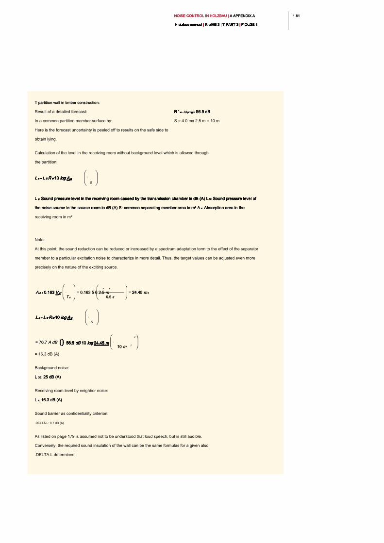
1 811 81NOISE CONTROL IN HOLZBAU | A APPENDIX A NOISE CONTROL IN HOLZBAU | A APPENDIX A NOISE CONTROL IN HOLZBAU | A APPENDIX A
H olzbau manual | R eIHE 3 | T PART 3 | F OLGE 1H olzbau manual | R eIHE 3 | T PART 3 | F OLGE 1H olzbau manual | R eIHE 3 | T PART 3 | F OLGE 1H olzbau manual | R eIHE 3 | T PART 3 | F OLGE 1H olzbau manual | R eIHE 3 | T PART 3 | F OLGE 1H olzbau manual | R eIHE 3 | T PART 3 | F OLGE 1H olzbau manual | R eIHE 3 | T PART 3 | F OLGE 1H olzbau manual | R eIHE 3 | T PART 3 | F OLGE 1H olzbau manual | R eIHE 3 | T PART 3 | F OLGE 1H olzbau manual | R eIHE 3 | T PART 3 | F OLGE 1H olzbau manual | R eIHE 3 | T PART 3 | F OLGE 1
T partition wall in timber construction:T partition wall in timber construction:
Result of a detailed forecast: R ' w - u prog = 56.5 dB R ' w - u prog = 56.5 dB R ' w - u prog = 56.5 dB R ' w - u prog = 56.5 dB R ' w - u prog = 56.5 dB R ' w - u prog = 56.5 dB
In a common partition member surface by: S = 4.0 mx 2.5 m = 10 m
Here is the forecast uncertainty is peeled off to results on the safe side to
obtain lying.
Calculation of the level in the receiving room without background level which is allowed through
the partition:
L e: Sound pressure level in the receiving room caused by the transmission chamber in dB (A) L S: Sound pressure level of L e: Sound pressure level in the receiving room caused by the transmission chamber in dB (A) L S: Sound pressure level of L e: Sound pressure level in the receiving room caused by the transmission chamber in dB (A) L S: Sound pressure level of L e: Sound pressure level in the receiving room caused by the transmission chamber in dB (A) L S: Sound pressure level of L e: Sound pressure level in the receiving room caused by the transmission chamber in dB (A) L S: Sound pressure level of
the noise source in the source room in dB (A) S: common separating member area in m² A e: Absorption area in the the noise source in the source room in dB (A) S: common separating member area in m² A e: Absorption area in the the noise source in the source room in dB (A) S: common separating member area in m² A e: Absorption area in the
receiving room in m²
Note:
At this point, the sound reduction can be reduced or increased by a spectrum adaptation term to the effect of the separator
member to a particular excitation noise to characterize in more detail. Thus, the target values can be adjusted even more
precisely on the nature of the exciting source.
= 16.3 dB (A)
Background noise:
L GE: 25 dB (A) L GE: 25 dB (A) L GE: 25 dB (A)
Receiving room level by neighbor noise:
L e: 16.3 dB (A) L e: 16.3 dB (A) L e: 16.3 dB (A)
Sound barrier as confidentiality criterion:
.DELTA.L: 8.7 dB (A)
As listed on page 179 is assumed not to be understood that loud speech, but is still audible.
Conversely, the required sound insulation of the wall can be the same formulas for a given also
.DELTA.L determined.
L e = L S R w 10 log A eL e = L S R w 10 log A eL e = L S R w 10 log A eL e = L S R w 10 log A eL e = L S R w 10 log A eL e = L S R w 10 log A eL e = L S R w 10 log A eL e = L S R w 10 log A eL e = L S R w 10 log A eL e = L S R w 10 log A e
S
A e = 0.163 V eA e = 0.163 V eA e = 0.163 V eA e = 0.163 V eA e = 0.163 V e
T eT e
= 0.163 5 6 2.5 m= 0.163 5 6 2.5 m
0.5 s 0.5 s
= 24.45 m 2= 24.45 m 2= 24.45 m 2
= 76.7 A dB= 76.7 A dB () 56.5 dB 10 log 24.45 m() 56.5 dB 10 log 24.45 m() 56.5 dB 10 log 24.45 m() 56.5 dB 10 log 24.45 m() 56.5 dB 10 log 24.45 m() 56.5 dB 10 log 24.45 m() 56.5 dB 10 log 24.45 m
10 m10 m
2
2
L e = L S R w 10 log A eL e = L S R w 10 log A eL e = L S R w 10 log A eL e = L S R w 10 log A eL e = L S R w 10 log A eL e = L S R w 10 log A eL e = L S R w 10 log A eL e = L S R w 10 log A eL e = L S R w 10 log A eL e = L S R w 10 log A e
S
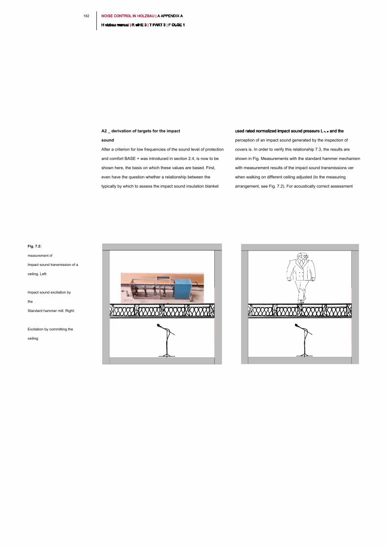
NOISE CONTROL IN HOLZBAU | A APPENDIX A NOISE CONTROL IN HOLZBAU | A APPENDIX A NOISE CONTROL IN HOLZBAU | A APPENDIX A
H olzbau manual | R eIHE 3 | T PART 3 | F OLGE 1H olzbau manual | R eIHE 3 | T PART 3 | F OLGE 1H olzbau manual | R eIHE 3 | T PART 3 | F OLGE 1H olzbau manual | R eIHE 3 | T PART 3 | F OLGE 1H olzbau manual | R eIHE 3 | T PART 3 | F OLGE 1H olzbau manual | R eIHE 3 | T PART 3 | F OLGE 1H olzbau manual | R eIHE 3 | T PART 3 | F OLGE 1H olzbau manual | R eIHE 3 | T PART 3 | F OLGE 1H olzbau manual | R eIHE 3 | T PART 3 | F OLGE 1H olzbau manual | R eIHE 3 | T PART 3 | F OLGE 1H olzbau manual | R eIHE 3 | T PART 3 | F OLGE 1
182
A2 _ derivation of targets for the impact
sound
After a criterion for low frequencies of the sound level of protection
and comfort BASE + was introduced in section 2.4, is now to be
shown here, the basis on which these values are based. First,
even have the question whether a relationship between the
typically by which to assess the impact sound insulation blanket
used rated normalized impact sound pressure L n, w and the used rated normalized impact sound pressure L n, w and the used rated normalized impact sound pressure L n, w and the
perception of an impact sound generated by the inspection of
covers is. In order to verify this relationship 7.3, the results are
shown in Fig. Measurements with the standard hammer mechanism
with measurement results of the impact sound transmissions ver
when walking on different ceiling adjusted (to the measuring
arrangement, see Fig. 7.2). For acoustically correct assessment
Fig. 7.2:
measurement of
Impact sound transmission of a
ceiling. Left:
Impact sound excitation by
the
Standard hammer mill. Right:
Excitation by committing the
ceiling.
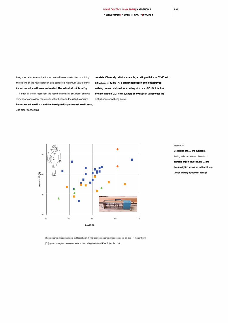
1 831 83NOISE CONTROL IN HOLZBAU | A APPENDIX A NOISE CONTROL IN HOLZBAU | A APPENDIX A NOISE CONTROL IN HOLZBAU | A APPENDIX A
H olzbau manual | R eIHE 3 | T PART 3 | F OLGE 1H olzbau manual | R eIHE 3 | T PART 3 | F OLGE 1H olzbau manual | R eIHE 3 | T PART 3 | F OLGE 1H olzbau manual | R eIHE 3 | T PART 3 | F OLGE 1H olzbau manual | R eIHE 3 | T PART 3 | F OLGE 1H olzbau manual | R eIHE 3 | T PART 3 | F OLGE 1H olzbau manual | R eIHE 3 | T PART 3 | F OLGE 1H olzbau manual | R eIHE 3 | T PART 3 | F OLGE 1H olzbau manual | R eIHE 3 | T PART 3 | F OLGE 1H olzbau manual | R eIHE 3 | T PART 3 | F OLGE 1H olzbau manual | R eIHE 3 | T PART 3 | F OLGE 1
tung was rated A-from the impact sound transmission in committing
the ceiling of the reverberation and corrected maximum value of the
impact sound level L AFmax, n educated. The individual points in Fig. impact sound level L AFmax, n educated. The individual points in Fig. impact sound level L AFmax, n educated. The individual points in Fig.
7.3, each of which represent the result of a ceiling structure, show a
very poor correlation. This means that between the rated standard
impact sound level L n, w and the A-weighted impact sound level L AFmax, impact sound level L n, w and the A-weighted impact sound level L AFmax, impact sound level L n, w and the A-weighted impact sound level L AFmax, impact sound level L n, w and the A-weighted impact sound level L AFmax,
n no clear connection n no clear connection
consists. Obviously calls for example, a ceiling with L n, w = 52 dB with consists. Obviously calls for example, a ceiling with L n, w = 52 dB with consists. Obviously calls for example, a ceiling with L n, w = 52 dB with
an L AF, max, n = 42 dB (A) a similar perception of the transferred an L AF, max, n = 42 dB (A) a similar perception of the transferred an L AF, max, n = 42 dB (A) a similar perception of the transferred
walking noises produced as a ceiling with L n, w = 37 dB. It is thus walking noises produced as a ceiling with L n, w = 37 dB. It is thus walking noises produced as a ceiling with L n, w = 37 dB. It is thus
evident that the L n, w is un suitable as evaluation variable for the evident that the L n, w is un suitable as evaluation variable for the evident that the L n, w is un suitable as evaluation variable for the
disturbance of walking noise.
Figure 7.3.:
Correlation of L n, w and subjective Correlation of L n, w and subjective Correlation of L n, w and subjective
feeling: relation between the rated
standard impact sound level L n, w and standard impact sound level L n, w and standard impact sound level L n, w and
the A-weighted impact sound level L AFmax, the A-weighted impact sound level L AFmax,
n when walking by wooden ceilings.n when walking by wooden ceilings.
Blue squares: measurements in Rosenheim ift [32] orange squares: measurements on the TH Rosenheim
[31] green triangles: measurements in the ceiling test stand Knauf, Iphofen [33].
20
30
40
50
30 40 50 60 70
L n, w in dBL n, w in dBL n, w in dBL n, w in dB
L A
F m
ax, n in dB
(A
)L
A
F m
ax, n in dB
(A
)L
A
F m
ax, n in dB
(A
)
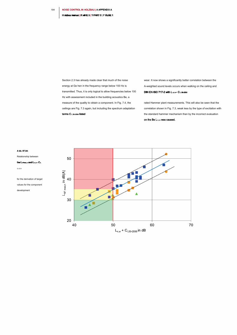
NOISE CONTROL IN HOLZBAU | A APPENDIX A NOISE CONTROL IN HOLZBAU | A APPENDIX A NOISE CONTROL IN HOLZBAU | A APPENDIX A
H olzbau manual | R eIHE 3 | T PART 3 | F OLGE 1H olzbau manual | R eIHE 3 | T PART 3 | F OLGE 1H olzbau manual | R eIHE 3 | T PART 3 | F OLGE 1H olzbau manual | R eIHE 3 | T PART 3 | F OLGE 1H olzbau manual | R eIHE 3 | T PART 3 | F OLGE 1H olzbau manual | R eIHE 3 | T PART 3 | F OLGE 1H olzbau manual | R eIHE 3 | T PART 3 | F OLGE 1H olzbau manual | R eIHE 3 | T PART 3 | F OLGE 1H olzbau manual | R eIHE 3 | T PART 3 | F OLGE 1H olzbau manual | R eIHE 3 | T PART 3 | F OLGE 1H olzbau manual | R eIHE 3 | T PART 3 | F OLGE 1
184
wear. It now shows a significantly better correlation between the
A-weighted sound levels occurs when walking on the ceiling and
DIN EN ISO 717-2 with L n, w + C I, 50-2500DIN EN ISO 717-2 with L n, w + C I, 50-2500DIN EN ISO 717-2 with L n, w + C I, 50-2500DIN EN ISO 717-2 with L n, w + C I, 50-2500DIN EN ISO 717-2 with L n, w + C I, 50-2500
rated Hammer plant measurements. This will also be seen that the
correlation shown in Fig. 7.3, weak less by the type of excitation with
the standard hammer mechanism than by the incorrect evaluation
on the Be L n, w was caused. on the Be L n, w was caused. on the Be L n, w was caused.
Section 2.3 has already made clear that much of the noise
energy at Ge hen in the frequency range below 100 Hz is
transmitted. Thus, it is only logical to allow frequencies below 100
Hz with assessment included in the building acoustics Be, a
measure of the quality to obtain a component. In Fig. 7.4, the
ceilings are Fig. 7.3 again, but including the spectrum adaptation
terms C I, 50-2500 listedterms C I, 50-2500 listedterms C I, 50-2500 listed
A bb. 07.04:A bb. 07.04:
Relationship between
the L AFmax, n and L n, w + C I, the L AFmax, n and L n, w + C I, the L AFmax, n and L n, w + C I, the L AFmax, n and L n, w + C I, the L AFmax, n and L n, w + C I, the L AFmax, n and L n, w + C I, the L AFmax, n and L n, w + C I,
50-2500
for the derivation of target
values for the component
development

1 851 85NOISE CONTROL IN HOLZBAU | A APPENDIX A NOISE CONTROL IN HOLZBAU | A APPENDIX A NOISE CONTROL IN HOLZBAU | A APPENDIX A
H olzbau manual | R eIHE 3 | T PART 3 | F OLGE 1H olzbau manual | R eIHE 3 | T PART 3 | F OLGE 1H olzbau manual | R eIHE 3 | T PART 3 | F OLGE 1H olzbau manual | R eIHE 3 | T PART 3 | F OLGE 1H olzbau manual | R eIHE 3 | T PART 3 | F OLGE 1H olzbau manual | R eIHE 3 | T PART 3 | F OLGE 1H olzbau manual | R eIHE 3 | T PART 3 | F OLGE 1H olzbau manual | R eIHE 3 | T PART 3 | F OLGE 1H olzbau manual | R eIHE 3 | T PART 3 | F OLGE 1H olzbau manual | R eIHE 3 | T PART 3 | F OLGE 1H olzbau manual | R eIHE 3 | T PART 3 | F OLGE 1
feels disturbed. This is according to Fig. 7.4 of ceiling with an L n, w + C I, feels disturbed. This is according to Fig. 7.4 of ceiling with an L n, w + C I, feels disturbed. This is according to Fig. 7.4 of ceiling with an L n, w + C I, feels disturbed. This is according to Fig. 7.4 of ceiling with an L n, w + C I, feels disturbed. This is according to Fig. 7.4 of ceiling with an L n, w + C I,
50-2500 < reaches 47 to 53 dB. It became a L n, w + C I, 50-2500 < 50 dB for the 50-2500 < reaches 47 to 53 dB. It became a L n, w + C I, 50-2500 < 50 dB for the 50-2500 < reaches 47 to 53 dB. It became a L n, w + C I, 50-2500 < 50 dB for the 50-2500 < reaches 47 to 53 dB. It became a L n, w + C I, 50-2500 < 50 dB for the 50-2500 < reaches 47 to 53 dB. It became a L n, w + C I, 50-2500 < 50 dB for the 50-2500 < reaches 47 to 53 dB. It became a L n, w + C I, 50-2500 < 50 dB for the 50-2500 < reaches 47 to 53 dB. It became a L n, w + C I, 50-2500 < 50 dB for the
sound level of protection in section BASE +
2.4 derived. To achieve a more noticeable improvement, the
improvement in L should AF, max, n are 5 dB (A) - at approx. 3 This improvement in L should AF, max, n are 5 dB (A) - at approx. 3 This improvement in L should AF, max, n are 5 dB (A) - at approx. 3 This
leads to an L n, w + C I, 50-2500 < 44 to 50 dB, from which the COMFORT leads to an L n, w + C I, 50-2500 < 44 to 50 dB, from which the COMFORT leads to an L n, w + C I, 50-2500 < 44 to 50 dB, from which the COMFORT leads to an L n, w + C I, 50-2500 < 44 to 50 dB, from which the COMFORT leads to an L n, w + C I, 50-2500 < 44 to 50 dB, from which the COMFORT leads to an L n, w + C I, 50-2500 < 44 to 50 dB, from which the COMFORT
sound level of protection with L n, w + C I, 50-2500 < 47 dB was derived. sound level of protection with L n, w + C I, 50-2500 < 47 dB was derived. sound level of protection with L n, w + C I, 50-2500 < 47 dB was derived. sound level of protection with L n, w + C I, 50-2500 < 47 dB was derived. sound level of protection with L n, w + C I, 50-2500 < 47 dB was derived. sound level of protection with L n, w + C I, 50-2500 < 47 dB was derived.
Laying down the targets for good sound insulation the subjective
feeling is now the resident on past experience on the
Störempfindung considered. Usually, most people feel at an L AF, max, Störempfindung considered. Usually, most people feel at an L AF, max,
n > 35 dB (A) is disturbed. So is the level which is caused by walking n > 35 dB (A) is disturbed. So is the level which is caused by walking n > 35 dB (A) is disturbed. So is the level which is caused by walking
on a ceiling, well below 35 dB (A), it is assumed that the user is no
longer
A -RatingA -Rating
approximately corresponds to the replication of human auditory perception.
The A rating reflects approximately against the disturbing effect of sound pressure levels in the human ear. There are
perceived not all sound pressure level at each frequency equally disturbing. The trend high frequencies are perceived
disturbing.
building acoustics review
corresponds to a comparison of the measured sizes building acoustic sound reduction and standard
impact sound with a reference curve. Rated sizes carry the index " w ".impact sound with a reference curve. Rated sizes carry the index " w ".impact sound with a reference curve. Rated sizes carry the index " w ".
≠
d B ( A )d B ( A )d B ( A )d B ( A )
L n, w ; R wL n, w ; R wL n, w ; R wL n, w ; R wL n, w ; R wL n, w ; R w

NOISE CONTROL IN HOLZBAU | L ITERATURVERZEICHNIS NOISE CONTROL IN HOLZBAU | L ITERATURVERZEICHNIS NOISE CONTROL IN HOLZBAU | L ITERATURVERZEICHNIS
H olzbau manual | R eIHE 3 | T PART 3 | F OLGE 1H olzbau manual | R eIHE 3 | T PART 3 | F OLGE 1H olzbau manual | R eIHE 3 | T PART 3 | F OLGE 1H olzbau manual | R eIHE 3 | T PART 3 | F OLGE 1H olzbau manual | R eIHE 3 | T PART 3 | F OLGE 1H olzbau manual | R eIHE 3 | T PART 3 | F OLGE 1H olzbau manual | R eIHE 3 | T PART 3 | F OLGE 1H olzbau manual | R eIHE 3 | T PART 3 | F OLGE 1H olzbau manual | R eIHE 3 | T PART 3 | F OLGE 1H olzbau manual | R eIHE 3 | T PART 3 | F OLGE 1H olzbau manual | R eIHE 3 | T PART 3 | F OLGE 1
186
8th _ bibliography8th _ bibliography
[6] Rabold, A., Hess Ingersoll, J., Bacher, S.,
Development of a prediction method for determining the
sound insulation of wood panel walls on the basis of the
design and the materials used, DGfH Research Report of
the Laboratory for Sound and Thermal Measuring,
Stephanskirchen, 2006
[7] Hess Ingersoll, J.; Buschbacher, H.-P .;
Rabold, A .; Holtz, F .: sound insulation of solid wood
constructions, advances in acoustics, DAGA 2004, p
739, 2004
[8] Winter Gerst, E., theory of sound -
permeability of simple and compound walls. Sound
equipment 4 [1931], 85, and 5 [1932],. 1
[9] Hessinger, J .; Buschbacher, HP;
Rabold, A .; Leitgeb, M .; Ramstein,
R .; Holtz, F .: vibrational behavior of wood panel walls,
the progress Acoustics - DAGA 2003, p 152, 2003
[10] Schmidt, H,.:
Sound technical Paperback; Vibration Compendium,
Springer-Verlag Berlin Heidelberg 1996
[11] Holtz, F .; Rabold, A .; Hessinger, J .;
Buschbacher, HP: Acoustic optimization of wood
construction by improving the wall constructions, AiF
Research Report of LSW lab for sound and heat
Messtechnik GmbH, 2004
[1] DIN 4109-1: 2018-01
Sound insulation in building construction - Part 1:
Minimum requirements DIN 4109-2: 2018-01 sound
insulation in building construction - Part 2: Calculated
evidence complying with DIN 4109-33: 2016-07 sound
insulation in building construction - Part 3: Data for the
mathematical proof of sound insulation (component
catalog) - wood, light and dry
[2] Gösele, K .; Schüle, W .; Künzel, H .:
Sound - heat - humidity, Bauverlag, Wiesbaden 10th
edition 1997
[3] Fasold, W., Veres, E .: soundproofing and
acoustics in practice, Huss media, Berlin 2nd
edition 2003
[4] Berger, R .: About the sound permeability,
R. Oldenbourg Verlag, 1911
[5] Huber, A., determination of planning data
for sound insulation of exterior walls in wood construction
with different insulation types. Data Collection -
component measurement - simulation thesis HS
Rosenheim, 2018
1 871 87NOISE CONTROL IN HOLZBAU | L ITERATURVERZEICHNIS NOISE CONTROL IN HOLZBAU | L ITERATURVERZEICHNIS NOISE CONTROL IN HOLZBAU | L ITERATURVERZEICHNIS
H olzbau manual | R eIHE 3 | T PART 3 | F OLGE 1H olzbau manual | R eIHE 3 | T PART 3 | F OLGE 1H olzbau manual | R eIHE 3 | T PART 3 | F OLGE 1H olzbau manual | R eIHE 3 | T PART 3 | F OLGE 1H olzbau manual | R eIHE 3 | T PART 3 | F OLGE 1H olzbau manual | R eIHE 3 | T PART 3 | F OLGE 1H olzbau manual | R eIHE 3 | T PART 3 | F OLGE 1H olzbau manual | R eIHE 3 | T PART 3 | F OLGE 1H olzbau manual | R eIHE 3 | T PART 3 | F OLGE 1H olzbau manual | R eIHE 3 | T PART 3 | F OLGE 1H olzbau manual | R eIHE 3 | T PART 3 | F OLGE 1
[16] Holtz, F.; Hessinger J .; Öchsle, O .;
Buschbacher, HP; Rabold, A .: Analysis, localization,
rehabilitation and prevention of sound technical defects in
timber, DGfH research report LSW - Laboratory for sound
and heat Messtechnik GmbH (funded by
Holzabsatzfonds), 2003
[17] Holtz, F .; Rabold, A .; Buschbacher, HP;
Hessinger J .:
Highly sound external components made of wood, DGfH
research report LSW - Laboratory for sound and heat
Messtechnik GmbH (funded by Holzabsatzfonds), 2003
[18] Rabold, A., Hess Ingersoll, J., Holtz, F.,
Buschbacher, HP,
"Sound insulation of building partitions in wood
construction," Advances in Acoustics
- DAGA 2005, p 613, 2005
[19] Holtz, F .; Hessinger J .; Rabold, A .;
Buschbacher, HP: INFORMATION SERVICES WOOD,
timber construction manual, R3 / T3 / F4, sound
insulation - walls and roofs, ed Holzabsatzfonds and
DGfH., 2004
[20] ift Rosenheim, Application Database walls
[12] Holtz, F .; Rabold, A .; Buschbacher,
HP; Hessinger J .:
INFORMATION SERVICE wood, wooden
constructions Manual, R3 / T3 / F3, acoustic
Holzbalken- and wooden ceiling,
Ed. Development Community timber, Munich
1999
[13] DIN 18560
Screeds in building DIN 18560-1:
2004-04
General requirements, testing and implementation;
DIN 18560-2: 2004-04
Screeds and heating screeds on insulation (floating
floor) DIN 18560-3: 2006-03 bonded screeds DIN
18560-4: 2004-04 screeds on separating layer DIN
18560-7: 2004-04 Heavy duty screeds (industrial
screeds)
[14] DIN EN 13318: 2000-12
Screeds and Estriche- terms
[15] Austrian Standard B 8115 to 1 Supplement 1: 2004-03
Sound insulation and room acoustics in buildings
Part 1: Definitions and units evaluation of the impact
sound reduction by floor coverings on a reference
wooden ceiling
NOISE CONTROL IN HOLZBAU | L ITERATURVERZEICHNIS NOISE CONTROL IN HOLZBAU | L ITERATURVERZEICHNIS NOISE CONTROL IN HOLZBAU | L ITERATURVERZEICHNIS
H olzbau manual | R eIHE 3 | T PART 3 | F OLGE 1H olzbau manual | R eIHE 3 | T PART 3 | F OLGE 1H olzbau manual | R eIHE 3 | T PART 3 | F OLGE 1H olzbau manual | R eIHE 3 | T PART 3 | F OLGE 1H olzbau manual | R eIHE 3 | T PART 3 | F OLGE 1H olzbau manual | R eIHE 3 | T PART 3 | F OLGE 1H olzbau manual | R eIHE 3 | T PART 3 | F OLGE 1H olzbau manual | R eIHE 3 | T PART 3 | F OLGE 1H olzbau manual | R eIHE 3 | T PART 3 | F OLGE 1H olzbau manual | R eIHE 3 | T PART 3 | F OLGE 1H olzbau manual | R eIHE 3 | T PART 3 | F OLGE 1
188
[25] DIN EN 14351-1:
2006 Windows and doors - Product standard
performance characteristics Part 1: Windows and exterior
doors without resistance to fire and / or smoke leakage,
Beuth Verlag., 2006
[26] DIN 18005-1: 2002-07
Noise abatement in town - Part 1: Fundamentals
and directions for planning, Beuth Verlag., 2002
[27] Holtz, F .; Buschbacher, HP;
Hessinger J .; Rabold, A .: sound insulation of staircases
in wood construction, inventory, analysis, optimization,
DGfH Research Report of the Laboratory for acoustic
and thermal measurement technology (funded by
Holzabsatzfonds), 2001
[28] Hessinger, J .; Buschbacher, HP; Holtz, F .:
Sound insulation of lightweight stairs in wood construction,
mikado 09/2001, page 62, 2001
[29] Holtz, F .; Buschbacher, HP; Hessinger,
J .: Sound insulation of lightweight stairs in timber
construction, timber construction 7/2002, page 27, 2002
[30] Rabold, A., Château Vieux-Hellwig, C.,
Mecking, S., optimization of wood ceilings in terms of DIN
4109, Proceedings timber special building physics, Bad
Woerishofen 2017
[21] Wohlmuth, B., Horger, T., Rank, E.,
Kollmannsberger, S., Frisch, F., Paolini, A.,
Schanda, U., Mecking, S., Kruse, T., Rabold, A.,
Château Vieux-Hellwig, C. Schramm, M., Müller, G., Winter,
C., vibro-acoustics in the planning process for wooden
houses - modeling, numerical simulation, validation -
research cooperation project TU Munich, Rosenheim
University, ift Rosenheim, 2017
[22] Château Vieux-Hellwig C., Bacher, S.,
Rabold, A.,
Sound insulation of flat roofs in timber construction -
airborne and impact sound insulation of flat roofs and roof
terraces, research project ift Rosenheim, in progress
[23] VDI 2566 Journal 2: 2004-05.
Sound design for lifts without machine room,
Association of German Engineers, 2004
[24] DIN 4109-35: 2016-07
Sound insulation in buildings - Part 35: Data for the
mathematical proof of sound insulation (component
catalog) - elements, windows, doors, curtain walls.
1 891 89NOISE CONTROL IN HOLZBAU | L ITERATURVERZEICHNIS NOISE CONTROL IN HOLZBAU | L ITERATURVERZEICHNIS NOISE CONTROL IN HOLZBAU | L ITERATURVERZEICHNIS
H olzbau manual | R eIHE 3 | T PART 3 | F OLGE 1H olzbau manual | R eIHE 3 | T PART 3 | F OLGE 1H olzbau manual | R eIHE 3 | T PART 3 | F OLGE 1H olzbau manual | R eIHE 3 | T PART 3 | F OLGE 1H olzbau manual | R eIHE 3 | T PART 3 | F OLGE 1H olzbau manual | R eIHE 3 | T PART 3 | F OLGE 1H olzbau manual | R eIHE 3 | T PART 3 | F OLGE 1H olzbau manual | R eIHE 3 | T PART 3 | F OLGE 1H olzbau manual | R eIHE 3 | T PART 3 | F OLGE 1H olzbau manual | R eIHE 3 | T PART 3 | F OLGE 1H olzbau manual | R eIHE 3 | T PART 3 | F OLGE 1
[31] Erhardt, D., Morkötter, D.,
Attempts to walk on wooden ceilings for
comparison with the evaluated standard impact
sound levels according to DIN EN ISO 717,
Student Thesis, University of Rosenheim, 2010
[32] Rabold, A., Rank, E.,
Application of Finite Element Method to the impact sound
calculation part report on the cooperation project:
Investigation of the acoustic interactions of wooden ceiling
and floor covering to develop new noise protection
measures, IBP Stuttgart, TU Munich, ift Rosenheim, DGfH
2009
[33] Seidel, J.,
Impact sound and walking measurements in the ceiling test
stand of the company. Knauf Gips KG, Iphofen, 2010
[34] DEGA recommendation 103:
"Sound insulation in housing - soundproofing
card" DEGA trade publication in 2018
[35] Minor, W., Moll, A.,
Sound insulation in housing - quality criteria,
options, structures,
Ernst W. + Sohn Verlag, 2011
[36] VDI 4100: 2007-08,
Noise control in dwellings - Criteria for
planning and assessment, VDI guideline, 2007


H olzbau Germany-Institut eV Kronenstraße H olzbau Germany-Institut eV Kronenstraße
55-58 D-10117 Berlin
Tel. +49 (0) 30 20314 533 Fax +49
(0) 30 20314 566
www.institut-holzbau.de
Technical inquiries to: counseling
timber Phone: (030) 57 70 19 95
Monday to Friday from 9 to 16:00 This service is
free of charge.
www.informationsdienst-holz.de
An offer of
Germany Timber-Institut eV in cooperation with
the Information Association Wood eV


