Embed Size (px)
Citation preview
Consolidated unofficial AMC/GM to Annex V (Part-SPA)
Page 1
European Aviation Safety Agency
Acceptable Means of Compliance (AMC)
and Guidance Material (GM)
to
Annex V – Part-SPA
Consolidated version including Issue 1, Amendment 21
9 December 2015
1 For the date of entry into force of this amendment, refer to Decision 2015/022/R in the Official Publication of the Agency.
Consolidated unofficial AMC/GM to Annex V (Part-SPA)
Page 2
Disclaimer
This consolidated document containing AMC/GM to Annex V (Part-SPA) to Commission Regulation
(EU) No 965/2012 on air operations includes the initial issue of and all subsequent amendments to
the AMC/GM associated with this Annex.
It is an unofficial courtesy document, intended for the easy use of stakeholders, and is meant purely
as a documentation tool. The Agency does not assume any liability for its contents.
The official documents can be found at http://www.easa.europa.eu/document-library/official-
publication.
AMC/GM TO ANNEX V (PART-SPA)
SUMMARY OF AMENDMENTS
Page 3
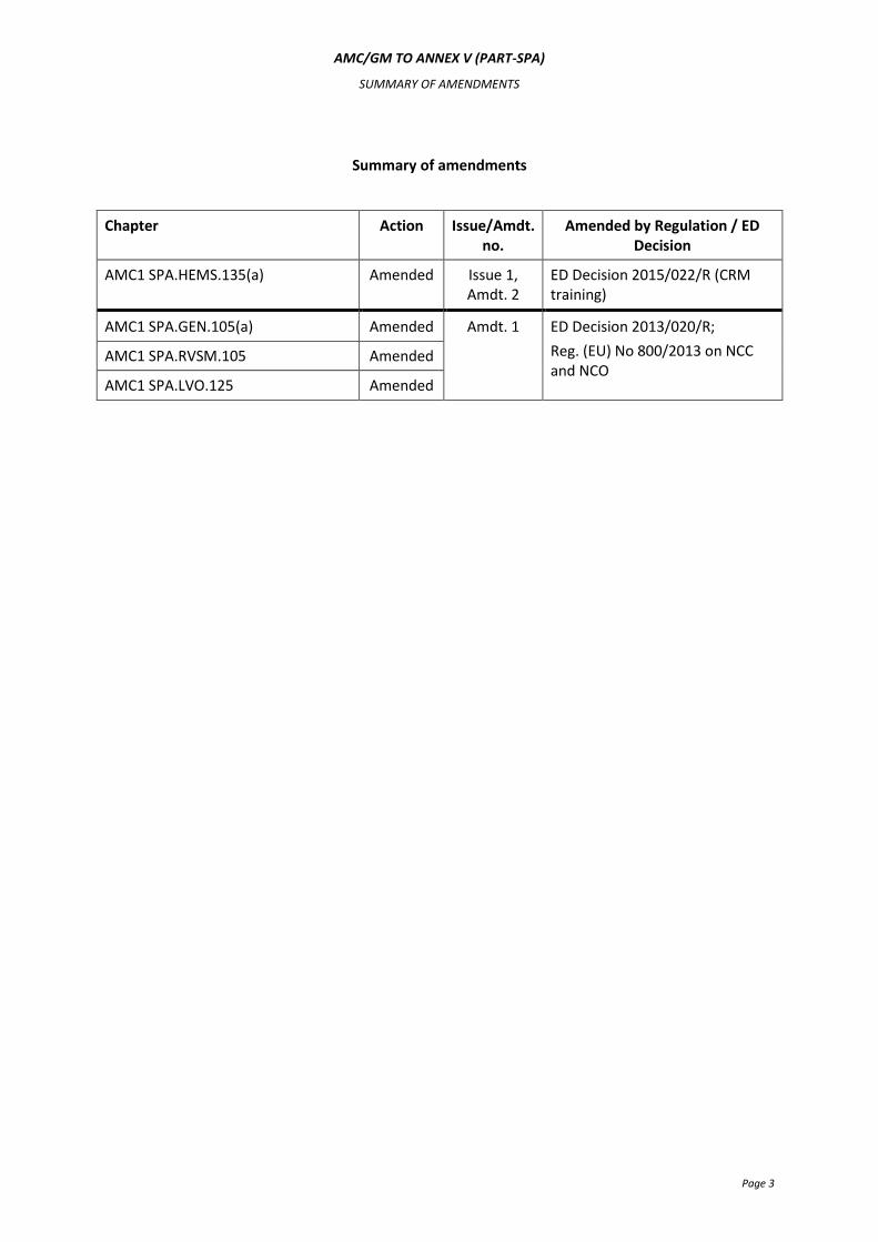
Summary of amendments
Chapter Action Issue/Amdt. no.
Amended by Regulation / ED Decision
AMC1 SPA.HEMS.135(a) Amended Issue 1, Amdt. 2
ED Decision 2015/022/R (CRM training)
AMC1 SPA.GEN.105(a) Amended Amdt. 1 ED Decision 2013/020/R;
Reg. (EU) No 800/2013 on NCC and NCO
AMC1 SPA.RVSM.105 Amended
AMC1 SPA.LVO.125 Amended
AMC/GM TO ANNEX V (PART-SPA)
TABLE OF CONTENTS
Page 4
Table of contents
Subpart A - General requirements .................................................................................................................... 8
AMC1 SPA.GEN.105(a) Application for a specific approval .............................................................................. 8
DOCUMENTATION ........................................................................................................................................ 8
Subpart B – Performance-based navigation (PBN) operations .......................................................................... 9
GM1 SPA.PBN.100 PBN operations .................................................................................................................. 9
GENERAL ....................................................................................................................................................... 9
Subpart C – Operations with specified minimum navigation performance (MNPS) ........................................ 13
GM1 SPA.MNPS.100 MNPS operations .......................................................................................................... 13
DOCUMENTATION ...................................................................................................................................... 13
AMC1 SPA.MNPS.105 MNPS operational approval ........................................................................................ 13
LONG RANGE NAVIGATION SYSTEM (LRNS) ............................................................................................... 13
Subpart D - Operations in airspace with reduced vertical separation minima (RVSM) ................................... 14
AMC1 SPA.RVSM.105 RVSM operational approval ........................................................................................ 14
CONTENT OF OPERATOR RVSM APPLICATION ........................................................................................... 14
AMC2 SPA.RVSM.105 RVSM operational approval ........................................................................................ 14
OPERATING PROCEDURES .......................................................................................................................... 14
GM1 SPA.RVSM.105(d)(9) RVSM operational approval ................................................................................. 18
SPECIFIC REGIONAL PROCEDURES .............................................................................................................. 18
AMC1 SPA.RVSM.110(a) RVSM equipment requirements ............................................................................. 18
TWO INDEPENDENT ALTITUDE MEASUREMENT SYSTEMS ......................................................................... 18
Subpart E – Low visibility operations (LV0) ..................................................................................................... 19
AMC1 SPA.LVO.100 Low visibility operations ................................................................................................. 19
LVTO OPERATIONS - AEROPLANES ............................................................................................................. 19
AMC2 SPA.LVO.100 Low visibility operations ................................................................................................. 20
LVTO OPERATIONS - HELICOPTERS ............................................................................................................. 20
AMC3 SPA.LVO.100 Low visibility operations ................................................................................................. 20
LTS CAT I OPERATIONS ................................................................................................................................ 20
AMC4 SPA.LVO.100 Low visibility operations ................................................................................................. 22
CAT II AND OTS CAT II OPERATIONS ........................................................................................................... 22
AMC5 SPA.LVO.100 Low visibility operations .................................................................................................. 23
CAT III OPERATIONS .................................................................................................................................... 23
AMC6 SPA.LVO.100 Low visibility operations ................................................................................................. 24
OPERATIONS UTILISING EVS ....................................................................................................................... 24
AMC7 SPA.LVO.100 Low visibility operations ................................................................................................. 27
EFFECT ON LANDING MINIMA OF TEMPORARILY FAILED OR DOWNGRADED EQUIPMENT ...................... 27
GM1 SPA.LVO.100 Low visibility operations ................................................................................................... 29
DOCUMENTS CONTAINING INFORMATION RELATED TO LOW VISIBILITY OPERATIONS ............................ 29
GM2 SPA.LVO.100 Low visibility operations ................................................................................................... 29
ILS CLASSIFICATION ..................................................................................................................................... 29
GM1 SPA.LVO.100(c),(e) Low visibility operations ......................................................................................... 29
ESTABLISHMENT OF MINIMUM RVR FOR CAT II AND CAT III OPERATIONS ............................................... 29
GM1 SPA.LVO.100(e) Low visibility operations .............................................................................................. 32
AMC/GM TO ANNEX V (PART-SPA)
TABLE OF CONTENTS
Page 5
CREW ACTIONS IN CASE OF AUTOPILOT FAILURE AT OR BELOW DH IN FAIL-PASSIVE CAT III OPERATIONS ............................................................................................................................................... 32
GM1 SPA.LVO.100(f) Low visibility operations ............................................................................................... 32
OPERATIONS UTILISING EVS ....................................................................................................................... 32
AMC1 SPA.LVO.105 LVO approval .................................................................................................................. 33
OPERATIONAL DEMONSTRATION - AEROPLANES ...................................................................................... 33
AMC2 SPA.LVO.105 LVO approval .................................................................................................................. 35
OPERATIONAL DEMONSTRATION - HELICOPTERS ...................................................................................... 35
AMC3 SPA.LVO.105 LVO approval .................................................................................................................. 37
CONTINUOUS MONITORING – ALL AIRCRAFT ............................................................................................ 37
AMC4 SPA.LVO.105 LVO approval .................................................................................................................. 37
TRANSITIONAL PERIODS FOR CAT II AND CAT III OPERATIONS .................................................................. 37
AMC5 SPA.LVO.105 LVO approval .................................................................................................................. 38
MAINTENANCE OF CAT II, CAT III AND LVTO EQUIPMENT ......................................................................... 38
AMC6 SPA.LVO.105 LVO approval .................................................................................................................. 38
ELIGIBLE AERODROMES AND RUNWAYS .................................................................................................... 38
GM1 SPA.LVO.105 LVO approval .................................................................................................................... 39
CRITERIA FOR A SUCCESSFUL CAT II, OTS CAT II, CAT III APPROACH AND AUTOMATIC LANDING ..................................................................................................................................................... 39
GM1 SPA.LVO.110(c)(4)(i) General operating requirements .......................................................................... 40
APPROVED VERTICAL FLIGHT PATH GUIDANCE MODE............................................................................... 40
AMC1 SPA.LVO.120 Flight crew training and qualifications ........................................................................... 40
GENERAL PROVISIONS ................................................................................................................................ 40
GROUND TRAINING .................................................................................................................................... 41
FSTD TRAINING AND/OR FLIGHT TRAINING ............................................................................................... 42
CONVERSION TRAINING .............................................................................................................................. 44
TYPE AND COMMAND EXPERIENCE ............................................................................................................ 45
RECURRENT TRAINING AND CHECKING ...................................................................................................... 46
LVTO OPERATIONS ...................................................................................................................................... 46
LTS CAT I, OTS CAT II, OPERATIONS UTILISING EVS .................................................................................... 47
GM1 SPA.LVO.120 Flight crew training and qualifications ............................................................................. 47
FLIGHT CREW TRAINING ............................................................................................................................. 47
AMC1 SPA.LVO.125 Operating procedures .................................................................................................... 48
GENERAL ..................................................................................................................................................... 48
PROCEDURES AND INSTRUCTIONS ............................................................................................................. 48
Subpart F - Extended range operations with two-engined aeroplanes (ETOPS) .............................................. 50
GM1 SPA.ETOPS.105 ETOPS operational approval ......................................................................................... 50
AMC 20-6 .................................................................................................................................................... 50
Subpart G - Transport of dangerous goods ..................................................................................................... 51
AMC1 SPA.DG.105(a) Approval to transport dangerous goods ..................................................................... 51
TRAINING PROGRAMME ............................................................................................................................. 51
AMC1 SPA.DG.105(b) Approval to transport dangerous goods ..................................................................... 52
PROVISION OF INFORMATION IN THE EVENT OF AN IN-FLIGHT EMERGENCY ........................................... 52
GM1 SPA.DG.105(b)(6) Approval to transport dangerous goods ................................................................... 52
PERSONNEL ................................................................................................................................................. 52
AMC1 SPA.DG.110(a) Dangerous goods information and documentation .................................................... 52
INFORMATION TO THE PILOT-IN-COMMAND/COMMANDER .................................................................... 52
AMC/GM TO ANNEX V (PART-SPA)
TABLE OF CONTENTS
Page 6
AMC1 SPA.DG.110(b) Dangerous goods information and documentation .................................................... 52
ACCEPTANCE OF DANGEROUS GOODS ....................................................................................................... 52
Subpart H – Helicopter operations with night vision imaging systems ........................................................... 53
AMC1 SPA.NVIS.110(b) Equipment requirements for NVIS operations ......................................................... 53
RADIO ALTIMETER ...................................................................................................................................... 53
GM1 SPA.NVIS.110(b) Equipment requirements for NVIS operations ........................................................... 53
RADIO ALTIMETER ...................................................................................................................................... 53
GM1 SPA.NVIS.110(f) Equipment requirements for NVIS operations ............................................................ 53
MODIFICATION OR MAINTENANCE TO THE HELICOPTER ........................................................................... 53
GM1 SPA.NVIS.130(e) Crew requirements for NVIS operations .................................................................... 54
UNDERLYING ACTIVITY ............................................................................................................................... 54
GM1 SPA.NVIS.130(e) Crew requirements for NVIS operations .................................................................... 54
OPERATIONAL APPROVAL ........................................................................................................................... 54
AMC1 SPA.NVIS.130(f)(1) Crew requirements for NVIS operations ............................................................... 54
TRAINING AND CHECKING SYLLABUS ......................................................................................................... 54
AMC1-SPA.NVIS.130(f) Crew requirements ................................................................................................... 55
CHECKING OF NVIS CREW MEMBERS ......................................................................................................... 55
GM1-SPA.NVIS.130(f) Crew requirements ..................................................................................................... 55
TRAINING GUIDELINES AND CONSIDERATIONS .......................................................................................... 55
GM2 SPA.NVIS.130(f) Crew requirements ...................................................................................................... 58
INSTRUCTION - GROUND TRAINING AREAS OF INSTRUCTION ................................................................... 58
GM3 SPA.NVIS.130(f) Crew requirements ...................................................................................................... 64
FLIGHT TRAINING - AREAS OF INSTRUCTION .............................................................................................. 64
GM4 SPA.NVIS.130(f) Crew requirements ...................................................................................................... 65
NVIS PRE-FLIGHT BRIEFING/CHECKLIST ...................................................................................................... 65
AMC1-SPA.NVIS.140 Information and documentation .................................................................................... 66
OPERATIONS MANUAL ............................................................................................................................... 66
GM1 SPA.NVIS.140 Information and documentation ................................................................................... 67
CONCEPT OF OPERATIONS.......................................................................................................................... 67
Subpart I – Helicopter hoist operations .......................................................................................................... 92
AMC1 SPA.HHO.110(a) Equipment requirements for HHO ............................................................................ 92
AIRWORTHINESS APPROVAL FOR HUMAN EXTERNAL CARGO ................................................................... 92
AMC1 SPA.HHO.130(b)(2)(ii) Crew requirements for HHO ............................................................................ 93
RELEVANT EXPERIENCE ............................................................................................................................... 93
AMC1 SPA.HHO.130(e) Crew requirements for HHO ..................................................................................... 93
CRITERIA FOR TWO PILOT HHO .................................................................................................................. 93
AMC1 SPA.HHO.130(f)(1) Crew requirements for HHO ................................................................................. 93
TRAINING AND CHECKING SYLLABUS ......................................................................................................... 93
AMC1 SPA.HHO.140 Information and documentation ................................................................................... 94
OPERATIONS MANUAL ............................................................................................................................... 94
Subpart J - Helicopter emergency medical service operations ........................................................................ 95
GM1 SPA.HEMS.100(a) Helicopter emergency medical service (HEMS) operations ...................................... 95
THE HEMS PHILOSOPHY .............................................................................................................................. 95
GM1 SPA.HEMS.120 HEMS operating minima ............................................................................................... 98
REDUCED VISIBILITY .................................................................................................................................... 98
GM1 SPA.HEMS.125(b)(3) Performance requirements for HEMS operations ............................................... 99
PERFORMANCE CLASS 2 OPERATIONS AT A HEMS OPERATING SITE ......................................................... 99
AMC/GM TO ANNEX V (PART-SPA)
TABLE OF CONTENTS
Page 7
AMC1 SPA.HEMS.125(b)(4) Performance requirements for HEMS operations ............................................. 99
HEMS OPERATING SITE DIMENSIONS ......................................................................................................... 99
AMC1 SPA.HEMS.130(b)(2) Crew requirements ............................................................................................ 99
EXPERIENCE ................................................................................................................................................ 99
AMC1 SPA.HEMS.130(d) Crew requirements ................................................................................................. 99
RECENCY ..................................................................................................................................................... 99
AMC1 SPA.HEMS.130(e) Crew requirements ................................................................................................. 99
HEMS TECHNICAL CREW MEMBER ............................................................................................................. 99
GM1 SPA.HEMS.130(e)(2)(ii) Crew requirements ........................................................................................ 100
SPECIFIC GEOGRAPHICAL AREAS .............................................................................................................. 100
AMC1 SPA.HEMS.130(e)(2)(ii)(B) Crew requirements .................................................................................. 100
FLIGHT FOLLOWING SYSTEM .................................................................................................................... 100
AMC1 SPA.HEMS.130(f)(1) Crew requirements ........................................................................................... 100
TRAINING AND CHECKING SYLLABUS ....................................................................................................... 100
AMC1 SPA.HEMS.130(f)(2)(ii)(B) Crew requirements ................................................................................... 102
LINE CHECKS .............................................................................................................................................. 102
AMC1 SPA.HEMS.135(a) HEMS medical passenger and other personnel briefing ....................................... 102
HEMS MEDICAL PASSENGER BRIEFING ..................................................................................................... 102
AMC1.1 SPA.HEMS.135(a) HEMS medical passenger and other personnel briefing .................................... 102
HEMS MEDICAL PASSENGER BRIEFING ..................................................................................................... 102
AMC1 SPA.HEMS.135(b) HEMS medical passenger and other personnel briefing....................................... 102
GROUND EMERGENCY SERVICE PERSONNEL ............................................................................................ 102
AMC1 SPA.HEMS.140 Information and documentation ............................................................................... 103
OPERATIONS MANUAL ............................................................................................................................. 103
AMC/GM TO ANNEX V (PART-SPA)
SUBPART A – GENERAL REQUIREMENTS
Page 8
Subpart A – General requirements
AMC1 SPA.GEN.105(a) Application for a specific approval
DOCUMENTATION
(a) Operating procedures should be documented in the operations manual.
(b) If an operations manual is not required, operating procedures may be described in a manual
specifying procedures (procedures manual). If the aircraft flight manual (AFM) or the pilot
operating handbook (POH) contains such procedures, they should be considered as acceptable
means to document the procedures.
AMC/GM TO ANNEX V (PART-SPA)
SUBPART B – PBN
Page 9
Subpart B – Performance-based navigation (PBN) operations
GM1 SPA.PBN.100 PBN operations
GENERAL
(a) There are two kinds of navigation specifications: area navigation (RNAV) and required
navigation performance (RNP). These specifications are similar. The key difference is that a
navigation specification that includes a requirement to have an on-board performance
monitoring and alerting system is referred to as an RNP specification. An RNAV specification
does not have such a requirement. The performance-monitoring and alerting system provides
some automated assurance functions to the flight crew. These functions monitor system
performance and alert the flight crew when the RNP parameters are not met, or cannot be
guaranteed with a sufficient level of integrity. RNAV and RNP performance is expressed by the
total system error (TSE). This is the deviation from the nominal or desired position and the
aircraft’s true position, measured in nautical miles. The TSE should remain equal to or less than
the required accuracy expected to be achieved at least 95 % of the flight time by the
population of aircraft operating within the airspace, route or procedure.
(b) The structure of RNAV and RNP navigation specifications can be classified by phases of flight as
detailed in Table 1. Some of these special approvals are in current use, some are under
development, and some apply to emerging standards for which AMC-20 material has yet to be
defined.
(c) The following RNAV and RNP navigation specifications are considered:
(1) Oceanic/Remote, RNAV10 (designated and authorised as RNP10)
Acceptable means of compliance for RNAV10 (RNP10) are provided in EASA AMC 20-12,
“Recognition of FAA order 8400.12a for RNP10 Operations”. Although RNAV10 airspace
is, for historical reasons, also called RNP10 airspace, there is no requirement for on-
board monitoring and alerting systems. RNAV10 can support 50 NM track spacing. For
an aircraft to operate in RNAV10 (RNP10) airspace it needs to be fitted with a minimum
of two independent long range navigation systems (LRNSs). Each LRNS should in
principle have a flight management system (FMS) that utilises positional information
from either an approved global navigation satellite system (GNSS) or an approved
inertial reference system (IRS) or mixed combination. The mix of sensors (pure GNSS,
pure IRS or mixed IRS/GNSS) determines pre-flight and in-flight operation and
contingencies in the event of system failure.
(2) Oceanic/Remote, RNP4
Guidance for this RNP standard is provided in ICAO Doc 9613. RNP4 is the
oceanic/remote navigation specification to support 30 NM track spacing with ADS-C and
CPDLC required. To meet this more accurate navigation requirement, two independent
LRNS are required for which GNSS sensors are mandatory. If GNSS is used as a stand-
alone LRNS, an integrity check is foreseen (fault detection and exclusion).Additional
aircraft requirements include two long range communication systems (LRCSs) in order to
operate in RNP4 designated airspace. The appropriate Aeronautical Information
Publication (AIP) should be consulted to assess coverage of HF and SATCOM. The

AMC/GM TO ANNEX V (PART-SPA)
SUBPART B – PBN
Page 10
additional requirements may include use of automatic dependent surveillance (ADS)
and/or controller pilot data link communication (CPDLC).
(3) RNAV5 (B-RNAV)
Acceptable means of compliance for RNAV5 are provided in AMC 20-4, “Airworthiness
Approval and Operational Criteria for the Use of Navigation Systems in European
Airspace Designated for the Basic-RNAV Operations”. No specific approval required.
(4) RNAV2
This is a non-European en-route standard. Guidance for this RNP standard is provided in
ICAO Doc 9613.
(5) RNAV1 (P-RNAV)
Acceptable means of compliance for RNAV1 (P-RNAV) are provided in JAA TGL-10
‘Airworthiness and Operational approval for precision RNAV operations in designated
European Airspace’, planned to be replaced by AMC 20 material.
(6) Basic–RNP1
This is a future standard yet to be implemented. Guidance material is provided in ICAO
Doc 9613.
(7) RNP APCH (RNP Approach)
Non-precision approaches supported by GNSS and APV (approach procedure with
vertical guidance) which are themselves divided in two types of APV approaches: APV
Baro and APV SBAS.
RNP APCH is charted as RNAV (GNSS). A minima line is provided for each of the available
types of non-precision approaches and the APV procedure at a specific runway:
- non-precision approach – lateral navigation (LNAV) or localiser performance (LP)
minima line;
- APV Baro - LNAV/VNAV (vertical navigation) minima line; and
- APV SBAS - localiser performance with vertical guidance (LPV) minima line.
Non-precision approaches to LNAV minima and APV approaches to LNAV/VNAV minima
are addressed in AMC 20-27, “Airworthiness Approval and Operational Criteria for RNP
approach (RNP APCH) operations including APV Baro VNAV operations”.
APV approaches to LPV minima are addressed in AMC 20-28 “Airworthiness Approval
and. Operational Criteria for RNAV GNSS approach operation to LPV minima using
SBAS”.
Non-precision approaches to LP minima have not yet been addressed in AMC 20.
(8) RNP AR APCH (approach)
RNP AR criteria have been developed to support RNP operations to RNP minima using
RNP less than or equal to 0.3 NM or fixed radius turns (RF). The vertical performance is
defined by a vertical error budget based upon Baro VNAV. Equivalent means of
compliance using SBAS may be demonstrated.
RNP AR APCH is charted as RNAV (RNP). A minima line is provided for each available RNP
value.
AMC/GM TO ANNEX V (PART-SPA)
SUBPART B – PBN
Page 11
Acceptable Means of Compliance for RNP AR are provided in AMC20-26 ‘Airworthiness
Approval and Operational Criteria for RNP Authorisation Required (RNP AR) Operations’.
Each RNP AR approach requires a special approval.
(d) Guidance material for the global performances specifications, approval process, aircraft
requirement (e.g. generic system performances, accuracy, integrity, continuity, signal-in-space,
RNP navigation specifications required for the on-board performance monitoring and alerting
system), requirements for specific sensor technologies, functional requirements, operating
procedures, flight crew knowledge and training and navigation databases integrity
requirements, can be found in:
(1) ICAO Doc 9613 Performance-Based Navigation (PBN) Manual; and
(2) Table 1.
AMC/GM TO ANNEX V (PART-SPA)
SUBPART B – PBN
Page 12
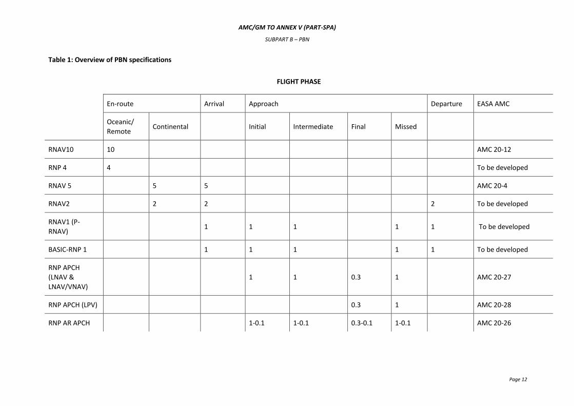
Table 1: Overview of PBN specifications
FLIGHT PHASE
En-route Arrival Approach Departure EASA AMC
Oceanic/
Remote Continental Initial Intermediate Final Missed
RNAV10 10 AMC 20-12
RNP 4 4 To be developed
RNAV 5 5 5 AMC 20-4
RNAV2 2 2 2 To be developed
RNAV1 (P-
RNAV) 1 1 1
1 1 To be developed
BASIC-RNP 1 1 1 1 1 1 To be developed
RNP APCH
(LNAV &
LNAV/VNAV)
1 1 0.3 1 AMC 20-27
RNP APCH (LPV) 0.3 1 AMC 20-28
RNP AR APCH 1-0.1 1-0.1 0.3-0.1 1-0.1 AMC 20-26
AMC/GM TO ANNEX V (PART-SPA)
SUBPART C – MNPS
Page 13
Subpart C – Operations with specified minimum navigation performance (MNPS)
GM1 SPA.MNPS.100 MNPS operations
DOCUMENTATION
MNPS and the procedures governing their application are published in the Regional Supplementary
Procedures, ICAO Doc 7030, as well as in national AIPs.
AMC1 SPA.MNPS.105 MNPS operational approval
LONG RANGE NAVIGATION SYSTEM (LRNS)
(a) For unrestricted operation in MNPS airspace an aircraft should be equipped with two
independent LRNSs.
(b) An LRNS may be one of the following:
(1) one inertial navigation system (INS);
(2) one global navigation satellite system (GNSS); or
(3) one navigation system using the inputs from one or more inertial reference system (IRS)
or any other sensor system complying with the MNPS requirement.
(c) In case of the GNSS is used as a stand-alone system for LRNS, an integrity check should be
carried out.
(d) For operation in MNPS airspace along notified special routes the aeroplane should be equipped
with one LRNS.

AMC/GM TO ANNEX V (PART-SPA)
SUBPART D – RVSM
Page 14
Subpart D – Operations in airspace with reduced vertical separation minima (RVSM)
AMC1 SPA.RVSM.105 RVSM operational approval
CONTENT OF OPERATOR RVSM APPLICATION
The following material should be made available to the competent authority, in sufficient time to
permit evaluation, before the intended start of RVSM operations:
(a) Airworthiness documents
Documentation that shows that the aircraft has RVSM airworthiness approval. This should
include an aircraft flight manual (AFM) amendment or supplement.
(b) Description of aircraft equipment
A description of the aircraft appropriate to operations in an RVSM environment.
(c) Training programmes, operating practices and procedures
The operator should submit training syllabi for initial and recurrent training programmes
together with other relevant material. The material should show that the operating practices,
procedures and training items, related to RVSM operations in airspace that requires State
operational approval, are incorporated.
(d) Manuals and checklists
The appropriate manuals and checklists should be revised to include information/guidance on
standard operating procedures. Manuals should contain a statement of the airspeeds, altitudes
and weights considered in RVSM aircraft approval, including identification of any operating
limitations or conditions established for that aircraft type. Manuals and checklists may need to
be submitted for review by the competent authority as part of the application process.
(e) Past performance
Relevant operating history, where available, should be included in the application. The
applicant should show that any required changes have been made in training, operating or
maintenance practices to improve poor height-keeping performance.
(f) Minimum equipment list
Where applicable, a minimum equipment list (MEL), adapted from the master minimum
equipment list (MMEL), should include items pertinent to operating in RVSM airspace.
(g) Plan for participation in verification/monitoring programmes
The operator should establish a plan for participation in any applicable verification/monitoring
programme acceptable to the competent authority. This plan should include, as a minimum, a
check on a sample of the operator's fleet by an regional monitoring agency (RMA)’s
independent height-monitoring system.
AMC2 SPA.RVSM.105 RVSM operational approval
OPERATING PROCEDURES
(a) Flight planning
AMC/GM TO ANNEX V (PART-SPA)
SUBPART D – RVSM
Page 15
(1) During flight planning the flight crew should pay particular attention to conditions that
may affect operation in RVSM airspace. These include, but may not be limited to:
(i) verifying that the airframe is approved for RVSM operations;
(ii) reported and forecast weather on the route of flight;
(iii) minimum equipment requirements pertaining to height-keeping and alerting
systems; and
(iv) any airframe or operating restriction related to RVSM operations.
(b) Pre-flight procedures
(1) The following actions should be accomplished during the pre-flight procedure:
(i) Review technical logs and forms to determine the condition of equipment
required for flight in the RVSM airspace. Ensure that maintenance action has
been taken to correct defects to required equipment.
(ii) During the external inspection of aircraft, particular attention should be paid to
the condition of static sources and the condition of the fuselage skin near each
static source and any other component that affects altimetry system accuracy.
This check may be accomplished by a qualified and authorised person other than
the pilot (e.g. a flight engineer or ground engineer).
(iii) Before take-off, the aircraft altimeters should be set to the QNH (atmospheric
pressure at nautical height) of the airfield and should display a known altitude,
within the limits specified in the aircraft operating manuals. The two primary
altimeters should also agree within limits specified by the aircraft operating
manual. An alternative procedure using QFE (atmospheric pressure at
aerodrome elevation/runway threshold) may also be used. The maximum value
of acceptable altimeter differences for these checks should not exceed 23 m
(75 ft). Any required functioning checks of altitude indicating systems should be
performed.
(iv) Before take-off, equipment required for flight in RVSM airspace should be
operative and any indications of malfunction should be resolved.
(c) Prior to RVSM airspace entry
(1) The following equipment should be operating normally at entry into RVSM airspace:
(i) two primary altitude measurement systems. A cross-check between the primary
altimeters should be made. A minimum of two will need to agree within ±60 m
(±200 ft). Failure to meet this condition will require that the altimetry system be
reported as defective and air traffic control (ATC) notified;
(ii) one automatic altitude-control system;
(iii) one altitude-alerting device; and
(iv) operating transponder.
(2) Should any of the required equipment fail prior to the aircraft entering RVSM airspace,
the pilot should request a new clearance to avoid entering this airspace.
(d) In-flight procedures
(1) The following practices should be incorporated into flight crew training and procedures:
AMC/GM TO ANNEX V (PART-SPA)
SUBPART D – RVSM
Page 16
(i) Flight crew should comply with any aircraft operating restrictions, if required for
the specific aircraft type, e.g. limits on indicated Mach number, given in the
RVSM airworthiness approval.
(ii) Emphasis should be placed on promptly setting the sub-scale on all primary and
standby altimeters to 1013.2 hPa / 29.92 in Hg when passing the transition
altitude, and rechecking for proper altimeter setting when reaching the initial
cleared flight level.
(iii) In level cruise it is essential that the aircraft is flown at the cleared flight level.
This requires that particular care is taken to ensure that ATC clearances are fully
understood and followed. The aircraft should not intentionally depart from
cleared flight level without a positive clearance from ATC unless the crew are
conducting contingency or emergency manoeuvres.
(iv) When changing levels, the aircraft should not be allowed to overshoot or
undershoot the cleared flight level by more than 45 m (150 ft). If installed, the
level off should be accomplished using the altitude capture feature of the
automatic altitude-control system.
(v) An automatic altitude-control system should be operative and engaged during
level cruise, except when circumstances such as the need to re-trim the aircraft
or turbulence require disengagement. In any event, adherence to cruise altitude
should be done by reference to one of the two primary altimeters. Following
loss of the automatic height-keeping function, any consequential restrictions will
need to be observed.
(vi) Ensure that the altitude-alerting system is operative.
(vii) At intervals of approximately 1 hour, cross-checks between the primary
altimeters should be made. A minimum of two will need to agree within ±60 m
(±200 ft). Failure to meet this condition will require that the altimetry system be
reported as defective and ATC notified or contingency procedures applied:
(A) the usual scan of flight deck instruments should suffice for altimeter
cross-checking on most flights; and
(B) before entering RVSM airspace, the initial altimeter cross-check of
primary and standby altimeters should be recorded.
(viii) In normal operations, the altimetry system being used to control the aircraft
should be selected for the input to the altitude reporting transponder
transmitting information to ATC.
(ix) If the pilot is notified by ATC of a deviation from an assigned altitude exceeding
±90 m (±300 ft) then the pilot should take action to return to cleared flight level
as quickly as possible.
(2) Contingency procedures after entering RVSM airspace are as follows:
(i) The pilot should notify ATC of contingencies (equipment failures, weather) that
affect the ability to maintain the cleared flight level and coordinate a plan of
action appropriate to the airspace concerned. The pilot should obtain to the
guidance on contingency procedures is contained in the relevant publications
dealing with the airspace.
(ii) Examples of equipment failures that should be notified to ATC are:
AMC/GM TO ANNEX V (PART-SPA)
SUBPART D – RVSM
Page 17
(A) failure of all automatic altitude-control systems aboard the aircraft;
(B) loss of redundancy of altimetry systems;
(C) loss of thrust on an engine necessitating descent; or
(D) any other equipment failure affecting the ability to maintain cleared
flight level.
(iii) The pilot should notify ATC when encountering greater than moderate
turbulence.
(iv) If unable to notify ATC and obtain an ATC clearance prior to deviating from the
cleared flight level, the pilot should follow any established contingency
procedures for the region of operation and obtain ATC clearance as soon as
possible.
(e) Post-flight procedures
(1) In making technical log entries against malfunctions in height-keeping systems, the pilot
should provide sufficient detail to enable maintenance to effectively troubleshoot and
repair the system. The pilot should detail the actual defect and the crew action taken to
try to isolate and rectify the fault.
(2) The following information should be recorded when appropriate:
(i) primary and standby altimeter readings;
(ii) altitude selector setting;
(iii) subscale setting on altimeter;
(iv) autopilot used to control the aircraft and any differences when an alternative
autopilot system was selected;
(v) differences in altimeter readings, if alternate static ports selected;
(vi) use of air data computer selector for fault diagnosis procedure; and
(vii) the transponder selected to provide altitude information to ATC and any
difference noted when an alternative transponder was selected.
(f) Crew training
(1) The following items should also be included in flight crew training programmes:
(i) knowledge and understanding of standard ATC phraseology used in each area of
operations;
(ii) importance of crew members cross-checking to ensure that ATC clearances are
promptly and correctly complied with;
(iii) use and limitations in terms of accuracy of standby altimeters in contingencies.
Where applicable, the pilot should review the application of static source error
correction/position error correction through the use of correction cards; such
correction data should be available on the flight deck;
(iv) problems of visual perception of other aircraft at 300 m (1 000 ft) planned
separation during darkness, when encountering local phenomena such as
northern lights, for opposite and same direction traffic, and during turns;
(v) characteristics of aircraft altitude capture systems that may lead to overshoots;
AMC/GM TO ANNEX V (PART-SPA)
SUBPART D – RVSM
Page 18
(vi) relationship between the aircraft's altimetry, automatic altitude control and
transponder systems in normal and abnormal conditions; and
(vii) any airframe operating restrictions, if required for the specific aircraft group,
related to RVSM airworthiness approval.
GM1 SPA.RVSM.105(d)(9) RVSM operational approval
SPECIFIC REGIONAL PROCEDURES
(a) The areas of applicability (by Flight Information Region) of RVSM airspace in identified ICAO
regions is contained in the relevant sections of ICAO Document 7030/4. In addition, these
sections contain operating and contingency procedures unique to the regional airspace
concerned, specific flight planning requirements and the approval requirements for aircraft in
the designated region.
(b) Comprehensive guidance on operational matters for European RVSM airspace is contained in
EUROCONTROL Document ASM ET1.ST.5000 entitled “The ATC Manual for a Reduced Vertical
Separation (RVSM) in Europe” with further material included in the relevant State aeronautical
publications.
AMC1 SPA.RVSM.110(a) RVSM equipment requirements
TWO INDEPENDENT ALTITUDE MEASUREMENT SYSTEMS
Each system should be composed of the following components:
(a) cross-coupled static source/system, with ice protection if located in areas subject to ice
accretion;
(b) equipment for measuring static pressure sensed by the static source, converting it to pressure
altitude and displaying the pressure altitude to the flight crew:
(c) equipment for providing a digitally encoded signal corresponding to the displayed pressure
altitude, for automatic altitude reporting purposes;
(d) static source error correction (SSEC), if needed to meet the performance criteria for RVSM
flight envelopes; and
(e) signals referenced to a flight crew selected altitude for automatic control and alerting. These
signals will need to be derived from an altitude measurement system meeting the performance
criteria for RVSM flight envelopes.
AMC/GM TO ANNEX V (PART-SPA)
SUBPART E – LVO
Page 19
Subpart E – Low visibility operations (LVO)
AMC1 SPA.LVO.100 Low visibility operations
LVTO OPERATIONS - AEROPLANES
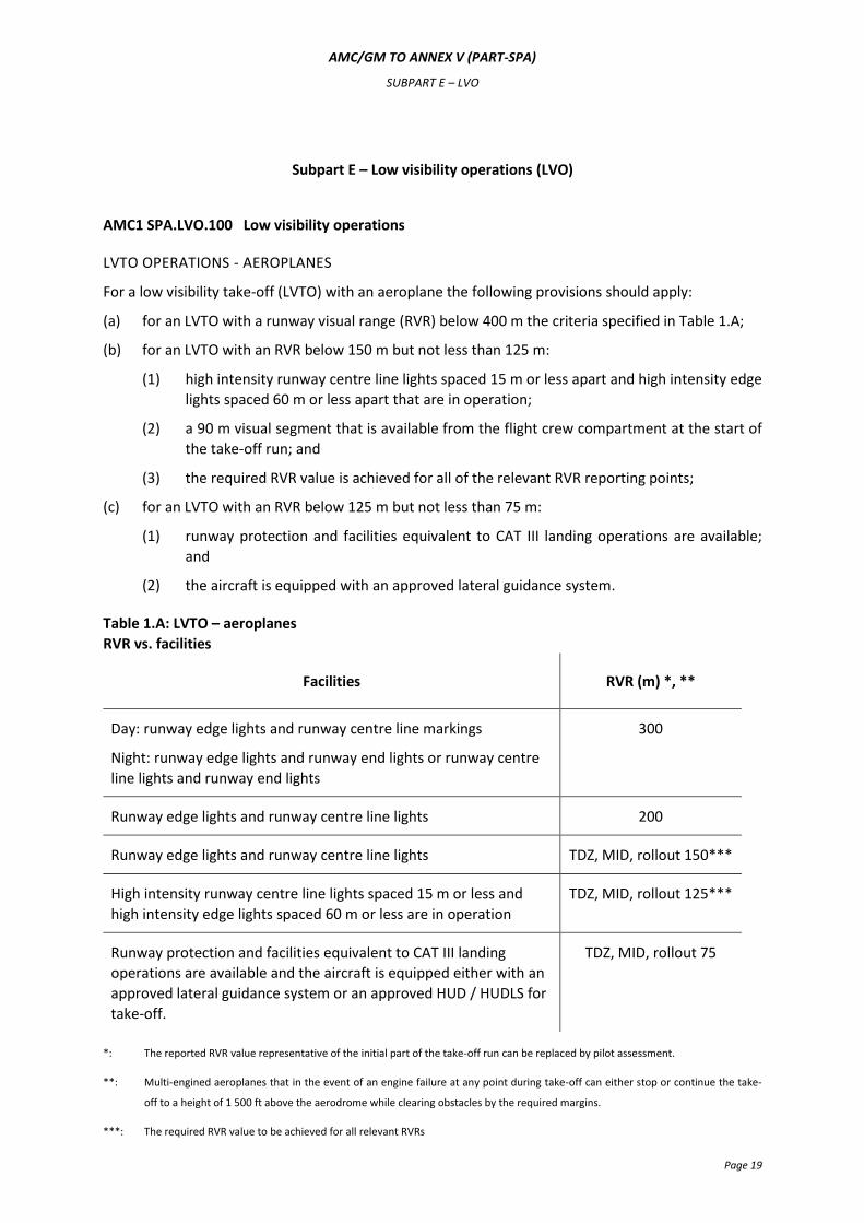
For a low visibility take-off (LVTO) with an aeroplane the following provisions should apply:
(a) for an LVTO with a runway visual range (RVR) below 400 m the criteria specified in Table 1.A;
(b) for an LVTO with an RVR below 150 m but not less than 125 m:
(1) high intensity runway centre line lights spaced 15 m or less apart and high intensity edge
lights spaced 60 m or less apart that are in operation;
(2) a 90 m visual segment that is available from the flight crew compartment at the start of
the take-off run; and
(3) the required RVR value is achieved for all of the relevant RVR reporting points;
(c) for an LVTO with an RVR below 125 m but not less than 75 m:
(1) runway protection and facilities equivalent to CAT III landing operations are available;
and
(2) the aircraft is equipped with an approved lateral guidance system.
Table 1.A: LVTO – aeroplanes
RVR vs. facilities
Facilities RVR (m) *, **
Day: runway edge lights and runway centre line markings
Night: runway edge lights and runway end lights or runway centre
line lights and runway end lights
300
Runway edge lights and runway centre line lights 200
Runway edge lights and runway centre line lights TDZ, MID, rollout 150***
High intensity runway centre line lights spaced 15 m or less and
high intensity edge lights spaced 60 m or less are in operation
TDZ, MID, rollout 125***
Runway protection and facilities equivalent to CAT III landing
operations are available and the aircraft is equipped either with an
approved lateral guidance system or an approved HUD / HUDLS for
take-off.
TDZ, MID, rollout 75
*: The reported RVR value representative of the initial part of the take-off run can be replaced by pilot assessment.
**: Multi-engined aeroplanes that in the event of an engine failure at any point during take-off can either stop or continue the take-
off to a height of 1 500 ft above the aerodrome while clearing obstacles by the required margins.
***: The required RVR value to be achieved for all relevant RVRs
AMC/GM TO ANNEX V (PART-SPA)
SUBPART E – LVO
Page 20
TDZ: touchdown zone, equivalent to the initial part of the take-off run
MID: midpoint
AMC2 SPA.LVO.100 Low visibility operations
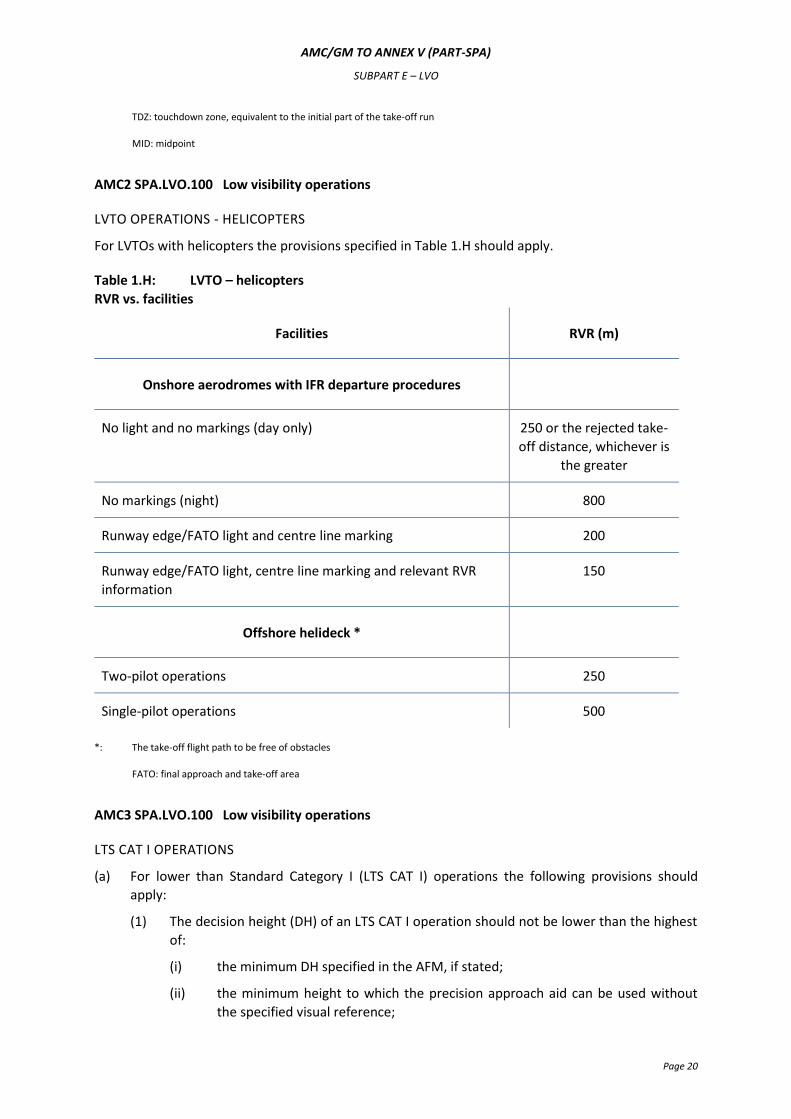
LVTO OPERATIONS - HELICOPTERS
For LVTOs with helicopters the provisions specified in Table 1.H should apply.
Table 1.H: LVTO – helicopters
RVR vs. facilities
Facilities RVR (m)
Onshore aerodromes with IFR departure procedures
No light and no markings (day only) 250 or the rejected take-
off distance, whichever is
the greater
No markings (night) 800
Runway edge/FATO light and centre line marking 200
Runway edge/FATO light, centre line marking and relevant RVR
information
150
Offshore helideck *
Two-pilot operations 250
Single-pilot operations 500
*: The take-off flight path to be free of obstacles
FATO: final approach and take-off area
AMC3 SPA.LVO.100 Low visibility operations
LTS CAT I OPERATIONS
(a) For lower than Standard Category I (LTS CAT I) operations the following provisions should
apply:
(1) The decision height (DH) of an LTS CAT I operation should not be lower than the highest
of:
(i) the minimum DH specified in the AFM, if stated;
(ii) the minimum height to which the precision approach aid can be used without
the specified visual reference;
AMC/GM TO ANNEX V (PART-SPA)
SUBPART E – LVO
Page 21
(iii) the applicable obstacle clearance height (OCH) for the category of aeroplane;
(iv) the DH to which the flight crew is qualified to operate; or
(v) 200 ft.
(2) An instrument landing system / microwave landing system (ILS/MLS) that supports an
LTS CAT I operation should be an unrestricted facility with a straight-in course, ≤ 3º
offset, and the ILS should be certified to:
(i) class I/T/1 for operations to a minimum of 450 m RVR; or
(ii) class II/D/2 for operations to less than 450 m RVR.
Single ILS facilities are only acceptable if level 2 performance is provided.
(3) The following visual aids should be available:
(i) standard runway day markings, approach lights, runway edge lights, threshold
lights and runway end lights;
(ii) for operations with an RVR below 450 m, additionally touch-down zone and/or
runway centre line lights.
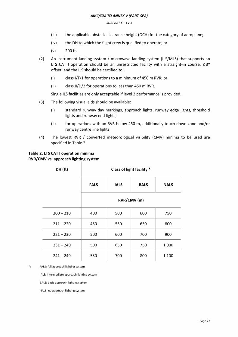
(4) The lowest RVR / converted meteorological visibility (CMV) minima to be used are
specified in Table 2.
Table 2: LTS CAT I operation minima
RVR/CMV vs. approach lighting system
DH (ft) Class of light facility *
FALS IALS BALS NALS
RVR/CMV (m)
200 – 210 400 500 600 750
211 – 220 450 550 650 800
221 – 230 500 600 700 900
231 – 240 500 650 750 1 000
241 – 249 550 700 800 1 100
*: FALS: full approach lighting system
IALS: intermediate approach lighting system
BALS: basic approach lighting system
NALS: no approach lighting system
AMC/GM TO ANNEX V (PART-SPA)
SUBPART E – LVO
Page 22
AMC4 SPA.LVO.100 Low visibility operations
CAT II AND OTS CAT II OPERATIONS
(a) For CAT II and other than Standard Category II (OTS CAT II) operations the following provisions
should apply:
(1) The ILS / MLS that supports OTS CAT II operation should be an unrestricted facility with a
straight in course (≤ 3º offset) and the ILS should be certified to class II/D/2.
Single ILS facilities are only acceptable if level 2 performance is provided.
(2) The DH for CAT II and OTS CAT II operation should not be lower than the highest of:
(i) the minimum DH specified in the AFM, if stated;
(ii) the minimum height to which the precision approach aid can be used without
the specified visual reference;
(iii) the applicable OCH for the category of aeroplane;
(iv) the DH to which the flight crew is qualified to operate; or
(v) 100 ft.
(3) The following visual aids should be available:
(i) standard runway day markings and approach and the following runway lights:
runway edge lights, threshold lights and runway end lights;
(ii) for operations in RVR below 450 m, additionally touch-down zone and/or
runway centre line lights;
(iii) for operations with an RVR of 400 m or less, additionally centre line lights.
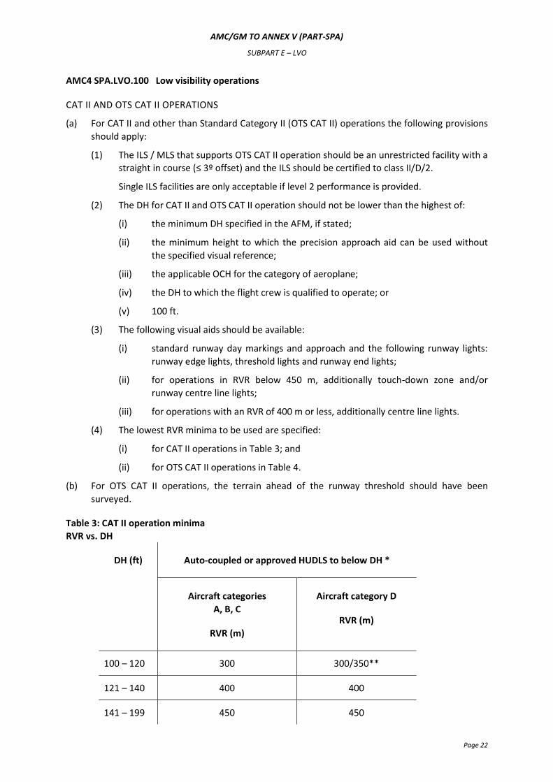
(4) The lowest RVR minima to be used are specified:
(i) for CAT II operations in Table 3; and
(ii) for OTS CAT II operations in Table 4.
(b) For OTS CAT II operations, the terrain ahead of the runway threshold should have been
surveyed.
Table 3: CAT II operation minima
RVR vs. DH
DH (ft) Auto-coupled or approved HUDLS to below DH *
Aircraft categories
A, B, C
RVR (m)
Aircraft category D
RVR (m)
100 – 120 300 300/350**
121 – 140 400 400
141 – 199 450 450
AMC/GM TO ANNEX V (PART-SPA)
SUBPART E – LVO
Page 23
*: This means continued use of the automatic flight control system or the HUDLS down to a height of 80 % of the DH.
**: An RVR of 300 m may be used for a category D aircraft conducting an auto-land.
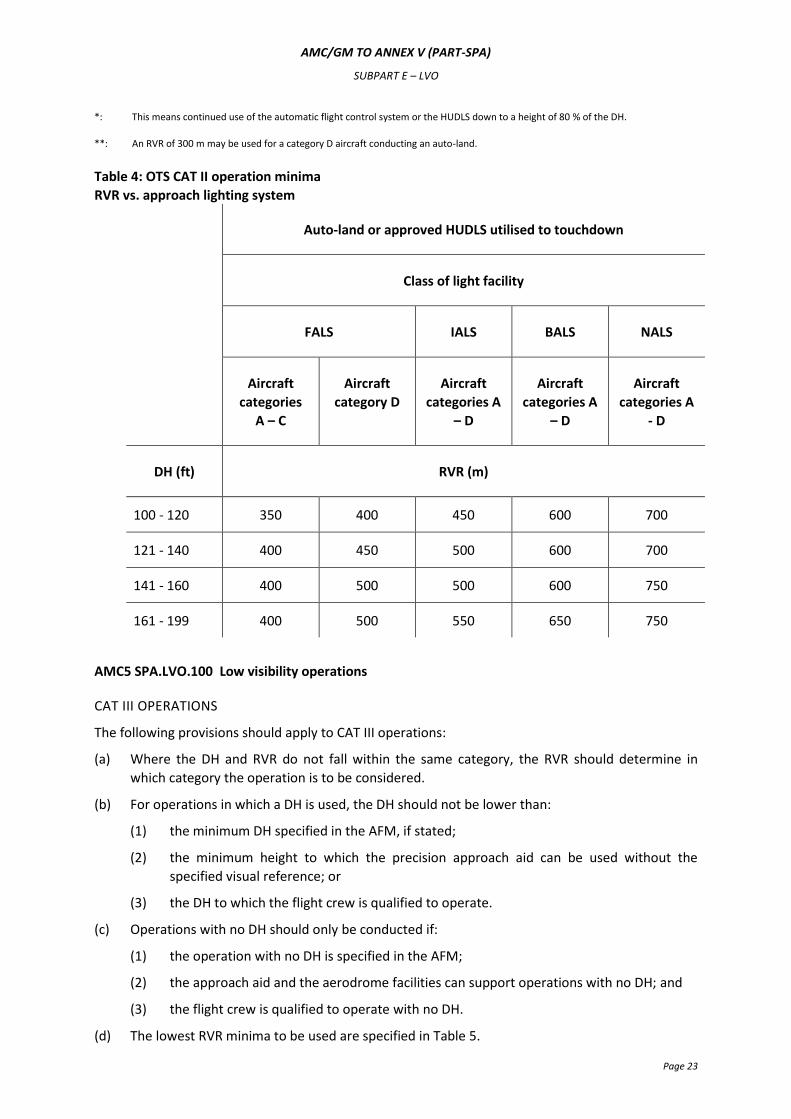
Table 4: OTS CAT II operation minima
RVR vs. approach lighting system
Auto-land or approved HUDLS utilised to touchdown
Class of light facility
FALS IALS BALS NALS
Aircraft
categories
A – C
Aircraft
category D
Aircraft
categories A
– D
Aircraft
categories A
– D
Aircraft
categories A
- D
DH (ft) RVR (m)
100 - 120 350 400 450 600 700
121 - 140 400 450 500 600 700
141 - 160 400 500 500 600 750
161 - 199 400 500 550 650 750
AMC5 SPA.LVO.100 Low visibility operations
CAT III OPERATIONS
The following provisions should apply to CAT III operations:
(a) Where the DH and RVR do not fall within the same category, the RVR should determine in
which category the operation is to be considered.
(b) For operations in which a DH is used, the DH should not be lower than:
(1) the minimum DH specified in the AFM, if stated;
(2) the minimum height to which the precision approach aid can be used without the
specified visual reference; or
(3) the DH to which the flight crew is qualified to operate.
(c) Operations with no DH should only be conducted if:
(1) the operation with no DH is specified in the AFM;
(2) the approach aid and the aerodrome facilities can support operations with no DH; and
(3) the flight crew is qualified to operate with no DH.
(d) The lowest RVR minima to be used are specified in Table 5.
AMC/GM TO ANNEX V (PART-SPA)
SUBPART E – LVO
Page 24
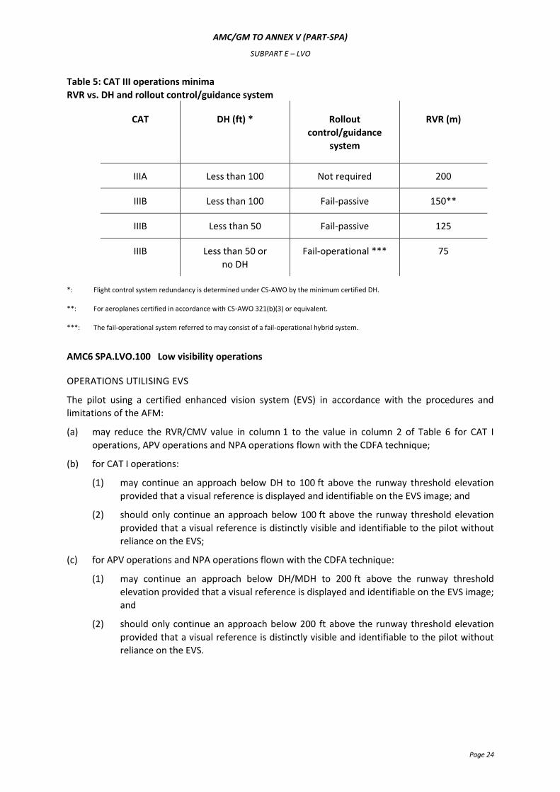
Table 5: CAT III operations minima
RVR vs. DH and rollout control/guidance system
CAT DH (ft) *
Rollout
control/guidance
system
RVR (m)
IIIA Less than 100 Not required 200
IIIB Less than 100 Fail-passive 150**
IIIB Less than 50 Fail-passive 125
IIIB Less than 50 or
no DH
Fail-operational *** 75
*: Flight control system redundancy is determined under CS-AWO by the minimum certified DH.
**: For aeroplanes certified in accordance with CS-AWO 321(b)(3) or equivalent.
***: The fail-operational system referred to may consist of a fail-operational hybrid system.
AMC6 SPA.LVO.100 Low visibility operations
OPERATIONS UTILISING EVS
The pilot using a certified enhanced vision system (EVS) in accordance with the procedures and
limitations of the AFM:
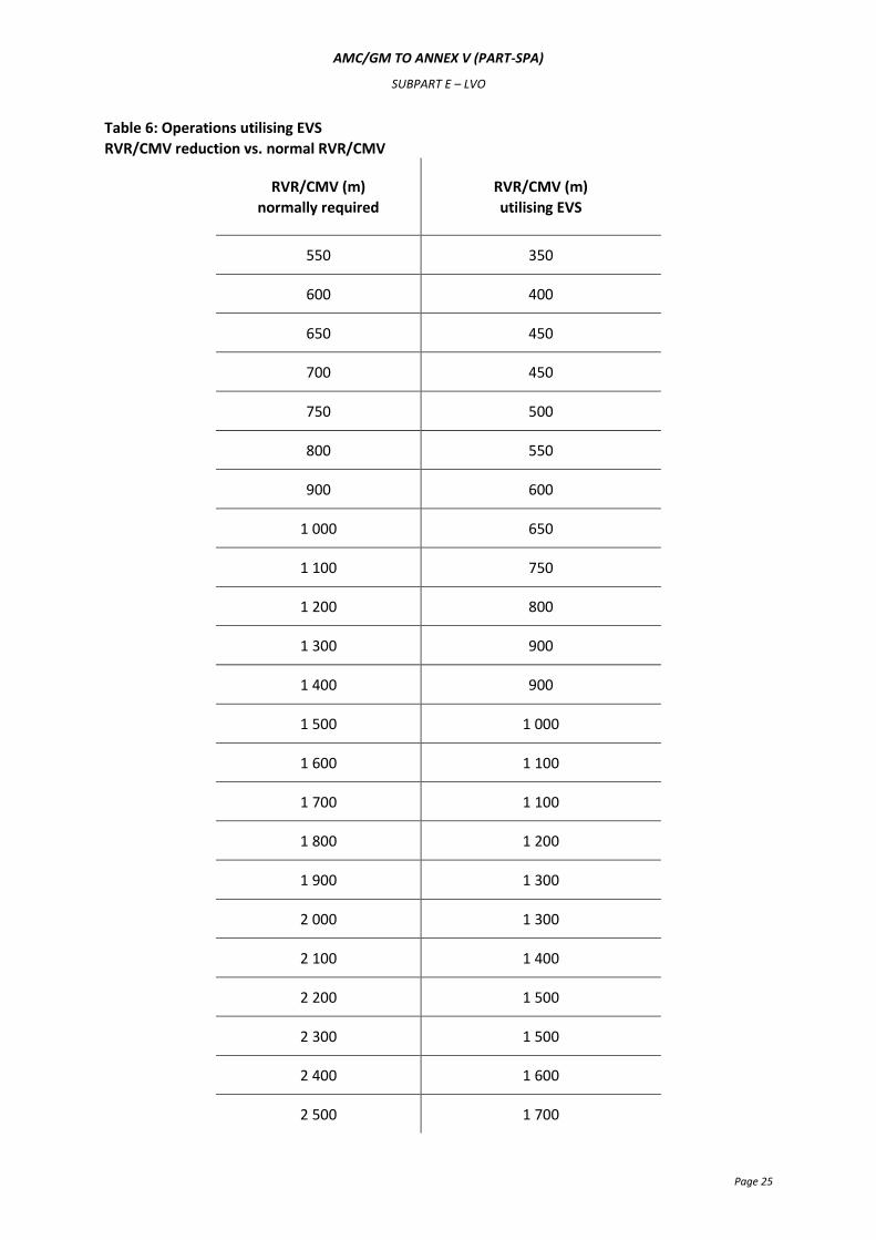
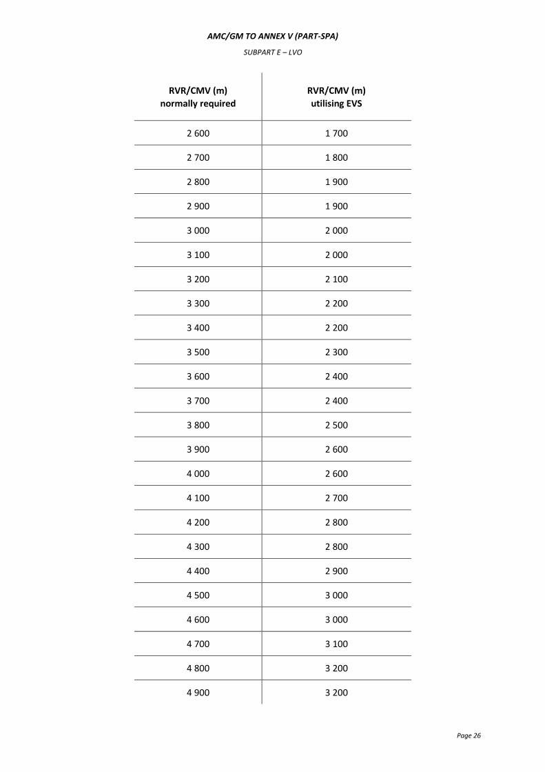
(a) may reduce the RVR/CMV value in column 1 to the value in column 2 of Table 6 for CAT I
operations, APV operations and NPA operations flown with the CDFA technique;
(b) for CAT I operations:
(1) may continue an approach below DH to 100 ft above the runway threshold elevation
provided that a visual reference is displayed and identifiable on the EVS image; and
(2) should only continue an approach below 100 ft above the runway threshold elevation
provided that a visual reference is distinctly visible and identifiable to the pilot without
reliance on the EVS;
(c) for APV operations and NPA operations flown with the CDFA technique:
(1) may continue an approach below DH/MDH to 200 ft above the runway threshold
elevation provided that a visual reference is displayed and identifiable on the EVS image;
and
(2) should only continue an approach below 200 ft above the runway threshold elevation
provided that a visual reference is distinctly visible and identifiable to the pilot without
reliance on the EVS.
AMC/GM TO ANNEX V (PART-SPA)
SUBPART E – LVO
Page 25
Table 6: Operations utilising EVS
RVR/CMV reduction vs. normal RVR/CMV
RVR/CMV (m)
normally required
RVR/CMV (m)
utilising EVS
550 350
600 400
650 450
700 450
750 500
800 550
900 600
1 000 650
1 100 750
1 200 800
1 300 900
1 400 900
1 500 1 000
1 600 1 100
1 700 1 100
1 800 1 200
1 900 1 300
2 000 1 300
2 100 1 400
2 200 1 500
2 300 1 500
2 400 1 600
2 500 1 700
AMC/GM TO ANNEX V (PART-SPA)
SUBPART E – LVO
Page 26
RVR/CMV (m)
normally required
RVR/CMV (m)
utilising EVS
2 600 1 700
2 700 1 800
2 800 1 900
2 900 1 900
3 000 2 000
3 100 2 000
3 200 2 100
3 300 2 200
3 400 2 200
3 500 2 300
3 600 2 400
3 700 2 400
3 800 2 500
3 900 2 600
4 000 2 600
4 100 2 700
4 200 2 800
4 300 2 800
4 400 2 900
4 500 3 000
4 600 3 000
4 700 3 100
4 800 3 200
4 900 3 200
AMC/GM TO ANNEX V (PART-SPA)
SUBPART E – LVO
Page 27
RVR/CMV (m)
normally required
RVR/CMV (m)
utilising EVS
5 000 3 300
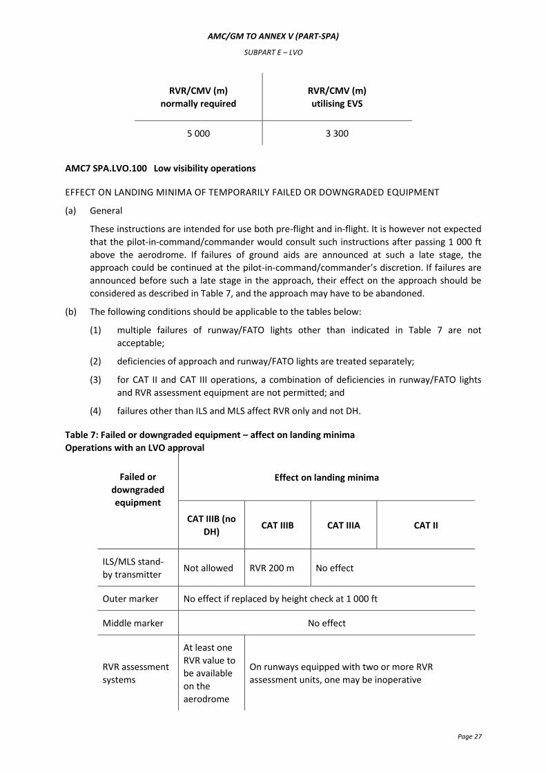
AMC7 SPA.LVO.100 Low visibility operations
EFFECT ON LANDING MINIMA OF TEMPORARILY FAILED OR DOWNGRADED EQUIPMENT
(a) General
These instructions are intended for use both pre-flight and in-flight. It is however not expected
that the pilot-in-command/commander would consult such instructions after passing 1 000 ft
above the aerodrome. If failures of ground aids are announced at such a late stage, the
approach could be continued at the pilot-in-command/commander’s discretion. If failures are
announced before such a late stage in the approach, their effect on the approach should be
considered as described in Table 7, and the approach may have to be abandoned.
(b) The following conditions should be applicable to the tables below:
(1) multiple failures of runway/FATO lights other than indicated in Table 7 are not
acceptable;
(2) deficiencies of approach and runway/FATO lights are treated separately;
(3) for CAT II and CAT III operations, a combination of deficiencies in runway/FATO lights
and RVR assessment equipment are not permitted; and
(4) failures other than ILS and MLS affect RVR only and not DH.
Table 7: Failed or downgraded equipment – affect on landing minima
Operations with an LVO approval
Failed or
downgraded
equipment
Effect on landing minima
CAT IIIB (no
DH) CAT IIIB CAT IIIA CAT II
ILS/MLS stand-
by transmitter Not allowed RVR 200 m No effect
Outer marker No effect if replaced by height check at 1 000 ft
Middle marker No effect
RVR assessment
systems
At least one
RVR value to
be available
on the
aerodrome
On runways equipped with two or more RVR
assessment units, one may be inoperative
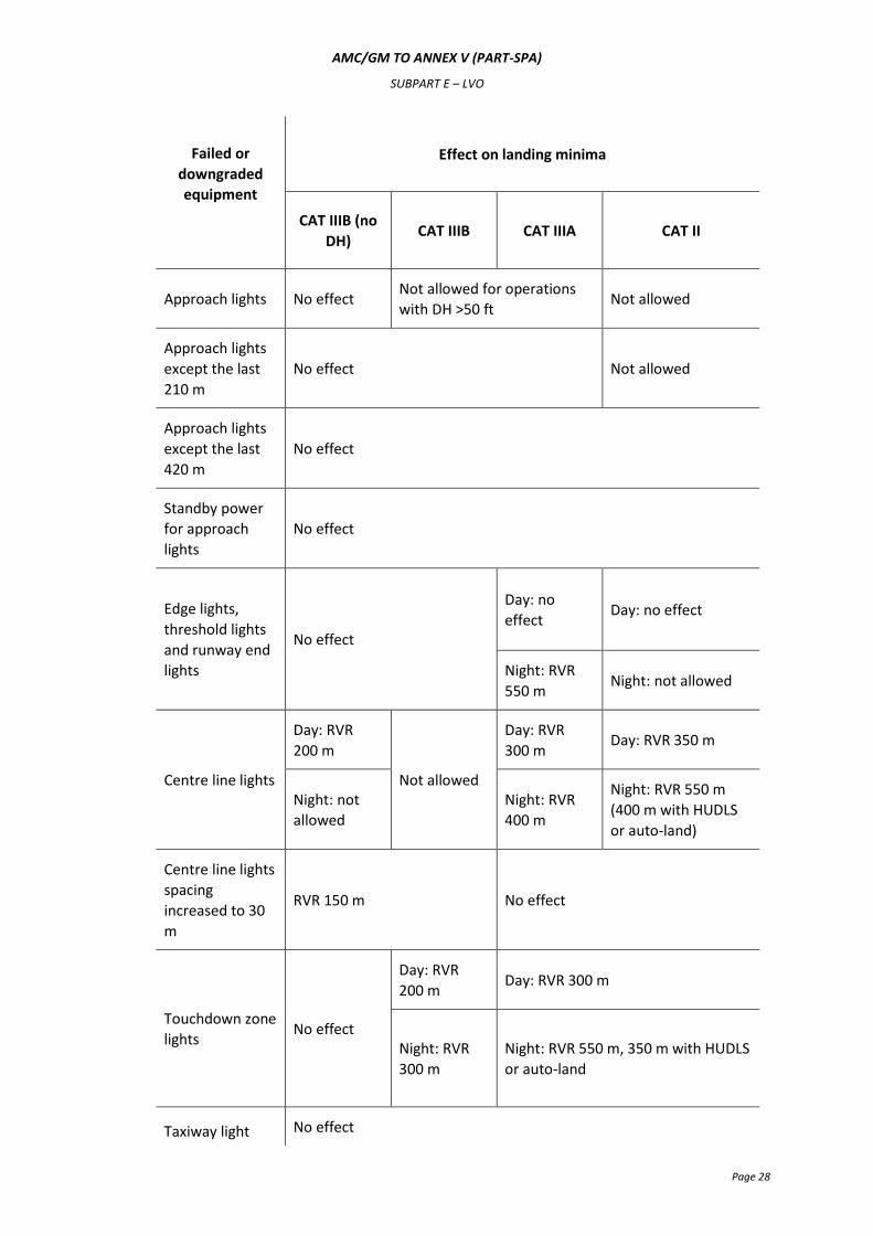
AMC/GM TO ANNEX V (PART-SPA)
SUBPART E – LVO
Page 28
Failed or
downgraded
equipment
Effect on landing minima
CAT IIIB (no
DH) CAT IIIB CAT IIIA CAT II
Approach lights No effect Not allowed for operations
with DH >50 ft Not allowed
Approach lights
except the last
210 m
No effect Not allowed
Approach lights
except the last
420 m
No effect
Standby power
for approach
lights
No effect
Edge lights,
threshold lights
and runway end
lights
No effect
Day: no
effect Day: no effect
Night: RVR
550 m Night: not allowed
Centre line lights
Day: RVR
200 m
Not allowed
Day: RVR
300 m Day: RVR 350 m
Night: not
allowed
Night: RVR
400 m
Night: RVR 550 m
(400 m with HUDLS
or auto-land)
Centre line lights
spacing
increased to 30
m
RVR 150 m No effect
Touchdown zone
lights No effect
Day: RVR
200 m Day: RVR 300 m
Night: RVR
300 m
Night: RVR 550 m, 350 m with HUDLS
or auto-land
Taxiway light No effect
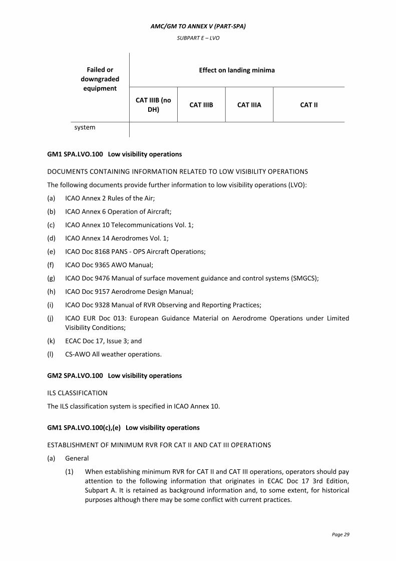
AMC/GM TO ANNEX V (PART-SPA)
SUBPART E – LVO
Page 29
Failed or
downgraded
equipment
Effect on landing minima
CAT IIIB (no
DH) CAT IIIB CAT IIIA CAT II
system
GM1 SPA.LVO.100 Low visibility operations
DOCUMENTS CONTAINING INFORMATION RELATED TO LOW VISIBILITY OPERATIONS
The following documents provide further information to low visibility operations (LVO):
(a) ICAO Annex 2 Rules of the Air;
(b) ICAO Annex 6 Operation of Aircraft;
(c) ICAO Annex 10 Telecommunications Vol. 1;
(d) ICAO Annex 14 Aerodromes Vol. 1;
(e) ICAO Doc 8168 PANS - OPS Aircraft Operations;
(f) ICAO Doc 9365 AWO Manual;
(g) ICAO Doc 9476 Manual of surface movement guidance and control systems (SMGCS);
(h) ICAO Doc 9157 Aerodrome Design Manual;
(i) ICAO Doc 9328 Manual of RVR Observing and Reporting Practices;
(j) ICAO EUR Doc 013: European Guidance Material on Aerodrome Operations under Limited
Visibility Conditions;
(k) ECAC Doc 17, Issue 3; and
(l) CS-AWO All weather operations.
GM2 SPA.LVO.100 Low visibility operations
ILS CLASSIFICATION
The ILS classification system is specified in ICAO Annex 10.
GM1 SPA.LVO.100(c),(e) Low visibility operations
ESTABLISHMENT OF MINIMUM RVR FOR CAT II AND CAT III OPERATIONS
(a) General
(1) When establishing minimum RVR for CAT II and CAT III operations, operators should pay
attention to the following information that originates in ECAC Doc 17 3rd Edition,
Subpart A. It is retained as background information and, to some extent, for historical
purposes although there may be some conflict with current practices.
AMC/GM TO ANNEX V (PART-SPA)
SUBPART E – LVO
Page 30
(2) Since the inception of precision approach and landing operations various methods have
been devised for the calculation of aerodrome operating minima in terms of DH and
RVR. It is a comparatively straightforward matter to establish the DH for an operation
but establishing the minimum RVR to be associated with that DH so as to provide a high
probability that the required visual reference will be available at that DH has been more
of a problem.
(3) The methods adopted by various States to resolve the DH/RVR relationship in respect of
CAT II and CAT III operations have varied considerably. In one instance there has been a
simple approach that entailed the application of empirical data based on actual
operating experience in a particular environment. This has given satisfactory results for
application within the environment for which it was developed. In another instance a
more sophisticated method was employed which utilised a fairly complex computer
programme to take account of a wide range of variables. However, in the latter case, it
has been found that with the improvement in the performance of visual aids, and the
increased use of automatic equipment in the many different types of new aircraft, most
of the variables cancel each other out and a simple tabulation can be constructed that is
applicable to a wide range of aircraft. The basic principles that are observed in
establishing the values in such a table are that the scale of visual reference required by a
pilot at and below DH depends on the task that he/she has to carry out, and that the
degree to which his/her vision is obscured depends on the obscuring medium, the
general rule in fog being that it becomes more dense with increase in height. Research
using flight simulation training devices (FSTDs) coupled with flight trials has shown the
following:
(i) most pilots require visual contact to be established about 3 seconds above DH
though it has been observed that this reduces to about 1 second when a fail-
operational automatic landing system is being used;
(ii) to establish lateral position and cross-track velocity most pilots need to see not
less than a three light segment of the centre line of the approach lights, or
runway centre line, or runway edge lights;
(iii) for roll guidance most pilots need to see a lateral element of the ground pattern,
i.e. an approach light cross bar, the landing threshold, or a barrette of the
touchdown zone light; and
(iv) to make an accurate adjustment to the flight path in the vertical plane, such as a
flare, using purely visual cues, most pilots need to see a point on the ground
which has a low or zero rate of apparent movement relative to the aircraft.
(v) With regard to fog structure, data gathered in the United Kingdom over a 20
year period have shown that in deep stable fog there is a 90 % probability that
the slant visual range from eye heights higher than 15 ft above the ground will
be less than the horizontal visibility at ground level, i.e. RVR. There are at
present no data available to show what the relationship is between the slant
visual range and RVR in other low visibility conditions such as blowing snow,
dust or heavy rain, but there is some evidence in pilot reports that the lack of
contrast between visual aids and the background in such conditions can produce
a relationship similar to that observed in fog.
(b) CAT II operations
The selection of the dimensions of the required visual segments that are used for CAT II
operations is based on the following visual provisions:
AMC/GM TO ANNEX V (PART-SPA)
SUBPART E – LVO
Page 31
(1) a visual segment of not less than 90 m will need to be in view at and below DH for pilot
to be able to monitor an automatic system;
(2) a visual segment of not less than 120 m will need to be in view for a pilot to be able to
maintain the roll attitude manually at and below DH; and
(3) for a manual landing using only external visual cues, a visual segment of 225 m will be
required at the height at which flare initiation starts in order to provide the pilot with
sight of a point of low relative movement on the ground.
Before using a CAT II ILS for landing, the quality of the localiser between 50 ft and touchdown
should be verified.
(c) CAT III fail-passive operations
(1) CAT III operations utilising fail-passive automatic landing equipment were introduced in
the late 1960s and it is desirable that the principles governing the establishment of the
minimum RVR for such operations be dealt with in some detail.
(2) During an automatic landing the pilot needs to monitor the performance of the aircraft
system, not in order to detect a failure that is better done by the monitoring devices
built into the system, but so as to know precisely the flight situation. In the final stages
the pilot should establish visual contact and, by the time the pilot reaches DH, the pilot
should have checked the aircraft position relative to the approach or runway centre line
lights. For this the pilot will need sight of horizontal elements (for roll reference) and
part of the touchdown area. The pilot should check for lateral position and cross-track
velocity and, if not within the pre-stated lateral limits, the pilot should carry out a
missed approach procedure. The pilot should also check longitudinal progress and sight
of the landing threshold is useful for this purpose, as is sight of the touchdown zone
lights.
(3) In the event of a failure of the automatic flight guidance system below DH, there are two
possible courses of action; the first is a procedure that allows the pilot to complete the
landing manually if there is adequate visual reference for him/her to do so, or to initiate
a missed approach procedure if there is not; the second is to make a missed approach
procedure mandatory if there is a system disconnect regardless of the pilot’s assessment
of the visual reference available:
(i) If the first option is selected then the overriding rule in the determination of a
minimum RVR is for sufficient visual cues to be available at and below DH for the
pilot to be able to carry out a manual landing. Data presented in ECAC Doc 17
showed that a minimum value of 300 m would give a high probability that the
cues needed by the pilot to assess the aircraft in pitch and roll will be available
and this should be the minimum RVR for this procedure.
(ii) The second option, to require a missed approach procedure to be carried out
should the automatic flight-guidance system fail below DH, will permit a lower
minimum RVR because the visual reference provision will be less if there is no
need to provide for the possibility of a manual landing. However, this option is
only acceptable if it can be shown that the probability of a system failure below
DH is acceptably low. It should be recognised that the inclination of a pilot who
experiences such a failure would be to continue the landing manually but the
results of flight trials in actual conditions and of simulator experiments show
that pilots do not always recognise that the visual cues are inadequate in such
situations and present recorded data reveal that pilots’ landing performance
AMC/GM TO ANNEX V (PART-SPA)
SUBPART E – LVO
Page 32
reduces progressively as the RVR is reduced below 300 m. It should further be
recognised that there is some risk in carrying out a manual missed approach
procedure from below 50 ft in very low visibility and it should therefore be
accepted that if an RVR lower than 300 m is to be approved, the flight deck
procedure should not normally allow the pilot to continue the landing manually
in such conditions and the aircraft system should be sufficiently reliable for the
missed approach procedure rate to be low.
(4) These criteria may be relaxed in the case of an aircraft with a fail-passive automatic
landing system that is supplemented by a head-up display that does not qualify as a fail-
operational system but that gives guidance that will enable the pilot to complete a
landing in the event of a failure of the automatic landing system. In this case it is not
necessary to make a missed approach procedure mandatory in the event of a failure of
the automatic landing system when the RVR is less than 300 m.
(d) CAT III fail-operational operations - with a DH
(1) For CAT III operations utilising a fail-operational landing system with a DH, a pilot should
be able to see at least one centre line light.
(2) For CAT III operations utilising a fail-operational hybrid landing system with a DH, a pilot
should have a visual reference containing a segment of at least three consecutive lights
of the runway centre line lights.
(e) CAT III fail operational operations - with no DH
(1) For CAT III operations with no DH the pilot is not required to see the runway prior to
touchdown. The permitted RVR is dependent on the level of aircraft equipment.
(2) A CAT III runway may be assumed to support operations with no DH unless specifically
restricted as published in the AIP or NOTAM.
GM1 SPA.LVO.100(e) Low visibility operations
CREW ACTIONS IN CASE OF AUTOPILOT FAILURE AT OR BELOW DH IN FAIL-PASSIVE CAT III
OPERATIONS
For operations to actual RVR values less than 300 m, a missed approach procedure is assumed in the
event of an autopilot failure at or below DH. This means that a missed approach procedure is the
normal action. However, the wording recognises that there may be circumstances where the safest
action is to continue the landing. Such circumstances include the height at which the failure occurs,
the actual visual references, and other malfunctions. This would typically apply to the late stages of
the flare. In conclusion, it is not forbidden to continue the approach and complete the landing when
the pilot-in-command/commander determines that this is the safest course of action. The operator’s
policy and the operational instructions should reflect this information.
GM1 SPA.LVO.100(f) Low visibility operations
OPERATIONS UTILISING EVS
(a) Introduction
(1) Enhanced vision systems use sensing technology to improve a pilot’s ability to detect
objects, such as runway lights or terrain, which may otherwise not be visible. The image
produced from the sensor and/or image processor can be displayed to the pilot in a
AMC/GM TO ANNEX V (PART-SPA)
SUBPART E – LVO
Page 33
number of ways including use of a HUD. The systems can be used in all phases of flight
and can improve situational awareness. In particular, infra-red systems can display
terrain during operations at night, improve situational awareness during night and low-
visibility taxiing, and may allow earlier acquisition of visual references during instrument
approaches.
(b) Background to EVS provisions
(1) The provisions for EVS were developed after an operational evaluation of two different
EVS systems, along with data and support provided by the FAA. Approaches using EVS
were flown in a variety of conditions including fog, rain and snow showers, as well as at
night to aerodromes located in mountainous terrain. The infra-red EVS performance can
vary depending on the weather conditions encountered. Therefore, the provisions take
a conservative approach to cater for the wide variety of conditions which may be
encountered. It may be necessary to amend the provisions in the future to take account
of greater operational experience.
(2) Provisions for the use of EVS during take-off have not been developed. The systems
evaluated did not perform well when the RVR was below 300 m. There may be some
benefit for use of EVS during take-off with greater visibility and reduced light; however,
such operations would need to be evaluated.
(3) Provisions have been developed to cover use of infra-red systems only. Other sensing
technologies are not intended to be excluded; however, their use will need to be
evaluated to determine the appropriateness of this, or any other provision. During the
development, it was envisaged what minimum equipment should be fitted to the
aircraft. Given the present state of technological development, it is considered that a
HUD is an essential element of the EVS equipment.
(4) In order to avoid the need for tailored charts for approaches utilising EVS, it is envisaged
that the operator will use AMC6 SPA.LVO.110 Table 6 Operations utilising EVS RVR/CMV
reduction vs. normal RVR/CMV to determine the applicable RVR at the commencement
of the approach.
(c) Additional operational considerations
(1) EVS equipment should have:
(i) a head-up display system (capable of displaying, airspeed, vertical speed, aircraft
attitude, heading, altitude, command guidance as appropriate for the approach
to be flown, path deviation indications, flight path vector and flight path angle
reference cue and the EVS imagery);
(ii) a head-down view of the EVS image, or other means of displaying the EVS-
derived information easily to the pilot monitoring the progress of the approach;
and
(iii) means to ensure that the pilot monitoring is kept in the ‘loop’ and crew resource
management (CRM) does not break down.
AMC1 SPA.LVO.105 LVO approval
OPERATIONAL DEMONSTRATION - AEROPLANES
(a) General
AMC/GM TO ANNEX V (PART-SPA)
SUBPART E – LVO
Page 34
(1) The purpose of the operational demonstration should be to determine or validate the
use and effectiveness of the applicable aircraft flight guidance systems, including HUDLS
if appropriate, training, flight crew procedures, maintenance programme, and manuals
applicable to the CAT II/III programme being approved.
(i) At least 30 approaches and landings should be accomplished in operations using
the CAT II/III systems installed in each aircraft type if the requested DH is 50 ft or
higher. If the DH is less than 50 ft, at least 100 approaches and landings should
be accomplished.
(ii) If the operator has different variants of the same type of aircraft utilising the
same basic flight control and display systems, or different basic flight control and
display systems on the same type of aircraft, the operator should show that the
various variants have satisfactory performance, but need not conduct a full
operational demonstration for each variant. The number of approaches and
landings may be based on credit given for the experience gained by another
operator, using the same aeroplane type or variant and procedures.
(iii) If the number of unsuccessful approaches exceeds 5 % of the total, e.g.
unsatisfactory landings, system disconnects, the evaluation programme should
be extended in steps of at least 10 approaches and landings until the overall
failure rate does not exceed 5 %.
(2) The operator should establish a data collection method to record approach and landing
performance. The resulting data and a summary of the demonstration data should be
made available to the competent authority for evaluation.
(3) Unsatisfactory approaches and/or automatic landings should be documented and
analysed.
(b) Demonstrations
(1) Demonstrations may be conducted in line operations or any other flight where the
operator's procedures are being used.
(2) In unique situations where the completion of 100 successful landings could take an
unreasonably long period of time and equivalent reliability assurance can be achieved, a
reduction in the required number of landings may be considered on a case-by-case
basis. Reduction of the number of landings to be demonstrated requires a justification
for the reduction. This justification should take into account factors such as a small
number of aircraft in the fleet, limited opportunity to use runways having CAT II/III
procedures or the inability to obtain ATS sensitive area protection during good weather
conditions. However, at the operator's option, demonstrations may be made on other
runways and facilities. Sufficient information should be collected to determine the cause
of any unsatisfactory performance (e.g. sensitive area was not protected).
(3) If the operator has different variants of the same type of aircraft utilising the same basic
flight control and display systems, or different basic flight control and display systems on
the same type or class of aircraft, the operator should show that the various variants
have satisfactory performance, but need not conduct a full operational demonstration
for each variant.
(4) Not more than 30 % of the demonstration flights should be made on the same runway.
(c) Data collection for operational demonstrations
AMC/GM TO ANNEX V (PART-SPA)
SUBPART E – LVO
Page 35
(1) Data should be collected whenever an approach and landing is attempted utilising the
CAT II/III system, regardless of whether the approach is abandoned, unsatisfactory, or is
concluded successfully.
(2) The data should, as a minimum, include the following information:
(i) Inability to initiate an approach. Identify deficiencies related to airborne
equipment that preclude initiation of a CAT II/III approach.
(ii) Abandoned approaches. Give the reasons and altitude above the runway at
which approach was discontinued or the automatic landing system was
disengaged.
(iii) Touchdown or touchdown and rollout performance. Describe whether or not
the aircraft landed satisfactorily within the desired touchdown area with lateral
velocity or cross track error that could be corrected by the pilot or automatic
system so as to remain within the lateral confines of the runway without
unusual pilot skill or technique. The approximate lateral and longitudinal
position of the actual touchdown point in relation to the runway centre line and
the runway threshold, respectively, should be indicated in the report. This report
should also include any CAT II/III system abnormalities that required manual
intervention by the pilot to ensure a safe touchdown or touchdown and rollout,
as appropriate.
(d) Data analysis
Unsuccessful approaches due to the following factors may be excluded from the analysis:
(1) ATS factors. Examples include situations in which a flight is vectored too close to the
final approach fix/point for adequate localiser and glide slope capture, lack of protection
of ILS sensitive areas, or ATS requests the flight to discontinue the approach.
(2) Faulty navaid signals. Navaid (e.g. ILS localiser) irregularities, such as those caused by
other aircraft taxiing, over-flying the navaid (antenna).
(3) Other factors. Any other specific factors that could affect the success of CAT II/ III
operations that are clearly discernible to the flight crew should be reported.
AMC2 SPA.LVO.105 LVO approval
OPERATIONAL DEMONSTRATION - HELICOPTERS
(a) The operator should comply with the provisions prescribed below when introducing into CAT II
or III service a helicopter type that is new to the EU.
(1) Operational reliability
The CAT II and III success rate should not be less than that required by CS-AWO or
equivalent.
(2) Criteria for a successful approach
An approach is regarded as successful if:
(i) the criteria are as specified in CS-AWO or equivalent are met; and
(ii) no relevant helicopter system failure occurs.
For helicopter types already used for CAT II or III operations in another Member State, the in-
service proving programme in (e) should be used instead.
AMC/GM TO ANNEX V (PART-SPA)
SUBPART E – LVO
Page 36
(b) Data collection during airborne system demonstration - general
(1) The operator should establish a reporting system to enable checks and periodic reviews
to be made during the operational evaluation period before the operator is approved to
conduct CAT II or III operations. The reporting system should cover all successful and
unsuccessful approaches, with reasons for the latter, and include a record of system
component failures. This reporting system should be based upon flight crew reports and
automatic recordings as prescribed in (c) and (d) below.
(2) The recordings of approaches may be made during normal line flights or during other
flights performed by the operator.
(c) Data collection during airborne system demonstration – operations with DH not less than 50 ft
(1) For operations with DH not less than 50 ft, data should be recorded and evaluated by
the operator and evaluated by the competent authority when necessary.
(2) It is sufficient for the following data to be recorded by the flight crew:
(i) FATO and runway used;
(ii) weather conditions;
(iii) time;
(iv) reason for failure leading to an aborted approach;
(v) adequacy of speed control;
(vi) trim at time of automatic flight control system disengagement;
(vii) compatibility of automatic flight control system, flight director and raw data;
(viii) an indication of the position of the helicopter relative to the ILS, MLS centre line
when descending through 30 m (100 ft); and
(ix) touchdown position.
(3) The number of approaches made during the initial evaluation should be sufficient to
demonstrate that the performance of the system in actual airline service is such that a
90 % confidence and a 95 % approach success will result.
(d) Data collection during airborne system demonstration – operations with DH less than 50 ft or
no DH
(1) For operations with DH less than 50 ft or no DH, a flight data recorder (FDR), or other
equipment giving the appropriate information, should be used in addition to the flight
crew reports to confirm that the system performs as designed in actual airline service.
The following data should be recorded:
(i) distribution of ILS, MLS deviations at 30 m (100 ft), at touchdown and, if
appropriate, at disconnection of the rollout control system and the maximum
values of the deviations between those points; and
(ii) sink rate at touchdown.
(2) Any landing irregularity should be fully investigated using all available data to determine
its cause.
(e) In-service proving
The operator fulfilling the provisions of (f) above should be deemed to have met the in-service
proving contained in this subparagraph.
AMC/GM TO ANNEX V (PART-SPA)
SUBPART E – LVO
Page 37
(1) The system should demonstrate reliability and performance in line operations consistent
with the operational concepts. A sufficient number of successful landings should be
accomplished in line operations, including training flights, using the auto-land and
rollout system installed in each helicopter type.
(2) The demonstration should be accomplished using a CAT II or CAT III ILS. Demonstrations
may be made on other ILS or MLS facilities if sufficient data are recorded to determine
the cause of unsatisfactory performance.
(3) If the operator has different variants of the same type of helicopter utilising the same
basic flight control and display systems, or different basic flight control and display
systems on the same type of helicopter, the operator should show that the variants
comply with the basic system performance criteria, but the operator need not conduct a
full operational demonstration for each variant.
(4) Where the operator introduces a helicopter type that has already been approved by the
competent authority of any Member State for CAT II and/or CAT III operations, a
reduced proving programme may be acceptable.
AMC3 SPA.LVO.105 LVO approval
CONTINUOUS MONITORING – ALL AIRCRAFT
(a) After obtaining the initial approval, the operations should be continuously monitored by the
operator to detect any undesirable trends before they become hazardous. Flight crew reports
may be used to achieve this.
(b) The following information should be retained for a period of 12 months:
(1) the total number of approaches, by aircraft type, where the airborne CAT II or III
equipment was utilised to make satisfactory, actual or practice, approaches to the
applicable CAT II or III minima; and
(2) reports of unsatisfactory approaches and/or automatic landings, by aerodrome and
aircraft registration, in the following categories:
(i) airborne equipment faults;
(ii) ground facility difficulties;
(iii) missed approaches because of ATC instructions; or
(iv) other reasons.
(c) The operator should establish a procedure to monitor the performance of the automatic
landing system or HUDLS to touchdown performance, as appropriate, of each aircraft.
AMC4 SPA.LVO.105 LVO approval
TRANSITIONAL PERIODS FOR CAT II AND CAT III OPERATIONS
(a) Operators with no previous CAT II or CAT III experience
(1) The operator without previous CAT II or III operational experience, applying for a CAT II
or CAT IIIA operational approval, should demonstrate to the competent authority that it
has gained a minimum experience of 6 months of CAT I operations on the aircraft type.
AMC/GM TO ANNEX V (PART-SPA)
SUBPART E – LVO
Page 38
(2) The operator applying for a CAT IIIB operational approval should demonstrate to the
competent authority that it has already completed 6 months of CAT II or IIIA operations
on the aircraft type.
(b) Operators with previous CAT II or III experience
(1) The operator with previous CAT II or CAT III experience, applying for a CAT II or CAT III
operational approval with reduced transition periods as set out in (a), should
demonstrate to the competent authority that it has maintained the experience
previously gained on the aircraft type.
(2) The operator approved for CAT II or III operations using auto-coupled approach
procedures, with or without auto-land, and subsequently introducing manually flown
CAT II or III operations using a HUDLS should provide the operational demonstrations set
out in AMC1 SPA.LVO.105 and AMC2 SPA.LVO.105 as if it would be a new applicant for a
CAT II or CAT III approval.
AMC5 SPA.LVO.105 LVO approval
MAINTENANCE OF CAT II, CAT III AND LVTO EQUIPMENT
Maintenance instructions for the on-board guidance systems should be established by the operator,
in liaison with the manufacturer, and included in the operator's aircraft maintenance programme in
accordance with Annex I to Regulation (EC) No 2042/20032 (Part-M).
AMC6 SPA.LVO.105 LVO approval
ELIGIBLE AERODROMES AND RUNWAYS
(a) Each aircraft type/runway combination should be verified by the successful completion of at
least one approach and landing in CAT II or better conditions, prior to commencing CAT III
operations.
(b) For runways with irregular pre-threshold terrain or other foreseeable or known deficiencies,
each aircraft type/runway combination should be verified by operations in CAT I or better
conditions, prior to commencing LTS CAT I, OTS CAT II or CAT III operations.
(c) If the operator has different variants of the same type of aircraft in accordance with (d),
utilising the same basic flight control and display systems, or different basic flight control and
display systems on the same type of aircraft in accordance with (d), the operator should show
that the variants have satisfactory operational performance, but need not conduct a full
operational demonstration for each variant/runway combination.
(d) For the purpose of this AMC, an aircraft type or variant of an aircraft type should be deemed to
be the same type/variant of aircraft if that type/variant has the same or similar:
(1) level of technology, including the following:
(i) flight control/guidance system (FGS) and associated displays and controls;
(ii) FMS and level of integration with the FGS; and
(iii) use of HUDLS;
2 OJ L 315, 28.11.2003, p. 1.
AMC/GM TO ANNEX V (PART-SPA)
SUBPART E – LVO
Page 39
(2) operational procedures, including:
(i) alert height;
(ii) manual landing /automatic landing;
(iii) no DH operations; and
(iv) use of HUD/HUDLS in hybrid operations;
(3) handling characteristics, including:
(i) manual landing from automatic or HUDLS guided approach;
(ii) manual missed approach procedure from automatic approach; and
(iii) automatic/manual rollout.
(e) Operators using the same aircraft type/class or variant of a type in accordance with (d) above
may take credit from each other’s experience and records in complying with this subparagraph.
(f) Where an approval is sought for OTS CAT II, the same provisions as set out for CAT II should be
applied.
GM1 SPA.LVO.105 LVO approval
CRITERIA FOR A SUCCESSFUL CAT II, OTS CAT II, CAT III APPROACH AND AUTOMATIC LANDING
(a) The purpose of this GM is to provide operators with supplemental information regarding the
criteria for a successful approach and landing to facilitate fulfilling the requirements prescribed
in SPA.LVO.105.
(b) An approach may be considered to be successful if:
(1) from 500 ft to start of flare:
(i) speed is maintained as specified in AMC-AWO 231, paragraph 2 ‘Speed Control’;
and
(ii) no relevant system failure occurs;
and
(2) from 300 ft to DH:
(i) no excess deviation occurs; and
(ii) no centralised warning gives a missed approach procedure command (if
installed).
(c) An automatic landing may be considered to be successful if:
(1) no relevant system failure occurs;
(2) no flare failure occurs;
(3) no de-crab failure occurs (if installed);
(4) longitudinal touchdown is beyond a point on the runway 60 m after the threshold and
before the end of the touchdown zone light (900 m from the threshold);
(5) lateral touchdown with the outboard landing gear is not outside the touchdown zone
light edge;
(6) sink rate is not excessive;
AMC/GM TO ANNEX V (PART-SPA)
SUBPART E – LVO
Page 40
(7) bank angle does not exceed a bank angle limit; and
(8) no rollout failure or deviation (if installed) occurs.
(d) More details can be found in CS-AWO 131, CS-AWO 231 and AMC-AWO 231.
GM1 SPA.LVO.110(c)(4)(i) General operating requirements
APPROVED VERTICAL FLIGHT PATH GUIDANCE MODE
The term ‘approved’ means that the vertical flight path guidance mode has been certified by the
Agency as part of the avionics product.
AMC1 SPA.LVO.120 Flight crew training and qualifications
GENERAL PROVISIONS
(a) The operator should ensure that flight crew member training programmes for LVO include
structured courses of ground, FSTD and/or flight training.
(1) Flight crew members with no CAT II or CAT III experience should complete the full
training programme prescribed in (b), (c), and (d) below.
(2) Flight crew members with CAT II or CAT III experience with a similar type of operation
(auto-coupled/auto-land, HUDLS/hybrid HUDLS or EVS) or CAT II with manual land, if
appropriate, with another EU operator may undertake an:
(i) abbreviated ground training course if operating a different type or class from
that on which the previous CAT II or CAT III experience was gained;
(ii) abbreviated ground, FSTD and/or flight training course if operating the same
type or class and variant of the same type or class on which the previous CAT II
or CAT III experience was gained. The abbreviated course should include at least
the provisions of (d)(1), (d)(2)(i) or (d)(2)(ii) as appropriate and (d)(3)(i). The
operator may reduce the number of approaches/landings required by (d)(2)(i) if
the type/class or the variant of the type or class has the same or similar:
(A) level of technology - flight control/guidance system (FGS);
(B) operating procedures;
(C) handling characteristics;
(D) use of HUDLS/hybrid HUDLS; and
(E) use of EVS,
as the previously operated type or class, otherwise the provisions of (d)(2)(i)
should be met.
(3) Flight crew members with CAT II or CAT III experience with the operator may undertake
an abbreviated ground, FSTD and/or flight training course.
(i) When changing aircraft type or class, the abbreviated course should include at
least the provisions of (d)(1), (d)(2)(i) or (d)(2)(ii) as appropriate and (d)(3)(i).
(ii) When changing to a different variant of aircraft within the same type or class
rating that has the same or similar:
(A) level of technology - FGS;
(B) operating procedures - integrity;
AMC/GM TO ANNEX V (PART-SPA)
SUBPART E – LVO
Page 41
(C) handling characteristics;
(D) use of HUDLS/Hybrid HUDLS; and
(E) use of EVS,
as the previously operated type or class, a difference course or familiarisation
appropriate to the change of variant should fulfil the abbreviated course
provisions.
(iii) When changing to a different variant of aircraft within the same type or class
rating that has a significantly different:
(A) level of technology - FGS;
(B) operating procedures - integrity;
(C) handling characteristics;
(D) use of HUDLS/Hybrid HUDLS; or
(E) use of EVS,
the provisions of (d)(1), (d)(2)(i) or (d)(2)(ii) as appropriate and (d)(3)(i) should
be fulfilled.
(4) The operator should ensure when undertaking CAT II or CAT III operations with different
variant(s) of aircraft within the same type or class rating that the differences and/or
similarities of the aircraft concerned justify such operations, taking into account at least
the following:
(i) the level of technology, including the:
(A) FGS and associated displays and controls;
(B) FMS and its integration or not with the FGS; and
(C) use of HUD/HUDLS with hybrid systems and/or EVS;
(ii) operating procedures, including:
(A) fail-passive / fail-operational, alert height;
(B) manual landing / automatic landing;
(C) no DH operations; and
(D) use of HUD/HUDLS with hybrid systems;
(iii) handling characteristics, including:
(A) manual landing from automatic HUDLS and/or EVS guided approach;
(B) manual missed approach procedure from automatic approach; and
(C) automatic/manual rollout.
GROUND TRAINING
(b) The initial ground training course for LVO should include at least the following:
(1) characteristics and limitations of the ILS and/or MLS;
(2) characteristics of the visual aids;
(3) characteristics of fog;
(4) operational capabilities and limitations of the particular airborne system to include HUD
symbology and EVS characteristics, if appropriate;
(5) effects of precipitation, ice accretion, low level wind shear and turbulence;
AMC/GM TO ANNEX V (PART-SPA)
SUBPART E – LVO
Page 42
(6) effect of specific aircraft/system malfunctions;
(7) use and limitations of RVR assessment systems;
(8) principles of obstacle clearance requirements;
(9) recognition of and action to be taken in the event of failure of ground equipment;
(10) procedures and precautions to be followed with regard to surface movement during
operations when the RVR is 400 m or less and any additional procedures required for
take-off in conditions below 150 m (200 m for category D aeroplanes);
(11) significance of DHs based upon radio altimeters and the effect of terrain profile in the
approach area on radio altimeter readings and on the automatic approach/landing
systems;
(12) importance and significance of alert height, if applicable, and the action in the event of
any failure above and below the alert height;
(13) qualification requirements for pilots to obtain and retain approval to conduct LVOs; and
(14) importance of correct seating and eye position.
FSTD TRAINING AND/OR FLIGHT TRAINING
(c) FSTD training and/or flight training
(1) FSTD and/or flight training for LVO should include at least:
(i) checks of satisfactory functioning of equipment, both on the ground and in
flight;
(ii) effect on minima caused by changes in the status of ground installations;
(iii) monitoring of:
(A) automatic flight control systems and auto-land status annunciators with
emphasis on the action to be taken in the event of failures of such
systems; and
(B) HUD/HUDLS/EVS guidance status and annunciators as appropriate, to
include head-down displays;
(iv) actions to be taken in the event of failures such as engines, electrical systems,
hydraulics or flight control systems;
(v) the effect of known unserviceabilities and use of MELs;
(vi) operating limitations resulting from airworthiness certification;
(vii) guidance on the visual cues required at DH together with information on
maximum deviation allowed from glide path or localiser; and
(viii) the importance and significance of alert height if applicable and the action in the
event of any failure above and below the alert height.
(2) Flight crew members should be trained to carry out their duties and instructed on the
coordination required with other crew members. Maximum use should be made of
suitably equipped FSTDs for this purpose.
(3) Training should be divided into phases covering normal operation with no aircraft or
equipment failures but including all weather conditions that may be encountered and
detailed scenarios of aircraft and equipment failure that could affect CAT II or III
AMC/GM TO ANNEX V (PART-SPA)
SUBPART E – LVO
Page 43
operations. If the aircraft system involves the use of hybrid or other special systems,
such as HUD/HUDLS or enhanced vision equipment, then flight crew members should
practise the use of these systems in normal and abnormal modes during the FSTD phase
of training.
(4) Incapacitation procedures appropriate to LVTO, CAT II and CAT III operations should be
practised.
(5) For aircraft with no FSTD available to represent that specific aircraft, operators should
ensure that the flight training phase specific to the visual scenarios of CAT II operations
is conducted in a specifically approved FSTD. Such training should include a minimum of
four approaches. Thereafter, the training and procedures that are type specific should
be practised in the aircraft.
(6) Initial CAT II and III training should include at least the following exercises:
(i) approach using the appropriate flight guidance, autopilots and control systems
installed in the aircraft, to the appropriate DH and to include transition to visual
flight and landing;
(ii) approach with all engines operating using the appropriate flight guidance
systems, autopilots, HUDLS and/or EVS and control systems installed in the
aircraft down to the appropriate DH followed by missed approach - all without
external visual reference;
(iii) where appropriate, approaches utilising automatic flight systems to provide
automatic flare, hover, landing and rollout; and
(iv) normal operation of the applicable system both with and without acquisition of
visual cues at DH.
(7) Subsequent phases of training should include at least:
(i) approaches with engine failure at various stages on the approach;
(ii) approaches with critical equipment failures, such as electrical systems, auto
flight systems, ground and/or airborne ILS, MLS systems and status monitors;
(iii) approaches where failures of auto flight equipment and/or HUD/HUDLS/EVS at
low level require either:
(A) reversion to manual flight to control flare, hover, landing and rollout or
missed approach; or
(B) reversion to manual flight or a downgraded automatic mode to control
missed approaches from, at or below DH including those which may
result in a touchdown on the runway;
(iv) failures of the systems that will result in excessive localiser and/or glideslope
deviation, both above and below DH, in the minimum visual conditions specified
for the operation. In addition, a continuation to a manual landing should be
practised if a head-up display forms a downgraded mode of the automatic
system or the head-up display forms the only flare mode; and
(v) failures and procedures specific to aircraft type or variant.
(8) The training programme should provide practice in handling faults which require a
reversion to higher minima.
AMC/GM TO ANNEX V (PART-SPA)
SUBPART E – LVO
Page 44
(9) The training programme should include the handling of the aircraft when, during a fail-
passive CAT III approach, the fault causes the autopilot to disconnect at or below DH
when the last reported RVR is 300 m or less.
(10) Where take-offs are conducted in RVRs of 400 m and below, training should be
established to cover systems failures and engine failure resulting in continued as well as
rejected take-offs.
(11) The training programme should include, where appropriate, approaches where failures
of the HUDLS and/or EVS equipment at low level require either:
(i) reversion to head down displays to control missed approach; or
(ii) reversion to flight with no, or downgraded, HUDLS guidance to control missed
approaches from DH or below, including those which may result in a touchdown
on the runway.
(12) When undertaking LVTO, LTS CAT I, OTS CAT II, CAT II and CAT III operations utilising a
HUD/HUDLS, hybrid HUD/HUDLS or an EVS, the training and checking programme
should include, where appropriate, the use of the HUD/HUDLS in normal operations
during all phases of flight.
CONVERSION TRAINING
(d) Flight crew members should complete the following low visibility procedures (LVPs) training if
converting to a new type or class or variant of aircraft in which LVTO, LTS CAT I, OTS CAT II,
approach operations utilising EVS with an RVR of 800 m or less and CAT II and CAT III
operations will be conducted. Conditions for abbreviated courses are prescribed in (a)(2), (a)(3)
and (a)(4).
(1) Ground training
The appropriate provisions are as prescribed in (b), taking into account the flight crew
member's CAT II and CAT III training and experience.
(2) FSTD training and/or flight training
(i) A minimum of six, respectively eight for HUDLS with or without EVS, approaches
and/or landings in an FSTD. The provisions for eight HUDLS approaches may be
reduced to six when conducting hybrid HUDLS operations.
(ii) Where no FSTD is available to represent that specific aircraft, a minimum of
three, respectively five for HUDLS and/or EVS, approaches including at least one
missed approach procedure is required on the aircraft. For hybrid HUDLS
operations a minimum of three approaches is required, including at least one
missed approach procedure.
(iii) Appropriate additional training if any special equipment is required such as
head-up displays or enhanced vision equipment. When approach operations
utilising EVS are conducted with an RVR of less than 800 m, a minimum of five
approaches, including at least one missed approach procedure are required on
the aircraft.
(3) Flight crew qualification
The flight crew qualification provisions are specific to the operator and the type of
aircraft operated.
AMC/GM TO ANNEX V (PART-SPA)
SUBPART E – LVO
Page 45
(i) The operator should ensure that each flight crew member completes a check
before conducting CAT II or III operations.
(ii) The check specified in (d)(3)(i) may be replaced by successful completion of the
FSTD and/or flight training specified in (d)(2).
(4) Line flying under supervision
Flight crew member should undergo the following line flying under supervision (LIFUS):
(i) For CAT II when a manual landing or a HUDLS approach to touchdown is
required, a minimum of:
(A) three landings from autopilot disconnect; and
(B) four landings with HUDLS used to touchdown,
except that only one manual landing, respectively two using HUDLS, to
touchdown is required when the training required in (d)(2) has been carried out
in an FSTD qualified for zero flight time conversion.
(ii) For CAT III, a minimum of two auto-lands, except that:
(A) only one auto-land is required when the training required in (d)(2) has
been carried out in an FSTD qualified for zero flight time conversion;
(B) no auto-land is required during LIFUS when the training required in
(d)(2) has been carried out in an FSTD qualified for zero flight time (ZFT)
conversion and the flight crew member successfully completed the ZFT
type rating conversion course; and
(C) the flight crew member, trained and qualified in accordance with (B), is
qualified to operate during the conduct of LIFUS to the lowest approved
DA/H and RVR as stipulated in the operations manual.
(iii) For CAT III approaches using HUDLS to touchdown, a minimum of four
approaches.
TYPE AND COMMAND EXPERIENCE
(e) Type and command experience
(1) Before commencing CAT II operations, the following additional provisions should be
applicable to pilots-in-command/commanders, or pilots to whom conduct of the flight
may be delegated, who are new to the aircraft type or class:
(i) 50 hours or 20 sectors on the type, including LIFUS; and
(ii) 100 m should be added to the applicable CAT II RVR minima when the operation
requires a CAT II manual landing or use of HUDLS to touchdown until:
(A) a total of 100 hours or 40 sectors, including LIFUS, has been achieved on
the type; or
(B) a total of 50 hours or 20 sectors, including LIFUS, has been achieved on
the type where the flight crew member has been previously qualified for
CAT II manual landing operations with an EU operator;
(C) for HUDLS operations the sector provisions in (e)(1) and (e)(2)(i) should
always be applicable; the hours on type or class do not fulfil the
provisions.
AMC/GM TO ANNEX V (PART-SPA)
SUBPART E – LVO
Page 46
(2) Before commencing CAT III operations, the following additional provisions should be
applicable to pilots-in-command/commanders, or pilots to whom conduct of the flight
may be delegated, who are new to the aircraft type:
(i) 50 hours or 20 sectors on the type, including LIFUS; and
(ii) 100 m should be added to the applicable CAT II or CAT III RVR minima unless
he/she has previously qualified for CAT II or III operations with an EU operator,
until a total of 100 hours or 40 sectors, including LIFUS, has been achieved on
the type.
RECURRENT TRAINING AND CHECKING
(f) Recurrent training and checking – LVO
(1) The operator should ensure that, in conjunction with the normal recurrent training and
operator’s proficiency checks, the pilot's knowledge and ability to perform the tasks
associated with the particular category of operation, for which the pilot is authorised by
the operator, are checked. The required number of approaches to be undertaken in the
FSTD within the validity period of the operator’s proficiency check should be a minimum
of two, respectively four when HUDLS and/or EVS is utilised to touchdown, one of which
should be a landing at the lowest approved RVR. In addition one, respectively two for
HUDLS and/or operations utilising EVS, of these approaches may be substituted by an
approach and landing in the aircraft using approved CAT II and CAT III procedures. One
missed approach should be flown during the conduct of an operator proficiency check. If
the operator is approved to conduct take-off with RVR less than 150 m, at least one
LVTO to the lowest applicable minima should be flown during the conduct of the
operator’s proficiency check.
(2) For CAT III operations the operator should use an FSTD approved for this purpose.
(3) For CAT III operations on aircraft with a fail-passive flight control system, including
HUDLS, a missed approach should be completed by each flight crew member at least
once over the period of three consecutive operator proficiency checks as the result of an
autopilot failure at or below DH when the last reported RVR was 300 m or less.
LVTO OPERATIONS
(g) LVTO with RVR less than 400 m
(1) Prior to conducting take-offs in RVRs below 400 m, the flight crew should undergo the
following training:
(i) normal take-off in minimum approved RVR conditions;
(ii) take-off in minimum approved RVR conditions with an engine failure:
(A) for aeroplanes between V1 and V2 (take-off safety speed), or as soon as
safety considerations permit;
(B) for helicopters at or after take-off decision point (TDP); and
(iii) take-off in minimum approved RVR conditions with an engine failure:
(A) for aeroplanes before V1 resulting in a rejected take-off; and
(B) for helicopters before the TDP.
AMC/GM TO ANNEX V (PART-SPA)
SUBPART E – LVO
Page 47
(2) The operator approved for LVTOs with an RVR below 150 m should ensure that the
training specified by (g)(1) is carried out in an FSTD. This training should include the use
of any special procedures and equipment.
(3) The operator should ensure that a flight crew member has completed a check before
conducting LVTO in RVRs of less than 150 m. The check may be replaced by successful
completion of the FSTD and/or flight training prescribed in (g)(1) on conversion to an
aircraft type.
LTS CAT I, OTS CAT II, OPERATIONS UTILISING EVS
(h) Additional training provisions
(1) General
Operators conducting LTS CAT I operations, OTS CAT II operations and operations
utilising EVS with RVR of 800 m or less should comply with the provisions applicable to
CAT II operations and include the provisions applicable to HUDLS, if appropriate. The
operator may combine these additional provisions where appropriate provided that the
operational procedures are compatible.
(2) LTS CAT I
During conversion training the total number of approaches should not be additional to
the requirements of Subpart FC of Annex III (ORO.FC) provided the training is conducted
utilising the lowest applicable RVR. During recurrent training and checking the operator
may also combine the separate requirements provided the above operational procedure
provision is met and at least one approach using LTS CAT I minima is conducted at least
once every 18 months.
(3) OTS CAT II
During conversion training the total number of approaches should not be less than those
to complete CAT II training utilising a HUD/HUDLS. During recurrent training and
checking the operator may also combine the separate provisions provided the above
operational procedure provision is met and at least one approach using OTS CAT II
minima is conducted at least once every 18 months.
(4) Operations utilising EVS with RVR of 800 m or less
During conversion training the total number of approaches required should not be less
than that required to complete CAT II training utilising a HUD. During recurrent training
and checking the operator may also combine the separate provisions provided the
above operational procedure provision is met and at least one approach utilising EVS is
conducted at least once every 12 months.
GM1 SPA.LVO.120 Flight crew training and qualifications
FLIGHT CREW TRAINING
The number of approaches referred to in AMC1 SPA.LVO.120 (g)(1) includes one approach and
landing that may be conducted in the aircraft using approved CAT II/III procedures. This approach
and landing may be conducted in normal line operation or as a training flight.
AMC/GM TO ANNEX V (PART-SPA)
SUBPART E – LVO
Page 48
AMC1 SPA.LVO.125 Operating procedures
GENERAL
(a) LVOs should include the following:
(1) manual take-off, with or without electronic guidance systems or HUDLS/hybrid
HUD/HUDLS;
(2) approach flown with the use of a HUDLS/hybrid HUD/HUDLS and/or EVS;
(3) auto-coupled approach to below DH, with manual flare, hover, landing and rollout;
(4) auto-coupled approach followed by auto-flare, hover, auto-landing and manual rollout;
and
(5) auto-coupled approach followed by auto-flare, hover, auto-landing and auto-rollout,
when the applicable RVR is less than 400 m.
PROCEDURES AND INSTRUCTIONS
(b) The operator should specify detailed operating procedures and instructions in the operations
manual or procedures manual.
(1) The precise nature and scope of procedures and instructions given should depend upon
the airborne equipment used and the flight deck procedures followed. The operator
should clearly define flight crew member duties during take-off, approach, flare, hover,
rollout and missed approach in the operations manual or procedures manual. Particular
emphasis should be placed on flight crew responsibilities during transition from non-
visual conditions to visual conditions, and on the procedures to be used in deteriorating
visibility or when failures occur. Special attention should be paid to the distribution of
flight deck duties so as to ensure that the workload of the pilot making the decision to
land or execute a missed approach enables him/her to devote himself/herself to
supervision and the decision making process.
(2) The instructions should be compatible with the limitations and mandatory procedures
contained in the AFM and cover the following items in particular:
(i) checks for the satisfactory functioning of the aircraft equipment, both before
departure and in flight;
(ii) effect on minima caused by changes in the status of the ground installations and
airborne equipment;
(iii) procedures for the take-off, approach, flare, hover, landing, rollout and missed
approach;
(iv) procedures to be followed in the event of failures, warnings to include
HUD/HUDLS/EVS and other non-normal situations;
(v) the minimum visual reference required;
(vi) the importance of correct seating and eye position;
(vii) action that may be necessary arising from a deterioration of the visual
reference;
(viii) allocation of crew duties in the carrying out of the procedures according to
(b)(2)(i) to (iv) and (vi), to allow the pilot-in-command/commander to devote
himself/herself mainly to supervision and decision making;
AMC/GM TO ANNEX V (PART-SPA)
SUBPART E – LVO
Page 49
(ix) the rule for all height calls below 200 ft to be based on the radio altimeter and
for one pilot to continue to monitor the aircraft instruments until the landing is
completed;
(x) the rule for the localiser sensitive area to be protected;
(xi) the use of information relating to wind velocity, wind shear, turbulence, runway
contamination and use of multiple RVR assessments;
(xii) procedures to be used for:
(A) LTS CAT I;
(B) OTS CAT II;
(C) approach operations utilising EVS; and
(D) practice approaches and landing on runways at which the full CAT II or
CAT III aerodrome procedures are not in force;
(xiii) operating limitations resulting from airworthiness certification; and
(xiv) information on the maximum deviation allowed from the ILS glide path and/or
localiser.

AMC/GM TO ANNEX V (PART-SPA)
SUBPART F – ETOPS
Page 50
Subpart F - Extended range operations with two-engined aeroplanes (ETOPS)
GM1 SPA.ETOPS.105 ETOPS operational approval
AMC 20-6
AMC 20-6 provides further criteria for the operational approval of ETOPS.
AMC/GM TO ANNEX V (PART-SPA)
SUBPART G – TRANSPORT OF DANGEROUS GOODS
Page 51
Subpart G - Transport of dangerous goods
AMC1 SPA.DG.105(a) Approval to transport dangerous goods
TRAINING PROGRAMME
(a) The operator should indicate for the approval of the training programme how the training will
be carried out. For formal training courses, the course objectives, the training programme
syllabus/curricula and examples of the written examination to be undertaken should be
included.
(b) Instructors should have knowledge of training techniques as well as in the field of transport of
dangerous goods by air so that the subject is covered fully and questions can be adequately
answered.
(c) Training intended to give general information and guidance may be by any means including
handouts, leaflets, circulars, slide presentations, videos, computer-based training, etc., and
may take place on-the-job or off-the-job. The person being trained should receive an overall
awareness of the subject. This training should include a written, oral or computer-based
examination covering all areas of the training programme, showing that a required minimum
level of knowledge has been acquired.
(d) Training intended to give an in-depth and detailed appreciation of the whole subject or
particular aspects of it should be by formal training courses, which should include a written
examination, the successful passing of which will result in the issue of the proof of
qualification. The course may be by means of tuition, as a self-study programme, or a mixture
of both. The person being trained should gain sufficient knowledge so as to be able to apply
the detailed rules of the Technical Instructions.
(e) Training in emergency procedures should include as a minimum:
(1) for personnel other than crew members:
(i) dealing with damaged or leaking packages; and
(ii) other actions in the event of ground emergencies arising from dangerous goods;
(2) for flight crew members:
(i) actions in the event of emergencies in flight occurring in the passenger
compartment or in the cargo compartments; and
(ii) the notification to ATS should an in-flight emergency occur;
(3) for crew members other than flight crew members:
(i) dealing with incidents arising from dangerous goods carried by passengers; or
(ii) dealing with damaged or leaking packages in flight.
(f) Training should be conducted at intervals of no longer than 2 years.
AMC/GM TO ANNEX V (PART-SPA)
SUBPART G – TRANSPORT OF DANGEROUS GOODS
Page 52
AMC1 SPA.DG.105(b) Approval to transport dangerous goods
PROVISION OF INFORMATION IN THE EVENT OF AN IN-FLIGHT EMERGENCY
If an in-flight emergency occurs the pilot-in-command/commander should, as soon as the situation
permits, inform the appropriate ATS unit of any dangerous goods carried as cargo on board the
aircraft, as specified in the Technical Instructions.
GM1 SPA.DG.105(b)(6) Approval to transport dangerous goods
PERSONNEL
Personnel include all persons involved in the transport of dangerous goods, whether they are
employees of the operator or not.
AMC1 SPA.DG.110(a) Dangerous goods information and documentation
INFORMATION TO THE PILOT-IN-COMMAND/COMMANDER
If the volume of information provided to the pilot-in-command/commander by the operator is such
that it would be impracticable to transmit it in the event of an in-flight emergency, an additional
summary of the information should also be provided, containing at least the quantities and class or
division of the dangerous goods in each cargo compartment.
AMC1 SPA.DG.110(b) Dangerous goods information and documentation
ACCEPTANCE OF DANGEROUS GOODS
(a) The operator should not accept dangerous goods unless:
(1) the package, overpack or freight container has been inspected in accordance with the
acceptance procedures in the Technical Instructions;
(2) they are accompanied by two copies of a dangerous goods transport document or the
information applicable to the consignment is provided in electronic form, except when
otherwise specified in the Technical Instructions; and
(3) the English language is used for:
(i) package marking and labelling; and
(ii) the dangerous goods transport document,
in addition to any other language provision.
(b) The operator or his/her handling agent should use an acceptance checklist which allows for:
(1) all relevant details to be checked; and
(2) the recording of the results of the acceptance check by manual, mechanical or
computerised means.
AMC/GM TO ANNEX V (PART-SPA)
SUBPART H – NVIS
Page 53
Subpart H – Helicopter operations with night vision imaging systems
AMC1 SPA.NVIS.110(b) Equipment requirements for NVIS operations
RADIO ALTIMETER
(a) The radio altimeter should:
(1) be of an analogue type display presentation that requires minimal interpretation for
both an instantaneous impression of absolute height and rate of change of height;
(2) be positioned to be instantly visible and discernable from each cockpit crew station;
(3) have an integral audio and visual low height warning that operates at a height selectable
by the pilot; and
(4) provide unambiguous warning to the crew of radio altimeter failure.
(b) The visual warning should provide:
(1) clear visual warning at each cockpit crew station of height below the pilot-selectable
height; and
(2) adequate attention-getting-capability for typical NVIS operations.
(c) The audio warning should:
(1) be unambiguous and readily cancellable;
(2) not extinguish any visual low height warnings when cancelled; and
(3) operate at the same pilot-selectable height as the visual warning.
GM1 SPA.NVIS.110(b) Equipment requirements for NVIS operations
RADIO ALTIMETER
An analogue type display presentation may be, for example, a representation of a dial, ribbon or bar,
but not a display that provides numbers only. An analogue type display may be embedded into an
electronic flight instrumentation system (EFIS).
GM1 SPA.NVIS.110(f) Equipment requirements for NVIS operations
MODIFICATION OR MAINTENANCE TO THE HELICOPTER
It is important that the operator reviews and considers all modifications or maintenance to the
helicopter with regard to the NVIS airworthiness approval. Special emphasis needs to be paid to
modification and maintenance of equipment such as light emitting or reflecting devices,
transparencies and avionics equipment, as the function of this equipment may interfere with the
NVGs.
AMC/GM TO ANNEX V (PART-SPA)
SUBPART H – NVIS
Page 54
GM1 SPA.NVIS.130(e) Crew requirements for NVIS operations
UNDERLYING ACTIVITY
Examples of an underlying activity are:
(a) commercial air transport (CAT);
(b) helicopter emergency medical service (HEMS); and
(c) helicopter hoist operation (HHO).
GM2 SPA.NVIS.130(e) Crew requirements for NVIS operations
OPERATIONAL APPROVAL
(a) When determining the composition of the minimum crew, the competent authority should
take account of the type of operation that is to be conducted. The minimum crew should be
part of the operational approval.
(b) If the operational use of NVIS is limited to the en-route phase of a CAT flight, a single-pilot
operation may be approved.
(c) Where operations to/from a HEMS operating site are to be conducted, a crew of at least one
pilot and one NVIS technical crew member would be necessary (this may be the suitably
qualified HEMS technical crew member).
(d) A similar assessment may be made for night HHO, when operating to unprepared sites.
AMC1 SPA.NVIS.130(f)(1) Crew requirements for NVIS operations
TRAINING AND CHECKING SYLLABUS
(a) The flight crew training syllabus should include the following items:
(1) NVIS working principles, eye physiology, vision at night, limitations and techniques to
overcome these limitations;
(2) preparation and testing of NVIS equipment;
(3) preparation of the helicopter for NVIS operations;
(4) normal and emergency procedures including all NVIS failure modes;
(5) maintenance of unaided night flying;
(6) crew coordination concept specific to NVIS operations;
(7) practice of the transition to and from NVG procedures;
(8) awareness of specific dangers relating to the operating environment; and
(9) risk analysis, mitigation and management.
(b) The flight crew checking syllabus should include:
(1) night proficiency checks, including emergency procedures to be used on NVIS
operations; and
(2) line checks with special emphasis on the following:
(i) local area meteorology;
AMC/GM TO ANNEX V (PART-SPA)
SUBPART H – NVIS
Page 55
(ii) NVIS flight planning;
(iii) NVIS in-flight procedures;
(iv) transitions to and from night vision goggles (NVG);
(v) normal NVIS procedures; and
(vi) crew coordination specific to NVIS operations.
(c) Whenever the crew is required to also consist of an NVIS technical crew member, he/she
should be trained and checked in the following items:
(1) NVIS working principles, eye physiology, vision at night, limitations, and techniques to
overcome these limitations;
(2) duties in the NVIS role, with and without NVGs;
(3) the NVIS installation;
(4) operation and use of the NVIS equipment;
(5) preparing the helicopter and specialist equipment for NVIS operations;
(6) normal and emergency procedures;
(7) crew coordination concepts specific to NVIS operations;
(8) awareness of specific dangers relating to the operating environment; and
(9) risk analysis, mitigation and management.
AMC1 SPA.NVIS.130(f) Crew requirements
CHECKING OF NVIS CREW MEMBERS
The checks required in SPA.NVIS.130 (f) may be combined with those checks required for the
underlying activity.
GM1 SPA.NVIS.130(f) Crew requirements
TRAINING GUIDELINES AND CONSIDERATIONS
(a) Purpose
The purpose of this GM is to recommend the minimum training guidelines and any associated
considerations necessary for the safe operation of a helicopter while operating with night
vision imaging systems (NVISs).
To provide an appropriate level of safety, training procedures should accommodate the
capabilities and limitations of the NVIS and associated systems as well as the restraints of the
operational environment.
(b) Assumptions
The following assumptions were used in the creation of this material:
(1) Most civilian operators may not have the benefit of formal NVIS training, similar to that
offered by the military. Therefore, the stated considerations are predicated on that
individual who has no prior knowledge of NVIS or how to use them in flight. The degree
to which other applicants who have had previous formal training should be exempted
from this training will be dependent on their prior NVIS experience.
AMC/GM TO ANNEX V (PART-SPA)
SUBPART H – NVIS
Page 56
(2) While NVIS are principally an aid to flying under VFR at night, the two- dimensional
nature of the NVG image necessitates frequent reference to the flight instruments for
spatial and situational awareness information. The reduction of peripheral vision and
increased reliance on focal vision exacerbates this requirement to monitor flight
instruments. Therefore, any basic NVIS training syllabus should include some instruction
on basic instrument flight.
(c) Two-tiered approach: basic and advance training
To be effective, the NVIS training philosophy would be based on a two-tiered approach: basic
and advanced NVIS training. The basic NVIS training would serve as the baseline standard for
all individuals seeking an NVIS endorsement. The content of this initial training would not be
dependent on any operational requirements. The training required for any individual pilot
should take into account the previous NVIS flight experience. The advanced training would
build on the basic training by focusing on developing specialised skills required to operate a
helicopter during NVIS operations in a particular operational environment. Furthermore, while
there is a need to stipulate minimum flight hour requirements for an NVIS endorsement, the
training should also be event-based. This necessitates that operators be exposed to all of the
relevant aspects, or events, of NVIS flight in addition to acquiring a minimum number of flight
hours. NVIS training should include flight in a variety of actual ambient light and weather
conditions.
(d) Training requirements
(1) Flight crew ground training
The ground training necessary to initially qualify a pilot to act as the pilot of a helicopter
using NVGs should include at least the following subjects:
(i) applicable aviation regulations that relate to NVIS limitations and flight
operations;
(ii) aero-medical factors relating to the use of NVGs to include how to protect night
vision, how the eyes adapt to operate at night, self-imposed stresses that affect
night vision, effects of lighting (internal and external) on night vision, cues
utilized to estimate distance and depth perception at night, and visual illusions;
(iii) NVG performance and scene interpretation;
(iv) normal, abnormal, and emergency operations of NVGs; and
(v) NVIS operations flight planning to include night terrain interpretation and
factors affecting terrain interpretation.
The ground training should be the same for flight crew and crew members other than
flight crew. An example of a ground training syllabus is presented in Table 1 of GM2
SPA.NVIS.130(f).
(2) Flight crew flight training
The flight training necessary to initially qualify a pilot to act as the pilot of a helicopter
using NVGs may be performed in a helicopter or FSTD approved for the purpose, and
should include at least the following subjects:
(i) preparation and use of internal and external helicopter lighting systems for NVIS
operations;
(ii) pre-flight preparation of NVGs for NVIS operations;
AMC/GM TO ANNEX V (PART-SPA)
SUBPART H – NVIS
Page 57
(iii) proper piloting techniques (during normal, abnormal, and emergency helicopter
operations) when using NVGs during the take-off, climb, en-route, descent, and
landing phases of flight that includes unaided flight and aided flight; and
(iv) normal, abnormal, and emergency operations of the NVIS during flight.
Crew members other than flight crew should be involved in relevant parts of the flight
training. An example of a flight training syllabus is presented in Table 1 of GM3
SPA.NVIS.130(f).
(3) Training crew members other than flight crew
Crew members other than flight crew (including the technical crew member) should be
trained to operate around helicopters employing NVIS. These individuals should
complete all phases of NVIS ground training that is given to flight crew. Due to the
importance of crew coordination, it is imperative that all crew members are familiar
with all aspects of NVIS flight. Furthermore, these crew members may have task
qualifications specific to their position in the helicopter or areas of responsibility. To this
end, they should demonstrate competency in those areas, both on the ground and in
flight.
(4) Ground personnel training
Non-flying personnel who support NVIS operations should also receive adequate
training in their areas of expertise. The purpose is to ensure, for example, that correct
light discipline is used when helicopters are landing in a remote area.
(5) Instructor qualifications
An NVIS flight instructor should at least have the following licences and qualifications:
(i) at least flight instructor (FI(H)) or type rating instructor (TRI(H)) with the
applicable type rating on which NVIS training will be given; and
(ii) logged at least 100 NVIS flights or 30 hours’ flight time under NVIS as pilot-in-
command/commander.
(6) NVIS equipment minimum requirements (training)
While minimum equipment lists and standard NVIS equipment requirements may be
stipulated elsewhere, the following procedures and minimum equipment requirements
should also be considered:
(i) NVIS: the following is recommended for minimum NVIS equipment and
procedural requirements:
(A) back-up power supply;
(B) NVIS adjustment kit or eye lane;
(C) use of helmet with the appropriate NVG attachment; and
(D) both the instructor and student should wear the same NVG type,
generation and model.
(ii) Helicopter NVIS compatible lighting, flight instruments and equipment: given the
limited peripheral vision cues and the need to enhance situational awareness,
the following is recommended for minimum compatible lighting requirements:
(A) NVIS compatible instrument panel flood lighting that can illuminate all
essential flight instruments;
(B) NVIS compatible hand-held utility lights;
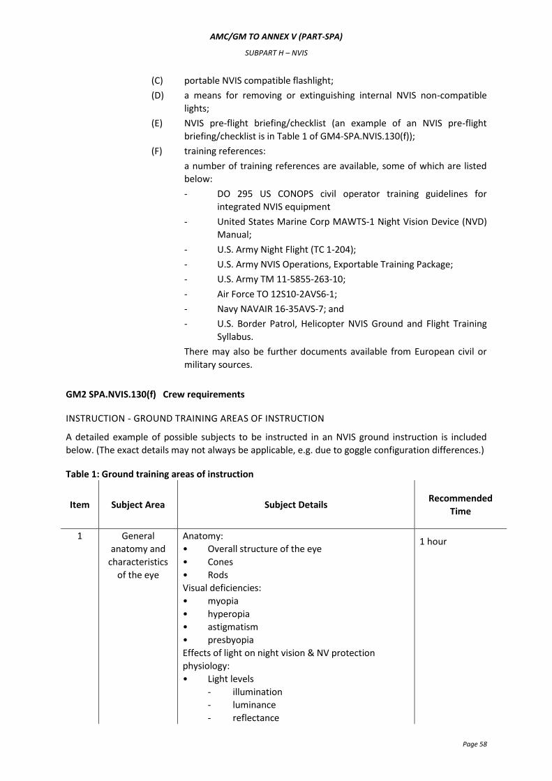
AMC/GM TO ANNEX V (PART-SPA)
SUBPART H – NVIS
Page 58
(C) portable NVIS compatible flashlight;
(D) a means for removing or extinguishing internal NVIS non-compatible
lights;
(E) NVIS pre-flight briefing/checklist (an example of an NVIS pre-flight
briefing/checklist is in Table 1 of GM4-SPA.NVIS.130(f));
(F) training references:
a number of training references are available, some of which are listed
below:
- DO 295 US CONOPS civil operator training guidelines for
integrated NVIS equipment
- United States Marine Corp MAWTS-1 Night Vision Device (NVD)
Manual;
- U.S. Army Night Flight (TC 1-204);
- U.S. Army NVIS Operations, Exportable Training Package;
- U.S. Army TM 11-5855-263-10;
- Air Force TO 12S10-2AVS6-1;
- Navy NAVAIR 16-35AVS-7; and
- U.S. Border Patrol, Helicopter NVIS Ground and Flight Training
Syllabus.
There may also be further documents available from European civil or
military sources.
GM2 SPA.NVIS.130(f) Crew requirements
INSTRUCTION - GROUND TRAINING AREAS OF INSTRUCTION
A detailed example of possible subjects to be instructed in an NVIS ground instruction is included
below. (The exact details may not always be applicable, e.g. due to goggle configuration differences.)
Table 1: Ground training areas of instruction
Item Subject Area Subject Details Recommended
Time
1 General
anatomy and
characteristics
of the eye
Anatomy:
• Overall structure of the eye
• Cones
• Rods
Visual deficiencies:
• myopia
• hyperopia
• astigmatism
• presbyopia
Effects of light on night vision & NV protection
physiology:
• Light levels
- illumination
- luminance
- reflectance
1 hour
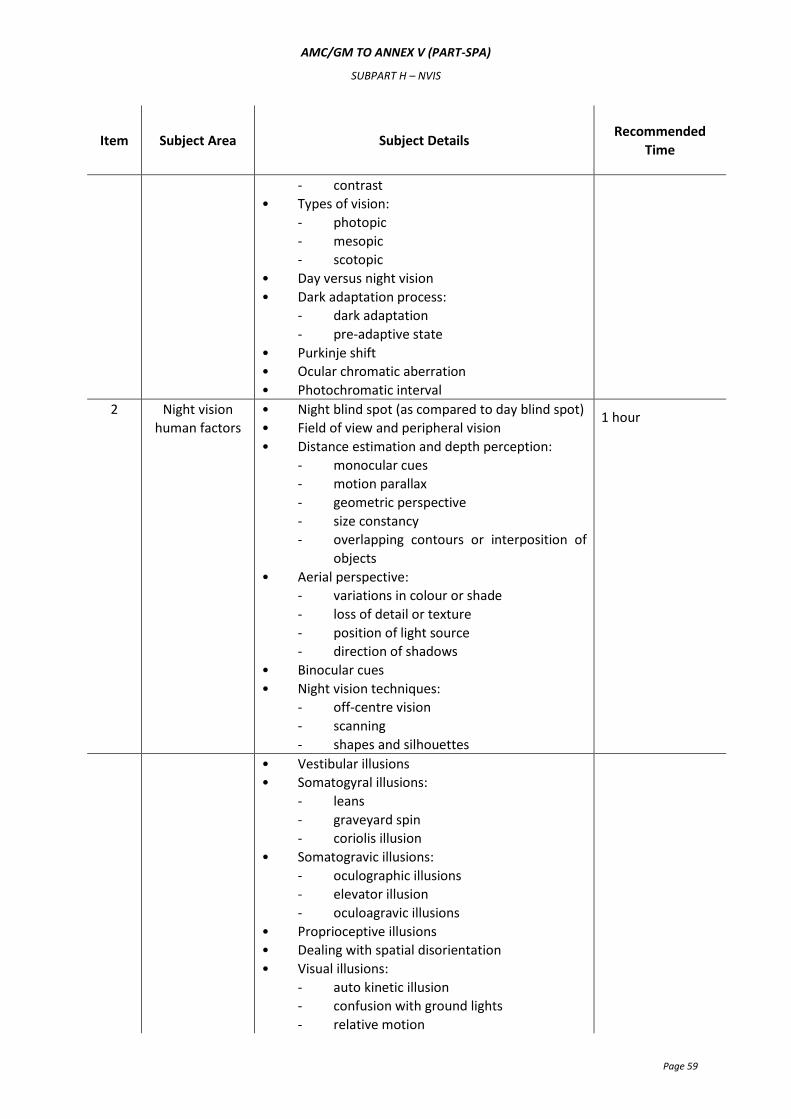
AMC/GM TO ANNEX V (PART-SPA)
SUBPART H – NVIS
Page 59
Item Subject Area Subject Details Recommended
Time
- contrast
• Types of vision:
- photopic
- mesopic
- scotopic
• Day versus night vision
• Dark adaptation process:
- dark adaptation
- pre-adaptive state
• Purkinje shift
• Ocular chromatic aberration
• Photochromatic interval
2 Night vision
human factors
• Night blind spot (as compared to day blind spot)
• Field of view and peripheral vision
• Distance estimation and depth perception:
- monocular cues
- motion parallax
- geometric perspective
- size constancy
- overlapping contours or interposition of
objects
• Aerial perspective:
- variations in colour or shade
- loss of detail or texture
- position of light source
- direction of shadows
• Binocular cues
• Night vision techniques:
- off-centre vision
- scanning
- shapes and silhouettes
1 hour
• Vestibular illusions
• Somatogyral illusions:
- leans
- graveyard spin
- coriolis illusion
• Somatogravic illusions:
- oculographic illusions
- elevator illusion
- oculoagravic illusions
• Proprioceptive illusions
• Dealing with spatial disorientation
• Visual illusions:
- auto kinetic illusion
- confusion with ground lights
- relative motion
AMC/GM TO ANNEX V (PART-SPA)
SUBPART H – NVIS
Page 60
Item Subject Area Subject Details Recommended
Time
- reversible perspective illusion
- false vertical and horizontal cues
- altered planes of reference
- height /depth perception illusion
- flicker vertigo
- fascination (fixation)
- structural illusions
- size-distance illusion
• Helicopter design limitations:
- windscreen condition
- helicopter instrument design
- helicopter structural obstruction
- interior lights
- exterior lights
• Self-imposed stresses:
- drugs
- exhaustion
- alcohol
- tobacco
- hypoglycaemia
- injuries
- physical fitness
• Stress & fatigue:
- acute vs. chronic
- prevention
• Hypoxia issues and night vision
• Weather/environmental conditions:
- snow (white-out)
- dust (brown-out)
- haze
- fog
- rain
- light level
• Astronomical lights (moon, star, northern lights)
• Effects of cloud cover
3 NVIS general
characteristics
• Definitions and types of NVIS:
- light spectrum
- types of NVIS
• Thermal-imaging devices
• Image-intensifier devices
• Image-intensifier operational theory
• Types of image intensifier systems:
- generation 1
- generation 2
- generation 3
- generation 4
1 hour
AMC/GM TO ANNEX V (PART-SPA)
SUBPART H – NVIS
Page 61
Item Subject Area Subject Details Recommended
Time
- type I / II
- class A & B minus blue filter
• NVIS equipment
- shipping and storage case
- carrying case
- binocular assembly
- lens caps
- lens paper
- operators manual
- power pack (dual battery)
- batteries
• Characteristics of NVIS:
- light amplification
- light intensification
- frequency sensitivity
- visual range acuity
- unaided peripheral vision
- weight
- flip-up device
- break-away feature
- neck cord
- maintenance issues
- human factor issues
• Description and functions of NVIS components:
- helmet visor cover and extension strap
- helmet NVIS mount and attachment
points
- different mount options for various
helmets
- lock release button
- vertical adjustment knob
- low battery indicator
- binocular assembly
- monocular tubes
- fore and aft adjustment knob
- eye span knob
- tilt adjustment lever
- objective focus rings
- eyepiece focus rings
- battery pack
4 NVIS care &
cleaning
• Handling procedures
• NVIS operating instructions:
- pre-mounting inspection
- mounting procedures
- focusing procedures
- faults
1 hour
AMC/GM TO ANNEX V (PART-SPA)
SUBPART H – NVIS
Page 62
Item Subject Area Subject Details Recommended
Time
• Post-flight procedures;
• Deficiencies: type and recognition of faults:
- acceptable faults
black spots
chicken wire
fixed pattern noise (honeycomb
effect)
output brightness variation
bright spots
image disparity
image distortion
emission points
- unacceptable faults:
shading
edge glow
fashing, flickering or intermittent
operation
• Cleaning procedures
• Care of batteries
• Hazardous material considerations;
5 Pre- & post-
flight
procedures
• Inspect NVIS
• Carrying case condition
• Nitrogen purge due date
• Collimation test due date
• Screens diagram(s) of any faults
• NVIS kit: complete
• NVIS binocular assembly condition
• Battery pack and quick disconnect condition
• Batteries life expended so far
• Mount battery pack onto helmet:
- verify no LED showing (good battery)
- fail battery by opening cap and LED
illuminates (both compartments)
• Mount NVIS onto helmet
• Adjust and focus NVIS
• Eye-span to known inter-pupillary distance
• Eye piece focus ring to zero
• Adjustments:
- vertical
- fore and aft
- tilt
- eye-span (fine-tuning)
• Focus (one eye at a time at 20 ft, then at 30 ft
from an eye chart)
- objective focus ring
- eye piece focus ring
1 hour
AMC/GM TO ANNEX V (PART-SPA)
SUBPART H – NVIS
Page 63
Item Subject Area Subject Details Recommended
Time
- verify both images are harmonised
- read eye-chart 20/40 line from 20 ft
• NVIS mission planning
• NVIS light level planning
• NVIS risk assessment
6 NVIS terrain
interpretation
and
environmental
factors
• Night terrain interpretation
• Light sources:
- natural
- lunar
- solar
- starlight
- northern lights
- artificial
- cultural
- infra-red
• Meteorological conditions:
- clouds/fog
- indications of restriction to visibility:
- loss of celestial lights
- loss of ground lights
- reduced ambient light levels
- reduced visual acuity
- increase in video noise
- increase in halo effect
• Cues for visual recognition:
- object size
- object shape
- contrast
- ambient light
- colour
- texture
- background
- reflectivity
• Factors affecting terrain interpretation:
- ambient light
- flight altitudes
- terrain type
• Seasons
• Night navigation cues:
- terrain relief
- vegetation
- hydrographical features
- cultural features
1 hour
7 NVIS training &
equipment
requirements
Cover the relevant regulations and guidelines that
pertain to night and NVIS flight to include as a
minimum:
1 hour
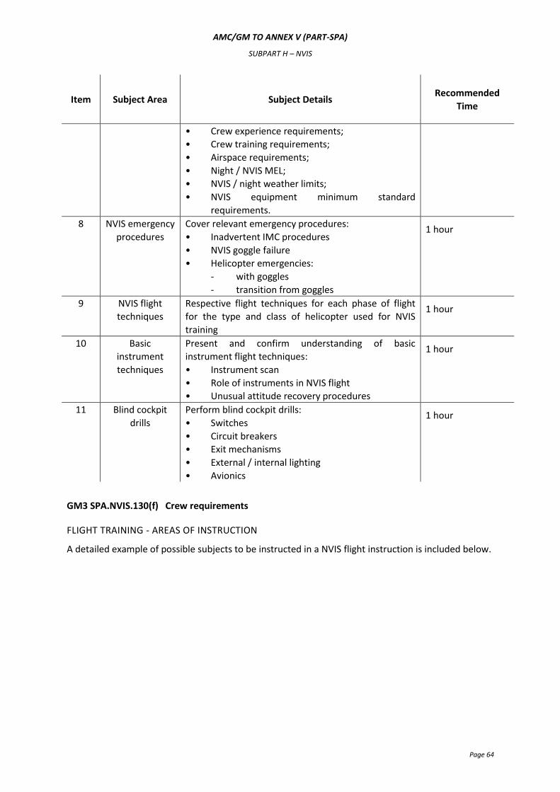
AMC/GM TO ANNEX V (PART-SPA)
SUBPART H – NVIS
Page 64
Item Subject Area Subject Details Recommended
Time
• Crew experience requirements;
• Crew training requirements;
• Airspace requirements;
• Night / NVIS MEL;
• NVIS / night weather limits;
• NVIS equipment minimum standard
requirements.
8 NVIS emergency
procedures
Cover relevant emergency procedures:
• Inadvertent IMC procedures
• NVIS goggle failure
• Helicopter emergencies:
- with goggles
- transition from goggles
1 hour
9 NVIS flight
techniques
Respective flight techniques for each phase of flight
for the type and class of helicopter used for NVIS
training
1 hour
10 Basic
instrument
techniques
Present and confirm understanding of basic
instrument flight techniques:
• Instrument scan
• Role of instruments in NVIS flight
• Unusual attitude recovery procedures
1 hour
11 Blind cockpit
drills
Perform blind cockpit drills:
• Switches
• Circuit breakers
• Exit mechanisms
• External / internal lighting
• Avionics
1 hour
GM3 SPA.NVIS.130(f) Crew requirements
FLIGHT TRAINING - AREAS OF INSTRUCTION
A detailed example of possible subjects to be instructed in a NVIS flight instruction is included below.
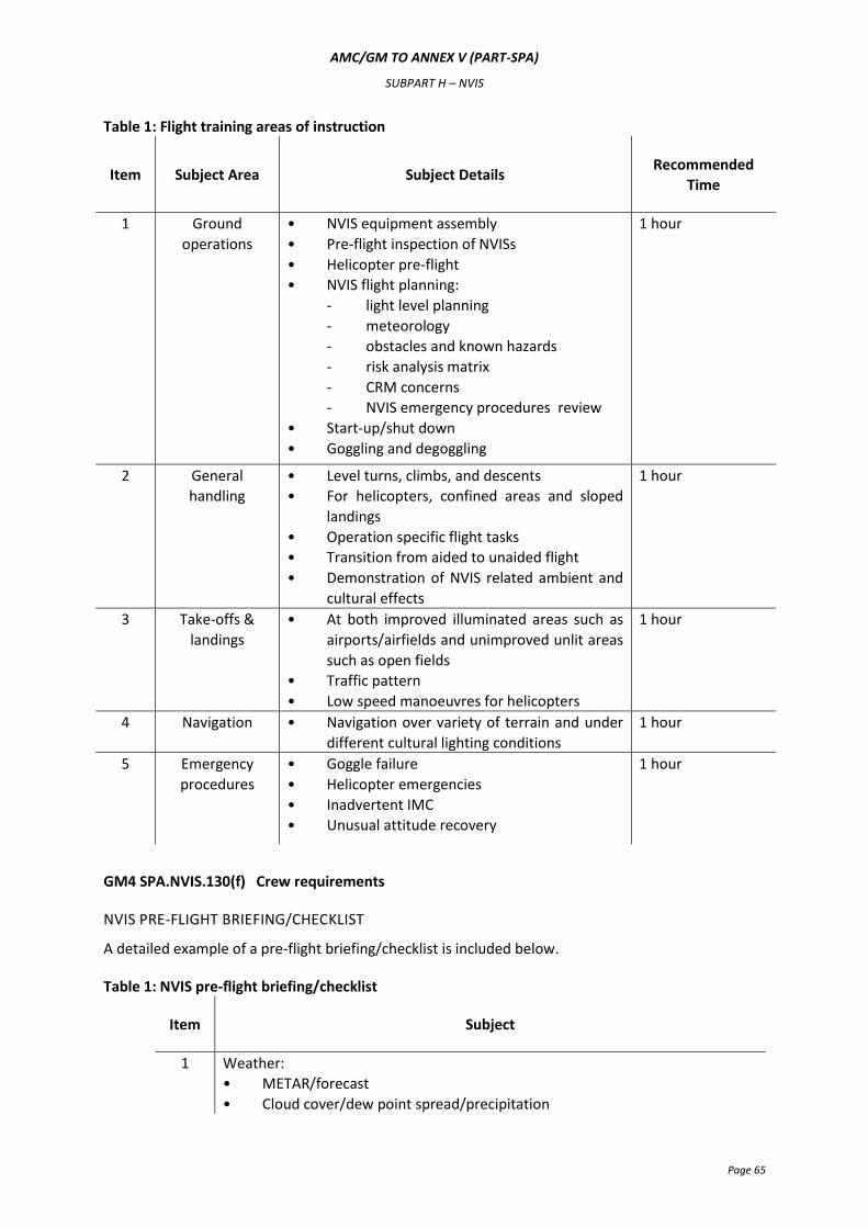
AMC/GM TO ANNEX V (PART-SPA)
SUBPART H – NVIS
Page 65
Table 1: Flight training areas of instruction
Item Subject Area Subject Details Recommended
Time
1 Ground
operations
• NVIS equipment assembly
• Pre-flight inspection of NVISs
• Helicopter pre-flight
• NVIS flight planning:
- light level planning
- meteorology
- obstacles and known hazards
- risk analysis matrix
- CRM concerns
- NVIS emergency procedures review
• Start-up/shut down
• Goggling and degoggling
1 hour
2 General
handling
• Level turns, climbs, and descents
• For helicopters, confined areas and sloped
landings
• Operation specific flight tasks
• Transition from aided to unaided flight
• Demonstration of NVIS related ambient and
cultural effects
1 hour
3 Take-offs &
landings
• At both improved illuminated areas such as
airports/airfields and unimproved unlit areas
such as open fields
• Traffic pattern
• Low speed manoeuvres for helicopters
1 hour
4 Navigation • Navigation over variety of terrain and under
different cultural lighting conditions
1 hour
5 Emergency
procedures
• Goggle failure
• Helicopter emergencies
• Inadvertent IMC
• Unusual attitude recovery
1 hour
GM4 SPA.NVIS.130(f) Crew requirements
NVIS PRE-FLIGHT BRIEFING/CHECKLIST
A detailed example of a pre-flight briefing/checklist is included below.
Table 1: NVIS pre-flight briefing/checklist
Item Subject
1 Weather:
• METAR/forecast
• Cloud cover/dew point spread/precipitation
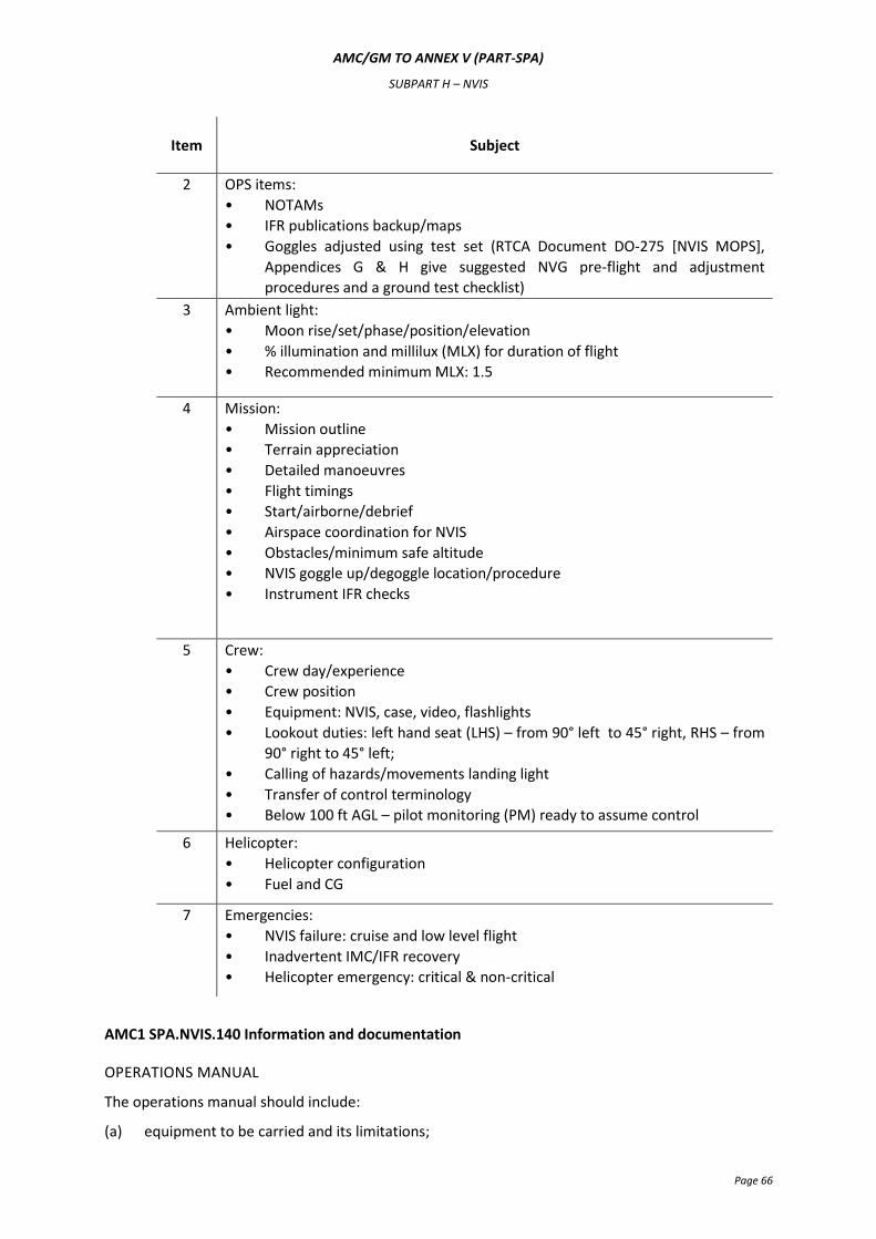
AMC/GM TO ANNEX V (PART-SPA)
SUBPART H – NVIS
Page 66
Item Subject
2 OPS items:
• NOTAMs
• IFR publications backup/maps
• Goggles adjusted using test set (RTCA Document DO-275 [NVIS MOPS],
Appendices G & H give suggested NVG pre-flight and adjustment
procedures and a ground test checklist)
3 Ambient light:
• Moon rise/set/phase/position/elevation
• % illumination and millilux (MLX) for duration of flight
• Recommended minimum MLX: 1.5
4 Mission:
• Mission outline
• Terrain appreciation
• Detailed manoeuvres
• Flight timings
• Start/airborne/debrief
• Airspace coordination for NVIS
• Obstacles/minimum safe altitude
• NVIS goggle up/degoggle location/procedure
• Instrument IFR checks
5 Crew:
• Crew day/experience
• Crew position
• Equipment: NVIS, case, video, flashlights
• Lookout duties: left hand seat (LHS) – from 90° left to 45° right, RHS – from
90° right to 45° left;
• Calling of hazards/movements landing light
• Transfer of control terminology
• Below 100 ft AGL – pilot monitoring (PM) ready to assume control
6 Helicopter:
• Helicopter configuration
• Fuel and CG
7 Emergencies:
• NVIS failure: cruise and low level flight
• Inadvertent IMC/IFR recovery
• Helicopter emergency: critical & non-critical
AMC1 SPA.NVIS.140 Information and documentation
OPERATIONS MANUAL
The operations manual should include:
(a) equipment to be carried and its limitations;
AMC/GM TO ANNEX V (PART-SPA)
SUBPART H – NVIS
Page 67
(b) the minimum equipment list (MEL) entry covering the equipment specified;
(c) risk analysis, mitigation and management;
(d) pre- and post-flight procedures and documentation;
(e) selection and composition of crew;
(f) crew coordination procedures, including:
(1) flight briefing;
(2) procedures when one crew member is wearing NVG and/or procedures when two or
more crew members are wearing NVGs;
(3) procedures for the transition to and from NVIS flight;
(4) use of the radio altimeter on an NVIS flight; and
(5) inadvertent instrument meteorological conditions (IMC) and helicopter recovery
procedures, including unusual attitude recovery procedures;
(g) the NVIS training syllabus;
(h) in-flight procedures for assessing visibility, to ensure that operations are not conducted below
the minima stipulated for non-assisted night VFR operations;
(i) weather minima, taking the underlying activity into account; and
(j) the minimum transition heights to/from an NVIS flight.
GM1 SPA.NVIS.140 Information and documentation
CONCEPT OF OPERATIONS
Night Vision Imaging System for Civil Operators
Foreword
This document, initially incorporated in JAA TGL-34, prepared by a Sub-Group of EUROCAE Working
Group 57 “Night Vision Imaging System (NVIS) Standardisation” is an abbreviated and modified
version of the RTCA Report DO-268 “Concept Of Operations – Night Vision Imaging Systems For Civil
Operators” which was prepared in the USA by RTCA Special Committee 196 (SC-196) and approved
by the RTCA Technical Management Committee in March 2001.
The EUROCAE Working Group 57 (WG-57) Terms of Reference included a task to prepare a Concept
of Operations (CONOPS) document describing the use of NVIS in Europe. To complete this task, a
Sub-Group of WG-57 reviewed the RTCA SC-196 CONOPS (DO-268) to assess its applicability for use
in Europe. Whilst the RTCA document was considered generally applicable, some of its content, such
as crew eligibility and qualifications and the detail of the training requirements, was considered to be
material more appropriately addressed in Europe by at that time other Joint Aviation Requirements
(JAR) documents such as JAR-OPS and JAR-FCL. Consequently, WG-57 condensed the RTCA CONOPS
document by removing this material which is either already addressed by other JAR documents or
will be covered by the Agency’s documents in the future.
In addition, many of the technical standards already covered in the Minimum Operational
Performance Standards (MOPS) for Integrated Night Vision Imaging System Equipment (DO-275)
have been deleted in this European CONOPS.
AMC/GM TO ANNEX V (PART-SPA)
SUBPART H – NVIS
Page 68
Executive summary
The hours of darkness add to a pilot’s workload by decreasing those visual cues commonly used
during daylight operations. The decreased ability of a pilot to see and avoid obstructions at night has
been a subject of discussion since aviators first attempted to operate at night. Technology
advancements in the late 1960s and early 1970s provided military aviators some limited ability to see
at night and therein changed the scope of military night operations. Continuing technological
improvements have advanced the capability and reliability of night vision imaging systems to the
point that they are receiving increasing scrutiny are generally accepted by the public and are viewed
by many as a tool for night flight.
Simply stated, night vision imaging systems are an aid to night VFR flight. Currently, such systems
consist of a set of night vision goggles and normally a complimentary array of cockpit lighting
modifications. The specifications of these two sub-system elements are interdependent and, as
technology advances, the characteristics associated with each element are expected to evolve. The
complete description and performance standards of the night vision goggles and cockpit lighting
modifications appropriate to civil aviation are contained in the Minimum Operational Performance
Standards for Integrated Night Vision Imaging System Equipment.
An increasing interest on the part of civil operators to conduct night operations has brought a
corresponding increased level of interest in employing night vision imaging systems. However, the
night vision imaging systems do have performance limitations. Therefore, it is incumbent on the
operator to employ proper training methods and operating procedures to minimise these limitations
to ensure safe operations. In turn, operators employing night vision imaging systems must have the
guidance and support of their regulatory agency in order to safely train and operate with these
systems.
The role of the regulatory agencies in this matter is to develop the technical standard orders for the
hardware as well as the advisory material and inspector handbook materials for the operations and
training aspect. In addition, those agencies charged with providing flight weather information should
modify their products to include the night vision imaging systems flight data elements not currently
provided.
An FAA study (DOT/FAA/RD-94/21, 1994) best summarised the need for night vision imaging systems
by stating, “When properly used, NVGs can increase safety, enhance situational awareness, and
reduce pilot workload and stress that are typically associated with night operations.”
AMC/GM TO ANNEX V (PART-SPA)
SUBPART H – NVIS
Page 69
Table of contents
Foreword .................................................................................................................................... 67
Executive summary ..................................................................................................................... 68
2 Terminology ............................................................................................................................. 72
2.1 Night vision goggles .......................................................................................................... 72
2.1.1 Type ....................................................................................................................... 72
2.1.2 Class ....................................................................................................................... 72
2.1.2.1 Class A .......................................................................................................... 72
2.1.2.2 Class B .......................................................................................................... 72
2.1.2.3 Modified class B ............................................................................................ 72
2.1.3 Generation ............................................................................................................. 72
2.1.4 OMNIBUS ............................................................................................................... 73
2.1.5 Resolution and visual acuity .................................................................................... 73
2.2 Aviation night vision imaging system (NVIS) ....................................................................... 73
2.2.1 Look under (under view) ......................................................................................... 73
2.3 NVIS lighting ..................................................................................................................... 73
2.3.1 Design considerations ............................................................................................. 73
2.3.2 Compatible ............................................................................................................. 73
2.4. NVIS operation................................................................................................................. 74
2.4.1 Aided ...................................................................................................................... 74
2.4.2 Unaided .................................................................................................................. 74
3 System description ................................................................................................................... 74
3.1 NVIS capabilities ............................................................................................................... 74
3.1.1 Critical elements ..................................................................................................... 74
3.1.2 Situation awareness ................................................................................................ 75
3.1.2.1 Environment detection and identification ...................................................... 75
3.1.3 Emergency situations .............................................................................................. 75
3.2.1 NVG design characteristics ...................................................................................... 75
3.2.1.1 Visual acuity ................................................................................................. 75
3.2.1.2 Field of view ................................................................................................. 75
3.2.1.3 Field of regard ............................................................................................... 75
3.2.1.4 NVG weight & centre of gravity ..................................................................... 76
3.2.1.5 Monochromatic image .................................................................................. 76
AMC/GM TO ANNEX V (PART-SPA)
SUBPART H – NVIS
Page 70
3.2.1.6 Ambient or artificial light ............................................................................... 76
3.2.2 Physiological and other conditions .......................................................................... 76
3.2.2.1 Cockpit resource management ...................................................................... 76
3.2.2.2 Fatigue .......................................................................................................... 76
3.2.2.3 Over-confidence ............................................................................................ 76
3.2.2.4 Spatial orientation ........................................................................................ 77
3.2.2.5 Depth perception & distance estimation ........................................................ 77
3.2.2.6 Instrument lighting brightness considerations ................................................ 78
3.2.2.7 Dark adaptation time from NVG to unaided operations.................................. 78
3.2.2.8 Complacency ................................................................................................. 78
3.2.2.9 Experience .................................................................................................... 78
4 Operations ............................................................................................................................... 79
4.1 Pilot eligibility ................................................................................................................... 79
4.2 Operating environment considerations .............................................................................. 79
4.2.1 Weather and atmospheric obscurants ..................................................................... 79
4.2.1.1 Weather ....................................................................................................... 79
4.2.1.2 Deteriorating weather ................................................................................... 80
4.2.1.3 Airborne obscurants ...................................................................................... 80
4.2.1.4 Winter operations ......................................................................................... 80
4.2.1.4.1 Snow ............................................................................................................80
4.2.1.4.2 Ice fog ..........................................................................................................80
4.2.1.4.3 Icing .............................................................................................................81
4.2.1.4.4 Low ambient temperatures ........................................................................81
4.2.2 Illumination ............................................................................................................ 81
4.2.2.1 Natural illumination ...................................................................................... 81
4.2.2.1.1 Moon phase ................................................................................................81
4.2.2.1.2 Lunar azimuth and elevation ......................................................................81
4.2.2.1.3 Shadowing ...................................................................................................81
4.2.2.1.3.1 BENEFITS OF SHADOWS .................................................................82
4.2.2.1.3.2 DISADVANTAGES DUE TO SHADOWS ............................................82
4.2.2.1.4 Sky glow ......................................................................................................82
4.2.2.2 Artificial illumination ..................................................................................... 82
4.2.3 Terrain contrast ...................................................................................................... 83
AMC/GM TO ANNEX V (PART-SPA)
SUBPART H – NVIS
Page 71
4.3 Aircraft considerations ...................................................................................................... 83
4.3.1 Lighting ................................................................................................................... 83
4.3.2 Cockpit ergonomics ................................................................................................. 83
4.3.3 Windshield reflectivity ............................................................................................ 83
4.4 Generic operating considerations ...................................................................................... 83
4.4.1 Normal procedures ................................................................................................. 83
4.4.1.1 Scanning ....................................................................................................... 83
4.4.1.1.1 Instrument crosscheck scan ........................................................................84
4.4.1.1.2 NVG scan .....................................................................................................84
4.4.1.1.3 Unaided scan ...............................................................................................84
4.4.1.1.4 Scan patterns ..............................................................................................84
4.4.1.2 Pre-flight planning ......................................................................................... 85
4.4.1.2.1 Illumination criteria .....................................................................................85
4.4.1.2.2 NVIS operations ..........................................................................................85
4.4.1.2.3 Aircraft pre-flight ........................................................................................85
4.4.1.2.4 Equipment ...................................................................................................85
4.4.1.2.5 Risk assessment ..........................................................................................85
4.4.1.3 Flight operations ........................................................................................... 86
4.4.1.3.1 Elevated terrain ...........................................................................................86
4.4.1.3.2 Over-water ..................................................................................................86
4.4.1.4 Remote area considerations .......................................................................... 86
4.4.1.5 Reconnaissance ............................................................................................. 86
4.4.1.6 Sources of high illumination .......................................................................... 86
4.4.2 Emergency procedures ............................................................................................ 86
4.4.3 Inadvertent IMC ...................................................................................................... 86
5 Training .................................................................................................................................... 87
6. Continuing airworthiness ......................................................................................................... 87
Acronyms used in this GM ........................................................................................................... 87
Glossary of terms used in this GM ................................................................................................ 88
References .................................................................................................................................. 90
AMC/GM TO ANNEX V (PART-SPA)
SUBPART H – NVIS
Page 72
2 Terminology
2.1 Night vision goggles
An NVG is a binocular appliance that amplifies ambient light and is worn by a pilot. The NVG
enhances the wearer’s ability to maintain visual surface reference at night.
2.1.1 Type
Type refers to the design of the NVG with regards to the manner in which the image is relayed to the
pilot. A Type 1 NVG is one in which the image is viewed directly in-line with the image intensification
process. A Type 1 NVG is also referred to as “direct view” goggle. A Type 2 NVG is one in which the
image intensifier is not in-line with the image viewed by the pilot. In this design, the image may be
reflected several times before being projected onto a combiner in front of the pilot’s eyes. A Type 2
NVG is also referred to as an “indirect view” goggle.
2.1.2 Class
Class is a terminology used to describe the filter present on the NVG objective lens. The filter restricts
the transmission of light below a determined frequency. This allows the cockpit lighting to be
designed and installed in a manner that does not adversely affect NVG performance.
2.1.2.1 Class A
Class A or “minus blue” NVGs incorporate a filter, which generally imposes a 625 nanometercutoff.
Thus, the use of colours in the cockpit (e.g., colour displays, colour warning lights, etc.) may be
limited. The blue green region of the light spectrum is allowed through the filter.
2.1.2.2 Class B
Class B NVGs incorporate a filter that generally imposes a 665 nanometercutoff. Thus, the cockpit
lighting design may incorporate more colours since the filter eliminates some yellows and oranges
from entering the intensification process.
2.1.2.3 Modified class B
Modified Class B NVGs incorporate a variation of a Class B filter but also incorporates a notch filter in
the green spectrum that allows a small percentage of light into the image intensification process.
Therefore, a Modified Class B NVG allows pilots to view fixed head-up display (HUD) symbology
through the NVG without the HUD energy adversely affecting NVG performance.
2.1.3 Generation
Generation refers to the technological design of an image intensifier. Systems incorporating these
light-amplifying image intensifiers were first used during WWII and were operationally fielded by the
US military during the Vietnam era. These systems were large, heavy and poorly performing devices
that were unsuitable for aviation use, and were termed Generation I (Gen I). Gen II devices
represented a significant technological advancement and provided a system that could be head-
mounted for use in ground vehicles. Gen III devices represented another significant technological
advancement in image intensification, and provided a system that was designed for aviation use.
Although not yet fielded, there are prototype NVGs that include technological advances that may
AMC/GM TO ANNEX V (PART-SPA)
SUBPART H – NVIS
Page 73
necessitate a Gen IV designation if placed into production. Because of the variations in
interpretations as to generation, NVGs will not be referred to by the generation designation.
2.1.4 OMNIBUS
The term OMNIBUS refers to a US Army contract vehicle that has been used over the years to
procure NVGs. Each successive OMNIBUS contract included NVGs that demonstrated improved
performance. There have been five contracts since the mid 1980s, the most current being OMNIBUS
V. There may be several variations of NVGs within a single OMNIBUS purchase, and some NVGs from
previous OMNIBUS contracts have been upgraded in performance to match the performance of
goggles from later contracts. Because of these variations, NVGs will not be referred to by the
OMNIBUS designation.
2.1.5 Resolution and visual acuity
Resolution refers to the capability of the NVG to present an image that makes clear and
distinguishable the separate components of a scene or object.
Visual acuity is the relative ability of the human eye to resolve detail and interpret an image.
2.2 Aviation night vision imaging system (NVIS)
The Night Vision Imaging System is the integration of all elements required to successfully and safely
operate an aircraft with night vision goggles. The system includes at a minimum NVGs, NVIS lighting,
other aircraft components, training, and continuing airworthiness.
2.2.1 Look under (under view)
Look under is the ability of pilots to look under or around the NVG to view inside and outside the
aircraft.
2.3 NVIS lighting
An aircraft lighting system that has been modified or designed for use with NVGs and which does not
degrade the performance of the NVG beyond acceptable standards, is designated as NVIS lighting.
This can apply to both interior and exterior lighting.
2.3.1 Design considerations
As the choice of NVG filter drives the cockpit lighting design, it is important to know which goggle will
be used in which cockpit. Since the filter in a Class A NVG allows wavelengths above 625 nanometers
into the intensification process, it should not be used in a cockpit designed for Class B or Modified
Class B NVGs. However, since the filter in a Class B and Modified Class B NVGs is more restrictive than
that in a Class ANVG, the Class B or Modified Class B NVG can be used with either Class A or Class B
cockpit lighting designs.
2.3.2 Compatible
Compatibility, with respect to an NVIS system, includes a number of different factors: compatibility
of internal and external lighting with the NVG, compatibility of the NVG with the crew station design
(e.g., proximity of the canopy or windows, proximity of overhead panels, operability of controls,
etc.), compatibility of crew equipment with the NVG and compatibility with respect to colour
discrimination and identification (e.g., caution and warning lights still maintain amber and red
AMC/GM TO ANNEX V (PART-SPA)
SUBPART H – NVIS
Page 74
colours). The purpose of this paragraph is to discuss compatibility with respect to aircraft lighting. An
NVIS lighting system, internal and external, is considered compatible if it adheres to the following
requirements:
1. the internal and external lighting does not adversely affect the operation of the NVG during
any phase of the NVIS operation;
2. the internal lighting provides adequate illumination of aircraft cockpit instruments, displays
and controls for unaided operations and for “look-under” viewing during aided operations; and
3. The external lighting aids in the detection and separation by other aircraft.
NVIS lighting compatibility can be achieved in a variety of ways that can include, but is not limited to,
modification of light sources, light filters or by virtue of location. Once aircraft lighting is modified for
using NVGs, it is important to keep in mind that changes in the crew station (e.g., addition of new
display) must be assessed relative to the effect on NVIS compatibility.
2.4. NVIS operation
A night flight wherein the pilot maintains visual surface reference using NVGs in an aircraft that is
NVIS approved
2.4.1 Aided
Aided flight is flight with NVGs in an operational position.
2.4.2 Unaided
Unaided flight is a flight without NVGs or a flight with NVGs in a non-operational position.
3 System description
3.1 NVIS capabilities
NVIS generally provides the pilot an image of the outside scene that is enhanced compared to that
provided by the unaided, dark-adapted eye. However, NVIS may not provide the user an image equal
to that observed during daylight. Since the user has an enhanced visual capability, situational
awareness is generally improved.
3.1.1 Critical elements
The following critical elements are the underlying assumptions in the system description for NVIS:
1. aircraft internal lighting has been modified or initially designed to be compatible;
2. environmental conditions are adequate for the use of NVIS (e.g. enough illumination is present,
weather conditions are favourable, etc.);
3. the NVIS has been properly maintained in accordance with the minimum operational
performance standards;
4. a proper pre-flight has been performed on the NVIS confirming operation in accordance with
the continued airworthiness standards and training guidelines; and
5. the pilot(s) has been properly trained and meets recency of experience requirements.
AMC/GM TO ANNEX V (PART-SPA)
SUBPART H – NVIS
Page 75
Even when insuring that these conditions are met, there still are many variables that can adversely
affect the safe and effective use of NVIS (e.g., flying towards a low angle moon, flying in a shadowed
area, flying near extensive cultural lighting, flying over low contrast terrain, etc.). It is important to
understand these assumptions and limitations when discussing the capabilities provided by the use
of NVIS.
3.1.2 Situation awareness
Situation awareness, being defined as the degree of perceptual accuracy achieved in the
comprehension of all factors affecting an aircraft and crew at a given time, is improved at night when
using NVG during NVIS operations. This is achieved by providing the pilot with more visual cues than
is normally available under most conditions when operating an aircraft unaided at night. However, it
is but one source of the factors necessary for maintaining an acceptable level of situational
awareness.
3.1.2.1 Environment detection and identification
An advantage of using NVIS is the enhanced ability to detect, identify, and avoid terrain and/or
obstacles that present a hazard to night operations. Correspondingly, NVIS aid in night navigation by
allowing the aircrew to view waypoints and features.
Being able to visually locate and then (in some cases) identify objects or areas critical to operational
success will also enhance operational effectiveness. Finally, use of NVIS may allow pilots to detect
other aircraft more easily.
3.1.3 Emergency situations
NVIS generally improve situational awareness, facilitating the pilot’s workload during emergencies.
Should an emergency arise that requires an immediate landing, NVIS may provide the pilot with a
means of locating a suitable landing area and conducting a landing. The pilot must determine if the
use of NVIS during emergencies is appropriate. In certain instances, it may be more advantageous for
the pilot to remove the NVG during the performance of an emergency procedure.
3.2.1 NVG design characteristics
There are limitations inherent in the current NVG design.
3.2.1.1 Visual acuity
The pilot’s visual acuity with NVGs is less than normal daytime visual acuity.
3.2.1.2 Field of view
Unaided field of view (FOV) covers an elliptical area that is approximately 120° lateral by 80° vertical,
whereas the field of view of current Type I NVG systems is nominally 40° and is circular. Both the
reduced field of view of the image and the resultant decrease in peripheral vision can increase the
pilot’s susceptibility to misperceptions and illusions. Proper scanning techniques must be employed
to reduce the susceptibility to misperception and illusions.
3.2.1.3 Field of regard
The NVG has a limited FOV but, because it is head-mounted, that FOV can be scanned when viewing
the outside scene. The total area that the FOV can be scanned is called the field of regard (FOR). The
AMC/GM TO ANNEX V (PART-SPA)
SUBPART H – NVIS
Page 76
FOR will vary depending on several factors: physiological limit of head movement, NVG design (e.g.,
protrusion of the binocular assembly, etc.) and cockpit design issues (e.g., proximity of canopy or
window, seat location, canopy bow, etc.).
3.2.1.4 NVG weight & centre of gravity
The increased weight and forward CG projection of head supported devices may have detrimental
effects on pilot performance due to neck muscle strain and fatigue. There also maybe an increased
risk of neck injury in crashes.
3.2.1.5 Monochromatic image
The NVG image currently appears in shades of green. Since there is only one colour, the image is said
to be “monochromatic”. This colour was chosen mostly because the human eye can see more detail
at lower brightness levels when viewing shades of green. Colour differences between components in
a scene helps one discriminate between objects and aids in object recognition, depth perception and
distance estimation. The lack of colour variation in the NVG image will degrade these capabilities to
varying degrees.
3.2.1.6 Ambient or artificial light
The NVG requires some degree of light (energy) in order to function. Low light levels, non-compatible
aircraft lighting and poor windshield/window light transmissibility, diminish the performance
capability of the NVG. It is the pilot’s responsibility to determine when to transition from aided to
unaided due to unacceptable NVG performance.
3.2.2 Physiological and other conditions
3.2.2.1 Cockpit resource management
Due to the inherent limitations of NVIS operations, there is a requirement to place emphasis on NVIS
related cockpit resource management (CRM). This applies to both single and multi-pilot cockpit
environments. Consequently, NVIS flight requires effective CRM between the pilot(s), controlling
agencies and other supporting personnel. An appropriate venue for addressing this issue is the pre-
flight NVIS mission brief.
3.2.2.2 Fatigue
Physiological limitations that are prevalent during the hours of darkness along with the limitations
associated with NVGs, may have a significant impact on NVIS operations. Some of these limitations
are the effects of fatigue (both acute and chronic), stress, eyestrain, working outside the pilot’s
normal circadian rhythm envelope, increased helmet weight, aggressive scanning techniques
associated with NVIS, and various human factors engineering concerns that may have a direct
influence on how the pilot works in the aircraft while wearing NVGs. These limitations may be
mitigated through proper training and recognition, experience, adaptation, rest, risk management,
and proper crew rest/duty cycles.
3.2.2.3 Over-confidence
Compared to other types of flight operations, there may be an increased tendency by the pilot to
over-estimate the capabilities of the NVIS.
AMC/GM TO ANNEX V (PART-SPA)
SUBPART H – NVIS
Page 77
3.2.2.4 Spatial orientation
There are two types of vision used in maintaining spatial orientation: central (focal) vision and
peripheral (ambient) vision. Focal vision requires conscious processing and is slow, whereas
peripheral information is processed subconsciously at a very fast rate. During daytime, spatial
orientation is maintained by inputs from both focal vision and peripheral vision, with peripheral
vision providing the great majority of the information. When using NVGs, peripheral vision can be
significantly degraded if not completely absent. In this case, the pilot must rely on focal vision to
interpret the NVG image as well as the information from flight instruments in order to maintain
spatial orientation and situation awareness. Even though maintaining spatial orientation requires
more effort when using NVGs than during daytime, it is much improved over night unaided
operations where the only information is obtained through flight instruments. However, anything
that degrades the NVG image to a point where the horizon is not visualised and/or ground reference
is lost or significantly degraded will necessitate a reversion to flight on instruments until adequate
external visual references can be established. Making this transition quickly and effectively is vital in
order to avoid spatial disorientation. Additionally, added focal task loading during the operation (e.g.,
communications, looking at displays, processing navigational information, etc.) will compete with the
focal requirement for interpreting the NVG image and flight instruments. Spatial disorientation can
result when the task loading increases to a point where the outside scene and/or the flight
instruments are not properly scanned. This potential can be mitigated to some extent through
effective training and experience.
3.2.2.5 Depth perception & distance estimation
When flying, it is important for pilots to be able to accurately employ depth perception and distance
estimation techniques. To accomplish this, pilots use both binocular and monocular vision. Binocular
vision requires the use of both eyes working together, and, practically speaking, is useful only out to
approximately 100 ft.
Binocular vision is particularly useful when flying close to the ground and/or near objects (e.g.
landing a helicopter in a small landing zone). Monocular vision can be accomplished with either eye
alone, and is the type of vision used for depth perception and distance estimation when viewing
beyond approximately 100 ft. Monocular vision is the predominant type of vision used when flying
fixed wing aircraft, and also when flying helicopters and using cues beyond 100 ft. When viewing an
NVG image, the two eyes can no longer provide accurate binocular information, even though the
NVG used when flying is a binocular system. This has to do with the way the eyes function
physiologically (e.g. accommodation, stereopsis, etc.) and the design of the NVG (i.e. a binocular
system with a fixed channel for each eye). Therefore, binocular depth perception and distance
estimation tasking when viewing terrain or objects with an NVG within 100 ft is significantly
degraded. Since monocular vision does not require both eyes working together, the adverse impact
on depth perception and distance estimation is much less, and is mostly dependent on the quality of
the NVG image. If the image is very good and there are objects in the scene to use for monocular
cueing (especially objects with which the pilot is familiar), then distance estimation and depth
perception tasking will remain accurate. However, if the image is degraded (e.g., low illumination,
airborne obscurants, etc.) and/or there are few or unfamiliar objects in the scene, depth perception
and distance estimation will be degraded to some extent. In summary, pilots using NVG will maintain
the ability to accurately perceive depth and estimate distances, but it will depend on the distances
used and the quality of the NVG image.
Pilots maintain some ability to perceive depth and distance when using NVGs by employing
monocular cues. However, these capabilities may be degraded to varying degrees.
AMC/GM TO ANNEX V (PART-SPA)
SUBPART H – NVIS
Page 78
3.2.2.6 Instrument lighting brightness considerations
When viewing the NVG image, the brightness of the image will affect the amount of time it takes to
adapt to the brightness level of the instrument lighting, thereby affecting the time it takes to
interpret information provided by the instruments. For example, if the instrument lighting is fairly
bright, the time it takes to interpret information provided by the instruments may be instantaneous.
However, if the brightness of the lighting is set to a very low level, it may take several seconds to
interpret the information, thus increasing the heads-down time and increasing the risk of spatial
disorientation. It is important to ensure that instrument lighting is kept at a brightness level that
makes it easy to rapidly interpret the information. This will likely be brighter than one is used to
during unaided operations.
3.2.2.7 Dark adaptation time from NVG to unaided operations
When viewing an NVG image, both rods and cones are being stimulated (i.e., mesopic vision), but the
brightness of the image is reducing the effectiveness of rod cells. If the outside scene is bright
enough (e.g., urban area, bright landing pad, etc.), both rods and cones will continue to be
stimulated. In this case there will be no improvement in acuity over time and the best acuity is
essentially instantaneous. In some cases (e.g., rural area with scattered cultural lights), the outside
scene will not be bright enough to stimulate the cones and some amount of time will be required for
the rods to fully adapt. In this case it may take the rods one to two minutes to fully adapt for the best
acuity to be realised. If the outside scene is very dark (e.g., no cultural lights and no moon), it may
take up to five minutes to fully adapt to the outside scene after removing the NVGs. The preceding
are general guidelines and the time required to fully adapt to the outside scene once removing the
NVG depends on many variables: the length of time the NVG has been used, whether or not the pilot
was dark adapted prior to flight, the brightness of the outside scene, the brightness of cockpit
lighting, and variability in visual function among the population. It is important to understand the
concept and to note the time requirements for the given operation.
3.2.2.8 Complacency
Pilots must understand the importance of avoiding complacency during NVG flights. Similar to other
specialised flight operations, complacency may lead to an acceptance of situations that would
normally not be permitted. Attention span and vigilance are reduced, important elements in a task
series are overlooked, and scanning patterns, which are essential for situational awareness, break
down (usually due to fixation on a single instrument, object or task). Critical but routine tasks are
often skipped.
3.2.2.9 Experience
High levels of NVIS proficiency, along with a well-balanced NVIS experience base, will help to offset
many of the visual performance degradations associated with night operations. NVIS experience is a
result of proper training coupled with numerous NVIS operations. An experienced NVIS pilot is
acutely aware of the NVIS operational envelope and its correlation to various operational effects,
visual illusions and performance limitations. This experience base is gained (and maintained) over
time through a continual, holistic NVIS training programme that exposes the pilot to NVIS operations
conducted under various moon angles, percentage of available illumination, contrast levels, visibility
levels, and varying degrees of cloud coverage. A pilot should be exposed to as many of these
variations as practicable during the initial NVIS qualification programme. Continued exposure during
the NVIS recurrent training will help strengthen and solidify this experience base.
AMC/GM TO ANNEX V (PART-SPA)
SUBPART H – NVIS
Page 79
4 Operations
Operations procedures should accommodate the capabilities and limitations of the systems
described in Section 3 of this GM as well as the restraints of the operational environment.
All NVG operations should fulfil all applicable requirements in accordance with Regulation (EC) No
216/2008.
4.1 Pilot eligibility
About 54% of the civil pilot population wears some sort of ophthalmic device to correct vision
necessary to safely operate an aircraft. The use of inappropriate ophthalmic devices with NVGs may
result in vision performance decrement, fatigue, and other human factor problems, which could
result in increased risk for aviation accidents and incidents.
4.2 Operating environment considerations
4.2.1 Weather and atmospheric obscurants
Any atmospheric condition, which absorbs, scatters, or refracts illumination, either before or after it
strikes terrain, may reduce the usable energy available to the NVG.
4.2.1.1 Weather
During NVIS operations, pilots can see areas of moisture that are dense (e.g., clouds, thick fog, etc.)
but may not see areas that are less dense (e.g., thin fog, light rain showers, etc.). The inability to see
some areas of moisture may lead to hazardous flight conditions during NVIS operations and will be
discussed separately in the next section.
The different types of moisture will have varying effects and it is important to understand these
effects and how they apply to NVIS operations. For example:
1. It is important to know when and where fog may form in the flying area. Typically, coastal, low-
lying river, and mountainous areas are most susceptible.
2. Light rain or mist may not be observed with NVIS but will affect contrast, distance estimation,
and depth perception. Heavy rain is more easily perceived due to large droplet size and energy
attenuation.
3. Snow occurs in a wide range of particle sizes, shapes, and densities. As with clouds, rain, and
fog, the denser the airborne snow, the greater the effect on NVG performance. On the ground,
snow has mixed effect depending on terrain type and the illumination level. In mountainous
terrain, snow may add contrast, especially if trees and rocks protrude through the snow. In
flatter terrain, snow may cover high contrast areas, reducing them to areas of low contrast. On
low illumination nights, snow may reflect the available energy better than the terrain it covers
and thus increase the level of illumination.
All atmospheric conditions reduce the illumination level to some degree and recognition of this
reduction with NVGs can be difficult. Thus, a good weather briefing, familiarity with the local weather
patterns and understanding the effects on NVG performance are important for a successful NVIS
flight.
AMC/GM TO ANNEX V (PART-SPA)
SUBPART H – NVIS
Page 80
4.2.1.2 Deteriorating weather
It is important to remain cognizant of changes in the weather when using NVGs. It is possible to “see
through” areas of light moisture when using NVGs, thus increasing the risk of inadvertently entering
IMC. Some ways to help reduce this possibility include the following:
1. Be attentive to changes in the NVG image. Halos may become larger and more diffuse due to
diffraction of light in moisture. Scintillation in the image may increase due to a lowering of the
illumination level caused by the increased atmospheric moisture. Loss of scene detail may be
secondary to the lowering illumination caused by the changing moisture conditions.
2. Obtain a thorough weather brief with emphasis on NVG effects prior to flight.
3. Be familiar with weather patterns in the flying area.
4. Occasionally scan the outside scene. The unaided eye may detect weather conditions that are
not detectable to the NVG.
Despite the many methods of inadvertent instrument meteorological conditions (IMC) prevention,
one should have established IMC recovery procedures and be familiar with them.
4.2.1.3 Airborne obscurants
In addition to weather, there may be other obscurants in the atmosphere that could block energy
from reaching the NVG, such as haze, dust, sand, or smoke. As with moisture, the size and
concentration of the particles will determine the degree of impact. Examples of these effects include
the following:
1. high winds during the day can place a lot of dust in the air that will still be present at night
when the wind may have reduced in intensity;
2. forest fires produce heavy volumes of smoke that may cover areas well away from the fire
itself;
3. the effects of rotor wash may be more pronounced when using NVGs depending on the
material (e.g. sand, snow, dust, etc.); and
4. pollution in and around major cultural areas may have an adverse effect on NVG performance.
4.2.1.4 Winter operations
Using NVGs during winter conditions provide unique issues and challenges to pilots.
4.2.1.4.1 Snow
Due to the reflective nature of snow, it presents pilots with significant visual challenges both en-
route and in the terminal area. During the en-route phase of a flight the snow may cause distractions
to the flying pilot if any aircraft external lights (e.g., anti-collision beacons/strobes, position lights,
landing lights, etc.) are not compatible with NVGs. In the terminal area, whiteout landings can create
the greatest hazard to unaided night operations. With NVGs the hazard is not lessened, and can be
more disorienting due to lights reflecting from the snow that is swirling around the aircraft during the
landing phase. Any emergency vehicle lighting or other airport lighting in the terminal area may
exaggerate the effects.
4.2.1.4.2 Ice fog
Ice fog presents the pilot with hazards normally associated with IMC in addition to problems
associated with snow operations. The highly reflective nature of ice fog will further aggravate any
AMC/GM TO ANNEX V (PART-SPA)
SUBPART H – NVIS
Page 81
lighting problems. Ice fog conditions can be generated by aircraft operations under extremely cold
temperatures and the right environmental conditions.
4.2.1.4.3 Icing
Airframe ice is difficult to detect while looking through NVGs. The pilot will need to develop a proper
crosscheck to ensure airframe icing does not exceed operating limits for that aircraft. Pilots should
already be aware of icing indicator points on their aircraft. These areas require consistent oversight
to properly determine environmental conditions.
4.2.1.4.4 Low ambient temperatures
Depending on the cockpit heating system, fogging of the NVGs can be a problem and this will
significantly reduce the goggle effectiveness. Another issue with cockpit temperatures is the reduced
battery duration. Operations in a cold environment may require additional battery resources.
4.2.2 Illumination
NVGs require illumination, either natural or artificial, to produce an image. Although current NVG
technology has significantly improved low light level performance, some illumination, whether
natural or artificial, is still required to provide the best possible image.
4.2.2.1 Natural illumination
The main sources of natural illumination include the moon and stars. Other sources can include sky
glow, the aurora borealis, and ionisation processes that take place in the upper atmosphere.
4.2.2.1.1 Moon phase
The moon provides the greatest source of natural illumination during night time. Moon phase and
elevation determines how much moonlight will be available, while moonrise and moonset times
determine when it will be available. Lunar illumination is reported in terms of percent illumination,
100% illumination being full moon. It should be noted that this is different from the moon phase
(e.g., 25% illumination does not mean the same thing as a quarter moon). Currently, percent lunar
illumination can only be obtained from sources on the Internet, military weather facilities and some
publications (e.g. Farmers Almanac).
4.2.2.1.2 Lunar azimuth and elevation
The moon can have a detrimental effect on night operations depending on its relationship to the
flight path. When the moon is on the same azimuth as the flight path, and low enough to be within or
near the NVG field of view, the effect on NVG performance will be similar to that caused by the sun
on the unaided eye during daytime. The brightness of the moon drives the NVG gain down, thus
reducing image detail. This can also occur with the moon at relatively high elevations. For example, it
is possible to bring the moon near the NVG field of view when climbing to cross a ridgeline or other
obstacle, even when the moon is at a relatively high elevation. It is important to consider lunar
azimuth and elevation during pre-flight planning. Shadowing, another effect of lunar azimuth and
elevation, will be discussed separately.
4.2.2.1.3 Shadowing
Moonlight creates shadows during night time just as sunlight creates shadows during daytime.
However, night time shadows contain very little energy for the NVG to use in forming an image.
Consequently, image quality within a shadow will be degraded relative to that obtained outside the
AMC/GM TO ANNEX V (PART-SPA)
SUBPART H – NVIS
Page 82
shadowed area. Shadows can be beneficial or can be a disadvantage to operations depending on the
situation.
4.2.2.1.3.1 Benefits of shadows
Shadows alert aircrew to subtle terrain features that may not otherwise be noted due to the reduced
resolution in the NVG image. This may be particularly important in areas where there is little contrast
differentiation; such as flat featureless deserts, where large dry washes and high sand dunes may go
unnoticed if there is no contrast to note their presence. The contrast provided by shadows helps
make the NVG scene appear more natural.
4.2.2.1.3.2 Disadvantages due to shadows
When within a shadow, terrain detail can be significantly degraded, and objects can be regarding
flight in or around shadowed areas is the pilot’s response to loss of terrain detail. During flight under
good illumination conditions, a pilot expects to see a certain level of detail. If flight into a shadow
occurs while the pilot is preoccupied with other matters (e.g., communication, radar, etc.), it is
possible that the loss in terrain detail may not have been immediately noted. Once looking outside
again, the pilot may think the reduced detail is due to an increase in flight altitude and thus begin a
descent - even though already at a low altitude. Consideration should be given during mission
planning to such factors as lunar azimuth and elevation, terrain type (e.g., mountainous, flat, etc.),
and the location of items significant to operation success (e.g., ridgelines, pylons, targets, waypoints,
etc.). Consideration of these factors will help predict the location of shadows and the potential
adverse effects.
4.2.2.1.4 Sky glow
Sky glow is an effect caused by solar light and continues until the sun is approximately 18 degrees
below the horizon. When viewing in the direction of sky glow there may be enough energy present to
adversely affect the NVG image (i.e., reduce image quality). For the middle latitudes the effect on
NVG performance may last up to an hour after official sunset. For more northern and southern
latitudes the effect may last for extended periods of times (e.g., days to weeks) during seasons when
the sun does not travel far below the horizon. This is an important point to remember if planning
NVG operations in those areas. Unlike sky glow after sunset, the sky glow associated with sunrise
does not have an obvious effect on NVG performance until fairly close to official sunrise. The
difference has to do with the length of time the atmosphere is exposed to the sun's irradiation,
which causes ionisation processes that release near-IR energy. It is important to know the difference
in these effects for planning purposes.
4.2.2.2 Artificial illumination
Since the NVGs are sensitive to any source of energy in the visible and near infrared spectrums, there
are also many types of artificial illumination sources (e.g., flares, IR searchlights, cultural lighting,
etc). As with any illumination source, these can have both positive and detrimental effects on NVG
utilisation. For example, viewing a scene indirectly illuminated by a searchlight can enable the pilot to
more clearly view the scene; conversely, viewing the same scene with the searchlight near or within
the NVG field of view will reduce the available visual cues. It is important to be familiar with the
effects of cultural lighting in the flying area in order to be able to avoid the associated problems and
to be able to use the advantages provided. Also, it is important to know how to properly use artificial
light sources (e.g., aircraft IR spotlight). It should be noted that artificial light sources may not always
be available or dependable, and this should be taken into consideration during flight planning.
AMC/GM TO ANNEX V (PART-SPA)
SUBPART H – NVIS
Page 83
4.2.3 Terrain contrast
Contrast is one of the more important influences on the ability to correctly interpret the NVG image,
particularly in areas where there are few cultural features. Any terrain that contains varying albedos
(e.g., forests, cultivated fields, etc.) will likely increase the level of contrast in a NVG image, thus
enhancing detail. The more detail in the image, the more visual information aircrews have for
manoeuvring and navigating. Low contrast terrain (e.g., flat featureless desert, snow-covered fields,
water, etc.) contains few albedo variations, thus the NVG image will contain fewer levels of contrast
and less detail.
4.3 Aircraft considerations
4.3.1 Lighting
Factors such as aircraft internal and external lighting have the potential to adversely impact NVG gain
and thus image quality. How well the windshield, canopy, or window panels transmit near infrared
energy can also affect the image. Cleanliness of the windshield directly impacts this issue.
4.3.2 Cockpit ergonomics
While wearing NVGs, the pilot may have limited range of head movement in the aircraft. For
example, switches on the overhead console may be difficult to read while wearing NVGs.
Instruments, controls, and switches that are ordinarily accessible, may now be more difficult to
access due to the extended mass (fore/aft) associated with NVGs.
In addition, scanning may require a more concentrated effort due to limited field of view. Lateral
viewing motion can be hindered by cockpit obstructions (i.e. door post or seat back design).
4.3.3 Windshield reflectivity
Consideration within the cockpit and cabin should be given to the reflectivity of materials and
equipment upon the windshield. Light that is reflected may interfere with a clear and unobstructed
view. Items such as flight suits, helmets, and charts, if of a light colour such as white, yellow, and
orange, can produce significant reflections. Colours that impart the least reflection are black, purple,
and blue. This phenomenon is not limited to windshields but may include side windows, chin
bubbles, canopies, etc.
4.4 Generic operating considerations
This section lists operating topics and procedures, which should be considered when employing NVIS.
The list and associated comments are not to be considered all inclusive. NVIS operations vary in
scope widely and this section is not intended to instruct a prospective operator on how to implement
an NVIS programme.
4.4.1 Normal procedures
4.4.1.1 Scanning
When using NVGs there are three different scan patterns to consider and each is used for different
reasons: instrument scan, aided scan outside, and unaided scan outside. Normally, all three are
integrated and there is a continuous transition from one to the other depending on the mission,
environmental conditions, immediate tasking, flight altitude and many other variables. For example,
scanning with the NVG will allow early detection of external lights. However, the bloom caused by
AMC/GM TO ANNEX V (PART-SPA)
SUBPART H – NVIS
Page 84
the lights will mask the aircraft until fairly close or until the lighting scheme is changed. Once close to
the aircraft (e.g., approximately one-half mile for smaller aircraft), visual acquisition can possibly be
made unaided or with the NVG. Whether to use the NVG or unaided vision depends on many
variables (e.g., external lighting configuration, distance to aircraft, size of aircraft, environmental
conditions, etc.). The points to be made are that a proper scan depends on the situation and
variables present, and that scanning outside is critical when close to another aircraft. Additionally, for
a multi-crew environment, coordination of scan responsibilities is vital.
4.4.1.1.1 Instrument crosscheck scan
In order to effect a proper and effective instrument scan, it is important to predict when it will be
important. A start can be made during pre-flight planning when critical phases of flight can be
identified and prepared for. For example, it may be possible when flying over water or featureless
terrain to employ a good instrument crosscheck. However, the most important task is to make the
appropriate decision during flight as conditions and events change. In this case, experience, training
and constant attention to the situation are vital contributors to the pilot’s assessment of the
situation.
4.4.1.1.2 NVG scan
To counteract the limited field of view, pilots should continually scan throughout the field of regard.
This allows aircrew to build a mental image of the surrounding environment. How quickly the outside
scene is scanned to update the mental image is determined by many variables. For example, when
flying over flat terrain where the highest obstacle is below the flight path, the scan may be fairly
slow. However, if flying low altitude in mountainous terrain, the scan will be more aggressive and
rapid due to the presence of more information and the increased risk. How much of the field of
regard to scan is also determined by many variables. For example, if a pilot is anticipating a turn,
more attention may be placed in the area around the turn point, or in the direction of the new
heading. In this situation, the scan will be limited briefly to only a portion of the field of regard.
As with the instrument scan, it is very important to plan ahead. It may, for example, be possible to
determine when the scan may be interrupted due to other tasks, when it may be possible to become
fixated on a specific task, or when it is important to maximise the outside scan. An important lesson
to learn regarding the NVG scan is when not to rely on visual information. It is easy to overestimate
how well one can see with NVGs, especially on high illumination nights, and it is vital to maintain a
constant awareness regarding their limitations. This should be pointed out often during training and,
as a reminder, should be included as a briefing item for NVG flights.
4.4.1.1.3 Unaided scan
Under certain conditions, this scan can be as important as the others can. For example, it may be
possible to detect distance and/or closure to another aircraft more easily using unaided vision,
especially if the halo caused by the external lights is masking aircraft detail on the NVG image.
Additionally, there are other times when unaided information can be used in lieu of or can augment
NVG and instrument information.
4.4.1.1.4 Scan patterns
Environmental factors will influence scan by limiting what may be seen in specific directions or by
degrading the overall image. If the image is degraded, aircrew may scan more aggressively in a
subconscious attempt to obtain more information, or to avoid the chance of missing information that
suddenly appears and/or disappears. The operation itself may influence the scan pattern. For
example, looking for another aircraft, landing zone, or airport may require focusing the scan in a

AMC/GM TO ANNEX V (PART-SPA)
SUBPART H – NVIS
Page 85
particular direction. In some cases, the operation may require aircrew in a multi place aircraft to
assign particular pilots responsibility for scanning specific sectors.
The restrictions to scan and the variables affecting the scan patter are not specific to night
operations or the use of NVGs, but, due to the NVG's limited field of view, the degree of impact is
magnified.
4.4.1.2 Pre-flight planning
4.4.1.2.1 Illumination criteria
The pilot should provide a means for forecasting the illumination levels in the operational area. The
pilot should make the effort to request at least the following information in addition to that normally
requested for night VFR: cloud cover and visibility during all phases of flight, sunset, civil and nautical
twilight, moon phase, moonrise and moonset, and moon and/or lux illumination levels, and unlit
tower NOTAMS.
4.4.1.2.2 NVIS operations
An inspection of the power pack, visor, mount, power cable and the binocular assembly should be
performed in accordance with the operations manual.
To ensure maximum performance of the NVGs, proper alignment and focus must be accomplished
following the equipment inspection. Improper alignment and focus may degrade NVIS performance.
4.4.1.2.3 Aircraft pre-flight
A normal pre-flight inspection should be conducted prior to an NVIS flight with emphasis on proper
operation of the NVIS lighting. The aircraft windshield must also be clean and free of major defects,
which might degrade NVIS performance.
4.4.1.2.4 Equipment
The basic equipment required for NVIS operations should be those instruments and equipment
specified within the current applicable regulations for VFR night operations. Additional equipment
required for NVIS operations, e.g. NVIS lighting system and a radio altimeter must be installed and
operational. All NVIS equipment, including any subsequent modifications, shall be approved.
4.4.1.2.5 Risk assessment
A risk assessment is suggested prior to any NVIS operation. The risk assessment should include as a
minimum:
1. illumination level
2. weather
3. pilot recency of experience
4. pilot experience with NVG operations
5. pilot vision
6. pilot rest condition and health
7. windshield/window condition
8. NVG tube performance
9. NVG battery condition

AMC/GM TO ANNEX V (PART-SPA)
SUBPART H – NVIS
Page 86
10. types of operations allowed
11. external lighting environment.
4.4.1.3 Flight operations
4.4.1.3.1 Elevated terrain
Safety may be enhanced by NVGs during operations near elevated terrain at night. The obscuration
of elevated terrain is more easily detected with NVGs thereby allowing the pilot to make alternate
flight path decisions.
4.4.1.3.2 Over-water
Flying over large bodies of water with NVGs is difficult because of the lack of contrast in terrain
features. Reflections of the moon or starlight may cause disorientation with the natural horizon. The
radio altimeter must be used as a reference to maintain altitude.
4.4.1.4 Remote area considerations
A remote area is a site that does not qualify as an aerodrome as defined by the applicable
regulations. Remote area landing sites do not have the same features as an aerodrome, so extra care
must be given to locating any obstacles that may be in the approach/departure path.
A reconnaissance must be made prior to descending at an unlighted remote site. Some features or
objects may be easy to detect and interpret with the unaided eye. Other objects will be invisible to
the unaided eye, yet easily detected and evaluated with NVGs.
4.4.1.5 Reconnaissance
The reconnaissance phase should involve the coordinated use of NVGs and white lights. The aircraft’s
external white lights such as landing lights, searchlights, and floodlights, should be used during this
phase of flight. The pilot should select and evaluate approach and departure paths to the site
considering wind speed and direction, and obstacles or signs of obstacles.
4.4.1.6 Sources of high illumination
Sources of direct high illumination may have the potential to reduce the effectiveness of the NVGs. In
addition, certain colour lights, such as red, will appear brighter, closer and may display large halos.
4.4.2 Emergency procedures
No modification for NVG operations is necessary to the aircraft emergency procedures as approved
in the operations manual or approved checklist. Special training may be required to accomplish the
appropriate procedures.
4.4.3 Inadvertent IMC
Some ways to help reduce the potential for inadvertent flight into IMC conditions are:
1. obtaining a thorough weather brief (including pilot reports);
2. being familiar with weather patterns in the local flying area; and
3. by looking beneath the NVG at the outside scene.

AMC/GM TO ANNEX V (PART-SPA)
SUBPART H – NVIS
Page 87
However, even with thorough planning a risk still exists. To help mitigate this risk it is important to
know how to recognise subtle changes to the NVG image that occur during entry into IMC conditions.
Some of these include the onset of scintillation, loss of scene detail, and changes in the appearance
of halos.
5 Training
To provide an appropriate level of safety, training procedures must accommodate the capabilities
and limitations of the systems described in Section 3 of this GM as well as the restraints of the
operational environment.
To be effective, the NVIS training philosophy would be based on a two-tiered approach: basic and
advanced NVIS training. The basic NVIS training would serve as the baseline standard for all
individuals seeking an NVIS endorsement. The content of this initial training would not be dependent
on any operational requirements. The advanced training would build on the basic training by
focusing on developing specialised skills required to operate an aircraft during NVIS operations in a
particular operational environment. Furthermore, while there is a need to stipulate minimum flight
hour requirements for an NVIS endorsement, the training must also be event based. This
necessitates that pilots be exposed to all of the relevant aspects, or events, of NVIS flight in addition
to acquiring a minimum number of flight hours.
6. Continuing airworthiness
The reliability of the NVIS and safety of operations are dependent on the pilots adhering to the
instructions for continuing airworthiness. Personnel who conduct the maintenance and inspection on
the NVIS must be qualified and possess the appropriate tools and facilities to perform the
maintenance.
Acronyms used in this GM
AC Advisory Circular
AGL above ground level
ATC air traffic control
CONOPs concept of operations
CG centre of gravity
CRM cockpit resource management
DOD Department of Defence
DOT Department of Transportation
EFIS electronic flight instrumentation systems
EMS emergency medical service
FAA Federal Aviation Administration
FLIR forward looking infrared radar
FOR field of regard
FOV field of view
AMC/GM TO ANNEX V (PART-SPA)
SUBPART H – NVIS
Page 88
GEN generation
HUD head-up display
IFR instrument flight rules
IMC instrument meteorological conditions
IR infrared
JAA Joint Aviation Authorities
MOPS Minimum Operational Performance Standard
NAS national airspace system
NOTAMS Notices to Airmen
NVD night vision device
NVED night vision enhancement device
NVG night vision goggles
NVIS night vision imaging system
SC special committee
TFR temporary flight restrictions
VA visual acuity
VFR visual flight rules
VMC visual meteorological conditions
Glossary of terms used in this GM
1. ‘Absorptance’: the ratio of the radiant energy absorbed by a body to that incident upon it.
2. ‘Albedo’: the ratio of the amount of light reflected from a surface to the amount of incident
light.
3. ‘Automatic brightness control (ABC)’: one of the automatic gain control circuits found in
second and third generation NVG devices. It attempts to provide consistent image output
brightness by automatic control of the micro channel plate voltage.
4. ‘Automatic gain control (AGC)’: comprised of the automatic brightness control and bright
source protection circuits. Is designed to maintain image brightness and protect the user and
the image tube from excessive light levels. This is accomplished by controlling the gain of the
intensifier tube.
5. ‘Blackbody’: an ideal body of surface that completely absorbs all radiant energy falling upon
with no reflection.
6. ‘Blooming’: common term used to denote the “washing out” of all or part of the NVG image
due to de-gaining of the image intensifier tube when a bright light source is in or near the NVG
field of view.
7. ‘Bright source protection (BSP)’: protective feature associated with second and third
generation NVGs that protects the intensifier tube and the user by controlling the voltage at
the photo cathode.
AMC/GM TO ANNEX V (PART-SPA)
SUBPART H – NVIS
Page 89
8. ‘Brownout’: condition created by blowing sand, dust, etc., which can cause the pilots to lose
sight of the ground. This is most commonly associated with landings in the desert or in dusty
LZs.
9. ‘Civil nautical twilight’: the time when the true altitude of the centre of the sun is six degrees
below the horizon. Illuminance level is approximately 3.40 lux and is above the usable level for
NVG operations.
10. ‘Diopter’: a measure of the refractive (light bending) power of a lens.
11. ‘Electro-optics (EO)’: the term used to describe the interaction between optics and electronics,
leading to transformation of electrical energy into light or vice versa.
12. ‘Electroluminescent (EL)’: referring to light emission that occurs from application of an
alternating current to a layer of phosphor.
13. ‘Foot-candle’: a measure of illuminance; specifically, the illuminance of a surface upon which
one lumen is falling per square foot.
14. ‘Foot-Lambert’: a measure of luminance; specifically the luminance of a surface that is
receiving an illuminance of one foot-candle.
15. ‘Gain’: when referring to an image intensification tube, the ratio of the brightness of the
output in units of foot-lambert, compared to the illumination of the input in foot-candles. A
typical value for a GEN III tube is 25,000 to 30,000 Fl/fc. A “tube gain” of 30,000 Fl/fc provides
an approximate “system gain” of 3,000. This means that the intensified NVG image is 3,000
times brighter to the aided eye than that of the unaided eye.
16. ‘Illuminance’: also referred to as illumination. The amount, ratio or density of light that strikes
a surface at any given point.
17. ‘Image intensifier’: an electro-optic device used to detect and intensify optical images in the
visible and near infrared region of the electromagnetic spectrum for the purpose of providing
visible images. The component that actually performs the intensification process in a NVG. This
component is composed of the photo cathode, MCP, screen optic, and power supply. It does
not include the objective and eyepiece lenses.
18. ‘Incandescent’: refers to a source that emits light based on thermal excitation, i.e., heating by
an electrical current, resulting in a very broad spectrum of energy that is dependent primarily
on the temperature of the filament.
19. ‘Infrared’: that portion of the electromagnetic spectrum in which wavelengths range from 0.7
microns to 1 mm. This segment is further divided into near infrared (0.7-3.0 microns), mid
infrared (3.0-6.0 microns), far infrared (6.0-15 microns), and extreme infrared (15 microns-1
mm). A NVG is sensitive to near infrared wavelengths approaching 0.9 microns.
20. ‘Irradiance’: the radiant flux density incident on a surface. For the purpose of this document
the terms irradiance and illuminance shall be interchangeable.
21. ’Lumen’: a measurement of luminous flux equal to the light emitted in a unit solid angle by a
uniform point source of one candle intensity.
22. ’Luminance’: the luminous intensity (reflected light) of a surface in a given direction per unit of
projected area. This is the energy used by NVGs.
23. ’Lux’: a unit measurement of illumination. The illuminance produced on a surface that is one-
meter square, from a uniform point source of one candle intensity, or one lumen per square
meter.
AMC/GM TO ANNEX V (PART-SPA)
SUBPART H – NVIS
Page 90
24. ‘Microchannel plate’: a wafer containing between 3 and 6 million specially treated microscopic
glass tubes designed to multiply electrons passing from the photo cathode to the phosphor
screen in second and third generation intensifier tubes.
25. ‘Micron’: a unit of measure commonly used to express wavelength in the infrared region; equal
to one millionth of a meter.
26. ‘Nanometer (nm)’: a unit of measure commonly used to express wavelength in the visible and
near infrared region; equal to one billionth of a meter.
27. ‘Night vision device (NVD)’: an electro-optical device used to provide a visible image using the
electromagnetic energy available at night.
28. ‘Photon’: a quantum (basic unit) of radiant energy (light).
29. ‘Photopic vision’: vision produced as a result of the response of the cones in the retina as the
eye achieves a light adapted state (commonly referred to as day vision).
30. ‘Radiance’: the flux density of radiant energy reflected from a surface. For the purposes of this
manual the terms radiance and luminance shall be interchangeable.
31. ‘Reflectivity’: the fraction of energy reflected from a surface.
32. ‘Scotopic vision’: that vision produced as a result of the response of the rods in the retina as
the eye achieves a dark-adapted state (commonly referred to as night vision).
33. ‘Situational awareness (SA)’: degree of perceptual accuracy achieved in the comprehension of
all factors affecting an aircraft and crew at a given time.
34. ‘Starlight’: the illuminance provided by the available (observable) stars in a subject
hemisphere. The stars provide approximately 0.00022 lux ground illuminance on a clear night.
This illuminance is equivalent to about one-quarter of the actual light from the night sky with
no moon.
35. ‘Stereopsis’: visual system binocular cues that are used for distance estimation and depth
perception. Three dimensional visual perception of objects. The use of NVGs seriously
degrades this aspect of near-depth perception.
36. ‘Transmittance’: the fraction of radiant energy that is transmitted through a layer of absorbing
material placed in its path.
37. ‘Ultraviolet’: that portion of the electromagnetic spectrum in which wavelengths range
between 0.1 and 0.4 microns.
38. ‘Wavelength’: the distance in the line of advance of a wave from any one point to the next
point of corresponding phase; is used to express electromagnetic energy including IR and
visible light.
39. ‘Whiteout’: a condition similar to brownout but caused by blowing snow.
References
1. Air Force Manual 11-217 Volume 2, Chapter 3, Night Vision Devices, August 6, 1998.
2. Department of Army, Training Circular 1-204, Night Flight: Techniques and Procedures, 1988.
3. DOT/FAA, Report no DOT/FAA/RD-94/21– Night Vision Goggles in Emergency Medical Services
(EMS) Helicopters, March 1994.
4. FAA, Guide for Aviation Medical Examiners, November 1996.
AMC/GM TO ANNEX V (PART-SPA)
SUBPART H – NVIS
Page 91
5. FAA, Notice for Proposed Rulemaking Statement- Night Vision Goggles, Draft, September 7,
1999.
6. FAA Handbook 8083-21, Rotorcraft Flying Handbook, 2000.
7. FAA Operation Specification, Rocky Mountain Helicopters Night Vision Goggle Operations,
February 4,1999.
8. FAA Supplemental Type Certificate Number SR09208RC, Rocky Mountain Holdings, BO-105,
January 19,1999.
9. FAA, Aeronautical Information Manual (AIM), February 24, 2000.
10. ITT Industries, Operator’s Manual-Image Intensifier Set, Night Vision AV4949UL, June 21,1999.
11. RTCA, Inc. – Basic Document Style Guide, July 1999.
12. JAA, JAR-OPS Night Vision Goggle Operations, Draft, 1999.
13. Mobility Air Forces, Concept of Operations-Aircrew Night Vision Goggles, September 8, 1998.
14. Perfetto, Nicholas J., Embry-Riddle Aeronautical University, The Feasibility of Metropolitan
Police Department Helicopter Pilots Using Night Vision Goggles, May 2000.
15. Simpson, Carol Dr., William, Doug., Gardner, Donald., Haworth, Loran., Analysis of Response to
Survey of Issues in the Application of Night Vision Goggles to Civil Rotorcraft Flight Operations,
Draft, July 12, 1999.
16. United States Marine Corps, Marine Aviation Weapons and Tactics Squadron One, Helicopter
Night Vision Device Manual, Summer 1995.
AMC/GM TO ANNEX V (PART-SPA)
SUBPART I – HHO
Page 92
Subpart I – Helicopter hoist operations
AMC1 SPA.HHO.110(a) Equipment requirements for HHO
AIRWORTHINESS APPROVAL FOR HUMAN EXTERNAL CARGO
(a) Hoist installations that have been certificated according to any of the following standards
should be considered to satisfy the airworthiness criteria for human external cargo (HEC)
operations:
(1) CS 27.865 or CS 29.865;
(2) JAR 27 Amendment 2 (27.865) or JAR 29 Amendment 2 (29.865) or later;
(3) FAR 27 Amendment 36 (27.865) or later - including compliance with CS 27.865(c)(6); or
(4) FAR 29 Amendment 43 (29.865) or later.
(b) Hoist installations that have been certified prior to the issuance of the airworthiness criteria for
HEC as defined in (a) may be considered as eligible for HHO provided that following a risk
assessment either:
(1) the service history of the hoist installation is found satisfactory to the competent
authority; or
(2) for hoist installations with an unsatisfactory service history, additional substantiation to
allow acceptance by the competent authority should be provided by the hoist
installation certificate holder (type certificate (TC) or supplemental type certificate
(STC)) on the basis of the following requirements:
(i) The hoist installation should withstand a force equal to a limit static load factor
of 3.5, or some lower load factor, not less than 2.5, demonstrated to be the
maximum load factor expected during hoist operations, multiplied by the
maximum authorised external load.
(ii) The reliability of the primary and back-up quick release systems at helicopter
level should be established and failure mode and effect analysis at equipment
level should be available. The assessment of the design of the primary and back-
up quick release systems should consider any failure that could be induced by a
failure mode of any other electrical or mechanical rotorcraft system.
(iii) The operations or flight manual contains one-engine-inoperative (OEI) hover
performance data and procedures for the weights, altitudes, and temperatures
throughout the flight envelope for which hoist operations are accepted.
(iv) Information concerning the inspection intervals and retirement life of the hoist
cable should be provided in the instructions for continued airworthiness.
(v) Any airworthiness issue reported from incidents or accidents and not addressed
by (i), (ii), (iii) and (iv) should be addressed.
AMC/GM TO ANNEX V (PART-SPA)
SUBPART I – HHO
Page 93
AMC1 SPA.HHO.130(b)(2)(ii) Crew requirements for HHO
RELEVANT EXPERIENCE
The experience considered should take into account the geographical characteristics (sea, mountain,
big cities with heavy traffic, etc.).
AMC1 SPA.HHO.130(e) Crew requirements for HHO
CRITERIA FOR TWO PILOT HHO
A crew of two pilots should be used when:
(a) the weather conditions are below VFR minima at the offshore vessel or structure;
(b) there are adverse weather conditions at the HHO site (i.e. turbulence, vessel movement,
visibility); and
(c) the type of helicopter requires a second pilot to be carried because of:
(1) cockpit visibility;
(2) handling characteristics; or
(3) lack of automatic flight control systems.
AMC1 SPA.HHO.130(f)(1) Crew requirements for HHO
TRAINING AND CHECKING SYLLABUS
(a) The flight crew training syllabus should include the following items:
(1) fitting and use of the hoist;
(2) preparing the helicopter and hoist equipment for HHO;
(3) normal and emergency hoist procedures by day and, when required, by night;
(4) crew coordination concepts specific to HHO;
(5) practice of HHO procedures; and
(6) the dangers of static electricity discharge.
(b) The flight crew checking syllabus should include:
(1) proficiency checks, which should include procedures likely to be used at HHO sites with
special emphasis on:
(i) local area meteorology;
(ii) HHO flight planning;
(iii) HHO departures;
(iv) a transition to and from the hover at the HHO site;
(v) normal and simulated emergency HHO procedures; and
(vi) crew coordination.
(c) HHO technical crew members should be trained and checked in the following items:
(1) duties in the HHO role;
AMC/GM TO ANNEX V (PART-SPA)
SUBPART I – HHO
Page 94
(2) fitting and use of the hoist;
(3) operation of hoist equipment;
(4) preparing the helicopter and specialist equipment for HHO;
(5) normal and emergency procedures;
(6) crew coordination concepts specific to HHO;
(7) operation of inter-communication and radio equipment;
(8) knowledge of emergency hoist equipment;
(9) techniques for handling HHO passengers;
(10) effect of the movement of personnel on the centre of gravity and mass during HHO;
(11) effect of the movement of personnel on performance during normal and emergency
flight conditions;
(12) techniques for guiding pilots over HHO sites;
(13) awareness of specific dangers relating to the operating environment; and
(14) the dangers of static electricity discharge.
AMC1 SPA.HHO.140 Information and documentation
OPERATIONS MANUAL
The operations manual should include:
(a) performance criteria;
(b) if applicable, the conditions under which offshore HHO transfer may be conducted including
the relevant limitations on vessel movement and wind speed;
(c) the weather limitations for HHO;
(d) the criteria for determining the minimum size of the HHO site, appropriate to the task;
(e) the procedures for determining minimum crew; and
(f) the method by which crew members record hoist cycles.
AMC/GM TO ANNEX V (PART-SPA)
SUBPART J – HEMS
Page 95
Subpart J – Helicopter emergency medical service operations
GM1 SPA.HEMS.100(a) Helicopter emergency medical service (HEMS) operations
THE HEMS PHILOSOPHY
(a) Introduction
This GM outlines the HEMS philosophy. Starting with a description of acceptable risk and
introducing a taxonomy used in other industries, it describes how risk has been addressed in
this Subpart to provide a system of safety to the appropriate standard. It discusses the
difference between HEMS and air ambulance - in regulatory terms. It also discusses the
application of operations to public interest sites in the HEMS context.
(b) Acceptable risk
The broad aim of any aviation legislation is to permit the widest spectrum of operations with
the minimum risk. In fact it may be worth considering who/what is at risk and who/what is
being protected. In this view three groups are being protected:
(1) third parties (including property) - highest protection;
(2) passengers (including patients); and
(3) crew members (including technical crew members) – lowest.
It is for the Legislator to facilitate a method for the assessment of risk - or as it is more
commonly known, safety management (refer to Part-ORO).
(c) Risk management
Safety management textbooks3 describe four different approaches to the management of risk.
All but the first have been used in the production of this section and, if it is considered that the
engine failure accountability of performance class 1 equates to zero risk, then all four are used
(this of course is not strictly true as there are a number of helicopter parts - such as the tail
rotor which, due to a lack of redundancy, cannot satisfy the criteria):
(1) Applying the taxonomy to HEMS gives:
(i) zero risk; no risk of accident with a harmful consequence – performance class 1
(within the qualification stated above) - the HEMS operating base;
(ii) de minimis; minimised to an acceptable safety target - for example the exposure
time concept where the target is less than 5 x 10⁻⁸ (in the case of elevated final
approach and take-off areas (elevated FATOs) at hospitals in a congested hostile
environment the risk is contained to the deck edge strike case - and so in effect
minimised to an exposure of seconds);
(iii) comparative risk; comparison to other exposure - the carriage of a patient with a
spinal injury in an ambulance that is subject to ground effect compared to the
risk of a HEMS flight (consequential and comparative risk);
3 Reason, J., 1997. Managing the Risks of Organizational Accidents. Ashgate, Farnham.
AMC/GM TO ANNEX V (PART-SPA)
SUBPART J – HEMS
Page 96
(iv) as low as reasonably practicable; where additional controls are not economically
or reasonably practicable - operations at the HEMS operating site (the accident
site).
(2) HEMS operations are conducted in accordance with the requirements contained in
Annex IV (Part-CAT) and Annex III (Part-ORO), except for the variations contained in
SPA.HEMS, for which a specific approval is required. In simple terms there are three
areas in HEMS operations where risk, beyond that allowed in Part-CAT and Part-ORO,
are identified and related risks accepted:
(i) in the en-route phase, where alleviation is given from height and visibility rules;
(ii) at the accident site, where alleviation is given from the performance and size
requirement; and
(iii) at an elevated hospital site in a congested hostile environment, where
alleviation is given from the deck edge strike - providing elements of the
CAT.POL.H.305 are satisfied.
In mitigation against these additional and considered risks, experience levels are set,
specialist training is required (such as instrument training to compensate for the
increased risk of inadvertent entry into cloud) and operation with two crew (two pilots,
or one pilot and a HEMS technical crew member) is mandated. (HEMS crews and
medical passengers are also expected to operate in accordance with good crew resource
management (CRM) principles.)
(d) Air ambulance
In regulatory terms, air ambulance is considered to be a normal transport task where the risk is
no higher than for operations to the full OPS.CAT and Part-ORO compliance. This is not
intended to contradict/complement medical terminology but is simply a statement of policy;
none of the risk elements of HEMS should be extant and therefore none of the additional
requirements of HEMS need be applied.
To provide a road ambulance analogy:
(1) if called to an emergency: an ambulance would proceed at great speed, sounding its
siren and proceeding against traffic lights - thus matching the risk of operation to the
risk of a potential death (= HEMS operations);
(2) for a transfer of a patient (or equipment) where life and death (or consequential injury
of ground transport) is not an issue: the journey would be conducted without sirens and
within normal rules of motoring - once again matching the risk to the task (= air
ambulance operations).
The underlying principle is that the aviation risk should be proportionate to the task.
It is for the medical professional to decide between HEMS or air ambulance - not the pilot. For
that reason, medical staff who undertake to task medical sorties should be fully aware of the
additional risks that are (potentially) present under HEMS operations (and the pre-requisite for
the operator to hold a HEMS approval). (For example in some countries, hospitals have
principal and alternative sites. The patient may be landed at the safer alternative site (usually
in the grounds of the hospital) thus eliminating risk - against the small inconvenience of a short
ambulance transfer from the site to the hospital.)
Once the decision between HEMS or air ambulance has been taken by the medical
professional, the commander makes an operational judgement over the conduct of the flight.
AMC/GM TO ANNEX V (PART-SPA)
SUBPART J – HEMS
Page 97
Simplistically, the above type of air ambulance operations could be conducted by any operator
holding an Air Operator Certificate (AOC) (HEMS operators hold an AOC) - and usually are when
the carriage of medical supplies (equipment, blood, organs, drugs etc.) is undertaken and when
urgency is not an issue.
(e) Operating under a HEMS approval
There are only two possibilities: transportation as passengers or cargo under the full auspices
of OPS.CAT and Part-ORO (this does not permit any of the alleviations of SPA.HEMS - landing
and take-off performance should be in compliance with the performance Subparts of Part-
CAT), or operations under a HEMS approval as contained in this Subpart.
(f) HEMS operational sites
The HEMS philosophy attributes the appropriate levels of risk for each operational site; this is
derived from practical considerations and in consideration of the probability of use. The risk is
expected to be inversely proportional to the amount of use of the site. The types of site are as
follows:
(1) HEMS operating base: from which all operations will start and finish. There is a high
probability of a large number of take-offs and landings at this HEMS operating base and
for that reason no alleviation from operating procedures or performance rules are
contained in this Subpart.
(2) HEMS operating site: because this is the primary pick-up site related to an incident or
accident, its use can never be pre-planned and therefore attracts alleviations from
operating procedures and performance rules, when appropriate.
(3) The hospital site: is usually at ground level in hospital grounds or, if elevated, on a
hospital building. It may have been established during a period when performance
criteria were not a consideration. The amount of use of such sites depends on their
location and their facilities; normally, it will be greater than that of the HEMS operating
site but less than for a HEMS operating base. Such sites attract some alleviation under
this Subpart.
(g) Problems with hospital sites
During implementation of the original HEMS rules contained in JAR-OPS 3, it was established
that a number of States had encountered problems with the impact of performance rules
where helicopters were operated for HEMS. Although States accept that progress should be
made towards operations where risks associated with a critical engine failure are eliminated, or
limited by the exposure time concept, a number of landing sites exist that do not (or never can)
allow operations to performance class 1 or 2 requirements.
These sites are generally found in a congested hostile environment:
(1) in the grounds of hospitals; or
(2) on hospital buildings.
The problem of hospital sites is mainly historical and, whilst the authority could insist that such
sites are not used - or used at such a low weight that critical engine failure performance is
assured - it would seriously curtail a number of existing operations.
Even though the rule for the use of such sites in hospital grounds for HEMS operations attracts
alleviation, it is only partial and will still impact upon present operations.
Because such operations are performed in the public interest, it was felt that the authority
should be able to exercise its discretion so as to allow continued use of such sites provided that
AMC/GM TO ANNEX V (PART-SPA)
SUBPART J – HEMS
Page 98
it is satisfied that an adequate level of safety can be maintained - notwithstanding that the site
does not allow operations to performance class 1 or 2 standards. However, it is in the interest
of continuing improvements in safety that the alleviation of such operations be constrained to
existing sites, and for a limited period.
It is felt that the use of public interest sites should be controlled. This will require that a State
directory of sites be kept and approval given only when the operator has an entry in the route
manual section of the operations manual.
The directory (and the entry in the operations manual) should contain for each approved site:
(i) the dimensions;
(ii) any non-conformance with ICAO Annex 14;
(iii) the main risks; and
(iv) the contingency plan should an incident occur.
Each entry should also contain a diagram (or annotated photograph) showing the main aspects
of the site.
(h) Summary
In summary, the following points are considered to be pertinent to the HEMS philosophy and
HEMS regulations:
(1) absolute levels of safety are conditioned by society;
(2) potential risk must only be to a level proportionate to the task;
(3) protection is afforded at levels appropriate to the occupants;
(4) this Subpart addresses a number of risk areas and mitigation is built in;
(5) only HEMS operations are dealt with by this Subpart;
(6) there are three main categories of HEMS sites and each is addressed appropriately; and
(7) State alleviation from the requirement at a hospital site is available but such alleviations
should be strictly controlled by a system of registration.
GM1 SPA.HEMS.120 HEMS operating minima
REDUCED VISIBILITY
(a) In the rule the ability to reduce the visibility for short periods has been included. This will allow
the commander to assess the risk of flying temporarily into reduced visibility against the need
to provide emergency medical service, taking into account the advisory speeds included in
Table 1. Since every situation is different it was not felt appropriate to define the short period
in terms of absolute figures. It is for the commander to assess the aviation risk to third parties,
the crew and the aircraft such that it is proportionate to the task, using the principles of GM1
SPA.HEMS.100(a).
(b) When flight with a visibility of less than 5 km is permitted, the forward visibility should not be
less than the distance travelled by the helicopter in 30 seconds so as to allow adequate
opportunity to see and avoid obstacles (see table below).
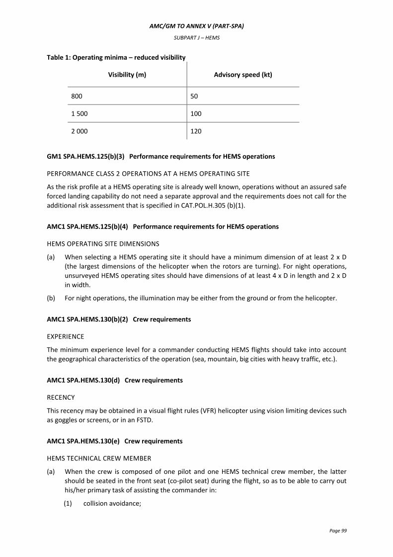
AMC/GM TO ANNEX V (PART-SPA)
SUBPART J – HEMS
Page 99
Table 1: Operating minima – reduced visibility
Visibility (m) Advisory speed (kt)
800 50
1 500 100
2 000 120
GM1 SPA.HEMS.125(b)(3) Performance requirements for HEMS operations
PERFORMANCE CLASS 2 OPERATIONS AT A HEMS OPERATING SITE
As the risk profile at a HEMS operating site is already well known, operations without an assured safe
forced landing capability do not need a separate approval and the requirements does not call for the
additional risk assessment that is specified in CAT.POL.H.305 (b)(1).
AMC1 SPA.HEMS.125(b)(4) Performance requirements for HEMS operations
HEMS OPERATING SITE DIMENSIONS
(a) When selecting a HEMS operating site it should have a minimum dimension of at least 2 x D
(the largest dimensions of the helicopter when the rotors are turning). For night operations,
unsurveyed HEMS operating sites should have dimensions of at least 4 x D in length and 2 x D
in width.
(b) For night operations, the illumination may be either from the ground or from the helicopter.
AMC1 SPA.HEMS.130(b)(2) Crew requirements
EXPERIENCE
The minimum experience level for a commander conducting HEMS flights should take into account
the geographical characteristics of the operation (sea, mountain, big cities with heavy traffic, etc.).
AMC1 SPA.HEMS.130(d) Crew requirements
RECENCY
This recency may be obtained in a visual flight rules (VFR) helicopter using vision limiting devices such
as goggles or screens, or in an FSTD.
AMC1 SPA.HEMS.130(e) Crew requirements
HEMS TECHNICAL CREW MEMBER
(a) When the crew is composed of one pilot and one HEMS technical crew member, the latter
should be seated in the front seat (co-pilot seat) during the flight, so as to be able to carry out
his/her primary task of assisting the commander in:
(1) collision avoidance;
AMC/GM TO ANNEX V (PART-SPA)
SUBPART J – HEMS
Page 100
(2) the selection of the landing site; and
(3) the detection of obstacles during approach and take-off phases.
(b) The commander may delegate other aviation tasks to the HEMS technical crew member, as
necessary:
(1) assistance in navigation;
(2) assistance in radio communication/radio navigation means selection;
(3) reading of checklists; and
(4) monitoring of parameters.
(c) The commander may also delegate to the HEMS technical crew member tasks on the ground:
(1) assistance in preparing the helicopter and dedicated medical specialist equipment for
subsequent HEMS departure; or
(2) assistance in the application of safety measures during ground operations with rotors
turning (including: crowd control, embarking and disembarking of passengers, refuelling
etc.).
(d) There may be exceptional circumstances when it is not possible for the HEMS technical crew
member to carry out his/her primary task as defined under (a).
This is to be regarded as exceptional and is only to be conducted at the discretion of the
commander, taking into account the dimensions and environment of the HEMS operating site.)
(e) When two pilots are carried, there is no requirement for a HEMS technical crew member,
provided that the pilot monitoring performs the aviation tasks of a technical crew member.
GM1 SPA.HEMS.130(e)(2)(ii) Crew requirements
SPECIFIC GEOGRAPHICAL AREAS
In defining those specific geographical areas, the operator should take account of the cultural lighting
and topography. In those areas where the cultural lighting an topography make it unlikely that the
visual cues would degrade sufficiently to make flying of the aircraft problematical, the HEMS
technical crew member is assumed to be able to sufficiently assist the pilot, since under such
circumstances instrument and control monitoring would not be required. In those cases where
instrument and control monitoring would be required the operations should be conducted with two
pilots.
AMC1 SPA.HEMS.130(e)(2)(ii)(B) Crew requirements
FLIGHT FOLLOWING SYSTEM
A flight following system is a system providing contact with the helicopter throughout its operational
area.
AMC1 SPA.HEMS.130(f)(1) Crew requirements
TRAINING AND CHECKING SYLLABUS
(a) The flight crew training syllabus should include the following items:
AMC/GM TO ANNEX V (PART-SPA)
SUBPART J – HEMS
Page 101
(1) meteorological training concentrating on the understanding and interpretation of
available weather information;
(2) preparing the helicopter and specialist medical equipment for subsequent HEMS
departure;
(3) practice of HEMS departures;
(4) the assessment from the air of the suitability of HEMS operating sites; and
(5) the medical effects air transport may have on the patient.
(b) The flight crew checking syllabus should include:
(1) proficiency checks, which should include landing and take-off profiles likely to be used at
HEMS operating sites; and
(2) line checks, with special emphasis on the following:
(i) local area meteorology;
(ii) HEMS flight planning;
(iii) HEMS departures;
(iv) the selection from the air of HEMS operating sites;
(v) low level flight in poor weather; and
(vi) familiarity with established HEMS operating sites in the operator’s local area
register.
(c) HEMS technical crew members should be trained and checked in the following items:
(1) duties in the HEMS role;
(2) map reading, navigation aid principles and use;
(3) operation of radio equipment;
(4) use of on-board medical equipment;
(5) preparing the helicopter and specialist medical equipment for subsequent HEMS
departure;
(6) instrument reading, warnings, use of normal and emergency checklists in assistance of
the pilot as required;
(7) basic understanding of the helicopter type in terms of location and design of normal and
emergency systems and equipment;
(8) crew coordination;
(9) practice of response to HEMS call out;
(10) conducting refuelling and rotors running refuelling;
(11) HEMS operating site selection and use;
(12) techniques for handling patients, the medical consequences of air transport and some
knowledge of hospital casualty reception;
(13) marshalling signals;
(14) underslung load operations as appropriate;
(15) winch operations as appropriate;
AMC/GM TO ANNEX V (PART-SPA)
SUBPART J – HEMS
Page 102
(16) the dangers to self and others of rotor running helicopters including loading of patients;
and
(17) the use of the helicopter inter-communications system.
AMC1 SPA.HEMS.130(f)(2)(ii)(B) Crew requirements
LINE CHECKS
Where due to the size, the configuration, or the performance of the helicopter, the line check cannot
be conducted on an operational flight, it may be conducted on a specially arranged representative
flight. This flight may be immediately adjacent to, but not simultaneous with, one of the biannual
proficiency checks.
AMC1 SPA.HEMS.135(a) HEMS medical passenger and other personnel briefing
HEMS MEDICAL PASSENGER BRIEFING
The briefing should ensure that the medical passenger understands his/her role in the operation,
which includes:
(a) familiarisation with the helicopter type(s) operated;
(b) entry and exit under normal and emergency conditions both for self and patients;
(c) use of the relevant on-board specialist medical equipment;
(d) the need for the commander’s approval prior to use of specialised equipment;
(e) method of supervision of other medical staff;
(f) the use of helicopter inter-communication systems;
(g) location and use of on board fire extinguishers; and
(h) the operator’s crew coordination concept including relevant elements of crew resource
management.
AMC1.1 SPA.HEMS.135(a) HEMS medical passenger and other personnel briefing
HEMS MEDICAL PASSENGER BRIEFING
Another means of complying with the rule as compared to that contained in AMC1-SPA.HEMS.135(a)
is to make use of a training programme as mentioned in AMC1.1 CAT.OP.MPA.170.
AMC1 SPA.HEMS.135(b) HEMS medical passenger and other personnel briefing
GROUND EMERGENCY SERVICE PERSONNEL
(a) The task of training large numbers of emergency service personnel is formidable. Wherever
possible, helicopter operators should afford every assistance to those persons responsible for
training emergency service personnel in HEMS support. This can be achieved by various means,
such as, but not limited to, the production of flyers, publication of relevant information on the
operator’s web site and provision of extracts from the operations manual.
(b) The elements that should be covered include:
(1) two-way radio communication procedures with helicopters;
AMC/GM TO ANNEX V (PART-SPA)
SUBPART J – HEMS
Page 103
(2) the selection of suitable HEMS operating sites for HEMS flights;
(3) the physical danger areas of helicopters;
(4) crowd control in respect of helicopter operations; and
(5) the evacuation of helicopter occupants following an on-site helicopter accident.
AMC1 SPA.HEMS.140 Information and documentation
OPERATIONS MANUAL
The operations manual should include:
(a) the use of portable equipment on board;
(b) guidance on take-off and landing procedures at previously unsurveyed HEMS operating sites;
(c) the final reserve fuel, in accordance with SPA.HEMS.150;
(d) operating minima;
(e) recommended routes for regular flights to surveyed sites, including the minimum flight
altitude;
(f) guidance for the selection of the HEMS operating site in case of a flight to an unsurveyed site;
(g) the safety altitude for the area overflown; and
(h) procedures to be followed in case of inadvertent entry into cloud.


