Embed Size (px)
Citation preview
Annex II to ED Decision 2021/007/R
General Acceptable Means of Compliance for Airworthiness of Products, Parts
and Appliances
(AMC-20)
Amendment 22
27 May 20211
1 For the date of entry into force of this Amendment, please refer to Decision 2021/007/R at the Official Publication of EASA.

AMC-20 — Amendment 22 Table of contents
Annex II to ED Decision 2021/007/R Page 2 of 617
TABLE OF CONTENTS
Table of contents ........................................................................... 2
Preamble ....................................................................................... 6
SUBPART A — GENERAL ............................................................... 10
AMC 20-1A .................................................................................................................................. 10
AMC 20-1A Certification of Aircraft Propulsion Systems Equipped with Electronic Control Systems ....................................................................................................................................... 10
AMC 20-2B .................................................................................................................................. 15
AMC 20-2B Certification of Essential Auxiliary Power Units (APUs) Equipped with Electronic Controls ....................................................................................................................................... 15
Appendix to AMC 20-2B ................................................................................................... 20
AMC 20-3B .................................................................................................................................. 21
AMC 20-3B Certification of Engines Equipped with Electronic Engine Control Systems ........... 21
AMC 20-6B .................................................................................................................................. 51
AMC 20-6B Extended-range operation with two-engine aeroplanes ETOPS certification and operation .................................................................................................................................... 51
Appendix 1 to AMC 20-6B – Propulsion system reliability assessment ........................... 79
Appendix 2 to AMC 20-6B – Aircraft systems reliability assessment ............................... 89
Appendix 3 to AMC 20-6B – Operational limitations ....................................................... 96
Appendix 4 to AMC 20-6B – Flight preparation and in-flight procedures ........................ 97
Appendix 5 to AMC 20-6B – ETOPS en-route alternate aerodromes ............................. 102
Appendix 6 to AMC 20-6B – ETOPS training programme ............................................... 104
Appendix 7 to AMC 20-6B – Typical ETOPS operations manual supplement ................ 106
Appendix 8 to AMC 20-6B – Continuing airworthiness considerations ......................... 108
AMC 20-8A ................................................................................................................................ 113
AMC 20-8A Occurrence reporting ............................................................................................ 113
AMC 20-9 .................................................................................................................................. 121
AMC 20-9 Acceptable Means of Compliance for the Approval of Departure Clearance via Data Communications over ACARS ................................................................................................... 121
Appendix 1 to AMC 20-9 PDC versus DCL: A Comparison .............................................. 128
Appendix 2 to AMC 20-9 Common Terms ...................................................................... 129
AMC 20-10 ................................................................................................................................ 130
AMC-20 — Amendment 22 Table of contents
Annex II to ED Decision 2021/007/R Page 3 of 617
AMC 20-10 Acceptable Means of Compliance for the Approval of Digital ATIS via Data Link over ACARS ............................................................................................................................... 130
Appendix 1 to AMC 20-10 Common Terms .................................................................... 137
AMC 20-15 ................................................................................................................................ 138
AMC 20-15 Airworthiness Certification Considerations for the Airborne Collision Avoidance System (ACAS II) with optional Hybrid Surveillance ................................................................. 138
Appendix 1 to AMC 20-15 – ACAS II/Mode S Transponder Ground Testing Precautions ........................................................................................................................................ 145
Appendix 2 to AMC 20-15 – List of Acronyms ................................................................ 146
AMC 20-19 ................................................................................................................................ 147
AMC 20-19 Passenger Service and In-Flight Entertainment (IFE) Systems .............................. 147
AMC 20-20B .............................................................................................................................. 170
AMC 20-20B Continuing structural integrity programme ........................................................ 170
Appendix 1 to AMC 20-20B — Guidelines for the development of a supplementary structural inspection programme................................................................................... 190
Appendix 2 to AMC 20-20B — Guidelines for the development of a programme to preclude the occurrence of widespread fatigue damage .............................................. 198
Annex 1 to Appendix 2 to AMC 20-20B — Full-scale fatigue test evidence ................... 224
Annex 2 to Appendix 2 to AMC 20-20B — Example of how to establish an LOV........... 232
Appendix 3 to AMC 20-20B — Guidelines for establishing instructions for continued airworthiness of structural repairs and modifications ................................................... 235
Annex 1 to Appendix 3 to AMC 20-20B — Approval process for new repairs ............... 254
Annex 2 to Appendix 3 to AMC 20-20B — Assessment of existing repairs .................... 255
Annex 3 to Appendix 3 to AMC 20-20B — Repairs and modifications to removable structural components ................................................................................................... 262
Annex 4 to Appendix 3 to AMC 20-20B — Service bulletin review process ................... 265
Annex 5 to Appendix 3 to AMC 20-20B — List of major changes and STSs that may adversely affect fatigue-critical structure ...................................................................... 268
Annex 6 to Appendix 3 to AMC 20-20B — Background to the need for damage-tolerance-based inspection programmes for repairs ..................................................... 269
Appendix 4 to AMC 20-20B — Guidelines for the development of a corrosion prevention control programme ........................................................................................................ 271
Appendix 5 to AMC 20-20BA — Guidelines for ensuring the validity of continuing structural integrity programmes .................................................................................... 285
AMC 20-21 ................................................................................................................................ 295
AMC 20-21 Programme to enhance aeroplane Electrical Wiring Interconnection System (EWIS) maintenance ............................................................................................................................. 295
Appendix A to AMC 20-21 Enhanced Zonal Analysis Logic Diagram and Steps ............. 311
AMC-20 — Amendment 22 Table of contents
Annex II to ED Decision 2021/007/R Page 4 of 617
Appendix B to AMC 20-21 Examples of Typical EZAP Worksheets ................................ 319
Appendix C to AMC 20-21 Determination if a major change to an aircraft should be specifically subjected to an EZAP ................................................................................... 326
Appendix D to AMC 20-21 .............................................................................................. 329
Appendix E to AMC 20-21 Causes of Wire Degradation ................................................ 330
AMC 20-22 ................................................................................................................................ 332
AMC 20-22 Aeroplane Electrical Wiring Interconnection System Training Programme .......... 332
Appendix A to AMC 20-22 – EWIS Minimum Initial Training Programme for Group 1 and 2 ...................................................................................................................................... 339
Appendix B to AMC 20-22 – EWIS Minimum Initial Training Programme for Group 3 through 8 ........................................................................................................................ 341
Appendix C to AMC 20-22 – Curriculum and Lessons Plan ............................................ 343
AMC 20-23 ................................................................................................................................ 358
AMC 20-23 Development of Electrical Standard Wiring Practices documentation ................. 358
Appendix A: Groups, Major Topics, Standardised Sequence and Description of Minimum Content ........................................................................................................................... 365
AMC 20-24 ................................................................................................................................ 367
AMC 20-24 Certification Considerations for the Enhanced ATS in Non-Radar Areas using ADS-B Surveillance (ADS-B-NRA) Application via 1090 MHZ Extended Squitter. ................................ 367
Appendix 1 to AMC 20-24 ......................................................................................................... 381
Appendix 2 to AMC 20-24 .............................................................................................. 382
Appendix 3 to AMC 20-24 .............................................................................................. 383
Appendix 4 to AMC 20-24 .............................................................................................. 385
AMC 20-25A .............................................................................................................................. 387
AMC 20-25A Airworthiness considerations for Electronic Flight Bags (EFBs) .......................... 387
AMC 20-29 ................................................................................................................................ 396
AMC 20-29 Composite Aircraft Structure ................................................................................. 396
Appendix 1 to AMC 20-29 – Applicable CSs and Relevant Guidance ............................. 423
Appendix 2 to AMC 20-29 – Definitions ......................................................................... 426
Appendix 3 to AMC 20-29 – Change of Composite Material and/or Process ................ 429
AMC 20-42 ................................................................................................................................ 433
AMC 20-42 Airworthiness information security risk assessment ............................................. 433
AMC 20-115D ............................................................................................................................ 437
AMC 20-115D Airborne Software Development Assurance Using EUROCAE ED-12 and RTCA DO-178 ...................................................................................................................................... 437
GM1 to AMC 20-115D – Software change impact analyses (CIAs) ................................ 449
GM2 to AMC 20-115D – Clarification of data coupling and control coupling ................ 450
AMC-20 — Amendment 22 Table of contents
Annex II to ED Decision 2021/007/R Page 5 of 617
GM3 to AMC 20-115D – Error-handling at design level ................................................. 450
AMC 20-128A ............................................................................................................................ 452
AMC 20-128A Design Considerations for Minimizing Hazards Caused by Uncontained Turbine Engine and Auxiliary Power Unit Rotor Failure ........................................................................ 452
Appendix 1 to AMC 20-128A User’s Manual .................................................................. 470
AMC 20-136 .............................................................................................................................. 486
AMC 20-136 Aircraft Electrical and Electronic System Lightning Protection ........................... 486
Appendix 1 to AMC 20-136 Definitions and acronyms .................................................. 505
AMC 20-152A ............................................................................................................................ 507
AMC 20-152A Development Assurance for Airborne Electronic Hardware (AEH) ................... 507
Appendix A — Glossary .................................................................................................. 534
Appendix B — Guidance Material to AMC 20-152A ....................................................... 537
Appendix C — Glossary of Guidance Material ............................................................... 550
AMC 20-158 .............................................................................................................................. 551
AMC 20-158 Aircraft Electrical and Electronic System High-Intensity Radiated Fields (HIRF) Protection ................................................................................................................................. 551
Appendix 1 to AMC 20-158 Generic transfer functions and attenuation ...................... 576
AMC 20-170 .............................................................................................................................. 581
AMC 20-170 Integrated modular avionics (IMA) ...................................................................... 581
AMC 20-189 .............................................................................................................................. 605
AMC 20-189 The Management of Open Problem Reports (OPRs) ........................................... 605
SUBPART B — LIST OF AMC-20 ITEMS ......................................... 615
LIST OF AMC-20 ITEMS ............................................................................................................. 615
AMC-20 — Amendment 22 Preamble
Annex II to ED Decision 2021/007/R Page 6 of 617
PREAMBLE
ED Decision 2021/007/R
Amendment 22
The following is a list of paragraphs affected by this Amendment:
AMC 20-20 Amended (NPA 2013-07)
ED Decision 2021/006/R
Amendment 21
The following is a list of paragraphs affected by this Amendment:
AMC 20-6 Amended (NPA 2017-15)
ED Decision 2020/023/R
Amendment 20
The following is a list of paragraphs affected by this Amendment:
SUBPART A — GENERAL Created
AMC 20-20A Amended (NPA 2013-07)
ED Decision 2020/010/R
Amendment 19
The following is a list of paragraphs affected by this Amendment:
SUBPART A — GENERAL Created
AMC 20-1 Amended (NPA 2017-09)
AMC 20-2 Amended (NPA 2017-09)
AMC 20-3 Amended (NPA 2017-09)
AMC 20-8 Amended (NPA 2016-19)
AMC 20-19 Created (NPA 2017-09)
AMC 20-152A Created (NPA 2018-09)
AMC 20-189 Created (NPA 2018-09)
SUBPART B — LIST OF AMC-20 ITEMS Created
ED Decision 2020/006/R
Amendment 18
The following is a list of paragraphs affected by this Amendment:
AMC 20-42 Created (NPA 2019-01)
AMC-20 — Amendment 22 Preamble
Annex II to ED Decision 2021/007/R Page 7 of 617
ED Decision 2019/011/R
Amendment 17
The following is a list of paragraphs affected by this Amendment:
AMC 20-4A Cancelled (NPA 2018-02)
AMC 20-5 Cancelled (NPA 2018-02)
AMC 20-12 Cancelled (NPA 2018-02)
AMC 20-26 Cancelled (NPA 2018-02)
AMC 20-27A Cancelled (NPA 2018-02)
AMC 20-28 Cancelled (NPA 2018-02)
ED Decision 2019/008/R
Amendment 16
The following is a list of paragraphs affected by this Amendment:
AMC 20-25 Amended (NPA 2016-12)
ED Decision 2018/008/R
Amendment 15
The following is a list of paragraphs affected by this Amendment:
AMC 20-170 Created (NPA 2017-11)
ED Decision 2017/020/R
Amendment 14
The following is a list of paragraphs affected by this Amendment:
AMC 20-115 Amended (NPA 2017-02)
ED Decision 2015/017/R
Amendment 13
The following is a list of paragraphs affected by this Amendment:
AMC 20-136 Created (NPA 2014-16)
AMC 20-158 Created (NPA 2014-16)
ED Decision 2014/001/R
Amendment 12
The following is a list of paragraphs affected by this Amendment:
AMC 20-25 Created (NPA 2012-02)
ED Decision 2013/030/R
Amendment 11
The following is a list of paragraphs affected by this Amendment:
AMC-20 — Amendment 22 Preamble
Annex II to ED Decision 2021/007/R Page 8 of 617
AMC 20-11 Cancelled (NPA 2013-06)
AMC 20-13 Cancelled (NPA 2012-19)
ED Decision 2013/026/R
Amendment 10
The following is a list of paragraphs affected by this Amendment:
AMC 20-2 Amended (NPA 2012-11)
AMC 20-3 Amended (NPA 2012-11)
AMC 20-4 Amended (NPA 2012-11)
AMC 20-27 Amended (NPA 2012-11)
AMC 20-115 Amended (NPA 2012-11)
ED Decision 2012/014/R
Amendment 9
The following is a list of paragraphs affected by this Amendment:
AMC 20-28 Created (NPA 2009-04)
ED Decision 2011/001/R
Amendment 8
The following is a list of paragraphs affected by this Amendment:
AMC 20-15 Created (NPA 2010-03)
ED Decision 2010/012/R
Amendment 7
The following is a list of paragraphs affected by this Amendment:
AMC 20-6 rev. 2 Created (NPA 2008-01)
AMC 20-6 adopted on the 05/11/2003 by means of ED Decision 2003/12/RM is replaced by AMC 20-6 rev. 2.
ED Decision 2010/003/R
Amendment 6
The following is a list of paragraphs affected by this Amendment:
AMC 20-29 Created (NPA 2009-06)
ED Decision 2009/019/R
Amendment 5
The following is a list of paragraphs affected by this Amendment:
AMC 20-26 Created (NPA 2008-14)
AMC 20-27 Created (NPA 2008-14)
AMC-20 — Amendment 22 Preamble
Annex II to ED Decision 2021/007/R Page 9 of 617
ED Decision 2008/007/R
Amendment 4
The following is a list of paragraphs affected by this Amendment:
AMC 20-21 Created (NPA 2007-01)
AMC 20-22 Created (NPA 2007-01)
AMC 20-23 Created (NPA 2007-01)
ED Decision 2008/004/R
Amendment 3
The following is a list of paragraphs affected by this Amendment:
AMC 20-24 Created (NPA 2007/05)
ED Decision 2007/019/R
Amendment 2
The following is a list of paragraphs affected by this Amendment:
AMC 20-1 Amended (NPA 04/2005)
AMC 20-3 Created (NPA 04/2005)
AMC 20-11 Created (NPA 11/2005)
AMC 20-20 Created (NPA 05/2006)
ED Decision 2006/012/R
Amendment 1
The following is a list of paragraphs affected by this Amendment:
AMC 20-9 Created
AMC 20-10 Created
AMC 20-12 Created
AMC 20-13 Created
AMC-20 — Amendment 22 SUBPART A — GENERAL
AMC 20-1A
Annex II to ED Decision 2021/007/R Page 10 of 617
SUBPART A — GENERAL
AMC 20-1A
AMC 20-1A Certification of Aircraft Propulsion Systems Equipped with Electronic Control Systems
1 GENERAL
The existing certification specifications (CSs) for Engine, Propeller and aircraft certification may require special interpretation for Engines and Propellers equipped with electronic control systems. Because of the nature of this technology and because of the greater interdependence of Engine, Propeller and aircraft systems, it has been found necessary to prepare acceptable means of compliance (AMC) specifically addressing the certification of these electronic control systems.
AMC 20-1( ) addresses the compliance tasks relating to the certification of the installation of propulsion systems equipped with electronic control systems. AMC 20-3( ) is dedicated to certification of Engine control systems but identifies some Engine-installation-related issues that should be read in conjunction with AMC 20-1( ).
Like any AMC, it is issued to outline issues to be considered during demonstration of compliance with the CSs.
2 RELEVANT SPECIFICATIONS
For aircraft certification, some of the related CSs are:
— for aeroplanes in CS-25 (and, where applicable, CS-23):
— paragraphs 33, 581, 631, 899, 901, 903, 905, 933, 937, 939, 961, 994, 995, 1103(d), 1143 (except (d)), 1149, 1153, 1155, 1163, 1181, 1183, 1189, 1301, 1305, 1307(c), 1309, 1337, 1351(b) and (d), 1353(a) and (b), 1355(c), 1357, 1431, 1461, 1521(a), 1527;
— for rotorcraft: equivalent specifications in CS-27 and CS-29.
3 SCOPE
This AMC is relevant to the CSs for aircraft installation of Engines or Propellers with electronic control systems, whether using electrical or electronic (analogue or digital) technology.
It gives guidance on the precautions to be taken for the use of electrical and electronic technology for Engine and Propeller control, protection and monitoring, and, where applicable, for integration of functions specific to the aircraft.
Precautions have to be adapted to the criticality of the functions. These precautions may be affected by the degree of authority of the system, the phase of flight, and the availability of a backup system.
This document also discusses the division of compliance tasks between the applicants for Engine, Propeller (when applicable), and aircraft type certificates. This guidance relates to issues to be considered during aircraft certification.
It does not cover APU control systems; APUs, which are not used as ‘propulsion systems’, are addressed in the dedicated AMC 20-2( ).
AMC-20 — Amendment 22 SUBPART A — GENERAL
AMC 20-1A
Annex II to ED Decision 2021/007/R Page 11 of 617
4 PRECAUTIONS
(a) General
The introduction of electrical and electronic technology can entail the following:
— greater interdependence of the Engine or Propeller and the aircraft owing to the exchange of electrical power and/or data between them;
— increased integration of the control and related indication functions;
— a risk of significant Failures that are common to more than one Engine or Propeller of the aircraft which might, for example, occur as a result of:
— insufficient protection from electromagnetic disturbance (e.g. lightning, internal or external radiation effects);
— insufficient integrity of the aircraft electrical power supply;
— insufficient integrity of data supplied from the aircraft;
— hidden design faults or discrepancies contained within the design of the propulsion system control software or airborne electronic hardware (AEH); or
— omissions or errors in the system/software/AEH specification.
Appropriate design and integration precautions should therefore be taken to minimise these risks.
(b) Objective
The introduction of electronic control systems should provide for the aircraft at least the equivalent level of safety, and the related reliability level, as achieved in aircraft equipped with Engine and Propellers using hydromechanical control and protection systems.
When possible, early coordination between the Engine, Propeller and aircraft applicants is recommended in association with EASA as discussed in Section 5 of this AMC.
(c) Precautions relating to electrical power supply and data from the aircraft
When considering the objectives of Section 4(a) or (b), due consideration should be given to the reliability of electrical power and data supplied to the electronic control systems and peripheral components. The potential adverse effects on Engine and Propeller operation of any loss of electrical power supply from the aircraft or failure of data coming from the aircraft are assessed during the Engine and Propeller certification.
During aircraft certification, the assumptions made as part of the Engine and Propeller certification on reliability of aircraft power and data should be checked for consistency with the actual aircraft design.
Aircraft should be protected from unacceptable effects of faults due to a single cause, simultaneously affecting more than one Engine or Propeller. In particular, the following cases should be considered:
— erroneous data received from the aircraft by the Engine/Propeller control system if the data source is common to more than one Engine/Propeller (e.g. air data sources, autothrottle synchronising); and
AMC-20 — Amendment 22 SUBPART A — GENERAL
AMC 20-1A
Annex II to ED Decision 2021/007/R Page 12 of 617
— control system operating faults propagating via data links between Engine/Propellers (e.g. maintenance recording, common bus, cross-talk, autofeathering, automatic reserve power system).
Any precautions needed may be taken either through the aircraft system architecture or by logic internal to the electronic control system.
(d) Local events
For Engine and Propeller certification, effects of local events should be assessed.
Whatever the local event, the behaviour of the electronic control system should not cause a hazard to the aircraft. This will require consideration of effects such as the control of the thrust reverser deployment, the overspeed of the Engine, transient effects or inadvertent Propeller pitch change under any flight condition.
When the demonstration that there is no hazard to the aircraft is based on the assumption that there exists another function to afford the necessary protection, it should be shown that this function is not rendered inoperative by the same local event (including destruction of wires, ducts, power supplies).
Such assessment should be reviewed during aircraft certification.
(e) Software and airborne electronic hardware (AEH)
The acceptability of the criticality levels and methods used for the development and verification of software and AEH which are part of the Engine and Propeller type designs should have been agreed between the aircraft, Engine and Propeller designers prior to the certification activity.
Note: In this AMC, the ‘criticality level’ is used to reflect either the software level of a software item or the AEH design assurance level (or DAL) of an AEH item.
(f) Environmental effects
The validated protection levels for the Engine and Propeller electronic control systems as well as their emissions of radio frequency energy are established during the Engine and Propeller certification and are contained in the instructions for installation. For the aircraft certification, it should be substantiated that these levels are appropriate.
5 INTERRELATION BETWEEN ENGINE, PROPELLER AND AIRCRAFT CERTIFICATION
(a) Objective
To satisfy the aircraft certification specifications, such as CS 25.901, CS 25.903 and CS 25.1309, an analysis of the consequences of failures of the system on the aircraft has to be made. It should be ensured that the software/AEH criticality levels and the safety and reliability objectives for the electronic control system are consistent with these requirements.
(b) Interface Definition
The interface has to be identified for the AEH and software aspects between the Engine, Propeller and the aircraft systems in the appropriate documents.
The Engine/Propeller/aircraft documents should cover in particular:
— the software/AEH criticality level (per function if necessary):
AMC-20 — Amendment 22 SUBPART A — GENERAL
AMC 20-1A
Annex II to ED Decision 2021/007/R Page 13 of 617
— the reliability objectives for a loss of Engine/Propeller control or significant change in thrust (including an IFSD due to a control system malfunction), or for the transmission of faulty parameters;
— the degree of protection against lightning or other electromagnetic effects (e.g. the level of induced voltages that can be supported at the interfaces);
— Engine, Propeller and aircraft interface data and characteristics; and
— the aircraft power supply and its characteristics (if relevant).
(c) Distribution of Compliance Demonstration
The certification tasks of the aircraft propulsion system equipped with electronic control systems may be shared between the Engine, Propeller and aircraft certification. The distribution between the different certification activities should be identified and agreed with EASA and/or the appropriate Engine and aircraft authorities (an example is given in Section 6 ‘TABLE’).
Appropriate evidence provided for Engine and Propeller certification should be used for aircraft certification. For example, the quality of any aircraft function software/AEH and aircraft/Engine/Propeller interface logic already demonstrated for Engine or Propeller certification should need no additional substantiation for aircraft certification.
Aircraft certification should deal with the specific precautions taken in respect of the physical and functional interfaces with the Engine/Propeller.
AMC-20 — Amendment 22 SUBPART A — GENERAL
AMC 20-1A
Annex II to ED Decision 2021/007/R Page 14 of 617
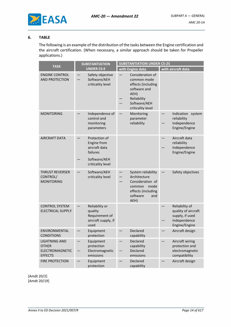
6. TABLE
The following is an example of the distribution of the tasks between the Engine certification and the aircraft certification. (When necessary, a similar approach should be taken for Propeller applications.)
TASK SUBSTANTIATION
UNDER CS-E
SUBSTANTIATION UNDER CS-25
with Engine data with aircraft data
ENGINE CONTROL AND PROTECTION
— Safety objective — Software/AEH
criticality level
— Consideration of common mode effects (including software and AEH)
— Reliability — Software/AEH
criticality level
MONITORING — Independence of control and monitoring parameters
— Monitoring parameter reliability
— Indication system reliability
— Independence Engine/Engine
AIRCRAFT DATA — Protection of Engine from aircraft data failures
— Software/AEH criticality level
— Aircraft data reliability
— Independence Engine/Engine
THRUST REVERSER CONTROL/ MONITORING
— Software/AEH criticality level
— System reliability — Architecture — Consideration of
common mode effects (including software and AEH)
— Safety objectives
CONTROL SYSTEM ELECTRICAL SUPPLY
— Reliability or quality Requirement of aircraft supply, if used
— Reliability of quality of aircraft supply, if used
— Independence Engine/Engine
ENVIRONMENTAL CONDITIONS
— Equipment protection
— Declared capability
— Aircraft design
LIGHTNING AND OTHER ELECTROMAGNETIC EFFECTS
— Equipment protection
— Electromagnetic emissions
— Declared capability
— Declared emissions
— Aircraft wiring protection and electromagnetic compatibility
FIRE PROTECTION — Equipment protection
— Declared capability
— Aircraft design
[Amdt 20/2] [Amdt 20/19]
AMC-20 — Amendment 22 SUBPART A — GENERAL
AMC 20-2B
Annex II to ED Decision 2021/007/R Page 15 of 617
AMC 20-2B
AMC 20-2B Certification of Essential Auxiliary Power Units (APUs) Equipped with Electronic Controls
1. GENERAL
The existing certification specifications (CSs) for APU and aircraft certification may require special interpretation for essential APUs equipped with electronic control systems. Because of the nature of this technology, it has been found necessary to prepare acceptable means of compliance (AMC) specifically addressing the certification of these electronic control systems.
Like any AMC, the content of this document is not mandatory. It is issued for guidance purposes, and to outline a method of compliance with the CSs. In lieu of following this method, an alternative method may be followed, provided that this is agreed by EASA as an acceptable method of compliance with the CSs.
This document discusses the compliance tasks relating to both the APU and the aircraft certification.
2 RELEVANT SPECIFICATIONS
2.1 APU certification
CS-APU
— Book 1, paragraph 2(c);
— Book 1, Section A, paragraphs 10(b), 20, 80, 90, 210, 220, 280 and 530;
— Book 2, Section A, AMC CS-APU 20.
2.2 Aircraft certification
Aeroplanes: CS-25
— paragraphs 581, 899, 901, 903, 939, 1141, 1163, 1181, 1183, 1189, 1301, 1305, 1307(c), 1309, 1337, 1351(b) and (d), 1353(a) and (b), 1355(c), 1357, 1431, 1461, 1521, 1524, 1527
3 SCOPE
This AMC provides guidance on electronic (analogue and digital) essential APU control systems, and on the interpretation and means of compliance with the relevant APU and aircraft certification requirements.
It gives guidance on the precautions to be taken for the use of electronic technology for APU control, protection and monitoring and, where applicable, for integration of functions specific to the aircraft.
Precautions have to be adapted to the criticality of the functions. These precautions may be affected by:
— degree of authority of the system;
— phase of flight;
— availability of backup system.
AMC-20 — Amendment 22 SUBPART A — GENERAL
AMC 20-2B
Annex II to ED Decision 2021/007/R Page 16 of 617
This document also discusses the division of compliance tasks between the APU and the aircraft certification.
4 PRECAUTIONS
4.1 General
The introduction of electronic technology can entail the following:
(a) greater interdependence of the APU and the aircraft owing to the exchange of electrical power and/or data between them;
(b) a risk of significant failures which might, for example, occur as a result of:
(i) insufficient protection from electromagnetic disturbance (e.g. lightning, internal or external radiation effects);
(ii) insufficient integrity of the aircraft electrical power supply;
(iii) insufficient integrity of data supplied from the aircraft;
(iv) hidden design faults or discrepancies contained within the design of the APU control software/airborne electronic hardware (AEH); or
(v) omissions or errors in the system specification.
Appropriate design and integration precautions must therefore be taken to minimise these risks.
4.2 Objective
The introduction of electronic control systems should provide for the aircraft at least the equivalent level of safety, and the related reliability level, as achieved by an essential APU equipped with hydromechanical control and protection systems.
This objective, when defined during the aircraft/APU certification for a specific application, will be agreed with EASA.
4.3 Precautions related to APU control, protection and monitoring
The software and AEH associated with the APU control, protection and monitoring functions must have a criticality level and architecture appropriate to the criticality of the functions performed.
For digital systems, any residual errors not detected during the software/AEH development and certification process could cause an unacceptable failure. The latest edition of AMC 20-115/AMC 20-152 constitutes an acceptable means of compliance for software/AEH development, verification and software/AEH aspects of certification. The APU software/AEH criticality level should determined by the APU and aircraft/system safety assessment process; ED-79A/ARP4754A and ARP4761 provide guidelines on how to conduct an aircraft/APU/system safety assessment process.
It should be noted that the software/AEH development assurance methods and disciplines described in the latest edition of AMC 20-115/AMC 20-152 may not, in themselves, be sufficient to ensure that the overall system safety and reliability targets have been achieved. This is particularly true for certain critical systems, such as full authority digital engine control (FADEC) systems. In such cases, it is accepted that other measures, usually within the system, in addition to a high level of software/AEH development assurance, may be necessary to achieve these safety objectives and demonstrate that they have been met.
AMC-20 — Amendment 22 SUBPART A — GENERAL
AMC 20-2B
Annex II to ED Decision 2021/007/R Page 17 of 617
It is outside the scope of the latest edition of AMC 20-115/AMC 20-152 to suggest or specify these measures, but in accepting that they may be necessary, it is also the intention to encourage the development of software/AEH techniques which could support meeting the overall system safety objectives.
Note: In this AMC, the ‘criticality level’ is used to reflect either the software level of a software item and the AEH design assurance level (or DAL) of an AEH item.
4.4 Precautions related to APU independence from the aircraft
4.4.1 Precautions related to electrical power supply and data from the aircraft
When considering the objectives of Section 4.2, due consideration must be given to the reliability of electrical power and data supplied to the electronic controls and peripheral components. Therefore, the potential adverse effects on APU operation of any loss of electrical power supply from the aircraft or failure of data coming from the aircraft must be assessed during the APU certification.
(a) Electrical power
The use of either the aircraft electrical power network or electrical power sources specific to the APU, or the combination of both, may meet the objectives.
If the aircraft electrical system supplies power to the APU control system at any time, the power supply quality, including transients or failures, must not lead to a situation identified during the APU certification which is considered during the aircraft certification to be a hazard to the aircraft.
(b) Data
The following cases should be considered:
(i) erroneous data received from the aircraft by the APU control system; and
(ii) control system operating faults propagating via data links.
In certain cases, defects of aircraft input data may be overcome by other data references specific to the APU in order to meet the objectives.
4.4.2 Local events
(a) In designing an electronic control system to meet the objectives of Section 4.2, special consideration needs to be given to local events.
Examples of local events include fluid leaks, mechanical disruptions, electrical problems, fires or overheat conditions. An overheat condition results when the temperature of the electronic control unit is greater than the maximum safe design operating temperature declared during the APU certification. This situation can increase the failure rate of the electronic control system.
(b) Whatever the local event, the behaviour of the electronic control system must not cause a hazard to the aircraft. This will require consideration of effects such as the overspeed of the APU.
When the demonstration that there is no hazard to the aircraft is based on the assumption that there exists another function to afford the necessary protection, it must be shown that this function is not rendered inoperative
AMC-20 — Amendment 22 SUBPART A — GENERAL
AMC 20-2B
Annex II to ED Decision 2021/007/R Page 18 of 617
by the same local event (including destruction of wires, ducts, power supplies).
(c) Specific design features or analysis methods may be used to show compliance with respect to hazardous effects. Where this is not possible, for example due to the variability or the complexity of the failure sequence, then testing may be required. These tests must be agreed with EASA.
4.4.3 Lightning and other electromagnetic effects
Electronic control systems are sensitive to lightning and other electromagnetic interference. The system design must incorporate sufficient protection in order to ensure the functional integrity of the control system when subjected to designated levels of electric or electromagnetic inductions, including external radiation effects.
The validated protection levels for the APU electronic control system must be detailed during the APU certification in an approved document. For aircraft certification, it must be substantiated that these levels are adequate.
4.5 Other functions integrated into the electronic control system
If functions other than those directly associated with the control of the APU are integrated into the electronic control system, the APU certification should take into account the applicable aircraft requirements.
5 INTERRELATION BETWEEN APU CERTIFICATION AND AIRCRAFT CERTIFICATION
5.1 Objective
To satisfy the certification requirements, such as CS 25.901, CS 25.903 and CS 25.1309, an analysis of the consequences of failures of the system on the aircraft has to be made. It should be ensured that the software/AEH criticality levels and the safety and reliability objectives for the electronic control system are consistent with these requirements.
5.2 Interface definition
The interface has to be identified for the AEH and software aspects between the APU and the aircraft systems in the appropriate documents.
The APU documents should cover in particular:
(a) the software/AEH criticality level (per function if necessary);
(b) the reliability objectives for:
an APU shutdown in flight;
a loss of APU control or a significant change in performance; and
the transmission of faulty parameters;
(c) the degree of protection against lightning or other electromagnetic effects (e.g. the level of induced voltages that can be supported at the interfaces);
(d) the APU and aircraft interface data and its characteristics; and
(e) the aircraft power supply and its characteristics (if relevant).
5.3 Distribution of compliance demonstrations
AMC-20 — Amendment 22 SUBPART A — GENERAL
AMC 20-2B
Annex II to ED Decision 2021/007/R Page 19 of 617
The certification of the APU equipped with electronic controls and of the aircraft may be shared between the APU certification and the aircraft certification. The distribution between the APU certification and the aircraft certification must be identified and agreed with EASA and/or the appropriate APU and aircraft authorities (an example is given in the appendix).
Appropriate evidence provided for the APU certification should be used for the aircraft certification. For example, the quality of any aircraft function software/AEH and aircraft/APU interface logic already demonstrated for the APU certification should need no additional substantiation for the aircraft certification.
Aircraft certification must deal with the specific precautions taken in respect of the physical and functional interfaces with the APU.
[Amdt 20/10] [Amdt 20/19]
AMC-20 — Amendment 22 SUBPART A — GENERAL
AMC 20-2B
Annex II to ED Decision 2021/007/R Page 20 of 617
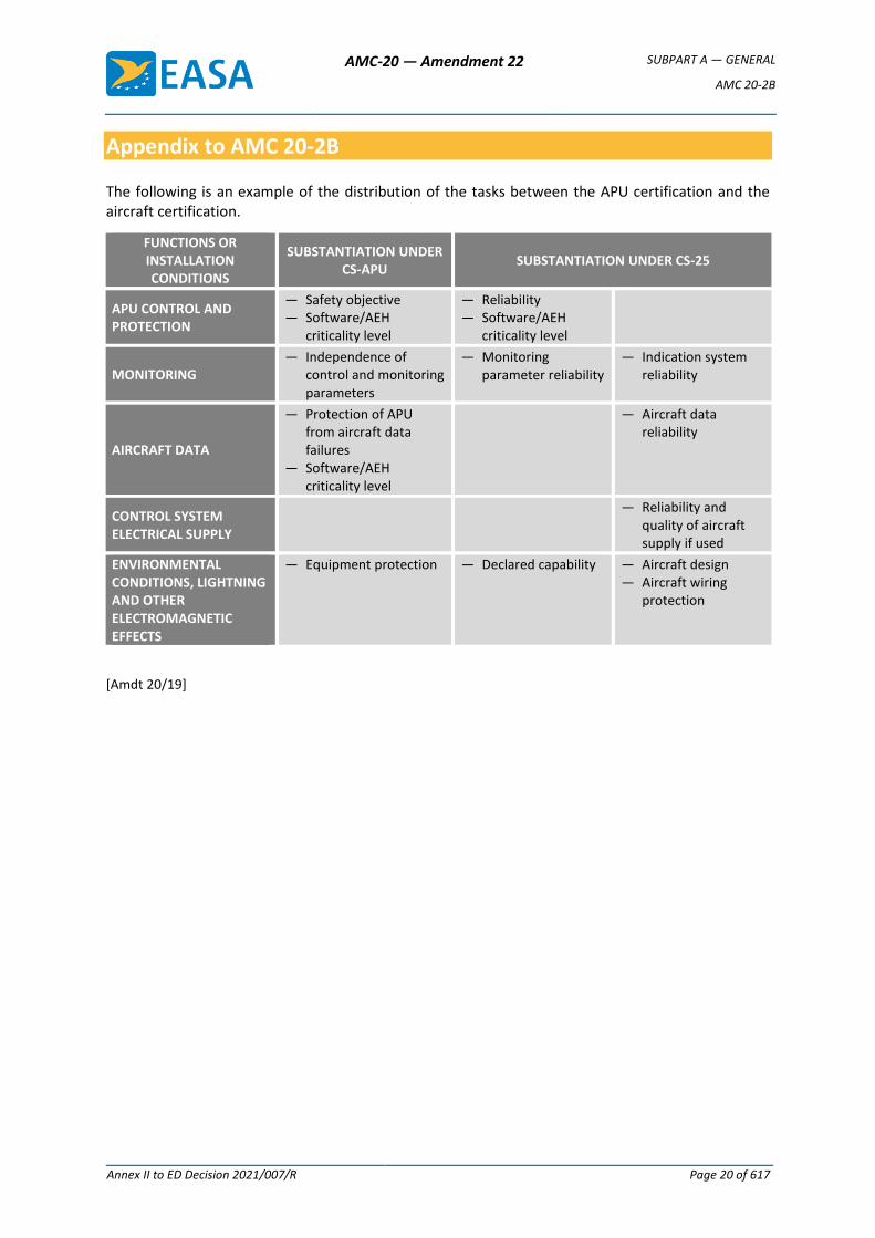
Appendix to AMC 20-2B
The following is an example of the distribution of the tasks between the APU certification and the aircraft certification.
FUNCTIONS OR INSTALLATION CONDITIONS
SUBSTANTIATION UNDER CS-APU
SUBSTANTIATION UNDER CS-25
APU CONTROL AND PROTECTION
— Safety objective — Software/AEH
criticality level
— ReliabiIity — Software/AEH
criticality level
MONITORING — Independence of
control and monitoring parameters
— Monitoring parameter reliability
— Indication system reliability
AIRCRAFT DATA
— Protection of APU from aircraft data failures
— Software/AEH criticality level
— Aircraft data reliability
CONTROL SYSTEM ELECTRICAL SUPPLY
— Reliability and quality of aircraft supply if used
ENVIRONMENTAL CONDITIONS, LIGHTNING AND OTHER ELECTROMAGNETIC EFFECTS
— Equipment protection — Declared capability — Aircraft design — Aircraft wiring
protection
[Amdt 20/19]
AMC-20 — Amendment 22 SUBPART A — GENERAL
AMC 20-3B
Annex II to ED Decision 2021/007/R Page 21 of 617
AMC 20-3B
AMC 20-3B Certification of Engines Equipped with Electronic Engine Control Systems
(1) PURPOSE
The existing certification specifications of CS-E for Engine certification may require specific interpretation for Engines equipped with Electronic Engine Control Systems (EECS), with special regard to interface with the certification of the aircraft and/or Propeller when applicable. Because of the nature of this technology, it has been considered useful to prepare acceptable means of compliance (AMC) specifically addressing the certification of these control systems.
Like any AMC, it is issued to outline issues to be considered during the demonstration of compliance with CS-E.
(2) SCOPE
This AMC is relevant to Engine certification specifications for EECS, whether they use electrical or electronic (analogue or digital) technology. This is in addition to other AMC such as AMC E 50 or AMC E 80.
It gives guidance on the precautions to be taken for the use of electrical and electronic technology for Engine control, protection, limiting and monitoring functions, and, where applicable, for the integration of aircraft or Propeller functions. In the latter case, this document is applicable to such functions integrated into the EECS, but only to the extent that these functions affect compliance with CS-E specifications.
The text deals mainly with the thrust and power functions of an EECS, since this is the prime function of the Engine. However, there are many other functions, such as bleed valve control, that may be integrated into the system for operability reasons. The principles outlined in this AMC apply to the whole EECS.
This document also discusses the division of compliance tasks for certification between the applicants for Engine, Propeller (when applicable), and aircraft type certificates. This guidance relates to issues to be considered during Engine certification. AMC 20-1( ) addresses issues associated with the Engine installation in the aircraft.
The introduction of electrical and electronic technology can entail the following:
— greater dependence of the Engine on the aircraft owing to the increased use of electrical power or data supplied from the aircraft;
— increased integration of control and related indication functions;
— increased risk of significant Failures that are common to more than one Engine of the aircraft which might, for example, occur as a result of:
— insufficient protection from electromagnetic disturbance (e.g. lightning, internal or external radiation effects) (see CS-E 50(a)(1), CS E-80 and CS-E 170);
— insufficient integrity of the aircraft electrical power supply (see CS-E 50(h));
— insufficient integrity of data supplied from the aircraft (see CS-E 50(g));
AMC-20 — Amendment 22 SUBPART A — GENERAL
AMC 20-3B
Annex II to ED Decision 2021/007/R Page 22 of 617
— hidden design Faults or discrepancies contained within the design of the propulsion system control software or airborne electronic hardware (AEH) (see CS-E 50(f)); or
— omissions or errors in the system/software/AEH specification (see CS-E 50(f)).
Appropriate design and integration precautions should therefore be taken to minimise any adverse effects from the above.
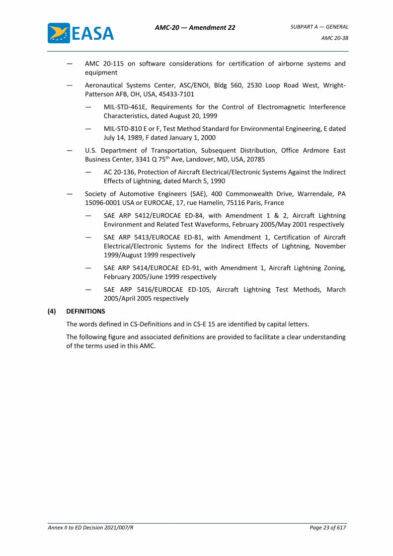
(3) RELEVANT SPECIFICATIONS AND REFERENCE DOCUMENTS
Although compliance with many CS-E specifications might be affected by the Engine Control System, the main paragraphs relevant to the certification of the Engine Control System itself are the following:
CS-E Specification Turbine Engines Piston Engines
CS-E 20 (Engine configuration and interfaces)
CS-E 25 (Instructions for Continued Airworthiness)
CS-E 30 (Assumptions)
CS-E 50 (Engine Control System)
CS-E 60 (Provision for instruments)
CS-E 80 (Equipment)
CS-E 110 (Drawing and marking of parts — Assembly of parts)
CS-E 130 (Fire prevention)
CS-E 140 (Tests-Engine configuration)
CS-E 170 (Engine systems and component verification)
CS-E 210 (Failure analysis)
CS-E 250 (Fuel System)
CS-E 390 (Acceleration tests)
CS-E 500 (Functioning)
CS-E-510 (Safety analysis)
CS-E 560 (Fuel system)
CS-E 745 (Engine Acceleration)
CS-E 1030 (Time-limited dispatch)
The following documents are referenced in AMC 20-3B:
— International Electrotechnical Commission (IEC), Central Office, 3, rue de Varembé, P.O. Box 131, CH - 1211 GENEVA 20, Switzerland
— IEC/PAS 62239, Electronic Component Management Plans, edition 1.0, dated April 2001
— IEC/PAS 62240, Use of Semiconductor Devices Outside Manufacturers’ Specified Temperature Ranges, edition 1.0, dated April 2001
— RTCA, Inc. 1828 L Street, NW, Suite 805, Washington, DC 20036 or EUROCAE, 17, rue Hamelin, 75116 Paris, France
— RTCA DO-254/EUROCAE ED-80, Design Assurance Guidance for Airborne Electronic Hardware, dated April 19, 2000
— RTCA DO-160/EUROCAE ED 14, Environmental Conditions and Test Procedures for Airborne Equipment
AMC-20 — Amendment 22 SUBPART A — GENERAL
AMC 20-3B
Annex II to ED Decision 2021/007/R Page 23 of 617
— AMC 20-115 on software considerations for certification of airborne systems and equipment
— Aeronautical Systems Center, ASC/ENOI, Bldg 560, 2530 Loop Road West, Wright-Patterson AFB, OH, USA, 45433-7101
— MIL-STD-461E, Requirements for the Control of Electromagnetic Interference Characteristics, dated August 20, 1999
— MIL-STD-810 E or F, Test Method Standard for Environmental Engineering, E dated July 14, 1989, F dated January 1, 2000
— U.S. Department of Transportation, Subsequent Distribution, Office Ardmore East Business Center, 3341 Q 75th Ave, Landover, MD, USA, 20785
— AC 20-136, Protection of Aircraft Electrical/Electronic Systems Against the Indirect Effects of Lightning, dated March 5, 1990
— Society of Automotive Engineers (SAE), 400 Commonwealth Drive, Warrendale, PA 15096-0001 USA or EUROCAE, 17, rue Hamelin, 75116 Paris, France
— SAE ARP 5412/EUROCAE ED-84, with Amendment 1 & 2, Aircraft Lightning Environment and Related Test Waveforms, February 2005/May 2001 respectively
— SAE ARP 5413/EUROCAE ED-81, with Amendment 1, Certification of Aircraft Electrical/Electronic Systems for the Indirect Effects of Lightning, November 1999/August 1999 respectively
— SAE ARP 5414/EUROCAE ED-91, with Amendment 1, Aircraft Lightning Zoning, February 2005/June 1999 respectively
— SAE ARP 5416/EUROCAE ED-105, Aircraft Lightning Test Methods, March 2005/April 2005 respectively
(4) DEFINITIONS
The words defined in CS-Definitions and in CS-E 15 are identified by capital letters.
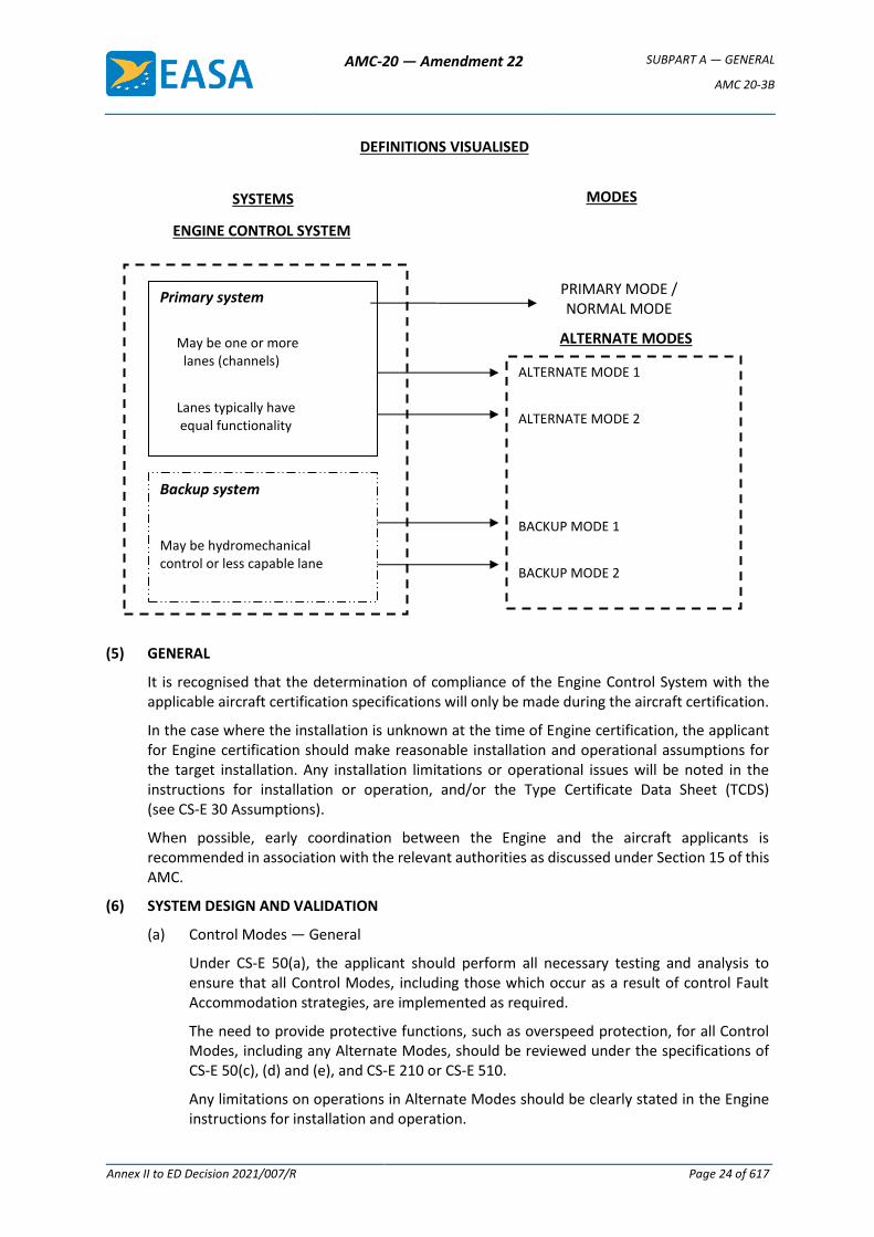
The following figure and associated definitions are provided to facilitate a clear understanding of the terms used in this AMC.
AMC-20 — Amendment 22 SUBPART A — GENERAL
AMC 20-3B
Annex II to ED Decision 2021/007/R Page 24 of 617
(5) GENERAL
It is recognised that the determination of compliance of the Engine Control System with the applicable aircraft certification specifications will only be made during the aircraft certification.
In the case where the installation is unknown at the time of Engine certification, the applicant for Engine certification should make reasonable installation and operational assumptions for the target installation. Any installation limitations or operational issues will be noted in the instructions for installation or operation, and/or the Type Certificate Data Sheet (TCDS) (see CS-E 30 Assumptions).
When possible, early coordination between the Engine and the aircraft applicants is recommended in association with the relevant authorities as discussed under Section 15 of this AMC.
(6) SYSTEM DESIGN AND VALIDATION
(a) Control Modes — General
Under CS-E 50(a), the applicant should perform all necessary testing and analysis to ensure that all Control Modes, including those which occur as a result of control Fault Accommodation strategies, are implemented as required.
The need to provide protective functions, such as overspeed protection, for all Control Modes, including any Alternate Modes, should be reviewed under the specifications of CS-E 50(c), (d) and (e), and CS-E 210 or CS-E 510.
Any limitations on operations in Alternate Modes should be clearly stated in the Engine instructions for installation and operation.
DEFINITIONS VISUALISED
SYSTEMS
Primary system
May be one or more lanes (channels)
Lanes typically have equal functionality
ENGINE CONTROL SYSTEM
Backup system
May be hydromechanical control or less capable lane
ALTERNATE MODE 1
ALTERNATE MODE 2 BACKUP MODE 1
BACKUP MODE 2
MODES
PRIMARY MODE / NORMAL MODE
ALTERNATE MODES
AMC-20 — Amendment 22 SUBPART A — GENERAL
AMC 20-3B
Annex II to ED Decision 2021/007/R Page 25 of 617
Descriptions of the functioning of the Engine Control System operating in its Primary and any Alternate Modes should be provided in the Engine instructions for installation and operation.
Analyses and/or testing are necessary to substantiate that operating in the Alternate Modes has no unacceptable effect on Engine durability or endurance. Demonstration of the durability and reliability of the control system in all modes is primarily addressed by the component testing of CS-E 170. Performing some portion of the Engine certification testing in the Alternate Mode(s) and during transition between modes can be used as part of the system validation required under CS-E 50(a).
(i) Engine Test Considerations
If the Engine certification tests defined in CS-E are performed using only the Engine Control System’s Primary Mode in the Full-up Configuration and if approval for dispatch in the Alternate Mode is requested by the applicant under CS-E 1030, it should be demonstrated, by analysis and/or test, that the Engine can meet the defined test-success criteria when operating in any Alternate Mode that is proposed as a dispatchable configuration as required by CS-E 1030.
Some capabilities, such as operability, blade-off, rain, hail, bird ingestion, etc., may be lost in some control modes that are not dispatchable. These modes do not require engine test demonstration as long as the installation and operating instructions reflect this loss of capability.
(ii) Availability
Availability of any Back-up Mode should be established by routine testing or monitoring to ensure that the Back-up Mode will be available when needed. The frequency of establishing its availability should be documented in the Instructions for Continued Airworthiness.
(b) Crew Training Modes
This AMC is not specifically intended to apply to any crew training modes. These modes are usually installation-, and possibly operator-, specific and need to be negotiated on a case-by-case basis. As an example, one common application of crew training modes is for simulation of the ‘failed-fixed’ mode on a twin-engine rotorcraft. Training modes should be described in the Engine instructions for installation and operation as appropriate. Also, precautions should be taken in the design of the Engine Control System and its crew interfaces to prevent inadvertent entry into any training modes. Crew training modes, including lock-out systems, should be assessed as part of the System Safety Analysis (SSA) of CS-E 50(d).
(c) Non-Dispatchable Configurations and Modes
For control configurations which are not dispatchable, but for which the applicant seeks to take credit in the system Loss of Thrust (or Power) Control (LOTC/LOPC) analysis, it may be acceptable to have specific operating limitations. In addition, compliance with CS-E 50(a) does not imply strict compliance with the operability specifications of CS-E 390, CS-E 500 and CS-E 745 in these non-dispatchable configurations, if it can be demonstrated that, in the intended installation, no likely pilot control system inputs will result in Engine surge, stall, flame-out or unmanageable delay in power recovery. For example, in a twin-engine rotorcraft, a rudimentary Backup System may be adequate since frequent and rapid changes in power setting with the Backup System may not be necessary.
AMC-20 — Amendment 22 SUBPART A — GENERAL
AMC 20-3B
Annex II to ED Decision 2021/007/R Page 26 of 617
In addition to these operability considerations, other factors which should be considered in assessing the acceptability of such reduced-capability Backup Modes include:
— the installed operating characteristics of the Backup Mode and the differences from the Primary Mode;
— the likely impact of the Backup Mode operations on pilot workload, if the aircraft installation is known;
— the frequency of transfer from the Primary Mode to the Backup Mode (i.e. the reliability of the Primary Mode); frequencies of transfer of less than 1 per 20 000 engine flight hours have been considered acceptable.
(d) Control Transitions
The intent of CS-E 50(b) is to ensure that any control transitions, which occur as a result of Fault Accommodation, occur in an acceptable manner.
In general, transition to Alternate Modes should be accomplished automatically by the Engine Control System. However, systems for which pilot action is required to engage the Backup Mode may also be acceptable. For instance, a Fault in the Primary System may result in a ‘failed-fixed’ fuel flow and some action is required by the pilot to engage the Backup System in order to modulate Engine power. Care should be taken to ensure that any reliance on manual transition is not expected to pose an unacceptable operating characteristic, unacceptable crew workload or require exceptional skill.
The transient change in power or thrust associated with transfer to Alternate Modes should be reviewed for compliance with CS-E 50(b). If available, input from the installer should be considered. Although this is not to be considered a complete list, some of the items that should be considered when reviewing the acceptability of Control Mode transitions are:
— The frequency of occurrence of transfers to any Alternate Mode and the capability of the Alternate Mode. Computed frequency-of-transfer rates should be supported with data from endurance or reliability testing, in-service experience on similar equipment, or other appropriate data.
— The magnitude of the power, thrust, rotor or Propeller speed transients.
— Successful demonstration, by simulation or other means, of the ability of the Engine Control System to control the Engine safely during the transition. In some cases, particularly those involving rotorcraft, it may not be possible to make a determination that the mode transition provides a safe system based solely on analytical or simulation data. Therefore, a flight test programme to support this data will normally be expected.
— An analysis should be provided to identify those Faults that cause Control Mode transitions either automatically or through pilot action.
— For turboprop or turboshaft engines, the transition should not result in excessive overspeed or underspeed of the rotor or Propeller which could cause emergency shutdown, loss of electrical generator power or the setting-off of warning devices.
The thrust or power change associated with the transition should be declared in the instructions for installing the Engine.
AMC-20 — Amendment 22 SUBPART A — GENERAL
AMC 20-3B
Annex II to ED Decision 2021/007/R Page 27 of 617
(i) Time Delays
Any observable time delays associated with Control Mode, channel or system transitions or in re-establishing the pilot’s ability to modulate Engine thrust or power should be identified in the Engine instructions for installation and operation (see CS-E 50(b)). These delays should be assessed during aircraft certification.
(ii) Annunciation to the Flight Crew
If annunciation is necessary to comply with CS-E 50(b)(3), the type of annunciation to the flight crew should be commensurate with the nature of the transition. For instance, reversion to an Alternate Mode of control where the transition is automatic and the only observable changes in operation of the Engine are different thrust control schedules, would require a very different form of annunciation to that required if timely action by the pilot is required in order to maintain control of the aircraft.
The intent and purpose of the cockpit annunciation should be clearly stated in the Engine instructions for installation and operation, as appropriate.
(e) Environmental conditions
Environmental conditions include electromagnetic interference (EMI), high-intensity radiated fields (HIRF) and lightning. The environmental conditions are addressed under CS-E 80 and CS-E 170. The following provides additional guidance for EMI, HIRF and lightning.
(i) Declared levels
When the installation is known during the Engine type-certification programme, the Engine Control System should be tested at levels that have been determined and agreed by the Engine and aircraft applicants. It is assumed that, by this agreement, the installation can meet the aircraft certification specifications. Successful completion of the testing to the agreed levels would be accepted for Engine type certification. This, however, may make the possibility of installing the Engine dependent on a specific aircraft.
If the aircraft installation is not known or defined at the time of the Engine certification, in order to determine the levels to be declared for the Engine certification, the Engine applicant may use the external threat level defined at the aircraft level and use assumptions on installation attenuation effects.
If none of the options defined above are available, it is recommended that the procedures and minimum default levels for HIRF testing should be agreed with EASA.
(ii) Test procedures
(A) General
The installed Engine Control System, including representative Engine–aircraft interface cables, should be the basis for certification testing.
EMI test procedures and test levels conducted in accordance with MIL-STD-461 or EUROCAE ED 14/DO-160 have been considered acceptable.
The applicant should use the HIRF test guidelines provided in EUROCAE ED 14/RTCA DO-160 or equivalent. However, it should be recognised that the
AMC-20 — Amendment 22 SUBPART A — GENERAL
AMC 20-3B
Annex II to ED Decision 2021/007/R Page 28 of 617
tests defined in EUROCAE ED 14/RTCA DO-160 are applicable at a component test level, requiring the applicant to adapt these test procedures to a system level HIRF test to demonstrate compliance with CS-E 80 and CS-E 170.
For lightning tests, the guidelines of SAE ARP5412, 5413, 5414 and 5416, and EUROCAE ED 14/RTCA DO-160 would be applicable.
Pin Injection Tests (PIT) are normally conducted as component tests on the EECS unit and other system components as required. PIT levels are selected as appropriate from the tables of EUROCAE ED 14/DO-160.
Environmental tests, such as MIL-STD-810, may be accepted in lieu of EUROCAE ED-14/DO-160 tests where these tests are equal to or more rigorous than those defined in EUROCAE ED 14/DO-160.
(B) Open-loop and Closed-loop Testing
HIRF and lightning tests should be conducted as system tests on closed-loop or open-loop laboratory set-ups.
The closed-loop set-up is usually provided with hydraulic pressure to move actuators to close the inner actuating loops. A simplified Engine simulation may be used to close the outer Engine loop.
Testing should be conducted with the Engine Control System controlling at the most sensitive operating point, as selected and detailed in the test plans by the applicant. The system should be exposed to the HIRF and lightning environmental threats while operating at the selected condition. There may be a different operating point for HIRF and lightning environmental threats.
For tests in open- and closed-loop set-ups, the following factors should also be considered:
— If a special EECS test software is used, that software should be developed at the criticality level determined by the Engine safety assessment process.
— The Engine Control System should be tested at the criticality levels that have been determined and agreed by the Engine and aircraft applicants. It is assumed that by this agreement, the installation meets the aircraft certification specifications. In some cases, the application code is modified to include the required test code features.
— The system test set-up should be capable of monitoring both the output signals and the input signals.
— Anomalies observed during open-loop testing on inputs or outputs should be duplicated on the Engine simulation to determine whether the resulting power or thrust perturbations comply with the pass–fail criteria.
(iii) Pass–Fail Criteria
The pass–fail criteria of CS-E 170 for HIRF and lightning should be interpreted as ‘no adverse effect’ on the functionality of the system.
The following are considered adverse effects:
AMC-20 — Amendment 22 SUBPART A — GENERAL
AMC 20-3B
Annex II to ED Decision 2021/007/R Page 29 of 617
— a greater than 3 % change of Take-off Power or Thrust for a period of more than 2 seconds;
— transfers to Alternate Channels, Backup Systems, or Alternate Modes;
— component damage;
— false annunciation to the flight crew, which could cause unnecessary or inappropriate flight crew action;
— erroneous operation of protection systems, such as overspeed or thrust reverser circuits.
AEH or software design changes implemented after the initial environmental testing should be evaluated for their effects with respect to the EMI, HIRF and lightning environment.
(iv) Maintenance Actions
CS-E 25 requires that the applicant prepare Instructions for Continued Airworthiness (ICA). These include a maintenance plan. Therefore, for any protection system that is part of the type design of the Engine Control System and is required by the system to meet the qualified levels of EMI, HIRF and lightning, a maintenance plan should be provided to ensure the continued airworthiness for the parts of the installed system which are supplied by the Engine type-certificate holder.
The maintenance actions to be considered include periodic inspections or tests for required structural shielding, wire shields, connectors, and equipment protection components. Inspections or tests when the part is exposed may also be considered. The applicant should provide the engineering validation and substantiation of these maintenance actions.
(v) Time-Limited Dispatch (TLD) Environmental Tests
Although TLD is only an optional requirement for certification (see CS-E 1000 and CS-E 1030), EMI, HIRF and lightning tests for TLD are usually conducted together with tests conducted for certification. Acceptable means of compliance are provided in AMC E 1030.
(7) INTEGRITY OF THE ENGINE CONTROL SYSTEM
(a) Objective
The intent of CS-E 50(c) is to establish Engine Control System integrity requirements consistent with operational requirements of the various installations. (See also paragraph (4) of AMC E 50).
(b) Definition of an LOTC/LOPC event
(i) For turbine Engines intended for CS-25 installations
An LOTC/LOPC event is defined as an event where the Engine Control System:
— has lost the capability of modulating thrust or power between idle and 90% of maximum rated power or thrust, or
— suffers a Fault which results in a thrust or power oscillation greater than the levels given in paragraph (7)(c) of this AMC, or
AMC-20 — Amendment 22 SUBPART A — GENERAL
AMC 20-3B
Annex II to ED Decision 2021/007/R Page 30 of 617
— has lost the capability to govern the Engine in a manner which allows compliance with the operability specifications given in CS-E 500(a) and CS-E 745.
(ii) For turbine Engines intended for rotorcraft
An LOPC event is defined as an event where the Engine Control System:
— has lost the capability of modulating power between idle and 90% of maximum rated power at the flight condition, except OEI power ratings, or
— suffers a Fault which results in a power oscillation greater than the levels given in paragraph (7)(c) of this AMC, or
— has lost the capability to govern the Engine in a manner which allows compliance with the operability specifications given in CS-E 500(a) and CS-E 745, with the exception that the inability to meet the operability specifications in the Alternate Modes may not be included as LOPC events.
— Single Engine rotorcraft will be required to meet the operability specifications in the Alternate Mode(s), unless the lack of this capability is demonstrated to be acceptable at the aircraft level. Engine operability in the Alternate Mode(s) is considered a necessity if:
— the control transitions to the Alternate Mode more frequently than the acceptable LOPC rate, or
— normal flight crew activity requires rapid changes in power to safely fly the aircraft.
— For multi-Engine rotorcraft, the LOPC definition may not need to include the inability to meet the operability specifications in the Alternate Mode(s). This may be considered acceptable because when one Engine control transitions to an Alternate Mode, which may not have robust operability, that Engine can be left at reasonably fixed power conditions. The Engine(s) with the normally operating control(s) can change power – as necessary – to complete aircraft manoeuvres and safely land the aircraft. Demonstration of the acceptability of this type of operation may be required at aircraft certification.
(iii) For turbine Engines intended for other installations
A LOTC/LOPC event is defined as an event where the Engine Control System:
— has lost the capability of modulating thrust or power between idle and 90% of maximum rated power or thrust, or
— suffers a Fault which results in a thrust or power oscillation that would impact controllability in the intended installation, or
— has lost the capability to govern the Engine in a manner which allows compliance with the operability specifications given in CS-E 500(a) and CS-E 745, as appropriate.
(iv) For piston Engines
An LOPC event is defined as an event where the Engine Control System:
— has lost the capability of modulating power between idle and 85% of maximum rated power at all operating conditions, or
AMC-20 — Amendment 22 SUBPART A — GENERAL
AMC 20-3B
Annex II to ED Decision 2021/007/R Page 31 of 617
— suffers a Fault which results in a power oscillation greater than the levels given in paragraph (7)(c) of this AMC, or
— has lost the capability to govern the Engine in a manner which allows compliance with the operability specifications given in CS-E 390.
(v) For engines incorporating functions for Propeller control integrated in the EECS
The following Faults or Failures should be considered as additional LOPC events:
— inability to command a change in pitch,
— uncommanded change in pitch,
— uncontrollable Propeller torque or speed fluctuation.
(c) Uncommanded thrust or power oscillations
Any uncommanded thrust or power oscillations should be of such a magnitude as not to impact aircraft controllability in the intended installation. Thrust or power oscillations less than 10% peak to peak of Take-off Power and/or Thrust have been considered acceptable in some installations, where the failure affects one engine only. Regardless of the levels discussed herein, if the flight crew has to shut down an Engine because of unacceptable thrust or power oscillations caused by the control system, such an event would be deemed an in-service LOTC/LOPC event.
(d) Acceptable LOTC/LOPC rate
The applicant may propose an LOTC/LOPC rate other than those below. Such a proposal should be substantiated in relation to the criticality of the Engine and control system relative to the intended installation. The intent is to show equivalence of the LOTC/LOPC rate to existing systems in comparable installations.
(i) For turbine Engines
The EECS should not cause more than one LOTC/LOPC event per 100 000 engine flight hours.
(ii) For piston Engines
An LOPC rate of 45 per million engine flight hours (or 1 per 22,222 engine flight hours) has been shown to represent an acceptable level for the most complex EECS. As a result of the architectures used in many of the EECS for these engines, the functions are implemented in independent system elements. These system elements or sub-systems can be fuel control, or ignition control, or others. If a system were to contain only one element such as fuel control, then the appropriate total system level would be 15 LOPC events per million engine flight hours. So the system elements are then additive up to a max of 45 LOPC events per million hours. For example, an EEC system comprised of fuel, ignition, and wastegate control functions should meet a total system reliability of 15+15+15 = 45 LOPC events per million engine flight hours. This criterion is then applied to the entire system and not allocated to each of the subsystems. Note that a maximum of 45 LOPC events per million engine flight hours are allowed, regardless of the number of subsystems. For example, if the EEC system includes more than three subsystems, the sum of the LOPC rates for the total system should not exceed 45 LOPC events per million engine flight hours for all of the electrical and electronic elements.

AMC-20 — Amendment 22 SUBPART A — GENERAL
AMC 20-3B
Annex II to ED Decision 2021/007/R Page 32 of 617
(e) LOTC/LOPC Analysis
A system reliability analysis should be submitted to substantiate the agreed LOTC/LOPC rate for the Engine Control System. A numerical analysis such as a Markov model analysis, fault tree analysis or equivalent analytical approach is expected.
The analysis should address all components in the system that can contribute to LOTC/LOPC events. This includes all electrical, mechanical, hydromechanical, and pneumatic elements of the Engine Control System. This LOTC/LOPC analysis should be done in conjunction with the System Safety Assessment required under CS-E 50(d). Paragraph (8) of this AMC provides additional guidance material.
The engine fuel pump is generally not included in the definition of the Engine Control System. It is usually considered part of the fuel delivery system.
The LOTC/LOPC analysis should include those sensors or elements which may not be part of the Engine type design, but which may contribute to LOTC/LOPC events. An example of this is the throttle or power lever transducer, which is usually supplied by the installer. The effects of loss, corruption or Failure of Aircraft-Supplied Data should be included in the Engine Control System’s LOTC/LOPC analysis. The reliability and interface requirements for these non-Engine type design elements should be contained in the Engine instructions for installation. It needs to be ensured that there is no double counting of the rate of Failure of non-engine parts within the aircraft system safety analyses.
The LOTC/LOPC analysis should consider all Faults, both detected and undetected. Any periodic maintenance actions needed to find and repair both Covered and Uncovered Faults, in order to meet the LOTC/LOPC rate, should be contained in the Engine instructions for continued airworthiness.
(f) Commercial or Industrial Grade Electronic Parts
When the Engine type design specifies commercial or industrial grade electronic components, which are parts not manufactured to military standards, the applicant should have the following data available for review, as applicable:
— Reliability data that substantiates the Failure rate for each component used in the LOTC/LOPC analysis and the SSA for each commercial and industrial grade electrical component specified in the design.
— The applicant’s procurement, quality assurance, and process control plans for the vendor-supplied commercial and industrial grade parts. These plans should ensure that the parts will be able to maintain the reliability level specified in the approved Engine type design.
— Unique databases for similar components obtained from different vendors, because commercial and industrial grade parts may not all be manufactured to the same accepted industry standard, such as military component standards.
— Commercial and industrial grade parts have typical operating ranges of 0 degrees to +70 degrees Celsius and -40 degrees to +85 degrees Celsius, respectively. Military grade parts are typically rated at -54 degrees to 125 degrees Celsius. Commercial and industrial grade parts are typically defined in these temperature ranges in vendor parts catalogues. If the declared temperature environment for the Engine Control System exceeds the stated capability of the commercial or industrial grade electronic components, the applicant should substantiate that the
AMC-20 — Amendment 22 SUBPART A — GENERAL
AMC 20-3B
Annex II to ED Decision 2021/007/R Page 33 of 617
proposed extended range of the specified components is suitable for the installation and that the Failure rates used for those components in the SSA and LOTC/LOPC analyses is appropriately adjusted for the extended temperature environment. Additionally, if commercial or industrial parts are used in an environment beyond their specified rating and cooling provisions are required in the design of the EECS, the applicant should specify these provisions in the instructions for installation to ensure that the provisions for cooling are not compromised. Failure modes of the cooling provisions included in the EECS design that cause these limits to be exceeded should be considered in determining the probability of Failure.
— Two examples of industry published documents which provide guidance on the application of commercial or industrial grade components are:
— IEC/PAS 62239, Electronic Component Management Plans
— IEC/PAS 62240, Use of Semiconductor Devices Outside Manufacturers’ Specified Temperature Ranges
When any electrical or electronic components are changed, the SSA and LOTC/LOPC analyses should be reviewed with regard to the impact of any changes in component reliability. Component, subassembly or assembly level testing may be required by the Agency to substantiate a change that introduces a commercial or industrial part(s). However, such a change would not be classified as ‘significant’ with respect to Part 21.A.101(b)1.
(g) Single Fault Accommodation
Compliance with the single Fault specifications of CS-E 50(c)(2) and (3) may be substantiated by a combination of tests and analyses. The intent is that single Failures or malfunctions in the Engine Control System’s components, in its fully operational condition, do not result in a Hazardous Engine Effect. In addition, in its full-up configuration the control system should be essentially single Fault tolerant of electrical/electronic component Failures with respect to LOTC/LOPC events. For dispatchable configurations refer to CS-E 1030 and AMC E 1030.
It is recognised that to achieve true single Fault tolerance for LOTC/LOPC events could require a triplicated design approach or a design approach with 100% Fault detection. Currently, systems have been designed with dual, redundant channels or with Back-up Systems that provide what has been called an "essentially single Fault tolerant" system. Although these systems may have some Faults that are not Covered Faults, they have demonstrated excellent in-service safety and reliability, and have proven to be acceptable.
The objective, of course, is to have all the Faults addressed as Covered Faults. Indeed, the dual channel or Back-up system configurations do cover the vast majority of potential electrical and electronic Faults. However, on a case-by-case basis, it may be appropriate for the applicant to omit some coverage because detection or accommodation of some electrical/electronic Faults may not be practical. In these cases, it is recognised that single, simple electrical or electronic components or circuits can be employed in a reliable manner, and that requiring redundancy in some situations may not be appropriate. In these circumstances, Failures in some single electrical or electronic components, elements or circuits may result in an LOTC/LOPC event. This is what is meant by the use of the term “essentially”, and such a system may be acceptable.
AMC-20 — Amendment 22 SUBPART A — GENERAL
AMC 20-3B
Annex II to ED Decision 2021/007/R Page 34 of 617
(h) Local Events
Examples of local events to be considered under CS-E 50(c)(4) include:
— Overheat conditions, for example, those resulting from hot air duct bursts,
— Fires, and
— Fluid leaks or mechanical disruptions which could lead to damage to control system electrical harnesses, connectors, or the control unit(s).
These local events would normally be limited to one Engine. Therefore, a local event is not usually considered to be a common mode event, and common mode threats, such as HIRF, lightning and rain, are not considered local events.
When demonstration that there is no Hazardous Engine Effect is based on the assumption that another function exists to afford the necessary protection, it should be shown that this function is not rendered inoperative by the same local event on the Engine (including destruction of wires, ducts, power supplies).
It is considered that an overheat condition exists when the temperature of the system components is greater than the maximum safe design operating temperature for the components, as declared by the Engine applicant in the Engine instructions for installation. The Engine Control System should not cause a Hazardous Engine Effect when the components or units of the system are exposed to an overheat or over-temperature condition. Specific design features or analysis methods may be used to show compliance with respect to the prevention of Hazardous Engine Effects. Where this is not possible, for example, due to the variability or the complexity of the Failure sequence, then testing may be required.
The Engine Control System, including the electrical, electronic and mechanical parts of the system, should comply with the fire specifications of CS-E 130 and the interpretative material of AMC E 130 is relevant. This rule applies to the elements of the Engine Control System which are installed in designated fire zones.
There is no probability associated with CS-E 50(c)(4). Hence, all foreseeable local events should be considered. It is recognised, however, that it is difficult to address all possible local events in the intended aircraft installation at the time of Engine certification. Therefore, sound Engineering judgement should be applied in order to identify the reasonably foreseeable local events. Compliance with this specification may be shown by considering the end result of the local event on the Engine Control System. The local events analysed should be well documented to aid in certification of the Engine installation.
The following guidance applies to Engine Control System wiring:
— Each wire or combination of wires interfacing with the EECS that could be affected by a local event should be tested or analysed with respect to local events. The assessment should include opens, shorts to ground and shorts to power (when appropriate) and the results should show that Faults result in identified responses and do not result in Hazardous Engine Effects.
— Engine control unit aircraft interface wiring should be tested or analysed for shorts to aircraft power, and these “hot” shorts should result in an identified and non-Hazardous Engine Effect. Where aircraft interface wiring is involved, the installer should be informed of the potential effects of interface wiring Faults by means of information provided in the Engine instructions for installation. It is the installer’s
AMC-20 — Amendment 22 SUBPART A — GENERAL
AMC 20-3B
Annex II to ED Decision 2021/007/R Page 35 of 617
responsibility to ensure that there are no wiring Faults which could affect more than one Engine. Where practical, wiring Faults should not affect more than one channel. Any assumptions made by the Engine applicant regarding channel separation should be included in the LOTC/LOPC analysis.
— Where physical separation of conductors is not practical, co-ordination between the Engine applicant and the installer should ensure that the potential for common mode Faults between Engine Control Systems is eliminated, and between channels on one Engine is minimised.
The applicant should assess by analysis or test the effects of fluid leaks impinging on components of the Electronic Engine Control System. Such conditions should not result in a Hazardous Engine Effect, nor should the fluids be allowed to impinge on circuitry or printed circuit boards and result in a potential latent Failure condition.
(8) SYSTEM SAFETY ASSESSMENT
(a) Scope of the assessment
The system safety assessment (SSA) required under CS-E 50(d) should address all operating modes, and the data used in the SSA should be substantiated.
The LOTC/LOPC analysis described in Section 7 is a subset of the SSA. The LOTC/LOPC analysis and SSA may be separate or combined as a single analysis.
The SSA should consider all Faults, both detected and undetected, and their effects on the Engine Control System and the Engine itself. The intent is primarily to address the Faults or malfunctions which only affect one Engine Control System, and therefore only one Engine. However, Faults or malfunctions in aircraft signals, including those in a multi-engine installation that could affect more than one Engine, should also be included in the SSA; these types of Faults are addressed under CS-E 50(g).
The Engine Control System SSA and LOTC/LOPC analysis, or combined analyses, should identify the applicable assumptions and installation requirements and establish any limitations relating to Engine Control System operation. These assumptions, requirements, and limitations should be stated in the Engine instructions for installation and operation as appropriate. If necessary, the limitations should be contained in the airworthiness limitations section of the instructions for continued airworthiness in accordance with CS-E 25(b)(1).
The SSA should address all Failure effects identified under CS-E 510 or CS-E 210, as appropriate. A summary should be provided, listing the malfunctions or Failures and their effects caused by the Engine Control System, such as:
— Failures affecting power or thrust resulting in LOTC/LOPC events.
— Failures which result in the Engine’s inability to meet the operability specifications. If these Failure cases are not considered as LOPC events according to paragraph (7)(b)(ii) of this AMC, the expected frequency of occurrence for these events should be documented.
— Transmission of erroneous parameters which could lead to thrust or power changes greater than 3% of Take-off Power or Thrust (10% for piston engines installations) (e.g., false high indication of the thrust or power setting parameter) or to Engine shutdown (e.g., high EGT or turbine temperatures or low oil pressure).
AMC-20 — Amendment 22 SUBPART A — GENERAL
AMC 20-3B
Annex II to ED Decision 2021/007/R Page 36 of 617
— Failures affecting functions included in the Engine Control System, which may be considered aircraft functions (e.g. Propeller control, thrust reverser control, control of cooling air, control of fuel recirculation)
— Failures resulting in Major Engine Effects and Hazardous Engine Effects.
The SSA should also consider all signals used by the Engine Control System, in particular any cross-Engine control signals and air signals as described in CS-E 50(i).
The criticality of functions included in the Engine Control System for aircraft level functions needs to be defined by the aircraft applicant.
(b) Criteria
The SSA should demonstrate or provide the following:
(i) Compliance with CS-E 510 or CS-E 210, as appropriate.
(ii) For Failures leading to LOTC/LOPC events, compliance with the agreed LOTC/LOPC rate for the intended installation (see paragraph (7)(d) of this AMC).
(iii) For Failures affecting Engine operability but not leading to LOPC events, compliance with the expected total frequency of occurrence of Failures that result in Engine response that is non-compliant with CS-E 390, CS-E 500(a) and CS-E 745 specifications (as appropriate). The acceptability of the frequency of occurrence for these events - along with any aircraft flight deck indications deemed necessary to inform the flight crew of such a condition - will be determined at aircraft certification.
(iv) The consequence of the transmission of a faulty parameter
The consequence of the transmission of a faulty parameter by the Engine Control System should be identified and included, as appropriate, in the LOTC/LOPC analysis. Any information necessary to mitigate the consequence of a faulty parameter transmission should be contained in the Engine operating instructions.
For example, the Engine operating instructions may indicate that a display of zero oil pressure be ignored in-flight if the oil quantity and temperature displays appear normal. In this situation, Failure to transmit oil pressure or transmitting a zero oil pressure signal should not lead to an Engine shutdown or LOTC/LOPC event. Admittedly, flight crew initiated shutdowns have occurred in-service during such conditions. In this regard, if the Engine operating instructions provide information to mitigate the condition, then control system Faults or malfunctions leading to the condition do not have to be included in the LOTC/LOPC analysis. In such a situation, the loss of multiple functions should be included in the LOTC/LOPC analysis. If the display of zero oil pressure and zero oil quantity (or high oil temperature) would result in a crew initiated shutdown, then those conditions should be included in the systems LOTC/LOPC analysis.
(c) Malfunctions or Faults affecting thrust or power
In multi-engine aeroplanes, Faults that result in thrust or power changes of less than approximately 10% of Take-off Power or Thrust may be undetectable by the flight crew. This level is based on pilot assessment and has been in use for a number of years. The pilots indicated that flight crews will note the Engine operating differences when the difference is greater than 10% in asymmetric thrust or power.
AMC-20 — Amendment 22 SUBPART A — GENERAL
AMC 20-3B
Annex II to ED Decision 2021/007/R Page 37 of 617
The detectable difference level for Engines for other installations should be agreed with the installer.
When operating in the take-off envelope, Uncovered Faults in the Engine Control System which result in a thrust or power change of less than 3% (10% for piston engines installations), are generally considered acceptable. However, this does not detract from the applicant’s obligation to ensure that the full-up system is capable of providing the declared minimum rated thrust or power. In this regard, Faults which could result in small thrust changes should be random in nature and detectable and correctable during routine inspections, overhauls or power-checks.
The frequency of occurrence of Uncovered Faults that result in a thrust or power change greater than 3% of Take-off Power or Thrust, but less than the change defined as an LOTC/LOPC event, should be contained in the SSA documentation. There are no firm specifications relating to this class of Faults for Engine certification; however the rate of occurrence of these types of Faults should be reasonably low, in the order of 10–4 events per Engine flight hour or less. These Faults may be required to be included in aircraft certification analysis.
Signals sent from one Engine Control System to another in an aeroplane installation, such as signals used for an Automatic Take-off Thrust Control System (ATTCS), synchrophasing, etc., are addressed under CS-E 50(g). They should be limited in authority by the receiving Engine Control System, so that undetected Faults do not result in an unacceptable change in thrust or power on the Engine using those signals. The maximum thrust or power loss on the Engine using a cross-Engine signal should generally be limited to 3% absolute difference of the current operating condition.
Note: It is recognised that ATTCS, when activated, may command a thrust or power increase of 10% or more on the remaining Engine(s). It is also recognised that signals sent from one Engine control to another in a rotorcraft installation, such as load sharing and One Engine Inoperative (OEI), can have a much greater impact on Engine power when those signals fail. Data of these Failure modes should be contained in the SSA.
When operating in the take-off envelope, detected Faults in the Engine Control System, which result in a thrust or power change of up to 10% (15% for piston engines) may be acceptable if the total frequency of occurrence for these types of Failures is relatively low. The predicted frequency of occurrence for this category of Faults should be contained in SSA documentation. It should be noted that requirements for the allowable frequency of occurrence for this category of Faults and any need for a flight deck indication of these conditions would be reviewed during aircraft certification. A total frequency of occurrence in excess of 10–4 events per Engine flight hour would not normally be acceptable.
Detected Faults in signals exchanged between Engine Control Systems should be accommodated so as not to result in greater than a 3% thrust or power change on the Engine using the cross-Engine signals.
(9) PROTECTIVE FUNCTIONS
(a) Rotor Over-speed Protection.
Rotor over-speed protection is usually achieved by providing an independent over-speed protection system, such that it requires two independent Faults or malfunctions (as described below) to result in an uncontrolled over-speed.
AMC-20 — Amendment 22 SUBPART A — GENERAL
AMC 20-3B
Annex II to ED Decision 2021/007/R Page 38 of 617
The following guidance applies if the rotor over-speed protection is provided solely by an Engine Control System protective function.
For dispatchable configurations, refer to CS-E 1030 and AMC E 1030.
The SSA should show that the probability per Engine flight hour of an uncontrolled over-speed condition from any cause in combination with a Failure of the over-speed protection system to function is less than one event per hundred million hours (a Failure rate of 10–8 events per Engine flight hour).
The over-speed protection system would be expected to have a Failure rate of less than 10–4 Failures per engine flight hour to ensure the integrity of the protected function.
A self-test of the over-speed protection system to ensure its functionality prior to each flight is normally necessary for achieving the objectives. Verifying the functionality of the over-speed protection system at Engine shutdown and/or start-up is considered adequate for compliance with this requirement. It is recognised that some Engines may routinely not be shut down between flight cycles. In this case this should be accounted for in the analyses.
Because in some over-speed protection systems there are multiple protection paths, there will always be uncertainty that all paths are functional at any given time. Where multiple paths can invoke the over-speed protection system, a test of a different path may be performed each Engine cycle. The objective is that a complete test of the over-speed system, including electro-mechanical parts, is achieved in the minimum number of Engine cycles. This is acceptable so long as the system meets a 10-4 Failure rate.
The applicant may provide data that demonstrates that the mechanical parts (this does not include the electro-mechanical parts) of the over-speed protection system can operate without Failure between stated periods, and a periodic inspection may be established for those parts. This data is acceptable in lieu of testing the mechanical parts of the sub-system each Engine cycle.
(b) Other protective functions
The Engine Control System may perform other protective functions. Some of these may be Engine functions, but others may be aircraft or Propeller functions. Engine functions should be considered under the guidelines of this AMC. The integrity of other protective functions provided by the Engine Control System should be consistent with a safety analysis associated with those functions, but if those functions are not Engine functions, they may not be a part of Engine certification.
As Engine Control Systems become increasingly integrated into the aircraft and Propeller systems, they are incorporating protective functions that were previously provided by the aircraft or Propeller systems. Examples are reducing the Engine to idle thrust if a thrust reverser deploys and providing the auto-feather function for the Propeller when an Engine fails.
The reliability and availability associated with these functions should be consistent with the top level hazard assessment of conditions involving these functions. This will be completed during aircraft certification.
For example, if an Engine Failure with loss of the auto-feather function is catastrophic at the aircraft level - and the auto-feather function is incorporated into the Engine Control System - the applicant will have to show for CS-25 installations (or CS-23 installations certified to CS-25 specifications) that an Engine Failure with loss of the auto-feather
AMC-20 — Amendment 22 SUBPART A — GENERAL
AMC 20-3B
Annex II to ED Decision 2021/007/R Page 39 of 617
function cannot result from a single control system Failure, and that combinations of control system Failures, or Engine and control system Failures, which lead to a significant Engine loss of thrust or power with an associated loss of the autofeather function may be required to have an extremely improbable event rate (i.e., 10–9 events per Engine flight hour).
Although these functions await evaluation at the aircraft level, it is strongly recommended that, if practicable, the aircraft level hazard assessment involving these functions be available at the time of the Engine Control System certification. This will facilitate discussions and co-ordination between the Engine and aircraft certification teams under the conditions outlined in paragraph (15) of this AMC. It is recognised that this co-ordination may not occur for various reasons. Because of this, the applicant should recognise that although the Engine may be certified, it may not be installable at the aircraft level.
The overall requirement is that the safety assessment of the Engine Control System should include all Failure modes of all functions incorporated in the system. This includes those functions which are added to support aircraft certification, so that the information of those Failure modes will get properly addressed and passed on to the installer for inclusion in the airframe SSA. Information concerning the frequencies of occurrence of those Failure modes may be needed as well.
(10) SOFTWARE AND AIRBORNE ELECTRONIC HARDWARE (AEH) DESIGN AND IMPLEMENTATION
(a) Objective
For Engine Control Systems that use software/AEH, the objective of CS-E 50(f) is to prevent as far as possible software/AEH errors that would result in an unacceptable effect on power or thrust, or any unsafe condition.
In multiple Engine installations, the possibility of software/AEH errors that are common to more than one Engine Control System may determine the criticality level of the software/AEH.
(b) Approved Methods
Methods for developing software/AEH that are compliant with the guidelines contained in the latest edition of AMC 20-115/AMC 20-152 are acceptable methods. Alternative methods for developing software/AEH may be proposed by the applicant and are subject to approval by EASA.
Software/AEH which was not developed using the versions of ED-12/ED-80 referenced in the latest edition of AMC 20-115/AMC 20-152 is referred to as legacy software/AEH. In general, changes made to legacy software/AEH applicable to its original installation are assured in the same manner as the original certification. When legacy software/AEH is used in a new aircraft installation that requires the latest edition of AMC 20-115/AMC 20-152, the original approval of the legacy software/AEH is still valid, assuming equivalence to the required software/AEH criticality level can be ascertained. If the software/AEH development method equivalence is acceptable to EASA, taking into account the conditions defined in the latest edition of AMC 20-115/AMC 20-152, the legacy software/AEH can be used in the new installation. If equivalence cannot be substantiated, all the software changes should be assured through the use of the latest edition of AMC 20-115 for software or of AMC 20-152 for AEH.
Note: In this AMC, the ‘criticality level’ is used to reflect either the software level of a software item or the AEH design assurance level (or DAL) of an AEH item.
AMC-20 — Amendment 22 SUBPART A — GENERAL
AMC 20-3B
Annex II to ED Decision 2021/007/R Page 40 of 617
(c) Software/AEH criticality level
The software/AEH criticality level is determined by the Engine safety assessment process. ED 79A/ARP4754A and ARP4761 provide guidelines on how to conduct an aircraft/Engine/system safety assessment process. The Engine software/AEH should be developed at the criticality levels that have been determined and agreed by the Engine and aircraft applicants. It is assumed that by this agreement, the aircraft certification specifications are met.
Determination of the appropriate software/AEH criticality level may depend on the Failure modes and consequences of those Failures. For example, it is possible that Failures resulting in significant thrust or power increases or oscillations may be more severe than an Engine shutdown and, therefore, the possibility of these types of Failures should be considered when selecting a given software/AEH criticality level.
(d) On-Board or Field Software Loading and Part Number Marking
The following guidelines should be followed when on-board or field loading of Electronic Engine Control software and associated Electronic Part Marking (EPM) is implemented.
For software changes, the software to be loaded should have been documented by an approved design change and released with a service bulletin.
For an EECS unit having separate part numbers for hardware and software, the software part number(s) need not be displayed on the unit as long as the software part number(s) is(are) embedded in the loaded software and can be verified by electronic means. When new software is loaded into the unit, the same verification requirement applies and the proper software part number should be verified before the unit is returned to service.
For an EECS unit having only one part number, which represents a combination of a software and hardware build, the unit part number on the nameplate should be changed or updated when the new software is loaded. The software build or version number should be verified before the unit is returned to service.
The configuration control system for an EECS that will be onboard/field loaded and using electronic part marking should be approved. The drawing system should provide a compatibility table that tabulates the combinations of hardware part numbers and software versions that have been approved by the Agency. The top-level compatibility table should be under configuration control, and it should be updated for each change that affects hardware/software combinations. The applicable service bulletin should define the hardware configurations with which the new software version is compatible.
The loading system should be in compliance with the guidelines of the latest edition of AMC 20-115.
If the applicant proposes more than one source for loading, (e.g., diskette, mass storage, Secure Disk card, USB stick flash, etc.), all sources should comply with these guidelines.
The service bulletin should require verification that the correct software version has been loaded after installation on the aircraft.
(e) Software Change Category
The processes and methods used to change software should not affect the software level of that software. For classification of software changes, refer to §4 in Appendix A of GM 21.A.91.
(f) Software Changes by Others than the TC Holder
AMC-20 — Amendment 22 SUBPART A — GENERAL
AMC 20-3B
Annex II to ED Decision 2021/007/R Page 41 of 617
There are two types of potential software changes that could be implemented by someone other than the original TC holder:
— option-selectable software, or
— user-modifiable software (UMS).
Option-selectable changes would have to be pre-certified utilising a method of selection which has been shown not to be capable of causing a control malfunction.
UMS is software intended for modification by the aircraft operator without review by the certification authority, the aircraft applicant, or the equipment vendor. For Engine Control Systems, UMS has generally not been applicable. However, approval of UMS, if required, would be addressed on a case-by-case basis.
In principle, persons other than the TC holder may modify the software within the modification constraints defined by the TC holder, if the system has been certified with the provision for software user modifications. To certify an Electronic Engine Control System with the provision for software modification by others than the TC holder, the TC holder should (1) provide the necessary information for approval of the design and implementation of a software change, and (2) demonstrate that the necessary precautions have been taken to prevent the user modification from affecting Engine airworthiness, especially if the user modification is incorrectly implemented.
In the case where the software is changed in a manner not pre-allowed by the TC holder as “user modifiable”, the “non-TC holder” applicant will have to comply with the requirements given in Part 21, subpart E.
(11) RESERVED
(12) AIRCRAFT-SUPPLIED DATA
(a) Objective
As required by CS-E 50(g), in case of loss, interruption, or corruption of Aircraft-Supplied Data, the Engine should continue to function in a safe and acceptable manner, without unacceptable effects on thrust or power, Hazardous Engine Effects, or loss of ability to comply with the operating specifications of CS-E 390, CS-E 500(a) and CS-E 745, as appropriate.
(b) Background
Historically, regulatory practice was to preserve the Engine independence from the aircraft. Hence even with very reliable architecture, such as triply redundant air data computer (ADC) systems, it was required that the Engine Control System provided an independent control means that could be used to safely fly the aircraft should all the ADC signals be lost.
However, with the increased Engine-aircraft integration that is currently occurring in the aviation industry and with the improvement in reliability and implementation of Aircraft-Supplied Data, the regulatory intent is being revised to require that Fault Accommodation be provided against single Failures of Aircraft-Supplied Data. This may include Fault Accommodation by transition into another Control Mode that is independent of Aircraft-Supplied Data.
The Engine Control System’s LOTC/LOPC analysis should contain the effects of air data system Failures in all allowable Engine Control System and air data system dispatch configurations.
AMC-20 — Amendment 22 SUBPART A — GENERAL
AMC 20-3B
Annex II to ED Decision 2021/007/R Page 42 of 617
When Aircraft-Supplied Data can affect Engine Control System operation, the applicant should address the following items, as applicable, in the SSA or other appropriate documents:
— Software in the data path to the EECS should be at a level consistent with that defined for the EECS. The data path may include other aircraft equipment, such as aircraft thrust management computers, or other avionics equipment.
— The applicant should state in the instructions for installation that the aircraft applicant is responsible for ensuring that changes to aircraft equipment, including software, in the data path to the Engine do not affect the integrity of the data provided to the Engine as defined by the Engine instructions for installation.
— The applicant should supply the effects of faulty and corrupted Aircraft-Supplied Data on the EECS in the Engine instructions for installation.
— The instructions for installation should state that the installer should ensure that those sensors and equipment involved in delivering information to the EECS are capable of operating in the EMI, HIRF and lightning environments, as defined in the certification basis for the aircraft, without affecting their proper and continued operation.
— The applicant should state the reliability level for the Aircraft-Supplied Data that was used as part of the SSA and LOTC/LOPC analysis as an “assumed value” in the instructions for installation.
As stated in CS-E 50(g), thrust and power command signals sent from the aircraft are not subject to the specifications of CS-E 50(g)(2). If the aircraft thrust or power command system is configured to move the Engine thrust or power levers or transmit an electronic signal to command a thrust or power change, the Engine Control System merely responds to the command and changes Engine thrust or power as appropriate. The Engine Control System may have no way of knowing that the sensed throttle or power lever movement was correct or erroneous.
In both the moving throttle (or power lever) and non-moving throttle (or power lever) configurations, it is the installer’s responsibility to show that a proper functional hazard analysis is performed on the aircraft system involved in generating Engine thrust or power commands, and that the system meets the appropriate aircraft’s functional hazard assessment safety related specifications. This task is an aircraft certification issue, however Failures of the system should be included in the Engine’s LOTC/LOPC analysis.
(c) Design assessment
The applicant should prepare a Fault Accommodation chart that defines the Fault Accommodation architecture for the Aircraft-Supplied Data.
There may be elements of the Engine Control System that are mounted in the aircraft and are not part of the Engine type design, but which are dedicated to the Engine Control System and powered by it, such as a throttle position resolver. In these instances, such elements are considered to be an integral component of the Electronic Engine Control System and are not considered aircraft data.
In the case where the particular Failure modes of the aircraft air data may be unknown, the typical Failure modes of loss of data and erroneous data should be assumed. The term “erroneous data” is used herein to describe a condition where the data appears to be valid but is incorrect.
AMC-20 — Amendment 22 SUBPART A — GENERAL
AMC 20-3B
Annex II to ED Decision 2021/007/R Page 43 of 617
Such assumptions and the results of the evaluation of erroneous aircraft data should be provided to the installer.
The following are examples of possible means of accommodation:
— Provision of an Alternate Mode that is independent of Aircraft-Supplied Data.
— Dual sources of aircraft-supplied sensor data with local Engine sensors provided as voters and alternate data sources.
— Use of synthesised Engine parameters to control or as voters. When synthesised parameters are used for control or voting purposes, the analysis should consider the impact of temperature and other environmental effects on those sensors whose data are used in the synthesis. The variability of any data or information necessary to relate the data from the sensors used in the synthesis to the parameters being synthesised should also be assessed.
— Triple redundant ADC systems that provide the required data.
If for aircraft certification it is intended to show that the complete loss of the aircraft air data system itself is extremely improbable, then it should be shown that the aircraft air data system is unaffected by a complete loss of aircraft generated power, for example, backed up by battery power. (See AMC 20-1)
(d) Effects on the Engine
CS-E 510 defines the Hazardous Engine Effects for turbine Engines.
CS-E 50(g) is primarily intended to address the effects of aircraft signals, such as aircraft air data information, or other signals which could be common to all Engine Control Systems in a multi-Engine installation. The control system design should ensure that the full-up system is capable of providing the declared minimum rated thrust or power throughout the Engine operating envelope.
CS-E 50(g) requires the applicant to provide an analysis of the effect of loss or corruption of aircraft data on Engine thrust or power. The effects of Failures in Aircraft-Supplied Data should be documented in the SSA as described in Section (8) above. Where appropriate, aircraft data Failures or malfunctions that contribute to LOTC/LOPC events should be included in the LOTC/LOPC analysis.
(e) Validation
Functionality of the Fault Accommodation logic should be demonstrated by test, analysis, or combination thereof. In the case where the aircraft air data system is not functional because of the loss of all aircraft generated power, the Engine Control System should include validated Fault Accommodation logic which allows the Engine to operate acceptably with the loss of all aircraft-supplied air data. Engine operation in this system configuration should be demonstrated by test.
For all dispatchable Control Modes, see CS-E 1030 and AMC E 1030.
If an Alternate Mode, independent of Aircraft-Supplied Data, has been provided to accommodate the loss of all data, sufficient testing should be conducted to demonstrate that the operability specifications have been met when operating in this mode. Characteristics of operation in this mode should be included in the instructions for installation and operation as appropriate. This Alternate Mode need not be dispatchable.
AMC-20 — Amendment 22 SUBPART A — GENERAL
AMC 20-3B
Annex II to ED Decision 2021/007/R Page 44 of 617
(13) AIRCRAFT-SUPPLIED ELECTRICAL POWER
(a) Objective
The objective is to provide an electrical power source that is single Fault tolerant (including common cause or mode) in order to allow the EECS to comply with CS-E 50(c)(2). The most common practice for achieving this objective has been to provide a dedicated electrical power source for the EECS. When aircraft electrical power is used, the assumed quality and reliability levels of this aircraft power should be contained in the instructions for installation.
(b) Electrical power sources
An Engine dedicated power source is defined herein as an electric power source providing electrical power generated and supplied solely for use by a single Engine Control System. Such a source is usually provided by an alternator(s), mechanically driven by the Engine or the transmission system of rotorcraft. However, with the increased integration of the Engine-aircraft systems and with the application of EECS to small Engines, both piston and turbine, use of an Engine-mounted alternator may not necessarily be the only design approach for meeting the objective.
Batteries are considered an Aircraft-Supplied Power source except in the case of piston Engines. For piston Engines, a battery source dedicated solely to the Engine Control System may be accepted as an Engine dedicated power source. In such applications, appropriate information for the installer should be provided including, for example, health status and maintenance requirements for the dedicated battery system.
(c) Analysis of the design architecture
An analysis and a review of the design architecture should identify the requirements for Engine dedicated power sources and Aircraft-Supplied Power sources. The analysis should include the effects of losing these sources. If the Engine is dependent on Aircraft-Supplied Power for any operational functions, the analysis should result in a definition of the requirements for Aircraft-Supplied Power.
The following configurations have been used:
— EECS dependent on Aircraft-Supplied Power
— EECS independent of Aircraft-Supplied Power (Engine dedicated power source)
— Aircraft-Supplied Power used for functions, switched by the EECS
— Aircraft-Supplied Power directly used for Engine functions, independently from the EECS
— Aircraft-Supplied Power used to back up the Engine dedicated power source
The capacity of any Engine dedicated power source, required to comply with CS-E 50(h)(2), should provide sufficient margin to maintain confidence that the Engine Control System will continue to function in all anticipated Engine operating conditions where the control system is designed and expected to recover Engine operation automatically in-flight. The autonomy of the Engine Control System should be sufficient to ensure its functioning in the case of immediate automatic relight after unintended shutdown. Conversely, the autonomy of the Engine Control System in the whole envelope of restart in windmilling conditions is not always required. This margin should account for any other anticipated variations in the output of the dedicated power source such as those due to temperature variations, manufacturing tolerances and idle speed variations. The design
AMC-20 — Amendment 22 SUBPART A — GENERAL
AMC 20-3B
Annex II to ED Decision 2021/007/R Page 45 of 617
margin should be substantiated by test and/or analysis and should also take into account any deterioration over the life of the Engine.
(d) Aircraft-Supplied Power Reliability
Any Aircraft-Supplied Power reliability values used in system analyses, whether supplied by the aircraft manufacturer or assumed, should be contained in the instructions for installation.
When Aircraft-Supplied Power is used in any architecture, if aircraft power Faults or Failures can contribute to LOTC/LOPC or Hazardous Engine Effects, these events should be included in the Engine SSA and LOTC/LOPC analyses.
When compliance with CS-E 50(h)(1) imposes an Engine dedicated power source, Failure of this source should be addressed in the LOTC/LOPC analysis required under CS-E 50 (c). While no credit is normally necessary to be given in the LOTC/LOPC analysis for the use of Aircraft-Supplied Power as a back-up power source, Aircraft-Supplied Power has typically been provided for the purpose of accommodating the loss of the Engine dedicated power source. However, LOTC/LOPC allowance and any impact on the SSA for the use of Aircraft-Supplied Power as the sole power source for an Engine control Back-up System or as a back-up power source would be reviewed on a case-by-case basis.
In some system architectures, an Engine dedicated power source may not be required and Aircraft-Supplied Power may be acceptable as the sole source of power.
An example is a system that consists of a primary electronic single channel and a full capability hydromechanical Back-up System that is independent of electrical power (a full capability hydromechanical control system is one that meets all CS-E specifications and is not dependent on aircraft power). In this type of architecture, loss or interruption of Aircraft-Supplied Power is accommodated by transferring control to the hydromechanical system. Transition from the electronic to the hydromechanical control system is addressed under CS-E 50(b).
Another example is an EECS powered by an aircraft power system that could support a critical fly-by-wire flight control system. Such a power system may be acceptable as the sole source of power for an EECS. In this example, it should be stated in the instructions for installation that a detailed design review and safety analysis is to be conducted to identify latent failures and common cause failures that could result in the loss of all electrical power. The instructions should also state that any emergency power sources must be known to be operational at the beginning of the flight. Any emergency power sources must be isolated from the normal electrical power system in such a way that the emergency power system will be available no matter what happens to the normal generated power system. If batteries are the source of emergency power, there must be a means of determining their condition prior to flight, and their capacity must be shown to be sufficient to assure exhaustion will not occur before getting the aircraft safely back on the ground.
This will satisfy that appropriate reliability assumptions are provided to the installer.
(e) Aircraft-Supplied Power Quality
When Aircraft-Supplied Power is necessary for operation of the Engine Control System, CS-E 50(h)(3) specifies that the Engine instructions for installation contain the Engine Control System’s electrical power supply quality requirements. This applies to any of the configurations listed in paragraph (13)(c) or any new configurations or novel approach not listed that use Aircraft-Supplied Power. These quality requirements should include
AMC-20 — Amendment 22 SUBPART A — GENERAL
AMC 20-3B
Annex II to ED Decision 2021/007/R Page 46 of 617
steady state and transient under-voltage and over-voltage limits for the equipment. The power input standards of RTCA DO-160/EUROCAE ED-14 are considered to provide an acceptable definition of such requirements. If RTCA DO-160/EUROCAE ED-14 is used, any exceptions to the power quality standards cited for the particular category of equipment specified should be stated.
It is recognised that the electrical or electronic components of the Engine Control System when operated on Aircraft-Supplied Power may cease to operate during some low voltage aircraft power supply conditions beyond those required to sustain normal operation, but in no case should the operation of the Engine control result in a Hazardous Engine Effect. In addition, low voltage transients outside the control system’s declared capability should not cause permanent loss of function of the control system, or result in inappropriate control system operation which could cause the Engine to exceed any operational limits, or cause the transmission of unacceptable erroneous data.
When aircraft power recovers from a low-voltage condition to a condition within which the control system is expected to operate normally, the Engine Control System should resume normal operation. The time interval associated with this recovery should be contained in the Engine instructions for installation. It is recognised that Aircraft-Supplied Power conditions may lead to an Engine shutdown or Engine condition which is not recoverable automatically. In these cases the Engine should be capable of being restarted, and any special flight crew procedures for executing an Engine restart during such conditions should be contained in the Engine instructions for operation. The acceptability of any non-recoverable Engine operating conditions - as a result of these Aircraft-Supplied Power conditions - will be determined at aircraft certification.
If Aircraft-Supplied Power supplied by a battery is required to meet an "all Engines out" restart requirement, the analysis according to paragraph 13(c) should result in a definition of the requirements for this Aircraft-Supplied Power. In any installation where aircraft electrical power is used to operate the Engine Control System, such as low Engine speed in-flight re-starting conditions, the effects of any aircraft electrical bus-switching transients or power transients associated with application of electrical loads, which could cause an interruption in voltage or a decay in voltage below that level required for proper control functioning, should be considered.
(f) Effects on the Engine
Where loss of aircraft power results in a change in Engine Control Mode, the Control Mode transition should meet the specifications of CS-E 50(b).
For some Engine control functions that rely exclusively upon Aircraft-Supplied Power, the loss of electrical power may still be acceptable. Acceptability is based on evaluation of the change in Engine operating characteristics, experience with similar designs, or the accommodation designed into the control system.
Examples of such Engine control functions that have traditionally been reliant on aircraft power include:
— Engine start and ignition
— Thrust Reverser deployment
— Anti-Icing (Engine probe heat)
— Fuel Shut-Off
— Over-speed Protection Systems
AMC-20 — Amendment 22 SUBPART A — GENERAL
AMC 20-3B
Annex II to ED Decision 2021/007/R Page 47 of 617
— Non-critical functions that are primarily performance enhancement functions which, if inoperative, do not affect the safe operation of the Engine.
(g) Validation
The applicant should demonstrate the effects of loss of Aircraft-Supplied Power by Engine test, system validation test or bench test or combination thereof.
(14) PISTON ENGINES
Piston Engines are addressed by the sections above; no additional specific guidance is necessary.
CS-E 50 specifications are applicable to these Engines but, when interpretation is necessary, the conditions which would be acceptable for the aircraft installation should be considered.
(15) ENGINE, PROPELLER AND AIRCRAFT SYSTEMS INTEGRATION AND THE INTERRELATION BETWEEN ENGINE, PROPELLER AND AIRCRAFT CERTIFICATION ACTIVITIES
(a) Aircraft or Propeller Functions Integrated into the Engine Control System
This involves the integration of aircraft or Propeller functions (i.e., those that have traditionally not been considered Engine control functions), into the Electronic Engine Control System’s hardware and software.
Examples of this include thrust reverser control systems, Propeller speed governors, which govern speed by varying pitch, and ATTCS. When this type of integration activity is pursued, the EECS becomes part of - and should be included in the aircraft’s SSA, and although the aircraft functions incorporated into the EECS may receive review at Engine certification, the acceptability of the safety analysis involving these functions should be determined at aircraft certification.
The EECS may be configured to contain only part of the aircraft system’s functionality, or it may contain virtually all of it. Thrust reverser control systems are an example where only part of the functionality is included in the EECS. In such cases, the aircraft is configured to have separate switches and logic (i.e., independent from the EECS) as part of the thrust reverser control system. This separation of reverser control system elements and logic provides an architectural means to limit the criticality of the functions provided by the EECS.
However, in some cases the EECS may be configured to incorporate virtually all of a critical aircraft function. Examples of this “virtual completeness” in aircraft functionality are EECS which contain full authority to govern Propeller speed in turboprop powered aircraft and ATTCS in turbofan power aircraft.
The first of these examples is considered critical because, if an Engine fails, the logic in the Engine Control System should be configured to feather the Propeller on that Engine. Failure to rapidly feather the Propeller following an Engine Failure results in excessive drag on the aircraft, and such a condition can be critical to the aircraft. When functions like these are integrated into the Engine control such that they render an EECS critical, special attention should be paid to assuring that no single (including common cause/mode) Failures could cause the critical Failure condition, e.g. exposure of the EECS to overheat should not cause both an Engine shutdown and Failure of the Propeller to feather.
The second example, that of an ATTCS, is considered critical because the system is required to increase the thrust of the remaining Engine(s) following an Engine Failure
AMC-20 — Amendment 22 SUBPART A — GENERAL
AMC 20-3B
Annex II to ED Decision 2021/007/R Page 48 of 617
during takeoff, and the increased thrust on the remaining Engines is necessary to achieve the required aircraft performance.
All of the above examples of integration involve aircraft functionality that would receive significant review during aircraft certification.
(b) Integration of Engine Control Functions into Aircraft Systems
The trend toward systems integration may lead to aircraft systems performing functions traditionally considered part of the Engine Control System. Some designs may use aircraft systems to implement a significant number of the Engine Control System functions. An example would be the complex integrated flight and Engine Control Systems – integrated in aircraft avionics units - which govern Engine speed, rotor speed, rotor pitch angle and rotor tilt angle in tilt-rotor aircraft.
In these designs, aircraft systems may be required to be used during Engine certification. In such cases, the Engine applicant is responsible for specifying the requirements for the EECS in the instructions for installation and substantiating the adequacy of those requirements.
An example of limited integration would be an Engine control which receives a torque output demand signal from the aircraft and responds by changing the Engine’s fuel flow and other variables to meet that demand. However, the EECS itself, which is part of the type design, provides all the functionality required to safely operate the Engine in accordance with CS-E or other applicable specifications.
(c) Certification activities
(i) Objective
To satisfy the aircraft specifications, such as CS 25.901, CS 25.903 and CS 25.1309, an analysis of the consequences of Failures of the Engine Control System on the aircraft has to be made. The Engine applicant should, together with the aircraft applicant, ensure that the software/AEH criticality levels and the safety and reliability objectives for the Engine electronic control system are consistent with these specifications.
(ii) Interface Definition and System Responsibilities
System responsibilities as well as interface definitions should be identified for the functional as well as hardware and software aspects between the Engine, Propeller and the aircraft systems in the appropriate documents.
The Engine/Propeller/aircraft documents should cover in particular:
— Functional requirements and criticality (which may be based on Engine, Propeller and aircraft considerations);
— Fault Accommodation strategies;
— Maintenance strategies;
— The software/AEH criticality level (per function if necessary);
— The reliability objectives for:
— LOTC/LOPC events,
— Transmission of faulty parameters;
AMC-20 — Amendment 22 SUBPART A — GENERAL
AMC 20-3B
Annex II to ED Decision 2021/007/R Page 49 of 617
— The environmental requirements including the degree of protection against lightning or other electromagnetic effects (e.g. level of induced voltages that can be supported at the interfaces);
— Engine, Propeller and aircraft interface data and characteristics;
— Aircraft power supply requirements and characteristics (if relevant).
(iii) Distribution of Compliance Tasks
The tasks for the certification of the aircraft propulsion system equipped with Electronic Engine Control Systems (EECSs) may be shared between the Engine, Propeller and aircraft applicants. The distribution of these tasks between the applicants should be identified and agreed with the appropriate Engine, Propeller and aircraft authorities. For further information refer to AMC 20-1( ).
The aircraft certification should deal with the overall integration of the Engine and Propeller in compliance with the applicable aircraft specifications.
The Engine certification will address the functional aspects of the Engine Control System in compliance with the applicable Engine specifications.
Appropriate evidence provided for Engine certification should be used for aircraft certification. For example, the quality of any aircraft function software/AEH and aircraft–Engine interface logic already demonstrated for Engine certification should need no additional substantiation for aircraft certification.
Two examples are given below to illustrate this principle.
(A) Case of an EECS performing the functions for the control of the Engine and the functions for the control of the Propeller.
The Engine certification would address all general requirements such as software/AEH development assurance procedures, EMI, HIRF and lightning protection levels, effects of loss of aircraft-supplied power.
The Engine certification would address the functional aspects for the Engine functions (safety analysis, rate of LOTC/LOPC events, effect of loss of aircraft-supplied data, etc.). The Fault Accommodation logic affecting the control of the Engine, for example, will be reviewed at that time.
The Propeller certification will similarly address the functional aspects for the Propeller functions. The Fault Accommodation logic affecting the control of the Propeller, for example, will be reviewed at that time.
In this example, the Propeller functions and characteristics defined by the Propeller applicant, which are to be provided by the Engine Control System, would normally need to be refined by flight test. The Propeller applicant is responsible for ensuring that these functions and characteristics, which are provided for use during the Engine certification programme, define an airworthy Propeller configuration, even if they have not yet been refined by flight test.
With regard to changes in design, agreement by all parties involved should be reached so that changes to the Engine Control System that affect the Propeller system, or vice versa, do not lead to any inadvertent effects on the other system.
AMC-20 — Amendment 22 SUBPART A — GENERAL
AMC 20-3B
Annex II to ED Decision 2021/007/R Page 50 of 617
(B) Case of an aircraft computer performing the functions for the control of the Engine.
The aircraft certification will address all general requirements such as software/AEH development assurance procedures, EMI, HIRF and lightning protection levels.
The aircraft certification will address the functional aspects for the aircraft functions.
The Engine certification will address the functional aspects for the Engine functions (safety analysis, rate of LOTC/LOPC events, effect of loss of aircraft-supplied data, etc.) The Fault Accommodation logic affecting the control of the Engine, for example, will be reviewed at that time.
[Amdt 20/2] [Amdt 20/10] [Amdt 20/19]
AMC-20 — Amendment 22 SUBPART A — GENERAL
AMC 20-6B
Annex II to ED Decision 2021/007/R Page 51 of 617
AMC 20-6B
AMC 20-6B Extended-range operation with two-engine aeroplanes ETOPS certification and operation
Chapter I GENERAL CONSIDERATIONS
SECTION 1: PURPOSE
This AMC states an acceptable means but not the only means for obtaining approval for two-engine aeroplanes intended to be used in extended-range operations and for the performance of such operations.
An applicant may elect to use another means of compliance which should be acceptable to EASA or the competent authority. Compliance with this AMC is not mandatory. Use of the terms shall and must apply only to an applicant who elects to comply with this AMC in order to obtain airworthiness approval or to demonstrate compliance with the operational criteria.
This AMC is structured in 3 chapters which contain the following information:
o Chapter I of this AMC provides general guidance and definitions related to extended-range operations.
o Chapter II of this AMC provides guidance to (S)TC holders that seek ETOPS type design approval of an engine or a particular aeroplane-engine combination. These aeroplanes may be used in extended-range operations.
o Chapter III of this AMC provides guidance to operators that seek ETOPS operational approval to conduct extended-range operations under the requirements of the applicable operational regulations.
The purpose of this revision No. 3 of AMC20-6 is to remove:
(a) the airworthiness criteria applicable to non-ETOPS operations between 120 minutes and 180 minutes; and
(b) the weight discriminant for the non-ETOPS operations.
ETOPS type design approvals and operational approvals obtained before the issue of this revision remain valid. Extension of existing ETOPS type design approvals or operational approvals beyond 180 minutes should be issued in accordance with this revision.
New ETOPS type design approvals and operational approvals should be issued in accordance with this revision.
SECTION 2: RELATED REFERENCES
CS-Definitions: ED Decision No. 2003/011/RM as last amended.
CS-E: ED Decision No. 2003/9/RM, as last amended (CS-E 1040).
CS-25: ED Decision No. 2003/2/RM, as last amended, (CS 25.901, 25.903, 25.1309, 25.1351(d), 25.1419, 25.1535, CS-25 Subpart J).
Part-21: Annex I to Commission Regulation (EU) No 748/2012, as last amended.
AMC-20 — Amendment 22 SUBPART A — GENERAL
AMC 20-6B
Annex II to ED Decision 2021/007/R Page 52 of 617
Part-M: Annex I to Commission Regulation (EU) No 1321/2014, as last amended.
Part-145: Annex II to Commission Regulation (EU) No 1321/2014, as last amended.
SECTION 3: ABBREVIATIONS
AFM: aeroplane flight manual
ATS: air traffic services
CAME: continuing airworthiness management exposition
CAMO: continuing airworthiness management organisation approved pursuant to Part-M Subpart-G
CG: centre of gravity
IFSD: in-flight shut-down
MCT: maximum continuous thrust
MMEL: master minimum equipment list
MEL: minimum equipment list
RFFS rescue and firefighting services
(S)TC: (supplemental) type certificate
SECTION 4: Terminology
a. Approved one-engine-inoperative cruise speed
(1) The approved one-engine-inoperative cruise speed for the intended area of operation must be a speed, within the certified limits of the aeroplane, selected by the operator and approved by the competent authority.
(2) The operator must use this speed in
(i) establishing the outer limit of the area of operation and any dispatch limitation,
(ii) calculation of single-engine fuel requirements under Appendix 4 Section 4 to this AMC and,
(iii) establishing the level off altitude (net performance) data. This level off altitude (net performance) must clear any obstacle en route by margins as specified in the operational requirements.
A speed other than the approved one-engine-inoperative-speed may be used as the basis for compliance with en-route altitude requirements.
The fuel required with that speed or the critical fuel scenario associated with the applicable ETOPS equal-time point, whichever is higher has to be uplifted.
(3) As permitted in Appendix 4 to this AMC, based on evaluation of the actual situation, the pilot-in-command may deviate from the planned one-engine-inoperative cruise speed.
Note: The diversion distance based on the approved one-engine-inoperative cruise speed may take into account the variation of the True Air Speed.
b. Dispatch
Dispatch is when the aircraft first moves under its own power for the purpose of taking off.
c. ETOPS configuration, maintenance and procedures (CMP)
AMC-20 — Amendment 22 SUBPART A — GENERAL
AMC 20-6B
Annex II to ED Decision 2021/007/R Page 53 of 617
The ETOPS CMP document contains the particular airframe-engine combination configuration minimum requirements, including any special inspection, hardware life limits, master minimum equipment list (MMEL) constraints, operating and maintenance procedures found necessary by EASA to establish the suitability of an airframe/engine combination for extended-range operation.
d. ETOPS significant system
ETOPS significant system means the aeroplane propulsion system and any other aeroplane system whose failure could adversely affect the safety of an ETOPS flight, or whose functioning is important to continued safe flight and landing during an aeroplane diversion.
Each ETOPS significant system is either a Group 1 or Group 2 system based on the following criteria:
(1) ETOPS Group 1 systems:
Group 1 systems are ETOPS significant systems that, related to the number of engines on the aeroplane or the consequences of an engine failure, make the capability of the systems important for an ETOPS flight. The following provides additional discriminating definitions of an ETOPS Group 1 Significant System:
(i) A system for which the fail-safe redundancy characteristics are directly linked to the number of engines (e.g. hydraulic system, pneumatic system, electrical system).
(ii) A system that may affect the proper functioning of the engines to the extent that it could result in an in-flight shutdown or uncommanded loss of thrust (e.g. fuel system, thrust reverser or engine control or indicating system, engine fire detection system).
(iii) A system which contributes significantly to the safety of an engine inoperative ETOPS diversion and is intended to provide additional redundancy to accommodate the system(s) lost by the inoperative engine. These include back-up systems such as an emergency generator, APU, etc.
(iv) A system essential for prolonged operation at engine inoperative altitudes such as anti-icing systems for a two-engine aeroplane if single engine performance results in the aeroplane operating in the icing envelope.
(2) ETOPS Group 2 systems:
Group 2 systems are ETOPS significant systems that do not relate to the number of engines on the aeroplane but are important to the safe operation of the aeroplane on an ETOPS flight. The following provides additional discriminating definitions of an ETOPS Group 2 Significant System:
(i) A system for which certain failure conditions would reduce the capability of the aeroplane or the ability of the crew to cope with an ETOPS diversion (e.g. long-range navigation or communication, equipment cooling, or systems important to safe operation on a ETOPS diversion after a decompression such as anti-icing systems).
(ii) Time-limited systems including cargo fire suppression and oxygen if the ETOPS diversion is oxygen-system-duration-dependent.
(iii) Systems whose failure would result in excessive crew workload or have operational implications or significant detrimental impact on the flight crew’s or passengers’ physiological well-being for an ETOPS diversion (e.g. flight control forces that would be exhausting for a maximum ETOPS diversion, or system failures that would require continuous fuel balancing to ensure proper CG, or a cabin environmental control failure that could cause extreme heat or cold to the extent it could incapacitate the crew or cause physical harm to the passengers).

AMC-20 — Amendment 22 SUBPART A — GENERAL
AMC 20-6B
Annex II to ED Decision 2021/007/R Page 54 of 617
(iv) A system specifically installed to enhance the safety of ETOPS operations and an ETOPS diversion regardless of the applicability of paragraphs (2)(i), (2)(ii) and (2)(iii) above (e.g. communication means).
e. Extended-range entry point
The extended-range entry point is the first point on the aeroplane’s route which is:
o For two-engine aeroplanes with a maximum approved passenger seating configuration of 20 or more, at 60 minutes flying time at the approved one-engine-inoperative cruise speed (under standard conditions in still air) from an adequate aerodrome.
o For two-engine aeroplanes with a maximum approved passenger seating configuration of 19 or less, at 180 minutes flying time at the approved one-engine-inoperative speed (in still air) from an adequate aerodrome.
f. In-flight shutdown (IFSD)
In-flight shutdown (IFSD) occurs when an engine ceases to function and is shut down, whether self-induced, flight crew initiated or caused by an external influence. For ETOPS, all IFSDs occurring from take-off decision speed until touch-down shall be counted.
EASA considers IFSD for all causes, for example: flameout, internal failure, flight crew-initiated shutdown, foreign object ingestion, icing, inability to obtain or control desired thrust or power, and cycling of the start control, however briefly, even if the engine operates normally for the remainder of the flight.
This definition excludes the cessation of the functioning of an engine when immediately followed by an automatic engine relight and when an engine does not achieve desired thrust or power but is not shut down. These events as well as engine failures occurring before take-off decision speed or after touchdown, although not counted as IFSDs, shall be reported to the competent authority in the frame of continued airworthiness for ETOPS.
g. Maximum approved diversion time
A maximum approved diversion time(s) for the airframe/engine combination or the engine, established in accordance with the type design criteria in this AMC and Appendices 1 and 2 to this AMC. This maximum approved diversion time(s) is reflected in the aeroplane and engine type certificate data sheets or (S)TC and in the AFM or AFM-supplement.
Any proposed increase in the maximum approved diversion time(s), or changes to the aircraft or engine, should be re-assessed by the (S)TC holder in accordance with Part 21A.101 to establish if any of the type design criteria in this AMC should be applied.
h. Operator’s approved diversion time
Operator’s approved diversion time is the maximum time authorised by the competent authority that the operator can operate a type of aeroplane at the approved one-engine-inoperative cruise speed (under standard conditions in still air) from an adequate aerodrome for the area of operation.
i. System
A system includes all elements of equipment necessary for the control and performance of a particular function. It includes both the equipment specifically provided for the function in question and other basic equipment such as that necessary to supply power for the equipment operation.
(1) Airframe system. Any system on the aeroplane that is not part of the propulsion system.
AMC-20 — Amendment 22 SUBPART A — GENERAL
AMC 20-6B
Annex II to ED Decision 2021/007/R Page 55 of 617
(2) Propulsion system. The aeroplane propulsion system includes the engine and each component that is necessary for propulsion; components that affect the control of the propulsion units; and components that affect the safe operation of the propulsion units.
SECTION 5: CONCEPTS
Although it is self-evident that the overall safety of an extended-range operation cannot be better than that provided by the reliability of the propulsion systems, some of the factors related to extended-range operation are not necessarily obvious.
For example, cargo compartment fire suppression/containment capability could be a significant factor, or operational/maintenance practices may invalidate certain determinations made during the aeroplane type design certification or the probability of system failures could be a more significant problem than the probability of propulsion system failures. Although propulsion system reliability is a critical factor, it is not the only factor which should be seriously considered in evaluating extended-range operation. Any decision relating to extended-range operation with two-engine aeroplanes should also consider the probability of occurrence of any conditions which would reduce the capability of the aeroplane or the ability of the crew to cope with adverse operating conditions.
The following is provided to define the concepts for evaluating extended-range operation with two-engine aeroplanes. This approach ensures that the level of safety of extended-range operation with two-engine aeroplanes is consistent with the level of safety required for current extended-range operation with three and four-engine turbine powered aeroplanes without unnecessarily restricting operation.
a. Airframe systems
A number of airframe systems have an effect on the safety of extended-range operation; therefore, the type design certification of the aeroplane should be reviewed to ensure that the design of these systems is acceptable for the safe conduct of the intended operation.
b. Propulsion systems
In order to maintain a level of safety consistent with the overall safety level achieved by modern aeroplanes, it is necessary for two-engine aeroplanes used in extended-range operation to have an acceptably low risk of significant loss of power/thrust for all design- and operation-related causes (see Appendix 1).
c. Maintenance and reliability programme definition
Since the quality of maintenance and reliability programmes can have an appreciable effect on the reliability of the propulsion system and the airframe systems required for extended-range operation, an assessment should be made of the proposed maintenance and reliability programme's ability to maintain a satisfactory level of propulsion and airframe system reliability for the particular airframe/engine combination.
d. Maintenance and reliability programme implementation
Following a determination that the airframe systems and propulsion systems are designed to be suitable for extended-range operation, an in-depth review of the applicant's training programmes, operations and maintenance and reliability programmes should be accomplished to show ability to achieve and maintain an acceptable level of systems reliability to safely conduct these operations.
AMC-20 — Amendment 22 SUBPART A — GENERAL
AMC 20-6B
Annex II to ED Decision 2021/007/R Page 56 of 617
e. Human factors
System failures or malfunctions occurring during extended-range operation could affect flight crew workload and procedures. Since the demands on the flight crew may increase, an assessment should be made to ensure that more than average piloting skills or crew co-ordination is not required.
AMC-20 — Amendment 22 SUBPART A — GENERAL
AMC 20-6B
Annex II to ED Decision 2021/007/R Page 57 of 617
Chapter II TYPE DESIGN APPROVAL CONSIDERATIONS
SECTION 1: APPLICABILITY
This chapter is applicable to (S)TC applicants or holders that seek ETOPS type design approval for an engine or a particular aeroplane-engine combination.
SECTION 2: COMPETENT AUTHORITY
The competent authority for the issue of an ETOPS type design approval is EASA.
SECTION 3: GENERAL
When a two-engine aeroplane is intended to be used in extended-range operations, a determination should be made that the design features are suitable for the intended operation. The ETOPS significant system for the particular airframe/engine combination should be shown to be designed to fail-safe criteria and it should be determined that it can achieve a level of reliability suitable for the intended operation. In some cases, modifications to systems may be necessary to achieve the desired reliability.
SECTION 4: ELEGIBILITY
To be eligible for extended-range operations, the specified airframe/engine combination, should have been certified according to the airworthiness standards of large aeroplanes and engines.
The process to obtain a type design ETOPS approval requires the applicant to show that in accordance with the criteria established in this Chapter II and Appendices 1 and 2:
o the design features of the particular airframe/engine combination are suitable for the intended operations; and,
o the particular airframe/engine combination, having been recognised eligible for ETOPS, can achieve a sufficiently high level of reliability.
The required level of reliability of the airframe/engine combination can be validated by the following methods:
(1) METHOD 1: in-service experience for ETOPS type design approval defined in Section 6.1 of and Appendices 1 and 2 to this AMC, or
(2) METHOD 2: a programme of design, test and analysis agreed between the applicant and EASA, (i.e. approval plan) for Early ETOPS type design approval defined in Appendices 1 and 2 to this AMC.
SECTION 5: REQUEST FOR APPROVAL
An applicant for, and holders of a (S)TC requesting a determination that a particular airframe/engine combination is a suitable type design for extended-range operation, should apply to EASA. EASA will then initiate an assessment of the engine and airframe/engine combination in accordance with the criteria laid down in this Chapter II and in Appendices 1 and 2 to this AMC.
SECTION 6: VALIDATION METHODS OF THE LEVEL OF RELIABLITY
This chapter together with Appendices 1 and 2 to this AMC should be followed to assess the reliability level of the propulsion system and airframe systems for which ETOPS type design approval is sought. Appendices 1 and 2 describe both the in-service experience method and the early ETOPS method.
AMC-20 — Amendment 22 SUBPART A — GENERAL
AMC 20-6B
Annex II to ED Decision 2021/007/R Page 58 of 617
6.1 METHOD 1: IN-SERVICE EXPERIENCE FOR ETOPS TYPE DESIGN APPROVAL
Prior to the ETOPS type design approval, it should be shown that the world fleet of the particular airframe/engine combination for which approval is sought can achieve or has achieved, as determined by EASA (see Appendices 1 and 2), an acceptable and reasonably stable level of propulsion system in-flight shutdown (IFSD) rate and airframe system reliability.
Engineering and operational judgement applied in accordance with the guidance provided in Appendix 1 will then be used to determine that the IFSD rate objective for all independent causes can be or has been achieved. This assessment is an integral part of the determination in Section 7 paragraph (2) for type design approval. This determination of propulsion system reliability is derived from a world fleet database containing, in accordance with requirements of Appendix 1, all in-flight shutdown events, all significant engine reliability problems, design and test data and available data on cases of significant loss of thrust, including those where the propulsion system failed or the engine was throttled back or shut down by the pilot. This determination will take due account of the approved maximum diversion time, proposed rectification of all identified propulsion and ETOPS significant systems problems, as well as events where in-flight starting capability may be degraded.
6.2 METHOD 2: EARLY ETOPS
ETOPS approval is considered feasible at the introduction to service of an airframe/engine combination as long as EASA is totally satisfied that all aspects of the approval plan have been completed. EASA must be satisfied that the approval plan achieves the level of safety intended in this AMC and in the aeroplane and engine certification bases. Any non-compliance with the approval plan can result in a lesser approval than sought for.
(S)TC holders will be required to respond to any incident or occurrence in the most expeditious manner. A serious single event or series of related events could result in immediate revocation of ETOPS type design approval. Any isolated problem not justifying immediate withdrawal of approval, should be addressed within 30 days in a resolution plan approved by EASA. (S)TC holders will be reliant on operators to supply incident and occurrence data.
SECTION 7: EVALUATION CRITERIA OF THE ETOPS TYPE DESIGN
The applicant should conduct an evaluation of failures and failure combinations based on engineering and operational consideration as well as acceptable fail-safe methodology. The evaluation should consider effects of operations with a single engine, including allowance for additional stress that could result from failure of the first propulsion system. Unless it can be shown that equivalent safety levels are provided or the effects of failure are minor, failure and reliability analysis should be used as guidance in verifying that the proper level of fail-safe design has been provided. Excluding failures of the engine, any system or equipment failure condition, or combination of failures that affects the aeroplane or engine and that would result in a need for a diversion, should be considered a Major event (CS 25.1309) and therefore the probability of such should be compatible with that safety objective. The following criteria are applicable to the extended-range operation of aeroplanes with two engines:
(1) Airframe systems should be shown to comply with CS 25.1309 in accordance with Sections 7 and 8 of Chapter II and with Appendix 2 to this AMC.
(2) The propulsion systems should be shown to comply with CS 25.901.
(i) Engineering and operational judgement, applied in accordance with the guidance provided in Section 6 and Appendix 1, should be used to show that the propulsion system can achieve the desired level of reliability.
AMC-20 — Amendment 22 SUBPART A — GENERAL
AMC 20-6B
Annex II to ED Decision 2021/007/R Page 59 of 617
(ii) Contained engine failure, cascading failures, consequential damage or failure of remaining systems or equipment should be assessed in accordance with CS 25.901.
(iii) It should be shown during the type design evaluation that the approved engine limits at all approved power settings will not be exceeded when conducting an extended duration single-engine operation during the diversion in all expected environmental conditions. The assessment should account for the effects of additional engine loading demands (e.g. anti-icing, electrical, etc.) which may be required during the single-engine flight phase associated with the diversion.
(3) The safety impact of an uncontained engine failure should be assessed in accordance with CS 25.903.
(4) The APU installation, if required for extended-range operations, should meet the applicable CS-25 provisions (Subpart J, APU) and any additional requirements necessary to demonstrate its ability to perform the intended function as specified by EASA following a review of the applicant's data. If certain extended-range operation may necessitate in-flight start and run of the APU, it must be substantiated that the APU has adequate capability and reliability for that operation.
The APU should demonstrate the required in-flight start reliability throughout the flight envelope (compatible with overall safety objective but not less than 95 %) taking account of all approved fuel types and temperatures. An acceptable procedure for starting and running the APU (e.g. descent to allow start) may be defined in order to demonstrate compliance with the required in-flight start reliability. If this reliability cannot be demonstrated, it may be necessary to require continuous operation of the APU.
(5) Extended duration, single-engine operations should not require exceptional piloting skills and/or crew co-ordination. Considering the degradation of the performance of the aeroplane type with an engine inoperative, the increased flight crew workload, and the malfunction of remaining systems and equipment, the impact on flight crew procedures should be minimised.
Consideration should also be given to the effects on the crew's and passengers' physiological needs (e.g., cabin temperature control), when continuing the flight with an inoperative engine or one or more inoperative airframe system(s).
The provision of essential services to ensure the continued safety of the aeroplane and safety of the passengers and crew, particularly during very long diversion times with depleted/degraded systems, should be assessed. The applicant should provide a list of aircraft system functions considered to be necessary to perform a safe ETOPS flight. The applicants should consider the following examples:
(i) Flight deck and cabin environmental systems integrity and reliability
(ii) The avionics/cooling and consequent integrity of the avionic systems
(iii) Cargo hold fire suppression capacity and integrity of any smoke/fire alerting system
(iv) Brake accumulator or emergency braking system capacity/integrity
(v) Adequate capacity of all-time dependent functions
(vi) Pressurisation system integrity/reliability
(vii) Oxygen system integrity/reliability/capacity, if the maximum approved diversion time is based on the oxygen system capability
(viii) Integrity/reliability/capacity of back-up systems (e.g. electrical, hydraulic)
AMC-20 — Amendment 22 SUBPART A — GENERAL
AMC 20-6B
Annex II to ED Decision 2021/007/R Page 60 of 617
(ix) Fuel system integrity and fuel accessibility. Fuel consumption with engine failure and/or other system failures (see paragraph (11))
(x) Fuel quantity and fuel used, indications and alerts (see paragraph (10))
(6) It should be demonstrated for extended duration single-engine operation, that the remaining power (electrical, hydraulic, pneumatic) will continue to be available at levels necessary to permit continued safe flight and landing, and to provide those services necessary for the overall safety of the passengers and crew.
Unless it can be shown that cabin pressure can be maintained on single-engine operation at the altitude necessary for continued flight to an ETOPS en-route alternate aerodrome, oxygen should be available to sustain the passengers and crew for the maximum diversion time.
(7) In the event of any single failure, or any combination of failures not shown to be Extremely Improbable, it should be shown that electrical power is provided for essential flight instruments, warning systems, avionics, communications, navigation, required route or destination guidance equipment, supportive systems and/or hardware and any other equipment deemed necessary for extended-range operation to continue safe flight and landing at an ETOPS en-route alternate aerodrome. Information provided to the flight crew should be of sufficient accuracy for the intended operation.
Functions to be provided may differ between aeroplanes and should be agreed with EASA. These should normally include:
(i) attitude information;
(ii) adequate radio communication (including the route specific long-range communication equipment as required by the applicable operational regulations) and intercommunication capability;
(iii) adequate navigation capability (including route specific long-range navigation equipment as required by the applicable operational regulations and weather radar);
(iv) adequate cockpit and instrument lighting, emergency lighting and landing lights;
(v) sufficient captain and first officer instruments, provided cross-reading has been evaluated;
(vi) heading, airspeed and altitude including appropriate pitot/static heating;
(vii) adequate flight controls including auto-pilot;
(viii) adequate engine controls, and restart capability with critical type fuel (from the stand-point of flame out and restart capability) and with the aeroplane initially at the maximum relight altitude;
(ix) adequate fuel supply system capability including such fuel boost and fuel transfer functions that may be necessary;
(x) adequate engine instrumentation;
(xi) such warning, cautions, and indications as are required for continued safe flight and landing;
(xii) fire protection (cargo, APU and engines);
(xiii) adequate ice protection including windshield de-icing;
(xiv) adequate control of cockpit and cabin environment including heating and pressurisation; and,
AMC-20 — Amendment 22 SUBPART A — GENERAL
AMC 20-6B
Annex II to ED Decision 2021/007/R Page 61 of 617
(xv) ATC transponder.
Note: For 90 minutes or less ETOPS operations, the functions to be provided must satisfy the requirements of CS 25.1351(d)(2) as interpreted by AMC 25.1351(d).
(8) Three or more reliable and independent electrical power sources should be available. As a minimum, following failure of any two sources, the remaining source should be capable of powering the items specified in paragraph (7). If one or more of the required electrical power sources are provided by an APU, hydraulic system, or ram air turbine, the following criteria apply as appropriate:
(i) The APU, when installed, should meet the criteria in paragraph (4).
(ii) The hydraulic power source should be reliable. To achieve this reliability, it may be necessary to provide two or more independent energy sources (e.g. bleed air from two or more pneumatic sources).
(iii) The ram air turbine (RAT) should be demonstrated to be sufficiently reliable in deployment and use. The RAT should not require engine-dependent power for deployment.
If one of the required electrical power sources is provided by batteries, the following criteria apply:
(iv) When one of the three independent electrical power sources is time-limited (e.g. batteries), such power source should have a capability to enable the items required in paragraph (7) to be powered for continued flight and landing to an ETOPS en-route alternate aerodrome and it will be considered to be a time-limited system in accordance with paragraph (12).
(9) For ETOPS approvals above 180 minutes, in addition to the criteria for electrical power sources specified in paragraph (8) above, the following criteria should also be applied:
(i) Unless it can be shown that the failure of all three independent power sources required by paragraph (8) above is extremely improbable, following failure of these three independent power sources, a fourth independent power source should be available that is capable of providing power to the essential functions referred to in paragraph (7) for continued safe flight and landing to an adequate ETOPS en-route alternate aerodrome
(ii) If the additional power source is provided by an APU, it should meet the criteria in paragraph (4).
(iii) If the additional power source is provided by a hydraulic system or ram air turbine, the provisions of paragraph (8) apply.
(10) It should be shown that adequate status monitoring information and procedures on all ETOPS significant systems are available for the flight crew to make pre-flight, in-flight go/no-go and diversion decisions.
Adequate fuel quantity information should be available to the flight crew, including alerts, and advisories, that consider the fuel required to complete the flight, abnormal fuel management or transfer between tanks, and possible fuel leaks in the tanks, the fuel lines and other fuel system components and the engines.
(11) Fuel system
AMC-20 — Amendment 22 SUBPART A — GENERAL
AMC 20-6B
Annex II to ED Decision 2021/007/R Page 62 of 617
(i) The aeroplane fuel system should provide fuel pressure and flow to the engine(s) in accordance with CS 25.951 and 25.955 for any fuel pump power supply failure condition not shown to be extremely improbable.
(ii) The fuel necessary to complete the ETOPS mission or during a diversion should be available to the operating engine(s) under any failure condition, other than fuel boost pump failures, not shown to be extremely improbable1 (e.g. cross-feed valve failures, automatic fuel management system failures).
(12) Time-limited system
In addition to the maximum approved diversion time, diversion time may also be limited by the capacity of the cargo hold fire suppression system or other ETOPS significant time-limited systems determined by considering other relevant failures, such as an engine inoperative, and combinations of failures not shown to be extremely improbable.
Time-limited system capability, if any, must be defined and stated in the Aeroplane Flight Manual or AFM-supplement and CMP document.
(13) Operation in icing conditions
Airframe and propulsion ice protection should be shown to provide adequate capability (aeroplane controllability, etc.) for the intended operation. This should account for prolonged exposure to lower altitudes associated with the single engine diversion, cruise, holding, approach and landing.
(i) The aeroplane should be certified for operation in icing conditions in accordance with CS 25.1419.
(ii) The aeroplane should be capable of continued safe flight and landing in icing conditions at depressurisation altitudes or engine inoperative altitudes.
The extent of ice accumulation on unprotected surfaces should consider the maximum super cooled liquid water catch at one-engine inoperative and depressurisation cruise altitudes. Substantiated icing scenario(s) should be assumed to occur during the period of time when icing conditions are forecast. The icing episode(s) assumed should be agreed with EASA. The probability of icing longer than that assumed, and agreed for the icing episode(s), in combination with the probability of the aeroplane having to operate in icing conditions (e.g. engine in-flight shutdown or decompression) should be shown to be extremely improbable.
(14) Solutions to achieve required reliability
The permanent solution to a problem should be, as far as possible, a hardware/design solution. However, if scheduled maintenance, replacement, and/or inspection are utilised to obtain type design approval for extended-range operation, and therefore are required in the CMP standard document, the specific maintenance information should be easily retrievable and clearly referenced and identified in an appropriate maintenance document.
(15) Engine condition monitoring
Procedures for an engine condition monitoring process should be defined and validated for ETOPS. The engine condition monitoring process should be able to determine, if an engine is no longer capable of providing, within certified engine operating limits, the maximum thrust required for a single engine diversion. The effects of additional engine loading demands (e.g.
1 Extremely improbable is defined in CS 25.1309 and AMC to CS 25.1309.
AMC-20 — Amendment 22 SUBPART A — GENERAL
AMC 20-6B
Annex II to ED Decision 2021/007/R Page 63 of 617
anti-ice, electrical), which may be required during an engine inoperative diversion, should be accounted for.
SECTION 8: ANALYSIS OF FAILURE EFFECTS AND RELIABILITY
8.1 General
The analysis and demonstrations of airframe and propulsion system level of reliability and failure effects required by Section 6 and Section 7 should be based on the expected longest diversion time for extended-range routes likely to be flown with the aeroplane. However, in certain failure scenarios, it may be necessary to consider a shorter diversion time due to the time-limited systems.
8.2 Propulsion systems
(i) An assessment of the propulsion system's reliability for particular airframe/engine combinations should be made in accordance with Section 6 and Appendix 1.
(ii) The analysis should consider:
(A) effects of operation with a single-propulsion system (i.e. high-power demands including extended use of MCT and bleed requirements, etc.) and include possible damage that could result from failure of the first propulsion system.
(B) effects of the availability and management of fuel for propulsion system operation (i.e. cross-feed valve failures, fuel mismanagement, ability to detect and isolate leaks, etc.).
(C) effects of other failures, external conditions, maintenance and crew errors, that could jeopardise the operation of the remaining propulsion system, should be examined.
(D) effect of inadvertent thrust reverser deployment, if not shown to be extremely improbable (includes design and maintenance).
8.3 Airframe systems
An assessment of the airframe system's reliability for particular airframe/engine combinations should be made in accordance with Section 7 and Appendix 2.
The analysis should consider:
(i) Hydraulic power and flight control
An analysis should be carried out taking into account the criteria detailed in Section 7 paragraph (6).
Consideration of these systems may be combined, since many commercial aeroplanes have full hydraulically powered controls. For aeroplanes with all flight controls being hydraulically powered, evaluation of hydraulic system redundancy should show that single failures or failure combinations, not shown to be extremely improbable, do not preclude continued safe flight and landing at an ETOPS en-route alternate aerodrome. As part of this evaluation, the loss of any parts of the hydraulic systems and any engine should be assumed to occur unless it is established during failure evaluation that there are no sources of damage or the location of the damage sources are such that this failure condition will not occur.
AMC-20 — Amendment 22 SUBPART A — GENERAL
AMC 20-6B
Annex II to ED Decision 2021/007/R Page 64 of 617
Note: For 75 minutes or less ETOPS approval, additional analysis to show compliance with Section 7 will not be required for airframe systems, where for basic (non-ETOPS) type design approval compliance with CS 25.1309, or its equivalent, has already been shown.
(ii) Services provided by electrical power
An analysis should show that the criteria detailed in Section 7 paragraphs (6), (7) and (8) are satisfied taking into account the exposure times established in paragraph (1).
Note1:For 75 minutes or less ETOPS approval, additional analysis to show compliance with Section 7 will not be required for airframe systems, where for basic (non-ETOPS) type design approval (TDA), compliance with CS 25.1309, or its equivalent, has already been shown.
Note 2: For ETOPS approval above 180 minutes, the analysis should also show that the criteria detailed in Section 7 paragraph (9) are satisfied.
(iii) Equipment cooling
An analysis should establish that the equipment (including avionics) necessary for extended-range operation has the ability to operate acceptably following failure modes in the cooling system not shown to be extremely improbable. Adequate indication of the proper functioning of the cooling system should be demonstrated to ensure system operation prior to dispatch and during flight.
Note: For 75 minutes or less ETOPS approval, additional analysis to show compliance with Section 7 will not be required for airframe systems, where for basic (non-ETOPS) type design approval (TDA), compliance with CS 25.1309, or its equivalent, has already been shown.
(iv) Cargo compartment
It should be shown that the cargo compartment design and fire protection system capability (where applicable) is consistent with the following:
(A) Design
The cargo compartment fire protection system integrity and reliability should be suitable for the intended operation considering fire detection sensors, liner materials, etc.
(B) Fire protection
The capacity/endurance of the cargo compartment fire suppression system should be established.
(v) Cabin pressurisation
Authority/EASA-approved aeroplane performance data should be available to verify the ability to continue safe flight and landing after loss of pressure and subsequent operation at a lower altitude (see also Section 7 paragraph (6)).
(vi) Cockpit and cabin environment
The analysis should show that an adequate cockpit and cabin environment is preserved following all combinations of propulsion and electrical system failures which are not shown to be extremely improbable, e.g. when the aeroplane is operating on standby electrical power only.
AMC-20 — Amendment 22 SUBPART A — GENERAL
AMC 20-6B
Annex II to ED Decision 2021/007/R Page 65 of 617
Note: For 75 minutes or less ETOPS approval, additional analysis to show compliance with Section 7 will not be required for airframe systems, where for basic (non-ETOPS) type design approval (TDA), compliance with CS 25.1309, or its equivalent, has already been shown.
SECTION 9: ASSESSMENT OF FAILURE CONDITIONS
In assessing the fail-safe features and effects of failure conditions, account should be taken of:
(1) The variations in the performance of the system, the probability of the failure(s), the complexity of the crew action.
(2) Factors alleviating or aggravating the direct effects of the initial failure condition, including consequential or related conditions existing within the aeroplane which may affect the ability of the crew to deal with direct effects, such as the presence of smoke, aeroplane accelerations, interruption of air-to-ground communication, cabin pressurisation problems, etc.
(3) A flight test should be conducted by the (S)TC holders and witnessed by EASA to validate expected aeroplane flying qualities and performance considering propulsion system failure, electrical power losses, etc. The adequacy of remaining aeroplane systems and performance and flight crew ability to deal with the emergency, considering remaining flight deck information, will be assessed in all phases of flight and anticipated operating conditions. Depending on the scope, content, and review by EASA of the (S)TC holders database, this flight test could also be used as a means for approving the basic aerodynamic and engine performance data used to establish the aeroplane performance identified in Chapter III.
(4) Safety assessments should consider the flight consequences of single or multiple system failures leading to a diversion, and the probability and consequences of subsequent failures or exhaustion of the capacity of time-limited systems that might occur during the diversion.
Safety assessments should determine:
(i) The effect of the initial failure condition on the capability of the aeroplane to cope with adverse conditions at the diversion airport, and
(ii) The means available to the crew to assess the extent and evolution of the situation during a prolonged diversion.
The aeroplane flight manual and the flight crew warning and alerting and display systems should provide clear information to enable the flight crew to determine when failure conditions are such that a diversion is necessary.
The assessment of the reliability of propulsion and airframe systems for a particular airframe/engine combination will be contained in the EASA-approved Aeroplane Assessment Report. In the case EASA is validating the approval issued by a third-country certification authority, the report may incorporate the assessment report established by the latter.
Following approval of the report, the propulsion and airframe system recommendations will be included in an EASA-approved CMP document that establishes the CMP standard requirements for the candidate engine or airframe/engine combination. This document will then be referenced in the Operation Specification and the Aircraft Flight Manual or AFM-Supplement.
SECTION 10: ISSUE OF THE ETOPS TYPE DESIGN APPROVAL
Upon satisfactory completion of the aeroplane evaluation through an engineering inspection and test programme consistent with the type certification procedures of EASA and sufficient in-service experience data (see Appendices 1 and 2):
AMC-20 — Amendment 22 SUBPART A — GENERAL
AMC 20-6B
Annex II to ED Decision 2021/007/R Page 66 of 617
(1) The type design approval, the maximum approved diversion Time and demonstrated capability of any time-limited systems will be reflected in the approved AFM or AFM-Supplement, and the aeroplane and engine type certification data sheet or supplemental type certificate which contain directly or by reference the following pertinent information, as applicable:
(i) special limitations (if necessary), including any limitations associated with a maximum diversion time established in accordance with Section 8 paragraph (1) and time-limited systems (for example, the endurance of cargo hold fire suppression systems);
(ii) additional markings or placards (if required);
(iii) revision to the performance section of the AFM to include the data required by Appendix 4 paragraph 10;
(iv) the airborne equipment, installation, and flight crew procedures required for extended-range operations;
(v) description or reference to the CMP document containing the approved aeroplane standards for extended-range operations;
(vi) a statement to the effect that:
‘The type design, systems reliability and performance of the considered aeroplane/engine models combinations have been evaluated by EASA in accordance with CS-25, CS-E and AMC 20-6 and have been found suitable for ETOPS operations when configured, maintained and operated in accordance with this document. This finding does not constitute an approval to conduct ETOPS operations.’
(2) The engine ETOPS type design approval and maximum approved diversion time will be reflected in the engine type certification data sheet or supplemental type certificate which contain directly or by referencing the following pertinent information, as applicable:
(i) special limitations (if necessary), including any limitations associated with the maximum approved diversion time should be established;
(ii) additional markings or placards (if required);
(iii) description or reference to a document containing the approved engine configuration.
SECTION 11: CONTINUED AIRWORTHINESS OF THE ETOPS TYPE DESIGN APPROVAL
(1) EASA will include the consideration of extended-range operation in its normal surveillance and design change approval functions.
(2) The (S)TC holders whose approval includes a type design ETOPS approval, as well as EASA, should periodically and individually review the in-service reliability of the airframe/engine combination and of the engine. Further to these reviews and each time that an urgent problem makes it necessary, in order to achieve and maintain the desired level of reliability and therefore the safety of ETOPS, EASA may:
o require that the type design standard be revised; for example, by the issuance of an airworthiness directive, or
o issue an emergency conformity information1.
(3) The Reliability Tracking Board will periodically check that the airframe/propulsion system reliability requirements for extended-range operation are achieved or maintained. For mature
1 See EASA Airworthiness Directive Policy reference C.Y001-01 (28.07.08).
AMC-20 — Amendment 22 SUBPART A — GENERAL
AMC 20-6B
Annex II to ED Decision 2021/007/R Page 67 of 617
ETOPS products, the RTB may be replaced by the process to monitor their reliability as defined in Appendix 1, Section 6.b and Appendix 2, Section 5.c.
Note: Periodically means in this context 2 years.
(4) Any significant problems which adversely affect extended-range operation will be corrected. Modifications or maintenance actions to achieve or maintain the reliability objective of extended-range operations for the airframe/engine combination will be incorporated into the CMP document. EASA will co-ordinate this action with the affected (S)TC holder.
(5) The CMP document which establishes the suitability of an engine or airframe/engine combination for extended-range operation defines the minimum standards for the operation.
AMC-20 — Amendment 22 SUBPART A — GENERAL
AMC 20-6B
Annex II to ED Decision 2021/007/R Page 68 of 617
Chapter III OPERATIONAL APPROVAL CONSIDERATIONS
SECTION 1: APPLICABILITY
This acceptable means of compliance is for operators seeking an ETOPS operational approval to operate:
(1) Two-engine aeroplanes with a maximum passenger seating configuration of 20 or more, in excess of 60 minutes at the approved one-engine-inoperative speed (under standard conditions in still air) from an adequate aerodrome;
(2) or Two-engine aeroplanes with a maximum passenger seating configuration of 19 or less, in excess of 180 minutes at the approved one-engine-inoperative speed (in still air) from an adequate aerodrome.
SECTION 2: COMPETENT AUTHORITY
The competent authority for the issue of an ETOPS operational approval to an operator is the authority that has issued its air operator certificate.
Nevertheless, as the operational approval requires the operator to comply with the continuing airworthiness requirements of Appendix 8 to this AMC, the operator has to ensure that the specific ETOPS elements related to continuing airworthiness are approved by the competent authority designated in Annex I (Part-M) to Regulation (EU) No 1321/2014.
SECTION 3: APPLICABLE OPERATIONAL REQUIREMENTS
This chapter details the approval process required for ETOPS in accordance with the operational requirements.
SECTION 4: METHODS FOR OBTAINING ETOPS OPERATIONS APPROVAL
There are two methods for obtaining an ETOPS approval, depending on the availability and amount of prior experience with the candidate airframe/engine combination:
• ‘Accelerated ETOPS approval’ that does not require prior in-service experience with the candidate airframe/engine combination;
• ‘In-service ETOPS approval’, based on a prerequisite amount of prior in-service experience with the candidate airframe/engine combination. Elements from the ‘accelerated ETOPS approval’ method may be used to reduce the amount of prior in-service experience.
SECTION 5: ACCELERATED ETOPS APPROVAL
The criteria defined in this section permit approval of ETOPS operations up to 180 minutes, when the operator has established that those processes that are necessary for successful ETOPS are in place and are proven to be reliable. The basis of the accelerated approval is that the operator will meet equivalent levels of safety and satisfy the objectives of this AMC.
The accelerated ETOPS approval process includes the following phases:
o Application phase
o Validation of the operator’s ETOPS processes
o Validation of operator ETOPS continuing airworthiness and operations capability
o Issue of ETOPS operations approval by the competent authority
5.1 Application phase
AMC-20 — Amendment 22 SUBPART A — GENERAL
AMC 20-6B
Annex II to ED Decision 2021/007/R Page 69 of 617
The operator should submit an accelerated ETOPS operations approval plan to the authority 6 months before the proposed start of ETOPS. This time will permit the competent authority to review the documented plans and ensure adequate ETOPS processes are in place.
(A) Accelerated ETOPS operations approval plan
The accelerated ETOPS operations approval plan should define:
1. The proposed routes and the ETOPS diversion time necessary to support those routes;
2. The proposed one-engine-inoperative cruise speed, which may be area-specific depending upon anticipated aeroplane loading and likely fuel penalties associated with the planned procedures;
3. How to comply with the ETOPS processes listed in paragraph (B);
4. The resources allocated to each ETOPS process to initiate and sustain ETOPS operations in a manner that demonstrates commitment by management and all personnel involved in ETOPS continuing airworthiness and operational support;
5. How to establish compliance with the build standard required for type design approval, e.g. CMP document compliance;
6. Review gates: A review gate is a milestone of the tracking plan to allow for the orderly tracking and documentation of specific provisions of this section. Normally, the review gate process will start 6 months before the proposed start of ETOPS and should continue until at least 6 months after the start of ETOPS. The review gate process will help ensure that the proven processes comply with the provisions of this AMC and are capable of continued ETOPS operations.
(B) Operator ETOPS process elements
The operator that seeks Accelerated ETOPS operations approval should also demonstrate to the competent authority that it has established an ETOPS process that includes the following ETOPS elements:
1. Airframe/engine combination and engine compliance with ETOPS type design build standard (CMP);
2. Compliance with the continuing airworthiness requirements as defined in Appendix 8, which should include:
a. A maintenance programme;
b. A proven ETOPS reliability programme;
c. A proven oil consumption monitoring programme;
d. A proven engine condition monitoring and reporting system;
e. A propulsion system monitoring programme;
f. An ETOPS parts control programme;
g. A proven plan for resolution of aeroplane discrepancies.
3. ETOPS Operations Manual supplement or its equivalent in the Operations Manual;
4. The operator should establish a programme that results in a high degree of confidence that the propulsion system reliability that is appropriate to the ETOPS diversion time would be maintained;
5. Initial and recurrent training and qualification programmes in place for ETOPS related personnel, including flight crew and all other operations personnel;
AMC-20 — Amendment 22 SUBPART A — GENERAL
AMC 20-6B
Annex II to ED Decision 2021/007/R Page 70 of 617
6. Compliance with the flight operations programme as defined in this AMC;
7. Proven flight planning and dispatch programmes that are appropriate to ETOPS;
8. Procedures to ensure the availability of meteorological information and MEL that are appropriate to ETOPS; and
9. Flight crew and dispatch personnel familiar with the ETOPS routes to be flown; in particular, the requirements for, and selection of ETOPS en-route alternate aerodromes.
(C) Process elements documentation
Documentation should be provided for the following elements:
1. Technology that is new to the operator and significant differences in ETOPS significant systems (engines, electrical, hydraulic and pneumatic), compared to the aeroplanes currently operated and the aeroplane for which the operator is seeking Accelerated ETOPS operations approval;
2. The plan to train the flight and continuing airworthiness personnel to the different ETOPS process elements;
3. The plan to use proven or manufacturer-validated training and maintenance and operations manual procedures relevant to ETOPS for the aeroplane for which the operator is seeking accelerated ETOPS operations approval;
4. Changes to any previously proven or manufacturer-validated training, maintenance or operations manual procedures described above. Depending on the nature of any changes, the operator may be required to provide a plan for validating such changes;
5. The validation plan for any additional operator unique training and procedures relevant to ETOPS, if any;
6. Details of any ETOPS support programme from the airframe/engine combination or engine (S)TC holder, other operators or any third-country authority or other competent authority; and
7. The control procedures when a contracted maintenance organisation or flight dispatch organisation is used.
5.2 Validation of the operator’s ETOPS processes
This section identifies process elements that need to be validated and approved prior to the start of accelerated ETOPS. For a process to be considered proven, the process should first be described, including a flow chart of process elements. The roles and responsibilities of the personnel that manage the process should be defined including any training requirement. The operator should demonstrate that the process is in place and functions as intended. This may be accomplished by providing data, documentation and analysis results and/or by demonstrating in practise that the process works and consistently provides the intended results. The operator should also demonstrate that a feedback loop exists to facilitate the surveillance of the process, based on in-service experience.
If any operator is currently approved for conducting ETOPS with a different engine and/or airframe/engine combination, it may be able to document proven ETOPS processes. In this case, only minimal further validation may be necessary. It will be necessary to demonstrate that processes are in place to assure equivalent results on the engine and/or airframe/engine combination being proposed for Accelerated ETOPS Operations Approval.
(A) Reduction in the validation requirements
AMC-20 — Amendment 22 SUBPART A — GENERAL
AMC 20-6B
Annex II to ED Decision 2021/007/R Page 71 of 617
The following elements will be useful or beneficial in justifying a reduction by the competent authority in the validation requirements of ETOPS processes:
1. Experience with other airframes and/or engines;
2. Previous ETOPS experience;
3. Experience with long-range, over-water operations with two, three or four engine aeroplanes;
4. Any experience gained by flight crews, continuing airworthiness personnel and flight dispatch personnel, while working with other ETOPS approved operators, particularly when such experience is with the same airframe or airframe/engine combination.
Process validation may be done on the airframe/engine combination, which will be used in accelerated ETOPS operation or on a different aeroplane type than that for which approval is being sought.
(B) Validation programme
A process could be validated by demonstrating that it produces equivalent results on a different aeroplane type or airframe/engine combination. In this case, the validation programme should address the following:
1. The operator should show that the ETOPS validation programme can be executed in a safe manner;
2. The operator should state in its application any policy guidance to personnel involved in the ETOPS process validation programme. Such guidance should clearly state that ETOPS process validation exercises should not be allowed to adversely impact the safety of actual operations, especially during periods of abnormal, emergency, or high cockpit workload operations. It should emphasise that during periods of abnormal or emergency operation or high cockpit workload ETOPS process validation exercises may be terminated;
3. The validation scenario should be of sufficient frequency and operational exposure to validate maintenance and operational support systems not validated by other means;
4. A means should be established to monitor and report performance with respect to accomplishment of tasks associated with ETOPS process elements. Any recommended changes that result from the validation programme to ETOPS continuing airworthiness and/or operational process elements should be defined.
(C) Documentation requirements for the process validation
The operator should:
1. document how each element of the ETOPS process was utilised during the validation;
2. document any shortcomings with the process elements and measures in place to correct such shortcomings;
3. document any changes to ETOPS processes, which were required after an in-flight shutdown (IFSD), unscheduled engine removals, or any other significant operational events;
4. provide periodic process validation reports to the competent authority (this may be addressed during review gates).
(D) Validation programme information
Prior to the start of the validation process, the following information should be submitted to the competent authority:
AMC-20 — Amendment 22 SUBPART A — GENERAL
AMC 20-6B
Annex II to ED Decision 2021/007/R Page 72 of 617
1. Validation periods, including start dates and proposed completion dates;
2. Definition of aeroplane to be used in the validation (the list should include registration numbers, manufacturer and serial number and model of the airframe and engines);
3. Description of the areas of operation (if relevant to validation) proposed for validation and actual operations;
4. Definition of designated ETOPS validation routes. The routes should be of duration required to ensure necessary process validation occurs;
5. Process validation reporting. The operator should compile results of ETOPS process validation.
5.3 Validation of operator ETOPS continuing airworthiness and operations capability
The operator should demonstrate competence to safely conduct and adequately support the intended operation. Prior to ETOPS approval, the operator should demonstrate that the ETOPS continuing airworthiness processes are being properly conducted.
The operator should also demonstrate that ETOPS flight dispatch and release practices, policies, and procedures are established for operations.
An operational validation flight may be required so that the operator can demonstrate dispatch and normal in-flight procedures. The content of this validation flight will be determined by the competent authority based on the previous experience of the operator.
Upon successful completion of the validation flight, when required, the operator should modify the operational manuals to include approval for ETOPS as applicable
5.4 ETOPS operations approval issued by the competent authority
Operations approvals granted with reduced in-service experience may be limited to those areas determined by the competent authority at time of issue. An application for a change is required for new areas to be added.
The approval issued by the competent authority for ETOPS up to 180 minutes should be based on the information required in Appendix 3 Section 3.
SECTION 6: IN-SERVICE ETOPS APPROVAL
Approval based on in-service experience on the particular airframe/engine combination.
6.1 Application
Any operator applying for ETOPS approval should submit a request, with the required supporting data, to the competent authority at least 3 months prior to the proposed start of ETOPS with the specific airframe/engine combination.
6.2 Operator experience
Each operator seeking approval via the in-service route should provide a report to the competent authority, indicating the operator’s capability to maintain and operate the specific airframe/engine combination for the intended extended-range operation. This report should include experience with the engine type or related engine types, experience with the aeroplane systems or related aeroplane systems, or experience with the particular airframe/engine combination on non-extended-range routes. Approval would be based on a review of this information.
Each operator that requests Approval to conduct ETOPS beyond 180 minutes should already have ETOPS experience and hold a 180-minute ETOPS approval.
AMC-20 — Amendment 22 SUBPART A — GENERAL
AMC 20-6B
Annex II to ED Decision 2021/007/R Page 73 of 617
Note 1: The operator’s authorised maximum diversion time may be progressively increased by the competent authority as the operator gains experience on the particular airframe/engine combination. Not less than 12 consecutive months experience will normally be required before authorisation of ETOPS up to 180 minutes maximum diversion time, unless the operator can demonstrate compensating factors. The factors to consider may include duration of experience, total number of flights, operator’s diversion events, record of the airframe/engine combination with other operators, quality of operator’s programmes and route structure. However, the operator will still need, in the latter case, to demonstrate the capability to maintain and operate the new airframe/engine combination at a similar level of reliability.
In considering an application from an operator to conduct extended-range operations, an assessment should be made of the operator’s overall safety record, past performance, flight crew training and experience, and maintenance programme. The data provided with the request should substantiate the operator’s ability and competence to safely conduct and support these operations and should include the means used to satisfy the considerations outlined in this paragraph. (Any reliability assessment obtained, either through analysis or service experience, should be used as guidance in support of operational judgements regarding the suitability of the intended operation.)
6.3 Assessment of the operator's propulsion system reliability
Following the accumulation of adequate operating experience by the world fleet of the specified airframe/engine combination and the establishment of an IFSD rate objective in accordance with Appendix 1 for use in ensuring the propulsion system reliability necessary for extended-range operations, an assessment should be made of the applicant’s ability to achieve and maintain this level of propulsion system reliability.
This assessment should include trend comparisons of the operator’s data with other operators as well as the world fleet average values, and the application of a qualitative judgement that considers all the relevant factors. The operator’s past record of propulsion system reliability with related types of power units should also be reviewed, as well as its record of achieved systems reliability with the airframe/engine combination for which authorisation is sought to conduct extended-range operations.
Note: Where statistical assessment alone may not be applicable, e.g. when the fleet size is small, the applicant’s experience will be reviewed on a case-by-case basis.
6.4 Validation of operator ETOPS continuing airworthiness and operations capability
The operator should demonstrate competence to safely conduct and adequately support the intended operation. Prior to ETOPS approval, the operator should demonstrate that the ETOPS continuing airworthiness processes are being properly conducted.
The operator should also demonstrate that ETOPS flight dispatch and release practices, policies, and procedures are established for operations.
An operational validation flight may be required so that the operator can demonstrate dispatch and normal in-flight procedures. The content of this validation flight will be determined by the competent authority based on the previous experience of the operator.
Upon successful completion of a validation flight, where required, the operational specifications and manuals should be modified accordingly to include approval for ETOPS as applicable.
6.5 ETOPS operations approval issued by the competent authority
Operations approvals based on in-service experience are limited to those areas agreed by the competent authority at time of issue. Additional approval is required for new areas to be added.
AMC-20 — Amendment 22 SUBPART A — GENERAL
AMC 20-6B
Annex II to ED Decision 2021/007/R Page 74 of 617
The approval issued by the competent authority for ETOPS should specifically include provisions as
described in Appendix 3 Section 4.
SECTION 7: ETOPS APPROVAL CATEGORIES
There are four approval categories:
o Approval for 90 minutes or less diversion time
o Approval for diversion time above 90 minutes up to 180 minutes
o Approval for diversion time above 180 minutes
o Approval for diversion times above 180 minutes of operators of two-engine aeroplanes with a maximum passenger seating configuration of 19 or less
An operator that seeks ETOPS approval in one of the above categories should comply with the requirements that are common to all categories and the specific requirements of the particular category for which approval is sought.
7.1 REQUIREMENTS COMMON TO ALL ETOPS APPROVAL CATEGORIES:
(i) Continuing airworthiness
The operator should comply with the continuing airworthiness considerations of Appendix 8.
(ii) Release considerations
(A) Minimum equipment list (MEL)
Aeroplanes should only be operated in accordance with the provisions of the approved minimum equipment list (MEL).
(B) Weather
To forecast terminal and en-route weather, an operator should only use weather information systems that are sufficiently reliable and accurate in the proposed area of operation.
(C) Fuel
Fuel should be sufficient to comply with the critical fuel scenario as described in Appendix 4 to this AMC.
(iii) Flight planning
The effects of wind and temperature at the one-engine-inoperative cruise altitude should be accounted for in the calculation of equal-time point. In addition to the nominated ETOPS en-route alternates, the operator should provide flight crews with information on adequate aerodromes on the route to be flown which are not forecast to meet the ETOPS en-route alternate weather minima. Aerodrome facility information and other appropriate planning data concerning these aerodromes should be provided before commencement of the flight to flight crews for use when executing a diversion.
(iv) Flight crew training
The operator’s ETOPS training programme should provide initial and recurrent training for flight crew in accordance with Appendix 6.
(v) En-route alternate
AMC-20 — Amendment 22 SUBPART A — GENERAL
AMC 20-6B
Annex II to ED Decision 2021/007/R Page 75 of 617
Appendix 5 to this AMC should be implemented when establishing the company operational procedures for ETOPS.
(vi) Communications equipment (VHF/HF, data link, satellite communications)
For all routes where voice communication facilities are available, the communication equipment required by operational requirements should include at least one voice-based system.
7.2 SPECIFIC REQUIREMENTS:
7.2.1 APPROVAL FOR 90 MINUTES OR LESS DIVERSION TIME
The operator’s approved diversion time is an operational limit that should not exceed either:
o the maximum approved diversion time, or
o the time-limited system capability minus 15 minutes.
If the airframe/engine combination does not yet have a type design approval for at least 90 minutes diversion time, the aircraft should satisfy the relevant ETOPS design requirements.
Consideration may be given to the approval of ETOPS up to 90 minutes for operators with minimal or no in-service experience with the airframe/engine combination. This determination considers such factors as the proposed area of operations, the operator's demonstrated ability to successfully introduce aeroplanes into operations and the quality of the proposed continuing airworthiness and operations programmes.
Minimum equipment list (MEL) restrictions for 120 minutes ETOPS should be used unless there are specific restrictions for 90 minutes or less.
7.2.2 APPROVAL FOR DIVERSION TIME ABOVE 90 MINUTES UP TO 180 MINUTES
Prior to approval, the operator’s capability to conduct operations and implement effective ETOPS programmes, in accordance with the criteria detailed in this AMC and the relevant appendices, will be examined.
The operator’s approved diversion time is an operational limit that should not exceed either:
o the maximum approved diversion time, or
o the time-limited system capability minus 15 minutes.
i) Additional considerations for aircraft with 120 minutes maximum approved diversion time
In the case of an aircraft approved for 120 minutes maximum approved diversion time, an operator may request an increase in the operator’s approved diversion time for specific routes provided:
1. The requested operator’s approved diversion time does not exceed either:
o 115 % of the maximum approved diversion time, or
o the time-limited system capability minus 15 minutes.
2. The aeroplane fuel carriage supports the requested Operator’s Approved Diversion Time.
3. It can be shown that the resulting routing will not reduce the overall safety of the operation.
Such increases will require:

AMC-20 — Amendment 22 SUBPART A — GENERAL
AMC 20-6B
Annex II to ED Decision 2021/007/R Page 76 of 617
(A) EASA to assess overall type design including time-limited systems, demonstrated reliability; and
(B) the development of an appropriate MEL related to the diversion time required.
ii) Additional considerations for aircraft with 180 minutes maximum approved diversion time
In the case of an aircraft certified for 180 minutes maximum approved diversion time, an operator may request an increase in the operator’s approved diversion time for specific routes provided:
1. The requested operator’s approved diversion time does not exceed either:
o 115 % of the maximum approved diversion time, or
o the time-limited system capability minus 15 minutes
2. The aeroplane fuel carriage supports the requested Operator’s Approved Diversion Time diversion time.
3. It can be shown that the resulting routing will not reduce the overall safety of the operation.
Such increases will require:
(A) EASA to assess overall type design including time-limited systems, demonstrated reliability; and
(B) the development of an appropriate MEL related to the diversion time required.
7.2.3 APPROVAL FOR DIVERSION TIME ABOVE 180 MINUTES
Approval to conduct operations with diversion times exceeding 180 minutes may be granted to operators with previous ETOPS experience on the particular engine/airframe combination and an existing 180-minute ETOPS approval on the airframe/engine combination listed in their application.
Operators should minimise diversion time along the preferred track. Increases in diversion time by disregarding ETOPS adequate aerodromes along the route, should only be planned in the interest of the overall safety of the operation.
The approval to operate more than 180 minutes from an adequate aerodrome shall be area-specific, based on the availability of adequate ETOPS en-route alternate aerodromes.
(i) Operating limitations
In view of the long diversion time involved (above 180 minutes), the operator is responsible for ensuring, at flight planning stage, that on any given day in the forecast conditions, such as prevailing winds, temperature and applicable diversion procedures, a diversion to an ETOPS en-route alternate aerodrome will not exceed the:
(A) Engine-related time-limited systems capability minus 15 minutes at the approved one-engine-inoperative cruise speed; and
(B) Non-engine-related time-limited system capability minus 15 minutes, such as cargo fire suppression, or other non-engine-related system capability at the all-engine-operative cruise speed.
(ii) Communications Equipment (VHF/HF, data link and satellite-based communications)
Operators should use any or all these forms of communications to ensure communications capability when operating ETOPS in excess of 180 minutes.
AMC-20 — Amendment 22 SUBPART A — GENERAL
AMC 20-6B
Annex II to ED Decision 2021/007/R Page 77 of 617
7.2.4 APPROVAL FOR DIVERSION TIMES ABOVE 180 MINUTES OF OPERATORS OF TWO-ENGINE AEROPLANES WITH A MAXIMUM PASSENGER SEATING CONFIGURATION OF 19 OR LESS
(i) Type design
The airframe/engine combination should have the appropriate Type Design approval for the requested maximum diversion times in accordance with the criteria in CS 25.1535 and Chapter II ‘Type design approval considerations’ of this AMC.
(ii) Operations approval
Approval to conduct operations with diversion times exceeding 180 minutes may be granted to operators with experience on the particular airframe/engine combination or existing ETOPS approval on a different airframe/engine combination, or equivalent experience. Operators should minimise diversion time along the preferred track to 180 minutes or less whenever possible. The approval to operate more than 180 minutes from an adequate aerodrome shall be area-specific, based on the availability of alternate aerodromes, the diversion to which would not compromise safety.
Note: Exceptionally for this type of aeroplanes, operators may use the accelerated ETOPS approval method to gain ETOPS approval. This method is described in Section 5.
SECTION 8: ETOPS OPERATIONS MANUAL SUPPLEMENT
The ETOPS Operations Manual supplement or its equivalent material in the Operations Manual, and any subsequent amendments, are subject to approval by the competent authority.
The authority will review the actual ETOPS in-service operation. Amendments to the Operations Manual may be required as a result. Operators should provide information for and participate in such reviews, with reference to the (S)TC holder where necessary. The information resulting from these reviews should be used to modify or update flight crew training programmes, operations manuals and checklists, as necessary.
An example outline of ETOPS Operations Manual supplement content is provided in Appendix 7 to this AMC.
SECTION 9: FLIGHT PREPARATION AND IN-FLIGHT PROCEDURES
The operator should establish pre-flight planning and dispatch procedures for ETOPS and they should be listed in the Operations Manual. These procedures should include, but not be limited to, the gathering and dissemination of forecast and actual weather information, both along the route and at the proposed ETOPS alternate aerodromes. Procedures should also be established to ensure that the requirements of the critical fuel scenario are included in the fuel planning for the flight.
The procedures and manual should require that sufficient information is available for the aeroplane pilot-in-command, to satisfy him or her that the status of the aeroplane and relevant airborne systems is appropriate for the intended operation. The manual should also include guidance on diversion decision-making and en-route weather monitoring.
Additional guidance on the content of the ‘Flight preparation and in-flight procedures’ section of the Operations Manual is provided in Appendix 4 to this AMC.
SECTION 10: OPERATIONAL LIMITATIONS
The operational limitations to the area of operations and the Operator’s approved diversion time are detailed in Appendix 3 to this AMC – ‘Operational limitations’.
AMC-20 — Amendment 22 SUBPART A — GENERAL
AMC 20-6B
Annex II to ED Decision 2021/007/R Page 78 of 617
SECTION 11: ETOPS EN-ROUTE ALTERNATE AERODROMES
An operator should select ETOPS en-route alternate aerodromes in accordance with the applicable operational requirements and Appendix 5 to this AMC – En-route alternate.
SECTION 12: INITIAL/RECURRENT TRAINING
An operator should ensure that prior to conducting ETOPS, each crew member has completed successfully ETOPS training and checking in accordance with a syllabus compliant with Appendix 7 to this AMC, approved by the competent authority and detailed in the Operations Manual.
This training should be type- and area-specific in accordance with the applicable operational requirements.
The operator should ensure that crew members are not assigned to operate ETOPS routes for which they have not successfully passed the training.
SECTION 13: CONTINUING SURVEILLANCE
The fleet-average IFSD rate for the specified airframe/engine combination will continue to be monitored in accordance with Appendices 1, 2 and 8. As with all other operations, the competent authority should also monitor all aspects of the extended-range operations that it has authorised to ensure that the levels of reliability achieved in extended-range operations remain at the necessary levels as provided in Appendix 1, and that the operation continues to be conducted safely. In the event that an acceptable level of reliability is not maintained, if significant adverse trends exist, or if significant deficiencies are detected in the type design or the conduct of the ETOPS operation, then the appropriate competent authority should initiate a special evaluation, impose operational restrictions if necessary, and stipulate corrective action for the operator to adopt in order to resolve the problems in a timely manner. The appropriate authority should alert the certification authority when a special evaluation is initiated and make provisions for their participation.
[Amdt 20/7] [Amdt 20/21]
AMC-20 — Amendment 22 SUBPART A — GENERAL
AMC 20-6B
Annex II to ED Decision 2021/007/R Page 79 of 617
Appendix 1 to AMC 20-6B – Propulsion system reliability assessment
1. ASSESSMENT PROCESS
To establish, by utilising service experience, whether a particular airframe/engine combination has satisfied the propulsion systems reliability requirements for ETOPS, an engineering assessment will be made by EASA, using all pertinent propulsion system data. To accomplish the assessment, EASA will need world fleet data (where available), and data from various sources (the operator, the engine and aeroplane (S)TC holder) which should be extensive enough and of sufficient maturity to enable EASA to assess with a high level of confidence, using engineering and operational judgement and standard statistical methods where appropriate, that the risk of total power loss from independent causes is sufficiently low. EASA will state whether or not the current propulsion system reliability of a particular airframe/engine combination satisfies the relevant criteria. Included in the statement, if the operation is approved, will be the engine build standard, propulsion system configuration, operating condition and limitations required to qualify the propulsion system as suitable for ETOPS.
Alternatively, where type design approval for Early ETOPS is sought at entry into service, the engineering assessment can be based on substantiation by analysis, test, in-service experience or other means, to show that the propulsion system will minimise failures and malfunctions and will achieve an IFSD rate that is compatible with the specified safety target associated with total loss of thrust.
If an approved engine CMP is maintained by the responsible engine authority and is duly referenced on the engine Type Certificate Data Sheet or STC, then this shall be made available to EASA conducting the aeroplane propulsion system reliability assessment. Such a CMP shall be produced taking into account all the requirements of Chapter II and should be incorporated or referenced in the aeroplane CMP.
2. RELIABILITY VALIDATION METHODS
There are two extremes in the ETOPS process with respect to maturity; one is the demonstration of stable reliability by the accumulation of in-service experience and the other is by a programme of design, test and analysis, agreed between the (S)TC holders and EASA. The extent to which a propulsion system is a derivative of previous propulsion systems used on an ETOPS approved aeroplane is also a factor of the level of maturity. When considering the acceptability of a propulsion system, maturity should be assessed not only in terms of total fleet hours but also taking account of fleet leader time over a calendar time and the extent to which test data and design experience can be used as an alternative.
a. Service experience
There is justification for the view that modern propulsion systems achieve a stable reliability level by 100 000 engine hours for new types and 50 000 engine hours for derivatives. 3 000 to 4 000 engine hours are considered to be the necessary time in service for a specific unit to indicate problem areas.
Normally, the in-service experience will be:
(1) For new propulsion systems: 100 000 engine hours and 12 months service. Where experience on another aeroplane is applicable, a significant portion of the 100 000 engine hours should normally be obtained on the candidate aeroplane.
On a case-by-case basis, relevant test and design experience, and maximum diversion time requested, could be taken into account when arriving at the in-service experience required.
AMC-20 — Amendment 22 SUBPART A — GENERAL
AMC 20-6B
Annex II to ED Decision 2021/007/R Page 80 of 617
(2) For derivative propulsion systems: 50 000 engine hours and 12 months service. These values may vary according to the degree of commonality. To this end, in determining the derivative status of a propulsion system, consideration should be given to technical criteria referring to the commonality with the previous propulsion system used on an ETOPS approved aeroplane. Prime areas of concern include:
(i) Turbomachinery;
(ii) Controls and accessories and control logic;
(iii) Configuration hardware (piping, cables, etc.);
(iv) Aeroplane to engine interfaces and interaction:
(A) Fire;
(B) Thrust reverser;
(C) Avionics;
(D) etc.
The extent to which the in-service experience might be reduced would depend upon the degree of commonality with the previous propulsion system used on an ETOPS approved aeroplane using the above criteria and would be decided on a case-by-case basis.
Also on a case-by-case basis, relevant test and design experience and maximum diversion time requested could be taken into account when arriving at the in-service experience required.
Thus, the required experience to demonstrate propulsion system reliability should be determined by:
(i) The extent to which previous service experience with a common propulsion system used on an ETOPS approved aeroplane system can be considered;
(ii) The extent to which compensating factors, such as design similarity and test evidence, can be used.
The two preceding considerations would then determine the amount of service experience needed for a particular propulsion system proposed for ETOPS.
These considerations would be made on a case-by-case basis and would need to provide a demonstrated level of propulsion system reliability in terms of IFSD rate. See paragraph 3 ‘Risk Management and Risk Model’.
(3) Data required for the assessment
(i) A list of all engine shutdown events for all causes (excluding normal training events). The list should provide the following for each event:
(A) date;
(B) airline;
(C) aeroplane and engine identification (model and serial number);
(D) power-unit configuration and modification history;
(E) engine position;
(F) symptoms leading up to the event, phase of flight or ground operation;
AMC-20 — Amendment 22 SUBPART A — GENERAL
AMC 20-6B
Annex II to ED Decision 2021/007/R Page 81 of 617
(G) weather/environmental conditions and reason for shutdown and any comment regarding engine restart potential;
(ii) All occurrences where the intended thrust level was not achieved, or where crew action was taken to reduce thrust below the normal level (for whatever reason);
(iii) Unscheduled engine removals/shop visit rates;
(iv) Total engine hours and aeroplane cycles;
(v) All events should be considered to determine their effects on ETOPS operations;
(vi) Additional data as required;
(vii) EASA will also consider relevant design and test data.
b. Early ETOPS
(1) Acceptable early ETOPS certification plan
Where type design approval for early ETOPS is sought at the first entry into service, the engineering assessment can be based on substantiation by analysis, test, in-service experience, CS-E 1040 compliance or other means to show that the propulsion system will minimise failures and malfunctions, and will achieve an IFSD rate that is compatible with the specified safety target associated with catastrophic loss of thrust. An approval plan, defining the early ETOPS reliability validation tests and processes, must be submitted by the applicant to EASA for agreement. This plan must be implemented and completed to the satisfaction of EASA before an ETOPS type design approval will be granted for a propulsion system.
(2) Propulsion system validation test
The propulsion system for which approval is being sought should be tested in accordance with the following schedule. The propulsion system for this test should be configured with the aeroplane installation nacelle and engine build-up hardware representative of the type certificate standards.
Tests of simulated ETOPS service operation and vibration endurance should consist of 3 000 representative service start-stop cycles (take-off, climb, cruise, descent, approach, landing and thrust reverse), plus three simulated diversions at maximum continuous thrust for the maximum approved diversion time for which ETOPS eligibility is sought. These diversions are to be approximately evenly distributed over the cyclic duration of the test, with the last diversion to be conducted within 100 cycles of the completion of the test.
This test must be run with the high speed and low speed main engine rotors unbalanced to generate at least 90 % of the applicant’s recommended maintenance vibration levels. Additionally, for engines with three main engine rotors, the intermediate speed rotor must be unbalanced to generate at least 90 % of the applicant’s recommended acceptance vibration level. The vibration level shall be defined as the peak level seen during a slow acceleration/deceleration of the engine across the operating speed range. Conduct the vibration survey at periodic intervals throughout the 3 000-cycle test. The average value of the peak vibration level observed in the vibration surveys must meet the 90 % minimum requirement. Minor adjustments in the rotor unbalance (up or down) may be necessary as the test progresses in order to meet the required average vibration level requirement. Alternatively to a method acceptable to EASA, an applicant may modify their test to accommodate a vibration level marginally less than 90 % or greater than 100 % of the vibration level required in lieu of adjusting rotor unbalance as the test progresses.
AMC-20 — Amendment 22 SUBPART A — GENERAL
AMC 20-6B
Annex II to ED Decision 2021/007/R Page 82 of 617
Each one hertz (60 rpm) bandwidth of the high-speed rotor service start-stop cycle speed range (take-off, climb, cruise, descent, approach, landing and thrust reverse) must be subjected to 3x10⁶ vibration cycles. An applicant may conduct the test in any rotor speed step increment up to 200 rpm as long as the service start-stop cycle speed range is covered. For a 200-rpm step, the corresponding vibration cycle count is to be 10 million cycles. In addition, each one hertz bandwidth of the high-speed rotor transient operational speed range between flight idle and cruise must be subjected to 3x10⁵ vibration cycles. An applicant may conduct the test in any rotor speed step increment up to 200 rpm as long as the transient service speed range is covered. For a 200-rpm step, the corresponding vibration cycle count is to be 1 million cycles.
At the conclusion of the test, the propulsion system must be:
(i) Visually inspected according to the applicant’s on-wing inspection recommendations and limits.
(ii) Completely disassembled and the propulsion system hardware must be inspected in accordance with the service limits submitted in compliance with relevant instructions for continued airworthiness. Any potential sources of in-flight shutdown, loss of thrust control, or other power loss encountered during this inspection must be tracked and resolved in accordance with paragraph 5 of this Appendix 1.
3. RISK MANAGEMENT AND RISK MODEL
Propulsion systems approved for ETOPS must be sufficiently reliable to assure that defined safety targets are achieved.
a. For ETOPS with a maximum approved diversion time of 180 minutes or less
An early review of information for modern fixed-wing jet-powered aircraft shows that the rate of fatal accidents for all causes is in the order of 0·3 x 10-6 per flying hour. The reliability of aeroplane types approved for extended-range operation should be such that they achieve at least as good an accident record as equivalent technology equipment. The overall target of 0 3 x 10⁻⁶ per flying hour has therefore been chosen as the safety target for ETOPS approvals up to 180 minutes.
When considering safety targets, an accepted practice is to allocate appropriate portions of the total to the various potential contributing factors. By applying this practice to the overall target of 0·3 x 10 -6 per flying hour, in the proportions previously considered appropriate, the probability of a catastrophic accident due to complete loss of thrust from independent causes must be no worse than 0·3 x 10-8 per flying hour.
Propulsion system related accidents may result from independent cause events but, based on historical evidence, result primarily from events such as uncontained engine failure events, common cause events, engine failure plus crew error events, human error related events and other. The majority of these factors are not specifically exclusive to ETOPS.
Using an expression developed by ICAO (ref. AN-WP/5593 dated 15/2/84), for the calculation of engine in-flight shutdown rate, together with the above safety objective and accident statistics, a relationship between target engine in-flight shutdown rate for all independent causes and maximum diversion time has been derived. This is shown in Figure 1.
In order that type design approval may be granted for extended operation range, it will be necessary to satisfy EASA that after application of the corrective actions identified during the engineering assessment (see Appendix 1, Section 4: ENGINEERING ASSESSMENT. CRITERIA FOR ACCEPTABLE RELIABILITY VALIDATION METHODS), the target engine in-flight shutdown rates
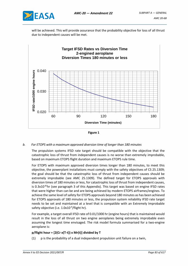
AMC-20 — Amendment 22 SUBPART A — GENERAL
AMC 20-6B
Annex II to ED Decision 2021/007/R Page 83 of 617
will be achieved. This will provide assurance that the probability objective for loss of all thrust due to independent causes will be met.
Figure 1
b. For ETOPS with a maximum approved diversion time of longer than 180 minutes
The propulsion systems IFSD rate target should be compatible with the objective that the catastrophic loss of thrust from independent causes is no worse than extremely improbable, based on maximum ETOPS flight duration and maximum ETOPS rule time.
For ETOPS with maximum approved diversion times longer than 180 minutes, to meet this objective, the powerplant installations must comply with the safety objectives of CS 25.1309; the goal should be that the catastrophic loss of thrust from independent causes should be extremely improbable (see AMC 25.1309). The defined target for ETOPS approvals with diversion times of 180 minutes or less, for catastrophic loss of thrust from independent causes, is 0.3x10⁻⁸/hr (see paragraph 3 of this Appendix). This target was based on engine IFSD rates that were higher than can be and are being achieved by modern ETOPS airframes/engines. To achieve the same level of safety for ETOPS approvals beyond 180 minutes as has been achieved for ETOPS approvals of 180 minutes or less, the propulsion system reliability IFSD rate target needs to be set and maintained at a level that is compatible with an Extremely Improbable safety objective (i.e. 1.0x10⁻⁹/flight hr).
For example, a target overall IFSD rate of 0.01/1000 hr (engine hours) that is maintained would result in the loss of all thrust on two engine aeroplanes being extremely improbable even assuming the longest time envisaged. The risk model formula summarised for a two-engine aeroplane is:
p/flight hour = [2(Cr xT-t) x Mr(t)] divided by T
(1) p is the probability of a dual independent propulsion unit failure on a twin,
0.020
0.030
0.040
60 90 120 150 180
IFS
D r
ate
/10
00
en
gin
e h
ou
rs
Diversion Time (minutes)
Target IFSD Rates vs Diversion Time 2-engined aeroplane
Diversion Times 180 minutes or less
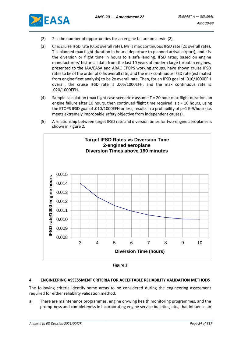
AMC-20 — Amendment 22 SUBPART A — GENERAL
AMC 20-6B
Annex II to ED Decision 2021/007/R Page 84 of 617
(2) 2 is the number of opportunities for an engine failure on a twin (2),
(3) Cr is cruise IFSD rate (0.5x overall rate), Mr is max continuous IFSD rate (2x overall rate), T is planned max flight duration in hours (departure to planned arrival airport), and t is the diversion or flight time in hours to a safe landing. IFSD rates, based on engine manufacturers’ historical data from the last 10 years of modern large turbofan engines, presented to the JAA/EASA and ARAC ETOPS working groups, have shown cruise IFSD rates to be of the order of 0.5x overall rate, and the max continuous IFSD rate (estimated from engine fleet analysis) to be 2x overall rate. Then, for an IFSD goal of .010/1000EFH overall, the cruise IFSD rate is .005/1000EFH, and the max continuous rate is .020/1000EFH.
(4) Sample calculation (max flight case scenario): assume T = 20 hour max flight duration, an engine failure after 10 hours, then continued flight time required is t = 10 hours, using the ETOPS IFSD goal of .010/1000EFH or less, results in a probability of p=1 E-9/hour (i.e. meets extremely improbable safety objective from independent causes).
(5) A relationship between target IFSD rate and diversion times for two-engine aeroplanes is shown in Figure 2.
Figure 2
4. ENGINEERING ASSESSMENT CRITERIA FOR ACCEPTABLE RELIABILITY VALIDATION METHODS
The following criteria identify some areas to be considered during the engineering assessment required for either reliability validation method.
a. There are maintenance programmes, engine on-wing health monitoring programmes, and the promptness and completeness in incorporating engine service bulletins, etc., that influence an
0.008
0.009
0.010
0.011
0.012
0.013
0.014
0.015
3 4 5 6 7 8 9 10
IFS
D r
ate
/1000 e
ng
ine h
ou
rs
Diversion Time (hours)
Target IFSD Rates vs Diversion Time2-engined aeroplane
Diversion Times above 180 minutes
AMC-20 — Amendment 22 SUBPART A — GENERAL
AMC 20-6B
Annex II to ED Decision 2021/007/R Page 85 of 617
operator’s ability to maintain a level of reliability. The data and information required will form a basis from which a world-fleet engine shutdown rate will be established, for use in determining whether a particular airframe/engine combination complies with criteria for extended-range operation.
b. An analysis will be made on a case-by-case basis, of all significant failures, defects and malfunctions experienced in service or during testing, including reliability validation testing, for the particular airframe/engine combination. Significant failures are principally those causing or resulting in in-flight shutdown or flameout of the engine(s), but may also include unusual ground failures and/or unscheduled removal of engines. In making the assessment, consideration should be given to the following:
(1) The type of propulsion system, previous experience, whether the power-unit is new or a derivative of an existing model, and the operating thrust level to be used after one engine shutdown;
(2) The trends in the cumulative 12-month rolling average, updated quarterly, of in-flight shutdown rates versus propulsion system flight hours and cycles;
(3) The demonstrated effect of corrective modifications, maintenance, etc. on the possible future reliability of the propulsion system;
(4) Maintenance actions recommended and performance and their effect on propulsion system and APU failure rates;
(5) The accumulation of operational experience which covers the range of environmental conditions likely to be encountered;
(6) Intended maximum flight duration and maximum diversion in the ETOPS segment, used in the extended-range operation under consideration.
c. Engineering judgement will be used in the analysis of paragraph b. above, such that the potential improvement in reliability, following the introduction of corrective actions identified during the analysis, can be quantified.
d. The resultant predicted reliability level and the criteria developed in accordance with Section 3 (RISK MANAGEMENT AND RISK MODEL) should be used together to determine the maximum diversion time for which the particular airframe/engine combination qualifies.
e. The type design standard for type approval of the airframe/engine combination, and the engine, for ETOPS will include all modifications and maintenance actions for which full or partial credit is taken by the (S)TC holder and other actions required by EASA to enhance reliability. The schedule for incorporation of type design standard items should normally be established in the configuration, maintenance and procedures (CMP) document, for example in terms of calendar time, hours or cycles.
f. When third-country (S)TC holders’ and/or third-country operators’ data is evaluated, the respective foreign authorities will be offered to participate in the assessment.
g. ETOPS reliability tracking board (RTB)’s findings
Once an assessment has been completed and the RTB has documented its findings, EASA will declare whether or not the particular airframe/engine combination and engine satisfy the relevant considerations of this AMC. Items recommended qualifying the propulsion system, such as maintenance requirements and limitations will be included in the Assessment Report (Chapter II Section 10 of this AMC).
AMC-20 — Amendment 22 SUBPART A — GENERAL
AMC 20-6B
Annex II to ED Decision 2021/007/R Page 86 of 617
h. In order to establish that the predicted propulsion system reliability level is achieved and subsequently maintained, the (S)TC holder should submit to EASA an assessment of the reliability of the propulsion system on a quarterly basis. The assessment should concentrate on the ETOPS configured fleet and should include ETOPS-related events from the non-configured fleet of the subject airframe/engine combination and from other combinations utilising a related engine model.
5. EARLY ETOPS OCCURRENCES REPORTING & TRACKING
a. The holder of a (supplemental) type certificate of an engine, which has been approved for ETOPS without service experience in accordance with this AMC, should establish a system to address problems and occurrences encountered on the engine that could affect the safety of operations and timely resolution.
b. The system should contain a means for: the prompt identification of ETOPS related events, the timely notification of the event to EASA, proposing a resolution of the event and obtaining EASA’s approval. The implementation of the problem resolution can be accomplished by way of EASA-approved change(s) to the type design, the manufacturing process, or an operating or maintenance procedure.
c. The reporting system should be in place for at least the first 100 000 fleet engine hours. The reporting requirement remains in place until the fleet has demonstrated a stable in-flight shutdown rate in accordance with the targets defined in this Appendix 1.
d. For the early ETOPS service period, an applicant must define the sources and content of the service data that will be made available to them in support of their occurrence reporting and tracking system. The content of this data should be adequate to evaluate the specific cause of all service incidents reportable under Part 21A.3A(b), in addition to the occurrences that could affect the safety of operations, and should be reported, including:
(1) in-flight shutdown events and rates;
(2) inability to control the engine or obtain desired power;
(3) precautionary thrust reductions (except for normal troubleshooting as allowed in the aircraft flight manual);
(4) degraded propulsion in-flight start capability;
(5) un-commanded power changes or surges;
(6) diversion or turn-back;
(7) failures or malfunctions of ETOPS significant systems;
(8) unscheduled engine removals for conditions that could result in one of the reportable items listed above.
6. CONTINUED AIRWORTHINESS OF TYPE DESIGN
For ETOPS, EASA will periodically review its original findings by means of a Reliability Tracking Board. In addition, the EASA document containing the CMP standard will be revised as necessary.
Note: The reliability tracking board will usually comprise specialists from aeroplane and engine disciplines (see also Appendix 2).
Periodic meetings of the ETOPS reliability tracking board are normally frequent at the start of the assessment of a new product. The periodicity is adjusted by EASA upon accumulation of substantial service experience if there is evidence that the reliability of the product is sufficiently stable. The
AMC-20 — Amendment 22 SUBPART A — GENERAL
AMC 20-6B
Annex II to ED Decision 2021/007/R Page 87 of 617
periodic meetings of the board are discontinued once an ETOPS product, or family of products, has been declared mature by EASA.
Note: The overall engine IFSD rate should be viewed as a world fleet average target figure of engine reliability (representative of the airframe/engine combination being considered) and if exceeded, may not, in itself, trigger action in the form of a change to the ETOPS design standard or a reduction in the ETOPS approval status of the engine. The actual IFSD rate and its causes should be assessed with considerable engineering judgement. For example, a high IFSD rate early after the commencement of the operation may be due to the limited number of hours contributing to the high rate. There may have been only one shutdown. The underlying causes have to be considered carefully. Conversely, a particular single event may warrant corrective action implementation, even though the overall IFSD rate objective is being achieved.
a. Mature ETOPS products
A family of ETOPS products with a high degree of similarity is considered to be mature ones if:
(1) The product family has accumulated at least 250 000 flight hours for an aeroplane family or 500 000 operating hours for an engine family;
(2) The product family has accumulated service experience covering a comprehensive spectrum of operating conditions (e.g. cold, hot, high, and humid);
(3) Each ETOPS approved model or variant in the family has achieved the reliability objectives for ETOPS and has remained stable at or below the objectives fleet-wide for at least 2 years.
New models or significant design changes may not be considered mature until they have individually satisfied the condition of paragraph 6.a above.
EASA makes the determination of when a product or a product family is considered mature.
b. Surveillance of mature ETOPS products
The (S)TC holder of an ETOPS product which EASA has found mature, should institute a process to monitor the reliability of the product in accordance with the objectives defined in this Appendix 1. In case of occurrence of an event or series of events or a statistical trend that implies a deviation of the reliability of the ETOPS fleet, or a portion of the ETOPS fleet (e.g. one model or a range of serial numbers), above the limits specified for ETOPS in this AMC, the (S)TC holder should:
(1) Inform EASA and define a means to restore the reliability through a minor revision of the CMP document, with a compliance schedule to be agreed with EASA if the situation has no immediate safety impact;
(2) Inform EASA and propose an ad hoc follow-up by EASA until the concern has been alleviated or confirmed if the situation requires further assessment;
(3) Inform EASA and propose the necessary corrective action(s) to be mandated by EASA through an AD if a direct safety concern exists.
In the absence of a specific event or trend requiring action, the (S)TC holder should provide EASA with the basic statistical indicators prescribed in this Appendix 1 on a yearly basis.
c. Minor revision of the ETOPS CMP document
A minor revision of the ETOPS CMP document is one that contains only editorial adjustments, configurations, maintenance and procedures equivalent to those already approved by EASA or new reliability improvements which have no immediate impact on the safety of ETOPS flights
AMC-20 — Amendment 22 SUBPART A — GENERAL
AMC 20-6B
Annex II to ED Decision 2021/007/R Page 88 of 617
and which are introduced as a means to control the continued compliance with the reliability objectives of ETOPS.
Minor revisions of the ETOPS CMP document should be approved by authorised signatories personnel of the (S)TC holder under the provisions of its approved design organisation handbook.
7. DESIGN ORGANISATION APPROVALS
(S)TC holders of products approved for ETOPS should hold a design organisation approval (DOA) conforming to Part 21, with the appropriate terms of approval and privileges. Their approved design organisation handbook (DOH) must contain an appropriate description of the organisation and procedures covering all applicable tasks and responsibilities of Part 21 and this AMC. [Amdt 20/7] [Amdt 20/21]
AMC-20 — Amendment 22 SUBPART A — GENERAL
AMC 20-6B
Annex II to ED Decision 2021/007/R Page 89 of 617
Appendix 2 to AMC 20-6B – Aircraft systems reliability assessment
1. ASSESSMENT PROCESS
The intent of this Appendix is to provide additional clarification to Sections 7 and 8 of Chapter II of this AMC. Airframe systems are required to show compliance with CS 25.1309. To establish whether a particular airframe/engine combination has satisfied the reliability requirements concerning the aircraft systems for extended-range operations, an assessment will be made by EASA, using all pertinent systems data provided by the applicant. To accomplish this assessment, EASA will need world-fleet data (where available) and data from various sources (operators, (S)TC holder, original equipment manufacturers (OEMs)). This data should be extensive enough and of sufficient maturity to enable EASA to assess with a high level of confidence, using engineering and operational judgement, that the risk of systems failures during a normal ETOPS flight or a diversion, is sufficiently low in direct relationship with the consequence of such failure conditions, under the operational environment of ETOPS missions.
EASA will declare whether or not the current system reliability of a particular airframe/engine combination satisfies the relevant criteria.
Included in the declaration, if the airframe/engine combination satisfies the relevant criteria, will be the airframe build standard, systems configuration, operating conditions and limitations, that are required to qualify the ETOPS significant systems as suitable for extended-range operations.
Alternatively, where type design approval for Early ETOPS is sought at first entry into service, the engineering assessment can be based on substantiation by analysis, test, in-service experience or other means to show that the airframe significant systems will minimise failures and malfunctions, and will achieve a failure rate that is compatible with the specified safety target.
2. SYSTEM SAFETY ASSESSMENT ‘SSA’ (INCLUDING RELIABILITY ANALYSIS)
The system safety assessment (SSA) which should be conducted in accordance with CS 25.1309 for all ETOPS significant systems should follow the steps below:
a. Conduct a (supplemental) functional hazard assessment (FHA) considering the ETOPS missions. In determining the effect of a failure condition during an ETOPS mission, the following should also be reviewed:
(1) Crew workload over a prolonged period of time;
(2) Operating conditions at single engine altitude;
(3) Lesser crew familiarity with the procedures and conditions to fly to and land at diversion aerodromes.
b. Introduce any additional failure scenario/objectives necessary to comply with this AMC.
c. For compliance demonstration of ETOPS significant system reliability to CS 25.1309, there will be no distinction made between ETOPS group 1 and group 2 systems. For qualitative analysis (FHA), the maximum flight time and the maximum ETOPS diversion time should be considered. For quantitative analysis (SSA), the average ETOPS mission time and maximum ETOPS diversion time should be considered. Consideration should be given to how the particular airframe/engine combination is to be utilised, and analyse the potential route structure and city pairs available, based upon the range of the aeroplane.
d. Consider effects of prolonged time and at single engine altitude in terms of continued operation of remaining systems following failures.
AMC-20 — Amendment 22 SUBPART A — GENERAL
AMC 20-6B
Annex II to ED Decision 2021/007/R Page 90 of 617
e. Specific ETOPS maintenance tasks, intervals and specific ETOPS flight procedures necessary to attain the safety objectives, shall be included in the appropriate approved documents (e.g. CMP document, MMEL).
f. Safety assessments should consider the flight consequences of single or multiple system failures leading to a diversion and the probability and consequences of subsequent failures or exhaustion of the capacity of time critical systems, which might occur during the diversion.
Safety assessments should determine whether a diversion should be conducted to the nearest aerodrome or to an aerodrome presenting better operating conditions, considering:
(1) The effect of the initial failure condition on the capability of the aeroplane to cope with adverse conditions at the diversion aerodrome, and
(2) The means available to the crew to assess the extent and evolution of the situation during a prolonged diversion.
The aircraft flight manual and the flight crew warning and alerting and display systems should provide clear information to enable the flight crew to determine when failure conditions are such that a diversion is necessary.
3. RELIABILITY VALIDATION METHODS
There are two extremes in the ETOPS process with respect to maturity; one is the demonstration of stable reliability by the accumulation of in-service experience and the other is by design, analysis and test programmes, agreed between the (S)TC holders and EASA/the authority.
a. In-service experience/systems safety assessment (SSA)
In-service experience should generally be in accordance with that identified in Appendix 1 for each airframe/engine combination. When considering the acceptability of airframe systems for ETOPS, maturity should be assessed in terms of used technology and the particular design under review.
In performing the SSA, defined in paragraph 2 of this Appendix 2, particular account will be taken of the following:
(1) For identical or similar equipment to those used on other aeroplanes, the SSA failure rates should be validated by in-service experience:
(i) The amount of in-service experience (either direct or related) should be indicated for each equipment of an ETOPS significant system.
(ii) Where related experience is used to validate failure modes and rates, an analysis should be produced to show the validity of the in-service experience.
(iii) In particular, if the same equipment is used on a different airframe/engine combination, it should be shown that there is no difference in operating conditions (e.g., vibrations, pressure, temperature) or that these differences do not adversely affect the failure modes and rates.
(iv) If in-service experience with similar equipment on other aeroplanes is claimed to be applicable, an analysis should be produced substantiating the reliability figures used on the quantitative analysis. This substantiation analysis should include details of the differences between the similar and new equipment, details of the in-service experience of the similar equipment and details of any ‘lessons learnt’ from modifications introduced and included in the new equipment.
AMC-20 — Amendment 22 SUBPART A — GENERAL
AMC 20-6B
Annex II to ED Decision 2021/007/R Page 91 of 617
(v) For certain equipment (e.g. IDGs, TRUs, bleeds and emergency generators), this analysis may have to be backed up by tests. This should be agreed with EASA.
(2) For new or substantially modified equipment, account should be taken in the SSA for the lack of validation of the failure rates by service experience.
A study should be conducted to determine the sensitivity of the assumed SSA failure condition probabilities to the failure rates of the subject equipment.
Should a failure case probability be sensitive to this equipment failure rate and close to the required safety objective, particular provision precautions should be applied (e.g. temporary dispatch restrictions, inspections, maintenance procedures, crew procedures) to account for the uncertainty, until the failure rate has been appropriately validated by in-service experience.
b. Early ETOPS
Where type design approval for early ETOPS is sought at the first entry into service of the airframe/engine combination, the engineering assessment can be based on substantiation by analysis, test, in-service experience (the same engine or airframe with different engines) or other means, to show that the ETOPS significant systems will achieve a failure rate that is compatible with the specified safety objective. An approval plan, defining the early ETOPS reliability validation tests and processes, should be submitted by the (S)TC holders to EASA for agreement. This certification plan should be completed and implemented to the satisfaction of EASA before an ETOPS type design approval will be granted.
(1) Acceptable early ETOPS approval plan
In addition to the above considerations, the following should be complied with for an early ETOPS approval:
(i) Aeroplane testing
For each airframe/engine combination that has not yet accumulated at least 15 000 engine hours in service, to be approved for ETOPS, one or more aeroplanes should conduct flight testing which demonstrates that the airframe/engine combination, its components and equipment are capable for, and function properly during, ETOPS flights and ETOPS diversions. These flight tests may be coordinated, but they are not in place of flight testing required in Part 21.A.35(b)(2).
The flight test programme should include:
(A) Flights simulating actual ETOPS operation, including normal cruise altitude, step climbs and APU operation if required for ETOPS;
(B) Demonstration of the maximum normal flight duration with the maximum diversion time for which eligibility is sought;
(C) Engine inoperative maximum time diversions to demonstrate the aeroplane and propulsion system’s capability to safely conduct an ETOPS diversion, including a repeat of an MCT diversion on the same engine;
(D) Non-normal conditions to demonstrate the aeroplane’s capability to safely conduct an ETOPS diversion under worst-case probable system failure conditions;
(E) Diversions into representative operational diversionary airports;
AMC-20 — Amendment 22 SUBPART A — GENERAL
AMC 20-6B
Annex II to ED Decision 2021/007/R Page 92 of 617
(F) Repeated exposure to humid and inclement weather on the ground followed by long-range operations at normal cruise altitude;
(G) Validation of the adequacy of the aeroplane’s flying qualities, performance and flight crew’s ability to deal with the conditions of paragraphs (C), (D) and (E) above.
(H) Engine-inoperative diversions evenly distributed among the number of engines except as required by paragraph (C) above.
(I) Provisions for the test aeroplane(s) to be operated and maintained using the recommended operations and maintenance manual procedures during the aeroplane demonstration test.
(J) At the completion of the aeroplane(s) demonstration testing, an operational or functional check of the ETOPS significant systems must undergo as per the Instructions for Continued Airworthiness of CS 25.1529. The engines must also undergo a gas path inspection. These inspections are intended to identify any abnormal conditions that could result in an in-flight shutdown or diversion. Any abnormal conditions must be identified, tracked and resolved in accordance with subpart (2) below. This inspection requirement can be relaxed for ETOPS significant systems similar in design to proven models.
(K) Maintenance and operational procedures. The applicant must validate all ETOPS significant systems maintenance and operational procedures. Any problems found as a result of the validation must be identified, tracked and resolved in accordance with subpart (2) below.
(ii) APU testing
If an APU is required for ETOPS, one APU of the type to be certified with the aeroplane should complete a test consisting of 3 000 equivalent aeroplane operational cycles. Following completion of the demonstration test, the APU must be disassembled and inspected. Any potential sources of in-flight start and/or run events should be identified, tracked and resolved in accordance with subpart (2) below.
(2) Early ETOPS occurrence reporting & tracking
(i) The holder of a (S)TC of an aeroplane which has been approved for ETOPS without service experience in accordance with this AMC, should establish a system to address problems and occurrences encountered on the airframe and propulsion systems that could affect the safety of ETOPS operations in order to timely resolve these events.
(ii) The system should contain a means for the prompt identification of ETOPS-related events, the timely notification of the event to EASA and for proposing to, and obtaining EASA’s approval for the resolution of this event. The implementation of the problem resolution can be accomplished by way of an EASA-approved change(s) to the type design, the manufacturing process, or an operating or maintenance procedure.
(iii) The reporting system should be in place for at least the first 100 000 flight hours. The reporting requirement remains in place until the airframe and propulsion
AMC-20 — Amendment 22 SUBPART A — GENERAL
AMC 20-6B
Annex II to ED Decision 2021/007/R Page 93 of 617
systems have demonstrated stable reliability in accordance with the required safety objectives.
(iv) If the airframe/engine combination certified is a derivative of a previously certified aeroplane, these criteria may be amended by EASA, to require reporting on only those changed systems.
(v) For the early ETOPS service period, an applicant must define the sources and content of in-service data that will be made available to them in support of their occurrence reporting and tracking system. The content of this data should be adequate to evaluate the specific cause of all service incidents reportable under Part 21.A.3A(b), in addition to the occurrences that could affect the safety of ETOPS operations and should be reported, including:
(A) In-flight shutdown events;
(B) Inability to control the engine or obtain desired power;
(C) Precautionary thrust reductions (except for normal troubleshooting as allowed in the aircraft flight manual);
(D) Degraded propulsion in-flight start capability;
(E) Inadvertent fuel loss or availability, or uncorrectable fuel imbalance in flight;
(F) Technical air turn-backs or diversions associated with an ETOPS Group 1 system;
(G) Inability of an ETOPS Group 1 system, designed to provide backup capability after failure of a primary system, to provide the required backup capability in-flight;
(H) Any loss of electrical power or hydraulic power system, during a given operation of the aeroplane;
(I) Any event that would jeopardise the safe flight and landing of the aeroplane during an ETOPS flight.
4. CONTINUING SURVEILLANCE
In order to confirm that the predicted system reliability level is achieved and maintained, the (S)TC holder should monitor the reliability of airframe ETOPS significant systems after entry into service. The (S)TC holder should submit a report to EASA, initially on a quarterly basis (for the first year of operation) and thereafter on a periodic basis and for a time to be agreed with EASA. The monitoring task should include all events on ETOPS significant systems, from both the ETOPS and non-ETOPS fleet of the subject family of airframes. This additional reliability monitoring is required only for ETOPS Group 1 systems.
5. CONTINUED AIRWORTHINESS
a. Reliability Tracking Board
EASA will periodically review its original findings by means of a reliability tracking board. In addition, the EASA document containing the CMP standard will be revised as necessary.
Note: The reliability tracking board will usually comprise specialists from aeroplane and engine disciplines. (See also Appendix 1).
Periodic meetings of the ETOPS reliability tracking board are normally frequent at the start of the assessment of a new product. The periodicity is adjusted by EASA upon accumulation of
AMC-20 — Amendment 22 SUBPART A — GENERAL
AMC 20-6B
Annex II to ED Decision 2021/007/R Page 94 of 617
substantial in-service experience if there is evidence that the reliability of the product is sufficiently stable. The periodic meetings of the board are discontinued once an ETOPS product, or family of products, has been declared mature by EASA.
b. Mature ETOPS products
A family of ETOPS products with a high degree of similarity is considered to be mature when:
(1) The product family has accumulated at least 250 000 flight hours for an aeroplane family;
(2) The product family has accumulated service experience covering a comprehensive spectrum of operating conditions (e.g. cold, hot, high, humid);
(3) Each ETOPS approved model or variant in the family has achieved the reliability objectives for ETOPS and has remained stable at or below the objectives fleet-wide for at least 2 years.
New models or significant design changes may not be considered mature until they have individually satisfied the conditions specified above.
EASA makes the determination of when a product or a product family is considered mature.
c. Surveillance of mature ETOPS products
The (S)TC holder of an ETOPS product which EASA has found mature, should institute a process to monitor the reliability of the product in accordance with the objectives defined in this Appendix. In case of occurrence of an event, a series of events or a statistical trend that implies a deviation of the reliability of the ETOPS fleet, or a portion of the ETOPS fleet (e.g. one model or a range of serial numbers), above the limits specified for ETOPS, the (S)TC should:
(1) Inform EASA and define a means to restore the reliability through a Minor Revision of the CMP document, with a compliance schedule to be agreed with EASA if the situation has no immediate safety impact;
(2) Inform EASA and propose an ad hoc follow-up by EASA until the concern has been alleviated, or confirmed if the situation requires further assessment;
(3) Inform EASA and propose the necessary corrective action(s) to be mandated by EASA through an AD if a direct safety concern exists.
In the absence of a specific event or trend requiring action, the (S)TC holder should provide EASA with the basic statistical indicators prescribed in this Appendix 2 on a yearly basis.
d. Minor revision of the ETOPS CMP document
A minor revision of the ETOPS CMP document is one that contains only editorial adjustments, configurations, maintenance and procedures equivalent to those already approved by EASA, or new reliability improvements which have no immediate impact on the safety of ETOPS flights and which are introduced as a means to control the continued compliance with the reliability objectives of ETOPS.
Minor revisions of the ETOPS CMP document should be approved by authorised signatories of the design organisation and under the provisions of its approved design organisation handbook.
6. DESIGN ORGANISATION APPROVAL
(S)TC holders of products approved for ETOPS should hold a design organisation approval (DOA) conforming to Part 21, with the appropriate terms of approval and privileges. Their approved design
AMC-20 — Amendment 22 SUBPART A — GENERAL
AMC 20-6B
Annex II to ED Decision 2021/007/R Page 95 of 617
organisation handbook (DOH) must contain an appropriate description of the organisation and procedures covering all applicable tasks and responsibilities of Part 21 and this AMC.
[Amdt 20/7] [Amdt 20/21]

AMC-20 — Amendment 22 SUBPART A — GENERAL
AMC 20-6B
Annex II to ED Decision 2021/007/R Page 96 of 617
Appendix 3 to AMC 20-6B – Operational limitations
1. AREA OF OPERATION
An operator is, when specifically approved, authorised to conduct ETOPS flights within an area where the diversion time, at any point along the proposed route of flight, to an adequate ETOPS en-route alternate aerodrome is within the operator’s approved diversion time (under standard conditions in still air) at the approved one-engine-inoperative cruise speed.
2. OPERATOR’S APPROVED DIVERSION TIME
The procedures established by the operator should ensure that ETOPS is only planned on routes where the operator’s approved diversion time to an adequate ETOPS en-route alternate aerodrome can be met.
3. ISSUE OF THE ETOPS OPERATIONS APPROVAL BY THE COMPETENT AUTHORITY
The approval issued by the competent authority for ETOPS operations should be based on the following information provided by the operator:
a. Specification of the particular airframe/engine combinations, including the current approved CMP document required for ETOPS as normally identified in the AFM;
b. Authorised area of operation;
c. Minimum altitudes to be flown along planned and diversionary routes;
d. Operator’s approved diversion time;
e. Aerodromes identified to be used, including alternates, and associated instrument approaches and operating minima;
f. The approved maintenance and reliability programme for ETOPS;
g. Identification of those aeroplanes designated for ETOPS by make and model as well as serial number and registration;
h. Specification of routes and the ETOPS diversion time necessary to support those routes;
i. The one-engine-inoperative cruise speed, which may be area-specific, depending upon anticipated aeroplane loading and likely fuel penalties associated with the planned procedures;
j. Processes and related resources allocated to initiate and sustain ETOPS operations in a manner that demonstrates commitment by management and all personnel involved in ETOPS continued airworthiness and operational support;
k. The plan for establishing compliance with the build standard required for type design approval, e.g. CMP document compliance.
[Amdt 20/7] [Amdt 20/21]
AMC-20 — Amendment 22 SUBPART A — GENERAL
AMC 20-6B
Annex II to ED Decision 2021/007/R Page 97 of 617
Appendix 4 to AMC 20-6B – Flight preparation and in-flight procedures
1. GENERAL
The flight release considerations specified in this paragraph are in addition to the applicable operational requirements. They specifically apply to ETOPS. Although many of the considerations in this AMC are currently incorporated into approved programmes for other aeroplanes or route structures, the unique nature of ETOPS necessitates a re-examination of these operations to ensure that the approved programmes are adequate for this purpose.
2. MINIMUM EQUIPMENT LIST (MEL)
The system redundancy levels appropriate to ETOPS should be reflected in the master minimum equipment list (MMEL). An operator’s MEL may be more restrictive than the MMEL considering the kind of ETOPS operation proposed, equipment and in-service problems unique to the operator. Systems and equipment considered to have a fundamental influence on safety may include, but are not limited to, the following:
a. electrical;
b. hydraulic;
c. pneumatic;
d. flight instrumentation, including warning and caution systems;
e. fuel;
f. flight control;
g. ice protection;
h. engine start and ignition;
i. propulsion system instruments;
j. navigation and communications, including any route specific long-range navigation and communication equipment;
k. auxiliary power-unit;
l. air conditioning and pressurisation;
m. cargo fire suppression;
n. engine fire protection;
o. emergency equipment;
p. systems and equipment required for engine condition monitoring.
In addition, the following systems are required to be operative for dispatch for ETOPS with diversion times above 180 minutes:
q. Fuel quantity indicating system (FQIS);
r. APU (including electrical and pneumatic supply to its designed capability), if necessary to comply with ETOPS requirements;
s. Automatic engine or propeller control system;
AMC-20 — Amendment 22 SUBPART A — GENERAL
AMC 20-6B
Annex II to ED Decision 2021/007/R Page 98 of 617
t. Communication system(s) relied on by the flight crew to comply with the requirement for communication capability.
3. COMMUNICATION AND NAVIGATION FACILITIES
For releasing an aeroplane on an ETOPS flight, the operators should ensure that:
a. Communications facilities are available to provide under normal conditions of propagation at all planned altitudes of the intended flight and the diversion scenarios, reliable two-way voice and/or data link communications;
b. Visual and non-visual aids are available at the specified alternates for the anticipated types of approaches and operating minima.
4. FUEL SUPPLY
a. General
For releasing an aeroplane on an ETOPS flight, the operators should ensure that it carries sufficient fuel and oil to meet the applicable operational requirements and any additional fuel that may be determined in accordance with this Appendix.
b. Critical fuel reserve
In establishing the critical fuel reserves, the applicant is to determine the fuel necessary to fly to the most critical point (at normal cruise speed and altitude, taking into account the anticipated meteorological conditions for the flight) and execute a diversion to an ETOPS en-route alternate under the conditions outlined in this Appendix, the ‘Critical fuel scenario’ (paragraph c. below).
These critical fuel reserves should be compared to the normal applicable operational requirements for the flight. If it is determined by this comparison that the fuel to complete the critical fuel scenario exceeds the fuel that would be on board at the most critical point, as determined by applicable operational requirements, additional fuel should be included to the extent necessary to safely complete the critical fuel scenario. When considering the potential diversion distance flown, account should be taken of the anticipated routing and approach procedures, in particular any constraints caused by airspace restrictions or terrain.
c. Critical fuel scenario
The following describes a scenario for a diversion at the most critical point. The applicant should confirm compliance with this scenario when calculating the critical fuel reserve necessary.
Note 1: If an APU is one of the required power sources, then its fuel consumption should be accounted for during the appropriate phases of flight.
Note 2: Additional fuel consumptions due to any MEL or CDL items should be accounted for during the appropriate phases of flight, when applicable.
The aeroplane is required to carry sufficient fuel taking into account the forecast wind and weather to fly to an ETOPS route alternate assuming the greater of:
(1) A rapid decompression at the most critical point followed by descent to a 10 000 ft or a higher altitude if sufficient oxygen is provided in accordance with the applicable operational requirements.
(2) A flight at the approved one-engine-inoperative cruise speed assuming a rapid decompression and a simultaneous engine failure at the most critical point followed by descent to a 10 000 ft or a higher altitude if sufficient oxygen is provided in accordance with the applicable operational requirements.
AMC-20 — Amendment 22 SUBPART A — GENERAL
AMC 20-6B
Annex II to ED Decision 2021/007/R Page 99 of 617
(3) A flight at the approved one-engine-inoperative cruise speed assuming an engine failure at the most critical point followed by descent to the one-engine-inoperative cruise altitude.
Upon reaching the alternate, hold at 1 500 ft above field elevation for 15 minutes and then conduct an instrument approach and landing.
Add a 5 % wind speed factor (i.e. an increment to headwind or a decrement to tailwind) on the actual forecast wind used to calculate fuel in the greater of (1), (2) or (3) above to account for any potential errors in wind forecasting. If an operator is not using the actual forecast wind based on wind model acceptable to the competent authority, allow 5 % of the fuel required for (1), (2) or (3) above, as reserve fuel to allow for errors in wind data. A wind aloft forecasting distributed worldwide by the World Area Forecast System (WAFS) is an example of a wind model acceptable to the competent authority.
d. Icing
Correct the amount of fuel obtained in paragraph c. above taking into account the greater of:
(1) the effect of airframe icing during 10 % of the time during which icing is forecast (including ice accumulation on unprotected surfaces, and the fuel used by engine and wing anti-ice during this period);
(2) fuel for engine anti-ice, and if appropriate wing anti-ice for the entire time during which icing is forecast.
Note: Unless a reliable icing forecast is available, icing may be presumed to occur when the total air temperature (TAT) at the approved one-engine-inoperative cruise speed is less than +10ºC, or if the outside air temperature is between 0ºC and -20ºC with a relative humidity (RH) of 55 % or greater.
The operator should have a programme established to monitor aeroplane in-service deterioration in cruise fuel burn performance and including in the fuel supply calculations sufficient fuel to compensate for any such deterioration. If there is no data available for such a programme, the fuel supply should be increased by 5 % to account for deterioration in cruise fuel burn performance.
5. ALTERNATE AERODROMES
To conduct an ETOPS flight, the ETOPS en-route alternate aerodromes should meet the weather requirements of planning minima for an ETOPS en-route alternate aerodrome contained in the applicable operational requirements. ETOPS planning minima apply until dispatch. The planned en-route alternates for using in the event of propulsion system failure or aeroplane system failure(s) which require a diversion should be identified and listed in the cockpit documentation (e.g. computerised flight plan) for all cases where the planned route to be flown contains an ETOPS point
See also Appendix 5 to this AMC ‘ETOPS En-route Alternate Aerodromes’.
6. IN-FLIGHT RE-PLANNING AND POST-DISPATCH WEATHER MINIMA
An aeroplane whether or not dispatched as an ETOPS flight may not re-route post dispatch without meeting the applicable operational requirements and without satisfying by a procedure that dispatch criteria have been met. The operator should have a system in place to facilitate such re-routes.
Post-dispatch, weather conditions at the ETOPS en-route alternates should be equal to or better than the normal landing minima for the available instrument approach.
AMC-20 — Amendment 22 SUBPART A — GENERAL
AMC 20-6B
Annex II to ED Decision 2021/007/R Page 100 of 617
7. DELAYED DISPATCH
If the dispatch of a flight is delayed by more than one hour, pilots and/or operations personnel should monitor weather forecasts and airport status at the nominated en-route alternates to ensure that they stay within the specified planning minima requirements until dispatch.
8. DIVERSION DECISION-MAKING
Operators shall establish procedures for flight crew, outlining the criteria that indicate when a diversion or change of routing is recommended whilst conducting an ETOPS flight. For an ETOPS flight, in the event of the shutdown of an engine, these procedures should include the shutdown of an engine, fly to and land at the nearest aerodrome appropriate for landing.
Factors to be considered when deciding upon the appropriate course of action and suitability of an aerodrome for diversion may include but are not limited to:
a. aircraft configuration/weight/systems status;
b. wind and weather conditions en route at the diversion altitude;
c. minimum altitudes en route to the diversion aerodrome;
d. fuel required for the diversion;
e. aerodrome condition, terrain, weather and wind;
f. runways available and runway surface condition;
g. approach aids and lighting;
h. RFFS* capability at the diversion aerodrome;
i. facilities for aircraft occupants - disembarkation & shelter;
j. medical facilities;
k. PILOT’S familiarity with the aerodrome;
l. information about the aerodrome available to the flight crew.
Contingency procedures should not be interpreted in any way that prejudices the final authority and responsibility of the pilot-in-command for the safe operation of the aeroplane.
Note: For an ETOPS en-route alternate aerodrome, a published RFFS category equivalent to ICAO category 4, available at 30 minutes’ notice, is acceptable.
9. IN-FLIGHT MONITORING
During the flight, the flight crew should remain informed of any significant changes in conditions at designated ETOPS en-route alternate aerodromes. Prior to the ETOPS entry point, the forecast weather, established aeroplane status, fuel remaining, and where possible field conditions and aerodrome services and facilities at designated ETOPS en-route alternates are to be evaluated. If any conditions are identified which could preclude safe approach and landing on a designated en-route alternate aerodrome, then the flight crew should take appropriate action, such as re-routing as necessary, to remain within the operator’s approved diversion time of an en-route alternate aerodrome with forecast weather to be at or above landing minima. In the event this is not possible, the next nearest en-route alternate aerodrome should be selected provided the diversion time does not exceed the maximum approved diversion time. This does not override the pilot’s-in-command authority to select the safest course of action.
10. AEROPLANE PERFORMANCE DATA
The operator should ensure that the Operations Manual contains sufficient data to support the critical fuel reserve and area of operations calculation.
AMC-20 — Amendment 22 SUBPART A — GENERAL
AMC 20-6B
Annex II to ED Decision 2021/007/R Page 101 of 617
The following data should be based on the information provided by the (S)TC holder. The requirements for one-engine-inoperative performance en-route can be found in the applicable operational requirements.
Detailed one-engine-inoperative performance data including fuel flow for standard and non-standard atmospheric conditions and as a function of airspeed and power setting, where appropriate, covering:
a. drift down (includes net performance);
b. cruise altitude coverage including 10 000 feet;
c. holding;
d. altitude capability (includes net performance);
e. missed approach.
Detailed all-engine-operating performance data, including nominal fuel flow data, for standard and non-standard atmospheric conditions and as a function of airspeed and power setting, where appropriate, covering:
a. cruise (altitude coverage including 10 000 feet); and
b. holding.
It should also contain details of any other conditions relevant to extended-range operations which can cause significant deterioration of performance, such as ice accumulation on the unprotected surfaces of the aeroplane, ram air turbine (RAT) deployment, thrust reverser deployment, etc.
The altitudes, airspeeds, thrust settings, and fuel flow used in establishing the ETOPS area of operations for each airframe/engine combination should be used in showing the corresponding terrain and obstruction clearances in accordance with the applicable operational requirements.
11. OPERATIONAL FLIGHT PLAN
The type of operation (i.e. ETOPS, including the diversion time used to establish the plan) should be listed on the operational flight plan as required by the applicable operational requirements. [Amdt 20/7] [Amdt 20/21]
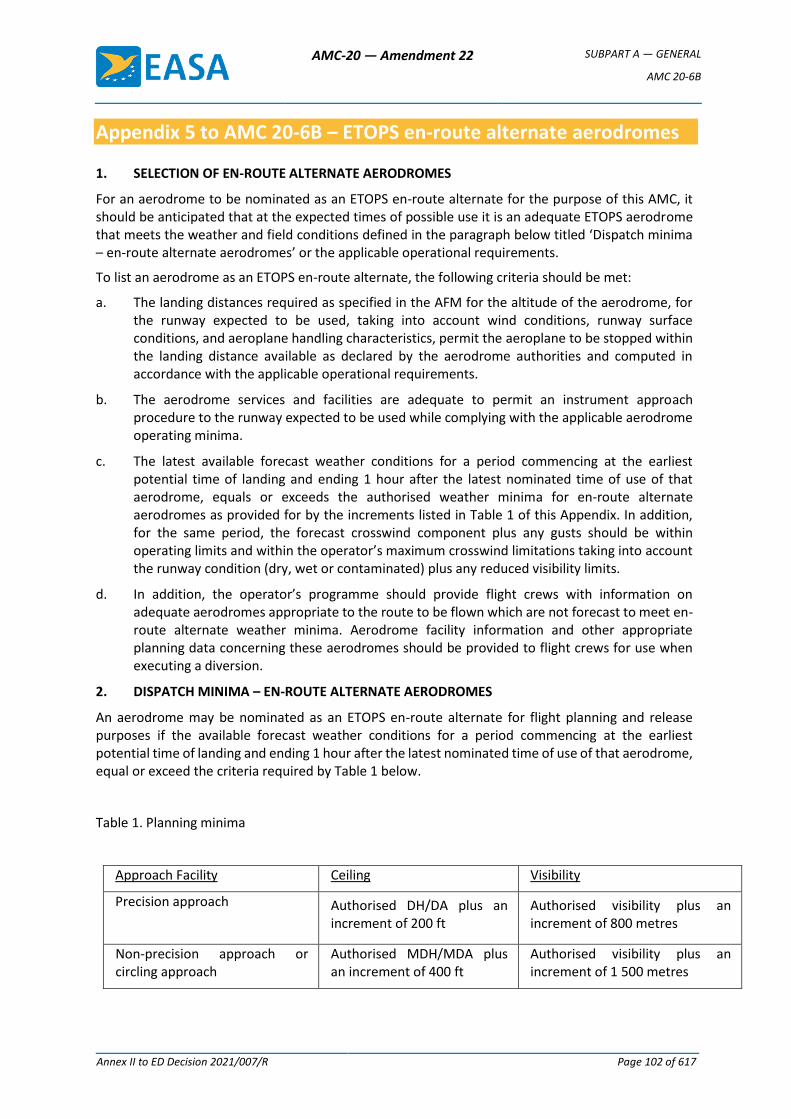
AMC-20 — Amendment 22 SUBPART A — GENERAL
AMC 20-6B
Annex II to ED Decision 2021/007/R Page 102 of 617
Appendix 5 to AMC 20-6B – ETOPS en-route alternate aerodromes
1. SELECTION OF EN-ROUTE ALTERNATE AERODROMES
For an aerodrome to be nominated as an ETOPS en-route alternate for the purpose of this AMC, it should be anticipated that at the expected times of possible use it is an adequate ETOPS aerodrome that meets the weather and field conditions defined in the paragraph below titled ‘Dispatch minima – en-route alternate aerodromes’ or the applicable operational requirements.
To list an aerodrome as an ETOPS en-route alternate, the following criteria should be met:
a. The landing distances required as specified in the AFM for the altitude of the aerodrome, for the runway expected to be used, taking into account wind conditions, runway surface conditions, and aeroplane handling characteristics, permit the aeroplane to be stopped within the landing distance available as declared by the aerodrome authorities and computed in accordance with the applicable operational requirements.
b. The aerodrome services and facilities are adequate to permit an instrument approach procedure to the runway expected to be used while complying with the applicable aerodrome operating minima.
c. The latest available forecast weather conditions for a period commencing at the earliest potential time of landing and ending 1 hour after the latest nominated time of use of that aerodrome, equals or exceeds the authorised weather minima for en-route alternate aerodromes as provided for by the increments listed in Table 1 of this Appendix. In addition, for the same period, the forecast crosswind component plus any gusts should be within operating limits and within the operator’s maximum crosswind limitations taking into account the runway condition (dry, wet or contaminated) plus any reduced visibility limits.
d. In addition, the operator’s programme should provide flight crews with information on adequate aerodromes appropriate to the route to be flown which are not forecast to meet en-route alternate weather minima. Aerodrome facility information and other appropriate planning data concerning these aerodromes should be provided to flight crews for use when executing a diversion.
2. DISPATCH MINIMA – EN-ROUTE ALTERNATE AERODROMES
An aerodrome may be nominated as an ETOPS en-route alternate for flight planning and release purposes if the available forecast weather conditions for a period commencing at the earliest potential time of landing and ending 1 hour after the latest nominated time of use of that aerodrome, equal or exceed the criteria required by Table 1 below.
Table 1. Planning minima
Approach Facility Ceiling Visibility
Precision approach
Authorised DH/DA plus an increment of 200 ft
Authorised visibility plus an increment of 800 metres
Non-precision approach or circling approach
Authorised MDH/MDA plus an increment of 400 ft
Authorised visibility plus an increment of 1 500 metres
AMC-20 — Amendment 22 SUBPART A — GENERAL
AMC 20-6B
Annex II to ED Decision 2021/007/R Page 103 of 617
The above criteria for precision approaches are only to be applied to Category 1 approaches.
When determining the usability of an instrument approach (IAP), forecast wind plus any gusts should be within operating limits, and within the operator’s maximum crosswind limitations taking into account the runway condition (dry, wet or contaminated) plus any reduced visibility limits. Conditional forecast elements need not be considered, except that a PROB 40 or TEMPO condition below the lowest applicable operating minima should be taken into account.
When dispatching under the provisions of the MEL, those MEL limitations affecting instrument approach minima should be considered in determining ETOPS alternate minima.
3. EN-ROUTE ALTERNATE AERODROME PLANNING MINIMA – ADVANCED LANDING SYSTEMS
The increments required by Table 1 are normally not applicable to Category II or III minima unless specifically approved by the authority.
Approval will be based on the following criteria:
a. Aircraft is capable of engine-inoperative Cat II/III landing; and
b. Operator is approved for normal Cat II/III operations.
The competent authority may require additional data (such as safety assessment or in-service records) to support such an application. For example, it should be shown that the specific aeroplane type can maintain the capability to safely conduct and complete the Category II/III approach and landing, in accordance with EASA CS-AWO, having encountered failure conditions in the airframe and/or propulsion systems associated with an inoperative engine that would result in the need for a diversion to the en-route alternate aerodrome.
Systems to support one-engine inoperative Category II or III capability should be serviceable if required to take advantage of Category II or III landing minima at the planning stage. [Amdt 20/7] [Amdt 20/21]

AMC-20 — Amendment 22 SUBPART A — GENERAL
AMC 20-6B
Annex II to ED Decision 2021/007/R Page 104 of 617
Appendix 6 to AMC 20-6B – ETOPS training programme
The operator’s ETOPS training programme should provide initial and recurrent training for flight crew as follows:
1. INTRODUCTION TO ETOPS REGULATIONS
a. Brief overview of the history of ETOPS;
b. ETOPS regulations;
c. Definitions;
d. Approved one-engine-inoperative cruise speed;
e. ETOPS type design approval – a brief synopsis;
f. Maximum approved diversion times and time-limited systems capability;
g. Operator’s approved diversion time;
h. Routes and aerodromes intended to be used in the ETOPS area of operations;
i. ETOPS operations approval;
j. ETOPS area and routes;
k. ETOPS en-route alternates aerodromes including all available let-down aids;
l. Navigation systems accuracy, limitations and operating procedures;
m. Meteorological facilities and availability of information;
n. In-flight monitoring procedures;
o. Computerised flight plan;
p. Orientation charts, including low level planning charts and flight progress charts usage (including position plotting);
q. Equal time point;
r. Critical fuel.
2. NORMAL OPERATIONS
a. Flight planning and dispatch
(1) ETOPS fuel requirements
(2) Route alternate selection - weather minima
(3) Minimum equipment list – ETOPS specific
(4) ETOPS service check and Tech log
(5) Pre-flight FMS set-up
b. Flight performance progress monitoring
(1) Flight management, navigation and communication systems
(2) Aeroplane system monitoring
(3) Weather monitoring
(4) In-flight fuel management – to include independent cross checking of fuel quantity
AMC-20 — Amendment 22 SUBPART A — GENERAL
AMC 20-6B
Annex II to ED Decision 2021/007/R Page 105 of 617
3. ABNORMAL AND CONTINGENCY PROCEDURES
a. Diversion procedures and diversion ‘decision-making’.
Initial and recurrent training to prepare flight crews to evaluate potential significant system failures. The goal of this training should be to establish crew competency in dealing with the most probable contingencies. The discussion should include the factors that may require medical, passenger-related or non-technical diversions.
b. Navigation and communication systems, including appropriate flight management devices in degraded modes.
c. Fuel management with degraded systems.
d. Initial and recurrent training which emphasises abnormal and emergency procedures to be followed in the event of foreseeable failures for each area of operation, including:
(1) Procedures for single and multiple failures in flight affecting ETOPS sector entry and diversion decisions. If standby sources of electrical power significantly degrade the cockpit instrumentation to the pilots, then training for approaches with the standby generator as the sole power source should be conducted during initial and recurrent training.
(2) Operational restrictions associated with these system failures including any applicable MEL considerations.
4. ETOPS LINE FLYING UNDER SUPERVISION (LFUS)
During the introduction into service of a new ETOPS type, or conversion of pilots not previously ETOPS qualified where ETOPS approval is sought, a minimum of two ETOPS sectors should be completed including an ETOPS line check.
ETOPS subjects should also be included in annual refresher training as part of the normal process.
5. FLIGHT OPERATIONS PERSONNEL OTHER THAN FLIGHT CREW
The operator’s training programme in respect to ETOPS should provide training where applicable for operations personnel other than flight crew (e.g. dispatchers), in addition to refresher training in the following areas:
a. ETOPS regulations/operations approval
b. Aeroplane performance/diversion procedures
c. Area of operation
d. Fuel requirements
e. Dispatch considerations MEL, CDL, weather minima, and alternate airports
f. Documentation
[Amdt 20/7] [Amdt 20/21]
AMC-20 — Amendment 22 SUBPART A — GENERAL
AMC 20-6B
Annex II to ED Decision 2021/007/R Page 106 of 617
Appendix 7 to AMC 20-6B – Typical ETOPS operations manual supplement
The ETOPS Operations Manual can take the form of a supplement or a dedicated manual, and it could be divided under these headings as follows:
PART A. GENERAL/BASIC
a. Introduction
(1) Brief description of ETOPS
(2) Definitions
b. Operations approval
(1) Criteria
(2) Assessment
(3) Approved diversion time
c. Training and checking
d. Operating procedures
e. ETOPS operational procedures
f. ETOPS flight preparation and planning
(1) Aeroplane serviceability
(2) ETOPS orientation charts
(3) ETOPS alternate aerodrome selection
(4) En-route alternate weather requirements for planning
(5) ETOPS computerised Flight Plans
g. Flight crew procedures
(1) Dispatch
(2) Re-routing or diversion decision-making
(3) ETOPS verification (following maintenance) flight requirements
(4) En-route monitoring
PART B. AEROPLANE OPERATING MATTERS
This part should include type-related instructions and procedures needed for ETOPS.
a. Specific type-related ETOPS operations
(1) ETOPS specific limitations
(2) Types of ETOPS operations that are approved
(3) Placards and limitations
(4) OEI speed(s)
(5) Identification of ETOPS aeroplanes
AMC-20 — Amendment 22 SUBPART A — GENERAL
AMC 20-6B
Annex II to ED Decision 2021/007/R Page 107 of 617
b. Dispatch and flight planning, plus in-flight planning
(1) Type-specific flight planning instructions for use during dispatch and post dispatch
(2) Procedures for engine(s)-out operations, ETOPS (particularly the one-engine-inoperative cruise speed and maximum distance to an adequate aerodrome should be included)
c. ETOPS fuel planning
d. Critical fuel scenario
e. MEL/CDL considerations
f. ETOPS specific minimum equipment list items
g. Aeroplane systems
(1) Aeroplane performance data including speed schedules and power settings
(2) Aeroplane technical differences, special equipment (e.g. satellite communications) and modifications required for ETOPS
PART C. ROUTE AND AERODROME INSTRUCTIONS
This part should comprise all instructions and information needed for the area of operation, to include the following as necessary:
a. ETOPS area and routes, approved area(s) of operations and associated limiting distances
b. ETOPS an-route alternates
c. Meteorological facilities and availability of information for in-flight monitoring
d. Specific ETOPS computerised flight plan information
e. Low altitude cruise information, minimum diversion altitude, minimum oxygen requirements and any additional oxygen required on specified routes if MSA restrictions apply
f. Aerodrome characteristics (landing distance available, take off distance available) and weather minima for aerodromes that are designated as possible alternates
PART D. TRAINING
This part should contain the route and aerodrome training for ETOPS operations. This training should have 12 months of validity or as required by the applicable operational requirements. Flight crew training records for ETOPS should be retained for 3 years or as required by the applicable requirements.
The operator's training programme in respect to ETOPS should include initial and recurrent training/checking as specified in this AMC.
[Amdt 20/7] [Amdt 20/21]
AMC-20 — Amendment 22 SUBPART A — GENERAL
AMC 20-6B
Annex II to ED Decision 2021/007/R Page 108 of 617
Appendix 8 to AMC 20-6B – Continuing airworthiness considerations
1. APPLICABILITY
The requirements of this Appendix apply to the continuing airworthiness management organisations (CAMOs) managing the aircraft for which an ETOPS operational approval is sought, and they are to be complied with in addition to the applicable continuing airworthiness requirements of Part-M. They specifically affect:
a. Occurrence reporting;
b. Aircraft maintenance programme and reliability programme;
c. Continuing airworthiness management exposition;
d. Competence of continuing airworthiness and maintenance personnel.
2. OCURRENCE REPORTING
In addition to the items generally required to be reported in accordance with AMC 20-8, the following items concerning ETOPS should be included:
a. in-flight shutdowns;
b. diversion or turn-back;
c. un-commanded power changes or surges;
d. inability to control the engine or obtain desired power; and
e. failures or malfunctions of ETOPS significant systems having a detrimental effect to ETOPS flight.
Note: Status messages, transient failures, intermittent indication of failure, messages tested satisfactorily on ground not duplicating the failure should only be reported after an assessment by the operator that an unacceptable trend has occurred on the system.
The report should identify as applicable the following:
a. aircraft identification;
b. engine, propeller or APU identification (make and serial number);
c. total time, cycles and time since last shop visit;
d. for systems, time since overhaul or last inspection of the defective unit;
e. phase of flight; and
f. corrective action.
The competent authority and the (S)TC holder should be notified within 72 hours of events that are reportable through this programme.
3. MAINTENANCE PROGRAMME AND RELIABILITY PROGRAMME
The quality of maintenance and reliability programmes can have an appreciable effect on the reliability of the propulsion system and the ETOPS significant systems. The competent authority should assess the proposed maintenance and reliability programme’s ability to maintain an acceptable level of safety for the propulsion system and the ETOPS significant systems of the particular airframe/engine combination.
AMC-20 — Amendment 22 SUBPART A — GENERAL
AMC 20-6B
Annex II to ED Decision 2021/007/R Page 109 of 617
3.1 MAINTENANCE PROGRAMME
The maintenance programme of an aircraft for which ETOPS operational approval is sought, should contain the standards, guidance and instructions necessary to support the intended operation. The specific ETOPS maintenance tasks identified by the (S)TC holder in the configuration, maintenance and procedures document (CMP) or equivalent should be included in the maintenance programme and identified as ETOPS tasks.
An ETOPS maintenance task could be an ETOPS specific task or/and a maintenance task affecting an ETOPS significant system. An ETOPS specific task could be either an existing task with a different interval for ETOPS, a task unique to ETOPS operations, or a task mandated by the CMP further to the in-service experience review (note that in the case ETOPS is considered as the baseline in the development of a maintenance program, no ‘ETOPS specific’ task may be identified in the MRB).
The maintenance programme should include tasks to maintain the integrity of cargo compartment and pressurisation features, including baggage hold liners, door seals and drain valve condition. Processes should be implemented to monitor the effectiveness of the maintenance programme in this regard.
3.1.1 PRE-DEPARTURE SERVICE CHECK
An ETOPS service check should be developed to verify the status of the aeroplane and the ETOPS significant systems. This check should be accomplished by an authorised and trained person prior to an ETOPS flight. Such a person may be a member of the flight crew.
3.2 RELIABILITY PROGRAMME
3.2.1 GENERAL
The reliability programme of an ETOPS operated aircraft should be designed with early identification and prevention of failures or malfunctions of ETOPS significant systems as the primary goal. Therefore the reliability programme should include assessment of ETOPS significant systems performance during scheduled inspection/testing, to detect system failure trends in order to implement appropriate corrective action such as scheduled task adjustment.
The reliability programme should be event-orientated and incorporate:
a. reporting procedures in accordance with Section 2: Occurrence reporting
b. operator’s assessment of propulsion systems reliability
c. APU in-flight start programme
d. Oil consumption programme
e. Engine condition monitoring programme
f. Verification programme
3.2.2 ASSESSMENT OF PROPULSION SYSTEMS RELIABILITY
a. The operator’s assessment of propulsion systems reliability for the ETOPS fleet should be made available to the competent authority (with the supporting data) on at least a monthly basis, to ensure that the approved maintenance programme continues to maintain a level of reliability necessary for ETOPS operations as established in Chapter III Section 6.3.
b. The assessment should include, as a minimum, engine hours flown in the period, in-flight shutdown rate for all causes and engine removal rate, both on a 12-month moving average basis. Where the combined ETOPS fleet is part of a larger fleet of the same aircraft/engine combination, data from the total fleet will be acceptable.
AMC-20 — Amendment 22 SUBPART A — GENERAL
AMC 20-6B
Annex II to ED Decision 2021/007/R Page 110 of 617
c. Any adverse sustained trend to propulsion systems would require an immediate evaluation to be accomplished by the operator in consultation with the competent authority. The evaluation may result in corrective action or operational restrictions being applied.
d. A high engine in-flight shutdown rate for a small fleet may be due to the limited number of engine operating hours and may not be indicative for an unacceptable trend. The underlying causes for such an increase in the rate will have to be reviewed on a case-by-case basis in order to identify the root cause of events so that the appropriate corrective action is implemented.
e. If an operator has an unacceptable engine in-flight shutdown rate caused by maintenance or operational practices, then the appropriated corrective actions should be taken.
3.2.3 APU IN-FLIGHT START PROGRAMME
a. Where an APU is required for ETOPS and the aircraft is not operated with this APU running prior to the ETOPS entry point, the operator should initially implement a cold soak in-flight starting programme to verify that start reliability at cruise altitude is above 95 %.
Once the APU in-flight start reliability is proven, the APU in-flight start monitoring programme may be alleviated. The APU in-flight start monitoring programme should be acceptable to the competent authority.
b. The maintenance procedures should include the verification of in-flight start reliability following maintenance of the APU and APU components, as defined by the OEM, where start reliability at altitude may have been affected.
3.2.4 OIL CONSUMPTION MONITORING PROGRAMME
The oil consumption monitoring programme should reflect the (S)TC holder’s recommendations and track oil consumption trends. The monitoring programme must be continuous and include all oil added at the departure station.
If oil analysis is recommended to the type of engine installed, it should be included in the programme.
If the APU is required for ETOPS dispatch, an APU oil consumption monitoring programme should be added to the oil consumption monitoring programme.
3.2.5 ENGINE CONDITION MONITORING PROGRAMME
The engine condition monitoring programme should ensure that a one-engine-inoperative diversion may be conducted without exceeding approved engine limits (e.g. rotor speeds, exhaust gas temperature) at all approved power levels and expected environmental conditions. Engine limits established in the monitoring programme should account for the effects of additional engine loading demands (e.g. anti-icing, electrical, etc.), which may be required during the one-engine-inoperative flight phase associated with the diversion.
The engine condition monitoring programme should describe the parameters to be monitored, method of data collection and corrective action process. The programme should reflect manufacturer’s instructions and industry practice. This monitoring will be used to detect deterioration at an early stage to allow for corrective action before safe operation of the aircraft is affected.
3.2.6 VERIFICATION PROGRAMME
The operator should develop a verification programme to ensure that the corrective action required to be accomplished following an engine shutdown, any ETOPS significant system failure or adverse trends or any event which require a verification flight or other verification action are established. A clear description of who must initiate verification actions and the section or group responsible for the
AMC-20 — Amendment 22 SUBPART A — GENERAL
AMC 20-6B
Annex II to ED Decision 2021/007/R Page 111 of 617
determination of what action is necessary should be identified in this verification programme. ETOPS significant systems or conditions requiring verification actions should be described in the continuing airworthiness management exposition (CAME). The CAMO may request the support of the (S)TC holder to identify when these actions are necessary. Nevertheless, the CAMO may propose alternative operational procedures to ensure system integrity. This may be based on system monitoring in the period of flight prior to entering an ETOPS area.
4. CONTINUING AIRWORTHINESS MANAGEMENT EXPOSITION
The CAMO should develop appropriate procedures to be used by all personnel involved in the continuing airworthiness and maintenance of the aircraft, including supportive training programmes, duties, and responsibilities.
The CAMO should specify the procedures necessary to ensure the continuing airworthiness of the aircraft particularly related to ETOPS operations. It should address the following subjects as applicable:
a. General description of ETOPS procedures
b. ETOPS maintenance programme development and amendment
c. ETOPS reliability programme procedures
(1) Engine/APU oil consumption monitoring
(2) Engine/APU Oil analysis
(3) Engine conditioning monitoring
(4) APU in-flight start programme
(5) Verification programme after maintenance
(6) Failures, malfunctions and defect reporting
(7) Propulsion system monitoring/reporting
(8) ETOPS significant systems reliability
d. Parts and configuration control programme
e. Maintenance procedures that include procedures to preclude identical errors being applied to multiple similar elements in any ETOPS significant system
f. Interface procedures with the ETOPS maintenance contractor, including the operator ETOPS procedures that involve the maintenance organisation and the specific requirements of the contract
g. Procedures to establish and control the competence of the personnel involved in the continuing airworthiness and maintenance of the ETOPS fleet.
5. COMPETENCE OF CONTINUING AIRWORTHINESS AND MAINTENANCE PERSONNEL
The CAMO should ensure that the personnel involved in the continuing airworthiness management of the aircraft have knowledge of the ETOPS procedures of the operator.
The CAMO should ensure that maintenance personnel that are involved in ETOPS maintenance tasks:
a. Have completed an ETOPS training programme reflecting the relevant ETOPS procedures of the operator, and,
b. Have satisfactorily performed ETOPS tasks under supervision, within the framework of the Part-145 approved procedures for Personnel Authorisation.
AMC-20 — Amendment 22 SUBPART A — GENERAL
AMC 20-6B
Annex II to ED Decision 2021/007/R Page 112 of 617
5.1. PROPOSED TRAINING PROGRAMME FOR PERSONNEL INVOLVED IN THE CONTINUING AIRWORTHINESS AND MAINTENANCE OF THE ETOPS FLEET
The operator’s ETOPS training programme should provide initial and recurrent training for as follows:
1. INTRODUCTION TO ETOPS REGULATIONS
a. Contents of AMC 20-6
b. ETOPS type design approval – a brief synopsis
2. ETOPS OPERATIONS APPROVAL
a. Maximum approved diversion times and time-limited systems capability
b. Operator’s approved diversion time
c. ETOPS area and routes
d. ETOPS MEL
3. ETOPS CONTINUING AIRWORTHINESS CONSIDERATIONS
a. ETOPS significant systems
b. CMP and ETOPS aircraft maintenance programme
c. ETOPS pre-departure service check
d. ETOPS reliability programme procedures
(1) Engine/APU oil consumption monitoring
(2) Engine/APU oil analysis
(3) Engine conditioning monitoring
(4) APU in-flight start programme
(5) Verification programme after maintenance
(6) Failures, malfunctions and defect reporting
(7) Propulsion system monitoring/reporting
(8) ETOPS significant systems reliability
e. Parts and configuration control programme
f. CAMO additional procedures for ETOPS
g. Interface procedures between Part-145 organisation and CAMO [Amdt 20/7] [Amdt 20/21]
AMC-20 — Amendment 22 SUBPART A — GENERAL
AMC 20-8A
Annex II to ED Decision 2021/007/R Page 113 of 617
AMC 20-8A
AMC 20-8A Occurrence reporting
1. INTENT
This AMC is interpretative material and provides guidance in order to determine when occurrences should be reported to EASA, competent authorities and other organisations.
It also describes the objective of the overall occurrence-reporting system, including internal and external functions.
2. APPLICABILITY
(a) This AMC applies to occurrence reporting by persons or organisations that are subject to Regulation (EU) No 748/2012 and Regulation (EU) No 1321/2014.
(b) In most cases, the obligation to report is on the holders of a certificate or approval, which in most cases are organisations, but in some cases can be a natural person. In addition, some reporting requirements are directed to persons. However, in order not to complicate the text, only the term ‘organisation’ is used.
(c) The AMC does not specifically address dangerous goods reporting. This subject is covered in specific operational requirements and guidance, and in European Union regulations and ICAO documents, namely:
(i) Commission Regulation (EU) No 965/2012 of 5 October 2012 laying down technical requirements and administrative procedures related to air operations pursuant to Regulation (EC) No 216/2008 of the European Parliament and of the Council;
(ii) ICAO Annex 18 ‘Safe Transport of Dangerous Goods by Air’; and
(iii) ICAO Doc 9284-AN/905 ‘Technical Instructions for the Safe Transport of Dangerous Goods by Air’.
3. OBJECTIVE OF OCCURRENCE REPORTING
(a) The occurrence-reporting system is an essential part of the overall monitoring function. The objective of the occurrence-reporting, collection, investigation and analysis systems described in the applicable requirements of Regulation (EU) 2018/1139, as well as of Regulation (EU) No 376/2014 and the delegated and implementing acts adopted on the basis thereof is to use the reported information to contribute to the improvement of aviation safety and it should not be used to attribute blame or liability or to establish benchmarks for safety performance.
(b) The detailed objectives of the occurrence-reporting systems are to:
(i) enable an assessment of the safety implications of each occurrence to be made, including previous similar occurrences, so that any necessary action can be initiated; this includes determining what had occurred and why, and what might prevent a similar occurrence from happening in the future;
(ii) ensure that knowledge of occurrences is disseminated so that other persons and organisations may learn from them.
(c) The occurrence-reporting system is complementary to the normal day-to-day procedures and ‘control’ systems and is not intended to duplicate or supersede any of them. The
AMC-20 — Amendment 22 SUBPART A — GENERAL
AMC 20-8A
Annex II to ED Decision 2021/007/R Page 114 of 617
occurrence-reporting system is a tool to identify those occasions where routine procedures have failed.
(d) Occurrences should remain in the database when judged reportable by the person submitting the report as the significance of such reports may only become obvious at a later date.
4. REPORTING TO EASA AND COMPETENT AUTHORITIES
(a) For organisations that have their principal place of business in a Member State, Commission Implementing Regulation (EU) 2015/1018 provides a classification of the occurrences in civil aviation for which reporting is mandatory. This list should not be understood as being an exhaustive collection of all the issues that may pose a significant risk to aviation safety, and therefore reporting should not be limited to the items listed therein and the additional items identified in points 21.A.129(f) and 21.A.165(f) of Part 21.
For organisations that do not have their principal place of business in a Member State, such a list is provided in Section 9.
(b) These lists are based on the following general airworthiness requirements:
(i) The design rules for products, parts and appliances prescribe that an occurrence that is defined as a failure, malfunction, defect or other occurrence related to a product or part, which has resulted or may result in an unsafe condition, must be reported to EASA.
(ii) The product and part production rules prescribe that products or parts released from the production organisation with deviations from the applicable design data that could lead to a potential unsafe condition, as identified with the holder of the type certificate (TC) or design approval holder (DAH), must be reported to the competent authority.
(iii) The continuing airworthiness rules stipulate that an occurrence that is defined as any safety-related event or condition of an aircraft or component identified by the organisation that endangers or, if not corrected or addressed, could endanger an aircraft, its occupants or any other person, must be reported to the competent authority.
(iv) In addition, the continuing airworthiness rules prescribe that any incident, malfunction, technical defect, exceedance of technical limitations, occurrence that would highlight inaccurate, incomplete or ambiguous information, contained in the Instructions for Continued Airworthiness (ICA) established in accordance with Regulation (EU) No 748/2012, or other irregular circumstance that has or may have endangered an aircraft, its occupants or any other person, must be reported to the competent authority and to the organisation responsible for the design of the aircraft.
(c) Reporting does not remove the responsibility of the reporter or the organisation to initiate actions to prevent similar occurrences from happening in the future.
(d) A design or maintenance programme may include additional reporting requirements for failures or malfunctions associated with that approval or programme.
AMC-20 — Amendment 22 SUBPART A — GENERAL
AMC 20-8A
Annex II to ED Decision 2021/007/R Page 115 of 617
5. REPORTING TIME — MANDATORY REPORTING — INITIAL REPORT
(a) The period of 72 hours is normally understood to start from when the person or organisation became aware of the occurrence. This means that there may be up to 72 hours maximum for a person to report to the organisation or to directly report to the competent authority, plus 72 hours maximum for the organisation to report to the competent authority.
(b) Within the overall limit of 72 hours for the submission of a report, the organisation should determine the degree of urgency based on the severity of consequence judged to have resulted from the occurrence:
(i) Where an occurrence is judged to have resulted in an immediate and particularly severe consequence, EASA and/or the competent authority expects to be notified immediately, and by the fastest possible means (e.g. telephone, fax, telex, e-mail) of whatever details are available at that time. This initial notification should then be followed up by a report within 72 hours.
A typical example of severe consequences would be an uncontained Engine failure that results in damage to the aircraft primary structure.
(ii) Where the occurrence is judged to have resulted in a less immediate and less significant risk, the report submission may be delayed up to the maximum of 72 hours in order to provide more details or more reliable information.
6. CONTENT OF INITIAL REPORTS
(a) For organisations that have their principal place of business in a Member State, the content of mandatory reports and, where possible, voluntary reports, is defined in Annex I to Regulation (EU) No 376/2014.
(b) For organisations that do not have their principal place of business in a Member State, mandatory reports and, where possible, voluntary reports, should include the information below:
(i) when: UTC date;
(ii) where: State/area of occurrence — location of occurrence;
(iii) aircraft-related information: aircraft identification, State of Registry, make-model series, aircraft category, propulsion type, mass group, aircraft serial number, and aircraft registration number;
(iv) aircraft operation and history of flight: operator, type of operation, last departure point, planned destination, flight phase;
(v) weather: the relevant weather;
(vi) where relevant, air-navigation-services-(ANS)-related information: ATM contribution, service affected, ATS unit name;
(vii) where relevant, aerodrome-related information: location indicator (ICAO airport code), location on the aerodrome; and
(viii) aircraft-damage- or personal-injury-related information: severity in terms of the highest level of damage and injury, the number and type of injuries to persons on the ground and in the aircraft).
AMC-20 — Amendment 22 SUBPART A — GENERAL
AMC 20-8A
Annex II to ED Decision 2021/007/R Page 116 of 617
7. REPORTING TIME — FOLLOW-UP REPORTS
(a) For organisations that have their principal place of business in a Member State, the reporting timelines for follow-up reports are those defined in Article 13 of Regulation (EU) No 376/2014.
(b) For organisations that do not have their principal place of business in a Member State, the following applies: where the organisation identifies an actual or potential aviation safety risk as a result of their analysis of occurrences or groups of occurrences reported to EASA, it should:
(i) transmit the following information to EASA within 30 days from the date of notification of the occurrence to EASA:
(1) the preliminary results of the risk assessment performed; and
(2) any preliminary mitigation action to be taken;
(ii) where required, transmit the final results of the risk analysis to EASA as soon as they are available and, in principle, no later than 3 months from the date of the initial notification of the occurrence to EASA.
8. REPORTING AMONG ORGANISATIONS
(a) In addition to reporting occurrences to the competent authority or EASA, reporting among organisations should be considered. Such reporting will depend on the type of the organisation, its interfaces with other organisations, and their respective safety policies and procedures, as well as the extent of contracting or subcontracting.
(b) Organisations may develop a customised list of occurrences to be reported among them, adapted to their particular aircraft, operations or products, and the organisations with which they interface. Such a customised list of occurrences to be reported among organisations is usually included or referenced in the organisation’s expositions/handbooks/manuals. Any such lists should, however, not be considered to be definitive or exhaustive, and it is essential for the reporter to use their judgement of the degree of risk or potential hazard that is involved.
(c) The following provides a non-exhaustive list of reporting lines that exist for the reporting of occurrences among organisations related to unsafe or non-airworthy conditions:
(i) production organisation to the organisation responsible for the design;
(ii) maintenance organisation/continuing airworthiness management organisation (CAMO) to the organisation responsible for the design;
(iii) maintenance organisation/CAMO to the operator;
(iv) operator to the organisation responsible for the design; and
(v) production organisation to another production organisation.
(d) The ‘design approval holder’ is a general term, which can be any one or a combination of the following natural persons or organisations:
(i) the holder of a type certificate (TC) of an aircraft, Engine or Propeller;
(ii) the holder of a supplemental type certificate (STC) on an aircraft, Engine or Propeller;
(iii) the holder of a European technical standard order (ETSO) authorisation; or

AMC-20 — Amendment 22 SUBPART A — GENERAL
AMC 20-8A
Annex II to ED Decision 2021/007/R Page 117 of 617
(iv) the holder of a repair design approval or a change to a type design approval.
(e) If it can be determined that the occurrence has an impact on or is related to an aircraft component which is covered by a separate design approval/authorisation (TC, STC or ETSO), then the holder of such approval/authorisation should be informed. Such information must be part of the reporting to the ‘main’ design approval holder. If an occurrence concerns a component which is covered by a TC, STC, repair or change design approval or an ETSO authorisation (e.g. during maintenance), then only that TC, STC, repair or change design approval holder or ETSO authorisation holder needs to be informed by the reporting person or organisation that first determined the impact of the TC, STC, repair or change design or ETSO authorisation.
(f) Any organisation that reports to the design approval holder should actively support any investigations that may be initiated by that organisation. Support should be provided by a timely response to information requests, and by making available the affected components, parts or appliances for the purpose of the investigation, subject to an agreement with the respective component, part or appliance owners. Design approval holders are expected to provide feedback to the reporting organisations on the results of their investigations.
(g) To ensure that there is effective reporting among organisations, it is important that:
(i) an interface is established between the organisations to ensure that there is an effective and timely exchange of information related to occurrences;
(ii) any relevant safety issue is identified; and
(iii) it is clearly established which party is responsible for taking further action, if required.
(h) Organisations should establish procedures to be used for reporting among them, which should include as a minimum:
(i) a description of the applicable requirements for reporting;
(ii) the scope of such reporting, considering the organisation’s interfaces with other organisations, including any contracting and subcontracting;
(iii) a description of the reporting mechanism, including reporting forms, means, and deadlines;
(iv) safeguards to ensure the confidentiality of the reporter and protection of personal data; and
(v) the responsibilities of the organisations and personnel involved in reporting, including for reporting to the competent authority.
Such procedures should be included in the organisation’s expositions/ handbooks/manuals.
Figure 1 below presents a simplified scheme of the reporting lines.
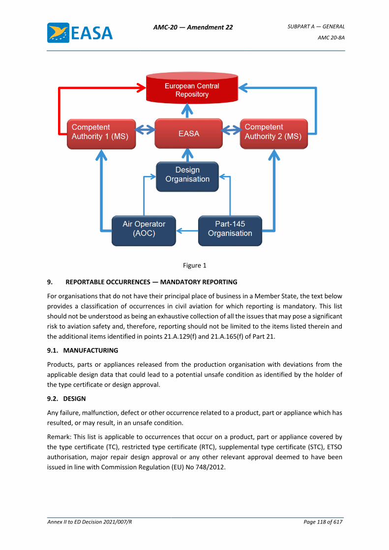
AMC-20 — Amendment 22 SUBPART A — GENERAL
AMC 20-8A
Annex II to ED Decision 2021/007/R Page 118 of 617
Figure 1
9. REPORTABLE OCCURRENCES — MANDATORY REPORTING
For organisations that do not have their principal place of business in a Member State, the text below
provides a classification of occurrences in civil aviation for which reporting is mandatory. This list
should not be understood as being an exhaustive collection of all the issues that may pose a significant
risk to aviation safety and, therefore, reporting should not be limited to the items listed therein and
the additional items identified in points 21.A.129(f) and 21.A.165(f) of Part 21.
9.1. MANUFACTURING
Products, parts or appliances released from the production organisation with deviations from the
applicable design data that could lead to a potential unsafe condition as identified by the holder of
the type certificate or design approval.
9.2. DESIGN
Any failure, malfunction, defect or other occurrence related to a product, part or appliance which has
resulted, or may result, in an unsafe condition.
Remark: This list is applicable to occurrences that occur on a product, part or appliance covered by
the type certificate (TC), restricted type certificate (RTC), supplemental type certificate (STC), ETSO
authorisation, major repair design approval or any other relevant approval deemed to have been
issued in line with Commission Regulation (EU) No 748/2012.
AMC-20 — Amendment 22 SUBPART A — GENERAL
AMC 20-8A
Annex II to ED Decision 2021/007/R Page 119 of 617
9.3. MAINTENANCE AND CONTINUING AIRWORTHINESS MANAGEMENT
(a) Serious structural damage (for example, cracks, permanent deformation, delamination,
debonding, burning, excessive wear, or corrosion) found during maintenance of the
aircraft or component.
(b) Serious leakage or contamination of fluids (for example, hydraulic, fuel, oil, gas or other
fluids).
(c) A failure or malfunction of any part of an Engine or power plant and/or transmission that
results in either or both of the following:
(i) non-containment of components/debris;
(ii) failure of the Engine mount structure.
(d) Damage to a Propeller, or a failure or defect of a Propeller, which could lead to in-flight
separation of the Propeller or any major portion of the Propeller and/or malfunctions of
the Propeller control.
(e) Damage to a main rotor gearbox/attachment, or a failure or defect of a main rotor
gearbox/attachment, which could lead to an in-flight separation of the rotor assembly
and/or malfunctions of the rotor control.
(f) A significant malfunction of a safety-critical system or equipment, including a malfunction
of an emergency system or equipment during maintenance testing, or a failure to activate
these systems after maintenance.
(g) The incorrect assembly or installation of components of the aircraft found during an
inspection or test procedure that was not intended for that specific purpose.
(h) An incorrect assessment of a serious defect, or a serious non-compliance with the MEL
or the technical logbook procedures.
(i) Serious damage to the electrical wiring interconnection system (EWIS).
(j) Any defect in a life-controlled critical part that causes its retirement before the
completion of its full service life.
(k) The use of products, components or materials from an unknown or suspect origin, or
unserviceable critical components.
(l) Misleading, incorrect or insufficient applicable maintenance data or procedures,
including language issues, which could lead to significant maintenance errors.
(m) The incorrect control or application of aircraft maintenance limitations or scheduled
maintenance.
(n) Releasing an aircraft to service from maintenance if there remains any non-compliance
which endangers flight safety.
(o) Serious damage caused to an aircraft during maintenance activities due to incorrect
maintenance or the use of inappropriate or unserviceable ground support equipment
that requires additional maintenance actions.
AMC-20 — Amendment 22 SUBPART A — GENERAL
AMC 20-8A
Annex II to ED Decision 2021/007/R Page 120 of 617
(p) Identified occurrences of burning, melting, smoke, arcing, overheating or fire.
(q) Any occurrence in which human performance, including the fatigue of the personnel, has
directly contributed, or could have contributed, to an accident or a serious incident.
(r) A significant malfunction, reliability issue, or recurrent recording quality issue that affects
a flight recorder system (such as a flight data recorder system, a data link recording
system or a cockpit voice recorder system) or a lack of the information needed to ensure
the serviceability of a flight recorder system.
[Amdt 20/19]
AMC-20 — Amendment 22 SUBPART A — GENERAL
AMC 20-9
Annex II to ED Decision 2021/007/R Page 121 of 617
AMC 20-9
AMC 20-9 Acceptable Means of Compliance for the Approval of Departure Clearance via Data Communications over ACARS
1 PREAMBLE
1.1 This AMC is issued in response to the EUROCONTROL Convergence and Implementation Plan that recommends an interim deployment of air-to-ground and ground- to-air data link applications based on the existing airline ACARS technology. One such application is Departure Clearance (DCL) data link now operational at various airports in Europe (as indicated in AIPs). Aircraft operators, on a voluntary basis, may take advantage of DCL over ACARS where it is available, subject to any arrangements that may be required by their responsible operations authority.
1.2 The use of ACARS for data link purposes is a transitional step to data link applications that will use VDL Mode 2 and the Aeronautical Telecommunications Network (ATN), compliant with ICAO SARPS, as proposed in the EUROCONTROL LINK2000+ programme1.
1.3 Described in EUROCAE document ED-85A (hereafter “ED-85A”), Data Link Application System document (DLASD) for the “Departure Clearance” Data Link Service, DCL over ACARS is a control tower application providing direct communication between the flight crew and the air traffic controller. ED-85A addresses three domains: airborne, ground ATC, and communication service providers. It deals also with associated flight crew and controller procedures. ED-85A takes account of EUROCAE document ED-78 which describes the global processes including approval planning, co-ordinated requirements determination, development and qualification of a system element, entry into service, and operations.
2 PURPOSE
2.1 This AMC is intended for operators seeking to use Departure Clearance via data link over ACARS as described in ED-85A. It may assist also other stakeholders such as airspace planners, air traffic service providers, ATS system manufacturers, communication service providers, aircraft and equipment manufacturers, and ATS regulatory authorities to advise them of the airborne requirements and procedures, and the related assumptions.
2.2 This AMC provides a method for evaluating compliance of a data link system to the requirements of ED-85A, and the means by which an aircraft operator can satisfy an authority that operational considerations have been addressed.
3 SCOPE
3.1 This AMC addresses DCL over ACARS using the ARINC 623 protocol as elaborated in EUROCAE document ED-85A and promoted by the EUROCONTROL Convergence and Implementation Plan as an interim data link application pending maturity of the LINK2000+ programme. The AMC is not directly applicable to Pre-Departure Clearance (PDC) as used in the USA and some other states. For PDC approval, guidance may be found in FAA document Safety and Interoperability Requirements for Pre- Departure
1 Information on LINK2000+ is available at web site www.eurocontrol.int/link2000
AMC-20 — Amendment 22 SUBPART A — GENERAL
AMC 20-9
Annex II to ED Decision 2021/007/R Page 122 of 617
Clearance, issued by AIR-100 on April 21, 1998. A comparison of PDC with DCL may be found in Appendix 1.
3.2 This AMC is not applicable to the phased implementation of data link services within the EUROCONTROL LINK2000+ programme, in particular, DCL over the Aeronautical Telecommunications Network via VHF Digital Data Link (VDL) Mode 2. In this case, the Safety and Performance Requirements (EUROCAE ED-120) and the Interoperability Requirements (EUROCAE ED-110) are established using EUROCAE document ED-78A, Guidelines for Approval of the Provision and use of Air Traffic Services supported by Data Communications. Guidance for the implementation of DCL over ATN may be found in EASA document AMC 20-11.
3.3 The operational requirements for the DCL application are published in the EUROCONTROL document OPR/ET1/ST05/1000, Edition 2, October 15, 1996, Transition guidelines for initial air ground data communication services. The EUROCONTROL document includes the re-issued clearance capability, however document ED-85A does not address this capability and it is not included in the scope of this AMC.
3.4 For the remainder of this document, the acronym DCL should be interpreted to mean DCL over ACARS using the ARINC 623 protocol unless stated otherwise.
4 REFERENCE DOCUMENTS
4.1 Related Requirements
CS/FAR 25.1301, 25.1307, 25.1309, 25.1322, 25.1431, 25.1581, or equivalent requirements of CS 23, 27 and 29 if applicable.
4.2 Related Standards and Guidance Material
ICAO Doc 9694 AN/955 Manual of Air Traffic Services (ATS) Data Link Applications
Doc 4444 Rules of the Air and Air Traffic Services
Draft Proposal PANS-Air Traffic Management
Annex 11 Air Traffic Services
Doc 8585 Designators for Aircraft Operating agencies, Aeronautical Authorities and Services
Doc 8643 Aircraft Type Designators
EASA AMC 25-11 Electronic Display Systems
EUROCONTROL CIP: COM. ET2.SO4; 2.1.5
Implement Air/Ground Communication Services- Interim step on non-ATN (ACARS) services.
OPR/ET1/ST05/1000 Transition guidelines for initial air ground data communication services
ESARR 4 Risk assessment and mitigation in ATM
FAA AC 25-11 Electronic Display Systems.
AC 120-COM Initial Air Carrier Operational Approval for use of Digital Communication Systems
AC 20-140 Guidelines for design approval of aircraft data communications systems
98-Air-PDC Safety and Interoperability requirement for Pre-Departure-Clearance (PDC). (Air-100, April 21,1998)
EUROCAE ED 78 Guidance material for the establishment of data link supported ATS Services
AMC-20 — Amendment 22 SUBPART A — GENERAL
AMC 20-9
Annex II to ED Decision 2021/007/R Page 123 of 617
ED-85A Data Link Application System document (DLASD) for the “ departure Clearance ” data link service
ED-112 Minimum operational performance specification for Crash protected airborne recorder systems
RTCA DO 224 Minimum Aviation System Performance Standards (MASPS) for Advanced VHF Digital Data Communications Including Compatibility with Digital Voice Techniques.
SAE ARP 4791 Human Machine Interface on the flight deck
5 ASSUMPTIONS
Applicants should note that this AMC is based on the assumptions stated in Chapter 3 of ED-85A together with the following that concern the measures taken by the responsible airspace authorities to safeguard DCL operations.
5.1 ATS Provider
5.1.1 The data link service for DCL has been shown to satisfy applicable airspace safety regulations and the relevant ATS domain performance, safety and interoperability requirements of ED-85A.
5.1.2 Procedures for the use of DCL take account of the performance limitations of ACARS and the airborne implementation capabilities meeting at least the provisions of this AMC.
Note: Some aircraft ACARS installations approved to earlier standards are classified as “Non Essential” without guarantees of performance or integrity. Consequently, procedures are necessary to compensate for any deficiency and to safeguard operations. ED-85A addresses this issue.
5.1.3 Appropriate procedures are established to minimise the possibility of failure to detect inconsistency in the case of a complex clearance.
5.1.4 Each ATS provider has published a list of communication service providers that may be used by aircraft operators for the DCL application. The list should take account of internetworking arrangements between service providers.
5.1.5 The procedures of the ATS provider state the actions that should be taken in the event of an inadequate communication service from the communications service provider (CSP).
5.2 Communications Service Provider
The communications service provider does not modify the operational information (content and format) exchanged between the ATS provider and the airborne equipment.
5.3 Aeronautical Information Service
Each State offering a DCL service by data link publishes in its AIP, or equivalent notification, availability of the service, relevant procedures, and confirmation of compliance with ED-85A.
5.4 Message Integrity
The Cyclic Redundancy Check (CRC) is implemented as required by ED-85A and is providing integrity of the end-to-end data link transmission path. On this basis, Performance Technical Requirement PTR_3 of ED-85A need not be demonstrated.
AMC-20 — Amendment 22 SUBPART A — GENERAL
AMC 20-9
Annex II to ED Decision 2021/007/R Page 124 of 617
6 AIRWORTHINESS CONSIDERATIONS
6.1 General
6.1.1 The installation will need to be shown compliant with the airborne domain requirements allocated as per ED-85A (§7.1) covering the Interoperability Operational Requirements, the Interoperability Technical Requirements, the Performance Technical Requirements, the Safety Operational & Technical Requirements.
6.1.2 If multiple ATS data link applications are available to the aircraft, the crew interface and related crew procedures will need to be based on a common and compatible philosophy.
6.2 Required Functions
An acceptable minimum airborne installation comprises the following functions:
(a) A means of data communication appropriate to the area of operation, e.g. plain old ACARS over AVLC (Aviation VHF Link Control) through VHF or SATCOM;
Note: VDL Mode 2 equipment can be used provided that radio transceiver is compliant with ED-92A.
(b) A means to manage data communications and to control the data communications system;
(c) A means to easily check and modify the parameters of the DCL request;
(d) “Visual” alerting of an incoming message, visible to both pilots;
(e) Means to display the text message, e.g. a single display readable by both crewmembers or a dedicated display for each pilot.
(f) A means to accept the DCL delivered by the ATS.
6.3 Recommended Functions
(a) “Audible” alerting of an incoming message;
(b) A means to print the messages;
(c) Recording of DCL messages and flight crew responses on an accident flight recorder.
Note: Data Link recording may be required in accordance with OPS rules.
7 ACCEPTABLE MEANS OF AIRWORTHINESS COMPLIANCE
7.1 Airworthiness
7.1.1 When demonstrating compliance with this AMC, the following specific points should be noted:
(a) Compliance with the airworthiness requirements for intended function and safety may be demonstrated by equipment qualification, safety analysis of the interface between the communications management system and data sources, structural analyses of new antenna installations, equipment cooling verification, and evidence of a suitable human to machine interface. The DCL function will need to be demonstrated by end-to-end ground testing that verifies system operation, either with an appropriate ATS unit, or by means
AMC-20 — Amendment 22 SUBPART A — GENERAL
AMC 20-9
Annex II to ED Decision 2021/007/R Page 125 of 617
of test equipment that has been shown to be representative of the actual ATS unit.
Note: This limited testing assumes that the communication systems (VHF or SATCOM) have been shown to satisfactorily perform their intended functions in the flight environment in accordance with applicable requirements.
(b) The safety analysis of the interface between the communications management system and its data sources should show that, under normal or fault conditions, no unwanted interaction which adversely affects essential systems can occur.
7.1.2 To minimise the certification effort for follow-on installations credit may be granted for applicable certification and test data obtained from equivalent aircraft installations.
7.2 Performance
The installation should be shown to meet the airborne domain performance requirements allocated by ED-85A (§7.1). Demonstration of Performance Technical Requirement PTR_A1 may be difficult for some airborne installations. The applicant may choose an alternative acceptable means of compliance for PTR_A1 consisting in an end-to-end demonstration of PTR_5 & PTR-6 of ED-85A (§5.2) with an appropriate ATS unit and communication service provider.
7.3 Aircraft Flight Manual
The Flight Manual should state the following limitation.
Note: This limited entry assumes that a detailed description of the installed system and related operating instructions are available in other operating or training manuals and that operating procedures take account of ED-85A.
Limitation: The Departure Clearance (DCL) over ACARS application has been demonstrated with data link services declared compliant with EUROCAE document ED- 85A.
7.4 Existing installations
The applicant will need to submit a compliance statement that shows how the criteria of this AMC have been satisfied for existing installations. Compliance may be established by inspection of the installed system to confirm the availability of required features and functionality.
Note: It is not intended that aircraft which have received airworthiness approval in compliance with ED-85 requirement should be reinvestigated where the installation is compliant with Section 6, 7 and 8 of this AMC.
8 OPERATIONAL CONSIDERATIONS
8.1 Flight Plan Information
8.1.1 The Aircraft Identification transmitted by data link will need to conform to the ICAO format and correspond with the flight identity as entered in the applicable flight plan.
8.1.2 Aircraft type designator includes both Aircraft Type and Sub-type and shall be coded in accordance with the format described in ICAO document 8643 at its latest
AMC-20 — Amendment 22 SUBPART A — GENERAL
AMC 20-9
Annex II to ED Decision 2021/007/R Page 126 of 617
edition. However, certain ACARS equipment can be pre-programmed only with Aircraft Type with the possibility of manual insertion of Sub-type via the system control panel. Absence of the Sub-type information may lead either to a rejected departure clearance request at some airports, or the issue of an inappropriate clearance where the aircraft performance capability is not taken into account. Where, to obtain the DCL service, Sub-type needs to be entered manually, the entry should be verified.
8.2 Operational Safety Aspects
8.2.1 Failure Conditions are presented in ED-85A (§6) together with the resulting safety requirements and operational means of mitigation. Failure Condition FC3 (undetected erroneous SID) is discussed further in the following paragraphs.
8.2.2 When a SID construct is simple and unambiguous (e.g. only one SID for one runway magnetic orientation (QFU) and one destination) so allowing the flight crew and the ATS controller to independently detect any inconsistency in the DCL, then additional means of mitigation are not required.
8.2.3 For other, more complex cases where the SID construction prevents the flight crew and the controller from readily detecting any inconsistency, a specific flight crew to controller procedure will need to be implemented to verify the clearance. This may be stated in the AIP or other notification issued by the State where aircraft will operate and use DCL service.
Note (1): In some countries (e.g. United Kingdom, AIC 125/1999, France AIC A19/00), following the investigation of level violations, voice confirmation of cleared altitude or flight level and SID identification is already required even for voice delivered departure clearance on the first contact with the approach control/departure radar. In such cases, no additional confirmation procedure is required.
Note (2): The ATS may agree that voice confirmation is not required where the data link function is certificated with an integrity level corresponding to the Essential category of CS25.1309.
8.2.4 In all cases, flight crews will need to comply with any mitigating procedures published by the States where aircraft will operate and use DCL service.
8.2.5 The assumptions of Section 5 need to be satisfied as a condition for operational use.
8.3 Operations Manual and Training
8.3.1 The Operations Manual shall reflect the Flight Manual statement of paragraph 7.3 and define operating procedures for use of the DCL.
8.3.2 Flight crew training should address:
(a) The different data link services available using the same airborne equipment (e.g. differences between DCL and PDC applications as described in Annex 1);
(b) ATS procedures for DCL; and
(c) The required format for the flight identification input.
AMC-20 — Amendment 22 SUBPART A — GENERAL
AMC 20-9
Annex II to ED Decision 2021/007/R Page 127 of 617
8.3.3 Subject to any arrangements that may be required by the responsible operations authority in respect of amendments to the Operations Manual, and the approval of training programmes, the aircraft operator may implement operations using DCL over ACARS.
8.4 Incident reporting
Significant incidents associated with a departure clearance transmitted by data link that affects or could affect the safe operation of the aircraft will need to be reported in accordance with applicable operational rules, and to the authority responsible for the airport where the DCL service was provided.
AVAILABILITY OF DOCUMENTS
EUROCAE documents may be purchased from EUROCAE, 17 rue Hamelin, 75783 Paris Cedex 16, France, (Fax: 33 1 45 05 72 30). Web site: www.eurocae.org.
JAA documents are available from the JAA publisher Information Handling Services (IHS). Information on prices, where and how to order is available on both the JAA web site www.jaa.nl and the IHS web site www.avdataworks.com.
EUROCONTROL documents may be requested from EUROCONTROL, Documentation Centre, GS4, Rue de la Fusee, 96, B-1130 Brussels, Belgium; (Fax: 32 2 729 9109 or web site www.eurocontrol.int).
ICAO documents may be purchased from Document Sales Unit, International Civil Aviation Organisation, 999 University Street, Montreal, Quebec, Canada H3C 5H7, (Fax: 1 514 954 6769, e-mail: [email protected]) or through national agencies.
FAA documents may be obtained from Department of Transportation, Subsequent Distribution Office SVC-121.23, Ardmore East Business Centre, 3341 Q 75th Avenue, Landover, MD 20785, USA. Web site www.faa.gov/aviation.htm
RTCA documents may be obtained from RTCA Inc, 1828 L Street, NW., Suite 805, Washington, DC 20036, USA., (Tel: 1 202 833 9339; Fax 1 202 833 9434). Web site: www.rtca.org.
SAE documents may be obtained from SAE World Headquarters, 400 Commonwealth Drive, Warrendale, PA 15096-0001, USA. Telephone 1-877-606-7323 (U.S. and Canada only) or 724/776-4970 (elsewhere). Web site www.sae.org.
[Amdt 20/1]
AMC-20 — Amendment 22 SUBPART A — GENERAL
AMC 20-9
Annex II to ED Decision 2021/007/R Page 128 of 617
Appendix 1 to AMC 20-9 PDC versus DCL: A Comparison
The US Pre-Departure Clearance.
In the United States, the concept of Pre-departure Clearance is used where PDC messages are delivered via the airlines own ACARS network and operational host computer. The airline host, or the flight crew, initiates the process for the generation of the PDC by submitting the flight plan information to the air traffic service, which in turn forwards the flight strip information to the appropriate airport control tower. Approximately 30 minutes before the aircraft is scheduled to depart, the approved PDC is transmitted from the tower via ground-ground data link to the airline host computer. The airline host responds with an acknowledgement that ultimately feeds back to the tower PDC workstation. Depending upon the airline capabilities, the PDC may then be transmitted directly to the aircraft flight deck via the ACARS data link. If the aircraft is not equipped with ACARS, the approved PDC is sent to an airport gate printer for delivery by hand in printed format to the aircraft. For a clearance requested from the aircraft, the flight crew will initiate a PDC request via the ACARS data link network to the airline host computer. The host will then respond via the ACARS network with the approved PDC.
Thus, the airline is responsible for ensuring that the clearance is delivered to the flight crew. Without PDC, Instrument Flight Rule (IFR) clearances for departing aircraft are provided by the clearance-delivery controller via a tower voice channel.
The PDC is pre-formatted in an ARINC 620 free text message. The ARINC 623 standard also may be used but it is not required. All failures are classified Minor by the fact that flight crew has to follow a procedure to verify the information with the initial flight plan and, by voice communication, with departure control.
Guidance on the use of PDC may be found in FAA document Safety and Interoperability Requirements for Pre-Departure Clearance, issued by AIR-100 on April 21, 1998.
The European Departure Clearance.
In Europe, departure clearance over ACARS is a direct ATC to pilot data link communication based on the EUROCAE ED-85A and ARINC 623 standards. The clearance delivered by data link is fully considered as an ATC departure clearance and it is not the responsibility of the airline to ensure delivery via its own facilities. ARINC 623 provides enhanced integrity of end-to-end communication, compared to ARINC 620 as used in the USA. However, flight crew verification procedures may still be required due to departure clearance options such as alternative SIDs, or to satisfy AIP requirements for local safety reasons.
Current operational implementation in Europe does not include a re-issued clearance capability, which is under study by some ATS providers.
[Amdt 20/1]
AMC-20 — Amendment 22 SUBPART A — GENERAL
AMC 20-9
Annex II to ED Decision 2021/007/R Page 129 of 617
Appendix 2 to AMC 20-9 Common Terms
Reference should be made to EUROCAE document ED-85A for definition of terms.
Abbreviations
ACARS Aircraft Communication, Addressing and Reporting System
AIP Aeronautical Information Publication
ARINC Aeronautical Radio Inc.
ATS Air Traffic Services
CPDLC Controller-Pilot Data Link Communication
DCL Departure Clearance
ESARR EUROCONTROL Safety Regulatory Requirement
EUROCAE European Organisation for Civil Aircraft Equipment
PDC Pre-departure Clearance (as used in USA)
PTR Performance Technical Requirement
RTCA RTCA Inc.
SAE Society of Automotive Engineers
SARPS ICAO Standards and Recommended Practices
SID Standard Instrument Departure
VDL VHF Digital Link
[Amdt 20/1]

AMC-20 — Amendment 22 SUBPART A — GENERAL
AMC 20-10
Annex II to ED Decision 2021/007/R Page 130 of 617
AMC 20-10
AMC 20-10 Acceptable Means of Compliance for the Approval of Digital ATIS via Data Link over ACARS
1 PREAMBLE
1.1 This AMC is issued in response to the EUROCONTROL Convergence and Implementation Plan that recommends an interim deployment of air-to-ground and ground-to-air data link applications based on the existing airline ACARS technology. One such application is Digital Automated Terminal Information Services (D-ATIS) now planned to be operational at various airports in Europe. Aircraft operators, on a voluntary basis, may take advantage of D-ATIS where it is available, provided the service is verified in accordance with operational procedures acceptable to the responsible operations authority.
1.2 The use of ACARS for data link purposes is a transitional step to data link applications that will use VHF Digital Link (VDL) Mode 2 and the Aeronautical Telecommunications Network (ATN), compliant with ICAO SARPS, as proposed in the EUROCONTROL LINK2000+ programme1.
1.3 Described in EUROCAE document ED-89A, Data Link Application System document (DLASD) for the “ATIS” Data Link Service, D-ATIS is a control tower application providing direct communication of ATIS information to the flight crew and, optionally automatic updating of this information. The ED-89A document addresses three domains: airborne, ground ATC, and communication service providers. It deals also with associated flight crew and air traffic service provider procedures. ED-89A incorporates the protocols and message formats formerly published in ARINC Specification 623, and takes account of EUROCAE document ED-78 which describes the global processes including approval planning, co-ordinated requirements determination, development and qualification of a system element, entry into service, and operations.
2. PURPOSE
2.1 This AMC is intended for operators intending to use Digital ATIS over ACARS as described in document EUROCAE ED-89A. It may assist also other stakeholders such as airspace planners, air traffic service providers (ATSP), ATS system manufacturers, communication service providers (CSP), aircraft and equipment manufacturers, and ATS regulatory authorities to advise them of the airborne requirements and procedures, and the related assumptions.
2.2 This AMC provides a method for evaluating compliance of a data link system to the requirements of ED-89A, and the means by which an aircraft operator can satisfy an authority that operational considerations have been addressed.
3 SCOPE
3.1 This AMC addresses D-ATIS over ACARS using the ARINC 623 protocol as elaborated in EUROCAE document ED-89A and promoted by the EUROCONTROL Convergence and Implementation Plan as an interim data link application pending maturity of the LINK 2000+ programme.
1 Information on LINK2000+ is available at web site www.eurocontrol.int/link2000
AMC-20 — Amendment 22 SUBPART A — GENERAL
AMC 20-10
Annex II to ED Decision 2021/007/R Page 131 of 617
3.2 Other implementation of D-ATIS service may exist in the world. They are not necessarily identical to the service defined within this AMC and EUROCAE document ED-89A. For example, application message formats may differ. Similarly, the ATSP may send ATIS information to an ACARS communication service provider who then distributes it to subscriber operators. This should not be considered as an air traffic service offered directly by an ATSP. In the USA, guidance on ATIS data link approval for use in the US airspace, may be found in FAA document 98-AIR D-ATIS: Safety and Interoperability Requirements for ATIS.
3.3 This AMC is not applicable to the phased implementation of data link services within the EUROCONTROL LINK2000+ programme, in particular, D-ATIS over the Aeronautical Telecommunications Network via VHF Digital Link (VDL) Mode 2. In this case, the Safety and Performance Requirements (EUROCAE ED-120) and the Interoperability Requirements (EUROCAE ED-110) have been established using EUROCAE document ED-78A, Guidelines for Approval of the Provision and use of Air Traffic Services supported by Data Communications. Guidance for the implementation of data link over ATN may be found in EASA document AMC 20-11.
3.4 The operational requirements for the D-ATIS application are published in EUROCONTROL document OPR/ET1/ST05/1000, Transition guidelines for initial air ground data communication services.
3.5 For the remainder of this document, the acronym D-ATIS should be interpreted to mean D-ATIS over ACARS using the ARINC 623 protocol in accordance with ED-89A unless stated otherwise.
4 REFERENCE DOCUMENTS
4.1 Related Requirements
CS/FAR 25.1301, 25.1307, 25.1309, 25.1322, 25.1431, 25.1581, or equivalent requirements of CS 23, 27 and 29, if applicable.
4.2 Related Standards and Guidance Material
ICAO Doc 9694 AN/955 Manual of Air Traffic Services (ATS) Data Link Applications
Doc 4444 Rules of the Air and Air Traffic Services
Annex 11 Air Traffic Services
Doc 8585 Designators for Aircraft Operating agencies, Aeronautical Authorities and Services.
EASA AMC 25-11 Electronic Display Systems
EUROCONTROL CIP: COM. ET2.SO4; 2.1.5
Implement Air/Ground Communication Services- Interim step on non-ATN (ACARS) services.
OPR/ET1/ST05/1000 Transition guidelines for initial air ground data communication services
ESARR 4 Risk assessment and mitigation in ATM
FAA AC 25-11 Electronic Display Systems.
AC 120-70 Initial Air Carrier Operational Approval for use of Digital Communication Systems
AC 20-140 Guidelines for design approval of aircraft data communications systems
98-Air-D-ATIS Safety and Interoperability requirement for D-ATIS (Air-100, April 21,1998)
AMC-20 — Amendment 22 SUBPART A — GENERAL
AMC 20-10
Annex II to ED Decision 2021/007/R Page 132 of 617
EUROCAE ED 78 Guidance material for the establishment of data link supported ATS Services
ED-89A Data Link Application System document (DLASD) for the “ATIS” data link service
ED-92A Minimum Operational Performance specification for an airborne VDL Mode 2 Transceiver
ED-112 Minimum operational performance specification for Crash protected airborne recorder systems Note: Includes criteria for recording of data link messages.
RTCA DO-224 Minimum Aviation System Performance Standards (MASPS) for Advanced VHF Digital Data Communications Including Compatibility with Digital Voice Techniques.
SAE ARP 4791 Human Machine Interface on the flight deck
5 ASSUMPTIONS
Applicants should note that this AMC is based on the assumptions stated in Chapter 3 of document ED-89A together with the following that concern the measures taken by the responsible airspace authorities to safeguard operations affected by the transmission of D-ATIS.
5.1 ATS Provider
5.1.1 The data link service for ATIS has been shown to satisfy applicable airspace safety regulations and the relevant ATS domain performance, safety and interoperability requirements of ED-89A.
5.1.2 The ATS Provider ensures that information provided through D-ATIS service is fully consistent with the voice information broadcast over VHF.
5.1.3 Appropriate procedures are established to minimise the possibility of failure to detect any inconsistency in ATIS information for approach, landing and take off.
5.1.4 Each ATS provider has published a list of communication service providers that may be used by aircraft operators for the D-ATIS application. The list should take account of internetworking arrangements between service providers.
5.1.5 The procedures of the ATS provider state the actions that should be taken in the event of an inadequate communication service from the communications service provider.
5.2 Communications Service Provider
The communications service provider does not modify the operational information (content and format) exchanged between the ATS provider and the airborne equipment.
5.3 Aeronautical Information Service
The availability of the D-ATIS service, a statement of compliance with ED-89A, and additional relevant procedures are published in the AIP or other notification issued by the States where D-ATIS is offered.
5.4 Message Integrity
The Cyclic Redundancy Check (CRC) is implemented as required by ED-89A and is providing integrity of the end-to-end data link transmission path. On this basis, Performance Technical Objective PTO_3 of ED-89A need not be demonstrated by end
AMC-20 — Amendment 22 SUBPART A — GENERAL
AMC 20-10
Annex II to ED Decision 2021/007/R Page 133 of 617
systems. The PTO_3 requirement is applicable only to the Communication Service Provider and limits the amount of corrupted messages that would be detected and rejected by end-systems.
Note: The CRC is described in ARINC Specification 622 Chapter 5.
6 AIRWORTHINESS CONSIDERATIONS
6.1 General
6.1.1 The installation will need to meet the airborne domain requirements allocated as per ED-89A (§7.1) covering the Interoperability Operational Requirements, the Interoperability Technical Requirements, the Performance Technical Requirements, and the Safety Operational & Technical Requirements.
6.1.2 If multiple ATS data link applications are available to the aircraft, the crew interface and related crew procedures will need to be based on a common and compatible philosophy.
6.2 Required Functions
An acceptable minimum airborne installation comprises the following functions:
(a) A means of data communication appropriate to the area of operation, e.g. plain old ACARS over AVLC (Aviation VHF Link Control) through VHF or SATCOM;
Note: VDL Mode 2 equipment can be used provided that radio transceiver is compliant with ED-92A.
(b) A means to manage data communications and to control the data communications system.
(c) A means to easily check and modify the D-ATIS request parameters.
(d) A means of attracting the attention of the flight crew to an incoming message.
Notes:
(1) Activation of a printer may suffice to meet this need.
(2) The means used will need to be such as to avoid confusion with other, non-data link, flight deck alerting devices.
(3) The need for temporary suppression of the attention-getter during critical flight phases should be considered.
(e) Means to display the text message, e.g. a single display readable by both pilots or a dedicated display for each pilot. For the interim deployment of D-ATIS over ACARS, a printer may serve as the primary display for messages subject to compliance with paragraph 7.3 of this AMC.
6.3 Recommended Functions
(a) A means to print the message.
(b) Recording of D-ATIS messages and flight crew requests on an accident flight recorder.
Note: Data Link recording may be required in accordance with OPS rules.
7 ACCEPTABLE MEANS OF AIRWORTHINESS COMPLIANCE
7.1 Airworthiness
AMC-20 — Amendment 22 SUBPART A — GENERAL
AMC 20-10
Annex II to ED Decision 2021/007/R Page 134 of 617
7.1.1 When demonstrating compliance with this AMC, the following should be noted:
(a) Compliance with the airworthiness requirements for intended function and safety may be demonstrated by equipment qualification, safety analyses of the interfaces between components of the airborne communications equipment, structural analyses of new antenna installations, equipment cooling verification, and evidence of a suitable human to machine interface. The D-ATIS function will need to be demonstrated by end-to-end ground testing that verifies system operation, either with an appropriate ATS unit, or by means of test equipment that has been shown to be representative of an actual ATS unit.
Note:
This limited testing assumes that the communication systems (VHF or SATCOM) have been shown to satisfactorily perform their intended functions in the flight environment in accordance with applicable requirements.
(b) The safety analysis of the interface between the ACARS and other systems should show that, under normal or fault conditions, no unwanted interaction that adversely affects essential systems can occur.
(c) Where a printer is used as the primary display of the ATIS message, its readability should be shown to be adequate for this purpose, and that it does not present an unacceptable risk of an erroneous display.
Note:
This does not preclude the use of a printer classified as non-essential provided it has demonstrated a satisfactory in-service record that supports compliance with paragraph 7.3 of this AMC.
7.1.2 To minimise the certification effort for follow-on installations, the applicant may claim credit, from the responsible authority, for applicable certification and test data obtained from equivalent aircraft installations.
7.2 Performance
The installation will need to be shown compliant with the airborne domain performance requirements allocated by ED-89A (§7.1). Demonstration of Performance Technical Requirement PTR_A1 may be difficult for some airborne installations. The applicant may choose an alternative acceptable means of compliance for PTR_A1 consisting in an end-to-end demonstration of PTR_5 & PTR_6 of ED-89A (§5.2) with an appropriate ATS unit and communication service provider.
7.3 Safety Objectives
7.3.1 Failure Conditions are presented in ED-89A (§6) together with the resulting safety objectives and operational means of mitigation. Failure Condition FC3 (Non-detected corrupted ATIS presented to an aircrew) requires that the occurrence of such a hazard at the aircraft level be demonstrated improbable.
7.3.2 ED-89A takes into account the possibility of using ACARS approved to earlier standards and classified as “non-essential” without guarantees of performance or integrity. Consequently, additional procedures are necessary to compensate for any deficiency and to safeguard operations. (See §8 of this AMC)
AMC-20 — Amendment 22 SUBPART A — GENERAL
AMC 20-10
Annex II to ED Decision 2021/007/R Page 135 of 617
7.4 Aircraft Flight Manual
The Aircraft Flight Manual (AFM) or the Pilot’s Operating Handbook (POH), whichever is applicable, should identify the D-ATIS over ACARS application as having been demonstrated with data link services declared compliant with EUROCAE document ED-89A.
If certification was not achieved at the level “essential”, the AFM or POH, whichever is applicable,shall remind the crew that they are responsible for checking the D-ATIS information received over ACARS is consistent with their request, or revert to a voice ATIS.
7.5 Existing installations
The applicant will need to submit a compliance statement that shows how the criteria of this AMC have been satisfied for existing installations. Compliance may be established by inspection of the installed system to confirm the availability of required features and functionality.
Note: It is not intended that aircraft which have received airworthiness approval in compliance with ED 89 requirement should be reinvestigated where the installation is compliant with Section 6, 7 and 8 of this AMC.
8 OPERATIONAL CONSIDERATIONS
8.1 Operational Safety Aspects
8.1.1 Failure Conditions are presented in ED-89A (§6) together with the resulting safety requirements and operational means of mitigation. Failure Condition FC3 (Non-detected corrupted ATIS presented to an aircrew) is discussed further in the following paragraphs.
8.1.2 Applying existing ICAO operational procedures can independently verify the majority of ATIS parameters. Certain information may need to be verified by additional operational procedures. Examples include runway surface conditions, air and dew point temperatures, and other essential operational information.
8.1.3 If the aircraft system is classified and certified as “non-essential”, additional flight crew verification procedures will need to be defined to compensate for this deficiency.
8.1.4 When the airborne system is certified as “essential”, then integrity and performance can be considered as acceptable without a voice ATIS cross check unless otherwise required by the AIP.
8.1.5 It is important that crew are aware that they remain responsible for checking that received ATIS information corresponds to their request in terms of airfield name, date, type of ATIS (D or A) and type of contract. In case of inconsistency, reversion to voice ATIS is required.
Note: ED-89A (§6) SOR-A1 (check of name of airfield), SOR-A2 (ATIS letter acknowledgement at first contact) and SOR-A3 (check of global consistency of information) require checks irrespective of the level of classification of the data link system
8.1.6 Flight crews will need to comply with any additional mitigating procedures published by the States where aircraft will operate and use a D-ATIS service.
AMC-20 — Amendment 22 SUBPART A — GENERAL
AMC 20-10
Annex II to ED Decision 2021/007/R Page 136 of 617
8.1.7 The assumptions of Section 5 of this AMC need to be satisfied as a condition for operational use.
8.2 Operations Manual and Training
8.2.1 The Operations Manual shall reflect the Flight Manual statement of paragraph 7.4, and to define operating procedures for the use of D-ATIS via ACARS taking into account the Operational Considerations discussed in paragraph 8 of this AMC.
8.2.2 Similarly, flight crew training shall address:
(a) The different data link services available using the same airborne equipment (e.g. differences between ATIS provided through D-ATIS service that are declared to conform to ED-89A requirements, and ATIS received through other means such as ACARS AOC).
(b) The procedures for safe use of D-ATIS over ACARS.
8.2.3 Subject to any arrangements that may be required by the responsible operations authority in respect of amendments to the Operations Manual, and the approval of training programmes, the aircraft operator may implement operations using D-ATIS over ACARS without the need for further formal operational approval.
8.3 Incident reporting
Significant incidents associated with a D-ATIS transmitted by data link that affects or could affect the safe operation of the aircraft will need to be reported in accordance with applicable operational rules. The incident should be reported also to the ATS authority responsible for the airport where the D-ATIS service is provided.
AVAILABILITY OF DOCUMENTS
EUROCAE documents may be purchased from EUROCAE, 17 rue Hamelin, 75783 Paris Cedex 16, France, (Fax: 33 1 45 05 72 30). Web site: www.eurocae.org
JAA documents are available from the JAA publisher Information Handling Services (IHS). Information on prices, where and how to order is available on both the JAA web site: www.jaa.nl and the IHS web site: www.avdataworks.com. JAA documents transposed to publications of the European Aviation Safety Agency (EASA) are available on the EASA web site www.easa.eu.int
EUROCONTROL documents may be requested from EUROCONTROL, Documentation Centre, GS4, Rue de la Fusee, 96, B-1130 Brussels, Belgium; (Fax: 32 2 729 9109). Web site: www.eurocontrol.int
ICAO documents may be purchased from Document Sales Unit, International Civil Aviation Organisation, 999 University Street, Montreal, Quebec, Canada H3C 5H7, (Fax: 1 514 954 6769, e-mail: [email protected]) or through national agencies.
FAA documents may be obtained from Department of Transportation, Subsequent Distribution Office SVC-121.23, Ardmore East Business Centre, 3341 Q 75th Avenue, Landover, MD 20785, USA.
RTCA documents may be obtained from RTCA Inc, 1828 L Street, NW. Suite 805, Washington, DC 20036, USA., (Tel: 1 202 833 9339; Fax 1 202 833 9434). Web site: www.rtca.org
SAE documents may be obtained from SAE World Headquarters, 400 Commonwealth Drive, Warrendale, PA 15096-0001, USA. Telephone 1-877-606-7323 (U.S. and Canada only) or 724/776-4970 (elsewhere). Web site: www.sae.org
[Amdt 20/1]

AMC-20 — Amendment 22 SUBPART A — GENERAL
AMC 20-10
Annex II to ED Decision 2021/007/R Page 137 of 617
Appendix 1 to AMC 20-10 Common Terms
Reference should be made to EUROCAE document ED-89A for definition of terms.
Abbreviations
[Amdt 20/1]
ACARS Aircraft Communication, Addressing and Reporting System
AIP Aeronautical Information Publication
ATIS Automatic Terminal Information Service
ATSP Air Traffic Service Provider
D-ATIS Digital ATIS
ARINC Aeronautical Radio Inc.
ATS Air Traffic services
CPDLC Controller-Pilot Data Link Communication
ESARR EUROCONTROL Safety Regulatory Requirement
EUROCAE European Organisation for Civil Aircraft Equipment
NAS National Airspace System (USA)
PTR Performance Technical Requirement
PTO Performance Technical Objective
RTCA RTCA Inc.
SAE Society of Automotive Engineers
SARPS ICAO Standards and Recommended Practices
VDL VHF Digital Link
AMC-20 — Amendment 22 SUBPART A — GENERAL
AMC 20-15
Annex II to ED Decision 2021/007/R Page 138 of 617
AMC 20-15
AMC 20-15 Airworthiness Certification Considerations for the Airborne Collision Avoidance System (ACAS II) with optional Hybrid Surveillance
1 PREAMBLE
This Acceptable Means of Compliance (AMC) provides a means that can be used to obtain an airworthiness approval for the installation of ACAS II equipment which may include optional hybrid surveillance. It is issued to support the operational requirement that requires the carriage of ACAS II.
Hybrid Surveillance is an optional feature that allows ACAS II to use a combination of active surveillance, i.e. actively interrogating the Mode-S Transponders of surrounding aircraft, and passive surveillance, i.e. use of ADS-B position and altitude data (extended squitter), to update an ACAS II track.
An applicant may elect to use an alternative means of compliance. However, those alternative means of compliance must meet the relevant requirements and ensure a safety objectives as defined in paragraph 5 are met. Compliance with this AMC is not mandatory.
2 RELEVANT REQUIREMENTS
The provisions to which this AMC applies are:
CS 25.1301, 1302, 1309, 1322, 1333, 1431, 1459, 1529 and 1581.
CS 23.1301, 1309, 1322, 1431, 1459, 1529 and 1581.
CS 27.1301, 1309, 1322, 1459, 1529 and 1581
CS 29.1301, 1309, 1322, 1333, 1431, 1459, 1529 and 1581
3 REFERENCE MATERIAL
EU OPS1 1.160, 1.668, 1.1045, 1.398
AMC 25.1302, AMC 25.1309, AMC 25.1322 and AMC 25-11.
ETSO-C113 Airborne Multipurpose Electronic Displays
ETSO-C119c Traffic Alert and Collision Avoidance System (TCAS) Airborne Equipment, TCAS II.
ETSO-2C112() Air Traffic Control Radar Beacon System/Mode Select (ATCRBS/Mode S) Airborne Equipment
EUROCAE ED-143 including change 1 Minimum Operational Performance Standards for Traffic Alert and Collision Avoidance Systems (TCAS) Airborne Equipment.
EUROCAE ED-112 Minimum Operational Performance Specification for Crash Protected Airborne Recorder Systems
1 Council Regulation (EEC) No 3922/91 on the harmonisation of technical requirements and administrative procedures in the field of civil
aviation. Regulation as last amended by Regulation (EC) No 1899/2006 of the European Parliament and of the Council of 12 December 2006 (OJ L 377, 27.12.2006, p. 1).
AMC-20 — Amendment 22 SUBPART A — GENERAL
AMC 20-15
Annex II to ED Decision 2021/007/R Page 139 of 617
RTCA DO-300 including change 1 Minimum Operational Performance Standards (MOPS) for Traffic Alert and Collision Avoidance System II (TCAS II) Hybrid surveillance.
4 MINIMUM EQUIPMENT QUALIFICATION
4.1 An acceptable minimum certification standard for the ACAS II equipment including optional hybrid surveillance is EASA ETSO-C119c.
4.2 An acceptable minimum certification standard for the associated Mode S transponder is EASA ETSO-2C112().
5 SAFETY OBJECTIVES
The applicant should perform a Functional Hazard Assessment (FHA) and System Safety Assessment (SSA) for the proposed ACAS II installation. For the purposes of this AMC, a system includes all airborne devices contributing to the ACAS II function. Guidance is provided in AMC 25.1309 or FAA AC 23-1309-1() or AC 27-1B or AC 29-2C. Acceptable probability levels for functionality and alerts are given below:
5.1 The probability of failure of the installed system to perform its intended function from a reliability and availability perspective should be shown to be no greater than 1x10⁻³ per flight hour.
5.2 The probability of failure of the system to provide the required RA aural or visual alert, when required, without a failure indication should be shown to be no greater than 1x10- 4
per flight hour in the terminal environment and 1x10⁻⁵ per flight hour in the en-route environment. See note 1.
5.3 The probability of a false or misleading RA aural and visual alert due to a failure of the system should be shown to be no greater than 1x10⁻⁴ per flight hour in the terminal environment and 1x10⁻⁵ per flight hour in the en-route environment. See note 1.
Note: The definition of a ‘misleading alert’ is when an RA condition exists, and an RA is issued, but the RA gives incorrect guidance. The definition of a ‘false alert’ is when an RA is issued, but an RA condition does not exist.
5.4 Failure of the installed ACAS II must not degrade the integrity of any essential or critical system which has an interface with the ACAS II.
The use of Hybrid Surveillance including transitions from active to passive surveillance and vice versa, using a system that complies with the requirements of RTCA DO-300 including Change 1, is assumed not to compromise the safety of ACAS II.
Note 1: In terminal airspace the frequency of encounters, where another aircraft could be present, may be assumed to be once every 10 hours. In en-route airspace the frequency of encounters, where another aircraft could be present, may be assumed to be once every 200 hours. Different frequencies may be used if supported by operational data.
6 HARDWARE AND INSTALLATION
6.1 General Considerations:
The installation should include as a minimum a single ACAS II system and a single Mode S Transponder that meet the requirements of paragraph 4.
AMC-20 — Amendment 22 SUBPART A — GENERAL
AMC 20-15
Annex II to ED Decision 2021/007/R Page 140 of 617
6.2 Aural Alerts:
(a) TA and RA aural alerts should be presented by the prescribed voice announcements via flight deck loudspeakers.
(b) Consideration should be given to presenting ACAS II voice announcements via headsets at a preset level.
(c) A means for the pilot to cancel active voice announcements and visual indicators is permitted but should not be necessary where voice announcements have a specific duration.
(d) The ACAS II voice announcements should be consistent with the general philosophy of other flight deck aural alerting systems. In particular, the prioritisation and compatibility of alerts and voice announcements from different warning systems should be consistent with each other. The alert priorities should be wind shear, TAWS and then ACAS II. Altitude callout advisories which occur simultaneously with ACAS II advisories are permitted, but the audibility of each voice alert will need to be understandable.
(e) The adequacy of aural levels will need to be demonstrated.
Note: For rotorcraft, TA and RA aural alerts should be presented via headsets at a preset level
6.3 Displays & Indications
(a) Warning and Caution alerts should comply with the guidance provided in AMC 25.1322 unless otherwise stated in this AMC.
(b) The display of Traffic and Resolution Advisory information should be consistent with the guidance provided in AMC 25.1322 and with paragraph 5.4 of AMC 25.1302.
(c) Resolution Advisory guidance should be presented at each pilot station in the pilot’s primary field of view.
Resolution Advisories may be presented on EFIS or IVSI displays provided their primary functions are not compromised.
(d) A discrete red warning Resolution Advisory enunciator or an Instantaneous Vertical Speed Indicator (IVSI) with a lighted red indication or Primary Flight Display (PFD) with a lighted red indication or an electronic attitude display with an alphanumeric message should be located in each pilot’s primary field of view.
(e) A means to display traffic information to each flight crew member should be provided. Traffic information may be provided on weather radar (WXR), Electronic Flight Instrument System (EFIS), Instantaneous Vertical Speed Indicator (IVSI) or other compatible display screen which has been demonstrated to meet the guidance of AMC 25-11, provided their primary functions are not compromised. A separate dedicated traffic display, readily visible to both pilots, is an acceptable alternative. In case a Multi Function Display is used, the display should meet the requirements of ETSO-C113.
(f) Discrete TA caution lights are optional.
(g) ACAS II Resolution and Traffic Advisories which trigger the Master Warning System will not be accepted.
AMC-20 — Amendment 22 SUBPART A — GENERAL
AMC 20-15
Annex II to ED Decision 2021/007/R Page 141 of 617
(h) An indication of ACAS II system and sensor failures which prevents correct operation should be provided.
(i) An indication that the ACAS II system is operating in TA mode should be provided.
(j) ACAS II should be automatically switched to TA mode, if ACAS II and wind shear voice or ACAS II and TAWS voice announcements occur simultaneously.
(k) The adequacy of display visibility needs to be demonstrated.
(l) The flight crew should be aware, at all times, of the operational state of the ACAS II system. Any change of the operational state of the ACAS II system is to be enunciated to the flight crew via suitable means.
6.4 ACAS II Controls:
(a) Control of the ACAS II should be readily accessible to the flight crew.
(b) A means to initiate the ACAS II Self Test function should be provided.
6.5 Antennas:
(a) Either a directional antenna and an omni-directional antenna, or two directional antennas may be installed.
Note: when installing a directional antenna and an omni-directional antenna the omni-directional antenna should be the lower antenna.
(b) The physical locations of the transponder antennas and the ACAS II antennas will need to satisfy isolation and longitudinal separation limits. The physical location should also ensure that propellers or rotors do not interfere with system operation, if applicable. ACAS II antennas may be installed with an angular offset from the aircraft centreline not exceeding 5 degrees.
6.6 Interfaces:
(a) Pressure altitude information will need to be obtained from the same sensor source that supplies the Mode S Transponder(s) and the flight deck altitude display(s). This source should be the most accurate source available on the aircraft. Altitude information should be provided via a digital data bus. ICAO Gray (Gillham) code should not be used.
(b) An interface to a radio altimeter sensor should be provided.
(c) Inhibit logic selected for input to the ACAS II to take account of the aircraft performance limitations will need to be evaluated and justified unless accepted for an earlier ACAS II standard.
(d) Other interfacing for discrete data should be provided, as required.
(e) The ACAS II installation should provide an interface with the flight recorder(s).
(f) Recording of ACAS II data should be accomplished in accordance with EUROCAE ED-112.
Note: Information necessary to retrieve and convert the stored data into engineering units should be provided.
(g) Interfaces between systems should be analysed to show no unwanted interaction under normal or fault conditions.
AMC-20 — Amendment 22 SUBPART A — GENERAL
AMC 20-15
Annex II to ED Decision 2021/007/R Page 142 of 617
7 CERTIFICATION TESTING
Ground testing will need to be performed with due consideration of the possible risk of nuisance advisories in operating aircraft. The precautions provided in Appendix 1 should be followed.
7.1 The bulk of testing for a modification to install ACAS II can be achieved by ground testing that verifies system operation and interfaces with aircraft systems.
7.2 The ground tests should include:
(a) verification check of the ICAO 24 bit airframe address.;
(b) bearing accuracy check of intruder. A maximum error of ± 15 degrees in azimuth should be demonstrated for each quadrant. Larger errors may be acceptable in the tail area of the aircraft;
(c) failure of sensors which are interfaced to ACAS II. A test should be performed to ensure that the effect on ACAS II agrees with the predicted results;
(d) correct warning prioritisation. The alert priorities should be wind shear, TAWS and then ACAS II;
(e) electromagnetic interference evaluation to ensure that ACAS II does not cause interference with other aircraft systems;
(f) the correct operation of any aircraft configurations which result in, by design, the inhibition of RAs.
7.3 Flight testing of an initial installation should evaluate overall operation including:
(a) surveillance range;
Note: Surveillance range may vary depending on airspace conditions.
(b) target azimuth reasonableness.
(c) freedom from unwanted interference;
(d) assessment, during adverse flight conditions, of instrument visibility, display lighting, sound levels and intelligibility of aural messages;
(e) the effects of electrical transients;
(f) validity and usability of Traffic information when the aircraft is subject to attitude changes of ± 15 degrees in pitch and ± 30 degrees in roll;
(g) the correct operation of any aircraft configurations which result in, by design, the inhibition of RAs;
Note: these tests may be considered to be a subset of the ground tests performed in paragraph 7.2 (f). Only those aircraft configurations which are practical to perform in an airborne environment need to be assessed.
(h) electromagnetic interference evaluation to ensure that ACAS II does not cause interference with other aircraft systems.
7.4 Flight testing to demonstrate RA performance in a planned encounter between aircraft will not normally be required for an ACAS II – Mode S equipment combination, previously demonstrated as performing correctly. Planned encounter flight testing should not be attempted without the agreement of the Agency.
AMC-20 — Amendment 22 SUBPART A — GENERAL
AMC 20-15
Annex II to ED Decision 2021/007/R Page 143 of 617
7.5 To minimise the certification effort for ACAS II for additional aircraft types listed in the type certificate, the applicant may claim credit, for applicable certification and flight test data obtained from equivalent aircraft installations, including testing performed for ACAS II version 6.04A or 7.0. Flight Testing of ACAS II will not normally be required where acceptable evidence exists relating to the previous certification standard of ACAS II. This assumes the introduction ACAS II involves equipment replacements only.
7.6 Equipment that meets the acceptable minimum certification standard for the ACAS II equipment (see paragraph 4.1) has demonstrated that hybrid surveillance function does not degrade the performance of the ACAS II active surveillance. Therefore, when the optional hybrid surveillance function is enabled, specific installation testing of this function is not required.
8 MAINTENANCE
The Instructions for Continued Airworthiness (ICA) should include the following:
8.1 Maintenance instructions for on aircraft ACAS II testing including the precautions of Appendix 1.
8.2 Maintenance instructions for the removal and installation of any directional antenna should include instructions to verify the correct display of ACAS II traffic in all four quadrants.
9 AIRCRAFT FLIGHT MANUAL/PILOT OPERATING HANDBOOK
The Aircraft Flight Manual (AFM) or the Pilots Operating Handbook (POH) should provide at least the following limited set of information. This limited set assumes that a detailed description of the installed system and related operating instructions are available in other operating or training manuals.
Note: Aircraft malfunctions which would prevent the aircraft from following ACAS II climb indication, and which do not automatically inhibit the ACAS II climb indication, should be addressed (e.g. as a cautionary note) in the AFM/POH.
9.1 Limitations Section: The following Limitations should to be included:
(a) Deviation from the ATC assigned altitude is authorised only to the extent necessary to comply with an ACAS II Resolution Advisory (RA).
9.2 Emergency Procedures Section: none.
9.3 Normal Procedures Section: The ACAS II flight procedures should address the following:
(a) For a non-crossing RA, to avoid negating the effectiveness of a coordinated manoeuvre by the intruder aircraft, advice that vertical speed should be accurately adjusted to comply with the RA.
(b) Non-compliance by one aircraft can result in reduced vertical separation with the need to achieve safe horizontal separation by visual means.
(c) A caution that under certain conditions, indicated manoeuvres may significantly reduce stall margins with the need to respect the stall warnings.
(d) Advice that evasive manoeuvring should be limited to the minimum required to comply with the RA.
(e) When a Climb RA is given with the aircraft in landing configuration, a normal go-around procedure should be initiated.
AMC-20 — Amendment 22 SUBPART A — GENERAL
AMC 20-15
Annex II to ED Decision 2021/007/R Page 144 of 617
10 AVAILABILITY OF DOCUMENTS
EASA documents may be obtained from EASA (European Aviation Safety Agency), 101253, D50452 Koln Germany or via the Website: http://www.easa.europa.eu/ws_prod/g/rg_certspecs.php.
EUROCAE documents may be purchased from EUROCAE, 102 rue Etienne Dolet, 92240 Malakoff, France, (Fax: +33 1 46 55 62 65), or website: www.eurocae.net.
RTCA documents may be obtained from RTCA Inc, 1828 L Street, NW., Suite 805, Washington, DC 20036, USA, (Tel.: +1 202 833 9339; Fax: +1 202 833 9434). Website: www.rtca.org.
FAA documents may be obtained from Superintendent of Documents, Government Printing Office, Washington DC, 20402-9325, USA. Website: www.faa.gov.
AMC-20 — Amendment 22 SUBPART A — GENERAL
AMC 20-15
Annex II to ED Decision 2021/007/R Page 145 of 617
Appendix 1 to AMC 20-15 – ACAS II/Mode S Transponder Ground Testing Precautions
Transponder/ACAS II system testing is a known source of ‘nuisance’ ACAS II warnings. The following information provides guidance which should be followed to minimise this risk:
— When not required, ensure all transponders are selected to ‘OFF’ or ‘Standby’.
— Before starting any test, contact the local Air Navigation Service Provider (ANSP) or Air Traffic Service (ATS) and advise them of your intention to conduct transponder testing. Advise of your start time and test duration. Also inform them of the altitude(s) at which you will be testing, your intended Aircraft Identification (Flight Id) and your intended Mode A code.
— Set the Mode A code to 7776 (or other Mode A code agreed with Air Traffic Control Unit).
Note: The Mode A code 7776 is assigned as a test code by the ORCAM Users Group, specifically for the testing of transponders.
— Set the Aircraft Identification (Flight Id) with the first 8 characters of the company name. This is the name of the company conducting the tests.
— Where possible, perform the testing inside a hangar to take advantage of any shielding properties it may provide.
— As a precaution, where practicable, use antenna transmission covers whether or not testing is performed inside or outside.
— When testing the altitude (Mode C or S) parameter, radiate directly into the ramp test set via the prescribed attenuator.
— In between testing, i.e. to transition from one altitude to another, select the transponder to ‘standby’ mode.
— If testing transponder/ACAS II system parameters that do not require ‘altitude’, set altitude to – 1000 feet (minus 1000 feet) or greater than 60,000 feet. This will minimise the possibility of ACAS II warning to airfield and over flying aircraft.
— When testing is complete select the transponder(s) to ‘OFF’ or ‘Standby’.
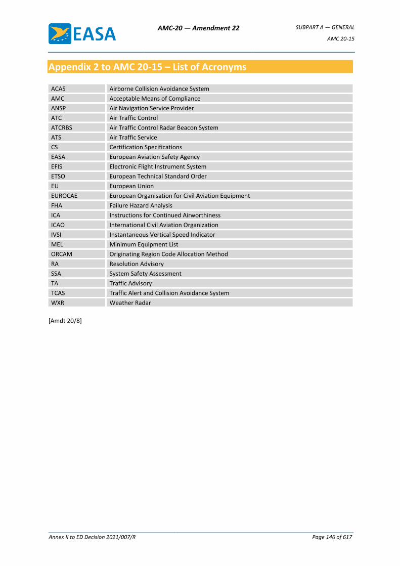
AMC-20 — Amendment 22 SUBPART A — GENERAL
AMC 20-15
Annex II to ED Decision 2021/007/R Page 146 of 617
Appendix 2 to AMC 20-15 – List of Acronyms
ACAS Airborne Collision Avoidance System
AMC Acceptable Means of Compliance
ANSP Air Navigation Service Provider
ATC Air Traffic Control
ATCRBS Air Traffic Control Radar Beacon System
ATS Air Traffic Service
CS Certification Specifications
EASA European Aviation Safety Agency
EFIS Electronic Flight Instrument System
ETSO European Technical Standard Order
EU European Union
EUROCAE European Organisation for Civil Aviation Equipment
FHA Failure Hazard Analysis
ICA Instructions for Continued Airworthiness
ICAO International Civil Aviation Organization
IVSI Instantaneous Vertical Speed Indicator
MEL Minimum Equipment List
ORCAM Originating Region Code Allocation Method
RA Resolution Advisory
SSA System Safety Assessment
TA Traffic Advisory
TCAS Traffic Alert and Collision Avoidance System
WXR Weather Radar
[Amdt 20/8]
AMC-20 — Amendment 22 SUBPART A — GENERAL
AMC 20-19
Annex II to ED Decision 2021/007/R Page 147 of 617
AMC 20-19
AMC 20-19 Passenger Service and In-Flight Entertainment (IFE) Systems
0 PREAMBLE
This document provides acceptable means of compliance (AMC) to obtain approval for the installation
of in-flight entertainment (IFE) systems. It has been developed on the basis of Joint Aviation
Authorities Temporary Guidance Leaflet (JAA TGL) No 17, and addresses the following concerns:
(a) the increase in the complexity of the IFE systems due to the additional cables, as well as the
increase in the power needed for IFE systems;
(b) the potential consequences on the aircraft or passengers of system/electrical faults, including
the risks of smoke, fire or interference with aircraft systems; these concerns are validated by
adverse service experience with different types of aircraft;
(c) the potential consequences for other aircraft systems due to the transmitting capability of the
IFE systems; and
(d) the lack of specific guidance on the installation of IFE systems, as these systems are categorised
as non-essential services, even though these systems may affect compliance with the applicable
provisions for seats and emergency evacuation.
1 PURPOSE
This AMC has been created to provide guidance to aircraft installers and equipment manufacturers on
the airworthiness of IFE systems and equipment installed on civil aircraft. It does not constitute a
regulation. It highlights safety concerns about IFE systems, and contains acceptable means of
compliance to address those concerns and obtain airworthiness approval of such systems. An
applicant for such an approval may choose another means of compliance.
2 RELATED CERTIFICATION SPECIFICATIONS (CSs)
Some of the certification specifications for which this AMC can be used are listed below. This list is for
reference only and should not be considered as comprehensive. Additional CS-25 provisions are
referenced where applicable. Provisions with the same number (e.g. CS 25.301) are generally read
across to the other CSs (e.g. 27.301 and 29.301). However, please note that in some cases, the same
topic is addressed by different provisions (e.g. for a specific CS-25 provision, the corresponding CS-23
provision may have a different number):
— CS 25.301, 303, 305, 307, 333, 337, 341, 365(g), 471, 561, 562, 581, 601, 603, 605, 609, 611,
785, 787, 789, 791, 811, 831, 853, 863, 869, 899, 1301, 1309, 1319, 1327, 1351, 1353, 1357,
1360, 1423, 1431, 1441, 1703, 1705, 1707, 1709, 1715, 1719, 1721, 1723;
— for CS-23:
AMC-20 — Amendment 22 SUBPART A — GENERAL
AMC 20-19
Annex II to ED Decision 2021/007/R Page 148 of 617
— Amendments 1 to 4: CS 23.561, 562, 785, 787, 791, 811, 867, 1301, 1309, 1327, 1351,
1353, 1357, 1359, 1431, 1441;
— Amendment 5: CS 23.2265, 2270, 2315, 2320, 2325, 2330, 2335, 2500, 2505, 2510, 2525,
2605, 2615;
— CS 27.561, 562, 610, 785, 787, 807, 853, 1301, 1309, 1319, 1327, 1351, 1353, 1357, 1365; and
— CS 29.561, 562, 610, 785, 787, 807, 853, 1301, 1309, 1319, 1327, 1351, 1353, 1357, 1359, 1431.
3 REFERENCE DOCUMENTS
The documents listed below are standards and guidance that were in force when this AMC (AMC 20-
19) was adopted. Later or previous amendments may apply whenever the retained certification basis
allows for it.
(a) ED Decision 2017/020/R, AMC-20 — Amendment 14, AMC 20-115D, Airborne software
development assurance using EUROCAE ED-12 and RTCA DO-178, 19 October 2017
(b) ED Decision 2020/010/R, AMC 20 — Amendment 19, AMC 20-152A, Development Assurance for
Airborne Electronic Hardware, July 2020
(c) ED Decision 2020/006/R, AMC 20 — Amendment 18, AMC 20-42, Airworthiness information
security risk assessment, 24 June 2020
(d) ED Decision 2014/029/R, AMC and GM to Part-CAT — Issue 2, Amendment 1, Portable electronic
devices, AMC/GM to CAT.GEN.MPA.140, 24 September 2014, as amended by ED Decision
2019/008/R of 27 February 2019
(e) EASA Certification Memorandum No CM-ES-001, Certification of Power Supply Systems for
Portable Electronic Device, Issue 1, 7 June 2012
(f) EASA Certification Memorandum No CM-ES-003, Guidance to Certify an Aircraft as PED tolerant,
Issue 1, 23 August 2017
(g) International Civil Aviation Organization (ICAO) Doc 9284-AN/905, Technical Instructions for the
Safe Transport of Dangerous Goods by Air (Addendum No. 2), 30 June 2005
(h) Federal Aviation Administration (FAA) Advisory Circular (AC) 21-16G, RTCA Document DO-160
versions D, E, F, and G, ‘Environmental Conditions Initiated by: AIR-100 and Test Procedures for
Airborne Equipment’, 22 June 2011
(i) FAA Policy Memorandum PS-ANM100-2000-00105 (also numbered 00-111-160), Interim Policy
Guidance for Certification of In-Flight Entertainment Systems on Title 14 CFR Part 25 Aircraft
(Policy Number 00-111-160), 18 September 2011
(j) FAA AC 91.21-1D, Use of Portable Electronic Devices Aboard Aircraft, 27 October 2017
(k) FAA AC 20.168, Certification Guidance for Installation of Non-Essential, Non-Required Aircraft
Cabin Systems & Equipment (CS&E), 21 July 2010
(l) FAA AC 20.115D, Airborne Software Development Assurance Using EUROCAE ED-12( ) and RTCA
DO-178( ), 21 July 2017
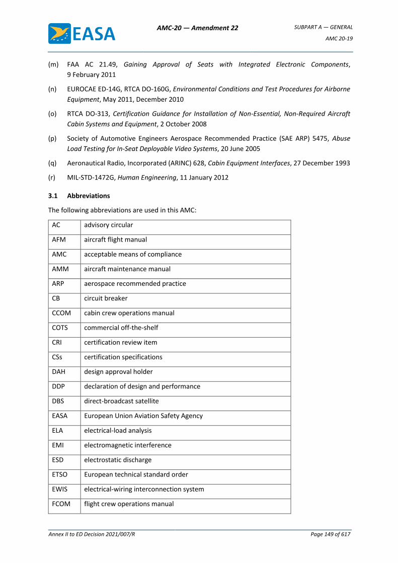
AMC-20 — Amendment 22 SUBPART A — GENERAL
AMC 20-19
Annex II to ED Decision 2021/007/R Page 149 of 617
(m) FAA AC 21.49, Gaining Approval of Seats with Integrated Electronic Components,
9 February 2011
(n) EUROCAE ED-14G, RTCA DO-160G, Environmental Conditions and Test Procedures for Airborne
Equipment, May 2011, December 2010
(o) RTCA DO-313, Certification Guidance for Installation of Non-Essential, Non-Required Aircraft
Cabin Systems and Equipment, 2 October 2008
(p) Society of Automotive Engineers Aerospace Recommended Practice (SAE ARP) 5475, Abuse
Load Testing for In-Seat Deployable Video Systems, 20 June 2005
(q) Aeronautical Radio, Incorporated (ARINC) 628, Cabin Equipment Interfaces, 27 December 1993
(r) MIL-STD-1472G, Human Engineering, 11 January 2012
3.1 Abbreviations
The following abbreviations are used in this AMC:
AC advisory circular
AFM aircraft flight manual
AMC acceptable means of compliance
AMM aircraft maintenance manual
ARP aerospace recommended practice
CB circuit breaker
CCOM cabin crew operations manual
COTS commercial off-the-shelf
CRI certification review item
CSs certification specifications
DAH design approval holder
DDP declaration of design and performance
DBS direct-broadcast satellite
EASA European Union Aviation Safety Agency
ELA electrical-load analysis
EMI electromagnetic interference
ESD electrostatic discharge
ETSO European technical standard order
EWIS electrical-wiring interconnection system
FCOM flight crew operations manual
AMC-20 — Amendment 22 SUBPART A — GENERAL
AMC 20-19
Annex II to ED Decision 2021/007/R Page 150 of 617
FDAL functional development assurance level
FHA functional hazard assessment
GM guidance material
GSM global system for mobile communications
GUI graphical user interface
ICA Instructions for Continued Airworthiness
ICAO International Civil Aviation Organization
IDAL item development assurance level
IEEE Institute of Electrical and Electronics Engineers
IFE in-flight entertainment
LAN local area network
MCA mobile communications on aircraft
MMEL master minimum equipment list
MoC means of compliance
OEM original-equipment manufacturer
PA public address
PABX private automatic branch exchange
PED portable electronic device
PFIS passenger flight information system
PSS power supply system
RTCA Radio Technical Commission for Aeronautics
R/T real time; real-time (as modifier)
SAE ARP Society of Automotive Engineers Aerospace Recommended Practice
SP special condition
STC supplemental type certificate
SWPM standard wiring practices manual
TC type certificate
T-PED transmitting portable electronic device
USB universal serial bus
VAC volts alternating-current
AMC-20 — Amendment 22 SUBPART A — GENERAL
AMC 20-19
Annex II to ED Decision 2021/007/R Page 151 of 617
VDC volts direct-current
Wi-Fi wireless fidelity
WLAN wireless local area network
AMC-20 — Amendment 22 SUBPART A — GENERAL
AMC 20-19
Annex II to ED Decision 2021/007/R Page 152 of 617
3.2 Definitions
The following definitions used in this AMC apply:
Term Definition
In-flight entertainment
systems
On-board systems that provide passengers with (safety) information,
connectivity and entertainment
Installer Type certificate (TC), supplemental type certificate (STC) or design
approval holder (DAH)
COTS equipment Equipment that is not designed or manufactured for use in aircraft, but
is purchased by the installer for use in a particular aircraft system
4 SCOPE
Communication, information and entertainment systems are often provided for the convenience of
aircraft passengers. As customer services improve, those systems are becoming more sophisticated
and complex. Subsystem design features are often unique, based on the needs of operators, thus
leading to many different possible IFE system configurations that depend both on the specific operator
requirements and the cabin layout.
The following non-exhaustive list contains some examples of IFE systems:
(a) systems that provide passengers with audio entertainment and the related controls;
(b) systems that provide passengers with video entertainment and the related controls;
(c) passenger flight information systems (PFISs);
(d) systems that provide passengers with information, e.g. safety videos;
(e) interfaces to, and functions of, systems for controlling some cabin environment parameters
such as, for example, reading lights, general cabin illumination, crew call buttons, air vents, etc.;
(f) systems that provide passengers with wired and/or wireless data distribution for entertainment
connectivity including television (TV) and communication access (i.e. telephone, internet).
The aim of this AMC is to provide general criteria for the approval of such systems and equipment as
they are installed in aircraft. The following aspects are addressed: mechanical installation, electrical
installation, software/hardware aspects and electromagnetic compatibility, as well as the assessment
of the potential hazards. In some cases, the application of this AMC, in conjunction with the
certification basis for the product, is deemed to be sufficient.
For certain systems and equipment, additional certification material may be needed to address the
aspects that are not covered by this AMC. Some examples are:
— IFE systems with wireless-communication capabilities (e.g. wireless fidelity (Wi-Fi) access
points, mobile-phone systems);
— electrical outlets installed in the cabin for connecting portable electronic devices (PEDs);
— lithium batteries;
AMC-20 — Amendment 22 SUBPART A — GENERAL
AMC 20-19
Annex II to ED Decision 2021/007/R Page 153 of 617
— data-loading systems;
— data communication systems (e.g. satellite TV, radios, passenger telephone systems, etc.); and
— large monitors/displays.
5 APPROVAL CONSIDERATIONS (AT AIRCRAFT LEVEL)
Section 6 below provides a summary of the issues that are pertinent to the safety of the aircraft, its
occupants and maintenance personnel, which the equipment manufacturer and the installer should
consider. Since IFE system installations are typical for commercially used large aeroplanes, it is
expected that the approach to be followed for General Aviation (GA) aircraft will be different (for the
purpose of this AMC, ‘General Aviation aircraft’ are those aircraft that comply with the CS-23
specifications). Section 6.7 below provides guidance in this regard. Some general considerations are
presented below:
(a) The applicant for the approval of an IFE system should demonstrate compliance with the
applicable aircraft certification basis. The installed IFE system should function as intended, and
no ‘credit’ should be given for its performance capability. Substantiation is required to
demonstrate that the IFE system and equipment in their installations and in operation do not
interfere with the operation of other aircraft systems, or do not cause any hazard to the aircraft,
to its occupants, or to maintenance personnel.
(b) If part of an IFE system is designed to transmit the required safety information (e.g. the
passenger briefing), the replacement system should also meet the safety objectives required
for that function. The installer should identify these safety objectives, which depend on the type
of function for which the IFE system is used.
(c) The applicant may use existing approvals for interfacing equipment (e.g. IFE system parts
mounted in seats). However, the applicant should ensure that all the applicable airworthiness
provisions are addressed. For example, European technical standard orders (ETSOs) on seats do
not contain electrical provisions; therefore, the electrical aspects of the seats should be
reviewed to ensure that the installation of IFE system equipment does not invalidate the original
ETSO for the seats.
(d) If other aircraft system installations are affected by the installation of the equipment of the IFE
system, then the applicable requirements for these affected systems should be taken into
account.
(e) If an IFE system is designed to be available for the operating crew, EASA should approve the
related flight operation limitations.
(f) The applicant should demonstrate that any non-essential equipment (which includes
equipment installed for the purpose of passenger entertainment), as installed:
— is not a source of danger in itself;
— does not prejudice the proper functioning of an essential service; and
— does not in any way reduce the airworthiness of the aircraft to which it is fitted, even in
the event of a failure to perform its intended functions.

AMC-20 — Amendment 22 SUBPART A — GENERAL
AMC 20-19
Annex II to ED Decision 2021/007/R Page 154 of 617
For example, for large aeroplanes, compliance should be demonstrated with CS 25.1309.
A functional hazard assessment (FHA) should be performed to identify the IFE system failure
scenarios and the worst possible consequences (e.g. electrical shock) for the aircraft and its
occupants. This assessment should take into account electrical, electronic, and component
faults that may result in a short circuit and/or electrical arcing and/or the release of smoke.
Particular attention should be given to the likelihood of the following:
— accidental damage due to exposure of wiring or components in the cabin, such as wires
that are pinched in the seat track;
— misuse of the equipment by passengers, such as the incorrect stowage of video screens,
stepping on or kicking the seat electronic box, spilling liquids, etc.;
— electronic-component breakdowns; and
— wire chafing.
(g) The installer should demonstrate that the equipment of the IFE system has been installed in
accordance with the equipment manufacturer’s declaration of design and performance (DDP)
and their installation instructions. The demonstration may, in addition, involve the examination
and testing of the equipment. Subpart O ‘EUROPEAN TECHNICAL STANDARD ORDER
AUTHORISATIONS’ of Annex I (Part 21) to Regulation (EU) No 748/2012 and the related AMC
21.A.608 provide guidance on drafting and formatting the DDP.
(h) If an operator allows passengers to use PEDs on board the aircraft, it should have procedures in
place to control the use of those PEDs. Regulation (EU) No 965/2012 and the related ED
Decisions contain, respectively, requirements and associated AMC and GM on PEDs. For
commercial air transport (CAT) operations, the corresponding requirement is point
CAT.GEN.MPA.140 of Annex IV (Part-CAT).
(i) If environmental testing of the IFE system equipment is required, EUROCAE ED-14/RTCA DO 160
‘Environmental Conditions and Test Procedures for Airborne Equipment’ may be followed. This
is addressed in Section 0.1 below.
6 SYSTEMS INSTALLATION
6.1 Mechanical systems — aspects
6.1.1 Equipment location
The equipment and its controls should be positioned in locations where they do not impede the
movement or the duties of the flight crew or the cabin crew (including in crew rest areas), or the
normal movement of passengers.
(a) In a light aircraft, for example, if audio entertainment is audible to the pilot, a means to control
the sound level should be provided to the pilot. Visual-entertainment equipment should be
located where it does not distract the crew.
(b) Equipment should be located and, where necessary, protected to minimise the risk of injury to
the occupants of the aircraft during a normal flight or an emergency landing. For equipment
AMC-20 — Amendment 22 SUBPART A — GENERAL
AMC 20-19
Annex II to ED Decision 2021/007/R Page 155 of 617
with cords in large aeroplanes, for example, the lengths of the cords should be determined by
their possible effects on the egress capability of the occupants. The cords should not span across
a main aisle such that they may become entangled in other features (such as armrests), thus
impeding egress. Means for proper and easy stowage should be provided.
(c) Equipment used for screens should not obscure any required notices or information signs (e.g.
‘Exit’, ‘No Smoking’, ‘Fasten Seat Belt’ signs, etc.). For video monitors in large-aeroplane
installations, the following should apply:
(1) For video monitors installed above the aisle:
— all the installations should be such that the required ‘exit’ signs are still visible
whether the monitors are fixed or retractable; if this is not possible, additional
‘EXIT’ signs are required;
— fixed video monitors should be such that the minimum distance between the cabin
floor and the lowest point of the monitor is 185 cm (73 in); and
— retractable video monitors that do not meet the 185-cm (73-in) limit in the
deployed position should not have sharp edges or should be padded, and they
should be able to be stowed manually without requiring exceptional strength.
(2) For video monitors installed underneath overhead compartments:
— all the installations should be such that the required signs (e.g. ‘No Smoking’,
‘Fasten Seat Belts’ signs, etc.) are visible whether the monitors are fixed or
retractable; if this is not possible, additional signs are required;
— fixed video monitors should be padded and should not be installed above or
between the seat backs of seat rows that border the access to emergency exits;
and
— retractable video monitors should be able to be stowed manually without requiring
exceptional strength and should not be installed above or between the seat backs
of seat rows that border the access to emergency exits.
(d) Connecting units for wired on-board data exchange (e.g. USBs, local area networks (LANs), etc.)
should be designed so that their use is obvious to the crew and passengers. Placards close to
their outlet units should describe their capabilities and functions.
Units that are capable of supplying power with:
— a voltage greater than or equal to 42 V;
— power greater than 15 W; or
— a current greater than 3 A,
should be treated as power outlets.
(e) For individual video monitors attached to the seats (e.g. to the seat armrests, seat backs,
movable hinge arms), the protection of the seat occupants, as well as of the crew and
passengers moving around the cabin, should be considered. Video monitor installations should
AMC-20 — Amendment 22 SUBPART A — GENERAL
AMC 20-19
Annex II to ED Decision 2021/007/R Page 156 of 617
be such that injuries due to contact with sharp edges/corners during normal operation and
turbulence are avoided. The abuse loading of video monitors (e.g. if a passenger leans on the
monitor when taking or leaving their seat) should be accounted for. The criteria of SAE ARP5475
‘Abuse Load Testing for In-Seat Deployable Video Systems’ or alternatives, as agreed by EASA,
may be used in assessing designs regarding this aspect.
6.1.2 Construction and attachment strength
(a) Any seat/monument installation, after modification, should continue to comply with the
original certification basis.
(b) Equipment, attachments, supporting structures, and their constituent parts should be
constructed such that they do not break loose when subjected to the loads (either for flight or
for emergency ditching) that are prescribed in the relevant CSs. Some commercial off-the-shelf
(COTS) equipment might not comply with these provisions and may need to be strengthened
before being installed in an aircraft (see Section 6.6 below on COTS equipment).
(c) The design of IFE-system-related antennas, their location and manner of attachment should be
such that there is no adverse effect on the aircraft systems and no danger to the aircraft under
any foreseeable operating conditions.
Remark: If external antennas are installed, the applicant should address the corresponding
certification aspects, for which specific guidance is available (i.e. antennas in pressurised areas,
the installation of large and/or deployable antennas, etc.). The certification approach for such
external antenna installations should be agreed with EASA.
(d) As far as practicable, the equipment should be positioned so that if it breaks loose, it is unlikely
to cause injury or to nullify any of the escape facilities for use after an emergency landing or
after ditching. When such positioning is not practicable, each such item of equipment should
be restrained under any load up to the prescribed ultimate inertia forces for the emergency
landing conditions. Furthermore, for each item of equipment that is subject to frequent
installation and removal, the local attachments of these items should be designed to withstand
1.33 times the specified loads (see CS 25.561(c)(2)). Compliance with CS 25.365(g) should also
be considered.
Note 1: The structural provisions applicable to equipment can vary depending upon the type
and size of the aircraft in which the equipment is installed; if the equipment is
designed to be installed in any aircraft, then the applicant should consult all the
relevant airworthiness CSs and create an envelope of conditions for design purposes.
Note 2: If an STC holder installs the equipment, they may need to consult the TC holder to
obtain data on the vertical-acceleration factors (resulting from gusts and aircraft
manoeuvres) that are applicable to a given aircraft type and to the proposed location
of the equipment.
(e) If the IFE system is installed in a seat or in a monument adjacent to a seat, the installation may
need to be reapproved for structural integrity and, if appropriate, for the emergency-landing
dynamic conditions, including the occupant injury criteria. For large aeroplanes, for example, to
avoid head injuries (CS 25.562(b) and CS 25.562(c), as referenced in CS 25.785) caused by
AMC-20 — Amendment 22 SUBPART A — GENERAL
AMC 20-19
Annex II to ED Decision 2021/007/R Page 157 of 617
seat-back-mounted IFE equipment, compliance with CS 25.562(c)(5) should be shown for a fully
equipped seat back in the take-off and landing position.
(f) Weight and stress assessments should be made in cases of already embodied shelves that need
to be relocated.
(g) Glass surfaces may be part of IFE system components, e.g. in display units. The potential hazard
for the occupants in case of breakage of large sheets of glass should be considered. The
approach that the applicant should follow should be agreed with EASA based on CS 25.788 (b).
Compliance with CS.25.365(g) should also be considered.
6.2 Electrical systems — aspects
6.2.1 Power supplies
The IFE system equipment should be powered by an electrical busbar that does not supply power to
the aircraft systems that are necessary for continued safe flight and landing.
The IFE system should be designed to provide circuit protection from overloads and short circuits by
means of suitable protective devices.
(a) The method of connection of the equipment to the aircraft electrical system and the operation
of the equipment should not adversely affect the reliability or integrity of the electrical system
or any other electrical unit or system that is essential for the safe operation of the aircraft.
(b) If applicable, the aircraft electrical system should be protected from any unacceptable EMI
caused by a connected PED.
(c) The flight/cabin crew should be provided with a clearly labelled and conspicuous means to
disconnect an IFE system from its source of power at any time, and that means should be as
close as practically possible to the source of power. The disabling/deactivating of component
outputs should not be considered to be an acceptable means to cut off power, i.e. the
disabling/deactivating of the output of a power supply unit, seat electronic box, etc., as opposed
to cutting off the input power of the system. Moreover, pulling system circuit breakers (CBs) as
the sole means to cut off the IFE system power is not considered to be acceptable. This is
because CBs are not normally designed to be used as switches. The pulling and resetting of CBs
over a period of time may degrade their trip characteristics, and then the CBs might not trip
when required.
(d) An electrical-load analysis (ELA) should be carried out, taking into account the maximum load
that the IFE system may utilise, to substantiate that the aircraft electrical-power generating
system has sufficient capacity to safely provide the maximum amount of power required by the
IFE system to operate properly. The applicant should base the IFE system ELA on an ELA that
accurately reflects the aircraft’s electrical loads prior to the installation of the IFE system. If this
is not available, the applicant should make measurements of the aircraft’s condition prior to the
installation of the IFE system, and use these measurements for the ELA of the IFE system.
(e) The potential cumulative effect of the installation of multiple IFE units on the harmonic content
of the electrical-power supply should be considered. There have been cases in which the
installation of multiple IFE units with switched mode power supplies has changed the shape of
AMC-20 — Amendment 22 SUBPART A — GENERAL
AMC 20-19
Annex II to ED Decision 2021/007/R Page 158 of 617
the alternating current (AC) voltage waveform to the extent that the operation of the aircraft
electrical power supply system (PSS) has been affected.
(f) Where batteries are used, consideration should be given to the stored energy, and provisions
should be made for protection from short circuits and other potential failure modes.
The safety issues associated with the use in the IFE system of batteries whose technology may pose
hazards that are not covered by the current provisions should be addressed by additional provisions
to be agreed with EASA (e.g. for lithium battery technology).
6.2.2 Bonding
The electrical bonding, as well as the protection against static discharge of the installed system and
equipment, should be such as to:
(a) prevent a dangerous accumulation of electrostatic charge; and
(b) minimise the risk of electrical shock to the crew, passengers and maintenance personnel.
The system bonding arrangements should be in accordance with the aircraft manufacturer’s standard
practices, and suitable for conducting any current, including a fault current, which may need to be
conducted. The designer should take into account bonding connections in the system design such that
the loss of a single bond does not result in the loss of more than one essential circuit or in the
dangerous inadvertent operation of any aircraft system.
Cabin equipment designers should adhere to the standard practices for bonding, grounding and
shielding, as well as to other methods for eliminating or controlling electrostatic discharge.
All electrical and electronic equipment and/or components should be installed so as to provide a
continuous low-resistance path from their metallic enclosures and wiring to the aircraft bonding
structure.
6.2.3 Interference
6.2.3.1 Magnetic effects
Whether the installed IFE system equipment is operating or not, the aircraft compass systems should
continue to meet the prescribed accuracy standards. Where other equipment approved as part of the
aircraft is installed, the installer should take account of the declared compass safe distance when
designing the installation.
Account should be taken of the compass safe distance in respect of both the compass and the flux
detector. The installer should also consider potential interference of the installed IFE system
equipment with the relatively low-level signal of the compass system interconnecting cables.
6.2.3.2 Electromagnetic interference (EMI)
The levels of conducted and radiated interference generated by the equipment via power supply
feeders, by system interfacing or by EMI should not cause an unacceptable degradation of the
performance of other aircraft systems. If some equipment or functions are never used, the applicable
AMC-20 — Amendment 22 SUBPART A — GENERAL
AMC 20-19
Annex II to ED Decision 2021/007/R Page 159 of 617
system function should be properly disabled and/or terminated to prevent any interference with other
aircraft systems.
(a) Antennas
Antennas for IFE systems should not be located where an unacceptable reduction in the
performance of a mandatory radio system would result. In addition, the effects of a lightning
strike on these antennas should be considered to ensure that essential services are not
disrupted by electrical transients conducted to the aircraft via these antenna leads.
(b) Cumulative interference effects
The actual interference effect on an aircraft receiver may be the cumulative effect of many
potentially interfering signals. For this reason, a system consisting of multiple units should be
operable even in the worst-case orientation when interference tests/demonstrations are
conducted. Tests/demonstrations should take into account the critical configurations of the use
of the IFE system, including the critical configurations of passengers’ portable electronic devices
(PEDs) connected to the IFE system. The test configuration should be agreed with EASA.
(c) Flight phases
If the whole IFE system or parts of it are to be active during the critical flight phases (i.e. take-
off and landing), particular attention should be paid to the demonstration of non-interference
during these critical flight phases.
6.2.4 Electrical shock
Occupants should be protected against the hazard of electrical shock. Therefore, the applicant should
demonstrate the means to minimise the risk of electrical shock as per CS 25.1360(a). Particular
attention should be given to high-voltage equipment. If high- or low-voltage power outlets are
available for passenger use, the aspects related to the use of PSSs for PEDs should be considered.
6.2.5 Wiring harness and routing
The electrical-wiring interconnection system (EWIS) associated with the IFE system should be
installed, as for all other electrical systems, in accordance with the provisions of CS-25 Subpart H, or
any equivalent document accepted by EASA. In order to meet these provisions, the applicant should
adhere to the following guidelines:
— the wiring installation should be in accordance with the standard wiring practices manual
(SWPM) of the aircraft or any equivalent standard accepted by EASA;
— standard original-equipment manufacturer (OEM) wiring or compatible types of wiring should
be used;
— all the data necessary to define the design, in accordance with point 21.A.31 (Annex I (Part 21)
to Regulation (EU) No 748/2012), including the installation drawings and wiring diagrams, shall
be available; and
AMC-20 — Amendment 22 SUBPART A — GENERAL
AMC 20-19
Annex II to ED Decision 2021/007/R Page 160 of 617
— where the IFE system EWIS is routed through standard aircraft wiring looms, spacers or
equivalent means of separation should be used to keep the IFE EWIS at a minimum distance
from any other electrical system in accordance with the SWPM of the aircraft.
In the absence of more specific guidelines in the SWPM of the aircraft, 230 VAC voltage power supply
wires should not be routed through standard aircraft wiring looms. As the EWIS connected to the IFE
system is present throughout the cabin (exposed in some cases), the potential for system faults is
increased by the wide exposure to varying hazards (e.g. EWIS chafing in the seat tracks, passengers
stepping on or kicking the seat electronic box, spilled liquids, etc.). Since these systems are exposed
to hazards, the potential to adversely affect other systems that are necessary for the safe operation
of the aircraft significantly increases, as well as the possibility of shock hazards to occupants. Special
consideration should be given to the protection against damage to the IFE EWIS components installed
in the seat itself: they should have appropriate protection means so that passengers cannot damage
them with their feet or access them with their hands. The engineering data that controls the
installation of IFE EWIS and equipment should contain specific and unambiguous provisions for the
routing, support and protection of all IFE EWIS and equipment, and should specify all the parts that
are necessary for those installations.
Care should be taken to ensure that any electrical IFE system equipment installed in aircraft seat
assemblies does not invalidate the seat certification (e.g. the applicable ETSO). In addition, it should
be noted that compliance alone with any applicable ETSO for seats does not cover the electrical
equipment installation aspects of the IFE system.
6.3 Aircraft interaction and interfaces
If an IFE system is electrically interfaced with other aircraft systems, the performance and integrity of
those aircraft systems should not be degraded. Appropriate means should be provided to isolate the
IFE system from the aircraft systems.
(a) If an IFE system is connected to the aircraft avionics system (or any other system that may have
a safety-related function), the installer should demonstrate that no malfunction of the IFE
system may affect the aircraft avionics system. The installer should conduct a safety analysis to
substantiate this. Supplementary to this safety analysis, special attention may be required due
to cybersecurity issues. The installer should assess the information security aspects in
accordance with AMC 20-42.
(b) If an IFE system interfaces with the public address (PA) function, the use of this system should
not impair the audibility of crew commands or instructions. A PA override feature should be
considered to allow cabin announcements to be heard by passengers.
(c) If an IFE system is available for the operating crew, the operation of this system should not
interfere with, or adversely affect, the crew’s ability to operate other aircraft systems and
respond to alerting systems. The aircraft flight manual (AFM) should contain appropriate
limitations and procedures.
The applicant should consider the following design interface features as acceptable means of
compliance:
(1) no access to any form of visual entertainment equipment;
AMC-20 — Amendment 22 SUBPART A — GENERAL
AMC 20-19
Annex II to ED Decision 2021/007/R Page 161 of 617
(2) automatic muting of the IFE systems when any cockpit aural caution or warning is
sounding; there should be no perceptible delay between the muting of the IFE system
and the activation of the caution/warning;
(3) automatic muting of the IFE systems when any real-time (R/T) transmission or reception
is in progress; there should be no perceptible delay between the muting of the IFE system
and the activation of the R/T transmission or reception; and
(4) readily available controls such that the volume of the IFE system is easily reduced.
(d) If an IFE system includes wireless capabilities (wireless local area network (WLAN), mobile
phone, Bluetooth, etc.) to connect with other aircraft equipment and/or passenger or crew
transmitting portable electronic devices (T-PEDs), the installer should address the
electromagnetic compatibility of the aircraft with the intentional emissions of the IFE system,
and the approach to be followed in that respect should be agreed with EASA.
Note: The responsibility for establishing the suitability for use of a PED on a given aircraft model
continues to rest with the operator, as required by point CAT.GEN.MPA.140 (Annex IV (Part-CAT) to
Regulation (EU) No 965/2012).
The design interface features used to comply with the above should be designed with a development
rigour that depends on the function that is being interfaced with or replaced by the IFE system.
6.4 Software/airborne electronic hardware (AEH)
6.4.1 Software architecture
The software architecture of IFE system components should consider the following distinction
between:
— core software as part of the functional scope defined in the specification of the component (e.g.
operating systems, hardware drivers, functional applications such as PA), including all the
required core software configuration data (the core software may be field loadable); and
— content data, including content configuration data (it may be field loadable by the aircraft
operator); for IFE system equipment, the aircraft operator is usually required to make some
adjustments and/or changes in the short term; such changes may be related to the content data
and/or content configuration data — some examples of the latter are the following:
— the selection of passenger-accessible graphical user interface (GUI) elements;
— the activation of predefined GUI designs; and
— the selection of regional information data (e.g. different country borderlines).
A change in the core software requires a component modification or redesign (change of part number)
and, therefore, leads to a change in the aircraft configuration.
A change in the content data remains in the operational responsibility of the aircraft operator
(field-loadable software) and, therefore, does not lead to a change in the aircraft configuration.
AMC-20 — Amendment 22 SUBPART A — GENERAL
AMC 20-19
Annex II to ED Decision 2021/007/R Page 162 of 617
6.4.2 Software development assurance
The item development assurance level (IDAL) required for the IFE system software should be
determined through the functional hazard assessment (FHA) that identifies the worst failure to which
the software may contribute. If the IDAL is equal to IDAL D or greater, AMC 20-115, latest revision,
provides guidance for the production of airborne systems and equipment software that performs its
intended function with a level of confidence in its safety that is compliant with airworthiness
provisions. This is an acceptable standard, and it should be taken into consideration for software in
IFE systems, in particular those that replace or interface with the required functions of the aircraft.
6.4.3 Airborne electronic hardware (AEH) development assurance
The functional development assurance levels (FDALs) identified through the FHA should be used, in
conjunction with the system architecture considerations, in order to determine the IDAL to be used
for the development of airborne electronic hardware (AEH), and to identify the rigour of the
development processes used.
For the development assurance of AEH of IFE systems that replace or interface with the required
functions of the aircraft, the provisions of AMC 20-152, latest revision, apply.
6.5 Other risks
For the risks associated with hazards that may be caused by the IFE system equipment due to the
operating environment of the aircraft, the standard environmental and operational test conditions
and test procedures of EUROCAE ED-14/RTCA DO-160 may be used in combination with FAA
AC 21-16G.
The responsibility for selecting the appropriate environmental and operational test conditions and
test procedures lies with the installer. Section 6.5.1 below provides guidance on the selection of the
test types. Sections 6.5.2, 6.5.3 and 6.5.4 below address other associated risks.
6.5.1 Environmental qualification
If the IFE system equipment is not linked to any other aircraft systems and is only connected to a
non-essential power busbar, the following is recommended as a minimum list of environmental tests:
— temperature and altitude,
— temperature variation,
— operational shocks and crash safety,
— vibration,
— power input,
— voltage spikes, and
— emissions of radio frequency energy.
The installer is responsible for selecting the appropriate test conditions and for agreeing them with
EASA. The assessment of the installation may prove that some of the above test types are unnecessary
or, contrarily, that additional tests should be performed.
AMC-20 — Amendment 22 SUBPART A — GENERAL
AMC 20-19
Annex II to ED Decision 2021/007/R Page 163 of 617
6.5.2 Touch temperature
In addition to CS 25.1360(b), the following should be considered: any hot surfaces of IFE system
components that are accessible to the crew or passengers should not be exposed if inadvertent
contact with those surfaces may pose a hazard.
The definition of MIL-STD-1472G ‘HUMAN ENGINEERING’ applies:
Equipment which, in normal operation, exposes personnel to surface temperatures greater than:
— For momentary contact: 60°C for metal, 68°C for glass, 85°C for plastic or wood;
— For prolonged contact: 49°C for metal, 59°C for glass, 69°C for plastic or wood;
or less than 0°C should be appropriately guarded.
6.5.3 Fluid exposure
If the equipment is mounted in a position where exposure to fluid is possible, for example on or under
a passenger seat, or where catering operations take place or liquid cleaning agents are used regularly,
it should be established that fluid spillage does not render the equipment hazardous. Where possible,
installations in areas susceptible to moisture should be avoided. Otherwise, consideration should be
given to minimise the hazard of liquid ingress, e.g. the inclusion of drip loops in wiring harnesses and
the installation of drip trays.
If the approach described above is followed, the fluid susceptibility test may be disregarded.
6.5.4 Rapid decompression and high-altitude operation
The installer should ensure that no arcing that causes a fire risk or unacceptable levels of interference
will occur in the equipment when the equipment is subjected to an atmospheric pressure that
corresponds to the maximum operating altitude of the aircraft. Alternatively, means should be
provided to automatically disconnect the electrical supply to the equipment when the cabin pressure
reduces to a level below which the safe operation of the equipment is not ensured (e.g. rapid
decompression). The guidance of RTCA DO-313 in this area may also be followed.
This section should be followed in addition to the test conditions of Section 6.5.1.
6.5.5 Explosion, fire, fumes and smoke
(a) The installer should pay particular attention to the quality and design of components such as
transformers, motors and composite connectors in order to minimise the risk of them
overheating. The design of the mounting provisions for IFE system components installed in the
passenger cabin (e.g. passenger seats, closet/cabin partition walls, overhead compartments,
etc.) should fully reflect the cooling provisions for the equipment, including heat sinking,
ventilation, proximity to other sources of heat, etc.
(b) All materials should meet the appropriate flammability provisions. Inadvertent blockage (e.g.
by passengers’ coats, luggage or litter) of any cooling vents should be prevented either by the
design or by operational procedures. Appropriate protection against overheating should be part
of the design of such in-seat systems.
AMC-20 — Amendment 22 SUBPART A — GENERAL
AMC 20-19
Annex II to ED Decision 2021/007/R Page 164 of 617
(c) For the installation of IFE system components in racks located in the equipment bay that are
not accessible in flight, the installer should address the potential hazard to other essential or
critical systems/equipment located in the equipment bay, in case of an IFE system malfunction.
The installer should substantiate that the worst-case scenario of a possible malfunction of the
IFE system does not affect the components located in the equipment bay that are necessary for
safe flight and landing. This demonstration should account for the risks of:
— overheating,
— smoke release,
— electrical failure, and
— fire propagation.
For large aeroplanes, for example, the following is considered an acceptable means of
compliance in that respect: a hazard analysis to demonstrate that none of the potential ignition
risks that originate from IFE system malfunctions pose a risk of a sustained fire in any area where
IFE system components are located; this demonstration should account for:
— the fire containment properties of the equipment,
— the non-fire-propagating properties of the adjacent materials, and
— the detectability of fire and smoke.
(d) The installer should consider protecting IFE system components that are located in the cabin to
ensure that fault conditions will not result in the failure of components within a unit that may
generate smoke or fumes (e.g. if using tantalum capacitors). In addition, power supplies should
have current-limiting output protection at a suitable level (e.g. in-seat equipment). The IFE
system installation should comply with the applicable fire and smoke provisions of CS 25.831(c),
CS 25.853(a), CS 25.863 and CS 25.869(a).
(e) Procedures should be established to terminate the operation of the IFE system at any time, in
case of smoke/fire/explosion. The crew should maintain overall control over the IFE system. If
control over the IFE system is possible via cabin controls only, appropriate procedures should
address flight crew compartment–cabin coordination.
The guidance of RTCA DO-313 in this area may also be followed.
6.6 Commercial off-the-shelf (COTS) equipment
This section provides guidance for the cases in which the installer uses COTS equipment as part of an
IFE system modification.
In principle, the installation of COTS equipment, as for all other IFE system equipment, should follow
the guidance provided in this document. It is, nevertheless, recognised that COTS equipment is
supplied from a market whose industry standards differ from the aviation ones. As a consequence, it
may be difficult to follow some of the guidance of this document.
The main impediments are the following:
— traceability and configuration control; and
AMC-20 — Amendment 22 SUBPART A — GENERAL
AMC 20-19
Annex II to ED Decision 2021/007/R Page 165 of 617
— it is burdensome to perform most of the testing in accordance with the state-of-the-art aviation
standards (e.g. EUROCAE ED-14/RTCA DO-160).
In certain cases, the installer may directly follow the guidance provided in this document by using
specific design features/adaptations and mitigations in terms of design or operational instructions.
The steps described below compose a road map that the installer may follow to apply for the approval
of COTS equipment as part of an IFE system:
— The installer should perform a safety risk assessment of the potential hazards associated with
the installation of the COTS equipment, either during normal operation of the equipment or in
case of its failure.
— Based on the identified hazards, some evidence of environmental qualification for the
equipment may be required. This could be achieved either by testing or by providing alternative
laboratory standards to which the equipment has been tested, or industry standards to which
the equipment has been certified. The acceptability of these standards should be agreed with
EASA.
— A design solution may be developed in some cases to provide means of compliance that are
alternatives to testing, e.g.:
— hosting of the COTS component in a ‘shelter case’ (an air-tight-sealed housing) with
electrical isolation of all the needed interfaces; or
— a declaration of ‘loose equipment’ that is temporarily brought on board and is
permanently accessible and visible by the crew.
— It should be ensured that the design specifications of the COTS equipment manufacturer are
followed (in terms of the operating environmental conditions, cooling, etc.).
— Configuration control: quality control criteria should be provided for those aspects of the COTS
equipment whose malfunctions may create hazards. If detailed design data is not available for
such aspects, the applicant should propose a process by which the configuration control of the
design is maintained and should ensure that any changes in the design or any non-compliance
introduced during manufacturing are identified. Critical characteristics of COTS equipment may
include power, dimensions, weight, electrical power, software and hardware parts, material
flammability behaviour, etc. This should also encompass subsequent changes to those parts.
The above points should help the installer in the certification of the COTS equipment. RTCA DO-313
Appendix D follows a similar approach and is considered to be an acceptable alternative.
6.7 Approach for General Aviation (GA) aircraft
This section provides guidance for the installation of IFE system equipment in GA aircraft.
The installer may follow the approach described in Sections 6.1 to 6.6, or follow the approach
described below:
— Perform an assessment of the potential hazards associated with the installation of the IFE
system equipment.
AMC-20 — Amendment 22 SUBPART A — GENERAL
AMC 20-19
Annex II to ED Decision 2021/007/R Page 166 of 617
— Identify the list of hazards and possible safety issues created through either normal operation
of the IFE system equipment or its failure.
— The hazards and issues described in Section 6 of this AMC may be used as a reference, but the
applicant is not expected to demonstrate the same level of compliance as that required for large
aircraft. Some evidence of environmental qualification (and/or testing) may be needed, but it is
expected that in many cases, alternative compliance solutions may be provided. Some examples
are the following:
— specific-installation solutions or the use of mitigations (via limitations and/or placards)
may provide an adequate level of safety and circumvent the need for environmental
testing; and
— industry and/or laboratory standards may provide an acceptable alternative.
The acceptability of the above should be agreed with EASA.
— It should be ensured that the design specifications of the IFE system equipment manufacturer
are followed (in terms of the operating environmental conditions, cooling, etc.).
— Configuration control: the configuration of the IFE system equipment should be identified, at
least for those design features whose malfunctions may create hazards.
It is worth mentioning that in many cases, the IFE system equipment installed in GA aircraft is COTS
equipment, thus the described approach largely reflects the approach to COTS equipment in
Section 6.6 above.
7 DOCUMENTATION
This section provides guidance on the documentation that should be developed for IFE system
installations.
7.1 Certification documentation
The certification documentation may consist of but it is not limited to:
— equipment specifications,
— the system description,
— analysis reports,
— test reports, and
— a DDP.
It should include references to the standards that are met.
The installer should demonstrate that they have taken proper account of the equipment
manufacturer’s DDP and installation instructions. This demonstration may, in addition, involve the
examination and testing of the equipment. Point 21.A.608 (Subpart O of Annex I (Part 21) to
Regulation (EU) No 748/2012) and AMC 21.A.608 provide guidance on the drafting and formatting of
the DDP.
AMC-20 — Amendment 22 SUBPART A — GENERAL
AMC 20-19
Annex II to ED Decision 2021/007/R Page 167 of 617
Appropriate documentation should be provided to define the designer’s responsibilities for
equipment installed in non-IFE system components of the cabin (e.g. IFE system equipment installed
in seats or galleys, or in-seat wiring harnesses). A DDP should be provided to confirm that the
installation of the IFE system equipment does not invalidate the approvals of existing equipment (e.g.
seat ETSOs, or the certification of the galley).
Wire routing should be specified in detail to minimise the variability in manufacture, installation and
maintenance in order to avoid the risk of wire chafing and damage.
7.2 Operations and training manuals
The design and installation of the IFE system should minimise its impact on the operational
procedures. However, since flight or cabin crew procedures should comply with the applicable
airworthiness provisions, these procedures should be included in the corresponding manufacturer’s
documentation to be provided to operators and, if appropriate, in the AFM.
7.3 Instructions for Continued Airworthiness (ICA)
For IFE system installations on board an aircraft, the installer should draft appropriate ICA and submit
them to EASA. The installer should accomplish this task not only at the aircraft level, but also at the
equipment level.
7.3.1 Equipment level
At the equipment level, the manufacturer should provide the installer with the necessary information
for the safe operation and maintenance of the component. In particular, it should be highlighted
whether a component requires scheduled maintenance or contains life-limited parts or has any other
limitation that affects its continued airworthiness.
Suitable means of providing ICA information at equipment level are the following (examples only):
— operator’s guides,
— CMMs,
— illustrated parts catalogues, or
— dedicated ICA manuals.
The documents that contain the ICA for the component/equipment should be referenced in the
corresponding DDP and cross-referenced in the documentation at the aircraft level.
7.3.2 Aircraft level
At the aircraft level, CS 25.1529, CS 25.1729 (or an equivalent SC if contained in the certification basis)
and Appendix H of CS-25, as applicable to the installation under consideration, determine the format
and the minimum content of the ICA. The ICA for an IFE system may include the following:
— system descriptions and operating instructions such as (non-exhaustive list):
— AFM supplements,
— supplements to the master minimum equipment list (MMEL),
AMC-20 — Amendment 22 SUBPART A — GENERAL
AMC 20-19
Annex II to ED Decision 2021/007/R Page 168 of 617
— supplements to the flight crew operations manual (FCOM), and
— supplements to the cabin crew operations manual (CCOM);
— maintenance instructions (including information on testing, inspections, troubleshooting,
servicing, the replacement of parts, lifetime limitations, tooling and software loading) via
supplements to the following (non-exhaustive list):
— the aircraft maintenance manual (AMM),
— the wiring manual,
— the illustrated parts catalogue,
— the maintenance planning document, and
— the service manual.
The amount and content of the necessary ICA may vary depending on the kind of installation.
7.3.3 Scheduled maintenance tasks
The installer should draft the ICA by following the method applied during the certification process of
the aircraft, including the development of scheduled maintenance tasks. However, some of these
methods may not properly address the specific operational and technical conditions of the IFE system
installations:
— in-service occurrences have shown that failures in or damage to the IFE system installation may
become a potential source of ignition and heat, creating a smoke hazard and/or a fire hazard;
— particular attention should be given to in-seat equipment and wiring that is vulnerable to
damage induced by passengers, servicing personnel, crew, changes to the cabin configuration
or maintenance actions, which therefore may become potential sources of an electrical shock
or other risks due to degraded or damaged electrical insulation; and
— contamination by dust, debris or spilled liquids in the cabin may cause overheating and a risk of
smoke or fire.
These kinds of potential causes of failure, especially if the failure or damage is not easily detectable
by the crew or the maintenance personnel while performing their normal duties, should also be
considered when defining the scheduled maintenance tasks for IFE system installations.
The scheduled maintenance of IFE system installations may include but is not limited to the following
tasks:
— functional checks of latent systems (e.g. the power shutdown function and/or IFE-system-
specific smoke detection function);
— inspections (e.g. of the condition of system cabling and/or seat-mounted components; the
correct position of physical protection, such as insulation, ducting, covers and/or drip trays);
— discarding/replacement of components (e.g. air filters and/or IFE system batteries); and
— restoration tasks (e.g. the cleaning of cooling vents or filters, the removal of dust and debris).
AMC-20 — Amendment 22 SUBPART A — GENERAL
AMC 20-19
Annex II to ED Decision 2021/007/R Page 169 of 617
8 OPERATIONAL PROCEDURES
The regulatory requirements related to air operations are specified in Regulation (EU) No 965/2012
(see also the related AMC and GM). The operator should ensure that both the flight crew and the
cabin crew are fully familiar with the operation of the IFE system, and that passengers are provided
with appropriate information, including restrictions on the use of the IFE systems in normal, abnormal
and emergency conditions.
[Amdt 20/19]
AMC-20 — Amendment 22 SUBPART A — GENERAL
AMC 20-20B
Annex II to ED Decision 2021/007/R Page 170 of 617
AMC 20-20B
AMC 20-20B Continuing structural integrity programme
1. PURPOSE
(a) This acceptable means of compliance (AMC) provides guidance to type certificate holders
(TCHs), supplemental type certificate (STCHs), repair approval holders, maintenance
organisations, operators and competent authorities for developing continuing structural
integrity programmes to ensure safe operation of ageing aircraft throughout their
operational lives.
This AMC is primarily aimed at large aeroplanes; however, this material is also applicable
to other aircraft types for operators and TCHs wishing to develop robust continuing
structural integrity programmes.
(b) It is particularly important for the TCHs of ageing aircraft to ensure that their continuing
structural integrity programmes remain valid throughout the operational life of the
aircraft.
(c) The means of compliance described in this document provides guidance to supplement
the engineering and operational judgement that must form the basis of any compliance
findings relative to continuing structural integrity programmes.
(d) Like all acceptable means of compliance material, this AMC is not in itself mandatory, and
does not constitute a requirement. It describes an acceptable means, but not the only
means, for showing compliance with the requirements. While these guidelines are not
mandatory, they are derived from extensive industry experience in determining
compliance with the relevant requirements.
(e) This AMC also supports compliance with the ageing structural integrity requirements in
Annex I (Part-26) to Regulation (EU) 2015/640, as introduced by Regulation (EU)
2020/1159 (ref. points 26.300 through 26.370 and the associated CS-26 paragraphs)
including limits of validity (LOVs), WFD evaluation, damage tolerance for repairs and
modifications, and processes for ensuring the continued validity of the continuing
structural integrity programme.
(f) This AMC also supports compliance with the ageing structural integrity requirements in
point 21.A.65 of Part 21 as well as compliance with the certification basis established in
accordance with points 21.A.101(h) and 21.A.433(a)(5) of Part 21.
2. RELATED REGULATIONS AND DOCUMENTS
(a) Implementing Rules and Certification Specifications:
Point 21.A.61 Instructions for continued airworthiness
Point 21.A.65 Continuing structural integrity for aeroplane structures
Point 21.A.101 Type-certification basis, operational suitability data certification basis and environmental protection requirements for a major change to a type- certificate
AMC-20 — Amendment 22 SUBPART A — GENERAL
AMC 20-20B
Annex II to ED Decision 2021/007/R Page 171 of 617
Point 21.A.120 Instructions for continued airworthiness
Points 26.300 through 26.334 applicable to DAHs
Point 21.A.433 Repair design
Point 26.370 Rules applicable to operators
Point M.A.302 Maintenance programme
CS 25.571 Damage tolerance and fatigue evaluation of structure
CS 25.1529 Instructions for continued airworthiness
CS 26.300 through 26.370 Means of compliance for Part-26 ageing aeroplane structures requirements
(b) EASA AMC and FAA Advisory Circulars
AMC 25.571 Damage tolerance and fatigue evaluation of structure
AMC1 21.A.101(h) Type-certification basis for changes to large aeroplanes subject to point 26.300 of Part-26
AMC1 21.A.433(a)(5) Requirements for the approval of repairs to large aeroplanes subject to point 26.302 of Part-26
AC 91-81 Management Programs for Airplanes with Demonstrated Risk of Catastrophic Failure Due to Fatigue, 29 April 2008, FAA
AC 91-56B Continuing Structural Integrity for Airplanes, 7 March 2008, FAA
AC 120-73 Damage Tolerance Assessment of Repairs to Pressurised Fuselages, FAA. 14 December 2000
AC 120-93 Damage Tolerance Inspections for Repairs and Alterations
AC 120-104 Establishing and Implementing Limit of Validity to Prevent Widespread Fatigue Damage
AC 25.1529-1A Instructions for Continued airworthiness of Structural Repairs on Transport Airplanes, FAA, 20 November 2007
(c) Related documents
— ‘Recommendations for Regulatory Action to Prevent Widespread Fatigue Damage in the Commercial Aeroplane Fleet’, Revision A, dated June 29, 1999 [A report of the Airworthiness Assurance Working Group for the Aviation Rulemaking Advisory Committee Transport Aircraft and Engine Issues].
— AAWG Final Report on Continued Airworthiness of Structural Repairs, Dec 1996.
— ATA report 51-93-01 structural maintenance programme guidelines for continuing airworthiness, May 1993.
— AAWG Report on Structures Task Group Guidelines, Rev 1 June 1996.
— AAWG Report: Recommendations concerning ARAC taskings FR Doc 04-10816 Ref.: Aging Airplane safety final rule. 14 CFR 121.370a and 129.16.
AMC-20 — Amendment 22 SUBPART A — GENERAL
AMC 20-20B
Annex II to ED Decision 2021/007/R Page 172 of 617
— Federal Aviation Administration 14 CFR Parts 26, 121, and 129 [Docket No FAA-2005-21693; Amendment Nos 26–1, 121–337, 129–44] Damage Tolerance Data for Repairs and Alterations Final Rule.
— Federal Aviation Administration 14 CFR Parts 25, 26, 121, and 129 [Docket No FAA-2006-24281; Amendment Nos 25–132, 26–5, 121–351, 129–48] Aging Airplane Program: Widespread Fatigue Damage Final Rule.
3. BACKGROUND
Service experience has shown there is a need to have continually updated knowledge on the structural integrity of aircraft, especially as they become older, to ensure they continue to meet the level of safety intended by the certification requirements. The continued structural integrity of aircraft is of concern because factors such as fatigue cracking and corrosion are time-dependent, and our knowledge about them can best be assessed based on real-time operational experience and the use of the most modern tools of analysis and testing.
In April 1988, a high-cycle transport aeroplane en-route from Hilo to Honolulu, Hawaii, suffered major structural damage to its pressurised fuselage during flight. This accident was attributed in part to the age of the aeroplane involved. The economic benefit of operating certain older technology aeroplanes resulted in the operation of many such aeroplanes beyond their previously expected retirement age. Because of the problems revealed by the accident in Hawaii and the continued operation of older aircraft, both the competent authorities and industry generally agreed that increased attention needed to be focused on the ageing fleet and on maintaining its continued operational safety.
In June 1988, the FAA sponsored a conference on ageing aircraft. As a result of that conference, an ageing aircraft task force was established in August 1988 as a sub-group of the FAA’s Research, Engineering, and Development Advisory Committee, representing the interests of the aircraft operators, aircraft manufacturers, regulatory authorities, and other aviation representatives. The task force, then known as the Airworthiness Assurance Task Force (AATF), set forth five major elements of a programme for keeping the ageing fleet safe. For each aeroplane model in the ageing transport fleet, these elements consisted of the following:
(a) Select service bulletins describing modifications and inspections necessary to maintain structural integrity;
(b) Develop inspection and prevention programmes to address corrosion;
(c) Develop generic structural maintenance programme guidelines for ageing aeroplanes;
(d) Review and update the supplemental structural inspection documents (SSIDs) which
describe inspection programmes to detect fatigue cracking; and
(e) Assess the damage tolerance of structural repairs.
Subsequent to these five major elements being identified, it was recognised that an additional factor in the Aloha accident was widespread fatigue cracking. Regulatory and industry experts agreed that, as the transport aircraft fleet continues to age, eventually widespread fatigue damage (WFD) is inevitable. Structures Task Groups sponsored by the Task Force were assigned the task of developing these elements into usable programmes. The Task Force was later re-established as the AAWG of the ARAC. Although there was JAA membership and European operators and industry representatives participated in the AAWG, recommendations for action focused on FAA operational rules which are not applicable in Europe. It was therefore decided to establish the EAAWG on this subject to implement ageing aircraft activities in Europe, not only for the initial ‘AATF eleven’ aeroplanes, but also other old aircraft and more recently
AMC-20 — Amendment 22 SUBPART A — GENERAL
AMC 20-20B
Annex II to ED Decision 2021/007/R Page 173 of 617
certified ones. EAAWG recommendations followed, leading to the development of guidance material for TCHs and operators, and proposals to develop Sub-part M of JAR OPS. The subsequent establishment of the Agency and new EU regulations led to the current format of Part-M for continuing airworthiness, the associated maintenance programme requirements and to the inclusion of ageing aircraft structures programmes in AMC Part M (M.A.302). AMC 20-20 supported this process and set out means by which TCHs and operators could develop and implement ageing aircraft structures programmes.
This AMC supports DAH and operator compliance with the requirements introduced by Commission Implementing Regulation (EU) 2020/1159 on ageing aeroplane structures, amending Regulation (EU) 2015/640 (Part-26), and the associated CS-26 specifications. The Regulation includes requirements for specific DAHs to perform damage tolerance and other evaluations of existing airframe structure, develop certain data and ICA if they have not already done so, and make it available to operators. Furthermore, operators, in addition to implementing these new ICA as envisaged under Part-M, are required by Part-26 to ensure that approved damage-tolerance-based inspections are obtained and implemented on all repairs and modifications affecting the FCS on aeroplanes certified for 30 passengers or more or for 7 500 lb or more payload.
Points 26.300 through 26.370 of Part-26 provide the requirements for a complete retroactively applicable continuing structural integrity programme for specific categories of large aeroplanes. The principal means of compliance with those requirements may be found in CS-26, which, in turn, refers to this AMC.
Additionally, this AMC supports (R)TCH compliance with the requirements introduced by Commission Delegated Regulation (EU) 2021/699 of 21 December 2020 on continuing structural integrity of large aeroplanes, amending Annex I (Part 21) to Commission Regulation (EU) No 748/2012.
4. DEFINITIONS AND ACRONYMS
(a) For the purposes of this AMC, the following definitions apply:
— Airworthiness limitation section (ALS) means a section in the instructions for
continued airworthiness, as required by points 21.A.61, 21.A.107 and 21.A.120A of
Annex I (Part 21) to Regulation (EU) No 748/2012, which contains airworthiness
limitations that set out each mandatory replacement time, inspection interval and
related inspection procedure.
— Baseline structure refers to the structure that is designed under the type
certificate for that aeroplane model (that is, the ‘as delivered aeroplane model
configuration’).
— Corrosion prevention and control programme (CPCP) is a document reflecting a
systematic approach to prevent and to control corrosion in an aeroplane’s primary
structure, consisting of basic corrosion tasks, including inspections, areas subject
to those tasks, defined corrosion levels and compliance times (implementation
thresholds and repeat intervals). A baseline CPCP is established by the type
certificate holder, which can be adapted by operators to create a CPCP in their
maintenance programme specific to their operations.
— Damage tolerance (DT) is the attribute of the structure that permits it to retain its
required residual strength without detrimental structural deformation for a period
AMC-20 — Amendment 22 SUBPART A — GENERAL
AMC 20-20B
Annex II to ED Decision 2021/007/R Page 174 of 617
of use after the structure has sustained a given level of fatigue, corrosion, and
accidental or discrete source damage.
— Design approval holder (DAH) is the holder of any design approval, including type
certificate, supplemental type certificate or earlier equivalent, or repair approval.
— Damage tolerance data is the combination of DTE documentation and DTI.
— Damage tolerance evaluation (DTE) is a process that leads to the determination of
the maintenance actions necessary to detect or preclude fatigue cracking that
could contribute to a catastrophic failure. When applied to repairs and changes, a
DTE includes the evaluation of the repair or change and the fatigue-critical
structure affected by the repair or change.
— Damage tolerance inspection (DTI) is a documented inspection requirement or
other maintenance action developed by holders of design approvals or third
parties as a result of a damage tolerance evaluation. A DTI includes the areas to be
inspected, the inspection method, the inspection procedures (including the
sequential inspection steps and acceptance and rejection criteria), the inspection
threshold and any repetitive intervals associated with those inspections. DTIs may
also specify maintenance actions such as replacement, repair or modification.
— Design service goal (DSG) is the period of time (in flight cycles or flight hours, or
both) established at design and/or certification during which the aeroplane
structure is expected to be reasonably free from significant cracking.
— Existing design changes or repairs are changes and repairs which are to be
approved before the date of entry into force of this rule.
— Fatigue-critical alteration structure (FCAS) is equivalent to fatigue-critical
modified structure.
— Fatigue-critical baseline structure (FCBS) is the baseline structure of an aeroplane
that is classified by the type certificate holder as a fatigue-critical structure.
— Fatigue-critical modified structure (FCMS) means any fatigue-critical structure of
an aeroplane introduced or affected by a change to its type design and that is not
already listed as part of the fatigue-critical baseline structure.
— Fatigue-critical structure (FCS) is a structure of an aeroplane that is susceptible to
fatigue cracking that could lead to a catastrophic failure of the aircraft. For the
purposes of this AMC, FCS refers to the same class of structure that would need to
be assessed for compliance with JAR 25.571 Change 7 or 14CFR § 25.571(a) at
Amendment 25-45, or later. The term ‘FCS’ may refer to fatigue-critical baseline
structure, fatigue-critical modified structure, or both.
— Inspection start point (ISP) is the point in time when special inspections of the fleet
are initiated due to a specific probability of having an MSD/MED condition.
— Future design changes and repairs are changes and repairs which are to be
approved on or after the date of entry into force of this rule.
AMC-20 — Amendment 22 SUBPART A — GENERAL
AMC 20-20B
Annex II to ED Decision 2021/007/R Page 175 of 617
— Limit of validity (LOV) (of the engineering data that supports the structural
maintenance programme) means, in the context of the engineering data that
supports the structural maintenance programme, a period of time, stated as a
number of total accumulated flight cycles or flight hours or both, during which it is
demonstrated that widespread fatigue damage will not occur in the aeroplane.
— Multiple-element damage (MED) is a source of widespread fatigue damage
characterised by the simultaneous presence of fatigue cracks in similar adjacent
structural elements.
— Multiple-site damage (MSD) is a source of widespread fatigue damage
characterised by the simultaneous presence of fatigue cracks in the same structural
element.
— Primary structure is structure that carries flight, ground, crash or pressurisation
loads.
— Published repair data are instructions for accomplishing repairs which are
published for general use in structural repair manuals and service bulletins (or
equivalent types of documents).
— Repair assessment guidelines (RAGs) provide a process to establish damage
tolerance inspections for repairs on the fuselage pressure boundary structure.
— Repair assessment programme (RAP) is a programme to incorporate
damage-tolerance-based inspections for repairs to the fuselage pressure boundary
structure (fuselage skin, door skin, and bulkhead webs) into the operator’s
maintenance and/or inspection programme.
— Repair evaluation guidelines (REGs) are established by the type certificate holder
and guide operators to establish damage tolerance inspections for repairs that
affect fatigue-critical structure to ensure the continued structural integrity of all
relevant repairs.
— Structural modification point (SMP) is the point in time when a structural area
must be modified to preclude WFD.
— Widespread fatigue damage (WFD) means the simultaneous presence of cracks at
multiple locations in the structure of an aeroplane that are of such size and number
that the structure will no longer meet the fail-safe strength or residual strength
used for the certification of that structure.
(b) The following list defines the acronyms that are used throughout this AMC:
AAWG Airworthiness Assurance Working Group
AC advisory circular
AD airworthiness directive
ALS airworthiness limitations section
AMC-20 — Amendment 22 SUBPART A — GENERAL
AMC 20-20B
Annex II to ED Decision 2021/007/R Page 176 of 617
AMC acceptable means of compliance
ARAC Aviation Rulemaking Advisory Committee
BZI baseline zonal inspection
CAW continuing airworthiness
CPCP corrosion prevention and control programme
CS
DAH
certification specification
design approval holder
DSD discrete source damage
DSG design service goal
DT damage tolerance
DTE damage tolerance evaluation
DTI damage tolerance inspection
EAAWG European Ageing Aircraft Working Group
EASA European Union Aviation Safety Agency
ESG extended service goal
FAA Federal Aviation Administration
FAR Federal Aviation Regulation
FCBS fatigue-critical baseline structure
FCS fatigue-critical structure
ICA instructions for continued airworthiness
ISP inspection start point
JAA Joint Aviation Authorities
JAR joint aviation regulation
LOV limit of validity
MED multiple-element damage
MRB Maintenance Review Board
MSD multiple-site damage
MTOM maximum take-off mass
MSG
NAA
Maintenance Steering Group
national aviation authority
NDI non-destructive inspection
AMC-20 — Amendment 22 SUBPART A — GENERAL
AMC 20-20B
Annex II to ED Decision 2021/007/R Page 177 of 617
NTSB National Transportation Safety Board
PSE principal structural element
RAP
REGs
repairs assessment programme
repair evaluation guidelines
SB service bulletin
SMP
SRM
structural modification point
structural repair manual
SSID supplemental structural inspection document
SSIP
STG
supplemental structural inspection programme
structural task group
STCH supplemental type certificate holder
TCH
WFD
type certificate holder
widespread fatigue damage
5. CONTINUING STRUCTURAL INTEGRITY PROGRAMME AND WAY OF WORKING
(a) General
The programmes and processes described in this and the subsequent paragraphs of this
AMC are all part of an acceptable process to provide a continuing structural integrity
programme that precludes unsafe levels of cracking.
DAHs and operators are expected to work together to ensure that their continuing
structural integrity programmes remain valid.
Point 21.A.65 of Part 21 has been introduced in order to require that (R)TCHs establish a
process to ensure that the continuing structural integrity programme for large aeroplanes
remains valid throughout the operational life of the aeroplanes.
Points 26.300 through 26.309 of Part-26 provide retroactive requirements for TCHs to
establish a continuing structural integrity programme for existing type designs of large
aeroplanes. Furthermore, the level of safety achieved for these products is then ensured
for future changes and repairs to these aeroplanes through compliance with points
21.A.101(h) and 21.A.433(a)(5). Aeroplanes certified in accordance with CS-25
Amendment 19 or later amendments have acceptable structural maintenance
programmes. Nonetheless, in both cases, there is a need to ensure that the continuing
structural integrity programme remains valid throughout the operational life of the
aeroplane.
(b) Maintaining the validity of the continuing structural integrity programme
Points 21.A.65 of Part 21 and 26.305 of Part-26 require (R)TCHs to establish a process
that ensures that the continuing structural integrity programme remains valid
throughout the operational life of the aeroplane, considering in-service experience and
AMC-20 — Amendment 22 SUBPART A — GENERAL
AMC 20-20B
Annex II to ED Decision 2021/007/R Page 178 of 617
current operations. AMC1 21.A.65 and CS 26.305(a) and (c) describe the core content of
the process required as the means of compliance with these points, and further details
are provided in Appendix 5 to this AMC.
The intent is for (R)TCHs for large transport aeroplanes to monitor the continued validity
of the assumptions upon which the maintenance programme is based, and to ensure that
unsafe levels of fatigue cracking or other structural deterioration will be precluded in
service. It should be noted that this requirement applies to all structures whose failure
could contribute to a catastrophic failure, and it is not limited to metallic structures or
fatigue cracking, but should also encompass composite and hybrid structures.
Typically, large aeroplanes are utilised in well-understood commercial transport
scenarios for which conservative or more rational and well-bounded assumptions can be
made at the time of certification or when the continuing structural integrity programme
is developed. Obvious changes to usage should be addressed for their impact on fatigue
and damage tolerance when they occur. In particular, aeroplanes used for conducting
surveys, VIP operations, firefighting or other special operations should be considered on
a case-by-case basis.
Furthermore, as part of this process, the assumptions made for fatigue, accidental and
environmental damage scenarios during certification should, on a regular basis, be
validated against service experience to see whether they remain applicable.
The monitoring of operational usage is best achieved in cooperation with the operators,
combined with fleet leader sampling inspection programmes. Where data does not
correspond to the original certification assumptions, its potential impact on all ageing
aeroplane structural programmes and CAW in general must be considered. The degree
of impact that a change of usage may have is dependent on the level of conservatism in
the selection of the original usage spectrum. It is recommended to review at regular
intervals the operational usage data for which a change from the original assumptions
would have an impact on the validity of the content of the programme. If this is not done,
it might be necessary to investigate the operational usage on each occasion of a service
finding in which operational usage could be a contributing factor.
(c) Way of working
All the ageing aircraft programme elements discussed in this AMC benefit from
cooperation between operators and TCHs. The use of structural task groups (STGs) has
historically proved very successful in this regard, and is recommended.
On the initiative of the TCH and EASA, an STG may be formed for each aircraft model for
which it is decided to put in place an ageing aircraft programme. The STG shall consist of
the TCH, selected operator members and EASA representative(s). The objective of the
STG is to complete all tasks covered in this AMC in relation to their respective model
types, including the following:
— Develop model-specific programmes,
— Define programme implementation,
AMC-20 — Amendment 22 SUBPART A — GENERAL
AMC 20-20B
Annex II to ED Decision 2021/007/R Page 179 of 617
— Conduct recurrent programme reviews as necessary.
It is recognised that it might not always be possible to form or to maintain an STG, due to
a potential lack of resources within the operators or TCH. Furthermore, for some mature
products, the programmes and their implementation may be sufficiently mature to
determine that an STG is not necessary, e.g. when large numbers of aeroplanes have
already reached their expected retirement age and none are going to be operated beyond
that point. This point could be determined by the LOV, provided that it is not extended.
In any case, the responsibilities for ensuring compliance with the applicable requirements
are outlined in subparagraph (d) of this paragraph.
An acceptable way of working for STGs is described in the ‘Report on Structures Task
Group Guidelines’ that was established by the AAWG with the additional clarifications
provided in the following subparagraphs.
(1) Meeting scheduling
It is the responsibility of the TCH to schedule STG meetings.
(2) Reporting
The STG may make recommendations for actions via the TCH to EASA. Additionally,
the STG should give periodic reports (for information only) to EASA as appropriate
with the objective of maintaining a consistent approach.
(3) Recommendations and decision-making
The decision-making process described in the AAWG Report on Structures Task
Group Guidelines paragraph 7 leads to recommendations for mandatory action
from the TCH to EASA. In addition, it should be noted that EASA is entitled to
mandate safety measures related to ageing aircraft structures, in addition to those
recommended by the STG, if it finds it necessary.
(d) Responsibilities
(1) The TCH is responsible for developing the ageing aircraft structures programme for
each aircraft type, detailing the actions necessary to maintain airworthiness. Other
DAHs should develop programmes or actions appropriate to the
modification/repair for which they hold approval, unless addressed by the TCH. All
the continuing structural integrity programmes, including associated maintenance
actions and DTIs, are changes to the ICA and, therefore, are subject to the Part 21
requirements for their promulgation. All DAHs will be responsible for monitoring
the effectiveness of their specific programme, and for amending the programme
as necessary.
(2) The operator is responsible for incorporating approved DAH actions necessary to
maintain airworthiness into its aircraft-specific maintenance programmes, in
accordance with Part-M (point M.A.302) and point 26.370.
AMC-20 — Amendment 22 SUBPART A — GENERAL
AMC 20-20B
Annex II to ED Decision 2021/007/R Page 180 of 617
(3) The competent authority of the State of registry, or the continuing airworthiness
management organisation (CAMO) when it holds the approval privilege, is
responsible for the approval of the aircraft maintenance programme.
(4) EASA will approve elements of ageing aircraft structures programmes developed
by DAHs and may issue ADs to support implementation, where necessary, e.g. to
implement applicable inspections and maintenance actions necessary to support
the LOV. However, it is intended that Part-M and, where necessary, Part-26
requirements will be the usual means of implementation of ageing aircraft
programmes in European registered aircraft. EASA, in conjunction with the DAH,
will monitor the overall effectiveness of ageing aircraft structures programmes.
(e) Continued airworthiness and management of cracks and other damage findings in service
Point 26.305 of Part-26 and point 21.A.65 of Part 21 require a process to be established
that ensures that the continuing structural integrity programme remains valid
throughout the operational life of the aeroplane, considering in-service experience and
current operations. One of the elements of this process is the review of new occurrences,
existing damage-tolerance-based inspections and service bulletins (SBs), which is
established in order to determine the need for mandatory changes in cases where
inspections alone would not be reliable enough, or to ensure that unsafe levels of
cracking are precluded.
For a new type design, the regulations include the damage tolerance approach for
preventing catastrophic failures due to fatigue. The damage tolerance approach depends
on directed inspection programmes to detect fatigue cracks before they reach their
critical sizes.
If an inspection finds cracks in a damage-tolerant fleet, the approval holder, together with
EASA, may determine that a demonstrated risk exists, and require additional
airworthiness actions, including more rigorous inspection requirements or fleet-wide
replacement or modification of the structure.
Cracking is a continued airworthiness issue because cracking usually reduces the strength
of the structure to less than its design ultimate strength level. Service history has shown
that the reliability of directed inspections is never sufficient to detect all cracks. As the
number of crack reports increases, the likelihood that a number of aeroplanes in the fleet
have undetected fatigue cracks also increases. Therefore, for areas where fatigue cracks
are reported, the likelihood increases that a number of aeroplanes in the fleet will have
strengths less than the design ultimate strength level. At some time during operation of
the fleet, the likelihood that the strength of any given structure in a fleet is less than the
design ultimate strength level may become unacceptably high. The loss of design ultimate
strength capability should be a rare event, and EASA rarely knowingly allows the strength
of aeroplanes to drop below the design ultimate strength level with any significant
frequency.
Approval holders can use the damage tolerance approach to address an unsafe condition.
However, it should be understood that damage-tolerance-based inspections may not
AMC-20 — Amendment 22 SUBPART A — GENERAL
AMC 20-20B
Annex II to ED Decision 2021/007/R Page 181 of 617
provide a permanent solution, as explained above, and in cases where cracks are
expected to continue to develop in the fleet, the approval holder should propose, and
EASA may require, the fleet-wide replacement, modification, or removal from service of
the structure.
Other than fatigue crack findings, significant environmental and accidental damage
findings should also be taken into account. Initial and critical damage scenarios assumed
for certification should be compared to those being reported and where there are
differences, the potential airworthiness impact should be evaluated. Differences may
include the pattern and extent of cracking, corrosion or accidental damage, the time at
which it was discovered and the rate of growth.
More guidance on the continued airworthiness procedures for airframe structures to
ensure the validity of the continuing structural integrity programme is provided in
Appendix 5.
6 DAMAGE-TOLERANCE-BASED INSPECTION PROGRAMME
Aeroplanes certified to JAR 25 Change 10 or later or 14 CFR 25 Amdt 54 or later are provided
with an airworthiness limitations section (ALS) that includes damage-tolerance-based
inspections. Many aeroplanes certified to earlier amendments have also been provided with a
DT-based ALS.
Point 26.302 of Part-26 requires TCHs for certain large transport aeroplanes to perform a
damage tolerance evaluation (DTE) and establish the associated inspections and other
procedures that ensure freedom from catastrophic failures due to fatigue throughout the
operational life of the aeroplane. An SSID or ALS developed according to the guidance of this
AMC or an SSID mandated under a current EASA AD will satisfy the requirements of point 26.302
of Part-26. In the absence of an approved damage-tolerance-based structural maintenance
inspection programme, the TCH, in conjunction with operators, is expected to initiate the
development of an SSIP for each aeroplane model. The role of the operator is principally to
comment on the practicality of the inspections and any other procedures defined by the TCH
and to implement them effectively.
The SSID or ALS should include inspection threshold, repeat interval and inspection methods
and procedures. The applicable modification status, associated life limitation and types of
operations for which the SSID is valid should also be identified and stated.
For aeroplanes for which a DTE is necessary in accordance with CS 25.571 or point 26.302 of
Part-26, all inspections and other procedures must be provided that are anticipated to be
necessary throughout the operational life of the aeroplane to prevent catastrophic failures due
to fatigue. For an aircraft maintenance programme subject to an LOV under point 26.303 of
Part-26 or CS 25.571, the DTE need only provide the inspections and other procedures necessary
to prevent catastrophic failures up to the LOV. For other aeroplanes, it is recommended that
the ALS includes an LOV or similar limitation on the applicability of the maintenance programme,
otherwise the programme should be shown to address the maximum potential usage of the
aeroplane based on experience with similar products or a conservative assumption. For an SSIP
newly developed to meet point 26.302 of Part-26, the guidance of this AMC applies.
AMC-20 — Amendment 22 SUBPART A — GENERAL
AMC 20-20B
Annex II to ED Decision 2021/007/R Page 182 of 617
In addition, the inspection access, the type of damage being considered, likely damage sites and
details of the resulting fatigue cracking scenario should be included as necessary to support the
prescribed inspections.
As a result of a periodic review, the TCH should revise the SSID whenever additional information
shows a need. The original SSID will normally be based on predictions or assumptions (from
analyses, tests, and/or service experience) of failure modes, time to initial damage, frequency of
damage, typically detectable damage, and the damage growth period. Consequently, a change
in these factors sufficient to justify a revision would have to be substantiated by test data or
additional service information. Any revision to SSID criteria and the basis for these revisions
should be submitted to EASA for review and approval of both engineering and maintenance
aspects.
7. DAMAGE TOLERANCE EVALUATION OF REPAIRS AND MODIFICATIONS
Early fatigue or fail-safe requirements (pre-JAR 25.571 Change 7 and 14 CFR §25.571 Amdt 45)
did not necessarily provide for timely inspection of critical structure so that damaged or failed
components could be dependably identified and repaired or replaced before a hazardous
condition developed. This applies to modifications and repairs as well as baseline structure.
Furthermore, it is known that application of later fatigue and damage tolerance requirements
to repairs was not always fully implemented according to the relevant certification bases.
As such, repairs and modifications that have not been subject to a DTE and provided with any
necessary DTI may have an adverse effect on the FCS and the safety level achieved by the
damage-tolerance-based inspection programme of the baseline structure.
As a result of the above considerations, Part-26 requirements for existing repairs and changes
to ageing aeroplane structure were introduced to include specific requirements applicable to
certain DAHs and operators of large aeroplanes. Some further details and background are
provided here, and Appendix 3 provides additional information on means of compliance with
the Part-26 requirements and the associated CS-26 specifications for existing repairs and
modifications.
For large aeroplanes with 30 pax or more or having a payload of 3 402 kg (7 500 lb) or more,
TCHs must:
(a) identify and list the FCS according to points 26.306 and 26.307 of Part-26 for FCBS and
FCMS respectively and make the list available to assist operators and STCHs needing to
identify changes that may require DTE and DTI;
(b) perform DTE of changes according to point 26.307 of Part-26 and submit the damage
tolerance data for approval to EASA; and
(c) review published repair data and perform DTE in accordance with point 26.308 of Part-
26.
DTIs are ICA and need to be made available to operators according to Part 21. Published repair
data includes structural repair manuals (SRMs) and SBs. The data in published repair
documentation that needs to be updated includes non-reinforcing repairs such as blending out
of scratches, etc. that could be implemented by operators in the future.
AMC-20 — Amendment 22 SUBPART A — GENERAL
AMC 20-20B
Annex II to ED Decision 2021/007/R Page 183 of 617
For large aeroplanes with 30 pax or more or having a payload of 3 402 kg (7 500 lb) or more,
STCHs must:
(a) identify changes that affect FCBSs and list FCMSs according to point 26.332 of Part-26,
and make lists of FCMSs available to assist operators and STCHs needing to identify
changes that may require DTE and DTI; and
(b) perform DTE of changes and published repairs to those changes according to points
26.333 or 26.334 of Part-26 for changes approved on or after 1 September 2003 or before
that date respectively, and submit the damage tolerance data to EASA for approval.
CS-26 specifies means of compliance for the DTE itself, and Appendix 3 to this AMC provides
means of compliance for the identification of the FCS and implementation of DTI.
The repair evaluation guidelines (REGs) developed by the TCH are intended to assist the
operator in addressing the adverse effects of existing reinforcing repairs on the FCS, including
the affected adjacent structure, based on damage tolerance principles, consistent with the
safety level provided by the SSID or ALS as applied to the baseline structure. In this context,
adjacent structure means structure whose fatigue and damage tolerance behaviour and DTE
are affected by the reinforcing repair. To achieve this, the REGs should be developed by the TCH
and implemented by the operator to ensure that an evaluation is performed of all existing
reinforcing repairs to structure that is susceptible to fatigue cracking and could contribute to a
catastrophic failure.
Even the best maintained aircraft will accumulate structural repairs when being operated. The
AAWG conducted two separate surveys of repairs placed on aircraft to collect data. The
evaluation of these surveys revealed that 90 % of all repairs found were on the fuselage, hence
these are a priority and repair assessment programmes (RAPs) have already been developed for
the fuselage pressure shell of many large transport aeroplanes not originally certified to damage
tolerance requirements. 40 % of the repairs were classified as adequate and 60 % of the repairs
required consideration for possible additional supplemental inspection during service.
Nonetheless, following further studies by the AAWG working groups, it was agreed that repairs
to all structure susceptible to fatigue and whose failure could contribute to catastrophic failure
should be considered. (Ref. AAWG Report: Recommendations concerning ARAC taskings FR Doc
04-10816 Ref. Aging Airplane safety final rule. 14 CFR 121.370a and 129.16.)
As aircraft operate into high cycles and high times, the ageing repaired structure needs the same
considerations as the original structure in respect of damage tolerance. Existing repairs may not
have been assessed for damage tolerance and appropriate inspections or other actions
implemented. Repairs are to be assessed, replaced if necessary or repeat inspections determined
and carried out as supplemental inspections or within the baseline zonal inspection programme.
A damage-tolerance-based inspection programme for repairs will be required to detect damage
which may develop in a repaired area before that damage degrades the load carrying capability
of the structure to less than the levels required by the applicable airworthiness standards.
Point 26.309 of Part-26 requires TCHs of aeroplanes with TCs issued prior to 11 January 2008,
with 30 pax or more or having a payload of 3 402 kg (7 500 lb) or more, to develop REGs and
submit them to EASA for approval.

AMC-20 — Amendment 22 SUBPART A — GENERAL
AMC 20-20B
Annex II to ED Decision 2021/007/R Page 184 of 617
The REGs should provide data for operators to address existing reinforcing repairs to all
structure that is susceptible to fatigue cracking and could contribute to a catastrophic failure.
The REGs may refer to the RAP, other existing approved data such as the SRMs and SBs or
provide specific means for obtaining data for individual repairs.
This fatigue and damage tolerance evaluation of repairs will establish an appropriate inspection
programme or a replacement schedule if the necessary inspection programme is too demanding
or not possible. Details of the means by which the REGs and the maintenance programme may
be developed are incorporated in Appendix 3 to this AMC.
Point 26.370 of Part-26 directs the operator and organisations responsible for the continuing
airworthiness of certain large aeroplanes to revise their maintenance programmes to address
the potential adverse effects of repairs and modifications on fatigue-critical structures. The basis
for achieving this for existing repairs is the implementation of the REGs supplied by the TCH and,
for modifications, the data supplied by the original DAH or a third party contracted by the
operator. All repairs and changes that affect the FCS and that are approved and implemented
after the applicable date of point 26.370 of Part-26 should be subject to DTE and provided ,with
inspections and other procedures as necessary. Further guidance on obtaining DTIs and the
implementation of the ICA is provided in Appendix 3 to this AMC.
AMC-20 — Amendment 22 SUBPART A — GENERAL
AMC 20-20B
Annex II to ED Decision 2021/007/R Page 185 of 617
8. LIMIT OF VALIDITY OF THE MAINTENANCE PROGRAMME AND WIDESPREAD FATIGUE DAMAGE (WFD) EVALUATION
(a) Initial WFD evaluation and LOV
All fatigue and damage tolerance evaluations are finite in scope and also therefore in their long-term ability to ensure continued airworthiness. The maintenance requirements that evolve from these evaluations have a finite period of validity defined by the extent of testing, analysis and service experience that make up the evaluation and the degree of associated uncertainties. The limit of validity (LOV) of the engineering data that supports the structural maintenance programme is defined as being not more than the period of time, stated as a number of total accumulated flight cycles or flight hours or both, for which it has been demonstrated that widespread fatigue damage (WFD) is unlikely to occur in the aeroplane structure. To support the establishment of the LOV, the DAH will demonstrate by test evidence, analysis, and, if available, service experience and teardown inspection results of high-time aeroplanes, that WFD is unlikely to occur in that aeroplane up to the LOV. The LOV, in effect, is the operational life of the aeroplane consistent with the evaluations accomplished and the maintenance actions established to prevent WFD.
Note: Although the LOV is established based on WFD considerations, it is intended that all maintenance actions required to address fatigue, corrosion, and accidental damage up to the LOV should be identified in the structural-maintenance programme. All the inspections and other procedures (e.g. modification times, replacement times) that are necessary to prevent a catastrophic failure due to fatigue, up to the LOV, should be included in the ALS of the instructions for continued airworthiness (ICA), as required by CS 25.1529, along with the LOV.
In some cases, the ALS may already contain an LOV which is approved in accordance with a regulation of another authority. There may also be other potentially more restrictive limitations on the validity of the maintenance programme. For these cases, when the TCH needs to publish the LOV as required by point 26.303 of Part-26, this LOV and its relationship with the existing or superseded limitation should be clearly described in order that no operator will exceed the most restrictive applicable limit on the general validity of the maintenance programme.
The likelihood of the occurrence of fatigue damage in an aircraft’s structure increases with aircraft usage. The design process generally establishes a design service goal (DSG) in terms of flight cycles/hours for the airframe. It was generally expected when fatigue and fail-safe rules were first developed that any cracking that occurs on an aircraft operated up to the DSG would occur in isolation (i.e. local cracking), originating from a single source, such as a random manufacturing flaw (e.g. a mis-drilled fastener hole) or a localised design detail. It was considered unlikely that cracks from manufacturing flaws or localised design issues would interact strongly as they grow. The SSIP described in paragraph 6 of and Appendix 1 to this AMC were intended to find all forms of fatigue damage before they become critical. Nonetheless, it has become apparent that as aircraft have approached and exceeded their DSG, only some SSIPs have correctly addressed WFD as described below.
It should be noted that the majority of aeroplanes in the European fleet are now damage-tolerance-certified, and that JAR and CS damage tolerance requirements have always required the consideration of all forms of fatigue damage, including damage that would now be described as multiple-site damage (MSD) or multiple-element damage (MED).
JAR 25.571 at Change 7 stated:
‘(b) Damage tolerance (fail-safe) evaluation.
AMC-20 — Amendment 22 SUBPART A — GENERAL
AMC 20-20B
Annex II to ED Decision 2021/007/R Page 186 of 617
The evaluation must include a determination of the probable locations and modes of damage due to fatigue, corrosion, or accidental damage. The determination must be by analysis supported by test evidence and (if available) service experience. Damage at multiple sites due to prior fatigue exposure must be included where the design is such that this type of damage can be expected to occur.’
AMC 25.571(a), (b) and (e) stated in Section 2.1.1.:
‘d. Provisions to limit the probability of concurrent multiple damage, particularly after long service, which could conceivably contribute to a common fracture path. The achievement of this would be facilitated by ensuring sufficient life to crack initiation.
Examples of such multiple damage are:
i. A number of small cracks which might coalesce to form a single long crack;
ii. Failures, or partial failures, in adjacent areas, due to the redistribution of loading following a failure of a single element; and
iii. Simultaneous failure, or partial failure, of multiple load path discrete elements, working at similar stress levels.
In practice it may not be possible to guard against the effects of multiple damage and failsafe substantiation may be valid only up to a particular life which would preclude multiple damage.’
Nonetheless, it is not clear whether all applicants followed this guidance, hence the development of the Part-26 ageing aeroplane structure requirements and the revision of CS 25.571 at Amendment 19 to include specific means to address WFD. The AMC to these requirements includes the establishment of maintenance actions to modify (or replace) WFD-susceptible structure prior to the LOV whenever necessary to preclude WFD.
In accordance with point 26.303 of Part-26, TCHs of aeroplanes with MTOMs > 34 019 kg (75 000 lb) have to establish an LOV and the maintenance actions upon which the LOV is dependent, for all model variations and derivatives approved under the TC before 26 February 2021, and all structural changes and replacements to the structural configurations of those aeroplanes that are required by an airworthiness directive (AD) issued before 26 February 2021. Future changes by the TCH to these aeroplanes should also be subject to WFD evaluation. For aeroplane structure certified to CS 25.571 Amdt 19 or later amendment, the fatigue and damage tolerance evaluation requires specific consideration of WFD, see AMC 25.571 paragraph 10.
For a new DTE performed to comply with Part-26 for existing changes or repairs or for new
changes or repairs, according to CS 25.571 Amdt 18 or earlier, the evaluation should take into
account cracking scenarios that could reasonably be expected to occur in the remaining
operational lifetime of the aeroplane in which the repair or modification is implemented. The
inspections and other procedures established do not have to include modification and
replacement, although the guidance of the applicable ACJ/AMC 25.571 as described above
should be considered.
WFD may originate in two basic forms, either as MSD or as MED. With extended usage,
uniformly loaded structure may develop cracks in adjacent repetitive features such as fastener
holes (MSD), or in adjacent similar structural details (MED). The development of cracks at
multiple locations (both MSD and MED) may also result in strong interactions that can affect
subsequent crack growth, in which case the predictions for local cracking would no longer apply.
AMC-20 — Amendment 22 SUBPART A — GENERAL
AMC 20-20B
Annex II to ED Decision 2021/007/R Page 187 of 617
An example of this situation may occur at any skin joint where load transfer occurs.
Simultaneous cracking at many fasteners along a common rivet line may reduce the residual
strength of the joint to less than the required levels before the cracks are detectable under the
maintenance programme established at the time of certification.
Appendix 2 provides guidelines for development of a programme to preclude the occurrence of
WFD. Such a programme must be implemented before analysis, tests, and/or service experience
indicate that WFD may develop in the fleet. The operator’s role is to provide service experience,
to help ensure the practicality of the programme and to ensure it is implemented effectively.
The proposed LOV and the results of the WFD evaluation should be presented for review and
approval to EASA for the aeroplane model being considered.
Note: The LOV applies to aeroplanes, not to individual parts. Should there be any concerns
about the service life of a removable component containing FCS or principal structural
elements (PSEs), a modification or life limitation arising from the WFD evaluation can be
mandated on that specific component, which would then need to be tracked.
EASA’s review of the WFD evaluation results will include both engineering and maintenance
aspects of the proposal. Per Appendix I to AMC M.A.302, any actions necessary to preclude
WFD, including the LOV, are to be incorporated in the maintenance programmes developed in
compliance with Part-M. Any SBs or other service information publications revised or issued as
a result of in-service MSD/MED findings resulting from implementation of these programmes
may require separate AD action.
In the event an acceptable WFD evaluation cannot be completed on a timely basis, EASA may
impose service life, operational, or inspection limitations to assure structural integrity of the
subject type design.
(b) Revision of WFD evaluation and LOV
New in-service experience findings, improvements in the prediction methodology, better load
spectrum data, a change in any of the factors upon which the WFD evaluation is based or
economic considerations, may dictate a revision to the evaluation. Accordingly, associated new
recommendations for service action should be developed including a revised LOV, if
appropriate, and submitted to EASA for review and approval of both engineering and
maintenance aspects.
An LOV may be extended under the provisions of Part 21. In such cases, the applicant must
demonstrate that WFD will not occur in the aeroplane up to the proposed extended LOV. The
applicant should consider the age (flight cycles or flight hours or both) of high-time aeroplanes
relative to the existing LOV to determine when to begin developing data to extend it. Because
the data is likely to include additional full-scale fatigue testing, the applicant should allow
sufficient time to complete such testing and to submit the compliance data for approval. An
extended LOV is a major change to the type design of an aeroplane and according to point
21.A.101(h) the level of safety provided by the existing LOV must be maintained up to the
extended LOV. An extended LOV may also include specified maintenance actions, which would
be part of the new LOV approval. Extended LOVs, along with any required maintenance actions
for the extended LOV, would be incorporated into the ALS.
AMC-20 — Amendment 22 SUBPART A — GENERAL
AMC 20-20B
Annex II to ED Decision 2021/007/R Page 188 of 617
Note: Extending an LOV without a physical modification to the aeroplane is not considered a
‘significant’ design change in accordance with point 21.A.101 of Part-21. However, if
extending the LOV requires a physical design change to the aeroplane, the design change
is to be evaluated in accordance with point 21.A.101 of Part-21.
For practical purposes, it is suggested that the SRM should also be reviewed and updated to
facilitate its continued applicability up to the extended LOV. If this is not done, all SRM-based
repairs will require individual approval. The results together with any necessary actions required
to preclude WFD from occurring before the aeroplane reaches the revised LOV should be
presented for review and approval by EASA.
Note: Although the extended LOV is established based on WFD considerations, it is intended
that all maintenance actions required to address fatigue, corrosion, and accidental
damage up to the extended LOV should be identified in the structural-maintenance
programme. All inspections and other procedures (e.g. modification times, replacement
times) that are necessary to prevent a catastrophic failure due to fatigue, up to the
extended LOV, should be included in the ALS of the ICA, as required by CS 25.1529, along
with the extended LOV.
9. CORROSION PREVENTION AND CONTROL PROGRAMME
A corrosion prevention and control programme (CPCP) is a systematic approach to prevent and
to control corrosion in the aircraft’s primary structure. The objective of a CPCP is to limit the
deterioration due to corrosion to the level necessary to maintain airworthiness and, where
necessary, to restore the corrosion protection schemes for the structure. A CPCP consists of a
basic corrosion inspection task, task areas, defined corrosion levels, and compliance times
(implementation thresholds and repeat intervals). The CPCP also includes procedures to notify
the competent authority and TCH of the findings and data associated with Level 2 and Level 3
corrosion and the actions taken to reduce future findings to Level 1 or better. See Appendix 4
for definitions and further details.
As part of the ICA, the TCH should provide an inspection programme that includes the frequency
and extent of the inspections necessary to provide the continued airworthiness of the aircraft.
Furthermore, the ICA should include the information needed to apply protective treatments to
the structure after inspection. In order for the inspections to be effectively accomplished, the
TCH should provide corrosion removal and cleaning procedures and reference allowable limits
(e.g. an SRM). The TCH should include all of these corrosion-related activities in a manual
referred to as the baseline CPCP. Alternatively, the baseline CPCP may be developed as part of
the ICA established by the MRB (ISC) using existing MSG-3 procedures. This baseline CPCP
documentation is intended to form a basis for operators to derive a systematic and
comprehensive CPCP for inclusion in the operator’s maintenance programme. For operators
and owners subject to point 26.370 of Part-26, the operator’s CPCP must take into account the
TCH’s baseline CPCP. The competent authority for the operator’s CPCP is the authority
responsible for their AMP. The TCH is responsible for monitoring the effectiveness of the
baseline CPCP and, if necessary, for recommending changes based on the operator’s reports of
findings. In line with the Part-M requirements, when the TCH publishes revisions to their
AMC-20 — Amendment 22 SUBPART A — GENERAL
AMC 20-20B
Annex II to ED Decision 2021/007/R Page 189 of 617
baseline CPCP, these should be reviewed and the operator’s programme adjusted as necessary
in order to limit corrosion to Level 1 or better.
The operator should ensure that the CPCP is comprehensive in that it addresses all corrosion
likely to affect primary structure, and is systematic in that:
(a) it provides step-by-step procedures that are applied on a regular basis to each identified
task area or zone, and
(b) these procedures are adjusted when they result in evidence that corrosion is not being
limited to an established acceptable level (Level 1 or better).
Note: For an aeroplane with an ALS, in addition to providing a suitable baseline CPCP in the ICA,
it is appropriate for the TCH to place an entry in the ALS stating that all corrosion should be
limited to Level 1 or better. (This practice is also described in ATA MSG-3.)
[Amdt 20/20] [Amdt 20/22]
AMC-20 — Amendment 22 SUBPART A — GENERAL
AMC 20-20B
Annex II to ED Decision 2021/007/R Page 190 of 617
Appendix 1 to AMC 20-20B — Guidelines for the development of a supplementary structural inspection programme
1. GENERAL
1.1 Purpose
This Appendix 1 gives interpretations, guidelines and acceptable means of compliance for
the SSIP actions. Aeroplanes addressed by point 26.302 of Part-26 require damage
tolerance inspections (DTIs) and other procedures to ensure freedom from catastrophic
failure due to fatigue throughout the operational life of the aircraft. Compliance can be
demonstrated by developing an SSIP or DT-based ALS. Other aircraft may benefit from an
SSIP, and some TCHs have already developed programmes for general aviation types that
should also be implemented under Part-M requirements.
1.2 Background
Service experience has demonstrated that there is a need to have continually updated
knowledge concerning the structural integrity of aircraft, especially as they become older,
to ensure they continue to meet the level of safety intended by the certification
specifications. In addition, early fatigue requirements, such as ‘fail-safe’ regulations, did
not provide for timely inspection of an aircraft’s critical structure to ensure that damaged
or failed components could be dependably identified and then repaired or replaced
before hazardous conditions developed.
In 1978 the damage tolerance concept was adopted for transport category aeroplanes in
the USA as Amendment 25-45 to 14 CFR 25.571. This amended rule required damage
tolerance analyses as part of the type design of transport category aeroplanes for which
application for type certification was received after the effective date of the amendment.
In 1980 the requirement for damage tolerance analyses was also included in JAR 25.571
Change 7.
One prerequisite for the successful application of the damage tolerance approach for
managing fatigue is that crack growth and residual strength can be anticipated with
sufficient precision to allow inspections to be established that will detect cracking before
it reaches a size that will degrade the strength to less than a specified level. When damage
is discovered, airworthiness is ensured by repair or revised maintenance action. Evidence
to date suggests that when all critical structure is included, fatigue and damage-
tolerance-based inspections and procedures (including modification and replacement
when necessary) provide the best approach to address aircraft fatigue.
Pre-14 CFR Part 25 Amendment 25-45 (JAR-25 Change 7) aeroplanes were built to varying
standards that embodied fatigue and fail-safe requirements. These aeroplanes, as
certified, had no specific mandated requirements to perform inspections for fatigue.
Following the amendment of 14 CFR Part 25 to embody damage tolerance requirements,
the FAA published Advisory Circular 91-56. That AC was applicable to pre-Amendment
25-45 aeroplanes with a maximum gross weight greater than 75 000 lb (34 019 kg).
AMC-20 — Amendment 22 SUBPART A — GENERAL
AMC 20-20B
Annex II to ED Decision 2021/007/R Page 191 of 617
According to the AC, the TCH, in conjunction with operators, was expected to initiate
development of an SSIP for each aeroplane model.
AC 91-56 provided guidance material for the development of such programmes based on
damage tolerance principles. Many TCHs of large aeroplanes developed SSIPs for their
pre-Amendment 25-45 aeroplanes. The documents containing the SSIP are designated
SSIDs or SIDs.
The competent authorities have in the past issued a series of ADs requiring compliance
with these SSIPs. Generally, these ADs require the operators to incorporate the SSIPs into
their maintenance programmes. Under Part-M requirements, it is expected that an
operator will automatically incorporate the SSID into their maintenance programme once
it is approved by EASA, unless already mandated by an AD.
For post-Amendment 25-45 aeroplanes (JAR-25 Change 7), it was required that
inspections or other procedures should be developed based on the DTEs required by 14
CFR 25.571, and included in the maintenance data. In Amendment 25-54 to 14 CFR 25
and change 10 to JAR-25, it was required to include these inspections and procedures in
the ALS of the ICA required by 25.1529. At the same amendment, 25.1529 was changed
to require applicants for type certificates to prepare ICA in accordance with Appendix H
to FAR/JAR-25. Appendix H requires that the ICA must contain a section titled
airworthiness limitations that is segregated and clearly distinguishable from the rest of
the document. This section shall contain the information concerning inspections and
other procedures as required by FAR/JAR/CS 25.571.
The content of the ALS of the ICA is designated by some TCHs as airworthiness limitations
instructions (ALI). Other TCHs have decided to designate the same items as ALI.
Part-M requires the ALS to be incorporated into the operator’s maintenance programme.
2. SUPPLEMENTAL STRUCTURAL INSPECTION PROGRAMME (SSIP)
Increased utilisation, longer operational lives, and the high safety demands imposed on the current fleet of transport aeroplanes indicate the need for a programme to ensure a high level of structural integrity for all aeroplanes in the transport fleet.
This AMC is intended to provide guidance to TCHs and other DAHs to develop or review existing inspection programmes for effectiveness. SSIPs are based on a thorough technical review of the damage-tolerance characteristics of the aircraft structure using the latest techniques and changes in operational usage. They lead to revised or new inspection requirements primarily for structural cracking and replacement or modification of structure where inspection is not practical.
Whether the aircraft was originally certified to be damage-tolerant or not, the TCH should
review its operational usage on a regular basis and ensure that it remains in accordance with
the assumptions made at certification or when the SSIP was first developed. Factors such as the
payload, fuel at take-off and landing, flight profile, etc. should be addressed. For large transport
aeroplanes, the requirement of point 26.305 of Part-26 stipulates that a process must be in
place to ensure that the continuing structural integrity programme remains valid, considering
service experience and current operations.
AMC-20 — Amendment 22 SUBPART A — GENERAL
AMC 20-20B
Annex II to ED Decision 2021/007/R Page 192 of 617
Large transport aeroplanes that were certified according to 14 CFR 25.571 Amendment 25-45
or JAR 25 Change 7 or later are damage-tolerant. The maintenance instructions and
airworthiness limitations arising from the fatigue and damage tolerance evaluations that have
been specified as mandatory are included in the ALS (and/or ADs). Other maintenance
instructions are usually part of the MRB Report, as required by ATA MSG-3. However, for pre-
ATA MSG-3 rev 2 aeroplanes there are no requirements for regular MRB Report review and for
post-ATA MSG-3 rev 2 aeroplanes there is only a requirement for regular MRB Report review in
order to assess whether the CPCP is effective. Concerning ageing aircraft activities, it is
important to regularly review the part of the MRB Report containing the structural inspections
resulting from the fatigue and damage tolerance analysis for effectiveness.
2.1 Pre-Amendment 25-45 aeroplanes
The TCH is expected to initiate development of an SSIP for each aeroplane model. Such a programme must be implemented before analysis, test and/or service experience indicate that a significant increase in inspection and or modification is necessary to maintain structural integrity of the aeroplane. This should ensure that an acceptable programme is available to the operators when needed. The programme should include procedures for obtaining service information, and assessment of service information, available test data, and new analysis and test data.
An SSID should be developed in accordance with Paragraph 3 of this Appendix 1. The recommended SSIP, along with the criteria used and the basis for the criteria, should be submitted by the TCH to EASA for approval. The SSIP should be adequately defined in the SSID and presented in a manner that is effective. The SSID should include the type of damage being considered, and likely sites; inspection access, threshold, interval method and procedures; applicable modification status and/or life limitation; and types of operation for which the SSID is valid.
The review of the SSID by EASA will include both engineering and maintenance aspects of the proposal. In the event an acceptable SSID cannot be obtained on a timely basis the competent authority may impose service life, operational, or inspection limitations to assure structural integrity.
The TCH should check the SSID periodically against current service experience. This should include an evaluation of current methods and findings. Any unexpected defect occurring should be assessed as part of the continuing assessment of structural integrity to determine a need for revision to the document.
2.2. Post-Amendment 25-45 aeroplanes
Aeroplanes certified to FAR 25.571 Amendment 25-45, JAR 25.571 Change 7 and CS-25 or later amendments are damage-tolerant. The airworthiness limitations including the inspections and procedures established in accordance with FAR/JAR/CS 25.571 shall be included in the ICA, ref. FAR/JAR/CS 25.1529. Further guidance for the actual contents is incorporated in FAR/JAR/CS-25 Appendix H.
To maintain the structural integrity of these aeroplanes, it is necessary to follow up the effectiveness of these inspections and procedures. The DAH should therefore check this information periodically against current service experience. Any unexpected defect occurring should be assessed as part of the continuing assessment of structural integrity to determine a need for revision to this information. The revised data should be developed in accordance with the same procedures as at type- certification giving
AMC-20 — Amendment 22 SUBPART A — GENERAL
AMC 20-20B
Annex II to ED Decision 2021/007/R Page 193 of 617
consideration to any additional test or service data available and changes to aeroplanes operating patterns.
3. GUIDELINES FOR DEVELOPMENT OF THE SUPPLEMENTAL STRUCTURAL INSPECTION DOCUMENT
This paragraph is based directly on Appendix 1 to FAA AC 91-56B which applies to transport
category aeroplanes that were certified prior to Amendment 25-45 of 14 CFR 25 or equivalent
requirement.
3.1. General
Amendment 25-45 to § 25.571 of 14 CFR Part 25 introduced wording which emphasises
damage-tolerant design. However, the structure to be evaluated, the type of damage
considered (fatigue, corrosion, service, and production damage), and the inspection
and/or modification criteria should, to the extent practicable, be in accordance with the
damage tolerance principles of the current § 25.571 of 14 CFR Part 25 standards. An
acceptable means of compliance can be found in AC 25.571-1C (‘Damage-Tolerance and
Fatigue Evaluation of Structure’, dated April 29, 1998) or later revision.
It is essential to identify the structural parts and components that contribute significantly
to carrying flight, ground, pressure, or control loads, and whose failure could affect the
structural integrity necessary for the continued safe operation of the aeroplane. The
damage tolerance of these parts and components must be established or confirmed.
Following the guidance material of AMC 25.571, it is essential that the inspections
provided in the SSIP or ALS are practical and effective in maintaining airworthiness.
Where this is not the case, modifications or replacements should be considered.
Analyses made in respect of the continuing assessment of structural integrity should be
based on supporting evidence, including test and service data. This supporting evidence
should include consideration of the operating loading spectra, structural loading
distributions, and material behaviour. Appropriate allowance should be made for the
scatter in life to crack initiation and rate of crack propagation in establishing the
inspection threshold, inspection frequency, and, where appropriate, retirement life.
Alternatively, an inspection threshold may be based solely on a statistical assessment of
fleet experience, if it can be shown that equal confidence can be placed in such an
approach.
An effective method of evaluating the structural condition of older aeroplanes is selective
inspection with intensive use of non-destructive techniques, and the inspection of
individual aeroplanes, involving partial or complete dismantling (‘teardown’) of available
structure.
The effect of repairs and modifications approved by the TCH should be considered. In
addition, it may be necessary to consider the effect of non-TCH repairs and modifications
on individual aircraft. The operator has the responsibility for ensuring notification and
consideration of any such aspects in conjunction with the DAH. Guidance on the EASA’s
requirements for the DT of repairs and modifications is found in Appendix 3 to this AMC,
AMC-20 — Amendment 22 SUBPART A — GENERAL
AMC 20-20B
Annex II to ED Decision 2021/007/R Page 194 of 617
and further guidance for the WFD evaluation of repairs and modifications is provided in
Section 7 of Appendix 2.
3.2. Damage-tolerant structures
The damage-tolerance assessment of the aircraft structure should be based on the best information available. The assessment should include a review of analysis, test data, operational experience, and any special inspections related to the type design.
A determination should then be made of the site or sites within each structural part or component considered likely to crack, and the time or number of flights at which this might occur.
The growth characteristics of damage and interactive effects on adjacent parts in promoting more rapid or extensive damage should be determined. This determination should be based on study of those sites that may be subject to the possibility of crack initiation due to fatigue, corrosion, stress corrosion, disbonding, accidental damage, or manufacturing defects in those areas shown to be vulnerable by service experience or design judgement. The damage tolerance certification specification of CS 25.571 requires not only fatigue damage to be addressed but also accidental and environmental damage. Some types of accidental damage (e.g. scribe marks) cannot be easily addressed by the MSG process and require specific inspections based on fatigue and damage tolerance analysis and tests. Furthermore, some applicants may choose to address other types of accidental damage and environmental damage in the SSID or ALS by modelling the damage as a crack and performing a fatigue and damage tolerance analysis. The resulting inspection programme may be tailored to look for the initial type of damage or the resulting fatigue cracking scenario, or both.
The minimum size of damage that is practical to detect and the proposed method of inspection should be determined. This determination should take into account the number of flights required for the crack to grow from detectable to the allowable limit, such that the structure has a residual strength corresponding to the conditions stated under CS 25.571.
Note: In determining the proposed method of inspection, consideration should be given to visual inspection, non-destructive testing, and analysis of data from built-in load and defect monitoring devices.
The continuing assessment of structural integrity may involve more extensive damage than might have been considered in the original fail-safe evaluation of the aircraft, such as:
(a) A number of small adjacent cracks, each of which may be less than the typically detectable length, developing suddenly into a long crack;
(b) Failures or partial failures in other locations following an initial failure due to redistribution of loading causing a more rapid spread of fatigue; and
(c) Concurrent failure or partial failure of multiple load path elements (e.g., lugs, planks, or crack arrest features) working at similar stress levels.
3.3. Information to be included in the assessment
The continuing assessment of structural integrity for the particular aircraft type should be based on the principles outlined in paragraph 3.2 of this Appendix. The following
AMC-20 — Amendment 22 SUBPART A — GENERAL
AMC 20-20B
Annex II to ED Decision 2021/007/R Page 195 of 617
information should be included in the assessment and kept by the TCH in a form available to EASA:
(a) The current operational statistics of the fleet in terms of hours or flights;
(b) The typical operational mission or missions assumed in the assessment;
(c) The structural loading conditions from the chosen missions; and
(d) Supporting test evidence and relevant service experience.
In addition to the information specified above, the following should be included for each critical part or component:
(a) The basis used for evaluating the damage-tolerance characteristics of the part or component;
(b) The site or sites within the part or component where damage could affect the structural integrity of the aircraft;
(c) The recommended inspection methods for the area;
(d) For damage-tolerant structures, the maximum damage size at which the residual strength capability can be demonstrated and the critical design loading case for the latter; and
(e) For damage-tolerant structures, at each damage site the inspection threshold and the damage growth interval between detectable and critical, including any likely interaction effect from other damage sites.
Note: Where re-evaluation of fail-safety or damage-tolerance of certain parts or components indicates that these qualities cannot be achieved, or can only be demonstrated using an inspection procedure whose practicability or reliability may be in doubt, replacement or modification action may need to be defined.
3.4. Inspection programme
The purpose of a continuing airworthiness assessment in its most basic terms is to adjust the current maintenance inspection programme, as required, to assure continued safety of the aircraft type.
In accordance with Paragraphs 1 and 2 of this Appendix, an allowable limit of the size of damage should be determined for each site such that the structure has a residual strength for the load conditions specified in CS 25.571. The size of damage that is practical to detect by the proposed method of inspection should be determined, along with the number of flights required for the crack to grow from detectable to the allowable limit.
The recommended inspection programme should be determined from the data described above, giving due consideration to the following:
(a) Fleet experience, including all scheduled maintenance checks;
(b) Confidence in the proposed inspection technique; and
(c) The joint probability of reaching the load levels described above and the final size of damage in those instances where probabilistic methods can be used with acceptable confidence.
Inspection thresholds for supplemental inspections should be established. These inspections would be supplemental to the normal inspections, including the detailed internal inspections.
AMC-20 — Amendment 22 SUBPART A — GENERAL
AMC 20-20B
Annex II to ED Decision 2021/007/R Page 196 of 617
(a) For structure with reported cracking, the threshold for inspection should be determined by analysis of the service data and available test data for each individual case.
(b) For structure with no reported cracking, it may be acceptable, provided sufficient fleet experience is available, to determine the inspection threshold on the basis of analysis of existing fleet data alone. This threshold should be set such as to include the inspection of a sufficient number of high-time aircraft to develop added confidence in the integrity of the structure (see Paragraph 1 of this Appendix).
3.5. The supplemental structural inspection document (SSID)
The SSID should contain the recommendations for the inspection procedures and
replacement or modification of parts or components necessary for the continued safe
operation of the aircraft up to the LOV. Where an LOV is not provided as a result of
needing to meet a specific requirement for an LOV, the applicant may establish an LOV
or must consider all the likely fatigue scenarios up to an operational life beyond which it
is highly unlikely that the aircraft will remain in service. This may be either conservatively
set based on experience or provided as a limitation in the ICA/SSID. The document should
be prefaced by the following information:
(a) identification of the variants of the basic aircraft type to which the document
relates;
(b) reference to documents giving any existing inspections or modifications of parts or
components;
(c) the types of operations for which the inspection programme is considered valid;
(d) a list of SBs (or other service information publication) revised as a result of the
structural reassessment undertaken to develop the SSID, including a statement
that the operator must account for these SBs;
(e) the type of damage which is being considered (i.e. fatigue, corrosion and/or
accidental damage); and
(f) guidance to the operator on which inspection findings should be reported to the
TCH.
The document should contain at least the following information for each critical part or
component (PSE and FCS):
(a) a description of the part or component and any relevant adjacent structure,
including means of access to the part;
(b) relevant service experience;
(c) likely site(s) of damage;
(d) inspection method and procedure, and alternatives;
(e) minimum size of damage considered detectable by the method(s) of inspection;
AMC-20 — Amendment 22 SUBPART A — GENERAL
AMC 20-20B
Annex II to ED Decision 2021/007/R Page 197 of 617
(f) SBs (or other service information publication) revised or issued as a result of in-
service findings resulting from implementation of the SSID (added as revision to
the initial SID);
(g) initial inspection threshold;
(h) repeat inspection interval;
(i) reference to any optional modification or replacement of part or component as
terminating action to inspection;
(j) reference to the mandatory modification or replacement of the part or component
at given life, if fail-safety by inspection is impractical; and
(k) information related to any variations found necessary to ‘safe lives’ already
declared.
The SSID should be compared from time to time against current service experience. Any
unexpected defect occurring should be assessed as part of the continuing assessment of
structural integrity to determine the need for revision of the SSID. Future structural SBs
should state their effect on the SSID.
[Amdt 20/20] [Amdt 20/22]
AMC-20 — Amendment 22 SUBPART A — GENERAL
AMC 20-20B
Annex II to ED Decision 2021/007/R Page 198 of 617
Appendix 2 to AMC 20-20B — Guidelines for the development of a programme to preclude the occurrence of widespread fatigue damage
1. INTRODUCTION
The terminology and methodology in this appendix is based upon material developed by the AAWG and lessons learned since the first issue of this AMC.
2. DEFINITIONS
Extended service goal (ESG) is an adjustment to the design service goal established by service
experience, analysis, and/or test during which the principal structure will be reasonably free
from significant cracking including WFD.
Monitoring period is the period of time when special inspections of the fleet are initiated due
to an increased risk of MSD/MED (ISP) and ending when the SMP is reached.
Scatter factor is a life reduction factor used in the interpretation of fatigue analysis and fatigue
test results.
Test-to-structure factor is a series of factors used to adjust test results to full-scale structure.
These factors could include, but are not limited to, differences in:
— stress spectrum,
— boundary conditions,
— specimen configuration,
— material differences,
— geometric considerations, and
— environmental effects.
− Teardown inspection is the process of disassembling structure and using destructive inspection
techniques or visual (magnifying glass and dye penetrant) or other non-destructive inspection
(NDI) methods (eddy current, ultrasonic) to identify the extent of damage, within a structure,
caused by fatigue, environmental or accidental damage.
WFD (average behaviour) is the point in time when 50 % of the fleet is expected to reach WFD for a
particular detail.
3. GENERAL
The likelihood of the occurrence of fatigue damage in an aircraft’s structure increases with
aircraft usage. The design process generally establishes a design service goal (DSG) in terms of
flight cycles/hours for the airframe. It is expected that any cracking that occurs on an aircraft
operated up to the DSG will occur in isolation (i.e. local cracking), originating from a single
source, such as a random manufacturing flaw (e.g. a mis-drilled fastener hole) or a localised
design detail. It is considered unlikely that cracks from manufacturing flaws or localised design
issues will interact strongly as they grow.
AMC-20 — Amendment 22 SUBPART A — GENERAL
AMC 20-20B
Annex II to ED Decision 2021/007/R Page 199 of 617
With extended usage, uniformly loaded structure may develop cracks in adjacent fastener
holes, or in adjacent similar structural details. These cracks may or may not interact, and they
can have an adverse effect on the residual strength capability of the structure before the cracks
become detectable. The development of cracks at multiple locations (both MSD and MED) may
also result in strong interactions that can affect subsequent crack growth; in which case, the
predictions for local cracking would no longer apply. An example of this situation may occur at
any skin joint where load transfer occurs. Simultaneous cracking at many fasteners along a
common rivet line may reduce the residual strength of the joint to less than the required levels
before the cracks are detectable under the routine maintenance programme established at the
time of certification.
For new type designs, certified to CS-25 Amendment 19, AMC 25.571 provides guidance on how
to establish an LOV. For existing types, for which TCHs need to comply with point 26.303 of Part-
26, CS 26.303 and this AMC apply. The TCH should conduct structural evaluations to determine
where and when MSD/MED may occur. Based on these evaluations, the TCH should provide
additional maintenance instructions for the structure, as appropriate. The maintenance
instructions include, but are not limited to, inspections, structural modifications, and limits of
validity of the new maintenance instructions. In most cases, a combination of inspections
and/or modifications/replacements is deemed necessary to achieve the required safety level.
Other cases will require modification or replacement if inspections are not viable.
There is a distinct possibility that there could be a simultaneous occurrence of MSD and MED in
a given structural area. This situation is possible on some details that were equally stressed. If
this is possible, then this scenario should be considered in developing appropriate service
actions for structural areas.
4. STRUCTURAL EVALUATION FOR WFD
4.1 General
The evaluation has three objectives:
(a) Identify fatigue-critical structure that may be susceptible to MSD/MED, see paragraph 4.2.
(b) Predict when it is likely to occur; see paragraph 4.3 and
(c) Establish additional maintenance actions, as necessary, to ensure continued safe operation of the aircraft; see paragraph 4.4.
4.2 Structure susceptible to MSD/MED
Susceptible structure is defined as that which has the potential to develop MSD/MED. Such structure typically has the characteristics of multiple similar details operating at similar stresses where structural capability could be affected by interaction of multiple cracking at a number of similar details. The following list provides examples of known types of structure susceptible to MSD/MED. (The list is not exhaustive):
STRUCTURAL AREA SEE FIGURE
Longitudinal Skin Joints, Frames, and Tear Straps (MSD/MED) A2-1
Circumferential Joints and Stringers (MSD/MED) A2-2
Lap joints with Milled, Chem-milled or Bonded Radius (MSD) A2-3
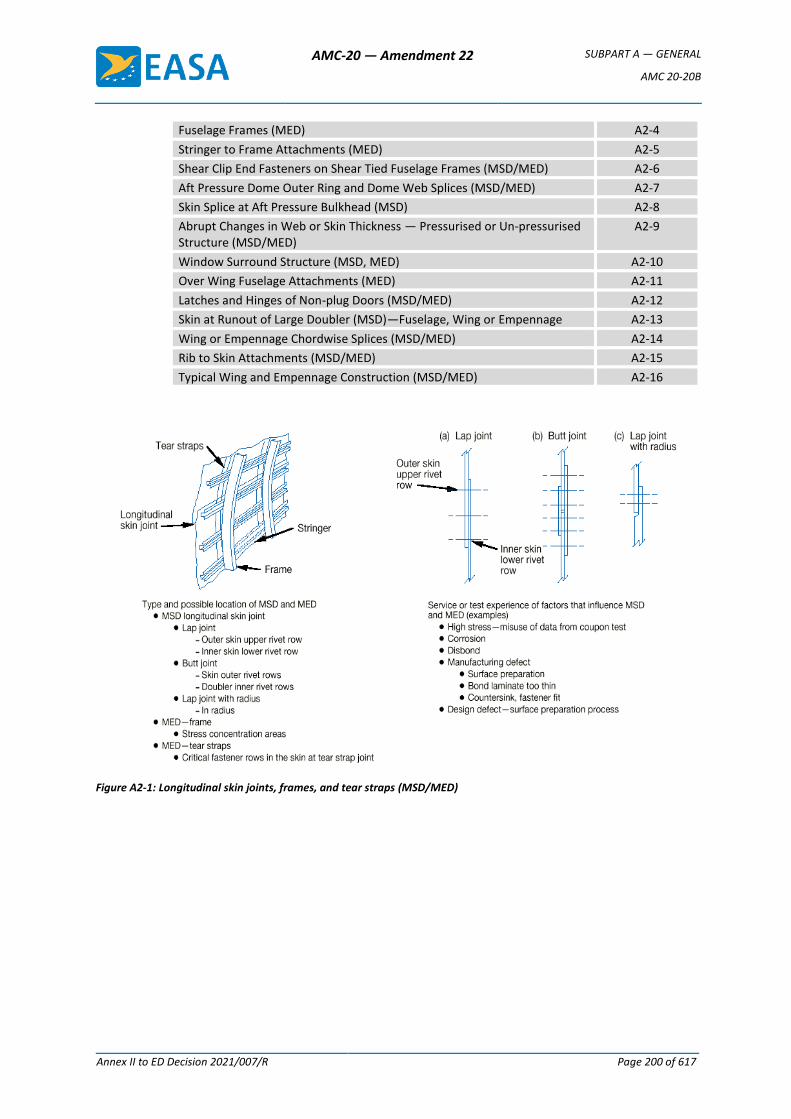
AMC-20 — Amendment 22 SUBPART A — GENERAL
AMC 20-20B
Annex II to ED Decision 2021/007/R Page 200 of 617
Fuselage Frames (MED) A2-4
Stringer to Frame Attachments (MED) A2-5
Shear Clip End Fasteners on Shear Tied Fuselage Frames (MSD/MED) A2-6
Aft Pressure Dome Outer Ring and Dome Web Splices (MSD/MED) A2-7
Skin Splice at Aft Pressure Bulkhead (MSD) A2-8
Abrupt Changes in Web or Skin Thickness — Pressurised or Un-pressurised Structure (MSD/MED)
A2-9
Window Surround Structure (MSD, MED) A2-10
Over Wing Fuselage Attachments (MED) A2-11
Latches and Hinges of Non-plug Doors (MSD/MED) A2-12
Skin at Runout of Large Doubler (MSD)—Fuselage, Wing or Empennage A2-13
Wing or Empennage Chordwise Splices (MSD/MED) A2-14
Rib to Skin Attachments (MSD/MED) A2-15
Typical Wing and Empennage Construction (MSD/MED) A2-16
Figure A2-1: Longitudinal skin joints, frames, and tear straps (MSD/MED)
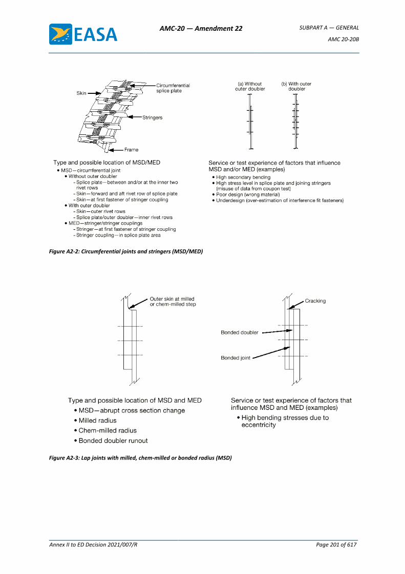
AMC-20 — Amendment 22 SUBPART A — GENERAL
AMC 20-20B
Annex II to ED Decision 2021/007/R Page 201 of 617
Figure A2-2: Circumferential joints and stringers (MSD/MED)
Figure A2-3: Lap joints with milled, chem-milled or bonded radius (MSD)
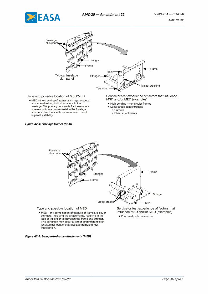
AMC-20 — Amendment 22 SUBPART A — GENERAL
AMC 20-20B
Annex II to ED Decision 2021/007/R Page 202 of 617
Figure A2-4: Fuselage frames (MED)
Figure A2-5: Stringer-to-frame attachments (MED)
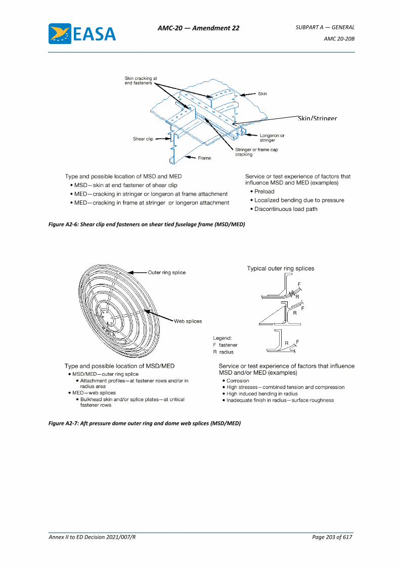
AMC-20 — Amendment 22 SUBPART A — GENERAL
AMC 20-20B
Annex II to ED Decision 2021/007/R Page 203 of 617
Figure A2-6: Shear clip end fasteners on shear tied fuselage frame (MSD/MED)
Figure A2-7: Aft pressure dome outer ring and dome web splices (MSD/MED)
Skin/Stringer Attachments
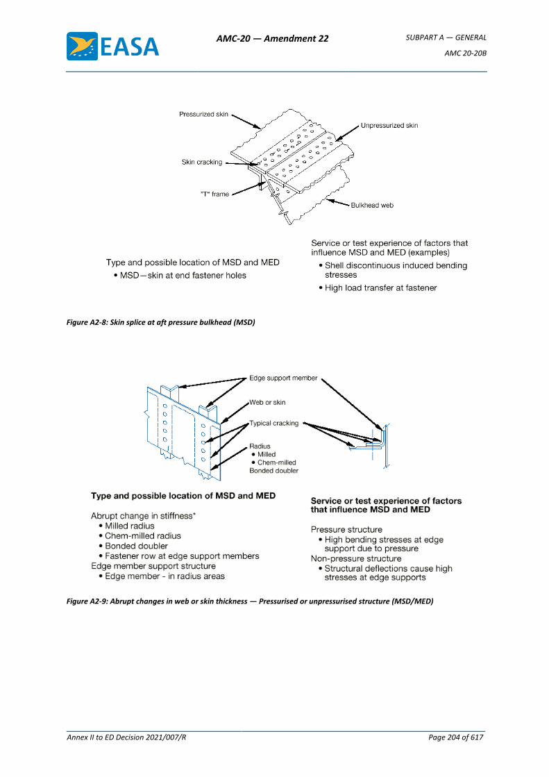
AMC-20 — Amendment 22 SUBPART A — GENERAL
AMC 20-20B
Annex II to ED Decision 2021/007/R Page 204 of 617
Figure A2-8: Skin splice at aft pressure bulkhead (MSD)
Figure A2-9: Abrupt changes in web or skin thickness — Pressurised or unpressurised structure (MSD/MED)
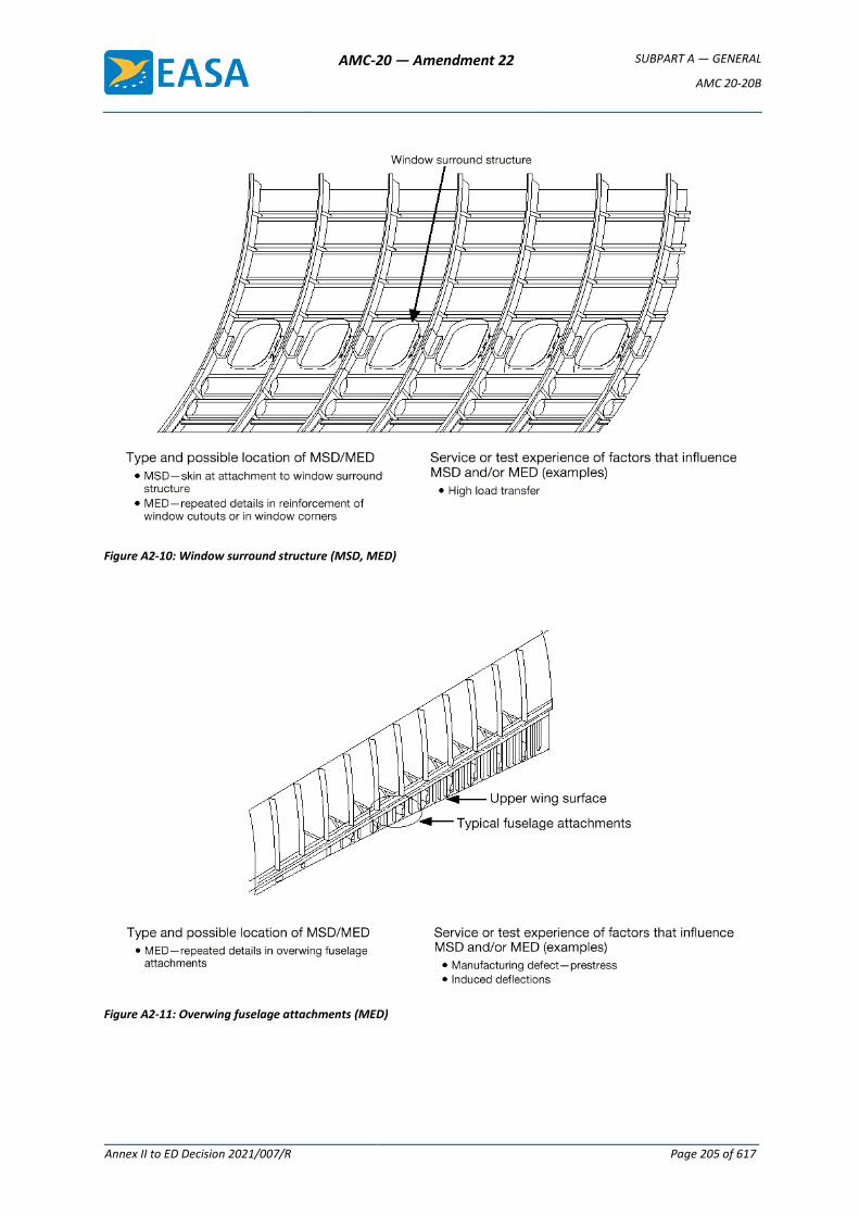
AMC-20 — Amendment 22 SUBPART A — GENERAL
AMC 20-20B
Annex II to ED Decision 2021/007/R Page 205 of 617
Figure A2-10: Window surround structure (MSD, MED)
Figure A2-11: Overwing fuselage attachments (MED)
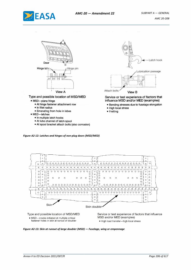
AMC-20 — Amendment 22 SUBPART A — GENERAL
AMC 20-20B
Annex II to ED Decision 2021/007/R Page 206 of 617
Figure A2-12: Latches and hinges of non-plug doors (MSD/MED)
Figure A2-13: Skin at runout of large doubler (MSD) — Fuselage, wing or empennage
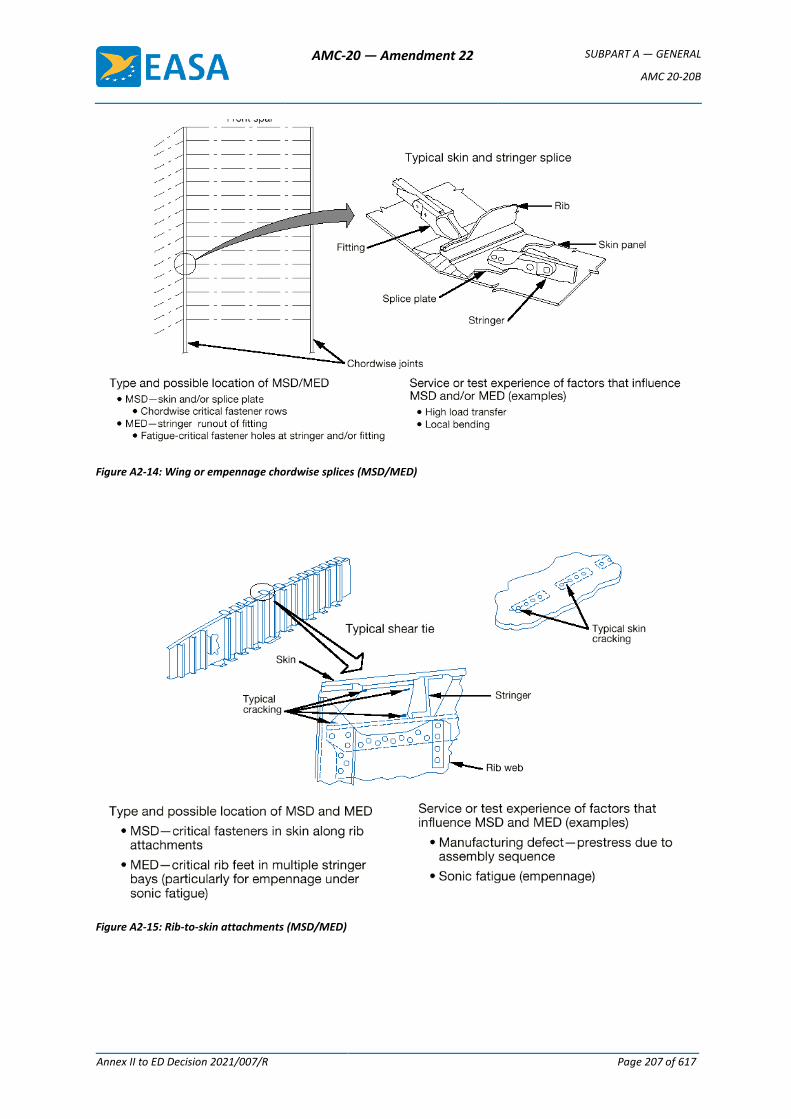
AMC-20 — Amendment 22 SUBPART A — GENERAL
AMC 20-20B
Annex II to ED Decision 2021/007/R Page 207 of 617
Figure A2-14: Wing or empennage chordwise splices (MSD/MED)
Figure A2-15: Rib-to-skin attachments (MSD/MED)
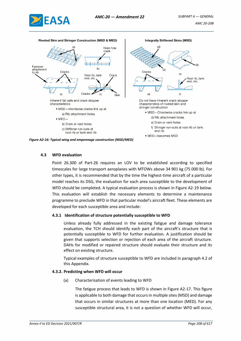
AMC-20 — Amendment 22 SUBPART A — GENERAL
AMC 20-20B
Annex II to ED Decision 2021/007/R Page 208 of 617
Figure A2-16: Typical wing and empennage construction (MSD/MED)
4.3 WFD evaluation
Point 26.300 of Part-26 requires an LOV to be established according to specified
timescales for large transport aeroplanes with MTOWs above 34 901 kg (75 000 lb). For
other types, it is recommended that by the time the highest-time aircraft of a particular
model reaches its DSG, the evaluation for each area susceptible to the development of
WFD should be completed. A typical evaluation process is shown in Figure A2-19 below.
This evaluation will establish the necessary elements to determine a maintenance
programme to preclude WFD in that particular model’s aircraft fleet. These elements are
developed for each susceptible area and include:
4.3.1 Identification of structure potentially susceptible to WFD
Unless already fully addressed in the existing fatigue and damage tolerance evaluation, the TCH should identify each part of the aircraft’s structure that is potentially susceptible to WFD for further evaluation. A justification should be given that supports selection or rejection of each area of the aircraft structure. DAHs for modified or repaired structure should evaluate their structure and its effect on existing structure.
Typical examples of structure susceptible to WFD are included in paragraph 4.2 of this Appendix.
4.3.2. Predicting when WFD will occur
(a) Characterisation of events leading to WFD
The fatigue process that leads to WFD is shown in Figure A2-17. This figure
is applicable to both damage that occurs in multiple sites (MSD) and damage
that occurs in similar structures at more than one location (MED). For any
susceptible structural area, it is not a question of whether WFD will occur,
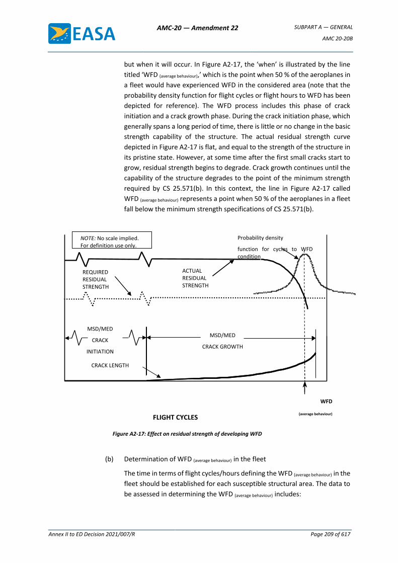
AMC-20 — Amendment 22 SUBPART A — GENERAL
AMC 20-20B
Annex II to ED Decision 2021/007/R Page 209 of 617
but when it will occur. In Figure A2-17, the ‘when’ is illustrated by the line
titled ‘WFD (average behaviour),’ which is the point when 50 % of the aeroplanes in
a fleet would have experienced WFD in the considered area (note that the
probability density function for flight cycles or flight hours to WFD has been
depicted for reference). The WFD process includes this phase of crack
initiation and a crack growth phase. During the crack initiation phase, which
generally spans a long period of time, there is little or no change in the basic
strength capability of the structure. The actual residual strength curve
depicted in Figure A2-17 is flat, and equal to the strength of the structure in
its pristine state. However, at some time after the first small cracks start to
grow, residual strength begins to degrade. Crack growth continues until the
capability of the structure degrades to the point of the minimum strength
required by CS 25.571(b). In this context, the line in Figure A2-17 called
WFD (average behaviour) represents a point when 50 % of the aeroplanes in a fleet
fall below the minimum strength specifications of CS 25.571(b).
Figure A2-17: Effect on residual strength of developing WFD
(b) Determination of WFD (average behaviour) in the fleet
The time in terms of flight cycles/hours defining the WFD (average behaviour) in the
fleet should be established for each susceptible structural area. The data to
be assessed in determining the WFD (average behaviour) includes:
CRACK LENGTH
REQUIRED RESIDUAL STRENGTH
WFD (Average Behavior
a cri
t
ACTUAL RESIDUAL STRENGTH
FLIGHT CYCLES
NOTE: No scale implied. For definition use only.
Probability Density Function for Cycles to
MSD/MED
CRACK
INITIATION
WFD
(average behaviour)
Probability density
function for cycles to WFD
condition
MSD/MED
CRACK GROWTH
AMC-20 — Amendment 22 SUBPART A — GENERAL
AMC 20-20B
Annex II to ED Decision 2021/007/R Page 210 of 617
— a complete review of the service history of the susceptible areas, to
identify any occurrences of fatigue cracking and the continuing
validity of loads and mission profiles,
— evaluation of the operational statistics of the fleet in terms of flight
hours and landings,
— significant production variants (material, design, assembly method,
and any other change that might affect the fatigue performance of the
detail),
— fatigue test evidence including relevant full-scale and component
fatigue and damage tolerance test data (see subparagraph 4.3.9 and
Annex 1 for more details),
— teardown inspections, and
— any fractographic analysis available.
The evaluation of the test results for the reliable prediction of the time to
when WFD might occur in each susceptible area should include appropriate
test-to-structure factors. If full-scale fatigue test evidence is used, Figure A2-
20 below relates how that data might be utilised in determining WFD (average
behaviour). Evaluation may be analytically determined, supported by test and,
where available, service evidence.
Regardless of whether the assessment of WFD (average behaviour) is based on in-
service data, full-scale fatigue test evidence, analyses, or a combination of
any of these, the following should be considered:
4.3.3 Initial crack/damage scenario
This is an estimate of the size and extent of multiple cracking expected at MSD/MED initiation. This prediction requires empirical data or an assumption of the crack/damage locations and sequence plus a fatigue evaluation to determine the time to MSD/MED initiation. Alternatively, analysis can be based on either:
— the distribution of equivalent initial flaws, as determined from the analytical assessment of flaws found during fatigue test and/or teardown inspections regressed to zero cycles; or
— a distribution of fatigue damage determined from relevant fatigue testing and/or service experience.
4.3.4 Final cracking scenario
This is an estimate of the size and extent of multiple cracking that could cause residual strength to fall to the minimum required level as shown in A2-17. Techniques exist for 3-D elastic-plastic analysis of such problems; however, there are several alternative test and analysis approaches available that provide an equivalent level of safety. One such approach is to define the final cracking scenario as a sub-critical condition (e.g. first crack at link-up). The use of a sub-critical scenario reduces the complexity of the analysis and, in many cases, will not
AMC-20 — Amendment 22 SUBPART A — GENERAL
AMC 20-20B
Annex II to ED Decision 2021/007/R Page 211 of 617
greatly reduce the total crack growth time, because the majority of the time taken to reach the critical condition is generally in the initiation phase.
4.3.5 Crack growth calculation
Progression of the crack distributions from the initial cracking scenario to the final cracking scenario should be developed. These curves can be developed:
— analytically, typically based on linear elastic fracture mechanics, or
— empirically, from test or service fractographic data.
4.3.6 Potential for discrete source damage (DSD)
A structure susceptible to fatigue including MSD/MED may also be affected by DSD
due to an uncontained failure of high-energy rotating machinery (i.e. turbine
engines). At this time, there is no specific requirement to address prior fatigue
cracking in combination with DSD for certification. Nonetheless, when assessing in-
service findings of fatigue cracking, the additional threat posed by any potential
DSD should be taken into account when developing the corrective actions and the
timescales for its implementation.
4.3.7 Analysis methodology
Differences between multiple-site damage and multiple-element damage
Details of the approach used to characterise events leading up to WFD may be
different. The differences will largely depend on whether MSD or MED is being
considered. This is especially true for crack interaction.
(a) Crack interaction
MSD has the potential for strong crack interaction, and the effect of multiple
cracks on each other needs to be addressed. MED, in most cases, does not
have the same potential for strong crack interaction. The differences
between the interaction effects for MSD and MED are illustrated in Figure
A2-18.
(b) MSD and MED interaction
Some areas of an aeroplane are potentially susceptible to both MSD and
MED. Simultaneous occurrence of MSD and MED is possible, even though it
is not common. A comparison of inspection start points (ISPs) or
modification start points might indicate the possibility of this occurrence. If
so, the evaluation should consider the interaction between MSD and MED.
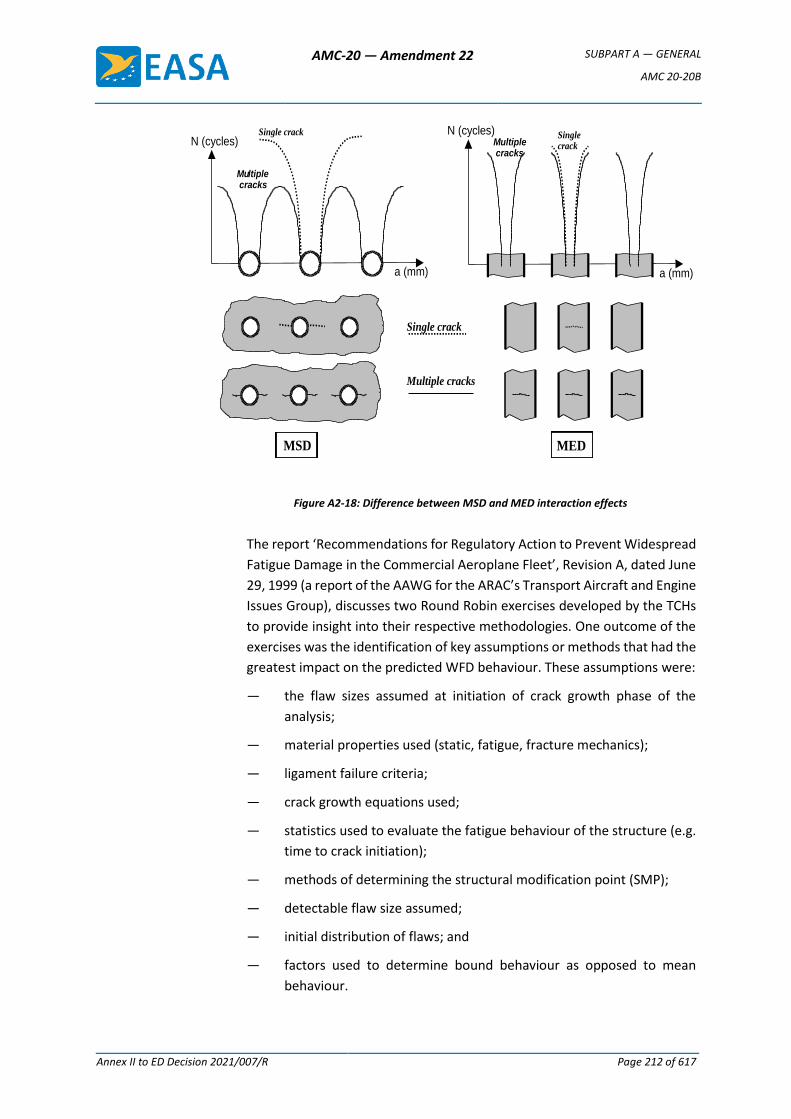
AMC-20 — Amendment 22 SUBPART A — GENERAL
AMC 20-20B
Annex II to ED Decision 2021/007/R Page 212 of 617
MED
a (mm)
N (cycles)
a (mm)
N (cycles)
MSD
Single crack Multiple cracks
Single crack Single crack
Multiple cracks
Mu ltiple cracks
Figure A2-18: Difference between MSD and MED interaction effects
The report ‘Recommendations for Regulatory Action to Prevent Widespread
Fatigue Damage in the Commercial Aeroplane Fleet’, Revision A, dated June
29, 1999 (a report of the AAWG for the ARAC’s Transport Aircraft and Engine
Issues Group), discusses two Round Robin exercises developed by the TCHs
to provide insight into their respective methodologies. One outcome of the
exercises was the identification of key assumptions or methods that had the
greatest impact on the predicted WFD behaviour. These assumptions were:
— the flaw sizes assumed at initiation of crack growth phase of the
analysis;
— material properties used (static, fatigue, fracture mechanics);
— ligament failure criteria;
— crack growth equations used;
— statistics used to evaluate the fatigue behaviour of the structure (e.g.
time to crack initiation);
— methods of determining the structural modification point (SMP);
— detectable flaw size assumed;
— initial distribution of flaws; and
— factors used to determine bound behaviour as opposed to mean
behaviour.
AMC-20 — Amendment 22 SUBPART A — GENERAL
AMC 20-20B
Annex II to ED Decision 2021/007/R Page 213 of 617
(c) MED
When considering MED, where interaction between cracks in different
elements is not a factor, the following should be considered:
(1) In a structure containing large numbers of similar elements, there is
not normally a high probability that, after a crack initiates in an
element, a second crack will initiate in the element right next to it. If
this does happen, however, the consequences to the overall structure
may be severe. This is because having two structural members fail
right next to each other can completely negate any ability of the
structure to tolerate additional damage. Consequently, when
performing an evaluation, applicants should make conservative
assumptions and assume failures to be adjacent to each other.
(2) When an element fails completely, the load that has to be
redistributed onto the non-failed structure can be large and can have
a significant impact on the strength of both the cracked and uncracked
structure; therefore, the effects of load redistribution must be
included in the evaluation.
(d) Establishing maintenance actions
The following parameters are developed from paragraphs 4.3.2 to 4.3.7
above, and are necessary to establish an MSD/MED maintenance
programme for the area under investigation.
Fatigue damage is the gradual deterioration of a material subjected to
repeated loads. This gradual deterioration is a function of use and can be
statistically quantified. The term ‘WFD’ is used, and can be statistically
quantified, at the end of the deterioration process when the structure is no
longer able to carry the residual strength loads. WFD can never be absolutely
precluded because there is always some probability, no matter how small,
that it will occur. Therefore, modifying or replacing structure at a
predetermined, analytically-derived time stated in flight cycles or flight
hours, minimises the probability of having WFD in the fleet. Modification or
replacement is the most reliable method for precluding WFD. The point at
which a modification is undertaken is referred to as the ‘structural
modification point (SMP)’ and it is illustrated in Figure 2-1 of Annex 2. The
SMP is generally a fraction of the number representing the point in time
when WFD (average behaviour) will occur, and should result in the same reliability
as a successful two-lifetime fatigue test. This level of reliability for setting
the SMP is acceptable if MSD or MED inspections are shown to be effective
in detecting cracks. If the inspections are effective, they should be
implemented before the SMP. The implementation times for these
inspections are known as the ‘inspection start points (ISPs)’. Repeat
inspections are usually necessary to maintain this effectiveness in detecting
AMC-20 — Amendment 22 SUBPART A — GENERAL
AMC 20-20B
Annex II to ED Decision 2021/007/R Page 214 of 617
cracks. If MSD or MED inspections are not effective in detecting cracks, then
the SMP should be set at the time of ISP. For the purposes of this AMC, an
inspection is effective if, when performed by properly trained maintenance
personnel, it will readily detect the damage in question1. The SMP should
minimise the extent of cracking in the susceptible structural area in a fleet
of affected aeroplanes. In fact, if this point is appropriately determined, a
high percentage of aeroplanes would not have any MSD or MED by the time
the SMP is reached.
Due to the redundant nature of semi-monocoque structures, MED can be
difficult to manage in a fleet environment. This stems from the fact that most
aircraft structures are built-up in nature, and that makes the visual
inspection of the various layers difficult. Also, visual inspections for MED
typically rely on internal inspections, which may not be practical at the
frequency necessary to preclude MED due to the time required to gain
access to the structure. However, these issues are dependent on the specific
design involved and the amount of damage being considered. In order to
implement a viable inspection programme for MED, static stability must be
maintained at all times and there should be no MED concurrent with MSD in
a given structural area.
4.3.8 Inspection start point (ISP)
This is the point at which inspection starts if a monitoring period is used. Inspection
is not practical for all applications and cannot replace the SMP. The ISP is
determined through a statistical analysis of crack initiation based on fatigue
testing, teardown, or service experience of similar structural details. It is assumed
that the ISP is equivalent to a lower bound value with a specific probability in the
statistical distribution of cracking events. Alternatively, the ISP may be established
by applying appropriate factors to the average behaviour.
When inspections are determined to be effective, it is necessary to establish when
those inspections should start. This point is illustrated in Figure 2-1. The start point
is determined through a statistical analysis of crack initiation based on fatigue
testing, teardown, or in-service experience of similar structure. The ISP is assumed
to be equivalent to a lower-bound value with a specific probability in the statistical
distribution of cracking events. Alternatively, an ISP may be established by applying
appropriate factors to the number representing WFD (average behaviour). (e.g. for
aluminium alloy structure, dividing the full-scale test result by a factor of 3).
For inspection intervals, see point 4.3.10.
1 The cracking identified in the FAA Airworthiness Directive (AD) 2002-07-09 is an example of the type of cracking that
MSD inspections are effective in detecting. These cracks grow from the fastener holes in the lower row of the lower skin panel in such a way that the cracking is readily detectable using NDI methods. The cracking identified in the FAA AD 2002-07-08 is an example of places where MSD inspections are not effective. These cracks grow in the outer surface and between the fastener holes in the lower row of the lower skin panel in such a way that the cracking is not readily detectable using NDI methods. Modification is the only option to address this type of cracking.
AMC-20 — Amendment 22 SUBPART A — GENERAL
AMC 20-20B
Annex II to ED Decision 2021/007/R Page 215 of 617
4.3.9 Structural modification point (SMP)
The SMP should be established as a point in time when structures should be
modified or replaced to prevent WFD from occurring. This is typically established
by:
— calculating when WFD would first occur in the structure (predicted using the
WFD (average behaviour)),
— setting a time before the predicted occurrence of WFD to perform
modifications or replacements that will prevent it.
The applicant should demonstrate that the proposed SMP established during the
evaluation has the same confidence level as current regulations require for new
certification. In lieu of other acceptable methods, the SMP for aluminium alloy
structures can be established as a point reduced from the WFD (average behaviour), based
on the viability of inspections in the monitoring period. The SMP may be
determined by dividing the number representing the timing when WFD (average
behaviour) will occur by a factor of 2 if there are effective inspections, or by a factor of
3 if inspections are not effective. For other materials such as high-strength steel
alloys, larger scatter factors may be necessary to account for increased variability
in fatigue performance.
An aircraft should not be operated beyond the SMP unless the structure is modified
or replaced, or unless additional approved data is provided that would extend the
SMP. However, if during the structural evaluation for WFD a TCH/DAH finds that
the flight cycles and/or flight hours SMP for a particular structural detail have been
exceeded by one or more aircraft in the fleet, the TCH/DAH should expeditiously
evaluate selected high-time aircraft in the fleet to determine their structural
condition. From this evaluation, the TCH/DAH should notify the competent
authorities and propose appropriate service actions.
A DAH may find that the SMP for a particular structural area has been exceeded by
one or more aeroplanes in the fleet. In that case, the DAH should expedite the
evaluation of those high-time aeroplanes to determine their structural condition,
notify EASA and propose appropriate maintenance actions specific to those
aeroplanes.
The initial SMP may be adjusted based on the following:
(a) The tasks necessary to extend an SMP may include any or all of the following:
(1) Additional fatigue or residual strength tests, or both, on a full-scale
aeroplane structure or a full-scale component followed by detailed
inspections and analyses.
(2) Fatigue tests of new structure or structure from in-service aeroplanes
on a smaller scale than full component tests (i.e. subcomponent or
AMC-20 — Amendment 22 SUBPART A — GENERAL
AMC 20-20B
Annex II to ED Decision 2021/007/R Page 216 of 617
panel tests, or both). If a subcomponent test is used, the SMP would
be extended only for that subcomponent.
(3) Teardown inspections (destructive) on structural components that
have been removed from service.
(4) Teardown inspections (non-destructive) accomplished by selected,
limited disassembly and subsequent reassembly of specific areas of
high-time aeroplanes.
(5) Analysis of in-service data (e.g. inspections) from a statistically
significant number of aeroplanes.
(b) If cracks are found in the structural detail for which the evaluation was done
during either the monitoring period or the modification programme, the
SMP should be re-evaluated to ensure that the SMP does provide the
required confidence level. If it is shown that the required confidence level is
not being met, the SMP should be adjusted and the adjustment reflected in
the appropriate SBs to address the condition of the fleet. Additional
regulatory action may be required.
4.3.10 Inspection interval and method
An interval should be chosen to provide a sufficient number of inspections
between the ISP and the SMP so that there is high confidence that no
MSD/MED condition will reach the final cracking scenario without detection.
The interval between inspections depends on the detectable crack size, the
critical crack lengths and the probability that the cracks will be detected with
the specific inspection method. Conservative scenarios should be assumed
for developing the inspection interval unless other assumptions can be
consistently supported by test and service experience. If the crack cannot be
detected, the SMP must be re-evaluated to ensure there is a high confidence
level that no aircraft will develop MSD/MED before modification.
4.4 Evaluation of maintenance actions
For all areas that have been identified as susceptible to MSD/MED, the current
maintenance programme should be evaluated to determine whether adequate structural
maintenance and inspection programmes exist to safeguard the structure against
unanticipated cracking or other structural degradation. The evaluation of the current
maintenance programme typically begins with the determination of the SMP for each
area.
Each area should then be reviewed to determine the current maintenance actions and
compare them to the maintenance needs established in this evaluation. Issues to be
considered include the following:
(a) Determine the inspection requirements (method, inspection start point, and
repeat interval) of the inspection for each susceptible area (including that structure

AMC-20 — Amendment 22 SUBPART A — GENERAL
AMC 20-20B
Annex II to ED Decision 2021/007/R Page 217 of 617
which is expected to arrest cracks) that is necessary to maintain the required level
of safety.
(b) Review the elements of the existing maintenance programmes already in place.
(c) Revise and highlight elements of the maintenance programme necessary to
maintain safety.
For susceptible areas approaching the SMP, where the SMP will not be increased or for
areas that cannot be reliably inspected, a programme should be developed and
documented that provides for replacement or modification of the susceptible structural
area.
4.4.1 Period of WFD evaluation validity
At whatever point the WFD evaluation is made, it should support the LOV of the
maintenance programme. Consistent with the use of test evidence to support
individual SMPs, as described above in paragraph 4.3.9, the LOV of the
maintenance programme should be based on fatigue test evidence. For an existing
ageing aircraft type, the initial WFD evaluation of the complete airframe will
typically cover a significant forward estimation of the projected aircraft usage
beyond its DSG, also known as the ‘proposed ESG’ and is effectively a proposed
LOV. Typically, an evaluation through an additional 25 % of the DSG would provide
a realistic forecast, with reasonable planning time for necessary maintenance
action. However, it may be appropriate to adjust the evaluation validity period
depending on issues such as:
(a) the projected useful life of the aircraft at the time of the initial evaluation;
(b) current NDI technology; and
(c) airline advance planning requirements for introduction of new maintenance
and modification programmes, to provide sufficient forward projection to
identify all likely maintenance/modification actions essentially as one
package.
Upon completion of the evaluation and publication of the revised maintenance
requirements, the ‘proposed ESG’ becomes the LOV.
Note: This assumes that all other aspects of the maintenance programme that are
required to support the LOV (such as SSID, CPCP, etc.) are in place and have been
evaluated to ensure they too remain valid up to the LOV.
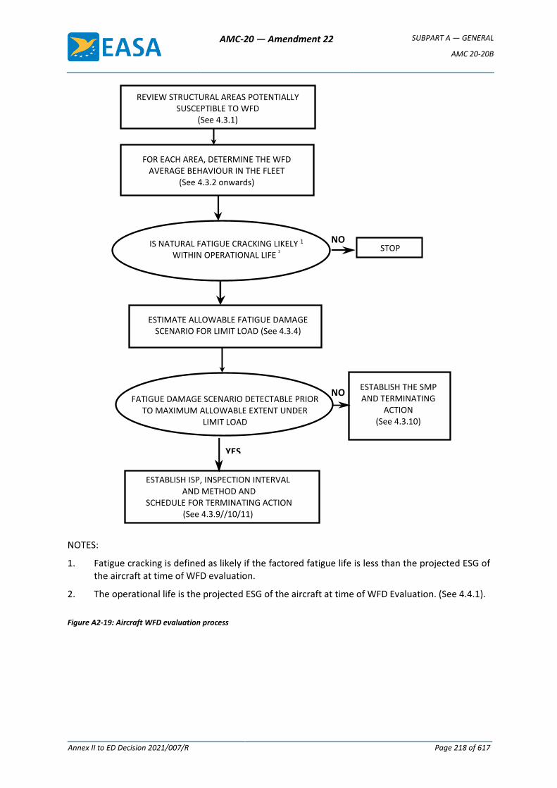
AMC-20 — Amendment 22 SUBPART A — GENERAL
AMC 20-20B
Annex II to ED Decision 2021/007/R Page 218 of 617
NOTES:
1. Fatigue cracking is defined as likely if the factored fatigue life is less than the projected ESG of the aircraft at time of WFD evaluation.
2. The operational life is the projected ESG of the aircraft at time of WFD Evaluation. (See 4.4.1).
Figure A2-19: Aircraft WFD evaluation process
YES
FOR EACH AREA, DETERMINE THE WFD AVERAGE BEHAVIOUR IN THE FLEET
(See 4.3.2 onwards)
ESTABLISH ISP, INSPECTION INTERVAL AND METHOD AND
SCHEDULE FOR TERMINATING ACTION (See 4.3.9//10/11)
ESTIMATE ALLOWABLE FATIGUE DAMAGE SCENARIO FOR LIMIT LOAD (See 4.3.4)
ESTABLISH THE SMP AND TERMINATING
ACTION (See 4.3.10)
STOP
FATIGUE DAMAGE SCENARIO DETECTABLE PRIOR TO MAXIMUM ALLOWABLE EXTENT UNDER
LIMIT LOAD
IS NATURAL FATIGUE CRACKING LIKELY 1 WITHIN OPERATIONAL LIFE ²
NO
REVIEW STRUCTURAL AREAS POTENTIALLY SUSCEPTIBLE TO WFD
(See 4.3.1)
NO
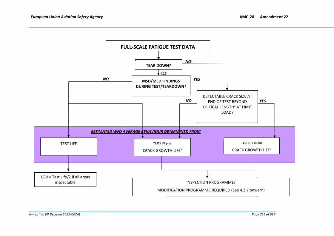
European Union Aviation Safety Agency AMC-20 — Amendment 22
Annex II to ED Decision 2021/007/R Page 219 of 617
NO
FULL SCALE FATIGUE TEST DATA
TEAR DOWN?
MSD/MED FINDINGS DURING
TEST/TEARDOWN?
TEST LIFE Minus
CRACK GROWTH LIFE3
TEST LIFE
TEST LIFE plus
CRACK GROWTH LIFE3
DETECTABLE CRACK SIZE AT END OF TEST
BEYOND CRITICAL LENGTH AT LIMIT LOAD?
NO
YES
YES
YES
NO1
ESTIMATED WFD AVERAGE BEHAVIOUR DETERMINED FROM
INSPECTION PROGRAMME/
MODIFICATION PROGRAMME REQUIRED (See 4.3.7 onward)
NO SPECIAL INSPECTIONS REQUIRED
(FAR 25.571, AMDT 96)
LOV = Test Life/2
FULL-SCALE FATIGUE TEST DATA
TEAR DOWN?
MSD/MED FINDINGS DURING TEST/TEARDOWN?
TEST LIFE minus
CRACK GROWTH LIFE3
TEST LIFE TEST LIFE plus
CRACK GROWTH LIFE3
DETECTABLE CRACK SIZE AT END OF TEST BEYOND
CRITICAL LENGTH2 AT LIMIT LOAD?
INSPECTION PROGRAMME/
MODIFICATION PROGRAMME REQUIRED (See 4.3.7 onward)
LOV = Test Life/2 if all areas inspectable
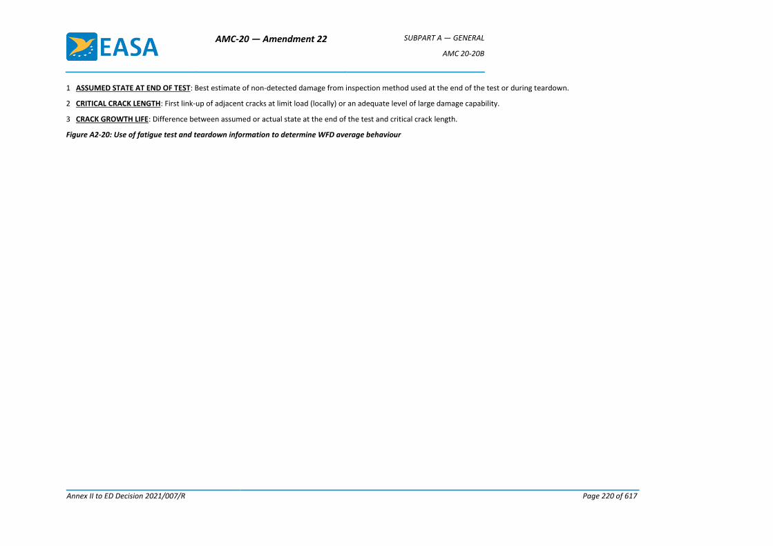
AMC-20 — Amendment 22 SUBPART A — GENERAL
AMC 20-20B
Annex II to ED Decision 2021/007/R Page 220 of 617
1 ASSUMED STATE AT END OF TEST: Best estimate of non-detected damage from inspection method used at the end of the test or during teardown.
2 CRITICAL CRACK LENGTH: First link-up of adjacent cracks at limit load (locally) or an adequate level of large damage capability.
3 CRACK GROWTH LIFE: Difference between assumed or actual state at the end of the test and critical crack length.
Figure A2-20: Use of fatigue test and teardown information to determine WFD average behaviour
AMC-20 — Amendment 22 SUBPART A — GENERAL
AMC 20-20B
Annex II to ED Decision 2021/007/R Page 221 of 617
5. DOCUMENTATION
Any person seeking approval of an LOV of an aircraft type design should develop a document
containing all the necessary ISPs, inspection procedures, replacement times, SMPs, and any
other maintenance actions necessary to preclude WFD, and to support the LOV. That person
must revise the SSID or ALS as necessary, and/or prepare SBs that contain the aforementioned
maintenance actions. Since WFD is a safety concern for all operators of older aircraft, EASA will
make mandatory the identified inspection and modification programmes. In addition, EASA may
consider separate AD action to address any SBs or other service information publications
revised or issued as a result of in-service MSD/MED findings resulting from implementation of
these programmes.
The following items should be contained in the front of the documentation supporting the LOV:
(a) identification of the variants of the basic aircraft type to which the document relates;
(b) summary of the operational statistics of the fleet in terms of hours and flights;
(c) description of the typical mission, or missions;
(d) the types of operations for which the inspection programme is considered valid;
(e) reference to documents giving any existing inspections, or modification of parts or
components; and
(f) the LOV of the maintenance programme in terms of flight cycles or flight hours or both
as appropriate to accommodate variations in usage.
The document should contain at least the following information for each critical part or
component:
(a) description of the primary structure susceptible to WFD;
(b) details of the monitoring period (ISP, repeat inspection interval, SMP, inspection method
and procedure (including crack size, location and direction, and alternatives) when
applicable;
(c) any optional modification or replacement of the structural element as terminating action
to inspection;
(d) any mandatory modification or replacement of the structural element;
(e) SBs (or other service information publications) revised or issued as a result of in-service
findings resulting from the WFD evaluations (added as a revision to the initial WFD
document); and
(f) guidance to the operator on which inspection findings should be reported to the
TCH/DAH, and appropriate reporting forms and methods of submission.
6. REPORTING REQUIREMENTS
Operators, TCHs and STCHs are required to report in accordance with various regulations (e.g.
point 21.A.3A, and point 145.A.60). The regulations to which this AMC relates do not require
any reporting requirements in addition to the current ones. Due to the potential threat to
AMC-20 — Amendment 22 SUBPART A — GENERAL
AMC 20-20B
Annex II to ED Decision 2021/007/R Page 222 of 617
structural integrity, the results of inspections must be accurately documented and reported in
a timely manner to preclude the occurrence of WFD. The current system of operator and TCH
communication has been useful in identifying and resolving a number of issues that can be
classified as WFD concerns. MSD/MED has been discovered via fatigue testing and in-service
experience. TCHs have been consistent in disseminating related data to operators to solicit
additional service experience. However, a more thorough means of surveillance and reporting
is essential to preclude WFD.
When damage is found while conducting an approved MSD/MED inspection programme, or at
the SMP where replacement or modification of the structure is occurring, the TCHs, STCHs and
the operators need to ensure that greater emphasis is placed on accurately reporting the
following items:
(a) a description (with a sketch) of the damage, including crack length, orientation, location,
flight cycles/hours, and condition of structure;
(b) results of follow-up inspections by operators that identify similar problems on other
aircraft in the fleet;
(c) findings where inspections accomplished during the repair or replacement/modification
identify additional similar damage sites; and
(d) adjacent repairs.
Operators must report all cases of MSD/MED to the TCH, STCH or the competent authority as
appropriate, irrespective of how frequently such cases occur. Cracked areas from in-service
aircraft (damaged structure) may be needed for detailed examination. Operators are
encouraged to provide fractographic specimens whenever possible. Aeroplanes undergoing
heavy maintenance checks are perhaps the most useful sources for such specimens.
Operators should remain diligent in the reporting of potential MSD/MED concerns not
identified by the TCH/DAH. Indications of a developing MSD/MED problem may include:
(a) damage at multiple locations in similar adjacent details;
(b) repetitive part replacement; or
(c) adjacent repairs.
Documentation will be provided by the TCH and STCH as appropriate to specify the required reporting format and time frame, supporting the mandatory reporting regulations (e.g. point 21.A.3A of Part-21, point 145.A.60 of Part-145). The data will be reviewed by the TCH or STCH, operator(s), and EASA to evaluate the nature and magnitude of the problem and to determine the appropriate corrective action.
7. WFD EVALUATION FOR STRUCTURAL MODIFICATIONS AND REPAIRS
TCHs of aeroplanes subject to the point 26.303 of Part-26 requirements for an LOV should
perform WFD evaluations to assess all the applicable existing structure and the effect of future
changes on the LOV.
The WFD evaluations of this AMC do not apply retroactively to existing STCH’s modifications,
nor to existing repairs. Future changes and repairs need to take into account the applicable
AMC-20 — Amendment 22 SUBPART A — GENERAL
AMC 20-20B
Annex II to ED Decision 2021/007/R Page 223 of 617
certification basis, and applicants should consider the guidance of the applicable ACJ and AMC
as discussed in paragraph 8 of this AMC. The DTEs for compliance with points 26.307, 26.308,
26.333 and 26.334 of Part-26 do not have to consider WFD (average behaviour), or the related SMP
and ISP.
In cases where a new DTE is performed by DAHs to comply with points 26.333 and 26.334 of
Part-26 for existing changes or for new changes or repairs, according to CS 25.571 Amdt 18 or
earlier amendments, the DTE and development of DTIs should take into account the cracking
scenarios that could reasonably be expected to occur in the remaining operational lifetime of
an aeroplane into which the repair or modification is, or may be, incorporated.
8. RESPONSIBILITY FOR WFD EVALUATION, ESTABLISHING THE LOV AND IMPLEMENTATION OF THE LOV AND MAINTENANCE ACTIONS
The primary responsibility is with the DAH to perform the analyses and supporting tests.
However, it is expected that if extensive maintenance actions are necessary, the practicality of
their implementation will be evaluated in a cooperative effort between the operators and
TCHs/DAHs, with participation of EASA.
The TCH is responsible for proposing and submitting an LOV in the ALS for approval.
Note: In some cases, the ALS may already contain an LOV which is approved in accordance with
a regulation of another authority. There may also be other potentially more restrictive
limitations on the validity of maintenance programmes. For these cases, when the TCH needs
to publish the LOV as required by point 26.303 of Part-26, this LOV and its relationship with the
existing or superseded limitation should be clearly described so that no operator will exceed
the most restrictive applicable limit on the general validity of the maintenance programme.
The operator is responsible for implementing the LOV in their maintenance programme.
Note: The LOV does not supersede or allow operations beyond any lower limitation applicable
to the individual aeroplane and the components controlled by the maintenance programme.
[Amdt 20/20] [Amdt 20/22]
AMC-20 — Amendment 22 SUBPART A — GENERAL
AMC 20-20B
Annex II to ED Decision 2021/007/R Page 224 of 617
Annex 1 to Appendix 2 to AMC 20-20B — Full-scale fatigue test evidence
Contents
(a) Overview
(b) Full-scale fatigue test evidence
(c) Key elements of a full-scale fatigue test programme
(1) Article
(2) Test set-up and loading
(i) Test set-up
(ii) Test loading
(3) Test duration
(i) New type certificates and derivatives
(ii) Repairs and type design changes
(4) Post-test evaluation
(i) Residual strength tests
(ii) Teardown inspections
(d) Scope of full-scale fatigue test article
(1) New type designs
(2) Derivative models
(3) Type design changes — SBs
(4) Type design changes — STCs
(5) Major repairs
(e) Use of existing full-scale fatigue test data
(f) Use of in-service data
AMC-20 — Amendment 22 SUBPART A — GENERAL
AMC 20-20B
Annex II to ED Decision 2021/007/R Page 225 of 617
(a) Overview
CS 25.571(b) Amendment 19 specifies that special consideration for WFD must be included in
the fatigue and damage tolerance evaluation where the design is such that this type of damage
could occur. CS 25.571(b) Amendment 19 specifies the effectiveness of the provisions to
preclude the possibility of WFD occurring within the limits of validity of the maintenance
programme to be demonstrated with sufficient full-scale fatigue test evidence. The
determination of what constitutes ‘sufficient full-scale test evidence’ requires a considerable
amount of engineering judgement and is a matter that should be discussed and agreed to
between an applicant and EASA early in the planning stage of a certification project. Sufficient
test evidence is also necessary to support compliance with CS 26.303 and the most
straightforward means of compliance is to utilise existing full-scale test evidence.
(b) Full-scale fatigue test evidence
In general, sufficient full-scale fatigue test evidence consists of full-scale fatigue testing to at
least twice the LOV, followed by specific inspections and analyses to determine that WFD has
not occurred. The following factors should be considered in determining the sufficiency of the
evidence:
Factor 1: The comparability of the load spectrum between the test and the projected usage of
the aeroplane.
Factor 2: The comparability of the airframe materials, design and build standards between the
test article and the certified aeroplane.
Factor 3: The extent of post-test teardown inspection, residual strength testing and analysis for
determining whether widespread fatigue cracking has occurred.
Factor 4: The duration of the fatigue testing.
Factor 5: The size and complexity of a design or build standard change. This factor applies to
design changes made to a model that has already been certified and for which full-scale fatigue
test evidence for the original structure should have already been determined to be sufficient.
Small, simple design changes, comparable to the original structure, could be analytically
determined to be equivalent to the original structure in their propensity for WFD. In such cases,
additional full-scale fatigue test evidence should not be necessary.
Factor 6: In the case of major changes and STCs, the age of an aeroplane being modified. This
factor applies to aeroplanes that have already accumulated a portion of their LOV prior to being
modified. An applicant should demonstrate freedom from WFD up to the LOV in place for the
original aeroplane and may take into account the age of the aeroplane being modified.
(c) Key elements of a full-scale fatigue test programme
The following guidance addresses key elements of a test programme that is intended to
generate the data necessary to support compliance, and it can also be used to evaluate and
interpret existing full-scale test data for the purposes of supporting compliance with point
26.303 of Part-26.

AMC-20 — Amendment 22 SUBPART A — GENERAL
AMC 20-20B
Annex II to ED Decision 2021/007/R Page 226 of 617
(1) Article. The test article should be representative of the structure of the aeroplane to be
evaluated (i.e. ideally a production-standard article). The attributes of the type design
that could affect MSD/MED initiation, growth and subsequent residual strength capability
should be replicated as closely as possible on the test article. Critical attributes include,
but are not limited to, the following:
— material types and forms;
— dimensions;
— joining methods and details;
— coating and plating;
— the use of faying surface sealant;
— assembly processes and sequences; and
— the influence of secondary structure (e.g. loads induced due to proximity to the
structure under evaluation).
(2) Test set-up and loading. The test set-up and loading should result in a realistic simulation
of the expected operational loads.
(i) Test set-up. The test set-up dictates how loads are introduced into the structure
and reacted. Every effort should be made to introduce and react loads as
realistically as possible. When a compromise is made (e.g. wing air loading), the
resulting internal loads should be evaluated (e.g. using finite element methods) to
ensure that the structure is not being unrealistically underloaded or overloaded,
locally or globally.
(ii) Loading spectrum. The test loading spectrum should include loads from all
damaging sources (e.g. cabin pressurisation, manoeuvres, gusts, engine thrust,
control surface deflections, and landing impacts) that are significant for the
structure being evaluated. Consideration should also be given to temperature and
other environmental effects that may affect internal loads. A supporting rationale
should be provided when a load source is not represented in a sequence.
Additionally, differences between the test sequence and the expected operational
sequence should be justified. For example, it is standard practice to eliminate low
loads that are considered to be non-damaging and to clip high infrequent loads
that may non-conservatively bias the outcome, but care should be taken in both
cases so that the test results are representative.
(3) Test duration. For any WFD-susceptible area, the average time in flight cycles and/or
hours to develop WFD should first be determined. This is referred to as the WFD (average
behaviour) for the subject area. The area should be modified or replaced at one third of this
time unless inspection for MSD/MED is practical. If inspection is practical, that inspection
should start at one third of the WFD (average behaviour), with modification/replacement at one
half of that time. It is standard practice to interpret the non-factored fatigue life of one
specimen as the average life. It follows that if one full-scale fatigue test article survives a
AMC-20 — Amendment 22 SUBPART A — GENERAL
AMC 20-20B
Annex II to ED Decision 2021/007/R Page 227 of 617
test duration of X time without an occurrence of WFD, it can be conservatively assumed
that the WFD (average behaviour) of all susceptible areas is equal to X. Based on this, and
assuming that the susceptible areas are impractical to inspect for MSD/MED, the
replacement or modification should be implemented at X/3. For areas where MSD/MED
inspections are practical, replacement/modification could be deferred until X/2, but
MSD/MED inspections would have to start at X/3. The procedure should be kept in mind
when deciding what the test duration will be.
(4) Post-test evaluation. One of the primary objectives of the full-scale fatigue test is to
generate the data needed to determine the absolute WFD (average behaviour) for each
susceptible area, or to establish a lower bound. Recall that the definition of WFD (average
behaviour) is the average time required for MSD/MED to initiate and grow to the point that
the static strength capability of the structure is reduced to less than the residual strength
requirements of CS 25.571(b). Some work is required at the end of the test to determine
the strength capability of the structure, either directly or indirectly.
(i) Residual strength tests. One acceptable way to demonstrate freedom from WFD at
the end of a full-scale fatigue test is to subject the article to the required residual
strength loads specified in CS 25.571(b). If the test article sustains the loads, it can
be concluded that the point of WFD has yet to be reached for any of the susceptible
areas. However, because fatigue cracks that might exist at the end of the test are
not quantified, it is not possible to determine how far beyond the test duration
WFD would occur in any of the susceptible areas without accomplishing additional
work (e.g. teardown inspection). Additionally, metallic test articles may be non-
conservatively compromised relative to their future fatigue performance if static
loads in excess of representative operational loads are applied. Residual strength
testing could preclude the possibility of using an article for additional fatigue
testing.
(ii) Teardown inspections. The residual strength capability may be evaluated indirectly
by performing teardown inspections to quantify the size of any MSD/MED cracks
that might be present, or to establish a lower bound on crack size based on the
capability of the inspection method. Once this is done, the residual strength
capability can be estimated analytically. Depending on the results, crack growth
analyses may also be required to project backwards or forwards in time to estimate
the WFD (average behaviour) for an area. As a minimum, teardown inspection methods
should be capable of detecting the minimum size of MSD or MED cracking that
would result in a WFD condition (i.e. residual strength degraded to less than the
level specified in CS 25.571(b)). Ideally, it is recommended that inspection methods
should be used that are capable of detecting MSD/MED cracking before it degrades
the strength to less than the required level. Effective teardown inspections that are
required to demonstrate freedom from WFD typically require significant resources.
They typically require disassembly (e.g. fastener removal) and destruction of the
test article. All areas that are or may be susceptible to WFD should be identified
and examined.
AMC-20 — Amendment 22 SUBPART A — GENERAL
AMC 20-20B
Annex II to ED Decision 2021/007/R Page 228 of 617
(d) Scope of full-scale fatigue test article
The following examples offer some guidance on the types of data sets that might constitute
‘sufficient evidence’ for some kinds of certification projects. The scope of the test specimen and
the duration of the test are considered.
(1) New type designs
Normally, this type of project would necessitate its own full-scale fatigue test of the
complete airframe to represent the new structure and its loading environment.
Nevertheless, prior full-scale fatigue test evidence from earlier tests performed by the
applicant, or others, may also be used, and could supplement additional tests on the new
model. Ultimately, the evidence needs to be sufficient to conclude with confidence that,
within the LOV of the airframe, WFD will not occur. Factors 1 to 4 should be considered
in determining the sufficiency of the evidence.
A test duration of a minimum of twice the LOV for the aeroplane model would normally
be necessary if the loading spectrum is realistic, the design and construction for the test
article principal structure are the same as for the certified aeroplane, and the post-test
teardown is exhaustive. If conformance to Factors 1 through 3 is less than ideal, a
significantly longer test duration would be needed to conclude with confidence that WFD
will not occur within the LOV. Moreover, no amount of fatigue testing will suffice if
conformance to Factors 1 through 3 above is not reasonable. Consideration should also
be given to the possible future need for life extension or product development, such as
potential weight increases, etc.
(2) Derivative models
The default position would be to test the entire airframe. However, it may be possible to
reliably determine the occurrence of WFD for all or part of the derivative model from the
data that the applicant generated or assembled during the original certification project.
Nevertheless, the evidence needs to be sufficient to allow confidence in the calculations
which show that WFD will not occur within the LOV of the aeroplane. Factors 1 through
5 should be considered in determining the sufficiency of the evidence for derivative
models. For example, a change in the structural design concept, a change in the
aerodynamic contours, or a modification of a structure that has a complex internal load
distribution might well make analytical extrapolation from the existing full-scale fatigue
test evidence very uncertain. Such changes might well necessitate full-scale fatigue
testing of the actual derivative principal structure. On the other hand, a typical derivative
often involves extending the fuselage by inserting ‘fuselage plugs’ that consist of a copy
of the typical semi-monocoque construction for that model, with slightly modified
material gauges. Normally this type of project would not necessitate its own full-scale
fatigue test, particularly if very similar load paths and operating stress levels are retained.
(3) Type design changes — SBs
Normally, this type of project would not necessitate its own full-scale fatigue test because
the applicant would have generated, or assembled, sufficient full-scale fatigue test
evidence during the original certification project that could be applied to the change.
AMC-20 — Amendment 22 SUBPART A — GENERAL
AMC 20-20B
Annex II to ED Decision 2021/007/R Page 229 of 617
Nevertheless, as cited in the previous example, the evidence needs to be sufficient to
allow confidence in the calculations which show that WFD will not occur within the LOV
of the aeroplane. In addition, Factor 5, ‘The size and complexity of a design change’,
should be considered.
(4) Type design changes — STCs
(i) Sufficient full-scale test evidence for structures certified under an STC may
necessitate additional full-scale fatigue testing, although the extent of the design
change may be small enough to use Factor 5 to establish the sufficiency of the
existing full-scale fatigue test evidence. The applicant for an STC may not have
access to the original equipment manufacturer (OEM)’s full-scale fatigue test data.
For aeroplane types for which an LOV has been published, the STC applicant may
assume that the basic structure was free from WFD up to the LOV, unless EASA has
taken AD action, or intends to take action (by a proposed AD) to alleviate a WFD
condition, or inspections or modifications exist in the ALS relating to WFD
conditions. For the purpose of the STC applicant’s demonstration that WFD will not
occur on its modification (or the underlying original structure) within the LOV, it
may be assumed that the model types, to which the LOV is applicable, have
received at least two full LOVs of fatigue testing, under realistic loads, and have
received thorough post-test inspections that did not detect any WFD, or the ALS
includes from the outset details of the modifications required to address WFD that
will need specific consideration by the STC applicant. With this knowledge, and
Factors 1 through 5, the STC applicant may be able to demonstrate that WFD will
not occur on its modification (or the underlying original structure) within the LOV.
If, however, the modification significantly affects the distribution of stress in the
underlying structure, or significantly alters loads in other parts of the aeroplane, or
significantly alters the intended mission of the aeroplane, or if the modification is
significantly different in its structural concept from the certified aeroplane being
modified, additional representative fatigue test evidence would be necessary.
(ii) In addition, Factor 6 ‘The age of the aeroplane being modified’ comes into play for
modifications made to older aeroplanes. The STC applicant should demonstrate
freedom from WFD up to the LOV of the aeroplane being modified. For example,
an applicant for an STC to an aeroplane that has reached an age equivalent to 75 %
of its LOV should demonstrate that the modified aeroplane will be free from WFD
for at least the remaining 25 % of the LOV. Although an applicant could attempt to
demonstrate freedom from WFD for a longer period, this may not be possible
unless the OEM cooperates by providing data for the basic structure. A short DSG
for the modification could simplify the demonstration of freedom from WFD for
the STC applicant. Nevertheless, the applicant should also be aware that the LOV
of the aeroplane is not a fixed life; it may be extended as a result of a structural re-
evaluation and service action plan, such as those developed for certain models
under the FAA’s ‘Aging Aircraft Program’. Unless the modifier also re-evaluates its
AMC-20 — Amendment 22 SUBPART A — GENERAL
AMC 20-20B
Annex II to ED Decision 2021/007/R Page 230 of 617
STC modification, the shorter goal for the modification could impede extending the
LOV of the modified aeroplanes.
(5) Major repairs. New repairs (for which the applicable certification basis requires WFD
evaluation) that differ from the repairs contained in the OEM’s SRM, but that are
equivalent in design from such repairs, and that meet CS-25 specifications in other
respects, would not necessitate full-scale fatigue testing to support freedom from WFD
up to the LOV. Major repair solutions (that may be susceptible to WFD) which utilise
design concepts (e.g. new materials, other production processes, new design details)
different from the previously approved repair data may need further testing.
(e) Use of existing full-scale fatigue test data
In some cases, especially for establishing an LOV in accordance with point 26.303 of Part-26, or
for derivative models and type design changes accomplished by the TCH, there may be existing
full-scale fatigue test data that may be used to support compliance and mitigate the need to
perform additional testing.
Any physical differences between the structure originally tested and the structure being
considered that could affect its fatigue behaviour must be identified and reconciled. Differences
that should be addressed include, but are not limited to, differences in any of the physical
attributes listed under point (c)(1) of this Annex and differences in operational loading. Typical
developments that affect the applicability of the original LOV demonstration data are the:
— gross weight (e.g. if it increases),
— cabin pressurisation (e.g. a change in the maximum cabin or operating altitude), or
— flight segment parameters.
The older the test data, the harder it may be to demonstrate that it is sufficient. Often test
articles were not conformed, neither were test plans or reports submitted to EASA as part of
the compliance data package. The rigour of loading sequences has varied significantly over the
years, and from OEM to OEM. Additionally, testing philosophies and protocols were not
standardised. For example, post-test evaluations, if any, varied significantly and in some cases
consisted of nothing more than limited visual inspections. However, there may be acceptable
data from the early full-scale fatigue tests that the applicant proposes to use to support
compliance. In order to use such data, the configuration of the test article and the loading must
be verified, and the issue of the residual strength capability of the article (or teardown data) at
the end of the test must be addressed.
(f) Use of in-service data
There may be in-service data that can be used to support WFD evaluations. Examples of such
data are as follows:
— Documented positive findings of MSD/MED cracks that include the location, size and the
time in service of the affected aeroplane, along with a credible record of how the aircraft
had been operated since the original delivery.
AMC-20 — Amendment 22 SUBPART A — GENERAL
AMC 20-20B
Annex II to ED Decision 2021/007/R Page 231 of 617
— Documented negative findings from in-service inspections for MSD/MED cracks on a
statistically significant number of aeroplanes, with the time in service of each aircraft,
and a credible record of how each aircraft had been operated since the original delivery.
For this data to be useful, the inspection methods used should have been capable of
detecting MSD/MED crack sizes equal to or smaller than those sizes that could reduce the
strength of the structure to less than the residual strength levels specified in CS 25.571(b).
— Documented findings from the destructive teardown inspection of structures from in-
service aircraft. This might be structures (e.g. fuselage splices) removed from the aircraft
that were subsequently returned to service, or from retired aircraft. It would also be
necessary to have a credible record of the operational loading experienced by the subject
structure up to the time it was taken out of service.
Prior to using in-service data, any physical or loading differences that exist between the
structure of the in-service or retired aeroplanes and the structure being certified should be
identified and reconciled as discussed above.
[Amdt 20/20] [Amdt 20/22]
AMC-20 — Amendment 22 SUBPART A — GENERAL
AMC 20-20B
Annex II to ED Decision 2021/007/R Page 232 of 617
Annex 2 to Appendix 2 to AMC 20-20B — Example of how to establish an LOV
This Annex provides a simplified example of how to establish an LOV for a specified aeroplane
structural configuration. The process for establishing an LOV involves four steps:
Step 1. Identifying a candidate LOV for the aeroplane structural configuration.
Step 2. Identifying WFD-susceptible structure. For this evaluation, it was determined that the
aeroplane structural configuration had six areas with WFD-susceptible structures.
Step 3. Performing a WFD evaluation for each of the six areas of WFD-susceptible structure to
determine whether there are inspection start points and structural modification points for the
candidate LOV identified. This allows the evaluation of the candidate LOV.
Figure 2-1, shown below, shows the WFD behaviour for one WFD-susceptible area. The figure also
shows three different candidate LOVs. Candidate LOV1 is at a point that occurs significantly before the
WFD average behaviour line. This LOV will not require any maintenance actions. Candidate LOV2
occurs before the WFD average behaviour line, but closer to it. As a result, inspection will need to start
before the LOV. Although candidate LOV3 occurs before the WFD average behaviour line, with this
LOV, the probability of WFD in the fleet is unacceptable, and inspection and subsequent modification
or replacement is required before the aeroplane reaches LOV3. Note that for LOV2 and LOV3, if
inspections were determined to be unreliable, then the SMP would occur at the point on the chart
where the ISP is. Using this example, this decision-making process needs to be repeated for all six
WFD-susceptible areas.
Applicants should evaluate the candidate LOVs and the results of WFD evaluations for each susceptible
area.
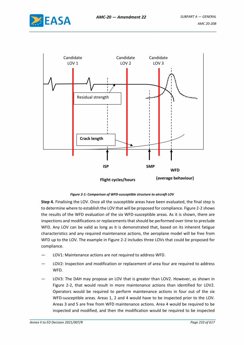
AMC-20 — Amendment 22 SUBPART A — GENERAL
AMC 20-20B
Annex II to ED Decision 2021/007/R Page 233 of 617
Figure 2-1: Comparison of WFD-susceptible structure to aircraft LOV
Step 4. Finalising the LOV. Once all the susceptible areas have been evaluated, the final step is
to determine where to establish the LOV that will be proposed for compliance. Figure 2-2 shows
the results of the WFD evaluation of the six WFD-susceptible areas. As it is shown, there are
inspections and modifications or replacements that should be performed over time to preclude
WFD. Any LOV can be valid as long as it is demonstrated that, based on its inherent fatigue
characteristics and any required maintenance actions, the aeroplane model will be free from
WFD up to the LOV. The example in Figure 2-2 includes three LOVs that could be proposed for
compliance.
— LOV1: Maintenance actions are not required to address WFD.
— LOV2: Inspection and modification or replacement of area four are required to address
WFD.
— LOV3: The DAH may propose an LOV that is greater than LOV2. However, as shown in
Figure 2-2, that would result in more maintenance actions than identified for LOV2.
Operators would be required to perform maintenance actions in four out of the six
WFD-susceptible areas. Areas 1, 2 and 4 would have to be inspected prior to the LOV.
Areas 3 and 5 are free from WFD maintenance actions. Area 4 would be required to be
inspected and modified, and then the modification would be required to be inspected
WFD
(average behaviour)
SMP ISP
Flight cycles/hours
Candidate LOV 1
Candidate LOV 2
Candidate LOV 3
Crack length
Residual strength
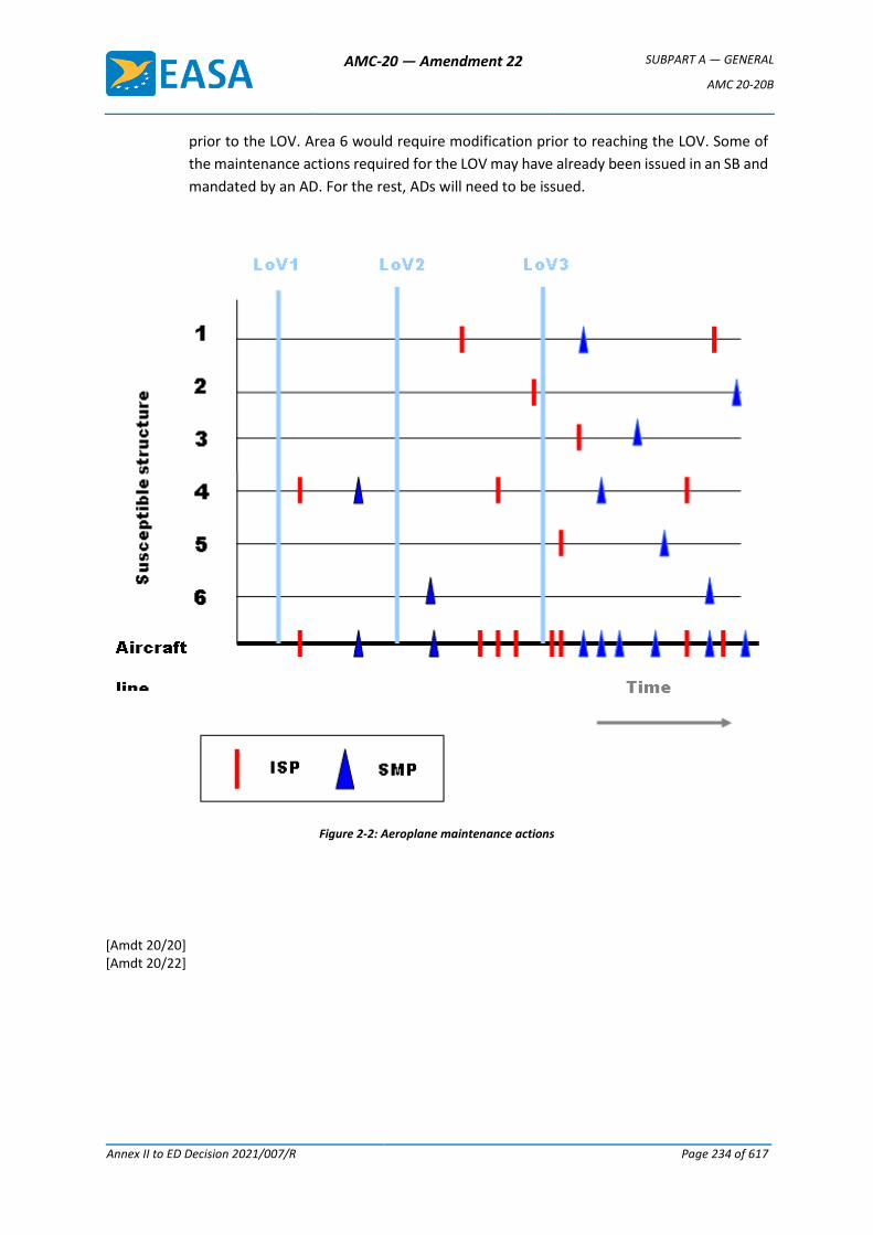
AMC-20 — Amendment 22 SUBPART A — GENERAL
AMC 20-20B
Annex II to ED Decision 2021/007/R Page 234 of 617
prior to the LOV. Area 6 would require modification prior to reaching the LOV. Some of
the maintenance actions required for the LOV may have already been issued in an SB and
mandated by an AD. For the rest, ADs will need to be issued.
Figure 2-2: Aeroplane maintenance actions
[Amdt 20/20] [Amdt 20/22]
AMC-20 — Amendment 22 SUBPART A — GENERAL
AMC 20-20B
Annex II to ED Decision 2021/007/R Page 235 of 617
Appendix 3 to AMC 20-20B — Guidelines for establishing instructions for continued airworthiness of structural repairs and modifications
1. INTRODUCTION
With an SSID, CPCP, mandatory modifications and an LOV in place, an individual aircraft may
still not meet the intended level of airworthiness for ageing aircraft structures. Repairs and
modifications to aircraft structure also warrant investigation. It is recommended that for large
transport aeroplanes, all repairs and modifications that affect the FCS should be assessed using
some form of damage-tolerance-based evaluation. A regulatory requirement for damage
tolerance was not applied to aeroplane design types certified before 1978, and even after this
time, the implementation of DTE on repairs and modifications was not consistent. Therefore,
the damage tolerance characteristics of repairs and modifications may vary widely and are
largely unknown. In view of these concerns, it is necessary to perform an assessment of the
repairs and modifications on certain aircraft in service to establish their damage tolerance
characteristics. Further information on the background to the need for damage-tolerance-
based inspection programmes for repairs is provided in Annex 6 to this Appendix.
Repairs and modifications to aeroplanes certified to JAR 25 Change 7 or 14 CFR 25 Amendment
45 or later must comply with the fatigue and damage tolerance requirements of their
certification basis. In addition, points 26.307, 26.308, 26.309, 26.332 to 26.334 and 26.370 of
Part-26 define additional requirements for certain repairs and modifications that must be
addressed using the damage tolerance methodology.
In cases where a new DTE is performed by DAHs to comply with points 26.333 and 26.334 of
Part-26 for existing changes or for new changes or repairs, according to CS 25.571 Amendment
18 or earlier amendments, the DTE and development of DTI should take into account the
cracking scenarios that could reasonably be expected to occur in the remaining operational
lifetime of the aeroplane into which the repair or modification can be incorporated.
2. DEFINITIONS
See paragraph 4 of this AMC.
3. ESTABLISHMENT OF A DAMAGE-TOLERANCE-BASED INSPECTION PROGRAMME FOR REPAIRS AFFECTING FCS
3.1 Overview of the TCH tasks for repairs that may affect the FCBS
(a) Identify the affected aircraft model, models, aircraft serial numbers, and DSG
stated as a number of flight cycles, flight hours, or both.
(b) Identify the certification level.
(c) Identify and develop a list of FCBS.
(d) Submit the list of FCBS to EASA for approval, and make it available to operators and
STCHs.
AMC-20 — Amendment 22 SUBPART A — GENERAL
AMC 20-20B
Annex II to ED Decision 2021/007/R Page 236 of 617
(e) Review and update published repair data as necessary.
(f) Submit any new or updated published repair data to EASA for approval (or approve
the data in accordance with Subpart M of Part 21), and make it available to
operators.
(g) Develop REGs and submit them to EASA for approval, and make the approved REGs
available to operators.
3.2. Certification level
In order to understand what data is required, the TCH should identify the amendment
level of the original aircraft certification relative to CS 25.571. The amendment level is
useful in identifying what DT data may be available and what standard should be used for
developing new DT data. The two relevant aircraft groups are:
Group A Aircraft certified to CAR 4b or 14 CFR § 25.571, prior to Amendment 25-45 or JAR 25 Change 7 or equivalent. These aircraft were not evaluated for damage tolerance as part of the original type certification. Unless previously accomplished, existing and future repairs to FCBS will need DT data to be developed.
Group B Aircraft certified to JAR 25 Change 7 or 14 CFR § 25.571, Amendment 25-45 or later. These aircraft were evaluated for damage tolerance as part of the original type certification. As noted in the introduction, some of these repairs may not have repair data that includes appropriate DTI and the TCH and operators may need to identify and perform a DTE of these repairs and develop DTIs.
3.3. Identifying fatigue-critical baseline structure (FCBS)
TC holders should identify and make available to operators a list of baseline structure that
is susceptible to fatigue cracking that could contribute to a catastrophic failure. The term
‘baseline’ refers to the structure that is designed under the original type certificate or
amended type certificate for that aircraft model (that is, the ‘as delivered aircraft model
configuration’). Guidance for identifying this structure can be found in CS-25 AMC 25.571.
This structure is referred to in this AMC as ‘fatigue-critical baseline structure.’ The
purpose of requiring identification and listing of FCS is to provide operators with a tool
that will help in evaluating existing and future repairs or modifications. In this context,
FCS is any structure that is susceptible to fatigue that could contribute to a catastrophic
failure, and should be subject to a DTE. The DTE would determine if DTIs need to be
established for the repaired or modified structure. For the purpose of this AMC, structure
that is modified after aircraft delivery from the TCH is not considered to be ‘baseline’
structure.
CS 25.571(a) states that ‘An evaluation of the strength, detail design, and fabrication must
show that catastrophic failure due to fatigue environmental and accidental damage, will
be avoided throughout the operational life of the aeroplane. This evaluation must be
conducted… for each part of the structure which could contribute to a catastrophic failure
(such as wing, empennage, control surfaces, fuselage, engine mounts, and their related
primary attachments)…’. When identifying FCBS, it is not sufficient to consider only that
AMC-20 — Amendment 22 SUBPART A — GENERAL
AMC 20-20B
Annex II to ED Decision 2021/007/R Page 237 of 617
structure identified in the SSID or ALS. Some SSIDs or ALSs might only include
supplemental inspections of the most highly stressed elements of the FCBS. An SSID or
ALS often refers to this structure as a PSE. If repaired, other areas of structure not
identified as a PSE in the SSID or ALS may require supplemental inspections. The term PSE
has, at times, been interpreted narrowly by industry. The narrow application of the term
PSE could incorrectly limit the scope of the structure that would be considered relative
to fatigue if repairs or modifications exist or are made subsequently. The relationship
between PSE and FCS could vary significantly depending on the TCH’s working definition
of PSE. In addition, there may be structure whose failure would be catastrophic, but due
to low operational loads on that part, the part will not experience fatigue cracking.
However, if the subject part is repaired or modified, the stresses in that part may be
increased to a level where it is now susceptible to fatigue cracking. These types of parts
should be considered as FCS.
TCHs should develop the list of FCBS and it should include the locations of the FCS and a
diagram showing the extent of the FCS. TCHs should make the list available to STCHs and
to operators.
Note: Typically, for the purposes of compliance with Part-26 related to FCS, it is not
expected that composite structures will be identified as FCS; however, metallic
repairs/changes to composites may be FCSs. If composite structures on a type design are
found to be susceptible to fatigue cracking, this should be discussed with EASA under the
CAW procedures. With the increase in the use of composites, EASA will monitor the
adequacy of existing structural integrity programmes for composite structures, including
repairs.
3.4. Certification standard applied when performing a DTE
For Group A aircraft, the TCH should use the requirements of JAR 25.571 Change 7 or 14
CFR § 25.571, at Amendment 25-45, as a minimum standard. For Group B aircraft, the
TCH should use the requirements that correspond to the original certification basis as a
minimum standard. For each repair requiring a DTE, the DAH should apply not less than
the minimum standard when developing new or revised DT data. The certification
standard applied by the TCH in performing a DTE for repairs should be identified in the
Part-26 compliance documentation submitted to EASA, and applicable Part-26
paragraphs clearly referenced in the approved documentation provided to the operator.
3.5. Performing a DTE on a repair that affects FCBS
When performing a DTE on a repair that affects the FCBS, the DTE would apply to the
affected FCBS and repair. This may consist of an individual analysis or the application of
a DT-based process such as RAGs that would be used by an operator. The result of the
DTE should lead to developing DTIs that address any adverse effects the repair may have
on the FCBS. If the DTE results determine that DTIs are not required to ensure the
continued airworthiness of the affected FCBS, the TCH should note that in the DTE
documentation.
AMC-20 — Amendment 22 SUBPART A — GENERAL
AMC 20-20B
Annex II to ED Decision 2021/007/R Page 238 of 617
The term ‘adverse effects’ refers to a degradation in the fatigue life or inspectability of
the affected FCBS. Degradation in fatigue life (earlier occurrence of critical fatigue
cracking) may result from an increase in internal loading, while degradation of
inspectability may result from physical changes made to the structure. The DTE should be
performed within a time frame that ensures the continued airworthiness of the affected
FCBS.
3.6. Review of published repair data
Published repair data are generally applicable instructions for accomplishing repairs, such
as those contained in SRMs and SBs. TCHs should review their existing repair data and
identify each repair that affects the FCBS. For each such repair, unless previously
accomplished, the TCH must perform a DTE and develop any necessary DTI for the
affected FCBS and repair data. For some repairs, the results of the DTE will conclude that
no new DTI will be required for the affected FCBS or repair. For these cases, the TCH
should provide a means that informs the operator that a DTE was performed for the
subject repair. This may be accomplished, for example, by providing a statement in a
document, such as an SRM, stating that all repairs contained in this manual have had a
DTE performed. This should preclude operators from questioning those repairs that do
not have DTIs. TCHs should provide a list of their published repair data to operators and
a statement that a DTE has been performed on this data. The following examples of
published repair data developed by the TCH should be reviewed and included in this list:
(a) SRMs,
(b) SBs,
(c) documents containing AD-mandated repairs, and
(d) other documents available to operators (e.g. some sections of aircraft
maintenance manuals and component maintenance manuals) that may contain
approved repair data.
3.7. Developing DT data for existing published repair data
3.7.1. SRMs
The TCH should review the repair data contained in each SRM and identify repairs
that affect FCBS. For these repairs, the TCH will need to determine if the SRM needs
revising to provide adequate DTI. In determining the extent to which an SRM may
need to be revised for compliance, the following should be considered:
(a) Whether the existing SRM contains an adequate description of DTIs for the
specific model.
(b) Whether normal maintenance procedures (e.g. the inspection threshold
and/or existing normal maintenance inspections) are adequate to ensure
that the continued airworthiness (inspectability) is equal to the unrepaired
surrounding structure.
(c) Whether SRM Chapter 51 standard repairs have a DTE.
AMC-20 — Amendment 22 SUBPART A — GENERAL
AMC 20-20B
Annex II to ED Decision 2021/007/R Page 239 of 617
(d) Whether all SRM-specific repairs affecting FCBS have had a DTE performed.
(e) Whether there is any guidance on proximity of repairs.
(f) Whether existing superseded repairs are addressed and how a DTE will be
performed for repairs that are likely to be superseded in the future and how
any DTI will be made available.
3.7.2. SBs
The TCH should review the repair data contained in its SBs (See Annex 4) and
identify those repairs that affect FCBS. For those repairs, the TCH should then
determine if a new DTE will need to be performed. This review may be done in
conjunction with the review of SBs for modifications that affect FCBS.
3.7.3. ADs
The TCH should review ADs that provide maintenance instructions to repair FCBS
and determine if the instructions include any necessary DT data. While
maintenance instructions supporting ADs are typically contained in SBs, other
means of documentation may be used.
3.7.4. Other forms of data transmission
In addition to SRMs, SBs, and documentation for ADs, the TCH should review any
other documents (e.g. aircraft maintenance manuals and component maintenance
manuals) that contain approved repair data. Individual repair data not contained
in the above documents will be identified and DT data obtained through the REGs
process.
3.8. Developing DT data for future published repair data
Following the completion of the review and revision of existing published data, any
subsequent repair data proposed for publication should also be subject to DTE and DTI
provided.
3.9. Approval of DT data developed for published repair data
For existing published repair data that requires new DT data for repairs affecting the
FCBS, the TCH should submit the revised documentation to EASA for approval unless
otherwise agreed in the compliance plan approved in accordance with point 26.301 of
Part-26. For instance, it may be agreed that the data can be approved according to an
existing or a modified process utilising the Part 21 DOA privileges for repair approval of
the TCH. The DT data for future published repair data may be approved according to
existing processes.
3.10. Documentation of DT data developed for published repair data
TCHs should include the means used to document any new DTI developed for published repair data. For example, in lieu of revising individual SBs, the TCH may choose to establish a collector document that would contain new DTI developed and approved for specific repairs contained in various SBs.
3.11. Existing repairs
AMC-20 — Amendment 22 SUBPART A — GENERAL
AMC 20-20B
Annex II to ED Decision 2021/007/R Page 240 of 617
TCHs should develop processes that will enable operators to identify and obtain DTI for
existing repairs on their aircraft that affect FCBS. Collectively, these processes are
referred to as REGs and are addressed in subparagraph 3.13.
According to point 26.309 of Part-26, REGs are required for aircraft for which the TC was
issued prior to 11 January 2008. Derivatives of aircraft for which the original TC was issued
prior to 11 January 2008 where only part of the structure is certified to CS-25 Amdt 1 or
later should have REGs that address the whole structure, due to the risk that subsequent
repairs may have been implemented without adequate knowledge of the applicability of
the certification basis to the various areas of the structure.
3.12. Future repairs
Future repairs to FCS must have a DTE performed in accordance with Part 21 and the
applicable certification basis. This includes blend-outs, trim-outs, etc., that are beyond
published limits. For new repairs, the applicant may, in conjunction with an operator, use
the three-stage approval process provided in Annex 1 to this Appendix. This process
involves incremental approval of certain engineering data to allow an operator to return
its aircraft to service before all DT data is developed and approved. The applicant should
document this process and the operator should reference it in their maintenance
programme if it is intended to apply it.
3.13. Repair evaluation guidelines
REGs provide instructions to the operator on how to survey aircraft, how to obtain DTI,
and an implementation schedule that provides timelines for these actions. Effective REGs
may require that certain DT data be developed by the TCH and made available to
operators. Updated SRMs and SBs, together with the existing, expanded, or new RAG
documents, form the core of the information that will need to be made available to the
operator to support this process. In developing REGs the TCH will need to determine what
DT data is currently available for repairs and what new DT data will need to be developed
to support operator compliance. REGs should include:
(a) a process for conducting surveys of affected aircraft that will enable identification
and documentation of all existing reinforcing repairs that affect FCBS;
(b) a process for obtaining DTI for repairs affecting FCBS that are identified during an
aircraft survey; and
(c) an implementation schedule that provides timelines for:
(1) conducting aircraft surveys,
(2) obtaining DTI, and
(3) incorporating DTI into the operator’s maintenance programme.
3.13.1. Implementation schedule
(a) The schedule provided in this Section is applicable to REGs produced
in compliance with point 26.309 of Part-26. In cases where REGs are
deemed necessary, the TCH should propose a schedule for approval
AMC-20 — Amendment 22 SUBPART A — GENERAL
AMC 20-20B
Annex II to ED Decision 2021/007/R Page 241 of 617
by EASA that takes into account the distribution of the fleet relative
to ¾ DSG, the extent of the work involved, and the airworthiness risk.
Aircraft fleets approaching or exceeding their DSGs should be given
priority in the implementation schedule.
(b) Survey schedule for EASA-approved REGs applicable to aircraft
maintained under Part-M
The following basis for accomplishing the aircraft repair assessment
survey is approved by EASA and may be used by operators maintaining
aircraft according to the Part-M and Part-26 requirements:
The repair survey, the first step of the repair assessment, must be
carried out at the earliest convenient opportunity (e.g. the next heavy
maintenance check). In addition, the implementation of the surveys
across the fleet must be achieved without exceeding the DSG or a
period of 7 years following the approval by EASA of these REGs,
whichever occurs later. By adhering to these timescales, the REGs are
acceptable to EASA for use by operators needing to demonstrate
compliance with point 26.370(a)(ii) of Part-26.
To ensure that the TCH can support the operators’ requests for data
following the survey, operators should not defer the implementation
of the programme across their fleet until the end of the allowed time
period.
(c) Obtaining DTIs and incorporation of DTIs into the maintenance
programme must be completed as follows:
For existing, non-published repairs and deviations from published
repairs identified in the survey, if the REGs direct operators to contact
the TCH to obtain DTIs, the TCH should approve the DTIs within 12
months after identification, unless the TCH uses another process
agreed by EASA. To facilitate this, the operator should provide the TCH
with that request and the associated information within 3 months
from the identification.
For repairs covered by the TCH’s published repair data, operators
should obtain and incorporate into their maintenance programmes
DTIs for existing repairs within 6 months after accomplishing the
aeroplane survey. For non-published repairs found during the survey,
the incorporation should be completed no later than 6 months after
the approval of the data (see Annex 2 to this Appendix for the DTI
assessment process).
3.13.2. Developing a process for conducting surveys of affected aircraft
The TCH should develop a process to be used by operators to conduct
aircraft surveys. These aircraft surveys are conducted by operators to
AMC-20 — Amendment 22 SUBPART A — GENERAL
AMC 20-20B
Annex II to ED Decision 2021/007/R Page 242 of 617
identify and document repairs and repairs to modifications that may be
installed on their aircraft. Surveys are intended to help the operators
determine which repairs may need a DTE in order to establish the need for
DTI. Identification of repairs that need DTI should encompass only existing
reinforcing repairs i.e. those repairs that reinforce and restore the strength
of the FCBS. This typically excludes maintenance actions such as blend-outs,
plug rivets, trim-outs, etc. The process the TCH develops to conduct surveys
should include:
(a) a survey schedule;
(b) areas and access provisions for the survey;
(c) a procedure for repair data collection that includes:
(1) repair dimensions,
(2) repair material,
(3) repair fastener type,
(4) repair location,
(5) repair proximity to other repairs,
(6) repairs covered by published repair data, and
(7) repairs requiring DTI;
(d) a means to determine whether a repair affects FCBS or not.
3.13.3. Developing a process to obtain dt data for repairs
(a) The TCH must develop a process that operators can use to obtain DTIs
that address the adverse effects that repairs may have on FCBS. In
developing this process, TCHs will need to identify all applicable DTIs
they have developed that are available to operators. This may include
updated SRMs and SBs, existing RAGs, expanded or new RAGs, and
other sources of DTIs developed by the TCH. For certain repairs, the
process may instruct the operators to obtain direct support from the
TCH. In this case, the TCH evaluates the operator’s request and makes
available the DTI for a specific repair or group of repairs, as needed.
These repairs may include operator or third-party
developed/approved repairs, and repairs that deviate from approved
published repair data.
(b) The process should state that existing repairs that already have DTIs
developed and in place in the maintenance programme require no
further action. For existing repairs identified during an individual
aircraft survey that need DTIs established, the process may direct the
operators to obtain the required DTIs from the following sources:
(1) TCH-published service information such as DT-based SRMs, SBs,
or other documents containing applicable DT data for repairs.
AMC-20 — Amendment 22 SUBPART A — GENERAL
AMC 20-20B
Annex II to ED Decision 2021/007/R Page 243 of 617
(2) Existing approved RAG documents (developed for compliance
with SFAR § 121.107).
(3) Expanded or newly developed RAG documents. In order to
expedite the process for an operator to obtain the necessary
DTI to address the adverse effects that repairs may have on
FCBS, the TCH may determine that the existing RAG document
should be expanded to address other FCBS of the aircraft’s
pressure boundary. In addition, for aircraft that do not currently
have a RAG, the TCH may determine that in order to fully
support operators in obtaining DTIs, a new RAG document may
need to be developed. General guidance for developing this
material can be found in Annex 2 below, which is similar to FAA
AC 120-73, Damage Tolerance Assessment of Repairs to
Pressurised Fuselages.
(4) Procedures developed to enable operators to establish DTIs
without having to contact the TCH for direct support. These
procedures may be similar in concept to the RAG documents.
(5) Direct support from the TCH for certain repairs. The operator
directly solicits DTIs from a TCH for certain individual repairs as
those repairs are identified during the survey.
3.14 Repairs to removable structural components
FCS may include structure on removable structural parts or assemblies that can be
exchanged from one aircraft to another, such as door assemblies and flight control
surfaces. In principle, the DT data development and implementation process also applies
to repairs to FCS on removable components. During their life history, however, these
parts may not have had their flight times recorded on an individual component level
because they have been removed and reinstalled on different aircraft multiple times.
These actions may make it impossible to determine the component’s age or total flight
hours or total flight cycles. In these situations, guidance for developing and implementing
DT data for existing and new repairs is provided in Annex 3 to this Appendix. Additional
guidance to assist in controlling and/or tracking certain maintenance requirements on
removable structure components might be found in A4A Spec 1201 ‘Removable Structural
Components Industry Guidelines’.
3.15 Training
The complexity of the repair assessment and evaluation may require adequate training
for proper implementation. In that case, it is necessary that each TCH consider providing
training to all operators of the aircraft considered in this AMC.
1 https://publications.airlines.org/CommerceProductDetail.aspx?Product=197
AMC-20 — Amendment 22 SUBPART A — GENERAL
AMC 20-20B
Annex II to ED Decision 2021/007/R Page 244 of 617
4. MODIFICATIONS AND REPAIRS TO MODIFICATIONS (COMPLIANCE WITH POINTS 26.307, 26.308 AND 26.332 TO 26.334 OF PART-26)
4.1. TCH and STCH tasks — Modifications and repairs to modifications
The following is an overview of the TCH and STCH tasks necessary for modifications that
affect FCBS. This overview also includes TCH and STCH tasks necessary for repairs that
may affect any FCS of the subject modifications. These tasks are applicable to those
modifications that have been developed by the TCH or STCH.
(a) Establish a list of modifications that may affect FCBS. From that list establish a list
of modifications that may contain FCS.
(b) In consultation with operators, determine which aircraft have the modification(s)
installed.
(c) STCHs should obtain a list of FCBS from the TCH for the aircraft models identified
above.
(d) STCHs should identify:
— modifications that affect FCBS, or
— modifications that contain FCS.
(e) Determine if DT data exists for the identified modifications.
(f) Develop additional DT data, if necessary.
(g) Establish an implementation schedule for DTI for modifications.
(h) Review existing DT data for published repairs made to modifications that affect
FCBS.
(i) Develop additional DT data for published repairs made to modifications that affect
FCBS.
(j) Establish an implementation schedule for DTI for published repairs made to
modifications.
(k) Prepare documentation, submit it to EASA for approval, and make it available to
operators.
4.2. Specific Modifications to be Considered
The TCH should consider modifications and any STCs they own for modifications that fall
into any of the categories listed in Annex 5 to this Appendix. STCHs should do the same
for their STC modifications. For modifications that are not developed by a TCH or STCH,
the operator should consider whether the modification falls into any of the categories
listed in Annex 5 to this Appendix.
4.3. Modifications and published repairs affecting those modifications that need DT data
Using the guidance provided in AMC 25.571 and the detailed knowledge of the
modification and its effect on the FCBS, the TCH or STCH, or in certain cases the operator,
AMC-20 — Amendment 22 SUBPART A — GENERAL
AMC 20-20B
Annex II to ED Decision 2021/007/R Page 245 of 617
should consider the following situations in determining what DT data needs to be
developed.
4.3.1. Modifications that affect FCBS
Any modification identified in Annex 5 that is installed on FCBS should be evaluated
regardless of the size or complexity of the modification. In addition, any
modification which indirectly affects FCBS (e.g. modifications which change the
fatigue loads environment, or affect the inspectability of the structure, etc.) must
also have a DTE performed to assess its impact.
4.3.2. Modifications that contain new FCS
For any modification identified in Annex 5 to this Appendix that affects FCBS, the
TCH or STCH should identify any FCS of the modification. Any modification that
contains new FCS should be evaluated regardless of the size or complexity of the
modification. Examples of this type of modification may be a modification that
adds new structural splices, or increases the operational loads causing existing
structure to become fatigue critical. If a modification does not affect FCBS, then it
can be assumed that this modification does not contain FCS.
4.3.3. Published repairs affecting modifications to FCS
Published repair data are generally applicable instructions for accomplishing
repairs, such as those contained in SRMs and SBs. TCHs and STCHs should review
their existing repair data and identify each repair that affects FCMS. The following
examples of published repair data developed by the TCHs and STCHs should be
reviewed and included in this list:
(a) SRMs,
(b) SBs,
(c) documents containing AD-mandated repairs, and
(d) other documents available to operators (e.g. some sections of aircraft
maintenance manuals and component maintenance manuals) that may
contain approved repair data.
4.4. Reviewing existing DT data for modifications that affect FCBS
Based on the CS 25.571 certification amendment level and other existing rules, the
modification’s approval documentation may already provide appropriate DT data.
The TCH or STCH should identify modifications that have existing approved DT data.
Acceptable DT data contains a statement of DTE accomplishment and are approved.
Confirmation that approved DT data exists should be provided to the operators.
Modifications that have been developed by a TCH may affect FCBS. These include design
changes and in some cases STCs. These changes to type design also require review for
appropriate DT data.
AMC-20 — Amendment 22 SUBPART A — GENERAL
AMC 20-20B
Annex II to ED Decision 2021/007/R Page 246 of 617
4.5. Developing additional DT data for modifications that affect FCBS
DT data may be submitted for approval and published as follows:
(a) STC modifications: Additional DT data for existing modifications may be approved
as a change to an existing STC by the STCH and published, for example, as a
supplement to the ALS. Alternatively, an application can be made to EASA in order
for the data to be submitted to EASA in the form of a specific Part-26 compliance
document, and the resulting approved DTI made available to operators.
(b) TC holder modifications: Additional DT data for existing modifications may be
published in the form of a revised ALS, an SSID and TCH service information.
Note: The TCH and STCH should submit data to EASA that describes and supports
the means used to determine whether a modification affects FCBS, and the means
used for establishing FCS of a modification.
(c) Modifications not developed by a TCH or STCH: For modifications identified in
Annex 5 to this Appendix that affect FCBS and were not developed by a TCH or
STCH, the operator is responsible for obtaining DT data for those modifications.
Operators may establish agreements with DAHs for those existing individual
modifications that do not have DT data or other procedures implemented. In
cooperation with the operator, the DAH should establish DT data according to an
implementation plan approved by the competent authority with respect to the
maintenance programme. Part-26 and CS-26 provide critical timelines for this
activity.
(d) In cases where the threshold inspection of the DTI is likely to have been or soon
will be exceeded by the fleet leaders, an implementation schedule will be needed.
Typically, the proposed grace period should not exceed 24 months.
The approval of the DT data will be according to a process agreed by EASA.
The process for operators to obtain the data and the implementation schedule
should follow that given in paragraph 6.
4.6. Developing additional DT data for published repairs that affect FCMS
For each such repair, unless previously accomplished, the TCH or other DAH must
perform a DTE and develop any necessary DTI for the affected FCBS, and repair data. For
some repairs, the results of the DTE will conclude that no new DTI will be required for the
affected FCBS or repair. For these cases, the TCH or other DAH should provide a means
that informs the operator that a DTE was performed for the subject repair. This may be
accomplished, for example, by providing a statement in a document, such as an SRM,
stating that ‘all the repairs contained in this manual have had a DTE performed’. This is
intended to assist operators in showing compliance with point 26.370 of Part-26 and
prevent them from questioning those repairs that do not have DTIs. TCHs and other DAHs
should provide a list of their published repair data to operators, and a statement that a
DTE has been performed on this data.
AMC-20 — Amendment 22 SUBPART A — GENERAL
AMC 20-20B
Annex II to ED Decision 2021/007/R Page 247 of 617
5. DEVELOPMENT OF TCH AND STCH DOCUMENTATION AND EASA APPROVAL
TCH, STCHs, operators and airworthiness authorities should work together to develop model-
specific documentation with oversight provided by those authorities and assistance from the
ARAC AAWG. It is anticipated that TCHs will utilise structural task groups (STGs) to support their
development of model-specific documents. EASA will approve the TCH or STCH submissions of
the REGs and any other associated documentation required by Part-26. In order to facilitate
operators’ compliance with Part-26, the DAHs may find it helpful to consolidate their
compliance data in as few documents as possible, or provide a guide to all the relevant DT data
in a separate communication to operators.
6. OPERATOR TASKS — REPAIRS, MODIFICATIONS AND REPAIRS TO MODIFICATIONS IN SUPPORT OF COMPLIANCE WITH POINT 26.370 OF PART-26 AND CS 26.370
This paragraph provides guidance to operators for developing a means for addressing the
adverse effects that repairs and modifications may have on FCS. The guidance supports
operators that need to comply with point 26.370 of Part-26, and explains how operators can
develop an implementation plan to obtain and implement all the applicable DT data for
modifications and repairs when using CS 26.370 as a means of compliance. The plan will contain
processes and timelines for operators to use, for obtaining and incorporating into their
maintenance programme, DTIs that address the adverse effects of repairs and modifications.
Operators will need to determine how they will obtain the information necessary to develop
the plan by considering the following conditions:
(a) The operator processes ensure that DT data for repairs and modifications affecting FCBS
have been developed and all the applicable DTIs have been incorporated into the
operator’s maintenance programme. If an operator is able to demonstrate that these
processes have been in place and followed throughout the operational life of the aircraft
for all repairs and modifications affecting FCBS, then no further action is required for
existing repairs and modifications.
(b) The TCH or STCH or other DAH exists and will make the DTIs available to the operator
automatically or upon request according to points 26.333 and 36.334 of Part-26
respectively.
(c) DTIs already exist and are available.
(d) DTIs are not available from the TCH or STCH or other DAH;
(e) DTIs are not available for modifications developed by organisations other than TCH or
STC holders (e.g. major changes approved under FAA Form 337, accepted under the EU-
USA bilateral agreement, but that were approved before 14 CFR Part-26 became
applicable).
Figure A3-1 below outlines an overview of developing a means of compliance for
modifications to be addressed by STCHs/TCHs and operators in order to comply with
points 26.306 to 26.309, 26.332 to 26.334 and 26.370 of Part-26.
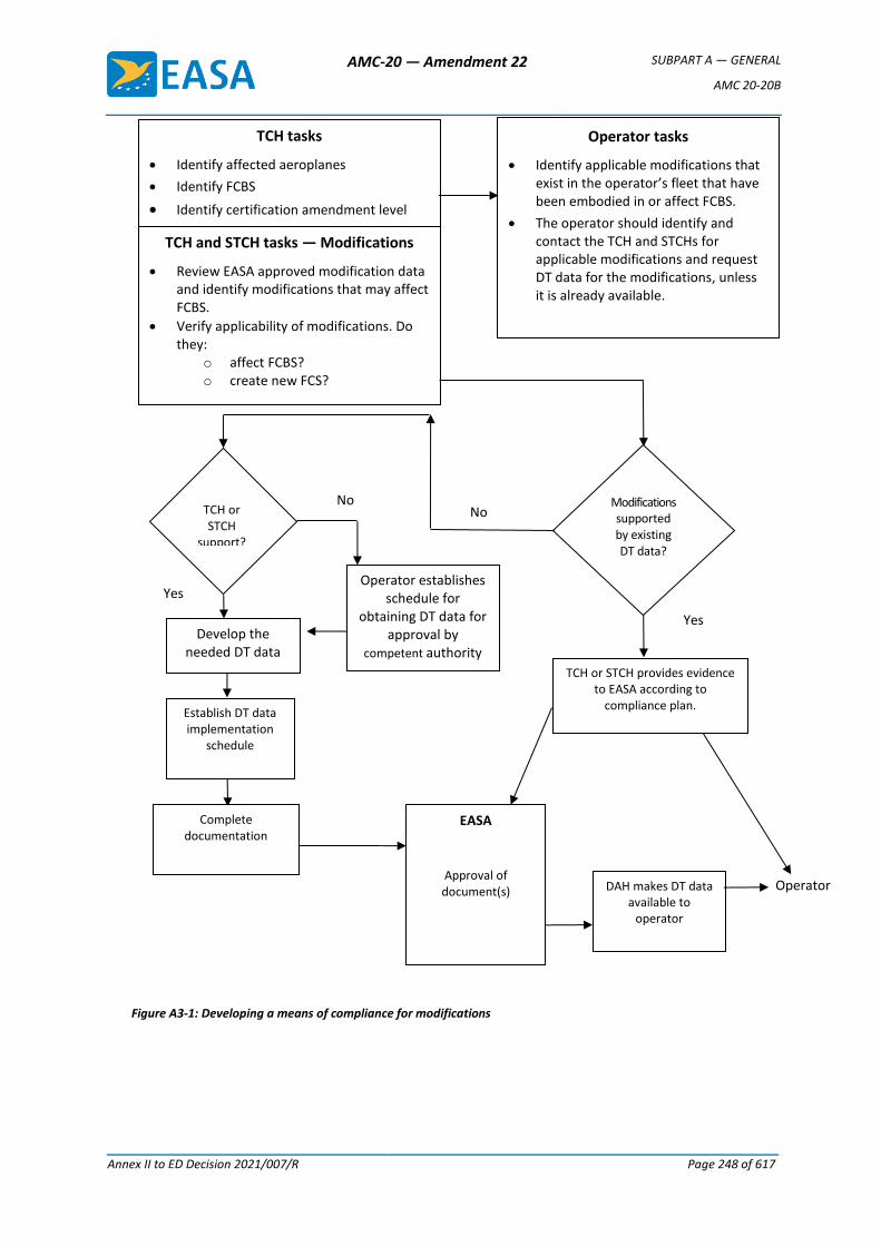
AMC-20 — Amendment 22 SUBPART A — GENERAL
AMC 20-20B
Annex II to ED Decision 2021/007/R Page 248 of 617
Yes
Operator tasks
• Identify applicable modifications that exist in the operator’s fleet that have been embodied in or affect FCBS.
• The operator should identify and contact the TCH and STCHs for applicable modifications and request DT data for the modifications, unless it is already available.
TCH tasks
• Identify affected aeroplanes
• Identify FCBS
• Identify certification amendment level
TCH and STCH tasks — Modifications
• Review EASA approved modification data and identify modifications that may affect FCBS.
• Verify applicability of modifications. Do they:
o affect FCBS? o create new FCS?
Establish DT data implementation
schedule
Operator
No
Develop the needed DT data
Modifications supported by existing DT data?
Operator establishes schedule for
obtaining DT data for approval by
competent authority
TCH or STCH provides evidence to EASA according to
compliance plan.
Complete documentation
EASA
Approval of document(s)
TCH or STCH
support?
Figure A3-1: Developing a means of compliance for modifications
Yes
No
DAH makes DT data available to
operator

AMC-20 — Amendment 22 SUBPART A — GENERAL
AMC 20-20B
Annex II to ED Decision 2021/007/R Page 249 of 617
6.1. Contents of the maintenance programme
(a) The operator’s maintenance programme should contain or refer to an
implementation plan that ensures that:
(1) all new repairs and modifications that affect FCBS will have DT data and DTI
or other procedures implemented;
(2) all existing repairs and modifications to FCBS have been or will be evaluated
for damage tolerance and have DTI or other procedures implemented. In the
context of this implementation plan, there should be a process that:
(i) reviews the operator processes to determine if DT data for repairs and
modifications affecting FCBS have been developed and incorporated
into the operator’s maintenance programme for the operational life
of the aircraft. If an operator is able to demonstrate that these
processes ensure that DT data is developed for all repairs and
modifications affecting FCBS, then no further action is required for
existing repairs and modifications;
(ii) identifies or surveys existing repairs (using the applicable REGs or
survey parameters from Annex 2 to this Appendix) and modifications
that affect FCBS and obtain and implement DTI for those repairs and
modifications. This should include an implementation schedule that
provides timing for incorporation of DT data into the operator’s
maintenance programme, within the time frame given in the
applicable TCH or STCH’s approved documentation.
(b) Figure A3-2 below outlines one possible means that an operator can use to develop
an implementation plan for aircraft in their fleet.
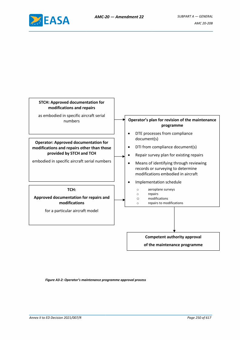
AMC-20 — Amendment 22 SUBPART A — GENERAL
AMC 20-20B
Annex II to ED Decision 2021/007/R Page 250 of 617
Figure A3-2: Operator’s maintenance programme approval process
Competent authority approval
of the maintenance programme
Operator’s plan for revision of the maintenance programme
• DTE processes from compliance document(s)
• DTI from compliance document(s)
• Repair survey plan for existing repairs
• Means of identifying through reviewing records or surveying to determine modifications embodied in aircraft
• Implementation schedule
o aeroplane surveys o repairs
o modifications o repairs to modifications
STCH: Approved documentation for modifications and repairs
as embodied in specific aircraft serial numbers
Operator: Approved documentation for modifications and repairs other than those
provided by STCH and TCH
embodied in specific aircraft serial numbers
TCH:
Approved documentation for repairs and modifications
for a particular aircraft model
AMC-20 — Amendment 22 SUBPART A — GENERAL
AMC 20-20B
Annex II to ED Decision 2021/007/R Page 251 of 617
6.1.1. Implementation plan for repairs
Except as described in CS 26.370, the maintenance programme should
include a repair survey schedule to identify repairs that may need DT data
developed. The TCH’s REGs may be used as a basis for this plan. (See
paragraph 3.13 above and Annex 2 for further information)
6.1.2. Implementation plan and actions for modifications
(a) Points 26.307, 26.308, 26.333 and 26.334 of Part-26 require DAHs to develop
DTI for existing modifications (design changes) within a certain timescale.
CS 26.370 provides means of compliance to operators on how to revise the
maintenance programme by including an implementation plan to show how
approved DTI data will be obtained and used to address the potential
adverse effects of repairs and modifications to FCS and submit it for approval
to the competent authority. To show compliance with CS 26.370, operators
are first requested to develop a list of modifications affecting FCBS through
a review of the aircraft records. The operator will need to show to their
competent authority that the aircraft records are a reliable means for
identifying modifications that affect FCBS. The aircraft records, in
conjunction with data provided by the DAH, may also be sufficient to help
identify whether DTI exists for all modifications. However, for some older
aircraft, a review of records alone may not always be adequate to identify
all the modifications that have an adverse effect on FCBS, or be sufficient to
establish whether a DTE has been accomplished and DTI is complete,
without requesting such information from the DAH. Physical inspection of
the aircraft may help establish the scope of the modification if it is unclear
from the records. Finally, the aircraft survey for repairs may also identify
modifications affecting FCS, which should then be evaluated and DTI
obtained as necessary in accordance with CS 26.370(h).
(b) To support identification of modifications that need to be addressed,
operators should — concurrently with the TCH and STCHs’ tasks — identify
the TCH or STC or other approval holder-developed modifications that exist
in their aircraft fleets. To support compliance with point 26.370 of Part-26
as envisaged in CS 26.370, operators should perform the following tasks:
(1) From the review of records, compile a listing of all TCH and STCH-
developed modifications that are currently installed on their fleet.
(2) Delete from the listing those modifications that do not affect FCBS.
Documents from the TCH may be used to identify the FCBS.
Note: In order to ensure timely compliance with point 26.370 of Part-
26, operators should begin developing the list of modifications
that affect FCBS, for each affected aircraft in the fleet, as soon
as the TCHs make their FCBS listing available.
AMC-20 — Amendment 22 SUBPART A — GENERAL
AMC 20-20B
Annex II to ED Decision 2021/007/R Page 252 of 617
(3) The modifications that affect FCBS must be reviewed to determine
whether:
(i) DT data already exists in the maintenance programme, or is
available and is complete; or
(ii) DT data needs to be developed.
(4) For DT data that is complete, the operator should incorporate it into
the maintenance programme and implement it according to the
schedule provided in 6.1.3 or as otherwise agreed by the competent
authority. Note: Complete DTI for STCs approved after 1 September
2003 should be available to operators not later than 30 months after
the date of applicability of point 26.370 of Part-26 following approval
by EASA unless the STCH no longer exists.
(5) For DT data that is not available or is incomplete 30 months after the
date of applicability of point 26.370 of Part-26, the operator should
ensure that the plan developed according to CS 26.370 will address
each affected modification.
(6) Where DT data is not available or is incomplete, the operator should
notify both the STCH or a third party that DT data for the modification
is required.
(7) Establish whether the STCH or a third party will provide the data.
Note: For modifications addressed by point 26.334 of Part-26 (for
change approvals issued before 1 September 2003), the DAH does not
need to develop the DT data until requested by an operator and has
24 months from that date to submit the data for approval. It is
therefore envisaged that DTI for these modifications will be addressed
in accordance with paragraph (8) and the timescales of CS 26.370 (h).
Whatever the approval date of the change, the operator is responsible
for obtaining the DTI from the approval holder once it becomes
available. It is therefore recommended that the operator contacts the
approval holder or a third party as soon as possible after identifying a
modification that affects FCBS to establish when the DTI will become
available.
(8) For those modifications where the DTI will not be incorporated into
the maintenance programme within 36 months from the date of
applicability of point 26.370(a)(ii) of Part-26, the operator’s DT data
implementation plan should contain the following information:
(i) a description of the modification;
(ii) the affected aircraft and the affected FCS;
(iii) the DSG of the affected aircraft;
AMC-20 — Amendment 22 SUBPART A — GENERAL
AMC 20-20B
Annex II to ED Decision 2021/007/R Page 253 of 617
(iv) a list of the FCS introduced by the modification (if it
exists);
(v) the CS 25.571 certification level for determining the DT
data;
(vi) a plan for obtaining DT data for each modification (e.g.
reliance on the existing STCH or a formal contract with a
Part 21-Subpart J-approved third party) to produce DT
data within a specified compliance time in accordance
with CS 26.370;
(vii) a DT data implementation schedule for incorporating the
DT data into the maintenance programme once it is
received;
(viii) a means of ensuring that the aircraft will not be operated
beyond the time limit established for obtaining DT data.
(9) For modifications that are found during the aircraft survey for repairs,
the operator should ensure that DT data is obtained and submitted to
EASA for approval. Once approved, the operator should incorporate
the DTIs into its maintenance programme no later than 12 months
from the date when the modification was identified.
6.1.3. Implementation of DTI
Operators should accomplish the first inspection of a change according to the
approved DTI implementation schedule. If the age of the modification is unknown,
the operator should use the aircraft age in total flight cycles or total flight hours,
as applicable. Where there is any doubt about the applicability of the programme
data or the timescales provided in the DAH documentation, EASA should be
consulted by the operators and competent authorities concerned.
7. ROLE OF THE COMPETENT AUTHORITY
The competent authority’s role is to verify that the AMP is in compliance with point 26.370 of
Part-26 and ensure that their aircraft continuing airworthiness monitoring survey programme
takes into account the risks associated with potential non-compliance of operators’ or owners’
AMPs with the requirements of point 26.370 of Part-26. (Ref. Part-M requirements for the
Competent Authority (M.B.301 and 303)).
[Amdt 20/20] [Amdt 20/22]
AMC-20 — Amendment 22 SUBPART A — GENERAL
AMC 20-20B
Annex II to ED Decision 2021/007/R Page 254 of 617
Annex 1 to Appendix 3 to AMC 20-20B — Approval process for new repairs
The approval process for new repairs may use a three-stage approach, as now commonly used in the
aviation industry.
DT data includes inspection requirements, such as the inspection threshold, inspection method, and
inspection repetitive interval, or may specify a time limit when a repair or modification needs to be
replaced or modified. The required data may be submitted all at once, prior to the aircraft’s return to
service, or it may be submitted in stages. The following three-stage approval process is available,
which involves incremental approval of engineering data to allow an aircraft to return to service
before all the engineering data previously described is submitted. The three stages are described as
follows:
(a) The first stage is the approval of the static strength data and the schedule for submission of the
DT data. This approval is required prior to returning an aircraft to service.
(b) The second stage is approval of the DT data. Sufficient data to substantiate continued safe
operation should be submitted no later than 12 months after the aircraft was returned to
service, unless a temporary limitation was substantiated by sufficient fatigue and damage
tolerance evaluation data and approved at the first stage of approval, in which case the second
stage DT data should be approved before the temporary limit is reached. At the second stage,
the DT data need only contain the threshold when inspections are required to begin as long as
a process is in place to develop the required inspection method and repetitive intervals before
the threshold is reached. In this case, the submission and approval of the remaining DT data
may be deferred to the third stage. The approved threshold acts as a limitation on the repair
data.
(c) The third stage is approval of the inspection method and the repetitive intervals. This final
element of the repair certification data in compliance with CS 25.571 should be submitted and
approved prior to the inspection threshold being reached.
The applicant should inform the operator if this process is being used, and of the expected timelines
for the delivery of the data. To follow the three-stage process, the DAHs subject to Part 21 will need
to establish procedures to be accepted by EASA under their design organisation approvals.
[Amdt 20/20] [Amdt 20/22]
AMC-20 — Amendment 22 SUBPART A — GENERAL
AMC 20-20B
Annex II to ED Decision 2021/007/R Page 255 of 617
Annex 2 to Appendix 3 to AMC 20-20B — Assessment of existing repairs
A DTI assessment process consists of an aircraft repair survey, identification and disposition of repairs
requiring immediate action and development of damage-tolerance-based inspections, as described
below.
1. AIRCRAFT REPAIR SURVEY
A survey will be used to identify existing repairs and repair configurations on all FCS and provide
a means to categorise those repairs. The survey would apply to all affected aircraft in an
operator’s fleet, as defined in the maintenance programme, using the process contained in the
REGs or similar documents. The procedure to identify repairs that require DTE should be
developed and documented using CS 25.571 and AMC 25.571 (dependent on aircraft
certification level), together with additional guidance specific to repairs, such as:
(a) Size of the repair;
(b) Repair configuration:
(1) SRM standards,
(2) other;
(c) Proximity to other repairs; and
(d) Potential effect on FCS:
(1) inspectability (access and method),
(2) load distribution.
See Paragraph 4 of this Annex for more details.
2. IDENTIFICATION AND DISPOSITION OF REPAIRS REQUIRING IMMEDIATE ACTION
Certain repairs may not meet the minimum requirements because of cracking, corrosion, dents,
or inadequate design. The operator should use the guidance provided in the compliance
document to identify these repairs and, once they are identified, take appropriate corrective
action. In some cases, modifications may need to be made before further flights. The operator
should consider establishing a fleet campaign if similar repairs may have been installed on other
aircraft.
3. DAMAGE TOLERANCE INSPECTION DEVELOPMENT
This includes the development of the appropriate maintenance plan for the repair under
consideration. During this step determine the inspection method, threshold, and repeat
interval. Determine this information from existing guidance information as documented in the
RAG (see Paragraph 4), the REGs or from the results of an individual DTE performed using the
guidance in AMC 25.571. Then determine the feasibility of an inspection programme to
maintain continued airworthiness. If the inspection programme is practical, incorporate the DTI
into the individual aircraft maintenance programme. If the inspection is either impractical or
impossible, incorporate a replacement time for the repair into the individual aircraft
AMC-20 — Amendment 22 SUBPART A — GENERAL
AMC 20-20B
Annex II to ED Decision 2021/007/R Page 256 of 617
maintenance programme. The three-stage approach discussed in Annex 1 to this Appendix may
be used, if appropriate.
4. REPAIR ASSESSMENT GUIDELINES
4.1. Criteria to assist in developing the repair assessment guidelines
The following criteria are those developed for the fuselage pressure boundary, similar to
those found in FAA AC 120-73 and previous JAA and EASA documentation. DAHs may find
it appropriate to develop similar practice for other types of aircraft and areas of the
structure.
The purpose is to develop repair assessment guidelines requiring specific maintenance
programmes, if necessary, to maintain the damage tolerance integrity of the repaired
airframe. The following criteria have been developed to assist in the development of that
guidance material:
(a) Specific repair size limits for which no assessment is necessary may be selected for
each model of aircraft and structural location. This will enable to minimise the
burden on the operator while ensuring that the aircraft’s baseline inspection
programme remains valid.
(b) Repairs that are not in accordance with SRM must be reviewed and may require
further action.
(c) Repairs must be reviewed where the repair has been installed in accordance with
SRM data that has been superseded or rendered inactive by new damage-tolerant
designs.
(d) Repairs in close proximity to other repairs or modifications require review to
determine their impact on the continued airworthiness of the aircraft.
(e) Repairs that exhibit structural distress should be replaced before further flights.
4.2. Repair assessment methodology
The next step is to develop a repair assessment methodology that is effective in
evaluating the continued airworthiness of existing repairs for the fuselage pressure
boundary. Older aircraft models may have many structural repairs, so the efficiency of
the assessment procedure is an important consideration. In the past, evaluation of
repairs for damage tolerance would require direct assistance from the DAH. Considering
that each repair design is different, that each aircraft model is different, that each area
of the aircraft is subjected to a different loading environment, and that the number of
engineers qualified to perform damage tolerance assessment is small, the size of an
assessment task conducted in that way would be unmanageable. Therefore, a new
approach has been developed as an alternative.
Since repair assessment results will depend on the model-specific structure and loading
environment, the DAHs should create an assessment methodology for the types of
repairs expected to be found on each affected aircraft model. Since the records of most
of these repairs are not readily available, locating the repairs will necessitate surveying
AMC-20 — Amendment 22 SUBPART A — GENERAL
AMC 20-20B
Annex II to ED Decision 2021/007/R Page 257 of 617
the structure of each aircraft. A survey form is created by the DAH that may be used to
record key repair design features needed to accomplish a repair assessment. Airline
personnel not trained as damage tolerance specialists can use this form to document the
configuration of each observed repair.
Some DAHs have developed simplified methods using the information from the survey
form as input data to determine the damage tolerance characteristics of the surveyed
repairs. Although the repair assessments should be performed by well-trained personnel
familiar with the model-specific repair assessment guidelines, these methods enable
appropriate staff, not trained as damage tolerance specialists, to perform the repair
assessment without the assistance of the TCH. This methodology should be generated by
the aircraft TCH. Model-specific repair assessment guidelines will be prepared by the
TCHs.
From the information on the survey form, it is also possible to classify repairs into one of
three categories:
Category A: A permanent repair for which the baseline zonal inspection (BZI) (typical
maintenance inspection intervals assumed to be performed by most
operators) is adequate to ensure continued airworthiness.
Category B: A permanent repair that requires supplemental inspections to ensure
continued airworthiness.
Category C: A temporary repair that will need to be reworked or replaced prior to an
established time limit. Supplemental inspections may be necessary to
ensure continued airworthiness prior to this limit.
When the LOV of the maintenance programme is extended, the initial categorisation of
repairs may need a review by the applicant for the LOV extension, and the operator may
need to ensure that these remain valid up to the new LOV.
4.3. Repair assessment process
There are two principal techniques that can be used to accomplish the repair assessment.
The first technique involves a three-stage procedure. This technique could be well-suited
for operators of small fleets. The second technique involves the incorporation of the
repair assessment guidelines as part of an operator’s routine maintenance programme.
This approach could be well-suited for operators of large fleets and would evaluate
repairs at predetermined planned maintenance visits as part of the maintenance
programme.
The first technique generally involves the execution of the following three stages (see
Figure A3(2)-1):
Stage 1: Data collection
This stage specifies what structure should be assessed for repairs and collects data for
further analysis. If a repair is on a structure in an area of concern, the analysis continues,
otherwise the repair does not require classification per this programme.
AMC-20 — Amendment 22 SUBPART A — GENERAL
AMC 20-20B
Annex II to ED Decision 2021/007/R Page 258 of 617
Repair assessment guidelines for each model will provide a list of structure for which
repair assessments are required. Some DAHs have reduced this list by determining the
inspection requirements for critical details. If the requirements are equal to normal
maintenance checks (e.g. BZI checks), those details may be excluded from this list.
Repair details are collected for further analysis in Stage 2. Repairs that do not meet the
minimum design requirements or are significantly degraded are immediately identified,
and corrective actions must be taken before further flights.
Stage 2: Repair categorisation
Repair categorisation is accomplished by using the data gathered in Stage 1 to answer
simple questions regarding structural characteristics.
If the maintenance programme is at least as rigorous as the BZI identified in the TCH’s
model-specific repair assessment guidelines, well-designed repairs in good condition
meeting size and proximity requirements are Category A. Simple condition and design
criteria questions are provided in Stage 2 to define the lower bounds of Category B and
C repairs. The process continues for Category B and C repairs.
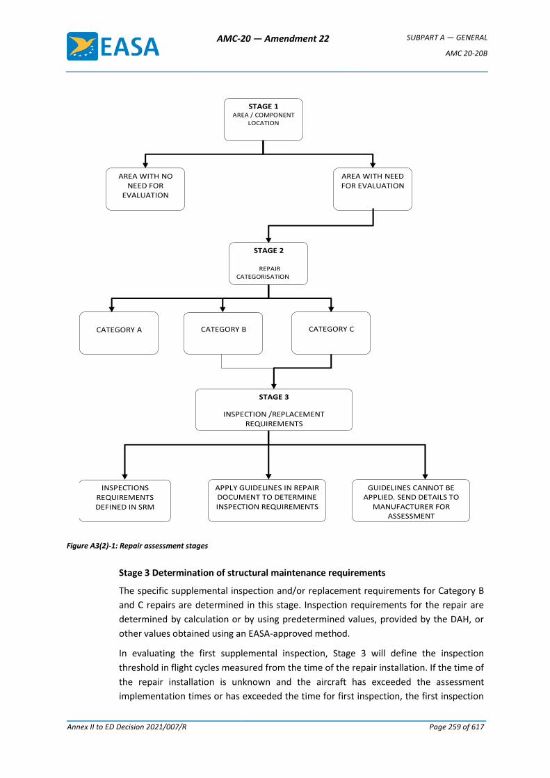
AMC-20 — Amendment 22 SUBPART A — GENERAL
AMC 20-20B
Annex II to ED Decision 2021/007/R Page 259 of 617
Figure A3(2)-1: Repair assessment stages
Stage 3 Determination of structural maintenance requirements
The specific supplemental inspection and/or replacement requirements for Category B
and C repairs are determined in this stage. Inspection requirements for the repair are
determined by calculation or by using predetermined values, provided by the DAH, or
other values obtained using an EASA-approved method.
In evaluating the first supplemental inspection, Stage 3 will define the inspection
threshold in flight cycles measured from the time of the repair installation. If the time of
the repair installation is unknown and the aircraft has exceeded the assessment
implementation times or has exceeded the time for first inspection, the first inspection
STAGE 1 AREA / COMPONENT
LOCATION
AREA WITH NO NEED FOR
EVALUATION
AREA WITH NEED FOR EVALUATION
GUIDELINES CANNOT BE APPLIED. SEND DETAILS TO
MANUFACTURER FOR ASSESSMENT
CATEGORY A
CATEGORY B
CATEGORY C
STAGE 3
INSPECTION /REPLACEMENT REQUIREMENTS
INSPECTIONS REQUIREMENTS DEFINED IN SRM
APPLY GUIDELINES IN REPAIR DOCUMENT TO DETERMINE INSPECTION REQUIREMENTS
STAGE 2
REPAIR CATEGORISATION

AMC-20 — Amendment 22 SUBPART A — GENERAL
AMC 20-20B
Annex II to ED Decision 2021/007/R Page 260 of 617
should occur by the next ‘C-check’ interval, or equivalent cycle limit after the repair data
is gathered (Stage 1).
The operator may choose to accomplish all three stages at once, or just Stage 1. In the
latter case, the operator would be required to adhere to the schedule specified in the
EASA-approved model-specific repair assessment guidelines for completion of Stages 2
and 3. Incorporating the maintenance requirements for Category B and C repairs into an
operator’s individual aircraft maintenance or inspection programme completes the repair
assessment process for the first technique.
The second technique would involve setting up a repair maintenance programme to
evaluate all the applicable structures as detailed in paragraph 1 at each predetermined
maintenance visit to confirm that they are permanent. This technique would require the
operator to choose an inspection method and interval in accordance with the EASA-
approved repair assessment guidelines. The repairs whose inspection requirements are
fulfilled by the chosen inspection method and interval would be inspected in accordance
with the approved maintenance programme. Any repair that is not permanent, or whose
inspection requirements are not fulfilled by the chosen inspection method and interval,
would either be:
(a) upgraded to allow utilisation of the chosen inspection method and interval; or
(b) individually tracked to account for the repair’s unique inspection method and
interval requirements.
This process is then repeated at the chosen inspection interval.
Repairs added between the predetermined maintenance visits, including interim repairs
installed at remote locations, would be required either to have a threshold greater than
the length of the predetermined maintenance visit or to be tracked individually to
account for the repair’s unique inspection method and interval requirements. This would
ensure the airworthiness of the structure until the next predetermined maintenance visit,
at which time the repair would be evaluated as part of the repair maintenance
programme.
5. MAINTENANCE PROGRAMME CHANGES
When a maintenance or inspection programme interval is revised, the operator should evaluate
the impact of the change on the repair assessment programme. If the revised maintenance or
inspection programme intervals are greater than those in the BZI, the previous classification of
Category A repairs may become invalid. The operator may need to obtain approval of an
alternative inspection method, upgrade the repair to allow utilisation of the chosen inspection
method and interval, or re-categorise some repairs and establish unique supplemental
inspection methods and intervals for specific repairs. Operators using the ‘second technique’ of
conducting repetitive repair assessments at predetermined maintenance visits would evaluate
whether the change to the predetermined maintenance visit continues to fulfil the repair
inspection requirements.
AMC-20 — Amendment 22 SUBPART A — GENERAL
AMC 20-20B
Annex II to ED Decision 2021/007/R Page 261 of 617
6. SRM UPDATE
The general section of each SRM will contain brief descriptions of damage tolerance
considerations, categories of repairs, description of BZIs, and the repair assessment logic
diagram. In updating each SRM, existing location-specific repairs should be labelled with
appropriate repair category identification (A, B or C), and specific inspection requirements for
B and C repairs should also be provided as applicable. SRM descriptions of generic repairs will
also contain repair category considerations regarding size, zone and proximity. Detailed
information for the determination of inspection requirements will have to be provided for each
model. Repairs which were installed in accordance with a previous revision of the SRM, but
which have now been superseded by a new damage-tolerant design, will require review. Such
repairs may be reclassified to Category B or C, requiring additional inspections and/or rework.
7. Structure modified by an STC
The current repair assessment guidelines provided by the TCH are not always applicable to
structure modified by an STC. Nonetheless, it is expected that all the structure modified by an
STC should be evaluated by the operator and, if possible, in conjunction with the STCH. Point
26.370 of Part-26 requires the operator to amend their maintenance programme to address all
such repairs, and a conservative extension of the TCH’s REGs to all STCs containing FCS can be
envisaged to ensure that all repairs to FCS are identified. Subsequently, each repair can be
subjected to a DTE, and DTI be provided with the support of a DAH. The STCH should conduct
specific damage tolerance assessments of known published repairs (SRM, SBs, etc.) and provide
appropriate instructions to the operator.
It is expected that the STCH will assist the operators by preparing the required documents. If
the STCH is no longer in business, or is otherwise unable to provide assistance, the operator
would have to acquire the EASA-approved guidelines independently. Ultimately, the operator
remains responsible for the continued safe operation of the aircraft.
[Amdt 20/20] [Amdt 20/22]
AMC-20 — Amendment 22 SUBPART A — GENERAL
AMC 20-20B
Annex II to ED Decision 2021/007/R Page 262 of 617
Annex 3 to Appendix 3 to AMC 20-20B — Repairs and modifications to removable structural components
1. DETERMINING THE AGE OF A REMOVABLE STRUCTURAL COMPONENT
Determining the actual component’s age or assigning a conservative age provides flexibility and
reduces operator burden when implementing DT data for repairs and modifications to
structural components. In some cases, the actual component’s age may be determined from
records. If the actual age cannot be determined this way, the component’s age may be
conservatively assigned using one of the following fleet leader concepts, depending upon the
origin of the component:
(a) If component times are not available, but records indicate that no part changes have
occurred, aircraft flight cycles or flight hours can be used.
(b) If no records are available, and the parts could have been switched from one or more
older aircraft under the same maintenance programme, it should be assumed that the
time on any component is equal to the oldest aircraft in the programme. If this is
unknown, the time should be assumed to be equal to the same model aircraft that is the
oldest or has the most flight cycles or flight hours in the world fleet.
(c) A manufacturing date marked on a component may also be used to help establish the
component’s age in flight cycles or flight hours. This can be done by using the above
reasoning and comparing it to aircraft in the affected fleet with the same or older
manufacturing date.
If none of these options can be used to determine or assign a component age or total number
of flight cycles or flight hours, a conservative implementation schedule can be established by
using the guidelines applied in paragraph 3 of this Appendix, for the initial inspection, if required
by the DT data.
2. TRACKING
An effective control or tracking system should be established for removable structural
components that are identified as FCBS or that contain FCS. This will help ensure compliance
with the maintenance programme’s requirements specific to repairs and modifications installed
on an affected removable structural component. Paragraph 4 of this Appendix provides options
that could be used to alleviate some of the burden associated with tracking all repairs to
affected removable structural components.
3. DEVELOPING AND IMPLEMENTING DT DATA
(a) Repairs
Accomplish the initial repair assessment of the affected structural component at the
same time as the aircraft level repair survey for the aircraft on which the component is
installed. Develop DT data according to the process given in Annex 2 and incorporate DTI
into the maintenance programme.
AMC-20 — Amendment 22 SUBPART A — GENERAL
AMC 20-20B
Annex II to ED Decision 2021/007/R Page 263 of 617
(b) Modifications
Accomplish the initial modification assessment of the affected structural component at
the same time as the aircraft level modification assessment for the aircraft on which the
component is installed. Develop DT data and incorporate DTI into the maintenance
programme.
If the actual age of the repairs or modification installation, or the total number of flight
cycles or flight hours is known, use that information to establish when the initial
inspection of the component should be performed. Repeat the inspection at the intervals
provided by the TCH or STCH for the repair or modification against the component.
If the actual age of the repairs or modifications installation, or the total number of flight
cycles or flight hours is unknown, but the component’s age or total number of flight cycles
or flight hours is known, or can be assigned conservatively, use the component’s age, or
the total number of flight cycles or flight hours to establish when the initial inspection of
the component should be performed. Repeat the inspection at the intervals provided by
the TCH or STCH for the repairs and modifications against the component.
As an option, accomplish the initial inspection of the affected component at the next C-
check (or equivalent interval) following the repair assessment. Repeat the inspection at
the intervals provided by the TCH or STCH for the repairs and modifications against the
component.
4. EXISTING REPAIRS AND MODIFICATIONS — COMPONENTS RETRIEVED FROM STORAGE
(a) If the time on the component (in flight cycles or flight hours) is known, or can be
conservatively assigned, perform the following:
(1) survey the component;
(2) dispose repairs and modifications;
(3) implement any DTI in accordance with the approved schedule;
(4) accomplish the initial inspection using the actual age of the repairs or
modifications, or the total number of flight cycles or flight hours, if known. If the
age of the repairs or modifications is not known, use the component’s age. Repeat
the inspection at the intervals given for the repairs or modifications against the
component.
(b) If the time on the component (in flight cycles or flight hours) is unknown and cannot be
conservatively assigned, perform the initial repair or modification assessment of the
affected component prior to installation, and perform the following actions:
(1) develop DT data according to the process given in paragraph 3 or 4 of Appendix 3
to this AMC as applicable;
(2) incorporate any DTI into the maintenance programme;
(3) accomplish the first inspection on the affected component at the next C-check (or
equivalent interval) following the repair or modification assessment;
AMC-20 — Amendment 22 SUBPART A — GENERAL
AMC 20-20B
Annex II to ED Decision 2021/007/R Page 264 of 617
(4) repeat the inspection at the intervals given for the repair or modification against
the component.
5. IMPLEMENTATION OPTIONS TO HELP REDUCE TRACKING BURDEN
The following implementation techniques could be used to alleviate some of the burden
associated with tracking repairs to affected removable structural components. These
techniques, if used, would need to be included in the maintenance programme and may require
additional EASA approval and TCH or STCH input for DTI.
(a) Upgrading existing repairs
As an option, existing repairs may be removed and replaced with new parts of the same
design revised as necessary to support the new installation. This practice would permit
the DTI requirements of the repair to be set to zero and to re-establish an initial tracking
point for the repair. Normally, this would be done at or before the survey for maximum
benefit. The initial and repetitive inspections for the upgraded repair would then be
accomplished at the intervals given for the repair against the component.
A repair could also be upgraded to one whose inspection requirements and methods are
already fulfilled by an operator’s maintenance or inspection programme. That repair
would then be repetitively inspected at each routine inspection interval applicable to the
repair. Specific tracking would not be required because that area of the aircraft would
have already been normally inspected on each aircraft in the fleet as part of the existing
approved maintenance programme. If the operator’s programme intervals were
changed, the effect on requirements for specific tracking would have to be re-evaluated.
(b) Special initial and/or routine inspections
As an option, existing repairs may have special initial inspections accomplished during the
component survey. This initial inspection establishes an initial tracking point for the
repair. Following this initial inspection, the DTI requirements (e.g. repetitive inspections)
of the repair would be implemented.
In addition, special routine inspections could be defined for typical repairs that could be
applied at a normal interval. In this case, an operator could check the affected
components on each aircraft for this type of a repair at the defined interval. If the repair
is found, the special inspection would be applied to ensure its airworthiness until the next
scheduled check. This alleviates the need to specifically track affected components for
every repair, especially typical ones.
[Amdt 20/20] [Amdt 20/22]

AMC-20 — Amendment 22 SUBPART A — GENERAL
AMC 20-20B
Annex II to ED Decision 2021/007/R Page 265 of 617
Annex 4 to Appendix 3 to AMC 20-20B — Service bulletin review process
Guidelines for following the service bulletin (SB) flow chart
Note: While it is believed that this guidance is fairly comprehensive, it may not address every possible
situation. It is therefore incumbent on the user to use good judgement and rationale when making
any determination.
Screening SBs to determine which ones require DT data is primarily a TCH responsibility.
The result of this screening is a list of SBs which require special directed inspections to ensure
continued airworthiness. SBs included in the list will be grouped into Type I and Type II SBs. Type I SBs
have existing DT data and Type II SBs require developing DT data. The list is not comprehensive and
will not include all the SBs associated with an aircraft. The list does not need to include those SBs
where the inspection programme developed for the repair assessment programme has been
determined to be sufficient to meet the damage tolerance requirements for the FCBS that is affected
by the SB.
To ensure compliance with Part-26, any DTI identified in the existing programme that is required to
continue to be implemented to satisfy point 26.370 should be identified as such in the ICA.
Query 1: Does the SB address a structural repair or a modification to FCS?
Historically, any SB, service letter or other document that lists ATA Chapters 51 through 57
could provide repair or modification instructions that may require DT data. In addition,
certain repairs or modifications accomplished under other ATA chapters may affect FCS. The
first step in the screening process is to identify all such service instructions and develop a list
of candidates for review (Q2).
Query 2: Does the service instruction specify either a repair or modification that creates or affects
FCS?
If it does, then the service instruction requires further review (Q3). If it does not, then the
service instruction does not require further review.
Query 3: Is the service instruction mandated?
SBs and other service instructions that are mandated by an AD have requirements to ensure
that inspection findings (e.g. detected cracks or other structural damage/degradation) are
addressed in an approved manner. If the TCH can demonstrate that they apply a process for
developing inspection programmes for mandated SBs using DT data and/or service-based
inspection results, and for continuously reviewing the SBs for their adequacy to detect cracks
in a timely manner, the mandated SBs should then be considered as compliant with the
intent of this process. Otherwise, the TCH will need to demonstrate that the inspection
programme in the mandated SB has been developed using DT data and/or appropriate
service-based inspection results. The outcome of Query 3 branches to two unrelated boxes
(Q4: if mandated by an AD, or Q7: if not mandated by an AD).
Query 4: Does the SB or service instruction contain terminating action?
AMC-20 — Amendment 22 SUBPART A — GENERAL
AMC 20-20B
Annex II to ED Decision 2021/007/R Page 266 of 617
Query 3 established that the inspection programme for the baseline configuration is
acceptable.
Query 5: Does the terminating action have DT data?
If the terminating action has a documented continuing airworthiness inspection programme
based on damage tolerance principles, then no further review is required. The SB should be
documented in the list. If the terminating action does not have DT data, or the status of the
inspection programme cannot be verified, then further review is necessary (Q6).
Query 6: Does the SB address a safe-life part?
If it does, no further action is required. Otherwise, damage-tolerance-based inspections will
need to be developed and provided to the operators. The SB should be included in the list
along with where to find the required continued airworthiness inspection programme.
Query 7: In Query 3 a structural SB that was mandated by AD was identified.
Query 7 asks if a one-time inspection is required to satisfy the intent of the requirement. If
it does, it is deemed that this is being done to verify that a condition does not exist and, on
finding that condition, correct that condition to baseline configuration. As such, normal SSID
programmes would then be expected to cover any required continued airworthiness
inspections. If a repair is necessary, it is further assumed that this was done by reference to
the SRM or other suitable means. No further action is required if this is the case and, if a
repair was necessary, other means exist to determine the required DT data. If no inspections
or multiple inspections are required, additional evaluation is required (Q8).
Query 8: Is this a major structural design change (e.g. modification)?
This is a TCH decision that is part of the original certification process and is not a major/minor
repair decision. If it is not a major design change, then proceed to Q10; if not, proceed to
Q9.
Query 9: Does the change require NDIs to verify the integrity of the structure or are normal routine
maintenance inspections sufficient?
This is a subjective question and may require re-evaluating the change and determining
where specific fatigue cracking might be expected. If normal maintenance inspections are
adequate, no further action is required. Otherwise, proceed to Q10.
Query 10: Does the SB contain DT data for both the baseline and modified aircraft configurations?
If so, the SB is satisfactory. Otherwise, damage-tolerance-based inspections will need to be
developed and provided to the operators. The SB should be documented in the list along
with where to find the required continued airworthiness inspection programme.
SB screening procedure
1. The TCH will perform the screening and the Structures Task Group will validate the results.
2. A list of all SBs requiring action will be included in the TCH compliance document. Those not
requiring action will not be included in the list.
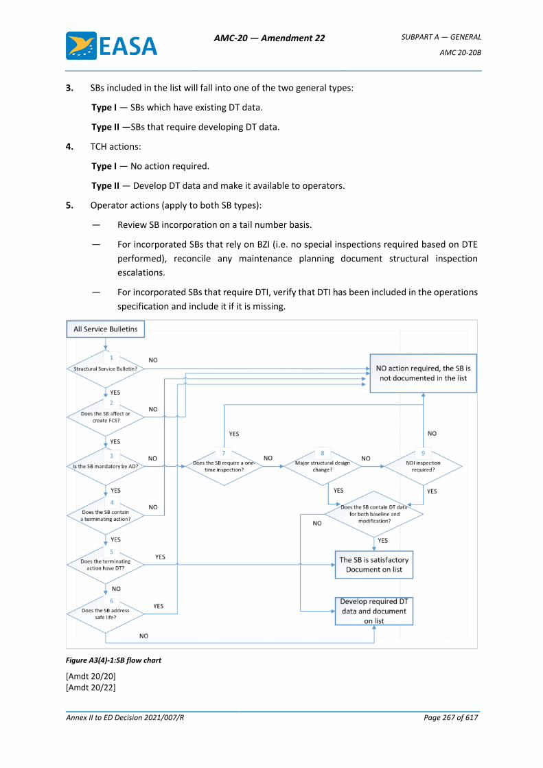
AMC-20 — Amendment 22 SUBPART A — GENERAL
AMC 20-20B
Annex II to ED Decision 2021/007/R Page 267 of 617
3. SBs included in the list will fall into one of the two general types:
Type I — SBs which have existing DT data.
Type II —SBs that require developing DT data.
4. TCH actions:
Type I — No action required.
Type II — Develop DT data and make it available to operators.
5. Operator actions (apply to both SB types):
— Review SB incorporation on a tail number basis.
— For incorporated SBs that rely on BZI (i.e. no special inspections required based on DTE
performed), reconcile any maintenance planning document structural inspection
escalations.
— For incorporated SBs that require DTI, verify that DTI has been included in the operations
specification and include it if it is missing.
Figure A3(4)-1:SB flow chart
[Amdt 20/20] [Amdt 20/22]
AMC-20 — Amendment 22 SUBPART A — GENERAL
AMC 20-20B
Annex II to ED Decision 2021/007/R Page 268 of 617
Annex 5 to Appendix 3 to AMC 20-20B — List of major changes and STSs that may adversely affect fatigue-critical structure
(1) Passenger-to-freighter conversions (including addition of main deck cargo doors).
(2) Gross weight increases (increased operating weights, increased zero fuel weights, increased
landing weights, and increased maximum take-off weights).
(3) Installation of fuselage cut-outs (passenger entry doors, emergency exit doors or crew escape
hatches, fuselage access doors, and cabin window relocations).
(4) Complete re-engine or pylon modifications.
(5) Engine hush kits.
(6) Wing modifications such as installing winglets or changes in flight control settings (flap droop),
and modification of wing trailing edge structure.
(7) Modified skin splices.
(8) Antenna installations.
(9) Any modification that affects several stringer or frame bays.
(10) Any modification that covers structure requiring periodic inspection by the operator’s
maintenance programme.
(11) Any modification that results in operational mission change that significantly changes the
manufacturer’s load or stress spectrum (e.g. passenger-to-freighter conversion).
(12) Any modification that changes areas of the fuselage that prevents external visual inspection
(e.g. installation of a large external fuselage doubler that results in hiding details beneath it).
(13) In general, attachment of interior monuments to FCS. Interior monuments include large items
of mass such as galleys, closets, and lavatories.
[Amdt 20/20] [Amdt 20/22]
AMC-20 — Amendment 22 SUBPART A — GENERAL
AMC 20-20B
Annex II to ED Decision 2021/007/R Page 269 of 617
Annex 6 to Appendix 3 to AMC 20-20B — Background to the need for damage-tolerance-based inspection programmes for repairs
Repairs are a concern on older aircraft because of the possibility that they may develop, cause, or
obscure metal fatigue, corrosion, or other damage during service. This damage might occur within the
repair itself or in the adjacent structure, and might ultimately lead to structural failure.
In general, repairs present a more challenging problem to solve than the original structure because
they are unique and tailored in design to correct particular damage to the original structure. While
the performance of the original structure may be predicted from tests and from experience on other
aircraft in service, the behaviour of a repair and its effect on the fatigue characteristics of the original
structure are generally known to a lesser extent than for the basic unrepaired structure.
Repairs may be of concern as time in service increases for the following reasons:
As aircraft age, both the number and age of the existing repairs increase. Along with this increase is
the possibility of unforeseen repair interaction, failure, or other damage occurring in the repaired
area. The continued operational safety of these aircraft depends primarily on a satisfactory
maintenance programme (with inspections conducted at the right time, in the right place, using the
most appropriate technique, or in some cases, replacement of the repair). To develop this programme,
a DTE of repairs to aircraft structure is essential. The longer an aircraft is in service, the more important
this evaluation and a subsequent inspection programme become.
The practice of repair justification has evolved gradually over the last 20 years. Some repairs described
in the aircraft manufacturers’ SRMs were not designed in accordance with fatigue and damage
tolerance principles (Ref. AAWG Report: Recommendations concerning ARAC taskings FR Doc
04-10816; Aging Aircraft Safety Final Rule. 14 CFR 121.370a and 129.16.). Repairs accomplished in
accordance with the information contained in the early versions of the SRMs may require additional
inspections if evaluated using the fatigue and damage tolerance methodology.
Damage tolerance is a structural design and inspection methodology used to maintain safety by
considering the possibility of metal fatigue or other structural damage (i.e. safety is maintained by
adequate structural inspection until the damage is repaired). One prerequisite for the successful
application of the damage tolerance approach for managing fatigue is that crack growth and residual
strength can be anticipated with sufficient precision to allow inspections to be established that will
detect cracking before it reaches a size that will degrade the strength to less than a specified level. A
DTE entails the prediction of sites where fatigue cracks are most likely to initiate in the aircraft’s
structure, the prediction of the crack path and rates of growth under repeated aircraft structural
loading, the prediction of the size of the damage at which strength limits are exceeded, and an analysis
of the potential opportunities for inspection of the damage as it progresses. This information is used
to establish an inspection programme for the structure that will be able to detect cracking that may
develop before it could contribute to a catastrophic failure.
The evidence to date is that when all the critical structure is included, damage-tolerance-based
inspections and procedures, including modification and replacement, provide the best assurance of
continued structural integrity that is currently available. In order to apply this concept to existing
AMC-20 — Amendment 22 SUBPART A — GENERAL
AMC 20-20B
Annex II to ED Decision 2021/007/R Page 270 of 617
transport aeroplanes, the competent authorities have issued a series of ADs requiring compliance with
the first supplemental inspection programmes resulting from the application of this concept to
existing aeroplanes. Generally, these ADs require that operators incorporate SSIDs into their
maintenance programmes for the affected aeroplanes. These documents were derived from damage
tolerance assessments of the originally certified type designs for these aeroplanes. For this reason,
the majority of ADs written for the SSIP did not attempt to address the issues related to the damage
tolerance of repairs that had been made to the aeroplanes. The objective of repair assessment and
repair evaluation guidelines is to provide the same level of assurance for areas of the structure that
have been repaired as that achieved by the SSIP for the baseline structure as originally certified.
[Amdt 20/22]
AMC-20 — Amendment 22 SUBPART A — GENERAL
AMC 20-20B
Annex II to ED Decision 2021/007/R Page 271 of 617
Appendix 4 to AMC 20-20B — Guidelines for the development of a corrosion prevention control programme
1. GENERAL
The TCH should develop a baseline CPCP, which should be reviewed by EASA. The baseline CPCP
is intended to facilitate the development of a CPCP by an operator for their maintenance
programme.
The operator should include a CPCP in the maintenance programme, and where a TCH baseline
CPCP exists, it should be taken into account in the development of the operator’s CPCP. The
operator should show that the CPCP is comprehensive in that it addresses all the corrosion likely
to affect primary structure, and systematic in that:
(a) it provides step-by-step procedures that are applied on a regular basis to each identified
task area or zone; and
(b) these procedures are adjusted when they result in evidence that corrosion is not being
controlled to an established acceptable level (Level 1 or better).
1.1 Purpose
This Appendix gives guidance to operators and DAHs who are developing and
implementing a CPCP for aeroplanes maintained in accordance with an aircraft
maintenance programme developed in compliance with point M.A.302 of Part-M.
CPCPs have been developed by the DAH with the assistance of aircraft operators and
competent authorities. They relied heavily on service experience to establish CPCP
implementation thresholds and repeat intervals. Since that time a logical evaluation
process that has been developed to ensure environmental damage is considered in the
evaluation of aircraft structure. This process is identified in the ATA MSG-3 Scheduled
maintenance development document, which introduced the CPCP concept in revision 2,
circa 1993.
1.2. Approval
Approval of a TCH CPCP may either be through the MRB (ISC) using existing procedures
for EASA MRBR approval, or directly by EASA if no EASA-approved MRBR exists for the
type. Provided that the operator has an NAA-approved aircraft maintenance programme
(AMP) that controls corrosion to Level 1 or better, the operator need not follow exactly
the programme offered by the TCH. However, revisions to the TCH’s approved
programme should be considered by the operator for incorporation in the operator’s MP
under the Part-M requirements.
2. DEFINITIONS
— Allowable limit: this is the amount of material (usually expressed in the thickness of the
material) that may be removed or blended out without affecting the ultimate design
strength capability of the structural member. Allowable limits may be established by the
TCH/DAH. EASA may also establish allowable limits. The DAH normally publishes
allowable limits in the SRM or in SBs. Note: This revision of the AMC amends the definition
AMC-20 — Amendment 22 SUBPART A — GENERAL
AMC 20-20B
Annex II to ED Decision 2021/007/R Page 272 of 617
of corrosion levels such that the concept of local and widespread corrosion is no longer
specified. Nonetheless, when deriving allowable limits for the structure and the adjacent
structure, the full extent of the damage and material removed in the finding and the
previous findings affecting the same areas must be taken into account. Applicable fatigue
and damage tolerance requirements must be taken into account when establishing the
allowable limits.
— Baseline CPCP: this is a CPCP developed for a specific aeroplane model. The TCH typically
develops the baseline CPCP (see TCH-Developed baseline CPCP below). It contains the
corrosion inspection tasks, an implementation threshold, and a repeat interval for task
accomplishment in each area or zone.
— Basic task(s): this is a specific and fundamental set of work elements that should be
performed repetitively in all task areas or zones to successfully control corrosion. The
contents of the basic task may vary depending upon the specific requirements in an
aeroplane area or zone. The basic task is developed to protect the primary structure of
the aeroplane.
— Corrosion prevention and control programme (CPCP): this is a comprehensive and
systematic approach to control corrosion in such a way that the load carrying capability
of an aircraft structure is not degraded to less than a level necessary to maintain
airworthiness. It is based upon the baseline CPCP described above. A CPCP consists of a
basic corrosion inspection task, task areas, defined corrosion levels, and compliance
times (implementation thresholds and repeat intervals).
The CPCP also includes procedures to notify the competent authority of the findings and
data associated with Level 2 and Level 3 corrosion and the actions taken to reduce future
findings to Level 1.
— Implementation threshold (IT): this is the aircraft age associated with the first time the
basic corrosion inspection task should be accomplished in an area or zone.
— Level 1 corrosion is:
Damage occurring between successive inspections that is within the allowable damage
limits; or
Damage occurring between successive inspections that does not require structural
reinforcement, replacement or new damage-tolerance-based inspections; or
Corrosion occurring between successive inspections that exceeds the allowable limits but
can be attributed to an event not typical of operator usage of other aircraft in the same
fleet; or
Light corrosion occurring repeatedly between inspections that eventually requires
structural reinforcement, replacement, or new damage-tolerance-based inspections.
— Level 2 corrosion is any corrosion finding that exceeds Level 1, requiring a review of the
operator’s CPCP effectiveness, but that is not determined to be Level 3.
The operator is responsible for making the initial determination of the corrosion level,
AMC-20 — Amendment 22 SUBPART A — GENERAL
AMC 20-20B
Annex II to ED Decision 2021/007/R Page 273 of 617
and this may subsequently be adjusted based on consultation with the DAH.
A finding of Level 2 corrosion requires repair, reinforcement, or complete or partial
replacement of the applicable structure, or revised fatigue and damage tolerance
inspections.
Note: A statement of fact in previously mandated CPCPs states: corrosion findings that
were discovered during the corrosion inspection task accomplished at the
implementation threshold, and which require repair, reinforcement, or complete or
partial replacement of the applicable structure, should not be used as an indicator of the
effectiveness of the operator’s CPCP. The argument is that an operator’s corrosion
programme effectiveness can only be determined after a repeat inspection has been
performed in a given inspection task area. This argument is valid for aircraft with
mandated CPCPs introduced after the aircraft has been in service for a number of years
without a CPCP. This argument, however, is not valid for aircraft that have been
maintained since entry into service using a CPCP that takes into account the TCH baseline
CPCP and environmental deterioration (ED) programme. Consequently, corrosion
findings exceeding Level 1 found on the corrosion inspection task implementation
threshold may indicate that the threshold has been set too high and action should be
taken to adjust the implementation threshold.
— Level 3 corrosion is that corrosion occurring during the first or subsequent
accomplishments of an inspection task that the operator or subsequently the TCH or
competent authority determines to be an urgent airworthiness concern.
Note: If Level 3 corrosion is determined at the implementation threshold or any repeat
inspection, then it should be reported. Any corrosion that is more than the maximum
acceptable to the DAH or EASA must be reported in accordance with the current
regulations. This determination should be conducted jointly with the DAH.
— Light corrosion is corrosion damage so slight that removal and blend-out over multiple
repeat intervals may be accomplished before material loss exceeds the allowable limit.
— Local corrosion. Generally, local corrosion is corrosion of a skin or web (wing, fuselage,
empennage or strut) that does not exceed one frame, stringer, or stiffener bay. Local
corrosion is typically limited to a single frame, chord, stringer or stiffener, or corrosion of
more than one frame, chord, stringer or stiffener where no corrosion exists on two
adjacent members on each side of the corroded member.
— Operator-developed programme. In order to operate an aeroplane in compliance with
the maintenance programme of Part-M and Part-26, an operator should include in their
maintenance or inspection programme an approved CPCP. An operator may adopt the
baseline CPCP provided by the DAH or they may choose to develop their own CPCP, or
may be required to if none is available from the DAH. In developing their own CPCP, an
operator may join with other operators and develop a baseline CPCP similar to a TCH-
developed baseline CPCP for use by all operators in the group. The advantages of an
operator-developed baseline CPCP are that it provides a common basis for all operators
AMC-20 — Amendment 22 SUBPART A — GENERAL
AMC 20-20B
Annex II to ED Decision 2021/007/R Page 274 of 617
in the group to develop their CPCP and it provides a broader experience base for
development of the corrosion inspection tasks and identification of the task areas.
— Repeat Interval (RI): this is the calendar time between the accomplishment of successive
corrosion inspection tasks for a task area or zone.
— Task area: this is a region of aircraft structure to which one or more corrosion inspection
tasks are assigned. The task area may also be referred to as a zone.
— TCH-developed baseline CPCP. The baseline CPCP may be developed as an integral part
of the ICA or in a stand-alone section or manual. The TCH should provide an inspection
programme that includes the frequency and extent of inspections necessary to ensure
the continued airworthiness of the aircraft. Furthermore, the programme should include
the information needed to apply protective treatments to the structure after inspection.
In order for the inspections to be effectively accomplished, the TCH should include, in the
ICA, corrosion removal and cleaning procedures and reference allowable limits. The
baseline CPCP is intended to facilitate the operator’s development of a CPCP for their
maintenance programme.
— Urgent airworthiness concern: this is damage that could jeopardise continued safe
operation of any aircraft. An urgent airworthiness concern typically requires correction
before the next flight and expeditious action to inspect the other aircraft in the operator’s
fleet.
— Widespread corrosion: this is corrosion of two or more adjacent skin or web bays (a web
bay is defined by frame, stringer or stiffener spacing). Or widespread corrosion is
corrosion of two or more adjacent frames, chords, stringers, or stiffeners. Or widespread
corrosion is corrosion of a frame, chord, stringer, or stiffener and an adjacent skin or web
bay.
— Zone. See ‘Task area’.
3. DEVELOPMENT OF A BASELINE CPCP
3.1. Baseline CPCP
The objective of a baseline CPCP is to establish requirements for control of corrosion of
aircraft structure to Level 1 or better for the operational life of the aircraft. The baseline
CPCP should include the basic task, implementation thresholds, and repeat intervals. The
baseline CPCP should also include procedures to notify the competent authority of the
findings and data associated with Level 2 and Level 3 corrosion and the actions taken to
reduce future findings to Level 1.
3.1.1. Baseline CPCP considerations
To establish an effective baseline CPCP, consideration of the following is necessary:
(a) the flight and maintenance history of the aircraft model and perhaps similar
models;
(b) the corrosion properties of the materials used in the aircraft structure;
AMC-20 — Amendment 22 SUBPART A — GENERAL
AMC 20-20B
Annex II to ED Decision 2021/007/R Page 275 of 617
(c) the protective treatments used;
(d) the general practice applied during construction and maintenance; and
(e) local and widespread corrosion* (see Figure A4-1).
* Note: In some existing CPCPs, the concept of local and widespread corrosion is
directly related to the corrosion level definitions, and for those programmes, those
definitions remain applicable. The alignment of a programme with the corrosion
level definitions of this amendment of the AMC may require a reassessment of the
allowable limits and the way they are presented in the applicable ICA. This is
because the assumptions made to determine the allowable limits may not have
taken into account the fatigue and damage tolerance requirements that are now
applicable through retroactive rulemaking and the updated certification basis. In
addition, programmes that addressed widespread corrosion within the allowable
limits as Level 2 corrosion may have addressed the derivation of the allowable
limits without assuming that the maximum material loss would occur over the
whole area.
When determining the detail of the corrosion inspection tasks, the implementation
threshold and the repeat interval, a realistic operational environment should be
considered. Technical representatives of both the TCH and the operators should
participate in evaluating the service history and operational environment for the
aircraft model. For new aircraft models and for aircraft models that have been in
operation for only a short time, technical representatives of operators of similar
aircraft models should be invited to participate.
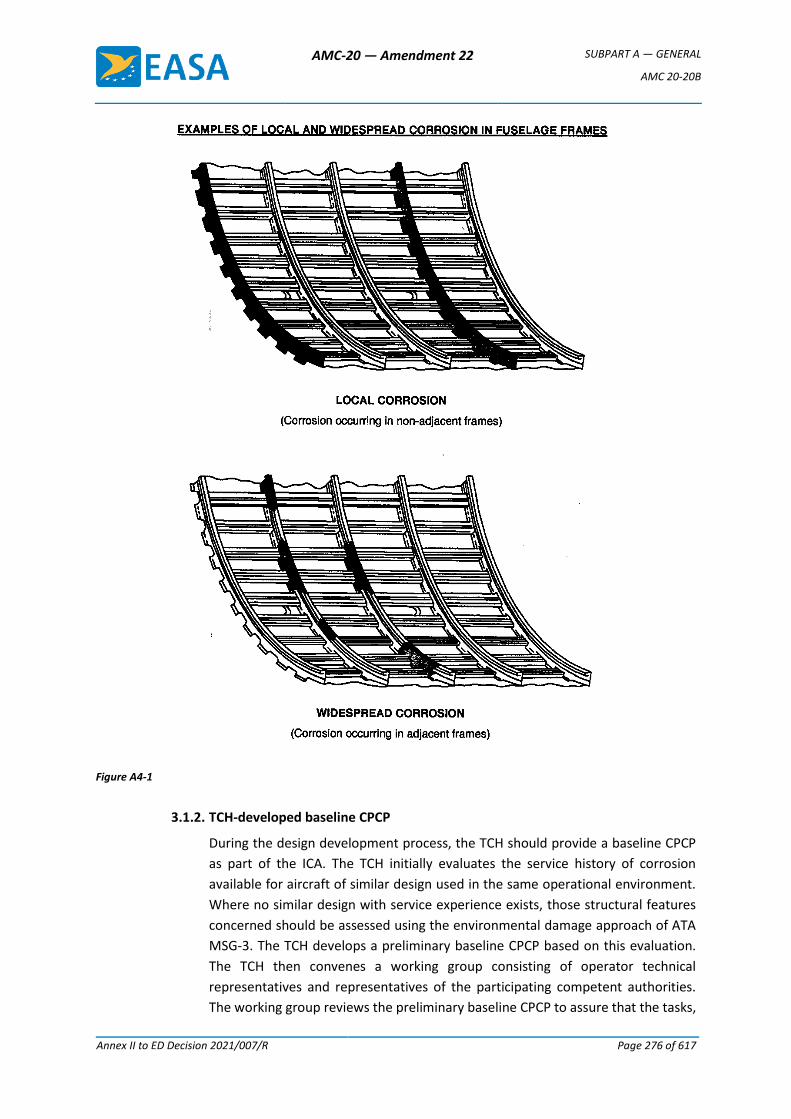
AMC-20 — Amendment 22 SUBPART A — GENERAL
AMC 20-20B
Annex II to ED Decision 2021/007/R Page 276 of 617
Figure A4-1
3.1.2. TCH-developed baseline CPCP
During the design development process, the TCH should provide a baseline CPCP
as part of the ICA. The TCH initially evaluates the service history of corrosion
available for aircraft of similar design used in the same operational environment.
Where no similar design with service experience exists, those structural features
concerned should be assessed using the environmental damage approach of ATA
MSG-3. The TCH develops a preliminary baseline CPCP based on this evaluation.
The TCH then convenes a working group consisting of operator technical
representatives and representatives of the participating competent authorities.
The working group reviews the preliminary baseline CPCP to assure that the tasks,
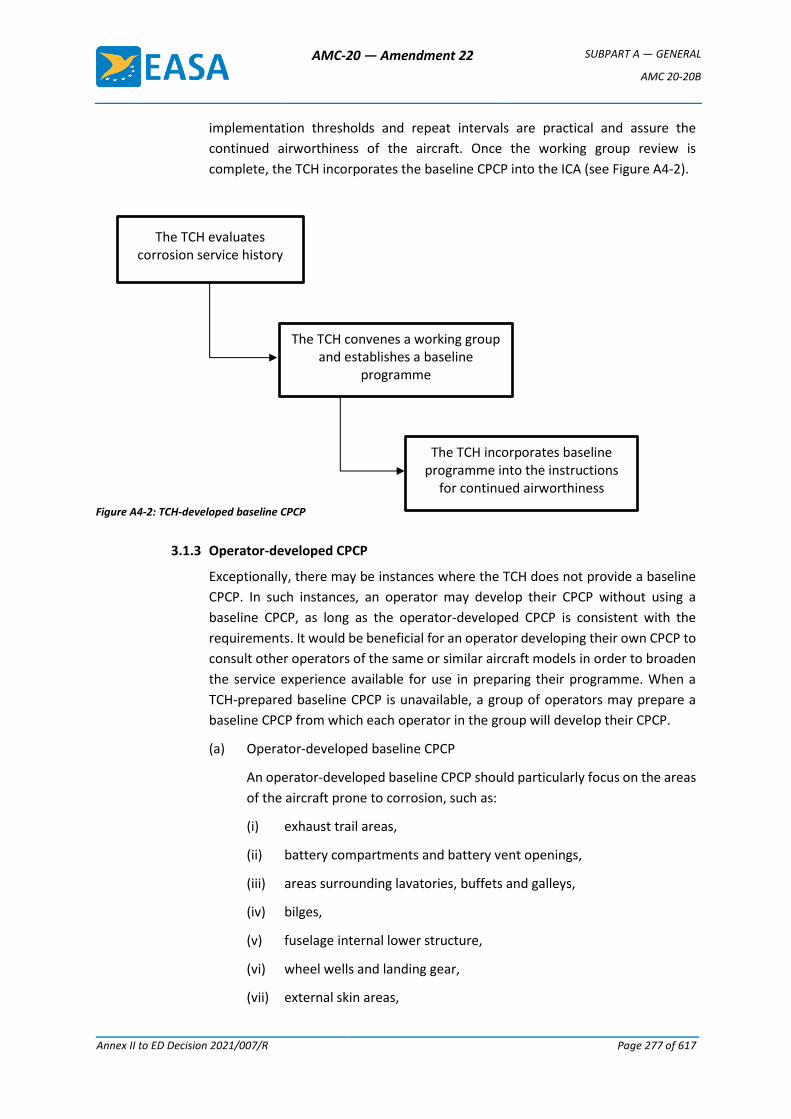
AMC-20 — Amendment 22 SUBPART A — GENERAL
AMC 20-20B
Annex II to ED Decision 2021/007/R Page 277 of 617
implementation thresholds and repeat intervals are practical and assure the
continued airworthiness of the aircraft. Once the working group review is
complete, the TCH incorporates the baseline CPCP into the ICA (see Figure A4-2).
Figure A4-2: TCH-developed baseline CPCP
3.1.3 Operator-developed CPCP
Exceptionally, there may be instances where the TCH does not provide a baseline
CPCP. In such instances, an operator may develop their CPCP without using a
baseline CPCP, as long as the operator-developed CPCP is consistent with the
requirements. It would be beneficial for an operator developing their own CPCP to
consult other operators of the same or similar aircraft models in order to broaden
the service experience available for use in preparing their programme. When a
TCH-prepared baseline CPCP is unavailable, a group of operators may prepare a
baseline CPCP from which each operator in the group will develop their CPCP.
(a) Operator-developed baseline CPCP
An operator-developed baseline CPCP should particularly focus on the areas
of the aircraft prone to corrosion, such as:
(i) exhaust trail areas,
(ii) battery compartments and battery vent openings,
(iii) areas surrounding lavatories, buffets and galleys,
(iv) bilges,
(v) fuselage internal lower structure,
(vi) wheel wells and landing gear,
(vii) external skin areas,
The TCH evaluates corrosion service history
The TCH convenes a working group and establishes a baseline
programme
The TCH incorporates baseline programme into the instructions
for continued airworthiness
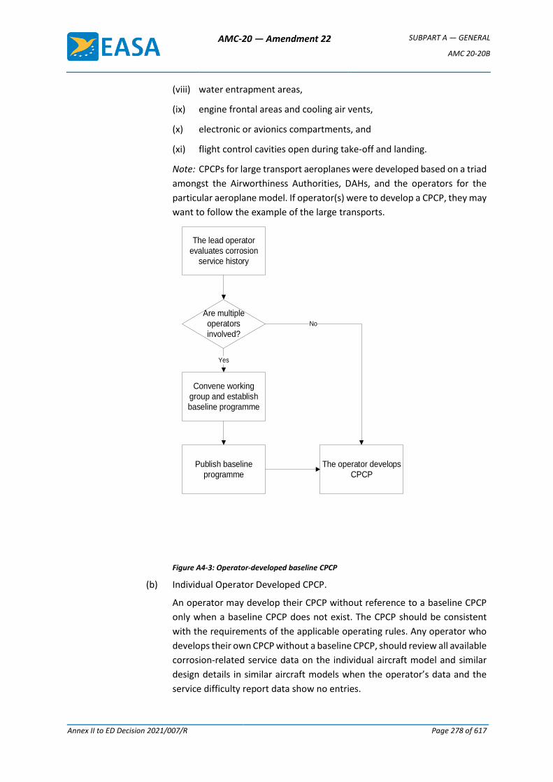
AMC-20 — Amendment 22 SUBPART A — GENERAL
AMC 20-20B
Annex II to ED Decision 2021/007/R Page 278 of 617
(viii) water entrapment areas,
(ix) engine frontal areas and cooling air vents,
(x) electronic or avionics compartments, and
(xi) flight control cavities open during take-off and landing.
Note: CPCPs for large transport aeroplanes were developed based on a triad
amongst the Airworthiness Authorities, DAHs, and the operators for the
particular aeroplane model. If operator(s) were to develop a CPCP, they may
want to follow the example of the large transports.
The lead operator
evaluates corrosion
service history
Convene working
group and establish
baseline programme
Publish baseline
programme
Are multiple
operators
involved?
Yes
The operator develops
CPCP
No
Figure A4-3: Operator-developed baseline CPCP
(b) Individual Operator Developed CPCP.
An operator may develop their CPCP without reference to a baseline CPCP
only when a baseline CPCP does not exist. The CPCP should be consistent
with the requirements of the applicable operating rules. Any operator who
develops their own CPCP without a baseline CPCP, should review all available
corrosion-related service data on the individual aircraft model and similar
design details in similar aircraft models when the operator’s data and the
service difficulty report data show no entries.
AMC-20 — Amendment 22 SUBPART A — GENERAL
AMC 20-20B
Annex II to ED Decision 2021/007/R Page 279 of 617
3.1.4. Continuous analysis and surveillance
The operator’s continuous analysis and surveillance system should contain
procedures to review corrosion inspection task findings and establish corrosion
levels. These procedures should provide criteria for determining if findings that
exceed allowable limits are an isolated incident not typical of the operator’s fleet.
The operator’s programme should also provide for notifying the competent
authority whenever a determination of Level 2 or Level 3 corrosion is made. Due
to the potential urgent airworthiness concern associated with a Level 3 finding, the
operator’s procedures should provide for notification as soon as possible but no
later than 3 calendar days after a Level 3 determination has been made.
3.2. Baseline CPCP documentation
The baseline CPCP documentation should include instructions to implement the baseline
CPCP. It may be in a printed form or other form acceptable to the competent authority.
It should also be in a form that is easy to revise. The date of the last revision should be
entered on each page. The baseline CPCP documentation should be clearly identified as
a baseline CPCP. The aircraft make, model and the person who prepared the
documentation should also be identified.
3.2.1. Purpose and background
This section of the documentation should state the purpose of the baseline CPCP,
which is to establish minimum requirements for preventing and controlling
corrosion that may jeopardise continuing airworthiness of the aircraft model fleet.
The section should further state that an operator should include an effective CPCP
in their maintenance or inspection programme.
3.2.2. Introduction
The introduction should include a general statement that corrosion becomes more
widespread as aircraft age and that it is more likely to occur in conjunction with
other damage such as fatigue cracking. The introduction should also indicate that
it is not the intent of a CPCP to establish rigid requirements to eliminate all
corrosion in the fleet, but to control corrosion at or below levels that do not
jeopardise continued airworthiness. However, due to the unpredictability of
corrosion, it must be removed and the structure repaired and corrosion prevention
treatment reapplied.
AMC-20 — Amendment 22 SUBPART A — GENERAL
AMC 20-20B
Annex II to ED Decision 2021/007/R Page 280 of 617
3.2.3. Programme application
For a programme to be fully effective, it is essential that a corrosion inspection task
be applied to all areas where corrosion may affect primary structure. This section
should recommend that priority for implementing the CPCP be given to older
aeroplanes and to areas requiring significant changes to previous maintenance
procedures in order to meet corrosion prevention and control requirements. This
section should allow an operator to continue their current corrosion control
procedures in a given task area or zone where there is documentation to show that
corrosion is being consistently controlled to Level 1.
3.2.4. Baseline CPCP
This section should fully describe the baseline CPCP. It should include the basic
task, corrosion inspection task areas, implementation thresholds, and repeat
intervals.
3.2.5. Reporting system
Procedures to report findings of Level 2 and Level 3 corrosion as necessary to the
TCH and the competent authority should be clearly established in this section. The
TCH should indicate any specific requirement they have for reporting on corrosion
levels that may be needed to revise the baseline CPCP. The information on Level 2
corrosion may be needed in a form acceptable to the competent authority
responsible for approval of any revision to the maintenance programme resulting
from a Level 2 finding. The timing of reporting should take into account the
processes for the periodic review (see 3.2.6). All Level 2 and Level 3 findings should
be reported in accordance with any applicable AD, operator’s service difficulty
reporting procedures or reporting required by other competent authorities.
Procedures for alerting the competent authority of Level 3 findings should be
established that expedite such reporting. This report to the competent authority
shall be made after the determination of the corrosion level.
3.2.6. Periodic review
This section should establish a period for the TCH (or lead operator) and
participating operators to meet with EASA and review the reported Level 2 and
Level 3 findings. The purpose of this review is to assess the baseline CPCP and make
adjustments if necessary. This may be accomplished through maintenance
programme reviews conducted via the Maintenance Programme Industry Steering
Committees (MRB Structures Working Group or equivalent meetings) for the
model.
3.2.7. Corrosion-related airworthiness directives
This section should include a list of all ADs that contain requirements related to
known corrosion-related problems. This section should state that these ADs are in
addition to and take precedence over the operator’s CPCP.
AMC-20 — Amendment 22 SUBPART A — GENERAL
AMC 20-20B
Annex II to ED Decision 2021/007/R Page 281 of 617
3.2.8. Development of the baseline CPCP
This section should identify the actions taken in preparing the baseline CPCP. It
should include a description of the participants, the documents (e.g. SBs, service
letters, ADs, service difficulty reports, accident and incident reports) reviewed, and
the methodology for selecting and categorising the corrosion-prone areas to be
included in the baseline CPCP. The selection criteria for corrosion-prone areas
should be based on areas having similar corrosion exposure characteristics and
inspection access requirements. Some corrosion-prone areas that should be
considered are the main wing box, the fuselage crown, the bilge, areas under
lavatories and galleys, etc. This section should state that the implementation
threshold was selected to represent the typical aircraft age beyond which an
effective corrosion inspection task should be implemented for a given task area.
3.2.9. Procedures for recording corrosion inspection findings
EASA has not imposed a requirement for additional record-keeping for an
operator’s CPCP. However, the operator should maintain adequate records to
substantiate any proposed programme adjustments. For example, an operator
should maintain records to enable the operator to determine the amount of
damage that has occurred during the repeat interval for each corrosion inspection
task. Such data should be maintained for multiple repeat intervals in order to
determine whether the damage remains constant or is increasing or decreasing.
Such records are necessary when an operator is seeking approval for interval
extension (escalation) or task reduction.
3.2.10. Glossary
This section should define all terms specifically used in the baseline CPCP
documentation.
3.2.11. Application of the basic task
This section should describe in detail the basic task. It should provide procedures
describing how to accomplish the following actions:
(a) Removal of all systems equipment and interior furnishings to allow access to
the area.
(b) Cleaning of the area as required.
(c) Visual inspection of all task areas and zones listed in the baseline CPCP.
(d) Removal of all corrosion, damage evaluation, and repair of structure as
necessary.
(e) Unblocking holes and gaps that may hinder drainage.
(f) Application of corrosion protective compounds.
(g) Reinstallation of dry insulation blankets, if applicable.
AMC-20 — Amendment 22 SUBPART A — GENERAL
AMC 20-20B
Annex II to ED Decision 2021/007/R Page 282 of 617
3.2.12. Determination of corrosion levels based on findings
This section should describe how the corrosion level definitions are used in
evaluating the corrosion findings and assigning a corrosion level. This section
should also instruct the operator to consult the DAH or the competent authority
for advice in determining corrosion levels.
3.2.13. Typical actions following determination of corrosion levels
This section should establish criteria for evaluating whether or not Level 2 or Level
3 corrosion is occurring on other aircraft in the operator’s fleet. Criteria to be
considered include: cause of the corrosion problem, past maintenance history,
operating environment, production build standard, years in service, and
inspectability of the corroded area. These and any other identified criteria should
be used in identifying those aircraft that should be included in a fleet campaign.
The results of the fleet campaign should be used to determine necessary
adjustments in the operator’s CPCP. The following instructions should also be
included in this section:
(a) If corrosion exceeding the allowable limit is found during accomplishment of
the corrosion inspection task implementation threshold for a task area, it
may be necessary to adjust the CPCP. (See ‘NOTE’ under ‘Level 2 corrosion’
definition)
(b) A single isolated occurrence of corrosion between successive inspections
that exceeds Level 1 does not necessarily warrant a change in the operator’s
CPCP. If the operator experiences multiple occurrences of Level 2 or Level 3
corrosion for a specific task area, then the operator should implement a
change to the CPCP.
(b) The operator should not defer maintenance actions for Level 2 and Level 3
corrosion. These maintenance actions should be accomplished in
accordance with the operator’s maintenance manual.
(c) The operator may implement changes such as the following to improve the
effectiveness of the programme:
(1) reduction of the repeat interval,
(2) multiple applications of corrosion treatments,
(3) additional drainage provisions,
(4) incorporation of DAHs service information, such as SBs and service
letters.
3.2.14. Programme implementation
This section should state that each task is to be implemented on each aircraft when
the aircraft reaches the age represented by the implementation threshold for the
task. It should also describe procedures to be used for establishing a schedule for
implementation where the aircraft age exceeds the implementation threshold for
AMC-20 — Amendment 22 SUBPART A — GENERAL
AMC 20-20B
Annex II to ED Decision 2021/007/R Page 283 of 617
individual tasks. Finally, it should state that once a task is implemented in an area,
subsequent tasks are to be accomplished at the repeat interval in that task area.
4. DEVELOPMENT OF OPERATORS PROGRAMME
4.1. Baseline CPCP available
If a baseline CPCP is available, the operator should use it as a basis for developing their
CPCP. In addition to adopting the basic task, task areas, implementation thresholds and
repeat intervals of the baseline CPCP, the operator should make provisions for:
(a) aeroplanes that have exceeded the implementation threshold for certain tasks,
(b) aeroplanes being removed from storage,
(c) unanticipated scheduling adjustments,
(d) corrosion findings made during non-CPCP inspections,
(e) adding newly acquired aircraft, and
(f) modifications, configuration changes, and operating environment.
4.1.1. Provisions for aircraft that have exceeded the implementation threshold
The operator’s CPCP must establish a schedule for accomplishing all corrosion
inspection tasks in task areas where the aircraft age has exceeded the
implementation threshold (see main text of AMC paragraph 12).
4.1.2. Aeroplanes being removed from storage
Corrosion inspection task intervals are established based on elapsed calendar time.
Elapsed calendar time includes time out of service. The operator’s CPCP should
provide procedures for establishing a schedule for accomplishment of corrosion
inspection tasks that have accrued during the storage period.
The schedule should result in accomplishment of all accrued corrosion inspection
tasks before the aircraft is placed in service.
4.1.3. Unanticipated scheduling adjustments
The operator’s CPCP should include provisions for adjustment of the repeat
interval for unanticipated schedule changes. Such provisions should not exceed
10 % of the repeat interval. The CPCP should include provisions for notifying the
competent authority when an unanticipated scheduling adjustment is made.
4.1.4. Corrosion findings made during non-CPCP inspections
Corrosion findings that exceed allowable limits may be found during any scheduled
or unscheduled maintenance or inspection activities. These findings may be
indicative of an ineffective CPCP. The operator should make provision in their CPCP
to evaluate these findings and adjust their CPCP accordingly.
4.1.5. Adding newly acquired aircraft
Before adding any aircraft to the fleet, the operator should establish a schedule for
accomplishing all corrosion inspection tasks in all task areas that are due. This
schedule should be established as follows:
AMC-20 — Amendment 22 SUBPART A — GENERAL
AMC 20-20B
Annex II to ED Decision 2021/007/R Page 284 of 617
(a) For aircraft that have previously operated under an approved maintenance
programme, the initial corrosion inspection task for the new operator must
be accomplished in accordance with the previous operator’s schedule or in
accordance with the new operator’s schedule, whichever would result in the
earliest accomplishment of the corrosion inspection task.
(b) For aircraft that have not previously been operated under an approved
maintenance programme, each initial corrosion task inspection must be
accomplished either before the aircraft is added to the operator’s fleet, or
in accordance with the schedule approved by the competent authority. After
each corrosion inspection task has been performed once, the subsequent
corrosion task inspections should be accomplished in accordance with the
new operator’s schedule.
4.1.6. Modifications, configuration changes and operating environment
The operator must ensure that their CPCP takes account of any modifications,
configurations changes and the operating environment applicable to them, that
were not addressed in the baseline CPCP documentation.
4.2. Baseline CPCP not available
If there is no baseline CPCP available for the operator to use in developing their CPCP, the
operator should develop their CPCP using the provisions listed in paragraph 3 of this
Appendix for a baseline CPCP as well as the provisions listed in subparagraphs 4.1.1
through 4.1.6 of this paragraph.
[Amdt 20/20] [Amdt 20/22]
AMC-20 — Amendment 22 SUBPART A — GENERAL
AMC 20-20B
Annex II to ED Decision 2021/007/R Page 285 of 617
Appendix 5 to AMC 20-20BA — Guidelines for ensuring the validity of continuing structural integrity programmes
1. GENERAL
Point 21.A.65 of Part 21 and point 26.305 of Part-26 require a process to be established that
ensures that the continuing structural integrity programme remains valid throughout the
operational life of the aircraft, considering in-service experience and current operations. The
intent is for the TCHs of large transport aeroplanes to review the validity of the certification
assumptions upon which the maintenance programme is based and to ensure that unsafe levels
of fatigue cracking or other damage will be minimised in service. This Appendix provides
guidance as to what the processes should include.
This Appendix also provides interpretation, guidelines and EASA accepted means of compliance
for the review of structural SBs including a procedure for selection, assessment and related
recommended corrective action for ageing aircraft structures.
2. CONTENT OF THE PROCESSES FOR COMPLIANCE WITH POINT 26.305 OF PART-26
AMC1 21.A.65 and CS 26.305 establish compliance on the basis of sub-paragraphs (a) to (g),
reproduced below, and consideration of the criteria of sub-paragraph (h):
(a) a process exists, and a report that describes the process and how it is implemented is
submitted to EASA; and
(b) the process is either continuous with each service finding or is a regular review following
a number of findings, or a combination of both; and
(c) the process includes a plan to audit and report to EASA the effectiveness of the continuing
structural integrity programme, including the continuing validity of the assumptions upon
which it is based, prior to reaching any significant point in the life of the aircraft; and
(d) the process includes criteria for summarising findings of fatigue environmental or
accidental damage and their causes and recording them in a way that allows any potential
interaction to be evaluated; and
(e) the process includes criteria to assess and record the relevance of each potential
contributing factor to the finding, including operational usage, fatigue load spectra,
environmental conditions, material properties, manufacturing processes and the fatigue
and damage tolerance analysis methodology and its implementation; and
(f) the process includes criteria for establishing and revising sampling programmes to
supplement the inspections and other procedures established in compliance with the
applicable fatigue and damage tolerance requirements; and
(g) the process includes criteria for establishing when structure should be modified or the
inspection programme revised in the light of in-service damage findings.
(h) Sunset criteria: The extent to which the above elements of the process require definition
may be tailored to the size of the fleet and its expected useful remaining life (e.g. if less
than 10 % of the fleet remains in operation worldwide at the date of applicability of point
AMC-20 — Amendment 22 SUBPART A — GENERAL
AMC 20-20B
Annex II to ED Decision 2021/007/R Page 286 of 617
26.305 and there is significant experience of aircraft reaching the maximum expected
operating life, then additional criteria beyond the existing processes may be agreed to be
unnecessary).
It should be noted that point 26.305 of Part-26 applies to all structure whose failure could
contribute to a catastrophic failure, and is not limited to metallic structures and fatigue cracking,
but should also encompass composite and hybrid structures.
The reporting of findings that could be relevant to the continuing structural integrity of the
aeroplane should be facilitated by providing clear instructions and easy-to-use reporting means
to operators that encourage and facilitate both their support and that of the customer support
staff in identifying developing risks.
The intent of the audit and the associated report is to provide the TCH and EASA with a series
of properly planned opportunities to assess the continuing structural integrity programme for
significant systemic shortcomings and take timely action in advance of potential unsafe
conditions. The audit should consider each of the parts of the continuing structural integrity
programme and any links between them or with programmes for other types. In the context of
this requirement, the audit should address all structures, not only metallic structures.
The audit report should summarise the processes and their evolutions. The report should
describe any measures taken in the audit that are beyond the basic processes established in
accordance with point 21.A.65 of Part 21 or as described in the original summary report
prepared in accordance with point 26.305 of Part-26 (e.g. additional field inspections or tear-
down inspections of fleet leading aircraft in terms of age and usage). The report should
summarise the status of each part of the continuing structural integrity programme, the findings
of the audit and proposals for the actions to be taken.
The audit should provide evidence that the processes required by point 21.A.65 of Part 21 and
point 26.305 of Part-26 have been properly implemented, such that:
— reported service findings have been recorded and summarised in a way that allows
causes, trends and actions to be reviewed;
— service findings are evaluated for consistency with the assumptions on which the
programme is based;
— the continuing structural integrity programme remains effective (e.g. changes have been
made to the programme in response to findings, and few emergency or short-term
airworthiness actions have been necessary);
— a comparison of the loading, operational usage, fatigue methodology, design tools, and
test evidence with that upon which the programme is based, shows that the programme
remains valid;
— causal analysis results have been reviewed and evaluated for evidence of repetitive
themes for which no specific action has been taken; and
— the fleet leader sampling programme has been implemented, and any findings resulting
from it have been properly dispositioned.
AMC-20 — Amendment 22 SUBPART A — GENERAL
AMC 20-20B
Annex II to ED Decision 2021/007/R Page 287 of 617
The audit report should record how any deviations from the applicable processes, identified
during the audit, have been or will be addressed.
Significant points in the aircraft life that should be considered in the audit plan include: points
at which a common threshold exist for multiple damage-tolerance-based inspections, half-DSG,
DSG, LOV, etc. In order to plan for a timely assessment that will allow proactive revision of the
maintenance programme, the audit should take place several years before reaching the
significant point.
Assumptions made at certification and subsequently regarding key operating variable
parameters such as weight, fuel, payload, mission length, etc., should be evaluated on a regular
basis or each time a finding indicates that the assumptions may be compromised, resulting in
an adverse effect on the fatigue analysis and inspection programme.
One way to ensure confidence in the maintenance programme is by establishing a fleet leader
sampling programme encompassing various operators and operations in different
environments. This may, for example, be developed in coordination with the MRB and requires
the cooperation of the leading operators. The sampling programme need not address all
potential damage locations, and should focus on the most critical that would provide early
indications of potentially erroneous assumptions. Sampling may also be beneficial where new
materials or methods of construction have been introduced, especially when the extent of
testing may have been limited at certification, e.g. for areas of hybrid structure where the
temperature differential was not part of the full-scale fatigue test. The sampling programme
may also impose more intrusive or detailed inspections and analyses of samples taken from the
structure (for composites or other materials subject to environmental degradation).
The details of the sampling programme requirements and the associated reporting
requirements should be established in coordination with the operators. The ICA, in compliance
with Appendix H to CS-25, may need to be supplemented with this information to support the
core compliance elements of the continuing structural integrity programme generated through
compliance with CS 25.571.
The process for establishing when a structure should be modified or the inspection programme
revised in the light of in-service damage findings should include special consideration of:
— damage detected and reported before the inspection threshold; and
— damage that is generally being found at or near to the critical crack size; and
— changing damage configurations for which the reasons are not fully understood; and
— new damage scenarios reported under existing inspection or repair procedures that could
otherwise be considered to be addressed, and overlooked.
The objectives of modifying structures are to provide a reasonably high probability that the
ultimate load capability will be retained over long periods of the aircraft’s life, and to
significantly reduce the potential for interaction with new cracking that may develop later in
the aircraft’s life.
AMC-20 — Amendment 22 SUBPART A — GENERAL
AMC 20-20B
Annex II to ED Decision 2021/007/R Page 288 of 617
The following guidance regarding the SB review process is retained from the original issue of
this AMC for general guidance on the subject, and the criteria for bulletin selection provide
useful additional factors for establishing when structures should be modified or the inspection
programme revised.
3. SB REVIEW PROCESS
SBs issued early in the life of an aircraft fleet may utilise inspections (in some cases
non-mandatory inspections) alone to maintain structural integrity. Inspections may be
adequate at this early stage, when cracking is possible, but not highly likely. However, as aircraft
age, the probability of fatigue cracking becomes more likely. During this later period, it is not
prudent to rely only on inspections alone because there are more opportunities for cracks to be
missed, and cracks may no longer occur in isolation. It is then prudent to reduce reliance strictly
on inspections, with their inherent human factors limitations, and to incorporate modifications
to the structure to eliminate the source of the cracking. In some cases, reliance on an inspection
programme, in lieu of modification, may be acceptable through the increased use of mandatory
versus non-mandatory inspections.
The TCH, in conjunction with the operators, is expected to initiate a review of all structurally
related inspection and modification SBs and determine which require further actions to ensure
continued airworthiness, including mandatory modification action or enforcement of special
repetitive inspections.
Any aircraft primary structural components that would require frequent repeat inspections, or
where the inspection is difficult to perform, taking into account the potential airworthiness
concern, should be reviewed to preclude the human factors issues associated with repetitive
inspections.
The SB review is an iterative process consisting of the following items:
(a) The TCH or the TCH in conjunction with the operators at a preliminary STG meeting
should review all the issued structural inspection and modification SBs to select candidate
bulletins, using the following four criteria:
(i) There is a high probability that structural cracking exists.
− Related to the number and type of finding in service and from fatigue testing.
− A ‘no finding’ result should be associated with the number of performed
inspections.
− The type of finding should include an analysis of its criticality.
(ii) Potential structural airworthiness concern.
− The structural airworthiness of the aircraft is dependent on repeat inspections to
verify its structural condition, and therefore on the reliability of the inspections.
− A short repeat inspection interval (e.g. a short time for a crack to grow from a
detectable crack to a critical length divided by a factor) will lead to increased
workloads for inspectors and a possible increased risk of them missing damage.
AMC-20 — Amendment 22 SUBPART A — GENERAL
AMC 20-20B
Annex II to ED Decision 2021/007/R Page 289 of 617
− Special attention should be paid to any single inspection tasks involving multiple
repeat actions needed to verify the structural condition that may increase the risk
of the inspectors missing damage (e.g. lap splice inspections).
(iii) Damage is difficult to detect during routine maintenance (i.e. there are few
additional opportunities for detection beyond the specific requirement of the SB).
(Of particular concern is damage that is found when it is well-developed and closer
to being critical, rather than damage which is in the early stages with several
further opportunities available for detection before it becomes critical.)
The areas to be inspected are difficult to access.
NDI methods are proving unsuitable.
The human factors associated with the inspection technique are so adverse that
the detection of cracks may not be sufficiently dependable to assure safety.
(iv) There is adjacent structural damage or the potential for it.
Particular attention should be paid to areas susceptible to WFD and also to
potential interaction between corrosion and fatigue cracking, e.g. between
fastener damage (due to stress corrosion or other factors) and fatigue cracking.
It is recommended to consider the potential interaction of modifications or repairs
usually implemented in the areas concerned to check whether the inspections are
still reliable or not (operator’s input).
(b) The TCH and operator members will be requested to submit information on their
individual fleet experience related to candidate SBs. This information will be collected
and evaluated by the TCH. The summarised results will then be reviewed in detail at an
STG meeting (see point (c) below).
(c) The final selection of SBs for recommendation of the appropriate corrective action to
assure structural continued airworthiness, taking into account the in-service experience,
will be made during an STG meeting by the voting members of the STG, either by
consensus or majority vote, depending on the preference of the individual STGs.
(d) An assessment will be made by the TCH as to whether or not any subsequent revisions to
SBs affect the decisions previously made. Any subsequent revisions to the SBs previously
chosen by the STG for mandatory inspection or incorporation of modification action that
would affect the previous STG recommended action should be submitted to the STG for
review.
(e) The TCH should review all new structural SBs periodically to select further candidate
bulletins. The TCH should schedule a meeting of the STG to address the candidates.
Operator members and the competent authority will be advised of the selected
candidates and provided with the opportunity to submit additional candidates.
The SB selection, review, assessment and recommendation process within the Structural Task
Group (STG) is summarised in Figure A5-1. For the first SB review within an STG meeting, all the
AMC-20 — Amendment 22 SUBPART A — GENERAL
AMC 20-20B
Annex II to ED Decision 2021/007/R Page 290 of 617
inspection SBs should be selected. Moreover, some specific modification SBs not linked to an
inspection SB may also be selected for review.
The information input by operators should address the points as detailed in Figure A5-2. This
information should be collected and analysed by the TCH for the STG meeting.
If, for a given selected SB, there is not sufficient in-service data available before the STG meeting
that would enable a recommendation to be made, its review may be deferred until enough data
is available. The TCH should then check periodically until the data becomes available.
The operators and EASA should be advised by the TCH of the SB selection list and be given the
opportunity to submit additional SBs. For this purpose, the TCH should give the operators
enough information in advance (e.g. 2 months) for them to be able to properly consider the
proposed selection and to gather data.
When an SB is selected, it is recommended to also select, in the same package, inspection SBs
that interact with it and all the related modification SBs. The main criteria for selecting SBs are
defined in the following subparagraphs.
4. STG MEETING, SB REVIEW AND RECOMMENDATIONS
It is recommended to review at the same time all SBs that can interact, the so-called SB package,
in the selection process. The meeting should start with an STG agreement on the selected SB
list and on those deferred. At the meeting the TCH should present their analysis of each SB
utilising the collection of operator input data. The STG should then collectively review the
ratings (Figure A5-2) against each criterion to reach a consensus recommendation. Such an STG
recommendation for a selected SB shall consider the following options:
(a) to mandate a structural modification at a given threshold,
(b) to mandate the selected inspection SB,
(c) to revise the modification or repair actions,
(d) to revise other SB(s) in the same area concerned by damages,
(e) to review the inspection method and related inspection intervals,
(f) to review ALI/MRBR or other maintenance instructions,
(g) to defer the review to the next STG and request operators’ reports on findings for a
specific SB or request an inspection sampling on the oldest aircraft.
STG recommendations for mandatory action are the responsibility of the TCH to forward to
EASA for appropriate action. Other STG recommendations is information provided to the STG
members. It is their own responsibility to carry them out within the appropriate framework.
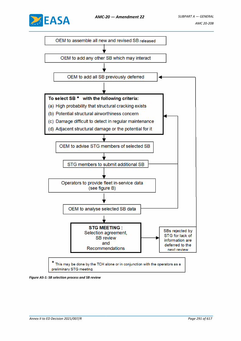
AMC-20 — Amendment 22 SUBPART A — GENERAL
AMC 20-20B
Annex II to ED Decision 2021/007/R Page 291 of 617
Figure A5-1: SB selection process and SB review
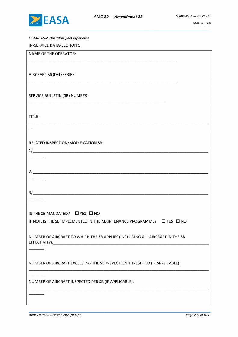
AMC-20 — Amendment 22 SUBPART A — GENERAL
AMC 20-20B
Annex II to ED Decision 2021/007/R Page 292 of 617
FIGURE A5-2: Operators fleet experience
IN-SERVICE DATA/SECTION 1
NAME OF THE OPERATOR: ____________________________________________________________________
AIRCRAFT MODEL/SERIES: ____________________________________________________________________
SERVICE BULLETIN (SB) NUMBER: ______________________________________________________________
TITLE: ____________________________________________________________________________________
RELATED INSPECTION/MODIFICATION SB:
1/_______________________________________________________________________________________
2/_______________________________________________________________________________________
3/_______________________________________________________________________________________
IS THE SB MANDATED? YES NO
IF NOT, IS THE SB IMPLEMENTED IN THE MAINTENANCE PROGRAMME? YES NO
NUMBER OF AIRCRAFT TO WHICH THE SB APPLIES (INCLUDING ALL AIRCRAFT IN THE SB EFFECTIVITY):______________________________________________________________________________
NUMBER OF AIRCRAFT EXCEEDING THE SB INSPECTION THRESHOLD (IF APPLICABLE): _________________________________________________________________________________________
NUMBER OF AIRCRAFT INSPECTED PER SB (IF APPLICABLE)? _________________________________________________________________________________________
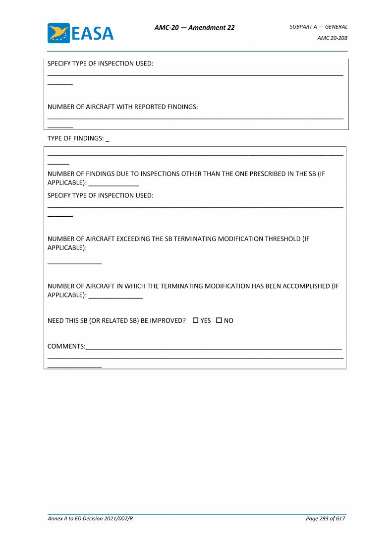
AMC-20 — Amendment 22 SUBPART A — GENERAL
AMC 20-20B
Annex II to ED Decision 2021/007/R Page 293 of 617
SPECIFY TYPE OF INSPECTION USED: _________________________________________________________________________________________
NUMBER OF AIRCRAFT WITH REPORTED FINDINGS: _________________________________________________________________________________________
TYPE OF FINDINGS: _
________________________________________________________________________________________
NUMBER OF FINDINGS DUE TO INSPECTIONS OTHER THAN THE ONE PRESCRIBED IN THE SB (IF APPLICABLE): ______________
SPECIFY TYPE OF INSPECTION USED: _________________________________________________________________________________________
NUMBER OF AIRCRAFT EXCEEDING THE SB TERMINATING MODIFICATION THRESHOLD (IF APPLICABLE):
_______________
NUMBER OF AIRCRAFT IN WHICH THE TERMINATING MODIFICATION HAS BEEN ACCOMPLISHED (IF APPLICABLE): _______________
NEED THIS SB (OR RELATED SB) BE IMPROVED? YES NO
COMMENTS:________________________________________________________________________________________________________________________________________________________________________
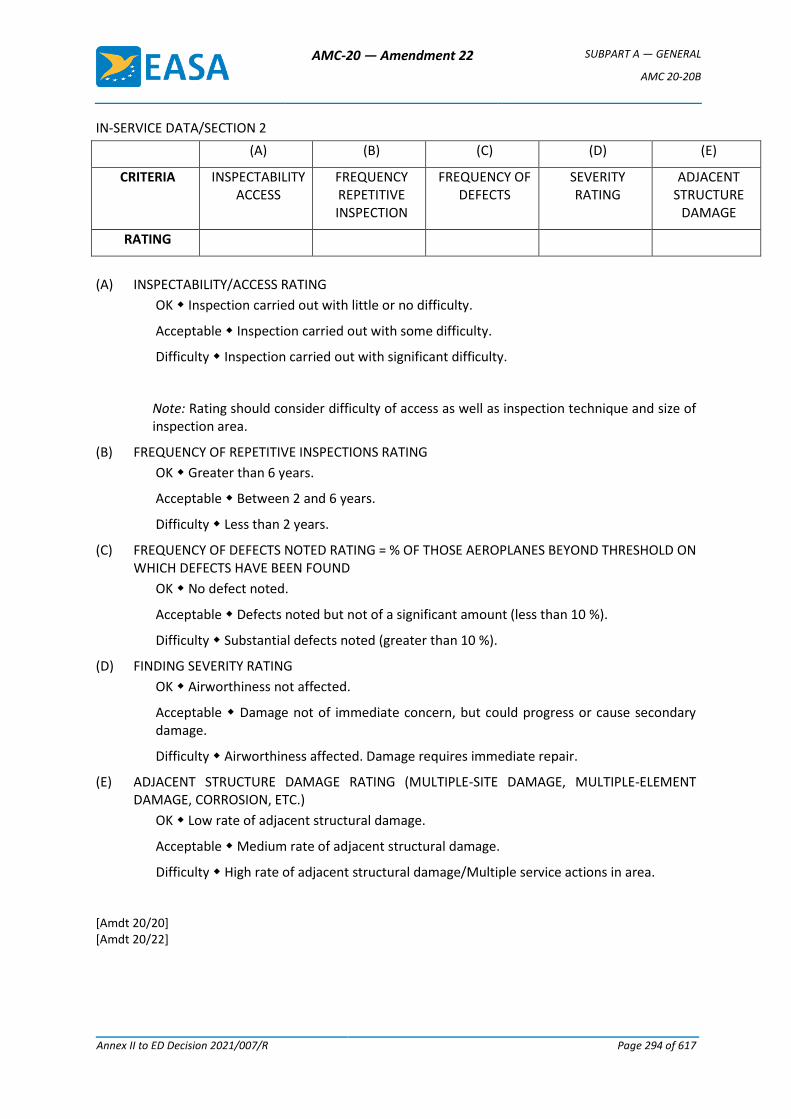
AMC-20 — Amendment 22 SUBPART A — GENERAL
AMC 20-20B
Annex II to ED Decision 2021/007/R Page 294 of 617
IN-SERVICE DATA/SECTION 2
(A) (B) (C) (D) (E)
CRITERIA INSPECTABILITY ACCESS
FREQUENCY REPETITIVE INSPECTION
FREQUENCY OF DEFECTS
SEVERITY RATING
ADJACENT STRUCTURE
DAMAGE
RATING
(A) INSPECTABILITY/ACCESS RATING
OK Inspection carried out with little or no difficulty.
Acceptable Inspection carried out with some difficulty.
Difficulty Inspection carried out with significant difficulty.
Note: Rating should consider difficulty of access as well as inspection technique and size of inspection area.
(B) FREQUENCY OF REPETITIVE INSPECTIONS RATING
OK Greater than 6 years.
Acceptable Between 2 and 6 years.
Difficulty Less than 2 years.
(C) FREQUENCY OF DEFECTS NOTED RATING = % OF THOSE AEROPLANES BEYOND THRESHOLD ON WHICH DEFECTS HAVE BEEN FOUND
OK No defect noted.
Acceptable Defects noted but not of a significant amount (less than 10 %).
Difficulty Substantial defects noted (greater than 10 %).
(D) FINDING SEVERITY RATING
OK Airworthiness not affected.
Acceptable Damage not of immediate concern, but could progress or cause secondary damage.
Difficulty Airworthiness affected. Damage requires immediate repair.
(E) ADJACENT STRUCTURE DAMAGE RATING (MULTIPLE-SITE DAMAGE, MULTIPLE-ELEMENT DAMAGE, CORROSION, ETC.)
OK Low rate of adjacent structural damage.
Acceptable Medium rate of adjacent structural damage.
Difficulty High rate of adjacent structural damage/Multiple service actions in area.
[Amdt 20/20] [Amdt 20/22]
AMC-20 — Amendment 22 SUBPART A — GENERAL
AMC 20-21
Annex II to ED Decision 2021/007/R Page 295 of 617
AMC 20-21
AMC 20-21 Programme to enhance aeroplane Electrical Wiring Interconnection System (EWIS) maintenance
1 PURPOSE
This AMC provides acceptable means of compliance for developing enhanced EWIS maintenance for operators, holders of type certificates (TC), holders of supplemental type certificates (STC) and maintenance organisations. The information in this AMC is derived from the maintenance, inspection, and alteration best practices identified through extensive research. This AMC provides an acceptable means of compliance with the appropriate certification, maintenance and operating rules. This AMC promotes a housekeeping philosophy of “protect, clean as you go” when performing maintenance, repair, or alterations on or around aircraft EWIS.
2 OBJECTIVE
The objective of this AMC is to enhance the maintenance of aircraft EWIS through adoption by the aviation industry of the following:
a. Enhanced Zonal Analysis Procedure (EZAP). This AMC presents an “enhanced zonal analysis procedure” and logic that will benefit all aircraft regardless of whether they currently have a structured Zonal Inspection Programme (ZIP), (see Appendix A. Enhanced Zonal Analysis Logic Diagram and Steps and Appendix B. EZAP Worksheets). Application of this procedure will ensure that appropriate attention is given to wiring installations. Using EZAP it will be possible to select stand-alone inspections (either general or detailed) and tasks to minimise the presence of combustible material. The procedure and logic in this AMC complement existing zonal analysis procedures and will also allow the identification of new wiring tasks for those aircraft that do not have a structured ZIP.
b. Guidance for General Visual Inspection (GVI). This AMC provides clarification of the definition for a GVI as well as guidance on what is expected from such an inspection, whether performed as a stand-alone GVI or as part of a zonal inspection. It is assumed this new inspection standard will be the standard applied by operators, or their maintenance provider, when the new tasks are incorporated in to their maintenance programme.
c. Protection and Caution. This AMC identifies protection and caution to be added to maintenance instructions, thereby enhancing procedures that will lead to minimisation of contamination and accidental damage while working on the aircraft.
The enhanced aircraft wiring maintenance information described in this AMC is intended to improve maintenance and inspection programmes for all aircraft systems. This information, when used appropriately, will improve the likelihood that wiring system degradation, including age-related problems, will be identified and corrected. Therefore, the goal of enhanced wiring maintenance information is to ensure that maintenance actions, such as inspection, repair, overhaul, replacement of parts, and preservation, do not cause a loss of wiring system function, do not cause an increase in the potential for smoke and fire in the aircraft, and do not inhibit the safe operation of the aircraft.
AMC-20 — Amendment 22 SUBPART A — GENERAL
AMC 20-21
Annex II to ED Decision 2021/007/R Page 296 of 617
In order to fully realise the objectives of this AMC, operators, TC holders, STC holders and maintenance providers, will need to rethink their current approach to maintaining and modifying aircraft wiring and systems. This may require more than simply updating maintenance manuals and work cards and enhancing training. Maintenance personnel need to be aware that aircraft EWIS should be maintained with the same level of intensity as any other system in the aircraft. They also need to recognise that visual inspection of wiring has inherent limitations. Small defects such as breached or cracked insulations, especially in small gauge wire may not always be apparent. Therefore effective wiring maintenance combines visual inspection techniques with improved wiring maintenance practices and training.
Good wiring maintenance practices should contain a "protect, clean as you go" housekeeping philosophy. In other words, care should be taken to protect wire bundles and connectors during work, and to ensure that all shavings, debris and contamination are cleaned up after work is completed. This philosophy is a proactive approach to wiring system health. Wiring needs to be given special attention when maintenance is being performed on it, or around it. This is especially true when performing structural repairs, work under STCs or field approvals, or other modifications.
To fully achieve the objectives of this AMC it is imperative that all personnel performing maintenance on or around EWIS receive appropriate training (see AMC 20-22: Aeroplane EWIS training programme).
3 APPLICABILITY
a. The guidance provided in this document is directed to operators, TC applicants and holders, STC applicants and maintenance organisations:
b. The guidance provided in this AMC can be applied to all aeroplane maintenance or inspection programmes. The EZAP in Appendix A of this AMC is specifically directed towards enhancing the maintenance programmes for aircraft whose current programme does not include tasks derived from a process that specifically considers wiring in all zones as the potential source of ignition of a fire.
c. This AMC, when followed in its entirety, outlines an acceptable means of compliance to the requirement for the development of enhanced scheduled maintenance tasks for the EWIS for the aircraft mentioned in 3a. above.
d. Similarly, it also provides an acceptable means of compliance for CS 25.1739 and 25.1529 Appendix H25.5 for new designs.
4 RELATED DOCUMENTS
— Regulation (EC) No 216/20081
— Regulation (EC) No 1702/20032
1 Regulation (EC) No 216/2008 of the European Parliament and of the Council of 20 February 2008 on common rules in the field of civil
aviation and establishing a European Aviation Safety Agency, and repealing Council Directive 91/670/EEC, Regulation (EC) No 1592/2002 and Directive 2004/36/EC (OJ L 79, 19.3.2008, p.1).
2 Commission Regulation (EC) No 1702/2003 of 24 September 2003 laying down implementing rules for the airworthiness and environmental certification of aircraft and related products, parts and appliances, as well as for the certification of design and production organisations (OJ L 243, 27.9.2003, p. 6). Regulation as last amended by Regulation (EC) No 287/2008 (OJ L 87, 29.3.2008, p.3).
AMC-20 — Amendment 22 SUBPART A — GENERAL
AMC 20-21
Annex II to ED Decision 2021/007/R Page 297 of 617
— Regulation (EC) No 2042/20031
— EASA Certification Specification CS-25 Large Aeroplanes2
— EU-OPS Commercial Air Transportation (Aeroplanes)3
5 RELATED READING MATERIAL
a. EASA AMC 20
— AMC 20-22 Aeroplane EWIS training
— AMC 20-23 Development of electrical standard wiring practices documentation
b. FAA Advisory Circulars (AC).
— AC 25-16 Electrical Fault and Fire Protection and Prevention
— AC 25.981-1B Fuel Tank Ignition Source Prevention Guidelines
— AC 43-12A Preventive Maintenance
— AC 43.13-1B Acceptable Methods, Techniques and Practices for Repairs and Alterations to Aircraft
— AC 43-204 Visual Inspection For Aircraft
— AC 43-206 Avionics Cleaning and Corrosion Prevention/Control
— AC 65-15A Airframe and Powerplant Mechanics Airframe Handbook, Chapter 11, Aircraft Electrical Systems
— AC 120-YYY Training modules for wiring maintenance
c. Reports
— Transport Aircraft Intrusive Inspection Project, (An Analysis of the Wire Installations of Six Decommissioned Aircraft), Final Report, The Intrusive Inspection Working Group, December 29, 2000. http://www.mitrecaasd.org/atsrac/intrusive_inspection.html
— FAA Aging Transport Non-Structural Systems Plan, July 1998.
— National Transportation Safety Board, Safety Recommendation, September 19, 2000, A-00-105 through -108. http://www.ntsb.gov/recs/letters/2000/A00_105_108.pdf
— Wire System Safety Interagency Working Group, National Science and Technology Council, Review of Federal Programmes for Wire System Safety 46 (2000).
— Aging Transport Systems Rulemaking Advisory Committee, Task 1 and 2, Aging Systems, Final Report.
1 Commission Regulation (EC) No 2042/2003 of 20 November 2003 on the continuing airworthiness of aircraft and aeronautical products,
parts and appliances, and on the approval of organisations and personnel involved in these tasks (OJ L 315, 28.11.2003, p. 1). Regulation as last amended by Regulation (EC) No 376/2007 of (OJ L 94, 4.4.2007, p. 18).
2 Executive Director Decision No 2003/2/RM of 14 October 2003 on certification specifications, including airworthiness codes and acceptable means of compliance, for large aeroplanes («CS-25»). Decision as last amended by Executive Director Decision No 2008/006/R of 29 August 2008 (CS-25 Amendment 5).
3 Council Regulation (EEC) No 3922/91 of 16 December 1991 on the harmonisation of technical requirements and administrative procedures in the field of civil aviation (OJ L 373, 31.12.1991, p. 4). Regulation as last amended by Regulation (EC) No 8/2008 of 11 December 2007 (OJ L 10, 12.1.2008, p. 1).
AMC-20 — Amendment 22 SUBPART A — GENERAL
AMC 20-21
Annex II to ED Decision 2021/007/R Page 298 of 617
http://www.mitrecaasd.org/atsrac/final_reports/Task_1&2_Final%20_August_2000.pdf
— Aging Transport Systems Rulemaking Advisory Committee, Task 3, Final Report. http://www.mitrecaasd.org/atsrac/final_reports/Task_3_Final.pdf
— Aging Transport Systems Rulemaking Advisory Committee, Task 4, Final Report, Standard Wiring Practices. http://www.mitrecaasd.org/atsrac/final_reports/Task_4_Final_Report_Sept_2000.pdf
— Aging Transport Systems Rulemaking Advisory Committee, Task 5, Final Report, Aircraft Wiring Systems Training Curriculum and Lesson Plans. http://www.mitrecaasd.org/atsrac/final_reports/Task_5_Final_March_2001%20.pdf
— ATA Specification 117 (Wiring Maintenance Practices/Guidelines).
d. Other Documents
— Operator/Manufacturer Scheduled Maintenance Development, ATA Maintenance Steering Group (MSG-3). May be obtained from the Air Transport Association of America; Suite 1100, 1301 Pennsylvania Ave, NW, Washington, DC 20004-1707.
6 DEFINITIONS
Arc tracking: A phenomenon in which a conductive carbon path is formed across an insulating surface. This carbon path provides a short circuit path through which current can flow. Normally a result of electrical arcing. Also referred to as "Carbon Arc Tracking," "Wet Arc Tracking," or "Dry Arc Tracking."
Combustible: For the purposes of this AMC the term combustible refers to the ability of any solid, liquid or gaseous material to cause a fire to be sustained after removal of the ignition source. The term is used in place of inflammable/flammable. It should not be interpreted as identifying material that will burn when subjected to a continuous source of heat as occurs when a fire develops.
Contamination: For the purposes of this AMC, wiring contamination refers to either of the following:
— The presence of a foreign material that is likely to cause degradation of wiring;
— The presence of a foreign material that is capable of sustaining combustion after removal of ignition source.
Detailed Inspection (DET): An intensive examination of a specific item, installation or assembly to detect damage, failure or irregularity. Available lighting is normally supplemented with a direct source of good lighting at an intensity deemed appropriate. Inspection aids such as mirrors, magnifying lenses or other means may be necessary. Surface cleaning and elaborate access procedures may be required.
Electrical Wiring Interconnection System (EWIS): See CS 25.1701.
Functional Failure: Failure of an item to perform its intended function within specified limits.
General Visual Inspection (GVI): A visual examination of an interior or exterior area, installation or assembly to detect obvious damage, failure or irregularity. This level of inspection is made from within touching distance unless otherwise specified. A mirror may be necessary to enhance visual access to all exposed surfaces in the inspection area. This level of inspection is
AMC-20 — Amendment 22 SUBPART A — GENERAL
AMC 20-21
Annex II to ED Decision 2021/007/R Page 299 of 617
made under normally available lighting conditions such as daylight, hangar lighting, flashlight or droplight and may require removal or opening of access panels or doors. Stands, ladders or platforms may be required to gain proximity to the area being checked.
Lightning/High Intensity Radiated Field (L/HIRF) protection: The protection of aeroplane electrical systems and structure from induced voltages or currents by means of shielded wires, raceways, bonding jumpers, connectors, composite fairings with conductive mesh, static dischargers, and the inherent conductivity of the structure; may include aircraft specific devices, e.g., RF Gaskets.
Maintenance: As defined in Regulation (EC) No 2042/2003 Article 2(h) “maintenance means inspection, overhaul, repair, preservation, and the replacement of parts, but excludes preventive maintenance.” For the purposes of this advisory material, it also includes preventive maintenance.
Maintenance Significant Item (MSI): Items identified by the manufacturer whose failure could result in one or more of the following:
— could affect safety (on ground or in flight);
— is undetectable during operations;
— could have significant operational impact;
— could have significant economic impact.
Needling: The puncturing of a wire’s insulation to make contact with the core to test the continuity and presence of voltage in the wire segment.
Stand-alone GVI: A GVI which is not performed as part of a zonal inspection. Even in cases where the interval coincides with the zonal inspection, the stand-alone GVI shall remain an independent step within the work card.
Structural Significant Item (SSI): Any detail, element or assembly that contributes significantly to carrying flight, ground, pressure or control loads and whose failure could affect the structural integrity necessary for the safety of the aircraft.
Swarf: A term used to describe the metal particles, generated from drilling and machining operations. Such particles may accumulate on and between wires within a wire bundle.
Zonal Inspection: A collective term comprising selected GVI and visual checks that are applied to each zone, defined by access and area, to check system and powerplant installations and structure for security and general condition.
7 BACKGROUND
Over the years there have been a number of in-flight smoke and fire events where contamination sustained and caused the fire to spread. Regulators and Accident Investigators have conducted aircraft inspections and found wiring contaminated with items such as dust, dirt, metal shavings, lavatory waste water, coffee, soft drinks, and napkins. In some cases dust has been found completely covering wire bundles and the surrounding area.
Research has also demonstrated that wiring can be harmed by collateral damage when maintenance is being performed on other aircraft systems. For example a person performing an inspection of an electrical power centre or avionics compartment may inadvertently cause damage to wiring in an adjacent area.
In recent years regulator and industry groups have come to the realisation that current maintenance practices may not be adequate to address aging non-structural systems. While age
AMC-20 — Amendment 22 SUBPART A — GENERAL
AMC 20-21
Annex II to ED Decision 2021/007/R Page 300 of 617
is not the sole cause of wire degradation, the probability that inadequate maintenance, contamination, improper repair or mechanical damage has caused degradation to a particular EWIS increases over time. Studies by industry and regulator working groups have found that although EWIS management is an important safety issue, there has been a tendency to be complacent about EWIS. These working groups have concluded that there is a need to better manage EWIS so that they continue to function safely.
8 WIRE DEGRADATION
Normal maintenance actions, even using acceptable methods, techniques and practices, can over time be a contributing factor to wire degradation. Zones that are subject to a high level of maintenance activity display more deterioration of the wiring insulation than those areas not subject to frequent maintenance. Degradation of wiring is further accelerated when inappropriate maintenance practices are used. Examples include the practice of needling wires to test the continuity or voltage, and using a metal wire or rod as a guide to feed new wires into an existing bundle. These practices could cause a breach in the wiring insulation that can contribute to arcing.
Over time, insulation can crack or breach, thereby exposing the conductor. This breakdown, coupled with maintenance actions, can exacerbate EWIS malfunction. Wiring that is undisturbed will have less degradation than wiring that is disturbed during maintenance.
For additional information on the principle causes of wire degradation see Appendix E.
9 INSPECTION OF EWIS
Typical analytical methods used for the development of maintenance programmes have not provided a focus on wiring. As a result most operators have not adequately addressed deterioration of EWIS in their programmes. EASA has reviewed the current inspection philosophies with the objectives of identifying improvements that could lead to a more consistent application of the inspection requirements, whether they are zonal, stand-alone GVI, or DET inspections.
EASA believes that it would be beneficial to provide guidance on the type of deterioration that a person performing a GVI, DET, or zonal inspection would be expected to discover. Though it may be realistically assumed that all operators provide such guidance to their inspectors, it is evident that significant variations exist and, in certain areas of the world, a significant enhancement of the inspection could be obtained if internationally agreed guidance material could be produced. The guidance provided by this AMC assumes each operator will adopt recent improvements made to the definitions of GVI and DET inspections. This information should be incorporated in operators’ training material and in the introductory section of maintenance planning documentation.
This section is divided into three parts. The first part addresses the levels of inspection applicable to EWIS, the second part provides guidance for performing zonal inspections, and the third part provides lists of installations and areas of concern.
a. Levels of inspection applicable to EWIS
(1) Detailed Inspection (DET)
An intensive examination of a specific item, installation or assembly to detect damage, failure or irregularity. Available lighting is normally supplemented with a direct source of good lighting at an intensity deemed appropriate. Inspection aids such as mirrors, magnifying lenses or other means may be necessary. Surface cleaning and elaborate access procedures may be required.
AMC-20 — Amendment 22 SUBPART A — GENERAL
AMC 20-21
Annex II to ED Decision 2021/007/R Page 301 of 617
A DET can be more than just a visual inspection since it may include tactile assessment in which a component or assembly is checked for tightness/security. This is of particular significance when identifying applicable and effective tasks to ensure the continued integrity of installations such as bonding jumpers, terminal connectors, etc.
Though the term Detailed Visual Inspection remains valid for DET using only eyesight, it should be recognised that this may represent only part of the inspection called for in the source documents used to establish an operator’s Maintenance Programme. For this reason it is recommend that the acronym “DVI” not be used since it excludes tactile examination from this level of inspection.
(2) General Visual Inspection (GVI).
A visual examination of an interior or exterior area, installation or assembly to detect obvious damage, failure or irregularity. This level of inspection is made from within touching distance unless otherwise specified. A mirror may be necessary to enhance visual access to all exposed surfaces in the inspection area. This level of inspection is made under normally available lighting conditions such as daylight, hangar lighting, flashlight or droplight and may require removal or opening of access panels or doors. Stands, ladders or platforms may be required to gain proximity to the area being checked.
Recent changes to this definition have added proximity guidance (within touching distance) and the allowance to use a mirror to enhance visual access to exposed surfaces when performing a GVI. These changes should result in more consistent application of GVI and support the expectations of what types of EWIS discrepancies should be detected by a GVI.
Though flashlights and mirrors may be required to provide an adequate view of all exposed surfaces, there is no requirement for equipment removal or displacement unless this is specifically called for in the access instructions. Paint and/or sealant removal is not necessary and should be avoided unless the observed condition is suspect. Should unsatisfactory conditions be suspected, items may need to be removed or displaced in order to permit proper assessment.
It is expected that the area to be inspected is clean enough to minimise the possibility that accumulated dirt or grease might hide unsatisfactory conditions that would otherwise be obvious. Any cleaning that is considered necessary should be performed in accordance with accepted procedures in order to minimise the possibility of the cleaning process itself introducing anomalies.
In general, the person performing a GVI is expected to identify degradation due to wear, vibration, moisture, contamination, excessive heat, aging, etc., and make an assessment as to what actions are appropriate to address the noted discrepancy. In making this assessment, any potential effect on adjacent system installations should be considered, particularly if these include wiring. Observations of discrepancies, such as chafing, broken clamps, sagging, interference, contamination, etc., need to be addressed.
(3) Zonal Inspection
A collective term comprising selected GVI and visual checks that are applied to each zone, defined by access and area, to check system and powerplant installations and structure for security and general condition.
AMC-20 — Amendment 22 SUBPART A — GENERAL
AMC 20-21
Annex II to ED Decision 2021/007/R Page 302 of 617
A zonal inspection is essentially a GVI of an area or zone to detect obvious unsatisfactory conditions and discrepancies. Unlike a stand-alone GVI, it is not directed to any specified component or assembly.
b. Guidance for zonal inspections
The following EWIS degradation items are typical of what should be detectable and subsequently addressed as a result of a zonal inspection (as well as a result of a stand-alone GVI). It is also recommended that these items be included in maintenance and training documentation. This list is not intended to be exhaustive and may be expanded as considered appropriate.
(1) Wire/Wire Harnesses
— Wire bundle/wire bundle or wire bundle/structure contact/chafing
— Wire bundle sagging or improperly secured
— Wires damaged (obvious damage due to mechanical impact, overheat, localised chafing, etc.)
— Lacing tape and/or ties missing/incorrectly installed
— Wiring protection sheath/conduit deformity or incorrectly installed
— End of sheath rubbing on end attachment device
— Grommet missing or damaged
— Dust and lint accumulation
— Surface contamination by metal shavings/swarf
— Contamination by liquids
— Deterioration of previous repairs (e.g., splices)
— Deterioration of production splices
— Inappropriate repairs (e.g., incorrect splice)
— Inappropriate attachments to or separation from fluid lines
(2) Connectors
— External corrosion on receptacles
— Backshell tail broken
— Rubber pad or packing on backshell missing
— No backshell wire securing device
— Foolproofing chain broken
— Missing or broken safety wire
— Discoloration/evidence of overheat on terminal lugs/blocks
— Torque stripe misalignment
(3) Switches
— Rear protection cap damaged
(4) Ground points

AMC-20 — Amendment 22 SUBPART A — GENERAL
AMC 20-21
Annex II to ED Decision 2021/007/R Page 303 of 617
— Corrosion
(5) Bonding braid/bonding jumper
— Braid broken or disconnected
— Multiple strands corroded
— Multiple strands broken
(6) Wiring clamps or brackets
— Corroded
— Broken/missing
— Bent or twisted
— Faulty attachment (bad attachment or fastener missing)
— Unstuck/detached
— Protection/cushion damaged
(7) Supports (rails or tubes/conduit)
— Broken
— Deformed
— Fastener missing
— Missing edge protection on rims of feed through holes
— Racetrack cushion damaged
— Obstructed drainage holes (in conduits)
(8) Circuit breakers, contactors or relays
— Signs of overheating
— Signs of arcing
c. Wiring installations and areas of concern
Research has shown that the following installations and areas need to be addressed in existing maintenance material.
(1) Wiring installations
Clamping points – Wire chafing is aggravated by damaged clamps, clamp cushion migration, or improper clamp installations. Aircraft manufacturers specify clamp type and part number for EWIS throughout the aircraft. When replacing clamps use those specified by the aircraft manufacturer. Tie wraps provide a rapid method of clamping especially during line maintenance operations. Improperly installed tie wraps can have a detrimental effect on wire insulation. When new wiring is installed as part of a STC or any other modification the drawings will provide wiring routing, clamp type and size, and proper location. Examples of significant wiring modifications are the installation of new avionics systems, new galley installations and new instrumentation. Wire routing, type of clamp and clamping location should conform to the approved drawings. Adding new wire to existing wire bundles may overload the clamps causing wire bundle to sag and wires to chafe.
AMC-20 — Amendment 22 SUBPART A — GENERAL
AMC 20-21
Annex II to ED Decision 2021/007/R Page 304 of 617
Raceway clamp foam cushions may deteriorate with age, fall apart, and consequently would not provide proper clamping.
Connectors – Worn environmental seals, loose connectors, missing seal plugs, missing dummy contacts, or lack of strain relief on connector grommets can compromise connector integrity and allow contamination to enter the connector, leading to corrosion or grommet degradation. Connector pin corrosion can cause overheating, arcing and pin-to-pin shorting. Drip loops should be maintained when connectors are below the level of the harness and tight bends at connectors should be avoided or corrected.
Terminations – Terminations, such as terminal lugs and terminal blocks, are susceptible to mechanical damage, corrosion, heat damage and contamination from chemicals, dust and dirt. High current-carrying feeder cable terminal lugs can over time lose their original torque value due to vibration. One sign of this is heat discoloration at the terminal end. Proper build-up and nut torque is especially critical on high current carrying feeder cable lugs. Corrosion on terminal lugs and blocks can cause high resistance and overheating. Dust, dirt and other debris are combustible and therefore could sustain a fire if ignited from an overheated or arcing terminal lug. Terminal blocks and terminal strips located in equipment power centres (EPC), avionics compartments and throughout the aircraft need to be kept clean and free of any combustibles.
Backshells – Wires may break at backshells, due to excessive flexing, lack of strain relief, or improper build-up. Loss of backshell bonding may also occur due to these and other factors.
Sleeving and Conduits – Damage to sleeving and conduits, if not corrected, may lead to wire damage. Therefore, damage such as cuts, dents and creases on conduits may require further investigation for condition of wiring within.
Grounding Points – Grounding points should be checked for security (i.e., finger tightness), condition of the termination, cleanliness, and corrosion. Any grounding points that are corroded or have lost their protective coating should be repaired.
Splices – Both sealed and non-sealed splices are susceptible to vibration, mechanical damage, corrosion, heat damage, chemical contamination, and environmental deterioration. Power feeder cables normally carry high current levels and are very susceptible to installation error and splice degradation. All splices should conform to the TC or STC holder’s published recommendations. In the absence of published recommendations, environmental splices are recommended to be used.
(2) Areas of concern
Wire Raceways and Bundles – Adding wires to existing wire raceways may cause undue wear and chafing of the wire installation and inability to maintain the wire in the raceway. Adding wire to existing bundles may cause wire to sag against the structure, which can cause chafing.
Wings – The wing leading and trailing edges are areas that experience difficult environments for wiring installations. The wing leading and trailing edge wiring is exposed on some aircraft models whenever the flaps or slats are extended. Other potential damage sources include slat torque shafts and bleed air ducts.

AMC-20 — Amendment 22 SUBPART A — GENERAL
AMC 20-21
Annex II to ED Decision 2021/007/R Page 305 of 617
Engine, Pylon, and Nacelle Area – These areas experience high vibration, heat, frequent maintenance, and are susceptible to chemical contamination.
Accessory compartment and equipment bays – These areas typically contain items such as electrical components, pneumatic components and ducting, hydraulic components and plumbing, and may be susceptible to vibration, heat, and liquid contamination.
Auxiliary Power Unit (APU) – Like the engine/nacelle area, the APU is susceptible to high vibration, heat, frequent maintenance, and chemical contamination.
Landing Gear and Wheel Wells – This area is exposed to severe external environmental conditions in addition to vibration and chemical contamination.
Electrical Panels and Line Replaceable Units (LRU) – Panel wiring is particularly prone to broken wires and damaged insulation when these high density areas are disturbed during troubleshooting activities, major modifications, and refurbishments. Wire damage may be minimised by tying wiring to wooden dowels to reduce wire disturbance during modification. There may be some configurations where connector support brackets would be more desirable and cause less disturbance of the wiring than removal of individual connectors from the supports.
Batteries – Wires in the vicinity of all aircraft batteries are susceptible to corrosion and discoloration. These wires should be inspected for corrosion and discoloration. Discoloured wires should be inspected for serviceability.
Power Feeders – High current wiring and associated connections have the potential to generate intense heat. Power feeder cables, terminals, and splices may be subject to degradation or loosening due to vibration. If any signs of overheating are seen, splices or termination should be replaced. Depending on design, service experience may highlight a need to periodically check for proper torque of power feeder cable terminal ends, especially in high vibration areas. This applies to galley and engine/APU generator power feeders.
Under Galleys, Lavatories, and Cockpit – Areas under the galleys, lavatories, and cockpit, are particularly susceptible to contamination from coffee, food, water, soft drinks, lavatory fluids, dust, lint, etc. This contamination can be minimised by adherence to proper floor panel sealing procedures in these areas.
Fluid Drain plumbing – Leaks from fluid drain plumbing may lead to liquid contamination of wiring. In addition to routine visual inspections, service experience may highlight a need for periodic leak checks or cleaning.
Fuselage Drain provisions – Some installations include features designed to catch leakage that is plumbed to an appropriate exit. Blockage of the drain path can result in liquid contamination of wiring. In addition to routine visual inspections, service experience may highlight that these installations and associated plumbing should be periodically checked to ensure the drain path is free of obstructions.
Cargo Bay/Underfloor – Damage to wiring in the cargo bay underfloor can occur due to maintenance activities in the area.
Wiring subject to movement – Wiring that is subject to movement or bending during normal operation or maintenance access should be inspected at locations such as doors, actuators, landing gear mechanisms, and electrical access panels.
AMC-20 — Amendment 22 SUBPART A — GENERAL
AMC 20-21
Annex II to ED Decision 2021/007/R Page 306 of 617
Access Panels – Wiring near access panels may receive accidental damage as a result of repetitive maintenance access and thus may warrant special attention.
Under Doors – Areas under cargo, passenger and service entry doors are susceptible to fluid ingress from rain, snow and liquid spills. Fluid drain provisions and floor panel sealing should be periodically inspected and repaired as necessary.
Under Cockpit Sliding Windows – Areas under cockpit sliding windows are susceptible to water ingress from rain and snow. Fluid drain provisions should be periodically inspected and repaired as necessary.
Areas where wiring is difficult to access – Areas where wiring is difficult to access (e.g., flight deck instrument panels, cockpit pedestal area) may accumulate excessive dust and other contaminants as a result of infrequent cleaning. In these areas it may be necessary to remove components and disassemble other systems to facilitate access to the area.
10 ENHANCED ZONAL ANALYSIS PROCEDURE (EZAP)
The EZAP identified in Appendix A of this AMC is designed to permit appropriate attention to be given to electrical wiring installations. This is achieved by providing a means to identify applicable and effective tasks to minimise accumulation of combustible materials and address wiring installation discrepancies that may not otherwise be reliably detected by inspections contained in existing maintenance programmes.
For aircraft models operating on maintenance programmes that already include a dedicated ZIP, the logic described in this AMC will result in enhancements to those programmes, and the zonal inspection requirements may not differ greatly from the existing ZIP.
In analysis conducted under the EZAP, items such as plumbing, ducting, systems installations, etc., should be evaluated for possible contribution to wiring failures. In cases where a GVI is required to assess degradation of these items, a zonal GVI within a ZIP may be considered appropriate.
For those operators that do not have a dedicated ZIP, application of the logic is likely to result in identification of a large number of wiring-related tasks that will need to be consolidated within the existing Systems/Powerplant Programme.
In either case, any new tasks identified by the logic may be compared with existing tasks and credit given for equivalent tasks already contained in the maintenance programme. For operators with ZIP that already contain zonal GVI, the number of new tasks that must be added to the programme may be significantly fewer than for an operator without a dedicated ZIP. Therefore, operators without a ZIP may find it beneficial to develop a ZIP in accordance with an industry-accepted methodology in conjunction with application of the EZAP.
The logic and procedures identified in this AMC apply to TC, STC and other modifications. It is expected that the TC and STC holders would use the logic and procedures to identify any need for additional instructions for continued airworthiness. However, the operator may be required to ensure the logic is used to identify such instructions for modifications or STC where they are no longer supported by the design organisation or STC holder.
11 MAINTENANCE PRACTICES: PROTECTION AND CAUTION RECOMMENDATIONS
EASA has identified some specific maintenance and servicing tasks for which more robust practices are recommended to be adopted by operators, and/or maintenance providers. These recommendations apply to all tasks, including those performed on an unscheduled basis without an accompanying routine job instruction card. Performance of these maintenance
AMC-20 — Amendment 22 SUBPART A — GENERAL
AMC 20-21
Annex II to ED Decision 2021/007/R Page 307 of 617
practices will help prevent contamination of EWIS that result from contact with harmful solids (such as metal shavings) or fluids during maintenance, modifications, and repairs of aeroplane structures, and components. In addition, the training of maintenance and servicing personnel should address the potential consequences of their actions on the wiring in the work vicinity.
a. Item 1: Installation, repair, or modification to wiring.
Wiring and its associated components (protective coverings, connectors, clamping provisions, conduits, etc.) often comprise the most delicate and maintenance-sensitive portions of an installation or system. Extreme care should be exercised and proper procedures used during installation, repair, or modification of wiring to ensure safe and reliable performance of the function supplied by the wiring.
Proper wire selection, routing/separation, clamping configurations, use of splices, repair or replacement of protective coverings, pinning/de-pinning of connections, etc., should be performed in accordance with the applicable sections of the Aircraft Maintenance Manual (AMM), Wiring Practices Manual (WPM), or other documents authorised for maintenance use. In addition, special care should be taken to minimise disturbance of existing adjacent wiring during all maintenance activities. When wiring is displaced during a maintenance activity, special attention should be given to returning it to its normal configuration in accordance with the applicable maintenance instructions.
b. Item 2: Structural repairs, STC, modifications.
Structural repair, STC or modification activity inherently introduces tooling and residual debris that is harmful to aircraft wiring. Structural repairs or modifications often require displacement (or removal) of wiring to provide access to the work area. Even minor displacement of wiring, especially while clamped, can damage wire insulation, which can result in degraded performance, arcing, or circuit failure.
Extreme care should be exercised to protect wiring from mechanical damage by tools or other equipment used during structural repairs, STC or modifications. Drilling blindly into the aircraft structure should be avoided. Damage to wire installation could cause wire arcing, fire and smoke. Wiring located adjacent to drilling or riveting operations should be carefully displaced or covered to reduce the possibility of mechanical damage.
Debris such as drill shavings, liberated fastener pieces, broken drill bits, etc., should not be allowed to contaminate or penetrate wiring or electrical components. This can cause severe damage to insulation and potential arcing by providing a conductive path to ground or between two or more wires of different loads. Once contaminated, removal of this type of debris from wire bundles is extremely difficult. Therefore, precautions should be taken to prevent contamination of any kind from entering the wire bundle.
Before initiating structural repair, STC or modification activity, the work area should be carefully surveyed to identify all wiring and electrical components that may be subject to contamination. All wiring and electrical components in the debris field should be covered or removed to prevent contamination or damage. Consideration should be given to using drills equipped with vacuum aspiration to further minimise risk of metallic debris contaminating wire bundles. Clean electrical components and wiring after completion of work per applicable maintenance instructions.
c. Item 3: Aircraft De-Icing or Anti-Icing.
In order to prevent damage to exposed electrical components and wiring in areas such as wing leading and trailing edges, wheelwells, and landing gear, care should be exercised
AMC-20 — Amendment 22 SUBPART A — GENERAL
AMC 20-21
Annex II to ED Decision 2021/007/R Page 308 of 617
when spraying de/anti-icing fluids. Direct pressure spray onto electrical components and wiring can lead to contamination or degradation and thus should be avoided.
d. Item 4: Inclement weather.
EWIS in areas below doorways, floors, access panels, and servicing bays are prone to corrosion or contamination due to their exposure to the elements. Snow, slush, or excessive moisture should be removed from these areas before closing doors or panels. Remove deposits of snow/slush from any items (e.g. cargo containers) before loading in the aircraft. During inclement weather, keep doors/panels closed as much as possible to prevent ingress of snow, slush, or excessive moisture that could increase potential for EWIS degradation.
e. Item 5: Component removal/installation (relating to attached wiring).
Excessive handling and movement during removal and installation of components may be harmful to aircraft wiring. Use appropriate connector pliers (e.g. soft jawed) to loosen coupling rings that are too tight to be loosened by hand. Alternately, pull on the plug body and unscrew the coupling ring until the connector is separated. Do not use excessive force, and do not pull on attached wires. When reconnecting, special care should be taken to ensure the connector body is fully seated, the jam nut is fully secured, and no tension is on the wires.
When equipment is disconnected, use protective caps on all connectors (plug or receptacle) to prevent contamination or damage of the contacts. Sleeves or plastic bags may be used if protective caps are not available. Use of sleeves or plastic bags should be temporary because of the risk of condensation. It is recommended to use a humidity absorber with sleeves or plastic bags.
f. Item 6: Pressure Washing.
In order to prevent damage to exposed electrical components and wiring in areas such as wing leading and trailing edges, wheelwells, and landing gear, care should be exercised when spraying water or cleaning fluids. Direct high-pressure spraying onto electrical components and wiring can lead to contamination or degradation and should be avoided. When practical, wiring and connectors should be protected before pressure washing. Water rinse should be used to remove cleaning solution residue after washing. Breakdown of wire insulation may occur with long term exposure of wiring to cleaning solutions. Although these recommendations are good practice and technique, the aeroplane maintenance manual or STC holder’s instructions should be consulted for additional detailed instructions regarding pressure washing.
g. Item 7: Cleaning of EWIS (in situ).
Extreme care should be exercised and proper procedures used during cleaning to ensure safe and reliable performance of the function supplied by the wiring.
Care should be taken to avoid displacement or disturbance of wiring during cleaning of non-aggressive contamination. However, in the event of contamination by aggressive contaminants (e.g. livestock waste, salt water, battery electrolyte, etc.) such displacement may be necessary. In these cases wiring should be released from its installation so as to avoid undue stress being induced in wiring or connectors. Similarly, if liquid contamination enters the bundle, then ties should be removed before separating the wires. Although these recommendations for cleaning of EWIS are considered good practice and technique, the aeroplane maintenance manual or STC holder’s instructions should be consulted for additional detailed instructions.
AMC-20 — Amendment 22 SUBPART A — GENERAL
AMC 20-21
Annex II to ED Decision 2021/007/R Page 309 of 617
Clean only the area and items that have contamination. Before cleaning, make sure that the cleaning materials and methods will not cause more contamination. If a cloth is used, make sure that it is clean, dry, and lint-free. A connector should be completely dry before mating. Any fluids remaining on a connector can have a deteriorating affect on the connector or the system or both.
h. Item 8: Servicing, modifying, or repairing waste/water systems.
EWIS in areas adjacent to waste/water systems are prone to contamination from those systems. Care should be exercised to prevent any fluids from reaching electrical components and wiring while servicing, modifying, or repairing waste/water systems. Cover exposed electrical components and wiring during waste/water system modification or repair. Operator practice may call for a weak acid solution to be periodically flushed through lavatory systems to enhance reliability and efficiency of operation. In view of the effect of acid contamination on systems and structure, the system should be confirmed to be free of leaks before using such solutions.
i. Item 9: Servicing, modifying, or repairing oil systems.
Electrical wiring interconnections in areas adjacent to oil systems are prone to contamination from those systems. To minimise the attraction and adhesion of foreign material, care should be exercised to avoid any fluids from reaching electrical components and wiring while servicing, modifying, or repairing oil systems. Oil and debris in combination with damaged wiring can present a fire hazard.
j. Item 10: Servicing, modifying, or repairing hydraulic systems.
EWIS in areas adjacent to hydraulic systems are prone to contamination from those systems. To minimise the attraction and adhesion of foreign material, care should be exercised to avoid any fluids from reaching electrical components and wiring while servicing, modifying, or repairing hydraulic systems.
k. Item 11: Gaining access (entering zones).
When entering or working on the aircraft, care should be exercised to prevent damage to adjacent or hidden electrical components and wiring, including wiring that may be hidden from view (e.g., covered by insulation blankets). Use protective boards or platforms for adequate support and protection. Avoid using wire bundles as handholds, steps and supports. Work lights should not be hung or supported by wiring. If wiring must be displaced (or removed) for work area access, it should be adequately released from its clamping (or other restraining provisions) to allow movement without damage and returned after work is completed.
l. Item 12: Application of Corrosion Preventions Compounds (CPC).
When applying CPC in aeroplane zones containing wire and associated components (i.e. clamps, connectors and ties), care should be taken to prevent CPC from coming in contact with the wire and components. Dust and lint is more likely to collect on wire that has CPC on it. Application of CPC should be done in accordance with the aircraft manufacturer’s recommendations.
12 CHANGES
The programme to enhance EWIS maintenance also applies to EWIS installed, modified, or affected by changes or STC. Changes that could affect EWIS include, but are not limited to, those that install new equipment in close proximity to wiring, introduce a heat source in the zone, or introduce potential sources of combustible material or harmful contamination into the zone.
AMC-20 — Amendment 22 SUBPART A — GENERAL
AMC 20-21
Annex II to ED Decision 2021/007/R Page 310 of 617
The owner/operator is responsible for determining if the EWIS has been changed (or affected by a change) and ensuring that their maintenance programme is enhanced as appropriate.
[Amdt 20/4]
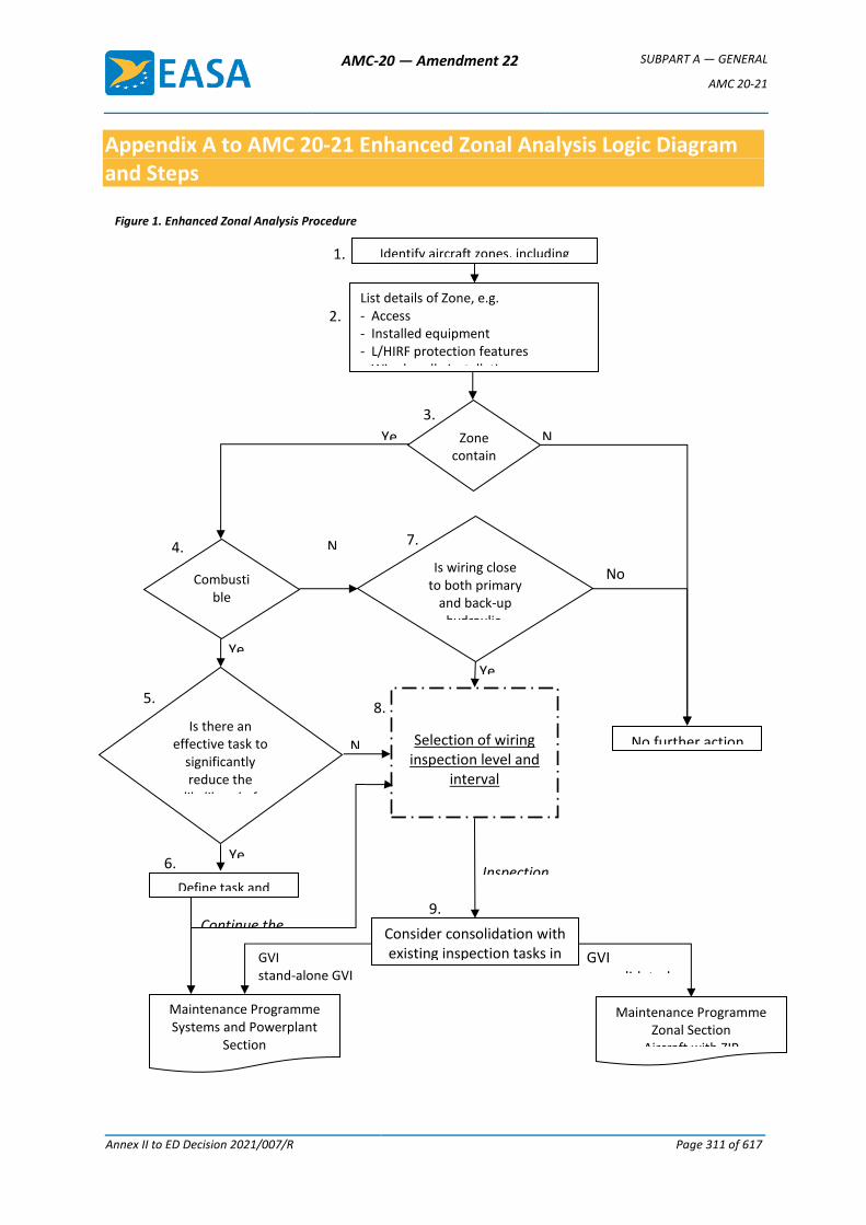
AMC-20 — Amendment 22 SUBPART A — GENERAL
AMC 20-21
Annex II to ED Decision 2021/007/R Page 311 of 617
Appendix A to AMC 20-21 Enhanced Zonal Analysis Logic Diagram and Steps
Figure 1. Enhanced Zonal Analysis Procedure
Identify aircraft zones, including boundaries
List details of Zone, e.g. - Access - Installed equipment - L/HIRF protection features - Wire bundle installation - Possible combustible materials
Zone contain
s wiring?
Combustible
materials in zone?
Is wiring close to both primary
and back-up hydraulic,
mechanical, or electrical flight
controls?
Is there an effective task to
significantly reduce the
likelihood of accumulation of
combustible materials?
Define task and interval
Maintenance Programme Systems and Powerplant
Section
Recommend inclusion in ATA 20
Maintenance Programme Zonal Section
Aircraft with ZIP
Selection of wiring inspection level and
interval
See Figure 2.
Inspection Task(s)
Yes
Yes
Yes
Yes
No
No
No
No
GVI stand-alone GVI DET
Consider consolidation with existing inspection tasks in
Systems & Powerplant and/or Zonal Programmes
1.
2.
3.
4.
5.
6.
7.
8.
9.
GVI consolidated in zonal inspection
No further action
Continue the analysis
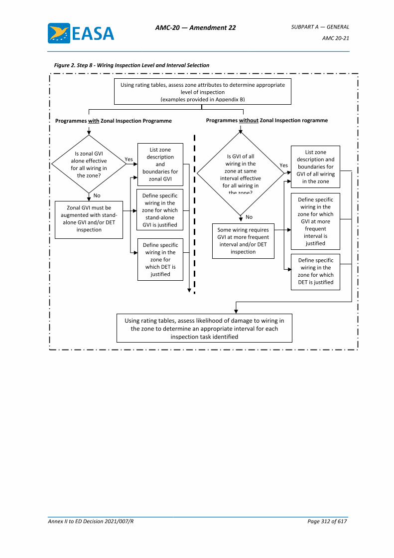
AMC-20 — Amendment 22 SUBPART A — GENERAL
AMC 20-21
Annex II to ED Decision 2021/007/R Page 312 of 617
List zone description and boundaries for
GVI of all wiring in the zone
List zone description
and boundaries for
zonal GVI
Zonal GVI must be augmented with stand-alone GVI and/or DET
inspection Some wiring requires GVI at more frequent interval and/or DET
inspection
Using rating tables, assess zone attributes to determine appropriate level of inspection
(examples provided in Appendix B)
Define specific wiring in the
zone for which GVI at more
frequent interval is justified
Define specific wiring in the
zone for which DET is justified
Define specific wiring in the
zone for which stand-alone
GVI is justified
Define specific wiring in the
zone for which DET is
justified
Using rating tables, assess likelihood of damage to wiring in the zone to determine an appropriate interval for each
inspection task identified
Programmes with Zonal Inspection Programme Programmes without Zonal Inspection rogramme
Figure 2. Step 8 - Wiring Inspection Level and Interval Selection
Yes
No
No
Yes
Is zonal GVI alone effective for all wiring in
the zone?
Is GVI of all wiring in the zone at same
interval effective for all wiring in
the zone?
AMC-20 — Amendment 22 SUBPART A — GENERAL
AMC 20-21
Annex II to ED Decision 2021/007/R Page 313 of 617
Explanation for Steps in Enhanced Zonal Analyses Procedure Logic Diagram
The following paragraphs provide further explanation of each step in the Enhanced Zonal Analyses Procedure logic, (Figures 1 and 2). It is recommended that, where possible, the analysts utilise the availability of actual aircraft to ensure they fully understand the zones being analysed. This will aid in determination of density, size, environmental issues, and accidental damage issues.
Step 1 “Identify aircraft zones, including boundaries”
The system consists of Major Zones, Major Sub Zones and Zones.
The zones, wherever possible, shall be defined by actual physical boundaries such as wing spars, major bulkheads, cabin floor, control surface boundaries, skin, etc. and include access provisions for each zone.
If the type design holder or operator has not yet established aircraft zones, it is recommended that it does so. Whenever possible, zones should be defined using a consistent method such as ATA iSpec 2200 (formerly ATA Spec 100), varied only to accommodate particular design constructional differences.
Step 2 “List of details of zone”
An evaluation will be carried out to identify system installations, significant components, L/HIRF protection features, typical power levels in any installed wiring bundles, combustible materials (present or possible accumulation), etc.
With respect to power levels the analyst should be aware whether the bundle consists primarily of main generator feeder cables, low voltage instrumentation wiring or standard bus wiring. This information will later be used in determining the potential effects of deterioration.
The reference to combustible materials highlights the need to assess whether the zone might contain material/vapour that could cause a fire to be sustained in the event of an ignition source arising in adjacent wiring. Examples include the possible presence of fuel vapours, dust/lint accumulation and contaminated insulation blankets. See also under Step 4 for further information.
For aircraft types whose design directives may not have excluded the possibility of inadequate segregation between systems, the analyst should identify locations where both primary and back-up flight controls are routed within 2 inches/50 mm of a wiring harness. This information is required to answer the question in Step 7.
Step 3 “Zone contains wiring?”
This question serves as a means to eliminate from the EZAP those zones that do not contain any wiring.
Step 4 “Combustible materials in zone?”
This question requires an evaluation of whether the zone might contain combustible material that could cause a fire to be sustained in the event of an ignition source arising in adjacent wiring. Examples include the possible presence of fuel vapours, dust/lint accumulation, and contaminated insulation blankets.
With respect to commonly used liquids (e.g., oils, hydraulic fluids, corrosion prevention compounds) the analyst should refer to the product specification in order to assess the potential for combustibility. The product may be readily combustible only in vapour/mist
AMC-20 — Amendment 22 SUBPART A — GENERAL
AMC 20-21
Annex II to ED Decision 2021/007/R Page 314 of 617
form and thus an assessment is required to determine if conditions might exist in the zone for the product to be in this state.
Although liquid contamination of wiring by most synthetic oil and hydraulic fluids (e.g. skydrol) may not be considered combustible, it is a cause for concern if it occurs in a zone where it causes significant adherence of dust and lint.
The analyst should assess what sources of combustible products may contaminate the zone following any single failure considered likely from in-service experience. Unshrouded pipes having connections within the zone should be considered as potential contamination sources. Inherent ventilation in the zone should be taken into account when determining the potential for subsequent combustion. This influences the response to the question of how near to the harness the source should be for there to be a concern.
Avionics and instruments located in the flight compartment and equipment bays tend to attract dust, etc. In view of the heat generated by these components and the relatively tightly packed installations, the analyst should consider these zones as having potential for combustible material. Thus, the enhanced logic should always be used for these zones.
Note: Although moisture (whether clean water or otherwise) is not combustible, its presence on wiring is a cause for concern because it may increase the probability of arcing from small breaches in the insulation, which could cause a localised fire in the wire bundle. The risk of a sustained fire caused by moisture induced arcing is mitigated in Step 5 by identification of a task to reduce the likelihood of accumulation of combustible material on or adjacent to the wiring.
Step 5 “Is there an effective task to significantly reduce the likelihood of accumulation of combustible materials?”
Most operator maintenance programmes have not included tasks directed towards removal or prevention of significant accumulations of combustible materials on or adjacent to wiring.
This question requires an evaluation of whether the accumulation on or adjacent to wiring can be significantly reduced. Task effectiveness criteria should include consideration of the potential for damaging the wiring.
Though restoration tasks (e.g., cleaning) are the most likely applicable tasks, the possibility to identify other tasks is not eliminated. A detailed inspection of a hydraulic pipe might be assessed as appropriate if high-pressure mist from pinhole corrosion could impinge a wire bundle and the inherent zone ventilation is low.
Step 6 “Define task and interval”
This step will define an applicable task and an effective interval. It should be included as a dedicated task in the Systems and Powerplant section. Within Maintenance Review Board (MRB) Reports, this may be introduced under ATA 20 with no Failure Effect Category quoted.
It is not the intent that restoration tasks should be so aggressive as to damage the wiring, but should be applied to a level that significantly reduces the likelihood of combustion.
Step 7 “Is wiring close to primary and back-up hydraulic, mechanical, or electrical flight controls?”
AMC-20 — Amendment 22 SUBPART A — GENERAL
AMC 20-21
Annex II to ED Decision 2021/007/R Page 315 of 617
Where wiring is close (i.e. within 5 cm (2 inches)) to both primary and back-up hydraulic, mechanical, or electrical flight controls, this question is asked to ensure that Step 8 logic is applied even in the absence of combustible materials in the zone.
For zones where combustible materials are present (as determined in Step 4), proximity is addressed in the inspection level definition portion of Step 8 and this question need not be asked.
It addresses the concern that segregation between primary and back-up flight controls may not have been consistently achieved. Even in the absence of combustible material, a localised wire arcing could impact continued safe flight and landing if hydraulic pipes, mechanical cables, or wiring for fly-by-wire controls are routed in close proximity (i.e. within 5 cm (2 inches)) to a wiring harness. In consideration of the redundancy in flight control systems, the question needs to be answered ‘Yes’ only if both the primary and back-up system might be affected by wire arcing. Note that in zones where a fire might be sustained by combustible material the enhanced logic will automatically be followed.
On all aircraft type designs, irrespective of TC date, modifications may not have taken into account the TC holder’s design and installation criteria. It is thus recommended that STC holders assess their design changes with this question included in the logic unless they can demonstrate that they followed equivalent installation criteria. Similarly, air carriers and air operators will have to assess modifications that have been accomplished on their aircraft.
Step 8 “Selection of Wiring Inspection Level and Interval”
a. Inspection Level.
At this point in the analysis, it is already confirmed that wiring is installed in a zone where the presence of combustible materials is possible and/or the wiring is in close proximity to primary and back-up hydraulic or mechanical flight controls. Therefore, some level of inspection of the wiring in the zone is required, and this step details how the proper level of inspection and interval can be selected.
One method of selecting the proper inspection level and interval is through the use of ratings tables which rate attributes of the zone and how the wiring is affected by, or can affect those attributes. The precise format of this will be determined by the analyst, but example rating tables appear in Appendix B and may be referred to for clarity.
The inspection level characteristics that may be included in the rating system are:
— Zone size (volume);
— Density of installed equipment within the zone;
— Potential effects of fire on adjacent wiring and systems.
Zone size will be assessed relative to the size of the aircraft, typically identified as small, medium or large. The smaller the zone and the less congested it is, the more likely it is that wiring degradation will be identified by GVI.
Density of installed equipment, including wiring, within the zone will be assessed relative to the size of the zone. The density of the zone is typically identified as low, medium or high.
Potential effects of fire on adjacent wiring and systems requires the analyst to assess the potential effect of a localised fire on adjacent wiring and systems by
AMC-20 — Amendment 22 SUBPART A — GENERAL
AMC 20-21
Annex II to ED Decision 2021/007/R Page 316 of 617
considering the potential for loss of multiple functions to the extent that continued safe operation may not be possible.
Consideration of potential effect must also include whether wiring is in close proximity (i.e. within 5 cm (2 inches)) to both primary and back-up flight controls. A GVI alone may not be adequate if a fire caused by failure of the wiring poses a risk to aircraft controllability.
At minimum, all wiring in the zone will require a GVI at a common interval. For operators with a ZIP, this may be defined as a zonal GVI. For operators without ZIP, it shall be defined as a GVI of all wiring in the zone.
The question is asked, "Is a GVI (or zonal GVI) of all wiring in the zone at the same interval effective for all wiring in the zone?" This is to consider if there are specific items/areas in the zone that are more vulnerable to damage or contamination and thus may warrant a closer or more frequent inspection.
This determination could result in the selection of a more frequent GVI, a stand-alone GVI (for operators with a ZIP), or even a DET inspection. The intention is to select a DET of wiring only when justified by consideration of all three characteristics of the zone (size, density, and potential effect of fire). The analyst should be cautious to avoid unnecessary selection of DET where GVI is adequate. Over-use of DET dilutes the effectiveness of the inspection.
Note: The level of inspection required may be influenced by tasks identified in Steps 5 and 6. For example, if a cleaning task was selected in Step 5 and 6 that will minimise the accumulation of combustible materials in the zone, this may justify selection of a GVI in lieu of a DET for the wiring in the zone.
b. Inspection Interval.
The selection of an effective interval can also be accomplished using a rating system. The characteristics for wiring to be rated should include the following:
— Possibility of Accidental Damage;
— Environmental factors.
The rating tables should be designed to define increasing inspection frequency with increasing risk of accidental damage and increasing severity of the local environment within the zone. Examples are provided in Appendix E.
The selection of inspection tasks possible in this step is specific to whether the maintenance programme includes a dedicated ZIP or not.
For ZIP programmes, the possible inspection tasks are:
— Zonal GVI;
— Stand-alone GVI;
— DET.
For non-ZIP programmes, the possible inspection tasks are:
— GVI;
— DET.
Note: At this point the analyst will have determined the required inspection level and interval for wiring in the zone. Task consolidation in Step 9 allows
AMC-20 — Amendment 22 SUBPART A — GENERAL
AMC 20-21
Annex II to ED Decision 2021/007/R Page 317 of 617
consideration as to whether an inspection selected as a result of this analysis can be considered accomplished as part of the existing maintenance programme.
Step 9 “Task Consolidation”
This step in the procedure examines the potential for consolidation between the tasks derived from the EZAP and inspections that already exist in the Maintenance Programme. Consolidation requires that the inspections in the existing maintenance programme are performed in accordance with the inspection definitions provided in this AMC.
For programmes that include a ZIP:
Some GVI identified by application of the EZAP may be adequately covered by existing zonal GVI in the zone and no change or addition to the existing zonal GVI is required. This should reduce the number of new GVI that must be introduced into a programme that already includes a ZIP.
The consolidation of GVI tasks has to take into account the access requirements and the interval of each task. The Working Group may conclude that a stand-alone GVI of the wiring may be justified if the zonal GVI of the other systems within the same zone does not need to have such a frequent inspection.
Stand-alone GVI and DET identified by application of EZAP cannot be consolidated into the ZIP and must be introduced and retained as dedicated tasks in the scheduled maintenance programme under ATA 20. These tasks, along with tasks identified to reduce the accumulation of combustible materials, shall be uniquely identified to ensure they are not consolidated in the zonal programme nor deleted during future programme development. Within MSG-3 based MRB Reports, these may be introduced under ATA 20 with no Failure Effect Category quoted.
For programmes without a ZIP:
Although non-ZIP programmes may already include some dedicated inspections of wiring that may be reviewed for equivalency to new tasks identified by application of the EZAP, it is expected that a significant number of new wiring inspections will be identified for introduction as dedicated tasks in the System and Powerplant programme. All new tasks identified by application of EZAP shall be uniquely identified to ensure they are not deleted during future programme development.
The following guide can be used to determine proper consolidation between EZAP derived inspections and existing inspections that have not been specifically identified as stand-alone tasks, of the same item or area:
a. Where the EZAP inspection interval and existing inspection interval are equal, but the inspection levels are different, the more intense inspection will take precedent (i.e. a 1C DET takes precedent over a 1C GVI).
b. Where the EZAP inspection interval and existing inspection interval are different, but the inspection levels are equal, the more frequent inspection will take precedent (i.e. a 1C GVI takes precedent over a 2C GVI).
c. Where the EZAP inspection interval and level are different from the existing inspection interval and level, these tasks may be consolidated only when the more frequent inspection is also the more intense (i.e. a 1C DET takes precedent over a 2C GVI). When the more frequent inspection is less intense, the tasks should not be consolidated.
AMC-20 — Amendment 22 SUBPART A — GENERAL
AMC 20-21
Annex II to ED Decision 2021/007/R Page 318 of 617
For all programmes, these tasks shall be uniquely identified in the programme for future development consideration.
For EZAP-derived STC tasks, it may not be possible for the STC holder to determine whether a ZIP exists on specific aircraft that will utilise the STC. Therefore, where a ZIP exists, consolidation of EZAP-derived STC tasks into a specific operator’s ZIP will be the responsibility of the operator and subject to approval by the competent authority.
In cases where the STC holder determines a requirement for a GVI that should not be consolidated into a ZIP, this stand-alone GVI should be specifically identified as such in the EZAP derived ICAW for the STC.
[Amdt 20/4]
AMC-20 — Amendment 22 SUBPART A — GENERAL
Annex II to ED Decision 2021/007/R Page 319 of 617
Appendix B to AMC 20-21 Examples of Typical EZAP Worksheets
The following worksheets are provided as an example to assist implementation of the EZAP logic explained in this AMC. These may be adjusted by the analyst to suit specific applications.
1. Details of Zone.
2. Assessment of Zone Attributes.
3A. Inspection Level Determination based on Rating Tables (for use where a dedicated ZIP exists).
3B. Inspection Level Determination based on Rating Tables (for use where no dedicated ZIP exists).
4. Interval Determination based on Rating Tables.
5. Task Summary.
In particular, the interval ranges quoted in the rating table on Sheet 4 are solely to explain a typical arrangement of values. For a particular application, these must be compatible with the interval framework used in the existing maintenance or inspection programme. They may be expressed in terms of usage parameter (e.g. flight hours or calendar time) or in terms of letter check (as in the example).
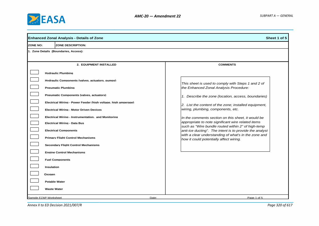
AMC-20 — Amendment 22 SUBPART A — GENERAL
Annex II to ED Decision 2021/007/R Page 320 of 617
Enhanced Zonal Analysis - Details of Zone Sheet 1 of 5
1. Zone Details (Boundaries, Access):
Pneumatic Components (valves, actuators)
Electrical Wiring - Power Feeder (high voltage, high amperage)
Electrical Wiring - Data Bus
Primary Flight Control Mechanisms
Electrical Components
ZONE DESCRIPTION:ZONE NO:
2. EQUIPMENT INSTALLED COMMENTS
Hydraulic Components (valves, actuators, pumps)
Waste Water
Insulation
Sample EZAP Worksheet Date: Page 1 of 5
Potable Water
Oxygen
Hydraulic Plumbing
Fuel Components
Engine Control Mechanisms
Pneumatic Plumbing
Electrical Wiring - Motor Driven Devices
Electrical Wiring - Instrumentation, and Monitoring
Secondary Flight Control Mechanisms
This sheet is used to comply with Steps 1 and 2 of
the Enhanced Zonal Analysis Procedure:
1. Describe the zone (location, access, boundaries)
2. List the content of the zone; installed equipment,
wiring, plumbing, components, etc.
In the comments section on this sheet, it would be
appropriate to note significant wire related items
such as "Wire bundle routed within 2" of high-temp
anti-ice ducting". The intent is to provide the analyst
with a clear understanding of what's in the zone and
how it could potentially affect wiring.
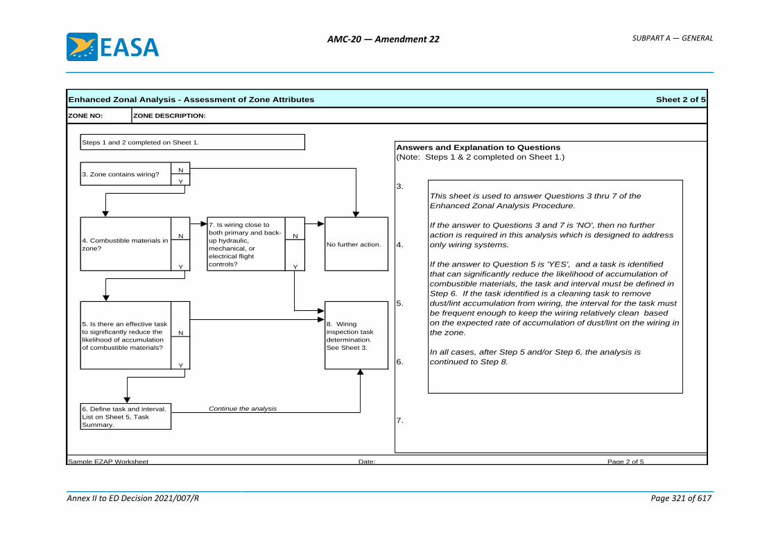
AMC-20 — Amendment 22 SUBPART A — GENERAL
Annex II to ED Decision 2021/007/R Page 321 of 617
Enhanced Zonal Analysis - Assessment of Zone Attributes Sheet 2 of 5
N
Y
N N
Y Y
N
Y
Continue the analysis
Steps 1 and 2 completed on Sheet 1.
ZONE NO: ZONE DESCRIPTION:
3. Zone contains wiring?
4. Combustible materials in
zone?
7. Is wiring close to
both primary and back-
up hydraulic,
mechanical, or
electrical flight
controls?
No further action.
5. Is there an effective task
to significantly reduce the
likelihood of accumulation
of combustible materials?
8. Wiring
inspection task
determination.
See Sheet 3.
Sample EZAP Worksheet Date: Page 2 of 5
6. Define task and interval.
List on Sheet 5, Task
Summary.
Answers and Explanation to Questions
(Note: Steps 1 & 2 completed on Sheet 1.)
3.
4.
5.
6.
7.
This sheet is used to answer Questions 3 thru 7 of the
Enhanced Zonal Analysis Procedure.
If the answer to Questions 3 and 7 is 'NO', then no further
action is required in this analysis which is designed to address
only wiring systems.
If the answer to Question 5 is 'YES', and a task is identified
that can significantly reduce the likelihood of accumulation of
combustible materials, the task and interval must be defined in
Step 6. If the task identified is a cleaning task to remove
dust/lint accumulation from wiring, the interval for the task must
be frequent enough to keep the wiring relatively clean based
on the expected rate of accumulation of dust/lint on the wiring in
the zone.
In all cases, after Step 5 and/or Step 6, the analysis is
continued to Step 8.
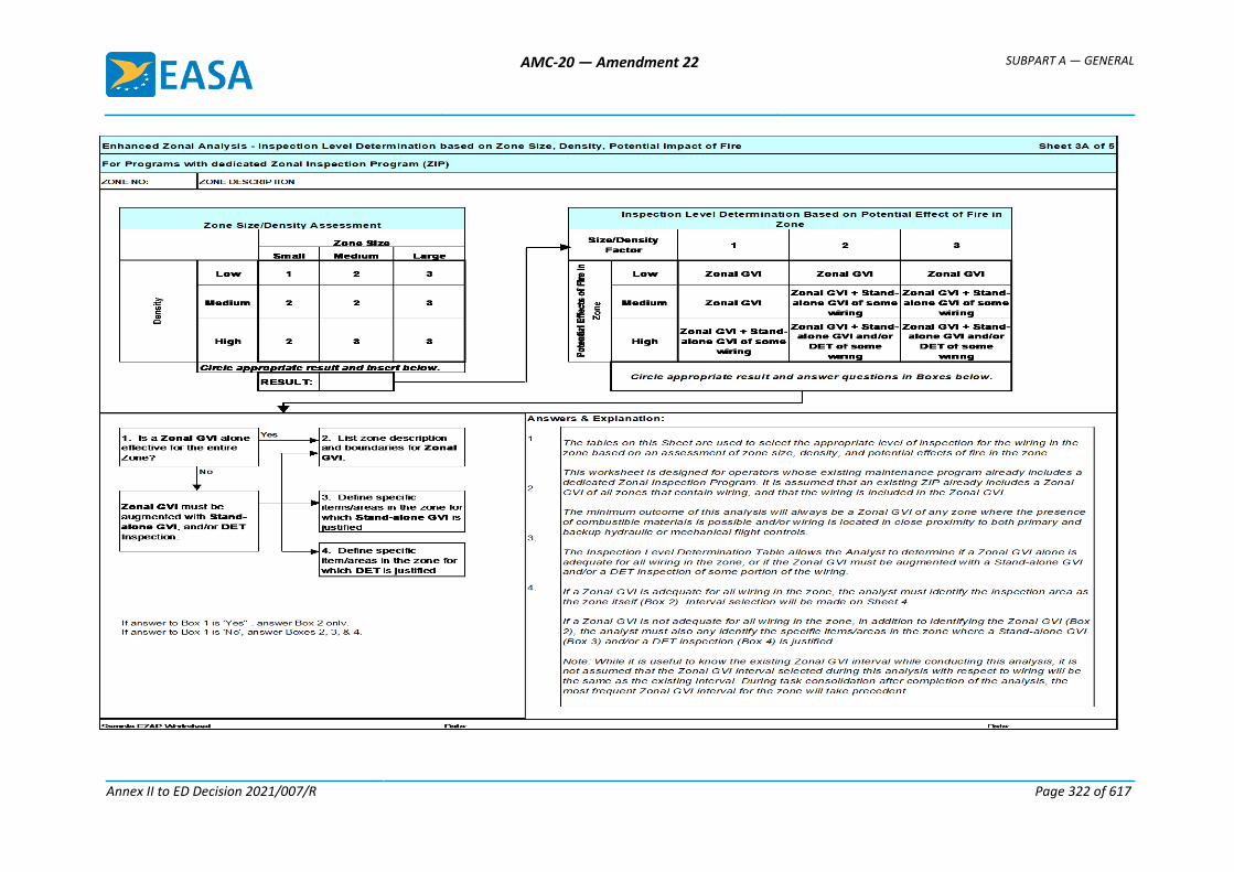
AMC-20 — Amendment 22 SUBPART A — GENERAL
Annex II to ED Decision 2021/007/R Page 322 of 617
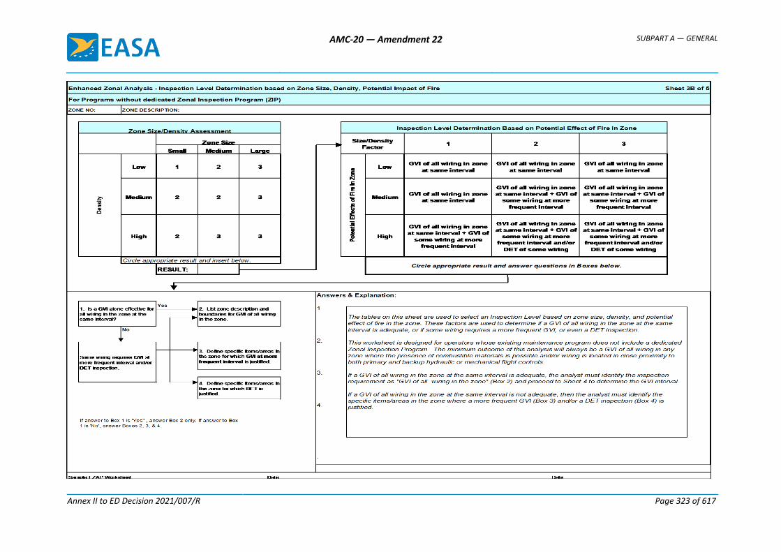
AMC-20 — Amendment 22 SUBPART A — GENERAL
Annex II to ED Decision 2021/007/R Page 323 of 617
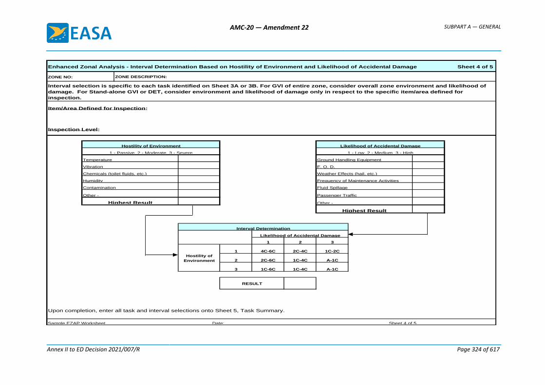
AMC-20 — Amendment 22 SUBPART A — GENERAL
Annex II to ED Decision 2021/007/R Page 324 of 617
Enhanced Zonal Analysis - Interval Determination Based on Hostility of Environment and Likelihood of Accidental Damage Sheet 4 of 5
ZONE NO:
Item/Area Defined for Inspection:
1 2 3
1 4C-6C 2C-4C 1C-2C
2 2C-6C 1C-4C A-1C
3 1C-6C 1C-4C A-1C
Upon completion, enter all task and interval selections onto Sheet 5, Task Summary.
Hostility of
Environment
Interval Determination
Humidity
Hostility of Environment
ZONE DESCRIPTION:
Sample EZAP Worksheet Date: Sheet 4 of 5
Contamination
1 - Passive, 2 - Moderate, 3 - Severe
Highest Result Other -
RESULT
Likelihood of Accidental Damage
Vibration
Highest Result
Other -
Weather Effects (hail, etc.)
Frequency of Maintenance Activities
Fluid Spillage
Passenger Traffic
Chemicals (toilet fluids, etc.)
1 - Low, 2 - Medium, 3 - High
Ground Handling Equipment
F. O. D.
Temperature
Interval selection is specific to each task identified on Sheet 3A or 3B. For GVI of entire zone, consider overall zone environment and likelihood of
damage. For Stand-alone GVI or DET, consider environment and likelihood of damage only in respect to the specific item/area defined for
inspection.
Inspection Level:
Likelihood of Accidental Damage
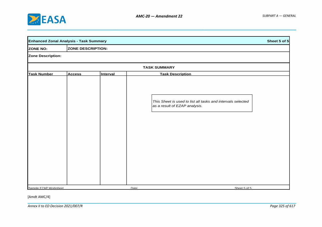
AMC-20 — Amendment 22 SUBPART A — GENERAL
Annex II to ED Decision 2021/007/R Page 325 of 617
[Amdt AMC/4]
Enhanced Zonal Analysis - Task Summary Sheet 5 of 5
ZONE NO:
Zone Description:
Task Number Access Interval
TASK SUMMARY
Sample EZAP Worksheet Date: Sheet 5 of 5
Task Description
ZONE DESCRIPTION:
This Sheet is used to list all tasks and intervals selected
as a result of EZAP analysis.
AMC-20 — Amendment 22 SUBPART A — GENERAL
AMC 20-21
Annex II to ED Decision 2021/007/R Page 326 of 617
Appendix C to AMC 20-21 Determination if a major change to an aircraft should be specifically subjected to an EZAP
The EZAP provides a means for TC and STC holders to develop improvements to EWIS maintenance programs. These improvements will be in the form of new inspections and other tasks designed to prevent significant accumulation of combustible materials on or adjacent to EWIS components that would be added to the Instructions for Continued Airworthiness or Service Bulletins (SB) for the aircraft and STC.
While TC holders are required to conduct the EZAP for all zones in an aircraft, it may be determined that EZAP for an SB or STC is not necessary where the modification does not appreciably affect the zones where it is installed. The “Determination if SB modification or STC requires EZAP” procedure was developed to identify modifications that sufficiently affect zone attributes to warrant re-application of EZAP to the entire zone.
This logic assumes that the aircraft TC holder has accomplished the EZAP on each zone of the aircraft without consideration of the SB modification or STC installation. The objective of this analysis is to assess whether the modification itself has affected wiring or certain zone attributes that could change the outcome of the EZAP performed by the aircraft TC holder.
The determination if the SB or STC requires EZAP, and re-application of the EZAP to SB or STC affected zones, is the responsibility of the respective holder of the SB or STC. It is expected that the TC and STC holders will collaborate with each other and operators as necessary to obtain information required to conduct the analysis. The TC or STC holder should communicate the results of the procedure, including the cases when no new tasks are identified. The method of communication may be via SB, Service Letter, ICAW Revision, or other means acceptable to EASA.
In situations where a previously installed STC is no longer supported by a viable STC holder (e.g. STC holder defunct), the responsibility for determining if the STC requires EZAP, and re-application of EZAP to any affected zones, is assigned to the individual operators who utilise the STC on their aircraft. In cases where the operator does not have experience in application of analytical logic processes, it will be necessary for the operator to gain competence in, or seek external assistance in conducting the analysis.
A record of the outcome of operator accomplished analysis for STC (even if no tasks are identified) should be permanently retained by the operator. A copy of the record should be included in the aircraft records normally transferred upon change of aircraft operator.
The attached logic chart provides a means to assess whether an SB modification or STC has sufficiently affected wiring or certain other zone attributes as to require reapplication of the EZAP to the entire zone with consideration of the modification present. The section following the chart provides detailed explanations of each step in the “Determination if SB modification or STC requires EZAP” with appropriate examples.
It is recommended that, where possible, the analyst should utilise the availability of actual aircraft to ensure they fully understand the zones being analysed. Specifically, it must be determined how installation of the modification could affect zone attributes such as density, environment, proximity of wiring to primary and back-up flight controls, presence of combustible materials, and potential for accidental damage to wiring.

AMC-20 — Amendment 22 SUBPART A — GENERAL
AMC 20-21
Annex II to ED Decision 2021/007/R Page 327 of 617
Appendix C. Figure 1. Determination if SB modification or STC requires EZAP
1Does the STC:
- affect or modify wiring or its environment- install or result in wiring being located
within 5 cm (2 inches) of both primary & backup hydraulic, mechanical, or
electrical flight controls- change the density of the zone, or
- change the potential effects of fire in the zone?
4Determine if there is an existing
MRBR EZAP task(s) that is applicable and effective?
2No further action required
NO
5No further action required because the existing
EZAPderived maintenance task is adequate
3Perform EZAP analysis
YES
YES
6Develop appropriate task and incorporate it into
existing maintenance program
NO
Explanation of Steps
Step 1: Does the SB or STC affect or modify wiring or it’s environment?
The question asks whether the STC affects or modifies wiring. Modifications to wiring or other EWIS components include, but are not limited to removal, addition, relocation, etc.
Does the SB or STC install or result in wiring being located within 5 cm (2 inches) of primary and back-up hydraulic, mechanical or electric flight controls, change the density of the zone or change the potential effects of fire in the zone?
Does the SB or STC affect zone density? If the STC includes the addition or deletion of numerous components in a small area, the density of the zone could be changed even if wire bundles are untouched. A significant change in the zone density should warrant re-analysis of the zone.
Potential effects of fire on adjacent wiring and systems require the analyst to assess the potential effect of a localised fire on adjacent wiring and systems by considering the potential for loss of multiple functions to the extent that a hazard could be introduced.
AMC-20 — Amendment 22 SUBPART A — GENERAL
AMC 20-21
Annex II to ED Decision 2021/007/R Page 328 of 617
Consideration of potential effect must also include whether wiring is in close proximity (i.e. within 5 cm (2 inches)) to both primary and back-up flight controls.
Additionally, this question requires an evaluation of whether the zone might contain combustible material that could cause a fire to be sustained in the event of an ignition source arising in adjacent wiring. Examples include the possible presence of fuel vapours, dust/lint accumulation, and contaminated insulation blankets.
With respect to commonly used liquids (e.g. oils, hydraulic fluids, and corrosion prevention compounds), the analyst should refer to the product specification in order to assess the potential for combustibility. The product may be readily combustible only in vapour/mist form and thus an assessment is required to determine if conditions might exist in the zone for the product to be in this state.
Although liquid contamination of wiring by most synthetic oil and hydraulic fluids (e.g. skydrol) may not be considered combustible, it is a cause for concern if it occurs in a zone where contamination causes significant adherence of dust and lint.
If the answer to this question is ‘No’, then no further action is required (Step 2), since the density of the zone or the potential effects of fire in the zone has not changed.
Step 2: No further action is required.
Step 3: Perform an EZAP analysis.
If the answer to question 1 is ‘Yes’, then the only way to determine if existing EWIS maintenance tasks are sufficient is to perform the EZAP for the SB or STC and compare the results with the existing EWIS maintenance tasks (see Step 4).
Step 4: Is there an existing MRBR EZAP task(s) that is applicable and effective?
Once the SB or STC EZAP has been accomplished, a comparison of the derived maintenance tasks can be made with the existing EWIS maintenance tasks. If the existing tasks are adequate, then no further action regarding EWIS maintenance actions for the STC is necessary.
Step 5: No further action is required since the existing EZAP-derived maintenance task is adequate.
Step 6: Develop an appropriate task and incorporate it into the existing maintenance programme.
These tasks should be incorporated into the operator’s existing maintenance programme.
[Amdt 20/4]

AMC-20 — Amendment 22 SUBPART A — GENERAL
AMC 20-21
Annex II to ED Decision 2021/007/R Page 329 of 617
Appendix D to AMC 20-21
(RESERVED)
AMC-20 — Amendment 22 SUBPART A — GENERAL
AMC 20-21
Annex II to ED Decision 2021/007/R Page 330 of 617
Appendix E to AMC 20-21 Causes of Wire Degradation
The following items are considered principal causes of wiring degradation and should be used to help focus maintenance programmes:
Vibration - High vibration areas tend to accelerate degradation over time, resulting in “chattering” contacts and intermittent symptoms. High vibration of tie-wraps or string-ties can cause damage to insulation. In addition, high vibration will exacerbate any existing problem with wire insulation cracking.
Moisture - High moisture areas generally accelerate corrosion of terminals, pins, sockets, and conductors. It should be noted that wiring installed in clean, dry areas with moderate temperatures appears to hold up well.
Maintenance - Scheduled and unscheduled maintenance activities, if done improperly, may contribute to long-term problems and wiring degradation. Certain repairs may have limited durability and should be evaluated to ascertain if rework is necessary. Repairs that conform to manufacturers recommended maintenance practices are generally considered permanent and should not require rework. Furthermore, care should be taken to prevent undue collateral damage to EWIS while performing maintenance on other systems.
Metal shavings and debris have been discovered on wire bundles after maintenance, repairs, modifications, or STC have been performed. Care should be taken to protect wire bundles and connectors during modification work. The work areas should be cleaned while the work progresses to ensure that all shavings and debris are removed; the work area should be thoroughly cleaned after the work is complete; and the work area should be inspected after the final cleaning.
Repairs should be performed using the most effective methods available. Since wire splices are more susceptible to degradation, arcing, and overheating, the recommended method of repairing a wire is with an environmental splice.
Indirect Damage - Events such as pneumatic duct ruptures or duct clamp leakage can cause damage that, while not initially evident, can cause wiring problems at a later stage. When events such as these occur, surrounding EWIS should be carefully inspected to ensure that there is no damage or no potential for damage is evident. The indirect damage caused by these types of events may be broken clamps or ties, broken wire insulation, or even broken conductor strands. In some cases the pressure of the duct rupture may cause wire separation from the connector or terminal strip.
Contamination - Wire contamination refers to either of the following situations:
a. The presence of a foreign material that is likely to cause degradation of wiring.
b. The presence of a foreign material that is capable of sustaining combustion after removal of ignition source.
The contaminant may be in solid or liquid form. Solid contaminants such as metal shavings, swarf, debris, livestock waste, lint and dust can accumulate on wiring and may degrade or penetrate wiring or electrical components.
Chemicals in fluids such as hydraulic fluid, battery electrolytes, fuel, corrosion inhibiting compounds, waste system chemicals, cleaning agents, de-icing fluids, paint, soft drinks and coffee can contribute to degradation of wiring.
Hydraulic fluids, de-icing fluids and battery electrolyte require special consideration. These fluids, although essential for aircraft operation, can damage connector grommets, wire bundle clamps, wire ties and wire lacing, causing chafing and arcing. Wiring exposed to these fluids should be given special
AMC-20 — Amendment 22 SUBPART A — GENERAL
AMC 20-21
Annex II to ED Decision 2021/007/R Page 331 of 617
attention during inspection. Contaminated wire insulation that has visible cracking or breaches to the core conductor can eventually arc and cause a fire. Wiring exposed to, or in close proximity to, any of these chemicals may need to be inspected more frequently for damage or degradation.
When cleaning areas or zones of the aircraft that contain both wiring and chemical contaminants, special cleaning procedures and precautions may be needed. Such procedures may include wrapping wire and connectors with a protective covering prior to cleaning. This would be especially true if pressure-washing equipment is utilised. In all cases the aircraft manufacturer recommended procedures should be followed.
Waste system spills also require special attention. Service history has shown that these spills can have detrimental effects on aircraft EWIS and have resulted in smoke and fire events. When this type of contamination is found all affected components in the EWIS should be thoroughly cleaned, inspected and repaired or replaced if necessary. The source of the spill or leakage should be located and corrected.
Heat - Exposure to high heat can accelerate degradation of wiring by causing insulation dryness and cracking. Direct contact with a high heat source can quickly damage insulation. Burned, charred or even melted insulation are the most likely indicators of this type of damage. Low levels of heat can also degrade wiring over a longer period of time. This type of degradation is sometimes seen on engines, in galley wiring such as coffee makers and ovens, and behind fluorescent lights, especially the ballasts.
[Amdt 20/4]

AMC-20 — Amendment 22 SUBPART A — GENERAL
AMC 20-22
Annex II to ED Decision 2021/007/R Page 332 of 617
AMC 20-22
AMC 20-22 Aeroplane Electrical Wiring Interconnection System Training Programme
1 PURPOSE
This AMC provides acceptable means of compliance for developing an enhanced Electrical Wiring Interconnection System (EWIS) training programme. The information in this AMC is derived from the best practices training developed through extensive research. This AMC is an effort by the Agency to officially endorse these best practices and to dispense this information industry-wide so that the benefits of this information can be effectively realised. Following this AMC will result in a training programme that will improve the awareness and skill level of the aviation personnel in EWIS production, modification, maintenance, inspection, alterations and repair. This AMC promotes a philosophy of training for all personnel who come into contact with aeroplane EWIS as part of their job and tailors the training for each workgroup to their particular needs.
2 OBJECTIVE
This AMC has been published in order to provide the approved organisations with acceptable means of compliance to comply with their training obligations as required in paragraphs 21.A.145 and 21.A.245 of Part-21, 145.A.30 and 145.A.35 of Part-145 and M.A.706 of Part-M with respect to EWIS.
To fully realise the objectives of this AMC, operators, holders of type certificates (TC), holders of supplemental type certificates (STC), maintenance organisations and persons performing modifications or repairs, will need to rethink their current approach to maintaining and modifying aeroplane wiring and systems. This may require more than simply updating maintenance manuals and work cards and enhancing training. Maintenance personnel need to be aware that aeroplane EWIS should be maintained with the same level of intensity as any other system in the aeroplane. They also need to recognise that visual inspection of wiring has inherent limitations. Small defects such as breached or cracked insulation, especially in small gage wire may not always be apparent. Therefore, effective wiring maintenance combines visual inspection techniques with improved wiring maintenance practices and training.
The objective of this EWIS training programme is to give operators, holders of TC, holders of STC, maintenance organisations and persons performing field approval modifications or repairs a model for the development of their own EWIS training programme. This will ensure that proper procedures, methods techniques, and practices are used when performing maintenance, preventive maintenance, inspection, alteration, and cleaning of EWIS.
The training syllabus and curriculum for those personnel directly involved in the maintenance and inspection of EWIS, identified as Target Group 1 and 2, are in Appendix A and C to this AMC.
This AMC also provides guidance on the development of EWIS training programmes for personnel who are not directly involved in the maintenance and inspection of EWIS. Although there is no direct regulatory requirement for EWIS training of these personnel, operators may choose to provide EWIS training. The training syllabus and curriculum for these personnel, identified as Target Groups 3 through 8, are in Appendix B and C to this AMC.
It is believed that training personnel in these groups would greatly enhance awareness of the importance of EWIS safety in the overall safe operation of aeroplanes. Although these groups
AMC-20 — Amendment 22 SUBPART A — GENERAL
AMC 20-22
Annex II to ED Decision 2021/007/R Page 333 of 617
are not directly involved in the maintenance of EWIS, they have the potential to have an adverse impact on EWIS. This can occur through inadvertent contact with EWIS during aeroplane cleaning or when individuals perform unrelated maintenance that could impact the integrity of EWIS. Mechanics leaving drill shavings on wire bundles is one example of how this could occur. Some people prepare paperwork that guides mechanics, training this target group in EWIS should help to ensure that proper attention is paid to EWIS issues.
This programme was developed for eight different target groups and may be used for the minimum requirements for initial and recurrent training (see training matrix). Depending on the duties, some may fall into more than one target group and, therefore, must fulfil all objectives of the associated target groups. The target groups are:
a. Qualified staff performing EWIS maintenance.
These staff members are personnel who perform wiring systems maintenance and their training is based on their job description and the work being done by them (e.g. avionics skilled workers or technicians cat B2).
b. Qualified staff performing maintenance inspections on wiring systems.
These staff members are personnel who perform EWIS inspections (but not maintenance), and their training is based on their job description and the work being done by them (e.g. inspectors/technicians cat B2).
c. Qualified staff performing electrical/avionic engineering on in-service aeroplane.
These staff members are personnel who are authorised to design EWIS installations, modifications and repairs (e.g. electric/avionic engineers).
d. Qualified staff performing general maintenance/inspections not involving wire maintenance (LRU change is not considered wire maintenance).
These staff members are personnel who perform maintenance on aeroplane that may require removal/reconnection of electrical connective devices (e.g. inspectors/technicians cat A or B1).
e. Qualified staff performing other engineering or planning work on in-service aeroplane.
These staff members are personnel who are authorised to design mechanical/structure systems installations, modifications and repairs, or personnel who are authorised to plan maintenance tasks.
f. Other service staff with duties in proximity to EEWIS.
These staff members are personnel whose duties would bring them into contact/view of aeroplane wiring systems. This would include, but not be limited to: Aeroplane cleaners, cargo loaders, fuelers, lavatory servicing personnel, de-icing personnel, push back personnel.
g. Flight Deck Crew.
(E.g. Pilots, Flight Engineers)
h. Cabin Crew.
3 APPLICABILITY
This AMC describes acceptable means, but not the only means, of compliance with the appropriate certification, maintenance and operating regulations.
AMC-20 — Amendment 22 SUBPART A — GENERAL
AMC 20-22
Annex II to ED Decision 2021/007/R Page 334 of 617
The information in this AMC is based on lessons learned by Aging Transport Systems Rulemaking Advisory Committee (ATSRAC) Harmonised Working Groups, regulatory authorities, manufacturers, airlines and repair stations. This AMC can be applied to any aeroplane training programme.
4 RELATED DOCUMENTS
— Regulation (EC) No 216/20081
— Regulation (EC) No 1702/20032
— Regulation (EC) No 2042/20033
— EASA Certification Specification CS-25 Large Aeroplanes4
— EU-OPS Commercial Air Transportation (Aeroplanes)5
5 RELATED READING MATERIAL
a. EASA AMC-20
— AMC 20-21 Programme to Enhance Aeroplane Electrical Wiring Interconnection System Maintenance
— AMC 20-23 Development of Electrical Standard Wiring Practices Documentation
b. FAA 14 CFR Parts
— Part 21, Certification Procedures for Products and Parts
— Part 25, Airworthiness Standards, Transport Category Aeroplanes
— Part 43, Maintenance, Preventive Maintenance, Rebuilding, and Alteration
— Part 91, General Operating and Flight Rules
— Part 119, Certification: Air Carriers and Commercial Operators
— Part 121, Operating Requirements: Domestic, Flag, and Supplemental Operations
— Part 125, Certification and Operations: Aeroplanes Having a Seating Capacity of 20 or More Passengers or a Maximum Payload Capacity of 6,000 pounds or More
— Part 129, Operations: Foreign Air Carriers and Foreign Operators of U.S.-Registered Aircraft Engaged in Common Carriage
1 Regulation (EC) No 216/2008 of the European Parliament and of the Council of 20 February 2008 on common rules in the field of civil
aviation and establishing a European Aviation Safety Agency, and repealing Council Directive 91/670/EEC, Regulation (EC) No 1592/2002 and Directive 2004/36/EC (OJ L 79, 19.3.2008, p. 1).
2 Commission Regulation (EC) No 1702/2003 of 24 September 2003 laying down implementing rules for the airworthiness and environmental certification of aircraft and related products, parts and appliances, as well as for the certification of design and production organisations (OJ L 243, 27.9.2003, p. 6). Regulation as last amended by Regulation (EC) No 287/2008 (OJ L 87, 29.3.2008, p. 3).
3 Commission Regulation (EC) No 2042/2003 of 20 November 2003 on the continuing airworthiness of aircraft and aeronautical products, parts and appliances, and on the approval of organisations and personnel involved in these tasks (OJ L 315, 28.11.2003, p. 1). Regulation as last amended by Regulation (EC) No 376/2007 of (OJ L 94, 4.4.2007, p. 18).
4 Executive Director Decision No 2003/2/RM of 14 October 2003 on certification specifications, including airworthiness codes and acceptable means of compliance, for large aeroplanes («CS-25»). Decision as last amended by Executive Director Decision No 2008/006/R of 29 August 2008 (CS-25 Amendment 5).
5 Council Regulation (EEC) No 3922/91 of 16 December 1991 on the harmonisation of technical requirements and administrative procedures in the field of civil aviation (OJ L 373, 31.12.1991, p. 4). Regulation as last amended by Regulation (EC) No 8/2008 of 11 December 2007 (OJ L 10, 12.1.2008, p. 1).
AMC-20 — Amendment 22 SUBPART A — GENERAL
AMC 20-22
Annex II to ED Decision 2021/007/R Page 335 of 617
— Part 135, Operating Requirements: Commuter and On-demand Operations
— Part 145, Repair Stations
c. FAA Advisory Circulars (AC)
— AC 20-13, Protection of Aircraft Electrical/Electronic Systems against the Indirect Effects of Lightning
— AC 20-53A, Protection of Aeroplane Fuel Systems against Fuel Vapour Ignition due to Lightning AC 25-16, Electrical Fault and Fire Protection and Prevention
— AC 25.981-1B, Fuel Tank Ignition Source Prevention Guidelines
— AC 25.17YY Development of Standard Wiring Practices Documentation
— AC 43-3, Non-destructive Testing in Aircraft
— AC 43-4A, Corrosion Control for Aircraft
— AC 43-7, Ultrasonic Testing for Aircraft
— AC 43-12A, Preventive Maintenance
— AC 43.13-1A, Acceptable Methods, Techniques and Practices - Aircraft Inspection and Repair
— AC 43.13-1B, Acceptable Methods, Techniques and Practices for Repairs and Alterations to Aircraft
— AC 43-204, Visual Inspection for Aircraft
— AC 43-206, Avionics Cleaning and Corrosion Prevention/Control
— AC 65-15A, Airframe and Powerplant Mechanics Airframe Handbook, Chapter 11. Aircraft Electrical Systems
— AC 120-XX, Programme to enhance aircraft Electrical Wiring Interconnection System maintenance
— AC 120-YY Aircraft Electrical Wiring Interconnection System training programme
d. Reports
— Transport Aircraft Intrusive Inspection Project, (An Analysis of the Wire Installations of Six Decommissioned Aircraft), Final Report, The Intrusive Inspection Working Group, December 29, 2000. http://www.mitrecaasd.org/atsrac/intrusive_inspection.html
— FAA Aging Transport Non-Structural Systems Plan, July 1998.
— National Transportation Safety Board, Safety Recommendation, September 19, 2000, A-00-105 through -108. http://www.ntsb.gov/recs/letters/2000/A00_105_108.pdf
— Wire System Safety Interagency Working Group, National Science and Technology Council, Review of Federal Programmes for Wire System Safety 46 (2000).
— Aging Transport Systems Rulemaking Advisory Committee, Task 1 and 2, Aging Systems, Final Report. http://www.mitrecaasd.org/atsrac/final_reports/Task_1&2_Final%20_August_2000.pdf
AMC-20 — Amendment 22 SUBPART A — GENERAL
AMC 20-22
Annex II to ED Decision 2021/007/R Page 336 of 617
— Aging Transport Systems Rulemaking Advisory Committee, Task 3, Final Report. http://www.mitrecaasd.org/atsrac/final_reports/Task_3_Final.pdf
— Aging Transport Systems Rulemaking Advisory Committee, Task 4, Final Report, Standard Wiring Practices. http://www.mitrecaasd.org/atsrac/final_reports/Task_4_Final_Report_Sept_2000.pdf
— Aging Transport Systems Rulemaking Advisory Committee, Task 5, Final Report, Aircraft Wiring Systems Training Curriculum and Lesson Plans. http://www.mitrecaasd.org/atsrac/final_reports/Task_5_Final_March_2001%20.pdf
— ATA Specification 117 (Wiring Maintenance Practices/Guidelines).
— Aging Transport Systems Rulemaking Advisory Committee, Task 6, Task 7 and Task 9 Working Group Final Reports http://www.mitrecaasd.org/atsrac/final_reports.html
e. Other Documents
ATA Operator/Manufacturer Scheduled Maintenance Development as revised, ATA Maintenance Steering Group (MSG-3), may be obtained from the Air Transport Association of America; Suite 1100: 1301 Pennsylvania Ave, NW, Washington, DC 20004-1707.
FAA Handbook Bulletin 91-15 "Origin and propagation of inaccessible aircraft fire under in-flight airflow conditions".
6 DEFINITIONS
Arc tracking: A phenomenon in which a conductive carbon path is formed across an insulating surface. This carbon path provides a short circuit path through which current can flow. Normally, a result of electrical arcing. Also referred to as "Carbon Arc Tracking", "Wet Arc Tracking", or "Dry Arc Tracking".
Combustible: For the purposes of this AMC, the term combustible refers to the ability of any solid, liquid or gaseous material to cause a fire to be sustained after removal of the ignition source. The term is used in place of inflammable/flammable. It should not be interpreted as identifying material that will burn when subjected to a continuous source of heat as occurs when a fire develops.
Contamination: For the purposes of this AMC, wiring contamination refers to either of the following:
— The presence of a foreign material that is likely to cause degradation of wiring.
— The presence of a foreign material that is capable of sustaining combustion after removal of ignition source.
Detailed Inspection (DET): An intensive examination of a specific item, installation, or assembly to detect damage, failure or irregularity. Available lighting is normally supplemented with a direct source of good lighting at an intensity deemed appropriate. Inspection aids such as mirrors, magnifying lenses or other means may be necessary. Surface cleaning and elaborate access procedures may be required.
Electrical Wiring Interconnection System (EWIS): See CS 25.1701.
Functional Failure: Failure of an item to perform its intended function within specified limits.
AMC-20 — Amendment 22 SUBPART A — GENERAL
AMC 20-22
Annex II to ED Decision 2021/007/R Page 337 of 617
General Visual Inspection (GVI): A visual examination of an interior or exterior area, installation, or assembly to detect obvious damage, failure or irregularity. This level of inspection is made from within touching distance unless otherwise specified. A mirror may be necessary to enhance visual access to all exposed surfaces in the inspection area. This level of inspection is made under normally available lighting conditions such as daylight, hangar lighting, flashlight or droplight and may require removal or opening of access panels or doors. Stands, ladders or platforms may be required to gain proximity to the area being checked.
Lightning/High Intensity Radiated Field (L/HIRF) protection: The protection of aeroplane electrical systems and structure from induced voltages or currents by means of shielded wires, raceways, bonding jumpers, connectors, composite fairings with conductive mesh, static dischargers, and the inherent conductivity of the structure; may include aeroplane specific devices, e.g., RF Gaskets.
Maintenance: As defined in Regulation (EC) 2042/2003 Article 2(h) “maintenance means inspection, overhaul, repair, preservation, and the replacement of parts, but excludes preventive maintenance.” For the purposes of this advisory material, it also includes preventive maintenance.
Maintenance Significant Item (MSI): Items identified by the manufacturer whose failure:
— could affect safety (on ground or in flight).
— is undetectable during operations.
— could have significant operational impact.
— could have significant economic impact.
Needling: The puncturing of a wire’s insulation to make contact with the core to test the continuity and presence of voltage in the wire segment.
Stand-alone General Visual Inspection (GVI): A GVI which is not performed as part of a zonal inspection. Even in cases where the interval coincides with the zonal inspection, the stand-alone GVI shall remain an independent step within the work card.
Structural Significant Item (SSI): Any detail, element or assembly that contributes significantly to carrying flight, ground, pressure, or control loads and whose failure could affect the structural integrity necessary for the safety of the aeroplane.
Swarf: A term used to describe the metal particles, generated from drilling and machining operations. Such particles may accumulate on and between wires within a wire bundle.
Zonal Inspection: A collective term comprising selected GVI and visual checks that are applied to each zone, defined by access and area, to check system and powerplant installations and structure for security and general condition.
7 BACKGROUND
Over the years there have been a number of in-flight smoke and fire events where contamination sustained and caused the fire to spread. Regulators and Accident Investigators have conducted aircraft inspections and found wiring contaminated with items such as dust, dirt, metal shavings, lavatory waste water, coffee, soft drinks, and napkins. In some cases, dust has been found completely covering wire bundles and the surrounding area.
Research has also demonstrated that wiring can be harmed by collateral damage when maintenance is being performed on other aircraft systems. For example, a person performing

AMC-20 — Amendment 22 SUBPART A — GENERAL
AMC 20-22
Annex II to ED Decision 2021/007/R Page 338 of 617
an inspection of an electrical power centre or avionics compartment may inadvertently cause damage to wiring in an adjacent area.
Aviation Accident Investigators have specifically cited the need for improved training of personnel to ensure adequate recognition and repair of potentially unsafe wiring conditions.
This AMC addresses only the training programme. It does not attempt to deal with the condition of the fleet's wiring, or develop performance tests for wiring.
This AMC captures, in EASA guidance form, the aeroplane EWIS training programme developed by ATSRAC. This includes a training syllabus, curriculum, training target groups and a matrix outlining training for each training group.
8 ESSENTIAL ELEMENTS FOR A TRAINING PROGRAMME
a. Initial Training.
Initial training should be conducted for each designated work group. The initial training for each designated work group is outlined in EWIS Minimum Initial Training Programme - Appendix A and B. Curriculum and Lesson Plans for each dedicated module are included in Appendix C.
The most important criteria are to meet the objectives of the Lesson Plans – Appendix C (using classroom discussion, computer-based training or hands-on practical training).
Assessment or achieving the objectives should be at the discretion of the training organisation (such as written test, oral test or demonstration of skills).
Supporting documentation such as AMC is an integral part of training and should be used to support development of the Curriculum and Lesson Plans.
b. Refresher Training.
Refresher training should be conducted in a period not exceeding two years. It could consist of a review of previously covered material plus any new material or revisions to publications. Refresher training will follow the EWIS Minimum Initial Training Programme - Appendix A or B for that particular target group.
[Amdt 20/4]
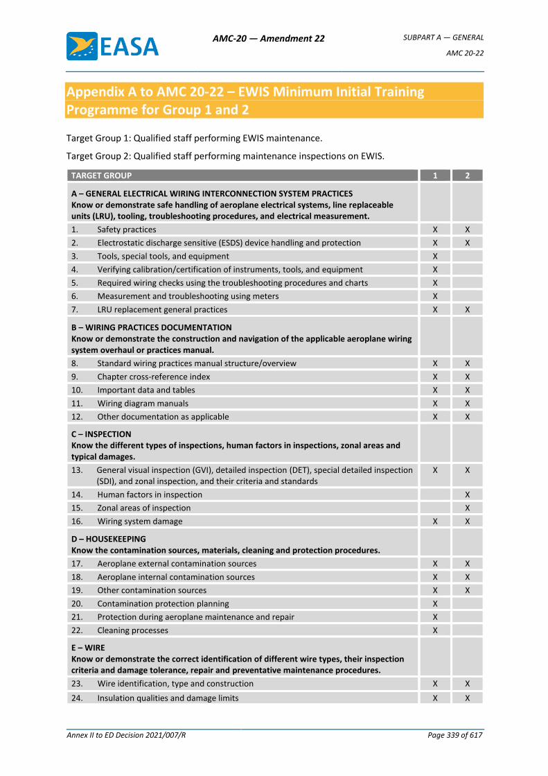
AMC-20 — Amendment 22 SUBPART A — GENERAL
AMC 20-22
Annex II to ED Decision 2021/007/R Page 339 of 617
Appendix A to AMC 20-22 – EWIS Minimum Initial Training Programme for Group 1 and 2
Target Group 1: Qualified staff performing EWIS maintenance.
Target Group 2: Qualified staff performing maintenance inspections on EWIS.
TARGET GROUP 1 2
A – GENERAL ELECTRICAL WIRING INTERCONNECTION SYSTEM PRACTICES Know or demonstrate safe handling of aeroplane electrical systems, line replaceable units (LRU), tooling, troubleshooting procedures, and electrical measurement.
1. Safety practices X X
2. Electrostatic discharge sensitive (ESDS) device handling and protection X X
3. Tools, special tools, and equipment X
4. Verifying calibration/certification of instruments, tools, and equipment X
5. Required wiring checks using the troubleshooting procedures and charts X
6. Measurement and troubleshooting using meters X
7. LRU replacement general practices X X
B – WIRING PRACTICES DOCUMENTATION Know or demonstrate the construction and navigation of the applicable aeroplane wiring system overhaul or practices manual.
8. Standard wiring practices manual structure/overview X X
9. Chapter cross-reference index X X
10. Important data and tables X X
11. Wiring diagram manuals X X
12. Other documentation as applicable X X
C – INSPECTION Know the different types of inspections, human factors in inspections, zonal areas and typical damages.
13. General visual inspection (GVI), detailed inspection (DET), special detailed inspection (SDI), and zonal inspection, and their criteria and standards
X X
14. Human factors in inspection X
15. Zonal areas of inspection X
16. Wiring system damage X X
D – HOUSEKEEPING Know the contamination sources, materials, cleaning and protection procedures.
17. Aeroplane external contamination sources X X
18. Aeroplane internal contamination sources X X
19. Other contamination sources X X
20. Contamination protection planning X
21. Protection during aeroplane maintenance and repair X
22. Cleaning processes X
E – WIRE Know or demonstrate the correct identification of different wire types, their inspection criteria and damage tolerance, repair and preventative maintenance procedures.
23. Wire identification, type and construction X X
24. Insulation qualities and damage limits X X
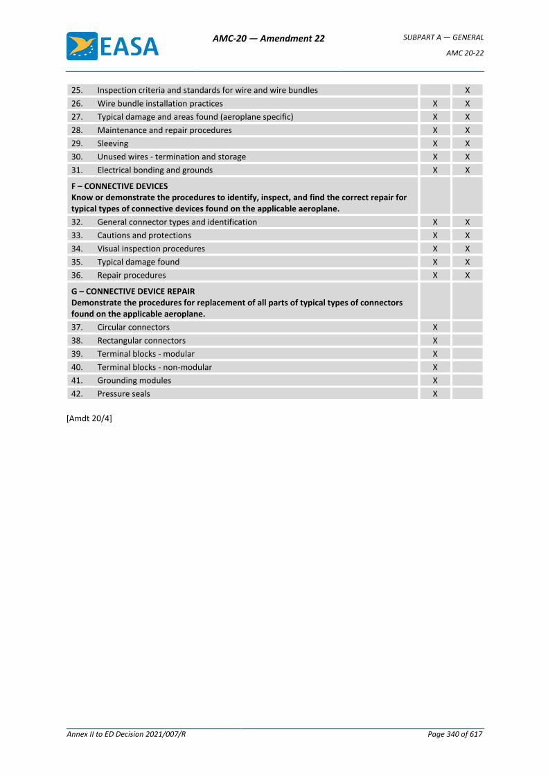
AMC-20 — Amendment 22 SUBPART A — GENERAL
AMC 20-22
Annex II to ED Decision 2021/007/R Page 340 of 617
25. Inspection criteria and standards for wire and wire bundles X
26. Wire bundle installation practices X X
27. Typical damage and areas found (aeroplane specific) X X
28. Maintenance and repair procedures X X
29. Sleeving X X
30. Unused wires - termination and storage X X
31. Electrical bonding and grounds X X
F – CONNECTIVE DEVICES Know or demonstrate the procedures to identify, inspect, and find the correct repair for typical types of connective devices found on the applicable aeroplane.
32. General connector types and identification X X
33. Cautions and protections X X
34. Visual inspection procedures X X
35. Typical damage found X X
36. Repair procedures X X
G – CONNECTIVE DEVICE REPAIR Demonstrate the procedures for replacement of all parts of typical types of connectors found on the applicable aeroplane.
37. Circular connectors X
38. Rectangular connectors X
39. Terminal blocks - modular X
40. Terminal blocks - non-modular X
41. Grounding modules X
42. Pressure seals X
[Amdt 20/4]
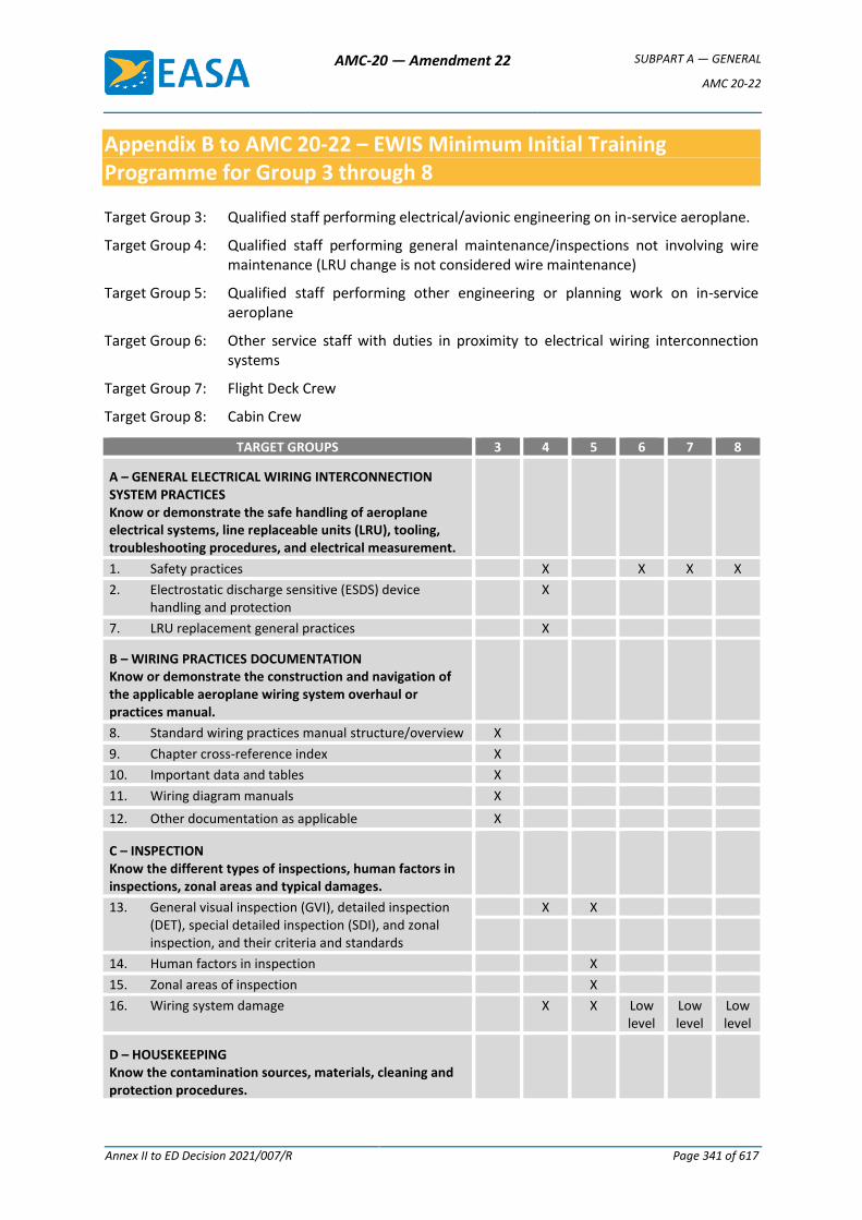
AMC-20 — Amendment 22 SUBPART A — GENERAL
AMC 20-22
Annex II to ED Decision 2021/007/R Page 341 of 617
Appendix B to AMC 20-22 – EWIS Minimum Initial Training Programme for Group 3 through 8
Target Group 3: Qualified staff performing electrical/avionic engineering on in-service aeroplane.
Target Group 4: Qualified staff performing general maintenance/inspections not involving wire maintenance (LRU change is not considered wire maintenance)
Target Group 5: Qualified staff performing other engineering or planning work on in-service aeroplane
Target Group 6: Other service staff with duties in proximity to electrical wiring interconnection systems
Target Group 7: Flight Deck Crew
Target Group 8: Cabin Crew
TARGET GROUPS 3 4 5 6 7 8
A – GENERAL ELECTRICAL WIRING INTERCONNECTION SYSTEM PRACTICES Know or demonstrate the safe handling of aeroplane electrical systems, line replaceable units (LRU), tooling, troubleshooting procedures, and electrical measurement.
1. Safety practices X X X X
2. Electrostatic discharge sensitive (ESDS) device handling and protection
X
7. LRU replacement general practices X
B – WIRING PRACTICES DOCUMENTATION Know or demonstrate the construction and navigation of the applicable aeroplane wiring system overhaul or practices manual.
8. Standard wiring practices manual structure/overview X
9. Chapter cross-reference index X
10. Important data and tables X
11. Wiring diagram manuals X
12. Other documentation as applicable X
C – INSPECTION Know the different types of inspections, human factors in inspections, zonal areas and typical damages.
13. General visual inspection (GVI), detailed inspection (DET), special detailed inspection (SDI), and zonal inspection, and their criteria and standards
X X
14. Human factors in inspection X
15. Zonal areas of inspection X
16. Wiring system damage X X Low level
Low level
Low level
D – HOUSEKEEPING Know the contamination sources, materials, cleaning and protection procedures.
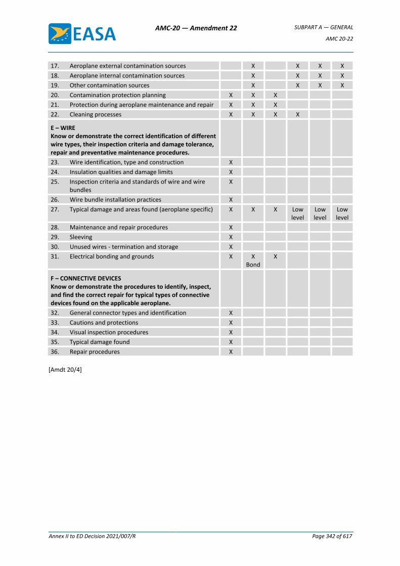
AMC-20 — Amendment 22 SUBPART A — GENERAL
AMC 20-22
Annex II to ED Decision 2021/007/R Page 342 of 617
17. Aeroplane external contamination sources X X X X
18. Aeroplane internal contamination sources X X X X
19. Other contamination sources X X X X
20. Contamination protection planning X X X
21. Protection during aeroplane maintenance and repair X X X
22. Cleaning processes X X X X
E – WIRE Know or demonstrate the correct identification of different wire types, their inspection criteria and damage tolerance, repair and preventative maintenance procedures.
23. Wire identification, type and construction X
24. Insulation qualities and damage limits X
25. Inspection criteria and standards of wire and wire bundles
X
26. Wire bundle installation practices X
27. Typical damage and areas found (aeroplane specific) X X X Low level
Low level
Low level
28. Maintenance and repair procedures X
29. Sleeving X
30. Unused wires - termination and storage X
31. Electrical bonding and grounds X X Bond
X
F – CONNECTIVE DEVICES Know or demonstrate the procedures to identify, inspect, and find the correct repair for typical types of connective devices found on the applicable aeroplane.
32. General connector types and identification X
33. Cautions and protections X
34. Visual inspection procedures X
35. Typical damage found X
36. Repair procedures X
[Amdt 20/4]
AMC-20 — Amendment 22 SUBPART A — GENERAL
AMC 20-22
Annex II to ED Decision 2021/007/R Page 343 of 617
Appendix C to AMC 20-22 – Curriculum and Lessons Plan
Electrical Wiring Interconnection System Curriculum
1 OVERVIEW
This training is targeted at each person who performs aeroplane maintenance, inspections, alterations or repairs on EWIS and/or structure. After training, the person is able to properly evaluate the EWIS and effectively use the manufacturers Chapter 20 Wiring System overhaul manual for that aeroplane. The training programme must include: wiring system condition, applicable repair schemes, wiring modifications and ancillary repairs to wiring systems and components. All of the training components are integrated to maintain wiring system quality and airworthiness of the aeroplane.
2 OBJECTIVES
Depending on the modules taught, the person shows competency in the following skills:
a. Know or demonstrate the safe handling of aeroplane electrical systems, Line Replaceable Units (LRU), tooling, troubleshooting procedures, and electrical measurement.
b. Know or demonstrate the construction and navigation of the applicable aeroplane wiring system overhaul or wiring practices manual.
c. Know the different types of inspections, human factors in inspections, zonal areas and typical damages.
d. Know the contamination sources, materials, cleaning and protection procedures.
e. Know or demonstrate the correct identification of different wire types, their inspection criteria, and damage tolerance, repair and preventative maintenance procedures.
f. Know or demonstrate the procedures to identify, inspect and find the correct repair for typical types of connective devices found on the applicable aeroplane.
g. Demonstrate the procedures for replacement of all parts of typical types of connective devices found on the applicable aeroplane.
3 SCOPE
The course is to be used by training providers for all maintenance persons at any stage in their careers. The person can be trained to the appropriate level using the applicable modules, depending on the person’s experience, work assignment and operator’s policy.
MODULE A – GENERAL ELECTRICAL WIRING INTERCONNECTION SYSTEM PRACTICES:
(1) Safety practices
(2) ESDS device handling and protection
(3) Tools, special tools and equipment
(4) Verify calibration/certification of instruments, tools, and equipment
(5) Required wiring checks using the Troubleshooting Procedures and charts
(6) Measurement and troubleshooting using meters
(7) LRU replacement general practices
AMC-20 — Amendment 22 SUBPART A — GENERAL
AMC 20-22
Annex II to ED Decision 2021/007/R Page 344 of 617
MODULE B – WIRING PRACTICES DOCUMENTATION:
(1) Chapter 20 structure/overview
(2) Chapter 20 cross-reference index
(3) Chapter 20 important data and tables
(4) Wiring Diagram Manual
(5) Other documentation (as applicable)
MODULE C – INSPECTION:
(1) Special inspections
(2) Criteria and standards
(3) Human factors in inspection
(4) Zonal areas of inspection
(5) Wiring system damage
MODULE D – HOUSEKEEPING:
(1) Aeroplane external contamination sources
(2) Aeroplane internal contamination sources
(3) Other contamination sources
(4) Contamination protection planning
(5) Protection during aeroplane maintenance and repair
(6) Cleaning processes
MODULE E – WIRE:
(1) Identification, type and construction
(2) Insulation qualities
(3) Inspection criteria and standards of wire and wire bundles
(4) Wire bundle installation practices
(5) Typical damage and areas found (aeroplane specific)
(6) Maintenance and repair procedures
(7) Sleeving
(8) Unused wires - termination and storage
(9) Electrical bonding and grounds
MODULE F – CONNECTIVE DEVICES:
(1) General types and identification
(2) Cautions and protections
(3) Visual inspection procedures
(4) Typical damage found
(5) Repair procedures
AMC-20 — Amendment 22 SUBPART A — GENERAL
AMC 20-22
Annex II to ED Decision 2021/007/R Page 345 of 617
MODULE G – CONNECTIVE DEVICE REPAIR:
(1) Circular connectors
(2) Rectangular connectors
(3) Terminal blocks - modular
(4) Terminal blocks - non-modular
(5) Grounding modules
(6) Pressure seals
MODULE A: GENERAL ELECTRICAL WIRING INTERCONNECTION SYSTEM PRACTICE
1 OVERVIEW
Through Module A, the instructor lays the groundwork of safe, effective maintenance and repair of the aeroplane EWIS and LRU removal and replacement, including BITE test, without damage to the aeroplane or injury to the student.
The instructor may vary the depth and scope of the topics to be covered, depending on the type of aeroplane to be maintained and skills of the persons.
2 OBJECTIVES
After this module is complete, the student is able to demonstrate the following skills:
a. Know the safety procedures of normal and non-normal maintenance procedures so that the person can protect himself/herself and the aeroplane.
b. Recognise ESDS equipment and demonstrate standard anti-static procedures so that no damage occurs to that equipment.
c. Demonstrate the correct use of hand tools including specialised and automated tools and equipment.
d. Verify the calibration of electrical measuring instruments, tools and equipment so that correct maintenance procedures may be carried out.
e. Demonstrate the process and procedures to successfully use the troubleshooting procedures and charts of current aeroplane faults and know re-occurring problems causing “No Fault Found” on removed LRU.
f. Demonstrate the correct use of electrical meters for measuring voltage, current, resistance, continuity, insulation and short to ground.
g. Know the removal and replacement techniques so that no damage will occur to the LRU or aeroplane connector.
3 STRATEGIES
Normal classroom lecture can be used for the majority of the training. The following strategies can be used to expedite learning and are recommended to the instructor:
ESDS handling and protection Multimedia/training aids
Calibration/certification of instruments, tools, and equipment Company policy
Wiring checks using the Troubleshooting Procedures and charts Aeroplane manuals
Measurement and troubleshooting using meters Meters and circuits
LRU removal and replacement Aeroplane manuals
AMC-20 — Amendment 22 SUBPART A — GENERAL
AMC 20-22
Annex II to ED Decision 2021/007/R Page 346 of 617
MODULE A – GENERAL ELECTRICAL WIRING INTERCONNECTION SYSTEM PRACTICES:
1 Safety Practices
a. Current is lethal - First aid
b. Applying power to the aeroplane
c. Isolating the circuit
d. Aeroplane warnings
e. Human factors
2 ESDS Device Handling and Protection
a. Sources of electrostatic discharge
b. Soft and hard failures
c. ESDS safety procedures
d. ESDS handling/packing procedures
3 Tools, Special Tools and Equipment
a. General hand tools
b. Specialised tools
c. Automated tools and equipment
4 Verify Calibration/Certification of Instruments, Tools and Equipment
a. Tools requiring certification
b. Determining certification requirements
c. Typical problems
5 Required Wiring Checks Using the Troubleshooting Procedures and charts
a. Troubleshooting procedures manual (all chapters)
b. Aeroplane Maintenance Manual/Illustrated Parts Catalogue
c. Wiring schematics/troubleshooting graphics
d. Wiring diagrams
e. The process of troubleshooting
f. Testing of LRU connectors
g. Troubleshooting exercises
h. Company “No Fault Found” policy and data
6 Measurement and Troubleshooting Using Meters
a. Voltage, current and resistance
b. Continuity
c. Insulation
d. Short to ground
AMC-20 — Amendment 22 SUBPART A — GENERAL
AMC 20-22
Annex II to ED Decision 2021/007/R Page 347 of 617
e. Loop impedance
7 LRU Replacement - General Practices
a. Different retention devices
b. Certification considerations (e.g. CAT 2/CAT3 Landing)
c. LRU re-racking procedures
d. “No Fault Found” data (aeroplane specific)
e. Built-in test equipment (BITE)
MODULE B: WIRING PRACTICES DOCUMENTATION
1 OVERVIEW
Through Module B, the instructor lays the groundwork for safe, effective maintenance and repair of aeroplane EWIS. The intent of this module is to teach the person how to locate desired information in the Chapter 20 Wiring System overhaul manual, Wiring Diagram Manual and other applicable documentation. The instructor may vary the depth and scope of the topics to be covered, depending on the type of aeroplane to be maintained and skills of the persons.
2 OBJECTIVES
After this module is complete, the person is able to demonstrate the following skills:
a. Know the applicable Sub-Chapters and Section to follow during normal and non-normal electrical maintenance procedures.
b. Demonstrate the use of the Cross-Reference Index, Chapter Table of Contents, and Subject Tables of Contents so as to find specific material within each Sub-Chapter and Section.
c. Demonstrate the use of the associated tables for replacement of wire, connective devices and contacts, and associated components, including approved replacements.
d. Demonstrate the use of the Wiring Diagram Manual.
e. Demonstrate the use of other documentation (as applicable).
3 STRATEGIES
Normal classroom lecture can be used for the majority of the training. The Chapter 20 Wiring Practices Manual, Wiring Diagram Manual, and other applicable documentation should be made available to the class so that hands-on exploration of the material can be achieved.
MODULE B – WIRING PRACTICES DOCUMENTATION:
1 Chapter 20 Structure/Overview
a. Table of contents
b. Sub-chapter titles
c. Section structure
d. General procedures
2 Chapter 20 Cross-Reference Index
AMC-20 — Amendment 22 SUBPART A — GENERAL
AMC 20-22
Annex II to ED Decision 2021/007/R Page 348 of 617
a. Cross-reference index – Alphanumeric
b. Cross-reference index – Standard Part number
c. Cross-reference index – Suppliers
e. Equivalence tables – Std Part Numbers EN-ASN-NSA
3 Chapter 20 Important Data and Tables
a. Contact crimp tools, insertion/extraction tools
b. Wire Insulation removal tools
c. Electrical cable binding
d. Wire type codes and part numbers identification
e. Connective devices types and contacts
f. Terminal blocks and terminations
g. Terminal blocks modules, grounding modules and contacts
h. Cleaning procedures
i. Repair procedures
4 Wiring Diagram Manual (WDM)
a. Front matter
b. Diagrams
c. Charts
d. Lists
5 Other documentation (as applicable)
MODULE C: INSPECTION
1 OVERVIEW
Through Module C, the instructor lays the groundwork for safe, effective maintenance and repair of aeroplane wiring systems, by teaching the skills of inspection so as to identify wiring system damage. The instructor may vary the depth and scope of the topics to be covered, depending on the type of aeroplane to be maintained and skills of the persons.
2 OBJECTIVES
After this module is complete, the person is able to demonstrate the following skills:
a. Know the different types of inspections: General Visual Inspection (GVI), Detailed Inspection (DET), Zonal Inspection and Enhanced Zonal Analysis Procedure (EZAP).
b. Know the criteria and standards of inspection so that the person knows which tools are used to ensure inspection procedures and standards are achieved, which leads to all defects being found.
c. Know the effects of fatigue and complacency during inspection and how to combat these effects (Human Factors).
AMC-20 — Amendment 22 SUBPART A — GENERAL
AMC 20-22
Annex II to ED Decision 2021/007/R Page 349 of 617
d. Know the specific zonal inspection requirements related to system affiliation and environmental conditions.
e. Recognise typical wiring system damage, such as hot gas, fluid contamination, external mechanically induced damage, chafing, corrosion, signs of overheating of wire, wire bundles, connective and control device assemblies.
3 STRATEGIES
Normal classroom lecture can be used for the majority of the training. ATA 117 video and colour photos of actual wiring system damage could be used to show typical problems found on the aeroplane. Examples of discrepancies should be made available to the student. AMC 20-21, Programme to Enhance Aeroplane EWIS Maintenance is recommended as a source of typical aeroplane wiring installations and areas of concern.
MODULE C – INSPECTION
1. Special Inspections
a. General Visual Inspection (GVI)
b. Detailed Inspection (DET)
c. Zonal Inspection
d. Enhanced Zonal Analysis Procedure (EZAP)
2. Criteria and Standards
a. Tools
b. Criteria/standards
c. Procedures of inspection
3. Human Factors in Inspection
a. Fatigue
b. Complacency
4. Zonal Areas of Inspection
a. Zonal areas of inspection
b. Zonal inspection procedures and standards
5. Wiring System Damage
a. Swarf/FOD/metal shavings
b. External mechanically induced damage
c. Hot gas
d. Fluid contamination
e. Vibration/chafing
f. Corrosion
g. Signs of overheating
AMC-20 — Amendment 22 SUBPART A — GENERAL
AMC 20-22
Annex II to ED Decision 2021/007/R Page 350 of 617
MODULE D: HOUSEKEEPING
1 OVERVIEW
Through Module D, the instructor lays the groundwork for safe, effective maintenance and repair of aeroplane EWIS, by teaching housekeeping strategies, so as to keep the EWIS free of contamination. The Instructor may vary the depth and scope of the topics to be covered, depending on the type of aeroplane to be maintained and skills of the persons.
2 OBJECTIVES
After this module is complete, the person is able to demonstrate the following skills:
a. Recognise external contamination and other damage due to external environmental conditions.
b. Know the aeroplane internal contamination sources so that inspection processes can be effectively carried out and contamination damage easily recognised.
c. Recognise other possible contamination sources.
d. Know the planning procedures to be followed, on EWIS areas in different parts of the aeroplane.
e. Know the protection procedures and processes to protect the EWIS during maintenance and repair.
f. Know the process of cleaning wiring systems during maintenance and repair.
3 STRATEGIES
Normal classroom lecture can be used for the majority of the training. ATA 117 video and colour photos of actual EWIS contamination could be used to show typical problems found on the aeroplane. Relevant Aeroplane Maintenance Manual and/or Chapter 20 Wiring Practices procedures should be used. The ATSRAC Task Group 1, Non-Intrusive Inspection Final Report could be used to identify typical housekeeping issues. AMC 20-21, Programme to Enhance Aeroplane EWIS Maintenance is recommended as a source of typical aeroplane wiring installations and areas of concern.
MODULE D – HOUSEKEEPING
1 Aeroplane External Contamination Sources
a. De-ice fluids
b. Water and rain
c. Snow and ice
d. Miscellaneous (e.g. cargo/beverage spillage)
e. Air erosion
2 Aeroplane Internal Contamination Sources
a. Hydraulic oils
b. Engine and APU oils
c. Fuel
d. Greases
AMC-20 — Amendment 22 SUBPART A — GENERAL
AMC 20-22
Annex II to ED Decision 2021/007/R Page 351 of 617
e. Galleys and toilets
f. Lint/Dust
g. Bleed air and hot areas
h. Hazardous materials
3 Other Contamination Sources
a. Paint
b. Corrosion inhibitor
c. Drill shavings/Swarf
d. Foreign objects (screws, washers, rivets, tools, etc.)
e. Animal waste
4 Contamination Protection Planning
a. Have a plan/types of plan/area mapping
b. Protection and Caution Recommendations
c. Procedures
d. Keep cleaning
5 Protection during Aeroplane Maintenance and Repair
a. Recommended general maintenance protection procedures
b. Recommended airframe repair protection procedures
c. Recommended powerplant repair protection procedures
6 Cleaning Processes
a. Fluid contamination
(1) Snow and ice
(2) De-ice fluid
(3) Cargo spillage
(4) Water and rain
(5) Galleys
(6) Toilets water waste
(7) Oils and greases
(8) Pressure washing
b. Solid contamination
(1) Drill shavings/Swarf
(2) Foreign objects (screws, washers, rivets, tools, etc.)
c. Environmental contamination
(1) Lint and dust
(2) Paint
AMC-20 — Amendment 22 SUBPART A — GENERAL
AMC 20-22
Annex II to ED Decision 2021/007/R Page 352 of 617
(3) Corrosion inhibitor
(4) Animal waste
MODULE E: WIRE
1 OVERVIEW
Through Module E, the instructor lays the groundwork for safe, effective maintenance, alteration and repair of aeroplane EWIS by teaching wire selection and inspection strategies. The Instructor may vary the depth and scope of the topics to be covered, depending on the type of aeroplane to be maintained and skills of the persons.
2 OBJECTIVES
After this module is complete, the person is able to demonstrate the following skills:
a. Demonstrate the procedure used to identify specific wire types using the aeroplane manuals.
b. Know from approved data different insulation types and their relative qualities.
c. Know the inspection criteria for wire and wire bundles.
d. Know the standard installation practices for wire and wire bundles (aeroplane specific).
e. Know typical damage that can be found (aeroplane specific).
f. Demonstrate the repair procedures for typical damage found on the student’s type of aeroplane.
g. Demonstrate the procedures to fitting differing types of sleeving (aeroplane specific).
h. Know the procedures for termination and storage of unused wires.
i. Know the correct installation practices for electrical bonds and grounds (aeroplane specific).
3 STRATEGIES
Normal classroom lecture can be used for the majority of the training with hands-on practice for Section 6. Chapter 20 Wiring Practices, Wiring Diagram Manual and WDM Lists should be made available to the class to ensure hands-on use of the manual so that wire identification, inspection, installation and repair procedures can be fully explored. Examples of wire discrepancies should be made available to the student. The ATSRAC Task Group 1, Intrusive Inspection Final Report could be used to identify typical wire issues. AMC 20-21, Programme to Enhance Aeroplane EWIS Maintenance is recommended as a source of typical aeroplane wiring installations and areas of concern.
MODULE E – WIRE
1 Identification, Type and Construction
a. Wire type codes – alphanumeric
b. Wire type codes – specification and standard part number
c. Wire type codes – specified wire and alternate
d. Manufacturer identification
AMC-20 — Amendment 22 SUBPART A — GENERAL
AMC 20-22
Annex II to ED Decision 2021/007/R Page 353 of 617
2 Insulation Qualities
a. Types of insulation
b. Typical insulation damage and limitations
c. Carbon arcing
3 Inspection Criteria and Standards of Wire and Wire Bundles
a. Inspection of individual wiring
b. Inspection of wire bundles
4 Wire Bundle Installation Practices
a. Routing
b. Segregation rules
c. Clearance
d. Clamp inspection
e. Clamp removal and fitting
f. Conduit types and fitting
g. Raceways
h. Heat shields and drip shields
5 Typical Damage and Areas Found (aeroplane specific)
a. Vibration
b. Heat
c. Corrosion
d. Contamination
e. Personnel traffic passage
6 Maintenance and Repair Procedures
a. Wire damage assessment and classification
b. Approved repairs - improper repairs
c. Shielded wire repair
d. Repair techniques
e. Terminals and splices
f. Preventative maintenance procedures
7 Sleeving
a. Identification sleeves
b. Shrink sleeves
c. Screen braid grounding crimp sleeves
d. Screen braid grounding solder sleeves
8 Unused Wires - Termination and Storage
AMC-20 — Amendment 22 SUBPART A — GENERAL
AMC 20-22
Annex II to ED Decision 2021/007/R Page 354 of 617
a. Termination – end caps
b. Storage and attachment
9 Electrical Bonding and Grounds
a. Inspection standards
b. Primary Bonding (HIRF protection)
c. Secondary Bonding (System grounding)
d. Lightning strikes
MODULE F: CONNECTIVE DEVICES
1 OVERVIEW
Through Module F, the instructor lays the groundwork for safe, effective maintenance, alteration and repair of aeroplane EWIS by teaching the identification, inspection and repair of connective devices found on the aeroplane. The instructor may vary the depth and scope of the topics to be covered, depending on the type of aeroplane to be maintained and skills of the persons.
2 OBJECTIVES
After this module is complete, the person is able to demonstrate the following skills:
a. Know the general types and positive identification of connective devices (aeroplane specific).
b. Know the various safety procedures, cautions and warnings prior to inspection.
c. Know the relevant visual inspection procedures for each type of connector so that any internal or external damage can be found.
d. Recognise typical external and internal damage to the connector.
e. Demonstrate where to find the relevant repair schemes from Chapter 20 for connector repair.
3 STRATEGIES
Normal classroom lecture can be used for the majority of the training. The Chapter 20 Wiring Practices manual should be made available to the class so that hands-on use of the manual can be ensured. Connector identification, inspection and repair procedures should be fully explored. Colour photographs of typical external damage and internal damage could be used to show problems on the aeroplane. The ATSRAC Task Group 1, Non-Intrusive Inspection and Intrusive Inspection Final Report, Chapter 7, could be used to identify typical connector issues. AMC 20-21, Programme to Enhance Aeroplane EWIS Maintenance is recommended as a source of typical aeroplane wiring installations and areas of concern.
MODULE F – CONNECTIVE DEVICES
1 General Types and Identification
a. Part number identification
b. Reference tables
AMC-20 — Amendment 22 SUBPART A — GENERAL
AMC 20-22
Annex II to ED Decision 2021/007/R Page 355 of 617
c. Specific connective devices chapters
2 Cautions and Protections
a. Safety precautions
b. Maintenance precautions
3 Visual Inspection Procedures
a. Installed inspection criteria
b. Removed inspection criteria
4 Typical Damage Found
a. Exterior damage
b. Internal damage
5 Repair Procedures
a. Finding the correct section
b. Finding the correct part
c. Finding the correct tooling
d. Confirming the correct repair
MODULE G: CONNECTIVE DEVICES REPAIR
1 OVERVIEW
Through Module G, the instructor lays the groundwork for safe, effective maintenance, alteration and repair of aeroplane EWIS. This module is primarily a hands-on class, emphasising the repair and replacement of connective devices found on the aeroplane. This list can be used to cover typical connectors for aeroplanes and can be adjusted to suit training requirements. The instructor may vary the depth and scope of the topics to be covered, depending on the type of aeroplane to be maintained and skills of the persons.
2 OBJECTIVE
After this module is complete, the person will have the following skills:
a. Demonstrate the replacement of components for circular connectors.
b. Demonstrate the replacement of components for rectangular connectors.
c. Demonstrate the replacement of components for terminal blocks - modular.
d. Demonstrate the replacement of components for terminal blocks - non-modular.
e. Demonstrate the replacement of components for grounding modules.
f. Demonstrate the replacement of pressure seals.
3 STRATEGIES
This class is primarily a hands-on class to give the student motor skills in the repair of connective devices from their aeroplane. The Chapter 20 Wiring Practices Manual and the appropriate connective devices should be made available to the class so that repair procedures can be fully explored. Photographs of typical internal conditions and external damage could be made available. It is recommended that MODULE F: CONNECTORS should precede this module.
AMC-20 — Amendment 22 SUBPART A — GENERAL
AMC 20-22
Annex II to ED Decision 2021/007/R Page 356 of 617
AMC 20-21, Programme to Enhance Aeroplane EWIS Maintenance is recommended as a source of typical aeroplane wiring installations and areas of concern.
MODULE G – CONNECTIVE DEVICES REPAIR
1 Circular Connectors
a. Disassembly
b. Back-shell maintenance
c. Contact extraction and insertion
d. Contact crimping
e. Assembly and strain relief
2 Rectangular Connectors
a. Disassembly
b. Back-shell maintenance
c. Contact extraction and insertion
d. Contact Crimping
e. Assembly and strain relief
3 Terminal Blocks - Modular
a. Disassembly
b. Contact extraction and insertion
c. Contact Crimping
d. Assembly and strain relief
4 Terminal Block – Non-modular
a. Disassembly
b. Terminal Lug Crimping
c. Terminal Lug Stacking
d. Assembly, torque and strain relief
5 Grounding Modules
a. Disassembly
b. Contact extraction and insertion
c. Contact Crimping
d. Assembly and strain relief
6 Pressure Seals
a. Disassembly
b. Maintenance
c. Assembly and strain relief
AMC-20 — Amendment 22 SUBPART A — GENERAL
AMC 20-22
Annex II to ED Decision 2021/007/R Page 357 of 617
[Amdt 20/4]
AMC-20 — Amendment 22 SUBPART A — GENERAL
AMC 20-23
Annex II to ED Decision 2021/007/R Page 358 of 617
AMC 20-23
AMC 20-23 Development of Electrical Standard Wiring Practices documentation
1 PURPOSE
This AMC provides acceptable means of compliance for developing an electrical standard wiring practices document for operators, holders of and applicants for type certificates (TC), applicants for supplemental type certificates (STC) and maintenance organisations. The information in this AMC is based on recommendations submitted to the FAA from the Aging Transport Systems Rulemaking Advisory Committee (ATSRAC). JAA and latterly EASA are participating members of ATSRAC. The information in this AMC is derived from the maintenance, inspection, and alteration best practices identified through extensive research by ATSRAC working groups and Federal government working groups. This AMC provides a means, but not the only means of creating a document that meets the expectations of CS 25.1529 and Appendix H.
2 OBJECTIVE
The objective of this AMC is to promote a common format for documents containing standard practices for electrical wiring, and to provide a summary of the minimum content expected to be contained within that document. Although the title of the document or manual is left to the discretion of the organisation, such a document will be referred to in this AMC as the Electrical Standard Wiring Practices Manual (ESWPM).
Titles in other organisations for such document may be Standard Wiring Practices Manual (SWPM) or Electrical Standard Practices Manual (ESPM).
3 APPLICABILITY
The guidance provided in this AMC is applicable to all operators, holders of and applicants for TC, applicants for STC and maintenance organisations.
4 RELATED DOCUMENTS
— Regulation (EC) No. 216/20081
— Regulation No. 1702/20032
— Regulation No. 2042/20033
1 Regulation (EC) No 216/2008 of the European Parliament and of the Council of 20 February 2008 on common rules in the field of civil
aviation and establishing a European Aviation Safety Agency, and repealing Council Directive 91/670/EEC, Regulation (EC) No 1592/2002 and Directive 2004/36/EC (OJ L 79, 19.3.2008, p.1).
2 Commission Regulation (EC) No 1702/2003 of 24 September 2003 laying down implementing rules for the airworthiness and environmental certification of aircraft and related products, parts and appliances, as well as for the certification of design and production organisations (OJ L 243, 27.9.2003, p. 6). Regulation as last amended by Regulation (EC) No 287/2008 (OJ L 87, 29.3.2008, p.3).
3 Commission Regulation (EC) No 2042/2003 of 20 November 2003 on the continuing airworthiness of aircraft and aeronautical products, parts and appliances, and on the approval of organisations and personnel involved in these tasks (OJ L 315, 28.11.2003, p. 1). Regulation as last amended by Regulation (EC) No 376/2007 of (OJ L 94, 4.4.2007, p. 18).
AMC-20 — Amendment 22 SUBPART A — GENERAL
AMC 20-23
Annex II to ED Decision 2021/007/R Page 359 of 617
— EASA Certification Specification CS-25 Large Aeroplanes1
— EU-OPS Commercial Air Transportation (Aeroplanes)2
5 RELATED READING MATERIAL
a. EASA AMC-20
— AMC 20-21, Programme to Enhance Aircraft Electrical Wiring Interconnection System Maintenance
— AMC 20-22, Aircraft Electrical Wiring Interconnection System Training Programme
b. FAA 14 CFR Parts
— Part 21, Certification Procedures for Products and Parts
— Part 25, Airworthiness Standards, Transport Category Airplanes
— Part 43, Maintenance, Preventive Maintenance, Rebuilding, and Alteration
— Part 91, General Operating and Flight Rules
— Part 119, Certification: Air Carriers and Commercial Operators
— Part 121, Operating Requirements: Domestic, Flag, and Supplemental Operations
— Part 125, Certification and Operations: Airplanes Having a Seating Capacity of 20 or More Passengers or a Maximum Payload Capacity of 6,000 pounds or More
— Part 129, Operations: Foreign Air Carriers and Foreign Operators of U.S.-Registered Aircraft Engaged in Common Carriage
— Part 135, Operating Requirements: Commuter and On-demand Operations and Rules Governing Persons on Board such Aircraft
— Part 145, Repair Stations
c. FAA Advisory Circulars (AC)
— AC 25-16, Electrical Fault and Fire Protection and Prevention
— AC 25.981-1B, Fuel Tank Ignition Source Prevention Guidelines
— AC 43-12A, Preventive Maintenance
— AC 43.13-1B, Acceptable Methods, Techniques and Practices for Repairs and Alterations to Aircraft
— AC 43-204, Visual Inspection for Aircraft
— AC 43-206, Avionics Cleaning and Corrosion Prevention/Control
— AC 65-15A, Airframe and Powerplant Mechanics Airframe Handbook, Chapter 11. Aircraft Electrical Systems
— AC 25.17XX Certification of EWIS on Transport Category Airplanes
1 Executive Director Decision No 2003/2/RM of 14 October 2003 on certification specifications, including airworthiness codes and
acceptable means of compliance, for large aeroplanes («CS-25»). Decision as last amended by Executive Director Decision No 2008/006/R of 29 August 2008 (CS-25 Amendment 5).
2 Council Regulation (EEC) No 3922/91 of 16 December 1991 on the harmonisation of technical requirements and administrative procedures in the field of civil aviation (OJ L 373, 31.12.1991, p. 4). Regulation as last amended by Regulation (EC) No 8/2008 of 11 December 2007 (OJ L 10, 12.1.2008, p. 1).
AMC-20 — Amendment 22 SUBPART A — GENERAL
AMC 20-23
Annex II to ED Decision 2021/007/R Page 360 of 617
d. Reports
— Aging Transport Systems Rulemaking Advisory Committee, Task 1 and 2, Aging Systems, Final Report http://www.mitrecaasd.org/atsrac/final_reports/Task_1&2_Final%20_August_2000.pdf
— Aging Transport Systems Rulemaking Advisory Committee, Task 3, Final Report http://www.mitrecaasd.org/atsrac/final_reports/Task_3_Final.pdf
— Aging Transport Systems Rulemaking Advisory Committee, Task 4, Final Report, Standard Wiring Practices http://www.mitrecaasd.org/atsrac/final_reports/Task_4_Final_Report_Sept_2000.pdf
— Transport Aircraft Intrusive Inspection Project, (An Analysis of the Wire Installations of Six Decommissioned Aircraft), Final Report, The Intrusive Inspection Working Group, December 29, 2000 http://www.mitrecaasd.org/atsrac/intrusive_inspection.html
— Aging Transport Systems Rulemaking Advisory Committee Task 7, Final Report, Electrical Standard Wire Practices Manual (ESWPM) http://www.mitrecaasd.org/atsrac/final_reports/Task_7_Final_Report-10-31-2002.pdf
e. Other Documents
— ATA Specification 117 (Wiring Maintenance Practices/Guidelines)
— FAA Policy Statement Number ANM-01-04: System Wiring Policy for Certification of Part 25 Airplanes, June 25, 2001
6 DEFINITIONS
Consumable materials: Materials consumed during the maintenance or repair of EWIS which are not an eventual component of the EWIS.
Drip loop: The practice of looping a wire or wire bundle to provide a point lower than the adjacent connector for moisture to collect.
Electrical Wiring Interconnection System (EWIS): See CS 25.1701.
Legacy document: An organisation’s ESWPM existing prior to the adoption of the requirements of H25.5(a)(2) of Appendix H to CS-25.
Master Breakdown Index (MBI): An index developed to supplement a legacy document. An MBI provides a means of finding information without the need for reformatting the legacy SWPM. An example of an MBI is presented at the end of paragraph 9 of this AMC.
Separation: Defined as either spatial distance, or physical barrier, between wiring from adjacent structure, systems or wiring; or the practice of installing wiring supporting redundant or multi-channel systems.
Standard practices: Industry-wide methods for repair and maintenance of electrical wire, cable bundles and coaxial cables. Procedures and practices for the inspection, installation and removal of electrical systems components including, but not limited to: wire splices, bundle attachment methods, connectors and electrical terminal connections, bonding/grounding, etc.
AMC-20 — Amendment 22 SUBPART A — GENERAL
AMC 20-23
Annex II to ED Decision 2021/007/R Page 361 of 617
7 STANDARDISED ESWPM FORMAT
A representative example of the standard format and sequence of major topics included within an ESWPM is contained within Appendix A of this AMC.
8 MINIMUM ESWPM CONTENT
A definition and description of ESWPM minimum content is necessary to ensure that operators and repair stations have at their disposal the information necessary to properly maintain their airplanes. Although the original airframe manufacturer’s electrical installation design philosophy concerning components, installation procedures, segregation rules, etc. need not be included within the ESWPM, sufficient minimum information should be provided to enable the end-user to maintain the aircraft in a condition that conforms to the electrical installation design philosophy of the original manufacturer.
The content of any ESWPM should include, at a minimum, the following:
a. Front Matter
Provide information regarding the content and use of the ESWPM. Describe changes to the document in a record of revisions. Ensure the document contains a table of contents or index to allow the user to readily retrieve necessary information.
b. Safety Practices
Provide general instruction, cautions and warnings which describe safe practices implemented prior to the start of any or all of the specific standard electrical practices contained within the core of the ESWPM. Safety cautions, warnings or notes specific to the procedure shall be placed within the body of the procedure.
c. Cleaning Requirements and Methods
“Protect, clean as you go” philosophy.
Non-destructive methods for cleaning dust, dirt, foreign object debris (FOD), lavatory fluid, and other contaminants produced by an aircraft environment from wiring systems.
Wire replacement guidelines when an accumulation of contaminants, either on the surface and/or imbedded in the wire bundle, cannot be safely removed.
d. Wire and Cable Identification
(1) Specify requirements for wire and cable identification and marking to provide safety of operation, safety to maintenance personnel, and ease of maintenance.
(2) Specify methods of direct wire marking. Also, identify specific requirements and cautions associated with certain types of wire marking.
e. Wire and Cable Damage Limits
Specify limits to positively identify the thresholds where damaged wire/cable replacement may be necessary and where repairs can be safely accomplished. Establish limits for each applicable wire/cable type, if necessary.
(1) Include damage limits for terminals, studs, connectors, and other wiring system components, as necessary.
f. Installation Clamping and Routing Requirements
(1) Specify the requirements for the installation of wiring systems with respect to physical attachment to the aircraft structure. These requirements must be
AMC-20 — Amendment 22 SUBPART A — GENERAL
AMC 20-23
Annex II to ED Decision 2021/007/R Page 362 of 617
compatible with the different environments applicable to aircraft and aircraft systems.
(2) Specify applicable methods of clamping, support, termination, and routing to facilitate installation, repair, and maintenance of wires, wire bundles, and cabling.
(3) Specify minimum bend radii for different types of wire and cable.
(4) Specify minimum clearance between wiring and other aircraft systems and aircraft structure.
(5) Include the requirements for the installation of wiring conduit with respect to physical attachment, routing, bend radii, drain holes, and conduit end coverings.
(6) Emphasise special wiring protective features, such as spatial separation, segregation, heat shielding, and moisture protection that are required to be maintained throughout the life of the aircraft.
(7) Ensure necessary information for the maintenance of bonding, grounding and lightning, high-intensity radio frequency (L/HIRF) provisions is included.
(8) Include information on the use and maintenance of wire protective devices, conduits, shields, sleeving etc. (this bullet is deleted in the FAA AC).
g. Repair and Replacement Procedures
Describe methods to safely repair and/or replace wiring and wiring system components.
(1) Include types and maximum numbers of splice repairs for wiring and any limitations on the use of splices. When splicing wire, environmental splices are highly recommended over non-environmental splices. Guidance should be provided on how long a temporary splice may be left in the wire.
(2) Specify procedures for the repair, replacement, and maintenance of connectors, terminals, modular terminal blocks, and other wiring components.
h. Inspection Methods
In wiring inspection methods, include a general visual inspection (GVI), or a detailed inspection (DET), as determined by the Enhanced Zonal Analysis Procedure (EZAP). Typical damage includes heat damage, chafing, cracked insulation, arcing, insulation delaminating, corrosion, broken wire or terminal, loose terminals, incorrect bend radii, contamination, and deteriorated repairs.
(1) Identify detailed inspections and, where applicable, established and emerging new technologies non-destructive test methods to complement the visual inspection process.
Whenever possible, ensure that inspection methods can detect wiring problems without compromising the integrity of the installation.
i. Customised data
Provide a location and procedures that allow users to include customised or unique data such as that relating to STC, operator-unique maintenance procedures, etc.
A comprehensive listing of the typical content included within an ESWPM, including the minimum required content described above, is contained within Appendix A of this AMC.
9 ALTERNATIVE PROCEDURE FOR LEGACY DOCUMENTS
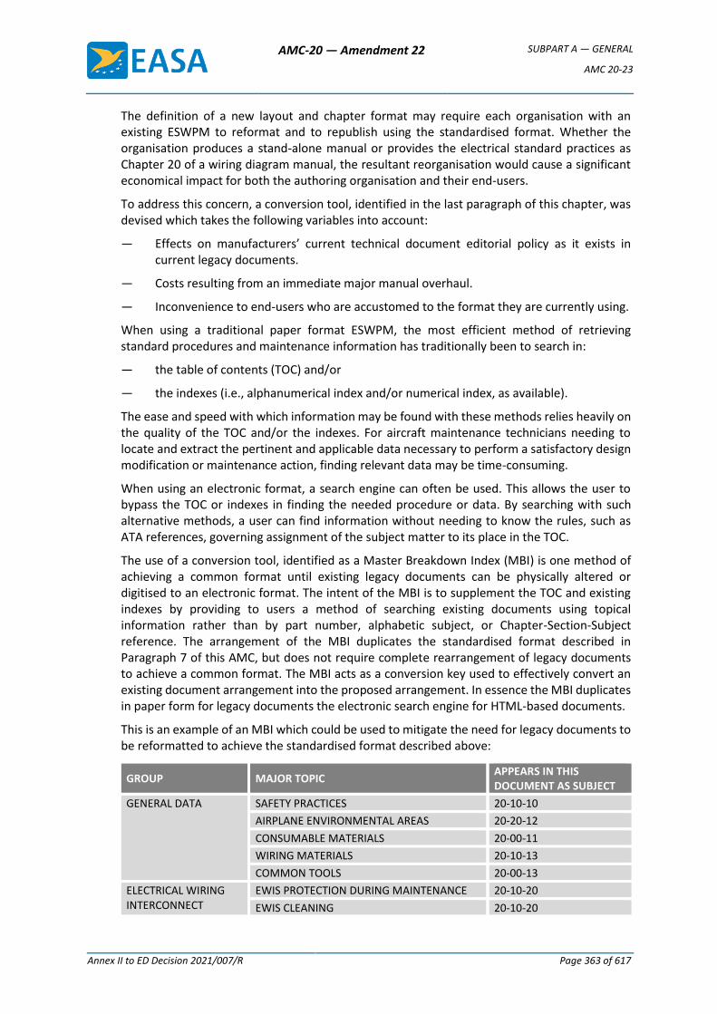
AMC-20 — Amendment 22 SUBPART A — GENERAL
AMC 20-23
Annex II to ED Decision 2021/007/R Page 363 of 617
The definition of a new layout and chapter format may require each organisation with an existing ESWPM to reformat and to republish using the standardised format. Whether the organisation produces a stand-alone manual or provides the electrical standard practices as Chapter 20 of a wiring diagram manual, the resultant reorganisation would cause a significant economical impact for both the authoring organisation and their end-users.
To address this concern, a conversion tool, identified in the last paragraph of this chapter, was devised which takes the following variables into account:
— Effects on manufacturers’ current technical document editorial policy as it exists in current legacy documents.
— Costs resulting from an immediate major manual overhaul.
— Inconvenience to end-users who are accustomed to the format they are currently using.
When using a traditional paper format ESWPM, the most efficient method of retrieving standard procedures and maintenance information has traditionally been to search in:
— the table of contents (TOC) and/or
— the indexes (i.e., alphanumerical index and/or numerical index, as available).
The ease and speed with which information may be found with these methods relies heavily on the quality of the TOC and/or the indexes. For aircraft maintenance technicians needing to locate and extract the pertinent and applicable data necessary to perform a satisfactory design modification or maintenance action, finding relevant data may be time-consuming.
When using an electronic format, a search engine can often be used. This allows the user to bypass the TOC or indexes in finding the needed procedure or data. By searching with such alternative methods, a user can find information without needing to know the rules, such as ATA references, governing assignment of the subject matter to its place in the TOC.
The use of a conversion tool, identified as a Master Breakdown Index (MBI) is one method of achieving a common format until existing legacy documents can be physically altered or digitised to an electronic format. The intent of the MBI is to supplement the TOC and existing indexes by providing to users a method of searching existing documents using topical information rather than by part number, alphabetic subject, or Chapter-Section-Subject reference. The arrangement of the MBI duplicates the standardised format described in Paragraph 7 of this AMC, but does not require complete rearrangement of legacy documents to achieve a common format. The MBI acts as a conversion key used to effectively convert an existing document arrangement into the proposed arrangement. In essence the MBI duplicates in paper form for legacy documents the electronic search engine for HTML-based documents.
This is an example of an MBI which could be used to mitigate the need for legacy documents to be reformatted to achieve the standardised format described above:
GROUP MAJOR TOPIC APPEARS IN THIS DOCUMENT AS SUBJECT
GENERAL DATA SAFETY PRACTICES 20-10-10
AIRPLANE ENVIRONMENTAL AREAS 20-20-12
CONSUMABLE MATERIALS 20-00-11
WIRING MATERIALS 20-10-13
COMMON TOOLS 20-00-13
ELECTRICAL WIRING INTERCONNECT
EWIS PROTECTION DURING MAINTENANCE 20-10-20
EWIS CLEANING 20-10-20
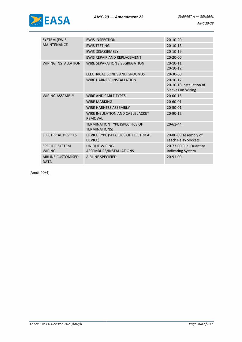
AMC-20 — Amendment 22 SUBPART A — GENERAL
AMC 20-23
Annex II to ED Decision 2021/007/R Page 364 of 617
SYSTEM (EWIS) MAINTENANCE
EWIS INSPECTION 20-10-20
EWIS TESTING 20-10-13
EWIS DISASSEMBLY 20-10-19
EWIS REPAIR AND REPLACEMENT 20-20-00
WIRING INSTALLATION WIRE SEPARATION / SEGREGATION 20-10-11 20-10-12
ELECTRICAL BONDS AND GROUNDS 20-30-60
WIRE HARNESS INSTALLATION 20-10-17 20-10-18 Installation of Sleeves on Wiring
WIRING ASSEMBLY WIRE AND CABLE TYPES 20-00-15
WIRE MARKING 20-60-01
WIRE HARNESS ASSEMBLY 20-50-01
WIRE INSULATION AND CABLE JACKET REMOVAL
20-90-12
TERMINATION TYPE (SPECIFICS OF TERMINATIONS)
20-61-44
ELECTRICAL DEVICES DEVICE TYPE (SPECIFICS OF ELECTRICAL DEVICE)
20-80-09 Assembly of Leach Relay Sockets
SPECIFIC SYSTEM WIRING
UNIQUE WIRING ASSEMBLIES/INSTALLATIONS
20-73-00 Fuel Quantity Indicating System
AIRLINE CUSTOMISED DATA
AIRLINE SPECIFIED 20-91-00
[Amdt 20/4]
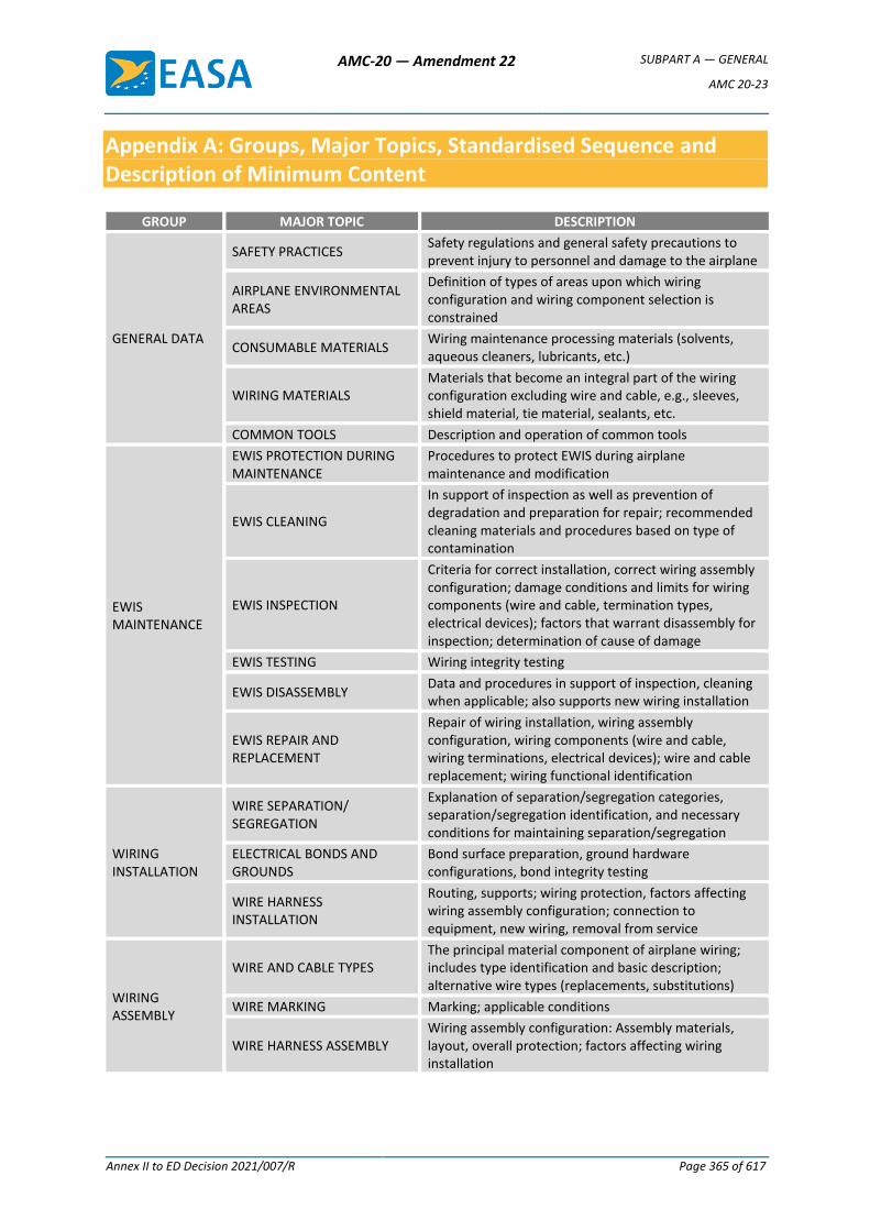
AMC-20 — Amendment 22 SUBPART A — GENERAL
AMC 20-23
Annex II to ED Decision 2021/007/R Page 365 of 617
Appendix A: Groups, Major Topics, Standardised Sequence and Description of Minimum Content
GROUP MAJOR TOPIC DESCRIPTION
GENERAL DATA
SAFETY PRACTICES Safety regulations and general safety precautions to prevent injury to personnel and damage to the airplane
AIRPLANE ENVIRONMENTAL AREAS
Definition of types of areas upon which wiring configuration and wiring component selection is constrained
CONSUMABLE MATERIALS Wiring maintenance processing materials (solvents, aqueous cleaners, lubricants, etc.)
WIRING MATERIALS Materials that become an integral part of the wiring configuration excluding wire and cable, e.g., sleeves, shield material, tie material, sealants, etc.
COMMON TOOLS Description and operation of common tools
EWIS MAINTENANCE
EWIS PROTECTION DURING MAINTENANCE
Procedures to protect EWIS during airplane maintenance and modification
EWIS CLEANING
In support of inspection as well as prevention of degradation and preparation for repair; recommended cleaning materials and procedures based on type of contamination
EWIS INSPECTION
Criteria for correct installation, correct wiring assembly configuration; damage conditions and limits for wiring components (wire and cable, termination types, electrical devices); factors that warrant disassembly for inspection; determination of cause of damage
EWIS TESTING Wiring integrity testing
EWIS DISASSEMBLY Data and procedures in support of inspection, cleaning when applicable; also supports new wiring installation
EWIS REPAIR AND REPLACEMENT
Repair of wiring installation, wiring assembly configuration, wiring components (wire and cable, wiring terminations, electrical devices); wire and cable replacement; wiring functional identification
WIRING INSTALLATION
WIRE SEPARATION/ SEGREGATION
Explanation of separation/segregation categories, separation/segregation identification, and necessary conditions for maintaining separation/segregation
ELECTRICAL BONDS AND GROUNDS
Bond surface preparation, ground hardware configurations, bond integrity testing
WIRE HARNESS INSTALLATION
Routing, supports; wiring protection, factors affecting wiring assembly configuration; connection to equipment, new wiring, removal from service
WIRING ASSEMBLY
WIRE AND CABLE TYPES The principal material component of airplane wiring; includes type identification and basic description; alternative wire types (replacements, substitutions)
WIRE MARKING Marking; applicable conditions
WIRE HARNESS ASSEMBLY Wiring assembly configuration: Assembly materials, layout, overall protection; factors affecting wiring installation
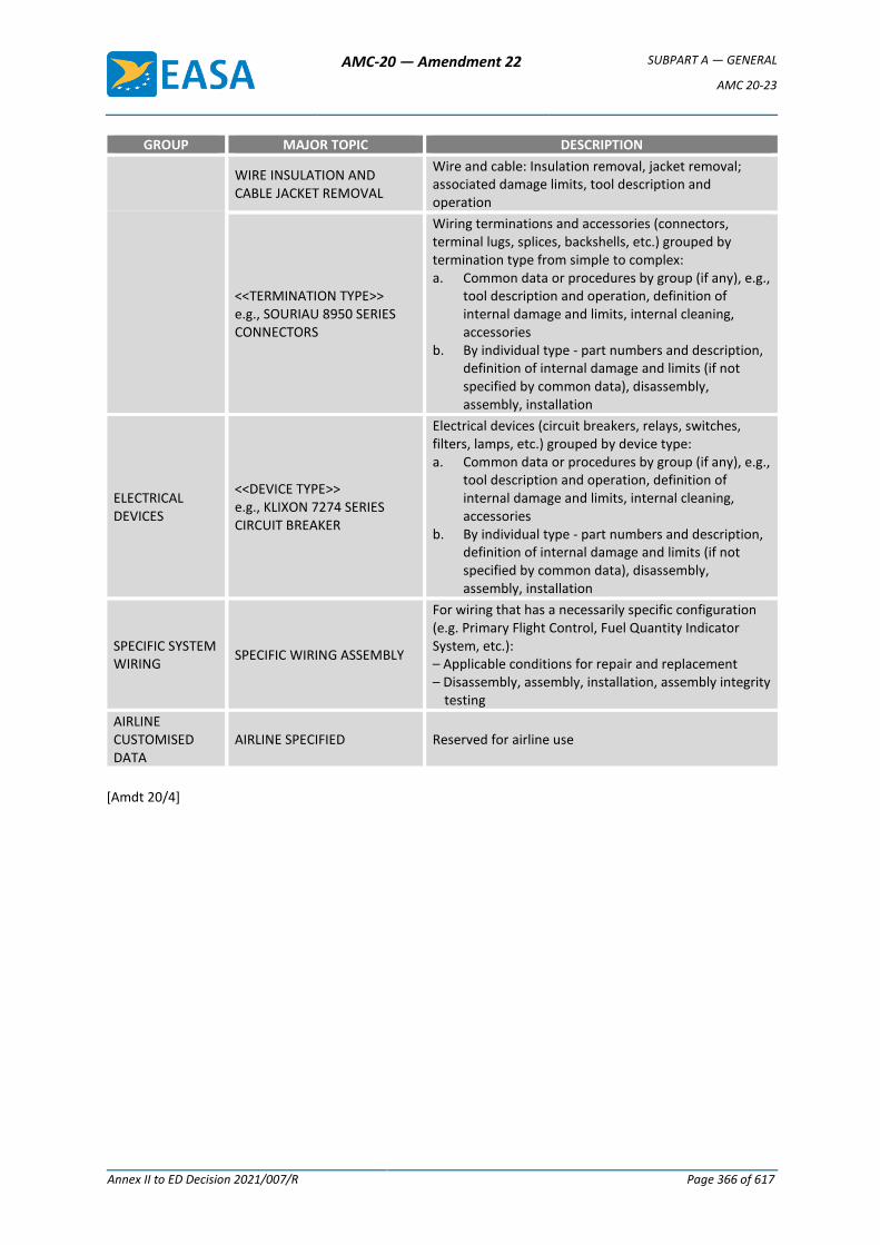
AMC-20 — Amendment 22 SUBPART A — GENERAL
AMC 20-23
Annex II to ED Decision 2021/007/R Page 366 of 617
GROUP MAJOR TOPIC DESCRIPTION
WIRE INSULATION AND CABLE JACKET REMOVAL
Wire and cable: Insulation removal, jacket removal; associated damage limits, tool description and operation
<<TERMINATION TYPE>> e.g., SOURIAU 8950 SERIES CONNECTORS
Wiring terminations and accessories (connectors, terminal lugs, splices, backshells, etc.) grouped by termination type from simple to complex: a. Common data or procedures by group (if any), e.g.,
tool description and operation, definition of internal damage and limits, internal cleaning, accessories
b. By individual type - part numbers and description, definition of internal damage and limits (if not specified by common data), disassembly, assembly, installation
ELECTRICAL DEVICES
<<DEVICE TYPE>> e.g., KLIXON 7274 SERIES CIRCUIT BREAKER
Electrical devices (circuit breakers, relays, switches, filters, lamps, etc.) grouped by device type: a. Common data or procedures by group (if any), e.g.,
tool description and operation, definition of internal damage and limits, internal cleaning, accessories
b. By individual type - part numbers and description, definition of internal damage and limits (if not specified by common data), disassembly, assembly, installation
SPECIFIC SYSTEM WIRING
SPECIFIC WIRING ASSEMBLY
For wiring that has a necessarily specific configuration (e.g. Primary Flight Control, Fuel Quantity Indicator System, etc.): – Applicable conditions for repair and replacement – Disassembly, assembly, installation, assembly integrity
testing
AIRLINE CUSTOMISED DATA
AIRLINE SPECIFIED Reserved for airline use
[Amdt 20/4]

AMC-20 — Amendment 22 SUBPART A — GENERAL
AMC 20-24
Annex II to ED Decision 2021/007/R Page 367 of 617
AMC 20-24
AMC 20-24 Certification Considerations for the Enhanced ATS in Non-Radar Areas using ADS-B Surveillance (ADS-B-NRA) Application via 1090 MHZ Extended Squitter.
1 PREAMBLE
1.1 The scope of this Acceptable Means of Compliance (AMC) is the airworthiness and operational approval of the “Enhanced Air Traffic Services in Non-Radar Areas using ADS-B Surveillance” (ADS-B-NRA) application.
1.2 Operational benefits of the ADS-B-NRA application include the enhancement of the Air Traffic Control Service in current non-radar airspace. ADS-B-NRA would provide controllers with improved situational awareness of aircraft positions, and in consequence appropriate separation minima could be applied depending on the environment and the approval of the competent authority. Current non-radar airspace is controlled using procedural methods which demand large separations. ADS-B-NRA separation minima would be smaller than that used in current non-radar airspace. Alerting Services in nonradar airspace will be enhanced by more accurate information on the latest position of aircraft.
Hence, it is expected that in areas where radar coverage is not feasible or not economically justified this application will provide benefits to capacity, efficiency and safety in a way similar to what would be achieved by use of SSR radar.
1.3 The European CASCADE programme is the mechanism for co-ordination of the European implementation of ADS-B (ADS-B-NRA and other ADS-B based ground and airborne surveillance applications). One of the programme’s aims is to ensure harmonisation and efficiency of implementation.
1.4 CASCADE uses the globally interoperable 1090 MHz Extended Squitter (ES) data link technology, compliant with ICAO SARPS in Annex 10 and in line with the recommendations of the Conference ICAO ANC-11.
1.5 In parallel, the FAA Airservices Australia and Nav Canada plan to deploy ADS-B using the same data link technology. It is assumed that aircraft will be interoperable with all implementation programmes using the EUROCAE/RTCA ADS-B-NRA standard (ED126, DO-303).
1.6 The meaning of abbreviations may be found in Appendix 1.
2 PURPOSE
2.1 This AMC is for operators seeking to operate in airspace classifications A to E where ADS-B-NRA services have been implemented by the Air Navigation Service Provider. It provides the basis for approval of aircraft systems and identifies operational considerations.
It may also assist other stakeholders by alerting them to aircraft requirements, operator procedures and related assumptions. These other stakeholders could include airspace planners, air traffic service providers, ATS system manufacturers, surveillance data
AMC-20 — Amendment 22 SUBPART A — GENERAL
AMC 20-24
Annex II to ED Decision 2021/007/R Page 368 of 617
processing system manufacturers, communication service providers, aircraft and avionics equipment manufacturers and ATS regulatory authorities.
2.2 Acceptable Means of Compliance (AMC) illustrate a means, but not the only means, by which a requirement contained in an EASA airworthiness code or an implementing rule of the Basic Regulation, can be met.
An applicant correctly implementing this AMC in its entirety is assured of acceptance of compliance with the airworthiness considerations prior to use of the automatic dependent surveillance broadcast equipment. The operational considerations in this AMC are consistent with the operational considerations in the position paper 039 revision 8, that is endorsed by the JAA Operations Sectorial Team (OST). An Operator that, in conjunction with the airworthiness considerations, has correctly implemented this AMC should be ensured of acceptance of compliance with the operations rules applicable in JAA Member States.
3 SCOPE
3.1 This AMC is applicable to the various ATS services contained in the ADS-B-NRA application, including separation services. This AMC fulfils the ADS-B-NRA Safety, Performance Requirements and Interoperability Requirements as established in EUROCAE ED-1261, using the methodology described in EUROCAE document ED-78A2.
AMC requirements are driven by the ED-126 requirements for a 5NM separation service (applicable to both en-route and TMA airspace).
Note: the actual choice of ADS-B-NRA ATC service provision, including of the applicable separation minima, is at the discretion of the implementing Air Traffic Service Provider, and should be based on local safety cases.
3.2 The AMC addresses the 1090 MHz Extended Squitter (ES) data link technology as the ADS-B transmit technology.3
4 REFERENCE DOCUMENTS
4.1 Related Regulatory Requirements
— CS/FAR 25.1301, 25.1307, 25.1309, 25.1322, 25.1431, 25.1581, or equivalent requirements of CS 23, 27 and 29, if applicable.
— EU-OPS 1.230, 1.420, 1.845, 1.865, 1040, 1.1045 and 1.1060, as amended, or, if applicable, equivalent requirements of JAR-OPS 3.
— National operating regulations.
4.2 Related EASA/JAA TGL/NPA/AMC (and FAA TSO) Material
— ETSO-2C112b: Minimum Operational Performance Specification for SSR Mode S Transponders (adopts ED-73B)
— ETSO-129A (TSO-129/TSO-129A): Airborne Supplemental Navigation Equipment Using the Global Positioning System (GPS)
1 ED-126: “Safety, Performance and Interoperability Requirements Document for ADS-B-NRA” Application
2 ED-78A: Guidelines for approval of the provision and use of Air Traffic Services supported by Data communications
3 Other, requirements compliant, ADS-B transmit systems (e.g. VDL Mode 4) are expected to be covered through separate regulatory material, as appropriate.
AMC-20 — Amendment 22 SUBPART A — GENERAL
AMC 20-24
Annex II to ED Decision 2021/007/R Page 369 of 617
— ETSO-145/ETSO-146 (TSO-145/TSO-146; TSO-145A/TSO-146A): Airborne Navigation Sensors Using the Global Positioning System (GPS) Augmented by the Wide Area Augmentation System (WAAS)
— AMC 20-13 Certification of Mode S Transponder Systems for Enhanced Surveillance
— JAA Temporary Guidance leaflet (TGL) 13, Revision 1: Certification of Mode S Transponder Systems for Elementary Surveillance
4.3 Related FAA Advisory Circular Material
— FAA AC20-138A: Airworthiness Approval of Global Navigation Satellite System (GNSS) Equipment
4.4 Related EUROCAE/RTCA Standards
— ED-126 (DO-303): Safety, Performance and Interoperability Requirements Document for ADS-B-NRA Application (December 2006)
— ED78A (DO-264): Guidelines for Approval of the Provision and Use of Air Traffic Services Supported by data communications;
— ED-102 (DO-260): MOPS for 1090MHz for ADS-B
— DO-260A: MOPS for 1090MHz for ADS-B
— ED-73B (DO-181C): Minimum Operational Performance Specification for Secondary Surveillance Radar Mode S Transponders
— ED-26: MPS for airborne altitude measurements and coding systems
4.5 Related ICAO Standards and Manuals
— PANS-ATM, Doc 4444, Amendment 4: Procedures for Air Navigation Services – Air Traffic Management
— Annex 10 (Volume III & IV): Aeronautical Telecommunications
5 ASSUMPTIONS
Applicants should note that this AMC is based on the following assumptions.
5.1 Air Traffic Service Provider (ATSP)
ATSP implements the ADS-B-NRA application compliant with relevant requirements of the safety, performance and interoperability requirements of EUROCAE standard ED-126. Deviations from, or supplements to the established standards are assessed by the ATSP. Deviations that potentially impact the airborne domain should be assessed in coordination with relevant stakeholders as per ED78A.
Section 8 of this document, “Airworthiness Considerations”, lists permissible deviations from the target requirements related to the use of existing aircraft installations in support of initial implementations1. These deviations are currently considered operationally acceptable under the assumption that ground mitigation means as discussed in the following subsections, are implemented, at the descretion of the ATSP.
5.1.1 Consistency of position quality indicators with associated position information at time of transmission
1 Refer to sections 8.3.3, 8.3.5 and 8.8.2.
AMC-20 — Amendment 22 SUBPART A — GENERAL
AMC 20-24
Annex II to ED Decision 2021/007/R Page 370 of 617
In cases where position quality indicators are not consistent with actual position quality (e.g., due to uncompensated latency in position transmissions), the implementing ATSP might:
— treat the higher quality indicator encodings as an advised lower one (e.g. NUC=7 may be treated as NUC=5) or,
— consider, for separation purpose, a quality indicator more stringent than the one stated in ED-126 (e.g. NUC =5 rather than NUC=4).
5.1.2 Encoding of NUC Quality Indicator (DO-260 compliant transponders)
In order to mitigate the encoding of the NUC quality indicator based on accuracy quality information (HFOM) in the case of the unavailability of the GPS RAIM function (i.e. unavailability of HPL information), the implementing ATSP may, for instance, rely on the analysis of the frequency and duration of the unavailability of the RAIM function (as part of the local safety assessment).
5.1.3 Transmission of generic emergency indicator only
In order to mitigate the transmission of only the generic emergency indicator (and not also the discrete codes selected by the flight crew), It is assumed that appropriate operational procedures have been established by the implementing ATSP and that pilots and controllers have been trained in their use.
5.1.4 Communications Service Provider (CSP)
In case of CSPs providing (part of) the ground surveillance data communication services (operation of ADS-B ground stations and/or surveillance data networks), the CSP is committed to provide communication services to ATSPs with the expected Quality of Service as defined in a specific Service Level Agreement.
The Service Level Agreement is bilaterally agreed between the CSP and an ATSP. The terms of reference of the Service Level Agreement are consistent with the performance requirements of the ED-126 document.
5.2 Aeronautical Information Service
Each State publishes in its AIP/NOTAM, or equivalent notification, information related to the surveillance provisions, schedule, relevant procedures and confirmation of compliance with ED-126.
6 SYSTEM DESCRIPTION
The basic concept of ADS-B involves the broadcasting of surveillance information from aircraft via a data link.
To support the ADS-B-NRA application, the overall ADS-B avionics system (in the following referred to as “ADS-B System”) would need to provide the following functions:
— Adequate surveillance data provision capability;
— ADS-B message processing (encoding and generation);
— ADS-B message transmission (1090 MHz ES airborne surveillance data-link);
Whereas the latter two functions are incorporated in the 1090 MHz ES ADS-B transmit system, the surveillance data provision is realised through various on-board surveillance data sources (e.g. horizontal position source, barometric altimetry, ATC transponder control panel).
AMC-20 — Amendment 22 SUBPART A — GENERAL
AMC 20-24
Annex II to ED Decision 2021/007/R Page 371 of 617
The horizontal position accuracy and integrity requirements of the ADS-B-NRA application are associated with quality indicators which form part of the air-to-ground ADS-B message exchange. The interconnecting avionics architecture is part of the ADS-B System.
7 FUNCTIONAL CRITERIA
Note: ICAO and EUROCAE/RTCA interoperability references, including aspects of range and resolution of the various data items listed hereafter, for both ED-102/DO-260 and DO-260A equipment-based ADS-B transmit systems, are presented in Appendix 4.
7.1 In line with ED-126 (section 4), the ADS-B System needs to meet the following surveillance data transmission requirements, as a minimum:
— A unique ICAO 24 bit aircraft address (contained within each ADS-B message transmission);
— Horizontal Position (latitude and longitude);
— Horizontal Position Quality Indicator(s) (position integrity for both ED-102/DO-260 and DO-260A based ADS-B transmit systems, as well as accuracy for DO-260A based ADS-B transmit systems);
— Barometric Altitude;
— Aircraft Identification;
— Special Position Identification (SPI);
— Emergency Status and Emergency Indicator;
— Version Number (in aircraft operational status message, if avionics are DO-260A compliant).
7.2 In line with ED-126 (section 4), it is recommended that the ADS-B System meets the following optional surveillance data transmission requirement:
— Ground Velocity.
8 AIRWORTHINESS CONSIDERATIONS
8.1 Airworthiness Certification Objectives
For the purposes of the ADS-B-NRA application, the ADS-B System installed in the aircraft needs to be designed to deliver data that satisfy the airborne domain requirements in line with ED-126 Section 3.4, (Appendix 3 provides a summary for information purposes).
8.2 ADS-B System
8.2.1 The (overall) ADS-B System integrity level with respect to the processing of horizontal position data and horizontal position quality indicators, covering the processing (and data exchange) chain from horizontal position data source(s) to ADS-B transmit data string encoding) needs to be 10-5/fh (refer also to Table 1 in Appendix 3).
Note 1: this integrity level is required to adequately protect against the corruption of horizontal position data and horizontal position quality indicators when applying separation.
Note 2: These performance figures have been set for the “ADS-B out” function, to be used in ADS-B NRA operations as laid down by the Operational Safety Assessment in Annex C of ED 126.
AMC-20 — Amendment 22 SUBPART A — GENERAL
AMC 20-24
Annex II to ED Decision 2021/007/R Page 372 of 617
Note 3: Compliance with these performance figures do not constitute per se a demonstration that the safety objectives of ADS-B NRA operations allocated to avionics are achieved.
Note 4: Also refer to § 3.1.
8.2.2 The (overall) ADS-B System continuity level needs to be 2*10-4/fh (refer also to Table 1 in Appendix 3).
Note 1: These performance figures have been set for the “ADS-B out” function, to be used in ADS-B NRA operations as laid down by the Operational Safety Assessment in Annex C of ED 126;
Note 2: Compliance with these performance figures do not constitute per se a demonstration that the safety objectives of ADS-B NRA operations allocated to avionics are achieved;
Note 3: Also refer to § 3.1.
8.2.3 The latency of the horizontal position data, including any uncompensated latency, introduced by the (overall) ADS-B System does not exceed 1.5 second in 95% and 3 seconds in 99.9% of all ADS-B message transmission cases (refer also to Table 1 in Appendix 3).
8.3 ADS-B Transmit System
8.3.1 Compliance with the air-ground interoperability requirements, as specified in ED-126 and presented in Section 7.1 and Appendix 4, needs to be demonstrated.
8.3.2. For 1090 MHz Extended Squitter ADS-B transmit systems, this should be demonstrated by the relevant tests documented in:
— ED-73B/ETSO-2C112b (or DO-181C);
— ED-102, as a minimum, or an equivalent standard which is acceptable to the Agency (e.g. DO-260 or DO-260A).
8.3.3 ADS-B transmit systems need to transmit horizontal position quality indicators consistent with the associated position information at the time of transmission.
For the expression of the position accuracy quality, the related indicator should therefore reflect:
— The quality (in terms of both integrity and accuracy) of the position measurement itself; and
— Any (uncompensated) latency incurring prior to transmission.
Note: guidance on the quality indicators is provided in Appendix 4.
The applicant needs to demonstrate the correctness of consistent quality indicator encodings in line with (minimum) position source quality and any (uncompensated) maximum latency as expressed in 8.2.3.
Permissible deviation for initial implementations:
For initial implementations, some aircraft installations may not take into account any (uncompensated) latency in the encoding of the position accuracy quality indicator as applicable at the time of transmission. Hence, such installations might transmit horizontal position quality indicators that are consistent with the
AMC-20 — Amendment 22 SUBPART A — GENERAL
AMC 20-24
Annex II to ED Decision 2021/007/R Page 373 of 617
associated position information only for lower quality indicator encodings1 (e.g. NUC=5 or NAC=5) but not higher ones (e.g. NUC=7 or NAC=7). Such deviation from the above target requirement need to be listed in the Aircraft Flight Manual (refer to Section 9.3).
8.3.4 The value of the horizontal position quality indicators need to be based on the integrity information for the encoding of the ED-102/DO-260 related NUC and the DO-260A related NIC quality indicator, as related to the horizontal position sources.
In addition, the encoding of the DO-260A NAC quality indicator needs to be based on the accuracy information of the horizontal position sources.
8.3.5 In case of ED-102/DO-260 based ADS-B transmit systems, the NUC Quality Indicator value need to be encoded based on the integrity containment radius2 only.
Permissible deviation for initial implementations:
For initial implementations, some GNSS position source based aircraft installations may encode the NUC Quality Indicator on accuracy quality information (HFOM) under rare satellite constellation circumstances leading to the temporary unavailability of the integrity monitoring (RAIM) function (i.e. unavailability of integrity containment radius calculation). Such deviation from the above target requirement need to be listed in the Aircraft Flight Manual (refer to Section 9.3).
8.3.6 If the ADS-B transmit system does not have a means to determine an appropriate integrity containment radius and a valid position is reported, then the Quality Indicator (i.e. NUC or NIC) need to be encoded to indicate that the integrity containment radius is unknown (i.e. NUC/NIC should be set to ‘zero’).
8.3.7 Transmitter antenna installation needs to comply with guidance for installation of ATC transponders to ensure satisfactory functioning. (Also refer to ED-73B)
8.3.8 If more than one ADS-B transmit system is installed, simultaneous operation of both transmit systems needs to be prevented.
8.4 Horizontal Position Data Sources
8.4.1 The requirements on horizontal position data sources are based on the ED-126 safety and performance assessments.
8.4.2 Components of horizontal position data sources external to the aircraft ADS-B system (such as the GNSS space segment) fall outside these airworthiness considerations. Such external components are assumed to operate in accordance with their specified nominal performance3.
Nevertheless, failures of the external data source components are required to be detected through on-board monitoring (as expressed in section 8.4.3).
1 This is a consequence of the definition of the quality indicator encoding describing an interval of values between a lower and an upper
bound (refer also to Appendix 4.2). For instance, a NUC=5 encoding expresses an upper bound of position accuracy quality indication of 0.3NM whilst a NUC=7 encoding expresses an upper bound of 0.05NM. Therefore, in case of e.g. the actual GNSS position source performance, a NUC=5 encoding provides sufficient margin to also correctly express the effects of on-board uncompensated latency whilst this is not the case for a NUC=7 encoding any more.
2 I.e. GNSS conformant HPL/HIL information.
3 For GNSS based systems, this includes satellite constellation aspects.
AMC-20 — Amendment 22 SUBPART A — GENERAL
AMC 20-24
Annex II to ED Decision 2021/007/R Page 374 of 617
8.4.3 Any eligible horizontal position data source needs to meet the following minimum requirements (refer also to Table 2 in Appendix 3):
— Correct encoding of quality indicator information in line with the actual performance of the selected horizontal position data source(s), i.e. in relation to position integrity containment bound (ED-102/DO-260 and DO-260A ADS-B transmit systems) and position accuracy (DO-260A ADS-B transmit systems);
— Position source failure probability: 10-4 per hour1;
— Position integrity alert failure probability, commensurate with the performance characteristics of GNSS integrity monitoring2: 10-3 (per position source failure event);
— Position integrity time to alert: 10 seconds.
8.4.4 If available and valid, integrity containment radius information should be provided to the ADS-B transmit system from the position data source, or equivalent, on the same interface as and together with each positional data.
8.4.5 If the integrity containment radius is not provided by the horizontal position data source, the ADS-B transmit system may use other means to establish an appropriate integrity containment radius3, provided a requirements compliant integrity alert mechanism is available.
8.4.6 Use of GNSS Systems as Primary Position Data Source
8.4.6.1 GNSS is considered as primary horizontal position data source for the provision of an acceptable accuracy and integrity performance in support of the ATC separation services contained within the ADS-B-NRA application.
The ED-126 safety and performance assessments are based on the specified performance and characteristics of GNSS systems, including receiver autonomous integrity monitoring. Therefore, for GNSS systems as specified in section 8.4.6.2, a safety and performance demonstration is not required.
8.4.6.2 If GNSS is used as a positional source, the GNSS system should be either compatible with:
— ETSO C-129A, TSO C-129 or TSO C-129A; or
— ETSO C-145/C-146 or TSO C-145A/C-146A,
capable of delivering position data with a periodic interval of at least 1.2 s4.
8.4.6.3 For GNSS systems compatible with (E)TSO C-129 (any revision), it is highly desired that the system incorporates Fault Detection and Exclusion
1 For GNSS based position sources, the failure occurs outside the aircraft system and is therefore expressed as per ATSU-hour. Proof of
compliance of alternative solely aircraft based sources should take this into account and might have to express the requirement as 10-5 per flight hour (i.e. for the en-route environment).
2 As realised through receiver autonomous integrity monitoring (RAIM), including its characteristics of increasingly less likely to fail for position errors beyond the horizontal protection limit. Within ED-126, the position source failure is modelled as a bias error that equals the integrity containment radius.
3 E.g. HPL/HIL based upon known RAIM protection threshold.
4 ETSO C-145/C146 provides additional capabilities compared with ETSO C129A such as: processing of GPS without Selective Availability, processing of SBAS signals when available and Fault Detection Exclusion as a basic function. Therefore ETSO C145/146 usually provides higher quality integrity values than ETSO C-129A equipment.

AMC-20 — Amendment 22 SUBPART A — GENERAL
AMC 20-24
Annex II to ED Decision 2021/007/R Page 375 of 617
capability as defined in AC 20-138A, Appendix 1, “GPS as a Primary Means of Navigation for Oceanic/Remote Operations”.
8.4.7 Use of Alternative Compliant Position Data Sources
As the ED-126 safety and performance assessments are based on the performance and characteristics of GNSS systems, for alternative position sources a dedicated safety and performance assessment is required to demonstrate compliance with the ED-126 requirements.
8.4.8 Use of Temporary Back-up Position Data Sources
Back-up position data sources not complying with the requirements referred to in section 8.4.3 may prove very useful in enhancing the continuity of ADS-B surveillance provision during temporary outages of the primary (or equivalent alternative) position data sources.
Any such back-up position data source needs to report its accuracy and integrity performance to the ADS-B transmit system, in a format compliant with ED-102/DO-260 or DO-260A, as appropriate.
8.5 Barometric Altitude Data Sources
8.5.1 Pressure altitude provided to the ADS-B transmit system needs to be in accordance with existing requirements for ATC transponders.
8.5.2 The digitizer code selected needs to correspond to within plus or minus 38.1 m (125 ft), on a 95% probability basis, with the pressure-altitude information (referenced to the standard pressure setting of 1013.25 hectopascals), used on board the aircraft to adhere to the assigned flight profile. (ICAO Annex 10, Vol IV, 3.1.1.7.12.2.4. See also EUROCAE ED-26).
The performance of the encoders and of the sensors needs to be independent from the pressure setting selected.
8.5.3 The transponder should indicate correctly the altitude resolution (quantisation) used, i.e. 25ft (from an appropriate source, default resolution) or 100ft (Gillham’s coded source, permissible alternative resolution).
The conversion of Gillham’s coded data to another format before inputting to the transponder is not permitted unless failure detection1 can be provided and the resolution (quantisation) is set in the transmitted data to indicate 100ft.
8.5.4 In case more stringent barometric altimetry requirements are applicable in line with e.g. airspace requirements (e.g. RVSM) or other function requirements (e.g. ACAS II), then these requirements and their related regulation take precedence.
8.6 Aircraft Identification
8.6.1 Identification needs to be provided to the ADS-B transmit system so that the information is identical to the filed ICAO flight plan. This information may be provided from:
— A flight management system; or
— A pilot control panel; or
1 For instance, this need can be satisfied by means of dual independent altitude corrected sensors together with an altitude data
comparator (which may be incorporated and enabled in the ADS-B transmit system).
AMC-20 — Amendment 22 SUBPART A — GENERAL
AMC 20-24
Annex II to ED Decision 2021/007/R Page 376 of 617
— For aircraft, which always operate with the same flight identification (e.g. using registration as the flight identification) it may be programmed into equipment at installation.
8.6.2 In case no ICAO flight plan is filed, the Aircraft Registration needs to be provided to the ADS-B transmit system.
8.7 Special Position Identification (SPI)
For ATC transponder-based ADS-B transmit systems, the SPI capability needs to be provided. The SPI capability should be integrated into the transponder functionality and should be controlled from the transponder control panel.
8.8 Emergency Status/Emergency Indicator
8.8.1 When an emergency status (i.e. discrete emergency code) has been selected by the flight crew, the emergency indicator needs to be set by the ADS-B transmit system.
8.8.2 For ATC transponder-based ADS-B transmit systems, the discrete emergency code declaration capability should be integrated into the transponder functionality and should be controlled from the transponder control panel.
Permissible deviation for initial implementations:
For initial implementations, instead of the required transmission of the discrete emergency codes 7500, 7600 and 7700 when selected by the flight crew, the transmission of only the generic emergency indicator can satisfy this requirement. Such deviation from the above target requirement needs to be listed in the Aircraft Flight Manual (refer to Section 9.3).
8.9 Airworthiness Considerations regarding Optional Provisions
8.9.1 Ground Velocity (OPTIONAL)
Ground velocity, e.g. from an approved GNSS receiver, in the form of East/West and North/South Velocity (including a velocity quality indicator) is recommended to be provided.
8.9.2 Special Position Identification (SPI) (OPTIONAL)
For non-ATC transponder-based ADS-B transmit systems (i.e. installations based on dedicated ADS-B transmitters), a discrete input or a control panel should be provided to trigger the SPI indication.
8.9.3 Emergency Status/Emergency Indicator (OPTIONAL)
For non-ATC transponder-based ADS-B transmit systems (i.e. installations based on dedicated ADS-B transmitters), a discrete input or a control panel should be provided to indicate the emergency status (discrete emergency code).
8.9.4 Flight Deck Control Capabilities (OPTIONAL)
8.9.4.1 Means should be provided to the flight crew to modify the Aircraft Identification information when airborne.
8.9.4.2 Means should be provided to the flight crew to disable the ADS-B function on instruction from ATC without disabling the operation of the ATC transponder function.
AMC-20 — Amendment 22 SUBPART A — GENERAL
AMC 20-24
Annex II to ED Decision 2021/007/R Page 377 of 617
Note: It is recommended to implement an independent ADS-B disabling function. For future ADS B application such flight deck capability may become mandatory. It should be recalled that disabling the operation of the transponder will disable also the ACAS function.
8.9.4.3 Means should be provided to the flight crew to disable the transmission of the barometric altitude.
9 COMPLIANCE WITH THIS AMC
9.1 Airworthiness
9.1.1 When showing compliance with this AMC, the following points should be noted:
a) The applicant will need to submit, to the Agency, a certification plan and a compliance statement that shows how the criteria of this AMC have been satisfied, together with evidence resulting from the activities described in the following paragraphs.
b) Compliance with the airworthiness requirements (e.g. CS-25) for intended function and safety may be demonstrated by equipment qualification, safety analysis of the interface between the ADS-B equipment and data sources, structural analyses of new antenna installations, equipment cooling verification, evidence of a human to machine interface, suitable for ADS-B-NRA.
c) The safety analysis of the interface between the ADS-B transmit system and its data sources should show no unwanted interaction under normal or fault conditions.
d) The functionality for ADS-B-NRA application may be demonstrated by testing that verifies nominal system operation, the aircraft derived surveillance data contained in the ADS-B messages, and the functioning of system monitoring tools/fault detectors (if any).
9.1.2 The functionality for ADS-B-NRA application may be further demonstrated by ground testing, using ramp test equipment where appropriate, that verifies nominal system operation, the aircraft derived surveillance data contained in the ADS-B messages, and the functioning of system monitoring tools/fault detectors (if any).
Note: this limited testing assumes that the air-ground surveillance systems have been shown to satisfactorily perform their intended functions in the flight environment in accordance with applicable requirements.
To minimise the certification effort for follow-on installations, the applicant may claim credit, from the Agency, for applicable certification and test data obtained from equivalent aircraft installations.
9.2 Performance
Where compliance with a performance requirement cannot readily be demonstrated by a test, then the performance may be verified by an alternative method such as analysis, including statistical analysis of measurements under operational conditions.
AMC-20 — Amendment 22 SUBPART A — GENERAL
AMC 20-24
Annex II to ED Decision 2021/007/R Page 378 of 617
9.3 Aircraft Flight Manual
9.3.1 The Aircraft Flight Manual (AFM) or the Pilot’s Operating Handbook (POH), whichever is applicable, needs to provide at least a statement of compliance that the ADS-B System complies with this AMC20-24 and if deviations are applicable. Deviations,1 including those stated in this document, as appropriate may be included or referred to.
9.4 Existing installations
9.4.1 The applicant will need to submit, to the Agency, a compliance statement, which shows how the criteria of this AMC have been satisfied for existing installations.
Compliance may be supported by design review and inspection of the installed system to confirm the availability of required features, functionality and acceptable human-machine interface.
9.4.2 Where this design review finds items of non-compliance, the applicant may offer mitigation that demonstrates an equivalent level of safety and performance. Items presented by the applicant which impact safety, performance and interoperability requirements allocation will need to be coordinated in accordance with ED-78A.
10 OPERATIONAL CONSIDERATIONS
10.1 General
10.1.1 The installation should be certified according to airworthiness considerations in section 8 prior to operational approval.
10.1.2 The assumptions in section 5, concerning Air Traffic and Communications Services Providers, and Aeronautical Information Services, should have been satisfied.
10.1.3 A unique ICAO 24 bit aircraft address should be assigned by the responsible authority to each airframe.
10.2 Operational Safety Aspects
10.2.1 In all cases, flight crews should comply with the surveillance provisions, schedules and relevant procedures contained in the Aeronautical Information Publications (AIP) published by the appropriate authorities.
10.2.2 Direct controller-pilot VHF voice communications should be available at all times.
10.2.3 If flight crew receive equipment indications showing that position being broadcast by the ADS-B system is in error (e.g. GPS anomaly), they should inform the ATSP, as appropriate, using any published contingency procedures.
10.2.4 When there is not an independent Flight Deck Control selection between the ADS-B function (ADS-B on/off) and the ATC transponder function, the crew must be fully aware that disabling the ADS B function will also lead to disable the ACAS function.
10.3 Operations Manual and Training
10.3.1 Operations Manual
1 Refer to sections 8.3.3, 8.3.5 and 8.8.2.
AMC-20 — Amendment 22 SUBPART A — GENERAL
AMC 20-24
Annex II to ED Decision 2021/007/R Page 379 of 617
10.3.1.1 The Operations Manual should include a system description, operational and contingency procedures and training elements for use of the ADS-B-NRA application.
10.3.1.2 The Operations Manual, preferably section B, should contain the operational aspects described in this guidance material.
10.3.1.3 Operators operating under the provisions of ICAO Annex 6 Part II “International General Aviation – Aeroplanes” are not required to have an operations manual.
However, in order to use ADS-B applications, the operator should develop similar training and operational procedures to the ones described in this guidance material. This material may need to be approved by the State of Registry of the operator in accordance with national practice and sight of this approval may be required by the ADS-B navigation service provider.
10.3.2 Flight Crew Training
10.3.2.1 Aircraft operators should ensure that flight crew are thoroughly familiar with all relevant aspects of ADS-B applications.
10.3.2.2 Flight crew training should address the:
a) General understanding of ADS-B-NRA operating procedures;
b) Specific ADS-B associated phraseology;
c) General understanding of the ADS-B technique and technology;
d) Characteristics and limitations of the flight deck human-machine interface, including an overview of ADS-B environment and system descriptions;
e) Need to use the ICAO defined format for entry of the Aircraft Identification or Aircraft Registration marking as applicable to the flight;
Note 1: ICAO Document 8168-OPS/611 Volume I (Procedures for Air Navigation Services) requires that flight crew of aircraft equipped with Mode “S” having an aircraft identification feature should set the aircraft identification into the transponder. This setting is required to correspond to the aircraft identification that has been specified at Item 7 of the ICAO flight plan and consists of no more than seven characters. If the aircraft identification consists of less than seven characters, no zeros, dashes or spaces should be added. If no flight plan has been filed, the setting needs to be the same as the aircraft’s registration, again, up to a maximum of seven characters.
Note 2: The shortened format commonly used by airlines (a format used by International Airlines Transport Association (IATA)) is not compatible with ICAO provisions for the flight planning and ATC services used by ATC ground systems.
f) Operational procedures regarding the transmission of solely the generic emergency flag in cases when the flight crew actually selected a discrete emergency code (if implemented, refer to section 8.8) and SPI;
AMC-20 — Amendment 22 SUBPART A — GENERAL
AMC 20-24
Annex II to ED Decision 2021/007/R Page 380 of 617
g) Indication of ADS-B transmit capability within the ICAO flight plan but only when the aircraft is certified according to this AMC;
h) Handling of data source errors (e.g. discrepancies between navigation data sources) (refer to 10.2.3);
i) Incident reporting procedures;
j) Crew Resources Management and associated human factors issues.
10.4 Incident reporting
Significant incidents associated with ATC surveillance information transmitted by the ADS-B data link that affects or could affect the safe operation of the aircraft will need to be reported in accordance with EU-OPS 1.420 (or national regulations, as applicable).
10.5 Minimum Equipment List
The MEL will need to be revised to indicate the possibility of despatch of aircraft with the ADS-B system unserviceable or partially unserviceable.
11 MAINTENANCE
11.1 Maintenance tests should include a periodic verification check of aircraft derived data including the ICAO 24 bit aircraft address using suitable ramp test equipment. The check of the 24 bit aircraft address should be made also in the event of a change of state of registration of the aircraft.
11.2 Maintenance tests should check the correct functioning of system fault detectors (if any).
11.3 Maintenance tests at ADS-B transmit system level for encoding altitude sensors with Gillham’s code output should be based on the transition points defined in EUROCAE ED-26, Table 13.
11.4 Periodicity for the check of the ADS-B transmitter should be established.
12 AVAILABILITY OF DOCUMENTS
EASA documents are available from http://www.easa.europa.eu.
JAA documents are available from the JAA publisher Information Handling Services (IHS). Information on prices, where and how to order is available on both the JAA web site www.jaa.nl and the IHS web site www.avdataworks.com.
ICAO documents may be purchased from Document Sales Unit, International Civil Aviation Organisation, 999 University Street, Montreal, Quebec, Canada H3C 5H7, (Fax: 1 514 954 6769, e-mail: [email protected]) or through national agencies.
EUROCAE documents may be purchased from EUROCAE, 102 rue Etienne Dolet, 92240 MALAKOFF, France, (Fax: 33 1 46556265). Web site: www.eurocae.org.
RTCA documents may be purchased from RTCA, Incorporated, 1828 L Street, Northwest, Suite 820, Washington, D.C. 20036-4001 U.S.A. Web site: www.rtca.org.
EUROCONTROL documents may be requested from EUROCONTROL, Documentation Centre, GS4, Rue de la Fusee, 96, B-1130 Brussels, Belgium; (Fax: 32 2 729 9109 or web site www.eurocontrol.int).
FAA documents may be obtained from Department of Transportation, Subsequent Distribution Office SVC-121.23, Ardmore East Business Centre, 3341 Q 75th Avenue, Landover, MD 20785, USA.
AMC-20 — Amendment 22 SUBPART A — GENERAL
AMC 20-24
Annex II to ED Decision 2021/007/R Page 381 of 617
Australia CASA documents are available from http://www.casa.gov.au/.
[Amdt 20/3]
Appendix 1 to AMC 20-24
Appendix 1.1: Common Terms
Reference should be made to EUROCAE document ED-126 for the definitions of terms.
Appendix 1.2: Abbreviations
ADS-B Automatic Dependent Surveillance- Broadcast
ADS-B-NRA Enhanced ATS in Non-Radar Areas using ADS-B Surveillance
AFM Aircraft Flight Manual
ANC Air Navigation Commission (ICAO)
ATSP Air Traffic Service Provider
ATC Air Traffic Control
ATS Air Traffic Services
ATSU Air Traffic Service Unit
ATM Air Traffic Management
CASCADE Co-operative ATS through Surveillance and Communication Applications Deployed in ECAC
EUROCONTROL European Organisation for the Safety of Air Navigation
FAA Federal Aviation Administration
GNSS Global Navigation Satellite System
HPL Horizontal Protection Limit
HIL Horizontal Integrity Limit
ICAO International Civil Aviation Organisation
INTEROP Interoperability Requirements
MEL Minimum Equipment List
NIC Navigation Integrity Category
NACp Navigation Accuracy Category
NUC Navigation Uncertainty Category
POH Pilots Operating Handbook
RFG Requirement Focus Group
SIL Surveillance Integrity Level
SPI Special Position Identifier
SPR Safety and Performance Requirements
SSR Secondary Surveillance Radar
OSED Operational Services and Environment Definition
Rc Horizontal Position Integrity Containment Radius
TMA Terminal Manoeuvring Area
[Amdt 20/3]
AMC-20 — Amendment 22 SUBPART A — GENERAL
AMC 20-24
Annex II to ED Decision 2021/007/R Page 382 of 617
Appendix 2 to AMC 20-24
Appendix 2.1: Summary of core ADS-B-NRA Operational Assumptions
— The ADS-B-NRA application assumes implementation of the procedures contained in the PANS-ATM ADS-B amendment. Fallback procedures from the radar environment apply to ADS-B-NRA when necessary. For example, ATC could apply alternate procedural separation (e.g., a vertical standard) during degraded modes.
— En route traffic density is assumed to be the same as in the current environment in which single radar coverage would enable the provision of a 5NM separation service for en route regions. This corresponds to low or medium density.
— Direct Controller-Pilot Communication (VHF) is assumed to be available at all times.
— It is assumed that the ADS-B coverage is known to the Controller in the controlled airspace.
Appendix 2.2: Summary of core ADS-B-NRA Ground Domain Assumptions
— Controller operating procedures are assumed to be unaffected by the selection of an ADS-B data link, i.e., the ADS-B data link is assumed to be transparent to the controller.
— Air Traffic Controllers are assumed to follow existing procedures for coordination and transfer of aircraft. This applies to coordinating appropriate information with downstream units and complying with local agreements established between ATC units regarding separation standards to be established prior to entry into a bordering ATC unit.
— Appropriate ATS authorities are assumed to provide controllers with adequate contingency procedures in the event of ADS-B failures or degradation.
— It is assumed that there is a monitoring capability in the ADS-B Receive Subsystem that monitors the health and operation of the equipment and sends alerts and status messages to the Air Traffic Processing Subsystem.
[Amdt 20/3]
AMC-20 — Amendment 22 SUBPART A — GENERAL
AMC 20-24
Annex II to ED Decision 2021/007/R Page 383 of 617
Appendix 3 to AMC 20-24
Summary of ADS-B-NRA Airborne Safety and Performance Requirements
Parameter Requirement
Horizontal Position and Horizontal Position Quality Indicator(s)
10-5/fh
ADS-B System Continuity 2*10-4/fh
Horizontal Position Latency1 1.5 sec/95%
Table 1: Overall Minimum Airborne ADS-B System2 Requirements
Parameter Requirement
Horizontal Position Source
— Accuracy (95%) — 5 NM Sep: 926 m
— Integrity
— Containment Radius (Rc) — 5 NM Sep: Rc=2 NM
— Source Failure Probability 10-4/h 3
— Alert Failure Probability 10-3 (per position source failure event)
— Time to Alert — 5 NM Sep: 10 sec
Table 2: Minimum Horizontal Position Source Requirements
Note: for DO-260 based ADS-B transmit systems, the related encoding of the horizontal position quality indicator through the Navigation Uncertainty Category (NUC) effectively leads to a containment radius requirement of 1NM for a 5 NM separation service.
Note: accuracy and integrity containment radius requirements are expressed here as guidance to related horizontal position source regulation (refer to section 8.4).
Note: the containment bound requirements reflect the outcomes of both the collision risk assessment (CAP) and time-to-alert assessment.
Note: the accuracy and integrity containment radius requirements have to be met by the horizontal position source, taking into account the effects of on-board latency (if not compensated for).
An uncompensated latency of 1.5 seconds translates into a dilution in the order of 450 metres (assuming an aircraft speed of 600 knots in en-route airspace). This value of 450 metres has to be added to the actual performance of the horizontal position source(s), the sum of which has to be within the required bounds.
The GNSS equipment specified in 8.4.6 meets the overall accuracy and integrity requirements, including the effects of an uncompensated latency of maximum 1.5 second accumulated up to the time of transmission.
1 Uncompensated delay measured from to the time of validity of position measurement until ADS-B transmission (i.e. at RF level).
2 As defined in section 6.
3 For GNSS based functions, expressed as an assumption of GNSS performance.
AMC-20 — Amendment 22 SUBPART A — GENERAL
AMC 20-24
Annex II to ED Decision 2021/007/R Page 384 of 617
Parameter Requirement
Barometric Altitude — Accuracy: as per the installed sensors (refer to section 8.5.2)
— Maximum Latency: 1 sec (as for SSR)
Aircraft Identification, SPI, Emergency Status As for SSR [AMC20-13].
Table 3: Other Minimum ADS-B Surveillance Data Requirements
Parameter Loss Corruption Note
Barometric Altitude Minor Minor As for SSR [AMC20-13].
Aircraft Identification Minor Minor As for SSR.[AMC20-13]
Table 4: Failure Condition Categories
[Amdt 20/3]
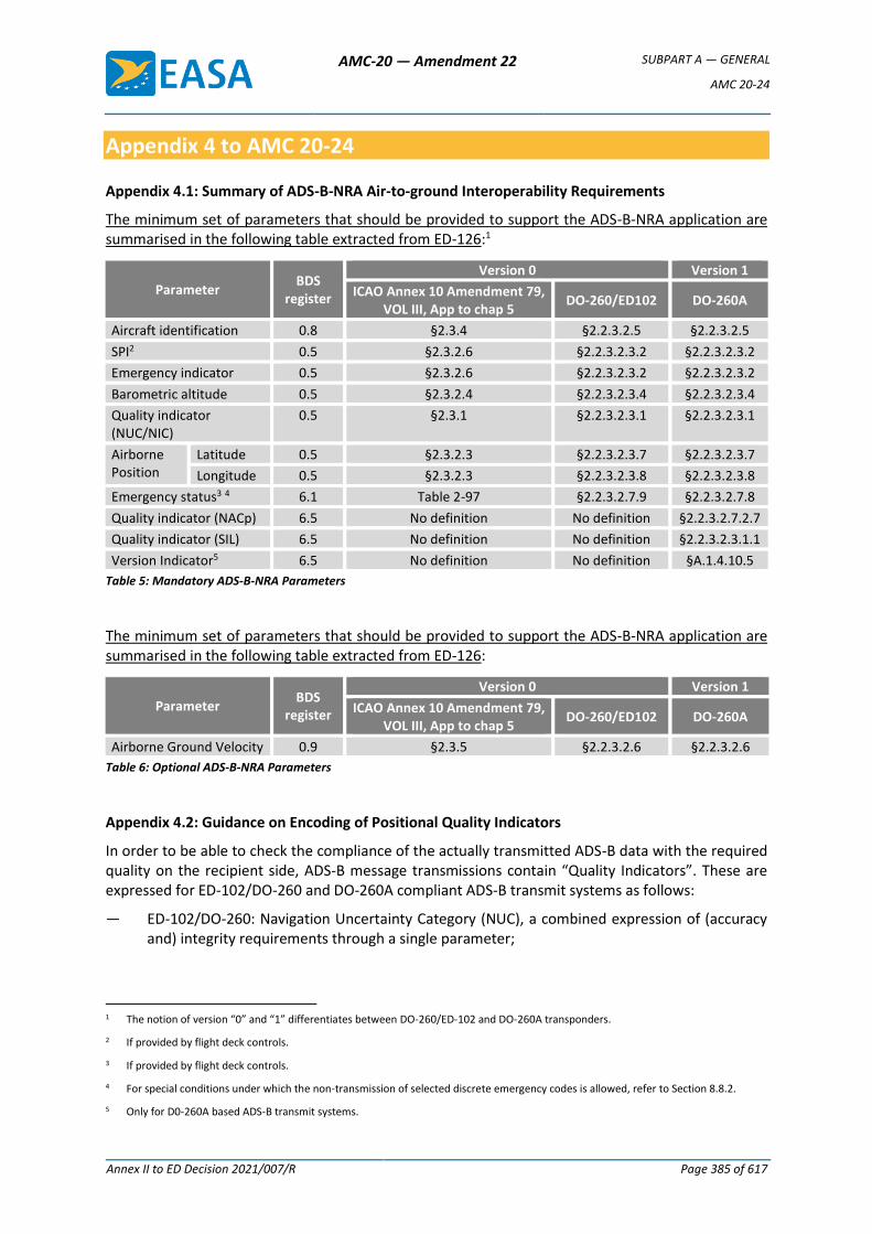
AMC-20 — Amendment 22 SUBPART A — GENERAL
AMC 20-24
Annex II to ED Decision 2021/007/R Page 385 of 617
Appendix 4 to AMC 20-24
Appendix 4.1: Summary of ADS-B-NRA Air-to-ground Interoperability Requirements
The minimum set of parameters that should be provided to support the ADS-B-NRA application are summarised in the following table extracted from ED-126:1
Parameter BDS
register
Version 0 Version 1
ICAO Annex 10 Amendment 79, VOL III, App to chap 5
DO-260/ED102 DO-260A
Aircraft identification 0.8 §2.3.4 §2.2.3.2.5 §2.2.3.2.5
SPI2 0.5 §2.3.2.6 §2.2.3.2.3.2 §2.2.3.2.3.2
Emergency indicator 0.5 §2.3.2.6 §2.2.3.2.3.2 §2.2.3.2.3.2
Barometric altitude 0.5 §2.3.2.4 §2.2.3.2.3.4 §2.2.3.2.3.4
Quality indicator (NUC/NIC)
0.5 §2.3.1 §2.2.3.2.3.1 §2.2.3.2.3.1
Airborne Position
Latitude 0.5 §2.3.2.3 §2.2.3.2.3.7 §2.2.3.2.3.7
Longitude 0.5 §2.3.2.3 §2.2.3.2.3.8 §2.2.3.2.3.8
Emergency status3 4 6.1 Table 2-97 §2.2.3.2.7.9 §2.2.3.2.7.8
Quality indicator (NACp) 6.5 No definition No definition §2.2.3.2.7.2.7
Quality indicator (SIL) 6.5 No definition No definition §2.2.3.2.3.1.1
Version Indicator5 6.5 No definition No definition §A.1.4.10.5
Table 5: Mandatory ADS-B-NRA Parameters
The minimum set of parameters that should be provided to support the ADS-B-NRA application are summarised in the following table extracted from ED-126:
Parameter BDS
register
Version 0 Version 1
ICAO Annex 10 Amendment 79, VOL III, App to chap 5
DO-260/ED102 DO-260A
Airborne Ground Velocity 0.9 §2.3.5 §2.2.3.2.6 §2.2.3.2.6
Table 6: Optional ADS-B-NRA Parameters
Appendix 4.2: Guidance on Encoding of Positional Quality Indicators
In order to be able to check the compliance of the actually transmitted ADS-B data with the required quality on the recipient side, ADS-B message transmissions contain “Quality Indicators”. These are expressed for ED-102/DO-260 and DO-260A compliant ADS-B transmit systems as follows:
— ED-102/DO-260: Navigation Uncertainty Category (NUC), a combined expression of (accuracy and) integrity requirements through a single parameter;
1 The notion of version “0” and “1” differentiates between DO-260/ED-102 and DO-260A transponders.
2 If provided by flight deck controls.
3 If provided by flight deck controls.
4 For special conditions under which the non-transmission of selected discrete emergency codes is allowed, refer to Section 8.8.2.
5 Only for D0-260A based ADS-B transmit systems.
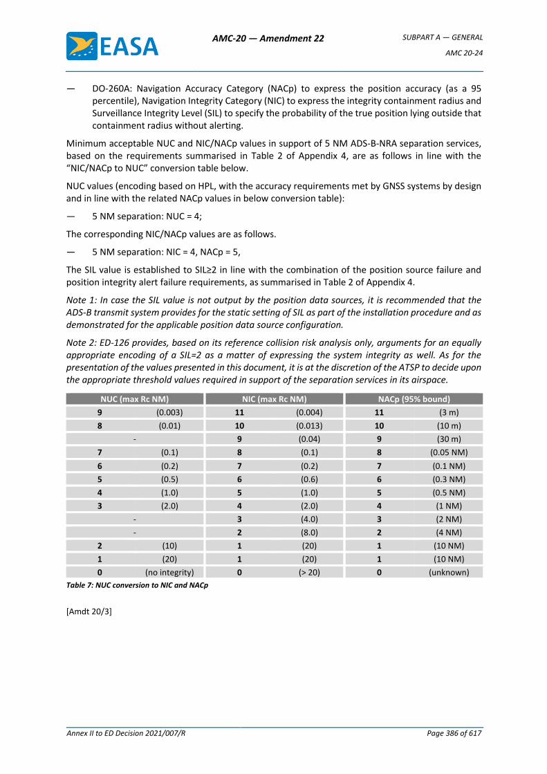
AMC-20 — Amendment 22 SUBPART A — GENERAL
AMC 20-24
Annex II to ED Decision 2021/007/R Page 386 of 617
— DO-260A: Navigation Accuracy Category (NACp) to express the position accuracy (as a 95 percentile), Navigation Integrity Category (NIC) to express the integrity containment radius and Surveillance Integrity Level (SIL) to specify the probability of the true position lying outside that containment radius without alerting.
Minimum acceptable NUC and NIC/NACp values in support of 5 NM ADS-B-NRA separation services, based on the requirements summarised in Table 2 of Appendix 4, are as follows in line with the “NIC/NACp to NUC” conversion table below.
NUC values (encoding based on HPL, with the accuracy requirements met by GNSS systems by design and in line with the related NACp values in below conversion table):
— 5 NM separation: NUC = 4;
The corresponding NIC/NACp values are as follows.
— 5 NM separation: NIC = 4, NACp = 5,
The SIL value is established to SIL≥2 in line with the combination of the position source failure and position integrity alert failure requirements, as summarised in Table 2 of Appendix 4.
Note 1: In case the SIL value is not output by the position data sources, it is recommended that the ADS-B transmit system provides for the static setting of SIL as part of the installation procedure and as demonstrated for the applicable position data source configuration.
Note 2: ED-126 provides, based on its reference collision risk analysis only, arguments for an equally appropriate encoding of a SIL=2 as a matter of expressing the system integrity as well. As for the presentation of the values presented in this document, it is at the discretion of the ATSP to decide upon the appropriate threshold values required in support of the separation services in its airspace.
NUC (max Rc NM) NIC (max Rc NM) NACp (95% bound)
9 (0.003) 11 (0.004) 11 (3 m)
8 (0.01) 10 (0.013) 10 (10 m)
- 9 (0.04) 9 (30 m)
7 (0.1) 8 (0.1) 8 (0.05 NM)
6 (0.2) 7 (0.2) 7 (0.1 NM)
5 (0.5) 6 (0.6) 6 (0.3 NM)
4 (1.0) 5 (1.0) 5 (0.5 NM)
3 (2.0) 4 (2.0) 4 (1 NM)
- 3 (4.0) 3 (2 NM)
- 2 (8.0) 2 (4 NM)
2 (10) 1 (20) 1 (10 NM)
1 (20) 1 (20) 1 (10 NM)
0 (no integrity) 0 (> 20) 0 (unknown)
Table 7: NUC conversion to NIC and NACp
[Amdt 20/3]
AMC-20 — Amendment 22 SUBPART A — GENERAL
AMC 20-25A
Annex II to ED Decision 2021/007/R Page 387 of 617
AMC 20-25A
AMC 20-25A Airworthiness considerations for Electronic Flight Bags (EFBs)
1 PURPOSE AND SCOPE
This Acceptable Means of Compliance (AMC) is one, but not the only, means to obtain an airworthiness approval for installed electronic flight bags (EFBs) and for EFB installed resources. Additional guidance material can be found in ICAO Doc 10020 ‘Manual of Electronic Flight Bags’.
Operational considerations for the evaluation and approval of the use of EFB applications can be found in Commission Regulation (EU) No 965/2012.
2 REFERENCE DOCUMENTS
2.1 Related Certification Specifications
CS 25.561, 25.777, 25.789, 25.1301, 25.1302, 25.1309, 25.1316, 25.1321, 25.1322, 25.1357, 25.1431, 25.1529, 25.1581
CS 23.2270, 23.2500, 23.2505, 23.2510, 23.2600, 23.2605, 23.2620
CS 29.1301, 29.1309, 29.1321, 29.1322, 29.1431, 29.1581
CS 27.1301, 27.1309, 27.1321, 27.1322, 27.1581
Appendix G to CS-23, Appendix H to CS-25, and Appendices A to CS-27 and CS-29: Instructions for Continued Airworthiness
EASA Special Condition: Information Security Protection of Aircraft Systems and Networks
2.2 Related Guidance Material
EASA AMC 25.1581 Appendix 1 – Computerised Aeroplane Flight Manual
EASA AMC 25.1309 System Design and Analysis
EASA AMC 25-11 Electronic Flight Deck Displays
EUROCAE ED-130() Guidance for the Use of Portable Electronic Devices (PEDs) on Board Aircraft
EUROCAE ED-12() Software Considerations in Airborne Systems and Equipment Certification
EUROCAE ED-14D/DO-160D (or later revisions) Environmental Conditions and Test Procedures for Airborne Equipment
EUROCAE ED-76/RTCA DO-200A (or later revisions) Standards for Processing Aeronautical Data
EUROCAE ED-80() Design Assurance Guidance for Airborne Electronic hardware
FAA AC 120-76() Guidelines for the Certification, Airworthiness, and Operational Approval of Electronic Flight Bag Computing Devices
FAA AC 20-173 Installation of Electronic Flight Bag Components
AMC-20 — Amendment 22 SUBPART A — GENERAL
AMC 20-25A
Annex II to ED Decision 2021/007/R Page 388 of 617
EASA ETSO-C165A/FAA TSO-C165A Electronic Map Systems for Graphical Depiction of Aircraft Position / Electronic Map Display Equipment for Graphical Depiction of Aircraft Position (Own-ship)
RTCA DO-178() Software Considerations in Airborne Systems and Equipment Certification
RTCA DO-254() Design Assurance Guidance for Airborne Electronic Hardware
RTCA DO-257() Minimum Operation Performance Standards for the Depiction of Navigational Information on Electronic Maps
RTCA DO-311() Minimum Operational Performance Standards for Rechargeable Lithium Battery Systems
TGM/21/07 Electrical Wiring Policy for certification of large Aeroplanes, Engines and Propeller
3 GLOSSARY OF TERMS IN THE CONTEXT OF THIS AMC
3.1 Consumer device
Electronic equipment primarily intended for non-aeronautical use.
3.2 Data connectivity for EFB systems
Data connectivity for EFB system supports either uni- or bi-directional data communication between the EFB and other aircraft systems (e.g. avionics).
Direct interconnectivity between EFBs or direct connectivity between EFBs and ground systems as with a T-PED (e.g. GSM, Bluetooth) are not covered by this definition.
3.3 Electronic Flight Bag (EFB)
An electronic information system, comprised of equipment and applications for flight crew, which allows for the storing, updating, displaying, and processing of EFB functions to support flight operations or duties.
3.4 EFB host platform
When considering an EFB system, the EFB host platform is the equipment (i.e. hardware) in which the computing capabilities and basic software (e.g. operating system, input/output software) reside.
3.5 EFB software application
Software installed on an EFB system that provides specific operational functionality.
3.6 EFB system
An EFB system comprises the hardware (including any battery, connectivity provision, I/O devices) and software (including databases and operating system) that is needed to support the intended EFB application(s).
3.7 EFB system supplier
The company that is responsible for developing, or for having developed the EFB system or part of it. The EFB system supplier is not necessarily a host platform or aircraft manufacturer.
3.8 Mounting device
A mounting device is an aircraft certified part that secures portable or installed EFB, or EFB system components.
AMC-20 — Amendment 22 SUBPART A — GENERAL
AMC 20-25A
Annex II to ED Decision 2021/007/R Page 389 of 617
3.9 Portable Electronic Device (PED)
PEDs are any kind of electronic device, typically, but not limited to, consumer electronics that is brought on board the aircraft by crew members, passengers, or as part of the cargo, and that is not included in the configuration of the certified aircraft. It includes all equipment that is able to consume electrical energy. The electrical energy can be provided from internal sources such as batteries (chargeable or non-rechargeable), or the devices may also be connected to specific aircraft power sources.
3.10 Software application developer
The company responsible for developing, or for having developed a particular software application.
3.11 Transmitting PED (T-PED)
PEDs that have intended radio frequency (RF) transmission capabilities.
4 SYSTEM DESCRIPTION AND CLASSIFICATION OF EFB SYSTEMS
EFB hardware are classified in two categories: portable and installed.
4.1 Portable EFB
A portable EFB is a portable EFB host platform, that is used on the flight deck, and that is not part of the certified aircraft configuration.
Except for installed components, portable EFBs are outside the scope of this document.
Any EFB component that is either not accessible in the flight crew compartment by the flight crew members or not removable by the flight crew, should be installed as ‘certified equipment’ covered by a type certificate (TC), changed TC or supplemental (S)TC.
4.2 Installed EFB
Definition
Installed EFB, means an EFB host platform that is installed in the aircraft and is considered as an aircraft part, covered, thus, by the aircraft airworthiness approval.
Complementary characteristics
An installed EFB is managed under the aircraft type design configuration.
In addition to hosting EFB applications (refer to point CAT.GEN.MPA.141 for the definitions and characteristics of EFB applications), an installed EFB may host certified applications, provided that the EFB meets the applicable certification specifications for hosting such applications, including assurance that the non-certified software applications do not adversely affect the certified application(s). For example, a robust partitioning mechanism is one possible means to ensure the independence between certified applications and the other types of applications.
5 AIRWORTHINESS CONSIDERATIONS
Airworthiness approval is necessary for installed EFB systems, as well as for EFB installed resources.
AMC-20 — Amendment 22 SUBPART A — GENERAL
AMC 20-25A
Annex II to ED Decision 2021/007/R Page 390 of 617
5.1 Hardware airworthiness approval
5.1.1 Installed resources
Installed resources are the input/output components external to the EFB host platform itself, such as an installed remote display, a control device (e.g. a keyboard, pointing device, switches, etc.), or a docking station.
The installed resources should be dedicated to EFB functions only, or in the case of use of resources shared with avionics, this possibility shall be part of the approved type design. It should be demonstrated, using the appropriate level of assessment, that the integration in the aircraft of the EFB and the EFB software applications does not jeopardise the compliance of the aircraft installed systems and equipment (including the shared resources) with the applicable certification specifications such as CS 25.1302 or 25.1309.
Installed resources require an airworthiness approval.
5.1.1.1 Mounting device
The mounting device (or other securing mechanism) attaches or allows the mounting of the EFB system. The EFB system may include more than one mounting device if it consists of separate items (e.g. one docking station for the EFB host platform and one cradle for the remote display).
The mounting device should not be positioned in such a way that it creates a significant obstruction to the flight crew’s view or hinders physical access to aircraft controls and/or displays, flight crew ingress or egress, or external vision. The design of the mounting device should allow the user easy access to any item of the EFB system, even if stowed, and notably to the EFB controls and a clear view of the EFB display while in use. The following design practices should be considered:
(a) The mounting device and associated mechanisms should not impede the flight crew in the performance of any task (whether normal, abnormal, or emergency) that are associated with operating any aircraft system.
(b) When the mounting device is used to secure an EFB display (e.g. portable EFB, installed EFB side display), the mount should be able to be locked in position easily. If necessary, the selection of positions should be adjustable enough to accommodate a range of flight crew member preferences. In addition, the range of available movement should accommodate the expected range of users’ physical abilities (i.e. anthropometrics constraints). Locking mechanisms should be of a low-wear type that will minimise slippage after extended periods of normal use.
(c) Crashworthiness considerations should be taken into account in the design of this device. This includes the appropriate restraint of any device when in use.
(d) When the mounting device is used to secure an EFB display (e.g. a portable EFB, an installed EFB side display), provision should be made to secure or lock the mounting device in a position out of the way of flight crew operations when it is not in use. When stowed, the device
AMC-20 — Amendment 22 SUBPART A — GENERAL
AMC 20-25A
Annex II to ED Decision 2021/007/R Page 391 of 617
and its securing mechanism should not intrude into the flight crew compartment space to the extent that they cause either visual or physical obstruction of flight controls/displays and/or egress routes.
(e) Mechanical interference issues of the mounting device, either on the side panel (side stick controller) or on the control yoke, in terms of full and free movement under all operating conditions and non-interference with buckles, etc. For yoke mounted devices, (supplemental)-type-certificate-holder data should be obtained to show that the mass inertia effect on column force has no adverse effect on the aircraft handling qualities.
(f) Adequate means should be provided (e.g. hardware or software) to shut down the portable EFB when its controls are not accessible by the flight crew when strapped in the normal seated position. This objective can be achieved through a dedicated installed resource certified according to 5.1.1 (e.g. a button accessible from the flight crew seated position).
5.1.1.2 Characteristics and placement of the EFB display
(a) Placement of the display
The EFB display and any other element of the EFB system should be placed in such a way that they do not unduly impair the flight crew’s external view during any phase of the flight. Equally, they should not impair the view of or access to any flight-crew-compartment control or instrument.
The location of the display unit and the other EFB system elements should be assessed for their impact on egress requirements.
When the EFB is in use (intended to be viewed or controlled), its display should be within 90 degrees on either side of each flight crew member’s line of sight.
Glare and reflection on the EFB display should not interfere with the normal duties of the flight crew or unduly impair the legibility of the EFB data.
The EFB data should be legible under the full range of lighting conditions expected in a flight crew compartment, including direct sunlight.
In addition, consideration should be given to the potential for confusion that could result from the presentation of relative directions when the EFB is positioned in an orientation that is inconsistent with that information. For example, it may be misleading if the aircraft heading indicator points to the top of the display and the display is not aligned with the aircraft longitudinal axis. This does not apply to charts that are presented in a static way (e.g. with no HMI mechanisation such as automatic repositioning), and that can be considered to be similar to paper charts.
(b) Display characteristics

AMC-20 — Amendment 22 SUBPART A — GENERAL
AMC 20-25A
Annex II to ED Decision 2021/007/R Page 392 of 617
Consideration should be given to the long-term degradation of a display as a result of abrasion and ageing. AMC 25-11 (paragraph 3.16a) can be used as appropriate guidance material to assess luminance and legibility aspects.
Users should be able to adjust the screen brightness of an EFB independently of the brightness of other displays in the flight crew compartment. In addition, when incorporating an automatic brightness adjustment, it should operate independently for each EFB in the flight crew compartment. Brightness adjustment using software means may be acceptable providing that this operation does not affect adversely the crew workload.
Buttons and labels should have adequate illumination for night use. ‘Buttons and labels’ refers to hardware controls located on the display itself.
The 90-degree viewing angle on either side of each flight crew member’s line of sight may be unacceptable for certain EFB applications if aspects of the display quality are degraded at large viewing angles (e.g. the display colours wash out or the displayed colour contrast is not discernible at the installation viewing angle).
(c) Applicable specifications
In addition to the specifications of this section, each EFB system should be evaluated against CS 23.1321, CS 25.1321, CS 27.1321, or CS 29.1321, as applicable.
If the display is an installed resource, it should be assessed against CS 25.1302 or in accordance with the applicable certification basis.
5.1.1.3 EFB data connectivity
Portable EFBs that have data connectivity to aircraft systems, either wired or wireless, may receive or transmit data to and from aircraft systems, provided the connection (hardware and software for data connection provisions) and adequate interface protection devices are incorporated into the aircraft type design.
Connectivity provisions for a portable EFB may allow the EFB to receive any data from aircraft systems, but data transmission from EFBs to aircraft systems is limited to:
(a) systems whose failures have no safety effect or a minor safety effect at the aircraft level (e.g. printers);
(b) aircraft systems that have been certified with the purpose of providing connectivity to non-certified devices such as PEDs or EFBs in accordance with the limitations established in the AFM; and
(c) EFB system installed resources according to Section 5.1.1.
EFB data connectivity should be validated and verified to ensure non-interference with and isolation from certified aircraft systems during data transmission and reception.
AMC-20 — Amendment 22 SUBPART A — GENERAL
AMC 20-25A
Annex II to ED Decision 2021/007/R Page 393 of 617
The safety assessment of the EFB data connectivity installation should include an analysis of vulnerabilities to new threats that may be introduced by the connection of the EFB to the aircraft systems (malware and unauthorised access) and their effect on safety. This assessment should be independent and should not take any credit from the operational assessment of EFB system security, which is intended to protect EFB systems themselves.
For aircraft systems certified for the purpose of receiving data from PEDs or EFBs (case (b) above), their connectivity with PEDs/EFBs should be taken into account in their demonstration of compliance with requirements such as CS 25.1302 and 25.1309. The applicant should in particular, conduct a safety assessment demonstrating that the failure conditions associated with the reception of erroneous PED/EFB data have criticalities that are not higher than minor. Adequate design measures such as preliminary flight crew review and acceptance of the imported parameters that mitigate the risk for using erroneous data should be implemented if needed.
Any consequent airworthiness limitations should be included in the AFM (please refer to 5.2.1).
5.1.1.4 Connecting cables
When cabling is installed to mate aircraft systems with an EFB,
(a) if the cable is not run inside the mount, the cable should not hang loosely in such a way that compromises task performance and safety. Flight crew should be able to easily secure the cables out of the way during operations (e.g., by using cable tether straps);
(b) cables that are external to the mounting device should be of sufficient length so that they do not obstruct the use of any movable device on the flight crew compartment; and
(c) installed cables are considered electrical wiring interconnection systems and, therefore, need to comply with CS-25 Subpart H (FAA Part-25, Transport Category Airplanes) or TGM/21/07 (FAA Part-29, Transport Category Rotorcraft).
5.1.2 Installed EFB
An installed EFB is considered to be a part of the aircraft, and, therefore, requires a full airworthiness approval. This host platform includes the operating system (OS).
The assessment of compliance with the airworthiness requirements would typically include two specific areas:
(a) the safety assessment addressing failure conditions of the EFB system hardware of any certified application installed on the EFB, and the partition provided for uncertified applications and miscellaneous software applications; and
(b) hardware and operating system software qualification conducted in accordance with the necessary development assurance level (DAL) for the system and its interfaces.
AMC-20 — Amendment 22 SUBPART A — GENERAL
AMC 20-25A
Annex II to ED Decision 2021/007/R Page 394 of 617
5.2 Certification documentation
5.2.1 Aircraft flight manual
For installed EFBs and certified installed resources, the AFM section or an aircraft flight manual supplement (AFMS) should contain:
(a) a statement of the limited scope of the airworthiness approval of EFB provisions (e.g. these EFB provisions are only intended for EFB applications. The airworthiness approval does not replace the operational assessment for the use of the EFB system).
(b) the identification of the installed equipment, which may include a very brief description of the installed system or resources; and
(c) appropriate amendments or supplements to cover any limitations concerning:
(1) the use of the EFB host platform for the installed EFB system; and
(2) the use of the installed EFB provisions/resources for the portable EFB system.
For this purpose, the AFM(S) should refer to any guidelines (relevant to the airworthiness approval), intended primarily for EFB software application developers or EFB system suppliers.
5.2.2 Guidelines for EFB software application developers (installed EFB and certified installed resources)
TC/STC holders for EFB installed resources or installed EFBs should compile and maintain guidelines to provide a set of limitations, considerations, and guidance to design, develop, and integrate software applications into the installed EFB or with certified resources for portable EFB. The guidelines should address, at least, the following:
(a) a description of the architecture of the EFB installed components;
(b) the development assurance level (DAL) of the EFB component and any assumptions, limitations, or risk mitigation means that are necessary to support this;
(c) information necessary to ensure the development of a software application that is consistent with the avionics interface and the human machine interface that is also accurate, reliable, secure, testable, and maintainable;
(d) integration procedures between any new software application and those already approved; and
(e) guidelines on how to integrate any new software application into the installed platform or installed resources.
The guideline document should be available at least to the aircraft operator, its competent authority, and EASA.
5.2.3 Guidelines for EFB system suppliers (installed resources for portable EFBs)
TC/STC holders for installed resources of portable EFBs should provide a set of requirements and guidelines to integrate the portable EFB into the installed resources, and to design and develop EFB software applications.
AMC-20 — Amendment 22 SUBPART A — GENERAL
AMC 20-25A
Annex II to ED Decision 2021/007/R Page 395 of 617
Guidelines that are intended primarily for use by the EFB system supplier should address, at least, the following:
(a) A description of the EFB installed resources and associated limitations, if any. For example, the:
(1) intended function, limitations of use, etc.;
(2) characteristics of the mounting devices, display units, control and pointing devices, printer, etc.;
(3) maximum authorised characteristics (dimensions, weight, etc.) of the portable parts of the EFB system that is supported by the mounting devices;
(4) architectural description of the EFB provisions, including normal/abnormal/manual/automatic reconfigurations; and
(5) normal/abnormal/emergency/maintenance procedures including the allowed phases of the flight.
(b) Characteristics and limitations, including safety and security considerations concerning:
(1) the power supply;
(2) the laptop battery; and
(3) data connectivity.
The guidelines should be available at least to the operator, its competent authority, and EASA.
[Amdt 20/16]
AMC-20 — Amendment 22 SUBPART A — GENERAL
AMC 20-29
Annex II to ED Decision 2021/007/R Page 396 of 617
AMC 20-29
AMC 20-29 Composite Aircraft Structure
1. PURPOSE
This AMC provides an acceptable means, but not the only means, for airworthiness certification of composite aircraft structures. Guidance information is also presented on the closely related design, manufacturing and maintenance aspects. This AMC primarily addresses carbon and glass fibre reinforced plastic structures, although many aspects of this document are also applicable to other forms of structure, e.g. metal bonded structure, wooden structure, etc.
Note: When applying this guidance to other forms of structure, additional design considerations may be necessary and other appropriate references should also be consulted.
2. OBJECTIVE
AMC 20-29 standardises recognised good design practices common to composite aircraft structures in one document.
For rotorcraft, AMC 20-29 complements existing AMC to CS-27 and CS-29 (referring to FAA AC 27-1B MG8 and AC 29-2C MG8).
3. APPLICABILITY
This AMC provides Acceptable Means of Compliance with the provisions of CS-23, CS-25, CS-27 and CS-29. Many of the concepts included in this AMC may also be applicable in part or in full to other CSs. However, when using this AMC as an Acceptable Means of Compliance for these other CSs, appropriate engineering judgement should be exercised and early agreement with the Agency sought.
This AMC applies to: applicants for a type-certificate, restricted type-certificate or supplemental type-certificate; certificate/approval holders; parts manufacturers; material suppliers; and maintenance and repair organisations.
Note: The technical content of this AMC is harmonised with FAA Advisory Circular AC 20-107B, dated 8 September 2009.
4. RELATED REGULATIONS AND GUIDANCE
a. Applicable paragraphs are listed in Appendix 1.
b. Relevant guidance considered complementary to this AMC is provided in Appendix 1.
5. GENERAL
a. The procedures outlined in this AMC provide Acceptable Means of Compliance and Guidance Material for composite structures, particularly those that are essential in maintaining the overall flight safety of the aircraft (“critical structure” as defined in Appendix 2). This AMC is published to aid in the evaluation of certification programmes for composite applications and to reflect the current status of composite technology. It is expected that this AMC will be modified periodically to reflect the continued evolution of composite technology and the data collected from service experience and expanding applications.
b. There are factors unique to the specific composite materials and processes used for a given application. For example, the environmental sensitivity, anisotropic properties, and
AMC-20 — Amendment 22 SUBPART A — GENERAL
AMC 20-29
Annex II to ED Decision 2021/007/R Page 397 of 617
heterogeneous nature of composites can make the determination of structural failure loads, modes, and locations difficult. The reliability of such evaluation depends on repeatable structural details created by scaled manufacturing or repair processes. The extent of testing and/or analysis may differ for a structure depending upon the criticality to flight safety, expected service usage, the material and processes selected, the design margins, the failure criteria, the database and experience with similar structures, and on other factors affecting a particular structure. It is expected that these factors will be considered when interpreting this AMC for use on a specific application.
c. Definitions of terms used in this AMC can be found in Appendix 2.
6. MATERIAL AND FABRICATION DEVELOPMENT
All composite materials and processes used in structures are qualified through enough fabrication trials and tests to demonstrate a reproducible and reliable design. One of the important features of composite construction is the degree of care needed in the procurement and processing of composite materials. The final mechanical behaviour of a given composite material may vary greatly depending on the processing methods employed to fabricate production parts. Special care needs to be taken in controlling both the materials being procured and how the material is processed once delivered to the fabrication facility. The CSs (namely paragraphs 2x.603 and 2x.605) specify the need to procure and process materials under approved material and process specifications that control the key parameters governing performance. These paragraphs outline a need to protect structures against the degradation possible in service. They also require that the design account for any changes in performance (e.g., environmental and variability effects) permitted by material and process specifications.
a. Material and Process Control
(1) Specifications covering material, material processing, and fabrication procedures are established to ensure a basis for fabricating reproducible and reliable structure. Material specifications are required to ensure consistent material can be procured, and batch acceptance testing or statistical process controls are used to ensure material properties do not drift over time. Specifications covering processing procedures should be developed to ensure that repeatable and reliable structure can be manufactured. The means of processing qualification and acceptance tests defined in each material specification should be representative of the expected applicable manufacturing process. The process parameters for fabricating test specimens should match the process parameters to be used in manufacturing actual production parts as closely as possible. Both test and production parts must conform to material and process specifications.
(2) Once the fabrication processes have been established, changes should undergo additional qualification, including testing of differences, before being implemented, (refer to Appendix 3). It is important to establish processing tolerances, material handling and storage limits, and key characteristics, which can be measured and tracked to judge part quality.
(3) Material requirements identified in procurement specifications should be based on the qualification test results for samples produced using the related process specifications. Qualification data must cover all properties important to the control of materials (composites and adhesives) and processes to be used for production of composite structure. Carefully selected physical, chemical, and mechanical qualification tests are used to demonstrate the formulation, stiffness, strength, durability, and reliability of materials and processes for aircraft applications. It is
AMC-20 — Amendment 22 SUBPART A — GENERAL
AMC 20-29
Annex II to ED Decision 2021/007/R Page 398 of 617
recommended that airframe designers and manufacturers work closely with material suppliers to properly define material requirements.
(4) To provide an adequate design database, environmental effects on critical properties of the material systems and associated processes should be established. In addition to testing in an ambient environment, variables should include extreme service temperature and moisture content conditions and effects of long-term durability. Qualification tests for environmental effects and long-term durability are particularly important when evaluating the materials, processes, and interface issues associated with structural bonding (refer to paragraph 6.c for related guidance).
(5) Key characteristics and processing parameters should be specified and monitored for in-process quality control. The overall quality control plan required by the certifying agency should involve all relevant disciplines, i.e., engineering, manufacturing, and quality control. A reliable quality control system should be in place to address special engineering requirements that arise in individual parts or areas as a result of potential failure modes, damage tolerance and flaw growth requirements, loadings, inspectability, and local sensitivities to manufacture and assembly.
(6) Tolerances permitted by the material and process specifications should be substantiated by analysis supported by test evidence, or tests at the coupon, element or sub-component level. For new production methods, repeatable processes should be demonstrated at sufficient structural scale in a way shown to be consistent with the material and process qualification tests and development of the associated specifications. This will require integration of the technical issues associated with product design and manufacturing details prior to a large investment in structural tests and analysis correlation. It will also ensure the relevance of quality control procedures defined to control materials and processes as related to the product structural details.
(7) Note that the Agency does not certify materials and processes. However, materials and processes specifications are part of the type-design subject to type-certification. Appropriate certification credit may be given to products and organisations using the same materials and processes in similar applications subject to substantiation and applicability. In some cases, material and processing information may become part of accepted shared databases used throughout the industry. New users of shared qualification databases must control the associated materials and processes through proper use of the related specifications and demonstrate their understanding by performing equivalency sampling tests for key properties. Note that materials and processes used in European Technical Standard Order (ETSO) articles or authorisations must also be qualified and controlled.
b. Design Considerations for Manufacturing Implementation
(1) Process specifications and manufacturing documentation are needed to control composite fabrication and assembly. The environment and cleanliness of facilities are controlled to a level validated by qualification and proof of structure testing. Raw and ancillary materials are controlled to specification requirements that are consistent with material and process qualifications. Parts fabricated should meet design drawing tolerances obtained from the production tolerances validated in qualification, design data development, and proof of structure tests. Some key
AMC-20 — Amendment 22 SUBPART A — GENERAL
AMC 20-29
Annex II to ED Decision 2021/007/R Page 399 of 617
fabrication process considerations requiring such control include: (i) material handling and storage, (ii) laminate layup and bagging (or other alternate process steps for non-laminated material forms and advanced processes), (iii) mating part dimensional tolerance control, (iv) part cure (thermal management), (v) machining and assembly, (vi) cured part inspection and handling procedures, and (vii) technician training for specific material, processes, tooling and equipment.
(2) Substantiating data is needed for design to justify all known defects, damage and anomalies allowed to remain in service without rework or repair. Adequate manufacturing records support the identification and substantiation of known defects, damage and anomalies.
(3) Additional substantiating design data is needed from new suppliers of parts previously certificated. This may be supported by manufacturing trials and quality assessments to ensure equivalent production and repeatability. Some destructive inspection of critical structural details is needed for manufacturing flaws that are not end item inspectable and require process controls to ensure reliable fabrication.
c. Structural Bonding
Bonded structures include multiple interfaces (e.g., composite-to-composite, composite-to-metal, or metal-to-metal), where at least one of the interfaces requires additional surface preparation prior to bonding. The general nature of technical parameters that govern different types of bonded structures are similar. A qualified bonding process is documented after demonstrating repeatable and reliable processing steps such as surface preparation. It entails understanding the sensitivity of structural performance based upon expected variation permitted per the process. Characterisation outside the process limits is recommended to ensure process robustness. In the case of bonding composite interfaces, a qualified surface preparation of all previously cured substrates is needed to activate their surface for chemical adhesion. For all bonding interfaces, regardless if on metallic or previously cured composite substrates, a qualified surface preparation is needed to activate their surface for chemical adhesion. Many technical issues for bonding require cross-functional teams for successful applications. Applications require stringent process control and a thorough substantiation of structural integrity.
(1) Many bond failures and problems in service have been traced to invalid qualifications or insufficient quality control of production processes. Physical and chemical tests may be used to control surface preparation, adhesive mixing, viscosity, and cure properties (e.g., density, degree of cure, glass transition temperature). Lap shear stiffness and strength are common mechanical tests for adhesive and bond process qualification. Shear tests do not provide a reliable measure of long-term durability and environmental degradation associated with poor bonding processes (i.e., lack of adhesion). Some type of peel test has proven more reliable for evaluating proper adhesion. Without chemical bonding, the so-called condition of a “weak bond” exists when the bonded joint is either loaded by peel forces or exposed to the environment over a long period of time, or both. Adhesion failures, which indicate the lack of chemical bonding between substrate and adhesive materials, are considered an unacceptable failure mode in all test types. Material or bond process problems that lead to adhesion failures are solved before proceeding with qualification tests.
AMC-20 — Amendment 22 SUBPART A — GENERAL
AMC 20-29
Annex II to ED Decision 2021/007/R Page 400 of 617
(2) Process specifications are needed to control adhesive bonding in manufacturing and repair. A “process control mentality”, which includes a combination of in-process inspections and tests, has proven to be the most reliable means of ensuring the quality of adhesive bonds. The environment and cleanliness of facilities used for bonding processes are controlled to a level validated by qualification and proof of structure testing. Adhesives and substrate materials are controlled to specification requirements that are consistent with material and bond process qualifications. The bonding processes used for production and repair meet tolerances validated in qualification, design data development, and proof of structure tests. Some key bond fabrication process considerations requiring such control include: (i) material handling and storage, (ii) bond surface preparation, (iii) mating part dimensional tolerance control, (iv) adhesive application and clamp-up pressure, (v) bond line thickness control, (vi) bonded part cure (thermal management), (vii) cured part inspection and handling procedures, and (vii) bond technician training for specific material, processes, tooling and equipment. Bond surface preparation and subsequent handling controls leading up to the bond assembly and cure must be closely controlled in time and exposure to environment and contamination.
(3) CS 23.573(a) sets the certification specification for primary composite airframe structures, including considerations for damage tolerance, fatigue, and bonded joints. Although this is a small aeroplane rule, the same performance standards are normally expected for large aeroplanes and rotorcraft (via special conditions and CRIs).
(a) For bonded joints, CS 23.573(a)(5) states:
"For any bonded joint, the failure of which would result in catastrophic loss of the aeroplane, the limit load capacity must be substantiated by one of the following methods:
(i) The maximum disbonds of each bonded joint consistent with the capability to withstand the loads in paragraph (a)(3) of this section must be determined by analysis, tests, or both. Disbonds of each bonded joint greater than this must be prevented by design features; or
(ii) Proof testing must be conducted on each production article that will apply the critical limit design load to each critical bonded joint; or
(iii) Repeatable and reliable non-destructive inspection techniques must be established that ensure the strength of each joint."
(b) These options do not supersede the need for a qualified bonding process and rigorous quality controls for bonded structures. For example, fail safety implied by the first option is not intended to provide adequate safety for the systematic problem of a bad bonding process applied to a fleet of aircraft structures. Instead, it gives fail safety against bonding problems that may occasionally occur over local areas (e.g., insufficient local bond contact pressure or contamination). Performing static proof tests to limit load, which is the second option, may not detect weak bonds requiring environmental exposure and time to degrade bonded joint strength. This issue should be covered by adequately demonstrating that qualified bonding materials and processes have long-term environmental durability. Finally, the third option
AMC-20 — Amendment 22 SUBPART A — GENERAL
AMC 20-29
Annex II to ED Decision 2021/007/R Page 401 of 617
is open for future advancement and validation of non-destructive inspection (NDI) technology to detect weak bonds, which degrade over time and lead to adhesion failures. Such technology has not been reliably demonstrated at a production scale to date.
(4) Adhesion failures are an unacceptable failure mode for bonded structure that require immediate action by the responsible engineers to identify the specific cause and isolate all affected parts and assemblies for directed inspection and repair. Depending on the suspected severity of the bonding problem, an airworthiness directive may be required to restore the affected aircraft to an airworthy condition. Any design, manufacturing or repair details linked to the bonding problem should also be permanently corrected.
d. Environmental Considerations
Environmental design criteria should be developed that identify the critical environmental exposures, including humidity and temperature, to which the material in the application under evaluation may be exposed. Service data (e.g., moisture content as a function of time in service) can be used to ensure such criteria are realistic. In addition, the peak temperatures for composite structure installed in close proximity to aircraft systems that generate thermal energy need to be identified for worst-case normal operation and system failure cases. Environmental design criteria are not required where existing data demonstrate that no significant environmental effects, including the effects of temperature and moisture, exist for the material system and construction details, within the bounds of environmental exposure being considered.
(1) Experimental evidence should be provided to demonstrate that the material design values or allowables are attained with a high degree of confidence in the appropriate critical environmental exposures to be expected in service. It should be realised that the worst case environment may not be the same for all structural details (e.g., hot wet conditions can be critical for some failure modes, while cold dry conditions may be worse for others). The effect of the service environment on static strength, fatigue and stiffness properties and design values should be determined for the material system through tests, e.g., accelerated environmental tests, or from applicable service data. The maximum moisture content considered is related to that possible during the service life, which may be a function of a given part thickness, moisture diffusion properties and realistic environmental exposures. The effects of environmental cycling (i.e., moisture and temperature) should be evaluated when the application involves fluctuations or unique design details not covered in the past. Existing test data may be used where it can be shown to be directly applicable to the material system, design details, and environmental cycling conditions characteristic of the application. All accelerated test methods should be representative of real-time environmental and load exposure. Any factors used for acceleration that chemically alter the material (e.g., high temperatures that cause post-cure) should be avoided to ensure behaviour representative of real environmental exposures.
(2) Depending on the design configuration, local structural details, and selected processes, the effects of residual stresses that depend on environment should be addressed (e.g., differential thermal expansion of attached parts).
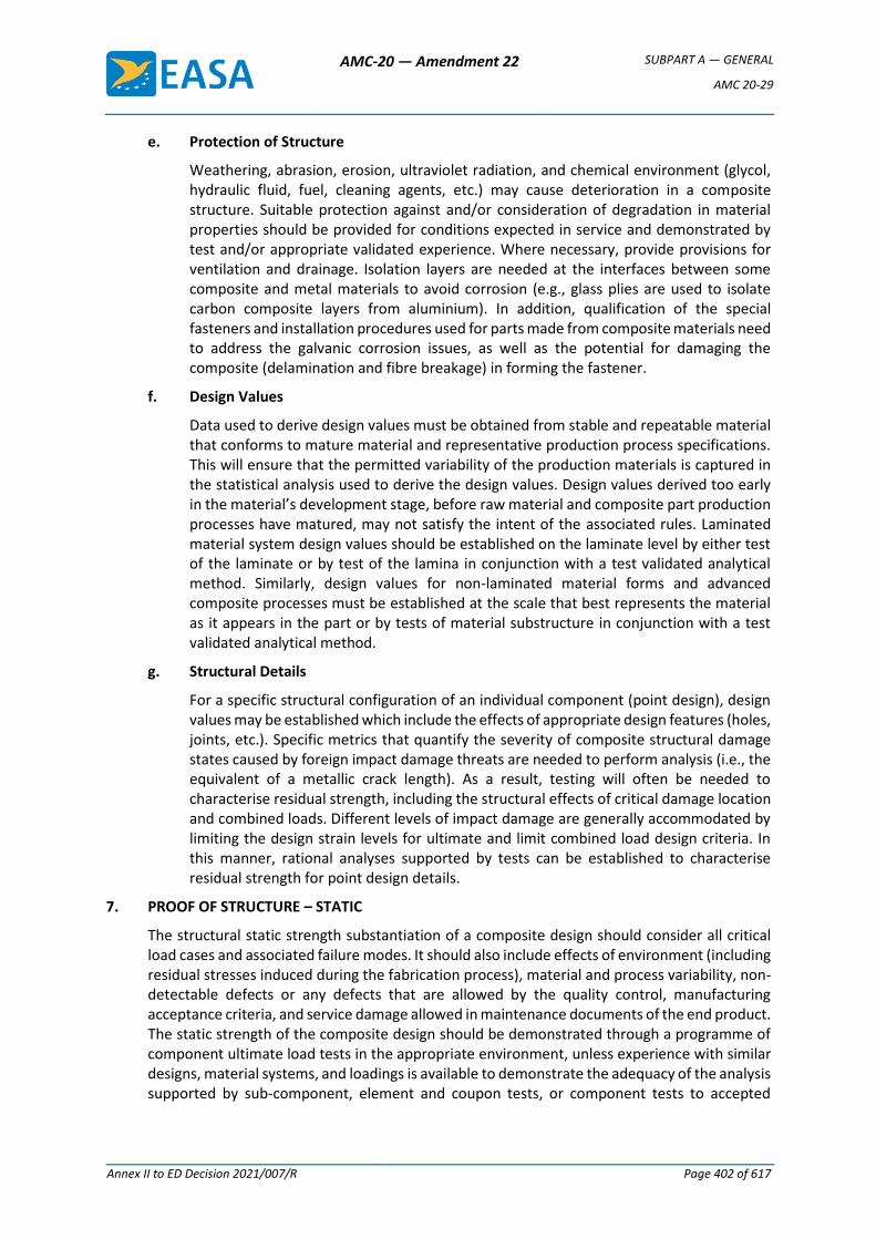
AMC-20 — Amendment 22 SUBPART A — GENERAL
AMC 20-29
Annex II to ED Decision 2021/007/R Page 402 of 617
e. Protection of Structure
Weathering, abrasion, erosion, ultraviolet radiation, and chemical environment (glycol, hydraulic fluid, fuel, cleaning agents, etc.) may cause deterioration in a composite structure. Suitable protection against and/or consideration of degradation in material properties should be provided for conditions expected in service and demonstrated by test and/or appropriate validated experience. Where necessary, provide provisions for ventilation and drainage. Isolation layers are needed at the interfaces between some composite and metal materials to avoid corrosion (e.g., glass plies are used to isolate carbon composite layers from aluminium). In addition, qualification of the special fasteners and installation procedures used for parts made from composite materials need to address the galvanic corrosion issues, as well as the potential for damaging the composite (delamination and fibre breakage) in forming the fastener.
f. Design Values
Data used to derive design values must be obtained from stable and repeatable material that conforms to mature material and representative production process specifications. This will ensure that the permitted variability of the production materials is captured in the statistical analysis used to derive the design values. Design values derived too early in the material’s development stage, before raw material and composite part production processes have matured, may not satisfy the intent of the associated rules. Laminated material system design values should be established on the laminate level by either test of the laminate or by test of the lamina in conjunction with a test validated analytical method. Similarly, design values for non-laminated material forms and advanced composite processes must be established at the scale that best represents the material as it appears in the part or by tests of material substructure in conjunction with a test validated analytical method.
g. Structural Details
For a specific structural configuration of an individual component (point design), design values may be established which include the effects of appropriate design features (holes, joints, etc.). Specific metrics that quantify the severity of composite structural damage states caused by foreign impact damage threats are needed to perform analysis (i.e., the equivalent of a metallic crack length). As a result, testing will often be needed to characterise residual strength, including the structural effects of critical damage location and combined loads. Different levels of impact damage are generally accommodated by limiting the design strain levels for ultimate and limit combined load design criteria. In this manner, rational analyses supported by tests can be established to characterise residual strength for point design details.
7. PROOF OF STRUCTURE – STATIC
The structural static strength substantiation of a composite design should consider all critical load cases and associated failure modes. It should also include effects of environment (including residual stresses induced during the fabrication process), material and process variability, non-detectable defects or any defects that are allowed by the quality control, manufacturing acceptance criteria, and service damage allowed in maintenance documents of the end product. The static strength of the composite design should be demonstrated through a programme of component ultimate load tests in the appropriate environment, unless experience with similar designs, material systems, and loadings is available to demonstrate the adequacy of the analysis supported by sub-component, element and coupon tests, or component tests to accepted
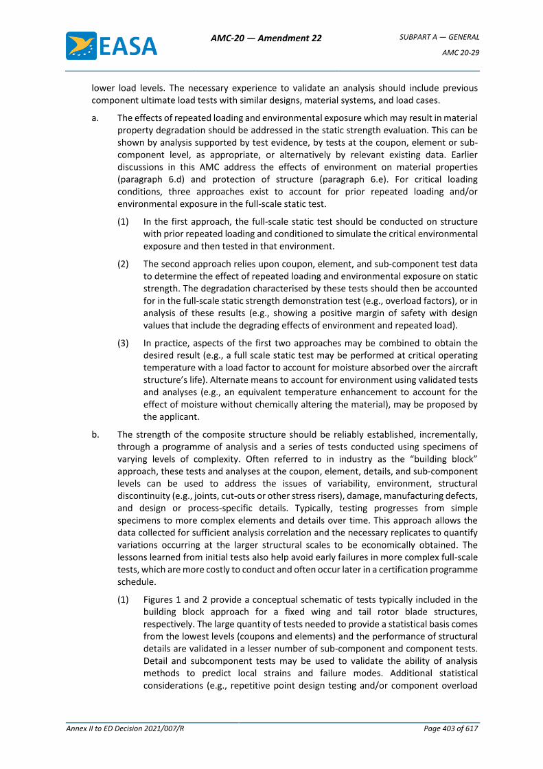
AMC-20 — Amendment 22 SUBPART A — GENERAL
AMC 20-29
Annex II to ED Decision 2021/007/R Page 403 of 617
lower load levels. The necessary experience to validate an analysis should include previous component ultimate load tests with similar designs, material systems, and load cases.
a. The effects of repeated loading and environmental exposure which may result in material property degradation should be addressed in the static strength evaluation. This can be shown by analysis supported by test evidence, by tests at the coupon, element or sub-component level, as appropriate, or alternatively by relevant existing data. Earlier discussions in this AMC address the effects of environment on material properties (paragraph 6.d) and protection of structure (paragraph 6.e). For critical loading conditions, three approaches exist to account for prior repeated loading and/or environmental exposure in the full-scale static test.
(1) In the first approach, the full-scale static test should be conducted on structure with prior repeated loading and conditioned to simulate the critical environmental exposure and then tested in that environment.
(2) The second approach relies upon coupon, element, and sub-component test data to determine the effect of repeated loading and environmental exposure on static strength. The degradation characterised by these tests should then be accounted for in the full-scale static strength demonstration test (e.g., overload factors), or in analysis of these results (e.g., showing a positive margin of safety with design values that include the degrading effects of environment and repeated load).
(3) In practice, aspects of the first two approaches may be combined to obtain the desired result (e.g., a full scale static test may be performed at critical operating temperature with a load factor to account for moisture absorbed over the aircraft structure’s life). Alternate means to account for environment using validated tests and analyses (e.g., an equivalent temperature enhancement to account for the effect of moisture without chemically altering the material), may be proposed by the applicant.
b. The strength of the composite structure should be reliably established, incrementally, through a programme of analysis and a series of tests conducted using specimens of varying levels of complexity. Often referred to in industry as the “building block” approach, these tests and analyses at the coupon, element, details, and sub-component levels can be used to address the issues of variability, environment, structural discontinuity (e.g., joints, cut-outs or other stress risers), damage, manufacturing defects, and design or process-specific details. Typically, testing progresses from simple specimens to more complex elements and details over time. This approach allows the data collected for sufficient analysis correlation and the necessary replicates to quantify variations occurring at the larger structural scales to be economically obtained. The lessons learned from initial tests also help avoid early failures in more complex full-scale tests, which are more costly to conduct and often occur later in a certification programme schedule.
(1) Figures 1 and 2 provide a conceptual schematic of tests typically included in the building block approach for a fixed wing and tail rotor blade structures, respectively. The large quantity of tests needed to provide a statistical basis comes from the lowest levels (coupons and elements) and the performance of structural details are validated in a lesser number of sub-component and component tests. Detail and subcomponent tests may be used to validate the ability of analysis methods to predict local strains and failure modes. Additional statistical considerations (e.g., repetitive point design testing and/or component overload
AMC-20 — Amendment 22 SUBPART A — GENERAL
AMC 20-29
Annex II to ED Decision 2021/007/R Page 404 of 617
factors to cover material and process variability) will be needed when analysis validation is not achieved. The static strength substantiation programme should also consider all critical loading conditions for all Critical Structure. This includes an assessment of residual strength and stiffness requirements after a predetermined length of service, which takes into account damage and other degradation due to the service period.
Figure 1 - Schematic diagram of building block tests for a fixed wing.
Figure 2 - Schematic diagram of building block tests for a tail rotor blade.
AMC-20 — Amendment 22 SUBPART A — GENERAL
AMC 20-29
Annex II to ED Decision 2021/007/R Page 405 of 617
(2) Successful static strength substantiation of composite structures has traditionally depended on proper consideration of stress concentrations (e.g., notch sensitivity of details and impact damage), competing failure modes and out-of-plane loads. A complete building block approach to composite structural substantiation addresses most critical structural issues in test articles with increasing levels of complexity so that many areas of reliable performance can be demonstrated prior to the component tests. The details and sub-component testing should establish failure criteria and account for impact damage in assembled composite structures. Component tests are needed to provide the final validation accounting for combined loads and complex load paths, which include some out-of-plane effects. When using the building block approach, the critical load cases and associated failure modes would be identified for component tests using the analytical methods, which are supported by test validation.
c. The component static test may be performed in an ambient atmosphere if the effects of the environment are reliably predicted by building block tests and are accounted for in the static test or in the analysis of the results of the static test.
d. The static test articles should be fabricated and assembled in accordance with production specifications and processes so that the test articles are representative of production structure including defects consistent with the limits established by manufacturing acceptance criteria.
e. The material and processing variability of the composite structure should be considered in the static strength substantiation. This is primarily achieved by establishing sufficient process and quality controls to manufacture structure and reliably substantiate the required strength by test and analysis. The scatter in strength properties due to variability in materials and processes are characterised by proper allowables or design values, which are derived in compliance with CS 2x.613. When the detail, sub-component and component tests show that local strains are adequately predicted and positive margins of safety exist using a validated analysis everywhere on the structure, then proof of static strength is said to be substantiated using analysis supported by test evidence. Alternatively, in the absence of sufficient building block test data and analysis validation, overloads are needed in the component test to gain proof of static strength for the structure using an approach referred to as substantiated by tests. The overload factors applied in this case need to be substantiated either through tests or past experience and must account for the expected material and process variation.
f. It should be shown that impact damage that can be expected from manufacturing and service, but not more than the established threshold of detectability for the selected inspection procedure, will not reduce the structural strength below ultimate load capability. This can be shown by analysis supported by test evidence, or by a combination of tests at the coupon, element, sub-component and component levels. The realistic test assessment of impact damage requires proper consideration of the structural details and boundary conditions. When using a visual inspection procedure, the likely impact damage at the threshold of reliable detection has been called barely visible impact damage (BVID). Selection of impact sites for static strength substantiation should consider the criticality of the local structural detail, and the ability to inspect a location. The size and shape of impactors used for static strength substantiation should be consistent with likely impact damage scenarios that may go undetected for the life of an aircraft. Note that it is possible for some designs to have detectable impact damage and still meet static strength
AMC-20 — Amendment 22 SUBPART A — GENERAL
AMC 20-29
Annex II to ED Decision 2021/007/R Page 406 of 617
loads and other requirements without repair (refer to allowable damage discussions in paragraph 10.c(1)).
g. Major material and process changes on existing certified structure require additional static strength substantiation (e.g., refer to Appendix 3).
8. PROOF OF STRUCTURE – FATIGUE AND DAMAGE TOLERANCE
The evaluation of composite structure should be based on the applicable certification specifications identified in the type-certification basis. Such evaluation must show that catastrophic failure due to fatigue, environmental effects, manufacturing defects, or accidental damage will be avoided throughout the operational life of the aircraft. The nature and extent of analysis or tests on complete structures and/or portions of the primary structure will depend upon applicable previous fatigue/damage tolerant designs, construction, tests, and service experience on similar structures. In the absence of experience with similar designs, Agency-approved structural development tests of components, sub-components, and elements should be performed (following the same principles discussed in paragraph 7.b and Appendix 3). The following considerations are unique to the use of composite material systems and provide guidance for the method of substantiation selected by the applicant. When establishing details for the damage tolerance and fatigue evaluation, attention should be given to a thorough damage threat assessment, geometry, inspectability, good design practice, and the types of damage/degradation of the structure under consideration.
— Composite damage tolerance and fatigue performance is strongly dependent on structural design details (e.g., skin laminate stacking sequence, stringer or frame spacing, stiffening element attachment details, damage arrestment features, and structural redundancy).
— Composite damage tolerance and fatigue evaluations require substantiation in component tests unless experience with similar designs, material systems, and loadings is available to demonstrate the adequacy of the analysis supported by coupons, elements, and sub-component tests.
— Final static strength, fatigue, and damage tolerance substantiation may be gained in testing a single component test article if sufficient building block test evidence exists to ensure that the selected sequence of repeated and static loading yield results representative of that possible in service or provide a conservative evaluation.
— Peak repeated loads are needed to practically demonstrate the fatigue and damage tolerance of composite aircraft structure in a limited number of component tests. As a result, metal structures present in the test article generally require additional consideration and testing. The information contained in AMC 25.571 provides fatigue and damage tolerance guidance for metallic structures.
a. Damage Tolerance Evaluation
(1) Damage tolerance evaluation starts with identification of structure whose failure would reduce the structural integrity of the aircraft. A damage threat assessment must be performed for the structure to determine possible locations, types, and sizes of damage considering fatigue, environmental effects, intrinsic flaws, and foreign object impact or other accidental damage (including discrete source) that may occur during manufacture, operation or maintenance.
(a) Currently, there are very few industry standards that outline the critical damage threats for particular composite structural applications with enough detail to establish the necessary design criteria or test and analysis protocol
AMC-20 — Amendment 22 SUBPART A — GENERAL
AMC 20-29
Annex II to ED Decision 2021/007/R Page 407 of 617
for complete damage tolerance evaluation. In the absence of standards, it is the responsibility of individual applicants to perform the necessary development tasks to establish such data in support of product substantiation. Some factors to consider in development of a damage threat assessment for a particular composite structure include part function, location on the aircraft, past service data, accidental damage threats, environmental exposure, impact damage resistance, durability of assembled structural details (e.g., long-term durability of bolted and bonded joints), adjacent system interface (e.g., potential overheating or other threats associated with system failure), and anomalous service or maintenance handling events that can overload or damage the part. As related to the damage threat assessment and maintenance procedures for a given structure, the damage tolerance capability and ability to inspect for known damage threats should be developed.
(b) Foreign object impact is a concern for most composite structures, requiring attention in the damage threat assessment. This is needed to identify impact damage severity and detectability for design and maintenance. It should include any available damage data collected from service plus an impact survey. An impact survey consists of impact tests performed with representative structure, which is subjected to boundary conditions characteristic of the real structure. Many different impact scenarios and locations should be considered in the survey, which has a goal of identifying the most critical impacts possible (i.e., those causing the most serious damage but are least detectable). When simulating accidental impact damage at representative energy levels, blunt or sharp impactors of different sizes and shapes should be selected to cause the most critical and least detectable damage, according to the load conditions (e.g., tension, compression or shear). Until sufficient service experience exists to make good engineering judgments on energy and impactor variables, impact surveys should consider a wide range of conceivable impacts, including runway or ground debris, hail, tool drops, and vehicle collisions. This consideration is important to the assumptions needed for use of probabilistic damage threat assessments in defining design criteria, inspection methods, and repeat inspection intervals for maintenance. Service data collected over time can better define impact surveys and design criteria for subsequent products, as well as establish more rational inspection intervals and maintenance practice. In review of such information, it should be realised that the most severe and critical impact damages, which are still possible, may not be part of the service database.
(c) Once a damage threat assessment is completed, various damage types can be classified into five categories of damage as described below (refer to figure 3). These categories of damage are used for communication purposes in this AMC. Other categories of damage, which help outline a specific path to fatigue and damage tolerance substantiation, may be used by applicants in agreement with the regulatory authorities.
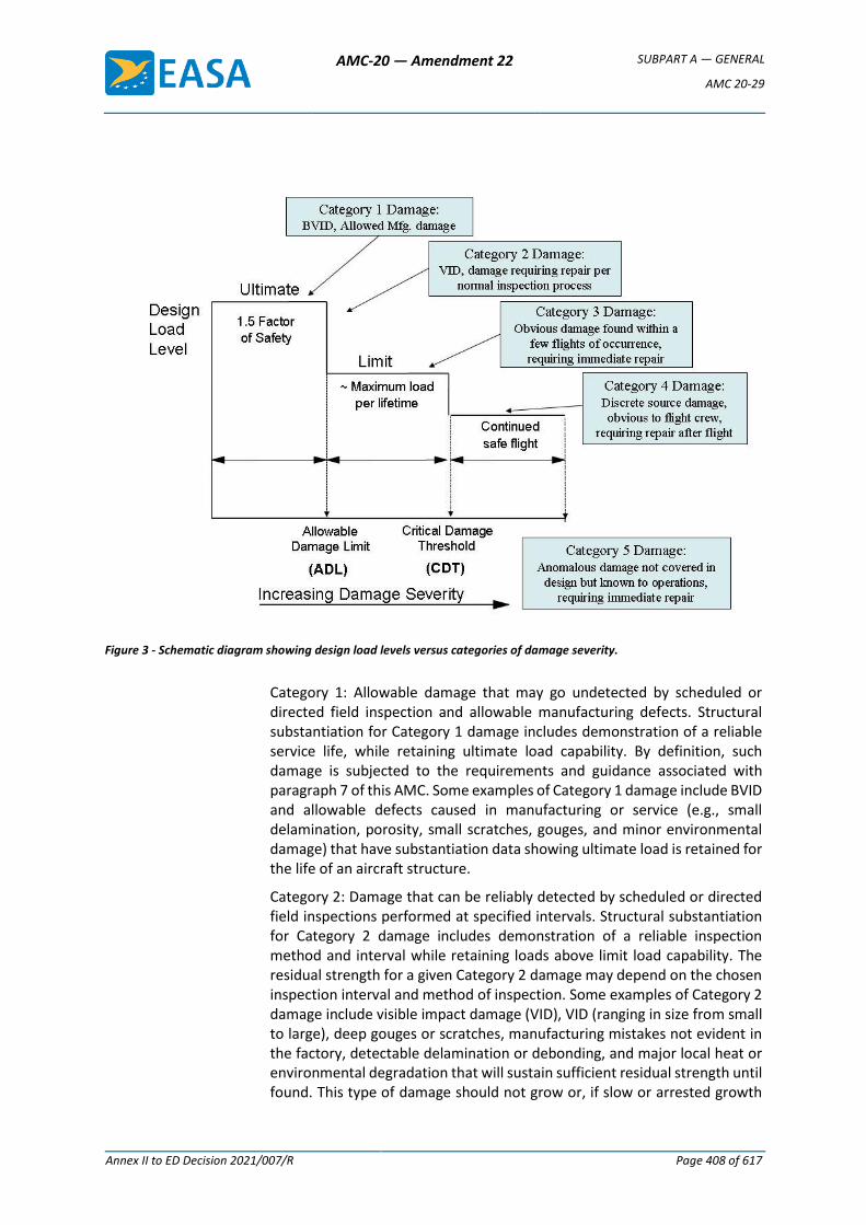
AMC-20 — Amendment 22 SUBPART A — GENERAL
AMC 20-29
Annex II to ED Decision 2021/007/R Page 408 of 617
Figure 3 - Schematic diagram showing design load levels versus categories of damage severity.
Category 1: Allowable damage that may go undetected by scheduled or directed field inspection and allowable manufacturing defects. Structural substantiation for Category 1 damage includes demonstration of a reliable service life, while retaining ultimate load capability. By definition, such damage is subjected to the requirements and guidance associated with paragraph 7 of this AMC. Some examples of Category 1 damage include BVID and allowable defects caused in manufacturing or service (e.g., small delamination, porosity, small scratches, gouges, and minor environmental damage) that have substantiation data showing ultimate load is retained for the life of an aircraft structure.
Category 2: Damage that can be reliably detected by scheduled or directed field inspections performed at specified intervals. Structural substantiation for Category 2 damage includes demonstration of a reliable inspection method and interval while retaining loads above limit load capability. The residual strength for a given Category 2 damage may depend on the chosen inspection interval and method of inspection. Some examples of Category 2 damage include visible impact damage (VID), VID (ranging in size from small to large), deep gouges or scratches, manufacturing mistakes not evident in the factory, detectable delamination or debonding, and major local heat or environmental degradation that will sustain sufficient residual strength until found. This type of damage should not grow or, if slow or arrested growth
AMC-20 — Amendment 22 SUBPART A — GENERAL
AMC 20-29
Annex II to ED Decision 2021/007/R Page 409 of 617
occurs, the level of residual strength retained for the inspection interval is sufficiently above limit load capability.
Category 3: Damage that can be reliably detected within a few flights of occurrence by operations or ramp maintenance personnel without special skills in composite inspection. Such damage must be in a location such that it is obvious by clearly visible evidence or cause other indications of potential damage that becomes obvious in a short time interval because of loss of the part form, fit or function. Both indications of significant damage warrant an expanded inspection to identify the full extent of damage to the part and surrounding structural areas. In practice, structural design features may be needed to provide sufficient large damage capability to ensure limit or near limit load is maintained with easily detectable, Category 3 damage. Structural substantiation for Category 3 damage includes demonstration of a reliable and quick detection, while retaining limit or near limit load capability. The primary difference between Category 2 and 3 damages are the demonstration of large damage capability at limit or near limit load for the latter after a regular interval of time, which is much shorter than the former. The residual strength demonstration for Category 3 damage may be dependent on the reliable short time detection interval. Some examples of Category 3 damage include large VID or other obvious damage that will be caught during walk-around inspection or during the normal course of operations (e.g., fuel leaks, system malfunctions or cabin noise).
Category 4: Discrete source damage from a known incident such as flight manoeuvres is limited. Structural substantiation for Category 4 damage includes a demonstration of residual strength for loads specified in the regulations. It should be noted that pressurised structure will generally have Category 4 residual strength requirements at a level higher than shown in figure 3. Some examples of Category 4 damage include rotor burst, bird strikes (as specified in the regulations), tyre bursts, and severe in-flight hail.
Category 5: Severe damage created by anomalous ground or flight events, which is not covered by design criteria or structural substantiation procedures. This damage is in the current guidance to ensure the engineers responsible for composite aircraft structure design and the Agency work with maintenance organisations in making operations personnel aware of possible damage from Category 5 events and the essential need for immediate reporting to responsible maintenance personnel. It is also the responsibility of structural engineers to design-in sufficient damage resistance such that Category 5 events are self-evident to the operations personnel involved. An interface is needed with engineering to properly define a suitable conditional inspection based on available information from the anomalous event. Such action will facilitate the damage characterisation needed prior to repair. Some examples of Category 5 damage include severe service vehicle collisions with aircraft, anomalous flight overload conditions, abnormally hard landings, maintenance jacking errors, and loss of aircraft parts in flight, including possible subsequent high-energy, wide-area (blunt) impact with adjacent structure. Some Category 5 damage scenarios will not have clearly visual indications of damage, particularly in composite structures. However, there should be knowledge of other evidence from the
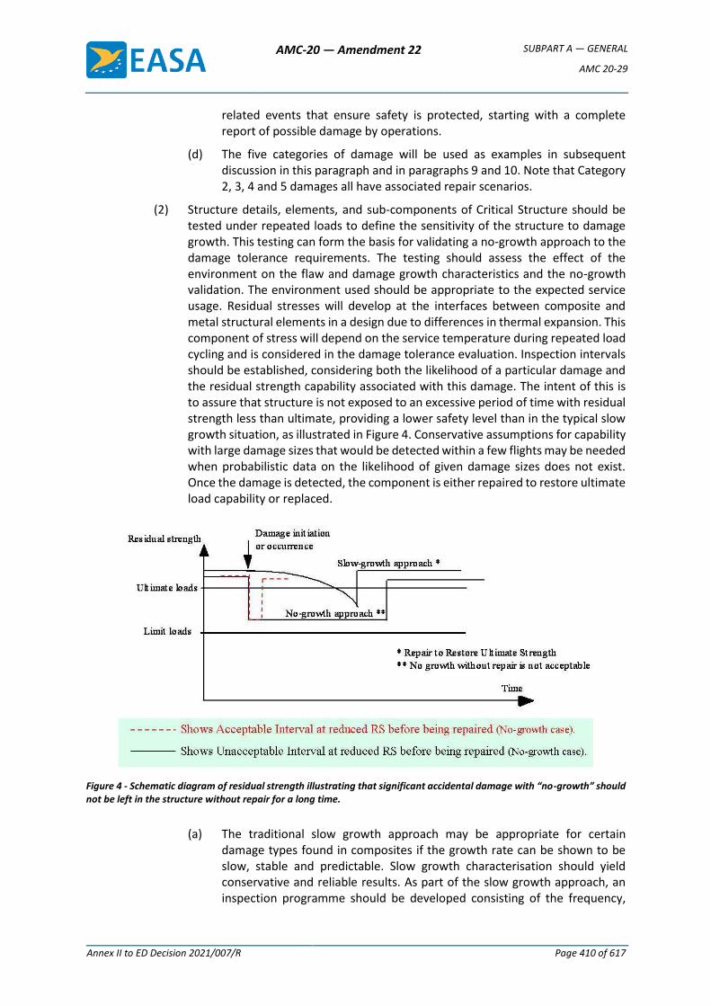
AMC-20 — Amendment 22 SUBPART A — GENERAL
AMC 20-29
Annex II to ED Decision 2021/007/R Page 410 of 617
related events that ensure safety is protected, starting with a complete report of possible damage by operations.
(d) The five categories of damage will be used as examples in subsequent discussion in this paragraph and in paragraphs 9 and 10. Note that Category 2, 3, 4 and 5 damages all have associated repair scenarios.
(2) Structure details, elements, and sub-components of Critical Structure should be tested under repeated loads to define the sensitivity of the structure to damage growth. This testing can form the basis for validating a no-growth approach to the damage tolerance requirements. The testing should assess the effect of the environment on the flaw and damage growth characteristics and the no-growth validation. The environment used should be appropriate to the expected service usage. Residual stresses will develop at the interfaces between composite and metal structural elements in a design due to differences in thermal expansion. This component of stress will depend on the service temperature during repeated load cycling and is considered in the damage tolerance evaluation. Inspection intervals should be established, considering both the likelihood of a particular damage and the residual strength capability associated with this damage. The intent of this is to assure that structure is not exposed to an excessive period of time with residual strength less than ultimate, providing a lower safety level than in the typical slow growth situation, as illustrated in Figure 4. Conservative assumptions for capability with large damage sizes that would be detected within a few flights may be needed when probabilistic data on the likelihood of given damage sizes does not exist. Once the damage is detected, the component is either repaired to restore ultimate load capability or replaced.
Figure 4 - Schematic diagram of residual strength illustrating that significant accidental damage with “no-growth” should not be left in the structure without repair for a long time.
(a) The traditional slow growth approach may be appropriate for certain damage types found in composites if the growth rate can be shown to be slow, stable and predictable. Slow growth characterisation should yield conservative and reliable results. As part of the slow growth approach, an inspection programme should be developed consisting of the frequency,

AMC-20 — Amendment 22 SUBPART A — GENERAL
AMC 20-29
Annex II to ED Decision 2021/007/R Page 411 of 617
extent, and methods of inspection for inclusion in the maintenance plan. Inspection intervals should be established such that the damage will have a very high probability of detection between the time it becomes initially detectable and the time at which the extent of the damage reduces the residual static strength to limit load (considered as ultimate), including the effects of environment. For any detected damage size that reduces the load capability below ultimate, the component is either repaired to restore ultimate load capability or replaced. Should functional impairment (such as unacceptable loss of stiffness) occur before the damage becomes otherwise critical, part repair or replacement will also be necessary.
(b) Another approach involving growth may be appropriate for certain damage types and design features adopted for composites if the growth can be reliably shown to be predictable and arrested before it becomes critical. Figure 5 shows schematic diagrams for all three damage growth approaches applied to composite structure. The arrested growth method is applicable when the damage growth is mechanically arrested or terminated before becoming critical (residual static strength reduced to limit load), as illustrated in Figure 5. Arrested growth may occur due to design features such as a geometry change, reinforcement, thickness change, or a structural joint. This approach is appropriate for damage growth that is detectable and found to be reliably arrested, including all appropriate dynamic effects. Structural details, elements, and sub-components of Critical Structure, components or full-scale structures, should be tested under repeated loads for validating an Arrested Growth Approach. As was the case for a “no-growth” approach to damage tolerance, inspection intervals should be established, considering the residual strength capability associated with the arrested growth damage size (refer to the dashed lines added to Figure 5 to conceptually show inspection intervals consistent with the slow growth basis). Again, this is intended to ensure that the structure does not remain in a damaged condition with residual strength capability close to limit load for long periods of time before repair. For any damage size that reduces load capability below ultimate, the component is either repaired to restore ultimate load capability or replaced.
(c) The repeated loading should be representative of anticipated service usage. The repeated load testing should include damage levels (including impact damage) typical of those that may occur during fabrication, assembly, and in-service, consistent with the inspection techniques employed. The damage tolerance test articles should be fabricated and assembled in accordance with production specifications and processes so that the test articles are representative of production structure.
(3) The extent of initially detectable damage should be established and be consistent with the inspection techniques employed during manufacture and in service. This information will naturally establish the transition between Category 1 and 2 damage types (i.e., inspection methods used by trained inspectors in scheduled maintenance). For damage that is clearly detectable to an extent that it will likely be found before scheduled maintenance (i.e., allowing classification as Category 3 damage), detection over shorter intervals and by untrained personnel may be permitted. Flaw/damage growth data should be obtained by repeated load cycling of intrinsic flaws or mechanically introduced damage. The number of cycles applied
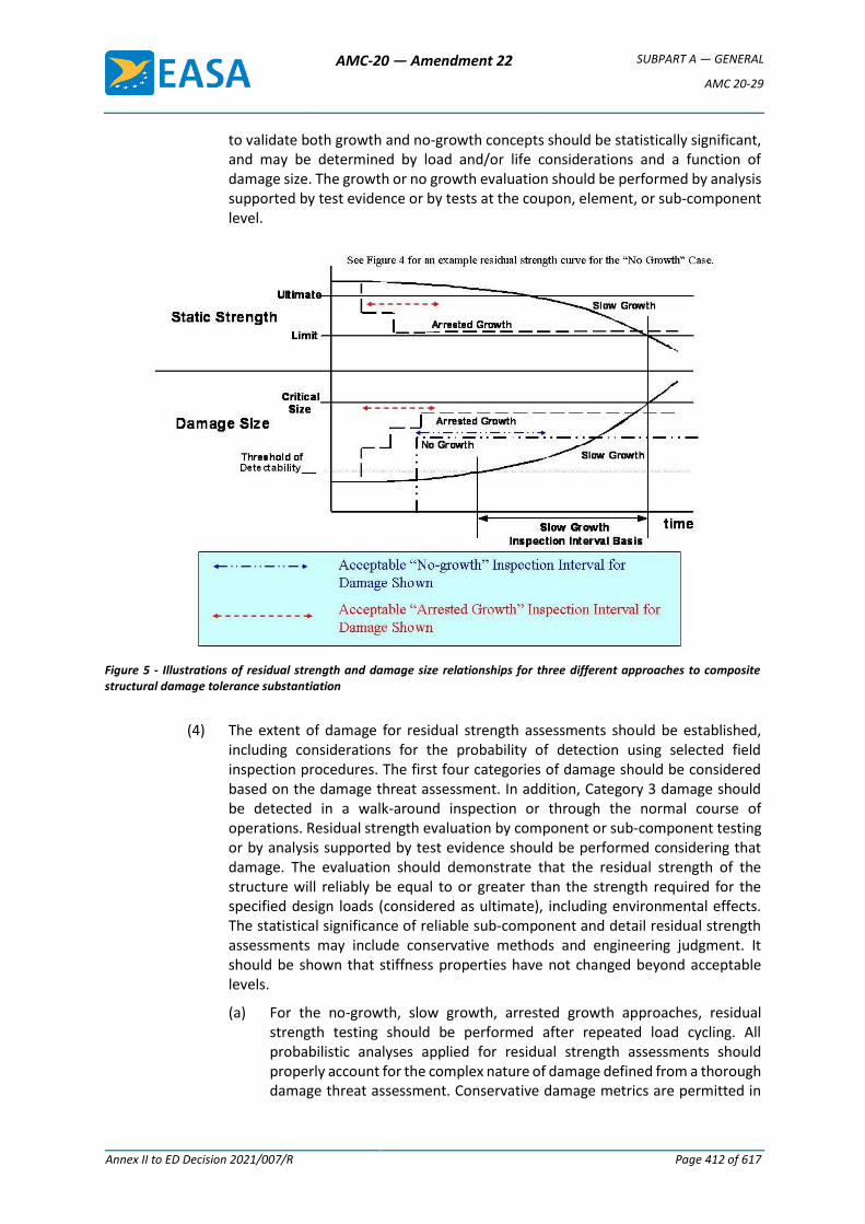
AMC-20 — Amendment 22 SUBPART A — GENERAL
AMC 20-29
Annex II to ED Decision 2021/007/R Page 412 of 617
to validate both growth and no-growth concepts should be statistically significant, and may be determined by load and/or life considerations and a function of damage size. The growth or no growth evaluation should be performed by analysis supported by test evidence or by tests at the coupon, element, or sub-component level.
Figure 5 - Illustrations of residual strength and damage size relationships for three different approaches to composite structural damage tolerance substantiation
(4) The extent of damage for residual strength assessments should be established, including considerations for the probability of detection using selected field inspection procedures. The first four categories of damage should be considered based on the damage threat assessment. In addition, Category 3 damage should be detected in a walk-around inspection or through the normal course of operations. Residual strength evaluation by component or sub-component testing or by analysis supported by test evidence should be performed considering that damage. The evaluation should demonstrate that the residual strength of the structure will reliably be equal to or greater than the strength required for the specified design loads (considered as ultimate), including environmental effects. The statistical significance of reliable sub-component and detail residual strength assessments may include conservative methods and engineering judgment. It should be shown that stiffness properties have not changed beyond acceptable levels.
(a) For the no-growth, slow growth, arrested growth approaches, residual strength testing should be performed after repeated load cycling. All probabilistic analyses applied for residual strength assessments should properly account for the complex nature of damage defined from a thorough damage threat assessment. Conservative damage metrics are permitted in
AMC-20 — Amendment 22 SUBPART A — GENERAL
AMC 20-29
Annex II to ED Decision 2021/007/R Page 413 of 617
such analyses assuming sufficient test data on repeated load and environmental exposure exists.
(b) Composite designs should afford the same level of fail-safe, multiple load path structure assurance as conventional metals design. Such is also the expectation in justifying the use of static strength allowables with a statistical basis of 90 percent probability with 95 percent confidence.
(c) Some special residual strength considerations for bonded structure are given in paragraph 6.c.(3).
(5) The repeated load spectrum developed for fatigue testing and analysis purposes should be representative of the anticipated service usage. Low amplitude load levels that can be shown not to contribute to damage growth may be omitted. Reducing maximum load levels is generally not accepted. Variability in repeated load behaviour should be covered by appropriate load enhancement or life scatter factors and these factors should take into account the number of specimens tested. The use of such factors to demonstrate reliability in component tests should be consistent with the fatigue and damage tolerance behaviour characterised for the materials, processes and other design details of the structure in building block tests.
(6) An inspection programme should be developed consisting of frequency, extent, and methods of inspection for inclusion in the maintenance plan. Inspection intervals should be established such that the damage will be reliably detected between the time it initially becomes detectable and the time at which the extent of damage reaches the limits for required residual strength capability. The potential for missed inspections should be considered.
(a) For the case of no-growth design concept, inspection intervals should be established as part of the maintenance programme. In selecting such intervals, the residual strength level associated with the assumed damages should be considered. This point was illustrated in Figures 4 and 5. Note that an acceptable inspection interval for the larger damages shown for the “no-growth” and “arrested growth” options in Figures 4 and 5 was conceptually shown as related to an acceptable slow growth basis in terms of the residual strength and time below ultimate load before damage was detected and repaired. Data on the probability of occurrence for different damage sizes also helps define an inspection interval.
(b) A thorough composite damage threat assessment and the separation of different damage sizes into categories, each with associated detection methods, supports programmes using a rigorous damage tolerance assessment to avoid conservative design criteria with very large damage assumptions. In such cases, Category 2 damage types will require the structural substantiation of well specified and reliable inspection methods applied by trained inspectors at scheduled maintenance intervals (by default, Category 1 damage is at the threshold of this evaluation). Those damages classified as Category 3 may take advantage of shorter service time intervals provided sufficient structural substantiation exists with demonstrated proof that there will be early detection by untrained ramp maintenance or operations personnel. By definition, Category 4 damage will require residual strength substantiation to levels that complete a flight with

AMC-20 — Amendment 22 SUBPART A — GENERAL
AMC 20-29
Annex II to ED Decision 2021/007/R Page 414 of 617
limited manoeuvres based on the associated regulatory loads. Due to the nature of service events leading to Category 4 damage, suitable inspections will need to be defined to evaluate the full extent of damage, prior to subsequent aircraft repair and return to service. By definition, Category 5 damages do not have associated damage tolerance design criteria or related structural substantiation tasks. Category 5 damage will require suitable inspections based on engineering assessment of the anomalous service event, and appropriate structural repair and/or part replacement, prior to the aircraft re-entering service.
(7) The structure should be able to withstand static loads (considered as ultimate loads) which are reasonably expected during a completion of the flight on which damage resulting from obvious discrete sources occur (i.e., uncontained engine failures, etc.). The extent of damage should be based on a rational assessment of service mission and potential damage relating to each discrete source. Structural substantiation will be needed for the most critical Category 4 damage as related to the associated load cases. Some Category 4 damage may have high margins but will likely still require suitable inspections since their detectability may not be consistent with the substantiations validated for Category 2 damage types.
(8) The effects of temperature, humidity, and other environmental or time-related aging factors, which may result in material property degradation, should be addressed in the damage tolerance evaluation. Unless tested in the environment, appropriate environmental factors should be derived and applied in the evaluation.
b. Fatigue Evaluation
Fatigue substantiation should be accomplished by component fatigue tests or by analysis supported by test evidence, accounting for the effects of the appropriate environment. The test articles should be fabricated and assembled in accordance with production specifications and processes so that the test articles are representative of production structures. Sufficient component, sub-component, element or coupon tests should be performed to establish the fatigue scatter and the environmental effects. Component, sub-component, and/or element tests may be used to evaluate the fatigue response of structure with impact damage levels typical of those that may occur during fabrication, assembly, and in service, consistent with the inspection procedures employed. Other allowed manufacturing and service defects, which would exist for the life of the structure, should also be included in fatigue testing. It should be demonstrated during the fatigue tests that the stiffness properties have not changed beyond acceptable levels. Replacement lives should be established based on the test results. By definition, Category 1 damage is subjected to fatigue evaluation and expected to retain ultimate load capability for the life of the aircraft structure.
c. Combined Damage Tolerance and Fatigue Evaluation
Generally, it is appropriate for a given structure to establish both an inspection programme and demonstrate a service life to cover all detectable and non-detectable damage, respectively, which is anticipated for the intended aircraft usage. Extensions in service life should include evidence from component repeated load testing, fleet leader programmes (including NDI and destructive tear-down inspections), and appropriate statistical assessments of accidental damage and environmental service data considerations.
AMC-20 — Amendment 22 SUBPART A — GENERAL
AMC 20-29
Annex II to ED Decision 2021/007/R Page 415 of 617
9. PROOF OF STRUCTURE – FLUTTER AND OTHER AEROELASTIC INSTABILITIES
The aeroelastic evaluations including flutter, control reversal, divergence, and any undue loss of stability and control as a result of structural loading and resulting deformation, are required. Flutter and other aeroelastic instabilities must be avoided through design, quality control, maintenance, and systems interaction.
a. The evaluation of composite structure needs to account for the effects of repeated loading, environmental exposure, and service damage scenarios (e.g., large Category 2, 3 or 4 damage) on critical properties such as stiffness, mass and damping. Some control surfaces exposed to large damage retain adequate residual strength margins, but the potential loss of stiffness or mass increase (e.g., sandwich panel disbond and/or water ingression) may adversely affect flutter and other aeroelastic characteristics. This is particularly important for control surfaces that are prone to accidental damage and environmental degradation. Other factors such as the weight or stiffness changes due to repair, manufacturing flaws, and multiple layers of paint need to be evaluated. There may also be issues associated with the proximity of high temperature heat sources near structural components (e.g., empennage structure in the path of jet engine exhaust streams or engine bleed air pneumatics system ducting). These effects may be determined by analysis supported by test evidence, or by tests at the coupon, element or sub-component level.
10. CONTINUED AIRWORTHINESS
The maintenance and repair of composite aircraft structure should meet all general, design and fabrication, static strength, fatigue/damage tolerance, flutter, and other considerations covered by this AMC as appropriate for the particular type of structure and its application.
a. Design for Maintenance
Composite aircraft structure should be designed for inspection and repair access in a field maintenance environment. The inspection and repair methods applied for structural details should recognise the special documentation and training needed for critical damage types that are difficult to detect, characterise and repair. The inspection intervals and life limits for any structural details and levels of damage that preclude repair must be clearly documented in the appropriate continued airworthiness documents.
b. Maintenance Practices
Maintenance manuals, developed by the appropriate organisations, should include appropriate inspection, maintenance, and repair procedures for composite structures, including jacking, disassembly, handling, part drying methods, and repainting instructions (including restrictions for paint colours that increase structural temperatures). Special equipment, repair materials, ancillary materials, tooling, processing procedures, and other information needed for inspection or repair of a given part should be identified since standard field practices, which have been substantiated for different aircraft types and models, are not common.
(1) Damage Detection
(a) Procedures used for damage detection must be shown to be reliable and capable of detecting degradation in structural integrity below ultimate load capability. These procedures must be documented in the appropriate sections of the instructions for continued airworthiness. This should be substantiated in static strength, environmental resistance, fatigue, and damage tolerance efforts as outlined in paragraphs 6, 7 and 8. Substantiated
AMC-20 — Amendment 22 SUBPART A — GENERAL
AMC 20-29
Annex II to ED Decision 2021/007/R Page 416 of 617
detection procedures will be needed for all damage types identified by the threat assessment, including a wide range of foreign object impact threats, manufacturing defects, and degradation caused by overheating. Degradation in surface layers (e.g., paints and coatings) that provide structural protection against ultraviolet exposure must be detected. Any degradation to the lightning strike protection system that affects structural integrity, fuel tank safety, and electrical systems must also be detected.
(b) Visual inspection is the predominant damage detection method used in the field and should be performed under prescribed lighting conditions. Visual inspection procedures should account for access, time relaxation in impact damage dent depth, and the colour, finish and cleanliness of part surfaces.
(2) Inspection. Visual indications of damage, which are often used for composite damage detection, provide limited details on the hidden parts of damage that require further investigation. As a result, additional inspection procedures used for complete composite damage characterisation will generally be different from those used for initial damage detection and need to be well documented. Non-destructive inspection performed prior to repair and destructive processing steps performed during repair must be shown to locate and determine the full extent of the damage. In-process controls of repair quality and post-repair inspection methods must be shown to be reliable and capable of providing engineers with the data to determine degradation in structural integrity below ultimate load capability caused by the process itself. Certain processing defects cannot be reliably detected at completion of the repair (e.g., weak bonds). In such cases, the damage threat assessment, repair design features and limits should ensure sufficient damage tolerance.
(3) Repair. All bolted and bonded repair design and processing procedures applied for a given structure shall be substantiated to meet the appropriate requirements. Of particular safety concern are the issues associated with bond material compatibilities, bond surface preparation (including drying, cleaning, and chemical activation), cure thermal management, composite machining, special composite fasteners, and installation techniques, and the associated in-process control procedures. The surface layers (e.g., paints and coatings) that provide structural protection against ultraviolet exposure, structural temperatures, and the lightning strike protection system must also be properly repaired.
(4) Documentation and Reporting. Documentation on all repairs must be added to the maintenance records for the specific part number. This information supports future maintenance damage disposition and repair activities performed on the same part. It is recommended that service difficulties, damage, and degradation occurring to composite parts in service should be reported back to the design approval holder to aid in continuous updates of damage threat assessments to support future design detail and process improvements. Such information will also support future design criteria, analysis, and test database development.
c. Substantiation of Repair
(1) When repair procedures are provided in Agency approved documents or the maintenance manual, it should be demonstrated by analysis and/or test that the method and techniques of repair will restore the structure to an airworthy condition. Repairable damage limits (RDL), which outline the details for damage to
AMC-20 — Amendment 22 SUBPART A — GENERAL
AMC 20-29
Annex II to ED Decision 2021/007/R Page 417 of 617
structural components that may be repaired based on existing data, must be clearly defined and documented. Allowable damage limits (ADL), which do not require repair, must also be clearly defined and documented. Both RDL and ADL must be based on sufficient analysis and test data to meet the appropriate structural substantiation requirements and other considerations outlined in this AMC. Additional substantiation data will generally be needed for damage types and sizes not previously considered in design development. Some damage types may require special instructions for field repair and the associated quality control. Bonded repair is subjected to the same structural bonding considerations as the base design (refer to paragraph 6.c).
(2) Operators and maintenance repair organisations (MRO) wishing to complete major repairs or alterations outside the scope of approved repair documentation should be aware of the extensive analysis, design, process, and test substantiation required to ensure the airworthiness of a certificated structure. Documented records and the certification approval of this substantiation should be retained in accordance with regulations to support any subsequent maintenance activities.
d. Damage Detection, Inspection and Repair Competency
(1) All technicians, inspectors and engineers involved in damage disposition and repair should have the necessary skills to perform their supporting maintenance tasks on a specific composite structural part. The continuous demonstration of acquired skills goes beyond initial training (e.g., similar to a welder qualification). The repair design, inspection methods, and repair procedures used will require approved structural substantiation data for the particular composite part. Society of Automotive Engineers International (SAE) Aerospace Information Report (AIR) 5719 outlines training for an awareness of the safety issues for composite maintenance and repair. Additional training for specific skill building will be needed to execute particular engineering, inspection and repair tasks.
(2) Pilots, ramp maintenance, and other operations personnel that service aircraft should be trained to immediately report anomalous ramp incidents and flight events that may potentially cause serious damage to composite aircraft structures. In particular, immediate reporting is needed for those service events that are outside the scope of the damage tolerance substantiation and standard maintenance practices for a given structure. The immediate detection of Category 4 and 5 damages are dependent on the proper reaction of personnel that operate and service the aircraft.
11. ADDITIONAL CONSIDERATIONS
a. Crashworthiness
(1) The crashworthiness of the aircraft is dominated by the impact response characteristics of the fuselage. Regulations, in general, evolve based on either experience gained through incidents and accidents of existing aircraft or in anticipation of safety issues raised by new designs. In the case of crashworthiness, regulations have evolved as experience has been gained during actual aircraft operations. For example, emergency load factors and passenger seat loads have been established to reflect dynamic conditions observed from fleet experience and from controlled FAA and industry research. Fleet experience has not demonstrated a need to have an aircraft level crashworthiness standard. As a result, the regulations reflect the capabilities of traditional aluminium aircraft structure under
AMC-20 — Amendment 22 SUBPART A — GENERAL
AMC 20-29
Annex II to ED Decision 2021/007/R Page 418 of 617
survivable crash conditions. This approach was satisfactory as aircraft have continued to be designed using traditional construction methods. With the advent of composite fuselage structure and/or the use of novel design, this historical approach may no longer be sufficient to substantiate the same level of protection for the passengers as provided by similar metallic designs.
(2) Airframe design should assure that occupants have every reasonable chance of escaping serious injury under realistic and survivable crash impact conditions. A composite design should account for unique behaviour and structural characteristics, including major repairs or alterations, as compared with conventional metal airframe designs. Structural evaluation may be done by test or analysis supported by test evidence. Service experience may also support substantiation.
(3) The crash dynamics of an aircraft and the associated energy absorption are difficult to model and fully define representative tests with respect to structural requirements. Each aircraft product type (i.e., large aeroplane, small aeroplane, and rotorcraft) has unique regulations governing the crashworthiness of particular aircraft structures. The regulations and guidance associated with each product type should be used accordingly. The regulations for large aeroplane and rotorcraft address some issues that go beyond those required of small aeroplanes.
(4) Special conditions are anticipated for large aeroplanes with composite fuselage structure to address crashworthiness survivability. The impact response of a composite fuselage structure must be evaluated to ensure the survivability is not significantly different from that of a similar-sized aircraft fabricated from metallic materials. Impact loads and resultant structural deformation of the supporting airframe and floor structures must be evaluated. Four main criteria areas should be considered in making such an evaluation.
(a) Occupants must be protected during the impact event from release of items of mass (e.g., overhead bins).
(b) At least the minimum number of emergency egress paths must remain following a survivable crash.
(c) The acceleration and loads experienced by occupants during a survivable crash must not exceed critical thresholds.
(d) A survivable volume of occupant space must be retained following the impact event.
(5) The criticality of each of these four criteria will depend on the particular crash conditions. For example, the loads and accelerations experienced by passengers may be higher at lower impact velocities where structural failures have not started to occur. As a result, validated analyses may be needed to practically cover all the crashworthiness criteria for a fuselage.
(6) Existing large aeroplane requirements also require that fuel tank structural integrity be addressed during a survivable crash impact event as related to fire safety (also refer to paragraph 11.b). As related to crashworthiness, composite fuel tank structure must not fail or deform to the extent that fire becomes a greater hazard than with metal structure.
(7) Physics and mechanics of the crashworthiness for composite structures involve several issues. The local strength, energy absorbing characteristics, and multiple
AMC-20 — Amendment 22 SUBPART A — GENERAL
AMC 20-29
Annex II to ED Decision 2021/007/R Page 419 of 617
competing failure modes need to be addressed for composite structure subjected to a survivable crash. This is not simply achieved for airframe structures made from anisotropic, quasi-brittle, composite materials. As a result, the accelerations and load histories experienced by passengers and equipment on a composite aircraft may differ significantly from that seen on a similar metallic aircraft unless specific considerations are designed into the composite structure. In addition, care should be taken when altering composite structure to achieve specific mechanical behaviours. (For example, where the change in behaviour of a metallic structure with a change in material thickness may be easily predicted, an addition or deletion of plies to a composite laminate may also require data for the effects of laminate stacking sequence on the failure mode and energy absorption characteristics of a composite element).
(8) Representative structure must be included to gain valid test and analysis results. Depending on aircraft loading (requiring investigation of various aircraft passenger and cargo configurations), structural dynamic considerations, and progressive failures, local strain rates and loading conditions may differ throughout the structure. Sensitivity of the structural behaviour to reasonable impact orientation should also be considered for large aeroplane and rotorcraft applications. This can be addressed by analysis supported by test evidence.
(9) Considering a need for comparative assessments with metal structure and a range of crash conditions, analysis with sufficient structural test evidence is often needed for large aeroplane and rotorcraft applications. Analysis requires extensive investigation of model sensitivity to modelling parameters (e.g., mesh optimisation, representation of joints, element material input stress-strain data). Test also requires investigation of test equipment sensitivity appropriate to composites (e.g., filter frequencies with respect to expected pulse characteristics in the structure). Model validation may be achieved using a building block approach, culminating in an adequately complex test (e.g., a drop test with sufficient structural details to properly evaluate the crashworthiness criteria).
b. Fire Protection, Flammability and Thermal Issues
(1) Fire and exposure to temperatures that exceed maximum operating conditions require special considerations for composite airframe structure. (Refer to note below). Requirements for flammability and fire protection of aircraft structure attempt to minimise the hazard to occupants in the event that flammable materials, fluids, or vapours ignite. The regulations associated with each aircraft product type (i.e., transport, small airplane, rotorcraft) should be used accordingly. Compliance may be shown by tests or analysis supported by test evidence. A composite design, including repair and alterations, should not decrease the existing level of safety relative to metallic structure. In addition, maintenance procedures should be available to evaluate the structural integrity of any composite aircraft structures exposed to fire and temperatures above the maximum operating conditions substantiated during design.
Note: Aircraft cabin interiors and baggage compartments have been areas of flammability concerns in protecting passenger safety. This revision of the AMC does not address composite materials used in aircraft interiors and baggage compartments. Please consult other Guidance Material for Acceptable Means of Compliance with flammability rules for interiors.
AMC-20 — Amendment 22 SUBPART A — GENERAL
AMC 20-29
Annex II to ED Decision 2021/007/R Page 420 of 617
(2) Fire protection and flammability has traditionally been considered for engine mount structure, firewalls, and other powerplant structures that include composite elements. Additional issues critical to passenger safety have come with the expanded use of composites in wing and fuselage structures for large aeroplanes. Existing regulations do not address the potential for the airframe structure itself to be flammable. Wing and fuselage applications should consider the effects of composite design and construction on the resulting passenger safety in the event of in-flight fires or emergency landing conditions, which combine with subsequent egress when a fuel-fed fire is possible.
(3) The results of fire protection and flammability testing with structural composite parts indicate dependence upon overall design and process details, as well as the origin of the fire and its extent. For example, the overall effects of composite fuselage structures exposed to fire may be significantly different when the fire originates within the cabin, where it can be controlled by limiting the structure’s contribution to spreading the fire, than when the fire occurs exterior to the fuselage after a crash landing, where fuel is likely to be the primary source for maintaining and spreading the fire. The threat in each case is different, and the approach to mitigation may also be different. In-flight fire safety addresses a fire originating within the aircraft due to some fault, whereas post-crash fire safety addresses a fuel fed pool fire external to the aircraft. Special conditions are anticipated for large aeroplanes with fuselage structure subjected to both in-flight and post-crash fire conditions. Large aeroplane wing structure will need to have special conditions for post-crash fire conditions.
(4) For an in-flight fire in large aeroplanes, it is critical that the fire not propagate or generate hazardous quantities of toxic by-products. In-flight fires have been catastrophic when they can grow in inaccessible areas. Composite fuselage structure could play a role different from traditional metal structure if the issue is not addressed.
(5) Metallic large aeroplane fuselage and wing structures have established a benchmark in fire protection that can be used to evaluate specific composite wing and fuselage structural details. Exterior fire protection issues associated with composite structure must include the effects of an exterior pool fire following a survivable crash landing. Fuselage structure should provide sufficient time for passenger egress, without fire penetration or the release of gasses and/or materials that are either toxic to escaping passengers or reduce visibility (smoke density) or could increase the fire severity. Furthermore, these considerations must be extended to wing and fuel tank structure, which must also be prevented from collapse and release of fuel (including consideration of the influence of fuel load upon the structural behaviour. For large aeroplanes, the standards of CS 25.856(b) provide the benchmark to establish the required level of safety.
(6) The exposure of composite structures to high temperatures needs to extend beyond the direct flammability and fire protection issues to other thermal issues. Many composite materials have glass transition temperatures, which mark the onset of reductions in strength and stiffness that are somewhat lower than the temperatures that can have a similar effect on equivalent metallic structure. The glass transition temperature of most composite materials is further reduced by moisture absorption. The reduced strength or stiffness of composites from high temperature exposures must be understood per the requirements of particular
AMC-20 — Amendment 22 SUBPART A — GENERAL
AMC 20-29
Annex II to ED Decision 2021/007/R Page 421 of 617
applications (e.g., engine or other system failures). After a system failure and/or known fire, it may be difficult to detect the full extent of irreversible heat damage to an exposed composite structure. As a result, composite structures exposed to high temperatures may require special inspections, tests, and analysis for proper disposition of heat damage. All appropriate damage threats and degradation mechanisms need to be identified and integrated into the damage tolerance and maintenance evaluation accordingly. Reliable inspections and test measurements of the extent of damage that exists in a part exposed to unknown levels of high temperatures should be documented. Particular attention should be given to defining the maximum damages that likely could remain undetected by the selected inspection procedures.
c. Lightning Protection
Lightning protection design features are needed for composite aircraft structures. Current Carbon fibre composites are approximately 1,000 times less electrically conductive than standard aluminium materials, and composite resins and adhesives are traditionally non-conductive. Glass and aramid fibre composites are non-conductive. A lightning strike to composite structures can result in structural failure or large area damage, and it can induce high lightning current and voltage on metal hydraulic tubes, fuel system tubes, and electrical wiring if proper conductive lightning protection is not provided. Aircraft lightning protection design guidance can be found in the FAA Technical Report “Aircraft Lightning Protection Handbook” (See Appendix 1 2.a). The lightning protection effectiveness for composite structures should be demonstrated by tests or analysis supported by tests. Such tests are typically performed on panels, coupons, subassemblies, or coupons representative of the aircraft structure, or tests on full aircraft. The lightning test waveforms and lightning attachment zones are defined in EUROCAE ED-84 and ED-91. Any structural damage observed in standard lightning tests should be limited to Category 1, 2 or 3, depending on the level of detection. This damage is characterised and integrated into damage tolerance analyses and tests as appropriate. Small simple aeroplanes certified under CS-23 for VFR use only may be certified based on engineering assessment, according to AC 23-15A. The effects of composite structural repairs and maintenance on the lightning protection system should be evaluated. Repairs should be designed to maintain lightning protection.
(1) Lightning Protection for Structural Integrity
(a) The composite structural design should incorporate the lightning protection when appropriate for the anticipated lightning attachment. The extent of lightning protection features depends on the lightning attachment zone designated for that area of the aircraft. Lightning protection features may include, but are not limited to, metal wires or mesh added to the outside surface of the composite structure where direct lightning attachment is expected.
(b) When lightning strikes an aircraft, very high currents flow through the airframe. Proper electrical bonding must be incorporated between structural parts. This is difficult to achieve for moveable parts (e.g., ailerons, rudders and elevators). The electrical bonding features must be sized to conduct the lightning currents or they can vaporise, sending the high currents through unintended paths such as control cables, control rods, or hydraulic tubes. Guidance for certification of lightning protection of aircraft structures can be found in EUROCAE ED-113.

AMC-20 — Amendment 22 SUBPART A — GENERAL
AMC 20-29
Annex II to ED Decision 2021/007/R Page 422 of 617
(2) Lightning Protection for Fuel Systems
(a) Special consideration must be given to the fuel system lightning protection for an aircraft with integral fuel tanks in a composite structure. Composite structure with integral fuel systems must incorporate specific lightning protection features on the external composite surfaces, on joints, on fasteners, and for structural supports for fuel system plumbing and components to eliminate structural penetration, arcing, sparks or other ignition sources. AC 20-53B provides certification guidance for aircraft fuel system lightning protection.
(b) Large aeroplane regulations for fuel system ignition prevention in CS 25.981 require lightning protection that is failure tolerant. As a result, redundant and robust lightning protection for composite structure joints and fasteners in fuel tank structure is needed to ensure proper protection in preventing ignition sources.
(3) Lightning Protection for Electrical and Electronic Systems
(a) Lightning strike protection of composite structures is needed to avoid inducing high lightning voltages and currents on the wiring for electrical and electronic systems whose upset or damage could affect safe aircraft operation. The consequences from a lightning strike of unprotected composite structures can be catastrophic for electrical and electronic systems that perform highly critical functions, such as fly-by-wire flight controls or engine controls.
(b) Electrical shields over system wiring and robust circuit design of electrical and electronic equipment both provide some protection against system upset or damage due to lightning. Since most composite materials provide poor shielding, at best, metal foil or mesh is typically added to the composite structure to provide additional shielding for wiring and equipment. Electrical bonding between composite structure parts and panels should be provided for the shielding to be effective. EUROCAE ED-81 and ED-107 provide certification guidance for aircraft electrical and electronic system lightning protection.
[Amdt 20/6]
AMC-20 — Amendment 22 SUBPART A — GENERAL
AMC 20-29
Annex II to ED Decision 2021/007/R Page 423 of 617
Appendix 1 to AMC 20-29 – Applicable CSs and Relevant Guidance
1. Applicable CSs. A list of applicable CS paragraphs is provided for subjects covered in this AMC (see notes). In most cases, these CS paragraphs apply regardless of the type of materials used in aircraft structures.
AMC Paragraphs CS-23 CS-25 CS-27 CS-29
1. Purpose of this AMC -------------- Not Applicable --------------
2. To Whom this AMC Applies -------------- Not Applicable --------------
3. Cancellation -------------- Not Applicable --------------
4. Related Regulations and Guidance -------------- Not Applicable --------------
5. General -------------- Not Applicable --------------
6. Material and Fabrication Development 603 605 609 613 619
603 605 609 613 619
603 605 609 613 619
603 605 609 613 619
7. Proof of Structure – Static 305 307
305 307
305 307
305 307
8. Proof of Structure – Fatigue and Damage Tolerance 573 571 571 571
9. Proof of Structure – Flutter 629 629 629 629
10. Continued Airworthiness 1529 App. G
1529 App. H
1529 App. H
1529 App. A
11. Additional Considerations a. Crashworthiness
(including impact dynamics) 561 562 601
721 783 785 787 789
807
965 967
561 562 601 631 721 783 785 787 789 801
809 963
967 981
561 562 601
783 785 787
801
807
963 965 967
561 562 601 631
783 785 787
801 803
809 963 965 967
AMC-20 — Amendment 22 SUBPART A — GENERAL
AMC 20-29
Annex II to ED Decision 2021/007/R Page 424 of 617
b. Fire Protection, Flammability and Thermal Issues
609
853 855 859
863 865 867 903
1121 1181 1182 1183
1189 1191 1193
1359 1365
609
853 855 859
863 865
903
1121 1181 1182 1183 1185
1189 1191 1193
609
853 855 859 861 863
1121
1183 1185 1187 1189 1191 1193 1194
609
853 855 859 861 863
903
1121 1181
1183 1185 1187 1189 1191 1193 1194
c. Lightning Protection
* see AMC 25.899 para.6
609
867
954
1309
581* 609
899* 954* 981
1316
609
954
1309
609 610
954
1309
Notes:
(1) This list may not be all inclusive and there may be differences between certification agencies (e.g. FAA and the Agency).
(2) Special conditions may be issued in accordance with Part-21 21.A.16B for novel and unusual design features (e.g., new composite materials systems).
2. Guidance
FAA issues guidance providing supportive information of showing compliance with regulatory requirements. Guidance may include the advisory circulars (AC) and policy statements (PS). In general, an AC presents information concerning acceptable means, but not the only means, of complying with regulations. The guidance listed below is deemed supportive to the purposes of this AMC. These FAA documents can be located via website: http://www.faa.gov/regulations_policies/. In addition, EUROCAE have developed industry standards that are recognised by the Agency.
Note: Many of the FAA documents are harmonised with EASA. Applicants should confirm with the Agency if in doubt regarding the status and acceptance of any such documents by the Agency.
AMC-20 — Amendment 22 SUBPART A — GENERAL
AMC 20-29
Annex II to ED Decision 2021/007/R Page 425 of 617
a. FAA/EUROCAE guidance documents
— AC 20-53B “Protection of Airplane Fuel Systems Against Fuel Vapor Ignition Due to Lightning” [6/06]
— AC 20-135 "Powerplant Installation and Propulsion System Component Fire Protection Test Methods, Standards, and Criteria" [2/90]
— AC 21-26 "Quality Control for the Manufacture of Composite Structures" [6/89]
— AC 21-31 "Quality Control for the Manufacture of Non-Metallic Compartment Interior Components" [11/91]
— AC 23-15A “Small Airplane Certification Compliance Program” [12/03]
— AC 23-20 "Acceptance Guidance on Material Procurement and Process Specifications for Polymer Matrix Composite Systems" [9/03]
— AC 25.571-1C “Damage Tolerance and Fatigue Evaluation of Structure” [4/98]
— AC 29 MG 8 “Substantiation of Composite Rotorcraft Structure” [4/06]
— AC 35.37-1A "Guidance Material for Fatigue Limit Tests and Composite Blade Fatigue Substantiation" [9/01]
— AC 145-6 "Repair Stations for Composite and Bonded Aircraft Structure" [11/96]
— RTCA DO-160 / EUROCAE ED-14
— EUROCAE ED-81 “Certification of Aircraft Electrical/Electronic Systems for the Indirect Effects of Lightning”
— EUROCAE ED-84 “Aircraft Lightning Environment and Related Test Waveforms”
— EUROCAE ED-91 “Aircraft Lightning Zoning”
— EUROCAE ED-107 “Guide to Certification of Aircraft in a High Intensity Radiated Field (HIRF)”
— EUROCAE ED-113 Aircraft Lightning Direct Effects Certification
— EUROCAE ED-14E Environmental Conditions and Test Procedures for Airborne Equipment
— FAA Technical Report “Aircraft Lightning Protection Handbook” (DOT/FAA/CT-89/22).
b. FAA Policy Statements
— "Static Strength Substantiation of Composite Airplane Structure" [PS-ACE100-2001-006, December 2001]
— "Final Policy for Flammability Testing per 14 CFR Part 23, Sections 23.853, 23.855 and 23.1359" [PS-ACE100-2001-002, January 2002]
— “Material Qualification and Equivalency for Polymer Matrix Composite Material Systems" [PS-ACE100-2002-006, September 2003]
— “Bonded Joints and Structures - Technical Issues and Certification
— Considerations” [PS-ACE100-2005-10038, September 2005]
[Amdt 20/6]
AMC-20 — Amendment 22 SUBPART A — GENERAL
AMC 20-29
Annex II to ED Decision 2021/007/R Page 426 of 617
Appendix 2 to AMC 20-29 – Definitions
The following definitions are applicable to AMC 20-29 and relevant CS paragraphs only.
Allowables: Material values that are determined from test data at the laminate or lamina level on a probability basis (e.g., A or B basis values, with 99% probability and 95% confidence, or 90% probability and 95% confidence, respectively). The amount of data required to derive these values is governed by the statistical significance (or basis) needed.
Anisotropic: Not isotropic; having mechanical and/or physical properties which vary with direction relative to natural reference axes inherent in the material.
Arrested Growth Approach: A method that requires demonstration that the structure, with defined flaws present, is able to withstand appropriate repeated loads with flaw growth which is either mechanically arrested or terminated before becoming critical (residual static strength reduced to limit load). This is to be associated with appropriate inspection intervals and damage detectability.
Category of Damage: One of five categories of damage based on residual strength capability, required load level, detectability, inspection interval, damage threat and whether (or not) the event creating damage is self-evident (see Section 8(a)(1)(c)).
Component: A major section of the airframe structure (e.g., wing, body, fin, horizontal stabiliser) which can be tested as a complete unit to qualify the structure.
Coupon: A small test specimen (e.g., usually a flat laminate) for evaluation of basic lamina or laminate properties or properties of generic structural features (e.g., bonded or mechanically fastened joints).
Critical Structure: A load bearing structure/element whose integrity is essential in maintaining the overall flight safety of the aircraft. This definition was adopted for this AMC because there are differences in the definitions of primary structure, secondary structure, and principle structural elements (PSE) when considering the different categories of aircraft. For example, PSE are critical structures for Large Aeroplanes.
Damage: A structural anomaly caused by manufacturing (processing, fabrication, assembly or handling) or service usage.
Debond: Same as Disbond.
Degradation: The alteration of material properties (e.g., strength, modulus, coefficient of expansion) which may result from deviations in manufacturing or from repeated loading and/or environmental exposure.
Delamination: The separation of the layers of material in a laminate. This may be local or may cover a large area of the laminate. It may occur at any time in the cure or subsequent life of the laminate and may arise from a wide variety of causes.
Design Values: Material, structural elements, and structural detail properties that have been determined from test data and chosen to assure a high degree of confidence in the integrity of the completed structure. These values are most often based on allowables adjusted to account for actual structural conditions, and used in analysis to compute margins-of-safety.
Detail: A non-generic structural element of a more complex structural member (e.g., specific design configured joints, splices, stringers, stringer runouts, or major access holes).
Disbond: An area within a bonded interface between two adherends in which an adhesion failure or separation has occurred. It may occur at any time during the life of the substructure and may arise
AMC-20 — Amendment 22 SUBPART A — GENERAL
AMC 20-29
Annex II to ED Decision 2021/007/R Page 427 of 617
from a wide variety of causes. Also, colloquially, an area of separation between two laminae in the finished laminate (in this case the term “delamination” is normally preferred).
Discrepancy: A manufacturing anomaly allowed and detected by the planned inspection procedure. They can be created by processing, fabrication or assembly procedures.
Element: A generic part of a more complex structural member (e.g., skin, stringers, shear panels, sandwich panels, joints, or splices).
Environment: External, non-accidental conditions (excluding mechanical loading), separately or in combination, that can be expected in service and which may affect the structure (e.g., temperature, moisture, UV radiation, and fuel).
Factor(s):
— Life (or Load) Enhancement Factor: An additional load factor and/or test duration applied to structural repeated load tests, relative to the intended design load and life values, used to account for material variability. It is used to develop the required level of confidence in data.
— Life Scatter Factor: Same as Life/Load Enhancement Factor.
— Overload Factor: A load factor applied to a specific structure test which is used to address parameters (e.g., environment, a short test pyramid, etc.) not directly addressed in that test. This factor is usually developed from lower pyramid testing addressing such parameters.
Heterogeneous: Descriptive term for a material consisting of dissimilar constituents separately identifiable; a medium consisting of regions of unlike properties separated by internal boundaries.
Intrinsic Flaw: Defect inherent in the composite material or resulting from the production process.
Manufacturing Defect: An anomaly or flaw occurring during manufacturing that can cause varying levels of degradation in structural strength, stiffness and dimensional stability. Those manufacturing defects (or permissible manufacturing variability) allowed by the quality control, manufacturing acceptance criteria are expected to meet appropriate structural requirements for the life of the aircraft part. Other manufacturing defects that escape detection in manufacturing quality control should be included in a damage threat assessment and must meet damage tolerance requirements until detected and repaired.
No-Growth Approach: A method that requires demonstration that the structure, with defined flaws present, is able to withstand appropriate repeated loads without detrimental flaw growth for the life of the structure.
Primary Structure: The structure which carries flight, ground, or pressurisation loads, and whose failure would reduce the structural integrity of the aircraft.
Point Design: An element or detail of a specific design which is not considered generically applicable to other structure for the purpose of substantiation, e.g., lugs and major joints. Such a design element or detail can be qualified by test or by a combination of test and analysis.
Slow Growth Approach: A method that requires demonstration that the structure, with defined flaws present, is able to withstand appropriate repeated loads with slow, stable, and predictable flaw growth for the life of the structure, or beyond appropriate inspection intervals associated with appropriate damage detectability.
Structural Bonding: A structural joint created by the process of adhesive bonding, comprising of one or more previously-cured composite or metal parts (referred to as adherends).
AMC-20 — Amendment 22 SUBPART A — GENERAL
AMC 20-29
Annex II to ED Decision 2021/007/R Page 428 of 617
Sub-component: A major three-dimensional structure which can provide completed structural representation of a section of the full structure (e.g., stub-box, section of a spar, wing panel, body panel with frames).
Weak Bond: A bond line with mechanical properties lower than expected, but without any possibility to detect that by normal NDI procedures. Such situation is mainly due to a poor chemical bonding.
[Amdt 20/6]
AMC-20 — Amendment 22 SUBPART A — GENERAL
AMC 20-29
Annex II to ED Decision 2021/007/R Page 429 of 617
Appendix 3 to AMC 20-29 – Change of Composite Material and/or Process
1. It is necessary to re-certify composite structures, which during production, incorporate substitutions of, or changes to, the materials and/or processes from those originally substantiated at the time of initial certification. For example, the original material supplier may either change its product, or cease production. Manufacturers may also find it necessary to modify their production processes to improve efficiency or correct product deficiencies. In either case, care must be taken to ensure that modifications and/or changes are adequately investigated to ensure the continued adequacy of already certificated composite structure. This appendix covers such material and/or process changes, but does not address other changes to design (e.g., geometry, loading). The definition of the materials and processes used is required in the specifications by Part 21.A.31. Changes to the material and process specifications are often major changes in type design and must be addressed as such under Part-21, subpart D or E as applicable.
2. The qualification and structural substantiation of new or modified materials and/or processes used to produce parts of a previously certified aircraft product requires:
a. The identification of the key material and/or process parameters governing performances;
b. The definition of the appropriate tests able to measure these parameters; and
c. The definition of pass/fail criteria for these tests.
3. ‘Qualification’ procedures developed by every manufacturer include specifications covering:
a. Physical and chemical properties,
b. Mechanical properties (coupon level), and
c. Reproducibility (by testing several batches).
4. Specifications and manufacturing quality procedures are designed to control specific materials and processes to achieve stable and repeatable structure for that combination of materials and processes. However, the interchangeability of alternate materials and processes for a structural application cannot be assumed if one only considers the properties outlined in those specifications (as it could be for materials that are much less process dependent, e.g., some metallic material forms). A structure fabricated using new or modified materials and/or processes, which meet the ‘qualification’ tests required for the original material and process specifications, does not necessarily produce components that meet all the original engineering requirements for the previously certified structure.
5. Until improvements in identifying the complex relations between key material parameters that govern composite processing occurs, there will be a need for extensive and diverse testing that directly interrogates material performance using a range of representative specimens of increasing complexity in building block tests. Furthermore, failure modes may vary from one material and/or process to another, and analytical models are sometimes insufficiently precise to reliably predict failure without sufficient empirical data. Therefore, a step-by-step test verification with more complex specimens may be required.
6. Classification of Material or Process Change
Material and/or process changes require appropriate classification in order to aid the determination of the extent of investigation necessary. Some minor changes may only require
AMC-20 — Amendment 22 SUBPART A — GENERAL
AMC 20-29
Annex II to ED Decision 2021/007/R Page 430 of 617
material equivalency sampling tests to be completed at the base of the test pyramid, whilst more significant changes will require more extensive investigations, including possibly a new structural substantiation.
a. Any of the following situations requires further investigation of possible changes to a given composite structure:
(1) Case A: A change in one or both of the basic constituents, resin, or fibre (including sizing or surface treatment alone) would yield an alternate material. Other changes that result in an alternate material include changes in fabric weave style, fibre aerial weight and resin content.
(2) Case B: Same basic constituents, but any change of the resin impregnation method. Such changes include: (i) prepregging process (e.g., solvent bath to hot melt coating), (ii) tow size (3k, 6k, 12k) for tape material forms with the same fibre areal weight, (iii) prepregging machine at the same suppliers, (iv) supplier change for a same material (licensed supplier).
(3) Case C: Same material, but modification of the processing route (if the modification to the processing route governs eventual composite mechanical properties). Example process changes of significance include: (i) curing cycle, (ii) bond surface preparation, (iii) changes in the resin transfer moulding process used in fabricating parts from dry fibre forms, (iv) tooling, (v) lay-up method, (vi) environmental parameters of the material lay-up room, and (vii) major assembly procedures.
b. For each of the above cases, a distinction should be made between those changes intended to be a replica of the former material/process combination (Case B and some of Case C) and those which are “truly new material” (Case A and some of Case C). So, two classes are proposed:
(1) “Identical materials/processes” in cases intended to create a replica structure.
(2) “Alternative materials/processes” in cases intended to create truly new structure.
c. Within the “identical materials/processes” class, a sub-classification can be made between a change of the prepregging machine alone at the supplier and licensed production elsewhere. For the time being, a change to a new fibre produced under a licensed process and reputed to be a replica of the former one, will be dealt with as an “alternative material/process”.
d. Some minor changes within the class representing identical materials/processes may not interact with structural performances (e.g., prepreg release papers, some bagging materials, etc.) and should not be submitted to the Agency as part of the change. However, the manufacturers (or the supplier) should develop a proper system for screening those changes, with adequate proficiency at all relevant decision levels. Other minor material changes that fall under Case B may warrant sampling tests to show equivalency only at lower levels of building block substantiation.
e. Case C changes that may yield major changes in material and structural performance need to be evaluated at all appropriate levels of the building block tests to determine whether the manufacturing process change yields identical or alternate materials. Engineering judgment will be needed in determining the extent of testing based on the proposed manufacturing change.
f. Case A (alternative material) should always be considered as an important change, which requires structural substantiation. It is not recommended to try a sub-classification
AMC-20 — Amendment 22 SUBPART A — GENERAL
AMC 20-29
Annex II to ED Decision 2021/007/R Page 431 of 617
according to the basic constituents being changed, as material behaviour (e.g., sensitivity to stress concentrations) may be governed by interfacial properties, which may be affected by either a fibre or a resin change.
7. Substantiation Method. Only the technical aspects of substantiation are addressed below.
a. Compliance Philosophy. Substantiation should be based on a comparability study between the structural performances of the material accepted for type certification, and the second material. Whatever the modification proposed for a certificated item, the revised margins of safety should remain adequate. Any reduction in the previously demonstrated margin should be investigated in detail.
(1) Alternative Material/Process: New design values for all relevant properties should be determined for any alternate material/process combination. Analytical models initially used to certify structure, including failure prediction models, should be reviewed and, if necessary, substantiated by tests. The procurement specification should be modified (or a new specification suited to the selected material should be defined) to ensure key quality variations are adequately controlled and new acceptance criteria defined. For example, changing from first to second generation of carbon fibres may improve tensile strength properties by more than 20% and a new acceptability threshold will be needed in the specification of the alternate material to ensure the detection of quality variations.
(2) Identical Material: Data should be provided that demonstrates that the original design values (whatever the level of investigation, material or design) remain valid. Statistical methods need to be employed for data to ensure that key design properties come from the same populations as the original material/process combination. Calculation models including failure prediction should remain the same. The technical content of the procurement specification (Case B) should not need to be changed to properly control quality.
b. Testing.
(1) The extent of testing needed to substantiate a material change should address the inherent structural behaviour of the composite and will be a function of the airworthiness significance of the part and the material change definition. For example, the investigation level might be restricted to the generic specimens at the test pyramid base (refer to figures in paragraph 7) for an identical material, but non-generic test articles from higher up the pyramid should be included for an alternative material. Care needs to be taken to ensure that the test methods used yield data compatible with data used to determine properties of the original structure.
(2) The testing that may be required for a range of possible material and/or process changes should consider all levels of structural substantiation that may be affected. In some instances (e.g., a minor cure cycle change), possible consequences can be assessed by tests on generic specimens only. For other changes, like those involving tooling (e.g., from a full bag process to thermo-expansive cores), the assessment should include an evaluation of the component itself (sometimes called the “tool proof test”). In this case, an expanded NDI procedure should be required for the first items to be produced. This should be supplemented – if deemed necessary – by “cut up” specimens from a representative component, for physical or mechanical investigations.
c. Number of Batches.
AMC-20 — Amendment 22 SUBPART A — GENERAL
AMC 20-29
Annex II to ED Decision 2021/007/R Page 432 of 617
(1) The purpose for testing a number of batches is the demonstration of an acceptable reproducibility of material characteristics. The number of batches required should take into account: material classification (identical or alternative), the investigation level (non-generic or generic specimen) the source of supply, and the property under investigation. Care should be taken to investigate the variation of both basic material and the manufacturing process.
(2) Existing references (e.g., The Composite Materials Handbook (CMH-17) Volumes 1 and 3, FAA Technical Report DOT/ FAA/AR-03/19), addressing composite qualification and equivalence and the building block approach, provide more detailed guidance regarding batch and test numbers and the appropriate statistical analysis up to laminate level. Changes at higher pyramid levels, or those associated with other material forms, e.g., braided VARTM (Vacuum-Assisted Resin Transfer Moulding) structure, may require use of other statistical procedures or engineering methods.
d. Pass/Fail Criteria. Target pass/fail criteria should be established as part of the test programme. For strength considerations for instance, a statistical analysis of test data should demonstrate that new design values derived for the second material provide an adequate margin of safety. Therefore, provision should be made for a sufficient number of test specimens to allow for such analysis. At the non-generic level, when only one test article is used to assess a structural feature, the pass criteria should be a result acceptable with respect to design ultimate loads. In the cases where test results show lower margins of safety, certification documentation will need to be revised.
e. Other Considerations. For characteristics other than static strength (all those listed in AMC 20-29, paragraphs 8, 9, 10 and 11), the substantiation should also ensure an equivalent level of safety.
[Amdt 20/6]
AMC-20 — Amendment 22 SUBPART A — GENERAL
AMC 20-42
Annex II to ED Decision 2021/007/R Page 433 of 617
AMC 20-42
AMC 20-42 Airworthiness information security risk assessment
1. PURPOSE
(a) This AMC describes an acceptable means, but not the only means, to show compliance with the applicable rules for the certification of products and parts. Compliance with this AMC is not mandatory and, therefore, an applicant may elect to use an alternative means of compliance. However, any alternative means of compliance must meet the relevant requirements and be accepted by EASA.
(b) This AMC recognises as an acceptable means of compliance the following European Organisation for Civil Aviation Equipment (EUROCAE) and Radio Technical Commission for Aeronautics (RTCA) documents:
— EUROCAE ED-202A, Airworthiness Security Process Specification, dated June 2014 / RTCA DO-326A, dated August 2014;
— EUROCAE ED-203A, Airworthiness Security Methods and Considerations, dated June 2018 / RTCA DO-356, dated June 2018;
— EUROCAE ED-204, Information Security Guidance for Continuing Airworthiness, dated June 2014 / RTCA DO-355, dated June 2014.
(c) This AMC establishes guidance to use ED-202A, 203A and 204 in the different contexts of the initial and continued airworthiness of products and parts.
(d) The possibility to give credit for products developed using previous versions of EUROCAE ED/RTCA DO documents may be discussed with and accepted by EASA.
Note: EUROCAE ED is hereinafter referred to as ‘ED’ and RTCA DO is hereinafter referred to as ‘DO’. Where the notation ‘ED-XXX/DO-XXX’ appears in this document, the referenced documents are recognised as being equivalent.
2. APPLICABILITY
This AMC applies to manufacturers of products and parts, and to design approval holders (DAHs) that apply for:
— the type certification of a new product (i.e. an aircraft, engine or propeller);
— a supplemental type certificate (STC) to an existing type-certified product;
— a change to a product;
— the approval of a new item of equipment or a change to equipment to be used in an ETSO article. In such a case, an ETSO article may contain one or more security measures. Those security measures may be assigned a security assurance level (SAL). Credit can be taken for those security measures and their associated SALs by the design organisation approval holder (DOAH), depending on the information system security risk assessment of the product;
— the certification of other systems or equipment that provide air service information whose certification is required by a national regulation;
— the approval of products and parts of information systems that are subject to potential information security threats and that could result in unacceptable safety risks.
AMC-20 — Amendment 22 SUBPART A — GENERAL
AMC 20-42
Annex II to ED Decision 2021/007/R Page 434 of 617
3. REPLACEMENT
Reserved.
4. GENERAL PRINCIPLES
(a) The information systems of the products, parts or equipment identified in Section 2 should be assessed against any potential intentional unauthorised electronic interaction (IUEI) security threat and vulnerability that could result in an unsafe condition. This risk assessment is referred to as a ‘product information security risk assessment’ (PISRA) and is further described in Section 5 of this AMC.
(b) The result of this assessment, after any necessary means of mitigation have been identified, should be that either the systems of the product or part have no identifiable vulnerabilities, or those vulnerabilities cannot be exploited to create a hazard or generate a failure that would have an effect that is deemed to be unacceptable against the certification specification and the acceptable means of compliance including industry standards for the product or part considered.
(c) When a risk needs to be mitigated, the applicant should demonstrate, as described in Section 5, that the means of mitigation provide sufficient grounds for evaluating that the residual risk is acceptable. The means of mitigation should be provided to the operators in a timely manner.
(d) Once the overall risk has been deemed to be acceptable, the applicant should, if necessary, develop instructions as described in Section 9, to maintain the information security risk of the systems of the product or part at an acceptable level, after the entry into service of the product or part.
5. PRODUCT INFORMATION SECURITY RISK ASSESSMENT
(a) The general product information security risk assessment (PISRA) should cover the following aspects:
(i) determination of the security environment for the information security of the product45;
(ii) identification of the assets;
(iii) identification of the attack paths;
(iv) assessment of the safety consequences of the threat to the affected assets;
(v) evaluation, by considering the existing security protection means, of the level of threat that would have an impact on safety;
(vi) determination of whether the risks, which are the result of the combination of the severities and the potentiality to attack (or, inversely, the difficulty of attacking), are acceptable:
If they are acceptable, preparation of the justification for certification, including the means to maintain the risk at an acceptable level (see Section 9);
If they are not acceptable,
(A) analysis of the proposed means of mitigation to ensure an acceptable level of safety,
45 To address the assumptions about external factors like organisations, processes, etc., see reference in ED-202A.
AMC-20 — Amendment 22 SUBPART A — GENERAL
AMC 20-42
Annex II to ED Decision 2021/007/R Page 435 of 617
(B) implementation of means of mitigation,
(C) evaluation of the effectiveness of the means of mitigation as in Section 8 with respect to the level of risk (combination of the level of threat and severity of the threat condition);
(vii) iteration from point (vi) until all the residual risks are acceptable.
(b) The process for the Security Risk Assessment identified in ED-202A Section 2.1.1 is an acceptable means of compliance for performing the PISRA for products and parts under Annex I (Part 21) to Regulation (EU) No 748/201246. Guidance material for the PISRA can be found in ED-203A.
6. RISK ACCEPTABILITY
Acceptable/Unacceptable Risk: whether or not a risk is unacceptable depends on the context and the criteria that are considered for the certification of the affected product or part. The risk may be acceptable in some cases and unacceptable in others. For example, a threat condition that has a potential major safety effect, as defined in CS xx.1309, may be not acceptable in the context of CS-25 products depending on the level of threat and the associated threat scenario. The same safety risk may be acceptable for products that are certified under CS-29.
7. REPORTING
The operator of a product or part should report any information security occurrences to the designer of this product or part or the aircraft TC/STC holder, in a manner that would allow a further impact analysis and corrective actions, if appropriate. If this impact analysis identifies the potential for an unsafe condition, the designer of that product or part should report it to the competent authority in a timely manner. For example, for organisations to which Regulation (EU) No 748/2012 applies, the reporting should be done in accordance with point 21.A.3A of Annex I (Part 21) to that Regulation.
8. VALIDATION AND VERIFICATION OF THE SECURITY PROTECTION
If information security risks that are identified during the product information security risk assessment (PISRA) need to be mitigated, security verification should be used to evaluate the effectiveness of the means of mitigation.
(a) This verification should be performed by a combination of analysis, security-oriented robustness testing, inspections, and reviews; and
(b) When necessary, by security testing that addresses information security from the perspective of a potential adversary.
9. INSTRUCTIONS FOR THE CONTINUED PROTECTION OF PRODUCT AND PART INFORMATION SECURITY
The applicant should identify the information security assets and protection mechanisms to be addressed by the Instructions for Continued Airworthiness (ICA) of the product or part (for example, physical and operational security procedures, auditing and monitoring of the security effectiveness, key management procedures that are used as assumptions in the security
46 Commission Regulation (EU) No 748/2012 of 3 August 2012 laying down implementing rules for the airworthiness
and environmental certification of aircraft and related products, parts and appliances, as well as for the certification of design and production organisations (OJ L 224, 21.8.2012, p. 1) (https://eur-lex.europa.eu/legal-content/EN/TXT/?qid=1574094487050&uri=CELEX:32012R0748).
AMC-20 — Amendment 22 SUBPART A — GENERAL
AMC 20-42
Annex II to ED Decision 2021/007/R Page 436 of 617
assurance process), and develop the appropriate procedures to maintain the security effectiveness after the product or part enters into service.
When an in-service occurrence is reported, the applicant should consider the possibility that it originated from an IUEI and should take any required corrective action accordingly. If an IUEI has generated an unsafe condition, then information about the occurrence, the investigation results and the recovery actions should be reported to EASA in accordance with point 21.A.3A of Annex I (Part 21) to Regulation (EU) No 748/2012.
According to Article 2(7) of Regulation (EU) No 376/201447, an occurrence is defined as any safety-related event which endangers, or which, if not corrected or addressed, could endanger an aircraft, its occupants or any other person, and includes, in particular, any accident or serious incident. Article 4 of the same Regulation requires the applicant to report to EASA any occurrence that represents a significant risk to aviation safety.
The applicant should also assess the impact of new threats that were not foreseen during previous product information security risk assessments (PISRAs) of the systems and parts of the product. If the assessment identifies an unacceptable threat condition, the applicant should notify the operators and the competent authority in a timely manner of the need and the means to mitigate the new risk (or the absence of a risk).
Guidance on continued airworthiness can be found in EUROCAE ED-203A/RTCA DO-356A and ED-204/RTCA DO-355.
10. DEFINITIONS
The terminology used in this AMC is consistent with the glossary provided in document EUROCAE ER 013 AERONAUTICAL INFORMATION SYSTEM SECURITY GLOSSARY.
[Amdt 20/18]
47 Regulation (EU) No 376/2014 of the European Parliament and of the Council of 3 April 2014 on the reporting, analysis
and follow-up of occurrences in civil aviation, amending Regulation (EU) No 996/2010 of the European Parliament and of the Council and repealing Directive 2003/42/EC of the European Parliament and of the Council and Commission Regulations (EC) No 1321/2007 and (EC) No 1330/2007 (OJ L 122, 24.4.2014, p. 18) (https://eur-lex.europa.eu/legal-content/EN/TXT/?uri=CELEX%3A32014R0376).
AMC-20 — Amendment 22 SUBPART A — GENERAL
AMC 20-115D
Annex II to ED Decision 2021/007/R Page 437 of 617
AMC 20-115D
AMC 20-115D Airborne Software Development Assurance Using EUROCAE ED-12 and RTCA DO-178
1. PURPOSE
a. This AMC describes an acceptable means, but not the only means, for showing compliance with the applicable airworthiness regulations with regard to the software aspects of airborne systems and equipment in the domain of product certification or European technical standard orders (ETSOs) authorisation. Compliance with this AMC is not mandatory and therefore an applicant may elect to use an alternative means of compliance (AltMoC). However, the AltMoC must meet the relevant requirements, ensure an equivalent level of software safety as this AMC, and be approved by the European Aviation Safety Agency (EASA) on a product or ETSO article basis.
b. This AMC recognises the following European Organisation for Civil Aviation Equipment (EUROCAE) and Radio Technical Commission for Aeronautics (RTCA) documents:
1. EUROCAE ED-12C, Software Considerations in Airborne Systems and Equipment Certification, 1 January 2012, and RTCA DO-178C, Software Considerations in Airborne Systems and Equipment Certification, 13 December 2011;
2. EUROCAE ED-215, Software Tool Qualification Considerations, 1 January 2012, and RTCA DO-330, Software Tool Qualification Considerations, 13 December 2011;
3. EUROCAE ED-216, Formal Methods Supplement to ED-12C and ED-109A, 1 January 2012, and RTCA DO-333, Formal Methods Supplement to DO-178C and DO-278A, 13 December 2011;
4. EUROCAE ED-217, Object-Oriented Technology and Related Techniques Supplement to ED-12C and ED-109A, 1 January 2012, and RTCA DO-332, Object-Oriented Technology and Related Techniques Supplement to DO-178C and DO-278A, 13 December 2011; and
5. EUROCAE ED-218, Model-Based Development and Verification Supplement to ED-12C and ED-109A, 1 January 2012, and RTCA DO-331, Model-Based Development and Verification Supplement to DO-178C and DO-278A, 13 December 2011.
Note: EUROCAE ED is hereinafter referred to as ‘ED’; RTCA DO is hereinafter referred to as ‘DO’. Where the notation ‘ED-XXX/DO-XXX’ appears in this document, the referenced documents are recognised as being equivalent.
c. This AMC identifies the following as supporting documents:
— ED-94C, Supporting Information for ED-12C and ED-109A, 1 January 2012; and
— DO-248C, Supporting Information for DO-178C and DO-278A, 13 December 2011.
ED-94C/DO-248C contains a collection of frequently asked questions (FAQs) and discussion papers (DPs) compiled and approved by the authors of ED-12C and DO-178C to provide clarification of the guidance contained in ED-12C/DO-178C.
d. References to the use of ED-12C/DO-178C in this AMC include the use of ED-215/DO-330 and supplements ED-216/DO-333, ED-217/DO-332 and ED-218/DO-331, as applicable.
AMC-20 — Amendment 22 SUBPART A — GENERAL
AMC 20-115D
Annex II to ED Decision 2021/007/R Page 438 of 617
e. This AMC establishes guidance for using existing ED-12B/DO-178B processes for new software development.
f. This AMC also establishes guidance for transitioning to ED-12C/DO-178C when making modifications to software previously approved using ED-12/DO-178, ED-12A/DO-178A, or ED-12B/DO-178B.
2. APPLICABILITY
This AMC applies to applicants, design approval holders (DAHs), and developers of airborne systems and equipment containing software to be installed on type-certified aircraft, engines, and propellers, or to be used in ETSO articles.
3. REPLACEMENT
This AMC replaces and cancels AMC 20-115C, Software Considerations in Airborne Systems and Equipment Certification, 12 September 2013.
4. BACKGROUND
a. ED-12C/DO-178C, Appendix A, Section 3, provides a summary of the differences between ED-12C/DO-178C and ED-12B/DO-178B. The EUROCAE and RTCA Inc. documents listed in subparagraph 1.b. of this AMC provide guidance for establishing software life cycle planning, development, verification, configuration management, quality assurance and certification liaison processes to be used in the development of software for airborne systems. The guidance provided in these documents is in the form of:
1. objectives for software life cycle processes;
2. activities that provide a means for satisfying the objectives; and
3. descriptions of the evidence indicating that the objectives have been satisfied.
b. The technical content of this AMC is, as far as practicable, harmonised with Federal Aviation Administration (FAA) AC 20-115D, which is also based on ED-12C/DO-178C.
5. USING ED-12B/DO-178B PROCESSES AND PROCEDURES FOR NEW SOFTWARE DEVELOPMENT
a. Applicants who have established software development assurance processes using ED-12B/DO-178B may continue to use those processes (including tool qualification processes) for new software development and certification projects, provided that the following criteria are met:
1. The software development assurance processes are shown to have no known process deficiencies, such as those discovered during internal or external audits or reviews, or identified in open problem reports (OPRs), resulting in non-satisfaction of one or more ED-12B/DO-178B objectives. Evidence of resolution and closure of all process-related OPRs and of all process-related audit or review findings may be requested.
2. The processes were previously used to develop software that was used in a certified product at a software level at least as high as the software level of the software to be developed.
3. If model-based development (MBD), object-oriented technology (OOT), or formal methods (FMs) are to be used, existing processes incorporating these methods should have been evaluated and found to be acceptable by EASA on a previous certified project. These processes should have been developed in accordance with EASA guidance specific to the technique, such as that contained in an associated certification review item (CRI) or a published certification memorandum (CM).
AMC-20 — Amendment 22 SUBPART A — GENERAL
AMC 20-115D
Annex II to ED Decision 2021/007/R Page 439 of 617
4. If configuration data is used, as defined in ED-12C/DO-178C under ‘Parameter data item’, existing processes for such data should have been evaluated and found to be acceptable by EASA on a previous certified project. In the absence of processes for using configuration data, the applicant should establish new processes for using PDIs in accordance with ED-12C/DO-178C.
5. There are no significant changes to the software processes described in the plans or to the software development environment. This should be supported through analysis of the changes to the previously accepted software development processes and environment.
6. The applicant does not intend to declare the proposed software as having satisfied ED-12C/DO-178C.
b. If the criteria of subparagraph 5.a. are not met, the applicant should upgrade their processes and develop the new software using ED-12C/DO-178C; tool qualification processes should be addressed in accordance with Section 12.2 of ED-12C/DO-178C and paragraph 10(c) of this AMC.
c. Applicants or developers should establish new software life cycle processes in accordance with ED-12C/DO-178C.
6. USING EUROCAE ED-12C AND RTCA DO-178C
ED-12C/DO-178C is an acceptable means of compliance (AMC) with regard to the software aspects of product certification or ETSOs authorisation. When using ED-12C/DO-178C, the following should apply:
a. The applicant should satisfy all of the objectives associated with the software level assigned to the software, and develop all of the associated life cycle data to demonstrate compliance with the applicable objectives, as listed in the Annex A tables of ED-12C/DO-178C and, where applicable, of ED-215/DO-330, ED-216/DO-333, ED-217/DO-332, and ED-218/DO-331. The applicant should plan and execute activities that satisfy each objective.
b. The applicant should submit to EASA the life cycle data specified in Section 9.3 of ED-12C/DO-178C, and Section 9.0 a. of ED-215/DO-330, as applicable to tool qualification. It is the applicant’s responsibility to perform the planned activities and produce the life cycle data necessary to satisfy all the applicable objectives.
c. Section 9.4 of ED-12C/DO-178C specifies the software life cycle data related to the type design of the certified product. However, not all of the specified data applies to all software levels; specifically the design description and the source code are not part of the type design data for Level D software.
d. The applicant should make available to EASA, upon request, any of the data described in Section 11 of ED-12C/DO-178C, applicable tool qualification data, data outputs from any applicable supplements, and any other data needed to substantiate the satisfaction of all the applicable objectives.
e. EASA may publish an AMC to specific certification specifications (CSs), stating the required relationship between the criticality of the software-based systems and the software levels, as defined in ED-12C/DO-178C. Such AMC takes precedence over the application of Section 2.3 of ED-12C/DO-178C.
7. RESERVED
8. GUIDANCE APPLICABLE TO ED-12B/DO-178B OR ED-12C/DO-178C
AMC-20 — Amendment 22 SUBPART A — GENERAL
AMC 20-115D
Annex II to ED Decision 2021/007/R Page 440 of 617
a. The use of supplements with ED-12C/DO-178C
The applicant should apply the guidance of supplements to ED-216/DO-333, ED-217/DO-332 and ED-218/DO-331 when incorporating the addressed software development techniques. If the applicant intends to use multiple software development techniques together, more than one supplement applies. The applicant should not use supplements as stand-alone documents.
1. When using one or more supplements, the applicant’s plan for software aspects of certification (PSAC) should describe:
a. how the applicant applies ED-12C/DO-178C and the supplement(s) together; and
b. how the applicant addresses the applicable ED-12C/DO-178C objectives and those added or modified by the supplement(s): which objectives from which documents apply to which software components, and how the applicant’s planned activities satisfy all the applicable objectives.
2. If the applicant intends to use any techniques addressed by the supplements to develop a qualified tool (for tool qualification levels (TQLs) 1, 2, 3, and 4 only), then the tool qualification plan (TQP) should describe:
a. based on supplement analysis, which tool qualification objectives are affected by the use of the technique(s); and
b. how the planned activities satisfy the added or modified objectives.
3. The intent of this subparagraph is to provide clarification of Section MB.6.8.1 of ED-218/DO-331. If the applicant uses models as defined in Section MB.1.0 of ED-218/DO-331 as the basis for developing software, the applicant should apply the guidance of ED-218/DO-331. When applying Section MB.6.8.1 of ED-218/DO-331, the applicant should do the following:
a. identify which review and analysis objectives are planned to be satisfied by simulation alone or in combination with reviews and analyses; all other objectives should be satisfied by reviews and analyses, as described in Section MB.6.3 of ED-218/DO-331; and
b. for each identified objective, justify in detail how the simulation activity, alone or in combination with reviews and analyses, fully satisfies the specific review and analysis objective.
b. Guidance on field-loadable software (FLS)
This Section supplements ED-12C/DO-178C and ED-12B/DO-178B. The applicant should use this guidance in addition to ED-12C/DO-178C and ED-12B/DO-178B when using FLS in their project.
1. As the developer, the applicant should provide the necessary information to support the system-level guidance identified in items a, b, c and d of ED-12C/DO-178C, Section 2.5.5, and items a, b, c and d of ED-12B/DO-178B, Section 2.5.
2. The FLS should be protected against corruption or partial loading at an integrity level appropriate for the FLS software level.
3. The FLS part number, when loaded in the airborne equipment, should be verifiable by appropriate means.
AMC-20 — Amendment 22 SUBPART A — GENERAL
AMC 20-115D
Annex II to ED Decision 2021/007/R Page 441 of 617
4. Protection mechanisms should be implemented to prevent inadvertent enabling of the field-loading function during cruising or any other safety-critical phase.
c. Guidance on user-modifiable software (UMS)
This Section supplements ED-12C/DO-178C and ED-12B/DO-178B. The applicant should use this guidance in addition to ED-12C/DO-178C and ED-12B/DO-178B when using UMS in their project.
1. As the developer, the applicant should provide the necessary information to support the system-level guidance identified in items a, b, c and f of ED-12C/DO-178C, Section 2.5.2, and items a and b of ED-12B/DO-178B, Section 2.4.
2. The modifiable part of the software should be developed at a software level at least as high as the software level assigned to that software.
9. MODIFYING AND REUSING SOFTWARE APPROVED USING ED-12/DO-178, ED-12A/DO-178A, OR ED-12B/DO-178B
a. EASA previously approved the software for many airborne systems using ED-12/DO-178, ED-12A/DO-178A, or ED-12B/DO-178B as a means of compliance. In this AMC, reference to legacy software includes the previously approved software or component(s) that makes up the software used in legacy systems. In this subparagraph, it is described how to demonstrate compliance with the software aspects of certification for an application that includes modifications to legacy software or the use of unmodified legacy software.
b. Figure 1 presents a flow chart for using legacy software. The applicant should use the flow chart while following the procedures in this subparagraph if the applicant modifies or reuses legacy software. Although these procedures apply to the majority of projects, the applicant should coordinate with EASA any cases that do not follow this flow.
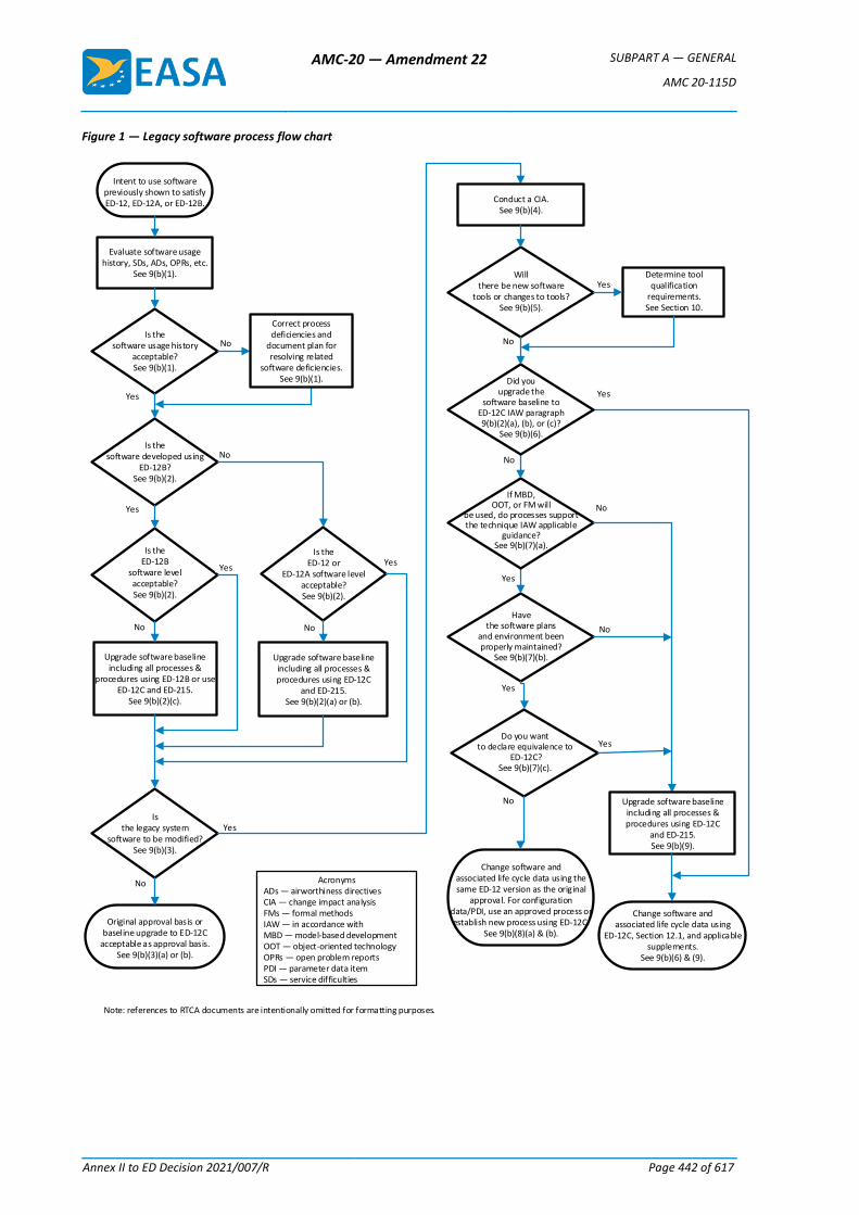
AMC-20 — Amendment 22 SUBPART A — GENERAL
AMC 20-115D
Annex II to ED Decision 2021/007/R Page 442 of 617
Figure 1 — Legacy software process flow chart
Isthe legacy system
software to be modified?See 9(b)(3).
Is theED-12B
software level acceptable?See 9(b)(2).
Yes
No
Is thesoftware developed using
ED-12B?See 9(b)(2).
Yes
No
Evaluate software usage history, SDs, ADs, OPRs, etc.
See 9(b)(1).
Is thesoftware usage history
acceptable?See 9(b)(1).
No
Yes
Yes
No
Yes
No
Havethe software plans
and environment been properly maintained?
See 9(b)(7)(b).
Yes
No
Do you wantto declare equivalence to
ED-12C?See 9(b)(7)(c).
Is theED-12 or
ED-12A software level acceptable?See 9(b)(2).
No
Yes
Upgrade software baseline including all processes &
procedures using ED-12B or use ED-12C and ED-215.
See 9(b)(2)(c).
Conduct a CIA.See 9(b)(4).
If MBD,OOT, or FM will
be used, do processes support the technique IAW applicable
guidance?See 9(b)(7)(a).
Intent to use software previously shown to satisfy ED-12, ED-12A, or ED-12B.
Change software andassociated life cycle data using the same ED-12 version as the original
approval. For configuration data/PDI, use an approved process or establish new process using ED-12C.
See 9(b)(8)(a) & (b).
Change software andassociated life cycle data using
ED-12C, Section 12.1, and applicable supplements.
See 9(b)(6) & (9).
Willthere be new software
tools or changes to tools?See 9(b)(5).
Determine tool qualification
requirements.See Section 10.
Yes
No
Upgrade software baseline including all processes & procedures using ED-12C
and ED-215.See 9(b)(2)(a) or (b).
Did youupgrade the
software baseline toED-12C IAW paragraph 9(b)(2)(a), (b), or (c)?
See 9(b)(6).
Yes
No
AcronymsADs — airworthiness directivesCIA — change impact analysisFMs — formal methodsIAW — in accordance withMBD — model-based developmentOOT — object-oriented technologyOPRs — open problem reportsPDI — parameter data itemSDs — service difficulties
Original approval basis orbaseline upgrade to ED-12C
acceptable as approval basis.See 9(b)(3)(a) or (b).
Upgrade software baseline including all processes & procedures using ED-12C
and ED-215.See 9(b)(9).
Yes
No
Note: references to RTCA documents are intentionally omitted for formatting purposes.
Correct process deficiencies and
document plan for resolving related
software deficiencies.See 9(b)(1).
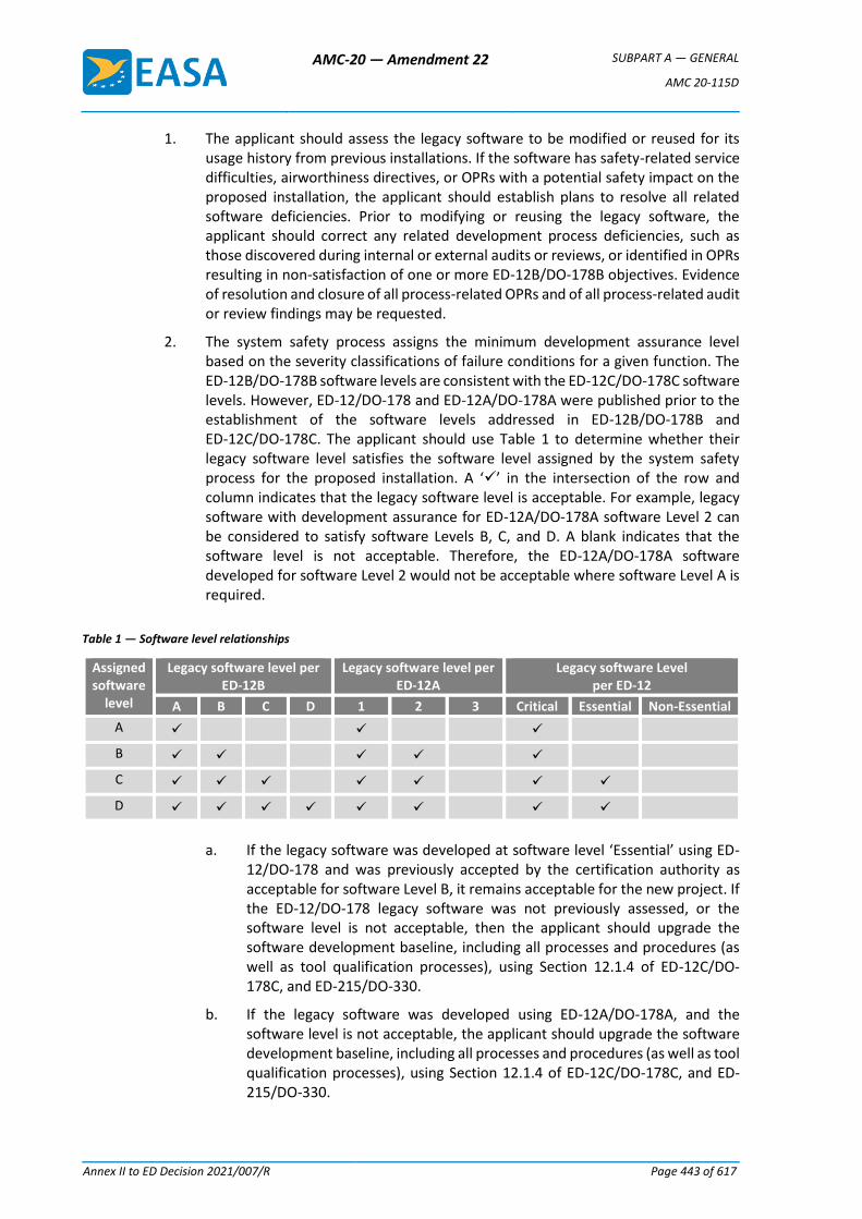
AMC-20 — Amendment 22 SUBPART A — GENERAL
AMC 20-115D
Annex II to ED Decision 2021/007/R Page 443 of 617
1. The applicant should assess the legacy software to be modified or reused for its usage history from previous installations. If the software has safety-related service difficulties, airworthiness directives, or OPRs with a potential safety impact on the proposed installation, the applicant should establish plans to resolve all related software deficiencies. Prior to modifying or reusing the legacy software, the applicant should correct any related development process deficiencies, such as those discovered during internal or external audits or reviews, or identified in OPRs resulting in non-satisfaction of one or more ED-12B/DO-178B objectives. Evidence of resolution and closure of all process-related OPRs and of all process-related audit or review findings may be requested.
2. The system safety process assigns the minimum development assurance level based on the severity classifications of failure conditions for a given function. The ED-12B/DO-178B software levels are consistent with the ED-12C/DO-178C software levels. However, ED-12/DO-178 and ED-12A/DO-178A were published prior to the establishment of the software levels addressed in ED-12B/DO-178B and ED-12C/DO-178C. The applicant should use Table 1 to determine whether their legacy software level satisfies the software level assigned by the system safety process for the proposed installation. A ‘’ in the intersection of the row and column indicates that the legacy software level is acceptable. For example, legacy software with development assurance for ED-12A/DO-178A software Level 2 can be considered to satisfy software Levels B, C, and D. A blank indicates that the software level is not acceptable. Therefore, the ED-12A/DO-178A software developed for software Level 2 would not be acceptable where software Level A is required.
Table 1 — Software level relationships
Assigned software
level
Legacy software level per ED-12B
Legacy software level per ED-12A
Legacy software Level per ED-12
A B C D 1 2 3 Critical Essential Non-Essential
A
B
C
D
a. If the legacy software was developed at software level ‘Essential’ using ED-12/DO-178 and was previously accepted by the certification authority as acceptable for software Level B, it remains acceptable for the new project. If the ED-12/DO-178 legacy software was not previously assessed, or the software level is not acceptable, then the applicant should upgrade the software development baseline, including all processes and procedures (as well as tool qualification processes), using Section 12.1.4 of ED-12C/DO-178C, and ED-215/DO-330.
b. If the legacy software was developed using ED-12A/DO-178A, and the software level is not acceptable, the applicant should upgrade the software development baseline, including all processes and procedures (as well as tool qualification processes), using Section 12.1.4 of ED-12C/DO-178C, and ED-215/DO-330.
AMC-20 — Amendment 22 SUBPART A — GENERAL
AMC 20-115D
Annex II to ED Decision 2021/007/R Page 444 of 617
c. If the legacy software was developed using ED-12B/DO-178B, and the software level is not acceptable, the applicant should upgrade the software development baseline, including all processes and procedures (as well as tool qualification processes), using Section 12.1.4 of ED-12B/DO-178B or ED-12C/DO-178C, and ED-215/DO-330.
3. If the criteria of 9(b)(1) and 9(b)(2) are satisfied and modifications to the software are not required, then:
a. the original approval may serve as the basis for the software in the installation approval of the proposed system; and
b. if the applicant upgraded the software development baseline using ED-12C/DO-178C and updated all processes and procedures, as well as tool qualification processes, to ED-12C/DO-178C and ED-215/DO-330, then the applicant may declare their software as equivalent to satisfying ED-12C/DO-178C; however, the applicant cannot declare their unmodified tools as equivalent to satisfying ED-12C/DO-178C and ED-215/DO-330. The applicant should make all subsequent modifications to all their software and tools using their processes and procedures that satisfy ED-12C/DO-178C and ED-215/DO-330.
4. If modifications to the software are required, the applicant should conduct a software change impact analysis (CIA) to determine the extent of the modifications, the impact of those modifications, and what verification is required to ensure that the modified software performs its intended function and continues to satisfy the identified means of compliance. The applicant should:
a. identify the software changes to be incorporated and conduct a CIA consisting of one or more analyses associated with the software change, as identified in ED-12C/DO-178C, Section 12.1;
b. conduct the verification, as indicated by the CIA; and
c. summarise the results of the CIA in the plan for software aspects of certification (PSAC) or in the software accomplishment summary (SAS).
5. If new software tools or modifications to tools are needed, please refer to paragraph 10 of this AMC to determine the tool qualification requirements.
6. If the applicant upgraded the software baseline to ED-12C/DO-178C in accordance with subparagraph 9(b)(2), they should make all modifications to the software using ED-12C/DO-178C, Section 12.1. If the applicant wants to declare their software as equivalent to satisfying ED-12C/DO-178C, the applicant’s equivalence declaration applies to both modified and unmodified software and is valid even if the applicant uses unmodified tools that have not been qualified using ED-12C/DO-178C. However, the applicant cannot declare their unmodified tools as equivalent to satisfying ED-12C/DO-178C and ED-215/DO-330. All subsequent modifications to all their software and tools are to be made using processes and procedures satisfying ED-12C/DO-178C and ED-215/DO-330.
7. If the applicant wants to use their existing processes to make modifications to their legacy software using the version of ED-12/DO-178 (i.e. ED-12/DO-178, ED-12A/DO-178A, or ED-12B/DO-178B) used for the original software approval, the applicant may do so, provided that all of the following conditions are met:
AMC-20 — Amendment 22 SUBPART A — GENERAL
AMC 20-115D
Annex II to ED Decision 2021/007/R Page 445 of 617
a. If MBD, OOT, or FMs are to be used, existing processes incorporating these methods should have been evaluated and found to be acceptable by EASA on a previous certified project. These processes should have been developed in accordance with EASA guidance specific to the technique, such as that contained in an associated CRI or a published CM.
b. The applicant has maintained, and can still use, the software plans, processes, and life cycle environment, including improvements to processes or to the life cycle environment as captured in revised plans.
c. The applicant does not intend to declare the proposed software as satisfying ED-12C/DO-178C.
8. If the conditions of subparagraph 9(b)(7) are satisfied:
a. the applicant may accomplish all modifications to the software using the same ED-12/DO-178 version as for the original approval. However, the applicant may not declare their software as equivalent to satisfying ED-12C/DO-178C; and
b. if configuration data is used, as defined under ‘Parameter data item’ in ED-12C/DO-178C, the applicant may use existing processes for such data if the processes were evaluated and found to be acceptable by EASA on a previous certified project; in the absence of processes for using configuration data, the applicant should establish new processes for using parameter data items (PDIs) in accordance with ED-12C/DO-178C.
9. If any of the conditions of subparagraph 9(b)(7) is not satisfied, the applicant should update all their processes and procedures, as well as tool qualification processes, using ED-12C/DO-178C and ED-215/DO-330, and make all modifications to the software using ED-12C/DO-178C, Section 12.1. If the applicant wants to declare their software as equivalent to satisfying ED-12C/DO-178C, their declaration applies to both the modified and unmodified software and is valid even if the applicant uses unmodified tools that have not been qualified using ED-12C/DO-178C and ED-215/DO-330. However, the applicant cannot declare their unmodified tools as equivalent to satisfying ED-12C/DO-178C and ED-215/DO-330. The applicant should make all subsequent modifications to all their software and tools using their processes and procedures that satisfy ED-12C/DO-178C and ED-215/DO-330.
10. TOOL QUALIFICATION
Sections 12.2 of ED-12C/DO-178C and ED-215/DO-330 provide an acceptable method for tool qualification. ED-215/DO-330 contains its own complete set of objectives, activities, and life cycle data for tool qualification.
a. If the applicant’s legacy software was previously approved using ED-12/DO-178 or ED-12A/DO-178A, and the applicant intends to use a new or modified tool for modifications to the legacy software, they should use the criteria of ED-12C/DO-178C, Section 12.2 to determine whether tool qualification is needed. If the applicant needs to qualify the tool, they should use the software level assigned by the system safety assessment for determining the required TQL, and should use ED-215/DO-330 for the applicable objectives, activities, and life cycle data. The applicant may declare their qualified tool as satisfying ED-215/DO-330, but not the legacy software as equivalent to satisfying ED-12C/DO-178C.
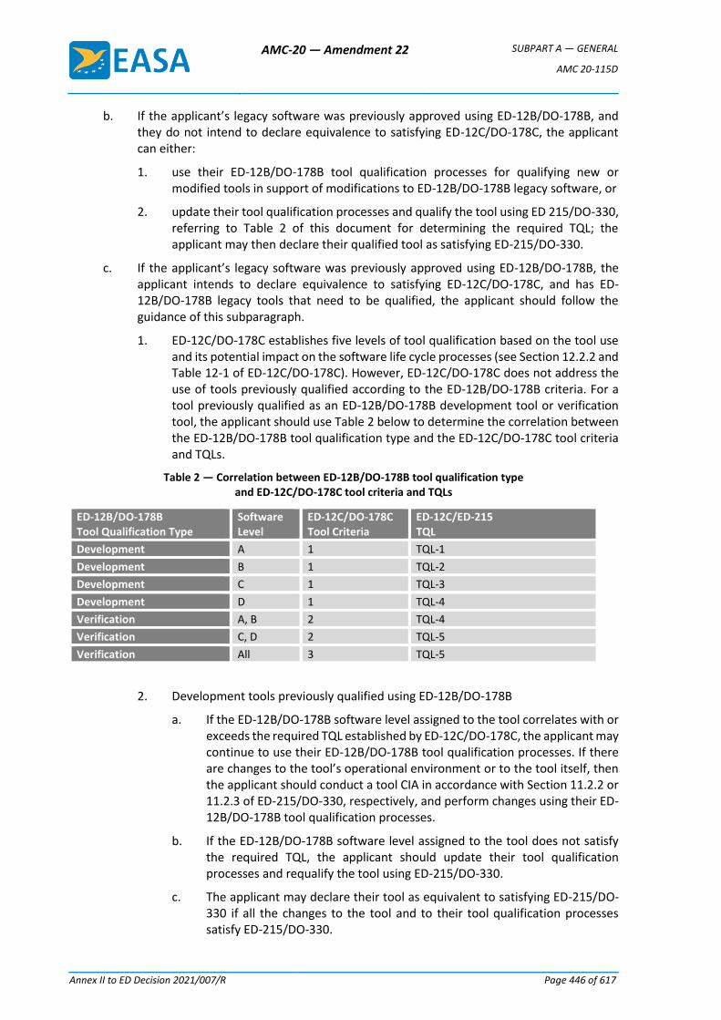
AMC-20 — Amendment 22 SUBPART A — GENERAL
AMC 20-115D
Annex II to ED Decision 2021/007/R Page 446 of 617
b. If the applicant’s legacy software was previously approved using ED-12B/DO-178B, and they do not intend to declare equivalence to satisfying ED-12C/DO-178C, the applicant can either:
1. use their ED-12B/DO-178B tool qualification processes for qualifying new or modified tools in support of modifications to ED-12B/DO-178B legacy software, or
2. update their tool qualification processes and qualify the tool using ED 215/DO-330, referring to Table 2 of this document for determining the required TQL; the applicant may then declare their qualified tool as satisfying ED-215/DO-330.
c. If the applicant’s legacy software was previously approved using ED-12B/DO-178B, the applicant intends to declare equivalence to satisfying ED-12C/DO-178C, and has ED-12B/DO-178B legacy tools that need to be qualified, the applicant should follow the guidance of this subparagraph.
1. ED-12C/DO-178C establishes five levels of tool qualification based on the tool use and its potential impact on the software life cycle processes (see Section 12.2.2 and Table 12-1 of ED-12C/DO-178C). However, ED-12C/DO-178C does not address the use of tools previously qualified according to the ED-12B/DO-178B criteria. For a tool previously qualified as an ED-12B/DO-178B development tool or verification tool, the applicant should use Table 2 below to determine the correlation between the ED-12B/DO-178B tool qualification type and the ED-12C/DO-178C tool criteria and TQLs.
Table 2 — Correlation between ED-12B/DO-178B tool qualification type and ED-12C/DO-178C tool criteria and TQLs
ED-12B/DO-178B Tool Qualification Type
Software Level
ED-12C/DO-178C Tool Criteria
ED-12C/ED-215 TQL
Development A 1 TQL-1
Development B 1 TQL-2
Development C 1 TQL-3
Development D 1 TQL-4
Verification A, B 2 TQL-4
Verification C, D 2 TQL-5
Verification All 3 TQL-5
2. Development tools previously qualified using ED-12B/DO-178B
a. If the ED-12B/DO-178B software level assigned to the tool correlates with or exceeds the required TQL established by ED-12C/DO-178C, the applicant may continue to use their ED-12B/DO-178B tool qualification processes. If there are changes to the tool’s operational environment or to the tool itself, then the applicant should conduct a tool CIA in accordance with Section 11.2.2 or 11.2.3 of ED-215/DO-330, respectively, and perform changes using their ED-12B/DO-178B tool qualification processes.
b. If the ED-12B/DO-178B software level assigned to the tool does not satisfy the required TQL, the applicant should update their tool qualification processes and requalify the tool using ED-215/DO-330.
c. The applicant may declare their tool as equivalent to satisfying ED-215/DO-330 if all the changes to the tool and to their tool qualification processes satisfy ED-215/DO-330.
AMC-20 — Amendment 22 SUBPART A — GENERAL
AMC 20-115D
Annex II to ED Decision 2021/007/R Page 447 of 617
3. Verification tools previously qualified using ED-12B/DO-178B
a. If TQL-5 is required, and the applicant’s verification tool was previously qualified using
ED-12B/DO-178B:
i. the applicant may continue to use their ED-12B/DO-178B tool qualification process; and
ii. If there are changes to the tool or the tool’s operational environment, the applicant should conduct a tool CIA and reverify the tool using their ED-12B/DO-178B tool qualification processes or requalify the tool using ED-215/DO-330.
b. If TQL-4 is required, the applicant should requalify their verification tool using ED-215/DO-330.
c. The applicant may declare their tool as equivalent to satisfying ED-215/DO-330 if all changes to the tool (if applicable) and to their tool qualification processes satisfy
ED-215/DO-330.
11. RELATED REGULATORY, ADVISORY, AND INDUSTRY MATERIAL
a. Related EASA CSs
1. Decision No. 2003/14/RM of the Executive Director of the Agency of 14 November 2003 on certification specifications, including airworthiness codes and acceptable means of compliance for normal, utility, aerobatic and commuter category aeroplanes (‘CS-23’).
2. Decision No. 2003/2/RM of the Executive Director of the Agency of 17 October 2003 on certification specifications, including airworthiness codes and acceptable means of compliance, for large aeroplanes (‘CS-25’).
3. Decision No. 2003/15/RM of the Executive Director of the Agency of 14 November 2003 on certification specifications for small rotorcraft (‘CS-27’).
4. Decision No. 2003/16/RM of the Executive Director of the Agency of 14 November 2003 on certification specifications for large rotorcraft (‘CS-29’).
5. Decision No. 2003/9/RM of the Executive Director of the Agency of 24 October 2003 on certification specifications, including airworthiness codes and acceptable means of compliance, for engines (‘CS-E’).
6. Decision No. 2003/7/RM of the Executive Director of the Agency of 24 October 2003 on certification specifications, including airworthiness codes and acceptable means of compliance, for propellers (‘CS-P’).
7. Decision No. 2003/10/RM of the Executive Director of the Agency of 24 October 2003 on certification specifications, including airworthiness codes and acceptable means of compliance, for European Technical Standard Orders (‘CS-ETSO’).
8. Decision No. 2003/5/RM of the Executive Director of the Agency of 17 October 2003 on certification specifications, including airworthiness codes and acceptable means of compliance, for auxiliary power units (‘CS-APU’).
AMC-20 — Amendment 22 SUBPART A — GENERAL
AMC 20-115D
Annex II to ED Decision 2021/007/R Page 448 of 617
9. Decision No. 2003/12/RM of the Executive Director of the Agency of 5 November 2003 on general acceptable means of compliance for airworthiness of products, parts and appliances (‘AMC-20’).
b. FAA advisory circulars (ACs)
1. AC 23.1309-1E, System Safety Analysis and Assessment for Part 23 Airplanes, 17 November 2011.
2. AC 27.1309A, Equipment, Systems, and Installations (included in AC 27-1B, Certification of Normal Category Rotorcraft), 4 February 2016.
3. AC 29.1309A, Equipment, Systems, and Installations (included in AC 29-2C, Certification of Transport Category Rotorcraft), 4 February 2016.
c. Industry documents
1. EUROCAE ED-12, Software Considerations in Airborne Systems and Equipment Certification, May 1982 (no longer in print).
2. EUROCAE ED-12A, Software Considerations in Airborne Systems and Equipment Certification, October 1985 (no longer in print).
3. EUROCAE ED-12B, Software Considerations in Airborne Systems and Equipment Certification, 1 December 1992.
4. EUROCAE ED-12C, Software Considerations in Airborne Systems and Equipment Certification, 1 January 2012.
5. EUROCAE ED-94C, Supporting Information for ED-12C and ED-109A, 1 January 2012.
6. EUROCAE ED-215, Software Tool Qualification Considerations, 1 January 2012.
7. EUROCAE ED-216, Formal Methods Supplement to ED-12C and ED-109A, 1 January 2012.
8. EUROCAE ED-217, Object-Oriented Technology and Related Techniques Supplement to ED-12C and ED-109A, 1 January 2012.
9. EUROCAE ED-218, Model-Based Development and Verification Supplement to ED-12C and ED-109A, 1 January 2012.
10. RTCA DO-178, Software Considerations in Airborne Systems and Equipment Certification, January 1982 (no longer in print).
11. RTCA DO-178A, Software Considerations in Airborne Systems and Equipment Certification, 1 March 1985 (no longer in print).
12. RTCA DO-178B, Software Considerations in Airborne Systems and Equipment Certification, 1 December 1992.
13. RTCA DO-178C, Software Considerations in Airborne Systems and Equipment Certification, 13 December 2011.
14. RTCA DO-248C, Supporting Information for DO-178C and DO-278A, 13 December 2011.
15. RTCA DO-297, Integrated Modular Avionics (IMA) Development Guidance and Certification Considerations, 8 November 2005.
16. RTCA DO-330, Software Tool Qualification Considerations, 13 December 2011.
AMC-20 — Amendment 22 SUBPART A — GENERAL
AMC 20-115D
Annex II to ED Decision 2021/007/R Page 449 of 617
17. RTCA DO-331, Model-Based Development and Verification Supplement to DO-178C and DO-278A, 13 December 2011.
18. RTCA DO-332, Object-Oriented Technology and Related Techniques Supplement to DO-178C and DO-278A, 13 December 2011.
19. RTCA DO-333, Formal Methods Supplement to DO-178C and DO-278A, 13 December 2011.
12. AVAILABILITY OF DOCUMENTS
— EASA CSs and AMC are available at: www.easa.europa.eu.
— FAA ACs are available at: www.faa.gov.
— EUROCAE are available on payment at:
European Organisation for Civil Aviation Equipment
102 rue Etienne Dolet, 92240 Malakoff, France
Telephone: +33 1 40 92 79 30; Fax +33 1 46 55 62 65
Email: [email protected], website: www.eurocae.net.
— RTCA documents are available on payment at:
RTCA, Inc.
1150 18th Street NW, Suite 910, Washington DC 20036, USA
Email: [email protected], website: www.rtca.org.
[Amdt 20/14]
GM1 to AMC 20-115D – Software change impact analyses (CIAs)
a. These practices provide complementary information to ED-12C/DO-178C and ED-12B/DO-178B, Sections 12.1.1, 12.1.2, and 12.1.3, and AMC 20-115D, subparagraph 9(b)(4). The applicant may use these practices when they need to conduct a software CIA.
b. A CIA identifies the released software baseline upon which the proposed software is to be built, providing:
1. a summary of the changes and the impact of those changes;
2. a listing and descriptions of the problem reports to be corrected as part of the intended change and/or change requests related to those changes; and
3. a listing of new functions to be activated and/or implemented.
c. A CIA addresses changes to the following items, where applicable:
1. the software level;
2. the development or verification environment;
3. the software processes;
4. the tools (e.g. when a new tool version is introduced or a tool’s use is modified);
5. the processor or other hardware components and interfaces;
6. the configuration data, especially when activating or deactivating functions;
AMC-20 — Amendment 22 SUBPART A — GENERAL
AMC 20-115D
Annex II to ED Decision 2021/007/R Page 450 of 617
7. the software interface characteristics and input/output (I/O) requirements; and
8. the software requirements, design, architecture, and code components, where such changes are not limited to the modified life cycle data, but should also consider the items affected by the change.
d. For each applicable item of subparagraph 13(c) above, a CIA describes the resulting impact of the change(s) and identifies the activities to be performed to satisfy ED-12C/DO-178C or ED-12B/DO-178B and continue to satisfy the requirements for safe operation.
[Amdt 20/14]
GM2 to AMC 20-115D – Clarification of data coupling and control coupling
These practices provide complementary information to ED-94C/DO-248C FAQ#67 for satisfying objective A-7 (8) of ED-12C/DO-178C and ED-12B/DO-178B.
a. Data coupling analysis is of a different type and purpose than control coupling analysis. Both analyses are necessary to satisfy said objective.
b. Although they support a verification objective, data coupling and control coupling analyses rely on good practices in the software design phase, for example, through the specification of the interfaces (I/O) and of the dependencies between components.
[Amdt 20/14]
GM3 to AMC 20-115D – Error-handling at design level
a. These practices provide complementary information to ED-12C/DO-178C and ED-12B/DO-178B, Sections 6.3.2, 6.3.3, and 6.3.4. Section 6.3.4.f., and identifies potential sources of errors that require specific activities focused at the source code review level. However, in order to protect against foreseeable unintended software behaviour, it is beneficial and recommended to handle these sources of error at the design level.
b. The possibility of unintended software behaviour may be reduced by considering the following activities:
1. identification of foreseeable sources of software errors, which include:
a. runtime exceptions or errors, such as fixed/floating-point arithmetic overflow, stack/heap overflow, division by zero, or counter and timer overrun/wrap-around;
b. data/memory corruption or timing issues, such as those caused by a lack of partitioning or improper interrupt management or cache management; and
c. features leading to unpredictable programme execution, such as dynamic allocation, out-of-order execution, or resource contention;
2. for each foreseeable source of software error, identification of the associated mitigation;
3. specification of protection mechanisms in the software requirements (high-level or low-level requirements) which should in particular include the specification of error-handling mechanisms; and
4. for software Levels A and B, it is recommended that consideration be given to incorporating runtime protection mechanisms since reliance on probabilistic approaches
AMC-20 — Amendment 22 SUBPART A — GENERAL
AMC 20-115D
Annex II to ED Decision 2021/007/R Page 451 of 617
or static analyses alone may not be appropriate; it may be a good practice to implement such runtime protection mechanisms for the other software levels as well.
c. The use of FMs in accordance with ED-216/DO-333 may enhance the detection of runtime errors.
[Amdt 20/14]
AMC-20 — Amendment 22 SUBPART A — GENERAL
AMC 20-128A
Annex II to ED Decision 2021/007/R Page 452 of 617
AMC 20-128A
AMC 20-128A Design Considerations for Minimizing Hazards Caused by Uncontained Turbine Engine and Auxiliary Power Unit Rotor Failure
1 PURPOSE.
This acceptable means of compliance (AMC) sets forth a method of compliance with the requirements of CS 23.901(f), 23.903(b)(1), 25.903(d)(1) and 25A903(d)(1)of the EASA Certification Specifications (CS) pertaining to design precautions taken to minimise the hazards to an aeroplane in the event of uncontained engine or auxiliary power unit (APU) rotor failures. The guidance provided within this AMC is harmonised with that of the Federal Aviation Administration (FAA) and is intended to provide a method of compliance that has been found acceptable. As with all AMC material, it is not mandatory and does not constitute a regulation.
2 RESERVED
3 APPLICABILITY.
This AMC applies to CS-23 and CS-25 aeroplanes.
4 RELATED DOCUMENTS.
Paragraphs 23.903, and 25.903 of the CS and other paragraphs relating to uncontained engine failures.
a. Related Joint Aviation Requirements. Sections which prescribe requirements for the design, substantiation and certification relating to uncontained engine debris include:
§ 23.863, 25.863 Flammable fluid fire protection
§ 25.365 Pressurised compartment loads
§ 25.571 Damage-tolerance and fatigue evaluation of structure
§ 25.963 Fuel tanks: general
§ 25.1189 Shut-off means
§ 25.1461 Equipment containing high energy rotors
CS-APU Auxiliary Power Units
NOTE: The provisions of § 25.1461 have occasionally been used in the approval of APU installations regardless of protection from high energy rotor disintegration. However, the more specific requirements of CS 25.903(d)(1) and associated guidance described within this AMC take precedence over the requirements of CS 25.1461.
b. Other Documents
ISO 2685:1992 Aircraft – Environmental conditions and test procedures for airborne equipment – Resistance to fire in designated fire zones
AC 20–135 Powerplant Installation and Propulsion System Component Fire Protection Test Methods, Standards, and Criteria.
c. Society of Automotive Engineers (SAE) Documents.
AIR1537 Report on Aircraft Engine Containment, October, 1977.
AIR4003 Uncontained Turbine Rotor Events Data Period 1976 through 1983.
AIR4770 Uncontained Turbine Rotor Events Data Period 1984 (Draft) through 1989.

AMC-20 — Amendment 22 SUBPART A — GENERAL
AMC 20-128A
Annex II to ED Decision 2021/007/R Page 453 of 617
These documents can be obtained from the Society of Automotive Engineers, Inc., 400 Commonwealth Drive, Warrendale, Pennsylvania, 15096.
5 BACKGROUND.
Although turbine engine and APU manufacturers are making efforts to reduce the probability of uncontained rotor failures, service experience shows that uncontained compressor and turbine rotor failures continue to occur. Turbine engine failures have resulted in high velocity fragment penetration of adjacent structures, fuel tanks, fuselage, system components and other engines on the aeroplane. While APU uncontained rotor failures do occur, and to date the impact damage to the aeroplane has been minimal, some rotor failures do produce fragments that should be considered. Since it is unlikely that uncontained rotor failures can be completely eliminated, CS-23 and CS-25 require that aeroplane design precautions be taken to minimise the hazard from such events.
a. Uncontained gas turbine engine rotor failure statistics are presented in the Society of Automotive Engineers (SAE) reports covering time periods and number of uncontained events listed in the table shown below. The following statistics summarise 28 years of service experience for fixed wing aeroplanes and do not include data for rotorcraft and APUs:
No. of Events
Report No. Period Total Category 3 Category 4
AIR1537 1962–75 275 44 5
AIR4003 1976–83 237 27 3
AIR4770 (Draft) 1984–89 164 22 7
TOTAL 676 93 15
The total of 676 uncontained events includes 93 events classified in Category 3 and 15 events classified in Category 4 damage to the aeroplane. Category 3 damage is defined as significant aeroplane damage with the aeroplane capable of continuing flight and making a safe landing. Category 4 damage is defined as severe aeroplane damage involving a crash landing, critical injuries, fatalities or hull loss.
During this 28 year period there were 1,089.6 million engine operating hours on commercial transports. The events were caused by a wide variety of influences classed as environmental (bird ingestion, corrosion/erosion, foreign object damage (FOD)), manufacturing and material defects, mechanical, and human factors (maintenance and overhaul, inspection error and operational procedures).
b. Uncontained APU rotor failure statistics covering 1962 through 1993 indicate that there have been several uncontained failures in at least 250 million hours of operation on transport category aeroplanes. No Category 3 or 4 events were reported and all failures occurred during ground operation. These events were caused by a wide variety of influences such as corrosion, ingestion of de-icing fluid, manufacturing and material defects, mechanical, and human factors (maintenance and overhaul, inspection error and operational procedures).
c. The statistics in the SAE studies indicate the existence of many different causes of failures not readily apparent or predictable by failure analysis methods. Because of the variety of causes of uncontained rotor failures, it is difficult to anticipate all possible causes of failure and to provide protection to all areas. However, design considerations outlined in this AMC provide guidelines for achieving the desired objective of minimising the hazard to an aeroplane from uncontained rotor failures. These guidelines, therefore, assume a rotor failure will occur and that analysis of the effects of this failure is necessary. These
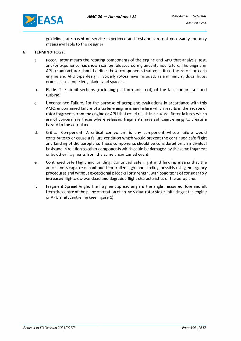
AMC-20 — Amendment 22 SUBPART A — GENERAL
AMC 20-128A
Annex II to ED Decision 2021/007/R Page 454 of 617
guidelines are based on service experience and tests but are not necessarily the only means available to the designer.
6 TERMINOILOGY.
a. Rotor. Rotor means the rotating components of the engine and APU that analysis, test, and/or experience has shown can be released during uncontained failure. The engine or APU manufacturer should define those components that constitute the rotor for each engine and APU type design. Typically rotors have included, as a minimum, discs, hubs, drums, seals, impellers, blades and spacers.
b. Blade. The airfoil sections (excluding platform and root) of the fan, compressor and turbine.
c. Uncontained Failure. For the purpose of aeroplane evaluations in accordance with this AMC, uncontained failure of a turbine engine is any failure which results in the escape of rotor fragments from the engine or APU that could result in a hazard. Rotor failures which are of concern are those where released fragments have sufficient energy to create a hazard to the aeroplane.
d. Critical Component. A critical component is any component whose failure would contribute to or cause a failure condition which would prevent the continued safe flight and landing of the aeroplane. These components should be considered on an individual basis and in relation to other components which could be damaged by the same fragment or by other fragments from the same uncontained event.
e. Continued Safe Flight and Landing. Continued safe flight and landing means that the aeroplane is capable of continued controlled flight and landing, possibly using emergency procedures and without exceptional pilot skill or strength, with conditions of considerably increased flightcrew workload and degraded flight characteristics of the aeroplane.
f. Fragment Spread Angle. The fragment spread angle is the angle measured, fore and aft from the centre of the plane of rotation of an individual rotor stage, initiating at the engine or APU shaft centreline (see Figure 1).
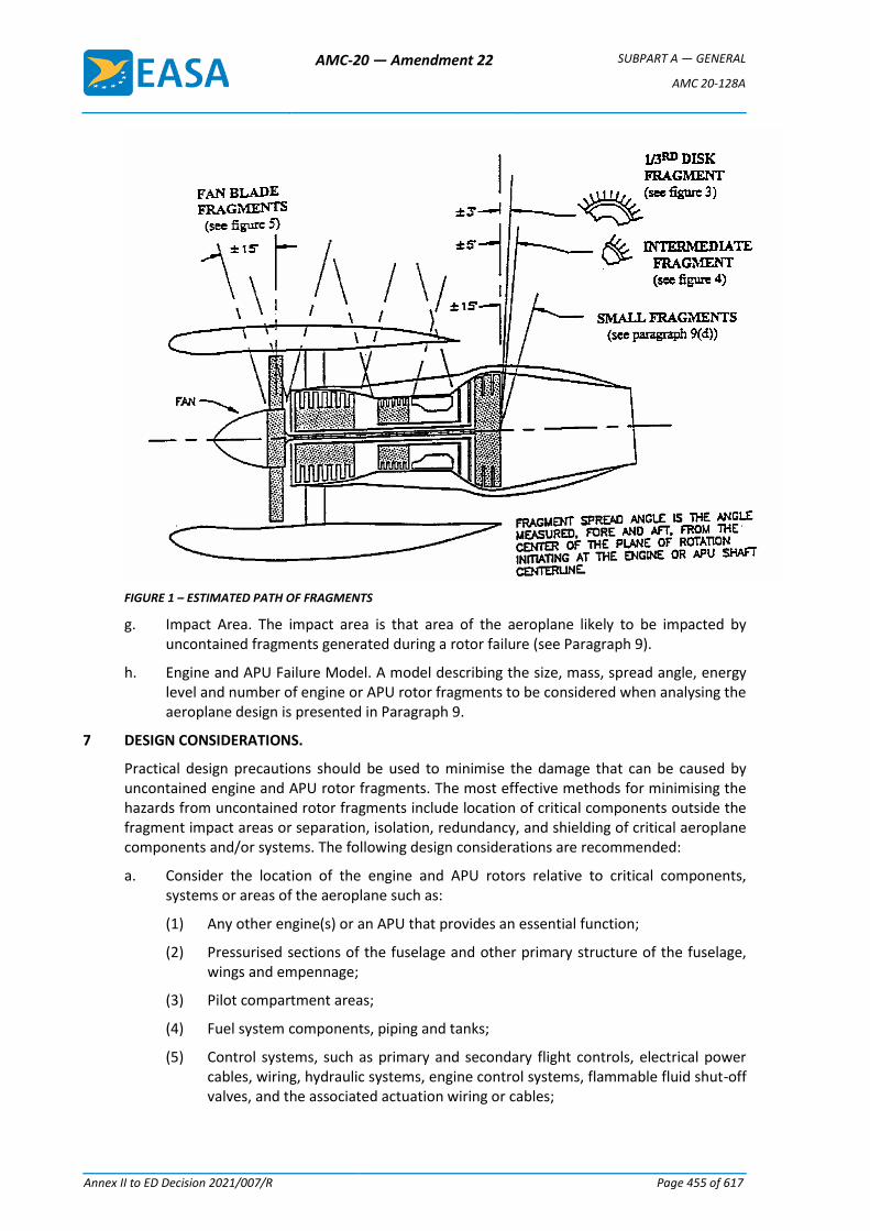
AMC-20 — Amendment 22 SUBPART A — GENERAL
AMC 20-128A
Annex II to ED Decision 2021/007/R Page 455 of 617
FIGURE 1 – ESTIMATED PATH OF FRAGMENTS
g. Impact Area. The impact area is that area of the aeroplane likely to be impacted by uncontained fragments generated during a rotor failure (see Paragraph 9).
h. Engine and APU Failure Model. A model describing the size, mass, spread angle, energy level and number of engine or APU rotor fragments to be considered when analysing the aeroplane design is presented in Paragraph 9.
7 DESIGN CONSIDERATIONS.
Practical design precautions should be used to minimise the damage that can be caused by uncontained engine and APU rotor fragments. The most effective methods for minimising the hazards from uncontained rotor fragments include location of critical components outside the fragment impact areas or separation, isolation, redundancy, and shielding of critical aeroplane components and/or systems. The following design considerations are recommended:
a. Consider the location of the engine and APU rotors relative to critical components, systems or areas of the aeroplane such as:
(1) Any other engine(s) or an APU that provides an essential function;
(2) Pressurised sections of the fuselage and other primary structure of the fuselage, wings and empennage;
(3) Pilot compartment areas;
(4) Fuel system components, piping and tanks;
(5) Control systems, such as primary and secondary flight controls, electrical power cables, wiring, hydraulic systems, engine control systems, flammable fluid shut-off valves, and the associated actuation wiring or cables;

AMC-20 — Amendment 22 SUBPART A — GENERAL
AMC 20-128A
Annex II to ED Decision 2021/007/R Page 456 of 617
(6) Any fire extinguisher system of a cargo compartment, an APU, or another engine including electrical wiring and fire extinguishing agent plumbing to these systems;
(7) Engine air inlet attachments and effects of engine case deformations caused by fan blade debris resulting in attachment failures;
(8) Instrumentation essential for continued safe flight and landing;
(9) Thrust reverser systems where inadvertent deployment could be catastrophic; and
(10) Oxygen systems for high altitude aeroplanes, where these are critical due to descent time.
b. Location of Critical Systems and Components. Critical aeroplane flight and engine control cables, wiring, flammable fluid carrying components and lines (including vent lines), hydraulic fluid lines and components, and pneumatic ducts should be located to minimise hazards caused by uncontained rotors and fan blade debris. The following design practices should be considered:
(1) Locate, if possible, critical components or systems outside the likely debris impact areas.
(2) Duplicate and separate critical components or systems, or provide suitable protection if located in debris impact areas.
(3) Protection of critical systems and components can be provided by using airframe structure or supplemental shielding.
These methods have been effective in mitigating the hazards from both single and multiple small fragments within the ± 15 impact area. Separation of multiplicated critical systems and components by at least a distance equal to the 1/2 blade fragment dimension has been accepted for showing minimisation from a single high energy small fragment when at least one of the related multiplicated critical components is shielded by significant structure such as aluminium lower wing skins, pylons, aluminium skin of the cabin pressure vessel, or equivalent structures.
Multiplicated critical systems and components positioned behind less significant structures should be separated by at least a distance equal to the 1/2 blade fragment dimension, and at least one of the multiplicated critical systems should be:
(i) Located such that equivalent protection is provided by other inherent structures such as pneumatic ducting, interiors, bulkheads, stringers, or
(ii) Protected by an additional shield such that the airframe structure and shield material provide equivalent shielding.
(4) Locate fluid shut-offs and actuation means so that flammable fluid can be isolated in the event of damage to the system.
(5) Minimise the flammable fluid spillage which could contact an ignition source.
(6) For airframe structural elements, provide redundant designs or crack stoppers to limit the subsequent tearing which could be caused by uncontained rotor fragments.
(7) Locate fuel tanks and other flammable fluid systems and route lines (including vent lines) behind aeroplane structure to reduce the hazards from spilled fuel or from tank penetrations. Fuel tank explosion-suppression materials, protective shields or deflectors on the fluid lines, have been used to minimise the damage and hazards.

AMC-20 — Amendment 22 SUBPART A — GENERAL
AMC 20-128A
Annex II to ED Decision 2021/007/R Page 457 of 617
c. External Shields and Deflectors. When shields, deflection devices or aeroplane structure are proposed to be used to protect critical systems or components, the adequacy of the protection, including mounting points to the airframe structure, should be shown by testing or validated analyses supported by test data, using the fragment energies supplied by the engine or APU manufacturer or those defined in Paragraph 9. For protection against engine small fragments, as defined in Paragraph 9, no quantitative validation as defined in Paragraph 10 is required if equivalency to the penetration resistant structures listed (e.g. pressure cabin skins, etc.) is shown.
8 ACCEPTED DESIGN PRECAUTIONS.
Design practices currently in use by the aviation industry that have been shown to reduce the overall risk, by effectively eliminating certain specific risks and reducing the remaining specific risks to a minimum level, are described within this paragraph of the AMC. Aeroplane designs submitted for evaluation by the regulatory authorities will be evaluated against these proven design practices.
a. Uncontrolled Fire.
(1) Fire Extinguishing Systems. The engine/APU fire extinguishing systems currently in use rely on a fire zone with a fixed compartment air volume and a known air exchange rate to extinguish a fire. The effectiveness of this type of system along with firewall integrity may therefore be compromised for the torn/ruptured compartment of the failed engine/APU. Protection of the aeroplane following this type of failure relies on the function of the fire warning system and subsequent fire switch activation to isolate the engine/APU from airframe flammable fluid (fuel and hydraulic fluid) and external ignition sources (pneumatic and electrical). Fire extinguishing protection of such a compromised system may not be effective due to the extent of damage. Continued function of any other engine, APU or cargo compartment fire warning and extinguisher system, including electrical wiring and fire extinguishing agent plumbing, should be considered as described in Paragraph 7.
(2) Flammable Fluid Shut-off Valve. As discussed above, shut-off of flammable fluid supply to the engine may be the only effective means to extinguish a fire following an uncontained failure, therefore the engine isolation/flammable fluid shut-off function should be assured following an uncontained rotor failure. Flammable fluid shut-off valves should be located outside the uncontained rotor impact area. Shut-off actuation controls that need to be routed through the impact area should be redundant and appropriately separated in relation to the one-third disc maximum dimension.
(3) Fire Protection of Critical Functions. Flammable fluid shut-off and other critical controls should be located so that a fire (caused by an uncontained rotor event) will not prevent actuation of the shut- off function or loss of critical aeroplane functions. If shut-off or other critical controls are located where a fire is possible following an uncontained rotor failure (e.g. in compartments adjacent to fuel tanks) then these items should meet the applicable fire protection guidelines such as ISO 2685:1992 or AC 20-135.
(4) Fuel Tanks. If fuel tanks are located in impact areas, the following precautions should be implemented:
(i) Protection from the effects of fuel leakage should be provided for any fuel tanks located above an engine or APU and within the one-third disc and intermediate fragment impact areas. Dry bays or shielding are acceptable
AMC-20 — Amendment 22 SUBPART A — GENERAL
AMC 20-128A
Annex II to ED Decision 2021/007/R Page 458 of 617
means. The dry bay should be sized based on analysis of possible fragment trajectories through the fuel tank wall and the subsequent fuel leakage from the damaged fuel tank so that fuel will not migrate to an engine, APU or other ignition source during either – flight or ground operation. A minimum drip clearance distance of 10 inches (254 mm) from potential ignition sources of the engine nacelle, for static conditions, has been acceptable (see Figure 2).
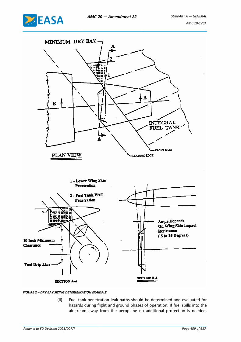
AMC-20 — Amendment 22 SUBPART A — GENERAL
AMC 20-128A
Annex II to ED Decision 2021/007/R Page 459 of 617
FIGURE 2 – DRY BAY SIZING DETERMINATION EXAMPLE
(ii) Fuel tank penetration leak paths should be determined and evaluated for hazards during flight and ground phases of operation. If fuel spills into the airstream away from the aeroplane no additional protection is needed.
AMC-20 — Amendment 22 SUBPART A — GENERAL
AMC 20-128A
Annex II to ED Decision 2021/007/R Page 460 of 617
Additional protection should be considered if fuel could spill, drain or migrate into areas housing ignition sources, such as engine or APU inlets or wheel wells. Damage to adjacent systems, wiring etc., should be evaluated regarding the potential that an uncontained fragment will create both an ignition source and fuel source. Wheel brakes may be considered as an ignition source during take-off and initial climb. Protection of the wheel wells may be provided by airflow discharging from gaps or openings, preventing entry of fuel, a ventilation rate precluding a combustible mixture or other provisions indicated in CS 23.863 and CS 25.863.
(iii) Areas of the aeroplane where flammable fluid migration is possible that are not drained and vented and have ignition sources or potential ignition sources should be provided with a means of fire detection and suppression and be explosion vented or equivalently protected.
b. Loss of Thrust.
(1) Fuel Reserves. The fuel reserves should be isolatable such that damage from a disc fragment will not result in loss of fuel required to complete the flight or a safe diversion. The effects of fuel loss, and the resultant shift of centre of gravity or lateral imbalance on aeroplane controllability should also be considered.
(2) Engine Controls. Engine control cables and/or wiring for the remaining powerplants that pass through the impact area should be separated by a distance equal to the maximum dimension of a one- third disc fragment or the maximum extent possible.
(3) Other Engine Damage. Protection of any other engines from some fragments should be provided by locating critical components, such as engine accessories essential for proper engine operation (e.g., high pressure fuel lines, engine controls and wiring, etc.), in areas where inherent shielding is provided by the fuselage, engine or nacelle (including thrust reverser) structure (see Paragraph 7).
c. Loss of Aeroplane Control
(1) Flight Controls. Elements of the flight control system should be adequately separated or protected so that the release of a single one-third disc fragment will not cause loss of control of the aeroplane in any axis. Where primary flight controls have duplicated (or multiplicated) elements, these elements should be located to prevent all elements in any axis being lost as a result of the single one- third disc fragment. Credit for maintaining control of the aeroplane by the use of trim controls or other means may be obtained, providing evidence shows that these means will enable the pilot to retain control.
(2) Emergency Power. Loss of electrical power to critical functions following an uncontained rotor event should be minimised. The determination of electrical system criticality is dependent upon aeroplane operations. For example, aeroplanes approved for Extended Twin Engine Operations (ETOPS) that rely on alternate power sources such as hydraulic motor generators or APUs may be configured with the electrical wiring separated to the maximum extent possible within the one-third disc impact zone.
(3) Hydraulic Supply. Any essential hydraulic system supply that is routed within an impact area should have means to isolate the hydraulic supply required to maintain control of the aeroplane. The single one-third disc should not result in loss of all essential hydraulic systems or loss of all flight controls in any axis of the aeroplane.
AMC-20 — Amendment 22 SUBPART A — GENERAL
AMC 20-128A
Annex II to ED Decision 2021/007/R Page 461 of 617
(4) Thrust reverser systems. The effect of an uncontained rotor failure on inadvertent in-flight deployment of each thrust reverser and possible loss of aeroplane control shall be considered. The impact area for components located on the failed engine may be different from the impact area defined in Paragraph 6. If uncontained failure could cause thrust reverser deployment, the engine manufacturer should be consulted to establish the failure model to be considered. One acceptable method of minimisation is to locate reverser restraints such that not all restraints can be made ineffective by the fragments of a single rotor.
d. Passenger and Crew Incapacitation.
(1) Pilot Compartment. The pilot compartment of large aeroplanes should not be located within the ± 15° spread angle of any engine rotor stage or APU rotor stage that has not been qualified as contained, unless adequate shielding, deflectors or equivalent protection is provided for the rotor stage in accordance with Paragraph 7c. Due to design constraints inherent in smaller CS-23 aeroplanes, it is not considered practical to locate the pilot compartment outside the ±15° spread angle. Therefore for other aeroplanes (such as new CS-23 commuter category aeroplanes) the pilot compartment area should not be located within the ±5° spread angle of any engine rotor stage or APU rotor stage unless adequate shielding, deflectors, or equivalent protection is provided for the rotor stage in accordance with Paragraph 7c of this AMC, except for the following:
(i) For derivative CS-23 category aeroplanes where the engine location has been previously established, the engine location in relation to the pilot compartment need not be changed.
(ii) For non-commuter CS-23 category aeroplanes, satisfactory service experience relative to rotor integrity and containment in similar engine installations may be considered in assessing the acceptability of installing engines in line with the pilot compartment.
(iii) For non-commuter new CS-23 category aeroplanes, where due to size and/or design considerations the ± 5° spread angle cannot be adhered to, the pilot compartment/engine location should be analysed and accepted in accordance with Paragraphs 9 and 10.
(2) Pressure Vessel. For aeroplanes that are certificated for operation above 41,000 feet, the engines should be located such that the pressure cabin cannot be affected by an uncontained one- third or intermediate disc fragment. Alternatively, it may be shown that rapid decompression due to the maximum hole size caused by fragments within the ± 15° zone and the associated cabin pressure decay rate will allow an emergency descent without incapacitation of the flightcrew or passengers. A pilot reaction time of 17 seconds for initiation of the emergency decent has been accepted. Where the pressure cabin could be affected by a one-third disc or intermediate fragments, design precautions should be taken to preclude incapacitation of crew and passengers. Examples of design precautions that have been previously accepted are:
(i) Provisions for a second pressure or bleed down bulkhead outside the impact area of a one- third or intermediate disc fragment.
(ii) The affected compartment in between the primary and secondary bulkhead was made inaccessible, by operating limitations, above the minimum altitude where incapacitation could occur due to the above hole size.
AMC-20 — Amendment 22 SUBPART A — GENERAL
AMC 20-128A
Annex II to ED Decision 2021/007/R Page 462 of 617
(iii) Air supply ducts running through this compartment were provided with non-return valves to prevent pressure cabin leakage through damaged ducts.
NOTE: If a bleed down bulkhead is used it should be shown that the rate of pressure decay and minimum achieved cabin pressure would not incapacitate the crew, and the rate of pressure decay would not preclude a safe emergency descent.
e. Structural Integrity. Installation of tear straps and shear ties within the uncontained fan blade and engine rotor debris zone to prevent catastrophic structural damage has been utilised to address this threat.
9. ENGINE AND APU FAILURE MODEL.
The safety analysis recommended in Paragraph 10 should be made using the following engine and APU failure model, unless for the particular engine/APU type concerned, relevant service experience, design data, test results or other evidence justify the use of a different model.
a. Single One-Third Disc fragment. It should be assumed that the one-third disc fragment has the maximum dimension corresponding to one-third of the disc with one-third blade height and a fragment spread angle of ± 3°. Where energy considerations are relevant, the mass should be assumed to be one-third of the bladed disc mass and its energy, the translational energy (i.e., neglecting rotational energy) of the sector travelling at the speed of its c.g. location as defined in Figure 3.
b. Intermediate Fragment. It should be assumed that the intermediate fragment has a maximum dimension corresponding to one-third of the bladed disc radius and a fragment spread angle of ± 5°. Where energy considerations are relevant, the mass should be assumed to be 1/30 of the bladed disc mass and its energy the transitional energy (i.e. neglecting rotational energy) of the piece travelling at rim speed (see Figure 4).
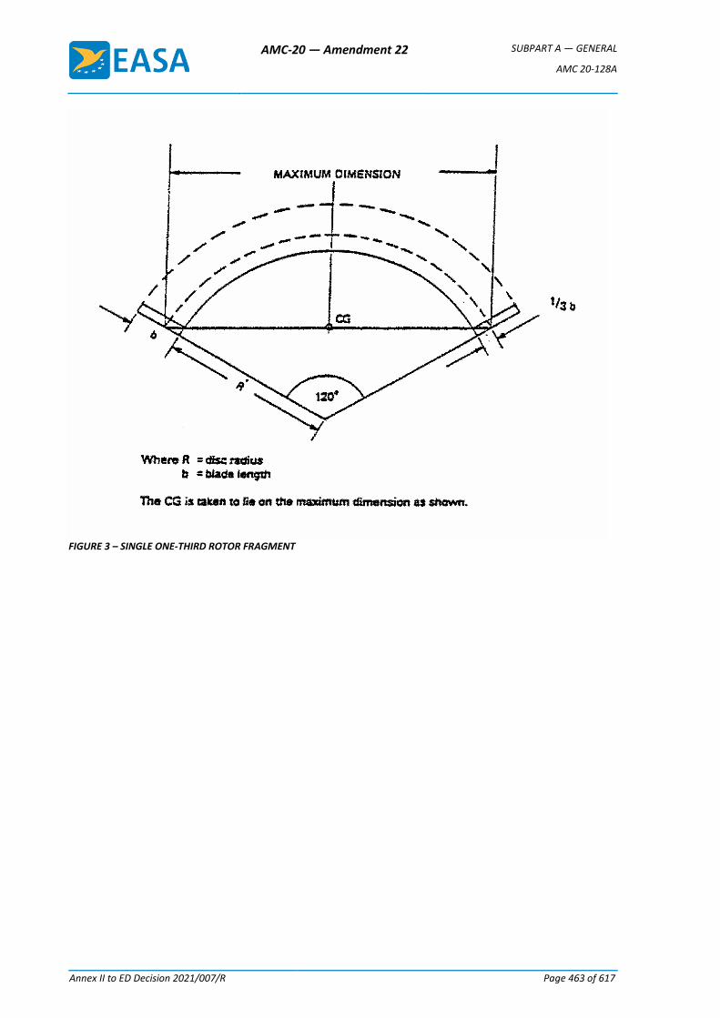
AMC-20 — Amendment 22 SUBPART A — GENERAL
AMC 20-128A
Annex II to ED Decision 2021/007/R Page 463 of 617
FIGURE 3 – SINGLE ONE-THIRD ROTOR FRAGMENT
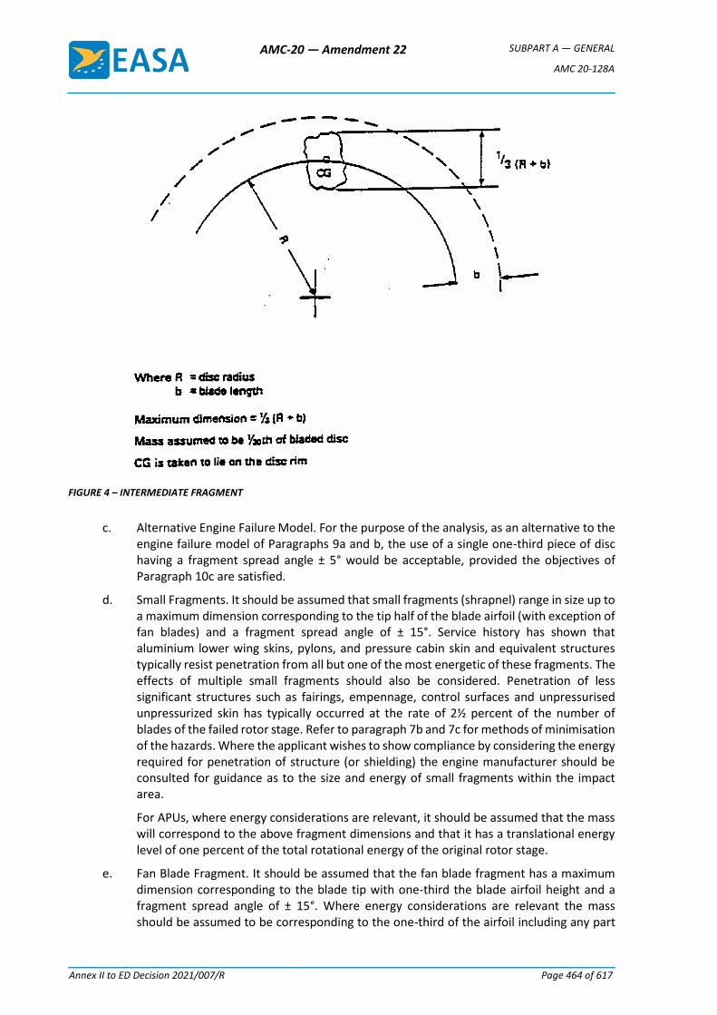
AMC-20 — Amendment 22 SUBPART A — GENERAL
AMC 20-128A
Annex II to ED Decision 2021/007/R Page 464 of 617
FIGURE 4 – INTERMEDIATE FRAGMENT
c. Alternative Engine Failure Model. For the purpose of the analysis, as an alternative to the engine failure model of Paragraphs 9a and b, the use of a single one-third piece of disc having a fragment spread angle ± 5° would be acceptable, provided the objectives of Paragraph 10c are satisfied.
d. Small Fragments. It should be assumed that small fragments (shrapnel) range in size up to a maximum dimension corresponding to the tip half of the blade airfoil (with exception of fan blades) and a fragment spread angle of ± 15°. Service history has shown that aluminium lower wing skins, pylons, and pressure cabin skin and equivalent structures typically resist penetration from all but one of the most energetic of these fragments. The effects of multiple small fragments should also be considered. Penetration of less significant structures such as fairings, empennage, control surfaces and unpressurised unpressurized skin has typically occurred at the rate of 2½ percent of the number of blades of the failed rotor stage. Refer to paragraph 7b and 7c for methods of minimisation of the hazards. Where the applicant wishes to show compliance by considering the energy required for penetration of structure (or shielding) the engine manufacturer should be consulted for guidance as to the size and energy of small fragments within the impact area.
For APUs, where energy considerations are relevant, it should be assumed that the mass will correspond to the above fragment dimensions and that it has a translational energy level of one percent of the total rotational energy of the original rotor stage.
e. Fan Blade Fragment. It should be assumed that the fan blade fragment has a maximum dimension corresponding to the blade tip with one-third the blade airfoil height and a fragment spread angle of ± 15°. Where energy considerations are relevant the mass should be assumed to be corresponding to the one-third of the airfoil including any part
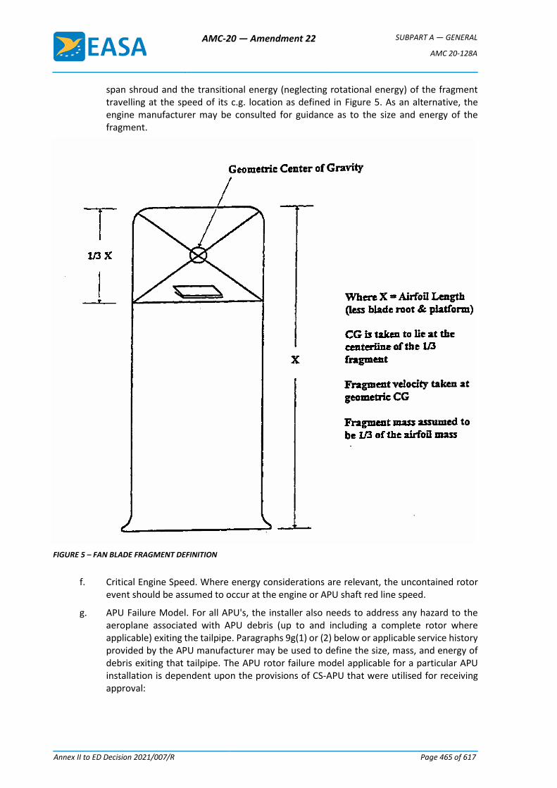
AMC-20 — Amendment 22 SUBPART A — GENERAL
AMC 20-128A
Annex II to ED Decision 2021/007/R Page 465 of 617
span shroud and the transitional energy (neglecting rotational energy) of the fragment travelling at the speed of its c.g. location as defined in Figure 5. As an alternative, the engine manufacturer may be consulted for guidance as to the size and energy of the fragment.
FIGURE 5 – FAN BLADE FRAGMENT DEFINITION
f. Critical Engine Speed. Where energy considerations are relevant, the uncontained rotor event should be assumed to occur at the engine or APU shaft red line speed.
g. APU Failure Model. For all APU's, the installer also needs to address any hazard to the aeroplane associated with APU debris (up to and including a complete rotor where applicable) exiting the tailpipe. Paragraphs 9g(1) or (2) below or applicable service history provided by the APU manufacturer may be used to define the size, mass, and energy of debris exiting that tailpipe. The APU rotor failure model applicable for a particular APU installation is dependent upon the provisions of CS-APU that were utilised for receiving approval:
AMC-20 — Amendment 22 SUBPART A — GENERAL
AMC 20-128A
Annex II to ED Decision 2021/007/R Page 466 of 617
(1) For APU's where rotor integrity has been demonstrated in accordance with CS-APU, i.e. without specific containment testing, Paragraphs 9a, b, and d, or Paragraphs 9c and 9d apply.
(2) For APU rotor stages qualified as contained in accordance with CS-APU, historical data shows that in-service uncontained failures have occurred. These failure modes have included bi-hub, overspeed, and fragments missing the containment ring which are not addressed by the CS-APU containment test. In order to address these hazards, the installer should use the APU small fragment definition of Paragraph 9d or substantiated in-service data supplied by the APU manufacturer.
10 SAFETY ANALYSIS.
The numerical assessment requested in Paragraph 10c(3) is derived from methods previously prescribed in ACJ No. 2 to CS 25.903(d)(1). The hazard ratios provided are based upon evaluation of various configurations of large aeroplanes, made over a period of time, incorporating practical methods of minimising the hazard to the aeroplane from uncontained engine debris.
a. Analysis. An analysis should be made using the engine/APU model defined in Paragraph 9 to determine the critical areas of the aeroplane likely to be damaged by rotor debris and to evaluate the consequences of an uncontained failure. This analysis should be conducted in relation to all normal phases of flight, or portions thereof.
NOTE: APPENDIX 1 provides additional guidance for completion of the numerical analysis requested by this paragraph.
(1) A delay of at least 15 seconds should be assumed before start of the emergency engine shut down. The extent of the delay is dependent upon circumstances resulting from the uncontained failure including increased flightcrew workload stemming from multiplicity of warnings which require analysis by the flightcrew.
(2) Some degradation of the flight characteristics of the aeroplane or operation of a system is permissible, provided the aeroplane is capable of continued safe flight and landing. Account should be taken of the behaviour of the aeroplane under asymmetrical engine thrust or power conditions together with any possible damage to the flight control system, and of the predicted aeroplane recovery manoeuvre.
(3) When considering how or whether to mitigate any potential hazard identified by the model, credit may be given to flight phase, service experience, or other data, as noted in Paragraph 7.
b. Drawings. Drawings should be provided to define the uncontained rotor impact threat relative to the areas of design consideration defined in Paragraphs 7a(1) through (10) showing the trajectory paths of engine and APU debris relative to critical areas. The analysis should include at least the following:
(1) Damage to primary structure including the pressure cabin, engine/APU mountings and airframe surfaces.
NOTE: Any structural damage resulting from uncontained rotor debris should be considered catastrophic unless the residual strength and flutter criteria of ACJ 25.571(a) subparagraph 2.7.2 can be met without failure of any part of the structure essential for completion of the flight. In addition, the pressurised compartment loads of CS 25.365(e)(1) and (g) must be met.
(2) Damage to any other engines (the consequences of subsequent uncontained debris from the other engine(s), need not be considered).
AMC-20 — Amendment 22 SUBPART A — GENERAL
AMC 20-128A
Annex II to ED Decision 2021/007/R Page 467 of 617
(3) Damage to services and equipment essential for safe flight and landing (including indicating and monitoring systems), particularly control systems for flight, engine power, engine fuel supply and shut-off means and fire indication and extinguishing systems.
(4) Pilot incapacitation, (see also paragraph 8 d(1)).
(5) Penetration of the fuel system, where this could result in the release of fuel into personnel compartments or an engine compartment or other regions of the aeroplane where this could lead to a fire or explosion.
(6) Damage to the fuel system, especially tanks, resulting in the release of a large quantity of fuel.
(7) Penetration and distortion of firewalls and cowling permitting a spread of fire.
(8) Damage to or inadvertent movement of aerodynamic surfaces (e.g.. flaps, slats, stabilisers, ailerons, spoilers, thrust reversers, elevators, rudders, strakes, winglets, etc.) and the resultant effect on safe flight and landing.
c. Safety Analysis Objectives. It is considered that the objective of minimising hazards will have been met if:
(1) The practical design considerations and precautions of Paragraphs 7 and 8 have been taken;
(2) The safety analysis has been completed using the engine/APU model defined in Paragraph 9;
(3) For CS-25 large aeroplanes and CS-23 commuter category aeroplanes, the following hazard ratio guidelines have been achieved:
(i) Single One-Third Disc Fragment. There is not more than a 1 in 20 chance of catastrophe resulting from the release of a single one-third disc fragment as defined in Paragraph 9a.
(ii) Intermediate Fragment. There is not more than a 1 in 40 chance of catastrophe resulting from the release of a piece of debris as defined in Paragraph 9b.
(iii) Multiple Disc Fragments. (Only applicable to any duplicated or multiplicated system when all of the system channels contributing to its functions have some part which is within a distance equal to the diameter of the largest bladed rotor, measured from the engine centreline). There is not more than 1 in 10 chance of catastrophe resulting from the release in three random directions of three one-third fragments of a disc each having a uniform probability of ejection over the 360° (assuming an angular spread of ±3° relative to the plane of the disc) causing coincidental damage to systems which are duplicated or multiplicated.
NOTE: Where dissimilar systems can be used to carry out the same function (e.g. elevator control and pitch trim), they should be regarded as duplicated (or multiplicated) systems for the purpose of this subparagraph provided control can be maintained.
The numerical assessments described above may be used to judge the relative values of minimisation. The degree of minimisation that is feasible may vary depending upon aeroplane size and configuration and this variation may prevent the specific hazard ratio from being achieved. These levels are design goals and
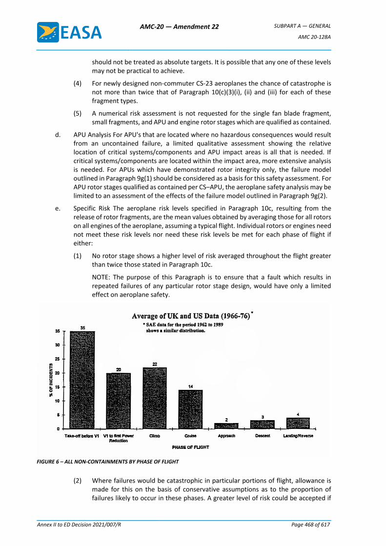
AMC-20 — Amendment 22 SUBPART A — GENERAL
AMC 20-128A
Annex II to ED Decision 2021/007/R Page 468 of 617
should not be treated as absolute targets. It is possible that any one of these levels may not be practical to achieve.
(4) For newly designed non-commuter CS-23 aeroplanes the chance of catastrophe is not more than twice that of Paragraph 10(c)(3)(i), (ii) and (iii) for each of these fragment types.
(5) A numerical risk assessment is not requested for the single fan blade fragment, small fragments, and APU and engine rotor stages which are qualified as contained.
d. APU Analysis For APU's that are located where no hazardous consequences would result from an uncontained failure, a limited qualitative assessment showing the relative location of critical systems/components and APU impact areas is all that is needed. If critical systems/components are located within the impact area, more extensive analysis is needed. For APUs which have demonstrated rotor integrity only, the failure model outlined in Paragraph 9g(1) should be considered as a basis for this safety assessment. For APU rotor stages qualified as contained per CS–APU, the aeroplane safety analysis may be limited to an assessment of the effects of the failure model outlined in Paragraph 9g(2).
e. Specific Risk The aeroplane risk levels specified in Paragraph 10c, resulting from the release of rotor fragments, are the mean values obtained by averaging those for all rotors on all engines of the aeroplane, assuming a typical flight. Individual rotors or engines need not meet these risk levels nor need these risk levels be met for each phase of flight if either:
(1) No rotor stage shows a higher level of risk averaged throughout the flight greater than twice those stated in Paragraph 10c.
NOTE: The purpose of this Paragraph is to ensure that a fault which results in repeated failures of any particular rotor stage design, would have only a limited effect on aeroplane safety.
FIGURE 6 – ALL NON-CONTAINMENTS BY PHASE OF FLIGHT
(2) Where failures would be catastrophic in particular portions of flight, allowance is made for this on the basis of conservative assumptions as to the proportion of failures likely to occur in these phases. A greater level of risk could be accepted if
AMC-20 — Amendment 22 SUBPART A — GENERAL
AMC 20-128A
Annex II to ED Decision 2021/007/R Page 469 of 617
the exposure exists only during a particular phase of flight e.g., during take-off. The proportional risk of engine failure during the particular phases of flight is given in SAE Papers referenced in Paragraph 4d. See also data contained in the CAA paper "Engine Non-Containments – The CAA View", which includes Figure 6. This paper is published in NASA Report CP-2017, "An Assessment of Technology for Turbo-jet Engine Rotor Failures", dated August 1977.
AMC-20 — Amendment 22 SUBPART A — GENERAL
AMC 20-128A
Annex II to ED Decision 2021/007/R Page 470 of 617
Appendix 1 to AMC 20-128A User’s Manual
RISK ANALYSIS METHODOLOGY for UNCONTAINED ENGINE/APU FAILURE
INDEX
1.0 GENERAL
2.0 SCOPE
3.0 FUNDAMENTAL COMPONENTS OF A SAFETY AND RISK ANALYSIS
4.0 ASSUMPTIONS
5.0 PLOTTING
6.0 METHODOLOGY – PROBABILITY ASSESSMENT
7.0 RESULTS ASSESSMENT
FIGURE 1 EXAMPLE – HAZARD TREE FIGURE 2 EXAMPLE – SYSTEM LOADING MATRIX FIGURE 3 TRI-SECTOR ROTOR BURST FIGURE 4 TYPICAL LAYOUT OF SYSTEMS IN ROTOR PLANE FIGURE 5 TRAJECTORY RANGE PLOTTING FIGURE 6 TYPICAL TRAJECTORY PLOTTING FIGURE 7 DEFINITION – THREAT WINDOW FIGURE 8 SAMPLE ROTOR STAGE PLOTTING CHART
1.0 GENERAL
1.1 The design of aeroplane and engine systems and the location of the engines relative to critical systems and structure have a significant impact on survivability of the aeroplane following an uncontained engine failure. CS 23.903(b)(1) and 25.903(d)(1) of the EASA Certification Specifications (CS) require that design precautions be taken to minimise the hazard to the aeroplane due to uncontained failures of engine or auxiliary power unit (APU). AMC 20-128A provides guidance for demonstrating compliance with these requirements.
1.2 As a part of this compliance demonstration, it is necessary to quantitatively assess the risk of a catastrophic failure in the event of an uncontained engine failure. This User’s Manual describes an acceptable method for this purpose.
1.3 The objective of the risk analysis is to measure the remaining risk after prudent and practical design considerations have been taken. Since each aeroplane would have unique features which must be considered when applying the methods described in this manual, there should be some flexibility in the methods and procedures.
1.4 It is a preferred approach to use these methods throughout the development of an aeroplane design to identify problem areas at an early stage when appropriate design changes are least disruptive. It is also advisable to involve the European Aviation Safety Agency (EASA) in this process at an early stage when appropriate interpretation of the methodology and documentation requirements can be established.
1.5 It should be noted that although the risk analysis produces quantitative results, subjective assessments are inherent in the methods of the analysis regarding the criticality of specific types of aeroplane component failures. Assumptions for such assessments should be documented along with the numerical results.
AMC-20 — Amendment 22 SUBPART A — GENERAL
AMC 20-128A
Annex II to ED Decision 2021/007/R Page 471 of 617
1.6 Aeroplane manufacturers have each developed their own method of assessing the effects of rotor failure, as there are many ways to get to the same result. This User’s Manual identifies all the elements that should be contained in an analysis, so that it can be interpreted by a person not familiar with such a process.
1.7 The intent of this manual therefore is to aid in establishing how an analysis is prepared, without precluding any technological advances or existing proprietary processes.
1.8 AMC 20-128A makes allowance for the broad configuration of the aeroplane as such damage to the structure due to rotor failure generally allows for little flexibility in design. System lay-out within a rotor burst zone, however, can be optimized.
1.9 Damage to structure, which may involve stress analysis, generally can be analyzed separately, and later coordinated with simultaneous system effects.
1.10 For an analysis of the effects on systems due to a rotor failure the aeroplane must be evaluated as a whole; and a risk analysis must specifically highlight all critical cases identified which have any potential to result in a catastrophe.
1.11 Such an analysis can then be used to establish that reasonable precautions have been taken to minimise the hazards, and that the remaining hazards are an acceptable risk.
1.12 A safety and a risk analysis are interdependent, as the risk analysis must be based on the safety analysis.
The safety analysis therefore is the starting point that identifies potential hazardous or catastrophic effects from a rotor failure and is the basic tool to minimise the hazard in accordance with the guidelines of AMC 20-128A.
1.13 The risk analysis subsequently assesses and quantifies the residual risk to the aeroplane.
2.0 SCOPE
The following describes the scope of analyses required to assess the aeroplane risk levels against the criteria set forth in Paragraph 10 of AMC 20-128A.
2.1 Safety
Analysis is required to identify the critical hazards that may be numerically analyzed (hazards remaining after all practical design precautions have been taken).
Functional criticality will vary by aeroplane and may vary by flight phase.
Thorough understanding of each aeroplane structure and system functions is required to establish the criticality relative to each fragment trajectory path of the theoretical failure.
Assistance from experts within each discipline is typically required to assure accuracy of the analysis in such areas as effects of fuel tank penetration on leakage paths and ignition hazards, thrust level control (for loss of thrust assessment), structural capabilities (for fuselage impact assessment), aeroplane controllability (for control cables impact assessment), and fuel asymmetry.
2.2 Risk
For each remaining critical hazard, the following assessments may be prepared using the engine/APU failure models as defined in Paragraph 9 of AMC 20-128A:
a. Flight mean risk for single 1/3 disc fragment.
b. Flight mean risk for single intermediate fragment.

AMC-20 — Amendment 22 SUBPART A — GENERAL
AMC 20-128A
Annex II to ED Decision 2021/007/R Page 472 of 617
c. Flight mean risk for alternate model (when used as an alternate to the 1/3 disc fragment and intermediate fragment).
d. Multiple 1/3 disc fragments for duplicated or multiplicated systems.
e. Specific risk for single 1/3 disc fragment and single intermediate fragment.
f. Specific risk for any single disc fragment that may result in catastrophic structural damage.
The risk level criteria for each failure model are defined in Paragraph 10 of AMC 20-128A.
3.0 FUNDAMENTAL COMPONENTS OF A SAFETY AND RISK ANALYSIS
3.1 The logical steps for a complete analysis are:
a. Establish at the design definition the functional hazards that can arise from the combined or concurrent failures of individual systems, including multiplicated systems and critical structure.
b. Establish a Functional Hazard Tree (see Figure 1), or a System Matrix (see Figure 2) that identifies all system interdependencies and failure combinations that must be avoided (if possible) when locating equipment in the rotor burst impact area.
In theory, if this is carried out to the maximum, no critical system hazards other than opposite engine or fuel line hits would exist.
c. Establish the fragment trajectories and trajectory ranges both for translational and spread risk angles for each damage. Plot these on a chart or graph, and identify the trajectory ranges that could result in hazardous combinations (threats) as per the above system matrix or functional hazard analysis.
d. Apply risk factors, such as phase of flight or other, to these threats, and calculate the risk for each threat for each rotor stage.
e. Tabulate, summarize and average all cases.
3.2 In accordance with AMC 20-128A the risk to the aeroplane due to uncontained rotor failure is assessed to the effects, once such a failure has occurred.
The probability of occurrence of rotor failure, as analyzed with the probability methods of AMC 25.1309 (i.e. probability as a function of critical uncontained rotor failure rate and exposure time), does not apply.
3.3 The total risk level to the aeroplane, as identified by the risk analysis, is the mean value obtained by averaging the values of all rotor stages of all engines of the aeroplane, expressed as Flight Mean Risk.
4.0 ASSUMPTIONS
4.1 The following conservative assumptions, in addition to those in Paragraphs 10(a)(1), (2) and (3) of AMC 20-128A, have been made in some previous analyses. However, each aeroplane design may have unique characteristics and therefore a unique basis for the safety assessment leading to the possibility of different assumptions. All assumptions should be substantiated within the analysis:
a. The 1/3 disc fragment as modeled in Paragraph 9(a) of the AMC 20-128A travels along a trajectory path that is tangential to the sector centroid locus, in the direction of rotor rotation (Refer to Figure 3).
AMC-20 — Amendment 22 SUBPART A — GENERAL
AMC 20-128A
Annex II to ED Decision 2021/007/R Page 473 of 617
The sector fragment rotates about its centroid without tumbling and sweeps a path equal to twice the greatest radius that can be struck from the sector centroid that intersects its periphery.
The fragment is considered to possess infinite energy, and therefore to be capable of severing lines, wiring, cables and unprotected structure in its path, and to be undeflected from its original trajectory unless deflection shields are fitted. However, protective shielding or an engine being impacted may be assumed to have sufficient mass to stop even the most energetic fragment.
b. The probability of release of debris within the maximum spread angle is uniformly distributed over all directions.
c. The effects of severed electrical wiring are dependent on the configuration of the affected system. In general, severed wiring is assumed to not receive inadvertent positive voltage for any significant duration.
d. Control cables that are struck by a fragment disconnect.
e. Hydraulically actuated, cable driven control surfaces, which do not have designated “fail to” settings, tend to fail to null when control cables are severed. Subsequent surface float is progressive and predictable.
f. Systems components are considered unserviceable if their envelope has been touched. In case of an engine being impacted, the nacelle structure may be regarded as engine envelope, unless damage is not likely to be hazardous.
g. Uncontained events involving in-flight penetration of fuel tanks will not result in fuel tank explosion.
h. Unpowered flight and off-airport landings, including ditching, may be assumed to be not catastrophic to the extent validated by accident statistics or other accepted factors.
i. Damage to structure essential for completion of flight is catastrophic (Ref. AMC 20-128A, Paragraph 10.b(1)).
j. The flight begins when engine power is advanced for takeoff and ends after landing when turning off the runway.
5.0 PLOTTING
5.1 Cross-section and plan view layouts of the aeroplane systems in the ranges of the rotor burst impact areas should be prepared, either as drawings, or as computer models
These layouts should plot the precise location of the critical system components, including fuel and hydraulic lines, flight control cables, electric wiring harnesses and junction boxes, pneumatic and environmental system ducting, fire extinguishing; critical structure, etc.
5.2 For every rotor stage a plane is developed. Each of these planes contains a view of all the system components respective outer envelopes, which is then used to generate a cross-section. See Figure 4.
5.3 Models or drawings representing the various engine rotor stages and their fore and aft deviation are then generated.
5.4 The various trajectory paths generated for each engine rotor stage are then superimposed on the cross-section layouts of the station planes that are in the range of that potential rotor burst in order to study the effects (see Figure 5). Thus separate plots are generated for each engine rotor stage or rotor group.
AMC-20 — Amendment 22 SUBPART A — GENERAL
AMC 20-128A
Annex II to ED Decision 2021/007/R Page 474 of 617
To reduce the amount of an analysis the engine rotor stages may also be considered as groups, as applicable for the engine type, using the largest rotor stage diameter of the group.
5.5 These trajectory paths may be generated as follows and as shown in Figure 6:
a. Two tangent lines T1 are drawn between the locus of the centroid and the target envelope.
b. At the tangent line touch points, lines N1 and N2 normal to the tangent lines, are drawn with the length equal to the radius of the fragment swept path (as also shown in Figure 1).
c. Tangent lines T2 are drawn between the terminal point of the normal lines and the locus of the centroid. The angle between these two tangent lines is the translational risk angle.
5.6 The entry and exit angles are then calculated.
5.7 The initial angle of intersection and the final angle of intersection are recorded, and the trajectories in between are considered to be the range of trajectories in which this particular part would be impacted by a rotor sector, and destroyed (i.e. the impact area).
The intersections thus recorded are then entered on charts in tabular form so that the simultaneous effects can be studied. Refer to Figure 8.
Thus it will be seen that the total systems’ effects can be determined and the worst cases identified.
5.9 If a potentially serious multiple system damage case is identified, then a more detailed analysis of the trajectory range will be carried out by breaking the failure case down into the specific fore-aft spread angle, using the individual rotor stage width instead of combined groups, if applicable.
6.0 METHODOLOGY – PROBABILITY ASSESSMENT
6.1 Those rotor burst cases that have some potential of causing a catastrophe are evaluated in the analysis in an attempt to quantify an actual probability of a catastrophe, which will, in all cases, depend on the following factors:
a. The location of the engine that is the origin of the fragment, and its direction of rotation.
b. The location of critical systems and critical structure.
c. The rotor stage and the fragment model.
d. The translational trajectory of the rotor fragment,
e. The specific spread angle range of the fragment.
f. The specific phase of the flight at which the failure occurs.
g. The specific risk factor associated with any particular loss of function.
6.2 Engine Location
The analysis should address the effects on systems during one flight after a single rotor burst has occurred, with a probability of 1.0. As the cause may be any one of the engines, the risk from each engine is later averaged for the number of engines.
AMC-20 — Amendment 22 SUBPART A — GENERAL
AMC 20-128A
Annex II to ED Decision 2021/007/R Page 475 of 617
The analysis trajectory charts will then clearly show that certain system damage is unique to rotor fragments from a particular engine due to the direction of rotation, or, that for similar system damage the trajectory range varies considerably between engines.
A risk summary should table each engine case separately with the engine location included.
6.3 Rotor Element
The probability of rotor failure is assumed to be 1.0 for each of all rotor stages. For the analysis the individual risk(s) from each rotor stage of the engine should be assessed and tabled.
6.4 Translational Risk Angle
The number of degrees of included arc (out of 360) at which a fragment intersects the component/structure being analyzed. Refer to Figure 6 and Figure 7.
6.5 Trajectory Probability (P)
The probability of a liberated rotor fragment leaving the engine case is equal over 360 , thus the probability P of that fragment hitting a system component is the identified Translational Risk Angle ɸ in degrees °, divided by 360, i.e.
𝑃 = 𝜙/360
or
𝜙1 − 𝜙2
360
6.6 Spread Angle
If the failure model of the analysis assumes a (fore and aft) spread of ± 5°, then the spread angle is a total of 10°. If a critical component can only be hit at a limited position within that spread, then the exposure of that critical component can then be factored according to the longitudinal position within the spread angle, e.g.:
𝜓2 − 𝜓1
𝑠𝑝𝑟𝑒𝑎𝑑 𝑎𝑛𝑔𝑙𝑒
If a component can only be hit at the extreme forward range of +4° to +5°, then the factor is .1 (for one degree out of 10).
6.7 Threat Window
The definition of a typical threat window is shown in Figure 7.
6.8 Phase of Flight
Certain types of system damage may be catastrophic only during a specific portion of the flight profile, such as a strike on the opposite engine during take-off after V1 (i.e. a probability of 1.0), while with altitude a straight-ahead landing may be possible under certain favourable conditions (e.g. a probability of less than 1.0). The specific case can then be factored accordingly.
6.8.1 The most likely time for an uncontained rotor failure to occur is during take-off, when the engine is under highest stress. Using the industry accepted standards for the percentage of engine failures occurring within each flight phase, the following probabilities are assumed:
Take-off before V1 35%
AMC-20 — Amendment 22 SUBPART A — GENERAL
AMC 20-128A
Annex II to ED Decision 2021/007/R Page 476 of 617
V1 to first power reduction 20%
Climb 22%
Cruise 14%
Descent 3%
Approach 2%
Landing/Reverse 4%
6.8.2 The flight phase failure distribution above is used in the calculations of catastrophic risk for all cases where this risk varies with flight phase.
𝐷𝑝 = 𝑃 𝑓𝑙𝑖𝑔ℎ𝑡 𝑝ℎ𝑎𝑠𝑒 %
100
6.9 Other Risk Factors
Risks such as fire, loss of pressurization, etc., are individually assessed for each case where applicable, using conservative engineering judgment. This may lead to a probability of catastrophe (i.e., risk factor) smaller than 1.0.
6.9.1 The above probabilities and factors are used in conjunction with the critical trajectory range defined to produce a probability of the specific event occurring from any random rotor burst.
This value is then factored by the "risk" factor assessed for the case, to derive a calculated probability of catastrophe for each specific case.
Typical conditional probability values for total loss of thrust causing catastrophic consequences are:
Phase Dp Risk
T.O.–V1 to first power reduction 0.20 1.0
Climb 0.22 0.4
Cruise 0.14 0.2
Descent 0.03 0.4
Approach 0.02 0.4
6.10 All individual case probabilities are then tabled and summarised.
6.11 The flight mean values are obtained by averaging those for all discs or rotor stages on all engines across a nominal flight profile.
The following process may be used to calculate the flight mean value for each Failure Model:
a. Establish from the table in Figure 8 the threat windows where, due to combination of individual damages, a catastrophic risk exists.
b. For each stage case calculate the risk for all Critical Hazards
c. For each stage case apply all risk factors, and, if applicable, factor for Flight Phase-Failure distribution
d. For each engine, average all stages over the total number of engine stages
e. For each aeroplane, average all engines over the number of engines.
7.0 RESULTS ASSESSMENT
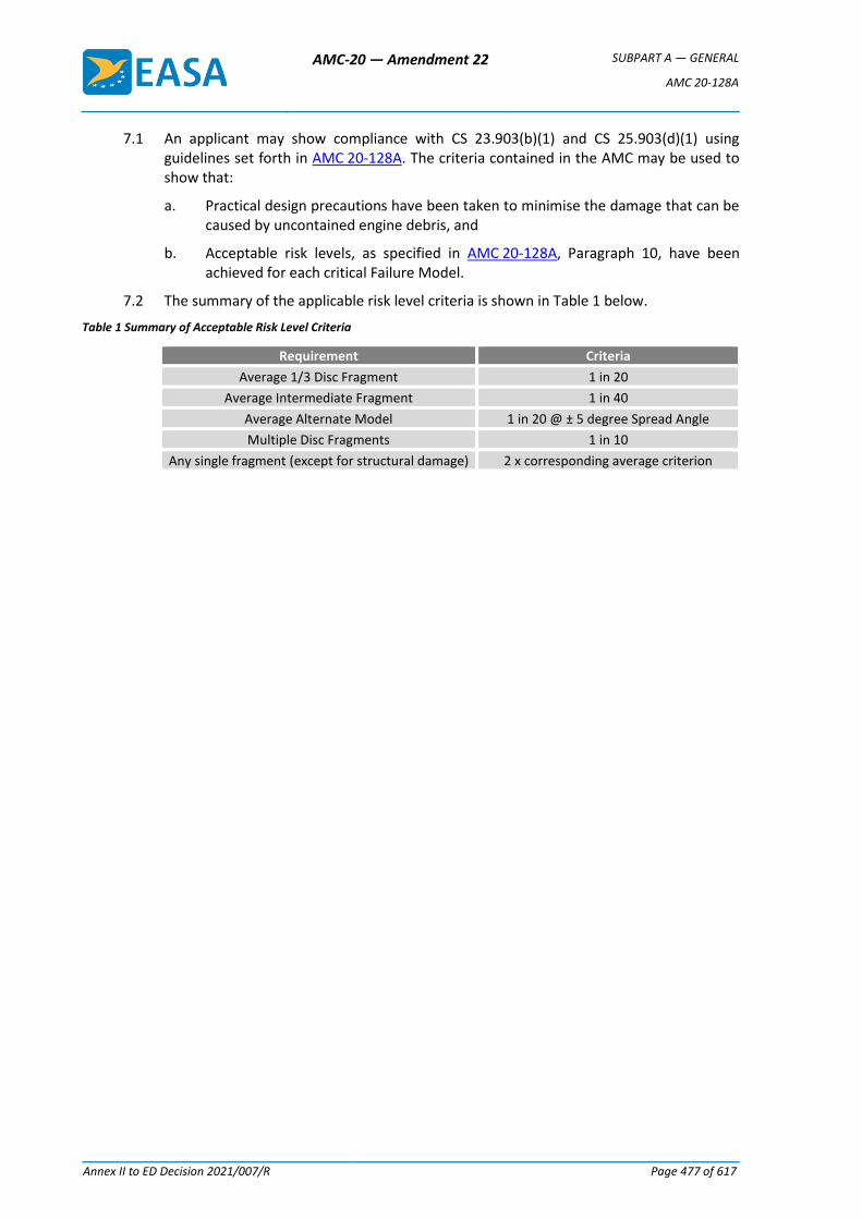
AMC-20 — Amendment 22 SUBPART A — GENERAL
AMC 20-128A
Annex II to ED Decision 2021/007/R Page 477 of 617
7.1 An applicant may show compliance with CS 23.903(b)(1) and CS 25.903(d)(1) using guidelines set forth in AMC 20-128A. The criteria contained in the AMC may be used to show that:
a. Practical design precautions have been taken to minimise the damage that can be caused by uncontained engine debris, and
b. Acceptable risk levels, as specified in AMC 20-128A, Paragraph 10, have been achieved for each critical Failure Model.
7.2 The summary of the applicable risk level criteria is shown in Table 1 below.
Table 1 Summary of Acceptable Risk Level Criteria
Requirement Criteria
Average 1/3 Disc Fragment 1 in 20
Average Intermediate Fragment 1 in 40
Average Alternate Model 1 in 20 @ ± 5 degree Spread Angle
Multiple Disc Fragments 1 in 10
Any single fragment (except for structural damage) 2 x corresponding average criterion
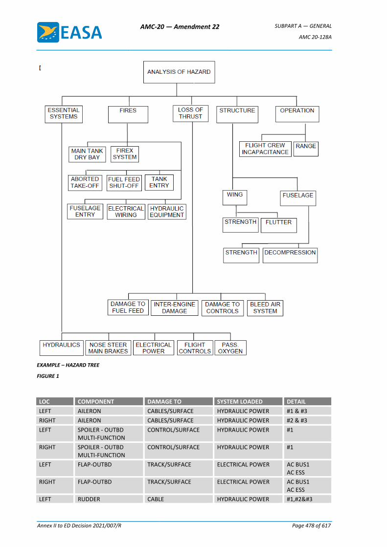
AMC-20 — Amendment 22 SUBPART A — GENERAL
AMC 20-128A
Annex II to ED Decision 2021/007/R Page 478 of 617
EXAMPLE – HAZARD TREE
FIGURE 1
LOC COMPONENT DAMAGE TO SYSTEM LOADED DETAIL
LEFT AILERON CABLES/SURFACE HYDRAULIC POWER #1 & #3
RIGHT AILERON CABLES/SURFACE HYDRAULIC POWER #2 & #3
LEFT SPOILER - OUTBD MULTI-FUNCTION
CONTROL/SURFACE HYDRAULIC POWER #1
RIGHT SPOILER - OUTBD MULTI-FUNCTION
CONTROL/SURFACE HYDRAULIC POWER #1
LEFT FLAP-OUTBD TRACK/SURFACE ELECTRICAL POWER AC BUS1 AC ESS
RIGHT FLAP-OUTBD TRACK/SURFACE ELECTRICAL POWER AC BUS1 AC ESS
LEFT RUDDER CABLE HYDRAULIC POWER #1,#2
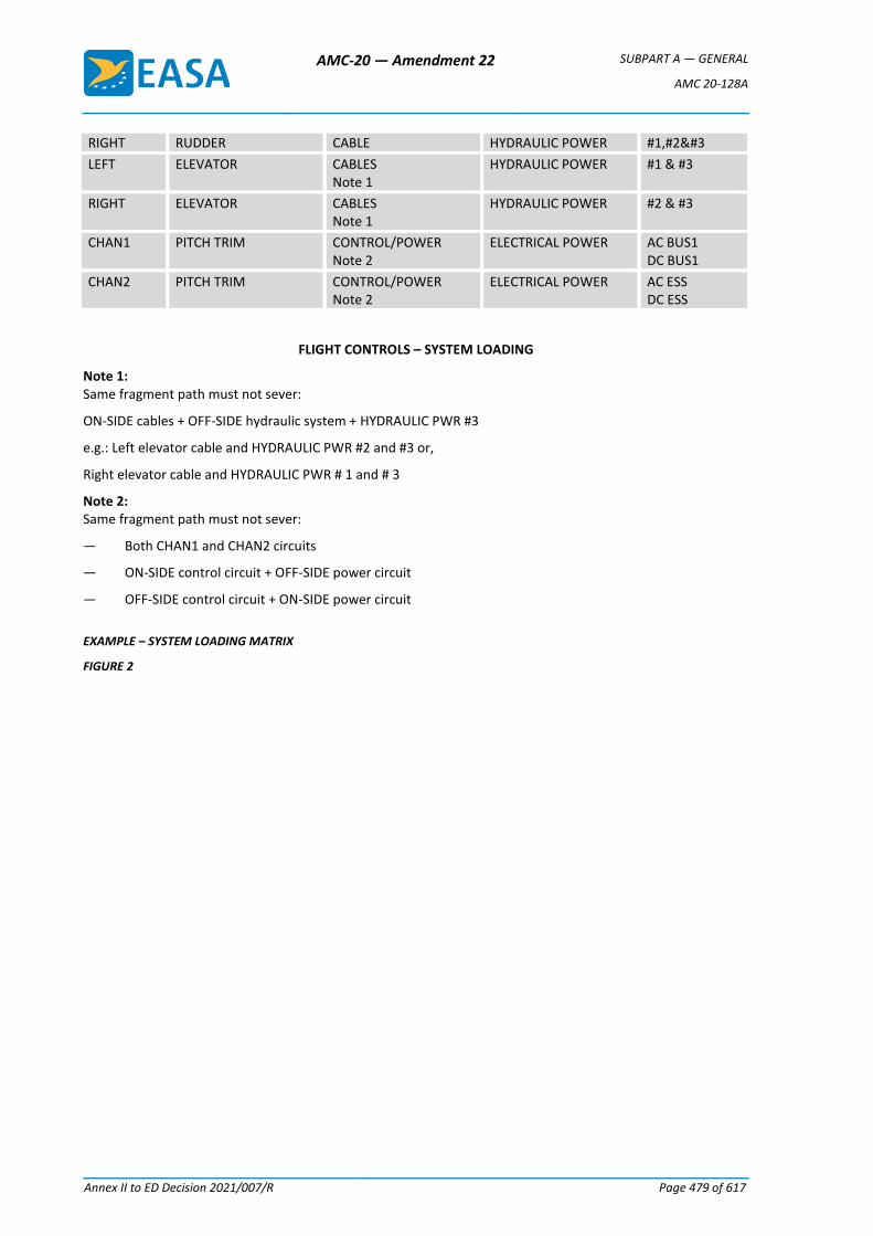
AMC-20 — Amendment 22 SUBPART A — GENERAL
AMC 20-128A
Annex II to ED Decision 2021/007/R Page 479 of 617
RIGHT RUDDER CABLE HYDRAULIC POWER #1,#2
LEFT ELEVATOR CABLES Note 1
HYDRAULIC POWER #1 & #3
RIGHT ELEVATOR CABLES Note 1
HYDRAULIC POWER #2 & #3
CHAN1 PITCH TRIM CONTROL/POWER Note 2
ELECTRICAL POWER AC BUS1 DC BUS1
CHAN2 PITCH TRIM CONTROL/POWER Note 2
ELECTRICAL POWER AC ESS DC ESS
FLIGHT CONTROLS – SYSTEM LOADING
Note 1: Same fragment path must not sever:
ON-SIDE cables + OFF-SIDE hydraulic system + HYDRAULIC PWR #3
e.g.: Left elevator cable and HYDRAULIC PWR #2 and #3 or,
Right elevator cable and HYDRAULIC PWR # 1 and # 3
Note 2: Same fragment path must not sever:
— Both CHAN1 and CHAN2 circuits
— ON-SIDE control circuit + OFF-SIDE power circuit
— OFF-SIDE control circuit + ON-SIDE power circuit
EXAMPLE – SYSTEM LOADING MATRIX
FIGURE 2
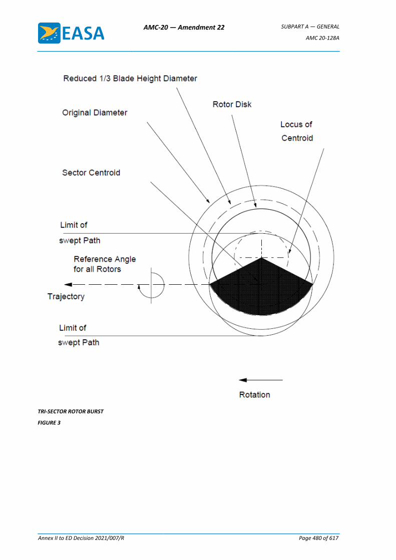
AMC-20 — Amendment 22 SUBPART A — GENERAL
AMC 20-128A
Annex II to ED Decision 2021/007/R Page 480 of 617
TRI-SECTOR ROTOR BURST
FIGURE 3
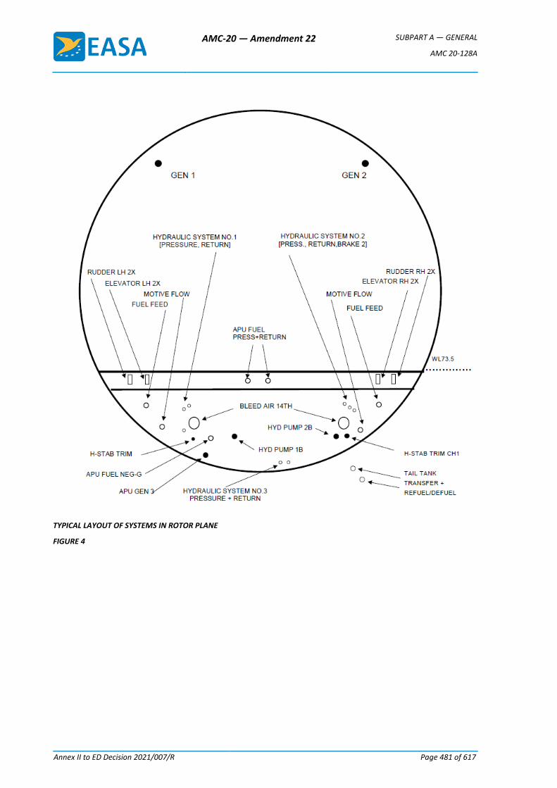
AMC-20 — Amendment 22 SUBPART A — GENERAL
AMC 20-128A
Annex II to ED Decision 2021/007/R Page 481 of 617
TYPICAL LAYOUT OF SYSTEMS IN ROTOR PLANE
FIGURE 4
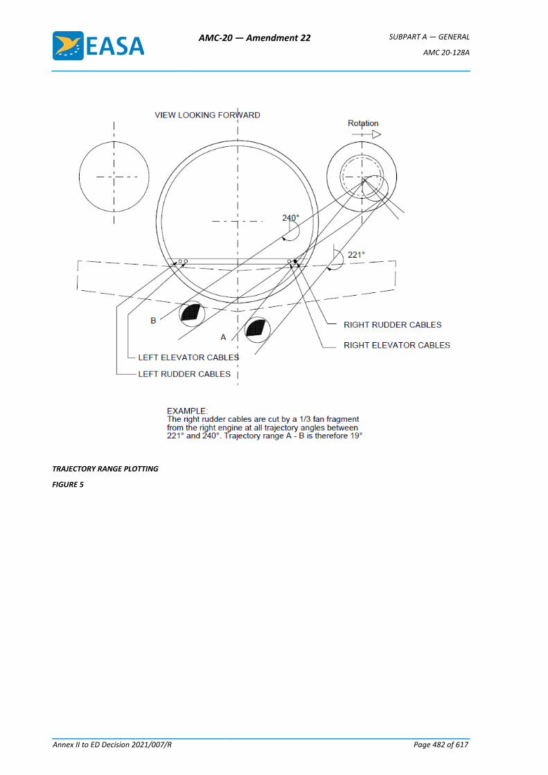
AMC-20 — Amendment 22 SUBPART A — GENERAL
AMC 20-128A
Annex II to ED Decision 2021/007/R Page 482 of 617
TRAJECTORY RANGE PLOTTING
FIGURE 5
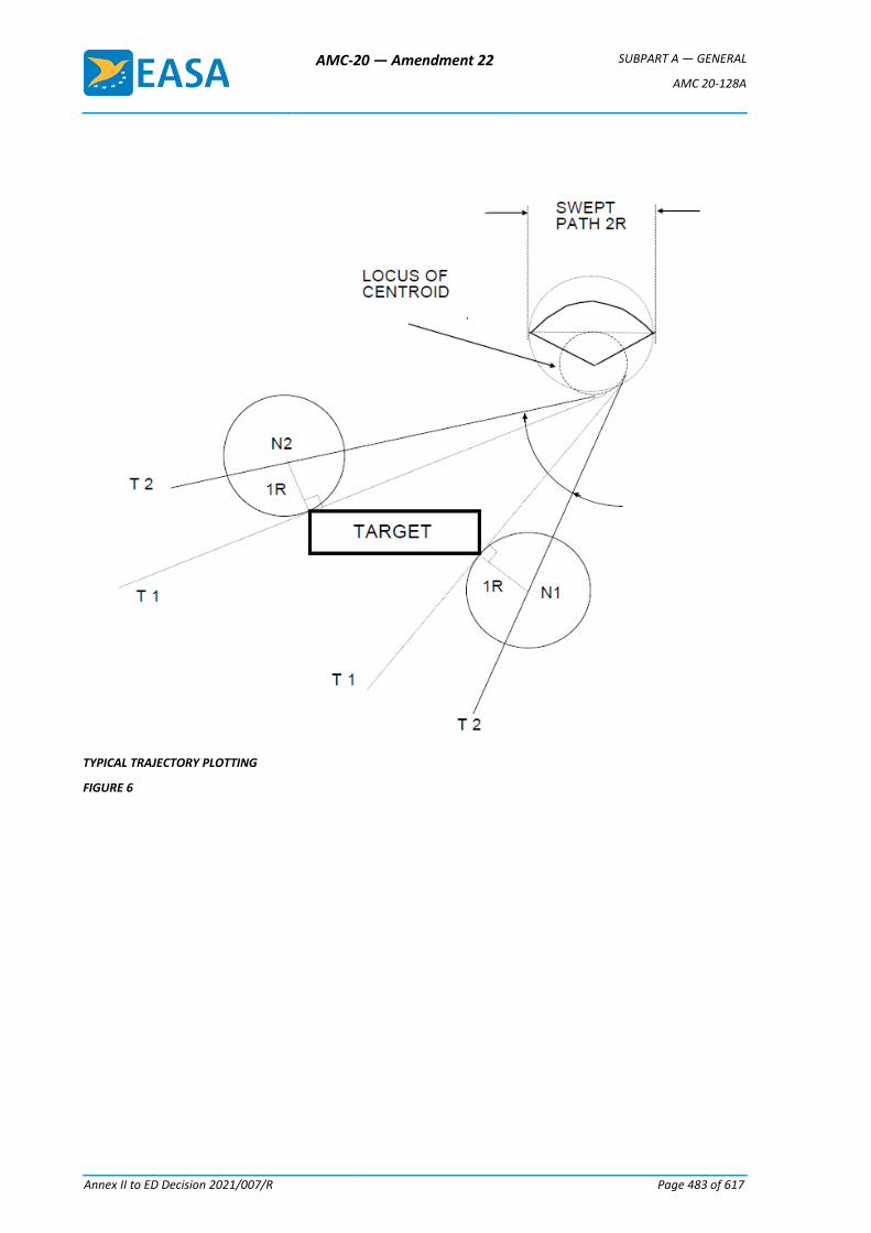
AMC-20 — Amendment 22 SUBPART A — GENERAL
AMC 20-128A
Annex II to ED Decision 2021/007/R Page 483 of 617
TYPICAL TRAJECTORY PLOTTING
FIGURE 6
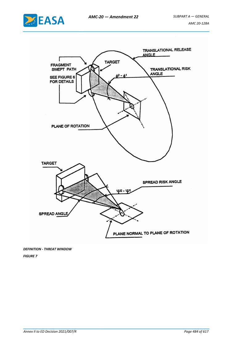
AMC-20 — Amendment 22 SUBPART A — GENERAL
AMC 20-128A
Annex II to ED Decision 2021/007/R Page 484 of 617
DEFINITION - THREAT WINDOW
FIGURE 7
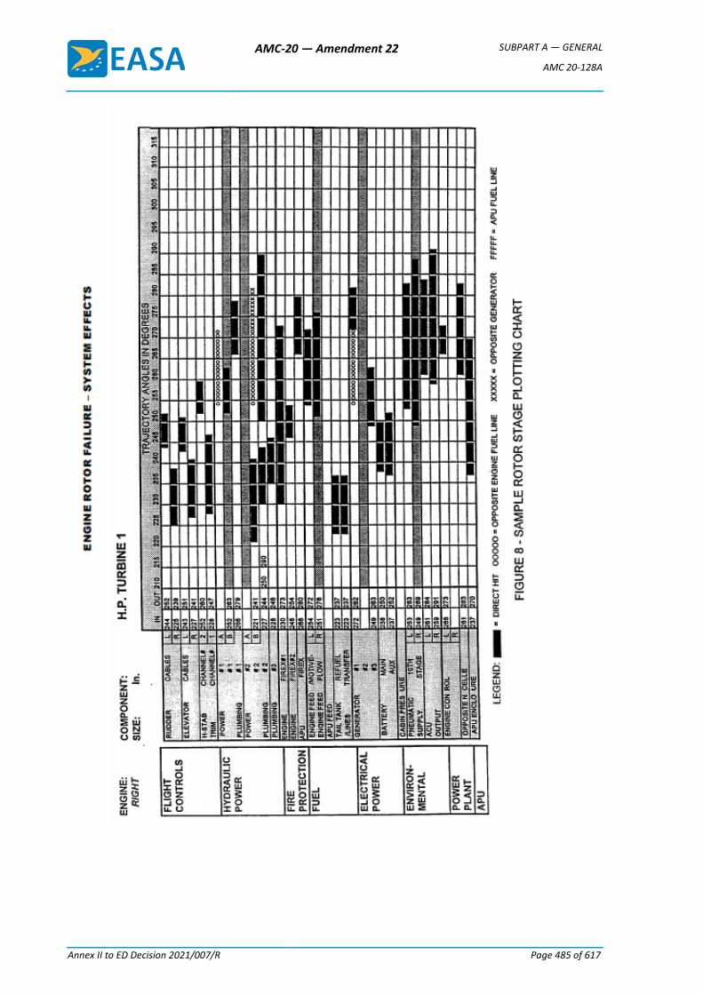
AMC-20 — Amendment 22 SUBPART A — GENERAL
AMC 20-128A
Annex II to ED Decision 2021/007/R Page 485 of 617
AMC-20 — Amendment 22 SUBPART A — GENERAL
AMC 20-136
Annex II to ED Decision 2021/007/R Page 486 of 617
AMC 20-136
AMC 20-136 Aircraft Electrical and Electronic System Lightning Protection
1. PURPOSE
a. This Acceptable Means of Compliance (AMC) provides the means and Guidance Material (GM) on how aircraft electrical and electronic systems can be protected from the effects of lightning. This AMC describes a means, but not the only means, to demonstrate compliance with the following Certification Specifications: CS 23.1306, CS 25.1316, CS 27.1316, and CS 29.1316, Electrical and electronic system lightning protection, as they pertain to aircraft type certification or supplemental type certification.
b. This AMC is not mandatory and does not constitute a regulation. In using the means described in this AMC, it must be followed in all important respects.
c. The verb ‘must’ is used to indicate mandatory requirements when following the guidance in this AMC in its entirety. The terms ‘should’ and ‘recommend’ are used when following the guidance is recommended but not required to comply with this AMC.
2. APPLICABILITY
This AMC applies to all applicants for a new Type Certificate (TC) or a change to an existing TC when the certification basis contains either CS 23.1306, or CS 25.1316, or CS 27.1316, or CS 29.1316.
3. SCOPE
a. AMC 20-136 provides the AMC and GM for complying with CS 23.1306, CS 25.1316, CS 27.1316, and CS 29.1316 for the effects on electrical and electronic systems due to lightning transients induced or conducted onto equipment and wiring.
b. CS 23.1306, CS 25.1316, CS 27.1316, and CS 29.1316 are also applicable to the effects on aircraft electrical and electronic systems when lightning directly attaches to equipment, components, or wiring. This AMC addresses the functional aspects of these effects on aircraft electrical and electronic equipment, components, or wiring. However, this AMC does not address lightning effects such as burning, eroding, and blasting of aircraft equipment, components, or wiring. For demonstrating compliance for these effects, we recommend using EUROCAE ED-113, Aircraft Lightning Direct Effects Certification.
c. For information on fuel ignition hazards, see AMC 25.954 and FAA AC 20-53, Protection of Aircraft Fuel Systems Against Fuel Vapor Ignition Caused By Lightning. This AMC does not address lightning zoning methods, lightning environment definition, or lightning test methods. For information on lightning zoning methods and lightning environment definition, see EUROCAE ED-91 and ED-84A. For information on Fuel Structural Lightning Protection, see EUROCAE policy ER-002. For information on lightning test methods, see EUROCAE ED-105A, Aircraft Lightning Test Methods, or ED-14G, Section 22, Lightning Induced Transient Susceptibility, and Section 23, Lightning Direct Effects.
4. RELATED MATERIAL
a. European Aviation Safety Agency (EASA) (in this document also referred to as the ‘Agency’)
AMC-20 — Amendment 22 SUBPART A — GENERAL
AMC 20-136
Annex II to ED Decision 2021/007/R Page 487 of 617
1. Certification Specifications CS-23: 23.867, 23.901, 23.954, 23.1301, 23.1306, 23.1309, 23.1529.
2. Certification Specifications CS-25: 25.581, 25.901, 25.954, 25.1301, 25.1309, 25.1316, 25.1529.
3. Certification Specifications CS-27: 27.610, 27.901, 27.954, 27.1301, 27.1309, 27.1316, 27.1529.
4. Certification Specifications CS-29: 29.610, 29.901, 29.954, 29.1301, 29.1309, 29.1316, 29.1529.
Copies of these CSs can be requested from the European Aviation Safety Agency, Postfach 10 12 53, D-50452 Cologne, Germany; telephone +49 221 8999 000; fax: +49 221 8999 099; Website: http://easa.europa.eu/official-publication/
b. Title 14 of the Code of Federal Regulations (14 CFR)
Copies of the following 14 CFR sections can be requested from the Superintendent of Documents, Government Printing Office, Washington, D.C. 20402-9325. Telephone 202-512-1800, fax 202-512-2250. Copies can also be requested from the Government Printing Office (GPO) via the electronic CFR Internet website at www.access.gpo.gov/ecfr/.
Part 23, Airworthiness Standards: Normal, Utility, Acrobatic, and Commuter Category Airplanes
§ 23.867 Electrical bonding and protection against lightning and static electricity
§ 23.901 Installation
§ 23.954 Fuel system lightning protection
§ 23.1301 Function and installation
§ 23.1309 Equipment, systems, and installations
§ 23.1306 Electrical and electronic system lightning protection
§ 23.1529 Instructions for continued airworthiness
Part 25, Airworthiness Standards: Transport Category Airplanes
§ 25.581 Lightning protection
§ 25.901 Installation
§ 25.954 Fuel system lightning protection
§ 25.1301 Function and installation
§ 25.1309 Equipment, systems, and installations
§ 25.1316 Electrical and electronic system lightning protection
§ 25.1529 Instructions for continued airworthiness
Part 27, Airworthiness Standards: Normal Category Rotorcraft
§ 27.610 Lightning and static electricity protection
§ 27.901 Installation
§ 27.954 Fuel system lightning protection
AMC-20 — Amendment 22 SUBPART A — GENERAL
AMC 20-136
Annex II to ED Decision 2021/007/R Page 488 of 617
§ 27.1301 Function and installation
§ 27.1309 Equipment, systems, and installations
§ 27.1316 Electrical and electronic system lightning protection
§ 27.1529 Instructions for continued airworthiness
Part 29, Airworthiness Standards: Transport Category Rotorcraft
§ 29.610 Lightning and static electricity protection
§ 29.901 Installation
§ 29.954 Fuel system lightning protection
§ 29.1301 Function and installation
§ 29.1309 Equipment, systems, and installations
§ 29.1316 Electrical and electronic system lightning protection
§ 29.1529 Instructions for continued airworthiness
c. FAA Advisory Circular
1. AC 20-155, SAE Documents to Support Aircraft Lightning Protection Certification.
2. AC 21-16, RTCA Document DO-160 Versions D, E, F, and G, Environmental Conditions and Test Procedures for Airborne Equipment.
3. AC 23-17, Systems and Equipment Guide for Certification of Part 23 Airplanes and Airships.
4. AC 23.1309-1E, System Safety Analysis and Assessment for Part 23 Airplanes.
5. AC 27-1B, Certification of Normal Category Rotorcraft.
6. AC 29-2C, Certification of Transport Category Rotorcraft.
Copies of these ACs are available at http://www.faa.gov/regulations_policies/advisory_circulars.
d. Industry documents
Note: The industry documents referenced in this section refer to the current revisions or regulatory authorities accepted revisions.
1. European Organization for Civil Aviation Equipment (EUROCAE). Copies of the following documents can be requested from EUROCAE, 102 rue Etienne Dolet, 92240 Malakoff. Telephone: +33 1 40 92 79 30, Fax: +33 1 46 55 62 65,
Website: http://www.eurocae.net.
EUROCAE ED-79A, Guidelines for Development of Civil Aircraft and Systems.
EUROCAE ED-14G, Environmental Conditions and Test Procedures for Airborne Equipment.
EUROCAE ED-84A, Aircraft Lightning Environment and Related Test Waveforms
EUROCAE ED-91, Aircraft Lightning Zoning
EUROCAE ED-105A, Aircraft Lightning Test Methods.
EUROCAE ED-113, Aircraft Lightning Direct Effects Certification.
AMC-20 — Amendment 22 SUBPART A — GENERAL
AMC 20-136
Annex II to ED Decision 2021/007/R Page 489 of 617
2. RTCA. You can get copies of RTCA/DO-160G, Environmental Conditions and Test Procedures for Airborne Equipment, from RTCA, Inc., 1150 18th Street NW, Suite 910, Washington, D.C. 20036. Telephone: +1 202 833 9339, Fax +1 202 833 9434, Website: http://www.rtca.org.
This document is technically equivalent to EUROCAE ED-14G. Anywhere there is a reference to RTCA/DO-160G, EUROCAE ED-14G may be used.
3. SAE International. You can get copies of the following documents from SAE Customer Service, 400 Commonwealth Drive, Warrendale, PA 15096-0001. Telephone: +1 724 776 4970, Fax: 724-776-0790, Website: www.sae.org.
ARP 4754A, Guidelines for Development of Civil Aircraft and Systems. This document is technically equivalent to EUROCAE ED-79A. Anywhere there is a reference to ARP 4754A, EUROCAE ED-79A may be used.
ARP 4761, Guidelines and Methods for Conducting the Safety Assessment Process on Civil Airborne Systems and Equipment.
ARP 5412B, Aircraft Lightning Environment and Related Test Waveforms. This document is technically equivalent to EUROCAE ED-84A. Anywhere there is a reference to ARP 5412A, EUROCAE ED-84A may be used.
ARP 5414A, Aircraft Lightning Zoning. This document is technically equivalent to EUROCAE ED-91. Anywhere there is a reference to ARP 5414A, EUROCAE ED-91 may be used.
ARP 5415A, User’s Manual for Certification of Aircraft Electrical/Electronic Systems for the Indirect Effects of Lightning.
ARP 5416A, Aircraft Lightning Test Methods. This document is technically equivalent to EUROCAE ED-105A. Anywhere there is a reference to ARP 5416A, EUROCAE ED-105A may be used.
ARP 5577, Aircraft Lightning Direct Effects Certification. This document is technically equivalent to EUROCAE ED-113. Anywhere there is a reference to ARP 5577, EUROCAE ED-113 may be used.
5. BACKGROUND
a. Regulatory Applicability. The certification specifications for aircraft electrical and electronic system lightning protection are based on the aircraft’s potential for lightning exposure and the consequences of system failure. The regulations require lightning protection of aeroplane/rotorcraft electrical and electronic systems with catastrophic, hazardous, or major failure conditions for aeroplane/rotorcraft certificated under CS-25 and 29. The requirements also apply to CS-23 aeroplanes and CS-27 rotorcraft approved for operations under instrument flight rules. Those CS-23 aeroplanes and CS-27 rotorcraft approved solely for operations under visual flight rules require lightning protection of electrical or electronic systems having catastrophic failure conditions.
b. Regulatory Requirements. Protection against the effects of lightning for aircraft electrical and electronic systems, regardless of whether these are ‘indirect’ or ‘direct’ effects of lightning, are addressed under CS 23.1306, 25.1316, 27.1316, and 29.1316. The terms ‘indirect’ and ‘direct’ are often used to classify the effects of lightning. However, the regulations do not, and are not intended to, differentiate between the effects of lightning. The focus is to protect aircraft electrical and electronic systems from effects of lightning. The regulations listed in this paragraph introduce several terms which are further explained below, including:
AMC-20 — Amendment 22 SUBPART A — GENERAL
AMC 20-136
Annex II to ED Decision 2021/007/R Page 490 of 617
1. System. A system can include equipment, components, parts, wire bundles, software, and firmware. Electrical and electronic systems consist of pieces of equipment connected by electrical conductors, all of which are required to perform one or more functions.
2. Function. The specific action of a system, equipment, and flight crew performance aboard the aircraft that, by itself, provides a completely recognizable operational capability. For example, “display aircraft heading to the pilots” is a function. One or more systems may perform a specific function or one system may perform multiple functions.
3. Adverse Effect. A lightning effect resulting in system failure, malfunction, or misleading information to a degree that is unacceptable for the specific aircraft function or system addressed in the system lightning protection regulations.
4. Timely Manner. The meaning of “in a timely manner” depends upon the function performed by the system being evaluated, the specific system design, interaction between that system and other systems, and interaction between the system and the flight crew. The definition of “in a timely manner” must be determined for each specific system and for specific functions performed by the system. The applicable definition should be included in the certification plan for review and approval by the certification authorities.
6. STEPS FOR DEMONSTRATING COMPLIANCE
a. The following seven steps describe how compliance with CS 23.1306, CS 25.1316, CS 27.1316, and CS 29.1316 may be demonstrated:
1. Identify the systems to be assessed.
2. Determine the lightning strike zones for the aircraft.
3. Establish the aircraft lightning environment for each zone.
4. Determine the lightning transient environment associated with the systems.
5. Establish Equipment Transient Design Levels (ETDLs) and aircraft Actual Transient Levels (ATLs).
6. Verify compliance with the requirements.
7. Take corrective measures, if needed.
b. Lightning considerations
The steps above should be performed to address lightning transients induced in electrical and electronic system wiring and equipment, and lightning damage to aircraft external equipment and sensors that are connected to electrical and electronic systems, such as radio antennas and air data probes. Additional guidance on lightning protection against lightning damage for external equipment and sensor installations can be found in EUROCAE ED-113.
c. Identify the systems to be assessed
1. General. The aircraft systems requiring lightning assessment should be identified. Address any lightning-related electrical or electronic system failure that may cause or contribute to an adverse effect on the aircraft. The effects of a lightning strike, therefore, should be assessed in a manner that allows for the determination of the degree to which the aircraft and/or its systems’ safety may be influenced. This assessment should cover:
AMC-20 — Amendment 22 SUBPART A — GENERAL
AMC 20-136
Annex II to ED Decision 2021/007/R Page 491 of 617
a. all normal aircraft operating modes, phases of flight, and operating conditions; and
b. all lightning-related failure conditions and their subsequent effects on aircraft operations and the flight crew.
2. Safety assessment. A safety assessment related to lightning effects should be conducted to establish and classify the system failure condition. Based on the failure condition classification established by the safety assessment, the systems should be assigned appropriate lightning certification levels, as shown in Table 1. The failure condition classifications and terms used in this AMC are consistent with those used in AC 23.1309-1E, System Safety Analysis and Assessment for CS-23 Aeroplanes, and AMC 25.1309, System Safety Analysis and Assessment for CS-25 Aeroplanes. Further guidance on processes for conducting safety assessments can be found in those AC/AMC and in AC 27-1B, Certification of Normal Category Rotorcraft, AC 29-2C, Certification of Transport Category Rotorcraft, EUROCAE ED-79A, Guidelines for Development of Civil Aircraft and Systems, and ARP 4761, Guidelines and Methods for Conducting the Safety Assessment Process on Civil Airborne Systems and Equipment. The specific aircraft safety assessment related to lightning effects required by CS 23.1306, CS 25.1316, CS 27.1316 and CS 29.1316 takes precedence over the more general safety assessment process described in AC 23.1309-1E, AMC 25.1309, AC 27-1B, and AC 29-2C. Lightning effects on electrical and electronic systems are generally assessed independently from other system failures that are unrelated to lightning, and do not need to be considered in combination with latent or active failures unrelated to lightning.
Table 1 — Lightning failure conditions and certification levels
Lightning Requirement Provisions From: CS 23.1306, CS 25.1316, CS 27.1316, CS 29.1316
Failure Condition System Lightning Certification Level
(a) Each electrical and electronic system that performs a function for which failure would prevent the continued safe flight and landing of the aircraft.
Catastrophic A
(b) Each electrical and electronic system that performs a function for which failure would reduce the capability of the aircraft or the ability of the flight crew to respond to an adverse operating condition.
Hazardous B
Major C
a. Level A systems. The system safety assessment should consider effects of lightning-related failures or malfunctions on systems with lower failure classification that may affect the function of Level A systems. The applicant should demonstrate that any system with wiring connections to a Level A system will not adversely affect the functions with catastrophic failure conditions performed by the Level A system when the aircraft is exposed to lightning. Redundancy alone cannot protect against lightning because the lightning-generated electromagnetic fields, conducted currents and induced currents in the aircraft can simultaneously induce transients in all electrical wiring on an aircraft.
b. Level B or C systems. Simultaneous and common failures due to lightning exposure generally do not have to be assumed for Level B or C systems incorporating redundant, spatially separated installations in the aircraft. This is because aircraft transfer function tests and in-service experience have shown these redundant and spatially separated installations are not
AMC-20 — Amendment 22 SUBPART A — GENERAL
AMC 20-136
Annex II to ED Decision 2021/007/R Page 492 of 617
simultaneously exposed to the maximum lightning-induced transients. For example, redundant external sensors may mitigate direct lightning attachment damage if there is acceptable separation between the sensors to prevent damage to multiple sensors so that the function is maintained. Therefore, simultaneous loss of all of these redundant and spatially separated Level B or C systems due to lightning exposure does not need to be considered. However, if multiple Level B or C systems are designed and installed within the same location in the aircraft, or share a common wiring connection, then the combined failure due to lightning exposure should be assessed to determine if the combined failures are catastrophic. If so, these systems should be designated as Level A systems.
c. Failure conditions. The safety assessment may show that some systems have different failure conditions in different phases of flight. Therefore, different lightning requirements may have to be applied to the system for different phases of flight. For example, an automatic flight control system may have a catastrophic failure condition for autoland, while automatic flight control system operations in cruise may have a hazardous failure condition.
d. Determine the lightning strike zones for the aircraft
The purpose of lightning zoning is to determine those areas of the aircraft likely to experience lightning channel attachment and those structures that may conduct lightning current between lightning attachment points. The lightning attachment zones for the aircraft configuration, should be determined, since the zones will be dependent upon the aircraft’s geometry, materials, and operational factors. Lightning attachment zones often vary from one aircraft type to another.
Note: EUROCAE ED-91 provides guidance to determine the lightning attachment zones for the aircraft.
e. Establish the aircraft lightning environment for each zone
Zones 1 and 2 identify where lightning is likely to attach and, as a result, the entrance and exit points for current flow through the aircraft. The appropriate voltage waveforms and current components to apply in those zones should be identified. By definition, Zone 3 areas carry lightning current flow between initial (or swept stroke) attachment points, so they may include contributions from all of the current components. The Agency accepts analysis to estimate Zone 3 current levels that result from the external environment. The external lightning environment is:
1. caused by the lightning flash interacting with the exterior of the aircraft; and
2. represented by combined waveforms of the lightning current components at the aircraft surface.
Note: EUROCAE ED-84A provides guidance for selecting the lightning waveforms and their applications.
f. Determine the lightning transient environment associated with the systems
1. The lightning environment, as seen by electrical and electronic systems, consists of voltages and currents produced by lightning current flowing through the aircraft. The voltages and currents that appear at system wiring interfaces result from aperture coupling, structural voltages, or conducted currents resulting from direct attachments to equipment and sensors.
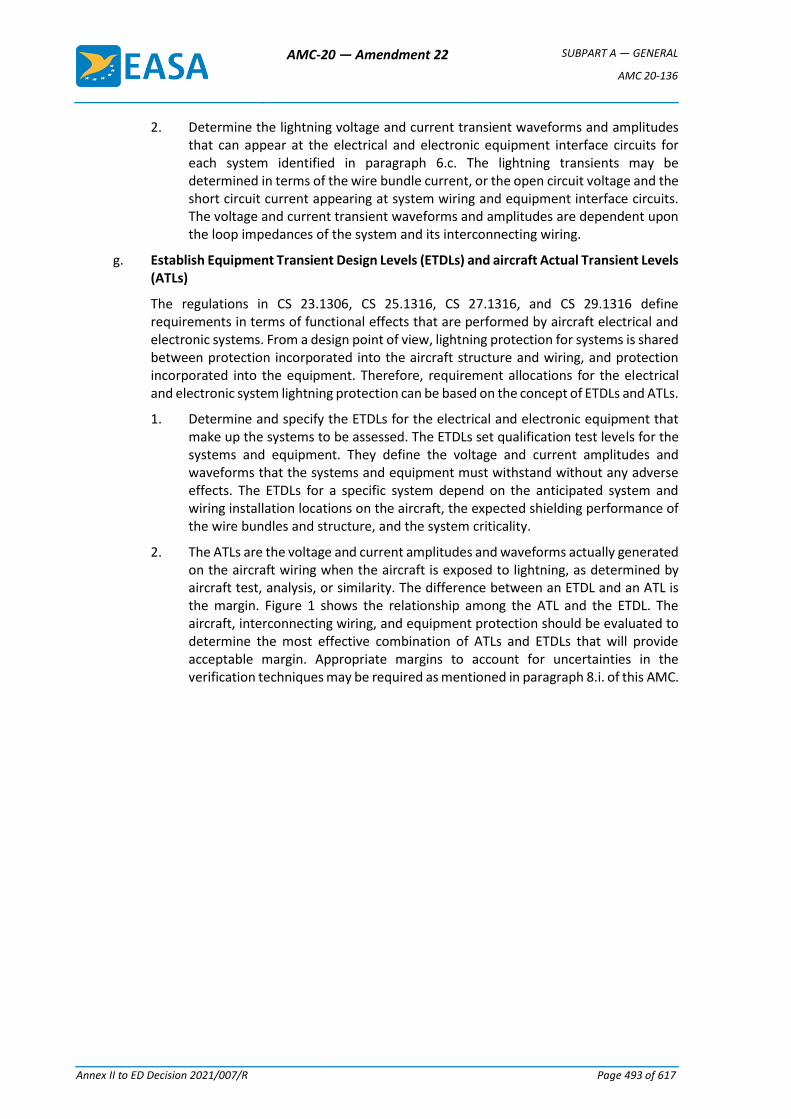
AMC-20 — Amendment 22 SUBPART A — GENERAL
AMC 20-136
Annex II to ED Decision 2021/007/R Page 493 of 617
2. Determine the lightning voltage and current transient waveforms and amplitudes that can appear at the electrical and electronic equipment interface circuits for each system identified in paragraph 6.c. The lightning transients may be determined in terms of the wire bundle current, or the open circuit voltage and the short circuit current appearing at system wiring and equipment interface circuits. The voltage and current transient waveforms and amplitudes are dependent upon the loop impedances of the system and its interconnecting wiring.
g. Establish Equipment Transient Design Levels (ETDLs) and aircraft Actual Transient Levels (ATLs)
The regulations in CS 23.1306, CS 25.1316, CS 27.1316, and CS 29.1316 define requirements in terms of functional effects that are performed by aircraft electrical and electronic systems. From a design point of view, lightning protection for systems is shared between protection incorporated into the aircraft structure and wiring, and protection incorporated into the equipment. Therefore, requirement allocations for the electrical and electronic system lightning protection can be based on the concept of ETDLs and ATLs.
1. Determine and specify the ETDLs for the electrical and electronic equipment that make up the systems to be assessed. The ETDLs set qualification test levels for the systems and equipment. They define the voltage and current amplitudes and waveforms that the systems and equipment must withstand without any adverse effects. The ETDLs for a specific system depend on the anticipated system and wiring installation locations on the aircraft, the expected shielding performance of the wire bundles and structure, and the system criticality.
2. The ATLs are the voltage and current amplitudes and waveforms actually generated on the aircraft wiring when the aircraft is exposed to lightning, as determined by aircraft test, analysis, or similarity. The difference between an ETDL and an ATL is the margin. Figure 1 shows the relationship among the ATL and the ETDL. The aircraft, interconnecting wiring, and equipment protection should be evaluated to determine the most effective combination of ATLs and ETDLs that will provide acceptable margin. Appropriate margins to account for uncertainties in the verification techniques may be required as mentioned in paragraph 8.i. of this AMC.
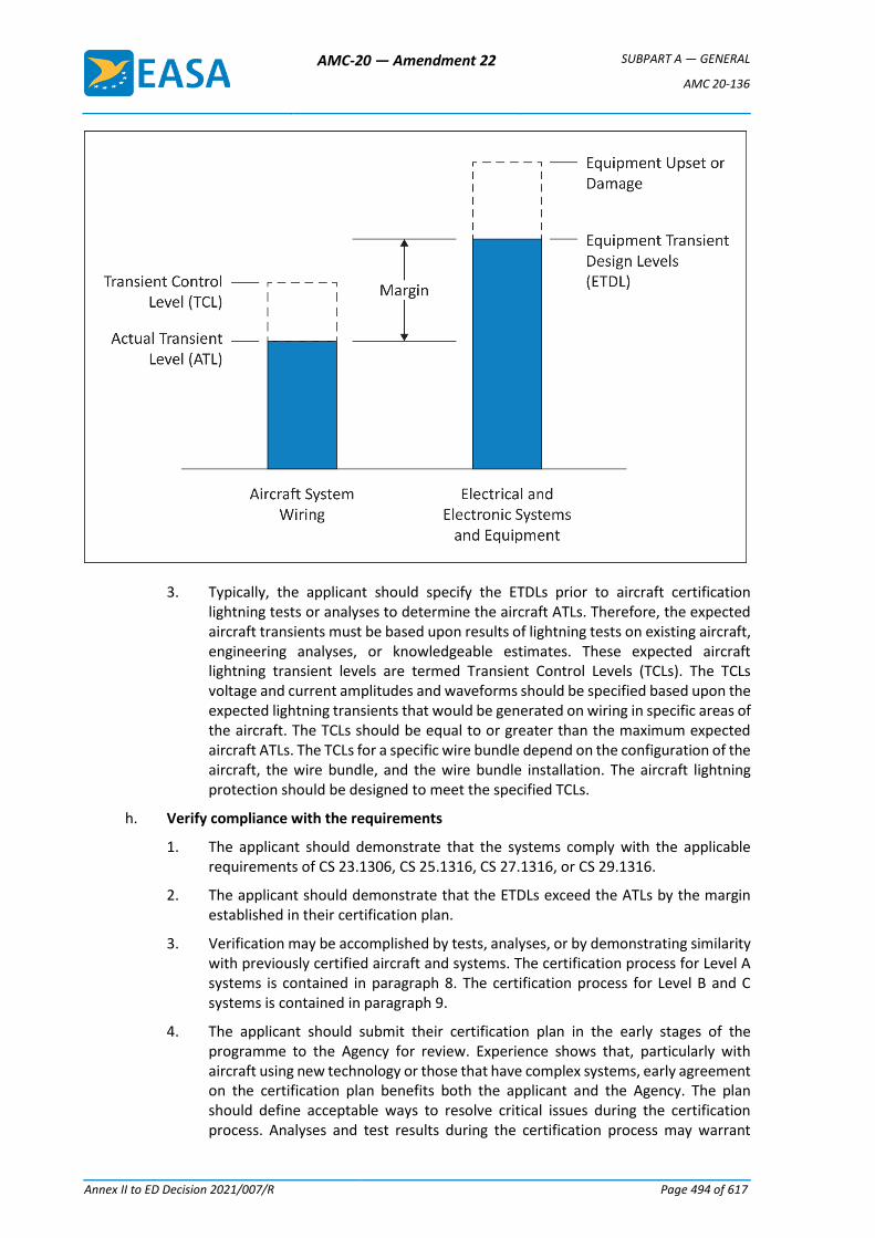
AMC-20 — Amendment 22 SUBPART A — GENERAL
AMC 20-136
Annex II to ED Decision 2021/007/R Page 494 of 617
3. Typically, the applicant should specify the ETDLs prior to aircraft certification lightning tests or analyses to determine the aircraft ATLs. Therefore, the expected aircraft transients must be based upon results of lightning tests on existing aircraft, engineering analyses, or knowledgeable estimates. These expected aircraft lightning transient levels are termed Transient Control Levels (TCLs). The TCLs voltage and current amplitudes and waveforms should be specified based upon the expected lightning transients that would be generated on wiring in specific areas of the aircraft. The TCLs should be equal to or greater than the maximum expected aircraft ATLs. The TCLs for a specific wire bundle depend on the configuration of the aircraft, the wire bundle, and the wire bundle installation. The aircraft lightning protection should be designed to meet the specified TCLs.
h. Verify compliance with the requirements
1. The applicant should demonstrate that the systems comply with the applicable requirements of CS 23.1306, CS 25.1316, CS 27.1316, or CS 29.1316.
2. The applicant should demonstrate that the ETDLs exceed the ATLs by the margin established in their certification plan.
3. Verification may be accomplished by tests, analyses, or by demonstrating similarity with previously certified aircraft and systems. The certification process for Level A systems is contained in paragraph 8. The certification process for Level B and C systems is contained in paragraph 9.
4. The applicant should submit their certification plan in the early stages of the programme to the Agency for review. Experience shows that, particularly with aircraft using new technology or those that have complex systems, early agreement on the certification plan benefits both the applicant and the Agency. The plan should define acceptable ways to resolve critical issues during the certification process. Analyses and test results during the certification process may warrant
AMC-20 — Amendment 22 SUBPART A — GENERAL
AMC 20-136
Annex II to ED Decision 2021/007/R Page 495 of 617
modifications to the design or verification methods. When significant changes are necessary, the certification plan should be updated accordingly. The plan may include the items listed in Table 2.
i. Take corrective measures
If tests and analyses show that the system did not meet the pass/fail criteria, review the aircraft, installation or system design and improve protection against lightning.
Table 2 — Items recommended for a lightning certification plan
Item Discussion
Description of systems
Describe the systems’ installation, including unusual or unique features; the system failure condition classifications; the operational aspects; lightning attachment zones; lightning environment; preliminary estimate of ETDLs and TCLs; and acceptable margins between ETDLs and ATLs.
Description of compliance method
Describe how to verify compliance. Typically, the verification method chosen includes similarity, analytical procedures, and tests. If using analytical procedures, describe how to verify them. (See paragraph 8.d.)
Acceptance criteria Determine the pass/fail criteria for each system by analysing how safe the system is. During this safety analysis, assess the aircraft in its various operational states; account for the failure and disruption modes caused by the effects of lightning.
Test plans Each test undertaken as part of the demonstration of compliance should be appropriately planned. The applicant can decide if test plans are separate documents or part of the compliance plan. Test plans should state the test sequence.
7. EFFECTS OF TRANSIENTS
Lightning causes voltage and current transients to appear on equipment circuits. Equipment circuit impedances and configurations will determine whether lightning transients are primarily voltage or current. These transient voltages and currents can degrade system performance permanently or temporarily. The two primary types of degradation are component damage and system functional upset.
a. Component damage
This is a permanent condition in which transients alter the electrical characteristics of a circuit. Examples of devices that may be susceptible to component damage include:
1. active electronic devices, especially high-frequency transistors, integrated circuits, microwave diodes, and power supply components;
2. passive electrical and electronic components, especially those of very low power or voltage rating;
3. electro-explosive devices, such as squibs and detonators;
4. electromechanical devices, such as indicators, actuators, relays, and motors; and
5. insulating materials (for example, insulating materials in printed circuit boards and connectors) and electrical connections that can burn or melt.
b. System functional upset
1. Functional upset is mainly a system problem caused by electrical transients. It may permanently or momentarily upset a signal, circuit, or a system component, which can adversely affect system performance enough to compromise flight safety. A functional upset is a change in digital or analogue state that may or may not require manual reset. In general, functional upset depends on circuit design and operating voltages, signal characteristics and timing, and system and software configuration.
AMC-20 — Amendment 22 SUBPART A — GENERAL
AMC 20-136
Annex II to ED Decision 2021/007/R Page 496 of 617
2. Systems or devices that may be susceptible to functional upset include computers and data/signal processing systems; electronic engine and flight controls; and power generating and distribution systems.
8. LEVEL A SYSTEM LIGHTNING CERTIFICATION
Figure 2 illustrates a process that the applicant can use to demonstrate that their Level A system complies with CS 23.1306, CS 25.1316, CS 27.1316, and CS 29.1316.
a. Identify Level A systems Level A systems should be identified as described in paragraph 6.c. The detailed system performance pass/fail criteria should be defined. The Agency should concur on this criterion before the applicant begins testing or analysing their Level A system. Specific equipment, components, sensors, power systems and wiring associated with each Level A system should be identified in order to perform the ETDL verification mentioned in paragraphs 8.g and 8.h.
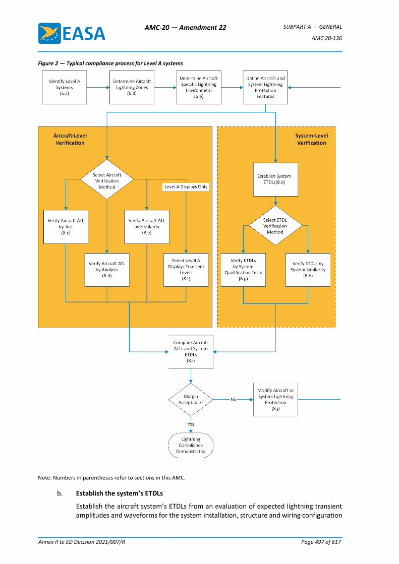
AMC-20 — Amendment 22 SUBPART A — GENERAL
AMC 20-136
Annex II to ED Decision 2021/007/R Page 497 of 617
Figure 2 — Typical compliance process for Level A systems
Note: Numbers in parentheses refer to sections in this AMC.
b. Establish the system’s ETDLs
Establish the aircraft system’s ETDLs from an evaluation of expected lightning transient amplitudes and waveforms for the system installation, structure and wiring configuration
AMC-20 — Amendment 22 SUBPART A — GENERAL
AMC 20-136
Annex II to ED Decision 2021/007/R Page 498 of 617
on a specific aircraft. ETDLs that exceed the ATLs by an acceptable margin should be established. In general, the ETDLs for equipment in a complex system will not be the same for all wire bundles connecting them to other equipment in the system. The applicant may use results of lightning tests on existing similar aircraft, engineering analyses, or knowledgeable estimates to establish the appropriate system’s ETDLs. While specific aircraft configurations and system installations may lead to ETDLs that have amplitudes and waveforms different than those defined in EUROCAE ED-14G, Section 22, ETDLs are often specified using the information from Section 22. The ETDLs must exceed the ATLs by an acceptable margin.
c. Determine the ATLs using aircraft tests
See SAE ARP 5415A, User’s Manual for Certification of Aircraft Electrical/Electronic Systems Against the Indirect Effects of Lightning, and EUROCAE ED-105A for guidance on how to determine the ATLs.
d. Determine the ATLs using analysis
See SAE ARP 5415A for guidance on how to analyse aircraft to determine the ATLs. Acceptance of the analysis method choosen will depend on the accuracy of the method. The applicant should confirm their analysis method accuracy using experimental data, and gain agreement of their analysis approach from the Agency.
e. Determine the ATLs using similarity
1. Theuse of similarity to determine the ATLs may be used when:
a. there are only minor differences between the previously certified aircraft and system installation and the aircraft and system installation to be certified; and
b. there is no unresolved in-service history of problems related to lightning strikes to the previously certified aircraft.
2. If significant differences are found that will affect the aircraft ATLs, the applicant should perform more tests and analyses to resolve the open issues.
3. To use similarity, the applicant should assess the aircraft, wiring, and system installation differences that can adversely affect the system’s susceptibility. When assessing a new installation, consider the differences affecting the internal lightning environment of the aircraft and its effects on the system. The assessment should cover:
a. aircraft type, equipment locations, airframe construction, structural materials, and apertures that could affect attenuation of the external lightning environment;
b. system wiring size, length, and routing; wire types (whether parallel or twisted wires), connectors, wire shields, and shield terminations;
c. lightning protection devices such as transient suppressors and lightning arrestors; and
d. grounding and bonding.
4. Similarity cannot be used for a new aircraft design with new systems.
f. Determine the transient levels using ED-14G, Section 22, Guidance for Level A displays only
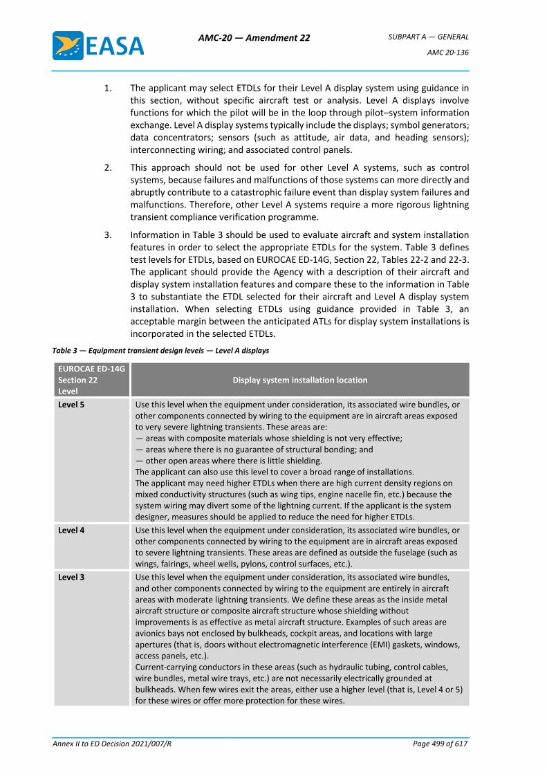
AMC-20 — Amendment 22 SUBPART A — GENERAL
AMC 20-136
Annex II to ED Decision 2021/007/R Page 499 of 617
1. The applicant may select ETDLs for their Level A display system using guidance in this section, without specific aircraft test or analysis. Level A displays involve functions for which the pilot will be in the loop through pilot–system information exchange. Level A display systems typically include the displays; symbol generators; data concentrators; sensors (such as attitude, air data, and heading sensors); interconnecting wiring; and associated control panels.
2. This approach should not be used for other Level A systems, such as control systems, because failures and malfunctions of those systems can more directly and abruptly contribute to a catastrophic failure event than display system failures and malfunctions. Therefore, other Level A systems require a more rigorous lightning transient compliance verification programme.
3. Information in Table 3 should be used to evaluate aircraft and system installation features in order to select the appropriate ETDLs for the system. Table 3 defines test levels for ETDLs, based on EUROCAE ED-14G, Section 22, Tables 22-2 and 22-3. The applicant should provide the Agency with a description of their aircraft and display system installation features and compare these to the information in Table 3 to substantiate the ETDL selected for their aircraft and Level A display system installation. When selecting ETDLs using guidance provided in Table 3, an acceptable margin between the anticipated ATLs for display system installations is incorporated in the selected ETDLs.
Table 3 — Equipment transient design levels — Level A displays
EUROCAE ED-14G Section 22 Level
Display system installation location
Level 5 Use this level when the equipment under consideration, its associated wire bundles, or other components connected by wiring to the equipment are in aircraft areas exposed to very severe lightning transients. These areas are: — areas with composite materials whose shielding is not very effective; — areas where there is no guarantee of structural bonding; and — other open areas where there is little shielding. The applicant can also use this level to cover a broad range of installations. The applicant may need higher ETDLs when there are high current density regions on mixed conductivity structures (such as wing tips, engine nacelle fin, etc.) because the system wiring may divert some of the lightning current. If the applicant is the system designer, measures should be applied to reduce the need for higher ETDLs.
Level 4 Use this level when the equipment under consideration, its associated wire bundles, or other components connected by wiring to the equipment are in aircraft areas exposed to severe lightning transients. These areas are defined as outside the fuselage (such as wings, fairings, wheel wells, pylons, control surfaces, etc.).
Level 3 Use this level when the equipment under consideration, its associated wire bundles, and other components connected by wiring to the equipment are entirely in aircraft areas with moderate lightning transients. We define these areas as the inside metal aircraft structure or composite aircraft structure whose shielding without improvements is as effective as metal aircraft structure. Examples of such areas are avionics bays not enclosed by bulkheads, cockpit areas, and locations with large apertures (that is, doors without electromagnetic interference (EMI) gaskets, windows, access panels, etc.). Current-carrying conductors in these areas (such as hydraulic tubing, control cables, wire bundles, metal wire trays, etc.) are not necessarily electrically grounded at bulkheads. When few wires exit the areas, either use a higher level (that is, Level 4 or 5) for these wires or offer more protection for these wires.
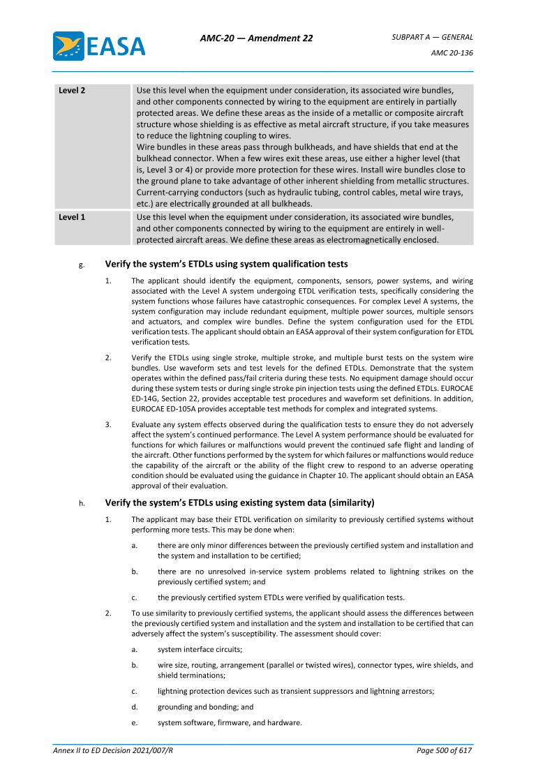
AMC-20 — Amendment 22 SUBPART A — GENERAL
AMC 20-136
Annex II to ED Decision 2021/007/R Page 500 of 617
Level 2 Use this level when the equipment under consideration, its associated wire bundles, and other components connected by wiring to the equipment are entirely in partially protected areas. We define these areas as the inside of a metallic or composite aircraft structure whose shielding is as effective as metal aircraft structure, if you take measures to reduce the lightning coupling to wires. Wire bundles in these areas pass through bulkheads, and have shields that end at the bulkhead connector. When a few wires exit these areas, use either a higher level (that is, Level 3 or 4) or provide more protection for these wires. Install wire bundles close to the ground plane to take advantage of other inherent shielding from metallic structures. Current-carrying conductors (such as hydraulic tubing, control cables, metal wire trays, etc.) are electrically grounded at all bulkheads.
Level 1 Use this level when the equipment under consideration, its associated wire bundles, and other components connected by wiring to the equipment are entirely in well-protected aircraft areas. We define these areas as electromagnetically enclosed.
g. Verify the system’s ETDLs using system qualification tests
1. The applicant should identify the equipment, components, sensors, power systems, and wiring associated with the Level A system undergoing ETDL verification tests, specifically considering the system functions whose failures have catastrophic consequences. For complex Level A systems, the system configuration may include redundant equipment, multiple power sources, multiple sensors and actuators, and complex wire bundles. Define the system configuration used for the ETDL verification tests. The applicant should obtain an EASA approval of their system configuration for ETDL verification tests.
2. Verify the ETDLs using single stroke, multiple stroke, and multiple burst tests on the system wire bundles. Use waveform sets and test levels for the defined ETDLs. Demonstrate that the system operates within the defined pass/fail criteria during these tests. No equipment damage should occur during these system tests or during single stroke pin injection tests using the defined ETDLs. EUROCAE ED-14G, Section 22, provides acceptable test procedures and waveform set definitions. In addition, EUROCAE ED-105A provides acceptable test methods for complex and integrated systems.
3. Evaluate any system effects observed during the qualification tests to ensure they do not adversely affect the system’s continued performance. The Level A system performance should be evaluated for functions for which failures or malfunctions would prevent the continued safe flight and landing of the aircraft. Other functions performed by the system for which failures or malfunctions would reduce the capability of the aircraft or the ability of the flight crew to respond to an adverse operating condition should be evaluated using the guidance in Chapter 10. The applicant should obtain an EASA approval of their evaluation.
h. Verify the system’s ETDLs using existing system data (similarity)
1. The applicant may base their ETDL verification on similarity to previously certified systems without performing more tests. This may be done when:
a. there are only minor differences between the previously certified system and installation and the system and installation to be certified;
b. there are no unresolved in-service system problems related to lightning strikes on the previously certified system; and
c. the previously certified system ETDLs were verified by qualification tests.
2. To use similarity to previously certified systems, the applicant should assess the differences between the previously certified system and installation and the system and installation to be certified that can adversely affect the system’s susceptibility. The assessment should cover:
a. system interface circuits;
b. wire size, routing, arrangement (parallel or twisted wires), connector types, wire shields, and shield terminations;
c. lightning protection devices such as transient suppressors and lightning arrestors;
d. grounding and bonding; and
e. system software, firmware, and hardware.
AMC-20 — Amendment 22 SUBPART A — GENERAL
AMC 20-136
Annex II to ED Decision 2021/007/R Page 501 of 617
3. If the applicant is unsure how the differences will affect the systems and installations, they should perform more tests and analyses to resolve the open issues.
4. The applicant should assess every system, even if it uses equipment and installation techniques that have a previous certification approval.
5. The use of similarity should not be used for a new aircraft design with new systems.
i. Verify compliance with the requirements
The applicant should compare the verified system ETDLs with the aircraft ATLs and determine if an acceptable margin exists between the ETDLs and the ATLs. Margins account for uncertainty in the verification method. As confidence in the verification method increases, the margin can decrease. An ETDL exceeding the ATL by a factor of two is an acceptable margin for Level A systems, if this margin is verified by aircraft test or by analysis supported by aircraft tests. For Level A display systems where the ETDLs are determined using guidance provided in Table 3, an acceptable margin is already incorporated in the selected ETDLs. For other verification methods, the margin should be agreed upon with the Agency.
j. Take corrective measures
1. When a system fails to meet the certification requirements, corrective actions should be selected. Any changes or modifications made to the aircraft, system installation or the equipment may require more testing and analysis.
2. To meet the certification requirements, the applicant may need to repeat system qualification testing, or aircraft testing and analysis (in whole or in part). This may include modification to the system or installation to get certification. The applicant should review these changes or modifications with the Agency to determine if they are significant. If these changes or modifications are significant, the applicant should update their lightning certification plan accordingly. The updated certification plan should be resubmitted to the Agency for review.
9. LEVEL B AND C SYSTEM LIGHTNING CERTIFICATION
a. Identify Level B and C systems
1. The applicant should identify their Level B and C systems as described in paragraph 6.c.
2. The applicant should define the detailed system performance pass/fail criteria. They should obtain the Agency’s concurrence on this criterion before starting tests or analyses of Level B and C systems.
3. Figure 3 illustrates a process the applicant can use to demonstrate that their Level B and C systems comply with the CS requirements.
Figure 3 — Typical compliance process for Level B and C systems
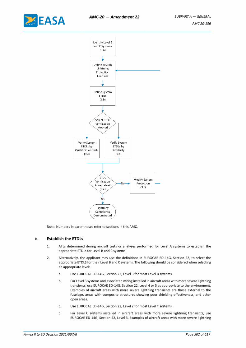
AMC-20 — Amendment 22 SUBPART A — GENERAL
AMC 20-136
Annex II to ED Decision 2021/007/R Page 502 of 617
Note: Numbers in parentheses refer to sections in this AMC.
b. Establish the ETDLs
1. ATLs determined during aircraft tests or analyses performed for Level A systems to establish the appropriate ETDLs for Level B and C systems.
2. Alternatively, the applicant may use the definitions in EUROCAE ED-14G, Section 22, to select the appropriate ETDLS for their Level B and C systems. The following should be considered when selecting an appropriate level:
a. Use EUROCAE ED-14G, Section 22, Level 3 for most Level B systems.
b. For Level B systems and associated wiring installed in aircraft areas with more severe lightning transients, use EUROCAE ED-14G, Section 22, Level 4 or 5 as appropriate to the environment. Examples of aircraft areas with more severe lightning transients are those external to the fuselage, areas with composite structures showing poor shielding effectiveness, and other open areas.
c. Use EUROCAE ED-14G, Section 22, Level 2 for most Level C systems.
d. For Level C systems installed in aircraft areas with more severe lightning transients, use EUROCAE ED-14G, Section 22, Level 3. Examples of aircraft areas with more severe lightning
AMC-20 — Amendment 22 SUBPART A — GENERAL
AMC 20-136
Annex II to ED Decision 2021/007/R Page 503 of 617
transients are those external to the fuselage, areas with composite structures showing poor shielding effectiveness, and other open areas.
e. The applicant should provide the Agency with a description of their aircraft and system installation features to substantiate the EUROCAE ED-14G, Section 22, levels selected for their system.
c. Verify the system’s ETDLs using equipment qualification tests
1. Equipment qualification tests should be performed using the selected test levels and single stroke, multiple stroke, and multiple burst waveform sets. It should be demonstrated that the equipment operates within the defined pass/fail criteria during these tests. No equipment damage should occur during these equipment qualification tests or during single stroke pin injection tests using the defined ETDLs. EUROCAE ED-14G, Section 22, provides acceptable test procedures and waveform set definitions.
2. Any equipment effects observed during the qualification tests should be evaluated to ensure that they do not adversely affect the system’s continued performance. The applicant should obtain the Agency’s approval of their evaluation.
3. Multiple stroke and multiple burst testing is not required if an analysis shows that the equipment is not susceptible to upset, or that the equipment may be susceptible to upset but a reset capability exists so that the system recovers in a timely manner.
d. Verify the system’s ETDLs using existing equipment data (similarity)
1. ETDLs may be verified by similarity to previously certified systems without performing more tests. The applicant may do this when:
a. there are only minor differences between the previously certified system and installation and the system and installation to be certified;
b. there are no unresolved in-service system problems related to lightning strikes on the previously certified system; and
c. the previously certified system ETDLs were verified by qualification tests.
2. The assessment should cover:
a. equipment interface circuits;
b. wire size, routing, arrangement (parallel or twisted wires), connector types, wire shields, and shield terminations;
c. lightning protection devices such as transient suppressors and lightning arrestors;
d. grounding and bonding; and
e. equipment software, firmware, and hardware.
3. If significant differences are found that will affect the systems and installations, the applicant should perform more tests and analyses to resolve the open issues.
e. Verify compliance with the requirements
The applicant should demonstrate that the Level B and C systems meet their defined acceptance criteria during the qualification tests at the selected system ETDLs.
f. Take corrective measures
When a system fails to meet the certification requirements, the applicant should decide on corrective actions. If they change or modify the system or installation, equipment qualification testing may need to be repeated. The applicant should review these changes or modifications with the Agency to determine if they are significant. If these changes or modifications are significant, the applicant should update their lightning certification plan accordingly. The updated certification plan should be resubmitted to the Agency for review.
AMC-20 — Amendment 22 SUBPART A — GENERAL
AMC 20-136
Annex II to ED Decision 2021/007/R Page 504 of 617
10. MAINTENANCE AND SURVEILLANCE
a. The applicant should identify the minimum maintenance required for the aircraft electrical and electronic system lightning protection in the Instructions for Continued Airworthiness (ICA). The applicant should define the requirements for periodic and conditional maintenance and surveillance of lightning protection devices or features to ensure acceptable protection performance while the aircraft is in service. Avoid using devices or features that may degrade with time because of corrosion, fretting, flexing cycles, or other causes. Alternatively, identify when to inspect or replace these devices.
b. The applicant should define the inspection techniques and intervals needed to ensure that the aircraft and system lightning protection remains effective in service. Also, identify built-in test equipment, resistance measurements, continuity checks of the entire system, or other means to determine the system’s integrity periodically and conditionally.
c. See SAE ARP 5415A for more information on aircraft lightning protection maintenance and surveillance.
[Amdt 20/13]
AMC-20 — Amendment 22 SUBPART A — GENERAL
AMC 20-136
Annex II to ED Decision 2021/007/R Page 505 of 617
Appendix 1 to AMC 20-136 Definitions and acronyms
a. Definitions
Actual Transient Level (ATL): The level of transient voltage or current that appears at the equipment interface circuits because of the external environment. This level may be less than or equal to the transient control level, but should not be greater.
Aperture: An electromagnetically transparent opening.
Attachment point: A point where the lightning flash contacts the aircraft.
Component damage: A condition in which transients permanently alter the electrical characteristics of a circuit. Because of this, the component can no longer perform to its specifications.
Continued safe flight and landing: The aircraft can safely abort or continue a take-off, or continue controlled flight and landing, possibly using emergency procedures. The aircraft must do this without requiring exceptional pilot skill or strength. Some aircraft damage may occur because of the failure condition or on landing. For large aeroplanes, the pilot must be able to land safely at a suitable airport.
For CS-23 aeroplanes, it is not necessary to land at an airport. For rotorcraft, the rotorcraft must continue to cope with adverse operating conditions, and the pilot must be able to land safely at a suitable site.
Direct effects: Physical damage to the aircraft or electrical and electronic systems. Direct attachment of lightning to the system’s hardware or components causes the damage. Examples of direct effects include tearing, bending, burning, vaporisation, or blasting of aircraft surfaces and structures, and damage to electrical and electronic systems.
Equipment Component of an electrical or electronic system with interconnecting electrical conductors.
Equipment Transient Design Level (ETDL): The peak amplitude of transients to which equipment is qualified.
External environment: The natural lightning environment, outside the aircraft, for design and certification purposes. See EUROCAE ED-84A, which reference documents that provide additional guidance on aircraft lightning environment and related waveforms.
Indirect effects: Electrical transients induced by lightning in aircraft electrical or electronic circuits.
Internal environment: The potential fields and structural voltages inside the aircraft produced by the external environment.
Lightning flash: The total lightning event. It may occur in a cloud, among clouds, or between a cloud and the ground. It can consist of one or more return strokes, plus intermediate or continuing currents.
Lightning strike: Attachment of the lightning flash to the aircraft.
Lightning strike zones: Aircraft surface areas and structures that are susceptible to lightning attachment, dwell time, and current conduction. See EUROCAE ED-91, which references documents that provide additional guidance on aircraft lightning zoning.
Lightning stroke (return stroke): A lightning current surge that occurs when the lightning leader (the initial current charge) makes contact with the ground or another charge centre. A charge centre is an area of high potential of opposite charge.
AMC-20 — Amendment 22 SUBPART A — GENERAL
AMC 20-136
Annex II to ED Decision 2021/007/R Page 506 of 617
Margin: The difference between the equipment transient design levels and the actual transient level.
Multiple burst: A randomly spaced series of bursts of short duration, low amplitude current pulses, with each pulse characterised by rapidly changing currents. These bursts may result as the lightning leader progresses or branches, and are associated with the cloud-to-cloud and intra-cloud flashes. The multiple bursts appear most intense when the initial leader attaches to the aircraft. See EUROCAE ED-84A.
Multiple stroke: Two or more lightning return strokes during a single lightning flash. See EUROCAE ED-84A.
Transient Control Level (TCL): The maximum allowable level of transients that appear at the equipment interface circuits because of the defined external environment.
b. Acronyms
AC: Advisory Circular
AMC: Acceptable Means of Compliance
ARP: Aerospace Recommended Practice
ATL: Actual Transient Level
CS: Certification Specification
ETDL: Equipment Transient Design Level
EASA: European Aviation Safety Agency
EUROCAE: European Organization for Civil Aviation Equipment
FAA: Federal Aviation Administration
ICA: Instructions for Continued Airworthiness
TCL: Transient Control Level
[Amdt 20/13]
AMC-20 — Amendment 22 SUBPART A — GENERAL
AMC 20-152A
Annex II to ED Decision 2021/007/R Page 507 of 617
AMC 20-152A
AMC 20-152A Development Assurance for Airborne Electronic Hardware (AEH)
1 PURPOSE
1.1 This AMC describes an acceptable means, but not the only means, for showing compliance
with the applicable airworthiness regulations for the electronic hardware aspects of airborne
systems and equipment in product certification or ETSO authorisation. Compliance with this
AMC is not mandatory, and an applicant may elect to use an alternative means of compliance.
However, the alternative means of compliance must meet the relevant requirements, ensure
an equivalent level of safety, and be approved by EASA on a product or ETSO article basis.
1.2 This AMC recognises EUROCAE ED-80, Design Assurance Guidance for Airborne Electronic
Hardware, dated April 2000, and RTCA DO-254, Design Assurance Guidance for Airborne
Electronic Hardware, dated 19 April 2000.
1.3 This AMC describes when to apply EUROCAE ED-80/RTCA DO-254, and it supplements
EUROCAE ED-80/RTCA DO-254 with additional guidance and clarification for the development
of custom devices, including the use of commercial off-the-shelf (COTS) intellectual property
(IP), for the use of COTS devices and for the development of circuit board assemblies (CBAs).
The additional guidance and clarifications are provided in the form of objectives. The applicant
is expected to describe the process and activities to satisfy the objectives of this AMC.
Note: EUROCAE ED is hereafter referred to as ‘ED’; RTCA DO is hereafter referred to as ‘DO’.
Where the notation ‘ED-80/DO-254’ appears in this document, the referenced documents are
recognised as being equivalent.
1.4 This AMC does not address the Single Event Effects (SEE) aspects or the assessment of
the hardware susceptibility to SEE. AMC SEE aspects are usually addressed through a
certification review item (CRI), and further guidance may be found in EASA CM-AS-004 Issue
01, issued 8 January 2018.
However, the Plan for Hardware Aspects of Certification may still be used to document the
certification considerations for SEE.
2 APPLICABILITY
This AMC may be used by applicants, design approval holders, and developers of airborne
systems and equipment containing airborne electronic hardware (AEH) to be installed on
type-certified aircraft, engines, and propellers. This applicability includes the developers of
ETSO articles.
This AMC is applicable to AEH that contributes to hardware development assurance level (DAL)
A,
DAL B, or DAL C functions.
AMC-20 — Amendment 22 SUBPART A — GENERAL
AMC 20-152A
Annex II to ED Decision 2021/007/R Page 508 of 617
When an objective is not applicable to a specific hardware DAL, the applicability restriction is
directly indicated within the objective text with the following convention, for instance ‘For DAL
A hardware, …’ For AEH contributing to hardware DAL C functions, only a limited set of
objectives applies.
Even though there is a benefit in having a structured development process that ensures a
proper flow-down of requirements to the hardware and the fulfilment by the hardware of the
intended function, the use of this AMC is not required for AEH contributing to hardware DAL D
functions. Appendix B provides some clarifications that may be used to ensure that the DAL D
hardware performs its intended function.
3 DOCUMENT HISTORY
This document is the initial issue of AMC 20-152. This initial issue, jointly developed with FAA,
is intentionally set at Revision A.
4 BACKGROUND
This AMC is related to the development of custom devices in AEH, including the use of
commercial off-the-shelf intellectual property (COTS IP) within custom devices, the use of COTS
devices, and the development of circuit board assemblies (CBAs). Each of these topics is
organised with:
— background information dedicated to each major topic,
— applicability, and
— sections where objectives are described and uniquely identified.
A unique identifier for each objective is defined with a prefix and an index number (i) as follows:
— for the development of custom devices, the identifier is ‘CD-i’;
— for the use of COTS IP in custom devices, the identifier is ‘IP-i’;
— for the use of COTS devices, the identifier is ‘COTS-i’;
— for the development of CBAs, the identifier is ‘CBA-i’.
Objectives are also differentiated from the rest of the text by formatting in italics.
The applicant should document in the Plan for Hardware Aspects of Certification (PHAC), or
any other related planning document, the process and activities that the applicant intends to
perform to satisfy the objectives of this AMC. The PHAC, as well as those related planning
documents, should be submitted for certification.
5 CUSTOM DEVICE DEVELOPMENT
This section provides guidance for the development assurance of programmable logic devices
(PLDs), field-programmable gate arrays (FPGAs), or application-specific integrated circuits
(ASICs), which are collectively referred to as ‘custom devices’. These custom devices are
addressed in ED-80/DO-254, Section 1.2, Item 3 as ‘custom micro-coded components’.
AMC-20 — Amendment 22 SUBPART A — GENERAL
AMC 20-152A
Annex II to ED Decision 2021/007/R Page 509 of 617
Developing a custom device demands a well-defined development process. However, it is
understood that the process to develop complex custom devices requires more comprehensive
activities and artefacts than for a simple device.
Section 5.1 identifies custom devices that are within the scope of this AMC.
Section 5.2 provides guidance on simple/complex classification for custom devices.
Section 5.3 provides guidance on development assurance for complex custom devices.
Section 5.4 provides guidance on development assurance for simple custom devices. In
particular, Section 5.4 defines which sections from 5.5 to 5.11 are applicable to the
development assurance of simple electronic devices.
Sections 5.5 to 5.10 provide clarifications on ED-80/DO-254.
Section 5.11 provides background information and guidance specific to COTS IP used in custom
devices.
5.1 Applicability to Custom Devices
Section 5 is applicable to a digital- or mixed-signal custom device that contributes to hardware
DAL A, B or C functions.
Appendix A to ED-80/DO-254 modulates the ED-80/DO-254 life-cycle data based on the DAL
allocated to the hardware function. This document recognises Appendix A for the modulation
of the life-cycle data according to the hardware DAL for the development of custom devices.
5.2 Simple/Complex Classification
ED-80/DO-254 introduces the notion of simple and complex hardware items. This section
clarifies and provides criteria that could be used to classify a device as simple by considering
the design content of the custom device, and subsequently, the ability to comprehensively
verify the device.
A hardware custom device is classified as simple only if a technical assessment of the design
content supports the ability of the device to be verified by a comprehensive combination of
deterministic tests and analyses that ensure correct functional performance under all
foreseeable operating conditions with no anomalous behaviour. The following criteria should
be used for assessing whether a device should be classified as simple:
— simplicity of the functions and their number,
— number and the simplicity of the interfaces,
— simplicity of the data/signal processing or transfer functions, and
— independence of functions/blocks/stages.
Additional criteria specific to the digital part of the design include:
— whether the design is synchronous or asynchronous,
— number of independent clocks,
AMC-20 — Amendment 22 SUBPART A — GENERAL
AMC 20-152A
Annex II to ED Decision 2021/007/R Page 510 of 617
— number of state machines, number of states and state transitions per state machine,
and
— independence between the state machines.
The applicant may propose other or additional criteria for the technical assessment of
simplicity.
When an item cannot be classified as simple, it should be classified as complex. However, note
that an item constructed entirely from simple items may itself be complex.
AMC-20 — Amendment 22 SUBPART A — GENERAL
AMC 20-152A
Annex II to ED Decision 2021/007/R Page 511 of 617
Objective CD-1
For each custom device, the applicant should document in the PHAC or any related planning
document:
1. the development assurance level,
2. the simple or complex classification, and
3. if a device is classified as simple, the justification based on the simple classification
criteria.
5.3 Development Assurance for Complex Custom Devices
ED-80/DO-254 is recognised as the industry standard for the development assurance of
complex custom devices.
The applicant should satisfy ED-80/DO-254 and the additional objectives or clarifications
described in this AMC from Sections 5.5 to 5.11.
5.4 Development Assurance for Simple Custom Devices
For the development of simple custom devices, it is understood that the life-cycle data might
be significantly reduced compared with the data required for a complex custom device.
ED-80/DO-254 acknowledges that the documentation for the design process of a simple
hardware device is less extensive than the one needed for a complex device. In addition, while
verification and configuration management are also needed, these supporting processes also
require less documentation for a simple device.
However, it is important that a simple custom device performs its intended function, and is
under configuration management, thus allowing the device to be reproduced, conformed, and
analysed to ensure continued operational safety.
Objective CD-2
The applicant should propose a process in the PHAC, or any other appropriate planning
document, to develop simple custom devices which encompasses the following:
1. definition of the device functions,
2. complete verification of the device functions through tests and analyses,
3. configuration management of the device, including problem reporting and the
instructions to reproduce the device,
4. assessment of the build conformance of the device.
Sections 5.5.2.4 and 5.5.2.5 of this document also apply to the verification process for simple
custom devices.
The life-cycle data for simple devices can be combined with other hardware data.
If tools are used for the simple custom device development process, the objectives or
clarifications of those objectives described in Section 5.8 of this document are also applicable.
AMC-20 — Amendment 22 SUBPART A — GENERAL
AMC 20-152A
Annex II to ED Decision 2021/007/R Page 512 of 617
When the applicant intends to reuse a previously developed simple device, ED-80/DO-254
Section 11.1 and the clarifications provided in Section 5.9 of this document should be used.
If the applicant intends to use COTS IP, the objectives or clarifications of those objectives
described in Section 5.11 of this document are also applicable.
5.5 Clarifications to ED-80/DO-254 Validation and Verification Processes
5.5.1 Validation Process
Establishing a correct and complete set of requirements is the cornerstone of the development
assurance process. ED-80/DO-254 Section 6.1 addresses the validation process to ensure the
completeness and correctness of derived requirements. Nevertheless, the validation process
is essential for all the requirements. Indeed, the upper-level requirements allocated to the
custom device are often refined, decomposed or restated at the custom device level, and in
terms that support the hardware design. These custom device requirements, which are
traceable from/to the upper-level requirements and, therefore, not considered to be ‘derived’,
should also be correct and complete.
Objective CD-3
The applicant should validate all the custom device requirements by following the ED-80/DO-
254 validation process (ED-80/DO-254 Section 6). This validation activity covers both derived
and non-derived requirements.
For DAL A and B development, validation activities should be performed with independence.
Note: ED-80/DO-254 Appendix A defines acceptable means for establishing independence.
5.5.2 Verification Process
ED-80/DO-254 broadly describes the verification process, but additional guidance is needed to
ensure the verification of the custom device is complete, particularly in the area of:
— design reviews,
— reviews of test cases and procedures, and
— verification of the implementation.
5.5.2.1 Conceptual Design Review
Conceptual design is the process of generating a high-level design description from the
hardware requirements (see ED-80/DO-254 Section 5.2). The conceptual design review is
typically used to ensure that the outcome of the conceptual design activities (see ED-80/DO-
254 Section 5.2.2) is consistent with the requirements, and identifies constraints for the
interfacing components (hardware or software) and architectural constraints for the detailed
design activities of the custom device.
Since this conceptual design review is already addressed in ED-80/DO-254 Section 5.2.2
through the note, no separate objective is needed.
5.5.2.2 Detailed Design Review
AMC-20 — Amendment 22 SUBPART A — GENERAL
AMC 20-152A
Annex II to ED Decision 2021/007/R Page 513 of 617
Detailed design is the process of generating, from the conceptual design and the requirements,
a hardware description language (HDL) or analogue representation of the design, constraints
for the implementation (e.g. timing constraints, pinout, I/O characteristics), and the hardware–
software interface description.
ED-80/DO-254 introduces design reviews in Section 6.3.3.2. A design review is considered to
be an essential step during the detailed design process (ED-80/DO-254 Section 5.3) supporting
the implementation process, and complementing requirements-based verification.
Objective CD-4
For hardware DAL A or DAL B, the applicant should review the detailed design with respect to the design
standards, and review the traceability between the detailed design and the custom device requirements,
in order to demonstrate that the detailed design covers the custom device requirements, is consistent
with the conceptual design, and is compliant with the hardware design standards.
For hardware DAL C, the applicant should demonstrate that the detailed design satisfies the hardware
design standards.
5.5.2.3 Implementation Review
Within a custom device development process, tools are used to convert the detailed design data into
the physical implementation. While ED-80/DO-254 does not explicitly address it, a review of the design
tool reports (e.g. synthesis and place and route reports) is necessary to ensure that the execution of the
tool to generate its output was performed correctly.
Objective CD-5
When tools are used to convert the detailed design data into the physical implementation, the applicant
should review the design tool reports (e.g. synthesis and place and route reports) to ensure that the tool
executed properly when generating the output.
5.5.2.4 Review of Verification Cases and Procedures
ED-80/DO-254 introduces verification coverage analysis in Section 6.2.2 Item 4 to satisfy the
ED-80/DO-254 verification process objectives and determine whether the verification process is correct
and complete. A part of the coverage analysis is clarified by the following objective.
Objective CD-6
Each verification case and procedure should be reviewed to confirm that it is appropriate for the
requirements to which it traces and that the requirements are correctly and completely covered by the
verification cases and procedures.
5.5.2.5 Verification of the Timing Performance of the Implementation
ED-80/DO-254 Section 6.2 addresses the verification of the implementation. The implementation results
from the process to generate the physical custom device from the detailed design data. The post-layout
netlist is the closest virtual representation of the physical custom device, resulting from synthesis (for
the digital part of the device) and place and route.
AMC-20 — Amendment 22 SUBPART A — GENERAL
AMC 20-152A
Annex II to ED Decision 2021/007/R Page 514 of 617
While it is recommended to test the implementation in its intended operational environment (i.e. by a
physical test), verification using the post-layout netlist may be necessary to complement the verification
of the implementation for certain requirements (e.g. features not accessible from the I/O pins of the
device, timing, abnormal conditions, or robustness cases). In such cases, the coverage of the
requirements by means other than a physical test should be justified.
The requirement to capture the activities in ED-80/DO-254 Section 5.1.2 Item 4.g introduces the need
for the requirements to address signal timing characteristics under normal- and worst-case conditions.
Nevertheless, ED-80/DO-254 does not explicitly address the necessity to verify the performance of the
device under all possible (best-case and worst-case) timing conditions that could possibly occur during
the operation of the device.
The following objective clarifies the need to take into account the variation of the environmental
conditions (temperature, voltage, etc.) during the evaluation of the timing performance of the design,
as well as the semiconductor device process variations.
Objective CD-7
The applicant should verify the timing performance of the design accounting for the temperature and
power supply variations applied to the device and the semiconductor device fabrication process
variations as characterised by the manufacturer of the semiconductor device.
Note: Static timing analysis (STA) with the necessary timing constraints and conditions is one of the
possible means of compliance with this objective for the digital parts of custom devices.
5.6 Clarifications to ED-80/DO-254 ‘Robustness Aspects’
ED-80/DO-254 mentions robustness defects but does not explicitly address robustness. The robustness
of the design is defined as the expected behaviour of the design under abnormal and boundary/worst-
case operating conditions of the inputs and internal design states. These conditions are often captured
as derived requirements when they are not allocated from the upper-level process. When subjected to
these conditions, it is understood that the design may not continue to perform as it would under normal
conditions.
Objective CD-8
For DAL A or DAL B hardware, the abnormal and boundary conditions and the associated expected
behaviour of the design should be defined as requirements.
5.7 Recognition of HDL Code Coverage Method
HDL code coverage analysis is an assessment of whether the HDL code of the design has been exercised
through HDL simulations.
The HDL code coverage method provides an assessment of the coverage of the design logic structure,
giving an indication of which aspects of the logic structure are exercised and which are not.
When performed during requirements-based verification (per ED-80/DO-254 Section 6.2), HDL code
coverage is recognised as a method to perform ED-80/DO-254 elemental analysis per Appendix B
Section 3.3.1 for digital devices. HDL code coverage supports the assessment of whether the HDL code
elements are fully covered by requirements-based simulations. As such, it does not represent an
AMC-20 — Amendment 22 SUBPART A — GENERAL
AMC 20-152A
Annex II to ED Decision 2021/007/R Page 515 of 617
assessment of the completeness of the requirements-based testing activities or the effectiveness of the
requirement coverage.
AMC-20 — Amendment 22 SUBPART A — GENERAL
AMC 20-152A
Annex II to ED Decision 2021/007/R Page 516 of 617
Objective CD-9
For hardware DAL A or DAL B, where HDL code coverage is used to perform elemental analysis
(ED-80/DO-254 Appendix B Section 3.3.1), the applicant should define in the planning documents the
detailed coverage criteria of the HDL code elements used in the design. The criteria should ensure
coverage over the various cases of the HDL code elements used in the design (e.g. branches, conditions,
etc.). Any non-covered case or element should be analysed and justified.
Note: Code coverage might need to be complemented by additional analysis for any hardware items that
are identified as not covered by the code coverage analysis, in order to complete the elemental analysis
of all elements. This situation may occur in the use of some COTS IP instantiations.
5.8 Clarifications to ED-80/DO-254 ‘Tool Assessment and Qualification’
ED-80/DO-254 introduces the notion of tool assessment and qualification. ED-80/DO-254 Figure 11-1
includes a flow chart indicating the tool assessment considerations and activities, and provides guidance
for when tool qualification may be necessary. This AMC uses the flow chart and its related text as a basis
for providing further clarification, as follows:
ED-80/DO-254 — Figure 11-1 Item 1 — Identify the Tool
Information capturing the environment required for tool operation and the tool revision should be
included with the tool identification.
ED-80/DO-254 — Figure 11-1 Item 2 — Identify the Process the Tool Supports
When identifying the design or verification process that the tool supports, it is important to also identify
what purpose or activity within the hardware development process the tool satisfies. While assessing
the tool limitations, evidence of formal assessment of the tool problem reports is not required if the tool
output has been completely and independently assessed.
ED-80/DO-254 — Figure 11-1 Item 3 — Is the Tool Output Independently Assessed?
The purpose of assessing the tool output is to completely cover, with an independent means, the
potential errors that the tool could introduce into the design or fail to detect during verification.
Objective CD-10
When the applicant intends to independently assess a tool output, the applicant should propose an
independent assessment that verifies the tool output is correct. The independent assessment should
justify that there is sufficient coverage of the tool output. The completeness of the tool assessment should
be based on the design/implementation and/or verification objectives that the tool is used to satisfy.
AMC-20 — Amendment 22 SUBPART A — GENERAL
AMC 20-152A
Annex II to ED Decision 2021/007/R Page 517 of 617
ED-80/DO-254 — Figure 11-1 Item 4 — Is the Tool a Level A, B or C Design Tool or a Level A or B
Verification Tool?
ED-80/DO-254 Figure 11-1 Item 4 of the tool assessment/qualification flow excludes the need for
activities for tools ‘used to assess the completion of verification testing, such as in an elemental analysis’.
The last statement is misleading regarding the intent of code coverage tools used for elemental analysis.
As stated in Section 5.7 of this document, ‘when a code coverage tool is used for elemental analysis, it
does not represent an assessment of the completeness of the requirements-based testing activities or
the effectiveness of the requirement coverage’.
It is therefore necessary to provide some further clarifications.
— This document recognises the Figure 11-1 Item 4 exclusion of tool assessment/qualification
activities for code coverage tools only when they are used to assess whether the code has been
exercised by requirements-based testing/simulations (elemental analysis).
— If test cases or procedures are automatically generated by a tool and this tool uses coverage to
determine the completion of the requirements verification, then the tool should be considered to
be a verification tool to answer the question raised in Figure 11-1 Item 4.
ED-80/DO-254 — Figure 11-1 Item 5 — Does the Tool have Relevant History?
In ED-80/DO-254, the supporting text for Figure 11-1 Item 5 can be misinterpreted to suggest that when
the tool has been previously used, no further tool assessment is necessary. Item 5 should be understood
to mean that the applicant will provide sufficient data and justification to substantiate the relevance and
credibility of the tool history.
Objective CD-11
When the applicant intends to claim credit for the relevant history of a tool, sufficient data should be
provided as a part of the tool assessment to demonstrate that there is a relevant and credible tool history
to justify that the tool will produce correct results for its proposed use.
ED-80/DO-254 — Figure 11-1 Item 9 — Design Tool Qualification
For design tools, contrary to the note in the supporting text for Figure 11-1 Item 9, the tool history should
not be used as a stand-alone means of tool assessment and qualification. A relevant tool history may be
used to compensate for some particular gaps in the tool assessment and qualification process, for
example, to explain the method of independent assessment of the tool output. In this case, a relevant
tool history is considered to be complementary data, providing more assurance for a tool.
In addition to what is already referenced in ED-80/DO-254 Figure 11-1 Item 9 for tool qualification
guidance, ED-12C/DO-178C and ED-215/DO-330 may also be used.
AMC-20 — Amendment 22 SUBPART A — GENERAL
AMC 20-152A
Annex II to ED Decision 2021/007/R Page 518 of 617
5.9 Clarifications to ED-80/DO-254 regarding Previously Developed Hardware (PDH)
Previously developed hardware (PDH) is defined as custom-developed hardware that has been
installed in an airborne system or equipment either approved through EASA type certification
(TC/STC) or authorized through ETSOA. The section providing clarification on the use of PDH
also covers PDH that was developed and approved prior to the use of ED-80/DO-254 in civil
certification.
This section provides guidance on the use of ED-80/DO-254 Section 11.1 for PDH.
Objective CD-12
When an applicant proposes to reuse PDH, the applicant should use ED-80/DO-254
Section 11.1 and its subordinate paragraphs. The applicant should perform the assessments
and analyses required in ED-80/DO-254 Section 11.1 in order to ensure that using the PDH is
valid and that the compliance shown during the previous approval was not compromised by
any of the following:
1. Modification of the PDH for the new application or for obsolescence management;
2. Change to the function, change to its use, or change to a higher failure condition
classification of the PDH in the new application; or
3. Change to the design environment of the PDH.
The results should be documented in the PHAC or any other appropriate planning document.
In the context of custom device development, any one of these three points potentially
invalidates the original development assurance credit for the PDH. In case of change or
modification, the applicant should assess these changes using ED-80/DO-254 Section 11.1 and
its subordinate paragraphs. When the original design assurance of the PDH is invalidated by
one of the above points, the custom device should be upgraded based on the assessment per
ED-80/DO-254 Section 11.1. When upgrading the hardware, the applicant should consider the
objectives of this document that are applicable per the assessment.
5.10 Clarifications to ED-80/DO-254 Appendix A
This section clarifies the life-cycle data referenced in ED-80/DO-254 Appendix A as follows.
— The row corresponding to 10.1.6 ‘Hardware Process Assurance Plan’ in Table A-1 should
also indicate HC2 for Level C to be consistent with row 10.8.
— The row corresponding to 10.2.2 ‘Hardware Design Standard’ in Table A-1 should also
indicate HC2 for Level C. HDL Coding Standards are part of the Hardware Design
Standards.
— The row corresponding to 10.3.2.2 ‘Detailed Design Data’ in Table A-1 should indicate
HC1 for Levels A, B and C.
— The row corresponding to 10.4.2 ‘Hardware Review and Analysis Procedures’ in Table
A-1 should also indicate HC2 for Level C to be consistent with row 10.4.3.
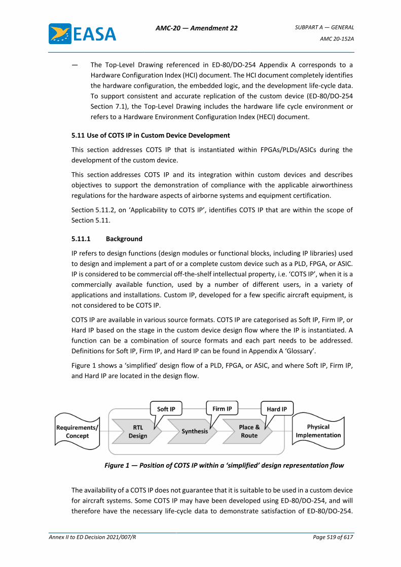
AMC-20 — Amendment 22 SUBPART A — GENERAL
AMC 20-152A
Annex II to ED Decision 2021/007/R Page 519 of 617
— The Top-Level Drawing referenced in ED-80/DO-254 Appendix A corresponds to a
Hardware Configuration Index (HCI) document. The HCI document completely identifies
the hardware configuration, the embedded logic, and the development life-cycle data.
To support consistent and accurate replication of the custom device (ED-80/DO-254
Section 7.1), the Top-Level Drawing includes the hardware life cycle environment or
refers to a Hardware Environment Configuration Index (HECI) document.
5.11 Use of COTS IP in Custom Device Development
This section addresses COTS IP that is instantiated within FPGAs/PLDs/ASICs during the
development of the custom device.
This section addresses COTS IP and its integration within custom devices and describes
objectives to support the demonstration of compliance with the applicable airworthiness
regulations for the hardware aspects of airborne systems and equipment certification.
Section 5.11.2, on ‘Applicability to COTS IP’, identifies COTS IP that are within the scope of
Section 5.11.
5.11.1 Background
IP refers to design functions (design modules or functional blocks, including IP libraries) used
to design and implement a part of or a complete custom device such as a PLD, FPGA, or ASIC.
IP is considered to be commercial off-the-shelf intellectual property, i.e. ‘COTS IP’, when it is a
commercially available function, used by a number of different users, in a variety of
applications and installations. Custom IP, developed for a few specific aircraft equipment, is
not considered to be COTS IP.
COTS IP are available in various source formats. COTS IP are categorised as Soft IP, Firm IP, or
Hard IP based on the stage in the custom device design flow where the IP is instantiated. A
function can be a combination of source formats and each part needs to be addressed.
Definitions for Soft IP, Firm IP, and Hard IP can be found in Appendix A ‘Glossary’.
Figure 1 shows a ‘simplified’ design flow of a PLD, FPGA, or ASIC, and where Soft IP, Firm IP,
and Hard IP are located in the design flow.
Figure 1 — Position of COTS IP within a ‘simplified’ design representation flow
The availability of a COTS IP does not guarantee that it is suitable to be used in a custom device
for aircraft systems. Some COTS IP may have been developed using ED-80/DO-254, and will
therefore have the necessary life-cycle data to demonstrate satisfaction of ED-80/DO-254.
AMC-20 — Amendment 22 SUBPART A — GENERAL
AMC 20-152A
Annex II to ED Decision 2021/007/R Page 520 of 617
However, most COTS IP are not developed to meet aviation development assurance standards
and, therefore, there are risks associated with their use in a custom device for aircraft systems
or equipment.
The risks of using COTS IP may include:
— Incomplete or missing documentation/data regarding:
— the behavioural operation of the COTS IP,
— how to integrate it into the design;
— Insufficient verification performed by the COTS IP provider;
— Deficient quality of the COTS IP.
The potential for design errors may be increased by the lack of development assurance and/or
by insufficient service experience.
Possible design errors within COTS IP or in the use of COTS IP may lead to a failure mode. Risk
factors for these types of errors include:
— Unknown level of rigour of the COTS IP design and verification process;
— Misalignment between the intended usage of the COTS IP by the IP provider and the
usage in the custom device by the IP user;
— Incomplete or missing details regarding the detailed operation of the COTS IP;
— Incorrect integration of the COTS IP with the rest of the custom device design;
— Integrator lacking expertise with the function of the IP.
Additionally, the COTS IP user completes the development of the integrated COTS IP up to the
physical implementation of the device. The COTS IP user may introduce a design error while
completing the physical implementation of the COTS IP because of the user’s incomplete
knowledge of the internal design of the COTS IP.
5.11.2 Applicability to COTS IP
Section 5.11 is applicable to COTS IP used in a custom device that meets the definition of
‘commercial off-the-shelf intellectual property’ in the Glossary of Appendix A. This scope
encompasses digital, analogue, and mixed-signal COTS IP.
Note: Analogue COTS IP is within the above-mentioned scope, as it could be instantiated within
a custom, mixed-signal device.
Section 5.11 is applicable to COTS IP contributing to hardware DAL A, B or C functions.
Section 5.11 is applicable to Soft IP, Firm IP, and Hard IP that are inserted within a custom
device by the applicant. However, Section 5.11 does not apply to Hard IP that is embedded in
the silicon of an FPGA or a PLD by the FPGA/PLD device manufacturer. This type of IP is
considered to be part of the COTS device, and is covered in Section 6 ‘Use of Commercial
Off-the-Shelf Devices.
AMC-20 — Amendment 22 SUBPART A — GENERAL
AMC 20-152A
Annex II to ED Decision 2021/007/R Page 521 of 617
5.11.3 Development Assurance for COTS IP
A COTS IP development assurance approach should be based on the category of the COTS IP
(Soft, Firm, Hard) and on the identified risks of failure due to a design error in the COTS IP itself
or an error in the way it is used in the custom device.
This section provides objectives addressing development assurance when using COTS IP. These
objectives are intended to cover the particular aspects of development when using COTS IP,
and are expressed in connection with the custom device development process that follows
ED-80/DO-254 and the custom device objectives of this document.
The development aspects related to COTS IP start from the custom device process that
captures the allocated requirements for the function that will be performed by the COTS IP.
From this entry point, the following aspects provide a basis to define the development
assurance objectives for the use of COTS IP:
— Selection of the COTS IP,
— Assessment of the IP provider and the IP data,
— Planning activities, including the verification strategy,
— Definition of the requirements/derived requirements,
— Design integration, implementation, and verification of the COTS IP in the custom
device.
5.11.3.1 Selection of the COTS IP to implement the function
COTS IP can be available in different forms/source formats and various levels of quality. Some
COTS IP may not be acceptable for use in airborne systems. The selection criteria below are
intended to address the essential characteristics that are considered a minimum for the use of
IP in custom AEH devices.
Objective IP-1
The applicant should select a COTS IP that is considered to be an acceptable solution, based on
at least the following criteria:
1. The IP is technically suitable for implementing the intended function;
2. The description of the COTS IP architecture or IP design concept provides an
understanding of the functionality, modes, and configuration of the IP. The description
should also include an understanding of the source format or combination of source
formats of the COTS IP;
3. The availability and quality of data and documentation allow the understanding of all
aspects of the COTS IP functions, modes, and behaviour, and enable the integration and
verification of the COTS IP (e.g. datasheets, application notes, user guide, knowledge of
errata, etc.);
AMC-20 — Amendment 22 SUBPART A — GENERAL
AMC 20-152A
Annex II to ED Decision 2021/007/R Page 522 of 617
4. Information exists for the IP user to be able to create the physical implementation of the
COTS IP (e.g. synthesis constraints, usage and performance limits, physical
implementation, and routing instructions);
5. It can be demonstrated that the COTS IP fulfils its intended function.
5.11.3.2 Assessment of the COTS IP Provider and COTS IP Data
Objective IP-2
The applicant should assess the COTS IP provider and the associated data of the COTS IP based
on at least the following criteria:
1. The IP provider provides all the information necessary for the integration of the COTS IP
within the custom device and to support the implementation of the COTS IP within the
device (e.g. synthesis constraints, usage domain, performance limits, physical
implementation, and routing instructions);
2. The configurations, selectable options, and scalable modules of the COTS IP design are
documented so that the implementation of the COTS IP can be properly managed;
3. The COTS IP has been verified by following a trustworthy and reliable process, and the
verification covers the applicant’s specific use case for the COTS IP (including the used
scale for scalable IP and the IP functions selected for selectable functions);
4. The known errors and limitations are available to the IP user, and there is a process to
provide updated information to the IP user;
5. The COTS IP has service experience data that shows reliable operation for the applicant’s
specific use case for the COTS IP.
The assessment should be documented. The results of the assessment should be submitted
together with the planning documents.
5.11.3.3 Planning of the Hardware Development Assurance Approach related to COTS IP
5.11.3.3.1 Complementary Development Assurance
Objective IP-3
When the IP-2 Objective criteria items 1, 2, 4 or 5 cannot be completely met using the IP
provider’s data, the applicant should define an appropriate development assurance activity to
mitigate the criteria that were not met and address the associated risk of development errors.
The development assurance activity should be based on the ED-80/DO-254 objectives.
Note: The results of the assessment of Objective IP-2 Item 3 are considered in Section
5.11.3.3.2.
AMC-20 — Amendment 22 SUBPART A — GENERAL
AMC 20-152A
Annex II to ED Decision 2021/007/R Page 523 of 617
5.11.3.3.2 The Verification Strategy for COTS IP Functions
In addition to the verification of the custom device functions supported by the COTS IP, there
is a need to ensure that the aspects related to the COTS IP and its usage are addressed. This
section focuses on defining a verification strategy to cover those aspects.
The verification performed by the COTS IP provider typically does not follow the ED-80/DO-254
verification process but may provide some credit to be used for the verification strategy.
However, the verification process for COTS IP generally differs from one IP vendor to another,
and the level of assurance varies depending on the IP provider’s development practices.
The verification strategy may combine different means to complement the traditional
requirements-based testing approach.
Based on the applicant’s assessment of the IP provider and the IP data through Objective IP-2,
the applicant is expected to establish a verification strategy. The aim of this verification
strategy is to cover all three of the following aspects:
— The COTS IP: the purpose is to ensure that the COTS IP is verified, addressing the risk
identified from the IP-2 Item 3 objective;
— Its implementation: the purpose is to ensure that the COTS IP still performs its allocated
function, and that no design errors have been introduced by the design steps performed
by the applicant (e.g. synthesis/place and route);
— Its integration within the custom device: the purpose is to ensure that the COTS IP has
been properly connected, configured, and constrained within the custom device.
The strategy may accomplish more than one aspect within a common verification step.
This section identifies a general objective for the verification of COTS IP used in a custom
device, enabling various verification approaches.
AMC-20 — Amendment 22 SUBPART A — GENERAL
AMC 20-152A
Annex II to ED Decision 2021/007/R Page 524 of 617
Objective IP-4
The applicant should describe in the hardware verification plan, PHAC, or any related planning
document, a verification strategy that should encompass all three of the following aspects:
1. The verification of the COTS IP itself, addressing the risk identified from the IP-2 Item 3
objective;
2. The verification of the COTS IP after the design steps performed by the applicant
(e.g. synthesis/place and route);
3. The verification of the integrated COTS IP functions within the custom device.
Note 1: Reliable and trustworthy test data, test cases or procedures from the COTS IP provider
may be used as part of the verification strategy to satisfy this objective.
Note 2: If the COTS IP implements functions based on an industry standard, proven
standardised test vectors verifying compliance with the standard may be used in the
verification strategy of the COTS IP.
Note 3: The verification strategy covers at a minimum the used functions of the COTS IP and
ensures that the unused functions are correctly disabled or deactivated and do not
interfere with the used functions.
5.11.3.3.3 COTS IP and Planning Aspects
The applicant has to define the activities that are needed for the hardware development
assurance approach related to COTS IP.
Objective IP-5
The applicant should describe in the PHAC, or any related planning document, a hardware
development assurance approach for using the COTS IP that at least includes:
1. identification of the selected COTS IP (version) and its source format(s) associated with
the point(s) in the design flow where the COTS IP is integrated into the custom device;
2. a summary of the COTS IP functions;
3. the development assurance process that the applicant defines to satisfy the objectives
of Section 5.11.3;
4. the process related to the design integration and to the usage of the COTS IP in the
development process of the custom device;
5. tool assessment and qualification aspects when the applicant uses a tool to perform
design and/or verification steps for the COTS IP.
5.11.3.4 Requirements for COTS IP Function and Validation
Custom device requirements typically contain requirements that relate to the function
supported by the COTS IP. The granularity of these requirements may be very different
AMC-20 — Amendment 22 SUBPART A — GENERAL
AMC 20-152A
Annex II to ED Decision 2021/007/R Page 525 of 617
depending on the COTS IP function and the visibility of the functions supported by the IP at
the custom device level.
Depending on the extent of requirements-based testing as a part of the chosen verification
strategy of the COTS IP, the level of detail and the granularity of the AEH custom device
requirements may need to be refined to specifically address the COTS IP functions and the
implementation of the COTS IP.
In addition, requirements should be captured to encompass all the necessary design detail
used to connect, configure, and constrain the COTS IP and properly integrate it into the AEH
custom device.
Objective IP-6
The requirements related to the allocated COTS IP functions should be captured to an extent
commensurate with the verification strategy.
In addition, derived requirements should be captured to cover the following aspects associated
with the integration of the COTS IP into the custom device design:
1. COTS IP used functions (including parameters, configuration, selectable aspects);
2. Deactivation or disabling of unused functions;
3. Correct control and use of the COTS IP, in accordance with the data from the COTS IP
provider.
When the applicant chooses a verification strategy (see Section 5.11.3.3.2) that solely relies
on requirements-based testing, the ‘extent commensurate with the verification strategy’
corresponds to a complete requirement capture of the COTS IP following ED-80/DO-254.
Regarding the validation aspects, the COTS IP requirements should be validated as a part of
the validation process of the AEH custom device.
5.11.3.5 Verification
The applicant should ensure that the COTS IP is verified as a part of the overall custom device
verification process per ED-80/DO-254 and based on the verification strategy for the COTS IP
that has been described in the PHAC or a related planning document.
For the requirements-based verification part, the applicant should satisfy ED-80/DO-254
Section 6.2 for the verification of the requirements related to the COTS IP (see Section 5.11.3.4
above). This can be performed as a part of the overall custom device process, therefore there
is no separate objective.
5.11.3.6 DO-254 Appendix B considerations
When developing a hardware DAL A or B custom device, ED-80/DO-254 Appendix B is
applicable.
Code coverage analysis that is recognised as part of elemental analysis (refer to Section 5.7 of
this document) might not be possible for the COTS IP part of the design. However,
AMC-20 — Amendment 22 SUBPART A — GENERAL
AMC 20-152A
Annex II to ED Decision 2021/007/R Page 526 of 617
ED-80/DO-254 Appendix B offers other acceptable methods, including safety-specific analysis.
The following objective further clarifies the expectations when using safety-specific analysis.
Objective IP-7
For COTS IP used in DAL A or DAL B hardware, the applicant should satisfy ED-80/DO-254
Appendix B.
The applicant may choose safety-specific analysis methods to satisfy Appendix B on the COTS
IP function and its integration within the custom device functions. This safety-specific analysis
should identify the safety-sensitive portions of the COTS IP and the potential for design errors
in the COTS IP that could affect the hardware DAL A and DAL B functions in the custom device
or system.
For unmitigated aspects of the safety-sensitive portions of the IP, the safety-specific analysis
should determine which additional requirements, design features, and verification activities
are required for the safe operation of the COTS IP in the custom device.
Any additional requirements, design features and/or verification activities that result from the
analysis should be fed back to the appropriate process.
6. USE OF COMMERCIAL OFF-THE-SHELF DEVICES
Applicants are increasingly using COTS electronic devices in aircraft/engines/propellers/
airborne systems, which may have safety implications for the aircraft, engines/propellers, or
systems.
Section 6 addresses the use of COTS devices through objectives that support the
demonstration of compliance with the applicable airworthiness regulations for hardware
aspects of airborne systems and equipment certification when using complex COTS devices.
Section 6.2 ‘Applicability to COTS devices’ enables applicants to identify the COTS devices that
are within the scope of Section 6.
Note: The term ‘COTS device’ used in this document applies to a semiconductor product that
is fully encapsulated in a package. This term does not apply to circuit board assemblies (CBAs).
6.1 Background
COTS devices continue to increase in complexity and are highly configurable. COTS devices
provide ‘off-the-shelf’ already developed functions, some of which are highly complex. Their
development and production processes undergo a semiconductor industry qualification based
on their intended market (consumer, automotive, telecom, etc.). Their usage by the aerospace
industry provides additional integration and higher performance capabilities than were
possible in the past.
The design data for these COTS devices is usually not available to the COTS user. Since these
devices are generally not developed for airborne system purposes, assurance has not been
demonstrated that the rigour of a COTS manufacturer’s development process is
commensurate with the aviation safety risks.
AMC-20 — Amendment 22 SUBPART A — GENERAL
AMC 20-152A
Annex II to ED Decision 2021/007/R Page 527 of 617
ED-80/DO-254 introduces a basis for the development assurance for the use of COTS devices
in Section 11.2 ‘COTS components usage’. This section states that ‘the use of COTS
components will be verified through the overall design process, including the supporting
processes’.
Since ED-80/DO-254 was released in the year 2000, the number of functions embedded and
integrated in a single COTS device has significantly increased. Functions which were previously
split into various components, making the interface between those components accessible for
verification, are now embedded within a single chip. While there are clearly some benefits of
integrating more functions within a device, the increased level of integration makes it difficult
for the user to verify the different hardware functions in the device due to lack of access to
the interfaces between functions. Since these devices are more complex and highly
configurable than the older separate devices, the risk is greater that the COTS device will not
achieve the intended function in particular use cases over the required operating conditions.
Furthermore, some additional assurance is needed because design errors may still be
discovered after the COTS device is released to the market, or when an applicant extends the
use of the device beyond the manufacturer’s specifications.
6.2 Applicability to COTS Devices
Section 6 is applicable to digital, hybrid, and mixed-signal COTS devices that contribute to
hardware DAL A, B or C functions. For COTS devices contributing to hardware DAL C functions,
a limited set of the objectives of this section will apply.
Section 6 is also applicable to FPGA and PLD devices that embed Hard IP (see definition) in
their produced/manufactured silicon, but only for the COTS part of the FPGAs/PLDs.
Section 6.4 only applies to COTS devices that are complex, as determined by the following
COTS complexity assessment.
6.3 COTS Complexity Assessment
In order to define which COTS devices are complex, the following high-level criteria should be
used, considering all functions of the device, including any functions intended to be unused:
A COTS device is complex when the device:
1. has multiple functional elements that can interact with each other; and
2. offers a significant number of functional modes; and
3. offers configurability of the functions, allowing different data/signal flows and
different resource sharing within the device.
Or when the device:
4. contains advanced data processing, advanced switching, or multiple processing
elements
(e.g. multicore processors, graphics processing, networking, complex bus switching,
interconnect fabrics with multiple masters, etc.).
AMC-20 — Amendment 22 SUBPART A — GENERAL
AMC 20-152A
Annex II to ED Decision 2021/007/R Page 528 of 617
For complex COTS devices, it is impractical to completely verify all possible configurations of
the device, and it is difficult to identify all potential failures.
Objective COTS-1
The applicant should assess the complexity of the COTS devices used in the design according to
the high-level criteria of Section 6.3, and document the list of relevant devices (see Note 1),
including the classification rationale, in the PHAC or any related hardware planning document.
Note 1: The applicant is not expected to assess the complete bill of material to satisfy the
above objective, but only those devices that are relevant for the classification,
including devices that are at the boundary between simple and complex. The resulting
classification (simple or complex) for those devices that are at the boundary and those
that are definitely complex should be documented.
Note 2: A classification rationale is required for those devices that are at the boundary
(meeting a part of the high-level criteria) and are classified as simple.
Some examples of classification are provided in the GM Appendix for illustration.
6.4 Development Assurance for Use of Complex COTS
ED-80/DO-254 Section 11.2.1 identifies some electronic component management process
(ECMP) items when using a COTS device. ED-80/DO-254 Section 11.2.2 and Section 6.1 of this
document identify some concerns with using a COTS device. The following objectives
acknowledge and supplement ED-80/DO-254 Section 11.2 in clarifying how to gain
certification credit when using complex COTS devices.
6.4.1 Electronic Component Management Process (ECMP)
As stated in ED-80/DO-254 Section 11.2, ‘the use of an electronic component management
process, in conjunction with the design process, provides the basis for COTS components
usage.’
Objective COTS-2
The applicant should ensure that an electronic component management process (ECMP) exists
to address the selection, qualification, and configuration management of COTS devices. The
ECMP should also address the access to component data such as the user manual, the
datasheet, errata, installation manual, and access to information on changes made by the
component manufacturer.
As part of the ECMP, for devices contributing to hardware DAL A or B functions, the process for
selecting a complex COTS device should consider the maturity of the COTS device and, where
risks are identified, they should be appropriately mitigated.
Note: Recognised industry standards describing the principles of electronic component
management may be used to support the development of the ECMP. See Appendix B.
AMC-20 — Amendment 22 SUBPART A — GENERAL
AMC 20-152A
Annex II to ED Decision 2021/007/R Page 529 of 617
6.4.1.1 Using a Device outside Ranges of Values Specified in its Datasheet
The device reliability is established by the device manufacturer through the device
qualification process (see definition of ‘qualification of a device’ in the glossary). ED-80/DO-
254 Section 11.2.1 Item 6 mentions that a device is selected based on the technical suitability
of the device for the intended application.
In some cases, the applicant may need to use the device outside the specified operating
conditions guaranteed by the device manufacturer. ED-80/DO-254 Section 11.2.1 Item 4 and
Item 6 should be addressed when the device is used outside its guaranteed specification. The
following objective describes what to achieve when using a device outside the ranges of values
specified in its datasheet.
Objective COTS-3
When the complex COTS device is used outside the limits of the device manufacturer’s
specification (such as the recommended operating limits), the applicant should establish the
reliability and the technical suitability of the device in the intended application.
6.4.1.2 Considerations when the COTS Device has Embedded Microcode
COTS devices may need microcode to execute some hardware functions. When those
functions are used by the applicant, there is a risk if the microcode has not been verified by
the device manufacturer during the COTS device qualification, or if the microcode is proposed
to be modified by the applicant.
If the microcode is delivered by the device manufacturer, is controlled by the device
manufacturer’s configuration management system, and is qualified together with the device
by the device manufacturer, it is accepted that the microcode is part of the qualified COTS
device. If the microcode is not qualified by the device manufacturer or if it is modified by the
applicant, the microcode cannot be considered to be part of the qualified COTS device.
Objective COTS-4
If the microcode is not qualified by the device manufacturer or if it is modified by the applicant,
the applicant should ensure that a means of compliance for this microcode integrated within
the COTS device is proposed by the appropriate process, and is commensurate with the usage
of the COTS device.
Note: The PHAC (or any other related planning document) should document the existence of
the microcode and refer to the process (hardware, software, system) where it is addressed.
6.4.2 COTS Device Malfunctions
Some COTS devices may contain errors that may or may not have been detected by the device
manufacturer.
AMC-20 — Amendment 22 SUBPART A — GENERAL
AMC 20-152A
Annex II to ED Decision 2021/007/R Page 530 of 617
Objective COTS-5
The applicant should assess the errata of the COTS device that are relevant to the use of the
device in the intended application, and identify and verify the means of mitigation for those
errata. If the mitigation means is not implemented in hardware, the mitigation means should
be fed back to and verified by the appropriate process.
Note: The above objective refers to any mitigation means (such as hardware, software, system,
or other means).
Objective COTS-6
The applicant should identify the failure modes of the used functions of the device and the
possible associated common modes, and feed both of these back to the system safety
assessment process.
6.4.3 Usage of COTS Devices
This section focuses on the usage of complex COTS devices, while Section 7 covers the overall
circuit board assembly development process. This Section 6.4.3 refers to the term ’intended
function of the hardware’, which is considered to be defined through the CBA development
process.
Complex COTS devices can have multiple functions and many configurations of those
functions. The configuration of a device should be managed in order to provide the ability to
consistently apply the required configuration settings, to replicate the configuration on
another item, and to modify the configuration in a controlled manner, when modification is
necessary.
The configuration of the device addresses at least the following topics:
— Used functions (e.g. identification of each function, configuration characteristics, modes
of operation),
— Unused functions and the means (internal/external) used to deactivate them,
— Means to control any inadvertent activation of the unused functions, or inadvertent
deactivation of the used functions,
— Means to manage device resets,
— Power-on configuration,
— Clocking configuration (e.g. identification of the different clock domains), and
— Operating conditions (e.g. clock frequency, power supply level, temperature, etc.).
AMC-20 — Amendment 22 SUBPART A — GENERAL
AMC 20-152A
Annex II to ED Decision 2021/007/R Page 531 of 617
Objective COTS-7
The applicant should ensure that the usage of the COTS device has been defined and verified
according to the intended function of the hardware. This also includes the hardware–software
interface and the hardware to (other) hardware interface.
When a COTS device is used in a hardware DAL A or B function, the applicant should show that
unused functions of the COTS device do not compromise the integrity and availability of the
COTS device’s used functions.
Note 1: For unused functions of the COTS device, it is recommended that an effective
deactivation means is used and verified, when available.
Note 2: Verification should be performed at an appropriate level (hardware, software,
equipment).
ED-80/DO-254 Section 10.3.2.2.4 introduces hardware/software (HW/SW) interface data,
which can be used as a reference to define the software interface data of the COTS device.
Some additional consideration should be given to the critical configuration settings. Those are
defined as the settings that are deemed necessary by the applicant for the proper usage of the
hardware, which, if inadvertently altered, could change the behaviour of the COTS device,
causing it to no longer fulfil the hardware intended function.
Objective COTS-8
If the complex COTS device contributes to DAL A or B functions, the applicant should develop
and verify a means that ensures an appropriate mitigation is specified in the event of any
inadvertent alteration of the ‘critical configuration settings’ of the COTS device.
Note: The mitigation means might be defined at the hardware, software, or system level, or a
combination of these. The mitigation means may also be defined by the safety assessment
process.
7 Development Assurance of Circuit Board Assemblies (CBAs)
This section provides guidance for the development assurance of CBAs (a board or a collection
of boards).
7.1 Applicability
Section 7 is applicable to CBAs that contribute to hardware DAL A, B or C functions.
7.2 Development Assurance of Circuit Board Assemblies (CBAs)
While it is already a common practice for applicants to have an internal process to address the
development of CBAs, it is necessary to clarify the expectations for development assurance,
including the flow-down of the equipment/system requirements to the hardware. For
consolidation of the development and/or the use of complex devices, it is essential to ensure
consistency in the overall development assurance approach for the hardware domain.
Moreover, definition of the CBA function is also necessary to enable the allocation of
requirements and their flow-down to the complex devices.
AMC-20 — Amendment 22 SUBPART A — GENERAL
AMC 20-152A
Annex II to ED Decision 2021/007/R Page 532 of 617
Objective CBA-1
The applicant should have a process to address the development of CBAs that contain complex
custom devices or complex COTS devices, in order to ensure that the CBA performs its intended
function. The process should include requirements capture, validation, verification, and
configuration management activities, and ensure an appropriate flow-down of requirements.
See Appendix B for additional information.
Note: The applicant’s process to address the development of the CBA may be defined together
with the equipment process, when relevant.
8 RELATED REGULATORY, ADVISORY AND INDUSTRY MATERIAL
(a) Related EASA Certification Specifications (CSs)
(1) CS-23, Certification Specifications and Acceptable Means of Compliance for
Normal, Utility, Aerobatic, and Commuter Category Aeroplanes
(2) CS-25, Certification Specifications and Acceptable Means of Compliance for Large
Aeroplanes
(3) CS-27, Certification Specifications and Acceptable Means of Compliance for Small
Rotorcraft
(4) CS-29, Certification Specifications and Acceptable Means of Compliance for Large
Rotorcraft
(5) CS-E, Certification Specifications and Acceptable Means of Compliance for
Engines, and AMC 20-3B, Certification of Engines Equipped with Electronic Engine
Control Systems
(6) CS-P, Certification Specifications for Propellers, and AMC 20-1A, Certification of
Aircraft Propulsion Systems Equipped with Electronic Control Systems
(7) CS-ETSO, Certification Specifications for European Technical Standard Orders
(8) CS-APU, Certification Specifications for Auxiliary Power Units; and AMC 20-2B,
Certification of Essential APU Equipped with Electronic Controls
(b) FAA Advisory Circulars (ACs)
(1) AC 20-152, Development Assurance for Airborne Electronic Hardware
(2) AC 00-72, Best Practices for Airborne Electronic Hardware Design Assurance Using
EUROCAE ED-80( ) and RTCA DO-254( )
(3) AC 23.1309-1, System Safety Analysis and Assessment for Part 23 Airplanes
(4) AC 25.1309-1, System Design and Analysis
(5) AC 27-1309, Equipment, Systems, and Installations (included in AC 27-1,
Certification of Normal Category Rotorcraft)
AMC-20 — Amendment 22 SUBPART A — GENERAL
AMC 20-152A
Annex II to ED Decision 2021/007/R Page 533 of 617
(6) AC 29-1309, Equipment, Systems, and Installations (included in AC 29-2,
Certification of Transport Category Rotorcraft)
(c) Industry Documents
(1) EUROCAE ED-79A, Guidelines for Development of Civil Aircraft and Systems, dated
December 2010
(2) EUROCAE ED-80, Design Assurance Guidance for Airborne Electronic Hardware,
dated
April 2000
(3) RTCA DO-254, Design Assurance Guidance for Airborne Electronic Hardware,
dated
19 April 2000
(4) SAE International Aerospace Recommended Practice (ARP) 4754A, Guidelines for
Development of Civil Aircraft and Systems, dated 21 December 2010
(5) SAE International Aerospace Recommended Practice (ARP) 4761, Guidelines and
Methods for Conducting the Safety Assessment Process on Civil Airborne Systems
and Equipment, dated December 1996
9 AVAILABILITY OF DOCUMENTS
(a) EASA Certification Specifications (CSs) and Acceptable Means of Compliance
(AMC) may be downloaded from the EASA website: www.easa.europa.eu
(b) FAA Advisory Circulars (ACs) may be downloaded from the FAA website:
www.faa.gov
(c) EUROCAE documents may be purchased from:
European Organisation for Civil Aviation Equipment
102 rue Etienne Dolet, 92240 Malakoff, France
Telephone: +33 1 40 92 79 30, Fax: +33 1 46 55 62 65
(Email: [email protected], website: www.eurocae.net)
(d) RTCA documents may be purchased from:
RTCA, Inc.
1150 18th Street NW, Suite 910, Washington DC 20036, USA
(Email: [email protected], website: www.rtca.org)
AMC-20 — Amendment 22 SUBPART A — GENERAL
AMC 20-152A
Annex II to ED Decision 2021/007/R Page 534 of 617
Appendix A — Glossary Abnormal conditions: conditions that are inconsistent with specified normal operating
conditions.
Airborne electronic hardware: an electronic ‘hardware item’ (see ED-80/DO-254 for definition
of ‘hardware Item’), intended to be installed in airborne equipment/systems.
Batch: a manufacturing lot of a semiconductor device that is reproduced using the same
semiconductor fabrication process.
Commercial off-the-shelf (COTS) device: a device, integrated circuit or multi-chip module
developed by a supplier for a wide range of customers (not restricted to airborne systems),
whose design and configuration is controlled by the supplier or an industry specification. A
COTS device can encompass digital, analogue, or mixed-signal technology. COTS electronic
components are generally developed by the semiconductor industry for the commercial
market, not particular to the airborne domain. These devices have widespread commercial use
and are developed according to the semiconductor manufacturer’s proprietary development
processes.
COTS device usage: definition of the used and unused functions that are implemented in the
device. This is further defined as an exhaustive list of conditions/constraints (such as
configuration settings, usage rules, protocol, timing constraints, input–output (I–O) interface,
and addressing schemes) associated with the performance characteristics of the used COTS
functions. Respecting the defined usage of the COTS will ensure the expected performance of
the device for a given set of constraints.
Commercial off-the-shelf intellectual property (COTS IP): intellectual property (IP) refers to
design functions (design modules or functional blocks, including IP libraries) used to design
and implement a part of or a complete custom device such as a PLD, FPGA, or an ASIC.
Intellectual property is considered to be ‘COTS IP’ when it is a commercially available function
used by a number of different users in a variety of applications and installations. In this
document, the terminology ‘a/the COTS IP’ refers to a piece of hardware that is COTS IP per
this definition. COTS IP is available in various source formats:
(a) Soft IP
Soft IP is COTS IP defined as register transfer level (RTL) code, captured in an HDL such as
Verilog or VHDL, that may be readable or encrypted. It is instantiated by the IP user within
the custom device HDL code or by selecting the COTS IP function in a library. Soft IP will
be synthesised, placed and routed in the AEH custom device.
In this document, the terminology ‘a/the Soft IP’ refers to a piece of hardware that is
Soft IP per this definition.
(b) Firm IP
Firm IP is COTS IP defined as a technology-dependent netlist. It is instantiated within the
custom device netlist (inserted by the user, called from a library, or selected by the user
as a library function). Firm IP will be placed and routed in the AEH custom device.
AMC-20 — Amendment 22 SUBPART A — GENERAL
AMC 20-152A
Annex II to ED Decision 2021/007/R Page 535 of 617
In this document, the terminology ‘a/the Firm IP’ refers to a piece of hardware that is
firm IP per this definition.
(c) Hard IP
Hard IP is COTS IP defined as a physical layout (stream, polygon, GDSII format, etc.).
Hard IP is instantiated by the IP user during the physical design layout stage; alternatively,
Hard IP is embedded into the silicon of the FPGA/PLD by the FPGA provider/device
manufacturer.
In this document, the terminology ‘a/the Hard IP’ refers to a piece of hardware that is
Hard IP per this definition.
Complex COTS device maturity: a complex device is mature when the risk of an unintended
function or misbehaviour is low. The risk of anomalous behaviour decreases as a device is
widely used and device errata are documented and communicated to the users of the device.
Critical configuration settings: those configuration settings that the applicant has determined
to be necessary for the proper usage of the hardware, which, if inadvertently altered, could
change the behaviour of the COTS device, causing it to no longer fulfil its intended function.
Development assurance for use of COTS device: all the planned and systematic activities
conducted to provide adequate confidence and evidence that the complex COTS device safely
performs its intended function under its operating conditions.
Hardware design assurance level of a function: refer to ED-80/DO-254 Table 2-1 for the
definition of DAL A, B, C and D functions.
Hybrid device: an integrated circuit combining different semiconductor dies and passive
components on a substrate.
IP libraries: ‘IP libraries’ used in the COTS IP definition refers to all submodules, sub-blocks, or
other design subfunctions that are formally/commercially made available by a COTS IP
provider and intended for integration within a COTS IP by the COTS IP user. However, Macro
Cells for FPGAs or Standard Cells for ASICs are not considered to be IP libraries, hence they are
not related to the COTS IP topic referred to in this document.
Microcode: this term often refers to a hardware-level set of instructions. It is typically stored
in the COTS device’s high-speed memory, and microcode instructions are generally translated
into sequences of detailed circuit-level operations. Microcode may be used in general-purpose
microprocessors, microcontrollers, digital-signal processors, channel controllers, disk
controllers, network interface controllers, network processors, graphics processing units, and
other hardware. A Basic Input/Output System (BIOS) is an example of microcode, which is used
to initialise microprocessor input and output process operations.
Mixed-signal device: a device that combines digital and analogue technologies.
Note: a note in this document is supporting information used to provide explanatory material,
emphasise a point, or draw attention to related items which are not entirely within context.
Objective: an objective in this document is a requirement for development assurance that
should be met to demonstrate compliance with the applicable airworthiness requirements.
AMC-20 — Amendment 22 SUBPART A — GENERAL
AMC 20-152A
Annex II to ED Decision 2021/007/R Page 536 of 617
Previously developed hardware (PDH): a custom-developed hardware device that has been
installed in an airborne system or equipment either approved through EASA type certification
(TC/STC) or authorised through ETSOA.
Qualification of a device: SAE EIA-STD-4899 defines component qualification as ‘The process
used to demonstrate that the component is capable of meeting its application specification
for all the required conditions and environments.’ Component qualification results in a
‘qualified device.’ Note that the use of ‘qualification’ is not intended to refer to ED-14/DO-160
environmental qualification testing.
AMC-20 — Amendment 22 SUBPART A — GENERAL
AMC 20-152A
Annex II to ED Decision 2021/007/R Page 537 of 617
Appendix B — Guidance Material to AMC 20-152A
B.1 Purpose
This document provides additional clarifications, explanatory text, or illustrations that could
be helpful when addressing some of the objectives of AMC 20-152A. This document is not
intended to cover each section of AMC 20-152A.
This AMC is a means of assisting applicants, design approval holders (DAH), and developers of
airborne systems and equipment containing electronic hardware intended to be installed on
type-certified aircraft, engines, and propellers, or to be used in European technical standard
order (ETSO) articles.
B.2 Guidance Material
B.2.1 Custom Devices
This guidance material provides complementary information to AMC 20-152A, Custom Device
Development, Section 5. Applicants may use this guidance material when developing custom
devices.
B.2.1.1 Clarifications to ED-80/DO-254 Appendix A for the Top-Level Drawing
B.2.1.1.1 Hardware Environment Configuration Index (HECI)
The purpose of the HECI is to aid the reproduction of the hardware life cycle environment for
hardware regeneration, reverification, or hardware modification. The HECI may be included or
referenced in the Hardware Configuration Index (HCI). The HECI should identify:
1. the life-cycle environment hardware (e.g. computer or workstation) and operating
system (OS) when relevant;
2. hardware design tools;
3. the test environment and validation/verification tools; and
4. qualified tools and qualification data.
B.2.1.1.2 Hardware Configuration Index (HCI)
The purpose of the HCI is to identify the configuration of the hardware item(s). The HCI should
include:
1. ASIC/PLD part number;
2. Media used to produce the physical component (e.g. the PLD/FPGA programming file or
ASIC netlist/GDSII);
3. Identification of each source code component, including individual source files,
constraints, scripts and versions;
4. Identification of any previously developed hardware;
5. Identification of any COTS Intellectual Property;
AMC-20 — Amendment 22 SUBPART A — GENERAL
AMC 20-152A
Annex II to ED Decision 2021/007/R Page 538 of 617
6. Identification of the test bench source code and scripts, including the versions;
7. Hardware life-cycle data items and their versions as defined in ED-80/DO-254
Table A-1;
8. Archive and release media (e.g. for the source data);
9. Instructions for building a PLD programming file or ASIC netlist;
10. Instructions for loading the bitstream file into the target PLD or FPGA hardware;
11. Reference to the HECI; and
12. Data integrity checks for the PLD programming file (n/a for ASICs).
B.2.1.2 Additional Information for Objective CD-1 on Simple/Complex Classification
Based on the definition of simple hardware in ED-80/DO-254, a custom device with complex
functions that is exhaustively verified with the help of a formal analysis or a verification tool
could be theoretically classified as simple. AMC 20-152A clarifies that the classification as
simple or complex is based on the design content of the device, regardless of the proposed
verification method. Therefore, such a device would be classified as complex following the
criteria of AMC 20-152A.
Here below is an illustration of the types of criteria commonly used by industry, and it is not
an exhaustive list. The applicant is responsible for determining the criteria that are applicable
to its own development process:
— Simplicity of the functions, simplicity of data/signal processing or transfer functions;
— Number of functions, number of interfaces;
— Independence of functions/blocks/stages.
Specific to digital designs:
— Synchronous or asynchronous design;
— Number of independent clocks, number of state machines and their independence,
number of states, and state transitions per state machine.
B.2.1.3 Additional Information for Objective CD-2 on Development Assurance of Simple
Custom Devices
A simple device is defined and designed to implement specific hardware functions. Due to the
simplicity of the device, the life-cycle data is reduced.
The functional performance of the device has to be ensured by verification means in order to
demonstrate that the simple device adequately and completely performs its intended
functions within the operating conditions without any anomalies.
The functions of a simple device may be defined through a requirement capture process, or
may be as part of the definition of functions for the overall hardware.
AMC-20 — Amendment 22 SUBPART A — GENERAL
AMC 20-152A
Annex II to ED Decision 2021/007/R Page 539 of 617
Operating conditions, in addition to the environmental conditions, encompass all the
functional modes for the device configurations and all the associated sets of inputs as
determined to completely cover the functions of the device in its intended hardware
implementation.
B.2.1.4 Additional Information for Objective CD-7 on Verification of Implementation Timing
Performance
Objective CD-7 specifies that applicants should verify the timing performance of the design,
accounting for the temperature and power supply variations applied to the device and the
semiconductor device fabrication process variations.
There are certain variations in the conditions in which the device performs its function that
may impact the timing behaviour of the device. If not all the cases are verified, the timing
aspects might result in device malfunctions under certain conditions.
The following examples identify constraints that may impact the timing behaviour of a device,
and information to help assess them:
— The temperature range is a design constraint input from the equipment environment
or taken from the device limitation/characterisation limits. Two different
temperatures need to be managed:
— junction temperatures: the static timing analysis (STA) tools and technology
limitations are based on the junction temperatures; and
— external temperature: application constraints are related to the external
temperature of the device.
Conversions between these two constraints have to be carefully managed when analysis
is performed.
— For voltage ranges, there are also two characteristics to take into account: constraints
from the environment (the board, voltage generator accuracy) and constraints from
the chosen device. Note that the voltage aspect is unambiguous.
— Device process variation is related to the chosen device, and the device manufacturer
often characterises the technology variations within the library.
To verify the timing performance of the design accounting for the temperature and power
supply variations applied to the device and the semiconductor device fabrication process
variations, an analysis is expected to be performed on all the corner cases to measure the
impact of such constraints (temperature, voltage, and process) in terms of timing that could
also affect the frequency at which the device can operate.
Static timing analysis (STA) can be used to conduct such an analysis. The source of each STA
constraint (delays and frequency constraints) has to be identified. In addition, the timing
parameters to be considered for launching an STA include:
— the input frequency: an external constraint with different characteristics (e.g.
accuracy, duty cycle); and
AMC-20 — Amendment 22 SUBPART A — GENERAL
AMC 20-152A
Annex II to ED Decision 2021/007/R Page 540 of 617
— input/output delays (e.g. setup, hold, skew).
STA provides timing results that highlight setup and hold violations, but does not analyse
delays longer than a clock period (multi-cycle paths, pulse width generation, etc.). Additional
verification may be needed to address those timing aspects not covered by STA.
B.2.1.5 Additional Information for Objective CD-9 on Recognition of HDL Code Coverage
Method
For Objective CD-9, the applicant determines the code coverage criteria that support the code
coverage method. The applicant should define criteria covering the hardware description
language (HDL) code elements that are used in the design and exercising the various cases of
HDL code. The following items suggest the type of criteria that could be used to cover the HDL
logic. These criteria are still to be translated into the specific metrics proposed by the chosen
code coverage tools:
1. Every statement has been reached;
2. All the possible branch directions have been exercised;
3. All the conditions expressed in a statement or for taking a branch have been exercised;
4. Every state of a finite state machine (FSM) and every state transition has been exercised.
B.2.1.6 Additional Information for Objective CD-10 on Tool Assessment and Qualification
As described in Objective CD-10, in a context where the applicant plans to use a verification
tool for a DAL A or B custom device, or a design tool for a DAL A, B or C custom device, the
applicant can choose to provide confidence in the use of the tool through an independent
assessment of the tool outputs.
Example:
Custom device development using the following tools:
— Design tools: synthesis tools, layout tools, programming file generation tools;
— Verification tools: simulation tools, STA tools.
Confidence in design tools can be gained through the fact that the outputs from the design
tools are independently verified by post-layout simulation and physical tests during
requirements-based testing. No further tool assessment is needed.
Confidence in verification tools can also be gained through independent assessment.
For instance, physical tests, either by rerunning part of the simulation test sequences or
retesting the requirements, allow confirmation of the results generated via the simulation test
cases or procedures. The following criteria can be used to determine whether the tool can be
independently assessed using this approach:
— a significant and representative set of custom device requirements is covered by both
simulation and physical tests; and
AMC-20 — Amendment 22 SUBPART A — GENERAL
AMC 20-152A
Annex II to ED Decision 2021/007/R Page 541 of 617
— the results for the simulation and the physical test of the same requirement are
equivalent.
Another example of independent assessment can be to rerun simulation tests on a dissimilar
simulation tool and compare the results obtained from each simulation tool to ensure their
equivalence.
Generally, independent assessment of the tool outputs is the preferred method for tool
assessment.
When the applicant largely covers custom device requirements through physical tests, it
reinforces the confidence in the tools.
B.2.1.7 Additional Information for Objective CD-11 on Tool Assessment and Qualification
When the applicant intends to present tool history to claim credit for tool assessment,
Objective CD-11 expects the applicant to provide sufficient data and justification to
substantiate the relevance and credibility of the tool history.
In general, the tool history is applicable to a specific version of the tool, because it is difficult
to determine whether different versions or releases of the same tool constitute the same tool.
If using a different version of the tool compared with the one that has a relevant tool history,
the applicant would then be expected to analyse the differences between the tool versions to
ensure that the tool history is relevant to the version of the tool used.
A list of characteristics/criteria that can be part of the relevant history data of the tool includes:
— The similarity of the tool operational environment in which the tool service history data
was collected to the one used by the applicant;
— The stability/maturity of the tool linked to the change history of the tool;
— The service experience of the custom devices developed using the tool;
— The tool has a good reputation and is well supported/maintained by the tool supplier;
— The number of tool users is significant;
— The tool has already been used in the applicant’s company on certified developments
without raising any major concerns;
— The list of errata is available and shows that these errata do not impact the use of the
tool in the development of the particular custom device.
If the tool has not been used by the applicant’s company in the frame of another custom device
development, it is preferable not to use the tool history for assessing the tool, and instead to
conduct an independent assessment approach.
AMC-20 — Amendment 22 SUBPART A — GENERAL
AMC 20-152A
Annex II to ED Decision 2021/007/R Page 542 of 617
B.2.1.8 Use of COTS IP in Custom Device Development
This guidance material provides complementary information to AMC 20-152A, Custom Device
Development, Section 5.11. Applicants may use this guidance material when using commercial
off-the-shelf intellectual property (COTS IP) in a custom device.
B.2.1.8.1 Clarification of Objective IP-2 on Assessment of the COTS IP Provider and COTS IP
Data
B.2.1.8.1.1 Assessment of Service Experience of COTS IP
The COTS IP should have been used in numerous application cases, and the IP errata should
be available and stable. The applicant will assess and document the relevance of the service
experience from data collected from previous or current usage of the component, and
consider the equivalence of the usage domain to ensure a certain level of maturity of the IP
for the user’s application. This data might be obtained with the support of the COTS IP
provider, but it might be difficult to demonstrate relevant service experience especially for
Soft and Firm IP. Some additional development assurance needs to be defined to address the
risk of insufficient or unrelated service experience.
B.2.1.8.1.2 Assessment of the COTS IP Provider and COTS IP data
The following paragraph provides some high-level examples of the assessment of different
source formats of COTS-IP; they are included for illustration only.
The following are two typical cases of insufficient coverage when assessing COTS IP with the
Objective IP-2 criteria:
— A Soft IP is proposed by an experienced provider, but with unknown COTS IP service
experience. The COTS IP provider offers limited support for the COTS IP, which may be
part of an FPGA provider’s catalogue.
— A new Soft IP is proposed by a new company with some documentation. The COTS IP
provider does not offer any support. There is insufficient evidence of complete
verification to make it trustworthy. The applicant may be the first user.
An example of a COTS IP assessment with the Objective IP-2 criteria that helps to define the
appropriate development assurance activity on the COTS IP is as follows:
— A communication Soft IP is proposed by an experienced provider. The COTS IP has
existed for more than 2 years and has been used in many applications by many
customers. The version of the IP is stable, and errata are available. The COTS IP is also
available as COTS hardware in an FPGA family. The Soft IP is distributed with a set of
design constraints and the associated implementation results are usable for various sets
of technology targets (which could be PLDs/FPGAs or ASICs). The test procedures used
by the COTS IP provider are not available, but a report providing results of those tests is
delivered. Moreover, compliance with the communication standard has been
established by the COTS IP provider through an external set of procedures and reports
AMC-20 — Amendment 22 SUBPART A — GENERAL
AMC 20-152A
Annex II to ED Decision 2021/007/R Page 543 of 617
that are also available. This assessment and availability of external sets of procedures
support the applicant in defining an acceptable verification strategy.
B.2.1.8.2 Clarification of Objective IP-4 on Verification Strategy for the COTS IP Function
The COTS IP assessment should determine the extent to which the COTS IP provider verified
their IP. This verification could vary from IP with no/little verification performed to IP that is
delivered with detailed life-cycle data. The amount of verification performed by the IP provider
will drive the applicant’s verification strategy.
Taken together, the verification performed by the COTS IP provider and the verification
performed by the applicant in the integrated device shows complete verification of all the used
functions of the COTS IP. Thus, if there is little verification data from the COTS IP provider, the
applicant will need to do more verification activities to verify the functionality of the IP. If
extensive data is provided, then the applicant may only need to show the proper
implementation and integration of the IP within the custom device. This activity may be
supported by the use of the COTS IP provider’s test cases, or by proven test vectors for a COTS
IP performing a standardised interface function.
The verification strategy describes the verification data delivered with the COTS IP, as well as
the verification data to be developed by the applicant. The verification activities proposed by
the applicant should address any missing items from the data delivered with the COTS IP and
ensure the proper implementation and integration of the IP within the custom device.
B.2.1.8.3 Clarification of Objective IP-6 on the Requirements for the COTS IP Function and
Validation
Depending on the need for requirements-based testing as a part of the chosen verification
strategy for the COTS IP, the level of detail and the granularity of the AEH custom device
requirements may need to be extended to particularly address the COTS IP function and
further design steps of the COTS IP.
When custom device requirements need to be refined to capture the COTS IP functions per
the verification strategy, it will be performed using all the documentation and design data
available. The requirement capture process will encompass all the IP functions, including the
means to deactivate any unused functions.
The following aspects could be captured as derived requirements:
1. Error or failure mode detection and correction behaviour performed by the IP;
2. Design constraints that control the interaction of the IP with the rest of the design of
the custom device;
3. Configuration parameters or settings used to alter or limit the functions provided by the
IP;
4. Controlling or deactivating unused features or characteristics of the design;
5. Design constraints to properly perform the implementation and mitigate the use of the
IP features, modes, and design characteristics with known failures or limitations; for
AMC-20 — Amendment 22 SUBPART A — GENERAL
AMC 20-152A
Annex II to ED Decision 2021/007/R Page 544 of 617
DAL A and DAL B, the behaviour of the IP during robustness conditions, boundary
conditions, failure conditions, and abnormal inputs and conditions;
6. The mitigation of known errata that would adversely affect the correct operation of the
function.
When the applicant chooses a verification strategy that solely relies on requirements-based
testing, a complete requirement capture of the COTS IP following ED-80/DO-254 is necessary.
It is recommended that this activity should begin with a thorough understanding of the COTS
IP architecture, and both its used and unused functions. The applicant could propose a method
in the Plan for Hardware Aspects of Certification (PHAC) for determining and assessing the
completeness of the requirements capture process, in order to guarantee that the
requirements cover all the used functions and the deactivation means for the unused ones (for
non-interference with the used functions).
B.2.2 COTS DEVICES
These practices provide complementary information to AMC 20-152A, COTS Devices,
Section 6. Applicants may use this guidance material when using COTS devices.
B.2.2.1 Additional Information for COTS Section 6.3 and Objective COTS-1 on COTS
Complexity Assessment
The applicant should assess the complexity of the COTS devices used in the design and produce
the list of all the complex COTS devices. This list of complex COTS devices is expected to be
known at an early stage and documented in the PHAC, or delivered together with the PHAC. It
is understood that the list may evolve during development, and the list should be made
available to the regulatory authority once the parts selection process is completed.
As stated in AMC 20-152A, the applicant is not expected to assess the complete bill of material
to meet Objective COTS-1, but only those devices that are relevant for the classification,
including devices that are on the boundary between simple and complex. The assessment and
the resulting classification (simple or complex) for those devices that are on the boundary and
classified as simple would be documented in a life-cycle data item that is referred to in the
PHAC and HAS.
The following examples provide some characteristics of complex and simple devices for
illustration, and on which the complexity assessment is performed by applying the generic
criteria identified in Section 6.3. These examples are provided for illustration only. Other
combinations of characteristics will occur in actual projects.
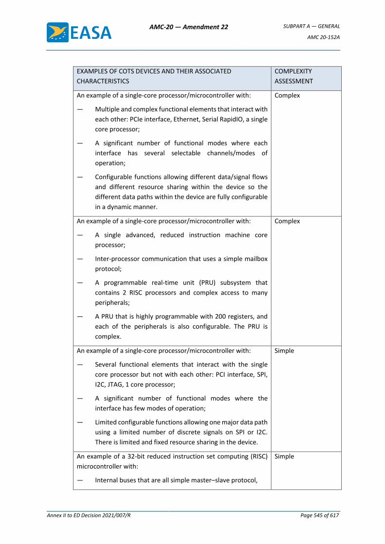
AMC-20 — Amendment 22 SUBPART A — GENERAL
AMC 20-152A
Annex II to ED Decision 2021/007/R Page 545 of 617
EXAMPLES OF COTS DEVICES AND THEIR ASSOCIATED
CHARACTERISTICS
COMPLEXITY
ASSESSMENT
An example of a single-core processor/microcontroller with:
— Multiple and complex functional elements that interact with
each other: PCIe interface, Ethernet, Serial RapidIO, a single
core processor;
— A significant number of functional modes where each
interface has several selectable channels/modes of
operation;
— Configurable functions allowing different data/signal flows
and different resource sharing within the device so the
different data paths within the device are fully configurable
in a dynamic manner.
Complex
An example of a single-core processor/microcontroller with:
— A single advanced, reduced instruction machine core
processor;
— Inter-processor communication that uses a simple mailbox
protocol;
— A programmable real-time unit (PRU) subsystem that
contains 2 RISC processors and complex access to many
peripherals;
— A PRU that is highly programmable with 200 registers, and
each of the peripherals is also configurable. The PRU is
complex.
Complex
An example of a single-core processor/microcontroller with:
— Several functional elements that interact with the single
core processor but not with each other: PCI interface, SPI,
I2C, JTAG, 1 core processor;
— A significant number of functional modes where the
interface has few modes of operation;
— Limited configurable functions allowing one major data path
using a limited number of discrete signals on SPI or I2C.
There is limited and fixed resource sharing in the device.
Simple
An example of a 32-bit reduced instruction set computing (RISC)
microcontroller with:
— Internal buses that are all simple master–slave protocol,
Simple
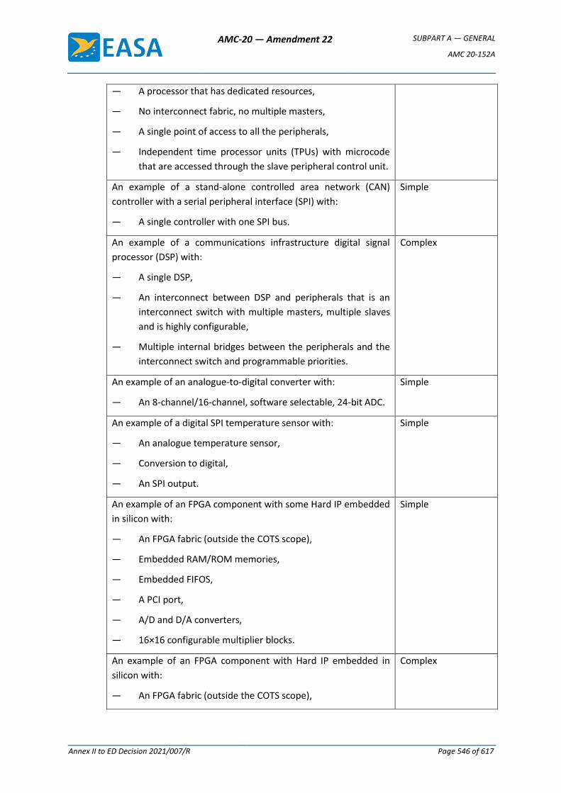
AMC-20 — Amendment 22 SUBPART A — GENERAL
AMC 20-152A
Annex II to ED Decision 2021/007/R Page 546 of 617
— A processor that has dedicated resources,
— No interconnect fabric, no multiple masters,
— A single point of access to all the peripherals,
— Independent time processor units (TPUs) with microcode
that are accessed through the slave peripheral control unit.
An example of a stand-alone controlled area network (CAN)
controller with a serial peripheral interface (SPI) with:
— A single controller with one SPI bus.
Simple
An example of a communications infrastructure digital signal
processor (DSP) with:
— A single DSP,
— An interconnect between DSP and peripherals that is an
interconnect switch with multiple masters, multiple slaves
and is highly configurable,
— Multiple internal bridges between the peripherals and the
interconnect switch and programmable priorities.
Complex
An example of an analogue-to-digital converter with:
— An 8-channel/16-channel, software selectable, 24-bit ADC.
Simple
An example of a digital SPI temperature sensor with:
— An analogue temperature sensor,
— Conversion to digital,
— An SPI output.
Simple
An example of an FPGA component with some Hard IP embedded
in silicon with:
— An FPGA fabric (outside the COTS scope),
— Embedded RAM/ROM memories,
— Embedded FIFOS,
— A PCI port,
— A/D and D/A converters,
— 16×16 configurable multiplier blocks.
Simple
An example of an FPGA component with Hard IP embedded in
silicon with:
— An FPGA fabric (outside the COTS scope),
Complex
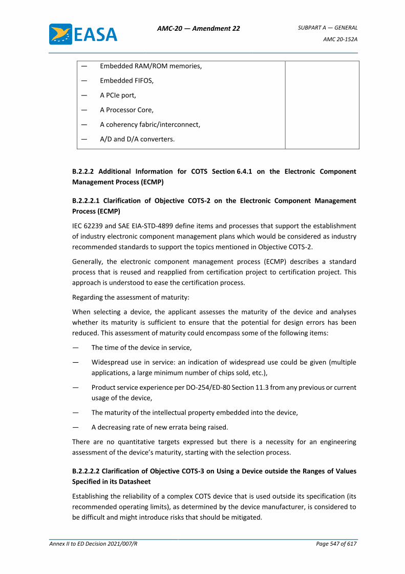
AMC-20 — Amendment 22 SUBPART A — GENERAL
AMC 20-152A
Annex II to ED Decision 2021/007/R Page 547 of 617
— Embedded RAM/ROM memories,
— Embedded FIFOS,
— A PCIe port,
— A Processor Core,
— A coherency fabric/interconnect,
— A/D and D/A converters.
B.2.2.2 Additional Information for COTS Section 6.4.1 on the Electronic Component
Management Process (ECMP)
B.2.2.2.1 Clarification of Objective COTS-2 on the Electronic Component Management
Process (ECMP)
IEC 62239 and SAE EIA-STD-4899 define items and processes that support the establishment
of industry electronic component management plans which would be considered as industry
recommended standards to support the topics mentioned in Objective COTS-2.
Generally, the electronic component management process (ECMP) describes a standard
process that is reused and reapplied from certification project to certification project. This
approach is understood to ease the certification process.
Regarding the assessment of maturity:
When selecting a device, the applicant assesses the maturity of the device and analyses
whether its maturity is sufficient to ensure that the potential for design errors has been
reduced. This assessment of maturity could encompass some of the following items:
— The time of the device in service,
— Widespread use in service: an indication of widespread use could be given (multiple
applications, a large minimum number of chips sold, etc.),
— Product service experience per DO-254/ED-80 Section 11.3 from any previous or current
usage of the device,
— The maturity of the intellectual property embedded into the device,
— A decreasing rate of new errata being raised.
There are no quantitative targets expressed but there is a necessity for an engineering
assessment of the device’s maturity, starting with the selection process.
B.2.2.2.2 Clarification of Objective COTS-3 on Using a Device outside the Ranges of Values
Specified in its Datasheet
Establishing the reliability of a complex COTS device that is used outside its specification (its
recommended operating limits), as determined by the device manufacturer, is considered to
be difficult and might introduce risks that should be mitigated.
AMC-20 — Amendment 22 SUBPART A — GENERAL
AMC 20-152A
Annex II to ED Decision 2021/007/R Page 548 of 617
One process to qualify the device, called an ‘uprating’ process, could be applied to verify the
appropriate operation of the device itself and to guarantee that performance is achieved in
the target environment in all operating conditions over the lifetime of the equipment. This
uprating process focuses on the device itself and takes into account the different variations in
technology (variation in performance over different batches/over different dies). This uprating
process evaluates the performance of the device itself, so it is different from ED-14/DO-160
environmental qualification of equipment.
Thermal uprating is addressed in IEC/TR 62240-1. ‘It provides information to select
semiconductor devices, to assess their capability to operate, and to assure their intended
quality in the wider temperature range. It also reports the need for documentation of such
usage.’
It is understood that each case of uprating might follow a different process depending on the
‘uprated’ characteristics (the frequency, temperature, voltage, etc.) and the performance
guaranteed by the device manufacturer’s datasheet. For that reason, Objective COTS-3 is
separated from Objective COTS-2 and is only to be applied in cases of COTS device uprating.
IEC/TR 62240-1 states the following: ‘For each instance of device usage outside the
manufacturer's specified temperature range relevant data are documented and stored in a
controlled, retrievable format.’ This is considered to be a best practice for any uprating case
as evidence satisfying Objective COTS-3.
Note: When a simple COTS device is used outside its datasheet values, applying an uprating
process would be considered to be a best practice to ensure that the device functions properly
within the newly defined and intended environment/usage conditions.
B.2.2.3 Additional Information for Section 6.4.2 ‘COTS Device Malfunctions’
The applicant needs access to errata information on the device during the entire life cycle of
the product (before and after certification). Refer to AMC, Section 6.4.1.
In general, this assessment typically includes the analysis of which errata are, or are not,
applicable to the specific installation of the equipment, and for each of the applicable errata:
— The description of the mitigation implemented, and
— The evidence that the implementation of errata mitigations are covered by relevant
requirements, design data, and are verified.
The assessment of the errata of a simple COTS device is considered a best practice to remove
the safety risks associated with device malfunctions.
While the applicant is expected to document the process applied for errata in the PHAC, the
errata and evidence of assessment would typically be captured in other documents that can
be referred to in the PHAC and HAS.
B.2.2.4 Additional Information for Objective COTS-6 on COTS Device Malfunctions
It is understood that the task linked with this objective is performed in close coordination with
the hardware, software, and system teams.

AMC-20 — Amendment 22 SUBPART A — GENERAL
AMC 20-152A
Annex II to ED Decision 2021/007/R Page 549 of 617
In order to support the safety analysis process, this objective focuses on the failure effects and
not on their root causes. The hardware domain, knowing the detailed usage of the device,
starts by identifying the effects of failures of the device on the intended functions. This
information will be provided to the system safety process. When necessary, mitigation means
will be defined and verified by the appropriate domain or across the hardware, software, and
system domains.
While the applicant is expected to document the process to satisfy Objective COTS-6 in the
PHAC, the evidence would typically be captured in other documents that can be referred to in
the PHAC and ultimately in the HAS.
When a simple COTS device interfaces with software, complying with Objective COTS-6 is
considered to be a best practice.
B.2.3 Clarification of Objective CBA-1 on Circuit Board Assembly Development
In the aviation domain, the applicant typically has internal processes to develop circuit board
assemblies. There is a clear benefit for the applicant (or developer of the airborne system and
equipment) in having a process to address the development of a circuit board assembly (a
board or a collection of boards) that encompasses the requirements capture, validation,
verification, and configuration management activities, and ensures an appropriate
requirements flow-down.
It is a common practice for the applicant’s internal process to already encompass the
above-mentioned activities that satisfy Objective CBA-1. Industry standards ED-80/DO-254 or
ED-79A/ARP4754A provide guidance that may be used by applicants seeking further
information.
Note 1: The applicant’s internal processes might be tailored according to the equipment and
hardware complexity if necessary.
Note 2: The organisation of the process life-cycle data is at the discretion of the applicant’s
internal process.
Note 3: The hardware requirements may be verified at a higher level of integration.
B.2.4 Development of Airborne Electronic Hardware Contributing to Hardware DAL D
Functions
For airborne electronic hardware contributing to hardware DAL D functions, the acceptable
means of compliance include ED-80/DO-254 or existing Level D hardware development
assurance practices that demonstrate that the requirements allocated to the DAL D airborne
electronic hardware have been satisfied. Additionally, system-level development assurance
practices such as ED-79A/ARP4754A or other means may be used if the applicant can
demonstrate at the system level that the requirements allocated to the DAL D airborne
electronic hardware have been satisfied.
AMC-20 — Amendment 22 SUBPART A — GENERAL
AMC 20-152A
Annex II to ED Decision 2021/007/R Page 550 of 617
Appendix C — Glossary of Guidance Material This glossary complements the terms defined in AMC 20-152A with terms used only in this
GM.
Uprating: A process to assess the capability of a COTS device to meet the performance
requirements of the application in which the device is used outside the manufacturer’s
datasheet ranges (definition adapted from the IEC/TR 62240-1 Thermal uprating definition).
[Amdt 20/19]
AMC-20 — Amendment 22 SUBPART A — GENERAL
AMC 20-158
Annex II to ED Decision 2021/007/R Page 551 of 617
AMC 20-158
AMC 20-158 Aircraft Electrical and Electronic System High-Intensity Radiated Fields (HIRF) Protection
1. PURPOSE
a. This Acceptable Means of Compliance (AMC) provides the means and Guidance Material (GM) related to High-Intensity Radiated Fields (HIRF) protection and the demonstration of compliance with the Certification Specifications CS 23.1308, CS 25.1317, CS 27.1317, and CS 29.1317.
b. This AMC is not mandatory and does not constitute a regulation. It describes an acceptable means, but not the only means, to demonstrate compliance with the requirements for the protection of the operation of electrical and electronic systems on an aircraft when the aircraft is exposed to an external HIRF environment. In using the means described in this AMC, they must be followed in all important respects.
2. SCOPE
This AMC applies to all applicants for a new Type Certificate (TC) or a change to an existing TC when the certification basis requires the address of the HIRF certification requirements of CS 23.1308, CS 25.1317, CS 27.1317, and CS 29.1317.
3. RELATED MATERIAL
a. European Aviation Safety Agency (EASA) (in this document also referred to as the ‘Agency’)
Certification Specifications:
CS 23.1308, CS 25.1317, CS 27.1317, and CS 29.1317, High-intensity Radiated Fields (HIRF) protection;
CS 23.1309, CS 25.1309, CS 27.1309, and CS 29.1309, Equipment, systems, and installations; and
CS 23.1529, CS 25.1529, CS 27.1529, and CS 29.1529, Instructions for Continued Airworthiness.
Copies of these CSs can be requested from the European Aviation Safety Agency, Postfach 10 12 53, D-50452 Cologne, Germany; Telephone +49 221 8999 000; Fax: +49 221 8999 099; Website: http://easa.europa.eu/official-publication/
b. Title 14 of the Code of Federal Regulations (14 CFR)
Sections:
§§ 23.1308, 25.1317, 27.1317, and 29.1317, High-intensity Radiated Fields (HIRF) protection;
§§ 23.1309, 25.1309, 27.1309, and 29.1309, Equipment, systems, and installations; and
§§ 23.1529, 25.1529, 27.1529, and 29.1529, Instructions for Continued Airworthiness.
Copies of the above 14 CFR sections can be requested from the Superintendent of Documents, Government Printing Office, Washington, D.C. 20402-9325, telephone 202-
AMC-20 — Amendment 22 SUBPART A — GENERAL
AMC 20-158
Annex II to ED Decision 2021/007/R Page 552 of 617
512-1800, fax 202-512-2250. Copies can also be requested from the Government Printing Office (GPO), electronic CFR Internet website at http://www.gpoaccess.gov/cfr/.
c. FAA Advisory Circulars (ACs)
AC 20-158A, The Certification of Aircraft Electrical and Electronic Systems for Operation in the High-Intensity Radiated Fields (HIRF) Environment.
AC 23.1309-1E, System Safety Analysis and Assessment for Part 23 Airplanes; and AC 25.1309-1A, SystemDesign and Analysis.
Copies of these ACs can be requested from the U.S. Department of Transportation, Subsequent Distribution Office, DOT Warehouse M30, Ardmore East Business Center, 3341 Q 75th Avenue, Landover, MD 20785; telephone +1 301 322 5377. These ACs can also be accessed via the FAA website: http://www.faa.gov/regulations_policies/advisory_circulars/.
d. European Organization for Civil Aviation Equipment (EUROCAE). Copies of these documents can be requested from EUROCAE, 102 rue Etienne Dolet, 92240 Malakoff, France; Telephone: +33 1 40 92 79 30; Fax: +33 1 46 55 62 65; Website: http://www.eurocae.net.
1. EUROCAE ED-107A, Guide to Certification of Aircraft in a High Intensity Radiated Field (HIRF) Environment. ED-107A and SAE ARP 5583A, referenced in paragraph 3.f.1. below, are technically equivalent and either document may serve as the ‘User’s Guide’ referred to in this AMC.
2. EUROCAE ED-14G, Environmental Conditions and Test Procedures for Airborne Equipment. This document is technically equivalent to RTCA/DO-160G. Whenever there is a reference to RTCA/DO-160G in this AMC, EUROCAE ED-14G may also be used.
3. EUROCAE ED-79A, Guidelines for Development of Civil Aircraft and Systems. This document is technically equivalent to ARP 4754A. Whenever there is a reference to ARP 4754A in this AMC, EUROCAE ED-79A may also be used.
e. Radio Technical Commission for Aeronautics (RTCA).
RTCA/DO-160G, Environmental Conditions and Test Procedures for Airborne Equipment. This document is technically equivalent to EUROCAE ED-14G.
Copies of this document can be requested from RTCA, Inc., 1828 L Street NW, Suite 805, Washington, DC 20036; Telephone: +1 202 833 9339; Website: http://www.rtca.org.
f. Society of Automotive Engineers (SAE International). Copies of the below documents can be requested from SAE World Headquarters, 400 Commonwealth Drive, Warrendale, Pennsylvania 15096-0001; Telephone: +1 724 776 4970; Website: http://www.sae.org.
1. SAE Aerospace Recommended Practice (ARP) 5583A, Guide to Certification of Aircraft in a High Intensity Radiated Field (HIRF) Environment. SAE ARP 5583A and ED-107A, referenced in paragraph 3.d.1. above, are technically equivalent and either document may serve as the ‘User’s Guide’ referred to in this AMC.
2. SAE ARP 4754A, Guidelines For Development Of Civil Aircraft And Systems, December 2010.
3. SAE ARP 4761, Guidelines and Methods for Conducting the Safety Assessment Process on Civil Airborne Systems and Equipment, December 1996.
AMC-20 — Amendment 22 SUBPART A — GENERAL
AMC 20-158
Annex II to ED Decision 2021/007/R Page 553 of 617
4. BACKGROUND
a. Aircraft protection. Concern for the protection of aircraft electrical and electronic systems has increased substantially in recent years because of:
1. greater dependence on electrical and electronic systems performing functions required for continued safe flight and landing of an aircraft;
2. reduced electromagnetic shielding afforded by some composite materials used in aircraft designs;
3. increased susceptibility of electrical and electronic systems to HIRF because of increased data bus and processor operating speeds, higher density integrated circuits and cards, and greater sensitivities of electronic equipment;
4. expanded frequency usage, especially above 1 gigahertz (GHz);
5. increased severity of the HIRF environment because of an increase in the number and radiated power of Radio Frequency (RF) transmitters; and
6. adverse effects experienced by some aircraft when exposed to HIRF.
b. HIRF environment. The electromagnetic HIRF environment exists because of the transmission of electromagnetic RF energy from radar, radio, television, and other ground-based, shipborne, or airborne RF transmitters. The User’s Guide (EUROCAE ED-107A) provides a detailed description of the derivation of these HIRF environments.
5. DEFINITIONS
Adverse effect: HIRF effect that results in system failure, malfunction, or misleading information to a degree that is unacceptable for the specific aircraft function or system addressed in the HIRF regulations. A determination of whether a system or function is adversely affected should consider the HIRF effect in relation to the overall aircraft and its operation.
Attenuation: Term used to denote a decrease in electromagnetic field strength in transmission from one point to another. Attenuation may be expressed as a scalar ratio of the input magnitude to the output magnitude or in decibels (dB).
Bulk Current Injection (BCI): Method of Electromagnetic Interference (EMI) testing that involves injecting current into wire bundles through a current injection probe.
Continued safe flight and landing: The aircraft can safely abort or continue a take-off, or continue controlled flight and landing, possibly using emergency procedures. The aircraft must do this without requiring exceptional pilot skill or strength. Some aircraft damage may occur because of the failure condition or on landing. For large aeroplanes, the pilot must be able to land safely at a suitable airport. For CS-23 aeroplanes, it is not necessary to land at an airport. For rotorcraft, the rotorcraft must continue to cope with adverse operating conditions, and the pilot must be able to land safely at a suitable site.
Continuous Wave (CW): RF signal consisting of only the fundamental frequency with no modulation in amplitude, frequency, or phase.
Coupling: Process whereby electromagnetic energy is induced in a system by radiation produced by a Radio Frequency (RF) source.
Current injection probe: Inductive device designed to inject RF signals directly into wire bundles when clamped around them.
Direct drive test: Electromagnetic Interference (EMI) test that involves electrically connecting a signal source directly to the unit being tested.
AMC-20 — Amendment 22 SUBPART A — GENERAL
AMC 20-158
Annex II to ED Decision 2021/007/R Page 554 of 617
Equipment: Component of an electrical or electronic system with interconnecting electrical conductors.
Equipment electrical interface: Location on a piece of equipment where an electrical connection is made to the other equipment in a system of which it is a part. The electrical interface may consist of individual wires or wire bundles that connect the equipment.
External High-Intensity Radiated Fields (HIRF) environment: Electromagnetic RF fields at the exterior of an aircraft.
Field strength: Magnitude of the electromagnetic energy propagating in free space expressed in volts per meter (V/m).
High-Intensity Radiated Fields (HIRF) environment: Electromagnetic environment that exists from the transmission of high power RF energy into free space.
HIRF vulnerability: Susceptibility characteristics of a system that cause it to suffer adverse effects when performing its intended function as a result of having been subjected to an HIRF environment.
Immunity: Capacity of a system or piece of equipment to continue to perform its intended function, in an acceptable manner, in the presence of RF fields.
Interface circuit: Electrical or electronic device connecting the electrical inputs and outputs of equipment to other equipment or devices in an aircraft.
Internal HIRF environment: The RF environment inside an airframe, equipment enclosure, or cavity. The internal RF environment is described in terms of the internal RF field strength or wire bundle current.
Margin: Difference between equipment susceptibility or qualification levels and the aircraft internal HIRF environment. Margin requirements may be specified to account for uncertainties in design, analysis, or test.
Modulation: Process whereby certain characteristics of a wave, often called the carrier wave, are varied in accordance with an applied function.
Radio Frequency (RF): Frequency useful for radio transmission. The present practical limits of RF transmissions are approximately 10 kilohertz (kHz) to 100 gigahertz (GHz). Within this frequency range, electromagnetic energy may be detected and amplified as an electric current at the wave frequency.
Reflection plane: Conducting plate that reflects RF signals.
Similarity: Process of using existing HIRF compliance documentation and data from a system or aircraft to demonstrate HIRF compliance for a nearly identical system or aircraft of equivalent design, construction, and installation.
Susceptibility: Property of a piece of equipment that describes its inability to function acceptably when subjected to unwanted electromagnetic energy.
Susceptibility level: Level where the effects of interference from electromagnetic energy become apparent.
System: Piece of equipment connected via electrical conductors to another piece of equipment, both of which are required to make a system function. A system may contain pieces of equipment, components, parts, and wire bundles.
AMC-20 — Amendment 22 SUBPART A — GENERAL
AMC 20-158
Annex II to ED Decision 2021/007/R Page 555 of 617
Transfer function: Ratio of the electrical output of a system to the electrical input of a system, expressed in the frequency domain. For HIRF, a typical transfer function is the ratio of the current on a wire bundle to the external HIRF field strength, as a function of frequency.
Upset: Impairment of system operation, either permanent or momentary. For example, a change of digital or analogue state that may or may not require a manual reset.
User’s Guide: Refers to SAE document ARP 5583A or EUROCAE document ED-107A.
6. APPROACHES TO COMPLIANCE
a. General. The following activities should be elements of a proper HIRF certification programme. The iterative application of these activities is left to the applicant. Adherence to the sequence shown is not necessary. The applicant should:
1. identify the systems to be assessed;
2. establish the applicable aircraft external HIRF environment;
3. establish the test environment for installed systems;
4. apply the appropriate method of HIRF compliance verification; and
5. verify HIRF protection effectiveness.
b. Identify the systems to be assessed
1. General. The aircraft systems that require HIRF assessment must be identified. The process used for identifying these systems should be similar to the process for demonstrating compliance with CS 23.1309, CS 25.1309, CS 27.1309, and CS 29.1309, as applicable. These sections address any system failure that may cause or contribute to an effect on the safety of flight of an aircraft. The effects of an encounter with HIRF, therefore, should be assessed in a manner that allows for the determination of the degree to which the aircraft and its systems’ safety may be influenced. The operation of the aircraft systems should be assessed separately and in combination with, or in relation to, other systems. This assessment should cover:
a. all normal aircraft operating modes, phases of flight, and operating conditions;
b. all failure conditions and their subsequent effect on aircraft operations and the flight crew; and
c. any corrective actions required.
2. Safety assessment. A safety assessment related to HIRF must be performed to establish and classify the equipment or system failure condition. Table 1 provides the corresponding failure condition classification and system HIRF certification level for the appropriate HIRF regulations. The failure condition classifications and terms used in this AMC are similar to those used in AC 23.1309-1E and AMC 25.1309, as applicable. Only those systems identified as performing or contributing to functions the failure of which would result in Catastrophic, Hazardous, or Major failure conditions are subject to HIRF regulations. Based on the failure condition classification established by the safety assessment, the systems should be assigned appropriate HIRF certification levels, as shown in Table 1. The safety assessment should consider the common cause effects of HIRF, particularly for highly integrated systems and systems with redundant elements. Further guidance on
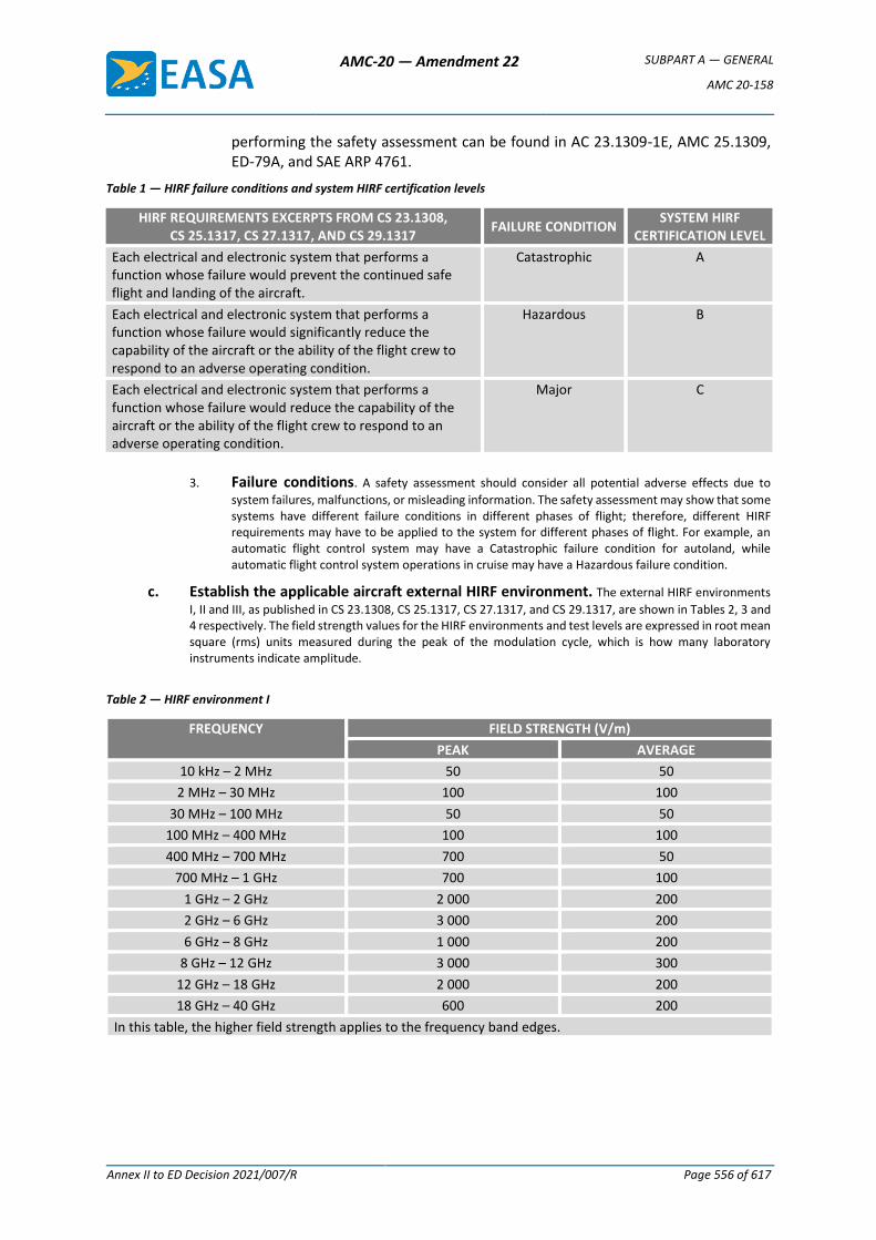
AMC-20 — Amendment 22 SUBPART A — GENERAL
AMC 20-158
Annex II to ED Decision 2021/007/R Page 556 of 617
performing the safety assessment can be found in AC 23.1309-1E, AMC 25.1309, ED-79A, and SAE ARP 4761.
Table 1 — HIRF failure conditions and system HIRF certification levels
HIRF REQUIREMENTS EXCERPTS FROM CS 23.1308, CS 25.1317, CS 27.1317, AND CS 29.1317
FAILURE CONDITION SYSTEM HIRF
CERTIFICATION LEVEL
Each electrical and electronic system that performs a function whose failure would prevent the continued safe flight and landing of the aircraft.
Catastrophic A
Each electrical and electronic system that performs a function whose failure would significantly reduce the capability of the aircraft or the ability of the flight crew to respond to an adverse operating condition.
Hazardous B
Each electrical and electronic system that performs a function whose failure would reduce the capability of the aircraft or the ability of the flight crew to respond to an adverse operating condition.
Major C
3. Failure conditions. A safety assessment should consider all potential adverse effects due to
system failures, malfunctions, or misleading information. The safety assessment may show that some systems have different failure conditions in different phases of flight; therefore, different HIRF requirements may have to be applied to the system for different phases of flight. For example, an automatic flight control system may have a Catastrophic failure condition for autoland, while automatic flight control system operations in cruise may have a Hazardous failure condition.
c. Establish the applicable aircraft external HIRF environment. The external HIRF environments
I, II and III, as published in CS 23.1308, CS 25.1317, CS 27.1317, and CS 29.1317, are shown in Tables 2, 3 and 4 respectively. The field strength values for the HIRF environments and test levels are expressed in root mean square (rms) units measured during the peak of the modulation cycle, which is how many laboratory instruments indicate amplitude.
Table 2 — HIRF environment I
FREQUENCY FIELD STRENGTH (V/m)
PEAK AVERAGE
10 kHz – 2 MHz 50 50
2 MHz – 30 MHz 100 100
30 MHz – 100 MHz 50 50
100 MHz – 400 MHz 100 100
400 MHz – 700 MHz 700 50
700 MHz – 1 GHz 700 100
1 GHz – 2 GHz 2 000 200
2 GHz – 6 GHz 3 000 200
6 GHz – 8 GHz 1 000 200
8 GHz – 12 GHz 3 000 300
12 GHz – 18 GHz 2 000 200
18 GHz – 40 GHz 600 200
In this table, the higher field strength applies to the frequency band edges.
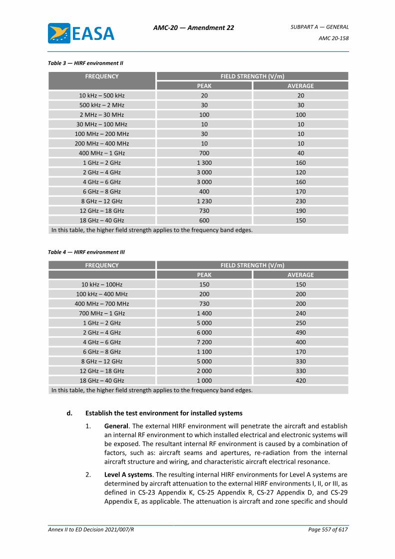
AMC-20 — Amendment 22 SUBPART A — GENERAL
AMC 20-158
Annex II to ED Decision 2021/007/R Page 557 of 617
Table 3 — HIRF environment II
FREQUENCY FIELD STRENGTH (V/m)
PEAK AVERAGE
10 kHz – 500 kHz 20 20
500 kHz – 2 MHz 30 30
2 MHz – 30 MHz 100 100
30 MHz – 100 MHz 10 10
100 MHz – 200 MHz 30 10
200 MHz – 400 MHz 10 10
400 MHz – 1 GHz 700 40
1 GHz – 2 GHz 1 300 160
2 GHz – 4 GHz 3 000 120
4 GHz – 6 GHz 3 000 160
6 GHz – 8 GHz 400 170
8 GHz – 12 GHz 1 230 230
12 GHz – 18 GHz 730 190
18 GHz – 40 GHz 600 150
In this table, the higher field strength applies to the frequency band edges.
Table 4 — HIRF environment III
FREQUENCY FIELD STRENGTH (V/m)
PEAK AVERAGE
10 kHz – 100Hz 150 150
100 kHz – 400 MHz 200 200
400 MHz – 700 MHz 730 200
700 MHz – 1 GHz 1 400 240
1 GHz – 2 GHz 5 000 250
2 GHz – 4 GHz 6 000 490
4 GHz – 6 GHz 7 200 400
6 GHz – 8 GHz 1 100 170
8 GHz – 12 GHz 5 000 330
12 GHz – 18 GHz 2 000 330
18 GHz – 40 GHz 1 000 420
In this table, the higher field strength applies to the frequency band edges.
d. Establish the test environment for installed systems
1. General. The external HIRF environment will penetrate the aircraft and establish an internal RF environment to which installed electrical and electronic systems will be exposed. The resultant internal RF environment is caused by a combination of factors, such as: aircraft seams and apertures, re-radiation from the internal aircraft structure and wiring, and characteristic aircraft electrical resonance.
2. Level A systems. The resulting internal HIRF environments for Level A systems are determined by aircraft attenuation to the external HIRF environments I, II, or III, as defined in CS-23 Appendix K, CS-25 Appendix R, CS-27 Appendix D, and CS-29 Appendix E, as applicable. The attenuation is aircraft and zone specific and should
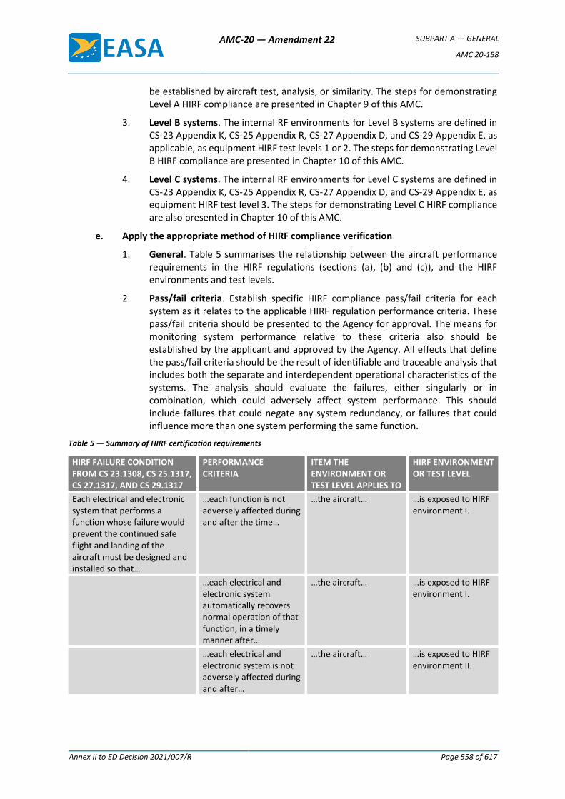
AMC-20 — Amendment 22 SUBPART A — GENERAL
AMC 20-158
Annex II to ED Decision 2021/007/R Page 558 of 617
be established by aircraft test, analysis, or similarity. The steps for demonstrating Level A HIRF compliance are presented in Chapter 9 of this AMC.
3. Level B systems. The internal RF environments for Level B systems are defined in CS-23 Appendix K, CS-25 Appendix R, CS-27 Appendix D, and CS-29 Appendix E, as applicable, as equipment HIRF test levels 1 or 2. The steps for demonstrating Level B HIRF compliance are presented in Chapter 10 of this AMC.
4. Level C systems. The internal RF environments for Level C systems are defined in CS-23 Appendix K, CS-25 Appendix R, CS-27 Appendix D, and CS-29 Appendix E, as equipment HIRF test level 3. The steps for demonstrating Level C HIRF compliance are also presented in Chapter 10 of this AMC.
e. Apply the appropriate method of HIRF compliance verification
1. General. Table 5 summarises the relationship between the aircraft performance requirements in the HIRF regulations (sections (a), (b) and (c)), and the HIRF environments and test levels.
2. Pass/fail criteria. Establish specific HIRF compliance pass/fail criteria for each system as it relates to the applicable HIRF regulation performance criteria. These pass/fail criteria should be presented to the Agency for approval. The means for monitoring system performance relative to these criteria also should be established by the applicant and approved by the Agency. All effects that define the pass/fail criteria should be the result of identifiable and traceable analysis that includes both the separate and interdependent operational characteristics of the systems. The analysis should evaluate the failures, either singularly or in combination, which could adversely affect system performance. This should include failures that could negate any system redundancy, or failures that could influence more than one system performing the same function.
Table 5 — Summary of HIRF certification requirements
HIRF FAILURE CONDITION FROM CS 23.1308, CS 25.1317, CS 27.1317, AND CS 29.1317
PERFORMANCE CRITERIA
ITEM THE ENVIRONMENT OR TEST LEVEL APPLIES TO
HIRF ENVIRONMENT OR TEST LEVEL
Each electrical and electronic system that performs a function whose failure would prevent the continued safe flight and landing of the aircraft must be designed and installed so that…
…each function is not adversely affected during and after the time…
…the aircraft… …is exposed to HIRF environment I.
…each electrical and electronic system automatically recovers normal operation of that function, in a timely manner after…
…the aircraft… …is exposed to HIRF environment I.
…each electrical and electronic system is not adversely affected during and after…
…the aircraft… …is exposed to HIRF environment II.
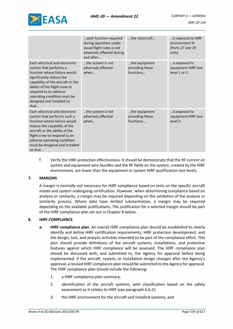
AMC-20 — Amendment 22 SUBPART A — GENERAL
AMC 20-158
Annex II to ED Decision 2021/007/R Page 559 of 617
…each function required during operation under visual flight rules is not adversely affected during and after…
…the rotorcraft… …is exposed to HIRF environment III (Parts 27 and 29 only).
Each electrical and electronic system that performs a function whose failure would significantly reduce the capability of the aircraft or the ability of the flight crew to respond to an adverse operating condition must be designed and installed so that…
…the system is not adversely affected when…
…the equipment providing these functions…
…is exposed to equipment HIRF test level 1 or 2.
Each electrical and electronic system that performs such a function whose failure would reduce the capability of the aircraft or the ability of the flight crew to respond to an adverse operating condition must be designed and installed so that…
…the system is not adversely affected when…
…the equipment providing these functions…
…is exposed to equipment HIRF test level 3.
f. Verify the HIRF protection effectiveness. It should be demonstrate that the RF current on system and equipment wire bundles and the RF fields on the system, created by the HIRF environment, are lower than the equipment or system HIRF qualification test levels.
7. MARGINS
A margin is normally not necessary for HIRF compliance based on tests on the specific aircraft model and system undergoing certification. However, when determining compliance based on analysis or similarity, a margin may be required depending on the validation of the analysis or similarity process. Where data have limited substantiation, a margin may be required depending on the available justifications. The justification for a selected margin should be part of the HIRF compliance plan set out in Chapter 8 below.
8. HIRF COMPLIANCE
a. HIRF compliance plan. An overall HIRF compliance plan should be established to clearly identify and define HIRF certification requirements, HIRF protection development, and the design, test, and analysis activities intended to be part of the compliance effort. This plan should provide definitions of the aircraft systems, installations, and protective features against which HIRF compliance will be assessed. The HIRF compliance plan should be discussed with, and submitted to, the Agency for approval before being implemented. If the aircraft, system, or installation design changes after the Agency’s approval, a revised HIRF compliance plan should be submitted to the Agency for approval. The HIRF compliance plan should include the following:
1. a HIRF compliance plan summary;
2. identification of the aircraft systems, with classification based on the safety assessment as it relates to HIRF (see paragraph 6.b.2);
3. the HIRF environment for the aircraft and installed systems; and
AMC-20 — Amendment 22 SUBPART A — GENERAL
AMC 20-158
Annex II to ED Decision 2021/007/R Page 560 of 617
4. the verification methods, such as test, analysis, or similarity.
b. HIRF verification test, analysis, or similarity plan. Specific HIRF test, analysis, or similarity plans should be prepared to describe specific verification activities. One or more verification plans may be necessary. For example, there may be several systems or equipment laboratory test plans, an aircraft test plan, or a similarity plan for selected systems on an aircraft.
1. Test plan
a. A HIRF verification test plan should include the equipment, system, and aircraft test objectives for the acquisition of data to support HIRF compliance. The plan should provide an overview of the factors being addressed for each system test requirement. The test plan should include:
1. the purpose of the test;
2. a description of the aircraft and/or system being tested;
3. system configuration drawings;
4. the proposed test set-up and methods;
5. intended test levels, modulations, and frequency bands;
6. pass/fail criteria; and
7. the test schedule and test location.
b. The test plan should cover Level A, B, and C systems and equipment, as appropriate. Level A systems may require both integrated systems laboratory tests and aircraft tests. Level B and Level C systems and equipment require only equipment laboratory testing.
c. The test plan should describe the appropriate aspects of the systems to be tested and their installation. Additionally, the test plan should reflect the results of any analysis performed in the overall process of the HIRF compliance evaluation.
2. Analysis plan. A HIRF compliance analysis plan should include the objectives, both at the system and equipment level, for generating data to support HIRF compliance verification. Comprehensive modelling and analysis for RF field coupling to aircraft systems and structures is an emerging technology; therefore, the analysis plan should be coordinated with the Agency to determine an acceptable scope for the analysis. The analysis plan should include:
a. the purpose and scope of the analysis;
b. a description of the aircraft and/or system addressed by the analysis;
c. system configuration descriptions;
d. proposed analysis methods;
e. the approach for validating the analysis results; and
f. pass/fail criteria, including margins to account for analysis uncertainty.
3. Similarity plan. A similarity plan should describe the approach taken in using certification data from previously certified systems, equipment, and aircraft. The similarity plan should include:
AMC-20 — Amendment 22 SUBPART A — GENERAL
AMC 20-158
Annex II to ED Decision 2021/007/R Page 561 of 617
a. the purpose and scope of the similarity assessment;
b. specific systems addressed by the similarity assessment;
c. data that will be used from the previously certified systems, equipment, and aircraft; and
d. any significant differences between the aircraft and system installation proposed for certification and the aircraft and system installation from which the data will be used. Include appropriate margins to account for similarity uncertainty.
c. Compliance reports. One or more compliance reports may be necessary to document the results of test, analysis, or similarity assessments. For new or significantly modified aircraft, HIRF compliance reports may include many system and equipment test reports, aircraft test reports, and HIRF analysis reports. For these types of HIRF certification programmes, a compliance summary report may be useful to summarise the results of tests and analyses. For HIRF certification programmes on relatively simple systems, a single compliance report may be adequate.
1. Test reports. Comprehensive test reports should be produced at the conclusion of HIRF compliance testing. The test reports should include descriptions of the salient aspects of equipment or system performance during the test, details of any area of non-compliance with HIRF requirements, actions taken to correct the non-compliance, and any similarity declarations. Supporting rationale for any deviations from system performance observed during testing should also be provided.
2. Analysis reports. Analysis reports should describe the details of the analytical model, the methods used to perform the analysis, and the results of the analysis. The reports should identify any modelling uncertainty and justify the margins established in the analysis plan.
3. Similarity reports. Similarity reports should document the significant aircraft, system, equipment, and installation features common between the aircraft or system that is the subject of the similarity analysis and the aircraft or system that previously was certified for HIRF. Identify all significant differences encountered, along with the assessment of the impact of these differences on HIRF compliance. These reports should also justify the margins established in the similarity plan.
d. Methods of compliance verification
1. Various methods are available to aid in demonstrating HIRF compliance. Methods acceptable to the Agency are described in Chapters 9 and 10. Figures 1 and 2 below outline the steps to demonstrate HIRF compliance for systems requiring Level A HIRF certification. Figure 3 below outlines the steps to demonstrate HIRF compliance for systems requiring Level B or C HIRF certification. The steps in these figures are not necessarily accomplished sequentially. Wherever a decision point is indicated on these figures, the applicant should complete the steps in that path as described in Chapters 9 and 10.
2. Other HIRF compliance techniques may be used to demonstrate system performance in the HIRF environment; however, those techniques should be approved by the Agency before using them.
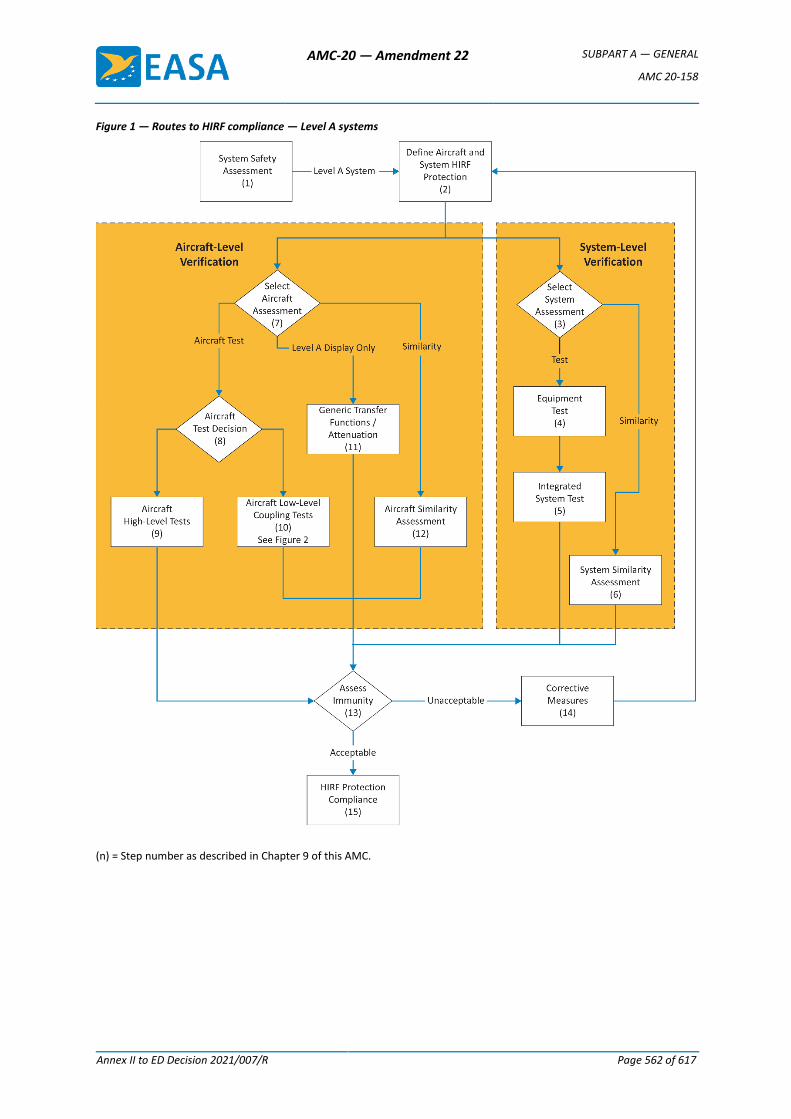
AMC-20 — Amendment 22 SUBPART A — GENERAL
AMC 20-158
Annex II to ED Decision 2021/007/R Page 562 of 617
Figure 1 — Routes to HIRF compliance — Level A systems
(n) = Step number as described in Chapter 9 of this AMC.
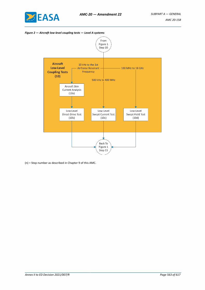
AMC-20 — Amendment 22 SUBPART A — GENERAL
AMC 20-158
Annex II to ED Decision 2021/007/R Page 563 of 617
Figure 2 — Aircraft low-level coupling tests — Level A systems
(n) = Step number as described in Chapter 9 of this AMC.
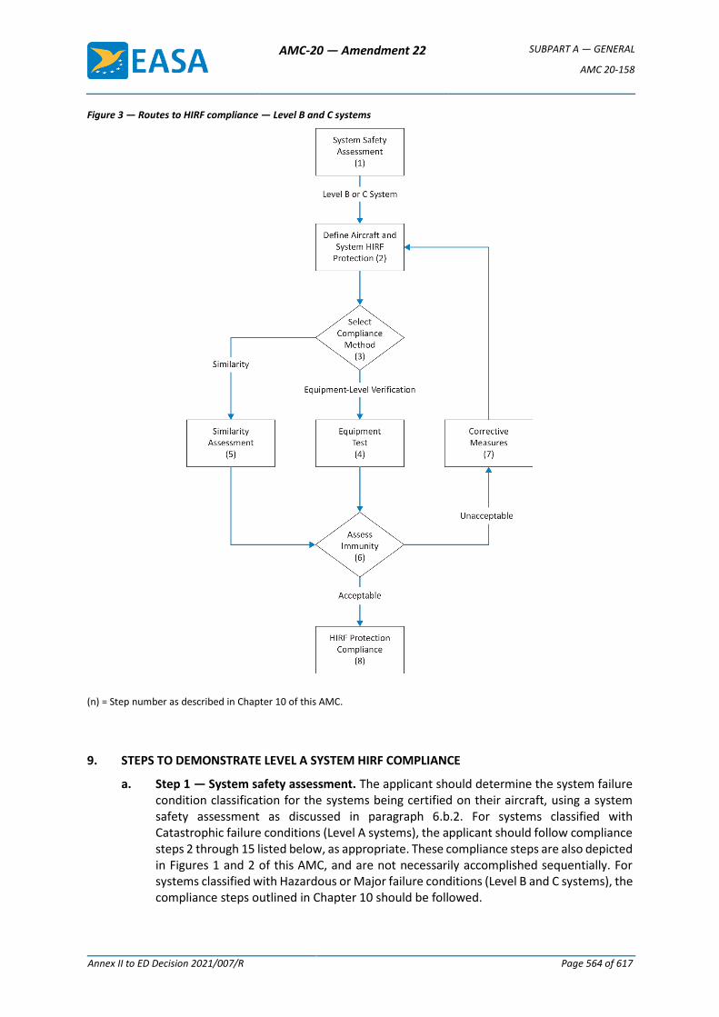
AMC-20 — Amendment 22 SUBPART A — GENERAL
AMC 20-158
Annex II to ED Decision 2021/007/R Page 564 of 617
Figure 3 — Routes to HIRF compliance — Level B and C systems
(n) = Step number as described in Chapter 10 of this AMC.
9. STEPS TO DEMONSTRATE LEVEL A SYSTEM HIRF COMPLIANCE
a. Step 1 — System safety assessment. The applicant should determine the system failure condition classification for the systems being certified on their aircraft, using a system safety assessment as discussed in paragraph 6.b.2. For systems classified with Catastrophic failure conditions (Level A systems), the applicant should follow compliance steps 2 through 15 listed below, as appropriate. These compliance steps are also depicted in Figures 1 and 2 of this AMC, and are not necessarily accomplished sequentially. For systems classified with Hazardous or Major failure conditions (Level B and C systems), the compliance steps outlined in Chapter 10 should be followed.
AMC-20 — Amendment 22 SUBPART A — GENERAL
AMC 20-158
Annex II to ED Decision 2021/007/R Page 565 of 617
b. Step 2 — Define aircraft and system HIRF protection. The applicant should define the HIRF protection features that will be incorporated into the aircraft and system designs, based on the HIRF environments that are applicable to their aircraft and its Level A systems. Equipment, system, and aircraft HIRF protection design may occur before aircraft-level tests are performed, and before the actual internal HIRF environment is determined. Therefore, the equipment, system and aircraft HIRF protection design should be based on an estimate of the expected internal HIRF environment. All aircraft configurations that may affect HIRF protection, such as opened landing gear doors, should be considered as part of the aircraft assessment (see Step 7).
c. Step 3 — System assessment decision. The applicant should determine whether to perform integrated system HIRF tests on the Level A system, or whether to base the system verification on previous integrated system HIRF tests performed on a similar system. Aircraft and system tests and assessments need not be performed for the HIRF environments above 18 GHz if data and design analysis show that the integrated system tests results (see Step 5) satisfy the pass criteria from 12 GHz to 18 GHz, and that the systems have no circuits that operate in the 18 GHz to 40 GHz frequency range.
d. Step 4 — Equipment test
1. Radiated and conducted RF susceptibility laboratory tests of ED-14G, Section 20, may be used to build confidence in the equipment's HIRF immunity before conducting integrated system laboratory tests in Step 5. The equipment should be tested in accordance with the test levels (wire bundle currents and RF field strengths) of ED-14G, Section 20, or to a level estimated for the aircraft and equipment installation using the applicable external HIRF environment.
2. Equipment HIRF tests may be used to augment the integrated system HIRF tests where appropriate. For equipment, whose HIRF immunity is evaluated as part of the integrated system-level HIRF tests discussed in Step 5, the individual equipment’s HIRF testing described in this step may be considered optional.
e. Step 5 — Integrated system test
1. Radiated and conducted RF susceptibility laboratory tests on an integrated system should be performed for Level A systems. The HIRF field strengths and wire bundle currents selected for this test should be based on the attenuated external HIRF environment determined in the aircraft assessment (see Steps 10, 11, or 12). In many cases, the integrated system test is performed before the aircraft assessment is complete. In these cases, the integrated system test field strengths and currents should be selected based on the expected aircraft attenuation or transfer function.
2. The installation details for the laboratory integrated system tests should be similar to the installation in the aircraft. For example, the bonding and grounding of the system, wire size, routing, arrangement (whether parallel or twisted wires), connector types, wire shields, and shield terminations, and the relative position of the elements to each other and the ground plane in the laboratory should match closely the system installation on the aircraft to be certificated. For this reason, the laboratory integrated system rig should have an EASA conformity inspection prior to conducting any EASA certification credit testing.
3. The integrated system should be tested with the system operating, and should include connected displays, sensors, actuators, and other equipment. To ensure that the integrated system is tested when operating at its maximum sensitivity, the system should be placed in various operating modes. If the connected equipment
AMC-20 — Amendment 22 SUBPART A — GENERAL
AMC 20-158
Annex II to ED Decision 2021/007/R Page 566 of 617
is not related to the functions with Catastrophic failures, these items may be simulated by test sets, if the test sets accurately represent the terminating circuit impedance of the sensor. However, the connected equipment should meet the appropriate HIRF requirements required for their failure condition classification.
4. The test levels should be selected based on the expected aircraft internal HIRF environment determined through aircraft tests (see Step 10), generic transfer functions and attenuation (see Step 11), or aircraft similarity assessment (see Step 12), using the applicable external HIRF environment. Integrated system test procedures are described in detail in the User’s Guide (SAE ARP 5583A/EUROCAE ED-107A).
5. Wire bundle current injection should be used for frequencies from 10 kHz to 400 MHz. RF currents are injected into the integrated system wiring via a current transformer. Each wire bundle in the system should be injected and the induced wire bundle current measured. If a system wire bundle branches, then each wire bundle branch also should be tested. Simultaneous multi-bundle current injection may be necessary on systems where there are redundant or multi-channel architectures.
6. High-level radiated susceptibility tests should be used at frequencies greater than 100 MHz. The radiating antenna should be far enough away to ensure the total volume of the equipment and at least half a wavelength of the wiring is simultaneously and uniformly illuminated during the test.
7. Define the appropriate pass/fail criteria for the system, based on the system safety assessment and the appropriate HIRF regulation. Any system susceptibility, including system malfunctions, upset, or damage should be recorded and evaluated based on these previously defined pass/fail criteria.
8. Using only the modulation to which the system under evaluation is most sensitive may minimise the test time. The User’s Guide provides guidance on modulation selection and suggested default modulations and dwell times.
9. The equipment tests in Step 4, using the techniques in ED-14G, Section 20, normally are not sufficient to demonstrate HIRF compliance for Step 5. However, for simple systems, these standard ED-14G, Section 20, tests may be sufficient if paragraphs 9.e.2. and 3. of this step are met.
f. Step 6 — System similarity assessment
1. The integrated system HIRF tests performed for a system previously certified on one aircraft model may be used to demonstrate system verification for a similar system. Each system considered under the similarity approach needs to be assessed independently even if it may use equipment and installation techniques that have been the subject of a previous certification.
2. The system used as the basis for similarity must have been certified previously for HIRF compliance on another aircraft model, and must have successfully completed integrated system HIRF tests. Similarity assessment requires comparison of both equipment and installation differences that could adversely affect HIRF immunity. The assessment should consider the differences between the previously HIRF certified system and the equipment circuit interfaces, wiring, grounding, bonding, connectors, and wire-shielding practices of the equipment that comprises the new system.
AMC-20 — Amendment 22 SUBPART A — GENERAL
AMC 20-158
Annex II to ED Decision 2021/007/R Page 567 of 617
3. If the assessment finds only minimal differences between the previously certified system and the new system to be certified, similarity may be used as the basis for system-level verification without the need for additional integrated system tests, providing there are no unresolved in-service HIRF problems related to the previously certified system. If there is uncertainty about the effects of the differences, additional tests and analyses should be conducted as necessary and appropriate to resolve the uncertainty. The amount of additional testing should be commensurate with the degree of difference identified between the new system and the system previously certified. If significant differences are found, similarity should not be used as the basis for system-level verification.
g. Step 7 — Aircraft assessment decision
1. Level A systems require an aircraft assessment. The aircraft assessment should determine the actual internal HIRF environment where the Level A systems are installed in the aircraft. The applicant should choose whether to use aircraft tests, previous coupling/attenuation data from similar aircraft types (similarity), or, for Level A display systems only, the generic transfer functions and attenuation in Appendix 1 to this AMC. Alternately, the aircraft assessment may be a test that exposes the entire aircraft with operating Level A systems to external HIRF environments I, II, or III (Tables 2, 3, and 4 respectively), as appropriate, to demonstrate acceptable Level A system performance.
2. Integrated display systems include the display equipment, control panels, and the sensors that provide information to the displays. In some systems, the sensors also provide information to Level A systems that are not displays. If the sensors also provide information to Level A flight controls, the applicant must use actual transfer functions and attenuation when demonstrating compliance for these sensors and the flight controls.
3. Other methods for aircraft HIRF assessment, such as analysis, may be acceptable. However, comprehensive modelling and analysis for RF field coupling to the aircraft structure is an emerging technology. Therefore, analysis alone is currently not adequate to demonstrate HIRF compliance for Level A systems and should be augmented by testing.
4. If analysis is used to determine aircraft attenuation and transfer function characteristics, test data should be provided to support this analysis. Any analysis results should take into account the quality and accuracy of the analysis. Significant testing, including aircraft level testing, may be required to support the analysis.
5. Aircraft and system tests and assessments need not be performed for the HIRF environments above 18 GHz if data and design analysis show that the integrated system tests results (see Step 5) satisfy the pass criteria from 12 GHz to 18 GHz, and the systems have no circuits that operate in the 18 GHz to 40 GHz frequency range.
h. Step 8 — Aircraft test decision
1. Various aircraft test procedures are available and accepted for collecting data for aircraft HIRF verification. The two main approaches to aircraft testing are the aircraft high-level test (see Step 9) and the aircraft low-level coupling test (see Step 10). The aircraft high-level field-illumination test involves radiating the aircraft at test levels equal to the applicable external HIRF environment in the HIRF regulations. Aircraft low-level coupling tests involve measuring the airframe
AMC-20 — Amendment 22 SUBPART A — GENERAL
AMC 20-158
Annex II to ED Decision 2021/007/R Page 568 of 617
attenuation and transfer functions, so that the internal HIRF electric fields and currents can be compared to the integrated system test levels.
2. Some test procedures may be more appropriate than others because of the size of the aircraft and the practicality of illuminating the entire aircraft with the appropriate external HIRF environment. The aircraft low-level coupling tests (see Step 10) may be more suitable for testing large aircraft than the high-level field-illumination test in Step 9, which requires illumination of the entire aircraft with the external HIRF environment.
i. Step 9 — Aircraft high-level tests
1. The aircraft high-level field-illumination test requires generating RF fields external to an aircraft at a level equal to the applicable external HIRF environment.
2. At frequencies below 400 MHz, the distance between the aircraft and the transmitting antenna should be sufficient to ensure the aircraft is illuminated uniformly by the external HIRF environment. The transmitting antenna should be placed in at least four positions around the aircraft, typically illuminating the nose, tail, and each wingtip. The aircraft should be illuminated by the antenna at each position while sweeping the frequency range. Separate frequency sweeps should be performed with the transmitting antenna oriented for horizontal and vertical polarisation. The RF field should be calibrated by measuring the RF field strength in the centre of the test volume before the aircraft is placed there.
3. At frequencies above 400 MHz, the RF illumination should be localised to the system under test, provided all parts of the system and at least one wavelength of any associated wiring (or the total length if less than one wavelength) are illuminated uniformly by the RF field. Reflection planes may be needed to illuminate relevant apertures on the bottom and top of the aircraft.
4. To ensure that the systems are tested when operating at their maximum sensitivity, Level A systems should be fully operational and the aircraft should be placed in various simulated operating modes.
5. The test time can be minimised by using only the modulation to which the system under evaluation is most sensitive. In this case, the rationale used to select the most sensitive modulation should be documented in the HIRF test plan as discussed in paragraph 8.b.1. The User’s Guide provides guidance on modulation selection and suggested default modulations and dwell times.
6. As an alternative to testing at frequencies below the first airframe resonant frequency, it is possible to inject high-level currents directly into the airframe using aircraft high-level direct-drive test methods. Aircraft skin current analysis should be performed as described in the User’s Guide, or low-level swept-current measurements should be made to determine the skin current distribution that will exist for different RF field polarisations and aircraft illumination angles so that these can be simulated accurately during this test. Aircraft high-level direct-drive testing, although applicable only from 10 kHz to the first airframe resonant frequency, is advantageous because it is possible to test all systems simultaneously.
j. Step 10 — Aircraft low-level coupling tests
1. General
AMC-20 — Amendment 22 SUBPART A — GENERAL
AMC 20-158
Annex II to ED Decision 2021/007/R Page 569 of 617
a. The aircraft low-level coupling tests include three different tests that cover the frequency range of 10 kHz to 18 GHz (see Figure 2). Detailed descriptions are available in the User’s Guide. Other techniques may be valid, but must be discussed with and approved by the Agency before being used.
b. The low-level direct-drive test (see Step 10b, Figure 2) and the low-level swept-current test (see Step 10c) are used for frequencies at or below 400 MHz. The low-level swept-field test (see Step 10d) is used for frequencies at and above 100 MHz. There is an overlap of test frequencies from 100 MHz to 400 MHz in the low-level swept-current test and the low-level swept-field test. The division at 400 MHz is not absolute but rather depends on when HIRF penetration of the equipment case becomes a significant factor.
2. Steps 10a and 10b — Aircraft skin current analysis and low-level direct-drive test. Low-level direct-drive tests in conjunction with skin current analysis should be used to determine the transfer function between the skin current and individual equipment wire bundle currents. The low-level direct-drive test is typically used for frequencies from 10 kHz to the first airframe resonant frequency. For the low-level direct-drive test to be applied successfully, a three-dimensional model of the aircraft should be derived using aircraft skin current analysis. The three-dimensional model can then be used to derive the aircraft's skin current pattern for the applicable external HIRF environment. Guidance on skin current analysis is in the User’s Guide. If the relationship between the external HIRF environment and the skin current is known for all illumination angles and polarisation, either because of aircraft skin current analysis or the use of the low-level swept-current test, the skin current can be set up by direct injection into the airframe. The resultant currents on the system wire bundles are measured with a current probe and normalised to 1 V/m electric field strength so that they can be scaled to the appropriate external HIRF environment. This test method has improved sensitivity over the low-level swept-current test and may be necessary for small aircraft or aircraft with high levels of airframe shielding.
3. Step 10c — Low-level swept-current test
a. The low-level swept-current test involves illuminating the aircraft with a low-level external HIRF field to measure the transfer function between the external field and the aircraft and equipment wire bundle currents. This test is typically used in the frequency range of 500 kHz to 400 MHz. The transfer function is resonant in nature and is dependent on both the aircraft structure and the system installation. Because the transfer function relates wire bundle currents to the external field, the induced bulk current injection test levels can be related to an external HIRF environment.
b. The transmitting antenna should be placed in at least four positions around the aircraft, typically the nose, tail, and each wingtip, with sufficient distance between the aircraft and the transmitting antenna to ensure the aircraft is illuminated uniformly. The aircraft should be illuminated by the antenna at each position while sweeping the frequencies in the range of 500 kHz to 400 MHz. Separate frequency sweeps should be performed with the transmitting antenna oriented for horizontal and vertical polarisation. The currents induced on the aircraft wire bundles should be measured.
AMC-20 — Amendment 22 SUBPART A — GENERAL
AMC 20-158
Annex II to ED Decision 2021/007/R Page 570 of 617
c. The ratio between the induced wire bundle current and the illuminating antenna field strength should be calculated and normalised to a ratio of 1 V/m. This provides the transfer function in terms of induced current per unit external field strength. Then the current induced by the applicable external HIRF environment can be calculated by multiplying the transfer function by the external HIRF field strength. The calculated HIRF currents for all transmitting antenna positions for each aircraft wire bundle being assessed should be overlaid to produce worst-case induced current for each wire bundle. These worst-case induced currents can be compared with the current used during the integrated system test in Step 5.
4. Step 10d — Low-level swept-field test. Low-level swept-field testing is typically used from 100 MHz to 18 GHz. The test procedures for the low-level swept-field test are similar to those used for the low-level swept-current test; however, in the low-level swept-field test, the internal RF fields in the vicinity of the equipment are measured instead of the wire bundle currents. Various techniques can be used to ensure the maximum internal field in the vicinity of the equipment is measured. Depending on the size of the aircraft and the size of the aircraft cabin, flight deck, and equipment bays, multipoint measurement or mode stirring can be used to maximise the internal field in the vicinity of the equipment. See the User’s Guide for detailed low-level swept-field test procedures.
k. Step 11 — Generic transfer functions and attenuation — Level A display systems only
1. Level A displays involve functions for which system information is displayed directly to the pilot. For Level A display systems, the aircraft attenuation data may be determined using generic attenuation and transfer function data. This approach should not be used for other Level A systems, such as control systems, because failures and malfunctions of those systems can more directly and abruptly contribute to a Catastrophic failure event than do display system failures and malfunctions; therefore, other Level A systems should have a more rigorous method of HIRF compliance verification.
2. The integrated system test levels specified in Step 5 may be derived from the generic transfer functions and attenuation for different types of aircraft. Acceptable transfer functions for calculating the test levels are given in Appendix 1 to this AMC. Appendix 1 to this AMC also contains guidelines for selecting the proper generic attenuation. The generic transfer functions show the envelope of the currents that might be expected to be induced in the types of aircraft in an external HIRF environment of 1 V/m. The current levels should be multiplied linearly by HIRF environment I, II, or III, as appropriate, to determine the integrated system test levels.
3. The internal HIRF electric field levels are the external HIRF environment divided by the appropriate attenuation, in linear units. For example, 20 dB or a 10:1 attenuation means the test level is the applicable external HIRF environment electric field strength reduced by a factor of 10.
4. The internal HIRF environments for Level A display systems can also be measured using on-aircraft low-level coupling measurements of the actual system installation (see Step 10). This procedure should provide more accurate information to the
AMC-20 — Amendment 22 SUBPART A — GENERAL
AMC 20-158
Annex II to ED Decision 2021/007/R Page 571 of 617
user, and the test levels may be lower than the generic transfer functions or attenuation, which are worst-case estimates.
l. Step 12 — Aircraft similarity assessment
1. The aircraft attenuation and transfer functions tests performed for a previously certified aircraft may be used to support aircraft-level verification for a similar aircraft model. The aircraft used as the basis for similarity must have been previously certified for HIRF compliance, using HIRF attenuation and transfer functions determined by tests on that aircraft.
2. The similarity assessment for the new aircraft should consider the aircraft differences that could impact the internal HIRF environment affecting the Level A systems and associated wiring. The comparison should consider equipment and wiring locations, airframe materials and construction, and apertures that could affect attenuation for the external HIRF environment.
3. If the assessment finds only minimal differences between the previously certified aircraft and the new aircraft to be certified, similarity may be used to determine aircraft attenuation and transfer functions without the need for additional aircraft tests, providing there are no unresolved in-service HIRF problems related to the existing aircraft. If there is uncertainty about the effects of the differences, additional tests and analyses should be conducted as necessary and appropriate to resolve the uncertainty. The amount of additional testing should be commensurate with the degree of difference identified between the new aircraft and the aircraft previously certified. If significant differences are found, similarity should not be used as the basis for aircraft-level verification.
m. Step 13 — Assess immunity
1. The test levels used for the integrated system test of Step 5 should be compared with the internal RF current or RF fields determined by the aircraft low-level coupling tests (see Step 10), the generic transfer functions and attenuation (see Step 11), or the aircraft similarity assessment (see Step 12). The actual aircraft internal RF currents and RF fields should be lower than the integrated system test levels. The applicant’s comparison method should be included in the HIRF compliance plan. The method should enable a direct comparison between the system test level and the aircraft internal HIRF environment at the equipment or system location, using current for frequencies from 10 kHz through 400 MHz, and using electric field strength for frequencies from 100 MHz through 18 GHz.
2. If the conducted RF susceptibility test levels used for the integrated system test (see Step 5) were too low when compared with the aircraft-induced currents determined in Steps 10b, 10c, 11 or 12, then corrective measures may be needed (see Step 14). If the radiated RF susceptibility test levels used for integrated system tests (see Step 5) were too low when compared with the aircraft internal fields determined in Steps 10d, 11 or 12, then corrective measures may also be needed (see Step 14).
3. When comparing the current measured during low-level swept-current tests in Step 10c with the current used during the integrated system tests in Step 5, there may be differences. These differences may be due to variations between the actual aircraft installation and the integrated system laboratory installation, such as wire bundle lengths, shielding and bonding, and wire bundle composition. The worst-case current signature for a particular wire bundle should be compared to the
AMC-20 — Amendment 22 SUBPART A — GENERAL
AMC 20-158
Annex II to ED Decision 2021/007/R Page 572 of 617
current induced at the particular test level or equipment malfunction over discrete frequency ranges such as 50 kHz to 500 kHz, 500 kHz to 30 MHz, and 30 MHz to 100 MHz. This comparison should be broken into discrete frequency ranges because the resonant frequencies may differ between the integrated system tests and the aircraft tests.
4. If the applicant used aircraft high-level tests (see Step 9) for aircraft HIRF verification, it should be determined if there were any Level A system susceptibilities. Any Level A system susceptibilities should be evaluated based on the pass/fail criteria as established in the test plan (see paragraph 8.b.1). If the HIRF susceptibilities are not acceptable, then corrective measures may be needed (see Step 14).
5. HIRF susceptibilities that were not anticipated or defined in the test plan pass/fail criteria may be observed during aircraft high-level tests or integrated system laboratory tests. If so, the data collected during the HIRF compliance verification process should be used to determine the effect of the HIRF susceptibility on the aircraft systems and functions. The pass/fail criteria may be modified if the effects neither cause nor contribute to conditions that adversely affect the aircraft functions or systems, as applicable, in the HIRF regulations. The applicant should provide an assessment of, and supporting rationale for, any modifications to the pass/fail criteria to the Agency for approval. If the HIRF susceptibilities are not acceptable, then corrective measures may be needed (see Step 14).
6. If the Level A systems show no adverse effects when tested to levels derived from HIRF environment I or III, as applicable, then this also demonstrates compliance of the system with HIRF environment II.
7. If the integrated system tests results (see Step 5) satisfy the pass criteria from 12 GHz to 18 GHz, and design analysis shows that the system has no circuits that operate in the 18 GHz to 40 GHz frequency range, then this demonstrates by analysis that the system is not adversely affected when exposed to HIRF environments above 18 GHz. If these conditions are satisfied, further aircraft and system tests and assessments above 18 GHz are not necessary.
8. Review the actual system installation in the aircraft and the system configuration used for the integrated system test (see Step 5). If significant configuration differences are identified, corrective measures may be needed (see Step 14).
9. Certain RF receivers with antennas connected should not be expected to perform without effects during exposure to the HIRF environments, particularly in the RF receiver operating band. Because the definition of adverse effects and the RF response at particular portions of the spectrum depends on the RF receiver system function, the applicant should refer to the individual RF receiver minimum performance standards for additional guidance. However, because many RF receiver minimum performance standards were prepared before implementation of HIRF requirements, the RF receiver pass/fail criteria should be coordinated with the Agency.
n. Step 14 — Corrective measures. Corrective measures should be taken if the system fails to satisfy the HIRF immunity assessment of Step 13. If changes or modifications to the aircraft, equipment, system or system installation are required, then additional tests may be necessary to verify the effectiveness of the changes. The ED-14G, Section 20,

AMC-20 — Amendment 22 SUBPART A — GENERAL
AMC 20-158
Annex II to ED Decision 2021/007/R Page 573 of 617
equipment tests, integrated system tests, and aircraft tests, in whole or in part, may need to be repeated to demonstrate HIRF compliance.
o. Step 15 — HIRF protection compliance. The test results and compliance report should be submitted to the Agency for approval as part of the overall aircraft type certification or supplemental type certification process.
10. STEPS TO DEMONSTRATE LEVEL B AND C SYSTEM HIRF COMPLIANCE
a. Step 1 — System safety assessment. The applicant should determine the system failure condition classification for the systems being certified on their aircraft using a system safety assessment as discussed in paragraph 6.b.2. For systems classified with Hazardous or Major failure conditions (Level B and C systems), the applicant should follow compliance steps 2 through 8 listed below, as appropriate. These compliance steps are also depicted in Figure 3 of this AMC, and are not necessarily accomplished sequentially. For systems classified with Catastrophic failure conditions (Level A systems), the compliance steps outlined in Chapter 9 should be followed.
b. Step 2 — Define aircraft and system HIRF protection. The applicant should define the HIRF protection features that will be incorporated into the aircraft and system designs, based on the HIRF environments that are applicable to their aircraft and its Level B and C systems. Equipment, system, and aircraft HIRF protection design may occur before aircraft-level tests are performed, and before the actual internal HIRF environment is determined. Therefore, the equipment, system and aircraft HIRF protection design should be based on an estimate of the expected internal HIRF environment.
c. Step 3 — Select compliance method. The applicant should determine whether to perform equipment HIRF tests on the Level B and C systems, or whether to base compliance on previous equipment tests performed for a similar system.
d. Step 4 — Equipment test
1. Level B and Level C systems do not require the same degree of HIRF compliance testing as Level A systems and, therefore, do not require aircraft-level testing. ED-14G, Section 20, laboratory test procedures should be used, using equipment test levels defined in the regulations. The test levels used depend on whether the system is categorised as Level B or C. Equipment HIRF test level 1 or 2, as applicable, should be used for Level B systems. ED-14G, Section 20, Category RR, satisfies the requirements of equipment HIRF test level 1. For equipment HIRF test level 2, the applicant may use the approach in paragraph 9.k. to help determine acceptable aircraft transfer function and attenuation curves for their Level B system. Equipment HIRF test level 3 should only be used for Level C systems. ED-14G, Section 20, Category TT, satisfies the requirements of equipment HIRF test level 3. When applying modulated signals, the test levels are given in terms of the peak of the test signal as measured by a root mean square (rms), indicating spectrum analyser’s peak detector. See the User’s Guide (SAE ARP 5583A/EUROCAE ED-107A) for more details on modulation.
2. Define the appropriate pass/fail criteria for the system, based on the system safety assessment and the appropriate HIRF regulation (see paragraph 6.b.2). Any susceptibility noted during the equipment tests, including equipment malfunctions, upset, or damage, should be recorded and evaluated based on the defined pass/fail criteria.

AMC-20 — Amendment 22 SUBPART A — GENERAL
AMC 20-158
Annex II to ED Decision 2021/007/R Page 574 of 617
e. Step 5 — Similarity assessment
1. The equipment HIRF tests performed for a system previously certified on one aircraft model may be used to show compliance for a similar system. Each system considered for similarity needs to be assessed independently even if it may use equipment and installation techniques that have been the subject of a previous certification.
2. The system used as the basis for certification by similarity must have been previously certified for HIRF compliance on another aircraft model, and must have successfully completed equipment HIRF tests. Similarity assessment requires comparison of both equipment and installation differences that could adversely affect HIRF immunity. An assessment of a new system should consider the differences in the equipment circuit interfaces, wiring, grounding, bonding, connectors, and wire-shielding practices.
3. If the assessment finds only minimal differences between the previously certified system and the new system to be certified, similarity may be used for HIRF compliance without the need for additional equipment HIRF tests, providing there are no unresolved in-service HIRF problems related to the previously certified system. If there is uncertainty about the effects of the differences, additional tests and analyses should be conducted as necessary and appropriate to resolve the uncertainty. The amount of additional testing should be commensurate with the degree of difference identified between the new system and the system previously certified. If significant differences are found, similarity should not be used as the basis for HIRF compliance.
f. Step 6 — Assess immunity
1. The results of the equipment test should be reviewed to determine if the pass/fail criteria is satisfied. HIRF susceptibilities that were not anticipated or defined in the test plan pass/fail criteria may be observed during equipment HIRF tests. If so, the applicant should determine the effect of the HIRF susceptibility on the aircraft systems and functions. The pass/fail criteria may be modified if the effects neither cause nor contribute to conditions that adversely affect the aircraft functions or systems, as applicable, in the HIRF regulations. The applicant should provide an assessment of, and supporting rationale for, any modifications to the pass/fail criteria to the Agency for approval. If the HIRF susceptibilities are not acceptable, then corrective measures may be needed (see Step 7).
2. The actual system installation in the aircraft and the configuration used for the equipment tests (see Step 4) should be reviewed. If significant differences in grounding, shielding, connectors, or wiring are identified, corrective measures may be needed (see Step 7).
3. Certain RF receivers with antennas connected should not be expected to perform without effects during exposure to the HIRF environments, particularly in the RF receiver operating band. Because the definition of adverse effects and the RF response at particular portions of the spectrum depends on the RF receiver system function, the applicant should refer to the individual RF receiver minimum performance standards for additional guidance. However, because many RF receiver minimum performance standards were prepared before implementation of HIRF requirements, the RF receiver pass/fail criteria should be coordinated with
AMC-20 — Amendment 22 SUBPART A — GENERAL
AMC 20-158
Annex II to ED Decision 2021/007/R Page 575 of 617
the Agency. Future modifications to the minimum performance standards should reflect HIRF performance requirements.
g. Step 7 — Corrective measures. Corrective measures should be taken if the system fails to satisfy the HIRF immunity assessment of Step 6. If changes or modifications to the equipment, system, or system installation are required, then additional tests may be necessary to verify the effectiveness of the changes. The ED-14G, Section 20, equipment tests, in whole or in part, may need to be repeated to demonstrate HIRF compliance.
h. Step 8 — HIRF protection compliance. The test results and compliance report should be submitted to the Agency for approval as part of the overall aircraft type certification or supplemental type certification process.
11. MAINTENANCE, PROTECTION ASSURANCE, AND MODIFICATIONS
a. The minimum maintenance required to support HIRF certification should be identified in the Instructions for Continued Airworthiness (ICA) as specified in CS 23.1529, CS 25.1529, CS 27.1529, and CS 29.1529, as appropriate. Dedicated devices or specific features may be required to provide HIRF protection for an equipment or system installation. Appropriate maintenance procedures should be defined for these devices and features to ensure in-service protection integrity. A HIRF protection assurance programme may be necessary to verify that the maintenance procedures are adequate. The User’s Guide (SAE ARP 5583A/EUROCAE ED-107A) provides further information on these topics.
b. The maintenance procedures should consider the effects of corrosion, fretting, flexing cycles, or other causes that could degrade these HIRF protection devices. Whenever applicable, specific replacement times for these devices and features should be defined and identified.
c. Aircraft or system modifications should be assessed for the impact any changes will have on the HIRF protection. This assessment should be based on analysis and/or measurement.
[Amdt 20/13]
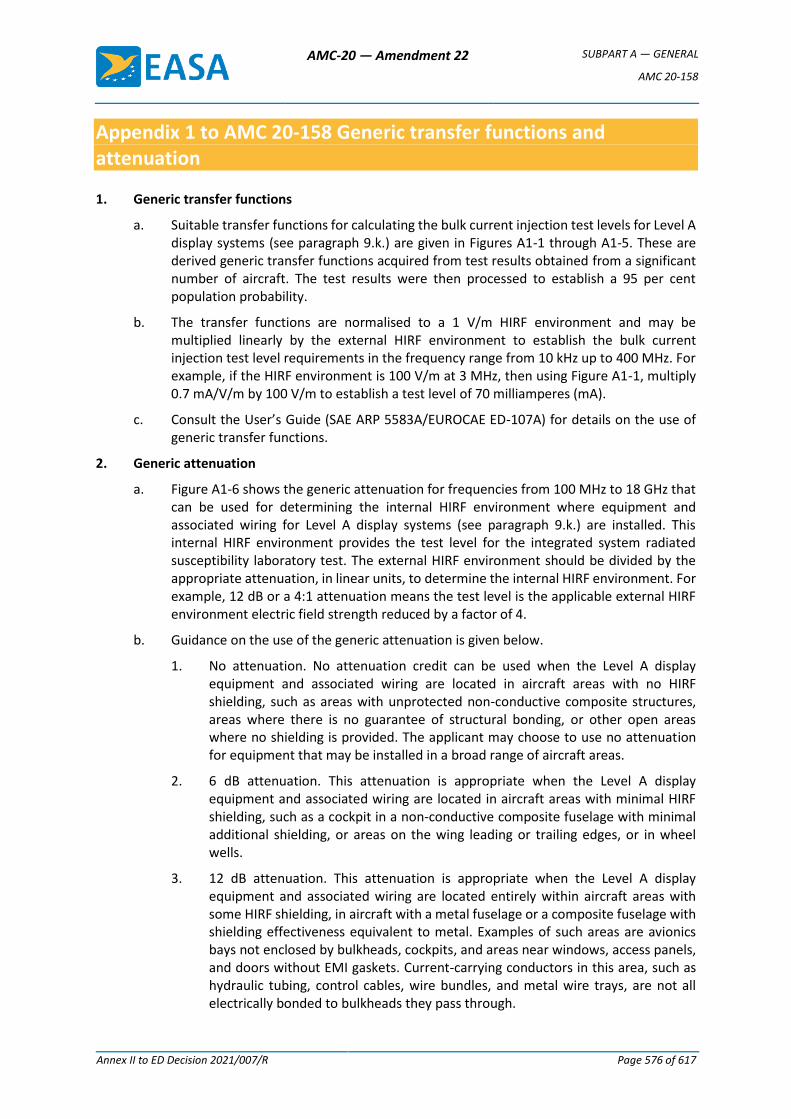
AMC-20 — Amendment 22 SUBPART A — GENERAL
AMC 20-158
Annex II to ED Decision 2021/007/R Page 576 of 617
Appendix 1 to AMC 20-158 Generic transfer functions and attenuation
1. Generic transfer functions
a. Suitable transfer functions for calculating the bulk current injection test levels for Level A display systems (see paragraph 9.k.) are given in Figures A1-1 through A1-5. These are derived generic transfer functions acquired from test results obtained from a significant number of aircraft. The test results were then processed to establish a 95 per cent population probability.
b. The transfer functions are normalised to a 1 V/m HIRF environment and may be multiplied linearly by the external HIRF environment to establish the bulk current injection test level requirements in the frequency range from 10 kHz up to 400 MHz. For example, if the HIRF environment is 100 V/m at 3 MHz, then using Figure A1-1, multiply 0.7 mA/V/m by 100 V/m to establish a test level of 70 milliamperes (mA).
c. Consult the User’s Guide (SAE ARP 5583A/EUROCAE ED-107A) for details on the use of generic transfer functions.
2. Generic attenuation
a. Figure A1-6 shows the generic attenuation for frequencies from 100 MHz to 18 GHz that can be used for determining the internal HIRF environment where equipment and associated wiring for Level A display systems (see paragraph 9.k.) are installed. This internal HIRF environment provides the test level for the integrated system radiated susceptibility laboratory test. The external HIRF environment should be divided by the appropriate attenuation, in linear units, to determine the internal HIRF environment. For example, 12 dB or a 4:1 attenuation means the test level is the applicable external HIRF environment electric field strength reduced by a factor of 4.
b. Guidance on the use of the generic attenuation is given below.
1. No attenuation. No attenuation credit can be used when the Level A display equipment and associated wiring are located in aircraft areas with no HIRF shielding, such as areas with unprotected non-conductive composite structures, areas where there is no guarantee of structural bonding, or other open areas where no shielding is provided. The applicant may choose to use no attenuation for equipment that may be installed in a broad range of aircraft areas.
2. 6 dB attenuation. This attenuation is appropriate when the Level A display equipment and associated wiring are located in aircraft areas with minimal HIRF shielding, such as a cockpit in a non-conductive composite fuselage with minimal additional shielding, or areas on the wing leading or trailing edges, or in wheel wells.
3. 12 dB attenuation. This attenuation is appropriate when the Level A display equipment and associated wiring are located entirely within aircraft areas with some HIRF shielding, in aircraft with a metal fuselage or a composite fuselage with shielding effectiveness equivalent to metal. Examples of such areas are avionics bays not enclosed by bulkheads, cockpits, and areas near windows, access panels, and doors without EMI gaskets. Current-carrying conductors in this area, such as hydraulic tubing, control cables, wire bundles, and metal wire trays, are not all electrically bonded to bulkheads they pass through.
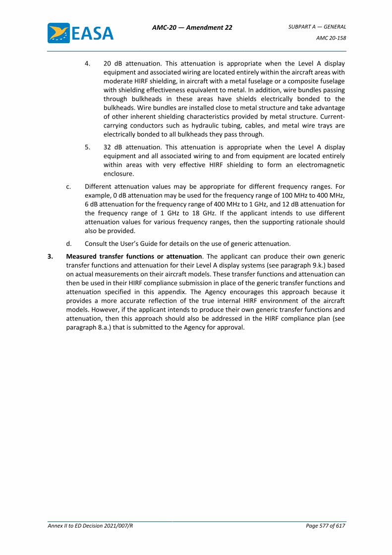
AMC-20 — Amendment 22 SUBPART A — GENERAL
AMC 20-158
Annex II to ED Decision 2021/007/R Page 577 of 617
4. 20 dB attenuation. This attenuation is appropriate when the Level A display equipment and associated wiring are located entirely within the aircraft areas with moderate HIRF shielding, in aircraft with a metal fuselage or a composite fuselage with shielding effectiveness equivalent to metal. In addition, wire bundles passing through bulkheads in these areas have shields electrically bonded to the bulkheads. Wire bundles are installed close to metal structure and take advantage of other inherent shielding characteristics provided by metal structure. Current-carrying conductors such as hydraulic tubing, cables, and metal wire trays are electrically bonded to all bulkheads they pass through.
5. 32 dB attenuation. This attenuation is appropriate when the Level A display equipment and all associated wiring to and from equipment are located entirely within areas with very effective HIRF shielding to form an electromagnetic enclosure.
c. Different attenuation values may be appropriate for different frequency ranges. For example, 0 dB attenuation may be used for the frequency range of 100 MHz to 400 MHz, 6 dB attenuation for the frequency range of 400 MHz to 1 GHz, and 12 dB attenuation for the frequency range of 1 GHz to 18 GHz. If the applicant intends to use different attenuation values for various frequency ranges, then the supporting rationale should also be provided.
d. Consult the User’s Guide for details on the use of generic attenuation.
3. Measured transfer functions or attenuation. The applicant can produce their own generic transfer functions and attenuation for their Level A display systems (see paragraph 9.k.) based on actual measurements on their aircraft models. These transfer functions and attenuation can then be used in their HIRF compliance submission in place of the generic transfer functions and attenuation specified in this appendix. The Agency encourages this approach because it provides a more accurate reflection of the true internal HIRF environment of the aircraft models. However, if the applicant intends to produce their own generic transfer functions and attenuation, then this approach should also be addressed in the HIRF compliance plan (see paragraph 8.a.) that is submitted to the Agency for approval.
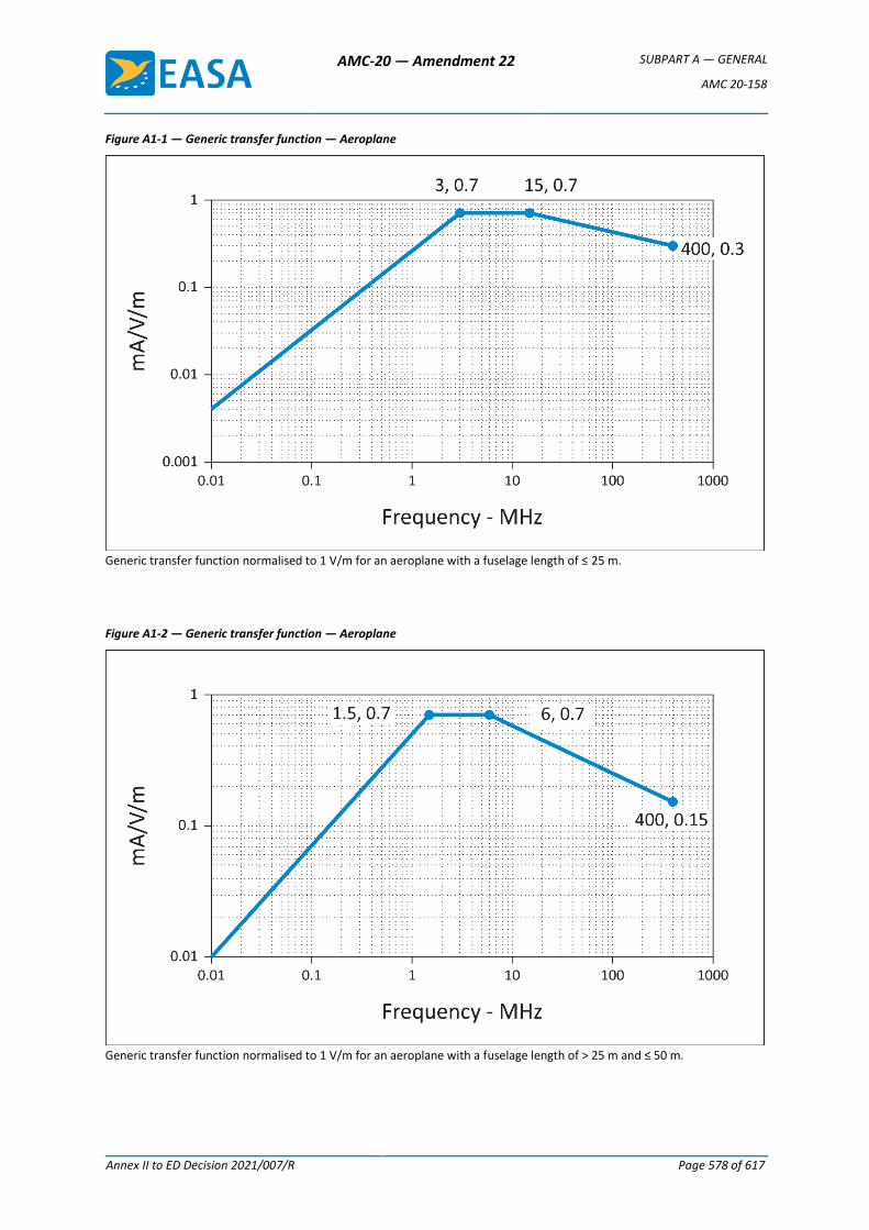
AMC-20 — Amendment 22 SUBPART A — GENERAL
AMC 20-158
Annex II to ED Decision 2021/007/R Page 578 of 617
Figure A1-1 — Generic transfer function — Aeroplane
Generic transfer function normalised to 1 V/m for an aeroplane with a fuselage length of ≤ 25 m.
Figure A1-2 — Generic transfer function — Aeroplane
Generic transfer function normalised to 1 V/m for an aeroplane with a fuselage length of > 25 m and ≤ 50 m.

AMC-20 — Amendment 22 SUBPART A — GENERAL
AMC 20-158
Annex II to ED Decision 2021/007/R Page 579 of 617
Figure A1-3 — Generic transfer function — Aeroplane
Generic transfer function normalised to 1 V/m for an aeroplane with a fuselage length of > 50 m.
Figure A1-4 — Generic transfer function — Rotorcraft
Generic transfer function normalised to 1 V/m for a rotorcraft.
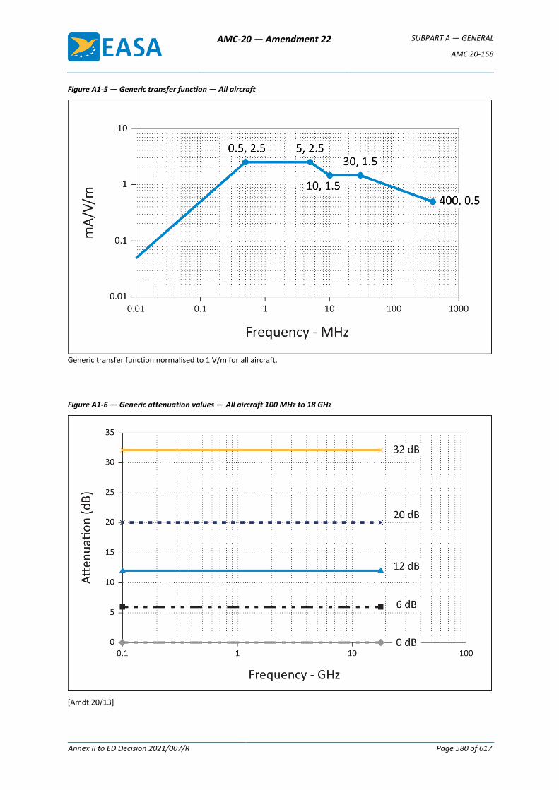
AMC-20 — Amendment 22 SUBPART A — GENERAL
AMC 20-158
Annex II to ED Decision 2021/007/R Page 580 of 617
Figure A1-5 — Generic transfer function — All aircraft
Generic transfer function normalised to 1 V/m for all aircraft.
Figure A1-6 — Generic attenuation values — All aircraft 100 MHz to 18 GHz
[Amdt 20/13]
AMC-20 — Amendment 22 SUBPART A — GENERAL
AMC 20-170
Annex II to ED Decision 2021/007/R Page 581 of 617
AMC 20-170
AMC 20-170 Integrated modular avionics (IMA)
1. Introduction
1.1. Purpose
This Acceptable Means of Compliance (AMC) provides a means that can be used to demonstrate that the safety aspects of integrated modular avionics (IMA) systems comply with the airworthiness requirements when such systems are integrated in a product, a part, or an appliance submitted to EASA for approval.
Compliance with this AMC is not mandatory and hence an applicant may elect to use alternative means of compliance. However, those alternative means of compliance must meet the relevant certification specifications, ensure an equivalent level of safety, and be accepted by EASA on a product basis.
1.2. Scope and applicability
The guidance contained in this AMC applies to any type certificate (TC) or supplemental type certificate (STC) applicants seeking approval from EASA for IMA systems installed in aircraft or rotorcraft.
IMA is a shared set of flexible, reusable and interoperable hardware and software resources that, when integrated, form a system that provides computing resources and services to hosted applications performing aircraft functions [ED-124].
An IMA architecture may integrate several aircraft functions on the same platform. Those functions are provided by several hosted applications that have historically been contained in functionally and physically separated ‘boxes’ or line replaceable units (LRUs).
This AMC addresses certification considerations for IMA systems, and should apply when:
— hosted applications* on the same platform are designed, verified and integrated independently (at application level**) from each other; and
— the platforms/modules provide shared resources (typically designed, verified and integrated independently from the hosted applications),
OR
— a process for obtaining incremental certification*** credit is anticipated or applied.
* A single application hosted on an independently developed platform is considered to be a traditional federated architecture and thus is not subject to this AMC. However, if additional application(s) that is (are) independently developed is (are) hosted on the same platform at a later stage (e.g. through a major change), this AMC should be applied.
** Software integration/verification activities are not performed on the whole set of integrated software as in a federated architecture.
*** Credit for incremental certification in an IMA context as detailed in Section 4.
AMC-20 — Amendment 22 SUBPART A — GENERAL
AMC 20-170
Annex II to ED Decision 2021/007/R Page 582 of 617
An applicant may choose to apply this AMC for a system which would not fulfil the conditions above. In that case, early discussions should take place between the applicant and EASA in order to confirm whether this AMC should be followed or not.
1.3. Document overview
This document:
(a) provides an overview of and background information on IMA systems and on concerns related to their certification (Section 2);
(b) presents the EASA policy for IMA certification by recognising the use of EUROCAE document ED-124, Integrated Modular Avionics (IMA) Development Guidance and Certification Considerations, as an acceptable means of compliance for the development and certification of IMA systems. It also clarifies and amends the intent, scope, and use of that document (in Section 3);
(c) introduces the incremental certification approach, and introduces the link to ETSO authorisations (ETSOAs) (in Section 4);
(d) complements ED-124 with additional considerations on dedicated topics, such as environmental qualification, open problem reports (OPRs), and configuration files (in Section 5).
1.4. Documents to be used with this AMC
This AMC should be used together with the following documents. The applicable version of the documents for a given project will be established in the certification basis or in the applicable CRIs.
Reference Title
ED-124/DO-297 Integrated Modular Avionics (IMA) Development Guidance and Certification Considerations
ED-79/ARP4754* Certification Considerations for Highly-Integrated or Complex Aircraft Systems
ED-79A/ARP4754A Guidelines for Development of Civil Aircraft and Systems
ED-12()/DO-178()** Software Considerations in Airborne Systems and Equipment Certification
ED-80/DO-254 Design Assurance Guidance for Airborne Electronic Hardware
ARP4761() Guidelines and Methods for Conducting the Safety Assessment Process on Airborne Systems and Equipment
ED-14()/DO-160() Environmental Conditions And Test Procedures For Airborne Equipment
ED-215/DO-330 Software Tool Qualification Considerations
* ED-79A should be used, unless ED-79 is the applicable document in a given project.
** Recommendations for software are developed in AMC 20-115().
1.5. Referenced material
1.5.1. Certification specifications (CS) and acceptable means of compliance (AMC)
Reference Title
CS XX.1301 Function and installation
CS XX.1302 Installed systems and equipment for use by the flight crew
CS XX.1309 Equipment, systems and installations
AMC-20 — Amendment 22 SUBPART A — GENERAL
AMC 20-170
Annex II to ED Decision 2021/007/R Page 583 of 617
Reference Title
AC 23.1309-1() System safety analysis and assessment for Part 23 airplanes
AMC 25.1309 System design and analysis
AC 27.1309 Equipment, systems and installations
AC 29.1309 Equipment, systems and installations
CS XX.1322 Flight crew alerting
CS-E 50 Engine control system
AMC E 50 Engine control system
AMC 20-3 Certification of engines equipped with electronic engine control systems
AMC 20-115() Software considerations for certification of airborne systems and equipment
ETSO-2C153 Integrated Modular Avionics (IMA) platform and modules
ETSO-C214 Functional-ETSO equipment using authorised ETSO-2C153 IMA platform or module
The applicable version of the documents for a given project will be established in the certification basis or in the applicable CRIs.
1.5.2. Referenced documents
Reference Title
ED-94C Supporting information for ED-12C and ED-109A
1.6. Definitions and abbreviations
1.6.1. Definitions
Term Meaning
Aircraft function
A capability of the aircraft that is provided by the hardware and software of the systems on the aircraft. [ED-124]
Application Software and/or application-specific hardware with a defined set of interfaces that, when integrated with a platform(s), performs a function. [ED-124]
Cabinet Result of the integration of hardware modules mounted within one rack. [ETSO-2C153]
Compliance credit
Evidence that a set of objectives related to certification requirements has been reached for a component or a set of components. Credit can be full or partial, meaning that, in case of partial credit, some objectives allocated to the component were not yet satisfied and should be completed at another stage.
Component A self-contained hardware part, software part, database, or combination of them that is configuration-controlled. A component does not provide an aircraft function by itself. [ED-124 Chapter 2.1.1]
Core software The operating system and support software that manage resources to provide an environment in which applications can execute. Core software is a necessary component of a platform and is typically comprised of one or more modules (such as, for example, libraries, drivers, kernel, data-loading, boot, etc.). [ED-124]
Federated system
Aircraft equipment architecture consisting of primarily line replaceable units that perform a specific function, connected by dedicated interfaces or aircraft system data buses. [ED-124]
AMC-20 — Amendment 22 SUBPART A — GENERAL
AMC 20-170
Annex II to ED Decision 2021/007/R Page 584 of 617
Term Meaning
IMA system Consists of an IMA platform(s) and a defined set of hosted applications. [ETSO-2C153]
Incremental certification
The incremental certification process is the process by which EASA agrees to grant compliance credit to IMA modules/platforms or hosted applications considered independently, based on activities performed at intermediate steps.
Intermixability The capability to intermix software and/or hardware of different versions and/or modification standards. [ED-124]
Interoperability The capability of several modules to operate together to accomplish a specific goal or function. [ED-124]
Module A component or collection of components that may be accepted by themselves or in the context of an IMA system. A module may also comprise other modules. A module may be software, hardware, or a combination of hardware and software, which provides resources to the IMA system hosted applications. [ED-124]
Module/ platform configuration
The action of setting some adjustable characteristics of the module/platform in order to adapt it to the user context. By extension, the result of this action. NOTE: A configuration table is one way but not the only way to configure a module/ platform.
Partitioning and robust partitioning
Partitioning is ‘An architectural technique to provide the necessary separation and independence of functions or applications to ensure that only intended coupling occurs.’ [ED-124] Robust partitioning is a means for assuring the intended isolation in all circumstances (including hardware failures, hardware and software design errors, or anomalous behaviour) of aircraft functions and hosted applications using shared resources. The objective of robust partitioning is to provide a level of functional isolation and independence equivalent to that of a federated system implementation.
Platform A module or group of modules, including core software, that manages resources in a manner sufficient to support at least one application. [ED-124]
Resource Any object (processor, memory, software, data, etc.) or component used by a processor, IMA platform, core software or application. A resource may be shared by multiple applications or dedicated to a specific application. A resource may be physical (a hardware device) or logical (a piece of information). [ED-124]
Support software
Embedded software necessary as a complement to the operating system to provide general services such as contributing to the intended function of resources sharing, handling hardware, drivers, software loading, health monitoring, boot strap, etc. [ETSO-2C153]
Usage domain The usage domain of an IMA module is defined as an exhaustive list of conditions (such as configuration settings, usage rules, etc.) to be respected by the user(s) to ensure that the IMA module continues to meet its characteristics. Compliance with the usage domain ensures that: the module is compliant with its functional, performance, safety and environmental requirements specified for all implemented intended functions; the module characteristics documented in the user guide/manual remain at the levels guaranteed by the manufacturer;
AMC-20 — Amendment 22 SUBPART A — GENERAL
AMC 20-170
Annex II to ED Decision 2021/007/R Page 585 of 617
Term Meaning
the module remains compliant with the applicable airworthiness requirements (including continuing airworthiness aspects). [Adapted from ETSO-2C153, without reference to the ETSO Minimum Performance Standard]
1.6.2. Abbreviations
Abbreviation Meaning
AEH airborne electronic hardware
AMC acceptable means of compliance
API application programming interface
ATA air transport association of America
CRI certification review item
CS certification specification
EASA European Aviation Safety Agency
ETSO European technical standard order
ETSOA European technical standard order authorisation
F-ETSO functional ETSO
HW hardware
IDAL item development assurance level
I/O input/output
IMA integrated modular avionics
LRU line replaceable unit
MMEL master minimum equipment list
OPR open problem report
RSC reusable software component
SOI stage of involvement
STC supplemental type certificate
SW software
TC type certificate
TQL tool qualification level
TSO technical standard order
TSOA technical standard order authorisation
2. Background
The use of IMA has rapidly expanded in the last two decades and is expected to progress even more in the future in all types of products, parts and appliances. Additional guidance is hence needed to address specific aspects at the application, component, platform, system, and aircraft levels.
2.1. IMA overview
A representation of a simple IMA architecture is illustrated in Figure 1:
— Applications implementing several aircraft functions are hosted on the same platform. Several applications (e.g. Applications 1.1 & 1.2) may contribute to the same aircraft function.
— The platform consists of:
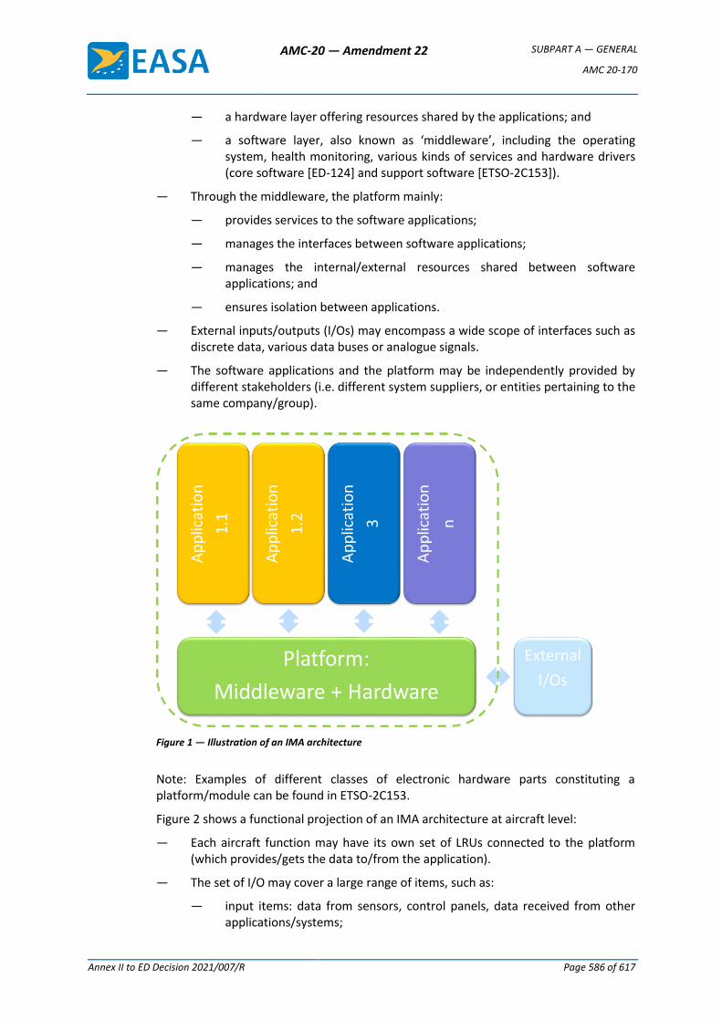
AMC-20 — Amendment 22 SUBPART A — GENERAL
AMC 20-170
Annex II to ED Decision 2021/007/R Page 586 of 617
— a hardware layer offering resources shared by the applications; and
— a software layer, also known as ‘middleware’, including the operating system, health monitoring, various kinds of services and hardware drivers (core software [ED-124] and support software [ETSO-2C153]).
— Through the middleware, the platform mainly:
— provides services to the software applications;
— manages the interfaces between software applications;
— manages the internal/external resources shared between software applications; and
— ensures isolation between applications.
— External inputs/outputs (I/Os) may encompass a wide scope of interfaces such as discrete data, various data buses or analogue signals.
— The software applications and the platform may be independently provided by different stakeholders (i.e. different system suppliers, or entities pertaining to the same company/group).
Figure 1 — Illustration of an IMA architecture
Note: Examples of different classes of electronic hardware parts constituting a platform/module can be found in ETSO-2C153.
Figure 2 shows a functional projection of an IMA architecture at aircraft level:
— Each aircraft function may have its own set of LRUs connected to the platform (which provides/gets the data to/from the application).
— The set of I/O may cover a large range of items, such as:
— input items: data from sensors, control panels, data received from other applications/systems;
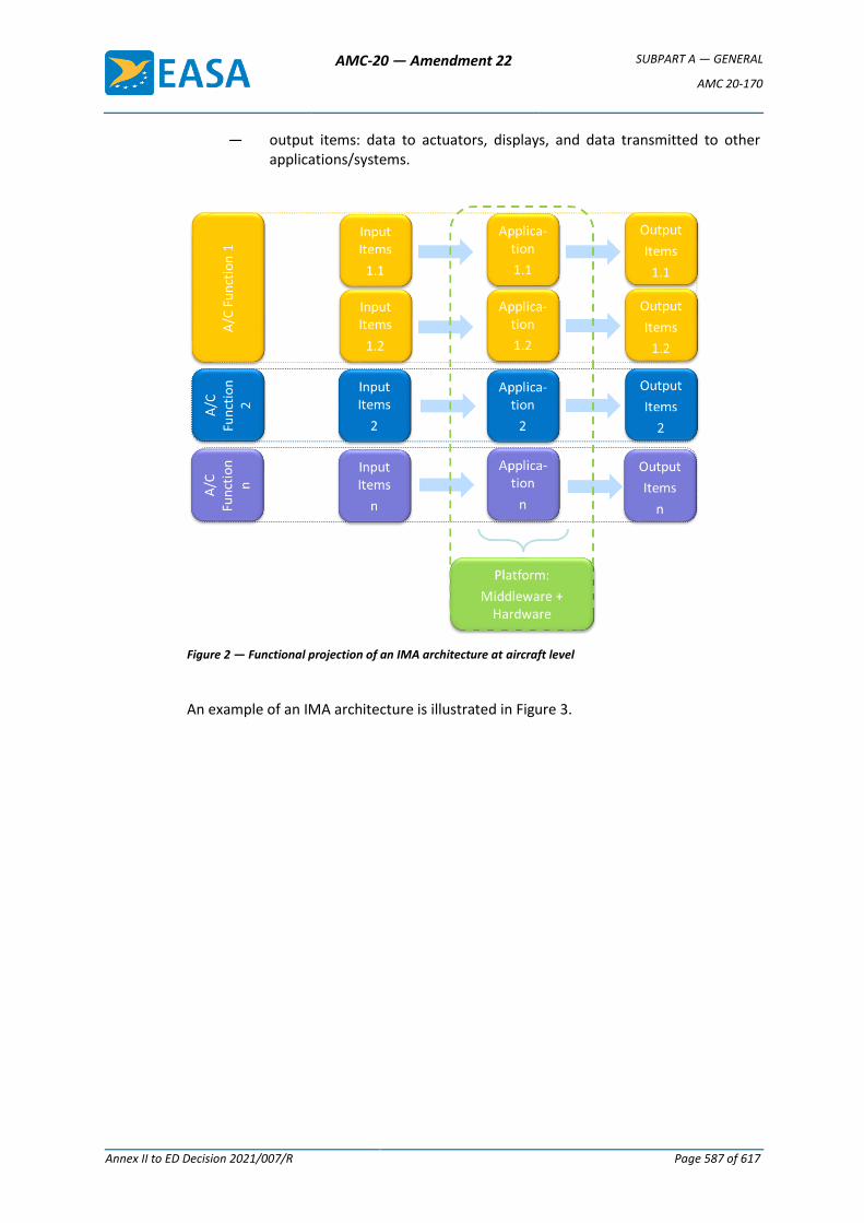
AMC-20 — Amendment 22 SUBPART A — GENERAL
AMC 20-170
Annex II to ED Decision 2021/007/R Page 587 of 617
— output items: data to actuators, displays, and data transmitted to other applications/systems.
Figure 2 — Functional projection of an IMA architecture at aircraft level
An example of an IMA architecture is illustrated in Figure 3.
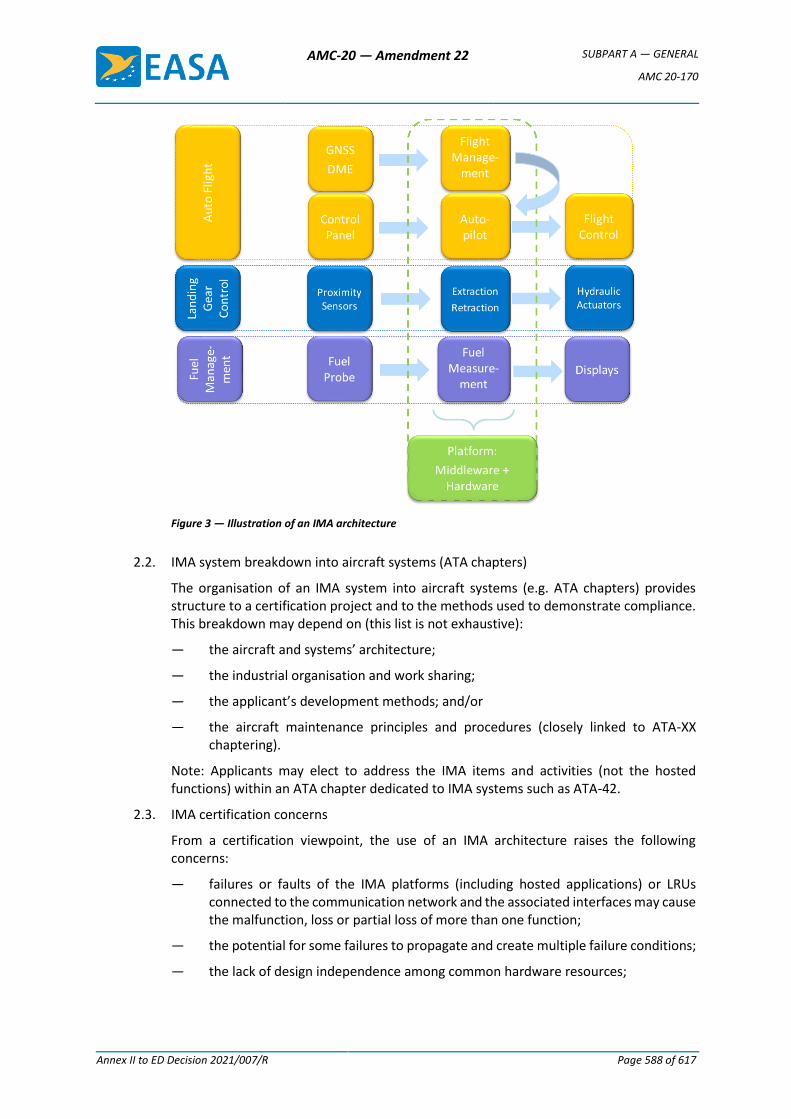
AMC-20 — Amendment 22 SUBPART A — GENERAL
AMC 20-170
Annex II to ED Decision 2021/007/R Page 588 of 617
Figure 3 — Illustration of an IMA architecture
2.2. IMA system breakdown into aircraft systems (ATA chapters)
The organisation of an IMA system into aircraft systems (e.g. ATA chapters) provides structure to a certification project and to the methods used to demonstrate compliance. This breakdown may depend on (this list is not exhaustive):
— the aircraft and systems’ architecture;
— the industrial organisation and work sharing;
— the applicant’s development methods; and/or
— the aircraft maintenance principles and procedures (closely linked to ATA-XX chaptering).
Note: Applicants may elect to address the IMA items and activities (not the hosted functions) within an ATA chapter dedicated to IMA systems such as ATA-42.
2.3. IMA certification concerns
From a certification viewpoint, the use of an IMA architecture raises the following concerns:
— failures or faults of the IMA platforms (including hosted applications) or LRUs connected to the communication network and the associated interfaces may cause the malfunction, loss or partial loss of more than one function;
— the potential for some failures to propagate and create multiple failure conditions;
— the lack of design independence among common hardware resources;
AMC-20 — Amendment 22 SUBPART A — GENERAL
AMC 20-170
Annex II to ED Decision 2021/007/R Page 589 of 617
— susceptibility to common mode failures, faults or design errors, within several identical modules or within the communication network;
— a lack of assurance that the system will behave as intended once all the hosted applications are integrated onto the platform/modules, when software and electronic hardware items have been independently developed and verified;
— inappropriate resource management leading to potential access conflicts and a lack of determinism or unexpected system behaviour; and
— improper isolation mechanisms or configuration not ensuring correct partitioning between functions.
2.4. Functional isolation and independence
From a safety perspective, the primary purpose of the IMA design and certification activities is to demonstrate that the level of functional isolation and independence between the aircraft functions hosted in the IMA system is equivalent to that which would be achieved in a federated architecture.
Functional isolation mostly relies on three pillars:
— proper allocation of shared resources, to prevent adverse interference between hosted applications;
— robust partitioning, concretely assuring the isolation and detection/mitigation of partitioning violations;
— fault containment, to prevent the propagation of faults between hosted applications.
3. Policy for IMA system certification
This section provides guidance to be used for the certification of an IMA system. Considering the IMA architecture, industrial organisation, and the experience in IMA system development of the applicant, several approaches are considered:
— use of the ED-124 standard;
— use of an alternative means to demonstrate compliance;
— use of previously recognised IMA certification processes.
3.1. Use of ED-124
3.1.1. Recognition of ED-124
EUROCAE document ED-124 on Integrated Modular Avionics (IMA) Development Guidance and Certification Considerations, published in July 2007 (equivalent to the RTCA document DO-297), provides guidance for the development and certification of IMA systems.
The use of ED-124 is acceptable to EASA to support the certification of IMA systems when it is used in conjunction with the additional considerations described in this AMC.
3.1.2. Scope of this AMC with respect to ED-124
ED-124 encompasses various aspects and some concepts which are not compatible with the EASA system or which are considered to be outside the scope of this AMC:
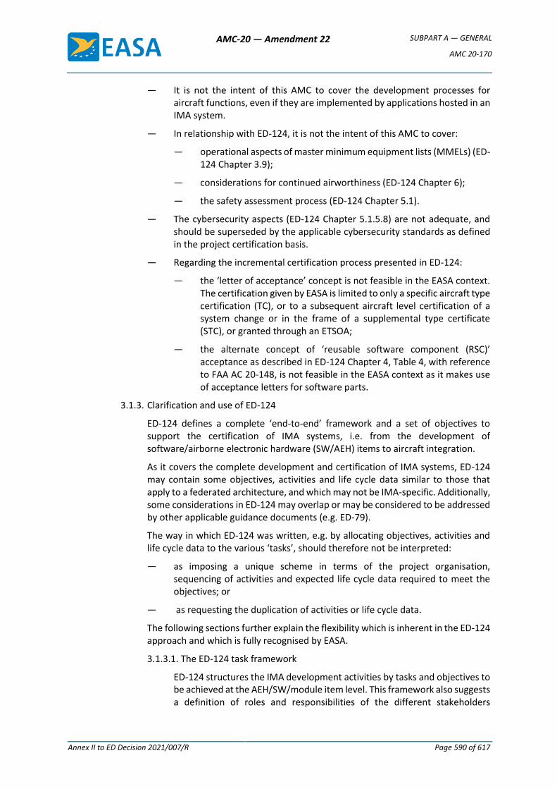
AMC-20 — Amendment 22 SUBPART A — GENERAL
AMC 20-170
Annex II to ED Decision 2021/007/R Page 590 of 617
— It is not the intent of this AMC to cover the development processes for aircraft functions, even if they are implemented by applications hosted in an IMA system.
— In relationship with ED-124, it is not the intent of this AMC to cover:
— operational aspects of master minimum equipment lists (MMELs) (ED-124 Chapter 3.9);
— considerations for continued airworthiness (ED-124 Chapter 6);
— the safety assessment process (ED-124 Chapter 5.1).
— The cybersecurity aspects (ED-124 Chapter 5.1.5.8) are not adequate, and should be superseded by the applicable cybersecurity standards as defined in the project certification basis.
— Regarding the incremental certification process presented in ED-124:
— the ‘letter of acceptance’ concept is not feasible in the EASA context. The certification given by EASA is limited to only a specific aircraft type certification (TC), or to a subsequent aircraft level certification of a system change or in the frame of a supplemental type certificate (STC), or granted through an ETSOA;
— the alternate concept of ‘reusable software component (RSC)’ acceptance as described in ED-124 Chapter 4, Table 4, with reference to FAA AC 20-148, is not feasible in the EASA context as it makes use of acceptance letters for software parts.
3.1.3. Clarification and use of ED-124
ED-124 defines a complete ‘end-to-end’ framework and a set of objectives to support the certification of IMA systems, i.e. from the development of software/airborne electronic hardware (SW/AEH) items to aircraft integration.
As it covers the complete development and certification of IMA systems, ED-124 may contain some objectives, activities and life cycle data similar to those that apply to a federated architecture, and which may not be IMA-specific. Additionally, some considerations in ED-124 may overlap or may be considered to be addressed by other applicable guidance documents (e.g. ED-79).
The way in which ED-124 was written, e.g. by allocating objectives, activities and life cycle data to the various ‘tasks’, should therefore not be interpreted:
— as imposing a unique scheme in terms of the project organisation, sequencing of activities and expected life cycle data required to meet the objectives; or
— as requesting the duplication of activities or life cycle data.
The following sections further explain the flexibility which is inherent in the ED-124 approach and which is fully recognised by EASA.
3.1.3.1. The ED-124 task framework
ED-124 structures the IMA development activities by tasks and objectives to be achieved at the AEH/SW/module item level. This framework also suggests a definition of roles and responsibilities of the different stakeholders
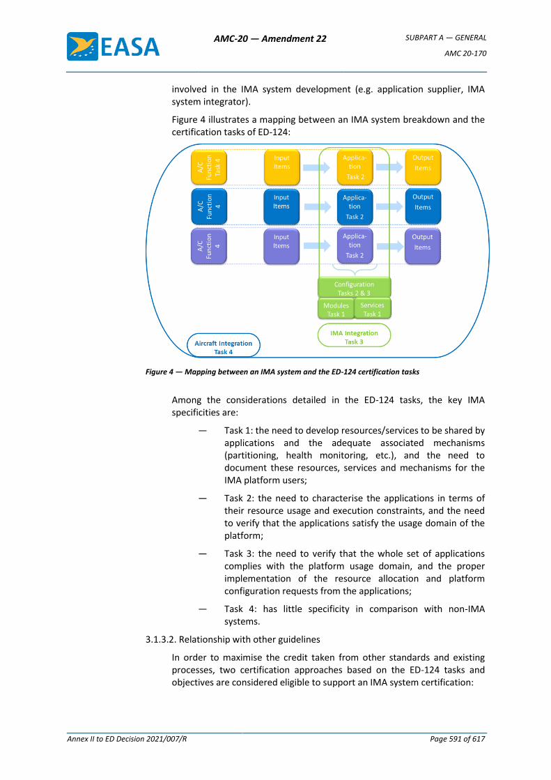
AMC-20 — Amendment 22 SUBPART A — GENERAL
AMC 20-170
Annex II to ED Decision 2021/007/R Page 591 of 617
involved in the IMA system development (e.g. application supplier, IMA system integrator).
Figure 4 illustrates a mapping between an IMA system breakdown and the certification tasks of ED-124:
Figure 4 — Mapping between an IMA system and the ED-124 certification tasks
Among the considerations detailed in the ED-124 tasks, the key IMA specificities are:
— Task 1: the need to develop resources/services to be shared by applications and the adequate associated mechanisms (partitioning, health monitoring, etc.), and the need to document these resources, services and mechanisms for the IMA platform users;
— Task 2: the need to characterise the applications in terms of their resource usage and execution constraints, and the need to verify that the applications satisfy the usage domain of the platform;
— Task 3: the need to verify that the whole set of applications complies with the platform usage domain, and the proper implementation of the resource allocation and platform configuration requests from the applications;
— Task 4: has little specificity in comparison with non-IMA systems.
3.1.3.2. Relationship with other guidelines
In order to maximise the credit taken from other standards and existing processes, two certification approaches based on the ED-124 tasks and objectives are considered eligible to support an IMA system certification:
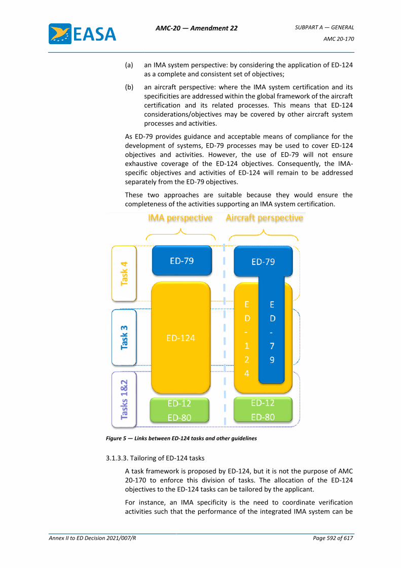
AMC-20 — Amendment 22 SUBPART A — GENERAL
AMC 20-170
Annex II to ED Decision 2021/007/R Page 592 of 617
(a) an IMA system perspective: by considering the application of ED-124 as a complete and consistent set of objectives;
(b) an aircraft perspective: where the IMA system certification and its specificities are addressed within the global framework of the aircraft certification and its related processes. This means that ED-124 considerations/objectives may be covered by other aircraft system processes and activities.
As ED-79 provides guidance and acceptable means of compliance for the development of systems, ED-79 processes may be used to cover ED-124 objectives and activities. However, the use of ED-79 will not ensure exhaustive coverage of the ED-124 objectives. Consequently, the IMA-specific objectives and activities of ED-124 will remain to be addressed separately from the ED-79 objectives.
These two approaches are suitable because they would ensure the completeness of the activities supporting an IMA system certification.
Figure 5 — Links between ED-124 tasks and other guidelines
3.1.3.3. Tailoring of ED-124 tasks
A task framework is proposed by ED-124, but it is not the purpose of AMC 20-170 to enforce this division of tasks. The allocation of the ED-124 objectives to the ED-124 tasks can be tailored by the applicant.
For instance, an IMA specificity is the need to coordinate verification activities such that the performance of the integrated IMA system can be
AMC-20 — Amendment 22 SUBPART A — GENERAL
AMC 20-170
Annex II to ED Decision 2021/007/R Page 593 of 617
guaranteed without requiring the reverification of each hosted application on the entire integrated system:
— ED-124 Chapter 3.1.3 d.2 may be interpreted as requesting that IMA integration should be performed with the full set of applications. However, the applicant may integrate and verify applications independently on the IMA platform, taking into account the platform properties (e.g. robust partitioning and resource management).
— Some Task 3 objectives may be already anticipated and accomplished during Task 2, or they may be deferred to Task 4.
If the applicant intends to develop an IMA system and the supported aircraft functions by tailoring the ED-124 tasks or by following another framework, the applicant should detail the division of tasks, the objectives of each work package, and the associated activities.
The applicant should describe how the work package objectives are mapped to the ED-124 objectives in order to ensure that the objectives of ED-124 are met within the alternative framework presented by the applicant. The ED-124 life cycle data can be also adapted to the division of tasks and work packages defined by the applicant.
Moreover, ED-124 Task 4 may have few IMA specificities compared to a federated architecture. The achievement of Task 4 to support compliance demonstration in the frame of this AMC could be deemed to be outside the scope of this AMC, provided that:
— the aircraft integration activity is covered through other guidance and its related applicant processes (to be clarified in the certification plan);
— Task 3 is complete: meaning that no objectives, activities, or life cycle data are deferred to or covered by Task 4.
Another area where tailoring can be performed is requirement validation. ED-124 Chapter 5.3.a. considers that each level of requirements within the hierarchy should be validated prior to validating the next lower level. A strict interpretation of this statement would not allow the development of a platform based on the assumptions for the intended use without consideration of the final aircraft functions (as suggested in Chapter 4.2.1.b). Also, it would imply a top-down approach from the aircraft functions to the level of hardware and the core/support software, which may not be relevant. A bottom-up approach is also feasible, which involves ensuring that the platform usage rules and constraints identified in the platform user guide/manual (Chapter 4.2.12.e.) are fulfilled, and that they satisfy the IMA system requirements.
3.1.4. Use of alternative means to demonstrate compliance
If an applicant elects to comply with an alternative means to demonstrate compliance with the CS, consistency with the ED-124 acceptance objectives in Annex A tables [A1-A6] (IMA module/platform development process objectives) should be demonstrated.
AMC-20 — Amendment 22 SUBPART A — GENERAL
AMC 20-170
Annex II to ED Decision 2021/007/R Page 594 of 617
Early coordination with EASA should be ensured.
3.2. Use of previously recognised means of compliance
Applicants who did not use this AMC in their past IMA certifications and who successfully used other means of compliance that were:
— discussed in specific CRI(s);
— previously recognised as equivalent to the ED-124 objectives; and
— previously accepted by EASA for covering IMA certification concerns,
may use the same means of compliance for their certification project, provided that the IMA system is similar to the previously certified one (i.e. with a similar architecture, the same design concepts, the same development process, and the same certification approach).
Early coordination with EASA to confirm the use of the applicant’s previously recognised means of compliance should be ensured.
3.3. Role of the IMA system certification plan
ED-124 objectives can be met by using various industrial mappings, based on the sharing of roles, activities and life cycle data. The strategy selected for demonstration of compliance with this AMC should be defined by the applicant in their certification plans.
An IMA system certification plan should introduce the planning, the organisation, the work share, work packages, and the development, validation, integration, and verification activities of the IMA system.
Considerations regarding the content of an IMA system certification plan can be found in ED-124 Chapter 4.4.3. The certification plan should particularly emphasise the following topics:
— The scope covered by the IMA system certification plan and its relationship with other certification plans, including the certification plans of the aircraft functions hosted (totally or partially) on the IMA system.
— The strategy proposed by the applicant to demonstrate compliance with this AMC, including:
— the certification approach selected (see paragraph 3);
— the relationship and credit potentially taken from other standards or processes to satisfy the objectives of ED-124;
— the nature and extent of credit claimed from previously approved components (i.e. having obtained an ETSOA) or from activities performed on components reused from previous certification projects (see paragraph 4);
— the identification of modules, platforms and applications for which full or partial incremental compliance credit is sought.
— The industrial organisation supporting the IMA system development and certification, including the roles, responsibilities and work share between the stakeholders, with, in particular:
— the sharing of activities related to aircraft functions hosted on the IMA platform and the IMA system integration activities;
AMC-20 — Amendment 22 SUBPART A — GENERAL
AMC 20-170
Annex II to ED Decision 2021/007/R Page 595 of 617
— when applicable, the tailoring and scope of the ED-124 tasks, or ED-124 life cycle data;
— the work package allocated to each IMA stakeholder, including the design, validation, verification and integration activities, including environmental qualification under their responsibility and the credit claimed for the incremental certification.
— The activities planned for the integration of the IMA system and its installation on an aircraft with an emphasis on:
— the establishment of full or partial incremental credit gained from the integration, validation and verification activities conducted at each stage of the development, with their associated transition criteria. If a future step cannot be planned by a stakeholder, who for instance would
— only perform the development of a function, the interface to future steps and the assumptions made (e.g. on resources used) need to be identified;
— the credit expected from the characteristics of the IMA platform to independently verify aircraft functions allocated or partially allocated to the IMA system;
— the activities to be completed for the installation of an ETSO-2C153 or C214 article;
— the rationale for not performing some ground or flight tests when the IMA system is installed on the aircraft.
— A description of the development and verification environments, with emphasis on the tools used to generate data or automate the activities and the rationale for the qualification or non-qualification of the tools.
Note: A dedicated IMA system certification plan may not be required provided that its role is equivalently performed by a comprehensive set of documents in the applicant’s data package.
4. Incremental certification process
As indicated in Section 3.1.2, the concepts of ‘letters of acceptance’ and of ‘reusable software components (RSCs)’ are not compatible with the EASA system.
Furthermore, within the EASA system, there is currently no means to benefit from the certification credit granted within a TC or an STC in the frame of another product certification. Formal compliance credit can only be claimed from an ETSOA.
However, the lack of an ETSOA, or the absence of a letter of acceptance, does not prevent an applicant from incrementally building confidence and demonstrating compliance of IMA components during the development flow (as per the ED-124 task framework), nor does it prevent the reuse of previous certification artefacts and activities for a new demonstration of compliance.
The incremental certification process is the process to certify a product for which EASA agrees to grant some credit to a component/module, application or system, before that module, application or system is configured, integrated and certified as part of the final product. The incremental certification process applies to the following approaches:
AMC-20 — Amendment 22 SUBPART A — GENERAL
AMC 20-170
Annex II to ED Decision 2021/007/R Page 596 of 617
(a) Incremental component qualification: credit is taken from activities performed during various steps of the development in order to reduce the effort during a subsequent phase (e.g. verification activities). This qualification is mainly built up using the incremental verification approach.
(b) Reuse: credit is taken from activities performed on components (modules, platforms, applications) reused from other projects. This approach encompasses the components reused from a previously approved TC or from legacy IMA systems.
(c) Compliance credit: formal credit is claimed from an ETSOA.
In all cases, the applicant should evaluate and substantiate the suitability and level of the credit sought. Early coordination with EASA should be ensured.
Note: An ETSOA is not a mandatory step in the certification of an IMA system.
Approach Demonstration of
compliance — responsibilities
Applicant activities Evidence supporting the
claim
(a) Incremental component qualification See paragraph 4.1
Under the full responsibility of the applicant*.
Full compliance demonstration is expected from the applicant.
Evidence of review and acceptance by the applicant, covering all objectives for which credit is sought, including final review reports (at software, hardware, platform, IMA system level(s), as applicable).
(b) Reuse from previous TC See paragraph 4.2
Under the full responsibility of the applicant*.
Compliance demonstration may be tailored depending on the agreement with EASA**. Note: Demonstration of compliance for the IMA components may be reduced (e.g. no software development and verification reviews (SOI#2&3) as part of Task 2).
Previous set of evidence. Evidence of review and acceptance by the applicant, covering all objectives for which credit is sought, including final review reports (at software, hardware, platform, IMA system level(s), as applicable).
(c) Compliance credit See paragraph 4.3
Shared between the: ETSO holder for the scope covered by the ETSOA (e.g. module/platform); applicant* for the completion of integration and/or installation activities.
Compliance demonstration is reduced according to the certification credit claimed from the ETSOA.
ETSOA
Incremental certification evidence table
* Applicant stands for the applicant developing and/or installing the IMA system.
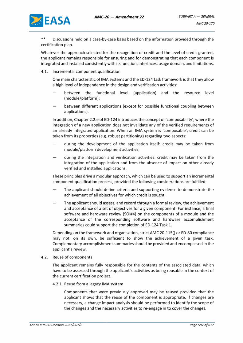
AMC-20 — Amendment 22 SUBPART A — GENERAL
AMC 20-170
Annex II to ED Decision 2021/007/R Page 597 of 617
** Discussions held on a case-by-case basis based on the information provided through the certification plan.
Whatever the approach selected for the recognition of credit and the level of credit granted, the applicant remains responsible for ensuring and for demonstrating that each component is integrated and installed consistently with its function, interfaces, usage domain, and limitations.
4.1. Incremental component qualification
One main characteristic of IMA systems and the ED-124 task framework is that they allow a high level of independence in the design and verification activities:
— between the functional level (application) and the resource level (module/platform);
— between different applications (except for possible functional coupling between applications).
In addition, Chapter 2.2.e of ED-124 introduces the concept of ‘composability’, where the integration of a new application does not invalidate any of the verified requirements of an already integrated application. When an IMA system is ‘composable’, credit can be taken from its properties (e.g. robust partitioning) regarding two aspects:
— during the development of the application itself: credit may be taken from module/platform development activities;
— during the integration and verification activities: credit may be taken from the integration of the application and from the absence of impact on other already verified and installed applications.
These principles drive a modular approach, which can be used to support an incremental component qualification process, provided the following considerations are fulfilled:
— The applicant should define criteria and supporting evidence to demonstrate the achievement of all objectives for which credit is sought.
— The applicant should assess, and record through a formal review, the achievement and acceptance of a set of objectives for a given component. For instance, a final software and hardware review (SOI#4) on the components of a module and the acceptance of the corresponding software and hardware accomplishment summaries could support the completion of ED-124 Task 1.
Depending on the framework and organisation, strict AMC 20-115() or ED-80 compliance may not, on its own, be sufficient to show the achievement of a given task. Complementary accomplishment summaries should be provided and encompassed in the applicant’s review.
4.2. Reuse of components
The applicant remains fully responsible for the contents of the associated data, which have to be assessed through the applicant’s activities as being reusable in the context of the current certification project.
4.2.1. Reuse from a legacy IMA system
Components that were previously approved may be reused provided that the applicant shows that the reuse of the component is appropriate. If changes are necessary, a change impact analysis should be performed to identify the scope of the changes and the necessary activities to re-engage in to cover the changes.
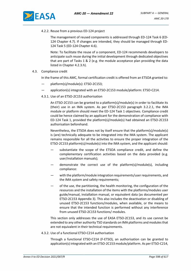
AMC-20 — Amendment 22 SUBPART A — GENERAL
AMC 20-170
Annex II to ED Decision 2021/007/R Page 598 of 617
4.2.2. Reuse from a previous ED-124 project
The management of reused components is addressed through ED-124 Task 6 (ED-124 Chapter 4.7). If changes are intended, they should be managed through ED-124 Task 5 (ED-124 Chapter 4.6).
Note: To facilitate the reuse of a component, ED-124 recommends developers to anticipate such reuse during the initial development through dedicated objectives that are part of Tasks 1 & 2 (e.g. the module acceptance plan providing the data listed in Chapter 4.2.3.h).
4.3. Compliance credit
In the frame of this AMC, formal certification credit is offered from an ETSOA granted to:
— platform(s)/module(s): ETSO-2C153;
— application(s) integrated with an ETSO-2C153 module/platform: ETSO-C214.
4.3.1. Use of an ETSO-2C153 authorisation
An ETSO-2C153 can be granted to a platform(s)/module(s) in order to facilitate its (their) use in an IMA system. As per ETSO-2C153 paragraph 3.2.2.1, the IMA module or platform should meet the ED-124 Task 1 objectives. Compliance credit could be hence claimed by an applicant for the demonstration of compliance with ED-124 Task 1, provided the platform(s)/module(s) had obtained an ETSO-2C153 authorisation beforehand.
Nevertheless, the ETSOA does not by itself ensure that the platform(s)/module(s) is (are) technically adequate to be integrated into the IMA system. The applicant remains responsible for all the activities to ensure the proper integration of the ETSO-2C153 platform(s)/module(s) into the IMA system, and the applicant should:
— substantiate the scope of the ETSOA compliance credit, and define the complementary certification activities based on the data provided (e.g. user/installation manuals);
— demonstrate the correct use of the platform(s)/module(s), including compliance:
— with the platform/module integration requirements/user requirements, and the IMA system and safety requirements;
— of the use, the partitioning, the health monitoring, the configuration of the resources and the installation of the items with the platforms/modules user guide/manual, installation manual, or equivalent data (as documented per ETSO-2C153 Appendix 3). This also includes the deactivation or disabling of unused ETSO-2C153 functions/modules, when available, or the means to ensure that the intended function is performed without any interference from unused ETSO-2C153 functions/ modules.
This section only addresses the use of EASA ETSO-2C153, and its use cannot be extended to any other authority TSO standards on IMA platforms and modules that are not equivalent in their technical requirements.
4.3.2. Use of a functional ETSO-C214 authorisation
Through a functional ETSO-C214 (F-ETSO), an authorisation can be granted to application(s) integrated with an ETSO-2C153 module/platform. As per ETSO-C214,
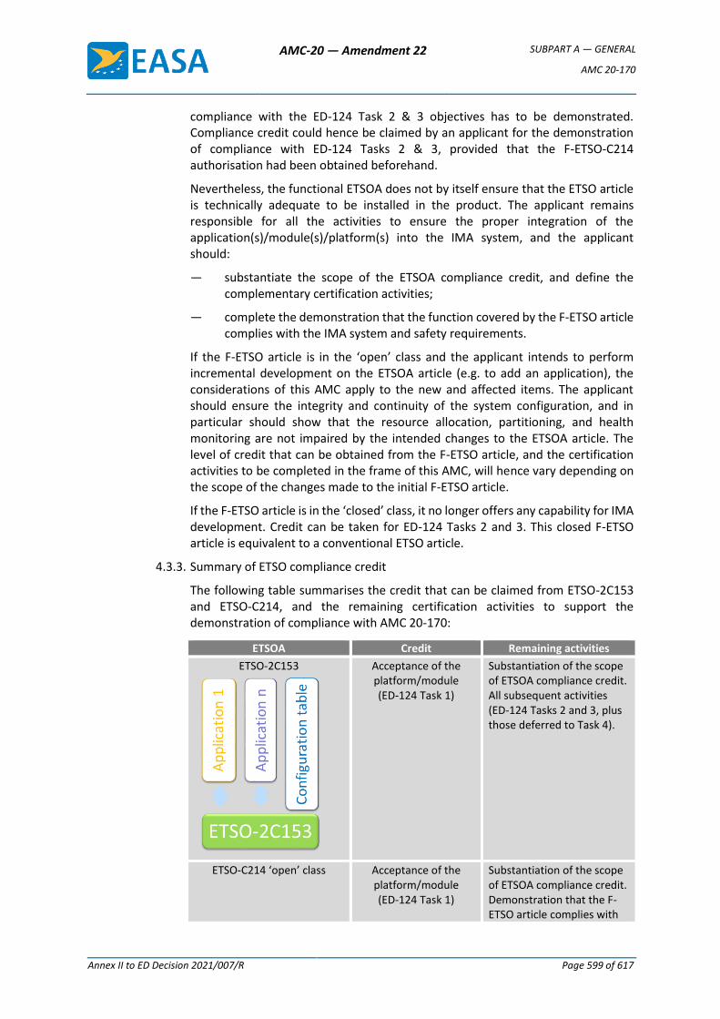
AMC-20 — Amendment 22 SUBPART A — GENERAL
AMC 20-170
Annex II to ED Decision 2021/007/R Page 599 of 617
compliance with the ED-124 Task 2 & 3 objectives has to be demonstrated. Compliance credit could hence be claimed by an applicant for the demonstration of compliance with ED-124 Tasks 2 & 3, provided that the F-ETSO-C214 authorisation had been obtained beforehand.
Nevertheless, the functional ETSOA does not by itself ensure that the ETSO article is technically adequate to be installed in the product. The applicant remains responsible for all the activities to ensure the proper integration of the application(s)/module(s)/platform(s) into the IMA system, and the applicant should:
— substantiate the scope of the ETSOA compliance credit, and define the complementary certification activities;
— complete the demonstration that the function covered by the F-ETSO article complies with the IMA system and safety requirements.
If the F-ETSO article is in the ‘open’ class and the applicant intends to perform incremental development on the ETSOA article (e.g. to add an application), the considerations of this AMC apply to the new and affected items. The applicant should ensure the integrity and continuity of the system configuration, and in particular should show that the resource allocation, partitioning, and health monitoring are not impaired by the intended changes to the ETSOA article. The level of credit that can be obtained from the F-ETSO article, and the certification activities to be completed in the frame of this AMC, will hence vary depending on the scope of the changes made to the initial F-ETSO article.
If the F-ETSO article is in the ‘closed’ class, it no longer offers any capability for IMA development. Credit can be taken for ED-124 Tasks 2 and 3. This closed F-ETSO article is equivalent to a conventional ETSO article.
4.3.3. Summary of ETSO compliance credit
The following table summarises the credit that can be claimed from ETSO-2C153 and ETSO-C214, and the remaining certification activities to support the demonstration of compliance with AMC 20-170:
ETSOA Credit Remaining activities
ETSO-2C153
Acceptance of the platform/module (ED-124 Task 1)
Substantiation of the scope of ETSOA compliance credit. All subsequent activities (ED-124 Tasks 2 and 3, plus those deferred to Task 4).
ETSO-C214 ‘open’ class Acceptance of the platform/module (ED-124 Task 1)
Substantiation of the scope of ETSOA compliance credit. Demonstration that the F-ETSO article complies with
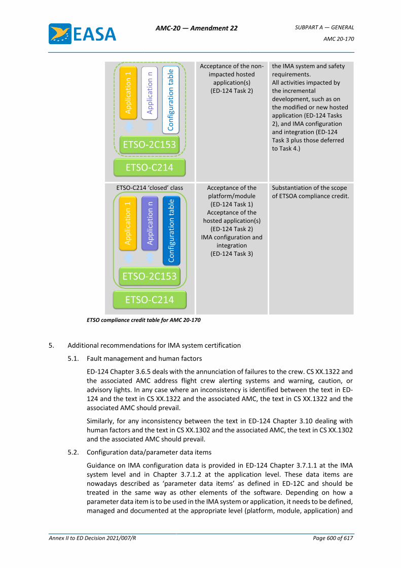
AMC-20 — Amendment 22 SUBPART A — GENERAL
AMC 20-170
Annex II to ED Decision 2021/007/R Page 600 of 617
Acceptance of the non-impacted hosted
application(s) (ED-124 Task 2)
the IMA system and safety requirements. All activities impacted by the incremental development, such as on the modified or new hosted application (ED-124 Tasks 2), and IMA configuration and integration (ED-124 Task 3 plus those deferred to Task 4.)
ETSO-C214 ‘closed’ class
Acceptance of the platform/module (ED-124 Task 1)
Acceptance of the hosted application(s)
(ED-124 Task 2) IMA configuration and
integration (ED-124 Task 3)
Substantiation of the scope of ETSOA compliance credit.
ETSO compliance credit table for AMC 20-170
5. Additional recommendations for IMA system certification
5.1. Fault management and human factors
ED-124 Chapter 3.6.5 deals with the annunciation of failures to the crew. CS XX.1322 and the associated AMC address flight crew alerting systems and warning, caution, or advisory lights. In any case where an inconsistency is identified between the text in ED-124 and the text in CS XX.1322 and the associated AMC, the text in CS XX.1322 and the associated AMC should prevail.
Similarly, for any inconsistency between the text in ED-124 Chapter 3.10 dealing with human factors and the text in CS XX.1302 and the associated AMC, the text in CS XX.1302 and the associated AMC should prevail.
5.2. Configuration data/parameter data items
Guidance on IMA configuration data is provided in ED-124 Chapter 3.7.1.1 at the IMA system level and in Chapter 3.7.1.2 at the application level. These data items are nowadays described as ‘parameter data items’ as defined in ED-12C and should be treated in the same way as other elements of the software. Depending on how a parameter data item is to be used in the IMA system or application, it needs to be defined, managed and documented at the appropriate level (platform, module, application) and
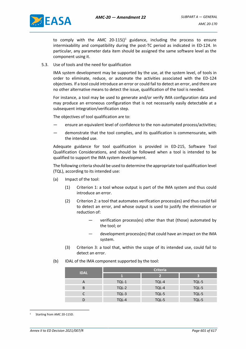
AMC-20 — Amendment 22 SUBPART A — GENERAL
AMC 20-170
Annex II to ED Decision 2021/007/R Page 601 of 617
to comply with the AMC 20-115()1 guidance, including the process to ensure intermixability and compatibility during the post-TC period as indicated in ED-124. In particular, any parameter data item should be assigned the same software level as the component using it.
5.3. Use of tools and the need for qualification
IMA system development may be supported by the use, at the system level, of tools in order to eliminate, reduce, or automate the activities associated with the ED-124 objectives. If a tool could introduce an error or could fail to detect an error, and there are no other alternative means to detect the issue, qualification of the tool is needed.
For instance, a tool may be used to generate and/or verify IMA configuration data and may produce an erroneous configuration that is not necessarily easily detectable at a subsequent integration/verification step.
The objectives of tool qualification are to:
— ensure an equivalent level of confidence to the non-automated process/activities;
— demonstrate that the tool complies, and its qualification is commensurate, with the intended use.
Adequate guidance for tool qualification is provided in ED-215, Software Tool Qualification Considerations, and should be followed when a tool is intended to be qualified to support the IMA system development.
The following criteria should be used to determine the appropriate tool qualification level (TQL), according to its intended use:
(a) Impact of the tool:
(1) Criterion 1: a tool whose output is part of the IMA system and thus could introduce an error.
(2) Criterion 2: a tool that automates verification process(es) and thus could fail to detect an error, and whose output is used to justify the elimination or reduction of:
— verification process(es) other than that (those) automated by the tool; or
— development process(es) that could have an impact on the IMA system.
(3) Criterion 3: a tool that, within the scope of its intended use, could fail to detect an error.
(b) IDAL of the IMA component supported by the tool:
IDAL Criteria
1 2 3
A TQL-1 TQL-4 TQL-5
B TQL-2 TQL-4 TQL-5
C TQL-3 TQL-5 TQL-5
D TQL-4 TQL-5 TQL-5
1 Starting from AMC 20-115D.
AMC-20 — Amendment 22 SUBPART A — GENERAL
AMC 20-170
Annex II to ED Decision 2021/007/R Page 602 of 617
5.4. Change management
This section deals not only with changes to components that were previously accepted through a TC, STC or ETSOA, but also with changes during the development as soon as components are delivered for use in a subsequent stage of the process and a formal baseline is established for these components.
The main objectives of the change management process are to conduct and document a change impact analysis and to reintegrate the changed component into the IMA system, performing all the necessary verification, validation, and integration activities (including regression analysis and testing).
(a) Since there are various levels of development and integration in an IMA system, and potentially various stakeholders (the module/platform developer, application developer, IMA system integrator, aircraft designer), agreements should be concluded between stakeholders to establish the way to communicate changes and to perform impact analyses at each level.
(b) A change impact analysis should consider the possible impacts to be reported at each relevant level:
— changes at the resource allocation level;
— changes at the module/platform level;
— changes at the application level.
(c) Impacts on incremental compliance credit (if applicable) also need to be considered.
(d) The changes should be documented in the appropriate life cycle data, including the trace data, configuration indexes and accomplishment summaries.
5.5. Management of problem reports
IMA systems contain multiple applications hosted on the same IMA module/platform, therefore any OPR related to a module/platform or application, collected at any level, could affect one or several aircraft functions directly or indirectly.
Considering the diversity of stakeholders in an IMA system, the management of problem reports can be more complex than with federated systems. In addition to the applicable guidance on OPR management, for IMA systems, the applicant should organise the management of OPRs, focusing on:
— the evaluation of the potential effect of each OPR on any shared resources and IMA services, and the evaluation of those OPRs for impact on any aircraft function that uses the affected shared resources and IMA services;
— the verification that necessary workarounds, including limitations, at the application and/or system levels, are documented within the IMA documentation (e.g. user guide/manual). In such cases, the efficiency of a workaround should be substantiated and the successful (i.e. complete and correct) deployment of the workaround should be ensured.
NOTE: In order to facilitate the assessment and the communication between stakeholders, the use of a harmonised classification scale for OPRs is recommended.
5.6. Environmental qualification
AMC-20 — Amendment 22 SUBPART A — GENERAL
AMC 20-170
Annex II to ED Decision 2021/007/R Page 603 of 617
The scope of this section is to provide environmental qualification guidance complementary to ED-124 Chapter 5.2.6 for the environmental qualification of an IMA system. It can be an IMA platform composed of only one LRU, or various modules in a given configuration. The platform is qualified in conditions of the same severity as those expected when installed on the aircraft, interfaced with its peripherals through the aircraft (or equivalent) harnesses, and loaded with its set of applications. The acceptance criteria to qualify the platform are driven by the operational requirements of a given aircraft.
Level of qualification testing activities: The modularity of an IMA platform makes it possible to conduct qualification testing activities at various stages:
— IMA module testing: the testing is performed on an IMA module, involving the shared resources (hardware and/or software), and when relevant, with a representative set of software applications loaded onto the module. In the case of a cabinet, the module can be a chassis and/or a backplane.
— IMA platform testing: the testing is performed on the platform or cabinet (chassis and backplane) equipped with its modules, and when relevant, loaded with a representative set of software applications.
— System testing: the testing is performed on a set of modules and/or the backplane installed in the cabinet, with system peripherals interfaced with the cabinet, and with representative software applications loaded onto the modules.
— Aircraft testing: the testing is performed with the systems installed on the aircraft.
The modularity of the IMA platform, combined with the variety of its possible configurations, leads to the establishment of principles to reuse qualification credit for IMA modules in the context of qualifying a desired IMA platform for a given aircraft:
(a) The environmental usage domain of an IMA module is the set of environmental conditions for which it is qualified. This is documented in the module user guide/manual.
(b) For an IMA module integrated within a cabinet, its environmental qualification conditions should consider:
— its environmental conditions (i.e. the envelope of thermal, electromagnetic, vibration, lightning, etc., conditions) encountered inside the cabinet when in use on the aircraft;
— all its possible arrangements in the cabinet (i.e. different IMA platform configurations).
Incremental environmental qualification is an approach used in qualifying a cabinet populated with modules in a known configuration for a given aircraft, relying on existing qualification credit for IMA modules in their environmental usage domain, and identifying any complementary qualification substantiation that would be necessary to cover the envelope of the environmental conditions of the aircraft. Thus it provides the latitude to populate a cabinet with already qualified modules, to qualify it without having to perform a full reassessment of the qualification of each module, and the capability to reuse its existing qualification dossier.
All the substantiation data recorded in the qualification plan should be based on dedicated tests or on equivalence with the reuse of existing qualification results, or existing authorisations such as ETSO-2C153. The representativeness of the
AMC-20 — Amendment 22 SUBPART A — GENERAL
AMC 20-170
Annex II to ED Decision 2021/007/R Page 604 of 617
substantiation should consider the testing configuration, the testing conditions (including electrical, thermal, mechanical interfaces, etc.), the qualification testing level, the application software used for the testing, the test scenario and the level of stress applied.
When an IMA system change is implemented, a change impact analysis should be conducted against the qualified configuration to assess the complementary qualification substantiation to be provided for each of its modules.
[Amdt 20/15]
AMC-20 — Amendment 22 SUBPART A — GENERAL
AMC 20-189
Annex II to ED Decision 2021/007/R Page 605 of 617
AMC 20-189
AMC 20-189 The Management of Open Problem Reports (OPRs)
1. PURPOSE
This AMC describes an acceptable means, but not the only means, for showing compliance with the
applicable airworthiness regulations for the management of open problem reports (OPRs) in ETSO
authorisations and type certification, for the system, software and airborne electronic hardware (AEH)
domains. Compliance with this AMC is not mandatory, and an applicant may elect to use an alternative
means of compliance. However, the alternative means of compliance must meet the relevant
requirements, ensure an equivalent level of safety, and be approved by EASA on a product or ETSO
article basis.
2. APPLICABILITYThis AMC may be used by applicants, design approval holders, and developers of
airborne systems and equipment to be installed on type-certified aircraft, engines, and
propellers. This AMC applies to all airborne electronic systems and equipment, including to the
software and AEH components contained in those systems, which could cause or contribute to
Catastrophic, Hazardous, or Major failure conditions.
3. BACKGROUND
3.1. Each of the system, software and AEH domains relies on problem report (PR) management to
ensure the proper management of open problem reports (OPRs) and to help ensure safe
products at the time of approval. However, the existing guidance on PR and OPR management
is inconsistent and incomplete across domains. Therefore, this AMC provides consistent
guidance across these domains for PR management, OPR management, stakeholder
responsibilities, reporting, and other aspects of OPR management. This AMC complements but
does not alleviate the project-applicable system, software and AEH guidance.
3.2. The technical content of this AMC has been jointly developed with the Federal Aviation
Administration (FAA), in order to harmonise as far as practicable.
4. DEFINITIONS
4.1. Terms defined in this AMC
Approval: the term ‘approval’ in this document addresses the approval by EASA of a product or
of changes to a product, or authorisation of an ETSO article or of changes to an ETSO article.
Article: refer to Article 1(2)(f) of Regulation (EU) No 748/2012 (‘EASA Part 21’).
Development assurance: all of those planned and systematic actions used to substantiate, with
an adequate level of confidence, that errors in requirements, design, and implementation have
been identified and corrected such that the system satisfies the applicable certification basis
(source: ARP4754A/ED-79A).
AMC-20 — Amendment 22 SUBPART A — GENERAL
AMC 20-189
Annex II to ED Decision 2021/007/R Page 606 of 617
Equipment: an item or collection of items with a defined set of requirements.
Error: a mistake in the requirements, design, or implementation with the potential of producing
a failure.
Failure: the inability of a system or system component to perform a function within specified
limits (source: DO-178C/ED-12C and DO-254/ED-80).
Item: a hardware or software element that has bounded and well-defined interfaces (source:
ARP4754A/ED-79A).
Open problem report (OPR): a problem report that has not reached the state ‘Closed’ at the
time of approval.
Problem report (PR): a means to identify and record the resolution of anomalous behaviour,
process non-compliance with development assurance plans and standards, and deficiencies in
life-cycle data (adapted from DO-178C/ED-12C).
Product: refer to Article 3(3) of Regulation (EU) 2018/1139 (the ‘EASA Basic Regulation’).
System: a combination of interrelated equipment, article(s), and/or items arranged to perform
a specific function (or functions) within a product.
4.2. States of PRs/OPRs
Recorded: a problem that has been documented using the problem-reporting process.
Classified: a problem report that has been categorised in accordance with an established
classification scheme.
Resolved: a problem report that has been corrected or fully mitigated, for which the resolution
of the problem has been verified but not formally reviewed and confirmed.
Closed: a resolved problem report that underwent a formal review and confirmation of the
effective resolution of the problem.
4.3. Classifications of PRs/OPRs
‘Significant’: assessed at the product, system, or equipment level, a PR that has an actual or
potential effect on the product, system, or equipment function that may lead to a Catastrophic,
Hazardous or Major failure condition, or may affect compliance with the operating rules.
‘Functional’: a PR that has an actual or a potential effect on a function at the product, system,
or equipment level.
‘Process’: a PR that records a process non-compliance or deficiency that cannot result in a
potential safety, nor a potential functional, effect.
‘Life-cycle data’: a PR that is linked to a deficiency in a life-cycle data item but not linked to a
process non-compliance or process deficiency.
5. PROBLEM REPORT MANAGEMENT

AMC-20 — Amendment 22 SUBPART A — GENERAL
AMC 20-189
Annex II to ED Decision 2021/007/R Page 607 of 617
The PR management process is a key enabler for the management of OPRs. The PR management
process enables the consistent and timely management of problems encountered across the system,
software and AEH domains. Consequently, this process reduces the risk of a loss of visibility of critical
issues remaining at the time of approval.
5.1 A PR management process across the system, software and AEH domains should be established
and used during the development (both for initial certification and subsequent changes) of a
product or an ETSO article. The PR management process should address the review and
resolution of PRs that impact the transition to other development assurance processes.
5.2 A problem recorded after approval should also be managed through the PR management
process, and any related systemic process issues should be identified and corrected.
5.3 PRs that cannot be resolved by the current stakeholder should be reported in a manner that is
understandable to the affected stakeholders.
5.4 For PRs that may have an impact on other products or articles that are developed within an
organisation, a means should be established for sharing PR information so that any necessary
corrective actions can be taken.
6. OPR MANAGEMENT
An OPR management process, based on the PR management process, should be established across
the system, software and AEH domains, including the following process steps:
6.1 The classification of OPRs
6.1.1 The applicant should establish an OPR classification scheme including, at a minimum, the
following classifications: ‘Significant’, ‘Functional’, ‘Process’ and ‘Life-cycle data’. Other
classifications or subclassifications may be created as needed. The classification scheme should
be described in the appropriate planning document(s).
6.1.2 Each OPR should be assigned a single classification per the classification scheme. When multiple
classifications apply, the OPR should be assigned the classification with the highest priority. The
priority from highest to lowest (including the defined subclassifications) is:
1. ‘Significant’;
2. ‘Functional’;
3. ‘Process’;
4. ‘Life-cycle data’;
5. any other OPR classification.
Note: The classification of an individual OPR may differ from one stakeholder to another,
depending on the known mitigations at the time of classification.
6.1.3 The classification of an OPR should account for and document all the mitigations known at the
time of classification that are under the control of the classifying stakeholder. A mitigation that
is controlled by another stakeholder may be considered in the classification only if validated
with that stakeholder, and provided this mitigation remains acceptable in the frame of the type
AMC-20 — Amendment 22 SUBPART A — GENERAL
AMC 20-189
Annex II to ED Decision 2021/007/R Page 608 of 617
certificate (TC) / supplemental type certificate (STC) approval or European technical standard
order (ETSO) article authorisation, as applicable.
6.1.4 A stakeholder, other than the aircraft TC or STC applicant, should classify as ‘Significant’ any
OPR for which the classification may vary between ‘Functional’ and ‘Significant’, depending on
the installation.
6.2 The assessment of OPRs
Each OPR should be assessed to determine:
1. any resulting functional limitations or operational restrictions at the equipment level (for
ETSOs) or at the product level (for other types of approvals);
2. relationships that may exist with other OPRs; and
3. for a ‘Significant’ or ‘Functional’ OPR, the underlying technical cause of the problem.
6.3 Disposition: OPRs classified as ‘Significant’ per the classification in Section 6.1, for which no
sufficient mitigation or justification exists to substantiate the acceptability of the safety effect,
should be resolved prior to approval. The disposition of OPRs may involve coordination with the
certification authority.
6.4 Reporting: an OPR summary report should be prepared and provided to the affected
stakeholder(s), and to the certification authority upon request. The OPR summary report may
be an aggregation of summaries (e.g. Software/Hardware Accomplishment Summaries or
system-level OPR reports) prepared by all the involved stakeholders. The summary report
should provide access to the following information for each OPR:
6.4.1 The identification of the OPR (for example, the OPR ID);
6.4.2 The identification of the affected configuration item(s) (for example, the item part number,
component name, artefact name) or of the affected process(es);
6.4.3 Title or a summary of the problem, formulated in a manner understandable by the affected
stakeholder(s);
6.4.4 Description of the problem, formulated in a manner understandable by the affected
stakeholder(s);
6.4.5 The conditions under which the problem occurs;
6.4.6 The OPR classification and assessment results (per Sections 6.1 and 6.2), including:
1. for each OPR, regardless of its classification:
a. the classification of the OPR, and
b. the relationships that are known to exist with other OPRs;
2. for OPRs classified as ‘Significant’:
a. a description of any mitigations or justifications used to substantiate the
acceptability of the OPR safety effect (per Section 6.3), and
AMC-20 — Amendment 22 SUBPART A — GENERAL
AMC 20-189
Annex II to ED Decision 2021/007/R Page 609 of 617
b. the functional limitations and operational restrictions, if any;
3. for OPRs classified as ‘Functional’:
a. a description of any mitigations or justifications used to reduce the safety effect to
Minor or No Safety Effect, and
b. the functional limitations and operational restrictions, if any;
4. for OPRs classified as ‘Process’, a description of the extent or nature of the process
non-compliance or deficiency that might contribute to not satisfying the applicable
development assurance objectives; and
5. for each OPR not classified as ‘Significant’ or ‘Functional’, the justification that the error
cannot have a safety or functional effect.
6.5 ETSO specifics: The ETSO authorisation holder may exclude from the reporting process (per
Section 6.4) any OPRs classified as ‘Process’ or ‘Life-cycle data’ that are not necessary for the
installation approval. However, all OPRs should be available upon request by the certification
authority for assessment in the frame of the ETSO approval.
7. STAKEHOLDER RESPONSIBILITIES
The levels of stakeholders include: item, equipment or ETSO article, system and product.
The actual stakeholders for a specific project depend on the project organisation.
7.1 PR management (per Section 5) should be performed by the stakeholder at each level. The
applicant has responsibility for the overall PR process for all the involved stakeholders.
7.2 OPR management (per Section 6) should be performed, at a minimum, at the ETSO article level,
at the level of each individual system within a product, and at the product level.
8. RELATED REGULATORY, ADVISORY AND INDUSTRY MATERIAL
(a) Related EASA Certification Specifications (CSs)
(1) CS-23, Certification Specifications and Acceptable Means of Compliance for Normal
Category Aeroplanes
(2) CS-25, Certification Specifications and Acceptable Means of Compliance for Large
Aeroplanes
(3) CS-27, Certification Specifications and Acceptable Means of Compliance for Small
Rotorcraft
(4) CS-29, Certification Specifications and Acceptable Means of Compliance for Large
Rotorcraft
(5) CS-E, Certification Specifications and Acceptable Means of Compliance for Engines, and
AMC 20-3A, Certification of Engines Equipped with Electronic Engine Control Systems
(6) CS-P, Certification Specifications for Propellers, and AMC 20-1, Certification of Aircraft
Propulsion Systems Equipped with Electronic Control Systems
AMC-20 — Amendment 22 SUBPART A — GENERAL
AMC 20-189
Annex II to ED Decision 2021/007/R Page 610 of 617
(7) CS-ETSO, Certification Specifications for European Technical Standard Orders
(8) CS-APU, Certification Specifications for Auxiliary Power Units, and AMC 20-2A,
Certification of Essential APU Equipped with Electronic Controls
(b) EASA Acceptable Means of Compliance (AMC)
(1) AMC 20-115( ), Airborne Software Development Assurance Using EUROCAE ED-12 and
RTCA DO-178
(2) AMC 20-152( ), Development Assurance for Airborne Electronic Hardware
(c) FAA ACs
Refer to latest version.
(1) AC 20-115( ), Airborne Software Development Assurance Using EUROCAE ED-12( ) and
RTCA DO-178( )
(2) AC 20-152( ), Development Assurance for Airborne Electronic Hardware
(3) AC 27-1309( ), Equipment, Systems, and Installations (included in AC 27-1, Certification of
Normal Category Rotorcraft)
(4) AC 29-1309( ), Equipment, Systems, and Installations (included in AC 29-2, Certification of
Transport Category Rotorcraft)
(d) Industry Documents
(1) EUROCAE ED-12, Software Considerations in Airborne Systems and Equipment
Certification, dated May 1982 (no longer in print)
(2) EUROCAE ED-12A, Software Considerations in Airborne Systems and Equipment
Certification, dated October 1985 (no longer in print)
(3) EUROCAE ED-12B, Software Considerations in Airborne Systems and Equipment
Certification, dated December 1992
(4) EUROCAE ED-12C, Software Considerations in Airborne Systems and Equipment
Certification, dated January 2012
(5) EUROCAE ED-79A, Guidelines for Development of Civil Aircraft and Systems, dated
December 2010
(6) EUROCAE ED-80, Design Assurance Guidance for Airborne Electronic Hardware, dated
April 2000
(7) EUROCAE ED-94C, Supporting Information for ED-12C and ED-109A, dated January 2012
(8) EUROCAE ED-215, Software Tool Qualification Considerations, dated January 2012
(9) EUROCAE ED-216, Formal Methods Supplement to ED-12C and ED-109A, dated January
2012
AMC-20 — Amendment 22 SUBPART A — GENERAL
AMC 20-189
Annex II to ED Decision 2021/007/R Page 611 of 617
(10) EUROCAE ED-217, Object-Oriented Technology and Related Techniques Supplement to
ED-12C and ED-109A, dated January 2012
(11) EUROCAE ED-218, Model-Based Development and Verification Supplement to ED-12C
and ED-109A, dated January 2012
(12) RTCA DO-178, Software Considerations in Airborne Systems and Equipment Certification,
dated January 1982 (no longer in print)
(13) RTCA DO-178A, Software Considerations in Airborne Systems and Equipment
Certification, dated March 1985 (no longer in print)
(14) RTCA DO-178B, Software Considerations in Airborne Systems and Equipment
Certification, dated 1 December 1992
(15) RTCA DO-178C, Software Considerations in Airborne Systems and Equipment
Certification, dated 13 December 2011
(16) RTCA DO-248C, Supporting Information for DO-178C and DO-278A, dated 13 December
2011
(17) RTCA DO-254, Design Assurance Guidance for Airborne Electronic Hardware, dated April
19, 2000
(18) RTCA DO-297, Integrated Modular Avionics (IMA) Development Guidance and
Certification Considerations, dated 8 November 2005
(19) RTCA DO-330, Software Tool Qualification Considerations, dated 13 December 2011
(20) RTCA DO-331, Model-Based Development and Verification Supplement to DO-178C and
DO-278A, dated 13 December 2011
(21) RTCA DO-332, Object-Oriented Technology and Related Techniques Supplement to DO-
178C and DO-278A, dated 13 December 2011
(22) RTCA DO-333, Formal Methods Supplement to DO-178C and DO-278A, dated
13 December 2011
(23) SAE International Aerospace Recommended Practice (ARP) 4754A, Guidelines for
Development of Civil Aircraft and Systems
AMC-20 — Amendment 22 SUBPART A — GENERAL
AMC 20-189
Annex II to ED Decision 2021/007/R Page 612 of 617
9. AVAILABILITY OF DOCUMENTS
(1) EASA Certification Specifications (CSs) and Acceptable Means of Compliance (AMC) may
be downloaded from the EASA website: www.easa.europa.eu
(2) FAA Advisory Circulars (ACs) may be downloaded from the FAA website: www.faa.gov
(3) EUROCAE documents may be purchased from:
European Organisation for Civil Aviation Equipment
9-23 rue Paul Lafargue
"Le Triangle" building
93200 Saint-Denis, France
Telephone: +33 1 49 46 19 65
(Email: [email protected], website: www.eurocae.net)
(4) RTCA documents may be purchased from:
RTCA, Inc.1150 18th Street NW, Suite 910, Washington DC 20036, USA
(Email: [email protected], website: www.rtca.org)
10. GUIDANCE MATERIAL
GM 20-189 The Management of Open Problem Reports
GM1 to AMC 20-189 — PR management
Typically, PR processes include the following aspects:
1. PR Recording: a means to document problems resulting from the execution of life-cycle
processes.
2. PR Classification: a means to classify PRs prior to the time of approval of the product or of the
ETSO article, as early in the life cycle as practical. While early classification may be preliminary,
it will help to focus attention on PRs with a potential safety or functional effect, as well as
process PRs that may impact the development or development assurance processes.
3. PR Assessment: a means to assess the effect of having a PR remain open at the time of approval.
The assessment of PRs classified as ‘Significant’, ‘Functional’ or ‘Process’ would typically be
performed by a review board. The assessment of PRs classified as ‘Life-cycle data’ may be
performed within the peer-review process instead of a review board.
4. PR Resolution: a means to correct or mitigate PRs prior to the time of approval, as early in the
life cycle as practical. The PR resolution process may depend on the classification of the PR; for
example, shorter closure loops could be set for PRs classified as ‘Life-cycle data’.
5. PR Closure: a means to close PRs, which includes the review and confirmation of the resolution
of the problem, and indicated through a documented authorisation process (e.g. Change
Control Board sign-off).
AMC-20 — Amendment 22 SUBPART A — GENERAL
AMC 20-189
Annex II to ED Decision 2021/007/R Page 613 of 617
GM2 to AMC 20-189 — OPR classification
The following paragraph links the classifications presented in DO-248C/ED-94C, DP #9 to those defined
in AMC 20-189, subparagraph 6.1. This paragraph highlights the clarifications made to the former
scheme (e.g. removing the overlaps between the classifications).
1. The most important clarification compared with the former classification scheme is to give each
OPR a single classification using a given order of priority as reflected in AMC 20-189
subparagraph 6.1.2. This promotes visibility of the most relevant issues and helps to prevent
inconsistencies in classification. For example, a missing or incorrect requirement issue can be
classified as ‘Life-cycle data’ only if it is confirmed that it cannot be classified as ‘Significant’,
‘Functional’, or ‘Process’, in that order of priority.
2. Type ‘Significant’: this typically maps to ‘Type 0’. However, some applicants may have used
‘Type 1A’ to characterise some PRs, for instance, those linked to Major failure conditions. The
AMC 20-189 scheme clarifies that those PRs potentially causing or contributing to Catastrophic,
Hazardous or Major failure conditions belong to the class ‘Significant’.
3. Type ‘Functional’: this typically maps to ‘Type 1A’ or ‘Type 1B’, that is, a problem that results in
a failure with a minor or no adverse impact on safety. A PR whose consequences are a failure
that can potentially lead to a Minor failure condition could be mapped to ‘Type 1A’, and a PR
leading to a failure having No Safety Effect could be mapped to ‘Type 1B’. Two separate
subclassifications could therefore be created in the applicant’s classification scheme to ease the
mapping: problems having a functional effect leading to a Minor failure condition could be
classified separately (e.g. ‘Functional 1’) from the ones having No Safety Effect (e.g.
‘Functional 2’). Moreover, an important clarification is that AMC 20-189 does not explicitly
consider the ‘operational’ nature of a PR in the classification scheme to avoid creating overlaps,
as a PR with operational consequences could either be classified as ‘Significant’ or ‘Functional’.
Creating an ‘Operational’ subclassification within the classification ‘Significant’ or ‘Functional’ is
nevertheless an option available to stakeholders to create a specific emphasis on operational
issues within the proposed classification scheme.
4. Type ‘Process’: this may map to ‘Type 3A’; however, not in cases where the process
non-compliance or deficiency could result in either not detecting a failure or creating a failure.
An important clarification in AMC 20-189 is the removal of the ambiguous notion of ‘significant
deviation from the plans or standards’ used in the definition of ‘Type 3A’. The ‘Process’
classification in AMC 20-189 should be used for PRs that record a process non-compliance or
deficiency, provided they cannot result in a potential safety or potential functional effect. An
example of an OPR that should not be classified as a ‘Process’ PR is one related to a requirement
that was not completely verified due to a process deficiency, because the potential safety or
functional impact remains undetermined. Considering the highest priority classification would,
in such a case, lead to a ‘Significant’ or ‘Functional’ classification, thus putting even more
emphasis on the need to resolve the shortcoming in the verification activities.
5. Type ‘Life-cycle data’: this typically maps to ‘Type 2’ or ‘Type 3B’. Since ‘Life-cycle data’ OPRs
may range widely, subclassifications may be proposed by stakeholders to distinguish the
different types of OPRs. Examples of OPRs classified as ‘Life-cycle data’ may range from issues
AMC-20 — Amendment 22 SUBPART A — GENERAL
AMC 20-189
Annex II to ED Decision 2021/007/R Page 614 of 617
in a component having no potential safety or functional impact to PRs on pure documentary
issues. Moreover, the removal of the notion of ‘non-significant deviation from the plans or
standards’ from the definition of ‘Type 3B’ helps to remove the ambiguity and overlap between
the ‘Process’ and ‘Life-cycle data’ classifications.
6. Other OPR classification: additional classifications of OPRs may be created to cover ‘Type 4’ or
any other classification not specified in AMC 20-189, paragraph 6.1.1.
GM3 to AMC 20-189 — Additional GM related to the ‘Significant’ classification
In the frame of an engine or propeller TC/STC or of an ETSO article authorisation, the definition of
‘Significant’ is based on the anticipation of a potential effect on the product, system, or equipment
function that could lead to a Catastrophic, Hazardous or Major failure condition. The goal is to identify
and enhance the visibility of OPRs that may pose potential safety risks at the aircraft installation level
(see AMC 20-189 paragraph 6.1.4).
For example, in the case of an engine TC, a partial or complete loss of thrust or power is regarded as
a Minor Engine Effect, whereas it may have a more severe effect at the aircraft level. Unless the engine
manufacturer can confirm that the effect at the installation level is no more than Minor, the OPR
would be classified as ‘Significant’. The associated assumptions or mitigations are usually recorded
through instructions for installing and operating the engine, e.g. in an engine installation manual.
In the case of an ETSO authorisation, classification of the failure condition is either based on
assumptions defined by the applicant, or mandated through the ETSO standard, and is the basis of the
safety analysis at the ETSO article level. An OPR is classified as ‘Significant’ when the OPR may lead to
a functional failure associated with a Catastrophic, Hazardous or Major failure condition.
[Amdt 20/19]
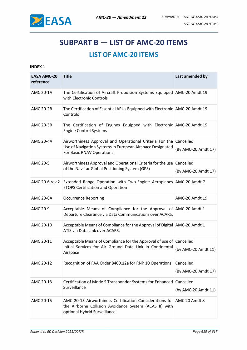
AMC-20 — Amendment 22 SUBPART B — LIST OF AMC-20 ITEMS
LIST OF AMC-20 ITEMS
Annex II to ED Decision 2021/007/R Page 615 of 617
SUBPART B — LIST OF AMC-20 ITEMS
LIST OF AMC-20 ITEMS
INDEX 1
EASA AMC-20 reference
Title Last amended by
AMC 20-1A The Certification of Aircraft Propulsion Systems Equipped with Electronic Controls
AMC-20 Amdt 19
AMC 20-2B The Certification of Essential APUs Equipped with Electronic Controls
AMC-20 Amdt 19
AMC 20-3B The Certification of Engines Equipped with Electronic Engine Control Systems
AMC-20 Amdt 19
AMC 20-4A Airworthiness Approval and Operational Criteria For the Use of Navigation Systems in European Airspace Designated For Basic RNAV Operations
Cancelled
(By AMC-20 Amdt 17)
AMC 20-5 Airworthiness Approval and Operational Criteria for the use of the Navstar Global Positioning System (GPS)
Cancelled
(By AMC-20 Amdt 17)
AMC 20-6 rev 2 Extended Range Operation with Two-Engine Aeroplanes ETOPS Certification and Operation
AMC-20 Amdt 7
AMC 20-8A Occurrence Reporting AMC-20 Amdt 19
AMC 20-9 Acceptable Means of Compliance for the Approval of Departure Clearance via Data Communications over ACARS.
AMC-20 Amdt 1
AMC 20-10 Acceptable Means of Compliance for the Approval of Digital ATIS via Data Link over ACARS.
AMC-20 Amdt 1
AMC 20-11 Acceptable Means of Compliance for the Approval of use of Initial Services for Air Ground Data Link in Continental Airspace
Cancelled
(by AMC-20 Amdt 11)
AMC 20-12 Recognition of FAA Order 8400.12a for RNP 10 Operations Cancelled
(By AMC-20 Amdt 17)
AMC 20-13 Certification of Mode S Transponder Systems for Enhanced Surveillance
Cancelled
(by AMC-20 Amdt 11)
AMC 20-15 AMC 20-15 Airworthiness Certification Considerations for the Airborne Collision Avoidance System (ACAS II) with optional Hybrid Surveillance
AMC 20 Amdt 8
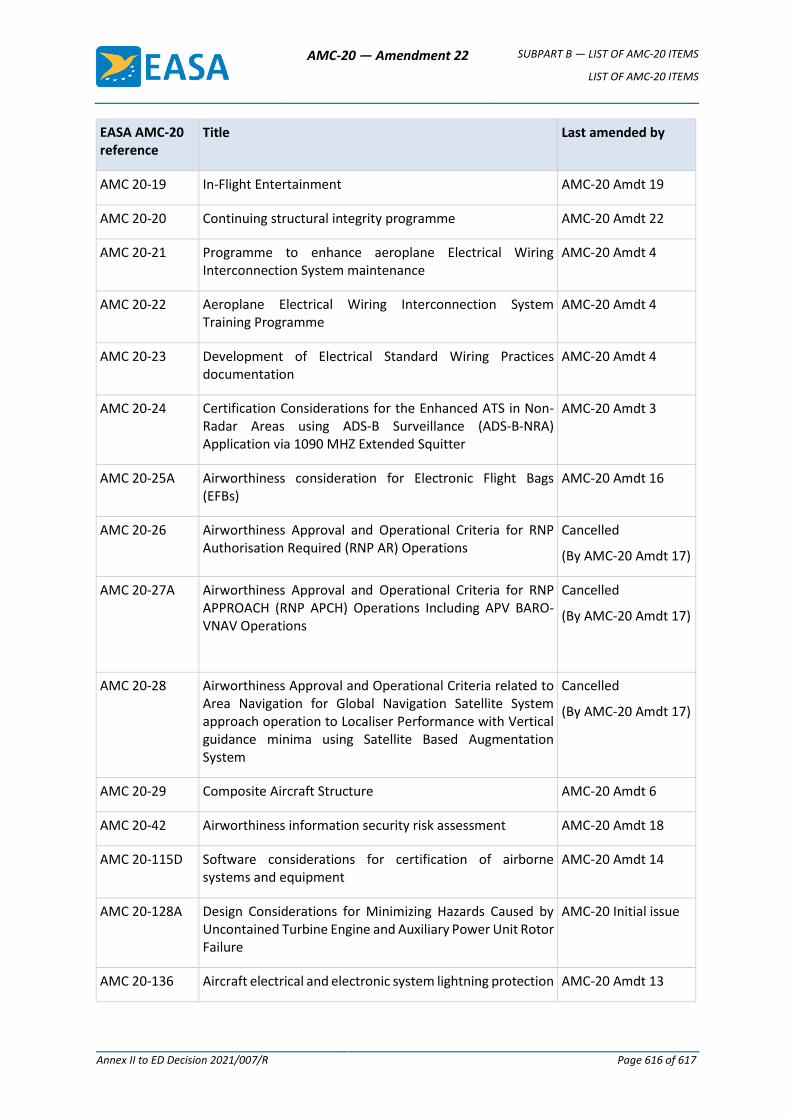
AMC-20 — Amendment 22 SUBPART B — LIST OF AMC-20 ITEMS
LIST OF AMC-20 ITEMS
Annex II to ED Decision 2021/007/R Page 616 of 617
EASA AMC-20 reference
Title Last amended by
AMC 20-19 In-Flight Entertainment AMC-20 Amdt 19
AMC 20-20 Continuing structural integrity programme AMC-20 Amdt 22
AMC 20-21 Programme to enhance aeroplane Electrical Wiring Interconnection System maintenance
AMC-20 Amdt 4
AMC 20-22 Aeroplane Electrical Wiring Interconnection System Training Programme
AMC-20 Amdt 4
AMC 20-23 Development of Electrical Standard Wiring Practices documentation
AMC-20 Amdt 4
AMC 20-24 Certification Considerations for the Enhanced ATS in Non-Radar Areas using ADS-B Surveillance (ADS-B-NRA) Application via 1090 MHZ Extended Squitter
AMC-20 Amdt 3
AMC 20-25A Airworthiness consideration for Electronic Flight Bags (EFBs)
AMC-20 Amdt 16
AMC 20-26 Airworthiness Approval and Operational Criteria for RNP Authorisation Required (RNP AR) Operations
Cancelled
(By AMC-20 Amdt 17)
AMC 20-27A Airworthiness Approval and Operational Criteria for RNP APPROACH (RNP APCH) Operations Including APV BARO-VNAV Operations
Cancelled
(By AMC-20 Amdt 17)
AMC 20-28 Airworthiness Approval and Operational Criteria related to Area Navigation for Global Navigation Satellite System approach operation to Localiser Performance with Vertical guidance minima using Satellite Based Augmentation System
Cancelled
(By AMC-20 Amdt 17)
AMC 20-29 Composite Aircraft Structure AMC-20 Amdt 6
AMC 20-42 Airworthiness information security risk assessment AMC-20 Amdt 18
AMC 20-115D Software considerations for certification of airborne systems and equipment
AMC-20 Amdt 14
AMC 20-128A Design Considerations for Minimizing Hazards Caused by Uncontained Turbine Engine and Auxiliary Power Unit Rotor Failure
AMC-20 Initial issue
AMC 20-136 Aircraft electrical and electronic system lightning protection AMC-20 Amdt 13
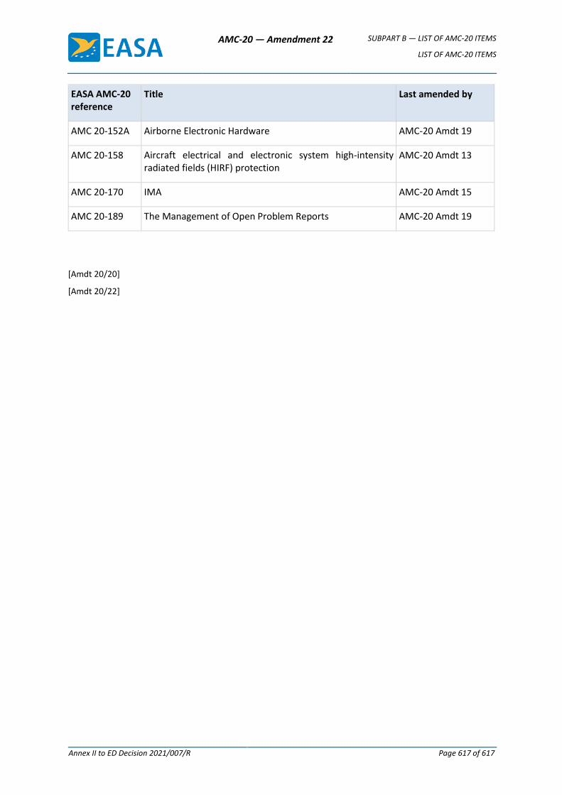
AMC-20 — Amendment 22 SUBPART B — LIST OF AMC-20 ITEMS
LIST OF AMC-20 ITEMS
Annex II to ED Decision 2021/007/R Page 617 of 617
EASA AMC-20 reference
Title Last amended by
AMC 20-152A Airborne Electronic Hardware AMC-20 Amdt 19
AMC 20-158 Aircraft electrical and electronic system high-intensity radiated fields (HIRF) protection
AMC-20 Amdt 13
AMC 20-170 IMA AMC-20 Amdt 15
AMC 20-189 The Management of Open Problem Reports AMC-20 Amdt 19
[Amdt 20/20]
[Amdt 20/22]


