Embed Size (px)
Citation preview
Repair of fractured spruce beams with bonded-in reinforcements
Parvez Alam Postdoctoral researcher
Department of Chemical Engineering, Åbo Akademi University Turku, Finland.
Martin P. Ansell Senior Lecturer
Department of Mechanical Engineering, University of Bath Bath, United Kingdom.
David Smedley
Technical Manager Rotafix Ltd.
Abercraf, Swansea, United Kingdom. Summary Constructional timber is susceptible to fracture damage. This paper researches methods and
materials used for repairing pre-fractured class C16 spruce beams loaded in flexure. Strength and
stiffness values for repaired beams are referenced against the original beam strength and stiffness
values. Repair configurations comprise mechanical reinforcement on both tensile and compressive
faces of the beam. Reinforcement materials include mild steel, CFRP and GFRP. Stiffer
reinforcements have a greater effect on improving the stiffness qualities of repaired beams. Repair
strengths rely more on the crack restraining capabilities of the reinforcement and less on their
unique mechanical properties. Steel reinforcements are superior to CFRP and GFRP with respect to
improving the composite stiffness and strength. When compared using the transformed section
method however, the CFRP composites show the greatest enhancement in repaired beam strength
compared with the initial strength.
1. Introduction The restoration of timber structures holds historical, economical, conservational and ecological
significance. Mechanical methods for repairing timber are under-researched and unrealistic
comparisons are often made between empirical research and the subsequent application of the
research to timber structures in need of repair. Jones (1997), Radford et al (2002), Ogawa (2000)
and Lopez-Anido et al (2003) have all conducted experimental investigations into what is
effectively, reinforcement of undamaged timber beams and have assumed the validity of the results
in repair scenarios. Jones (1997) for example, conducted tests on beams reinforced with steel rods
located in deep grooves cut in from the compressive face of timber beams. This method is often
used in repair when aesthetics or, indeed, impracticalities necessitate non-standard methods of
applying reinforcements. Though Jones’s tests have significance with respect to reinforcement, they
were not simulations of repair. Radford et al (2002) suggested the use of ‘shear spikes’ for repair.
The spikes were inserted vertically at intervals along the length of two solid timber beams stacked
on top of each other, each spike penetrating the full depth of each beam. However, the repair
method was geared to the horizontal shear failure mode, where the shear spikes were simply
connecting two horizontally laminated wood sections and might have been less effective than repair
systems using adhesives (such as in adhesively bonded glued laminated timbers). Lopez-Anido et al
(2003) conducted wood pile repair simulation tests. In their tests, damage was simulated by

geometrically reducing the cross sectional diameter of the wood piles. The reinforcement was then
applied around the area of the reduced cross section and the improvement measured against an
unreinforced wood pile. Duarte et al (2004) developed a timber replacement system comprised of
three steel rods placed in a groove cut into the centre of the tensile face of a wood beam. Duarte and
co-workers tested solid pine beams in flexure and replaced fractured central portions with the
replacement system using the steel rods and adhesive to join the sections. The method is used
practically and is an efficient way of repairing damaged timber provided support can be applied to
the original timber beam-ends during replacement. The method does not however, address the issue
of repairing fracture paths, but rather, effectively joins reinforced and unreinforced flexural beam
sections. The objective of this paper is to investigate fracture repairs in timber beams that have been
subjected to flexural failure.
2. Procedure C16 spruce beams were manufactured by halving a wider beam into two equal segments and gluing
them together, Figure 1, using Rotafix CB10TSS, a slow setting thixotropic epoxy adhesive. Beams
assembled in this way were tested in flexure, Figure 2, to the point of the first audible fracture
accompanied by a drop in load. A linear variable differential transformer (LVDT) displacement
transducer was used to monitor the centre point deflection of the beam as a function of time.
Cut centrally along length
Original timber beam
Beam segments are vertically
laminated and are subsequently
bonded together to form a single
composite beam with dimensions b, t,
and l.
b
t
l
Fig 1 Manufacture of the C16 spruce beams
6h
6h
6h
F/2 F/2
F/2 F/2 18h
h = 100mm
h = depth
LVDT
1800mm
600mm 600mm
600mm
Fig 2 Four-point bending test arrangement
The beams were then repaired on both the compressive and tensile faces, Figure 3. Prior to repair,
the beams were flattened out by applying load to the underside of the flexed beam. The materials
used for repairing the fractured beams comprised mild steel, carbon fibre reinforced plastic (CFRP)
and glass fibre reinforced plastic (GFRP). Further repair tests using FULCRUM (glass fibre
reinforced polyurethane composites) as well as alternative repair configurations (compressive only

and tensile only) are described by Alam (2004). The dimensions of the reinforcements used in
repair are provided in Table 1.
Surface pre-treatments of the mild steel comprised grit blasting to SA 2.5 using guidance in
SIS055900 (1967) after which it was coated with a primer. A peel-ply layer was removed from the
CFRP prior to adhesion. Wet and dry grade 320 emery papers were used to roughen the surface of
the GFRP.
Table 1 Dimensions of reinforcement materials used to repair fractured C16 spruce beams
Reinforcement Length/mm Depth/mm Width/mm MILD STEEL 1900 20 5.0
CFRP 1900 20 1.5
GFRP 1900 20 4.0
3. Section properties of composite beams The composite second area moment, I, and section modulus, W, for each beam is a function of beam
width, b, and beam depth, t, (Eqns. 1 & 2).
12
3bt
I = [1] 6
2bt
W = [2]
The transformed section method was used to analyse beam properties, Figure 3. Each beam was
transformed using specific individual beam dimensions. In these figures, b refers to a width
dimension, t is a thickness dimension, y is the distance from a local centroid to the local edge and E
is an elastic modulus. The subscripts r, a and w are designated to reinforcement material, adhesive
material and wood respectively. The subscripts 1, 2 and 3 refer to transformed elements.
w
w
aa
w
rr bE
bE
E
bEbb 4
2231 +
+== ar tttt === 31 ( )312 tttt w +−=
Fig 3 Transforming section for beams repaired in both tension and compression
The transformed second moments of area are calculated using Eqn. 3. The transformed section
modulus for all repair configurations can then be calculated from Eqn. 4.
ba
br
bw
tr, ta
tw
b3
b2
t3
t2
b1
t1

( ) ( )
+++
+
++=
2
3233
3
33
3
22
2
1211
3
11,
2212122212
tttb
tbtbtttb
tbI bt [3]
w
bt
btt
IW
,
,
2= [4]
The flexural strengths and transformed flexural strengths, σ, can then be calculated according to
Equation 5 using the composite section modulus (Equation 2) for the flexural strength calculations
and the transformed section moduli (Equation 4) for the transformed flexural strength calculations.
In Eqn. 5, F is the load value at first fracture and a is the distance from the loading point to the
nearest lower roller.
W
aF
2=σ [5]
4. Flexural properties of C16 spruce beams Flexural strength properties of 36 as-received C16 beams are plotted in Figure 4 and related to the
influence of knots in the failure mode. Power law curves are fitted to the data sets and coefficients
of determination are given. Beam fractures influenced by knot presence have a higher scatter in
properties than beams that fracture independent of knot presence. Furthermore, beam strengths are
generically lower where knots have influenced the fracture mode. Examples of fracture are given in
Figure 5. Where knots are believed to influence fracture; indications are given by black dots. The
arithmetic mean flexural modulus of the spruce beams was measured as 9.6GPa with a standard
deviation of ±2.3GPa. The mean flexural strength for all beams was measured as 27.3MPa with a
standard deviation of ±8.1MPa about the mean. prEN 338 (2000) considers the mean modulus and
strength values of C16 timber to be 8GPa and 16MPa respectively.
Fig 4 Comparison of the flexural strengths of C16
spruce beams in relation to their mode of failure
1
2
3
4
5
6
Fig 5 Examples of beam fracture for the first
6 beams tested.
5. Flexural properties of repaired C16 spruce beams Figures 6-8 show the flexural modulus values of spruce beams and the post-repair flexural moduli
for beams reinforced by mild steel (beams 14, 20 and 34), CFRP (beams 1, 13 and 18) and GFRP
(beams 17 and 22) respectively. Beams were reinforced on both faces and they were selected

randomly from the 36 beams evaluated. The percentage increase or loss in flexural modulus
properties post-repair is provided for each beam.
Beams repaired with higher modulus reinforcements show less loss in stiffness, or indeed in the
case of steel, a significant improvement over the original flexural modulus values. Steel is weight-
for-weight considerably cheaper than CFRP and GFRP and would be the material of choice with
respect to stiffness enhancement. This said, the pultruded composites do effectively bridge fracture
paths and hence restore the original beam depth. For this reason, the contribution of the pultruded
composites to stiffness should not be ignored and it can be said that at least, CFRP and GFRP bring
the beams closer to their original stiffness than otherwise would be the case without repair.
Figures 9-11 show the flexural strength values of spruce beams and the post-repair flexural
strengths for beams reinforced by mild steel, CFRP and GFRP respectively. The percentage
increase or loss in flexural modulus properties post-repair is provided for each beam. In every case,
repaired beam strengths exceed original beam strengths, with the superior repair material being mild
steel followed by CFRP and finally GFRP. It is quite likely that the most effectual reinforcement is
that which is placed in tension since it closes tensile fractures and restrains their growth. Indeed in
many cases, failure fractures actually initiated from a different area of the repaired beam
independent of the original pre-repair fracture path. Mild steel reinforcement is ductile, can
maintain high stresses over large deformations and strain hardens as a function of increasing strain
(past the limit of elastic proportionality). This, coupled with the higher volume fraction of steel
used, is perhaps one aspect that makes them better than the pultruded composite reinforcements at
enhancing the flexural strength of the fractured beams relative to their original strength values.
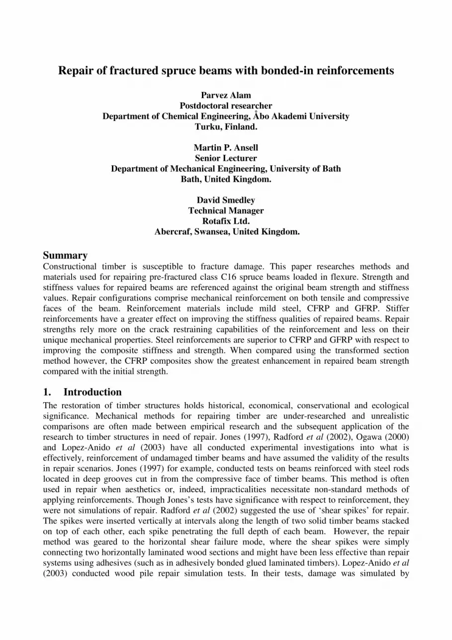
Figures 12-14 show the transformed section flexural strength values of spruce beams and the post-
repair flexural strengths for beams reinforced by mild steel, CFRP and GFRP respectively. The
percentage increase or loss in flexural modulus properties post-repair is provided for each beam.
Since the method of transforming section takes into account the dimensions and modulus of the
reinforcement material relative to the wood, it is in some ways a better indicator of how effective
the reinforcement is compared with the equivalent dimensions of wood. Using the transformed
section method, steel is found to enhance beam strength similarly to GFRP composites but
noticeably less than CFRP composites. Therefore, using this method of analysis, CFRP composites
are more effective as repairing materials.
Observing the stiffness and strength histograms, Figures 6-11, it can be seen that strength properties
are considerably easier to enhance in a repair situation than stiffness properties. It is postulated that
the reinforcing material is less effective at increasing the flexural modulus because of the relatively
small volume of reinforcement. The significance of the reinforcement is that it increases the
stiffness as a function of the reinforcement stiffness properties, the dimensions of the unfractured
spruce and its location within the composite beam. Steel, therefore, has the greatest effect on
repaired beam stiffness. Contrarily, strength is a non-recoverable attribute of deformation. The
function of the reinforcement is not only to offer a contribution to beam strength as a function of its
own strength; but also to effectively constrain the growth of pre-existing cracks in the timber
material.

Fig 6 Flexural modulus values for C16 beams
before and after steel repair
Fig 7 Flexural modulus values for C16 beams
before and after CFRP repair
Fig 8 Flexural modulus values for C16 beams
before and after GFRP repair
Fig 9 Flexural strength values for C16 beams
before and after steel repair
Fig 10 Flexural strength values for C16 beams
before and after CFRP repair
Fig 11 Flexural strength values for C16 beams
before and after GFRP repair
Fig 12 Transformed strength values for C16
beams before and after steel repair
Fig 13 Transformed strength values for C16
beams before and after CFRP repair
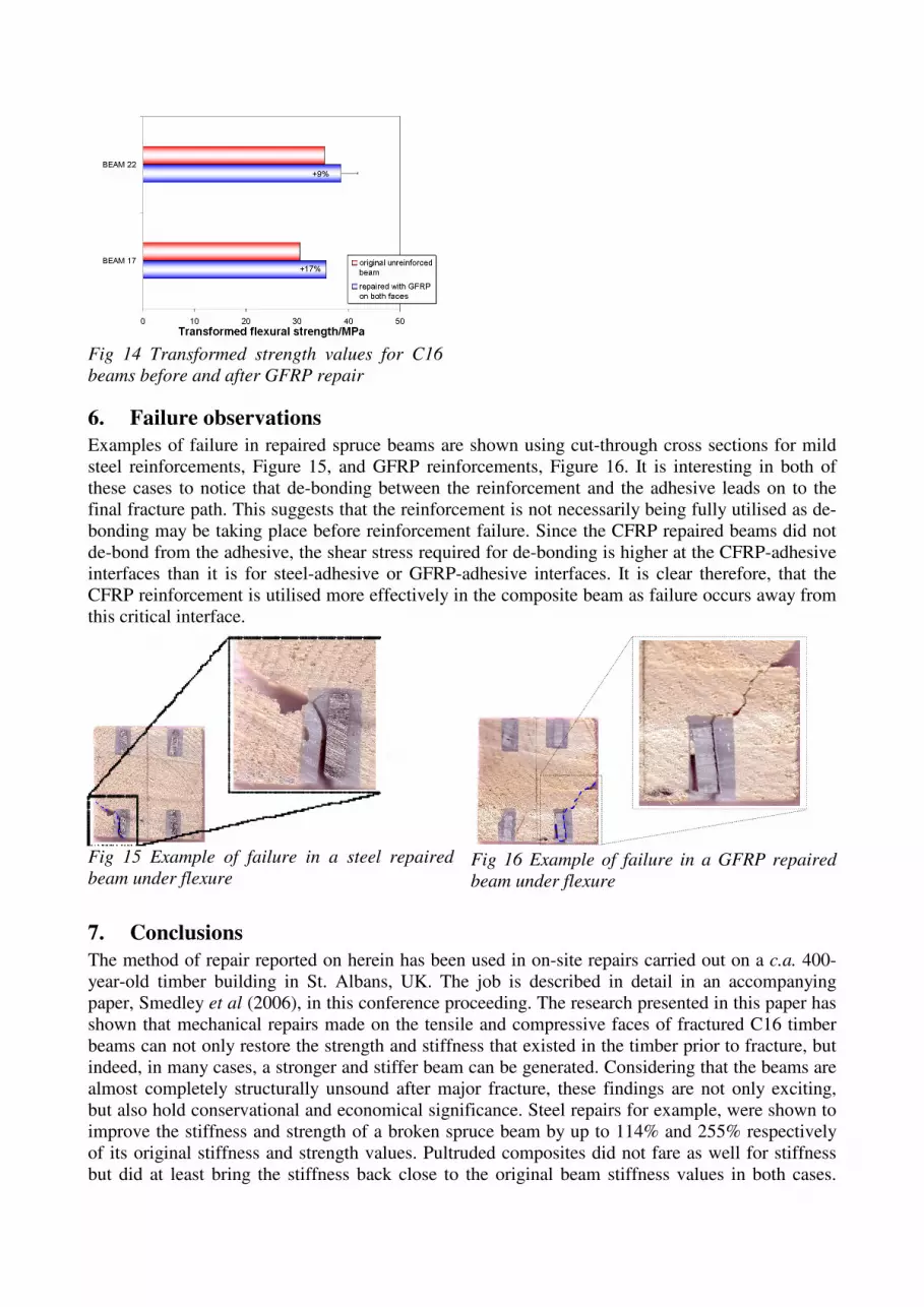
Fig 14 Transformed strength values for C16
beams before and after GFRP repair
6. Failure observations Examples of failure in repaired spruce beams are shown using cut-through cross sections for mild
steel reinforcements, Figure 15, and GFRP reinforcements, Figure 16. It is interesting in both of
these cases to notice that de-bonding between the reinforcement and the adhesive leads on to the
final fracture path. This suggests that the reinforcement is not necessarily being fully utilised as de-
bonding may be taking place before reinforcement failure. Since the CFRP repaired beams did not
de-bond from the adhesive, the shear stress required for de-bonding is higher at the CFRP-adhesive
interfaces than it is for steel-adhesive or GFRP-adhesive interfaces. It is clear therefore, that the
CFRP reinforcement is utilised more effectively in the composite beam as failure occurs away from
this critical interface.
Fig 15 Example of failure in a steel repaired
beam under flexure Fig 16 Example of failure in a GFRP repaired
beam under flexure
7. Conclusions The method of repair reported on herein has been used in on-site repairs carried out on a c.a. 400-
year-old timber building in St. Albans, UK. The job is described in detail in an accompanying
paper, Smedley et al (2006), in this conference proceeding. The research presented in this paper has
shown that mechanical repairs made on the tensile and compressive faces of fractured C16 timber
beams can not only restore the strength and stiffness that existed in the timber prior to fracture, but
indeed, in many cases, a stronger and stiffer beam can be generated. Considering that the beams are
almost completely structurally unsound after major fracture, these findings are not only exciting,
but also hold conservational and economical significance. Steel repairs for example, were shown to
improve the stiffness and strength of a broken spruce beam by up to 114% and 255% respectively
of its original stiffness and strength values. Pultruded composites did not fare as well for stiffness
but did at least bring the stiffness back close to the original beam stiffness values in both cases.

With respect to strength enhancement, all mechanical reinforcements enhanced broken timber
beams to between 11% and 255% of the original beam strengths (prior to breakage). Steel and
CFRP reinforcements performed similarly well with respect to flexural strength improvement with
GFRP materials showing the smallest improvement.
On transformation of sections however, CFRP composites were seen to be superior to both GFRP
and steel reinforcements. The repaired beam strength is a function of the bond strength coupled with
the restraining capabilities of the reinforcing material. It is the ability of the material to restrain the
growth of the original fracture path that determines its applicability as a mechanical repair material.
Both steel and GFRP reinforcements experienced de-bonding at the adhesive interface, which led to
premature fracture in the timber beam. However, CFRP composites were utilised to their full
potential as no premature interfacial failure was observed for these materials.
8. References Alam, P. (2004); The reinforcement of timber for structural applications and repair; Ph.D. Thesis,
Department of Mechanical Engineering, University of Bath, United Kingdom.
Duarte, A., Negrão, J. and Cruz, H. (2004); Rehabilitation of timber beams with reinforced epoxy
plates; Proceeedings of the 8th
World Conference on Timber Engineering (WCTE2004); Lahti,
Finland, Vol. 1 pp. 371-376.
Jones, R. (1997); Upgrading of timber members in historic buildings; Journal of the Institute of
Wood Science; Vol. 14 No. 4 pp. 192-203.
Lopez-Anido, R., Michael, A. P. and Sandford, T. C. (2003); Experimental characterization of FRP
composite-wood pile structural response by bending tests; Marine Structures; Vol. 16 pp. 257-274.
Ogawa, H. (2000); Architectural application of carbon fibres. Development of a new carbon fibre
reinforced glulam; Carbon; Vol. 38 pp. 211-226.
prEN (2000); Structural timber – strength classes; British Standards Institution, London.
Radford, D. W., Van Goethem, D., Gutkowski, R. M. and Peterson, M. L. (2002); Composite repair
of timber structures; Construction and Building Materials Vol. 16 pp. 417-425.
SIS 055900 (1967); Pictorial surface preparation standards for painting steel surfaces; Swedish
Standard.
Smedley, D., Alam, P. and Ansell, M. P. (2006); George Street, St. Albans, UK – a case study in
the repair of historic timber structures using bonded-in pultruded plates, Proceedings of the 9th
World Conference on Timber Engineering (WCTE2006); Portland, Oregon, United States of
America.


