Embed Size (px)
Citation preview

REPAIRS MANUAL ENGLISH
Genesis 302-382 AC/DCWU21

Code: 92.08.01001Edition: 05/03Rev.: 1.0
SELCO s.r.l.Via Palladio, 19I - 35010 ONARA DI TOMBOLO (Padova) ItalyTel. +39 049 9413111Fax +39 049 9413311e-mail: [email protected]
How to contact Selco Service Department:
SELCO s.r.l.Service Departmentc/o SELCO 2 Via Macello, 61I - 35010 CITTADELLA (Padova) ItalyTel. +39 049 9413111Fax +39 049 9413311e-mail: [email protected]
All translation, reproduction and adaptation rights, total or par-tial and by any means (including photostat copies, films andmicro films), are reserved and forbidden without the writtenauthorisation of Selco S.r.l.
INDEX :
1) PURPOSE OF THE MANUAL . . . . . . . . . . . . . . . . .32) WARNINGS, PRECAUTIONS AND
GENERAL NOTICES FOR PERFORMING REPAIRS . .43) INSTRUMENTS AND CONVENTIONS
FOR PERFORMING DIAGNOSIS AND REPAIR . . . .54) DESCRIPTION OF OPERATION OF THE POWER
SOURCES AND TECHNICAL DATES . . . . . . . . . . . .75) WIRING AND CONNECTION DIAGRAMS . . . . . . .226) PC BOARDS’ LOCATION . . . . . . . . . . . . . . . . . . . .287) DESCRIPTION OF DIAGNOSTIC INDICATIONS . .308) SET-UP PARAMETERS . . . . . . . . . . . . . . . . . . . . . .369) DESCRIPTION, TESTING AND REPLACEMENT
OF THE ELECTRONIC BOARDS, CURRENT CALIBRATION . . . . . . . . . . . . . . . . . . . .38
10) AVAILABLE SPARE PARTS . . . . . . . . . . . . . . . . . . . .62
2

Purpose of the manual 3
1) PURPOSE OF THE MANUAL
This manual is designed to provide authorised service centreswith the basic information necessary for performing repairs onthe models Genesis 302 AC/DC and 382 AC/DC.
In order to avoid serious injury to persons or damage to things,this manual must be used only by qualified technicians. Selco S.r.l. accepts no liability for any injury to persons or dama-ge to things that may occur during performance of repairs, evenafter reading or practical application of this manual.
For a detailed description of the operation, use and ordinarymaintenance of the machine, please refer to the "Instructions foruse and maintenance manual" which must always accompanythe machine. The purchaser must follow the directions contai-ned in the above manual. Failure to do so will exempt Selcofrom all liability.
The operations described in this manual require the use of adigital multimeter, an AC/DC ammeter clamp and a basic kno-wledge of how the machine works. Basic electrotechnical kno-wledge is also required.
Repair consists in identification of the faulty part, included inthe list of available spare parts, and replacement of it. In the event of failure of an electronic board, repair entailsreplacement of the board and not replacement of the faultyelectronic component on the board.
For troubleshooting advice, see introduction to chapter 9.
Do not carry out modifications or maintenance not scheduledin this manual.
If the problem cannot be solved by following the instructionsprovided in this manual, contact the Selco Service Departmentor send the machine to Selco for repair.

4 Warnings, precautions and general notices for performing repairs
2) WARNINGS, PRECAUTIONS AND GENERAL NOTICES FOR PERFORMING REPAIRS
Repairs must be performed by qualified personnel only.
Before performing the repair, you should read and assimilate thecontents of this manual, in particular the safety precautions.
Avoid performing repairs without the presence of another personable to provide help in the event of an accident.
The repair of a machine requires access to its internal parts and con-sequently removal of some of the protective panels. Additional pre-cautions are therefore necessary with respect to use of the machi-ne for welding in order to prevent possible injury or damage cau-sed by contact with
- live parts- moving parts- parts at high temperature
Live parts:
CAUTION ! When handling internal parts of themachine, remember that opening of the switch doesnot prevent the risk of electric shocks: the machinemust be unplugged from the power supply.
Wait approx. one minute before carrying out work on theinternal parts as the capacitors may be loaded at high voltage.
CAUTION ! When taking measurements, remem-ber that the measuring instruments can be live andyou should therefore avoid touching their metalparts.
CAUTION! When TIG operation is selected with HFstart, the machine generates a series of high volta-ge impulses (approx. 10,000 V) to spark the wel-
ding arc. When an arc sparking test in TIG with HF dischar-ge is not specifically scheduled in the diagnostic phase, youare therefore advised to disconnect the terminals FN1 andFN2 of the HF 15.14.286 board.After carrying out the repair, remember to reconnect FN1and FN2 of the board 15.14.286 before finally closing themachine, then perform a few welding tests, including TIG HFsparking.
Moving parts:CAUTION ! Keep your hands well away from thefan when the machine is connected to the powersupply. Ensure that the machine is unplugged andthat the fan is at a standstill before replacing it.
Parts at high temperature:CAUTION ! When handling internal parts of themachine, remember that some of them may bevery hot. In particular avoid contact with heatsinks.

Instruments and conventions for performing diagnosis and repair 5
3) INSTRUMENTS AND CONVENTIONS FOR PERFOR-MING DIAGNOSIS AND REPAIR
3.1) Instruments for basic diagnosis
The following are required:
- a multimeter with the following scales:Ohm: from 0 to a few MohmDiode testingDirect voltage (Vdc): from mVdc to 1000 VdcAlternating voltage (Vac): from 10 Vac to 700 Vac
NOTE: You are advised to use an instrument withautomatic scale since it is not theoretically possible topredict the electrical quantity to be measured whenthe machine has broken down.
- an AC/DC ammeter clamp at least in class 2.5 with e.o.s. 400A pk
- alternatively to the ammeter clamp, a shunt can be used withvalue 60 mV @ 400 A.
NOTES: * remember that other types of shunts can also be used,
but accuracy is reduced with higher capacities, whe-reas with lower capacities the measurement must betaken quickly to avoid overheating of the shunt
* once fitted, the shunt is at welding potential (becareful especially with discharges during arc stri-king in TIG HF)
* the ammeter clamp is preferable as it is more practi-cal
3.2) Repair tools
- complete set of fork spanners - complete set of pipe spanners for hexagonal nuts - complete set of blade screwdrivers - complete set of Phillips screwdrivers - complete set of Allen keys- Phillips torque screwdriver for M3 screws with tigh-
tening torque adjustable range from 1 to 3 Nxm,accuracy 0.1 Nxm
- crimper for insulated wire terminals (blue, red andyellow)
- pliers for AMP contacts- tweezers and cutting nippers - type commonly used
for electronic components - tongs (dimensions suitable for closing gas pipe
clamps)- welder for electronic components, minimum power
50 W - portable electric drill
3.3) Grid load
Use of grid load can speed up fault tracing and machine testing. Just remember that a fixed power resistor applied to machine'soutput is somewhat equivalent to a welding arc, but only insideof a narrow output voltage range, whose center value can bedetermined by the formula:
TIG DC WELDING:V OUT 10 + 0.04 x I OUT
Es.: 12Vdc @ 50A14Vdc @ 100A18Vdc @ 200A etc.
STICK WELDING::V OUT 20 + 0.04 x I OUT
Es.: 22Vdc @ 50A24Vdc @ 100A28Vdc @ 200A etc.
If output voltage goes too much above or below the rated value,the generator could either saturate or go into arc force or otherspecial features could be performed (such as anti-flashing): inboth cases real output current could be much different fromexpected value and the generator could even show an intermit-tent output power (output power led blinking, see also sec.7.1in the following).
Grid load resistor's rated power is also important, 'cos a 24Vdc@ 100A grid load produces 2400W to be dissipated by aircooling.
So, when using grid load, pay attention to both out-put current & output voltage and use correct resistan-ce value & power!
6 Instruments and conventions for performing diagnosis and repair
3.4) Conventions
By convention, when a measurement has to be taken betweentwo points, for example a b , the arrow point indicateswhere to apply the red tip of the multimeter (a),while the blacktip is applied at the other end (b).
When a double arrow appears between two measuring points(e.g.: c d ), the voltage to be measured is alternating(normally at 50 Hz), therefore it does not matter in which orderthe multimeter terminals are applied.
In drawings and tables, when a voltage measurement appearsreferring to terminals of components such as DIODES, BJT,MOSFET and IGBT, the multimeter is used in "diode test" mode(these measurements are always taken with the machine swit-ched off and normally give values in the range +0.10 … +0.90Vdc). In this case the following symbol is affixed beside thevalue to be measured
Junction measurement (multimeter in "diode test" mode)
The following symbols will be used in the same way:
AC or DC voltage measurement (multimeter in voltmetermode)
Resistance measurement (multimeter in ohmmeter mode)
Current measurement (ammeter clamp or shunt + multi-meter in millivoltmeter mode)
Frequency measurement (multimeter in frequency metermode)
The measuring conditions (power source on/off, MMA/TIG ope-rating mode, etc.) are always clearly indicated beside the valuesto be measured.
In the tables the various auxiliary power supply voltages aremarked with the initials V1, V2, etc. to permit identificationwhen present in several boards. When a power supply voltagederives from another one, the second takes the name of the firstwith the addition of a letter in increasing order (e.g.: V1a, V1b,etc.). In these cases, all the derived voltages have the same earthin common.
The connector terminals are indicated by the name of the con-nector followed by a slash and the number of the terminal; forexample CN1/2 indicates terminal 2 of connector CN1.
Unless otherwise specified, all the measurements must be per-formed with the boards fitted, together with their connections.
Remember that the first of the tests to be perfor-med is the VISUAL CHECK!The visual check reduces troubleshooting timesand directs any subsequent tests towards thedamaged part!

1.0 SAFETY
Prior to performing any operation on the machine, make surethat you have thoroughly read and understood the contents ofthis manual.Do not perform modifications or maintenance operations whichare not prescribed.For any doubt or problem regarding the use of the machine,even if not described herein, consult qualified personnel.The productor cannot be held responsible for damage to per-sons or property caused by the operator's failure to read orapply the contents of this manual.
1.1 Operator and other persons' protectionThe welding process is a noxious source of radiations, noise,heat and gas emissions. Persons fitted with pacemakers mustconsult their doctor before undertaking arc welding or plasmacut operations. If the above prescription is not observed, themanufacturer accepts no liability for any damages sustained inthe event of an accident.
Personal protection:- Do not wear contact lenses!!!- Keep a first aid kit ready for use.- Do not underestimate any burning or injury.- Wear protective clothing to protect your skin from the arc rays,
sparks or incandescent metal, and a helmet or a welding cap.- Wear masks with side face guards and suitable protection fil-
ter (at least NR10 or above) for the eyes.- Use headphones if dangerous noise levels are reached
during the welding.Always wear safety goggles with side guards, especiallyduring the manual or mechanical removal of welding slags.lf you feel an electric shock, interrupt the welding ope-rations immediately.
Other persons' protection:- Position a fire-retardant partition to protect the surroun-
ding area from rays, sparks and incandescent slags.- Advise any person in the vicinity not to stare at the arc or at
the incandescent metal and to get an adequate protection.- lf the noise level exceeds the limits prescribed by the law,
delimit the work area and make sure that anyone gettingnear it is protected with headphones or earphones.
1.2 Fire/explosion preventionThe welding process may cause fires and/or explosions.- Compressed gas cylinders are dangerous; consult the sup-
plier before handling them.Protect them from:- direct exposure to sun rays;- flames;- sudden changes in temperature;- very low temperatures.Compressed gas cylinders must be fixed to the walls or toother supports, in order to prevent them from falling.
- Clear the work area and the surrounding area from anyinfiammable or combustible materials or objects.
- Position a fire-fighting device or material near the workarea.
- Do not perform welding or cutting operations on closedcontainers or pipes.
- lf said containers or pipes have been opened, emptied andcarefully cleaned, the welding operation must in any case beperformed with great care.
- Do not weld in places where explosive powders, gases orvapours are present.
- Do not perform welding operations on or near containersunder pressure.
- Don’t use this machine to defrost pipes.
1.3 Protection against fumes and gasesFumes, gases and powders produced during the welding pro-cess can be noxious for your health.- Do not use oxygen for the ventition.- Provide for proper ventilation, either natural or forced, in the
work area.- In case of welding in extremely small places the work of the
operator carrying out the weld should be supervised by a col-league standing outside.
- Position gas cylinders outdoors or in places with good ventilation.- Do not perform welding operations near degreasing or
painting stations.
1.4 Positioning the power sourceKeep to the following rules:- Easy access to the equipment controls and connections
must be provided.- Do not position the equipment in reduced spaces.- Do not place the generator on surfaces with inclination
exceeding 10° with respect to the horizontal plane.
1.5 lnstalling the apparatus- Comply with the local safety regulations for the installation
and carry out the maintenance service of the machine accor-ding to the constructor's directions.
- Any maintenance operation must be performed by qua-lified personnel only.
- The connection (series or parallel) of the generators is prohi-bited.
- Before operating inside the generator, disconnect thepower supply.
- Carry out the routine maintenance on the equipment.- Make sure that the supply mains and the earthing are suffi-
cient and adequate.- The earth cable must be connected as near the area to be
welded as possible.- Take the precautions relevant to the protection degree of the
power source.- Before welding, check the condition of the electric cables and
of the torch, and if they are damaged repair or change them.- Neither get on the material to be welded, nor lean against it.- The operator must not touch two torches or two electrode
holders at the same time.
The manufacturer accepts no liability if the above prescriptionis not duly observed and complied with at all times.
Description of operation of the power sources and technical dates 7
WARNING
4) DESCRIPTION OF OPERATION OF THE POWER SOURCES AND TECHNICAL DATES
4.1) Use and routine maintenance (excerpt from the "Instructions for use" manual provided with each power source).

2.0 ELECTROMAGNETIC COMPATIBILITY (EMC)
This device is built in compliance with the indications containedin the harmonized standard EN50199, to which the operatormust refer for the use of this apparatus.- lnstall and use the apparatus keeping to the instructions
given in this manual.- This device must be used for professional applications
only, in industrial environments It is important to remem-ber that it may be difficult to ensure the electromagneticcompatibility in other environments.
2.1 Installation, use and area examination- The user must be an expert in the sector and as such is
responsible for installation and use of the equipment accor-ding to the manufacturer's instructions. lf any electromagnetic disturbance is noticed, the user mustsoave the problem, if necessary with the manufacturer's tech-nical assistance.
- In any case electromagnetic disturbances must be reduceduntil they are not a nuisance any longer.
- Before installing this apparatus, the user must evaluate thepotential electromagnetic problems that may arise in thesurrounding area, considering in particular the health con-ditions of the persons in the vicinity, for example of per-sons fitted with pacemakers or hearing aids.
2.2 Emission reduction methods
MAINS POWER SUPPLY- The welding power source must be connected to the
supply mains according to the manufacturer's instructions.In case of interference, it may be necessary to take further pre-cautions like the filtering of the mains power supply.lt is also necessary to consider the possibility to shield the powersupply cable.
WELDING POWER SOURCE MAINTENANCE The welding power source needs routine maintenance accor-ding to the manufacturer's instructions.When the equipment is working, all the access and operatingdoors and covers must be closed and fixed.The welding power source must not be modified in any way.
WELDING AND CUTTING CABLESThe welding cables must be kept as short as possible, positionednear one another and laid at or approximately at ground level.
EQUIPOTENTIAL CONNECTIONThe earth connection of all the metal componente in the wel-ding installation and near it must be taken in consideration.However, the metal componente connected to the work-piecewill increase the risk of electric shock for the operator, if he tou-ches said metal componente and the electrode at the sametime.Therefore, the operator must be insulated from all the earthedmetal componente.The equipotential connection must be made according to thenational regulations.
EARTHING THE WORKPIECEWhen the workpiece is not earthed for electrical safety reasonsor due to its size and position, the earthing of the workpiecemay reduce the emissione. It is important to remember that theearthing of the workpiece should neither increase the risk ofaccidents for the operators, nor damage other electric equip-ment.The earthing must be made according to the national regula-tions.
SHIELDINGThe selective shielding of other cables and equipment presentin the surrounding area may reduce the problems due to inter-ference. The shielding of the entire welding installation can betaken in consideration for special applications.
8 Description of operation of the power sources and technical dates
WARNING
3.0 RISK ANALYSIS
Risks posed by the machine Risk of wrong installation.
Electrical risks.Risks connected with electromagnetic disturbances producedby the welding power source and induced on the weldingpower source.
Solutions adopted to pervent themA manual with the instructions for use has been pro-duced for this purpose.Application of the EN 60974-1 Standard.Application of the EN 50199 Standard.

Description of operation of the power sources and technical dates 9
The contents of this chapter are of vital importance and the-refore necessary for operation of the warranties. The manu-facturer accepts no liability if the operator fails to observethe above precautions and instructions.
4.0 MACHINE DESCRIPTION
The Genesis 302 AC/DC e Genesis 382 AC/DC power sourcesoffer excellent performance in the following welding procedures:- TIG AC with square, sine and triangular wave;- TIG DC with remote arc striking with high frequency (TIG HF-
START) and gas delivery control via torch button;- TIG DC with contact start with reduction of short circuit current
(TIG LIFT-START) and gas delivery control via torch button; - MMA.In inverter welders the output current is insensitive to variationsin the power supply voltage and length of the arc and is per-fectly levelled, providing best weld quality. On all the power sources features the following devices:- a positive socket (+), a negative socket (-) and a central soc-
ket for connection of the TIG torch- a front control panel with socket for remote controls
- RC16 potentiometer remote control for MMA and TIG welding (optional)
- RC12 pedal remote control for TIG welding (optional)- a rear control panel with gas socket The Genesis 302 AC/DC and Genesis 382 AC/DC can be sup-plied with WU21 cooling unit for liquid cooling of the TIGtorch.
4.1 Front control panel (fig. 1)
Fig.1
* L1 : Power on: green led.Comes on when the ignition switch on the rear panel (Fig. 2) "I1"is in position "I". Indicates that the system is on and powered.
* L2: Protection device: yellow led.Indicates cut-in of the thermal protection device or protectiondue to incorrect power supply voltage. With “L2” on, analarm code blinks on “D1”. The power source remains con-nected to the mains but does not deliver power at the output.If an overtemperature has occurred, “L2” remains on until theinternal temperatures have returned to normal; in this case,leave the power source on and wait for the welder to cool. Inthe event of alarms connected to the mains voltage, press anybutton to resume operations.
* Alarm codes.The system manages the following alarms:10 mains alarm: no phases, undervoltage or overvoltage11 no cooling liquid12 primary module thermal switch13 AC module thermal switch 19 load too inductive: inversions not possible20 memory fault24 incorrect system parameters or memory still empty
(first switch-on)25 system parameters could not be stored (24C08)26 standard parameters checksum incorrect: either the memory
has failed or powerful interferences have damaged it27 advanced parameters checksum incorrect: either the memo-
ry has failed or powerful interferences have damaged it* L3: Voltage output (work): red led.
Indicates presence of voltage at the output. * Display D1.
Displays the welding current or value of the welding parame-ter chosen via “S5” on the graph “G1”. It is used to showalarm and error messages and to enter the set-up parameters.
* E1 : Encoder for entering the welding current, weldingparameters and set-up values. Allows you to change the value shown in “D1” of the para-meter selected via “S5” in graph “G1” (also during welding). Allows you to enter the required set-up line and vary thevalue. Allows you to continuously adjust the welding current both inTIG and MMA. (This current remains unchanged during wel-ding when the power supply and welding conditions varywithin the ranges declared in the technical specifications). In MMA the presence of HOT-START and ARC-FORCE meansthat the mean output current can be higher than the one set.
* S1 : Current regulation system key.Selects the welding current regulation system:- from front panel in "internal" mode- from remote control in "external" modeIn this case via “E1” it is possible to enter the maximum cur-rent value that can be selected via the remote control.
* J1 : 7-pole military standard connector.For connection of the remote controls RC16 and RC12.
* S2 : Tasto selezione tipo di corrente per saldatura TIG.Key for selecting type of TIG welding current- CONSTANT current with or without SLOPES. - PULSED current with or without SLOPES. - MEDIUM FREQUENCY current with or without SLOPES. Switch-on of the led at the side of the symbol confirms theselection. The MEDIUM FREQUENCY function is not enabled in AC.
* S3 : Key for selecting control mode in TIG.- 2-stroke welding (2T)- 4-stroke welding (4T)- 2-level welding (BILEVEL)Switch-on of the led at the side of the symbol confirms theselection. With the RC12 pedal control, only the 2T mode is possible. In 2-stroke, when the button is pressed the gas flows and thearc is struck; when the button is released, the current goes tozero in the slope-down time; once the arc is off, the gas flowsfor the post-gas time. In 4-stroke, the first time the button is pressed the gas flowsfor the manual pre-gas time; when the button is released, thearc is struck. If the button is pressed again and definitivelyreleased, the current slope-down and post-gas time begin. In BILEVEL the welder can weld with 2 different currents pre-viously set via “S5”.

10 Description of operation of the power sources and technical dates
The first time the torch button is pressed, the pre-gas time isrun, the arc is struck and welding is performed with the initialcurrent. The first time it is released, slope-up to current "I1" occurs. Ifthe welder presses and quickly releases the button, themachine will go to "I2"; by pressing and quickly releasing thebutton it returns to "I1" and so on. If the button is pressed for longer, the current slope-downbegins which leads to the final current. When the button is released the arc goes out while the gascontinues to flow for the post-gas time.
* S4: Welding procedure selection key.Permits selection of the welding procedure. Switch-on of the led at the side of the symbol confirms theselection. Procedures:- MMA (electrode)- TIG DC- TIG AC
* S5: SET-UP/parameters key. Permits access to the SET-UP and welding parameter values. When pressed at switch-on, it permits access to the set-upparameters while the software version appears on “D1”. If pressed after the end of the welder switch-on procedure, itselects in sequence the welding parameters presented in thegraph “G1” with value shown by “D1” and variable with “E1”. Tu Slope-up timel Welding currentlb Basic current in pulsed and medium frequency
welding Tp Peak time in pulsed and medium frequency weldingTb Basic time in pulsed and medium frequency weldingTd Slope-down timelf Final currentPg Post-gas timel2 Second welding current in BILEVEL
When in MEDIUM FREQUENCY operation, the ledsTp and Tb come on simultaneously and the pulsefrequency value appears on the display “D1”.
By keeping the key "S5" pressed for 1 second, you accessadjustment of the following parameters:- frequency in AC (Led L4);- electrode diameter setting in AC (Led L5);
by setting this value on the power source the Genesis 302/382 AC/DC can optimise (using the FUZZY LOGIC ) the welding start parameters in AC;
- balance AC (Led L6); adjustment in % of the positive wavevalue during the AC period.A higher value indicates greater cleaning action of the elec-tric arc on the weld pool; a lower value indicates greater penetration and melting action of the arc.
* Set-up parameters.When “S5” is pressed after switch-on, the set-up menu isaccessed (confirmed by a central "0" on the display “D1”)while the software version appears on “D1”. Via E1 the set-upline is varied, via “S5” the required line is confirmed, via “E1”the value is varied, via “S5” the value is confirmed and so on. 0 Quit and save1 Initial current as a percentage with respect to
welding current2 Pre-gas time3 HOT-START percentage4 ARC-FORCE percentage5 Waveform in AC
The following table shows the correspondence between thenumbers and the half waves:
Number Half wave - Half wave +0 Sine Sine1 Triangle Triangle2 Square Square3 Sine Triangle4 Sine Square5 Triangle Sine6 Triangle Square7 Square Sine8 Square Triangle
6 Min current value in TIG EXT7 Max current value in TIG EXT welding 8 LIFT start in TIG DC (1) or HF start (0)
(default=0)9 Reset of parameters12 Welding in DC+ (1) or DC - (0) (default=0)14 Pulsed TIG basic l setting mode (0=in amps,
1=percentage of peak l) (default=0)15 HF first pulse polarity (1= on same side as current,
0= inverted, improved sparking)16 Cooling unit activity time from end of welding (s);
if 0 is set, the unit never comes on.17 With "1" in AC in the fastpulse position the mix AC/DC
procedure is enabled. 18 Current reference during the HF start in TIG DC19 Current reference during HF start in TIG AC20 Extra energy (% of positive wave amplitude in respect of
negative wave amplitude)23 TIMER mode setting
(23 = 0: 2-stage mode, 23 ≠ 0: welding time)99 Reset of all parameters
If we enter lines "9" and "99" and press “S5”, all theset-up parameters will go to the factory-set values.
To quit set-up and save the set values, return toline “0” and press “S5”.
Description of operation of the power sources and technical dates 11
4.2 Rear control panel (Fig. 2)* I1 : Ignition switch
Controls electric ignition of welder.It has two positions: "O" off and "l" on.
* With l1 set to the position "l" on, the welder is operationaland voltage is present between the positive (+) and nega-tive sockets (-) on the electrode. In TIG the welder requi-res the pedal or torch button start for voltage to be presentbetween the sockets (+) and (-).
* When the welder is connected to the mains, even with l1set to the "O" position some of the internal parts will belive. Carefully follow the warnings given in this manual.
* 1 : Power supply cable* 2 : Gas fitting
Fig.2
4.3 Operation
The machine stores the last welding status and dis-plays it when switched back on.
* Set the ignition switch “l1” to “l”; switch-on of the power led“L1” (green led) confirms that the system is powered.
* The display “D1” shows the figure 302/382 and all the ledscome on (for control) for 3 seconds. The leds on the frontpanel then go out and “D1” shows the welder software ver-sion (e.g. 1.0) for 4 seconds; during this time it is possible:- to enter the SET-UP mode by pressing the key “S5”;- or proceed with welding (or parameter variation).
* If chosen, entry to the SET-UP mode is confirmed by a central“0“ on the display “D1”:- Turn the potentiometer “E1”: the numbers corresponding
to the parameters appear (in sequence) on the display “D1”; stop on the parameter required and press “S5”. Via parameter (9) all the modifications performed in the SET-UP are cancelled and you return to the standard values set by SELCO.
- The number on the display “D1” is replaced by the value of the parameter which is modified via the potentiometer “E1”.
* If it is necessary to modify the welding parameter values of thegraph “G1”:- Let 4 seconds elapse from switch-off of the panel leds; led
“l” (welding current) will remain on in the graph. - Press “S5”; every time it is pressed one of the leds in the
graph “G1” will come on (in clockwise sequence) and the value of the related parameter will appear on the display “D1”; stop on the parameter required.
- Turn the potentiometer “E1” and modify the parameter value.
- Press the “S5” SET-UP/parameters key again to go on to another parameter or wait 5 seconds (led "l" in the graph “G1” will automatically come back on).
The machine is always ready to weld and the statusis indicated by the set of leds lit up on the panel.
The fan only starts once the system has warmed up.
WARNING
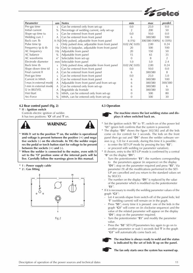
ParameterPre-gas timeInitial currentSlope-up time tuWelding curr. lBack curr. lbPulse time tpFrequency tp & tbAC frequency AC balance AC waveformsElectrode diameter Back time tbSlope-down time tdFinal current lfPost-gas timeCurrent in MMAl max in external model min in external model2 in BILEVELHot-StartArc-Force
ums%sA
A (%)s
HzHz%n°
mmssAsAAAA%%
min0.02
0.06
6 (1%)0.02 (AC 0.05)
2020150
1.00.02 (AC 0.05)
0.06
0.0666600
max25.020010.0
300/380300/380 (100%)
2.00500150658
5.02.0010.0
300/38025.0
300/380300/380300/380300/380
500500
predef.0.0500.0100
6 (50%)0.2410050352
2.40.240.08
5.0100
300/3806
508030
NotesCan be entered only from set-up Percentage of welding current, only set-up Can be entered from front panel Can be entered from front panel Only pulsed, adjustable from front panel Only pulsed slow, adjustable from front panel Only in fastpulse, adjustable from front panel Adjustable from panel Adjustable from panelSelectable from set-upSelectable from panelOnly pulsed slow, adjustable from front panel Can be entered from front panel Can be entered from front panel Can be entered from front panel Can be entered from front panel Adjustable from front panel and from set-upCan be entered only from set-up Regolabile da frontaleMMA, can be entered only from set-up MMA, can be entered only from set-up
12 Description of operation of the power sources and technical dates
4.4 Cooling unit WU21It is optional and permits liquid cooling of the TIG torch. Thereis one single electrical connection between WU21 and Genesis302/382 AC/DC and once assembled, they form one singlebody.
*All WU21 replacement, repair or connection ope-rations must be performed by expert personnel instructed by SELCO.
*Filling or topping up of the tank with cooling liquid must be performed with the power source and WU21 assembled and positioned on a horizontal surface.
*Filling or topping up of the tank must be performed with Selco cooling liquid, code 18.91.001.
*In order not to damage the cooling unit, always fit the by-pass pipe when the torch is not connected tothe cooling liquid inlet/outlet terminals.
4.5 Remote controls4.5.1 RC16 potentiometer remote control for MMA and TIGwelding.This device allows you to vary, byremote control, the amount of cur-rent necessary without interruptingthe welding process or abandoningthe work area. 5, 10 and 20 m con-nection cables are available.
4.5.2 RC12 pedal remote control for TIG welding. Once the power source has beenswitched to the EXTERNAL CON-TROL mode, the output current isvaried from a minimum to a maxi-mum value (can be entered fromSETUP) by varying the angle bet-ween the pedal surface (where thefoot rests) and base. A microswitchprovides the weld start signal atminimum pressure.
RATING PLATE
4.6 Technical specifications
G 302 AC/DC G 382 AC/DCPower supply voltage (50/60Hz) 3x400V ± 15% 3x400V ± 15%Maximum power absorbedin TIG 9.7kW (x=40%) 13kW (x=35%) Maximum current absorbedin TIG 16 A (x=40%) 21.5 A (x=35%) Current absorbed in TIG (x=100%) 9 A 13 A Maximum power absorbedin MMA 11.8kW (x=40%) 15kW (x=35%) Maximum current absorbedin MMA 17 A (x=40%) 22.8 A (x=35%) Current absorbedin MMA (x=100%) 11 A 16 A Power factor 0.95 0.95Cosϕ 0.99 0.99Welding current in TIG(x=40%) 300 A 380 A(x=60%) 250 A 320 A(x=100%) 220 A 280 AWelding current in MMA(x=35%) 300 A 350 A(x=60%) 250 A 320 A(x=100%) 220 A 280 ATIG (MMA) Adjustment range 6-300 6-380 (350 A)Loadless voltage 80 V 80 V Protection rating IP23C IP23CInsulation class H HConstruction standards EN60974-1 EN60974-1
EN50199 EN50199Dimensions (lxdxh) 275x620x500 mm 275x620x500 mmWeight 33 Kg. 33 Kg.
Data at 40°C ambient temperature
WU21 Power supply voltage (50/60 Hz) 1x400 V ± 15% Rated current absorbed 0.8 ATank capacity 6 lCooling power 2000 W Protection rating IP23C Dimensions (lxdxh) 250x655x280 mm Weight with liquid 16 Kg.

Dimensions and mass
5.0 TRANSPORT - UNLOADINGNever underestimate the weight of the equip-ment, (see technical specifications).
Never make the cargo pass or leave it suspendedover people or things.
Neither let the equipment or the single unit fall,nor put it down with force.
Once it has been removed from the packing, thepower source is supplied with an extendible beltwhich can be used to move it in the hand or on theshoulder.
6.0 INSTALLATION
Choose an adequate installation area by followingthe criteria provided in Section "1.0 SAFETY" and“2.0 ELECTROMAGNETIC COMPATIBILITY(EMC)”.
Do not position the power source and the equip-ment on surfaces with inclination exceeding 10°with respect to the horizontal plane.Protect the installation from heavy rain and sun.
Do not use the power source to thaw pipes.
6.1 Electrical connection to mainsThe system is provided with one single electrical connectionwith 5 m cable at the rear of the power source. Power source input cable and fuse sizing table:
Power source G 302 AC/DCRated voltage 3x400 V ± 15%Voltage range 340 V - 460 V Delayed fuses 20 APower supply cable 4x6 mm2
Power source G 382 AC/DCRated voltage 3x400 V ± 15%Voltage range 340 V - 460 VDelayed fuses 30 A Power supply cable 4x6 mm2
* The electrical system must be made by skilled technicianswith the specific professional and technical qualificationsand in compliance with the regulations in force in thecountry where the equipment is installed.
* The welding power source supply cable is provided with ayellow/green wire that must ALWAYS be earthed. This yel-low/green wire must NEVER be used with other voltageconductors.
* Verity the existence of the earthing in the used plant andthe good condition of the socket/s
* lnstall only plugs that are homologated according tothe safety regulations.
6.2 Connecting the equipment components
Keep to the safety regulations contalned in section“1.0 SAFETY”.
Connect the componente carefully, in order toavoid power losses.
Description of operation of the power sources and technical dates 13
WARNING
Model
G. 302G. 382
Trolley
29 29
Powersource
3333
WU21with liquid
1616
Tot. Kg
7878
GT23 930 1000 610 29
Trolleytype
MassKgA B C
Dimensions in mm
14 Description of operation of the power sources and technical dates
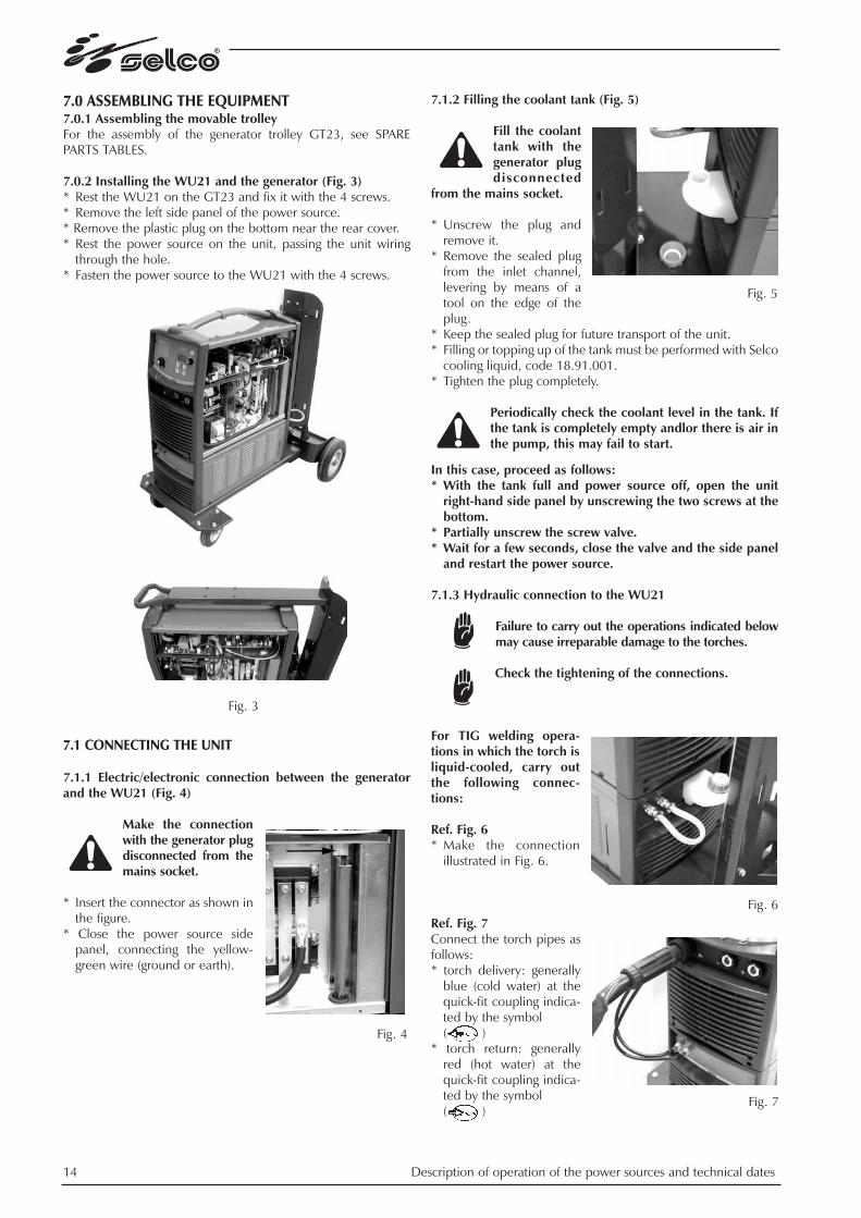
7.0 ASSEMBLING THE EQUIPMENT7.0.1 Assembling the movable trolleyFor the assembly of the generator trolley GT23, see SPAREPARTS TABLES.
7.0.2 Installing the WU21 and the generator (Fig. 3)* Rest the WU21 on the GT23 and fix it with the 4 screws.* Remove the left side panel of the power source.* Remove the plastic plug on the bottom near the rear cover.* Rest the power source on the unit, passing the unit wiring
through the hole. * Fasten the power source to the WU21 with the 4 screws.
7.1 CONNECTING THE UNIT
7.1.1 Electric/electronic connection between the generatorand the WU21 (Fig. 4)
Make the connectionwith the generator plugdisconnected from themains socket.
* Insert the connector as shown inthe figure.
* Close the power source sidepanel, connecting the yellow-green wire (ground or earth).
7.1.2 Filling the coolant tank (Fig. 5)
Fill the coolanttank with thegenerator plugdisconnected
from the mains socket.
* Unscrew the plug andremove it.
* Remove the sealed plugfrom the inlet channel,levering by means of atool on the edge of theplug.
* Keep the sealed plug for future transport of the unit.* Filling or topping up of the tank must be performed with Selco
cooling liquid, code 18.91.001. * Tighten the plug completely.
Periodically check the coolant level in the tank. Ifthe tank is completely empty andlor there is air inthe pump, this may fail to start.
In this case, proceed as follows:* With the tank full and power source off, open the unit
right-hand side panel by unscrewing the two screws at thebottom.
* Partially unscrew the screw valve.* Wait for a few seconds, close the valve and the side panel
and restart the power source.
7.1.3 Hydraulic connection to the WU21
Failure to carry out the operations indicated belowmay cause irreparable damage to the torches.
Check the tightening of the connections.
For TIG welding opera-tions in which the torch isliquid-cooled, carry outthe following connec-tions:
Ref. Fig. 6* Make the connection
illustrated in Fig. 6.
Ref. Fig. 7Connect the torch pipes asfollows:* torch delivery: generally
blue (cold water) at thequick-fit coupling indica-ted by the symbol ( )
* torch return: generallyred (hot water) at thequick-fit coupling indica-ted by the symbol ( )
Fig. 3
Fig. 4
Fig. 5
Fig. 6
Fig. 7

Description of operation of the power sources and technical dates 15
For TIG welding in thetorch is NOT liquid-cooled, it is advisable toclose the cooling circuitand make the connec-tions illustrated in Fig.8:
7.1.4 Connection for MMA welding
Carefully read 6.2.
* Connect the earth clampto the negative socket ofthe generator.
* Connect the electrodeholder to the positive soc-ket (+) of the generator.
The connection described above ensures weldingwith reverse polarity. To weld with straight pola-rity, reverse the connection.
7.1.5 Connection for TIG welding
Carefully read 6.2.
1) Connect the earth clamp(Fig. 10) to the positivesocket (+) of the genera-tor.
2) Connect the TIG torchcoupling to the torchsocket ( ) of the gene-rator.
* Connect the gas pipecoupling (Fig.11) to thegas coupling ( ) onthe generator rear panel.
If the TIG torch is cooled with liquid:
* Connect the hydraulicpipes of the torch tothe cooling unit, see7.1.3 (Hydraulic con-nection to the WU21).
3) Connect the gas pipecoupling (Fig.11) to thegas coupling ( ) onthe generator rearpanel.
8.0 PROBLEMS - CAUSES
8.1 Possible faults in the MMA welding
8.2 Possible faults in the TIG welding
Fault Oxidations
Tungsten inclusions
Porosity
Hot cracks
Cause1) lnsufficient gas.2) No protection on the re-
verse.1) lncorrect electrode shar-
pening.2) Electrode too small.3) Operating failure (contact
of the tip with the work-piece).
1) Dirt on the edges.2) Dirt on the filler material.3) High advancement speed.4) Current intensity too low.1) Unsuitable filler material.2) High heat supply.3) Dirty materials.
Fig. 8
FaultExcessive spatter
Craters
Inclusions
Insufficient penetration
Sticking
Blow-hole and porosity
Cracks
Cause1) Long arc.2) High current.1) Fast movement of the
electrode away from piece.1) Poor cleanliness or distri-
bution of the passes.2) Defective movement of
the electrode.1) High progression speed.2) Welding current too low.3) Narrow chamfering.4) Deseaming failure on top.1) Arc too short.2) Current too low.1) Humidity in electrode.2) Long arc.1) Current too high.2) Dirty materials.3) Hydrogen in weld
(present on electrodecoating).Fig. 9
Fig. 10
Fig. 11

16 Description of operation of the power sources and technical dates
8.3 Possible electrical failures
If you have any doubts or problems, do not hesitate to con-sult your nearest technical service centre.
9.0 NECESSARY ORDINARY MAINTENANCE
Avoid accumulation of metal dust near and on the ventilation fins.
Disconnect the system before all operations!
Periodical checks on the power source andWU21:* Clean the inside using compressed air at low
pressure and soft bristle brushes. * Check the electrical connections and all connec-
tion cables.
For maintenance and use of the pressure redu-cers, consult the specific manuals.
For maintenance and replacement of the compo-nents of the TIG torches, electrode gun and/orground cables:
* Disconnect the system before all operations. * Check the temperature of the components and ensure
that they are not overheated. * Always use gloves in compliance with regulations. * Use suitable spanners and tools.
Note: Failure to perform said maintenance will invalidate allwarranties and exempt the manufacturer from all liability.
FaultMachine does not come on(Green led off)
Power delivery not correct(Green LED on)
No current at output (Green LED on)
Cause 1) No voltage at power supply
socket.2) Faulty power supply plug or
cable. 3) Internal fuse blown. 1) Incorrect setting of welding
parameters. 2) Mains voltage low. 3) Faulty current regulation
potentiometer. 1) Yellow led on and ERROR
code blinking on display.

Description of operation of the power sources and technical dates 17
4.2) Operating principle - Block diagram
General overview
1. EMI input filter2. Three phases input rectifier3. Smoothing capacitor4. Quasi-resonant full bridge inverter5. Snubbing inductor6. Primary current transformer7. Resonant inductor8. Power transformer9. Secondary power rectifier10. Secondary inverter11. Hall-effect secondary current sensor12. Output filter13. HF transformer14. HF generator15. Auxiliary multi-output switching power supply16. Resonant inverter logic17. Synchronisation unit18. Microprocessor logic19. Superimposition & AC control20. Smoothing inductor

18 Description of operation of the power sources and technical dates
Quasi-resonant full bridge power inverter
- 30kHz switching frequency*= Fast response welding current loop= High stability welding arc
- ZVS/ZCS for power switches (IGBTs)= Improved efficiency + lower EMI= Space saving = Low weight
- Primary overcurrent fast protection circuit
- Auixiliary power supplies switching frequency derived frominverter logic
= System synchronization for noiseless Tig welding arc(audible subarmonic frequency generation avoided in TIGwelding arc)
* Note: due to resonant topology of primary power inverter,switching frequency is not constant: it varies in [27 ... 33]kHzrange, depending on actual output power; due to full bridgetopology, secondary rectifier works at double inverterfrquency, that is 55...65kHz, thus allowing a very precise arccontrol.

Description of operation of the power sources and technical dates 19
Output Rectifier & AC Inverter
- Full bridge FRED rectifier
- Microprocessor AC current shaping
- Microprocessor controlled inversion= Minimized voltage clamp
- Superimposition pulse generator= Easy arc inversion and stable arc in AC welding
- Microprocessor triggered arc striking circuit
- Superimposition pulse + arc striking pulse= Very easy arc striking even in worst operational contidions(hard oxide on workpiece)
20 Description of operation of the power sources and technical dates
Auxiliary Switching Mode Power Supply (SMPS)
- Flyback topology running @ 30kHz switching frequency*
- Buck topology running @ 30kHz switching frequency*
- Directly derived from 560V DC link
- Post-regulated primary side auxiliary supplies
- Post-regulated secondary side auxiliary supplies
- Regulated secondary side auxiliary supplies
- Synchronization circuit for noise free TIG welding arc
* Note: due to resonant topology of primary power inverter,switching frequency is not constant: it varies in [27 ... 33]kHzrange, depending on actual output power.
Description of operation of the power sources and technical dates 21
Microprocessor supervision
- Overvoltage, undervoltage, phase lack alarms for safety ope-rational mode
- Thermal protections management for power stages: inverter,output rectifier & AC inverter
- Microprocessor programming of temperature level that acti-vates fan cooling= less noise, less dust incoming, power saving
- Microprocessor recognized alarm events = Alarm code displayed on front panel
- Wide range of parameters settable via software (setup)= customisation of welding procedures

22 Wiring and connection diagrams
5) WIRING AND CONNECTION DIAGRAMS
The power sources in the Genesis 302-382 AC/DC series consist basically of the same electronic boards, possibly with some confi-guration and/or calibration differences (cf. in the following chapter 9 the sections dedicated to the individual boards).
The basic differences between the two models are (cf. also following sec. 6 "Arrangement of the boards"):- different size of primary inverter IGBT power modules - different composition of secondary inverter stageIn fact, the spare parts codes for the primary and secondary units are different for the two models.


Wiring and connection diagrams 25
5.3) Cooling unit wiring diagram

26 Wiring and connection diagrams
5.4) Connections for central adapter and remote control connector
Note: - To connect the trigger on the torch, use the central adapter only;- The sole purpose of the military connector is to connect the button on the remote control, where applicable (e.g.: RC 12);
- if there is a potentiometer, it should have a value in the range [2.5 ~ 10] k .
FRONT VIEWS
CENTRAL TORCH ADAPTER REMOTE CONTROL
3 - 5 = Torch trigger A = EXT 5V (max power)B = EXT GND (min power + torch trigger)C = EXT POT (to central ref.)D = - (not connected)E = - (not connected)F = - (not connected)G = EXT PT (torch trigger)

Wiring and connection diagrams 27
5.5) Remote control wiring diagrams
RC16 Wiring diagram
RC12 Wiring diagram
28 PC boards’ location
6) PC BOARDS’ LOCATION

PC boards’ location 29

30 Description of diagnostic indications
7) DESCRIPTION OF DIAGNOSTIC INDICATIONS
For the meaning and use of the various controls, please refer to the respective user manuals; only the diagnostic indications aredescribed in this section.
The Genesis 302-382 AC/DC series automatically compensates for the variations in power supply voltage, i.e. variations of ±15%with respect to the rated power supply voltage do not produce significant variations in the welding current.
7.1) External diagnostic indications
The microprocessor on the mainboard controls the status of the equipment and communicates it to the operator via the leds andthe display on the panel.
Power supply led (GREEN)Indicates the machine on status. Always on if the panel, and therefore the machine, is correctly powered.
Thermal led + protections (YELLOW)Indicates an alarm status of the equipment. Only on if there is a problem. The type of alarm is indicated by means of a code on the display (see below).
DisplayAt switch-on, the power source performs an autotest during which the display shows the size of the power source "302" or "382";immediately after, the display briefly indicates the software version installed (e.g. u01).The display indicates the welding parameters required by the operator (with the help of the other keys) and immediately after stri-king of the arc goes to reading mode, providing the actual value of the current delivered.

Simultaneously with switch-on of the yellow led, it indicates an alarm status via blinking codes (in this status only the two powersupply and alarm leds are on):
* N.B.: to perform a MASTER RESET, see procedure in following section 8.
Normally, when cause(s) of alarm(s) is(are) removed, press one of the keys to exit from alarm status (or switch off and on the machi-ne): machine will execute a new autotest and then start as in normal operation.
In case of error code E00, see also next section 7.2 "Internal diagnostic indicators": this could help to recognize specific cause ofinstantaneous alarm.
In the case of error E10, check the power supply voltages on the input filter board 15.14.269 (see also following section 7.2 "Internaldiagnostic indications"), with reference to the following table:
In the case of error E11: check the state of the pressure switch inside the cooling unit WU21 (see wiring diagram in previous sec.5.3). When the water pump is off, the contact is normally closed, whereas with the pump operating, +5Vdc should be measuredbetween terminals 1 & 2 of the pressure switch. To exclude the pressure switch, simply disconnect one of the terminals (e.g. wire n° 74).Caution: the delay in de-activating the water pump can be set via setup parameter 16 (see following sec. 8).
In the case of error E12 or E13, check the state of the thermal protection devices in the following section 7.3 "Arrangement of thethermal protections".In the case of actual overheating, cooling of the power source is optimised by leaving the machine on in TIG 2T with torch buttonreleased (no-load voltage at output = 0Vdc).When checking the ventilation, remember that the G302/382 controls the fan in order to minimise noise, energy consumption andsucking in of dust from the outside: the fan is activated only when the power source internal temperature exceeds 42°C.
Blinking of "Power at output" led
If the "Power at output" led blinks in MMA mode, perform the following checks: - output voltage too low:
may be due to a short circuit outside (welding clamps, torch, welding cables) or inside the power source (secondary rectifier,secondary inverter, overimposition board);
- output voltage on load too high (does not happen loadless):could be due to incorrect use of any static load (excess resistive value, see also sec. 3.3).
Indicat.E00
E10
E11
E12
E13
E19
E20E24E25E26E27
Description of diagnostic indications 31
Type of errorGeneral error due to a temporaryfault in the power supply or in theoutput current Mains alarm (overvoltage, under-voltage, no phase)
No cooling fluid
Primary inverter stage overtempe-rature
Secondary rectifier or AC stageovertemperature
Welding circuit excess inductance
Control panel memory error
ActionSee errors E10 & E19.
Check the power supply voltages 400Vac ± 15% on the board 15.14.269 (see follo-wing sec. 7.2).
Check the cooling fluid level. Remove the WU21 side panel and check the state ofthe pressure switch (N.C., see below). Leave the power source to cool.If the error persists: remove covers, check internal temperature, check fan, check pri-mary thermal sensor (see following sec. 7.3).Leave the power source to cool.If the error persists: remove covers, check internal temperature, check fan, checksecondary thermal sensor (see following sec. 7.3).Welding cables too long. If the piece to be welded has inductive characteristics (win-dings etc.), move the earth clamp to minimise the overall circuit inductance.
Switch the machine off and then on again and perform a MASTER RESET*. If the errorpersists, the machine operates but is no longer able to store the modified parametersor recall the last welding configuration used: replace the control panel.
Under/Overvoltage alarm thresholdsPower supply rated voltage3x400 V (50-60Hz)
Undervoltage340V
Overvoltage460V
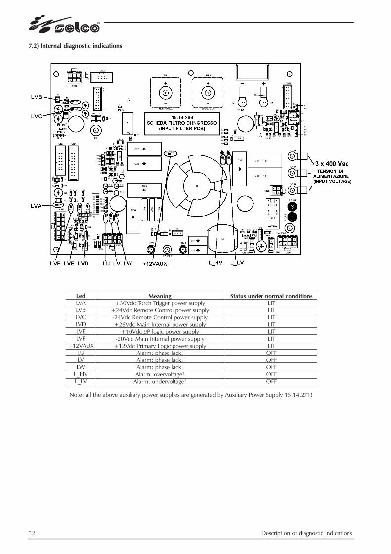
7.2) Internal diagnostic indications
Note: all the above auxiliary power supplies are generated by Auxiliary Power Supply 15.14.271!
LedLVALVBLVCLVDLVELVF
+12VAUXLULVLW
L_HVL_LV
Meaning+30Vdc Torch Trigger power supply
+24Vdc Remote Control power supply-24Vdc Remote Control power supply+26Vdc Main Internal power supply
+10Vdc µP logic power supply-20Vdc Main Internal power supply
+12Vdc Primary Logic power supplyAlarm: phase lack!Alarm: phase lack!Alarm: phase lack!Alarm: overvoltage!
Alarm: undervoltage!
Status under normal conditionsLITLITLITLITLITLITLITOFFOFFOFFOFFOFF
32 Description of diagnostic indications

Note: all the above auxiliary power supplies are generated within Pre-regulator PCB (on the basis of +26Vdc Main Internal powersupply coming from Input Filter 15.14.269!)
LedL1L2L3L4L5
L6
L7
Status under normal conditionsLITLITLITLITLIT
LIT
LIT
Meaning-20Vdc Secondary Inverter Driver power supply+20Vdc Secondary Inverter Driver power supply-20Vdc Secondary Inverter Driver power supply+20Vdc Secondary Inverter Driver power supply
+15Vdc Aux. power supply (+400Vdc to HF and Superimposition PCBs)
+15Vdc Aux. power supply (insulate commands to HF and Superimp. PCBs)
+10Vdc Aux. power supply (not used)
Description of diagnostic indications 33

34 Description of diagnostic indications
7.3) Thermal devices connectors locations

Description of diagnostic indications 35
Operation of the power source fan (not the auxiliary one mounted on the board 15.14.321 and shown in the figure above) is con-trolled by means of two sensors NTC: the first sensor detects the temperature of the secondary dissipator, the second sensor detectsthe temperature of the air inside the power source. If one of these two temperatures exceeds the factory-set value (currently 42°C) the power source fan will cut in, otherwise it willremain off. This operation is independent of whether the power source is delivering power or not and is controlled by the µP onthe control panel.In the case of overtemperature of the primary or secondary dissipators, the specific thermal protection will cut in: the output powerwill be interrupted and the thermal alarm will appear (see errors E12-E13 in the previous section).
Notes: - The thermal alarm does not depend on the state of the two NTCs, which serve only to control the power source fan.- Due to the tolerance of these components, the values indicated for the NTC sensors are only approximate and must be measu-
red with the machine switched off and cold, with all the connections fitted.- The auxiliary fan mounted on the board 15.14.321 is active only during TIG AC welding and does not depend on the power
source temperature.- The WU21 cooling unit fan operates together with the cooling fluid pump (they are activated simultaneously during TIG wel-
ding, independently of all temperature conditions). - The cooling unit operation time after the end of welding can be set from Set-up (see parameter 16 in the following section 8).

8) SET-UP PARAMETERS
The settings of the G 302-382 AC/DC front panel are incremented by those present inside the set-up, which is accessed as follows(see also figure in sec. 6.2):- Switch the equipment on.- The machine performs an autotest during which only the green power supply led remains on; the display shows the power sour-
ce size ("302" or "382") and the software version (e.g.: u01), then the machine goes to the last welding conditions set.- Press the "PARAMETERS" key for at least 3 seconds. - The display will show "0".- By turning the current encoder (knob on the panel), figures from "0" to "99" can be set and by pressing the "PARAMETERS" key it
is possible to see the value of the associated parameter, according to the following tables:
* note: Imax = 300A for G302 AC/DC, 380A for G382 AC/DC.
** note: waveform in AC
Param.0123456789
12
14
15
16
17
181920
21
22
98
99
36 Set-up parameters
Description/meaningExit From Set UpSetting the initial "I" percentage on the welding "I"Pre Flow Time Hot Start, Percent above Peak Current Arc Force, Percent above Peak Current Setting the AC Wave FormMin Current Value with Remote ControlMax Current Value with Remote ControlLift or HF Start in DC, Ignored in ACReset of all Parameters……………………… parameters not used …………………………….....Welding in DC+ or DC- (ignored in TIG AC)……………………… parameter not used ……………………………...Ibase setting mode in pulsed TIG DC.
HF first impulse polarity.N.B.: inverted polarity facilitates sparking.
Cooling unit activation time after the end of welding.N.B.: by setting "0" the cooling unit will be always off.
MIX AC/DC enable by selecting "Medium Frequency" in TIG AC.N.B.: Medium Frequency operation cannot be activated in AC.Current reference during HF start in TIG DCCurrent reference during HF start in TIG ACEnergy Saving (amplitude % of positive half-wave with respect to negative)Slope-down interruption with torch button
Maximum current with remote control in MIX AC/DC operation for DC part…………………………parameters not used ……………………………..Reset of all the parameters (use only in the case of persistent errors on thedisplay - see sec. 7.1) [MASTER RESET]For use only in countries with reduced no-load output voltage (e.g.:Belgium), otherwise use following code "99".Reset of all parameters (use only in the case of persistent errors on the dis-play - see sec. 7.1) [MASTER RESET]
Range-
0 - 200%0.0 - 25.0s0 - 500%0 - 500%
0 - 8 **(see table below)6 - Imax* A6 - Imax* A
0 = HF 1 = LIFT-
0 = DC- 1 = DC+
0 = Amps1 = % of welding current
0 = inverse with respect tooutput voltage
1 = complying with outputvoltage0 - 600s
0 = Medium Frequency 1 = MIX AC/DC
6 - Imax*6 - Imax*1 - 200%
0 = non-active1 = active6 - Imax*
-
Default-
50%0.0s80%30%
2 (Square)6A
Imax* A0-
0
0
0
180s
0
100A30A
100%
0
Imax* A
-

Set-up parameters 37
- The value of the parameter selected during the previous step can be changed by turning the knob on the panel.- We can see from the table that some parameters do not really have a value associated: if we select one of these parameters and
press the "Parameters" key, the associated operation is performed (e.g. if we enter Setup, select parameter "9" and press the"Parameters" key, factory settings are resumed for all parameters.
- Parameters labelled "not used" cannot be accessed, i.e. nothing happens when the "Parameters" key is pressed. - To save changes made to parameters and exit the Setup menu, return to parameter "0" and press the "Parameters" key; otherwi-
se, switching the machine off directly will mean none of the changes will be saved, and the last confirmed parameter settings willremain.
- After quitting Set-up, the machine resumes normal operation, if necessary taking account of the new configuration of the para-meters set.
Parameter012345678
Half wave -SineTriangleSquareSineSineTriangleTriangleSquareSquare
Half wave +SineTriangleSquareTriangleSquareSineSquareSineTriangle

Unless specified otherwise, all the measurements must be taken with the boards fitted, together with their connections!
38 Description, testing and replacement of the electronic boards, current calibration
9) DESCRIPTION, TESTING AND REPLACEMENT OF THE ELECTRONIC BOARDS, CURRENT CALIBRATION
Introduction
Malfunctioning of a machine can be due to various causes. Firstly you should check that the machine has been correctly installed and connected to the power supply (use of motor generator,extensions, plugs, presence of other large-size equipment that can interfere with the electrical power supply, etc.). Secondly, you should check correct use of the power source according to the type and whether the problem could be due to cau-ses outside the power source (gas, pressure reducers, torches, expendable materials, earth clamps, welding cables, remote controlsetc.). You should then assess whether the problem could be due to incorrect setting of the welding parameters (e.g. check how the Setuphas been configured, perform Reset of the user parameters, cf. param. 9 in previous sec. 8).Only after you have carried out the above checks should you look at the power source itself, opening the covers and performingan initial visual inspection. If necessary, carry out routine maintenance (blow-clean the power source). Sometimes a fault in a machine can be due to loose contacts in the wiring and in the internal connections and these should there-fore be inspected, at least visually. In other cases the problem may be due to a faulty electronic board. To speed up troubleshooting and optimise repair times, you are advised to proceed as follows:1. visual inspection and checking of connections2. with the machine switched off: instrumental check on power parts and any boards that may be faulty; if faults are found, repla-
ce the parts with equivalent spares (be careful of any configurations/calibrations to be performed on multi-purpose spares);instrumental re-check with the machine switched off
3. with the machine on: instrumental check on power parts and any parts that have been replaced 4. power source test to check that the fault is no longer present5. if an electronic board has been replaced, it may be advisable to perform the following check:
remove the board you have just fitted and replace it with the board previously removed, then re-test the machine to check thatthe fault re-appears:- if the original problem does not reappear when the original board is re-installed, then the problem is not due to that
board and you must continue the troubleshooting procedure;- if the original problem re-appears, then the fault is due to that board; re-install the spare part and perform a final test on
the power source.
Caution! Performance of the check in point 5 above requires particular care and is not necessary when the boardshows signs of burning or evident faults (in this case re-installation of the faulty board can cause further damage tothe remaining parts of the power source).
In accordance with the above procedure, the following sections illustrate the normal working conditions of the power source boardsand provide the standard electrical values at the main points of the boards, both with the machine off and with the machine on.
All the measurements indicated can be performed with a digital multimeter.
Remember that the first test to be performed is the VISUAL CHECK! The visual check reduces troubleshooting times and directs any subsequent tests towards the damaged part!
In general, points to be visually checked are: - input filter area- electrolytic levelling capacitors- traces of smoke on the inside of the bonnet - power and signal connections- overall condition of the boards
Caution: unless specified otherwise, before taking any measurement described below on the Genesis 302-382AC/DC, disconnect the HF circuit (FN1 & FN2 in board 15.14.286).
Caution: when the machine is connected to the power supply, the main switch is live, regardless of its status (openor closed)! It is therefore important to unplug the machine before touching any internal part of the power source! Wait approx. one minute before carrying out work on the internal parts as the capacitors may be loaded at highvoltage!

Description, testing and replacement of the electronic boards, current calibration 39
Unless specified otherwise, all the measurements must be taken with the boards fitted, together with their connections!
INDEX :
9.1) INPUT FILTER PC BOARD 15.14.269 . . . . . . . . . . . . . . . . . . . . . . . . . . . . . . . . . . . . . . .409.2) AUXILIARY POWER SUPPLY PC BOARD 15.14.271 . . . . . . . . . . . . . . . . . . . . . . . . . . . . . .429.3) CONTROL PANEL PC BOARD 15.14.324 . . . . . . . . . . . . . . . . . . . . . . . . . . . . . . . . . . . . . .449.4) POWER INVERTER PC BOARD 15.14.176 . . . . . . . . . . . . . . . . . . . . . . . . . . . . . . . . . . . . .469.5) RESONANT INVERTER CONTROL PC BOARD 15.14.298 . . . . . . . . . . . . . . . . . . . . . . . . . .489.6) INVERTER DRIVER PC BOARD 15.14.200 . . . . . . . . . . . . . . . . . . . . . . . . . . . . . . . . . . . . .499.7) PRE-REGULATOR PC BOARD 15.14.321 . . . . . . . . . . . . . . . . . . . . . . . . . . . . . . . . . . . . . .509.8) HF PC BOARD 15.14.286 . . . . . . . . . . . . . . . . . . . . . . . . . . . . . . . . . . . . . . . . . . . . . . . . .529.9) AC DRIVER & SUPERIMPOSITION PC BOARD 15.14.253 . . . . . . . . . . . . . . . . . . . . . . . . .549.10) OUTPUT FILTER PC BOARD 15.14.322 . . . . . . . . . . . . . . . . . . . . . . . . . . . . . . . . . . . . . . .559.11) SECONDARY RECTIFIER & AC INVERTER . . . . . . . . . . . . . . . . . . . . . . . . . . . . . . . . . . . . .569.12) CLAMP PC BOARD 15.14.323 . . . . . . . . . . . . . . . . . . . . . . . . . . . . . . . . . . . . . . . . . . . . . .589.13) OUTPUT CURRENT CALIBRATION (DELIVERED AND DISPLAYED) . . . . . . . . . . . . . . . . . .60

40 Description, testing and replacement of the electronic boards, current calibration Unless specified otherwise, all the measurements must be taken with the boards fitted, together with their connections!
9.1) Input filter PC board 15.14.269
This board performs the following functions:- EMC input filter- power input rectifier- power source voltages supervision- isolated auxiliary power sources for the various machine circuits (see table on following page)- gas solenoid valve, fans and WU21 water pump control relay power supply
The weld switching points on the board are factory-set and must not be modified by the user.
WARNING! Soldered jumpers (factory setted):- PZ_PE, PZ_PE1, PZ_PE2, PZ_PE3 must be always earthed! K1 = CLOSED- PZ_PE3 brass jumpers must be always closed! K2 = CLOSED
K3 = CLOSEDK4 = OPEN
Power diode module (PR1 & PR2) replacing instructions:- MOUNTING: use torque screw driver @ 3 Nxm (26 lbxin)- use thermal grease as necessary.

Related circuitInverter input voltage, HF & Superimposition high voltage power supply inputInput voltage alarms (overvoltage, undervoltage, phase lack)Torch triggerRemote controlMain positive auxiliary power supply (inverter control logic, microprocessor, welding logic, Hallprobe, thermal alarm, power source fan, gas solenoid valve, WU21 fan and water pump powersupply relay, HF and overimposition boards logic). - (power supply output not used)Negative auxiliary power (inverter control logic, microprocessor, welding logic, Hall probe, gas sole-noid valve).
Power supplyV1V2V3
V4, V5 V6
V7V8
Fuse*-
F4F2
F5, F6F9
F8F7
Notes:* to activate fan, machine should be warmed up by welding
for 5 minutes @ 200A (18°C Ambient Temperature) ** to activate cooler unit, pull torch trigger in TIG mode; once
started, cooler unit remains active for 3 minutes after wel-ding job is terminated.
Hints: - removing of Auxiliary Power Supply 15.14.271 is not requi-
red to perform checks listed above- to ease measurements, PZ_- , +12VAUX , PZ_+ signals
are electrically connected to CNB/9, CNB/10, CNB/16respectively.
Description, testing and replacement of the electronic boards, current calibration 41
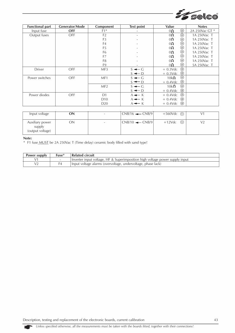
Unless specified otherwise, all the measurements must be taken with the boards fitted, together with their connections!
Functional partInput rectifier
Generator fan
WU21 fan
WU21 pump
Generator/ModeOFF
OFF
OFF
OFF
ComponentPR1 / PR2
FT1
FT2
RL1 (coil)(contact)
Test pointPZ_U PZ+PZ_V PZ+PZ_W PZ+
PZ- PZ_UPZ- PZ_VPZ- PZ_WS GS DS GS D
D13 K ACN9/1 PZ_U
Value+ 0.5Vdc+ 0.5Vdc+ 0.5Vdc+ 0.5Vdc+ 0.5Vdc+ 0.5Vdc+ 0.7Vdc+ 0.6Vdc+ 0.7Vdc+ 0.6Vdc
880 (open
contact)
Notes
Input voltage
Input rectifier
Aux power supplies
Phase lack alarms
Overvoltage alarmUndervoltage alarmGenerator fan
WU21 fan
WU21 pump
ON
ON
ON
ON
ONON
ON *
ON / TIG**
ON / TIG**
-
PR1 / PR2
+12VAUX = LITLVA = LITLVB = LITLVC = LITLVD = LITLVE = LITLVF = LITLU = OFFLV = OFFLW = OFF
L_HV = OFFL_LV = OFF
-
-
RL1 (coil)RL1 (contact)
PZ_U PZ_VPZ_U PZ_WPZ_W PZ_V
PZ+ PZ-
CNB/10 CNB/9TP17 TP16TP9 TP11TP10 TP11TP24 TP21TP27 TP21TP23 TP21
TP20 CNB/9TP19 CNB/9TP18 CNB/9TP7 CNB/9TP8 CNB/9
CN7/2 CN7/1
CN10/2 CN10/1
D13 K ACN9/1 PZ_W
400Vac ± 15%400Vac ± 15%400Vac ± 15%
+560Vdc ± 15%
+12Vdc+30Vdc+24Vdc-24Vdc+26Vdc+10Vdc-20Vdc+12Vdc+12Vdc+12Vdc+12Vdc+12Vdc+26Vdc
+26Vdc
+26Vdc400Vac ± 15%
V1
V2V3V4V5V6V7V8
* Note: fuses are located on Aux. Power Supply PC board 15.14.271 (see related section below).

9.2) Auxiliary power supply PC board 15.14.271
This board performs the following functions:- auxiliary power supplies of all the boards
CN1 = high voltage output, NOT USED!CN2/1 = synchronization signal from main clock generatorPZGNDL = ground connection to Input Filter PC Board, well tighten screw needed
Note:* F1 fuse MUST be 2A 250Vac T (Time delay) ceramic body filled with sand type!
Protected circuitAuxiliary power supply inputTorch trigger- (not used power supply output)Input voltage alarms (over/under voltage & phase lack)Remote control logicNegative auxiliary power supply (inverter control logic, microprocessor, welding logic, Hall probe, gas solenoid valve).
- (not used power supply output)Main positive auxiliary power supply (inverter control logic, microprocessor, welding logic, Hall probe, thermal alarm,power source fan, gas solenoid valve, WU21 fan and water pump power supply relay, HF and overimposition boardslogic).
Fuse F1*F2F3F4
F5, F6F7
F8F9
42 Description, testing and replacement of the electronic boards, current calibrationUnless specified otherwise, all the measurements must be taken with the boards fitted, together with their connections!
Note:* F1 fuse MUST be 2A 250Vac T (Time delay) ceramic body filled with sand type!
Related circuitInverter input voltage, HF & Superimposition high voltage power supply inputInput voltage alarms (overvoltage, undervoltage, phase lack)
Unless specified otherwise, all the measurements must be taken with the boards fitted, together with their connections!
Description, testing and replacement of the electronic boards, current calibration 43
Power supplyV1V2
Fuse*-
F4
Functional partInput fuse
Output fuses
Driver
Power switches
Power diodes
Generator/ModeOFFOFF
OFF
OFF
OFF
ComponentF1*F2F3F4F5F6F7F8F9
MF3
MF1
MF2
D1D10D20
Test point---------
S GS DS GS DS GS DA KA KA K
Value0 0 0 0 0 0 0 0 0
+ 0.3Vdc+ 0.5Vdc
10k+ 0.4Vdc
10k+ 0.4Vdc+ 0.4Vdc+ 0.4Vdc+ 0.4Vdc
Notes2A 250Vac GT *
1A 250Vac T1A 250Vac T1A 250Vac T1A 250Vac T1A 250Vac T1A 250Vac T1A 250Vac T5A 250Vac T
Input voltage
Auxiliary powersupply
(output voltage)
ON
ON
-
-
CNB/16 CNB/9
CNB/10 CNB/9
+560Vdc
+12Vdc
V1
V2

44 Description, testing and replacement of the electronic boards, current calibration
Unless specified otherwise, all the measurements must be taken with the boards fitted, together with their connections!
9.3) Control panel PC board 15.14.324
This board performs the following functions:- microprocessor control of all the machine - interface for remote control
Dip-switch (factory setted): REMOTE CONTROL CONNECTOR CN11:DS1 G302 G382 pin 1 wire n° 20 A +5Vdc (to remot pot.)1 OFF OFF pin 2 wire n° 21 G Remote trigger 2 OFF ON pin 3 wire n° 22 C Potentiometer (to central ref.)3 OFF OFF pin 4 wire n° 23 B GND (to minimum potentiometer + remote trigger)4 OFF OFF
CAUTION!- PZ_PE1 and PZ_PE2 must always be electrically connected to the metal plate on the front via the metal spacers.- The metal plate on the front must always be connected to the earth protection.

* Note: fuses are located on Aux. Power Supply PC board 15.14.271 (see related section above).
Related circuitPositive auxiliary power supply (microprocessor logic, led, controls and control panel display) Negative auxiliary power supply (microprocessor logic)Remote control
Functional partMicroprocessorpower supply
Auxiliary power supplies
Reference for inverter control Remote control
auxiliaries powersupplies
Generator / ModeOFF
ON
ON/TIG
ON
ComponentD6
L13 = LIT
Test pointA K
TP9 TP8TP10 TP8TP7 TP8TP11 TP8TP5 TP8
TP2 TP3TP4 TP3TP1 TP3
Value+0.4Vdc
+15Vdc-15Vdc+5Vdc+5Vdc
+3.0 Vdc in TIG welding to 300A
+15Vdc+5Vdc-15Vdc
Notes
V6dV8dV6eV6f
V4aV4bV5a
Power supplyV6d, V6e, V6f
V8dV4a, V4b, V5a
Unless specified otherwise, all the measurements must be taken with the boards fitted, together with their connections!
Description, testing and replacement of the electronic boards, current calibration 45
Fuse*F9F7
F5, F6

9.4) Power inverter PC board 15.14.176
This board performs the following functions:- power inverter
Power IGBT module (IG1 & IG2) replacing instructions:- MOUNTING & TERMINALS: use torque screw driver @ 3 Nxm (26 lbxin)- use thermal grease as necessary.Anyway, in case of inverter failure use of replacement kit is suggested (see also "PC Boards location" section above).14.60.078 for G30214.60.079 for G382
NOTE: Values below are referred to each sigle component tested alone (without any connection); any other other valuein this page is referred to normal conditions (with all connections correctly made).
IGBT MODULE OFF IG1/IG2 C2-E1 C1E2 C2-E1B1 C2-E1B1 C1B2 E2B2 C2-E1
+0.4Vdc+0.4Vdc
46 Description, testing and replacement of the electronic boards, current calibrationUnless specified otherwise, all the measurements must be taken with the boards fitted, together with their connections!

Unless specified otherwise, all the measurements must be taken with the boards fitted, together with their connections!
Description, testing and replacement of the electronic boards, current calibration 47
WARNING:To test operation of the inverter in safe conditions, it may be useful to disconnect the power cables from C1 ("+" red) and E2 ("-"black) of IG2, re-tighten the screws and power the inverter power stage with an insulated external power supply source at low vol-tage and limited current (protected against short circuits); in this case when the G302/382 power source is switched on in TIG 2T,everything operates correctly but reading of the output voltage must be appropriately scaled (e.g. by connecting a +48Vdc exter-nal power supply to C1 and E2 you should obtain approximately 7Vdc no-load voltage in TIG 2T); in this way it is possible to safelytest correct operation of the inverter, the secondary power rectifier and the AC stage. CAUTION! The external power supply source must be electrically insulated from the power source 400Vac three-phase powersupply.
Caution: before implementing the above procedure, disconnect the HF (FN1 & FN2 in board 15.14.286) in order to pre-vent damage due to HF discharges.
Functional partFiull bridge inverter
Resonant snubber
Thermal switchInverter input high
voltage
Output voltage
Generator / ModeOFF
OFF
ONON / TIG 2T
(trigger released)
ON / STICK
ComponentIG1
IG2
D1D2D3D4D5D6
MF1 (G E)MF2 (G E)
-IG1 or IG2
Test pointC2-E1 C1E2 C2-E1
B1 E1B2 E2
C2-E1 C1E2 C2-E1
B1 E1B2 E2A KA KA KA KA KA K
CN6/5 CN6/6CN6/1 CN6/2CN7/1 CN7/2
C1 E2
Vout
Value0.40 Vdc0.40 Vdc
10k10k
0.40 Vdc0.40 Vdc
10k10k
0.40 Vdc0.40 Vdc0.40 Vdc0.40 Vdc0.40 Vdc0.40 Vdc
22220
+560Vdc
+80Vdc
Notes
V1

9.5) Resonant inverter control PC board 15.14.298
This board performs the following functions: - resonant inverter control logic - welding current reading
Soldered jumpers (factory setted): Dip-switch (factory setted):K1 = OPEN DS1 G302 G382K2 = OPEN (located on solder side of PC Board). 1 OFF ON
2 OFF OFF3 ON OFF4 OFF OFF
* WARNING! Before executing this test, disconnect FN1 & FN2 terminals from HF pc board to avoid possible damages toinstruments or body injuries due to HF discharge!
Notes:L1 = Inverter Disabled (no power out), due to "POT" signal or internal aux. power supply voltage low or primary overcurrentL2 = Inverter Enabled (power out)L3 = "POT" signal, that is Inverter Disabled due to microprocessor logic command, coming from Front Panel PC Board.
* * Note: fuses are located on Aux. Power Supply PC board 15.14.271 (see related section above).
Related circuitInverter control logic, Hall probe, thermal alarm Main positive supply (welding & inverter control logic, Hall probe).
Power supplyV6a
V8a, V8b
Fuse*F9F7
48 Description, testing and replacement of the electronic boards, current calibrationUnless specified otherwise, all the measurements must be taken with the boards fitted, together with their connections!
Functional partAux. Power supplies
Inverter control
Output current (Hall effect probe)
Generator/ModeON
ON / TIG 2T(trigger released)
ON / STICK(or TIG with trigger
pulled*)ON
ON / TIG DC
Component-
-L1L2L3L1L2L3---
Test pointCN2/6 CN2/5
TP17 CN2/5------
CN2/4 CN2/5CN2/1 CN2/5CN2/2 CN2/5
Value+26Vdc
-10VdcONOFFONOFFONOFF
+15Vdc-15Vdc-2.3Vdc
(welding to 300A)
NotesV6
V8a
V6aV8b

Unless specified otherwise, all the measurements must be taken with the boards fitted, together with their connections!
Description, testing and replacement of the electronic boards, current calibration 49
9.6) Inveter driver PC board 15.14.200
This board performs the following functions:- driving of resonant inverter power components
Soldered jumpers (factory setted, all located on solder side of PC Board):K1 = CLOSEDK2 = CLOSEDK3 = CLOSEDK4 = CLOSEDK5 = CLOSEDK6 = CLOSED.
CNA/1 = synchronization signal
* Note: torch trigger released
Functional partDriver input
Output driver(to inverter)
Driver output(to resonant
snubber)
Generator/ModeOFFOFF
OFF
Component-------
Test pointTP1 GNDTP2 TP3TP4 TP5TP6 TP7TP8 TP9
TP10 TP11TP12 TP13
Value10k10k10k10k10k2222
Notes
Driver inputDriver output(to inverter)
Driver output(to resonant
snubber)
ON / TIG 2T*ON / TIG 2T*
ON/ TIG 2T *
-------
TP1 GNDTP2 TP3TP4 TP5TP6 TP7TP8 TP9
TP10 TP11TP12 TP13
0Vdc0Vdc0Vdc0Vdc0Vdc0Vdc0Vdc

50 Description, testing and replacement of the electronic boards, current calibrationUnless specified otherwise, all the measurements must be taken with the boards fitted, together with their connections!
9.7) Pre-regulator PC board 15.14.321
This board performs the following functions: - generation of auxiliary power supplies- powering and control of HF and Overimposition boards - power source internal temperature detection - power source fan control
CN1/3 = synchronization signal
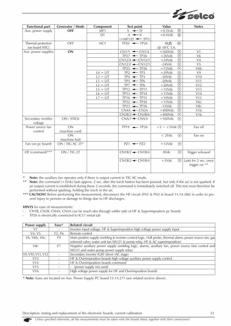
* Note: the auxiliary fan operates only if there is output current in TIG AC mode. ** Note: the command (+3Vdc) lasts approx. 2 sec. after the torch button has been pressed, but only if the arc is not sparked. If
an output current is established during these 2 seconds, the command is immediately switched off. This test must therefore beperformed without sparking, holding the torch in the air.
*** CAUTION! Before performing this measurement, disconnect the HF circuit (FN1 & FN2 in board 15.14.286) in order to pre-vent injury to persons or damage to things due to HF discharges.
HINTS for ease of measurements:- CN1B, CN2B, CN4A, CN5A can be reach also through solder side of HF & Superimposition pc boards- TP26 is electrically connected to IC17 metal tab
* Note: fuses are located on Aux. Power Supply PC board 15.14.271 (see related section above).
Related circuitInverter input voltage, HF & Superimposition high voltage power supply inputRemote controlMain positive supply (welding & inverter control logic, Hall probe, thermal alarm, power source fan, gassolenoid valve, water unit fan WU21 & pump relay, HF & AC superimposition)Negative auxiliary power supply (welding logic, alarms, auxiliary fan, power source fans control andWU21 and water pump power supply relay) Secondary inverter IGBT driver (AC stage)HF & Overimposition boards high voltage auxiliary power supply control HF & Overimposition boards command- (power supply not used)High voltage power supply for HF and Overimposition boards
Power supplyV1
V4, V5 V6, V6b, V6c
V8c
V9, V10, V11, V12V13V14V15V16
Fuse*-
F5, F6F9
F7
-----
Unless specified otherwise, all the measurements must be taken with the boards fitted, together with their connections!
Description, testing and replacement of the electronic boards, current calibration 51
Functional partAux. power supply
Thermal protection(on board NTC)
Aux. power supplies
Secondary rectifiervoltage
Power source fancontrol
Fan (on pc board)
HF (command)***
Generator / ModeOFF
OFF
ON
ON / STICK
ON (machine cool)
ON (machine hot)
ON / TIG AC 2T*
ON / TIG 2T
ComponentMF1D1
NC1
L4 = LITL3 = LITL1 = LITL2 = LITL5 = LITL6 = LITL7 = LIT
Test pointS DA K
(=MF1/D TP1)TP20 TP26
CN1/1 CN1/4TP27 TP26
CN12/4 CN12/1CN12/2 CN12/1
TP25 TP26TP2 TP3TP4 TP3TP5 TP6TP7 TP6
TP12 TP11TP13 TP14TP16 TP15TP22 TP26TP23 TP26CN4A CN5A
CN2B/2 CN2B/6CNA/1 CNA/4
TP19 TP26
PZ1 PZ2
CN1B/2 CN1B/4
CN1B/2 CN1B/4
Value+0.5Vdc+0.4Vdc
8k @ 18°C T.A.
+560Vdc+26Vdc+24Vdc-24Vdc+15Vdc+20Vdc-20Vdc-20Vdc+20Vdc+15Vdc+15Vdc+10Vdc+15Vdc-15Vdc
+400Vdc+400Vdc+160Vdc
+3 ~ +5Vdc
< 2Vdc
+15Vdc
0Vdc
+3Vdc
Notes
V1V6V4V5
V6bV9
V10V11V12V13V14V15V6cV8cV16V16
Fan off
Fan on
Trigger released
Lasts for 2 sec. oncetrigger on **

52 Description, testing and replacement of the electronic boards, current calibration Unless specified otherwise, all the measurements must be taken with the boards fitted, together with their connections!
9.8) HF PC board 15.14.286
This board generates a series of impulses in high voltage which are used to remote-spark the arc in the TIG AC and DC procedures.
Weld switching point configuration (factory setting, the switching point is located on the welding side of the board):K1 = OPEN
N.B.: in the machines produced prior to 2003, K1 is closed.

* CAUTION! Before performing this measurement, disconnect the HF circuit (FN1 & FN2) in order to prevent injury to personsor damage to things due to HF discharges.
** Note: the command (+3Vdc) lasts approx. 2 sec. after the torch button has been pressed, but only if the arc is not sparked. Ifan output current is established during these 2 seconds, the command is immediately switched off. This test must therefore beperformed without sparking, holding the torch in the air.
HINT for ease of measurement:- CN1 can be reach also from solder side of pc board.
Related circuitHigh voltage power supply for HF and Overimposition boards. HF board internal auxiliary power supply
Power supplyV16V17
Unless specified otherwise, all the measurements must be taken with the boards fitted, together with their connections!
Description, testing and replacement of the electronic boards, current calibration 53
Fuse*--
Functional partAux. power supply
HF output
Input power
Aux. power supply
HF command*
Generator / ModeOFF
OFF
ON
ON
ON/TIG DC HF 2 step
ComponentMF3
D10S1D1D2
L1 = LIT
L2 = OFF
L2 = LIT
Test pointS DS GA KG KA KA K
TP7 TP2
TP6 TP2
CN1/2 CN1/4
Value+0.4Vdc
10k+0.5Vdc
13+0.5Vdc+0.5Vdc+400Vdc
+19Vdc
0Vdc
+3Vdc
Notes
V16
V17
Trigger released
Lasts 2 sec. after trigger on**

54 Description, testing and replacement of the electronic boards, current calibration Unless specified otherwise, all the measurements must be taken with the boards fitted, together with their connections!
9.9) AC driver & superimposition PC board 15.14.253
This board controls the status (on or off) of the secondary AC stage IGBTs and generates a series of impulses in high voltage (ove-rimposition) that stabilise the arc during switching in TIG AC.
Weld switching point configuration (factory settings, all the switching points are on the welding side of the board):K1 = CLOSEDK2 = CLOSEDK3 = CLOSED
* Note: the command (0Vdc) lasts approximately 1 sec. after the torch button has been pressed. This test must be performedwithout sparking the arc, holding the torch in the air.
HINT for ease of measurement:- CN4, CN5 can be reached also from solder side of pc board.
Functional partSuperimposition
Secondary inverterdriver
Aux. power supplies
AC command
Secondary inverterdriver
Generator / ModeOFF
OFF
ON/ STICK
ON / STICKON / TIG AC
ON / STICK
ON / TIG AC
ComponentIG1D1IG2D5
D20D21
Test pointTP3 TP4
A KTP7 TP8
A KA KA K
TP15 TP14TP17 TP16CN4 CN5
TP19 TP18TP13 TP18TP13 TP18
TP15 TP14TP17 TP16TP15 TP14TP17 TP16
Value10k
+0.4Vdc10k
+0.4Vdc+0.2Vdc+0.2Vdc
10k10k
+400Vdc+15Vdc+14Vdc
0Vdc
-13Vdc+13Vdc+13Vdc-13Vdc
Notes
V16V14
Lasts 1 sec. with torchbutton pressed *
Lasts 1 sec. with torchbutton pressed *
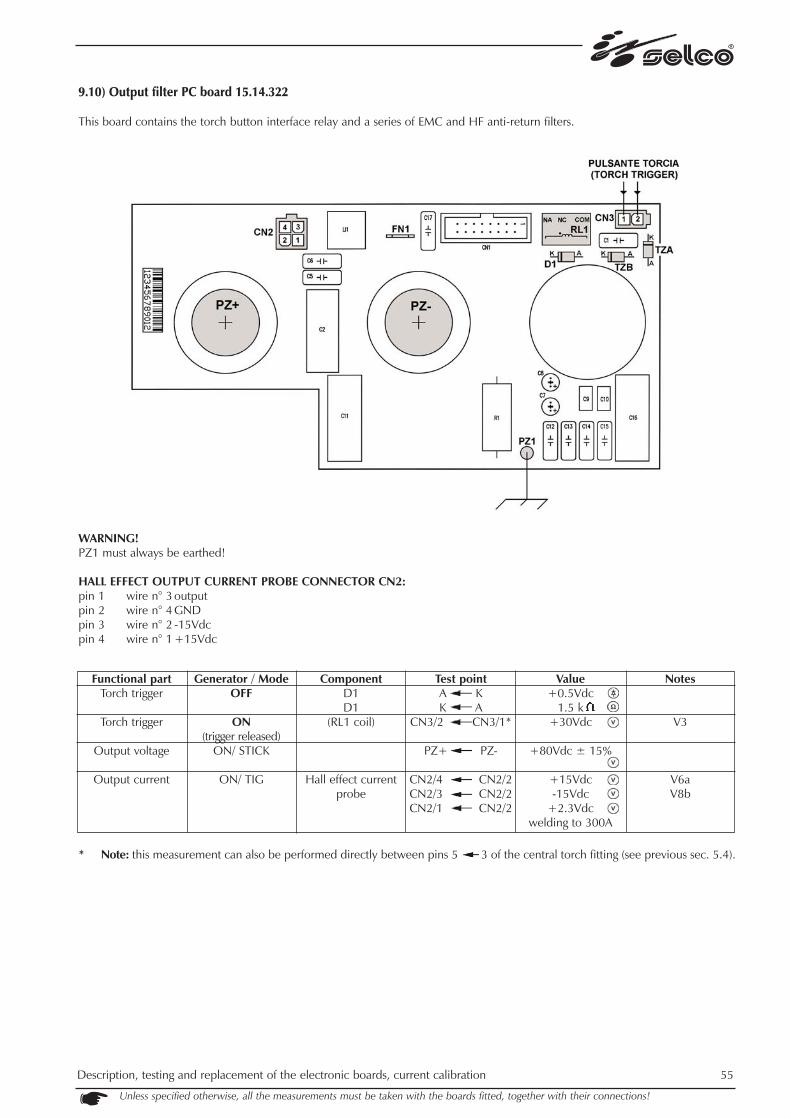
Description, testing and replacement of the electronic boards, current calibration 55
Unless specified otherwise, all the measurements must be taken with the boards fitted, together with their connections!
9.10) Output filter PC board 15.14.322
This board contains the torch button interface relay and a series of EMC and HF anti-return filters.
WARNING!PZ1 must always be earthed!
HALL EFFECT OUTPUT CURRENT PROBE CONNECTOR CN2:pin 1 wire n° 3 output pin 2 wire n° 4 GND pin 3 wire n° 2 -15Vdcpin 4 wire n° 1 +15Vdc
* Note: this measurement can also be performed directly between pins 5 3 of the central torch fitting (see previous sec. 5.4).
Functional partTorch trigger
Torch trigger
Output voltage
Output current
Generator / ModeOFF
ON(trigger released)
ON/ STICK
ON/ TIG
ComponentD1D1
(RL1 coil)
Hall effect currentprobe
Test pointA KK A
CN3/2 CN3/1*
PZ+ PZ-
CN2/4 CN2/2CN2/3 CN2/2CN2/1 CN2/2
Value+0.5Vdc
1.5 k+30Vdc
+80Vdc ± 15%
+15Vdc-15Vdc
+2.3Vdc welding to 300A
Notes
V3
V6aV8b
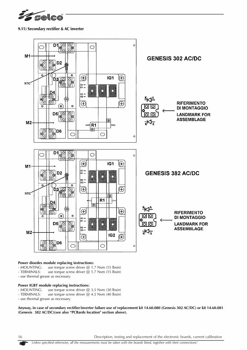
56 Description, testing and replacement of the electronic boards, current calibration Unless specified otherwise, all the measurements must be taken with the boards fitted, together with their connections!
9.11) Secondary rectifier & AC inverter
Power dioedes module replacing instructions:- MOUNTING: use torque screw driver @ 1.7 Nxm (15 lbxin) - TERMINALS: use torque screw driver @ 1.7 Nxm (15 lbxin)- use thermal grease as necessary.
Power IGBT module replacing instructions:- MOUNTING: use torque screw driver @ 3.5 Nxm (30 lbxin) - TERMINALS: use torque screw driver @ 4.5 Nxm (40 lbxin)- use thermal grease as necessary.
Anyway, in case of secondary rectifier/inverter failure use of replacement kit 14.60.080 (Genesis 302 AC/DC) or kit 14.60.081(Genesis 382 AC/DC)(see also “PCBards location" section above).
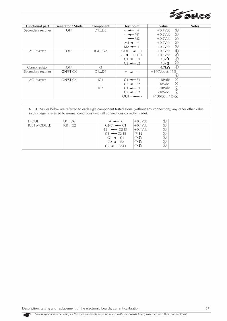
NOTE: Values below are referred to each sigle component tested alone (without any connection); any other other valuein this page is referred to normal conditions (with all connections correctly made).
Description, testing and replacement of the electronic boards, current calibration 57
Unless specified otherwise, all the measurements must be taken with the boards fitted, together with their connections!
Functional partSecondary rectifier
AC inverter
Clamp resistorSecondary rectifier
AC inverter
Generator / ModeOFF
OFF
OFFON/STICK
ON/STICK
ComponentD1...D6
IG1, IG2
R1D1...D6
IG1
IG2
Test point- +- M1- M2M1 +M2 +
OUT+ +- OUT+
G1 E1G2 E2
+ -
G1 E1G2 E2G1 E1G2 E2
OUT+ -
Value+0.4Vdc+0.2Vdc+0.2Vdc+0.2Vdc+0.2Vdc+0.3Vdc+0.3Vdc
10k10k4.7k
+160Vdc ± 15%
+18Vdc-18Vdc+18Vdc-18Vdc
+160Vdc ± 15%
Notes
DIODEIGBT MODULE
D1...D6IG1, IG2
A KC2-E1 C1
E2 C2-E1G1 C2-E1
G1 C1G2 E2
G2 C2-E1
+0.3Vdc+0.4Vdc+0.4Vdc

58 Description, testing and replacement of the electronic boards, current calibration
Unless specified otherwise, all the measurements must be taken with the boards fitted, together with their connections!
9.12) Clamp PC board 15.14.323
This board filters any disturbances on the rectifier and secondary AC stage.
NOTES: - PZ9, PZ10, PZ11 are to be electrically connected to power copper bars, well tighten screws needed
WARNING!- P1 must always be connected to the earth protection (via the metal spacer and the dissipator). - P1 (brass jumper) must be always close

Description, testing and replacement of the electronic boards, current calibration 59
Unless specified otherwise, all the measurements must be taken with the boards fitted, together with their connections!
* Notes:- power source fan depends mainly on NTC probe located on secondary heatsink (see previous section)- power source fan can also be activated by NC1 probe located on Pre-regulator pc board 15.14.321(see related section above)- The WU21 cooling unit fan is activated together with the cooling fluid pump (they are activated simultaneously during TIG wel-
ding, independently of any temperature condition). N.B.: the cooling unit operating time after the end of welding can be set from Set-up (see parameter 16 in the previous spe-cific section).
- The thermal alarms depend only on the primary and secondary thermal protections (they do not depend on the NTC sensors, seealso previous sec. 7.3).
Functional partClipping diode
Limiting resistors
Secondary thermalprotection*
Secondary temp.sensing (NTC probe)
AC drivers
Generator / ModeOFFOFF
OFF
OFF
OFF
ComponentD1
R8 // R9
Test pointA K
CN3/5 CN3/6
CN3/7 CN3/8
PZ1 PZ2PZ5 PZ6PZ3 PZ4PZ7 PZ8
Value+0.4Vdc
0.5
0
8k @ 18°C T.A.
10k10k10k10k
Notes
Secondary rectifieroutput
AC drivers
ON/STICK
ON/STICK
CN2/1 CN2/4
PZ1 PZ2PZ5 PZ6PZ3 PZ4PZ8 PZ7
+160Vdc ± 15%-18Vdc+18Vdc-18Vdc+18Vdc

60 Description, testing and replacement of the electronic boards, current calibration Unless specified otherwise, all the measurements must be taken with the boards fitted, together with their connections!
9.13) Output current calibration (delivered and displayed)
WARNING!Use of a grid load or striking a TIG arc is required to perform calibration!Exthernal accurate measurement of actual output current is required!You are advised to use an ammeter clamp with class 2 minimum rating, accurately calibrated (calibration certifica-te issued no more than 12 months previously). Using a grid load, output voltage measurement is required, too.
WARNING!Output current calibration could be required only in one of the following cases:- inverter group replacing- front panel replacing- pre-regulator pc board replacing- replacement of Hall-effect current probeDue to all spare parts being factory setted & calibrated, "calibration procedure" should be perfomed only once the failure has beenremoved, the power source is proven to work correctly and a deviation of more than 10A is find in delivered and/or displayed out-put current!
In case of incorrect calibration performing, the machine will deliver a totally wrong current during welding and damagescould occur to the welding power source itself!

Unless specified otherwise, all the measurements must be taken with the boards fitted, together with their connections!
Description, testing and replacement of the electronic boards, current calibration 61
To perform calibration of the power source G302 [the data in brackets refer to the G382], follow the procedure below:1. be sure to have correctly replaced the damaged part and that the unit has been correctly repaired & tested; a "Master Reset"
sould also have been performed through setup parameter 99 (see related section in the following)2. disconnect FN1/FN2 from HF pc board 15.14.286 output to prevent HF discharge damaging exthernal measuring instrument3. connect the unit to the mains4. switch the unit on5. select TIG DC 4 STEP mode and set output current @ 300A (380A) by turning the knob on front panel6. press the torch button and connect a static load of approx. 0.070 10'000W (21V@300A) [26V@380A] or spark a TIG arc
with scratch start (spark on a suitably sized piece of iron, to prevent overheating, and then fix the torch to a support to keep itin position): the power source should deliver approx. 300 [380] ± 10 A and approx. "300" ["380"] should be shown on the dis-play as the actual output current
7. measure the effective output current with an accurately calibrated ammeter clamp
BE CAREFUL WITH CORRECT IDENTIFICATION OF THE TRIMMERS: P4 MAY NOT BE FITTED.
8. current displayed: in this step figures displayed on control panel will not change while real output current changes by adjustingP3 trimmer: adjust P3 trimmer on resonant inverter control PCB 15.14.298 until value showed by external clamp ammeter mat-ches the value showed on control panel (this value is the real output current and could be different from 300 [380] value set atstep 5 above)
9. current delivered: in this step figures displayed on control panel and those displayed on external clamp ammeter change simul-taneously (they still match) and max output current is adjusted by P2 trimmer: adjust P2 trimmer on resonant inverter controlPCB 15.14.298 until 300A [380A] is displayed on both control panel and external clamp ammeter.
10. press the torch button again and disconnect any static load 11. switch the power source off, seal the trimmers P2 & P3, reconnect FN1 and FN2 on the HF board and re-close the power source12. perform some TIG AC welding tests to check correct operation of the power source
WARNING!P2 & P3 are very sensitive trimmers, thus little adjustaments will cause large output current variations!
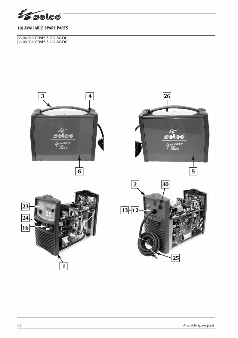
62 Available spare parts
10) AVAILABLE SPARE PARTS
Nota: aggiungere il seguente articolo all'elenco dei ricambi (senza riferimento all'esploso):18.91.001 LIQUIDO REFRIGERANTE CU-10 simbolo dell'indice:Nota sul liquido refrigerante:- miscela pronta all'uso, non diluire!- non miscelare o sostituire con altri prodotti o additivi!
9) DATI TECNICI
COME PAG. 171 MANUALE UTENTE
55.08.030 GENESIS 302 AC/DC55.08.038 GENESIS 382 AC/DC

Available spare parts 63

64 Available spare parts
ITAL
IAN
OPO
S.D
ESCR
IZIO
NE
COD
ICE
1Pa
nnel
lo p
lasti
co fr
onta
le01
.04.
271
2Pa
nnel
lo p
lasti
co p
oste
riore
01.0
5.22
53
Man
ico
01.1
5.03
84
Chiu
sura
man
ico
01.1
5.03
95
Pann
ello
late
rale
des
tro se
rigra
fato
(G
302
AC/
DC)
03.0
7.10
4Pa
nnel
lo la
tera
le d
estro
serig
rafa
to
(G 3
82 A
C/D
C)03
.07.
106
6Pa
nnel
lo la
tera
le si
nistr
o se
rigra
fato
(G
302
AC/
DC)
03.0
7.10
5Pa
nnel
lo la
tera
le si
nistr
o se
rigra
fato
(G
382
AC/
DC)
03.0
7.10
77
Tras
form
ator
e 05
.02.
028
8Tr
asfo
rmat
ore
H.F.
05.0
3.01
19
Indu
ttanz
a di
live
llam
ento
05.0
4.22
610
Indu
ttanz
a ris
onan
te05
.04.
208
11Ve
ntila
tore
07.1
1.01
012
Pres
saca
vo08
.22.
012
13Co
ntro
dado
08.2
2.01
314
Inte
rrutto
re09
.01.
011
15El
ettro
valv
ola
09.0
5.00
316
Pres
a fis
sa10
.13.
020
17Se
nsor
e H
inod
e11
.19.
003
18Co
nden
sato
re12
.03.
020
19Sc
heda
con
trollo
15.1
4.25
320
Sche
da H
F15
.14.
286
21Sc
heda
pre
-rego
lato
re15
.14.
321
22Sc
heda
filtr
o us
cita
15.1
4.32
223
Pann
ello
com
andi
FP1
6415
.22.
164
(con
tiene
sche
da 1
5.14
.324
)24
Adat
tato
re19
.06.
101
25Ca
vo a
limen
tazi
one
49.0
4.05
826
Cofa
no su
perio
re01
.02.
092
27Sc
heda
logi
ca ri
sona
nte
15.1
4.29
828
Gru
ppo
inve
rter s
econ
dario
(G
302
AC/
DC)
14.6
0.08
0G
rupp
o in
verte
r sec
onda
rio
(G 3
82 A
C/D
C)14
.60.
081
(con
tiene
sche
da 1
5.14
.323
, co
mpo
nent
i di p
oten
za e
radi
ator
e)29
Gru
ppo
inve
rter p
rimar
io
(G 3
02 A
C/D
C)14
.60.
078
Gru
ppo
inve
rter p
rimar
io
(G 3
82 A
C/D
C)14
.60.
079
(con
tiene
sche
de 1
5.14
.200
, 15.
14.1
76,
15.1
4.29
8, 1
5.14
.241
, com
pone
nti d
i pot
enza
e
radi
ator
e)30
Man
opol
a09
.11.
009
31Sc
heda
filtr
o in
gres
so15
.14.
269
32Sc
heda
alim
enta
zion
e15
.14.
271
ENG
LISH
POS.
DES
CRIP
TIO
NCO
DE
1Fr
ont p
lasti
c pa
nel
01.0
4.27
12
Rear
pla
stic
pane
l01
.05.
225
3H
andl
e01
.15.
038
4Fa
stene
r han
dle
01.1
5.03
95
Side
pan
el ri
ght (
G 3
02 A
C/D
C)03
.07.
104
Side
pan
el ri
ght (
G 3
82 A
C/D
C)03
.07.
106
6Si
de p
anel
left
(G 3
02 A
C/D
C)03
.07.
105
Side
pan
el le
ft (G
382
AC/
DC)
03.0
7.10
77
Tran
sform
er
05.0
2.02
88
H.F.
tran
sform
er05
.03.
011
9Le
velin
g in
duct
ance
05.0
4.22
610
Reso
nant
indu
ctan
ce
05.0
4.20
811
Fan
07.1
1.01
012
Cabl
e cl
amp
08.2
2.01
213
Coun
ter-n
ut08
.22.
013
14Sw
itch
09.0
1.01
115
Sole
noid
val
ve09
.05.
003
16Fi
xed
sock
et10
.13.
020
17H
inod
e se
nsor
11.1
9.00
318
Capa
cito
r12
.03.
020
19Co
ntro
l P.C
. boa
rd15
.14.
253
20H
F bo
ard
15.1
4.28
621
Pre-
adju
ster b
oard
15.1
4.32
122
Out
put f
ilter
boa
rd15
.14.
322
23Co
ntro
l pan
el F
P164
15
.22.
164
(con
tain
s boa
rd 1
5.14
.324
)24
Adap
ter
19.0
6.10
125
Supp
ly c
able
49.0
4.05
826
Upp
er c
over
01.0
2.09
227
Reso
nant
logi
c bo
ard
15.1
4.29
828
Seco
ndar
y in
verte
r uni
t(G
302
AC/
DC)
14.6
0.08
0Se
cond
ary
inve
rter u
nit
(G 3
82 A
C/D
C)14
.60.
081
(con
tain
s boa
rd 1
5.14
.323
, po
wer
com
pone
nts a
nd ra
diat
or)
29Pr
imar
y in
verte
r uni
t (G
302
AC/
DC)
14.6
0.07
8Pr
imar
y in
verte
r uni
t (G
382
AC/
DC)
14.6
0.07
9(c
onta
ins b
oard
s 15.
14.2
00, 1
5.14
.176
, 15
.14.
298,
15.
14.2
41, p
ower
com
pone
nts
and
radi
ator
)30
Turn
-Kno
b09
.11.
009
31In
put f
ilter
boa
rd
15.1
4.26
932
Supp
ly b
oard
15.1
4.27
1
DEU
TSC
HPO
S.BE
SCH
REIB
UN
GCO
DE
1St
irnpl
astik
tafe
l01
.04.
271
2H
inte
re P
lastk
atel
01.0
5.22
53
Grif
f01
.15.
038
4G
riffv
ersc
hlus
s01
.15.
039
5Se
itent
eil r
echt
s (G
302
AC/
DC)
03.0
7.10
4Se
itent
eil r
echt
s (G
382
AC/
DC)
03.0
7.10
66
Seite
ntei
l lin
ks (G
302
AC/
DC)
03.0
7.10
5Se
itent
eil l
inks
(G 3
82 A
C/D
C)03
.07.
107
7Tr
ansfo
rmat
or
05.0
2.02
88
Tran
sform
ator
H.F.
05.0
3.01
19
Dro
ssel
spul
e05
.04.
226
10Re
sona
nzin
dukt
anz
05.0
4.20
811
Vent
ilato
r 07
.11.
010
12Ka
belk
lem
me
08.2
2.01
213
Geg
enm
utte
r08
.22.
013
14Sc
halte
r09
.01.
011
15El
ektro
vent
il09
.05.
003
16Fe
ste S
teck
dose
10.1
3.02
017
Sens
or H
inod
e11
.19.
003
18Ko
nden
sato
r12
.03.
020
19St
euer
ungs
plat
ine
15.1
4.25
320
HF.-
Plat
ine
15.1
4.28
621
Vore
inste
llpla
tine
15.1
4.32
122
Ausg
angf
ilter
plat
ine
15.1
4.32
223
Bedi
enun
gsfe
ld F
P164
15.2
2.16
4(e
nthä
lt di
e pl
atin
e 15
.14.
324)
24Ad
apte
r19
.06.
101
25Sp
eise
kabe
l49
.04.
058
26O
bere
Hau
be01
.02.
092
27Re
sona
nzlo
gikp
latin
e15
.14.
298
28Se
kund
aer-i
nver
tere
inhe
it (G
302
AC/
DC)
14.6
0.08
0Se
kund
aer-i
nver
tere
inhe
it (G
382
AC/
DC)
14.6
0.08
1(e
nthä
lt di
e pl
atin
e 15
.14.
323,
Le
istun
gste
ile u
nd K
uehl
er)
29Pr
imae
r-inv
erte
rein
heit
(G
302
AC/
DC)
14.6
0.07
8Pr
imae
r-inv
erte
rein
heit
(G 3
82 A
C/D
C)14
.60.
079
(ent
hält
die
plat
inen
15.
14.2
00, 1
5.14
.176
, 15
.14.
298,
15.
14.2
41, L
eistu
ngste
ile u
nd K
uehl
er)
30D
rehk
nopf
09.1
1.00
931
Eing
angs
filte
rpla
tine
15.1
4.26
932
Spei
serp
latin
e15
.14.
271
FRAN
ÇAI
SPO
S.D
ESCR
IPTI
ON
COD
E1
Pann
eau
plas
tique
ant
érie
ur
01.0
4.27
12
Pann
eau
plas
tique
pos
térie
ur
01.0
5.22
53
Poig
nee
01.1
5.03
84
Ferm
etur
e du
poi
gnee
01.1
5.03
95
Pann
eau
late
ral d
roite
ave
c se
rigra
phie
(G
302
AC/
DC)
03.0
7.10
4Pa
nnea
u la
tera
l dro
ite a
vec
serig
raph
ie
(G 3
82 A
C/D
C)03
.07.
106
6Pa
nnea
u lat
eral
gauc
he a
vec
serig
raph
ie(G
302
AC/
DC)
03.0
7.10
5Pa
nnea
u lat
eral
gauc
he a
vec
serig
raph
ie(G
382
AC/
DC)
03.0
7.10
77
Tran
sform
ateu
r 05
.02.
028
8Tr
ansfo
rmat
eur H
.F.05
.03.
011
9In
duct
ance
d'éc
rêta
ge05
.04.
226
10In
duct
ance
reso
nnan
te05
.04.
208
11Ve
ntila
teur
07.1
1.01
012
Serre
-cab
le08
.22.
012
13Ec
rou
de b
loca
ge08
.22.
013
14D
isjon
cteu
r09
.01.
011
15So
upap
e el
ectri
que
09.0
5.00
316
Prise
fixe
10.1
3.02
017
Capt
eur H
inod
e11
.19.
003
18Co
nden
sate
ur12
.03.
020
19Pl
atin
e de
con
trol
15.1
4.25
320
Plat
ine
H.F.
15.1
4.28
621
Plat
ine
pré-
régu
late
ur15
.14.
321
22Pl
atin
e fil
tre so
rtie
15.1
4.32
223
Pann
eau
de re
glag
e FP
164
15.2
2.16
4(il
con
tient
la p
latin
e 15
.14.
324)
24Ad
apta
teur
19.0
6.10
125
Câbl
e d’
alim
enta
tion
49.0
4.05
826
Capo
t sup
érie
ur01
.02.
092
27Pl
atin
e lo
giqu
e re
sona
nce
15.1
4.29
828
Gro
upe
ondu
leur
seco
ndai
re
(G 3
02 A
C/D
C)14
.60.
080
Gro
upe
ondu
leur
seco
ndai
re
(G 3
82 A
C/D
C)14
.60.
081
(il c
ontie
nt la
pla
tine
15.1
4.32
3,
com
posa
nts d
e pu
issan
ce e
t rad
iate
ur)
29G
roup
e on
dule
ur p
rimai
re
(G 3
02 A
C/D
C)14
.60.
078
Gro
upe
ondu
leur
prim
aire
(G
382
AC/
DC)
14.6
0.07
9(il
con
tient
la p
latin
es 1
5.14
.200
, 15.
14.1
76,
15.1
4.29
8, 1
5.14
.241
, com
posa
nts d
e pu
issan
ce
et ra
diat
eur)
30Bo
uton
09.1
1.00
931
Plat
ine
filtre
d’e
ntré
e15
.14.
269
32Pl
atin
e al
imen
tate
ur15
.14.
271
ESPA
ÑO
LPO
S.D
ESCR
IPCI
ON
COD
IGO
1Pa
nel p
lásti
co a
nter
ior
01.0
4.27
12
Pane
l plá
stico
pos
terio
r 01
.05.
225
3M
ango
01.1
5.03
84
Cier
re m
ango
01.1
5.03
95
Pane
l lat
eral
der
echo
con
serig
rafia
(G
302
AC/
DC)
03.0
7.10
4Pa
nel l
ater
al d
erec
ho c
on se
rigra
fia
(G 3
82 A
C/D
C)03
.07.
106
6Pa
nel l
ater
al iz
quie
rdo
con
serig
rafia
(G
302
AC/
DC)
03.0
7.10
5Pa
nel l
ater
al iz
quie
rdo
con
serig
rafia
(G
382
AC/
DC)
03.0
7.10
77
Tran
sform
ador
05
.02.
028
8Tr
ansfo
rmad
or H
.F.05
.03.
011
9Bo
bina
de
indu
ctan
cia
stabi
lizad
ora
de c
orrie
nte
05.0
4.22
610
Indu
ctan
cia
reso
nant
e05
.04.
208
11Ve
ntila
dor
07.1
1.01
012
Abra
zade
ra08
.22.
012
13Co
ntra
tuer
ca08
.22.
013
14In
terru
ptor
09.0
1.01
115
Elec
trová
lvul
a09
.05.
003
16En
chuf
e fij
a10
.13.
020
17Ca
ptad
or H
inod
e11
.19.
003
18Co
nden
sado
r12
.03.
020
19Ta
rjeta
de
cont
rol
15.1
4.25
320
Tarje
ta H
.F.15
.14.
286
21Ta
rjeta
pre
-regu
lado
r15
.14.
321
22Ta
rjeta
filtr
o sa
lida
15.1
4.32
223
Pane
l de
cont
rol F
P164
15.2
2.16
4(c
ontie
ne la
tarje
ta 1
5.14
.324
)24
Adap
tado
r19
.06.
101
25Ca
ble
de a
limen
taci
ón49
.04.
058
26Co
fre su
perio
r01
.02.
092
27Ta
rjeta
logi
ca re
sona
ncia
15.1
4.29
828
Gru
po in
verte
r sec
unda
rio
(G 3
02 A
C/D
C)14
.60.
080
Gru
po in
verte
r sec
unda
rio
(G 3
82 A
C/D
C)14
.60.
081
(con
tiene
la ta
rjeta
15.
14.3
23,
com
pone
ntes
de
pote
ncia
y ra
diad
or)
29G
rupo
inve
rter p
rimar
io
(G 3
02 A
C/D
C)14
.60.
078
Gru
po in
verte
r prim
ario
(G
382
AC/
DC)
14.6
0.07
9(c
ontie
ne la
tarje
tas 1
5.14
.200
, 15.
14.1
76,
15.1
4.29
8, 1
5.14
.241
, com
pone
ntes
de
pote
ncia
y
radi
ador
)30
Boto
n09
.11.
009
31Ta
rjeta
filtr
o en
trada
15.1
4.26
932
Tarje
ta a
limen
taci
on15
.14.
271

Available spare parts 65
ITALIANOPOS.DESCRIZIONE CODICE001 Pannello plastico frontale
e posteriore 01.04.273002 Pannello laterale DX 01.03.034003 Pannello laterale SX 01.03.035004 Cofano superiore 01.02.090005 Attacco rapido acqua 19.50.043006 Ventilatore 07.10.020007 Pressostato 09.08.002008 Radiatore 18.81.002009 Pompa 07.23.004010 Serbatoio 20.04.039
FRANÇAISPOS.DESCRIPTION CODE001 Panneau plastique
antérieur/postérieur 01.04.273002 Panneau lateral droite 01.03.034003 Panneau lateral gauche 01.03.035004 Capot supérieur 01.02.090005 Connecteur rapide eau 19.50.043006 Ventilateur 07.10.020007 Pressostat 09.08.002008 Radiateur 18.81.002009 Pompe 07.23.004010 Réservoir 20.04.039
ENGLISHPOS.DESCRIPTION CODE001 Plastic front/rear panel 01.04.273002 Side panel right 01.03.034003 Side panel left 01.03.035004 Upper cover 01.02.090005 Water rapid connector 19.50.043006 Fan 07.10.020007 Pressure switch 09.08.002008 Condensator 18.81.002009 Pump 07.23.004010 Reservoir 20.04.039
ESPAÑOLPOS.DESCRIPCION CODIGO001 Panel plastico frontal y posterior 01.04.273002 Panel lateral derecho 01.03.034003 Panel lateral izquierdo 01.03.035004 Cofre superior 01.02.090005 Enchufe rapido agua 19.50.043006 Ventilador 07.10.020007 Presostato 09.08.002008 Radiador 18.81.002009 Bomba 07.23.004010 Tanque 20.04.039
DEUTSCHPOS.BESCHREIBUNG CODE001 Stirnplastiktafel, Hintereplastiktafel 01.04.273002 Seitenteil rechte 01.03.034003 Seitenteil links 01.03.035004 Obere Haube 01.02.090005 Wasserschnellanschluss 19.50.043006 Ventilator 07.10.020007 Druckschalter 09.08.002008 Kueler 18.81.002009 Pumpe 07.23.004010 Tank 20.04.039
71.03.021 WU 21
18.91.001 COOLING FLUID
Note on cooling fluid:- mixture ready for use - do not dilute- do not mix or replace with other products or additives

66 Available spare parts
71.03.02301 Generator trolley GT23 TLH
ITALIANOPOS.DESCRIZIONE CODICE001 Ruota posteriore fissa 04.02.003002 Cinghia 21.06.007003 Ruota anteriore girevole 04.03.002004 Cappuccio bloccaggio rapido 18.77.201005 Base di ancoraggio 02.07.053006 Maniglia 01.15.040007 Supporto bombola 01.11.080
FRANÇAISPOS.DESCRIPTION CODE001 Roue arriére fixe 04.02.003002 Courroie 21.06.007003 Roue avant pivotante 04.03.002004 Couvercle à blocage rapide 18.77.201005 Base d'ancrage 02.07.053006 Poigneé 01.15.040007 Support bouteille 01.11.080
ENGLISHPOS.DESCRIPTION CODE001 Fixed rear wheel 04.02.003002 Belt 21.06.007003 Swiveling front wheel 04.03.002004 Rapid locking cap 18.77.201005 Anchorage base 02.07.053006 Handle 01.15.040007 Cylinder support 01.11.080
ESPAÑOLPOS.DESCRIPCION CODIGO001 Rueda trasera fija 04.02.003002 Correa 21.06.007003 Rueda delantera giratoria 04.03.002004 Capuchón de bloqueo rápido 18.77.201005 Base de anclaje 02.07.053006 Mango 01.15.040007 Soporte bombona 01.11.080
DEUTSCHPOS.BESCHREIBUNG CODE001 Hinteres Fixrad 04.02.003002 Riemen 21.06.007003 Vorderes Drehrad 04.03.002004 Schnellsperrkappe 18.77.201005 Verankerungsbasis 02.07.053006 Griff 01.15.040007 Flaschenhalter 01.11.080


