Embed Size (px)
Citation preview
6.3 Addressing over Gb
Addressing over Gb is performed over virtual connections. At NS and BSSGP layers, each entity communicates with its peer through this kind of connection. The goal of this section is to explain the hierarchy that has beendefined between the different virtual connections and to introduce the technical words that are used in the standard for the description of the Gb interface.
Addressing is very simple, but it requires an understanding of basic concepts that will be introduced in the following sections. Once these concepts have been presented, a global overview of addressing will be given.
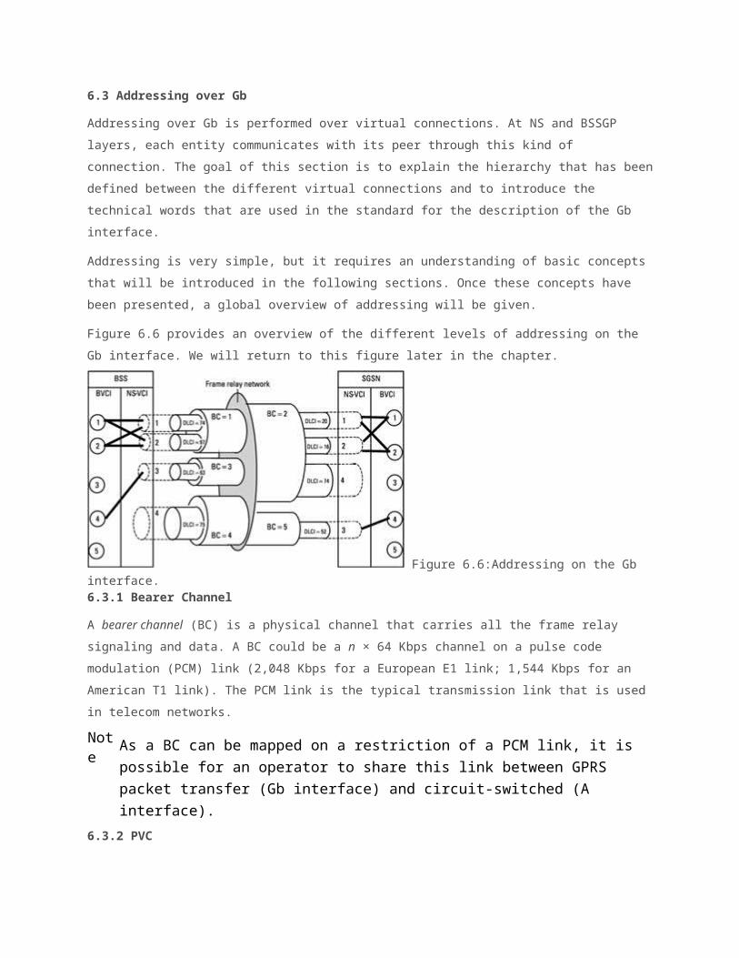
Figure 6.6 provides an overview of the different levels of addressing on the Gb interface. We will return to this figure later in the chapter.
Figure 6.6:Addressing on the Gb interface.6.3.1 Bearer Channel
A bearer channel (BC) is a physical channel that carries all the frame relay signaling and data. A BC could be a n × 64 Kbps channel on a pulse code modulation (PCM) link (2,048 Kbps for a European E1 link; 1,544 Kbps for an American T1 link). The PCM link is the typical transmission link that is used in telecom networks.
Note
As a BC can be mapped on a restriction of a PCM link, it is possible for an operator to share this link between GPRS packet transfer (Gb interface) and circuit-switched (A interface).
6.3.2 PVC
The frame relay PVC was introduced in Section 6.2. It allows the multiplexing of different flow on the BC. The BC can support several PVCs. At BSS side, a DLCI, which can be different from the one at the SGSN side, identifies a PVC.
Note
There is a dedicated DLCI (DLCI = 0) that is used for signaling purposes (link management). This DLCI does not identify a PVC.
6.3.3 Network Service Virtual Link
An SGSN and a BSS can be connected directly via a physical link or they can beconnected indirectly because of intermediate equipment or transmission networks (frame relay network), in which case different physical links are used.
The concept of the network service virtual link (NS-VL) is introduced to identify the link defined by a PVC and its supporting BC. Each NS-VL is identified by a network service virtual link identifier (NS-VLI). An NS-VL is supported by only one physical link, and several NS-VLs can be mapped on a physical link. One NS-VLIcorresponds to the association DLCI and BC identifier.6.3.4 Network Service Virtual Connection
As described previously, the NS layer has been split into two sublayers, SNS and SNC, in order to have the SNC sublayer independent of the intermediate transmission network (frame relay). In order to provide an end-to-end connection between the BSS and the SGSN irrespective of the exact configuration of the Gb interface and transmission network, the concept of network service virtual connection (NS-VC) has been introduced at the SNC layer.
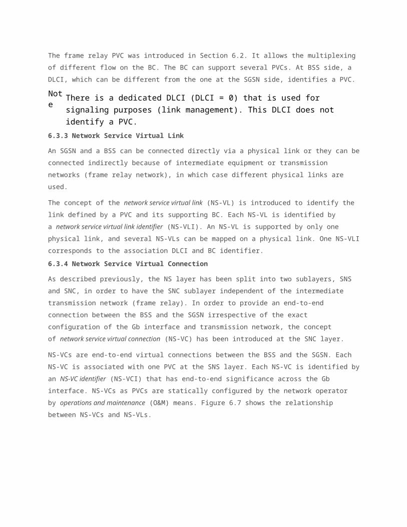
NS-VCs are end-to-end virtual connections between the BSS and the SGSN. Each NS-VC is associated with one PVC at the SNS layer. Each NS-VC is identified byan NS-VC identifier (NS-VCI) that has end-to-end significance across the Gb interface. NS-VCs as PVCs are statically configured by the network operator by operations and maintenance (O&M) means. Figure 6.7 shows the relationship between NS-VCs and NS-VLs.
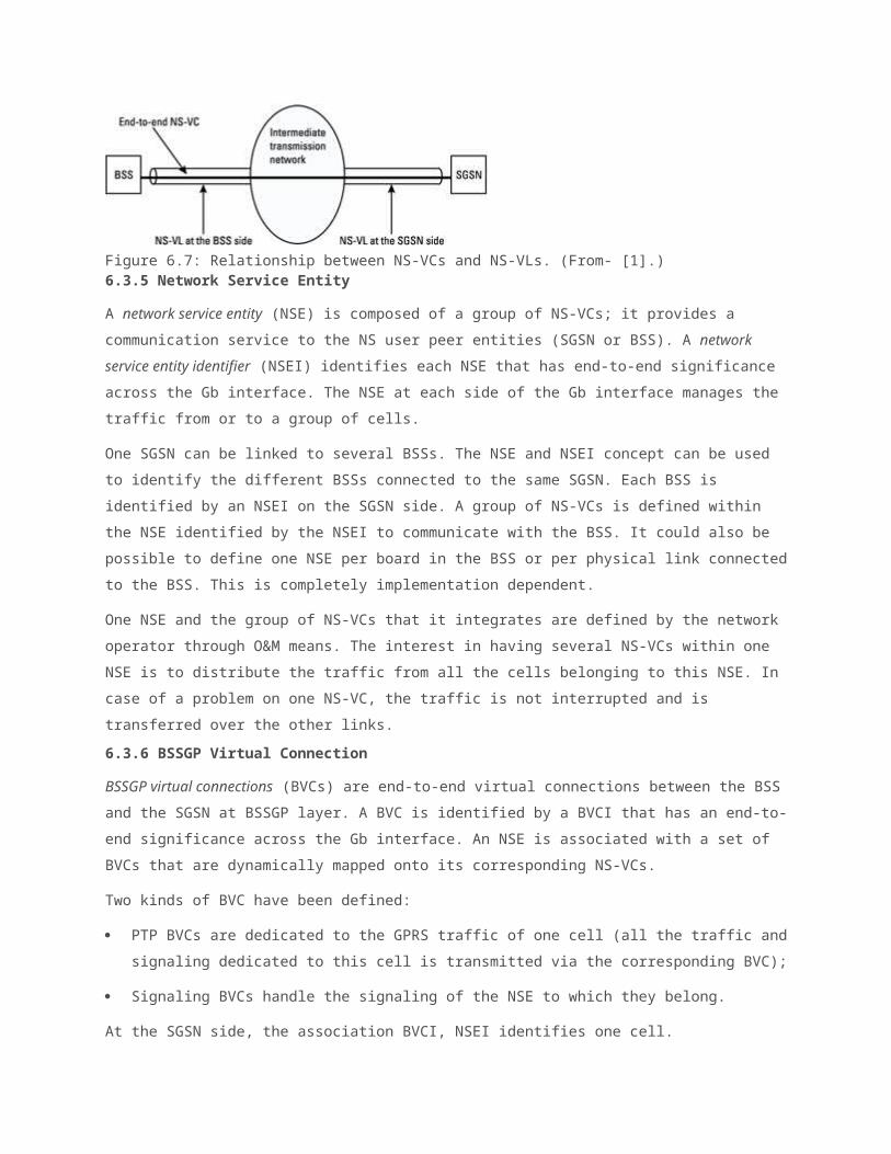
Figure 6.7: Relationship between NS-VCs and NS-VLs. (From- [1].)6.3.5 Network Service Entity
A network service entity (NSE) is composed of a group of NS-VCs; it provides a communication service to the NS user peer entities (SGSN or BSS). A network service entity identifier (NSEI) identifies each NSE that has end-to-end significance across the Gb interface. The NSE at each side of the Gb interface manages the traffic from or to a group of cells.
One SGSN can be linked to several BSSs. The NSE and NSEI concept can be used to identify the different BSSs connected to the same SGSN. Each BSS is identified by an NSEI on the SGSN side. A group of NS-VCs is defined within the NSE identified by the NSEI to communicate with the BSS. It could also be possible to define one NSE per board in the BSS or per physical link connectedto the BSS. This is completely implementation dependent.
One NSE and the group of NS-VCs that it integrates are defined by the network operator through O&M means. The interest in having several NS-VCs within one NSE is to distribute the traffic from all the cells belonging to this NSE. In case of a problem on one NS-VC, the traffic is not interrupted and is transferred over the other links.6.3.6 BSSGP Virtual Connection
BSSGP virtual connections (BVCs) are end-to-end virtual connections between the BSSand the SGSN at BSSGP layer. A BVC is identified by a BVCI that has an end-to-end significance across the Gb interface. An NSE is associated with a set of BVCs that are dynamically mapped onto its corresponding NS-VCs.
Two kinds of BVC have been defined:
PTP BVCs are dedicated to the GPRS traffic of one cell (all the traffic andsignaling dedicated to this cell is transmitted via the corresponding BVC);
Signaling BVCs handle the signaling of the NSE to which they belong.
At the SGSN side, the association BVCI, NSEI identifies one cell.
In the BSS, the BVCIs are statically configured by administrative means. At the SGSN side, BVCIs associated with PTP functional entities are dynamically configured, and BVCIs associated with signaling functional entities are statically configured.6.3.7 Addressing
Figures 6.6 and 6.8 provide a summary of the different concepts presented in the previous sections. In Figure 6.6, two cells 1 and 2 are identified by BVCI= 1 and BVCI = 2. They share the two NS-VCs identified by NS-VCI = 1 and NS-VCI = 2.
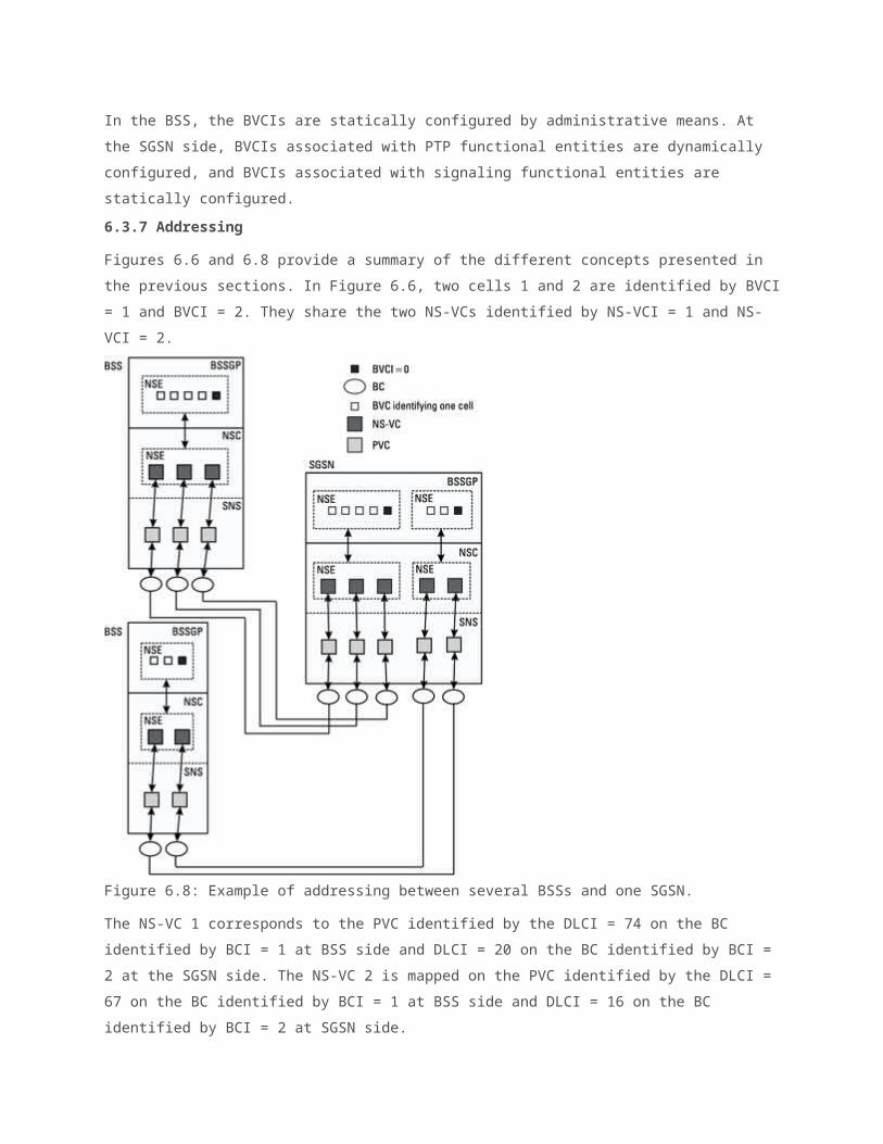
Figure 6.8: Example of addressing between several BSSs and one SGSN.
The NS-VC 1 corresponds to the PVC identified by the DLCI = 74 on the BC identified by BCI = 1 at BSS side and DLCI = 20 on the BC identified by BCI = 2 at the SGSN side. The NS-VC 2 is mapped on the PVC identified by the DLCI = 67 on the BC identified by BCI = 1 at BSS side and DLCI = 16 on the BC identified by BCI = 2 at SGSN side.
All the traffic addressed to cell 1 or cell 2 from the SGSN or received in cell 1 or cell 2 in the BSS is transferred on the corresponding BVC at the BSSGP layer. The traffic is dynamically distributed on the NS-VCs identified by NS-VCI = 1 and NS-VCI = 2 at the SNC layer.
Figure 6.8 details the addressing between one SGSN and several BSSs. The SGSN is connected to two different BSSs. The BVCs and NS-VCs of each BSS belong to one NSE; each one is identified by a different NSEI.
One BVC is reserved for signaling purposes. On the SGSN side, BVCs and NS-VCs belonging to the same BSS are grouped within the same NSE. One NSE is created for each BSS. For each NSE, a set of BVCs is mapped onto a set of NS-VCs. There is a one-to-one mapping between NS-VC and PVC. Within one SGSN, one cellwithin one BSS is directly identified by one BVCI and one NSEI.
User planeFigure 4-3 shows the protocol architecture of the GPRS user/transmission plane. The user plane provides user informationtransfer and associated signaling procedures, e.g., flow control and error detection and correction.GGSN-SGSN. The user data packets arriving at the SGSN from the MSor at the GGSN from the external PDN are encapsulated before onward transmission within the GPRS backbone network. The GPRS tunneling protocol for user plane (GTP-U) is used to tunnel the user data between SGSN and GGSN over the Gn interface and betweenGSNs from different PLMNs over the Gp interface. GTP carries the user packets, i.e., X.25 or IP.TCP/UDP is used to transport GTP packets within the GPRS intra-PLMN backbone. TCP carries GTP PDUs (G-PDUs) for protocols that require a reliable data link, e.g., X.25. UDP carries G-PDUs for protocols that do not require a reliable data link, e.g., IP.
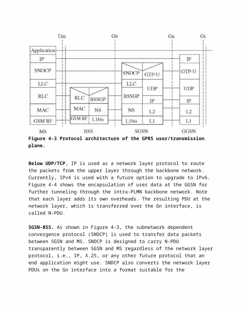
Figure 4-3 Protocol architecture of the GPRS user/transmission plane.
Below UDP/TCP, IP is used as a network layer protocol to route the packets from the upper layer through the backbone network. Currently, IPv4 is used with a future option to upgrade to IPv6.Figure 4-4 shows the encapsulation of user data at the GGSN for further tunneling through the intra-PLMN backbone network. Note that each layer adds its own overheads. The resulting PDU at the network layer, which is transferred over the Gn interface, is called N-PDU.
SGSN-BSS. As shown in Figure 4-3, the subnetwork dependent convergence protocol (SNDCP) is used to transfer data packets between SGSN and MS. SNDCP is designed to carry N-PDU transparently between SGSN and MS regardless of the network layerprotocol, i.e., IP, X.25, or any other future protocol that an end application might use. SNDCP also converts the network layer PDUs on the Gn interface into a format suitable for the
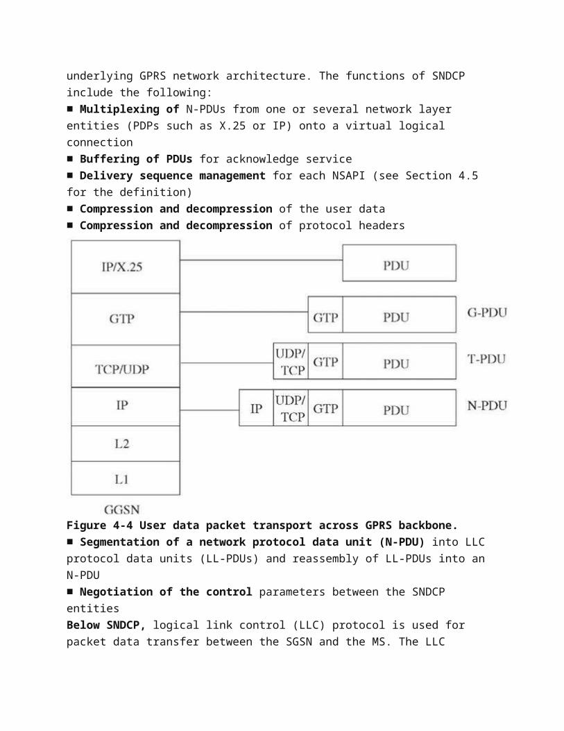
underlying GPRS network architecture. The functions of SNDCP include the following:■ Multiplexing of N-PDUs from one or several network layer entities (PDPs such as X.25 or IP) onto a virtual logical connection■ Buffering of PDUs for acknowledge service■ Delivery sequence management for each NSAPI (see Section 4.5 for the definition)■ Compression and decompression of the user data■ Compression and decompression of protocol headers
Figure 4-4 User data packet transport across GPRS backbone.■ Segmentation of a network protocol data unit (N-PDU) into LLC protocol data units (LL-PDUs) and reassembly of LL-PDUs into an N-PDU■ Negotiation of the control parameters between the SNDCP entitiesBelow SNDCP, logical link control (LLC) protocol is used for packet data transfer between the SGSN and the MS. The LLC
provides a highly reliable, ciphered logical link between the MS and the SGSN. The LLC frame format is based on the LAPD protocol with a few modifications to make it suitable to be used on a radio link. It uses both acknowledged and unacknowledged data transfer, depending upon the requirement on QoS. The LLC also manages frame retransmission and buffering based on the negotiated QoS.The data from several mobile stations is multiplexed over a Gb link in downlink direction. The same is true for the uplink direction, where the data destined to several MSs is to be multiplexed over a Gb link. How can LLC frames belonging to a MS be routed to the right MS (RLC/MAC) via a BSS? The base station subsystem GPRS protocol (BSSGP), which is a new and GPRS-specificprotocol, in conjunction with the network service (NS) layer, performs this task. The tasks performed by the BSSGP are:■ In the uplink direction, the BSSGP at the BSS provides the needed information to route the user data to the SGSN. The information is derived from the RLC/MAC.■ In the downlink direction, the BSSGP layer at the SGSN providesradio-related information used by the RLC/MAC function.■ Node management functions between the SGSN and the BSS.The relay function at the BSS transfers LLC frames between the RLC/MAC layers and the BSSGP layer. The BSSGP uses the following identifiers to indicate to the NS layer the destination of packets:■ BSSGP virtual connection identifier (BVCI)■ Link selection parameter (LSP)■ Network service entity identifier (NSEI)BVCI identifies entities at the SGSN and the BSS between which the data and signaling information is to be transferred. Each BVCI between two peer entities is unique.In the case of load sharing, LSP is used in conjunction with the BVCI to identify a physical link. The BSSGP virtual connection between the SGSN and the BSS is uniquely identified with the combination of BVCI and NSEI.
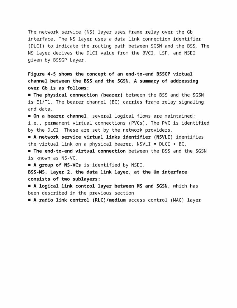
The network service (NS) layer uses frame relay over the Gb interface. The NS layer uses a data link connection identifier (DLCI) to indicate the routing path between SGSN and the BSS. TheNS layer derives the DLCI value from the BVCI, LSP, and NSEI given by BSSGP Layer.
Figure 4-5 shows the concept of an end-to-end BSSGP virtual channel between the BSS and the SGSN. A summary of addressing over Gb is as follows:■ The physical connection (bearer) between the BSS and the SGSN is E1/T1. The bearer channel (BC) carries frame relay signaling and data.■ On a bearer channel, several logical flows are maintained; i.e., permanent virtual connections (PVCs). The PVC is identifiedby the DLCI. These are set by the network providers.■ A network service virtual links identifier (NSVLI) identifies the virtual link on a physical bearer. NSVLI = DLCI + BC.■ The end-to-end virtual connection between the BSS and the SGSN is known as NS-VC.■ A group of NS-VCs is identified by NSEI.BSS-MS. Layer 2, the data link layer, at the Um interface consists of two sublayers:■ A logical link control layer between MS and SGSN, which has been described in the previous section■ A radio link control (RLC)/medium access control (MAC) layer
Figure 4-5 BSSGP virtual channel.The main task of the RLC sublayer is to establish a reliable linkbetween the MS and the BSS. The functions of RLC layer include:
■ LLC PDU transfer between the LLC and the MAC layers.■ Segmentation of LLC PDUs into smaller RLC data blocks and reassembly of the blocks to fit into a TDMA frame. This is done because the LLC PDU size is too big to be transferred on the air interface efficiently. A unique temporary frame identity (TFI) identifies each segment. The TFI is derived from the MS identifier TLLI (see Section 4.5 for the definition) and the frame sequence number.■ Backward error correction of RLC data blocks. The backward error correction is based on the NAK automatic repeat request (ARQ) protocol. If the receiving RLC entity detects a missing TFI, it requests retransmission of the missing block. Once the missing block is available, the LLC frame is built and passed to the upper layer.
The medium access control (MAC) controls and manages the common transmission medium to enable data transfer from and to multiple MSs. It employs algorithms for contention resolution, scheduling,and prioritization based on negotiated QoS.The physical interface between the MS and the BSS is divided intotwo sublayers, i.e., the physical link layer (PLL) and the physical RF layer (RFL). The PLL resides at the physical channelsand provides services for channel coding, error detection, and error correction. It is also responsible for interleaving one radio block onto four consecutive bursts. The RFL is responsible for modulation, demodulation, frequency selection, etc.
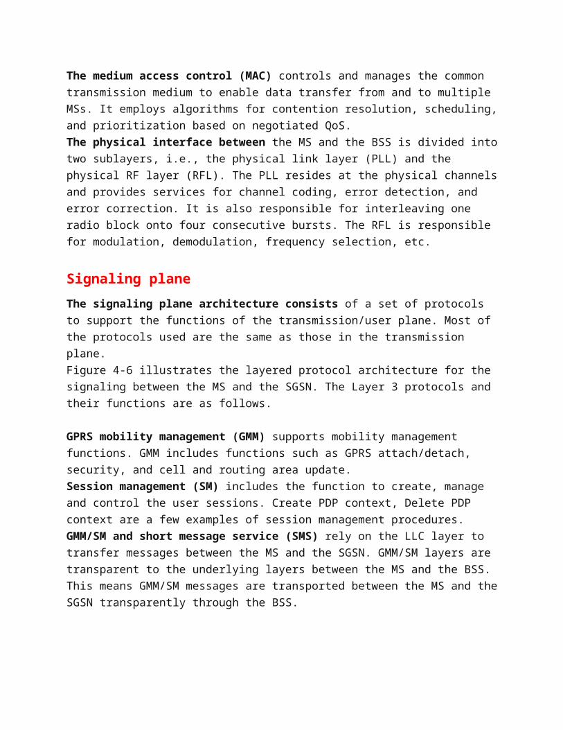
Signaling planeThe signaling plane architecture consists of a set of protocols to support the functions of the transmission/user plane. Most of the protocols used are the same as those in the transmission plane.Figure 4-6 illustrates the layered protocol architecture for the signaling between the MS and the SGSN. The Layer 3 protocols and their functions are as follows.
GPRS mobility management (GMM) supports mobility management functions. GMM includes functions such as GPRS attach/detach, security, and cell and routing area update.Session management (SM) includes the function to create, manage and control the user sessions. Create PDP context, Delete PDP context are a few examples of session management procedures.GMM/SM and short message service (SMS) rely on the LLC layer to transfer messages between the MS and the SGSN. GMM/SM layers are transparent to the underlying layers between the MS and the BSS. This means GMM/SM messages are transported between the MS and theSGSN transparently through the BSS.
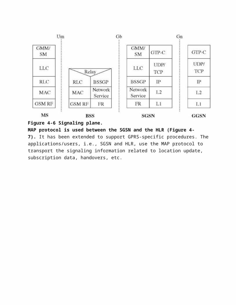
Figure 4-6 Signaling plane.MAP protocol is used between the SGSN and the HLR (Figure 4-7). It has been extended to support GPRS-specific procedures. Theapplications/users, i.e., SGSN and HLR, use the MAP protocol to transport the signaling information related to location update, subscription data, handovers, etc.
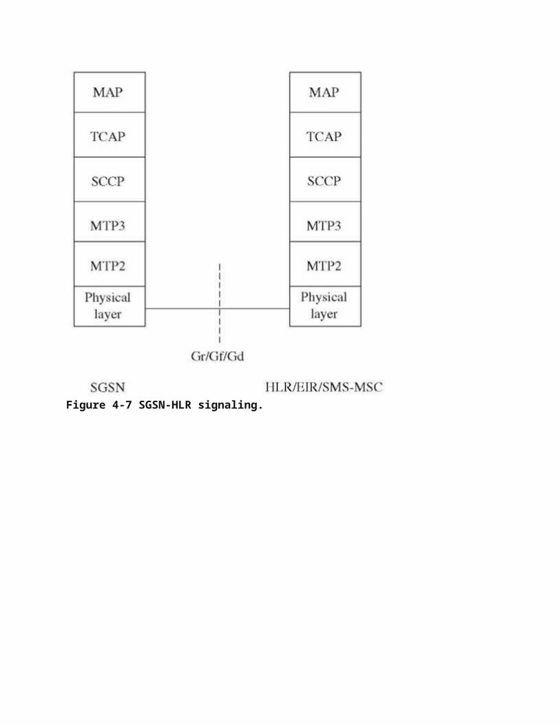
Figure 4-7 SGSN-HLR signaling.
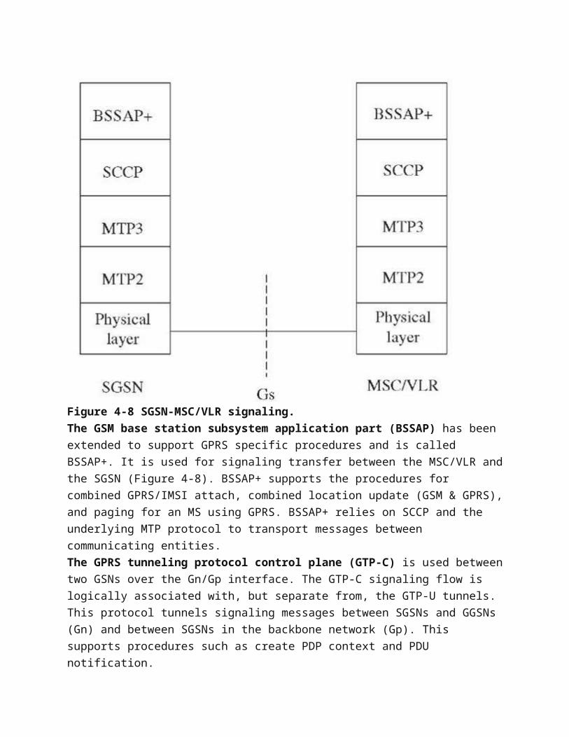
Figure 4-8 SGSN-MSC/VLR signaling.The GSM base station subsystem application part (BSSAP) has been extended to support GPRS specific procedures and is called BSSAP+. It is used for signaling transfer between the MSC/VLR andthe SGSN (Figure 4-8). BSSAP+ supports the procedures for combined GPRS/IMSI attach, combined location update (GSM & GPRS),and paging for an MS using GPRS. BSSAP+ relies on SCCP and the underlying MTP protocol to transport messages between communicating entities.The GPRS tunneling protocol control plane (GTP-C) is used betweentwo GSNs over the Gn/Gp interface. The GTP-C signaling flow is logically associated with, but separate from, the GTP-U tunnels. This protocol tunnels signaling messages between SGSNs and GGSNs (Gn) and between SGSNs in the backbone network (Gp). This supports procedures such as create PDP context and PDU notification.


