Embed Size (px)
Citation preview
midasnGen nGen 2021 v( 1.1 ) Release Note
Next Generation Softwarefor Integrated Analysis, Design, Drawing of Building Systems
Release NoteRelease Date : Feb., 2021
Product Ver. : nGen 2021 v1.1
midasnGen nGen 2021 v( 1.1 ) Release Note
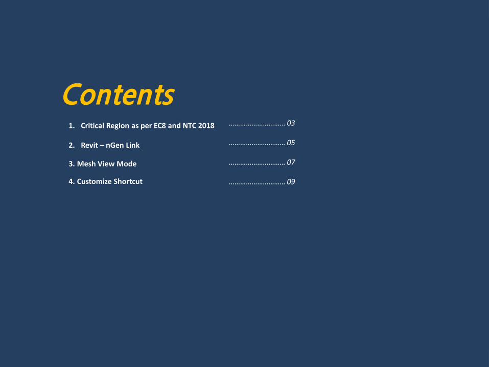
Contents1. Critical Region as per EC8 and NTC 2018
2. Revit – nGen Link
3. Mesh View Mode
4. Customize Shortcut
………………………… 03
………………………… 05
………………………… 07
………………………… 09
midasnGen nGen 2021 v( 1.1 ) Release Note
1. Critical Region as per EC8 and NTC 2018
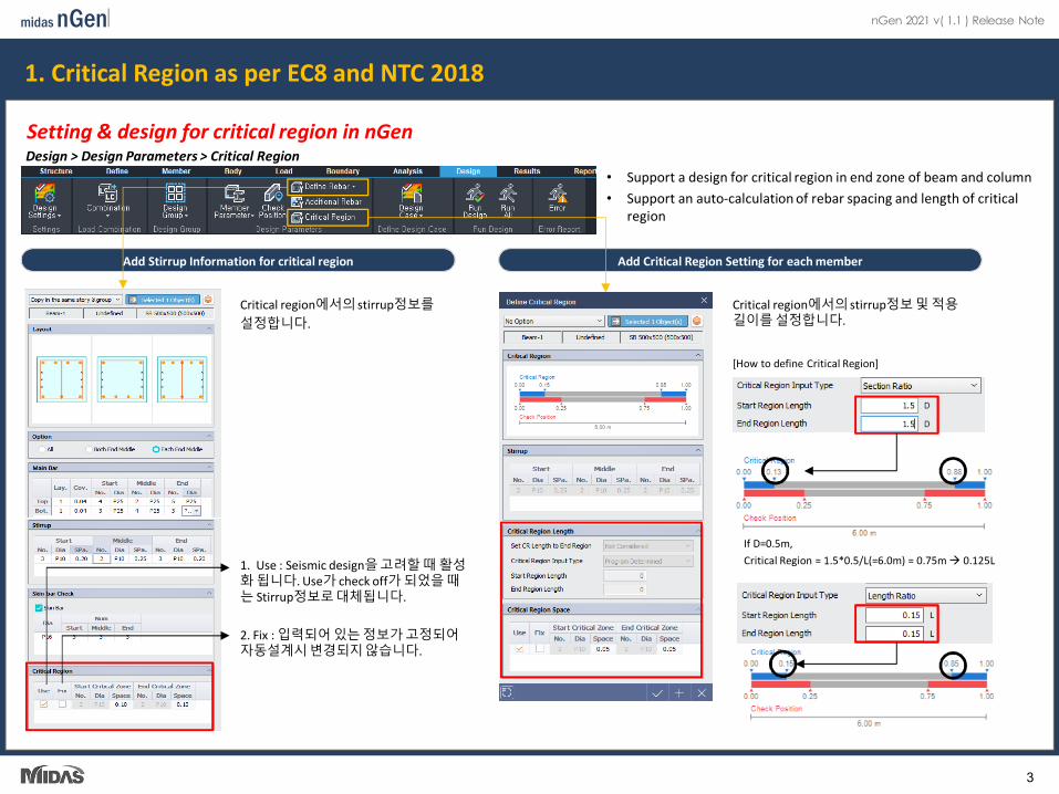
Setting & design for critical region in nGen
Add Stirrup Information for critical region
Design > Design Parameters > Critical Region• Support a design for critical region in end zone of beam and column• Support an auto-calculation of rebar spacing and length of critical
region
Add Critical Region Setting for each member
1. Use : Seismic design을고려할 때 활성화 됩니다. Use가 check off가 되었을 때는 Stirrup정보로대체됩니다.
2. Fix : 입력되어 있는 정보가 고정되어자동설계시변경되지않습니다.
Critical region에서의 stirrup정보를설정합니다.
Critical region에서의 stirrup정보및 적용길이를 설정합니다.
If D=0.5m, Critical Region = 1.5*0.5/L(=6.0m) = 0.75m 0.125L
[How to define Critical Region]
3
midasnGen nGen 2021 v( 1.1 ) Release Note
1. Critical Region as per EC8 and NTC 2018
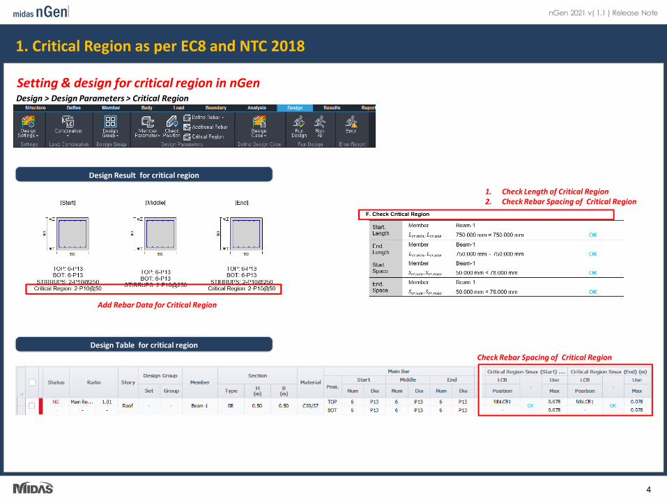
Setting & design for critical region in nGen
Add Rebar Data for Critical Region
1. Check Length of Critical Region2. Check Rebar Spacing of Critical Region
Design > Design Parameters > Critical Region
Design Result for critical region
Design Table for critical regionCheck Rebar Spacing of Critical Region
4
midasnGen nGen 2021 v( 1.1 ) Release Note
1. Critical Region as per EC8 and NTC 2018
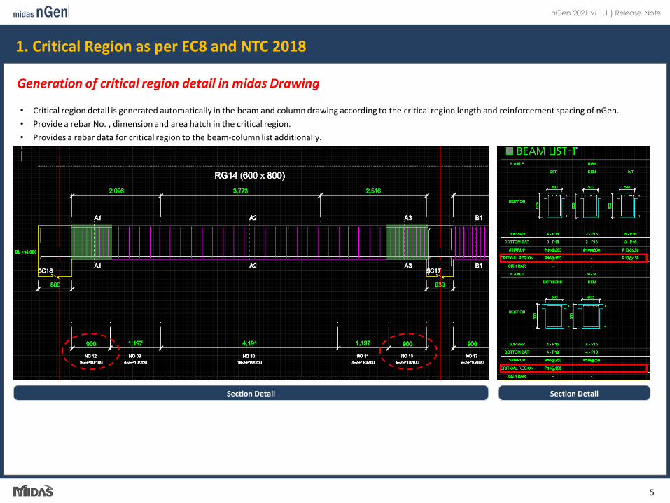
Generation of critical region detail in midas Drawing
Section Detail Section Detail
• Critical region detail is generated automatically in the beam and column drawing according to the critical region length and reinforcement spacing of nGen.• Provide a rebar No. , dimension and area hatch in the critical region.• Provides a rebar data for critical region to the beam-column list additionally.• Calculation by adding critical region rebar quantity to the reinforcement drawing quantity and BOM
5
midasnGen nGen 2021 v( 1.1 ) Release Note
2. Revit – nGen Link
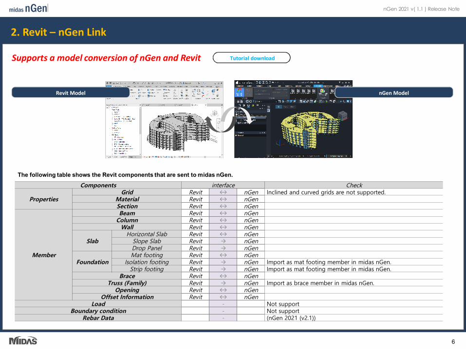
Supports a model conversion of nGen and Revit
The following table shows the Revit components that are sent to midas nGen.Components interface Check
PropertiesGrid Revit ↔ nGen Inclined and curved grids are not supported.
Material Revit ↔ nGenSection Revit ↔ nGen
Member
Beam Revit ↔ nGenColumn Revit ↔ nGen
Wall Revit ↔ nGen
SlabHorizontal Slab Revit ↔ nGen
Slope Slab Revit → nGenDrop Panel Revit → nGen
FoundationMat footing Revit ↔ nGen
Isolation footing Revit → nGen Import as mat footing member in midas nGen.Strip footing Revit → nGen Import as mat footing member in midas nGen.
Brace Revit ↔ nGenTruss (Family) Revit → nGen Import as brace member in midas nGen.
Opening Revit ↔ nGenOffset Information Revit ↔ nGen
Load - Not supportBoundary condition - Not support
Rebar Data - (nGen 2021 (v2.1))
Tutorial download
Revit Model nGen Model
6
midasnGen nGen 2021 v( 1.1 ) Release Note
3. Mesh View Mode
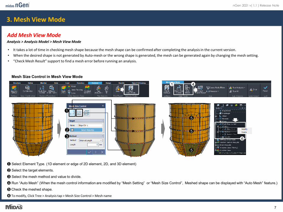
Add Mesh View ModeAnalysis > Analysis Model > Mesh View Mode
• It takes a lot of time in checking mesh shape because the mesh shape can be confirmed after completing the analysis in the current version.• When the desired shape is not generated by Auto-mesh or the wrong shape is generated, the mesh can be generated again by changing the mesh setting.• “Check Mesh Result” support to find a mesh error before running an analysis.
1
23
❶ Select Element Type. (1D element or edge of 2D element, 2D, and 3D element)
❷ Select the target elements.
❸ Select the mesh method and value to divide.
❹ Run “Auto Mesh” (When the mesh control information are modified by “Mesh Setting” or “Mesh Size Control”, Meshed shape can be displayed with “Auto Mesh” feature.)
❺ Check the meshed shape.
❻ To modify, Click Tree > Analysis tap > Mesh Size Control > Mesh name
6
5
5
5
41
Mesh Size Control in Mesh View Mode
7
midasnGen nGen 2021 v( 1.1 ) Release Note
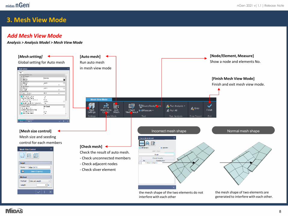
[Check mesh]Check the result of auto mesh.- Check unconnected members- Check adjacent nodes- Check sliver element
[Mesh setting]Global setting for Auto mesh
[Mesh size control]Mesh size and seeding control for each members
[Auto mesh]Run auto mesh in mesh view mode
[Finish Mesh View Mode]Finish and exit mesh view mode.
[Node/Element, Measure]Show a node and elements No.
the mesh shape of the two elements do not interfere with each other
Incorrect mesh shape
the mesh shape of two elements are generated to interfere with each other.
Normal mesh shape
3. Mesh View Mode
Add Mesh View ModeAnalysis > Analysis Model > Mesh View Mode
8
midasnGen nGen 2021 v( 1.1 ) Release Note
4. Customize Shortcut
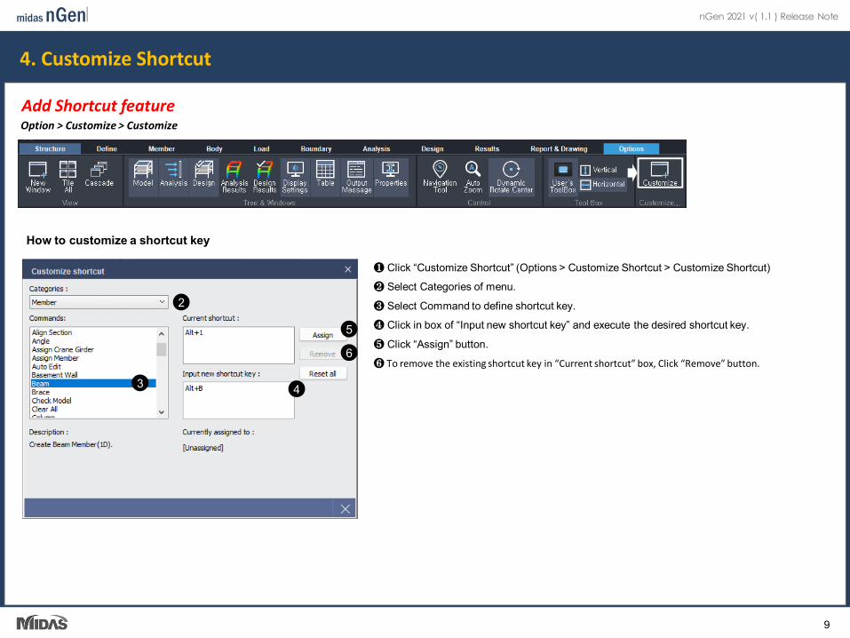
Add Shortcut featureOption > Customize > Customize
2
3 4
❶ Click “Customize Shortcut” (Options > Customize Shortcut > Customize Shortcut)
❷ Select Categories of menu.
❸ Select Command to define shortcut key.
❹ Click in box of “Input new shortcut key” and execute the desired shortcut key.
❺ Click “Assign” button.
❻ To remove the existing shortcut key in “Current shortcut” box, Click “Remove” button.
5
6
How to customize a shortcut key
9


