Embed Size (px)
Citation preview

Manual B9+
FRILO Software GmbH 06.12.2021 Page 1
Reinforced Concrete Corbel – B9+
Contents
Application options 2
Basis of calculation 3
Data entry 4
Basic parameters 4System 5Loading 6Design / Reinforcement 7Reinforcement details 8Reinforcement plan 9Output 10
Basic Documentation – Overview
In addition to the individual program manuals, you will find basic explanations on the operation of theprograms on our homepage www.frilo.com SupportArticles/InformationBasic operating instructions.

Manual B9+
FRILO Software GmbH 06.12.2021 Page 2
Application options
The B9+ application is suitable for the design of corbels with loads applying directly from above (“corbel withdirect load introduction”).
Available direct loading Vertical load
Horizontal load
Available standards DIN EN 1992-1-1: 2012 + 2013 + 2015
ÖNORM EN 1992-1-1:2011 + 2018
BS EN 1992-1-1: 2015
PN EN 1992-1-1:2010
EN 1992-1-1:2014
The following entities are determined: Framework (if possible) including node dimensions, as well as rod forces (forces in the compression strut
and tension band)
Stability against compressive web fracture (excess of stress in the compression strut at the upper node)
Compressive strain under load
Required As of the tensile and web reinforcement
Anchorage and lap lengths of the reinforcement including intermediate values (for control)
Output of reinforcement dimensions and layers in the form of tables and as a reinforcement plan
The prerequisite is compliance with the corbel condition c
0
a1,0
z and min. φ <= φ <= max. φ
(see Basis of Calculation)
ac = horizontal distance of the upper node from the edge of the support (DAfStb1, Booklet 599, Section 11)
z0 = internal lever arm (vertical length of the compression strut up to the column contact surface)
2D/3D-graphical user interface (GUI)The elements concrete, dimension chains, utilisation,reinforcement etc. can be displayed or hidden via thevisibility icons in the menu bar.
The GUI is interactive. See also the context menu (rightmouse button) in the document"Basic Operating Instructions - PLUS".
1 German Committee for Reinforced Concrete

Manual B9+
FRILO Software GmbH 06.12.2021 Page 3
Basis of calculation
The calculation is based on the equivalent member method. The regulations of the different National Annexesare taken into account.
Manual B9+
FRILO Software GmbH 06.12.2021 Page 4
Data entry
The fastest way to enter an item for the first time is to use the wizard.
You can find general information on entering data in the left menu tree or in the interactive GUI and on usingthe context menu (right mouse button) in thedocument "Basic Operating Instructions-PLUS".
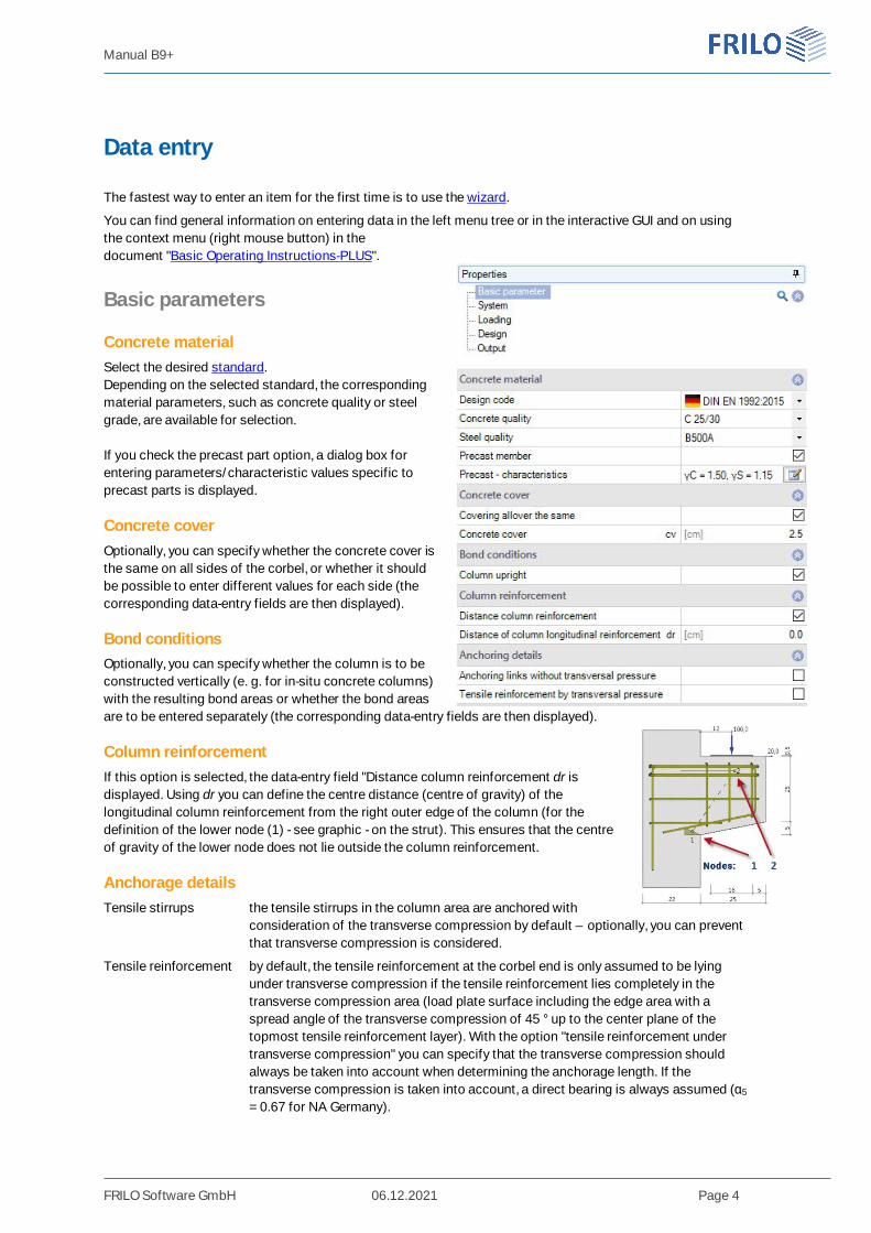
Basic parameters
Concrete materialSelect the desired standard.Depending on the selected standard, the correspondingmaterial parameters, such as concrete quality or steelgrade, are available for selection.
If you check the precast part option, a dialog box forentering parameters/characteristic values specific toprecast parts is displayed.
Concrete coverOptionally, you can specify whether the concrete cover isthe same on all sides of the corbel, or whether it shouldbe possible to enter different values for each side (thecorresponding data-entry fields are then displayed).
Bond conditionsOptionally, you can specify whether the column is to beconstructed vertically (e. g. for in-situ concrete columns)with the resulting bond areas or whether the bond areasare to be entered separately (the corresponding data-entry fields are then displayed).
Column reinforcementIf this option is selected, the data-entry field "Distance column reinforcement dr isdisplayed. Using dr you can define the centre distance (centre of gravity) of thelongitudinal column reinforcement from the right outer edge of the column (for thedefinition of the lower node (1) - see graphic - on the strut). This ensures that the centreof gravity of the lower node does not lie outside the column reinforcement.
Anchorage detailsTensile stirrups the tensile stirrups in the column area are anchored with
consideration of the transverse compression by default – optionally, you can preventthat transverse compression is considered.
Tensile reinforcement by default, the tensile reinforcement at the corbel end is only assumed to be lyingunder transverse compression if the tensile reinforcement lies completely in thetransverse compression area (load plate surface including the edge area with aspread angle of the transverse compression of 45 ° up to the center plane of thetopmost tensile reinforcement layer). With the option "tensile reinforcement undertransverse compression" you can specify that the transverse compression shouldalways be taken into account when determining the anchorage length. If thetransverse compression is taken into account, a direct bearing is always assumed (α5
= 0.67 for NA Germany).
Manual B9+
FRILO Software GmbH 06.12.2021 Page 5
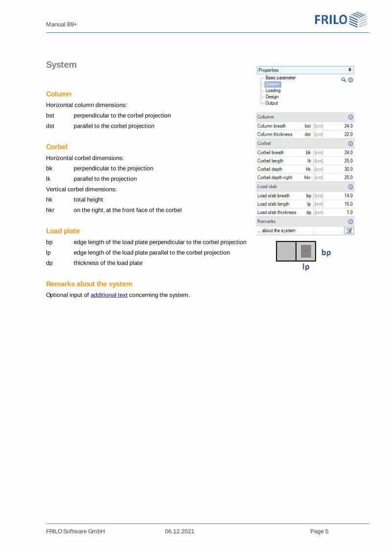
System
ColumnHorizontal column dimensions:
bst perpendicular to the corbel projection
dst parallel to the corbel projection
CorbelHorizontal corbel dimensions:
bk perpendicular to the projection
lk parallel to the projection
Vertical corbel dimensions:
hk total height
hkr on the right, at the front face of the corbel
Load platebp edge length of the load plate perpendicular to the corbel projection
lp edge length of the load plate parallel to the corbel projection
dp thickness of the load plate
Remarks about the systemOptional input of additional text concerning the system.

Manual B9+
FRILO Software GmbH 06.12.2021 Page 6
Loading
LoadingThe dead weight can optionally be taken into account.
Vertical/Horizontal design value of the load in the respective direction.
Load impact pointsDistance Vertical load horizontal distance a of the vertical load from the
outer edge of the column.
Distance Horizontal load vertical distance Hed of the horizontal load from thetop edge of the corbel (positive to the top).
For Hed at least 0.2 · Fed should be used in accordance with DAfStb, Booklet600 (at least 0.1 · Fed in accordance with ÖNorm B 1992-1-1)!
This regulation was also adopted for calculations in accordance with the Eurocodes.
Remarks about the effectsOptional input of additional text concerning the loading.

Manual B9+
FRILO Software GmbH 06.12.2021 Page 7
Design / Reinforcement
You can enter the number of layers and the diameters of the respectivestirrups/loops.
Further information is shown in the info line below after activation of a data-entry field.
Option „move the lower node up…“In this way (analogous to the "old" B9), if the maximum permissible strutinclination is exceeded, the lower node can be shifted upwards until thepermissible strut inclination is maintained. This option must be set explicitlyby the user. Alternatively, as before, there is the option of increasing the upperconcrete cover.
Remarks on ResultsOptional input of additional text concerning the results.
Reinforcement detailsYou can make further fine adjustments in the Reinforcement Details dialog box.
Manual B9+
FRILO Software GmbH 06.12.2021 Page 8
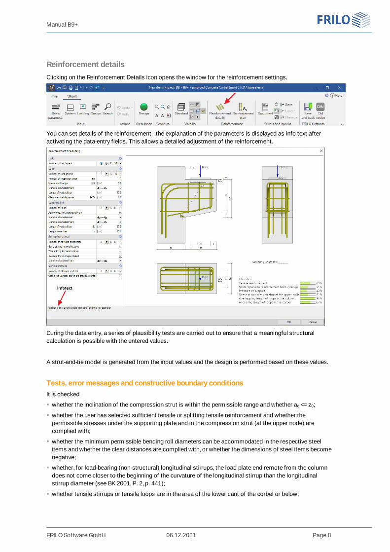
Reinforcement detailsClicking on the Reinforcement Details icon opens the window for the reinforcement settings.
You can set details of the reinforcement - the explanation of the parameters is displayed as info text afteractivating the data-entry fields. This allows a detailed adjustment of the reinforcement.
During the data entry, a series of plausibility tests are carried out to ensure that a meaningful structuralcalculation is possible with the entered values.
A strut-and-tie model is generated from the input values and the design is performed based on these values.
Tests, error messages and constructive boundary conditionsIt is checked
whether the inclination of the compression strut is within the permissible range and whether ac <= z0;
whether the user has selected sufficient tensile or splitting tensile reinforcement and whether thepermissible stresses under the supporting plate and in the compression strut (at the upper node) arecomplied with;
whether the minimum permissible bending roll diameters can be accommodated in the respective steelitems and whether the clear distances are complied with, or whether the dimensions of steel items becomenegative;
whether, for load-bearing (non-structural) longitudinal stirrups, the load plate end remote from the columndoes not come closer to the beginning of the curvature of the longitudinal stirrup than the longitudinalstirrup diameter (see BK 2001, P. 2, p. 441);
whether tensile stirrups or tensile loops are in the area of the lower cant of the corbel or below;

Manual B9+
FRILO Software GmbH 06.12.2021 Page 9
whether the anchorage and overlap lengths of the tensile reinforcement in the corbel or in the column areadhered to;
whether, for DIN EN 1992-1-1, the vertical dimension of the lower node meets the requirements of DAfStb,Booklet 599, Section 11.3;
whether, for ÖNorm B 1992-1-1, the corbel height under the load accounts for at least 60 % of the corbelheight at the contact face and whether the length of the diagonal strut of the lower node accounts formaximally 25 % of the structural corbel height.
Possibly, a message is displayed if the load plate is not enclosed by reinforcement and if the horizontal loadis less than recommended by the standard.
If the test conditions are not complied with, the verification traffic light is coloured red (or yellow forindications) and by clicking on it a window with error messages is displayed.
Note: The program offers the possibility to arrange several tensile stirrups or loops next to each other(useful for wider corbels). If both, tensile stirrups and loops are positioned, there should be thesame number of stirrups and loops per layer, otherwise the clear distance, e. g. for the positioningof longitudinal stirrups, would be too small.
Reinforcement planUse the reinforcement plan symbol to open the window with the reinforcement drawing and the parts list.
Via the context menu (right mouse button) you can save the graphic separately in different formats (jpg, emf,...).
Manual B9+
FRILO Software GmbH 06.12.2021 Page 10
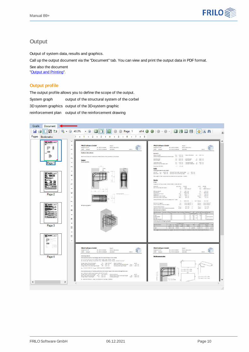
Output
Output of system data, results and graphics.
Call up the output document via the "Document" tab. You can view and print the output data in PDF format.
See also the document"Output and Printing".
Output profileThe output profile allows you to define the scope of the output.
System graph output of the structural system of the corbel
3D system graphics output of the 3D-system graphic
reinforcement plan output of the reinforcement drawing


