Embed Size (px)
Citation preview
1
Reducing Clearances by Integration of Externally Gapped
Line Arresters on HV Transmission Lines
Bastian Robben, Siemens AG, Germany
Maja Jolic, Siemens AG, Germany
Introduction
A growing demand for power has resulted in the need for an increase of transmissioncapacity and power quality. Many developed countries cannot afford to build newoverhead transmission lines(OHLs)duetosystematicpublicoppositionandenvironmentalconsiderations. It becomes necessary for them to “uprate” the existing powersystems. In many cases, even though the public authorization is granted, linedesigners and utilities are requested to create new concepts of transmissionstructures in order to reduce footprint and visual impact. Line Compaction and LineUprating involve the need to review conventional ratings and standard designs whichapply fordecades.
The latest developments of composite insulators and surge arresters allow compact linedesigns as realistic alternatives to the standard line designs for the utilities to builddiscrete and aesthetic linestructures. Taking the surge arrester’s operating principle intoconsideration, structures’ clearances and insulator arcing distances can be significantlyreduced and at the same time power availabilitycan be improved. Conventional ratings,such as lightning and switching impulse withstand values of insulator assemblies can becoordinated with transmission line surge arresters to achieve advanced insulationcoordination ratings. The integration of arresters will bring the Compact Line concept tothenextlevel.
Thispaperdescribes,afterashort introductionto theprinciplesof transmission linesurgearresters, the idea and the opportunitieswhich can be accomplished for transmission linecapacityandpowerquality optimization. The paper addresses also the main technicalchallenges which must be considered before the implementation of compact powersystemsolutions.
2
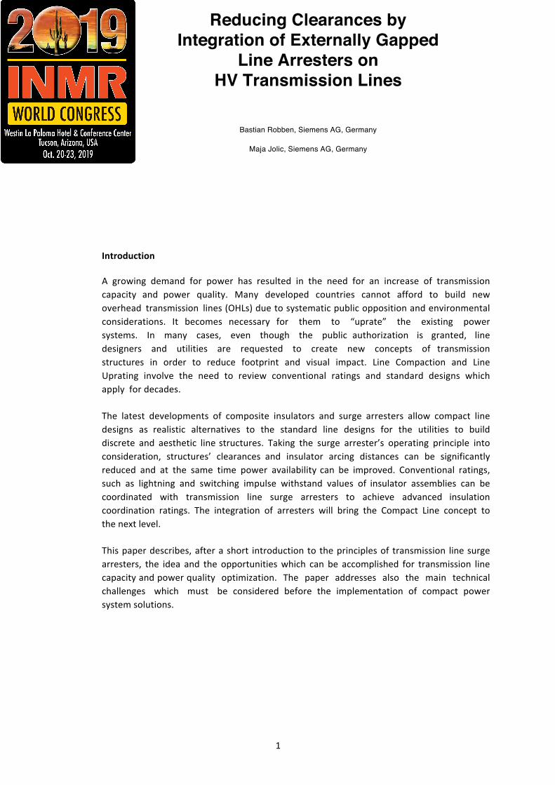
1 Overvoltages and their mitigation by using surge arresters Thevoltageswhichcanoccurinahigh-voltageelectricalpowersystemareshowninError!Referencesourcenotfound.wherethedifferenttypesof(over-)voltages(red-coloredcurve)versusdurationoftheir appearance are summarized and compared to both, equipment’s (blue-colored curve) andarrester’s(green-coloredcurve)withstandvoltages,respectively.
Figure1:Schematicrepresentationofthemagnitudeofvoltagesandovervoltagesinahigh-voltageelectricalpowersystemversusdurationoftheirappearance(1p.u.=√2Us/√3)
Theredcurveshowsthattheinsulationwithstandvoltageoftheequipment(blue-coloredcurve)isexcessivelyexceeded incaseof lightningandswitchingovervoltages.Byusingsurgearrester theseovervoltagesarebeingsafelyreduced,asitcanbeseeninthegreencurve,whichisbelowtheblue-coloredwithstandvoltageoftheequipmenttobeprotected[1].
Conventional application of station class arrester aims to protect valuable equipment in thesubstations as a local insulation for power transformers, entrance of substations, instrumentstransformersandgas-insulatedswitchgears.TheapplicationofLineSurgeArresters(LSA’s)servesadifferentpurpose.
LSA’spreventflashoversoninsulatorstringsalongthetransmissionlinecausedby lightningstrikes.Installedonmulti-circuittransmissionlines,theyareanexcellentsolutiontoeliminateanypossibledouble-circuitfailure.TheycanalsobeusedonEHV1linestocontrolswitchingsurgefactors.
ThemaincommercialapplicationforLSA’sistoimprovethelightningperformanceonexistinglinesas retrofit activities. Such applications require to analyze the line parameters and investigate theenvironmentalconditionsinordertooptimizetheLSA’sconfigurationandtheireffectiveness.
1EHV:Extrahigh-voltage
3
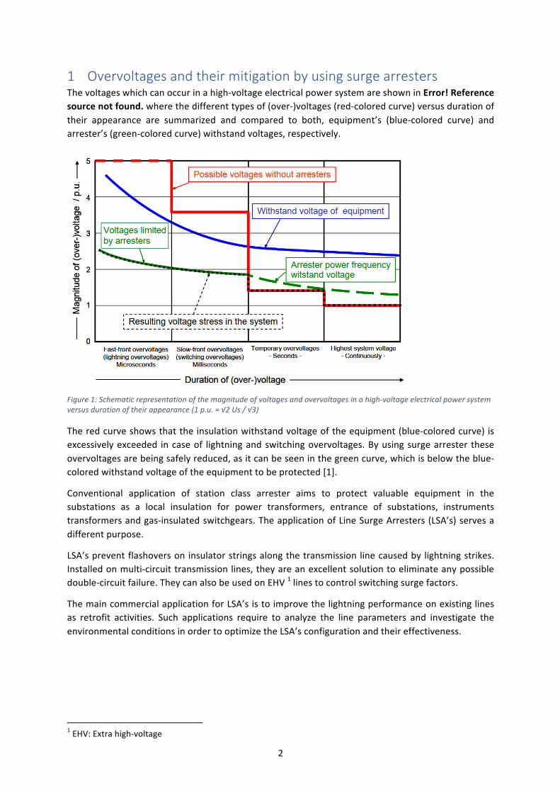
Figure2:TLAsavoidflashoverfailuresoninsulators
Figure 2 shows schematically an example of a shielded transmission line equipped with LSA’sinstalledinparallelandnexttotheinsulatorstringstopreventashieldingfailuresincethelightningstrokehitdirectlythephaseconductor.
Therearethetwobasicscenariostounderstandtheprincipleofflashoversduetolightningactivities.Back-flashoverandDirect-flashover(alsoknownasshieldingfailure).
Back-flashoveriswhenthelightningstrokehitstheshieldingwireorthetowertop
Insulatorback flashover ratescanbeefficiently reduced incaseof shieldedoverhead lines locatedeitherinhighlightningactivityareasorhavingpoorfootingresistance.Thesetypesofoutagescouldbereducedbyplacingarresters inallphasesoronlyonthephase(s)with lowestcouplingfactortotheshieldwireswhichnormallyisthebottomphaseinhighfootingresistanceareas.Intheseareas,it isimportanttoapplythearrestersnotonlyonstructuresintheareasofhighfootingresistances,butalsoononeortwostructureswithgood(low)footingresistancesrightnexttothehighfootingresistanceareas.Thiswillpreventflashoversatthelowresistancestructurescausedbythearresteroperationsatthehighfootingresistancestructures.Thehigherthefootingresistance,thehigherisabsorbedenergybyeachindividualLSA’s.
Directflashoveriswhenthelightningstrokedirectlyhitsthephaseconductor
Insulator flashovers result from so-called shielding failures mostly observed on unshieldedtransmission lines and very infrequently in shielded lines that may experience lightning strokesdirectly to the high voltage conductor. For unshielded transmission/distribution lines, those directlightning strokes to the phase conductorswill bemuchmore frequent than for properly shieldedlines,sincetheselinesaresimplynotprotected(shielded)againstlightningatall.Insuchcases,linearresters can also be used to address shielding failure flashovers by applying the arresters on theuppermostexposedphases.
Furthersystemflashovercasesinducedbylightningstrokesareobservedonmulti-circuittowers,i.e.on underbuilt distribution lines or on double-circuit transmission lines which generally leads tosevereimpactsonthewholetransmissionsystem.
Doublecircuitoutagereduction
Linearresterscanbeusedondouble-circuittransmissionlinestobeinstalledonallthree-phasesononeofthedouble-circuitsystemstopreventdouble-systemfailures.Thisapproachcanbeeffectivelyusedforallsystemvoltagerates,includingEHVsystems[4].
4
Underbuiltdistributionlines
If a distribution line shares a tower or a pole with a shielded transmission circuit, the underbuiltdistribution conductors are not likely to be struck directly, since they are actually shielded by thetransmission circuit above.However, thedistribution line is prone toback flashovers, because thecouplingbetweendistributionconductorsandshieldwiresisweak.
The insulation strengthon thedistribution line is also lower thanon the transmission line.Onceadistribution conductor flashes over, the coupling to the transmission conductorswill increase andminimizetheriskofaback-flashoveronthetransmissioncircuit.Thetransmissioncircuit’slightningperformance may improve at the expense of the underbuilt distribution circuit’s lightningperformance.This issuecanbereliablyavoidedwithapplicationof linearrestersontheunderbuiltdistributioncircuit.Usuallyarrestersareneededateverytowerorpole,onatleastoneofthethreephases.
2differentdesignsofLSAsareavailablewithadvantagesandinconveniences:
• Non-GappedLineArresters(NGLA)alsocalledgapless• ExternallyGappedLineArresters(EGLA)
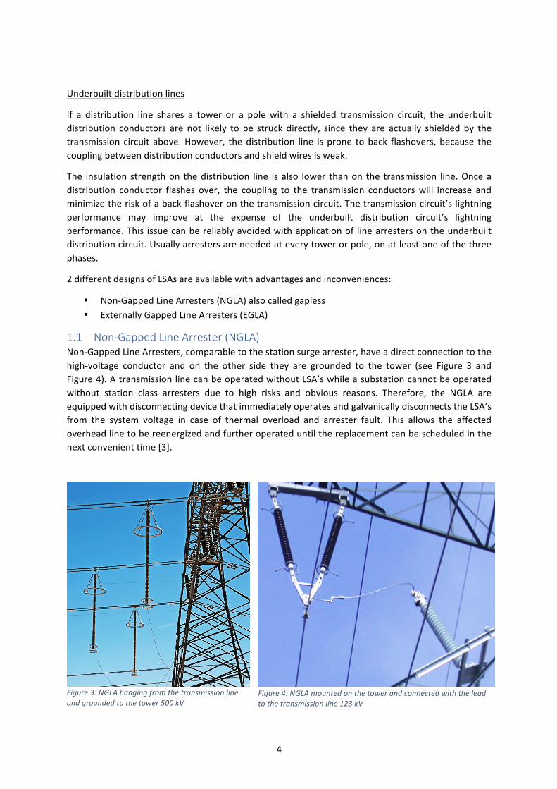
1.1 Non-Gapped Line Arrester (NGLA) Non-GappedLineArresters,comparabletothestationsurgearrester,haveadirectconnectiontothehigh-voltage conductor and on the other side they are grounded to the tower (see Figure 3 andFigure4).AtransmissionlinecanbeoperatedwithoutLSA’swhileasubstationcannotbeoperatedwithout station class arresters due to high risks and obvious reasons. Therefore, the NGLA areequippedwithdisconnectingdevicethatimmediatelyoperatesandgalvanicallydisconnectstheLSA’sfrom the system voltage in case of thermal overload and arrester fault. This allows the affectedoverheadlinetobereenergizedandfurtheroperateduntilthereplacementcanbescheduledinthenextconvenienttime[3].
Figure3:NGLAhangingfromthetransmissionlineandgroundedtothetower500kV
Figure4:NGLAmountedonthetowerandconnectedwiththeleadtothetransmissionline123kV
5
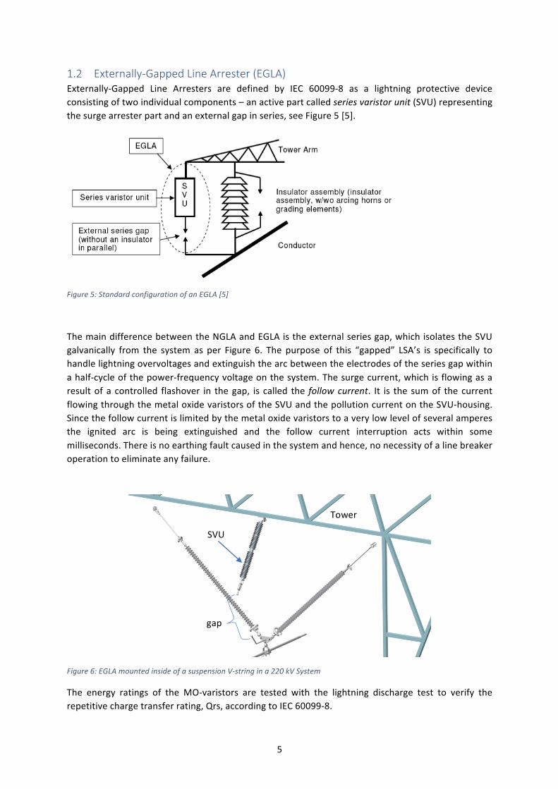
1.2 Externally-Gapped Line Arrester (EGLA) Externally-Gapped Line Arresters are defined by IEC 60099-8 as a lightning protective deviceconsistingoftwoindividualcomponents–anactivepartcalledseriesvaristorunit(SVU)representingthesurgearresterpartandanexternalgapinseries,seeFigure5[5].
Figure5:StandardconfigurationofanEGLA[5]
ThemaindifferencebetweentheNGLAandEGLAistheexternalseriesgap,whichisolatestheSVUgalvanically from the system as per Figure 6. The purpose of this “gapped” LSA’s is specifically tohandlelightningovervoltagesandextinguishthearcbetweentheelectrodesoftheseriesgapwithinahalf-cycleofthepower-frequencyvoltageonthesystem.Thesurgecurrent,whichisflowingasaresultofa controlled flashover in thegap, is called the followcurrent. It is the sumof thecurrentflowingthroughthemetaloxidevaristorsoftheSVUandthepollutioncurrentontheSVU-housing.Sincethefollowcurrentislimitedbythemetaloxidevaristorstoaverylowlevelofseveralamperesthe ignited arc is being extinguished and the follow current interruption acts within somemilliseconds.Thereisnoearthingfaultcausedinthesystemandhence,nonecessityofalinebreakeroperationtoeliminateanyfailure.
Figure6:EGLAmountedinsideofasuspensionV-stringina220kVSystem
The energy ratings of the MO-varistors are tested with the lightning discharge test to verify therepetitivechargetransferrating,Qrs,accordingtoIEC60099-8.
SVU
gap
Tower
6
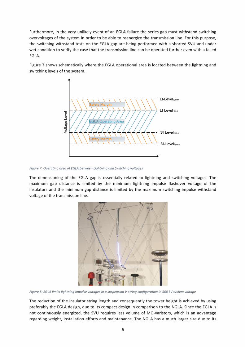
Furthermore, intheveryunlikelyeventofanEGLAfailuretheseriesgapmustwithstandswitchingovervoltagesofthesysteminordertobeabletoreenergizethetransmissionline.Forthispurpose,theswitchingwithstandtestsontheEGLAgaparebeingperformedwithashortedSVUandunderwetconditiontoverifythecasethatthetransmissionlinecanbeoperatedfurtherevenwithafailedEGLA.
Figure7showsschematicallywheretheEGLAoperationalareaislocatedbetweenthelightningandswitchinglevelsofthesystem.
Figure7:OperatingareaofEGLAbetweenLightningandSwitchingvoltages
The dimensioning of the EGLA gap is essentially related to lightning and switching voltages. Themaximum gap distance is limited by the minimum lightning impulse flashover voltage of theinsulators and theminimumgap distance is limited by themaximum switching impulsewithstandvoltageofthetransmissionline.
Figure8:EGLAlimitslightningimpulsevoltagesinasuspensionV-stringconfigurationin500kVsystemvoltage
ThereductionoftheinsulatorstringlengthandconsequentlythetowerheightisachievedbyusingpreferablytheEGLAdesign,duetoitscompactdesignincomparisontotheNGLA.SincetheEGLAisnot continuously energized, the SVU requires less volume ofMO-varistors,which is an advantageregardingweight, installationeffortsandmaintenance.TheNGLAhasamuch largersizedueto its
7
disconnectorandassociatedgroundlead,whichmayshort-circuitthesubjacentphasesonthetowerwhen falling down during an arrester overload (triggering of the disconnector). Furthermore, thesubstantial reduction in material for the EGLA design allows a more compact size and a betterintegrationinthetower.Itoffersalsoawiderangeofinstallationoptions.
ThecorrectconfigurationofanEGLAincludestheSVUratings(energyrating,residualvoltage,arcingdistance),thedimensioningofthegapdistancewithrespecttolightning-andswitchingvoltages,aswell as themechanical design which differs often from the installation arrangement. EngineeringeffortsarerequiredtointegrateproperlytheEGLAintothestructure.Itcanbeinstalledonthecross-arms,onthestructureordirectlyontheinsulatorstring.Themainrequirementistohavestablegapdistance under vibration and galloping of the line. New transmission lines offer generally moreoptionthanexistinglines.
Themainfactorsfortheoptimaldimensioningofareducedinsulator’sarcingdistancearethemin.creepagedistanceand the lightning impulsewithstandvoltage.Thehigher the systemvoltage, themoreimportantbecomestheswitchingsurges,especiallyabove300kVsystemvoltages.
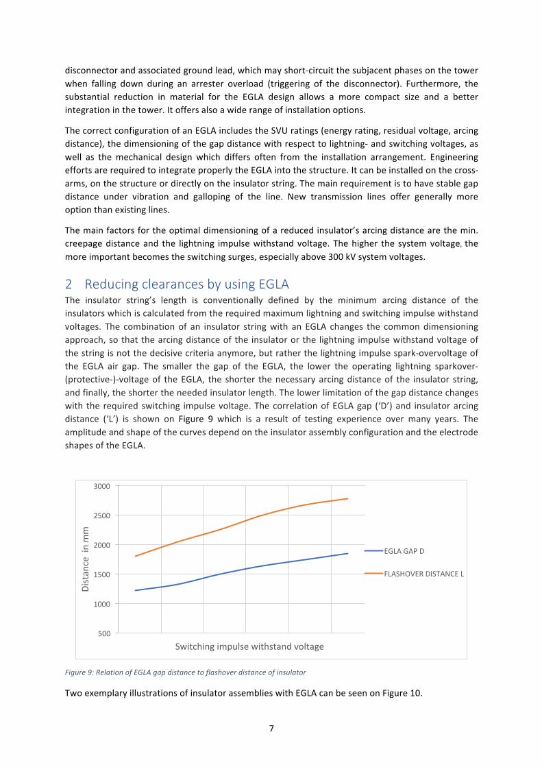
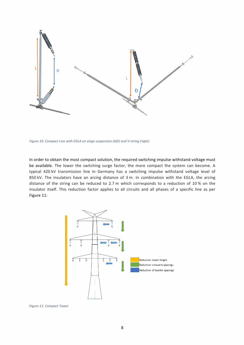
2 Reducing clearances by using EGLA The insulator string’s length is conventionally defined by the minimum arcing distance of theinsulatorswhichiscalculatedfromtherequiredmaximumlightningandswitchingimpulsewithstandvoltages. The combination of an insulator stringwith an EGLA changes the commondimensioningapproach,sothatthearcingdistanceofthe insulatororthe lightning impulsewithstandvoltageofthestringisnotthedecisivecriteriaanymore,butratherthelightningimpulsespark-overvoltageofthe EGLA air gap. The smaller the gap of the EGLA, the lower the operating lightning sparkover-(protective-)-voltageof theEGLA, the shorter thenecessaryarcingdistanceof the insulator string,andfinally,theshortertheneededinsulatorlength.Thelowerlimitationofthegapdistancechangeswith the requiredswitching impulsevoltage.ThecorrelationofEGLAgap (‘D’)and insulatorarcingdistance (‘L’) is shown on Figure 9 which is a result of testing experience over many years. TheamplitudeandshapeofthecurvesdependontheinsulatorassemblyconfigurationandtheelectrodeshapesoftheEGLA.
Figure9:RelationofEGLAgapdistancetoflashoverdistanceofinsulator
TwoexemplaryillustrationsofinsulatorassemblieswithEGLAcanbeseenonFigure10.
500
1000
1500
2000
2500
3000
Distanceinmm
Switchingimpulsewithstandvoltage
EGLAGAPD
FLASHOVERDISTANCEL
8
Figure10:CompactLinewithEGLAonsingesuspension(left)andV-string(right)
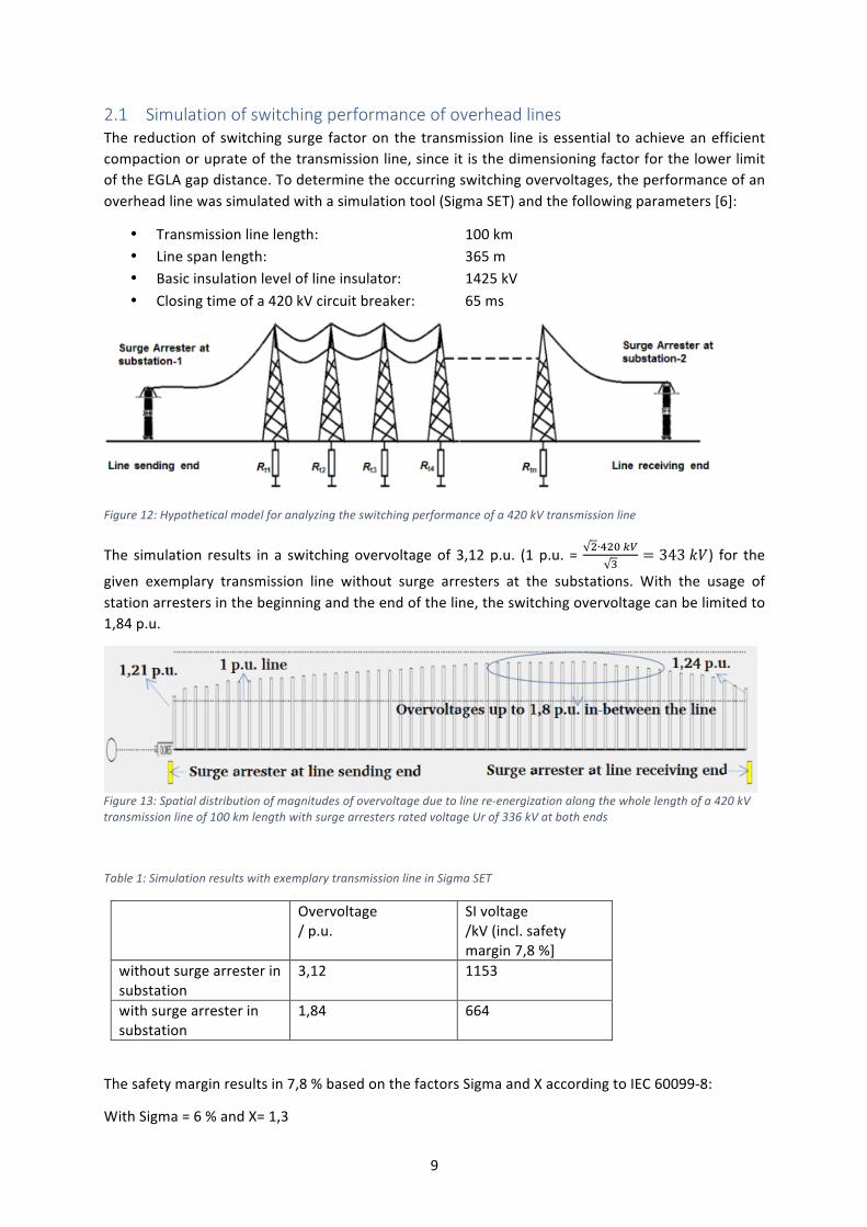
Inordertoobtainthemostcompactsolution,therequiredswitchingimpulsewithstandvoltagemustbe available. The lower the switching surge factor, themore compact the system can become. Atypical 420kV transmission line in Germany has a switching impulse withstand voltage level of850kV. The insulators have an arcing distance of 3m. In combination with the EGLA, the arcingdistance of the string can be reduced to 2.7mwhich corresponds to a reduction of 10% on theinsulator itself. This reduction factor applies to all circuits and all phases of a specific line as perFigure11:
Figure11:CompactTower
9
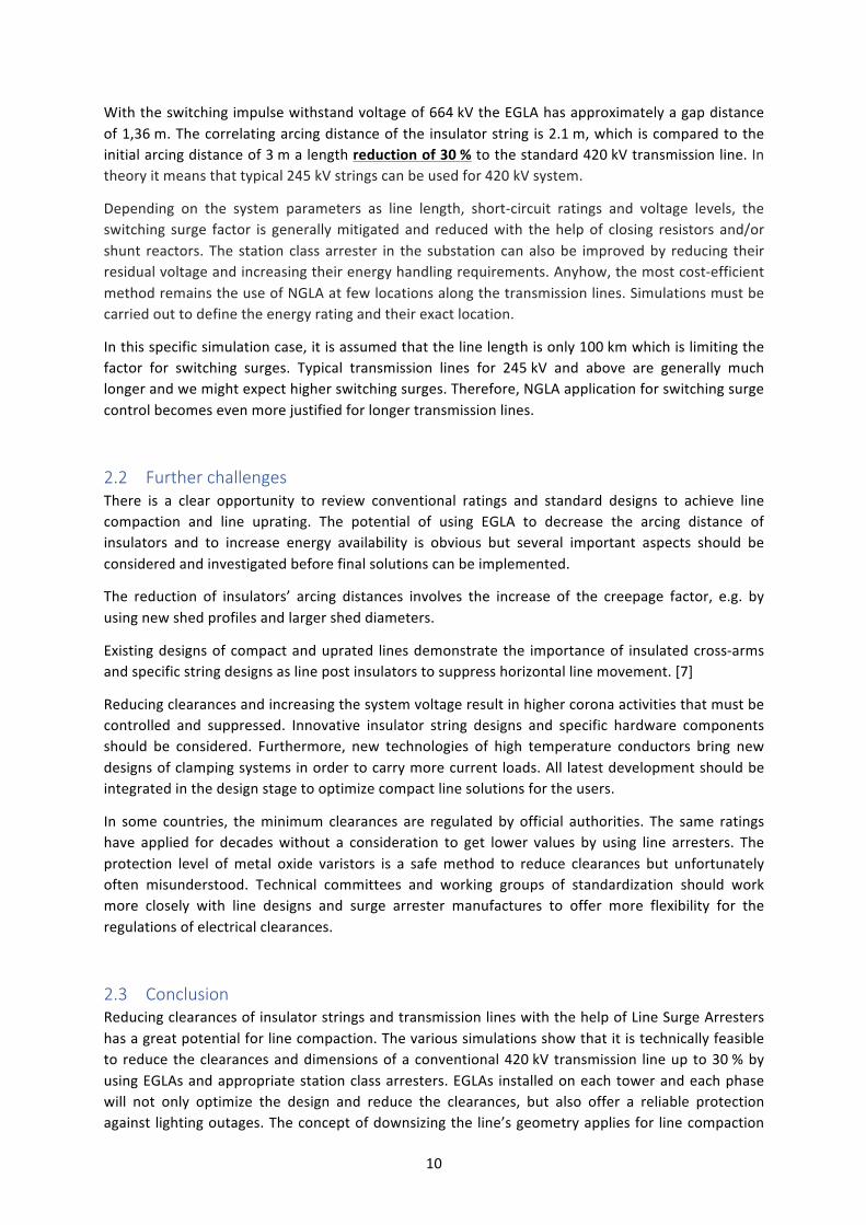
2.1 Simulation of switching performance of overhead lines Thereductionof switchingsurge factoron the transmission line isessential toachieveanefficientcompactionoruprateofthetransmissionline,sinceitisthedimensioningfactorforthelowerlimitoftheEGLAgapdistance.Todeterminetheoccurringswitchingovervoltages,theperformanceofanoverheadlinewassimulatedwithasimulationtool(SigmaSET)andthefollowingparameters[6]:
• Transmissionlinelength: 100km• Linespanlength: 365m• Basicinsulationleveloflineinsulator: 1425kV• Closingtimeofa420kVcircuitbreaker: 65ms
Figure12:Hypotheticalmodelforanalyzingtheswitchingperformanceofa420kVtransmissionline
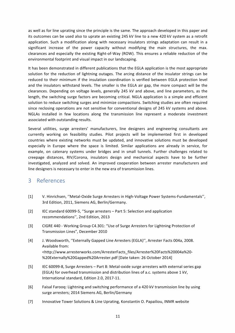
The simulation results in a switchingovervoltageof 3,12p.u. (1p.u. = !∙!"# !"!
= 343 𝑘𝑉) for thegiven exemplary transmission line without surge arresters at the substations. With the usage ofstationarrestersinthebeginningandtheendoftheline,theswitchingovervoltagecanbelimitedto1,84p.u.
Figure13:Spatialdistributionofmagnitudesofovervoltageduetolinere-energizationalongthewholelengthofa420kVtransmissionlineof100kmlengthwithsurgearrestersratedvoltageUrof336kVatbothends
Table1:SimulationresultswithexemplarytransmissionlineinSigmaSET
Overvoltage/p.u.
SIvoltage/kV(incl.safetymargin7,8%]
withoutsurgearresterinsubstation
3,12 1153
withsurgearresterinsubstation
1,84 664
Thesafetymarginresultsin7,8%basedonthefactorsSigmaandXaccordingtoIEC60099-8:
WithSigma=6%andX=1,3
10
Withtheswitchingimpulsewithstandvoltageof664kVtheEGLAhasapproximatelyagapdistanceof1,36m.Thecorrelatingarcingdistanceofthe insulatorstring is2.1m,which iscomparedtotheinitialarcingdistanceof3malengthreductionof30%tothestandard420kVtransmissionline.Intheoryitmeansthattypical245kVstringscanbeusedfor420kVsystem.
Depending on the system parameters as line length, short-circuit ratings and voltage levels, theswitching surge factor is generallymitigatedand reducedwith thehelpof closing resistors and/orshunt reactors. The stationclassarrester in the substationcanalsobe improvedby reducing theirresidualvoltageandincreasingtheirenergyhandlingrequirements.Anyhow,themostcost-efficientmethodremainstheuseofNGLAatfewlocationsalongthetransmissionlines.Simulationsmustbecarriedouttodefinetheenergyratingandtheirexactlocation.
Inthisspecificsimulationcase,itisassumedthatthelinelengthisonly100kmwhichislimitingthefactor for switching surges. Typical transmission lines for 245kV and above are generally muchlongerandwemightexpecthigherswitchingsurges.Therefore,NGLAapplicationforswitchingsurgecontrolbecomesevenmorejustifiedforlongertransmissionlines.
2.2 Further challenges There is a clear opportunity to review conventional ratings and standard designs to achieve linecompaction and line uprating. The potential of using EGLA to decrease the arcing distance ofinsulators and to increase energy availability is obvious but several important aspects should beconsideredandinvestigatedbeforefinalsolutionscanbeimplemented.
The reduction of insulators’ arcing distances involves the increase of the creepage factor, e.g. byusingnewshedprofilesandlargersheddiameters.
Existingdesignsofcompactanduprated linesdemonstratethe importanceof insulatedcross-armsandspecificstringdesignsaslinepostinsulatorstosuppresshorizontallinemovement.[7]
Reducingclearancesandincreasingthesystemvoltageresultinhighercoronaactivitiesthatmustbecontrolled and suppressed. Innovative insulator string designs and specific hardware componentsshould be considered. Furthermore, new technologies of high temperature conductors bring newdesignsofclampingsystemsinordertocarrymorecurrentloads.All latestdevelopmentshouldbeintegratedinthedesignstagetooptimizecompactlinesolutionsfortheusers.
In some countries, theminimum clearances are regulated by official authorities. The same ratingshave applied for decadeswithout a consideration to get lower values by using line arresters. Theprotection level ofmetal oxide varistors is a safemethod to reduce clearances but unfortunatelyoften misunderstood. Technical committees and working groups of standardization should workmore closely with line designs and surge arrester manufactures to offer more flexibility for theregulationsofelectricalclearances.
2.3 Conclusion ReducingclearancesofinsulatorstringsandtransmissionlineswiththehelpofLineSurgeArrestershasagreatpotentialforlinecompaction.Thevarioussimulationsshowthatitistechnicallyfeasibleto reduce theclearancesanddimensionsofaconventional420kV transmission lineup to30%byusingEGLAsandappropriatestationclassarresters.EGLAs installedoneachtowerandeachphasewill not only optimize the design and reduce the clearances, but also offer a reliable protectionagainst lightingoutages.Theconceptofdownsizingtheline’sgeometryappliesfor linecompaction
11
aswellasforlineupratingsincetheprincipleisthesame.Theapproachdevelopedinthispaperanditsoutcomescanbeusedalsotouprateanexisting245kVlinetoanew420kVsystemasaretrofitapplication. Such amodification alongwith necessary insulators strings adaptation can result in asignificant increase of the power capacity without modifying the main structures, the max.clearancesandespecially theexistingRight-of-Way (ROW).Thisensuresa reliable reductionof theenvironmentalfootprintandvisualimpactinourlandscaping.
IthasbeendemonstratedindifferentpublicationsthattheEGLAapplicationisthemostappropriatesolution for the reduction of lightning outages. The arcing distance of the insulator strings can bereduced to theirminimum if the insulation coordination is verifiedbetweenEGLAprotection leveland the insulatorswithstand levels.Thesmaller is theEGLAairgap, themorecompactwillbe theclearances. Depending on voltage levels, generally 245 kV and above, and line parameters, as thelength, theswitchingsurge factorsarebecomingcritical.NGLAapplication isasimpleandefficientsolutiontoreduceswitchingsurgesandminimizecompactions.Switchingstudiesareoftenrequiredsincereclosingoperationsarenotsensitive forconventionaldesignsof245kVsystemsandabove.NGLAs installed in few locations along the transmission line represent a moderate investmentassociatedwithoutstandingresults.
Several utilities, surge arresters’ manufacturers, line designers and engineering consultants arecurrently working on feasibility studies. Pilot projects will be implemented first in developedcountrieswhere existing networksmust be updated, and innovative solutionsmust be developedespecially in Europe where the space is limited. Similar applications are already in service, forexample, on catenary systems under bridges and in small tunnels. Further challenges related tocreepage distances, RIV/Corona, insulators design and mechanical aspects have to be furtherinvestigated, analyzed and solved. An improved cooperation between arrestermanufacturers andlinedesignersisnecessarytoenterintheneweraoftransmissionlines.
3 References
[1] V.Hinrichsen,‘‘Metal-OxideSurgeArrestersinHigh-VoltagePowerSystems-Fundamentals’’,3rdEdition,2011,SiemensAG,Berlin/Germany.
[2] IECstandard60099-5,‘‘Surgearresters–Part5:Selectionandapplicationrecommendations’’,2ndEdition,2013
[3] CIGRE440-WorkingGroupC4.301:“UseofSurgeArrestersforLightningProtectionofTransmissionLines”,December2010
[4] J.Woodsworth,‘‘ExternallyGappedLineArresters(EGLA)’’,ArresterFacts004a,2008.Availablefrom:<http://www.arresterworks.com/ArresterFacts_files/Arrester%20Facts%20004a%20-%20Externally%20Gapped%20Arrester.pdf[Datetaken:26October2014]
[5] IEC60099-8,SurgeArresters–Part8:Metal-oxidesurgearresterswithexternalseriesgap(EGLA)foroverheadtransmissionanddistributionlinesofa.c.systemsabove1kV,Internationalstandard,Edition2.0,2017-11.
[6] FaisalFarooq:Lightningandswitchingperformanceofa420kVtransmissionlinebyusingsurgearresters;2014SiemensAG,Berlin/Germany
[7] InnovativeTowerSolutions&LineUprating,KonstantinO.Papailiou,INMRwebsite