Embed Size (px)
Citation preview
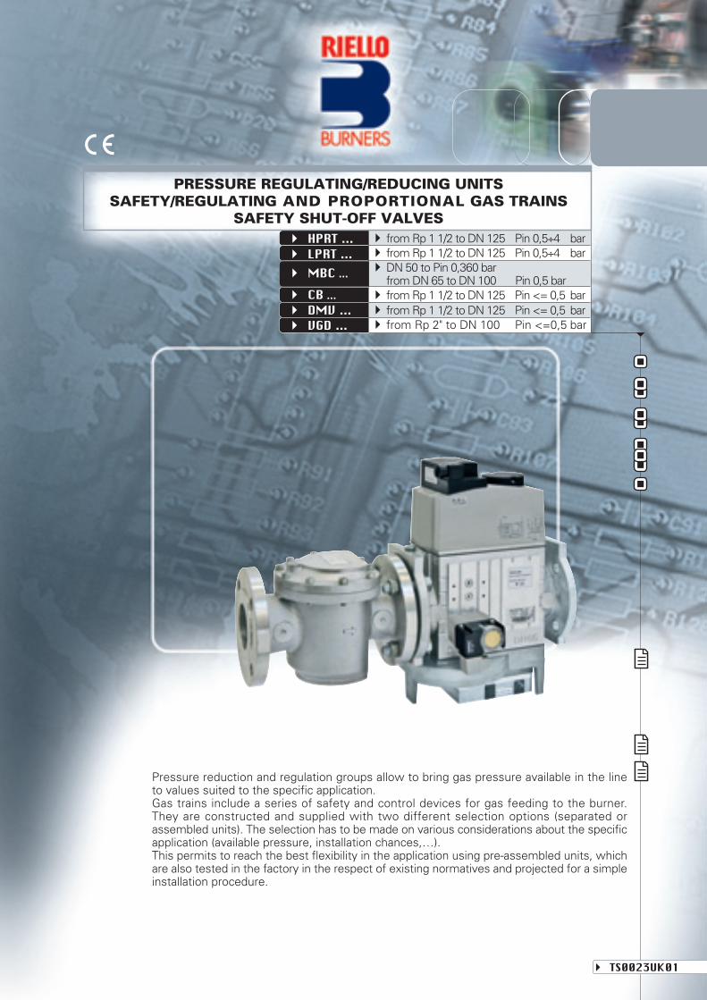
Pressure reduction and regulation groups allow to bring gas pressure available in the lineto values suited to the specific application.Gas trains include a series of safety and control devices for gas feeding to the burner.They are constructed and supplied with two different selection options (separated orassembled units). The selection has to be made on various considerations about the specificapplication (available pressure, installation chances,…).This permits to reach the best flexibility in the application using pre-assembled units, whichare also tested in the factory in the respect of existing normatives and projected for a simpleinstallation procedure.
TS0023UK01
PRESSURE REGULATING/REDUCING UNITSSAFETY/REGULATING AND PROPORTIONAL GAS TRAINS
SAFETY SHUT-OFF VALVESfrom Rp 1 1/2 to DN 125 Pin 0,5÷4 barfrom Rp 1 1/2 to DN 125 Pin 0,5÷4 barDN 50 to Pin 0,360 barfrom DN 65 to DN 100 Pin 0,5 barfrom Rp 1 1/2 to DN 125 Pin <= 0,5 barfrom Rp 1 1/2 to DN 125 Pin <= 0,5 barfrom Rp 2" to DN 100 Pin <=0,5 bar
HPRT ...
CB ...DMV ...
LPRT ...MBC ...
VGD ...
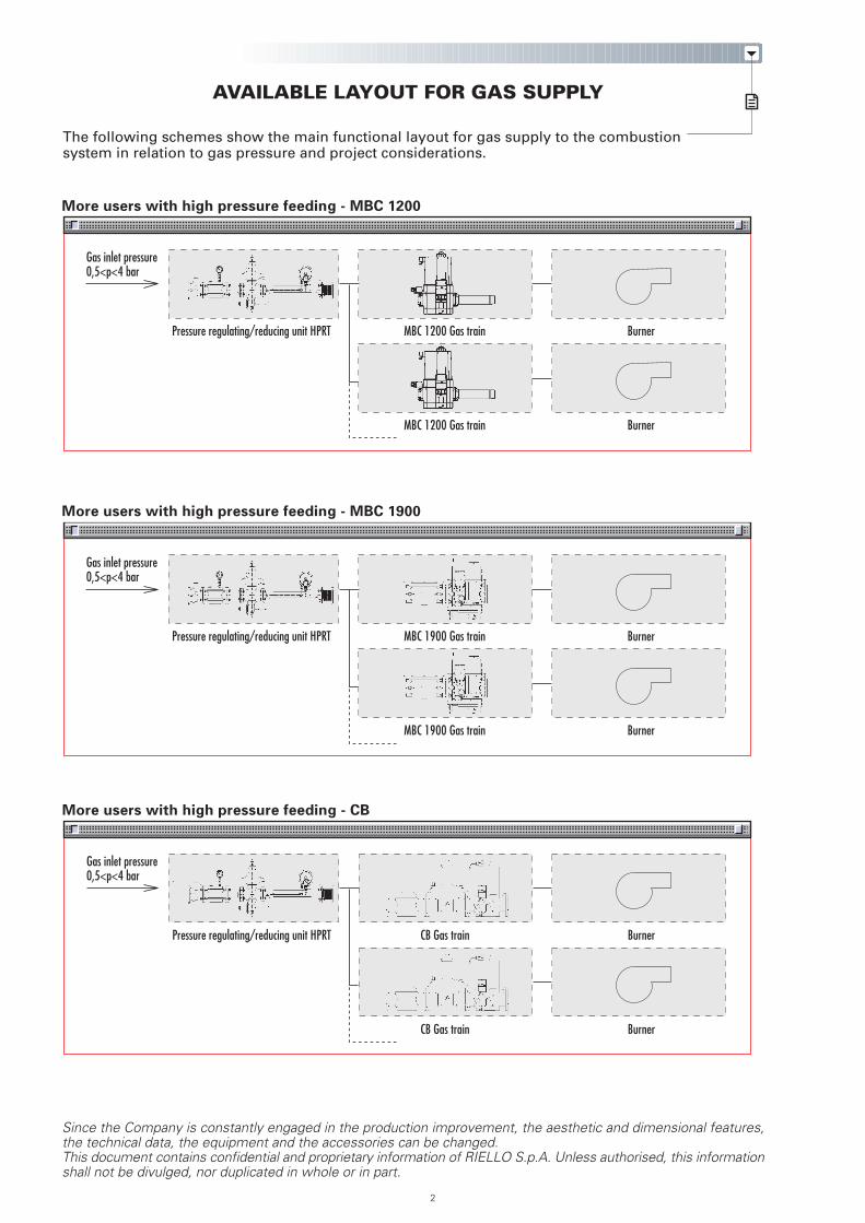
AVAILABLE LAYOUT FOR GAS SUPPLY
The following schemes show the main functional layout for gas supply to the combustionsystem in relation to gas pressure and project considerations.
More users with high pressure feeding - CB
More users with high pressure feeding - MBC 1200
More users with high pressure feeding - MBC 1900
Since the Company is constantly engaged in the production improvement, the aesthetic and dimensional features,the technical data, the equipment and the accessories can be changed.This document contains confidential and proprietary information of RIELLO S.p.A. Unless authorised, this informationshall not be divulged, nor duplicated in whole or in part.
2
Gas inlet pressure0,5<p<4 bar
Pressure regulating/reducing unit HPRT CB Gas train Burner
CB Gas train Burner
Gas inlet pressure0,5<p<4 bar
Pressure regulating/reducing unit HPRT MBC 1200 Gas train Burner
MBC 1200 Gas train Burner
Gas inlet pressure0,5<p<4 bar
Pressure regulating/reducing unit HPRT MBC 1900 Gas train Burner
MBC 1900 Gas train Burner
3
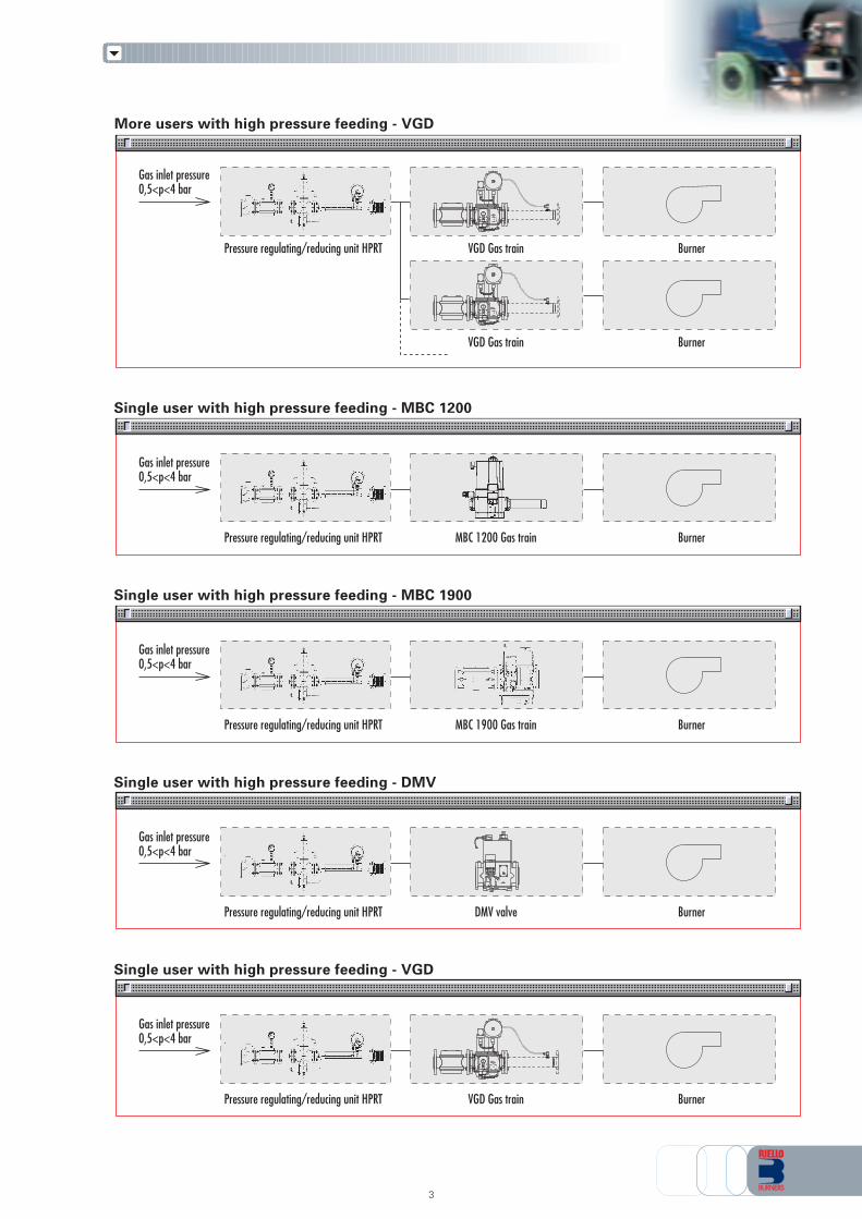
Single user with high pressure feeding - DMV
Gas inlet pressure0,5<p<4 bar
Pressure regulating/reducing unit HPRT DMV valve Burner
More users with high pressure feeding - VGD
B
B
Gas inlet pressure0,5<p<4 bar
Pressure regulating/reducing unit HPRT VGD Gas train Burner
VGD Gas train Burner
Single user with high pressure feeding - MBC 1200
Gas inlet pressure0,5<p<4 bar
Pressure regulating/reducing unit HPRT MBC 1200 Gas train Burner
Single user with high pressure feeding - MBC 1900
Gas inlet pressure0,5<p<4 bar
Pressure regulating/reducing unit HPRT MBC 1900 Gas train Burner
Single user with high pressure feeding - VGD
Gas inlet pressure0,5<p<4 bar
Pressure regulating/reducing unit HPRT VGD Gas train Burner
B
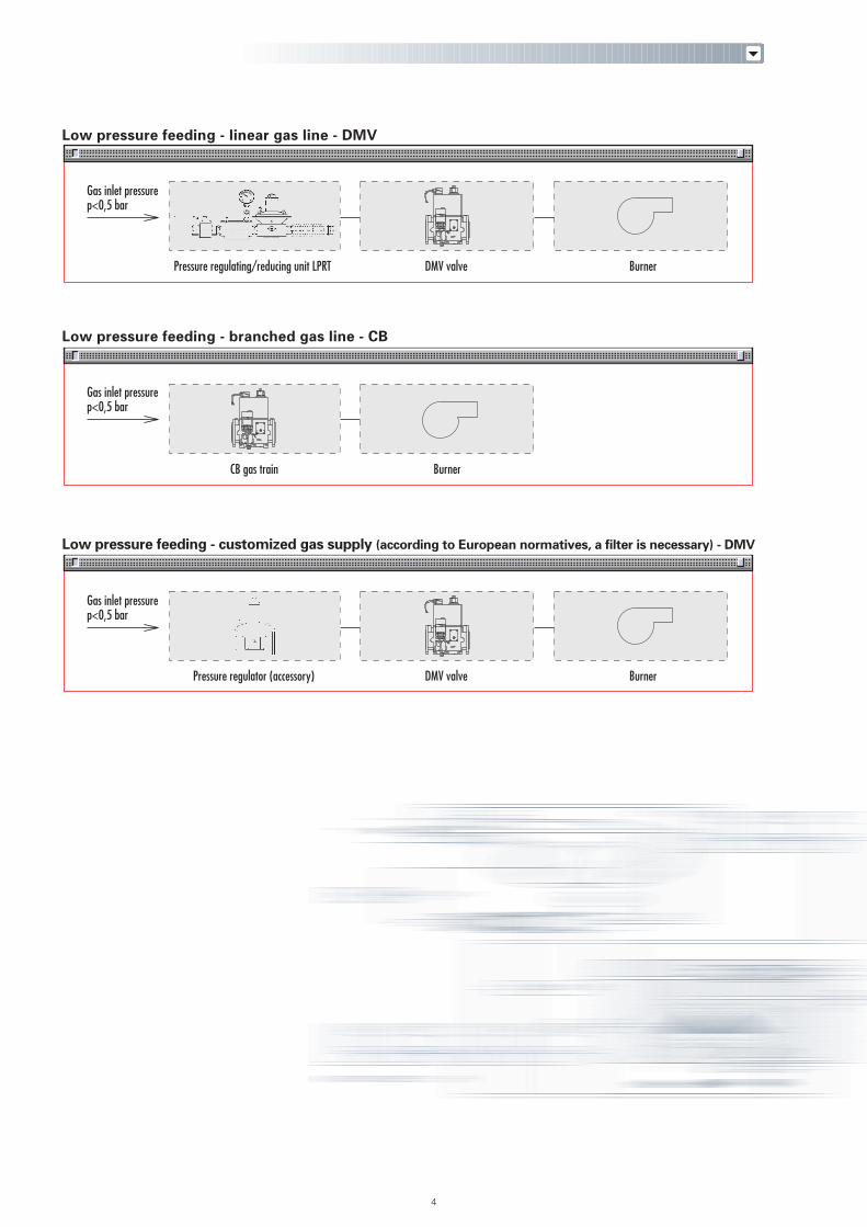
Low pressure feeding - branched gas line - CB
Low pressure feeding - customized gas supply (according to European normatives, a filter is necessary) - DMV
4
Gas inlet pressurep<0,5 bar
BurnerCB gas train
Gas inlet pressurep<0,5 bar
Pressure regulator (accessory) DMV valve Burner
Low pressure feeding - linear gas line - DMV
Gas inlet pressurep<0,5 bar
Pressure regulating/reducing unit LPRT DMV valve Burner
LOW PRESSURE REGULATING/REDUCING UNITS LPRT seriesTechnical data of available models of LPRT series
HIGH PRESSURE REGULATING/REDUCING UNITS HPRT seriesTechnical data of available models of HPRT series
TECHNICAL DESCRIPTION - OPERATION (LPRT - HPRT series)
SELECTION DIAGRAMS
INSTALLATION - START-UP - ADJUSTMENT (LPRT - HPRT series)
OVERALL DIMENSIONS
SPECIFICATIONList of available modelsProduct constructive specificationState of supply
SAFETY/REGULATING GAS TRAINS MBC seriesTechnical data of available models of MBC series
SAFETY/REGULATING GAS TRAINS CB seriesTechnical data of available models of CB series
SAFETY SHUT-OFF VALVES DMV seriesTechnical data of available models of DMV series
SAFETY/REGULATING PROPORTIONAL GAS TRAINS VGD seriesTechnical data of available models of VGD series
TECHNICAL DESCRIPTION - OPERATION (MBC - CB - DMV - VGD series)
SELECTION DIAGRAMS
INSTALLATION - START-UP - ADJUSTMENT (MBC - CB - DMV - VGD series)
OVERALL DIMENSIONS
SPECIFICATIONSList of available modelsProduct constructive specificationsState of supply
Springs for pressure regulatorConnection adaptersManual valvesAnti-vibrating jointsFiltersPressure regulatorsPressure gauge kit + push-button cockGas pressure switch for seal control installed on control panelSeal control kit
INDEX OF CONTENTS
PRESSURE REGULATING/REDUCING UNITS
5
SAFETY/REGULATING AND PROPORTIONAL GAS TRAINS - SAFETY SHUT-OFF VALVES
ACCESSORIES
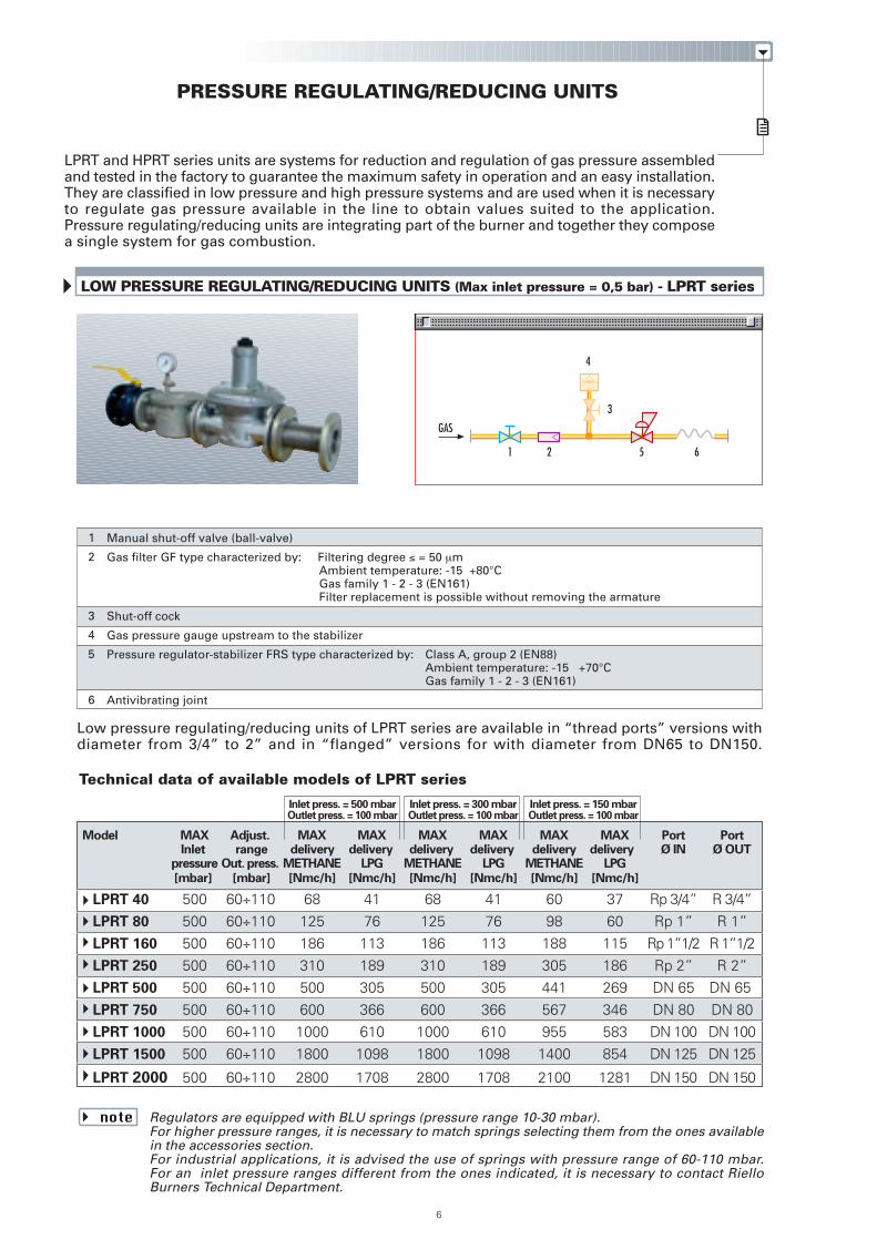
LOW PRESSURE REGULATING/REDUCING UNITS (Max inlet pressure = 0,5 bar) - LPRT series
6
4
521
3
6
Low pressure regulating/reducing units of LPRT series are available in “thread ports” versions withdiameter from 3/4” to 2” and in “flanged” versions for with diameter from DN65 to DN150.
PRESSURE REGULATING/REDUCING UNITS
LPRT and HPRT series units are systems for reduction and regulation of gas pressure assembledand tested in the factory to guarantee the maximum safety in operation and an easy installation.They are classified in low pressure and high pressure systems and are used when it is necessaryto regulate gas pressure available in the line to obtain values suited to the application.Pressure regulating/reducing units are integrating part of the burner and together they composea single system for gas combustion.
Regulators are equipped with BLU springs (pressure range 10-30 mbar).For higher pressure ranges, it is necessary to match springs selecting them from the ones availablein the accessories section.For industrial applications, it is advised the use of springs with pressure range of 60-110 mbar.For an inlet pressure ranges different from the ones indicated, it is necessary to contact RielloBurners Technical Department.
note
1
2
3
4
5
6
Manual shut-off valve (ball-valve)
Gas filter GF type characterized by: Filtering degree ≤ = 50 µm Ambient temperature: -15 +80°C Gas family 1 - 2 - 3 (EN161)
Filter replacement is possible without removing the armature
Shut-off cock
Gas pressure gauge upstream to the stabilizer
Pressure regulator-stabilizer FRS type characterized by: Class A, group 2 (EN88) Ambient temperature: -15 +70°C Gas family 1 - 2 - 3 (EN161)
Antivibrating joint
Model MAX Adjust. MAX MAX MAX MAX MAX MAX Port PortInlet range delivery delivery delivery delivery delivery delivery Ø IN Ø OUT
pressure Out. press. METHANE LPG METHANE LPG METHANE LPG
[mbar] [mbar] [Nmc/h] [Nmc/h] [Nmc/h] [Nmc/h] [Nmc/h] [Nmc/h]
LPRT 40 500 60÷110 68 41 68 41 60 37 Rp 3/4” R 3/4”LPRT 80 500 60÷110 125 76 125 76 98 60 Rp 1” R 1”LPRT 160 500 60÷110 186 113 186 113 188 115 Rp 1”1/2 R 1”1/2LPRT 250 500 60÷110 310 189 310 189 305 186 Rp 2” R 2”LPRT 500 500 60÷110 500 305 500 305 441 269 DN 65 DN 65
LPRT 750 500 60÷110 600 366 600 366 567 346 DN 80 DN 80LPRT 1000 500 60÷110 1000 610 1000 610 955 583 DN 100 DN 100LPRT 1500 500 60÷110 1800 1098 1800 1098 1400 854 DN 125 DN 125
LPRT 2000 500 60÷110 2800 1708 2800 1708 2100 1281 DN 150 DN 150
Inlet press. = 500 mbarOutlet press. = 100 mbar
Inlet press. = 300 mbarOutlet press. = 100 mbar
Inlet press. = 150 mbarOutlet press. = 100 mbar
Technical data of available models of LPRT series
GAS
1
2
3
4
5
6
7
8
9
10
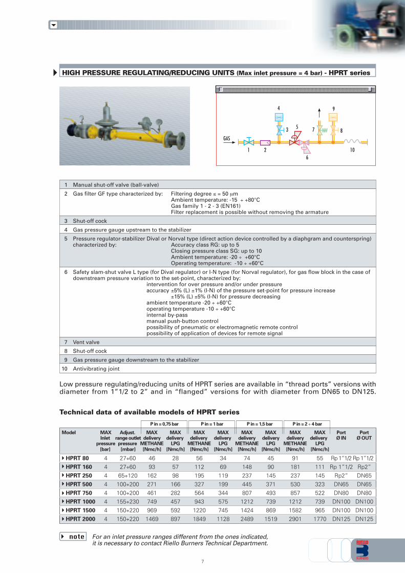
Manual shut-off valve (ball-valve)
Gas filter GF type characterized by: Filtering degree ≤ = 50 µm Ambient temperature: -15 ÷ +80°C Gas family 1 - 2 - 3 (EN161) Filter replacement is possible without removing the armature
Shut-off cock
Gas pressure gauge upstream to the stabilizer
Pressure regulator-stabilizer Dival or Norval type (direct action device controlled by a diaphgram and counterspring)characterized by: Accuracy class RG: up to 5 Closing pressure class SG: up to 10 Ambient temperature: -20 ÷ +60°C Operating temperature: -10 ÷ +60°C
Safety slam-shut valve L type (for Dival regulator) or I-N type (for Norval regulator), for gas flow block in the case ofdownstream pressure variation to the set-point, characterized by: intervention for over pressure and/or under pressure accuracy ±5% (L) ±1% (I-N) of the pressure set-point for pressure increase ±15% (L) ±5% (I-N) for pressure decreasing ambient temperature -20 ÷ +60°C operating temperature -10 ÷ +60°C internal by-pass manual push-button control possibility of pneumatic or electromagnetic remote control possibility of application of devices for remote signal
Vent valve
Shut-off cock
Gas pressure gauge downstream to the stabilizer
Antivibrating joint
HIGH PRESSURE REGULATING/REDUCING UNITS (Max inlet pressure = 4 bar) - HPRT series
3
10
7
6
4
21
5
9
8GAS
7
Model MAX Adjust. MAX MAX MAX MAX MAX MAX MAX MAX Port PortInlet range outlet delivery delivery delivery delivery delivery delivery delivery delivery Ø IN Ø OUT
pressure pressure METHANE LPG METHANE LPG METHANE LPG METHANE LPG
[bar] [mbar] [Nmc/h] [Nmc/h] [Nmc/h] [Nmc/h] [Nmc/h] [Nmc/h] [Nmc/h] [Nmc/h]
HPRT 80 4 27÷60 46 28 56 34 74 45 91 55 Rp 1”1/2 Rp 1”1/2HPRT 160 4 27÷60 93 57 112 69 148 90 181 111 Rp 1”1/2 Rp2”HPRT 250 4 65÷120 162 98 195 119 237 145 237 145 Rp2” DN65HPRT 500 4 100÷200 271 166 327 199 445 371 530 323 DN65 DN65HPRT 750 4 100÷200 461 282 564 344 807 493 857 522 DN80 DN80HPRT 1000 4 155÷230 749 457 943 575 1212 739 1212 739 DN100 DN100HPRT 1500 4 150÷220 969 592 1220 745 1424 869 1582 965 DN100 DN100HPRT 2000 4 150÷220 1469 897 1849 1128 2489 1519 2901 1770 DN125 DN125
P in = 2 ÷ 4 barP in = 1,5 barP in = 1 barP in = 0,75 bar
Low pressure regulating/reducing units of HPRT series are available in “thread ports” versions withdiameter from 1”1/2 to 2” and in “flanged” versions for with diameter from DN65 to DN125.
Technical data of available models of HPRT series
For an inlet pressure ranges different from the ones indicated,it is necessary to contact Riello Burners Technical Department.
note
1
2
3
4
5
6
7
8
9
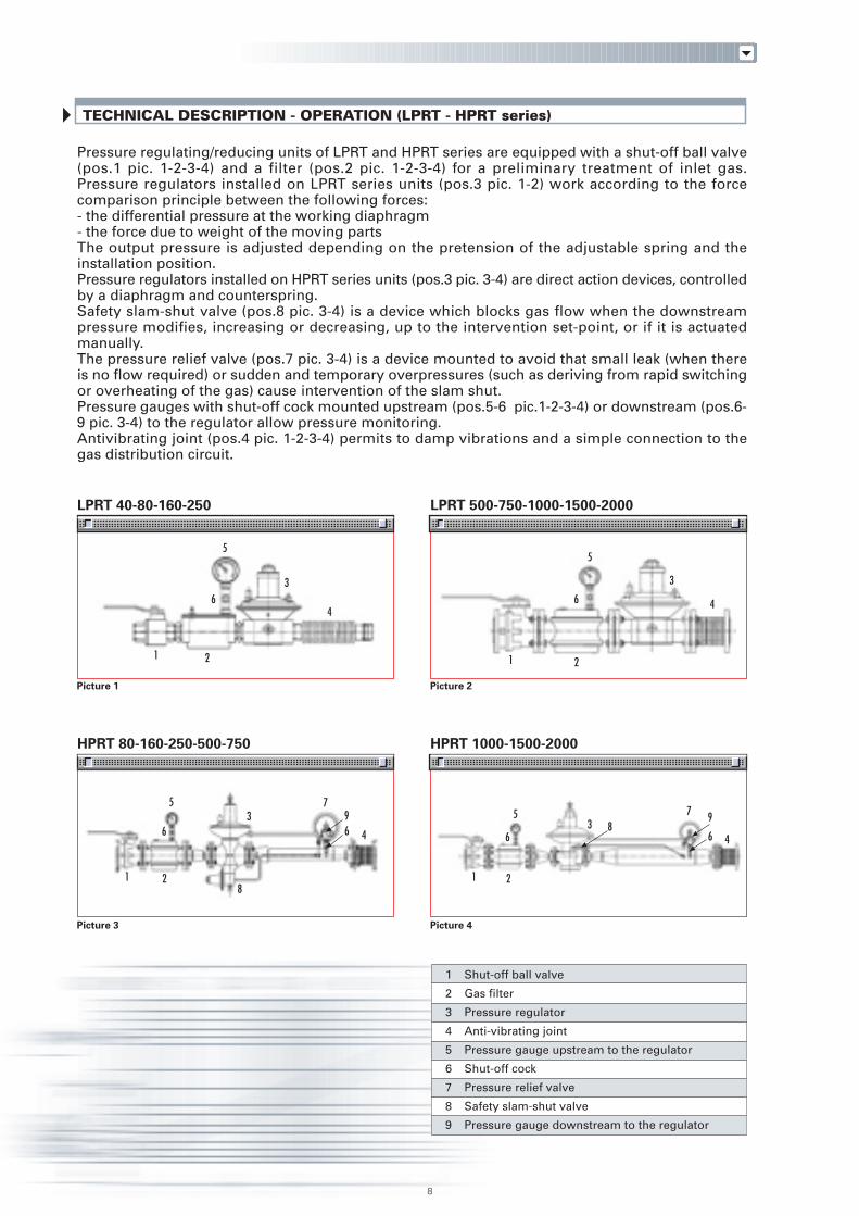
Shut-off ball valve
Gas filter
Pressure regulator
Anti-vibrating joint
Pressure gauge upstream to the regulator
Shut-off cock
Pressure relief valve
Safety slam-shut valve
Pressure gauge downstream to the regulator
LPRT 40-80-160-250 LPRT 500-750-1000-1500-2000
HPRT 80-160-250-500-750 HPRT 1000-1500-2000
Picture 1
Picture 3
Picture 2
Picture 4
3
5
64
21
8
TECHNICAL DESCRIPTION - OPERATION (LPRT - HPRT series)
Pressure regulating/reducing units of LPRT and HPRT series are equipped with a shut-off ball valve(pos.1 pic. 1-2-3-4) and a filter (pos.2 pic. 1-2-3-4) for a preliminary treatment of inlet gas.Pressure regulators installed on LPRT series units (pos.3 pic. 1-2) work according to the forcecomparison principle between the following forces:- the differential pressure at the working diaphragm- the force due to weight of the moving partsThe output pressure is adjusted depending on the pretension of the adjustable spring and theinstallation position.Pressure regulators installed on HPRT series units (pos.3 pic. 3-4) are direct action devices, controlledby a diaphragm and counterspring.Safety slam-shut valve (pos.8 pic. 3-4) is a device which blocks gas flow when the downstreampressure modifies, increasing or decreasing, up to the intervention set-point, or if it is actuatedmanually.The pressure relief valve (pos.7 pic. 3-4) is a device mounted to avoid that small leak (when thereis no flow required) or sudden and temporary overpressures (such as deriving from rapid switchingor overheating of the gas) cause intervention of the slam shut.Pressure gauges with shut-off cock mounted upstream (pos.5-6 pic.1-2-3-4) or downstream (pos.6-9 pic. 3-4) to the regulator allow pressure monitoring.Antivibrating joint (pos.4 pic. 1-2-3-4) permits to damp vibrations and a simple connection to thegas distribution circuit.
3
5
6 4
21
35
4
21
6
79
8
63
5
4
21
6
7 98
6
9
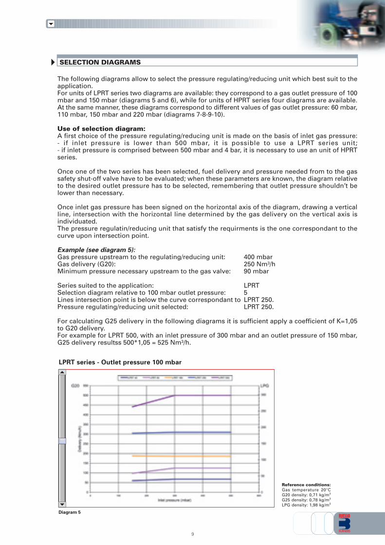
Diagram 5
Reference conditions:Gas temperature 20°CG20 density: 0,71 kg/m3
G25 density: 0,78 kg/m3
LPG density: 1,98 kg/m3
LPRT series - Outlet pressure 100 mbar
SELECTION DIAGRAMS
The following diagrams allow to select the pressure regulating/reducing unit which best suit to theapplication.For units of LPRT series two diagrams are available: they correspond to a gas outlet pressure of 100mbar and 150 mbar (diagrams 5 and 6), while for units of HPRT series four diagrams are available.At the same manner, these diagrams correspond to different values of gas outlet pressure: 60 mbar,110 mbar, 150 mbar and 220 mbar (diagrams 7-8-9-10).
Use of selection diagram:A first choice of the pressure regulating/reducing unit is made on the basis of inlet gas pressure:- if inlet pressure is lower than 500 mbar, it is possible to use a LPRT series unit;- if inlet pressure is comprised between 500 mbar and 4 bar, it is necessary to use an unit of HPRTseries.
Once one of the two series has been selected, fuel delivery and pressure needed from to the gassafety shut-off valve have to be evaluated; when these parameters are known, the diagram relativeto the desired outlet pressure has to be selected, remembering that outlet pressure shouldn’t belower than necessary.
Once inlet gas pressure has been signed on the horizontal axis of the diagram, drawing a verticalline, intersection with the horizontal line determined by the gas delivery on the vertical axis isindividuated.The pressure regulatin/reducing unit that satisfy the requirments is the one correspondant to thecurve upon intersection point.
Example (see diagram 5):Gas pressure upstream to the regulating/reducing unit: 400 mbarGas delivery (G20): 250 Nm3/hMinimum pressure necessary upstream to the gas valve: 90 mbar
Series suited to the application: LPRTSelection diagram relative to 100 mbar outlet pressure: 5Lines intersection point is below the curve correspondant to LPRT 250.Pressure regulating/reducing unit selected: LPRT 250.
For calculating G25 delivery in the following diagrams it is sufficient apply a coefficient of K=1,05to G20 delivery.For example for LPRT 500, with an inlet pressure of 300 mbar and an outlet pressure of 150 mbar,G25 delivery resultss 500*1,05 = 525 Nm3/h.
10
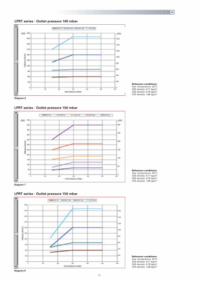
Diagram 6
Diagram 7
Diagram 8
LPRT series - Outlet pressure 100 mbar
Reference conditions:Gas temperature 20°CG20 density: 0,71 kg/m3
G25 density: 0,78 kg/m3
LPG density: 1,98 kg/m3
LPRT series - Outlet pressure 150 mbar
Reference conditions:Gas temperature 20°CG20 density: 0,71 kg/m3
G25 density: 0,78 kg/m3
LPG density: 1,98 kg/m3
LPRT series - Outlet pressure 150 mbar
Reference conditions:Gas temperature 20°CG20 density: 0,71 kg/m3
G25 density: 0,78 kg/m3
LPG density: 1,98 kg/m3
11
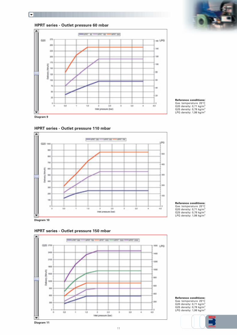
Diagram 9
Diagram 10
Diagram 11
HPRT series - Outlet pressure 60 mbar
Reference conditions:Gas temperature 20°CG20 density: 0,71 kg/m3
G25 density: 0,78 kg/m3
LPG density: 1,98 kg/m3
HPRT series - Outlet pressure 110 mbar
Reference conditions:Gas temperature 20°CG20 density: 0,71 kg/m3
G25 density: 0,78 kg/m3
LPG density: 1,98 kg/m3
HPRT series - Outlet pressure 150 mbar
Reference conditions:Gas temperature 20°CG20 density: 0,71 kg/m3
G25 density: 0,78 kg/m3
LPG density: 1,98 kg/m3
INSTALLATION - START UP - ADJUSTMENT (LPRT - HPRT series)
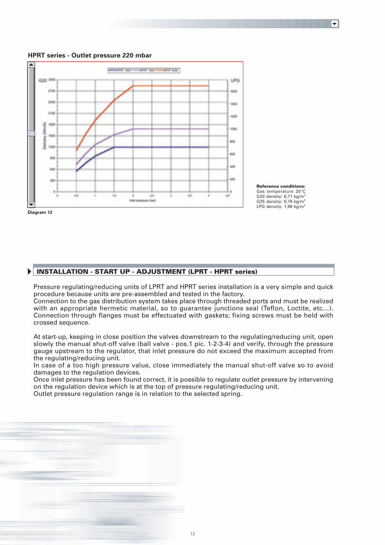
Diagram 12
HPRT series - Outlet pressure 220 mbar
Reference conditions:Gas temperature 20°CG20 density: 0,71 kg/m3
G25 density: 0,78 kg/m3
LPG density: 1,98 kg/m3
12
Pressure regulating/reducing units of LPRT and HPRT series installation is a very simple and quickprocedure because units are pre-assembled and tested in the factory.Connection to the gas distribution system takes place through threaded ports and must be realizedwith an appropriate hermetic material, so to guarantee junctions seal (Teflon, Loctite, etc…).Connection through flanges must be effectuated with gaskets; fixing screws must be held withcrossed sequence.
At start-up, keeping in close position the valves downstream to the regulating/reducing unit, openslowly the manual shut-off valve (ball valve - pos.1 pic. 1-2-3-4) and verify, through the pressuregauge upstream to the regulator, that inlet pressure do not exceed the maximum accepted fromthe regulating/reducing unit.In case of a too high pressure value, close immediately the manual shut-off valve so to avoiddamages to the regulation devices.Once inlet pressure has been found correct, it is possible to regulate outlet pressure by interveningon the regulation device which is at the top of pressure regulating/reducing unit.Outlet pressure regulation range is in relation to the selected spring.
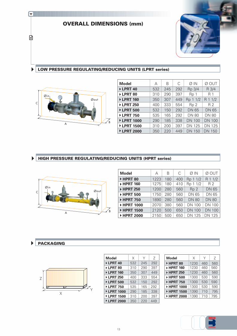
OVERALL DIMENSIONS (mm)
X
Z
Y
PACKAGING
13
LOW PRESSURE REGULATING/REDUCING UNITS (LPRT series)
Model A B C Ø IN Ø OUTLPRT 40 532 245 292 Rp 3/4 R 3/4LPRT 80 310 290 397 Rp 1 R 1LPRT 160 350 307 449 Rp 1 1/2 R 1 1/2
LPRT 250 400 333 554 Rp 2 R 2LPRT 500 532 150 292 DN 65 DN 65LPRT 750 535 165 292 DN 80 DN 80LPRT 1000 290 185 338 DN 100 DN 100LPRT 1500 310 200 397 DN 125 DN 125LPRT 2000 350 220 449 DN 150 DN 150
C
BA
ØoutØin
Model X Y ZHPRT 80 1230 460 560HPRT 160 1230 460 560
HPRT 250 1230 460 560HPRT 500 1300 530 590HPRT 750 1300 530 590HPRT 1000 1300 530 590HPRT 1500 1390 710 795HPRT 2000 1390 710 795
Model X Y ZLPRT 40 532 245 292LPRT 80 310 290 397LPRT 160 350 307 449
LPRT 250 400 333 554LPRT 500 532 150 292LPRT 750 535 165 292LPRT 1000 290 185 338LPRT 1500 310 200 397LPRT 2000 350 220 449
HIGH PRESSURE REGULATING/REDUCING UNITS (HPRT series)
Model A B C Ø IN Ø OUTHPRT 80 1223 180 400 Rp 1 1/2 R 1 1/2HPRT 160 1275 180 410 Rp 1 1/2 R 2
HPRT 250 1200 280 560 Rp 2 DN 65HPRT 500 1750 280 560 DN 65 DN 65HPRT 750 1890 280 560 DN 80 DN 80HPRT 1000 2070 380 560 DN 100 DN 100HPRT 1500 2120 500 650 DN 100 DN 100HPRT 2000 2150 500 650 DN 125 DN 125
C
BA
ØoutØin
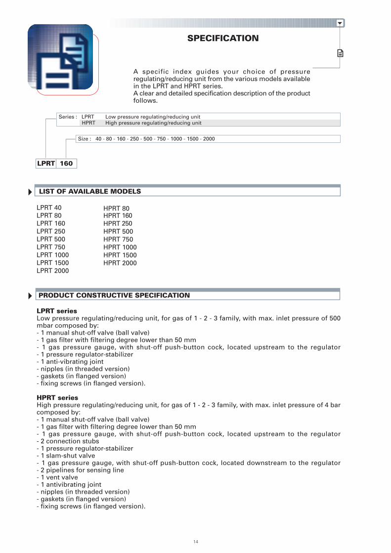
SPECIFICATION
A specific index guides your choice of pressureregulating/reducing unit from the various models availablein the LPRT and HPRT series.A clear and detailed specification description of the productfollows.
PRODUCT CONSTRUCTIVE SPECIFICATION
LPRT seriesLow pressure regulating/reducing unit, for gas of 1 - 2 - 3 family, with max. inlet pressure of 500mbar composed by:- 1 manual shut-off valve (ball valve)- 1 gas filter with filtering degree lower than 50 mm- 1 gas pressure gauge, with shut-off push-button cock, located upstream to the regulator- 1 pressure regulator-stabilizer- 1 anti-vibrating joint- nipples (in threaded version)- gaskets (in flanged version)- fixing screws (in flanged version).
HPRT seriesHigh pressure regulating/reducing unit, for gas of 1 - 2 - 3 family, with max. inlet pressure of 4 barcomposed by:- 1 manual shut-off valve (ball valve)- 1 gas filter with filtering degree lower than 50 mm- 1 gas pressure gauge, with shut-off push-button cock, located upstream to the regulator- 2 connection stubs- 1 pressure regulator-stabilizer- 1 slam-shut valve- 1 gas pressure gauge, with shut-off push-button cock, located downstream to the regulator- 2 pipelines for sensing line- 1 vent valve- 1 antivibrating joint- nipples (in threaded version)- gaskets (in flanged version)- fixing screws (in flanged version).
Size : 40 - 80 - 160 - 250 - 500 - 750 - 1000 - 1500 - 2000
LPRT 160
Series : LPRT Low pressure regulating/reducing unitHPRT High pressure regulating/reducing unit
LIST OF AVAILABLE MODELS
14
HPRT 80HPRT 160HPRT 250HPRT 500HPRT 750HPRT 1000HPRT 1500HPRT 2000
LPRT 40LPRT 80LPRT 160LPRT 250LPRT 500LPRT 750LPRT 1000LPRT 1500LPRT 2000
Standard equipment:- instruction handbook for installation, use and maintenance- gaskets (in flanged version)- fixing screws (in flanged version).
Available accessories to be ordered separately (see accessories section):- spring for pressure regulator- manual shut-off valve (ball valve from 3/4” to 2”, from DN65 to DN150)- anti-vibrating joint (from 3/4” to 2”, from DN65 to DN150)- filter (1”1/2, 2”, DN65, DN100, DN125)- pressure regulator (1”1/2, 2”, DN65, DN100, DN125)- pressure gauge kit with push-button (for pressure of 60, 150, 300, 500 mbar, 1-4 bar).
STATE OF SUPPLY
Pressure regulating/reducing units of LPRT/HPRT series are supplied pre-assembled and tested in thefactory, protected from a nylon cover and packaged in carton boxes or wood cases.
The supply includes:- pressure regulating/reducing unit- gaskets (in flanged version)- fixing screws (in flanged version)- instruction handbook for installation, use and maintenance
15
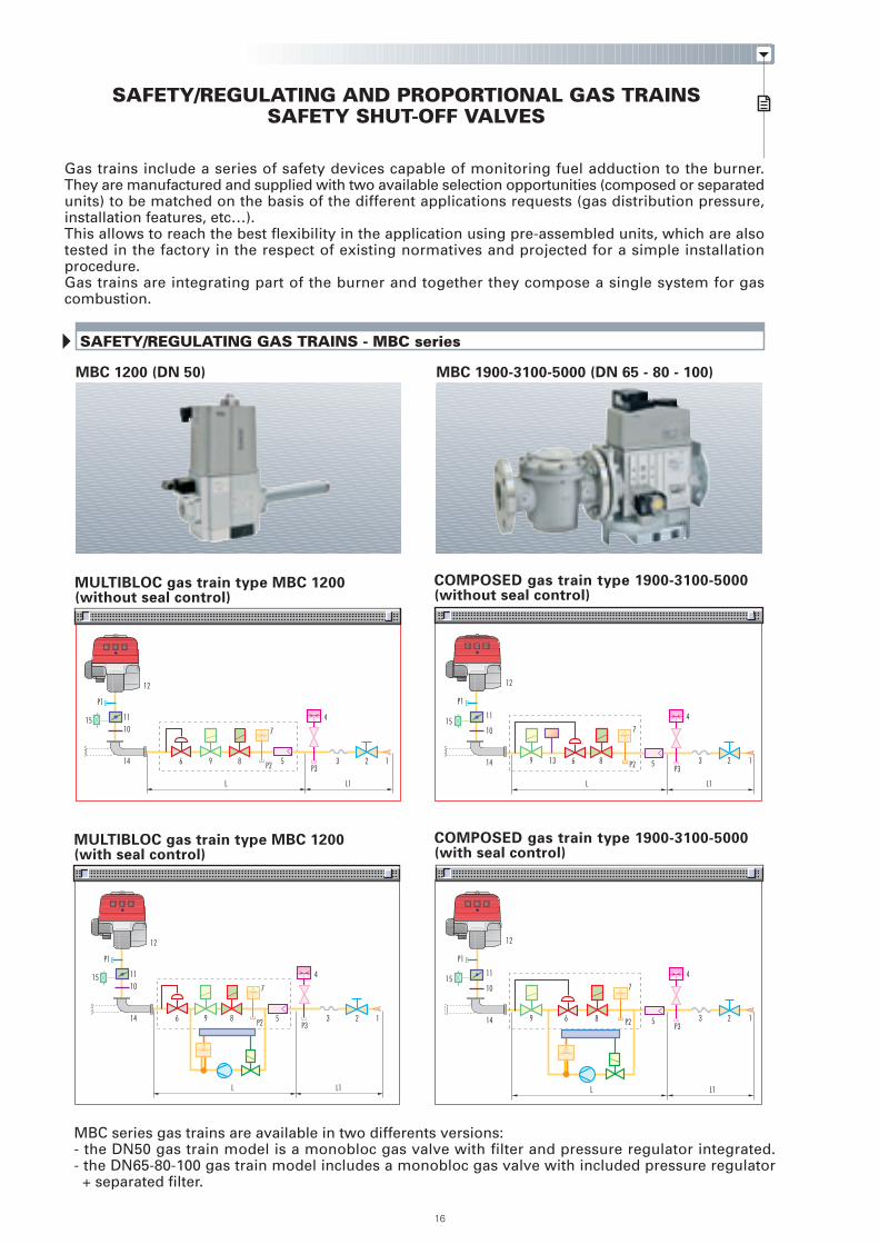
SAFETY/REGULATING GAS TRAINS - MBC series
MBC 1200 (DN 50) MBC 1900-3100-5000 (DN 65 - 80 - 100)
MULTIBLOC gas train type MBC 1200(without seal control)
COMPOSED gas train type 1900-3100-5000(with seal control)
12
12
16
SAFETY/REGULATING AND PROPORTIONAL GAS TRAINSSAFETY SHUT-OFF VALVES
Gas trains include a series of safety devices capable of monitoring fuel adduction to the burner.They are manufactured and supplied with two available selection opportunities (composed or separatedunits) to be matched on the basis of the different applications requests (gas distribution pressure,installation features, etc…).This allows to reach the best flexibility in the application using pre-assembled units, which are alsotested in the factory in the respect of existing normatives and projected for a simple installationprocedure.Gas trains are integrating part of the burner and together they compose a single system for gascombustion.
MBC series gas trains are available in two differents versions:- the DN50 gas train model is a monobloc gas valve with filter and pressure regulator integrated.- the DN65-80-100 gas train model includes a monobloc gas valve with included pressure regulator
+ separated filter.
COMPOSED gas train type 1900-3100-5000(without seal control)
L L1
12
P1
1511
10
14 9 13 6 8
7
5
4
P3P2 3 2 1
P1
1511
10
14 9 6 8
7
5
4
P3P2 3 2 1
MULTIBLOC gas train type MBC 1200(with seal control)
12
P1
15 1110
14 6
L L1
9 8 5
4
P33 2 1
7
P2
L L1
P1
15 1110
14 6
L L1
9 8
7
5
4
P3P2 3 2 1
5
5
13
7
6-8-9
6-8-9
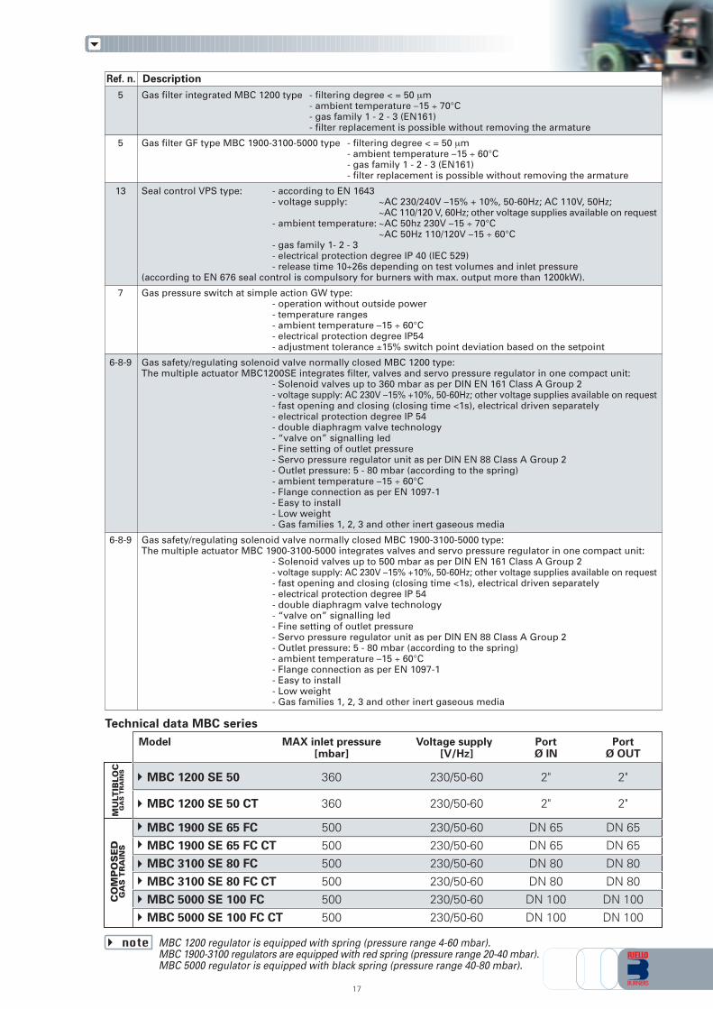
Gas filter integrated MBC 1200 type - filtering degree < = 50 µm- ambient temperature –15 ÷ 70°C- gas family 1 - 2 - 3 (EN161)- filter replacement is possible without removing the armature
Gas filter GF type MBC 1900-3100-5000 type - filtering degree < = 50 µm- ambient temperature –15 ÷ 60°C- gas family 1 - 2 - 3 (EN161)- filter replacement is possible without removing the armature
Seal control VPS type: - according to EN 1643- voltage supply: ~AC 230/240V –15% + 10%, 50-60Hz; AC 110V, 50Hz;
~AC 110/120 V, 60Hz; other voltage supplies available on request- ambient temperature: ~AC 50hz 230V –15 ÷ 70°C
~AC 50Hz 110/120V –15 ÷ 60°C- gas family 1- 2 - 3- electrical protection degree IP 40 (IEC 529)- release time 10÷26s depending on test volumes and inlet pressure
(according to EN 676 seal control is compulsory for burners with max. output more than 1200kW).
Gas pressure switch at simple action GW type:- operation without outside power- temperature ranges- ambient temperature –15 ÷ 60°C- electrical protection degree IP54- adjustment tolerance ±15% switch point deviation based on the setpoint
Gas safety/regulating solenoid valve normally closed MBC 1200 type:The multiple actuator MBC1200SE integrates filter, valves and servo pressure regulator in one compact unit:
- Solenoid valves up to 360 mbar as per DIN EN 161 Class A Group 2- voltage supply: AC 230V –15% +10%, 50-60Hz; other voltage supplies available on request- fast opening and closing (closing time <1s), electrical driven separately- electrical protection degree IP 54- double diaphragm valve technology- “valve on” signalling led- Fine setting of outlet pressure- Servo pressure regulator unit as per DIN EN 88 Class A Group 2- Outlet pressure: 5 - 80 mbar (according to the spring)- ambient temperature –15 ÷ 60°C- Flange connection as per EN 1097-1- Easy to install- Low weight- Gas families 1, 2, 3 and other inert gaseous media
Gas safety/regulating solenoid valve normally closed MBC 1900-3100-5000 type:The multiple actuator MBC 1900-3100-5000 integrates valves and servo pressure regulator in one compact unit:
- Solenoid valves up to 500 mbar as per DIN EN 161 Class A Group 2- voltage supply: AC 230V –15% +10%, 50-60Hz; other voltage supplies available on request- fast opening and closing (closing time <1s), electrical driven separately- electrical protection degree IP 54- double diaphragm valve technology- “valve on” signalling led- Fine setting of outlet pressure- Servo pressure regulator unit as per DIN EN 88 Class A Group 2- Outlet pressure: 5 - 80 mbar (according to the spring)- ambient temperature –15 ÷ 60°C- Flange connection as per EN 1097-1- Easy to install- Low weight- Gas families 1, 2, 3 and other inert gaseous media
CO
MP
OS
ED
GA
S T
RA
INS
MU
LTIB
LOC
GA
S T
RA
INS
17
Model MAX inlet pressure Voltage supply Port Port[mbar] [V/Hz] Ø IN Ø OUT
MBC 1200 SE 50 360 230/50-60 2" 2"
MBC 1200 SE 50 CT 360 230/50-60 2" 2"
MBC 1900 SE 65 FC 500 230/50-60 DN 65 DN 65MBC 1900 SE 65 FC CT 500 230/50-60 DN 65 DN 65MBC 3100 SE 80 FC 500 230/50-60 DN 80 DN 80MBC 3100 SE 80 FC CT 500 230/50-60 DN 80 DN 80MBC 5000 SE 100 FC 500 230/50-60 DN 100 DN 100MBC 5000 SE 100 FC CT 500 230/50-60 DN 100 DN 100
MBC 1200 regulator is equipped with spring (pressure range 4-60 mbar).MBC 1900-3100 regulators are equipped with red spring (pressure range 20-40 mbar).MBC 5000 regulator is equipped with black spring (pressure range 40-80 mbar).
note
Technical data MBC series
Ref. n. Description
18
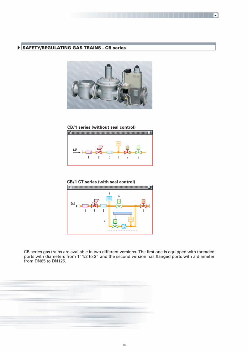
SAFETY/REGULATING GAS TRAINS - CB series
CB/1 series (without seal control)
CB/1 CT series (with seal control)
GAS
GAS
1 2 3 5 76
3
5
7
6
4
21
CB series gas trains are available in two different versions. The first one is equipped with threadedports with diameters from 1”1/2 to 2” and the second version has flanged ports with a diameterfrom DN65 to DN125.
1
2
3
4
5
6
7
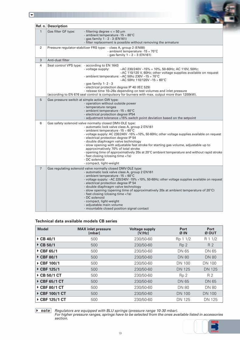
Gas filter GF type: - filtering degree < = 50 µm- ambient temperature -15 ÷ 80°C- gas family 1 - 2 - 3 (EN161)- filter replacement is possible without removing the armature
Pressure regulator-stabilizer FRS type: - class A, group 2 (EN88)- ambient temperature -15 ÷ 70°C- gas family 1 – 2 – 3 (EN161)
Anti-dust filter
Seal control VPS type: - according to EN 1643- voltage supply: ~AC 230/240V –15% + 10%, 50-60Hz; AC 110V, 50Hz;
~AC 110/120 V, 60Hz; other voltage supplies available on request- ambient temperature: ~AC 50hz 230V –15 ÷ 70°C
~AC 50Hz 110/120V –15 ÷ 60°C- gas family 1- 2 - 3- electrical protection degree IP 40 (IEC 529)- release time 10÷26s depending on test volumes and inlet pressure
(according to EN 676 seal control is compulsory for burners with max. output more than 1200kW).
Gas pressure switch at simple action GW type:- operation without outside power- temperature ranges- ambient temperature -15 ÷ 60°C- electrical protection degree IP54- adjustment tolerance ±15% switch point deviation based on the setpoint
Gas safety solenoid valve normally closed DMV-DLE type:- automatic lock valve class A, group 2 EN161- ambient temperature -15 ÷ 60°C- voltage supply: AC 230/240V -15% +10%, 50-60Hz; other voltage supplies available on request- electrical protection degree IP 54- double diaphragm valve technology- slow opening with adjustable fast stroke for starting gas volume, adjustable up to approximatively 70% of total stroke- opening time of approximatively 20s at 20°C ambient temperature and without rapid stroke- fast closing (closing time <1s)- DC solenoid- compact, light-weight
Gas regulating solenoid valve normally closed DMV-DLE type:- automatic lock valve class A, group 2 EN161- ambient temperature -15 ÷ 60°C- voltage supply: ~AC 220/240V -15% +10%, 50-60Hz; other voltage supplies available on request- electrical protection degree IP 54- double diaphragm valve technology- slow opening (opening time of approximatively 20s at ambient temperature of 20°C)- fast closing (closing time <1s)- DC solenoid- compact, light-weight- adjustable main volume- mountable closed position signal contact
19
Model MAX inlet pressure Voltage supply Port Port[mbar] [V/Hz] Ø IN Ø OUT
CB 40/1 500 230/50-60 Rp 1 1/2 R 1 1/2CB 50/1 500 230/50-60 Rp 2 R 2CBF 65/1 500 230/50-60 DN 65 DN 65CBF 80/1 500 230/50-60 DN 80 DN 80CBF 100/1 500 230/50-60 DN 100 DN 100
CBF 125/1 500 230/50-60 DN 125 DN 125CB 50/1 CT 500 230/50-60 Rp 2 R 2CBF 65/1 CT 500 230/50-60 DN 65 DN 65CBF 80/1 CT 500 230/50-60 DN 80 DN 80CBF 100/1 CT 500 230/50-60 DN 100 DN 100CBF 125/1 CT 500 230/50-60 DN 125 DN 125
Regulators are equipped with BLU springs (pressure range 10-30 mbar).For higher pressure ranges, springs have to be selected from the ones available listed in accessoriessection.
note
Technical data available models CB series
Ref. n. Description
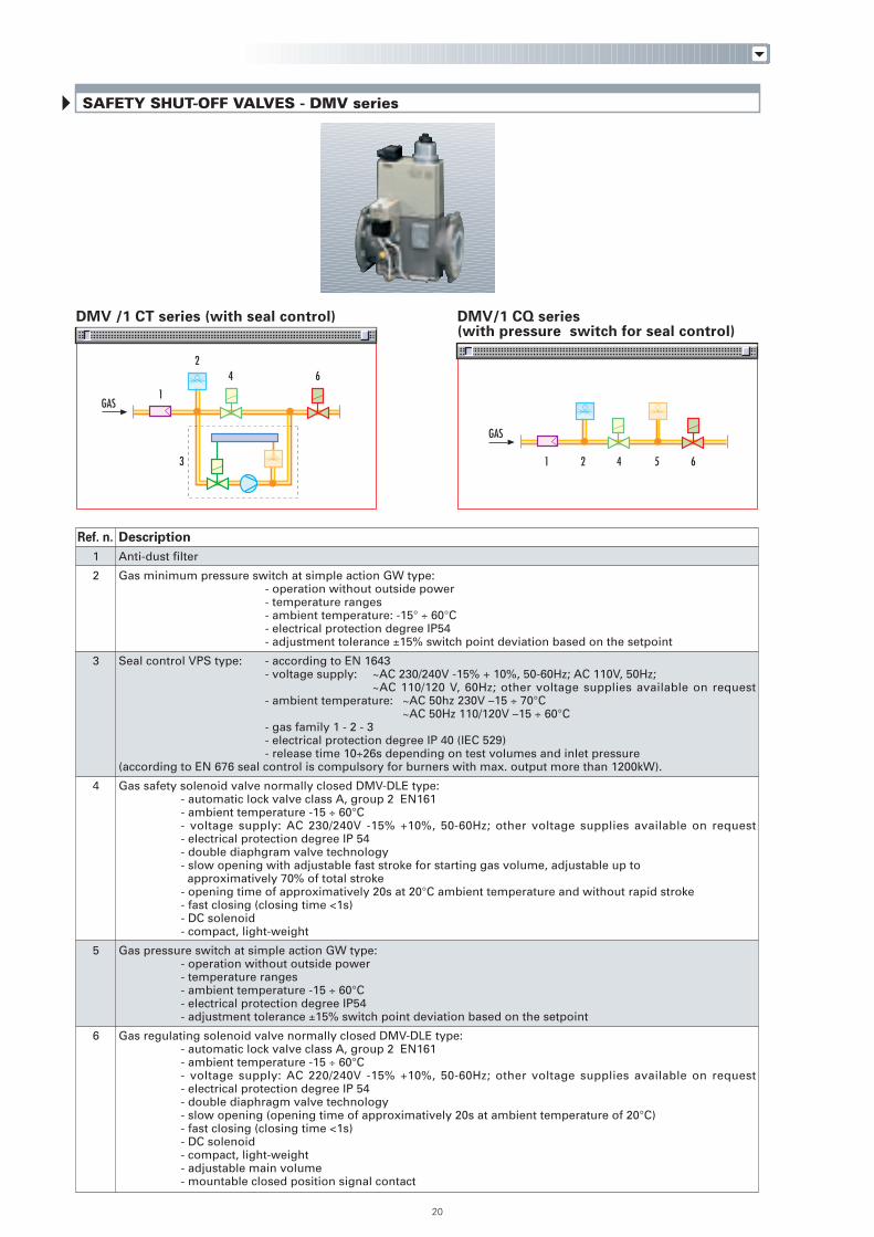
DMV/1 CQ series(with pressure switch for seal control)
DMV /1 CT series (with seal control)
1
2
3
4
5
6
Anti-dust filter
Gas minimum pressure switch at simple action GW type:- operation without outside power
- temperature ranges - ambient temperature: -15° ÷ 60°C - electrical protection degree IP54 - adjustment tolerance ±15% switch point deviation based on the setpoint
Seal control VPS type: - according to EN 1643- voltage supply: ~AC 230/240V -15% + 10%, 50-60Hz; AC 110V, 50Hz;
~AC 110/120 V, 60Hz; other voltage supplies available on request- ambient temperature: ~AC 50hz 230V –15 ÷ 70°C
~AC 50Hz 110/120V –15 ÷ 60°C- gas family 1 - 2 - 3- electrical protection degree IP 40 (IEC 529)- release time 10÷26s depending on test volumes and inlet pressure
(according to EN 676 seal control is compulsory for burners with max. output more than 1200kW).
Gas safety solenoid valve normally closed DMV-DLE type:- automatic lock valve class A, group 2 EN161- ambient temperature -15 ÷ 60°C- voltage supply: AC 230/240V -15% +10%, 50-60Hz; other voltage supplies available on request- electrical protection degree IP 54- double diaphgram valve technology- slow opening with adjustable fast stroke for starting gas volume, adjustable up to approximatively 70% of total stroke- opening time of approximatively 20s at 20°C ambient temperature and without rapid stroke- fast closing (closing time <1s)- DC solenoid- compact, light-weight
Gas pressure switch at simple action GW type:- operation without outside power- temperature ranges- ambient temperature -15 ÷ 60°C- electrical protection degree IP54- adjustment tolerance ±15% switch point deviation based on the setpoint
Gas regulating solenoid valve normally closed DMV-DLE type:- automatic lock valve class A, group 2 EN161- ambient temperature -15 ÷ 60°C- voltage supply: AC 220/240V -15% +10%, 50-60Hz; other voltage supplies available on request- electrical protection degree IP 54- double diaphragm valve technology- slow opening (opening time of approximatively 20s at ambient temperature of 20°C)- fast closing (closing time <1s)- DC solenoid- compact, light-weight- adjustable main volume- mountable closed position signal contact
2 5 6413
6
1
24
GAS
GAS
20
SAFETY SHUT-OFF VALVES - DMV series
Ref. n. Description
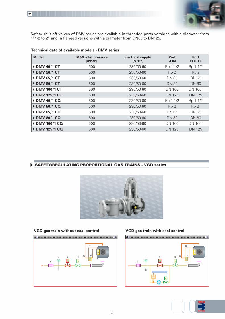
SAFETY/REGULATING PROPORTIONAL GAS TRAINS - VGD series
VGD gas train without seal control VGD gas train with seal control
P2
7 8
5
10 PG
PC
PA
P2
7 8
5
10 PG
PC
PA
21
Technical data of available models - DMV series
Model MAX inlet pressure Electrical supply Port Port[mbar] [V/Hz] Ø IN Ø OUT
DMV 40/1 CT 500 230/50-60 Rp 1 1/2 Rp 1 1/2DMV 50/1 CT 500 230/50-60 Rp 2 Rp 2DMV 65/1 CT 500 230/50-60 DN 65 DN 65DMV 80/1 CT 500 230/50-60 DN 80 DN 80DMV 100/1 CT 500 230/50-60 DN 100 DN 100
DMV 125/1 CT 500 230/50-60 DN 125 DN 125DMV 40/1 CQ 500 230/50-60 Rp 1 1/2 Rp 1 1/2DMV 50/1 CQ 500 230/50-60 Rp 2 Rp 2DMV 65/1 CQ 500 230/50-60 DN 65 DN 65DMV 80/1 CQ 500 230/50-60 DN 80 DN 80DMV 100/1 CQ 500 230/50-60 DN 100 DN 100DMV 125/1 CQ 500 230/50-60 DN 125 DN 125
Safety shut-off valves of DMV series are available in threaded ports versions with a diameter from1”1/2 to 2” and in flanged versions with a diameter from DN65 to DN125.
13 13
5
13
7
8-10
Gas filter - filtering degree < = 50 µm- ambient temperature –15 ÷ 70°C- gas family 1 - 2 - 3 (EN161)- filter replacement is possible without removing the armature
Seal control VPS type: - according to EN 1643- voltage supply: ~AC 230/240V –15% +10%, 50-60Hz; AC 110V, 50Hz;
~AC 110/120 V, 60Hz; other voltage supplies available on request- ambient temperature: ~AC 50hz 230V –15 ÷ 70°C
~AC 50Hz 110/120V –15 ÷ 60°C- gas family 1- 2 - 3- electrical protection degree IP 40 (IEC 529)- release time 10 ÷ 26s depending on test volumes and inlet pressure
(according to EN 676 seal control is compulsory for burners with max. output more than 1200kW).
Gas pressure switch at simple action GW type:- operation without outside power- temperature ranges- ambient temperature –15 ÷ 60°C- electrical protection degree IP54- adjustment tolerance ±15% switch point deviation based on the setpoint
Gas safety/regulating solenoid valve normally closed VGD typeThe multiple VGD integrates valves and servo pressure regulator in one compact unit:
- Inlet pressure up to 500 mbar as per DIN EN 161 Class A Group 2- voltage supply: AC 230V –15% +10%, 50-60Hz; other voltage supplies available on request- fast opening and closing (closing time <1s), electrical driven separately- electrical protection degree IP 54- double diaphragm valve technology- “valve on” signalling led and indicator of stroke on SKP75- ambient temperature –10° ÷ 60°C- flange connection as per EN 1097-1- easy to install, low power consumption, low weight- gas families 1, 2, 3 and other inert gaseous media
22
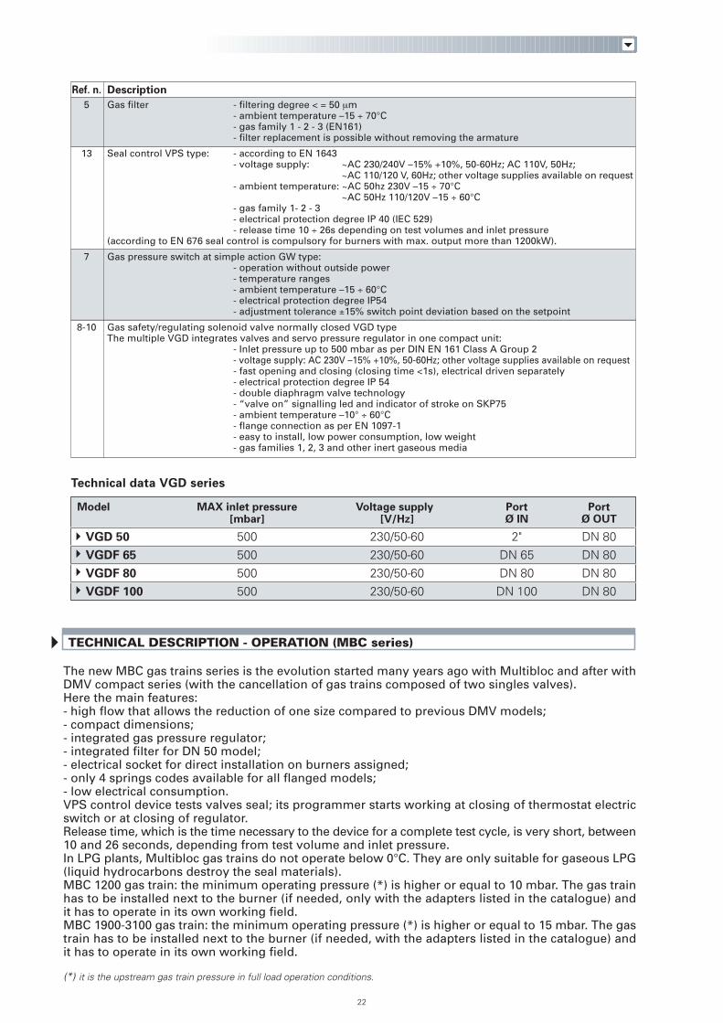
Model MAX inlet pressure Voltage supply Port Port[mbar] [V/Hz] Ø IN Ø OUT
VGD 50 500 230/50-60 2" DN 80VGDF 65 500 230/50-60 DN 65 DN 80VGDF 80 500 230/50-60 DN 80 DN 80VGDF 100 500 230/50-60 DN 100 DN 80
Technical data VGD series
TECHNICAL DESCRIPTION - OPERATION (MBC series)
The new MBC gas trains series is the evolution started many years ago with Multibloc and after withDMV compact series (with the cancellation of gas trains composed of two singles valves).Here the main features:- high flow that allows the reduction of one size compared to previous DMV models;- compact dimensions;- integrated gas pressure regulator;- integrated filter for DN 50 model;- electrical socket for direct installation on burners assigned;- only 4 springs codes available for all flanged models;- low electrical consumption.VPS control device tests valves seal; its programmer starts working at closing of thermostat electricswitch or at closing of regulator.Release time, which is the time necessary to the device for a complete test cycle, is very short, between10 and 26 seconds, depending from test volume and inlet pressure.In LPG plants, Multibloc gas trains do not operate below 0°C. They are only suitable for gaseous LPG(liquid hydrocarbons destroy the seal materials).MBC 1200 gas train: the minimum operating pressure (*) is higher or equal to 10 mbar. The gas trainhas to be installed next to the burner (if needed, only with the adapters listed in the catalogue) andit has to operate in its own working field.MBC 1900-3100 gas train: the minimum operating pressure (*) is higher or equal to 15 mbar. The gastrain has to be installed next to the burner (if needed, with the adapters listed in the catalogue) andit has to operate in its own working field.
(*) it is the upstream gas train pressure in full load operation conditions.
Ref. n. Description
TECHNICAL DESCRIPTION - OPERATION (CB-DMV series)
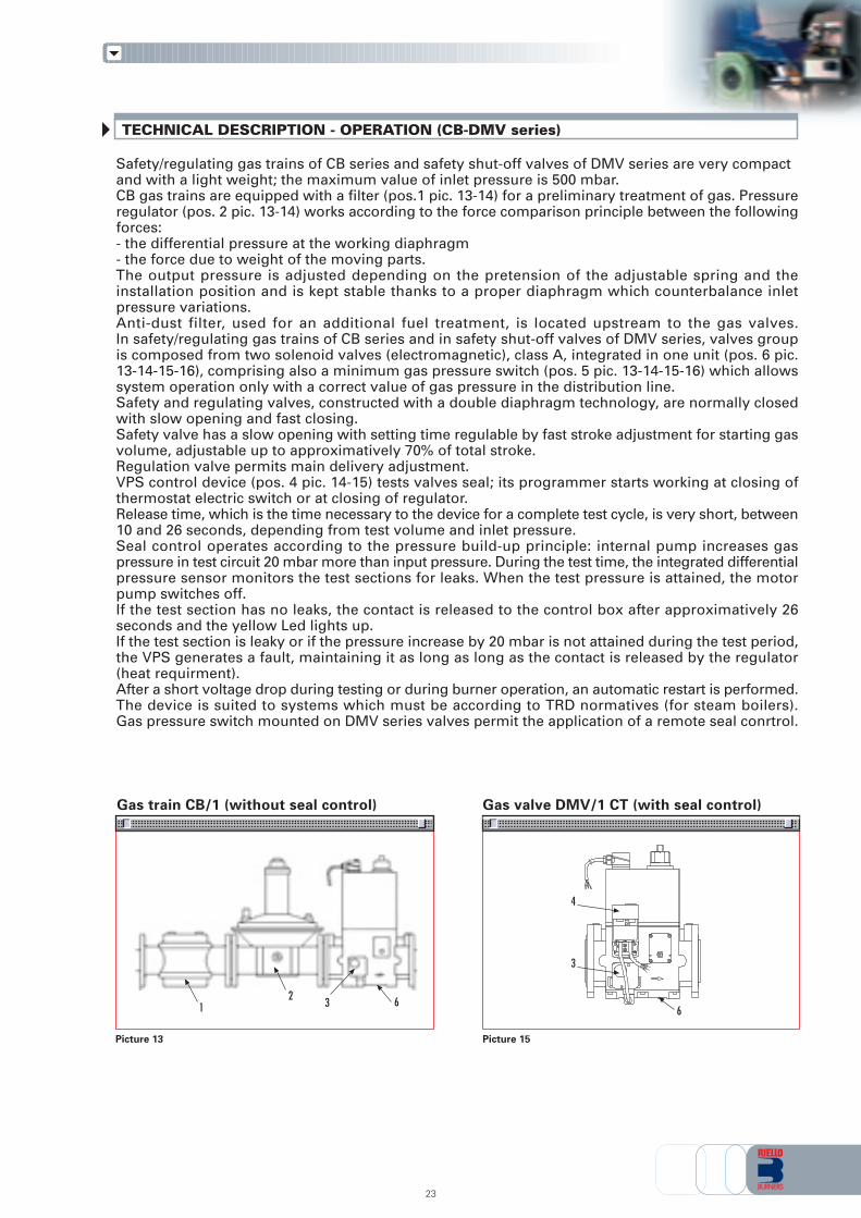
Picture 13 Picture 15
Gas train CB/1 (without seal control) Gas valve DMV/1 CT (with seal control)
23
Safety/regulating gas trains of CB series and safety shut-off valves of DMV series are very compactand with a light weight; the maximum value of inlet pressure is 500 mbar.CB gas trains are equipped with a filter (pos.1 pic. 13-14) for a preliminary treatment of gas. Pressureregulator (pos. 2 pic. 13-14) works according to the force comparison principle between the followingforces:- the differential pressure at the working diaphragm- the force due to weight of the moving parts.The output pressure is adjusted depending on the pretension of the adjustable spring and theinstallation position and is kept stable thanks to a proper diaphragm which counterbalance inletpressure variations.Anti-dust filter, used for an additional fuel treatment, is located upstream to the gas valves.In safety/regulating gas trains of CB series and in safety shut-off valves of DMV series, valves groupis composed from two solenoid valves (electromagnetic), class A, integrated in one unit (pos. 6 pic.13-14-15-16), comprising also a minimum gas pressure switch (pos. 5 pic. 13-14-15-16) which allowssystem operation only with a correct value of gas pressure in the distribution line.Safety and regulating valves, constructed with a double diaphragm technology, are normally closedwith slow opening and fast closing.Safety valve has a slow opening with setting time regulable by fast stroke adjustment for starting gasvolume, adjustable up to approximatively 70% of total stroke.Regulation valve permits main delivery adjustment.VPS control device (pos. 4 pic. 14-15) tests valves seal; its programmer starts working at closing ofthermostat electric switch or at closing of regulator.Release time, which is the time necessary to the device for a complete test cycle, is very short, between10 and 26 seconds, depending from test volume and inlet pressure.Seal control operates according to the pressure build-up principle: internal pump increases gaspressure in test circuit 20 mbar more than input pressure. During the test time, the integrated differentialpressure sensor monitors the test sections for leaks. When the test pressure is attained, the motorpump switches off.If the test section has no leaks, the contact is released to the control box after approximatively 26seconds and the yellow Led lights up.If the test section is leaky or if the pressure increase by 20 mbar is not attained during the test period,the VPS generates a fault, maintaining it as long as long as the contact is released by the regulator(heat requirment).After a short voltage drop during testing or during burner operation, an automatic restart is performed.The device is suited to systems which must be according to TRD normatives (for steam boilers).Gas pressure switch mounted on DMV series valves permit the application of a remote seal conrtrol.
4
3
63 62
1
1
2
3
4
5
6
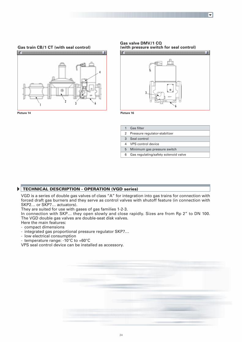
Picture 14 Picture 16
Gas train CB/1 CT (with seal control)Gas valve DMV/1 CQ(with pressure switch for seal control)
24
TECHNICAL DESCRIPTION - OPERATION (VGD series)
Gas filter
Pressure regulator-stabilizer
Seal control
VPS control device
Minimum gas pressure switch
Gas regulating/safety solenoid valve
3
63 62
1
4
VGD is a series of double gas valves of class “A” for integration into gas trains for connection withforced draft gas burners and they serve as control valves with shutoff feature (in connection withSKP2… or SKP7… actuators).They are suited for use with gases of gas families 1-2-3.In connection with SKP… they open slowly and close rapidly. Sizes are from Rp 2” to DN 100.The VGD double gas valves are double-seat disk valves.Here the main features:- compact dimensions- integrated gas proportional pressure regulator SKP7…- low electrical consumption- temperature range: -10°C to +60°CVPS seal control device can be installed as accessory.
SELECTION DIAGRAMS
25
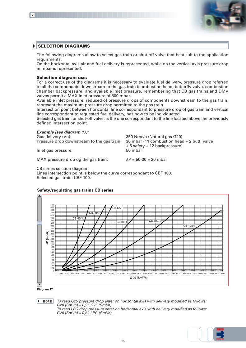
The following diagrams allow to select gas train or shut-off valve that best suit to the applicationrequirments.On the horizontal axis air and fuel delivery is represented, while on the vertical axis pressure dropin mbar is represented.
Selection diagram use:For a correct use of the diagrams it is necessary to evaluate fuel delivery, pressure drop referredto all the components downstream to the gas train (combustion head, butterfly valve, combustionchamber backpressure) and available inlet pressure, remembering that CB gas trains and DMVvalves permit a MAX inlet pressure of 500 mbar.Available inlet pressure, reduced of pressure drops of components downstream to the gas train,represent the maximum pressure drop permitted to the gas train.Intersection point between horizontal line correspondant to pressure drop of gas train and verticalline correspondant to requested fuel delivery, has now to be individuated.Selected gas train, or shut-off valve, is the one correspondant to the line located above the previouslydefined intersection point.
Example (see diagram 17):Gas delivery (Vn): 350 Nmc/h (Natural gas G20)Pressure drop downstream to the gas train: 30 mbar (11 combustion head + 2 butt. valve
+ 5 safety + 12 backpressure)Inlet gas pressure: 50 mbar
MAX pressure drop og the gas train: ∆P = 50-30 = 20 mbar
CB series selction diagramLines intersection point is below the curve correspondant to CBF 100.Selected gas train: CBF 100.
To read G25 pressure drop enter on horizontal axis with delivery modified as follows:G20 (Sm3/h) = 0,95 G25 (Sm3/h).To read LPG drop pressure enter on horizontal axis with delivery modified as follows:G20 (Sm3/h) = 0,62 LPG (Sm3/h).
note
Diagram 17
Safety/regulating gas trains CB series
020406080
100120140160180200220240260280300320340360380400420440460480500
0 100 200 300 400 500 600 700 800 900 1000 1100 1200 1300 1400 1500 1600 1700 1800 1900 2000 2100 2200 2300 2400 2500 2600 2700 2800 2900 3000
G 20 (Nmc/h)
∆P (
mb
ar)
CB 40/1
CB 50/1
CB 65/1
CB 80/1 CB 100/1
CB 125/1
G 20 (Sm3/h)
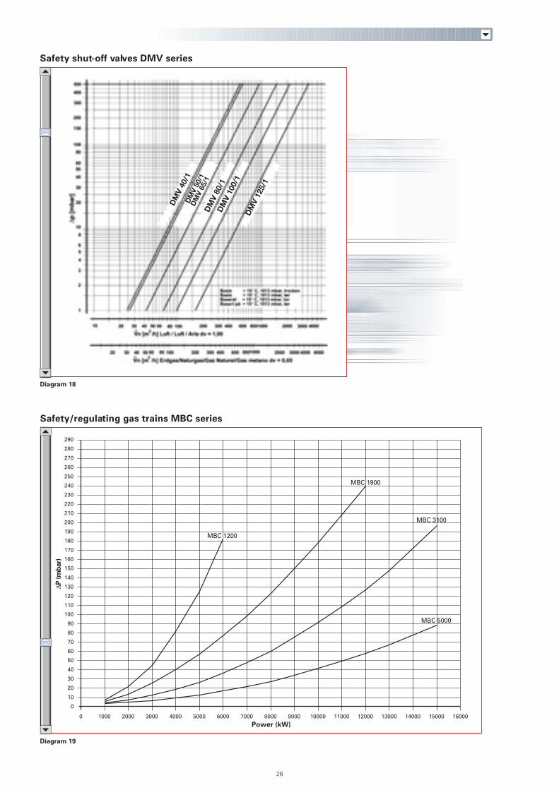
Diagram 19
Safety/regulating gas trains MBC series
0
10
20
30
40
50
60
70
80
90
100
110
120
130
140
150
160
170
180
190
200
210
220
230
240
250
260
270
280
290
0 1000 2000 3000 4000 5000 6000 7000 8000 9000 10000 11000 12000 13000 14000 15000 16000
Power (kW)
MBC 5000
MBC 3100
MBC 1900
MBC 1200
26
Diagram 18
Safety shut-off valves DMV series
DM
V 40
/1D
MV
50/1
DM
V 65
/1D
MV
80/1
DM
V 10
0/1
DM
V 12
5/1
∆P
(m
bar)
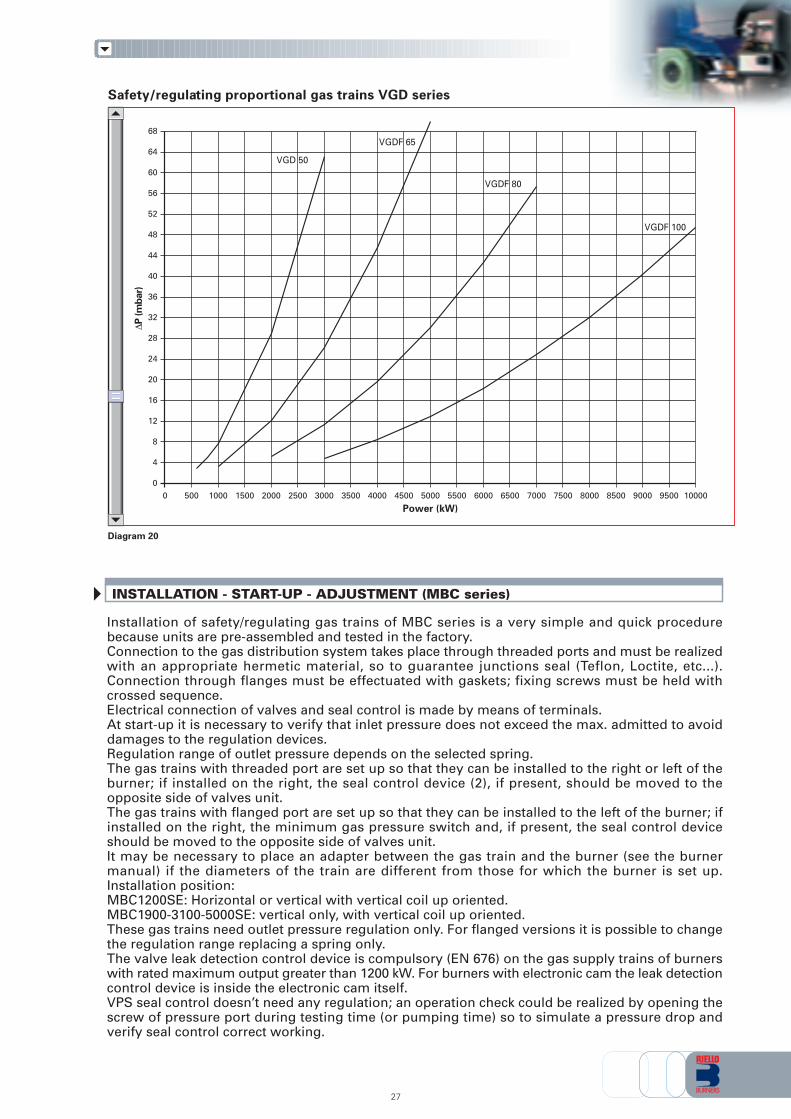
Diagram 20
Safety/regulating proportional gas trains VGD series
0
4
8
12
16
20
24
28
32
36
40
44
48
52
56
60
64
68
0 500 1000 1500 2000 2500 3000 3500 4000 4500 5000 5500 6000 6500 7000 7500 8000 8500 9000 9500 10000
VGD 50
VGDF 65
VGDF 80
VGDF 100
Power (kW)
Installation of safety/regulating gas trains of MBC series is a very simple and quick procedurebecause units are pre-assembled and tested in the factory.Connection to the gas distribution system takes place through threaded ports and must be realizedwith an appropriate hermetic material, so to guarantee junctions seal (Teflon, Loctite, etc...).Connection through flanges must be effectuated with gaskets; fixing screws must be held withcrossed sequence.Electrical connection of valves and seal control is made by means of terminals.At start-up it is necessary to verify that inlet pressure does not exceed the max. admitted to avoiddamages to the regulation devices.Regulation range of outlet pressure depends on the selected spring.The gas trains with threaded port are set up so that they can be installed to the right or left of theburner; if installed on the right, the seal control device (2), if present, should be moved to theopposite side of valves unit.The gas trains with flanged port are set up so that they can be installed to the left of the burner; ifinstalled on the right, the minimum gas pressure switch and, if present, the seal control deviceshould be moved to the opposite side of valves unit.It may be necessary to place an adapter between the gas train and the burner (see the burnermanual) if the diameters of the train are different from those for which the burner is set up.Installation position:MBC1200SE: Horizontal or vertical with vertical coil up oriented.MBC1900-3100-5000SE: vertical only, with vertical coil up oriented.These gas trains need outlet pressure regulation only. For flanged versions it is possible to changethe regulation range replacing a spring only.The valve leak detection control device is compulsory (EN 676) on the gas supply trains of burnerswith rated maximum output greater than 1200 kW. For burners with electronic cam the leak detectioncontrol device is inside the electronic cam itself.VPS seal control doesn’t need any regulation; an operation check could be realized by opening thescrew of pressure port during testing time (or pumping time) so to simulate a pressure drop andverify seal control correct working.
INSTALLATION - START-UP - ADJUSTMENT (MBC series)
27
∆P
(m
bar)
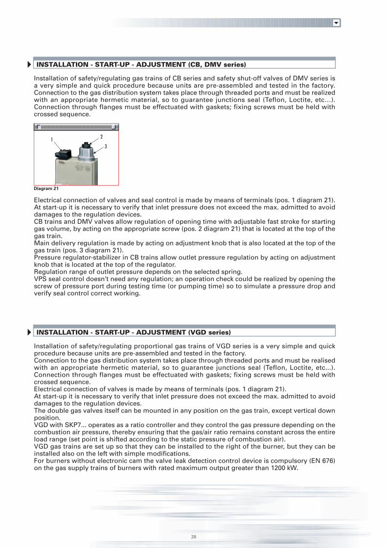
Installation of safety/regulating gas trains of CB series and safety shut-off valves of DMV series isa very simple and quick procedure because units are pre-assembled and tested in the factory.Connection to the gas distribution system takes place through threaded ports and must be realizedwith an appropriate hermetic material, so to guarantee junctions seal (Teflon, Loctite, etc…).Connection through flanges must be effectuated with gaskets; fixing screws must be held withcrossed sequence.
Electrical connection of valves and seal control is made by means of terminals (pos. 1 diagram 21).At start-up it is necessary to verify that inlet pressure does not exceed the max. admitted to avoiddamages to the regulation devices.CB trains and DMV valves allow regulation of opening time with adjustable fast stroke for startinggas volume, by acting on the appropriate screw (pos. 2 diagram 21) that is located at the top of thegas train.Main delivery regulation is made by acting on adjustment knob that is also located at the top of thegas train (pos. 3 diagram 21).Pressure regulator-stabilizer in CB trains allow outlet pressure regulation by acting on adjustmentknob that is located at the top of the regulator.Regulation range of outlet pressure depends on the selected spring.VPS seal control doesn’t need any regulation; an operation check could be realized by opening thescrew of pressure port during testing time (or pumping time) so to simulate a pressure drop andverify seal control correct working.
INSTALLATION - START-UP - ADJUSTMENT (CB, DMV series)
Installation of safety/regulating proportional gas trains of VGD series is a very simple and quickprocedure because units are pre-assembled and tested in the factory.Connection to the gas distribution system takes place through threaded ports and must be realisedwith an appropriate hermetic material, so to guarantee junctions seal (Teflon, Loctite, etc...).Connection through flanges must be effectuated with gaskets; fixing screws must be held withcrossed sequence.Electrical connection of valves is made by means of terminals (pos. 1 diagram 21).At start-up it is necessary to verify that inlet pressure does not exceed the max. admitted to avoiddamages to the regulation devices.The double gas valves itself can be mounted in any position on the gas train, except vertical downposition.VGD with SKP7... operates as a ratio controller and they control the gas pressure depending on thecombustion air pressure, thereby ensuring that the gas/air ratio remains constant across the entireload range (set point is shifted according to the static pressure of combustion air).VGD gas trains are set up so that they can be installed to the right of the burner, but they can beinstalled also on the left with simple modifications.For burners without electronic cam the valve leak detection control device is compulsory (EN 676)on the gas supply trains of burners with rated maximum output greater than 1200 kW.
INSTALLATION - START-UP - ADJUSTMENT (VGD series)
28
Diagram 21
2
31

OVERALL DIMENSIONS (mm)
MBC SERIES SAFETY / REGULATING GAS TRAINS
Example of gas train “COMPOSED” type without seal control
Example of gas train “MULTIBLOC” type without seal control
29
C
BA
ØoutØin
Model A B C Ø IN Ø OUTCB 40/1 891 195 261 Rp 1 1/2 R 1 1/2CB 50/1 986 250 328 Rp 2 R 2CBF 65/1 874 285 356 DN 65 DN 65CBF 80/1 934 285 416 DN 80 DN 80CBF 100/1 1054 350 501 DN 100 DN 100
CBF 125/1 1164 400 780 DN 125 DN 125CB 50/1 CT 986 250 328 Rp 2 R 2CBF 65/1 CT 874 285 356 DN 65 DN 65CBF 80/1 CT 934 285 416 DN 80 DN 80CBF 100/1 CT 1054 350 501 DN 100 DN 100CBF 125/1 CT 1164 400 780 DN 125 DN 125
CB SERIES SAFETY/REGULATING GAS TRAINS
Model A B C Ø IN Ø OUTMBC 1200 SE 50 573 425 161 2” 2”MBC 1900 SE 65 583 430 237 DN 65 DN 65MBC 3100 SE 80 633 500 240 DN 80 DN 80MBC 5000 SE 100 733 576 350 DN 100 DN 100MBC 1200 SE 50 CT 573 425 290 2” 2”MBC 1900 SE 65 CT 583 430 300 DN 65 DN 65MBC 3100 SE 80 CT 633 500 320 DN 80 DN 80MBC 5000 SE 100 CT 733 576 350 DN 100 DN 100
CA
B
Øin
Øout
CA
Øin
ØoutB
X
Z
Y
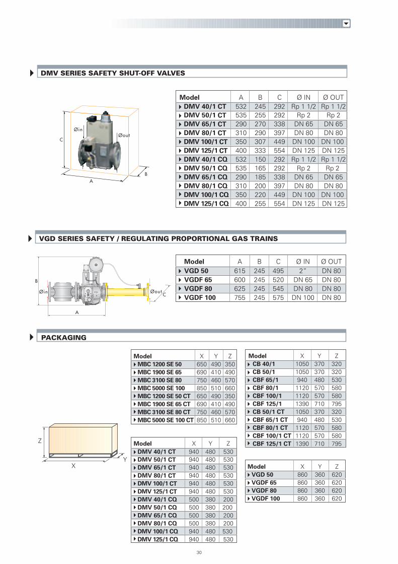
VGD SERIES SAFETY / REGULATING PROPORTIONAL GAS TRAINS
C
BA
30
PACKAGING
ØoutØin
Model A B C Ø IN Ø OUTDMV 40/1 CT 532 245 292 Rp 1 1/2 Rp 1 1/2DMV 50/1 CT 535 255 292 Rp 2 Rp 2DMV 65/1 CT 290 270 338 DN 65 DN 65DMV 80/1 CT 310 290 397 DN 80 DN 80DMV 100/1 CT 350 307 449 DN 100 DN 100
DMV 125/1 CT 400 333 554 DN 125 DN 125DMV 40/1 CQ 532 150 292 Rp 1 1/2 Rp 1 1/2DMV 50/1 CQ 535 165 292 Rp 2 Rp 2DMV 65/1 CQ 290 185 338 DN 65 DN 65DMV 80/1 CQ 310 200 397 DN 80 DN 80DMV 100/1 CQ 350 220 449 DN 100 DN 100DMV 125/1 CQ 400 255 554 DN 125 DN 125
DMV SERIES SAFETY SHUT-OFF VALVES
Model X Y ZCB 40/1 1050 370 320CB 50/1 1050 370 320CBF 65/1 940 480 530CBF 80/1 1120 570 580CBF 100/1 1120 570 580
CBF 125/1 1390 710 795CB 50/1 CT 1050 370 320CBF 65/1 CT 940 480 530CBF 80/1 CT 1120 570 580CBF 100/1 CT 1120 570 580CBF 125/1 CT 1390 710 795Model X Y Z
DMV 40/1 CT 940 480 530DMV 50/1 CT 940 480 530DMV 65/1 CT 940 480 530DMV 80/1 CT 940 480 530DMV 100/1 CT 940 480 530
DMV 125/1 CT 940 480 530DMV 40/1 CQ 500 380 200DMV 50/1 CQ 500 380 200DMV 65/1 CQ 500 380 200DMV 80/1 CQ 500 380 200DMV 100/1 CQ 940 480 530DMV 125/1 CQ 940 480 530
Model X Y ZMBC 1200 SE 50 650 490 350MBC 1900 SE 65 690 410 490MBC 3100 SE 80 750 460 570MBC 5000 SE 100 850 510 660MBC 1200 SE 50 CT 650 490 350MBC 1900 SE 65 CT 690 410 490MBC 3100 SE 80 CT 750 460 570MBC 5000 SE 100 CT 850 510 660
Model X Y ZVGD 50 860 360 620VGDF 65 860 360 620VGDF 80 860 360 620VGDF 100 860 360 620
Model A B C Ø IN Ø OUTVGD 50 615 245 495 2” DN 80VGDF 65 600 245 520 DN 65 DN 80VGDF 80 625 245 545 DN 80 DN 80VGDF 100 755 245 575 DN 100 DN 80B
Øin Øout
B
C
A
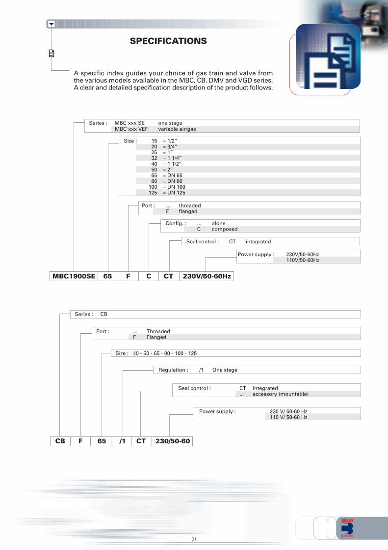
SPECIFICATIONS
A specific index guides your choice of gas train and valve fromthe various models available in the MBC, CB, DMV and VGD series.A clear and detailed specification description of the product follows.
Size : 40 - 50 - 65 - 80 - 100 - 125
Port : ... ThreadedF Flanged
CB F 65 /M 230/50-60
Regulation : /1 One stage
Seal control : CT integrated... accessory (mountable)
Power supply : 230 V/ 50-60 Hz110 V/ 50-60 Hz
CT
Series : CB
/1
Port : ... threadedF flanged
MBC1900SE 65 F /M 230V/50-60Hz
Seal control : CT integrated
Power supply : 230V/50-60Hz110V/50-60Hz
CT
Series : MBC xxx SE one stageMBC xxx VEF variable air/gas
C
Config. : ... aloneC composed
Size : 15 = 1/2”20 = 3/4”25 = 1”32 = 1 1/4”40 = 1 1/2”50 = 2”65 = DN 6580 = DN 80
100 = DN 100125 = DN 125
31
Size : 40 - 50 - 65 - 80 - 100 - 125
Port : ... ThreadedF Flanged
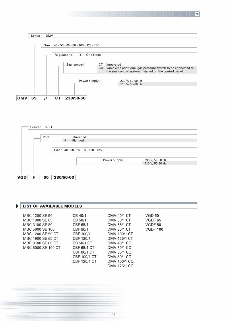
VGD F 65 /M230/50-60
Power supply : 230 V/ 50-60 Hz110 V/ 50-60 Hz
Series : VGD
32
Seal control : CT integratedCQ Valve with additional gas pressure switch to be connected to
the seal control system installed on the control panel
Size : 40 - 50 - 65 - 80 - 100 - 125 - 150
DMV 65 230/50-60
Regulation : /1 One stage
Power supply : 230 V/ 50-60 Hz110 V/ 50-60 Hz
CT
Series : DMV
/1
LIST OF AVAILABLE MODELS
CB 40/1CB 50/1CBF 65/1CBF 80/1CBF 100/1CBF 125/1CB 50/1 CTCBF 65/1 CTCBF 80/1 CTCBF 100/1 CTCBF 125/1 CT
DMV 40/1 CTDMV 50/1 CTDMV 65/1 CTDMV 80/1 CTDMV 100/1 CTDMV 125/1 CTDMV 40/1 CQDMV 50/1 CQDMV 65/1 CQDMV 80/1 CQDMV 100/1 CQDMV 125/1 CQ
MBC 1200 SE 50MBC 1900 SE 65MBC 3100 SE 80MBC 5000 SE 100MBC 1200 SE 50 CTMBC 1900 SE 65 CTMBC 3100 SE 80 CTMBC 5000 SE 100 CT
VGD 50VGDF 65VGDF 80VGDF 100
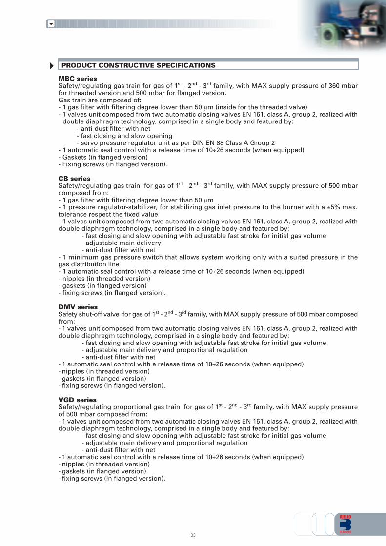
PRODUCT CONSTRUCTIVE SPECIFICATIONS
MBC seriesSafety/regulating gas train for gas of 1st - 2nd - 3rd family, with MAX supply pressure of 360 mbarfor threaded version and 500 mbar for flanged version.Gas train are composed of:- 1 gas filter with filtering degree lower than 50 µm (inside for the threaded valve)- 1 valves unit composed from two automatic closing valves EN 161, class A, group 2, realized with
double diaphragm technology, comprised in a single body and featured by:- anti-dust filter with net- fast closing and slow opening- servo pressure regulator unit as per DIN EN 88 Class A Group 2
- 1 automatic seal control with a release time of 10÷26 seconds (when equipped)- Gaskets (in flanged version)- Fixing screws (in flanged version).
CB seriesSafety/regulating gas train for gas of 1st - 2nd - 3rd family, with MAX supply pressure of 500 mbarcomposed from:- 1 gas filter with filtering degree lower than 50 µm- 1 pressure regulator-stabilizer, for stabilizing gas inlet pressure to the burner with a ±5% max.tolerance respect the fixed value- 1 valves unit composed from two automatic closing valves EN 161, class A, group 2, realized withdouble diaphragm technology, comprised in a single body and featured by:
- fast closing and slow opening with adjustable fast stroke for initial gas volume- adjustable main delivery- anti-dust filter with net
- 1 minimum gas pressure switch that allows system working only with a suited pressure in thegas distribution line- 1 automatic seal control with a release time of 10÷26 seconds (when equipped)- nipples (in threaded version)- gaskets (in flanged version)- fixing screws (in flanged version).
DMV seriesSafety shut-off valve for gas of 1st - 2nd - 3rd family, with MAX supply pressure of 500 mbar composedfrom:- 1 valves unit composed from two automatic closing valves EN 161, class A, group 2, realized withdouble diaphragm technology, comprised in a single body and featured by:
- fast closing and slow opening with adjustable fast stroke for initial gas volume- adjustable main delivery and proportional regulation- anti-dust filter with net
- 1 automatic seal control with a release time of 10÷26 seconds (when equipped)- nipples (in threaded version)- gaskets (in flanged version)- fixing screws (in flanged version).
VGD seriesSafety/regulating proportional gas train for gas of 1st - 2nd - 3rd family, with MAX supply pressureof 500 mbar composed from:- 1 valves unit composed from two automatic closing valves EN 161, class A, group 2, realized withdouble diaphragm technology, comprised in a single body and featured by:
- fast closing and slow opening with adjustable fast stroke for initial gas volume- adjustable main delivery and proportional regulation- anti-dust filter with net
- 1 automatic seal control with a release time of 10÷26 seconds (when equipped)- nipples (in threaded version)- gaskets (in flanged version)- fixing screws (in flanged version).
33
34
Standard equipment:- instruction handbook for installation, use and maintenance- gaskets (in flanged version)- fixing screws (in flanged version)- electrical connection terminals.
Available accessories to be ordered separately (see accessories section):- spring for pressure regulator- manual shut-off valve (ball valve from 3/4” to 2”, from DN65 to DN150)- anti-vibrating joint (from 3/4” to 2”, from DN65 to DN150)- filter (1”1/2, 2”, DN65, DN100, DN125)- pressure regulator (1”1/2, 2”, DN65, DN100, DN125)- pressure gauge kit with push-button (for pressure of 60, 150, 300, 500 mbar, 1-4 bar)- connection adaptor- gas pressure switch for seal control- seal control kit
STATE OF SUPPLY
Safety/regulating gas trains of MBC - CB - VGD series and safety shut-off valves of DMV series aresupplied pre-assembled and tested in the factory, packaged in carton boxes or wood cases.
The supply includes:- gas train or safety shut-off valve- seal control pre-assembled (when equipped)- instruction handbook for installation, use and maintenance- gaskets (in flanged version)- fixing screws (in flanged version)- electrical connection terminals
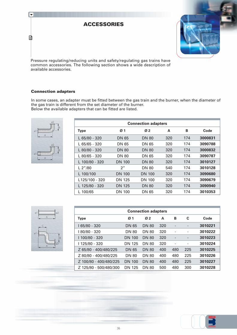
Pressure regulating/reducing units and safety/regulating gas trains havecommon accessories. The following section shows a wide description ofavailable accessories.
ACCESSORIES
35
Connection adapters
L 65/80 - 320
L 65/65 - 320
L 80/80 - 320
L 80/65 - 320
L 100/80 - 320
L 2”/80
L 100/100
L125/100 - 320
L 125/80 - 320
L 100/65
Type Code
3000831
3090788
3000832
3090787
3010127
3010128
3090680
3090679
3090940
3010353
B
174
174
174
174
174
174
174
174
174
174
A
320
320
320
320
320
540
320
320
320
320
Ø 2
DN 80
DN 65
DN 80
DN 65
DN 80
DN 80
DN 100
DN 100
DN 80
DN 65
DN 65
DN 65
DN 80
DN 80
DN 100
2”
DN 100
DN 125
DN 125
DN 100
Ø 1
A
B
ø2
ø1
A
B
ø2
ø1
Connection adapters
I 65/80 - 320
I 80/80 - 320
I 100/80 - 320
I 125/80 - 320
Z 65/80 - 400/480/225
Z 80/80 - 400/480/225
Z 100/80 - 400/480/225
Z 125/80 - 500/480/300
Type Code
3010221
3010222
3010223
3010224
3010225
3010226
3010227
3010228
BAØ 2Ø 1 C
-
-
-
-
480
480
480
480
320
320
320
320
400
400
400
500
DN 80
DN 80
DN 80
DN 80
DN 80
DN 80
DN 80
DN 80
DN 65
DN 80
DN 100
DN 125
DN 65
DN 80
DN 100
DN 125
-
-
-
-
225
225
225
300
ø2
ø1
C
B
A
ø2ø1
A
Connection adapters
In some cases, an adapter must be fitted between the gas train and the burner, when the diameter ofthe gas train is different from the set diameter of the burner.Below the available adapters that can be fitted are listed.
36
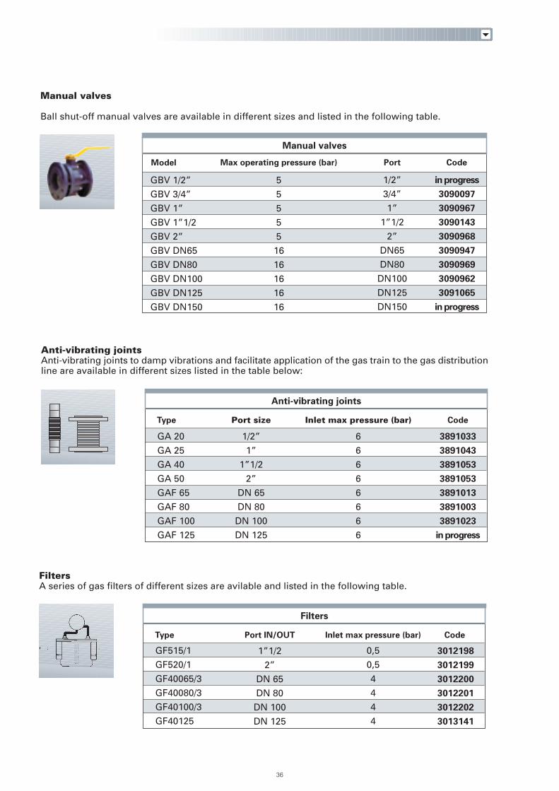
Anti-vibrating jointsAnti-vibrating joints to damp vibrations and facilitate application of the gas train to the gas distributionline are available in different sizes listed in the table below:
Anti-vibrating joints
GA 20
GA 25
GA 40
GA 50
GAF 65
GAF 80
GAF 100
GAF 125
Type Code
3891033
3891043
3891053
3891053
3891013
3891003
3891023
in progress
1/2”
1”
1”1/2
2”
DN 65
DN 80
DN 100
DN 125
Port size
6
6
6
6
6
6
6
6
Inlet max pressure (bar)
3010221
3010222
3010223
3010224
3010225
3010226
3010227
3010228
174174174174174174174174
174174174174174174174174
Manual valves
Max operating pressure (bar) CodePort
GBV 1/2”
GBV 3/4”
GBV 1”
GBV 1”1/2
GBV 2”
GBV DN65
GBV DN80
GBV DN100
GBV DN125
GBV DN150
Model
1/2”
3/4”
1”
1”1/2
2”
DN65
DN80
DN100
DN125
DN150
5
5
5
5
5
16
16
16
16
16
in progress
3090097
3090967
3090143
3090968
3090947
3090969
3090962
3091065
in progress
Manual valves
Ball shut-off manual valves are available in different sizes and listed in the following table.
Filters
Type Code
FiltersA series of gas filters of different sizes are avilable and listed in the following table.
Port IN/OUT Inlet max pressure (bar)
3012198
3012199
3012200
3012201
3012202
3013141
1”1/2
2”
DN 65
DN 80
DN 100
DN 125
GF515/1
GF520/1
GF40065/3
GF40080/3
GF40100/3
GF40125
0,5
0,5
4
4
4
4
37
CodeGas train
3010123
3010125
3010367
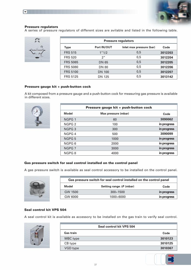
Seal control kit VPS 504
A seal control kit is available as accessory to be installed on the gas train to verify seal control.
Seal control kit VPS 504
MBC type
CB type
VGD type
Pressure regulators
Type Code
Pressure regulatorsA series of pressure regulators of different sizes are avilable and listed in the following table.
Port IN/OUT Inlet max pressure (bar)
1”1/2
2”
DN 65
DN 80
DN 100
DN 125
3012203
3012204
3012205
3012206
3012207
3013142
FRS 515
FRS 520
FRS 5065
FRS 5080
FRS 5100
FRS 5125
0,5
0,5
0,5
0,5
0,5
0,5
Pressure gauge kit + push-button cock
A kit composed from a pressure gauge and a push-button cock for measuring gas pressure is availablein different sizes.
Pressure gauge kit + push-button cock
CodeModel Max pressure (mbar)
NGPG 1
NGPG 2
NGPG 3
NGPG 4
NGPG 5
NGPG 6
NGPG 7
NGPG 8
60
100
300
500
1000
2000
3000
4000
3090062
in progress
in progress
3090099
in progress
in progress
in progress
in progress
Gas pressure switch for seal control installed on the control panel
A gas pressure switch is available as seal control accessory to be installed on the control panel.
CodeModel Setting range ∆P (mbar)
in progress
in progress
Gas pressure switch for seal control installed on the control panel
GW 1500
GW 6000
300÷1500
1000÷6000
38
Springs for pressure regulators CB and LPRT series
CB 40
CB 40
CB 40
CB 40
CB 50
CB 50
CB 50
CB 50
CBF 65/80
CBF 65/80
CBF 65/80
CBF 65/80
CBF 65/80
CBF 100
CBF 100
CBF 100
CBF 100
CBF 100
CBF 125
CBF 125
CBF 125
CBF 125
Type Code
3010131
3010157
3090486
3010132
3010158
3090487
3010133
3010135
3090456
3010134
3010136
3090489
3010381
3010382
3010383
3010384
LPRT 40
LPRT 40
LPRT 40
LPRT 40
LPRT 80
LPRT 80
LPRT 80
LPRT 80
LPRT 160
LPRT 160
LPRT 160
LPRT 160
LPRT 250
LPRT 250
LPRT 250
LPRT 250
LPRT 500/750
LPRT 500/750
LPRT 500/750
LPRT 500/750
LPRT 500/750
LPRT 1000
LPRT 1000
LPRT 1000
LPRT 1000
LPRT 1000
LPRT 1500
LPRT 1500
LPRT 1500
LPRT 1500
LPRT 2000
LPRT 2000
LPRT 2000
LPRT 2000
MBC series
MBC series
MBC series
MBC series
Type Port
Rp 3/4”
Rp 3/4”
Rp 3/4”
Rp 3/4”
Rp 1”
Rp 1”
Rp 1”
Rp 1”
Rp 1”1/2
Rp 1”1/2
Rp 1”1/2
Rp 1”1/2
Rp 2”
Rp 2”
Rp 2”
Rp 2”
DN 65/80
DN 65/80
DN 65/80
DN 65/80
DN 65/80
DN 100
DN 100
DN 100
DN 100
DN 100
DN 125
DN 125
DN 125
DN 125
DN 150
DN 150
DN 150
DN 150
DN 68÷100
DN 68÷100
DN 68÷100
DN 68÷100
Outletpressure [mbar]
25÷55
30÷70
60÷110
90÷150
25÷55
30÷70
60÷110
90÷150
25÷55
30÷70
60÷110
90÷150
25÷55
30÷70
60÷110
90÷150
25÷55
30÷70
60÷110
90÷150
140÷200
25÷55
30÷70
60÷110
90÷150
140÷200
25÷55
30÷70
60÷110
90÷150
25÷55
30÷70
60÷110
90÷150
0÷20
20÷40
40÷80
80÷150
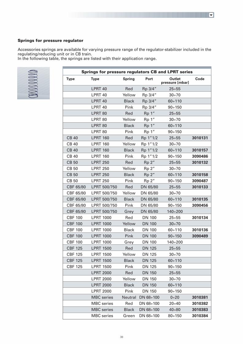
Springs for pressure regulator
Accessories springs are available for varying pressure range of the regulator-stabilizer included in theregulating/reducing unit or in CB train.In the following table, the springs are listed with their application range.
Spring
Red
Yellow
Black
Pink
Red
Yellow
Black
Pink
Red
Yellow
Black
Pink
Red
Yellow
Black
Pink
Red
Yellow
Black
Pink
Grey
Red
Yellow
Black
Pink
Grey
Red
Yellow
Black
Pink
Red
Yellow
Black
Pink
Neutral
Red
Black
Green

39

ISO 9001 Cert. n. 0061
RIELLO S.p.A. - Via Ing. Pilade Riello, 5 - 37048 San Pietro di Legnago (VR) ItalyTel. ++39.0442630111 - Fax ++39.044221980
Internet: http://www.rielloburners.com - E-mail: [email protected]
Since the Company is constantly engaged in the production improvement, the aesthetic anddimensional features, the technical data, the equipment and the accessories can be changed.
This document contains confidential and proprietary information of RIELLO S.p.A.Unless authorised, this information shall not be divulged, nor duplicated in whole or in part.


