Embed Size (px)
Citation preview


2
Special Servicing Note
If the instrument needs to be serviced, contact either: The RAE Systems distributor from whom the instrument was purchased; they will return the instrument on your behalf.
or
The RAE Systems Technical Service Department. Before returning the instrument for service or repair, obtain a Returned
Material Authorization (RMA) number for proper tracking of your equipment. This number needs to be on all documentation
and posted on the outside of the box in which the instrument is returned for service or upgrade. Packages without RMA Numbers will be refused at the factory.
© Copyright 2014 RAE Systems by Honeywell.

Contents
WARNINGS............................................................................... 2
1 General Information ............................................................ 3 2 Purpose Of This Guide ........................................................ 4
3 Proper Product Disposal At End Of Life............................. 4 4 FCC Part 15 Statement ........................................................ 4 5 Flexible Configurations ....................................................... 5
6 RAEPoint DC-Powered Wireless Alarm Bar Mounting ..... 6 6.1 Drilling Chart & Dimensions ................................ 7
6.2 DC-Powered Wireless Alarm Bar Wiring ............. 8 6.2.1 Complete RAEPoint DC-Powered Wireless Alarm Bar Wiring Diagram ............................... 9
6.2.2 Opening The Horn ........................................... 11 6.2.3 Connecting Power Wiring ............................... 12
6.2.4 Internal Grounding .......................................... 13 6.2.5 Reassembly ...................................................... 14 6.2.6 External Grounding ......................................... 14
7 Powering And Programming ............................................. 14 7.1 RAEPoint DC-Powered Wireless Alarm Bar
Individual Component Specifications ................. 15 8 Replacement parts ............................................................. 17 9 Technical Support...............Error! Bookmark not defined.
10 RAE Systems Contacts ............................................... 19

1
IMPORTANT!
Read Before Installing
This Installation Guide is for wiring and installation of the DC-Powered Alarm Bar only. It must be used in conjunction with the RAEPoint User’s Guide for
safe calibration and operation. The RAEPoint User’s Guide is available at www.raesystems.com.

2
Read Before Operating
This manual must be carefully read by all individuals who have or will have the responsibility of using, maintaining,
or servicing this product. The product will perform as designed only if it is used, maintained, and serviced in accordance with the manufacturer’s instructions. The user
should understand how to set the correct parameters and interpret the obtained results.
CAUTION! To reduce the risk of electric shock, turn the power off
before opening this instrument or performing service. Never operate the instrument when the instrument is
open. Use and service this product only in an area known to be non-hazardous.
WARNINGS For safety reasons, this equipment must be operated and serviced by qualified personnel only. Read and
understand instruction manual completely before operating or servicing.
AVERTISSEMENT
Pour des raisons de sécurité, cet équipment doit être
utilisé, entretenu et réparé uniquement par un personnel qualifié. Étudier le manuel d’instructions en entier avant d’utiliser, d’entretenir ou de réparer l’équipement.

3
1 General Information As part of a wireless mesh network, the RAEPoint DC-Powered Wireless Alarm Bar communicates with wireless detectors and controllers and can direct any of its five internal relays to trigger audible and visible alarms. Remote alarm notifications are critical for many applications where local device alarms are simply not visible enough or loud enough to alert a wide area. RAEPoint relay settings can be fully configured wirelessly via the system controller. RAEPoint can also be configured as a wireless host, and communicate directly with detectors, providing a localized alarm notification solution that does not require a controller. The RAEPoint DC-Powered Wireless Alarm Bar is suitable for use in ATEX Zone 1 hazardous area locations.
Key Features
Mounted and pre-wired with two 5J xenon lights and a 110dB horn.
Five internal SPDT relays Wireless transmission distance of 1000 ft (300m), line of
sight. Range can be extended by using wireless routers. Suitable for use in ATEX Zone 1 hazardous locations Explosion-proof enclosure for hazardous environment
applications LEDs indicate status
Applications
Oil and gas exploration Refineries and petrochemical plants Fenceline monitoring

4
2 Purpose Of This Guide This guide is designed to provide information on installing and wiring the RAEPoint DC-Powered Wireless Alarm Bar. Refer to the RAEPoint User’s Guide for
testing and operation information (all functions of the RAEPoint DC-Powered Wireless Alarm Bar are
controlled through the RAEPoint that is integrated with the horn and strobe lights).
3 Proper Product Disposal At End Of Life
The Waste Electrical and Electronic Equipment (WEEE) directive (2002/96/EC) is intended to promote recycling of electrical and electronic equipment and their components at end of life. This symbol (crossed-out wheeled bin) indicates separate collection of waste electrical and electronic equipment in the EU countries.
4 FCC Part 15 Statement This device complies with Part15 of the FCC rules. Operation is subject to the following two conditions: (1) This device may not cause harmful interference, and (2) this device must accept any interference received, including interference that may cause undesired operation.

5
5 Flexible Configurations RAEPoint, including the RAEPoint DC-Powered Wireless Alarm Bar, can be configured for large or small systems, and the network can be expanded or units removed, depending on the facility or facilities being monitored. Simple configuration that uses MeshGuard sensors and a RAEPoint DC-Powered Wireless Alarm Bar host

6
Large network, including externally controlled devices
6 RAEPoint DC-Powered Wireless Alarm Bar Mounting Make sure that there is approximately 12" (30 cm) of clearance on all sides of the RAEPoint DC-Powered
Wireless Alarm Bar so that the horn’s sound is not attenuated and to ensure clear view of the two visible
alarm lights.

7
6.1 Drilling Chart & Dimensions When mounting the RAEPoint on a wall, make sure to
use heavy-duty steel screws spaced as indicated below.
Follow these steps:
1. Locate the RAEPoint DC-Powered Wireless Alarm Bar on a wall or other flat surface and mark the six
holes’ locations. 2. Remove the RAEPoint DC-Powered Wireless Alarm
Bar. 3. Drill the six holes. 4. Hold the RAEPoint DC-Powered Wireless Alarm Bar
firmly against the wall and insert and tighten the screws.
The RAEPoint DC-Powered Wireless Alarm Bar is now ready for electrical wiring and testing.

8
6.2 DC-Powered Wireless Alarm Bar Wiring The RAEPoint DC-Powered Wireless Alarm Bar already has most wiring done at the factory. It is only necessary to connect the positive and negative DC power supply wires and grounding (according to local requirements). Power and internal grounding wires must be fed through a connector at the bottom of the unit.
Note: Ensure that only the correct listed or certified cable glands (not included) are used and that the assembly is
correctly grounded (earthed). All cable glands should be of an equivalent IP rating to that of the unit and integrated with the unit so that this rating is maintained.
IMPORTANT!
Prior to factory shipment, the RAEPoint is tested. However, the instrument should be tested after installation.
Wires must be fed in through an M25 threaded insert
(ATEX)

9
6.2.1 Complete RAEPoint DC-Powered Wireless Alarm Bar Wiring Diagram The diagram on the next page shows how the RAEPoint
DC-Powered Wireless Alarm Bar is wired.
Refer to the diagram on page 12 for power connections.

10

11
6.2.2 Opening The Horn You must remove the cover assembly from the front of the horn in order to connect wires to the terminal block.
Unscrew the four M6 screws (5.0mm hex key) holding
the cover assembly to the base. Keep these screws in a safe, accessible place; they are not retained in the cover.
Before lifting the cover, gently twist the cover assembly clockwise and then counterclockwise to break the seal.
Continue to gently twist the cover clockwise and counter-clockwise while gently lifting the cover assembly away from
the base of the enclosure to gain access to the interior.
Note: The cover assembly is connected to the cover by a nylon restraining strap.

12
6.2.3 Connecting Power Wiring This diagram shows the factory wiring for DC power to the RAEPoint DC-Powered Wireless Alarm Bar. The
internal ground point is also shown:
Note: This diagram only shows the connection points for external power and ground. For clarity, other wires for the RAEPoint DC-Powered Wireless Alarm Bar are not
shown. Refer to the schematic drawing on page 6.2.19 for comprehensive wiring.
Other wires are connected to the RAEPoint and the rest of the Wireless Alarm Bar. Do not alter them or their
connections.
V+
V–
Ground

13
6.2.4 Internal Grounding If internal grounding is required, connect the ground wire’s connector to the location shown in the wiring
diagram, and tighten it down using the nut and washer:

14
6.2.5 Reassembly Once wiring is completed, ensure that the mating surfaces of both the cover and body are well covered with a
suitable anti-seize compound. Carefully lower the cover assembly back onto the base, avoiding damage to the
mating surfaces, ensuring the O-ring is correctly seated in its groove during reassembly. Replace the four M6 screws into the holes in the cover assembly and tighten evenly.
Ensure the required gap (0.2mm maximum) is maintained between the cover and the base.
6.2.6 External Grounding If external or redundant grounding is required, a lug is
located on each light and the horn. There are also two points on the exterior of the RAEPoint. Screw the ground
wire’s connector onto the lug and run it to the appropriate grounding location.
7 Powering And Programming Refer to the RAEPoint User’s Guide for information on how to power, test, and program the RAEPoint. The horn and lights are prewired, so all operations are controlled by
the RAEPoint.
Ground
Lug Ground wire

15
7.1 RAEPoint DC-Powered Wireless Alarm Bar Individual Component Specifications The RAEPoint DC-Powered Wireless Alarm Bar includes the RAEPoint, as specified in the RAEPoint User’s
Guide, plus two strobe lights and a horn, as detailed below:
Alarm Bar
Input Voltage 24 VDC
Peak Current
Consumption
1.5A @ 24 VDC
IP Rating IP-65
Back Plate Material 316 stainless steel
Dimensions 27-11/64" (690 mm) x 9" (229 mm) x 9.5" (241
mm)
Weight 31 lbs (14 kg)
5-Joule Xenon Strobes (Each)
Peak Intensity Yellow: 19,103 Cd
2,665 Cd (Blue)
Material LM25 TF Marine-Grade Alloy
Horn
Peak Decibels 110 dBA at 10 feet (3.05m)
Material LM25 TF Marine-Grade Alloy with ABS Flare
Specifications subject to change
16
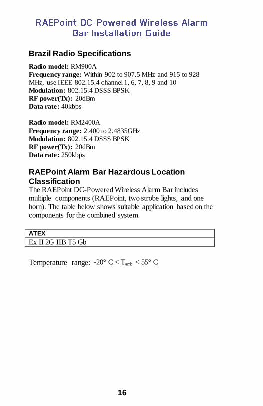
Brazil Radio Specifications
Radio model: RM900A
Frequency range: Within 902 to 907.5 MHz and 915 to 928
MHz, use IEEE 802.15.4 channel 1, 6, 7, 8, 9 and 10
Modulation: 802.15.4 DSSS BPSK
RF power(Tx): 20dBm
Data rate: 40kbps
Radio model: RM2400A
Frequency range: 2.400 to 2.4835GHz
Modulation: 802.15.4 DSSS BPSK
RF power(Tx): 20dBm
Data rate: 250kbps RAEPoint Alarm Bar Hazardous Location
Classification The RAEPoint DC-Powered Wireless Alarm Bar includes multiple components (RAEPoint, two strobe lights, and one horn). The table below shows suitable application based on the components for the combined system.
Temperature range: -20° C < Tamb < 55° C
ATEX
Ex II 2G IIB T5 Gb

17
8 Replacement parts Refer to next page for part numbers and descriptions.
5
4
1
3
2
SM87HXBA Lights
DB1 Horn

18
Part Numbers and Descriptions
Item Number
RAE Systems Part Number
RAE Systems Description
Component Quan-tity
Compo-nent unit of mea-sure
1 F08- 2101-000
TOP HORN FLARE, DB1 HORN, AC/DC WIRELESS ALARM BAR
1 Ea.
2 F08- 2102-000
FLARE SCREW (RED), DB1 HORN (PACK OF 3),AC/DC WIRELESS ALARM BAR
3 Pack
3 F08- 2103-000
O-RING, DB1 HORN, AC/DC WIRELESS ALARM BAR
1 Ea.
F08- 2104-000
PC BOARD, DB1 HORN, AC/DC WIRE-LESS ALARM BAR
1 Ea.
4 F08- 2114-000
YELLOW LENS AND LENS GUARD W/O-RING, SM87HXBA, DC WIRELESS ALARM BAR
1 Ea.
4 F08- 2115-000
BLUE LENS AND LENS GUARD W/O-RING, SM87HXBA, DC WIRELESS ALARM BAR
1 Ea.
4 F08- 2116-000
RED LENS AND LENS GUARD W/O-RING, SM87HXBA, DC WIRELESS ALARM BAR
1 Ea.
4 F08- 2117-000
GREEN LENS AND LENS GUARD W/O-RING, SM87HXBA, DC WIRELESS ALARM BAR
1 Ea.
5 F08- 2118-000
XENON STROBE BULB, SM87HXB, DC WIRELESS ALARM BAR
1 Ea.

19
9 Technical Support To contact RAE Systems Technical Support:
Monday through Friday, 7:00AM to 5:00PM Pacific (US) Time
Phone (toll-free): +1 888-723-4800 Phone: +1 408-952-8461 Email: [email protected]
10 RAE Systems Contacts
RAE Systems by Honeywell
World Headquarters
3775 N. First St. San Jose, CA 95134-1708 USA Phone: +1 408.952.8200
Fax: +1 408.952.8480 E-mail: [email protected]
Web: www.raesystems.com RAE Systems Technical Support
Monday through Friday, 7:00AM to 5:00PM Pacific Time Phone: +1.408.952.8461
Email: [email protected]

20
EMEAI Headquarters
Life Safety Distribution AG Javastrasse 2
8604 Hegnau, Switzerland Phone: +41 (0)44 943 4300
Fax: +41 (0)44 943 4398 Email: [email protected]
RAE Systems France ZI des Ayats
679390 MILLERY France Phone: +33 4 78 46 16 65
Fax: +33 4 78 46 25 98 Phone: +33 4 78 46 16 65
Fax: +33 4 78 46 25 98 Email: [email protected] Web: www.raesystems.fr
RAE BeNeLux BV
Rijndal 20 2904 DC Capelle a/d Ijssel Netherlands
Phone: +31 10 4426149 Fax: +31 10 4426148
Email: [email protected] Web: www.rae.nl
RAE Systems Spain, s.l. Av. Remolar, 31
08820 El Prat de Llobregat Spain Phone: +34 933 788 352
Fax: +34 933 788 353 Email: [email protected]
Web: www.raespain.com

21
RAE Systems (Hong Kong) Ltd.
Room 8, 6/F, Hong Leong Plaza 33 Lok Yip Road
Fanling, N.T, Hong Kong Phone: +852.2669.0828
Fax: +852.2669.0803 Email: [email protected]
RAE Systems Japan
Marunouchi Nakadori Bldg 6F-617-B, 2-3, Marunouchi 2-Chome, Chiyoda-ku,
Tokyo, 100-0005 Japan Phone: +81-3-6269-9646
Fax: +81-3-6269-9647 Email: [email protected]
RAE Systems Korea #1010, DaeMyungAnsVill First,
Sang-Dong 412-2, Wonmi-Gu, Bucheon, Kyungki-Do, Korea Phone: 82-32-328-7123
Fax: 82-32-328-7127 Email: [email protected]


