Embed Size (px)
Citation preview
Quick setup guideRadar sensor for continuous level measurement of liquids
VEGAPULS 64Two-wire 4 … 20 mA/HART
Document ID: 51462
2
Contents
VEGAPULS 64 • Two-wire 4 … 20 mA/HART
51462-EN-210621
Contents1 For your safety ......................................................................................................................... 3
1.1 Authorised personnel ....................................................................................................... 31.2 Appropriate use ................................................................................................................ 31.3 Warning about incorrect use ............................................................................................. 31.4 General safety instructions ............................................................................................... 31.5 EU conformity ................................................................................................................... 41.6 NAMUR recommendations .............................................................................................. 41.7 Radio license for Europe .................................................................................................. 41.8 Environmental instructions ............................................................................................... 5
2 Product description ................................................................................................................. 62.1 Configuration .................................................................................................................... 6
3 Mounting ................................................................................................................................... 73.1 Mounting preparations, mounting strap ............................................................................ 73.2 Mounting instructions ....................................................................................................... 8
4 Connecting to power supply ................................................................................................. 104.1 Connecting ..................................................................................................................... 104.2 Wiring plan, single chamber housing.............................................................................. 11
5 Set up with the display and adjustment module ................................................................ 125.1 Insert display and adjustment module ............................................................................ 125.2 Parameter adjustment - Quick setup .............................................................................. 135.3 Menu overview ............................................................................................................... 15
6 Set up with smartphone/tablet, PC/notebook via Bluetooth ............................................. 176.1 Preparations ................................................................................................................... 176.2 Connecting ..................................................................................................................... 186.3 Sensor parameter adjustment ........................................................................................ 18
7 Supplement ............................................................................................................................ 207.1 Technical data ................................................................................................................ 20
Information:This quick setup guide enables quick setup and commissioning of your instrument.Youcanfindsupplementaryinformationinthecorresponding,moredetailed Operating Instructions Manual as well as the Safety Manual thatcomeswithinstrumentswithSILqualification.Thesemanualsareavailable on our homepage.
Operating instructions VEGAPULS 64 - Two-wire 4 … 20 mA/HART: Document-ID 51141Editing status of the quick setup guide: 2021-06-10

3
1 For your safety
VEGAPULS 64 • Two-wire 4 … 20 mA/HART
5146
2-EN
-210
621
1 For your safety
1.1 Authorised personnelAll operations described in this documentation must be carried out onlybytrained,qualifiedpersonnelauthorisedbytheplantoperator.During work on and with the device, the required personal protective equipment must always be worn.
1.2 Appropriate useVEGAPULS 64 is a sensor for continuous level measurement. Youcanfinddetailedinformationabouttheareaofapplicationinchapter " Product description". Operational reliability is ensured only if the instrument is properly usedaccordingtothespecificationsintheoperatinginstructionsmanual as well as possible supplementary instructions.
1.3 Warning about incorrect useInappropriate or incorrect use of this product can give rise to applica-tion-specifichazards,e.g.vesseloverfillthroughincorrectmountingor adjustment. Damage to property and persons or environmental contamination can result. Also, the protective characteristics of the instrument can be impaired.
1.4 General safety instructionsThis is a state-of-the-art instrument complying with all prevailing regulations and directives. The instrument must only be operated in a technicallyflawlessandreliablecondition.Theoperatorisresponsi-ble for the trouble-free operation of the instrument. When measuring aggressive or corrosive media that can cause a dangerous situation if the instrument malfunctions, the operator has to implement suitable measures to make sure the instrument is functioning properly.The safety instructions in this operating instructions manual, the na-tional installation standards as well as the valid safety regulations and accident prevention rules must be observed by the user.For safety and warranty reasons, any invasive work on the device beyond that described in the operating instructions manual may be carried out only by personnel authorised by the manufacturer. Arbi-traryconversionsormodificationsareexplicitlyforbidden.Forsafetyreasons,onlytheaccessoryspecifiedbythemanufacturermustbeused.To avoid any danger, the safety approval markings and safety tips on the device must also be observed.The low transmitting power of the radar sensor is far below the inter-nationallyapprovedlimits.Nohealthimpairmentsaretobeexpectedwith intended use. The band range of the measuring frequency can be found in chapter " Technical data".
4
1 For your safety
VEGAPULS 64 • Two-wire 4 … 20 mA/HART
51462-EN-210621
1.5 EU conformityThedevicefulfilsthelegalrequirementsoftheapplicableEUdirec-tives.ByaffixingtheCEmarking,weconfirmtheconformityoftheinstrument with these directives.The EU conformity declaration can be found on our homepage.
1.6 NAMUR recommendationsNAMUR is the automation technology user association in the process industry in Germany. The published NAMUR recommendations are acceptedasthestandardinfieldinstrumentation.ThedevicefulfilstherequirementsofthefollowingNAMURrecom-mendations:
• NE 21 – Electromagnetic compatibility of equipment• NE 43 – Signal level for fault information from measuring transduc-
ers• NE53–Compatibilityoffielddevicesanddisplay/adjustment
components• NE107–Self-monitoringanddiagnosisoffielddevicesFor further information see www.namur.de.
1.7 Radio license for EuropeThe instrument was tested according to the latest issue of the follow-ingharmonizedstandards:
• EN 302372 - Tank Level Probing Radar• EN 302729 - Level Probing Radar
It is hence approved for use inside and outside closed vessels in countries of the EU.Use is also approved in EFTA countries, provided the respective standards have been implemented.Foroperationinsideofclosedvessels,pointsatofinannexEofEN302372mustbefulfilled.For operation outside of closed vessels, the following conditions must befulfilled:
• The instrument must be stationary mounted and the antenna directed vertically downward
• The instrument may only be used outside closed vessels in the version with G1½ or 1½ NPT thread with integrated horn antenna.
• The mounting location must be at least 4 km away from radio astronomy stations, unless special permission was granted by the responsible national approval authority
• When installed within 4 to 40 km of a radio astronomy station, the instrument must not be mounted higher than 15 m above the ground.
A list of the respective radio astronomy stations can be found in chap-ter " Appendix" of the operating instructions.

5
1 For your safety
VEGAPULS 64 • Two-wire 4 … 20 mA/HART
5146
2-EN
-210
621
1.8 Environmental instructionsProtection of the environment is one of our most important duties. That is why we have introduced an environment management system with the goal of continuously improving company environmental pro-tection.Theenvironmentmanagementsystemiscertifiedaccordingto DIN EN ISO 14001.Pleasehelpusfulfilthisobligationbyobservingtheenvironmentalinstructions in this manual:
• Chapter " Packaging, transport and storage" • Chapter " Disposal"
6
2 Product description
VEGAPULS 64 • Two-wire 4 … 20 mA/HART
51462-EN-210621
2 Product description
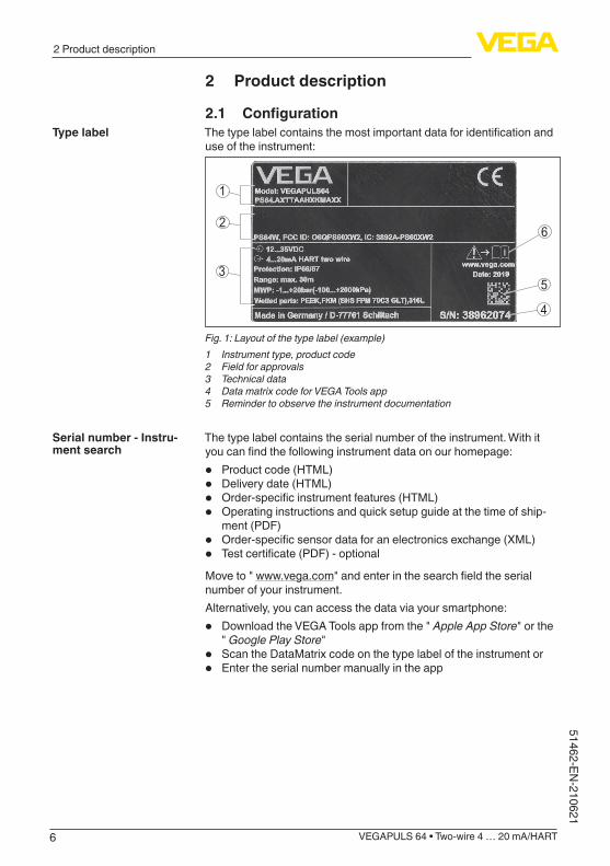
2.1 ConfigurationThetypelabelcontainsthemostimportantdataforidentificationanduse of the instrument:
6
5
4
3
2
1
Fig. 1: Layout of the type label (example)1 Instrument type, product code2 Field for approvals3 Technical data4 Data matrix code for VEGA Tools app5 Reminder to observe the instrument documentation
The type label contains the serial number of the instrument. With it youcanfindthefollowinginstrumentdataonourhomepage:
• Product code (HTML)• Delivery date (HTML)• Order-specificinstrumentfeatures(HTML)• Operating instructions and quick setup guide at the time of ship-
ment (PDF)• Order-specificsensordataforanelectronicsexchange(XML)• Testcertificate(PDF)-optionalMove to " www.vega.com"andenterinthesearchfieldtheserialnumber of your instrument. Alternatively, you can access the data via your smartphone:
• Download the VEGA Tools app from the " Apple App Store" or the " Google Play Store"
• ScantheDataMatrixcodeonthetypelabeloftheinstrumentor• Enter the serial number manually in the app
Type label
Serial number - Instru-ment search
7
3 Mounting
VEGAPULS 64 • Two-wire 4 … 20 mA/HART
5146
2-EN
-210
621
3 Mounting
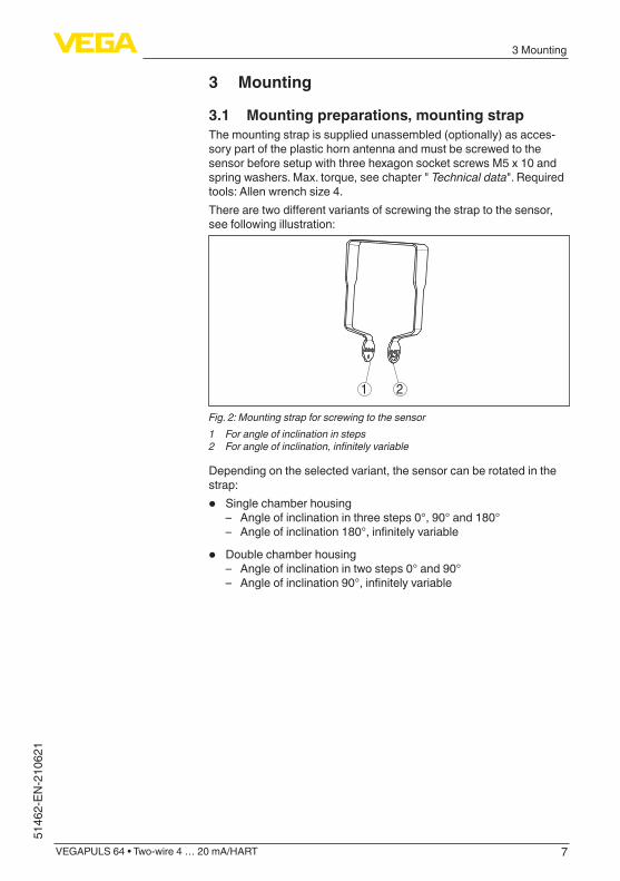
3.1 Mounting preparations, mounting strapThe mounting strap is supplied unassembled (optionally) as acces-sory part of the plastic horn antenna and must be screwed to the sensorbeforesetupwiththreehexagonsocketscrewsM5x10andspringwashers.Max.torque,seechapter"Technical data". Required tools:Allenwrenchsize4.Therearetwodifferentvariantsofscrewingthestraptothesensor,see following illustration:
1 2
Fig. 2: Mounting strap for screwing to the sensor1 For angle of inclination in steps2 Forangleofinclination,infinitelyvariable
Depending on the selected variant, the sensor can be rotated in the strap:
• Single chamber housing – Angle of inclination in three steps 0°, 90° and 180° – Angleofinclination180°,infinitelyvariable
• Double chamber housing – Angle of inclination in two steps 0° and 90° – Angleofinclination90°,infinitelyvariable
8
3 Mounting
VEGAPULS 64 • Two-wire 4 … 20 mA/HART
51462-EN-210621
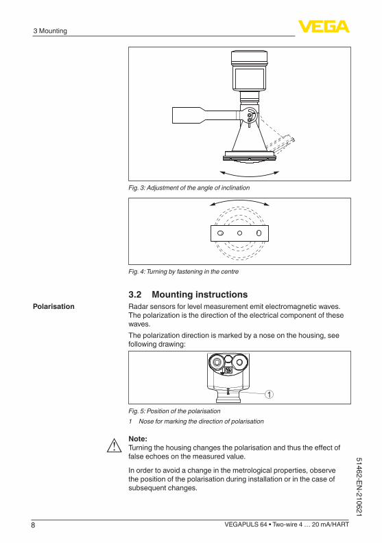
Fig. 3: Adjustment of the angle of inclination
Fig. 4: Turning by fastening in the centre
3.2 Mounting instructionsRadar sensors for level measurement emit electromagnetic waves. Thepolarizationisthedirectionoftheelectricalcomponentofthesewaves.Thepolarizationdirectionismarkedbyanoseonthehousing,seefollowing drawing:
1
Fig. 5: Position of the polarisation1 Nose for marking the direction of polarisation
Note:Turningthehousingchangesthepolarisationandthustheeffectoffalse echoes on the measured value.
In order to avoid a change in the metrological properties, observe the position of the polarisation during installation or in the case of subsequent changes.
Polarisation
9
3 Mounting
VEGAPULS 64 • Two-wire 4 … 20 mA/HART
5146
2-EN
-210
621
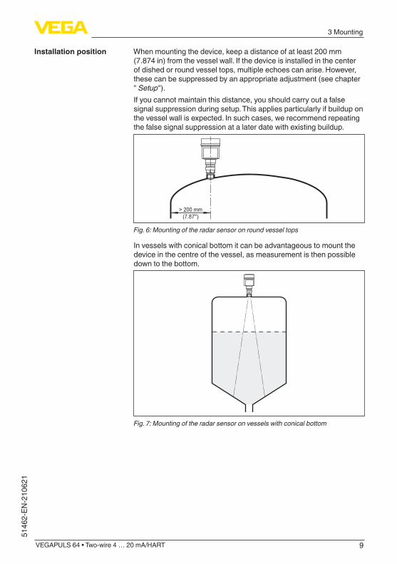
When mounting the device, keep a distance of at least 200 mm (7.874 in) from the vessel wall. If the device is installed in the center of dished or round vessel tops, multiple echoes can arise. However, these can be suppressed by an appropriate adjustment (see chapter " Setup"). If you cannot maintain this distance, you should carry out a false signal suppression during setup. This applies particularly if buildup on thevesselwallisexpected.Insuchcases,werecommendrepeatingthefalsesignalsuppressionatalaterdatewithexistingbuildup.
> 200 mm(7.87")
Fig. 6: Mounting of the radar sensor on round vessel tops
In vessels with conical bottom it can be advantageous to mount the device in the centre of the vessel, as measurement is then possible down to the bottom.
Fig. 7: Mounting of the radar sensor on vessels with conical bottom
Installation position
10
4 Connecting to power supply
VEGAPULS 64 • Two-wire 4 … 20 mA/HART
51462-EN-210621
4 Connecting to power supply
4.1 ConnectingThe voltage supply and signal output are connected via the spring-loaded terminals in the housing.Connection to the display and adjustment module or to the interface adapter is carried out via contact pins in the housing.
Information:The terminal block is pluggable and can be removed from the electronics. To do this, lift the terminal block with a small screwdriver and pull it out. When reinserting the terminal block, you should hear it snap in.
Proceed as follows:1. Unscrew the housing lid2. If a display and adjustment module is installed, remove it by turn-
ing it slightly to the left3. Loosen compression nut of the cable gland and remove blind
plug4. Removeapprox.10cm(4in)ofthecablemantle,stripapprox.
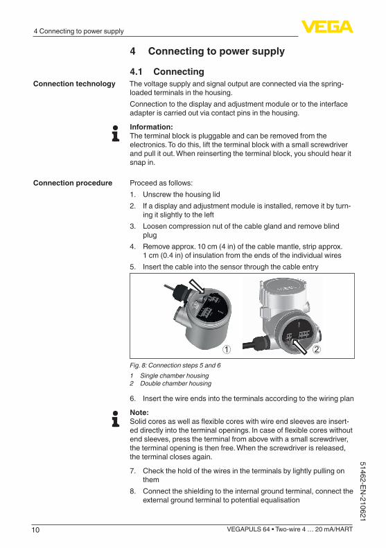
1 cm (0.4 in) of insulation from the ends of the individual wires5. Insert the cable into the sensor through the cable entry
1 2
Fig. 8: Connection steps 5 and 61 Single chamber housing2 Double chamber housing
6. Insert the wire ends into the terminals according to the wiring plan
Note:Solidcoresaswellasflexiblecoreswithwireendsleevesareinsert-eddirectlyintotheterminalopenings.Incaseofflexiblecoreswithoutend sleeves, press the terminal from above with a small screwdriver, the terminal opening is then free. When the screwdriver is released, the terminal closes again.
7. Check the hold of the wires in the terminals by lightly pulling on them
8. Connect the shielding to the internal ground terminal, connect the externalgroundterminaltopotentialequalisation
Connection technology
Connection procedure
11
4 Connecting to power supply
VEGAPULS 64 • Two-wire 4 … 20 mA/HART
5146
2-EN
-210
621
9. Tighten the compression nut of the cable entry gland. The seal ring must completely encircle the cable
10. Reinsert the display and adjustment module, if one was installed11. Screw the housing lid back onTheelectricalconnectionisfinished.
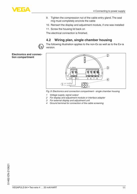
4.2 Wiring plan, single chamber housingThefollowingillustrationappliestothenon-ExaswellastotheEx-iaversion.
51 2+( ) (-) 6 7 8
4...20mA
2
3
41
Fig. 9: Electronics and connection compartment - single chamber housing1 Voltage supply, signal output2 For display and adjustment module or interface adapter3 For external display and adjustment unit4 Ground terminal for connection of the cable screening
Electronics and connec-tion compartment
12
5 Set up with the display and adjustment module
VEGAPULS 64 • Two-wire 4 … 20 mA/HART
51462-EN-210621
5 Set up with the display and adjustment module
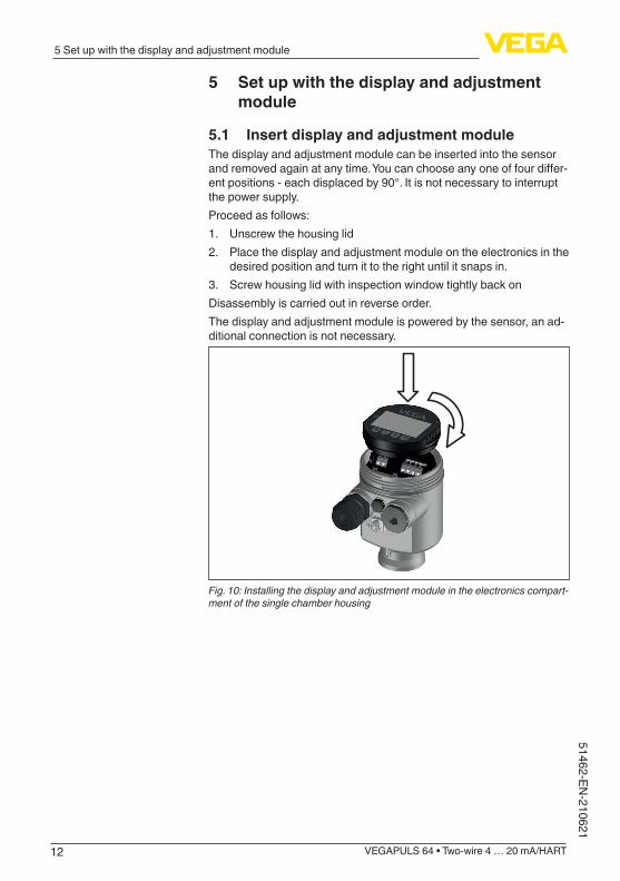
5.1 Insert display and adjustment moduleThe display and adjustment module can be inserted into the sensor andremovedagainatanytime.Youcanchooseanyoneoffourdiffer-ent positions - each displaced by 90°. It is not necessary to interrupt the power supply.Proceed as follows:1. Unscrew the housing lid2. Place the display and adjustment module on the electronics in the
desired position and turn it to the right until it snaps in.3. Screw housing lid with inspection window tightly back onDisassembly is carried out in reverse order.The display and adjustment module is powered by the sensor, an ad-ditional connection is not necessary.
Fig. 10: Installing the display and adjustment module in the electronics compart-ment of the single chamber housing
13
5 Set up with the display and adjustment module
VEGAPULS 64 • Two-wire 4 … 20 mA/HART
5146
2-EN
-210
621
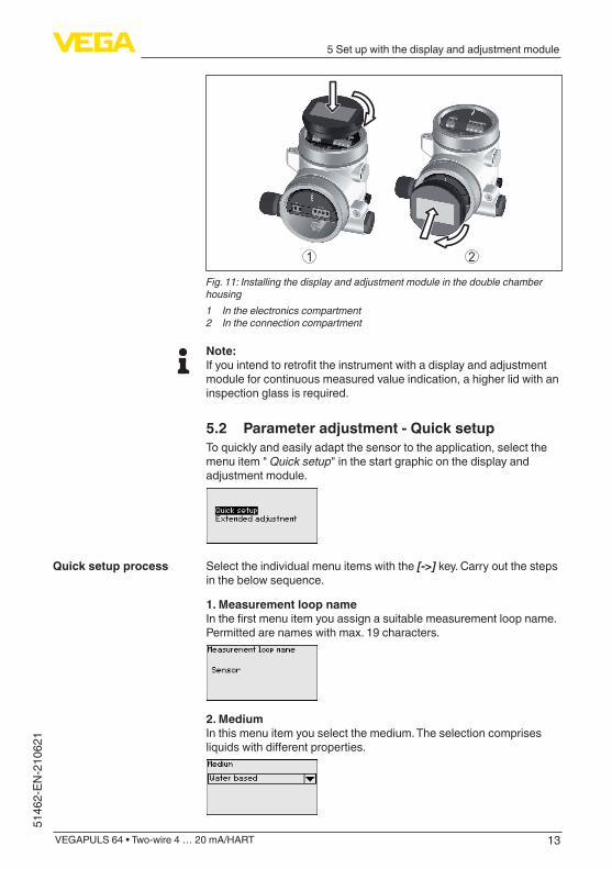
1 2
Fig. 11: Installing the display and adjustment module in the double chamber housing1 In the electronics compartment2 In the connection compartment
Note:Ifyouintendtoretrofittheinstrumentwithadisplayandadjustmentmodule for continuous measured value indication, a higher lid with an inspection glass is required.
5.2 Parameter adjustment - Quick setupTo quickly and easily adapt the sensor to the application, select the menu item " Quick setup" in the start graphic on the display and adjustment module.
Select the individual menu items with the [->] key. Carry out the steps in the below sequence.
1. Measurement loop nameInthefirstmenuitemyouassignasuitablemeasurementloopname.Permittedarenameswithmax.19characters.
2. MediumIn this menu item you select the medium. The selection comprises liquidswithdifferentproperties.
Quick setup process
14
5 Set up with the display and adjustment module
VEGAPULS 64 • Two-wire 4 … 20 mA/HART
51462-EN-210621
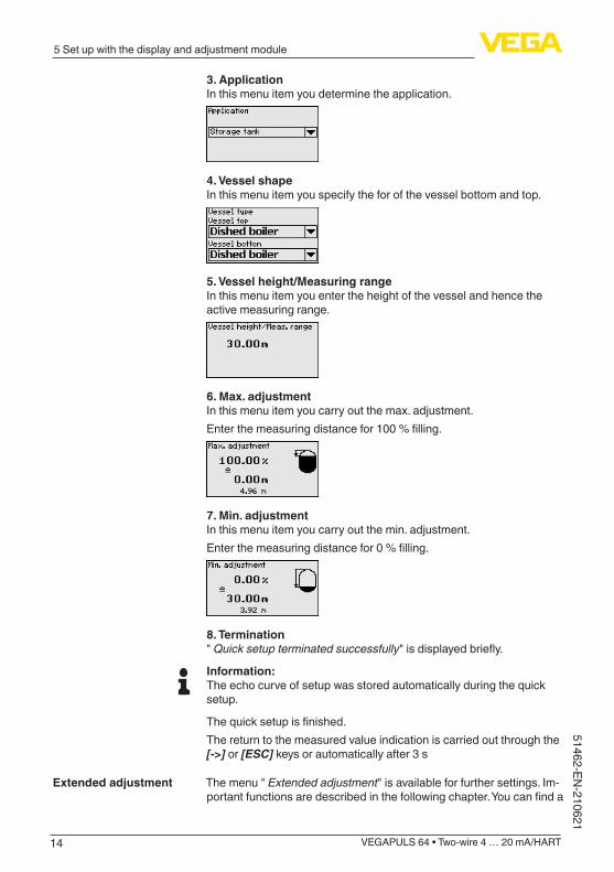
3. ApplicationIn this menu item you determine the application.
4. Vessel shapeIn this menu item you specify the for of the vessel bottom and top.
5. Vessel height/Measuring rangeIn this menu item you enter the height of the vessel and hence the active measuring range.
6. Max. adjustmentInthismenuitemyoucarryoutthemax.adjustment.Enterthemeasuringdistancefor100%filling.
7. Min. adjustmentIn this menu item you carry out the min. adjustment.Enterthemeasuringdistancefor0%filling.
8. Termination" Quick setup terminated successfully"isdisplayedbriefly.
Information:The echo curve of setup was stored automatically during the quick setup.
Thequicksetupisfinished.The return to the measured value indication is carried out through the [->] or [ESC] keys or automatically after 3 s
The menu " Extended adjustment" is available for further settings. Im-portantfunctionsaredescribedinthefollowingchapter.Youcanfinda
Extended adjustment
15
5 Set up with the display and adjustment module
VEGAPULS 64 • Two-wire 4 … 20 mA/HART
5146
2-EN
-210
621
complete description of all functions of the " Extended adjustment" in the operating instructions manual of VEGAPULS 64.
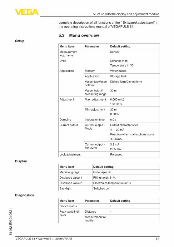
5.3 Menu overview
Menu item Parameter Default setting
Measurement loop name
Sensor
Units Distance in mTemperature in °C
Application Medium Water based
Application Storage tank
Vessel top/Vessel bottom
Dished form/Dished form
Vessel height/Measuring range
30 m
Adjustment Max.adjustment 0,000 m(d)100.00 %
Min. adjustment 30 m0.00 %
Damping Integration time 0.0 s
Current output Current output - Mode
Output characteristics4 … 20 mAReaction when malfunctions occur≤3.6mA
Current output - Min./Max.
3.8 mA20.5 mA
Lock adjustment Released
Menu item Default setting
Menu language Order-specific
Displayed value 1 Filling height in %
Displayed value 2 Electronics temperature in °C
Backlight Switched on
Menu item Parameter Default setting
Device status -
Peak value indi-cator
Distance -
Measurement re-liability
-
Setup
Display
Diagnostics
16
5 Set up with the display and adjustment module
VEGAPULS 64 • Two-wire 4 … 20 mA/HART
51462-EN-210621
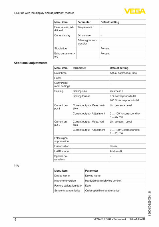
Menu item Parameter Default setting
Peak values, ad-ditional
Temperature -
Curve display Echo curve -
False signal sup-pression
-
Simulation Percent
Echo curve mem-ory
Percent
Menu item Parameter Default setting
Date/Time Actual date/Actual time
Reset -
Copy instru-ment settings
-
Scaling Scalingsize Volume in l
Scaling format 0 % corresponds to 0 l100 % corresponds to 0 l
Current out-put 1
Current output - Meas. vari-able
Lin. percent - Level
Current output - Adjustment 0 … 100 % correspond to 4 … 20 mA
Current out-put 2
Current output - Meas. vari-able
Lin. percent - Level
Current output - Adjustment 0 … 100 % correspond to 4 … 20 mA
False signal suppression
-
Linearisation Linear
HART mode Address 0
Special pa-rameters
-
Menu item Parameter
Device name Device name
Instrument version Hardware and software version
Factory calibration date Date
Sensor characteristics Order-specificcharacteristics
Additional adjustments
Info
17
6 Set up with smartphone/tablet, PC/notebook via Bluetooth
VEGAPULS 64 • Two-wire 4 … 20 mA/HART
5146
2-EN
-210
621
6 Set up with smartphone/tablet, PC/notebook via Bluetooth
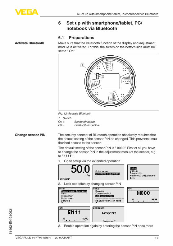
6.1 PreparationsMake sure that the Bluetooth function of the display and adjustment module is activated. For this, the switch on the bottom side must be set to " On".
1
OnO�
Fig. 12: Activate Bluetooth1 SwitchOn = Bluetooth activeOff= Bluetoothnotactive
The security concept of Bluetooth operation absolutely requires that the default setting of the sensor PIN be changed. This prevents unau-thorizedaccesstothesensor.The default setting of the sensor PIN is " 0000". First of all you have to change the sensor PIN in the adjustment menu of the sensor, e.g. to " 1111": 1. Gotosetupviatheextendedoperation
2. Lock operation by changing sensor PIN
3. Enable operation again by entering the sensor PIN once more
Activate Bluetooth
Change sensor PIN
18
6 Set up with smartphone/tablet, PC/notebook via Bluetooth
VEGAPULS 64 • Two-wire 4 … 20 mA/HART
51462-EN-210621
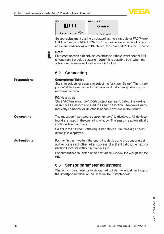
Sensor adjustment via the display/adjustment module or PACTware/DTM by means of VEGACONNECT is thus released again. For ac-cess(authentication)withBluetooth,thechangedPINisstilleffective.
Note:Bluetooth access can only be established if the current sensor PIN differsfromthedefaultsetting"0000". It is possible both when the adjustment is unlocked and when it is locked.
6.2 ConnectingSmartphone/TabletStart the adjustment app and select the function "Setup". The smart-phone/tablet searches automatically for Bluetooth-capable instru-ments in the area.
PC/NotebookStart PACTware and the VEGA project assistant. Select the device search via Bluetooth and start the search function. The device auto-matically searches for Bluetooth-capable devices in the vicinity.
The message " Instrument search running" is displayed. All devices found are listed in the operating window. The search is automatically continued continuously. Select in the device list the requested device. The message " Con-necting" is displayed.
Forthefirstconnection,theoperatingdeviceandthesensormustauthenticateeachother.Aftersuccessfulauthentication,thenextcon-nection functions without authentication.Forauthentication,enterinthenextmenuwindowthe4-digitsensorPIN.
6.3 Sensor parameter adjustmentThesensorparameterizationiscarriedoutviatheadjustmentapponthe smartphone/tablet or the DTM on the PC/notebook.
Preparations
Connecting
Authenticate

19
6 Set up with smartphone/tablet, PC/notebook via Bluetooth
VEGAPULS 64 • Two-wire 4 … 20 mA/HART
5146
2-EN
-210
621
Fig. 13: Example of an app view - Setup sensor adjustment
App view
20
7 Supplement
VEGAPULS 64 • Two-wire 4 … 20 mA/HART
51462-EN-210621
7 Supplement
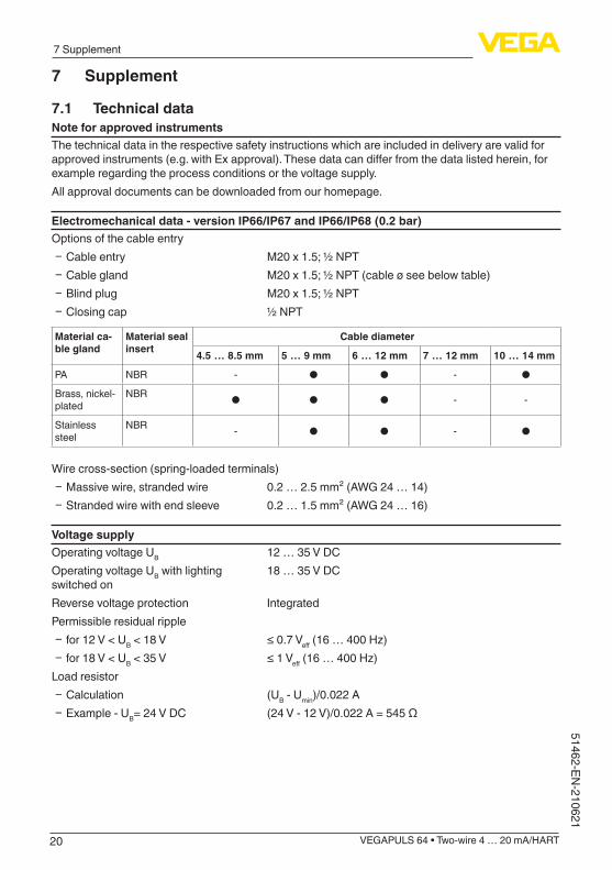
7.1 Technical dataNote for approved instrumentsThe technical data in the respective safety instructions which are included in delivery are valid for approvedinstruments(e.g.withExapproval).Thesedatacandifferfromthedatalistedherein,forexampleregardingtheprocessconditionsorthevoltagesupply.All approval documents can be downloaded from our homepage.
Electromechanical data - version IP66/IP67 and IP66/IP68 (0.2 bar)Options of the cable entry
Ʋ Cable entry M20x1.5;½NPT Ʋ Cable gland M20x1.5;½NPT(cableøseebelowtable) Ʋ Blind plug M20x1.5;½NPT Ʋ Closing cap ½ NPT
Material ca-ble gland
Material seal insert
Cable diameter
4.5 … 8.5 mm 5 … 9 mm 6 … 12 mm 7 … 12 mm 10 … 14 mm
PA NBR - ● ● - ●
Brass, nickel-plated
NBR ● ● ● - -
Stainless steel
NBR - ● ● - ●
Wire cross-section (spring-loaded terminals) Ʋ Massive wire, stranded wire 0.2 … 2.5 mm² (AWG 24 … 14) Ʋ Stranded wire with end sleeve 0.2 … 1.5 mm² (AWG 24 … 16)
Voltage supplyOperating voltage UB 12 … 35 V DCOperating voltage UB with lighting switched on
18 … 35 V DC
Reverse voltage protection IntegratedPermissible residual ripple
Ʋ for 12 V < UB < 18 V ≤0.7Veff(16…400Hz) Ʋ for 18 V < UB < 35 V ≤1Veff(16…400Hz)
Load resistor Ʋ Calculation (UB - Umin)/0.022 A Ʋ Example-UB= 24 V DC (24V-12V)/0.022A=545Ω
21
Notes
VEGAPULS 64 • Two-wire 4 … 20 mA/HART
5146
2-EN
-210
621
22
Notes
VEGAPULS 64 • Two-wire 4 … 20 mA/HART
51462-EN-210621
23
Notes
VEGAPULS 64 • Two-wire 4 … 20 mA/HART
5146
2-EN
-210
621

Printing date:
VEGA Grieshaber KGAm Hohenstein 11377761 SchiltachGermany
5146
2-EN
-210
621
All statements concerning scope of delivery, application, practical use and operat-ing conditions of the sensors and processing systems correspond to the information available at the time of printing.Subject to change without prior notice
© VEGA Grieshaber KG, Schiltach/Germany 2021
Phone +49 7836 50-0E-mail: [email protected]