Embed Size (px)
Citation preview

Seediscussions,stats,andauthorprofilesforthispublicationat:http://www.researchgate.net/publication/243218648
PropagationofgeneralizedMathieu-Gaussbeamsthroughparaxialmisalignedopticalsystem
ARTICLEinOPTICSCOMMUNICATIONS·OCTOBER2009
ImpactFactor:1.45·DOI:10.1016/j.optcom.2009.03.062
CITATIONS
5
READS
32
3AUTHORS,INCLUDING:
AbdelmajidBelafhal
ChouaibDoukkaliUniversity,ElJadida,Mo…
106PUBLICATIONS401CITATIONS
SEEPROFILE
Availablefrom:AbdelmajidBelafhal
Retrievedon:24October2015
Optics Communications 282 (2009) 3934–3939
Contents lists available at ScienceDirect
Optics Communications
journal homepage: www.elsevier .com/ locate/optcom
Propagation of generalized Mathieu–Gauss beams through paraxialmisaligned optical systems
A. Chafiq, Z. Hricha, A. Belafhal *
Laboratoire de Physique Nucléaire, Atomique et Moléculaire, Département de Physique, Faculté des Sciences, Université Chouaïb Doukkali, B.P. 20, 24000 El Jadida, Morocco
a r t i c l e i n f o a b s t r a c t
Article history:Received 29 December 2008Received in revised form 24 March 2009Accepted 26 March 2009
Keywords:Generalized Mathieu–Gauss beamsGeneralized diffraction integralMisaligned optical system
0030-4018/$ - see front matter � 2009 Elsevier B.V. Adoi:10.1016/j.optcom.2009.03.062
* Corresponding author.E-mail address: [email protected] (A. Belafhal).
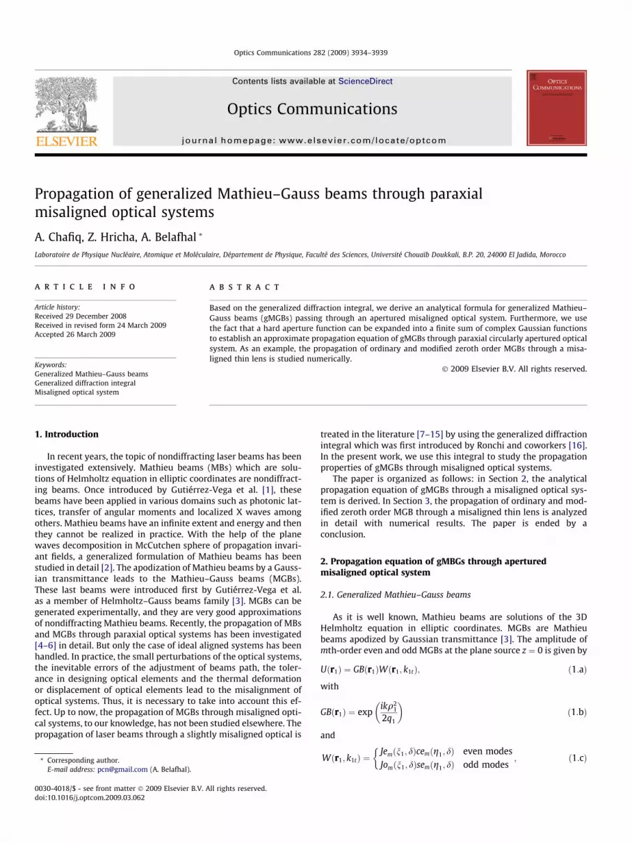
Based on the generalized diffraction integral, we derive an analytical formula for generalized Mathieu–Gauss beams (gMGBs) passing through an apertured misaligned optical system. Furthermore, we usethe fact that a hard aperture function can be expanded into a finite sum of complex Gaussian functionsto establish an approximate propagation equation of gMGBs through paraxial circularly apertured opticalsystem. As an example, the propagation of ordinary and modified zeroth order MGBs through a misa-ligned thin lens is studied numerically.
� 2009 Elsevier B.V. All rights reserved.
1. Introduction
In recent years, the topic of nondiffracting laser beams has beeninvestigated extensively. Mathieu beams (MBs) which are solu-tions of Helmholtz equation in elliptic coordinates are nondiffract-ing beams. Once introduced by Gutiérrez-Vega et al. [1], thesebeams have been applied in various domains such as photonic lat-tices, transfer of angular moments and localized X waves amongothers. Mathieu beams have an infinite extent and energy and thenthey cannot be realized in practice. With the help of the planewaves decomposition in McCutchen sphere of propagation invari-ant fields, a generalized formulation of Mathieu beams has beenstudied in detail [2]. The apodization of Mathieu beams by a Gauss-ian transmittance leads to the Mathieu–Gauss beams (MGBs).These last beams were introduced first by Gutiérrez-Vega et al.as a member of Helmholtz–Gauss beams family [3]. MGBs can begenerated experimentally, and they are very good approximationsof nondiffracting Mathieu beams. Recently, the propagation of MBsand MGBs through paraxial optical systems has been investigated[4–6] in detail. But only the case of ideal aligned systems has beenhandled. In practice, the small perturbations of the optical systems,the inevitable errors of the adjustment of beams path, the toler-ance in designing optical elements and the thermal deformationor displacement of optical elements lead to the misalignment ofoptical systems. Thus, it is necessary to take into account this ef-fect. Up to now, the propagation of MGBs through misaligned opti-cal systems, to our knowledge, has not been studied elsewhere. Thepropagation of laser beams through a slightly misaligned optical is
ll rights reserved.
treated in the literature [7–15] by using the generalized diffractionintegral which was first introduced by Ronchi and coworkers [16].In the present work, we use this integral to study the propagationproperties of gMGBs through misaligned optical systems.
The paper is organized as follows: in Section 2, the analyticalpropagation equation of gMGBs through a misaligned optical sys-tem is derived. In Section 3, the propagation of ordinary and mod-ified zeroth order MGB through a misaligned thin lens is analyzedin detail with numerical results. The paper is ended by aconclusion.
2. Propagation equation of gMBGs through aperturedmisaligned optical system
2.1. Generalized Mathieu–Gauss beams
As it is well known, Mathieu beams are solutions of the 3DHelmholtz equation in elliptic coordinates. MGBs are Mathieubeams apodized by Gaussian transmittance [3]. The amplitude ofmth-order even and odd MGBs at the plane source z ¼ 0 is given by
Uðr1Þ ¼ GBðr1ÞWðr1; k1tÞ; ð1:aÞ
with
GBðr1Þ ¼ expikq2
1
2q1
� �ð1:bÞ
and
Wðr1; k1tÞ ¼Jemðn1; dÞcemðg1; dÞ even modesJomðn1; dÞsemðg1; dÞ odd modes
;
�ð1:cÞ
z
zm
RP2
RP1
RP2m
RP1m
⎥⎦
⎤⎢⎣
⎡DC
BA
ε'ε
z
O1m
O2m
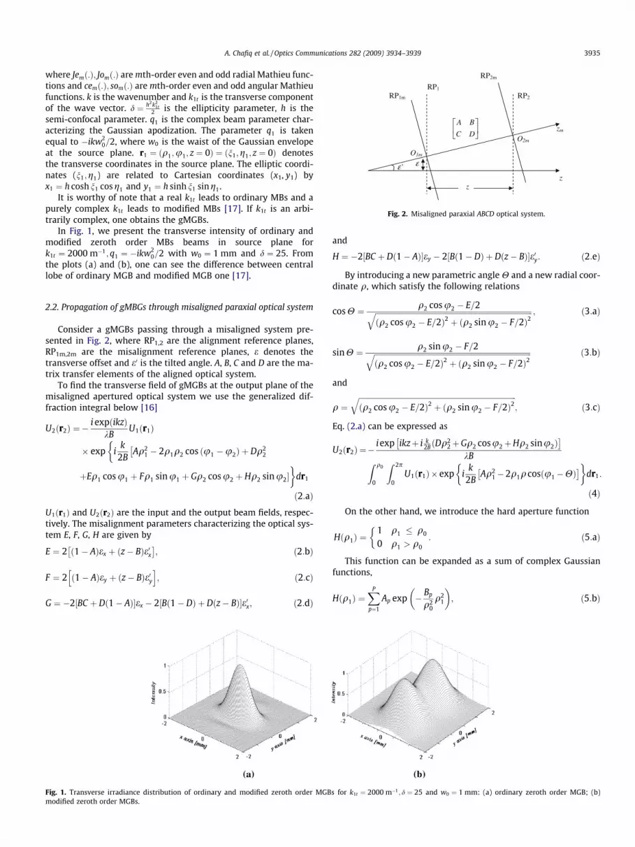
Fig. 2. Misaligned paraxial ABCD optical system.
A. Chafiq et al. / Optics Communications 282 (2009) 3934–3939 3935
where Jemð:Þ; Jomð:Þ are mth-order even and odd radial Mathieu func-tions and cemð:Þ; somð:Þ are mth-order even and odd angular Mathieufunctions. k is the wavenumber and k1t is the transverse componentof the wave vector. d ¼ h2k2
1t2 is the ellipticity parameter, h is the
semi-confocal parameter. q1 is the complex beam parameter char-acterizing the Gaussian apodization. The parameter q1 is takenequal to �ikw2
0=2, where w0 is the waist of the Gaussian envelopeat the source plane. r1 ¼ ðq1;u1; z ¼ 0Þ ¼ ðn1;g1; z ¼ 0Þ denotesthe transverse coordinates in the source plane. The elliptic coordi-nates (n1;g1) are related to Cartesian coordinates (x1, y1) byx1 ¼ h cosh n1 cosg1 and y1 ¼ h sinh n1 sing1.
It is worthy of note that a real k1t leads to ordinary MBs and apurely complex k1t leads to modified MBs [17]. If k1t is an arbi-trarily complex, one obtains the gMGBs.
In Fig. 1, we present the transverse intensity of ordinary andmodified zeroth order MBs beams in source plane fork1t ¼ 2000 m�1; q1 ¼ �ikw2
0=2 with w0 ¼ 1 mm and d ¼ 25. Fromthe plots (a) and (b), one can see the difference between centrallobe of ordinary MGB and modified MGB one [17].
2.2. Propagation of gMBGs through misaligned paraxial optical system
Consider a gMGBs passing through a misaligned system pre-sented in Fig. 2, where RP1,2 are the alignment reference planes,RP1m,2m are the misalignment reference planes, e denotes thetransverse offset and e0 is the tilted angle. A, B, C and D are the ma-trix transfer elements of the aligned optical system.
To find the transverse field of gMGBs at the output plane of themisaligned apertured optical system we use the generalized dif-fraction integral below [16]
U2ðr2Þ ¼ �i expðikzÞ
kBU1ðr1Þ
� exp ik
2BAq2
1 � 2q1q2 cos u1 �u2ð Þ þ Dq22
��
þEq1 cos u1 þ Fq1 sin u1 þ Gq2 cos u2 þ Hq2 sinu2��
dr1
ð2:aÞ
U1ðr1Þ and U2ðr2Þ are the input and the output beam fields, respec-tively. The misalignment parameters characterizing the optical sys-tem E, F, G, H are given by
E ¼ 2 ð1� AÞex þ ðz� BÞe0x� �
; ð2:bÞ
F ¼ 2 ð1� AÞey þ ðz� BÞe0yh i
; ð2:cÞ
G ¼ �2½BC þ Dð1� AÞ�ex � 2½Bð1� DÞ þ Dðz� BÞ�e0x; ð2:dÞ
Fig. 1. Transverse irradiance distribution of ordinary and modified zeroth order MGBmodified zeroth order MGBs.
and
H ¼ �2½BC þ Dð1� AÞ�ey � 2½Bð1� DÞ þ Dðz� BÞ�e0y: ð2:eÞ
By introducing a new parametric angle H and a new radial coor-dinate q, which satisfy the following relations
cos H ¼ q2 cos u2 � E=2ffiffiffiffiffiffiffiffiffiffiffiffiffiffiffiffiffiffiffiffiffiffiffiffiffiffiffiffiffiffiffiffiffiffiffiffiffiffiffiffiffiffiffiffiffiffiffiffiffiffiffiffiffiffiffiffiffiffiffiffiffiffiffiffiffiffiffiffiffiffiffiffiffiffiffiffiffiffiffiffiffiffiffiffiffiq2 cos u2 � E=2ð Þ2 þ ðq2 sin u2 � F=2Þ2
q ; ð3:aÞ
sin H ¼ q2 sin u2 � F=2ffiffiffiffiffiffiffiffiffiffiffiffiffiffiffiffiffiffiffiffiffiffiffiffiffiffiffiffiffiffiffiffiffiffiffiffiffiffiffiffiffiffiffiffiffiffiffiffiffiffiffiffiffiffiffiffiffiffiffiffiffiffiffiffiffiffiffiffiffiffiffiffiffiffiffiffiffiffiffiffiffiffiffiffiffiðq2 cos u2 � E=2Þ2 þ ðq2 sinu2 � F=2Þ2
q ð3:bÞ
and
q ¼ffiffiffiffiffiffiffiffiffiffiffiffiffiffiffiffiffiffiffiffiffiffiffiffiffiffiffiffiffiffiffiffiffiffiffiffiffiffiffiffiffiffiffiffiffiffiffiffiffiffiffiffiffiffiffiffiffiffiffiffiffiffiffiffiffiffiffiffiffiffiffiffiffiffiffiffiffiffiffiffiffiffiffiffiffiðq2 cos u2 � E=2Þ2 þ ðq2 sin u2 � F=2Þ2
q; ð3:cÞ
Eq. (2.a) can be expressed as
U2ðr2Þ ¼�i exp ikzþ i k
2B ðDq22þGq2 cosu2þHq2 sinu2Þ
� �kBZ q0
0
Z 2p
0U1ðr1Þ� exp i
k2B
Aq21�2q1qcosðu1�HÞ
� �� �dr1:
ð4Þ
On the other hand, we introduce the hard aperture function
Hðq1Þ ¼1 q1 � q0
0 q1 > q0
:
�ð5:aÞ
This function can be expanded as a sum of complex Gaussianfunctions,
Hðq1Þ ¼XP
p¼1
Ap exp � Bp
q20
q21
� �; ð5:bÞ
s for k1t ¼ 2000 m�1; d ¼ 25 and w0 ¼ 1 mm: (a) ordinary zeroth order MGB; (b)

3936 A. Chafiq et al. / Optics Communications 282 (2009) 3934–3939
where Ap and Bp are the expansion and Gaussian coefficients, whichcan be obtained by numerical optimization of the hard aperturefunction Hðq1Þ [18].
By introducing the function Hðq1Þ in the integral of Eq. (4) andafter making some algebraic transformations, we obtain
U2ðr2Þ ¼�iexp ikzþ i k
2B Dðq22�q2ÞþGq2 cosu2þHq2 sinu2
� � kB
�XP¼10
p¼1
Ap
Z 1
0
Z 2p
0U1pðr1Þ�exp i
k2B
Aq21�2r1rþDq2
� �� �dr1;
ð6:aÞ
where
Fig. 4. Normalized intensity of ordinary zeroth order MGBs propagatk1t ¼ 15 � 103 m�1; d ¼ 20;q0 ¼ 2 mm;q0w0 ¼ 0:1 and k ¼ 632:8 nm. (a) in ðx; zÞ plane,position of the beam center at the input plane.
Input plane Output plane
Thin lens
z
zm
xε or yε
Fig. 3. Misaligned thin lens: displacement ex in x-direction or ey in y-direction.
U1pðr1Þ ¼ GBpðr1ÞWðr1; kt1Þ; ð6:bÞwith
GBpðr1Þ ¼ expikq2
1
2q1p
!ð6:cÞ
and
1q1p¼ 1
q1þ 2iBp
kq20
: ð6:dÞ
In Eq. (6.a), r ¼ ðq;HÞ denotes the coordinates of the misalignedbeams in the output plane. One can point out that the propagationequation of gMGBs through misaligned paraxial optical system canbe deduced easily from the propagation equation through alignedsystems following the form given in Eq. (6.a). So, by using the samenotation of Ref. [19], Eq. (6.a) can be rewritten as
U2ðr2Þ ¼ exp ik
2BDðq2
2 � q2Þ þ Gq2 cos u2 þ Hq2 sin u2
� �� �
�XP¼10
p¼1
ApGBpðrÞ exp �ik1tk2tB
2k
� �Wðr; k2tÞ; ð7:aÞ
where
GBpðrÞ ¼expðikzÞ
Aþ B=q1pexp
ikq2
2q2p
!; ð7:bÞ
ing through a truncated and misaligned thin lens for f = 0.5 m,for ex ¼ 0:1 mm; (b) in ðy; zÞ plane, for ey ¼ 0:1 mm. Dashed lines indicate the

A. Chafiq et al. / Optics Communications 282 (2009) 3934–3939 3937
with
q2p ¼Aq1p þ BCq1p þ D
ð7:cÞ
and
k2t ¼k1t
Aþ B=q1p: ð7:dÞ
Eq. (7.a) is the main result of this paper. It leads to describe thepropagation properties of any gMGB through misaligned opticalsystems. Apart from an exponential factor, the output field is ex-pressed as a sum of ten terms with the same mathematical expres-sions as in the input field. Therefore, the output field is mainlyrelated to the evaluation of Wð:; :Þ. This later can be calculated di-rectly either by using the elliptic coordinates and Mathieu functions[1,20] or by using the cylindrical coordinates and Bessel functions[4,17]. On the other hand, from Eq. (7.a), one can deduce that thetransverse shape of the output generalized MGBs will change be-cause k2t and q2p are not proportional to k1t and q1p.
The radial coordinate of the beam center in the output plane canbe written as
q ¼ffiffiffiffiffiffiffiffiffiffiffiffiffiffiffiffiffiffiffiffiffiffiffiffiffiffiffiffiffiffiffiffiffiffiffiffiffiffiffiffiffiffiffiffiffiffiffiffiffiffiffiffiffiffiðx2 � E=2Þ2 þ ðy2 � F=2Þ2
q; ð8Þ
where x2 and y2 are the cartesian coordinates of the beam center inthe output plane of an aligned optical system. From Eq. (8), it isclear that the obtained gMGBs in the output plane becomes decen-tered, and the center of the beam is shifted from the optical axis by
Fig. 5. Normalized intensity of modified zeroth order MGBs propagatk1t ¼ 200 m�1; d ¼ 10;q0 ¼ 20 mm;q0w0 ¼
ffiffiffi5p
and k ¼ 632:8 nm. (a) in ðx; zÞ plane, for ethe beam center at the input plane.
E=2 in x-direction and F=2 in y-direction. Consequently, the shift ofthe output beam is closely related to the misalignment parametersand the matrix transfer elements of the optical system.
On the other hand, when the radius of the input apertureq0 !1, Eq. (7.a) leads to the propagation equation of MGBsthrough an unapertured misaligned optical system
U2ðr2Þ ¼ exp �ik1tk2tB
2kþ i
k2B
Dðq22 � q2Þ þ Gq2 cos u2
��
þHq2 sin u2��
GBðrÞWðr; k2tÞ: ð9Þ
It is to be noted that in this case, q2p is replaced by q2 ¼ ðAq1 þ BÞ=ðCq1 þ DÞwith q1p ¼ q1, and k2t becomes k2t ¼ k1tðAþ B=q1Þ.
If we put ex ¼ ey ¼ e0x ¼ e0y ¼ 0, Eqs. (8) and (9) reduce to thepropagation equations of gMGBs propagating through an alignedoptical system.
Finally, the irradiance of the generalized MGBs propagatingthrough an apertured misaligned optical system can be expressedas follows:
Iðr; k2tÞ ¼XP¼10
p¼1
ApGBpðrÞ exp �ik1tk2tB
2k
� �Wðr; k2tÞ
" #
XP¼10
p¼1
ApGBpðrÞ exp �ik1tk2tB
2k
� �Wðr; k2tÞ
" #�; ð10Þ
where � denotes the complex conjugate.
ing through a truncated and misaligned thin lens for f = 0.5 m,x ¼ 0:6 mm; (b) ðy; zÞ plane, for ey ¼ 0:6 mm. Dashed lines indicate the position of
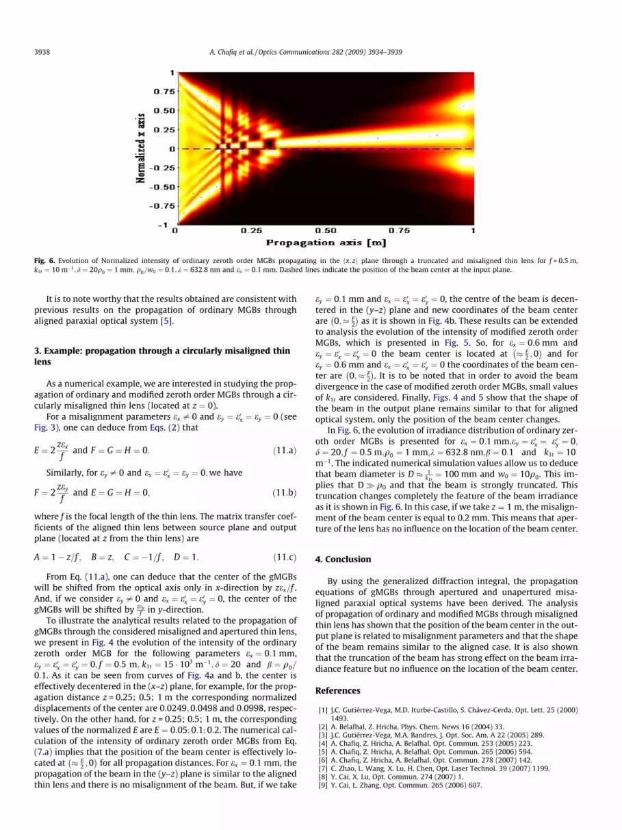
Fig. 6. Evolution of Normalized intensity of ordinary zeroth order MGBs propagating in the ðx; zÞ plane through a truncated and misaligned thin lens for f = 0.5 m,k1t ¼ 10 m�1; d ¼ 20q0 ¼ 1 mm; q0=w0 ¼ 0:1; k ¼ 632:8 nm and ex ¼ 0:1 mm. Dashed lines indicate the position of the beam center at the input plane.
3938 A. Chafiq et al. / Optics Communications 282 (2009) 3934–3939
It is to note worthy that the results obtained are consistent withprevious results on the propagation of ordinary MGBs throughaligned paraxial optical system [5].
3. Example: propagation through a circularly misaligned thinlens
As a numerical example, we are interested in studying the prop-agation of ordinary and modified zeroth order MGBs through a cir-cularly misaligned thin lens (located at z ¼ 0).
For a misalignment parameters ex – 0 and ey ¼ e0x ¼ ey ¼ 0 (seeFig. 3), one can deduce from Eqs. (2) that
E ¼ 2zex
fand F ¼ G ¼ H ¼ 0: ð11:aÞ
Similarly, for ey – 0 and ex ¼ e0x ¼ ey ¼ 0;we have
F ¼ 2zey
fand E ¼ G ¼ H ¼ 0; ð11:bÞ
where f is the focal length of the thin lens. The matrix transfer coef-ficients of the aligned thin lens between source plane and outputplane (located at z from the thin lens) are
A ¼ 1� z=f ; B ¼ z; C ¼ �1=f ; D ¼ 1: ð11:cÞ
From Eq. (11.a), one can deduce that the center of the gMGBswill be shifted from the optical axis only in x-direction by zex=f .And, if we consider ey – 0 and ex ¼ e0x ¼ e0y ¼ 0, the center of thegMGBs will be shifted by zey
f in y-direction.To illustrate the analytical results related to the propagation of
gMGBs through the considered misaligned and apertured thin lens,we present in Fig. 4 the evolution of the intensity of the ordinaryzeroth order MGB for the following parameters ex ¼ 0:1 mm,ey ¼ e0x ¼ e0y ¼ 0; f ¼ 0:5 m; k1t ¼ 15 � 103 m�1; d ¼ 20 and b ¼ q0=
0:1. As it can be seen from curves of Fig. 4a and b, the center iseffectively decentered in the (x–z) plane, for example, for the prop-agation distance z = 0.25; 0.5; 1 m the corresponding normalizeddisplacements of the center are 0:0249;0:0498 and 0:0998, respec-tively. On the other hand, for z = 0.25; 0.5; 1 m, the correspondingvalues of the normalized E are E ¼ 0:05; 0:1; 0:2. The numerical cal-culation of the intensity of ordinary zeroth order MGBs from Eq.(7.a) implies that the position of the beam center is effectively lo-cated at � E
2 ;0� �
for all propagation distances. For ex ¼ 0:1 mm, thepropagation of the beam in the (y–z) plane is similar to the alignedthin lens and there is no misalignment of the beam. But, if we take
ey ¼ 0:1 mm and ex ¼ e0x ¼ e0y ¼ 0, the centre of the beam is decen-tered in the (y–z) plane and new coordinates of the beam centerare 0;� F
2
� �as it is shown in Fig. 4b. These results can be extended
to analysis the evolution of the intensity of modified zeroth orderMGBs, which is presented in Fig. 5. So, for ex ¼ 0:6 mm andey ¼ e0x ¼ e0y ¼ 0 the beam center is located at � E
2 ;0� �
and forey ¼ 0:6 mm and ex ¼ e0x ¼ e0y ¼ 0 the coordinates of the beam cen-ter are 0;� F
2
� �. It is to be noted that in order to avoid the beam
divergence in the case of modified zeroth order MGBs, small valuesof k1t are considered. Finally, Figs. 4 and 5 show that the shape ofthe beam in the output plane remains similar to that for alignedoptical system, only the position of the beam center changes.
In Fig. 6, the evolution of irradiance distribution of ordinary zer-oth order MGBs is presented for ex ¼ 0:1 mm;ey ¼ e0x ¼ e0y ¼ 0;d ¼ 20; f ¼ 0:5 m;q0 ¼ 1 mm;k ¼ 632:8 nm;b ¼ 0:1 and k1t ¼ 10m�1. The indicated numerical simulation values allow us to deducethat beam diameter is D � 1
k1t¼ 100 mm and w0 ¼ 10q0. This im-
plies that D q0 and that the beam is strongly truncated. Thistruncation changes completely the feature of the beam irradianceas it is shown in Fig. 6. In this case, if we take z ¼ 1 m, the misalign-ment of the beam center is equal to 0.2 mm. This means that aper-ture of the lens has no influence on the location of the beam center.
4. Conclusion
By using the generalized diffraction integral, the propagationequations of gMGBs through apertured and unapertured misa-ligned paraxial optical systems have been derived. The analysisof propagation of ordinary and modified MGBs through misalignedthin lens has shown that the position of the beam center in the out-put plane is related to misalignment parameters and that the shapeof the beam remains similar to the aligned case. It is also shownthat the truncation of the beam has strong effect on the beam irra-diance feature but no influence on the location of the beam center.
References
[1] J.C. Gutiérrez-Vega, M.D. Iturbe-Castillo, S. Chávez-Cerda, Opt. Lett. 25 (2000)1493.
[2] A. Belafhal, Z. Hricha, Phys. Chem. News 16 (2004) 33.[3] J.C. Gutiérrez-Vega, M.A. Bandres, J. Opt. Soc. Am. A 22 (2005) 289.[4] A. Chafiq, Z. Hricha, A. Belafhal, Opt. Commun. 253 (2005) 223.[5] A. Chafiq, Z. Hricha, A. Belafhal, Opt. Commun. 265 (2006) 594.[6] A. Chafiq, Z. Hricha, A. Belafhal, Opt. Commun. 278 (2007) 142.[7] C. Zhao, L. Wang, X. Lu, H. Chen, Opt. Laser Technol. 39 (2007) 1199.[8] Y. Cai, X. Lu, Opt. Commun. 274 (2007) 1.[9] Y. Cai, L. Zhang, Opt. Commun. 265 (2006) 607.

A. Chafiq et al. / Optics Communications 282 (2009) 3934–3939 3939
[10] Y. Cai, Q. Lin, J. Opt. A: Pure Appl. Opt. 6 (2004) 390.[11] Y. Cai, Q. Lin, J. Opt. Soc. Am. A 21 (2004) 390.[12] Y. Cai, Q. Lin, J. Opt. A: Pure Appl. Opt. 6 (2004) 1061.[13] J. Gu, D. Zhao, Z. Mei, Optik 115 (2004) 187.[14] M. Shen, S. Wang, D. Zhao, Optik 115 (2004) 193.[15] G. Ding, B. Lü, Opt. Quantum Electron. 35 (2003) 91.[16] S. Wang, L. Ronchi, in: E. Wolf (Ed.), Progress in Optics, vol. 25, 1988, p. 279.
[17] H.T. Eyyuboglu, Appl. Phys. B 91 (2008) 629.[18] J.J. Wen, M.A. Breazeale, J. Acoust. Soc. Am. 1752 (1988) 83.[19] M. Guizar-Sicairos, J.C. Gutiérrez-Vega, Opt. Lett. 31 (2006) 2912.[20] J.C. Gutiérrez-Vega, Theory and Numerical analysis of the Mathieu functions,
Monterrey, NL, México, 2003, Available at <http://homepages.mty.itesm.mx/jgutierr/>.


