Embed Size (px)
Citation preview
Product Catalogue

Environment and quality policy
Draka Keila Cables Ltd. wishes to gain satisfac-
tion of the customers, employees and owners
without damaging of environment. In Draka
Keila Cables Ltd. the decisions are made, which
allow to develop the company and to save envi-
ronment at the same time and on the assump-
tion of this principle continuously to improve
the system of management.
In Draka Keila Cables Ltd. there is used the
multistage program of the quality control, which
covers production process from development of
the cables, purchasing of raw materials and pro-
duction of installation and power cables to the
documentation of supplemental examinations
and tests.
The quality and environmental management
system of Draka Keila Cables Ltd. has appraised
and approved by Lloyd’s Register Quality As-
surance Limited, which performs regular au-
dits according to standard of quality system
ISO 9001 and ISO 14001.
Table of Contents
Introduction . . . . . . . . . . . . . . . . . . . . . . . . . . . . . . . .2
General information . . . . . . . . . . . . . . . . . . . . . . . . . .3
Basic cable data . . . . . . . . . . . . . . . . . . . . . . . . . . . . .3
Power cables
ACSR . . . . . . . . . . . . . . . . . . . . . . . . . . . . . . . . . . . . . 8
HK . . . . . . . . . . . . . . . . . . . . . . . . . . . . . . . . . . . . . . . . 10
AS . . . . . . . . . . . . . . . . . . . . . . . . . . . . . . . . . . . . . . . . 11
A . . . . . . . . . . . . . . . . . . . . . . . . . . . . . . . . . . . . . . . . . 12
AXMK-PLUS and XMK-PLUS 1-core . . . . . . . . . . . . 13
AXPK-PLUS . . . . . . . . . . . . . . . . . . . . . . . . . . . . . . . . 14
AXPK . . . . . . . . . . . . . . . . . . . . . . . . . . . . . . . . . . . . . 16
EMC-Line 1 kV (IFSI) . . . . . . . . . . . . . . . . . . . . . . . . . 18
AMCMK 3 1/2-core . . . . . . . . . . . . . . . . . . . . . . . . . 20
AMCMK 4 1/2-core . . . . . . . . . . . . . . . . . . . . . . . . . 22
MCMK 3-core . . . . . . . . . . . . . . . . . . . . . . . . . . . . . . 24
MCMK 4-core. . . . . . . . . . . . . . . . . . . . . . . . . . . . . . 25
MCMK 5-core . . . . . . . . . . . . . . . . . . . . . . . . . . . . . . 26
MCCMK 4-core . . . . . . . . . . . . . . . . . . . . . . . . . . . . 28
MCCMK 5-core . . . . . . . . . . . . . . . . . . . . . . . . . . . . 29
MCMK 3 1/2-core . . . . . . . . . . . . . . . . . . . . . . . . . . . 30
MCMK 4 1/2-core. . . . . . . . . . . . . . . . . . . . . . . . . . . 32
MCMO . . . . . . . . . . . . . . . . . . . . . . . . . . . . . . . . . . . . 34
ARLC Aluminium Road Lighting Cable . . . . . . . . 35
EX . . . . . . . . . . . . . . . . . . . . . . . . . . . . . . . . . . . . . . . 36
AMKA . . . . . . . . . . . . . . . . . . . . . . . . . . . . . . . . . . . . .37
AHXAMK-W 6/10 (12) kV . . . . . . . . . . . . . . . . . . . . 38
AHXAMK-W 12/20 (24) kV . . . . . . . . . . . . . . . . . . . 39
AXLJ-TT 7/12 kV . . . . . . . . . . . . . . . . . . . . . . . . . . . 40
AXLJ-TT 14/24 kV . . . . . . . . . . . . . . . . . . . . . . . . . . . 41
AXLJ-TTCL TSLF 14/24 kV . . . . . . . . . . . . . . . . . . 42
AXLJ-TT 7/12 kV (3-core) . . . . . . . . . . . . . . . . . . . . 43
AXLJ-TT 14/24 kV (3-core) . . . . . . . . . . . . . . . . . . 44
AXLJ-RMF 7/12 kV . . . . . . . . . . . . . . . . . . . . . . . . . 45
AXLJ-RMF 14/24 kV . . . . . . . . . . . . . . . . . . . . . . . . 46
AXQJ-RMF 7/12 kV . . . . . . . . . . . . . . . . . . . . . . . . . 47
AXQJ-RMF 14/24 kV . . . . . . . . . . . . . . . . . . . . . . . . 48
AXQJ-F 7/12 kV . . . . . . . . . . . . . . . . . . . . . . . . . . . . 49
AXQJ-F 14/24 kV . . . . . . . . . . . . . . . . . . . . . . . . . . 50
PAS-W 20 kV . . . . . . . . . . . . . . . . . . . . . . . . . . . . . . . 51
Installation cables and wires
PL / ML / H07V-U . . . . . . . . . . . . . . . . . . . . . . . . . . 53
PK / MK / H07V-R . . . . . . . . . . . . . . . . . . . . . . . . . 54
MK 90 / H07V2-R . . . . . . . . . . . . . . . . . . . . . . . . . . 55
MKEM 90 / H07V2-K . . . . . . . . . . . . . . . . . . . . . . . 56
MMO . . . . . . . . . . . . . . . . . . . . . . . . . . . . . . . . . . . . . 57
EKLK 450/750 V . . . . . . . . . . . . . . . . . . . . . . . . . . 58
PPJ . . . . . . . . . . . . . . . . . . . . . . . . . . . . . . . . . . . . . . 59
MSK / H05VV-F . . . . . . . . . . . . . . . . . . . . . . . . . . . 60
PROFIT . . . . . . . . . . . . . . . . . . . . . . . . . . . . . . . . . . . . 61
Automation, data and telecommunication cables
JAMAK . . . . . . . . . . . . . . . . . . . . . . . . . . . . . . . . . . . 62
JAMAK ARM . . . . . . . . . . . . . . . . . . . . . . . . . . . . . . 63
NOMAK. . . . . . . . . . . . . . . . . . . . . . . . . . . . . . . . . . . 64
KLMA . . . . . . . . . . . . . . . . . . . . . . . . . . . . . . . . . . . . 65
PULS 2,5 75V . . . . . . . . . . . . . . . . . . . . . . . . . . . . . 66
MHS . . . . . . . . . . . . . . . . . . . . . . . . . . . . . . . . . . . . . 67
VMOHBU . . . . . . . . . . . . . . . . . . . . . . . . . . . . . . . . . 68
H05RN-F; RDO/05RN-F 300/500 V . . . . . . . . . . 69
DRAKAFLEX H07RN-F 450/750 V . . . . . . . . . . . 70
Halogen-fee and fire resistant cables
DRAKAFLEX-TARMO
H07BN4-F 450/750 V LSZH . . . . . . . . . . . . . . . . .72
HULT(FLEX) LSOH FB 90 0,6/1 kV . . . . . . . . . . . .74
HULT(FLEX) LSOH FB 30/60 0,6/1 kV . . . . . . . . 75
Signal cable type 2300 FB 30 (mbzh). . . . . . . . . .76
Signal cable type 2300 FB 90 (mbzh) . . . . . . . . 78
Draka SF/UTP Cat."5" FB 90 (mbzh) . . . . . . . . . . 80
BI(c) 250V . . . . . . . . . . . . . . . . . . . . . . . . . . . . . . . . . 81
BFSI-EMC 1 kV . . . . . . . . . . . . . . . . . . . . . . . . . . . . . 82
HULT(FLEX) LSOH 0,6/1 kV . . . . . . . . . . . . . . . . . 83
EQQ-Light 300/500 V . . . . . . . . . . . . . . . . . . . . . . 84
EQLQ 450/750 V . . . . . . . . . . . . . . . . . . . . . . . . . . 85
FQLQ 450/750 V . . . . . . . . . . . . . . . . . . . . . . . . . . 86
AXQJ 0,6/1 kV . . . . . . . . . . . . . . . . . . . . . . . . . . . . . 87
EXQJ 0,6/1 kV . . . . . . . . . . . . . . . . . . . . . . . . . . . . . 88
FXQJ 0,6/1 kV . . . . . . . . . . . . . . . . . . . . . . . . . . . . . 89
Drums
Drum handling guide . . . . . . . . . . . . . . . . . . . . . . . 90
Drum dimensions and weights . . . . . . . . . . . . . . . 92
2 | Draka Keila Cables Product Catalogue
Introduction
Draka Keila Cables was established in 1992. Company’s equity holders are Draka NK Cables Ltd. (former Nokia Cables), with 66%, and an Estonian electrical equip-ment producing company AS Harju Elekter with 34%.
Through Draka NK Cables Keila Kaabel belongs to DRA-KA Holding, one of the biggest cable producers in the world. The group consists of 59 entities located in 24 countries in Europe, Americas and Asia.
The headquarter and manufacturing facilities of Draka Keila Cables are located on territory of AS Harju Ele-kter in Keila, Estonia. Our major markets are Baltic countries. Representative offices have been set up in Riga and Vilnius to ensure proper communication with our customers in Latvia and Lithuania.
Draka Keila Cables is focused on the three main prod-uct groups: low-voltage and special purpose cables, power cables and telecommunication cables. Our
goal is to provide customers the best solutions for transmission of energy and information. Cables are produced in a wide range, according to needs of cus-tomers and current standards. Products are certified in internationally recognized certification authority SGS-FIMKO.
The quality of our products is assured by modern tech-nology, high-quality raw material and well-trained pro-fessionals. Company’s quality management system was declared to be in accordance with of ISO 9001 by LRQA in 1998. In 2001 Keila Kaabel environmental manage-ment system acquired certificate of accordance with the requirements of ISO 14 001.
Draka Keila Cables is a fast growing manufacturing company, the key to our success is ability to respond flexibly to rapidly changing business environment. Dra-ka Keila Cables is open for co-operation possibilities coming from east as well as west.
Draka and Prysmian joined to form global Prysmian Group A merger of two large cable corporations formed the Prysmian Group, the world’s largest cable corporation, having active representations in 50 countries and a total of 90 factories with more than 20,000 employees. Both Draka and Prysmian are globally strong brands and have strong sides, so the brands will remain in parallel existence and development in the future. As a result of the merger, our product range is extended because both companies have numerous unique products that complement the previous product ranges of each other. Also, the availability and delivery security of products will improve. We can now serve our customers with the know-how and product devel-opment of both corporations, and we can better involve our customers in product and service development, taking into account the local specifics.
3Draka Keila Cables |Product Catalogue
General information
Standards
All conductors and cables in this catalogue are manufactured according to valid international standards. The cable meets the requirements of the standards mentioned in the cable description.
Special conductors and cables
Also other types of conductors and cables, not included in this cata-logue, are available by Draka, as agreed with the client.
Catalogue information
The dimensions and weights are nominal values. Due to continu-ous product research and development the listed data is subject to change. Our product development is a continuous process. We reserve the right to change the data without prior notice.
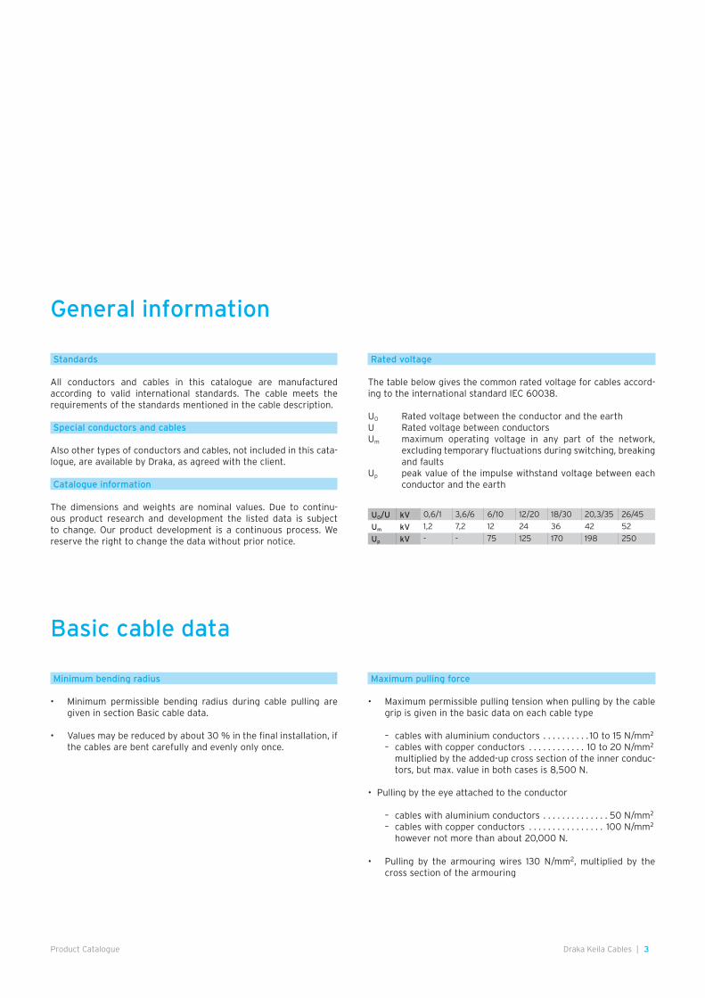
Rated voltage
The table below gives the common rated voltage for cables accord-ing to the international standard IEC 60038.
U0 Rated voltage between the conductor and the earthU Rated voltage between conductorsUm maximum operating voltage in any part of the network,
excluding temporary fluctuations during switching, breaking and faults
Up peak value of the impulse withstand voltage between each conductor and the earth
Basic cable data
Minimum bending radius
• Minimum permissible bending radius during cable pulling are given in section Basic cable data.
• Values may be reduced by about 30 % in the final installation, if the cables are bent carefully and evenly only once.
Maximum pulling force
• Maximum permissible pulling tension when pulling by the cable grip is given in the basic data on each cable type
– cables with aluminium conductors . . . . . . . . . . 10 to 15 N/mm2
– cables with copper conductors . . . . . . . . . . . . 10 to 20 N/mm2 multiplied by the added-up cross section of the inner conduc-
tors, but max. value in both cases is 8,500 N.
• Pulling by the eye attached to the conductor
– cables with aluminium conductors . . . . . . . . . . . . . . 50 N/mm2
– cables with copper conductors . . . . . . . . . . . . . . . . 100 N/mm2
however not more than about 20,000 N.
• Pulling by the armouring wires 130 N/mm2, multiplied by the cross section of the armouring
U0/U kV 0,6/1 3,6/6 6/10 12/20 18/30 20,3/35 26/45
Um kV 1,2 7,2 12 24 36 42 52
Up kV - - 75 125 170 198 250
4 | Draka Keila Cables Product Catalogue
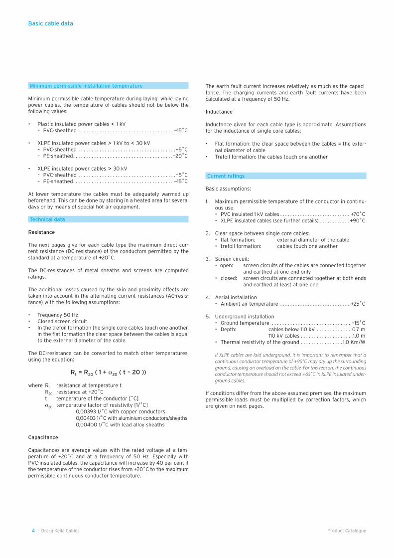
Minimum permissible installation temperature
Minimum permissible cable temperature during laying: while laying power cables, the temperature of cables should not be below the following values:
• Plastic insulated power cables < 1 kV – PVC-sheathed . . . . . . . . . . . . . . . . . . . . . . . . . . . . . . . . . . . . —15˚C
• XLPE insulated power cables > 1 kV to < 30 kV – PVC-sheathed . . . . . . . . . . . . . . . . . . . . . . . . . . . . . . . . . . . . .—5˚C – PE-sheathed . . . . . . . . . . . . . . . . . . . . . . . . . . . . . . . . . . . . . .—20˚C
• XLPE insulated power cables > 30 kV – PVC-sheathed . . . . . . . . . . . . . . . . . . . . . . . . . . . . . . . . . . . . .—5˚C – PE-sheathed . . . . . . . . . . . . . . . . . . . . . . . . . . . . . . . . . . . . . . —15˚C
At lower temperature the cables must be adequately warmed up beforehand. This can be done by storing in a heated area for several days or by means of special hot air equipment.
Technical data
Resistance
The next pages give for each cable type the maximum direct cur-rent resistance (DC-resistance) of the conductors permitted by the standard at a temperature of +20˚C.
The DC-resistances of metal sheaths and screens are computed ratings.
The additional losses caused by the skin and proximity effects are taken into account in the alternating current resistances (AC-resis-tance) with the following assumptions:
• Frequency 50 Hz• Closed screen circuit• In the trefoil formation the single core cables touch one another,
in the flat formation the clear space between the cables is equal to the external diameter of the cable.
The DC-resistance can be converted to match other temperatures, using the equation:
Rt = R20 ( 1 + a20 ( t – 20 ))
where Rt resistance at temperature t R20 resistance at +20˚C t temperature of the conductor [˚C] a20 temperature factor of resistivity [1/˚C] 0,00393 1/˚C with copper conductors 0,00403 1/˚C with aluminium conductors/sheaths 0,00400 1/˚C with lead alloy sheaths
Capacitance
Capacitances are average values with the rated voltage at a tem-perature of +20˚C and at a frequency of 50 Hz. Especially with PVC-insulated cables, the capacitance will increase by 40 per cent if the temperature of the conductor rises from +20˚C to the maximum permissible continuous conductor temperature.
The earth fault current increases relatively as much as the capaci-tance. The charging currents and earth fault currents have been calculated at a frequency of 50 Hz.
Inductance
Inductance given for each cable type is approximate. Assumptions for the inductance of single core cables:
• Flat formation: the clear space between the cables = the exter-nal diameter of cable
• Trefoil formation: the cables touch one another
Current ratings
Basic assumptions:
1. Maximum permissible temperature of the conductor in continu-ous use:
• PVC insulated 1 kV cables . . . . . . . . . . . . . . . . . . . . . . . . . . . . +70˚C • XLPE insulated cables (see further details) . . . . . . . . . . . . +90˚C
2. Clear space between single core cables: • flat formation: external diameter of the cable • trefoil formation: cables touch one another
3. Screen circuit: • open: screen circuits of the cables are connected together
and earthed at one end only • closed: screen circuits are connected together at both ends
and earthed at least at one end
4. Aerial installation • Ambient air temperature . . . . . . . . . . . . . . . . . . . . . . . . . . . . +25˚C
5. Underground installation • Ground temperature . . . . . . . . . . . . . . . . . . . . . . . . . . . . . . +15˚C • Depth: cables below 110 kV . . . . . . . . . . . . . 0,7 m 110 kV cables . . . . . . . . . . . . . . . . . . . .1,0 m • Thermal resistivity of the ground . . . . . . . . . . . . . . . . 1,0 Km/W
If XLPE cables are laid underground, it is important to remember that a continuous conductor temperature of +90˚C may dry up the surrounding ground, causing an overload on the cable. For this reason, the continuous conductor temperature should not exceed +65˚C in XLPE insulated under-ground cables.
If conditions differ from the above-assumed premises, the maximum permissible loads must be multiplied by correction factors, which are given on next pages.
Basic cable data
5Draka Keila Cables |Product Catalogue
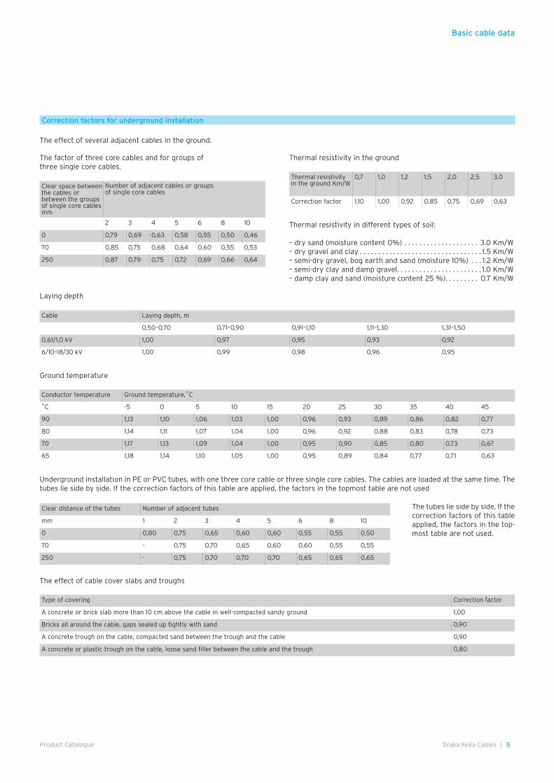
The effect of cable cover slabs and troughs
The tubes lie side by side. If the correction factors of this table applied, the factors in the top-most table are not used.
Ground temperature
The factor of three core cables and for groups of three single core cables.
Thermal resistivity in the ground
Laying depth
Correction factors for underground installation
Thermal resistivity in different types of soil:
– dry sand (moisture content 0%) . . . . . . . . . . . . . . . . . . . . 3.0 Km/W– dry gravel and clay . . . . . . . . . . . . . . . . . . . . . . . . . . . . . . . . . 1.5 Km/W– semi-dry gravel, bog earth and sand (moisture 10%) . . . 1.2 Km/W– semi-dry clay and damp gravel . . . . . . . . . . . . . . . . . . . . . . . 1.0 Km/W– damp clay and sand (moisture content 25 %) . . . . . . . . . 0.7 Km/W
Underground installation in PE or PVC tubes, with one three core cable or three single core cables. The cables are loaded at the same time. The tubes lie side by side. If the correction factors of this table are applied, the factors in the topmost table are not used
The effect of several adjacent cables in the ground.
Basic cable data
Thermal resistivity in the ground Km/W
0,7 1,0 1,2 1,5 2,0 2,5 3,0
Correction factor 1,10 1,00 0,92 0,85 0,75 0,69 0,63
Cable Laying depth, m
0,50–0,70 0,71–0,90 0,91–1,10 1,11–1,30 1,31–1,50
0,61/1,0 kV 1,00 0,97 0,95 0,93 0,92
6/10–18/30 kV 1,00 0,99 0,98 0,96 0,95
Conductor temperature Ground temperature,˚C
˚C -5 0 5 10 15 20 25 30 35 40 45
90 1,13 1,10 1,06 1,03 1,00 0,96 0,93 0,89 0,86 0,82 0,77
80 1,14 1,11 1,07 1,04 1,00 0,96 0,92 0,88 0,83 0,78 0,73
70 1,17 1,13 1,09 1,04 1,00 0,95 0,90 0,85 0,80 0,73 0,67
65 1,18 1,14 1,10 1,05 1,00 0,95 0,89 0,84 0,77 0,71 0,63
Clear distance of the tubes Number of adjacent tubes
mm 1 2 3 4 5 6 8 10
0 0,80 0,75 0,65 0,60 0,60 0,55 0,55 0,50
70 - 0,75 0,70 0,65 0,60 0,60 0,55 0,55
250 - 0,75 0,70 0,70 0,70 0,65 0,65 0,65
Type of covering Correction factor
A concrete or brick slab more than 10 cm above the cable in well-compacted sandy ground 1,00
Bricks all around the cable, gaps sealed up tightly with sand 0,90
A concrete trough on the cable, compacted sand between the trough and the cable 0,90
A concrete or plastic trough on the cable, loose sand filler between the cable and the trough 0,80
Clear space between the cables or between the groups of single core cables mm
Number of adjacent cables or groups of single core cables
2 3 4 5 6 8 10
0 0,79 0,69 0,63 0,58 0,55 0,50 0,46
70 0,85 0,75 0,68 0,64 0,60 0,55 0,53
250 0,87 0,79 0,75 0,72 0,69 0,66 0,64
6 | Draka Keila Cables Product Catalogue
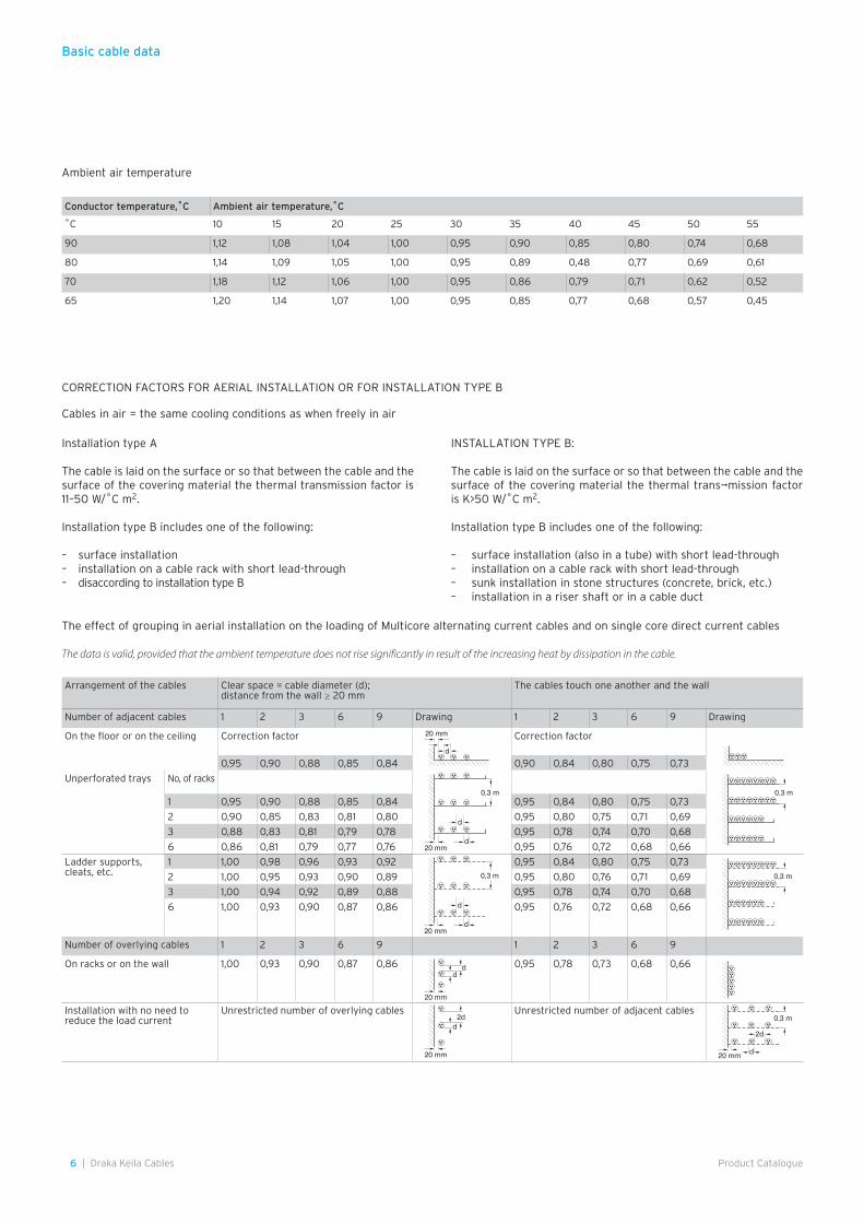
The effect of grouping in aerial installation on the loading of Multicore alternating current cables and on single core direct current cables
The data is valid, provided that the ambient temperature does not rise significantly in result of the increasing heat by dissipation in the cable.
Installation type A
The cable is laid on the surface or so that between the cable and the surface of the covering material the thermal transmission factor is 11–50 W/˚C m2.
Installation type B includes one of the following:
– surface installation– installation on a cable rack with short lead-through– disaccording to installation type B
INSTALLATION TYPE B: The cable is laid on the surface or so that between the cable and the surface of the covering material the thermal trans¬mission factor is K>50 W/˚C m2.
Installation type B includes one of the following:
– surface installation (also in a tube) with short lead-through– installation on a cable rack with short lead-through– sunk installation in stone structures (concrete, brick, etc.)– installation in a riser shaft or in a cable duct
Ambient air temperature
Cables in air = the same cooling conditions as when freely in air
CORRECTION FACTORS FOR AERIAL INSTALLATION OR FOR INSTALLATION TYPE B
Basic cable data
Conductor temperature,˚C Ambient air temperature,˚C
˚C 10 15 20 25 30 35 40 45 50 55
90 1,12 1,08 1,04 1,00 0,95 0,90 0,85 0,80 0,74 0,68
80 1,14 1,09 1,05 1,00 0,95 0,89 0,48 0,77 0,69 0,61
70 1,18 1,12 1,06 1,00 0,95 0,86 0,79 0,71 0,62 0,52
65 1,20 1,14 1,07 1,00 0,95 0,85 0,77 0,68 0,57 0,45
Arrangement of the cables Clear space = cable diameter (d); distance from the wall ≥ 20 mm
The cables touch one another and the wall
Number of adjacent cables 1 2 3 6 9 Drawing 1 2 3 6 9 Drawing
On the floor or on the ceiling Correction factor 20 mm
d
Correction factor
0,95 0,90 0,88 0,85 0,84 0,90 0,84 0,80 0,75 0,73
Unperforated trays No, of racks
1 0,95 0,90 0,88 0,85 0,84 0,95 0,84 0,80 0,75 0,73
2 0,90 0,85 0,83 0,81 0,80 0,95 0,80 0,75 0,71 0,69
3 0,88 0,83 0,81 0,79 0,78 0,95 0,78 0,74 0,70 0,68
6 0,86 0,81 0,79 0,77 0,76 0,95 0,76 0,72 0,68 0,66
Ladder supports,cleats, etc.
1 1,00 0,98 0,96 0,93 0,92 0,95 0,84 0,80 0,75 0,73
2 1,00 0,95 0,93 0,90 0,89 0,95 0,80 0,76 0,71 0,69
3 1,00 0,94 0,92 0,89 0,88 0,95 0,78 0,74 0,70 0,68
6 1,00 0,93 0,90 0,87 0,86 0,95 0,76 0,72 0,68 0,66
Number of overlying cables 1 2 3 6 9 1 2 3 6 9
On racks or on the wall 1,00 0,93 0,90 0,87 0,86 0,95 0,78 0,73 0,68 0,66
Installation with no need to reduce the load current
Unrestricted number of overlying cables Unrestricted number of adjacent cables
20 mm
d
d
0,3 m
20 mm
dd
20 mm
2dd
20 mm
d
d
0,3 m 0,3 m
0,3 m
20 mm
2d
d
0,3 m
7Draka Keila Cables |Product Catalogue
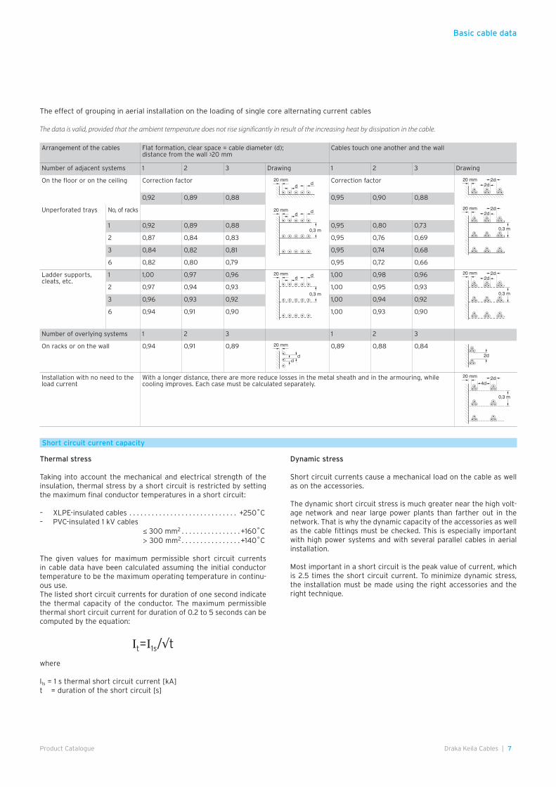
The effect of grouping in aerial installation on the loading of single core alternating current cables
The data is valid, provided that the ambient temperature does not rise significantly in result of the increasing heat by dissipation in the cable.
Short circuit current capacity
Thermal stress
Taking into account the mechanical and electrical strength of the insulation, thermal stress by a short circuit is restricted by setting the maximum final conductor temperatures in a short circuit:
– XLPE-insulated cables . . . . . . . . . . . . . . . . . . . . . . . . . . . . . +250˚C– PVC-insulated 1 kV cables ≤ 300 mm2 . . . . . . . . . . . . . . . . +160˚C > 300 mm2 . . . . . . . . . . . . . . . . +140˚C
The given values for maximum permissible short circuit currents in cable data have been calculated assuming the initial conductor temperature to be the maximum operating temperature in continu-ous use.The listed short circuit currents for duration of one second indicate the thermal capacity of the conductor. The maximum permissible thermal short circuit current for duration of 0.2 to 5 seconds can be computed by the equation:
Ιt=Ι1s/√t
where
l1s = 1 s thermal short circuit current [kA] t = duration of the short circuit [s]
Dynamic stress
Short circuit currents cause a mechanical load on the cable as well as on the accessories.
The dynamic short circuit stress is much greater near the high volt-age network and near large power plants than farther out in the network. That is why the dynamic capacity of the accessories as well as the cable fittings must be checked. This is especially important with high power systems and with several parallel cables in aerial installation.
Most important in a short circuit is the peak value of current, which is 2.5 times the short circuit current. To minimize dynamic stress, the installation must be made using the right accessories and the right technique.
Basic cable data
Arrangement of the cables Flat formation, clear space = cable diameter (d); distance from the wall >20 mm
Cables touch one another and the wall
Number of adjacent systems 1 2 3 Drawing 1 2 3 Drawing
On the floor or on the ceiling Correction factor Correction factor
0,92 0,89 0,88 0,95 0,90 0,88
Unperforated trays No, of racks
1 0,92 0,89 0,88 0,95 0,80 0,73
2 0,87 0,84 0,83 0,95 0,76 0,69
3 0,84 0,82 0,81 0,95 0,74 0,68
6 0,82 0,80 0,79 0,95 0,72 0,66
Ladder supports, cleats, etc.
1 1,00 0,97 0,96 1,00 0,98 0,96
2 0,97 0,94 0,93 1,00 0,95 0,93
3 0,96 0,93 0,92 1,00 0,94 0,92
6 0,94 0,91 0,90 1,00 0,93 0,90
Number of overlying systems 1 2 3 1 2 3
On racks or on the wall 0,94 0,91 0,89 0,89 0,88 0,84
Installation with no need to the load current
With a longer distance, there are more reduce losses in the metal sheath and in the armouring, while cooling improves. Each case must be calculated separately.
20 mmd d
20 mm2d
2d
20 mmd d
0,3 m
20 mm2d
2d
0,3 m
20 mmd d
0,3 m
20 mm2d
2d
0,3 m
20 mm
dd
2d
20 mm
4d2d
0,3 m
8 | Draka Keila Cables Product Catalogue
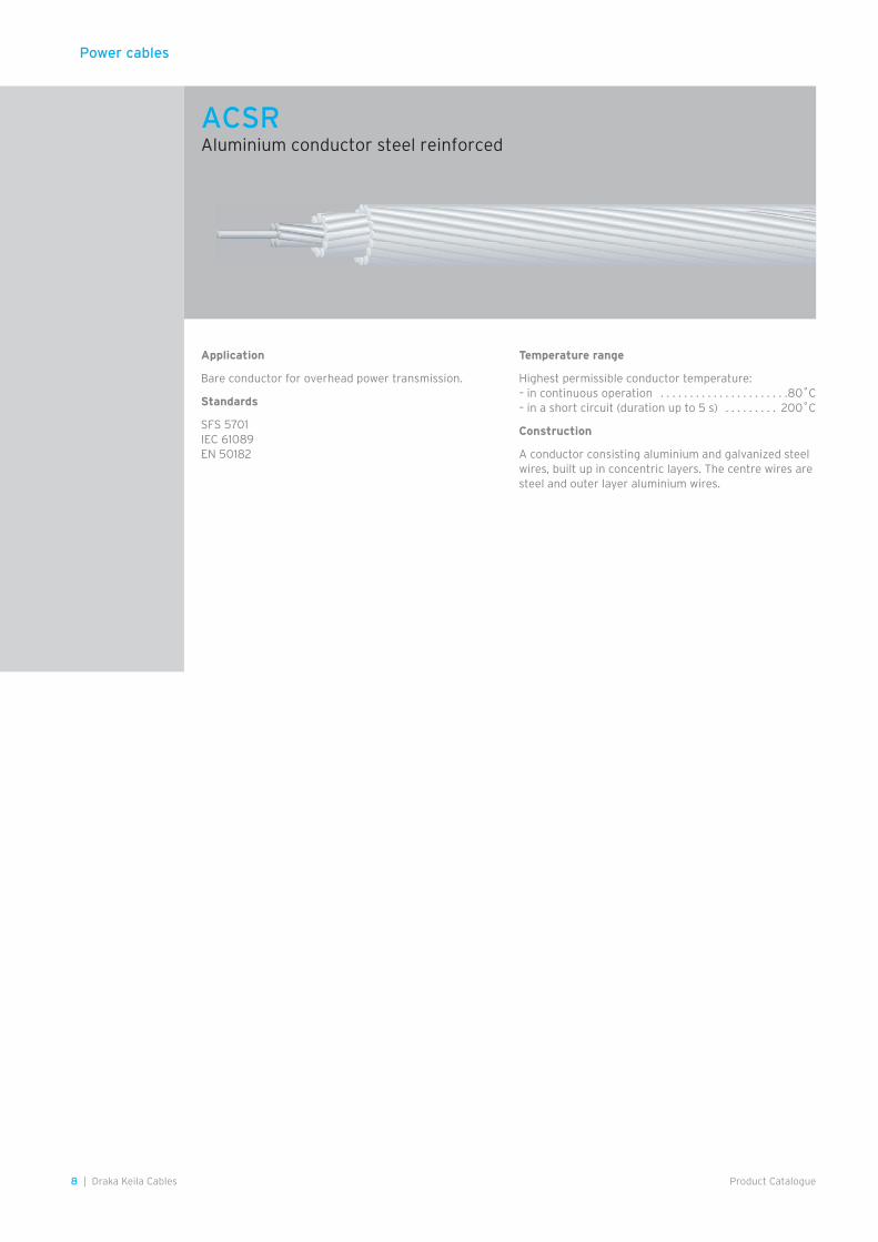
Application
Bare conductor for overhead power transmission.
Standards
SFS 5701IEC 61089EN 50182
Temperature range
Highest permissible conductor temperature:– in continuous operation . . . . . . . . . . . . . . . . . . . . . .80˚C– in a short circuit (duration up to 5 s) . . . . . . . . . 200˚C
Construction
A conductor consisting aluminium and galvanized steel wires, built up in concentric layers. The centre wires are steel and outer layer aluminium wires.
Power cables
ACSRAluminium conductor steel reinforced
9Draka Keila Cables |Product Catalogue
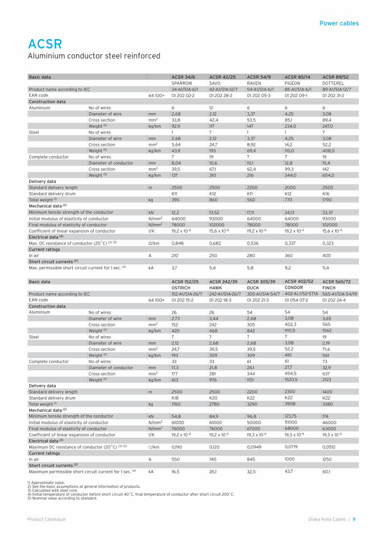
Basic data ACSR 34/6 ACSR 42/25 ACSR 54/9 ACSR 85/14 ACSR 89/52SPARROW SAVO RAVEN PIGEON DOTTEREL
Product name according to IEC 34-A1/S1A-6/1 42-A1/S1A-12/7 54-A1/S1A-6/1 85-A1/S1A-6/1 89-A1/S1A-12/7EAN code 64 100+ 01 202 02-2 01 202 28-2 01 202 05-3 01 202 09-1 01 202 31-2
Construction data
Aluminium No of wires 6 12 6 6 6
Diameter of wire mm 2,68 2,12 3,37 4,25 3,08
Cross section mm2 33,8 42,4 53,5 85,1 89,4
Weight (5) kg/km 92,9 117 147 234,0 247,0
Steel No of wires 1 7 1 1 7
Diameter of wire mm 2,68 2,12 3,37 4,25 3,08
Cross section mm2 5,64 24,7 8,92 14,2 52,2
Weight (5) kg/km 43,9 193 69,4 110,0 408,0
Complete conductor No of wires 7 19 7 7 19
Diameter of conductor mm 8,04 10,6 10,1 12,8 15,4
Cross section mm2 39,5 67,1 62,4 99,3 142
Weight (5) kg/km 137 310 216 344,0 654,0
Delivery data
Standard delivery length m 2500 2500 2200 2000 2500
Standard delivery drum K11 K12 K11 K12 K16
Total weight (1) kg 390 860 560 770 1790
Mechanical data (2)
Minimum tensile strength of the conductor kN 12,2 13,52 17,11 24,13 33,37
Initial modulus of elasticity of conductor N/mm2 64000 93000 64000 64000 93000
Final modulus of elasticity of conductor N/mm2 78000 102000 78000 78000 102000
Coefficient of linear expansion of conductor 1/K 19,2 x 10⁻⁶ 15,6 x 10⁻⁶ 19,2 x 10⁻⁶ 19,2 x 10⁻⁶ 15,6 x 10⁻⁶
Electrical data (2)
Max. DC resistance of conductor (20˚C) (3) (5) Ω/km 0,848 0,682 0,536 0,337 0,323
Current ratings
In air A 210 250 280 360 400
Short circuit currents (2)
Max. permissible short circuit current for 1 sec. (4) kA 3,7 5,4 5,8 9,2 11,4
1) Approximate value.2) See the basic assumptions at general information of products.3) Calculated with steel core.4) Initial temperature of conductor before short circuit 40˚C, final temperature of conductor after short circuit 200˚C.5) Nominal value according to standard.
ACSRAluminium conductor steel reinforced
Basic data ACSR 152/25 ACSR 242/39 ACSR 305/39 ACSR 402/52 ACSR 565/72
OSTRICH HAWK DUCK CONDOR FINCH
Product name according to IEC 152-A1/S1A-26/7 242-A1/S1A-26/7 305-A1/S1A-54/7 402-AL1/52-ST1A 565-A1/S1A-54/19EAN code 64 100+ 01 202 15-2 01 202 18-3 01 202 21-3 01 054 07-2 01 202 24-4
Construction dataAluminium No of wires 26 26 54 54 54
Diameter of wire mm 2,73 3,44 2,68 3,08 3,65
Cross section mm2 152 242 305 402,3 565
Weight (5) kg/km 420 668 842 1110,5 1562
Steel No of wires 7 7 7 7 19
Diameter of wire mm 2,12 2,68 2,68 3,08 2,19
Cross section mm2 24,7 39,5 39,5 52,2 71,6
Weight (5) kg/km 193 309 309 410 561
Complete conductor No of wires 33 33 61 61 73
Diameter of conductor mm 17,3 21,8 24,1 27,7 32,9
Cross section mm2 177 281 344 454,5 637
Weight (5) kg/km 613 976 1151 1520,5 2123
Delivery data
Standard delivery length m 2500 2500 2200 2300 1400
Standard delivery drum K18 K20 K22 K22 K22
Total weight (1) kg 1760 2780 3290 3908 3380
Mechanical data (2)
Minimum tensile strength of the conductor kN 54,8 84,9 96,8 123,75 174
Initial modulus of elasticity of conductor N/mm2 61000 61000 50000 51000 46000
Final modulus of elasticity of conductor N/mm2 76000 76000 67000 68000 63000
Coefficient of linear expansion of conductor 1/K 19,2 x 10⁻⁶ 19,2 x 10⁻⁶ 19,3 x 10⁻⁶ 19,3 x 10⁻⁶ 19,3 x 10⁻⁶
Electrical data (2)
Maximum DC resistance of conductor (20˚C) (3) (5) Ω/km 0,190 0,120 0,0949 0,0719 0,0512
Current ratings
In air A 550 745 845 1000 1250
Short circuit currents (2)
Maximum permissible short circuit current for 1 sec. (4) kA 16,5 26,1 32,5 43,7 60,1
Power cables
Power cables
10 | Draka Keila Cables Product Catalogue
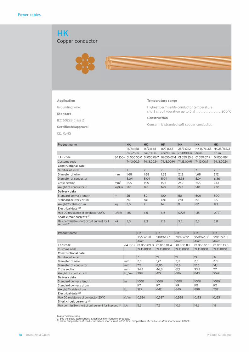
Application
Grounding wire.
Standard
IEC 60228 Class 2
Certificate/approval
CE, RoHS
Temperature range
Highest permissible conductor temperatureshort circuit (duration up to 5 s) . . . . . . . . . . . . . . 200˚C
Construction
Concentric stranded soft copper conductor.
1) Approximate value2) See the basic assumptions at general information of products.3) Initial temperature of conductor before short circuit 40˚C, final temperature of conductor after short circuit 200˚C.
Product name HK HK HK HK HK HK
16/7x1.68 16/7x1.68 16/7x1.68 25/7x2.12 HK 16/7x1.68 HK 25/7x2.12
coil/25 m coil/50 m coil/100 m coil/100 m drum drumEAN code 64 100+ 01 050 05-0 01 050 06-7 01 050 07-4 01 050 25-8 01 550 07-9 01 050 08-1
Customs code 74.13.00.91 74.13.00.91 74.13.00.91 74.13.00.91 74.13.00.91 74.13.00.91
Constructional data
Number of wires 7 7 7 7 7 7
Diameter of wire mm 1,68 1,68 1,68 2,12 1,68 2,12
Diameter of conductor 5,04 5,04 5,04 6,36 5,04 6,36
Cross section mm2 15,5 15,5 15,5 24,7 15,5 24,7
Weight of conductor (1) kg/km 140 140 140 222 140 222
Delivery data
Standard delivery length m 25 50 100 50 500 500
Standard delivery drum coil coil coil coil K6 K6
Weight (1) cable+drum kg 3,5 7 14 11 82 123
Electrical data (2)
Max DC resistance of conductor 20˚C Ω/km 1,15 1,15 1,15 0,727 1,15 0,727
Short circuit currents (2)
Max permissible short circuit current for 1 second (3)
kA 2,3 2,3 2,3 3,8 2,3 3,8
Product name HK HK HK HK HK35/7x2.50 50/19x1.77 70/19x2.12 95/19x2.50 120/37x2.01drum drum drum drum drum
EAN code 64 100+ 01 050 09-8 01 050 10-4 01 050 11-1 01 050 12-8 01 050 13-5 Customs code 74.13.00.91 74.13.00.91 74.13.00.91 74.13.00.91 74.13.00.91 Constructional data Number of wires 7 19 19 19 37Diameter of wire mm 2,5 1,77 2,12 2,5 2,01Diameter of conductor mm 7,5 8,85 10,6 12,5 14,1Cross section mm2 34,4 46,8 67,1 93,3 117Weight of conductor (1) kg/km 309 422 606 843 1062Delivery data Standard delivery length m 1000 1000 1000 1000 1000Standard delivery drum K7 K7 K9 K11 K11Weight (1) cable+drum kg 329 642 640 898 1152Electrical data (2) Max DC resistance of conductor 20˚C Ω/km 0,524 0,387 0,268 0,193 0,153Short circuit currents (2) Max permissible short circuit current for 1 second (3) kA 5,3 7,2 10,3 14,3 18
HKCopper conductor
Power cables
11Draka Keila Cables |Product Catalogue
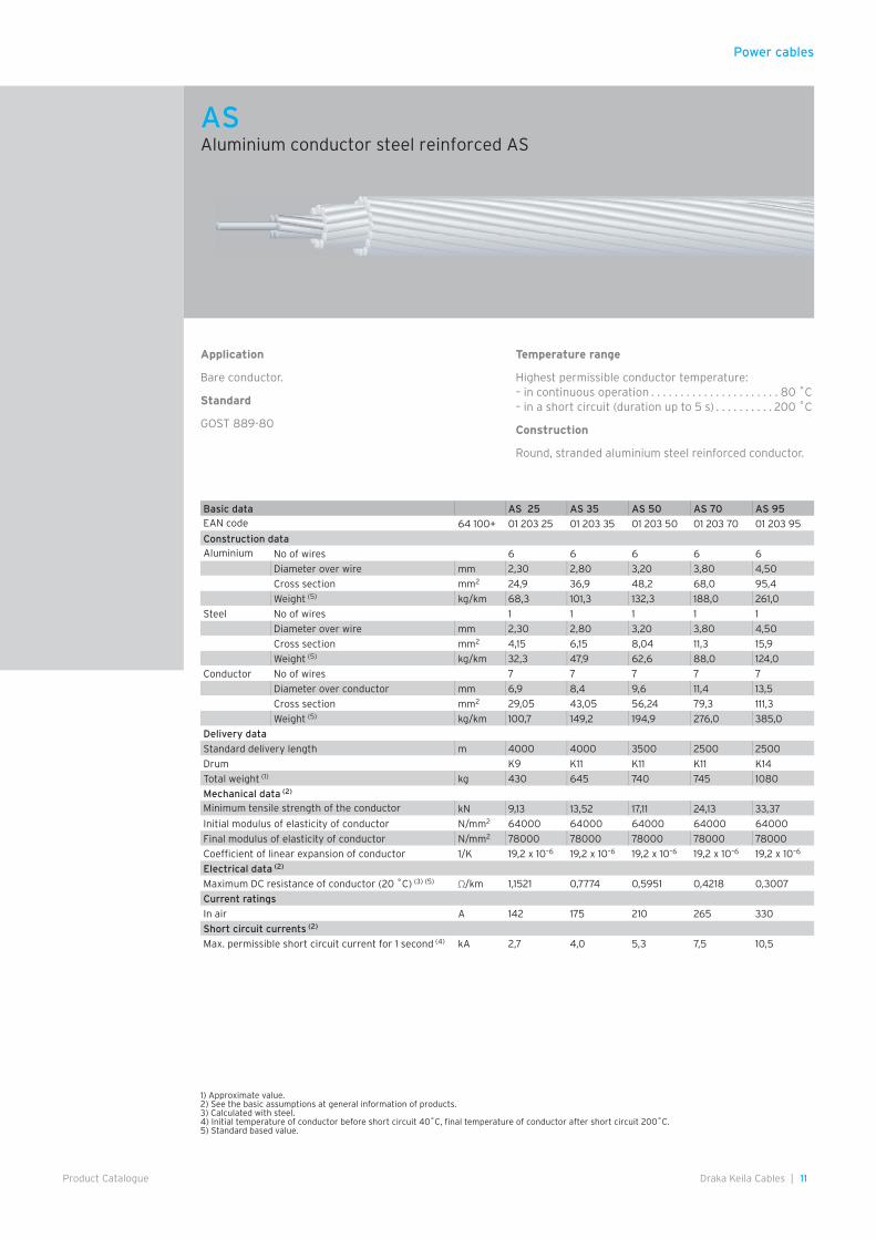
Application
Bare conductor.
Standard
GOST 889-80
Temperature range
Highest permissible conductor temperature:– in continuous operation . . . . . . . . . . . . . . . . . . . . . . 80 ˚C– in a short circuit (duration up to 5 s) . . . . . . . . . . 200 ˚C
Construction
Round, stranded aluminium steel reinforced conductor.
Basic data AS 25 AS 35 AS 50 AS 70 AS 95EAN code 64 100+ 01 203 25 01 203 35 01 203 50 01 203 70 01 203 95
Construction dataAluminium No of wires 6 6 6 6 6
Diameter over wire mm 2,30 2,80 3,20 3,80 4,50
Cross section mm2 24,9 36,9 48,2 68,0 95,4
Weight (5) kg/km 68,3 101,3 132,3 188,0 261,0
Steel No of wires 1 1 1 1 1
Diameter over wire mm 2,30 2,80 3,20 3,80 4,50
Cross section mm2 4,15 6,15 8,04 11,3 15,9
Weight (5) kg/km 32,3 47,9 62,6 88,0 124,0
Conductor No of wires 7 7 7 7 7
Diameter over conductor mm 6,9 8,4 9,6 11,4 13,5
Cross section mm2 29,05 43,05 56,24 79,3 111,3
Weight (5) kg/km 100,7 149,2 194,9 276,0 385,0
Delivery data
Standard delivery length m 4000 4000 3500 2500 2500
Drum K9 K11 K11 K11 K14
Total weight (1) kg 430 645 740 745 1080
Mechanical data (2)
Minimum tensile strength of the conductor kN 9,13 13,52 17,11 24,13 33,37
Initial modulus of elasticity of conductor N/mm2 64000 64000 64000 64000 64000
Final modulus of elasticity of conductor N/mm2 78000 78000 78000 78000 78000
Coefficient of linear expansion of conductor 1/K 19,2 x 10⁻⁶ 19,2 x 10⁻⁶ 19,2 x 10⁻⁶ 19,2 x 10⁻⁶ 19,2 x 10⁻⁶
Electrical data (2)
Maximum DC resistance of conductor (20 ˚C) (3) (5) Ω/km 1,1521 0,7774 0,5951 0,4218 0,3007
Current ratings
In air A 142 175 210 265 330
Short circuit currents (2)
Max. permissible short circuit current for 1 second (4) kA 2,7 4,0 5,3 7,5 10,5
1) Approximate value.2) See the basic assumptions at general information of products.3) Calculated with steel.4) Initial temperature of conductor before short circuit 40˚C, final temperature of conductor after short circuit 200˚C.5) Standard based value.
ASAluminium conductor steel reinforced AS
Power cables
12 | Draka Keila Cables Product Catalogue
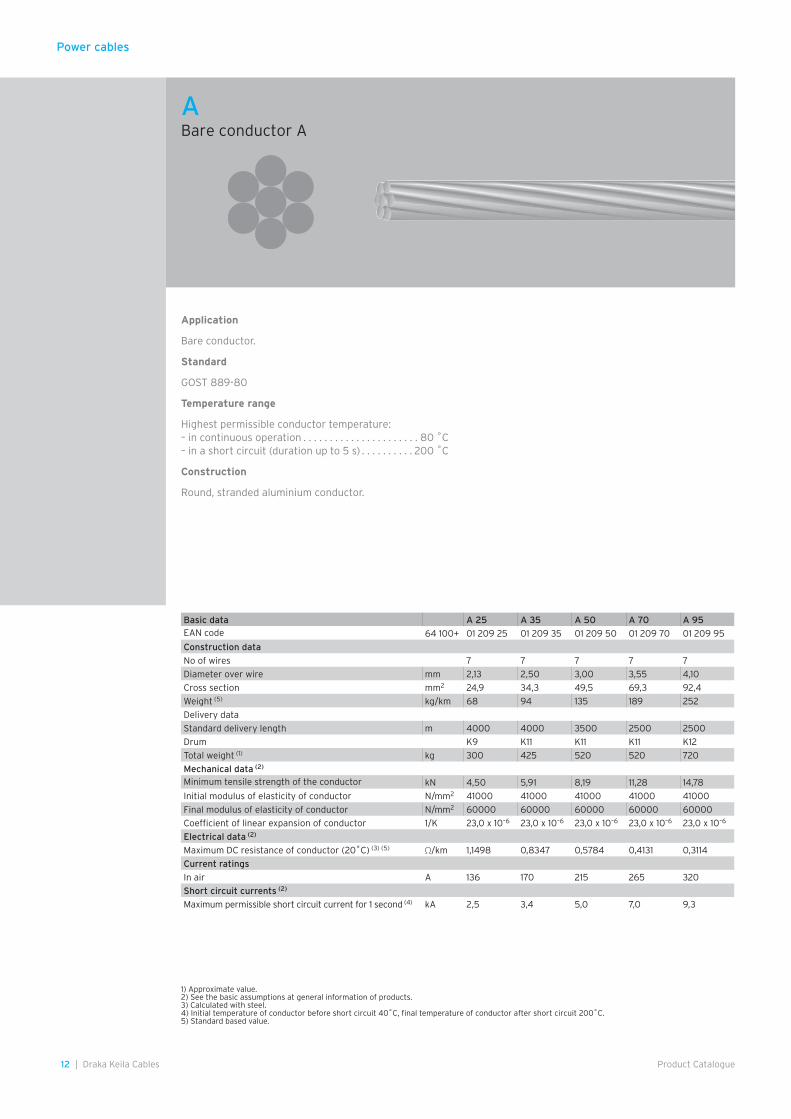
Application
Bare conductor.
Standard
GOST 889-80
Temperature range
Highest permissible conductor temperature:– in continuous operation . . . . . . . . . . . . . . . . . . . . . . 80 ˚C– in a short circuit (duration up to 5 s) . . . . . . . . . . 200 ˚C
Construction
Round, stranded aluminium conductor.
Basic data A 25 A 35 A 50 A 70 A 95EAN code 64 100+ 01 209 25 01 209 35 01 209 50 01 209 70 01 209 95
Construction data
No of wires 7 7 7 7 7
Diameter over wire mm 2,13 2,50 3,00 3,55 4,10
Cross section mm2 24,9 34,3 49,5 69,3 92,4
Weight (5) kg/km 68 94 135 189 252
Delivery data
Standard delivery length m 4000 4000 3500 2500 2500
Drum K9 K11 K11 K11 K12
Total weight (1) kg 300 425 520 520 720
Mechanical data (2)
Minimum tensile strength of the conductor kN 4,50 5,91 8,19 11,28 14,78
Initial modulus of elasticity of conductor N/mm2 41000 41000 41000 41000 41000
Final modulus of elasticity of conductor N/mm2 60000 60000 60000 60000 60000
Coefficient of linear expansion of conductor 1/K 23,0 x 10⁻⁶ 23,0 x 10⁻⁶ 23,0 x 10⁻⁶ 23,0 x 10⁻⁶ 23,0 x 10⁻⁶
Electrical data (2)
Maximum DC resistance of conductor (20˚C) (3) (5) Ω/km 1,1498 0,8347 0,5784 0,4131 0,3114
Current ratings
In air A 136 170 215 265 320
Short circuit currents (2)
Maximum permissible short circuit current for 1 second (4) kA 2,5 3,4 5,0 7,0 9,3
1) Approximate value.2) See the basic assumptions at general information of products.3) Calculated with steel.4) Initial temperature of conductor before short circuit 40˚C, final temperature of conductor after short circuit 200˚C.5) Standard based value.
ABare conductor A
Power cables
13Draka Keila Cables |Product Catalogue
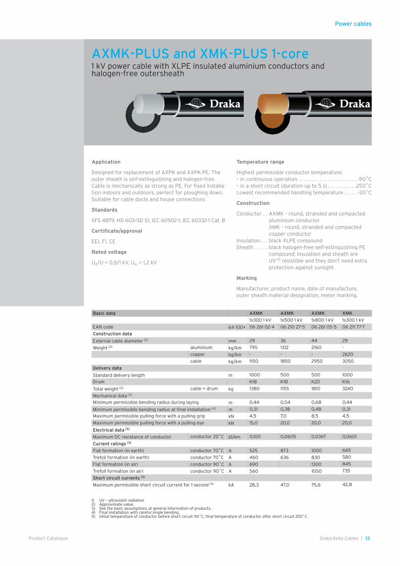
Application
Designed for replacement of AXPK and AXPK-PE. The outer sheath is self-extinguishing and halogen-free. Cable is mechanically as strong as PE. For fixed installa-tion indoors and outdoors, perfect for ploughing down. Suitable for cable ducts and house connections
Standards
SFS 4879, HD 603-5D S1, IEC 60502-1, IEC 60332-1 Cat. B
Certificate/approval
EEI, FI, CE
Rated voltage
U0/U = 0,6/1 kV, Um = 1,2 kV
Temperature range
Highest permissible conductor temperature:– in continuous operation . . . . . . . . . . . . . . . . . . . . . . .90˚C– in a short circuit (duration up to 5 s) . . . . . . . . . . .250˚CLowest recommended handling temperature . . . . . –20˚C
Construction
Conductor . . AXMK – round, stranded and compacted aluminium conductorXMK – round, stranded and compacted copper conductor
Insulation . . . black XLPE compoundSheath . . . . . black halogen-free self-extinguishing PE
compound; insulation and sheath are UV (1) resistible and they don't need extra protection against sunlight.
Marking
Manufacturer, product name, date of manufacture, outer sheath material designation, meter marking.
Basic data AXMK AXMK AXMK XMK
1x300 1 kV 1x500 1 kV 1x800 1 kV 1x300 1 kV
EAN code 64 100+ 06 261 02-4 06 210 27-5 06 261 05-5 06 211 77-7
Construction data
External cable diameter (2) mm 29 36 44 29
Weight (2) aluminium kg/km 795 1312 2160 -
copper kg/km - - - 2620
cable kg/km 1150 1850 2950 3050
Delivery data
Standard delivery length m 1000 500 500 1000
Drum K18 K18 K20 K16
Total weight (2) cable + drum kg 1380 1155 1810 3240
Mechanical data (3)
Minimum permissible bending radius during laying m 0,44 0,54 0,68 0,44
Minimum permissible bending radius at final installation (4) m 0,31 0,38 0,48 0,31
Maximum permissible pulling force with a pulling grip kN 4,5 7,0 8,5 4,5
Maximum permissible pulling force with a pulling eye kN 15,0 20,0 20,0 20,0
Electrical data (3)
Maximum DC resistance of conductor conductor 20˚C Ω/km 0,100 0,0605 0,0367 0,0601
Current ratings (3)
Flat formation (in earth) conductor 70˚C A 525 873 1000 665
Trefoil formation (in earth) conductor 70˚C A 460 636 830 580
Flat formation (in air) conductor 90˚C A 690 1300 845
Trefoil formation (in air) conductor 90˚C A 560 1050 735
Short circuit currents (3)
Maximum permissible short circuit current for 1 second (5) kA 28,3 47,0 75,6 42,8
1) UV – ultraviolet radiation2) Approximate value.3) See the basic assumptions at general information of products.4) Final installation with careful single bending.5) Initial temperature of conductor before short circuit 90˚C, final temperature of conductor after short circuit 250˚C.
AXMK-PLUS and XMK-PLUS 1-core1 kV power cable with XLPE insulated aluminium conductors and halogen-free outersheath

14 | Draka Keila Cables Product Catalogue
Power cables
Application
Designed for replacement of AXPK and AXPK-PE. The outer sheath is self-extinguishing and halogen-free. Cable is mechanically as strong as PE sheathed cable. For fixed installation indoors and outdoors, perfect for ploughing down. Suitable for cable ducts and house connections.
Standards
SFS 4879, HD 603-5D S1, IEC 60502-1, IEC 60332-1 Cat. B, HD 308 S2:2002
Certificate/approval
FI, CE
Rated voltage
U0/U = 0,6/1 kVUm = 1,2 kV
Temperature range
Highest permissible conductor temperature: - in continuous operation . . . . . . . . . . . . . . . . . . . . . . .90˚C- in a short circuit (duration up to 5 s) . . . . . . . . . . 250˚CLowest recommended temp. during laying . . . . . . . –20˚C
Construction
Conductor . . . . . . . 16 mm2 – solid round aluminium conductor;25–300 mm2 – stranded, compacted and annealed sector shaped alu-minium conductor
Insulation . . . . . . . black XLPE compoundLaying up . . . . . . . four insulated conductors stranded
togetherSheath . . . . . . . . . . black halogen-free self-extinguishing
PE compound;insulation and sheath are UV(1) resistible and they don't need extra protection against sunlight.
Identification of cores
Phase conductors . . brown, black, greyPEN conductor . . . yellow-green
Marking
Manufacturer, product name, date of manufacture, outer sheath material designation, meter marking.
1) UV – ultraviolet radiation
AXPK-PLUS1 kV power cable with XLPE insulated aluminium conductors and halogen-free outersheath
15Draka Keila Cables |Product Catalogue
Power cables
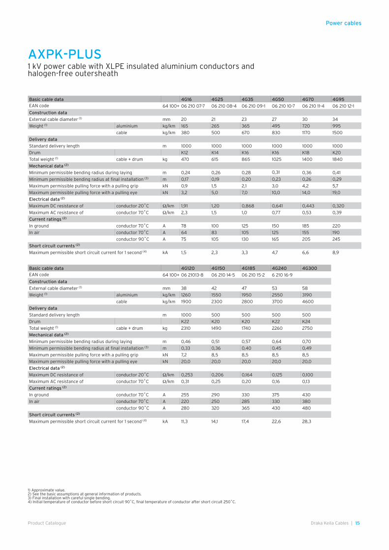
Basic cable data 4G16 4G25 4G35 4G50 4G70 4G95EAN code 64 100+ 06 210 07-7 06 210 08-4 06 210 09-1 06 210 10-7 06 210 11-4 06 210 12-1
Construction data
External cable diameter (1) mm 20 21 23 27 30 34
Weight (1) aluminium kg/km 165 265 365 495 720 995
cable kg/km 380 500 670 830 1170 1500
Delivery data
Standard delivery length m 1000 1000 1000 1000 1000 1000
Drum K12 K14 K16 K16 K18 K20
Total weight (1) cable + drum kg 470 615 865 1025 1400 1840
Mechanical data (2)
Minimum permissible bending radius during laying m 0,24 0,26 0,28 0,31 0,36 0,41
Minimum permissible bending radius at final installation (3) m 0,17 0,19 0,20 0,23 0,26 0,29
Maximum permissible pulling force with a pulling grip kN 0,9 1,5 2,1 3,0 4,2 5,7
Maximum permissible pulling force with a pulling eye kN 3,2 5,0 7,0 10,0 14,0 19,0
Electrical data (2)
Maximum DC resistance of conductor 20˚C Ω/km 1,91 1,20 0,868 0,641 0,443 0,320
Maximum AC resistance of conductor 70˚C Ω/km 2,3 1,5 1,0 0,77 0,53 0,39
Current ratings (2)
In ground conductor 70˚C A 78 100 125 150 185 220
In air conductor 70˚C A 64 83 105 125 155 190
conductor 90˚C A 75 105 130 165 205 245
Short circuit currents (2)
Maximum permissible short circuit current for 1 second (4) kA 1,5 2,3 3,3 4,7 6,6 8,9
Basic cable data 4G120 4G150 4G185 4G240 4G300EAN code 64 100+ 06 21013-8 06 210 14-5 06 210 15-2 6 210 16-9
Construction data
External cable diameter (1) mm 38 42 47 53 58
Weight (1) aluminium kg/km 1260 1550 1950 2550 3190
cable kg/km 1900 2300 2800 3700 4600
Delivery data
Standard delivery length m 1000 500 500 500 500
Drum K22 K20 K20 K22 K24
Total weight (1) cable + drum kg 2310 1490 1740 2260 2750
Mechanical data (2)
Minimum permissible bending radius during laying m 0,46 0,51 0,57 0,64 0,70
Minimum permissible bending radius at final installation (3) m 0,33 0,36 0,40 0,45 0,49
Maximum permissible pulling force with a pulling grip kN 7,2 8,5 8,5 8,5 8,5
Maximum permissible pulling force with a pulling eye kN 20,0 20,0 20,0 20,0 20,0
Electrical data (2)
Maximum DC resistance of conductor 20˚C Ω/km 0,253 0,206 0,164 0,125 0,100
Maximum AC resistance of conductor 70˚C Ω/km 0,31 0,25 0,20 0,16 0,13
Current ratings (2)
In ground conductor 70˚C A 255 290 330 375 430
In air conductor 70˚C A 220 250 285 330 380
conductor 90˚C A 280 320 365 430 480
Short circuit currents (2)
Maximum permissible short circuit current for 1 second (4) kA 11,3 14,1 17,4 22,6 28,3
1) Approximate value.2) See the basic assumptions at general information of products.3) Final installation with careful single bending.4) Initial temperature of conductor before short circuit 90˚C, final temperature of conductor after short circuit 250˚C.
AXPK-PLUS1 kV power cable with XLPE insulated aluminium conductors and halogen-free outersheath

Power cables
16 | Draka Keila Cables Product Catalogue
Application
Fixed indoor, outdoor and underground installations.
Standards
SFS 4879, HD 603-5D S1, IEC 60502-1, IEC 60332-1 Cat. B, HD 308 S2:2002
Certificate/approval
EEI, FI, CE
Rated voltage
U0/U = 0,6/1 kVUm = 1,2 kV
Temperature range
Highest permissible conductor temperature: - in continuous operation . . . . . . . . . . . . . . . . . . . . . . .90˚C- in a short circuit (duration up to 5 s) . . . . . . . . . . 250˚CLowest recommended temp. during laying . . . . . . . –15˚C
Construction
Conductor . . . . . . . 16 mm2 – solid round aluminium conductor;25–300 mm2 – stranded, compacted and annealed sector shaped alu-minium conductor
Insulation . . . . . . . black XLPE compoundLaying up . . . . . . . four insulated conductors stranded
togetherSheath . . . . . . . . . . black PVC;
plastics are UV(1) resistible and they don't need extra protection against sunlight.
Identification of cores
Phase conductors . . brown, black, greyPEN conductor . . . yellow-green
Marking
Manufacturer, product name, date of manufacture, outer sheath material designation, meter marking.
1) UV – ultraviolet radiation
AXPK1 kV power cable with XLPE insulated aluminium conductors

Power cables
17Draka Keila Cables |Product Catalogue
Basic cable data 4G16 4G25 4G35 4G50 4G70 4G95EAN code 64 100+ 06 210 07-7 06 210 08-4 06 210 09-1 06 210 10-7 06 210 11-4 06 210 12-1
Construction data
External cable diameter (1) mm 20 21 23 27 30 34
Weight (1) aluminium kg/km 165 265 365 495 720 995
cable kg/km 380 500 670 830 1170 1500
Delivery data
Standard delivery length m 1000 1000 1000 1000 1000 1000
Drum K12 K14 K16 K16 K18 K20
Total weight (1) cable + drum kg 470 615 865 1025 1400 1840
Mechanical data (2)
Minimum permissible bending radius during laying m 0,24 0,26 0,28 0,31 0,36 0,41
Minimum permissible bending radius at final installation (3) m 0,17 0,19 0,20 0,23 0,26 0,29
Maximum permissible pulling force with a pulling grip kN 0,9 1,5 2,1 3,0 4,2 5,7
Maximum permissible pulling force with a pulling eye kN 3,2 5,0 7,0 10,0 14,0 19,0
Electrical data (2)
Maximum DC resistance of conductor 20˚C Ω/km 1,91 1,20 0,868 0,641 0,443 0,320
Maximum AC resistance of conductor 70˚C Ω/km 2,3 1,5 1,0 0,77 0,53 0,39
Current ratings (2)
In ground conductor 70˚C A 78 100 125 150 185 220
In air conductor 70˚C A 64 83 105 125 155 190
conductor 90˚C A 75 105 130 165 205 245
Short circuit currents (2)
Maximum permissible short circuit current for 1 second (4) kA 1,5 2,3 3,3 4,7 6,6 8,9
Basic cable data 4G120 4G150 4G185 4G240 4G300EAN code 64 100+ 06 21013-8 06 210 14-5 06 210 15-2 6 210 16-9
Construction data
External cable diameter (1) mm 38 42 47 53 58
Weight (1) aluminium kg/km 1260 1550 1950 2550 3190
cable kg/km 1900 2300 2800 3700 4600
Delivery data
Standard delivery length m 1000 500 500 500 500
Drum K22 K20 K20 K22 K24
Total weight (1) cable + drum kg 2310 1490 1740 2260 2750
Mechanical data (2)
Minimum permissible bending radius during laying m 0,46 0,51 0,57 0,64 0,70
Minimum permissible bending radius at final installation (3) m 0,33 0,36 0,40 0,45 0,49
Maximum permissible pulling force with a pulling grip kN 7,2 8,5 8,5 8,5 8,5
Maximum permissible pulling force with a pulling eye kN 20,0 20,0 20,0 20,0 20,0
Electrical data (2)
Maximum DC resistance of conductor 20˚C Ω/km 0,253 0,206 0,164 0,125 0,100
Maximum AC resistance of conductor 70˚C Ω/km 0,31 0,25 0,20 0,16 0,13
Current ratings (2)
In ground conductor 70˚C A 255 290 330 375 430
In air conductor 70˚C A 220 250 285 330 380
conductor 90˚C A 280 320 365 430 480
Short circuit currents (2)
Maximum permissible short circuit current for 1 second (4) kA 11,3 14,1 17,4 22,6 28,3
1) Approximate value.2) See the basic assumptions at general information of products.3) Final installation with careful single bending.4) Initial temperature of conductor before short circuit 90˚C, final temperature of conductor after short circuit 250˚C.
AXPK1 kV power cable with XLPE insulated aluminium conductors

18 | Draka Keila Cables Product Catalogue
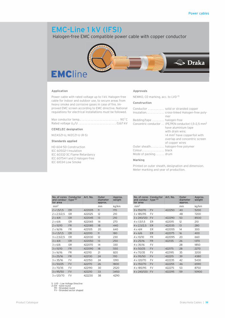
Application
Power cable with rated voltage up to 1 kV. Halogen-free cable for indoor and outdoor use, to secure areas from heavy smoke and corrosive gases in case of fire. Im-proved EMC screen according to EMC directive. National regulations for electrical installations must be followed.
Max conductor temperature. . . . . . . . . . . . . . . . . . . . 9O˚CRated voltage U0/U . . . . . . . . . . . . . . . . . . . . . . . . . 0,6/1 kVCENELEC designation . . . . . . . . . . . . . . . . N1ZCZ1-AR (AS)
Standards applied
HD 604-5D ConstructionIEC 60502-1 InsulationIEC 60332-3C Flame RetardancyIEC 60754-1 and 2 Halogen-freeIEC 61034 Low Smoke
Approvals
NEMKO CE-marked, acc. to LVD(1)
Construction
Conductor . . . . . . . . . . . stranded aluminium Insulation . . . . . . . . . . . . cross-linked halogen-free poly-
mer Bedding/tape . . . . . . . . halogen-free Concentric conductor . . (PE/PEN conductor) copperfoil
with overlap and concentric screen of copper wires
Outer sheath . . . . . . . . . halogen-free polymer Colour . . . . . . . . . . . . . . . black Mode of packing . . . . . . drum
Marking
Printed on outer sheath, designation and dimension. Meter marking and year of production.
1) LVD – Low Voltage Directive2) ER – Solid round FR – Stranded round FV – Stranded sector shaped
EMC-Line 1 kV (IFSI)Halogen-free EMC compatible power cable with aluminium conductor
No. of cores and conductor area
Conductor type (2) Art. No. Outer diameter approx.
Approx. weight Normal delivery length
mm2 mm kg/km m
3x25/10 AFR 478130 23 550 500
3 x 50/16 AFV 478170 26 850 500
3 x 95/35 AFV 478210 34 1590 500
3 x 150/50 AFV 478553 40 2290 500
3 x 240/70 AFV 478563 49 3520 400
4 x 25/10 AFR 478135 25 660 500
4 x 50/16 AFV 478175 29 1050 500
4 x 95/35 AFV 478215 36 1920 500
4 x 150/50 AFV 478556 45 2820 500
4 x 240/70 AFV 478566 55 4400 400
Power cables
19Draka Keila Cables |Product Catalogue
Application
Power cable with rated voltage up to 1 kV. Halogen-free cable for indoor and outdoor use, to secure areas from heavy smoke and corrosive gases in case of fire. Im-proved EMC screen according to EMC directive. National regulations for electrical installations must be followed.
Max conductor temp. . . . . . . . . . . . . . . . . . . . . . . . . . . 9O˚CRated voltage U0/U . . . . . . . . . . . . . . . . . . . . . . . . . 0,6/1 kV
CENELEC designation
N1ZA5Z1-U, N1ZCZ1-U (R-S)
Standards applied
HD 604-5D ConstructionIEC 60502-1 InsulationIEC 60332-3C Flame RetardancyIEC 60754-1 and 2 Halogen-freeIEC 61034 Low Smoke
Approvals
NEMKO, CE-marking, acc. to LVD (1)
Construction
Conductor . . . . . . . . . . . solid or stranded copperInsulation . . . . . . . . . . . . cross-linked Halogen-free poly-
mer Bedding/tape . . . . . . . . halogen-free Concentric conductor . . (PE/PEN conductor) 1,5–2,5 mm2
have aluminium tapewith drain wire;>4 mm2 have copperfoil with overlap and concentric screen of copper wires
Outer sheath . . . . . . . . . halogen-free polymer Colour . . . . . . . . . . . . . . . black Mode of packing . . . . . . drum
Marking
Printed on outer sheath, designation and dimension. Meter marking and year of production.
1) LVD – Low Voltage Directive2) ER – Solid round FR – Stranded round FV – Stranded sector shaped
EMC-Line 1 kV (IFSI) Halogen-free EMC compatible power cable with copper conductor
No. of cores and conduc-tor area
Conductor type (2)
Art. No. Outer diameter approx.
Approx. weight
mm2 mm kg/km
2 x 1,5/1,5 ER 422005 11 170
2 x 2,5/2,5 ER 422025 12 210
2 x 4/4 ER 422045 13 210
2 x 6/6 ER 422065 14 270
2 x 10/10 FR 422085 18 440
2 x 16/16 FR 422105 20 640
3 x 1,5/1,5 ER 422010 11 180
3 x 2,5/2,5 ER 422030 12 230
3 x 4/4 ER 422050 13 250
3 x 6/6 ER 422070 14 330
3 x 10/10 FR 422090 18 550
3 x 16/16 FR 422110 21 820
3 x 25/16 FR 422130 24 1110
3 x 35/16 FV 422150 24 1390
3 x 50/25 FV 422170 26 1800
3 x 70/35 FV 422190 30 2520
3 x 95/50 FV 422210 33 3450
3 x 120/70 FV 422230 38 4290
No. of cores and conduc-tor area
Conductor type (2)
Art. No. Outer diameter approx.
Approx. weight
mm2 mm kg/km
3 x 150/70 FV 422250 40 5200
3 x 185/95 FV 48 7200
3 x 240/120 FV 422290 53 8500
4 x 1,5/1,5 ER 422015 12 210
4 x 2,5/2,5 ER 422035 13 280
4 x 4/4 ER 422055 14 300
4 x 6/6 ER 422075 16 400
4 x 10/10 FR 422095 20 660
4 x 25/16 FR 422135 26 1370
4 x 35/16 FV 28 1850
4 x 50/25 FV 422175 28 2270
4 x 70/35 FV 422195 35 3200
4 x 95/50 FV 422215 39 4380
4 x 120/70 FV 422235 42 5430
4 x 150/70 FV 422255 46 6590
4 x 185/95 FV 422275 53 8750
4 x 240/120 FV 422295 59 10900
Power cables
20 | Draka Keila Cables Product Catalogue
Power cables
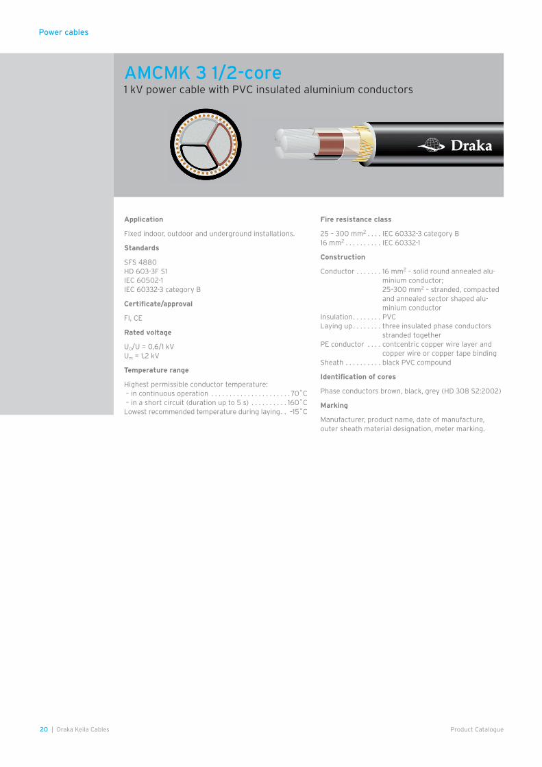
Application
Fixed indoor, outdoor and underground installations.
Standards
SFS 4880HD 603-3F S1IEC 60502-1IEC 60332-3 category B
Certificate/approval
FI, CE
Rated voltage
U0/U = 0,6/1 kVUm = 1,2 kV
Temperature range
Highest permissible conductor temperature: – in continuous operation . . . . . . . . . . . . . . . . . . . . . . 70˚C – in a short circuit (duration up to 5 s) . . . . . . . . . . 160˚CLowest recommended temperature during laying . . –15˚C
Fire resistance class
25 – 300 mm2 . . . . IEC 60332-3 category B16 mm2 . . . . . . . . . . IEC 60332-1
Construction
Conductor . . . . . . . 16 mm2 – solid round annealed alu-minium conductor;25–300 mm2 – stranded, compacted and annealed sector shaped alu-minium conductor
Insulation . . . . . . . . PVCLaying up . . . . . . . . three insulated phase conductors
stranded togetherPE conductor . . . . contcentric copper wire layer and
copper wire or copper tape bindingSheath . . . . . . . . . . black PVC compound
Identification of cores
Phase conductors brown, black, grey (HD 308 S2:2002)
Marking
Manufacturer, product name, date of manufacture, outer sheath material designation, meter marking.
AMCMK 3 1/2-core1 kV power cable with PVC insulated aluminium conductors

21Draka Keila Cables |Product Catalogue
Power cables
Basic cable data AMCMK AMCMK AMCMK AMCMK AMCMK AMCMK
3x16Al/10Cu 3x25Al/16Cu 3x35Al/16Cu 3x50Al/16Cu 3x70Al/21Cu 3x95Al/29Cu
AN 1 kV AN 1 kV AN 1 kV AN 1 kV AN 1 kV AN 1 kV
Construction data
External cable diameter (1) mm 22 23 24 28 31 35
Weight (1) aluminium kg/km 125 200 275 370 540 750
copper kg/km 95 145 145 145 190 260
cable kg/km 560 620 730 975 1300 1750
Delivery data
Standard delivery length m 1000 500 500 500 500 500
Drum 15G K11 K12 K12 K14 K14
Total weight (1) cable + drum kg 710 365 485 580 765 990Mechanical data (2)
Minimum permissible bending radius during laying m 0,25 0,28 0,30 0,34 0,38 0,42
Minimum permissible bending radius at final installation (3) m 0,18 0,20 0,21 0,24 0,27 0,30
Maximum permissible pulling force with a pulling grip kN 0,7 1,1 1,6 2,2 3,1 4,3
Maximum permissible pulling force with a pulling eye kN 2,4 3,7 5,2 7,5 10,5 14,2
Electrical data (2)
Maximum DC resistance of conductor 20˚C Ω/km 1,91 1,20 0,868 0,641 0,443 0,320
Maximum AC resistance of conductor 70˚C Ω/km 2,3 1,4 1,0 0,77 0,53 0,39
Maximum DC resistance of PEN conductor 20˚C Ω/km 1,91 1,91 1,91 1,20 0,868 0,641
Inductance (1) mH/km 0,26 0,26 0,26 0,25 0,24 0,24
Operating capacitance (1) µF/km 0,40 0,45 0,55 0,60 0,65 0,75
Current ratings (2)
In air conductor 70˚C A 64 83 105 125 155 190
In ground conductor 70˚C A 78 100 125 150 185 220
Short circuit currents (2)
Maximum permissible short circuit current for 1 second
phase conductor (4) kA 1,2 1,9 2,6 3,8 5,3 7,2PE conductor (5) kA 1,7 1,7 1,7 2,6 3,7 4,6
1) Approximate value.2) See the basic assumptions at general information of products.3) Final installation with careful single bending.4) Initial temperature of conductor before short circuit 70˚C, final temperature of conductor after short circuit 160˚C.5) Initial temperature of PE conductor before short circuit 65˚C, final temperature of PE conductor after short circuit 160˚C.
Basic cable data AMCMK AMCMK AMCMK AMCMK AMCMK
3x120Al/41Cu 3x150Al/41Cu 3x185Al/57Cu 3x240Al/72Cu 3x300Al/88Cu
AN 1 kV AN 1 kV AN 1 kV AN 1 kV AN 1 kV
Construction data
External cable diameter (1) mm 39 42 48 53 58
Weight (1) aluminium kg/km 945 1160 1460 1910 2390
copper kg/km 370 370 525 660 790
cable kg/km 2150 2550 3250 4100 5000Delivery data
Standard delivery length m 500 500 500 500 500
Drum K16 K18 K20 K22 K24
Total weight (1) cable + drum kg 1270 1500 1950 2450 2950
Mechanical data (2)
Minimum permissible bending radius during laying m 0,47 0,51 0,58 0,64 0,70
Minimum permissible bending radius at final installation (3) m 0,33 0,36 0,41 0,45 0,49
Maximum permissible pulling force with a pulling grip kN 5,4 6,7 8,3 8,5 8,5
Maximum permissible pulling force with a pulling eye kN 18,0 20,0 20,0 20,0 20,0
Electrical data (2)
Maximum DC resistance of conductor 20˚C Ω/km 0,253 0,206 0,164 0,125 0,100
Maximum AC resistance of conductor 70˚C Ω/km 0,31 0,25 0,20 0,15 0,13
Maximum DC resistance of PEN conductor 20˚C Ω/km 0,443 0,443 0,320 0,253 0,206
Inductance (1) mH/km 0,23 0,23 0,23 0,23 0,23
Operating capacitance (1) µF/km 0,80 0,80 0,85 0,85 0,90
Current ratings (2)
In air conductor 70˚C A 220 250 285 330 380
In ground conductor 70˚C A 255 290 330 375 430
Short circuit currents (2)
Maximum permissible short circuit current for 1 second
phase conductor (4) kA 9,1 11,4 14,0 18,2 22,8PE conductor (5) kA 6,7 6,7 8,8 11,4 13,9
AMCMK 3 1/2-core1 kV power cable with PVC insulated aluminium conductors
22 | Draka Keila Cables Product Catalogue
Power cables
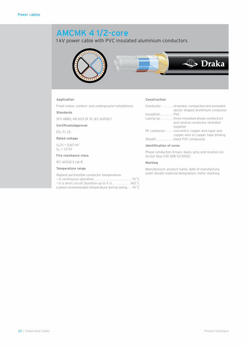
Application
Fixed indoor, outdoor and underground installations.
Standards
SFS 4880, HD 603-3F S1, IEC 60502-1
Certificate/approval
EEI, FI, CE
Rated voltage
U0/U = 0,6/1 kVUm = 1,2 kV
Fire resistance class
IEC 60332-3 cat B
Temperature range
Highest permissible conductor temperature:– in continuous operation . . . . . . . . . . . . . . . . . . . . . . . 70˚C– in a short circuit (duration up to 5 s) . . . . . . . . . . . 160˚CLowest recommended temperature during laying . . –15˚C
Construction
Conductor . . . . . . . stranded, compacted and annealed sector shaped aluminium conductor
Insulation . . . . . . . . PVCLaying up . . . . . . . . three insulated phase conductors
and neutral conductor stranded together
PE conductor . . . . concentric copper wire layer and copper wire or copper tape binding
Sheath . . . . . . . . . . black PVC compound
Identification of cores
Phase conductors brown, black, grey and neutral con-ductor blue (HD 308 S2:2002).
Marking
Manufacturer, product name, date of manufacture, outer sheath material designation, meter marking.
AMCMK 4 1/2-core1 kV power cable with PVC insulated aluminium conductors
23Draka Keila Cables |Product Catalogue
Power cables
1) Approximate value.2) See the basic assumptions at general information of products.3) Final installation with careful single bending.4) Initial temperature of conductor before short circuit 70˚C, final temperature of conductor after short circuit 160˚C.5) Initial temperature of PE conductor before short circuit 65˚C, final temperature of PE conductor after short circuit 160˚C.
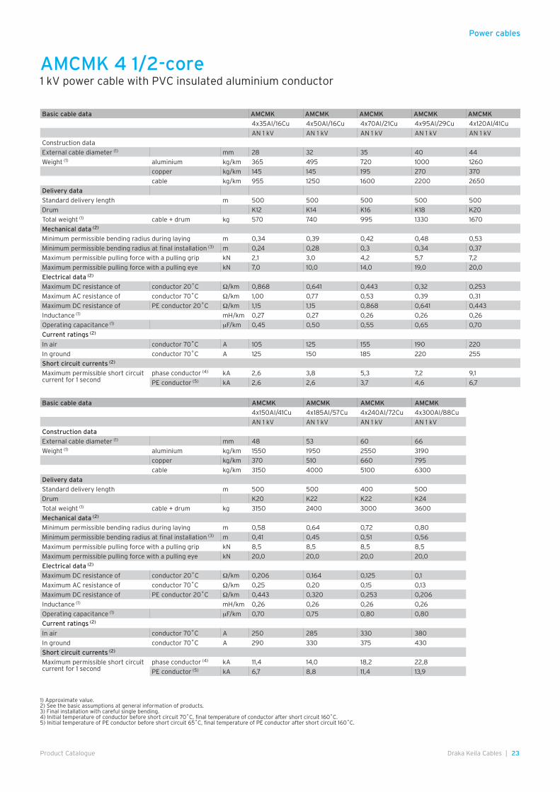
Basic cable data AMCMK AMCMK AMCMK AMCMK AMCMK
4x35Al/16Cu 4x50Al/16Cu 4x70Al/21Cu 4x95Al/29Cu 4x120Al/41Cu
AN 1 kV AN 1 kV AN 1 kV AN 1 kV AN 1 kV
Construction data
External cable diameter (1) mm 28 32 35 40 44
Weight (1) aluminium kg/km 365 495 720 1000 1260
copper kg/km 145 145 195 270 370
cable kg/km 955 1250 1600 2200 2650
Delivery data
Standard delivery length m 500 500 500 500 500
Drum K12 K14 K16 K18 K20
Total weight (1) cable + drum kg 570 740 995 1330 1670
Mechanical data (2)
Minimum permissible bending radius during laying m 0,34 0,39 0,42 0,48 0,53
Minimum permissible bending radius at final installation (3) m 0,24 0,28 0,3 0,34 0,37
Maximum permissible pulling force with a pulling grip kN 2,1 3,0 4,2 5,7 7,2
Maximum permissible pulling force with a pulling eye kN 7,0 10,0 14,0 19,0 20,0
Electrical data (2)
Maximum DC resistance of conductor 20˚C Ω/km 0,868 0,641 0,443 0,32 0,253
Maximum AC resistance of conductor 70˚C Ω/km 1,00 0,77 0,53 0,39 0,31
Maximum DC resistance of PE conductor 20˚C Ω/km 1,15 1,15 0,868 0,641 0,443
Inductance (1) mH/km 0,27 0,27 0,26 0,26 0,26
Operating capacitance (1) µF/km 0,45 0,50 0,55 0,65 0,70
Current ratings (2)
In air conductor 70˚C A 105 125 155 190 220
In ground conductor 70˚C A 125 150 185 220 255
Short circuit currents (2)
Maximum permissible short circuit current for 1 second
phase conductor (4) kA 2,6 3,8 5,3 7,2 9,1
PE conductor (5) kA 2,6 2,6 3,7 4,6 6,7
Basic cable data AMCMK AMCMK AMCMK AMCMK
4x150Al/41Cu 4x185Al/57Cu 4x240Al/72Cu 4x300Al/88Cu
AN 1 kV AN 1 kV AN 1 kV AN 1 kV
Construction data
External cable diameter (1) mm 48 53 60 66
Weight (1) aluminium kg/km 1550 1950 2550 3190
copper kg/km 370 510 660 795
cable kg/km 3150 4000 5100 6300
Delivery data
Standard delivery length m 500 500 400 500
Drum K20 K22 K22 K24
Total weight (1) cable + drum kg 3150 2400 3000 3600
Mechanical data (2)
Minimum permissible bending radius during laying m 0,58 0,64 0,72 0,80
Minimum permissible bending radius at final installation (3) m 0,41 0,45 0,51 0,56
Maximum permissible pulling force with a pulling grip kN 8,5 8,5 8,5 8,5
Maximum permissible pulling force with a pulling eye kN 20,0 20,0 20,0 20,0
Electrical data (2)
Maximum DC resistance of conductor 20˚C Ω/km 0,206 0,164 0,125 0,1
Maximum AC resistance of conductor 70˚C Ω/km 0,25 0,20 0,15 0,13
Maximum DC resistance of PE conductor 20˚C Ω/km 0,443 0,320 0,253 0,206
Inductance (1) mH/km 0,26 0,26 0,26 0,26
Operating capacitance (1) µF/km 0,70 0,75 0,80 0,80
Current ratings (2)
In air conductor 70˚C A 250 285 330 380
In ground conductor 70˚C A 290 330 375 430
Short circuit currents (2)
Maximum permissible short circuit current for 1 second
phase conductor (4) kA 11,4 14,0 18,2 22,8
PE conductor (5) kA 6,7 8,8 11,4 13,9
AMCMK 4 1/2-core1 kV power cable with PVC insulated aluminium conductor
Power cables
24 | Draka Keila Cables Product Catalogue
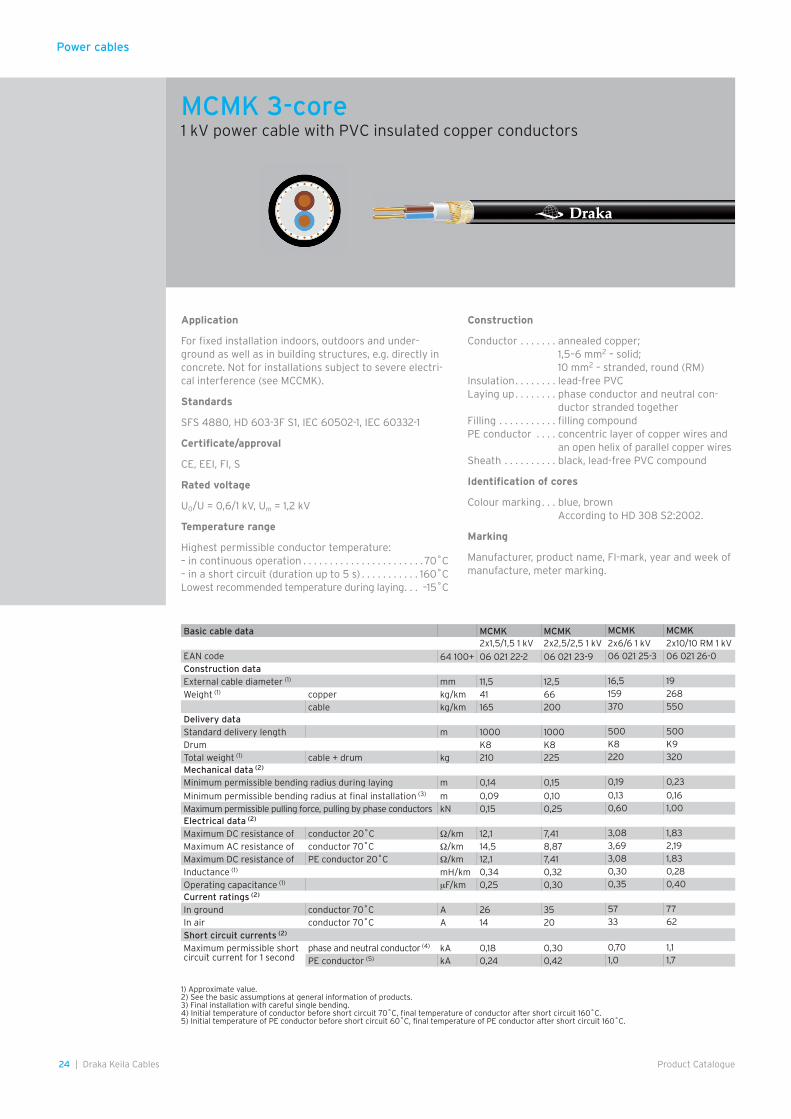
Application
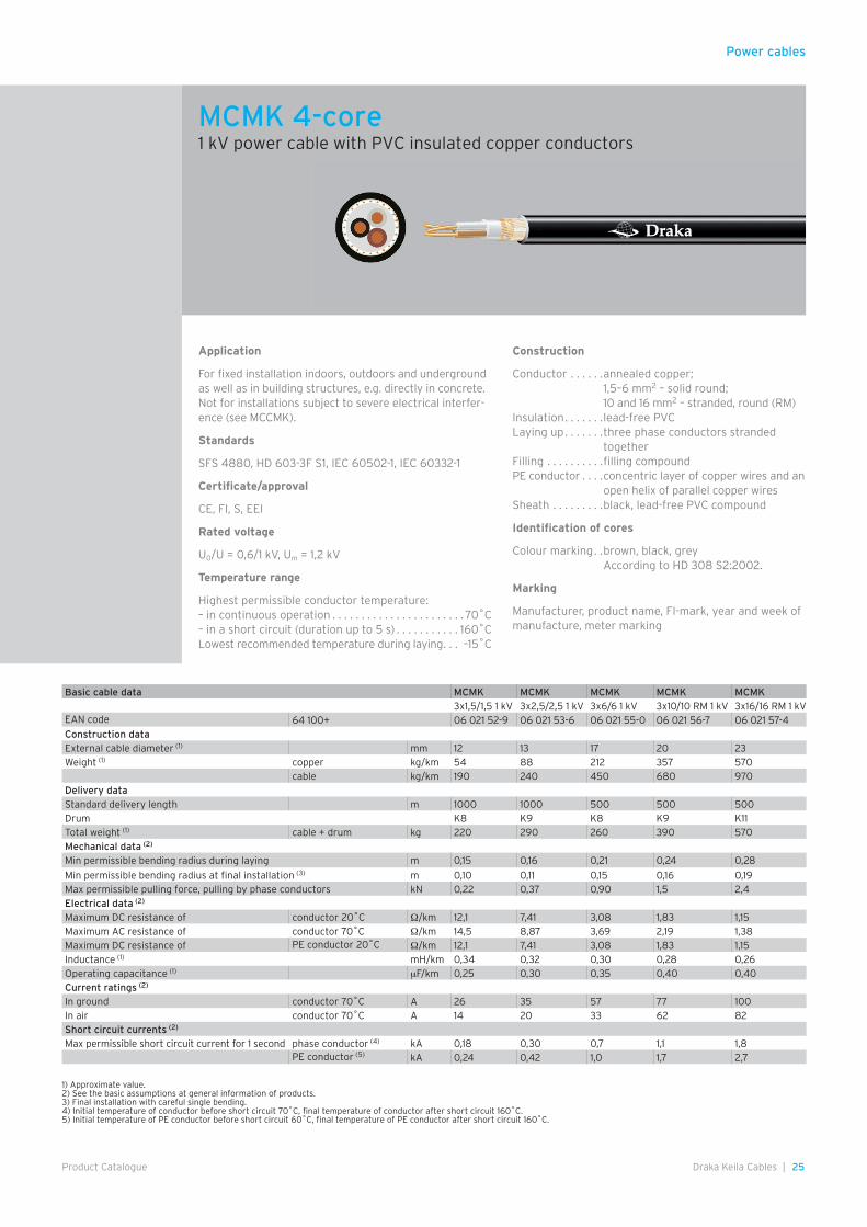
For fixed installation indoors, outdoors and under-ground as well as in building structures, e.g. directly in concrete. Not for installations subject to severe electri-cal interference (see MCCMK).
Standards
SFS 4880, HD 603-3F S1, IEC 60502-1, IEC 60332-1
Certificate/approval
CE, EEI, FI, S
Rated voltage
U0/U = 0,6/1 kV, Um = 1,2 kV
Temperature range
Highest permissible conductor temperature:– in continuous operation . . . . . . . . . . . . . . . . . . . . . . . 70˚C– in a short circuit (duration up to 5 s) . . . . . . . . . . . 160˚CLowest recommended temperature during laying . . . –15˚C
Construction
Conductor . . . . . . . annealed copper;1,5–6 mm2 – solid;10 mm2 – stranded, round (RM)
Insulation . . . . . . . . lead-free PVCLaying up . . . . . . . . phase conductor and neutral con-
ductor stranded togetherFilling . . . . . . . . . . . filling compoundPE conductor . . . . concentric layer of copper wires and
an open helix of parallel copper wiresSheath . . . . . . . . . . black, lead-free PVC compound
Identification of cores
Colour marking . . . blue, brownAccording to HD 308 S2:2002.
Marking
Manufacturer, product name, FI-mark, year and week of manufacture, meter marking.
Basic cable data MCMK MCMK MCMK MCMK2x1,5/1,5 1 kV 2x2,5/2,5 1 kV 2x6/6 1 kV 2x10/10 RM 1 kV
EAN code 64 100+ 06 021 22-2 06 021 23-9 06 021 25-3 06 021 26-0Construction dataExternal cable diameter (1) mm 11,5 12,5 16,5 19
Weight (1) copper kg/km 41 66 159 268
cable kg/km 165 200 370 550Delivery dataStandard delivery length m 1000 1000 500 500
Drum K8 K8 K8 K9
Total weight (1) cable + drum kg 210 225 220 320Mechanical data (2)
Minimum permissible bending radius during laying m 0,14 0,15 0,19 0,23
Minimum permissible bending radius at final installation (3) m 0,09 0,10 0,13 0,16
Maximum permissible pulling force, pulling by phase conductors kN 0,15 0,25 0,60 1,00Electrical data (2)
Maximum DC resistance of conductor 20˚C Ω/km 12,1 7,41 3,08 1,83
Maximum AC resistance of conductor 70˚C Ω/km 14,5 8,87 3,69 2,19
Maximum DC resistance of PE conductor 20˚C Ω/km 12,1 7,41 3,08 1,83
Inductance (1) mH/km 0,34 0,32 0,30 0,28
Operating capacitance (1) µF/km 0,25 0,30 0,35 0,40Current ratings (2)
In ground conductor 70˚C A 26 35 57 77
In air conductor 70˚C A 14 20 33 62
Short circuit currents (2)
Maximum permissible short circuit current for 1 second
phase and neutral conductor (4) kA 0,18 0,30 0,70 1,1
PE conductor (5) kA 0,24 0,42 1,0 1,7
1) Approximate value.2) See the basic assumptions at general information of products.3) Final installation with careful single bending.4) Initial temperature of conductor before short circuit 70˚C, final temperature of conductor after short circuit 160˚C.5) Initial temperature of PE conductor before short circuit 60˚C, final temperature of PE conductor after short circuit 160˚C.
MCMK 3-core1 kV power cable with PVC insulated copper conductors
Power cables
25Draka Keila Cables |Product Catalogue
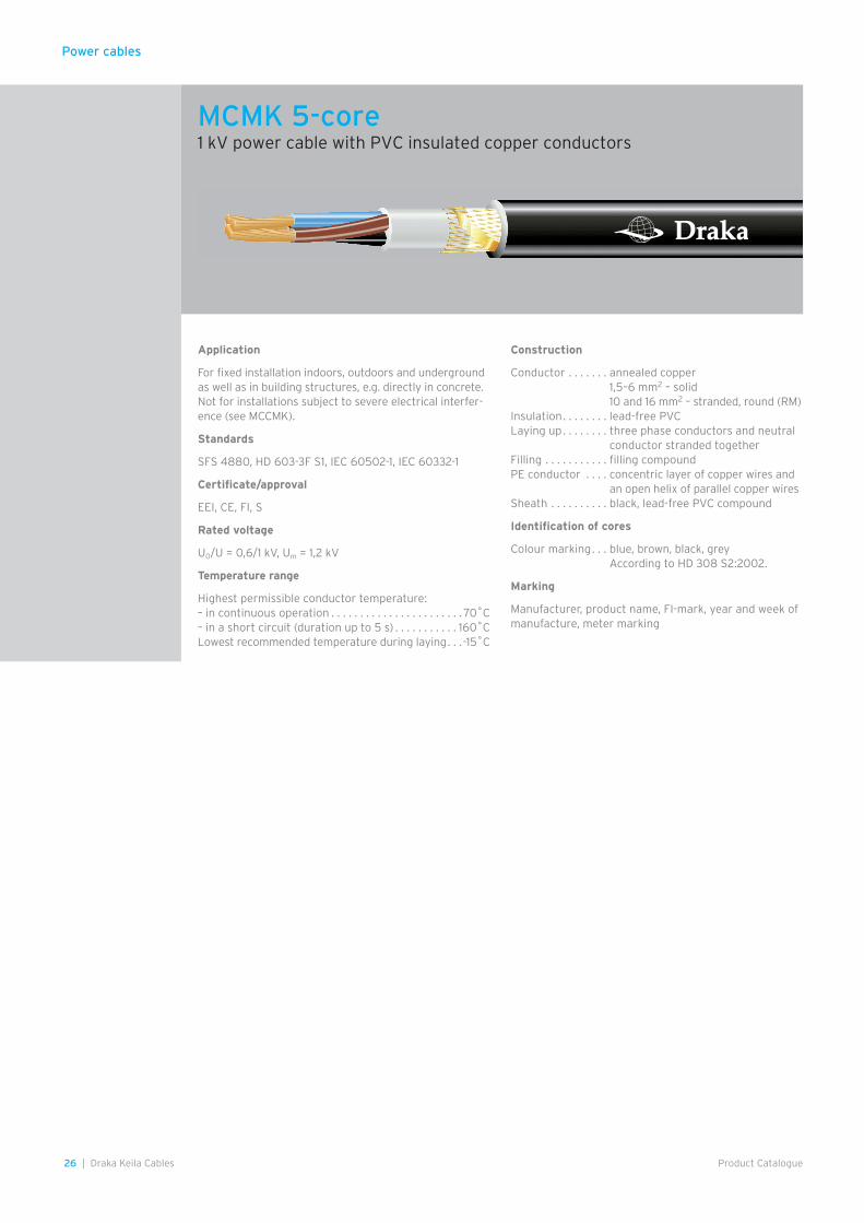
Application
For fixed installation indoors, outdoors and underground as well as in building structures, e.g. directly in concrete. Not for installations subject to severe electrical interfer-ence (see MCCMK).
Standards
SFS 4880, HD 603-3F S1, IEC 60502-1, IEC 60332-1
Certificate/approval
CE, FI, S, EEI
Rated voltage
U0/U = 0,6/1 kV, Um = 1,2 kV
Temperature range
Highest permissible conductor temperature: – in continuous operation . . . . . . . . . . . . . . . . . . . . . . . 70˚C– in a short circuit (duration up to 5 s) . . . . . . . . . . . 160˚CLowest recommended temperature during laying . . . –15˚C
Construction
Conductor . . . . . .annealed copper;1,5–6 mm2 – solid round;10 and 16 mm2 – stranded, round (RM)
Insulation . . . . . . .lead-free PVCLaying up . . . . . . .three phase conductors stranded
togetherFilling . . . . . . . . . .filling compoundPE conductor . . . .concentric layer of copper wires and an
open helix of parallel copper wiresSheath . . . . . . . . .black, lead-free PVC compound
Identification of cores
Colour marking . .brown, black, greyAccording to HD 308 S2:2002.
Marking
Manufacturer, product name, FI-mark, year and week of manufacture, meter marking
Basic cable data MCMK MCMK MCMK MCMK MCMK3x1,5/1,5 1 kV 3x2,5/2,5 1 kV 3x6/6 1 kV 3x10/10 RM 1 kV 3x16/16 RM 1 kV
EAN code 64 100+ 06 021 52-9 06 021 53-6 06 021 55-0 06 021 56-7 06 021 57-4Construction dataExternal cable diameter (1) mm 12 13 17 20 23Weight (1) copper kg/km 54 88 212 357 570
cable kg/km 190 240 450 680 970Delivery dataStandard delivery length m 1000 1000 500 500 500Drum K8 K9 K8 K9 K11Total weight (1) cable + drum kg 220 290 260 390 570Mechanical data (2)
Min permissible bending radius during laying m 0,15 0,16 0,21 0,24 0,28
Min permissible bending radius at final installation (3) m 0,10 0,11 0,15 0,16 0,19Max permissible pulling force, pulling by phase conductors kN 0,22 0,37 0,90 1,5 2,4Electrical data (2)
Maximum DC resistance of conductor 20˚C Ω/km 12,1 7,41 3,08 1,83 1,15Maximum AC resistance of conductor 70˚C Ω/km 14,5 8,87 3,69 2,19 1,38Maximum DC resistance of PE conductor 20˚C Ω/km 12,1 7,41 3,08 1,83 1,15Inductance (1) mH/km 0,34 0,32 0,30 0,28 0,26Operating capacitance (1) µF/km 0,25 0,30 0,35 0,40 0,40Current ratings (2)
In ground conductor 70˚C A 26 35 57 77 100In air conductor 70˚C A 14 20 33 62 82Short circuit currents (2)
Max permissible short circuit current for 1 second phase conductor (4) kA 0,18 0,30 0,7 1,1 1,8PE conductor (5) kA 0,24 0,42 1,0 1,7 2,7
1) Approximate value.2) See the basic assumptions at general information of products.3) Final installation with careful single bending.4) Initial temperature of conductor before short circuit 70˚C, final temperature of conductor after short circuit 160˚C.5) Initial temperature of PE conductor before short circuit 60˚C, final temperature of PE conductor after short circuit 160˚C.
MCMK 4-core1 kV power cable with PVC insulated copper conductors
26 | Draka Keila Cables Product Catalogue
Power cables
Application
For fixed installation indoors, outdoors and underground as well as in building structures, e.g. directly in concrete. Not for installations subject to severe electrical interfer-ence (see MCCMK).
Standards
SFS 4880, HD 603-3F S1, IEC 60502-1, IEC 60332-1
Certificate/approval
EEI, CE, FI, S
Rated voltage
U0/U = 0,6/1 kV, Um = 1,2 kV
Temperature range
Highest permissible conductor temperature: – in continuous operation . . . . . . . . . . . . . . . . . . . . . . . 70˚C– in a short circuit (duration up to 5 s) . . . . . . . . . . . 160˚CLowest recommended temperature during laying . . .-15˚C
Construction
Conductor . . . . . . . annealed copper1,5–6 mm2 – solid10 and 16 mm2 – stranded, round (RM)
Insulation . . . . . . . . lead-free PVCLaying up . . . . . . . . three phase conductors and neutral
conductor stranded togetherFilling . . . . . . . . . . . filling compoundPE conductor . . . . concentric layer of copper wires and
an open helix of parallel copper wiresSheath . . . . . . . . . . black, lead-free PVC compound
Identification of cores
Colour marking . . . blue, brown, black, greyAccording to HD 308 S2:2002.
Marking
Manufacturer, product name, FI-mark, year and week of manufacture, meter marking
MCMK 5-core1 kV power cable with PVC insulated copper conductors
27Draka Keila Cables |Product Catalogue
Power cables
1) Approximate value.2) See the basic assumptions at general information of products.3) Final installation with careful single bending.4) Initial temperature of conductor before short circuit 70˚C, final temperature of conductor after short circuit 160˚C.5) Initial temperature of PE conductor before short circuit 60˚C, final temperature of PE conductor after short circuit 160˚C.
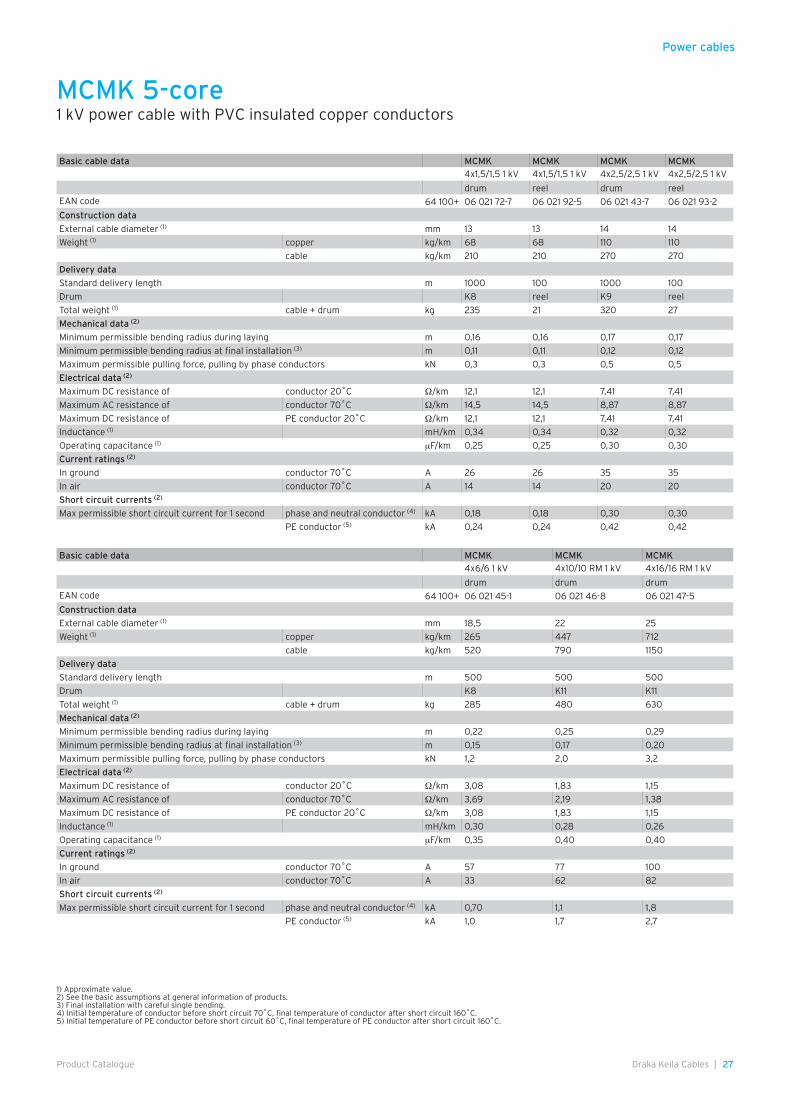
Basic cable data MCMK MCMK MCMK MCMK4x1,5/1,5 1 kV 4x1,5/1,5 1 kV 4x2,5/2,5 1 kV 4x2,5/2,5 1 kV
drum reel drum reelEAN code 64 100+ 06 021 72-7 06 021 92-5 06 021 43-7 06 021 93-2
Construction data
External cable diameter (1) mm 13 13 14 14
Weight (1) copper kg/km 68 68 110 110
cable kg/km 210 210 270 270
Delivery data
Standard delivery length m 1000 100 1000 100
Drum K8 reel K9 reel
Total weight (1) cable + drum kg 235 21 320 27
Mechanical data (2)
Minimum permissible bending radius during laying m 0,16 0,16 0,17 0,17
Minimum permissible bending radius at final installation (3) m 0,11 0,11 0,12 0,12
Maximum permissible pulling force, pulling by phase conductors kN 0,3 0,3 0,5 0,5
Electrical data (2)
Maximum DC resistance of conductor 20˚C Ω/km 12,1 12,1 7,41 7,41
Maximum AC resistance of conductor 70˚C Ω/km 14,5 14,5 8,87 8,87
Maximum DC resistance of PE conductor 20˚C Ω/km 12,1 12,1 7,41 7,41
Inductance (1) mH/km 0,34 0,34 0,32 0,32
Operating capacitance (1) µF/km 0,25 0,25 0,30 0,30
Current ratings (2)
In ground conductor 70˚C A 26 26 35 35
In air conductor 70˚C A 14 14 20 20
Short circuit currents (2)
Max permissible short circuit current for 1 second phase and neutral conductor (4) kA 0,18 0,18 0,30 0,30
PE conductor (5) kA 0,24 0,24 0,42 0,42
Basic cable data MCMK MCMK MCMK4x6/6 1 kV 4x10/10 RM 1 kV 4x16/16 RM 1 kV
drum drum drumEAN code 64 100+ 06 021 45-1 06 021 46-8 06 021 47-5
Construction data
External cable diameter (1) mm 18,5 22 25
Weight (1) copper kg/km 265 447 712
cable kg/km 520 790 1150
Delivery data
Standard delivery length m 500 500 500
Drum K8 K11 K11
Total weight (1) cable + drum kg 285 480 630
Mechanical data (2)
Minimum permissible bending radius during laying m 0,22 0,25 0,29
Minimum permissible bending radius at final installation (3) m 0,15 0,17 0,20
Maximum permissible pulling force, pulling by phase conductors kN 1,2 2,0 3,2
Electrical data (2)
Maximum DC resistance of conductor 20˚C Ω/km 3,08 1,83 1,15
Maximum AC resistance of conductor 70˚C Ω/km 3,69 2,19 1,38
Maximum DC resistance of PE conductor 20˚C Ω/km 3,08 1,83 1,15
Inductance (1) mH/km 0,30 0,28 0,26
Operating capacitance (1) µF/km 0,35 0,40 0,40
Current ratings (2)
In ground conductor 70˚C A 57 77 100
In air conductor 70˚C A 33 62 82
Short circuit currents (2)
Max permissible short circuit current for 1 second phase and neutral conductor (4) kA 0,70 1,1 1,8
PE conductor (5) kA 1,0 1,7 2,7
MCMK 5-core1 kV power cable with PVC insulated copper conductors
Power cables
28 | Draka Keila Cables Product Catalogue
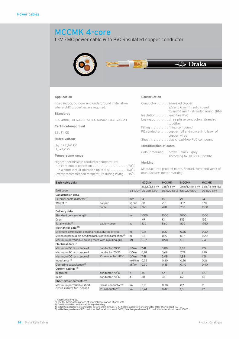
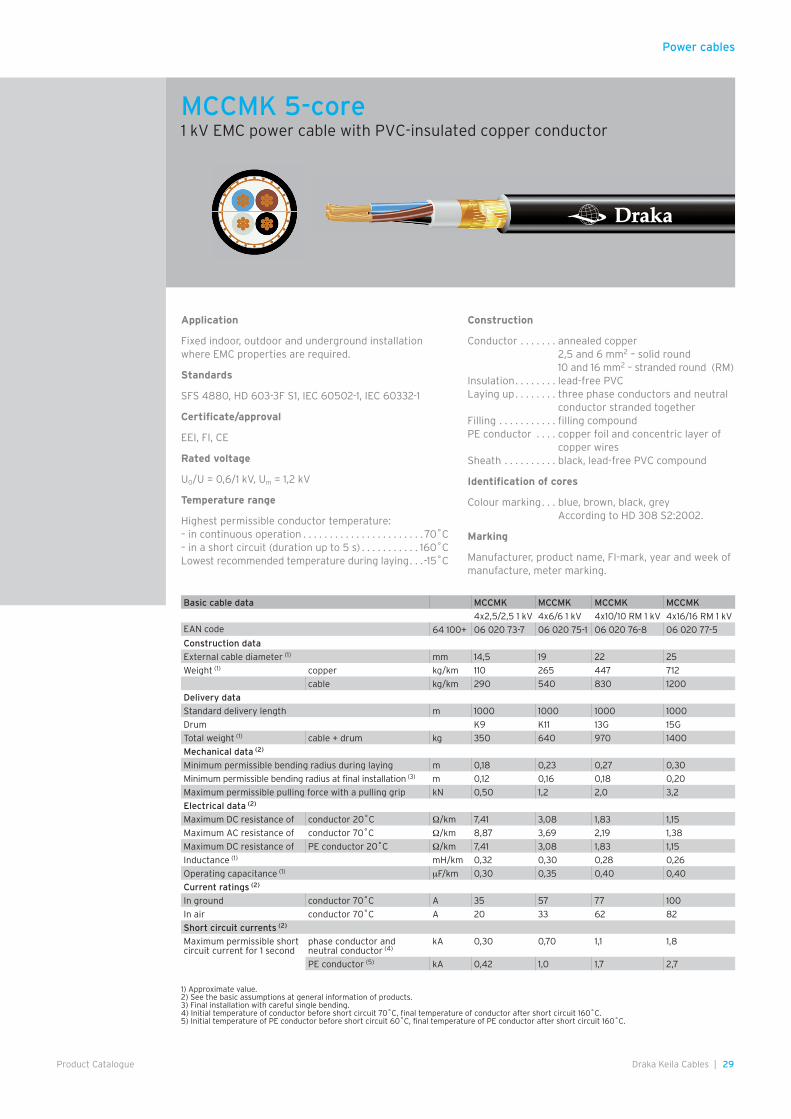
Application
Fixed indoor, outdoor and underground installation where EMC properties are required.
Standards
SFS 4880, HD 603-3F S1, IEC 60502-1, IEC 60322-1
Certificate/approval
EEI, FI, CE
Rated voltage
U0/U = 0,6/1 kVUm = 1,2 kV
Temperature range
Highest permissible conductor temperature: – in continuous operation . . . . . . . . . . . . . . . . . . . . . . 70˚C – in a short circuit (duration up to 5 s) . . . . . . . . . . 160˚CLowest recommended temperature during laying . . –15˚C
Construction
Conductor . . . . . . . annealed copper;2,5 and 6 mm2 – solid round;10 and 16 mm2 – stranded round (RM)
Insulation . . . . . . . . lead-free PVCLaying up . . . . . . . . three phase conductors stranded
togetherFilling . . . . . . . . . . . filling compoundPE conductor . . . . copper foil and concentric layer of
copper wiresSheath . . . . . . . . . . black, lead-free PVC compound
Identification of cores
Colour marking . . . brown – black – greyAccording to HD 308 S2:2002.
Marking
Manufacturer, product name, FI-mark, year and week of manufacture, meter marking
1) Approximate value.2) See the basic assumptions at general information of products.3) Final installation with careful single bending.4) Initial temperature of conductor before short circuit 70˚C, final temperature of conductor after short circuit 160˚C.5) Initial temperature of PE conductor before short circuit 60˚C, final temperature of PE conductor after short circuit 160˚C.
Basic cable data MCCMK MCCMK MCCMK MCCMK
3x2,5/2,5 1 kV 3x6/6 1 kV 3x10/10 RM 1 kV 3x16/16 RM 1 kVEAN code 64 100+ 06 020 53-9 06 020 55-3 06 020 56-0 06 020 57-7
Construction data
External cable diameter (1) mm 14 18 21 24
Weight (1) copper kg/km 88 212 357 570
cable kg/km 260 470 700 1050
Delivery data
Standard delivery length m 1000 1000 1000 1000
Drum K9 K11 K12 15G
Total weight (1) cable + drum kg 320 560 820 1250
Mechanical data (2)
Minimum permissible bending radius during laying m 0,16 0,22 0,25 0,30
Minimum permissible bending radius at final installation (3) m 0,11 0,15 0,17 0,20
Maximum permissible pulling force with a pulling grip kN 0,37 0,90 1,5 2,4
Electrical data (2)
Maximum DC resistance of conductor 20˚C Ω/km 7,41 3,08 1,83 1,15
Maximum AC resistance of conductor 70˚C Ω/km 8,87 3,69 2,19 1,38
Maximum DC resistance of PE conductor 20˚C Ω/km 7,41 3,08 1,83 1,15
Inductance (1) mH/km 0,32 0,30 0,26 0,26
Operating capacitance (1) µF/km 0,30 0,35 0,40 0,40
Current ratings (2)
In ground conductor 70˚C A 35 57 77 100
In air conductor 70˚C A 20 33 62 82
Short circuit currents (2)
Maximum permissible short circuit current for 1 second
phase conductor (4) kA 0,18 0,30 0,7 1,1PE conductor (5) kA 0,24 0,42 1,0 1,7
MCCMK 4-core1 kV EMC power cable with PVC-insulated copper conductor
Power cables
29Draka Keila Cables |Product Catalogue
Application
Fixed indoor, outdoor and underground installation where EMC properties are required.
Standards
SFS 4880, HD 603-3F S1, IEC 60502-1, IEC 60332-1
Certificate/approval
EEI, FI, CE
Rated voltage
U0/U = 0,6/1 kV, Um = 1,2 kV
Temperature range
Highest permissible conductor temperature: – in continuous operation . . . . . . . . . . . . . . . . . . . . . . . 70˚C– in a short circuit (duration up to 5 s) . . . . . . . . . . . 160˚CLowest recommended temperature during laying . . .-15˚C
Construction
Conductor . . . . . . . annealed copper2,5 and 6 mm2 – solid round10 and 16 mm2 – stranded round (RM)
Insulation . . . . . . . . lead-free PVCLaying up . . . . . . . . three phase conductors and neutral
conductor stranded togetherFilling . . . . . . . . . . . filling compoundPE conductor . . . . copper foil and concentric layer of
copper wires Sheath . . . . . . . . . . black, lead-free PVC compound
Identification of cores
Colour marking . . . blue, brown, black, greyAccording to HD 308 S2:2002.
Marking
Manufacturer, product name, FI-mark, year and week of manufacture, meter marking.
1) Approximate value.2) See the basic assumptions at general information of products.3) Final installation with careful single bending.4) Initial temperature of conductor before short circuit 70˚C, final temperature of conductor after short circuit 160˚C.5) Initial temperature of PE conductor before short circuit 60˚C, final temperature of PE conductor after short circuit 160˚C.
Basic cable data MCCMK MCCMK MCCMK MCCMK
4x2,5/2,5 1 kV 4x6/6 1 kV 4x10/10 RM 1 kV 4x16/16 RM 1 kVEAN code 64 100+ 06 020 73-7 06 020 75-1 06 020 76-8 06 020 77-5
Construction data
External cable diameter (1) mm 14,5 19 22 25
Weight (1) copper kg/km 110 265 447 712
cable kg/km 290 540 830 1200
Delivery data
Standard delivery length m 1000 1000 1000 1000
Drum K9 K11 13G 15G
Total weight (1) cable + drum kg 350 640 970 1400
Mechanical data (2)
Minimum permissible bending radius during laying m 0,18 0,23 0,27 0,30
Minimum permissible bending radius at final installation (3) m 0,12 0,16 0,18 0,20
Maximum permissible pulling force with a pulling grip kN 0,50 1,2 2,0 3,2
Electrical data (2)
Maximum DC resistance of conductor 20˚C Ω/km 7,41 3,08 1,83 1,15
Maximum AC resistance of conductor 70˚C Ω/km 8,87 3,69 2,19 1,38
Maximum DC resistance of PE conductor 20˚C Ω/km 7,41 3,08 1,83 1,15
Inductance (1) mH/km 0,32 0,30 0,28 0,26
Operating capacitance (1) µF/km 0,30 0,35 0,40 0,40
Current ratings (2)
In ground conductor 70˚C A 35 57 77 100
In air conductor 70˚C A 20 33 62 82
Short circuit currents (2)
Maximum permissible short circuit current for 1 second
phase conductor and neutral conductor (4)
kA 0,30 0,70 1,1 1,8
PE conductor (5) kA 0,42 1,0 1,7 2,7
MCCMK 5-core1 kV EMC power cable with PVC-insulated copper conductor
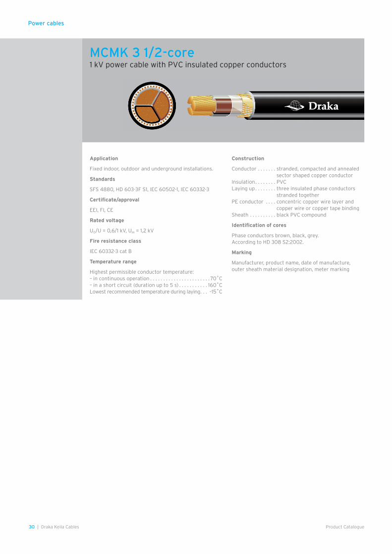
30 | Draka Keila Cables Product Catalogue
Power cables
Application
Fixed indoor, outdoor and underground installations.
Standards
SFS 4880, HD 603-3F S1, IEC 60502-1, IEC 60332-3
Certificate/approval
EEI, FI, CE
Rated voltage
U0/U = 0,6/1 kV, Um = 1,2 kV
Fire resistance class
IEC 60332-3 cat B
Temperature range
Highest permissible conductor temperature:– in continuous operation . . . . . . . . . . . . . . . . . . . . . . . 70˚C– in a short circuit (duration up to 5 s) . . . . . . . . . . . 160˚CLowest recommended temperature during laying . . . –15˚C
Construction
Conductor . . . . . . . stranded, compacted and annealed sector shaped copper conductor
Insulation . . . . . . . . PVCLaying up . . . . . . . . three insulated phase conductors
stranded togetherPE conductor . . . . concentric copper wire layer and
copper wire or copper tape bindingSheath . . . . . . . . . . black PVC compound
Identification of cores
Phase conductors brown, black, grey. According to HD 308 S2:2002.
Marking
Manufacturer, product name, date of manufacture, outer sheath material designation, meter marking
MCMK 3 1/2-core1 kV power cable with PVC insulated copper conductors
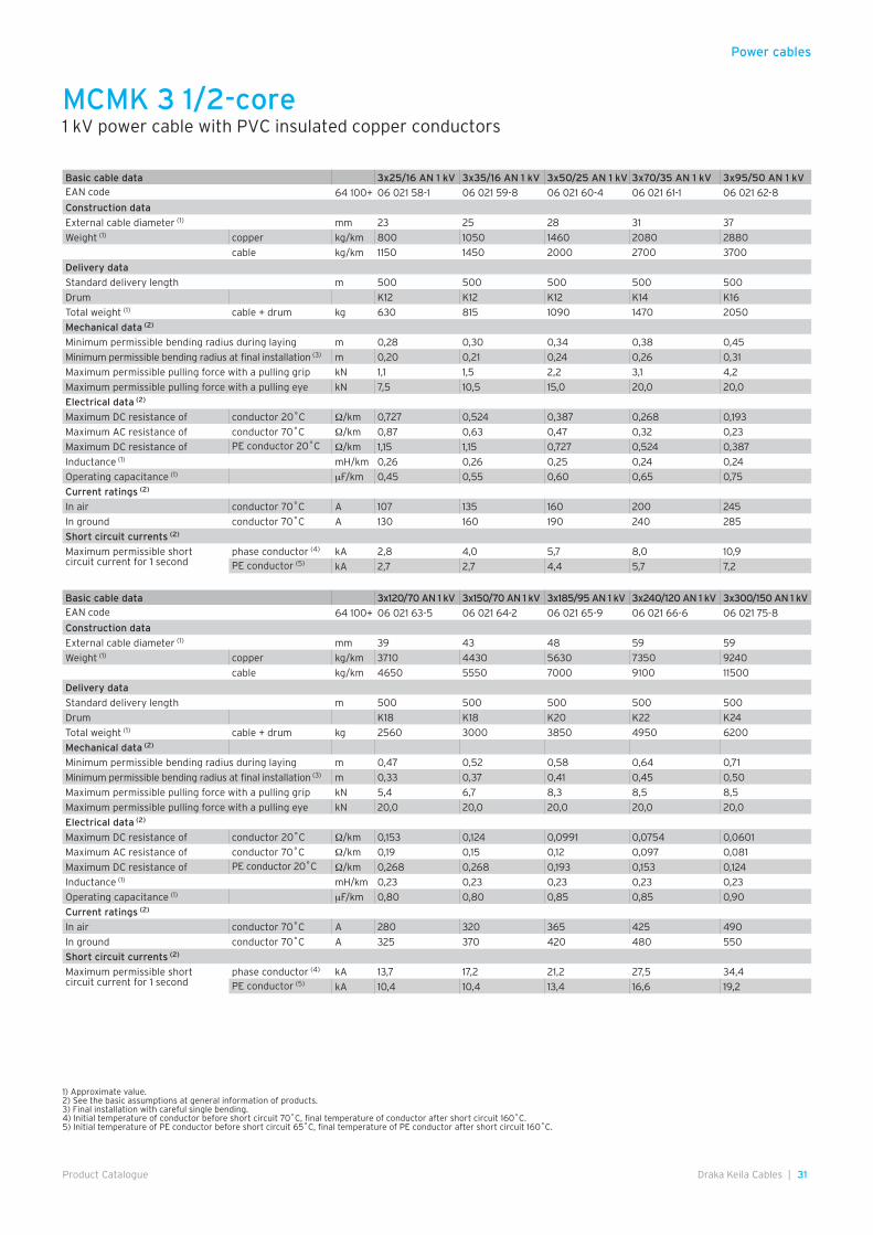
31Draka Keila Cables |Product Catalogue
Power cables
1) Approximate value.2) See the basic assumptions at general information of products.3) Final installation with careful single bending.4) Initial temperature of conductor before short circuit 70˚C, final temperature of conductor after short circuit 160˚C.5) Initial temperature of PE conductor before short circuit 65˚C, final temperature of PE conductor after short circuit 160˚C.
Basic cable data 3x25/16 AN 1 kV 3x35/16 AN 1 kV 3x50/25 AN 1 kV 3x70/35 AN 1 kV 3x95/50 AN 1 kVEAN code 64 100+ 06 021 58-1 06 021 59-8 06 021 60-4 06 021 61-1 06 021 62-8
Construction data
External cable diameter (1) mm 23 25 28 31 37
Weight (1) copper kg/km 800 1050 1460 2080 2880
cable kg/km 1150 1450 2000 2700 3700
Delivery data
Standard delivery length m 500 500 500 500 500
Drum K12 K12 K12 K14 K16
Total weight (1) cable + drum kg 630 815 1090 1470 2050
Mechanical data (2)
Minimum permissible bending radius during laying m 0,28 0,30 0,34 0,38 0,45
Minimum permissible bending radius at final installation (3) m 0,20 0,21 0,24 0,26 0,31
Maximum permissible pulling force with a pulling grip kN 1,1 1,5 2,2 3,1 4,2
Maximum permissible pulling force with a pulling eye kN 7,5 10,5 15,0 20,0 20,0
Electrical data (2)
Maximum DC resistance of conductor 20˚C Ω/km 0,727 0,524 0,387 0,268 0,193
Maximum AC resistance of conductor 70˚C Ω/km 0,87 0,63 0,47 0,32 0,23
Maximum DC resistance of PE conductor 20˚C Ω/km 1,15 1,15 0,727 0,524 0,387
Inductance (1) mH/km 0,26 0,26 0,25 0,24 0,24
Operating capacitance (1) µF/km 0,45 0,55 0,60 0,65 0,75
Current ratings (2)
In air conductor 70˚C A 107 135 160 200 245
In ground conductor 70˚C A 130 160 190 240 285
Short circuit currents (2)
Maximum permissible shortcircuit current for 1 second
phase conductor (4) kA 2,8 4,0 5,7 8,0 10,9PE conductor (5) kA 2,7 2,7 4,4 5,7 7,2
Basic cable data 3x120/70 AN 1 kV 3x150/70 AN 1 kV 3x185/95 AN 1 kV 3x240/120 AN 1 kV 3x300/150 AN 1 kVEAN code 64 100+ 06 021 63-5 06 021 64-2 06 021 65-9 06 021 66-6 06 021 75-8
Construction data
External cable diameter (1) mm 39 43 48 59 59
Weight (1) copper kg/km 3710 4430 5630 7350 9240
cable kg/km 4650 5550 7000 9100 11500
Delivery data
Standard delivery length m 500 500 500 500 500
Drum K18 K18 K20 K22 K24
Total weight (1) cable + drum kg 2560 3000 3850 4950 6200
Mechanical data (2)
Minimum permissible bending radius during laying m 0,47 0,52 0,58 0,64 0,71
Minimum permissible bending radius at final installation (3) m 0,33 0,37 0,41 0,45 0,50
Maximum permissible pulling force with a pulling grip kN 5,4 6,7 8,3 8,5 8,5
Maximum permissible pulling force with a pulling eye kN 20,0 20,0 20,0 20,0 20,0
Electrical data (2)
Maximum DC resistance of conductor 20˚C Ω/km 0,153 0,124 0,0991 0,0754 0,0601
Maximum AC resistance of conductor 70˚C Ω/km 0,19 0,15 0,12 0,097 0,081
Maximum DC resistance of PE conductor 20˚C Ω/km 0,268 0,268 0,193 0,153 0,124
Inductance (1) mH/km 0,23 0,23 0,23 0,23 0,23
Operating capacitance (1) µF/km 0,80 0,80 0,85 0,85 0,90
Current ratings (2)
In air conductor 70˚C A 280 320 365 425 490
In ground conductor 70˚C A 325 370 420 480 550
Short circuit currents (2)
Maximum permissible shortcircuit current for 1 second
phase conductor (4) kA 13,7 17,2 21,2 27,5 34,4PE conductor (5) kA 10,4 10,4 13,4 16,6 19,2
MCMK 3 1/2-core1 kV power cable with PVC insulated copper conductors

32 | Draka Keila Cables Product Catalogue
Power cables
Application
Fixed indoor, outdoor and underground installations.
Fire resistance class
IEC 60332-3 cat B
Standards
SFS 4880, HD 603-3F S1, IEC 60502-1, IEC 60332-3
Certificate/approval
FI, CE
Rated voltage
U0/U = 0,6/1 kV, Um = 1,2 kV
Temperature range
Highest permissible conductor temperature: – in continuous operation . . . . . . . . . . . . . . . . . . . . . . . 70˚C– in a short circuit (duration up to 5 s) . . . . . . . . . . . 160˚CLowest recommended temperature during laying . . –15˚C
Construction
Conductor . . . . . . . stranded, compacted and annealed sector shaped copper conductor
Insulation . . . . . . . . PVCLaying up . . . . . . . . three insulated phase conductors
and neutral conductor stranded together
PE conductor . . . . concentric copper wire layer and copper wire or copper tape binding
Sheath . . . . . . . . . . black PVC compound
Identification of cores
Phase conductors brown, black, grey and neutral con-ductor blue. According to HD 308 S2:2002.
Marking
Manufacturer, product name, date of manufacture, outer sheath material designation, meter marking
MCMK 4 1/2-core1 kV power cable with PVC insulated copper conductors

33Draka Keila Cables |Product Catalogue
Power cables
1) Approximate value.2) See the basic assumptions at general information of products.3) Final installation with careful single bending.4) Initial temperature of conductor before short circuit 70˚C, final temperature of conductor after short circuit 160˚C.5) Initial temperature of PE conductor before short circuit 65˚C, final temperature of PE conductor after short circuit 160˚C.
Basic cable data 4x25/16 AN 4x35/16 AN 4x50/25 AN 4x70/35 AN 4x95/50 AN
1 kV 1 kV 1 kV 1 kV 1 kVEAN code 64 100+ 06 018 58-1 06 018 59-8 06 018 60-4 06 018 61-1 06 018 62-8
Construction data
External cable diameter (1) mm 26 28 32 35 41
Weight (1) copper kg/km 1020 1350 1870 2670 3700
cable kg/km 1450 1850 2500 3450 4750
Delivery data
Standard delivery length m 500 500 500 500 500
Drum K11 K12 K14 K16 K18
Total weight (1) cable + drum kg 780 1020 1370 1920 2610
Mechanical data (2)
Minimum permissible bending radius during laying m 0,32 0,34 0,39 0,42 0,50
Minimum permissible bending radius at final installation (3) m 0,22 0,24 0,28 0,30 0,35
Maximum permissible pulling force with a pulling grip kN 1,5 2,1 3,0 4,2 5,7
Maximum permissible pulling force with a pulling eye kN 10,0 14,0 20,0 20,0 20,0
Electrical data (2)
Maximum DC resistance of conductor 20˚C Ω/km 0,727 0,524 0,387 0,268 0,193
Maximum AC resistance of conductor 70˚C Ω/km 0,87 0,63 0,46 0,32 0,23
Maximum DC resistance of PE conductor 20˚C Ω/km 1,15 1,15 0,727 0,524 0,387
Inductance (1) mH/km 0,28 0,27 0,27 0,26 0,26
Operating capacitance (1) µF/km 0,40 0,45 0,50 0,55 0,65
Current ratings (2)
In air conductor 70˚C A 107 135 160 200 245
In ground conductor 70˚C A 130 160 190 240 285
Short circuit currents (2)
Maximum permissible shortcircuit current for 1 second
phase and neutral conductor (4) kA 2,8 4,0 5,7 8,0 10,9
PE conductor (5) kA 2,7 2,7 4,4 5,7 7,2
Basic cable data 4x120/70 AN 4x150/70 AN 4x185/95 AN 4x240/120 AN 4x300/150 AN
1 kV 1 kV 1 kV 1 kV 1 kVEAN code 64 100+ 06 018 63-5 06 018 64-2 06 018 65-9 06 018 66-6 06 018 67-3
Construction data
External cable diameter (1) mm 44 49 54 60 66
Weight (1) copper kg/km 4740 5710 7230 9450 11900
cable kg/km 5900 7150 8950 12000 14500
Delivery data
Standard delivery length m 500 500 500 500 500
Drum K20 K22 K22 K24 K24
Total weight (1) cable + drum kg 3300 4000 4900 6500 7750
Mechanical data (2)
Minimum permissible bending radius during laying m 0,53 0,59 0,65 0,72 0,8
Minimum permissible bending radius at final installation (3) m 0,37 0,42 0,46 0,51 0,56
Maximum permissible pulling force with a pulling grip kN 7,2 8,5 8,5 8,5 8,5
Maximum permissible pulling force with a pulling eye kN 20,0 20,0 20,0 20,0 20,0
Electrical data (2)
Maximum DC resistance of conductor 20˚C Ω/km 0,153 0,124 0,0991 0,0754 0,0601
Maximum AC resistance of conductor 70˚C Ω/km 0,19 0,15 0,12 0,097 0,080
Maximum DC resistance of PE conductor 20˚C Ω/km 0,268 0,268 0,193 0,153 0,124
Inductance (1) mH/km 0,26 0,26 0,26 0,26 0,26
Operating capacitance (1) µF/km 0,70 0,70 0,85 0,80 0,80
Current ratings (2)
In air conductor 70˚C A 280 320 365 425 490
In ground conductor 70˚C A 325 370 420 480 550
Short circuit currents (2)
Maximum permissible shortcircuit current for 1 second
phase and neutral conductor (4) kA 13,7 17,2 21,2 27,5 34,4
PE conductor (5) kA 10,4 10,4 13,4 16,6 19,2
MCMK 4 1/2-core1 kV power cable with PVC insulated copper conductors
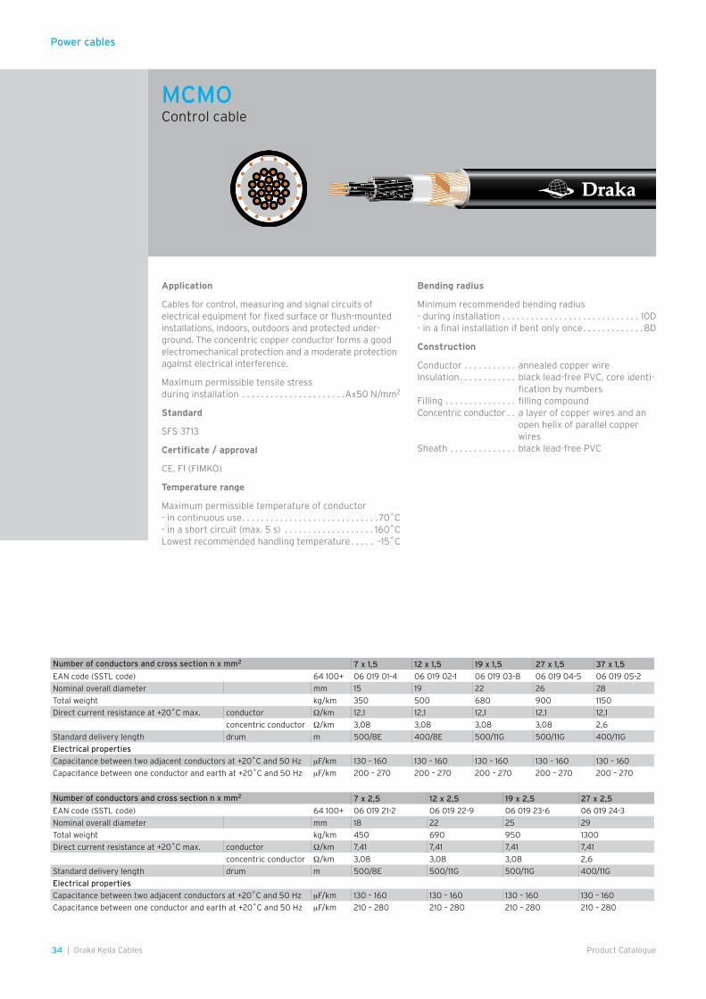
Power cables
34 | Draka Keila Cables Product Catalogue
Application
Cables for control, measuring and signal circuits of electrical equipment for fixed surface or flush-mounted installations, indoors, outdoors and protected under-ground. The concentric copper conductor forms a good electromechanical protection and a moderate protection against electrical interference.
Maximum permissible tensile stress during installation . . . . . . . . . . . . . . . . . . . . . .Ax50 N/mm2
Standard
SFS 3713
Certificate / approval
CE, FI (FIMKO)
Temperature range
Maximum permissible temperature of conductor- in continuous use . . . . . . . . . . . . . . . . . . . . . . . . . . . . . 70˚C- in a short circuit (max. 5 s) . . . . . . . . . . . . . . . . . . . 160˚CLowest recommended handling temperature . . . . . –15˚C
Bending radius
Minimum recommended bending radius- during installation . . . . . . . . . . . . . . . . . . . . . . . . . . . . . 10D- in a final installation if bent only once . . . . . . . . . . . . .8D
Construction
Conductor . . . . . . . . . . . annealed copper wireInsulation . . . . . . . . . . . . black lead-free PVC, core identi-
fication by numbersFilling . . . . . . . . . . . . . . . filling compoundConcentric conductor . . a layer of copper wires and an
open helix of parallel copper wires
Sheath . . . . . . . . . . . . . . black lead-free PVC
Number of conductors and cross section n x mm2 7 x 1,5 12 x 1,5 19 x 1,5 27 x 1,5 37 x 1,5
EAN code (SSTL code) 64 100+ 06 019 01-4 06 019 02-1 06 019 03-8 06 019 04-5 06 019 05-2
Nominal overall diameter mm 15 19 22 26 28
Total weight kg/km 350 500 680 900 1150
Direct current resistance at +20˚C max. conductor Ω/km 12,1 12,1 12,1 12,1 12,1
concentric conductor Ω/km 3,08 3,08 3,08 3,08 2,6
Standard delivery length drum m 500/8E 400/8E 500/11G 500/11G 400/11G
Electrical properties
Capacitance between two adjacent conductors at +20˚C and 50 Hz µF/km 130 – 160 130 – 160 130 – 160 130 – 160 130 – 160
Capacitance between one conductor and earth at +20˚C and 50 Hz µF/km 200 – 270 200 – 270 200 – 270 200 – 270 200 – 270
Number of conductors and cross section n x mm2 7 x 2,5 12 x 2,5 19 x 2,5 27 x 2,5
EAN code (SSTL code) 64 100+ 06 019 21-2 06 019 22-9 06 019 23-6 06 019 24-3
Nominal overall diameter mm 18 22 25 29
Total weight kg/km 450 690 950 1300
Direct current resistance at +20˚C max. conductor Ω/km 7,41 7,41 7,41 7,41
concentric conductor Ω/km 3,08 3,08 3,08 2,6
Standard delivery length drum m 500/8E 500/11G 500/11G 400/11G
Electrical properties
Capacitance between two adjacent conductors at +20˚C and 50 Hz µF/km 130 – 160 130 – 160 130 – 160 130 – 160
Capacitance between one conductor and earth at +20˚C and 50 Hz µF/km 210 – 280 210 – 280 210 – 280 210 – 280
MCMOControl cable
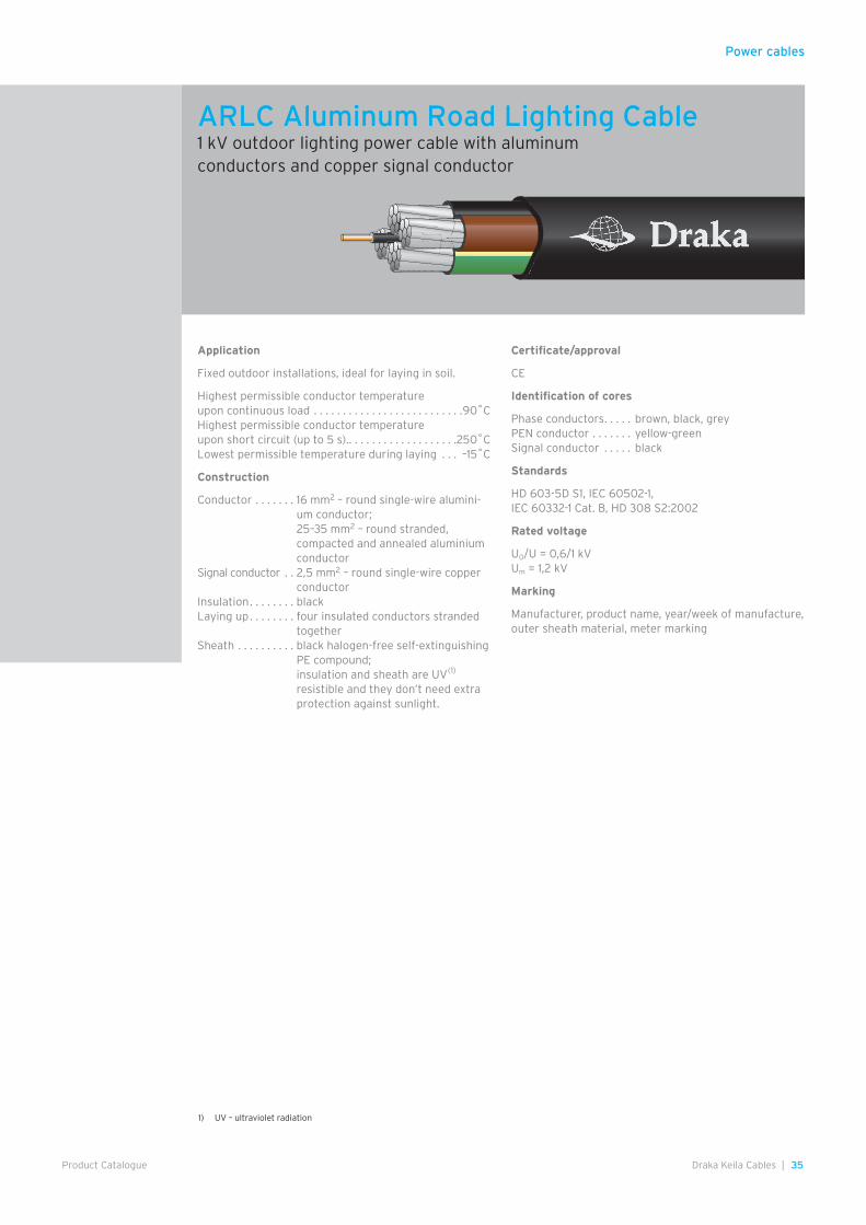
Power cables
35Draka Keila Cables |Product Catalogue
ARLC Aluminum Road Lighting Cable1 kV outdoor lighting power cable with aluminumconductors and copper signal conductor
Application
Fixed outdoor installations, ideal for laying in soil.
Highest permissible conductor temperature upon continuous load . . . . . . . . . . . . . . . . . . . . . . . . . .90˚CHighest permissible conductor temperature upon short circuit (up to 5 s). . . . . . . . . . . . . . . . . . . .250˚CLowest permissible temperature during laying . . . –15˚C
Construction
Conductor . . . . . . . 16 mm2 – round single-wire alumini-um conductor;25–35 mm2 – round stranded, compacted and annealed aluminium conductor
Signal conductor . . 2,5 mm2 – round single-wire copper conductor
Insulation . . . . . . . . blackLaying up . . . . . . . . four insulated conductors stranded
togetherSheath . . . . . . . . . . black halogen-free self-extinguishing
PE compound;insulation and sheath are UV(1) resistible and they don’t need extra protection against sunlight.
Certificate/approval
CE
Identification of cores
Phase conductors . . . . . brown, black, greyPEN conductor . . . . . . . yellow-greenSignal conductor . . . . . black
Standards
HD 603-5D S1, IEC 60502-1, IEC 60332-1 Cat. B, HD 308 S2:2002
Rated voltage
U0/U = 0,6/1 kVUm = 1,2 kV
Marking
Manufacturer, product name, year/week of manufacture, outer sheath material, meter marking
1) UV – ultraviolet radiation
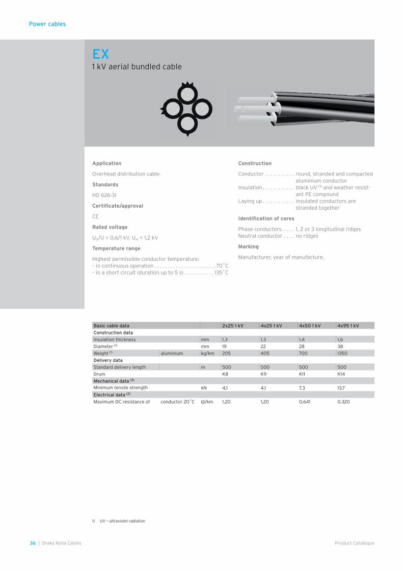
Power cables
36 | Draka Keila Cables Product Catalogue
Application
Overhead distribution cable.
Standards
HD 626-3I
Certificate/approval
CE
Rated voltage
U0/U = 0,6/1 kV, Um = 1,2 kV
Temperature range
Highest permissible conductor temperature: – in continuous operation . . . . . . . . . . . . . . . . . . . . . . . 70˚C – in a short circuit (duration up to 5 s) . . . . . . . . . . . 135˚C
Construction
Conductor . . . . . . . . . . . round, stranded and compacted aluminium conductor
Insulation . . . . . . . . . . . . black UV (1) and weather resist-ant PE compound
Laying up . . . . . . . . . . . . insulated conductors are stranded together
Identification of cores
Phase conductors . . . . . 1, 2 or 3 longitudinal ridgesNeutral conductor . . . . no ridges
Marking
Manufacturer, year of manufacture.
Basic cable data 2x25 1 kV 4x25 1 kV 4x50 1 kV 4x95 1 kV
Construction data
Insulation thickness mm 1,3 1,3 1,4 1,6
Diameter (1) mm 19 22 28 38
Weight (1) aluminium kg/km 205 405 700 1350
Delivery data
Standard delivery length m 500 500 500 500
Drum K8 K9 K11 K14
Mechanical data (2)
Minimum tensile strength kN 4,1 4,1 7,3 13,7
Electrical data (2)
Maximum DC resistance of conductor 20˚C Ω/km 1,20 1,20 0,641 0,320
EX1 kV aerial bundled cable
1) UV – ultraviolet radiation
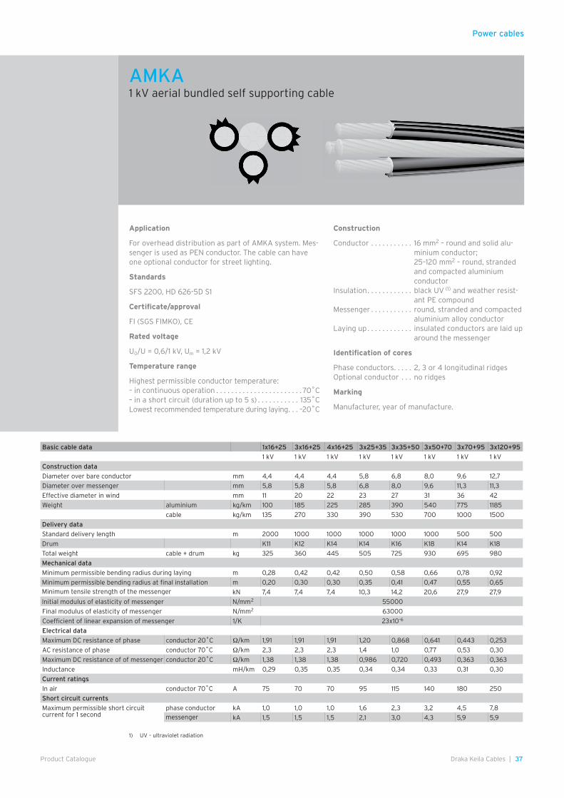
Power cables
37Draka Keila Cables |Product Catalogue
Application
For overhead distribution as part of AMKA system. Mes-senger is used as PEN conductor. The cable can have one optional conductor for street lighting.
Standards
SFS 2200, HD 626-5D S1
Certificate/approval
FI (SGS FIMKO), CE
Rated voltage
U0/U = 0,6/1 kV, Um = 1,2 kV
Temperature range
Highest permissible conductor temperature: – in continuous operation . . . . . . . . . . . . . . . . . . . . . . . 70˚C– in a short circuit (duration up to 5 s) . . . . . . . . . . . 135˚CLowest recommended temperature during laying . . . –20˚C
Construction
Conductor . . . . . . . . . . . 16 mm2 – round and solid alu-minium conductor;25–120 mm2 – round, stranded and compacted aluminium conductor
Insulation . . . . . . . . . . . . black UV (1) and weather resist-ant PE compound
Messenger . . . . . . . . . . . round, stranded and compacted aluminium alloy conductor
Laying up . . . . . . . . . . . . insulated conductors are laid up around the messenger
Identification of cores
Phase conductors . . . . . 2, 3 or 4 longitudinal ridgesOptional conductor . . . no ridges
Marking
Manufacturer, year of manufacture.
Basic cable data 1x16+25 3x16+25 4x16+25 3x25+35 3x35+50 3x50+70 3x70+95 3x120+95
1 kV 1 kV 1 kV 1 kV 1 kV 1 kV 1 kV 1 kV
Construction data
Diameter over bare conductor mm 4,4 4,4 4,4 5,8 6,8 8,0 9,6 12,7
Diameter over messenger mm 5,8 5,8 5,8 6,8 8,0 9,6 11,3 11,3
Effective diameter in wind mm 11 20 22 23 27 31 36 42
Weight aluminium kg/km 100 185 225 285 390 540 775 1185
cable kg/km 135 270 330 390 530 700 1000 1500
Delivery data
Standard delivery length m 2000 1000 1000 1000 1000 1000 500 500
Drum K11 K12 K14 K14 K16 K18 K14 K18
Total weight cable + drum kg 325 360 445 505 725 930 695 980
Mechanical data
Minimum permissible bending radius during laying m 0,28 0,42 0,42 0,50 0,58 0,66 0,78 0,92
Minimum permissible bending radius at final installation m 0,20 0,30 0,30 0,35 0,41 0,47 0,55 0,65Minimum tensile strength of the messenger kN 7,4 7,4 7,4 10,3 14,2 20,6 27,9 27,9
Initial modulus of elasticity of messenger N/mm2 55000
Final modulus of elasticity of messenger N/mm2 63000
Coefficient of linear expansion of messenger 1/K 23x10-6
Electrical data
Maximum DC resistance of phase conductor 20˚C Ω/km 1,91 1,91 1,91 1,20 0,868 0,641 0,443 0,253
AC resistance of phase conductor 70˚C Ω/km 2,3 2,3 2,3 1,4 1,0 0,77 0,53 0,30
Maximum DC resistance of of messenger conductor 20˚C Ω/km 1,38 1,38 1,38 0,986 0,720 0,493 0,363 0,363
Inductance mH/km 0,29 0,35 0,35 0,34 0,34 0,33 0,31 0,30
Current ratings
In air conductor 70˚C A 75 70 70 95 115 140 180 250
Short circuit currents
Maximum permissible short circuitcurrent for 1 second
phase conductor kA 1,0 1,0 1,0 1,6 2,3 3,2 4,5 7,8messenger kA 1,5 1,5 1,5 2,1 3,0 4,3 5,9 5,9
AMKA1 kV aerial bundled self supporting cable
1) UV – ultraviolet radiation
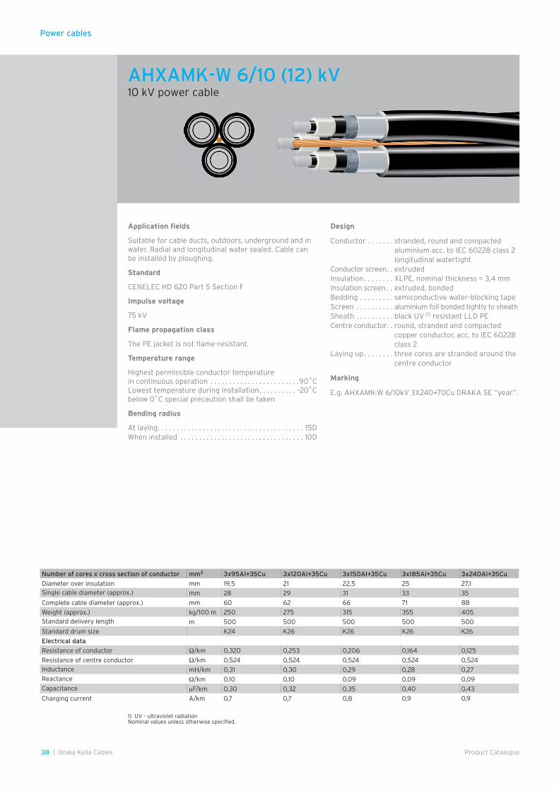
Power cables
38 | Draka Keila Cables Product Catalogue
Application fields
Suitable for cable ducts, outdoors, underground and in water. Radial and longitudinal water sealed. Cable can be installed by ploughing.
Standard
CENELEC HD 620 Part 5 Section F
Impulse voltage
75 kV
Flame propagation class
The PE jacket is not flame-resistant.
Temperature range
Highest permissible conductor temperaturein continuous operation . . . . . . . . . . . . . . . . . . . . . . . .90˚CLowest temperature during installation . . . . . . . . . . –20˚Cbelow 0˚C special precaution shall be taken
Bending radius
At laying . . . . . . . . . . . . . . . . . . . . . . . . . . . . . . . . . . . . . . . 15DWhen installed . . . . . . . . . . . . . . . . . . . . . . . . . . . . . . . . . 10D
Design
Conductor . . . . . . . stranded, round and compacted aluminium acc. to IEC 60228 class 2 longitudinal watertight
Conductor screen . . extrudedInsulation . . . . . . . . XLPE, nominal thickness = 3,4 mmInsulation screen . . extruded, bondedBedding . . . . . . . . . semiconductive water-blocking tapeScreen . . . . . . . . . . aluminium foil bonded tightly to sheathSheath . . . . . . . . . . black UV (1) resistant LLD PECentre conductor. . round, stranded and compacted
copper conductor, acc. to IEC 60228 class 2
Laying up . . . . . . . . three cores are stranded around the centre conductor
Marking
E.g. AHXAMK-W 6/10kV 3X240+70Cu DRAKA SE “year”.
Number of cores x cross section of conductor mm2 3x95Al+35Cu 3x120Al+35Cu 3x150Al+35Cu 3x185Al+35Cu 3x240Al+35Cu
Diameter over insulation mm 19,5 21 22,5 25 27,1Single cable diameter (approx.) mm 28 29 31 33 35
Complete cable diameter (approx.) mm 60 62 66 71 88
Weight (approx.) kg/100 m 250 275 315 355 405Standard delivery length m 500 500 500 500 500
Standard drum size K24 K26 K26 K26 K26
Electrical data
Resistance of conductor Ω/km 0,320 0,253 0,206 0,164 0,125
Resistance of centre conductor Ω/km 0,524 0,524 0,524 0,524 0,524Inductance mH/km 0,31 0,30 0,29 0,28 0,27Reactance Ω/km 0,10 0,10 0,09 0,09 0,09Capacitance µF/km 0,30 0,32 0,35 0,40 0,43
Charging current A/km 0,7 0,7 0,8 0,9 0,9
1) UV – ultraviolet radiation Nominal values unless otherwise specified.
AHXAMK-W 6/10 (12) kV10 kV power cable
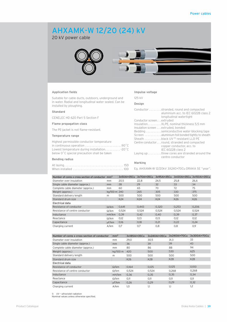
Power cables
39Draka Keila Cables |Product Catalogue
Application fields
Suitable for cable ducts, outdoors, underground and in water. Radial and longitudinal water sealed. Can be installed by ploughing.
Standard
CENELEC HD 620 Part 5 Section F
Flame propagation class
The PE-jacket is not flame-resistant.
Temperature range
Highest permissible conductor temperaturein continuous operation . . . . . . . . . . . . . . . . . . . . . . . .90˚CLowest temperature during installation . . . . . . . . . . –20˚Cbelow 0˚C special precaution shall be taken
Bending radius
At laying . . . . . . . . . . . . . . . . . . . . . . . . . . . . . . . . . . . . . . . 15DWhen installed . . . . . . . . . . . . . . . . . . . . . . . . . . . . . . . . . 10D
Impulse voltage
125 kV
Design
Conductor . . . . . . . . stranded, round and compacted aluminium acc. to IEC 60228 class 2 longitudinal watertight
Conductor screen . . .extrudedInsulation . . . . . . . . .XLPE, nominal thickness 5,5 mmInsulation screen . . .extruded, bondedBedding . . . . . . . . . . semiconductive water-blocking tapeScreen . . . . . . . . . . . aluminium foil bonded tightly to sheathSheath . . . . . . . . . . .black UV (1) resistant LLD PECentre conductor . . . round, stranded and compacted
copper conductor, acc. to IEC 60228 class 2
Laying up . . . . . . . . . three cores are stranded around the centre conductor
Marking
Eg. AHXAMK-W 12/20kV 3X240+70Cu DRAKA SE “year”.
1) UV – ultraviolet radiationNominal values unless otherwise specified.
Number of cores x cross section of conductor mm2 3x50Al+35Cu 3x70Al+35Cu 3x95Al+35Cu 3x120Al+35Cu 3x150Al+35Cu
Diameter over insulation mm 20,5 22,8 24,5 25,8 26,6Single cable diameter (approx.) mm 28 29 32 33 34Complete cable diameter (approx.) mm 60 65 70 72 75Weight (approx.) kg/100 m 240 265 305 330 375Standard delivery length m 500 500 500 500 500Standard drum size K24 K24 K24 K26 K26
Electrical dataResistance of conductor Ω/km 0,641 0,443 0,320 0,253 0,206
Resistance of centre conductor Ω/km 0,524 0,524 0,524 0,524 0,524
Inductance mH/km 0,39 0,42 0,40 0,39 0,37Reactance Ω/km 0,12 0,13 0,13 0,12 0,12
Capacitance µF/km 0,16 0,18 0,21 0,22 0,24
Charging current A/km 0,7 0,7 0,8 0,8 0,9
Number of cores x cross section of conductor mm2 3x185Al+35Cu 3x240Al+35Cu 3x240Al+70Cu 3x300Al+70Cu
Diameter over insulation mm 29,0 30,5 31,3 33
Single cable diameter (approx.) mm 36 39 39 43
Complete cable diameter (approx.) mm 80 86 88 94
Weight (approx.) kg/100 m 420 500 530 625
Standard delivery length m 500 500 500 500
Standard drum size K26 K28 K28 K28
Electrical data
Resistance of conductor Ω/km 0,164 0,125 0,125 0,100
Resistance of centre conductor Ω/km 0,524 0,524 0,268 0,268
Inductance mH/km 0,36 0,35 0,35 0,34
Reactance Ω/km 0,11 0,11 0,11 0,11Capacitance µF/km 0,26 0,29 0,29 0,32
Charging current A/km 1,0 1,1 1,1 1,2
AHXAMK-W 12/20 (24) kV20 kV power cable

Power cables
40 | Draka Keila Cables Product Catalogue
Number of cores x cross section of conductor mm2 1x50/16 1x95/16 1x150/25 1x240/25
Diameter over insulation mm 16,0 19,3 22,2 26,1
Overall diameter (approx.) mm 23,3 26,6 29,7 33,8
Weight (approx.) kg/100 m 59,7 79,4 107,4 141,4Standard delivery length m 500 500 500 500
Standard drum size K11 K12 K12 K14
Article number 0070410 0070420 0070440 0070460
Electrical data at +20˚C
Conductor resistance Ω/km 0,641 0,320 0,206 0,125
Screen resistance Ω/km 1,2 1,2 0,8 0,8
Inductance in trefoil/flat formation (2) (3) mH/km 0,40/0,73 0,36/0,66 0,34/0,63 0,31/0,58
Reactance Ω/km 0,29 0,21 0,20 0,18
Capacitance µF/km 0,23 0,30 0,35 0,43Earth fault current A/km 1,5 2,0 2,3 2,8
Electrical dataCurrent rating at core temp. 65˚C in ground (3) A 170 250 315 395Current rating at core temp. 65˚C in air (3) A 165 255 325 420Current rating at core temp. 90˚C in air (3) A 205 310 395 515Max. short circuit current on the conductor during 1 s at initial temp. 70˚C kA 5,1 9,7 15,3 24,4Max. short circuit current on the conductor during 1 s at initial temp. 90˚C kA 4,7 9,0 14,2 22,7
Nominal values unless otherwise specified.1) UV – ultraviolet radiation2) Cable distance, installation flat formation = 70 mm. 3) Trefoil with screen grounded in both ends.
Application fields
Single core distribution cable suitable for laying outdoors in 1- or 3-phase formation. Installation in pipes and in ground/water. Both radial and longitudinal water sealed. Can be installed by ploughing.
Alternative designation
SE-N10XC7A5T5E-AR
Standard
SS 424 14 16 CENELEC HD 620 Part 5 Section K
Fire propagation class
F1 acc. to SS 424 14 75
Material declaration
AXLJ-TT
Impulse voltage
75 kV
Temperature range
In continuous operation max. conductor temp. . . . .90˚C Lowest cable temperature under installation . . . . . –20˚C below 0˚C special precaution shall be taken
Bending radius
At fixed mounting . . . . . . . . . . . . . . . . . . . . . . . . . . . . . . 10D At pulling in . . . . . . . . . . . . . . . . . . . . . . . . . . . . . . . . . . . . 15D At ploughing down . . . . . . . . . . . . . . . . . . . . . . . . . . . . . . .8D
Design
Conductor . . . . . . . . . . . stranded, round and compacted aluminium acc. to IEC 60228 class 2, longitudinal water sealed
Conductor screen . . . . . extrudedInsulation . . . . . . . . . . . . XLPE, min. thickness= 2,96 mmInsulation screen . . . . . extruded bondedLongitudinal water sealing . . . . . . . . . . . . . . swellable conducting tapeConcentric conductor . . annealed copper wiresRadial water sealing . . . aluminium PE laminateSheath . . . . . . . . . . . . . . black UV (1) resistant LLD PE
Marking
E.g. AXLJ-TT 08DRAKA TSLE 12kV 1X240 AFR/25 “Date”, meter marked.
AXLJ-TT 7/12 kV10 kV power cable
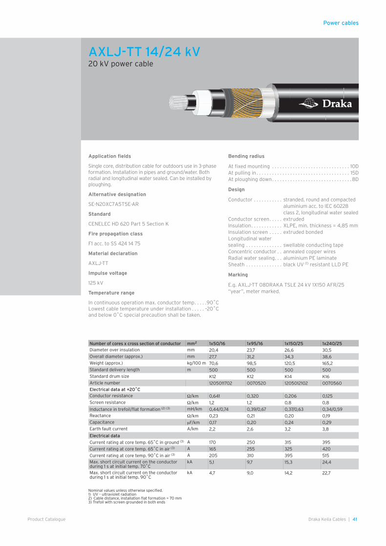
Power cables
41Draka Keila Cables |Product Catalogue
Application fields
Single core, distribution cable for outdoors use in 3-phase formation. Installation in pipes and ground/water. Both radial and longitudinal water sealed. Can be installed by ploughing.
Alternative designation
SE-N20XC7A5T5E-AR
Standard
CENELEC HD 620 Part 5 Section K
Fire propagation class
F1 acc. to SS 424 14 75
Material declaration
AXLJ-TT
Impulse voltage
125 kV
Temperature range
In continuous operation max. conductor temp . . . . .90˚CLowest cable temperature under installation . . . . . –20˚C and below 0˚C special precaution shall be taken.
Bending radius
At fixed mounting . . . . . . . . . . . . . . . . . . . . . . . . . . . . . . 10DAt pulling in . . . . . . . . . . . . . . . . . . . . . . . . . . . . . . . . . . . . 15DAt ploughing down . . . . . . . . . . . . . . . . . . . . . . . . . . . . . . .8D
Design
Conductor . . . . . . . . . . . stranded, round and compacted aluminium acc. to IEC 60228 class 2, longitudinal water sealed
Conductor screen . . . . . extrudedInsulation . . . . . . . . . . . . XLPE, min. thickness = 4,85 mmInsulation screen . . . . . extruded bondedLongitudinal water sealing . . . . . . . . . . . . . . swellable conducting tapeConcentric conductor . . annealed copper wiresRadial water sealing . . . aluminium PE laminateSheath . . . . . . . . . . . . . . black UV (1) resistant LLD PE
Marking
E.g. AXLJ-TT 08DRAKA TSLE 24 kV 1X150 AFR/25 “year”, meter marked.
Nominal values unless otherwise specified.1) UV – ultraviolet radiation2) Cable distance, installation flat formation = 70 mm3) Trefoil with screen grounded in both ends
Number of cores x cross section of conductor mm2 1x50/16 1x95/16 1x150/25 1x240/25Diameter over insulation mm 20,4 23,7 26,6 30,5Overall diameter (approx.) mm 27,7 31,2 34,3 38,6Weight (approx.) kg/100 m 70,6 98,5 120,5 165,2Standard delivery length m 500 500 500 500Standard drum size K12 K12 K14 K16Article number 1205011702 0070520 1205012102 0070560Electrical data at +20˚CConductor resistance Ω/km 0,641 0,320 0,206 0,125Screen resistance Ω/km 1,2 1,2 0,8 0,8
Inductance in trefoil/flat formation (2) (3) mH/km 0,44/0,74 0,39/0,67 0,37/0,63 0,34/0,59Reactance Ω/km 0,23 0,21 0,20 0,19Capacitance µF/km 0,17 0,20 0,24 0,29Earth fault current A/km 2,2 2,6 3,2 3,8
Electrical data
Current rating at core temp. 65˚C in ground (3) A 170 250 315 395
Current rating at core temp. 65˚C in air (3) A 165 255 325 420
Current rating at core temp. 90˚C in air (3) A 205 310 395 515Max. short circuit current on the conductor during 1 s at initial temp. 70˚C
kA 5,1 9,7 15,3 24,4
Max. short circuit current on the conductor during 1 s at initial temp. 90˚C
kA 4,7 9,0 14,2 22,7
AXLJ-TT 14/24 kV20 kV power cable
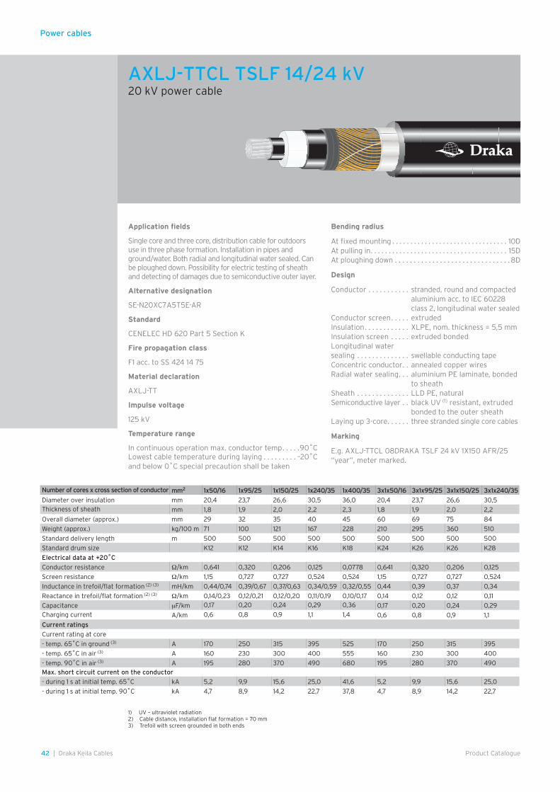
Power cables
42 | Draka Keila Cables Product Catalogue
Application fields
Single core and three core, distribution cable for outdoors use in three phase formation. Installation in pipes and ground/water. Both radial and longitudinal water sealed. Can be ploughed down. Possibility for electric testing of sheath and detecting of damages due to semiconductive outer layer.
Alternative designation
SE-N20XC7A5T5E-AR
Standard
CENELEC HD 620 Part 5 Section K
Fire propagation class
F1 acc. to SS 424 14 75
Material declaration
AXLJ-TT
Impulse voltage
125 kV
Temperature range
In continuous operation max. conductor temp . . . . .90˚CLowest cable temperature during laying . . . . . . . . . –20˚C and below 0˚C special precaution shall be taken
Bending radius
At fixed mounting . . . . . . . . . . . . . . . . . . . . . . . . . . . . . . . . 10DAt pulling in . . . . . . . . . . . . . . . . . . . . . . . . . . . . . . . . . . . . . . 15DAt ploughing down . . . . . . . . . . . . . . . . . . . . . . . . . . . . . . .8D
Design
Conductor . . . . . . . . . . . stranded, round and compacted aluminium acc. to IEC 60228 class 2, longitudinal water sealed
Conductor screen . . . . . extrudedInsulation . . . . . . . . . . . . XLPE, nom. thickness = 5,5 mmInsulation screen . . . . . extruded bondedLongitudinal water sealing . . . . . . . . . . . . . . swellable conducting tapeConcentric conductor . . annealed copper wiresRadial water sealing . . . aluminium PE laminate, bonded
to sheathSheath . . . . . . . . . . . . . . LLD PE, naturalSemiconductive layer . . black UV (1) resistant, extruded
bonded to the outer sheathLaying up 3-core. . . . . . three stranded single core cables
Marking
E.g. AXLJ-TTCL 08DRAKA TSLF 24 kV 1X150 AFR/25 “year”, meter marked.
Number of cores x cross section of conductor mm2 1x50/16 1x95/25 1x150/25 1x240/35 1x400/35 3x1x50/16 3x1x95/25 3x1x150/25 3x1x240/35
Diameter over insulation mm 20,4 23,7 26,6 30,5 36,0 20,4 23,7 26,6 30,5Thickness of sheath mm 1,8 1,9 2,0 2,2 2,3 1,8 1,9 2,0 2,2
Overall diameter (approx.) mm 29 32 35 40 45 60 69 75 84
Weight (approx.) kg/100 m 71 100 121 167 228 210 295 360 510
Standard delivery length m 500 500 500 500 500 500 500 500 500
Standard drum size K12 K12 K14 K16 K18 K24 K26 K26 K28
Electrical data at +20˚C
Conductor resistance Ω/km 0,641 0,320 0,206 0,125 0,0778 0,641 0,320 0,206 0,125
Screen resistance Ω/km 1,15 0,727 0,727 0,524 0,524 1,15 0,727 0,727 0,524
Inductance in trefoil/flat formation (2) (3) mH/km 0,44/0,74 0,39/0,67 0,37/0,63 0,34/0,59 0,32/0,55 0,44 0,39 0,37 0,34
Reactance in trefoil/flat formation (2) (3) Ω/km 0,14/0,23 0,12/0,21 0,12/0,20 0,11/0,19 0,10/0,17 0,14 0,12 0,12 0,11
Capacitance µF/km 0,17 0,20 0,24 0,29 0,36 0,17 0,20 0,24 0,29Charging current A/km 0,6 0,8 0,9 1,1 1,4 0,6 0,8 0,9 1,1
Current ratings
Current rating at core
- temp. 65˚C in ground (3) A 170 250 315 395 525 170 250 315 395
- temp. 65˚C in air (3) A 160 230 300 400 555 160 230 300 400
- temp. 90˚C in air (3) A 195 280 370 490 680 195 280 370 490Max. short circuit current on the conductor
- during 1 s at initial temp. 65˚C kA 5,2 9,9 15,6 25,0 41,6 5,2 9,9 15,6 25,0
- during 1 s at initial temp. 90˚C kA 4,7 8,9 14,2 22,7 37,8 4,7 8,9 14,2 22,7
1) UV – ultraviolet radiation2) Cable distance, installation flat formation = 70 mm3) Trefoil with screen grounded in both ends
AXLJ-TTCL TSLF 14/24 kV20 kV power cable
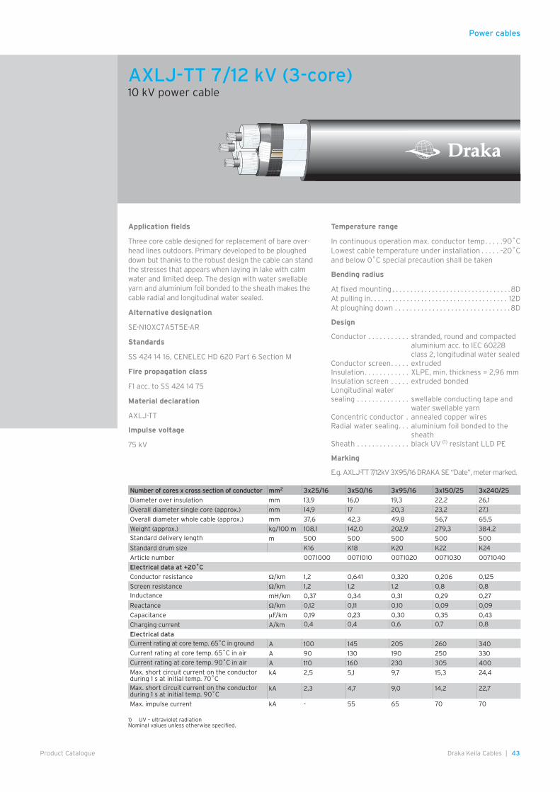
Power cables
43Draka Keila Cables |Product Catalogue
Application fields
Three core cable designed for replacement of bare over-head lines outdoors. Primary developed to be ploughed down but thanks to the robust design the cable can stand the stresses that appears when laying in lake with calm water and limited deep. The design with water swellable yarn and aluminium foil bonded to the sheath makes the cable radial and longitudinal water sealed.
Alternative designation
SE-N10XC7A5T5E-AR
Standards
SS 424 14 16, CENELEC HD 620 Part 6 Section M
Fire propagation class
F1 acc. to SS 424 14 75
Material declaration
AXLJ-TT
Impulse voltage
75 kV
Temperature range
In continuous operation max. conductor temp . . . . .90˚CLowest cable temperature under installation . . . . . –20˚Cand below 0˚C special precaution shall be taken
Bending radius
At fixed mounting . . . . . . . . . . . . . . . . . . . . . . . . . . . . . . . . .8DAt pulling in . . . . . . . . . . . . . . . . . . . . . . . . . . . . . . . . . . . . . . 12DAt ploughing down . . . . . . . . . . . . . . . . . . . . . . . . . . . . . . .8D
Design
Conductor . . . . . . . . . . . stranded, round and compacted aluminium acc. to IEC 60228 class 2, longitudinal water sealed
Conductor screen . . . . . extrudedInsulation . . . . . . . . . . . . XLPE, min. thickness = 2,96 mmInsulation screen . . . . . extruded bondedLongitudinal water sealing . . . . . . . . . . . . . . swellable conducting tape and
water swellable yarnConcentric conductor . annealed copper wiresRadial water sealing . . . aluminium foil bonded to the
sheathSheath . . . . . . . . . . . . . . black UV (1) resistant LLD PE
Marking
E.g. AXLJ-TT 7/12kV 3X95/16 DRAKA SE “Date”, meter marked.
Number of cores x cross section of conductor mm2 3x25/16 3x50/16 3x95/16 3x150/25 3x240/25
Diameter over insulation mm 13,9 16,0 19,3 22,2 26,1
Overall diameter single core (approx.) mm 14,9 17 20,3 23,2 27,1
Overall diameter whole cable (approx.) mm 37,6 42,3 49,8 56,7 65,5
Weight (approx.) kg/100 m 108,1 142,0 202,9 279,3 384,2Standard delivery length m 500 500 500 500 500
Standard drum size K16 K18 K20 K22 K24
Article number 0071000 0071010 0071020 0071030 0071040
Electrical data at +20˚C
Conductor resistance Ω/km 1,2 0,641 0,320 0,206 0,125
Screen resistance Ω/km 1,2 1,2 1,2 0,8 0,8Inductance mH/km 0,37 0,34 0,31 0,29 0,27
Reactance Ω/km 0,12 0,11 0,10 0,09 0,09
Capacitance µF/km 0,19 0,23 0,30 0,35 0,43
Charging current A/km 0,4 0,4 0,6 0,7 0,8
Electrical dataCurrent rating at core temp. 65˚C in ground A 100 145 205 260 340Current rating at core temp. 65˚C in air A 90 130 190 250 330Current rating at core temp. 90˚C in air A 110 160 230 305 400Max. short circuit current on the conductor during 1 s at initial temp. 70˚C
kA 2,5 5,1 9,7 15,3 24,4
Max. short circuit current on the conductor during 1 s at initial temp. 90˚C
kA 2,3 4,7 9,0 14,2 22,7
Max. impulse current kA - 55 65 70 70
AXLJ-TT 7/12 kV (3-core)10 kV power cable
1) UV – ultraviolet radiationNominal values unless otherwise specified.
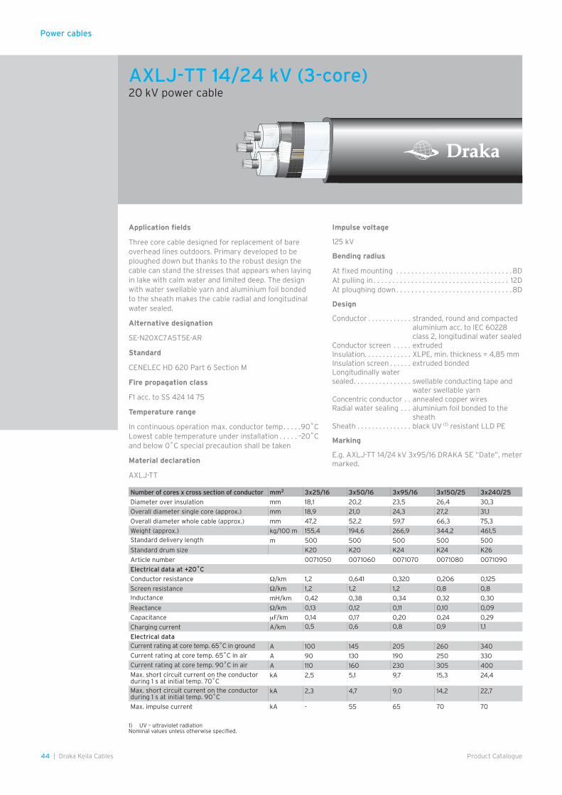
Power cables
44 | Draka Keila Cables Product Catalogue
Application fields
Three core cable designed for replacement of bare overhead lines outdoors. Primary developed to be ploughed down but thanks to the robust design the cable can stand the stresses that appears when laying in lake with calm water and limited deep. The design with water swellable yarn and aluminium foil bonded to the sheath makes the cable radial and longitudinal water sealed.
Alternative designation
SE-N20XC7A5T5E-AR
Standard
CENELEC HD 620 Part 6 Section M
Fire propagation class
F1 acc. to SS 424 14 75
Temperature range
In continuous operation max. conductor temp . . . . .90˚CLowest cable temperature under installation . . . . . –20˚Cand below 0˚C special precaution shall be taken
Material declaration
AXLJ-TT
Impulse voltage
125 kV
Bending radius
At fixed mounting . . . . . . . . . . . . . . . . . . . . . . . . . . . . . . .8DAt pulling in . . . . . . . . . . . . . . . . . . . . . . . . . . . . . . . . . . . . 12DAt ploughing down . . . . . . . . . . . . . . . . . . . . . . . . . . . . . . .8D
Design
Conductor . . . . . . . . . . . . stranded, round and compacted aluminium acc. to IEC 60228 class 2, longitudinal water sealed
Conductor screen . . . . . extrudedInsulation . . . . . . . . . . . . . XLPE, min. thickness = 4,85 mmInsulation screen . . . . . . extruded bondedLongitudinally water sealed . . . . . . . . . . . . . . . . swellable conducting tape and
water swellable yarnConcentric conductor . . annealed copper wiresRadial water sealing . . . aluminium foil bonded to the
sheathSheath . . . . . . . . . . . . . . . black UV (1) resistant LLD PE
Marking
E.g. AXLJ-TT 14/24 kV 3x95/16 DRAKA SE “Date”, meter marked.
1) UV – ultraviolet radiationNominal values unless otherwise specified.
Number of cores x cross section of conductor mm2 3x25/16 3x50/16 3x95/16 3x150/25 3x240/25
Diameter over insulation mm 18,1 20,2 23,5 26,4 30,3
Overall diameter single core (approx.) mm 18,9 21,0 24,3 27,2 31,1
Overall diameter whole cable (approx.) mm 47,2 52,2 59,7 66,3 75,3
Weight (approx.) kg/100 m 155,4 194,6 266,9 344,2 461,5Standard delivery length m 500 500 500 500 500
Standard drum size K20 K20 K24 K24 K26
Article number 0071050 0071060 0071070 0071080 0071090
Electrical data at +20˚C
Conductor resistance Ω/km 1,2 0,641 0,320 0,206 0,125
Screen resistance Ω/km 1,2 1,2 1,2 0,8 0,8Inductance mH/km 0,42 0,38 0,34 0,32 0,30
Reactance Ω/km 0,13 0,12 0,11 0,10 0,09
Capacitance µF/km 0,14 0,17 0,20 0,24 0,29
Charging current A/km 0,5 0,6 0,8 0,9 1,1
Electrical dataCurrent rating at core temp. 65˚C in ground A 100 145 205 260 340Current rating at core temp. 65˚C in air A 90 130 190 250 330Current rating at core temp. 90˚C in air A 110 160 230 305 400Max. short circuit current on the conductor during 1 s at initial temp. 70˚C
kA 2,5 5,1 9,7 15,3 24,4
Max. short circuit current on the conductor during 1 s at initial temp. 90˚C
kA 2,3 4,7 9,0 14,2 22,7
Max. impulse current kA - 55 65 70 70
AXLJ-TT 14/24 kV (3-core)20 kV power cable

Power cables
45Draka Keila Cables |Product Catalogue
Application fields
Three core cable designed for replacement of bare overhead lines outdoors. Primary developed to be ploughed down but thanks to the robust design it can stand the stresses that appears when laying in water.
Alternative designation
SE-N10XC7V-AR
Standards
S 424 14 16CENELEC HD 620 Part 6 Section M
Fire propagation class
F1 acc. to SS 424 14 75
Material declaration
AXLJ LT, -F, -RMF
Temperature range
In continuous operation max. conductor temp . . . . .90˚CLowest cable temperature under installation . . . . . –20˚C and below 0˚C special precaution shall be taken
Impulse voltage
75 kV
Bending radius
At fixed mounting . . . . . . . . . . . . . . . . . . . . . . . . . . . . . . .8DAt pulling in . . . . . . . . . . . . . . . . . . . . . . . . . . . . . . . . . . . . 12DAt ploughing down . . . . . . . . . . . . . . . . . . . . . . . . . . . . . . .8D
Design
Conductor . . . . . . . . . . . stranded, round and compacted aluminium acc. to IEC 60228 class 2, longitudinal water sealed
Conductor screen . . . . . extrudedInsulation . . . . . . . . . . . . XLPE, min. thickness = 2,96 mmInsulation screen . . . . . extruded bondedTaping . . . . . . . . . . . . . . . conductive tapeConcentric conductor . . annealed copper wiresSheath . . . . . . . . . . . . . . black UV (1) resistant LLD PE
Marking
E.g. AXLJ-RMF 7/12 KV 3X150/25 LT DRAKA SE “year”.
1) UV – ultraviolet radiationNominal values unless otherwise specified.
Number of cores x cross section of conductor mm2 3x25/16 3x50/16 3x95/16 3x150/25 3x240/25
Diameter over insulation mm 14,0 16,2 19,5 22,4 26,3
Overall diameter (approx.) mm 39,1 44,0 51,6 58,4 67,2
Weight (approx.) kg/100 m 103,5 135,4 195,1 267,1 372,8Standard delivery length m 500 500 500 500 500
Standard drum size K16 K18 K20 K22 K24
Article number 1040031502 1040031702 1040031902 1040032102 1040032302
Electrical data at +20˚C
Conductor resistance Ω/km 1,2 0,641 0,320 0,206 0,125
Screen resistance Ω/km 1,2 1,2 1,2 0,8 0,8Inductance mH/km 0,38 0,34 0,31 0,29 0,27
Reactance Ω/km 0,12 0,11 0,10 0,09 0,09
Capacitance µF/km 0,19 0,23 0,30 0,35 0,42
Charging current A/km 0,4 0,4 0,6 0,7 0,8
Electrical data
Current rating at core temp. 65˚C in ground A 100 145 205 260 340
Current rating at core temp. 65˚C in air A 90 130 190 250 330
Current rating at core temp. 90˚C in air A 110 160 230 305 400Max. short circuit current on the conductor during 1 s at initial temp. 70˚C
kA 2,5 5,1 9,7 15,3 24,4
Max. short circuit current on the conductor during 1 s at initial temp. 90˚C
kA 2,3 4,7 9,0 14,2 22,7
Max. impulse current kA - 55 65 70 70
AXLJ-RMF 7/12 kV10 kV power cable

Power cables
46 | Draka Keila Cables Product Catalogue
Application fields
Three core cable designed for replacement of bare overhead lines outdoors. Primary developed to be ploughed down but thanks to the robust design it can stand the stresses that appears when laying in water.
Alternative designation
SE-N20XC7V-AR
Standards
S 424 14 16, CENELEC HD 620 Part 6 Section M
Fire propagation class
F1 acc. to SS 424 14 75
Temperature range
In continuous operation max. conductor temp . . . . .90˚CLowest cable temperature under installation . . . . . –20˚Cand below 0˚C special precaution shall be taken
Material declaration
AXLJ LT, -F, -RMF
Impulse voltage
125 kV
Bending radius
At fixed mounting . . . . . . . . . . . . . . . . . . . . . . . . . . . . . . . . .8DAt pulling in . . . . . . . . . . . . . . . . . . . . . . . . . . . . . . . . . . . . . . 12DAt ploughing down . . . . . . . . . . . . . . . . . . . . . . . . . . . . . . .8D
Design
Conductor . . . . . . . . . . . stranded, round and compacted aluminium acc. to IEC 60228 class 2, longitudinal water sealed
Conductor screen . . . . . extrudedInsulation . . . . . . . . . . . . XLPE, min. thickness = 4,85 mmInsulation screen . . . . . extruded bondedTaping . . . . . . . . . . . . . . . conductive tapeConcentric conductor . . annealed copper wiresSheath . . . . . . . . . . . . . . black UV (1) resistant LLD PE
Marking
E.g. AXLJ-RMF 14/24 KV 3X150/25 LT DRAKA SE “year”.
1) UV – ultraviolet radiationNominal values unless otherwise specified.
Number of cores x cross section of conductor mm2 3x25/16 3x50/16 3x95/16 3x150/25 3x240/25
Diameter over insulation mm 18,2 20,4 23,7 26,7 30,7
Overall diameter (approx.) mm 49,0 53,9 61,4 68,1 77,1
Weight (approx.) kg/100 m 147,2 185,1 253,9 328,1 445,5
Standard delivery length m 500 500 500 500 500
Standard drum size K20 K20 K24 K24 K26
Article number 1045031502 1045031702 1045031902 1045032102 1045032302
Electrical data at +20˚C
Conductor resistance Ω/km 1,2 0,641 0,320 0,206 0,125
Screen resistance Ω/km 1,2 1,2 1,2 0,8 0,8Inductance mH/km 0,43 0,39 0,35 0,32 0,30
Reactance Ω/km 0,14 0,12 0,11 0,10 0,09
Capacitance µF/km 0,14 0,16 0,20 0,24 0,29
Charging current A/km 0,5 0,6 0,8 0,9 1,1
Electrical data
Current rating at core temp. 65˚C in ground A 100 145 205 260 340
Current rating at core temp. 65˚C in air A 90 130 190 250 330
Current rating at core temp. 90˚C in air A 110 160 230 305 400Max. short circuit current on the conductor during 1 s at initial temp. 70˚C
kA 2,5 5,1 9,7 15,3 24,4
Max. short circuit current on the conductor during 1 s at initial temp. 90˚C
kA 2,3 4,7 9,0 14,2 22,7
Max. impulse current kA - 55 65 70 70
AXLJ-RMF 14/24 kV20 kV power cable

Power cables
47Draka Keila Cables |Product Catalogue
Application fields
Halogen-free and fire classified cable. No emittance of corrosive gases, low smoke density in case of fire. Primary developed for installation indoors, tunnels etc. The cable can also with advantage be installed outdoors and in ground. Ploughing down is not recommended.
Alternative designation
SE-N10XC7Z1-AR
Standards
SS 424 14 16CENELEC HD 620 Part 6 Section MCENELEC HD 604 Halogen-free MaterialsIEC 60754-1, –2 Corrosive GasesIEC 61034 Smoke Density
Fire propagation class
F4B acc. to SS 424 14 75 and IEC 60332-3 cat B and SS-EN 50266-2-3
Temperature range
In continuous operation max. conductor temp . . . . .90˚CLowest cable temperature under installation . . . . . –20˚Cand below 0˚C special precaution shall be taken.
Material declaration
AXQJ-F, –RMF
Impulse voltage
75 kV
Bending radius
At fixed mounting . . . . . . . . . . . . . . . . . . . . . . . . . . . . . . . . .8DAt pulling in . . . . . . . . . . . . . . . . . . . . . . . . . . . . . . . . . . . . . . 12DAt ploughing down . . . . . . . . . . . . . . . . . . . . . . . . . . . . . . .8D
Design
Conductor . . . . . . . . . . . stranded, round and compacted aluminium acc. to IEC 60228 class 2, longitudinal water sealed
Conductor screen . . . . . extrudedInsulation . . . . . . . . . . . . XLPE, min. thickness = 2,96 mmInsulation screen . . . . . extruded bondedTaping . . . . . . . . . . . . . . . conductive tapeConcentric conductor . . annealed copper wiresSheath . . . . . . . . . . . . . . halogen-free compound, black
Marking
E.g. AXQJ-RMF 7/12 kV 3x150/25 LT F4B DRAKA SE “Date”, meter marked.
Nominal values unless otherwise specified.
Number of cores x cross section of conductor mm2 3x50/16 3x95/16 3x150/25 3x240/25
Diameter over insulation mm 16,0 19,3 22,2 26,1
Overall diameter (approx.) mm 43,6 51,1 58,0 66,8
Weight (approx.) kg/100 m 153,2 219,4 297,3 405,3
Standard delivery length m 500 500 500 500
Standard drum size K18 K20 K22 K24
Article number 0071210 0071220 0071230 0071240
Electrical data at +20˚C
Conductor resistance Ω/km 0,641 0,320 0,206 0,125
Screen resistance Ω/km 1,2 1,2 0,8 0,8Inductance mH/km 0,34 0,31 0,29 0,27
Reactance Ω/km 0,11 0,10 0,09 0,09
Capacitance µF/km 0,23 0,30 0,35 0,43
Charging current A/km 0,4 0,6 0,7 0,8
Electrical data
Current rating at core temp. 65˚C in ground A 145 205 260 340Current rating at core temp. 65˚C in air A 130 190 250 330Current rating at core temp. 90˚C in air A 160 230 305 400Max. short circuit current on the conductor during 1 s at initial temp. 70˚C
kA 5,1 9,7 15,3 24,4
Max. short circuit current on the conductor during 1 s at initial temp. 90˚C
kA 4,7 9,0 14,2 22,7
Max. impulse current kA 55 65 70 70
AXQJ-RMF 7/12 kV10 kV halogen-free power cable
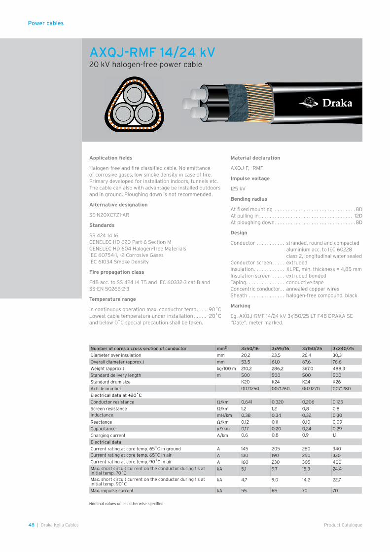
Power cables
48 | Draka Keila Cables Product Catalogue
Application fields
Halogen-free and fire classified cable. No emittance of corrosive gases, low smoke density in case of fire. Primary developed for installation indoors, tunnels etc. The cable can also with advantage be installed outdoors and in ground. Ploughing down is not recommended.
Alternative designation
SE-N20XC7Z1-AR
Standards
SS 424 14 16CENELEC HD 620 Part 6 Section MCENELEC HD 604 Halogen-free MaterialsIEC 60754-1, –2 Corrosive GasesIEC 61034 Smoke Density
Fire propagation class
F4B acc. to SS 424 14 75 and IEC 60332-3 cat B and SS-EN 50266-2-3
Temperature range
In continuous operation max. conductor temp . . . . .90˚CLowest cable temperature under installation . . . . . –20˚Cand below 0˚C special precaution shall be taken.
Material declaration
AXQJ-F, –RMF
Impulse voltage
125 kV
Bending radius
At fixed mounting . . . . . . . . . . . . . . . . . . . . . . . . . . . . . . .8DAt pulling in . . . . . . . . . . . . . . . . . . . . . . . . . . . . . . . . . . . . 12DAt ploughing down . . . . . . . . . . . . . . . . . . . . . . . . . . . . . . .8D
Design
Conductor . . . . . . . . . . . stranded, round and compacted aluminium acc. to IEC 60228 class 2, longitudinal water sealed
Conductor screen . . . . . extrudedInsulation . . . . . . . . . . . . XLPE, min. thickness = 4,85 mmInsulation screen . . . . . extruded bondedTaping . . . . . . . . . . . . . . . conductive tapeConcentric conductor . . annealed copper wiresSheath . . . . . . . . . . . . . . halogen-free compound, black
Marking
Eg. AXQJ-RMF 14/24 kV 3x150/25 LT F4B DRAKA SE “Date”, meter marked.
Nominal values unless otherwise specified.
Number of cores x cross section of conductor mm2 3x50/16 3x95/16 3x150/25 3x240/25
Diameter over insulation mm 20,2 23,5 26,4 30,3
Overall diameter (approx.) mm 53,5 61,0 67,6 76,6
Weight (approx.) kg/100 m 210,2 286,2 367,0 488,3
Standard delivery length m 500 500 500 500
Standard drum size K20 K24 K24 K26
Article number 0071250 0071260 0071270 0071280
Electrical data at +20˚C
Conductor resistance Ω/km 0,641 0,320 0,206 0,125
Screen resistance Ω/km 1,2 1,2 0,8 0,8Inductance mH/km 0,38 0,34 0,32 0,30
Reactance Ω/km 0,12 0,11 0,10 0,09
Capacitance µF/km 0,17 0,20 0,24 0,29
Charging current A/km 0,6 0,8 0,9 1,1
Electrical data
Current rating at core temp. 65˚C in ground A 145 205 260 340Current rating at core temp. 65˚C in air A 130 190 250 330Current rating at core temp. 90˚C in air A 160 230 305 400Max. short circuit current on the conductor during 1 s at initial temp. 70˚C
kA 5,1 9,7 15,3 24,4
Max. short circuit current on the conductor during 1 s at initial temp. 90˚C
kA 4,7 9,0 14,2 22,7
Max. impulse current kA 55 65 70 70
AXQJ-RMF 14/24 kV20 kV halogen-free power cable
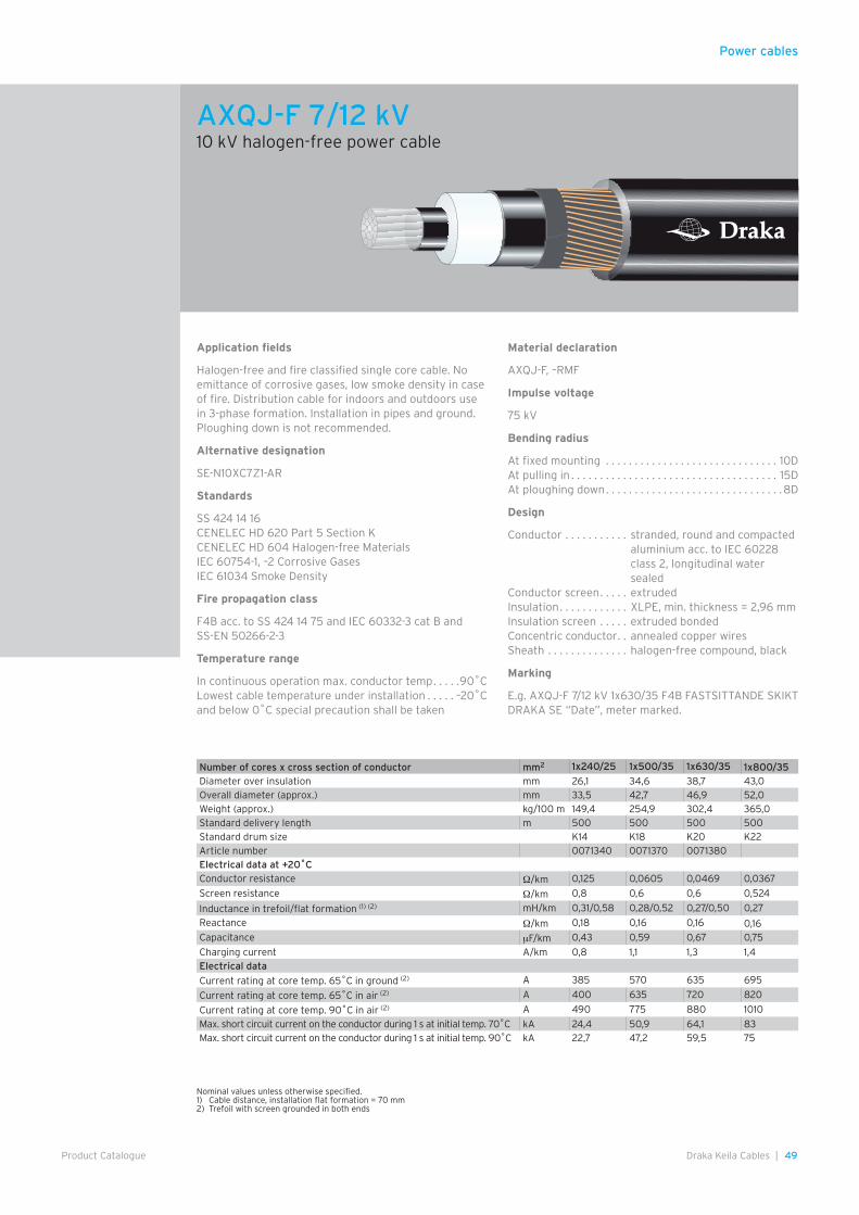
Power cables
49Draka Keila Cables |Product Catalogue
Application fields
Halogen-free and fire classified single core cable. No emittance of corrosive gases, low smoke density in case of fire. Distribution cable for indoors and outdoors use in 3-phase formation. Installation in pipes and ground. Ploughing down is not recommended.
Alternative designation
SE-N10XC7Z1-AR
Standards
SS 424 14 16CENELEC HD 620 Part 5 Section KCENELEC HD 604 Halogen-free MaterialsIEC 60754-1, –2 Corrosive GasesIEC 61034 Smoke Density
Fire propagation class
F4B acc. to SS 424 14 75 and IEC 60332-3 cat B and SS-EN 50266-2-3
Temperature range
In continuous operation max. conductor temp . . . . .90˚CLowest cable temperature under installation . . . . . –20˚Cand below 0˚C special precaution shall be taken
Material declaration
AXQJ-F, –RMF
Impulse voltage
75 kV
Bending radius
At fixed mounting . . . . . . . . . . . . . . . . . . . . . . . . . . . . . . 10DAt pulling in . . . . . . . . . . . . . . . . . . . . . . . . . . . . . . . . . . . . 15DAt ploughing down . . . . . . . . . . . . . . . . . . . . . . . . . . . . . . .8D
Design
Conductor . . . . . . . . . . . stranded, round and compacted aluminium acc. to IEC 60228 class 2, longitudinal water sealed
Conductor screen . . . . . extrudedInsulation . . . . . . . . . . . . XLPE, min. thickness = 2,96 mmInsulation screen . . . . . extruded bondedConcentric conductor . . annealed copper wiresSheath . . . . . . . . . . . . . . halogen-free compound, black
Marking
E.g. AXQJ-F 7/12 kV 1x630/35 F4B FASTSITTANDE SKIKT DRAKA SE “Date”, meter marked.
Number of cores x cross section of conductor mm2 1x240/25 1x500/35 1x630/35 1x800/35Diameter over insulation mm 26,1 34,6 38,7 43,0Overall diameter (approx.) mm 33,5 42,7 46,9 52,0Weight (approx.) kg/100 m 149,4 254,9 302,4 365,0Standard delivery length m 500 500 500 500Standard drum size K14 K18 K20 K22Article number 0071340 0071370 0071380Electrical data at +20˚CConductor resistance Ω/km 0,125 0,0605 0,0469 0,0367
Screen resistance Ω/km 0,8 0,6 0,6 0,524
Inductance in trefoil/flat formation (1) (2) mH/km 0,31/0,58 0,28/0,52 0,27/0,50 0,27
Reactance Ω/km 0,18 0,16 0,16 0,16Capacitance µF/km 0,43 0,59 0,67 0,75
Charging current A/km 0,8 1,1 1,3 1,4Electrical data
Current rating at core temp. 65˚C in ground (2) A 385 570 635 695
Current rating at core temp. 65˚C in air (2) A 400 635 720 820
Current rating at core temp. 90˚C in air (2) A 490 775 880 1010
Max. short circuit current on the conductor during 1 s at initial temp. 70˚C kA 24,4 50,9 64,1 83Max. short circuit current on the conductor during 1 s at initial temp. 90˚C kA 22,7 47,2 59,5 75
Nominal values unless otherwise specified.1) Cable distance, installation flat formation = 70 mm2) Trefoil with screen grounded in both ends
AXQJ-F 7/12 kV10 kV halogen-free power cable
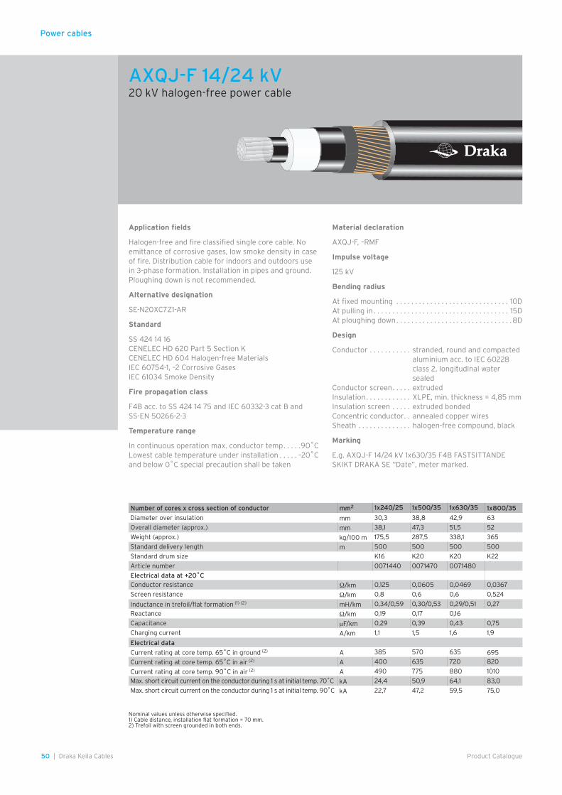
Power cables
50 | Draka Keila Cables Product Catalogue
Application fields
Halogen-free and fire classified single core cable. No emittance of corrosive gases, low smoke density in case of fire. Distribution cable for indoors and outdoors use in 3-phase formation. Installation in pipes and ground. Ploughing down is not recommended.
Alternative designation
SE-N20XC7Z1-AR
Standard
SS 424 14 16CENELEC HD 620 Part 5 Section KCENELEC HD 604 Halogen-free MaterialsIEC 60754-1, –2 Corrosive GasesIEC 61034 Smoke Density
Fire propagation class
F4B acc. to SS 424 14 75 and IEC 60332-3 cat B and SS-EN 50266-2-3
Temperature range
In continuous operation max. conductor temp . . . . .90˚CLowest cable temperature under installation . . . . . –20˚Cand below 0˚C special precaution shall be taken
Material declaration
AXQJ-F, –RMF
Impulse voltage
125 kV
Bending radius
At fixed mounting . . . . . . . . . . . . . . . . . . . . . . . . . . . . . . 10DAt pulling in . . . . . . . . . . . . . . . . . . . . . . . . . . . . . . . . . . . . 15DAt ploughing down . . . . . . . . . . . . . . . . . . . . . . . . . . . . . . .8D
Design
Conductor . . . . . . . . . . . stranded, round and compacted aluminium acc. to IEC 60228 class 2, longitudinal water sealed
Conductor screen . . . . . extrudedInsulation . . . . . . . . . . . . XLPE, min. thickness = 4,85 mmInsulation screen . . . . . extruded bondedConcentric conductor . . annealed copper wiresSheath . . . . . . . . . . . . . . halogen-free compound, black
Marking
E.g. AXQJ-F 14/24 kV 1x630/35 F4B FASTSITTANDE SKIKT DRAKA SE “Date”, meter marked.
Number of cores x cross section of conductor mm2 1x240/25 1x500/35 1x630/35 1x800/35
Diameter over insulation mm 30,3 38,8 42,9 63
Overall diameter (approx.) mm 38,1 47,3 51,5 52
Weight (approx.) kg/100 m 175,5 287,5 338,1 365
Standard delivery length m 500 500 500 500
Standard drum size K16 K20 K20 K22
Article number 0071440 0071470 0071480
Electrical data at +20˚CConductor resistance Ω/km 0,125 0,0605 0,0469 0,0367
Screen resistance Ω/km 0,8 0,6 0,6 0,524
Inductance in trefoil/flat formation (1) (2) mH/km 0,34/0,59 0,30/0,53 0,29/0,51 0,27
Reactance Ω/km 0,19 0,17 0,16
Capacitance µF/km 0,29 0,39 0,43 0,75
Charging current A/km 1,1 1,5 1,6 1,9
Electrical data
Current rating at core temp. 65˚C in ground (2) A 385 570 635 695
Current rating at core temp. 65˚C in air (2) A 400 635 720 820
Current rating at core temp. 90˚C in air (2) A 490 775 880 1010
Max. short circuit current on the conductor during 1 s at initial temp. 70˚C kA 24,4 50,9 64,1 83,0
Max. short circuit current on the conductor during 1 s at initial temp. 90˚C kA 22,7 47,2 59,5 75,0
Nominal values unless otherwise specified.1) Cable distance, installation flat formation = 70 mm.2) Trefoil with screen grounded in both ends.
AXQJ-F 14/24 kV20 kV halogen-free power cable
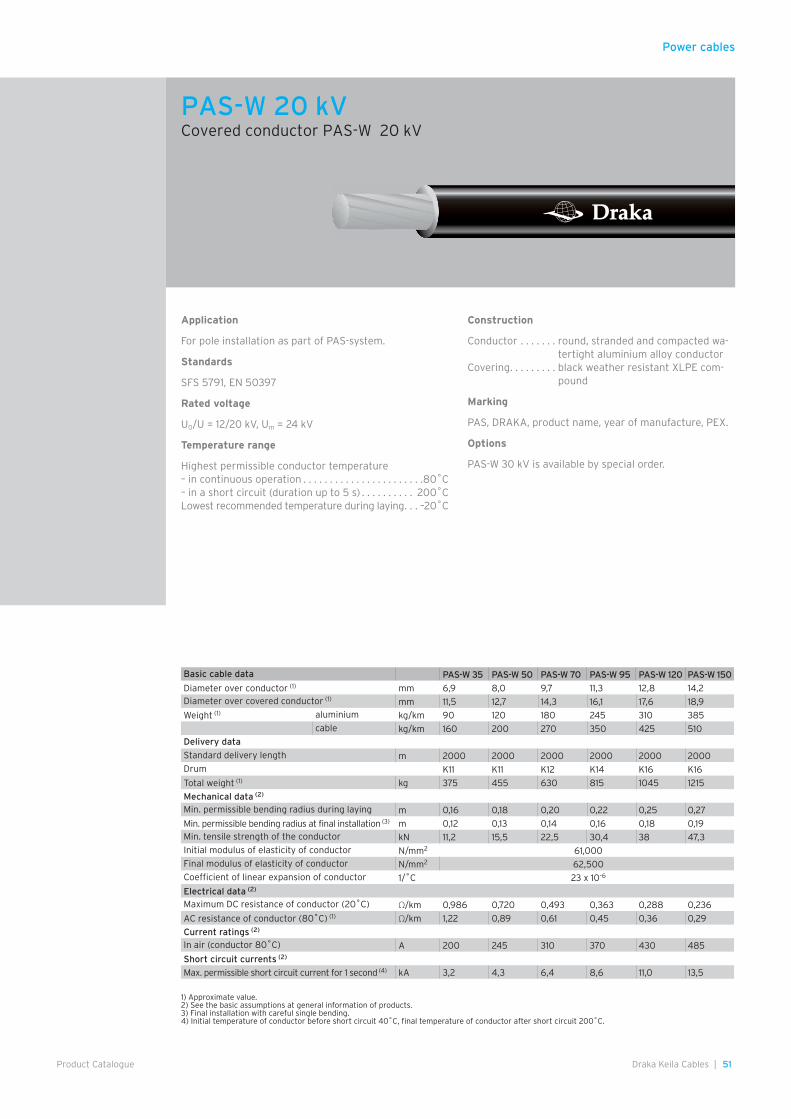
Power cables
51Draka Keila Cables |Product Catalogue
Application
For pole installation as part of PAS-system.
Standards
SFS 5791, EN 50397
Rated voltage
U0/U = 12/20 kV, Um = 24 kV
Temperature range
Highest permissible conductor temperature– in continuous operation . . . . . . . . . . . . . . . . . . . . . . .80˚C– in a short circuit (duration up to 5 s) . . . . . . . . . . 200˚CLowest recommended temperature during laying . . . –20˚C
Construction
Conductor . . . . . . . round, stranded and compacted wa-tertight aluminium alloy conductor
Covering . . . . . . . . . black weather resistant XLPE com-pound
Marking
PAS, DRAKA, product name, year of manufacture, PEX.
Options
PAS-W 30 kV is available by special order.
Basic cable data PAS-W 35 PAS-W 50 PAS-W 70 PAS-W 95 PAS-W 120 PAS-W 150
Diameter over conductor (1) mm 6,9 8,0 9,7 11,3 12,8 14,2Diameter over covered conductor (1) mm 11,5 12,7 14,3 16,1 17,6 18,9
Weight (1) aluminium kg/km 90 120 180 245 310 385cable kg/km 160 200 270 350 425 510
Delivery data
Standard delivery length m 2000 2000 2000 2000 2000 2000Drum K11 K11 K12 K14 K16 K16
Total weight (1) kg 375 455 630 815 1045 1215
Mechanical data (2)
Min. permissible bending radius during laying m 0,16 0,18 0,20 0,22 0,25 0,27
Min. permissible bending radius at final installation (3) m 0,12 0,13 0,14 0,16 0,18 0,19Min. tensile strength of the conductor kN 11,2 15,5 22,5 30,4 38 47,3Initial modulus of elasticity of conductor N/mm2 61,000Final modulus of elasticity of conductor N/mm2 62,500Coefficient of linear expansion of conductor 1/˚C 23 x 10-6
Electrical data (2)
Maximum DC resistance of conductor (20˚C) Ω/km 0,986 0,720 0,493 0,363 0,288 0,236
AC resistance of conductor (80˚C) (1) Ω/km 1,22 0,89 0,61 0,45 0,36 0,29
Current ratings (2)
In air (conductor 80˚C) A 200 245 310 370 430 485
Short circuit currents (2)
Max. permissible short circuit current for 1 second (4) kA 3,2 4,3 6,4 8,6 11,0 13,5
1) Approximate value.2) See the basic assumptions at general information of products.3) Final installation with careful single bending.4) Initial temperature of conductor before short circuit 40˚C, final temperature of conductor after short circuit 200˚C.
PAS-W 20 kVCovered conductor PAS-W 20 kV
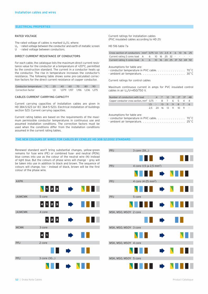
Installation cables and wires
52 | Draka Keila Cables Product Catalogue
Renewed standard won’t bring substantial changes, yellow-green remains for fuse wire (PE) or combined fuse- and neutral (PEN); blue comes into use as the colour of the neutral wire (N) instead of light blue. But the colours of phase wires will change – grey will be taken into use in addition to black and brown. The sequence of colours will change, too – instead of black, brown will be the first colour of the phase wire.
THE NEW COLOURS OF WIRES FOR CABLES BY CENELEC HD 308 S2:2002 STANDARD
321 321
324 1 324 1
321 321
4 14 1
Cross section of conductors mm2 0,75 1,0 1,5 2,5 4 6 10 16 25
Current rating 2 cores load A 6 10 16 25 32 - - - -
Current rating 3 cores load A 6 10 16 20 25 37 52 69 92
Conductor temperature °C 20 40 60 70 80 90
Correction factor 1,0 1,079 1,157 1,196 1,236 1,275
Number of conductors with load 4 7 12 19 27 37 48
Copper conductor cross section, mm2 0,75 - 8 7 6 5 4 4
1,5 - 13 11 9 8 7 6
2,5 20 16 13 11 10 9 -
RATED VOLTAGE
The rated voltage of cables is marked U0/U, where:U0 - rated voltage between the conductor and earth of metallic screenU - rated voltage between conductors.
DIRECT CURRENT RESISTANCE OF CONDUCTORS
For each cable, the catalogue lists the maximum direct current resis-tance value for the conductor at a temperature of +20°C, permitted by the construction standard. The current in a conductor heats up the conductor. The rise in temperature increases the conductor’s resistance. The following table shows some pre-calculated correc-tion factors for the direct current resistance of copper conductor.
Assumptions for table are: - conductor temperature in PVC cable. . . . . . . . . . . . . . 70˚C- ambient air temperature. . . . . . . . . . . . . . . . . . . . . 25˚C
Assumptions for table are:- conductor temperature in PVC cable. . . . . . . . . . . . . . 70˚C- ambient air temperature. . . . . . . . . . . . . . . . . . . . . 30˚C
Current ratings for control cables
Maximum continuous current in amps for PVC insulated control cables in air Uo/U=450/750 V.
ELECTRICAL PROPERTIES
CABLES CURRENT CARRYING CAPACITY
Current carrying capacities of installation cables are given in HD 384.5.523 (or IEC 364-5-523). Electrical installation of buildings section 523: Current carrying capacities.
Current rating tables are based on the requirements of the maxi-mum permissible conductor temperatures in continuous use and assumed installation conditions. The correction factors must be used when the conditions differ from the installation conditions assumed in the current rating tables.
Current ratings for installation cables(PVC insulated cables according to HD 21)
HD 516 table 7a
PPJ 2 core
AXPK
(A)MCMK 5 core
(A)MCMK 4 core
MCMK 3 core
PPJ 3 core (3G...)
PPJ 3 core (3X...)
PPJ 4 core (1,5 ja 2,5 mm2)
PPJ 4 core (4–25 mm2)
PPJ 5 core
MSK, MSO, MSOY 2 core
MSK, MSO, MSOY 3 core
MSK, MSO, MSOY 4 core
MSK, MSO, MSOY 5 core
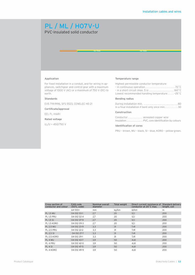
53Draka Keila Cables |Product Catalogue
Installation cables and wires
Application
For fixed installation in a conduit, and for wiring in ap-pliances, switchgear and control gear with a maximum voltage of 1000 V (AC) or a maximum of 750 V (DC) to earth.
Standards
EVS 719:1996, SFS 5523, CENELEC HD 21
Certificate/approval
EEI, FI, <HAR>
Rated voltage
U0/U = 450/750 V
Temperature range
Highest permissible conductor temperature– in continuous operation . . . . . . . . . . . . . . . . . . . . . . . 70˚C– in a short circuit (max. 5 s) . . . . . . . . . . . . . . . . . . . 160˚CLowest recommended handling temperature . . . . . –25˚C
Bending radius
During installation min. . . . . . . . . . . . . . . . . . . . . . . . . . .8DIn a final installation if bent only once min. . . . . . . . . . . 3D
Construction
Conductor . . . . . . . . . . . annealed copper wire Insulation . . . . . . . . . . . . . . PVC, core identification by colours
Identification of cores
PRU – brown, MU – black, SI – blue, KORO – yellow-green.
PL / ML / H07V-UPVC-insulated solid conductor
Cross section of conductor and colour
EAN code (SSTL code)
Nominal overall diameter
Total weight Direct current resistance of conductor at 20˚C max.
Standard delivery length, coil
64 100+ mm kg/km Ω/km m
PL 1,5 MU 04 012 03-1 2,7 20 12,1 200
PL 1,5 PRU 04 012 02-4 2,7 20 12,1 200
PL 1,5 SI 04 012 07-9 2,7 20 12,1 200
PL 1,5 KORO 04 012 09-3 2,7 20 12,1 200
PL 2,5 MU 04 012 23-9 3,3 31 7,41 200
PL 2,5 PRU 04 012 22-2 3,3 31 7,41 200
PL 2,5 SI 04 012 27-7 3,3 31 7,41 200
PL 2,5 KORO 04 012 29-1 3,3 31 7,41 200
PL 4 MU 04 012 43-7 3,9 50 4,61 200
PL 4 PRU 04 012 42-0 3,9 50 4,61 200
PL 4 SI 04 012 47-5 3,9 50 4,61 200
PL 4 KORO 04 012 49-9 3,9 50 4,61 200
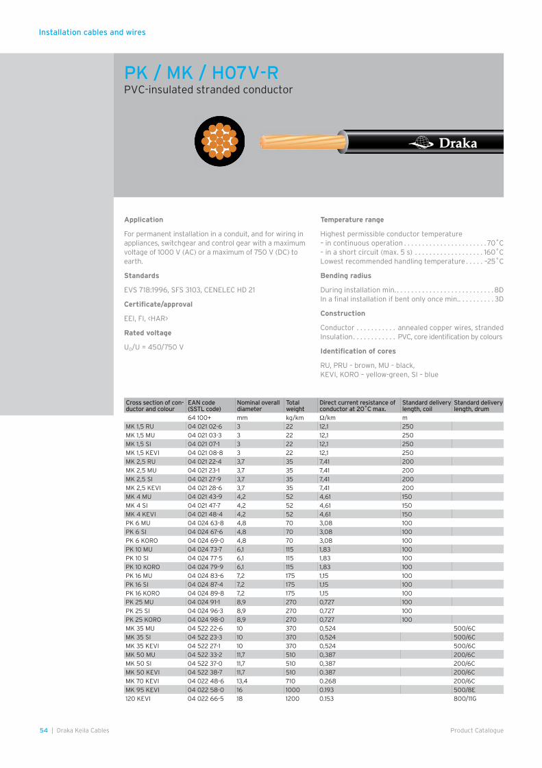
Installation cables and wires
54 | Draka Keila Cables Product Catalogue
Application
For permanent installation in a conduit, and for wiring in appliances, switchgear and control gear with a maximum voltage of 1000 V (AC) or a maximum of 750 V (DC) to earth.
Standards
EVS 718:1996, SFS 3103, CENELEC HD 21
Certificate/approval
EEI, FI, <HAR>
Rated voltage
U0/U = 450/750 V
Temperature range
Highest permissible conductor temperature – in continuous operation . . . . . . . . . . . . . . . . . . . . . . . 70˚C– in a short circuit (max. 5 s) . . . . . . . . . . . . . . . . . . . 160˚CLowest recommended handling temperature . . . . . –25˚C
Bending radius
During installation min. . . . . . . . . . . . . . . . . . . . . . . . . . . .8DIn a final installation if bent only once min. . . . . . . . . . . 3D
Construction
Conductor . . . . . . . . . . . annealed copper wires, strandedInsulation . . . . . . . . . . . . PVC, core identification by colours
Identification of cores
RU, PRU – brown, MU – black, KEVI, KORO – yellow-green, SI – blue
PK / MK / H07V-RPVC-insulated stranded conductor
Cross section of con-ductor and colour
EAN code (SSTL code)
Nominal overall diameter
Total weight
Direct current resistance of conductor at 20˚C max.
Standard delivery length, coil
Standard delivery length, drum
64 100+ mm kg/km Ω/km mMK 1,5 RU 04 021 02-6 3 22 12,1 250MK 1,5 MU 04 021 03-3 3 22 12,1 250MK 1,5 SI 04 021 07-1 3 22 12,1 250MK 1,5 KEVI 04 021 08-8 3 22 12,1 250MK 2,5 RU 04 021 22-4 3,7 35 7,41 200MK 2,5 MU 04 021 23-1 3,7 35 7,41 200MK 2,5 SI 04 021 27-9 3,7 35 7,41 200MK 2,5 KEVI 04 021 28-6 3,7 35 7,41 200MK 4 MU 04 021 43-9 4,2 52 4,61 150MK 4 SI 04 021 47-7 4,2 52 4,61 150MK 4 KEVI 04 021 48-4 4,2 52 4,61 150PK 6 MU 04 024 63-8 4,8 70 3,08 100PK 6 SI 04 024 67-6 4,8 70 3,08 100PK 6 KORO 04 024 69-0 4,8 70 3,08 100PK 10 MU 04 024 73-7 6,1 115 1,83 100PK 10 SI 04 024 77-5 6,1 115 1,83 100PK 10 KORO 04 024 79-9 6,1 115 1,83 100PK 16 MU 04 024 83-6 7,2 175 1,15 100PK 16 SI 04 024 87-4 7,2 175 1,15 100PK 16 KORO 04 024 89-8 7,2 175 1,15 100PK 25 MU 04 024 91-1 8,9 270 0,727 100PK 25 SI 04 024 96-3 8,9 270 0,727 100PK 25 KORO 04 024 98-0 8,9 270 0,727 100MK 35 MU 04 522 22-6 10 370 0,524 500/6CMK 35 SI 04 522 23-3 10 370 0,524 500/6CMK 35 KEVI 04 522 27-1 10 370 0,524 500/6CMK 50 MU 04 522 33-2 11,7 510 0,387 200/6CMK 50 SI 04 522 37-0 11,7 510 0,387 200/6CMK 50 KEVI 04 522 38-7 11,7 510 0.387 200/6CMK 70 KEVI 04 022 48-6 13,4 710 0.268 200/6CMK 95 KEVI 04 022 58-0 16 1000 0.193 500/8E120 KEVI 04 022 66-5 18 1200 0.153 800/11G
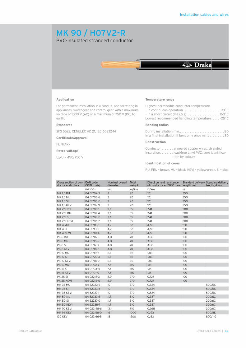
Installation cables and wires
55Draka Keila Cables |Product Catalogue
Application
For permanent installation in a conduit, and for wiring in appliances, switchgear and control gear with a maximum voltage of 1000 V (AC) or a maximum of 750 V (DC) to earth.
Standards
SFS 5523, CENELEC HD 21, IEC 60332-14
Certificate/approval
FI, <HAR>
Rated voltage
U0/U = 450/750 V
Temperature range
Highest permissible conductor temperature – in continuous operation . . . . . . . . . . . . . . . . . . . . . . .90˚C– in a short circuit (max.5 s) . . . . . . . . . . . . . . . . . . . . 160˚CLowest recommended handling temperature . . . . . -25˚C
Bending radius
During installation min. . . . . . . . . . . . . . . . . . . . . . . . . . . .8DIn a final installation if bent only once min. . . . . . . . . . . 3D
Construction
Conductor . . . . . . . annealed copper wires, strandedInsulation . . . . . . . . lead-free Linyl PVC, core identifica-
tion by colours
Identification of cores
RU, PRU – brown, MU – black, KEVI – yellow-green, SI – blue
MK 90 / H07V2-RPVC-insulated stranded conductor
Cross section of con-ductor and colour
EAN code (SSTL code)
Nominal overall diameter
Total weight
Direct current resistance of conductor at 20˚C max.
Standard delivery length, coil
Standard delivery length, drum
64 100+ mm kg/km Ω/km mMK 1,5 RU 04 01704-3 3 22 12,1 250MK 1,5 MU 04 01703-6 3 22 12,1 250MK 1,5 SI 04 01705-0 3 22 12,1 250MK 1,5 KEVI 04 01702-9 3 22 12,1 250MK 2,5 RU 04 01708-1 3,7 35 7,41 200MK 2,5 MU 04 01707-4 3,7 35 7,41 200MK 2,5 SI 04 01709-8 3,7 35 7,41 200MK 2,5 KEVI 04 01706-7 3,7 35 7,41 200MK 4 MU 04 01711-91 4,2 52 4,61 150MK 4 SI 04 01713-5 4,2 52 4,61 150MK 4 KEVI 04 01710-4 4,2 52 4,61 150PK 6 RU 04 01716-6 4,8 70 3,08 100PK 6 MU 04 01715-9 4,8 70 3,08 100PK 6 SI 04 01717-3 4,8 70 3,08 100PK 6 KEVI 04 01714-2 4,8 70 3,08 100PK 10 MU 04 01719-5 6,1 115 1,83 100PK 10 SI 04 01720-3 6,1 115 1,83 100PK 10 KEVI 04 01718-0 6,1 115 1,83 100PK 16 MU 04 01722-7 7,2 175 1,15 100PK 16 SI 04 01723-4 7,2 175 1,15 100PK 16 KEVI 04 01721-0 7,2 175 1,15 100PK 25 SI 04 02215-3 8,9 270 0,727 100PK 25 KEVI 04 02216-0 8,9 270 0,727 100MK 35 MU 04 52222-6 10 370 0,524 500/6CMK 35 SI 04 52223-3 10 370 0,524 500/6CMK 35 KEVI 04 52227-1 10 370 0,524 500/6CMK 50 MU 04 52233-2 11,7 510 0,387 200/6CMK 50 SI 04 52237-0 11,7 510 0,387 200/6CMK 50 KEVI 04 52238-7 11,7 510 0,387 200/6CMK 70 KEVI 04 022 48-6 13,4 710 0,268 200/6CMK 95 KEVI 04 022 58-0 16 1000 0,193 500/8E120 KEVI 04 022 66-5 18 1200 0,153 800/11G

Installation cables and wires
56 | Draka Keila Cables Product Catalogue
Application
For fixed installation in a conduit, and for wiring in appli-ances, switchgear and control gear with a maximum volt-age of 1000 V (AC) or a maximum of 750 V (DC) to earth.
Temperature range
Highest permissible conductor temperature – in continuous operation . . . . . . . . . . . . . . . . . . . . . . .90˚C– in a short circuit (max. 5 s) . . . . . . . . . . . . . . . . . . . 160˚CLowest recommended handling temperature . . . . . -25˚C
Bending radius
During installation min. . . . . . . . . . . . . . . . . . . . . . . . . . .8DIn a final installation if bent only once min. . . . . . . . . . 3D
Construction
Conductor . . . . annealed copper wires, stranded flexibleInsulation . . . . . lead-free Linyl PVC, core identification
by colours
Identification of cores
RU – brown, MU – black, KEVI – yellow-green, SI – blue
Standards
SFS 5523, CENELEC HD 21, IEC 60332-14
Certificate/approval
FI, <HAR>
Rated voltage
U0/U = 450/750 V
MKEM 90 / H07V2-KPVC-insulated flexible conductor
Cross section of con-ductor and colour
EAN code (SSTL code)
Nominal overall diameter
Total weight Direct current resistance of conductor at 20˚C max.
Standard delivery length, coil
Standard delivery length, drum
64 100+ mm kg/km Ω/km m m
1,5 RU 04 03102-5 3 21 13,3 250
1,5 MU 04 03103-2 3 21 13,3 250
1,5 SI 04 03107-0 3 21 13,3 250
1,5 KEVI 04 03108-7 3 21 13,3 250
2,5 RU 04 03122-3 3,6 32 7,98 200
2,5 MU 04 03123-0 3,6 32 7,98 200
2,5 SI 04 03127-8 3,6 32 7,98 200
2,5 KEVI 04 03128-5 3,6 32 7,98 200
4 MU 04 03143-8 4,1 45 4,95 100
4 SI 04 03147-6 4,1 45 4,95 100
4 KEVI 04 03148-3 4,1 45 4,95 100
6 MU 04 03163-6 5 70 3,3 100
6 SI 04 03167-4 5 70 3,3 100
6 KEVI 04 03168-1 5 70 3,3 100
10 MU 04 03183-4 6,5 115 1,91 100
10 SI 04 03187-2 6,5 115 1,91 100
10 KEVI 04 03188-9 6,5 115 1,91 100
16 MU 04 03203-9 7,6 170 1,21 100
16 SI 04 03207-9 7,6 170 1,21 100
16 KEVI 04 03208-9 7,6 170 1,21 100
25 MU 04 03213-8 9,4 270 0,78 100
25 SI 04 03217-6 9,4 270 0,78 100
25 KEVI 04 03218-3 9,4 270 0,78 100
35 MU 04 53223-2 11 370 0,554 500/6C
35 SI 04 53227-0 11 370 0,554 500/6C
35 KEVI 04 53228-7 11 370 0,554 500/6C
50 MU 04 53233-1 13 520 0,386 200/6C
50 SI 04 53237-9 13 520 0,386 200/6C
50 KEVI 04 53238-6 13 520 0,386 200/6C
70 MU 04 022 43-0 15 730 0,272 200/6C
70 SI 04 022 47-8 15 730 0,272 200/6C
70 KEVI 04 022 48-5 15 730 0,272 200/6C
95 MU 04 03253-4 17,5 940 0,206 200/7E
95 SI 04 03257-2 17,5 940 0,206 200/7E
120 MU 04 032 63-3 19 1200 0,161 200/7E
150 MU 04 032 73-2 22 1450 0,129 200/7E
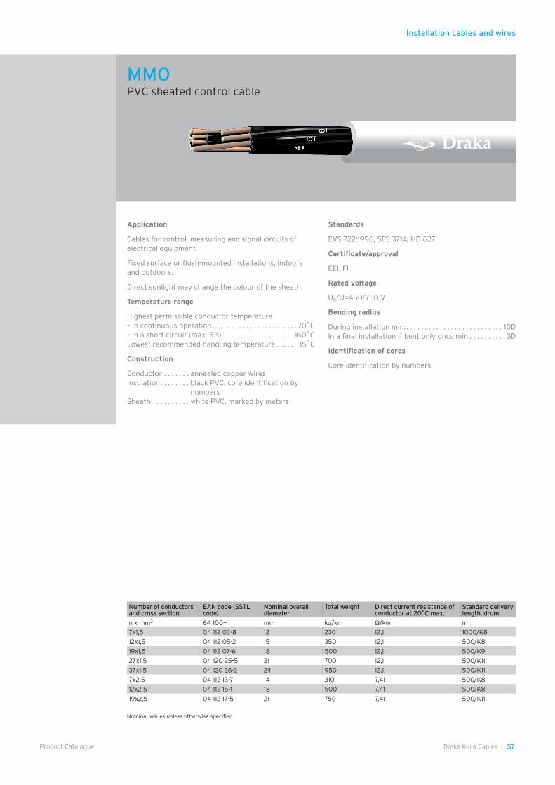
Installation cables and wires
57Draka Keila Cables |Product Catalogue
Application
Cables for control, measuring and signal circuits of electrical equipment.
Fixed surface or flush-mounted installations, indoors and outdoors.
Direct sunlight may change the colour of the sheath.
Temperature range
Highest permissible conductor temperature– in continuous operation . . . . . . . . . . . . . . . . . . . . . . . 70˚C– in a short circuit (max. 5 s) . . . . . . . . . . . . . . . . . . . 160˚CLowest recommended handling temperature . . . . . –15˚C
Construction
Conductor . . . . . . . annealed copper wiresInsulation . . . . . . . . black PVC, core identification by
numbersSheath . . . . . . . . . . white PVC, marked by meters
Standards
EVS 722:1996, SFS 3714; HD 627
Certificate/approval
EEI, FI
Rated voltage
U0/U=450/750 V
Bending radius
During installation min. . . . . . . . . . . . . . . . . . . . . . . . . . . 10DIn a final installation if bent only once min. . . . . . . . . . . 3D
Identification of cores
Core identification by numbers.
MMOPVC sheated control cable
Nominal values unless otherwise specified.
Number of conductors and cross section
EAN code (SSTL code)
Nominal overall diameter
Total weight Direct current resistance of conductor at 20˚C max.
Standard delivery length, drum
n x mm2 64 100+ mm kg/km Ω/km m
7x1,5 04 112 03-8 12 230 12,1 1000/K8
12x1,5 04 112 05-2 15 350 12,1 500/K8
19x1,5 04 112 07-6 18 500 12,1 500/K9
27x1,5 04 120 25-5 21 700 12,1 500/K11
37x1,5 04 120 26-2 24 950 12,1 500/K11
7x2,5 04 112 13-7 14 310 7,41 500/K8
12x2,5 04 112 15-1 18 500 7,41 500/K8
19x2,5 04 112 17-5 21 750 7,41 500/K11
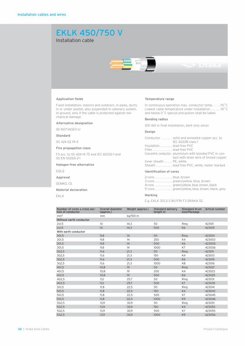
Installation cables and wires
58 | Draka Keila Cables Product Catalogue
EKLK 450/750 VInstallation cable
Application fields
Fixed installation, indoors and outdoors, in pipes, ducts, in or under plaster, also suspended in catenary system. In ground, only if the cable is protected against me-chanical damage.
Alternative designation
SE-N07VA5EV-U
Standard
SS 424 02 19-4
Fire propagation class
F3 acc. to SS 424 14 75 and IEC 60332-1 and SS-EN 50265-2-1
Halogen-free alternative
EQLQ
Approval
SEMKO, CE
Material declaration
EKLK
Temperature range
In continuous operation max. conductor temp . . . . . 70˚CLowest cable temperature under installation . . . . . .-15˚Cand below 0˚C special precaution shall be taken.
Bending radius
12D (6D in final installation, bent only once)
Design
Conductor . . . . . . . solid and annealed copper acc. to IEC 60228 class 1
Insulation . . . . . . . . lead-free PVCFiller . . . . . . . . . . . . lead-free PVCConcentric conductor . aluminium with bonded PVC in con-
tact with drain wire of tinned copperInner sheath . . . . . PE, whiteSheath . . . . . . . . . . lead-free PVC, white, meter marked
Identification of cores
2-core . . . . . . . . . . . blue, brown3-core . . . . . . . . . . . green/yellow, blue, brown4-core . . . . . . . . . . . . green/yellow, blue, brown, black5-core . . . . . . . . . . . green/yellow, blue, brown, black, grey
Marking
E.g. EKLK 3G1,5 S BLYFRI F3 DRAKA SE.
Number of cores x cross sec-tion of conductor
Overall diameter (approx.)
Weight (approx.) Standard delivery length m
Standard drum size/Package
Article number
mm2 mm kg/100 mWithout earth conductor2x1,5 10 14,3 50 Ring 4231012x1,5 10 14,3 500 K6 423105With earth conductor3G1,5 9,8 14 50 Ring 4230013G1,5 9,8 14 250 K4 4230033G1,5 9,8 14 500 K6 4230053G1,5 9,8 14 1000 K7 4230063G2,5 11,6 21,3 50 Ring 4230113G2,5 11,6 21,3 150 K4 4230133G2,5 11,6 21,3 500 K6 4230153G2,5 11,6 21,3 1000 K8 4230164G1,5 10,8 19 50 Ring 4230214G1,5 10,8 19 200 K4 4230234G1,5 10,8 19 500 K6 4230254G2,5 13,1 25,7 50 Ring 4230314G2,5 13,1 25,7 500 K7 4230355G1,5 11,8 22,5 50 Ring 4230415G1,5 11,8 22,5 150 K4 4230435G1,5 11,8 22,5 500 K7 4230455G1,5 11,8 22,5 1000 K9 4230465G2,5 13,9 30,9 50 Ring 4230515G2,5 13,9 30,9 150 K4 4230535G2,5 13,9 30,9 500 K7 4230555G2,5 13,9 30,9 1000 K9 423056
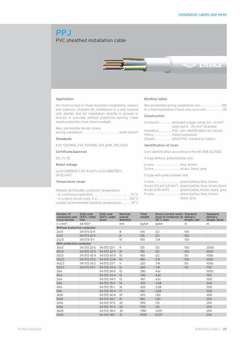
Installation cables and wires
59Draka Keila Cables |Product Catalogue
Application
For fixed surface or flush-mounted installations, indoors and outdoors. Suitable for installation in a slot covered with plaster. Not for installation directly in ground or directly in concrete without protective ducting. Cable needs protection from direct sunlight.
Max. permissible tensile stress during installation . . . . . . . . . . . . . . . . . . . . . .Ax50 N/mm2
Standards
EVS 720:1996, EVS 721:1996, SFS 2091, SFS 5524
Certificate/approval
EEI, FI, CE
Rated voltage
U0/U=300/500 V (1,5–4 mm2), U0/U=450/750 V (6–25 mm2)
Temperature range
Highest permissible conductor temperature – in continuous operation . . . . . . . . . . . . . . . . . . . . . . . 70˚C– in a short circuit (max. 5 s) . . . . . . . . . . . . . . . . . . . 160˚CLowest recommended handling temperature . . . . . –15˚C
Bending radius
Recommended during installation min . . . . . . . . . . . . . 10DIn a final installation if bent only once min . . . . . . . . . . 3D
Construction
Conductor . . . . . . . annealed copper wires; 1,5 – 4 mm2 solid and 6 – 25 mm2 stranded
Insulation . . . . . . . . PVC, core identification by coloursFilling . . . . . . . . . . . filling compoundSheath . . . . . . . . . . white PVC, marked by meters
Identification of cores
Core identification according to the HD 308 S2:2002
X type without green/yellow core
2-core . . . . . . . . . . . . . . . . blue, brown3-core . . . . . . . . . . . . . . . . brown, black, grey
G type with green/yellow core
3-core . . . . . . . . . . . . . . . . green/yellow, blue, brown4-core (1,5 and 2,5 mm2) . green/yellow, blue, brown,black4-core (4–25 mm2). . . . . . . green/yellow, brown, black, grey5-core . . . . . . . . . . . . . . . . green/yellow, blue, brown,
black, grey
PPJPVC sheathed installation cable
Number of conductors and cross section
EAN code (SSTL code) reel
EAN code (SSTL code) drum
Nominal overall diameter
Total weight
Direct current resist-ance of conductor at 20˚C max
Standard delivery length, reel
Standard delivery length, drum
n x mm2 64 100+ mm kg/km Ω/km m mWithout protective conductor2x1,5 04 073 12-4 8 105 12,1 1003x1,5 04 073 22-3 9 125 12,1 1002x2,5 04 073 13-1 10 150 7,41 100With protective conductor3G1,5 04 072 22-6 04 572 22-1 9 125 12,1 100 20004G1,5 04 072 32-5 04 572 32-0 10 155 12,1 100 10005G1,5 04 072 42-4 04 072 42-9 10 180 12,1 50 10003G2,5 04 072 23-3 04 572 23-8 10 180 7,41 100 10004G2,5 04 072 33-2 04 572 33-7 11 220 7,41 50 10005G2,5 04 072 43-1 04 572 43-6 12 260 7,41 50 7503G4 04 572 24-5 10 280 4,61 10004G4 04 572 34-4 12 340 4,61 7505G4 04 572 44-3 13 410 4,61 5003G6 04 572 25-2 14 350 3,08 5004G6 04 572 35-1 16 430 3,08 5005G6 04 572 45-0 17 510 3,08 5004G10 04 572 36-8 19 670 1,83 4005G10 04 572 46-7 21 810 1,83 2504G16 04 572 37-5 22 950 1,15 2505G16 04 572 47-4 24 1150 1,15 2504G25 04 572 38-2 30 1780 0,727 2505G25 04 572 48-1 31 1900 0,727 250
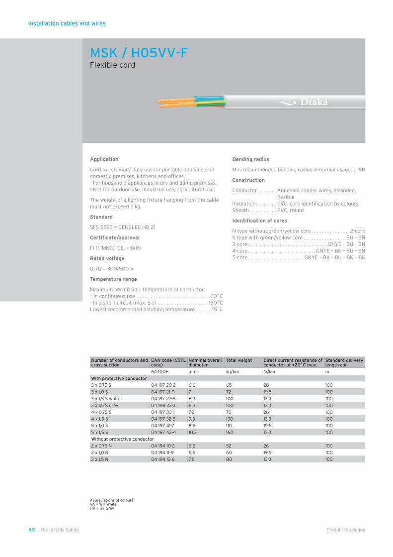
Installation cables and wires
60 | Draka Keila Cables Product Catalogue
Application
Cord for ordinary duty use for portable appliances in domestic premises, kitchens and offices.- For household appliances in dry and damp premises.- Not for outdoor use, industrial use, agricultural use.
The weight of a lighting fixture hanging from the cable must not exceed 2 kg.
Standard
SFS 5525 = CENELEC HD 21
Certificate/approval
FI (FIMKO), CE, <HAR>
Rated voltage
U0/U = 300/500 V
Temperature range
Maximum permissible temperature of conductor: – in continuous use . . . . . . . . . . . . . . . . . . . . . . . . . . . .60˚C- in a short circuit (max. 5 s) . . . . . . . . . . . . . . . . . . . 150˚CLowest recommended handling temperature . . . . . . 15˚C
Bending radius
Min. recommended bending radius in normal usage . . . 6D
Construction
Conductor . . . . . . . Annealed copper wires, stranded, flexible
Insulation . . . . . . . . PVC, core identification by coloursSheath . . . . . . . . . . PVC, round
Identification of cores
N type without green/yellow core . . . . . . . . . . . . . . .2-coreS type with green/yellow core . . . . . . . . . . . . . . . . BU – BN3-core . . . . . . . . . . . . . . . . . . . . . . . . . . . . . . GNYE – BU – BN4-core . . . . . . . . . . . . . . . . . . . . . . . . . .GNYE – BK – BU – BN5-core . . . . . . . . . . . . . . . . . . . . . GNYE – BK – BU – BN – BK
Abbreviations of coloursVA = WH WhiteHA = GY Grey
MSK / H05VV-FFlexible cord
Number of conductors and cross section
EAN code (SSTL code)
Nominal overall diameter
Total weight Direct current resistance of conductor at +20˚C max.
Standard delivery length coil
64 100+ mm kg/km Ω/km m
With protective conductor
3 x 0,75 S 04 197 20-2 6,6 65 26 100
3 x 1,0 S 04 197 21-9 7 72 19,5 100
3 x 1,5 S white 04 197 22-6 8,3 100 13,3 100
3 x 1,5 S grey 04 198 22-3 8,3 100 13,3 100
4 x 0,75 S 04 197 30-1 7,2 75 26 100
4 x 1,5 S 04 197 32-5 9,3 130 13,3 100
5 x 1,0 S 04 197 41-7 8,6 110 19,5 100
5 x 1,5 S 04 197 42-4 10,3 160 13,3 100
Without protective conductor
2 x 0,75 N 04 194 10-2 6,2 52 26 100
2 x 1,0 N 04 194 11-9 6,6 60 19,5 100
2 x 1,5 N 04 194 12-6 7,6 80 13,3 100

Installation cables and wires
61Draka Keila Cables |Product Catalogue
Application
For fixed installation in electrical- and information network. Conduit is suitable for installation in concrete
Standards
Conduit EN 50086, cables and wires have own
Certificates
CE, RoHS
Properties
Self-extinguishingMaximum permissible temperature of conduit in use and installation . . . . . . . . . . . . . . . . . . . . . . . . . .90˚CMinimum permissible temperature of conduit in installation . . . . . . . . . . . . . . . . . . . . . . . . . . . . . . . . –25˚CCompression resistance . . . . . . . . . . . . . . . 750 N (ICTA 3)Impact resistance . . . . . . . . . . . . . . . 2 kg/100 mm (ICTA 3)
Properties of cables and cores as without conduit.
Current carrying capacities of ML/MK/MKZ according to HD 384.5.523 (or IEC 364-5-523): “Electrical installation of buildings” section 523: Current carrying capacities.
Construction
Conduit . . . . . . . . . . Flexible PP conduit, lead-free, ICTA 3342
Cables and coresPROFIT ML . . . . . . . H07V-U cores in Ø16/20 conduitPROFIT MK . . . . . . H07V-R cores in Ø16/20 conduitPROFIT MKZ . . . . . H07V-R cores in Ø16/20 conduit,
wires twisted togetherPROFIT CAT 5e . . . CAT 5e UTP in Ø20 conduitPROFIT CAT 6 . . . . CAT 6 UTP in Ø20 conduitPROFIT TELLU 13 . . TELLU 13 in Ø16 conduitPROFIT MHS . . . . . MHS in Ø16 conduit
ML(H07V-U), MK(H07V-R), MKZ colours according to HD 308 S2
Name SSTL code Total weight kg/km
Coil length m Pallet length m
PROFIT MK 3x1.5 S 16/R100 04 123 02 110 100 1800
PROFIT MK 3x2.5 S 16/R100 04 123 04 145 100 1800
PROFIT MK 3x4 S 20/R50 04 017 34 210 50 900
PROFIT MK 4x1.5 S 16/R100 04 123 06 130 100 1800
PROFIT MK 4x2.5 S 20/R50 04 017 42 190 50 900
PROFIT MK 5x1.5 S 20/R50 04 123 08 165 50 900
PROFIT MK 5x2.5 S 20/R50 04 123 10 225 50 900
PROFIT MK 6 KEVI 16/R100 04 123 12 115 100 1800
PROFIT MK 7x1.5 S 20/R50 205 50 900
PROFIT ML 3x1.5 N 16/R100 04 011 30 105 100 1800
PROFIT ML 3x1.5 S 16/R100 04 011 32 105 100 1800
PROFIT ML 3x2.5 S 16/R100 04 011 34 140 100 1800
PROFIT ML 4x1.5 S 16/R100 04 011 36 125 100 1800
PROFIT ML 5x1.5 N 16/R100 04 011 38 160 100 900
PROFIT ML 5x1.5 S 16/R100 04 011 40 160 100 900
PROFIT ML 5x2.5 S 20/R100 04 011 41 215 100 900
PROFIT ML 7x1.5 S 20/R100 04 017 71 195 100 900
PROFIT CAT 5e UTP 2x4p 20/R100 02 413 12 130 100 900
PROFIT CAT 6 UTP 2x4p 20/R100 02 413 14 140 100 900
PROFIT TELLU 13 16/R100 02 321 78 105 100 1800
PROFIT MHS 3x2x0,5 16/R100 02 024 07 85 100 1800
PROFITConduit with cores
Convenient installation without twistsMulti-installation base ensure uncoiled and smooth running of the cable from the package.
SSTL code 64 070 09
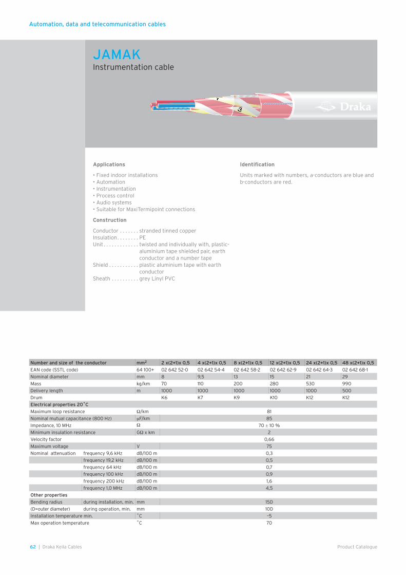
Automation, data and telecommunication cables
62 | Draka Keila Cables Product Catalogue
Applications
• Fixed indoor installations • Automation• Instrumentation• Process control• Audio systems• Suitable for MaxiTermipoint connections
Construction
Conductor . . . . . . . stranded tinned copperInsulation . . . . . . . . PEUnit . . . . . . . . . . . . . twisted and individually with, plastic-
aluminium tape shielded pair, earth conductor and a number tape
Shield . . . . . . . . . . . plastic aluminium tape with earth conductor
Sheath . . . . . . . . . . grey Linyl PVC
Identification
Units marked with numbers, a-conductors are blue and b-conductors are red.
Number and size of the conductor mm2 2 x(2+1)x 0,5 4 x(2+1)x 0,5 8 x(2+1)x 0,5 12 x(2+1)x 0,5 24 x(2+1)x 0,5 48 x(2+1)x 0,5
EAN code (SSTL code) 64 100+ 02 642 52-0 02 642 54-4 02 642 58-2 02 642 62-9 02 642 64-3 02 642 68-1
Nominal diameter mm 8 9,5 13 15 21 29
Mass kg/km 70 110 200 280 530 990
Delivery length m 1000 1000 1000 1000 1000 500
Drum K6 K7 K9 K10 K12 K12
Electrical properties 20˚C
Maximum loop resistance Ω/km 81
Nominal mutual capacitance (800 Hz) µF/km 85
Impedance, 10 MHz Ω 70 ± 10 %
Minimum insulation resistance GΩ x km 2
Velocity factor 0,66
Maximum voltage V 75
Nominal attenuation frequency 9,6 kHz dB/100 m 0,3
frequency 19,2 kHz dB/100 m 0,5
frequency 64 kHz dB/100 m 0,7
frequency 100 kHz dB/100 m 0,9
frequency 200 kHz dB/100 m 1,6
frequency 1,0 MHz dB/100 m 4,5
Other properties
Bending radius during installation, min. mm 15D
(D=outer diameter) during operation, min. mm 10D
Installation temperature min. ˚C –5
Max operation temperature ˚C 70
JAMAKInstrumentation cable
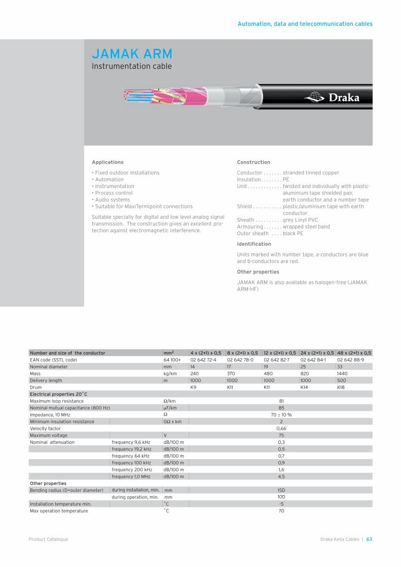
Automation, data and telecommunication cables
63Draka Keila Cables |Product Catalogue
Applications
• Fixed outdoor installations • Automation• Instrumentation• Process control• Audio systems• Suitable for MaxiTermipoint connections
Suitable specially for digital and low level analog signal transmission. The construction gives an excellent pro-tection against electromagnetic interference.
Construction
Conductor . . . . . . . stranded tinned copperInsulation . . . . . . . . PEUnit . . . . . . . . . . . . . twisted and individually with plastic-
aluminium tape shielded pair, earth conductor and a number tape
Shield . . . . . . . . . . . plastic/aluminium tape with earth conductor
Sheath . . . . . . . . . . grey Linyl PVCArmouring . . . . . . . wrapped steel bandOuter sheath . . . . black PE
Identification
Units marked with number tape, a-conductors are blue and b-conductors are red.
Other properties
JAMAK ARM is also available as halogen-free (JAMAK ARM-HF)
Number and size of the conductor mm2 4 x (2+1) x 0,5 8 x (2+1) x 0,5 12 x (2+1) x 0,5 24 x (2+1) x 0,5 48 x (2+1) x 0,5
EAN code (SSTL code) 64 100+ 02 642 72-4 02 642 78-0 02 642 82-7 02 642 84-1 02 642 88-9
Nominal diameter mm 14 17 19 25 33
Mass kg/km 240 370 480 820 1440
Delivery length m 1000 1000 1000 1000 500
Drum K9 K11 K11 K14 K18
Electrical properties 20˚C
Maximum loop resistance Ω/km 81
Nominal mutual capacitance (800 Hz) µF/km 85
Impedance, 10 MHz Ω 70 ± 10 %
Minimum insulation resistance GΩ x km 2
Velocity factor 0,66
Maximum voltage V 75
Nominal attenuation frequency 9,6 kHz dB/100 m 0,3
frequency 19,2 kHz dB/100 m 0,5
frequency 64 kHz dB/100 m 0,7
frequency 100 kHz dB/100 m 0,9
frequency 200 kHz dB/100 m 1,6
frequency 1,0 MHz dB/100 m 4,5
Other properties
Bending radius (D=outer diameter) during installation, min. mm 15D
during operation, min. mm 10D
Installation temperature min. ˚C -5
Max operation temperature ˚C 70
JAMAK ARMInstrumentation cable
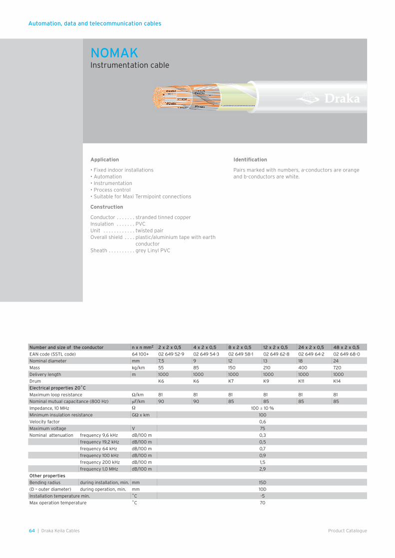
Automation, data and telecommunication cables
64 | Draka Keila Cables Product Catalogue
Application
• Fixed indoor installations• Automation• Instrumentation• Process control• Suitable for Maxi Termipoint connections
Construction
Conductor . . . . . . . stranded tinned copperInsulation . . . . . . . PVCUnit . . . . . . . . . . . . twisted pairOverall shield . . . . plastic/aluminium tape with earth
conductorSheath . . . . . . . . . . grey Linyl PVC
Identification
Pairs marked with numbers, a-conductors are orange and b-conductors are white.
Number and size of the conductor n x n mm2 2 x 2 x 0,5 4 x 2 x 0,5 8 x 2 x 0,5 12 x 2 x 0,5 24 x 2 x 0,5 48 x 2 x 0,5
EAN code (SSTL code) 64 100+ 02 649 52-9 02 649 54-3 02 649 58-1 02 649 62-8 02 649 64-2 02 649 68-0
Nominal diameter mm 7,5 9 12 13 18 24
Mass kg/km 55 85 150 210 400 720
Delivery length m 1000 1000 1000 1000 1000 1000
Drum K6 K6 K7 K9 K11 K14
Electrical properties 20˚C
Maximum loop resistance Ω/km 81 81 81 81 81 81
Nominal mutual capacitance (800 Hz) µF/km 90 90 85 85 85 85
Impedance, 10 MHz Ω 100 ± 10 %
Minimum insulation resistance GΩ x km 100
Velocity factor 0,6
Maximum voltage V 75
Nominal attenuation frequency 9,6 kHz dB/100 m 0,3
frequency 19,2 kHz dB/100 m 0,5
frequency 64 kHz dB/100 m 0,7
frequency 100 kHz dB/100 m 0,9
frequency 200 kHz dB/100 m 1,5
frequency 1,0 MHz dB/100 m 2,9
Other properties
Bending radius during installation, min. mm 15D
(D – outer diameter) during operation, min. mm 10D
Installation temperature min. ˚C -5
Max operation temperature ˚C 70
NOMAK Instrumentation cable
Automation, data and telecommunication cables
65Draka Keila Cables |Product Catalogue
Applications
• Fixed indoor installations • Building automation• Alarm, signal and security control transmission
Construction
According to . . SFS 2755Conductor . . . . tinned copperInsulation . . . . . PVCUnit . . . . . . . . . twisted conductors shielded with
plastic/aluminium tape,earth conductorSheath . . . . . . . grey Linyl PVC
Identification
1. conductor . . . . . . . . . . blue2. conductor . . . . . . . . . yellow3. conductor . . . . . . . . . white4. conductor . . . . . . . . . red
Other properties
KLMA is also available as halogen-free KLMA-LSZH version
Number and size of the conductor n x mm 2 x 0,8 + 0,8 4 x 0,8 + 0,8
EAN code (SSTL code) 64 100+ 02 920 01-7 02 920 03-1
Nominal diameter mm 5 5,5
Mass kg/km 30 45
Delivery length m 500 500
Electrical properties 20˚C
Maximum loop resistance Ω/km 36,7 36,7
Minimum insulation resistance GΩ x km 500 500
Maximum voltage V 75 75
Other properties
Bending radius (D=outer diameter) during installation, min. mm 15D 15D
during operation, min. mm 10D 10D
Installation temperature min. ˚C –5 –5
Max operation temperature ˚C 70 70
KLMASignal cable
Automation, data and telecommunication cables
66 | Draka Keila Cables Product Catalogue
Application
Traffic light cable with a maximum voltage of 75 V (AC) or a maximum of 50 V (DC) to earth.
Standards
IEC 60228, CENELEC HD 22, IEC 60332-1
Certificate/approval
RoHS
Rated voltage
U = 75 VDC; 50 VAC
Temperature range
Highest permissible conductor temperature- in continuous operation . . . . . . . . . . . . . . . . . . . . . . .90˚C- in a short circuit (max. 30 s) . . . . . . . . . . . . . . . . . 200˚CLowest recommended handling temperature . . . . .–40˚C
Construction
Conductor . . . . . . . annealed tinned copper wires, stranded flexible
Insulation . . . . . . . . heat resistant plasticOuter sheath . . . . . black oil retardant rubber
Bending radius
During installation . . . . . . . . . . . . . . . . . . . . . . . . . . . min 3D
Cross section of conductor and colour PULS 2,5 MU 75 V
EAN code (SSTL code) 64 100+ 0231002
Nominal overall diameter mm 4
Total weight kg/km 30
Direct current resistance of conductor at 20˚C max. Ω/km 8,21
Minimum recommended bending radius during installation m 0,012
Standard delivery length m 1000
Reel S4
PULS 2,5 75VTraffic sensor cable
Automation, data and telecommunication cables
67Draka Keila Cables |Product Catalogue
Construction
Conductor . . . . . . . annealed, tinned copper wireInsulation . . . . . . . . PETwinning . . . . . . . . . two insulated conductors in a pairLay-up . . . . . . . . . . stranded into unitsSignal wire . . . . . . . red, insulated conductorGround wire . . . . . . annealed, tinned copper wireScreen . . . . . . . . . . plastic coated aluminium foilSheath . . . . . . . . . . grey Linyl PVC
Conductor number and diameter
EAN code Nominal sheath thickness
Nominal outer diameter
Nominal mass
Standard delivery length
mm 64 100+ mm mm kg/km m
1 x 4 x 0,5 1,0 4,5 30
drum 02 951 31-8 1000
coil 02 551 21-1 100
coil 02 551 31-0 300
3 x 2 x 0,5 1,0 5,0 36
drum 02 951 32-5 1000
coil 02 551 32-7 200
5 x 2 x 0,5 1,0 6,0 50
drum 02 951 33-2 1000
coil 02 551 33-4 150
10 x 2 x 0,5 1,0 7,6 78
drum 02 551 34-1 1000
coil 02 551 35-8 200
20 x 2 x 0,5
drum 02 551 36-5 1,0 9,5 130 1000
coil 02 551 39-6 150
30 x 2 x 0,5 02 551 37-2 1,1 11,5 185 1000
50 x 2 x 0,5 02 551 38-9 1,1 14,0 285 1000
100 x 2 x 0,5 02 551 40-2 1,2 19,0 550 1000
200 x 2 x 0,5 02 551 42-6 1,5 26,0 1030 1000
400 x 2 x 0,5 02 551 44-0 1,8 36,0 2000 500
800 x 2 x 0,5 02 551 48-8 2,2 50,0 3950 500
Electric properties (+20˚C)
Loop resistance maximum 192 Ω/km
maximum average 184 Ω/km
Insulation resistance minimum 500 V, 1 min. 500 MΩkm
Mutual capacitance maximum 65 µF/km
maximum average 60 µF/km
Capacitance unbalance maximum 250 pF/500 m
over 30-pair cables, 95 % of values 150 pF/500 m
MHSIndoor telecommunication cable
Automation, data and telecommunication cables
68 | Draka Keila Cables Product Catalogue
Construction
Conductor . . . . . . . annealed copper wire Insulation . . . . . . . . PE Twinning . . . . . . . . . two insulated conductors in a pair Signal wire . . . . . . . red, insulated conductor Filling compound . . special jelly Screen . . . . . . . . . . aluminium laminate Sheath . . . . . . . . . . black PE
VMOHBUOutdoor telecommunication cable
Conductor number and diameter
EAN code Nominal sheath thickness
Nominal outer diameter
Nominal cable mass
Standard delivery length
mm 64 100+ mm mm kg/km m
100 x 2 x 0,4 02 565 08-9 2,2 24 600 1000
200 x 2 x 0,4 02 565 09-6 2,4 33 1150 1000
300 x 2 x 0,4 02 565 11-9 2,6 38 1600 1000
400 x 2 x 0,4 02 565 12-6 2,6 43 2100 1000
600 x 2 x 0,4 02 565 13-3 2,8 52 3000 500
800 x 2 x 0,4 02 565 14-0 3 58 3850 500
1200 x 2 x 0,4 02 565 16-4 3 71 5700 500
3 x 2 x 0,5 02 563 21-4 2 9,7 80 1000
5 x 2 x 0,5 02 564 74-7 2 11 105 1000
10 x 2 x 0,5 02 564 75-4 2 12,5 145 1000
20 x 2 x 0,5 02 564 76-1 2 15,5 235 1000
30 x 2 x 0,5 02 564 77-8 2 17,5 315 1000
50 x 2 x 0,5 02 564 78-5 2 22 480 1000
100 x 2 x 0,5 02 564 79-2 2,2 28 860 1000
200 x 2 x 0,5 02 564 80-8 2,4 39 1650 1000
300 x 2 x 0,5 02 564 81-5 2,4 45 2350 1000
400 x 2 x 0,5 02 564 82-2 2,6 52 3050 500
600 x 2 x 0,5 02 564 83-9 3 62 4500 500
800 x 2 x 0,5 02 564 84-6 3,2 71 5900 500
5 x 2 x 0,6 02 565 43-0 2 12 130 1000
10 x 2 x 0,6 02 565 44-7 2 14 185 1000
20 x 2 x 0,6 02 565 45-4 2 17,5 305 1000
30 x 2 x 0,6 02 565 46-1 2 21 425 1000
50 x 2 x 0,6 02 565 47-8 2 25 630 1000
100 x 2 x 0,6 02 565 48-5 2,2 33 1200 1000
200 x 2 x 0,6 02 565 62-1 2,6 46 2300 1000
300 x 2 x 0,6 02 565 63-8 2,6 54 3300 500
400 x 2 x 0,6 02 565 64-5 2,6 63 4400 500
10 x 2 x 0,8 02 565 50-8 2 16,5 275 1000
20 x 2 x 0,8 02 565 51-5 2 22 480 1000
30 x 2 x 0,8 02 565 52-2 2 25 680 1000
50 x 2 x 0,8 02 565 53-9 2,2 32 1100 1000
100 x 2 x 0,8 02 565 54-6 2,4 42 2000 1000
3 x 2 x 1,0 02 565 03-4 2 14 185 1000
Diameter of conductor
Capacitance unbalance pair-to pair
Capacitance unbalance pair-to-earth
maximum 95% of values maximum 95% of value
mm pF/500 m pF/500 m pF/500 m pF/500 m
0,4-0,6 250 150 - -
0,8 180 100 1700 1000
Number of pairs in cable 50 and more less than 50
Mutual capacitance maximum µF/km 45 46
Mutual capacitance max average µF/km 40 –
Diameter of conductor mm 0,8
Resistance unbalance maximum % 2
Insulation resistance 500 V, 1 min
Minimum GΩ km 2
Diameter of conductor mm 0,4 0,5 0,6 0,8
Loop resistance max Ω/km 300 192 134 74
Loop resistance max average Ω/km 288 184 128 71
Electric properties (+20˚C)
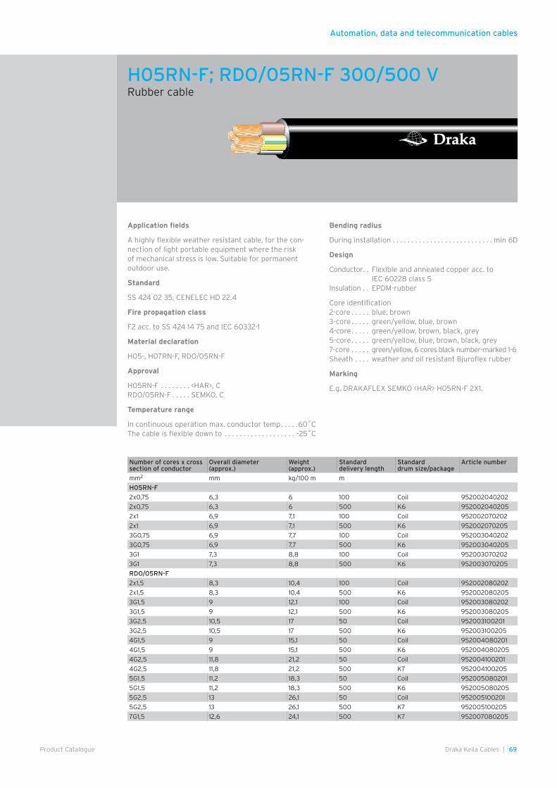
Automation, data and telecommunication cables
69Draka Keila Cables |Product Catalogue
Application fields
A highly flexible weather resistant cable, for the con-nection of light portable equipment where the risk of mechanical stress is low. Suitable for permanent outdoor use.
Standard
SS 424 02 35, CENELEC HD 22.4
Fire propagation class
F2 acc. to SS 424 14 75 and IEC 60332-1
Material declaration
H05-, H07RN-F, RDO/05RN-F
Approval
H05RN-F . . . . . . . . <HAR>, CRDO/05RN-F . . . . . SEMKO, C
Temperature range
In continuous operation max. conductor temp . . . . .60˚C The cable is flexible down to . . . . . . . . . . . . . . . . . . . –25˚C
Bending radius
During installation . . . . . . . . . . . . . . . . . . . . . . . . . . . min 6D
Design
Conductor. . Flexible and annealed copper acc. to IEC 60228 class 5
Insulation . . EPDM-rubber
Core identification2-core . . . . . blue, brown3-core . . . . . green/yellow, blue, brown4-core . . . . . green/yellow, brown, black, grey5-core . . . . . green/yellow, blue, brown, black, grey7-core . . . . . green/yellow, 6 cores black number-marked 1-6Sheath . . . . weather and oil resistant Bjuroflex rubber
Marking
E.g. DRAKAFLEX SEMKO <HAR> H05RN-F 2X1.
Number of cores x cross section of conductor
Overall diameter (approx.)
Weight (approx.)
Standard delivery length
Standard drum size/package
Article number
mm2 mm kg/100 m m
H05RN-F
2x0,75 6,3 6 100 Coil 952002040202
2x0,75 6,3 6 500 K6 952002040205
2x1 6,9 7,1 100 Coil 952002070202
2x1 6,9 7,1 500 K6 952002070205
3G0,75 6,9 7,7 100 Coil 952003040202
3G0,75 6,9 7,7 500 K6 952003040205
3G1 7,3 8,8 100 Coil 952003070202
3G1 7,3 8,8 500 K6 952003070205
RDO/05RN-F
2x1,5 8,3 10,4 100 Coil 952002080202
2x1,5 8,3 10,4 500 K6 952002080205
3G1,5 9 12,1 100 Coil 952003080202
3G1,5 9 12,1 500 K6 952003080205
3G2,5 10,5 17 50 Coil 952003100201
3G2,5 10,5 17 500 K6 952003100205
4G1,5 9 15,1 50 Coil 952004080201
4G1,5 9 15,1 500 K6 952004080205
4G2,5 11,8 21,2 50 Coil 952004100201
4G2,5 11,8 21,2 500 K7 952004100205
5G1,5 11,2 18,3 50 Coil 952005080201
5G1,5 11,2 18,3 500 K6 952005080205
5G2,5 13 26,1 50 Coil 952005100201
5G2,5 13 26,1 500 K7 952005100205
7G1,5 12,6 24,1 500 K7 952007080205
H05RN-F; RDO/05RN-F 300/500 VRubber cable
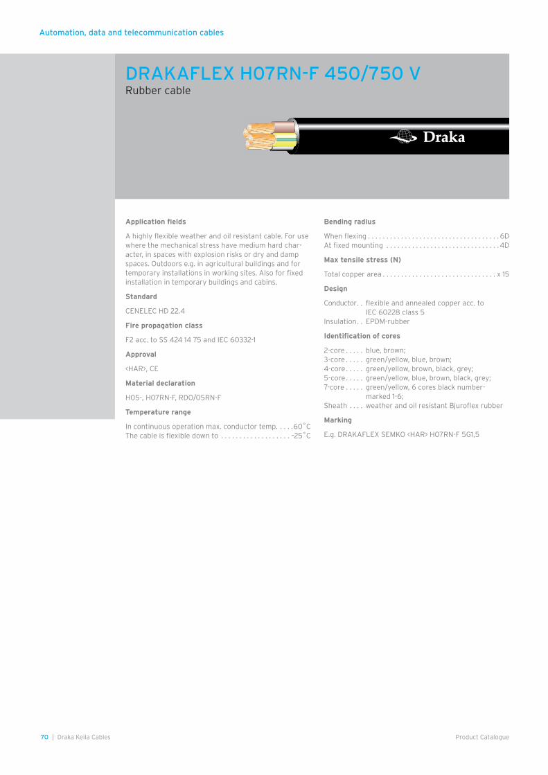
Automation, data and telecommunication cables
70 | Draka Keila Cables Product Catalogue
Application fields
A highly flexible weather and oil resistant cable. For use where the mechanical stress have medium hard char-acter, in spaces with explosion risks or dry and damp spaces. Outdoors e.g. in agricultural buildings and for temporary installations in working sites. Also for fixed installation in temporary buildings and cabins.
Standard
CENELEC HD 22.4
Fire propagation class
F2 acc. to SS 424 14 75 and IEC 60332-1
Approval
<HAR>, CE
Material declaration
H05-, H07RN-F, RDO/05RN-F
Temperature range
In continuous operation max. conductor temp. . . . .60˚C The cable is flexible down to . . . . . . . . . . . . . . . . . . . –25˚C
Bending radius
When flexing . . . . . . . . . . . . . . . . . . . . . . . . . . . . . . . . . . . . 6DAt fixed mounting . . . . . . . . . . . . . . . . . . . . . . . . . . . . . . . 4D
Max tensile stress (N)
Total copper area . . . . . . . . . . . . . . . . . . . . . . . . . . . . . . . x 15
Design
Conductor . . flexible and annealed copper acc. to IEC 60228 class 5
Insulation . . EPDM-rubber
Identification of cores
2-core . . . . . blue, brown;3-core . . . . . green/yellow, blue, brown;4-core . . . . . green/yellow, brown, black, grey;5-core . . . . . green/yellow, blue, brown, black, grey;7-core . . . . . green/yellow, 6 cores black number-
marked 1-6;Sheath . . . . weather and oil resistant Bjuroflex rubber
Marking
E.g. DRAKAFLEX SEMKO <HAR> H07RN-F 5G1,5
DRAKAFLEX H07RN-F 450/750 VRubber cable
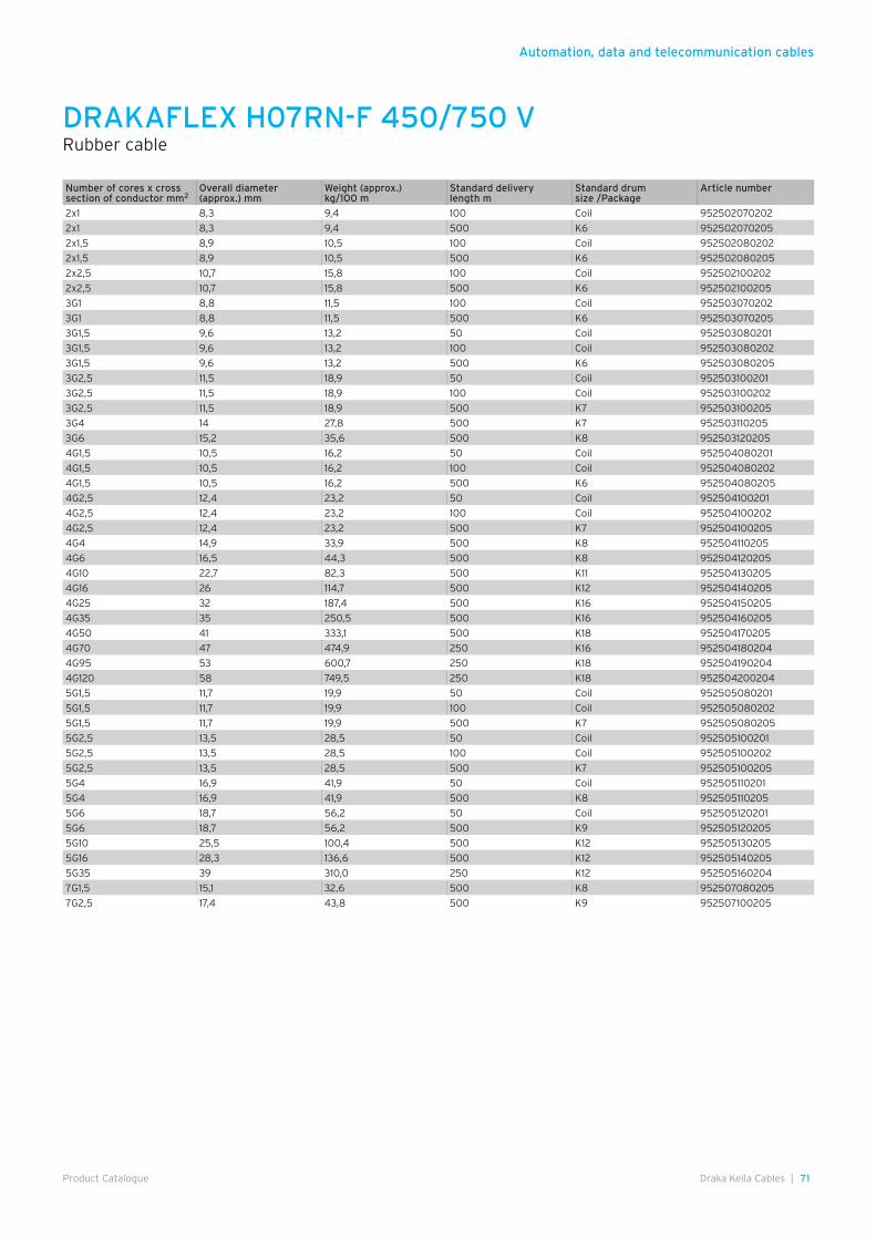
Automation, data and telecommunication cables
71Draka Keila Cables |Product Catalogue
Number of cores x cross section of conductor mm2
Overall diameter (approx.) mm
Weight (approx.) kg/100 m
Standard delivery length m
Standard drum size /Package
Article number
2x1 8,3 9,4 100 Coil 952502070202
2x1 8,3 9,4 500 K6 952502070205
2x1,5 8,9 10,5 100 Coil 952502080202
2x1,5 8,9 10,5 500 K6 952502080205
2x2,5 10,7 15,8 100 Coil 952502100202
2x2,5 10,7 15,8 500 K6 952502100205
3G1 8,8 11,5 100 Coil 952503070202
3G1 8,8 11,5 500 K6 952503070205
3G1,5 9,6 13,2 50 Coil 952503080201
3G1,5 9,6 13,2 100 Coil 952503080202
3G1,5 9,6 13,2 500 K6 952503080205
3G2,5 11,5 18,9 50 Coil 952503100201
3G2,5 11,5 18,9 100 Coil 952503100202
3G2,5 11,5 18,9 500 K7 952503100205
3G4 14 27,8 500 K7 952503110205
3G6 15,2 35,6 500 K8 952503120205
4G1,5 10,5 16,2 50 Coil 952504080201
4G1,5 10,5 16,2 100 Coil 952504080202
4G1,5 10,5 16,2 500 K6 952504080205
4G2,5 12,4 23,2 50 Coil 952504100201
4G2,5 12,4 23,2 100 Coil 952504100202
4G2,5 12,4 23,2 500 K7 952504100205
4G4 14,9 33,9 500 K8 952504110205
4G6 16,5 44,3 500 K8 952504120205
4G10 22,7 82,3 500 K11 952504130205
4G16 26 114,7 500 K12 952504140205
4G25 32 187,4 500 K16 952504150205
4G35 35 250,5 500 K16 952504160205
4G50 41 333,1 500 K18 952504170205
4G70 47 474,9 250 K16 952504180204
4G95 53 600,7 250 K18 952504190204
4G120 58 749,5 250 K18 952504200204
5G1,5 11,7 19,9 50 Coil 952505080201
5G1,5 11,7 19,9 100 Coil 952505080202
5G1,5 11,7 19,9 500 K7 952505080205
5G2,5 13,5 28,5 50 Coil 952505100201
5G2,5 13,5 28,5 100 Coil 952505100202
5G2,5 13,5 28,5 500 K7 952505100205
5G4 16,9 41,9 50 Coil 952505110201
5G4 16,9 41,9 500 K8 952505110205
5G6 18,7 56,2 50 Coil 952505120201
5G6 18,7 56,2 500 K9 952505120205
5G10 25,5 100,4 500 K12 952505130205
5G16 28,3 136,6 500 K12 952505140205
5G35 39 310,0 250 K12 952505160204
7G1,5 15,1 32,6 500 K8 952507080205
7G2,5 17,4 43,8 500 K9 952507100205
DRAKAFLEX H07RN-F 450/750 VRubber cable
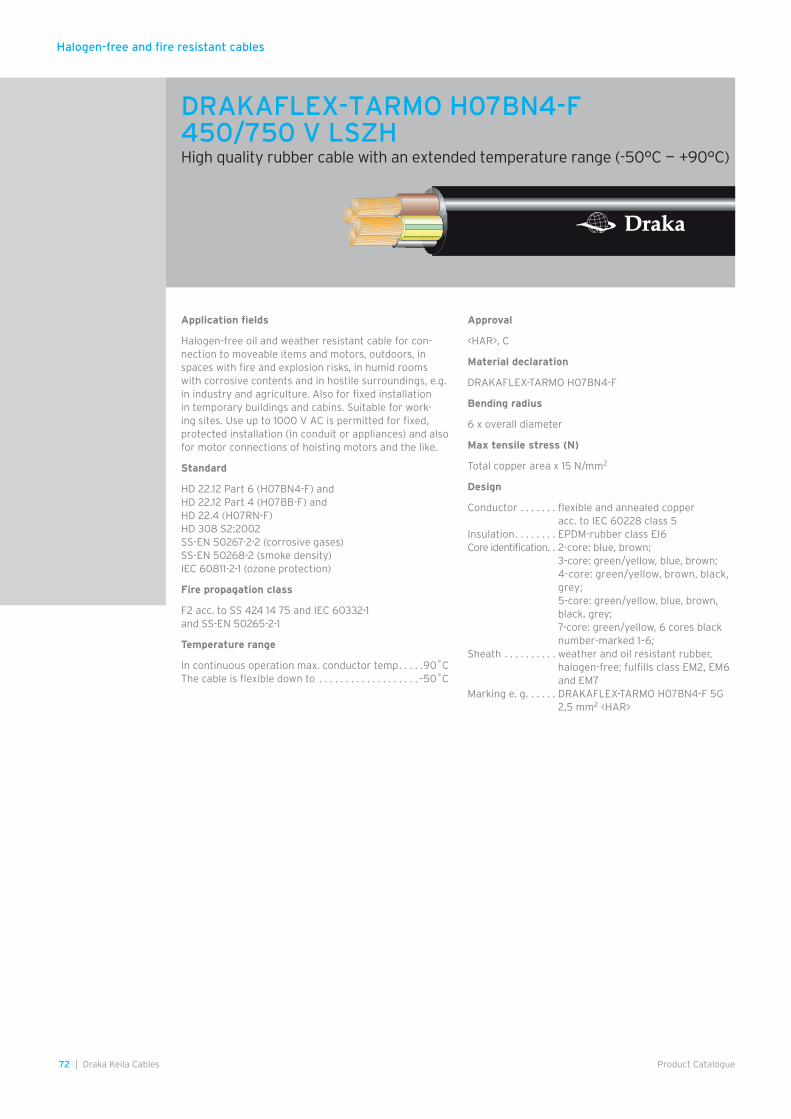
Halogen-free and fire resistant cables
72 | Draka Keila Cables Product Catalogue
Application fields
Halogen-free oil and weather resistant cable for con-nection to moveable items and motors, outdoors, in spaces with fire and explosion risks, in humid rooms with corrosive contents and in hostile surroundings, e.g. in industry and agriculture. Also for fixed installation in temporary buildings and cabins. Suitable for work-ing sites. Use up to 1000 V AC is permitted for fixed, protected installation (in conduit or appliances) and also for motor connections of hoisting motors and the like.
Standard
HD 22.12 Part 6 (H07BN4-F) andHD 22.12 Part 4 (H07BB-F) andHD 22.4 (H07RN-F)HD 308 S2:2002SS-EN 50267-2-2 (corrosive gases)SS-EN 50268-2 (smoke density)IEC 60811-2-1 (ozone protection)
Fire propagation class
F2 acc. to SS 424 14 75 and IEC 60332-1 and SS-EN 50265-2-1
Temperature range
In continuous operation max. conductor temp . . . . .90˚CThe cable is flexible down to . . . . . . . . . . . . . . . . . . . –50˚C
Approval
<HAR>, C
Material declaration
DRAKAFLEX-TARMO H07BN4-F
Bending radius
6 x overall diameter
Max tensile stress (N)
Total copper area x 15 N/mm2
Design
Conductor . . . . . . . flexible and annealed copper acc. to IEC 60228 class 5
Insulation . . . . . . . . EPDM-rubber class EI6Core identification. . 2-core: blue, brown;
3-core: green/yellow, blue, brown; 4-core: green/yellow, brown, black, grey; 5-core: green/yellow, blue, brown, black, grey; 7-core: green/yellow, 6 cores black number-marked 1–6;
Sheath . . . . . . . . . . weather and oil resistant rubber, halogen-free; fulfills class EM2, EM6 and EM7
Marking e. g. . . . . . DRAKAFLEX-TARMO H07BN4-F 5G 2,5 mm2 <HAR>
DRAKAFLEX-TARMO H07BN4-F 450/750 V LSZH High quality rubber cable with an extended temperature range (-50°C – +90°C)
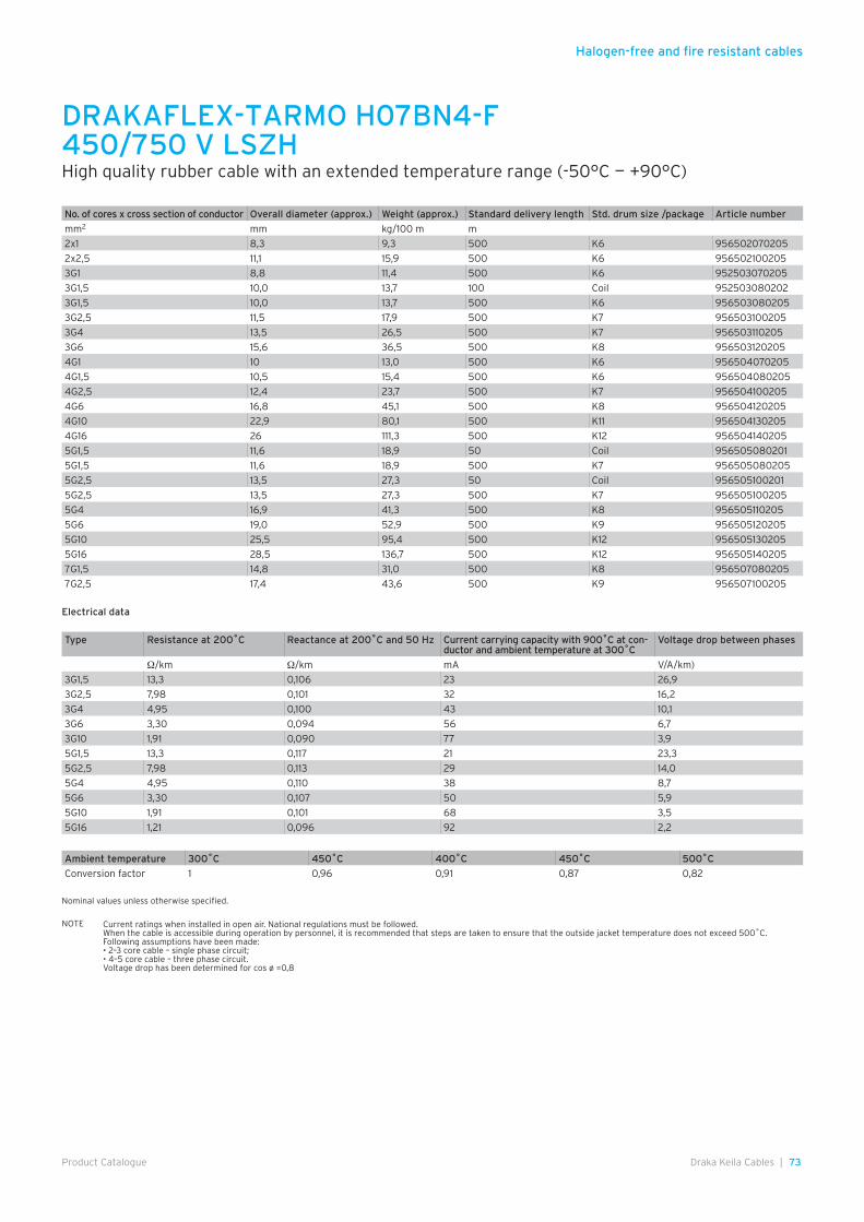
Halogen-free and fire resistant cables
73Draka Keila Cables |Product Catalogue
DRAKAFLEX-TARMO H07BN4-F 450/750 V LSZH High quality rubber cable with an extended temperature range (-50°C – +90°C)
No. of cores x cross section of conductor Overall diameter (approx.) Weight (approx.) Standard delivery length Std. drum size /package Article number
mm2 mm kg/100 m m
2x1 8,3 9,3 500 K6 956502070205
2x2,5 11,1 15,9 500 K6 956502100205
3G1 8,8 11,4 500 K6 952503070205
3G1,5 10,0 13,7 100 Coil 952503080202
3G1,5 10,0 13,7 500 K6 956503080205
3G2,5 11,5 17,9 500 K7 956503100205
3G4 13,5 26,5 500 K7 956503110205
3G6 15,6 36,5 500 K8 956503120205
4G1 10 13,0 500 K6 956504070205
4G1,5 10,5 15,4 500 K6 956504080205
4G2,5 12,4 23,7 500 K7 956504100205
4G6 16,8 45,1 500 K8 956504120205
4G10 22,9 80,1 500 K11 956504130205
4G16 26 111,3 500 K12 956504140205
5G1,5 11,6 18,9 50 Coil 956505080201
5G1,5 11,6 18,9 500 K7 956505080205
5G2,5 13,5 27,3 50 Coil 956505100201
5G2,5 13,5 27,3 500 K7 956505100205
5G4 16,9 41,3 500 K8 956505110205
5G6 19,0 52,9 500 K9 956505120205
5G10 25,5 95,4 500 K12 956505130205
5G16 28,5 136,7 500 K12 956505140205
7G1,5 14,8 31,0 500 K8 956507080205
7G2,5 17,4 43,6 500 K9 956507100205
Ambient temperature 300˚C 450˚C 400˚C 450˚C 500˚C
Conversion factor 1 0,96 0,91 0,87 0,82
Nominal values unless otherwise specified.
NOTE Current ratings when installed in open air. National regulations must be followed. When the cable is accessible during operation by personnel, it is recommended that steps are taken to ensure that the outside jacket temperature does not exceed 500˚C.Following assumptions have been made:• 2–3 core cable – single phase circuit;• 4–5 core cable – three phase circuit.Voltage drop has been determined for cos ø =0,8
Type Resistance at 200˚C Reactance at 200˚C and 50 Hz Current carrying capacity with 900˚C at con-ductor and ambient temperature at 300˚C
Voltage drop between phases
Ω/km Ω/km mA V/A/km)
3G1,5 13,3 0,106 23 26,9
3G2,5 7,98 0,101 32 16,2
3G4 4,95 0,100 43 10,1
3G6 3,30 0,094 56 6,7
3G10 1,91 0,090 77 3,9
5G1,5 13,3 0,117 21 23,3
5G2,5 7,98 0,113 29 14,0
5G4 4,95 0,110 38 8,7
5G6 3,30 0,107 50 5,9
5G10 1,91 0,101 68 3,5
5G16 1,21 0,096 92 2,2
Electrical data
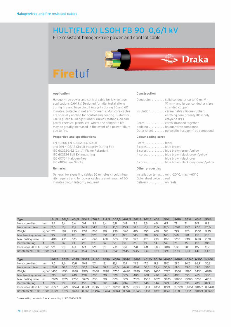
Halogen-free and fire resistant cables
74 | Draka Keila Cables Product Catalogue
Type 2x1,5 3G1,5 4G1,5 5G1,5 7G1,5 2x2,5 3G2,5 4G2,5 5G2,5 7G2,5 4G6 5G6 4G10 5G10 4G16 5G16
Nom. core diam. mm 3,4 3,4 3,4 3,4 3,4 3,4 3,8 3,8 3,8 3,8 4,9 4,9 7,1 7,1 8,3 8,3
Nom. outer diam. mm 11,6 12,1 13,9 14,3 14,9 12,4 13,0 15,3 18,0 16,1 15,6 17,0 20,0 23,2 22,0 26,6
Weight kg/km 175 190 230 260 265 210 230 340 410 350 420 510 775 920 1000 1295
Min. bending radius mm 95 100 115 115 120 100 105 125 145 130 125 140 160 190 180 215
Max. pulling force N 400 435 575 610 665 460 505 700 970 775 730 865 1200 1610 1450 2120
Current Rating A 26 26 23 23 17 36 36 32 25 23 54 54 75 75 100 100
Conductor 20˚C AC Ω/km 12,1 12,1 12,1 12,1 12,1 12,1 7,41 7,41 7,41 7,41 3,08 3,08 1,83 1,83 1,15 1,15
Resistance 90˚C DC Ω/km 15,4 15,4 15,4 15,4 15,4 15,4 9,45 9,45 9,45 9,45 3,93 3,93 2,33 2,33 1,47 1,47
Type 4G25 5G25 4G35 5G35 4x50 5G50 4G70 5G70 5G95 4G120 5G120 4G150 4G185 4G240 1x300 1x400
Nom. core diam. mm 9,6 9,6 10,8 10,8 12,1 12,1 13,1 13,1 15,8 17,2 17,2 19,2 21,5 24,2 26,9 30,2
Nom. outer diam. mm 26,0 30,2 30,0 33,7 34,6 38,3 40,0 44,0 49,4 50,0 54,4 55,0 61,0 69,0 33,0 37,0
Weight kg/km 1450 1855 1980 2415 2660 3240 3700 4440 5970 6180 7400 7520 9360 12120 3430 4280
Min. bending radius mm 210 245 240 270 280 310 320 355 400 400 440 440 490 555 265 300
Max. pulling force N 2025 2735 2700 3405 280 310 320 355 7320 7500 8875 9075 10000 10000 3265 4105
Current Rating A 127 127 158 158 192 192 246 246 298 346 346 399 456 538 703 823
Conductor 20˚C AC Ω/km 0,727 0,727 0,524 0,524 0,387 0,387 0.268 0.268 0,193 0,153 0,153 0,124 0,0991 0,0754 0,0601 0,0470
Resistance 90˚C DC Ω/km 0,927 0,927 0,669 0,669 0,494 0,494 0.344 0.344 0,248 0,198 0,198 0,161 0,131 0,102 0,0831 0,0685
Current rating: cables in free air according to IEC 60364-5-52
Application
Halogen-free power and control cable for low voltage applications 0,6/1 kV. Designed for vital installations during fire and have circuit integrity during 30 and 60 minutes. Suitable in wet environments. Multicore cables are specially applied for control engineering. Suited for use in public buildings tunnels, railway stations, oil and petrol chemical plants, etc where the danger to life may be greatly increased in the event of a power failure due to fire.
Properties and specifications
EN 50200 EN 50362, IEC 60331 and DIN 4102/12 Circuit Integrity During FireIEC 60332-3-22 (Cat A) Flame RetardantIEC 60332-1 Self ExtinguishingIEC 60754 Halogen-freeIEC 61034 Low Smoke
Remarks
General, for signalling cables 30 minutes circuit integ-rity required and for power cables is a minimum of 60 minutes circuit Integrity required.
Construction
Conductor . . . . . . . . solid conductor up to 10 mm2;10 mm2 and larger conductor sizes stranded copper
Insulation . . . . . . . . . ceramifiable silicone rubber;earthing core green/yellow poly-ethylene (PE)
Cores . . . . . . . . . . . . cores stranded togetherBedding . . . . . . . . . . halogen-free compoundOuter sheet . . . . . . . polyolefin, halogen-free compound
Colour coding cores
1 core . . . . . . . . . . . . black2 cores . . . . . . . . . . . blue brown3 cores . . . . . . . . . . . blue brown green/yellow4 cores . . . . . . . . . . . blue brown black green/yellow
blue brown black grey5 cores . . . . . . . . . . . blue brown black grey green/yellow
Other properties
Installation temp. . . min. –20˚C, max. +60˚C Outer sheet colour . . redDelivery . . . . . . . . . . on reels
HULT(FLEX) LSOH FB 90 0,6/1 kVFire resistant halogen-free power and control cable
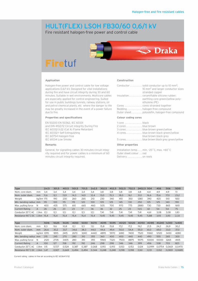
Halogen-free and fire resistant cables
75Draka Keila Cables |Product Catalogue
Application
Halogen-free power and control cable for low voltage applications 0,6/1 kV. Designed for vital installations during fire and have circuit integrity during 30 and 60 minutes. Suitable in wet environments. Multicore cables are especially applied for control engineering. Suited for use in public buildings tunnels, railway stations, oil and petrol chemical plants, etc where the danger to life may be greatly increased in the event of a power failure due to fire.
Properties and specifications
EN 50200 EN 50362, IEC 60331 and DIN 4102/12 Circuit Integrity During FireIEC 60332-3-22 (Cat A) Flame RetardantIEC 60332-1 Self ExtinguishingIEC 60754 Halogen-freeIEC 61034 Low Smoke
Remarks
General, for signalling cables 30 minutes circuit integ-rity required and for power cables is a minimum of 60 minutes circuit integrity required.
Construction
Conductor . . . . . . . . . solid conductor up to 10 mm2;10 mm2 and larger conductor sizes stranded copper
Insulation . . . . . . . . . . ceramifiable silicone rubber;earthing core green/yellow poly-ethylene (PE)
Cores . . . . . . . . . . . . . cores stranded togetherBedding . . . . . . . . . . . halogen-free compoundOuter sheet . . . . . . . . polyolefin, halogen-free compound
Colour coding cores
1 core . . . . . . . . . . . . . black2 cores . . . . . . . . . . . . blue brown3 cores . . . . . . . . . . . . blue brown green/yellow4 cores . . . . . . . . . . . . blue brown black green/yellow
blue brown black grey5 cores . . . . . . . . . . . . blue brown black grey green/yellow
Other properties
Installation temp. . . . min. –20˚C, max. +60˚COuter sheet colour . . redDelivery . . . . . . . . . . . on reels
Type 2x1,5 3G1,5 4G1,5 5G1,5 7G1,5 2x2,5 3G2,5 4G2,5 5G2,5 7G2,5 24G2,5 5G4 4G6 5G6 5G10
Nom. core diam. mm 3,4 3,4 3,4 3,4 3,4 3,4 3,8 3,8 3,8 3,8 3,8 4,4 4,9 4,9 7,1
Nom. outer diam. mm 11,6 12,1 13,9 14,3 14,9 12,4 13,0 15,3 18,0 16,1 31,0 16,6 15,6 17,0 23,2
Weight kg/km 175 190 230 260 265 210 230 340 410 350 1280 390 420 510 920
Min. bending radius mm 95 100 115 115 120 100 105 125 145 130 250 125 125 140 190
Max. pulling force N 400 435 575 610 665 460 505 700 970 775 2880 730 730 865 1610
Current Rating A 26 26 23 23 17 36 36 32 25 23 13,5 42 54 54 75
Conductor 20˚C AC Ω/km 12,1 12,1 12,1 12,1 12,1 12,1 7,41 7,41 7,41 7,41 7,41 4,61 3,08 3,08 1,83
Resistance 90˚C DC Ω/km 15,4 15,4 15,4 15,4 15,4 15,4 9,45 9,45 9,45 9,45 9,45 5,88 3,93 3,93 2,33
Type 5G16 5G25 5G35 4G50 5G50 5G70 4G95 5G95 4G120 5G120 4G150 4G185 4G240 1x300 1x400
Nom. core diam. mm 8,3 9,6 10,8 12,1 12,1 13,1 15,8 15,8 17,2 17,2 19,2 21,5 24,2 26,9 30,2
Nom. outer diam. mm 26,6 30,2 33,7 34,6 38,3 44,0 44,6 49,4 50,0 54,4 55,0 61,0 69,0 33,0 37,0
Weight kg/km 1295 1855 2415 2670 3240 4440 4895 5970 6180 7400 7520 9360 12120 3430 4280
Min. bending radius mm 215 245 270 280 310 355 360 400 400 440 440 490 555 265 300
Max. pulling force N 2120 2735 3405 280 310 355 5965 7320 7500 8875 9075 10000 10000 3265 4105
Current Rating A 100 127 158 192 192 246 298 298 346 346 399 456 538 703 823
Conductor 20˚C AC Ω/km 1,15 0,727 0,524 0,387 0,387 0.268 0,193 0,193 0,153 0,153 0,124 0,0991 0,0754 0,0601 0,0470
Resistance 90˚C DC Ω/km 1,47 0,927 0,669 0,494 0,494 0.344 0,248 0,248 0,198 0,198 0,161 0,131 0,102 0,0831 0,0685
Current rating: cables in free air according to IEC 60364-5-52
HULT(FLEX) LSOH FB30/60 0,6/1 kVFire resistant halogen-free power and control cable
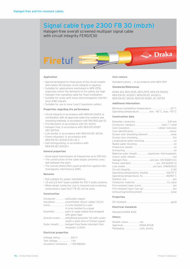
Halogen-free and fire resistant cables
76 | Draka Keila Cables Product Catalogue
Application
• Special developed for those parts of the circuit installa-tions where 30 minutes circuit integrity is required.
• Suitable for applications mentioned in NPR 2576, especially where the demands of fire safety are high.
• Halogen-free signalling cable for fixed installation.• Suitable for areas with many electromagnetic interfer-
ence (EMI) signals.• Suitable for use in zone 1 and 2 (explosion safety).
Properties regarding fire performance
• Circuit integrity in accordance with NEN-EN 50200, in combination with all approved cable tray systems and mounting methods, in accordance with DIN 4102 part 12.
• Fire Resistant, in accordance with IEC 60331.• Halogen-free, in accordance with NEN-EN 50267
(IEC 60754).• Low smoke, in accordance with NEN-EN-IEC 61034.• Flame retardant, in accordance with
NEN-EN-IEC 60332-3-24 Cat C.• Self-extinguishing, in accordance with
NEN-EN-IEC 60332-1.
General properties
• Good signal transmission at frequencies up to 100 kHz.• The construction of the cable largely prevents cross
talk between the pairs.• The overall shield offers good protection against elec-
tromagnetic interference (EMI).
Remarks
• Not suitable for power installations.• 1,5 and 2,5 mm2 types suitable for 100 V audio systems.• When larger conductor size is required and screening
unnecessary, type HULT FB 30 can be used.
Construction
Conductor . . . . . . . solid plain copperInsulation . . . . . . . . ceramifiable silicon rubber (XLSr)Cores . . . . . . . . . . . 2 cores twisted to a pair
4 cores twisted to a quadAssembly . . . . . . . . pairs or quad cabled and wrapped
with glass tapeOverall screen . . . . metallized polyester foil with under-
neath a drain wire of tinned copperOuter sheath . . . . . halogen-free flame retardant ther-
moplastic (LSOH)
Electrical properties
Voltage rating . . . . . . . . 300 VTest voltage . . . . . . . . . . 1 kVInsulation resistance . . > 100 MΩ/km
Core colours
Standard colours . . in accordance with NEN 1597
Standards/References
KEMA 163, NEN 2535, NEN 2575, NEN-EN 50200, NEN-EN-IEC 60332-1, NEN-EN-IEC 60332-3, NEN-EN-IEC 61034, NEN-EN 50267, IEC 60754
Additional information:
Minimum installation temperature . . . . . . . . . . . . . . –20˚COperating temperature . . . . . . . . min. –40˚C, max. +70˚C
Construction data
Diameter conductor . . . . . . . . . . . . . . . . . . . . . . . . . 0.8 mmConductor category . . . . . . . . . . . . . . . . . . . . class 1 = solidCore insulation . . . . . . . . . . . . . . . . . . . . . . rubber (silicone)Core identification . . . . . . . . . . . . . . . . . . . . . . . . . . . .colourScreen over stranding element . . . . . . . . . . . . . . . . . . noneScreen over stranding . . . . . . . . . . . . . . . . . . . . . . . . . . . .foilLongitudinal water blocking . . . . . . . . . . . . . . . . . . . . . . . noRadial water blocking . . . . . . . . . . . . . . . . . . . . . . . . . . . . noProtective sheath . . . . . . . . . . . . . . . . . . . . . . . . . . . . . . . . noArmouring . . . . . . . . . . . . . . . . . . . . . . . . . . . . . . . . . . . . . . noMaterial outer sheath . . . . . . . .copolymer, thermoplasticColour outer sheath . . . . . . . . . . . . . . . . . . . . . . . . . . . . . redHalogen-free . . . . . . . . . . . . . . . . . .yes (acc. EN 50267-2-2)Flame retardant . . . . . . . . . . . . . . . . . . . .acc. EN 60332-1-2Low smoke . . . . . . . . . . . . . . . . . . . . . yes (acc. EN61034-2)Circuit integrity. . . . . . . . . . . . . . . . . . . . . . . . . . . . . . . . E 60Operating temperature, flexible . . . . . . . . . . . . . -20/70˚COperating temperature, fix . . . . . . . . . . . . . . . . . . -40/90˚COutdoor use . . . . . . . . . . . . . . . . . . . . . . . . . . . . . . . . . . . yesConductor material . . . . . . . . . . . . . . . . . . . . . . . . . Cu, bareFire-resistant layer (core) . . . . . . . . . . . . . . . . . . . . . . . . yesFire-resistant layer (lay-up) . . . . . . . . . . . . . . . . . . . . . . yesArmouring/reinforcement . . . . . . . . . . . . . . . . . . . . . . none
Properties
Oil resistant . . . . . . . . . . . . . . . . . . . . . . . . . . . . . . . . . . . good
Electrical standards
Standard KEMA K102
Others
Sheath colour . . . . . . . . redApproval. . . . . . . . . . . . . KEMA-KEURPackaging . . . . . . . . . . . coils, drums
Signal cable type 2300 FB 30 (mbzh)Halogen-free overall screened multipair signal cable with circuit integrity FE90/E30
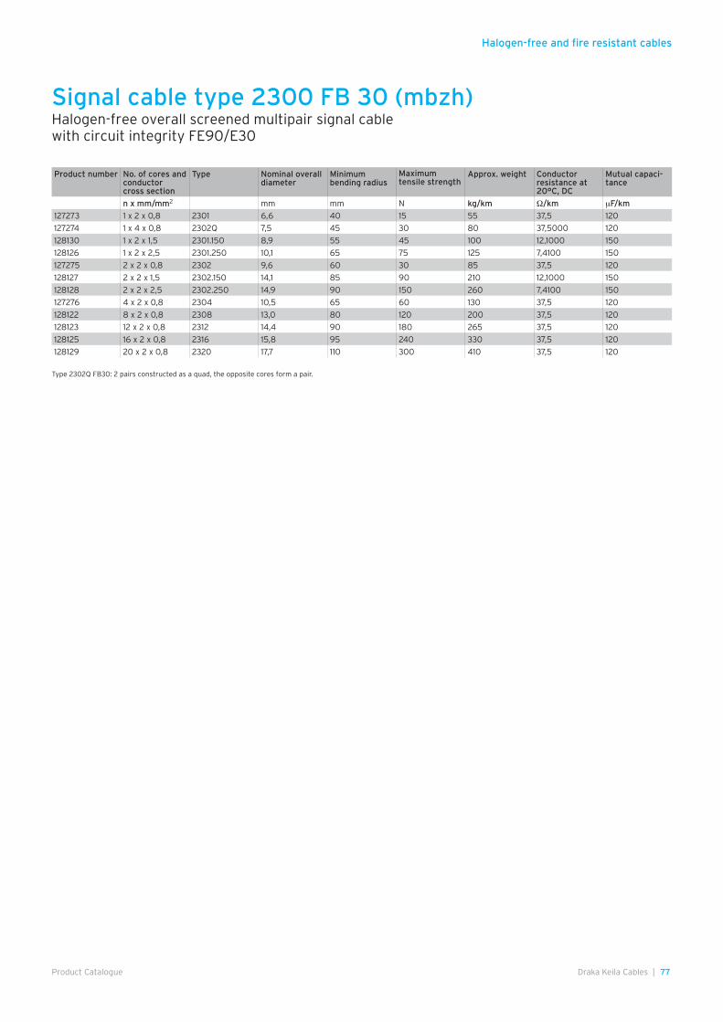
Halogen-free and fire resistant cables
77Draka Keila Cables |Product Catalogue
Signal cable type 2300 FB 30 (mbzh)Halogen-free overall screened multipair signal cable with circuit integrity FE90/E30
Product number No. of cores andconductor cross section
Type Nominal overalldiameter
Minimum bending radius
Maximum tensile strength
Approx. weight Conductor resistance at 20°C, DC
Mutual capaci-tance
n x mm/mm2 mm mm N kg/km Ω/km µF/km
127273 1 x 2 x 0,8 2301 6,6 40 15 55 37,5 120
127274 1 x 4 x 0,8 2302Q 7,5 45 30 80 37,5000 120
128130 1 x 2 x 1,5 2301.150 8,9 55 45 100 12,1000 150
128126 1 x 2 x 2,5 2301.250 10,1 65 75 125 7,4100 150
127275 2 x 2 x 0,8 2302 9,6 60 30 85 37,5 120
128127 2 x 2 x 1,5 2302.150 14,1 85 90 210 12,1000 150
128128 2 x 2 x 2,5 2302.250 14,9 90 150 260 7,4100 150
127276 4 x 2 x 0,8 2304 10,5 65 60 130 37,5 120
128122 8 x 2 x 0,8 2308 13,0 80 120 200 37,5 120
128123 12 x 2 x 0,8 2312 14,4 90 180 265 37,5 120
128125 16 x 2 x 0,8 2316 15,8 95 240 330 37,5 120
128129 20 x 2 x 0,8 2320 17,7 110 300 410 37,5 120
Type 2302Q FB30: 2 pairs constructed as a quad, the opposite cores form a pair.
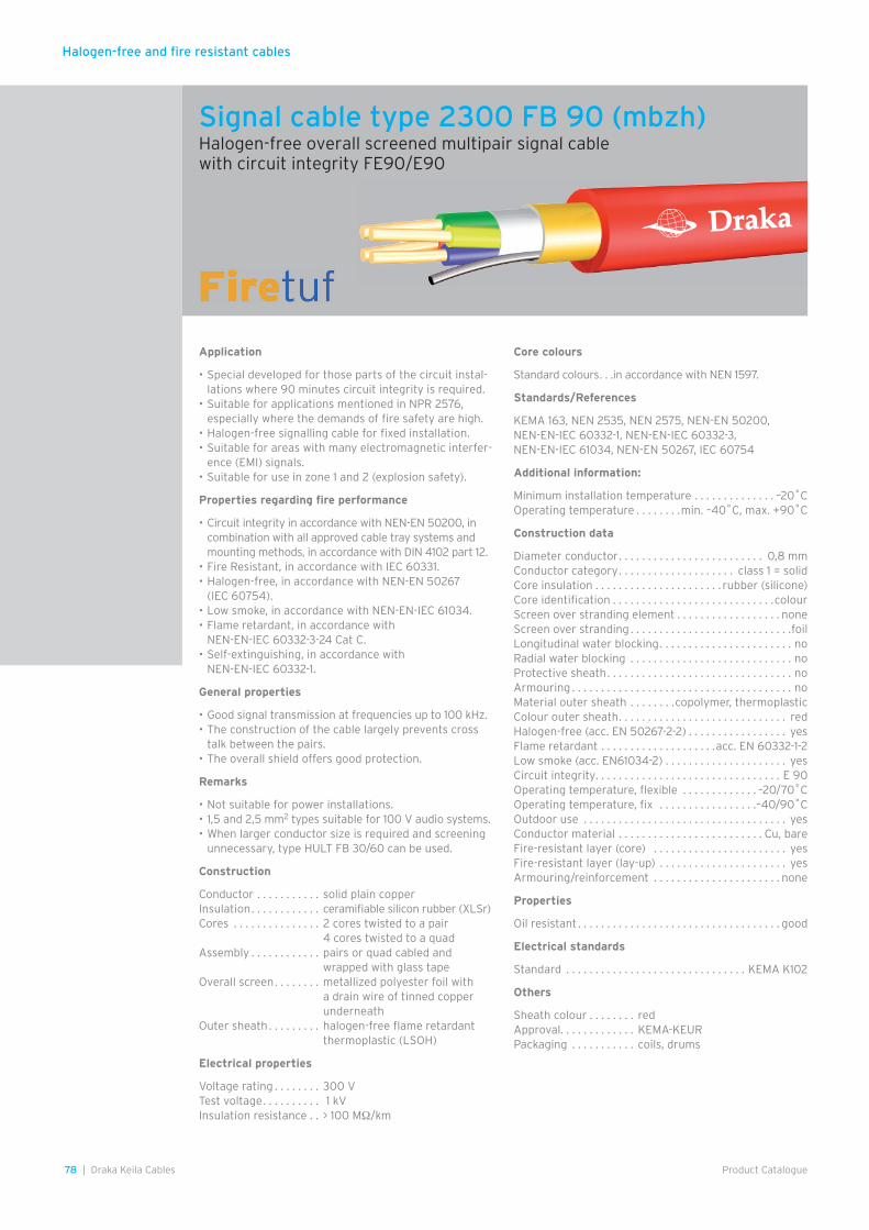
Halogen-free and fire resistant cables
78 | Draka Keila Cables Product Catalogue
Application
• Special developed for those parts of the circuit instal-lations where 90 minutes circuit integrity is required.
• Suitable for applications mentioned in NPR 2576, especially where the demands of fire safety are high.
• Halogen-free signalling cable for fixed installation.• Suitable for areas with many electromagnetic interfer-
ence (EMI) signals.• Suitable for use in zone 1 and 2 (explosion safety).
Properties regarding fire performance
• Circuit integrity in accordance with NEN-EN 50200, in combination with all approved cable tray systems and mounting methods, in accordance with DIN 4102 part 12.
• Fire Resistant, in accordance with IEC 60331.• Halogen-free, in accordance with NEN-EN 50267
(IEC 60754).• Low smoke, in accordance with NEN-EN-IEC 61034.• Flame retardant, in accordance with
NEN-EN-IEC 60332-3-24 Cat C.• Self-extinguishing, in accordance with
NEN-EN-IEC 60332-1.
General properties
• Good signal transmission at frequencies up to 100 kHz.• The construction of the cable largely prevents cross
talk between the pairs.• The overall shield offers good protection.
Remarks
• Not suitable for power installations.• 1,5 and 2,5 mm2 types suitable for 100 V audio systems.• When larger conductor size is required and screening
unnecessary, type HULT FB 30/60 can be used.
Construction
Conductor . . . . . . . . . . . solid plain copperInsulation . . . . . . . . . . . . ceramifiable silicon rubber (XLSr)Cores . . . . . . . . . . . . . . . 2 cores twisted to a pair
4 cores twisted to a quadAssembly . . . . . . . . . . . . pairs or quad cabled and
wrapped with glass tapeOverall screen . . . . . . . . metallized polyester foil with
a drain wire of tinned copper underneath
Outer sheath . . . . . . . . . halogen-free flame retardant thermoplastic (LSOH)
Electrical properties
Voltage rating . . . . . . . . 300 VTest voltage . . . . . . . . . . 1 kVInsulation resistance . . > 100 MΩ/km
Core colours
Standard colours . . .in accordance with NEN 1597.
Standards/References
KEMA 163, NEN 2535, NEN 2575, NEN-EN 50200, NEN-EN-IEC 60332-1, NEN-EN-IEC 60332-3, NEN-EN-IEC 61034, NEN-EN 50267, IEC 60754
Additional information:
Minimum installation temperature . . . . . . . . . . . . . . –20˚COperating temperature . . . . . . . .min. –40˚C, max. +90˚C
Construction data
Diameter conductor . . . . . . . . . . . . . . . . . . . . . . . . . 0,8 mmConductor category . . . . . . . . . . . . . . . . . . . . class 1 = solidCore insulation . . . . . . . . . . . . . . . . . . . . . . rubber (silicone)Core identification . . . . . . . . . . . . . . . . . . . . . . . . . . . .colourScreen over stranding element . . . . . . . . . . . . . . . . . . noneScreen over stranding . . . . . . . . . . . . . . . . . . . . . . . . . . . .foilLongitudinal water blocking . . . . . . . . . . . . . . . . . . . . . . . noRadial water blocking . . . . . . . . . . . . . . . . . . . . . . . . . . . . noProtective sheath . . . . . . . . . . . . . . . . . . . . . . . . . . . . . . . . noArmouring . . . . . . . . . . . . . . . . . . . . . . . . . . . . . . . . . . . . . . noMaterial outer sheath . . . . . . . .copolymer, thermoplasticColour outer sheath . . . . . . . . . . . . . . . . . . . . . . . . . . . . . redHalogen-free (acc. EN 50267-2-2) . . . . . . . . . . . . . . . . . yesFlame retardant . . . . . . . . . . . . . . . . . . . .acc. EN 60332-1-2Low smoke (acc. EN61034-2) . . . . . . . . . . . . . . . . . . . . . yesCircuit integrity. . . . . . . . . . . . . . . . . . . . . . . . . . . . . . . . E 90Operating temperature, flexible . . . . . . . . . . . . . –20/70˚COperating temperature, fix . . . . . . . . . . . . . . . . .–40/90˚COutdoor use . . . . . . . . . . . . . . . . . . . . . . . . . . . . . . . . . . . yesConductor material . . . . . . . . . . . . . . . . . . . . . . . . . Cu, bareFire-resistant layer (core) . . . . . . . . . . . . . . . . . . . . . . . yesFire-resistant layer (lay-up) . . . . . . . . . . . . . . . . . . . . . . yesArmouring/reinforcement . . . . . . . . . . . . . . . . . . . . . . none
Properties
Oil resistant . . . . . . . . . . . . . . . . . . . . . . . . . . . . . . . . . . . good
Electrical standards
Standard . . . . . . . . . . . . . . . . . . . . . . . . . . . . . . . KEMA K102
Others
Sheath colour . . . . . . . . redApproval. . . . . . . . . . . . . KEMA-KEURPackaging . . . . . . . . . . . coils, drums
Signal cable type 2300 FB 90 (mbzh)Halogen-free overall screened multipair signal cable with circuit integrity FE90/E90
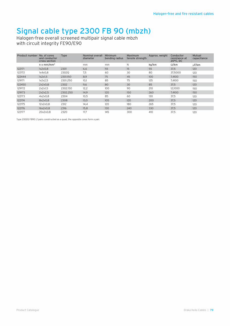
Halogen-free and fire resistant cables
79Draka Keila Cables |Product Catalogue
Signal cable type 2300 FB 90 (mbzh)Halogen-free overall screened multipair signal cable mbzhwith circuit integrity FE90/E90
Product number No. of cores and conductor cross section
Type Nominal overalldiameter
Minimum bending radius
Maximum tensile strength
Approx. weight Conductor resistance at 20°C, DC
Mutual capacitance
n x mm/mm2 mm mm N kg/km Ω/km µF/km
122171 1x2x0,8 2301 6,6 55 15 55 37,5 120122172 1x4x0,8 2302Q 7,5 60 30 80 37,5000 120
122444 1x2x1,5 2301.150 8,9 75 45 100 7,4100 150129171 1x2x2,5 2301.250 10,1 85 75 125 7,4100 150
122450 2x2x0,8 2302 9,6 80 30 85 37,5 120129172 2x2x1,5 2302.150 12,2 100 90 210 12,1000 150
129173 2x2x2,5 2302.250 14,9 120 150 260 7,4100 150122173 4x2x0,8 2304 10,5 85 60 130 37,5 120
122174 8x2x0,8 2308 13,0 105 120 200 37,5 120122175 12x2x0,8 2312 14,4 120 180 265 37,5 120
122176 16x2x0,8 2316 15,8 130 240 330 37,5 120122177 20x2x0,8 2320 17,7 145 300 410 37,5 120
Type 2302Q FB90: 2 pairs constructed as a quad, the opposite cores form a pair.
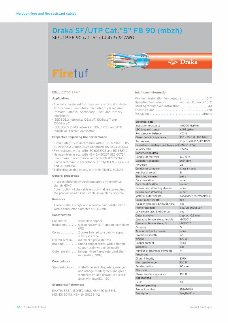
Halogen-free and fire resistant cables
80 | Draka Keila Cables Product Catalogue
Draka SF/UTP Cat."5" FB 90 (mbzh)SF/UTP FB 90 cat "5" rd# 4x2x22 AWG
DIN: J-02YSCH PiMF
Application
· Specially developed for those parts of circuit installa-tions where 90 minutes circuit integrity is required
· Primary (Campus), Secondary (Riser) and Tertiary (Horizontal)
· IEEE 802.3 networks: 10Base-T, 100Base-T and 1000Base-T
· IEEE 802.5 16 MB networks: ISDN, TPDDI and ATM· Industrial Ethernet application
Properties regarding fire performance
· Circuit integrity in accordance with NEN-EN 50200, BS 5839-1:2002 Clause 26.2e Enhanced, BS 8434-2:2003
· Fire resistant in acc. with IEC 60331-23 and BS 6387-C· Halogen-free in acc. with NEN-EN 50267 (IEC 60754)· Low smoke in accordance with NEN-EN-IEC 61034· Flame retardant in accordance with NEN-EN 50266-2-3
and UL 1581 VW1· Self-extinguishing in acc. with NEN-EN-IEC 60332-1
General properties
· In areas effected by electromagnetic interference signals (EMC)
· Construction of the cable is such that is approaches the properties of a Cat 5 cable as much as possible
Remarks
· There is also a single and a double pair construction with a conductor diameter of 0,63 mm
Construction
Conductor . . . . . . . solid plain copperInsulation . . . . . . . . silicon rubber (SiR) and polyethylene
(PE)Cores . . . . . . . . . . . 2 cores twisted to a pair, wrapped
with glass tapeOverall screen . . . . metallized polyester foilBraiding . . . . . . . . . tinned copper wires, with a tinned
copper drain wire underneathOuter sheath . . . . . halogen-free flame retardant ther-
moplastic (LSOH)
Core colours
Standard colours . . . white/blue and blue, white/orange and orange, white/green and green, white/brown and brown (in accord-ance with ISO/IEC 11801)
Standards/References
EIA/TIA 568A, ISO/IEC 11801, NEN-IEC 61156-6, NEN-EN 50173, NEN-EN 50288-4-2
Electrical data
Insulation resistance ≥ 5000 MΩ/km
LDC loop resistance ≤ 192 Ω/km
Resistance unbalance ≤ 2 %
Characteristic impedance 100 ± 15 Ω (1 - 100 MHz)
Return loss in acc. with ISO/IEC 11801
Capacitance unbalance (pair to ground) ≤ 1600 pF/km
Velocity ratio ± 57%
Construction data
Conductor material Cu, bare
Diameter conductor 0,64 mm
AWG-size 22
Conductor category Class 1 = solid
Number of cores 8
Stranding element pairs
Core insulation other
Core identification colour
Screen over stranding element none
Screen over stranding other
Material outer sheath copolymer, thermoplastic
Colour outer sheath red
Halogen-free (acc. EN 50267-2-2) yes
Flame retardant acc. EN 50266-2-4
Low smoke (acc. EN61034-2) yes
Outer diameter approx. 10.5 mm
Operating temperature, flexible -20/60˚C
Operating temperature, fix -20/60˚C
Category 5
Armouring/reinforcement none
Protective sheath no
Weight 125 kg
Copper content 41 kg
Elements x2x
Number of stranding elements 4
Properties
Circuit integrity E 90
Max. tensile force 100 N
Bending radius 85 mm
Electrical
Characteristic impedance 100 ΩApplications
Patch noProduct packing
Product number 128690NN
Description length of 1 m
Additional information
Minimum installation temperature . . . . . . . . . . . . . . . . 0˚COperating temperature . . . . . . . . min. -20˚C, max. +60˚CBending radius: fixed installation . . . . . . . . . . . . . . . . . . 4DSheath colour . . . . . . . . . . . . . . . . . . . . . . . . . . . . . . . . . . redPackaging . . . . . . . . . . . . . . . . . . . . . . . . . . . . . . . . . . .drums
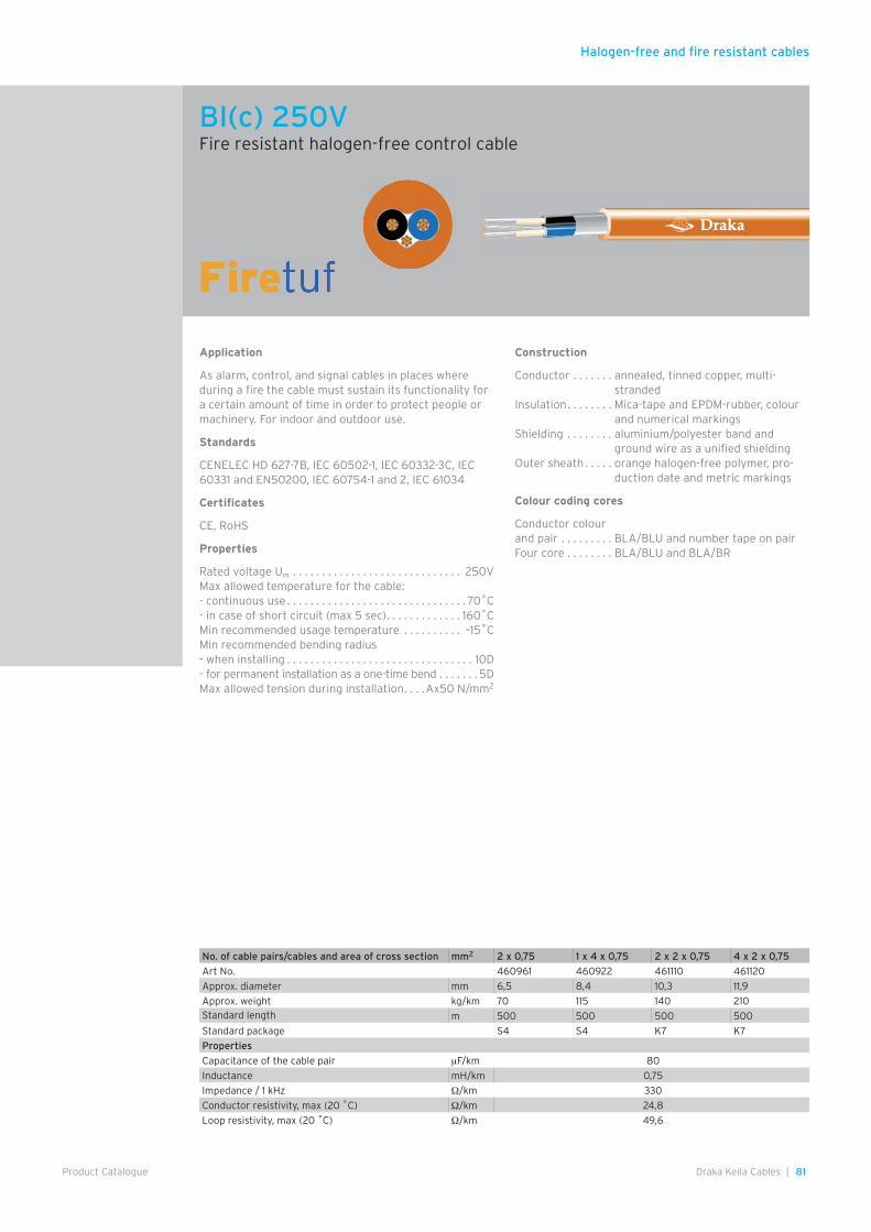
Halogen-free and fire resistant cables
81Draka Keila Cables |Product Catalogue
Application
As alarm, control, and signal cables in places where during a fire the cable must sustain its functionality for a certain amount of time in order to protect people or machinery. For indoor and outdoor use.
Standards
CENELEC HD 627-7B, IEC 60502-1, IEC 60332-3C, IEC 60331 and EN50200, IEC 60754-1 and 2, IEC 61034
Certificates
CE, RoHS
Properties
Rated voltage Um . . . . . . . . . . . . . . . . . . . . . . . . . . . . . 250VMax allowed temperature for the cable:- continuous use . . . . . . . . . . . . . . . . . . . . . . . . . . . . . . . 70˚C- in case of short circuit (max 5 sec) . . . . . . . . . . . . . 160˚CMin recommended usage temperature . . . . . . . . . . –15˚CMin recommended bending radius- when installing . . . . . . . . . . . . . . . . . . . . . . . . . . . . . . . . 10D- for permanent installation as a one-time bend . . . . . . . 5DMax allowed tension during installation . . . .Ax50 N/mm2
Construction
Conductor . . . . . . . annealed, tinned copper, multi-stranded
Insulation . . . . . . . . Mica-tape and EPDM-rubber, colour and numerical markings
Shielding . . . . . . . . aluminium/polyester band and ground wire as a unified shielding
Outer sheath . . . . . orange halogen-free polymer, pro-duction date and metric markings
Colour coding cores
Conductor colour and pair . . . . . . . . . BLA/BLU and number tape on pairFour core . . . . . . . . BLA/BLU and BLA/BR
No. of cable pairs/cables and area of cross section mm2 2 x 0,75 1 x 4 x 0,75 2 x 2 x 0,75 4 x 2 x 0,75
Art No. 460961 460922 461110 461120
Approx. diameter mm 6,5 8,4 10,3 11,9
Approx. weight kg/km 70 115 140 210Standard length m 500 500 500 500
Standard package S4 S4 K7 K7
Properties
Capacitance of the cable pair µF/km 80
Inductance mH/km 0,75
Impedance / 1 kHz Ω/km 330
Conductor resistivity, max (20 ˚C) Ω/km 24,8
Loop resistivity, max (20 ˚C) Ω/km 49,6
BI(c) 250VFire resistant halogen-free control cable
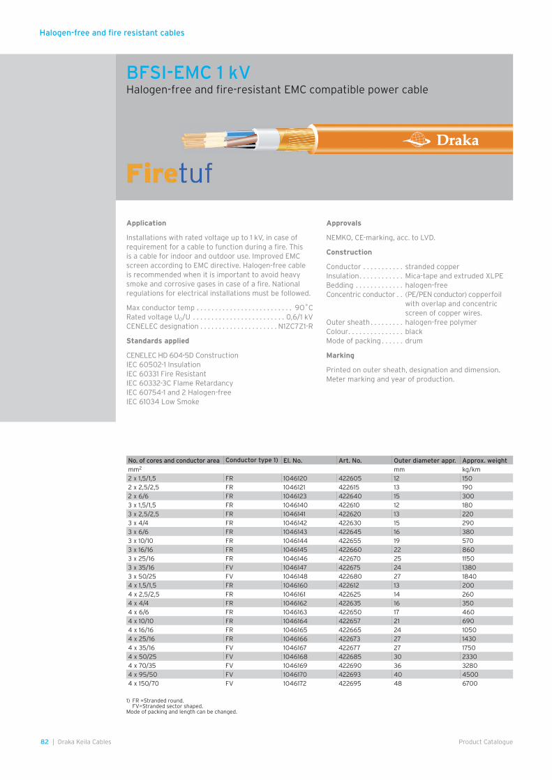
Halogen-free and fire resistant cables
82 | Draka Keila Cables Product Catalogue
1) FR =Stranded round. FV=Stranded sector shaped.Mode of packing and length can be changed.
BFSI-EMC 1 kVHalogen-free and fire-resistant EMC compatible power cable
Application
Installations with rated voltage up to 1 kV, in case of requirement for a cable to function during a fire. This is a cable for indoor and outdoor use. Improved EMC screen according to EMC directive. Halogen-free cable is recommended when it is important to avoid heavy smoke and corrosive gases in case of a fire. National regulations for electrical installations must be followed.
Max conductor temp . . . . . . . . . . . . . . . . . . . . . . . . . . 9O˚CRated voltage U0/U . . . . . . . . . . . . . . . . . . . . . . . . . 0,6/1 kVCENELEC designation . . . . . . . . . . . . . . . . . . . . . N1ZC7Z1-R
Standards applied
CENELEC HD 604-5D ConstructionIEC 60502-1 InsulationIEC 60331 Fire ResistantIEC 60332-3C Flame RetardancyIEC 60754-1 and 2 Halogen-freeIEC 61034 Low Smoke
Approvals
NEMKO, CE-marking, acc. to LVD.
Construction
Conductor . . . . . . . . . . . stranded copperInsulation . . . . . . . . . . . . Mica-tape and extruded XLPEBedding . . . . . . . . . . . . . halogen-freeConcentric conductor . . (PE/PEN conductor) copperfoil
with overlap and concentric screen of copper wires.
Outer sheath . . . . . . . . . halogen-free polymerColour . . . . . . . . . . . . . . . blackMode of packing . . . . . . drum
Marking
Printed on outer sheath, designation and dimension. Meter marking and year of production.
No. of cores and conductor area Conductor type 1) El. No. Art. No. Outer diameter appr. Approx. weightmm2 mm kg/km2 x 1,5/1,5 FR 1046120 422605 12 1502 x 2,5/2,5 FR 1046121 422615 13 1902 x 6/6 FR 1046123 422640 15 3003 x 1,5/1,5 FR 1046140 422610 12 1803 x 2,5/2,5 FR 1046141 422620 13 2203 x 4/4 FR 1046142 422630 15 2903 x 6/6 FR 1046143 422645 16 3803 x 10/10 FR 1046144 422655 19 5703 x 16/16 FR 1046145 422660 22 8603 x 25/16 FR 1046146 422670 25 11503 x 35/16 FV 1046147 422675 24 13803 x 50/25 FV 1046148 422680 27 18404 x 1,5/1,5 FR 1046160 422612 13 2004 x 2,5/2,5 FR 1046161 422625 14 2604 x 4/4 FR 1046162 422635 16 3504 x 6/6 FR 1046163 422650 17 4604 x 10/10 FR 1046164 422657 21 6904 x 16/16 FR 1046165 422665 24 10504 x 25/16 FR 1046166 422673 27 14304 x 35/16 FV 1046167 422677 27 17504 x 50/25 FV 1046168 422685 30 23304 x 70/35 FV 1046169 422690 36 32804 x 95/50 FV 1046170 422693 40 45004 x 150/70 FV 1046172 422695 48 6700
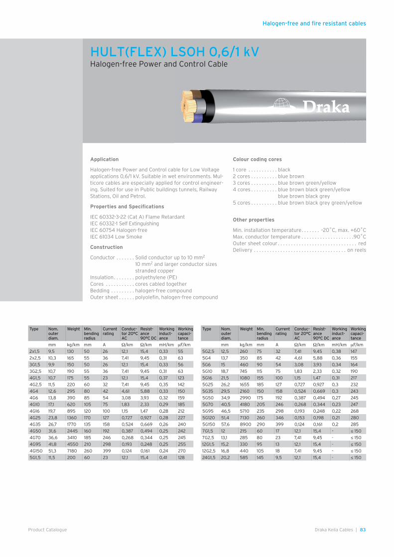
Halogen-free and fire resistant cables
83Draka Keila Cables |Product Catalogue
Application
Halogen-free Power and Control cable for Low Voltage applications 0,6/1 kV. Suitable in wet environments. Mul-ticore cables are especially applied for control engineer-ing. Suited for use in Public buildings tunnels, Railway Stations, Oil and Petrol.
Properties and Specifications
IEC 60332-3-22 (Cat A) Flame RetardantIEC 60332-1 Self ExtinguishingIEC 60754 Halogen-freeIEC 61034 Low Smoke
Construction
Conductor . . . . . . . Solid conductor up to 10 mm2
10 mm2 and larger conductor sizes stranded copper
Insulation . . . . . . . . polyethylene (PE)Cores . . . . . . . . . . . cores cabled togetherBedding . . . . . . . . . halogen-free compoundOuter sheet . . . . . . polyolefin, halogen-free compound
Colour coding cores
1 core . . . . . . . . . . . black2 cores . . . . . . . . . . blue brown3 cores . . . . . . . . . . blue brown green/yellow4 cores . . . . . . . . . . blue brown black green/yellow
blue brown black grey5 cores . . . . . . . . . . blue brown black grey green/yellow
Other properties
Min. installation temperature . . . . . . . –20˚C, max. +60˚CMax. conductor temperature . . . . . . . . . . . . . . . . . . . .90˚COuter sheet colour . . . . . . . . . . . . . . . . . . . . . . . . . . . . . . redDelivery . . . . . . . . . . . . . . . . . . . . . . . . . . . . . . . . . . . on reels
HULT(FLEX) LSOH 0,6/1 kVHalogen-free Power and Control Cable
Type Nom. outer diam.
Weight Min. bending radius
Current rating
Conduc-tor 20°C AC
Resist-ance 90°C DC
Working induct-ance
Working capaci-tance
mm kg/km mm A Ω/km Ω/km mH/km µF/km
2x1,5 9,5 130 50 26 12,1 15,4 0,33 55
2x2,5 10,3 165 55 36 7,41 9,45 0,31 63
3G1,5 9,9 150 50 26 12,1 15,4 0,33 56
3G2,5 10,7 190 55 36 7,41 9,45 0,31 63
4G1,5 10,7 175 55 23 12,1 15,4 0,37 123
4G2,5 11,5 220 60 32 7,41 9,45 0,35 142
4G4 12,6 295 80 42 4,61 5,88 0,33 150
4G6 13,8 390 85 54 3,08 3,93 0,32 159
4G10 17,1 620 105 75 1,83 2,33 0,29 185
4G16 19,7 895 120 100 1,15 1,47 0,28 212
4G25 23,8 1360 170 127 0,727 0,927 0,28 227
4G35 26,7 1770 135 158 0,524 0,669 0,26 240
4G50 31,6 2445 160 192 0,387 0,494 0,25 242
4G70 36,6 3410 185 246 0,268 0,344 0,25 245
4G95 41,8 4550 210 298 0,193 0,248 0,25 255
4G150 51,3 7180 260 399 0,124 0,161 0,24 270
5G1,5 11,5 200 60 23 12,1 15,4 0,41 128
Type Nom. outer diam.
Weight Min. bending radius
Current rating
Conduc-tor 20°C AC
Resist-ance 90°C DC
Working induct-ance
Working capaci-tance
mm kg/km mm A Ω/km Ω/km mH/km µF/km
5G2,5 12,5 260 75 32 7,41 9,45 0,38 147
5G4 13,7 350 85 42 4,61 5,88 0,36 155
5G6 15 460 90 54 3,08 3,93 0,34 164
5G10 18,7 745 115 75 1,83 2,33 0,32 190
5G16 21,5 1080 155 100 1,15 1,47 0,31 217
5G25 26,2 1655 185 127 0,727 0,927 0,3 232
5G35 29,5 2160 150 158 0,524 0,669 0,3 243
5G50 34,9 2990 175 192 0,387 0,494 0,27 245
5G70 40,5 4180 205 246 0,268 0,344 0,23 247
5G95 46,5 5710 235 298 0,193 0,248 0,22 268
5G120 51,4 7130 260 346 0,153 0,198 0,21 280
5G150 57,6 8900 290 399 0,124 0,161 0,2 285
7G1,5 12 215 60 17 12,1 15,4 - ≤ 150
7G2,5 13,1 285 80 23 7,41 9,45 - ≤ 150
12G1,5 15,2 330 95 13 12,1 15,4 - ≤ 150
12G2,5 16,8 440 105 18 7,41 9,45 - ≤ 150
24G1,5 20,2 585 145 9,5 12,1 15,4 - ≤ 150

Halogen-free and fire resistant cables
84 | Draka Keila Cables Product Catalogue
Application fields
Halogen-free, no emittance of corrosive gases, low smoke density in case of fire. Fixed installation, in pipes, ducts, in or under plaster, also suspended in catenary system. Indoors and outdoors, however not in ground or water. UV protected(1) for outdoor use in the Nordic countries.
Alternative Designation
SE-S05Z1Z1-U
Standard
SS 424 02 19-5 and EN 50265-2-1 (corrosive gases)EN 50268-2 (smoke density)
Fire propagation class
F3 acc. to SS 424 14 75 and IEC 60332-1 and SS-EN 50265-2-1
Temperature range
In continuous operation max. conductor temp . . . . . 70˚CLowest cable temperature under installation . . . . . –15˚Cand below 0˚C special precaution shall be taken
Approval
SEMKO, S-marked, C
Material declaration
EQQ-Light
PVC alternative
EKK-Light
Bending radius
8D (4D in final installation, bent only once)
Design
Conductor . . . . . . . solid and annealed copper acc. to IEC 60228 class 1
Insulation . . . . . . . . halogen-free compoundCore identification . 2-core: blue, brown
3-core: green/yellow, blue, brown 4-core: green/yellow, blue, brown, black 5-core: green/yellow, blue, brown, black, grey
Filler . . . . . . . . . . . . halogen-free compoundSheath . . . . . . . . . . halogen-free compound, white,
meter markedMarking . . . . . . . . . . . . e.g. DRAKA EQQ-LIGHT 3G1,5 300/500
V LSZH S
EQQ-Light 300/500 VHalogen-free installation cable
Number of cores x cross section of con-ductor
Overall diameter (approx.)
Weight (approx.) Standard delivery length
Standard drum size /Package
Article number
mm2 mm kg/100 m m
Without earth conductor
2 x 1,5 8,6 10,0 500 K6 0445065
With earth conductor
3G1,5 8,6 10,9 50 Coil 0445001
3G1,5 8,6 10,9 250 K4,5 0445003
3G1,5 8,6 10,9 500 K6 0445005
3G2,5 10,7 16,9 50 Coil 0445011
3G2,5 10,7 16,9 150 K4,5 0445013
3G2,5 10,7 16,9 500 K6 0445015
4G1,5 10,1 14,2 50 Coil 0445021
4G1,5 10,1 14,2 200 K4,5 0445023
4G1,5 10,1 14,2 500 K6 0445025
5G1,5 10,2 15,3 50 Coil 0445041
5G1,5 10,2 15,3 150 K4,5 0445043
5G1,5 10,2 15,3 500 K6 0445045
5G2,5 12,8 23,9 50 Coil 0445051
5G2,5 12,8 23,9 150 K4,5 0445053
5G2,5 12,8 23,9 500 K7 0445055
1) UV – ultraviolet radiationNominal values unless otherwise specified.
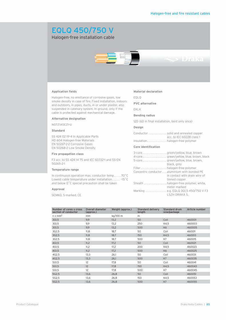
Halogen-free and fire resistant cables
85Draka Keila Cables |Product Catalogue
Application fields
Halogen-free, no emittance of corrosive gases, low smoke density in case of fire. Fixed installation, indoors and outdoors, in pipes, ducts, in or under plaster, also suspended in catenary system. In ground, only if the cable is protected against mechanical damage.
Alternative designation
N07Z1A5EZ1-U
Standard
SS 424 02 19-4 In Applicable PartsHD 604 Halogen-free MaterialsEN 50267-2-2 Corrosive GasesEN 50268-2 Low Smoke Density
Fire propagation class
F3 acc. to SS 424 14 75 and IEC 60332-1 and SS-EN 50265-2-1
Temperature range
In continuous operation max. conductor temp . . . . . 70˚CLowest cable temperature under installation . . . . . –15˚C and below 0˚C special precaution shall be taken
Approval
SEMKO, S-marked, CE
Material declaration
EQLQ
PVC alternative
EKLK
Bending radius
12D (6D in final installation, bent only once)
Design
Conductor . . . . . . . . . . . . solid and annealed copper acc. to IEC 60228 class 1
Insulation . . . . . . . . . . . . . halogen-free polymer
Core identification
3-core . . . . . . . . . . . . . . . . green/yellow, blue, brown4-core . . . . . . . . . . . . . . . . green/yellow, blue, brown, black5-core . . . . . . . . . . . . . . . . green/yellow, blue, brown,
black, greyFiller . . . . . . . . . . . . . . . . . halogen-free polymerConcentric conductor . . . aluminium with bonded PE
in contact with drain wire of tinned copper
Sheath . . . . . . . . . . . . . . . halogen-free polymer, white, meter marked
Marking . . . . . . . . . . . . . . e.g. EQLQ 3G1,5 450/750 V F3 LSZH DRAKA S.
EQLQ 450/750 VHalogen-free installation cable
Number of cores x cross section of conductor
Overall diameter (approx.)
Weight (approx.) Standard delivery length
Standard drum size/package
Article number
n x mm2 mm kg/100 m m
3G1,5 9,9 13,2 50 Coil 460001
3G1,5 9,9 13,2 250 K4,5 460003
3G1,5 9,9 13,2 500 K6 460005
3G2,5 11,8 18,7 50 Coil 460011
3G2,5 11,8 18,7 150 K4,5 460013
3G2,5 11,8 18,7 500 K7 460015
4G1,5 11,2 17,2 50 Coil 460021
4G1,5 11,2 17,2 200 K4,5 460023
4G1,5 11,2 17,2 500 K6 460025
4G2,5 13,3 26,1 50 Coil 460031
4G2,5 13,3 26,1 500 K7 460035
5G1,5 12 17,8 50 Coil 460041
5G1,5 12 17,8 150 K4,5 460043
5G1,5 12 17,8 500 K7 460045
5G2,5 13,6 26,8 50 Coil 460051
5G2,5 13,6 26,8 150 K4,5 460053
5G2,5 13,6 26,8 500 K7 460055
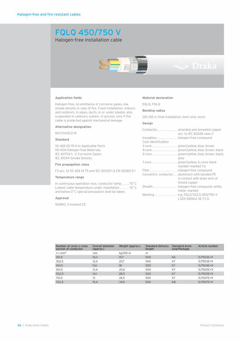
Halogen-free and fire resistant cables
86 | Draka Keila Cables Product Catalogue
Application fields
Halogen-free, no emittance of corrosive gases, low smoke density in case of fire. Fixed installation, indoors and outdoors, in pipes, ducts, in or under plaster, also suspended in catenary system. In ground, only if the cable is protected against mechanical damage.
Alternative designation
N07Z1A5EZ1-R
Standard
SS 424 02 19-4 In Applicable PartsHD 604 Halogen-free MaterialsIEC 60754-1, –2 Corrosive GasesIEC 61034 Smoke Density
Fire propagation class
F3 acc. to SS 424 14 75 and IEC 60332-1 & EN 50265-2-1
Temperature range
In continuous operation max. conductor temp . . . . . 70˚CLowest cable temperature under installation . . . . . –15˚C and below 0˚C special precaution shall be taken.
Approval
SEMKO, S-marked CE
Material declaration
EQLQ, FQLQ
Bending radius
12D (6D in final installation, bent only once)
Design
Conductor . . . . . . . . . . . . . stranded and annealed copper acc. to IEC 60228 class 2
Insulation . . . . . . . . . . . . . . halogen-free compoundCore identification3-core . . . . . . . . . . . . . . . . . green/yellow, blue, brown4-core . . . . . . . . . . . . . . . . . green/yellow, blue, brown, black5-core . . . . . . . . . . . . . . . . . green/yellow, blue, brown, black,
grey7-core . . . . . . . . . . . . . . . . . green/yellow, 6 cores black
number-marked 1-6Filler . . . . . . . . . . . . . . . . . . halogen-free compoundConcentric conductor . . . aluminium with bonded PE
in contact with drain wire of tinned copper
Sheath . . . . . . . . . . . . . . . . halogen-free compound, white, meter marked
Marking . . . . . . . . . . . . . . . e.g. FQLQ 5G2,5 450/750 V LSZH DRAKA SE F3 S.
FQLQ 450/750 VHalogen-free installation cable
Number of cores x cross section of conductor
Overall diameter (approx.)
Weight (approx.) Standard delivery length
Standard drum size/Package
Article number
n x mm2 mm kg/100 m m
3G1,5 10,3 15,7 500 K6 5,17503E+11
3G2,5 12,4 20,7 500 K7 5,17503E+11
4G1,5 11,6 18 500 K7 5,17504E+11
5G1,5 12,4 20,6 500 K7 5,17505E+11
5G2,5 14,1 28,5 500 K7 5,17505E+11
7G1,5 13 24,5 500 K7 5,17507E+11
7G2,5 15,4 34,9 500 K8 5,17507E+11
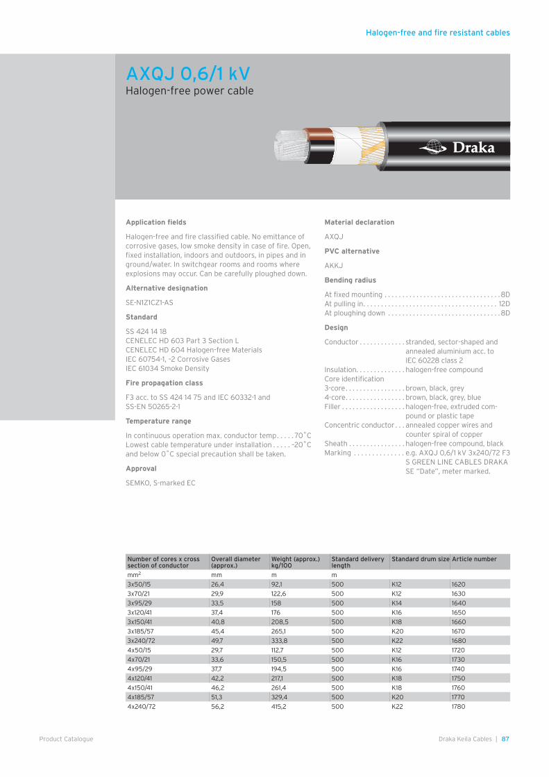
Halogen-free and fire resistant cables
87Draka Keila Cables |Product Catalogue
Application fields
Halogen-free and fire classified cable. No emittance of corrosive gases, low smoke density in case of fire. Open, fixed installation, indoors and outdoors, in pipes and in ground/water. In switchgear rooms and rooms where explosions may occur. Can be carefully ploughed down.
Alternative designation
SE-N1Z1CZ1-AS
Standard
SS 424 14 18CENELEC HD 603 Part 3 Section LCENELEC HD 604 Halogen-free MaterialsIEC 60754-1, –2 Corrosive GasesIEC 61034 Smoke Density
Fire propagation class
F3 acc. to SS 424 14 75 and IEC 60332-1 and SS-EN 50265-2-1
Temperature range
In continuous operation max. conductor temp . . . . . 70˚CLowest cable temperature under installation . . . . . –20˚C and below 0˚C special precaution shall be taken.
Approval
SEMKO, S-marked EC
Material declaration
AXQJ
PVC alternative
AKKJ
Bending radius
At fixed mounting . . . . . . . . . . . . . . . . . . . . . . . . . . . . . . . . .8DAt pulling in . . . . . . . . . . . . . . . . . . . . . . . . . . . . . . . . . . . . . . 12DAt ploughing down . . . . . . . . . . . . . . . . . . . . . . . . . . . . . . . .8D
Design
Conductor . . . . . . . . . . . . . stranded, sector-shaped and annealed aluminium acc. to IEC 60228 class 2
Insulation . . . . . . . . . . . . . . halogen-free compoundCore identification3-core . . . . . . . . . . . . . . . . . brown, black, grey4-core . . . . . . . . . . . . . . . . . brown, black, grey, blueFiller . . . . . . . . . . . . . . . . . . halogen-free, extruded com-
pound or plastic tapeConcentric conductor . . . annealed copper wires and
counter spiral of copperSheath . . . . . . . . . . . . . . . . halogen-free compound, blackMarking . . . . . . . . . . . . . . e.g. AXQJ 0,6/1 kV 3x240/72 F3
S GREEN LINE CABLES DRAKA SE “Date”, meter marked.
AXQJ 0,6/1 kVHalogen-free power cable
Number of cores x cross section of conductor
Overall diameter (approx.)
Weight (approx.) kg/100
Standard delivery length
Standard drum size Article number
mm2 mm m m
3x50/15 26,4 92,1 500 K12 1620
3x70/21 29,9 122,6 500 K12 1630
3x95/29 33,5 158 500 K14 1640
3x120/41 37,4 176 500 K16 1650
3x150/41 40,8 208,5 500 K18 1660
3x185/57 45,4 265,1 500 K20 1670
3x240/72 49,7 333,8 500 K22 1680
4x50/15 29,7 112,7 500 K12 1720
4x70/21 33,6 150,5 500 K16 1730
4x95/29 37,7 194,5 500 K16 1740
4x120/41 42,2 217,1 500 K18 1750
4x150/41 46,2 261,4 500 K18 1760
4x185/57 51,3 329,4 500 K20 1770
4x240/72 56,2 415,2 500 K22 1780
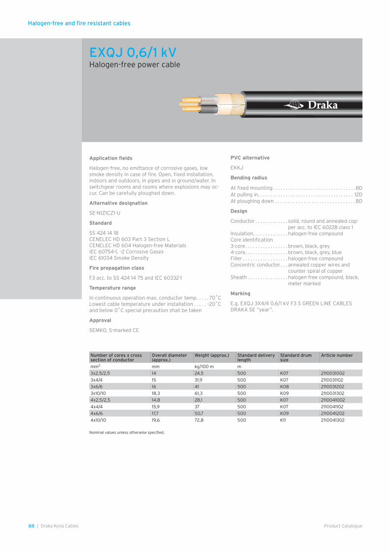
Halogen-free and fire resistant cables
88 | Draka Keila Cables Product Catalogue
Application fields
Halogen-free, no emittance of corrosive gases, low smoke density in case of fire. Open, fixed installation, indoors and outdoors, in pipes and in ground/water. In switchgear rooms and rooms where explosions may oc-cur. Can be carefully ploughed down.
Alternative designation
SE-N1Z1CZ1-U
Standard
SS 424 14 18CENELEC HD 603 Part 3 Section LCENELEC HD 604 Halogen-free MaterialsIEC 60754-1, –2 Corrosive GasesIEC 61034 Smoke Density
Fire propagation class
F3 acc. to SS 424 14 75 and IEC 60332-1
Temperature range
In continuous operation max. conductor temp . . . . . 70˚CLowest cable temperature under installation . . . . . –20˚C and below 0˚C special precaution shall be taken
Approval
SEMKO, S-marked CE
PVC alternative
EKKJ
Bending radius
At fixed mounting . . . . . . . . . . . . . . . . . . . . . . . . . . . . . . . . .8DAt pulling in . . . . . . . . . . . . . . . . . . . . . . . . . . . . . . . . . . . . . . 12DAt ploughing down . . . . . . . . . . . . . . . . . . . . . . . . . . . . . . .8D
Design
Conductor . . . . . . . . . . . . . solid, round and annealed cop-per acc. to IEC 60228 class 1
Insulation . . . . . . . . . . . . . . halogen-free compoundCore identification3-core . . . . . . . . . . . . . . . . . brown, black, grey4-core . . . . . . . . . . . . . . . . . brown, black, grey, blueFiller . . . . . . . . . . . . . . . . . . halogen-free compoundConcentric conductor . . . annealed copper wires and
counter spiral of copperSheath . . . . . . . . . . . . . . . . halogen-free compound, black,
meter marked
Marking
E.g. EXQJ 3X4/4 0,6/1 kV F3 S GREEN LINE CABLES DRAKA SE “year”.
Nominal values unless otherwise specified.
EXQJ 0,6/1 kVHalogen-free power cable
Number of cores x cross section of conductor
Overall diameter (approx.)
Weight (approx.) Standard delivery length
Standard drum size
Article number
mm2 mm kg/100 m m
3x2,5/2,5 14 24,5 500 K07 2110031002
3x4/4 15 31,9 500 K07 2110031102
3x6/6 16 41 500 K08 2110031202
3x10/10 18,3 61,3 500 K09 2110031302
4x2,5/2,5 14,8 28,1 500 K07 2110041002
4x4/4 15,9 37 500 K07 2110041102
4x6/6 17,7 50,7 500 K09 2110041202
4x10/10 19,6 72,8 500 K11 2110041302
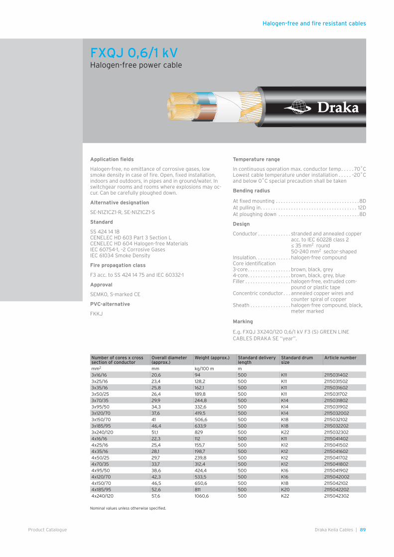
Halogen-free and fire resistant cables
89Draka Keila Cables |Product Catalogue
Nominal values unless otherwise specified.
Application fields
Halogen-free, no emittance of corrosive gases, low smoke density in case of fire. Open, fixed installation, indoors and outdoors, in pipes and in ground/water. In switchgear rooms and rooms where explosions may oc-cur. Can be carefully ploughed down.
Alternative designation
SE-N1Z1CZ1-R, SE-N1Z1CZ1-S
Standard
SS 424 14 18CENELEC HD 603 Part 3 Section LCENELEC HD 604 Halogen-free MaterialsIEC 60754-1, –2 Corrosive GasesIEC 61034 Smoke Density
Fire propagation class
F3 acc. to SS 424 14 75 and IEC 60332-1
Approval
SEMKO, S-marked CE
PVC-alternative
FKKJ
Temperature range
In continuous operation max. conductor temp . . . . . 70˚CLowest cable temperature under installation . . . . . –20˚C and below 0˚C special precaution shall be taken
Bending radius
At fixed mounting . . . . . . . . . . . . . . . . . . . . . . . . . . . . . . . . .8DAt pulling in . . . . . . . . . . . . . . . . . . . . . . . . . . . . . . . . . . . . . . 12DAt ploughing down . . . . . . . . . . . . . . . . . . . . . . . . . . . . . . . .8D
Design
Conductor . . . . . . . . . . . . . stranded and annealed copper acc. to IEC 60228 class 2 ≤ 35 mm2 round 50–240 mm2 sector-shaped
Insulation . . . . . . . . . . . . . . halogen-free compoundCore identification3-core . . . . . . . . . . . . . . . . . brown, black, grey4-core . . . . . . . . . . . . . . . . . brown, black, grey, blueFiller . . . . . . . . . . . . . . . . . . halogen-free, extruded com-
pound or plastic tapeConcentric conductor . . . annealed copper wires and
counter spiral of copperSheath . . . . . . . . . . . . . . . . halogen-free compound, black,
meter marked
Marking
E.g. FXQJ 3X240/120 0,6/1 kV F3 (S) GREEN LINE CABLES DRAKA SE “year”.
FXQJ 0,6/1 kVHalogen-free power cable
Number of cores x cross section of conductor
Overall diameter (approx.)
Weight (approx.) Standard delivery length
Standard drum size
Article number
mm2 mm kg/100 m m3x16/16 20,6 94 500 K11 21150314023x25/16 23,4 128,2 500 K11 21150315023x35/16 25,8 162,1 500 K11 21150316023x50/25 26,4 189,8 500 K11 21150317023x70/35 29,9 244,8 500 K14 21150318023x95/50 34,3 332,6 500 K14 21150319023x120/70 37,6 419,5 500 K14 21150320023x150/70 41 506,6 500 K18 21150321023x185/95 46,4 633,9 500 K18 21150322023x240/120 51,1 829 500 K22 21150323024x16/16 22,3 112 500 K11 21150414024x25/16 25,4 155,7 500 K12 21150415024x35/16 28,1 198,7 500 K12 21150416024x50/25 29,7 239,8 500 K12 21150417024x70/35 33,7 312,4 500 K12 21150418024x95/50 38,6 424,4 500 K16 21150419024x120/70 42,3 533,5 500 K16 21150420024x150/70 46,5 650,6 500 K18 21150421024x185/95 52,6 811 500 K20 21150422024x240/120 57,6 1060,6 500 K22 2115042302
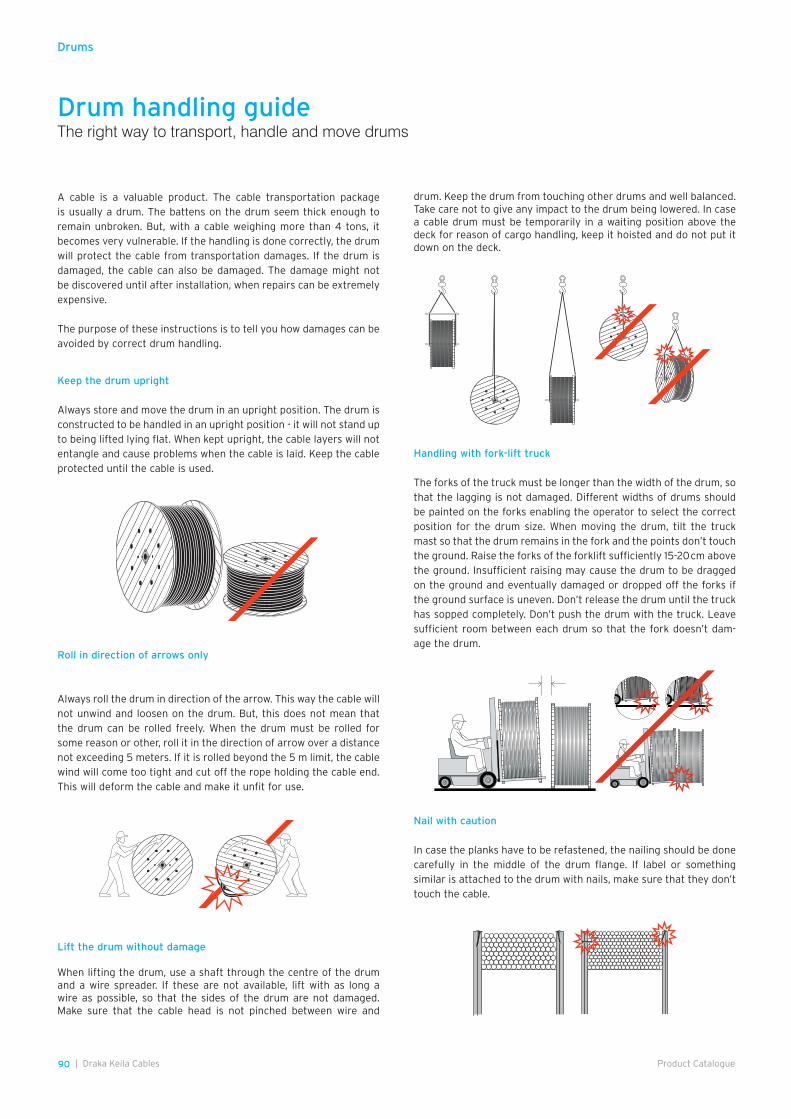
90 | Draka Keila Cables Product Catalogue
Drum handling guideThe right way to transport, handle and move drums
A cable is a valuable product. The cable transportation package is usually a drum. The battens on the drum seem thick enough to remain unbroken. But, with a cable weighing more than 4 tons, it becomes very vulnerable. If the handling is done correctly, the drum will protect the cable from transportation damages. If the drum is damaged, the cable can also be damaged. The damage might not be discovered until after installation, when repairs can be extremely expensive.
The purpose of these instructions is to tell you how damages can be avoided by correct drum handling.
Roll in direction of arrows only
Always roll the drum in direction of the arrow. This way the cable will not unwind and loosen on the drum. But, this does not mean that the drum can be rolled freely. When the drum must be rolled for some reason or other, roll it in the direction of arrow over a distance not exceeding 5 meters. If it is rolled beyond the 5 m limit, the cable wind will come too tight and cut off the rope holding the cable end. This will deform the cable and make it unfit for use.
drum. Keep the drum from touching other drums and well balanced. Take care not to give any impact to the drum being lowered. In case a cable drum must be temporarily in a waiting position above the deck for reason of cargo handling, keep it hoisted and do not put it down on the deck.
Keep the drum upright
Always store and move the drum in an upright position. The drum is constructed to be handled in an upright position - it will not stand up to being lifted lying flat. When kept upright, the cable layers will not entangle and cause problems when the cable is laid. Keep the cable protected until the cable is used.
Handling with fork-lift truck
The forks of the truck must be longer than the width of the drum, so that the lagging is not damaged. Different widths of drums should be painted on the forks enabling the operator to select the correct position for the drum size. When moving the drum, tilt the truck mast so that the drum remains in the fork and the points don’t touch the ground. Raise the forks of the forklift sufficiently 15-20 cm above the ground. Insufficient raising may cause the drum to be dragged on the ground and eventually damaged or dropped off the forks if the ground surface is uneven. Don’t release the drum until the truck has sopped completely. Don’t push the drum with the truck. Leave sufficient room between each drum so that the fork doesn’t dam-age the drum.
Nail with caution
In case the planks have to be refastened, the nailing should be done carefully in the middle of the drum flange. If label or something similar is attached to the drum with nails, make sure that they don’t touch the cable.
Lift the drum without damage
When lifting the drum, use a shaft through the centre of the drum and a wire spreader. If these are not available, lift with as long a wire as possible, so that the sides of the drum are not damaged. Make sure that the cable head is not pinched between wire and
Drums
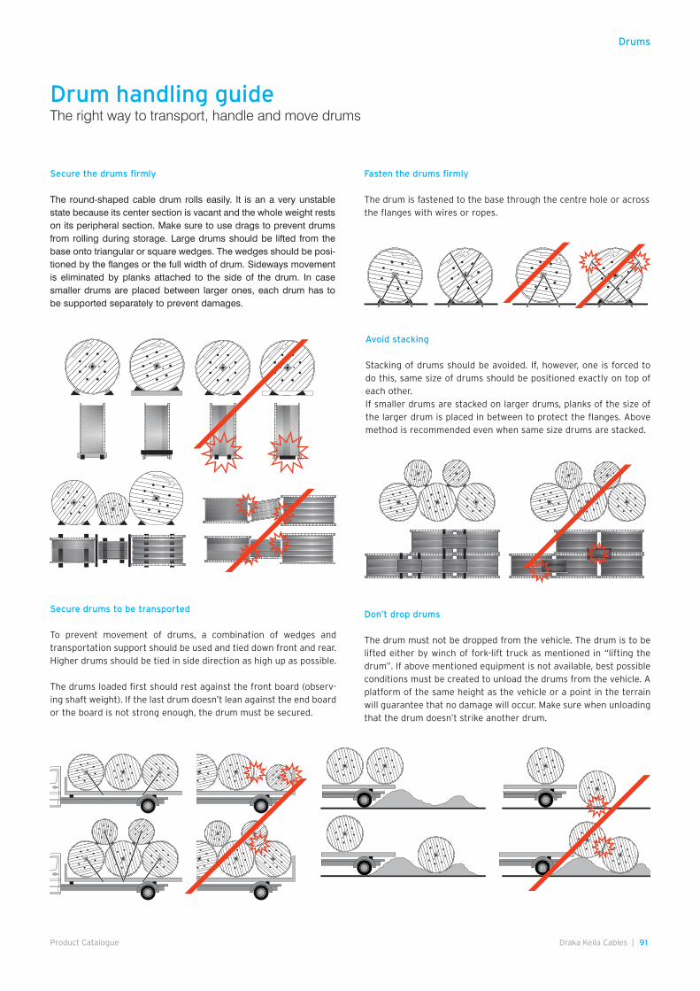
91Draka Keila Cables |Product Catalogue
Secure the drums firmly
The round-shaped cable drum rolls easily. It is an a very unstable state because its center section is vacant and the whole weight rests on its peripheral section. Make sure to use drags to prevent drums from rolling during storage. Large drums should be lifted from the base onto triangular or square wedges. The wedges should be posi-tioned by the flanges or the full width of drum. Sideways movement is eliminated by planks attached to the side of the drum. In case smaller drums are placed between larger ones, each drum has to be supported separately to prevent damages.
Avoid stacking
Stacking of drums should be avoided. If, however, one is forced to do this, same size of drums should be positioned exactly on top of each other.If smaller drums are stacked on larger drums, planks of the size of the larger drum is placed in between to protect the flanges. Above method is recommended even when same size drums are stacked.
Fasten the drums firmly
The drum is fastened to the base through the centre hole or across the flanges with wires or ropes.
Secure drums to be transported
To prevent movement of drums, a combination of wedges and transportation support should be used and tied down front and rear. Higher drums should be tied in side direction as high up as possible.
The drums loaded first should rest against the front board (observ-ing shaft weight). If the last drum doesn’t lean against the end board or the board is not strong enough, the drum must be secured.
Don’t drop drums
The drum must not be dropped from the vehicle. The drum is to be lifted either by winch of fork-lift truck as mentioned in “lifting the drum”. If above mentioned equipment is not available, best possible conditions must be created to unload the drums from the vehicle. A platform of the same height as the vehicle or a point in the terrain will guarantee that no damage will occur. Make sure when unloading that the drum doesn’t strike another drum.
Drum handling guideThe right way to transport, handle and move drums
Drums
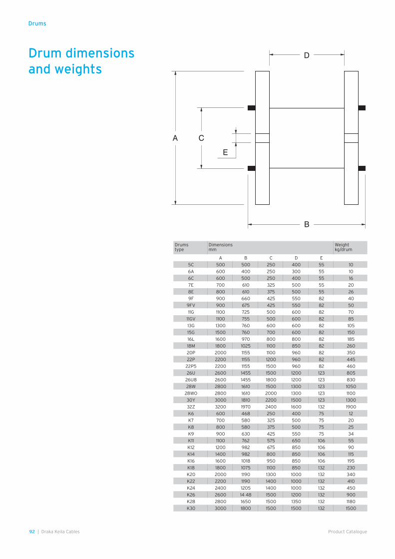
92 | Draka Keila Cables Product Catalogue
Drum dimensions and weights
D
B
E
CA
Drums
Drums type
Dimensions mm
Weight kg/drum
A B C D E
5C 500 500 250 400 55 10
6A 600 400 250 300 55 10
6C 600 500 250 400 55 16
7E 700 610 325 500 55 20
8E 800 610 375 500 55 26
9F 900 660 425 550 82 40
9FV 900 675 425 550 82 50
11G 1100 725 500 600 82 70
11GV 1100 755 500 600 82 85
13G 1300 760 600 600 82 105
15G 1500 760 700 600 82 150
16L 1600 970 800 800 82 185
18M 1800 1025 1100 850 82 260
20P 2000 1155 1100 960 82 350
22P 2200 1155 1200 960 82 445
22P5 2200 1155 1500 960 82 460
26U 2600 1455 1500 1200 123 805
26U8 2600 1455 1800 1200 123 830
28W 2800 1610 1500 1300 123 1050
28WO 2800 1610 2000 1300 123 1100
30Y 3000 1810 2200 1500 123 1300
32Z 3200 1970 2400 1600 132 1900
K6 600 468 250 400 75 12
K7 700 580 325 500 75 20
K8 800 580 375 500 75 25
K9 900 630 425 550 75 34
K11 1100 762 575 650 106 55
K12 1200 982 675 850 106 90
K14 1400 982 800 850 106 115
K16 1600 1018 950 850 106 195
K18 1800 1075 1100 850 132 230
K20 2000 1190 1300 1000 132 340
K22 2200 1190 1400 1000 132 410
K24 2400 1205 1400 1000 132 450
K26 2600 14 48 1500 1200 132 900
K28 2800 1650 1500 1350 132 1180
K30 3000 1800 1500 1500 132 1500
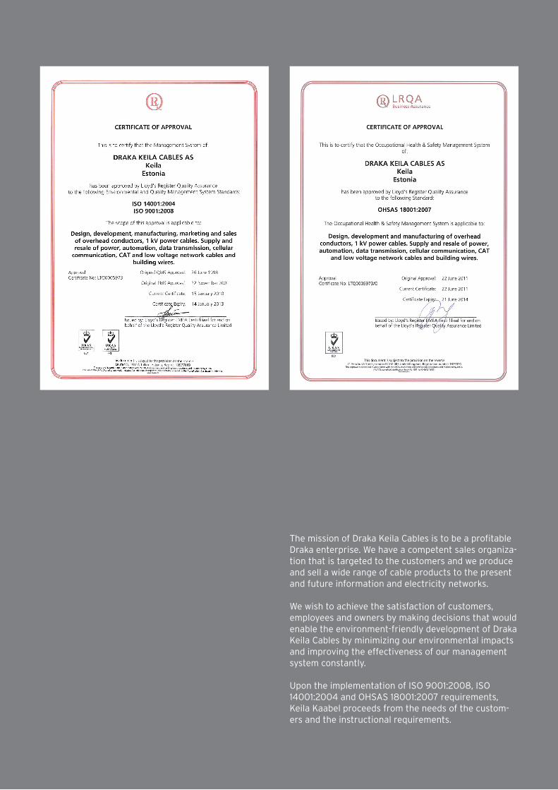
The mission of Draka Keila Cables is to be a profitable Draka enterprise. We have a competent sales organiza-tion that is targeted to the customers and we produce and sell a wide range of cable products to the present and future information and electricity networks.
We wish to achieve the satisfaction of customers, employees and owners by making decisions that would enable the environment-friendly development of Draka Keila Cables by minimizing our environmental impacts and improving the effectiveness of our management system constantly.
Upon the implementation of ISO 9001:2008, ISO 14001:2004 and OHSAS 18001:2007 requirements, Keila Kaabel proceeds from the needs of the custom-ers and the instructional requirements.

AS Draka Keila CablesPaldiski Road 3176606 KeilaEstonia
Phone +372 674 7466Fax +372 674 7468
www.draka.ee
Member of Prysmian Groupwww.prysmian.com
All information concerning material properties, fire performance, construction, electrical and technical data, prices etc. reflects our current level of knowledge and is provided without obligation. Dimensions and weights are only given as a guide. The technical specifications may change any time without prior notice.


