Embed Size (px)
Citation preview

Product catalogue2022 | 2023

2
MAGNUM Heating B.V.Stevinweg 84691SM Tholen
T +31(0)166 - 609 300E [email protected] magnumheating.com
KvK 22043037BTW NL8074.91.950.B01IBAN NL37INGB0655775129BIC/SWIFT INGBNL2A
In 3 decades MAGNUM Heating has grown into a successful, market-leading and brand-oriented European designer, manufacturer and supplier of innovative electrical and water-based heating systems and related products.
DurableOur systems have a very long life span and respond perfectly to the fundamental energy transition from fossil heating sources to sustainable climate solutions.
In-house productionWe manufacture and assemble most products ourselves in our own production departments. This way, we control the process from beginning to end and ensure optimum quality control. This makes us the most reliable supplier of heating products.
MAGNUM Heating B.V. is part of the MAGNUM Heating Group B.V.
About us
3
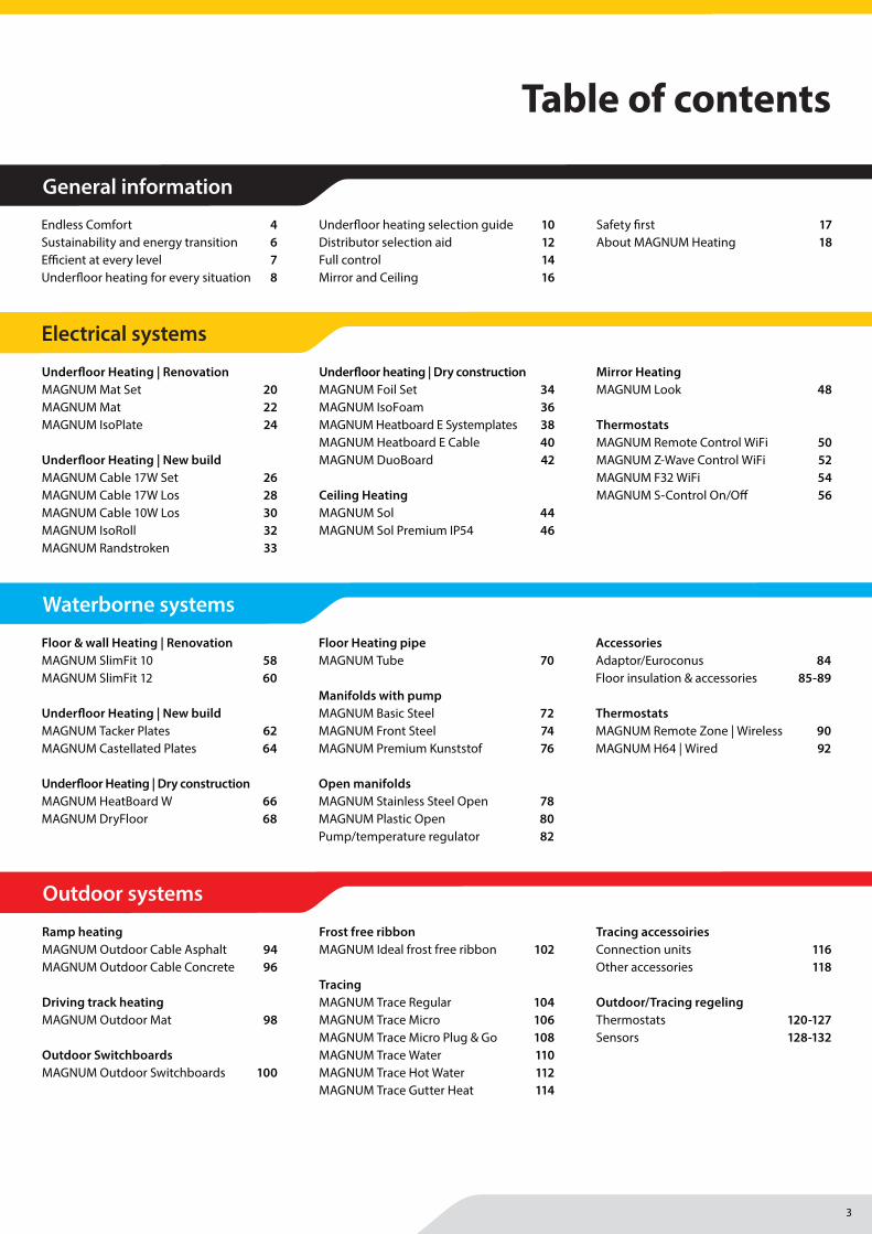
Table of contents
General information
Endless Comfort 4Sustainability and energy transition 6Efficient at every level 7Underfloor heating for every situation 8
Underfloor heating selection guide 10Distributor selection aid 12Full control 14Mirror and Ceiling 16
Safety first 17About MAGNUM Heating 18
Underfloor Heating | RenovationMAGNUM Mat Set 20MAGNUM Mat 22MAGNUM IsoPlate 24
Underfloor Heating | New buildMAGNUM Cable 17W Set 26MAGNUM Cable 17W Los 28MAGNUM Cable 10W Los 30MAGNUM IsoRoll 32MAGNUM Randstroken 33
Underfloor heating | Dry constructionMAGNUM Foil Set 34MAGNUM IsoFoam 36MAGNUM Heatboard E Systemplates 38MAGNUM Heatboard E Cable 40MAGNUM DuoBoard 42
Ceiling Heating MAGNUM Sol 44MAGNUM Sol Premium IP54 46
Mirror HeatingMAGNUM Look 48
ThermostatsMAGNUM Remote Control WiFi 50MAGNUM Z-Wave Control WiFi 52MAGNUM F32 WiFi 54MAGNUM S-Control On/Off 56
Floor & wall Heating | RenovationMAGNUM SlimFit 10 58MAGNUM SlimFit 12 60
Underfloor Heating | New buildMAGNUM Tacker Plates 62MAGNUM Castellated Plates 64
Underfloor Heating | Dry constructionMAGNUM HeatBoard W 66MAGNUM DryFloor 68
Floor Heating pipeMAGNUM Tube 70
Manifolds with pumpMAGNUM Basic Steel 72MAGNUM Front Steel 74MAGNUM Premium Kunststof 76
Open manifoldsMAGNUM Stainless Steel Open 78MAGNUM Plastic Open 80Pump/temperature regulator 82
AccessoriesAdaptor/Euroconus 84Floor insulation & accessories 85-89
ThermostatsMAGNUM Remote Zone | Wireless 90MAGNUM H64 | Wired 92
Ramp heatingMAGNUM Outdoor Cable Asphalt 94MAGNUM Outdoor Cable Concrete 96
Driving track heatingMAGNUM Outdoor Mat 98
Outdoor SwitchboardsMAGNUM Outdoor Switchboards 100
Frost free ribbonMAGNUM Ideal frost free ribbon 102
TracingMAGNUM Trace Regular 104MAGNUM Trace Micro 106MAGNUM Trace Micro Plug & Go 108MAGNUM Trace Water 110MAGNUM Trace Hot Water 112MAGNUM Trace Gutter Heat 114
Tracing accessoiriesConnection units 116Other accessories 118
Outdoor/Tracing regelingThermostats 120-127 Sensors 128-132
Electrical systems
Waterborne systems
Outdoor systems

4
5
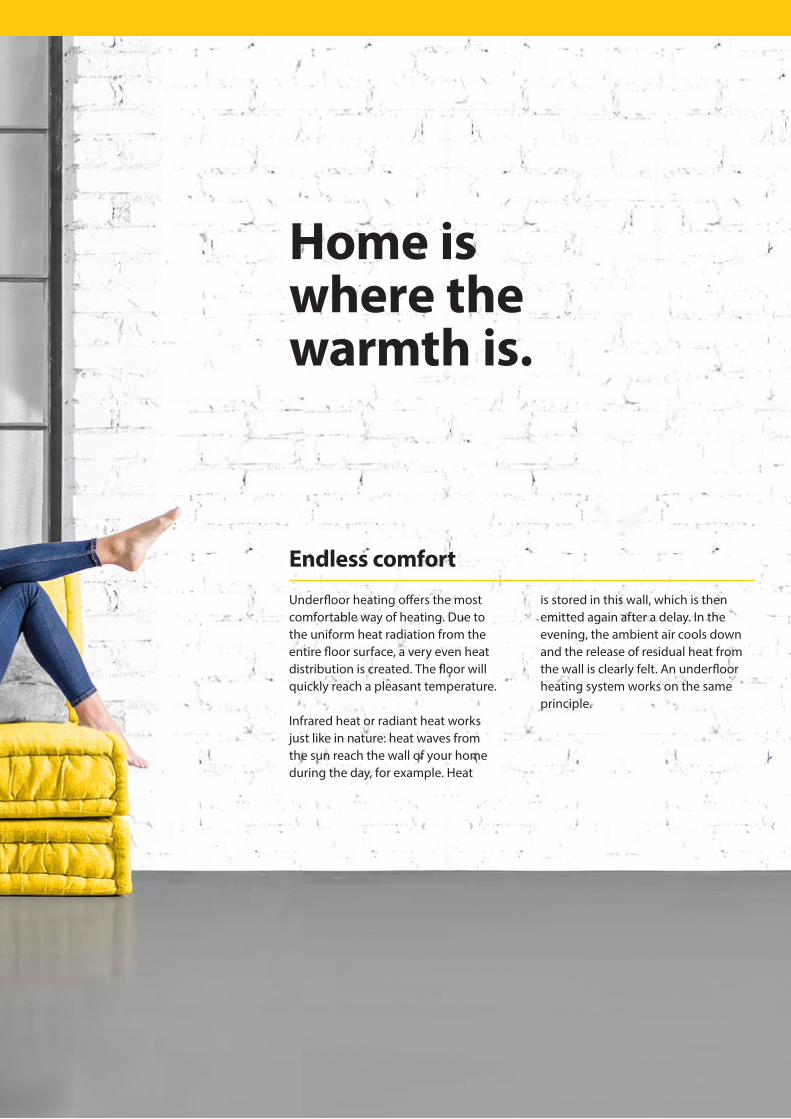
Home iswhere the warmth is.
Underfloor heating offers the most comfortable way of heating. Due to the uniform heat radiation from the entire floor surface, a very even heat distribution is created. The floor will quickly reach a pleasant temperature.
Infrared heat or radiant heat works just like in nature: heat waves from the sun reach the wall of your home during the day, for example. Heat
is stored in this wall, which is then emitted again after a delay. In the evening, the ambient air cools down and the release of residual heat from the wall is clearly felt. An underfloor heating system works on the same principle.
Endless comfort
6
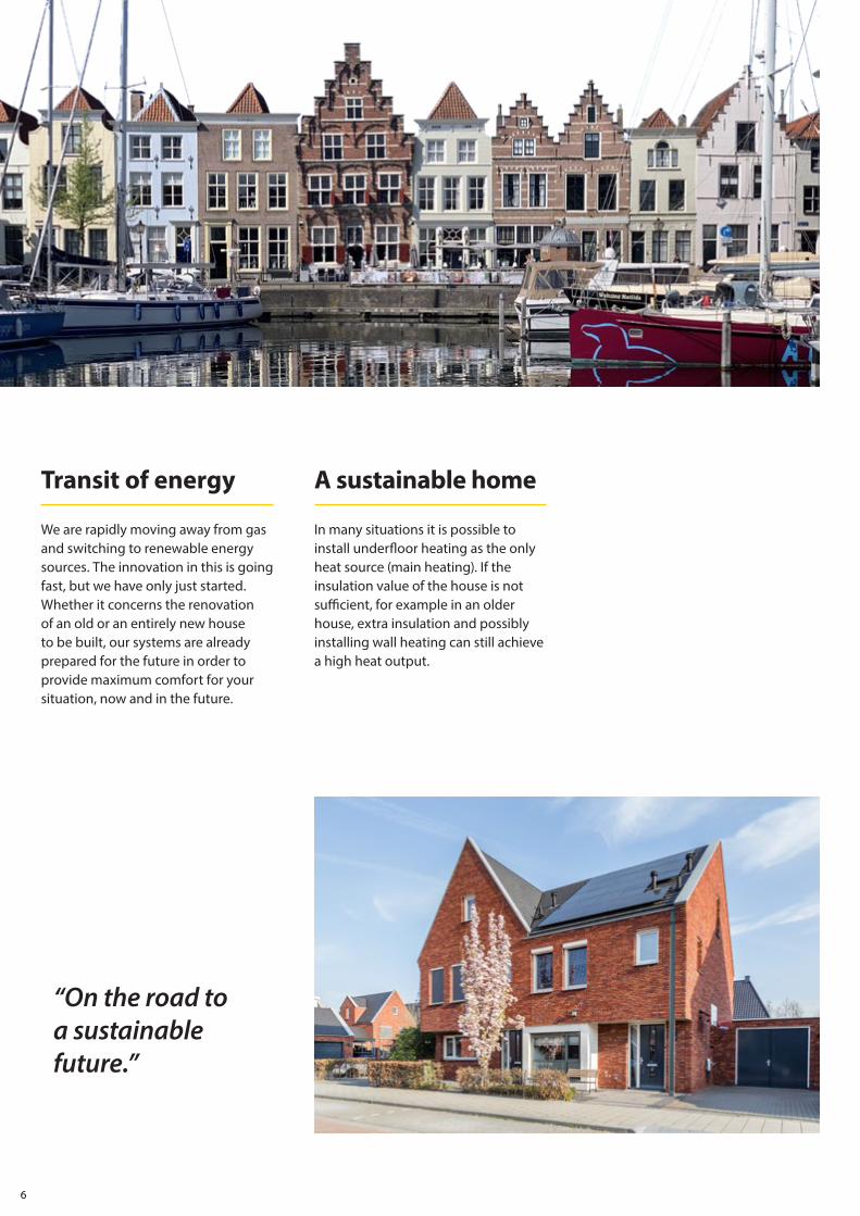
“On the road to a sustainable future.”
We are rapidly moving away from gas and switching to renewable energy sources. The innovation in this is going fast, but we have only just started. Whether it concerns the renovation of an old or an entirely new house to be built, our systems are already prepared for the future in order to provide maximum comfort for your situation, now and in the future.
In many situations it is possible to install underfloor heating as the only heat source (main heating). If the insulation value of the house is not sufficient, for example in an older house, extra insulation and possibly installing wall heating can still achieve a high heat output.
Transit of energy A sustainable home

7
With radiant heat (underfloor heating), the heat is emitted directly so that the room is heated more evenly and more quickly felt. Traditional convection heating only heats the air. Warm air has the property that it rises so that the temperature at the ceiling is significantly higher than close to the floor. Consequence: cold feet and a warm head.
Underfloor heating offers enormous comfort at a lower temperature. By setting the lowering temperature of the system not lower than 5OC, the heat remains in the floor mass. It takes less energy to bring the system back up to temperature than to let the floor cool down further each time. Not only the temperature is lower, but also your energy bill!
A well-functioning system strongly depends on the insulation value of your house. By first applying a good insulation you limit the heat loss downwards. The floor will retain the heat longer as a result. After all, underfloor heating works more efficiently with a well insulated subfloor.
The difference Lower temperature Insulation is the key
Efficiencyand comfortat every level.

8
“Good insulationis the key to an efficiently functioning
system.”
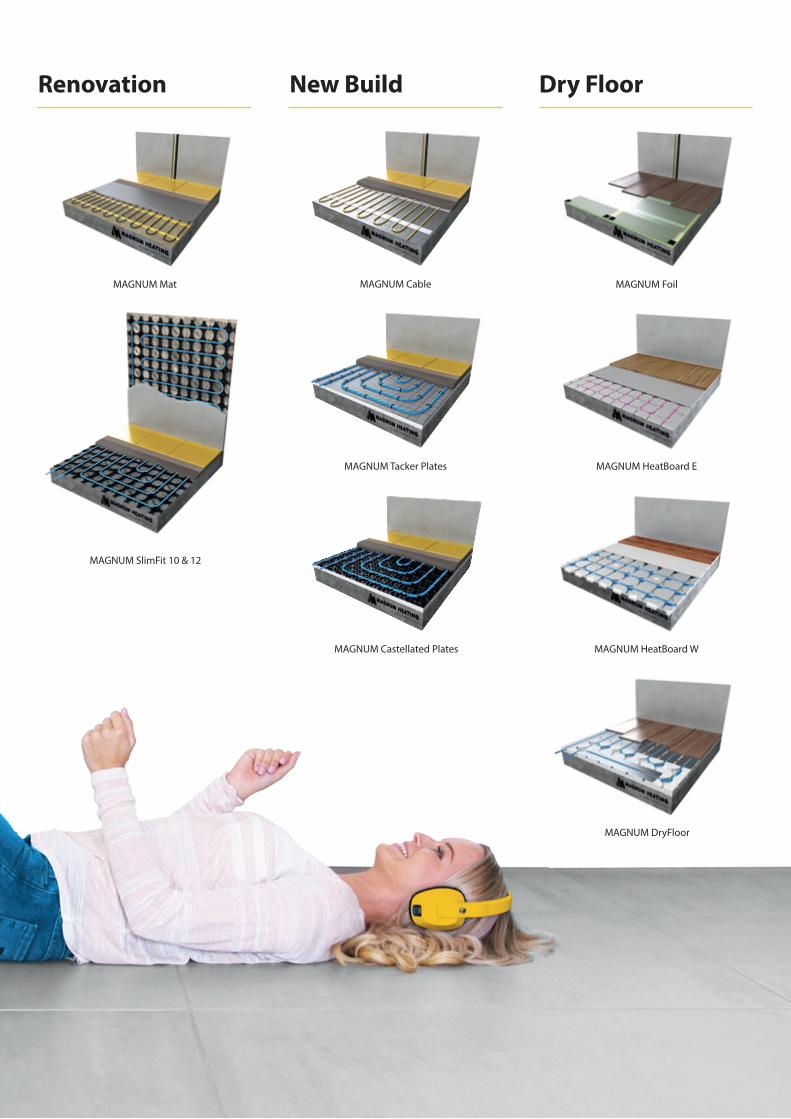
Underfloor heating for every situation.Choosing the right underfloor heating for your situation is simple. A heating demand can easily be divided into 3 categories: New build, Renovation or Dry build.
New build systems can be installed directly in the cement screed. This allows more mass to be heated and the heat output is optimal.
For renovations it is important that systems can be applied without far-reaching interventions (such as milling). The minimum installation height of
these systems ensures that they can be installed on an existing floor and even in the wall, so that no radiators are needed.
Wood and laminate floors require weather systems that keep the temperature below 28oC in connection with the (natural) functioning of these floor coverings.
There is a solution for every heating demand.
9
MAGNUM Mat
MAGNUM SlimFit 10 & 12
MAGNUM Tacker Plates
MAGNUM HeatBoard W
MAGNUM Cable
MAGNUM HeatBoard E
MAGNUM Castellated Plates
MAGNUM Foil
MAGNUM DryFloor
New BuildRenovation Dry Floor
10
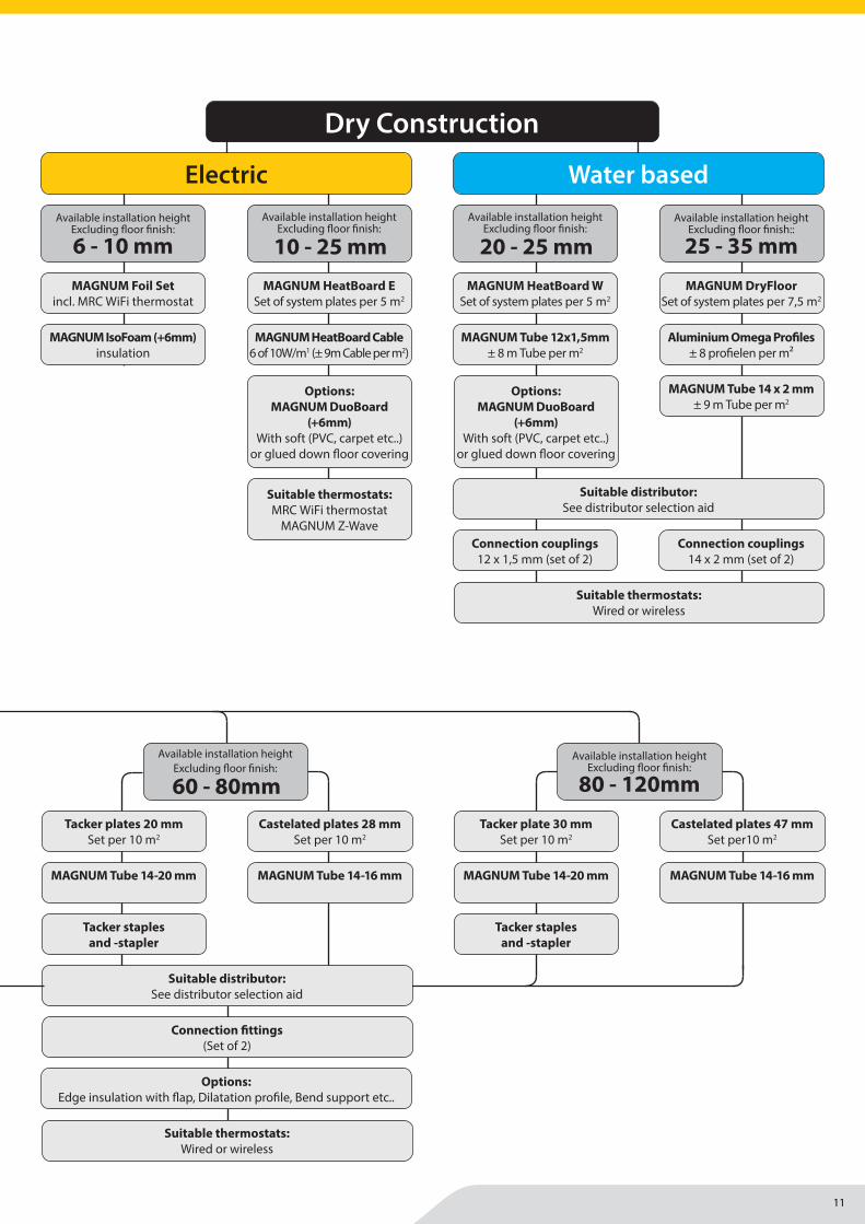
MAGNUM IsoFoam (+6mm)insulation
MAGNUM Foil Setincl. MRC WiFi thermostat
MAGNUM HeatBoard Cable6 of 10W/m1 (± 9m Cable per m2)
MAGNUM HeatBoard E Set of system plates per 5 m2
Suitable thermostats:MRC WiFi thermostat
MAGNUM Z-Wave
Options: MAGNUM DuoBoard
(+6mm)With soft (PVC, carpet etc..)
or glued down fl oor covering
ElectricAvailable installation height
Excluding fl oor fi nish:
10 - 25 mmAvailable installation height
Excluding fl oor fi nish:
6 - 10 mm
MAGNUM Tube 12x1,5mm± 8 m Tube per m2
MAGNUM HeatBoard W Set of system plates per 5 m2
Water based
Connection couplings12 x 1,5 mm (set of 2)
MAGNUM Tube 14 x 2 mm± 9 m Tube per m2
MAGNUM DryFloor Set of system plates per 7,5 m2
Connection couplings14 x 2 mm (set of 2)
Aluminium Omega Profi les± 8 profi elen per m²
Available installation height Excluding fl oor fi nish::
25 - 35 mmAvailable installation height
Excluding fl oor fi nish:
20 - 25 mm
Suitable distributor:See distributor selection aid
Suitable thermostats:Wired or wireless
Dry Construction
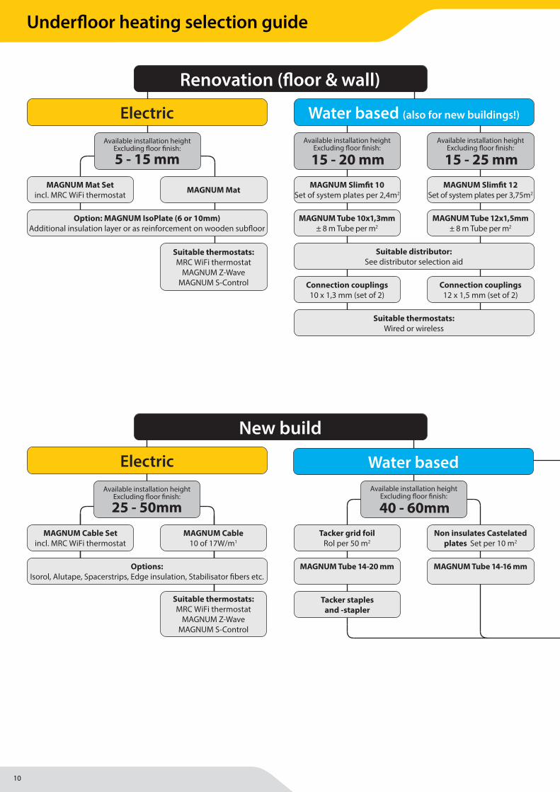
MAGNUM Mat Setincl. MRC WiFi thermostat MAGNUM Mat
Option: MAGNUM IsoPlate (6 or 10mm)Additional insulation layer or as reinforcement on wooden subfl oor
Suitable thermostats:MRC WiFi thermostat
MAGNUM Z-WaveMAGNUM S-Control
ElectricAvailable installation height
Excluding fl oor fi nish:
5 - 15 mm
MAGNUM Tube 10x1,3mm± 8 m Tube per m2
MAGNUM Slimfi t 10 Set of system plates per 2,4m2
Available installation height Excluding fl oor fi nish:
15 - 20 mm
MAGNUM Tube 12x1,5mm± 8 m Tube per m2
MAGNUM Slimfi t 12 Set of system plates per 3,75m2
Connection couplings10 x 1,3 mm (set of 2)
Connection couplings12 x 1,5 mm (set of 2)
Water based (also for new buildings!)
Available installation height Excluding fl oor fi nish:
15 - 25 mm
Suitable distributor:See distributor selection aid
Suitable thermostats:Wired or wireless
Renovation (fl oor & wall)
ElectricAvailable installation height
Excluding fl oor fi nish:
25 - 50mm
MAGNUM Cable 10 of 17W/m1
Suitable thermostats:MRC WiFi thermostat
MAGNUM Z-WaveMAGNUM S-Control
MAGNUM Cable Setincl. MRC WiFi thermostat
MAGNUM Tube 14-20 mm
Tacker grid foilRol per 50 m2
MAGNUM Tube 14-16 mm
Non insulates Castelated plates Set per 10 m2
MAGNUM Tube 14-16 mm
Castelated plates 28 mm Set per 10 m2
MAGNUM Tube 14-16 mm
Castelated plates 47 mm Set per10 m2
MAGNUM Tube 14-20 mm
Tacker plates 20 mmSet per 10 m2
MAGNUM Tube 14-20 mm
Tacker plate 30 mmSet per 10 m2
Options:Edge insulation with fl ap, Dilatation profi le, Bend support etc..
Tacker staples and -stapler
Tacker staples and -stapler
Tacker staples and -stapler
Suitable distributor:See distributor selection aid
Connection fi ttings(Set of 2)
Suitable thermostats:Wired or wireless
Water based Available installation height
Excluding fl oor fi nish:
40 - 60mmAvailable installation height
Excluding fl oor fi nish:
60 - 80mmAvailable installation height
Excluding fl oor fi nish:
80 - 120mm
Options:Isorol, Alutape, Spacerstrips, Edge insulation, Stabilisator fi bers etc.
New build
Options: MAGNUM DuoBoard
(+6mm)With soft (PVC, carpet etc..)
or glued down fl oor covering
Underfloor heating selection guide
11
MAGNUM IsoFoam (+6mm)insulation
MAGNUM Foil Setincl. MRC WiFi thermostat
MAGNUM HeatBoard Cable6 of 10W/m1 (± 9m Cable per m2)
MAGNUM HeatBoard E Set of system plates per 5 m2
Suitable thermostats:MRC WiFi thermostat
MAGNUM Z-Wave
Options: MAGNUM DuoBoard
(+6mm)With soft (PVC, carpet etc..)
or glued down fl oor covering
ElectricAvailable installation height
Excluding fl oor fi nish:
10 - 25 mmAvailable installation height
Excluding fl oor fi nish:
6 - 10 mm
MAGNUM Tube 12x1,5mm± 8 m Tube per m2
MAGNUM HeatBoard W Set of system plates per 5 m2
Water based
Connection couplings12 x 1,5 mm (set of 2)
MAGNUM Tube 14 x 2 mm± 9 m Tube per m2
MAGNUM DryFloor Set of system plates per 7,5 m2
Connection couplings14 x 2 mm (set of 2)
Aluminium Omega Profi les± 8 profi elen per m²
Available installation height Excluding fl oor fi nish::
25 - 35 mmAvailable installation height
Excluding fl oor fi nish:
20 - 25 mm
Suitable distributor:See distributor selection aid
Suitable thermostats:Wired or wireless
Dry Construction
MAGNUM Mat Setincl. MRC WiFi thermostat MAGNUM Mat
Option: MAGNUM IsoPlate (6 or 10mm)Additional insulation layer or as reinforcement on wooden subfl oor
Suitable thermostats:MRC WiFi thermostat
MAGNUM Z-WaveMAGNUM S-Control
ElectricAvailable installation height
Excluding fl oor fi nish:
5 - 15 mm
MAGNUM Tube 10x1,3mm± 8 m Tube per m2
MAGNUM Slimfi t 10 Set of system plates per 2,4m2
Available installation height Excluding fl oor fi nish:
15 - 20 mm
MAGNUM Tube 12x1,5mm± 8 m Tube per m2
MAGNUM Slimfi t 12 Set of system plates per 3,75m2
Connection couplings10 x 1,3 mm (set of 2)
Connection couplings12 x 1,5 mm (set of 2)
Water based (also for new buildings!)
Available installation height Excluding fl oor fi nish:
15 - 25 mm
Suitable distributor:See distributor selection aid
Suitable thermostats:Wired or wireless
Renovation (fl oor & wall)
ElectricAvailable installation height
Excluding fl oor fi nish:
25 - 50mm
MAGNUM Cable 10 of 17W/m1
Suitable thermostats:MRC WiFi thermostat
MAGNUM Z-WaveMAGNUM S-Control
MAGNUM Cable Setincl. MRC WiFi thermostat
MAGNUM Tube 14-20 mm
Tacker grid foilRol per 50 m2
MAGNUM Tube 14-16 mm
Non insulates Castelated plates Set per 10 m2
MAGNUM Tube 14-16 mm
Castelated plates 28 mm Set per 10 m2
MAGNUM Tube 14-16 mm
Castelated plates 47 mm Set per10 m2
MAGNUM Tube 14-20 mm
Tacker plates 20 mmSet per 10 m2
MAGNUM Tube 14-20 mm
Tacker plate 30 mmSet per 10 m2
Options:Edge insulation with fl ap, Dilatation profi le, Bend support etc..
Tacker staples and -stapler
Tacker staples and -stapler
Tacker staples and -stapler
Suitable distributor:See distributor selection aid
Connection fi ttings(Set of 2)
Suitable thermostats:Wired or wireless
Water based Available installation height
Excluding fl oor fi nish:
40 - 60mmAvailable installation height
Excluding fl oor fi nish:
60 - 80mmAvailable installation height
Excluding fl oor fi nish:
80 - 120mm
Options:Isorol, Alutape, Spacerstrips, Edge insulation, Stabilisator fi bers etc.
New build
Options: MAGNUM DuoBoard
(+6mm)With soft (PVC, carpet etc..)
or glued down fl oor covering
Underfloor heating selection guide
12
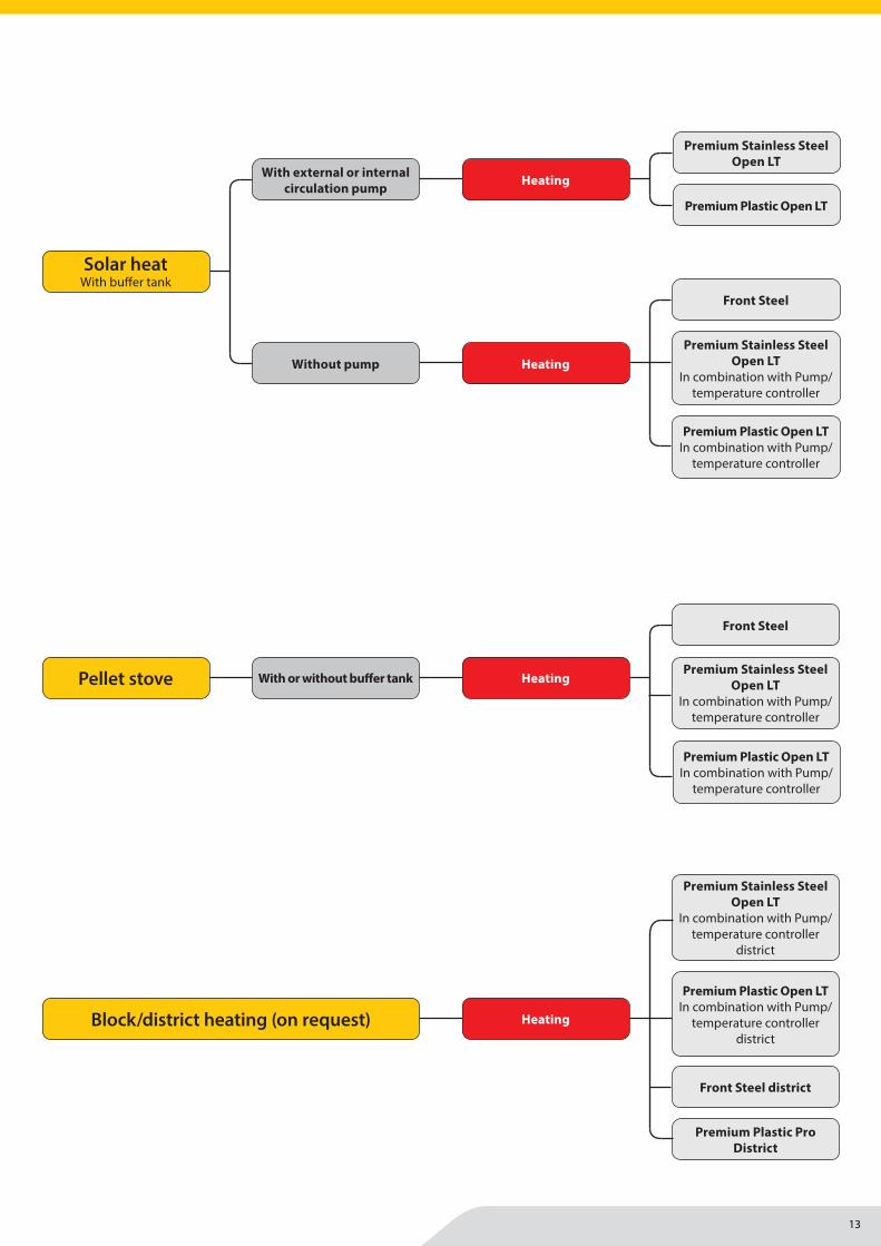
Pellet stove HeatingPremium Stainless Steel
Open LTIn combination with Pump/
temperature controller
Premium Plastic Open LTIn combination with Pump/
temperature controller
Front Steel
With or without buff er tank
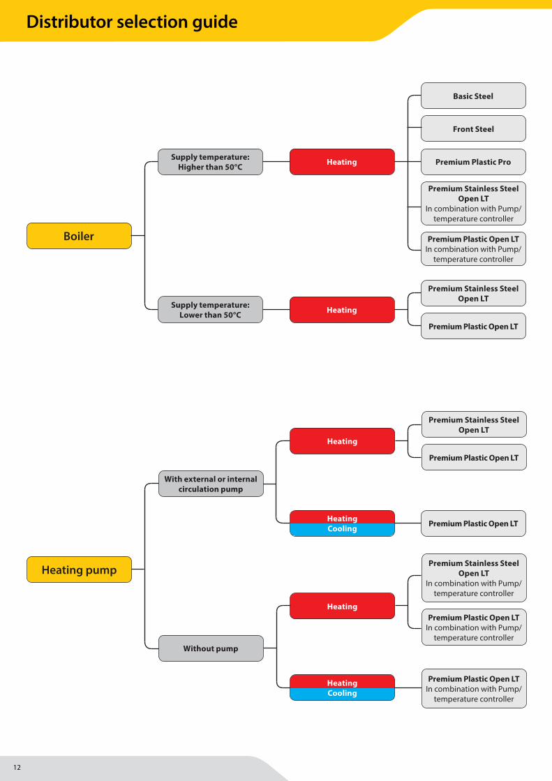
Boiler
Supply temperature:Higher than 50°C
Supply temperature:Lower than 50°C
Premium Plastic Pro
Front Steel
Basic Steel
Premium Stainless Steel Open LT
Premium Plastic Open LT
Heating
Premium Stainless Steel Open LT
In combination with Pump/temperature controller
Premium Plastic Open LTIn combination with Pump/
temperature controller
Heating
Block/district heating (on request) Heating
Premium Stainless Steel Open LT
In combination with Pump/temperature controller
district
Premium Plastic Open LTIn combination with Pump/
temperature controller district
Front Steel district
Premium Plastic Pro District
Heating pump
Premium Plastic Open LT
Premium Stainless Steel Open LT
Premium Plastic Open LT
Premium Plastic Open LTIn combination with Pump/
temperature controller
Heating
Premium Stainless Steel Open LT
In combination with Pump/temperature controller
Premium Plastic Open LTIn combination with Pump/
temperature controller
Heating
HeatingCooling
With external or internalcirculation pump
Without pump
HeatingCooling
Solar heatWith buff er tank
Premium Stainless Steel Open LT
In combination with Pump/temperature controller
Premium Plastic Open LTIn combination with Pump/
temperature controller
Front Steel
Premium Plastic Open LT
Premium Stainless Steel Open LT
HeatingWith external or internalcirculation pump
Without pump Heating
Distributor selection guide
13
Pellet stove HeatingPremium Stainless Steel
Open LTIn combination with Pump/
temperature controller
Premium Plastic Open LTIn combination with Pump/
temperature controller
Front Steel
With or without buff er tank
Boiler
Supply temperature:Higher than 50°C
Supply temperature:Lower than 50°C
Premium Plastic Pro
Front Steel
Basic Steel
Premium Stainless Steel Open LT
Premium Plastic Open LT
Heating
Premium Stainless Steel Open LT
In combination with Pump/temperature controller
Premium Plastic Open LTIn combination with Pump/
temperature controller
Heating
Block/district heating (on request) Heating
Premium Stainless Steel Open LT
In combination with Pump/temperature controller
district
Premium Plastic Open LTIn combination with Pump/
temperature controller district
Front Steel district
Premium Plastic Pro District
Heating pump
Premium Plastic Open LT
Premium Stainless Steel Open LT
Premium Plastic Open LT
Premium Plastic Open LTIn combination with Pump/
temperature controller
Heating
Premium Stainless Steel Open LT
In combination with Pump/temperature controller
Premium Plastic Open LTIn combination with Pump/
temperature controller
Heating
HeatingCooling
With external or internalcirculation pump
Without pump
HeatingCooling
Solar heatWith buff er tank
Premium Stainless Steel Open LT
In combination with Pump/temperature controller
Premium Plastic Open LTIn combination with Pump/
temperature controller
Front Steel
Premium Plastic Open LT
Premium Stainless Steel Open LT
HeatingWith external or internalcirculation pump
Without pump Heating
Distributor selection guide

14
Add to Siri
Add to Siri
Add to Siri
Full control.Even when you’re not at home.
Intuitive design Cleverly controlled
In the development of our thermostats, in addition to a lot of technical aspects, we take user-friendliness as our starting point. The smart MAGNUM MRC WiFi thermostat, for our electrical systems, is easy to program and operate. Equipped with step-by-step instructions for trouble-free setting of the desired times and temperatures.
The MRC is equiped with an automatic intelligent funtion: All you have to do is enter the periods in which you want to have a warm floor. It gradually learns the ideal warm-up time of the floor and automatically adjusts its program accordingly. So if you set that you want the floor to be at 23°C at 7:00 AM, the thermostat will do the rest.
15
Optimal precision
Zone control
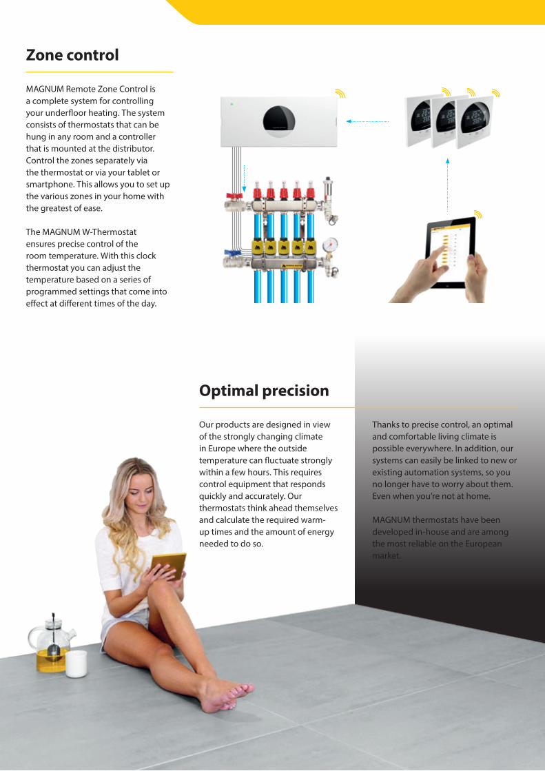
MAGNUM Remote Zone Control is a complete system for controlling your underfloor heating. The system consists of thermostats that can be hung in any room and a controller that is mounted at the distributor. Control the zones separately via the thermostat or via your tablet or smartphone. This allows you to set up the various zones in your home with the greatest of ease.
The MAGNUM W-Thermostat ensures precise control of the room temperature. With this clock thermostat you can adjust the temperature based on a series of programmed settings that come into effect at different times of the day.
Our products are designed in view of the strongly changing climate in Europe where the outside temperature can fluctuate strongly within a few hours. This requires control equipment that responds quickly and accurately. Our thermostats think ahead themselves and calculate the required warm-up times and the amount of energy needed to do so.
Thanks to precise control, an optimal and comfortable living climate is possible everywhere. In addition, our systems can easily be linked to new or existing automation systems, so you no longer have to worry about them. Even when you’re not at home.
MAGNUM thermostats have been developed in-house and are among the most reliable on the European market.

16
Always a condensation-free mirror thanks to a very simple solution. MAGNUM Look electric mirror heating is stuck directly on the back of the mirror and is an indispensable addition to your bathroom, it prevents condensation from forming in “no time”.
Connect the mirror heating directly to the existing light switch and the heating element will only be switched on during your presence in the bathroom. This way you save energy!
A clear view
MAGNUM Sol ceiling radiant heaters can be installed in a suspended ceiling and offer maximum freedom in designing the interior of any office, showroom or shop. With the integrated suspension bracket, the panels can also be fixed directly to any other ceiling.
If you are looking for an extra source of heat in your bathroom, the MAGNUM Sol Premium ceiling radiant heaters are the solution. These panels have an IP54 standard and are therefore very suitable for wet rooms.
These ceiling radiant heaters heat everything within the radiation range in a very short time. This makes them ideal for rooms that do not have a continuous occupancy and need to be warmed up in a short time.
Ceiling heating

17
Safety first.Withoutcompromise.
Safety, prevention and continuity are the key words that justify an investment in the construction of a frost-free installation. Especially for ramps and exits at an angle of inclination of distribution centres, car parks, hospitals, fire stations, office buildings, etc. The MAGNUM Outdoor system offers you safety and reliability
at minimum investment, consumption and maintenance costs.
The MAGNUM Trace range offers total solutions for keeping (water) pipes, gutters and drains frost-free. There is also a plug-in frost-free tape available with built-in thermostat.
Exceptionally safe

18

19
We manufacture and assemble most products ourselves in our own pro-duction departments. In this way, the process is kept in our own hands from start to finish and there is optimal qua-lity control. This makes us the most reliable supplier of heating products.
Own manufacturing
Over the past 3 decades, MAGNUM Heating has grown into a successful, market-leading and brand-oriented European designer, manufacturer and supplier of innovative electric and waterborne heating systems and re-lated products. We have a continuous focus on innovation, supported by our customers.
Know-How
Prepared for a sustainable future.
Our systems have a very long lifespan and respond perfectly to the funda-mental energy transition from fossil heating sources to sustainable climate solutions. We are continuously active to refine production and logistic processes in order to make our carbon footprint as small as possible.
Sustainable
Our products are available from any authorised E & W installer or bathroom specialist. They usually also advise and take care of the installation.
Would you like more information in the meantime? Visit magnumheating.nl or call 0166 - 609 300 during office hours.
More information?
20
MAGNUM Heating Group B.V.Stevinweg 84691SM TholenThe Netherlands
T +31 166 609300E [email protected] www.magnumheatinggroup.com
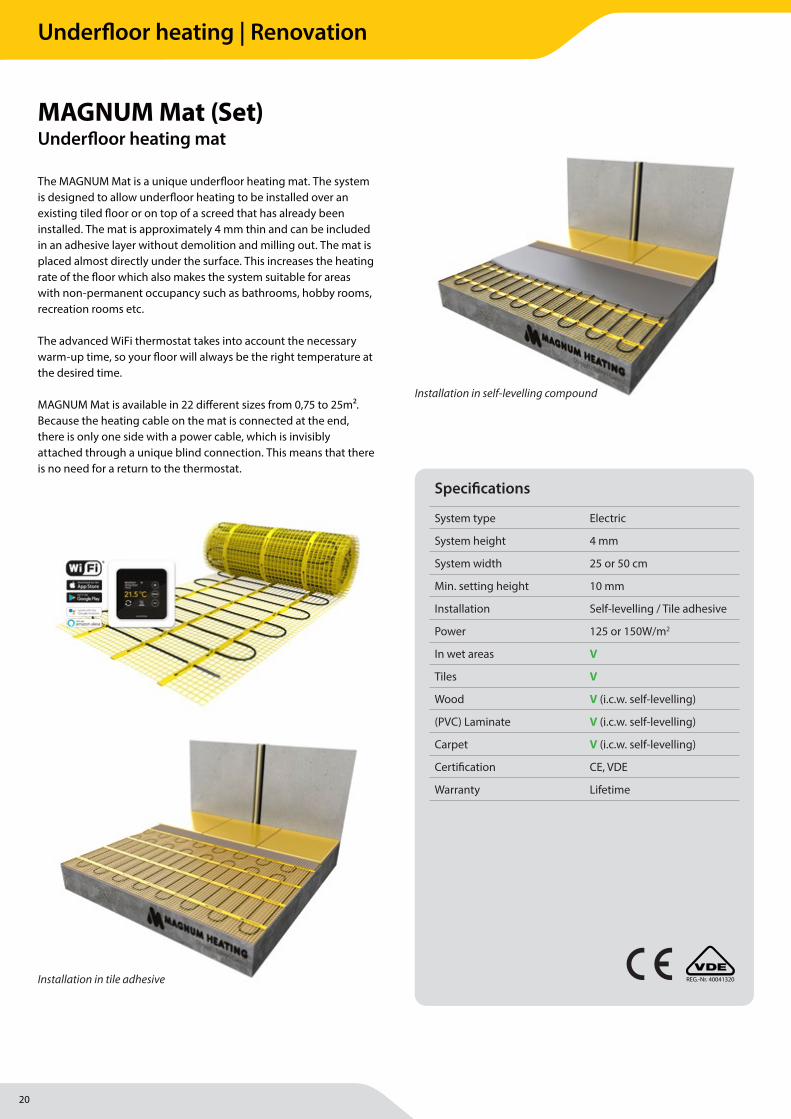
The MAGNUM Mat is a unique underfl oor heating mat. The system is designed to allow underfl oor heating to be installed over an existing tiled fl oor or on top of a screed that has already been installed. The mat is approximately 4 mm thin and can be included in an adhesive layer without demolition and milling out. The mat is placed almost directly under the surface. This increases the heating rate of the fl oor which also makes the system suitable for areas with non-permanent occupancy such as bathrooms, hobby rooms, recreation rooms etc.
The advanced WiFi thermostat takes into account the necessary warm-up time, so your fl oor will always be the right temperature at the desired time.
MAGNUM Mat is available in 22 diff erent sizes from 0,75 to 25m². Because the heating cable on the mat is connected at the end, there is only one side with a power cable, which is invisibly attached through a unique blind connection. This means that there is no need for a return to the thermostat.
MAGNUM Mat (Set)Underfl oor heating mat
Specifi cations
System type Electric
System height 4 mm
System width 25 or 50 cm
Min. setting height 10 mm
Installation Self-levelling / Tile adhesive
Power 125 or 150W/m2
In wet areas V
Tiles V
Wood V (i.c.w. self-levelling)
(PVC) Laminate V (i.c.w. self-levelling)
Carpet V (i.c.w. self-levelling)
Certifi cation CE, VDE
Warranty Lifetime
REG.-Nr. 40041320
Installation in self-levelling compound
Installation in tile adhesive
Underfloor heating | Renovation
21
MAGNUM Heating Group B.V.Stevinweg 84691SM TholenThe Netherlands
T +31 166 609300E [email protected] www.magnumheatinggroup.com
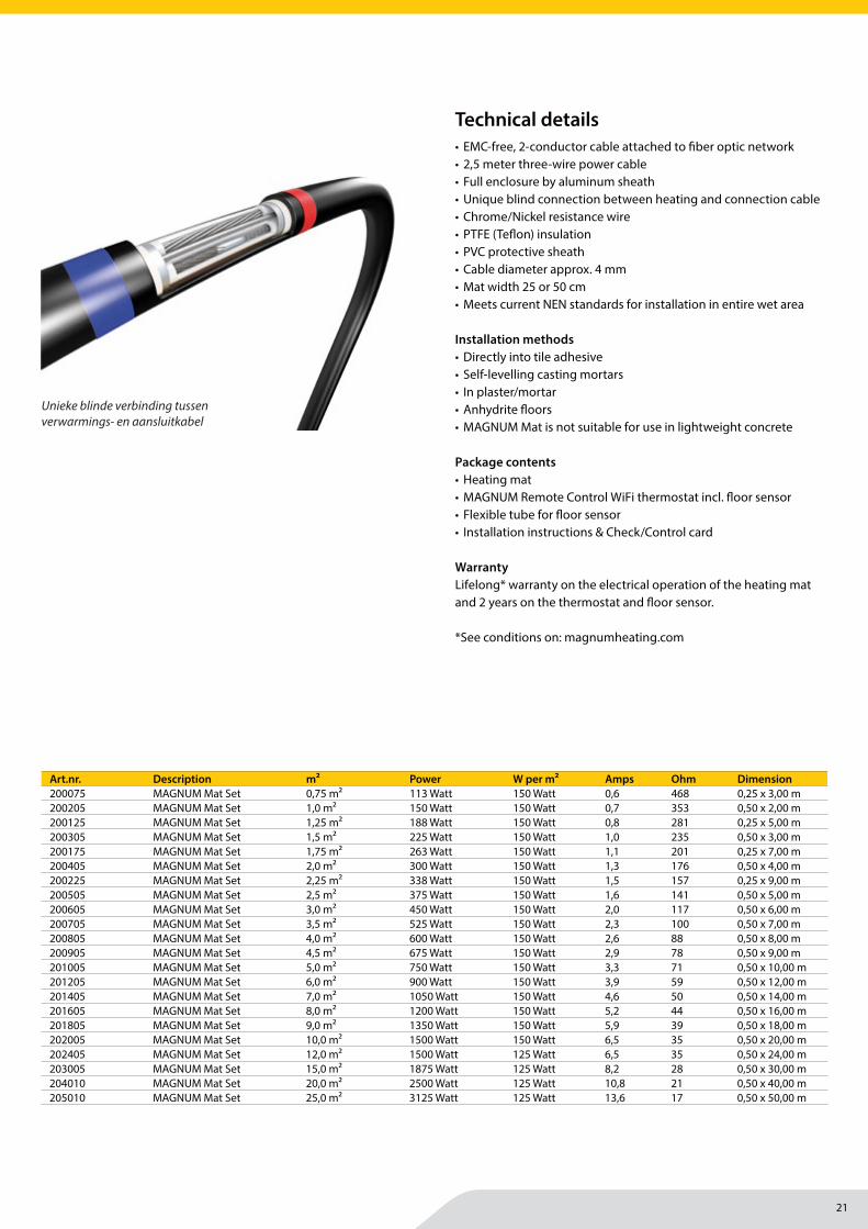
• EMC-free, 2-conductor cable attached to fi ber optic network• 2,5 meter three-wire power cable• Full enclosure by aluminum sheath• Unique blind connection between heating and connection cable• Chrome/Nickel resistance wire• PTFE (Tefl on) insulation• PVC protective sheath• Cable diameter approx. 4 mm• Mat width 25 or 50 cm• Meets current NEN standards for installation in entire wet area
Installation methods• Directly into tile adhesive• Self-levelling casting mortars• In plaster/mortar• Anhydrite fl oors• MAGNUM Mat is not suitable for use in lightweight concrete
Package contents• Heating mat• MAGNUM Remote Control WiFi thermostat incl. fl oor sensor• Flexible tube for fl oor sensor• Installation instructions & Check/Control card
WarrantyLifelong* warranty on the electrical operation of the heating mat and 2 years on the thermostat and fl oor sensor.
*See conditions on: magnumheating.com
Art.nr. Description m² Power W per m² Amps Ohm Dimension200075 MAGNUM Mat Set 0,75 m² 113 Watt 150 Watt 0,6 468 0,25 x 3,00 m200205 MAGNUM Mat Set 1,0 m² 150 Watt 150 Watt 0,7 353 0,50 x 2,00 m200125 MAGNUM Mat Set 1,25 m² 188 Watt 150 Watt 0,8 281 0,25 x 5,00 m200305 MAGNUM Mat Set 1,5 m² 225 Watt 150 Watt 1,0 235 0,50 x 3,00 m200175 MAGNUM Mat Set 1,75 m² 263 Watt 150 Watt 1,1 201 0,25 x 7,00 m200405 MAGNUM Mat Set 2,0 m² 300 Watt 150 Watt 1,3 176 0,50 x 4,00 m200225 MAGNUM Mat Set 2,25 m² 338 Watt 150 Watt 1,5 157 0,25 x 9,00 m200505 MAGNUM Mat Set 2,5 m² 375 Watt 150 Watt 1,6 141 0,50 x 5,00 m200605 MAGNUM Mat Set 3,0 m² 450 Watt 150 Watt 2,0 117 0,50 x 6,00 m200705 MAGNUM Mat Set 3,5 m² 525 Watt 150 Watt 2,3 100 0,50 x 7,00 m200805 MAGNUM Mat Set 4,0 m² 600 Watt 150 Watt 2,6 88 0,50 x 8,00 m200905 MAGNUM Mat Set 4,5 m² 675 Watt 150 Watt 2,9 78 0,50 x 9,00 m201005 MAGNUM Mat Set 5,0 m² 750 Watt 150 Watt 3,3 71 0,50 x 10,00 m201205 MAGNUM Mat Set 6,0 m² 900 Watt 150 Watt 3,9 59 0,50 x 12,00 m201405 MAGNUM Mat Set 7,0 m² 1050 Watt 150 Watt 4,6 50 0,50 x 14,00 m201605 MAGNUM Mat Set 8,0 m² 1200 Watt 150 Watt 5,2 44 0,50 x 16,00 m201805 MAGNUM Mat Set 9,0 m² 1350 Watt 150 Watt 5,9 39 0,50 x 18,00 m202005 MAGNUM Mat Set 10,0 m² 1500 Watt 150 Watt 6,5 35 0,50 x 20,00 m202405 MAGNUM Mat Set 12,0 m² 1500 Watt 125 Watt 6,5 35 0,50 x 24,00 m203005 MAGNUM Mat Set 15,0 m² 1875 Watt 125 Watt 8,2 28 0,50 x 30,00 m204010 MAGNUM Mat Set 20,0 m² 2500 Watt 125 Watt 10,8 21 0,50 x 40,00 m205010 MAGNUM Mat Set 25,0 m² 3125 Watt 125 Watt 13,6 17 0,50 x 50,00 m
Technical details
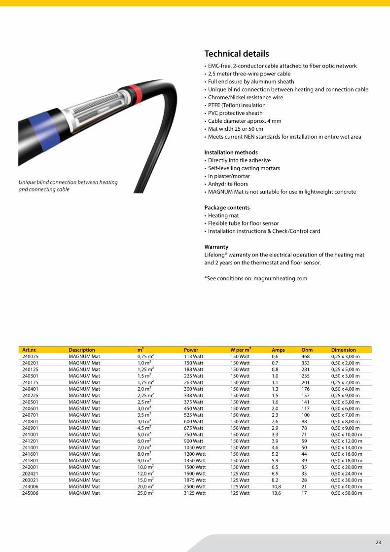
Unieke blinde verbinding tussen verwarmings- en aansluitkabel
22
MAGNUM Heating Group B.V.Stevinweg 84691SM TholenThe Netherlands
T +31 166 609300E [email protected] www.magnumheatinggroup.com
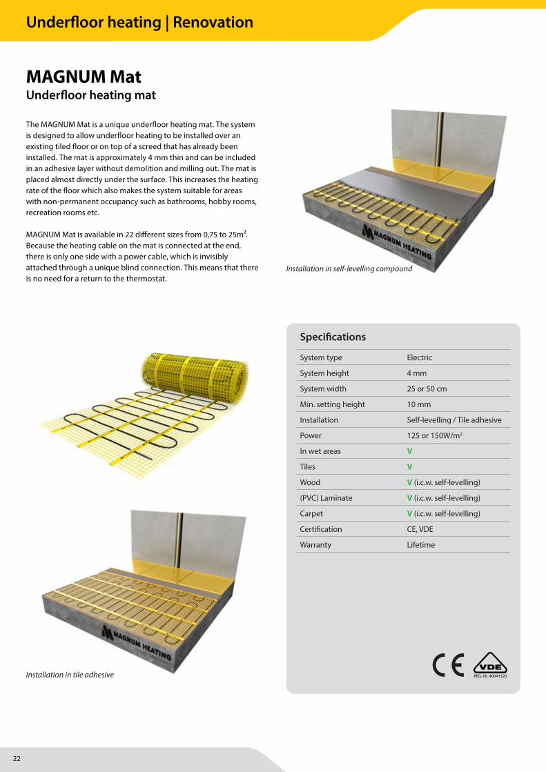
The MAGNUM Mat is a unique underfl oor heating mat. The system is designed to allow underfl oor heating to be installed over an existing tiled fl oor or on top of a screed that has already been installed. The mat is approximately 4 mm thin and can be included in an adhesive layer without demolition and milling out. The mat is placed almost directly under the surface. This increases the heating rate of the fl oor which also makes the system suitable for areas with non-permanent occupancy such as bathrooms, hobby rooms, recreation rooms etc.
MAGNUM Mat is available in 22 diff erent sizes from 0,75 to 25m². Because the heating cable on the mat is connected at the end, there is only one side with a power cable, which is invisibly attached through a unique blind connection. This means that there is no need for a return to the thermostat.
MAGNUM MatUnderfl oor heating mat
REG.-Nr. 40041320
Installation in self-levelling compound
Installation in tile adhesive
Specifi cations
System type Electric
System height 4 mm
System width 25 or 50 cm
Min. setting height 10 mm
Installation Self-levelling / Tile adhesive
Power 125 or 150W/m2
In wet areas V
Tiles V
Wood V (i.c.w. self-levelling)
(PVC) Laminate V (i.c.w. self-levelling)
Carpet V (i.c.w. self-levelling)
Certifi cation CE, VDE
Warranty Lifetime
Underfloor heating | Renovation
23
MAGNUM Heating Group B.V.Stevinweg 84691SM TholenThe Netherlands
T +31 166 609300E [email protected] www.magnumheatinggroup.com
• EMC-free, 2-conductor cable attached to fi ber optic network• 2,5 meter three-wire power cable• Full enclosure by aluminum sheath• Unique blind connection between heating and connection cable• Chrome/Nickel resistance wire• PTFE (Tefl on) insulation• PVC protective sheath• Cable diameter approx. 4 mm• Mat width 25 or 50 cm• Meets current NEN standards for installation in entire wet area
Installation methods• Directly into tile adhesive• Self-levelling casting mortars• In plaster/mortar• Anhydrite fl oors• MAGNUM Mat is not suitable for use in lightweight concrete
Package contents• Heating mat• Flexible tube for fl oor sensor• Installation instructions & Check/Control card
WarrantyLifelong* warranty on the electrical operation of the heating mat and 2 years on the thermostat and fl oor sensor.
*See conditions on: magnumheating.com
Art.nr. Description m² Power W per m² Amps Ohm Dimension240075 MAGNUM Mat 0,75 m² 113 Watt 150 Watt 0,6 468 0,25 x 3,00 m240201 MAGNUM Mat 1,0 m² 150 Watt 150 Watt 0,7 353 0,50 x 2,00 m240125 MAGNUM Mat 1,25 m² 188 Watt 150 Watt 0,8 281 0,25 x 5,00 m240301 MAGNUM Mat 1,5 m² 225 Watt 150 Watt 1,0 235 0,50 x 3,00 m240175 MAGNUM Mat 1,75 m² 263 Watt 150 Watt 1,1 201 0,25 x 7,00 m240401 MAGNUM Mat 2,0 m² 300 Watt 150 Watt 1,3 176 0,50 x 4,00 m240225 MAGNUM Mat 2,25 m² 338 Watt 150 Watt 1,5 157 0,25 x 9,00 m240501 MAGNUM Mat 2,5 m² 375 Watt 150 Watt 1,6 141 0,50 x 5,00 m240601 MAGNUM Mat 3,0 m² 450 Watt 150 Watt 2,0 117 0,50 x 6,00 m240701 MAGNUM Mat 3,5 m² 525 Watt 150 Watt 2,3 100 0,50 x 7,00 m240801 MAGNUM Mat 4,0 m² 600 Watt 150 Watt 2,6 88 0,50 x 8,00 m240901 MAGNUM Mat 4,5 m² 675 Watt 150 Watt 2,9 78 0,50 x 9,00 m241001 MAGNUM Mat 5,0 m² 750 Watt 150 Watt 3,3 71 0,50 x 10,00 m241201 MAGNUM Mat 6,0 m² 900 Watt 150 Watt 3,9 59 0,50 x 12,00 m241401 MAGNUM Mat 7,0 m² 1050 Watt 150 Watt 4,6 50 0,50 x 14,00 m241601 MAGNUM Mat 8,0 m² 1200 Watt 150 Watt 5,2 44 0,50 x 16,00 m241801 MAGNUM Mat 9,0 m² 1350 Watt 150 Watt 5,9 39 0,50 x 18,00 m242001 MAGNUM Mat 10,0 m² 1500 Watt 150 Watt 6,5 35 0,50 x 20,00 m202421 MAGNUM Mat 12,0 m² 1500 Watt 125 Watt 6,5 35 0,50 x 24,00 m203021 MAGNUM Mat 15,0 m² 1875 Watt 125 Watt 8,2 28 0,50 x 30,00 m244006 MAGNUM Mat 20,0 m² 2500 Watt 125 Watt 10,8 21 0,50 x 40,00 m245006 MAGNUM Mat 25,0 m² 3125 Watt 125 Watt 13,6 17 0,50 x 50,00 m
Technical details
Unique blind connection between heating and connecting cable
Underfloor heating | Renovation
24
MAGNUM Heating Group B.V.Stevinweg 84691SM TholenThe Netherlands
T +31 166 609300E [email protected] www.magnumheatinggroup.com
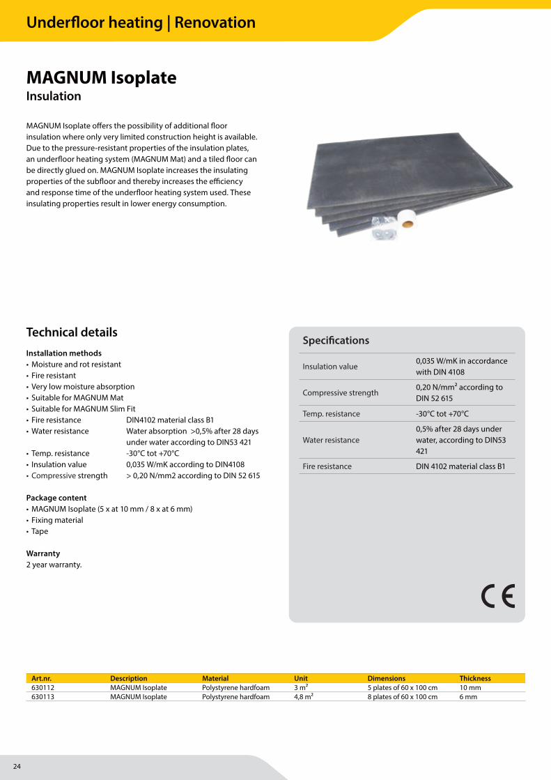
MAGNUM Isoplate off ers the possibility of additional fl oor insulation where only very limited construction height is available. Due to the pressure-resistant properties of the insulation plates, an underfl oor heating system (MAGNUM Mat) and a tiled fl oor can be directly glued on. MAGNUM Isoplate increases the insulating properties of the subfl oor and thereby increases the effi ciency and response time of the underfl oor heating system used. These insulating properties result in lower energy consumption.
MAGNUM IsoplateInsulation
Installation methods• Moisture and rot resistant• Fire resistant• Very low moisture absorption• Suitable for MAGNUM Mat• Suitable for MAGNUM Slim Fit• Fire resistance DIN4102 material class B1• Water resistance Water absorption >0,5% after 28 days
under water according to DIN53 421• Temp. resistance -30°C tot +70°C• Insulation value 0,035 W/mK according to DIN4108• Compressive strength > 0,20 N/mm2 according to DIN 52 615
Package content• MAGNUM Isoplate (5 x at 10 mm / 8 x at 6 mm)• Fixing material• Tape
Warranty2 year warranty.
Art.nr. Description Material Unit Dimensions Thickness630112 MAGNUM Isoplate Polystyrene hardfoam 3 m² 5 plates of 60 x 100 cm 10 mm630113 MAGNUM Isoplate Polystyrene hardfoam 4,8 m² 8 plates of 60 x 100 cm 6 mm
Technical detailsSpecifi cations
Insulation value0,035 W/mK in accordance with DIN 4108
Compressive strength0,20 N/mm2 according to DIN 52 615
Temp. resistance -30°C tot +70°C
Water resistance0,5% after 28 days under water, according to DIN53 421
Fire resistance DIN 4102 material class B1
Underfloor heating | Renovation

25
Underfloor heating | Renovation
26
MAGNUM Heating Group B.V.Stevinweg 84691SM TholenThe Netherlands
T +31 166 609300E [email protected] www.magnumheatinggroup.com
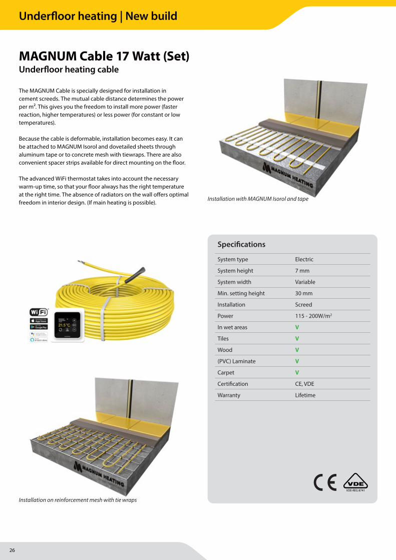
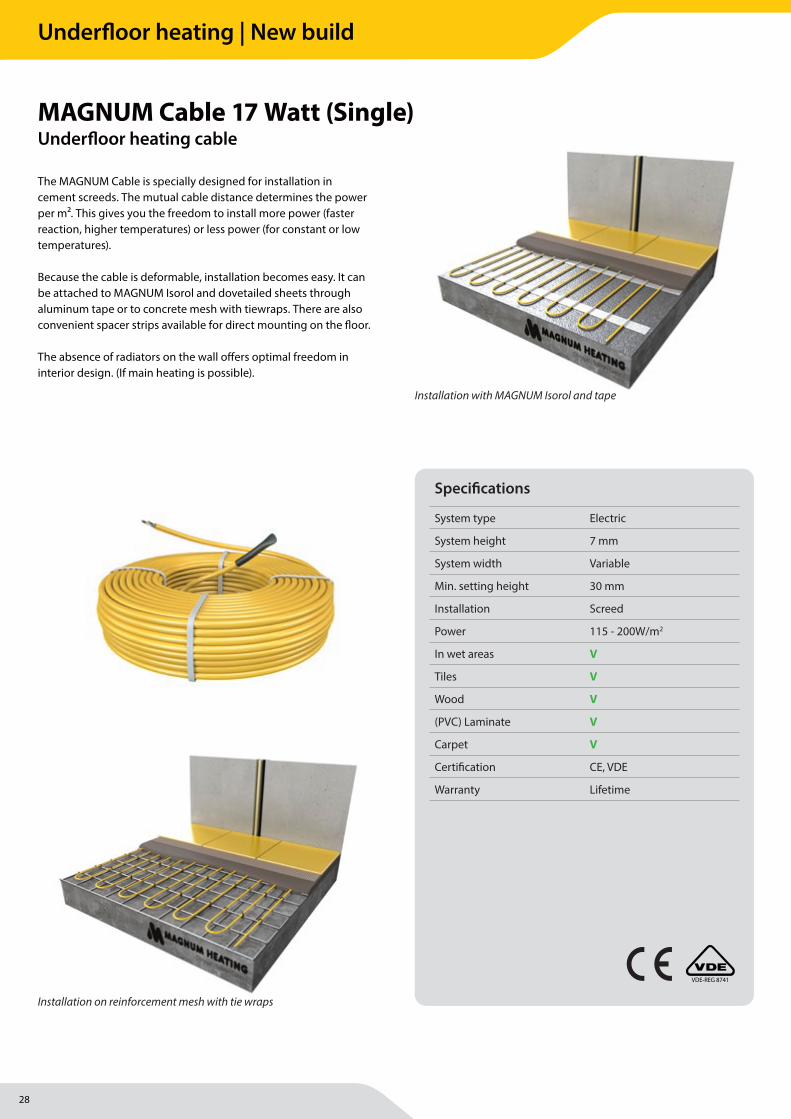
The MAGNUM Cable is specially designed for installation in cement screeds. The mutual cable distance determines the power per m2. This gives you the freedom to install more power (faster reaction, higher temperatures) or less power (for constant or low temperatures).
Because the cable is deformable, installation becomes easy. It can be attached to MAGNUM Isorol and dovetailed sheets through aluminum tape or to concrete mesh with tiewraps. There are also convenient spacer strips available for direct mounting on the fl oor.
The advanced WiFi thermostat takes into account the necessary warm-up time, so that your fl oor always has the right temperature at the right time. The absence of radiators on the wall off ers optimal freedom in interior design. (If main heating is possible).
MAGNUM Cable 17 Watt (Set)Underfl oor heating cable
Specifi cations
System type Electric
System height 7 mm
System width Variable
Min. setting height 30 mm
Installation Screed
Power 115 - 200W/m2
In wet areas V
Tiles V
Wood V
(PVC) Laminate V
Carpet V
Certifi cation CE, VDE
Warranty Lifetime
Installation on reinforcement mesh with tie wraps
Installation with MAGNUM Isorol and tape
VDE-REG 8741
Underfloor heating | New build
27
MAGNUM Heating Group B.V.Stevinweg 84691SM TholenThe Netherlands
T +31 166 609300E [email protected] www.magnumheatinggroup.com
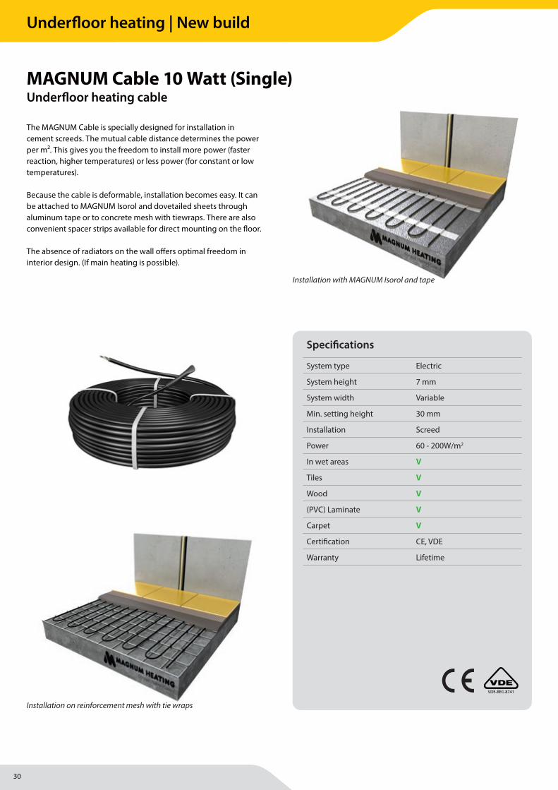
• EMC-free, 2-conductor cable• 2,5 meter three-wire power cable• Unique blind connection between heating and connection cable• Full enclosure by aluminum sheath• Chrome/Nickel resistance wire• XLPE insulation• PVC protective sheath• 17 Watt per meter power, 230 Volt• Cable diameter approx. 7 mm• Produced and inspected in accordance with IEC 800 standards• VDE approved and CE standard within Europe
Installation methodsThe cables are available in total capacities from 300 to 3300 Watts, suffi cient for surfaces between 2 and 30 m2. Because the cable is looped at the end, there is only one side of a power cable, which is invisibly attached through the unique connection. This means that there is no need for a return to the thermostat. MAGNUM Cable is not suitable for use in lightweight concrete.
Package contents• Heating cable• MAGNUM Remote Control WiFi thermostat• Floor sensor• Mounting tape• Flexible tube for fl oor sensor• Installation instructions
WarrantyLifelong* warranty on the electrical function of the heating cable and 2 years on the thermostat and fl oor sensor.
*See conditions on: magnumheating.com
Art.nr. Description Cable length Power Amps Ohm100305 MAGNUM Cable Set 17,6 m 300 Watt 1,3 177100505 MAGNUM Cable Set 29,4 m 500 Watt 2,2 109100705 MAGNUM Cable Set 41,2 m 700 Watt 3 76101005 MAGNUM Cable Set 58,8 m 1000 Watt 4,3 53101255 MAGNUM Cable Set 73,5 m 1250 Watt 5,5 42101705 MAGNUM Cable Set 100 m 1700 Watt 7,4 31102105 MAGNUM Cable Set 123,5 m 2100 Watt 9 25102605 MAGNUM Cable Set 152,9 m 2600 Watt 11,3 20102905 MAGNUM Cable Set 170,6 m 2900 Watt 12,8 18103305 MAGNUM Cable Set 194,1 m 3300 Watt 14,3 16
Art.nr. Options Unit720100 MAGNUM Stabiliser fi bres Bag of 150 gram720200 MAGNUM Aluminium tape Roll of 22,5 m x 5 cm720310 MAGNUM Spacer strips 10 m720315 MAGNUM Spacer strips 15 m720400 MAGNUM Edge strips Roll of 10 m x 10 cm720502 MAGNUM Isorol Roll of 24 m² (20 x 1,2 m) - 3 mm thick
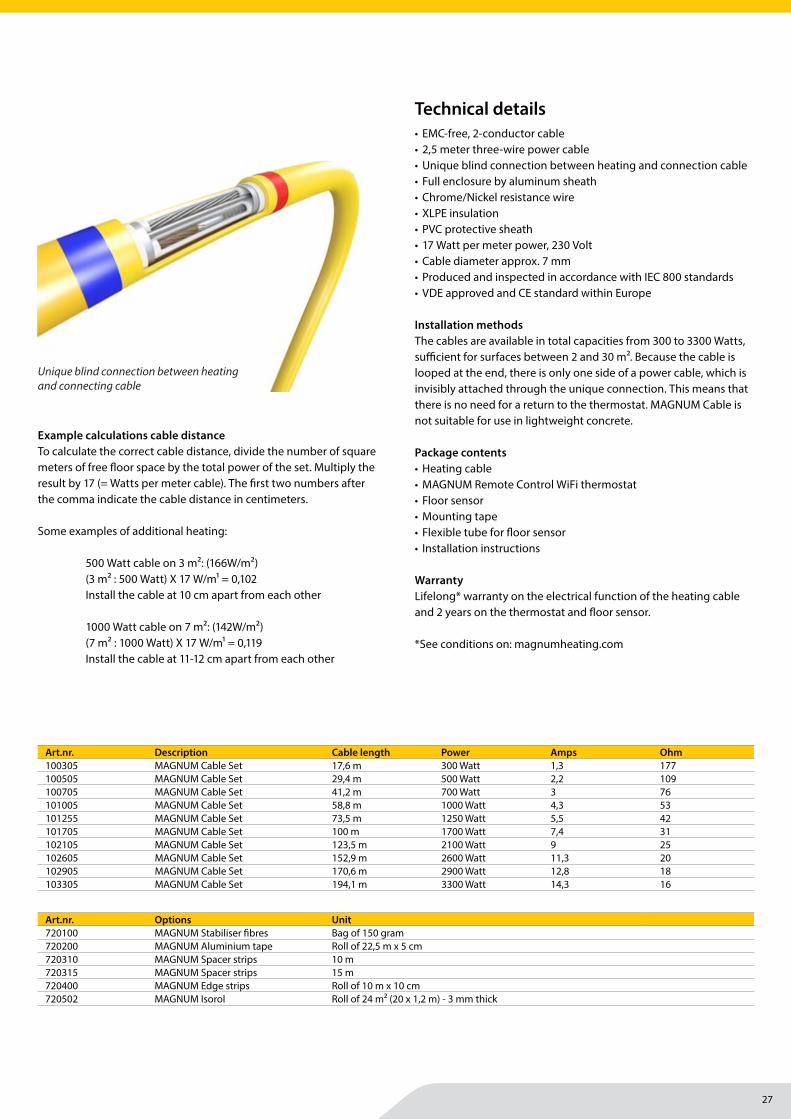
Unique blind connection between heating and connecting cable
Technical details
Example calculations cable distanceTo calculate the correct cable distance, divide the number of square meters of free fl oor space by the total power of the set. Multiply the result by 17 (= Watts per meter cable). The fi rst two numbers after the comma indicate the cable distance in centimeters.
Some examples of additional heating:
500 Watt cable on 3 m2: (166W/m2) (3 m2 : 500 Watt) X 17 W/m1 = 0,102 Install the cable at 10 cm apart from each other
1000 Watt cable on 7 m2: (142W/m2) (7 m2 : 1000 Watt) X 17 W/m1 = 0,119 Install the cable at 11-12 cm apart from each other
Underfloor heating | New build
28
MAGNUM Heating Group B.V.Stevinweg 84691SM TholenThe Netherlands
T +31 166 609300E [email protected] www.magnumheatinggroup.com
The MAGNUM Cable is specially designed for installation in cement screeds. The mutual cable distance determines the power per m2. This gives you the freedom to install more power (faster reaction, higher temperatures) or less power (for constant or low temperatures).
Because the cable is deformable, installation becomes easy. It can be attached to MAGNUM Isorol and dovetailed sheets through aluminum tape or to concrete mesh with tiewraps. There are also convenient spacer strips available for direct mounting on the fl oor.
The absence of radiators on the wall off ers optimal freedom in interior design. (If main heating is possible).
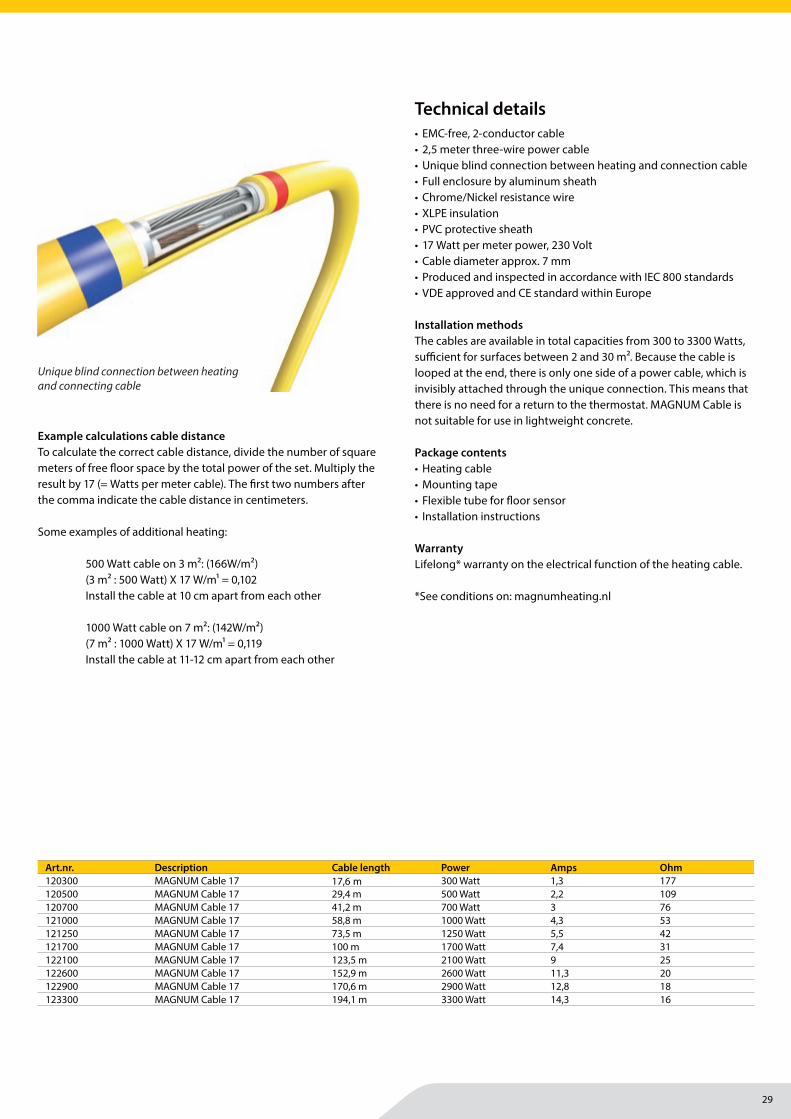
MAGNUM Cable 17 Watt (Single)Underfl oor heating cable
Specifi cations
System type Electric
System height 7 mm
System width Variable
Min. setting height 30 mm
Installation Screed
Power 115 - 200W/m2
In wet areas V
Tiles V
Wood V
(PVC) Laminate V
Carpet V
Certifi cation CE, VDE
Warranty Lifetime
Installation on reinforcement mesh with tie wraps
Installation with MAGNUM Isorol and tape
VDE-REG 8741
Underfloor heating | New build
29
MAGNUM Heating Group B.V.Stevinweg 84691SM TholenThe Netherlands
T +31 166 609300E [email protected] www.magnumheatinggroup.com
• EMC-free, 2-conductor cable• 2,5 meter three-wire power cable• Unique blind connection between heating and connection cable• Full enclosure by aluminum sheath• Chrome/Nickel resistance wire• XLPE insulation• PVC protective sheath• 17 Watt per meter power, 230 Volt• Cable diameter approx. 7 mm• Produced and inspected in accordance with IEC 800 standards• VDE approved and CE standard within Europe
Installation methodsThe cables are available in total capacities from 300 to 3300 Watts, suffi cient for surfaces between 2 and 30 m2. Because the cable is looped at the end, there is only one side of a power cable, which is invisibly attached through the unique connection. This means that there is no need for a return to the thermostat. MAGNUM Cable is not suitable for use in lightweight concrete.
Package contents• Heating cable• Mounting tape• Flexible tube for fl oor sensor• Installation instructions
WarrantyLifelong* warranty on the electrical function of the heating cable.
*See conditions on: magnumheating.nl
Art.nr. Description Cable length Power Amps Ohm120300 MAGNUM Cable 17 17,6 m 300 Watt 1,3 177120500 MAGNUM Cable 17 29,4 m 500 Watt 2,2 109120700 MAGNUM Cable 17 41,2 m 700 Watt 3 76121000 MAGNUM Cable 17 58,8 m 1000 Watt 4,3 53121250 MAGNUM Cable 17 73,5 m 1250 Watt 5,5 42121700 MAGNUM Cable 17 100 m 1700 Watt 7,4 31122100 MAGNUM Cable 17 123,5 m 2100 Watt 9 25122600 MAGNUM Cable 17 152,9 m 2600 Watt 11,3 20122900 MAGNUM Cable 17 170,6 m 2900 Watt 12,8 18123300 MAGNUM Cable 17 194,1 m 3300 Watt 14,3 16
Unique blind connection between heating and connecting cable
Technical details
Example calculations cable distanceTo calculate the correct cable distance, divide the number of square meters of free fl oor space by the total power of the set. Multiply the result by 17 (= Watts per meter cable). The fi rst two numbers after the comma indicate the cable distance in centimeters.
Some examples of additional heating:
500 Watt cable on 3 m2: (166W/m2) (3 m2 : 500 Watt) X 17 W/m1 = 0,102 Install the cable at 10 cm apart from each other
1000 Watt cable on 7 m2: (142W/m2) (7 m2 : 1000 Watt) X 17 W/m1 = 0,119 Install the cable at 11-12 cm apart from each other
Underfloor heating | New build
30
MAGNUM Heating Group B.V.Stevinweg 84691SM TholenThe Netherlands
T +31 166 609300E [email protected] www.magnumheatinggroup.com
The MAGNUM Cable is specially designed for installation in cement screeds. The mutual cable distance determines the power per m2. This gives you the freedom to install more power (faster reaction, higher temperatures) or less power (for constant or low temperatures).
Because the cable is deformable, installation becomes easy. It can be attached to MAGNUM Isorol and dovetailed sheets through aluminum tape or to concrete mesh with tiewraps. There are also convenient spacer strips available for direct mounting on the fl oor.
The absence of radiators on the wall off ers optimal freedom in interior design. (If main heating is possible).
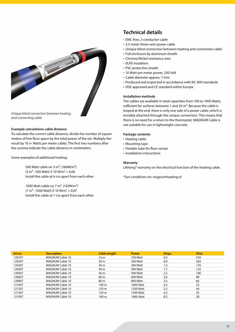
MAGNUM Cable 10 Watt (Single)Underfl oor heating cable
Specifi cations
System type Electric
System height 7 mm
System width Variable
Min. setting height 30 mm
Installation Screed
Power 60 - 200W/m2
In wet areas V
Tiles V
Wood V
(PVC) Laminate V
Carpet V
Certifi cation CE, VDE
Warranty Lifetime
Installation on reinforcement mesh with tie wraps
Installation with MAGNUM Isorol and tape
VDE-REG 8741
Underfloor heating | New build
31
MAGNUM Heating Group B.V.Stevinweg 84691SM TholenThe Netherlands
T +31 166 609300E [email protected] www.magnumheatinggroup.com
• EMC-free, 2-conductor cable• 2,5 meter three-wire power cable• Unique blind connection between heating and connection cable• Full enclosure by aluminum sheath• Chrome/Nickel resistance wire• XLPE insulation• PVC protective sheath• 10 Watt per meter power, 230 Volt• Cable diameter approx. 7 mm• Produced and inspected in accordance with IEC 800 standards• VDE approved and CE standard within Europe
Installation methodsThe cables are available in total capacities from 100 to 1900 Watts, suffi cient for surfaces between 1 and 20 m2. Because the cable is looped at the end, there is only one side of a power cable, which is invisibly attached through the unique connection. This means that there is no need for a return to the thermostat. MAGNUM Cable is not suitable for use in lightweight concrete.
Package contents• Heating cable• Mounting tape• Flexible tube for fl oor sensor• Installation instructions
WarrantyLifelong* warranty on the electrical function of the heating cable.
*See conditions on: magnumheating.nl
Art.nr. Description Cable length Power Amps Ohm120107 MAGNUM Cable 10 10 m 100 Watt 0,4 529120207 MAGNUM Cable 10 20 m 200 Watt 0,9 264120307 MAGNUM Cable 10 30 m 300 Watt 1,3 176120407 MAGNUM Cable 10 40 m 400 Watt 1,7 132120507 MAGNUM Cable 10 50 m 500 Watt 2,2 106120607 MAGNUM Cable 10 60 m 600 Watt 2,6 88120807 MAGNUM Cable 10 80 m 800 Watt 3,5 66121007 MAGNUM Cable 10 100 m 1000 Watt 4,3 53121207 MAGNUM Cable 10 120 m 1200 Watt 5,2 44121507 MAGNUM Cable 10 150 m 1500 Watt 6,5 35121907 MAGNUM Cable 10 190 m 1900 Watt 8,3 28
Unique blind connection between heating and connecting cable
Technical details
Example calculations cable distanceTo calculate the correct cable distance, divide the number of square meters of free fl oor space by the total power of the set. Multiply the result by 10 (= Watts per meter cable). The fi rst two numbers after the comma indicate the cable distance in centimeters.
Some examples of additional heating:
500 Watt cable on 3 m2: (166W/m2) (3 m2 : 500 Watt) X 10 W/m1 = 0,06 Install the cable at 6 cm apart from each other
1000 Watt cable on 7 m2: (142W/m2) (7 m2 : 1000 Watt) X 10 W/m1 = 0,07 Install the cable at 7 cm apart from each other
Underfloor heating | New build
32
MAGNUM Heating Group B.V.Stevinweg 84691SM TholenThe Netherlands
T +31 166 609300E [email protected] www.magnumheatinggroup.com
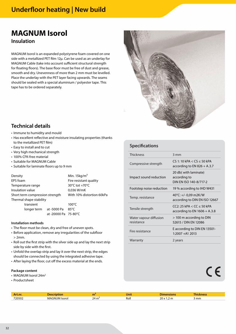
MAGNUM Isorol is an expanded polystyrene foam covered on one side with a metallized PET fi lm 12µ. Can be used as an underlay for MAGNUM Cable (take into account suffi cient structural strength for fl oating fl oors). The base fl oor must be free of dust and grease, smooth and dry. Unevenness of more than 2 mm must be levelled. Place the underlay with the PET layer facing upwards. The seams should be sealed with a special aluminium / polyester tape. This tape has to be ordered separately.
MAGNUM IsorolInsulation
• Immune to humidity and mould• Has excellent refl ective and moisture insulating properties (thanks
to the metallized PET fi lm)• Easy to install and to cut• Very high mechanical strength• 100% CFK-free material• Suitable for MAGNUM Cable• Suitable for laminate fl oors up to 9 mm
Density Min. 15kg/m³EPS foam Fire resistant qualityTemperature range 30°C tot +70°CInsulation value 0,036 W/mKShort term compression strength With 10% distortion 60kPaThermal shape stability transient 100°C longer term at -5000 Pa 85°C at -20000 Pa 75-80°C
Installation methods• The fl oor must be clean, dry and free of uneven spots.• Before application, remove any irregularities of the subfl oor
> 2mm.• Roll out the fi rst strip with the silver side up and lay the next strip
side by side with the fi rst.• Unfold the overlap strip and lay it over the next strip, the edges
should be connected by using the integrated adhesive tape.• After laying the fl oor, cut off the excess material at the ends.
Package content• MAGNUM Isorol 24m2
• Productsheet
Art.nr. Description m² Unit Dimensions Thickness720502 MAGNUM Isorol 24 m² Roll 20 x 1,2 m 3 mm
Technical details
Specifi cations
Thickness 3 mm
Compressive strengthCS 1: 10 kPA < CS ≤ 50 kPA according to EN 826 + A.3.7
Impact sound reduction20 db( with laminate) according to DIN EN ISO 140-8/717-2
Footstep noise reduction 19 % according to IHD W431
Temp. resistance40°C: +/- 0,09 m2K/W according to DIN EN ISO 12667
Tensile strengthCC2: 25 kPA < CC ≤ 50 kPA according to EN 1606 + A.3.8
Water vapour diff usion resistance
> 100 m according to DIN 52615 / DIN EN 12086
Fire resistanceE according to DIN EN 13501-1:2007 +A1 2013
Warranty 2 years
Underfloor heating | New build
33
Underfloor heating | New build
MAGNUM Heating Group B.V.Stevinweg 84691SM TholenThe Netherlands
T +31 166 609300E [email protected] www.magnumheatinggroup.com
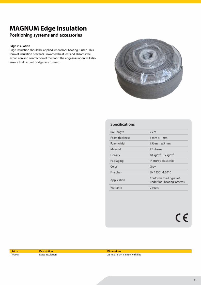
Edge insulationEdge insulation should be applied when fl oor heating is used. This form of insulation prevents unwanted heat loss and absorbs the expansion and contraction of the fl oor. The edge insulation will also ensure that no cold bridges are formed.
MAGNUM Edge insulationPositioning systems and accessories
Specifi cations
Roll length 25 m
Foam thickness 8 mm ± 1 mm
Foam width 150 mm ± 5 mm
Material PE - foam
Density 18 kg/m3 ± 5 kg/m3
Packaging In sturdy plastic foil
Color Grey
Fire class EN 13501-1:2010
Application Conforms to all types of underfl oor heating systems
Warranty 2 years
Art.nr. Description DimensionsW90111 Edge insulation 25 m x 15 cm x 8 mm with fl ap
34
MAGNUM Heating Group B.V.Stevinweg 84691SM TholenThe Netherlands
T +31 166 609300E [email protected] www.magnumheatinggroup.com
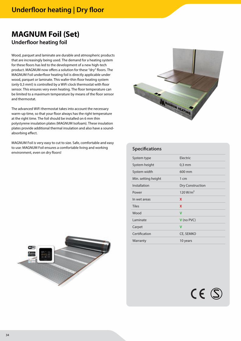
Wood, parquet and laminate are durable and atmospheric products that are increasingly being used. The demand for a heating system for these fl oors has led to the development of a new high-tech product. MAGNUM now off ers a solution for these “dry” fl oors. The MAGNUM Foil underfl oor heating foil is directly applicable under wood, parquet or laminate. This wafer-thin fl oor heating system (only 0,3 mm!) is controlled by a WiFi clock thermostat with fl oor sensor. This ensures very even heating. The fl oor temperature can be limited to a maximum temperature by means of the fl oor sensor and thermostat.
The advanced WiFi thermostat takes into account the necessary warm-up time, so that your fl oor always has the right temperature at the right time. The foil should be installed on 6 mm thin polystyrene insulation plates (MAGNUM Isofoam). These insulation plates provide additional thermal insulation and also have a sound-absorbing eff ect.
MAGNUM Foil is very easy to cut to size. Safe, comfortable and easy to use: MAGNUM Foil ensures a comfortable living and working environment, even on dry fl oors!
MAGNUM Foil (Set)Underfl oor heating foil
Specifi cations
System type Electric
System height 0,3 mm
System width 600 mm
Min. setting height 1 cm
Installation Dry Construction
Power 120 W/m2
In wet areas X
Tiles X
Wood V
Laminate V (no PVC)
Carpet V
Certifi cation CE, SEMKO
Warranty 10 years
Underfloor heating | Dry floor
35
MAGNUM Heating Group B.V.Stevinweg 84691SM TholenThe Netherlands
T +31 166 609300E [email protected] www.magnumheatinggroup.com
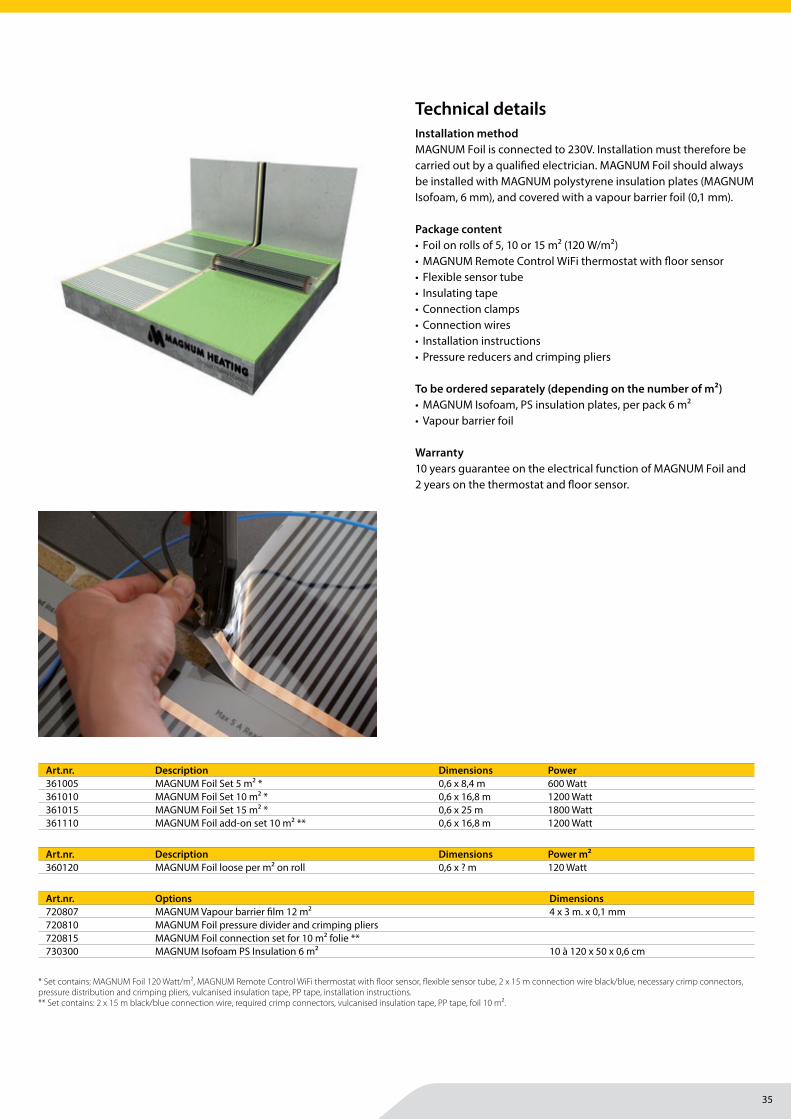
Installation methodMAGNUM Foil is connected to 230V. Installation must therefore be carried out by a qualifi ed electrician. MAGNUM Foil should always be installed with MAGNUM polystyrene insulation plates (MAGNUM Isofoam, 6 mm), and covered with a vapour barrier foil (0,1 mm).
Package content• Foil on rolls of 5, 10 or 15 m² (120 W/m²)• MAGNUM Remote Control WiFi thermostat with fl oor sensor• Flexible sensor tube• Insulating tape• Connection clamps• Connection wires• Installation instructions• Pressure reducers and crimping pliers
To be ordered separately (depending on the number of m²)• MAGNUM Isofoam, PS insulation plates, per pack 6 m²• Vapour barrier foil
Warranty10 years guarantee on the electrical function of MAGNUM Foil and 2 years on the thermostat and fl oor sensor.
Art.nr. Description Dimensions Power361005 MAGNUM Foil Set 5 m2 * 0,6 x 8,4 m 600 Watt361010 MAGNUM Foil Set 10 m2 * 0,6 x 16,8 m 1200 Watt361015 MAGNUM Foil Set 15 m2 * 0,6 x 25 m 1800 Watt361110 MAGNUM Foil add-on set 10 m2 ** 0,6 x 16,8 m 1200 Watt
Art.nr. Options Dimensions720807 MAGNUM Vapour barrier fi lm 12 m2 4 x 3 m. x 0,1 mm720810 MAGNUM Foil pressure divider and crimping pliers720815 MAGNUM Foil connection set for 10 m² folie **730300 MAGNUM Isofoam PS Insulation 6 m2 10 à 120 x 50 x 0,6 cm
Art.nr. Description Dimensions Power m2360120 MAGNUM Foil loose per m2 on roll 0,6 x ? m 120 Watt
Technical details
* Set contains: MAGNUM Foil 120 Watt/m², MAGNUM Remote Control WiFi thermostat with fl oor sensor, fl exible sensor tube, 2 x 15 m connection wire black/blue, necessary crimp connectors, pressure distribution and crimping pliers, vulcanised insulation tape, PP tape, installation instructions.** Set contains: 2 x 15 m black/blue connection wire, required crimp connectors, vulcanised insulation tape, PP tape, foil 10 m².
Underfloor heating | Dry floor
36
MAGNUM Heating Group B.V.Stevinweg 84691SM TholenThe Netherlands
T +31 166 609300E [email protected] www.magnumheatinggroup.com
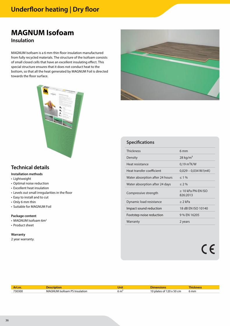
MAGNUM Isofoam is a 6 mm thin fl oor insulation manufactured from fully recycled materials. The structure of the Isofoam consists of small closed cells that have an excellent insulating eff ect. This special structure ensures that it does not conduct heat to the bottom, so that all the heat generated by MAGNUM Foil is directed towards the fl oor surface.
MAGNUM IsofoamInsulation
Specifi cations
Thickness 6 mm
Density 28 kg/m3
Heat resistance 0,19 m2K/W
Heat transfer coeffi cient 0,029 – 0,034 W/(mK)
Water absorption after 24 hours ≤ 1 %
Water absorption after 24 days ≤ 2 %
Compressive strength ≥ 10 kPa PN-EN ISO 826:2013
Dynamic load resistance ≥ 2 kPa
Impact sound reduction 18 dB EN ISO 10140
Footstep noise reduction 9 % EN 16205
Warranty 2 years
Installation methods• Lightweight• Optimal noise reduction• Excellent heat insulation• Levels out small irregularities in the fl oor• Easy to install and to cut• Only 6 mm thin• Suitable for MAGNUM Foil
Package content• MAGNUM Isofoam 6m2
• Product sheet
Warranty2 year warranty.
Art.nr. Description Unit Dimensions Thickness730300 MAGNUM Isofoam PS Insulation 6 m² 10 plates of 120 x 50 cm 6 mm
Technical details
Underfloor heating | Dry floor

37
Underfloor heating | Dry floor
38
MAGNUM Heating Group B.V.Stevinweg 84691SM TholenThe Netherlands
T +31 166 609300E [email protected] www.magnumheatinggroup.com
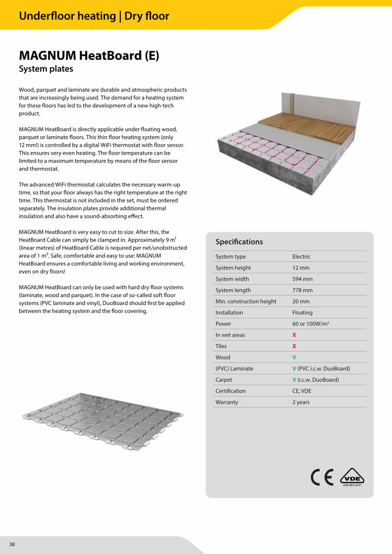
Wood, parquet and laminate are durable and atmospheric products that are increasingly being used. The demand for a heating system for these fl oors has led to the development of a new high-tech product.
MAGNUM HeatBoard is directly applicable under fl oating wood, parquet or laminate fl oors. This thin fl oor heating system (only 12 mm!) is controlled by a digital WiFi thermostat with fl oor sensor. This ensures very even heating. The fl oor temperature can be limited to a maximum temperature by means of the fl oor sensor and thermostat.
The advanced WiFi thermostat calculates the necessary warm-up time, so that your fl oor always has the right temperature at the right time. This thermostat is not included in the set, must be ordered separately. The insulation plates provide additional thermal insulation and also have a sound-absorbing eff ect.
MAGNUM HeatBoard is very easy to cut to size. After this, the HeatBoard Cable can simply be clamped in. Approximately 9 m1 (linear metres) of HeatBoard Cable is required per net/unobstructed area of 1 m2. Safe, comfortable and easy to use: MAGNUM HeatBoard ensures a comfortable living and working environment, even on dry fl oors!
MAGNUM HeatBoard can only be used with hard dry fl oor systems (laminate, wood and parquet). In the case of so-called soft fl oor systems (PVC laminate and vinyl), DuoBoard should fi rst be applied between the heating system and the fl oor covering.
MAGNUM HeatBoard (E)System plates
Specifi cations
System type Electric
System height 12 mm
System width 594 mm
System length 778 mm
Min. construction height 20 mm
Installation Floating
Power 60 or 100W/m2
In wet areas X
Tiles X
Wood V
(PVC) Laminate V (PVC i.c.w. DuoBoard)
Carpet V (i.c.w. DuoBoard)
Certifi cation CE, VDE
Warranty 2 years
VDE-REG 8741
Underfloor heating | Dry floor
39
MAGNUM Heating Group B.V.Stevinweg 84691SM TholenThe Netherlands
T +31 166 609300E [email protected] www.magnumheatinggroup.com
• Designation according to standard EPS-EN13163-T2-L2-W2-S2-P2-DLT(1)5-CS(10)150
• Nominal thickness dL 11,5 mm• Coeffi cient of thermal conductivity 0,036 W/mK DIN V 4108-10 • Thermal resistance 0,32 m2K/W • Compressive stress 150 kPa (at 10 % compression)• Load under tension 45 kPa• Heat resistance < 80°C• Area of application DEO according to DIN 4108-10• Fire behaviour Class E according to EN 1350• Building material class B2 according to DIN 4102 • Material EPS polystyrene hard foam (CFK-free)• Valid standard EN 13163, DIN V 4108-10
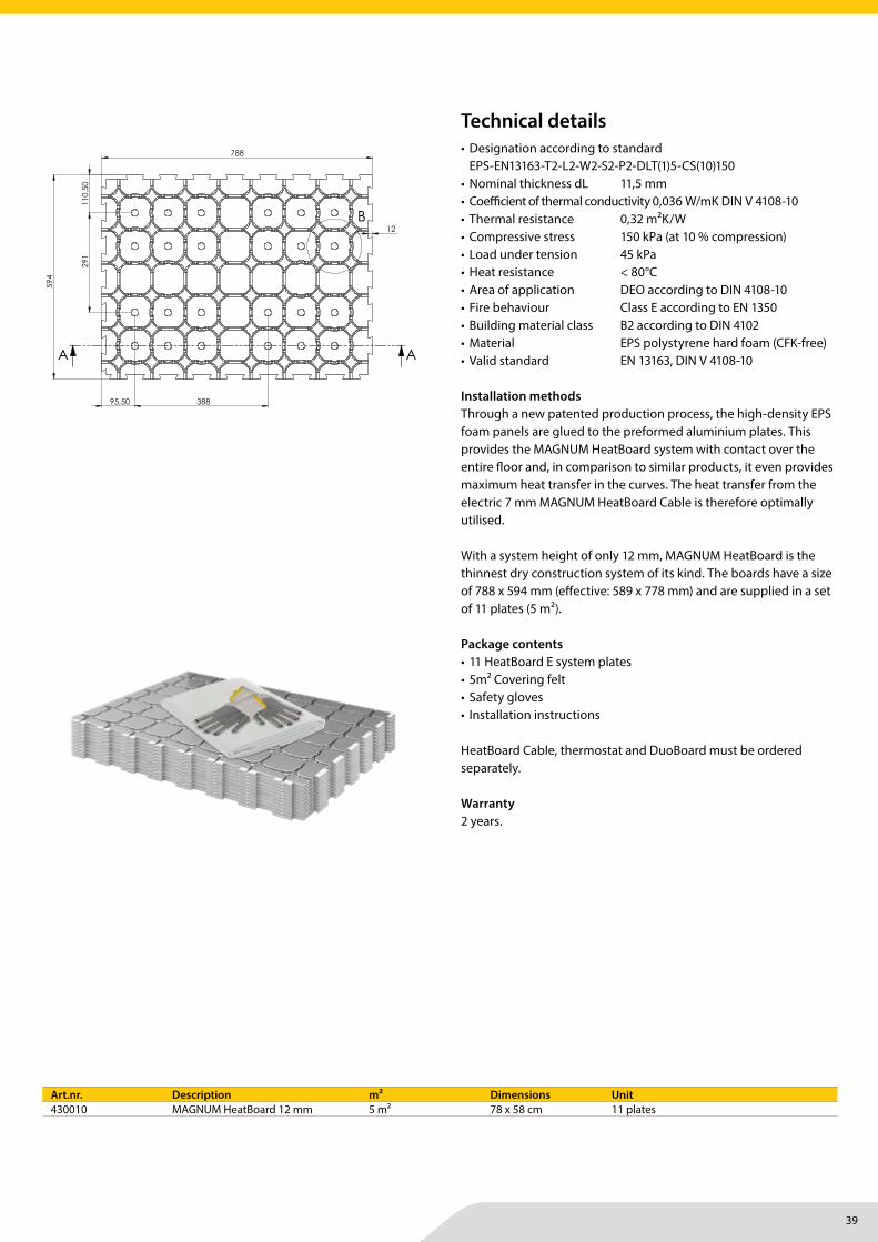
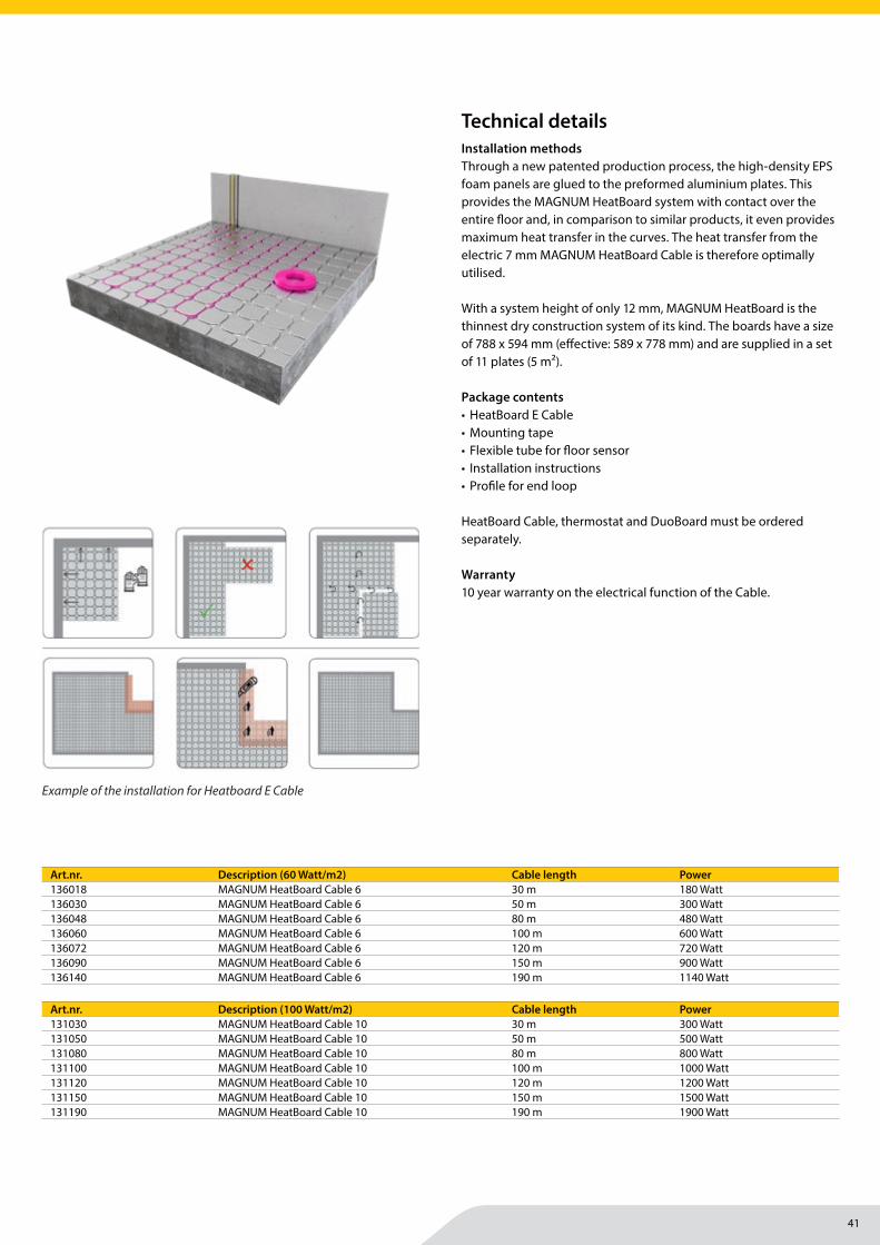
Installation methodsThrough a new patented production process, the high-density EPS foam panels are glued to the preformed aluminium plates. This provides the MAGNUM HeatBoard system with contact over the entire fl oor and, in comparison to similar products, it even provides maximum heat transfer in the curves. The heat transfer from the electric 7 mm MAGNUM HeatBoard Cable is therefore optimally utilised.
With a system height of only 12 mm, MAGNUM HeatBoard is the thinnest dry construction system of its kind. The boards have a size of 788 x 594 mm (eff ective: 589 x 778 mm) and are supplied in a set of 11 plates (5 m2).
Package contents• 11 HeatBoard E system plates• 5m2 Covering felt• Safety gloves• Installation instructions
HeatBoard Cable, thermostat and DuoBoard must be ordered separately.
Warranty2 years.
Art.nr. Description m2 Dimensions Unit430010 MAGNUM HeatBoard 12 mm 5 m2 78 x 58 cm 11 plates
Technical details 788
594
12
388 95,50
110
,50
291
AA
B
10
C
SECTION A-A
SCALE 1 : 5
97
97
DETAIL B
SCALE 2 : 5
3
5,60
R1 20
DETAIL C
SCALE 2 : 5
D
E
F
C
1 2 3 5
B
A
321 5
C
D
4 6 7 8
A
B
Vloerverw plaat raster 97 10mmNAAM:
Rotterdamseweg 248-2542628 AS DelftPostbus 92Telefoon : 015 - 2511151Telefax : 015 - 2620329www.hordijk.nl
1:10
25-9-2017 Magnum
A3
auteursrecht voorbehouden volgens de wet4
Klant:
Material: EPS 30gr/L Volume:
Rev 03945944.29E.v.K
Datum:
Getekend:
Revisie: Format: Scale:
Tek. Nr.:
Underfloor heating | Dry floor
40
MAGNUM Heating Group B.V.Stevinweg 84691SM TholenThe Netherlands
T +31 166 609300E [email protected] www.magnumheatinggroup.com
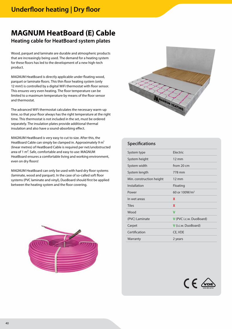
Wood, parquet and laminate are durable and atmospheric products that are increasingly being used. The demand for a heating system for these fl oors has led to the development of a new high-tech product.
MAGNUM HeatBoard is directly applicable under fl oating wood, parquet or laminate fl oors. This thin fl oor heating system (only 12 mm!) is controlled by a digital WiFi thermostat with fl oor sensor. This ensures very even heating. The fl oor temperature can be limited to a maximum temperature by means of the fl oor sensor and thermostat.
The advanced WiFi thermostat calculates the necessary warm-up time, so that your fl oor always has the right temperature at the right time. This thermostat is not included in the set, must be ordered separately. The insulation plates provide additional thermal insulation and also have a sound-absorbing eff ect.
MAGNUM HeatBoard is very easy to cut to size. After this, the HeatBoard Cable can simply be clamped in. Approximately 9 m1 (linear metres) of HeatBoard Cable is required per net/unobstructed area of 1 m2. Safe, comfortable and easy to use: MAGNUM HeatBoard ensures a comfortable living and working environment, even on dry fl oors!
MAGNUM HeatBoard can only be used with hard dry fl oor systems (laminate, wood and parquet). In the case of so-called soft fl oor systems (PVC laminate and vinyl), DuoBoard should fi rst be applied between the heating system and the fl oor covering.
MAGNUM HeatBoard (E) CableHeating cable for HeatBoard system plates
Specifi cations
System type Electric
System height 12 mm
System width from 20 cm
System length 778 mm
Min. construction height 12 mm
Installation Floating
Power 60 or 100W/m2
In wet areas X
Tiles X
Wood V
(PVC) Laminate V (PVC i.c.w. DuoBoard)
Carpet V (i.c.w. DuoBoard)
Certifi cation CE, VDE
Warranty 2 years
VDE-REG 8741
Underfloor heating | Dry floor
41
MAGNUM Heating Group B.V.Stevinweg 84691SM TholenThe Netherlands
T +31 166 609300E [email protected] www.magnumheatinggroup.com
Installation methodsThrough a new patented production process, the high-density EPS foam panels are glued to the preformed aluminium plates. This provides the MAGNUM HeatBoard system with contact over the entire fl oor and, in comparison to similar products, it even provides maximum heat transfer in the curves. The heat transfer from the electric 7 mm MAGNUM HeatBoard Cable is therefore optimally utilised.
With a system height of only 12 mm, MAGNUM HeatBoard is the thinnest dry construction system of its kind. The boards have a size of 788 x 594 mm (eff ective: 589 x 778 mm) and are supplied in a set of 11 plates (5 m2).
Package contents• HeatBoard E Cable• Mounting tape• Flexible tube for fl oor sensor• Installation instructions• Profi le for end loop
HeatBoard Cable, thermostat and DuoBoard must be ordered separately.
Warranty10 year warranty on the electrical function of the Cable.
Art.nr. Description (60 Watt/m2) Cable length Power136018 MAGNUM HeatBoard Cable 6 30 m 180 Watt136030 MAGNUM HeatBoard Cable 6 50 m 300 Watt136048 MAGNUM HeatBoard Cable 6 80 m 480 Watt136060 MAGNUM HeatBoard Cable 6 100 m 600 Watt136072 MAGNUM HeatBoard Cable 6 120 m 720 Watt136090 MAGNUM HeatBoard Cable 6 150 m 900 Watt136140 MAGNUM HeatBoard Cable 6 190 m 1140 Watt
Art.nr. Description (100 Watt/m2) Cable length Power131030 MAGNUM HeatBoard Cable 10 30 m 300 Watt131050 MAGNUM HeatBoard Cable 10 50 m 500 Watt131080 MAGNUM HeatBoard Cable 10 80 m 800 Watt131100 MAGNUM HeatBoard Cable 10 100 m 1000 Watt131120 MAGNUM HeatBoard Cable 10 120 m 1200 Watt131150 MAGNUM HeatBoard Cable 10 150 m 1500 Watt131190 MAGNUM HeatBoard Cable 10 190 m 1900 Watt
Example of the installation for Heatboard E Cable
Technical details
MAGNUM HeatBoard (E)
4
3. Voorbereidingen
Zorg dat de ondergrond waar het systeem verwerkt wordt egaal, schoon, stof- en vetvrij is. Verwijder oneffenheden in de vloer en vul eventuele gaten op.
4. Leggen van de HeatBoard systeemplaten
Begin vanuit een hoek met het leggen van de platen. Gebruik hiervoor de meegeleverde veiligheidshandschoenen om eventuele snijwonden door het aluminium te voorkomen. De platen kunnen eenvoudig aan elkaar worden gelegd door de puzzelvorm. De hele ruimte dient te worden bedekt, eventueel restmateriaal kan eenvoudig worden weggesneden.
Nederlands
LEES GO
ED D
OO
R A.U.B.:BELAN
GRIJKE AAN
DACH
TSPUN
TEN U
IT DE
ALGEM
ENE IN
STALLATIEVOO
RSCHRIFTEN
VOO
RKOM
BESCHA
DIG
ING
Neem
voorzorgsmaatregelen om
te voorkomen
dat tijdens en na installatie de verwarm
ingskabels w
orden beschadigd door bv. het laten vallen van scherpe objecten, het betreden van de kabels, het onvoorzichtig aanbrengen van dekvloer en overige w
erkzaamheden na het aanbrengen van
de dekvloer.
VERWERK H
ET SYSTEEM VO
LLEDIG
Zorg ervoor dat de verwarm
ingskabel of vloerver-w
armingsm
at volledig wordt verw
erkt. In het geval van het M
AGN
UM
Mat/Cable systeem
mag grootte
nooit groter zijn dan het te beleggen oppervlakte.
AA
RDLEKSCH
AKELA
AR VERPLICH
TH
et systeem dient achter een aardlekschakelaar
van maxim
aal 30mA te w
orden geplaatst KN
IP DE VERW
ARM
ING
SKABEL N
OO
IT DO
OR EN
KO
RT DE KA
BEL/MAT N
OO
IT IN!
Indien de
verwarm
ingskabel abusievelijk
toch beschadigd of doorgeknipt is, raadpleeg dan direct de support line: tel. 0900-9110911
LET OP BIJ H
ET PLAATSEN VAN
DE VLO
ERSENSO
R!Plaats de sensor in een afgesloten buis. Installeer deze op ruim
e afstand (min. 50 cm
) van CV of w
aterleidingen. Installeer de sensor exact tussen 2 kabels (lus) van het verw
armingssysteem
. Voorkom
dat de warm
tekabels direct contact maken m
et de buis w
aarin de vloersensor wordt gem
onteerd. Laat de sensorbuis lineair aan de richting van de verw
armingskabel lopen.
BITTE SORG
FÄLTIG LESEN
:W
ICHTIG
E PUN
KTE IN D
EN ALLG
EMEIN
EN
INSTALLATIO
NSVO
RSCHRIFTEN
VERMEID
EN SIE BESCH
ÄD
IGU
NG
ENTreffen Sie Vorsorgem
aßnahmen, um
zu vermei-
den, dass die Heizkabel w
ährend und nach der Installation beschädigt w
erden, z.B. durch das fal-len lassen spitzer G
egenstände, auf die Kabel tre-ten, unsachgem
äßes Anbringen des Bodenbelags und anderer Tätigkeiten nach dem
Anbringen des Bodenbelags.
VERARBEITEN
SIE DA
S SYSTEM VO
LLSTÄN
DIG
Sorgen Sie dafür, dass die Heizkabel bzw
. die Bodenheizungsm
atte vollständig verarbeitet wer-
den. Für das MAG
NU
M M
at/Cable System darf
die Größe der M
atte niemals die zu bedeckende
Oberfläche überschreiten.
F.I.-SCHU
TZSCHA
LTER OBLIG
ATORISCH
Die System
e müssen hinter einen F.I.-Schutzschalter
von höchstens 30 mA positioniert w
erden. D
AS
HEIZKA
BEL N
IEMA
LS D
URC
HSC
HN
EIDEN
U
ND
DIE KA
BEL/MATTE N
IEMA
LS KÜRZEN
! Sollte das H
eizkabel versehentlich doch beschä-digt oder durchgeschnitten w
erden, bitten wir Sie,
Ihren MAG
NU
M H
ändler vor Ort via m
agnumhea-
ting.com zu kontaktieren.
VORSICH
T BEIM
PO
SITION
IEREN
DES
BOD
EN-
FÜH
LERS!Stecken Sie den Fühler in ein verschlossenes Rohr und
installieren Sie
dieses in
angemessenem
Abstand (m
in. 50 cm) zur ZH
bzw. W
asserleitungen. Installieren Sie den Fühler exakt zw
ischen zwei
Kabeln (Schlaufe) des Heizsystem
s. Vermeiden Sie,
Underfloor heating | Dry floor
42
MAGNUM Heating Group B.V.Stevinweg 84691SM TholenThe Netherlands
T +31 166 609300E [email protected] www.magnumheatinggroup.com
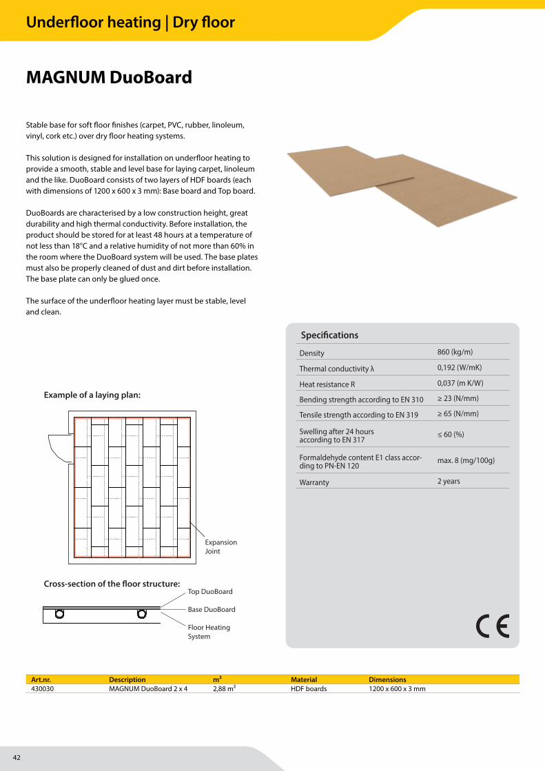
Stable base for soft fl oor fi nishes (carpet, PVC, rubber, linoleum, vinyl, cork etc.) over dry fl oor heating systems.
This solution is designed for installation on underfl oor heating to provide a smooth, stable and level base for laying carpet, linoleum and the like. DuoBoard consists of two layers of HDF boards (each with dimensions of 1200 x 600 x 3 mm): Base board and Top board.
DuoBoards are characterised by a low construction height, great durability and high thermal conductivity. Before installation, the product should be stored for at least 48 hours at a temperature of not less than 18°C and a relative humidity of not more than 60% in the room where the DuoBoard system will be used. The base plates must also be properly cleaned of dust and dirt before installation. The base plate can only be glued once.
The surface of the underfl oor heating layer must be stable, level and clean.
MAGNUM DuoBoard
Specifi cations
Density 860 (kg/m)
Thermal conductivity λ 0,192 (W/mK)
Heat resistance R 0,037 (m K/W)
Bending strength according to EN 310 ≥ 23 (N/mm)
Tensile strength according to EN 319 ≥ 65 (N/mm)
Swelling after 24 hours according to EN 317
≤ 60 (%)
Formaldehyde content E1 class accor-ding to PN-EN 120
max. 8 (mg/100g)
Warranty 2 years
EXAMPLE OF ARRANGEMENT
Base plate
- dimensions: 1200 x 600 x 3 mm- material: HDF- one side coated with glueprotected by PE foil
Edge profile
Expansion joints between rooms
Expansion joints between rooms
Expansion joints (Dilatation profile)
Expansion joints (Dilatation profile)
Expansion joints (Dilatation profile)
Top plate
- dimensions: 1200 x 600 x 3 mm- material: HDF
Top plate
Base plate
Dry underfloor heating board
Edge strip
Edge profile
not less than 1 cm
CROSS SECTION TROUGH THE HEATING FLOOR
Contents of the package:
4x Base DuoBoard
- Measurements: 1200x600x3mm- Material: HDF- 1 side with adhesive layer protected by protective sheet
4x Top DuoBoard
- Measurements: 1200x600x3mm- Material: HDF
Example of a laying plan:
Expansion Joint
EXAMPLE OF ARRANGEMENT
Base plate
- dimensions: 1200 x 600 x 3 mm- material: HDF- one side coated with glueprotected by PE foil
Edge profile
Expansion joints between rooms
Expansion joints between rooms
Expansion joints (Dilatation profile)
Expansion joints (Dilatation profile)
Expansion joints (Dilatation profile)
Top plate
- dimensions: 1200 x 600 x 3 mm- material: HDF
Top plate
Base plate
Dry underfloor heating board
Edge strip
Edge profile
not less than 1 cm
CROSS SECTION TROUGH THE HEATING FLOORTop DuoBoard
Base DuoBoard
Floor Heating System
DUO BOARD - HDF floating non-structural subfloor
A Duo Board set consists of 2x4 HDF boards with dimensions 1200x600x3 mm: Base Board and a Top Board. These have a very good thermal conductivity, low building height and high durability. Prior to installation, the product must be stored for at least 48 hours in a room where the Duo Boards are installed with a minimum temperature of +18°C. Before installation, the subfloor must be free of dust and other dirt. The Duo Boards are only suitable for one-time adhesives.
Installation:
1. Place an edge strip along the walls of the room and install a dry underfloor heating system of your choi-ce.
2. The Base Board should be laid first with the adhesive side facing up, then the Top Board is laid on Base Board in a “brick” manner and thus produces a seamless surface. The boards should be laid parallel or perpendicular to the wall. At least 1cm of space must be left between the edge strip and the Duo Board underlay.
3. To install the Top Boards as described in the second point, cut the row of boards in about 1/3 or 1/2 of their width. The boards can be made to measure using a knife, jigsaw, circular saw etc.
4. Then gradually remove the protective foil from the rest of the Base Board and stick the Top Board to the base. Again, at least 1cm of space should be left between the edge strip and the Duo Board underlay.
5. Expansion joints must be used in rooms that are longer than 8 metres. Use a special expansion profile of foam covered with reinforcement film and place it between the surfaces of the underlay. Expansion joints should also be used in the doorways.
6. If, after laying the Duo Board, the boards forming the surface do not match properly, sand the edges with sandpaper to a smooth surface.
7. You can start laying the floor covering after 48 hours. In the meantime, the temperature in the room should remain +18 degrees Celsius and the humidity should not exceed 60%.
Cross-section of the floor structure:
Art.nr. Description m² Material Dimensions430030 MAGNUM DuoBoard 2 x 4 2,88 m² HDF boards 1200 x 600 x 3 mm
Underfloor heating | Dry floor

43
Underfloor heating | Dry floor
44
MAGNUM Heating Group B.V.Stevinweg 84691SM TholenThe Netherlands
T +31 166 609300E [email protected] www.magnumheatinggroup.com
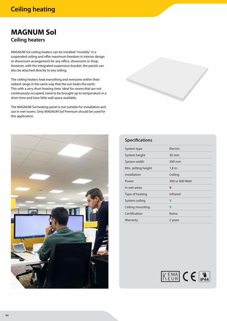
MAGNUM Sol ceiling heaters can be installed “invisibly” in a suspended ceiling and off er maximum freedom in interior design or showroom arrangement for any offi ce, showroom or shop. However, with the integrated suspension bracket, the panels can also be attached directly to any ceiling.
The ceiling heaters heat everything and everyone within their radiant range in the same way that the sun heats the earth. This with a very short heating time. Ideal for rooms that are not continuously occupied, need to be brought up to temperature in a short time and have little wall space available.
The MAGNUM Sol heating panel is not suitable for installation and use in wet rooms. Only MAGNUM Sol Premium should be used for this application.
MAGNUM SolCeiling heaters
Specifi cations
System type Electric
System height 30 mm
System width 590 mm
Min. setting height 1,8 m
Installation Ceiling
Power 300 or 600 Watt
In wet areas X
Type of heating Infrared
System ceiling V
Ceiling mounting V
Certifi cation Kema
Warranty 2 years
IP44
Ceiling heating
45
MAGNUM Heating Group B.V.Stevinweg 84691SM TholenThe Netherlands
T +31 166 609300E [email protected] www.magnumheatinggroup.com
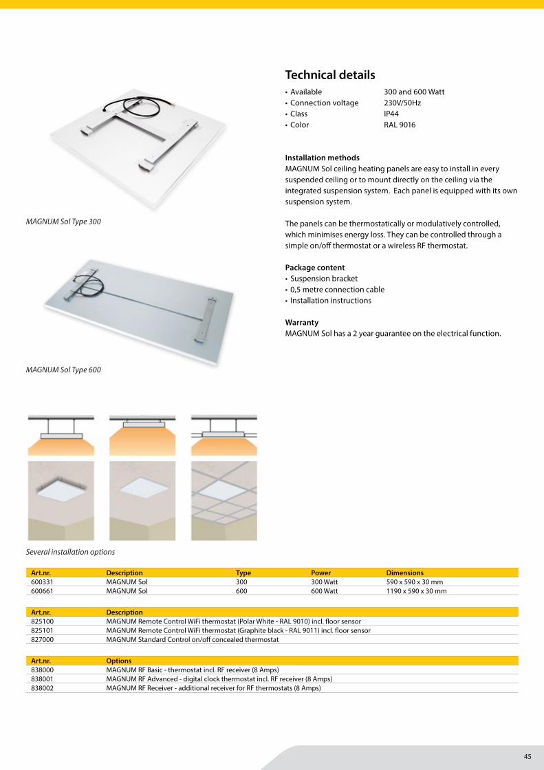
• Available 300 and 600 Watt• Connection voltage 230V/50Hz• Class IP44• Color RAL 9016
Installation methodsMAGNUM Sol ceiling heating panels are easy to install in every suspended ceiling or to mount directly on the ceiling via the integrated suspension system. Each panel is equipped with its own suspension system.
The panels can be thermostatically or modulatively controlled, which minimises energy loss. They can be controlled through a simple on/off thermostat or a wireless RF thermostat.
Package content• Suspension bracket• 0,5 metre connection cable• Installation instructions
WarrantyMAGNUM Sol has a 2 year guarantee on the electrical function.
Art.nr. Description825100 MAGNUM Remote Control WiFi thermostat (Polar White - RAL 9010) incl. fl oor sensor825101 MAGNUM Remote Control WiFi thermostat (Graphite black - RAL 9011) incl. fl oor sensor827000 MAGNUM Standard Control on/off concealed thermostat
Art.nr. Description Type Power Dimensions600331 MAGNUM Sol 300 300 Watt 590 x 590 x 30 mm600661 MAGNUM Sol 600 600 Watt 1190 x 590 x 30 mm
Art.nr. Options838000 MAGNUM RF Basic - thermostat incl. RF receiver (8 Amps)838001 MAGNUM RF Advanced - digital clock thermostat incl. RF receiver (8 Amps)838002 MAGNUM RF Receiver - additional receiver for RF thermostats (8 Amps)
Technical details
MAGNUM Sol Type 600
MAGNUM Sol Type 300
Several installation options
Ceiling heating
46
MAGNUM Heating Group B.V.Stevinweg 84691SM TholenThe Netherlands
T +31 166 609300E [email protected] www.magnumheatinggroup.com
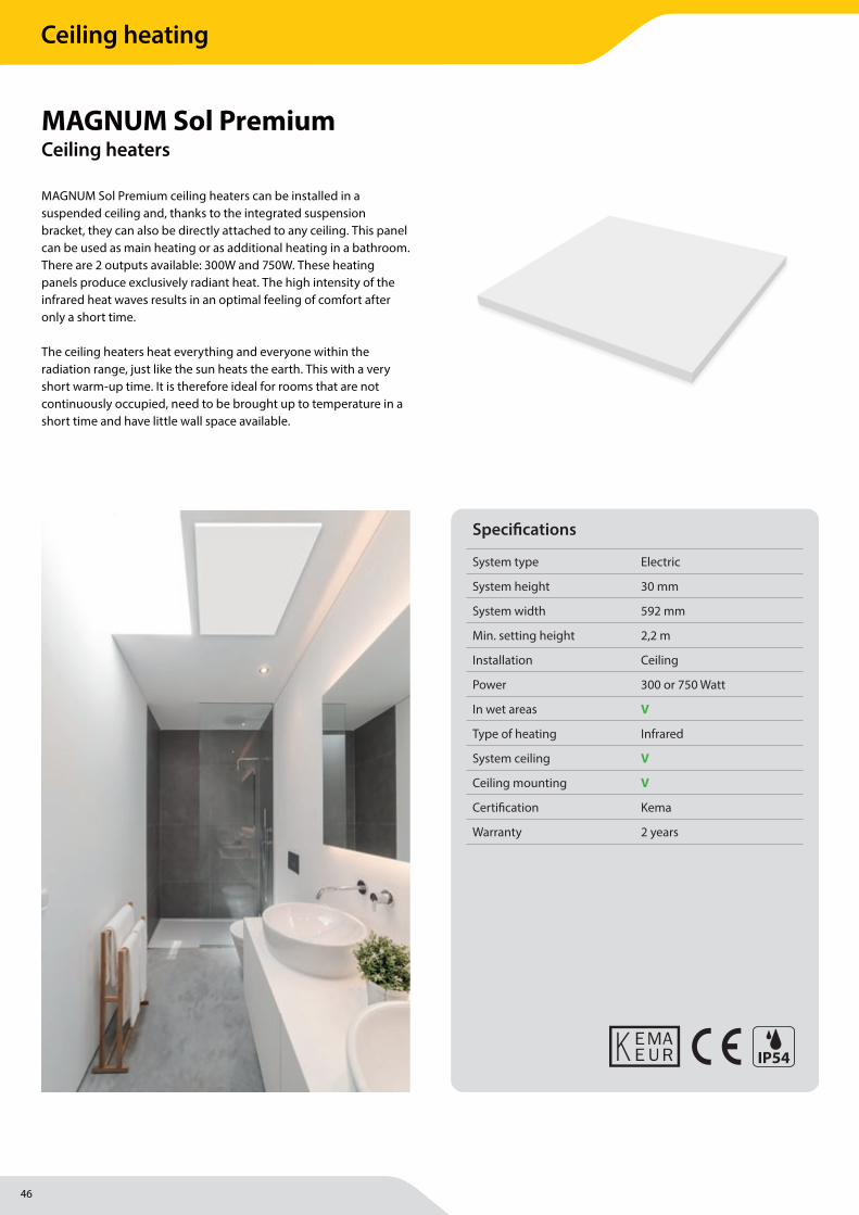
MAGNUM Sol Premium ceiling heaters can be installed in a suspended ceiling and, thanks to the integrated suspension bracket, they can also be directly attached to any ceiling. This panel can be used as main heating or as additional heating in a bathroom. There are 2 outputs available: 300W and 750W. These heating panels produce exclusively radiant heat. The high intensity of the infrared heat waves results in an optimal feeling of comfort after only a short time.
The ceiling heaters heat everything and everyone within the radiation range, just like the sun heats the earth. This with a very short warm-up time. It is therefore ideal for rooms that are not continuously occupied, need to be brought up to temperature in a short time and have little wall space available.
MAGNUM Sol PremiumCeiling heaters
Specifi cations
System type Electric
System height 30 mm
System width 592 mm
Min. setting height 2,2 m
Installation Ceiling
Power 300 or 750 Watt
In wet areas V
Type of heating Infrared
System ceiling V
Ceiling mounting V
Certifi cation Kema
Warranty 2 years
IP54
Ceiling heating
47
MAGNUM Heating Group B.V.Stevinweg 84691SM TholenThe Netherlands
T +31 166 609300E [email protected] www.magnumheatinggroup.com
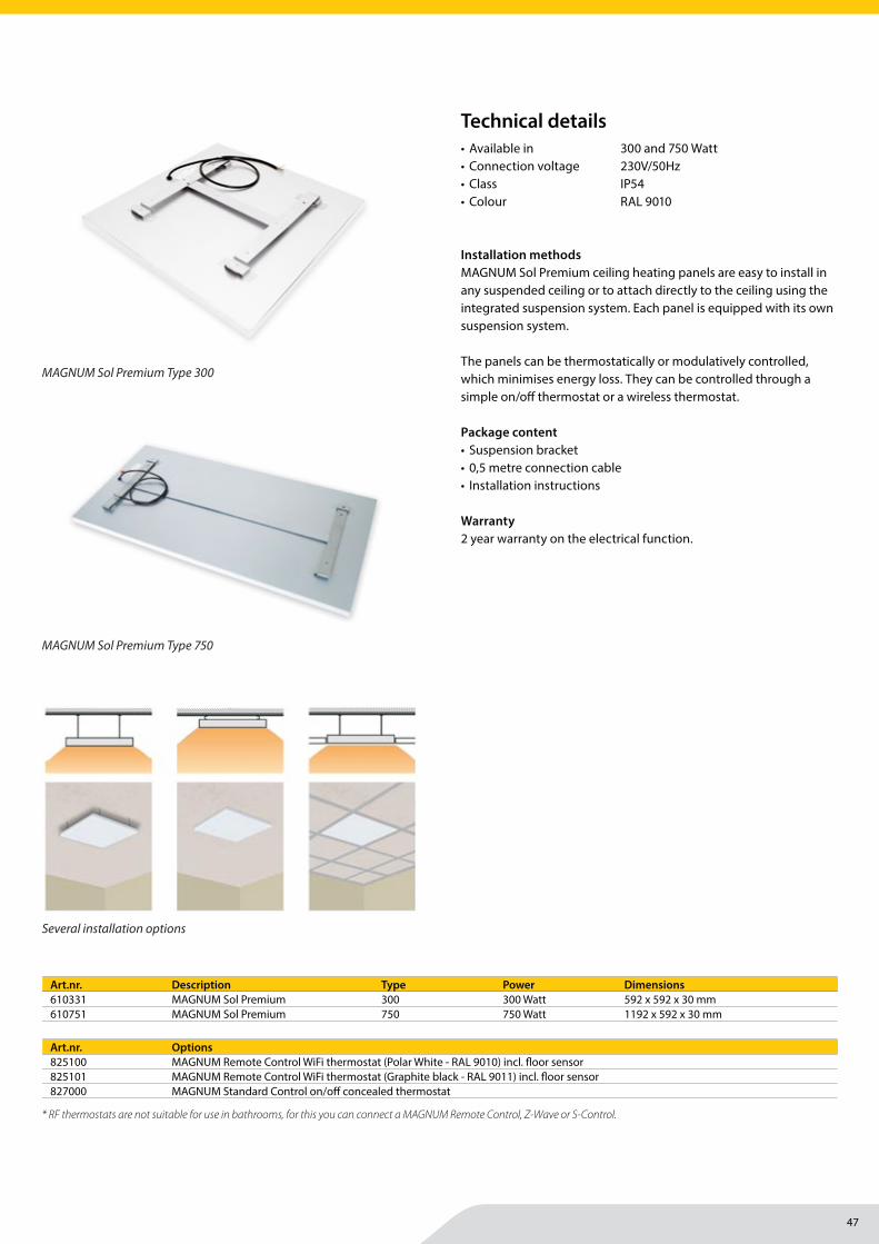
• Available in 300 and 750 Watt• Connection voltage 230V/50Hz• Class IP54• Colour RAL 9010
Installation methodsMAGNUM Sol Premium ceiling heating panels are easy to install in any suspended ceiling or to attach directly to the ceiling using the integrated suspension system. Each panel is equipped with its own suspension system.
The panels can be thermostatically or modulatively controlled, which minimises energy loss. They can be controlled through a simple on/off thermostat or a wireless thermostat.
Package content• Suspension bracket• 0,5 metre connection cable• Installation instructions
Warranty2 year warranty on the electrical function.
Art.nr. Description Type Power Dimensions610331 MAGNUM Sol Premium 300 300 Watt 592 x 592 x 30 mm610751 MAGNUM Sol Premium 750 750 Watt 1192 x 592 x 30 mm
Art.nr. Options825100 MAGNUM Remote Control WiFi thermostat (Polar White - RAL 9010) incl. fl oor sensor825101 MAGNUM Remote Control WiFi thermostat (Graphite black - RAL 9011) incl. fl oor sensor827000 MAGNUM Standard Control on/off concealed thermostat
Technical details
* RF thermostats are not suitable for use in bathrooms, for this you can connect a MAGNUM Remote Control, Z-Wave or S-Control.
MAGNUM Sol Premium Type 750
MAGNUM Sol Premium Type 300
Several installation options
Ceiling heating
48
MAGNUM Heating Group B.V.Stevinweg 84691SM TholenThe Netherlands
T +31 166 609300E [email protected] www.magnumheatinggroup.com
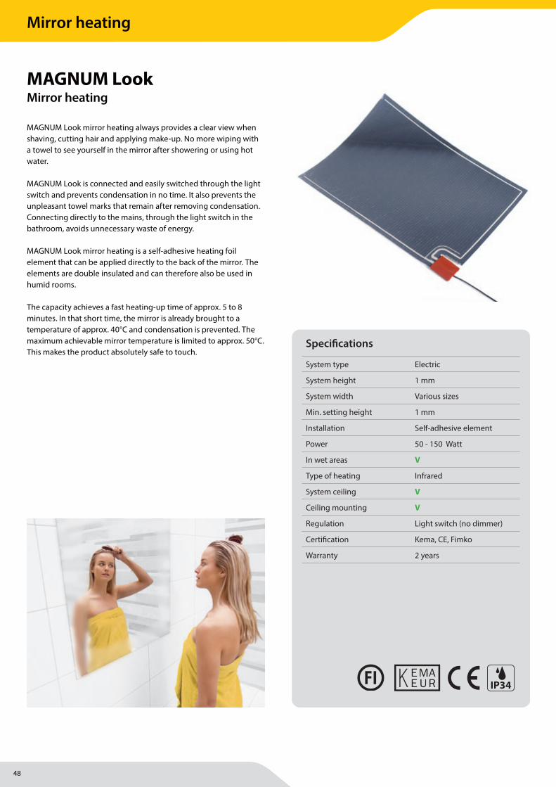
MAGNUM Look mirror heating always provides a clear view when shaving, cutting hair and applying make-up. No more wiping with a towel to see yourself in the mirror after showering or using hot water.
MAGNUM Look is connected and easily switched through the light switch and prevents condensation in no time. It also prevents the unpleasant towel marks that remain after removing condensation. Connecting directly to the mains, through the light switch in the bathroom, avoids unnecessary waste of energy.
MAGNUM Look mirror heating is a self-adhesive heating foil element that can be applied directly to the back of the mirror. The elements are double insulated and can therefore also be used in humid rooms.
The capacity achieves a fast heating-up time of approx. 5 to 8 minutes. In that short time, the mirror is already brought to a temperature of approx. 40°C and condensation is prevented. The maximum achievable mirror temperature is limited to approx. 50°C. This makes the product absolutely safe to touch.
MAGNUM LookMirror heating
Specifi cations
System type Electric
System height 1 mm
System width Various sizes
Min. setting height 1 mm
Installation Self-adhesive element
Power 50 - 150 Watt
In wet areas V
Type of heating Infrared
System ceiling V
Ceiling mounting V
Regulation Light switch (no dimmer)
Certifi cation Kema, CE, Fimko
Warranty 2 years
IP34
Mirror heating
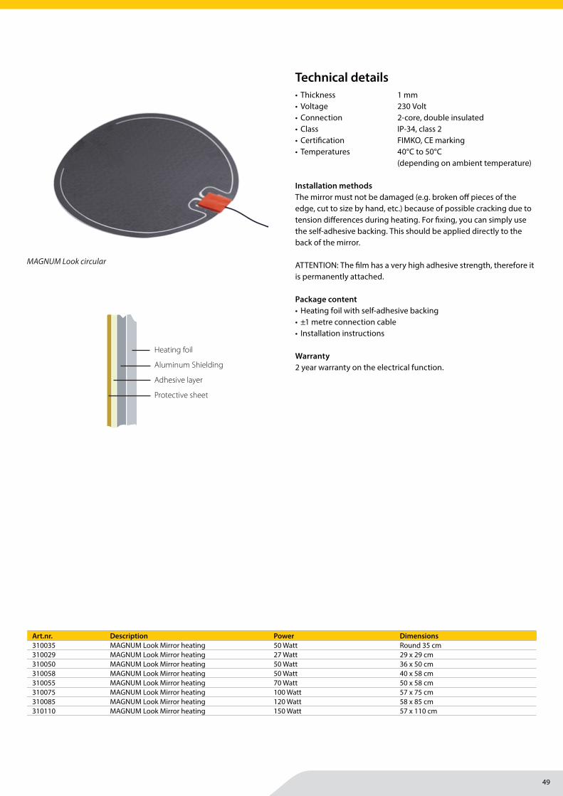
49
MAGNUM Heating Group B.V.Stevinweg 84691SM TholenThe Netherlands
T +31 166 609300E [email protected] www.magnumheatinggroup.com
• Thickness 1 mm• Voltage 230 Volt• Connection 2-core, double insulated• Class IP-34, class 2• Certifi cation FIMKO, CE marking• Temperatures 40°C to 50°C
(depending on ambient temperature)
Installation methodsThe mirror must not be damaged (e.g. broken off pieces of the edge, cut to size by hand, etc.) because of possible cracking due to tension diff erences during heating. For fi xing, you can simply use the self-adhesive backing. This should be applied directly to the back of the mirror.
ATTENTION: The fi lm has a very high adhesive strength, therefore it is permanently attached.
Package content• Heating foil with self-adhesive backing• ±1 metre connection cable• Installation instructions
Warranty2 year warranty on the electrical function.
Art.nr. Description Power Dimensions310035 MAGNUM Look Mirror heating 50 Watt Round 35 cm310029 MAGNUM Look Mirror heating 27 Watt 29 x 29 cm310050 MAGNUM Look Mirror heating 50 Watt 36 x 50 cm310058 MAGNUM Look Mirror heating 50 Watt 40 x 58 cm310055 MAGNUM Look Mirror heating 70 Watt 50 x 58 cm310075 MAGNUM Look Mirror heating 100 Watt 57 x 75 cm310085 MAGNUM Look Mirror heating 120 Watt 58 x 85 cm310110 MAGNUM Look Mirror heating 150 Watt 57 x 110 cm
Technical details
MAGNUM Look MAGNUM LookMANUAL DE INSTALACIÓN
Aplicación de la lámina:- El espejo no debe estar dañado (por ejemplo: piezas rotas en el borde, espejos cortados manualmente a medida, etc.). Estas circunstancias pueden originar grietas en el espejo debido a fluctuaciones de tensión durante el calentamiento.- Para acoplar la lámina al espejo, puede utilizar fácilmente la parte posterior autoadhesiva. Debe colocarse directamente en la parte posterior del espejo. NOTA: La lámina tiene una fuerza adhesiva muy alta y permanentemente.
Instalación del espejo en la pared:- Cuando utilice sujeciones específicas de espejo, no lo fije a la lámina sino a la superficie libre del espejo.- Tenga en cuenta que el conector del elemento calefactor tiene un grosor de ± 4 mm. Debe dejar suficiente espacio en la parte posterior del espejo o puede retirar una parte de la pared si es necesario.- Si el espejo se coloca contra una pared exterior, se recomienda una capa aislante (por ejemplo, MAGNUM Isorol) entre la pared y el espejo.
Adhesión del espejo sobre la pared:- Adhiera la lámina solamente sobre la superficie libre del espejo (la pieza sin elemento calefactor). PRECAUCIÓN: Nunca adhiera sobre el elemento calefactor.
Conexión:- El cable de conexión es de ± 100 cm de longitud y puede extenderse o acortarse.
- Conectar directamente a la red eléctrica, a través del interruptor de iluminación en el baño. Con ello evita el desperdicio innecesario de energía. Debe proporcionar un tubo eléctrico desde el espejo hasta el punto de alimentación eléctrica.- Si se instalan múltiples elementos, deben estar conectados en paralelo, nunca en serie.- Si el espejo está provisto de elementos metálicos, deben de estar conectadas a una toma tierra.
Datos técnicos:
Art.nr. Medida W 310035 redondo 35 cm. 50W310029 29 x 29 cm. 27W310050 36 x 50 cm. 50W310058 40 x 58 cm. 65W310055 50 x 58 cm. 70W310075 57 x 75 cm. 100W310085 58 x 85 cm. 120W310110 57 x 110 cm. 150W
Voltaje 230 VGrosor lámina 1 mm Longitud cable conexión 100 cm Normativa IP34 Clase 2Certificado FIMKO, Marcado CE Temperaturas de 40 a 50°C (dependiendo de la temperatura ambiente)
INSTALLATION MANUAL
Mirror de-misting panel is the totally safe and simple answer to steamed-up mirrors. It is double insulated and designed for use in wet areas such as bathrooms, etc. The panel is only 0.4mm thick. It is simply installed by peeling off the self-adhesive backing and sticking it directly onto the back of the mirror. The capacity of each panel is sufficient to warm up the mirror to 30 °C in 5 to 8 minutes. The surface temperature of the mirror is limited to 45°C. To save energy, the panel wires are connected to the lighting system and switched on only when required. The mirror de-misting panel is for de-misting the mirror and is not a bathroom heater.
Note: - All electrical connections should be undertaken by a qualified electrician. An MCB or RCCB must be used as applicable. - The mirror should not be cut, drilled or altered in any way as this may weaken the mirror.
Installation:Mirror de-misting panels designed for glass mirrors only. Ensure the mirror is larger than the mirror de-misting panel. Carefully peel off self-adhesive backing from the mirror de-misting panels and place directly onto the back of the mirror making sure there are no creases or bubbles. Allow for heat expansion when mounting the mirror i.e. do not butt tiles hard against the mirror allow a silicone expansion gap.
- Do not fit mirror onto or near metallic surfaces, i.e. Aluminium, Stainless steel etc.- Corner brackets must have clearance to allow for
expansion.- If fitting mirror to wall using adhesive, the adhesive should be placed around the edge of the mirror (Minimum 40 mm gap between panel and edge of mirror).- Do not put adhesive onto the mirror de-misting panel.- Do not cut, drill or weaken the mirror structure in any way.- Do not cut or alter the mirror de-misting panel.- Wiring should be carried out in accordance with IEE regulations.
Technical details:
Art.nr. Size Watt 310035 Round 35 cm. 50Watt310029 29 x 29 cm. 27Watt310050 36 x 50 cm. 50Watt310058 40 x 58 cm. 50Watt310055 50 x 58 cm. 70Watt310075 57 x 75 cm. 100Watt310085 58 x 85 cm. 120Watt310110 57 x 110 cm. 150Watt
Voltage 230 VCapacity Depending on sizeThickness 0.4mmCable length 100 cmStandard IP34 Class 2Approval FIMKO, CE markTemperatures Ca 40 to 50 °C maximum
www.magnumheating.com
Español
Engl
ish
VerwarmingsfolieAlu-schildLijmlaagSchutvel
VerwarmingsfolieAlu-schildLijmlaagSchutvel
Heating foil
Aluminum Shielding
Adhesive layer
Protective sheet
Lámina calefactora
Blindaje de aluminio
Capa adhesiva
Hoja protectora
MAGNUM Look circular
Mirror heating
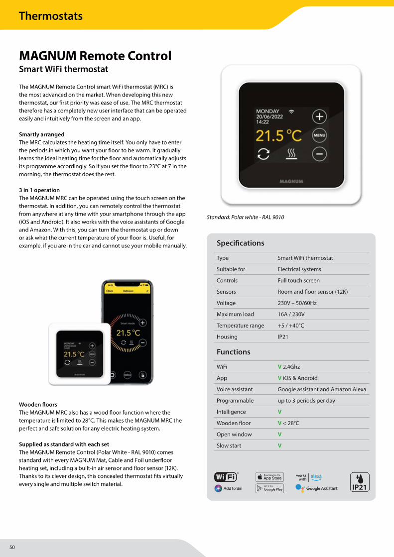
50
MAGNUM Heating Group B.V.Stevinweg 84691SM TholenThe Netherlands
T +31 166 609300E [email protected] www.magnumheatinggroup.com
The MAGNUM Remote Control smart WiFi thermostat (MRC) is the most advanced on the market. When developing this new thermostat, our fi rst priority was ease of use. The MRC thermostat therefore has a completely new user interface that can be operated easily and intuitively from the screen and an app. Smartly arrangedThe MRC calculates the heating time itself. You only have to enter the periods in which you want your fl oor to be warm. It gradually learns the ideal heating time for the fl oor and automatically adjusts its programme accordingly. So if you set the fl oor to 23°C at 7 in the morning, the thermostat does the rest. 3 in 1 operationThe MAGNUM MRC can be operated using the touch screen on the thermostat. In addition, you can remotely control the thermostat from anywhere at any time with your smartphone through the app (iOS and Android). It also works with the voice assistants of Google and Amazon. With this, you can turn the thermostat up or down or ask what the current temperature of your fl oor is. Useful, for example, if you are in the car and cannot use your mobile manually.
Wooden fl oorsThe MAGNUM MRC also has a wood fl oor function where the temperature is limited to 28°C. This makes the MAGNUM MRC the perfect and safe solution for any electric heating system.
Supplied as standard with each setThe MAGNUM Remote Control (Polar White - RAL 9010) comes standard with every MAGNUM Mat, Cable and Foil underfl oor heating set, including a built-in air sensor and fl oor sensor (12K). Thanks to its clever design, this concealed thermostat fi ts virtually every single and multiple switch material.
MAGNUM Remote ControlSmart WiFi thermostat
Specifi cations
Type Smart WiFi thermostat
Suitable for Electrical systems
Controls Full touch screen
Sensors Room and fl oor sensor (12K)
Voltage 230V – 50/60Hz
Maximum load 16A / 230V
Temperature range +5 / +40°C
Housing IP21
Functions
WiFi V 2.4Ghz
App V iOS & Android
Voice assistant Google assistant and Amazon Alexa
Programmable up to 3 periods per day
Intelligence V
Wooden fl oor V < 28°C
Open window V
Slow start V
Standard: Polar white - RAL 9010
IP21
Add to Siri
Add to Siri
Add to Siri
Thermostats
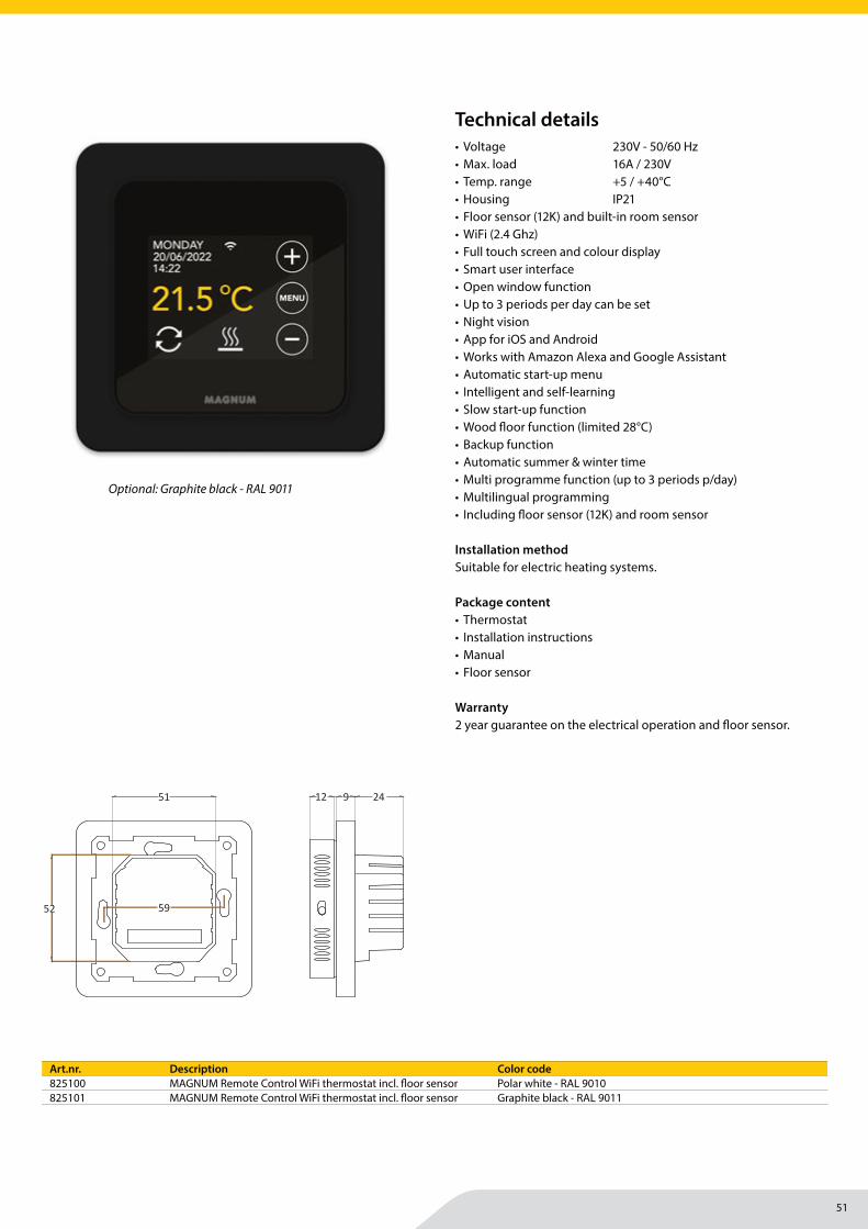
51
MAGNUM Heating Group B.V.Stevinweg 84691SM TholenThe Netherlands
T +31 166 609300E [email protected] www.magnumheatinggroup.com
• Voltage 230V - 50/60 Hz• Max. load 16A / 230V• Temp. range +5 / +40°C• Housing IP21 • Floor sensor (12K) and built-in room sensor• WiFi (2.4 Ghz)• Full touch screen and colour display• Smart user interface• Open window function• Up to 3 periods per day can be set• Night vision • App for iOS and Android• Works with Amazon Alexa and Google Assistant • Automatic start-up menu• Intelligent and self-learning• Slow start-up function• Wood fl oor function (limited 28°C)• Backup function• Automatic summer & winter time• Multi programme function (up to 3 periods p/day)• Multilingual programming• Including fl oor sensor (12K) and room sensor
Installation methodSuitable for electric heating systems.
Package content• Thermostat• Installation instructions• Manual• Floor sensor
Warranty2 year guarantee on the electrical operation and fl oor sensor.
Art.nr. Description Color code825100 MAGNUM Remote Control WiFi thermostat incl. fl oor sensor Polar white - RAL 9010825101 MAGNUM Remote Control WiFi thermostat incl. fl oor sensor Graphite black - RAL 9011
Optional: Graphite black - RAL 9011
Technical details
86
86 59
51
52
24912
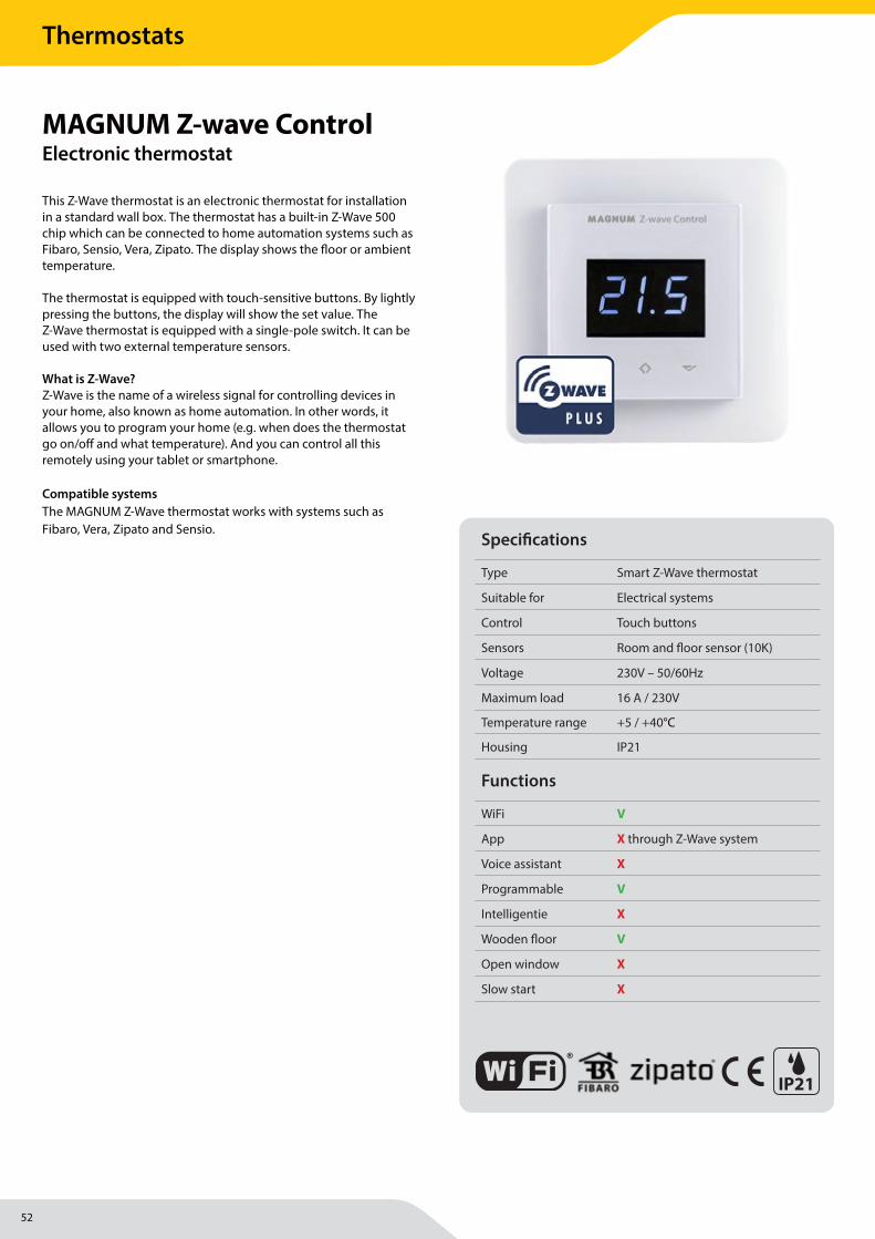
52
MAGNUM Heating Group B.V.Stevinweg 84691SM TholenThe Netherlands
T +31 166 609300E [email protected] www.magnumheatinggroup.com
This Z-Wave thermostat is an electronic thermostat for installation in a standard wall box. The thermostat has a built-in Z-Wave 500 chip which can be connected to home automation systems such as Fibaro, Sensio, Vera, Zipato. The display shows the fl oor or ambient temperature.
The thermostat is equipped with touch-sensitive buttons. By lightly pressing the buttons, the display will show the set value. The Z-Wave thermostat is equipped with a single-pole switch. It can be used with two external temperature sensors.
What is Z-Wave? Z-Wave is the name of a wireless signal for controlling devices in your home, also known as home automation. In other words, it allows you to program your home (e.g. when does the thermostat go on/off and what temperature). And you can control all this remotely using your tablet or smartphone.
Compatible systemsThe MAGNUM Z-Wave thermostat works with systems such as Fibaro, Vera, Zipato and Sensio.
MAGNUM Z-wave ControlElectronic thermostat
Specifi cations
Type Smart Z-Wave thermostat
Suitable for Electrical systems
Control Touch buttons
Sensors Room and fl oor sensor (10K)
Voltage 230V – 50/60Hz
Maximum load 16 A / 230V
Temperature range +5 / +40°C
Housing IP21
Functions
WiFi V
App X through Z-Wave system
Voice assistant X
Programmable V
Intelligentie X
Wooden fl oor V
Open window X
Slow start X
IP21
Thermostats

53
MAGNUM Heating Group B.V.Stevinweg 84691SM TholenThe Netherlands
T +31 166 609300E [email protected] www.magnumheatinggroup.com
• Voltage 230 Volt - 50/60 Hz• Max. load 16A / 230 V• Temperature range +5 / +40°C• Class IP21 • Color Polar white (RAL 9010)
Black (RAL 9011)• Certifi cation CE • Power consumption 1,5W• Min/Max operating temp. 5°C tot 40°C• Temp.interval fl oor sensor 5°C tot 40°C• Temp.interval room sensor 5°C tot 40°C• Smartstart Adding the thermostat to a
Z-wave network by scanning a supplied QR code
• Power metering Reading consumption• Over The Air Update (OTA) The ability to update the
Z-wave wirelessly• Room and fl oor sensor• Temperature limiter• Power controller• Built-in Z-Wave chip 500 series• Weekly programme through gateway• 7-segment LCD display• Can be used in combination with various NTC sensors• Lock mode / child lock• Backlight• Calibration possibility• 8 scenarios• Works with Fibaro, Sensio, Vera and Zipato systems
Installation methodSuitable for electric heating systems.
Package content• Thermostat• Installation instructions• Floor sensor
Warranty2 year guarantee on the electrical operation and fl oor sensor.
Art.nr. Description Color code825861 MAGNUM Z-wave Control for Fibaro, Sensio, Vera and Zipato systems Polar white - RAL 9010825860 MAGNUM Z-wave Control for Fibaro, Sensio, Vera and Zipato systems Graphite black - RAL 9011
MAGNUM Z-wave all black (optional)
Technical details
MAGNUM Z-wave measurements
INTRODUCTIONHeatit Z-TRM3 is an electronic thermostat for electrical
floor heating, designed to be mounted in a standard
flush box. The thermostat has a built-in Z-Wave chip
that can be connected with Home Automation
systems. Heatit Z-TRM3 is equipped with a single pole
switch and fits into System 55 frames. The thermostat
can withstand a load of max 16A /3600W at 230V.
The thermostat may be used for water based heating
if the thermostat is linked with the Heatit Z-Water.
NB! If the sensor mode is changed to A or AF mode
then a room sensor compensation process will
start, which limits maximum power output to 75%.
The thermostat adapts to the environment within
a few days. No internal sensor calibration should be
performed during the first few days.
INSTALLATIONUse e.g. a small slotted screwdriver. Start by carefully
removing the front cover by pushing the release springs.
The front cover and the frame may now be removed.
Connect the wires to the thermostat terminals: Use
1,5mm² or 2,5mm² according to load.
HEATIT Z-TRM3 Quickguide Ver 2020-A
Read the full manual at:manuals.heatit.com
manuals.thermo-floor.no
49,5mm
49,5
mm
8 7 6 5
D
C
B
A
B
C
D
E
F
12345678
F
E
A
Date
Pages
Author
Designer
Scale
Document type
Document descriptionItem
Document code and revision
1/1
Modifier
Page size
-- A4
XL1331-A-02
XL1331
Drawing
PRINTED Z-TRM3 THERMOSTAT BOTTOM
21.01.2020MM--
This document and all information and data inclosed herein or herewith are the con�dential and proprietary property of Ouman Oy and are not to be used, reproduced or disclosed in whole or in part to anyone without written permission of Ouman Oy.
Part: XKA367Tool: YP1079
51,1mm
15,6mm21,3mm
HEATING (N) Heating cable connection (Neutral)
N Power connection (Neutral) 230V
L Power connection (Live) 230V
HEATING (L) Heating cable connection
FLOOR SENSOR NTC type (10, 12, 15, 22, 33 or 47kΩ). Default 10kΩ.
EXTERNAL SENSOR NTC type (10, 12, 15, 22, 33 or 47kΩ). Default 10kΩ.
Next, position the thermostat and fasten it onto the
wall’s mounting box using 2-4 screws. Position the
frame, then position and carefully press the front cover
until it snaps in place. Check that the front cover has
snapped in place properly on both left and right side.
The front cover should now be firmly fixed on all sides.
To be able to to read the Power Metering, the load
needs to be connected to both heating L + N.
Release spring
58,8mm
87mm
1: Left 2: Center 3: Right
MULTIREG® Z-WAVE
Thermostats
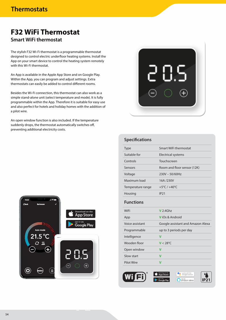
54
Thermostats
MAGNUM Heating Group B.V.Stevinweg 84691SM TholenThe Netherlands
T +31 166 609300E [email protected] www.magnumheatinggroup.com
The stylish F32 Wi-Fi thermostat is a programmable thermostat designed to control electric underfl oor heating systems. Install the App on your smart device to control the heating system remotely with this Wi-Fi thermostat.
An App is available in the Apple App Store and on Google Play. Within the App, you can program and adjust settings. Extra thermostats can easily be added to control diff erent rooms.
Besides the Wi-Fi connection, this thermostat can also work as a simple stand-alone unit (select temperature and mode). It is fully programmable within the App. Therefore it is suitable for easy use and also perfect for hotels and holiday homes with the addition of a pilot wire.
An open window function is also included. If the temperature suddenly drops, the thermostat automatically switches off , preventing additional electricity costs.
F32 WiFi ThermostatSmart WiFi thermostat
Auto mode
BathroomBack
14:22
Auto mode
BathroomBack
14:22
BLUE LED (wi� function):Form “Homescreen” Press O for 5 sec.Blink Fast : Open app (shows APP) choose thermostat in APP and connect.LED Blink Slow: Connecting to wi� (WF slow blink in displayBLUE LED On / CON in display: Wi� connected, (homes-creen after 10 sec.)
GREEN:On : Mode selected
RED:
IN HOME SCREEN AND ONHeating in progress
BLINK FAST + ERROR MESSAGES:
LOST WIFI CONNECTIONWF in screen and RED LED both Blink fast
FLOOR SENSOR ERRORFSE in screen and RED LED both blink fast.
OPEN WINDOW DETECTEDOW in screen and RED LED both blink fast.
WHITE: LEDPress any button 1x: wake up display and buttons (= Homescreen) Temperature shown in display)Falls asleep in 30sec.
Within 30 sec. on homescreen Press O : Shows which mode it’s in (AUT, MA, FSP, HOL, SLO). Within 5 sec. Press + or - to choose between di� e-rent modes.
Chosing HOL and con� rm with O next screen is number of day’s 1-999. Press + or - to choose num-ber of days. Press O again to con� rm (Shows Green LED + HOL 2 sec/ Number of days 2 sec and returns to homescreen)
Any other mode: Press O again to con� rm chosen mode, shows green LED and mode in display (goes to wake up screen and buttons after 4 sec.)
au
A
FSP
HoL
SlO
fSe
F
APP
LOC
O
CON
= auto mode
= manual mode
= frost protection
= holiday mode
= slow start + Red LED blinking slow
= fl oor sensor error + Red LED blinking fast
= Connecting to WiFi + Blue LED blinking slow
= Blinking + Blue LED blinking fast
= Keylock active
= Open Window + Red LED blinking fast
= WiFi Connected + Blue LED on
F
2 O.5 2 O.5 2 O.5 2 O.5
jj
jj
FUNCTION KEYS:
Form “Homescreen”
Press + or - to choose desired temp.
press - for 5 sec.= Keylock onpress + for 5 sec= Keylock o�
jj
7 seg display
Auto mode
BathroomBack
14:22
Auto mode
BathroomBack
14:22
BLUE LED (wi� function):Form “Homescreen” Press O for 5 sec.Blink Fast : Open app (shows APP) choose thermostat in APP and connect.LED Blink Slow: Connecting to wi� (WF slow blink in displayBLUE LED On / CON in display: Wi� connected, (homes-creen after 10 sec.)
GREEN:On : Mode selected
RED:
IN HOME SCREEN AND ONHeating in progress
BLINK FAST + ERROR MESSAGES:
LOST WIFI CONNECTIONWF in screen and RED LED both Blink fast
FLOOR SENSOR ERRORFSE in screen and RED LED both blink fast.
OPEN WINDOW DETECTEDOW in screen and RED LED both blink fast.
WHITE: LEDPress any button 1x: wake up display and buttons (= Homescreen) Temperature shown in display)Falls asleep in 30sec.
Within 30 sec. on homescreen Press O : Shows which mode it’s in (AUT, MA, FSP, HOL, SLO). Within 5 sec. Press + or - to choose between di� e-rent modes.
Chosing HOL and con� rm with O next screen is number of day’s 1-999. Press + or - to choose num-ber of days. Press O again to con� rm (Shows Green LED + HOL 2 sec/ Number of days 2 sec and returns to homescreen)
Any other mode: Press O again to con� rm chosen mode, shows green LED and mode in display (goes to wake up screen and buttons after 4 sec.)
au
A
FSP
HoL
SlO
fSe
F
APP
LOC
O
CON
= auto mode
= manual mode
= frost protection
= holiday mode
= slow start + Red LED blinking slow
= fl oor sensor error + Red LED blinking fast
= Connecting to WiFi + Blue LED blinking slow
= Blinking + Blue LED blinking fast
= Keylock active
= Open Window + Red LED blinking fast
= WiFi Connected + Blue LED on
F
2 O.5 2 O.5 2 O.5 2 O.5
jj
jj
FUNCTION KEYS:
Form “Homescreen”
Press + or - to choose desired temp.
press - for 5 sec.= Keylock onpress + for 5 sec= Keylock o�
jj
7 seg display
Specifi cations
Type Smart WiFi thermostat
Suitable for Electrical systems
Controls Touchscreen
Sensors Room and fl oor sensor (12K)
Voltage 230V – 50/60Hz
Maximum load 16A /230V
Temperature range +5°C / +40°C
Housing IP21
Functions
WiFi V 2.4Ghz
App V iOs & Android
Voice assistant Google assistant and Amazon Alexa
Programmable up to 3 periods per day
Intelligence V
Wooden fl oor V < 28°C
Open window V
Slow start V
Pilot Wire V
IP21

55
MAGNUM Heating Group B.V.Stevinweg 84691SM TholenThe Netherlands
T +31 166 609300E [email protected] www.magnumheatinggroup.com
• Housing IP 21• Voltage 230 Volt - 50/60 Hz• Temperature range +5°C / +40°C• Maximum power 16A - 3600 Watt• Certifi cation FI / CE• Thermostat with WiFi function• 7 segment display screen• Touch-sensitive button control• Free App available for iOS and Android• Works with Google Assistant and Amazon Alexa• Night clock screen saver• Automatic start-up menu• Intelligent and self-learning• Slow start-up function• Wooden fl oor function (limited 28°C)• Pilot wire• Backup function• Automatic summer & winter time• Multi programme function (3 periods p/day)• Multilingual programming in App
Installation methodSuitable for electric heating systems.
Package content• F32 WiFi Thermostat• Cover frame• Floor sensor (12K) • Installation instructions
Warranty2 year guarantee on the electrical operation and fl oor sensor.
Art.nr. Description825880 F32 Smart WiFi thermostat incl. fl oor sensor
Technical details
86
86 59
51
52
24912
2 O.5
Thermostats Q2-2022
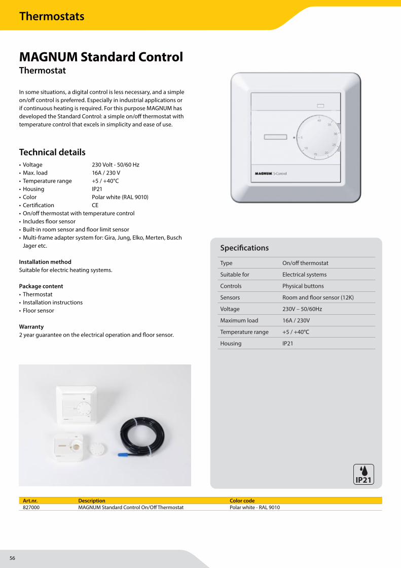
56
Thermostats
MAGNUM Heating Group B.V.Stevinweg 84691SM TholenThe Netherlands
T +31 166 609300E [email protected] www.magnumheatinggroup.com
In some situations, a digital control is less necessary, and a simple on/off control is preferred. Especially in industrial applications or if continuous heating is required. For this purpose MAGNUM has developed the Standard Control: a simple on/off thermostat with temperature control that excels in simplicity and ease of use.
MAGNUM Standard ControlThermostat
• Voltage 230 Volt - 50/60 Hz• Max. load 16A / 230 V• Temperature range +5 / +40°C• Housing IP21 • Color Polar white (RAL 9010)• Certifi cation CE • On/off thermostat with temperature control• Includes fl oor sensor• Built-in room sensor and fl oor limit sensor• Multi-frame adapter system for: Gira, Jung, Elko, Merten, Busch
Jager etc.
Installation methodSuitable for electric heating systems.
Package content• Thermostat• Installation instructions• Floor sensor
Warranty2 year guarantee on the electrical operation and fl oor sensor.
Art.nr. Description Color code827000 MAGNUM Standard Control On/Off Thermostat Polar white - RAL 9010
Technical details
Specifi cations
Type On/off thermostat
Suitable for Electrical systems
Controls Physical buttons
Sensors Room and fl oor sensor (12K)
Voltage 230V – 50/60Hz
Maximum load 16A / 230V
Temperature range +5 / +40°C
Housing IP21
IP21

57
Thermostats

58
MAGNUM Heating Group B.V.Stevinweg 84691SM TholenThe Netherlands
T +31 166 609300E [email protected] www.magnumheatinggroup.com
MAGNUM SlimFit 10Underfl oor heating system
Specifi cations
System type Water based
System height 12 mm (incl. tube)
System width from 20 cm
Min. setting height 15 mm
Installation Self-levelling / Screed
Power Variable
In wet areas V
Tiles V
Wood V (i.c.w. self-levelling)
(PVC) Laminate V (i.c.w. self-levelling)
Carpet V (i.c.w. self-levelling)
Certifi cation CE, KOMO, MPA, SKZ
Warranty 50 years
With an installation height from 10 mm, MAGNUM Slimfi t is one of the lowest systems of its kind. Can be used for both wall and fl oor heating.
This system consists of plastic mats (tiles) that are simply clicked together. An underfl oor heating tube of 10 mm is clamped in the mats with the same ease. The total height of only 12 mm makes this system ideal for renovation projects. Installation is possible both on the fl oor and in the wall.
The open structure of the tiles ensures perfect adhesion of the cast fl oor to the base fl oor as well as to the wall. This system can also be used as main heating.
If the system is used as a heating/cooling system in the wall, the mat supports the plaster and the MAGNUM Slimfi t behaves like a reinforcement.
MAGNUM Slimfi t 10 was developed for the 10 mm MAGNUM Tube. The 10 mm tube is supplied in lengths of 80 and 240 metres. The maximum tube length per group is 80 metres.
Floor heating | Renovation
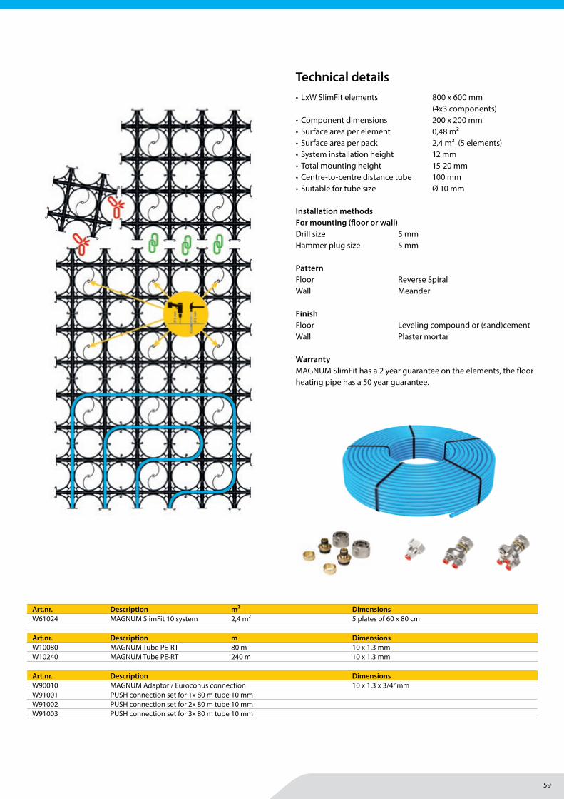
59
MAGNUM Heating Group B.V.Stevinweg 84691SM TholenThe Netherlands
T +31 166 609300E [email protected] www.magnumheatinggroup.com
• LxW SlimFit elements 800 x 600 mm (4x3 components)
• Component dimensions 200 x 200 mm• Surface area per element 0,48 m2• Surface area per pack 2,4 m2 (5 elements)• System installation height 12 mm• Total mounting height 15-20 mm• Centre-to-centre distance tube 100 mm • Suitable for tube size Ø 10 mm
Installation methodsFor mounting (fl oor or wall) Drill size 5 mmHammer plug size 5 mm
PatternFloor Reverse SpiralWall Meander FinishFloor Leveling compound or (sand)cementWall Plaster mortar
WarrantyMAGNUM SlimFit has a 2 year guarantee on the elements, the fl oor heating pipe has a 50 year guarantee.
Art.nr. Description m² DimensionsW61024 MAGNUM SlimFit 10 system 2,4 m² 5 plates of 60 x 80 cm
Technical details
Art.nr. Description m DimensionsW10080 MAGNUM Tube PE-RT 80 m 10 x 1,3 mmW10240 MAGNUM Tube PE-RT 240 m 10 x 1,3 mm
Art.nr. Description DimensionsW90010 MAGNUM Adaptor / Euroconus connection 10 x 1,3 x 3/4” mmW91001 PUSH connection set for 1x 80 m tube 10 mmW91002 PUSH connection set for 2x 80 m tube 10 mmW91003 PUSH connection set for 3x 80 m tube 10 mm
Floor heating | Renovation
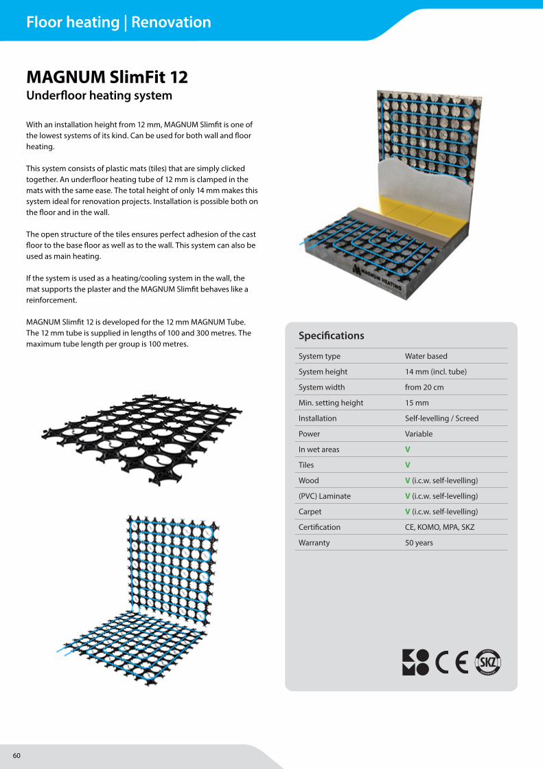
60
MAGNUM Heating Group B.V.Stevinweg 84691SM TholenThe Netherlands
T +31 166 609300E [email protected] www.magnumheatinggroup.com
MAGNUM SlimFit 12Underfl oor heating system
Specifi cations
System type Water based
System height 14 mm (incl. tube)
System width from 20 cm
Min. setting height 15 mm
Installation Self-levelling / Screed
Power Variable
In wet areas V
Tiles V
Wood V (i.c.w. self-levelling)
(PVC) Laminate V (i.c.w. self-levelling)
Carpet V (i.c.w. self-levelling)
Certifi cation CE, KOMO, MPA, SKZ
Warranty 50 years
With an installation height from 12 mm, MAGNUM Slimfi t is one of the lowest systems of its kind. Can be used for both wall and fl oor heating.
This system consists of plastic mats (tiles) that are simply clicked together. An underfl oor heating tube of 12 mm is clamped in the mats with the same ease. The total height of only 14 mm makes this system ideal for renovation projects. Installation is possible both on the fl oor and in the wall.
The open structure of the tiles ensures perfect adhesion of the cast fl oor to the base fl oor as well as to the wall. This system can also be used as main heating.
If the system is used as a heating/cooling system in the wall, the mat supports the plaster and the MAGNUM Slimfi t behaves like a reinforcement.
MAGNUM Slimfi t 12 is developed for the 12 mm MAGNUM Tube. The 12 mm tube is supplied in lengths of 100 and 300 metres. The maximum tube length per group is 100 metres.
Floor heating | Renovation

61
MAGNUM Heating Group B.V.Stevinweg 84691SM TholenThe Netherlands
T +31 166 609300E [email protected] www.magnumheatinggroup.com
• LxW SlimFit elements 1000 x 750 mm (4x3 components)
• Component dimensions 250 x 250 mm• Surface area per element 0,75 m2• Surface area per pack 3,75 m2 (5 elements)• System installation height 14 mm• Total mounting height 17-22 mm• Centre-to-centre distance tube 125 mm • Suitable for tube size Ø 12 mm
Installation methodsFor mounting (fl oor or wall) Drill size 5 mmHammer plug size 5 mm
PatternFloor Reverse SpiralWall Meander FinishFloor Leveling compound or (sand)cementWall Plaster mortar
WarrantyMAGNUM SlimFit has a 2 year guarantee on the elements, the fl oor heating pipe has a 50 year guarantee.
Art.nr. Description m² DimensionsW61012 MAGNUM SlimFit 12 system 3,75 m² 5 plates of 75 x 100 cm
Technical details
Art.nr. Description m DimensionsW12100 MAGNUM Tube PE-RT 100 m 12 x 1,5 mmW12300 MAGNUM Tube PE-RT 300 m 12 x 1,5 mm
Art.nr. Description DimensionsW90012 MAGNUM Adaptor / Euroconus connection 12 x 1,5 x 3/4” mmW91201 PUSH connection set for 1x 80 m tube 12 mmW91202 PUSH connection set for 2x 80 m tube 12 mmW91203 PUSH connection set for 3x 80 m tube 12 mm
Floor heating | Renovation
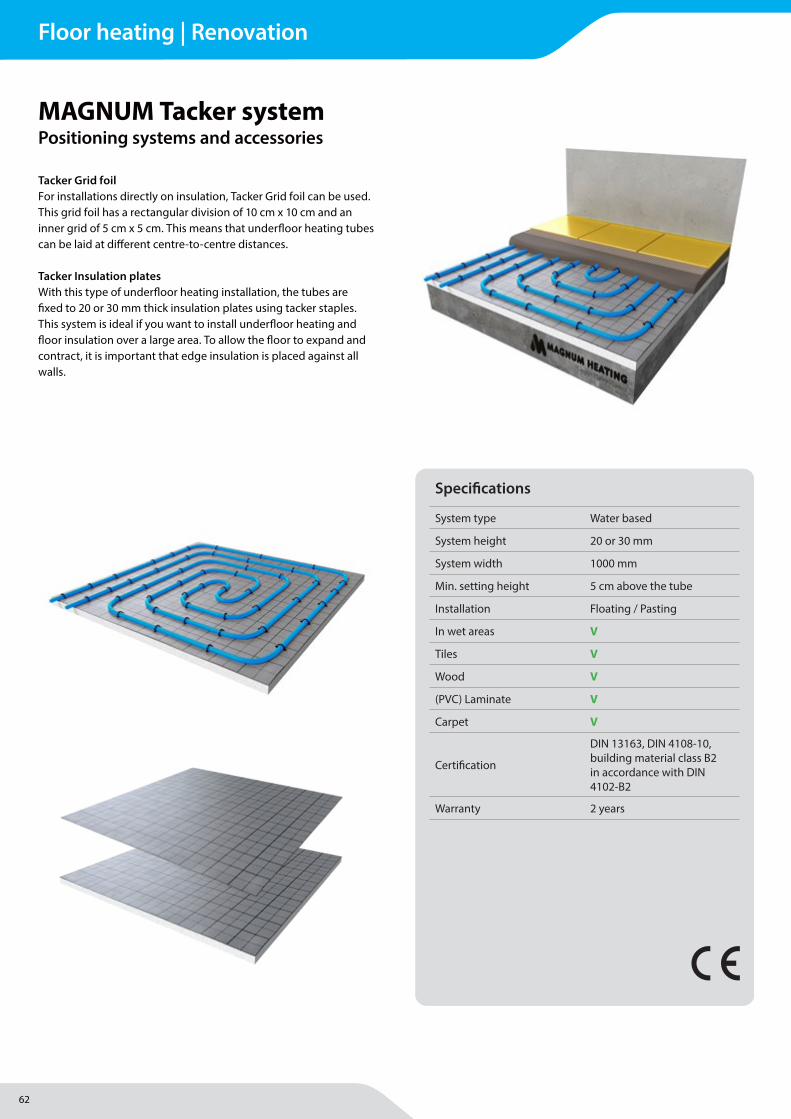
62
MAGNUM Heating Group B.V.Stevinweg 84691SM TholenThe Netherlands
T +31 166 609300E [email protected] www.magnumheatinggroup.com
Tacker Grid foilFor installations directly on insulation, Tacker Grid foil can be used. This grid foil has a rectangular division of 10 cm x 10 cm and an inner grid of 5 cm x 5 cm. This means that underfl oor heating tubes can be laid at diff erent centre-to-centre distances.
Tacker Insulation platesWith this type of underfl oor heating installation, the tubes are fi xed to 20 or 30 mm thick insulation plates using tacker staples. This system is ideal if you want to install underfl oor heating and fl oor insulation over a large area. To allow the fl oor to expand and contract, it is important that edge insulation is placed against all walls.
MAGNUM Tacker systemPositioning systems and accessories
Specifi cations
System type Water based
System height 20 or 30 mm
System width 1000 mm
Min. setting height 5 cm above the tube
Installation Floating / Pasting
In wet areas V
Tiles V
Wood V
(PVC) Laminate V
Carpet V
Certifi cation
DIN 13163, DIN 4108-10, building material class B2 in accordance with DIN 4102-B2
Warranty 2 years
Floor heating | Renovation
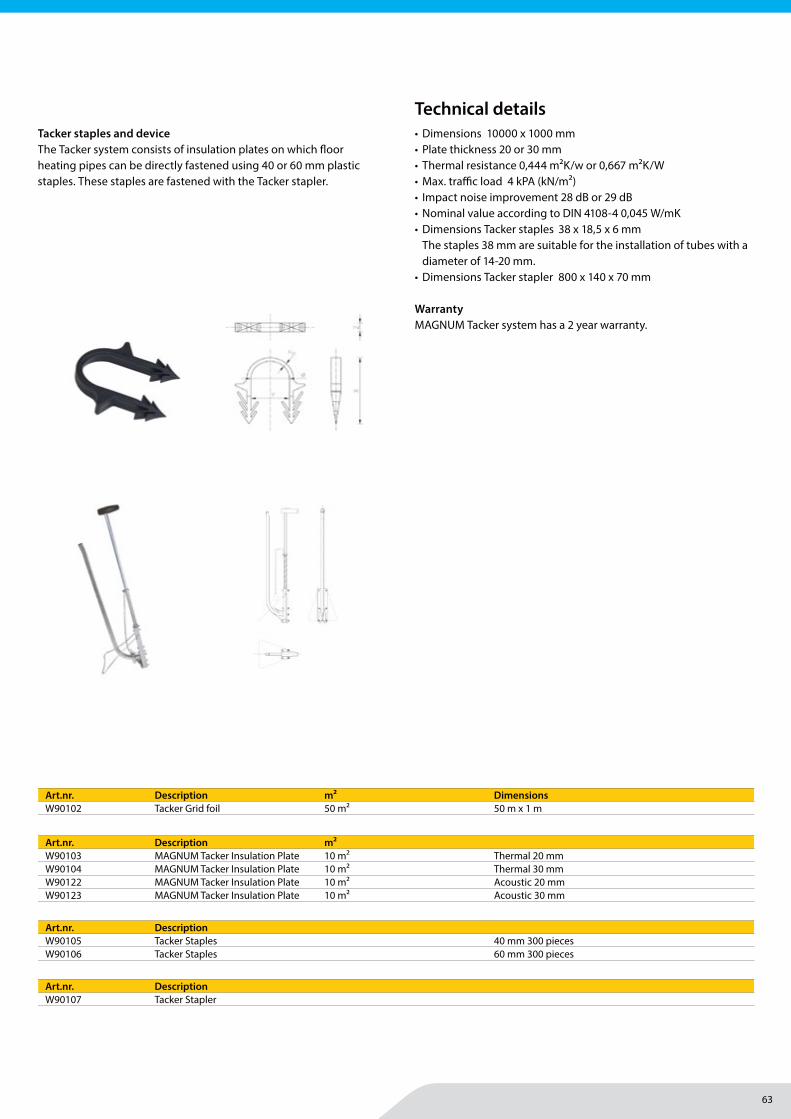
63
MAGNUM Heating Group B.V.Stevinweg 84691SM TholenThe Netherlands
T +31 166 609300E [email protected] www.magnumheatinggroup.com
• Dimensions 10000 x 1000 mm• Plate thickness 20 or 30 mm• Thermal resistance 0,444 m2K/w or 0,667 m2K/W• Max. traffi c load 4 kPA (kN/m2)• Impact noise improvement 28 dB or 29 dB• Nominal value according to DIN 4108-4 0,045 W/mK• Dimensions Tacker staples 38 x 18,5 x 6 mm
The staples 38 mm are suitable for the installation of tubes with a diameter of 14-20 mm.
• Dimensions Tacker stapler 800 x 140 x 70 mm
WarrantyMAGNUM Tacker system has a 2 year warranty.
Art.nr. Description m² DimensionsW90102 Tacker Grid foil 50 m² 50 m x 1 m
Art.nr. DescriptionW90107 Tacker Stapler
Art.nr. Description m²W90103 MAGNUM Tacker Insulation Plate 10 m² Thermal 20 mmW90104 MAGNUM Tacker Insulation Plate 10 m² Thermal 30 mmW90122 MAGNUM Tacker Insulation Plate 10 m² Acoustic 20 mmW90123 MAGNUM Tacker Insulation Plate 10 m² Acoustic 30 mm
Art.nr. DescriptionW90105 Tacker Staples 40 mm 300 piecesW90106 Tacker Staples 60 mm 300 pieces
Technical details
T iA S p . z o . o . +48 12 262 96 59 Słowackiego 22a [email protected] 37-200 Przeworsk [email protected] Poland www.tia.com.pl
Taker Tacker gun for UFH
DANE PRODUKTU / SPECIFICATIONS
MATERIAŁ: Stal, aluminium ZALETY UŻYWANIA TAKERA TIA:
krótki czas montażu, co zwiększa wydajność i komfort pracy całkowita niezawodność urządzenia wysoka precyzja pracy łatwość użytkowania solidna konstrukcja i zastosowanie materiałów wysokiej jakości
zapewnia długotrwałe użytkowanie i odporność na uszkodzenia
Taker jest ergonomicznym urządzeniem służącym do szybkiego montażu klipsów mocujących rurę w systemach ogrzewania podłogowego. Długość klipsów może być dobrana w zależności od grubości styropianu. Taker doskonale współpracuje z klipsami marki TiA o długościach: 38, 40, 45 lub 60 mm, jak również z innymi dostępnymi na rynku dzięki odpowiedniemu systemowi regulacji.
MATERIAL: Steel, aluminum ADVANTAGES OF USING TIA’S TACKER:
short installation time, what improves efficiency and work comfort
total reliability of tacker high precision of work ease of utilisation solid construction of tacker and its performance of high quality
materials ensure the long-lasting use and resistance to damages
Tacker gun is an ergonomic device used for efficient fixing pipes in underfloor heating systems, by driving in tacker staples to the insulating layer of styrofoam. Length of staples can be selected according to the thickness of the styrofoam. Taker works perfectly with staples brand TiA length 38, 40, 45 or 60 mm and others on the market thanks to the proper system of adjustment.
Znajdź ten produkt na naszej stronie! Find this product on our website!
SYSTEMY GRZEWCZE / HEATING SYSTEMS
WŁASNOŚCI PRODUKTU / PRODUCT FEATURES
T iA S p . z o . o . +48 12 262 96 59 Słowackiego 22a [email protected] 37-200 Przeworsk [email protected] Poland www.tia.com.pl
Klips do montażu ręcznego 38 mm / MTGP-KMR Pipe staples for manual mounting 38 mm
DANE PRODUKTU / SPECIFICATIONS
MATERIAŁ: Polipropylen
Klipsy stosuje się do mocowania rur ogrzewania podłogowego do styropianowej warstwy izolacyjnej.
Długość klipsów zastosowanych do montażu zależy od grubości zastosowanej warstwy izolacyjnej.
Klips 38 mm znajduje zastosowanie przy montażu rur o średnicach w zakresie 14-20mm.
MATERIAL: Polypropylene
Znajdź ten produkt na naszej stronie! Find this product on our website!
SYSTEMY GRZEWCZE / HEATING SYSTEMS
WŁASNOŚCI PRODUKTU / PRODUCT FEATURES
Staples 38 mm are used to fasten floor heating pipes to insulating layer.
Length of staples, that should be used for fixing depends on the thickness of the applied insulation layer.
Staple 38 mm is suitable for installation of pipes with diameters of 14-20mm.
Tacker staples and device The Tacker system consists of insulation plates on which fl oor heating pipes can be directly fastened using 40 or 60 mm plastic staples. These staples are fastened with the Tacker stapler.
Floor heating | Renovation
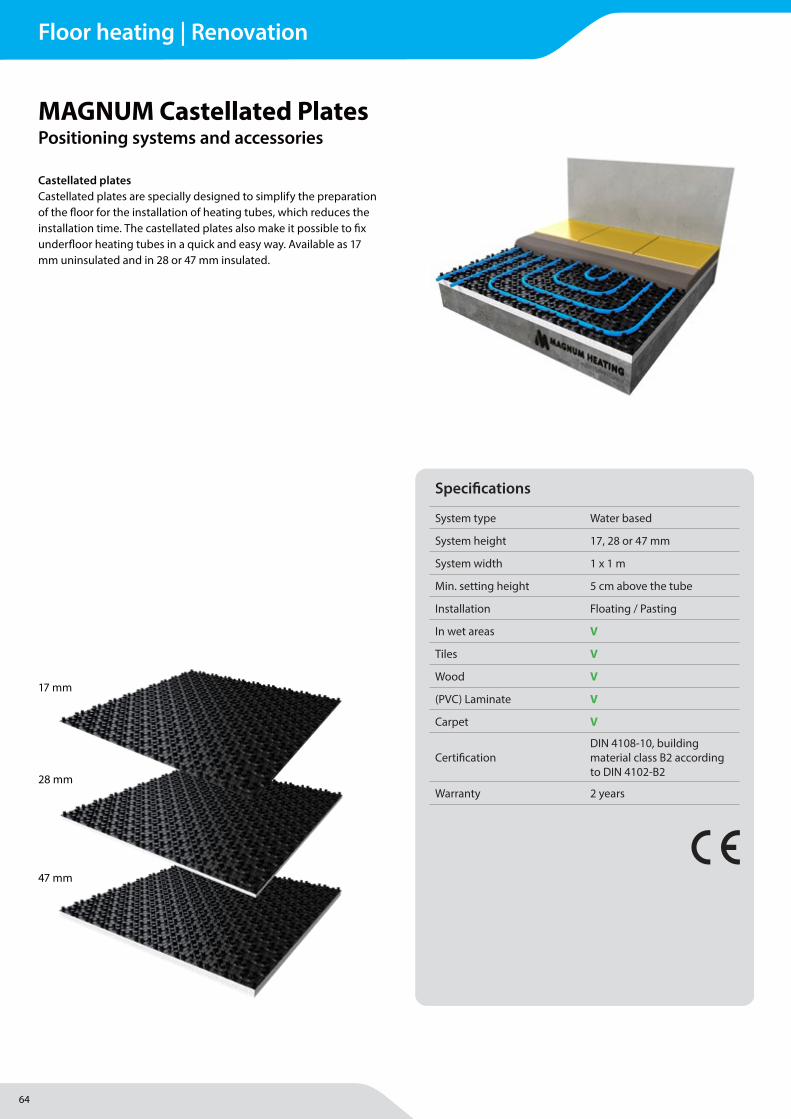
64
MAGNUM Heating Group B.V.Stevinweg 84691SM TholenThe Netherlands
T +31 166 609300E [email protected] www.magnumheatinggroup.com
Castellated platesCastellated plates are specially designed to simplify the preparation of the fl oor for the installation of heating tubes, which reduces the installation time. The castellated plates also make it possible to fi x underfl oor heating tubes in a quick and easy way. Available as 17 mm uninsulated and in 28 or 47 mm insulated.
MAGNUM Castellated PlatesPositioning systems and accessories
Specifi cations
System type Water based
System height 17, 28 or 47 mm
System width 1 x 1 m
Min. setting height 5 cm above the tube
Installation Floating / Pasting
In wet areas V
Tiles V
Wood V
(PVC) Laminate V
Carpet V
Certifi cationDIN 4108-10, building material class B2 according to DIN 4102-B2
Warranty 2 years
17 mm
28 mm
47 mm
Floor heating | Renovation
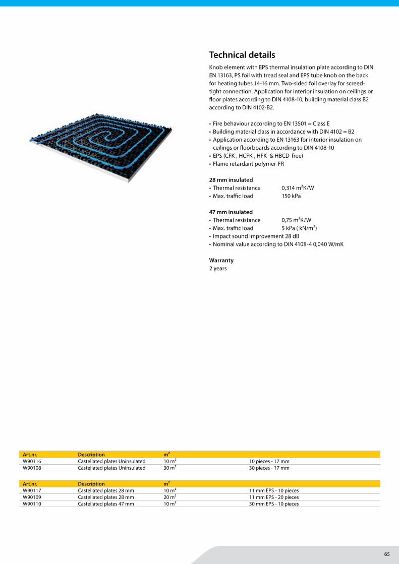
65
MAGNUM Heating Group B.V.Stevinweg 84691SM TholenThe Netherlands
T +31 166 609300E [email protected] www.magnumheatinggroup.com
Knob element with EPS thermal insulation plate according to DIN EN 13163, PS foil with tread seal and EPS tube knob on the back for heating tubes 14-16 mm. Two-sided foil overlay for screed-tight connection. Application for interior insulation on ceilings or fl oor plates according to DIN 4108-10, building material class B2 according to DIN 4102-B2.
• Fire behaviour according to EN 13501 = Class E• Building material class in accordance with DIN 4102 = B2• Application according to EN 13163 for interior insulation on
ceilings or fl oorboards according to DIN 4108-10• EPS (CFK-, HCFK-, HFK- & HBCD-free) • Flame retardant polymer-FR
28 mm insulated• Thermal resistance 0,314 m²K/W• Max. traffi c load 150 kPa
47 mm insulated• Thermal resistance 0,75 m²K/W• Max. traffi c load 5 kPa ( kN/m²)• Impact sound improvement 28 dB• Nominal value according to DIN 4108-4 0,040 W/mK
Warranty2 years
Technical details
Art.nr. Description m²W90116 Castellated plates Uninsulated 10 m² 10 pieces - 17 mmW90108 Castellated plates Uninsulated 30 m² 30 pieces - 17 mm
Art.nr. Description m²W90117 Castellated plates 28 mm 10 m² 11 mm EPS - 10 piecesW90109 Castellated plates 28 mm 20 m² 11 mm EPS - 20 piecesW90110 Castellated plates 47 mm 10 m² 30 mm EPS - 10 pieces
Floor heating | Renovation
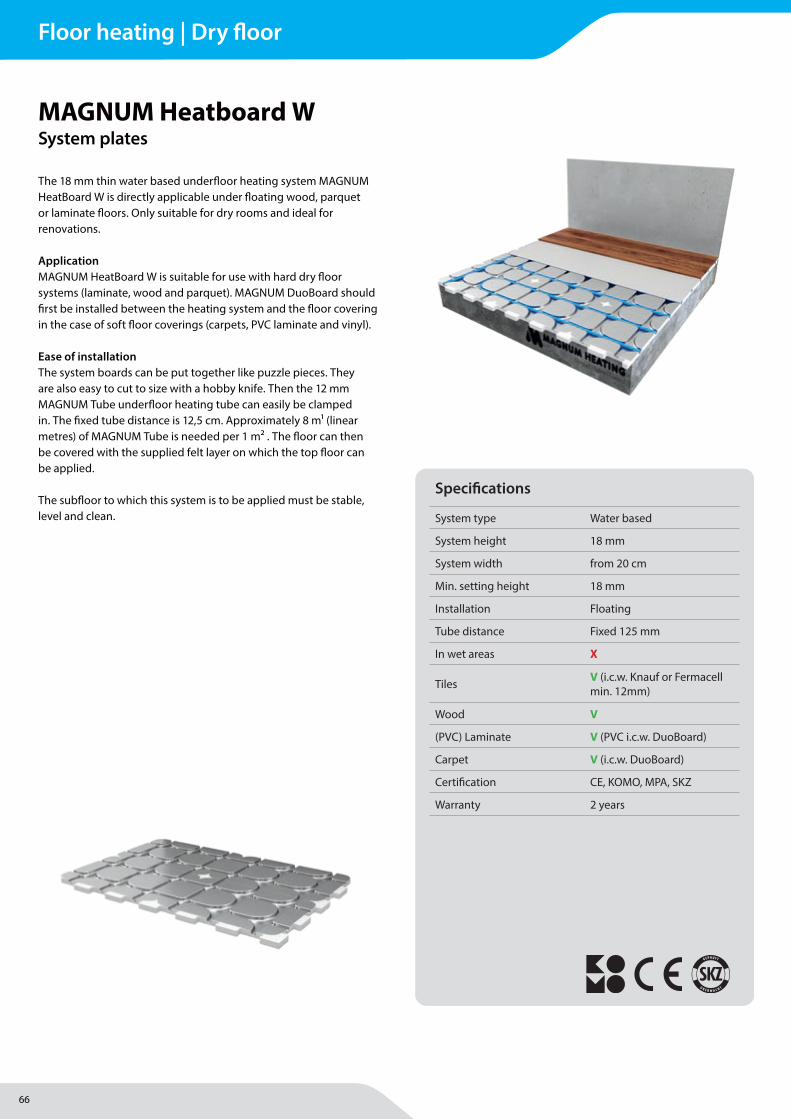
66
MAGNUM Heating Group B.V.Stevinweg 84691SM TholenThe Netherlands
T +31 166 609300E [email protected] www.magnumheatinggroup.com
The 18 mm thin water based underfl oor heating system MAGNUM HeatBoard W is directly applicable under fl oating wood, parquet or laminate fl oors. Only suitable for dry rooms and ideal for renovations.
Application MAGNUM HeatBoard W is suitable for use with hard dry fl oor systems (laminate, wood and parquet). MAGNUM DuoBoard should fi rst be installed between the heating system and the fl oor covering in the case of soft fl oor coverings (carpets, PVC laminate and vinyl).
Ease of installationThe system boards can be put together like puzzle pieces. They are also easy to cut to size with a hobby knife. Then the 12 mm MAGNUM Tube underfl oor heating tube can easily be clamped in. The fi xed tube distance is 12,5 cm. Approximately 8 m1 (linear metres) of MAGNUM Tube is needed per 1 m2 . The fl oor can then be covered with the supplied felt layer on which the top fl oor can be applied.
The subfl oor to which this system is to be applied must be stable, level and clean.
MAGNUM Heatboard WSystem plates
Specifi cations
System type Water based
System height 18 mm
System width from 20 cm
Min. setting height 18 mm
Installation Floating
Tube distance Fixed 125 mm
In wet areas X
Tiles V (i.c.w. Knauf or Fermacell min. 12mm)
Wood V
(PVC) Laminate V (PVC i.c.w. DuoBoard)
Carpet V (i.c.w. DuoBoard)
Certifi cation CE, KOMO, MPA, SKZ
Warranty 2 years
Floor heating | Dry floor
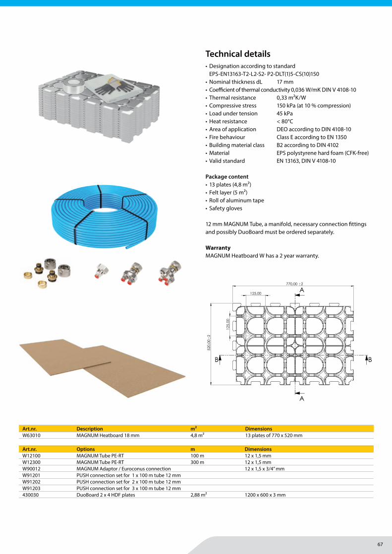
67
MAGNUM Heating Group B.V.Stevinweg 84691SM TholenThe Netherlands
T +31 166 609300E [email protected] www.magnumheatinggroup.com
• Designation according to standard EPS-EN13163-T2-L2-S2- P2-DLT(1)5-CS(10)150
• Nominal thickness dL 17 mm• Coeffi cient of thermal conductivity 0,036 W/mK DIN V 4108-10 • Thermal resistance 0,33 m2K/W • Compressive stress 150 kPa (at 10 % compression)• Load under tension 45 kPa• Heat resistance < 80°C• Area of application DEO according to DIN 4108-10• Fire behaviour Class E according to EN 1350• Building material class B2 according to DIN 4102 • Material EPS polystyrene hard foam (CFK-free)• Valid standard EN 13163, DIN V 4108-10
Package content• 13 plates (4,8 m2) • Felt layer (5 m2)• Roll of aluminum tape• Safety gloves
12 mm MAGNUM Tube, a manifold, necessary connection fi ttings and possibly DuoBoard must be ordered separately.
WarrantyMAGNUM Heatboard W has a 2 year warranty.
Art.nr. Description m² DimensionsW63010 MAGNUM Heatboard 18 mm 4,8 m2 13 plates of 770 x 520 mm
Art.nr. Options m DimensionsW12100 MAGNUM Tube PE-RT 100 m 12 x 1,5 mmW12300 MAGNUM Tube PE-RT 300 m 12 x 1,5 mmW90012 MAGNUM Adaptor / Euroconus connection 12 x 1,5 x 3/4” mmW91201 PUSH connection set for 1 x 100 m tube 12 mmW91202 PUSH connection set for 2 x 100 m tube 12 mmW91203 PUSH connection set for 3 x 100 m tube 12 mm430030 DuoBoard 2 x 4 HDF plates 2,88 m2 1200 x 600 x 3 mm
Technical details
520
,00
2
770,00 2
125,00
125
,00
A
A
BB
High density 17,00 2
37,00 2
12,00
R6,30
SECTION A-A
kra
alra
nd 3
,00
32,00 Tegenvorm lengte 24,00
R6,30 TRUE R3,50
SECTION B-B
Langdurende bel: 60kPaWarmtegeleiding: 0.035 W/mk
Brandstof klasse : E nach EN 13501-1Brandstof klasse : B1 nach DIN 4102Warmte bestend: 80°C
D
E
F
C
1 2 3 5
B
A
321 5
C
D
4 6 7 8
A
B
Vl verw pl raster 125 17 + 20NAAM:
Rotterdamseweg 248-2542628 AS DelftPostbus 92Telefoon : 015 - 2511151Telefax : 015 - 2620329www.hordijk.nl
1:5
25-4-2019 Magnum
A3
auteursrecht voorbehouden volgens de wet4
Klant:
Material: Volume:
V1.12-EvK
Datum:
Getekend:
Revisie: Format: Scale:
Tek. Nr.: 18372
Floor heating | Dry floor
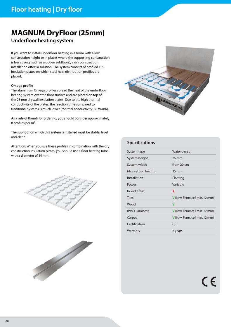
68
MAGNUM Heating Group B.V.Stevinweg 84691SM TholenThe Netherlands
T +31 166 609300E [email protected] www.magnumheatinggroup.com
If you want to install underfl oor heating in a room with a low construction height or in places where the supporting construction is less strong (such as wooden subfl oors), a dry construction installation off ers a solution. The system consists of profi led EPS insulation plates on which steel heat distribution profi les are placed.
Omega profi leThe aluminium Omega profi les spread the heat of the underfl oor heating system over the fl oor surface and are placed on top of the 25 mm drywall insulation plates. Due to the high thermal conductivity of the plates, the reaction time compared to traditional systems is much lower (thermal conductivity: 80 W/mK).
As a rule of thumb for ordering, you should consider approximately 8 profi les per m².
The subfl oor on which this system is installed must be stable, level and clean.
Attention: When you use these profi les in combination with the dry construction insulation plates, you should use a fl oor heating tube with a diameter of 14 mm.
MAGNUM DryFloor (25mm)Underfl oor heating system
Specifi cations
System type Water based
System height 25 mm
System width from 20 cm
Min. setting height 25 mm
Installation Floating
Power Variable
In wet areas X
Tiles V (i.c.w. Fermacell min. 12 mm)
Wood V
(PVC) Laminate V (i.c.w. Fermacell min. 12 mm)
Carpet V (i.c.w. Fermacell min. 12 mm)
Certifi cation CE
Warranty 2 years
Floor heating | Dry floor
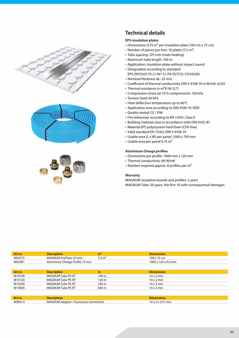
69
MAGNUM Heating Group B.V.Stevinweg 84691SM TholenThe Netherlands
T +31 166 609300E [email protected] www.magnumheatinggroup.com
EPS-insulation plates• Dimensions: 0,75 m² per insulation plate (100 cm x 75 cm)• Number of pieces per box: 10 plates (7,5 m²)• Tube spacing: 125 mm (main heating)• Maximum tube length: 100 m• Application: insulation plate without impact sound• Designation according to standard:
EPS-EN13163-T4-L1-W1-S1-P4-DLT(1)5-CS(10)200• Nominal thickness dL: 25 mm• Coeffi cient of thermal conductivity DIN V 4108-10 in W/mK: 0,035• Thermal resistance in m2K/W: 0,71• Compressive stress (at 10 % compression): 150 kPa• Tension load: 60 kPa• Heat defl ection temperature up to 80°C• Application area according to DIN 4108-10: DEO• Quality tested: CE / FIW• Fire behaviour according to EN 13501: Class E• Building material class in accordance with DIN 4102: B1• Material EPS polystyrene hard foam (CFK-free)• Valid standard EN 13163, DIN V 4108-10• Usable area (L x W) per panel 1,000 x 750 mm• Usable area per panel 0,75 m2
Aluminium Omega profi les • Dimensions per profi le: 1000 mm x 120 mm• Thermal conductivity: 80 W/mK• Number required approx. 8 profi les per m²
WarrantyMAGNUM insulation boards and profi les: 2 yearsMAGNUM Tube: 50 years, the fi rst 10 with consequential damages.
Art.nr. Description m² DimensionsW62075 MAGNUM DryFloor 25 mm 7,5 m2 100 x 75 cmW62901 Aluminium Omega Profi le 14 mm 1000 x 120 x 0,4 mm
Art.nr. Description m DimensionsW14100 MAGNUM Tube PE-RT 100 m 14 x 2 mmW14120 MAGNUM Tube PE-RT 120 m 14 x 2 mmW14240 MAGNUM Tube PE-RT 240 m 14 x 2 mmW14600 MAGNUM Tube PE-RT 600 m 14 x 2 mm
Art.nr. Description DimensionsW90014 MAGNUM Adaptor / Euroconus connection 14 x 2 x 3/4” mm
Technical details
Floor heating | Dry floor
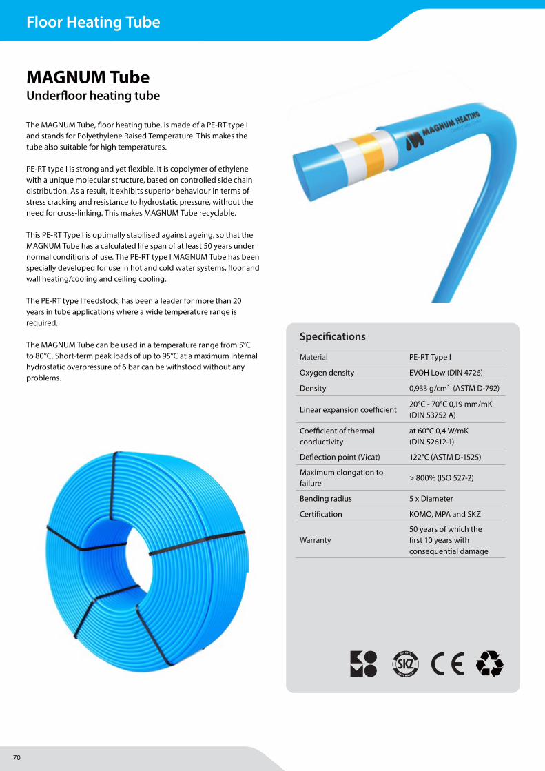
70
MAGNUM Heating Group B.V.Stevinweg 84691SM TholenThe Netherlands
T +31 166 609300E [email protected] www.magnumheatinggroup.com
The MAGNUM Tube, fl oor heating tube, is made of a PE-RT type I and stands for Polyethylene Raised Temperature. This makes the tube also suitable for high temperatures.
PE-RT type I is strong and yet fl exible. It is copolymer of ethylene with a unique molecular structure, based on controlled side chain distribution. As a result, it exhibits superior behaviour in terms of stress cracking and resistance to hydrostatic pressure, without the need for cross-linking. This makes MAGNUM Tube recyclable.
This PE-RT Type I is optimally stabilised against ageing, so that the MAGNUM Tube has a calculated life span of at least 50 years under normal conditions of use. The PE-RT type I MAGNUM Tube has been specially developed for use in hot and cold water systems, fl oor and wall heating/cooling and ceiling cooling.
The PE-RT type I feedstock, has been a leader for more than 20 years in tube applications where a wide temperature range is required.
The MAGNUM Tube can be used in a temperature range from 5°C to 80°C. Short-term peak loads of up to 95°C at a maximum internal hydrostatic overpressure of 6 bar can be withstood without any problems.
MAGNUM TubeUnderfl oor heating tube
Specifi cations
Material PE-RT Type I
Oxygen density EVOH Low (DIN 4726)
Density 0,933 g/cm3 (ASTM D-792)
Linear expansion coeffi cient20°C - 70°C 0,19 mm/mK (DIN 53752 A)
Coeffi cient of thermal conductivity
at 60°C 0,4 W/mK (DIN 52612-1)
Defl ection point (Vicat) 122°C (ASTM D-1525)
Maximum elongation to failure
> 800% (ISO 527-2)
Bending radius 5 x Diameter
Certifi cation KOMO, MPA and SKZ
Warranty50 years of which the fi rst 10 years with consequential damage
Floor Heating Tube

71
MAGNUM Heating Group B.V.Stevinweg 84691SM TholenThe Netherlands
T +31 166 609300E [email protected] www.magnumheatinggroup.com
• Density 0,933 g/cm3 (ASTM D-792)• Linear expansion coeffi cient 20°C - 70°C
0,19 mm/mK (DIN 53752 A)• Coeffi cient of thermal conductivity at 60°C
0,4 Watt/mK (DIN 52612-1)• Defl ection point (Vicat) 122°C (ASTM D-1525)• Maximum elongation to failure > 800% (ISO 527-2)• Bending radius 5 x Diameter• Oxygen density EVOH Low (DIN 4726)• With KOMO, MPA and SKZ certifi cation
Warranty50 years of which the fi rst 10 years with consequential damage.
MAGNUM Heating is a company. More info available at www.cf-floorheating.com
MAGNUM HeatingStevinweg 84691SM TholenThe Netherlands
T +31(0)166-609 300F +31(0)166-604 877E [email protected] www.CF-floorheating.com
MAGNUM TubePE-RT 5 layer Underfloor Heating Tube (10mm)
This Polyethylene Raised Temperature tube is made of 5 layers. The first layer or the basic layer is made of PE-RT type 1. The second layer is an adhesive layer for fixing the third layer, the EVOH layer. This layer guarantees that the tube stops the oxygen diffusion. The fourth is an adhesive and fifth PE-RT type 1. The MAGNUM Tube is impermeable to the oxygen diffusion in accordance with DIN 4726.
FeaturesThe PE-RT type 1 resin has a good flexibility. It is an ethylene-octene copolymer with a unique molecular structure, based on a controlled distribution in a side chain. Consequently, it proves its higher behavior with respect to the lifetime until breakdown, without requiring the crosslinking PEX.
The PE-RT type 1 resin is optimally stabilized anti-ageing, so that the piping systems fitted on these PE-RT have a calculated lifetime of at least 50 years under normal operating conditions, based on the internationally accepted regulations. In addition, the material is authorized as per the most used regulations with respect to drinking water.
The tubes made of PE-RT type 1 resin may be used at a temperature range of 5ºC to 80ºC. The short-term peak charges of up to 95ºC at an internal hydrostatic overpressure of 6 bar at most are supported without any issues.
Technical Specifications• Temperature range 5°C – 80°C, peak 95°C• Bending radius 5 times outside diameter• Density 0,933 g/cm³ (ASTM D-792)• Linear expansion coefficient 20°C - 70°C (DIN 53752 A)• Thermal conductivity at 60°C 0,4 W/mK (DIN 52612-1)• Softening point (Vicat) 122°C (ASTM D-1525)• Maximum elongation at break >800% (ISO 527-2)• Oxygen permeability according DIN 4726 and ISO 17455• Warranty 50 years at max. 6 Bar at 70°C• Approvals KOMO and MPA approved at the KIWA institute• Manufactured The Netherlands
Available products:10 x 1,3 mm. / 80 meter10 x 1,3 mm. / 240 meter
Cross section of the PE-RT 5 layered heating tube:
a. b. c. d. e.
a. PE-RT, Type 1 b. Adhesive layerc. EVOH layerd. Adhesive layere. PE-RT, Type 1
Art.nr. Description Length Dimensions10 mm for MAGNUM SlimFit 10 system
W10080 MAGNUM Tube, underfl oor heating tube PE-RT 80 m 10 x 1,3 mmW10240 MAGNUM Tube, underfl oor heating tube PE-RT 240 m 10 x 1,3 mm
Art.nr. Description Length Dimensions12 mm for MAGNUM Heatboard W system & MAGNUM SlimFit 12 system
W12100 MAGNUM Tube, underfl oor heating tube PE-RT 100 m 12 x 1,5 mmW12300 MAGNUM Tube, underfl oor heating tube PE-RT 300 m 12 x 1,5 mm
Art.nr. Description Length Dimensions14 mm
W14100 MAGNUM Tube, underfl oor heating tube PE-RT 100 m 14 x 2 mmW14120 MAGNUM Tube, underfl oor heating tube PE-RT 120 m 14 x 2 mmW14240 MAGNUM Tube, underfl oor heating tube PE-RT 240 m 14 x 2 mmW14600 MAGNUM Tube, underfl oor heating tube PE-RT 600 m 14 x 2 mm
Art.nr. Description Length Dimensions16 mm
W16090 MAGNUM Tube, underfl oor heating tube PE-RT 90 m 16 x 2 mmW16100 MAGNUM Tube, underfl oor heating tube PE-RT 100 m 16 x 2 mmW16120 MAGNUM Tube, underfl oor heating tube PE-RT 120 m 16 x 2 mmW16240 MAGNUM Tube, underfl oor heating tube PE-RT 240 m 16 x 2 mmW16600 MAGNUM Tube, underfl oor heating tube PE-RT 600 m 16 x 2 mm
Art.nr. Description Length Dimensions18 mm
W18130 MAGNUM Tube, underfl oor heating tube PE-RT 130 m 18 x 2 mmW18260 MAGNUM Tube, underfl oor heating tube PE-RT 260 m 18 x 2 mmW18520 MAGNUM Tube, underfl oor heating tube PE-RT 520 m 18 x 2 mm
Art.nr. Description Length Dimensions20 mm
W20120 MAGNUM Tube, underfl oor heating tube PE-RT 120 m 20 x 2 mmW20240 MAGNUM Tube, underfl oor heating tube PE-RT 240 m 20 x 2 mmW20500 MAGNUM Tube, underfl oor heating tube PE-RT 500 m 20 x 2 mm
Technical details
Floor Heating Tube
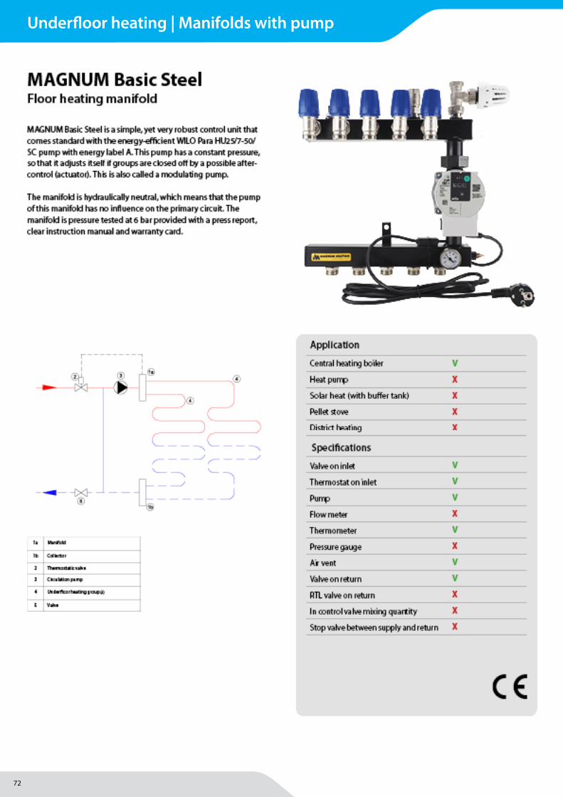
72
Underfloor heating | Manifolds with pump
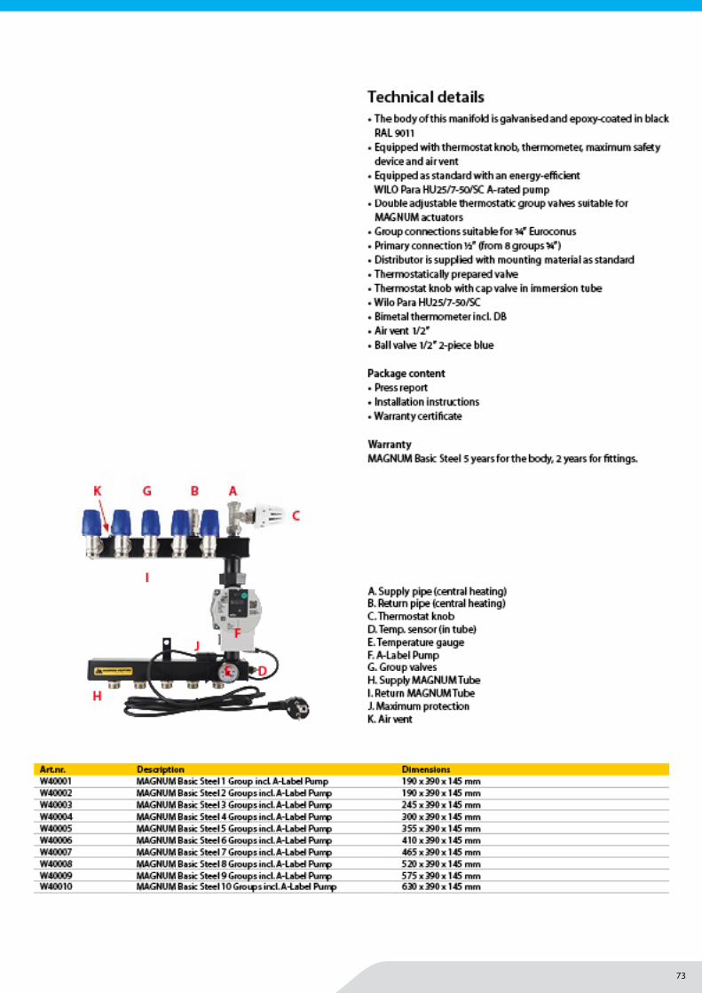
73
Underfloor heating | Manifolds with pump
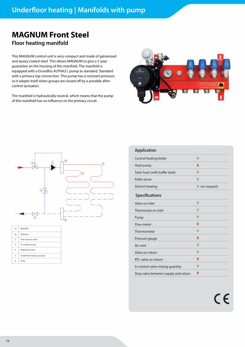
74
MAGNUM Heating Group B.V.Stevinweg 84691SM TholenThe Netherlands
T +31 166 609300E [email protected] www.magnumheatinggroup.com
This MAGNUM control unit is very compact and made of galvanised and epoxy coated steel. This allows MAGNUM to give a 5-year guarantee on the housing of this manifold. The manifold is equipped with a Grundfos ALPHA2 L pump as standard. Standard with a primary top connection. This pump has a constant pressure, so it adapts itself when groups are closed off by a possible after-control (actuator).
The manifold is hydraulically neutral, which means that the pump of this manifold has no infl uence on the primary circuit.
MAGNUM Front SteelFloor heating manifold
Application
Central heating boiler V
Heat pump X
Solar heat (with buff er tank) V
Pellet stove V
District heating V (on request)
Specifi cations
Valve on inlet V
Thermostat on inlet V
Pump V
Flow meter X
Thermometer V
Pressure gauge X
Air vent V
Valve on return V
RTL valve on return X
In control valve mixing quantity V
Stop valve between supply and return X
1a Manifold
1b Collector
2 Thermostatic valve
3 Circulation pump
4 Regulating valve
5 Underfl oor heating group(s)
6 Valve
Underfloor heating | Manifolds with pump
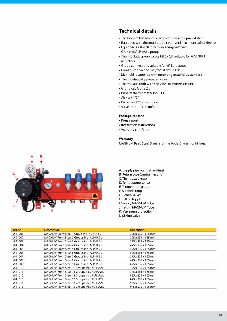
75
MAGNUM Heating Group B.V.Stevinweg 84691SM TholenThe Netherlands
T +31 166 609300E [email protected] www.magnumheatinggroup.com
• The body of this manifold is galvanised and epoxied steel• Equipped with thermometer, air vent and maximum safety device• Equipped as standard with an energy-effi cient
Grundfos ALPHA2 L pump• Thermostatic group valves M30x 1,5 suitable for MAGNUM
actuators• Group connections suitable for ¾” Eurocones• Primary connection ½” (from 8 groups ¾”)• Manifold is supplied with mounting material as standard• Thermostatically prepared valve • Thermostat knob with cap valve in immersion tube• Grundfoss Alpha 2 L• Bimetal thermometer incl. DB• Air vent 1/2”• Ball valve 1/2” 2-part blue• Valve insert LTV manifold
Package content• Press report• Installation instructions• Warranty certifi cate
WarrantyMAGNUM Basic Steel 5 years for the body, 2 years for fi ttings.
Art.nr. Description DimensionsW41001 MAGNUM Front Steel 1 Group incl. ALPHA2 L 325 x 235 x 185 mmW41002 MAGNUM Front Steel 2 Groups incl. ALPHA2 L 325 x 235 x 185 mmW41003 MAGNUM Front Steel 3 Groups incl. ALPHA2 L 375 x 235 x 185 mmW41004 MAGNUM Front Steel 4 Groups incl. ALPHA2 L 425 x 235 x 185 mmW41005 MAGNUM Front Steel 5 Groups incl. ALPHA2 L 475 x 235 x 185 mmW41006 MAGNUM Front Steel 6 Groups incl. ALPHA2 L 525 x 235 x 185 mmW41007 MAGNUM Front Steel 7 Groups incl. ALPHA2 L 575 x 235 x 185 mmW41008 MAGNUM Front Steel 8 Groups incl. ALPHA2 L 625 x 235 x 185 mmW41009 MAGNUM Front Steel 9 Groups incl. ALPHA2 L 675 x 235 x 185 mmW41010 MAGNUM Front Steel 10 Groups incl. ALPHA2 L 725 x 235 x 185 mmW41011 MAGNUM Front Steel 11 Groups incl. ALPHA2 L 775 x 235 x 185 mmW41012 MAGNUM Front Steel 12 Groups incl. ALPHA2 L 825 x 235 x 185 mmW41013 MAGNUM Front Steel 13 Groups incl. ALPHA2 L 875 x 235 x 185 mmW41014 MAGNUM Front Steel 14 Groups incl. ALPHA2 L 925 x 235 x 185 mmW41015 MAGNUM Front Steel 15 Groups incl. ALPHA2 L 975 x 235 x 185 mm
Technical details
A. Supply pipe (central heating)B. Return pipe (central heating)C. Thermostat knobD. Temperature sensorE. Temperature gauge F. A-Label PumpG. Group valvesH. Filling NippleI. Supply MAGNUM TubeJ. Return MAGNUM TubeK. Maximum protectionL. Mixing valve
A B
C
F
E
G
HI
J
D K
L
Underfloor heating | Manifolds with pump
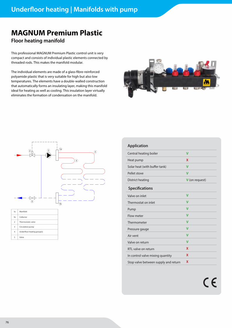
76
MAGNUM Heating Group B.V.Stevinweg 84691SM TholenThe Netherlands
T +31 166 609300E [email protected] www.magnumheatinggroup.com
This professional MAGNUM Premium Plastic control unit is very compact and consists of individual plastic elements connected by threaded rods. This makes the manifold modular.
The individual elements are made of a glass-fi bre-reinforced polyamide plastic that is very suitable for high but also low temperatures. The elements have a double-walled construction that automatically forms an insulating layer, making this manifold ideal for heating as well as cooling. This insulation layer virtually eliminates the formation of condensation on the manifold.
MAGNUM Premium PlasticFloor heating manifold
Application
Central heating boiler V
Heat pump X
Solar heat (with buff er tank) V
Pellet stove V
District heating V (on request)
Specifi cations
Valve on inlet V
Thermostat on inlet V
Pump V
Flow meter V
Thermometer V
Pressure gauge V
Air vent V
Valve on return V
RTL valve on return X
In control valve mixing quantity X
Stop valve between supply and return X
1a Manifold
1b Collector
2 Thermostatic valve
3 Circulation pump
4 Underfl oor heating group(s)
5 Valve
Underfloor heating | Manifolds with pump
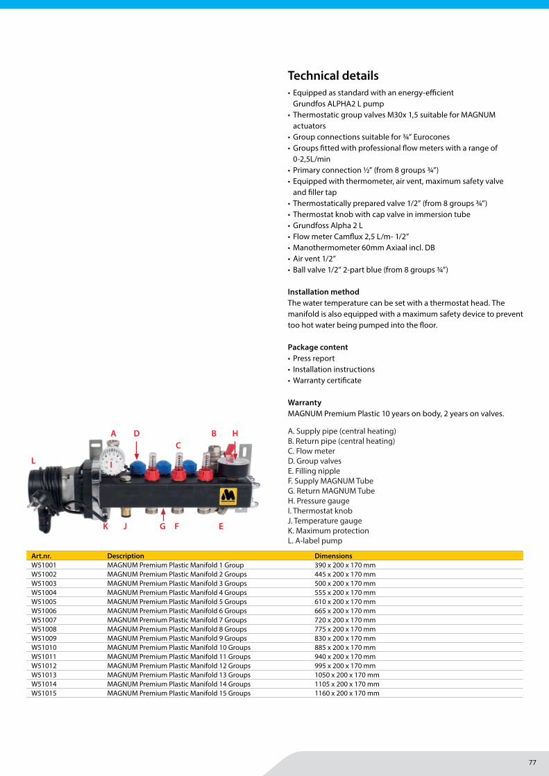
77
MAGNUM Heating Group B.V.Stevinweg 84691SM TholenThe Netherlands
T +31 166 609300E [email protected] www.magnumheatinggroup.com
• Equipped as standard with an energy-effi cient Grundfos ALPHA2 L pump
• Thermostatic group valves M30x 1,5 suitable for MAGNUM actuators
• Group connections suitable for ¾” Eurocones• Groups fi tted with professional fl ow meters with a range of
0-2,5L/min• Primary connection ½” (from 8 groups ¾”)• Equipped with thermometer, air vent, maximum safety valve
and fi ller tap• Thermostatically prepared valve 1/2” (from 8 groups ¾”)• Thermostat knob with cap valve in immersion tube• Grundfoss Alpha 2 L• Flow meter Camfl ux 2,5 L/m- 1/2”• Manothermometer 60mm Axiaal incl. DB• Air vent 1/2”• Ball valve 1/2” 2-part blue (from 8 groups ¾”)
Installation method The water temperature can be set with a thermostat head. The manifold is also equipped with a maximum safety device to prevent too hot water being pumped into the fl oor.
Package content• Press report• Installation instructions• Warranty certifi cate
WarrantyMAGNUM Premium Plastic 10 years on body, 2 years on valves.
Art.nr. Description DimensionsW51001 MAGNUM Premium Plastic Manifold 1 Group 390 x 200 x 170 mmW51002 MAGNUM Premium Plastic Manifold 2 Groups 445 x 200 x 170 mmW51003 MAGNUM Premium Plastic Manifold 3 Groups 500 x 200 x 170 mmW51004 MAGNUM Premium Plastic Manifold 4 Groups 555 x 200 x 170 mmW51005 MAGNUM Premium Plastic Manifold 5 Groups 610 x 200 x 170 mmW51006 MAGNUM Premium Plastic Manifold 6 Groups 665 x 200 x 170 mmW51007 MAGNUM Premium Plastic Manifold 7 Groups 720 x 200 x 170 mmW51008 MAGNUM Premium Plastic Manifold 8 Groups 775 x 200 x 170 mmW51009 MAGNUM Premium Plastic Manifold 9 Groups 830 x 200 x 170 mmW51010 MAGNUM Premium Plastic Manifold 10 Groups 885 x 200 x 170 mmW51011 MAGNUM Premium Plastic Manifold 11 Groups 940 x 200 x 170 mmW51012 MAGNUM Premium Plastic Manifold 12 Groups 995 x 200 x 170 mmW51013 MAGNUM Premium Plastic Manifold 13 Groups 1050 x 200 x 170 mmW51014 MAGNUM Premium Plastic Manifold 14 Groups 1105 x 200 x 170 mmW51015 MAGNUM Premium Plastic Manifold 15 Groups 1160 x 200 x 170 mm
Technical details
A. Supply pipe (central heating)B. Return pipe (central heating)C. Flow meterD. Group valvesE. Filling nippleF. Supply MAGNUM TubeG. Return MAGNUM TubeH. Pressure gaugeI. Thermostat knobJ. Temperature gaugeK. Maximum protectionL. A-label pump
BAC
EFG
D H
I
JK
L
Underfloor heating | Manifolds with pump
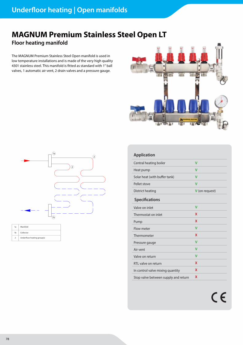
78
MAGNUM Heating Group B.V.Stevinweg 84691SM TholenThe Netherlands
T +31 166 609300E [email protected] www.magnumheatinggroup.com
The MAGNUM Premium Stainless Steel Open manifold is used in low temperature installations and is made of the very high quality 4301 stainless steel. This manifold is fi tted as standard with 1” ball valves, 1 automatic air vent, 2 drain valves and a pressure gauge.
MAGNUM Premium Stainless Steel Open LTFloor heating manifold
Application
Central heating boiler V
Heat pump V
Solar heat (with buff er tank) V
Pellet stove V
District heating V (on request)
Specifi cations
Valve on inlet V
Thermostat on inlet X
Pump X
Flow meter V
Thermometer X
Pressure gauge V
Air vent V
Valve on return V
RTL valve on return X
In control valve mixing quantity X
Stop valve between supply and return X
1a Manifold
1b Collector
2 Underfl oor heating group(s)
Underfloor heating | Open manifolds
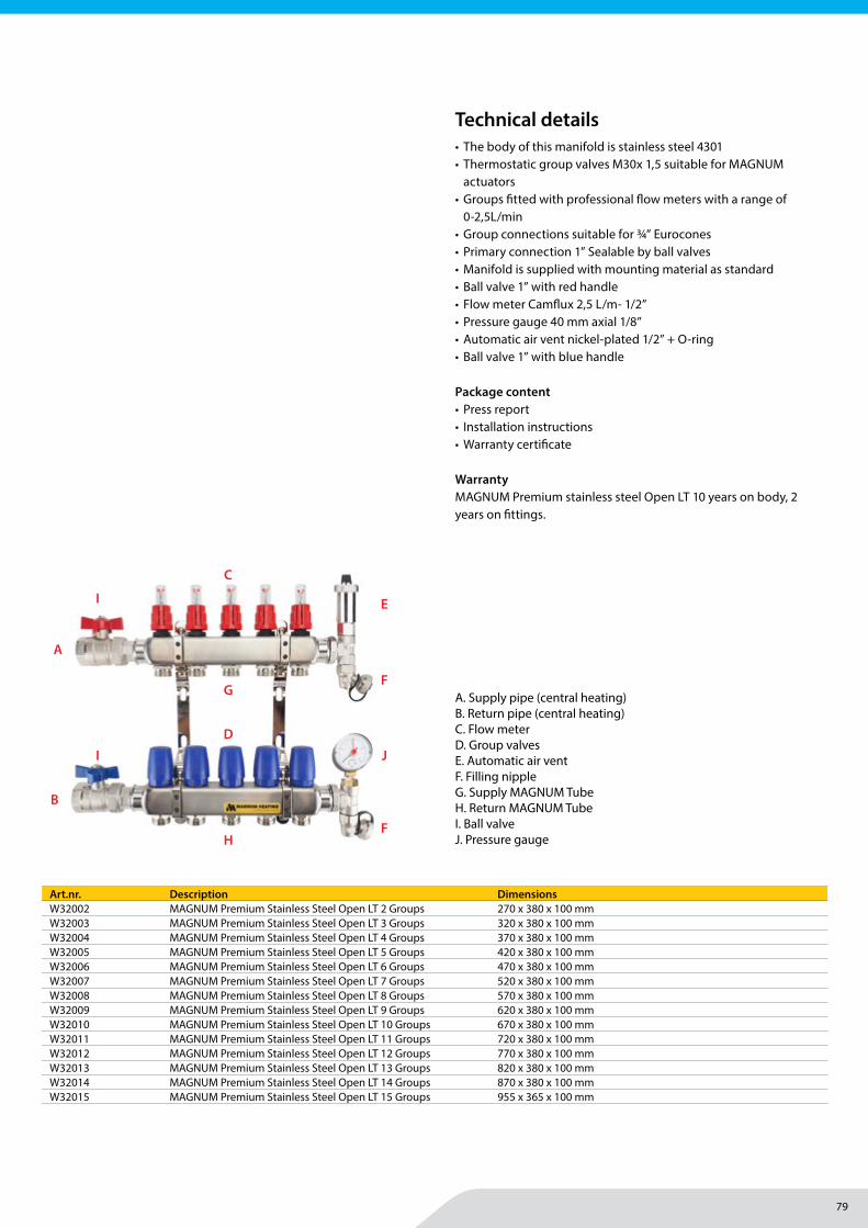
79
MAGNUM Heating Group B.V.Stevinweg 84691SM TholenThe Netherlands
T +31 166 609300E [email protected] www.magnumheatinggroup.com
• The body of this manifold is stainless steel 4301• Thermostatic group valves M30x 1,5 suitable for MAGNUM
actuators• Groups fi tted with professional fl ow meters with a range of
0-2,5L/min• Group connections suitable for ¾” Eurocones• Primary connection 1” Sealable by ball valves• Manifold is supplied with mounting material as standard• Ball valve 1” with red handle• Flow meter Camfl ux 2,5 L/m- 1/2”• Pressure gauge 40 mm axial 1/8”• Automatic air vent nickel-plated 1/2” + O-ring• Ball valve 1” with blue handle
Package content• Press report• Installation instructions• Warranty certifi cate
WarrantyMAGNUM Premium stainless steel Open LT 10 years on body, 2 years on fi ttings.
Art.nr. Description DimensionsW32002 MAGNUM Premium Stainless Steel Open LT 2 Groups 270 x 380 x 100 mmW32003 MAGNUM Premium Stainless Steel Open LT 3 Groups 320 x 380 x 100 mmW32004 MAGNUM Premium Stainless Steel Open LT 4 Groups 370 x 380 x 100 mmW32005 MAGNUM Premium Stainless Steel Open LT 5 Groups 420 x 380 x 100 mmW32006 MAGNUM Premium Stainless Steel Open LT 6 Groups 470 x 380 x 100 mmW32007 MAGNUM Premium Stainless Steel Open LT 7 Groups 520 x 380 x 100 mmW32008 MAGNUM Premium Stainless Steel Open LT 8 Groups 570 x 380 x 100 mmW32009 MAGNUM Premium Stainless Steel Open LT 9 Groups 620 x 380 x 100 mmW32010 MAGNUM Premium Stainless Steel Open LT 10 Groups 670 x 380 x 100 mmW32011 MAGNUM Premium Stainless Steel Open LT 11 Groups 720 x 380 x 100 mmW32012 MAGNUM Premium Stainless Steel Open LT 12 Groups 770 x 380 x 100 mmW32013 MAGNUM Premium Stainless Steel Open LT 13 Groups 820 x 380 x 100 mmW32014 MAGNUM Premium Stainless Steel Open LT 14 Groups 870 x 380 x 100 mmW32015 MAGNUM Premium Stainless Steel Open LT 15 Groups 955 x 365 x 100 mm
Technical details
A. Supply pipe (central heating)B. Return pipe (central heating)C. Flow meterD. Group valvesE. Automatic air ventF. Filling nippleG. Supply MAGNUM TubeH. Return MAGNUM TubeI. Ball valveJ. Pressure gauge
A
B
C
DJ
E
F
F
G
H
I
I
Underfloor heating | Open manifolds
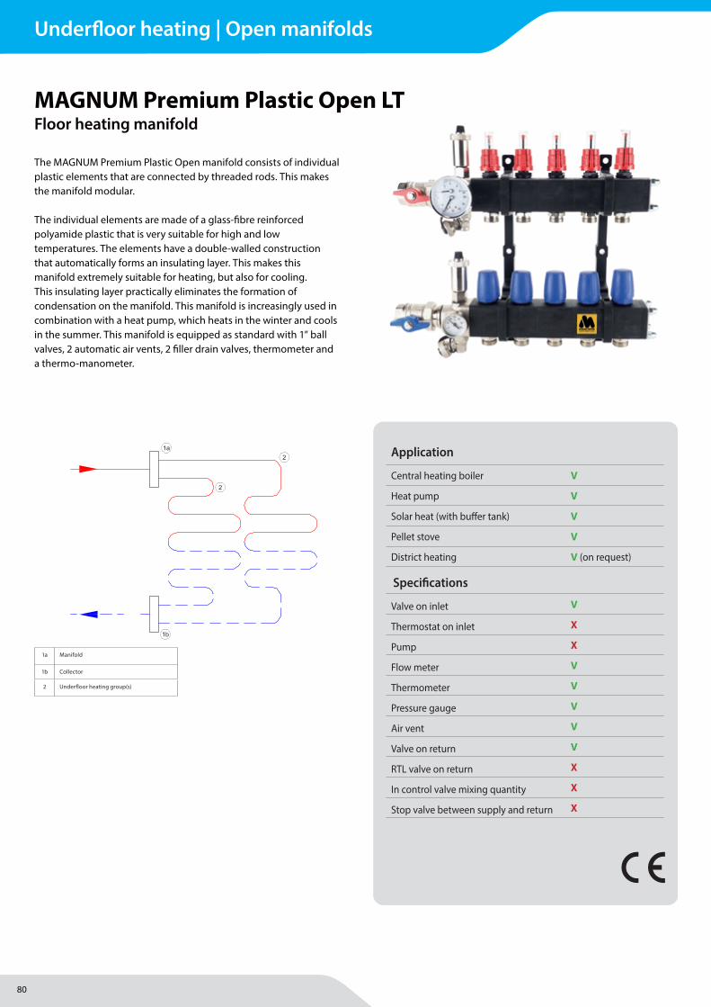
80
MAGNUM Heating Group B.V.Stevinweg 84691SM TholenThe Netherlands
T +31 166 609300E [email protected] www.magnumheatinggroup.com
The MAGNUM Premium Plastic Open manifold consists of individual plastic elements that are connected by threaded rods. This makes the manifold modular.
The individual elements are made of a glass-fi bre reinforced polyamide plastic that is very suitable for high and low temperatures. The elements have a double-walled construction that automatically forms an insulating layer. This makes this manifold extremely suitable for heating, but also for cooling. This insulating layer practically eliminates the formation of condensation on the manifold. This manifold is increasingly used in combination with a heat pump, which heats in the winter and cools in the summer. This manifold is equipped as standard with 1” ball valves, 2 automatic air vents, 2 fi ller drain valves, thermometer and a thermo-manometer.
MAGNUM Premium Plastic Open LTFloor heating manifold
Application
Central heating boiler V
Heat pump V
Solar heat (with buff er tank) V
Pellet stove V
District heating V (on request)
Specifi cations
Valve on inlet V
Thermostat on inlet X
Pump X
Flow meter V
Thermometer V
Pressure gauge V
Air vent V
Valve on return V
RTL valve on return X
In control valve mixing quantity X
Stop valve between supply and return X
1a Manifold
1b Collector
2 Underfl oor heating group(s)
Underfloor heating | Open manifolds
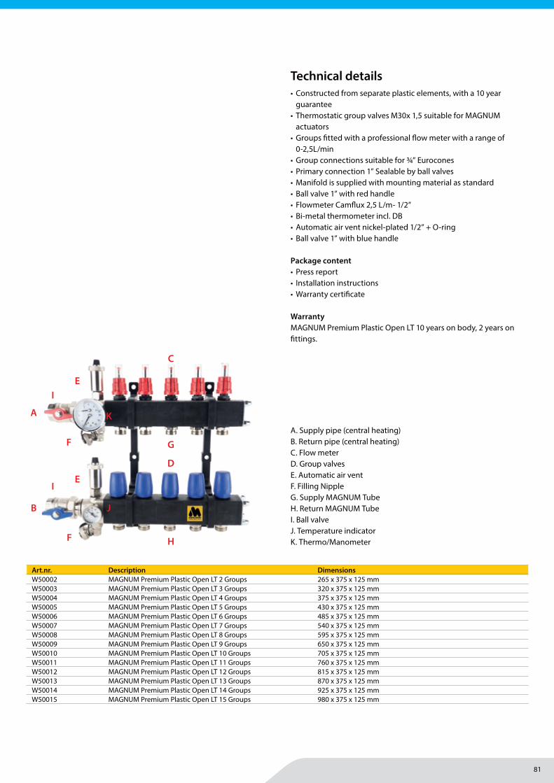
81
MAGNUM Heating Group B.V.Stevinweg 84691SM TholenThe Netherlands
T +31 166 609300E [email protected] www.magnumheatinggroup.com
• Constructed from separate plastic elements, with a 10 year guarantee
• Thermostatic group valves M30x 1,5 suitable for MAGNUM actuators
• Groups fi tted with a professional fl ow meter with a range of 0-2,5L/min
• Group connections suitable for ¾” Eurocones• Primary connection 1” Sealable by ball valves• Manifold is supplied with mounting material as standard• Ball valve 1” with red handle• Flowmeter Camfl ux 2,5 L/m- 1/2”• Bi-metal thermometer incl. DB• Automatic air vent nickel-plated 1/2” + O-ring• Ball valve 1” with blue handle
Package content• Press report• Installation instructions• Warranty certifi cate
WarrantyMAGNUM Premium Plastic Open LT 10 years on body, 2 years on fi ttings.
Art.nr. Description DimensionsW50002 MAGNUM Premium Plastic Open LT 2 Groups 265 x 375 x 125 mmW50003 MAGNUM Premium Plastic Open LT 3 Groups 320 x 375 x 125 mmW50004 MAGNUM Premium Plastic Open LT 4 Groups 375 x 375 x 125 mmW50005 MAGNUM Premium Plastic Open LT 5 Groups 430 x 375 x 125 mmW50006 MAGNUM Premium Plastic Open LT 6 Groups 485 x 375 x 125 mmW50007 MAGNUM Premium Plastic Open LT 7 Groups 540 x 375 x 125 mmW50008 MAGNUM Premium Plastic Open LT 8 Groups 595 x 375 x 125 mmW50009 MAGNUM Premium Plastic Open LT 9 Groups 650 x 375 x 125 mmW50010 MAGNUM Premium Plastic Open LT 10 Groups 705 x 375 x 125 mmW50011 MAGNUM Premium Plastic Open LT 11 Groups 760 x 375 x 125 mmW50012 MAGNUM Premium Plastic Open LT 12 Groups 815 x 375 x 125 mmW50013 MAGNUM Premium Plastic Open LT 13 Groups 870 x 375 x 125 mmW50014 MAGNUM Premium Plastic Open LT 14 Groups 925 x 375 x 125 mmW50015 MAGNUM Premium Plastic Open LT 15 Groups 980 x 375 x 125 mm
Technical details
A. Supply pipe (central heating)B. Return pipe (central heating)C. Flow meterD. Group valvesE. Automatic air ventF. Filling NippleG. Supply MAGNUM TubeH. Return MAGNUM Tube I. Ball valveJ. Temperature indicatorK. Thermo/Manometer
A
B
C
D
E
K
F
F
G
H
E
J
I
I
Underfloor heating | Open manifolds
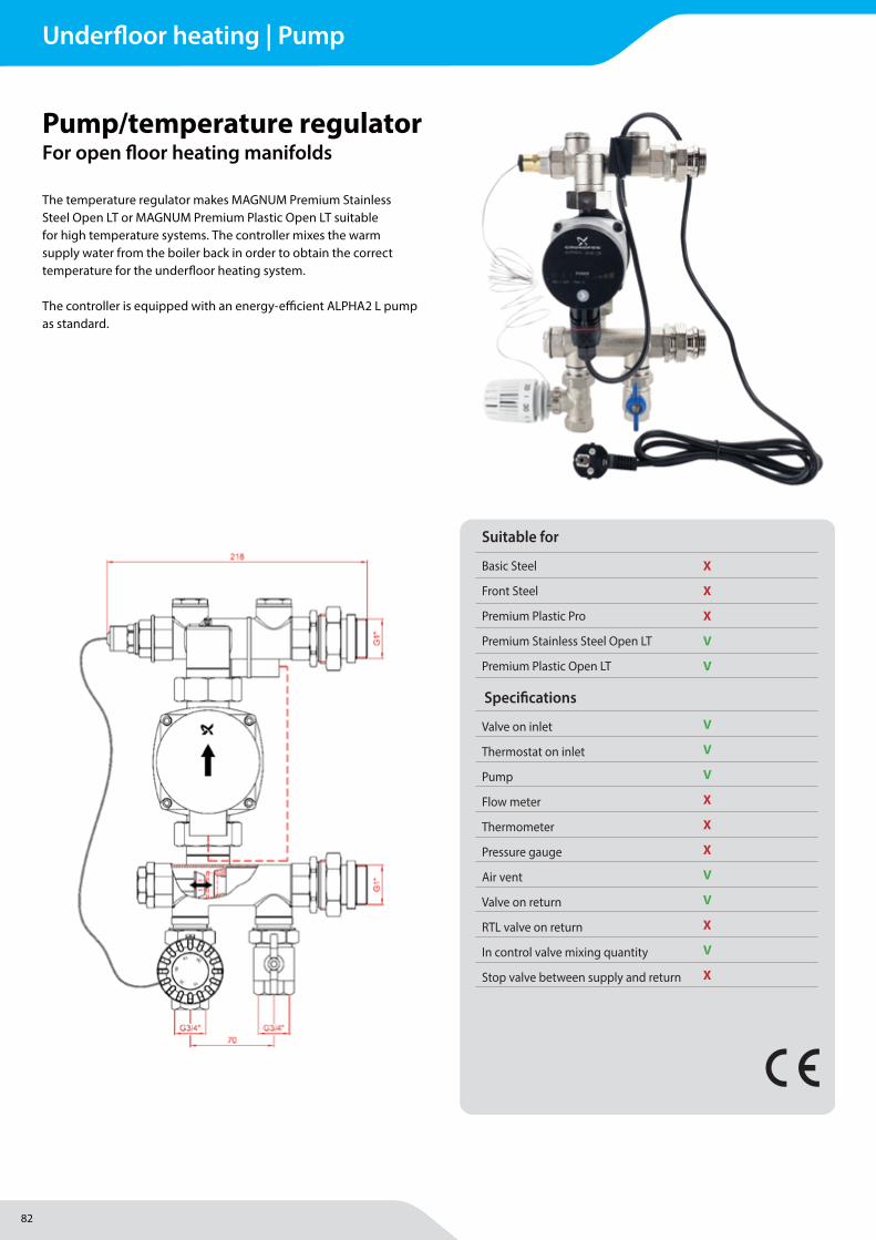
82
MAGNUM Heating Group B.V.Stevinweg 84691SM TholenThe Netherlands
T +31 166 609300E [email protected] www.magnumheatinggroup.com
The temperature regulator makes MAGNUM Premium Stainless Steel Open LT or MAGNUM Premium Plastic Open LT suitable for high temperature systems. The controller mixes the warm supply water from the boiler back in order to obtain the correct temperature for the underfl oor heating system.
The controller is equipped with an energy-effi cient ALPHA2 L pump as standard.
Pump/temperature regulatorFor open fl oor heating manifolds
Specifi cations
Valve on inlet V
Thermostat on inlet V
Pump V
Flow meter X
Thermometer X
Pressure gauge X
Air vent V
Valve on return V
RTL valve on return X
In control valve mixing quantity V
Stop valve between supply and return X
Suitable for
Basic Steel X
Front Steel X
Premium Plastic Pro X
Premium Stainless Steel Open LT V
Premium Plastic Open LT V
Underfloor heating | Pump
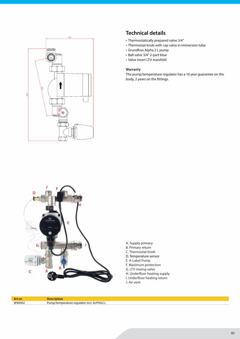
83
Underfloor heating | Pump
MAGNUM Heating Group B.V.Stevinweg 84691SM TholenThe Netherlands
T +31 166 609300E [email protected] www.magnumheatinggroup.com
• Thermostatically prepared valve 3/4”• Thermostat knob with cap valve in immersion tube• Grundfoss Alpha 2 L pump• Ball valve 3/4” 2-part blue• Valve insert LTV manifold
WarrantyThe pump/temperature regulator has a 10 year guarantee on the body, 2 years on the fi ttings.
Art.nr. DescriptionW90002 Pump/temperature regulator incl. ALPHA2 L
Technical details
A. Supply primaryB. Primary return C. Thermostat knob D. Temperature sensorE. A-Label PumpF. Maximum protectionG. LTV mixing valveH. Underfl oor heating supplyI. Underfl oor heating returnJ. Air vent
CB
D
E
F
G
A
H
I
J
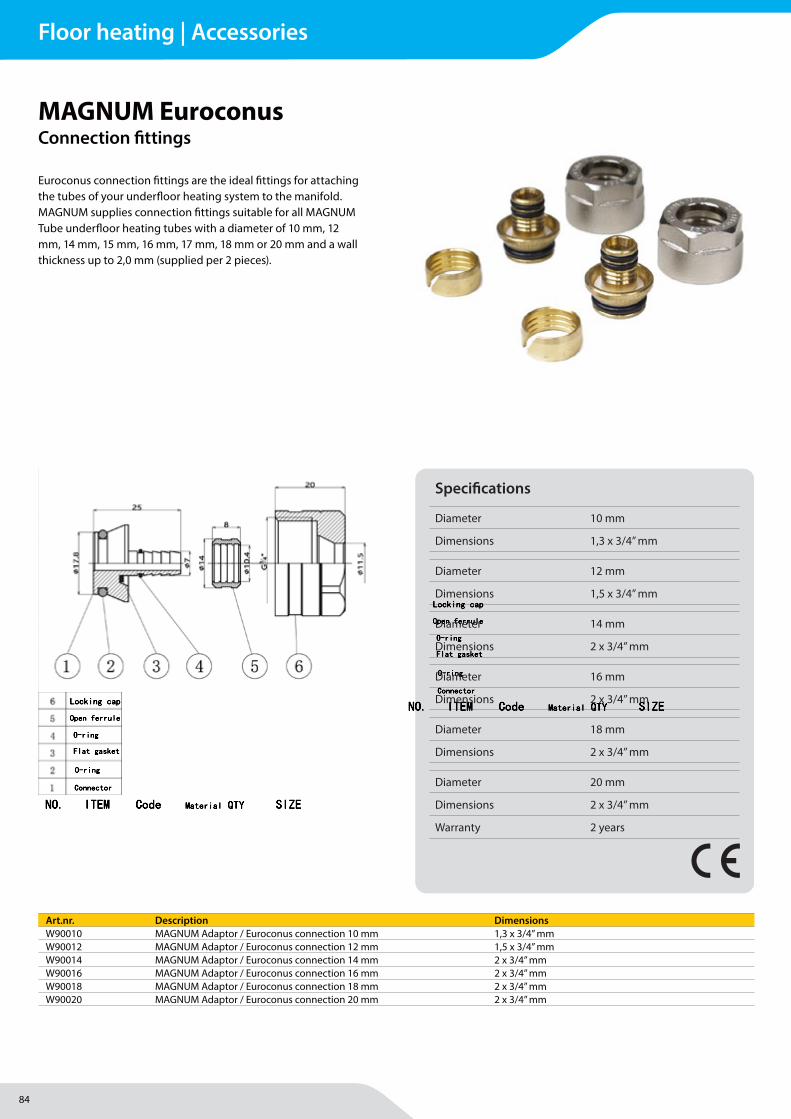
84
MAGNUM Heating Group B.V.Stevinweg 84691SM TholenThe Netherlands
T +31 166 609300E [email protected] www.magnumheatinggroup.com
Euroconus connection fi ttings are the ideal fi ttings for attaching the tubes of your underfl oor heating system to the manifold. MAGNUM supplies connection fi ttings suitable for all MAGNUM Tube underfl oor heating tubes with a diameter of 10 mm, 12 mm, 14 mm, 15 mm, 16 mm, 17 mm, 18 mm or 20 mm and a wall thickness up to 2,0 mm (supplied per 2 pieces).
NO. ITEM Code Material QTY SIZE
Locking cap
Open ferrule
O-ring
O-ring
Connector
Flat gasket
NO. ITEM Code Material QTY SIZE
Locking cap
Open ferrule
O-ring
O-ring
Connector
Flat gasket
MAGNUM EuroconusConnection fi ttings
Specifi cations
Diameter 10 mm
Dimensions 1,3 x 3/4” mm
Diameter 12 mm
Dimensions 1,5 x 3/4” mm
Diameter 14 mm
Dimensions 2 x 3/4” mm
Diameter 16 mm
Dimensions 2 x 3/4” mm
Diameter 18 mm
Dimensions 2 x 3/4” mm
Diameter 20 mm
Dimensions 2 x 3/4” mm
Warranty 2 years
Art.nr. Description DimensionsW90010 MAGNUM Adaptor / Euroconus connection 10 mm 1,3 x 3/4” mmW90012 MAGNUM Adaptor / Euroconus connection 12 mm 1,5 x 3/4” mmW90014 MAGNUM Adaptor / Euroconus connection 14 mm 2 x 3/4” mmW90016 MAGNUM Adaptor / Euroconus connection 16 mm 2 x 3/4” mmW90018 MAGNUM Adaptor / Euroconus connection 18 mm 2 x 3/4” mmW90020 MAGNUM Adaptor / Euroconus connection 20 mm 2 x 3/4” mm
Floor heating | Accessories
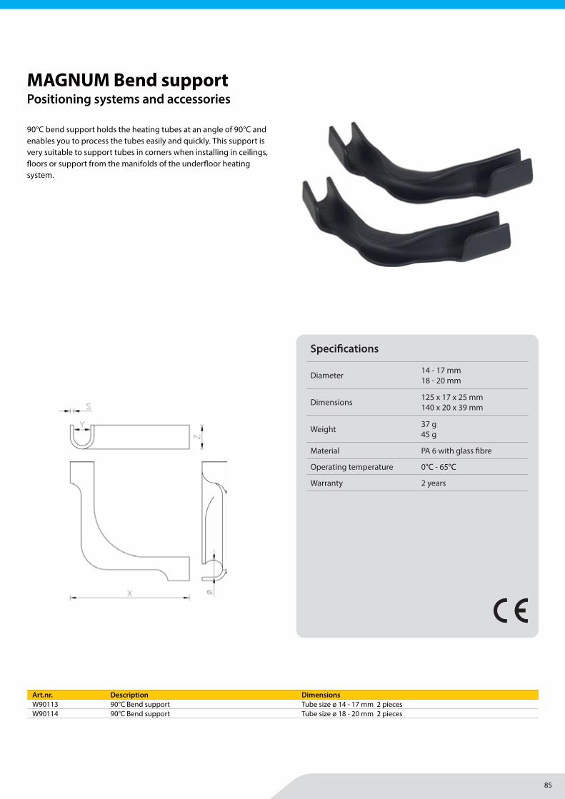
85
MAGNUM Heating Group B.V.Stevinweg 84691SM TholenThe Netherlands
T +31 166 609300E [email protected] www.magnumheatinggroup.com
90°C bend support holds the heating tubes at an angle of 90°C and enables you to process the tubes easily and quickly. This support is very suitable to support tubes in corners when installing in ceilings, fl oors or support from the manifolds of the underfl oor heating system.
T iA S p . z o . o . +48 12 262 96 59 Słowackiego 22a [email protected] 37-200 Przeworsk [email protected] Poland www.tia.com.pl
Łuk prowadzący / MTGP-ŁP Pipe bend support
DANE PRODUKTU / SPECIFICATIONS
MATERIAŁ: Poliamid z włóknem szklanym PARAMETRY TECHNICZNE:
Temperatura pracy: 0 ˚C- 65 ˚C
Łuk prowadzący zapewnia bezpieczne wyprowadzenie rury grzewczej pod kątem 90˚ z poziomej lub pionowej powierzchni grzewczej do szafki rozdzielacza. Usztywnia rurę w miejscu jej zagięcia, chroni przed złamaniem oraz zapewnia większą stabilność podejścia instalacji ogrzewania podłogowego.
Dostępny jest w 3 rozmiarach: na rurę 14-18 mm, 20-22 mm oraz 25 mm.
MATERIAL: PA 6 with fiber glass TECHNICAL DATA:
Working temperature 0 ˚C-65 ˚C
The pipe bend support allows plumber to bend heating pipes in a 90 degree bow. The pipe bend support can be used to guide pipes through floors, ceilings and to a manifold cabinet. It holds the pipe and directs it to a manifold cabinet.
Pipe bend support are available in three dimensions: for the pipe with fi 14-18, 20-22, 25.
Znajdź ten produkt na naszej stronie! Find this product on our website!
SYSTEMY GRZEWCZE / HEATING SYSTEMS
WŁASNOŚCI PRODUKTU / PRODUCT FEATURES
MAGNUM Bend supportPositioning systems and accessories
Specifi cations
Diameter 14 - 17 mm18 - 20 mm
Dimensions 125 x 17 x 25 mm140 x 20 x 39 mm
Weight 37 g45 g
Material PA 6 with glass fi bre
Operating temperature 0°C - 65°C
Warranty 2 years
Art.nr. Description DimensionsW90113 90°C Bend support Tube size ø 14 - 17 mm 2 piecesW90114 90°C Bend support Tube size ø 18 - 20 mm 2 pieces
Floor heating | Accessories
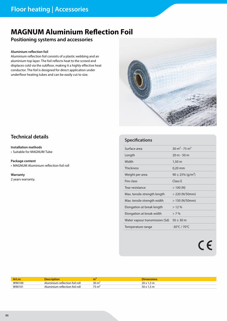
86
MAGNUM Heating Group B.V.Stevinweg 84691SM TholenThe Netherlands
T +31 166 609300E [email protected] www.magnumheatinggroup.com
Aluminium refl ection foilAluminium refl ection foil consists of a plastic webbing and an aluminium top layer. The foil refl ects heat to the screed and displaces cold via the subfl oor, making it a highly eff ective heat conductor. The foil is designed for direct application under underfl oor heating tubes and can be easily cut to size.
MAGNUM Aluminium Refl ection Foil Positioning systems and accessories
Specifi cations
Surface area 30 m2 - 75 m2
Length 20 m - 50 m
Width 1,50 m
Thickness 0,20 mm
Weight per area 90 ± 25% (g/m²)
Fire class Class E
Tear resistance > 100 (N)
Max. tensile strength length > 220 (N/50mm)
Max. tensile strength width > 150 (N/50mm)
Elongation at break length > 12 %
Elongation at break width > 7 %
Water vapour transmission (Sd) 50 ± 30 m
Temperature range -30°C / 70°C
Art.nr. Description m² DimensionsW90100 Aluminium refl ection foil roll 30 m² 20 x 1,5 mW90101 Aluminium refl ection foil roll 75 m² 50 x 1,5 m
Installation methods• Suitable for MAGNUM Tube
Package content• MAGNUM Aluminium refl ection foil roll
Warranty2 years warranty.
Technical details
Floor heating | Accessories
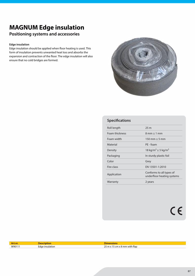
87
Floor heating | Accessories
MAGNUM Heating Group B.V.Stevinweg 84691SM TholenThe Netherlands
T +31 166 609300E [email protected] www.magnumheatinggroup.com
Edge insulationEdge insulation should be applied when fl oor heating is used. This form of insulation prevents unwanted heat loss and absorbs the expansion and contraction of the fl oor. The edge insulation will also ensure that no cold bridges are formed.
MAGNUM Edge insulationPositioning systems and accessories
Specifi cations
Roll length 25 m
Foam thickness 8 mm ± 1 mm
Foam width 150 mm ± 5 mm
Material PE - foam
Density 18 kg/m3 ± 5 kg/m3
Packaging In sturdy plastic foil
Color Grey
Fire class EN 13501-1:2010
Application Conforms to all types of underfl oor heating systems
Warranty 2 years
Art.nr. Description DimensionsW90111 Edge insulation 25 m x 15 cm x 8 mm with fl ap
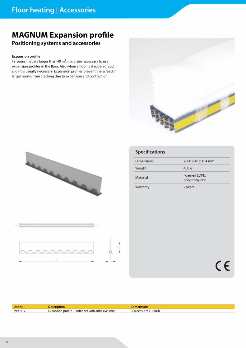
88
Floor heating | Accessories
MAGNUM Heating Group B.V.Stevinweg 84691SM TholenThe Netherlands
T +31 166 609300E [email protected] www.magnumheatinggroup.com
Expansion profi leIn rooms that are larger than 40 m², it is often necessary to use expansion profi les in the fl oor. Also when a fl oor is staggered, such a joint is usually necessary. Expansion profi les prevent the screed in larger rooms from cracking due to expansion and contraction.
T iA S p . z o . o . +48 12 262 96 59 Słowackiego 22a [email protected] 37-200 Przeworsk [email protected] Poland www.tia.com.pl
Profil dylatacyjny PE expansion joint with self-adhesive rail
DANE PRODUKTU / SPECIFICATIONS
MATERIAŁ: Spieniony LDPE, polipropylen
Dybel - polipropylen
Profil dylatacyjny używany jest do rozgraniczenia stref grzewczych w systemach ogrzewania podłogowego.
Zapobiega powstawaniu pęknięć wylewki i warstwy wykończeniowej. Profil wyposażony jest w taśmę klejącą ułatwiającą montaż do podłoża.
MATERIAL: Foamed LDPE, Polypropylene
Znajdź ten produkt na naszej stronie! Find this product on our website!
SYSTEMY GRZEWCZE / HEATING SYSTEMS
WŁASNOŚCI PRODUKTU / PRODUCT FEATURES
PE expansion joint with self-adhesive rail is used for separation of heating zones in underfloor heating systems.
It prevents cracking of concrete and finishing layers. PE expansion is equipped with a strip of adhesive tape that facilitates its fitting to the floor.
MAGNUM Expansion profi lePositioning systems and accessories
Art.nr. Description DimensionsW90112 Expansion profi le - Profi le set with adhesive strip 5 pieces 2 m (10 m/l)
Specifi cations
Dimensions 2000 x 40 x 104 mm
Weight 400 g
Material Foamed LDPE, polypropylene
Warranty 2 years
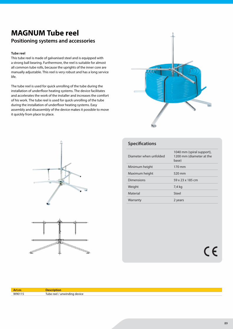
89
MAGNUM Heating Group B.V.Stevinweg 84691SM TholenThe Netherlands
T +31 166 609300E [email protected] www.magnumheatinggroup.com
Tube reelThis tube reel is made of galvanised steel and is equipped with a strong ball bearing. Furthermore, the reel is suitable for almost all common tube rolls, because the uprights of the inner core are manually adjustable. This reel is very robust and has a long service life.
The tube reel is used for quick unrolling of the tube during the installation of underfl oor heating systems. The device facilitates and accelerates the work of the installer and increases the comfort of his work. The tube reel is used for quick unrolling of the tube during the installation of underfl oor heating systems. Easy assembly and disassembly of the device makes it possible to move it quickly from place to place.
MAGNUM Tube reelPositioning systems and accessories
Art.nr. DescriptionW90115 Tube reel / unwinding device
Specifi cations
Diameter when unfolded1040 mm (spiral support), 1200 mm (diameter at the base)
Minimum height 170 mm
Maximum height 520 mm
Dimensions 59 x 23 x 185 cm
Weight 7,4 kg
Material Steel
Warranty 2 years
T iA S p . z o . o . +48 12 262 96 59 Słowackiego 22a [email protected] 37-200 Przeworsk [email protected] Poland www.tia.com.pl
Rozwijak Pipe decoiler
DANE PRODUKTU / SPECIFICATIONS
MATERIAŁ: Stal
Rozwijak służy do szybkiego rozwijania zwoju rury podczas montażu systemów ogrzewania podłogowego. Rozwijak ułatwia i przyspiesza pracę instalatora oraz podnosi komfort jego pracy. Rura umieszczona na rozwijaku nie ulega splątaniu i załamaniu. Dzięki łatwemu montażowi i demontażowi urządzenie można łatwo przenosić z miejsca na miejsca.
- średnica po rozłożeniu: 1040mm wsparcie rolki, 1200mm podstawy
- minimalna wysokość: 170mm
- maksymalna wysokość: 520mm
MATERIAL: Steel
Znajdź ten produkt na naszej stronie! Find this product on our website!
SYSTEMY GRZEWCZE / HEATING SYSTEMS
WŁASNOŚCI PRODUKTU / PRODUCT FEATURES
Pipe decoiler is used for quickly unrolling the pipe during installation of underfloor heating systems. Device facilitates and speeds up the work of installer and increases the comfort of his work. Pipe placed on the pipe decolier is not tangled and crashed. Easy assembly and disassembly of the device allows for its quick moving from place to place.
- diameter when unfolded: 1040 mm (coil support), 1200 mm (diameter at the base)
- minimum height: 170mm
- maximum height: 520mm
Floor heating | Accessories
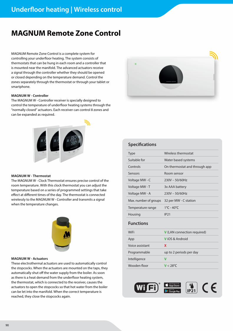
90
Underfloor heating | Wireless control
MAGNUM Heating Group B.V.Stevinweg 84691SM TholenThe Netherlands
T +31 166 609300E [email protected] www.magnumheatinggroup.com
MAGNUM Remote Zone Control is a complete system for controlling your underfl oor heating. The system consists of thermostats that can be hung in each room and a controller that is mounted near the manifold. The advanced actuators receive a signal through the controller whether they should be opened or closed depending on the temperature demand. Control the zones separately through the thermostat or through your tablet or smartphone.
MAGNUM W - ControllerThe MAGNUM W - Controller receiver is specially designed to control the temperature of underfl oor heating systems through the “normally closed” actuators. Each receiver can control 8 zones and can be expanded as required.
MAGNUM Remote Zone Control
MAGNUM W - ThermostatThe MAGNUM W - Clock Thermostat ensures precise control of the room temperature. With this clock thermostat you can adjust the temperature based on a series of programmed settings that take eff ect at diff erent times of the day. The thermostat is connected wirelessly to the MAGNUM W - Controller and transmits a signal when the temperature changes.
MAGNUM W - ActuatorsThese electrothermal actuators are used to automatically control the stopcocks. When the actuators are mounted on the taps, they automatically shut off the water supply from the boiler. As soon as there is a heat demand from the underfl oor heating system, the thermostat, which is connected to the receiver, causes the actuators to open the stopcocks so that hot water from the boiler can be let into the manifold. When the correct temperature is reached, they close the stopcocks again.
IP21
Specifi cations
Type Wireless thermostat
Suitable for Water based systems
Controls On thermostat and through app
Sensors Room sensor
Voltage MW - C 230V – 50/60Hz
Voltage MW - T 3x AAA battery
Voltage MW - A 230V – 50/60Hz
Max. number of groups 32 per MW - C station
Temperature range 1°C - 40°C
Housing IP21
Functions
WiFi V (LAN connection required)
App V iOS & Android
Voice assistant X
Programmable up to 2 periods per day
Intelligence V
Wooden fl oor V < 28°C
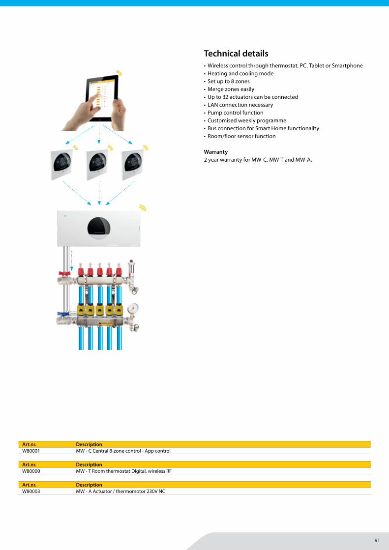
91
MAGNUM Heating Group B.V.Stevinweg 84691SM TholenThe Netherlands
T +31 166 609300E [email protected] www.magnumheatinggroup.com
• Wireless control through thermostat, PC, Tablet or Smartphone• Heating and cooling mode• Set up to 8 zones• Merge zones easily• Up to 32 actuators can be connected• LAN connection necessary• Pump control function• Customised weekly programme• Bus connection for Smart Home functionality• Room/fl oor sensor function
Warranty2 year warranty for MW-C, MW-T and MW-A.
Art.nr. DescriptionW80001 MW - C Central 8-zone control - App control
Technical details
Art.nr. DescriptionW80000 MW - T Room thermostat Digital, wireless RF
Art.nr. DescriptionW80003 MW - A Actuator / thermomotor 230V NC
Underfloor heating | Wireless control
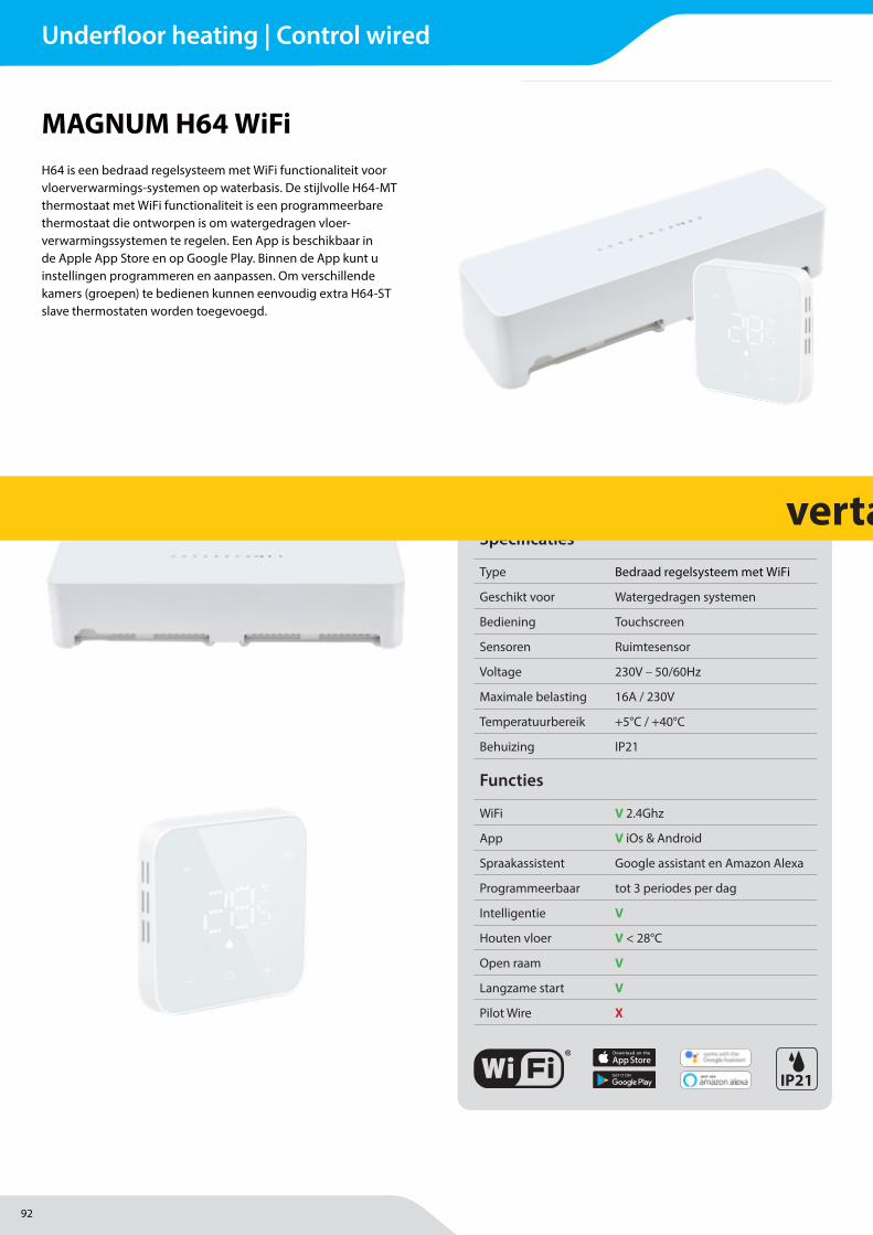
92
Underfloor heating | Control wired
MAGNUM Heating B.V.Stevinweg 84691SM TholenThe Netherlands
T +31 166 609300E [email protected] www.magnumheating.com
H64 is een bedraad regelsysteem met WiFi functionaliteit voor vloerverwarmings-systemen op waterbasis. De stijlvolle H64-MT thermostaat met WiFi functionaliteit is een programmeerbare thermostaat die ontworpen is om watergedragen vloer-verwarmingssystemen te regelen. Een App is beschikbaar in de Apple App Store en op Google Play. Binnen de App kunt u instellingen programmeren en aanpassen. Om verschillende kamers (groepen) te bedienen kunnen eenvoudig extra H64-ST slave thermostaten worden toegevoegd.
MAGNUM H64 WiFi
Specifi caties
Type Bedraad regelsysteem met WiFi
Geschikt voor Watergedragen systemen
Bediening Touchscreen
Sensoren Ruimtesensor
Voltage 230V – 50/60Hz
Maximale belasting 16A / 230V
Temperatuurbereik +5°C / +40°C
Behuizing IP21
Functies
WiFi V 2.4Ghz
App V iOs & Android
Spraakassistent Google assistant en Amazon Alexa
Programmeerbaar tot 3 periodes per dag
Intelligentie V
Houten vloer V < 28°C
Open raam V
Langzame start V
Pilot Wire X
IP21
vertalen!
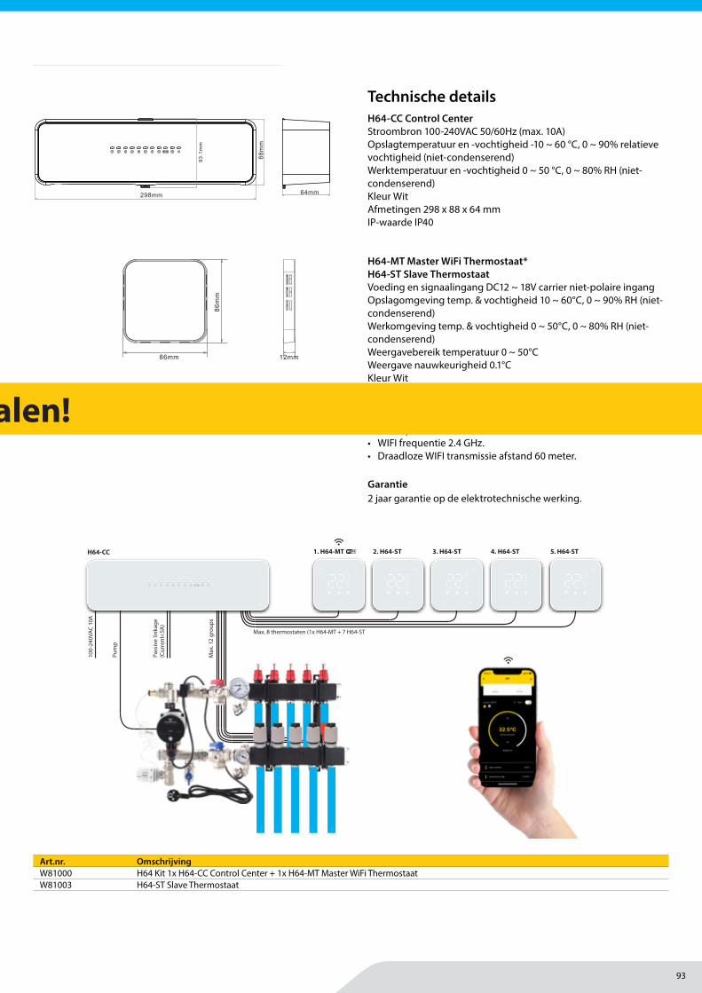
93
Underfloor heating | Control wired
MAGNUM Heating B.V.Stevinweg 84691SM TholenThe Netherlands
T +31 166 609300E [email protected] www.magnumheating.com
H64-CC Control CenterStroombron 100-240VAC 50/60Hz (max. 10A)Opslagtemperatuur en -vochtigheid -10 ~ 60 °C, 0 ~ 90% relatieve vochtigheid (niet-condenserend)Werktemperatuur en -vochtigheid 0 ~ 50 °C, 0 ~ 80% RH (niet-condenserend)Kleur WitAfmetingen 298 x 88 x 64 mmIP-waarde IP40
H64-MT Master WiFi Thermostaat* H64-ST Slave ThermostaatVoeding en signaalingang DC12 ~ 18V carrier niet-polaire ingangOpslagomgeving temp. & vochtigheid 10 ~ 60°C, 0 ~ 90% RH (niet-condenserend)Werkomgeving temp. & vochtigheid 0 ~ 50°C, 0 ~ 80% RH (niet-condenserend)Weergavebereik temperatuur 0 ~ 50°CWeergave nauwkeurigheid 0.1°CKleur WitAfmetingen (LxBxD) 86 x 86 x 12 mmIP-klasse IP21
* Extra op de H64-MT Master WiFi Thermostaat:• WIFI frequentie 2.4 GHz.• Draadloze WIFI transmissie afstand 60 meter.
Garantie2 jaar garantie op de elektrotechnische werking.
Art.nr. OmschrijvingW81000 H64 Kit 1x H64-CC Control Center + 1x H64-MT Master WiFi ThermostaatW81003 H64-ST Slave Thermostaat
Technische details
Wiring control centre H64-CC
Power source: 100-240VAC 50 / 60Hz (maximum current 10A)
Storage environment temperature and humidity: -10 ~ 60°C, 0 ~ 90% RH (non-condensing)
Working environment temperature and humidity: 0 ~ 50 °C, 0 ~ 80% RH (non-condensing)
Color: WhiteSize: 298 X 88 X 64mmIP rating: IP40
Technical Parameters
88
mm
298mm9
3.1
mm
64mm
01
1 2 3 4 5 6 7 8
* Power supply and signal input: DC12 ~ 18V carrier non-polarity input (power supply wiring control centre, maximum current 100mA)* Storage environment temperature and humidity: -10 ~ 60°C, 0 ~ 90% RH (non-condensing)* Working environment temperature and humidity: 0 ~ 50°C, 0 ~ 80% RH (non-condensing)* Temperature display range: 0 ~ 50°C* Display accuracy: 0.1°C* Color: White* Size: 86x86x12mm (length * width * thickness)* Protection level: IP21* WIFI antenna emission frequency(master controller): 2.4GMHz* WIFI wireless transmission distance(master controller): 60M in the open area
86m
m
86mm 12mm03
Master(H64-MT WiFi) / Slave(H64-ST)
1 2 3 4 5 6 7 8
1. H64-MT 2. H64-ST 3. H64-ST 4. H64-ST 5. H64-STH64-CC
Max
. 12
grou
ps
100-
240V
AC 1
0A
Pum
p
Pass
ive
linka
ge
(Cur
rent
<5A
)
Max. 8 thermostaten (1x H64-MT + 7 H64-ST
vertalen!
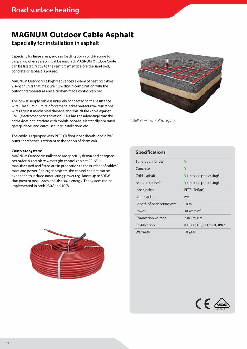
94
Road surface heating
MAGNUM Heating Group B.V.Stevinweg 84691SM TholenThe Netherlands
T +31 166 609300E [email protected] www.magnumheatinggroup.com
Especially for large areas, such as loading docks or driveways for car parks, where safety must be ensured. MAGNUM Outdoor Cable can be fi xed directly to the reinforcement before the sand bed, concrete or asphalt is poured.
MAGNUM Outdoor is a highly advanced system of heating cables, 2 sensor units that measure humidity in combination with the outdoor temperature and a custom-made control cabinet.
The power supply cable is uniquely connected to the resistance wire. The aluminium reinforcement jacket protects the resistance wires against mechanical damage and shields the cable against EMC (electromagnetic radiation). This has the advantage that the cable does not interfere with mobile phones, electrically operated garage doors and gates, security installations etc.
The cable is equipped with PTFE (Tefl on) inner sheaths and a PVC outer sheath that is resistant to the action of chemicals.
Complete systemsMAGNUM Outdoor installations are specially drawn and designed per order. A complete watertight control cabinet (IP-65) is manufactured and fi tted out in proportion to the number of cables/mats and power. For larger projects, the control cabinet can be expanded to include modulating power regulators up to 50kW that prevent peak loads and also save energy. The system can be implemented in both 230V and 400V.
MAGNUM Outdoor Cable AsphaltEspecially for installation in asphalt
Specifi cations
Sand bed + bricks V
Concrete V
Cold asphalt V unrolled processing!
Asphalt < 240oC V unrolled processing!
Inner jacket PFTE (Tefl on)
Outer jacket PVC
Length of connecting wire 10 m
Power 30 Watt/m1
Connection voltage 230 V/50Hz
Certifi cation IEC 800, CE, ISO 9001, IPX7
Warranty 10 year
VDE-REG 8741
Installation in unrolled asphalt
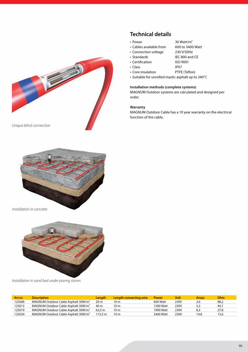
95
MAGNUM Heating Group B.V.Stevinweg 84691SM TholenThe Netherlands
T +31 166 609300E [email protected] www.magnumheatinggroup.com
• Power 30 Watt/m1• Cables available from 600 to 3400 Watt • Connection voltage 230 V/50Hz• Standards IEC 800 and CE• Certifi cation ISO 9001• Class IPX7• Core insulation PTFE (Tefl on)• Suitable for unrolled mastic asphalt up to 240°C
Installation methods (complete systems)MAGNUM Outdoor systems are calculated and designed per order.
WarrantyMAGNUM Outdoor Cable has a 10 year warranty on the electrical function of the cable.
Art.nr. Description Length Length connecting wire Power Volt Amps Ohm125006 MAGNUM Outdoor Cable Asphalt 30W/m1 20 m 10 m 600 Watt 230V 2,6 88,2125012 MAGNUM Outdoor Cable Asphalt 30W/m1 40 m 10 m 1200 Watt 230V 5,2 44,1125019 MAGNUM Outdoor Cable Asphalt 30W/m1 63,3 m 10 m 1900 Watt 230V 8,3 27,8125034 MAGNUM Outdoor Cable Asphalt 30W/m1 113,3 m 10 m 3400 Watt 230V 14,8 15,6
Unique blind connection
Technical details
Installation in concrete
Installation in sand bed under paving stones
Road surface heating
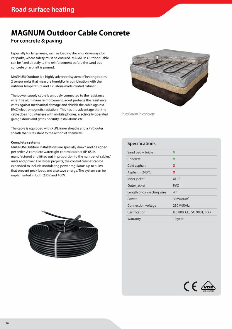
96
Road surface heating
MAGNUM Heating Group B.V.Stevinweg 84691SM TholenThe Netherlands
T +31 166 609300E [email protected] www.magnumheatinggroup.com
Especially for large areas, such as loading docks or driveways for car parks, where safety must be ensured. MAGNUM Outdoor Cable can be fi xed directly to the reinforcement before the sand bed, concrete or asphalt is poured.
MAGNUM Outdoor is a highly advanced system of heating cables, 2 sensor units that measure humidity in combination with the outdoor temperature and a custom-made control cabinet.
The power supply cable is uniquely connected to the resistance wire. The aluminium reinforcement jacket protects the resistance wires against mechanical damage and shields the cable against EMC (electromagnetic radiation). This has the advantage that the cable does not interfere with mobile phones, electrically operated garage doors and gates, security installations etc.
The cable is equipped with XLPE inner sheaths and a PVC outer sheath that is resistant to the action of chemicals.
Complete systemsMAGNUM Outdoor installations are specially drawn and designed per order. A complete watertight control cabinet (IP-65) is manufactured and fi tted out in proportion to the number of cables/mats and power. For larger projects, the control cabinet can be expanded to include modulating power regulators up to 50kW that prevent peak loads and also save energy. The system can be implemented in both 230V and 400V.
MAGNUM Outdoor Cable ConcreteFor concrete & paving
Specifi cations
Sand bed + bricks V
Concrete V
Cold asphalt X
Asphalt < 240oC X
Inner jacket XLPE
Outer jacket PVC
Length of connecting wire 4 m
Power 30 Watt/m1
Connection voltage 230 V/50Hz
Certifi cation IEC 800, CE, ISO 9001, IPX7
Warranty 10 year
VDE-REG 8741
Installation in concrete
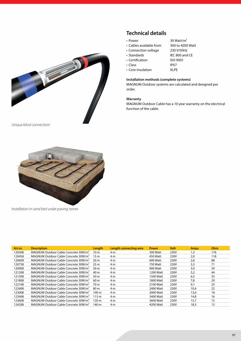
97
MAGNUM Heating Group B.V.Stevinweg 84691SM TholenThe Netherlands
T +31 166 609300E [email protected] www.magnumheatinggroup.com
• Power 30 Watt/m1• Cables available from 300 to 4200 Watt • Connection voltage 230 V/50Hz• Standards IEC 800 and CE• Certifi cation ISO 9001• Class IPX7• Core insulation XLPE
Installation methods (complete systems)MAGNUM Outdoor systems are calculated and designed per order.
WarrantyMAGNUM Outdoor Cable has a 10 year warranty on the electrical function of the cable.
Art.nr. Description Length Length connecting wire Power Volt Amps Ohm120308 MAGNUM Outdoor Cable Concrete 30W/m1 10 m 4 m 300 Watt 230V 1,3 176120458 MAGNUM Outdoor Cable Concrete 30W/m1 15 m 4 m 450 Watt 230V 2,0 118120608 MAGNUM Outdoor Cable Concrete 30W/m1 20 m 4 m 600 Watt 230V 2,6 88120758 MAGNUM Outdoor Cable Concrete 30W/m1 25 m 4 m 750 Watt 230V 3,3 71120908 MAGNUM Outdoor Cable Concrete 30W/m1 30 m 4 m 900 Watt 230V 3,9 59121208 MAGNUM Outdoor Cable Concrete 30W/m1 40 m 4 m 1200 Watt 230V 5,2 44121508 MAGNUM Outdoor Cable Concrete 30W/m1 50 m 4 m 1500 Watt 230V 6,5 35121808 MAGNUM Outdoor Cable Concrete 30W/m1 60 m 4 m 1800 Watt 230V 7,8 29122108 MAGNUM Outdoor Cable Concrete 30W/m1 70 m 4 m 2100 Watt 230V 9,1 25122408 MAGNUM Outdoor Cable Concrete 30W/m1 80 m 4 m 2400 Watt 230V 10,4 22123008 MAGNUM Outdoor Cable Concrete 30W/m1 100 m 4 m 3000 Watt 230V 13,0 18123408 MAGNUM Outdoor Cable Concrete 30W/m1 113 m 4 m 3400 Watt 230V 14,8 16123608 MAGNUM Outdoor Cable Concrete 30W/m1 120 m 4 m 3600 Watt 230V 15,7 15124208 MAGNUM Outdoor Cable Concrete 30W/m1 140 m 4 m 4200 Watt 230V 18,3 13
Unique blind connection!
Technical details
Installation in sand bed under paving stones
Road surface heating
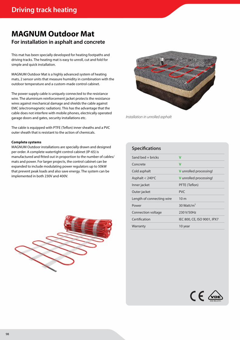
98
Driving track heating
MAGNUM Heating Group B.V.Stevinweg 84691SM TholenThe Netherlands
T +31 166 609300E [email protected] www.magnumheatinggroup.com
This mat has been specially developed for heating footpaths and driving tracks. The heating mat is easy to unroll, cut and fold for simple and quick installation.
MAGNUM Outdoor Mat is a highly advanced system of heating mats, 2 sensor units that measure humidity in combination with the outdoor temperature and a custom-made control cabinet.
The power supply cable is uniquely connected to the resistance wire. The aluminium reinforcement jacket protects the resistance wires against mechanical damage and shields the cable against EMC (electromagnetic radiation). This has the advantage that the cable does not interfere with mobile phones, electrically operated garage doors and gates, security installations etc.
The cable is equipped with PTFE (Tefl on) inner sheaths and a PVC outer sheath that is resistant to the action of chemicals.
Complete systemsMAGNUM Outdoor installations are specially drawn and designed per order. A complete watertight control cabinet (IP-65) is manufactured and fi tted out in proportion to the number of cables/mats and power. For larger projects, the control cabinet can be expanded to include modulating power regulators up to 50kW that prevent peak loads and also save energy. The system can be implemented in both 230V and 400V.
MAGNUM Outdoor MatFor installation in asphalt and concrete
Installation in unrolled asphalt
VDE-REG 8741
Specifi cations
Sand bed + bricks V
Concrete V
Cold asphalt V unrolled processing!
Asphalt < 240oC V unrolled processing!
Inner jacket PFTE (Tefl on)
Outer jacket PVC
Length of connecting wire 10 m
Power 30 Watt/m1
Connection voltage 230 V/50Hz
Certifi cation IEC 800, CE, ISO 9001, IPX7
Warranty 10 year
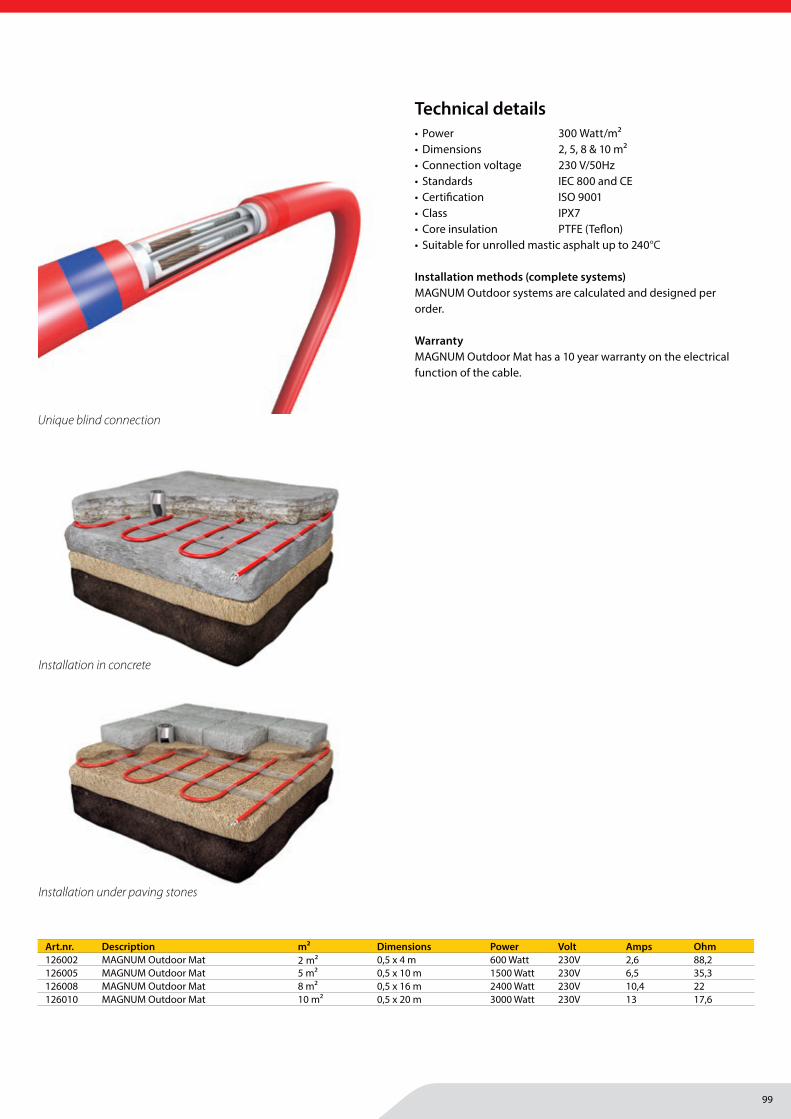
99
MAGNUM Heating Group B.V.Stevinweg 84691SM TholenThe Netherlands
T +31 166 609300E [email protected] www.magnumheatinggroup.com
• Power 300 Watt/m2• Dimensions 2, 5, 8 & 10 m2• Connection voltage 230 V/50Hz• Standards IEC 800 and CE• Certifi cation ISO 9001• Class IPX7• Core insulation PTFE (Tefl on)• Suitable for unrolled mastic asphalt up to 240°C
Installation methods (complete systems)MAGNUM Outdoor systems are calculated and designed per order.
WarrantyMAGNUM Outdoor Mat has a 10 year warranty on the electrical function of the cable.
Art.nr. Description m2 Dimensions Power Volt Amps Ohm126002 MAGNUM Outdoor Mat 2 m2 0,5 x 4 m 600 Watt 230V 2,6 88,2126005 MAGNUM Outdoor Mat 5 m2 0,5 x 10 m 1500 Watt 230V 6,5 35,3126008 MAGNUM Outdoor Mat 8 m2 0,5 x 16 m 2400 Watt 230V 10,4 22126010 MAGNUM Outdoor Mat 10 m2 0,5 x 20 m 3000 Watt 230V 13 17,6
Unique blind connection
Technical details
Installation under paving stones
Installation in concrete
Driving track heating

100
Road surface heating | Switchboard
MAGNUM Heating Group B.V.Stevinweg 84691SM TholenThe Netherlands
T +31 166 609300E [email protected] www.magnumheatinggroup.com
Complete watertight control cabinets manufactured and fi tted according to the number of cables/mats and power. The system can be implemented in both 230V and 400V.
Connection boxThe control cabinets can be assembled custom-made for each project. The standard version is equipped (according to NEN1010) with the necessary waterproof cable entries, magnetic circuits (relays), circuit breakers, earth leakage switches, terminal strips for easy connection of power and heating cables and the special outdoor road sensor units. For this, the diagram shown in the switch box must be followed.
MAGNUM Outdoor ControlControl cabinets
Specifi cations
ETO2-4550 DIN-rail Thermostat 0°C / +5°C 230V
2x ETOG-56 Sensorunits Humidity & Temperature
Potential-free contacts 3 x 16 Amps
Required solenoid circuits (relays)
230V/400V
Required installation circuit breakers 16 Amps
Connection terminals for mounting power cables
Indicator lights
Warranty 2 year
Art.nr. Description kW Cabinet dimensions Unit900004 MAGNUM Outdoor control cabinet 3,6 kW 430 x 310 x 160 mm units/1 incl. ETO2-4550 DIN-rail thermostat and 2x ETOG-56 sensor units900010 MAGNUM Outdoor control cabinet 10 kW 500 x 400 x 200 mm units/1 incl. ETO2-4550 DIN-rail thermostat and 2x ETOG-56 sensor units900020 MAGNUM Outdoor control cabinet 20 kW 500 x 400 x 200 mm units/1 incl. ETO2-4550 DIN-rail thermostat and 2x ETOG-56 sensor units900030 MAGNUM Outdoor control cabinet 30 kW 700 x 520 x 253 mm units/1 incl. ETO2-4550 DIN-rail thermostat and 2x ETOG-56 sensor units900040 MAGNUM Outdoor control cabinet 40 kW 700 x 520 x 253 mm units/1 incl. ETO2-4550 DIN-rail thermostat and 2x ETOG-56 sensor units900050 MAGNUM Outdoor control cabinet 50 kW 700 x 520 x 253 mm units/1 incl. ETO2-4550 DIN-rail thermostat and 2x ETOG-56 sensor units

101
Road surface heating | Switchboard
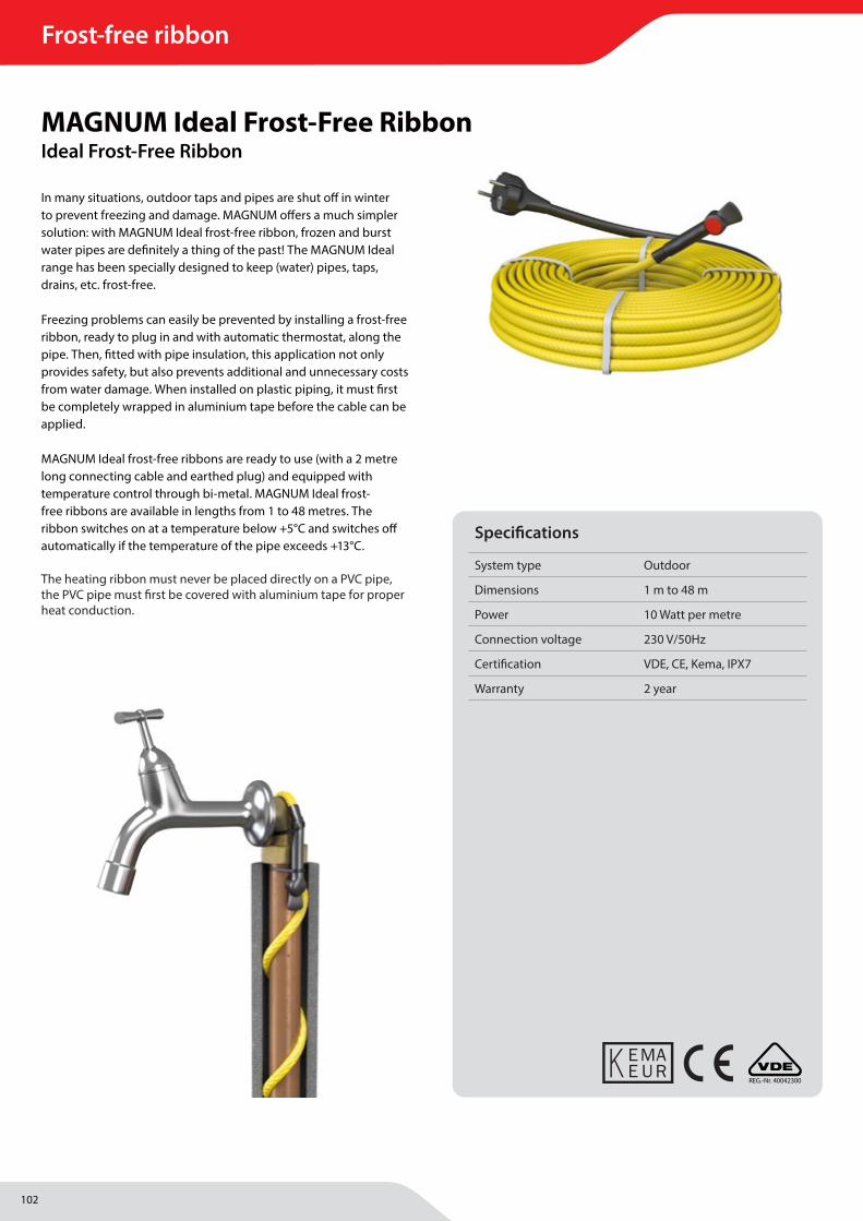
102
Frost-free ribbon
MAGNUM Heating Group B.V.Stevinweg 84691SM TholenThe Netherlands
T +31 166 609300E [email protected] www.magnumheatinggroup.com
In many situations, outdoor taps and pipes are shut off in winter to prevent freezing and damage. MAGNUM off ers a much simpler solution: with MAGNUM Ideal frost-free ribbon, frozen and burst water pipes are defi nitely a thing of the past! The MAGNUM Ideal range has been specially designed to keep (water) pipes, taps, drains, etc. frost-free.
Freezing problems can easily be prevented by installing a frost-free ribbon, ready to plug in and with automatic thermostat, along the pipe. Then, fi tted with pipe insulation, this application not only provides safety, but also prevents additional and unnecessary costs from water damage. When installed on plastic piping, it must fi rst be completely wrapped in aluminium tape before the cable can be applied.
MAGNUM Ideal frost-free ribbons are ready to use (with a 2 metre long connecting cable and earthed plug) and equipped with temperature control through bi-metal. MAGNUM Ideal frost-free ribbons are available in lengths from 1 to 48 metres. The ribbon switches on at a temperature below +5°C and switches off automatically if the temperature of the pipe exceeds +13°C.
The heating ribbon must never be placed directly on a PVC pipe, the PVC pipe must fi rst be covered with aluminium tape for proper heat conduction.
MAGNUM Ideal Frost-Free RibbonIdeal Frost-Free Ribbon
REG.-Nr. 40042300
Specifi cations
System type Outdoor
Dimensions 1 m to 48 m
Power 10 Watt per metre
Connection voltage 230 V/50Hz
Certifi cation VDE, CE, Kema, IPX7
Warranty 2 year
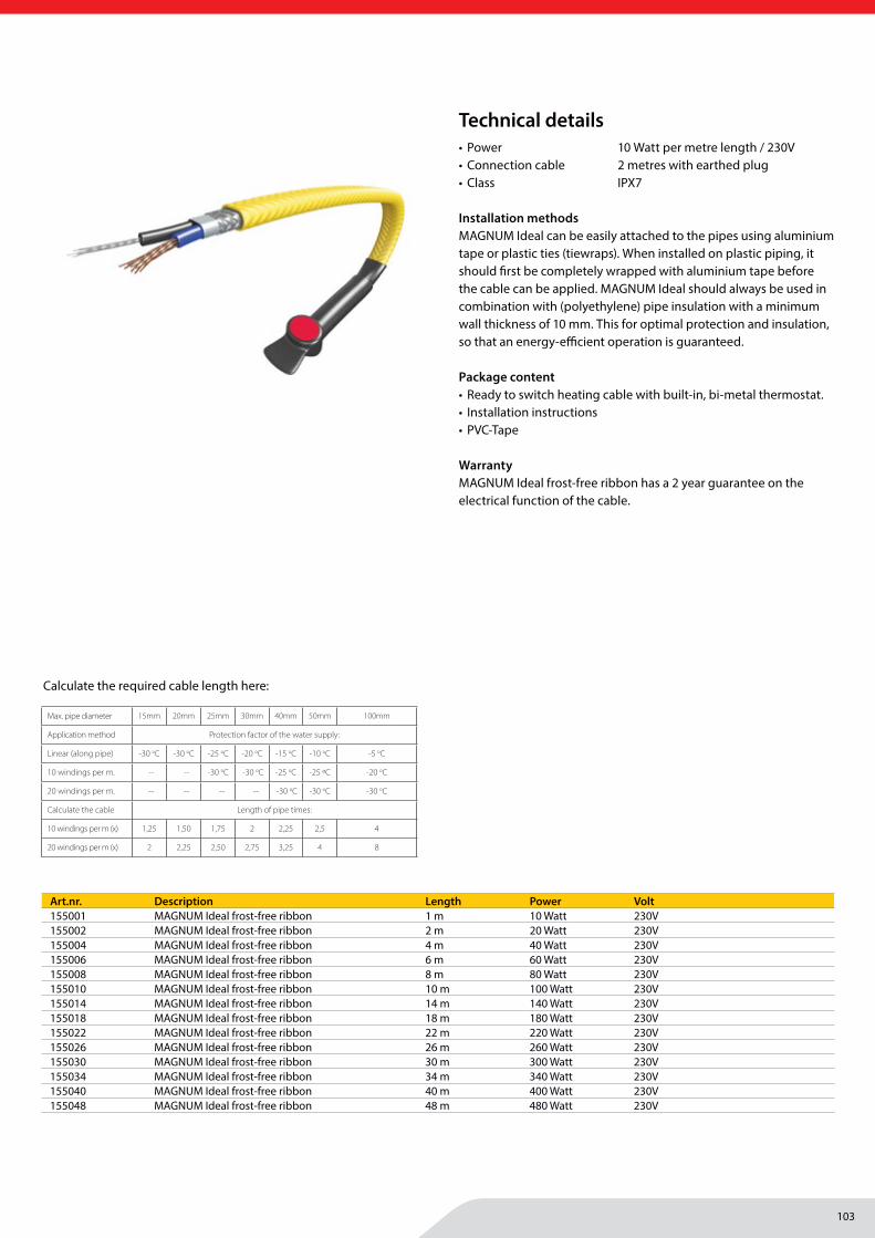
103
Frost-free ribbon
MAGNUM Heating Group B.V.Stevinweg 84691SM TholenThe Netherlands
T +31 166 609300E [email protected] www.magnumheatinggroup.com
• Power 10 Watt per metre length / 230V• Connection cable 2 metres with earthed plug• Class IPX7
Installation methodsMAGNUM Ideal can be easily attached to the pipes using aluminium tape or plastic ties (tiewraps). When installed on plastic piping, it should fi rst be completely wrapped with aluminium tape before the cable can be applied. MAGNUM Ideal should always be used in combination with (polyethylene) pipe insulation with a minimum wall thickness of 10 mm. This for optimal protection and insulation, so that an energy-effi cient operation is guaranteed.
Package content• Ready to switch heating cable with built-in, bi-metal thermostat.• Installation instructions• PVC-Tape
WarrantyMAGNUM Ideal frost-free ribbon has a 2 year guarantee on the electrical function of the cable.
Art.nr. Description Length Power Volt155001 MAGNUM Ideal frost-free ribbon 1 m 10 Watt 230V155002 MAGNUM Ideal frost-free ribbon 2 m 20 Watt 230V155004 MAGNUM Ideal frost-free ribbon 4 m 40 Watt 230V155006 MAGNUM Ideal frost-free ribbon 6 m 60 Watt 230V155008 MAGNUM Ideal frost-free ribbon 8 m 80 Watt 230V155010 MAGNUM Ideal frost-free ribbon 10 m 100 Watt 230V155014 MAGNUM Ideal frost-free ribbon 14 m 140 Watt 230V155018 MAGNUM Ideal frost-free ribbon 18 m 180 Watt 230V155022 MAGNUM Ideal frost-free ribbon 22 m 220 Watt 230V155026 MAGNUM Ideal frost-free ribbon 26 m 260 Watt 230V155030 MAGNUM Ideal frost-free ribbon 30 m 300 Watt 230V155034 MAGNUM Ideal frost-free ribbon 34 m 340 Watt 230V155040 MAGNUM Ideal frost-free ribbon 40 m 400 Watt 230V155048 MAGNUM Ideal frost-free ribbon 48 m 480 Watt 230V
Technical details
Max. pipe diameter 15mm 20mm 25mm 30mm 40mm 50mm 100mm
Application method Protection factor of the water supply:
Linear (along pipe) -30 oC -30 oC -25 oC -20 oC -15 oC -10 oC -5 oC
10 windings per m. -- -- -30 oC -30 oC -25 oC -25 ºC -20 oC
20 windings per m. -- -- -- -- -30 oC -30 oC -30 oC
Calculate the cable Length of pipe times:
10 windings per m (x) 1,25 1,50 1,75 2 2,25 2,5 4
20 windings per m (x) 2 2,25 2,50 2,75 3,25 4 8
Calculate the required cable length here:
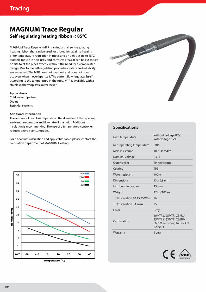
104
Tracing
MAGNUM Heating Group B.V.Stevinweg 84691SM TholenThe Netherlands
T +31 166 609300E [email protected] www.magnumheatinggroup.com
MAGNUM Trace Regular - MTR is an industrial, self-regulating heating ribbon that can be used for protection against freezing or for temperature regulation in tubes and on vehicles up to 85°C. Suitable for use in non-risky and corrosive areas. It can be cut to size on site to fi t the pipes exactly, without the need for a complicated design. Due to the self-regulating properties, safety and reliability are increased. The MTR does not overheat and does not burn up, even when it overlaps itself. The current fl ow regulates itself according to the temperature in the tube. MTR is available with a stainless, thermoplastic outer jacket.
ApplicationsCold water pipelinesDrainsSprinkler systems
Additional Information The amount of heat loss depends on the diameter of the pipeline, ambient temperature and fl ow rate of the fl uid. Additional insulation is recommended. The use of a temperature controller reduces energy consumption.
For a heat loss calculation and applicable cable, please contact the calculation department of MAGNUM Heating.
25
50
45
40
35
30
TTeemmppeerraattuurree ((ooCC))
NNoorr
mmaall
((WW
//MM))
Temperature graph ( DECKER )
0 10 20 30 40W//℃
20
15
10
5
-20 -10
33W
25W
15W
10W
MAGNUM Trace RegularSelf regulating heating ribbon < 85°C
Specifi cations
Max. temperature Without voltage 85°CWith voltage 65°C
Min. operating temperature -30°C
Max. resistance 18,2 Ohm/km
Nominal voltage 230V
Outer jacket Tinned copper
Coating TPE
Water resistant 100%
Dimensions 13 x 6,8 mm
Min. bending radius 25 mm
Weight 12 kg/100 m
T-classifi cation 10,15,25 W/m T6
T-classifi cation 33 W/m T5
Color Grey
Certifi cation
10MTR & 25MTR: CE /RU 15MTR & 33MTR: CE/RU/FM/EX,according to DIN EN 62395-1
Warranty 2 year
REG.-Nr. 40040697
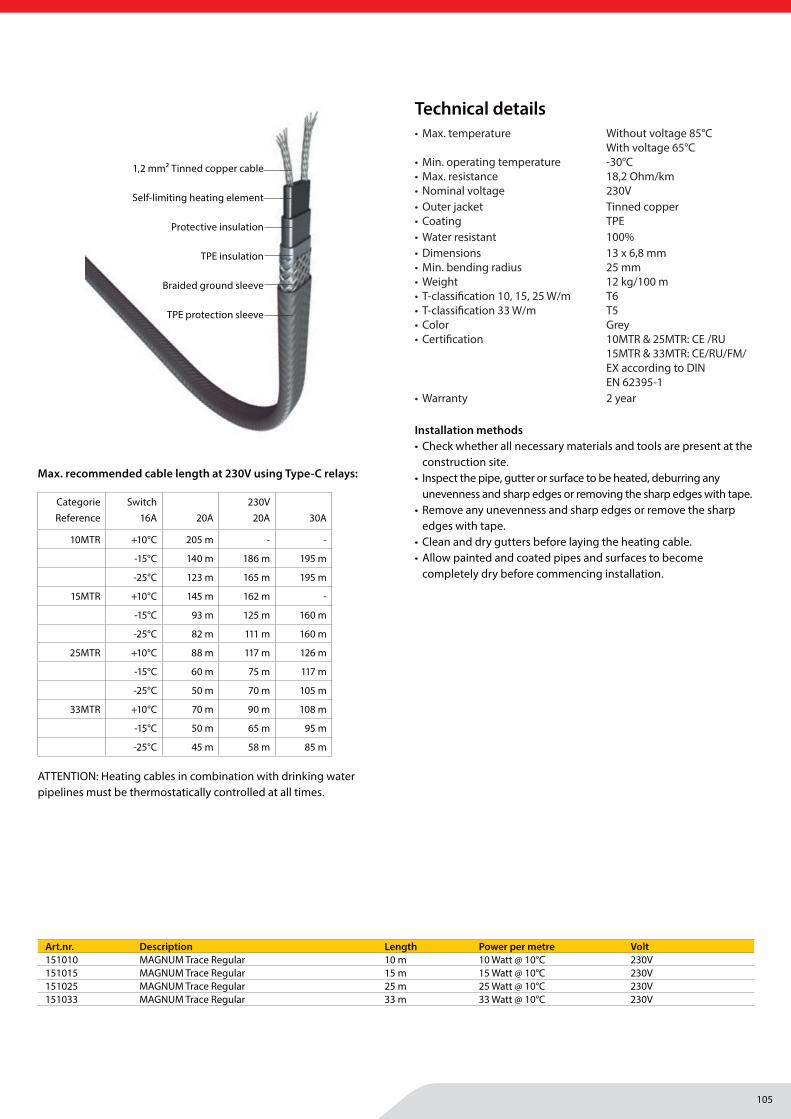
105
Tracing
MAGNUM Heating Group B.V.Stevinweg 84691SM TholenThe Netherlands
T +31 166 609300E [email protected] www.magnumheatinggroup.com
• Max. temperature Without voltage 85°C With voltage 65°C
• Min. operating temperature -30°C• Max. resistance 18,2 Ohm/km• Nominal voltage 230V• Outer jacket Tinned copper• Coating TPE• Water resistant 100%• Dimensions 13 x 6,8 mm• Min. bending radius 25 mm• Weight 12 kg/100 m• T-classifi cation 10, 15, 25 W/m T6• T-classifi cation 33 W/m T5• Color Grey• Certifi cation 10MTR & 25MTR: CE /RU
15MTR & 33MTR: CE/RU/FM/ EX according to DIN EN 62395-1
• Warranty 2 year
Installation methods• Check whether all necessary materials and tools are present at the
construction site.• Inspect the pipe, gutter or surface to be heated, deburring any
unevenness and sharp edges or removing the sharp edges with tape. • Remove any unevenness and sharp edges or remove the sharp
edges with tape.• Clean and dry gutters before laying the heating cable.• Allow painted and coated pipes and surfaces to become
completely dry before commencing installation.
Art.nr. Description Length Power per metre Volt151010 MAGNUM Trace Regular 10 m 10 Watt @ 10°C 230V151015 MAGNUM Trace Regular 15 m 15 Watt @ 10°C 230V151025 MAGNUM Trace Regular 25 m 25 Watt @ 10°C 230V151033 MAGNUM Trace Regular 33 m 33 Watt @ 10°C 230V
Technical details
1,2 mm2 Tinned copper cable
Self-limiting heating element
Protective insulation
TPE insulation
Braided ground sleeve
TPE protection sleeve
Max. recommended cable length at 230V using Type-C relays:
CategorieReference
Switch16A 20A
230V 20A 30A
10MTR +10°C 205 m - -
-15°C 140 m 186 m 195 m
-25°C 123 m 165 m 195 m
15MTR +10°C 145 m 162 m -
-15°C 93 m 125 m 160 m
-25°C 82 m 111 m 160 m
25MTR +10°C 88 m 117 m 126 m
-15°C 60 m 75 m 117 m
-25°C 50 m 70 m 105 m
33MTR +10°C 70 m 90 m 108 m
-15°C 50 m 65 m 95 m
-25°C 45 m 58 m 85 m
ATTENTION: Heating cables in combination with drinking water pipelines must be thermostatically controlled at all times.
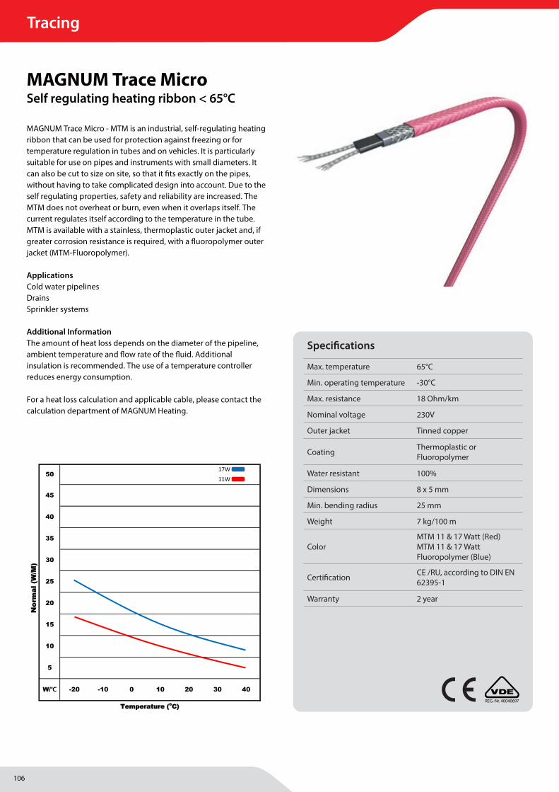
106
Tracing
MAGNUM Heating Group B.V.Stevinweg 84691SM TholenThe Netherlands
T +31 166 609300E [email protected] www.magnumheatinggroup.com
MAGNUM Trace Micro - MTM is an industrial, self-regulating heating ribbon that can be used for protection against freezing or for temperature regulation in tubes and on vehicles. It is particularly suitable for use on pipes and instruments with small diameters. It can also be cut to size on site, so that it fi ts exactly on the pipes, without having to take complicated design into account. Due to the self regulating properties, safety and reliability are increased. The MTM does not overheat or burn, even when it overlaps itself. The current regulates itself according to the temperature in the tube. MTM is available with a stainless, thermoplastic outer jacket and, if greater corrosion resistance is required, with a fl uoropolymer outer jacket (MTM-Fluoropolymer).
ApplicationsCold water pipelinesDrainsSprinkler systems
Additional Information The amount of heat loss depends on the diameter of the pipeline, ambient temperature and fl ow rate of the fl uid. Additional insulation is recommended. The use of a temperature controller reduces energy consumption.
For a heat loss calculation and applicable cable, please contact the calculation department of MAGNUM Heating.
25
50
45
40
35
30
TTeemmppeerraattuurree ((ooCC))
NNoorr
mmaall
((WW
//MM))
Temperature graph ( SMALL )
0 10 20 30 40W//℃
20
15
10
5
-20 -10
17W
11W
MAGNUM Trace MicroSelf regulating heating ribbon < 65°C
REG.-Nr. 40040697
Specifi cations
Max. temperature 65°C
Min. operating temperature -30°C
Max. resistance 18 Ohm/km
Nominal voltage 230V
Outer jacket Tinned copper
Coating Thermoplastic or Fluoropolymer
Water resistant 100%
Dimensions 8 x 5 mm
Min. bending radius 25 mm
Weight 7 kg/100 m
ColorMTM 11 & 17 Watt (Red) MTM 11 & 17 Watt Fluoropolymer (Blue)
Certifi cation CE /RU, according to DIN EN 62395-1
Warranty 2 year

107
Tracing
MAGNUM Heating Group B.V.Stevinweg 84691SM TholenThe Netherlands
T +31 166 609300E [email protected] www.magnumheatinggroup.com
• Max. temperature 65°C• Min. operating temperature -30°C• Max. resistance 18 Ohm/km• Nominal voltage 230V• Outer jacket Tinned copper• Coating Thermoplastic or
Fluoropolymer• Water resistant 100%• Dimensions 8 x 5 mm• Min. bending radius 25 mm• Weight 7 kg/100 m• Color MTM 11 & 17 Watt (Red)
MTM 11 & 17 Watt Fluoropolymer (Blue)
• Certifi cation CE /RU, according to DIN EN 62395-1
• Warranty 2 year
Installation methods• Check whether all necessary materials and tools are present at the
construction site.• Inspect the pipe, gutter or surface to be heated, deburring any
unevenness and sharp edges or removing the sharp edges with tape.
• Remove any unevenness and sharp edges or remove the sharp edges with tape.
• Clean and dry gutters before laying the heating cable.• Allow painted and coated pipes and surfaces to become
completely dry before commencing installation.
Art.nr. Description Length Power per metre Volt150211 MAGNUM Trace Micro 11 Per metre 11 Watt @ 10°C 230V150411 MAGNUM Trace Micro 11 Roll 25 metres 11 Watt @ 10°C 230V150511 MAGNUM Trace Micro 11 Roll 50 metres 11 Watt @ 10°C 230V150611 MAGNUM Trace Micro 11 Roll 100 metres 11 Watt @ 10°C 230V150217 MAGNUM Trace Micro 17 Per metre 17 Watt @ 10°C 230V150417 MAGNUM Trace Micro 17 Roll 25 metres 17 Watt @ 10°C 230V150517 MAGNUM Trace Micro 17 Roll 50 metres 17 Watt @ 10°C 230V150617 MAGNUM Trace Micro 17 Roll 100 metres 17 Watt @ 10°C 230V
Art.nr. Description Length Power per metre Volt150311 MAGNUM Trace Micro Fluoropolymer Per metre 11 Watt @ 10°C 230V150317 MAGNUM Trace Micro Fluoropolymer Per metre 17 Watt @ 10°C 230V
Technical details
1,2 mm2 Tinned copper cable
Self-limiting heating element
Protective insulation
TPE insulation
Braided ground sleeve
TPE or fl uoropolymer protective sleeve
Max. recommended cable length at 230V using Type-C relays:
Fluoropolymer
CategorieReferentie
Switch Temp. 6A
230V 10A 16A
11MTM 5°C 70 m 100 m 110 m
0°C 65 m 95 m 105 m
-20°C 44 m 77 m 90 m
-30°C 38 m 67 m 80 m
17MTM 5°C 39 m 60 m 70 m
0°C 37 m 58 m 65 m
-20°C 25 m 44 m 50 m
-30°C 23 m 41 m 47 m
ATTENTION: Heating cables in combination with drinking water pipelines must be thermostatically controlled at all times.
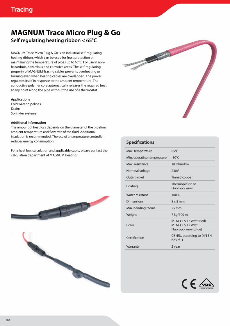
108
Tracing
MAGNUM Heating Group B.V.Stevinweg 84691SM TholenThe Netherlands
T +31 166 609300E [email protected] www.magnumheatinggroup.com
MAGNUM Trace Micro Plug & Go is an industrial self-regulating heating ribbon, which can be used for frost protection or maintaining the temperature of pipes up to 65°C. For use in non-hazardous, hazardous and corrosive areas. The self-regulating property of MAGNUM Tracing cables prevents overheating or burning even when heating cables are overlapped. The power regulates itself in response to the ambient temperature. The conductive polymer core automatically releases the required heat at any point along the pipe without the use of a thermostat.
ApplicationsCold water pipelinesDrainsSprinkler systems
Additional Information The amount of heat loss depends on the diameter of the pipeline, ambient temperature and fl ow rate of the fl uid. Additional insulation is recommended. The use of a temperature controller reduces energy consumption.
For a heat loss calculation and applicable cable, please contact the calculation department of MAGNUM Heating.
MAGNUM Trace Micro Plug & GoSelf regulating heating ribbon < 65°C
REG.-Nr. 40040697
Specifi cations
Max. temperature 65°C
Min. operating temperature -30°C
Max. resistance 18 Ohm/km
Nominal voltage 230V
Outer jacket Tinned copper
Coating Thermoplastic or Fluoropolymer
Water resistant 100%
Dimensions 8 x 5 mm
Min. bending radius 25 mm
Weight 7 kg/100 m
ColorMTM 11 & 17 Watt (Red) MTM 11 & 17 Watt Fluoropolymer (Blue)
Certifi cation CE /RU, according to DIN EN 62395-1
Warranty 2 year
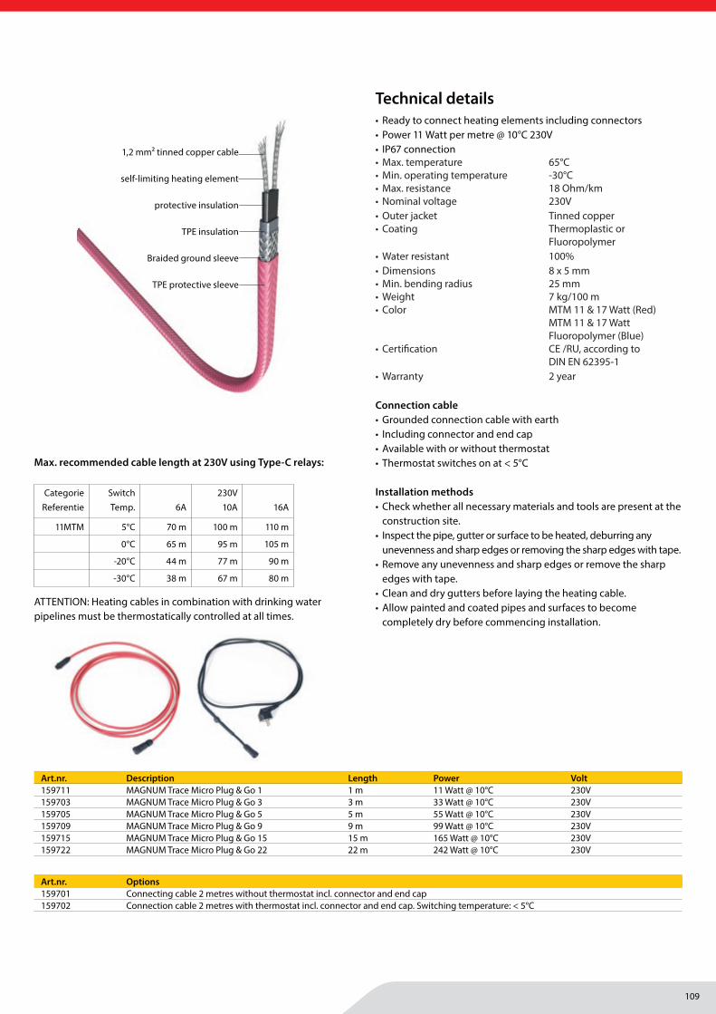
109
Tracing
MAGNUM Heating Group B.V.Stevinweg 84691SM TholenThe Netherlands
T +31 166 609300E [email protected] www.magnumheatinggroup.com
• Ready to connect heating elements including connectors• Power 11 Watt per metre @ 10°C 230V• IP67 connection• Max. temperature 65°C• Min. operating temperature -30°C• Max. resistance 18 Ohm/km• Nominal voltage 230V• Outer jacket Tinned copper• Coating Thermoplastic or
Fluoropolymer• Water resistant 100%• Dimensions 8 x 5 mm• Min. bending radius 25 mm• Weight 7 kg/100 m• Color MTM 11 & 17 Watt (Red)
MTM 11 & 17 Watt Fluoropolymer (Blue)
• Certifi cation CE /RU, according to DIN EN 62395-1
• Warranty 2 year
Connection cable• Grounded connection cable with earth• Including connector and end cap• Available with or without thermostat• Thermostat switches on at < 5°C
Installation methods• Check whether all necessary materials and tools are present at the
construction site.• Inspect the pipe, gutter or surface to be heated, deburring any
unevenness and sharp edges or removing the sharp edges with tape. • Remove any unevenness and sharp edges or remove the sharp
edges with tape.• Clean and dry gutters before laying the heating cable.• Allow painted and coated pipes and surfaces to become
completely dry before commencing installation.
Art.nr. Description Length Power Volt159711 MAGNUM Trace Micro Plug & Go 1 1 m 11 Watt @ 10°C 230V159703 MAGNUM Trace Micro Plug & Go 3 3 m 33 Watt @ 10°C 230V159705 MAGNUM Trace Micro Plug & Go 5 5 m 55 Watt @ 10°C 230V159709 MAGNUM Trace Micro Plug & Go 9 9 m 99 Watt @ 10°C 230V159715 MAGNUM Trace Micro Plug & Go 15 15 m 165 Watt @ 10°C 230V159722 MAGNUM Trace Micro Plug & Go 22 22 m 242 Watt @ 10°C 230V
Art.nr. Options159701 Connecting cable 2 metres without thermostat incl. connector and end cap159702 Connection cable 2 metres with thermostat incl. connector and end cap. Switching temperature: < 5°C
Technical details
1,2 mm2 tinned copper cable
self-limiting heating element
protective insulation
TPE insulation
Braided ground sleeve
TPE protective sleeve
Max. recommended cable length at 230V using Type-C relays:
CategorieReferentie
Switch Temp. 6A
230V 10A 16A
11MTM 5°C 70 m 100 m 110 m
0°C 65 m 95 m 105 m
-20°C 44 m 77 m 90 m
-30°C 38 m 67 m 80 m
ATTENTION: Heating cables in combination with drinking water pipelines must be thermostatically controlled at all times.
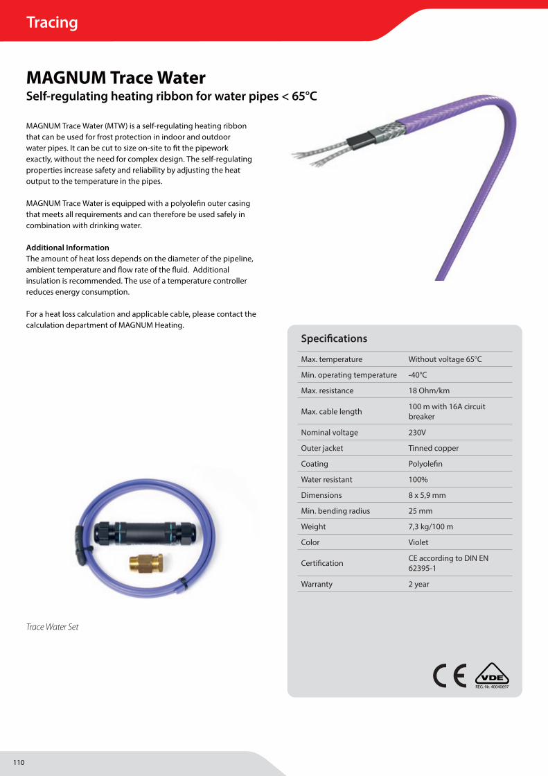
110
Tracing
MAGNUM Heating Group B.V.Stevinweg 84691SM TholenThe Netherlands
T +31 166 609300E [email protected] www.magnumheatinggroup.com
MAGNUM Trace Water (MTW) is a self-regulating heating ribbon that can be used for frost protection in indoor and outdoor water pipes. It can be cut to size on-site to fi t the pipework exactly, without the need for complex design. The self-regulating properties increase safety and reliability by adjusting the heat output to the temperature in the pipes.
MAGNUM Trace Water is equipped with a polyolefi n outer casing that meets all requirements and can therefore be used safely in combination with drinking water.
Additional Information The amount of heat loss depends on the diameter of the pipeline, ambient temperature and fl ow rate of the fl uid. Additional insulation is recommended. The use of a temperature controller reduces energy consumption.
For a heat loss calculation and applicable cable, please contact the calculation department of MAGNUM Heating.
MAGNUM Trace WaterSelf-regulating heating ribbon for water pipes < 65°C
Trace Water Set
REG.-Nr. 40040697
Specifi cations
Max. temperature Without voltage 65°C
Min. operating temperature -40°C
Max. resistance 18 Ohm/km
Max. cable length 100 m with 16A circuit breaker
Nominal voltage 230V
Outer jacket Tinned copper
Coating Polyolefi n
Water resistant 100%
Dimensions 8 x 5,9 mm
Min. bending radius 25 mm
Weight 7,3 kg/100 m
Color Violet
Certifi cation CE according to DIN EN 62395-1
Warranty 2 year
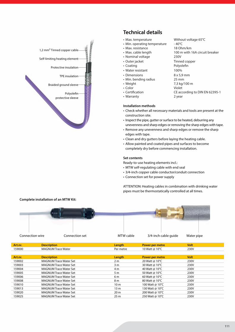
111
Tracing
MAGNUM Heating Group B.V.Stevinweg 84691SM TholenThe Netherlands
T +31 166 609300E [email protected] www.magnumheatinggroup.com
Art.nr. Description Length Power per metre Volt159000 MAGNUM Trace Water Per metre 10 Watt @ 10°C 230V
Art.nr. Description Length Power per metre Volt159002 MAGNUM Trace Water Set 2 m 20 Watt @ 10°C 230V159003 MAGNUM Trace Water Set 3 m 30 Watt @ 10°C 230V159004 MAGNUM Trace Water Set 4 m 40 Watt @ 10°C 230V159005 MAGNUM Trace Water Set 5 m 50 Watt @ 10°C 230V159006 MAGNUM Trace Water Set 6 m 60 Watt @ 10°C 230V159008 MAGNUM Trace Water Set 8 m 80 Watt @ 10°C 230V159010 MAGNUM Trace Water Set 10 m 100 Watt @ 10°C 230V159013 MAGNUM Trace Water Set 13 m 130 Watt @ 10°C 230V159020 MAGNUM Trace Water Set 20 m 200 Watt @ 10°C 230V159025 MAGNUM Trace Water Set 25 m 250 Watt @ 10°C 230V
Technical details
1,2 mm2 Tinned copper cable
Self-limiting heating element
Protective insulation
TPE insulation
Braided ground sleeve
Polyolefi n protective sleeve
Connection wire Connection set MTW cable 3/4-inch cable guide Water pipe
Complete installation of an MTW Kit:
• Max. temperature Without voltage 65°C• Min. operating temperature - 40°C• Max. resistance 18 Ohm/km• Max. cable length 100 m with 16A circuit breaker• Nominal voltage 230V• Outer jacket Tinned copper• Coating Polyolefi n• Water resistant 100%• Dimensions 8 x 5,9 mm• Min. bending radius 25 mm• Weight 7,3 kg/100 m• Color Violet• Certifi cation CE according to DIN EN 62395-1• Warranty 2 year
Installation methods• Check whether all necessary materials and tools are present at the
construction site.• Inspect the pipe, gutter or surface to be heated, deburring any
unevenness and sharp edges or removing the sharp edges with tape. • Remove any unevenness and sharp edges or remove the sharp
edges with tape.• Clean and dry gutters before laying the heating cable.• Allow painted and coated pipes and surfaces to become
completely dry before commencing installation.
Set contentsReady-to-use heating elements incl.:• MTW self-regulating cable with end seal• 3/4-inch copper cable conductor/conduit connection• Connection set for power supply
ATTENTION: Heating cables in combination with drinking water pipes must be thermostatically controlled at all times.
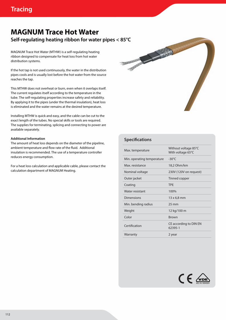
112
Tracing
MAGNUM Heating Group B.V.Stevinweg 84691SM TholenThe Netherlands
T +31 166 609300E [email protected] www.magnumheatinggroup.com
MAGNUM Trace Hot Water (MTHW) is a self-regulating heating ribbon designed to compensate for heat loss from hot water distribution systems.
If the hot tap is not used continuously, the water in the distribution pipes cools and is usually lost before the hot water from the source reaches the tap.
This MTHW does not overheat or burn, even when it overlaps itself. The current regulates itself according to the temperature in the tube. The self-regulating properties increase safety and reliability. By applying it to the pipes (under the thermal insulation), heat loss is eliminated and the water remains at the desired temperature.
Installing MTHW is quick and easy, and the cable can be cut to the exact length of the tubes. No special skills or tools are required. The supplies for terminating, splicing and connecting to power are available separately.
Additional Information The amount of heat loss depends on the diameter of the pipeline, ambient temperature and fl ow rate of the fl uid. Additional insulation is recommended. The use of a temperature controller reduces energy consumption.
For a heat loss calculation and applicable cable, please contact the calculation department of MAGNUM Heating.
REG.-Nr. 40040697
Specifi cations
Max. temperature Without voltage 85°CWith voltage 65°C
Min. operating temperature -30°C
Max. resistance 18,2 Ohm/km
Nominal voltage 230V (120V on request)
Outer jacket Tinned copper
Coating TPE
Water resistant 100%
Dimensions 13 x 6,8 mm
Min. bending radius 25 mm
Weight 12 kg/100 m
Color Brown
Certifi cation CE according to DIN EN 62395-1
Warranty 2 year
MAGNUM Trace Hot WaterSelf-regulating heating ribbon for water pipes < 85°C
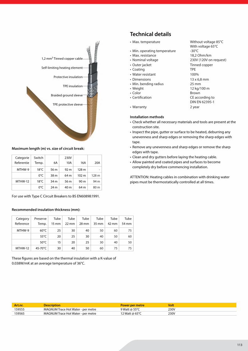
113
Tracing
MAGNUM Heating Group B.V.Stevinweg 84691SM TholenThe Netherlands
T +31 166 609300E [email protected] www.magnumheatinggroup.com
• Max. temperature Without voltage 85°C With voltage 65°C
• Min. operating temperature -30°C• Max. resistance 18,2 Ohm/km• Nominal voltage 230V (120V on request)• Outer jacket Tinned copper• Coating TPE• Water resistant 100%• Dimensions 13 x 6,8 mm• Min. bending radius 25 mm• Weight 12 kg/100 m• Color Brown• Certifi cation CE according to
DIN EN 62395-1• Warranty 2 year
Installation methods• Check whether all necessary materials and tools are present at the
construction site.• Inspect the pipe, gutter or surface to be heated, deburring any
unevenness and sharp edges or removing the sharp edges with tape.
• Remove any unevenness and sharp edges or remove the sharp edges with tape.
• Clean and dry gutters before laying the heating cable.• Allow painted and coated pipes and surfaces to become
completely dry before commencing installation.
ATTENTION: Heating cables in combination with drinking water pipes must be thermostatically controlled at all times.
Art.nr. Description Power per metre Volt159555 MAGNUM Trace Hot Water - per metre 9 Watt @ 55°C 230V159565 MAGNUM Trace Hot Water - per metre 12 Watt @ 65°C 230V
Technical details
1,2 mm2 Tinned copper cable
Self-limiting heating element
Protective insulation
TPE insulation
Braided ground sleeve
TPE protective sleeve
Maximum length (m) vs. size of circuit break:
CategorieReferentie
Switch Temp. 6A
230V 10A 16A 20A
MTHW-9 18°C 56 m 92 m 128 m -
0°C 38 m 64 m 102 m 128 m
MTHW-12 18°C 34 m 56 m 90 m 94 m
0°C 24 m 40 m 64 m 80 m
For use with Type C Circuit Breakers to BS EN60898:1991.
These fi gures are based on the thermal insulation with a K-value of 0.038W/mK at an average temperature of 36°C.
Recommended insulation thickness (mm):
CategoryReference
Preserve Temp.
Tube 15 mm
Tube 22 mm
Tube 28 mm
Tube 35 mm
Tube 42 mm
Tube54 mm
MTHW-9 60°C 25 30 40 50 60 75
55°C 20 25 30 40 50 60
50°C 15 20 25 30 40 50
MTHW-12 45-70°C 30 40 50 60 75 75
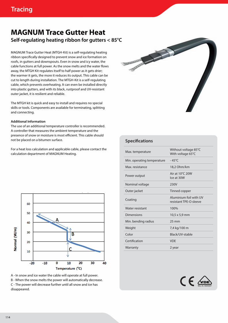
114
Tracing
MAGNUM Heating Group B.V.Stevinweg 84691SM TholenThe Netherlands
T +31 166 609300E [email protected] www.magnumheatinggroup.com
MAGNUM Trace Gutter Heat (MTGH-Kit) is a self-regulating heating ribbon specifi cally designed to prevent snow and ice formation on roofs, in gutters and downspouts. Even in snow and icy water, the cable functions at full power. As the snow melts and the water fl ows away, the MTGH Kit regulates itself to half power as it gets drier; the warmer it gets, the more it reduces its output. This cable can be cut to length during installation. The MTGH-Kit is a self-regulating cable, which prevents overheating. It can even be installed directly into plastic gutters, and with its black, rustproof and UV-resistant outer jacket, it is resilient and reliable.
The MTGH kit is quick and easy to install and requires no special skills or tools. Components are available for terminating, splitting and connecting.
Additional Information The use of an additional temperature controller is recommended. A controller that measures the ambient temperature and the presence of snow or moisture is most effi cient. This cable should not be placed on a bitumen surface.
For a heat loss calculation and applicable cable, please contact the calculation department of MAGNUM Heating.
A - In snow and ice water the cable will operate at full power.B - When the snow melts the power will automatically decrease.C - The power will decrease further until all snow and ice has disappeared.
REG.-Nr. 40040697
Specifi cations
Max. temperature Without voltage 85°CWith voltage 65°C
Min. operating temperature - 45°C
Max. resistance 18,2 Ohm/km
Power output Air at 10°C 20WIce at 30W
Nominal voltage 230V
Outer jacket Tinned copper
Coating Aluminium foil with UVresistant TPE-O sleeve
Water resistant 100%
Dimensions 10,5 x 5,9 mm
Min. bending radius 25 mm
Weight 7,4 kg/100 m
Color Black/UV-stable
Certifi cation VDE
Warranty 2 year
MAGNUM Trace Gutter HeatSelf-regulating heating ribbon for gutters < 85°C

115
Tracing
MAGNUM Heating Group B.V.Stevinweg 84691SM TholenThe Netherlands
T +31 166 609300E [email protected] www.magnumheatinggroup.com
• Max. temperature Without voltage 85°C With voltage 65°C
• Min. operating temperature - 45°C• Max. resistance 18,2 Ohm/km• Power output Air at 10°C 20W Ice at 30W• Nominal voltage 230V • Outer jacket Tinned copper• Coating Aluminium foil with UV
resistant TPE-O sleeve• Water resistant 100%• Dimensions 10,5 x 5,9 mm• Min. bending radius 25 mm• Weight 7,4 kg/100 m• Color Black/UV-stable• Certifi cation VDE• Warranty 2 year
Ready-to-use heating elements with built-in thermostat. Easy to use and can be installed immediately. With built-in thermostat that switches on at temperatures below 5°C and off at temperatures below -10°C and at 13°C.
Installation methods• Check whether all necessary materials and tools are present at the
construction site.• Inspect the pipe, gutter or surface to be heated, deburring any
unevenness and sharp edges or removing the sharp edges with tape.
• Remove any unevenness and sharp edges or remove the sharp edges with tape.
• Clean and dry gutters before laying the heating cable.• Allow painted and coated pipes and surfaces to become
completely dry before commencing installation.
Set contents• Incl. connection cable 3 metres long• 2x Bi-metal thermostat• Mounting clips (1 per metre length)• Metal strips for support in drainpipe
Art.nr. Description Length Power Volt159605 MAGNUM Trace Gutter Heat Set 5 m 100 Watt 230V159610 MAGNUM Trace Gutter Heat Set 10 m 200 Watt 230V159615 MAGNUM Trace Gutter Heat Set 15 m 300 Watt 230V159625 MAGNUM Trace Gutter Heat Set 25 m 500 Watt 230V
Technical details
1,2 mm2 Tinned copper cable
Self-limiting heating element
Protective insulation
TPE insulation
Aluminium grounding sleeve with wire
TPE protective sleeve
Art.nr. Description Power per metre Volt151020 MAGNUM Trace Gutter Heat 20 Watt @ 10°C 230V160107 MAGNUM Support bracket for rain pipe 3 pieces
Maximum length (m) vs. size of circuit break:
CategoryReference
Switch Temp. 6A
230V 16A 20A
MTGH-20 10°C 44 m 72 m 80 m
0°C 36 m 58 m 80 m
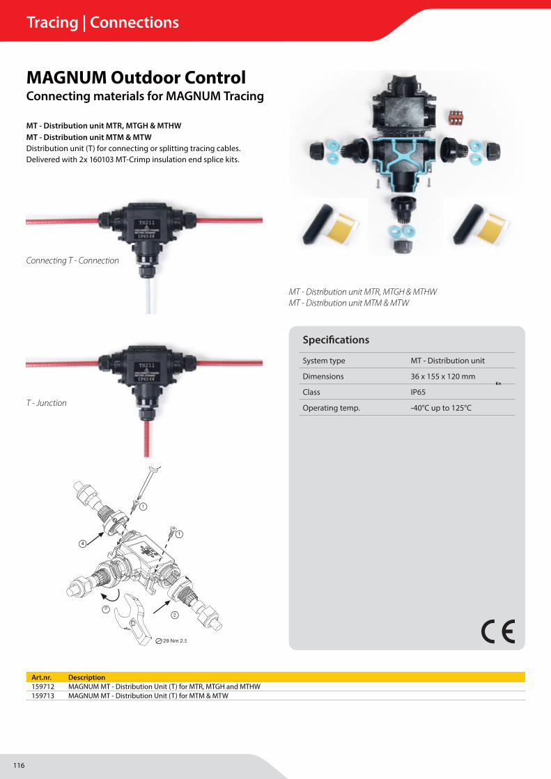
116
Tracing | Connections
MAGNUM Heating Group B.V.Stevinweg 84691SM TholenThe Netherlands
T +31 166 609300E [email protected] www.magnumheatinggroup.com
MT - Distribution unit MTR, MTGH & MTHWMT - Distribution unit MTM & MTWDistribution unit (T) for connecting or splitting tracing cables. Delivered with 2x 160103 MT-Crimp insulation end splice kits.
MAGNUM Outdoor ControlConnecting materials for MAGNUM Tracing
Specifi cations
System type MT - Distribution unit
Dimensions 36 x 155 x 120 mm
Class IP65
Operating temp. -40°C up to 125°C
Art.nr. Description159712 MAGNUM MT - Distribution Unit (T) for MTR, MTGH and MTHW159713 MAGNUM MT - Distribution Unit (T) for MTM & MTW
Connecting T - Connection
T - Junction
MT - Distribution unit MTR, MTGH & MTHWMT - Distribution unit MTM & MTW
2
1
3
24 Nm 2.5
29 Nm 4.0
29 Nm 2.5
1
1
23
4
3+3 POLES
7
6
8
8
No unsheathing
Piercing clip terminals 5.1
30÷50 mm
ADAPTER HOLEØ 9.0 mm
≤ Ø 7.0 mm
1 2 3
4 5
159712 MT-Verteilereinheit für MTR, MTGH und MTHW159713 MT-Verteilereinheit für MTM & MTW
Verteilereinheit (T) zum Anschließen oder Teilen von Beglei-theizungskabeln. Lieferung einschließlich 2 x 160103 MT-Crimpisolierung Endlaschenkits.
Technische DetailsMaße (mm) 36 x 155 x 120 mmKlasse IP65Betriebstemperatur -40 °C bis +125 °C
Knip de verwarmingskabel op de gewenste lengte.
Cut the heating cable to the desired length.
Heizleitung gerade abschneiden.
Verwijder 20mm van de buitenste isolatie.
Remove 20mm of the outer insulation.
20mm der äuβern Isolierung entfernen.
Verwijder het aardevechtwerk (20mm).
Remove the earthing braid (20mm).
Freigelegten Teil des Gefl echts abtrennen (20mm).
Breng de waterdichte tape aan over het uiteinde van de kabel (30mm).
Apply the waterproof tape at about 30mm from the end of the cable.
Teilweise über das vorbereitete Heizbandende und äuβern Isolierung das wasserabweisende Band verkleben (30mm).
Schuif de eindkap erover en verwarm deze met een hittepistool tot de eindkap volledig gekrompen is.
Slide the end cap over and heat it with a heat gun until the end cap completely shrunk.
Endabschlusskappe nun über das Heizbandende schieben und vom Ende hher beginnend erwärmen bis die Endkappe gleichmäβig anliegt und ein wenig Schmelzkleber am Übergang zum Heizband austritt.
160103 MAGNUM Trace Krimpisolatie eindlas kit Voor het afsluiten van een kabeleind. Gebruik: 1 Krimpkous per kabeleind.
160103 MAGNUM Trace Shrinkage insulation end seal kit For sealing a cable end. Use: 1 Shrink tube per cable end.
160103 MAGNUM Trace Crimpsiolierung Endlaschen Kit Zum Abschließen von Kabelenden. Anwendung: 1 Crimpkabelschuh pro Kabelende.
Knip de verwarmingskabel op de gewenste lengte.Knip de verwarmingskabel op de gewenste lengte.
20 mm.
Benodigd gereedschap:Necessary tools:Benötigte Werkzeuge:
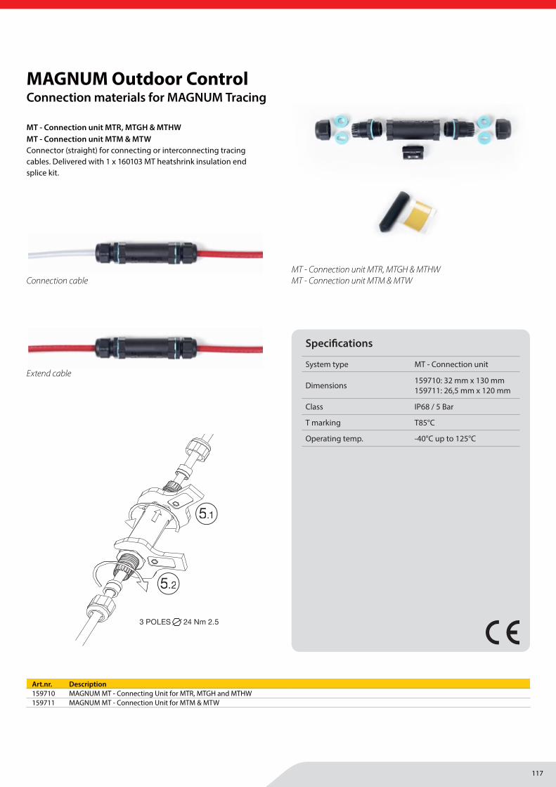
117
Tracing | Connections
MAGNUM Heating Group B.V.Stevinweg 84691SM TholenThe Netherlands
T +31 166 609300E [email protected] www.magnumheatinggroup.com
MT - Connection unit MTR, MTGH & MTHWMT - Connection unit MTM & MTW Connector (straight) for connecting or interconnecting tracing cables. Delivered with 1 x 160103 MT heatshrink insulation end splice kit.
MAGNUM Outdoor ControlConnection materials for MAGNUM Tracing
Specifi cations
System type MT - Connection unit
Dimensions 159710: 32 mm x 130 mm159711: 26,5 mm x 120 mm
Class IP68 / 5 Bar
T marking T85°C
Operating temp. -40°C up to 125°C
MT - Connection unit MTR, MTGH & MTHWMT - Connection unit MTM & MTW Connection cable
Extend cable
Art.nr. Description159710 MAGNUM MT - Connecting Unit for MTR, MTGH and MTHW159711 MAGNUM MT - Connection Unit for MTM & MTW
IP68 5bar
159710 MT-Verbindungseinheit für MTR, MTGH und MTHW159711 MT-Verbindungseinheit für MTM & MTW
Verbindungsstück (gerade) zum Anschluss von Begleitheizungskabeln. Im Lieferumfang inbegri�en: 1 x 160103 MT-Crimpisolierung Endlaschenkit.
Technische detailsMaße (mm) 159710: 32mm x 130mm / 159711: 26,5mm x 120mm Klasse IP68 / 5 BarT-Markierung T 85 °CBetriebstemperatur -40°C bis +125°C
3 POLES
Ø 7.0 ÷ 9.0 mm
Ø 9.0 ÷ 13.5 mm
3 POLES1 2
TH020 3 POLES
3
4 5
4.1 5.1
5.2
4.2
6
3 POLES 24 Nm 2.5
7
3 POLES 24 Nm 2.5
No unsheathing
Piercing clip terminals
3.1
30 mm
Knip de verwarmingskabel op de gewenste lengte.
Cut the heating cable to the desired length.
Heizleitung gerade abschneiden.
Verwijder 20mm van de buitenste isolatie.
Remove 20mm of the outer insulation.
20mm der äuβern Isolierung entfernen.
Verwijder het aardevechtwerk (20mm).
Remove the earthing braid (20mm).
Freigelegten Teil des Gefl echts abtrennen (20mm).
Breng de waterdichte tape aan over het uiteinde van de kabel (30mm).
Apply the waterproof tape at about 30mm from the end of the cable.
Teilweise über das vorbereitete Heizbandende und äuβern Isolierung das wasserabweisende Band verkleben (30mm).
Schuif de eindkap erover en verwarm deze met een hittepistool tot de eindkap volledig gekrompen is.
Slide the end cap over and heat it with a heat gun until the end cap completely shrunk.
Endabschlusskappe nun über das Heizbandende schieben und vom Ende hher beginnend erwärmen bis die Endkappe gleichmäβig anliegt und ein wenig Schmelzkleber am Übergang zum Heizband austritt.
160103 MAGNUM Trace Krimpisolatie eindlas kit Voor het afsluiten van een kabeleind. Gebruik: 1 Krimpkous per kabeleind.
160103 MAGNUM Trace Shrinkage insulation end seal kit For sealing a cable end. Use: 1 Shrink tube per cable end.
160103 MAGNUM Trace Crimpsiolierung Endlaschen Kit Zum Abschließen von Kabelenden. Anwendung: 1 Crimpkabelschuh pro Kabelende.
Knip de verwarmingskabel op de gewenste lengte.Knip de verwarmingskabel op de gewenste lengte.
20 mm.
Benodigd gereedschap:Necessary tools:Benötigte Werkzeuge:
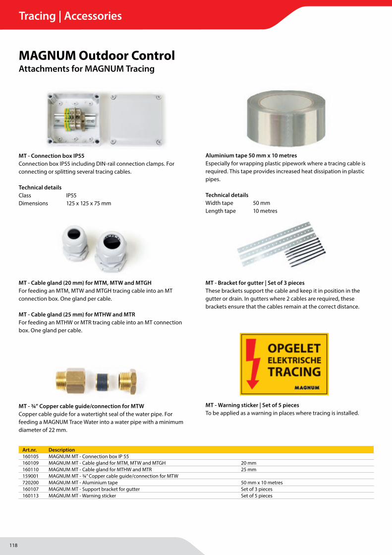
118
Tracing | Accessories
MAGNUM Heating Group B.V.Stevinweg 84691SM TholenThe Netherlands
T +31 166 609300E [email protected] www.magnumheatinggroup.com
MT - Connection box IP55 Connection box IP55 including DIN-rail connection clamps. For connecting or splitting several tracing cables.
Technical detailsClass IP55Dimensions 125 x 125 x 75 mm
MAGNUM Outdoor ControlAttachments for MAGNUM Tracing
MT - ¾” Copper cable guide/connection for MTW Copper cable guide for a watertight seal of the water pipe. For feeding a MAGNUM Trace Water into a water pipe with a minimum diameter of 22 mm.
MT - Cable gland (20 mm) for MTM, MTW and MTGHFor feeding an MTM, MTW and MTGH tracing cable into an MT connection box. One gland per cable.
MT - Cable gland (25 mm) for MTHW and MTR For feeding an MTHW or MTR tracing cable into an MT connection box. One gland per cable.
MT - Warning sticker | Set of 5 pieces To be applied as a warning in places where tracing is installed.
MT - Bracket for gutter | Set of 3 piecesThese brackets support the cable and keep it in position in the gutter or drain. In gutters where 2 cables are required, these brackets ensure that the cables remain at the correct distance.
Aluminium tape 50 mm x 10 metres Especially for wrapping plastic pipework where a tracing cable is required. This tape provides increased heat dissipation in plastic pipes.
Technical detailsWidth tape 50 mmLength tape 10 metres
Art.nr. Description160105 MAGNUM MT - Connection box IP 55160109 MAGNUM MT - Cable gland for MTM, MTW and MTGH 20 mm160110 MAGNUM MT - Cable gland for MTHW and MTR 25 mm159001 MAGNUM MT - ¾” Copper cable guide/connection for MTW720200 MAGNUM MT - Aluminium tape 50 mm x 10 metres160107 MAGNUM MT - Support bracket for gutter Set of 3 pieces160113 MAGNUM MT - Warning sticker Set of 5 pieces

119
Tracing | Accessories
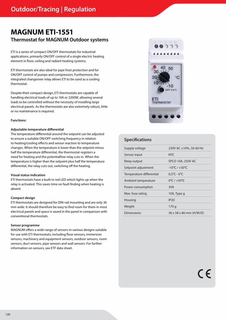
120
Outdoor/Tracing | Regulation
MAGNUM Heating Group B.V.Stevinweg 84691SM TholenThe Netherlands
T +31 166 609300E [email protected] www.magnumheatinggroup.com
ETI is a series of compact ON/OFF thermostats for industrial applications, primarily ON/OFF control of a single electric heating element in fl oor, ceiling and radiant heating systems.
ETI thermostats are also ideal for pipe frost protection and for ON/OFF control of pumps and compressors. Furthermore, the integrated changeover relay allows ETI to be used as a cooling thermostat.
Despite their compact design, ETI thermostats are capable of handling electrical loads of up to 10A or 2200W, allowing several loads to be controlled without the necessity of installing large electrical panels. As the thermostats are also extremely robust, little or no maintenance is required.
Functions:
Adjustable temperature diff erentialThe temperature diff erential around the setpoint can be adjusted to ensure a suitable ON/OFF switching frequency in relation to heating/cooling eff ects and sensor reaction to temperature changes. When the temperature is lower than the setpoint minus half the temperature diff erential, the thermostat registers a need for heating and the potentialfree relay cuts in. When the temperature is higher than the setpoint plus half the temperature diff erential, the relay cuts out, switching off the heating.
Visual status indicationETI thermostats have a built-in red LED which lights up when the relay is activated. This saves time on fault fi nding when heating is absent.
Compact designETI thermostats are designed for DIN-rail mounting and are only 36 mm wide. It should therefore be easy to fi nd room for them in most electrical panels and space is saved in the panel in comparison with conventional thermostats.
Sensor programmeMAGNUM off ers a wide range of sensors in various designs suitable for use with ETI thermostats, including fl oor sensors, immersion sensors, machinery and equipment sensors, outdoor sensors, room sensors, duct sensors, pipe sensors and wall sensors. For further information on sensors, see ETF data sheet.
MAGNUM ETI-1551Thermostat for MAGNUM Outdoor systems
Specifi cations
Supply voltage 230V AC ±10%, 50-60 Hz
Sensor input NTC
Relay output SPCO 10A, 250V AC
Setpoint adjustment -10°C / +50°C
Temperature diff erential 0,3°C - 6°C
Ambient temperature 0°C / +50°C
Power consumption 3VA
Max. fuse rating 10A, Type g
Housing IP20
Weight 170 g
Dimensions 36 x 58 x 86 mm (H/W/D)
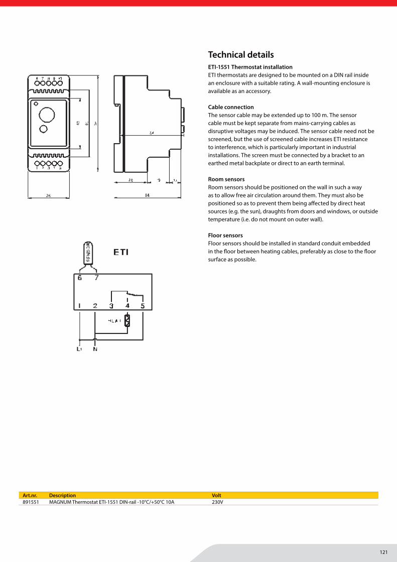
121
Outdoor/Tracing | Regulation
MAGNUM Heating Group B.V.Stevinweg 84691SM TholenThe Netherlands
T +31 166 609300E [email protected] www.magnumheatinggroup.com
PRODUCT PROGRAMME -10/+50°C
TYPE PRODUCT
ETI-1551 Thermostat 230VETI/F-1551 Thermostat with IP65 floor sensor 230V
ACCESSORIES
ETF-aa33/44/55 Temperature sensors, NTC, -20 - +70°C(see ETF data sheet)
ETF-aa44/99 Temperature sensors, NTC, -20 - +70°C(see ETF data sheet)
ETNK Enclosure for wall mounting
PRODUCT PROGRAMME +10/+110°C
TYPE PRODUCT
ETI-1221 Thermostat 230V
ACCESSORIES
ETF-aa22 Temperature sensors, NTC, -40 - +120° C(see ETF data sheet)
ETNK Enclosure for wall mounting
Application exampleWiring diagram Dimensions
FUNKTION
Fault protection
In case of sensor fault, the relay cuts out and defectivesensors can therefore not cause overheating.
CE MARKINGETI thermostats meet the requirements contained in thefollowing standards:
EMC DIRECTIVE LOW VOLTAGE DIRECTIVE
EN 61000-6-2, EN 61000-6-3 EN 60730-2-9, EN 60730-1
INSTALLATION
Thermostat installation
ETI thermostats are designed to be mounted on a DIN railinside an enclosure with a suitable rating. A wall-mountingenclosure is available as an accessory.
Cable connection
The sensor cable may be extended up to 100 m. The sensorcable must be kept separate from mains-carrying cables asdisruptive voltages may be induced. The sensor cable neednot be screened, but the use of screened cable increasesETI resistance to interference, which is particularly importantin industrial installations. The screen must be connected bya bracket to an earthed metal backplate or direct to an earthterminal.
Room sensors
Room sensors should be positioned on the wall in such away as to allow free air circulation around them. They mustalso be positioned so as to prevent them being affected bydirect heat sources (e.g. the sun), draughts from doors andwindows, or outside temperature (i.e. do not mount on outerwall).
Floor sensors
Floor sensors should be installed in standard conduitembedded in the floor between heating cables, preferablyas close to the floor surface as possible.
4.1.4-04
.11-ET
I-GB·S
ubject
toalterations
·®Th
eOJtrade
markisaregistredtrade
markbe
long
ingto
OJElec
tronics
A/S
TECHNICAL DATA
Supply voltage ETI-1xx1: 230V AC ±10%, 50-60 Hz
Sensor input NTC
Relay output SPCO 10A, 250V AC
Setpoint adjustment ETI-x221 +10/+110°C
ETI-x551 -10/+50°C
Temperature differential ETI-x221 0,5-10°C
ETI-x551 0,3-6°C
Ambient temperature 0/+50°C
Power consumption 3VA
Max. fuse rating 10A, Type g
Enclosure IP 20
Dimensions (W/H/D) 36 x 58 x 86 mm
Weight 170 g
© 2011 OJ Electronics A/S
OJ ELECTRONICS A/S
STENAGER 13B
DK-6400 SØNDERBORG
DENMARK
T. +45 73 12 13 14
F. +45 73 12 13 13
WWW.OJELECTRONICS.COM
Art.nr. Description Volt891551 MAGNUM Thermostat ETI-1551 DIN-rail -10°C/+50°C 10A 230V
Technical detailsETI-1551 Thermostat installationETI thermostats are designed to be mounted on a DIN rail inside an enclosure with a suitable rating. A wall-mounting enclosure is available as an accessory.
Cable connectionThe sensor cable may be extended up to 100 m. The sensor cable must be kept separate from mains-carrying cables as disruptive voltages may be induced. The sensor cable need not be screened, but the use of screened cable increases ETI resistance to interference, which is particularly important in industrial installations. The screen must be connected by a bracket to an earthed metal backplate or direct to an earth terminal.
Room sensorsRoom sensors should be positioned on the wall in such a way as to allow free air circulation around them. They must also be positioned so as to prevent them being aff ected by direct heat sources (e.g. the sun), draughts from doors and windows, or outside temperature (i.e. do not mount on outer wall).
Floor sensorsFloor sensors should be installed in standard conduit embedded in the fl oor between heating cables, preferably as close to the fl oor surface as possible.
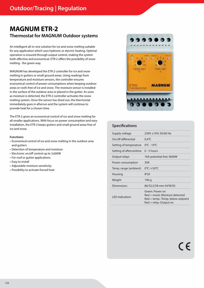
122
Outdoor/Tracing | Regulation
MAGNUM Heating Group B.V.Stevinweg 84691SM TholenThe Netherlands
T +31 166 609300E [email protected] www.magnumheatinggroup.com
An intelligent all-in-one solution for ice and snow melting suitable for any application which uses hydronic or electric heating. Optimal operation is ensured through output control, making the system both eff ective and economical. ETR-2 off ers the possibility of snow melting - the green way.
MAGNUM has developed the ETR-2 controller for ice and snowmelting in gutters or small ground areas. Using readings from temperature and moisture sensors, the controller ensures economical control of power consumptions when keeping outdoor areas or roofs free of ice and snow. The moisture sensor is installed in the surface of the outdoor area or placed in the gutter. As soon as moisture is detected, the ETR-2 controller activates the snow melting system. Once the sensor has dried out, the thermostat immediately goes in afterrun and the system will continue to provide heat for a chosen time.
The ETR-2 gives an economical control of ice-and snow melting for all smaller applications. With focus on power consumption and easy installation, the ETR-2 keeps gutters and small ground areas free of ice and snow.
Functions:• Economical control of ice and snow melting in the outdoor area
and gutters• Detection of temperature and moisture• Electronic on/off control up to 3,600W• For roof or gutter applications• Easy to install• Adjustable moisture sensitivity• Possibility to activate forced heat
MAGNUM ETR-2Thermostat for MAGNUM Outdoor systems
Specifi cations
Supply voltage 230V ±10% 50/60 Hz
On/off diff erential 0,4°C
Setting of temperature 0°C - 10°C
Setting of afterruntime 0 - 5 hours
Output relays 16A potential-free 3600W
Power consumption 3VA
Temp. range (ambient) 0°C /+50°C
Housing IP20
Weight 190 g
Dimensions 86/52,5/58 mm (H/W/D)
LED indication:
Green: Power onRed + moist: Moisture detectedRed + temp.: Temp. below setpointRed + relay: Output on
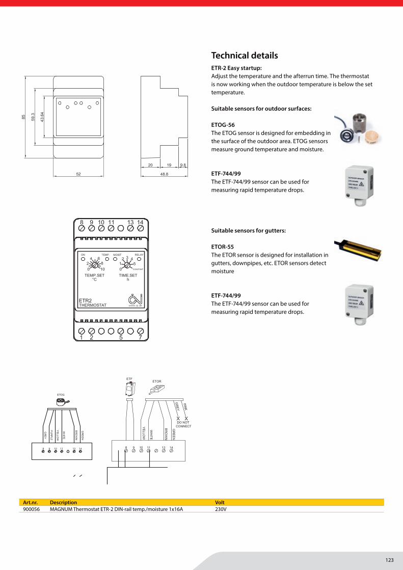
123
Outdoor/Tracing | Regulation
MAGNUM Heating Group B.V.Stevinweg 84691SM TholenThe Netherlands
T +31 166 609300E [email protected] www.magnumheatinggroup.com
OJ ELECTRONICS A/S
STENAGER 13B
DK-6400 SØNDERBORG
DENMARK
T. +45 73 12 13 14
F. +45 73 12 13 13
WWW.OJELECTRONICS.COM
3.5.
4-07
.11-
ETR
2-G
B ·
Sub
ject
to a
ltera
tions
· ®
The
OJ
trade
mar
k is
a re
gist
red
trade
mar
k be
long
ing
to O
J El
ectro
nics
A/S
THERMOSTAT FUNCTIONS
For Gutters - ETR2-4550, ETOR-55 and ETF-744/99:The sensor type ETOR is designed for mounting in gutters and down pipes etc. ETOR detects moisture, while ETF detects temperature. The snow melting system will be energized only when the outdoor temperature is below the selected setting and snow or ice occurs on the ETOR.
For Outdoor areas - ETR2-4550 and ETOG-55 is used:The sensor type ETOG is designed for embedding into the surface of the outdoor area. ETOG detects ground temperature and moisture. The air sensor type ETF-744/99 can be used for measuring rapidly temperature decreases.The snow melting system will be energized only when the outdoor temperature is below the selected setting and snow or ice occurs on the ETOG.
Easy startup:Adjust the temperature and the afterrun time. The thermostat is now working when the outdoor temperature is below the set temperature.
SENSORS
Ground sensor type ETOG:Designed for embedding into the surface of the outdoor area. Detects temperature and moisture.Up to two sensors type ETOG can be installed.
Gutter sensor type ETOR:Designed for mounting in gutters and down pipes etc. Detects moisture only. Is mounted in combination with outdoor sensor ETF. Up to two sensors type ETOR can be installed.
Outdoor sensor type ETF:Detects temperature. Is used in combination with gutter sensor ETOR, but can also be used separately only for temperature detection. The outdoor sensor can also be used together with the ETOG sensor for outdoor areas. The outdoor sensor detects rapidly decrease in air temperatures avoiding icy areas.
MOUNTING
Mounting of thermostat ETR2:DIN-rail mounting in switchboard.
Mounting of ground sensor ETOG:Is mounted where the worst snow and ice problems normally occur. The sensor is mounted on a hard foundation, in a concrete base, with the top of the sensor flush with the surface. Where an asphalt surface is used, it should be placed in a concrete recess. The sensor cable must be mounted in accordance with local regulation, the use of conduit is suggested.
Mounting of gutter sensor ETOR:Is mounted in the gutter or down pipe on the sunny side of the building. The contact point of the sensor must be placed in the direction of flow of the melting water. Where necessary, it is possible to connect two sensors in parallel.
Mounting of outdoor sensor ETF:Is mounted under the roof eaves on the north side of the building.
TECHNICAL DATA
Supply voltage: 230V ±10, 50/60 Hz
Output relay: 16A potential-free 3600W
On / off differential 0,4°C
Setting of temperature 0-10°C
Setting of afterruntime 0-5 hours
LEDS indicates: Green - Power on
Red - moist - moisture is detected
Red - temp - Outdoor temperature is below setpoint
Red - relay - Output is on
Power consumption 3VA
Ambient temperature 0 / +50 °C
Housing IP20
Dimensions (mm) ConnectionConnection ETOG
Connection ETF, ETOR
© 2011 OJ Electronics A/S
PINK
Art.nr. Description Volt900056 MAGNUM Thermostat ETR-2 DIN-rail temp./moisture 1x16A 230V
Technical detailsETR-2 Easy startup:Adjust the temperature and the afterrun time. The thermostat is now working when the outdoor temperature is below the set temperature.
Suitable sensors for outdoor surfaces:
ETOG-56 The ETOG sensor is designed for embedding in the surface of the outdoor area. ETOG sensors measure ground temperature and moisture.
ETF-744/99 The ETF-744/99 sensor can be used for measuring rapid temperature drops.
Suitable sensors for gutters:
ETOR-55The ETOR sensor is designed for installation in gutters, downpipes, etc. ETOR sensors detect moisture
ETF-744/99 The ETF-744/99 sensor can be used for measuring rapid temperature drops.
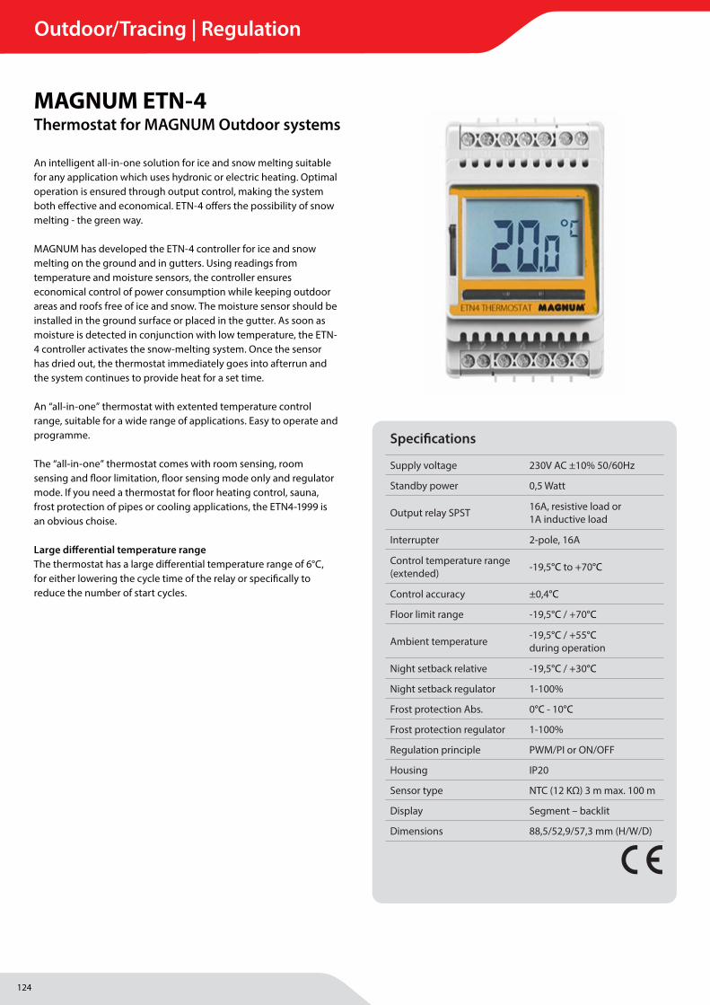
124
Outdoor/Tracing | Regulation
MAGNUM Heating Group B.V.Stevinweg 84691SM TholenThe Netherlands
T +31 166 609300E [email protected] www.magnumheatinggroup.com
An intelligent all-in-one solution for ice and snow melting suitable for any application which uses hydronic or electric heating. Optimal operation is ensured through output control, making the system both eff ective and economical. ETN-4 off ers the possibility of snow melting - the green way.
MAGNUM has developed the ETN-4 controller for ice and snow melting on the ground and in gutters. Using readings from temperature and moisture sensors, the controller ensures economical control of power consumption while keeping outdoor areas and roofs free of ice and snow. The moisture sensor should be installed in the ground surface or placed in the gutter. As soon as moisture is detected in conjunction with low temperature, the ETN-4 controller activates the snow-melting system. Once the sensor has dried out, the thermostat immediately goes into afterrun and the system continues to provide heat for a set time. An “all-in-one” thermostat with extented temperature control range, suitable for a wide range of applications. Easy to operate and programme.
The “all-in-one” thermostat comes with room sensing, room sensing and fl oor limitation, fl oor sensing mode only and regulator mode. If you need a thermostat for fl oor heating control, sauna, frost protection of pipes or cooling applications, the ETN4-1999 is an obvious choise.
Large diff erential temperature rangeThe thermostat has a large diff erential temperature range of 6°C, for either lowering the cycle time of the relay or specifi cally to reduce the number of start cycles.
MAGNUM ETN-4Thermostat for MAGNUM Outdoor systems
Specifi cations
Supply voltage 230V AC ±10% 50/60Hz
Standby power 0,5 Watt
Output relay SPST 16A, resistive load or1A inductive load
Interrupter 2-pole, 16A
Control temperature range (extended) -19,5°C to +70°C
Control accuracy ±0,4°C
Floor limit range -19,5°C / +70°C
Ambient temperature -19,5°C / +55°C during operation
Night setback relative -19,5°C / +30°C
Night setback regulator 1-100%
Frost protection Abs. 0°C - 10°C
Frost protection regulator 1-100%
Regulation principle PWM/PI or ON/OFF
Housing IP20
Sensor type NTC (12 KΩ) 3 m max. 100 m
Display Segment – backlit
Dimensions 88,5/52,9/57,3 mm (H/W/D)
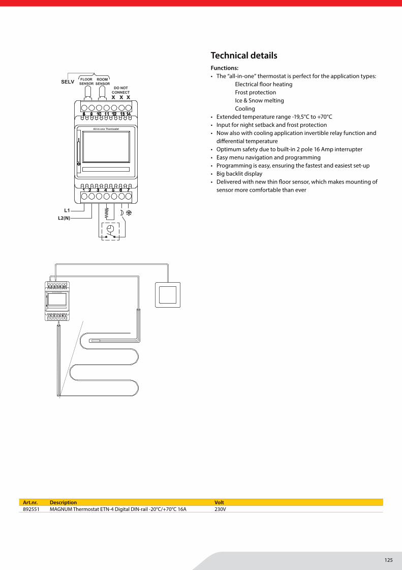
125
Outdoor/Tracing | Regulation
MAGNUM Heating Group B.V.Stevinweg 84691SM TholenThe Netherlands
T +31 166 609300E [email protected] www.magnumheatinggroup.com
© 2014 OJ Electronics A/S
OJ ELECTRONICS A/S
STENAGER 13B
DK-6400 SØNDERBORG
DENMARK
T. +45 73 12 13 14
F. +45 73 12 13 13
WWW.OJELECTRONICS.COM
3.4.
2-01
.14-
ETN
4-19
99-G
B ·
Sub
ject
to a
ltera
tions
· ®
The
OJ
trade
mar
k is
a re
gist
red
trade
mar
k be
long
ing
to O
J El
ectro
nics
A/S
BR-0991-A04b
L2(N)
Night SetbackThe input for night setback can be set to increase and de-crease the temperature.
The thermostat can also decrease the heating period in %, when set to regulator mode.
Frost ProtectionThe input for frost protection can be set in thermostat mode as well as in regulator mode.
Invertible Relay FeatureThe relay function can be inverted so that the thermostat can be used for cooling applications. Here the variable differential, up to 6°C, is also an advantage.
Two External sensorsIt is possible to attach two external sensors to the ther-mostat for controlling a room thermostat with a floor limit sensor, protecting expensive wooden floor coverings from overheating.
Two individual inputs for setback temperaturesThe thermostat has built-in individual connectors for setting night setback and frost protection mode.
MODE TEMPERATURE
NIGHT SETBACK Lowering or increasing temperature by 10°C
FROST PROTECTION Securing temperatures between 0 to +10°C
Connector for easy „daisy chain“ of control wire.The thermostat can easily be mounted and wired side by side due to the spare live connector.
Built-in 2 Pole InterrupterThe built-in interrupter gives the best safety, and according to local regulations in some countries an external interrupter can be left out.
TECHNICAL DATA
Supply voltage 230V AC ±10% 50/60Hz
Standby power 0.5 Watt
Output relay SPST 16A, resistive load or
1A inductive load
Interrupter 2-pole, 16A
Control temperature range (extended) -19.5 to +70°C
Control accuracy ±0.4°C
Floor limit range -19.5/+70°C
Ambient temperature -19.5/+55°C during operation
Night setback relative -19.5/+30°C
Night setback regulator 1-100%
Frost protection Abs. 0-10°C
Frost protection regulator 1-100%
Regulation principle PWM / PI or ON/OFF
Housing IP20
Sensor type NTC (12 KΩ) 3m max. 100m
Display Segment – backlit
Dimensions, (H/W/D) 88.5 / 52.9 / 57.3 mm
Warranty 3 years
BR991-A01aBR991-A04b
Art.nr. Description Volt892551 MAGNUM Thermostat ETN-4 Digital DIN-rail -20°C/+70°C 16A 230V
Technical detailsFunctions:• The “all-in-one” thermostat is perfect for the application types:
Electrical fl oor heating Frost protection Ice & Snow melting Cooling
• Extended temperature range -19,5°C to +70°C• Input for night setback and frost protection• Now also with cooling application invertible relay function and
diff erential temperature• Optimum safety due to built-in 2 pole 16 Amp interrupter• Easy menu navigation and programming• Programming is easy, ensuring the fastest and easiest set-up• Big backlit display• Delivered with new thin fl oor sensor, which makes mounting of
sensor more comfortable than ever
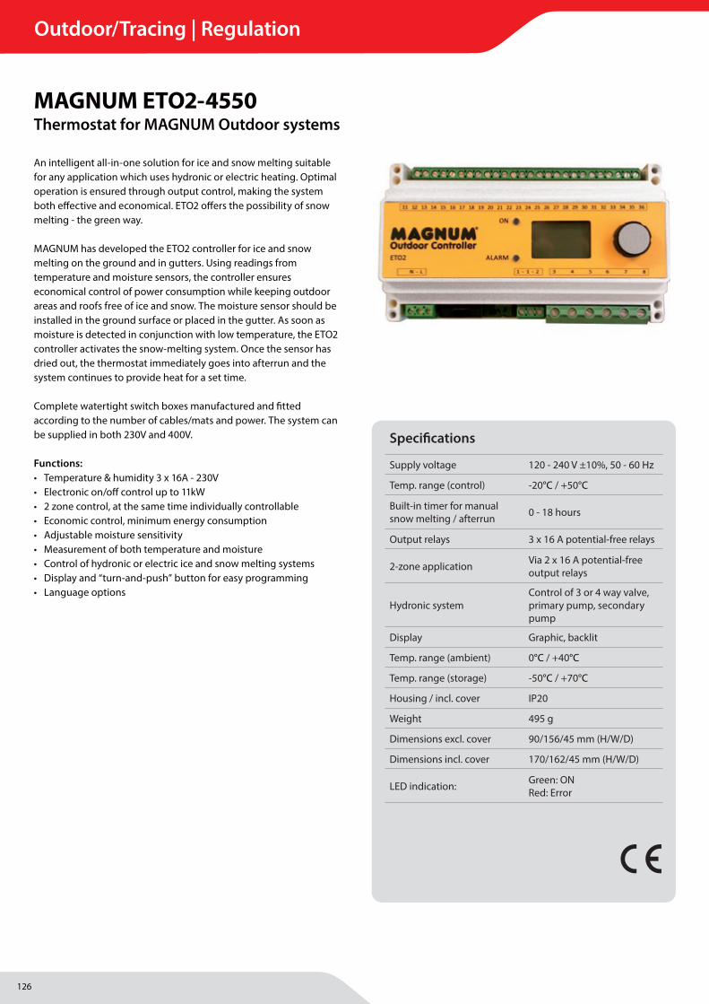
126
Outdoor/Tracing | Regulation
MAGNUM Heating Group B.V.Stevinweg 84691SM TholenThe Netherlands
T +31 166 609300E [email protected] www.magnumheatinggroup.com
An intelligent all-in-one solution for ice and snow melting suitable for any application which uses hydronic or electric heating. Optimal operation is ensured through output control, making the system both eff ective and economical. ETO2 off ers the possibility of snow melting - the green way.
MAGNUM has developed the ETO2 controller for ice and snow melting on the ground and in gutters. Using readings from temperature and moisture sensors, the controller ensures economical control of power consumption while keeping outdoor areas and roofs free of ice and snow. The moisture sensor should be installed in the ground surface or placed in the gutter. As soon as moisture is detected in conjunction with low temperature, the ETO2 controller activates the snow-melting system. Once the sensor has dried out, the thermostat immediately goes into afterrun and the system continues to provide heat for a set time. Complete watertight switch boxes manufactured and fi tted according to the number of cables/mats and power. The system can be supplied in both 230V and 400V.
Functions:• Temperature & humidity 3 x 16A - 230V • Electronic on/off control up to 11kW• 2 zone control, at the same time individually controllable• Economic control, minimum energy consumption• Adjustable moisture sensitivity• Measurement of both temperature and moisture• Control of hydronic or electric ice and snow melting systems• Display and “turn-and-push” button for easy programming• Language options
MAGNUM ETO2-4550Thermostat for MAGNUM Outdoor systems
Specifi cations
Supply voltage 120 - 240 V ±10%, 50 - 60 Hz
Temp. range (control) -20°C / +50°C
Built-in timer for manualsnow melting / afterrun 0 - 18 hours
Output relays 3 x 16 A potential-free relays
2-zone application Via 2 x 16 A potential-free output relays
Hydronic systemControl of 3 or 4 way valve, primary pump, secondary pump
Display Graphic, backlit
Temp. range (ambient) 0°C / +40°C
Temp. range (storage) -50°C / +70°C
Housing / incl. cover IP20
Weight 495 g
Dimensions excl. cover 90/156/45 mm (H/W/D)
Dimensions incl. cover 170/162/45 mm (H/W/D)
LED indication: Green: ONRed: Error
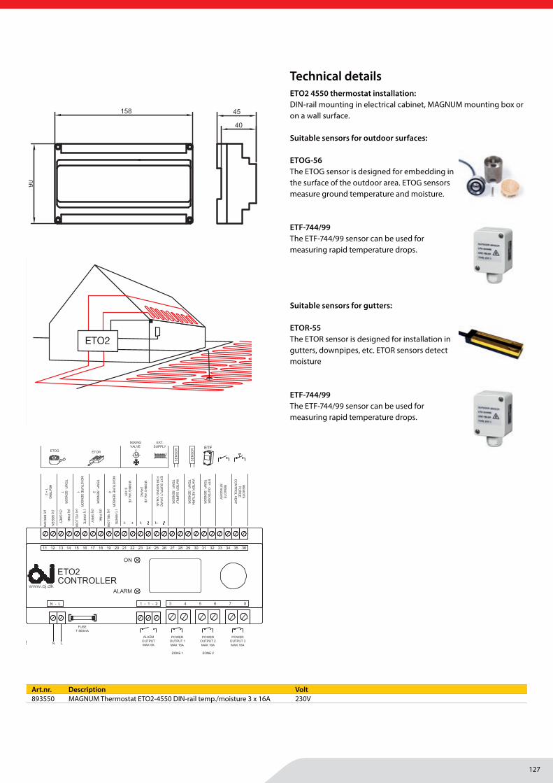
127
Outdoor/Tracing | Regulation
MAGNUM Heating Group B.V.Stevinweg 84691SM TholenThe Netherlands
T +31 166 609300E [email protected] www.magnumheatinggroup.com
ConnectionsDimensions (mm)
3.5.
3-03
.16-
ETO
2-G
B ·
Sub
ject
to a
ltera
tions
· ®
The
OJ
trade
mar
k is
a re
gist
ered
trad
emar
k be
long
ing
to O
J El
ectro
nics
A/S
*Sou
rce:
DM
I, M
osco
w 2
010
Ground and roof application
Remote control:It is possible to control the ETO2 via an external signal (day/week timer, GSM module or other signal source). The ETO2 can be switched on/off (standby) and the system can be temporarily forced to provide heat during the period of time set in the afterrun menu.
SENSORSETOG ground sensor:Designed for embedding in the surface of the outdoor area. Measures temperature and moisture.Up to two ETOG sensors can be installed.
ETOR gutter sensor:Designed for installation in gutters, downpipes, etc. Measures moisture only. Should be installed in combination with an ETF outdoor temperature sensor. Up to two ETOR sensors can be installed.
ETF outdoor temperature sensor:Measures temperature. Is normally used in combination with ETOR gutter sensors, but can also be used separately for temperature measurement only. An ETF sensor can also be used in combination with ETOG ground sensors for outdoor areas. The ETF sensor can detect rapid drops in air temperature, thus avoiding icy areas.
INSTALLATIONETO2 thermostat installation:DIN-rail mounting in electrical cabinet, OJ mounting box or on a wall surface.
ETOG ground sensor installation:Should be installed where the worst snow and ice problems normally occur. The sensor should be embedded in a concrete base on a hard surface with the top of the sensor flush with the surface. Where an asphalt surface is used, or where easy installation is desired, installing ETOG-56 together with ETOK-1 is the obvious choice.
ETOR gutter sensor installation:Should be installed in the gutter or downpipe on the sunny side of the building. The sensor contact point must be aligned in the direction of the melt-water flow. Where necessary, two sensors can be connected in parallel.
ETF outdoor temperature sensor installation:Should be installed beneath the eaves on the northern side of the building.
TECHNICAL DATA
ETO2-4550 thermostat:
Supply voltage 120-240 V ±10%, 50-60 Hz
Temperature range (control) -20/+50°C
Built-in timer for manual snow melting / afterrun 0-18 hours
Output relays 3 x 16 A potential-free relays
2-zone application Via 2 x 16 A potential-free output relays
Hydronic system Control of 3 or 4 way valve, primary pump, secondary pump
Display Graphic, backlit
Temperature range (ambient) 0/+40°C
Temperature range (storage) -50/+70°C
Housing / incl. cover IP20
Weight 495 g
Dimensions excl. cover (H/W/D) 90/156/45 mm
Dimensions incl. cover (H/W/D) 170/162/45 mm
LED indication: ON/Green Thermostat energised Error/Red Fault
ETOG-55 ground sensor: Measurement Moisture and temperature Installation Outdoor surface Housing IP68 Temperature range (ambient) -50/+70°C Dimensions (H/Ø) 32/60 mm
ETOG-56/ETOK-1 embedded ground sensor: Measurement Moisture and temperature Installation Outdoor surface Housing IP68 Temperature range (ambient) -50/+70°C Dimensions, sensor (H/Ø) 32/60 mm Dimensions, tube (H/Ø) 78/63.5 mm
ETOR-55 gutter sensor: Measurement Moisture Installation Gutter or downpipe Housing IP68 Temperature range (ambient) -50/+70°C Dimensions (H/W/D) 105/30/13 mm
ETF-744/99 outdoor temperature sensor: Measurement Temperature Installation Wall surface Housing IP54 Temperature range (ambient) -50/+70°C Dimensions (H/W/D) 86/45/35 mm
All products: 3-year warranty from production date
© 2016 OJ Electronics A/S
OJ ELECTRONICS A/S
STENAGER 13B
DK-6400 SØNDERBORG
DENMARK
T. +45 73 12 13 14
F. +45 73 12 13 13
WWW.OJELECTRONICS.COM
BR
899A
12
BR
978A
03h
BR
978A
02
Art.nr. Description Volt893550 MAGNUM Thermostat ETO2-4550 DIN-rail temp./moisture 3 x 16A 230V
Technical detailsETO2 4550 thermostat installation:DIN-rail mounting in electrical cabinet, MAGNUM mounting box or on a wall surface.
Suitable sensors for outdoor surfaces:
ETOG-56 The ETOG sensor is designed for embedding in the surface of the outdoor area. ETOG sensors measure ground temperature and moisture.
ETF-744/99 The ETF-744/99 sensor can be used for measuring rapid temperature drops.
Suitable sensors for gutters:
ETOR-55The ETOR sensor is designed for installation in gutters, downpipes, etc. ETOR sensors detect moisture
ETF-744/99 The ETF-744/99 sensor can be used for measuring rapid temperature drops.
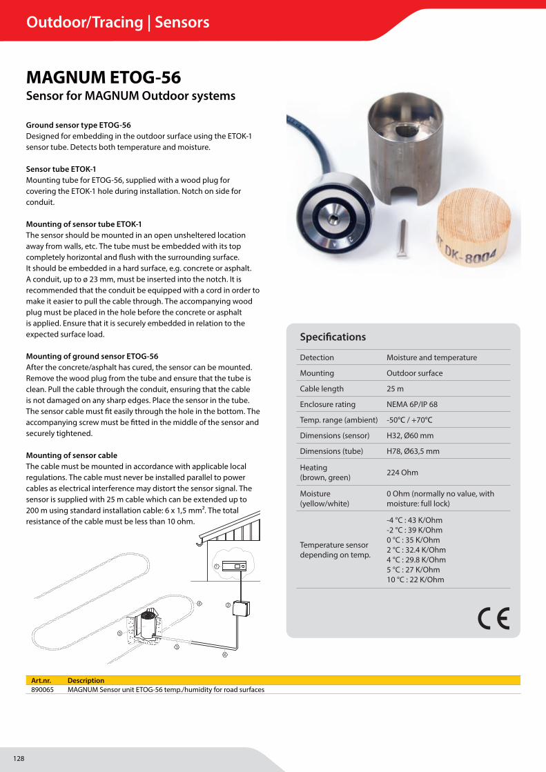
128
Outdoor/Tracing | Sensors
MAGNUM Heating Group B.V.Stevinweg 84691SM TholenThe Netherlands
T +31 166 609300E [email protected] www.magnumheatinggroup.com
Ground sensor type ETOG-56Designed for embedding in the outdoor surface using the ETOK-1 sensor tube. Detects both temperature and moisture.
Sensor tube ETOK-1Mounting tube for ETOG-56, supplied with a wood plug for covering the ETOK-1 hole during installation. Notch on side for conduit.
Mounting of sensor tube ETOK-1The sensor should be mounted in an open unsheltered location away from walls, etc. The tube must be embedded with its top completely horizontal and fl ush with the surrounding surface.It should be embedded in a hard surface, e.g. concrete or asphalt. A conduit, up to ø 23 mm, must be inserted into the notch. It is recommended that the conduit be equipped with a cord in order to make it easier to pull the cable through. The accompanying wood plug must be placed in the hole before the concrete or asphalt is applied. Ensure that it is securely embedded in relation to the expected surface load.
Mounting of ground sensor ETOG-56After the concrete/asphalt has cured, the sensor can be mounted.Remove the wood plug from the tube and ensure that the tube is clean. Pull the cable through the conduit, ensuring that the cable is not damaged on any sharp edges. Place the sensor in the tube. The sensor cable must fi t easily through the hole in the bottom. The accompanying screw must be fi tted in the middle of the sensor and securely tightened.
Mounting of sensor cableThe cable must be mounted in accordance with applicable local regulations. The cable must never be installed parallel to power cables as electrical interference may distort the sensor signal. The sensor is supplied with 25 m cable which can be extended up to 200 m using standard installation cable: 6 x 1,5 mm². The total resistance of the cable must be less than 10 ohm.
6 © 2020 OJ Electronics A/S
Fig. 1 - English:1 = Snow melting thermostat ETO2 / ETR2.2 = Junction box (only if sensor cable is too short)3 = Conduit for sensor cable4 = Heating cable5 = ETOG-56 sensor6 = Sensor cable
Fig. 1 - Deutsch: 1 = Schneeschmelzthermostat ETO2/ETR22 = Sammeldose (nur bei zu kurzem Fühlerkabel)3 = Schutzrohr für Fühlerkabel4 = Heizkabel5 = Fühler ETOG-566 = Fühlerkabel
Fig. 1 - Français : 1 = Thermostat pour fonte de la neige ETO2 / ETR22 = Boîte de jonction (seulement si le câble de la
sonde est trop court)3 = Conduit pour câble de sonde4 = Câble chauffant5 = Sonde ETOG-566= Câble de la sonde
Fig. 1 - Italiano:1 = Termostato per la liquefazione della neve
ETO2 / ETR2.2 = Scatola di giunzione (solo in caso di insufficien-
te lunghezza del cavo del sensore)3 = Guaina protettiva per il cavo del sensore4 = Cavo di riscaldamento5 = Sensore ETOG-566 = Cavo del sensore
Fig. 1 - Polski: 1 = Termostat ETO2 / ETR2 sterujący systemem
przeciwoblodzeniowym2 = Puszka połączeniowa
(tylko jeśli przewód czujnika jest za krótki)3 = Kanał przewodu czujnika4 = Przewód grzewczy5 = Czujnik ETOG-566 = Przewód czujnika
Fig. 1 - Русский: 1 = Термостат снеготаяния ETO2 / ETR2.2 = Соединительная коробка (только, если
кабель датчика слишком короткий)3 = Канал для кабеля датчика4 = Греющий кабель5 = Датчик ETOG-566 = Кабель датчика
Fig. 1 - Suomi:1 = Lumensulatustermostaatti ETO2/ETR22 = Kytkentärasia
(vain jos anturikaapeli on liian lyhyt)3 = Anturikaapelin kanava4 = Lämmityskaapeli5 = ETOG-56-anturi6 = Anturikaapeli
Obr. 1 – Česky:1 = Termostat pro odtávání sněhu ETO2 / ETR2.2 = Přípojná krabice (pouze v případě příliš krátkého
kabelu čidla)3 = Kabelovod pro kabel čidla4 = Topný kabel5 = Čidlo ETOG-566 = Kabel čidla
Fig. 1
1 1
4
2
3
BR995A04© 2012 OJ Electronics A/S
Fig. 2
1
1
4
2
3
BR995A05© 2012 OJ Electronics A/S
Fig. 3
Fig. 2 + 3 - English1 = Heating cable2 = Ground sensor, EF 50-25 H3 = Protective duct for sensor cable4 = Paving slab in case of soft substrate
Fig. 2 + 3 - Deutsch1 = Heizkabel2 = Bodenfühler EF 50-25 H3 = Schutzrohr für Fühlerkabel4 = Gehwegplatte bei weichem Untergrund
Fig. 2 + 3 - Français1 = Câble chauffant2 = Sonde de sol, ETOG-563 = Conduit de protection pour le câble de la sonde4 = Dalle de pavé pour les cas de substrat mou
Fig. 2+3 - Italiano1 = Cavo di riscaldamento2 = Sensore da terreno, ETOG-563 = Condotta di protezione per il cavo del sensore4 = Piastra di pavimentazione in caso di sottostrato
morbido
Fig. 2+3 – Polski1 = Przewód grzewczy2 = Czujnik gruntowy ETOG-563 = Wąż kablowy zabezpieczający przewód czujnika4 = Płyta nawierzchniowa w przypadku miękkiego
podłoża
Fig. 2+3 - Английский1 = Нагревательный кабель2 = Датчик для грунта, ETOG-563 = Защитная трубка для кабеля датчика4 = Дорожное покрытие в случае мягкого
основания грунта
Fig. 2 + 3 – Suomi1 = Lämmityskaapeli2 = Maa-anturi ETOG-563 = Anturikaapelin suojaputki4 = Katukäytävälaatta, jos pohja on pehmeä
Obr. 2 + 3 – Česky1 = Topný kabel2 = Zemní čidlo, EF 50-25 H3 = Ochranný kabelovod pro kabel čidla4 = Dlažební deska v případě měkké půdy
B
R97
8D01
a
B
R99
5A04
B
R99
5A05
MAGNUM ETOG-56Sensor for MAGNUM Outdoor systems
Specifi cations
Detection Moisture and temperature
Mounting Outdoor surface
Cable length 25 m
Enclosure rating NEMA 6P/IP 68
Temp. range (ambient) -50°C / +70°C
Dimensions (sensor) H32, Ø60 mm
Dimensions (tube) H78, Ø63,5 mm
Heating (brown, green) 224 Ohm
Moisture (yellow/white)
0 Ohm (normally no value, with moisture: full lock)
Temperature sensor depending on temp.
-4 °C : 43 K/Ohm-2 °C : 39 K/Ohm0 °C : 35 K/Ohm2 °C : 32.4 K/Ohm4 °C : 29.8 K/Ohm5 °C : 27 K/Ohm10 °C : 22 K/Ohm
Art.nr. Description890065 MAGNUM Sensor unit ETOG-56 temp./humidity for road surfaces
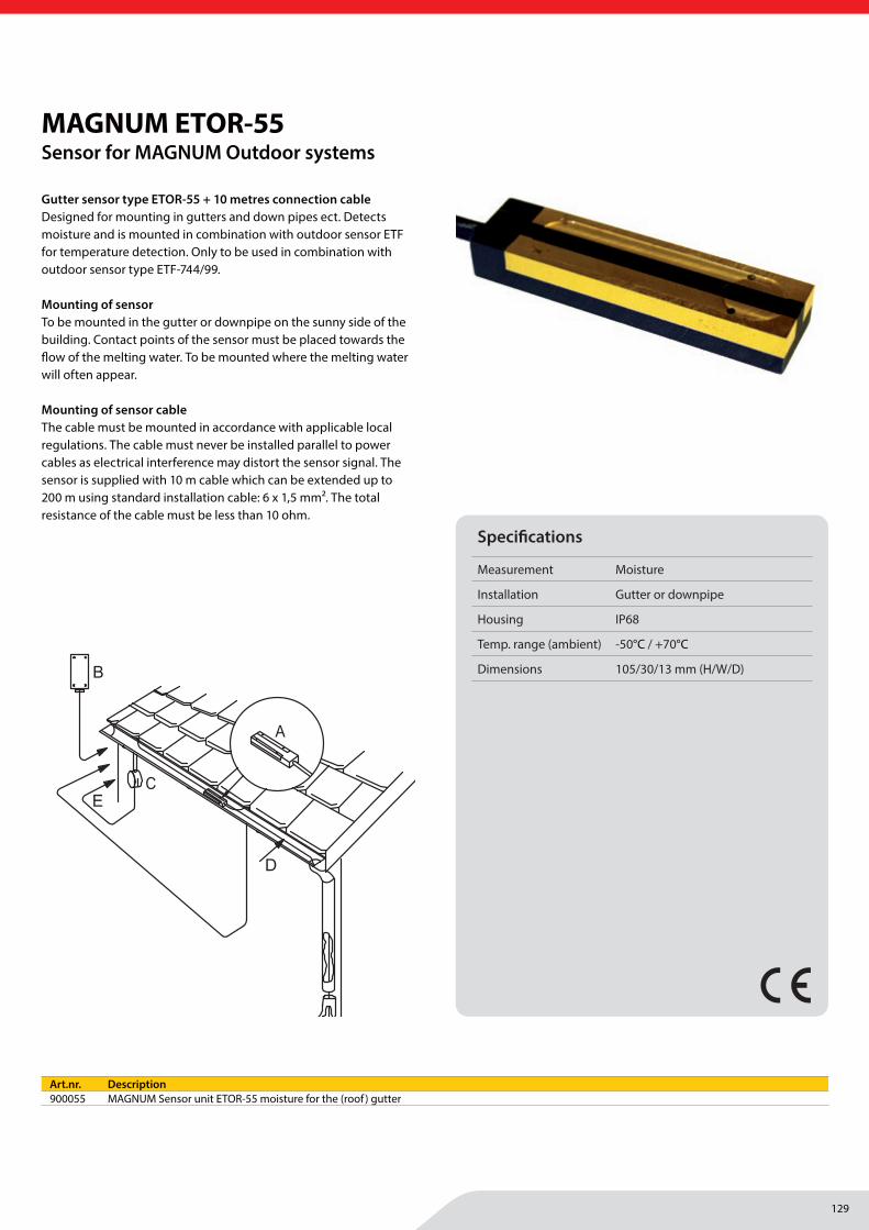
129
Outdoor/Tracing | Sensors
MAGNUM Heating Group B.V.Stevinweg 84691SM TholenThe Netherlands
T +31 166 609300E [email protected] www.magnumheatinggroup.com
Gutter sensor type ETOR-55 + 10 metres connection cableDesigned for mounting in gutters and down pipes ect. Detects moisture and is mounted in combination with outdoor sensor ETF for temperature detection. Only to be used in combination with outdoor sensor type ETF-744/99.
Mounting of sensorTo be mounted in the gutter or downpipe on the sunny side of the building. Contact points of the sensor must be placed towards the fl ow of the melting water. To be mounted where the melting water will often appear.
Mounting of sensor cableThe cable must be mounted in accordance with applicable local regulations. The cable must never be installed parallel to power cables as electrical interference may distort the sensor signal. The sensor is supplied with 10 m cable which can be extended up to 200 m using standard installation cable: 6 x 1,5 mm2. The total resistance of the cable must be less than 10 ohm.
3© 2020 OJ Electronics A/S · ® The OJ trademark is a registred trademark belonging to OJ Electronics A/S
English:1 = Snow melting thermostat ETO2 / ETR22 = ETOR-55 sensor3 = ETF sensor
A = ETOR-55 sensorB = ETF sensorC = Junction box (Only if sensor cable is too short)D = Heating cable
Deutsch: 1 = Schneeschmelzthermostat ETO2/ETR22 = Fühler ETOR-553 = Fühler ETF
A = Fühler ETOR-55B = Fühler ETF C = Sammeldose (nur bei zu kurzem Fühlerkabel)D = Heizkabel
Français : 1 = Thermostat pour fonte de la neige ETO2 / ETR22 = Sonde ETOR-553 = Sonde ETF
A = Sonde ETOR-55B = Sonde ETF C = Boîte de jonction (seulement si le câble de la
sonde est trop court)D = Câble chauffant
Italiano:1 = Termostato per la liquefazione della neve ETO2 /
ETR22 = Sensore ETOR-553 = Sensore ETF
A = Sensore ETOR-55B = Sensore ETF C = Scatola di giunzione (solo in caso di insufficiente
lunghezza del cavo del sensore)D = Cavo di riscaldamento
Polski: 1 = Termostat ETO2 / ETR2 sterujący systemem prze-
ciwoblodzeniowym2 = Czujnik ETOR-553 = Czujnik ETF
A = Czujnik ETOR-55B = Czujnik ETF C = Puszka połączeniowa (tylko jeśli przewód czujnika
jest za krótki)D = Przewód grzewczy
Czech: 1 = Termostat pro tání sněhu ETO2 / ETR22 = Senzor ETOR-553 = Senzor ETF
A = Senzor ETOR-55B = Senzor ETFC = Svorková skříňka (pouze pokud je kabel senzoru
krátký)D = Topný kabel
Русский: 1 = Термостат снеготаяния ETO2 / ETR2.2 = Датчик ETOR-553 = Датчик ETF
A = Датчик ETOR-55B = Датчик ETFC = Соединительная коробка (только, если кабель
датчика слишком короткий)D = Греющий кабель
Suomi:1 = Lumensulatustermostaatti ETO2/ETR22 = ETOR-55-anturi3 = ETF-anturi
A = ETOR-55-anturiB = ETF-anturiC = Kytkentärasia (vain jos anturikaapeli on liian lyhyt)D = Lämmityskaapeli
Fig. 1Abb. 1Rys. 1Рис. 1Kuva 1
BR899B06
C
D
B
A
E
Fig. 2Abb. 2Rys. 2Рис. 2Kuva 2
MAGNUM ETOR-55Sensor for MAGNUM Outdoor systems
Specifi cations
Measurement Moisture
Installation Gutter or downpipe
Housing IP68
Temp. range (ambient) -50°C / +70°C
Dimensions 105/30/13 mm (H/W/D)
Art.nr. Description900055 MAGNUM Sensor unit ETOR-55 moisture for the (roof ) gutter

130
Outdoor/Tracing | Sensors
MAGNUM Heating Group B.V.Stevinweg 84691SM TholenThe Netherlands
T +31 166 609300E [email protected] www.magnumheatinggroup.com
The snow melting system is only energized when the outdoor temperature drops below the selected setting and snow or ice is detected by the sensors. Energy is therefore used only when absolutely necessary.
ETF-744/99 External Outdoor Temperature SensorThis outdoor sensor only records the temperature. To be used in combination with outdoor sensor type ETOR-55 or only for temperature recording.
For gutters - ETO2-4550, ETOR-55 and ETF-744/99The ETOR sensor is designed for installation in gutters, downpipes, etc. ETOR sensors detect moisture, while ETF sensors measure temperature.
ETF outdoor temperature sensorMeasures temperature. Is normally used in combination with ETOR gutter sensors, but can also be used separately for temperature measurement only. An ETF sensor can also be used in combination with ETOG ground sensors for outdoor areas. The ETF sensor can detect rapid drops in air temperature, avoiding icy areas.
ETF outdoor temperature sensor installationShould be installed beneath the eaves on the northern side of the building.
MAGNUM ETF-744/99Sensor for MAGNUM Outdoor systems
Specifi cations
Measurement Temperature
Installation Wall surface
Housing IP54
Temp. range (ambient) -50°C / +70°C
Dimensions 86 x 45 x 35 mm (H/W/D)
Art.nr. Description901441 MAGNUM Sensor unit ETF-744/99 External outside temperature sensor
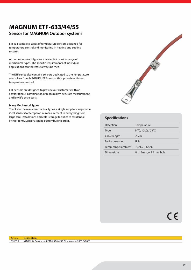
131
Outdoor/Tracing | Sensors
MAGNUM Heating Group B.V.Stevinweg 84691SM TholenThe Netherlands
T +31 166 609300E [email protected] www.magnumheatinggroup.com
ETF is a complete series of temperature sensors designed for temperature control and monitoring in heating and cooling systems.
All common sensor types are available in a wide range of mechanical types. The specifi c requirements of individual applications can therefore always be met.
The ETF series also contains sensors dedicated to the temperature controllers from MAGNUM. ETF sensors thus provide optimum temperature control.
ETF sensors are designed to provide our customers with an advantageous combination of high quality, accurate measurement and low life cycle costs.
Many Mechanical TypesThanks to the many mechanical types, a single supplier can provide ideal sensors for temperature measurement in everything from large tank installations and cold-storage facilities to residential living rooms. Sensors can be custombuilt to order.
MAGNUM ETF-633/44/55Sensor for MAGNUM Outdoor systems
Specifi cations
Detection Temperature
Type NTC, 12kΩ / 25°C
Cable length 2,5 m
Enclosure rating IP54
Temp. range (ambient) -40°C / +120°C
Dimensions 8 x 12mm, ø 3,5 mm hole
Art.nr. Description891650 MAGNUM Sensor unit ETF-633/44/55 Pipe sensor -20°C /+70°C
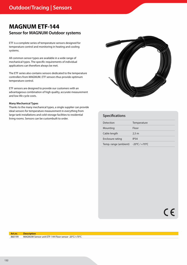
132
Outdoor/Tracing | Sensors
MAGNUM Heating Group B.V.Stevinweg 84691SM TholenThe Netherlands
T +31 166 609300E [email protected] www.magnumheatinggroup.com
ETF is a complete series of temperature sensors designed for temperature control and monitoring in heating and cooling systems.
All common sensor types are available in a wide range of mechanical types. The specifi c requirements of individual applications can therefore always be met.
The ETF series also contains sensors dedicated to the temperature controllers from MAGNUM. ETF sensors thus provide optimum temperature control.
ETF sensors are designed to provide our customers with an advantageous combination of high quality, accurate measurement and low life cycle costs.
Many Mechanical TypesThanks to the many mechanical types, a single supplier can provide ideal sensors for temperature measurement in everything from large tank installations and cold-storage facilities to residential living rooms. Sensors can be custombuilt to order.
MAGNUM ETF-144Sensor for MAGNUM Outdoor systems
Specifi cations
Detection Temperature
Mounting Floor
Cable length 2,5 m
Enclosure rating IP54
Temp. range (ambient) -20°C / +70°C
Art.nr. Description860199 MAGNUM Sensor unit ETF-144 Floor sensor -20°C/+70°C

133
Outdoor/Tracing | Sensors

134
Notes
135
Notes

136
Notes

137
138
Notes

139
Notes

MAGNUM Heating B.V.
Stevinweg 8
4691 SM Tholen
T +31(0)166-609 300
W magnumheating.com
© MAGNUM Heating B.V. | 2022 This edition cancels all previous editions. All our sales and deliveries are subject to our general terms and conditions of sale. No rights can be derived from the contents of this brochure. Nothing in this brochure may be duplicated or published without the consent of MAGNUM Heating B.V. v0122


