Embed Size (px)
Citation preview

1 23
Materials and Structures ISSN 1359-5997 Mater StructDOI 10.1617/s11527-014-0286-7
Prediction of material damping in timberfloors, and subsequent evaluation ofstructural damping
Nathalie Labonnote, Anders Rønnquist& Kjell Arne Malo

1 23
Your article is protected by copyright and all
rights are held exclusively by RILEM. This e-
offprint is for personal use only and shall not
be self-archived in electronic repositories. If
you wish to self-archive your article, please
use the accepted manuscript version for
posting on your own website. You may
further deposit the accepted manuscript
version in any repository, provided it is only
made publicly available 12 months after
official publication or later and provided
acknowledgement is given to the original
source of publication and a link is inserted
to the published article on Springer's
website. The link must be accompanied by
the following text: "The final publication is
available at link.springer.com”.

ORIGINAL ARTICLE
Prediction of material damping in timber floors,and subsequent evaluation of structural damping
Nathalie Labonnote • Anders Rønnquist •
Kjell Arne Malo
Received: 4 July 2013 / Accepted: 6 March 2014
� RILEM 2014
Abstract Dynamic properties of two timber floor
specimens are experimentally evaluated by the impact
method. Each specimen uses one specified type of
connectors, either screws or nails. A numerical model
is developed using constrained degrees-of-freedom for
the modeling of connectors. Numerical analyses have
been performed, and show good agreement with
experimental results. A procedure is written using
the finite element software Abaqus to predict material
damping from a strain energy approach. Estimation of
structural damping is performed as the difference
between the experimentally evaluated total damping
and the predicted material damping. The contribution
from floor members to material damping is exten-
sively investigated.
Keywords Timber floors �Material damping �Structural damping � Strain energy approach
1 Introduction
Low damping is one of the primary causes of
excessive human-induced floor vibration in buildings
[27]. Modern timber structures are prone to low
fundamental frequencies due to the generalization of
long-span architecture and ‘‘open-space’’ solutions.
These low fundamental frequencies may unfortunately
coincide with the frequency of walking excitation,
rendering amplified dynamic response. However,
compared to other building materials such as steel,
timber exhibits a great advantage in the form of higher
damping, which in general will decrease both the
duration of transient vibrations and the amplitude of
steady-state vibrations. In addition, higher damping in
floors should ensure that vibrations are predominantly
transient, and therefore more easily tolerated [16],
since both duration and amplitude were largely
recognized as influential parameters on the perception
of vibration by human subjects [5].
When the response is damping controlled, there is a
clear consensus about including damping in criteria
for assessing the performance of existing floors.
However, at present the omission of damping in
design criteria originates from the difficulty for the
practicing engineer to predict the damping character-
istics of a floor during the design process. This is
especially relevant for wood structures where the
damping characteristics to a large degree will depend
on the workmanship [32] and construction techniques
[11]. Although designers have accurate models and
N. Labonnote (&)
Materials and Structures, SINTEF Building and
Infrastructure, 7465 Trondheim, Norway
e-mail: [email protected]
A. Rønnquist � K. A. Malo
Department of Structural Engineering, Norwegian
University of Science and Technology, 7491 Trondheim,
Norway
Materials and Structures
DOI 10.1617/s11527-014-0286-7
Author's personal copy

tools to predict strength and stiffness, the estimation
and calculation of damping is usually more difficult
due to a general lack of knowledge of the damping
phenomena. The total damping: ntot, is commonly
divided into at least two categories:
– the material damping, nmat, which refers to internal
friction in the materials and
– the structural damping, nstruct, which may arise
from other sources such as friction between
components and/or friction due to connectors.
Hence:
ntot ¼ nmat þ nstruct: ð1ÞStructural damping nstruct is therefore partially
dependent on the workmanship, whereas material
damping nmat is only dependent on the actual material
properties. A first, yet conservative, step towards the
better prediction of damping in timber structures can
therefore be accomplished by considering material
damping nmat as a lower boundary for total damping
ntot, i.e.:
min ntotð Þ ¼ nmat: ð2ÞThe great advantage in this formulation is that
prediction models of material damping nmat have been
developed over the last few decades by means of the
strain energy approach [3, 35]. The use of available
prediction models for material damping nmat may also
result in possible estimations of structural damping
nstruct as the difference between the measurable total
damping ntot and the predicted material damping nmat:
nstruct ¼ ntot � nmat: ð3ÞThe main applications of the strain energy approach
were directed towards composite single members,
either beams or plates [2, 4, 8, 17, 24, 26, 28].
Berthelot et al. [6] developed a synthesis of damping
analysis of laminate materials, and applied the strain
energy method to a composite structure composed of
different materials. So far, there have been few similar
studies on timber members and/or timber structures,
with the exception of studies dealing with laminated
plates [21, 22, 33], among them some timber panels.
The present study implements the strain energy
method by means of finite element modeling in order
to predict the material damping nmat exhibited by
timber floors and to estimate the structural damping
nstruct.
The total damping ntot of two timber floors using
two types of connectors has been experimentally
assessed by the impact method (Sect. 2). A prediction
model for the material damping nmat using the strain
energy approach is then derived (Sect. 3), and used in
combination with a commercial finite element soft-
ware (Sect. 4). The structural damping nstruct is
furthermore estimated from Eq. (3) and different
investigations are performed on the contributions to
the material damping nmat (Sect. 5). The overall
procedure is summarized in Fig. 1.
2 Experimental design
2.1 Selected timber floors
Two timber floor specimens are tested: one with all
screw connectors, referred to as the screwed floor, and
one where connectors are all nails, referred to as the
nailed floor. Both specimens have the same layout, and
are composed of two edge joists with sec-
tion 225 mm 9 67 mm, five joists with sec-
tion 225 mm 9 48 mm, 22 mm thick particleboard
panels on top, and 13 mm thick particleboard panels
on bottom. Nominal dimensions of particleboard
panels are 600 mm 9 2,400 mm, and the timber
floors themselves are 2,400 mm 9 2,880 mm. All
dimensions sketched in Fig. 2 are nominal, and are
given in mm.
Assembling of the floors was performed according
to SINTEF Building Research Design Guides [31].
Connection between joists and sheathing was achieved
accordingly by the use of glue, in addition to
recommended timber nails (65 mm long) and recom-
mended timber screws (50–55 mm long), with a
recommended maximal center to center spacing of
300 mm.
Edge joists and joist are glulam beams of GL36c, as
defined in EN 1194 [12]. Particleboard panels are
made out of small wood particles, pressed together
under high temperature and pressure inside a matrix of
glue. Their material properties are defined in EN-
12369-1 [13]. Glulam beams are considered to be
transversely isotropic, whereas particleboard panels
are considered to be isotropic. Mean stiffness values
and characteristic densities for the glulam beams and
the particleboard panels are summarized in Tables 1
and 2 for convenience, with respect both to the
Materials and Structures
Author's personal copy

longitudinal direction (L) and the transverse direction
(T).
Temperature and relative humidity were not
explicitly controlled, but were according to standard
indoor summer conditions, i.e. 20 �C and 60 %
respectively.
2.2 Roving hammer experimental protocol
The modal hammer ‘‘heavy duty type 8208’’ from
Bruel and Kjær [7] is used to set the panel into motion
and to record the impact load. A soft tip is employed in
order to excite lower frequencies. Transient vibrations
due to modal hammer impact are recorded by one
ceramic/quartz impedance head Kistler 8770A50
Fig. 1 Summarized procedure and main outputs
Fig. 2 Lay-out and dimensions of floors
Table 1 Mean stiffness values and characteristic density val-
ues [13]
E (MPa) G (MPa) Density
(kg/m3)
Particleboard panel:
22 mm thick
1,600 770 550
Particleboard panel:
13 mm thick
1,700 830 600
Table 2 Mean stiffness values, poison ratios, and characteristic density values [9, 12]
EL (MPa) ET (MPa) GLT (MPa) GTT (MPa) mLT mTT Density (kg/m3)
Glulam beam GL36c 14,700 460 850 30 0.39 0.64 430
L Longitudinal direction, T transverse direction, TT radial-tangential plane, for the considered member
Fig. 3 Experimental measurements on timber floors by the
roving hammer method
Materials and Structures
Author's personal copy

accelerometer screwed into the top particleboard
panel, as shown in Fig. 3. The load and acceleration
time series are then digitalized and processed by a
dynamic signal analyzer. An experimental modal
analysis software provided by National Instruments
[23] is used to record and process the data by means of
the graphical development environment LabVIEW.
The sampling frequency is fixed to 1,000 Hz, and 5 s
data are recorded for each impact.
The mode shapes corresponding to each floor are
evaluated by means of the ‘‘roving hammer’’ method
[29], which consists of impacting different points,
usually organized on a grid, while the accelerometer
remains at one unique location. The grid consists of
195 measurements points, i.e. a 20 9 20 cm spaced
grid. Each measurement point is impacted twice. Both
timber floors are simply supported at only four
corners, by means of 20 cm long steel cylinders
located along the edge joists, as illustrated in Fig. 3.
2.3 Modal parameter identification
Experimental modal analysis [14] is used for determin-
ing the fundamental frequencies, the damping ratios
and the mode shapes of the two floors, all under the
fundamental assumption of small total damping values.
The frequency response function H relates the input
signal spectrum F from the hammer’s load cell and the
output signal spectrum X from the accelerometer:
HðxÞ � XðxÞFðxÞ ; ð4Þ
where x is the circular frequency in rad/s. A linear
average of the frequency response function over two
impacts is performed. Identification of transfer func-
tion models is performed by curve fitting the averaged
frequency response function with suitable analytical
expressions, so that:
Hik ¼Xn
r¼1
wiwkð Þrx2
r �x2þ 2jnrxrx� �
with
wiwkð Þr¼ residues
xr ¼ natural frequency
nr ¼ equivalent viscous modal damping ratio,
8>><
>>:
ð5Þ
where r is the mode number, n is the total number of
modes, and j¼ffiffiffiffiffiffiffi�1p
. The natural frequency and the
modal viscous damping ratio are directly extracted
from Eq. (5). The mode shape vectors Wr are extracted
as:
Wr ¼ w21
� �r
w1w2ð Þr . . . w1w13ð Þrh i
: ð6Þ
The parameter identification method is based on the
Frequency-Domain Direct Parameter Identification
fitting method, which is a frequency domain multiple
degree-of-freedom modal analysis method suitable for
narrow frequency band and well separated modes.
3 Prediction model
3.1 Analytical derivation
In 1962, Ungar and Kerwin [35] were among the first
to define damping in terms of energy:
g ¼ D
2pW; ð7Þ
where g is the hysteretic damping, D is the dissipated
energy per cycle, and W is the total energy (kinetic
plus potential) associated with the vibration. They
recognized that the definition of W as the total energy
for the considered cycle was unambiguous only for
lightly damped structures, where the total energy does
not fluctuate much throughout a cycle. They therefore
proposed to compute W as the total strain energy at
instant of maximum strain at a reference point in the
case of lightly damped structures. Adams and Bacon
[3] used Ungar and Kerwin’s suggestion, and defined
the specific damping capacity u as the ratio between
the dissipated energy DU per cycle of vibration to the
maximum strain energy U:
u ¼ 2pg ¼ DU
U: ð8Þ
The strain energy U is expressed with respect to the
stress r and strain e matrices as:
U ¼ 1
2
ZZZrTedV : ð9Þ
The strain energy U may be divided into different
energies, i.e.:
U ¼ U11 þ U22 þ U33 þ U12 þ U13 þ U23
with Uij ¼1
2
ZZZrijeijdV :
ð10Þ
Materials and Structures
Author's personal copy

When considering material damping in particular,
the dissipated energy DU during one cycle s may be
expressed in the most general way [26, 30] as:
DU ¼Z
s
ZZZ1
2~rT ~edV
� �dt ¼ 2p
ZZZ1
2~rT ~edV ð11Þ
where ~r and ~e are damped quantities. Damped
quantities have been commonly defined by dividing
the dissipated energy DU into different parts as well
[2, 20, 25], i.e.:
DU ¼ DU11 þ DU22 þ DU33 þ DU12 þ DU13
þ DU23: ð12Þ
The different dissipated energies DUij are defined
with respect to specific loss factors gij:
DUij ¼ 2pgij
ZZZ1
2rijeijdV: ð13Þ
The relationship between equivalent viscous damp-
ing n with hysteretic damping g at resonance yields
[10]:
n ¼
ffiffiffiffiffiffiffiffiffiffiffiffiffiffiffiffiffiffiffiffiffiffiffiffiffiffiffiffiffiffi�1þ
ffiffiffiffiffiffiffiffiffiffiffiffiffi1þ g2
p
2
s
� g2: ð14Þ
The predicted material damping nmat is finally
expressed as:
Adams and Bacon [2] and Maheri [20] defined
relevant loss factors g11, g22 and g12 as the longitudinal
loss factor, the transverse loss factor and the shear loss
factor, respectively. Pervez and Zabaras [25] consid-
ered in addition loss factors due to transverse shears:
g13 and g23.
3.2 Application to beam, plate and floor
In the present investigation, the evaluated floors are
composed of various timber members, acting either as
beams or plates. For beams, all energy quantities
defined in Eq. (10) are relevant. However, since here
both top and bottom plates exhibit a very low
thickness-to-length ratio, thin plate theory may be
introduced, which means that, if 1 and 2 are the in-
plane axes of the plate, as shown in Fig. 3, only r11,
r22, r12, e11, e22, and e12 are non-null. Consequently,
only U11, U22, and U12 are non-null for plates. The
total material damping of the floor is then defined
nmat ¼1
2
g11U11 þ g22U22 þ g33U33 þ g12U12 þ g13U13 þ g23U23
U11 þ U22 þ U33 þ 2U12 þ 2U13 þ 2U23
: ð15Þ
nmat ¼1
2Utot
X
Beamelements
g11;bU11;b þ g22;bU22;b þ g33;bU33;b þ g12;bU12;b þ g13;bU13;b þ g23;bU23;b
þX
Plateelements
g11;pU11;p þ g22;pU22;p þ 2g12;pU12;p
0BB@
1CCA; ð16Þ
Table 3 Loss factors estimated from previous studies
Loss factors
Glulam beams [18] gEL = 0.0081 gGLT = 0.1551
Particleboard panels [19] gE = 0.0200
L Longitudinal direction, T transverse direction
Materials and Structures
Author's personal copy

as:where Utot is the total strain energy of the floor, Uij,b
is the strain energy for a beam member, Uij,p is the
strain energy for a plate member.
3.3 Estimation of loss factors
Unlike existing estimations of elastic moduli for wood
[34, 37], experimental data on loss factors are very
scarce. A method for estimating loss factors for solid
wood beams, glulam beams, and various types of
timber panels has been recently provided by Labon-
note et al. [18, 19]. It is hoped that this method will be
further generalized to other types of timber products so
as to provide access to a database for loss factors that
could be used for design purposes.
The loss factors used in this study are therefore
estimated after previous experimental studies on
timber beams [18] and timber panels [19] with quality
similar to the edge joists and joists as well as the top
and bottom plates. For convenience, loss factors from
the above-mentioned studies are also reported in
Table 3.
Edge joists and joists are glulam beams, hence they
are considered as transversely isotropic. The following
loss factors: gL, gT, gLT, gTT, referred to as longitu-
dinal loss factor, transversal loss factor, in-plane shear
loss factor, transversal shear loss factor, respectively,
are necessary to implement in Eq. (16). From Table 3,
gL is estimated as gEL, and gLT is estimated as gGLT.
The remaining loss factors are assumed to be propor-
tional to stiffness. They are therefore estimated from
available data in Table 3 by taking into account the
ratio between the longitudinal elastic modulus EL and
the transverse elastic modulus ET, and the ratio
between both shear elastic moduli GLT and GTT, all
given in Table 1:
gT ¼ET
EL
gL
gTT ¼GTT
GLT
gLT:
ð17Þ
The top and bottom plates are isotropic, and in that
case, according to Eq. (16), the loss factor gE as well as
the shear loss factor gG are needed. The loss factor gE
is simply taken as the loss factor gE reported in
Table 3, whereas the shear loss factor gG is estimated
from the ratio between the elastic modulus E and the
shear modulus G, so that:
gG ¼G
EgE ð18Þ
The estimated loss factors are summarized in
Table 4.
4 Numerical analyses
4.1 Numerical models
The strain energies needed for the application of the
prediction model (16) are numerically determined, as
described in Fig. 1. The commercial software Abaqus
is used to perform finite element analyses. Particle-
board panels are modeled as two continuous plates
over the whole surface of the floor, one on top and one
at the bottom. The general linear, reduced integration,
shell element S4R is used. Edge joists and joists are
modeled using the 8-node linear brick, reduced
integration, continuum element C3D8R. Given the
very low motion induced by the impact test and the
recommended assembling process [31], connection
between timber components was assumed to be rigid
instead of semi-rigid. Joist-to-joist connection, as well
as joist-to-sheathing connection, whether involving
screws or nails, were therefore simplified by a ‘‘tie’’
constraint between adjacent surfaces. Rotational and
translational degrees-of-freedom were consequently
equal for adjacent surfaces. The mesh size is chosen to
be approximately 0.04 m, and corresponds to a
converging model.
Material properties are implemented as nominal
values, given in Table 1. Boundary conditions are
implemented by constraining selected degrees-of-
Table 4 Estimated loss factors used in the present study
Loss factors
Edge joists and joists gL = 0.0081 gT = 0.0003 gLT = 0.1551 gTT = 0.0055
Top plate and bottom plate gE = 0.0200 gG = 0.0100
L Longitudinal direction, T transverse direction
Materials and Structures
Author's personal copy

freedom along bottom plate selected surfaces,
assumed to be in contact with the steel cylinder
supports.
Numerical results are considered as undamped
results. Johnson and Kienholz [15] and later Rebillat
and Boutillon [26] assumed that for lightly damped
structures, mode shapes and fundamental frequencies
remain unchanged by the addition of damping. The
approximation was found reasonable even for values
of material damping in excess of unity [15].
Undamped numerical results are therefore considered
to be similar to damped experimental results.
4.2 Calculation of strain energy components
A procedure is written to calculate the strain energy
components Uij from Eq. (10) using Abaqus. Strain
energy components are calculated for each element,
and then summed over members: edge joist, joists, top
plate and bottom plates. For the continuum elements,
used to model edge joists and joists, the strain energy
components are calculated with respect to the strain
and stress related to the unique integration point. For
the shell elements, used to model the top and bottom
plates, the stress and strain are integrated over the
thickness of the shell section by the Gauss integration
method, with three points across the shell thickness h,
as presented in Fig. 4.
This method induces less than 2 % error on the total
strain energy per shell element. The location and
weights of the points [1] are summarized in Table 5.
5 Results and discussion
5.1 Comparison between experimental results
for nailed and screwed floors
Since the accelerometer was located on the top plate,
mode shapes recorded experimentally correspond to
the bending modes of the top plate. The observed
experimental mode shapes show similarities between
the screwed floor and the nailed floor for the two first
modes. No experimental data from higher modes are
available from measurements on the nailed floor,
unlike the screwed floor for which a third mode was
detected. Mode shapes obtained for the screwed floor
are plotted in Fig. 5, where the experimental used grid
is superimposed.
Fundamental frequencies f and corresponding
evaluated damping ratios ntot are presented in
Table 6. As expected, screw connectors make the
floor slightly stiffer than nail connectors, and the
Table 5 Gauss numerical integration constants
Point 1 Point 2 Point 3
Location xi �ffiffiffiffiffiffiffiffi3=5
ph2
0ffiffiffiffiffiffiffiffi3=5
ph2
Weight 5/18 4/9 5/18
Fig. 5 Experimental mode shapes
for the screwed floor
Table 6 Experimentally evaluated modal properties of floors
Mode 1 Mode 2 Mode 3
Nailed floor f1 = 28.5 Hz
ntot = 0.0196
f2 = 41.2 Hz
ntot = 0.0249
–
Screwed floor f1 = 29.7 Hz
ntot = 0.0194
f2 = 43.9 Hz
ntot = 0.0251
f3 = 53.0 Hz
ntot = 0.0293
Fig. 4 Gauss integration points on a shell thickness
Materials and Structures
Author's personal copy
fundamental frequencies f are observed to increase
by 4 and 6 % for the first mode and the second
mode, respectively. However, experimental estima-
tions of the total damping ntot reveal no significant
influence from the type of connector, probably due
to the additional presence of glue in the connections.
These observations have to be considered with care
since they are related to a limited number of
specimens: one for each type of connector.
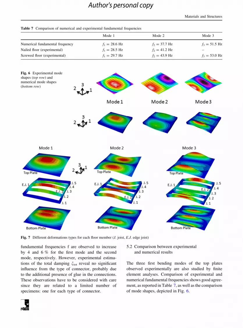
5.2 Comparison between experimental
and numerical results
The three first bending modes of the top plates
observed experimentally are also studied by finite
element analyses. Comparison of experimental and
numerical fundamental frequencies shows good agree-
ment, as reported in Table 7, as well as the comparison
of mode shapes, depicted in Fig. 6.
Table 7 Comparison of numerical and experimental fundamental frequencies
Mode 1 Mode 2 Mode 3
Numerical fundamental frequency f1 = 28.6 Hz f2 = 37.7 Hz f3 = 51.5 Hz
Nailed floor (experimental) f1 = 28.5 Hz f2 = 41.2 Hz –
Screwed floor (experimental) f1 = 29.7 Hz f2 = 43.9 Hz f3 = 53.0 Hz
Fig. 6 Experimental mode
shapes (top row) and
numerical mode shapes
(bottom row)
Fig. 7 Different deformations types for each floor member (J. joist, E.J. edge joist)
Materials and Structures
Author's personal copy

Within the same range of frequency (28–53 Hz),
additional numerical modes are detected, but they are
all related to bending modes of the lower plate. This is
the reason why they were not detected experimentally.
Their study is therefore dismissed.
A more accurate visualization of the three first
bending modes, given by numerical simulation,
including detailed member deformations, is presented
in Fig. 7.
5.3 Contribution from floor members to material
damping
From the model displayed in Eq. (16), the material
damping nmat is calculated as the sum of material
damping quantities exhibited by each floor member.
The contributions from each floor member to the floor
material damping nmat are presented in Table 8 and
Fig. 8.
As expected, the top and bottom plates provide a
governing contribution to material damping, com-
pared to edge joists and joists, since they are also
subject to larger deformation, as shown in Fig. 7. For
the same reason, material damping induced by the
bottom plate is larger than material damping induced
by the top plate.
5.4 Prediction of material damping and estimation
of structural damping in floors
The material damping nmat may be estimated from Eq.
(15) for the three first vibration modes of the floors.
The structural damping nstruct, which includes damp-
ing due to friction between components and damping
due to connectors, is therefore estimated from the
difference between the measured total damping n and
the estimated material damping nmat, as expressed in
Eq. (3). The predicted material damping nmat and the
estimated structural damping nstruct are reported in
Table 9 for both types of floors: screwed floor and
nailed floor.
Very little difference between the two types of
floors is observed concerning the estimated structural
damping nstruct. This is likely due to the small
amplitude of vibrations under testing. Low amplitude
induces less friction; hence the influence of a specific
type of connectors is reduced.
From Fig. 9 and Table 9, it also appears that the
share of structural damping increases with the mode
number. This is especially clear for the third mode, e.g.
Table 8 Breakdown of material damping among floor
members
Mode
1
Mode
2
Mode
3
Edge joist 1 0.0004 0.0003 0.0001
Edge joist 2 0.0004 0.0003 0.0001
Joist 1 0.0000 0.0008 0.0007
Joist 2 0.0006 0.0014 0.0004
Joist 3 0.0014 0.0000 0.0005
Joist 4 0.0006 0.0014 0.0004
Joist 5 0.0000 0.0008 0.0007
Edge joists ? joists 0.0034 0.0050 0.0029
Top plate 0.0030 0.0031 0.0031
Bottom plate 0.0036 0.0038 0.0051
Sum plates 0.0066 0.0069 0.0082
Plates ? edge
joists ? joists = Material
damping nmat
0.0100 0.0119 0.0111
Fig. 8 Contribution to material damping from floor members (J. joist, E.J. edge joist)
Materials and Structures
Author's personal copy

for the screwed floor, where the structural damping
represents about 62 % of the total damping, whereas
structural damping represents only 48 % of the first
mode’s damping. The use of material damping as the
lower boundary of the total damping, as expressed in
Eq. (2), is therefore less accurate as the mode number
increases.
In 1971, Yeh, Hartz and Brown [36] compared the
magnitudes of different damping sources evaluated
experimentally. They however considered the material
damping, as a constant value equal to 0.0035 for any
timber structure and any vibration mode, which clearly
explains why they measured a significantly higher
ratio between material damping and structural damp-
ing (1:6) for conventional construction.
6 Conclusion
The present study describes an efficient approach for
prediction of material damping and estimation of
structural damping in timber floors. The prediction
method for material damping is derived from the strain
energy approach, and a procedure has been written
using the commercial finite element software Abaqus.
This method allows a precise estimation of the
different contributions to material damping from each
floor member. In particular it is observed that top and
bottom plates introduce larger material damping than
joists or edge joists.
Estimation of structural damping is performed as
the difference between experimentally evaluated total
damping and predicted material damping. The results
reveal a lower than expected share of structural
damping, compared to material damping. Insignificant
influence of the type of connectors is observed, and
this is probably due to the very low level of induced
motion. In addition, the contribution from structural
damping to total damping is observed to increase with
the mode number. In particular structural damping is
larger than material damping for the third mode
considered. This demonstrates that estimating a lower
boundary of the total damping by predicting the
material damping becomes more conservative as the
mode number increases.
The proposed procedure to predict material damp-
ing is dependent on the accuracy and the availability of
loss factors, but is convenient to implement and
efficient to use. However, further research is needed
regarding the influence of the type of connectors. More
timber floor specimens exhibiting different types of
joist-to-sheathing connection need to be systemati-
cally experimentally measured. Corresponding semi-
rigid connection numerical models need also to be
established and validated in order to enhance knowl-
edge on structural damping predictions in general.
Acknowledgments Bjørn Ottar Torp from Moelven
ByggModul is gratefully acknowledged for supplying the floors
used in the present study, and for his support and his time in general.
References
1. Abaqus Analysis User’s manual, version 6.9 (2010) Das-
sault Systemes Simulia Corp., Providence
2. Adams RD, Bacon DGC (1973) Effect of fiber orientation
and laminate geometry on the dynamic properties of CFRP.
J Compos Mater 7:402–428
3. Adams RD, Bacon DGC (1973) Measurement of the flex-
ural damping capacity and dynamic Young’s modulus of
metals and reinforced plastics. J Phys D 6(1):27–41. doi:10.
1088/0022-3727/6/1/308
Table 9 Predicted material damping and estimated structural
damping in floors
Mode 1 Mode 2 Mode 3
nmat—Nailed floor and
screwed floor
0.0100 0.0119 0.0111
nstruct—Nailed floor 0.0096 0.0130 –
nstruct—Screwed floor 0.0094 0.0132 0.0182
Fig. 9 Share of material damping and structural damping over
the total damping
Materials and Structures
Author's personal copy

4. Adams RD, Maheri MR (1994) Dynamic flexural properties
of anisotropic fibrous composite beams. Compos Sci
Technol 50(4):497–514
5. Alves N, Roitman N, Magluta C (1999) Dynamic response
under human movements. Mater Struct 32(1):31–37. doi:10.
1007/bf02480409
6. Berthelot J-M, Assarar M, Sefrani Y, Mahi AE (2008)
Damping analysis of composite materials and structures.
Compos Struct 85(3):189–204
7. Bruel & Kjær (2011) Product data: heavy duty impact
hammer: Type 8208. http://www.bksv.com/doc/bp2079.
pdf. Accessed 7 Feb 2011
8. Chandra R, Singh SP, Gupta K (2003) A study of damping
in fiber-reinforced composites. J Sound Vib
262(3):475–496
9. Dahl KB (2009) Mechanical properties of clear wood from
Norway spruce. Norwegian University of Science and
Technology, Trondheim
10. De Silva CW (2005) Vibration and shock handbook. Taylor
& Francis, Boca Raton
11. Dolan JD, Murray TM, Johnson JR, Runte D, Shue BC
(1999) Preventing annoying wood floor vibrations. J Struct
Eng 125:19–24
12. European Committee for Standardization (1999) NS - EN
1194 - Timber structures - Glued laminated timber -
Strength classes and determination of characteristic values.
Brussels
13. European Committee for Standardization (2001) NS-EN
12369-1 Wood-based panels: characteristic values for
structural design: Part 1: OSB, particleboards and fibre-
boards. Brussels
14. Ewins DJ (2000) Modal testing: theory, practice and
application. Research Studies Press, Baldock
15. Johnson CD, Kienholz DA (1983) Prediction of damping in
structures with viscoelastic materials. Paper presented at the
MSC Software World Users’ Conference, CA, USA
16. Kalkert RE, Dolan JD, Woeste FE (1993) The current status
of analysis and design for annoying wooden floor vibrations.
Wood Fiber Sci 25(3):305–314
17. Kam TY, Chang RR (1994) Design of thick laminated
composite plates for maximum damping. Compos Struct
29(1):57–67
18. Labonnote N, Rønnquist A, Malo KA (2013) Modified
hysteretic damping model applied to Timoshenko timber
beams. Comput Struct 121:22–31
19. Labonnote N, Rønnquist A, Malo KA (2013) Semi-analyt-
ical prediction and experimental evaluation of material
damping in wood panels. Holzforschung 67(3):333–343
20. Maheri MR (2011) The effect of layup and boundary con-
ditions on the modal damping of FRP composite panels.
J Compos Mater 45(13):1411–1422. doi:10.1177/
0021998310382314
21. McIntyre ME, Woodhouse J (1978) The influence of
geometry on linear damping. Acustica 39(4):209–224
22. McIntyre ME, Woodhouse J (1988) On measuring the
elastic and damping constants of orthotropic sheet materi-
als. Acta Metall 36(6):1397–1416. doi:10.1016/0001-
6160(88)90209-x
23. National Instruments (2011) Modal analysis. http://zone.ni.
com/devzone/cda/tut/p/id/8276. Accessed 31 Jan 2011
24. Ni RG, Adams RD (1984) The damping and dynamic
moduli of symmetric laminated composite beams: theoret-
ical and experimental results. J Compos Mater
18(2):104–121
25. Pervez T, Zabaras N (1992) Transient dynamic and damp-
ing analysis of laminated anisotropic plates using a refined
plate theory. Int J Numer Methods Eng 33(5):1059–1080
26. Rebillat M, Boutillon X (2011) Measurement of relevant
elastic and damping material properties in sandwich thick
plates. J Sound Vib 330(25):6098–6121
27. Saidi I, Haritos N, Gad EF, Wilson JL (2006) Floor vibra-
tions due to human excitation: damping perspective. Paper
presented at the Earthquake Engineering in Australia Con-
ference, Canberra, Australia, 24–26 Nov 2006
28. Saravanos DA (1994) Integrated damping mechanics for
thick composite laminates and plates. J Appl Mech
61(2):375–383
29. Schwarz BJ, Richardson MH (1999) Experimental modal
analysis. In: CSI Reliability Week. Orlando
30. Siala W, Abdennadher M, Hammami L, Haddar M (2008)
Modal damping prediction of sandwich panel with visco-
elastic thick core. In: Proceedings of the Institution of
Mechanical Engineers, Part C (J Mech Eng Sci) 222(C11):
2077–2086. doi:10.1243/09544062jmes1080
31. SINTEF Byggforsk (2011) Undergolv pa trebjelkelag. By-
ggforskserien, Byggdetaljer 522.861. SINTEF Byggforsk,
Oslo
32. Smith I, Chui YH (1988) Design of lightweight wooden
floors to avoid human discomfort. Can J Civ Eng
15(2):254–262
33. Talbot JP, Woodhouse J (1997) The vibration damping of
laminated plates. Composites Part A 28A(12):1007–1012.
doi:10.1016/s1359-835x(97)00056-0
34. Thomas W (2004) Planar shear moduli of rigidity of an
oriented strand board from bending and shear tests. Mater
Struct 37(7):480–484. doi:10.1007/bf02481585
35. Ungar EE, Kerwin EM Jr (1962) Loss factors of viscoelastic
systems in terms of energy concepts. J Acoust Soc Am
34(7):954–957
36. Yeh CT, Hartz BJ, Brown CB (1971) Damping sources in
wood structures. J Sound Vib 19(4):411–419. doi:10.1016/
0022-460X(71)90612-2
37. Yoshihara H, Tsunematsu S (2006) Feasibility of estimation
methods for measuring Young’s modulus of wood by three-
point bending test. Mater Struct 39(1):29–36. doi:10.1617/
s11527-005-9015-6
Materials and Structures
Author's personal copy


