Embed Size (px)
Citation preview
FACTA UNIVERSITATIS
Series: Electronics and Energetics Vol. 34, No 3, September 2021, pp. 381-392
https://doi.org/10.2298/FUEE2103381T
© 2021 by University of Niš, Serbia | Creative Commons License: CC BY-NC-ND
Original scientific paper
DAMPING ANALYSIS TO IMPROVE THE PERFORMANCE OF
SHUNT CAPACITIVE RF MEMS SWITCH
Lakshmi Narayana Thalluri1, K V V Kumar2, Konari Raja Sekhar3,
N Bhushana Babu D3, S S Kiran4, Koushik Guha5
1Department of ECE, Andhra Loyola Institute of Engineering and Technology, Vijayawada,
Andhra Pradesh, India 2Department of ECE, Universal College of Engineering and Technology, Perecharla, A P,
India 3Department of ECE, N S Raju Institute of Technology (Autonomous),Sontyam, A P, India 4Department of ECE, Lendi Institute of Engineering and Technology, Visakhapatnam, A P,
India 5National MEMS Design Center, Department of ECE, National Institute of Technology,
Silchar, Assam, India
Abstract. This paper describes the significance of the iterative approach and the structure
damping analysis which help to get better the performance and validation of shunt
capacitive RF MEMS switch. The micro-cantilever based electrostatic ally actuated shunt
capacitive RF MEMS switch is designed and after multiple iterations on cantilever structure
a modification of the structure is obtained that requires low actuation voltage of 7.3 V for 3
µm deformation. To validate the structure we have performed the damping analysis for each
iteration. The low actuation voltage is a consequence of identifying the critical membrane
thickness of 0.7 µm, and incorporating two slots and holes into the membrane. The holes to
the membrane help in stress distribution. We performed the Eigen frequency analysis of the
membrane. The RF MEMS switch is micro machined on a CPW transmission line with Gap-
Strip-Gap (G-S-G) of 85 µm - 70 µm - 85 µm. The switch RF isolation properties are
analyzed with high dielectric constant thin films i.e., AlN, GaAs, and HfO2. For all the
dielectric thin films the RF MEMS switch shows a high isolation of -63.2 dB, but there is
shift in the radio frequency. Because of presence of the holes in the membrane the switch
exhibits a very low insertion loss of -0.12 dB.
Key words: Vibration analysis, RF MEMS switches, material science, FEM tools analysis.
Received March 22, 2021; received in revised form June 06, 2021 Corresponding author: Lakshmi Narayana Thalluri
Department of ECE, Andhra Loyola Institute of Engineering and Technology, Vijayawada, Andhra Pradesh, India
E-mail: [email protected] * An earlier version of this paper was presented at the International Conference on Micr/Nano electronics
devices, Circuits and Systems (MNDCS-2021), 30-31 January, 2021, India [1].
382 L. N. THALLURI, K V V KUMAR, K. R. SEKHAR, N B BABU D.3, S S KIRAN, K. GUHA
1. INTRODUCTION
RF MEMS switches are becoming prominent because of their low power consumption and high linearity [1]. Shunt capacitive RF MEMS switches are extremely useful in RF MEMS technology which has great potential in the design of reconfigurable antennas [2]. The frequency range of 1.5 - 15 GHz is the major band which will cover significant wireless applications like GPS, GSM, Wi-Fi, Wi-Max, and UMTS [3]. Potential major research challenges of Electrostatically actuated RF MEMS switches are how to reduce the required actuation voltage, improve their switching time and reliability. A proper iterative study helps to obtain better mechanical, electrical and RF properties of the switch. The cantilever-based, serpentine, fixed-fixed, folded membrane structures are popular in the design of MEMS devices. Among these, the cantilever based devices offer low actuation voltage and better switching properties [4-6].
But, there is still room to improve the cantilever performance by the iterative analysis. Material science also helps to choose the most suitable thin film for the substrate, the transmission line and the membrane [7].
2. RELATED WORK
In the early decades, several researchers advanced the research on RF MEMS switches. Electrostatic, magneto static, piezo resistive, and thermal are the popular actuation techniques. Among these, electrostatic actuation offers major advantages [8]. However, there are still a few potential research challenges in electrostatically actuated RF MEMS switches, like improving the reliability, reducing the actuation voltage, and improving the switching time [9, 10]. The prior iterative analysis obviously helps to improve the performance of the RF MEMS switches. Material science has a prominent role in the selection of thin films for the transmission lines and the membranes. Silicon or glass materials are generally used for the substrate [11]. The CPW and the membranes are micro machined in Au, Al, Cu, and Ti. For capacitive MEMS switches the dielectric material used plays an important role in improving the RF properties [12]. The RF properties i.e., insertion and isolation losses of the switch truly rely on the capacitance ratio. The ratio of downstate capacitance to upstate capacitance is known as the capacitance ratio [13].
3. MATHEMATICAL ANALYSIS
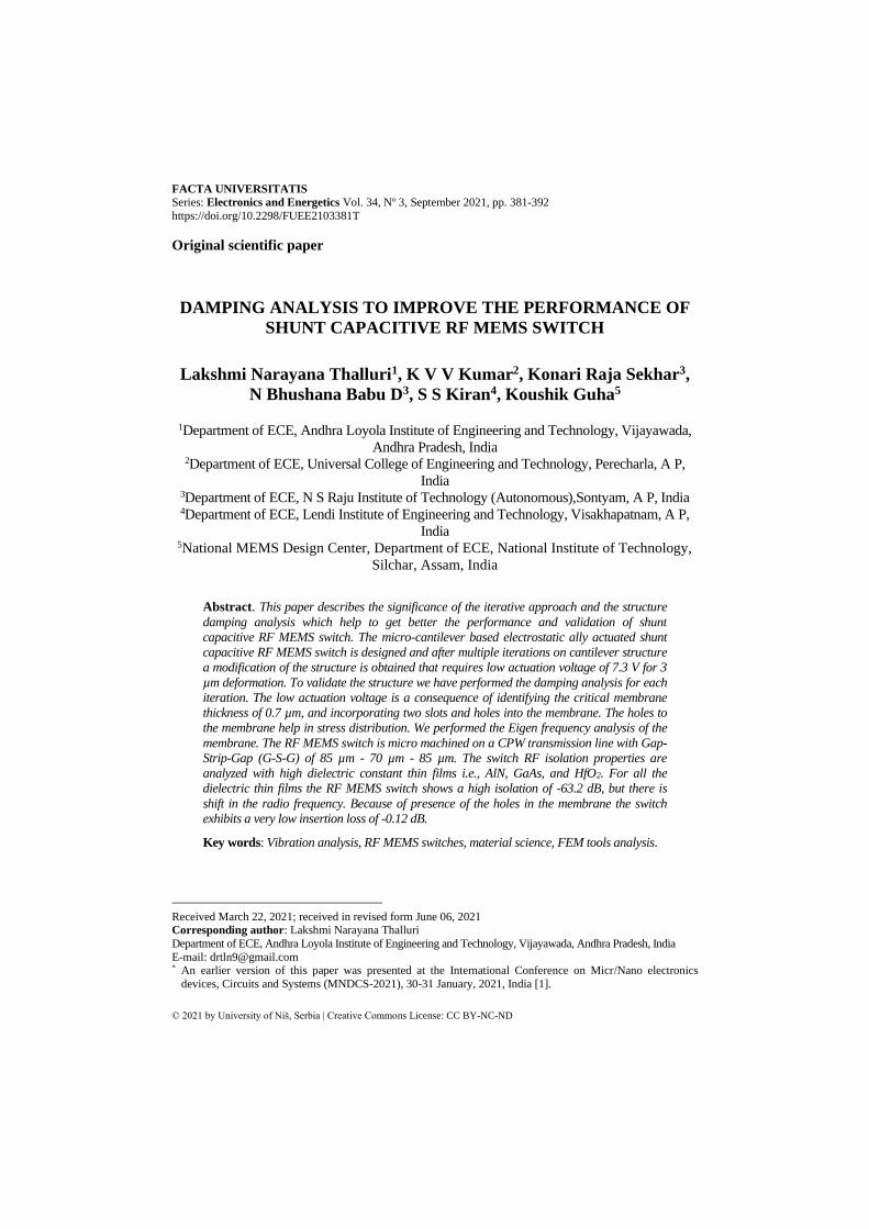
The rectangular cantilever critical stress analysis is indispensable because it primarily
determines the switch reliability. The critical stress (σc) in terms of cantilever dimensions
and the Young's modulus (E) can be expresses as [14],
2 2
248 (1 )c
Et
l
=
− (1)
Fig. 1 Cantilever membrane
Damping Analysis to Improve the Performance of Shunt Capacitive RF MEMS Switch 383
For the cantilever membrane as shown in Fig. 1, the stiffness is equal to that of the
spring constant (K). The mathematical equation can be given as [15],
3
34
EWtK
l= (2)
The resonant frequency of the cantilever membrane can be written as
0 1
2 2r
Kf
m
= = (3)
Where, m denotes membrane mass is given as m=ρ*l*w*t. The time required for the MEMS
switch to come from the up state to the down state is known as the switching time. For an
electrostatically actuated MEMS switch, the switching time can be expressed as
0
3.67pull in
s
s
Vt
V
− (4)
The capacitive switch insertion and the isolation properties truly depend on the switch
capacitance ratio. The RF MEMS switch upstate and down state capacitance can be expresses
as [16],
0
1
up
d
r
AC
tg
=
+
(5)
0 r
down
d
AC
t
= (6)
'A' is the cross sectional area among the membrane and the CPW strip, and ‘td’ is the
dielectric thin film thickness. In terms of the return loss and the upstate and downstate
capacitance the insertion losses (S21) can be expressed as
2
2
21 2
11
1 up
down
CS
CS
=
(7)
The isolation losses (S21) depend on the characteristic impedance and the RF frequency
(f0) of the switch and can be expressed as
02 2 2
0
22
21 02
0
2 2
02
0
4
4
4
down
s
for f fC Z
RS for f f
Z
Lfor f f
Z
=
(8)
384 L. N. THALLURI, K V V KUMAR, K. R. SEKHAR, N B BABU D.3, S S KIRAN, K. GUHA
4. MEMBRANE ITERATIVE ANALYSIS
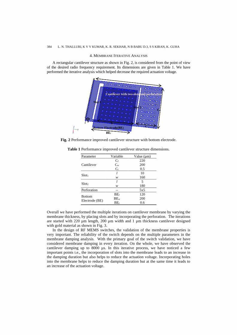
A rectangular cantilever structure as shown in Fig. 2, is considered from the point of view
of the desired radio frequency requirement. Its dimensions are given in Table 1. We have
performed the iterative analysis which helped decrease the required actuation voltage.
Fig. 2 Performance improved cantilever structure with bottom electrode.
Table 1 Performance improved cantilever structure dimensions.
Parameter Variable Value (µm)
Cantilever
Cl 220
Cw 200
Ct 0.5
Slot1 l 10
w 160
Slot2 l 5
w 180
Perforation -- 5x5
Bottom
Electrode (BE)
BEl 120
BEw 200
BEt 0.6
Overall we have performed the multiple iterations on cantilever membrane by varying the membrane thickness, by placing slots and by incorporating the perforation. The iterations are started with 220 µm length, 200 µm width and 1 µm thickness cantilever designed with gold material as shown in Fig. 3.
In the design of RF MEMS switches, the validation of the membrane properties is very important. The reliability of the switch depends on the multiple parameters in the membrane damping analysis. With the primary goal of the switch validation, we have considered membrane damping in every iteration. On the whole, we have observed the cantilever damping up to 8000 µs. In this iterative process, we have noticed a few important points i.e., the incorporation of slots into the membrane leads to an increase in the damping duration but also helps to reduce the actuation voltage. Incorporating holes into the membrane helps to reduce the damping duration but at the same time it leads to an increase of the actuation voltage.
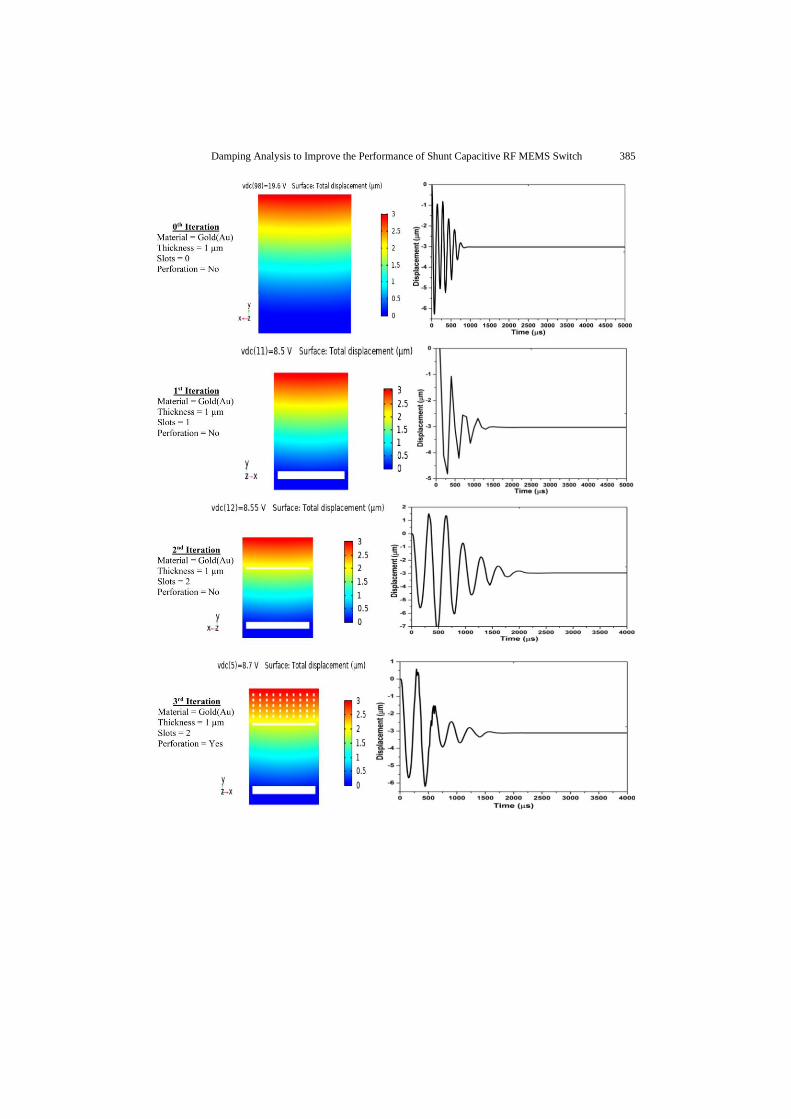
Damping Analysis to Improve the Performance of Shunt Capacitive RF MEMS Switch 385
386 L. N. THALLURI, K V V KUMAR, K. R. SEKHAR, N B BABU D.3, S S KIRAN, K. GUHA
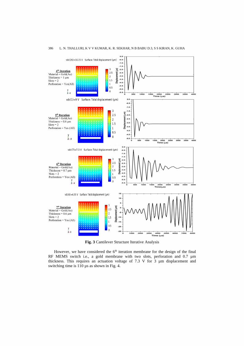
Fig. 3 Cantilever Structure Iterative Analysis
However, we have considered the 6th iteration membrane for the design of the final
RF MEMS switch i.e., a gold membrane with two slots, perforation and 0.7 µm
thickness. This requires an actuation voltage of 7.3 V for 3 µm displacement and
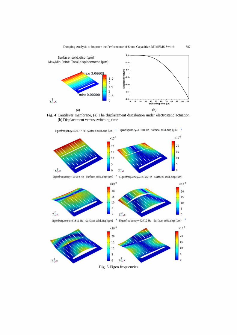
switching time is 110 µs as shown in Fig. 4.
Damping Analysis to Improve the Performance of Shunt Capacitive RF MEMS Switch 387
(a) (b)
Fig. 4 Cantilever membrane, (a) The displacement distribution under electrostatic actuation,
(b) Displacement versus switching time
Fig. 5 Eigen frequencies
388 L. N. THALLURI, K V V KUMAR, K. R. SEKHAR, N B BABU D.3, S S KIRAN, K. GUHA
In the RF MEMS switch performance analysis, Eigen frequencies help to analyze the
deformation of the membrane during electrostatic actuation as shown in Fig.5. The real
advantage of introducing holes into the membrane is that it helps to improve the insertion
properties of the switch. This facilitates the electrostatic actuation and at the same time
the holes make the release of the membrane during the fabrication process easier. The
membrane thickness reduction helps reduce the required actuation voltage but up to some
level the damping duration becomes limited. However, if the membrane thickness is
below 0.7 µm, the membrane damping duration exceeds the limits. In the 7th iteration,
we have notices that for a 0.6 µm thickness the membrane undergoes continuous damping
which will lead to membrane collapse. So eventually, we have taken the membrane with
0.7 µm thickness which requires 7.3 V for a 3 µm displacement. The designed membrane
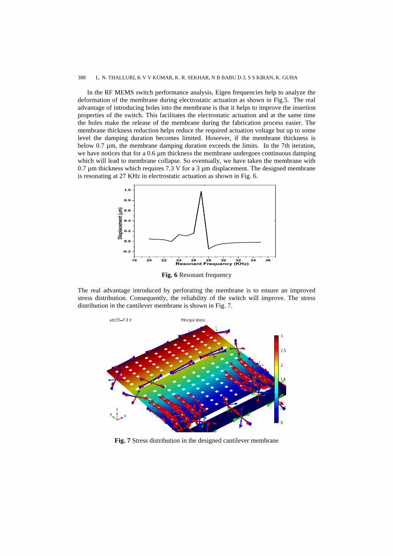
is resonating at 27 KHz in electrostatic actuation as shown in Fig. 6.
Fig. 6 Resonant frequency
The real advantage introduced by perforating the membrane is to ensure an improved
stress distribution. Consequently, the reliability of the switch will improve. The stress
distribution in the cantilever membrane is shown in Fig. 7.
Fig. 7 Stress distribution in the designed cantilever membrane
Damping Analysis to Improve the Performance of Shunt Capacitive RF MEMS Switch 389
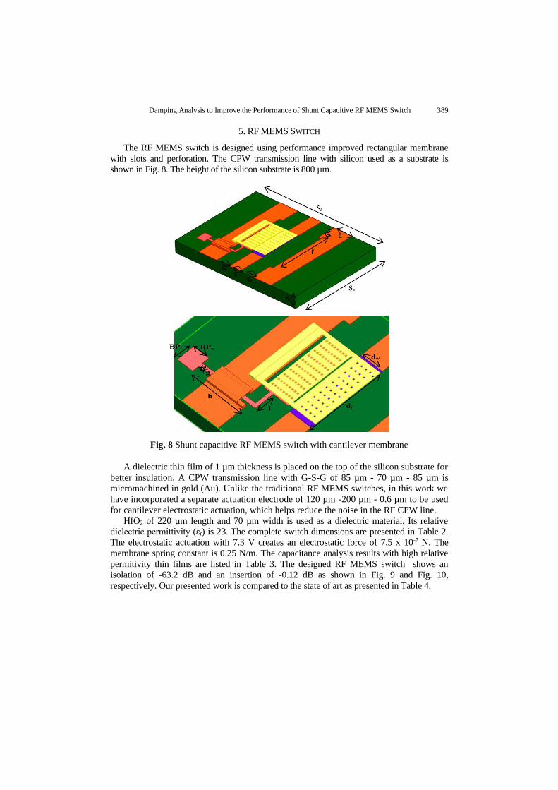
5. RF MEMS SWITCH
The RF MEMS switch is designed using performance improved rectangular membrane
with slots and perforation. The CPW transmission line with silicon used as a substrate is
shown in Fig. 8. The height of the silicon substrate is 800 µm.
Fig. 8 Shunt capacitive RF MEMS switch with cantilever membrane
A dielectric thin film of 1 µm thickness is placed on the top of the silicon substrate for
better insulation. A CPW transmission line with G-S-G of 85 µm - 70 µm - 85 µm is
micromachined in gold (Au). Unlike the traditional RF MEMS switches, in this work we
have incorporated a separate actuation electrode of 120 µm -200 µm - 0.6 µm to be used
for cantilever electrostatic actuation, which helps reduce the noise in the RF CPW line.
HfO2 of 220 µm length and 70 µm width is used as a dielectric material. Its relative
dielectric permittivity (εr) is 23. The complete switch dimensions are presented in Table 2.
The electrostatic actuation with 7.3 V creates an electrostatic force of 7.5 x 10⁻⁷ N. The
membrane spring constant is 0.25 N/m. The capacitance analysis results with high relative
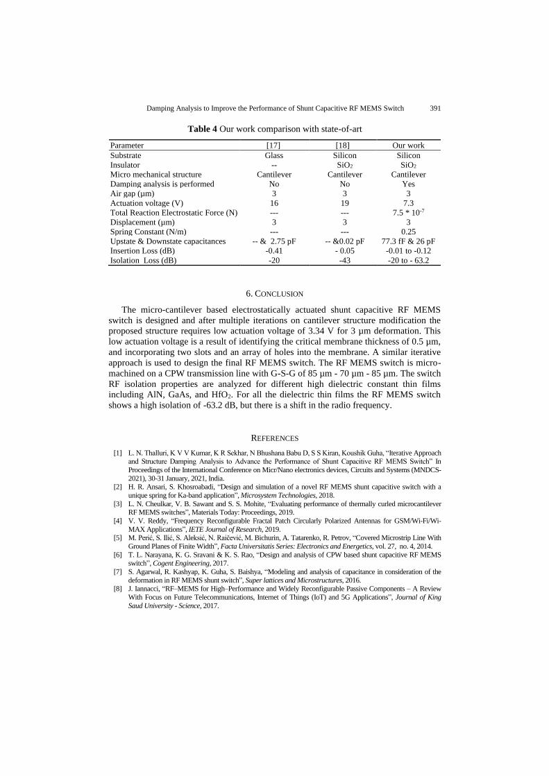
permitivity thin films are listed in Table 3. The designed RF MEMS switch shows an
isolation of -63.2 dB and an insertion of -0.12 dB as shown in Fig. 9 and Fig. 10,
respectively. Our presented work is compared to the state of art as presented in Table 4.
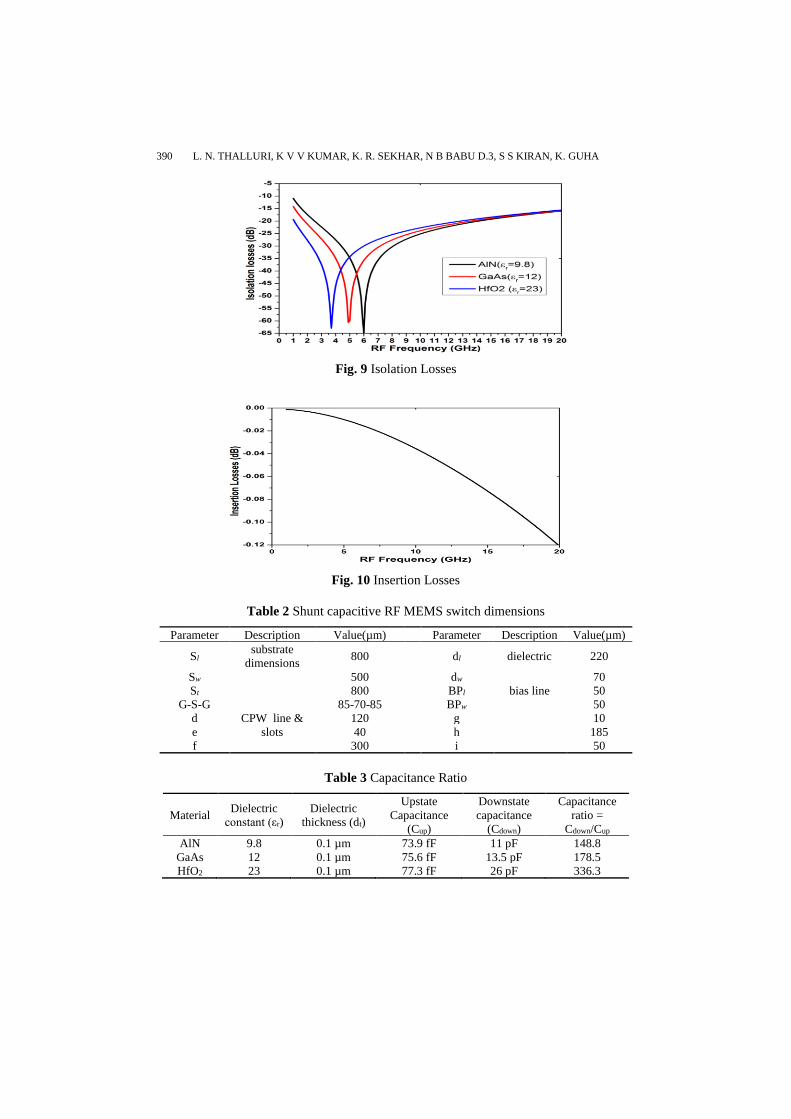
390 L. N. THALLURI, K V V KUMAR, K. R. SEKHAR, N B BABU D.3, S S KIRAN, K. GUHA
Fig. 9 Isolation Losses
Fig. 10 Insertion Losses
Table 2 Shunt capacitive RF MEMS switch dimensions
Parameter Description Value(µm) Parameter Description Value(µm)
Sl substrate
dimensions 800 dl dielectric 220
Sw 500 dw 70
St 800 BPl bias line 50
G-S-G
CPW line &
slots
85-70-85 BPw 50
d 120 g 10
e 40 h 185
f 300 i 50
Table 3 Capacitance Ratio
Material Dielectric
constant (εr)
Dielectric
thickness (dt)
Upstate
Capacitance
(Cup)
Downstate
capacitance
(Cdown)
Capacitance
ratio =
Cdown/Cup
AlN 9.8 0.1 µm 73.9 fF 11 pF 148.8
GaAs 12 0.1 µm 75.6 fF 13.5 pF 178.5
HfO2 23 0.1 µm 77.3 fF 26 pF 336.3
Damping Analysis to Improve the Performance of Shunt Capacitive RF MEMS Switch 391
Table 4 Our work comparison with state-of-art
Parameter [17] [18] Our work
Substrate Glass Silicon Silicon
Insulator -- SiO2 SiO2
Micro mechanical structure Cantilever Cantilever Cantilever
Damping analysis is performed No No Yes
Air gap (µm) 3 3 3
Actuation voltage (V) 16 19 7.3
Total Reaction Electrostatic Force (N) --- --- 7.5 * 10-7
Displacement (µm) 3 3 3
Spring Constant (N/m) --- --- 0.25
Upstate & Downstate capacitances -- & 2.75 pF -- &0.02 pF 77.3 fF & 26 pF
Insertion Loss (dB) -0.41 - 0.05 -0.01 to -0.12
Isolation Loss (dB) -20 -43 -20 to - 63.2
6. CONCLUSION
The micro-cantilever based electrostatically actuated shunt capacitive RF MEMS
switch is designed and after multiple iterations on cantilever structure modification the
proposed structure requires low actuation voltage of 3.34 V for 3 µm deformation. This
low actuation voltage is a result of identifying the critical membrane thickness of 0.5 µm,
and incorporating two slots and an array of holes into the membrane. A similar iterative
approach is used to design the final RF MEMS switch. The RF MEMS switch is micro-
machined on a CPW transmission line with G-S-G of 85 µm - 70 µm - 85 µm. The switch
RF isolation properties are analyzed for different high dielectric constant thin films
including AlN, GaAs, and HfO2. For all the dielectric thin films the RF MEMS switch
shows a high isolation of -63.2 dB, but there is a shift in the radio frequency.
REFERENCES
[1] L. N. Thalluri, K V V Kumar, K R Sekhar, N Bhushana Babu D, S S Kiran, Koushik Guha, “Iterative Approach and Structure Damping Analysis to Advance the Performance of Shunt Capacitive RF MEMS Switch” In
Proceedings of the International Conference on Micr/Nano electronics devices, Circuits and Systems (MNDCS-
2021), 30-31 January, 2021, India. [2] H. R. Ansari, S. Khosroabadi, “Design and simulation of a novel RF MEMS shunt capacitive switch with a
unique spring for Ka-band application”, Microsystem Technologies, 2018.
[3] L. N. Cheulkar, V. B. Sawant and S. S. Mohite, “Evaluating performance of thermally curled microcantilever RF MEMS switches”, Materials Today: Proceedings, 2019.
[4] V. V. Reddy, “Frequency Reconfigurable Fractal Patch Circularly Polarized Antennas for GSM/Wi-Fi/Wi-
MAX Applications”, IETE Journal of Research, 2019. [5] M. Perić, S. Ilić, S. Aleksić, N. Raičević, M. Bichurin, A. Tatarenko, R. Petrov, “Covered Microstrip Line With
Ground Planes of Finite Width”, Facta Universitatis Series: Electronics and Energetics, vol. 27, no. 4, 2014.
[6] T. L. Narayana, K. G. Sravani & K. S. Rao, “Design and analysis of CPW based shunt capacitive RF MEMS switch”, Cogent Engineering, 2017.
[7] S. Agarwal, R. Kashyap, K. Guha, S. Baishya, “Modeling and analysis of capacitance in consideration of the
deformation in RF MEMS shunt switch”, Super lattices and Microstructures, 2016. [8] J. Iannacci, “RF–MEMS for High–Performance and Widely Reconfigurable Passive Components – A Review
With Focus on Future Telecommunications, Internet of Things (IoT) and 5G Applications”, Journal of King
Saud University - Science, 2017.
392 L. N. THALLURI, K V V KUMAR, K. R. SEKHAR, N B BABU D.3, S S KIRAN, K. GUHA
[9] J. Iannacci, “RF-MEMS technology as an enabler of 5G: Low-loss ohmic switch tested up to 110 GHz”, Sensors and Actuators A, vol. 279, pp. 624–629, 2018.
[10] T. Ciric, Z. Marinković, R. Dhuri, O. Pronić-Rančić, V. Marković, “Hybrid Neural Lumped Element Approach
In Inverse Modeling Of RF MEMS Switches”, Facta Universitatis Series: Electronics and Energetics, vol. 33 no. 1, 2020.
[11] H. Kuisma, A. Cardoso, T. Braun, “Fan-out wafer-level packaging as packaging technology for MEMS”, 2020.
[12] R. Laishram, O. P. Thakur, D. K. Bhattacharya, Harsh, Anshu Goyal, Renu Sharma, Jagbir Singh, and Ramjay Pal, “Low Temperature Deposited BST Thin Films for RF MEMS Switch”, Integrated Ferroelectrics, vol. 116,
pp. 35–40, 2010.
[13] I. Tittonen, M. Koskenvuori, “Electrostatic and RF-properties of MEMS structures”, Silicon Based MEMS
Materials and Technologies, 2020.
[14] T. Singh, A. Elhady, H. Jia, A. Mojdeh, C. Kaplan, V. Sharma, M. Basha, E. Abdel-Rahman, “Modeling of
low-damping laterally actuated electrostatic MEMS”, Mechatronics, vol. 52, 2018. [15] T. Zengerle, J. Joppich, P. Schwarz, A. Ababneh, H. Seidel, “Modeling the damping mechanism of MEMS
oscillators in the transitional flow regime with thermal waves”, Sensors and Actuators: A. Physical, 2020.
[16] J. Kaczynski, C. Ranacher, C. Fleury, “Computationally efficient model for viscous damping in perforated MEMS structures”, Sensors and Actuators A, vol. 314, 2020.
[17] M. Angira, D. Bansal, P. Kumar, K. Mehta, K. Rangra, “A novel capacitive RF-MEMS switch for multi-
frequency operation”, Superlattices and Microstructures, vol. 133, 2019. [18] O. Pertin, Kurmendra, “Pull-in-voltage and RF analysis of MEMS based high performance capacitive shunt
switch”, Microelectronics Journal, vol. 77, 2018.


