Embed Size (px)
Citation preview

Post Construction Storm Water Management - Structural BMP’s Course No: C10-001
Credit: 10 PDH
Gilbert Gedeon, P.E.
Continuing Education and Development, Inc.22 Stonewall CourtWoodcliff Lake, NJ 07677
P: (877) [email protected]

Post-Construction Storm Water Management in New Development and Redevelopment
Regulatory Text
• You must develop, implement, and enforce a program to address storm water runoff from new development and redevelopment projects that disturb greater than or equal to one acre, including projects less than one acre that are part of a larger common plan of development or sale, that discharge into your small MS4. Your program must ensure that controls are in place that would prevent or minimize water quality impacts.
• You must:
o Develop and implement strategies which include a combination of structural and/or non-structural best management practices (BMPs) appropriate for your community;
o Use an ordinance or other regulatory mechanism to address post-construction runoff from new development and redevelopment projects to the extent allowable under State, Tribal or local law;
o Ensure adequate long-term operation and maintenance of BMPs.
Guidance
If water quality impacts are considered from the beginning stages of a project, new development and potentially redevelopment provide more opportunities for water quality protection. EPA recommends that the BMPs chosen: be appropriate for the local community; minimize water quality impacts; and attempt to maintain pre-development runoff conditions. In choosing appropriate BMPs, EPA encourages you to participate in locally-based watershed planning efforts which attempt to involve a diverse group of stakeholders including interested citizens. When developing a program that is consistent with this measure's intent, EPA recommends that you adopt a planning process that identifies the municipality's program goals (e.g., minimize water quality impacts resulting from post-construction runoff from new development and redevelopment), implementation strategies (e.g., adopt a combination of structural and/or non-structural BMPs), operation and maintenance policies and procedures, and enforcement procedures. In developing your program, you should consider assessing existing ordinances, policies, programs and studies that address storm water runoff quality. In addition to assessing these existing documents and programs, you should provide opportunities to the public to participate in the development of the program. Non-structural BMPs are preventative actions that involve management and source controls such as: policies and ordinances that provide requirements and standards to direct growth to identified areas, protect sensitive areas such as wetlands and riparian areas, maintain and/or increase open space (including a dedicated funding source for open space acquisition), provide buffers along sensitive water bodies, minimize impervious surfaces, and minimize disturbance of soils and vegetation; policies or ordinances that encourage infill development in higher density urban areas, and areas with existing infrastructure; education programs for developers and the public about project designs that minimize water quality impacts; and measures such as minimization of percent impervious area

National Menu for BMP Practices Post-Construction Storm Water Management
2
after development and minimization of directly connected impervious areas. Structural BMPs include: storage practices such as wet ponds and extended-detention outlet structures; filtration practices such as grassed swales, sand filters and filter strips; and infiltration practices such as infiltration basins and infiltration trenches. EPA recommends that you ensure the appropriate implementation of the structural BMPs by considering some or all of the following: pre-construction review of BMP designs; inspections during construction to verify BMPs are built as designed; post-construction inspection and maintenance of BMPs; and penalty provisions for the noncompliance with design, construction or operation and maintenance. Storm water technologies are constantly being improved, and EPA recommends that your requirements be responsive to these changes, developments or improvements in control technologies.
BMP Fact Sheets
Structural BMPs
Ponds
Dry extended detention ponds
Wet ponds
Infiltration practices
Infiltration basin
Infiltration trench
Porous pavement
Filtration practices
Bioretention
Sand and organic filters
Vegetative practices
Storm water wetland
Grassed swales
Grassed filter strip
Runoff pretreatment practices
Catch basin
In-line storage
Manufactured products for storm water inlets

National Menu for BMP Practices Post-Construction Storm Water Management
3
Nonstructural BMPs
Experimental practices
Alum injection
On-lot Treatment
On-Lot treatment
Better site design
Buffer zones
Open space design
Urban forestry
Conservation easements
Infrastructure planning
Narrower residential streets
Eliminating curbs and gutters
Green parking
Alternative turnarounds
Alternative pavers
BMP inspection and maintenance
Ordinances for postconstruction runoff
Zoning
Additional Fact Sheets
Bioretention
Hydrodynamic Separators
Infiltration Drainfields
Infiltration Trench
Modular Treatment System
Porous Pavement
Sand Filters
Storm Water Wetlands

National Menu for BMP Practices Post-Construction Storm Water Management
4
Vegetative Swales
Water Quality Inlets
Wet Detention Ponds

National Menu for BMP Practices Post-Construction Storm Water Management
5
Structural BMPs
Ponds
Dry Extended Detention Pond
Postconstruction Storm Water Management in New Development and Redevelopment
Description
Dry extended detention ponds (a.k.a. dry ponds, extended detention basins, detention ponds, extended detention ponds) are basins whose outlets have been designed to detain the storm water runoff from a water quality design storm for some minimum time (e.g., 24 hours) to allow particles and associated pollutants to settle. Unlike wet ponds, these facilities do not have a large permanent pool. However, they are often designed with small pools at the inlet and outlet of the basin. They can also be used to provide flood control by including additional flood detention storage.
Applicability
Dry extended detention ponds are among the most widely applicable storm water management practices. Although they have limited applicability in highly urbanized settings, they have few other restrictions.
Regional Applicability
Dry extended detention ponds can be applied in all regions of the United States. Some minor design modifications might be needed, however, in cold or arid climates or in regions with karst (i.e. limestone) topography.
Ultra-Urban Areas
Ultra-urban areas are densely developed urban areas in which little pervious surface is present. It is difficult to use dry extended detention ponds in the ultra-urban environment because of the land area each pond consumes. They can, however, be used in an ultra-urban environment if a relatively large area is available downstream of the pond.
Storm Water Hot Spots
Storm water hot spots are areas where land use or activities generate highly contaminated runoff, with concentrations of pollutants in excess of those typically found in storm water. Dry extended

National Menu for BMP Practices Post-Construction Storm Water Management
6
detention ponds can accept runoff from storm water hot spots, but they need significant separation from ground water if they will be used for this purpose.
Storm Water Retrofit
A storm water retrofit is a storm water management practice (usually structural) put into place after development has occurred to improve water quality, protect downstream channels, reduce flooding, or meet other specific objectives. Dry extended detention ponds are very useful storm water retrofits, and they have two primary applications as a retrofit design. In many communities in the past, detention basins have been designed for flood control. It is possible to modify these facilities to incorporate features that encourage water quality control and/or channel protection. It is also possible to construct new dry ponds in open areas of a watershed to capture existing drainage.
Cold Water (Trout) Streams
A study in Prince George's County, Maryland, found that storm water management practices can increase stream temperatures (Galli, 1990). Overall, dry extended detention ponds increased temperature by about 5°F. In cold water streams, dry ponds should be designed to detain storm water for a relatively short time (i.e., less than 12 hours) to minimize the amount of warming that occurs in the practice.
Siting and Design Considerations
Siting Considerations
Although dry extended detention ponds can be applied rather broadly, designers need to ensure that they are feasible at the site in question. This section provides basic guidelines for siting dry extended detention ponds.
Drainage Area
In general, dry extended detention ponds should be used on sites with a minimum area of 10 acres. On smaller sites, it can be challenging to provide channel or water quality control because the orifice diameter at the outlet needed to control relatively small storms becomes very small and thus prone to clogging. In addition, it is generally more cost-effective to control larger drainage areas due to the economies of scale (see Cost Considerations).
Slope
Dry extended detention basins can be used on sites with slopes up to about 15 percent. The local slope needs to be relatively flat, however, to maintain reasonably flat side slopes in the practice. There is no minimum slope requirement, but there does need to be enough elevation drop from the pond inlet to the pond outlet to ensure that flow can move through the system.
Soils / Topography
Extended detention basins can be used with almost all soils and geology, with minor design adjustments for regions of karst topography or in rapidly percolating soils such as sand. In these areas, extended detention ponds should be designed with an impermeable liner to prevent ground water contamination or sinkhole formation.

National Menu for BMP Practices Post-Construction Storm Water Management
7
Ground Water
Except for the case of hot spot runoff, the only consideration regarding ground water is that the base of the extended detention facility should not intersect the ground water table. A permanently wet bottom may become a mosquito breeding ground. Research in Southwest Florida (Santana et al., 1994) demonstrated that intermittently flooded systems, such as dry extended detention ponds, produce more mosquitoes than other pond systems, particularly when the facilities remained wet for more than 3 days following heavy rainfall.
Design Considerations
Specific designs may vary considerably, depending on site constraints or preferences of the designer or community. Some features, however, should be incorporated into most dry extended detention pond designs. These design features can be divided into five basic categories: pretreatment, treatment, conveyance, maintenance reduction, and landscaping.
Pretreatment
Pretreatment incorporates design features that help to settle out coarse sediment particles. By removing these particles from runoff before they reach the large permanent pool, the maintenance burden of the pond is reduced. In ponds, pretreatment is achieved with a sediment forebay, which is a small pool (typically about 10 percent of the volume of water to be treated for pollutant removal).
Treatment
Treatment design features help enhance the ability of a storm water management practice to remove pollutants. Designing dry ponds with a high length-to-width ratio (i.e., at least 1.5:1) and incorporating other design features to maximize the flow path effectively increases the detention time in the system by eliminating the potential of flow to short-circuit the pond. Designing ponds with relatively flat side slopes can also help to lengthen the effective flow path. Finally, the pond should be sized to detain the volume of runoff to be treated for between 12 and 48 hours.
Conveyance
Conveyance of storm water runoff into and through a storm water management practice is a critical component of any such practice. Storm water should be conveyed to and from practices safely in a manner that minimizes erosion potential. The outfall of pond systems should always be stabilized to prevent scour. To convey low flows through the system, designers should provide a pilot channel. A pilot channel is a surface channel that should be used to convey low flows through the pond. In addition, an emergency spillway should be provided to safely convey large flood events. To help mitigate warming at the outlet channel, designers should provide shade around the channel at the pond outlet.
Maintenance Reduction
In addition to regular maintenance activities needed to maintain the function of storm water practices, some design features can be incorporated to ease the maintenance burden of each practice. In dry extended detention ponds, a "micropool" at the outlet can prevent resuspension of sediment and outlet clogging. A good design includes maintenance access to the forebay and micropool.

National Menu for BMP Practices Post-Construction Storm Water Management
8
Another design feature that can reduce maintenance needs is a non-clogging outlet. Typical examples include a reverse-slope pipe or a weir outlet with a trash rack. A reverse slope pipe draws from below the permanent pool extending in a reverse angle up to the riser and determines the water elevation of the micropool. Because these outlets draw water from below the level of the permanent pool, they are less likely to be clogged by floating debris.
Landscaping
Designers should maintain a vegetated buffer around the pond and should select plants within the extended detention zone (i.e., the portion of the pond up to the elevation where storm water is detained) that can withstand both wet and dry periods. The side slopes of dry ponds should be relatively flat to reduce safety risks.
Design Variations
Dry Detention Ponds
Dry detention ponds are similar in design to extended detention ponds, except that they do not incorporate features to improve water quality. In particular, these practices do not detain storm water from small-flow events. Therefore, detention ponds provide almost no pollutant removal. However, dry ponds can help to meet flood control, and sometimes channel protection, objectives in a watershed.
Tank Storage
Another variation of the dry detention pond design is the use of tank storage. In these designs, storm water runoff is conveyed to large storage tanks or vaults underground. This practice is most often used in the ultra-urban environment, on small sites where no other opportunity is available to provide flood control. Tank storage is provided on small areas because providing underground storage for a large drainage area would generally be cost-prohibitive. Because the drainage area contributing to tank storage is typically small, the outlet diameter needed to reduce the flow from very small storms would very small. A very small outlet diameter, along with the underground location of the tanks, creates the potential for debris being caught in the outlet and resulting maintenance problems. Since it is necessary to control small runoff events (such as the runoff from a 1-inch storm) to improve water quality, it is generally infeasible to use tank storage for water quality and generally impractical to use it to protect stream channels.
Regional Variations
Arid or Semi-Arid Climates
In arid and semi-arid regions, some modifications might be needed to conserve scarce water resources. Any landscaping plans should prescribe drought-tolerant vegetation wherever possible. In addition, the wet forebay can be replaced with an alternative dry pretreatment, such as a detention cell. One opportunity in regions with a distinct wet and dry season, as in many arid regions, is to use regional extended detention ponds as a recreation area such as a ball field during the dry season.

National Menu for BMP Practices Post-Construction Storm Water Management
9
Cold Climates
In cold climates, some additional design features can help to treat the spring snowmelt. One such modification is to increase the volume available for detention to help treat this relatively large runoff event. In some cases, dry facilities may be an option as a snow storage facility to promote some treatment of plowed snow. If a pond is used to treat road runoff or is used for snow storage, landscaping should incorporate salt-tolerant species. Finally, sediment might need to be removed from the forebay more frequently than in warmer climates (see Maintenance Considerations for guidelines) to account for sediment deposited as a result of road sanding.
Limitations
Although dry extended detention ponds are widely applicable, they have some limitations that might make other storm water management options preferable:
• Dry extended detention ponds have only moderate pollutant removal when compared to other structural storm water practices, and they are ineffective at removing soluble pollutants (See Effectiveness).
• Dry extended detention ponds may become a nuisance due to mosquito breeding.
• Habitat destruction may occur during construction if the practice is designed in-stream or within the stream buffer.
• Although wet ponds can increase property values, dry ponds can actually detract from the value of a home (see Cost Considerations).
Dry extended detention ponds on their own only provide peak flow reduction and do little to control overall runoff volume, which could result in adverse downstream impacts.
Maintenance Considerations
In addition to incorporating features into the pond design to minimize maintenance, some regular maintenance and inspection practices are needed. Table 1 outlines some of these practices.
Effectiveness
Structural management practices can be used to achieve four broad resource protection goals: flood control, channel protection, ground water recharge, and pollutant removal. Dry extended detention basins can provide flood control and channel protection, as well as some pollutant removal.
Flood Control
One objective of storm water management practices can be to reduce the flood hazard associated with large storm events by reducing the peak flow associated with these storms. Dry extended detention basins can easily be designed for flood control, and this is actually the primary purpose of most extended detention ponds.

National Menu for BMP Practices Post-Construction Storm Water Management
10
Table 1. Typical maintenance activities for dry ponds (Source: Modified from WMI, 1997)
Activity Schedule
• Note erosion of pond banks or bottom Semiannual inspection
• Inspect for damage to the embankment • Monitor for sediment accumulation in the facility and
forebay • Examine to ensure that inlet and outlet devices are free of
debris and operational
Annual inspection
• Repair undercut or eroded areas • Mow side slopes • Manage pesticide and nutrients • Remove litter and debris
Standard maintenance
• Seed or sod to restore dead or damaged ground cover Annual maintenance
(as needed)
• Remove sediment from the forebay 5- to 7-year maintenance
• Monitor sediment accumulations, and remove sediment when the pond volume has been reduced by 25 percent 25- to 50-year maintenance
Channel Protection
One result of urbanization is the geomorphic changes that occur in response to modified hydrology. Traditionally, dry extended detention basins have provided control of the 2-year storm (i.e., the storm that occurs, on average, once every 2 years) for channel protection. It appears that this control has been relatively ineffective, and recent research suggests that control of a smaller storm might be more appropriate (MacRae, 1996). Slightly modifying the design of dry extended detention basins to reduce the flow of smaller storm events might make them effective tools in reducing downstream erosion.
Pollutant Removal
Dry extended detention basins provide moderate pollutant removal, provided that the design features described in the Siting and Design Considerations section are incorporated. Although they can be effective at removing some pollutants through settling, they are less effective at removing soluble pollutants because of the absence of a permanent pool. A few studies are available on the effectiveness of dry extended detention ponds. Typical removal rates, as reported by Schueler (1997), are as follows:
Total suspended solids: 61% Total phosphorus: 19% Total nitrogen: 31% Nitrate nitrogen: 9% Metals: 26%–54%
There is considerable variability in the effectiveness of ponds, and it is believed that properly designing and maintaining ponds may help to improve their performance. The siting and design criteria presented in this sheet reflect the best current information and experience to improve the

National Menu for BMP Practices Post-Construction Storm Water Management
11
performance of wet ponds. A recent joint project of the American Society of Civil Engineers (ASCE) and the USEPA Office of Water might help to isolate specific design features that can improve performance. The National Storm Water Best Management Practice (BMP) database is a compilation of storm water practices that includes both design information and performance data for various practices. As the database expands, inferences about the extent to which specific design criteria influence pollutant removal may be made. For more information on this database, access the ASCE web page at http://www.asce.org.
Cost Considerations
Dry extended detention ponds are the least expensive storm water management practice, on the basis of cost per unit area treated. The construction costs associated with these facilities range considerably. One recent study evaluated the cost of all pond systems (Brown and Schueler, 1997). Adjusting for inflation, the cost of dry extended detention ponds can be estimated with the equation
C = 12.4V0.760
where:
C = Construction, design, and permitting cost, and
V = Volume needed to control the 10-year storm (ft3).
Using this equation, typical construction costs are
$ 41,600 for a 1 acre-foot pond
$ 239,000 for a 10 acre-foot pond
$ 1,380,000 for a 100 acre-foot pond
Interestingly, these costs are generally slightly higher than the cost of wet ponds on a cost per total volume basis. Dry extended detention ponds are generally less expensive on a given site, however, because they are usually smaller than a wet pond design for the same site.
Ponds do not consume a large area compared to the total area treated (typically 2 to 3 percent of the contributing drainage area). It is important to note, however, that each pond is generally large. Other practices, such as filters or swales, may be "squeezed in" on relatively unusable land, but ponds need a relatively large continuous area.
For ponds, the annual cost of routine maintenance is typically estimated at about 3 to 5 percent of the construction cost. Alternatively, a community can estimate the cost of the maintenance activities outlined in the maintenance section. Finally, ponds are long-lived facilities (typically longer than 20 years). Thus, the initial investment into pond systems can be spread over a relatively long time period.
Another economic concern associated with dry ponds is that they might detract slightly from the value of adjacent properties. One study found that dry ponds can actually detract from the perceived value of homes adjacent to a dry pond by between 3 and 10 percent (Emmerling-Dinovo, 1995).

National Menu for BMP Practices Post-Construction Storm Water Management
12
References
Design References:
Denver Urban Drainage and Flood Control District. 1992. Urban Storm Drainage Criteria Manual—Volume 3: Best Management Practices. Denver, CO.
Watershed Management Institute (WMI). 1997. Operation, Maintenance, and Management of Storm Water Management Systems. Prepared for U.S. Environmental Protection Agency, Office of Water. Washington, DC.
Other References:
Brown, W., and T. Schueler. 1997. The Economics of Storm Water BMPs in the Mid-Atlantic Region. Prepared for Chesapeake Research Consortium. Edgewater, MD. Center for Watershed Protection. Ellicott City, MD.
Emmerling-Dinovo, C. 1995. Storm Water Detention Basins and Residential Locational Decisions. Water Resources Bulletin 31(3): 515–521
Galli, J. 1990. Thermal Impacts Associated with Urbanization and Storm Water Management Best Management Practices. Metropolitan Washington Council of Governments. Prepared for Maryland Department of the Environment, Baltimore, MD.
MacRae, C. 1996. Experience from Morphological Research on Canadian Streams: Is Control of the Two-Year Frequency Runoff Event the Best Basis for Stream Channel Protection? In Effects of Watershed Development and Management on Aquatic Ecosystems. American Society of Civil Engineers. Edited by L. Roesner. Snowbird, UT. pp. 144–162.
Santana, F., J. Wood, R. Parsons, and S. Chamberlain. 1994. Control of Mosquito Breeding in Permitted Storm Water Systems. Prepared for Southwest Florida Water Management District, Brooksville, FL.
Schueler, T. 1997. Influence of Ground Water on Performance of Storm Water Ponds in Florida. Watershed Protection Techniques 2(4):525–528.
Information Resources
Center for Watershed Protection (CWP), Environmental Quality Resources, and Loiederman Associates. 1997. Maryland Storm Water Design Manual. Draft. Prepared for Maryland Department of the Environment, Baltimore, MD.
Center for Watershed Protection (CWP). 1997. Storm Water BMP Design Supplement for Cold Climates. Prepared for U.S. Environmental Protection Agency, Office of Wetlands, Oceans and Watersheds. Washington, DC.
U.S. Environmental Protection Agency (USEPA). 1993. Guidance Specifying Management Measures for Sources of Nonpoint Pollution in Coastal Waters. EPA-840-B-92-002. U.S. Environmental Protection Agency, Office of Water, Washington, DC.

National Menu for BMP Practices Post-Construction Storm Water Management
13
Wet Ponds
Postconstruction Storm Water Management in New Development and Redevelopment
Description
Wet ponds (a.k.a. storm water ponds, retention ponds, wet extended detention ponds) are constructed basins that have a permanent pool of water throughout the year (or at least throughout the wet season). Ponds treat incoming storm water runoff by settling and algal uptake. The primary removal mechanism is settling as storm water runoff resides in this pool, and pollutant uptake, particularly of nutrients, also occurs through biological activity in the pond. Wet ponds are among the most cost-effective and widely used storm water practices. While there are several different versions of the wet pond design, the most common modification is the extended detention wet pond, where storage is provided above the permanent pool in order to detain storm water runoff in order to provide settling.
Applicability
Wet ponds are widely applicable storm water management practices. Although they have limited applicability in highly urbanized settings and in arid climates, they have few other restrictions.
Regional Applicability
Wet extended detention ponds can be applied in most regions of the United States, with the exception of arid climates. In arid regions, it is difficult to justify the supplemental water needed to maintain a permanent pool because of the scarcity of water. Even in semi-arid Austin, Texas, one study found that 2.6 acre-feet per year of supplemental water was needed to maintain a permanent pool of only 0.29 acre-feet (Saunders and Gilroy, 1997). Other modifications and design variations are needed in semi-arid and cold climates, and karst (i.e., limestone) topography.
Ultra-Urban Areas
Ultra-urban areas are densely developed urban areas in which little pervious surface exists. It is difficult to use wet ponds in the ultra-urban environment because of the land area each pond consumes. They can, however, be used in an ultra-urban environment if a relatively large area is available downstream of the site.

National Menu for BMP Practices Post-Construction Storm Water Management
14
Storm Water Hot Spots
Storm water hot spots are areas where land use or activities generate highly contaminated runoff, with concentrations of pollutants in excess of those typically found in storm water. A typical example is a gas station. Wet ponds can accept runoff from storm water hot spots, but need significant separation from ground water if they will be used for this purpose.
Storm Water Retrofit
A storm water retrofit is a storm water management practice (usually structural) put into place after development has occurred, to improve water quality, protect downstream channels, reduce flooding, or meet other specific objectives. Wet ponds are very useful storm water retrofits and have two primary applications as a retrofit design. In many communities, detention ponds have been designed for flood control in the past. It is possible to modify these facilities to develop a permanent wet pool to provide water quality control (see Treatment under Design Considerations), and modify the outlet structure to provide channel protection. Alternatively, wet ponds may be designed in-stream, or in open areas as a part of a retrofit study.
Cold Water (Trout) Streams
Wet ponds pose a risk to cold water systems because of their potential for stream warming. When water remains in the permanent pool, it is heated by the sun. A study in Prince George's County, Maryland, found that storm water wet ponds heat storm water by about 9°F from the inlet to the outlet (Galli, 1990).
Siting and Design Considerations
Siting Considerations
In addition to the restrictions and modifications to adapting wet ponds to different regions and land uses, designers need to ensure that this management practice is feasible at the site in question. The following section provides basic guidelines for siting wet ponds.
Drainage Area
Wet ponds need sufficient drainage area to maintain the permanent pool. In humid regions, this is typically about 25 acres, but a greater area may be needed in regions with less rainfall.
Slope
Wet ponds can be used on sites with an upstream slope up to about 15 percent. The local slope should be relatively shallow, however. Although there is no minimum slope requirement, there does need to be enough elevation drop from the pond inlet to the pond outlet to ensure that water can flow through the system.
Soils / Topography
Wet ponds can be used in almost all soils and geology, with minor design adjustments for regions of karst topography (see Design Considerations).

National Menu for BMP Practices Post-Construction Storm Water Management
15
Ground Water
Unless they receive hot spot runoff, ponds can often intersect the ground water table. However, some research suggests that pollutant removal is reduced when ground water contributes substantially to the pool volume (Schueler, 1997b).
Design Considerations
Specific designs may vary considerably, depending on site constraints or preferences of the designer or community. There are some features, however, that should be incorporated into most wet pond designs. These design features can be divided into five basic categories: pretreatment, treatment, conveyance, maintenance reduction, and landscaping.
Pretreatment
Pretreatment incorporates design features that help to settle out coarse sediment particles. By removing these particles from runoff before they reach the large permanent pool, the maintenance burden of the pond is reduced. In ponds, pretreatment is achieved with a sediment forebay. A sediment forebay is a small pool (typically about 10 percent of the volume of the permanent pool). Coarse particles remain trapped in the forebay, and maintenance is performed on this smaller pool, eliminating the need to dredge the entire pond.
Treatment
Treatment design features help enhance the ability of a storm water management practice to remove pollutants. The purpose of most of these features is to increase the amount of time that storm water remains in the pond.
One technique of increasing the pollutant removal of a pond is to increase the volume of the permanent pool. Typically, ponds are sized to be equal to the water quality volume (i.e., the volume of water treated for pollutant removal). Designers may consider using a larger volume to meet specific watershed objectives, such as phosphorous removal in a lake system. Regardless of the pool size, designers need to conduct a water balance analysis to ensure that sufficient inflow is available to maintain the permanent pool.
Other design features do not increase the volume of a pond, but can increase the amount of time storm water remains in the practice and eliminate short-circuiting. Ponds should always be designed with a length-to-width ratio of at least 1.5:1. In addition, the design should incorporate features to lengthen the flow path through the pond, such as underwater berms designed to create a longer route through the pond. Combining these two measures helps ensure that the entire pond volume is used to treat storm water. Another feature that can improve treatment is to use multiple ponds in series as part of a "treatment train" approach to pollutant removal. This redundant treatment can also help slow the rate of flow through the system.
Conveyance
Storm water should be conveyed to and from all storm water management practices safely and to minimize erosion potential. The outfall of pond systems should always be stabilized to prevent scour. In addition, an emergency spillway should be provided to safely convey large flood

National Menu for BMP Practices Post-Construction Storm Water Management
16
events. To help mitigate warming at the outlet channel, designers should provide shade around the channel at the pond outlet.
Maintenance Reduction
In addition to regular maintenance activities needed to maintain the function of storm water practices, some design features can be incorporated to ease the maintenance burden of each practice. In wet ponds, maintenance reduction features include techniques to reduce the amount of maintenance needed, as well as techniques to make regular maintenance activities easier.
One potential maintenance concern in wet ponds is clogging of the outlet. Ponds should be designed with a non-clogging outlet such as a reverse-slope pipe, or a weir outlet with a trash rack. A reverse-slope pipe draws from below the permanent pool extending in a reverse angle up to the riser and establishes the water elevation of the permanent pool. Because these outlets draw water from below the level of the permanent pool, they are less likely to be clogged by floating debris. Another general rule is that no orifice should be less than 3 inches in diameter. (Smaller orifices are more susceptible to clogging).
Design features are also incorporated to ease maintenance of both the forebay and the main pool of ponds. Ponds should be designed with a maintenance access to the forebay to ease this relatively routine (5–7 year) maintenance activity. In addition, ponds should generally have a pond drain to draw down the pond for the more infrequent dredging of the main cell of the pond.
Landscaping
Landscaping of wet ponds can make them an asset to a community and can also enhance the pollutant removal of the practice. A vegetated buffer should be preserved around the pond to protect the banks from erosion and provide some pollutant removal before runoff enters the pond by overland flow. In addition, ponds should incorporate an aquatic bench (i.e., a shallow shelf with wetland plants) around the edge of the pond. This feature may provide some pollutant uptake, and it also helps to stabilize the soil at the edge of the pond and enhance habitat and aesthetic value.
Design Variations
There are several variations of the wet pond design. Some of these design alternatives are intended to make the practice adaptable to various sites and to account for regional constraints and opportunities.
Wet Extended Detention Pond
The wet extended detention pond combines the treatment concepts of the dry extended detention pond and the wet pond. In this design, the water quality volume is split between the permanent pool and detention storage provided above the permanent pool. During storm events, water is detained above the permanent pool and released over 12 to 48 hours. This design has similar pollutant removal to a traditional wet pond and consumes less space. Wet extended detention ponds should be designed to maintain at least half the treatment volume of the permanent pool. In addition, designers need to carefully select vegetation to be planted in the extended detention zone to ensure that the selected vegetation can withstand both wet and dry periods.

National Menu for BMP Practices Post-Construction Storm Water Management
17
Pocket Pond
In this design alternative, a pond drains a smaller area than a traditional wet pond, and the permanent pool is maintained by intercepting the ground water. While this design achieves less pollutant removal than a traditional wet pond, it may be an acceptable alternative on sites where space is at a premium, or in a retrofit situation.
Water Reuse Pond
Some designers have used wet ponds to act as a water source, usually for irrigation. In this case, the water balance should account for the water that will be taken from the pond. One study conducted in Florida estimated that a water reuse pond could provide irrigation for a 100-acre golf course at about one-seventh the cost of the market rate of the equivalent amount of water ($40,000 versus $300,000).
Regional Adaptations
Semi-Arid Climates
In arid climates, wet ponds are not a feasible option (see Applicability), but they may possibly be used in semi-arid climates if the permanent pool is maintained with a supplemental water source, or if the pool is allowed to vary seasonally. This choice needs to be seriously evaluated, however. Saunders and Gilroy (1997) reported that 2.6 acre-feet per year of supplemental water were needed to maintain a permanent pool of only 0.29 acre-feet in Austin, Texas.
Cold Climates
Cold climates present many challenges to designers of wet ponds. The spring snowmelt may have a high pollutant load and a large volume to be treated. In addition, cold winters may cause freezing of the permanent pool or freezing at inlets and outlets. Finally, high salt concentrations in runoff resulting from road salting, and sediment loads from road sanding, may impact pond vegetation as well as reduce the storage and treatment capacity of the pond.
One option to deal with high pollutant loads and runoff volumes during the spring snowmelt is the use of a seasonally operated pond to capture snowmelt during the winter, and retain the permanent pool during warmer seasons. In this option, proposed by Oberts (1994), the pond has two water quality outlets, both equipped with gate valves. In the summer, the lower outlet is closed. During the fall and throughout the winter, the lower outlet is opened to draw down the permanent pool. As the spring melt begins, the lower outlet is closed to provide detention for the melt event. This method can act as a substitute for using a minimum extended detention storage volume. When wetlands preservation is a downstream objective, seasonal manipulation of pond levels may not be desired. An analysis of the effects on downstream hydrology should be conducted before considering this option. In addition, the manipulation of this system requires some labor and vigilance; a careful maintenance agreement should be confirmed.
Several other modifications may help to improve the performance of ponds in cold climates. Designers should consider planting the pond with salt-tolerant vegetation if the facility receives road runoff. In order to counteract the effects of freezing on inlet and outlet structures, the use of inlet and outlet structures that are resistant to frost, including weirs and larger diameter pipes, may be useful. Designing structures on-line, with a continuous flow of water through the pond, will also help prevent freezing of these structures. Finally, since freezing of the permanent pool

National Menu for BMP Practices Post-Construction Storm Water Management
18
can reduce the effectiveness of pond systems, it may be useful to incorporate extended detention into the design to retain usable treatment area above the permanent pool when it is frozen.
Karst Topography
In karst (i.e., limestone) topography, wet ponds should be designed with an impermeable liner to prevent ground water contamination or sinkhole formation, and to help maintain the permanent pool.
Limitations
Limitations of wet ponds include:
• If improperly located, wet pond construction may cause loss of wetlands or forest.
• Although wet ponds consume a small amount of space relative to their drainage areas, they are often inappropriate in dense urban areas because each pond is generally quite large.
• Their use is restricted in arid and semi-arid regions due to the need to supplement the permanent pool.
• In cold water streams, wet ponds are not a feasible option due to the potential for stream warming.
• Wet ponds may pose safety hazards.
Maintenance Considerations
In addition to incorporating features into the pond design to minimize maintenance, some regular maintenance and inspection practices are needed. The table below outlines these practices.
Table 1. Typical maintenance activities for wet ponds (Source: WMI, 1997)
Activity Schedule
• If wetland components are included, inspect for invasive vegetation. Semi-annual inspection
• Inspect for damage. • Note signs of hydrocarbon build-up, and deal with appropriately. • Monitor for sediment accumulation in the facility and forebay. • Examine to ensure that inlet and outlet devices are free of debris
and operational.
Annual inspection
• Repair undercut or eroded areas. As needed maintenance
• Clean and remove debris from inlet and outlet structures. • Mow side slopes. Monthly maintenance
• Manage and harvest wetland plants. Annual maintenance (if needed)
• Remove sediment from the forebay. 5- to 7-year maintenance
• Monitor sediment accumulations, and remove sediment when the pool volume has become reduced significantly or the pond becomes eutrophic.
20-to 50-year maintenance

National Menu for BMP Practices Post-Construction Storm Water Management
19
Effectiveness
Structural storm water management practices can be used to achieve four broad resource protection goals. These include flood control, channel protection, ground water recharge, and pollutant removal. Wet ponds can provide flood control, channel protection, and pollutant removal.
Flood Control
One objective of storm water management practices can be to reduce the flood hazard associated with large storm events by reducing the peak flow associated with these storms. Wet ponds can easily be designed for flood control by providing flood storage above the level of the permanent pool.
Channel Protection
When used for channel protection, wet ponds have traditionally controlled the 2-year storm. It appears that this control has been relatively ineffective, and recent research suggests that control of a smaller storm may be more appropriate (MacRae, 1996).
Ground Water Recharge
Wet ponds cannot provide ground water recharge. Infiltration is impeded by the accumulation of debris on the bottom of the pond.
Pollutant Removal
Wet ponds are among the most effective storm water management practices at removing storm water pollutants. A wide range of research is available to estimate the effectiveness of wet ponds. Table 2 summarizes some of the research completed on wet pond removal efficiency. Typical removal rates, as reported by Schueler (1997a) are:
Total Suspended Solids: 67%
Total Phosphorous: 48%
Total Nitrogen: 31%
Nitrate Nitrogen: 24%
Metals: 24–73%
Bacteria: 65%

National Menu for BMP Practices Post-Construction Storm Water Management
20
Table 2. Wet pond percent removal efficiency data
Wet Pond Removal Efficiencies
Study TSS TP TN NO3 Metals Bacteria Practice Type
City of Austin, TX 1991. Woodhollow, TX 54 46 39 45 69–76 46 wet pond
Driscoll 1983. Westleigh, MD 81 54 37 - 26–82 - wet pond
Dorman et al., 1989. West Pond, MN 65 25 - 61 44–66 - wet pond
Driscoll, 1983. Waverly Hills, MI 91 79 62 66 57–95 - wet pond
Driscoll, 1983. Unqua, NY 60 45 - - 80 86 wet pond
Cullum, 1985. Timber Creek, FL 64 60 15 80 - - wet pond
City of Austin, TX 1996. St. Elmo, TX. 92 80 19 -17 2–58 89-91 wet pond
Horner, Guedry, and Kortenhoff, 1990. SR 204, WA 99 91 - - 88–90 - wet pond
Horner, Guedry, and Kortenhoff, 1990. Seattle, WA 86.7 78.4 - - 65–67 - wet pond
Kantrowitz and Woodham, 1995. Saint Joe's Creek, FL 45 45 - 36 38–82 - wet pond
Wu, 1989. Runaway Bay, NC 62 36 - - 32–52 - wet pond
Driscoll 1983. Pitt-AA, MI 32 18 - 7 13–62 - wet pond
Bannerman and Dodds, 1992. Monroe Street, WI 90 65 - - 65–75 70 wet pond
Horner, Guedry, and Kortenhoff, 1990. Mercer, WA 75 67 - - 23–51 - wet pond
Oberts, Wotzka, and Hartsoe 1989. McKnight, MN 85 48 30 24 67 - wet pond
Yousef, Wanielista, and Harper 1986. Maitland, FL - - - 87 77–96 - wet pond
Wu, 1989. Lakeside Pond, NC 93 45 - - 80–87 - wet pond
Oberts, Wotzka, and Hartsoe, 1989. Lake Ridge, MN 90 61 41 10 73 - wet pond

National Menu for BMP Practices Post-Construction Storm Water Management
21
Table 2. (continued)
Wet Pond Removal Efficiencies
Study TSS TP TN NO3 Metals Bacteria Practice Type
Driscoll, 1983. Lake Ellyn, IL 84 34 - - 71-78 - wet pond
Dorman et al., 1989. I-4, FL 54 69 - 97 47–74 - wet pond
Martin, 1988. Highway Site, FL 83 37 30 28 50–77 - wet pond
Driscoll, 1983. Grace Street, MI 32 12 6 -1 26 - wet pond
Occoquan Watershed Monitoring Laboratory, 1983. Farm Pond, VA 85 86 34 - - - wet pond
Occoquan Watershed Monitoring Laboratory, 1983. Burke, VA -33.3 39 32 - 38–84 - wet pond
Dorman et al., 1989. Buckland, CT 61 45 - 22 -25 to -51 - wet pond
Holler, 1989. Boynton Beach Mall, FL 91 76 - 87 - - wet pond
Urbonas, Carlson, and Vang 1994. Shop Creek, CO 78 49 -12 -85 51–57 - wet pond
Oberts and Wotzka, 1988. McCarrons, MN 91 78 85 - 90 - wet pond
Gain, 1996. FL 54 30 16 24 42–73 - wet pond
Ontario Ministry of the Environment, 1991. Uplands, Ontario
82 69 - - - 97 wet extended detention pond
Borden et al., 1996. Piedmont, NC 19.6 36.5 35.1 65.9 -4 to-97 -6 wet extended detention pond
Holler, 1990. Lake Tohopekaliga District, FL - 85 - - - - wet extended
detention pond
Ontario Ministry of the Environment 1991. Kennedy-Burnett, Ontario
98 79 54 - 21–39 99 wet extended detention pond
Ontario Ministry of the Environment 1991. East Barrhaven, Ontario
52 47 - - - 56 wet extended detention pond
Borden et al., 1996. Davis, NC 60.4 46.2 16 18.2 15–51 48 wet extended detention pond

National Menu for BMP Practices Post-Construction Storm Water Management
22
detention pond
There is considerable variability in the effectiveness of ponds, and it is believed that properly designing and maintaining ponds may help to improve their performance. The siting and design criteria presented in this sheet reflect the best current information and experience to improve the performance of wet ponds. A recent joint project of the American Society of Civil Engineers (ASCE) and the USEPA Office of Water may help to isolate specific design features that can improve performance. The National Stormwater Best Management Practice (BMP) database is a compilation of storm water practices which includes both design information and performance data for various practices. As the database expands, inferences about the extent to which specific design criteria influence pollutant removal may be made. More information on this database is available from the ASCE web page at www.asce.org.
Cost Considerations
Wet ponds are relatively inexpensive storm water practices. The construction costs associated with these facilities range considerably. A recent study (Brown and Schueler, 1997) estimated the cost of a variety of storm water management practices. The study resulted in the following cost equation, adjusting for inflation:
C = 24.5V0.705
where:
C = Construction, design and permitting cost;
V = Volume in the pond to include the 10-year storm (ft3).
Using this equation, typical construction costs are:
$45,700 for a 1 acre-foot facility
$232,000 for a 10 acre-foot facility
$1,170,000 for a 100 acre-foot facility
Ponds do not consume a large area (typically 2–3 percent of the contributing drainage area). Therefore, the land consumed to design the pond will not be very large. It is important to note, however, that these facilities are generally large. Other practices, such as filters or swales, may be "squeezed" into relatively unusable land, but ponds need a relatively large continuous area.
For ponds, the annual cost of routine maintenance is typically estimated at about 3 to 5 percent of the construction cost. Alternatively, a community can estimate the cost of the maintenance activities outlined in the maintenance section. Ponds are long-lived facilities (typically longer than 20 years). Thus, the initial investment into pond systems may be spread over a relatively long time period.
In addition to the water resource protection benefits of wet ponds, there is some evidence to suggest that they may provide an economic benefit by increasing property values. The results of one study suggest that "pond front" property can increase the selling price of new properties by about 10 percent (USEPA, 1995). Another study reported that the perceived value (i.e., the value

National Menu for BMP Practices Post-Construction Storm Water Management
23
estimated by residents of a community) of homes was increased by about 15 to 25 percent when located near a wet pond (Emmerling-Dinovo, 1995).
References
Bannerman, R., and R. Dodds. 1992. Unpublished data. Bureau of Water Resources Management, Wisconsin Department of Natural Resources, Madison, WI.
Borden, R. C., J.L. Dorn, J.B. Stillman, and S.K. Liehr. 1996. Evaluation of Ponds and Wetlands For Protection of Public Water Supplies. Draft Report. Water Resources Research Institute of the University of North Carolina, Department of Civil Engineering, North Carolina State University, Raleigh, NC.
Brown, W., and T. Schueler. 1997. The Economics of Stormwater BMPs in the Mid-Atlantic Region. Prepared for the Chesapeake Research Consortium, Edgewater, MD, by the Center for Watershed Protection, Ellicott City, MD.
City of Austin, TX. 1991. Design Guidelines for Water Quality Control Basins. Public Works Department, Austin, TX.
City of Austin, TX. 1996. Evaluation of Non-Point Source Controls: A 319 Grant Project. Draft Water Quality Report Series, Public Works Department, Austin, TX.
Cullum, M. 1985. Stormwater Runoff Analysis at a Single Family Residential Site. Publication 85-1. University of Central Florida, Orlando, FL. pp. 247–256.
Dorman, M.E., J. Hartigan, R.F. Steg, and T. Quasebarth. 1989. Retention, Detention and Overland Flow for Pollutant Removal From Highway Stormwater Runoff. Vol. 1 Research Report. FHWA/RD 89/202. Federal Highway Administration, Washington, DC.
Driscoll, E.D. 1983. Performance of Detention Basins for Control of Urban Runoff Quality. Presented at the 1983 International Symposium on Urban Hydrology, Hydraulics and Sedimentation Control, University of Kentucky, Lexington, KY.
Emmerling-Dinovo, C. 1995. Stormwater detention basins and residential locational decisions. Water Resources Bulletin, 31(3):515–52.
Gain, W.S. 1996. The Effects of Flow Path Modification on Water Quality Constituent Retention in an Urban Stormwater Detention Pond and Wetland System. Water Resources Investigations Report 95-4297. U.S. Geological Survey, Tallahassee, FL.
Galli, F. 1990. Thermal Impacts Associated with Urbanization and Stormwater Best Management Practices. Prepared for the Maryland Department of the Environment, Baltimore, MD, by the Metropolitan Council of Governments, Washington, DC.
Holler, J.D. 1989. Water quality efficiency of an urban commercial wet detention stormwater management system at Boynton Beach Mall in South Palm Beach County, FL. Florida Scientist 52(1):48–57.
Holler, J.D. 1990. Nonpoint source phosphorous control by a combination wet detention/filtration facility in Kissimmee, FL. Florida Scientist 53(1):28–37.

National Menu for BMP Practices Post-Construction Storm Water Management
24
Horner, R.R., J. Guedry, and M.H. Kortenhoff. 1990. Improving the Cost Effectiveness of Highway Construction Site Erosion and Pollution Control. Final Report. Washington State Transportation Commission, Olympia, WA.
References (continued)
Kantrowitz, I., and W. Woodham. 1995. Efficiency of a Stormwater Detention Pond in Reducing Loads of Chemical and Physical Constituents in Urban Streamflow, Pinellas County, Florida. Water Resources Investigations Report 94-4217. U.S. Geological Survey, Tallahassee, FL.
Martin, E. 1988. Effectiveness of an urban runoff detention pond/wetland system. Journal of Environmental Engineering 114(4):810–827.
Oberts, G.L. 1994. Performance of stormwater ponds and wetlands in winter. Watershed Protection Techniques 1(2):64–68.
Oberts, G.L., P.J. Wotzka, and J.A. Hartsoe. 1989. The Water Quality Performance of Select Urban Runoff Treatment Systems. Publication No. 590-89-062a. Prepared for the Legislative Commission on Minnesota Resources, Metropolitan Council, St. Paul, MN.
Oberts, G.L., and L. Wotzka. 1988. The water quality performance of a detention basin wetland treatment system in an urban area. In Nonpoint Source Pollution: Economy, Policy, Management and Appropriate Technology. American Water Resources Association, Middleburg, VA.
Occoquan Watershed Monitoring Laboratory. 1983. Metropolitan Washington Urban Runoff Project. Final Report. Prepared for the Metropolitan Washington Council of Governments, Washington, DC, by the Occoquan Watershed Monitoring Laboratory, Manassas, VA.
Ontario Ministry of the Environment. 1991. Stormwater Quality Best Management Practices. Marshall Macklin Monaghan Limited, Toronto, Ontario.
Saunders, G. and M. Gilroy. 1997. Treatment of Nonpoint Source Pollution With Wetland/Aquatic Ecosystem Best Management Practices. Texas Water Development Board, Lower Colorado River Authority, Austin, TX.
Schueler, T. 1997a. Comparative pollutant removal capability of urban BMPs: A reanalysis. Watershed Protection Techniques 2(4):515–520.
Schueler, T. 1997b. Influence of groundwater on performance of stormwater ponds in Florida. Watershed Protection Techniques 2(4):525–528.
Urbonas, B., J. Carlson, and B. Vang. 1994. Joint Pond-Wetland System in Colorado. Denver Urban Drainage and Flood Control District, Denver, CO.
U.S. Environmental Protection Agency (USEPA). 1995. Economic Benefits of Runoff Controls. U.S. Environmental Protection Agency, Office of Wetlands, Oceans, and Watersheds, Washington, DC.
Watershed Management Institute (WMI). 1997. Operation, Maintenance, and Management of Stormwater Management Systems. Prepared for U.S. Environmental Protection Agency, Office of Water, Washington, DC, by the Watershed Management Institute, Ingleside, MD.

National Menu for BMP Practices Post-Construction Storm Water Management
25
Wu, J. 1989. Evaluation of Detention Basin Performance in the Piedmont Region of North Carolina. Report No. 89-248. North Carolina Water Resources Research Institute, Raleigh, NC.
References (continued)
Yousef, Y., M. Wanielista, and H. Harper. 1986. Design and Effectiveness of Urban Retention Basins. In Urban Runoff Quality—Impact and Quality Enhancement Technology. B. Urbonas and L.A. Roesner (Eds.). American Society of Civil Engineering, New York, New York. pp. 338–350.
Information Resources
Center for Watershed Protection (CWP). 1995. Stormwater Management Pond Design Example for Extended Detention Wet Pond. Center for Watershed Protection, Ellicott City, MD.
Center for Watershed Protection (CWP). 1997. Stormwater BMP Design Supplement for Cold Climates. Prepared for U.S. Environmental Protection Agency, Office of Wetlands, Oceans and Watersheds, Washington, DC, by the Center for Watershed Protection, Ellicott City, MD.
Denver Urban Drainage and Flood Control District. 1992. Urban Storm Drainage Criteria Manual—Volume 3: Best Management Practices. Denver Urban Drainage and Flood Control District, Denver, CO.
Galli, J. 1992. Preliminary Analysis of the Performance and Longevity of Urban BMPs Installed in Prince George's County, Maryland. Prince George's County, Maryland, Department of Natural Resources, Largo, MD.
MacRae, C. 1996. Experience from Morphological Research on Canadian Streams: Is Control of the Two-Year Frequency Runoff Event the Best Basis for Stream Channel Protection? In Effects of Watershed Development and Management on Aquatic Ecosystems. American Society of Civil Engineers. Snowbird, UT. pp. 144–162.
Maryland Department of the Environment (MDE). 2000. Maryland Stormwater Design Manual. [http://www.mde.state.md.us/environment/wma/stormwatermanual]. Accessed May 22, 2001.
Minnesota Pollution Control Agency. 1989. Protecting Water Quality in Urban Areas: Best Management Practices. Minnesota Pollution Control Agency, Minneapolis, MN.
U.S. Environmental Protection Agency (USEPA). 1993. Guidance Specifying Management Measures for Sources of Nonpoint Pollution in Coastal Waters. EPA-840-B-92-002. U.S. Environmental Protection Agency, Office of Water, Washington, DC.

National Menu for BMP Practices Post-Construction Storm Water Management
26
Infiltration practices
Infiltration Basin
Postconstruction Storm Water Management in New Development and Redevelopment
Description
An infiltration basin is a shallow impoundment which is designed to infiltrate storm water into the ground water. This practice is believed to have a high pollutant removal efficiency and can also help recharge the ground water, thus restoring low flows to stream systems. Infiltration basins can be challenging to apply on many sites, however, because of soils requirements. In addition, some studies have shown relatively high failure rates compared with other management practices.
Applicability
Infiltration basins have select applications. Their use is often sharply restricted by concerns over ground water contamination, soils, and clogging at the site.
Regional Applicability
Infiltration basins can be utilized in most regions of the country, with some design modifications in cold and arid climates. In regions of karst (i.e., limestone) topography, these storm water management practices may not be applied due to concerns of sink hole formation and ground water contamination.
Ultra-Urban Areas
Ultra-urban areas are densely developed urban areas in which little pervious surface exists. In these areas, few storm water practices can be easily applied due to space limitations. Infiltration basins can rarely be applied in the ultra-urban environment. Two features that can restrict their use are the potential of infiltrated water to interfere with existing infrastructure, and the relatively poor infiltration capacity of most urban soils. In addition, while they consume only the space of the infiltration basin site itself, they need a continuous, relatively flat area. Thus, it is more difficult to fit them into small unusable areas on a site.
Storm Water Hot Spots
A storm water hot spot is an area where land use or activities generate highly contaminated runoff, with concentrations of pollutants in excess of those typically found in storm water. Infiltration basins should never receive runoff from storm water hot spots, unless the storm water

National Menu for BMP Practices Post-Construction Storm Water Management
27
has already been treated by another practice. This caution is due to potential ground water contamination.
Storm Water Retrofit
A storm water retrofit is a storm water practice (usually structural) put into place after development has occurred, to improve water quality, protect downstream channels, reduce flooding, or meet other specific objectives. Infiltration basins have limited applications as a storm water retrofit. Their use is restricted by three factors. First, infiltration basins should be used to treat small sites (less than 5 acres). Practices that are applied to small sites, such as infiltration basins, are generally a high-cost retrofit option in terms of construction cost and the maintenance burden associated with the large number of practices needed to retrofit a watershed. Second, it is often difficult to find areas where soils are appropriate for infiltration in an already urban or suburban environment. Finally, infiltration basins are best applied to small sites, yet need a flat, relatively continuous area. It is often difficult to find sites with this type of area available.
Cold Water (Trout) Streams
Infiltration basins are an excellent option for cold water streams because they encourage infiltration of storm water and maintain dry weather flow. Because storm water travels underground to the stream, it has little opportunity to increase in temperature.
Siting and Design Considerations
When designing infiltration basins, designers need to carefully consider both the restrictions on the site and design features to improve the long-term performance of the practice.
Siting Considerations
Infiltration practices need to be located extremely carefully. In particular, designers need to ensure that the soils on the site are appropriate for infiltration, and that designs minimize the potential for ground water contamination and long-term maintenance problems.
Drainage Area
Infiltration basins have historically been used as regional facilities, serving for both quantity and quality control. In some regions of the country, this practice is feasible, particularly if the soils are particularly sandy. In most areas, however, infiltration basins experience high rates of failure when used in this manner. In general, the practice is best applied to relatively small drainage areas (i.e., less than 10 acres).
Slope
The bottom of infiltration basins needs to be completely flat to allow infiltration throughout the entire basin bottom.
Soils/Topography
Soils and topography are strongly limiting factors when locating infiltration practices. Soils must be significantly permeable to ensure that the practice can infiltrate quickly enough to reduce the potential for clogging, and soils that infiltrate too rapidly may not provide sufficient treatment,

National Menu for BMP Practices Post-Construction Storm Water Management
28
creating the potential for ground water contamination. The infiltration rate should range between 0.5 and 3 inches per hour. In addition, the soils should have no greater than 20 percent clay content, and less than 40 percent silt/clay content (MDE, 2000). Finally, infiltration basins may not be used in regions of karst topography, due to the potential for sinkhole formation or ground water contamination.
Ground Water
Designers always need to provide significant separation distance (2 to 5 feet) from the bottom of the infiltration basin and the seasonally high ground water table, to reduce the risk of contamination. Infiltration practices should also be separated from drinking water wells.
Design Considerations
Specific designs may vary considerably, depending on site constraints or preferences of the designer or community. There are some features, however, that should be incorporated into most infiltration basin designs. These design features can be divided into five basic categories: pretreatment, treatment, conveyance, maintenance reduction, and landscaping.
Pretreatment
Pretreatment refers to design features that provide settling of large particles before runoff reaches a management practice, easing the long-term maintenance burden. Pretreatment is important for all structural management practices, but it is particularly important for infiltration practices. In order to ensure that pretreatment mechanisms are effective, designers should incorporate "multiple pretreatment," using practices such as grassed swales, sediment basins, and vegetated filter strips in series.
Treatment
Treatment design features enhance the pollutant removal of a practice. For infiltration practices, designers need to stabilize upland soils to ensure that the basin does not become clogged with sediment. In addition, the facility needs to be sized so that the volume of water to be treated infiltrates through the bottom in a given amount of time. Because infiltration basins are designed in this manner, infiltration basins designed on less permeable soils should be significantly larger than those designed on more permeable soils.
Conveyance
Storm water needs to be conveyed through storm water management practices safely and in a way that minimizes erosion. Designers need to be particularly careful in ensuring that channels leading to an infiltration practice are designed to minimize erosion. In general, infiltration basins should be designed to treat only small storms (i.e., only for water quality). Thus, these practices should be designed "off-line," using a flow separator to divert only small flows to the practice.
Maintenance Reduction
In addition to regular maintenance activities, designers also need to incorporate features into the design to ensure that the maintenance burden of a practice is reduced. These features can make regular maintenance activities easier or reduce the need to perform maintenance. In infiltration basins, designers need to provide access to the basin for regular maintenance activities. Where

National Menu for BMP Practices Post-Construction Storm Water Management
29
possible, a means to drain the basin, such as an underdrain, should be provided in case the bottom becomes clogged. This feature allows the basin to be drained and accessed for maintenance in the event that the water has ponded in the basin bottom or the soil is saturated.
Landscaping
Landscaping can enhance the aesthetic value of storm water practices or improve their function. In infiltration basins, the most important purpose of vegetation is to reduce the tendency of the practice to clog. Upland drainage needs to be properly stabilized with a thick layer of vegetation, particularly immediately following construction. In addition, providing a thick turf at the basin bottom helps encourage infiltration and prevent the formation of rills in the basin bottom.
Design Variations
Some modifications may be needed to ensure the performance of infiltration basins in arid and cold climates.
Arid or Semi-Arid Climates
In arid regions, infiltration practices are often highly recommended because of the need to recharge the ground water. In arid regions, designers need to emphasize pretreatment even more strongly to ensure that the practice does not clog, because of the high sediment concentrations associated with storm water runoff in areas such as the Southwest. In addition, the basin bottom may be planted with drought-tolerant species and/or covered with an alternative material such as sand or gravel.
Cold Climates
In extremely cold climates (i.e., regions that experience permafrost), infiltration basins may be an infeasible option. In most cold climates, infiltration basins can be a feasible practice, but there are some challenges to its use. First, the practice may become inoperable during some portions of the year when the surface of the basin becomes frozen. Other design features also may be incorporated to deal with the challenges of cold climates. One such challenge is the volume of runoff associated with the spring snowmelt event. The capacity of the infiltration basin might be increased to account for snowmelt volume.
Another option is the use of a seasonably operated facility (Oberts, 1994). A seasonally operated infiltration/detention basin combines several techniques to improve the performance of infiltration practices in cold climates. Two features, the underdrain system and level control valves, are useful in cold climates. These features are used as follows: At the beginning of the winter season, the level control valve is opened and the soil is drained. As the snow begins to melt in the spring, the underdrain and the level control valves are closed. The snowmelt is infiltrated until the capacity of the soil is reached. Then, the facility acts as a detention facility, providing storage for particles to settle.
Other design features can help to minimize problems associated with winter conditions, particularly concerns that chlorides from road salting may contaminate ground water. The basin may be disconnected during the winter to ensure that chlorides do not enter the ground water in areas where this is a problem, or if the basin is used to treat roadside runoff. Designers may also want to reconsider application of infiltration practices on parking lots or roads where deicing is used, unless it is confirmed that the practice will not cause elevated chloride levels in the ground

National Menu for BMP Practices Post-Construction Storm Water Management
30
water. If the basin is used for snow storage, or to treat roadside or parking lot runoff, the basin bottom should be planted with salt-tolerant vegetation.
Limitations
Although infiltration basins can be useful practices, they have several limitations. Infiltration basins are not generally aesthetic practices, particularly if they clog. If they clog, the soils become saturated, and the practice can be a source of mosquitoes. In addition, these practices are challenging to apply because of concerns over ground water contamination and sufficient soil infiltration. Finally, maintenance of infiltration practices can be burdensome, and they have a relatively high rate of failure.
Maintenance Considerations
Regular maintenance is critical to the successful operation of infiltration basins (see Table 1). Historically, infiltration basins have had a poor track record. In one study conducted in Prince George's County, Maryland (Galli, 1992), all of the infiltration basins investigated clogged within 2 years. This trend may not be the same in soils with high infiltration rates, however. A study of 23 infiltration basins in the Pacific Northwest showed better long-term performance in an area with highly permeable soils (Hilding, 1996). In this study, few of the infiltration basins had failed after 10 years.
Table 1. Typical maintenance activities for infiltration basins (Source: Modified from WMI, 1997)
Activity Schedule
• Inspect facility for signs of wetness or damage to structures • Note eroded areas. • If dead or dying grass on the bottom is observed, check to
ensure that water percolates 2–3 days following storms. • Note signs of petroleum hydrocarbon contamination and
handle properly.
Semi-annual inspection
• Mow and remove litter and debris. • Stabilize of eroded banks. • Repair undercut and eroded areas at inflow and outflow
structures.
Standard maintenance (as needed)
• Disc or otherwise aerate bottom. • Dethatch basin bottom.
Annual maintenance
• Scrape bottom and remove sediment. Restore original cross-section and infiltration rate.
• Seed or sod to restore ground cover.
5-year maintenance

National Menu for BMP Practices Post-Construction Storm Water Management
31
Effectiveness
Structural management practices can be used to achieve four broad resource protection goals. These include flood control, channel protection, ground water recharge, and pollutant removal. Infiltration basins can provide ground water recharge and pollutant removal.
Ground Water Recharge
Infiltration basins recharge the ground water because runoff is treated for water quality by filtering through the soil and discharging to ground water.
Pollutant Removal
Very little data are available regarding the pollutant removal associated with infiltration basins. It is generally assumed that they have very high pollutant removal because none of the storm water entering the practice remains on the surface. Schueler (1987) estimated pollutant removal for infiltration basins based on data from land disposal of wastewater. The average pollutant removal, assuming the infiltration basin is sized to treat the runoff from a 1-inch storm, is:
TSS 75%
Phosphorous 60–70%
Nitrogen 55–60%
Metals 85–90%
Bacteria 90%
These removal efficiencies assume that the infiltration basin is well designed and maintained. The information in the Siting and Design Considerations and Maintenance Considerations sections represent the best available information on how to properly design these practices. The design references below also provide additional information.
Cost Considerations
Infiltration basins are relatively cost-effective practices because little infrastructure is needed when constructing them. One study estimated the total construction cost at about $2 per ft3 (adjusted for inflation) of storage for a 0.25-acre basin (SWRPC, 1991). Infiltration basins typically consume about 2 to 3 percent of the site draining to them, which is relatively small. Maintenance costs are estimated at 5 to 10 percent of construction costs.
One cost concern associated with infiltration practices is the maintenance burden and longevity. If improperly maintained, infiltration basins have a high failure rate (see Maintenance Considerations). Thus, it may be necessary to replace the basin after a relatively short period of time.

National Menu for BMP Practices Post-Construction Storm Water Management
32
References
Galli, J. 1992. Analysis of Urban BMP Performance and Longevity in Prince George's County, Maryland. Metropolitan Washington Council of Governments, Washington, DC.
Hilding, K. 1996. Longevity of infiltration basins assessed in Puget Sound. Watershed Protection Techniques 1(3):124–125.
Maryland Department of the Environment (MDE). 2000. Maryland Stormwater Design Manual. [http://www.mde.state.md.us/environment/wma/stormwatermanual]. Accessed May 22, 2001.
Oberts, G. 1994. Performance of Stormwater Ponds and Wetlands in Winter. Watershed Protection Techniques 1(2): 64–68.
Schueler, T. 1987. Controlling Urban Runoff: A Practical Manual for Planning and Designing Urban BMPs. Metropolitan Washington Council of Governments, Washington, DC.
Southeastern Wisconsin Regional Planning Commission (SWRPC). 1991. Costs of Urban Nonpoint Source Water Pollution Control Measures. Southeastern Wisconsin Regional Planning Commission, Waukesha, WI.
Watershed Management Institute (WMI). 1997. Operation, Maintenance, and Management of Stormwater Management Systems. Prepared for U.S. Environmental Protection Agency Office of Water, Washington, DC.
Information Resources
Center for Watershed Protection (CWP). 1997. Stormwater BMP Design Supplement for Cold Climates. Prepared for U.S. Environmental Protection Agency Office of Wetlands, Oceans and Watersheds. Washington, DC.
Ferguson, B.K., 1994. Stormwater Infiltration. CRC Press, Ann Arbor, MI.
USEPA. 1993. Guidance to Specify Management Measures for Sources of Nonpoint Pollution in Coastal Waters. EPA-840-B-92-002. U.S. Environmental Protection Agency, Office of Water, Washington, DC.
National Menu for BMP Practices Post-Construction Storm Water Management
33
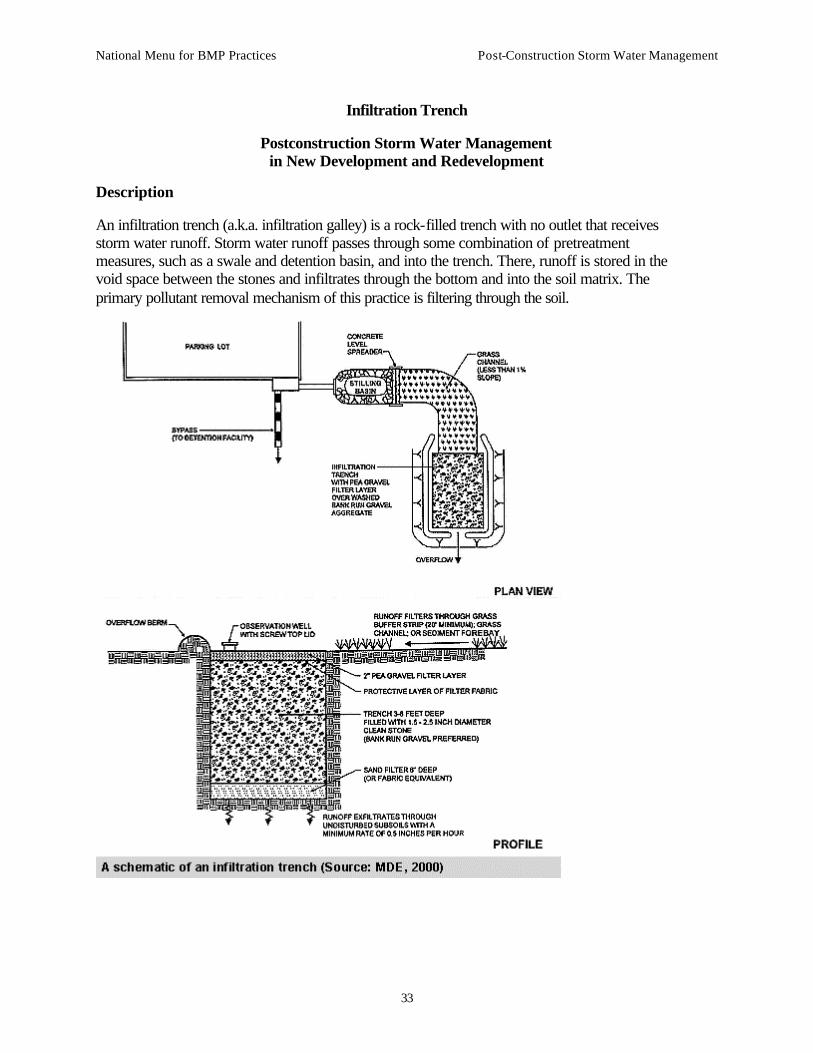
Infiltration Trench
Postconstruction Storm Water Management in New Development and Redevelopment
Description
An infiltration trench (a.k.a. infiltration galley) is a rock-filled trench with no outlet that receives storm water runoff. Storm water runoff passes through some combination of pretreatment measures, such as a swale and detention basin, and into the trench. There, runoff is stored in the void space between the stones and infiltrates through the bottom and into the soil matrix. The primary pollutant removal mechanism of this practice is filtering through the soil.

National Menu for BMP Practices Post-Construction Storm Water Management
34
Applicability
Infiltration trenches have select applications. While they can be applied in most regions of the country, their use is sharply restricted by concerns due to common site factors, such as potential ground water contamination, soils, and clogging.
Regional Applicability
Infiltration trenches can be utilized in most regions of the country, with some design modifications in cold and arid climates. In regions of karst (i.e., limestone) topography, these storm water management practices may not be applied due to concerns of sink hole formation and ground water contamination.
Ultra-Urban Areas
Ultra-urban areas are densely developed urban areas in which little pervious surface exists. Infiltration trenches can sometimes be applied in the ultra-urban environment. Two features that can restrict their use are the potential of infiltrated water to interfere with existing infrastructure, and the relatively poor infiltration of most urban soils.
Storm Water Hot Spots
Storm water hot spots are areas where land use or activities generate highly contaminated runoff, with concentrations of pollutants in excess of those typically found in storm water. Infiltration trenches should not receive runoff from storm water hot spots, unless the storm water has already been treated by another storm water management practice, because of potential ground water contamination.
Storm Water Retrofit
A storm water retrofit is a storm water management practice (usually structural) put into place after development has occurred, to improve water quality, protect downstream channels, reduce flooding, or meet other specific objectives. Infiltration trenches may be used as a storm water retrofit. Their use is somewhat restricted, however, by two factors. First, infiltration trenches should be used to treat small sites (less than 5 acres). Small site storm water management practices are generally a high cost retrofit option in terms of construction cost and the maintenance burden associated with the number of small site practices. Second, it is often difficult to find areas where soils are appropriate for infiltration in an already urban or suburban environment.
Cold Water (Trout) Streams
Infiltration trenches are an excellent option for cold water streams because they encourage infiltration of storm water. This storm water does not warm as it travels underground to the receiving stream, lessening the temperature impacts commonly associated with urbanization.
Siting and Design Considerations
Infiltration trenches have select applications. Although they can be applied in a variety of situations, the use of infiltration trenches is restricted by concerns over ground water contamination, soils, and clogging.

National Menu for BMP Practices Post-Construction Storm Water Management
35
Siting Considerations
Infiltration practices need to be sited extremely carefully. In particular, designers need to ensure that the soils on site are appropriate for infiltration and that designs minimize the potential for ground water contamination and long-term maintenance.
Drainage Area
Infiltration trenches generally can be applied to relatively small sites (less than 5 acres), with relatively high impervious cover. Application to larger sites generally causes clogging, resulting in a high maintenance burden.
Slope
Infiltration trenches should be placed on flat ground, but the slopes of the site draining to the practice can be as steep as 15 percent.
Soils/Topography
Soils and topography are strongly limiting factors when locating infiltration practices. Soils must be significantly permeable to ensure that the storm water can infiltrate quickly enough to reduce the potential for clogging. In addition, soils that infiltrate too rapidly may not provide sufficient treatment, creating the potential for ground water contamination. The infiltration rate should range between 0.5 and 3 inches per hour. In addition, the soils should have no greater than 20-percent clay content, and less than 40-percent silt/clay content (MDE, 2000). The infiltration rate and textural class of the soil need to be confirmed in the field; designers should not rely on more generic information such as a soil survey. Finally, infiltration trenches may not be used in regions of karst topography, due to the potential for sinkhole formation or ground water contamination.
Ground Water
Designers always need to provide significant separation (2 to 5 feet) from the bottom of the infiltration trench and the seasonally high ground water table, to reduce the risk of contamination. In addition, infiltration practices should be separated from drinking water wells.
Design Considerations
Specific designs may vary considerably, depending on site constraints or preferences of the designer or community. There are some features, however, that should be incorporated into most infiltration trench designs. These design features can be divided into five basic categories: pretreatment, treatment, conveyance, maintenance reduction, and landscaping.
Pretreatment
Pretreatment refers to design features that provide settling of large particles before runoff reaches a management practice, easing the long-term maintenance burden. Pretreatment is important for all structural storm water management practices, but it is particularly important for infiltration practices. To ensure that pretreatment mechanisms are effective, designers should incorporate "multiple pretreatment," using practices such as grassed swales, vegetated filter strips, detention, or a plunge pool in series.

National Menu for BMP Practices Post-Construction Storm Water Management
36
Treatment
Treatment design features enhance the pollutant removal of a practice. During the construction process, the upland soils of infiltration trenches need to be stabilized to ensure that the trench does not become clogged with sediment. Furthermore, the practice should be filled with large clean stones that can retain the volume of water to be treated in their voids. Like infiltration basins, this practice should be sized so that the volume to be treated can infiltrate out of the trench bottom in 24 hours.
Conveyance
Storm water needs to be conveyed through storm water management practices safely, and in a way that minimizes erosion. Designers need to be particularly careful in ensuring that channels leading to an infiltration practice are designed to minimize erosion. Infiltration trenches should be designed to treat only small storms, (i.e., only for water quality). Thus, these practices should be designed "off-line," using a structure to divert only small flows to the practice. Finally, the sides of an infiltration trench should be lined with a geotextile fabric to prevent flow from causing rills along the edge of the practice.
Maintenance Reduction
In addition to regular maintenance activities, designers also need to incorporate features into the design to ensure that the maintenance burden of a practice is reduced. These features can make regular maintenance activities easier or reduce the need to perform maintenance. As with all management practices, infiltration trenches should have an access path for maintenance activities. An observation well (i.e., a perforated PVC pipe that leads to the bottom of the trench) can enable inspectors to monitor the drawdown rate. Where possible, trenches should have a means to drain the practice if it becomes clogged, such as an underdrain. An underdrain is a perforated pipe system in a gravel bed, installed on the bottom of filtering practices to collect and remove filtered runoff. An underdrain pipe with a shutoff valve can be used in an infiltration system to act as an overflow in case of clogging.
Landscaping
In infiltration trenches, there is no landscaping on the practice itself, but it is important to ensure that the upland drainage is properly stabilized with thick vegetation, particularly following construction.
Regional Variations
Arid or Semi-Arid Climates
In arid regions, infiltration practices are often highly recommended because of the need to recharge the ground water. One concern in these regions is the potential of these practices to clog, due to relatively high sediment concentrations in these environments. Pretreatment needs to be more heavily emphasized in these dryer climates.
Cold Climates
In extremely cold climates (i.e., regions that experience permafrost), infiltration trenches may be an infeasible option. In most cold climates, infiltration trenches can be a feasible management

National Menu for BMP Practices Post-Construction Storm Water Management
37
practice, but there are some challenges to their use. The volume may need to be increased in order to treat snowmelt. In addition, if the practice is used to treat roadside runoff, it may be desirable to divert flow around the trench in the winter to prevent infiltration of chlorides from road salting, where this is a problem. Finally, a minimum setback from roads is needed to ensure that the practice does not cause frost heaving.
Limitations
Although infiltration trenches can be a useful management practice, they have several limitations. While they do not detract visually from a site, infiltration trenches provide no visual enhancements. Their application is limited due to concerns over ground water contamination and other soils requirements. Finally, maintenance can be burdensome, and infiltration practices have a relatively high rate of failure.
Maintenance Considerations
In addition to incorporating features into the design to minimize maintenance, some regular maintenance and inspection practices are needed. Table 1 outlines some of these practices.
Table 1. Typical maintenance activities for infiltration trenches (Source: Modified from WMI, 1997)
Activity Schedule
• Check observation wells following 3 days of dry weather. Failure to percolate within this time period indicates clogging.
• Inspect pretreatment devices and diversion structures for sediment build-up and structural damage.
Semi-annual inspection
• Remove sediment and oil/grease from pretreatment devices and overflow structures.
Standard maintenance
• If bypass capability is available, it may be possible to regain the infiltration rate in the short term by using measures such as providing an extended dry period.
5-year maintenance
• Total rehabilitation of the trench should be conducted to maintain storage capacity within 2/3 of the design treatment volume and 72-hour exfiltration rate limit.
• Trench walls should be excavated to expose clean soil.
Upon failure
Infiltration practices have historically had a high rate of failure compared to other storm water management practices. One study conducted in Prince George's County, Maryland (Galli, 1992), revealed that less than half of the infiltration trenches investigated (of about 50) were still functioning properly, and less than one-third still functioned properly after 5 years. Many of

National Menu for BMP Practices Post-Construction Storm Water Management
38
these practices, however, did not incorporate advanced pretreatment. By carefully selecting the location and improving the design features of infiltration practices, their performance should improve.
Effectiveness
Structural storm water management practices can be used to achieve four broad resource protection goals. These include flood control, channel protection, ground water recharge, and pollutant removal. Infiltration trenches can provide ground water recharge, pollutant control, and can help somewhat to provide channel protection.
Ground Water Recharge
Infiltration trenches recharge the ground water because runoff is treated for water quality by filtering through the soil and discharging to ground water.
Pollutant Removal
Very little data are available regarding the pollutant removal associated with infiltration trenches. It is generally assumed that they have very high pollutant removal, because none of the storm water entering the practice remains on the surface. Schueler (1987) estimated pollutant removal for infiltration trenches based on data from land disposal of wastewater. The average pollutant removal, assuming the infiltration trench is sized to treat the runoff from a 1-inch storm, is:
TSS 75%
Phosphorous 60–70%
Nitrogen 55–60%
Metals 85–90%
Bacteria 90%
These removal efficiencies assume that the infiltration trench is well designed and maintained. The information in the Siting and Design Considerations and Maintenance Considerations sections represent the best available information on how to properly design these practices. The design references below provide additional information.
Cost Considerations
Infiltration trenches are somewhat expensive, when compared to other storm water practices, in terms of cost per area treated. Typical construction costs, including contingency and design costs, are about $5 per ft3 of storm water treated (SWRPC, 1991; Brown and Schueler, 1997).
Infiltration trenches typically consume about 2 to 3 percent of the site draining to them, which is relatively small. In addition, infiltration trenches can fit into thin, linear areas. Thus, they can generally fit into relatively unusable portions of a site.
One cost concern associated with infiltration practices is the maintenance burden and longevity. If improperly maintained, infiltration trenches have a high failure rate (see Maintenance Considerations). In general, maintenance costs for infiltration trenches are estimated at between

National Menu for BMP Practices Post-Construction Storm Water Management
39
5 percent and 20 percent of the construction cost. More realistic values are probably closer to the 20-percent range, to ensure long-term functionality of the practice.
References
Maryland Department of the Environment (MDE). 2000. Maryland Stormwater Design Manual. [http://www.mde.state.md.us/environment/wma/stormwatermanual]. Accessed May 22, 2001.
Watershed Management Institute (WMI). 1997. Operation, Maintenance, and Management of Stormwater Management Systems. Prepared for U.S. Environmental Protection Agency, Office of Water, Washington, DC.
Brown, W., and T. Schueler. 1997. The Economics of Stormwater BMPs in the Mid-Atlantic Region. Prepared for the Chesapeake Research Consortium, Edgewater, MD, by the Center for Watershed Protection, Ellicott City, MD.
Galli, J. 1992. Analysis of Urban BMP Performance and Longevity in Prince George's County, Maryland. Metropolitan Washington Council of Governments, Washington, DC.
Schueler, T. 1987. Controlling Urban Runoff: A Practical Manual for Planning and Designing Urban BMPs. Metropolitan Washington Council of Governments, Washington, DC.
Southeastern Wisconsin Regional Planning Commission (SWRPC). 1991. Costs of Urban Nonpoint Source Water Pollution Control Measures. Southeastern Wisconsin Regional Planning Commission, Waukesha, WI.
Information Resources
Center for Watershed Protection (CWP). 1997. Stormwater BMP Design Supplement for Cold Climates. Prepared for the U.S. Environmental Protection Agency, Office of Wetlands, Oceans and Watersheds, Washington, DC, by the Center for Watershed Protection, Ellicott City, MD.
Ferguson, B.K. 1994. Stormwater Infiltration. CRC Press, Ann Arbor, MI.
Minnesota Pollution Control Agency. 1989. Protecting Water Quality in Urban Areas: Best Management Practices. Minnesota Pollution Control Agency, Minneapolis, MN.
USEPA. 1993. Guidance to Specify Management Measures for Sources of Nonpoint Pollution in Coastal Waters. EPA-840-B-92-002. U.S. Environmental Protection Agency, Office of Water, Washington, DC.

National Menu for BMP Practices Post-Construction Storm Water Management
40
Porous Pavement
Postconstruction Storm Water Management in New Development and Redevelopment
Description
Porous pavement is a permeable pavement surface with an underlying stone reservoir to temporarily store surface runoff before it infiltrates into the subsoil. This porous surface replaces traditional pavement, allowing parking lot storm water to infiltrate directly and receive water quality treatment. There are a few porous pavement options, including porous asphalt, pervious concrete, and grass pavers. Porous asphalt and pervious concrete appear to be the same as traditional pavement from the surface, but are manufactured without "fine" materials, and incorporate void spaces to allow infiltration. Grass pavers are concrete interlocking blocks or synthetic fibrous gridded systems with open areas designed to allow grass to grow within the void areas. Other alternative paving surfaces can help reduce the runoff from paved areas but do not incorporate the stone trench for temporary storage below the pavement (see Green Parking fact sheet). While porous pavement has the potential to be a highly effective treatment practice, maintenance has been a concern in past applications of the practice.
Application
The ideal application for porous pavement is to treat low-traffic or overflow parking areas. Porous pavement may also have some application on highways, where it is currently used as a surface material to reduce hydroplaning.
Regional Applicability
Porous pavement can be applied in most regions of the country, but the practice has unique challenges in cold climates. Porous pavement cannot be used where sand is applied to the pavement surface because the sand will clog the surface of the material. Care also needs to be taken when applying salt to a porous pavement surface as chlorides from road salt may migrate into the ground water. For block pavers, plowing may be challenging because the edge of the snow plow blade can catch the edge of the blocks, damaging the surface. This difficulty does not imply that it is impossible to use porous pavement in cold climates. Another concern in cold climates is that infiltrating runoff below pavement may cause frost heave, although design modifications can reduce this risk. Porous pavement has been used successfully in Norway (Stenmark, 1995), incorporating design features to reduce frost heave. Furthermore, some experience suggests that snow melts faster on a porous surface because of rapid drainage below the snow surface (Cahill Associates, 1993).

National Menu for BMP Practices Post-Construction Storm Water Management
41
Ultra-Urban Areas
Ultra-urban areas are densely developed urban areas in which little pervious surface exists. Porous pavements are a good option in these areas because they consume no space. They are not ideal for high-traffic areas, however, because of the potential for failure due to clogging (Galli, 1992).
Storm Water Hot Spots
Storm water hot spots are areas where land use or activities generate highly contaminated runoff, with concentrations of pollutants in excess of those typically found in storm water. These areas include commercial nurseries, auto recycle facilities, commercial parking lots, fueling stations, storage areas, industrial rooftops, marinas, outdoor container storage of liquids, outdoor loading/unloading facilities, public works storage areas, hazardous materials generators (if containers are exposed to rainfall), vehicle service and maintenance areas, and vehicle and equipment washing/steam cleaning facilities. Since porous pavement is an infiltration practice, it should not be applied on storm water hot spots due to the potential for ground water contamination.
Storm Water Retrofit
A storm water retrofit is a storm water management practice (usually structural) put into place after development has occurred, to improve water quality, protect downstream channels, reduce flooding, or meet other specific objectives. Since porous pavement can only be applied to relatively small sites, using porous pavement as a primary tool for watershed retrofitting would be expensive. The best application of porous pavement for retrofits is on individual sites where a parking lot is being resurfaced.
Cold Water (Trout) Streams
Porous pavement can help to reduce the increased temperature commonly associated with increased impervious cover. Storm water ponds on the surface of conventional pavement, and is subsequently heated by the sun and hot pavement surface. By rapidly infiltrating rainfall, porous pavement reduces the time that storm water is exposed to the sun and heat.
Siting and Design Considerations
Siting Considerations
Porous pavement has the same siting considerations as other infiltration practices (see Infiltration Trench fact sheet). The site needs to meet the following criteria:
• Soils need to have a permeability between 0.5 and 3.0 inches per hour.
• The bottom of the stone reservoir should be completely flat so that infiltrated runoff will be able to infiltrate through the entire surface.
• Porous pavement should be sited at least 2 to 5 feet above the seasonally high ground water table, and at least 100 feet away from drinking water wells.
• Porous pavement should be sited on low-traffic or overflow parking areas, which are not sanded for snow removal.

National Menu for BMP Practices Post-Construction Storm Water Management
42
Design Considerations
Some basic features should be incorporated into all porous pavement practices. These design features can be divided into five basic categories: pretreatment, treatment, conveyance, maintenance reduction, and landscaping.
1. Pretreatment. In porous pavement designs, the pavement itself acts as pretreatment to the stone reservoir below. Because the surface serves this purpose, frequent maintenance of the surface is critical to prevent clogging. Another pretreatment item can be the incorporation of a fine gravel layer above the coarse gravel treatment reservoir. Both of these pretreatment measures are marginal, which is one reason that these systems have a high failure rate.
2. Treatment. The stone reservoir below the pavement surface should be composed of layers of small stone directly below the pavement surface, and the stone bed below the permeable surface should be sized to attenuate storm flows for the storm event to be treated. Typically, porous pavement is sized to treat a small event, such as a water quality storm (i.e., the storm that will be treated for pollutant removal), which can range from 0.5 to 1.5 inches. As in infiltration trenches, water can be stored only in the void spaces of the stone reservoir.
Conveyance. Water is conveyed to the stone reservoir through the surface of the pavement and infiltrates into the ground through the bottom of this stone reservoir. A geosynthetic liner and sand layer should be placed below the stone reservoir to prevent preferential flow paths and to maintain a flat bottom. Designs also need some method to convey larger storms to the storm drain system. One option is to use storm drain inlets set slightly above the elevation of the pavement. This would allow for some ponding above the surface, but would bypass flows that are too large to be treated by the system or when the surface clogs.
3. Maintenance Reduction. One nonstructural component that can help ensure proper maintenance of porous pavement is the use of a carefully worded maintenance agreement that provides specific guidance, including how to conduct routine maintenance and how the surface should be repaved. Ideally, signs should be posted on the site identifying porous pavement areas. One design option incorporates an "overflow edge," which is a trench surrounding the edge of the pavement. The trench connects to the stone reservoir below the surface of the pavement. Although this feature does not in itself reduce maintenance requirements, it acts as a backup in case the surface clogs. If the surface clogs, storm water will flow over the surface and into the trench, where some infiltration and treatment will occur.
4. Landscaping. For porous pavement, the most important landscaping feature is a fully stabilized upland drainage. Reducing sediment loads entering the pavement can help to prevent clogging.
Design Variations
In one design variation, the stone reservoir below the filter can also treat runoff from other sources such as rooftop runoff. In this design, pipes are connected to the stone reservoir to direct

National Menu for BMP Practices Post-Construction Storm Water Management
43
flow throughout the bottom of the storage reservoir (Cahill Associates, 1993; Schueler, 1987). If used to treat off-site runoff, porous pavement should incorporate pretreatment, as with all structural management practices.
Regional Adaptations
In cold climates, the base of the stone reservoir should be below the frost line. This modification will help to reduce the risk of frost heave.
Limitations
In addition to the relatively strict siting requirements of porous pavement, a major limitation to the practice is the poor success rate it has experienced in the field. Several studies indicate that, with proper maintenance, porous pavement can retain its permeability (e.g., Goforth et al., 1983; Gburek and Urban, 1980; Hossain and Scofield, 1991). When porous pavement has been implemented in communities, however, the failure rate has been as high as 75 percent over 2 years (Galli, 1992).
Maintenance Considerations
Porous pavement requires extensive maintenance compared with other practices. In addition to owners not being aware of porous pavement on a site, not performing these maintenance activities is the chief reason for failure of this practice. Typical requirements are shown in Table 1.
Table 1. Typical maintenance activities for porous pavement (Source: WMI, 1997)
Activity Schedule
• Avoid sealing or repaving with non-porous materials.
N/A
• Ensure that paving area is clean of debris.
• Ensure that paving dewaters between storms.
• Ensure that the area is clean of sediments.
Monthly
• Mow upland and adjacent areas, and seed bare areas.
• Vacuum sweep frequently to keep the surface free of sediment.
As needed (typically three
to four times per
year).
• Inspect the surface for deterioration or spalling. Annual

National Menu for BMP Practices Post-Construction Storm Water Management
44
Effectiveness
Porous pavement can be used to provide ground water recharge and to reduce pollutants in storm water runoff. Some data suggest that as much as 70 to 80 percent of annual rainfall will go toward ground water recharge (Gburek and Urban, 1980). These data will vary depending on design characteristics and underlying soils. Two studies have been conducted on the long-term pollutant removal of porous pavement, both in the Washington, DC, area. They suggest high pollutant removal, although it is difficult to extrapolate these results to all applications of the practice. The results of the studies are presented in Table 2.
Table 2. Effectiveness of porous pavement pollutant removal (Schueler, 1987)
Pollutant Removal (%)
Study TSS TP TN COD Metals
Prince William, VA 82 65 80 - -
Rockville, MD 95 65 85 82 98–99
Cost Considerations
Porous pavement is significantly more expensive than traditional asphalt. While traditional asphalt is approximately $0.50 to $1.00 per ft2, porous pavement can range from $2 to $3 per ft2, depending on the design (CWP, 1998; Schueler, 1987). Subtracting the cost of traditional pavement, this amounts to approximately $45,000 and $100,000 per impervious acre treated, which would be quite expensive. In addition, the cost of vacuum sweeping may be substantial if a community does not already perform vacuum sweeping operations. Finally, the practice life may be very short because the risk of clogging is high.

National Menu for BMP Practices Post-Construction Storm Water Management
45
References
Cahill Associates. 1993. Stormwater Management Systems: Porous Pavement with Underground Recharge Beds. Cahill Associates, West Chester, PA.
Watershed Management Institute (WMI). 1997. Operation, Maintenance, and Management of Stormwater Management Systems. Prepared for U.S. Environmental Protection Agency, Office of Water, Washington, DC.
Galli, J. 1992. Preliminary Analysis of the Performance and Longevity of Urban BMPs Installed In Prince George's County, Maryland. Department of Natural Resources, Annapolis, MD.
Gburek, W., and J. Urban, 1980. Storm Water Detention and Groundwater Recharge Using Porous Asphalt—Experimental Site. In Proceedings: International Symposium on Urban Storm Runoff. University of Kentucky, Lexington, KY, p. 89–97.
Goforth, G., E. Diniz, and J. Rauhut. 1983. Stormwater Hydrological Characteristics of Porous and Conventional Paving Systems. U.S. Environmental Protection Agency, Office of Research and Development, Cincinnati, OH.
Hossain, M., and L. Scofield, 1991. Porous Pavement for Control of Highway Runoff. Arizona Department of Transportation, Phoenix, AZ.
Schueler, T. 1987. Controlling Urban Runoff: A Practical Manual for Planning and Designing Urban BMPs. Metropolitan Washington Council of Governments, Washington, DC.
Stenmark, C. 1995. An Alternative Road Construction for Stormwater Management. Water Science and Technology 32(1):79–84.
Information Resources
Center for Watershed Protection (CWP). 1997. Stormwater BMP Design Supplement for Cold Climates. Prepared for U.S. Environmental Protection Agency, Office of Wetlands, Oceans and Watersheds, Washington, DC, by the Center for Watershed Protection, Ellicott City, MD.
Center for Watershed Protection (CWP). 1998. Better Site Design: A Handbook for Changing Development Rules in Your Community. Center for Watershed Protection, Ellicott City, MD.

National Menu for BMP Practices Post-Construction Storm Water Management
46
Filtration practices
Bioretention
Postconstruction Storm Water Management in New Development and Redevelopment
Description
Bioretention areas are landscaping features adapted to provide on-site treatment of storm water runoff. They are commonly located in parking lot islands or within small pockets of residential land uses. Surface runoff is directed into shallow, landscaped depressions. These depressions are designed to incorporate many of the pollutant removal mechanisms that operate in forested ecosystems. During storms, runoff ponds above the mulch and soil in the system. Runoff from larger storms is generally diverted past the facility to the storm drain system. The remaining runoff filters through the mulch and prepared soil mix. Typically, the filtered runoff is collected in a perforated underdrain and returned to the storm drain system.
Applicability
Bioretention systems are generally applied to small sites and in a highly urbanized setting. Bioretention can be applied in many climatological and geologic situations, with some minor design modifications.
Regional Applicability
Bioretention systems are applicable almost everywhere in the United States. In arid or cold climates, however, some minor design modifications may be needed.
Ultra-Urban Areas
Ultra-urban areas are densely developed urban areas in which little pervious surface exists. Bioretention facilities are ideally suited to many ultra-urban areas, such as parking lots. While they consume a fairly large amount of space (approximately 5 percent of the area that drains to them), they can be fit into existing parking lot islands or other landscaped areas.
Storm Water Hot Spots
Storm water hot spots are areas where land use or activities generate highly contaminated runoff, with concentrations of pollutants in excess of those typically found in storm water. A typical

National Menu for BMP Practices Post-Construction Storm Water Management
47
example is a gas station or convenience store parking lot. Bioretention areas can be used to treat storm water hot spots as long as an impermeable liner is used at the bottom of the filter bed.
Storm Water Retrofit
A storm water retrofit is a storm water management practice (usually structural) put into place after development has occurred, to improve water quality, protect downstream channels, reduce flooding, or meet other specific objectives. Bioretention can be used as a storm water retrofit, by modifying existing landscaped areas, or if a parking lot is being resurfaced. In highly urbanized areas, this is one of the few retrofit options that can be employed. However, it is very expensive to retrofit an entire watershed or subwatershed using storm water management practices designed to treat small sites.
Cold Water (Trout) Streams
Some species in cold water streams, notably trout, are extremely sensitive to changes in temperature. In order to protect these resources, designers should avoid treatment practices that increase the temperature of the storm water runoff they treat. Bioretention is a good option in cold water streams because water ponds in them for only a short time, decreasing the potential for stream warming.
Siting and Design Considerations
In addition to the broad applicability concerns described above, designers need to consider conditions at the site level. In addition, they need to incorporate design features to improve the longevity and performance of the practice, while minimizing the maintenance burden.
Siting
Some considerations for selecting a storm water management practice are the drainage area the practice will need to treat, the slopes both at the location of the practice and the drainage area, soil and subsurface conditions, and the depth of the seasonably high ground water table. Bioretention can be applied on many sites, with its primary restriction being the need to apply the practice on small sites.
Drainage Area
Bioretention areas should usually be used on small sites (i.e., 5 acres or less). When used to treat larger areas, they tend to clog. In addition, it is difficult to convey flow from a large area to a bioretention area.
Slope
Bioretention areas are best applied to relatively shallow slopes (usually about 5 percent). However, sufficient slope is needed at the site to ensure that water that enters the bioretention area can be connected with the storm drain system. These storm water management practices are most often applied to parking lots or residential landscaped areas, which generally have shallow slopes.

National Menu for BMP Practices Post-Construction Storm Water Management
48
Soils/Topography
Bioretention areas can be applied in almost any soils or topography, since runoff percolates through a man-made soil bed and is returned to the storm water system.
Ground Water
Bioretention should be separated somewhat from the ground water to ensure that the ground water table never intersects with the bed of the bioretention facility. This design consideration prevents possible ground water contamination.
Design Considerations
Specific designs may vary considerably, depending on site constraints or preferences of the designer or community. There are some features, however, that should be incorporated into most bioretention area designs. These design features can be divided into five basic categories: pretreatment, treatment, conveyance, maintenance reduction, and landscaping.
Pretreatment
Pretreatment refers to features of a management practice that cause coarse sediment particles and their associated pollutants to settle. Incorporating pretreatment helps to reduce the maintenance burden of bioretention and reduces the likelihood that the soil bed will clog over time. Several different mechanisms can be used to provide pretreatment in bioretention facilities. Often, runoff is directed to a grass channel or filter strip to filter out coarse materials before the runoff flows into the filter bed of the bioretention area. Other features may include a pea gravel diaphragm, which acts to spread flow evenly and drop out larger particles.
Treatment
Treatment design features help enhance the ability of a storm water management practice to remove pollutants. Several basic features should be incorporated into bioretention designs to enhance their pollutant removal. The bioretention system should be sized between 5 and 10 percent of the impervious area draining to it. The practice should be designed with a soil bed that is a sand/soil matrix, with a mulch layer above the soil bed. The bioretention area should be designed to pond a small amount of water (6–9 inches) above the filter bed.
Conveyance
Conveyance of storm water runoff into and through a storm water practice is a critical component of any storm water management practice. Storm water should be conveyed to and from practices safely and to minimize erosion potential. Ideally, some storm water treatment can be achieved during conveyance to and from the practice.
Bioretention practices are designed with an underdrain system to collect filtered runoff at the bottom of the filter bed and direct it to the storm drain system. An underdrain is a perforated pipe system in a gravel bed, installed on the bottom of the filter bed. Designers should provide an overflow structure to convey flow from storms that are not treated by the bioretention facility to the storm drain.

National Menu for BMP Practices Post-Construction Storm Water Management
49
Maintenance Reduction
In addition to regular maintenance activities needed to maintain the function of storm water practices, some design features can be incorporated to reduce the required maintenance of a practice. Designers should ensure that the bioretention area is easily accessible for maintenance.
Landscaping
Landscaping is critical to the function and aesthetic value of bioretention areas. It is preferable to plant the area with native vegetation, or plants that provide habitat value, where possible. Another important design feature is to select species that can withstand the hydrologic regime they will experience. At the bottom of the bioretention facility, plants that tolerate both wet and dry conditions are preferable. At the edges, which will remain primarily dry, upland species will be the most resilient. Finally, it is best to select a combination of trees, shrubs, and herbaceous materials.
Design Variations
One design alternative to the traditional bioretention practice is the use of a "partial exfiltration" system, used to promote ground water recharge. Other design modifications may make this practice more effective in arid or cold climates.
Partial Exfiltration
In one design variation of the bioretention system, the underdrain is only installed on part of the bottom of the bioretention system. This design alternative allows for some infiltration, with the underdrain acting as more of an overflow. This system can be applied only when the soils and other characteristics are appropriate for infiltration (see Infiltration Trench and Infiltration Basin).
Arid Climates
In arid climates, bioretention areas should be landscaped with drought-tolerant species.
Cold Climates
In cold climates, bioretention areas can be used as snow storage areas. If used for this purpose, or if used to treat runoff from a parking lot where salt is used as a deicer, the bioretention area should be planted with salt-tolerant, nonwoody plant species.
Limitations
Bioretention areas have a few limitations. Bioretention areas cannot be used to treat a large drainage area, limiting their usefulness for some sites. In addition, although the practice does not consume a large amount of space, incorporating bioretention into a parking lot design may reduce the number of parking spaces available. Finally, the construction cost of bioretention areas is relatively high compared with many other management practices (see Cost Considerations).

National Menu for BMP Practices Post-Construction Storm Water Management
50
Maintenance Considerations
Bioretention requires frequent landscaping maintenance, including measures to ensure that the area is functioning properly, as well as maintenance of the landscaping on the practice. In many cases, bioretention areas initially require intense maintenance, but less maintenance is needed over time. In many cases, maintenance tasks can be completed by a landscaping contractor, who may already be hired at the site.
Table 1. Typical maintenance activities for bioretention areas (Source: ETA and Biohabitats, 1993)
Activity Schedule
• Remulch void areas • Treat diseased trees and shrubs • Mow turf areas
As needed
• Water plants daily for 2 weeks At project completion
• Inspect soil and repair eroded areas • Remove litter and debris
Monthly
• Remove and replace dead and diseased vegetation
Twice per year
• Add mulch • Replace tree stakes and wires
Once per year
Effectiveness
Structural storm water management practices can be used to achieve four broad resource protection goals. These include flood control, channel protection, ground water recharge, and pollutant removal. In general, bioretention areas can provide only pollutant removal.
Flood Control
Bioretention areas are not designed to provide flood control. These larger flows must be diverted to a detention pond that can provide flood peak reduction.
Channel Protection
Bioretention areas are generally not designed to provide channel protection because at the scale at which they are typically installed they are not able to infiltrate large volumes. (They are typically designed to treat and infiltrate the first inch of runoff and are bypassed by larger flows that can erode channels.) Channel protection must be provided by other means, such as ponds or other volume control practices.

National Menu for BMP Practices Post-Construction Storm Water Management
51
Ground Water Recharge
Bioretention areas do not usually recharge the ground water, except in the case of the partial exfiltration design (see Design Variations).
Pollutant Removal
Little pollutant removal data have been collected on the pollutant removal effectiveness of bioretention areas. A field and laboratory analysis of bioretention facilities conducted by Davis et al. (1997), showed very high removal rates (roughly 95 percent for copper, 98 percent for phosphorus, 20 percent for nitrate, and 50 percent for total Kjeldhal nitrogen (TKN). Table 2 shows data from two other studies of field bioretention sites in Maryland.
Table 2. Pollutant removal effectiveness of two bioretention areas in Maryland (USEPA, 2000).
Pollutant Pollutant Removal
Copper 43%–97%
Lead 70%–95%
Zinc 64%–95%
Phosphorus 65%–87%
TKN 52–67%
NH4+ 92%
NO3- 15%–16%
Total nitrogen (TN) 49%
Calcium 27%
Assuming that bioretention systems behave similarly to swales, their removal rates are relatively high. The negative removal rate for bacteria may reflect sampling errors, such as failure to account for bacterial sources in the practice. Alternatively, these data may be the result of bacteria reproduction in the moist soils of swale systems.
There is considerable variability in the effectiveness of bioretention areas, and it is believed that properly designing and maintaining these areas may help to improve their performance. The siting and design criteria presented in this sheet reflect the best current information and experience to improve the performance of bioretention areas. A recent joint project of the American Society of Civil Engineers (ASCE) and the EPA Office of Water may help to isolate specific design features that can improve performance. The National Stormwater Best Management Practice (BMP) database is a compilation of storm water practices which includes both design information and performance data for various practices. As the database expands,

National Menu for BMP Practices Post-Construction Storm Water Management
52
inferences about the extent to which specific design criteria influence pollutant removal might be made. More information on this database is accessible on the ASCE web page at http://www.asce.org.
Cost Considerations
Bioretention areas are relatively expensive. A recent study (Brown and Schueler, 1997) estimated the cost of a variety of storm water management practices. The study resulted in the following cost equation for bioretention areas, adjusting for inflation:
C = 7.30 V0.99
where:
C = Construction, design, and permitting cost ($); and
V = Volume of water treated by the facility (ft3).
An important consideration when evaluating the costs of bioretention is that this practice replaces an area that most likely would have been landscaped. Thus, the true cost of the practice is less than the construction cost reported. Similarly, maintenance activities conducted on bioretention areas are not very different from maintenance of a landscaped area. The land consumed by bioretention areas is relatively high compared with other practices (about 5 percent of the drainage area). Again, this area should not necessarily be considered lost, since the practice may only be slightly larger than a traditional landscaped area. Finally, bioretention areas can improve upon existing landscaping and can therefore be an aesthetic benefit.

National Menu for BMP Practices Post-Construction Storm Water Management
53
References
Brown, W., and T. Schueler. 1997. The Economics of Stormwater BMPs in the Mid-Atlantic Region. Prepared for Chesapeake Research Consortium. Edgewater, MD. Center for Watershed Protection. Ellicott City, MD.
Davis, A., M. Shokouhian, H. Sharma, and C. Henderson. 1997. Bioretention Monitoring—Preliminary Data Analysis. Environmental Engineering Program of the University of Maryland, College Park, MD.
Engineering Technologies Associates and Biohabitats. 1993. Design Manual for Use of Bioretention in Stormwater Management. Prepared for Prince George's County Government, Watershed Protection Branch, Landover, MD.
Schueler, T. 1997. Comparative Pollutant Removal Capability of Urban BMPs: A Reanalysis. Watershed Protection Techniques 2(4): 515–520.
Information Resources
Maryland Department of the Environment (MDE). 2000. Maryland Stormwater Design Manual. [http://www.mde.state.md.us/environment/wma/stormwatermanual]. Accessed May 22, 2001.
Center for Watershed Protection (CWP). 1997. Stormwater BMP Design Supplement for Cold Climates. Prepared for U.S. Environmental Protection Agency Office of Wetlands, Oceans, and Watersheds, Washington, DC.
Center for Watershed Protection (CWP). 1996. Design of Stormwater Filtering Systems. Prepared for Chesapeake Research Consortium, Solomons, MD, and USEPA Region V, Chicago, IL.
Prince George's County Department of Environmental Resources. 1997. Low Impact Development. Prince George's County Department of Environmental Resources, Largo, MD.

National Menu for BMP Practices Post-Construction Storm Water Management
54
Sand and Organic Filters
Postconstruction Storm Water Management in New Development and Redevelopment
Description
Sand filters are usually two-chambered storm water practices; the first is a settling chamber, and the second is a filter bed filled with sand or another filtering media. As storm water flows into the first chamber, large particles settle out, and then finer particles and other pollutants are removed as storm water flows through the filtering medium. There are several modifications of the basic sand filter design, including the surface sand filter, underground sand filter, perimeter sand filter, organic media filter, and Multi-Chamber Treatment Train. All of these filtering practices operate on the same basic principle. Modifications to the traditional surface sand filter were made primarily to fit sand filters into more challenging design sites (e.g., underground and perimeter filters) or to improve pollutant removal (e.g., organic media filter).
Applicability
Sand filters can be applied in most regions of the country and on most types of sites. Some restrictions at the site level, however, might restrict the use of sand filters as a storm water management practice (see Siting and Design Considerations).
Regional Applicability
Although sand filters can be used in both cold and arid climates, some design modifications might be necessary (See Siting and Design Considerations).

National Menu for BMP Practices Post-Construction Storm Water Management
55
Ultra-Urban Areas
Ultra-urban areas are densely developed urban areas in which little pervious surface is present. Sand filters in general are good options in these areas because they consume little space. Underground and perimeter sand filters in particular are well suited to the ultra-urban setting because they consume no surface space.
Storm Water Hot Spots
Storm water hot spots are areas where land use or activities generate highly contaminated runoff, with concentrations of pollutants in excess of those typically found in storm water. These areas include commercial nurseries, auto recycle facilities, commercial parking lots, fueling stations, storage areas, industrial rooftops, marinas, outdoor container storage of liquids, outdoor loading/unloading facilities, public works storage areas, hazardous materials generators (if containers are exposed to rainfall), vehicle service and maintenance areas, and vehicle and equipment washing/steam cleaning facilities. Sand filters are an excellent option to treat runoff from storm water hot spots because storm water treated by sand filters has no interaction with, and thus no potential to contaminate, the groundwater.
Storm Water Retrofit
A storm water retrofit is a storm water management practice (usually structural) put into place after development has occurred to improve water quality, protect downstream channels, reduce flooding, or meet other specific objectives. Sand filters are a good option to achieve water quality goals in retrofit studies where space is limited because they consume very little surface space and have few site restrictions. It is important to note, however, that sand filters cannot treat a very large drainage area. Using small-site BMPs in a retrofit may be the only option for a retrofit study in a highly urbanized area, but it is expensive to treat the drainage area of an entire watershed using many small-site practices, as opposed to one larger facility such as a pond.
Cold Water (Trout) Streams
Some species in cold water streams, notably trout, are extremely sensitive to changes in temperature. To protect these resources, designers should avoid treatment practices that increase the temperature of the storm water runoff they treat. Sand filters can be a good treatment option for cold water streams. In some storm water treatment practices, particularly wet ponds, runoff is warmed by the sun as it resides in the permanent pool. Surface sand filters are typically not designed with a permanent pool, although there is ponding in the sedimentation chamber and above the sand filter. Designers may consider shortening the detention time in cold water watersheds. Underground and perimeter sand filter designs have little potential for warming because these practices are not exposed to the sun.
Siting and Design Considerations
In addition to the broad applicability issues described above, designers need to consider conditions at the site level and need to incorporate design features to improve the longevity and performance of the practice, while minimizing the maintenance burden.

National Menu for BMP Practices Post-Construction Storm Water Management
56
Siting Considerations
Some considerations when selecting a storm water management practice are the drainage area the practice will need to treat, the slopes both at the location of the practice and draining to it, soil and subsurface conditions, and the depth of the seasonably high ground water table. Although sand filters are relatively versatile, some site restrictions such as available head might limit their use.
Drainage Area
Sand filters are best applied on relatively small sites (up to 10 acres for surface sand filters and closer to 2 acres for perimeter or underground filters [MDE, 2000]). Filters have been used on larger drainage areas, of up to 100 acres, but these systems can clog when they treat larger drainage areas unless adequate measures are provided to prevent clogging, such as a larger sedimentation chamber or more intensive regular maintenance.
Slope
Sand filters can be used on sites with slopes up to about 6 percent. It is challenging to use most sand filters in very flat terrain because they require a significant amount of elevation drop, or head (about 5 to 8 feet), to allow flow through the system. One exception is the perimeter sand filter, which can be applied with as little as 2 feet of head.
Soils/Topography
When sand filters are designed as a stand-alone practice, they can be used on almost any soil because they can be designed so that storm water never infiltrates into the soil or interacts with the ground water. Alternatively, sand filters can be designed as pretreatment for an infiltration practice, where soils do play a role.
Ground Water
Designers should provide at least 2 feet of separation between the bottom of the filter and the seasonally high ground water table. This design feature prevents both structural damage to the filter and possibly, though unlikely, ground water contamination.
Design Considerations
Specific designs may vary considerably, depending on site constraints or preferences of the designer or community. Some features, however, should be incorporated into most designs. These design features can be divided into five basic categories: pretreatment, treatment, conveyance, maintenance reduction, and landscaping.
Pretreatment
Pretreatment is a critical component of any storm water management practice. In sand filters, pretreatment is achieved in the sedimentation chamber that precedes the filter bed. In this chamber, the coarsest particles settle out and thus do not reach the filter bed. Pretreatment reduces the maintenance burden of sand filters by reducing the potential of these sediments to clog the filter. Designers should provide at least 25 percent of the water quality volume in a dry or wet sedimentation chamber as pretreatment to the filter system. The water quality volume is

National Menu for BMP Practices Post-Construction Storm Water Management
57
the amount of runoff that will be treated for pollutant removal in the practice. Typical water quality volumes are the runoff from a 1-inch storm or ½ inch of runoff over the entire drainage area to the practice.
The area of the sedimentation chamber may be determined based on the Camp-Hazen equation, as adapted by the Washington State Department of Ecology (Washington State DOE, 1992). This equation can be expressed as:
As = (Qo/W)ln(1-E)
where:
As = surface area (ft2);
Qo = discharge rate from basin (water quality volume/detention time);
W = particle settling velocity (ft/s);
[CWP (1996) used a settling of 0.0004 ft/s for drainage areas greater than 75% impervious and 0.0033 ft/s for drainage areas less than or equal to 75% impervious to account for the finer particles that erode from pervious surfaces.]
E = removal efficiency fraction (usually assumed to be about 0.9(90%)).
Using the simplifying assumption of a 24-hour detention time, CWP (1996) reduced the above equation to
As = 0.066WTV (>75%)
As = 0.0081WTV (< or = 75%)
where
WTV = water quality volume (ft3), or the volume of storm water to be treated by the practice.
Treatment
Treatment design features help enhance the ability of a storm water management practice to remove pollutants. In filtering systems, designers should provide at least 75 percent of the water quality volume in the practice (including both the sand chamber and the sediment chamber). In sand filters, designers should select a medium sand as the filtering medium.
The filter bed should be sized using Darcy's Law, which relates the velocity of fluids to the hydraulic head and the coefficient of permeability of a medium. The resulting equation, as derived by the city of Austin, Texas, (1996), is
AF = WTV d/[k t (h+d)]
where
AF = area of the filter bed (ft2);
d = depth of the filter bed (ft; usually about 1.5 feet, depending on the design);

National Menu for BMP Practices Post-Construction Storm Water Management
58
k = coefficient of permeability of the filtering medium (ft/day);
t = time for the water quality volume to filter through the system (days; usually assumed to be 1.67 days); and
h = average water height above the sand bed (ft; assumed to be one-half of the maximum head).
Typical values for k, as assembled by CWP (1996), are shown in Table 1.
Table 1: Coefficient of permeability values for storm water filtering practices (CWP, 1996)
Filter Medium Coefficient of Permeability (ft/day)
Sand 3.5
Peat/Sand 2.75
Compost 8.7
Conveyance
Conveyance of storm water runoff into and through a storm water practice is a critical component of any storm water management practice. Storm water should be conveyed to and from practices safely and in a manner that minimizes erosion potential. Ideally, some storm water treatment can be achieved during conveyance to and from the practice.
Typically, filtering practices are designed as "off-line" systems, meaning that they have the smaller water quality volume diverted to them only during larger storms, using a flow splitter, which is a structure that bypasses larger flows to the storm drain system or to a stabilized channel. One exception is the perimeter filter; in this design, all flows enter the system, but larger flows overflow to an outlet chamber and are not treated by the practice.
All filtering practices, with the exception of exfilter designs (see Design Variations) are designed with an under drain below the filtering bed. An under drain is a perforated pipe system in a gravel bed, installed on the bottom of filtering practices and used to collect and remove filtered runoff.
Maintenance Reduction
In addition to regular maintenance activities needed to maintain the function of storm water practices, some design features can be incorporated to ease the maintenance burden of each practice. Designers should provide maintenance access to filtering systems. In underground sand filters, confined space rules defined by the Occupational Safety and Health Administration (OSHA) need to be addressed.
Landscaping
Landscaping can add to both the aesthetic value and the treatment ability of storm water practices. In sand filters, little landscaping is generally used on the practice, although surface

National Menu for BMP Practices Post-Construction Storm Water Management
59
sand filters and organic media filters may be designed with a grass cover on the surface of the filter. In all filters, designers need to ensure that the contributing drainage has dense vegetation to reduce sediment loads to the practice.
Design Variations
As mentioned earlier in this fact sheet, there are five basic storm water filter designs--surface sand filter, underground filter, perimeter filter (also known as the "Delaware" filter), organic media filter, and Multi-Chamber Treatment Train. Other design variations can incorporate design features to recharge ground water or to meet the design challenges of cold or arid climates.
Surface Sand Filter
The surface sand filter is the original sand filter design. In this practice both the filter bed and the sediment chamber are aboveground. The surface sand filter is designed as an off-line practice, where only the water quality volume is directed to the filter. The surface sand filter is the least expensive filter option and has been the most widely used.
Underground Sand Filter
The underground sand filter is a modification of the surface sand filter, where all of the filter components are underground. Like the surface sand filter, this practice is an off-line system that receives only the smaller water quality events. Underground sand filters are expensive to construct but consume very little space. They are well suited to highly urbanized areas.
Perimeter Sand Filter
The perimeter sand filter also includes the basic design elements of a sediment chamber and a filter bed. In this design, however, flow enters the system through grates, usually at the edge of a parking lot. The perimeter sand filter is the only filtering option that is on-line, with all flows entering the system but larger events bypassing treatment by entering an overflow chamber. One major advantage to the perimeter sand filter design is that it requires little hydraulic head and thus is a good option in areas of low relief.
Organic Media Filter
Organic media filters are essentially the same as surface filters, with the sand medium replaced with or supplemented by another medium. Two examples are the peat/sand filter (Galli, 1990) and the compost filter system (CSF, 1996). The assumption is that these systems will have enhanced pollutant removal for many compounds because of the increased cation exchange capacity achieved by increasing the organic matter.
Multi-Chamber Treatment Train
The Multi-Chamber Treatment Train (Robertson et al., 1995) is essentially a "deluxe sand filter." This underground system consists of three chambers. Storm water enters into the first chamber, where screening occurs, trapping large sediments and releasing highly volatile materials. The second chamber provides settling of fine sediments and further removal of volatile compounds and also floatable hydrocarbons through the use of fine bubble diffusers and sorbent pads. The final chamber provides filtration by using a sand and peat mixed medium for reduction of the remaining pollutants. The top of the filter is covered by a filter fabric that evenly distributes the

National Menu for BMP Practices Post-Construction Storm Water Management
60
water volume and prevents channelization. Although this practice can achieve very high pollutant removal rates, it might be prohibitively expensive in many areas and has been implemented only on an experimental basis.
Exfiltration/Partial Exfiltration
In exfilter designs, all or part of the under drain system is replaced with an open bottom that allows infiltration to the ground water. When the under drain is present, it is used as an overflow device in case the filter becomes clogged. These designs are best applied in the same soils where infiltration practices are used (see Infiltration Basin and Infiltration Trench fact sheets).
Regional Variations
Arid Climates
Filters have not been widely used in arid climates. In these climates, however, it is probably necessary to increase storage in the sediment chamber to account for high sediment loads. Designers should consider increasing the volume of the sediment chamber to up to 40 percent of the water quality volume.
Cold Climates
In cold climates, filters can be used, but surface or perimeter filters will not be effective during the winter months, and unintended consequences might result from a frozen filter bed. Using alternative conveyance measures such as a weir system between the sediment chamber and filter bed may avoid freezing associated with the traditional standpipe. Where possible, the filter bed should be below the frost line. Some filters, such as the peat/sand filter, should be shut down during the winter. These media will become completely impervious during freezing conditions. Using a larger under drain system to encourage rapid draining during the winter months may prevent freezing of the filter bed. Finally, the sediment chamber should be larger in cold climates to account for road sanding (up to 40 percent of the water quality volume).
Limitations
Sand filters can be used in unique conditions where many other storm water management practices are inappropriate, such as in karst (i.e., limestone) topography or in highly urbanized settings. There are several limitations to these practices, however. Sand filters cannot control floods and generally are not designed to protect stream channels from erosion or to recharge the ground water. In addition, sand filters require frequent maintenance, and underground and perimeter versions of these practices are easily forgotten because they are out of sight. Perhaps one of the greatest limitations to sand filters is that they cannot be used to treat large drainage areas. Finally, surface sand filters are generally not aesthetically pleasing management practices. Underground and perimeter sand filters are not visible, and thus do not add or detract from the aesthetic value of a site.
Maintenance Considerations
Intense and frequent maintenance and inspection practices are needed for filter systems. Table 2 outlines some of these requirements.

National Menu for BMP Practices Post-Construction Storm Water Management
61
Table 2: Typical maintenance/inspection activities for filtration systems (Adapted from WMI, 1997; CWP, 1997)
Activity Schedule
• Ensure that contributing area, filtering practice, inlets, and outlets are clear of debris.
• Ensure that the contributing area is stabilized and mowed, with clippings removed.
• Check to ensure that the filter surface is not clogging (also after moderate and major storms).
• Ensure that activities in the drainage area minimize oil/grease and sediment entry to the system.
• If a permanent pool is present, ensure that the chamber does not leak and that normal pool level is retained.
Monthly
• Replace sorbent pillows (Multi-Chamber Treatment Train only). Biannual
• Check to see that the filter bed is clean of sediments, and the sediment chamber is no more than one-half full of sediment. Remove sediment if necessary.
• Make sure that there is no evidence of deterioration, sailing, or cracking of concrete.
• Inspect grates (if used).
• Inspect inlets, outlets, and overflow spillway to ensure good condition and no evidence of erosion.
• Repair or replace any damaged structural parts.
• Stabilize any eroded areas.
• Ensure that flow is not bypassing the facility.
• Ensure that no noticeable odors are detected outside the facility.
Annual
Effectiveness
Structural storm water management practices can be used to achieve four broad resource protection goals: flood control, channel protection, ground water recharge, and pollutant removal. Filtering practices are for the most part adapted only to provide pollutant removal.
Ground Water Recharge
In exfilter designs, some ground water recharge can be provided; however, none of the other sand filter designs can provide recharge.

National Menu for BMP Practices Post-Construction Storm Water Management
62
Pollutant Removal
Sand filters are effective storm water management practices for pollutant removal. Removal rates for all sand filters and organic filters are presented in Table 3. With the exception of nitrates, which appear to be exported from filtering systems, they perform relatively well at removing pollutants. The export of nitrates from filters may be caused by mineralization of organic nitrogen in the filter bed. Table 3 shows typical removal efficiencies for sand filters.
Table 3: Sand filter removal efficiencies (percent)
Compost Filter System Multi-Chamber Treatment Train
Sand Filters (Schueler,
1997)
Peat/Sand Filter
(Curran, 1996) Stewart,
1992 Leif, 1999
Pitt et al., 1997
Pitt, 1996 Greb et al., 1998
TSS 87 66 95 85 85 83 98
TP 51 51 41 4 80 - 84
TN 44 47 - - - - -
Nitrate -13 22 -34 -95 - 14 -
Metals 34-80 26-75 61-88 44-75 65-90 91-100 83-89
Bacteria 55 - - - - - -
From the few studies available, it is difficult to determine if organic filters necessarily have higher removal efficiencies than sand filters. The Multi-Chamber Treatment Train appears to have high pollutant removal for some constituents, although these data are based on only a handful of studies. The siting and design criteria presented in this fact sheet reflect the best current information and experience to improve the performance of sand filters. A recent joint project of the American Society of Civil Engineers (ASCE) and the U.S. EPA Office of Water may help to isolate specific design features that can improve performance. The National Stormwater Best Management Practice (BMP) database is a compilation of storm water practices that includes both design information and performance data for various practices. As the database expands, inferences about the extent to which specific design criteria influence pollutant removal may be made. For more information on this database, access the ASCE web page at http://www.asce.org.
Cost Considerations
There are few consistent data on the cost of sand filters, largely because, with the exception of Austin, Texas, Alexandria, Virginia, and Washington, D.C., they have not been widely used. Furthermore, filters have such varied designs that it is difficult to assign a cost to filters in

National Menu for BMP Practices Post-Construction Storm Water Management
63
general. A study by Brown and Schueler (1997) was unable to find a statistically valid relationship between the volume of water treated in a filter and the cost of the practice, but
typical total cost of installation ranged between $2.50 and $7.50 per cubic foot of storm water treated, with an average cost of about $5 per cubic foot. (This estimate includes approximately 25 percent contingency costs beyond the construction costs reported). The cost per impervious acre treated varies considerably depending on the region and design used (see Table 4). It is important to note that, although underground and perimeter sand filters can be more expensive than surface sand filters, they consume no surface space, making them a relatively cost-effective practice in ultra-urban areas where land is at a premium.
Table 4: Construction costs for various sand filters (Source: Schueler, 1994)
Region (Design) Cost/Impervious Acre
Delaware (Perimeter) $10,000
Alexandria, VA (Perimeter) $23,500
Austin, TX (<2 acres) (Surface) $16,000
Austin, TX (>5 acres) (Surface) $3,400
Washington, DC (underground) $14,000
Denver, CO $30,000–$50,000
Multi-Chamber Treatment Train $40,000–$80,000
Information Resources
Center for Watershed Protection (CWP). 1997. Stormwater BMP Design Supplement for Cold Climates. Prepared for U.S. EPA Office of Wetlands, Oceans and Watersheds, Washington, DC, by the Center for Watershed Protection, Ellicott City, MD.
City of Alexandria, VA. Unconventional BMP Design Criteria. In Alexandria Supplement to the Northern Virginia BMP Handbook. Alexandria, VA.
Shaver, E. and R. Baldwin. 1991. Sand Filter Design for Water Quality Treatment. Delaware Department of Natural Resources and Environmental Control, Dover, DE.
Urbonas, B.R. 1999. Design of a Sand Filter for Stormwater Quality Enhancement. Water Environ. Res., 71:102–113.

National Menu for BMP Practices Post-Construction Storm Water Management
64
Appendix I. Filter removal efficiency data
Filter Removal Efficiencies
Study TSS TP TN NO3 Metals Bacteria Practice Type
Bell et al., 1995 79 65.5 47 -53.3 25–91 - perimeter sand filter
Horner and Horner, 1995 83 46.3 - - 22–33 - perimeter sand filter
Horner and Horner, 1995 8 20 - - 31–69 - perimeter sand filter
Harper and Herr, 1993 98 61 - 27 37–89 - surface sand filter
Welborn and Veenhuis, 1987 78 27 27 -100 33–60 81 surface sand filter
City of Austin, TX, 1990 75 59 44 -13 34–67 36 surface sand filter
City of Austin, TX, 1990 92 80 71 23 84–91 83 surface sand filter
City of Austin, TX, 1990 86 19 31 -5 33–71 37 surface sand filter
City of Austin, TX, 1990 87 61 32 -79 60-86 37 surface sand filter
Barton Springs/Edwards Aquifer Conservation District, 1996 81 39 13 -11 58–79 - vertical sand filter
Barton Springs/Edwards Aquifer Conservation District, 1996 55 45 15 -87 58–60 - vertical sand filter
Stewart, 1992 95 41 - -34 61–87 - organic filter
Curran, 1996 66 51 47 22 26–75 - organic filter
References
AquaLogicTM Stormwater Filtration System Engineering Manual. AquaLogic Storm Water Abatement Filter Systems. San Antonio, TX. August 2000.
Barton Springs/Edwards Aquifer Conservation District. 1996. Final Report: Enhanced Roadway Runoff Best Management Practices. City of Austin, Drainage Utility, LCRA, TDOT. Austin, TX. 200 pp.
Bell, W., L. Stokes, L.J. Gavan, and T.N. Nguyen. 1995. Assessment of the Pollutant Removal Efficiencies of Delaware Sand Filter BMPs. Final Report. Department of Transportation and Environmental Services. Alexandria, VA. 140 pp. Also in Performance of Delaware Sand Filter Assessed. Watershed Protection Techniques. Center for Watershed Protection. Fall 1995. Vol. 2(1): 291–293.

National Menu for BMP Practices Post-Construction Storm Water Management
65
Brown, W., and T. Schueler. 1997. The Economics of Stormwater BMPs in the Mid-Atlantic Region. Prepared for the Chesapeake Research Consortium, Edgewater, MD, by the Center for Watershed Protection, Ellicott City, MD.
Center for Watershed Protection (CWP). 1996. Design of Stormwater Filtering Systems. Prepared for the Chesapeake Research Consortium, Solomons, MD, and U.S. EPA Region 5, Chicago, IL, by the Center for Watershed Protection, Ellicott City, MD.
Center for Watershed Protection (CWP). 1997. Multi-Chamber Treatment Train developed for stormwater hot spots. Watershed Protection Techniques 2(3):445–449.
City of Austin, TX. 1990. Removal Efficiencies of Stormwater Control Structures. Final Report. Environmental Resource Management Division. 36 p. Also in: Developments in Sand Filter Technology to Improve Stormwater Runoff Quality. Watershed Protection Techniques. Center for Watershed Protection. Summer 1994. Vol. 1(2): 47–54.
City of Austin, TX. 1996. Design of Water Quality Controls. City of Austin, TX.
CSF Treatment Systems, Inc. (CSF). 1996. Stormwater management promotional brochure. CSF Treatment Systems, Inc., Portland, OR.
Curran, T. 1996. Peat Sand Efficiency Calculations for McGregor Park. Unpublished data. Lower Colorado River Authority. Austin, TX.
Galli, F. 1990. Peat-Sand Filters: A Proposed Stormwater Management Practice for Urban Areas. Metropolitan Washington Council of Governments, Washington, DC.
Greb, S., S. Corsi, and R. Waschbush. 1998. Evaluation of Stormceptor© and Multi-Chamber Treatment Train as Urban Retrofit Strategies. Presented at Retrofit Opportunities for Water Resource Protection in Urban Environments, A National Conference. The Westin Hotel, Chicago, IL, February 10–12, 1998.
Harper, H., and J. Herr. 1993. Treatment Efficiency of Detention With Filtration Systems. Environmental Research and Design, Inc. Final Report Submitted to Florida Department of Environmental Regulation. Orlando, FL. 164 pp.
Horner, R.R., and C.R. Horner. 1995. Design, Construction and Evaluation of a Sand Filter Stormwater Treatment System. Part II. Performance Monitoring. Report to Alaska Marine Lines, Seattle, WA. 38 p. Also in Performance of Delaware Sand Filter Assessed. Watershed Protection Techniques. Center for Watershed Protection. Fall 1995. Vol. 2(1): 291–293.
King County, Washington, Department of Natural Resources. 2000. King County Surface Water Design Manual. [http://splash.metrokc.gov/wlr/dss/manual.htm]. Last updated March 6, 2000. Accessed January 5, 2001.
Leif, T. 1999. Compost Stormwater Filter Evaluation. Snohomish County, Washington, Department of Public Works, Everett, WA.
Maryland Department of the Environment (MDE). 2000. Maryland Stormwater Design Manual. [http://www.mde.state.md.us/environment/wma/stormwatermanual]. Accessed May 22, 2001.

National Menu for BMP Practices Post-Construction Storm Water Management
66
Pitt, R. 1996. The Control of Toxicants at Critical Source Areas. Presented at the ASCE/Engineering Foundation Conference, Snowbird, UT, August 1996.
Pitt, R., M. Lilburn, and S. Burian. 1997. Storm Drainage Design for the Future: Summary of Current U.S. EPA Research. American Society of Civil Engineers Technical Conference, Gulf Shores, AL, July 1997.
Robertson, B., R. Pitt, A. Ayyoubi, and R. Field. 1995. A Multi-Chambered Stormwater Treatment Train. In Proceedings of the Engineering Foundation Conference: Stormwater NPDES-Related Monitoring Needs, Mt. Crested Butte, Colorado, August 7–12, 1994, American Society of Civil Engineers, New York, New York.
Schueler, T. 1994. Developments in sand filter technology to improve stormwater runoff quality. Watershed Protection Techniques 1(2):47–54.
Schueler, T. 1997. Comparative Pollutant Removal Capability of Urban BMPs: A Reanalysis. Watershed Protection Techniques 2(4):515–520.
Stewart, W. 1992. Compost Stormwater Treatment System. W&H Pacific Consultants. Draft Report. Portland, OR. Also in Innovative Leaf Compost System Used to Filter Runoff at Small Sites in the Northwest. Watershed Protection Techniques. Center for Watershed Protection. February 1994. Vol. 1(1): 13–14.
Washington State Department of Ecology (DOE). 1992. Stormwater Management Manual for the Puget Sound Basin, Washington State Department of Ecology, Olympia, WA.
Watershed Management Institute (WMI). 1997. Operation, Maintenance, and Management of Stormwater Management Systems. Prepared for U.S. EPA Office of Water, Washington, DC, by Watershed Management Institute.
Welborn, C., and J. Veenhuis. 1987. Effects of Runoff Controls on the Quantity and Quality of Urban Runoff in Two Locations in Austin, TX. USGS Water Resources Investigations Report. 87–4004. 88 pp.

National Menu for BMP Practices Post-Construction Storm Water Management
67
Storm Water Wetland
Postconstruction Storm Water Management in New Development and Redevelopment
Description
Storm water wetlands (a.k.a. constructed wetlands) are structural practices similar to wet ponds (see Wet Pond fact sheet) that incorporate wetland plants into the design. As storm water runoff flows through the wetland, pollutant removal is achieved through settling and biological uptake within the practice. Wetlands are among the most effective storm water practices in terms of pollutant removal and they also offer aesthetic value. Although natural wetlands can sometimes be used to treat storm water runoff that has been properly pretreated, storm water wetlands are fundamentally different from natural wetland systems. Storm water wetlands are designed specifically for the purpose of treating storm water runoff, and typically have less biodiversity than natural wetlands in terms of both plant and animal life. Several design variations of the storm water wetland exist, each design differing in the relative amounts of shallow and deep water, and dry storage above the wetland.
A distinction should be made between using a constructed wetland for storm water management and diverting storm water into a natural wetland. The latter practice is not recommended because altering the hydrology of the existing wetland with additional storm water can degrade the resource and result in plant die-off and the destruction of wildlife habitat. In all circumstances, natural wetlands should be protected from the adverse effects of development, including impacts from increased storm water runoff. This is especially important because natural wetlands provide storm water and flood control benefits on a regional scale.
Applicability
Constructed wetlands are widely applicable storm water management practices. While they have limited applicability in highly urbanized settings and in arid climates, wetlands have few other restrictions.
Regional Applicability
Storm water wetlands can be applied in most regions of the United States, with the exception of arid climates. In arid and semi-arid climates, it is difficult to design any storm water practice that has a permanent pool. Because storm water wetlands are shallow, a relatively large area is subject to evaporation relative, to the volume of the practice. This makes maintaining the permanent pool in wetlands both more challenging and more important than maintaining the pool of a wet pond (see Wet Pond fact sheet).

National Menu for BMP Practices Post-Construction Storm Water Management
68
Ultra-Urban Areas
Ultra-urban areas are densely developed urban areas in which little pervious surface exists. It is difficult to use wet ponds in the ultra-urban environment because of the land area each wetland consumes. They can, however, be used in an ultra-urban environment if a relatively large area is available downstream of the site.
Storm Water Hot Spots
Storm water hot spots are areas where land use or activities generate highly contaminated runoff, with concentrations of pollutants in excess of those typically found in storm water. A typical example is a gas station. Wetlands can accept runoff from storm water hot spots, but need significant separation from ground water if they will be used for this purpose. Caution also needs to be exercised, if these practices are designed to encourage wildlife use, to ensure that pollutants in storm water runoff do not work their way through the food chain of organisms living in or near the wetland.
Storm Water Retrofit
A storm water retrofit is a storm water management practice (usually structural) put into place after development has occurred, to improve water quality, protect downstream channels, reduce flooding, or meet other specific objectives. When retrofitting an entire watershed, storm water wetlands have the advantage of providing both educational and habitat value. One disadvantage to wetlands, however, is the difficulty of storing large amounts of runoff without consuming a large amount of land. It is also possible to incorporate wetland elements into existing practices, such as wetland plantings (see Wet Pond and Dry Extended Detention Pond fact sheets)
Cold Water (Trout) Streams
Wetlands pose a risk to cold water systems because of their potential for stream warming. When water remains in the permanent pool, it is heated by the sun. A study in Prince George's County, Maryland, investigated the thermal impacts of a wide range of storm water management practices (Galli, 1990). In this study, only one wetland was investigated, which was an extended detention wetland (see Design Variations). The practice increased the average temperature of storm water runoff that flowed through the practice by about 3°F. As a result, it is likely that wetlands increase water temperature.
Siting and Design Considerations
In addition to the broad applicability concerns described above, designers need to consider conditions at the site level. In addition, they need to incorporate design features to improve the longevity and performance of the practice, while minimizing the maintenance burden.
Siting Considerations
In addition to the restrictions and modifications to adapting storm water wetlands to different regions and land uses, designers need to ensure that this management practice is feasible at the site in question. The following section provides basic guidelines for siting wetlands.
Drainage Area

National Menu for BMP Practices Post-Construction Storm Water Management
69
Wetlands need sufficient drainage area to maintain the permanent pool. In humid regions, this is typically about 25 acres, but a greater area may be needed in regions with less rainfall.
Slope
Wetlands can be used on sites with an upstream slope of up to about 15 percent. The local slope should be relatively shallow, however. While there is no minimum slope requirement, there does need to be enough elevation drop from the inlet to the outlet to ensure that hydraulic conveyance by gravity is feasible (generally about 3 to 5 feet).
Soils/Topography
Wetlands can be used in almost all soils and geology, with minor design adjustments for regions of karst (i.e. limestone) topography (see Design Considerations).
Ground Water
Unless they receive hot spot runoff, wetlands can often intersect the ground water table. Some research suggests that pollutant removal is reduced when ground water contributes substantially to the pool volume (Schueler, 1997b). It is assumed that wetlands would have a similar response.
Design Considerations
Specific designs may vary considerably, depending on site constraints or preferences of the designer or community. There are some features, however, that should be incorporated into most wetland designs. These design features can be divided into five basic categories: pretreatment, treatment, conveyance, maintenance reduction, and landscaping.
Pretreatment
Pretreatment incorporates design features that help to settle out coarse sediment particles. By removing these particles from runoff before they reach the large permanent pool, the maintenance burden of the pond is reduced. In wetlands, pretreatment is achieved with a sediment forebay. A sediment forebay is a small pool (typically about 10 percent of the volume of the permanent pool). Coarse particles remain trapped in the forebay, and maintenance is performed on this smaller pool, eliminating the need to dredge the entire pond.
Treatment
Treatment design features help enhance the ability of a storm water management practice to remove pollutants. The purpose of most of these features is to increase the amount of time and flowpath by which storm water remains in the wetland. Some typical design features include
• The surface area of wetlands should be at least 1 percent of the drainage area to the practice.
• Wetlands should have a length-to-width ratio of at least 1.5:1. Making the wetland longer than it is wide helps prevent "short circuiting" of the practice.
• Effective wetland design displays "complex microtopography." In other words, wetlands should have zones of both very shallow (<6 inches) and moderately shallow (<18 inches) wetlands incorporated, using underwater earth berms to create the zones. This design will

National Menu for BMP Practices Post-Construction Storm Water Management
70
provide a longer flow path through the wetland to encourage settling, and it provides two depth zones to encourage plant diversity.
Conveyance
Conveyance of storm water runoff into and through a storm water management practice is a critical component of any practice. Storm water should be conveyed to and from practices safely and to minimize erosion potential. The outfall of pond systems should always be stabilized to prevent scour. In addition, an emergency spillway should be provided to safely convey large flood events. To help mitigate warming at the outlet channel, designers should provide shade around the channel at the pond outlet.
Maintenance Reduction
In addition to regular maintenance activities needed to maintain the function of storm water practices, some design features can be incorporated to ease the maintenance burden of each practice. In wetlands, maintenance reduction features include techniques to reduce the amount of maintenance needed, as well as techniques to make regular maintenance activities easier.
One potential maintenance concern in wet ponds is clogging of the outlet. Wetlands should be designed with a nonclogging outlet such as a reverse-slope pipe or a weir outlet with a trash rack. A reverse-slope pipe draws from below the permanent pool extending in a reverse angle up to the riser and establishes the water elevation of the permanent pool. Because these outlets draw water from below the level of the permanent pool, they are less likely to be clogged by floating debris. Another general rule is that no orifice should be less than 3 inches in diameter. Smaller orifices are generally more susceptible to clogging, without specific design considerations to reduce this problem. Another feature that can help reduce the potential for clogging of the outlet is to incorporate a small pool, or "micropool" at the outlet.
Design features are also incorporated to ease maintenance of both the forebay and the main pool of wetlands. Wetlands should be designed with a maintenance access to the forebay to ease this relatively routine (5- to 7-year) maintenance activity. In addition, the permanent pool should have a pond drain to draw down the pond for the more infrequent dredging of the main cell of the wetland.
Landscaping
Landscaping of wetlands can make them an asset to a community and can also enhance the pollutant removal of the practice. In wetland systems, landscaping is an integral part of the design. To ensure the establishment and survival of wetland plants, a landscaping plan should provide detailed information about the plants selected, when they will be planted, and a strategy for maintaining them. The plan should detail wetland plants, as well as vegetation to be established adjacent to the wetland.
A variety of techniques can be used to establish wetland plants. The most effective techniques are the use of nursery stock as dormant rhizomes, live potted plants, and bare rootstock. A "wetland mulch," soil from a natural wetland or a designed "wetland mix," can be used to supplement wetland plantings or alone to establish wetland vegetation. Wetland mulch carries with it the seed bank from the original wetland, and can help to enhance diversity in the wetland. The least expensive option to establish wetlands is to allow the wetland to colonize itself. One

National Menu for BMP Practices Post-Construction Storm Water Management
71
disadvantage to this last technique is that invasive species such as cattails or Phragmites may dominate the wetland.
When developing a plan for wetland planting, care needs to be taken to ensure that plants are established in the proper depth and within the planting season. This season varies regionally, and is generally between 2 and 3 months long in the spring to early summer. Plant lists are available for various regions of the United States through wetland nurseries, extension services, and conservation districts.
Design Variations
There are several variations of the wetland design. The designs are characterized by the volume of the wetland in deep pool, high marsh, and low marsh, and whether the design allows for detention of small storms above the wetland surface. Other design variations help to make wetland designs practical in cold climates.
Shallow Marsh
In the shallow marsh design, most of the wetland volume is in the relatively shallow high marsh or low marsh depths. The only deep portions of the shallow wetland design are the forebay at the inlet to the wetland and the micropool at the outlet. One disadvantage to this design is that, since the pool is very shallow, a large amount of land is typically needed to store the water quality volume (i.e., the volume of runoff to be treated in the wetland).
Extended Detention Wetland
This design is the same as the shallow marsh, with additional storage above the surface of the marsh. Storm water is temporarily ponded above the surface in the extended detention zone for between 12 and 24 hours. This design can treat a greater volume of storm water in a smaller space than the shallow wetland design. In the extended detention wetland option, plants that can tolerate wet and dry periods should be specified in the extended detention zone.
Pond/Wetland System
The pond/wetland system combines the wet pond (see Wet Pond fact sheet) design with a shallow marsh. Storm water runoff flows through the wet pond and into the shallow marsh. Like the extended detention wetland, this design requires less surface area than the shallow marsh because some of the volume of the practice is in the relatively deep (i.e., 6–8 feet) pond.
Pocket Wetland
This design is very similar to the pocket pond (see Wet Pond fact sheet). In this design, the bottom of the wetland intersects the ground water, which helps to maintain the permanent pool. Some evidence suggests that ground water flows may reduce the overall effectiveness of storm water management practices (Schueler, 1997b). This option may be used when there is not significant drainage area to maintain a permanent pool.
Gravel-Based Wetlands

National Menu for BMP Practices Post-Construction Storm Water Management
72
In this design, runoff flows through a rock filter with wetland plants at the surface. Pollutants are removed through biological activity on the surface of the rocks, as well as by pollutant uptake of the plants. This practice is fundamentally different from other wetland designs because, while most wetland designs behave like wet ponds with differences in grading and landscaping, gravel-based wetlands are more similar to a filtering system.
Regional Variations
Cold Climates
Cold climates present many challenges to designers of wetlands. During the spring snowmelt, a large volume of water runs off in a short time, carrying a relatively high pollutant load. In addition, cold winter temperatures may cause freezing of the permanent pool or freezing at inlets and outlets. Finally, high salt concentrations in runoff resulting from road salting, as well as sediment loads from road sanding, may impact wetland vegetation.
One of the greatest challenges of storm water wetlands, particularly shallow marshes, is that much of the practice is very shallow. Therefore, much of the volume in the wetland can be lost as the surface of the practice freezes. One study found that the performance of a wetland system was diminished during the spring snowmelt because the outlet and surface of the wetland had frozen. Sediment and pollutants in snowmelt and rainfall events "skated" over the surface of the wetland, depositing at the outlet of the wetland. When the ice melted, this sediment was washed away by storm events (Oberts, 1994). Several design features can help minimize this problem, including:
• "On-line" designs allowing flow to move continuously can help prevent outlets from freezing.
• Wetlands should be designed with multiple cells, with a berm or weir separating each cell. This modification will help to retain storage for treatment above the ice layer during the winter season.
• Outlets that are resistant to freezing should be used. Some examples include weirs or pipes with large diameters.
The salt and sand used to remove ice from roads and parking lots may also create a challenge to designing wetlands in cold climates. When wetlands drain highway runoff, or parking lots, salt-tolerant vegetation, such as pickle weed or cord grass should be used. (Contact a local nursery or extension agency for more information in your region). In addition, designers should consider using a large forebay to capture the sediment from road sanding.
Karst Topography
In karst (i.e., limestone) topography, wetlands should be designed with an impermeable liner to prevent ground water contamination or sinkhole formation, and to help maintain the permanent pool.
Limitations

National Menu for BMP Practices Post-Construction Storm Water Management
73
Some features of storm water wetlands that may make the design challenging include the following:
• Each wetland consumes a relatively large amount of space, making it an impractical option on many sites.
• Improperly designed wetlands can become a breeding area for mosquitoes.
• Wetlands require careful design and planning to ensure that wetland plants are sustained after the practice is in place.
• It is possible that storm water wetlands may release nutrients during the nongrowing season.
• Designers need to ensure that wetlands do not negatively impact natural wetlands or forest during the design phase.
• Wetlands consume a large amount of land. This characteristic may limit their use in areas where land values are high.
Maintenance Considerations
In addition to incorporating features into the wetland design to minimize maintenance, some regular maintenance and inspection practices are needed. Table 1 outlines these practices.
Table 1. Regular maintenance activities for wetlands (Source: Adapted from WMI, 1997, and CWP, 1998)
Activity Schedule • Replace wetland vegetation to maintain at least 50% surface area coverage
in wetland plants after the second growing season. One-time
• Inspect for invasive vegetation and remove where possible. Semi-annual inspection
• Inspect for damage to the embankment and inlet/outlet structures. Repair as necessary.
• Note signs of hydrocarbon build-up, and deal with appropriately. • Monitor for sediment accumulation in the facility and forebay. • Examine to ensure that inlet and outlet devices are free of debris and are
operational.
Annual inspection
• Repair undercut or eroded areas. As needed maintenance
• Clean and remove debris from inlet and outlet structures. • Mow side slopes.
Frequent (3–4 times/year) maintenance
• Supplement wetland plants if a significant portion have not established (at least 50% of the surface area).
• Harvest wetland plants that have been "choked out" by sediment build-up.
Annual maintenance (if needed)
• Remove sediment from the forebay. 5- to 7-year maintenance
• Monitor sediment accumulations, and remove sediment when the pool volume has become reduced significantly, plants are "choked" with sediment, or the wetland becomes eutrophic.
20- to 50-year maintenance
Effectiveness

National Menu for BMP Practices Post-Construction Storm Water Management
74
Structural storm water management practices can be used to achieve four broad resource protection goals. These include flood control, channel protection, ground water recharge, and pollutant removal. Wetlands can provide flood control, channel protection, and pollutant removal.
Flood Control
One objective of storm water management practices can be to reduce the flood hazard associated with large storm events by reducing the peak flow associated with these storms. Wetlands can easily be designed for flood control by providing flood storage above the level of the permanent pool.
Channel Protection
When used for channel protection, wetlands have traditionally controlled the 2-year storm. It appears that this control has been relatively ineffective, and recent research suggests that control of a smaller storm may be more appropriate (MacRae, 1996).
Ground Water Recharge
Wetlands cannot provide ground water recharge. The build-up of debris at the bottom of the wetland prevents the movement of water into the subsoil.
Pollutant Removal
Wetlands are among the most effective storm water management practices at removing storm water pollutants. A wide range of research is available to estimate the effectiveness of wetlands. Wetlands have high pollutant removal rates, and are more effective than any other practice at removing nitrate and bacteria. Table 2 provides pollutant removal data derived from the Center for Watershed Protections's National Pollutant Removal Database for Stormwater Treatment Practices (Winer, 2000).
The effectiveness of wetlands varies considerably, but many believe that proper design and maintenance might help to improve their performance. The siting and design criteria presented in this sheet reflect the best current information and experience to improve the performance of wetlands. A recent joint project of the American Society of Civil Engineers (ASCE) and the U.S. EPA Office of Water may help to isolate specific design features that can improve performance. The National Stormwater Best Management Practice (BMP) database is a compilation of storm water practices which includes both design information and performance data for various practices. As the database expands, inferences about the extent to which specific design criteria influence pollutant removal may be made. More information on this database is available on the ASCE web page at http://www.asce.org.
Table 2. Typical Pollutant Removal Rates of Wetlands (%) (Winer, 2000)

National Menu for BMP Practices Post-Construction Storm Water Management
75
Stormwater Treatment Practice Design Variation Pollutant
Shallow Marsh
ED Wetland1
Pond/Wetland System
Submerged Gravel Wetland1
TSS 83±51 69 71±35 83
TP 43±40 39 56±35 64
TN 26±49 56 19±29 19
NOx 73±49 35 40±68 81
Metals 36–85 (-80)–63 0–57 21–83
Bacteria 761 NA NA 78
1Data based on fewer than five data points
Cost Considerations
Wetlands are relatively inexpensive storm water practices. Construction cost data for wetlands are rare, but one simplifying assumption is that they are typically about 25 percent more expensive than storm water ponds of an equivalent volume. Using this assumption, an equation developed by Brown and Schueler (1997) to estimate the cost of wet ponds can be modified to estimate the cost of storm water wetlands using the equation:
C = 30.6V0.705
where:
C = Construction, design, and permitting cost;
V = Wetland volume needed to control the 10-year storm (ft3).
Using this equation, typical construction costs are the following:
$ 57,100 for a 1 acre-foot facility
$ 289,000 for a 10 acre-foot facility
$ 1,470,000 for a 100 acre-foot facility
Wetlands consume about 3 to 5 percent of the land that drains to them, which is relatively high compared with other storm water management practices. In areas where land value is high, this may make wetlands an infeasible option.
For wetlands, the annual cost of routine maintenance is typically estimated at about 3 percent to 5 percent of the construction cost. Alternatively, a community can estimate the cost of the

National Menu for BMP Practices Post-Construction Storm Water Management
76
maintenance activities outlined in the maintenance section. Wetlands are long-lived facilities (typically longer than 20 years). Thus, the initial investment into these systems may be spread over a relatively long time period.
Although no studies are available on wetlands in particular, there is some evidence to suggest that wet ponds may provide an economic benefit by increasing property values. The results of one study suggest that "pond frontage" property can increase the selling price of new properties by about 10 percent (USEPA, 1995). Another study reported that the perceived value (i.e., the value estimated by residents of a community) of homes was increased by about 15 to 25 percent when located near a wet pond (Emmerling-Dinovo, 1995). It is anticipated that well-designed wetlands, which incorporate additional aesthetic features, would have the same benefit.
References
Brown, W., and T. Schueler. 1997. The Economics of Stormwater BMPs in the Mid-Atlantic Region. Prepared for Chesapeake Research Consortium, Edgewater, MD by Center for Watershed Protection, Ellicott City, MD.
Emmerling-Dinovo, C. 1995. Stormwater Detention Basins and Residential Locational Decisions. Water Resources Bulletin, 31(3):515–521.
Galli, F. 1990. Thermal Impacts Associated with Urbanization and Stormwater Best Management Practices. Prepared for Maryland Department of the Environment, Baltimore, MD, by Metropolitan Council of Governments, Washington, DC.
MacRae, C. 1996. Experience from morphological research on canadian streams: Is control of the two-year frequency runoff event the best basis for stream channel protection? In Effects of Watershed Development and Management on Aquatic Ecosystems. American Society of Civil Engineers, Snowbird, UT.
Maryland Department of the Environment (MDE). 2000. Maryland Stormwater Design Manual. [http://www.mde.state.md.us/environment/wma/stormwatermanual]. Accessed May 22, 2001.
Oberts, G. 1994. Performance of stormwater ponds and wetlands in winter. Watershed Protection Techniques, 1(2): 64–68
Schueler, T. 1997b. Influence of ground water on performance of stormwater ponds in Florida. Watershed Protection Techniques 2(4):525–528.
USEPA. 1995. Economic Benefits of Runoff Controls. U.S. Environmental Protection Agency, Office of Wetlands, Oceans, and Watersheds, Washington, DC.
Watershed Management Institute (WMI). 1997. Operation, Maintenance, and Management of Stormwater Management Systems. Prepared for U.S. Environmental Protection Agency, Office of Water, Washington, DC, by Watershed Management Institute, Ingleside, MD.
Winer, R. 2000. National Pollutant Removal Database for Stormwater Treatment Practices: 2nd Edition. Center for Watershed Protection, Ellicott City, MD.
Information Resources

National Menu for BMP Practices Post-Construction Storm Water Management
77
Center for Watershed Protection (CWP). 1997. Stormwater BMP Design Supplement for Cold Climates. Prepared for U.S. Environmental Protection Agency, Office of Wetlands, Oceans, and Watersheds, Washington, DC, by Center for Watershed Protection, Ellicott City, MD.
Denver Urban Drainage and Flood Control District. 1992. Urban Storm Drainage Criteria Manual: Volume 3—Best Management Practices. Denver Urban Drainage and Flood Control District, Denver, CO.
Egan, T., S. Burroughs, and T. Attaway. 1995. Packed bed filter. In: Proceedings Fourth Biennial Stormwater Research Conference, Clearwater, FL.
Horsley, S. 1994. The Storm Treat System—A new technology for treating stormwater runoff. Watershed Protection Techniques 2(1):304–307.
Kadlec, R.H., and R.L. Knight. 1996. Treatment Wetlands. CRC Lewis Press, Boca Raton, FL.
Mellichamp, T., J. Matthews, and M. Murray. 1996. Selection and Planting Guide for Aquatic and Wetland Plants in the Piedmont Region of North Carolina. University of North Carolina, Charlotte, NC.
Minnesota Pollution Control Agency. 1989. Protecting Water Quality in Urban Areas: Best Management Practices. Minnesota Pollution Control Agency, Minneapolis, MN.
Reuter, J., T. Djohan, and C. Goldman. 1992. The Use of Wetlands for Nutrient removal from Surface Runoff in a Cold-Climate Region of California-Results from a Newly Constructed Wetland at Lake Tahoe. Journal of Environmental Management, 36:35-53.
Schueler, 1992. Design of Stormwater Wetland Systems: Guidelines for Creating Diverse and Effective Stormwater Wetlands in the Mid-Atlantic Region. Metropolitan Washington Council of Governments, Washington, DC.
Schueler, T. 1997a. Comparative pollutant removal capability of urban BMPs: A reanalysis. Watershed Protection Techniques 2(4):515–520.
Thunhorst, G.A. 1993. Wetland Planning Guide for the Northeastern United States Plants for Wetland Creation, Restoration, and Enhancement. Environmental Concern, Inc., St. Michaels, MD.
USEPA. 1993. Guidance Specifying Management Measures for Sources of Nonpoint Pollution in Coastal Waters. EPA-840-B-92-002. U.S. Environmental Protection Agency, Office of Water, Washington, DC.

National Menu for BMP Practices Post-Construction Storm Water Management
78
Grassed Swales
Postconstruction Storm Water Management in New Development and Redevelopment
Description
The term swale (a.k.a. grassed channel, dry swale, wet swale, biofilter) refers to a series of vegetated, open channel management practices designed specifically to treat and attenuate storm water runoff for a specified water quality volume. As storm water runoff flows through these channels, it is treated through filtering by the vegetation in the channel, filtering through a subsoil matrix, and/or infiltration into the underlying soils. Variations of the grassed swale include the grassed channel, dry swale, and wet swale. The specific design features and methods of treatment differ in each of these designs, but all are improvements on the traditional drainage ditch. These designs incorporate modified geometry and other features for use of the swale as a treatment and conveyance practice.
Applicability
Grassed swales can be applied in most situations with some restrictions. Swales are very well suited for treating highway or residential road runoff because they are linear practices.
Regional Applicability
Grassed swales can be applied in most regions of the country. In arid and semi-arid climates, however, the value of these practices needs to be weighed against the water needed to irrigate them.
Ultra-Urban Areas
Ultra-urban areas are densely developed urban areas in which little pervious surface exists. Grassed swales are generally not well suited to ultra-urban areas because they require a relatively large area of pervious surfaces.
Storm Water Hot Spots
Storm water hot spots are areas where land use or activities generate highly contaminated runoff, with concentrations of pollutants in excess of those typically found in storm water. A typical example is a gas station or convenience store. With the exception of the dry swale design (see Design Variations), hot spot runoff should not be directed toward grassed channels. These

National Menu for BMP Practices Post-Construction Storm Water Management
79
practices either infiltrate storm water or intersect the ground water, making use of the practices for hot spot runoff a threat to ground water quality.
Storm Water Retrofit
A storm water retrofit is a storm water management practice (usually structural) put into place after development has occurred, to improve water quality, protect downstream channels, reduce flooding, or meet other specific objectives. One retrofit opportunity using grassed swales modifies existing drainage ditches. Ditches have traditionally been designed only to convey storm water away from roads. In some cases, it may be possible to incorporate features to enhance pollutant removal or infiltration such as check dams (i.e., small dams along the ditch that trap sediment, slow runoff, and reduce the longitudinal slope). Since grassed swales cannot treat a large area, using this practice to retrofit an entire watershed would be expensive because of the number of practices needed to manage runoff from a significant amount of the watershed's land area.
Cold Water (Trout) Streams
Grassed channels are a good treatment option within watersheds that drain to cold water streams. These practices do not pond water for a long period of time and often induce infiltration. As a result, standing water will not typically be subjected to warming by the sun in these practices.
Siting and Design Considerations
In addition to the broad applicability concerns described above, designers need to consider conditions at the site level. In addition, they need to incorporate design features to improve the longevity and performance of the practice, while minimizing the maintenance burden.
Siting Considerations
In addition to considering the restrictions and adaptations of grassed swales to different regions and land uses, designers need to ensure that this management practice is feasible at the site in question because some site conditions (i.e., steep slopes, highly impermeable soils) might restrict the effectiveness of grassed channels.
Drainage Area
Grassed swales should generally treat small drainage areas of less than 5 acres. If the practices are used to treat larger areas, the flows and volumes through the swale become too large to design the practice to treat storm water runoff through infiltration and filtering.
Slope
Grassed swales should be used on sites with relatively flat slopes of less than 4 percent slope; 1 to 2 percent slope is recommended. Runoff velocities within the channel become too high on steeper slopes. This can cause erosion and does not allow for infiltration or filtering in the swale.
Soils / Topography
Grassed swales can be used on most soils, with some restrictions on the most impermeable soils. In the dry swale (see Design Variations) a fabricated soil bed replaces on-site soils in order to ensure that runoff is filtered as it travels through the soils of the swale.

National Menu for BMP Practices Post-Construction Storm Water Management
80
Ground Water
The depth to ground water depends on the type of swale used. In the dry swale and grassed channel options, designers should separate the bottom of the swale from the ground water by at least 2 ft to prevent a moist swale bottom, or contamination of the ground water. In the wet swale option, treatment is enhanced by a wet pool in the practice, which is maintained by intersecting the ground water.
Design Considerations
Although there are different design variations of the grassed swale (see Design Variations), there are some design considerations common to all three. One overriding similarity is the cross-sectional geometry of all three options. Swales should generally have a trapezoidal or parabolic cross section with relatively flat side slopes (flatter than 3:1). Designing the channel with flat side slopes maximizes the wetted perimeter. The wetted perimeter is the length along the edge of the swale cross section where runoff flowing through the swale is in contact with the vegetated sides and bottom of the swale. Increasing the wetted perimeter slows runoff velocities and provides more contact with vegetation to encourage filtering and infiltration. Another advantage to flat side slopes is that runoff entering the grassed swale from the side receives some pretreatment along the side slope. The flat bottom of all three should be between 2–8 ft wide. The minimum width ensures a minimum filtering surface for water quality treatment, and the maximum width prevents braiding, the formation of small channels within the swale bottom.
Another similarity among all three designs is the type of pretreatment needed. In all three design options, a small forebay should be used at the front of the swale to trap incoming sediments. A pea gravel diaphragm, a small trench filled with river run gravel, should be used as pretreatment for runoff entering the sides of the swale.
Two other features designed to enhance the treatment ability of grassed swales are a flat longitudinal slope (generally between 1 percent and 2 percent) and a dense vegetative cover in the channel. The flat slope helps to reduce the velocity of flow in the channel. The dense vegetation also helps reduce velocities, protect the channel from erosion, and act as a filter to treat storm water runoff. During construction, it is important to stabilize the channel before the turf has been established, either with a temporary grass cover or with the use of natural or synthetic erosion control products.
In addition to treating runoff for water quality, grassed swales need to convey larger storms safely. Typical designs allow the runoff from the 2-year storm (i.e., the storm that occurs, on average, once every two years) to flow through the swale without causing erosion. Swales should also have the capacity to pass larger storms (typically a 10-year storm) safely.
Design Variations
The following discussion identifies three different variations of open channel practices, including the grassed channel, the dry swale, and the wet swale.
Grassed Channel
Of the three grassed swale designs, grassed channels are the most similar to a conventional drainage ditch, with the major differences being flatter side slopes and longitudinal slopes, and a slower design velocity for water quality treatment of small storm events. Of all of the grassed

National Menu for BMP Practices Post-Construction Storm Water Management
81
swale options, grassed channels are the least expensive but also provide the least reliable pollutant removal. The best application of a grassed channel is as pretreatment to other structural storm water practices.
One major difference between the grassed channel and most of the other structural practices is the method used to size the practice. Most storm water management water quality practices are sized by volume. This method sets the volume available in the practice equal to the water quality volume, or the volume of water to be treated in the practice. The grassed channel, on the other hand, is a flow-rate-based design. Based on the peak flow from the water quality storm (this varies from region to region, but a typical value is the 1-inch storm), the channel should be designed so that runoff takes, on average, 10 minutes to flow from the top to the bottom of the channel. A procedure for this design can be found in Design of Storm Water Filtering Systems (CWP, 1996).
Dry Swales
Dry swales are similar in design to bioretention areas (see Bioretention fact sheet). These designs incorporate a fabricated soil bed into their design. The existing soil is replaced with a sand/soil mix that meets minimum permeability requirements. An underdrain system is used under the soil bed. This system is a gravel layer that encases a perforated pipe. Storm water treated in the soil bed flows through the bottom into the underdrain, which conveys this treated storm water to the storm drain system. Dry swales are a relatively new design, but studies of swales with a native soil similar to the man-made soil bed of dry swales suggest high pollutant removal.
Wet Swales
Wet swales intersect the ground water and behave almost like a linear wetland cell (see Storm Water Wetland fact sheet). This design variation incorporates a shallow permanent pool and wetland vegetation to provide storm water treatment. This design also has potentially high pollutant removal. One disadvantage to the wet swale is that it cannot be used in residential or commercial settings because the shallow standing water in the swale is often viewed as a potential nuisance by homeowners and also breeds mosquitos.
Regional Variations
Cold Climates
In cold or snowy climates, swales may serve a dual purpose by acting as both a snow storage/treatment and a storm water management practice. This dual purpose is particularly relevant when swales are used to treat road runoff. If used for this purpose, swales should incorporate salt-tolerant vegetation, such as creeping bentgrass.
Arid Climates
In arid or semi-arid climates, swales should be designed with drought-tolerant vegetation, such as buffalo grass. As pointed out in the Applicability section, the value of vegetated practices for water quality needs to be weighed against the cost of water needed to maintain them in arid and semi-arid regions.

National Menu for BMP Practices Post-Construction Storm Water Management
82
Limitations
Grassed swales have some limitations, including the following:
• Grassed swales cannot treat a very large drainage area.
• Wet swales may become a nuisance due to mosquito breeding.
• If designed improperly (e.g., if proper slope is not achieved), grassed channels will have very little pollutant removal.
• A thick vegetative cover is needed for these practices to function properly.
Maintenance Considerations
Maintenance of grassed swales mostly involves maintenance of the grass or wetland plant cover. Typical maintenance activities are included in Table 1.
Table 1. Typical maintenance activities for grassed swales (Source: Adapted from CWP, 1996)
Activity Schedule
• Inspect pea gravel diaphragm for clogging and correct the problem.
• Inspect grass along side slopes for erosion and formation of rills or gullies and correct.
• Remove trash and debris accumulated in the inflow forebay.
• Inspect and correct erosion problems in the sand/soil bed of dry swales.
• Based on inspection, plant an alternative grass species if the original grass cover has not been successfully established.
• Replant wetland species (for wet swale) if not sufficiently established.
Annual (semi-annual the first year)
• Rototill or cultivate the surface of the sand/soil bed of dry swales if the swale does not draw down within 48 hours.
• Remove sediment build-up within the bottom of the swale once it has accumulated to 25 percent of the original design volume.
As needed (infrequent)
• Mow grass to maintain a height of 3–4 inches As needed (frequent seasonally)

National Menu for BMP Practices Post-Construction Storm Water Management
83
Effectiveness
Structural storm water management practices can be used to achieve four broad resource protection goals. These include flood control, channel protection, ground water recharge, and pollutant removal. Grassed swales can be used to meet ground water recharge and pollutant removal goals.
Ground Water Recharge
Grassed channels and dry swales can provide some ground water recharge as infiltration is achieved within the practice. Wet swales, however, generally do not contribute to ground water recharge. Infiltration is impeded by the accumulation of debris on the bottom of the swale.
Pollutant Removal
Few studies are available regarding the effectiveness of grassed channels. In fact, only 9 studies have been conducted on all grassed channels designed for water quality (Table 2). The data suggest relatively high removal rates for some pollutants, but negative removals for some bacteria, and fair performance for phosphorous. One study of available performance data (Schueler, 1997) estimates the removal rates for grassed channels as:
Total Suspended Solids: 81%
Total Phosphorous: 29%
Nitrate Nitrogen: 38%
Metals: 14% to 55%
Bacteria: -50%
Table 2. Grassed swale pollutant removal efficiency data
Removal Efficiencies (% Removal) Study TSS TP TN NO3 Metals Bacteria Type Goldberg 1993 67.8 4.5 - 31.4 42–62 -100 grassed channel Seattle Metro and Washington Department of Ecology 1992 60 45 - -25 2–16 -25 grassed channel
Seattle Metro and Washington Department of Ecology, 1992 83 29 - -25 46–73 -25 grassed channel
Wang et al., 1981 80 - - - 70–80 - dry swale Dorman et al., 1989 98 18 - 45 37–81 - dry swale Harper, 1988 87 83 84 80 88–90 - dry swale
Kercher et al., 1983 99 99 99 99 99 - dry swale Harper, 1988. 81 17 40 52 37–69 - wet swale Koon, 1995 67 39 - 9 -35 to 6 - wet swale Occoquan Watershed Monitoring Lab, 1983 -100 100 100 - -100 - drainage channel

National Menu for BMP Practices Post-Construction Storm Water Management
84
Table 2. (continued)
Removal Efficiencies (% Removal) Study TSS TP TN NO3 Metals Bacteria Type Yousef et al., 1985 - 8 13 11 14–29 - drainage channel Occoquan Watershed Monitoring Lab, 1983 -50 -9.1 18.2 - -100 - drainage channel
Yousef et al., 1985 - 19.5 8 2 41–90 - drainage channel Occoquan Watershed Monitoring Lab, 1983 31 -23 36.5 - -100 to
33 - drainage channel
Welborn and Veenhuis, 1987 0 -25 -25 -25 0 - drainage channel Yu et al., 1993 68 60 - - 74 - drainage channel Dorman et al., 1989 65 41 - 11 14-55 - drainage channel Pitt and McLean, 1986 0 - 0 - 0 0 drainage channel Oakland, 1983 33 -25 - - 20–58 0 drainage channel Dorman et al., 1989 -85 12 - -100 14–88 - drainage channel
While it is difficult to distinguish between different designs based on the small amount of available data, grassed channels generally have poorer removal rates than wet and dry swales, although wet swales appear to export soluble phosphorous (Harper, 1988; Koon, 1995). It is not clear why swales export bacteria. One explanation is that bacteria thrive in the warm swale soils. Another is that studies have not accounted for some sources of bacteria, such as local residents walking dogs within the grassed swale area.
Cost Considerations
Little data are available to estimate the difference in cost between various swale designs. One study (SWRPC, 1991) estimated the construction cost of grassed channels at approximately $0.25 per ft2. This price does not include design costs or contingencies. Brown and Schueler (1997) estimate these costs at approximately 32 percent of construction costs for most storm water management practices. For swales, however, these costs would probably be significantly higher since the construction costs are so low compared with other practices. A more realistic estimate would be a total cost of approximately $0.50 per ft2, which compares favorably with other storm water management practices.

National Menu for BMP Practices Post-Construction Storm Water Management
85
References
Center for Watershed Protection (CWP). 1996. Design of Stormwater Filtering Systems. Prepared for the Chesapeake Research Consortium, Solomons, MD, and USEPA Region V, Chicago, IL, by the Center for Watershed Protection, Ellicott City, MD.
Brown, W., and T. Schueler. 1997. The Economics of Stormwater BMPs in the Mid-Atlantic Region. Prepared for the Chesapeake Research Consortium, Edgewater, MD, by the Center for Watershed Protection, Ellicott City, MD.
Dorman, M.E., J. Hartigan, R.F. Steg, and T. Quasebarth. 1989. Retention, Detention and Overland Flow for Pollutant Removal From Highway Stormwater Runoff. Vol. 1. FHWA/RD 89/202. Federal Highway Administration, Washington, DC.
Goldberg. 1993. Dayton Avenue Swale Biofiltration Study. Seattle Engineering Department, Seattle, WA.
Harper, H. 1988. Effects of Stormwater Management Systems on Groundwater Quality. Prepared for Florida Department of Environmental Regulation, Tallahassee, FL, by Environmental Research and Design, Inc., Orlando, FL.
Kercher, W.C., J.C. Landon, and R. Massarelli. 1983. Grassy swales prove cost-effective for water pollution control. Public Works, 16: 53–55.
Koon, J. 1995. Evaluation of Water Quality Ponds and Swales in the Issaquah/East Lake Sammamish Basins. King County Surface Water Management, Seattle, WA, and Washington Department of Ecology, Olympia, WA.
Oakland, P.H. 1983. An evaluation of stormwater pollutant removal through grassed swale treatment. In Proceedings of the International Symposium of Urban Hydrology, Hydraulics and Sediment Control, Lexington, KY. pp. 173–182.
Occoquan Watershed Monitoring Laboratory. 1983. Final Report: Metropolitan Washington Urban Runoff Project. Prepared for the Metropolitan Washington Council of Governments, Washington, DC, by the Occoquan Watershed Monitoring Laboratory, Manassas, VA.
Pitt, R., and J. McLean. 1986. Toronto Area Watershed Management Strategy Study: Humber River Pilot Watershed Project. Ontario Ministry of Environment, Toronto, ON.
Schueler, T. 1997. Comparative Pollutant Removal Capability of Urban BMPs: A reanalysis. Watershed Protection Techniques 2(2):379–383.
Seattle Metro and Washington Department of Ecology. 1992. Biofiltration Swale Performance: Recommendations and Design Considerations. Publication No. 657. Water Pollution Control Department, Seattle, WA.
Southeastern Wisconsin Regional Planning Commission (SWRPC). 1991. Costs of Urban Nonpoint Source Water Pollution Control Measures. Technical report no. 31. Southeastern Wisconsin Regional Planning Commission, Waukesha, WI.

National Menu for BMP Practices Post-Construction Storm Water Management
86
References (continued)
Wang, T., D. Spyridakis, B. Mar, and R. Horner. 1981. Transport, Deposition and Control of Heavy Metals in Highway Runoff. FHWA-WA-RD-39-10. University of Washington, Department of Civil Engineering, Seattle, WA.
Welborn, C., and J. Veenhuis. 1987. Effects of Runoff Controls on the Quantity and Quality of Urban Runoff in Two Locations in Austin, TX. USGS Water Resources Investigations Report No. 87-4004. U.S. Geological Survey, Reston, VA.
Yousef, Y., M. Wanielista, H. Harper, D. Pearce, and R. Tolbert. 1985. Best Management Practices: Removal of Highway Contaminants By Roadside Swales. University of Central Florida and Florida Department of Transportation, Orlando, FL.
Yu, S., S. Barnes, and V. Gerde. 1993. Testing of Best Management Practices for Controlling Highway Runoff. FHWA/VA-93-R16. Virginia Transportation Research Council, Charlottesville, VA.
Information Resources
Maryland Department of the Environment (MDE). 2000. Maryland Stormwater Design Manual. [www.mde.state.md.us/environment/wma/stormwatermanual]. Accessed May 22, 2001.
Reeves, E. 1994. Performance and Condition of Biofilters in the Pacific Northwest. Watershed Protection Techniques 1(3):117–119.
Seattle Metro and Washington Department of Ecology. 1992. Biofiltration Swale Performance. Recommendations and Design Considerations. Publication No. 657. Seattle Metro and Washington Department of Ecology, Olympia, WA.
USEPA 1993. Guidance Specifying Management Measures for Sources of Nonpoint Pollution in Coastal Waters. EPA-840-B-92-002. U.S. Environmental Protection Agency, Office of Water. Washington, DC.
Watershed Management Institute (WMI). 1997. Operation, Maintenance, and Management of Stormwater Management Systems. Prepared for U.S. Environmental Protection Agency, Office of Water. Washington, DC, by the Watershed Management Institute, Ingleside, MD.

National Menu for BMP Practices Post-Construction Storm Water Management
87
Grassed Filter Strip
Postconstruction Storm Water Management in New Development and Redevelopment
Description
Grassed filter strips (vegetated filter strips, filter strips, and grassed filters) are vegetated surfaces that are designed to treat sheet flow from adjacent surfaces. Filter strips function by slowing runoff velocities and filtering out sediment and other pollutants, and by providing some infiltration into underlying soils. Filter strips were originally used as an agricultural treatment practice, and have more recently evolved into an urban practice. With proper design and maintenance, filter strips can provide relatively high pollutant removal. One challenge associated with filter strips, however, is that it is difficult to maintain sheet flow, so the practice may be "short circuited" by concentrated flows, receiving little or no treatment.
Applicability
Filter strips are applicable in most regions, but are restricted in some situations because they consume a large amount of space relative to other practices. Filter strips are best suited to treating runoff from roads and highways, roof downspouts, very small parking lots, and pervious surfaces. They are also ideal components of the "outer zone" of a stream buffer (see Buffer Zones fact sheet), or as pretreatment to a structural practice. This recommendation is consistent with recommendations in the agricultural setting that filter strips are most effective when combined with another practice (Magette et al., 1989). In fact, the most recent storm water manual for Maryland does not consider the filter strip as a treatment practice, but does offer storm water volume reductions in exchange for using filter strips to treat some of a site.
Regional Applicability
Filter strips can be applied in most regions of the country. In arid areas, however, the cost of irrigating the grass on the practice will most likely outweigh its water quality benefits.
Ultra-Urban Areas
Ultra-urban areas are densely developed urban areas in which little pervious surface exists. Filter strips are impractical in ultra-urban areas because they consume a large amount of space.
Storm Water Hot Spots
Storm water hot spots are areas where land use or activities generate highly contaminated runoff, with concentrations of pollutants in excess of those typically found in storm water. A typical

National Menu for BMP Practices Post-Construction Storm Water Management
88
example is a gas station. Filter strips should not receive hot spot runoff, because the practice encourages infiltration. In addition, it is questionable whether this practice can reliably remove pollutants, so it should definitely not be used as the sole treatment of hot spot runoff.
Storm Water Retrofit
A storm water retrofit is a storm water management practice (usually structural), put into place after development has occurred, to improve water quality, protect downstream channels, reduce flooding, or meet other specific objectives. Filter strips are generally a poor retrofit option because they consume a relatively large amount of space and cannot treat large drainage areas.
Cold Water (Trout) Streams
Some cold water species, such as trout, are sensitive to changes in temperature. While some treatment practices, such as wet ponds (see Wet Ponds fact sheet), can warm storm water substantially, filter strips do not warm pond water on the surface for long periods of time and are not expected to increase storm water temperatures. Thus, these practices are good for protection of cold-water streams.
Siting and Design Considerations
Siting Considerations
In addition to the restrictions and modifications to adapting filter strips to different regions and land uses, designers need to ensure that this management practice is feasible at the site in question. The following section provides basic guidelines for siting filter strips.
Drainage Area
Typically, filter strips are used to treat very small drainage areas. The limiting design factor, however, is not the drainage area the practice treats but the length of flow leading to it. As storm water runoff flows over the ground's surface, it changes from sheet flow to concentrated flow. Rather than moving uniformly over the surface, the concentrated flow forms rivulets which are slightly deeper and cover less area than the sheet flow. When flow concentrates, it moves too rapidly to be effectively treated by a grassed filter strip. As a rule, flow concentrates within a maximum of 75 feet for impervious surfaces, and 150 feet for pervious surfaces (CWP, 1996). Using this rule, a filter strip can treat one acre of impervious surface per 580-foot length.
Slope
Filter strips should be designed on slopes between 2 and 6 percent. Greater slopes than this would encourage the formation of concentrated flow. Except in the case of very sandy or gravelly soil, runoff would pond on the surface on slopes flatter than 2 percent, creating potential mosquito breeding habitat.
Soils /Topography
Filter strips should not be used on soils with a high clay content, because they require some infiltration for proper treatment. Very poor soils that cannot sustain a grass cover crop are also a limiting factor.

National Menu for BMP Practices Post-Construction Storm Water Management
89
Ground Water
Filter strips should be separated from the ground water by between 2 and 4 ft to prevent contamination and to ensure that the filter strip does not remain wet between storms.
Design Considerations
Filter strips appear to be a minimal design practice because they are basically no more than a grassed slope. However, some design features are critical to ensure that the filter strip provides some minimum amount of water quality treatment.
• A pea gravel diaphragm should be used at the top of the slope. The pea gravel diaphragm (a small trench running along the top of the filter strip) serves two purposes. First, it acts as a pretreatment device, settling out sediment particles before they reach the practice. Second, it acts as a level spreader, maintaining sheet flow as runoff flows over the filter strip.
• The filter strip should be designed with a pervious berm of sand and gravel at the toe of the slope. This feature provides an area for shallow ponding at the bottom of the filter strip. Runoff ponds behind the berm and gradually flows through outlet pipes in the berm. The volume ponded behind the berm should be equal to the water quality volume. The water quality volume is the amount of runoff that will be treated for pollutant removal in the practice. Typical water quality volumes are the runoff from a 1-inch storm or ½-inch of runoff over the entire drainage area to the practice.
• The filter strip should be at least 25 feet long to provide water quality treatment.
• Designers should choose a grass that can withstand relatively high velocity flows and both wet and dry periods.
• Both the top and toe of the slope should be as flat as possible to encourage sheet flow and prevent erosion.
Regional Variations
In cold climates, filter strips provide a convenient area for snow storage and treatment. If used for this purpose, vegetation in the filter strip should be salt-tolerant, (e.g., creeping bentgrass), and a maintenance schedule should include the removal of sand built up at the bottom of the slope. In arid or semi-arid climates, designers should specify drought-tolerant grasses (e.g., buffalo grass) to minimize irrigation requirements.
Limitations
Filter strips have several limitations related to their performance and space consumption:
• The practice has not been shown to achieve high pollutant removal.
• Filter strips require a large amount of space, typically equal to the impervious area they treat, making them often infeasible in urban environments where land prices are high.
• If improperly designed, filter strips can become a mosquito breeding ground.

National Menu for BMP Practices Post-Construction Storm Water Management
90
• Proper design requires a great deal of finesse, and slight problems in the design, such as improper grading, can render the practice ineffective in terms of pollutant removal.
Maintenance Considerations
Filter strips require similar maintenance to other vegetative practices (see Grassed Swales fact sheet). These maintenance needs are outlined below. Maintenance is very important for filter strips, particularly in terms of ensuring that flow does not short circuit the practice.
Table 1. Typical maintenance activities for grassed filter strips (Source: CWP, 1996)
Activity Schedule
• Inspect pea gravel diaphragm for clogging and remove built-up sediment.
• Inspect vegetation for rills and gullies and correct. Seed or sod bare areas.
• Inspect to ensure that grass has established. If not, replace with an alternative species.
Annual inspection (semi-annual the first year)
• Mow grass to maintain a 3–4 inch height Regular (frequent)
• Remove sediment build-up within the bottom when it has accumulated to 25% of the original capacity.
Regular (infrequent)
Effectiveness
Structural storm water management practices can be used to achieve four broad resource protection goals. These include flood control, channel protection, ground water recharge, and pollutant removal. The first two goals, flood control and channel protection, require that a storm water practice be able to reduce the peak flows of relatively large storm events (at least 1- to 2-year storms for channel protection and at least 10- to 50-year storms for flood control). Filter strips do not have the capacity to detain these events, but can be designed with a bypass system that routes these flows around the practice entirely.
Filter strips can provide a small amount of ground water recharge as runoff flows over the vegetated surface and ponds at the toe of the slope. In addition, it is believed that filter strips can provide modest pollutant removal. Studies from agricultural settings suggest that a 15-foot-wide grass buffer can achieve a 50 percent removal rate of nitrogen, phosphorus, and sediment, and that a 100-foot buffer can reach closer to 70 percent removal of these constituents (Desbonette et al., 1994). It is unclear how these results can be translated to the urban environment, however. The characteristics of the incoming flows are radically different both in terms of pollutant concentration and the peak flows associated with similar storm events. To date, only one study (Yu et al., 1992) has investigated the effectiveness of a grassed filter strip to treat runoff from a large parking lot. The study found that the pollutant removal varied depending on the length of flow in the filter strip. The narrower (75-foot) filter strip had moderate removal for some pollutants and actually appeared to export lead, phosphorus, and nutrients (See Table 2).

National Menu for BMP Practices Post-Construction Storm Water Management
91
Table 2. Pollutant removal of an urban vegetated filter strip (Source: Yu et al., 1993)
Pollutant Removal (%)
75-Ft Filter Strip 150-Ft Filter Strip
Total suspended solids 54 84
Nitrate+nitrite -27 20
Total phosphorus -25 40
Extractable lead -16 50
Extractable zinc 47 55
Cost Considerations
Little data are available on the actual construction costs of filter strips. One rough estimate can be the cost of seed or sod, which is approximately 30¢ per ft2 for seed or 70¢ per ft2 for sod. This amounts to between $13,000 and $30,000 per acre for a filter strip, or the same amount per impervious acre treated. This cost is relatively high compared with other treatment practices. However, the grassed area used as a filter strip may have been seeded or sodded even if it were not used for treatment. In these cases, the only additional costs are the design, which is minimal, and the installation of a berm and gravel diaphragm. Typical maintenance costs are about $350/acre/year (adapted from SWRPC, 1991). This cost is relatively inexpensive and, again, might overlap with regular landscape maintenance costs.
The true cost of filter strips is the land they consume, which is higher than for any other treatment practice. In some situations this land is available as wasted space beyond back yards or adjacent to roadsides, but this practice is cost-prohibitive when land prices are high and land could be used for other purposes.

National Menu for BMP Practices Post-Construction Storm Water Management
92
References
Design Reference
Center for Watershed Protection (CWP). 1996. Design of Stormwater Filtering Systems. Prepared for Chesapeake Research Consortium, Solomons, MD, and EPA Region V, Chicago, IL.
Other References
Desbonette, A., P. Pogue, V. Lee, and N. Wolff. 1994. Vegetated Buffers in the Coastal Zone: A Summary Review and Bibliography. Coastal Resources Center. University of Rhode Island, Kingston, RI.
Magette, W., R. Brinsfield, R. Palmer and J. Wood. 1989. Nutrient and Sediment Removal by Vegetated Filter Strips. Transactions of the American Society of Agricultural Engineers 32(2): 663–667.
Southeastern Wisconsin Regional Planning Commission (SWRPC). 1991. Costs of Urban Nonpoint Source Water Pollution Control Measures. Technical report no. 31. Southeastern Wisconsin Regional Planning Commission, Waukesha, WI.
Yu, S., S. Barnes and V. Gerde. 1993. Testing of Best Management Practices for Controlling Highway Runoff. FHWA/VA 93-R16. Virginia Transportation Research Council, Charlottesville, VA.
Information Resources
Center for Watershed Protection (CWP). 1997. Stormwater BMP Design Supplement for Cold Climates. Prepared for U.S. Environmental Protection Agency Office of Wetlands, Oceans and Watersheds. Washington, DC.
Maryland Department of the Environment (MDE). 2000. Maryland Stormwater Design Manual. [http://www.mde.state.md.us/environment/wma/stormwatermanual]. Accessed May 22, 2001.

National Menu for BMP Practices Post-Construction Storm Water Management
93
Runoff pretreatment practices
Catch Basin
Postconstruction Storm Water Management in New Development and Redevelopment
Description
A catch basin (a.k.a. storm drain inlet, curb inlet) is an inlet to the storm drain system that typically includes a grate or curb inlet and a sump to capture sediment, debris, and associated pollutants. They are also used in combined sewer overflow (CSO) watersheds to capture floatables and settle some solids. Catch basins act as pretreatment for other treatment practices by capturing large sediments. The performance of catch basins at removing sediment and other pollutants depends on the design of the catch basin (e.g., the size of the sump) and maintenance procedures to retain the storage available in the sump to capture sediment.
Applicability
Catch basins are used in drainage systems throughout the United States. However, many catch basins are not ideally designed for sediment and pollutant capture. Ideal application of catch basins is as pretreatment to another storm water management practice. Retrofitting existing catch basins may help to improve their performance substantially. A simple retrofit option is to ensure that all catch basins have a hooded outlet to prevent floatable materials, such as trash and debris, from entering the storm drain system.
Limitations
Catch basins have three major limitations, including:
• Even ideally designed catch basins cannot remove pollutants as well as structural storm water management practices, such as wet ponds, sand filters, and storm water wetlands.
• Unless frequently maintained, catch basins can become a source of pollutants through resuspension.
• Catch basins cannot effectively remove soluble pollutants or fine particles.
Siting and Design Considerations
The performance of catch basins is related to the volume in the sump (i.e., the storage in the catch basin below the outlet). Lager et al. (1997) described an "optimal" catch basin sizing criterion, which relates all catch basin dimensions to the diameter of the outlet pipe (D):

National Menu for BMP Practices Post-Construction Storm Water Management
94
• The diameter of the catch basin should be equal to 4D.
• The sump depth should be at least 4D. This depth should be increased if cleaning is infrequent or if the area draining to the catch basin has high sediment loads.
• The top of the outlet pipe should be 1.5 D from the bottom of the inlet to the catch basin.
Catch basins can also be sized to accommodate the volume of sediment that enters the system. Pitt et al. (1997) propose a sizing criterion based on the concentration of sediment in storm water runoff. The catch basin is sized, with a factor of safety, to accommodate the annual sediment load in the catch basin sump. This method is preferable where high sediment loads are anticipated, and where the optimal design described above is suspected to provide little treatment.
The basic design should also incorporate a hooded outlet to prevent floatable materials and trash from entering the storm drain system. Adding a screen to the top of the catch basin would not likely improve the performance of catch basins for pollutant removal, but would help capture trash entering the catch basin (Pitt et al., 1997).
A variety of other materials may also be used to filter runoff entering the catch basin. These products are known as "catch basin inserts." There are two basic catch basin insert varieties. One insert option consists of a series of trays, with the top tray serving as an initial sediment trap, and the underlying trays composed of media filters. Another option uses filter fabric to remove pollutants from storm water runoff. These devices have a very small volume, compared to the volume of the catch basin sump, and would typically require very frequent sediment removal. Bench test studies found that a variety of options showed little removal of total suspended solids, partially due to scouring from relatively small (6-month) storm events (ICBIC, 1995).
One design adaptation of the standard catch basin is to incorporate infiltration through the catch basin bottom. Two challenges are associated with this design. The first is potential ground water impacts, and the second is potential clogging, preventing infiltration. Infiltrating catch basins should not be used in commercial or industrial areas, because of possible ground water contamination. While it is difficult to prevent clogging at the bottom of the catch basin, it might be possible to incorporate some pretreatment into the design.
Maintenance Considerations
Typical maintenance of catch basins includes trash removal if a screen or other debris capturing device is used, and removal of sediment using a vactor truck. Operators need to be properly trained in catch basin maintenance. Maintenance should include keeping a log of the amount of sediment collected and the date of removal. Some cities have incorporated the use of GIS systems to track sediment collection and to optimize future catch basin cleaning efforts.
One study (Pitt, 1985) concluded that catch basins can capture sediments up to approximately 60 percent of the sump volume. When sediment fills greater than 60 percent of their volume, catch basins reach steady state. Storm flows can then resuspend sediments trapped in the catch basin, and will bypass treatment. Frequent clean-out can retain the volume in the catch basin sump available for treatment of storm water flows.
At a minimum, catch basins should be cleaned once or twice per year (Aronson et al., 1993). Two studies suggest that increasing the frequency of maintenance can improve the performance

National Menu for BMP Practices Post-Construction Storm Water Management
95
of catch basins, particularly in industrial or commercial areas. One study of 60 catch basins in Alameda County, California, found that increasing the maintenance frequency from once per year to twice per year could increase the total sediment removed by catch basins on an annual basis (Mineart and Singh, 1994). Annual sediment removed per inlet was 54 pounds for annual cleaning, 70 pounds for semi-annual and quarterly cleaning, and 160 pounds for monthly cleaning. For catch basins draining industrial uses, monthly cleaning increased total annual sediment collected to six times the amount collected by annual cleaning (180 pounds versus 30 pounds). These results suggest that, at least for industrial uses, more frequent cleaning of catch basins may improve efficiency. However, the cost of increased operation and maintenance costs needs to be weighed against the improved pollutant removal.
In some regions, it may be difficult to find environmentally acceptable disposal methods for collected sediments. The sediments may not always be land-filled, land-applied, or introduced into the sanitary sewer system due to hazardous waste, pretreatment, or ground water regulations. This is particularly true when catch basins drain runoff from hot spot areas.
Effectiveness
What is known about the effectiveness of catch basins is limited to a few studies. Table 1 outlines the results of some of these studies.
Table 1. Pollutant removal of catch basins (percent).
Study Notes TSSa CODa BODa TNa TPa Metals
Pitt et al., 1997 – 32 – – – –
Aronson et al., 1983
Only very small storms were monitored in this study.
60–97 10–56 54–88 – – –
Mineart and Singh, 1994
Annual load reduction estimated based on concentrations and mass of catch basin sediment.
– – – – – For Copper:
3–4% (Annual cleaning) 15% (Monthly cleaning)
a TSS=total suspended solids; COD=chemical oxygen demand; BOD=biological oxygen demand; TN=total nitrogen; TP=total phosphorus
Cost Considerations
A typical pre-cast catch basin costs between $2,000 and $3,000. The true pollutant removal cost associated with catch basins, however, is the long-term maintenance cost. A vactor truck, the most common method of catch basin cleaning, costs between $125,000 and $150,000. This initial cost may be high for smaller Phase II communities. However, it may be possible to share a vactor truck with another community. Typical vactor trucks can store between 10 and 15 cubic yards of material, which is enough storage for three to five catch basins with the "optimal" design and an 18-inch inflow pipe. Assuming semi-annual cleaning, and that the vactor truck could be filled and material disposed of twice in one day, one truck would be sufficient to clean between 750 and 1,000 catch basins. Another maintenance cost is the staff time needed to

National Menu for BMP Practices Post-Construction Storm Water Management
96
operate the truck. Depending on the regulations within a community, disposal costs of the sediment captured in catch basins may be significant.
References
Aronson, G., D. Watson, and W. Pisaro. Evaluation of Catch Basin Performance for Urban Stormwater Pollution Control. U.S. Environmental Protection Agency, Washington, DC.
Interagency Catch Basin Insert Committee (ICBIC). 1995. Evaluation of Commercially-Available Catch Basin Inserts for the Treatment of Stormwater Runoff from Developed Sites. Seattle, WA.
Lager, J., W. Smith, R. Finn, and E. Finnemore. 1977. Urban Stormwater Management and Technology: Update and Users' Guide. Prepared for U.S. Environmental Protection Agency. EPA-600/8-77-014. 313 pp.
Mineart, P., and S. Singh. 1994. Storm Inlet Pilot Study. Alameda County Urban Runoff Clean Water Program, Oakland, CA.
Pitt, R., and P. Bissonnette. 1984. Bellevue Urban Runoff Program Summary Report. U.S. Environmental Protection Agency, Water Planning Division, Washington, DC.
Pitt, R., M. Lilburn, S. Nix, S.R. Durrans, S. Burian, J. Voorhees, and J. Martinson. 2000. Guidance Manual for Integrated Wet Weather Flow (WWF) Collection and Treatment Systems for Newly Urbanized Areas (New WWF Systems). U.S. Environmental Protection Agency, Office of Research and Development, Cincinnati, OH.

National Menu for BMP Practices Post-Construction Storm Water Management
97
In-Line Storage
Postconstruction Storm Water Management in New Development and Redevelopment
Description
In-line storage refers to a number of practices designed to use the storage within the storm drain system to detain flows. While these practices can reduce storm peak flows, they are unable to improve water quality or protect downstream channels. Storage is achieved by placing devices in the storm drain system to restrict the rate of flow. Devices can slow the rate of flow by backing up flow, as in the case of a dam or weir, or through the use of vortex valves, devices that reduce flow rates by creating a helical flow path in the structure. A description of various flow regulators is included in Urbonas and Stahre (1990).
Applicability
In-line storage practices serve the same purpose as traditional detention basins (see Dry Extended Detention Pond). These practices can act as a surrogate for aboveground storage when little space is available for aboveground storage facilities.
Limitations
In-line storage has several limitations, including:
• In-line storage practices only control flow, and thus are not able to improve the water quality of storm water runoff.
• If improperly designed, these practices may cause upstream flooding.
Siting and Design Considerations
Flow regulators cannot be applied to all storm drain systems. In older cities, the storm drainpipes may not be oversized, and detaining storm water within them would cause upstream flooding. Another important issue in siting these practices is the slope of the pipes in the system. In areas with very flat slopes, restricting flow within the system is likely to cause upstream flooding because introducing a regulator into the system will cause flows to back up a long distance before the regulator. In steep pipes, on the other hand, a storage flow regulator cannot utilize much of the storage available in the storm drain system.

National Menu for BMP Practices Post-Construction Storm Water Management
98
Maintenance Considerations
Flow regulators require very little maintenance, because they are designed to be "self cleaning," much like the storm drain system. In some cases, flow regulators may be modified based on downstream flows, new connections to the storm drain, or the application of other flow regulators within the system. For some designs, such as check dams, regulations will require only moderate construction in order to modify the structure's design.
Effectiveness
The effectiveness of in-line storage practices is site-specific and depends on the storage available in the storm drain system. In one study, a single application was able to reduce peak flows by approximately 50 percent (VDCR, 1999).
Cost Considerations
Flow regulators are relatively low cost options, particularly since they require little maintenance and consume little surface area.
References
Urbonas, B., and T. Stahre. 1990. Storm Water Best Management Practices and Detention for Water Quality, Drainage and CSO Management. Prentice-Hall, Inc., Englewood Cliffs, NJ.
Virginia Department of Conservation and Recreation (VDCR). 1999. Watershed and Lake BMPs--Best Management Practices for Established Urban Communities. Virginia Department of Conservation and Recreation, Richmond, VA.

National Menu for BMP Practices Post-Construction Storm Water Management
99
Manufactured Products for Storm Water Inlets
Postconstruction Storm Water Management in New Development and Redevelopment
Description
A variety of products for storm water inlets known as swirl separators, or hydrodynamic structures, have been widely applied in recent years. Swirl separators are modifications of the traditional oil-grit separator and include an internal component that creates a swirling motion as storm water flows through a cylindrical chamber. The concept behind these designs is that sediments settle out as storm water moves in this swirling path. Additional compartments or chambers are sometimes present to trap oil and other floatables. There are several different types of proprietary separators, each of which incorporates slightly different design variations, such as off-line application. Another common manufactured product is the catch basin insert. These products are discussed briefly in the Catch Basin fact sheet.
Applicability
Swirl separators are best installed on highly impervious sites. Because little data are available on their performance, and independently conducted studies suggest marginal pollutant removal, swirl separators should not be used as a stand-alone practice for new development. The best

National Menu for BMP Practices Post-Construction Storm Water Management
100
application of these products is as pretreatment to another storm water device, or in a retrofit situation where space is limited.
Limitations
Limitations to swirl separators include:
• Very little data are available on the performance of these practices, and independent studies suggest only moderate pollutant removal. In particular, these practices are ineffective at removing fine particles and soluble pollutants.
• The practice has a high maintenance burden (i.e., frequent cleanout).
• Swirl concentrators are restricted to small and highly impervious sites.
Siting and Design Considerations
The specific design of swirl concentrators is specified by product literature available from each manufacturer. For the most part, swirl concentrators are a rate-based design. That is, they are sized based on the peak flow of a specific storm event. This design contrasts with most other storm water management practices, which are sized based on capturing and storing or treating a specific volume. Sizing based on flow rate allows the practice to provide treatment within a much smaller area than other storm water management practices.
Maintenance Considerations
Swirl concentrators require frequent maintenance (typically quarterly). Maintenance is performed using a vactor truck, as is used for catch basins (see Catch Basin). In some regions, it may be difficult to find environmentally acceptable disposal methods. The sediments may not always be land-filled, land-applied, or introduced into the sanitary sewer system due to hazardous waste, pretreatment, or groundwater regulations. This is particularly true when catch basins drain runoff from hot spot areas.
Effectiveness
While manufacturers' literature typically reports removal rates for swirl separator design, there is actually very little independent data to evaluate the effectiveness of these products. Two studies investigated one of these products. Both studies reported moderate pollutant removal. While the product outperforms oil/grit separators, which have virtually no pollutant removal (Schueler, 1997), the removal rates are not substantially different from the standard catch basin. One long-term advantage of these products over catch basins is that, if they incorporate an off-line design, trapped sediment will not become resuspended. Data from two studies are presented below. Both of these studies are summarized in a Claytor (1999).

National Menu for BMP Practices Post-Construction Storm Water Management
101
Table 1. Effectiveness of manufactured products for storm water inlets
Study Greb et al., 1998 Labatiuk et al., 1997
Notes Investigated 45 precipitation events over a 9-month period. Percent removal rates reflect overall efficiency, accounting for pollutants in bypassed flows.
Data represent the mean percent removal rate for four storm events.
TSSa 21 51.5
TDSa -21 -
TPa 17 -
DPa 17 -
Pba 24 51.2
Zna 17 39.1
Cua - 21.5
PAHa 32 -
NO2+NO3a 5 -
a TSS=total suspended solids; TDS=total dissolved solids; TP=total phosphorus; DP=dissolved phosphorus; Pb=lead; Zn=zinc; Cu=copper; PAH=polynuclear aromatic hydrocarbons; NO2+NO3=nitrite+nitrate-nitrogen
Cost Considerations
A typical swirl separator costs between $5,000 and $35,000, or between $5,000 and $10,000 per impervious acre. This cost is within the range of some sand filters, which also treat highly urbanized runoff (see Sand Filters). Swirl separators consume very little land, making them attractive in highly urbanized areas.
The maintenance of these practices is relatively expensive. Swirl concentrators typically require quarterly maintenance, and a vactor truck, the most common method of cleaning these practices, costs between $125,000 and $150,000. This initial cost may be high for smaller Phase II communities. However, it may be possible to share a vactor truck with another community. Depending on the rules within a community, disposal costs of the sediment captured in swirl separators may be significant.

National Menu for BMP Practices Post-Construction Storm Water Management
102
References
Claytor, R. 1999. Performance of a proprietary stormwater treatment device: The Stormceptor®. Watershed Protection Techniques 3(1):605–608.
Greb, S., S. Corsi, and R. Waschbusch. 1998. Evaluation of Stormceptor® and multi-chamber treatment train as urban retrofit strategies. In Proceedings: National Conference on Retrofit Opportunities for Water Resource Protection in Urban Environments, Chicago, IL, February 9–12, 1998. U.S. Environmental Protection Agency, Washington, DC.
Labatiuk, C., V. Natal, and V. Bhardwaj. 1997. Field evaluation of a pollution abatement device for stormwater quality improvement. In Proceedings of the 1997 CSCE-ASCE Environmental Engineering Conference, Edmonton, Alberta. Canadian Society for Civil Engineering, Montréal, Québec, and American Society of Civil Engineers, Reston, VA.
Schueler, T. 1997. Performance of oil-grit separator at removing pollutants at small sites. Watershed Protection Techniques 2(4): 539–542.
King County, WA. 2000. King County Surface Water Design Manual. [splash.metrokc.gov/wlr/dss/manual.htm]. Last updated March 6, 2000. Accessed January 5, 2001.