Embed Size (px)
Citation preview

I N D U S T R I A L V A L V E S
PETROCHEMICAL, ENERGY & GAS DIVISIONS
arfluREV.3 - MAY 2014
Absolute Regulation of Fluids

www.arflu.com
arflu
Head Office ARFLU, S.A.Polígono Telleriondo. Calle Olabide 1348600 SOPELA (BIZKAIA) – SPAINPhone:+ 34 - 94 676 60 01 Fax: +34 - 94 676 41 22
I N D U S T R I A L V A L V E S F O R T H E

ARFLU
1. GATE VALVES
2. GLOBE VALVES
3. CHECK VALVES
4. BALL VALVES
5. PLUG VALVES
6. DUAL EXPANDING PLUG VALVES
TECHNICAL DATAS
I N D E X 4
8
24
36
60
86
98
111
DIMENSIONS
TECHNICAL HELP
FLANGESBUTT WELDING
FORGED STEEL STANDARDS COMPARISONCAST IRONFERRITIC STEELSCOPPER ALLOYSNICKEL ALLOYSAUSTENITIC STEELSNICKEL-COPPER ALLOYS PRESSURE - TEMPERATURE RATINGS
I N D U S T R I A L V A L V E S F O R T H E
PETROCHEMICAL, ENERGY & GAS DIVISIONS

I N D U S T R I A L V A L V E S
PETROCHEMICAL, ENERGY & GAS DIVISIONS
WATE
R DIV
ISION
SOLA
RDIV
ISION
MARIN
EDIV
ISION
GASDIV
ISION
PETROCHEM
ICAL
DIVISIO
N
We are pleased to present you our company which, since its foundation is dedicated to the pro
duction of highquality valves. With more than 25 years experience, Arflu has been designing and manufacturing a wide range of industrial valves for the Petrochemical, Gas, Water & Desalination, Solar power and Marine markets, under our brand ARFLU
We are equipped with the most modern installations and a highlyqualified human team, enabling us to offer the widest possible range of valves combining high standards in technology, quality and productivity. Arflu’s valves are manufactured according to most restrictive International codes that ensures the highest quality and reliability of our products.
4

PETROCHEMICAL, ENERGY & GAS DIVISIONS
ARFLU‘s quality guarantee system is certified according to the UNEEN ISO 9001 standard, through which we ensure complete understanding and satisfaction of customer needs, fulfillment of contract obligations, compliance with standards and codes, and continuous improvement in our quality performance.
Arflu is also certified according to H module of 97/23 CE of the UE.
Living in a world of technology and communications, in Arflu we keep at the forefront of the industry. Arflu owns the latest information technology systems. Our valves are the most advanced and efficient technologically. We are able to control each piece of the manufacturing process.
We are also able to control each piece in each process, having all times all the required information due to ARFLU’s own communication system and following step by step all the manufacturing process.
ARFLU is one of the most qualified companies in their field. We develop taylor made solutions as well as provid ing customized advice and training for our clients.

The complete Arflu team is trained in quality processes to ensure that customers, no matter where they are located, receive consistent and excellent quality in our products and services. Our valves are characterized by their high quality, guaranteed through testing one by one, each with an individual number for complete traceability.
Our test benches and laboratory facilities are provided with equipment to realize examinations of all kinds like hydrostatic and pneumatic pressure test, thickness verification, fugitive emission test and all types of nondestructive examinations.
QUALITY:
This point is the cornerstone of our company philosophy and a key to our global competitiveness.
6
0035
���������
�
0.04.08159 6D.0933 0075554 0003031902206465FIRE SAFE
557/EX-AB 2072/13

THE QUALITY POLICY
ARFLU, S.A. Management has implemented and maintains a system of quality management based on the requirements of the UNEENISO 9001 (2008) : ``Quality management system Requirements´´ for manufacturing activities of valves for fluid control.
The Quality management system’s aim is to achieve Arflu´s customer satisfaction by complying with all requirements, specified by both the client and legal or regulatory requirements as well as the necessary ones to assure the effectiveness of the manufacture. Therefore ARFLU , S.A management promises to fulfil the following general targets:
• Managing quality of services provided, according to International Standard ISO 9001 (2008).
• Compliance with the requirements agreed with our customers (product specifications, delivery, agreed price, etc.), strengthening their confidence in our organization.
• Compliance with other requirements: legal requirements and implicit requirements to ensure adequacy of services provided to customer needs
• Continuous improvement of the efficiency of quality management.
The Quality Policy is spread to the whole personnel through training seminars and by distribution of controlled copies of the present document. In addition, another controlled copy is placed in the bulletin board of ARFLU, S.A. By this means, ARFLU, S.A ensures that the Quality Policy is understood by the whole personnel of the company.
The review of the Quality Policy, as well as the establishment and review of specific and quantified quality targets, is carried out by the management during system review.
arfl
uIN
DU
ST
RIA
L V
AL
VE
S
7

GATEVALVES
GATEVALVES
Gate valvesGate valves can be used in many ap-plications. They allow the fluid to flow in full open position and restrict in full closed position, with the mini-mum head losses. It is not recom-mended for intermediate positions. Gate valves are bidirectional and can be installed horizontal or vertical
8

MANUFACTURING AND DESIGN
STANDARDS
API 600 (ISO 10434) bolted bonnet steel gate valves for petroleum and natural gas industriesAPI 602 Steel Gate, Globe and Check Valves for Sizes DN 100 and Smaller for the Petroleum and Natural Gas Industries API6D ISO 14313:1999, petroleum and natural gas industriespipeline transportation systemspipeline valvesASME B16.34 VALVES flanged, threaded, and welding end BS 1414 Steel wedge gate valves (flanged and buttwelding ends) for the petroleum, petrochemical and allied industries.
DESIGN AND MANUFACTURING:
Gate valves are designed and manufactured according to the following international codes and standards:
API 600 (ISO 10434) bolted bonnet steel gate valves for petroleum and natural gas industriesAPI6D ISO 14313:1999, petroleum and natural gas industriespipeline transportation systemspipeline valvesAPI 598 valve inspection and testing
INSPECTION AND TEST:
ASME B16.5 pipe flanges and flanged fittingsASME B16.47 large diameter steel flanges: nps 26 through nps 60MSS SP 44 steel pipeline flanges
FLANGE DIMENSION:
ASME B16.25 buttwelding endsASME B16.11 forged steel fittings, socketwelding and threaded ASME B1.20.1 pipe threads general purpose
WELDED OR THREATED ENDS:
ASME B16.10 face to face and endtoend dimensions of valves API6D ISO 14313:1999 petroleum and natural gas industries pipeline transportation Systemspipeline valves
FACE TO FACE AND END TO END
arfl
uIN
DU
ST
RIA
L V
AL
VE
S
9

The valve body is manufactured of cast steel, or forged steel, depending on the customer’s requirements. In any case ANSI B16.34 pressuretemperature ratings, and API 600, or API 602 minimum wall thickness are strictly fulfilled.
Gate valves are bidirectional and may be installed in both vertical and horizontal position.
Class 150 bodies are designed with elliptical sections. These sections are carefully calculated in order to prevent stress concentrations. Class 300 and bigger bodies have circular sections to make minimum stresses, under severe working conditions.Sealing rings seating is carefully machined and inspected to prevent leakage between seat ring and body. Seating surface must be 1,6 AARH at least.
Tapered machining on seat sealing is controlled to ensure perfect sealing and interchange ability with spare parts.
Special care is taken to ensure, body end flanges, and bonnet flange to be parallel and perpendicular to prevent operating problems in line and during testing.
Flange facing is spiral smooth finish 125250 AARH standard machining. Other facings are available under request.
Auxiliary connection bosses are provided according to ASME B16.34 for instrumentation, drain, or measure purposes.
Flange dimensions fulfil with ASME B16.5, ASME B16.47 and MSS SP 44. Other flange types may be produced under request.
BODY
DESIGN FEATURES
Gate valves NPS 2” and bigger are flexible wedge design, NPS smaller than 2” are solid wedge. Sealing surfaces may be overlaid or not depending on the customer’s requirements.
Special manufactures such as SPLIT WEDGE, or SOFT SEATED may be produced for special applications.
Sealing surfaces are carefully machined so that long life, small torque, and no leakage are achieved.
GATE
Bonnet design is elliptical for class 150 valves, and circular for bigger ratings. In all cases bonnet flange thickness is designed to work under most severe conditions according to ASME B16.34.
Body bonnet connection is flat face for class 150 valves, and malefemale for bigger ratings. On request other connections such as RTJ or pressure seal may be supplied.
Auxiliary connection boxes are provided according to ASME B16.34 for instrumentation, drain, or measure purposes.
Bonnet machining is carefully checked to ensure wedge travel to be perpendicular to the bore line, so that operating problems are avoided. Stem nut seating must be parallel to bonnet connection.
Stuffing box must be extremely smooth machined to provide perfect tightness without applying too much strength on the eye bolts. Life loaded stuffing box may be fitted for special applications using Belleville springs to improve durability and reliability of the packing seal.
BONNET
GATE VALVES
Depending on the size of the valve between the handwheel and the bonnet a yoke is set.
The connecting flange of the yoke to the bonnet must be carefully machined to ensure wedge travel to be perpendicular to the bore line, so that operating problems are avoided.
A basement is provided on the bonnet to ensure perfect alignment with the stem nut.
YOKEFor carbon steel valves seat ring is manufactured from forged steel. The sealing surface is sprayed welded with the material required by customer. Renewable threaded seat is used for NPS 10” and smaller valves, welded seat design is used for NPS 12” and bigger. For stainless steel valves usually integral seat is used, overlaid, or not. Other constructions are available under request.
Seat surfaces are carefully machined to provide tightness. Special attention must be taken with the seat ring thread to avoid seizing.
Special care is taken to provide hardness difference between seat and wedge according to API 600. For this reason seat rings are heat treated.
SEAT
10

GLAND ASSEMBLY
STEMStem is made of one piece forged steel. The diameter of the stem fulfil with API600. Wedge connection is T type, and has been designed to fulfil with API591 on a strength test. T head is properly designed to allow the wedge adapt to the stem in any assembling position (vertical or horizontal)
Back seat sealing face is carefully machined to provide tightness on pressurized pipe line with valve fully opened. For this reason the surface finish of the packing seal must be smooth enough.
Machining of ACME threads is smooth enough to obtain a low operating torque.
BACK SEATAll of our valves have back seat design according to API600. Carbon steel valves are fitted with renewable back seat 13% Cr minimum. For stainless steel valves, the back seat is directly machined on the body. Overlaid surface is possible under request.
The gland flange and the gland bushing push the packing rings to make them seal the stuffing box and the stem. Gland bushing is shoulder type to prevent over strength over the packing. Gland flange is designed with enough resistance to work on the most severe conditions. Gland flange and gland bushing are self adjusting to each other to ensure perpendicular pressure on the packing.
Stem nut is made of different materials such as ASTM A439 D2, NiResist, or Aluminium bronze.
Depending on the size and class of the valves rolling bearings are fitted on both sides of the stem nut, in order to make operation torque minimum.
STEM NUT
arfl
uIN
DU
ST
RIA
L V
AL
VE
S
11
1
2
3
4
5
6
7
8
9
10
11
12
13
14
15
16
17
18
19
20
21
SET SCREW
HAND WHEEL NUT
HAND WHEEL
YOKE SLEEVE NUT
STEM NUT
NIPPLE
BONNET
BONNET NUT
BONNET BOLT
GLAND FLANGE
EYEBOLT PIN
EYEBOLT NUT
GLAND EYEBOLT
GLAND
PACKING
BACKSEAT BUSHING
STEM
WEDGE
SEAT RING
GASKET
BODY
ANSI ANSI ANSI
CARBON STEEL CARBON STEEL CARBON STEEL
DUCTILE IRON DUCTILE IRON DUCTILE IRON
CARBON STEEL CARBON STEEL CARBON STEEL
ASTM A439 D2 ASTM A439 D2 ASTM A439 D2
CARBON STEEL STAINLESS STEEL STAINLESS STEEL
ASTM A216 WCB ASTM A351 CF8 ASTM A351 CF8M
ASTM A194 2H ASTM A194 8 ASTM A194 8M
ASTM A193 B7 ASTM A193 B8 ASTM A193 B8M
ASTM A216 WCB ASTM A351 CF8 ASTM A351 CF8M
ASTM A36 SS 304 SS 316
ASTM A194 2H ASTM A194 8 ASTM A194 8M
ASTM A193 B7 ASTM A193 B8 ASTM A193 B8M
ASTM A182 F6A ASTM A182 F304 ASTM A182 F316
GRAPHITE GRAPHITE GRAPHITE
ASTM A182 F6A ASTM A351 CF8 ASTM A351 CF8M
ASTM A182 F6A ASTM A182 F304 ASTM A182 F316
ASTM A351 CF8 ASTM A351 CF8M
ASTM A351 CF8 ASTM A351 CF8M
304 + GRAPHITE 304 + GRAPHITE 316 + GRAPHITE
ASTM A216 WCB ASTM A351 CF8 ASTM A351 CF8M
ANSI 1020 ANSI 1020 ANSI 1020
CARBON STEEL CARBON STEEL CARBON STEEL
DUCTILE IRON DUCTILE IRON DUCTILE IRON
CARBON STEEL CARBON STEEL CARBON STEEL
ASTM A439 D2 ASTM A439 D2 ASTM A439 D2
CARBON STEEL CARBON STEEL CARBON STEEL
ASTM A352 LCB ASTM A217 WC6 ASTM A217 C5
ASTM A194 4 ASTM A194 7 ASTM A194 7
ASTM A193 L7 ASTM A193 B16 ASTM A193 B16
ASTM A2352 LCB ASTM A217 WC6 ASTM A217 C5
ASTM A36 ASTM A36 ASTM A36
ASTM A194 4 ASTM A194 7 ASTM A194 7
ASTM A193 L7 ASTM A193 B16 ASTM A193 B16
ASTM A182 F6A ASTM A182 F6A
GRAPHITE GRAPHITE GRAPHITE
ASTM A182 F6A ASTM A182 F6A
ASTM A182 F6A ASTM A182 F6A
304 + GRAPHITE 304 + GRAPHITE
ASTM A352 LCB ASTM A217 WC6 ASTM A351 CF8M
WCB TRIM 1/5/8 LCB TRIM 8/10CF8/304 WC6 TRIM 5/8CF8M/316 C5 TRIM 5/8
ASTM A216 WCB + 13%CR ASTM A216 WCB + STL ASTM A216 WCB + 13%CR
A105 + 13%CR A105 + STL A105 + STL
TRIM 1 TRIM 5 TRIM8
TRIM 8 TRIM 10
ASTM A182 F6A ASTM A182 F316
TRIM 5 TRIM 8
ASTM A217 WC6 + STL ASTM A217 WC6 + 13%CR
TRIM 5 TRIM 8
ASTM A217 C5 + STL ASTM A217 C5 + 13%CR
TRIM 5 TRIM 8
ASTM A217 WC6 + STL ASTM A217 WC6 + 13%CR
TRIM 5 TRIM 8
ASTM A217 C5 + STL ASTM A217 C5 + STL
TRIM 8 TRIM 10
TRIM 8 TRIM 10
TRIM 8 TRIM 10
TRIM 8 TRIM 10
TRIM 8 TRIM 10
ASTM A182 F6A ASTM A182 F316
ASTM A182 F6A ASTM A182 F316
ASTM A352 LCB + 13%CR ASTM A352 LCB + AISI 316
A350 LF2 + STL A350 LF2 + AISI 316
304 + GRAPHITE 316 + GRAPHITE
MATERIALS
technical datastechnical datas technical datastechnical datas
12
cod.
* Other measures upon request.
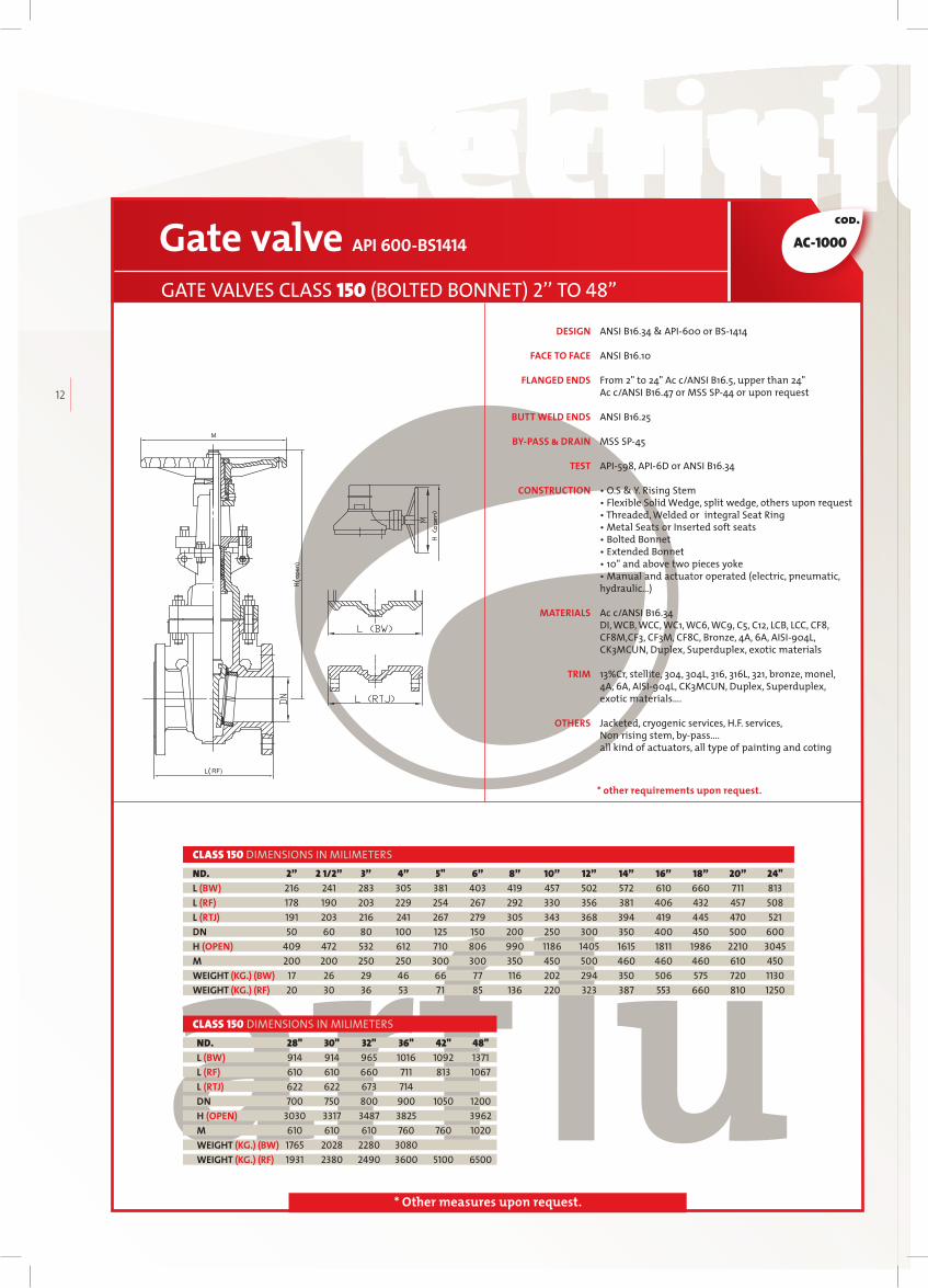
Gate valve API 600-BS1414
GATE VALVES CLASS 150 (BOLTED BONNET) 2’’ TO 48”
28" 30" 32" 36" 42" 48" 914 914 965 1016 1092 1371 610 610 660 711 813 1067 622 622 673 714 700 750 800 900 1050 1200 3030 3317 3487 3825 3962 610 610 610 760 760 1020 1765 2028 2280 3080 1931 2380 2490 3600 5100 6500
ND.L (BW)L (RF)L (RTJ)DNH (OPEN)MWEIGHT (KG.) (BW)WEIGHT (KG.) (RF)
CLASS 150 DIMENSIONS IN MILIMETERS
ND.L (BW)L (RF)L (RTJ) DNH (OPEN) MWEIGHT (KG.) (BW)WEIGHT (KG.) (RF)
CLASS 150 DIMENSIONS IN MILIMETERS 2” 2 1/2” 3” 4” 5" 6” 8” 10” 12” 14” 16” 18” 20” 24" 216 241 283 305 381 403 419 457 502 572 610 660 711 813 178 190 203 229 254 267 292 330 356 381 406 432 457 508 191 203 216 241 267 279 305 343 368 394 419 445 470 521 50 60 80 100 125 150 200 250 300 350 400 450 500 600 409 472 532 612 710 806 990 1186 1405 1615 1811 1986 2210 3045 200 200 250 250 300 300 350 450 500 460 460 460 610 450 17 26 29 46 66 77 116 202 294 350 506 575 720 1130 20 30 36 53 71 85 136 220 323 387 553 660 810 1250
AC-1000
ANSI B16.34 & API600 or BS1414
ANSI B16.10
From 2" to 24" Ac c/ANSI B16.5, upper than 24" Ac c/ANSI B16.47 or MSS SP44 or upon request
ANSI B16.25
MSS SP45
API598, API6D or ANSI B16.34
• O.S & Y. Rising Stem• Flexible Solid Wedge, split wedge, others upon request• Threaded, Welded or integral Seat Ring • Metal Seats or Inserted soft seats • Bolted Bonnet• Extended Bonnet • 10" and above two pieces yoke• Manual and actuator operated (electric, pneumatic, hydraulic…)
Ac c/ANSI B16.34DI, WCB, WCC, WC1, WC6, WC9, C5, C12, LCB, LCC, CF8, CF8M,CF3, CF3M, CF8C, Bronze, 4A, 6A, AISI904L, CK3MCUN, Duplex, Superduplex, exotic materials
13%Cr, stellite, 304, 304L, 316, 316L, 321, bronze, monel, 4A, 6A, AISI904L, CK3MCUN, Duplex, Superduplex, exotic materials….
Jacketed, cryogenic services, H.F. services, Non rising stem, bypass…. all kind of actuators, all type of painting and coting
DESIGN
FACE TO FACE
FLANGED ENDS
BUTT WELD ENDS
BY-PASS & DRAIN
TEST
CONSTRUCTION
MATERIALS
TRIM
OTHERS
* other requirements upon request.

technical datastechnical datas technical datastechnical datas
arfl
uIN
DU
ST
RIA
L V
AL
VE
S
13
cod.
* Other measures upon request.
ANSI B16.34 & API600 or BS1414
ANSI B16.10
From 2" to 24" Ac c/ANSI B16.5, upper than 24" Ac c/ANSI B16.47 or MSS SP44 or upon request
ANSI B16.25
MSS SP45
API598, API6D or ANSI B16.34
• O.S & Y. Rising Stem• Flexible Solid Wedge, split wedge, others upon request• Threaded, Welded or integral Seat Ring • Metal Seats or Inserted soft seats • Bolted Bonnet• Extended Bonnet • 8" and above two pieces yoke• Manual and actuator operated (electric, pneumatic, hydraulic…)
Ac c/ANSI B16.34DI, WCB, WCC, WC1, WC6, WC9, C5, C12, LCB, LCC, CF8, CF8M,CF3, CF3M, CF8C, Bronze, 4A, 6A, AISI904L, CK3MCUN, Duplex, Superduplex, exotic materials
13%Cr, stellite, 304, 304L, 316, 316L, 321, bronze, monel, 4A, 6A, AISI904L, CK3MCUN, Duplex, Superduplex, exotic materials….
Jacketed, cryogenic services, H.F. services, Non rising stem, bypass…. all kind of actuators, all type of painting and coating
DESIGN
FACE TO FACE
FLANGED ENDS
BUTT WELD ENDS
BY-PASS & DRAIN
TEST
CONSTRUCTION
MATERIALS
TRIM
OTHERS
Gate valve API 600-BS1414
GATE VALVES CLASS 300 (BOLTED BONNET) 2’’ TO 48”
2” 2 1/2” 3” 4” 5" 6” 8” 10” 12” 14” 16” 18" 20" 24" 30" 216 241 283 305 381 403 419 457 502 762 838 914 991 1143 1397 ” ” ” ” ” ” ” ” ” ” ” ” ” ” ” 232 257 298 321 397 419 435 473 518 778 854 930 1010 1165 1422 50 65 80 100 125 150 200 250 300 350 400 450 500 600 750 400 477 543 650 770 880 1037 1275 1438 1650 1840 2030 2240 2900 3540 200 250 250 300 300 350 450 500 560 460 460 610 610 610 760 26 34 47 68 77 118 195 271 432 595 848 1025 1460 2294 3220 30 39 55 83 92 137 240 333 536 669 1010 1205 1720 2800 3786
ND.L (BW)L (RF)L (RTJ)DNH (OPEN)MWEIGHT (KG.) (BW)WEIGHT (KG.) (RF)
CLASS 300 DIMENSIONS IN MILIMETERS
28" 30" 32" 36" 42" 48" 1346 1397 1524 1727 2032 2286 1346 1397 1524 1727 2032 2286 1372 1422 1553 1756 700 750 800 900 1050 1200 2641 2743 2857 3048 860 860 860 860 720 720 3600 3780 4235 5900 4027 4310 4850 6632 9750 13050
ND.L (BW)L (RF)L (RTJ)DNH (OPEN)MWEIGHT (KG.) (BW)WEIGHT (KG.) (RF)
CLASS 300 DIMENSIONS IN MILIMETERS
AC-3000
* other requirements upon request.

technical datastechnical datas technical datastechnical datas
14
cod.
* Other measures upon request.
ANSI B16.34 & API600 or BS1414
ANSI B16.10
From 2" to 48" Ac c/ANSI B16.5Ac c/ANSI B16.47 or MSS SP44 or upon request
ANSI B16.25
MSS SP45
API598, API6D or ANSI B16.34
• O.S & Y. Rising Stem• Flexible Solid Wedge, split wedge, others upon request• Threaded, Welded or integral Seat Ring • Metal Seats or Inserted soft seats • Bolted Bonnet• Extended Bonnet • 8" and above two pieces yoke• Manual and actuator operated (electric, pneumatic, hydraulic…)
Ac c/ANSI B16.34DI, WCB, WCC, WC1, WC6, WC9, C5, C12, LCB, LCC, CF8, CF8M,CF3, CF3M, CF8C, Bronze, 4A, 6A, AISI904L, CK3MCUN, Duplex, Superduplex, exotic materials
13%Cr, stellite, 304, 304L, 316, 316L, 321, bronze, monel, 4A, 6A, AISI904L, CK3MCUN, Duplex, Superduplex, exotic materials….
Jacketed, cryogenic services, H.F. services, Non rising stem, bypass…. all kind of actuators, all type of painting and coating
DESIGN
FACE TO FACE
FLANGED ENDS
BUTT WELD ENDS
BY-PASS & DRAIN
TEST
CONSTRUCTION
MATERIALS
TRIM
OTHERS
Gate valve API 600-BS1414
GATE VALVES CLASS 600 (BOLTED BONNET) 2’’ TO 48”
2" 2 1/2” 3” 4” 6” 8” 10” 12” 14” 16" 18" 20" 24" 292 330 356 432 559 660 787 838 889 991 1092 1194 1397 ” ” ” ” ” ” ” ” ” ” ” ” ” 295 333 359 435 562 664 791 841 892 994 1095 1200 1407 50 65 80 100 150 200 250 300 350 400 450 500 600 474 553 593 713 970 1122 1330 1519 1730 1835 2290 2510 3022 250 250 300 350 500 560 720 610 610 610 610 760 760 35 50 68 104 208 328 496 637 1120 1448 1828 2201 3360 41 58 88 131 253 413 623 784 1288 1820 2150 2540 4080
ND.L (BW)L (RF)L (RTJ)DNH (OPEN)MWEIGHT (KG.) (BW)WEIGHT (KG.) (RF)
CLASS 600 DIMENSIONS IN MILIMETERS
28" 30" 32" 36" 42" 48" 1549 1651 1778 2083 2260 2667 1549 1651 1778 2083 2260 2667 1562 1664 1794 2099 700 750 800 900 1050 1200 610 610 720 720 720 720 6160 9580 5960 6700 8312 10125 16460 22900
ND.L (BW)L (RF)L (RTJ)DNH (OPEN)MWEIGHT (KG.) (BW)WEIGHT (KG.) (RF)
CLASS 600 DIMENSIONS IN MILIMETERS
AC-6000
* other requirements upon request.

technical datastechnical datas technical datastechnical datas
arfl
uIN
DU
ST
RIA
L V
AL
VE
S
15
cod.
* Other measures upon request.
ANSI B16.34 & API600 or BS1414
ANSI B16.10
ANSI B16.5
ANSI B16.25
MSS SP45
API598, API6D or ANSI B16.34
• O.S & Y. Rising Stem• Flexible Solid Wedge, split wedge, others upon request• Threaded, Welded or integral Seat Ring • Metal Seats or Inserted soft seats • Bolted Bonnet• Extended Bonnet • 8" and above two pieces yoke• Manual and actuator operated (electric, pneumatic, hydraulic…)
Ac c/ANSI B16.34DI, WCB, WCC, WC1, WC6, WC9, C5, C12, LCB, LCC, CF8, CF8M,CF3, CF3M, CF8C, Bronze, 4A, 6A, AISI904L, CK3MCUN, Duplex, Superduplex, exotic materials
13%Cr, stellite, 304, 304L, 316, 316L, 321, bronze, monel, 4A, 6A, AISI904L, CK3MCUN, Duplex, Superduplex, exotic materials….
Jacketed, cryogenic services, H.F. services, Non rising stem, bypass…. all kind of actuators, all type of painting and coating
DESIGN
FACE TO FACE
FLANGED ENDS
BUTT WELD ENDS
BY-PASS & DRAIN
TEST
CONSTRUCTION
MATERIALS
TRIM
OTHERS
Gate valve API 600-BS1414
GATE VALVES CLASS 900 (BOLTED BONNET) 2’’ TO 20”
2” 2 1/2” 3” 4” 6” 8” 10” 12” 14” 16” 18” 20” 368 419 381 457 610 737 838 965 1029 1130 1219 1321 ” ” ” ” ” ” ” ” ” ” “ “ 371 422 384 460 613 740 841 968 1038 1140 1232 1334 50 65 80 100 150 200 250 300 350 400 450 500 590 666 764 827 895 1173 1050 1243 1332 1500 1634 350 350 400 450 460 460 460 530 530 600 600 600 82 93 108 122 359 566 980 1450 2000 2390 2995 3810 82 93 108 122 359 566 980 1450 2000 2390 2995 3810
ND.L (BW)L (RF)L (RTJ)DNH (OPEN)MWEIGHT (KG.) (BW)WEIGHT (KG.) (RF)
CLASS 900 DIMENSIONS IN MILIMETERS
AC-9000
* other requirements upon request.

technical datastechnical datas technical datastechnical datas
16
cod.
* Other measures upon request.
ANSI B16.34 & API600 or BS1414
ANSI B16.10
ANSI B16.5
ANSI B16.25
MSS SP45
API598, API6D or ANSI B16.34
• O.S & Y. Rising Stem• Flexible Solid Wedge, split wedge, others upon request• Threaded, Welded or integral Seat Ring • Metal Seats or Inserted soft seats • Bolted Bonnet• Extended Bonnet • 8" and above two pieces yoke• Manual and actuator operated (electric, pneumatic, hydraulic…)
Ac c/ANSI B16.34DI, WCB, WCC, WC1, WC6, WC9, C5, C12, LCB, LCC, CF8, CF8M,CF3, CF3M, CF8C, Bronze, 4A, 6A, AISI904L, CK3MCUN, Duplex, Superduplex, exotic materials
13%Cr, stellite, 304, 304L, 316, 316L, 321, bronze, monel,4A, 6A, AISI904L, CK3MCUN, Duplex, Superduplex, exotic materials….
Jacketed, cryogenic services, H.F. services, Non rising stem, bypass…. all kind of actuators, all type of painting and coating
DESIGN
FACE TO FACE
FLANGED ENDS
BUTT WELD ENDS
BY-PASS & DRAIN
TEST
CONSTRUCTION
MATERIALS
TRIM
OTHERS
Gate valve API 600-BS1414
GATE VALVES CLASS 1500 (BOLTED BONNET) 2’’ TO 16”
2" 2 1/2” 3" 4" 6" 8" 10" 12" 14" 16" 368 419 470 546 705 832 991 1130 1257 1384 ” ” ” ” ” ” ” ” ” ” 371 422 473 549 711 841 1000 1146 1276 1407 50 65 80 100 150 200 250 300 350 400 574 700 806 887 1079 1370 1520 1651 1945 2250 350 400 450 560 305* 610* 760* 760* 760* 760 93 144 185 285 584 978 1990 2850 3320 4890 117 175 240 337 680 1228 2278 3260 4100 5960
ND.L (BW)L (RF)L (RTJ)DNH (OPEN)MWEIGHT (KG.) (BW)WEIGHT (KG.) (RF)
CLASS 1500 DIMENSIONS IN MILIMETERS
AC-4000
* other requirements upon request.

technical datastechnical datas technical datastechnical datas
arfl
uIN
DU
ST
RIA
L V
AL
VE
S
17
cod.
* Other measures upon request.
ANSI B16.34
ANSI B16.10
ANSI B16.5
ANSI B16.25
MSS SP45
API598, API6D or ANSI B16.34
• O.S & Y. Rising Stem• Flexible Solid Wedge, split wedge, others upon request• Threaded, Welded or integral Seat Ring • Metal Seats or Inserted soft seats • Pressure Seal• Extended Bonnet • Manual and actuator operated (electric, pneumatic, hydraulic…)
Ac c/ANSI B16.34DI, WCB, WCC, WC1, WC6, WC9, C5, C12, LCB, LCC, CF8, CF8M,CF3, CF3M, CF8C, Bronze, 4A, 6A, AISI904L, CK3MCUN, Duplex, Superduplex, exotic materials
13%Cr, stellite, 304, 304L, 316, 316L, 321, bronze, monel, 4A, 6A, AISI904L, CK3MCUN, Duplex, Superduplex, exotic materials….
Jacketed, cryogenic services, H.F. services, Non rising stem, bypass…. all kind of actuators, all type of painting and coating
DESIGN
FACE TO FACE
FLANGED ENDS
BUTT WELD ENDS
BY-PASS & DRAIN
TEST
CONSTRUCTION
MATERIALS
TRIM
OTHERS
Gate valve ANSI B16.34
GATE VALVES CLASS 900 (PRESSURE SEAL) 2’’ TO 16”
2" 2 1/2” 3” 4” 6” 8” 10” 12” 14” 16” 216 254 305 355 508 660 787 914 991 1092 368 419 381 457 610 737 838 965 1029 1130 371 422 384 460 613 740 841 968 1039 1140 50 65 80 100 150 200 250 300 350 400 554 637 680 796 1084 1372 1494 1550 1960 2210 300 350 350 400 560 460* 610* 610* 610* 760* 60 70 77 101 275 395 690 990 1200 1670 80 90 95 130 310 505 870 1210 1450 2018
ND.L (BW)L (RF)L (RTJ)DNH (OPEN)MWEIGHT (KG.) (BW)WEIGHT (KG.) (RF)
CLASS 900 DIMENSIONS IN MILIMETERS. HIGH PRESSURE - PRESSURE SEAL
AC-9000-P
* other requirements upon request.

technical datastechnical datas technical datastechnical datas
18
cod.
* Other measures upon request.
ANSI B16.34
ANSI B16.10
ANSI B16.5
ANSI B16.25
MSS SP45
API598, API6D or ANSI B16.34
• O.S & Y. Rising Stem• Flexible Solid Wedge, split wedge, others upon request• Threaded, Welded or integral Seat Ring • Metal Seats or Inserted soft seats • Pressure Seal• Extended Bonnet • Manual and actuator operated (electric, pneumatic, hydraulic…)
Ac c/ANSI B16.34DI, WCB, WCC, WC1, WC6, WC9, C5, C12, LCB, LCC, CF8, CF8M,CF3, CF3M, CF8C, Bronze, 4A, 6A, AISI904L, CK3MCUN, Duplex, Superduplex, exotic materials
13%Cr, stellite, 304, 304L, 316, 316L, 321, bronze, monel, 4A, 6A, AISI904L, CK3MCUN, Duplex, Superduplex, exotic materials….
Jacketed, cryogenic services, H.F. services, Non rising stem, bypass…. all kind of actuators, all type of painting and coating
DESIGN
FACE TO FACE
FLANGED ENDS
BUTT WELD ENDS
BY-PASS & DRAIN
TEST
CONSTRUCTION
MATERIALS
TRIM
OTHERS
Gate valve ANSI B16.34
GATE VALVES CLASS 1500 (PRESSURE SEAL) 2’’ TO 16”
2" 2 1/2” 3” 4” 6” 8” 10” 12” 14” 16” 216 254 305 406 559 711 864 991 1067 1194 368 419 470 546 705 832 991 1130 1257 1384 371 422 473 549 711 841 1000 1146 1276 1407 50 65 80 100 150 200 250 300 350 400 554 637 767 875 1094 1372 1655 1834 2150 2260 300 450 450 560 305* 460* 610* 610* 760* 760 46 71 71 130 292 587 974 1615 2010 2815 60 91 91 182 394 795 1370 2120 2800 3870
ND.L (BW)L (RF)L (RTJ)DNH (OPEN)MWEIGHT (KG.) (BW)WEIGHT (KG.) (RF)
CLASS 1500 DIMENSIONS IN MILIMETERS. HIGH PRESSURE - PRESSURE SEAL
AC-4000-P
* other requirements upon request.

technical datastechnical datas technical datastechnical datas
arfl
uIN
DU
ST
RIA
L V
AL
VE
S
19
cod.
* Other measures upon request.
ANSI B16.34
ANSI B16.10
ANSI B16.5
ANSI B16.25
MSS SP45
API598, API6D or ANSI B16.34
• O.S & Y. Rising Stem• Flexible Solid Wedge, split wedge, others upon request• Threaded, Welded or integral Seat Ring • Metal Seats or Inserted soft seats • Pressure Seal• Extended Bonnet • Manual and actuator operated (electric, pneumatic, hydraulic…)
Ac c/ANSI B16.34DI, WCB, WCC, WC1, WC6, WC9, C5, C12, LCB, LCC, CF8, CF8M,CF3, CF3M, CF8C, Bronze, 4A, 6A, AISI904L, CK3MCUN, Duplex, Superduplex, exotic materials
13%Cr, stellite, 304, 304L, 316, 316L, 321, bronze, monel, 4A, 6A, AISI904L, CK3MCUN, Duplex, Superduplex, exotic materials….
Jacketed, cryogenic services, H.F. services, Non rising stem, bypass…. all kind of actuators, all type of painting and coating
DESIGN
FACE TO FACE
FLANGED ENDS
BUTT WELD ENDS
BY-PASS & DRAIN
TEST
CONSTRUCTION
MATERIALS
TRIM
OTHERS
Gate valve ANSI B16.34
GATE VALVES CLASS 2500 (PRESSURE SEAL) 2’’ TO 16”
2" 2 1/2” 3” 4” 6” 8” 10” 12” 14” 16” 279 330 368 457 610 762 914 1041 1118 1245 451 508 578 673 917 1022 1270 1422 454 514 584 683 930 1038 1292 1444 50 65 80 100 150 200 250 300 350 400 610 654 753 850 1254 1374 1685 500 500 600 600 460* 460* 610* 88 135 144 158 500 892 1550 121 175 195 229 720 1295 2250
ND.L (BW)L (RF)L (RTJ)DNH (OPEN)MWEIGHT (KG.) (BW)WEIGHT (KG.) (RF)
CLASS 2500 DIMENSIONS IN MILIMETERS. HIGH PRESSURE - PRESSURE SEAL
AC-7000-P
* other requirements upon request.

technical datastechnical datas technical datastechnical datas
20
cod.
* Other measures upon request.
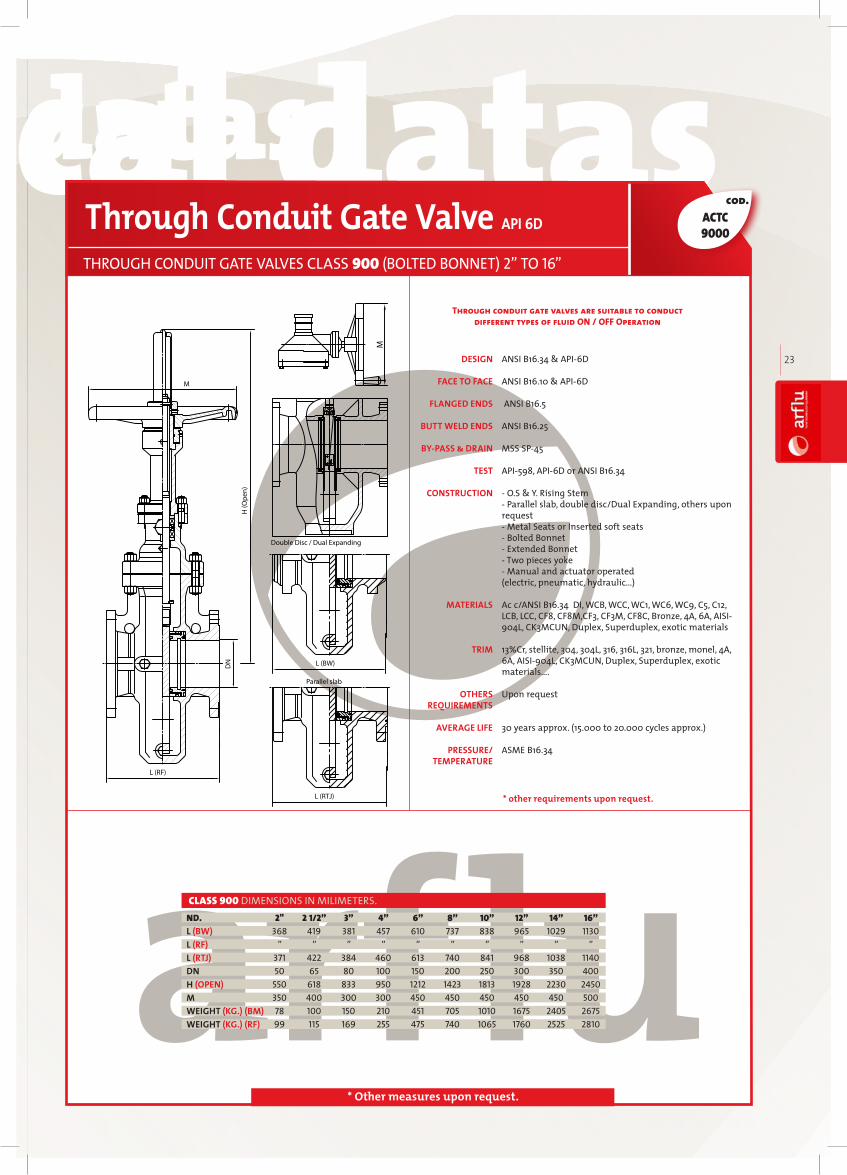
Through conduit gate valves are suitable to conduct different types of fluid ON / OFF Operation
DESIGN
FACE TO FACE
FLANGED ENDS
BUTT WELD ENDS
BY-PASS & DRAIN
TEST
CONSTRUCTION
MATERIALS
TRIM
OTHERS REQUIREMENTS
AVERAGE LIFE
PRESSURE/ TEMPERATURE
Through Conduit Gate Valve API 6D
THROUGH CONDUIT GATE VALVES CLASS 150 (BOLTED BONNET) 2” TO 24”
ACTC 1000
ANSI B16.34 & API6D
ANSI B16.10 & API6D
ANSI B16.5 ANSI B16.25
MSS SP45
API598, API6D or ANSI B16.34
- O.S & Y. Rising Stem Parallel slab, double disc/Dual Expanding, others upon request Metal Seats or Inserted soft seats Bolted Bonnet Extended Bonnet Two pieces yoke Manual and actuator operated (electric, pneumatic, hydraulic…)
Ac c/ANSI B16.34 DI, WCB, WCC, WC1, WC6, WC9, C5, C12, LCB, LCC, CF8, CF8M,CF3, CF3M, CF8C, Bronze, 4A, 6A, AISI904L, CK3MCUN, Duplex, Superduplex, exotic materials
13%Cr, stellite, 304, 304L, 316, 316L, 321, bronze, monel, 4A, 6A, AISI904L, CK3MCUN, Duplex, Superduplex, exotic materials….
Upon request
30 years approx. (15.000 to 20.000 cycles approx.) ASME B16.34
CLASS 150 DIMENSIONS IN MILIMETERS. 2” 2 1/2” 3” 4” 5” 6” 8” 10” 12” 14” 16” 18” 20” 24”216 241 283 305 381 403 419 457 502 572 610 660 711 813178 190 203 229 254 267 292 330 356 381 406 432 457 508191 203 216 241 267 279 305 343 368 394 419 445 470 52150 60 80 100 125 150 200 250 300 350 400 450 500 600475 535 600 700 825 910 1095 1510 1610 1890 2030 2415 2565 3045300 300 300 350 350 350 350 300 300 450 450 450 450 45048 59 63 73 100 158 264 310 420 650 910 1155 1485 237054 70 73 85 120 180 300 350 475 735 1030 1310 1680 2685
ND.L (BW)L (RF)L (RTJ)DNH (OPEN)MWEIGHT (KG.) (BM)WEIGHT (KG.) (RF)
L (RF)
DN
H (O
pen)
M
L (BW)
L (RTJ)
Double Disc / Dual Expanding
Parallel slab
M
* other requirements upon request.

technical datastechnical datas technical datastechnical datas
arfl
uIN
DU
ST
RIA
L V
AL
VE
S
21
cod.
* Other measures upon request.
CLASS 300 DIMENSIONS IN MILIMETERS.
Through conduit gate valves are suitable to conduct different types of fluid ON / OFF Operation
DESIGN
FACE TO FACE
FLANGED ENDS
BUTT WELD ENDS
BY-PASS & DRAIN
TEST
CONSTRUCTION
MATERIALS
TRIM
OTHERS REQUIREMENTS
AVERAGE LIFE
PRESSURE/ TEMPERATURE
Through Conduit Gate Valve API 6D
THROUGH CONDUIT GATE VALVES CLASS 300 (BOLTED BONNET) 2” TO 24”
2” 2 1/2” 3” 4” 5” 6” 8” 10” 12” 14” 16” 18” 20” 24”216 241 283 305 381 403 419 457 502 762 838 914 991 1143” ” ” ” ” ” ” ” ” ” ” ” ” ”232 257 298 321 397 419 435 473 518 778 854 930 1010 116550 65 80 100 125 150 200 250 300 350 400 450 500 600475 535 600 700 810 910 1235 1510 1610 1890 2030 2415 2565 3045250 300 300 350 350 350 300 300 300 450 450 450 450 45051 62 66 78 130 159 290 435 605 920 1300 1670 2160 347054 70 73 90 150 180 320 490 680 1035 1450 1860 2380 3810
ND.L (BW)L (RF)L (RTJ)DNH (OPEN)MWEIGHT (KG.) (BM)WEIGHT (KG.) (RF)
ACTC 3000
ANSI B16.34 & API6D
ANSI B16.10 & API6D
ANSI B16.5 ANSI B16.25
MSS SP45
API598, API6D or ANSI B16.34
- O.S & Y. Rising Stem Parallel slab, double disc/Dual Expanding, others upon request Metal Seats or Inserted soft seats Bolted Bonnet Extended Bonnet Two pieces yoke Manual and actuator operated (electric, pneumatic, hydraulic…)
Ac c/ANSI B16.34 DI, WCB, WCC, WC1, WC6, WC9, C5, C12, LCB, LCC, CF8, CF8M,CF3, CF3M, CF8C, Bronze, 4A, 6A, AISI904L, CK3MCUN, Duplex, Superduplex, exotic materials
13%Cr, stellite, 304, 304L, 316, 316L, 321, bronze, monel, 4A, 6A, AISI904L, CK3MCUN, Duplex, Superduplex, exotic materials….
Upon request
30 years approx. (15.000 to 20.000 cycles approx.) ASME B16.34
L (RF)
DN
H (O
pen)
M
L (BW)
L (RTJ)
Double Disc / Dual Expanding
Parallel slab
M
* other requirements upon request.

technical datastechnical datas technical datastechnical datas
22
cod.
* Other measures upon request.
CLASS 600 DIMENSIONS IN MILIMETERS.
ANSI B16.34 & API6D
ANSI B16.10 & API6D
ANSI B16.5 ANSI B16.25
MSS SP45
API598, API6D or ANSI B16.34
- O.S & Y. Rising Stem Parallel slab, double disc/Dual Expanding, others upon request Metal Seats or Inserted soft seats Bolted Bonnet Extended Bonnet Two pieces yoke Manual and actuator operated (electric, pneumatic, hydraulic…)
Ac c/ANSI B16.34 DI, WCB, WCC, WC1, WC6, WC9, C5, C12, LCB, LCC, CF8, CF8M,CF3, CF3M, CF8C, Bronze, 4A, 6A, AISI904L, CK3MCUN, Duplex, Superduplex, exotic materials
13%Cr, stellite, 304, 304L, 316, 316L, 321, bronze, monel, 4A, 6A, AISI904L, CK3MCUN, Duplex, Superduplex, exotic materials….
Upon request
30 years approx. (15.000 to 20.000 cycles approx.) ASME B16.34
DESIGN
FACE TO FACE
FLANGED ENDS
BUTT WELD ENDS
BY-PASS & DRAIN
TEST
CONSTRUCTION
MATERIALS
TRIM
OTHERS REQUIREMENTS
AVERAGE LIFE
PRESSURE/ TEMPERATURE
Through Conduit Gate Valve API 6D
THROUGH CONDUIT GATE VALVES CLASS 600 (BOLTED BONNET) 2” TO 24”
2” 2 1/2” 3” 4” 6” 8” 10” 12” 14” 16” 18” 20” 24”292 330 356 432 559 660 787 838 889 991 1092 1194 1397” ” ” ” ” ” ” ” ” ” ” ” ”295 333 359 435 562 664 791 841 892 994 1095 1200 140750 65 80 100 150 200 250 300 350 400 450 500 600499 562 630 735 1096 1290 1580 1705 1977 2125 2525 2685 2922300 350 350 400 300 300 450 450 450 450 450 450 50059 78 106 134 235 405 570 995 1345 1400 2000 2425 387068 90 122 167 280 505 750 1190 1660 1850 2490 3045 4810
ND.L (BW)L (RF)L (RTJ)DNH (OPEN)MWEIGHT (KG.) (BM)WEIGHT (KG.) (RF)
L (RF)
DN
H (O
pen)
M
L (BW)
L (RTJ)
Double Disc / Dual Expanding
Parallel slab
M
* other requirements upon request.
ACTC 6000
Through conduit gate valves are suitable to conduct different types of fluid ON / OFF Operation
technical datastechnical datas technical datastechnical datas
arfl
uIN
DU
ST
RIA
L V
AL
VE
S
23
cod.
* Other measures upon request.
ANSI B16.34 & API6D
ANSI B16.10 & API6D
ANSI B16.5 ANSI B16.25
MSS SP45
API598, API6D or ANSI B16.34
- O.S & Y. Rising Stem Parallel slab, double disc/Dual Expanding, others upon request Metal Seats or Inserted soft seats Bolted Bonnet Extended Bonnet Two pieces yoke Manual and actuator operated (electric, pneumatic, hydraulic…)
Ac c/ANSI B16.34 DI, WCB, WCC, WC1, WC6, WC9, C5, C12, LCB, LCC, CF8, CF8M,CF3, CF3M, CF8C, Bronze, 4A, 6A, AISI904L, CK3MCUN, Duplex, Superduplex, exotic materials
13%Cr, stellite, 304, 304L, 316, 316L, 321, bronze, monel, 4A, 6A, AISI904L, CK3MCUN, Duplex, Superduplex, exotic materials….
Upon request
30 years approx. (15.000 to 20.000 cycles approx.) ASME B16.34
DESIGN
FACE TO FACE
FLANGED ENDS
BUTT WELD ENDS
BY-PASS & DRAIN
TEST
CONSTRUCTION
MATERIALS
TRIM
OTHERS REQUIREMENTS
AVERAGE LIFE
PRESSURE/ TEMPERATURE
Through Conduit Gate Valve API 6D
THROUGH CONDUIT GATE VALVES CLASS 900 (BOLTED BONNET) 2” TO 16”
2" 2 1/2” 3” 4” 6” 8” 10” 12” 14” 16” 368 419 381 457 610 737 838 965 1029 1130 ” ” ” ” ” ” ” ” ” ” 371 422 384 460 613 740 841 968 1038 1140 50 65 80 100 150 200 250 300 350 400 550 618 833 950 1212 1423 1813 1928 2230 2450 350 400 300 300 450 450 450 450 450 500 78 100 150 210 451 705 1010 1675 2405 2675 99 115 169 255 475 740 1065 1760 2525 2810
ND.L (BW)L (RF)L (RTJ)DNH (OPEN)MWEIGHT (KG.) (BM)WEIGHT (KG.) (RF)
CLASS 900 DIMENSIONS IN MILIMETERS.
L (RF)
DN
H (O
pen)
M
L (BW)
L (RTJ)
Double Disc / Dual Expanding
Parallel slab
M
* other requirements upon request.
ACTC 9000
Through conduit gate valves are suitable to conduct different types of fluid ON / OFF Operation

GLOBEVALVES
24
GLOBEVALVES
Globe valvesBecause of their configura-tion, globe valves are perfect to regulate or limit the flow. Depending on the system needs, design or position, they could generate different head losses in the line.

BS 1873 steel globe and globe stop and check valves (flanged and butt welding ends) for the petroleum, petrochemical and allied industriesB55352 steel gate, globe and check valves for sizes dn 2” and smaller for the petroleum and natural gas industriesASME B16.34 valves flanged, threaded, and welding end API 602 Steel Gate, Globe and Check Valves for Sizes DN 100 and Smaller for the Petroleum and Natural Gas Industries
DESIGN AND MANUFACTURING:
MANUFACTURING AND DESIGN
Globe valves are designed and manufactured according to the following international codes and standards:
API 598 valve inspection and testingBS1873 steel globe and globe stop and check valves (flanged and buttwelding ends)
INSPECTION AND TEST:
ASME B16.5 pipe flanges and flanged fittings
FLANGE DIMENSION:
ASME B16.25 buttwelding endsASME B16.11 forged steel fittings, socketwelding and threadedASME B1.20.1 pipe threads general purpose
WELDED OR THREADED ENDS:
STANDARDS
ASME B16.10 face to face and endtoend dimensions of valves
FACE TO FACE AND END TO END
arfl
uIN
DU
ST
RIA
L V
AL
VE
S
25

DESIGN FEATURES
The valve body is manufactured of cast steel, or forged steel, depending on the customer’s requirements. In any case ANSI B16.34 pressuretemperature ratings, and BS 1873, or B55352 minimum wall thickness are strictly fulfilled.
Globe valves are unidirectional and may be installed in both vertical and horizontal position.
All ratings valves have circular sections to make minimum stresses, under severe working conditions,. These sections are carefully calculated in order to prevent stress concentrations.
Sealing ring seating is carefully machined and inspected to prevent leakage between seat ring and body. Seating surface must be 1,6 AARH at least.
Machining on seat sealing is controlled to ensure perfect sealing and interchange ability with spare parts.
Special care is taken to ensure body end flanges and bonnet flange to be parallel and perpendicular to prevent operating problems in line and during testing.
Flange facing is spiral smooth finish 125250 AARH standard machining. Other facings are available under request.
Auxiliary connection bosses are provided according to ASME B16.34 for instrumentation, drain, or measure purposes.
Flange dimensions fulfil with ASME B16.5. Other flange types may be produced under request.
BODY
cases opening is in two steps. In the first one the pressure equalizes on both sizes of the plug, and in the second one the valve opens. For pipelines with a lot of turbulence, or for valves in vertical position, the plug is guided in the seat ring.
Special manufactures such as parabolycal or percentual plug, or SOFT SEATED may be produced for special applications.
Sealing surfaces are carefully machined so that long life, small torque, and no leakage are achieved.
Bonnet design is circular for all ratings. In all cases bonnet flange thickness is designed to work under most severe conditions according to ASME B16.34.
Body bonnet connection is usually malefemale designed up to 900 class valves. For class 1500 and 2500 pressure seal design is preferable. On request other connections such as RTJ seal may be supplied. Auxiliary connection bosses are provided according to ASME B16.34 for instrumentation, drain, or measure purposes.
Bonnet machining is carefully checked to ensure disc travel to be perpendicular to the bore line, so that operating problems are avoided. Stem nut seating must be parallel to bonnet connection.
Stuffing box must be extremely smooth machined to provide perfect tightness without applying too much strength on the eye bolts. Life loaded stuffing box may be fitted for special applications using Belleville springs to improve durability and reliability of the packing seal.
BONNET
GLOBE VALVES
For carbon steel valves seat ring is manufactured from forged steel. The sealing surface is sprayed welded with the material required by customer. Renewable threaded seat is used for NPS 10” and smaller valves, welded seat design is used for NPS 12” and bigger. For stainless steel valves usually integral seat is used, overlaid, or not. Other constructions are available under request.
Seat surfaces are carefully machined to provide tightness. Special attention must be taken with the seat ring thread to avoid seizing.
Special care is taken to provide hardness difference between seat and wedge according to BS 1873. For this reason seat rings are heat treated.
SEAT
The disc seats on the seat ring to tight the valve. Disc is designed to revolve free over the stem to avoid rubbing against the seat ring while closing and prevent galling at the closure.
Plug sealing surface is at least 13% Cr, integral or overlaid.
Usually plug works opposite to the pressure line. For big size valves, or big ratings, to achieve a smaller torque on line, the design is changed to make plug work parallel to the pressure line. In this
DISC
26
MATERIALS

GLAND ASSEMBLYStem nut is made of different materials such as ASTM A439 D2, NiResist, or Aluminium bronze. Depending on the size and class of the valves rolling bearings are fitted on both sides of the stem nut, in order to make torque operation minimum.
STEM NUTSTEMStem is made of one piece forged steel. The diameter of the stem fulfil with BS1873.
Stem connection is T type. T head is properly designed to allow the plug adapt to the stem in any assembling position (vertical or horizontal). In some cases a washer is assembled to help the plug adapt to the stem.
Stem connection is designed to prevent the stem being disengaged from the plug using a stem nut and one split washer.
Back seat sealing face is carefully machined to provide tightness on pressurized pipe line with valve fully opened. For this reason the surface finish of the packing seal must be smooth enough.
Machining of ACME threads is smooth enough to obtain a low operating torque.
BACK SEATAll of our valves have back seat design according to BS 1873. Carbon steel valves are fitted with renewable back seat 13% Cr minimum. For stainless steel valves, the back seat is directly machined on the body. Overlaid surface is possible under request.
The gland flange and the gland bushing push the packing rings to make them seal the stuffing box and the stem.Gland bushing is shoulder type to prevent over strength over the packing. Gland flange is designed with enough resistance to work on the most severe conditions.Gland flange and gland bushing are self adjusting to each other to ensure perpendicular pressure on the packing.
Special design valves may be supplied under request;
Jacketed valves, extended bonnet valves, cryogenic valves, bellow seal valves, flat gate valves, and so on..
SPECIAL VALVES
arfl
uIN
DU
ST
RIA
L V
AL
VE
S
271
2
3
4
5
6
7
8
9
10
11
12
13
14
15
16
17
18
19
HAND WHEEL NUT
HAND WHEEL
STEM NUT
EYEBOLT NUT
GLAND FLANGE
GLAND
GLAND EYEBOLT
EYEBOLT PIN
PACKING
BONNET
BACKSEAT BUSHING
GASKET
BONNET BOLT
BONNET NUT
DISC NUT
STEM
DISC
SEAT RING
BODY
Carbon steel Carbon steel Carbon steel
Ductile Iron Ductile Iron Ductile Iron
ASTM A439 D2 ASTM A439 D2 ASTM A439 D2
ASTM A194 2H ASTM A194 8 ASTM A194 8M
ASTM A216 WCB ASTM A351 CF8 ASTM A351 CF8M
ASTM A182 F6a ASTM A182 F304 ASTM A182 F316
ASTM A193 B7 ASTM A193 B8 ASTM A193 B8M
ASTM A36 SS 304 SS 316
Graphite Graphite Graphite
ASTM A216 WCB ASTM A351 CF8 ASTM A351 CF8M
ASTM A182 F6a ASTM A351 CF8 ASTM A351 CF8M
SS 304 + Graphite 304 + Graphite 316 + Graphite
ASTM A193 B7 ASTM A193 B8 ASTM A193 B8M
ASTM A194 2H ASTM A194 8 ASTM A194 8M
ASTM A216 WCB ASTM A351 CF8 ASTM A351 CF8M
ASTM A182 F6a ASTM A182 F304 ASTM A182 F316
ASTM A351 CF8 ASTM A351 CF8M
ASTM A351 CF8 ASTM A351 CF8M
ASTM A216 WCB ASTM A351 CF8 ASTM A351 CF8M
WCB TRIM 1/5/8 CF8/304 CF8M/316
MATERIALS
ASTM A216 WCB + 13%CR ASTM A216 WCB + STL ASTM A216 WCB + 13%CR
A105 + 13%CR A105 + STL A105 + STL
Carbon steel Carbon steel Carbon steel
Ductile Iron Ductile Iron Ductile Iron
ASTM A439 D2 ASTM A439 D2 ASTM A439 D2
ASTM A194 4 ASTM A194 7 ASTM A194 7
ASTM A352 LCB ASTM A217 WC6 ASTM A217 C5
ASTM A182 F6A ASTM A182 F6A
ASTM A193 L7 ASTM A193 B16 ASTM A193 B16
ASTM A36 ASTM A36 ASTM A36
Graphite Graphite Graphite
ASTM A352 LCB ASTM A217 WC6 ASTM A217 C5
ASTM A182 F6A ASTM A182 F6A
304 + Graphite 304 + Graphite
ASTM A193 L7 ASTM A193 B16 ASTM A193 B16
ASTM A194 4 ASTM A194 7 ASTM A194 7
ASTM A352 LCB ASTM A217 WC6 ASTM A217 C5
ASTM A182 F6A ASTM A182 F6A
ASTM A352 LCB ASTM A217 WC6 ASTM A351 CF8M
a
LCB TRIM 8/10 WC6 TRIM 5/8 C5 TRIM 5/8
TRIM 5 TRIM 8
ASTM A217 WC6 + STL ASTM A217 WC6 + 13%CR
TRIM 5 TRIM 8
ASTM A217 C5 + STL ASTM A217 C5 + 13%CR
TRIM 5 TRIM 8
ASTM A217 WC6 + STL ASTM A217 WC6 + STL
TRIM 5 TRIM 8
ASTM A217 C5 + STL ASTM A217 C5 + STL
TRIM 8 TRIM 10
TRIM 8 TRIM 10
TRIM 8 TRIM 10
ASTM A182 F6A ASTM A182 F316
ASTM A352 LCB + 13% CR ASTM A352 LCB + AISI 316
A350 LF2 + STL ASTM A352 LCB + AISI 316
TRIM 8 TRIM 10
ASTM A182 F6A ASTM A182 F316
TRIM 8 TRIM 10
ASTM A182 F6A ASTM A182 F316
TRIM 8 TRIM 10
304 + GRAPHITE 316 + GRAPHITE
technical datastechnical datas technical datastechnical datas
28
cod.
* Other measures upon request.
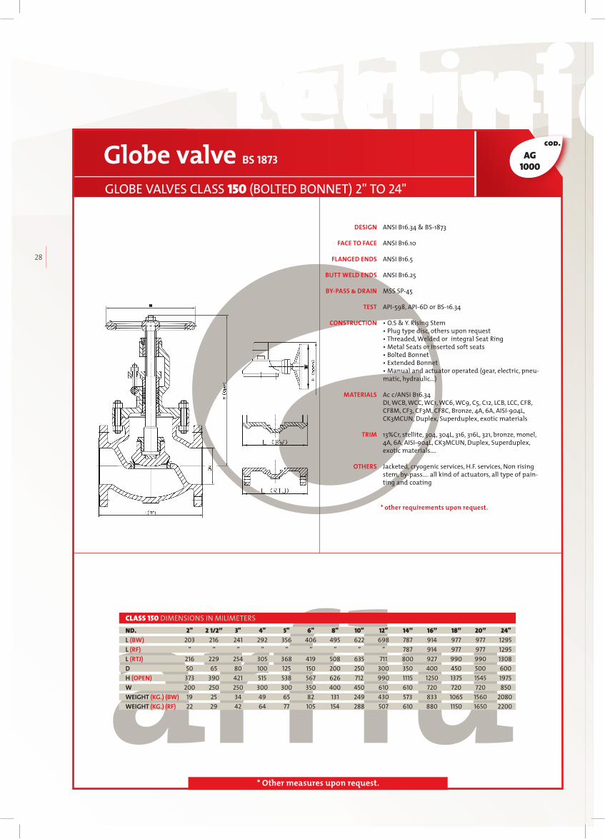
ANSI B16.34 & BS1873
ANSI B16.10
ANSI B16.5
ANSI B16.25
MSS SP45
API598, API6D or BS16.34
• O.S & Y. Rising Stem• Plug type disc, others upon request• Threaded, Welded or integral Seat Ring • Metal Seats or Inserted soft seats • Bolted Bonnet• Extended Bonnet • Manual and actuator operated (gear, electric, pneumatic, hydraulic…)
Ac c/ANSI B16.34DI, WCB, WCC, WC1, WC6, WC9, C5, C12, LCB, LCC, CF8, CF8M, CF3, CF3M, CF8C, Bronze, 4A, 6A, AISI904L, CK3MCUN, Duplex, Superduplex, exotic materials
13%Cr, stellite, 304, 304L, 316, 316L, 321, bronze, monel, 4A, 6A, AISI904L, CK3MCUN, Duplex, Superduplex, exotic materials….
Jacketed, cryogenic services, H.F. services, Non rising stem, bypass…. all kind of actuators, all type of painting and coating
DESIGN
FACE TO FACE
FLANGED ENDS
BUTT WELD ENDS
BY-PASS & DRAIN
TEST
CONSTRUCTION
MATERIALS
TRIM
OTHERS
Globe valve BS 1873
GLOBE VALVES CLASS 150 (BOLTED BONNET) 2" TO 24"
2" 2 1/2” 3" 4" 5" 6" 8" 10" 12" 14” 16” 18” 20” 24" 203 216 241 292 356 406 495 622 698 787 914 977 977 1295 ” ” ” ” ” ” ” ” ” 787 914 977 977 1295 216 229 254 305 368 419 508 635 711 800 927 990 990 1308 50 65 80 100 125 150 200 250 300 350 400 450 500 600 373 390 421 515 538 567 626 712 990 1115 1250 1375 1545 1975 200 250 250 300 300 350 400 450 610 610 720 720 720 850 19 25 34 49 65 82 131 249 430 573 833 1065 1560 2080 22 29 42 64 77 105 154 288 507 610 880 1150 1650 2200
ND.L (BW)L (RF)L (RTJ)DH (OPEN)WWEIGHT (KG.) (BW)WEIGHT (KG.) (RF)
CLASS 150 DIMENSIONS IN MILIMETERS
AG1000
WW
* other requirements upon request.

technical datastechnical datas technical datastechnical datas
arfl
uIN
DU
ST
RIA
L V
AL
VE
S
29
cod.
* Other measures upon request.
AG3000
ANSI B16.34 & BS1873
ANSI B16.10
Ac c/ANSI B16.5
ANSI B16.25
MSS SP45
API598, API6D or BS16.34
• O.S & Y. Rising Stem• Plug type disc, others upon request• Threaded, Welded or integral Seat Ring • Metal Seats or Inserted soft seats • Bolted Bonnet• Extended Bonnet • Manual and actuator operated (gear, electric, pneumatic, hydraulic…)
Ac c/ANSI B16.34DI, WCB, WCC, WC1, WC6, WC9, C5, C12, LCB, LCC, CF8, CF8M, CF3, CF3M, CF8C, Bronze, 4A, 6A, AISI904L, CK3MCUN, Duplex, Superduplex, exotic materials
13%Cr, stellite, 304, 304L, 316, 316L, 321, bronze, monel, 4A, 6A,AISI904L, CK3MCUN, Duplex, Superduplex, exotic materials….
Jacketed, cryogenic services, H.F. services, Non rising stem, bypass…. all kind of actuators, all type of painting and coating
DESIGN
FACE TO FACE
FLANGED ENDS
BUTT WELD ENDS
BY-PASS & DRAIN
TEST
CONSTRUCTION
MATERIALS
TRIM
OTHERS
Globe valve BS 1873
GLOBE VALVES CLASS 300 (BOLTED BONNET) 2" TO 24"
2" 2 1/2” 3" 4" 5" 6" 8" 10" 12" 14” 16” 18” 20” 24" 267 292 318 356 400 444 559 622 711 838 863 977 1016 1346 ” ” ” ” ” ” ” ” ” “ “ “ “ “ 283 308 333 371 416 460 575 638 727 854 879 993 1035 50 65 80 100 125 150 200 250 300 350 400 450 500 600 398 436 462 560 620 694 982 1130 1049 200 250 250 350 400 450 560 864 460* 610 610 610 720 720 26 28 44 68 110 138 228 329 618 31 43 57 86 130 168 280 385 724 876 1200 1600 2100 3150
ND.L (BW)L (RF)L (RTJ)DH (OPEN)WWEIGHT (KG.) (BW)WEIGHT (KG.) (RF)
CLASS 300 DIMENSIONS IN MILIMETERS
W
1368
* other requirements upon request.

technical datastechnical datas technical datastechnical datas
30
cod.
* Other measures upon request.
ANSI B16.34 & BS1873
ANSI B16.10
ANSI B16.5
ANSI B16.25
MSS SP45
API598, API6D or BS16.34
• O.S & Y. Rising Stem• Plug type disc, others upon request• Threaded, Welded or integral Seat Ring • Metal Seats or Inserted soft seats • Bolted Bonnet• Extended Bonnet • Manual and operated (gear, electric, pneumatic, hydraulic…)
Ac c/ANSI B16.34DI, WCB, WCC, WC1, WC6, WC9, C5, C12, LCB, LCC, CF8, CF8M, CF3, CF3M, CF8C, Bronze, 4A, 6A, AISI904L, CK3MCUN, Duplex, Superduplex, exotic materials
13%Cr, stellite, 304, 304L, 316, 316L, 321, bronze, monel, 4A, 6A, AISI904L, CK3MCUN, Duplex, Superduplex, exotic materials….
Jacketed, cryogenic services, H.F. services, Non rising stem, bypass…. all kind of actuators, all type of painting and coating
DESIGN
FACE TO FACE
FLANGED ENDS
BUTT WELD ENDS
BY-PASS & DRAIN
TEST
CONSTRUCTION
MATERIALS
TRIM
OTHERS
Globe valve BS 1873
GLOBE VALVES CLASS 600 (BOLTED BONNET) 2" TO 16"
2" 2 1/2” 3" 4" 6" 8" 10" 12" 14” 16” 292 330 356 432 559 660 787 838 889 991 ” ” ” ” ” ” ” ” ” ” 295 333 359 435 562 663 790 841 892 994 50 65 80 100 150 200 250 300 350 600 425 502 521 548 780 852 936 1132 1280 1400 250 300 350 400 460 550 550 550 550 610 33 48 61 95 324 507 729 1085 1295 1525 34 56 68 120 349 532 754 1100 1320 1550
ND.L (BW)L (RF)L (RTJ)DH (OPEN)WWEIGHT (KG.) (BW)WEIGHT (KG.) (RF)
CLASS 600 DIMENSIONS IN MILIMETERS
W
* other requirements upon request.
AG6000

technical datastechnical datas technical datastechnical datas
arfl
uIN
DU
ST
RIA
L V
AL
VE
S
31
cod.
* Other measures upon request.
ANSI B16.34 & BS1873
ANSI B16.10
ANSI B16.5
ANSI B16.25
MSS SP45
API598, API6D or BS16.34
• O.S & Y. Rising Stem• Plug type disc, others upon request• Threaded, Welded or integral Seat Ring • Metal Seats or Inserted soft seats • Bolted Bonnet• Extended Bonnet • Manual and operated (gear, electric, pneumatic, hydraulic…)
Ac c/ANSI B16.34DI, WCB, WCC, WC1, WC6, WC9, C5, C12, LCB, LCC, CF8, CF8M, CF3, CF3M, CF8C, Bronze, 4A, 6A, AISI904L, CK3MCUN, Duplex, Superduplex, exotic materials
13%Cr, stellite, 304, 304L, 316, 316L, 321, bronze, monel, 4A, 6A, AISI904L, CK3MCUN, Duplex, Superduplex, exotic materials….
Jacketed, cryogenic services, H.F. services, Non rising stem, bypass…. all kind of actuators, all type of painting and coating
DESIGN
FACE TO FACE
FLANGED ENDS
BUTT WELD ENDS
BY-PASS & DRAIN
TEST
CONSTRUCTION
MATERIALS
TRIM
OTHERS
Globe valve BS 1873
GLOBE VALVES CLASS 900 (BOLTED BONNET) 2" TO 12"
2" 2 1/2” 3" 4" 6" 8" 10” 12” 368 419 381 457 610 737 838 965 368 419 381 457 610 737 838 965 371 422 384 460 613 740 841 968 50 65 80 100 150 200 250 300 428 465 502 630 899 985 1050 1141 350 400 400 460 460 460 610 610 75 94 105 260 340 665 1200 1360 100 118 130 293 464 745 1300 1450
ND.L (BW)L (RF)L (RTJ)DH (OPEN)WWEIGHT (KG.) (BW)WEIGHT (KG.) (RF)
CLASS 900 DIMENSIONS IN MILIMETERS
* other requirements upon request.
AG9000

technical datastechnical datas technical datastechnical datas
32
cod.
* Other measures upon request.
* other requirements upon request.
AG4000
ANSI B16.34 & BS1873
ANSI B16.10 ANSI B16.5
ANSI B16.25
MSS SP45
API598, API6D or BS16.34
• O.S & Y. Rising Stem• Plug type disc, others upon request• Threaded, Welded or integral Seat Ring • Metal Seats or Inserted soft seats • Bolted Bonnet• Extended Bonnet • Manual and operated (gear, electric, pneumatic, hydraulic…)
Ac c/ANSI B16.34DI, WCB, WCC, WC1, WC6, WC9, C5, C12, LCB, LCC, CF8, CF8M, CF3, CF3M, CF8C, Bronze, 4A, 6A, AISI904L, CK3MCUN, Duplex, Superduplex, exotic materials
13%Cr, stellite, 304, 304L, 316, 316L, 321, bronze, monel, 4A, 6A, AISI904L, CK3MCUN, Duplex, Superduplex, exotic materials….
Jacketed, cryogenic services, H.F. services, Non rising stem, bypass…. all kind of actuators, all type of painting and coating
DESIGN
FACE TO FACE
FLANGED ENDS
BUTT WELD ENDS
BY-PASS & DRAIN
TEST
CONSTRUCTION
MATERIALS
TRIM
OTHERS
Globe valve BS 1873
GLOBE VALVES 1500 LBS (BOLTED BONNET) 2" TO 8"
2" 2 1/2” 3" 4" 6" 8" 368 419 470 546 705 832 ” ” ” ” ” ” 371 422 473 549 711 841 50 65 80 100 150 200 592 660 692 907 1015 1145 350 400 450 460* 610* 610* 84 115 183 277 715 615 112 141 228 336 822 720
ND.L (BW)L (RF)L (RTJ)DH (OPEN)MWEIGHT (KG.) (BW)WEIGHT (KG.) (RF)
CLASS 1500 DIMENSIONS IN MILIMETERS

technical datastechnical datas technical datastechnical datas
arfl
uIN
DU
ST
RIA
L V
AL
VE
S
33
cod.
* Other measures upon request.
ANSI B16.34
ANSI B16.10
ANSI B16.5
ANSI B16.25
MSS SP45
API598, API6D or BS16.34
• O.S & Y. Rising Stem• Plug type disc, others upon request• Threaded, Welded or integral Seat Ring • Metal Seats or Inserted soft seats • Pressure Seal• Extended Bonnet • Manual and operated (gear, electric, pneumatic, hydraulic…)
Ac c/ANSI B16.34DI, WCB, WCC, WC1, WC6, WC9, C5, C12, LCB, LCC, CF8, CF8M, CF3, CF3M, CF8C, Bronze, 4A, 6A, AISI904L, CK3MCUN, Duplex, Superduplex, exotic materials
13%Cr, stellite, 304, 304L, 316, 316L, 321, bronze, monel, 4A, 6A, AISI904L, CK3MCUN, Duplex, Superduplex, exotic materials….
Jacketed, cryogenic services, H.F. services, Non rising stem, bypass…. all kind of actuators, all type of painting and coating
DESIGN
FACE TO FACE
FLANGED ENDS
BUTT WELD ENDS
BY-PASS & DRAIN
TEST
CONSTRUCTION
MATERIALS
TRIM
OTHERS
Globe valve ANSI B16.34
GLOBE VALVES CLASS 900 (PRESSURE SEAL) 2" TO 8"
2" 2 1/2” 3" 4" 6" 8" 216 254 305 356 508 660 368 419 381 457 610 737 371 422 384 460 613 740 50 65 80 100 150 200 550 605 678 798 930 1260 350 350 400 450 458 610* 66 91 87 128 355 868 78 108 102 142 400 960
ND.L (BW)L (RF)L (RTJ)DH (OPEN)WWEIGHT (KG.) (BW)WEIGHT (KG.) (RF)
CLASS 900 DIMENSIONS IN MILIMETERS. PRESSURE SEAL
W
* other requirements upon request.
AG9000-P
technical datastechnical datas technical datastechnical datas
34
cod.
* Other measures upon request.
ANSI B16.34
ANSI B16.10
ANSI B16.5
ANSI B16.25
MSS SP45
API598, API6D or BS16.34
• O.S & Y. Rising Stem• Plug type disc, others upon request• Threaded, Welded or integral Seat Ring • Metal Seats or Inserted soft seats • Pressure Seal• Extended Bonnet • Manual and operated (gear, electric, pneumatic, hydraulic…)
Ac c/ANSI B16.34DI, WCB, WCC, WC1, WC6, WC9, C5, C12, LCB, LCC, CF8, CF8M, CF3, CF3M, CF8C, Bronze, 4A, 6A, AISI904L, CK3MCUN, Duplex, Superduplex, exotic materials
13%Cr, stellite, 304, 304L, 316, 316L, 321, bronze, monel, 4A, 6A,AISI904L, CK3MCUN, Duplex, Superduplex, exotic materials….
Jacketed, cryogenic services, H.F. services, Non rising stem, bypass…. all kind of actuators, all type of painting and coating
DESIGN
FACE TO FACE
FLANGED ENDS
BUTT WELD ENDS
BY-PASS & DRAIN
TEST
CONSTRUCTION
MATERIALS
TRIM
OTHERS
Globe valve ANSI B16.34
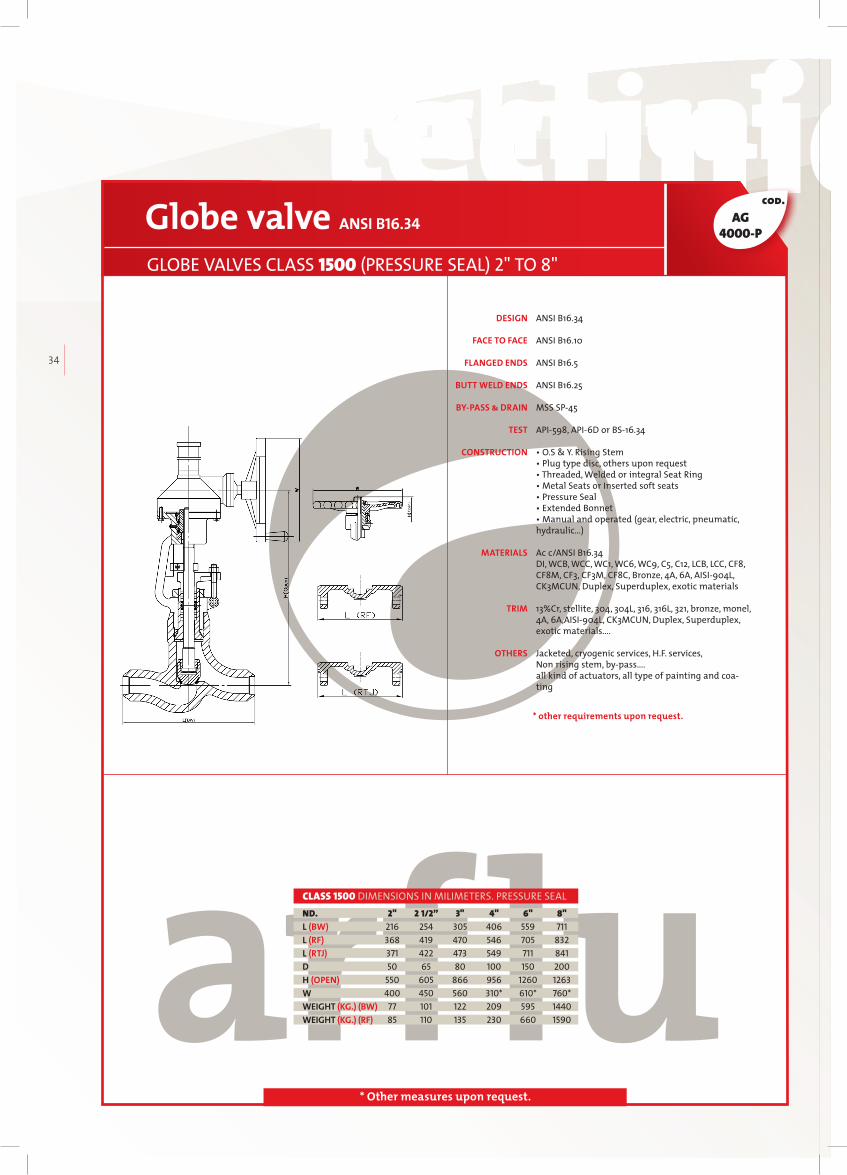
GLOBE VALVES CLASS 1500 (PRESSURE SEAL) 2" TO 8"
2" 2 1/2” 3" 4" 6" 8" 216 254 305 406 559 711 368 419 470 546 705 832 371 422 473 549 711 841 50 65 80 100 150 200 550 605 866 956 1260 1263 400 450 560 310* 610* 760* 77 101 122 209 595 1440 85 110 135 230 660 1590
ND.L (BW)L (RF)L (RTJ)DH (OPEN)WWEIGHT (KG.) (BW)WEIGHT (KG.) (RF)
CLASS 1500 DIMENSIONS IN MILIMETERS. PRESSURE SEAL
W
* other requirements upon request.
AG4000-P

technical datastechnical datas technical datastechnical datas
arfl
uIN
DU
ST
RIA
L V
AL
VE
S
35
cod.
* Other measures upon request.
ANSI B16.34
ANSI B16.10
ANSI B16.5
ANSI B16.25
MSS SP45
API598, API6D or BS16.34
• O.S & Y. Rising Stem• Plug type disc, others upon request• Threaded, Welded or integral Seat Ring • Metal Seats or Inserted soft seats • Pressure Seal• Extended Bonnet • Manual and operated (gear, electric, pneumatic, hydraulic…)
Ac c/ANSI B16.34DI, WCB, WCC, WC1, WC6, WC9, C5, C12, LCB, LCC, CF8, CF8M, CF3, CF3M, CF8C, Bronze, 4A, 6A, AISI904L, CK3MCUN, Duplex, Superduplex, exotic materials
13%Cr, stellite, 304, 304L, 316, 316L, 321, bronze, monel, 4A, 6A, AISI904L, CK3MCUN, Duplex, Superduplex, exotic materials….
Jacketed, cryogenic services, H.F. services, Non rising stem, bypass…. all kind of actuators, all type of painting and coating
DESIGN
FACE TO FACE
FLANGED ENDS
BUTT WELD ENDS
BY-PASS & DRAIN
TEST
CONSTRUCTION
MATERIALS
TRIM
OTHERS
Globe valve ANSI B16.34
GLOBE VALVES CLASS 2500 (PRESSURE SEAL) 2" TO 8"
2" 2 1/2” 3" 4" 6" 8" 279 330 368 457 610 762 451 508 578 673 914 1022 454 514 584 683 927 1038 50 65 80 100 150 200 560 720 755 1230 1791 2086 400 450 560 310* 610* 760* 100 118 180 438 1148 2594 140 168 247 620 1500 3200
ND.L (BW)L (RF)L (RTJ)DH (OPEN)WWEIGHT (KG.) (BW)WEIGHT (KG.) (RF)
CLASS 2500 DIMENSIONS IN MILIMETERS. PRESSURE SEAL
W
* other requirements upon request.
AG7000-P

CHECKVALVES
CHECKVALVESCheck valvesCheck valves are automatic operation valves, they have safety applications to avoid flow returns. When the pump is not working, they maintain the pipe line full. These valves are unidirectional, and can be installed in horizontal and vertical in the line.
36
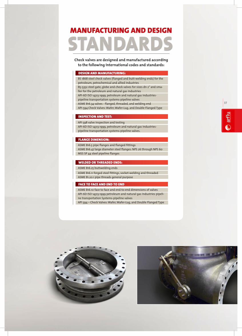
MANUFACTURING AND DESIGN
Check valves are designed and manufactured according to the following international codes and standards:
STANDARDS
BS 1868 steel check valves (flanged and buttwelding ends) for the petroleum, petrochemical and allied industriesB55352 steel gate, globe and check valves for sizes dn 2” and smaller for the petroleum and natural gas industriesAPI6D ISO 14313:1999, petroleum and natural gas industriespipeline transportation systemspipeline valvesASME B16.34 valves flanged, threaded, and welding end API594 Check Valves: Wafer, WaferLug, and Double Flanged Type
DESIGN AND MANUFACTURING:
API 598 valve inspection and testingAPI6D ISO 14313:1999, petroleum and natural gas industriespipeline transportation systemspipeline valves.
INSPECTION AND TEST:
ASME B16.5 pipe flanges and flanged fittingsASME B16.47 large diameter steel flanges: NPS 26 through NPS 60MSS SP 44 steel pipeline flanges
FLANGE DIMENSION:
ASME B16.25 buttwelding ends
ASME B16.11 forged steel fittings, socketwelding and threaded ASME B1.20.1 pipe threads general purpose
WELDED OR THREADED ENDS:
ASME B16.10 face to face and endtoend dimensions of valvesAPI6D ISO 14313:1999 petroleum and natural gas industries pipeline transportation Systemspipeline valves API 594 – Check Valves: Wafer, WaferLug, and Double Flanged Type
FACE TO FACE AND END TO END
arfl
uIN
DU
ST
RIA
L V
AL
VE
S
37
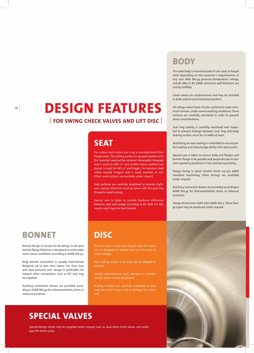
DESIGN FEATURESFOR SWING CHECK VALVES AND LIFT DISC
The valve body is manufactured of cast steel, or forged steel, depending on the customer’s requirements. In any case ANSI B16.34 pressuretemperature ratings, and BS 1867, or BS 51868 minimum wall thickness are strictly fulfilled.
Check valves are unidirectional and may be installed in both vertical and horizontal position.
All ratings valves have circular sections to make minimum stresses, under severe working conditions. These sections are carefully calculated in order to prevent stress concentrations.
Seat ring sealing is carefully machined and inspected to prevent leakage between seat ring and body. Seating surface must be 1,6 AARH at least.
Machining on seat sealing is controlled to ensure perfect sealing and interchange ability with spare parts.
Special care is taken to ensure body end flanges and bonnet flange to be parallel and perpendicular to prevent operating problems in line and during testing.
Flange facing is spiral smooth finish 125250 AARH standard machining. Other facings are available under request.
Auxiliary connection bosses are provided according to ASME B16.34 for instrumentation, drain, or measure purposes.
Flange dimensions fulfil with ASME B16.5. Other flange types may be produced under request.
BODY
Bonnet design is circular for all ratings. In all cases bonnet flange thickness is designed to work under most severe conditions according to ASME B16.34.
Body bonnet connection is usually malefemale designed up to 900 class valves. For class 1500 and 2500 pressure seal design is preferable. On request other connections such as RTJ seal may be supplied.
Auxiliary connection bosses are provided according to ASME B16.34 for instrumentation, drain, or measure purposes.
BONNET
For carbon steel valves seat ring is manufactured from forged steel. The sealing surface is sprayed welded with the material required by customer. Renewable threaded seat is used for NPS 10” and smaller valves, welded seat design is used for NPS 12” and bigger. For stainless steel valves usually integral seat is used, overlaid, or not. Other constructions are available under request.
Seat surfaces are carefully machined to provide tightness. Special attention must be taken with the seat ring thread to avoid seizing.
Special care is taken to provide hardness difference between seat and wedge according to BS 1868. For this reason seat rings are heat treated.
SEAT
The disc seats on the seat ring to tight the valve. Disc is designed to revolve free over the arm to avoid leakage
Disc sealing surface is at least 13% Cr, integral or overlaid.
Special manufactures such damped or counter weight valves may be developed.
Sealing surfaces are carefully machined so that long life, small torque, and no leakage are achieved.
DISC
Special design valves may be supplied under request such as dual plate check valves, and wafer type lift check valves.
SPECIAL VALVES
38

COMPARISON SWING CHECK VALVES- DUAL PLATE CHECK VALVES
PRESSURE OF WATER HAMMERWater hammer pressure of dual plate wafer type swing check valve is 1⁄2 to 1/5 times of swing check valve.
SIZE AND WEIGHTFace to face dimensions for dual plate wafer type valve is 1⁄4 to 1/6 times of swing check valve
FLOW RESISTANCEPressure loss for dual plate valves is lower than swing check valves. Disc in swing check valves can not be fully opened with low working pressure, which makes valve required diameter being bigger.
INSTALLATIONBoth valves are suitable for vertical and horizontal assembling, however swing check valve is heavier than dual plate valve, so supports are often needed.
OPENING PRESSUREThe opening pressure is lower in dual plate valves. The inlet pressure has only to exceed the pressure of the two springs. For swing check valves the disc is very heavy, specially for big valves, which makes high inlet pressure necessary to fully open the valve.
RELIABILITYGenerally the dual plate valve itself is smaller and the closing impact force is lower than swing check valve. For swing check valves as big impact force is involved in closing, the seal surfaces can easily get damaged, and also hammer water pressure is bigger.These two facts make dual plate valve more reliable that swing check valve.
arfl
uIN
DU
ST
RIA
L V
AL
VE
S
39

technical datastechnical datas technical datastechnical datas
40
Check valve
M A T E R I A L S
1
2
3
4
5
6
7
8
9
10
11
12
13
BODY
SEAT RING
DISC
ARM
NUT
ARM PIN
YOKE
BONNET NUT
BONNET BOLT
BOLT
GASKET
BONNET
EYE BOLT
WCB TRIM 1/5/8 LCB TRIM 8/10CF8/304 CF8/304CF8M/316 CF8M/316
ASTM A216 WCB
ASTM A216 WCB
ASTM A194 2H
ASTM A182 F6A
ASTM A216 WCB
ASTM A194 2H
ASTM A193 B7
ASTM A193 B7
SS 304 SHEET + GRAPHITE
ASTM A216 WCB
ASTM A181
ASTM A352 LCB
ASTM A352 LCB
ASTM A194 4
ASTM A352 LCB
ASTM A194 4
ASTM A193 L7
ASTM A193 L7
ASTM A352 LCB
ASTM A181
ASTM A351 CF8
ASTM A351 CF8
ASTM A351 CF8
ASTM A351 CF8
ASTM A194 8
ASTM A182 F304
ASTM A351 CF8
ASTM A194 8
ASTM A193 B8
ASTM A193 B8
SS 304 + GRAPHITE
ASTM A351 CF8
ASTM A181
ASTM A351 CF8
ASTM A351 CF8
ASTM A351 CF8
ASTM A351 CF8
ASTM A194 8
ASTM A182 F304
ASTM A351 CF8
ASTM A194 8
ASTM A193 B8
ASTM A193 B8
SS 304 + GRAPHITE
ASTM A351 CF8
ASTM A181
ASTM A351 CF8M
ASTM A351 CF8M
ASTM A351 CF8M
ASTM A351 CF8M
ASTM A194 8M
ASTM A182 F316
ASTM A351 CF8M
ASTM A194 8M
ASTM A193 B8M
ASTM A193 B8M
SS 316 + GRAPHITE
ASTM A351 CF8M
ASTM A181
ASTM A351 CF8M
ASTM A351 CF8M
ASTM A351 CF8M
ASTM A351 CF8M
ASTM A194 8M
ASTM A182 F316
ASTM A351 CF8M
ASTM A194 8M
ASTM A193 B8M
ASTM A193 B8M
SS 316 + GRAPHITE
ASTM A351 CF8M
ASTM A181
A105 + 13%CR A105 + STL A105 + STL
ASTM A216 WCB + 13%CR ASTM A216 WCB + STL ASTM A216 WCB + 13%CR
A350 LF2 + STL A350 LF2 + AISI 316
ASTM A352 LCB + 13%CR A352 WCB + AISI 316
TRIM 8 TRIM 10 TRIM 1 TRIM 5 TRIM 8
A182 F6A A182 F316
TRIM 8 TRIM 10
SOFT IRON /
SS 304 + GRAPHITE
SOFT IRON /
SS 316 + GRAPHITE
TRIM 8 TRIM 10

technical datastechnical datas technical datastechnical datas
arfl
uIN
DU
ST
RIA
L V
AL
VE
S
41
cod.
* Other measures upon request.
ANSI B16.34 & API6D or BS1868
ANSI B16.10 & API6D
From 2" to 24" Ac c/ANSI B16.5, upper than 24" Ac c/ANSI B16.47 or MSS SP44 or upon request
ANSI B16.25
MSS SP45
API598, API6D or BS16.34
• Swing Type Disc• Threaded, Welded or integral Seat Ring • Bolted Cover
Ac c/ANSI B16.34DI, WCB, WCC, WC1, WC6, WC9, C5, C12, LCB, LCC, CF8, CF8M,CF3, CF3M, CF8C, Bronze, 4A, 6A, AISI904L, CK3MCUN, Duplex, Superduplex, exotic materials
13%Cr, stellite, 304, 304L, 316, 316L, 321, bronze, monel, 4A, 6A, AISI904L, CK3MCUN, Duplex, Superduplex, exotic materials….
Cryogenic services, H.F. services all type of painting and coating.
DESIGN
FACE TO FACE
FLANGED ENDS
BUTT WELD ENDS
BY-PASS & DRAIN
TEST
CONSTRUCTION
MATERIALS
TRIM
OTHERS
Check valve API 6D-BS1868
SWING CHECK VALVES CLASS 150 (BOLTED BONNET) 2" TO 36"
2” 2 1/2” 3” 4” 5" 6” 8” 10” 12” 14” 16” 18” 20” 24" 203 216 241 292 330 356 495 622 698 787 864 978 978 1295 203 216 241 292 330 356 495 622 698 787 864 978 978 1295 216 229 254 305 343 368 508 635 711 800 876 991 991 1308 50 65 80 100 125 150 200 250 300 350 400 450 500 600 150 168 180 210 230 275 340 355 410 475 552 600 660 740 13 17 24 36 57 62 96 158 238 324 483 548 782 1150 17 21 29 42 69 74 108 177 282 372 570 665 900 1359
ND.L (BW)L (RF)L (RTJ)DNMWEIGHT (KG.) (BW)WEIGHT (KG.) (RF)
CLASS 150 DIMENSIONS IN MILIMETERS
28" 30" 36" 1448 1524 1955 1448 1524 1955 1461 1537 1968 700 750 900 770 980 1035 1780 2120 3344 1931 2380 3600
ND.L (BW)L (RF)L (RTJ)DNMWEIGHT (KG.) (BW)WEIGHT (KG.) (RF)
CLASS 150 DIMENSIONS IN MILIMETERS
AR1000
* other requirements upon request.

technical datastechnical datas technical datastechnical datas
42
cod.
* Other measures upon request.
ANSI B16.34 & API6D or BS1868
ANSI B16.10 & API6D
From 2" to 24" Ac c/ANSI B16.5, upper than 24" Ac c/ANSI B16.47 or MSS SP44 or upon request
ANSI B16.25
MSS SP45
API598, API6D or BS16.34
• Swing Type Disc• Threaded, Welded or integral Seat Ring • Bolted Cover
Ac c/ANSI B16.34DI, WCB, WCC, WC1, WC6, WC9, C5, C12, LCB, LCC, CF8, CF8M, CF3, CF3M, CF8C, Bronze, 4A, 6A, AISI904L, CK3MCUN, Duplex, Superduplex, exotic materials
13%Cr, stellite, 304, 304L, 316, 316L, 321, bronze, monel, 4A, 6A, AISI904L, CK3MCUN, Duplex, Superduplex, exotic materials….
Cryogenic services, H.F. services all type of painting and coating.
Check valve API 6D-BS1868
SWING CHECK VALVES CLASS 300 (BOLTED BONNET) 2” TO 36”
2” 2 1/2” 3” 4” 5” 6” 8” 10” 12” 14” 16” 18” 20” 24” 267 292 318 356 400 444 533 622 711 838 864 978 1016 1346 267 292 318 356 400 444 533 622 711 838 864 978 1016 1346 283 308 333 371 416 460 549 638 727 854 879 994 1036 1368 50 65 80 100 125 150 200 250 300 350 400 450 500 600 180 185 210 270 345 360 370 385 440 520 654 690 714 740 16 24 35 44 61 105 167 272 375 560 710 828 1070 1568 21 32 43 61 84 131 213 384 448 680 840 1025 1320 1960
ND.L (BW)L (RF) L (RTJ)DN HWEIGHT (KG.) (BW)WEIGHT (KG.) (RF)
CLASS 300 DIMENSIONS IN MILIMETERS
28" 30" 36” 1499 1594 2083 1499 1594 2083 1524 1619 2111 700 750 900 880 1066 1300 2350 2830 4065 2880 3270 4610
ND.L (BW)L (RF)L (RTJ)DNHWEIGHT (KG.) (BW)WEIGHT (KG.) (RF)
CLASS 300 DIMENSIONS IN MILIMETERS
DESIGN
FACE TO FACE
FLANGED ENDS
BUTT WELD ENDS
BY-PASS & DRAIN
TEST
CONSTRUCTION
MATERIALS
TRIM
OTHERS
* other requirements upon request.
AR3000

technical datastechnical datas technical datastechnical datas
arfl
uIN
DU
ST
RIA
L V
AL
VE
S
43
cod.
* Other measures upon request.
2” 2 1/2” 3” 4” 5” 6” 8” 10” 12” 14” 16” 18” 20” 24” 292 330 356 432 508 559 660 787 838 889 991 1092 1194 1397 292 330 356 432 508 559 660 787 838 889 991 1092 1194 1397 295 333 359 435 511 562 664 791 841 892 994 1095 1200 1407 50 65 80 100 125 150 200 250 300 350 400 450 500 600 197 207 231 281 320 362 437 490 528 572 660 720 746 960 28 40 57 83 120 191 361 543 770 773 1015 1350 1750 2520 36 49 68 111 170 230 416 673 875 944 1220 1620 2120 3100
ND.L (BW)L (RF) L (RTJ)DN HWEIGHT (KG.) (BW)WEIGHT (KG.) (RF)
CLASS 600 DIMENSIONS IN MILIMETERS
28" 30" 36” 1600 1651 2083 1600 1651 2083 1613 1664 2099 700 750 900 1000 1095 1190 3740 4510 6005 4270 4950 6550
ND.L (BW)L (RF)L (RTJ)DNHWEIGHT (KG.) (BW)WEIGHT (KG.) (RF)
CLASS 600 DIMENSIONS IN MILIMETERS
ANSI B16.34 & API6D or BS1868
ANSI B16.10 & API6D
From 2" to 24" Ac c/ANSI B16.5, upper than 24” Ac c/ANSI B16.47 or MSS SP44 or upon request
ANSI B16.25
MSS SP45
API598, API6D or BS16.34
• Swing Type Disc• Threaded, Welded or integral Seat Ring • Bolted Cover
Ac c/ANSI B16.34DI, WCB, WCC, WC1, WC6, WC9, C5, C12, LCB, LCC, CF8, CF8M,CF3, CF3M, CF8C, Bronze, 4A, 6A, AISI904L, CK3MCUN, Duplex, Superduplex, exotic materials
13%Cr, stellite, 304, 304L, 316, 316L, 321, bronze, monel, 4A, 6A, AISI904L, CK3MCUN, Duplex, Superduplex, exotic materials….
Cryogenic services, H.F. services all type of painting and coating.
Check valve API 6D-BS1868
SWING CHECK VALVES CLASS 600 (BOLTED BONNET) 2” TO 36”
DESIGN
FACE TO FACE
FLANGED ENDS
BUTT WELD ENDS
BY-PASS & DRAIN
TEST
CONSTRUCTION
MATERIALS
TRIM
OTHERS
* other requirements upon request.
AR6000

technical datastechnical datas technical datastechnical datas
44
cod.
* Other measures upon request.
ANSI B16.34 & API6D or BS1868
ANSI B16.10 & API6D
ANSI B16.5
ANSI B16.25
MSS SP45
API598, API6D or BS16.34
• Swing Type Disc• Threaded, Welded or integral Seat Ring • Bolted Cover
Ac c/ANSI B16.34DI, WCB, WCC, WC1, WC6, WC9, C5, C12, LCB, LCC, CF8, CF8M,CF3, CF3M, CF8C, Bronze, 4A, 6A, AISI904L, CK3MCUN, Duplex, Superduplex, exotic materials
13%Cr, stellite, 304, 304L, 316, 316L, 321, bronze, monel, 4A, 6A, AISI904L, CK3MCUN, Duplex, Superduplex, exotic materials….
Cryogenic services, H.F. services all type of painting and coating.
Check valve API 6D-BS1868
SWING CHECK VALVES CLASS 900 (BOLTED BONNET) 2” TO 20”
2” 2 1/2” 3” 4” 5” 6” 8” 10” 12” 14” 16” 18” 20” 368 419 381 457 559 610 737 838 965 1029 1130 1219 1321 368 419 381 457 559 610 737 838 965 1029 1130 1219 1321 371 422 384 460 562 613 740 841 968 1038 1140 1232 1334 50 65 80 100 125 150 200 250 300 350 400 450 500 240 260 260 320 340 382 530 560 590 630 700 750 850 52 74 70 112 165 218 448 733 975 1240 1760 2310 3500 69 93 91 145 190 259 565 900 1200 1500 2130 2700 4100
ND.L (BW)L (RF)L (RTJ)DNHWEIGHT (KG.) (BW)WEIGHT (KG.) (RF)
CLASS 900 DIMENSIONS IN MILIMETERS
DESIGN
FACE TO FACE
FLANGED ENDS
BUTT WELD ENDS
BY-PASS & DRAIN
TEST
CONSTRUCTION
MATERIALS
TRIM
OTHERS
* other requirements upon request.
AR9000
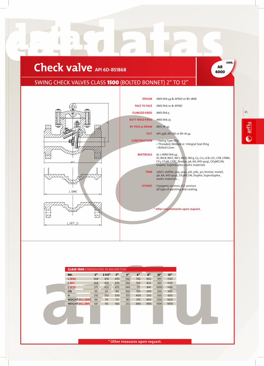
technical datastechnical datas technical datastechnical datas
arfl
uIN
DU
ST
RIA
L V
AL
VE
S
45
cod.
* Other measures upon request.
ANSI B16.34 & API6D or BS1868
ANSI B16.10 & API6D
ANSI B16.5
ANSI B16.25
MSS SP45
API598, API6D or BS16.34
• Swing Type Disc• Threaded, Welded or integral Seat Ring • Bolted Cover
Ac c/ANSI B16.34DI, WCB, WCC, WC1, WC6, WC9, C5, C12, LCB, LCC, CF8, CF8M,CF3, CF3M, CF8C, Bronze, 4A, 6A, AISI904L, CK3MCUN, Duplex, Superduplex, exotic materials
13%Cr, stellite, 304, 304L, 316, 316L, 321, bronze, monel, 4A, 6A, AISI904L, CK3MCUN, Duplex, Superduplex, exotic materials….
Cryogenic services, H.F. services all type of painting and coating.
Check valve API 6D-BS1868
SWING CHECK VALVES CLASS 1500 (BOLTED BONNET) 2” TO 12”
2” 2 1/2” 3” 4” 6” 8” 10” 12” 368 419 470 546 705 832 991 1130 368 419 470 546 705 832 991 1130 371 422 473 549 711 841 1000 1146 50 65 80 100 150 200 250 300 310 310 330 355 400 530 560 650 49 74 111 185 375 803 1250 1625 69 93 140 232 490 990 1490 1970
ND.L (BW)L (RF)L (RTJ)DNHWEIGHT (KG.) (BW)WEIGHT (KG.) (RF)
CLASS 1500 DIMENSIONS IN MILIMETERS
DESIGN
FACE TO FACE
FLANGED ENDS
BUTT WELD ENDS
BY-PASS & DRAIN
TEST
CONSTRUCTION
MATERIALS
TRIM
OTHERS
* other requirements upon request.
AR4000
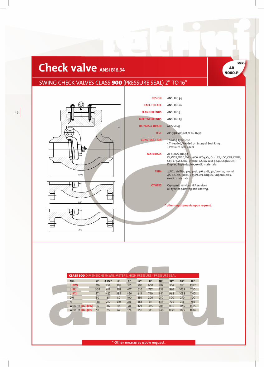
technical datastechnical datas technical datastechnical datas
46
cod.
* Other measures upon request.
ANSI B16.34
ANSI B16.10
ANSI B16.5
ANSI B16.25
MSS SP45
API598, API6D or BS16.34
• Swing Type Disc• Threaded, Welded or integral Seat Ring • Pressure Seal Cover
Ac c/ANSI B16.34DI, WCB, WCC, WC1, WC6, WC9, C5, C12, LCB, LCC, CF8, CF8M,CF3, CF3M, CF8C, Bronze, 4A, 6A, AISI904L, CK3MCUN, Duplex, Superduplex, exotic materials
13%Cr, stellite, 304, 304L, 316, 316L, 321, bronze, monel, 4A, 6A, AISI904L, CK3MCUN, Duplex, Superduplex, exotic materials….
Cryogenic services, H.F. services all type of painting and coating.
Check valve ANSI B16.34
SWING CHECK VALVES CLASS 900 (PRESSURE SEAL) 2” TO 16”
2” 2 1/2” 3” 4” 6” 8” 10” 12” 14” 16” 216 254 305 355 508 660 787 914 991 1092 368 419 381 457 610 737 838 965 1029 1130 371 422 384 460 613 740 841 968 1038 1140 50 65 80 100 150 200 250 300 250 300 188 210 210 216 368 511 614 705 736 756 35 46 44 78 179 385 705 1130 1355 1465 50 65 62 124 256 513 940 1450 1725 1834
ND.L (BW)L (RF)L (RTJ)DNHWEIGHT (KG.) (BW)WEIGHT (KG.) (RF)
CLASS 900 DIMENSIONS IN MILIMETERS. HIGH PRESSURE - PRESSURE SEAL
DESIGN
FACE TO FACE
FLANGED ENDS
BUTT WELD ENDS
BY-PASS & DRAIN
TEST
CONSTRUCTION
MATERIALS
TRIM
OTHERS
H
L (BW)
L (RF)
L (RTJ)
* other requirements upon request.
AR9000-P
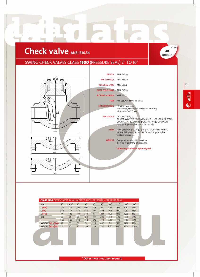
technical datastechnical datas technical datastechnical datas
arfl
uIN
DU
ST
RIA
L V
AL
VE
S
47
cod.
* Other measures upon request.
ANSI B16.34
ANSI B16.10
ANSI B16.5
ANSI B16.25
MSS SP45
API598, API6D or BS16.34
• Swing Type Disc• Threaded, Welded or integral Seat Ring • Pressure Seal Cover
Ac c/ANSI B16.34DI, WCB, WCC, WC1, WC6, WC9, C5, C12, LCB, LCC, CF8, CF8M,CF3, CF3M, CF8C, Bronze, 4A, 6A, AISI904L, CK3MCUN, Duplex, Superduplex, exotic materials
13%Cr, stellite, 304, 304L, 316, 316L, 321, bronze, monel, 4A, 6A, AISI904L, CK3MCUN, Duplex, Superduplex, exotic materials….
Cryogenic services, H.F. services all type of painting and coating.
Check valve ANSI B16.34
SWING CHECK VALVES CLASS 1500 (PRESSURE SEAL) 2” TO 16”
2” 2 1/2” 3” 4” 6” 8” 10” 12” 14” 16” 216 254 305 406 559 711 864 991 1067 1194 368 419 470 546 705 832 991 1130 1257 1384 371 422 473 549 711 841 1000 1146 1276 1407 50 65 80 100 150 200 250 300 250 300 265 265 270 370 475 570 630 770 795 824 42 53 51 86 230 460 715 1150 1390 1544 60 75 73 130 334 590 1025 1530 1854 2060
ND.L (BW)L (RF)L (RTJ)DNHWEIGHT (KG.) (BW)WEIGHT (KG.) (RF)
CLASS 1500 DIMENSIONS IN MILIMETERS. HIGH PRESSURE - PRESSURE SEAL
DESIGN
FACE TO FACE
FLANGED ENDS
BUTT WELD ENDS
BY-PASS & DRAIN
TEST
CONSTRUCTION
MATERIALS
TRIM
OTHERS
H
L (BW)
L (RF)
L (RTJ)
* other requirements upon request.
AR4000-P

technical datastechnical datas technical datastechnical datas
48
cod.
* Other measures upon request.
ANSI B16.34
ANSI B16.10
ANSI B16.5
ANSI B16.25
MSS SP45
API598, API6D or BS16.34
• Swing Type Disc• Threaded, Welded or integral Seat Ring • Pressure Seal Cover
Ac c/ANSI B16.34DI, WCB, WCC, WC1, WC6, WC9, C5, C12, LCB, LCC, CF8, CF8M,CF3, CF3M, CF8C, Bronze, 4A, 6A, AISI904L, CK3MCUN, Duplex, Superduplex, exotic materials
13%Cr, stellite, 304, 304L, 316, 316L, 321, bronze, monel, 4A, 6A, AISI904L, CK3MCUN, Duplex, Superduplex, exotic materials….
Cryogenic services, H.F. services all type of painting and coating.
Check valve ANSI B16.34
SWING CHECK VALVES CLASS 2500 (PRESSURE SEAL) 2” TO 12”
2” 2 1/2” 3” 4” 6” 8” 10” 12” 279 330 368 457 610 762 914 1041 451 508 578 673 914 1022 1270 1422 454 514 584 683 927 1038 1292 1445 50 65 80 100 150 200 250 300 280 305 310 370 485 544 710 800 88 90 95 160 385 640 1200 1725 88 115 135 215 550 900 1600 2300
ND.L (BW)L (RF)L (RTJ)DNHWEIGHT (KG.) (BW)WEIGHT (KG.) (RF)
CLASS 2500 DIMENSIONS IN MILIMETERS. HIGH PRESSURE - PRESSURE SEAL
DESIGN
FACE TO FACE
FLANGED ENDS
BUTT WELD ENDS
BY-PASS & DRAIN
TEST
CONSTRUCTION
MATERIALS
TRIM
OTHERS
H
L (BW)
L (RF)
L (RTJ)
* other requirements upon request.
AR7000-P
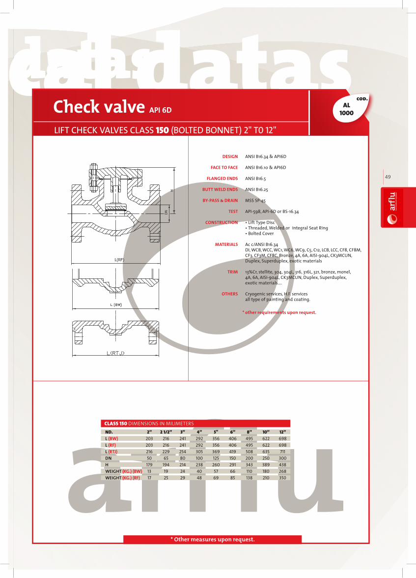
technical datastechnical datas technical datastechnical datas
arfl
uIN
DU
ST
RIA
L V
AL
VE
S
49
cod.
* Other measures upon request.
ANSI B16.34 & API6D
ANSI B16.10 & API6D
ANSI B16.5
ANSI B16.25
MSS SP45
API598, API6D or BS16.34
• Lift Type Disc• Threaded, Welded or integral Seat Ring • Bolted Cover
Ac c/ANSI B16.34DI, WCB, WCC, WC1, WC6, WC9, C5, C12, LCB, LCC, CF8, CF8M,CF3, CF3M, CF8C, Bronze, 4A, 6A, AISI904L, CK3MCUN, Duplex, Superduplex, exotic materials
13%Cr, stellite, 304, 304L, 316, 316L, 321, bronze, monel, 4A, 6A, AISI904L, CK3MCUN, Duplex, Superduplex, exotic materials….
Cryogenic services, H.F. services all type of painting and coating.
Check valve API 6D
LIFT CHECK VALVES CLASS 150 (BOLTED BONNET) 2" T0 12"
2” 2 1/2” 3” 4” 5" 6” 8” 10” 12” 203 216 241 292 356 406 495 622 698 203 216 241 292 356 406 495 622 698 216 229 254 305 369 419 508 635 711 50 65 80 100 125 150 200 250 300 179 194 214 238 260 291 343 389 438 13 19 24 40 57 66 110 180 268 17 25 29 48 69 85 138 210 350
ND.L (BW)L (RF)L (RTJ)DNHWEIGHT (KG.) (BW)WEIGHT (KG.) (RF)
CLASS 150 DIMENSIONS IN MILIMETERS
DESIGN
FACE TO FACE
FLANGED ENDS
BUTT WELD ENDS
BY-PASS & DRAIN
TEST
CONSTRUCTION
MATERIALS
TRIM
OTHERS
* other requirements upon request.
AL1000
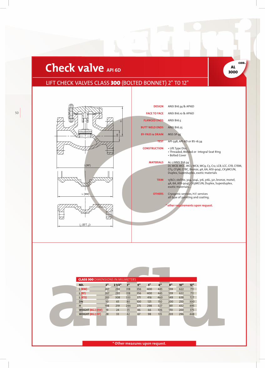
technical datastechnical datas technical datastechnical datas
50
cod.
* Other measures upon request.
ANSI B16.34 & API6D
ANSI B16.10 & API6D
ANSI B16.5
ANSI B16.25
MSS SP45
API598, API6D or BS16.34
• Lift Type Disc• Threaded, Welded or integral Seat Ring • Bolted Cover
Ac c/ANSI B16.34DI, WCB, WCC, WC1, WC6, WC9, C5, C12, LCB, LCC, CF8, CF8M,CF3, CF3M, CF8C, Bronze, 4A, 6A, AISI904L, CK3MCUN, Duplex, Superduplex, exotic materials
13%Cr, stellite, 304, 304L, 316, 316L, 321, bronze, monel, 4A, 6A, AISI904L, CK3MCUN, Duplex, Superduplex, exotic materials….
Cryogenic services, H.F. services all type of painting and coating.
Check valve API 6D
LIFT CHECK VALVES CLASS 300 (BOLTED BONNET) 2" T0 12"
2” 2 1/2” 3” 4” 5" 6” 8” 10” 12” 267 292 318 356 400 445 559 622 711 267 292 318 356 400 445 559 622 711 283 308 333 371 416 460 549 638 727 50 65 80 100 125 150 200 250 300 198 219 244 275 298 327 381 432 495 19 24 35 46 66 106 170 200 375 28 33 42 67 98 135 203 296 448
ND.L (BW)L (RF)L (RTJ)DNHWEIGHT (KG.) (BW)WEIGHT (KG.) (RF)
CLASS 300 DIMENSIONS IN MILIMETERS
DESIGN
FACE TO FACE
FLANGED ENDS
BUTT WELD ENDS
BY-PASS & DRAIN
TEST
CONSTRUCTION
MATERIALS
TRIM
OTHERS
* other requirements upon request.
AL3000

technical datastechnical datas technical datastechnical datas
arfl
uIN
DU
ST
RIA
L V
AL
VE
S
51
cod.
* Other measures upon request.
ANSI B16.34 & API6D
ANSI B16.10 & API6D
ANSI B16.5
ANSI B16.25
MSS SP45
API598, API6D or BS16.34
• Lift Type Disc• Threaded, Welded or integral Seat Ring • Bolted Cover
Ac c/ANSI B16.34DI, WCB, WCC, WC1, WC6, WC9, C5, C12, LCB, LCC, CF8, CF8M,CF3, CF3M, CF8C, Bronze, 4A, 6A, AISI904L, CK3MCUN, Duplex, Superduplex, exotic materials
13%Cr, stellite, 304, 304L, 316, 316L, 321, bronze, monel, 4A, 6A, AISI904L, CK3MCUN, Duplex, Superduplex, exotic materials….
Cryogenic services, H.F. services all type of painting and coating.
Check valve API 6D
LIFT CHECK VALVES CLASS 600 (BOLTED BONNET) 2" T0 12"
2” 2 1/2” 3” 4” 5" 6” 8” 10” 12” 292 330 356 432 508 559 584 711 813 292 330 356 432 508 559 660 787 838 295 333 359 435 511 562 664 791 841 50 65 80 100 125 150 200 250 300 32 45 58 102 147 195 308 455 630 27 38 47 79 104 148 211 305 470 32 45 58 102 147 195 308 455 630
ND.L (BW)L (RF)L (RTJ)DNHWEIGHT (KG.) (BW)WEIGHT (KG.) (RF)
CLASS 600 DIMENSIONS IN MILIMETERS
DESIGN
FACE TO FACE
FLANGED ENDS
BUTT WELD ENDS
BY-PASS & DRAIN
TEST
CONSTRUCTION
MATERIALS
TRIM
OTHERS
* other requirements upon request.
AL6000

technical datastechnical datas technical datastechnical datas
52
cod.
* Other measures upon request.
API594 & API6D API594 and API6D Ac c/ANSI B16.5 ASME API594
API598, API6D • Wafer Lift Type Disc • Other requirements upon request Ac c/ANSI B16.34 DI, WCB, WCC, WC1, WC6, WC9, C5, C12, LCB, LCC, CF8, CF8M, CF3, CF3M, CF8C, Bronze, 4A, 6A, AISI904L, CK3MCUN, Duplex, Superduplex, exotic materials 13%Cr, stellite, 304, 304L, 316, 316L, 321, bronze, monel, 4A, 6A, AISI904L, CK3MCUN, Duplex, Superduplex, exotic materials…. Cryogenic services, H.F. services all type of painting and coating.
Check valve API 6D - API 594
WAFER CHECK VALVES CLASS 150 1/2" T0 6"
1/2" 3/4" 1" 1 1/4" 1 1/2" 2" 2 1/2" 3" 4" 6" 16 19 22 28,5 31,5 40 46 51 60 106 15 20 25 32 40 50 65 80 100 150 48 57 67 76 86 105 124 137 175 222 0,3 0,35 0,5 0,7 0,9 1,3 2,5 3,4 7,5 16
ND.L (WF)DND1WEIGHT (KG.) (WF)
CLASS 150 DIMENSIONS IN MILIMETERS
DESIGN
FACE TO FACE
FLANGES CONNECTION
SHELL WALL THICKNESS
TEST
CONSTRUCTION
MATERIALS
TRIM
OTHERS
L
DN
D1
* other requirements upon request.
ALW1000

technical datastechnical datas technical datastechnical datas
arfl
uIN
DU
ST
RIA
L V
AL
VE
S
53
cod.
* Other measures upon request.
API594 & API6D API594 and API6D Ac c/ANSI B16.5 ASME API594
API598, API6D • Wafer Lift Type Disc • Other requirements upon request Ac c/ANSI B16.34 DI, WCB, WCC, WC1, WC6, WC9, C5, C12, LCB, LCC, CF8, CF8M, CF3, CF3M, CF8C, Bronze, 4A, 6A, AISI904L, CK3MCUN, Duplex, Superduplex, exotic materials 13%Cr, stellite, 304, 304L, 316, 316L, 321, bronze, monel, 4A, 6A, AISI904L, CK3MCUN, Duplex, Superduplex, exotic materials…. Cryogenic services, H.F. services all type of painting and coating.
Check valve API 6D - API 594
WAFER CHECK VALVES CLASS 300 1/2" T0 6"
1/2" 3/4" 1" 1 1/4" 1 1/2" 2" 2 1/2" 3" 4" 6" 25 31,5 35,5 40 46 56 63,5 71 80 125 15 20 25 32 40 50 65 80 100 150 54 65 73 81 95 111 130 149 181 251 0,35 0,45 0,6 0,85 1,2 2,4 3,5 5,9 9,8 21
ND.L (WF)DND1WEIGHT (KG.) (WF)
CLASS 300 DIMENSIONS IN MILIMETERS
DESIGN
FACE TO FACE
FLANGES CONNECTION
SHELL WALL THICKNESS
TEST
CONSTRUCTION
MATERIALS
TRIM
OTHERS
L
DN
D1
* other requirements upon request.
ALW3000

technical datastechnical datas technical datastechnical datas
54
cod.
* Other measures upon request.
API594 & API6D API594 and API6D Ac c/ANSI B16.5
ASME API594
API598, API6D • Wafer Lift Type Disc
Ac c/ANSI B16.34 DI, WCB, WCC, WC1, WC6, WC9, C5, C12, LCB, LCC, CF8, CF8M, CF3, CF3M, CF8C, Bronze, 4A, 6A, AISI904L, CK3MCUN, Duplex, Superduplex, exotic materials 13%Cr, stellite, 304, 304L, 316, 316L, 321, bronze, monel, 4A, 6A, AISI904L, CK3MCUN, Duplex, Superduplex, exotic materials…. Cryogenic services, H.F. services all type of painting and coating.
Check valve API 6D - API 594
WAFER CHECK VALVES CLASS 600 1/2" T0 6"
1/2" 3/4" 1" 1 1/4" 1 1/2" 2" 2 1/2" 3" 4" 6" 25 31,5 35,5 40 46 56 63,5 71 80 125 15 20 25 32 40 50 65 80 100 150 57 65 73 81 95 111 130 149 194 267 0,38 0,47 0,64 0,9 1,35 2,5 4,2 6,5 12 24
ND.L (WF)DND1WEIGHT (KG.) (WF)
CLASS 600 DIMENSIONS IN MILIMETERS
DESIGN
FACE TO FACE
FLANGES CONNECTION
SHELL WALL THICKNESS
TEST
CONSTRUCTION
MATERIALS
TRIM
OTHERS
L
DN
D1
* other requirements upon request.
ALW6000

technical datastechnical datas technical datastechnical datas
arfl
uIN
DU
ST
RIA
L V
AL
VE
S
55
cod.
* Other measures upon request.
API594 & API6D API594 and API6D From 2" to 24" Ac c/ANSI B16.5, upper than 24" Ac c/ANSI B16.47 or MSS SP44 or upon request ASME API594 API598, API6D • Wafer Double Disc Swing Type • Wafer Lug Double Disc Swing Type • Wafer Double Flanged Double Disc Swing Type Ac c/ANSI B16.34 DI, WCB, WCC, WC1, WC6, WC9, C5, C12, LCB, LCC, CF8, CF8M, CF3, CF3M, CF8C, Bronze, 4A, 6A, AISI904L, CK3MCUN, Duplex, Superduplex, exotic materials 13%Cr, stellite, 304, 304L, 316, 316L, 321, bronze, monel, 4A, 6A, AISI904L, CK3MCUN, Duplex, Superduplex, exotic materials…. Cryogenic services, H.F. servicesall type of painting and coating.
Check valve API 6D - API 594
WAFER DOUBLE DISC CHECK VALVES CLASS 150 2" T0 48"
2" 2 1/2" 3" 4" 6" 8" 10" 12" 14" 16" 18" 20" 24" 30" 42" 48" 60 67 73 73 98 127 146 181 184 191 203 219 222 305 432 524 50 65 80 100 150 200 250 300 350 400 450 500 600 750 1050 1200 105 124 137 175 222 279 340 410 451 514 549 606 718 883 1219 1384 2,7 3,6 5,4 7,7 17 30 48 85 95 124 146 187 282 530 1270 1995
ND.L (WF)DND1WEIGHT (KG.) (WF)
CLASS 150 DIMENSIONS IN MILIMETERS
DESIGN
FACE TO FACE
FLANGES CONNECTION
SHELL WALL THICKNESS
TEST
CONSTRUCTION
MATERIALS
TRIM
OTHERSL
DN
D1
* other requirements upon request.
ADC1000

technical datastechnical datas technical datastechnical datas
56
cod.
* Other measures upon request.
API594 & API6D API594 and API6D From 2" to 24" Ac c/ANSI B16.5, upper than 24" Ac c/ANSI B16.47 or MSS SP44 or upon request ASME API594 API598, API6D • Wafer Double Disc Swing Type • Wafer Lug Double Disc Swing Type • Wafer Double Flanged Double Disc Swing Type
Ac c/ANSI B16.34 DI, WCB, WCC, WC1, WC6, WC9, C5, C12, LCB, LCC, CF8, CF8M, CF3, CF3M, CF8C, Bronze, 4A, 6A, AISI904L, CK3MCUN, Duplex, Superduplex, exotic materials 13%Cr, stellite, 304, 304L, 316, 316L, 321, bronze, monel, 4A, 6A, AISI904L, CK3MCUN, Duplex, Superduplex, exotic materials…. Cryogenic services, H.F. servicesall type of painting and coating.
Check valve API 6D - API 594
WAFER DOUBLE DISC CHECK VALVES CLASS 300 2" T0 48"
2" 2 1/2" 3" 4" 6" 8" 10" 12" 14" 16" 18" 20" 24" 30" 42" 48" 60 67 73 73 98 127 146 181 222 232 264 292 318 368 568 629 50 65 80 100 150 200 250 300 350 400 450 500 600 750 1050 1200 111 130 149 181 251 308 362 422 486 540 597 654 775 953 1289 1492 3,2 4,5 5,4 8,5 17 35 56 95 136 180 294 362 495 950 2610 2835
ND.L (WF)DND1WEIGHT (KG.) (WF)
CLASS 300 DIMENSIONS IN MILIMETERS
DESIGN
FACE TO FACE
FLANGES CONNECTION
SHELL WALL THICKNESS
TEST
CONSTRUCTION
MATERIALS
TRIM
OTHERS
L
DN
D1
* other requirements upon request.
ADC3000

technical datastechnical datas technical datastechnical datas
arfl
uIN
DU
ST
RIA
L V
AL
VE
S
57
cod.
* Other measures upon request.
API594 & API6D API594 and API6D From 2" to 24" Ac c/ANSI B16.5, upper than 24" Ac c/ANSI B16.47 or MSS SP44 or upon request ASME API594 API598, API6D • Wafer Double Disc Swing Type • Wafer Lug Double Disc Swing Type • Wafer Double Flanged Double Disc Swing Type
Ac c/ANSI B16.34 DI, WCB, WCC, WC1, WC6, WC9, C5, C12, LCB, LCC, CF8, CF8M, CF3, CF3M, CF8C, Bronze, 4A, 6A, AISI904L, CK3MCUN, Duplex, Superduplex, exotic materials 13%Cr, stellite, 304, 304L, 316, 316L, 321, bronze, monel, 4A, 6A, AISI904L, CK3MCUN, Duplex, Superduplex, exotic materials…. Cryogenic services, H.F. servicesall type of painting and coating.
Check valve API 6D - API 594
WAFER DOUBLE DISC CHECK VALVES CLASS 600 2" T0 30"
2" 2 1/2" 3" 4" 6" 8" 10" 12" 14" 16" 18" 20" 24" 30" 60 67 73 73 137 165 213 229 273 305 362 368 438 505 50 65 80 100 150 200 250 300 350 400 450 500 600 750 111 130 149 194 267 321 400 457 492 565 613 680 791 972 3,2 4,5 5,4 10 32 68 95 130 180 250 345 600 840 1330
ND.L (WF)DND1WEIGHT (KG.) (WF)
CLASS 600 DIMENSIONS IN MILIMETERS
DESIGN
FACE TO FACE
FLANGES CONNECTION
SHELL WALL THICKNESS
TEST
CONSTRUCTION
MATERIALS
TRIM
OTHERSL
DN
D1
* other requirements upon request.
ADC6000

technical datastechnical datas technical datastechnical datas
58
cod.
* Other measures upon request.
API594 & API6D API594 and API6D Ac c/ANSI B16.5 ASME API594 API598, API6D • Wafer Double Disc Swing Type • Wafer Lug Double Disc Swing Type • Wafer Double Flanged Double Disc Swing Type
Ac c/ANSI B16.34 DI, WCB, WCC, WC1, WC6, WC9, C5, C12, LCB, LCC, CF8, CF8M, CF3, CF3M, CF8C, Bronze, 4A, 6A, AISI904L, CK3MCUN, Duplex, Superduplex, exotic materials 13%Cr, stellite, 304, 304L, 316, 316L, 321, bronze, monel, 4A, 6A, AISI904L, CK3MCUN, Duplex, Superduplex, exotic materials…. Cryogenic services, H.F. servicesall type of painting and coating.
Check valve API 6D - API 594
WAFER DOUBLE DISC CHECK VALVES CLASS 900 2" T0 24"
2" 2 1/2" 3" 4" 6" 8" 10" 12" 14" 16" 18" 20" 24" 70 83 83 102 159 206 241 292 356 384 451 451 495 50 65 80 100 150 200 250 300 350 400 450 500 600 143 465 168 206 289 359 435 498 521 578 638 699 838 6 7 12 17 48 85 127 165 290 380 490 635 920
ND.L (WF)DND1WEIGHT (KG.) (WF)
CLASS 900 DIMENSIONS IN MILIMETERS
DESIGN
FACE TO FACE
FLANGES CONNECTION
SHELL WALL THICKNESS
TEST
CONSTRUCTION
MATERIALS
TRIM
OTHERS
L
DN
D1
* other requirements upon request.
ADC9000
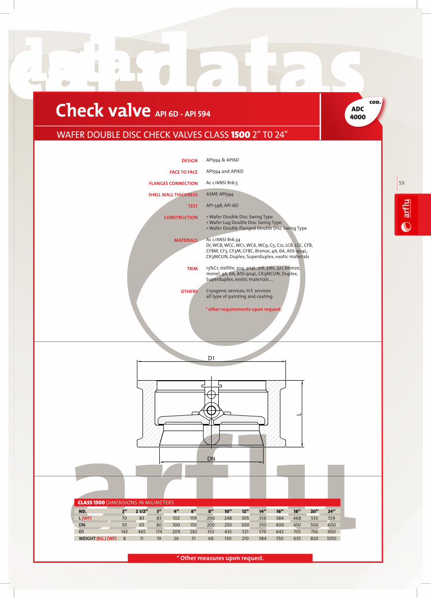
technical datastechnical datas technical datastechnical datas
arfl
uIN
DU
ST
RIA
L V
AL
VE
S
59
cod.
* Other measures upon request.
API594 & API6D API594 and API6D Ac c/ANSI B16.5 ASME API594 API598, API6D • Wafer Double Disc Swing Type • Wafer Lug Double Disc Swing Type • Wafer Double Flanged Double Disc Swing Type
Ac c/ANSI B16.34 DI, WCB, WCC, WC1, WC6, WC9, C5, C12, LCB, LCC, CF8, CF8M, CF3, CF3M, CF8C, Bronze, 4A, 6A, AISI904L, CK3MCUN, Duplex, Superduplex, exotic materials 13%Cr, stellite, 304, 304L, 316, 316L, 321, bronze, monel, 4A, 6A, AISI904L, CK3MCUN, Duplex, Superduplex, exotic materials…. Cryogenic services, H.F. servicesall type of painting and coating.
Check valve API 6D - API 594
WAFER DOUBLE DISC CHECK VALVES CLASS 1500 2" T0 24"
2” 2 1/2” 3” 4” 6” 8” 10” 12” 14” 16” 18” 20” 24” 70 83 83 102 159 206 248 305 356 384 468 533 559 50 65 80 100 150 200 250 300 350 400 450 500 600 143 465 174 209 282 353 435 521 579 642 705 756 900 8 11 19 26 51 68 130 210 384 550 635 820 1050
ND.L (WF)DND1WEIGHT (KG.) (WF)
CLASS 1500 DIMENSIONS IN MILIMETERS
DESIGN
FACE TO FACE
FLANGES CONNECTION
SHELL WALL THICKNESS
TEST
CONSTRUCTION
MATERIALS
TRIM
OTHERS
L
DN
D1
* other requirements upon request.
ADC4000

BALLVALVESBALLVALVES
Ball valvesBall valves, like gate valves, are used in open or close position, not recommended for intermediate positions. Unlike gate valves, ball valves are quarter turn valves which closure mem-ber rotates very fast from full-open to full-closed position.
60

MANUFACTURING AND DESIGN
STANDARDS
ASME B16.34 valves flanged, threaded, and welding endAPI6D ISO 14313:1999, petroleum and natural gas industriespipeline transportation systemspipeline valvesBS 5351 steel ball valves for petroleum, petrochemical and allied industriesAPI 608 metal ball valves flanged, threaded, and welding end ISO 17292 – Metal ball valves for petroleum, petrochemical and allied industries
DESIGN AND MANUFACTURING:
Ball valves are designed and manufactured according to the following international codes and standards:
API 598 valve inspection and testingAPI6D ISO 14313:1999, petroleum and natural gas industriespipeline transportation systemspipeline valves.
INSPECTION AND TEST:
ASME B16.5 pipe flanges and flanged fittingsASME B16.47 large diameter steel flanges: NPS 26 through NPS 60MSS SP 44 steel pipeline flanges
FLANGE DIMENSION:
ASME B16.25 buttwelding endsASME B16.11 forged steel fittings, socketwelding and threaded ASME B1.20.1 pipe threads general purpose
WELDED OR THREADED ENDS:
ASME B16.10 face to face and endtoend dimensions of valves API6D ISO 14313:1999 petroleum and natural gas industries pipeline transportation Systemspipeline valves
FACE TO FACE AND END TO END
arfl
uIN
DU
ST
RIA
L V
AL
VE
S
61

The body is made of cast steel or forged steel, depending on the customers’ requirements. In the case of normal design standards, (API6D, EN 17292, etc.) the thickness of the body will comply with what is indicated in these standards according to the pressure rating of the valve. Should none of these standards apply ARFLU uses the regular standard EN 12516 for the determination of minimum thickness. All our ball valves are bidirectional and can be installed both in vertical and horizontal position. The spherical sections are designed to reduce tension under the most severe working conditions. The sealing rings of the seats are carefully machined to prevent leaks between the body and the seat. The surface of the seats should be at least 1.6 AARH Extraordinary careful attention is made to ensure that the body flange and the bonnet flange are parallel and perpendicular to prevent leakage problems between both, except for fully welded valves in which case they are obviously welded. The standard flange face has a spiral type smooth finish 125250 AARH. Other finishes may be carried according to requirements. Our valves are provided with the possibility of fitting auxiliary plugs or connections in accordance with ASME B 16.34 to allow drainage, secondary injection lines, instrumentation, measurements, etc. The connections from the valves to the pipes can be done using flanges or butt weld ends according to either international or national standards as the client so requirements.
BODY AND ENDSBall valves are a quarter turn operating valves, usually for ONOFF services.
Main design parameters in ball valves are the parallelism, and perpendicularity of the turning axe and the pipeline, and the spherical of the ball. Taking care of these two facts operating torque will be smooth and the valve will have a long tight life, as not foreseen stresses on the seat will be avoided.
DESIGN FEATURES
SPECIFIC DESIGN
Many different design features are fitted on ball valves depending on the specific application. Main ones are the following:
APPLICATIONS
BALL VALVES
62
DOUBLE BLACK AND BLEED A system that allows the closure of the two faces and a venting of the valve chamber.
PACKINGThe packing, in general, is made of elastomeric or graphite rings. The most usual shapes of these rings are V or rectangular. The pressure in the rings is supplied by means of the gland flange. In the gas valves Arflu uses dual packing made up of an elastomeric or graphite ring and two Orings.
AUTO DECOMPRESSION OF THE BODY CAVITYThe spring system in the seat rings means that the sealing ring is always in contact with the ball. In the event of a pressure increase in the chamber of the body due, for example, to thermal expansion which exceeds the load of the seat springs, the springs will compress freeing the liquid from the cavity to the tube, creating an autodecompression of the area.
FULLY WELDED VALVES In this type of valve the bodyface union is done by welding. In these cases Arflu carries out a specific design of these zones, giving maximum importance to the welding angle. Welds are carried out by approved procedures and welders. To guarantee the quality of the welds non destructive tests, such as ultrasound and penetrating liquids, are carried out. During the welding process special attention is paid to ensure no damage is done to the seats. To do so, the temperature of the seat area is controlled by thermocouples.
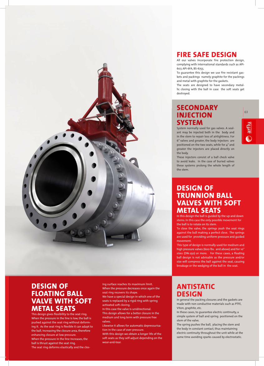
arfl
uIN
DU
ST
RIA
L V
AL
VE
S
63
DESIGN OF FLOATING BALL VALVE WITH SOFT METAL SEATSThis design gives flexibility to the seat ring. When the pressure in the line is low, the ball is pushed against the seat ring without deforming it. As the seat ring is flexible it can adapt to the ball, increasing the closure area, therefore enhancing closure at low pressure. When the pressure in the line increases, the ball is thrust against the seat ring. The seat ring deforms elastically and the clos
ing surface reaches its maximum limit. When the pressure decreases once again the seat ring recovers its shape. We have a special design in which one of the seats is replaced by a rigid ring with spring activated soft closing. In this case the valve is unidirectional. This design allows for a better closure in the medium and long term with pressure free valves. Likewise it allows for automatic depressurisation in the case of over pressure. With this design we obtain a longer life of the soft seats as they selfadjust depending on the wearandtear.
FIRE SAFE DESIGN All our valves incorporate fire protection design, complying with international standards such as API607, API6FA, BS6755. To guarantee this design we use fire resistant gaskets and packings namely graphite for the packings and metal with graphite for the gaskets. The seats are designed to have secondary metallic closing with the ball in case the soft seats get destroyed.
SECONDARY INJECTION SYSTEMSystem normally used for gas valves. A sealant may be injected both in the body and in the stem to repair loss of airtightness. For 6” valves and greater, the body injectors are positioned on the two seats, while for 4” and greater the injectors are placed directly on the body. These injectors consist of a ball check valve to avoid leaks. In the case of buried valves these systems prolong the whole length of the stem.
DESIGN OF TRUNNION BALL VALVES WITH SOFT METAL SEATSIn this design the ball is guided by the up and down stems. In this case the only possible movement for the ball is to rotate on its stem. To close the valve, the springs push the seat rings against the ball making a perfect close. The springs are used for providing uniform pressure and guided movement. This type of design is normally used for medium and high pressure valves (600 lbs. and above) and for 10” sizes (DN250) or more. For these cases, a floating ball design is not advisable as the pressure and/or size will compress the ball against the seat, causing breakage or the wedging of the ball in the seat.
ANTISTATIC DESIGNIn general the packing closures and the gaskets are made with non conductive materials such as PTFE, Viton, graphite, etc. In these cases, to guarantee electric continuity, a simple system of ball and spring positioned on the stem of the valve. The spring pushes the ball, placing the stem and the body in constant contact, thus maintaining electric continuity throughout the unit while at the same time avoiding sparks caused by electrostatic.

technical datastechnical datas technical datastechnical datas
6464
Floating Ball Valves
arfluarflu1
2
3
4
5
6
7
8
9
10
11
12
13
14
15
16
17
18
BODY
PAKING
STEM BEARING
GLAND
GLAND FLANGE
GLAND BOLT
STOP COLLAR
ANTISTATIC DEVICE
LEVER
NUT HEAD
THRUST WASHER
STEM
BALL
SEAT
GASKET
BODY NUT
BODY BOLTING
CLOSURE
ASTM A216 WCB ASTM A351 CF8 ASTM A351 CF8M
PTFE or PTFE+Graphite PTFE or PTFE+Graphite PTFE or PTFE+Graphite
PTFE PTFE PTFE
ASTM A182 F6a ASTM A182 F304 ASTM A182 F316 ASTM A182 F304 ASTM A182 F316
ASTM A216 WCB ASTM A351 CF8 ASTM A351 CF8M
ASTM A193 B7 ASTM A193 B8 ASTM A193 B8M
Carbon steel Stainless steel Stainless steel
Carbon steel Stainless steel Stainless steel
Carbon steel Carbon steel Carbon steel
Carbon steel Carbon steel Carbon steel
PTFE PTFE PTFE
ASTM A182 F6a ASTM A182 F304 ASTM A182 F316 ASTM A182 F304 ASTM A182 F316
ASTM A182 F6a ASTM A182 F304 ASTM A182 F316 ASTM A182 F304 ASTM A182 F316
PTFE or RPTFE or NYLON PTFE or RPTFE or NYLON PTFE or RPTFE or NYLON
PTFE or PTFE+Graphite PTFE or PTFE+Graphite PTFE or PTFE+Graphite
ASTM A194 2H ASTM A194 8 ASTM A194 8M
ASTM A193 B7 ASTM A193 B8 ASTM A193 B8M
ASTM A216 WCB ASTM A351 CF8 ASTM A351 CF8M
ASTM 216 WCB
PTFE
PTFE
ASTM A182 F316
ASTM A216 WCB
ASTM A193 B7
Carbon steel
Carbon steel
Carbon steel
Carbon steel
PTFE
ASTM A182 F316
ASTM A182 F316
Reinforced PTFE
PTFE
ASTM A194 2H
ASTM A193 B7
ASTM A216 WCB
ASTM A352 LCB
PTFE
PTFE
ASTM A182 F304
ASTM A352 LCB
ASTM A193 B7
Carbon steel
Carbon steel
Carbon steel
Carbon steel
PTFE
ASTM A182 F304
ASTM A182 F304
Reinforced PTFE
PTFE
ASTM A194 2H
ASTM A193 B7
ASTM A352 LCB
WCB /5/8 CF8 LCB / F6CF8M LCB / F304WCB /5/8 WCB /5/8

technical datastechnical datas technical datastechnical datas
arfl
uIN
DU
ST
RIA
L V
AL
VE
S
65
arfl
uIN
DU
ST
RIA
L V
AL
VE
S
65
cod.
* Other measures upon request.
Ball valve API-6D & API-608 OR ISO 17292
TWO-PIECE FLOATING BALL VALVES CLASS 150 1/2" TO 8"
1/2" 3/4" 1" 1 1/2" 2" 2 1/2" 3" 4" 6" 8" 140 152 165 190 216 241 283 305 457 521 108 117 127 165 178 191 203 229 394 457 119 130 140 178 191 203 216 241 406 470 12 20 25 40 50 65 80 100 150 200 59 63 75 95 153 165 195 213 272 342 130 130 160 230 230 400 400 600 850 1100 2 2,5 3,8 5,8 12 17 21 36 93 154 2,3 3 4,5 7 15 20 25 40 97 160
ND.L (BW)L (RF)L (RTJ)DNH (OPEN)WWEIGHT (KG.) (BW)WEIGHT (KG.) (RF)
CLASS 150 DIMENSIONS IN MILIMETERS
ANSI B16.34 & API6D & API608 or ISO 17292
ANSI B16.10 & API6D
ANSI B16.5
ANSI B16.25
MSS SP45
API598, API6D & ISO 5208
• Open/close position indicator • Locking Device • Anti-blow out stem • Antistatic Device • Fire Protection Structure • Middle Flange Leak-tight Structure • Dependable Seating Structure
DESIGN
FACE TO FACE
FLANGED ENDS
BUTT WELD ENDS
BY-PASS & DRAIN
TEST
CONSTRUCTION
• Self-relieving Structure • Full and Reduced Bore • Manual and actuator operated (gearbox,electric, pneumatic…)
Ac c/ANSI B16.34 DI, WCB, WCC, WC1, WC6, WC9, C5, C12, LCB, LCC, CF8, CF8M, CF3, CF3M, CF8C, Bronze, 4A, 6A, AISI904L, CK3MCUN, Duplex, Superduplex, exotic materials 13%Cr, 304, 304L, 316, 316L, 321, bronze, monel, 4A, 6A, AISI904L, CK3MCUN, Duplex, Superduplex, exotic materials…
Soft (PTFE, Viton, Nylon) and Metal to Metal all kind available
Jacketed, cryogenic services, H.F. services, all kind of operated, all type of painting and coating
MATERIALS
TRIM
SEATS
OTHERS
AB-1000
* other requirements upon request.

technical datastechnical datas technical datastechnical datas
66
cod.
* Other measures upon request.
ANSI B16.34 & API6D & API608 or ISO 17292
ANSI B16.10 & API6D
ANSI B16.5
ANSI B16.25
MSS SP45
API598, API6D & ISO 5208
• Open/close position indicator • Locking Device • Anti-blow out stem • Antistatic Device • Fire Protection Structure • Middle Flange Leak-tight Structure • Dependable Seating Structure
Ball valve API-6D & API-608 OR ISO 17292
TWO-PIECE FLOATING BALL VALVES CLASS 300 1/2" TO 8"
1/2" 3/4" 1" 1 1/2" 2" 2 1/2" 3" 4" 6" 8" 140 152 165 190 216 241 283 305 457 521 140 152 165 190 216 241 283 305 403 502 151 165 178 203 232 257 298 321 419 518 12 20 25 40 50 65 80 100 150 200 59 63 75 107 153 165 195 213 272 342 130 130 160 230 230 400 400 600 850 1100 2,1 3 4,8 8,7 17 22 28 48 105 185 2,5 3,5 5,5 10,5 20 25 31 52 118 200
ND.L (BW)L (RF)L (RTJ)DNH (OPEN)WWEIGHT (KG.) (BW)WEIGHT (KG.) (RF)
CLASS 300 DIMENSIONS IN MILIMETERS
• Self-relieving Structure • Full and Reduced Bore• Manual and actuator operated (gearbox,electric, pneumatic…)
Ac c/ANSI B16.34, DI, WCB, WCC, WC1, WC6, WC9, C5, C12, LCB, LCC, CF8, CF8M, CF3, CF3M, CF8C, Bronze, 4A, 6A, AISI904L, CK3MCUN, Duplex, Superduplex, exotic materials
13%Cr, 304, 304L, 316, 316L, 321, bronze, monel, 4A, 6A, AISI904L, CK3MCUN, Duplex, Superduplex, exotic materials…
Soft (PTFE, Viton, Nylon) and Metal to Metal all kind available
Jacketed, cryogenic services, H.F. services, all kind of operated, all type of painting and coating
MATERIALS
TRIM
SEATS
OTHERS
DESIGN
FACE TO FACE
FLANGED ENDS
BUTT WELD ENDS
BY-PASS & DRAIN
TEST
CONSTRUCTION
AB-3000
* other requirements upon request.

technical datastechnical datas technical datastechnical datas
arfl
uIN
DU
ST
RIA
L V
AL
VE
S
67
cod.
* Other measures upon request.
ANSI B16.34 & API6D & API608 or ISO 17292
ANSI B16.10 & API6D
ANSI B16.5
ANSI B16.25
MSS SP45
API598, API6D & ISO 5208
• Open/close position indicator • Locking Device • Anti-blow out stem • Antistatic Device • Fire Protection Structure • Middle Flange Leak-tight Structure • Dependable Seating Structure
Ball valve API-6D & API-608 OR ISO 17292
TWO-PIECE FLOATING BALL VALVES CLASS 600 1/2" TO 11/2"
CLASS 600 DIMENSIONS IN MILIMETERS 1/2" 3/4" 1" 1 1/2" 165 190 216 241 165 190 216 241 165 190 216 241 12 20 25 40 59 63 75 107 130 130 160 230 6 8,7 11 14,7 7,5 10,5 14,5 18,5
ND.L (BW)L (RF)L (RTJ)DNH (OPEN)WWEIGHT (KG.) (BW)WEIGHT (KG.) (RF)
• Self-relieving Structure • Full and Reduced Bore • Manual and actuator operated (gearbox,electric, pneumatic…)
Ac c/ANSI B16.34 DI, WCB, WCC, WC1, WC6, WC9, C5, C12, LCB, LCC, CF8, CF8M, CF3, CF3M, CF8C, Bronze, 4A, 6A, AISI904L, CK3MCUN, Duplex, Superduplex, exotic materials 13%Cr, 304, 304L, 316, 316L, 321, bronze, monel, 4A, 6A, AISI904L, CK3MCUN, Duplex, Superduplex, exotic materials…
Soft (PTFE, Viton, Nylon) and Metal to Metal all kind available
Jacketed, cryogenic services, H.F. services, all kind of operated, all type of painting and coating
MATERIALS
TRIM
SEATS
OTHERS
DESIGN
FACE TO FACE
FLANGED ENDS
BUTT WELD ENDS
BY-PASS & DRAIN
TEST
CONSTRUCTION
AB-6000
* other requirements upon request.

technical datastechnical datas technical datastechnical datas
68
TRUNNION BALL VALVES
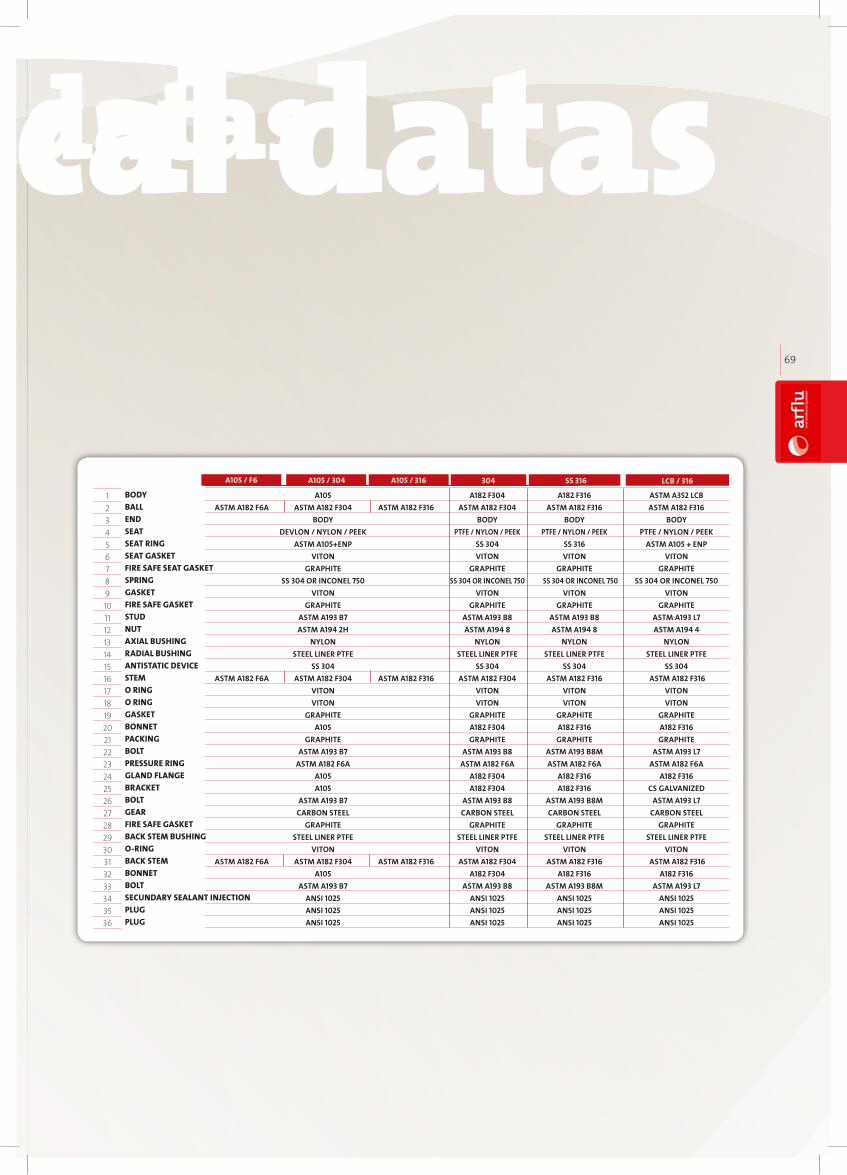
technical datastechnical datas technical datastechnical datas
arfl
uIN
DU
ST
RIA
L V
AL
VE
S
69
BODYBALLENDSEATSEAT RINGSEAT GASKETFIRE SAFE SEAT GASKETSPRINGGASKETFIRE SAFE GASKETSTUDNUTAXIAL BUSHINGRADIAL BUSHINGANTISTATIC DEVICESTEMO RINGO RINGGASKETBONNETPACKINGBOLTPRESSURE RINGGLAND FLANGEBRACKETBOLTGEARFIRE SAFE GASKETBACK STEM BUSHINGO-RINGBACK STEMBONNETBOLTSECUNDARY SEALANT INJECTIONPLUGPLUG
123456789101112131415161718192021222324252627282930313233343536
A105 A182 F304 A182 F316
ASTM A182 F6A ASTM A182 F304 ASTM A182 F316 ASTM A182 F304 ASTM A182 F316
BODY BODY BODY
DEVLON / NYLON / PEEK PTFE / NYLON / PEEK PTFE / NYLON / PEEK
ASTM A105+ENP SS 304 SS 316
VITON VITON VITON
GRAPHITE GRAPHITE GRAPHITE
SS 304 OR INCONEL 750 SS 304 OR INCONEL 750 SS 304 OR INCONEL 750
VITON VITON VITON
GRAPHITE GRAPHITE GRAPHITE
ASTM A193 B7 ASTM A193 B8 ASTM A193 B8
ASTM A194 2H ASTM A194 8 ASTM A194 8
NYLON NYLON NYLON
STEEL LINER PTFE STEEL LINER PTFE STEEL LINER PTFE
SS 304 SS 304 SS 304
ASTM A182 F6A ASTM A182 F304 ASTM A182 F316 ASTM A182 F304 ASTM A182 F316
VITON VITON VITON
VITON VITON VITON
GRAPHITE GRAPHITE GRAPHITE
A105 A182 F304 A182 F316
GRAPHITE GRAPHITE GRAPHITE
ASTM A193 B7 ASTM A193 B8 ASTM A193 B8M
ASTM A182 F6A ASTM A182 F6A ASTM A182 F6A
A105 A182 F304 A182 F316
A105 A182 F304 A182 F316
ASTM A193 B7 ASTM A193 B8 ASTM A193 B8M
CARBON STEEL CARBON STEEL CARBON STEEL
GRAPHITE GRAPHITE GRAPHITE
STEEL LINER PTFE STEEL LINER PTFE STEEL LINER PTFE
VITON VITON VITON
ASTM A182 F6A ASTM A182 F304 ASTM A182 F316 ASTM A182 F304 ASTM A182 F316
A105 A182 F304 A182 F316
ASTM A193 B7 ASTM A193 B8 ASTM A193 B8M
ANSI 1025 ANSI 1025 ANSI 1025
ANSI 1025 ANSI 1025 ANSI 1025
ANSI 1025 ANSI 1025 ANSI 1025
ASTM A352 LCB
ASTM A182 F316
BODY
PTFE / NYLON / PEEK
ASTM A105 + ENP
VITON
GRAPHITE
SS 304 OR INCONEL 750
VITON
GRAPHITE
ASTM A193 L7
ASTM A194 4
NYLON
STEEL LINER PTFE
SS 304
ASTM A182 F316
VITON
VITON
GRAPHITE
A182 F316
GRAPHITE
ASTM A193 L7
ASTM A182 F6A
A182 F316
CS GALVANIZED
ASTM A193 L7
CARBON STEEL
GRAPHITE
STEEL LINER PTFE
VITON
ASTM A182 F316
A182 F316
ASTM A193 L7
ANSI 1025
ANSI 1025
ANSI 1025
A105 / F6 304 SS 316 LCB / 316A105 / 304 A105 / 316

technical datastechnical datas technical datastechnical datas
70
cod.
* Other measures upon request.
ABT-1000
ANSI B16.34 & API6D & API608 or ISO 17292 ANSI B16.10 & API6D From 2" to 24" Ac c/ANSI B16.5, upper than 24" Ac c/ANSI B16.47 or MSS SP44 or upon request ANSI B16.25 MSS SP45 API598, API6D • Distinctive Seating Structure• Self-relieving Structure • First Aid of Seal• Fire Safe Design• Antistatic Structure• Locking Device• Full and Reduced Bore Structure• Discharge Device On Valve Body• Corrosion Resistance• Sulfide Stress Cracking Resistance• Extension Bar Device• Manual and actuator operated (gearbox,electric, pneumatic…) Ac c/ANSI B16.34 DI, WCB, WCC, WC1, WC6, WC9, C5, C12, LCB, LCC, CF8, CF8M, CF3, CF3M, CF8C, Bronze, 4A, 6A, AISI904L, CK3MCUN, Duplex, Superduplex, exotic materials
13%Cr, stellite, 304, 304L, 316, 316L, 321, bronze, monel, 4A, 6A, AISI904L, CK3MCUN, Duplex, Superduplex, exotic materials… Soft (PTFE, Viton, Nylon) and Metal to Metal all kind available Jacketed, cryogenic services, H.F. services, all kind of operated, all type of painting and coating
DESIGN
FACE TO FACE
FLANGED ENDS
BUTT WELD ENDS
BY-PASS & DRAIN
TEST
CONSTRUCTION
MATERIALS
TRIM
SEATS
OTHERS
Ball valve API6D, API 608 OR ISO17292
TRUNNION MOUNTED BALL VALVES CLASS 150 2" TO 60"
2" 2 1/2" 3" 4" 5" 6" 8" 10" 12" 14" 16" 18" 20" 24" 216 241 282 305 381 457 521 559 635 762 838 914 991 1143 178 191 203 229 356 394 457 533 610 686 762 864 914 1067 191 203 216 241 369 406 470 546 622 699 775 876 927 1080 50 65 80 100 125 150 200 250 300 350 400 450 500 600 107 125 152 178 252 378 421 482 549 582 687 730 772 995 230 400 400 650 1050 400 400 400 600 600 800 800 800 800 11 15,3 21,3 34 55,4 72 201 310 447 536 814 1210 1500 3000 12 16 22 35 58 74 205 322 460 576 864 1280 1600 3540
CLASS 150 DIMENSIONS IN MILIMETERS
26" 28" 30" 32" 34" 36" 40" 42" 48” 56” 60” 1245 1346 1397 1524 1626 1727 1956 2083 2100 2250 2489 1143 1245 1295 1372 1473 1524 1753 1855 1995 2300 2489 650 700 750 800 850 900 1000 1050 1166 1360 1458 1022 1088 1153 1223 1307 1374 1468 1532 1620 1700 1795 800 800 800 800 800 800 960 960 1000 1000 1000 3240 3710 4530 4870 5305 6010 7400 12150 21200 29600 32800 3930 4500 5370 5940 6615 7540 9320 14450 24210 34100 38500
CLASS 150 DIMENSIONS IN MILIMETERS
ND.L (BW)L (RF)L (RTJ)DNH (OPEN)WWEIGHT (KG.) (BW)WEIGHT (KG.) (RF)
ND.L (BW)L (RF)DNH (OPEN)WWEIGHT (KG.) (BW)WEIGHT (KG.) (RF)
* other requirements upon request.
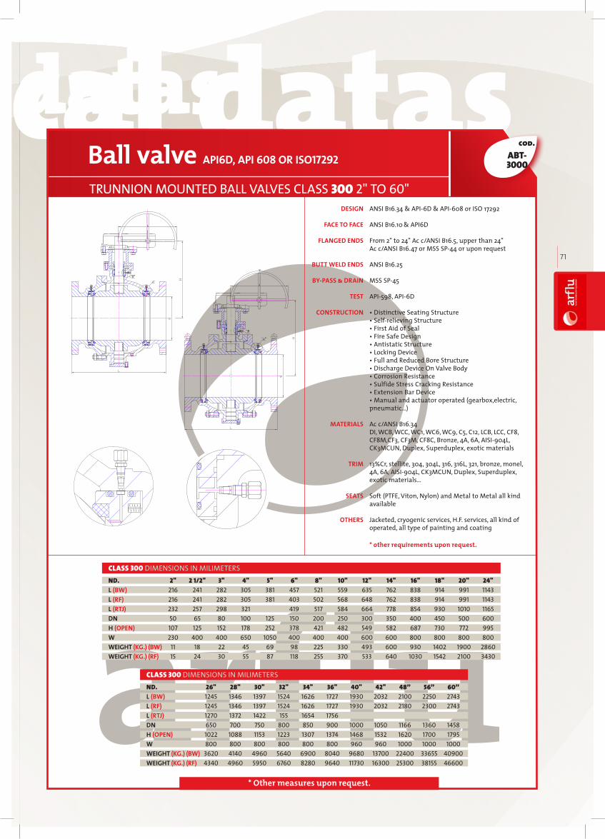
technical datastechnical datas technical datastechnical datas
arfl
uIN
DU
ST
RIA
L V
AL
VE
S
71
cod.
* Other measures upon request.
ABT-3000
ANSI B16.34 & API6D & API608 or ISO 17292 ANSI B16.10 & API6D From 2" to 24" Ac c/ANSI B16.5, upper than 24" Ac c/ANSI B16.47 or MSS SP44 or upon request ANSI B16.25 MSS SP45 API598, API6D • Distinctive Seating Structure• Self-relieving Structure • First Aid of Seal• Fire Safe Design• Antistatic Structure• Locking Device• Full and Reduced Bore Structure• Discharge Device On Valve Body• Corrosion Resistance• Sulfide Stress Cracking Resistance• Extension Bar Device• Manual and actuator operated (gearbox,electric, pneumatic…) Ac c/ANSI B16.34 DI, WCB, WCC, WC1, WC6, WC9, C5, C12, LCB, LCC, CF8, CF8M,CF3, CF3M, CF8C, Bronze, 4A, 6A, AISI904L, CK3MCUN, Duplex, Superduplex, exotic materials 13%Cr, stellite, 304, 304L, 316, 316L, 321, bronze, monel, 4A, 6A, AISI904L, CK3MCUN, Duplex, Superduplex, exotic materials… Soft (PTFE, Viton, Nylon) and Metal to Metal all kind available Jacketed, cryogenic services, H.F. services, all kind of operated, all type of painting and coating
DESIGN
FACE TO FACE
FLANGED ENDS
BUTT WELD ENDS
BY-PASS & DRAIN
TEST
CONSTRUCTION
MATERIALS
TRIM
SEATS
OTHERS
Ball valve API6D, API 608 OR ISO17292
TRUNNION MOUNTED BALL VALVES CLASS 300 2" TO 60"
2" 2 1/2" 3" 4" 5" 6" 8" 10" 12" 14" 16" 18" 20" 24" 216 241 282 305 381 457 521 559 635 762 838 914 991 1143 216 241 282 305 381 403 502 568 648 762 838 914 991 1143 232 257 298 321 419 517 584 664 778 854 930 1010 1165 50 65 80 100 125 150 200 250 300 350 400 450 500 600 107 125 152 178 252 378 421 482 549 582 687 730 772 995 230 400 400 650 1050 400 400 400 600 600 800 800 800 800 11 18 22 45 69 98 225 330 493 600 930 1402 1900 2860 15 24 30 55 87 118 255 370 533 640 1030 1542 2100 3430
ND.L (BW)L (RF)L (RTJ)DNH (OPEN)WWEIGHT (KG.) (BW)WEIGHT (KG.) (RF)
CLASS 300 DIMENSIONS IN MILIMETERS
26" 28" 30" 32" 34" 36" 40" 42" 48” 56” 60” 1245 1346 1397 1524 1626 1727 1930 2032 2100 2250 2743 1245 1346 1397 1524 1626 1727 1930 2032 2180 2300 2743 1270 1372 1422 155 1654 1756 650 700 750 800 850 900 1000 1050 1166 1360 1458 1022 1088 1153 1223 1307 1374 1468 1532 1620 1700 1795 800 800 800 800 800 800 960 960 1000 1000 1000 3620 4140 4960 5640 6900 8040 9680 13700 22400 33655 40900 4340 4960 5950 6760 8280 9640 11730 16300 25300 38155 46600
ND.L (BW)L (RF)L (RTJ)DNH (OPEN)WWEIGHT (KG.) (BW)WEIGHT (KG.) (RF)
CLASS 300 DIMENSIONS IN MILIMETERS
* other requirements upon request.

technical datastechnical datas technical datastechnical datas
72
cod.
* Other measures upon request.
ABT-6000
ANSI B16.34 & API6D & API608 or ISO 17292 ANSI B16.10 & API6D From 2" to 24" Ac c/ANSI B16.5, upper than 24" Ac c/ANSI B16.47 or MSS SP44 or upon request ANSI B16.25 MSS SP45 API598, API6D • Distinctive Seating Structure• Self-relieving Structure • First Aid of Seal• Fire Safe Design• Antistatic Structure• Locking Device• Full and Reduced Bore Structure• Discharge Device On Valve Body• Corrosion Resistance• Sulfide Stress Cracking Resistance• Extension Bar Device• Manual and actuator operated (gearbox,electric, pneuma tic…) Ac c/ANSI B16.34 DI, WCB, WCC, WC1, WC6, WC9, C5, C12, LCB, LCC, CF8, CF8M, CF3, CF3M, CF8C, Bronze, 4A, 6A, AISI904L, CK3MCUN, Duplex, Superduplex, exotic materials 13%Cr, stellite, 304, 304L, 316, 316L, 321, bronze, monel, 4A, 6A, AISI904L, CK3MCUN, Duplex, Superduplex, exotic materials… Soft (PTFE, Viton, Nylon) and Metal to Metal all kind available Jacketed, cryogenic services, H.F. services, all kind of operated, all type of painting and coating
DESIGN
FACE TO FACE
FLANGED ENDS
BUTT WELD ENDS
BY-PASS & DRAIN
TEST
CONSTRUCTION
MATERIALS
TRIM
SEATS
OTHERS
Ball valve API6D, API 608 OR ISO17292
TRUNNION MOUNTED BALL VALVES CLASS 600 2" TO 60"
2" 2 1/2" 3" 4" 6" 8" 10" 12" 14" 16" 18" 20" 24" 292 330 356 432 559 660 787 838 889 991 1092 1194 1397 292 330 356 432 559 660 787 838 889 991 1092 1194 1397 295 333 359 435 562 664 791 841 892 994 1095 1200 1407 50 65 80 100 150 200 250 300 350 400 450 500 600 107 125 152 178 389 449 497 550 582 687 730 780 995 400 650 650 1050 400 600 600 800 800 800 800 800 800 29 31 45 78 182 310 590 790 1490 1720 1830 2770 4030 35 38 55 102 232 390 710 960 1700 1970 2180 3250 4880
CLASS 600 DIMENSIONS IN MILIMETERS
26" 28" 30" 32" 34" 36" 40” 42” 48” 56” 60” 1448 1549 1651 1778 1930 2083 1900 1950 2180 2385 2949 1448 1549 1651 1778 1930 2083 2000 2100 2400 2710 2949 1461 1562 1664 1794 1946 2099 650 700 750 800 850 900 976 1020 1166 1360 1458 1038 1088 1157 1190 1246 1292 1328 1442 1558 1690 1795 800 800 800 800 960 960 1000 1000 1000 1000 1000 4840 5610 6210 7060 8640 10070 16135 18456 26695 44980 55800 5830 6700 7450 8470 10360 12080 18335 21356 31195 47483 61500
CLASS 600 DIMENSIONS IN MILIMETERS
ND.L (BW)L (RF)L (RTJ)DNH (OPEN)WWEIGHT (KG.) (BW)WEIGHT (KG.) (RF)
ND.L (BW)L (RF)L (RTJ)DNH (OPEN)WWEIGHT (KG.) (BW)WEIGHT (KG.) (RF)
* other requirements upon request.

technical datastechnical datas technical datastechnical datas
arfl
uIN
DU
ST
RIA
L V
AL
VE
S
73
cod.
* Other measures upon request.
ABT-9000
ANSI B16.34 & API6D & API608 or ISO 17292 ANSI B16.10 & API6D From 2" to 24" Ac c/ANSI B16.5, upper than 24" Ac c/ANSI B16.47 or MSS SP44 or upon request ANSI B16.25 MSS SP45 API598, API6D • Distinctive Seating Structure• Self-relieving Structure • First Aid of Seal• Fire Safe Design• Antistatic Structure• Locking Device• Full and Reduced Bore Structure• Discharge Device On Valve Body• Corrosion Resistance• Sulfide Stress Cracking Resistance• Extension Bar Device• Manual and actuator operated (gearbox,electric, pneumatic…) Ac c/ANSI B16.34 DI, WCB, WCC, WC1, WC6, WC9, C5, C12, LCB, LCC, CF8, CF8M, CF3, CF3M, CF8C, Bronze, 4A, 6A, AISI904L, CK3MCUN, Duplex, Superduplex, exotic materials
13%Cr, stellite, 304, 304L, 316, 316L, 321, bronze, monel, 4A, 6A, AISI904L, CK3MCUN, Duplex, Superduplex, exotic materials… Soft (PTFE, Viton, Nylon) and Metal to Metal all kind available Jacketed, cryogenic services, H.F. services, all kind of operated, all type of painting and coating
DESIGN
FACE TO FACE
FLANGED ENDS
BUTT WELD ENDS
BY-PASS & DRAIN
TEST
CONSTRUCTION
MATERIALS
TRIM
SEATS
OTHERS
Ball valve API6D, API 608 OR ISO17292
TRUNNION MOUNTED BALL VALVES CLASS 900 2" TO 56"
2" 2 1/2" 3" 4" 6" 8" 10" 12" 14" 16" 18" 20" 24" 368 419 381 457 610 737 838 965 1029 1130 1219 1321 1549 368 419 381 457 610 737 838 965 1029 1130 1219 1321 1549 1038 1140 1232 1568 50 65 80 100 150 200 250 300 350 400 450 500 600 123 136 185 225 389 449 497 550 582 687 730 780 995 650 800 400 400 600 600 800 800 800 800 800 800 800 40 60 70 109 264 540 800 1110 1370 1910 2310 3120 4640 50 75 92 146 339 640 960 1330 1640 2240 2770 3740 5560
ND.L (BW)L (RF)L (RTJ)DNH (OPEN)WWEIGHT (KG.) (BW)WEIGHT (KG.) (RF)
CLASS 900 DIMENSIONS IN MILIMETERS
26" 28" 30" 32" 34” 36” 40” 42” 48” 56” 1651 1753 1880 2032 2159 2286 2100 2180 2380 2400 1651 1753 1880 2032 2159 2286 2180 2250 2450 2949 1674 1775 1902 2054 2188 2315 2210 2280 2480 650 700 750 800 808 855 956 1006 1149 1360 1038 1088 1157 1190 1240 1290 1340 1395 1455 1508 800 800 800 960 960 960 960 960 1000 1000 5880 6730 8070 9170 10492 12105 16900 19995 27410 36541 7070 8070 9680 11000 13618 14280 20235 24600 31800 44483
ND.L (BW)L (RF)L (RTJ)DNH (OPEN)WWEIGHT (KG.) (BW)WEIGHT (KG.) (RF)
CLASS 900 DIMENSIONS IN MILIMETERS
* other requirements upon request.

technical datastechnical datas technical datastechnical datas
74
cod.
* Other measures upon request.
ABT4000
ANSI B16.34 & API6D & API608 or ISO 17292
ANSI B16.10 & API6D
From 2" to 24" Ac c/ANSI B16.5, upper than 24" Ac c/ANSI B16.47 or MSS SP44 or upon request
ANSI B16.25
MSS SP45
API598, API6D • Distinctive Seating Structure• Self-relieving Structure • First Aid of Seal• Fire Safe Design• Antistatic Structure• Locking Device• Full and Reduced Bore Structure• Discharge Device On Valve Body• Corrosion Resistance• Sulfide Stress Cracking Resistance• Extension Bar Device• Manual and actuator operated (gearbox,electric, pneumatic…) Ac c/ANSI B16.34 DI, WCB, WCC, WC1, WC6, WC9, C5, C12, LCB, LCC, CF8, CF8M, CF3, CF3M, CF8C, Bronze, 4A, 6A, AISI904L, CK3MCUN, Duplex, Superduplex, exotic materials 13%Cr, stellite, 304, 304L, 316, 316L, 321, bronze, monel, 4A, 6A, AISI904L, CK3MCUN, Duplex, Superduplex, exotic materials… Soft (PTFE, Viton, Nylon) and Metal to Metal all kind available Jacketed, cryogenic services, H.F. services, all kind of operated, all type of painting and coating
DESIGN
FACE TO FACE
FLANGED ENDS
BUTT WELD ENDS
BY-PASS & DRAIN
TEST
CONSTRUCTION
MATERIALS
TRIM
SEATS
OTHERS
Ball valve API6D, API 608 OR ISO17292
TRUNNION MOUNTED BALL VALVES CLASS 1500 2" TO 36"
2" 2 1/2" 3" 4" 6" 8" 10" 12" 14" 16" 18" 20" 24" 368 419 470 546 705 832 991 1130 1257 1384 1537 1664 1943 368 419 470 546 705 832 991 1130 1257 1384 1537 1664 1943 371 422 473 549 711 841 1000 1146 1276 1407 1559 1686 1972 49 62 74 100 144 192 239 287 315 380 406 454 546 154 169 187 217 346 384 452 512 561 601 688 727 803 400 400 600 600 800 800 800 800 800 800 800 800 800 40 60 82 150 414 677 1132 1777 2589 3782 4812 6555 9900 50 75 117 216 532 870 1467 2270 3240 4645 6035 8077 12357
ND.L (BW)L (RF)L (RTJ)DNH (OPEN)WWEIGHT (KG.) (BW)WEIGHT (KG.) (RF)
CLASS 1500 DIMENSIONS IN MILIMETERS
28" 30" 32" 36” 2148 2251 2346 2743 2148 2251 2346 2743 2176 2281 2380 2755 641 686 730 819 938 1070 1200 1328 960 960 960 960 12422 14586 19993 26905 16314 19466 25728 32510
CLASS 1500 DIMENSIONS IN MILIMETERSND.L (BW)L (RF)L (RTJ)DNH (OPEN)WWEIGHT (KG.) (BW)WEIGHT (KG.) (RF)
* other requirements upon request.

technical datastechnical datas technical datastechnical datas
arfl
uIN
DU
ST
RIA
L V
AL
VE
S
75
cod.
* Other measures upon request.
ANSI B16.34 & API6D & API608 or ISO 17292 ANSI B16.10 & API6D From 2" to 24" Ac c/ANSI B16.5, upper than 24" Ac c/ANSI B16.47 or MSS SP44 or upon request ANSI B16.25 MSS SP45 API598, API6D • One-piece valve body,top installed trunnion to fix and support, flanged or butt welded structure.• In coned bellows spring makes the sealed metal seat moving oward the ball,providing the two way seal function of inlet and outlet.• Distinctive technology of retractable valve seat, inline replace ability of ball arm,valve stem sealing ring,metal seat and bellows spring, and torque down to the minimum for the easy to operation.• Easy to repair and installation,long performance life. Ac cess for repair and replacement of trims may be done with no need to remove the valve from the pipeline, thus to lengthen the service life.• Low torque, reliable sealing, and spherical seat different from ordinary ball valves, which can automatically adjust the position of seal.• Preset platform and bolt holes for drie device, and to ISO5211. Drive device can be installed ac cording to users' different requirments.• DBB(double block and bleed) function. • Hand operated top installed ball valve adopts high strength onepiece ball arm structure to ensure the precise positioning of the ball.• Anti-blowout protective structure of valve stem to enhance the operational safety of the valve.• Manual and actuator operated (gearbox,electric, pneumatic…)
Ac c/ANSI B16.34 DI, WCB, WCC, WC1, WC6, WC9, C5, C12, LCB, LCC, CF8, CF8M, CF3, CF3M, CF8C, Bronze, 4A, 6A, AISI904L, CK3MCUN, Duplex, Superduplex, exotic materials 13%Cr, stellite, 304, 304L, 316, 316L, 321, bronze, monel, 4A, 6A, AISI904L, CK3MCUN, Duplex, Superduplex, exotic materials… Soft (PTFE, Viton, Nylon) and Metal to Metal all kind available Jacketed, cryogenic services, HJacketed, cryogenic services, H.F. services, all kind of operated, all type of painting and coating.
DESIGN
FACE TO FACE
FLANGED ENDS
BUTT WELD ENDS
BY-PASS & DRAIN
TEST
CONSTRUCTION
MATERIALS
TRIM
SEATS
OTHERS
Ball valve API6D, API 608 OR ISO17292
TOP ENTRY BALL VALVES CLASS 150 2" TO 32"
2" 3" 4" 6" 8" 10" 12" 14" 16" 18" 20" 24" 292 356 432 559 660 787 838 889 991 1092 1194 1397 292 356 432 559 660 787 838 889 991 1092 1194 1397 295 359 435 562 664 791 841 892 994 1095 1200 1406 50 80 100 150 200 250 300 350 400 450 500 600 212 228 272 281 320 360 403 453 459 502 551 606 450 600 600 350 500 500 700 700 700 700 700 700 28 55 105 235 430 475 610 795 1160 1570 2000 3300
ND.L (BW)L (RF)L (RTJ)DNH (OPEN)WWEIGHT (KG.) (RF)
CLASS 150 DIMENSIONS IN MILIMETERS
26" 28" 30" 32" 1448 1549 1651 1778 1448 1549 1651 1778 1460 1562 1664 1794 650 700 750 800 675 735 795 840 700 700 700 620 3970 4755 5820 7240
ND.L (BW)L (RF)L (RTJ)DNH (OPEN)WWEIGHT (KG.) (RF)
CLASS 150 DIMENSIONS IN MILIMETERS
ABE-1000
* other requirements upon request.

technical datastechnical datas technical datastechnical datas
76
cod.
* Other measures upon request.
ANSI B16.34 & API6D & API608 or ISO 17292 ANSI B16.10 & API6D From 2" to 24" Ac c/ANSI B16.5, upper than 24" Ac c/ANSI B16.47 or MSS SP44 or upon request
ANSI B16.25 MSS SP45 API598, API6D • One-piece valve body,top installed trunnion to fix and support, flanged or butt welded structure. • In coned bellows spring makes the sealed metal seat moving toward the ball,providing the two way seal function of inlet and outlet.• Distinctive technology of retractable valve seat, inline replace ability of ball arm,valve stem sealing ring,metal seat and bellows spring, and torque down to the minimum for the easy to operation.• Easy to repair and installation,long performance life. Ac cess for repair and replacement of trims may be done with no need to remove the valve from the pipeline, thus to lengthen the service life.• Low torque, reliable sealing, and spherical seat different from ordinary ball valves, which can automatically adjust the position of seal.• Preset platform and bolt holes for drie device, and to O5211. Drive device can be installed ac cording to users' different requirments.• DBB(double block and bleed) function. • Hand operated top installed ball valve adopts high strength onepiece ball arm structure to ensure the precise positioning of the ball.• Anti-blowout protective structure of valve stem to enhance the operational safety of the valve. • Manual and actuator operated (gearbox,electric, pneumatic…)
Ac c/ANSI B16.34 DI, WCB, WCC, WC1, WC6, WC9, C5, C12, LCB, LCC, CF8, CF8M,CF3, CF3M, CF8C, Bronze, 4A, 6A, AISI904L, CK3MCUN, Duplex, Superduplex, exotic materials 13%Cr, stellite, 304, 304L, 316, 316L, 321, bronze, monel, 4A, 6A, AISI904L, CK3MCUN, Duplex, Superduplex, exotic materials… Soft (PTFE, Viton, Nylon) and Metal to Metal all kind available Jacketed, cryogenic services, H.F. services, all kind of operated, all type of painting and coating
DESIGN
FACE TO FACE
FLANGED ENDS
BUTT WELD ENDS
BY-PASS & DRAIN
TEST
CONSTRUCTION
MATERIALS
TRIM
SEATS
OTHERS
Ball valve API6D, API 608 OR ISO17292
TOP ENTRY BALL VALVES CLASS 300 2" TO 32"
2" 3" 4" 6" 8" 10" 12" 14" 16" 18" 20" 24" 292 356 432 559 660 787 838 889 991 1092 1194 1397 292 356 432 559 660 787 838 889 991 1092 1194 1397 295 359 435 562 664 791 841 892 994 1095 1200 1406 50 80 100 150 200 250 300 350 400 450 500 600 212 228 272 281 330 371 418 470 477 522 573 631 450 600 1000 500 700 700 700 700 700 700 700 700 33 64 123 275 505 557 715 932 1360 1840 2340 3870
ND.L (BW)L (RF)L (RTJ)DNH (OPEN)WWEIGHT (KG.) (RF)
CLASS 300DIMENSIONS IN MILIMETERS
26" 28" 30" 32" 1448 1549 1651 1778 1448 1549 1651 1778 1460 1562 1664 1794 650 700 750 800 702 764 827 874 620 1400 1400 1400 4655 5575 6825 8490
ND.L (BW)L (RF)L (RTJ)DNH (OPEN)WWEIGHT (KG.) (RF)
CLASS 300 DIMENSIONS IN MILIMETERS
ABE-3000
* other requirements upon request.

technical datastechnical datas technical datastechnical datas
arfl
uIN
DU
ST
RIA
L V
AL
VE
S
77
cod.
* Other measures upon request.
ANSI B16.34 & API6D & API608 or ISO 17292 ANSI B16.10 & API6D From 2" to 24" Ac c/ANSI B16.5, upper than 24" Ac c/ANSI B16.47 or MSS SP44 or upon request ANSI B16.25 MSS SP45 API598, API6D • One-piece valve body,top installed trunnion to fix and support, flanged or butt welded structure.• In coned bellows spring makes the sealed metal seat moving toward the ball,providing the two way seal function of inlet and outlet. • Distinctive technology of retractable valve seat, inline replace ability of ball arm,valve stem sealing ring,metal seat and bellows spring, and torque down to the minimum for the easy to operation. • Easy to repair and installation,long performance life.Ac cess for repair and replacement of trims may be done with no need to remove the valve from the pipeline,thus to lengthen the service life. • Low torque, reliable sealing, and spherical seat different from ordinary ball valves, which can automatically adjust the position of seal.• Preset platform and bolt holes for drie device, and to ISO5211. Drive device can be installed according to users' different requirments. • DBB(double block and bleed) function.• Hand operated top installed ball valve adopts high strength onepiece ball arm structure to ensure the precise positioning of the ball. • Anti-blowout protective structure of valve stem to enhance the operational safety of the valve. • Manual and actuator operated (gearbox,electric, pneumatic…)
Ac c/ANSI B16.34 DI, WCB, WCC, WC1, WC6, WC9, C5, C12, LCB, LCC, CF8, CF8M, CF3, CF3M, CF8C, Bronze, 4A, 6A, AISI904L, CK3MCUN, Duplex, Superduplex, exotic materials
13%Cr, steelite, 304, 304L, 316, 316L, 321, bronze, monel, 4A, 6A, AISI904L, CK3MCUN, Duplex, Superduplex, exotic materials… Soft (PTFE, Viton, Nylon) and Metal to Metal all kind available Jacketed, cryogenic services, H.F. services, all kind of operated, all type of painting and coating
DESIGN
FACE TO FACE
FLANGED ENDS
BUTT WELD ENDS
BY-PASS & DRAIN
TEST
CONSTRUCTION
MATERIALS
TRIM
SEATS
OTHERS
Ball valve API6D, API 608 OR ISO17292
TOP ENTRY BALL VALVES CLASS 600 2” A 32”
2" 3" 4" 6" 8" 10" 12" 14" 16" 18" 20" 24" 292 356 432 559 660 787 838 889 991 1092 1194 1397 292 356 432 559 660 787 838 889 991 1092 1194 1397 295 359 435 562 664 791 841 892 994 1095 1200 1406 50 80 100 150 200 250 300 350 400 450 500 600 212 228 250 281 340 355 401 451 493 539 592 653 600 1000 1000 700 700 700 700 700 700 700 700 1400 37 72 137 302 560 710 910 1190 1735 2350 3000 4950
ND.L (BW)L (RF)L (RTJ)DNH (OPEN)WWEIGHT (KG.) (RF)
CLASS 600 DIMENSIONS IN MILIMETERS
26" 28" 30" 32" 1448 1549 1651 1778 1448 1549 1651 1778 1460 1562 1664 1794 650 700 750 800 725 790 850 900 1400 1400 1400 1400 5950 7130 8730 10850
ND.L (BW)L (RF)L (RTJ)DNH (OPEN)WWEIGHT (KG.) (RF)
CLASS 600 DIMENSIONS IN MILIMETERS
ABE-6000
* other requirements upon request.

technical datastechnical datas technical datastechnical datas
78
cod.
* Other measures upon request.
ANSI B16.34 & API6D & API608 or ISO 17292 ANSI B16.10 & API6D Ac c/ANSI B16.5 ANSI B16.25 MSS SP45 API598, API6D • One-piece valve body,top installed trunnion to fix and support, flanged or butt welded structure.• In coned bellows spring makes the sealed metal seat moving toward the ball,providing the two way seal function of inlet and outlet. • Distinctive technology of retractable valve seat, inline replace ability of ball arm,valve stem sealing ring,metal seat and bellows spring, and torque down to the minimum for the easy to operation. • Easy to repair and installation,long performance life.Ac cess for repair and replacement of trims may be done with no need to remove the valve from the pipeline,thus to lengthen the service life. • Low torque, reliable sealing, and spherical seat different from ordinary ball valves, which can automatically adjust the position of seal.• Preset platform and bolt holes for drie device, and to ISO5211. Drive device can be installed according to users' different requirments. • DBB(double block and bleed) function.• Hand operated top installed ball valve adopts high strength onepiece ball arm structure to ensure the precise positioning of the ball. • Anti-blowout protective structure of valve stem to enhance the operational safety of the valve. • Manual and actuator operated (gearbox,electric, pneumatic…)
Ac c/ANSI B16.34 DI, WCB, WCC, WC1, WC6, WC9, C5, C12, LCB, LCC, CF8, CF8M, CF3, CF3M, CF8C, Bronze, 4A, 6A, AISI904L, CK3MCUN, Duplex, Superduplex, exotic materials
13%Cr, steelite, 304, 304L, 316, 316L, 321, bronze, monel, 4A, 6A, AISI904L, CK3MCUN, Duplex, Superduplex, exotic materials… Soft (PTFE, Viton, Nylon) and Metal to Metal all kind available Jacketed, cryogenic services, H.F. services, all kind of operated, all type of painting and coating
DESIGN
FACE TO FACE
FLANGED ENDS
BUTT WELD ENDS
BY-PASS & DRAIN
TEST
CONSTRUCTION
MATERIALS
TRIM
SEATS
OTHERS
ABE-9000Ball valve API6D, API 608 OR ISO17292
TOP ENTRY BALL VALVES CLASS 900 2" TO 24"
2" 3" 4" 6" 8" 10" 12" 14" 16" 18" 20" 24" 368 381 457 610 737 838 965 1029 1130 1219 1321 1549 368 381 457 610 737 838 965 1029 1130 1219 1321 1549 371 384 460 613 740 841 968 1038 1140 1232 1331 1568 50 80 100 150 200 250 300 350 400 450 500 600 215 193 227 258 318 370 418 470 515 560 620 680 600 1000 500 700 700 700 700 700 700 700 1400 1400 52 108 200 456 845 1070 1675 1800 2650 3550 4530 7450
ND.L (BW)L (RF)L (RTJ)DNH (OPEN)WWEIGHT (KG.) (RF)
CLASS 900 DIMENSIONS IN MILIMETERS
* other requirements upon request.

technical datastechnical datas technical datastechnical datas
arfl
uIN
DU
ST
RIA
L V
AL
VE
S
79
cod.
* Other measures upon request.
ANSI B16.34 & API6D & API608 or ISO 17292
ANSI B16.10 & API6D Ac c/ANSI B16.5 ANSI B16.25
MSS SP45
API598, API6D
• One-piece valve body,top installed trunnion to fix and support, flanged or butt welded structure.
• In coned bellows spring makes the sealed metal seat moving toward the ball,providing the two way seal function of inlet and outlet.
• Distinctive technology of retractable valve seat, inline replace ability of ball arm,valve stem sealing ring,metal seat and bellows spring, and torque down to the minimum for the easy to operation.
• Easy to repair and installation,long performance life. Ac cess for repair and replacement of trims may be done with no need to remove the valve from the pipeline, thus to lengthen the service life.
• Low torque, reliable sealing, and spherical seat different from ordinary ball valves, which can automatically adjust the position of seal.
• Preset platform and bolt holes for drie device, and to ISO5211. Drive device can be installed ac cording to users' different requirments.
• DBB(double block and bleed) function.• Hand operated top installed ball valve adopts high strength one-
piece ball arm structure to ensure the precise positioning of the ball.• Anti-blowout protective structure of valve stem to enhance the ope
rational safety of the valve.• Manual and actuator operated (gearbox,electric, pneumatic…)
Ac c/ANSI B16.34 DI, WCB, WCC, WC1, WC6, WC9, C5, C12, LCB, LCC, CF8, CF8M, CF3, CF3M, CF8C, Bronze, 4A, 6A, AISI904L, CK3MCUN, Duplex, Superduplex, exotic materials
13%Cr, stellite, 304, 304L, 316, 316L, 321, bronze, monel, 4A, 6A, AISI904L, CK3MCUN, Duplex, Superduplex, exotic materials… Soft (PTFE, Viton, Nylon) and Metal to Metal all kind available Jacketed, cryogenic services, HJacketed, cryogenic services, H.F. services, all kind of operated, all type of painting and coating.F. services, all kind of operated, all type of painting and coating
Ball valve API6D, API 608 OR ISO17292
TOP ENTRY BALL VALVES CLASS 1500 2" TO 24"
2" 3" 4" 6" 8" 10" 12" 14" 16" 18" 20" 24" 368 470 546 705 832 991 1130 1257 1384 1537 1664 2043 368 470 546 705 832 991 1130 1257 1384 1537 1664 2043 371 473 549 711 841 1000 1146 1276 1406 1559 1686 2071 50 80 100 150 200 250 300 350 400 450 500 600 179 201 240 273 335 385 436 485 530 585 640 708 600 1000 700 700 700 700 700 700 700 1400 1400 1400 52 152 280 640 1180 1500 2065 2700 3980 5325 6800 11900
ND.L (BW)L (RF)L (RTJ)DNH (OPEN)WWEIGHT (KG.) (RF)
CLASS 1500 DIMENSIONS IN MILIMETERS
ABE-4000
DESIGN
FACE TO FACE
FLANGED ENDS
BUTT WELD ENDS
BY-PASS & DRAIN
TEST
CONSTRUCTION
MATERIALS
TRIM
SEATS
OTHERS
* other requirements upon request.

technical datastechnical datas technical datastechnical datas
80
BODYBALLENDSEATSEAT RINGSEAT GASKETFIRE SAFE SEAT GASKETBACK SEAT RINGSPRINGGASKETKEYSHAFTFRICTION BEARINGBOLTFRICTION BEARINGRADIAL BEARINGANTISTATIC DEVICESTEMO-RINGO-RINGFIRE SAFE GASKETBONNETPACKINGGLAND FLANGESTUDNUTWASHERO-RINGFIRE SAFE GASKETTRUNNIONCHECK VALVEPLUGINJECTION FITTING
CUERPOBOLA
CARRETEASIENTO
ANILLO DEL ASIENTOJUNTA DEL ASIENTO
JUNTA ASIENTO ANTIFUEGOANILLO EMPUJE
MUELLEJUNTA
CHAVETARODAMIENTO DE FRICCION
TORNILLORODAMIENTO DE FRICCION
CASQUILLO RADIALSISTEMA ANTIESTATICO
HUSILLOJUNTA TORICAJUNTA TORICA
JUNTA ANTIFUEGOTAPA
EMPAQUETADURABRIDA PRENSA
ESPARRAGOTUERCA
ARANDELAORING
JUNTA ANTIFUEGOTRUNNION
VALVULA DE RETENCIONTAPON
INJECTOR
ASTM A105 ASTM A350 LF2
ASTM A216 WCB+ ENP ASTM A351 CF8 ASTM A351 CF3 ASTM A352 LCB+ ENP ASTM A351 CF8 ASTM A351 CF3
ASTM A105 ASTM A350 LF2
ASTM A105 + ENP ASTM A182 F304 ASTM A182 F316 ASTM A350 LF2+ ENP ASTM A182 F304 ASTM A182 F316
PTFE / NYLON / PEEK PTFE / NYLON / PEEK
GRAPHITE GRAPHITE
GRAPHITE GRAPHITE
ASTM A105 + ENP ASTM A182 F304 ASTM A182 F316 ASTM A350 LF2+ ENP ASTM A182 F304 ASTM A182 F316
INCONEL X-750 INCONEL X-750
GRAPHITE GRAPHITE
KEYSHAFT STEEL KEYSHAFT STEEL
STEEL LINER PTFE STEEL LINER PTFE
ASTM A193 B7 ASTM A193 L7
STEEL LINER PTFE STEEL LINER PTFE
STEEL LINER PTFE STEEL LINER PTFE
SS304 SS304
ASTM A182 F6 ASTM A182 F304 ASTM A182 F316 ASTM A350 LF2 ASTM A182 F304 ASTM A182 F316
VITON VITON
VITON VITON
GRAPHITE GRAPHITE
ASTM A105 ASTM A350 LF2
GRAPHITE GRAPHITE
ASTM A105 ASTM A350 LF2
ASTM A193 B7 ASTM A193 L7
ASTM A194 2H ASTM A194 4
CARBON STEEL CARBON STEEL
VITON VITON
GRAPHITE GRAPHITE
ASTM A182 F6 ASTM A182 F304 ASTM A182 F316 ASTM A350 LF2 ASTM A182 F304 ASTM A182 F316
ANSI-1025 ANSI-1025
ANSI-1025 ANSI-1025
ANSI-1025 ANSI-1025
A-105 / WCB+ENP WCB / WCB+ENP WCB / 304 WCB / 316A-105 / 304 A-105 / 316
Fully Welded Ball Valves
1234567891011121314151617181920212223242526272829303132

technical datastechnical datas technical datastechnical datas
arfl
uIN
DU
ST
RIA
L V
AL
VE
S
81
cod.
* Other measures upon request.
ANSI B16.34 & API6D & API608 or BS5351
ANSI B16.10
From 2" to 24" Ac c/ANSI B16.5, upper than 24" Ac c/ANSI B16.47 or MSS SP44 or upon request
ANSI B16.25
MSS SP45
API598, API6D
• Distinctive Seating Structure• Self-relieving Structure • First Aid of Seal• Fire Safe Design• Antistatic Structure• Locking Device• Full and Reduced Bore Structure• Discharge Device On Valve Body• Corrosion Resistance• Sulfide Stress Cracking Resistance• Extension Bar Device• Manual operated (gearbox, electric, pneumatic…)
Ac c/ANSI B16.34 A105, LF2, LF1 WCB, WCC, LCB, LCC
F6, 304, 316, 316L, A105+ENP, WCB+ENP, CF8, CF8M, CF3M
Soft (PTFE, Viton, Nylon) and Metal to Metal all kind available
Ball valve FULLY WELDED
FULLY WELDED BALL VALVES 300 LBS 2" TO 60"
BFWG-3000
26” 28” 30” 32” 34” 36” 40” 42” 48” 56” 60” 1245 1346 1397 1524 1626 1727 1780 1840 2100 2250 2743 According customer request
2" 2 1/2" 3" 4" 5" 6" 8" 10" 12" 14" 16" 18" 20" 24" 216 241 283 305 403 521 559 635 762 838 914 991 1092 1143 According customer request
ND.L (BW)H
ND.L (BW)H
CLASS 300 DIMENSIONS IN MILIMETERS
CLASS 300 DIMENSIONS IN MILIMETERS
DESIGN
FACE TO FACE
FLANGED ENDS
BUTT WELD ENDS
BY-PASS & DRAIN
TEST
CONSTRUCTION
MATERIALS
TRIM
SEATS
* OTHER STANDARDS UPON REQUEST
* other requirements upon request.

technical datastechnical datas technical datastechnical datas
82
cod.
* Other measures upon request.
ANSI B16.34 & API6D & API608 or BS5351
ANSI B16.10
From 2" to 24" Ac c/ANSI B16.5, upper than 24" Ac c/ANSI B16.47 or MSS SP44 or upon request
ANSI B16.25
MSS SP45
API598, API6D
• Distinctive Seating Structure• Self-relieving Structure • First Aid of Seal• Fire Safe Design• Antistatic Structure• Locking Device• Full and Reduced Bore Structure• Discharge Device On Valve Body• Corrosion Resistance• Sulfide Stress Cracking Resistance• Extension Bar Device• Manual operated (gearbox, electric, pneumatic…)
Ac c/ANSI B16.34 A105, LF2, LF1 WCB, WCC, LCB, LCC
F6, 304, 316, 316L, A105+ENP, WCB+ENP, CF8, CF8M, CF3M
Soft (PTFE, Viton, Nylon) and Metal to Metal all kind available
Ball valve FULLY WELDED
FULLY WELDED BALL VALVES 600 LBS 2" TO 60"
ABTG-6000
26” 28” 30” 32” 34” 36” 40” 42” 48” 56” 60” 1448 1549 1651 1778 1930 2083 1900 1950 2180 2385 2949 668 684 735 779 830 874 976 1020 1166 1360 1458 ACCORDING CUSTOMER REQUEST
2" 2 1/2" 3" 4" 5" 6" 8" 10" 12" 14" 16" 18" 20" 24" 292 330 356 432 508 559 660 787 838 889 991 1092 1194 1397 49 62 74 100 125 150 201 252 303 334 385 436 487 589 ACCORDING CUSTOMER REQUEST
ND.L (BW)DNH
ND.L (BW)DNH
CLASS 600 DIMENSIONS IN MILIMETERS
CLASS 600 DIMENSIONS IN MILIMETERS
DESIGN
FACE TO FACE
FLANGED ENDS
BUTT WELD ENDS
BY-PASS & DRAIN
TEST
CONSTRUCTION
MATERIALS
TRIM
SEATS
* OTHER STANDARDS UPON REQUEST
* other requirements upon request.

technical datastechnical datas technical datastechnical datas
arfl
uIN
DU
ST
RIA
L V
AL
VE
S
83
cod.
* Other measures upon request.
ANSI B16.34 & API6D & API608 or BS5351
ANSI B16.10
From 2" to 24" Ac c/ANSI B16.5, upper than 24" Ac c/ANSI B16.47 or MSS SP44 or upon request
ANSI B16.25
MSS SP45
API598, API6D
• Distinctive Seating Structure• Self-relieving Structure • First Aid of Seal• Fire Safe Design• Antistatic Structure• Locking Device• Full and Reduced Bore Structure• Discharge Device On Valve Body• Corrosion Resistance• Sulfide Stress Cracking Resistance• Extension Bar Device• Manual operated (gearbox, electric, pneumatic…)
Ac c/ANSI B16.34 A105, LF2, LF1 WCB, WCC, LCB, LCC
F6, 304, 316, 316L, A105+ENP, WCB+ENP, CF8, CF8M, CF3M
Soft (PTFE, Viton, Nylon) and Metal to Metal all kind available
Ball valve FULLY WELDED
FULLY WELDED BALL VALVES 900 LBS 2" TO 56"
ABTG-6000
26” 28” 30” 32” 34” 36” 40” 42” 48” 56” 1651 1753 1880 2032 2159 2286 2100 2180 2380 2400 617 665 712 760 808 855 956 1006 1149 1360 ACCORDING CUSTOMER REQUEST
2" 2 1/2" 3" 4" 5" 6" 8" 10" 12" 14" 16" 18" 20" 24" 368 419 381 457 534 610 737 838 965 1029 1130 1219 1321 1549 49 62 74 100 125 150 201 252 303 322 373 423 471 570 ACCORDING CUSTOMER REQUEST
ND.L (BW)DNH
ND.L (BW)DNH
CLASS 900 DIMENSIONS IN MILIMETERS
CLASS 900 DIMENSIONS IN MILIMETERS
DESIGN
FACE TO FACE
FLANGED ENDS
BUTT WELD ENDS
BY-PASS & DRAIN
TEST
CONSTRUCTION
MATERIALS
TRIM
SEATS
* OTHER STANDARDS UPON REQUEST
* other requirements upon request.

technical datastechnical datas technical datastechnical datas
84
CLASS 2500Ball Valves
13
6
4 5
11
28
291530
3133
34
32
3512
36
131418
19
2123
202
22
2526
27
24
15
16
177
8
910
BODYBALLENDSEATSEAT RINGSEAT GASKETFIRE SAFE SEAT GASKETSPRINGGASKETFIRE SAFE GASKETSTUDNUTAXIAL BUSHINGRADIAL BUSHINGANTISTATIC DEVICESTEMO RINGO RINGFIRE SAFE GASKETBONNETPACKINGBOLTPRESSURE RINGGLAND FLANGEBRACKETBOLTGEARFIRE SAFE GASKETBACK STEM BUSHINGO-RINGBACK STEMBONNETBOLTSECUNDARY SEALANT INJECTIONPLUGPLUG
123456789101112131415161718192021222324252627282930313233343536
A105 A182 F304 A182 F316
ASTM A182 F6A ASTM A182 F304 ASTM A182 F316 ASTM A182 F304 ASTM A182 F316
A105 A182 F304 A182 F316
DEVLON / NYLON / PEEK DEVLON / NYLON / PEEK DEVLON / NYLON / PEEK
ASTM A105+ENP SS 304 SS 316
VITON VITON VITON
GRAPHITE GRAPHITE GRAPHITE
INCONEL 750 INCONEL 750 INCONEL 750
VITON VITON VITON
GRAPHITE GRAPHITE GRAPHITE
ASTM A193 B7 ASTM A193 B8 ASTM A193 B8
ASTM A194 2H ASTM A194 8 ASTM A194 8
NYLON NYLON NYLON
STEEL LINER PTFE STEEL LINER PTFE STEEL LINER PTFE
SS 304 SS 304 SS 304
ASTM A182 F6A ASTM A182 F304 ASTM A182 F316 ASTM A182 F304 ASTM A182 F316
VITON VITON VITON
VITON VITON VITON
GRAPHITE GRAPHITE GRAPHITE
A105 A182 F304 A182 F316
GRAPHITE GRAPHITE GRAPHITE
ASTM A193 B7 ASTM A193 B8 ASTM A193 B8M
ASTM A182 F6A ASTM A182 F6A ASTM A182 F6A
A105 A182 F304 A182 F316
CS GALVANIZED CS GALVANIZED CS GALVANIZED
ASTM A193 B7 ASTM A193 B8 ASTM A193 B8M
CARBON STEEL CARBON STEEL CARBON STEEL
GRAPHITE GRAPHITE GRAPHITE
STEEL LINER PTFE STEEL LINER PTFE STEEL LINER PTFE
VITON VITON VITON
ASTM A182 F6A ASTM A182 F304 ASTM A182 F316 ASTM A182 F304 ASTM A182 F316
A105 A182 F304 A182 F316
ASTM A193 B7 ASTM A193 B8 ASTM A193 B8M
ANSI 1025 ANSI 1025 ANSI 1025
ANSI 1025 ANSI 1025 ANSI 1025
ANSI 1025 ANSI 1025 ANSI 1025
A350 LF2
ASTM A182 F316
A350 LF2
DEVLON / NYLON / PEEK
SS 316
VITON
GRAPHITE
INCONEL 750
VITON
GRAPHITE
ASTM A193 L7
ASTM A194 4
NYLON
STEEL LINER PTFE
SS 304
ASTM A182 F316
VITON
VITON
GRAPHITE
A350 LF2
GRAPHITE
ASTM A193 L7
ASTM A182 F6A
A350 LF2
CS GALVANIZED
ASTM A193 L7
CARBON STEEL
GRAPHITE
STEEL LINER PTFE
VITON
ASTM A182 F316
A350 LF2
ASTM A193 L7
ANSI 1025
ANSI 1025
ANSI 1025
A105 / F6 SS 304/ SS 304 SS 316 / SS 316 LF2 / 316A105 / SS 304 A105 / SS 316

technical datastechnical datas technical datastechnical datas
arfl
uIN
DU
ST
RIA
L V
AL
VE
S
85
cod.
* Other measures upon request.
36
ABT7000
ANSI B16.34 & API6D
ANSI B16.10 & API6D
Ac c/ANSI B16.5
ANSI B16.25
MSS SP45
API598, API6D • Distinctive Seating Structure• Self-relieving Structure • First Aid of Seal• Fire Safe Design• Antistatic Structure• Locking Device• Full and Reduced Bore Structure• Discharge Device On Valve Body• Corrosion Resistance• Sulfide Stress Cracking Resistance• Extension Bar Device• Manual and actuator operated (gearbox,electric, pneumatic…) Ac c/ANSI B16.34 DI, WCB, WCC, WC1, WC6, WC9, C5, C12, LCB, LCC, CF8, CF8M, CF3, CF3M, CF8C, Bronze, 4A, 6A, AISI904L, CK3MCUN, Duplex, Superduplex, exotic materials 13%Cr, stellite, 304, 304L, 316, 316L, 321, bronze, monel, 4A, 6A, AISI904L, CK3MCUN, Duplex, Superduplex, exotic materials… Soft (PTFE, Viton, Nylon) and Metal to Metal all kind available Jacketed, cryogenic services, H.F. services, all kind of operated, all type of painting and coating
DESIGN
FACE TO FACE
FLANGED ENDS
BUTT WELD ENDS
BY-PASS & DRAIN
TEST
CONSTRUCTION
MATERIALS
TRIM
SEATS
OTHERS
Ball valve API6D, API 608 OR ISO17292
TRUNNION MOUNTED BALL VALVES CLASS 2500 2" TO 12"
* other requirements upon request.
2" 2 1/2" 3" 4" 6" 8" 10" 12" 368 419 470 546 705 832 991 1130 368 419 470 546 705 832 991 1130 371 422 473 549 711 841 1000 1146 50 65 80 100 150 200 250 300 154 169 187 217 346 384 452 512 350 400 450 500 700 700 800 800 40 60 82 150 414 677 1132 1777 50 75 117 216 532 870 1467 2270
ND.L (BW)L (RF)L (RTJ)DNH (OPEN)WWEIGHT (KG.) (BW)WEIGHT (KG.) (RF)
CLASS 2500 DIMENSIONS IN MILIMETERS
THREE-PIECE

Plug valvesA cone is the closing element of plug valves. Like ball valves, they are quarter turn valves. They are valves of simple configuration, consequently, they have a low cost of maintenance.
PLUGVALVESPLUGVALVES
86

API 599 Metal Plug Valves Flanged, Threaded and Welding EndsAPI6D ISO 14313:1999, petroleum and natural gas industriespipeline transportation systemspipeline valves
DESIGN AND MANUFACTURING:
Plug valves are designed and manufactured according to the following international codes and standards:
API 598 valve inspection and testing API6D ISO 14313:1999 petroleum and natural gas industries pipeline transportation Systemspipeline valves
INSPECTION AND TEST:
ASME B16.5 pipe flanges and flanged fittings
FLANGE DIMENSION:
ASME B16.25 buttwelding ends
WELDED END:
ASME B16.10 face to face and endtoend dimensions of valves API6D ISO 14313:1999 petroleum and natural gas industries pipeline transportation Systemspipeline valves’ API599 Metal Plug Valves – Flanged, Threaded and Welding Ends
FACE TO FACE AND END TO END
MANUFACTURING AND DESIGN
STANDARDS
arfl
uIN
DU
ST
RIA
L V
AL
VE
S
87

In this design the sealing is metal to metal, so greasing on the sealing surface is necessary to reduce valve operating torque. As the valve is being operated, a thin film of grease retained on the body will be applied on the sealing surface.In case of small leakage, the plug may be regulated and pushed against the body to make the valve tight. In this case the valve operating torque will quickly be increased. Injecting grease on the valve will make the valve easy operating.Grease is usually injected through the stem and conducted on the sealing surface across the ducts and grooves specially designed.
LUBRICATED SEALING VALVES
DESIGN FEATURES
In this design, the sealing is made by a PTFE sleeve and the surface of the plug. The PTFE sleeve is locked into the body by means of grooves and metal lips. In case of small leakage, the plug may be regulated and pushed down on the sleeve tightening the valve.
NON LUBRICATED SEALING VALVES
PLUG VALVES
Plug valves are a quarter turn valves similar to ball valves. The valve closure system consists of a conical plug, which seats against a soft material sleeve, or against the body of the valve.Plug valves are used as ONOFF valves. Fully opened valves have a low pressure loss value.Comparing with ball valves, plug valves have the following advantages:
• Less valve weight, specially important for big sizes.
• Bigger seating surface than a same size ball valve.
• Much more uniform velocity of the fluid while closing. Wire drawing is avoided.
Plug valves may be lubricated or non lubricated design.
88

arfl
uIN
DU
ST
RIA
L V
AL
VE
S
89
SLEEVE TYPE SOFT SEALING PLUG VALVES
1
2
3
4
5
6
7
8
9
10
11
12
13
14
15
16
17
BODY
SLEEVE
PLUG
ANTISTATIC DEVICE
GASKET
O-RING
GASKET
PLATE
BONNET
BOLT
GLAND RING
GLAND FLANGE
BOLT
BOLT
BRACKET
BOLT
GEAR
ASTM A216 WCB ASTM A351 CF8 ASTM A351 CF8M
PTFE PTFE PTFE
ASTM A182 F6 ASTM A351 CF8 ASTM A351 CF8 ASTM A351 CF8M
SS304 SS304 SS304 SS316
PTFE PTFE PTFE
VITON VITON VITON VITON
PTFE PTFE PTFE
ASTM A216 WCB ASTM A351 CF8 ASTM A351 CF8M
ASTM A216 WCB ASTM A351 CF8 ASTM A351 CF8M
ASTM A193 B7 ASTM A193 B8 ASTM A193 B8M
ASTM A105 ASTM A182 F304 ASTM A182 F316
ASTM A216 WCB ASTM A351 CF8 ASTM A351 CF8M
ASTM A193 B7 ASTM A193 B8 ASTM A193 B8M
ASTM A193 B7 ASTM A193 B8 ASTM A193 B8M
CARBON STEEL CARBON STEEL CARBON STEEL
ASTM A193 B7 ASTM A193 B8 ASTM A193 B8M
CARBON STEEL CARBON STEEL CARBON STEEL
WCB / F6 / PTFE CF8M / 316 / PTFECF8 / 304 / PTFE
1
2
3
4
5
6
7
8
9
10
11
12
13
14
15
16
17
18
19
20
21
22
23
24
25
26
BODY
COVER
BLOCK
NUT
EYEBOLT
O-RING
SET STUD
DISC
DISC
DISC
PLUG
SMALL BALL
SMALL SPRING
COUPLING
STEM
GASKET
ANTISTATIC DEVICE
O-RING
GASKET
GLAND FLANGE
BOLT
PIN
STOP PLATE
O-RING
LEVER COVER
LEVER
ASTM A216 WCB ASTM A351 CF8 ASTM A351 CF8M
ASTM A216 WCB ASTM A351 CF8 ASTM A351 CF8M
CARBON STEEL SS304 SS316
A194 2H ASTM A194 8 ASTM A194 8M
ASTM A193 B7 ASTM A193 B8 ASTM A193 B8M
VITON VITON VITON
CARBON STEEL SS304 SS316
CARBON STEEL SS304 SS316
CARBON STEEL SS304 SS316
CARBON STEEL SS304 SS316
ASTM A182 F6 ASTM A351 CF8 ASTM A351 CF8 ASTM A351 CF8M
SS304 SS304 SS316
SS304 SS304 SS316
SS304 SS304 SS316
ASTM A182 F6 ASTM A182 F304 ASTM A182 F304 ASTM A182 F316
PTFE PTFE PTFE
S304 SS304 SS304 SS316
VITON VITON VITON
PTFE PTFE PTFE
ASTM A105 ASTM A351 CF8 ASTM A351 CF8M
ASTM A193 B7 ASTM A193 B8 ASTM A193 B8M
CARBON STEEL SS304 SS316
CARBON STEEL CARBON STEEL CARBON STEEL
VITON VITON VITON
CARBON STEEL CARBON STEEL CARBON STEEL
CARBON STEEL CARBON STEEL CARBON STEEL
WCB / F6 / MM WCB / CF8 / MM CF8 / 304 / MM
INVERTED PRESSURE BALANCE LUBRICATED PLUG VALVES

technical datastechnical datas technical datastechnical datas
90
cod.
* Other measures upon request.
ANSI B16.34 & API6D & API599
ANSI B16.10 & API6D Ac c/ANSI B16.5 ANSI B16.25 MSS SP45 API598, API6D • The product has reasonable structure, reliable sealing, excellent performance and beautiful appearance. • Its sealing is realized by the sealing face around the sleeve.It has unique 360 degree metal edge for protection and fixing of the sleeve. • There is no cavity in the valve. • Metal edge provides the function of self-cleaning when the plug is rotated, applicable to the operation condition that is glutinous and apt to smudge. • Its characteristic double-direction flow makes installation and use more convenient. • The materials of the parts and sizes of flanges can be reasonably configured ac cording the actual operation condition of the requirements of the customers. So as to meet the various needs of engineering. • Manual and operated (gearbox,electric, pneumatic…) Ac c/ANSI B16.34 DI, WCB, WCC, WC1, WC6, WC9, C5, C12, LCB, LCC, CF8, CF8M, CF3, CF3M, CF8C, Bronze, 4A, 6A, AISI904L, CK3MCUN, Duplex, Superduplex, exotic materials 13%Cr, stellite, 304, 304L, 316, 316L, 321, bronze, monel, 4A, 6A, AISI904L, CK3MCUN, Duplex, Superduplex, exotic materials…. PTFE or others.
Jacketed, cryogenic services, H.F. services, all kind of actuators, all type of painting and coating.
DESIGN
FACE TO FACE
FLANGED ENDS
BUTT WELD ENDS
BY-PASS & DRAIN
TEST
CONSTRUCTION
MATERIALS
PLUG
SLEEVE
OTHERS
Plug valve API 6D - API 599
1/2" 3/4" 1" 1 1/4" 1 1/2" 2" 2 1/2" 3" 4" 5" 6" 8" 10" 12" 14" 140 149 172 241 267 305 330 356 457 521 559 635 762 108 117 127 140 165 178 190 203 229 254 267 292 330 356 381 108 117 140 153 178 191 204 216 242 267 281 305 343 369 394 15 20 25 32 40 50 65 80 100 125 150 200 250 300 350 180 180 185 200 210 215 250 270 300 340 365 400 450 510 590 400 400 500 500 600 600 820 820 300 300 320 320 350 380 380 10 12 14 17 19 21 29 33 48 75 98 125 171 230 370
ND.L (BW)L (RF)L (RTJ)DNH (OPEN)WWEIGHT (KG.) (RF)
CLASS 150 DIMENSIONS IN MILIMETERS
AP-1000
SLEEVE TYPE SOFT SEALING PLUG VALVES CLASS 150 1/2” TO 14”
* other requirements upon request.

technical datastechnical datas technical datastechnical datas
arfl
uIN
DU
ST
RIA
L V
AL
VE
S
91
cod.
* Other measures upon request.
ANSI B16.34 & API6D & API599 ANSI B16.10 & API6D
Ac c/ANSI B16.5 ANSI B16.25 MSS SP45 API598, API6D
• The product has reasonable structure, reliable sealing, excellent performance and beautiful appearance. • Its sealing is realized by the sealing face around the sleeve.It has unique 360 degree metal edge for protection and fixing of the sleeve. • There is no cavity in the valve. • Metal edge provides the function of self-cleaning when the plug is rotated, applicable to the operation condition that is glutinous and apt to smudge. • Its characteristic double-direction flow makes installation and use more convenient. • The materials of the parts and sizes of flanges can be reasonably configured ac cording the actual operation condition of the requirements of the customers. So as to meet the various needs of engineering. • Manual and operated (gearbox,electric, pneumatic…) Ac c/ANSI B16.34 DI, WCB, WCC, WC1, WC6, WC9, C5, C12, LCB, LCC, CF8, CF8M, CF3, CF3M, CF8C, Bronze, 4A, 6A, AISI904L, CK3MCUN, Duplex, Superduplex, exotic materials 13%Cr, stellite, 304, 304L, 316, 316L, 321, bronze, monel, 4A, 6A, AISI904L, CK3MCUN, Duplex, Superduplex, exotic materials…. PTFE or others. Jacketed, cryogenic services, H.F. services, all kind of actuators, all type of painting and coating.
DESIGN
FACE TO FACE
FLANGED ENDS
BUTT WELD ENDS
BY-PASS & DRAIN
TEST
CONSTRUCTION
MATERIALS
PLUG
SLEEVE
OTHERS
Plug valve API 6D - API 599
1/2" 3/4" 1" 1 1/4" 1 1/2" 2" 2 1/2" 3" 4" 5" 6" 8" 10" 12" 14" 140 149 172 241 267 305 330 356 457 521 559 635 762 140 152 165 178 191 216 241 283 305 381 403 419 457 502 762 151 165 178 191 204 232 257 299 321 397 419 435 473 518 778 15 20 25 32 40 50 65 80 100 125 150 200 250 300 350 180 180 185 200 210 215 250 270 300 340 365 400 450 510 590 400 400 500 600 600 820 1000 1000 300 300 320 320 350 380 380 12 14 16 19 21 24 31 36 61 86 130 190 255 380 560
ND.L (BW)L (RF)L (RTJ)DNH (OPEN)WWEIGHT (KG.) (RF)
CLASS 300 DIMENSIONS IN MILIMETERS
AP-3000
SLEEVE TYPE SOFT SEALING PLUG VALVES CLASS 300 LBS 1/2" TO 14"
* other requirements upon request.

technical datastechnical datas technical datastechnical datas
92
cod.
* Other measures upon request.
ANSI B16.34 & API6D & API599 ANSI B16.10 & API6D ANSI B16.5
ANSI B16.25 MSS SP45 API598, API6D • The product has reasonable structure, reliable sealing, excellent performance and beautiful appearance. • Its sealing is realized by the sealing face around the sleeve.It has unique 360 degree metal edge for protection and fixing of the sleeve. • There is no cavity in the valve. • Metal edge provides the function of self-cleaning when the plug is rotated, applicable to the operation condition that is glutinous and apt to smudge. • Its characteristic double-direction flow makes installation and use more convenient. • The materials of the parts and sizes of flanges can be reasonably configured according the actual operation condition of the requirements of the customers. So as to meet the various needs of engineering. • Manual and operated (gearbox,electric, pneumatic…) Ac c/ANSI B16.34 DI, WCB, WCC, WC1, WC6, WC9, C5, C12, LCB, LCC, CF8, CF8M, CF3, CF3M, CF8C, Bronze, 4A, 6A, AISI904L, CK3MCUN, Duplex, Superduplex, exotic materials 13%Cr, stellite, 304, 304L, 316, 316L, 321, bronze, monel, 4A, 6A, AISI904L, CK3MCUN, Duplex, Superduplex, exotic materials…. PTFE or others.
Jacketed, cryogenic services, H.F. services, all kind of actuators, all type of painting and coating.
DESIGN
FACE TO FACE
FLANGED ENDS
BUTT WELD ENDS
BY-PASS & DRAIN
TEST
CONSTRUCTION
MATERIALS
PLUG
SLEEVE
OTHERS
Plug valve API 6D - API 599
SLEEVE TYPE SOFT SEALING PLUG VALVES CLASS 600 1/2" TO 14"
1/2" 3/4" 1" 1 1/4" 1 1/2" 2" 2 1/2" 3" 4" 5" 6" 8" 10" 12" 14" 165 190 216 229 241 292 330 356 432 508 457 660 787 838 889 165 190 216 229 241 292 330 356 432 508 559 660 787 838 889 165 190 216 229 241 295 333 359 435 511 562 664 791 841 892 15 20 25 32 40 50 65 80 100 125 150 200 250 300 350 180 180 185 200 210 215 250 270 300 340 365 400 450 510 590 400 400 500 600 600 820 1000 1000 300 300 320 320 350 380 380 14 16 18 20 24 29 35 47 91 129 210 320 660 920 1250
ND.L (BW)L (RF)L (RTJ)DNH (OPEN)WWEIGHT (KG.) (RF)
CLASS 600 DIMENSIONS IN MILIMETERS
AP-6000
* other requirements upon request.

technical datastechnical datas technical datastechnical datas
arfl
uIN
DU
ST
RIA
L V
AL
VE
S
93
cod.
* Other measures upon request.
ANSI B16.34 & API6D & API599
ANSI B16.10 & API6D ANSI B16.5
ANSI B16.25 MSS SP45 API598, API6D • The product has reasonable structure, reliable sealing, excellent performance and beautiful appearance. • Its sealing is realized by the sealing face around the sleeve. It has unique 360 degree metal edge for protection and fixing of the sleeve. • There is no cavity in the valve. • Metal edge provides the function of self-cleaning when the plug is rotated, applicable to the operation condition that is glutinous and apt to smudge. • Its characteristic double-direction flow makes installation and use more convenient. • The materials of the parts and sizes of flanges can be reasonably configured according the actual operation condition of the requirements of the customers. So as to meet the various needs of engineering. • Manual and operated (gearbox,electric, pneumatic…) Ac c/ANSI B16.34 DI, WCB, WCC, WC1, WC6, WC9, C5, C12, LCB, LCC, CF8, CF8M, CF3, CF3M, CF8C, Bronze, 4A, 6A, AISI904L, CK3MCUN, Duplex, Superduplex, exotic materials 13%Cr, stellite, 304, 304L, 316, 316L, 321, bronze, monel, 4A, 6A, AISI904L, CK3MCUN, Duplex, Superduplex, exotic materials…. PTFE or others.
Jacketed, cryogenic services, H.F. services, all kind of actuators, all type of painting and coating.
DESIGN
FACE TO FACE
FLANGED ENDS
BUTT WELD ENDS
BY-PASS & DRAIN
TEST
CONSTRUCTION
MATERIALS
PLUG
SLEEVE
OTHERS
Plug valve API 6D - API 599
1/2" 3/4" 1" 1 1/4" 1 1/2" 2" 2 1/2" 3" 4" 5" 6" 8" 10" 12" 14" 229 229 254 279 305 368 419 381 457 559 610 737 838 965 1029 229 229 254 279 305 368 419 381 457 559 610 737 838 965 1029 229 229 254 279 305 371 422 384 460 562 613 740 841 968 1038 15 20 25 32 40 50 65 80 100 125 150 200 250 300 350 180 180 185 200 210 215 250 270 300 340 365 400 450 510 590 400 400 500 600 600 820 1000 1000 300 300 320 320 350 380 380 17 29 21 24 30 37 44 65 110 160 255 380 810 1050 1460
ND.L (BW)L (RF)L (RTJ)DNH (OPEN)WWEIGHT (KG.) (RF)
CLASS 900 DIMENSIONS IN MILIMETERS
AP-9000
SLEEVE TYPE SOFT SEALING PLUG VALVES CLASS 900 1/2" TO 14"
* other requirements upon request.
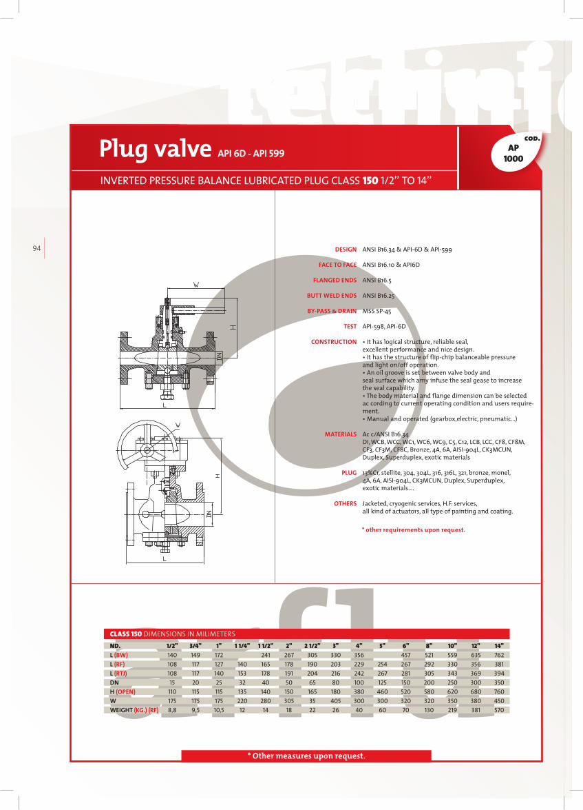
technical datastechnical datas technical datastechnical datas
94
cod.
* Other measures upon request.
Plug valve API 6D - API 599
INVERTED PRESSURE BALANCE LUBRICATED PLUG CLASS 150 1/2’’ TO 14’’
1/2" 3/4" 1" 1 1/4" 1 1/2" 2" 2 1/2" 3" 4" 5" 6" 8" 10" 12" 14" 140 149 172 241 267 305 330 356 457 521 559 635 762 108 117 127 140 165 178 190 203 229 254 267 292 330 356 381 108 117 140 153 178 191 204 216 242 267 281 305 343 369 394 15 20 25 32 40 50 65 80 100 125 150 200 250 300 350 110 115 115 135 140 150 165 180 380 460 520 580 620 680 760 175 175 175 220 280 305 35 405 300 300 320 320 350 380 450 8,8 9,5 10,5 12 14 18 22 26 40 60 70 130 219 381 570
ND.L (BW)L (RF)L (RTJ)DNH (OPEN)WWEIGHT (KG.) (RF)
CLASS 150 DIMENSIONS IN MILIMETERS
AP1000
ANSI B16.34 & API6D & API599 ANSI B16.10 & API6D
ANSI B16.5
ANSI B16.25
MSS SP45 API598, API6D • It has logical structure, reliable seal, excellent performance and nice design. • It has the structure of flip-chip balanceable pressure and light on/off operation. • An oil groove is set between valve body and seal surface which amy infuse the seal gease to increase the seal capability. • The body material and flange dimension can be selected ac cording to current operating condition and users requirement. • Manual and operated (gearbox,electric, pneumatic…) Ac c/ANSI B16.34DI, WCB, WCC, WC1, WC6, WC9, C5, C12, LCB, LCC, CF8, CF8M, CF3, CF3M, CF8C, Bronze, 4A, 6A, AISI904L, CK3MCUN, Duplex, Superduplex, exotic materials 13%Cr, stellite, 304, 304L, 316, 316L, 321, bronze, monel, 4A, 6A, AISI904L, CK3MCUN, Duplex, Superduplex, exotic materials…. Jacketed, cryogenic services, H.F. services, all kind of actuators, all type of painting and coating.
DESIGN
FACE TO FACE
FLANGED ENDS
BUTT WELD ENDS
BY-PASS & DRAIN
TEST
CONSTRUCTION
MATERIALS
PLUG
OTHERS
* other requirements upon request.

technical datastechnical datas technical datastechnical datas
arfl
uIN
DU
ST
RIA
L V
AL
VE
S
95
cod.
* Other measures upon request.
Plug valve API 6D - API 599
INVERTED PRESSURE BALANCE LUBRICATED PLUG CLASS 300 1/2’’ TO 14’’
1/2" 3/4" 1" 1 1/4" 1 1/2" 2" 2 1/2" 3" 4" 5" 6" 8" 10" 12" 14" 140 149 172 241 267 305 330 356 457 521 559 635 762 140 152 165 178 191 216 241 283 305 381 403 419 457 502 762 151 165 178 191 204 232 257 299 321 397 419 435 473 518 778 15 20 25 32 40 50 65 80 100 125 150 200 250 300 350 110 115 115 135 140 150 165 180 380 460 520 580 620 680 760 175 175 175 220 280 305 350 405 300 300 320 320 350 380 450 9,5 10,5 12 14 16 20 24 29 53 75 85 185 230 390 550
ND.L (BW)L (RF)L (RTJ)DNH (OPEN)WWEIGHT (KG.) (RF)
CLASS 300 DIMENSIONS IN MILIMETERS
AP3000
ANSI B16.34 & API6D & API599 ANSI B16.10 & API6D
ANSI B16.5
ANSI B16.25
MSS SP45 API598, API6D • It has logical structure, reliable seal, excellent performance and nice design. • It has the structure of flip-chip balanceable pressure and light on/off operation. • An oil groove is set between valve body and seal surface which amy infuse the seal gease to increase the seal capability. • The body material and flange dimension can be selected ac cording to current operating condition and users requirement. • Manual and operated (gearbox, electric, pneumatic…) Ac c/ANSI B16.34DI, WCB, WCC, WC1, WC6, WC9, C5, C12, LCB, LCC, CF8, CF8M, CF3, CF3M, CF8C, Bronze, 4A, 6A, AISI904L, CK3MCUN, Duplex, Superduplex, exotic materials 13%Cr, stellite, 304, 304L, 316, 316L, 321, bronze, monel, 4A, 6A, AISI904L, CK3MCUN, Duplex, Superduplex, exotic materials…. Jacketed, cryogenic services, H.F. services, all kind of actuators, all type of painting and coating.
DESIGN
FACE TO FACE
FLANGED ENDS
BUTT WELD ENDS
BY-PASS & DRAIN
TEST
CONSTRUCTION
MATERIALS
PLUG
OTHERS
* other requirements upon request.

technical datastechnical datas technical datastechnical datas
96
cod.
* Other measures upon request.
Plug valve API 6D - API 599
INVERTED PRESSURE BALANCE LUBRICATED PLUG CLASS 600 1/2’’ TO 14’’
1/2" 3/4" 1" 1 1/4" 1 1/2" 2" 2 1/2" 3" 4" 5" 6" 8" 10" 12" 14" 165 190 216 229 241 292 330 356 432 508 457 660 787 838 889 165 190 216 229 241 292 330 356 432 508 559 660 787 838 889 165 190 216 229 241 295 333 359 435 511 562 664 791 841 892 15 20 25 32 40 50 65 80 100 125 150 200 250 300 350 110 115 115 135 140 150 165 180 380 460 520 580 620 680 760 175 175 175 220 280 305 350 405 300 300 320 320 350 380 450 11 13 17 20 23 27 31 36 72 98 141 245 330 515 710
ND.L (BW)L (RF)L (RTJ)DNH (OPEN)WWEIGHT (KG.) (RF)
CLASS 600 DIMENSIONS IN MILIMETERS
ANSI B16.34 & API6D & API599 ANSI B16.10 & API6D
ANSI B16.5
ANSI B16.25
MSS SP45 API598, API6D • It has logical structure, reliable seal, excellent performance and nice design. • It has the structure of flip-chip balanceable pressure and light on/off operation. • An oil groove is set between valve body and seal surface which amy infuse the seal gease to increase the seal capability. • The body material and flange dimension can be selected ac cording to current operating condition and users requirement. • Manual and operated (gearbox,electric, pneumatic…) Ac c/ANSI B16.34DI, WCB, WCC, WC1, WC6, WC9, C5, C12, LCB, LCC, CF8, CF8M, CF3, CF3M, CF8C, Bronze, 4A, 6A, AISI904L, CK3MCUN, Duplex, Superduplex, exotic materials 13%Cr, stellite, 304, 304L, 316, 316L, 321, bronze, monel, 4A, 6A, AISI904L, CK3MCUN, Duplex, Superduplex, exotic materials…. Jacketed, cryogenic services, H.F. services, all kind of actuators, all type of painting and coating.
DESIGN
FACE TO FACE
FLANGED ENDS
BUTT WELD ENDS
BY-PASS & DRAIN
TEST
CONSTRUCTION
MATERIALS
PLUG
OTHERS
* other requirements upon request.
AP6000

technical datastechnical datas technical datastechnical datas
arfl
uIN
DU
ST
RIA
L V
AL
VE
S
97
cod.
* Other measures upon request.
Plug valve API 6D - API 599
INVERTED PRESSURE BALANCE LUBRICATED PLUG CLASS 900 1/2’’ TO 14’’
1/2" 3/4" 1" 1 1/4" 1 1/2" 2" 2 1/2" 3" 4" 5" 6" 8" 10" 12" 14" 229 229 254 279 305 368 419 381 457 559 610 737 838 965 1029 229 229 254 279 305 368 419 381 457 559 610 737 838 965 1029 229 229 254 279 305 371 422 384 460 562 613 740 841 968 1038 15 20 25 32 40 50 65 80 100 125 150 200 250 300 350 110 115 115 135 140 150 165 180 380 460 520 580 620 680 760 175 175 175 220 280 305 350 405 300 300 320 320 350 380 450 13 16 21 24 28 32 40 47 91 117 165 285 420 610 860
ND.L (BW)L (RF)L (RTJ)DNH (OPEN)WWEIGHT (KG.) (RF)
CLASS 900 DIMENSIONS IN MILIMETERS
ANSI B16.34 & API6D & API599 ANSI B16.10 & API6D
ANSI B16.5
ANSI B16.25
MSS SP45 API598, API6D • It has logical structure, reliable seal, excellent performance and nice design. • It has the structure of flip-chip balanceable pressure and light on/off operation. • An oil groove is set between valve body and seal surface which amy infuse the seal gease to increase the seal capability. • The body material and flange dimension can be selected ac cording to current operating condition and users requirement. • Manual and operated (gearbox,electric, pneumatic…) Ac c/ANSI B16.34DI, WCB, WCC, WC1, WC6, WC9, C5, C12, LCB, LCC, CF8, CF8M, CF3, CF3M, CF8C, Bronze, 4A, 6A, AISI904L, CK3MCUN, Duplex, Superduplex, exotic materials 13%Cr, stellite, 304, 304L, 316, 316L, 321, bronze, monel, 4A, 6A, AISI904L, CK3MCUN, Duplex, Superduplex, exotic materials…. Jacketed, cryogenic services, H.F. services,all kind of actuators, all type of painting and coating.
DESIGN
FACE TO FACE
FLANGED ENDS
BUTT WELD ENDS
BY-PASS & DRAIN
TEST
CONSTRUCTION
MATERIALS
PLUG
OTHERS
* other requirements upon request.
AP9000

ARFLU dual expanding plug valves represent the “single valve solution” and avoid all these problems, they are easy to operate, require very little maintenance and offer verifiable double block & bleed service with an extraordinary long lifetime.
Not only do we help our clients to avoid product loss, our valves prevent fuel contamination in Multi Product Manifolds, avoid errors in meter calibration and at the same time help to protect health and the environment by positively containing the fluid in the pipeline.
DUALEXPANDINGPLUGVALVES
DUALEXPANDINGPLUGVALVES
DOUBLE BLOCK AND BLEED
98

DOUBLE BLOCK AND BLEED
Double Block & Bleed service is a challenge in many applications, as droptight sealing on both the upstream and the downstream side is essential in many sectors like:
The antiquated system to achieve double block & bleed features is the use of 2 block valves and a spool piece with bleed valve. This configuration requires a lot of space and the operation of 2 valves, which especially in the actuated version is a very expensive and maintenanceintensive solution.
Common valve designs like most gate and ball valves depend on line pressure or springs to achieve sealing and cannot guarantee longterm double block & bleed service as their sealing mechanism is based on friction and tearing and consequently seal abrasion and scored seating elements may lead to product loss and contamination.
• Tank Storage
• Loading/unloading Stations
• Multi-Product Manifolds
• Metering Stations
• Aviation fuel Services
• Custody Transfer Units
• Offshore Platforms
arfl
uIN
DU
ST
RIA
L V
AL
VE
S
99
When closing, the cam starts turning the plug 90 degrees and pushing it downwards to set the slips in front of the ports. During this process neither the slip nor the elastomer seat will be in contact with the body, therefore avoiding any friction force that would damage the sealing surface.Finally the plug will continue to move downwards pushing and expanding the slips towards the
ports until metal to metal closure is made, also obtaining a bubble tight closure due to the elastomer compression.
Opening the valve will take it through the same movements in reverse order, separating the slips from the body first, once again avoiding any damage to the parts, and afterwards turning 90 degrees until the flow path is totally opened.
In the open position the slips with the permanently bonded seals are completely out of the flow and not in contact with the body.
HOW IT WORKS
General consideration
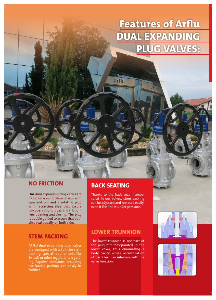
Features of Arflu DUAL EXPANDING
PLUG VALVES:
NO FRICTION
Our dual expanding plug valves are based on a rising stem design with cam and pin and a rotating plug with retracting slips that assure low operating torques and frictionfree opening and closing. The plug is double guided to assure that both slips seal equally on both sides.
STEM PACKINGARFLU dual expanding plug valves are equipped with a fullsize stem packing; special requirements like TALuft or other regulations regarding fugitive emissions, including live loaded packing, can easily be fulfilled.
BACK SEATINGThanks to the back seat incorporated in our valves, stem packing can be adjusted and replaced easily, even if the line is under pressure.
LOWER TRUNNIONThe lower trunnion is not part of the plug but incorporated in the lower cover, thus eliminating a body cavity where accumulation of particles may interfere with the valve function.
100

1. MBV: MANUAL BODY BLEED.
This system is hand operated. In order to check the seal effectiveness the Double Block & Bleed Plug valve must be fully closed, then you can proceed to open the manual valve and bleed the body. Manual valve must be closed before reopening the DBB valve.
2. TRB:THERMAL RELIEF TO BODY.
This system routes excess pressure that might be generated due to thermal expansion. Once the thermal relief valve detects 25 psi above pipeline pressure the excess is released. This system includes an isolation valve that if closed will not let the overpressure be released, and therefore should be left open.
3. MBTR:MANUAL BLEED AND THERMAL RELIEF.
This system is a combination of a MBV and a TRB. The body can be manually bled and if 25 psi above pipeline pressure is detected, overpressure will be released. It also includes an isolation valve.
PRESSURE RELIEF DEVICESDUAL EXPANDING PLUG VALVES
A pressure relief device should be included in all Double Block & Bleed Plug valves in order to satisfy API 6D requirements. Even the slightest change in the temperature could result in a significant increase in body cavity pressure due to thermal expansion. For instance something as common as direct sunlight could increase the temperature, therefore all DEP valves in liquid service must include a pressure relief device.
Other bleed systems like automatic body bleed or remote leak detection device are available upon request.*
DOUBLE BLOCK & BLEEDARFLU dual expanding plug valves have a double block and bleed function both upstream and downstream which otherwise would require two separated valves to obtain the same effect. This does not only mean an easier operation but also lower cost of maintenance and saving space.
ACTUATIONARFLU dual expanding plug valves can be equipped with any type of actuator, including linear pneumatic ones.
MAINTENANCE AND SERVICEABILITYARFLU dual expanding plug valves are top and bottom entry type. If changing the slips is required, these can easily be accessed by removing the lower cover without any special tools. The valve should be in open position to remove the slips downwards.
arfl
uIN
DU
ST
RIA
L V
AL
VE
S
101

8
7
6
5
11
10
40
4
2
49
26
3
9
12
102
DUAL EXPANDING PLUG VALVE
BODYPLUGSLIPLOWER STEMBACKSEATPACKINGGLAND RINGGLAND FLANGELOWER STEM PINCAMUPPER STEMUPPER STEM/CAM PINCAM PINBEARINGCOVERGREASING INJECTORUPPER COVERUPPER GASKETYOKEO-RINGTRUNNIONGASKETLOWER COVERLOWER GASKETDRAIN PLUGBLEED SYSTEMCOVER STUDCOVER NUTYOKE NUT YOKE STUDSTUD GLAND FLANGENUT GLAND FLANGELOWER COVER STUDLOWER COVER NUTPOSITION INDICATOR STEMYOKE COVERPIN PLUGBEARINGSCREWLOWER STEM/CAM PINSCREWSCREWINDICATOR COVERWHEELWHEEL FIXINGSTUDPOSITION INDICATORSTEM NUTBUSHING
ASTM A216 WCB + CRASTM A216 WCB + ENPASTM A536-80-55-06 + VI-TONASTM A182 F6AASTM A182 F6AGRAPHITEASTM A182 F6AASTM A10517 -4PHF158 CASTM A182 F6A17 -4PH17 -4PHASTM CARBON STEELASTM A216 WCB STEELASTM A216 WCBSW316+GRAPHITEASTM A216 WCBVITONASTM A182 F6AGRAPHITEASTM A216 WCBSW316+GRAPHITEASTM A105NCARBON STEELASTM A193 B7ASTM A194 2HASTM A194 2HASTM A193 B7ASTM A193 B7ASTM A194 2HASTM A193 B7ASTM A194 2HPOLYETHYLENE COATEDASTM A10517 -4PHCARBON STEEL8.817 -4PH8.88.8STEELCARBON STEELCARBON STEELCARBON STEELCARBON STEELBRONZECARBON STEEL + PTFE
01020304050607080910111213141516171819202122232425262728293031323334353637383940414243444546474849
1121151111112222111211111188662288112261841111111
ITEM DENOMINATION MATERIAL/STANDARDQUANT.
Other materials available upon request

28
27
17
18
01
24
23
33
3425
22
21
39
20
1641
1513
13
29
30
37
19
38
38
36
44
4645
43
35
47
48
arfl
uIN
DU
ST
RIA
L V
AL
VE
S
103

technical datastechnical datas technical datastechnical datas
104
cod.
* Other measures upon request.
ANSI B16.34 & API6A / API 599
ANSI B16.10 /Standard ARFLU
From 2" to 24" Ac c/ANSI B16.5, upper than 24" Ac c/ANSI B16.47 or MSS SP44 or upon request
ANSI B16.25
MSS SP45
API598, API6D or ANSI B16.34
• Y. Rising Stem• Inserted soft seats • Bolted Bonnet• Extended Bonnet • Manual and actuator operated (electric, pneumatic, hydraulic…)
Ac c/ANSI B16.34WCB, WCC, LCB, CF8 & CF8M
CLASS 150 LBS REDUCED BORE
NOTE - Dimensions are for information only. Certified dimensional drawings are available upon request.
SIZE A B C D E OPERATOR
(inch) (mm) (mm) (mm) (mm) (mm)
2” 178 125 270 150 150 HANDWHEEL
3” 203 140 280 195 190 HANDWHEEL
4” 229 150 315 225 230 HANDWHEEL
6” 266 215 400 270 280 HANDWHEEL
8” 292 265 460 310 345 GEARBOX
10” 330 315 500 340 405 GEARBOX
12” 355 340 725 415 485 GEARBOX
14” 381 390 830 530 535 GEARBOX
16” 406 500 975 600 595 GEARBOX
20” 864 650 1120 690 700 GEARBOX
24” 914 750 1250 800 815 GEARBOX
30” 1295 900 1375 970 * GEARBOX
36” 1727 1050 1500 1140 * GEARBOX
DBB- Plug ValveDEPV REDUCED BORE 150 LBS 2” TO 36”
APDB-1000
DESIGN
FACE TO FACE
FLANGED ENDS
BUTT WELD ENDS
BY-PASS & DRAIN
TEST
CONSTRUCTION
MATERIALS
* other requirements upon request.

technical datastechnical datas technical datastechnical datas
arfl
uIN
DU
ST
RIA
L V
AL
VE
S
105
cod.
* Other measures upon request.
ANSI B16.34 & API6A / API 599
ANSI B16.10 /Standard ARFLU
From 2" to 24" Ac c/ANSI B16.5, upper than 24" Ac c/ANSI B16.47 or MSS SP44 or upon request
ANSI B16.25
MSS SP45
API598, API6D or ANSI B16.34
• Y. Rising Stem• Inserted soft seats • Bolted Bonnet• Extended Bonnet • Manual and actuator operated (electric, pneumatic, hydraulic…)
Ac c/ANSI B16.34WCB, WCC, LCB, CF8 & CF8M
CLASS 150 LBS FULL BORE
NOTE - Dimensions are for information only. Certified dimensional drawings are available upon request.
SIZE A B C D E OPERATOR
(inch) (mm) (mm) (mm) (mm) (mm)
2” 298 125 270 240 150 HANDWHEEL
3” 343 140 280 255 190 HANDWHEEL
4” 432 150 315 300 230 HANDWHEEL
6” 533 215 400 330 280 GEARBOX
8” 610 265 460 370 345 GEARBOX
10” 787 315 500 400 405 GEARBOX
12” 914 340 725 415 485 GEARBOX
14” 978 390 830 440 535 GEARBOX
16” 991 500 975 545 595 GEARBOX
20” 1245 650 1120 650 700 GEARBOX
24” 1346 750 1250 770 815 GEARBOX
30” 1727 900 1375 1040 * GEARBOX
36” 2108 1050 1500 1310 * GEARBOX
DBB- Plug ValveDEPV FULL BORE 150 LBS 2” TO 36”
APDB-1000
DESIGN
FACE TO FACE
FLANGED ENDS
BUTT WELD ENDS
BY-PASS & DRAIN
TEST
CONSTRUCTION
MATERIALS
* other requirements upon request.

technical datastechnical datas technical datastechnical datas
106
cod.
* Other measures upon request.
ANSI B16.34 & API6A / API 599
ANSI B16.10 /Standard ARFLU
From 2" to 24" Ac c/ANSI B16.5, upper than 24" Ac c/ANSI B16.47 or MSS SP44 or upon request
ANSI B16.25
MSS SP45
API598, API6D or ANSI B16.34
• Y. Rising Stem• Inserted soft seats • Bolted Bonnet• Extended Bonnet • Manual and actuator operated (electric, pneumatic, hydraulic…)
Ac c/ANSI B16.34WCB, WCC, LCB, CF8 & CF8M
CLASS 300 LBS REDUCED BORE
NOTE - Dimensions are for information only. Certified dimensional drawings are available upon request.
SIZE A B C D E OPERATOR
(inch) (mm) (mm) (mm) (mm) (mm) (mm)
2” 216 135 280 150 150 HANDWHEEL
3” 283 150 290 195 190 HANDWHEEL
4” 305 160 325 225 230 HANDWHEEL
6” 403 225 410 270 280 HANDWHEEL
8” 419 275 470 310 345 GEARBOX
10” 457 325 510 340 405 GEARBOX
12” 502 350 735 415 485 GEARBOX
14” 762 400 840 530 535 GEARBOX
16” 838 510 985 600 595 GEARBOX
20” 991 660 1130 690 700 GEARBOX
24” 1346 760 1260 800 815 GEARBOX
30” 1594 910 1385 970 * GEARBOX
APDB-3000DBB- Plug Valve
DEPV REDUCED BORE 300 LBS 2” TO 30”
DESIGN
FACE TO FACE
FLANGED ENDS
BUTT WELD ENDS
BY-PASS & DRAIN
TEST
CONSTRUCTION
MATERIALS
* other requirements upon request.

technical datastechnical datas technical datastechnical datas
arfl
uIN
DU
ST
RIA
L V
AL
VE
S
107
cod.
* Other measures upon request.
ANSI B16.34 & API6A / API 599
ANSI B16.10 /Standard ARFLU
From 2" to 24" Ac c/ANSI B16.5, upper than 24" Ac c/ANSI B16.47 or MSS SP44 or upon request
ANSI B16.25
MSS SP45
API598, API6D or ANSI B16.34
• Y. Rising Stem• Inserted soft seats • Bolted Bonnet• Extended Bonnet • Manual and actuator operated (electric, pneumatic, hydraulic…)
Ac c/ANSI B16.34WCB, WCC, LCB, CF8 & CF8M
CLASS 300 LBS FULL BORE
NOTE - Dimensions are for information only. Certified dimensional drawings are available upon request.
SIZE A B C D E OPERATOR
(inch) (mm) (mm) (mm) (mm) (mm) (mm)
2” 313 135 280 240 150 HANDWHEEL
3” 387 150 290 255 190 HANDWHEEL
4” 457 160 325 300 230 HANDWHEEL
6” 559 225 410 330 280 GEARBOX
8” 686 275 470 370 345 GEARBOX
10” 826 325 510 400 405 GEARBOX
12” 965 350 735 415 485 GEARBOX
14” 864 400 840 440 535 GEARBOX
16” 914 510 985 545 595 GEARBOX
20” 1245 660 1130 650 700 GEARBOX
24” 1394 760 1260 770 815 GEARBOX
30” 1727 910 1385 1040 * GEARBOX
APDB-3000DBB- Plug Valve
DEPV FULL BORE 300 LBS 2” TO 30”
DESIGN
FACE TO FACE
FLANGED ENDS
BUTT WELD ENDS
BY-PASS & DRAIN
TEST
CONSTRUCTION
MATERIALS
* other requirements upon request.

technical datastechnical datas technical datastechnical datas
108
cod.
* Other measures upon request.
CLASS 600 LBS REDUCED BORE
NOTE - Dimensions are for information only. Certified dimensional drawings are available upon request.
SIZE A B C D E OPERATOR
(inch) (mm) (mm) (mm) (mm) (mm) (mm)
2” 292 145 290 150 150 HANDWHEEL
3” 356 160 300 195 190 HANDWHEEL
4” 432 170 335 225 230 HANDWHEEL
6” 559 235 420 270 280 HANDWHEEL
8” 660 285 480 310 345 GEARBOX
10” 787 335 520 340 405 GEARBOX
12” 838 360 745 415 485 GEARBOX
DBB- Plug ValveDEPV REDUCED BORE 600 LBS 2” TO 12”
APDB-6000
ANSI B16.34 & API6A / API 599
ANSI B16.10 /Standard ARFLU
ANSI B16.5
ANSI B16.25
MSS SP45
API598, API6D or ANSI B16.34
• Y. Rising Stem• Inserted soft seats • Bolted Bonnet• Extended Bonnet • Manual and actuator operated (electric, pneumatic, hydraulic…)
Ac c/ANSI B16.34WCB, WCC, LCB, CF8 & CF8M
DESIGN
FACE TO FACE
FLANGED ENDS
BUTT WELD ENDS
BY-PASS & DRAIN
TEST
CONSTRUCTION
MATERIALS
* other requirements upon request.

technical datastechnical datas technical datastechnical datas
arfl
uIN
DU
ST
RIA
L V
AL
VE
S
109
cod.
* Other measures upon request.
CLASS 600 LBS FULL BORE
NOTE - Dimensions are for information only. Certified dimensional drawings are available upon request.
SIZE A B C D E OPERATOR
(inch) (mm) (mm) (mm) (mm) (mm) (mm)
2” 330 145 290 240 150 HANDWHEEL
3” 444 160 300 255 190 HANDWHEEL
4” 508 170 335 300 230 HANDWHEEL
6” 660 235 420 330 280 HANDWHEEL
8” 794 285 480 370 345 GEARBOX
10” 940 335 520 400 405 GEARBOX
12” 1067 360 745 415 485 GEARBOX
DBB- Plug ValveDEPV FULL BORE 600 LBS 2” TO 12”
APDB-6000
ANSI B16.34 & API6A / API 599
ANSI B16.10 /Standard ARFLU
ANSI B16.5 Ac c/ANSI B16.47 or MSS SP44 or upon request
ANSI B16.25
MSS SP45
API598, API6D or ANSI B16.34
• Y. Rising Stem• Inserted soft seats • Bolted Bonnet• Extended Bonnet • Manual and actuator operated (electric, pneumatic, hydraulic…)
Ac c/ANSI B16.34WCB, WCC, LCB, CF8 & CF8M
DESIGN
FACE TO FACE
FLANGED ENDS
BUTT WELD ENDS
BY-PASS & DRAIN
TEST
CONSTRUCTION
MATERIALS
* other requirements upon request.

LIST OF REFERENCE DESIGN STANDARDS:
110
The Double Block &Bleed Dual Expanding Plug valves
meet the international standards listed below:
1- DOUBLE BLOCK & BLEED Easier operation, lower costs of maintenance and space saving
2- BACK SEATING Stem packing easily replaced or adjusted, even if line is under pressure
3- LATEST DESIGN
Our design is optimized by the most modern informatic technology, 3D design (Solid Works), finite element calculus, etc.
4- MANUFACTURING CAPACITY 5- NO FRICTION
Low operating torques and frictionfree opening & closing.
6- MAINTENANCE AND SERVICEABILITY Easy access to the slips to change them quickly, if required. Low cost maintenance.
7- STEM PACKING with special requirements (i.e. TALuft, fugitive emissions, etc)
8- LOWER TRUNNION
No body cavity therefore no accumulation of particles that could interfere with valve function.
9- DOUBLE GUIDED PLUG
This assures the sealing of both slips equally
THE COMPETITIVE ADVANTAGES DUAL EXPANDING PLUG
1. API 6D: Pipeline Valves. Pressure Test Specification.
2. ANSI B 16.34: ValvesFlanged, Threaded, and Welding End.
3. ANSI B 16.5:Steel Pipe Flanges and Flanges Fittings, Flange dimensions.
4. ANSI B 16.10: FacetoFace and EndtoEnd Dimensions of Ferrous Valves.
5. ANSI B 31.3: Chemical Plant and Petroleum Refinery Piping.
6. ANSI B 31.4:Liquid Petroleum Transportation Piping Systems.
7. API 598: Valve Inspection and Test. Optional Test Specification.
8. API 599: Steel Plug valves.
9. API RP6FA: Fire Test for Valves.

Technical datas
Technical help
dimensions
materialsFORGED STEEL STANDARDS COMPARISON
CAST IRON
FERRITIC STEELS
COPPER ALLOYS
NICKEL ALLOYS
AUSTENITIC STEELS
NICKEL-COPPER ALLOYS
PRESSURE - TEMPERATURE RATINGS
FLANGES
BUTT WELDING

technical datastechnical datas technical datastechnical datas
112
Clas
s 15
0 lb
s
Flanges ASME B 16.5 RF
DIMENSIONS
Class 150 lbs | Class 300 lbs
Flanges ASME B 16.5 RF Class 150 lbs
Nominal size
A D D1 D2 b d Bolt L1 L225,4
Size of port valve
Flanges diameter
Holescircle
diameter
Raised diameter
Flange thickness
Diameterof holes
Number of holes
Diameterof bolts
Length stud bolts
Lengthmachine
boltsNPS DN
1/2" 15inch. 1/2 3,50 2,38 1,38 0,38 0,62
4 1/2"2,50 2,00
mm. 13 88,90 60,45 35,05 9,65 15,75 63,50 50,80
3/4" 20inch. 3/4 3,88 2,75 1,69 0,41 0,62
4 1/2"2,50 2,25
mm. 20 98,55 69,85 42,93 10,41 15,75 63,50 57,15
1" 25inch. 1 4,25 3,12 2,00 0,44 0,62
4 1/2"2,75 2,25
mm. 25 107,95 79,25 50,80 11,18 15,75 69,85 57,15
1 1/4" 32inch. 1 1/4 4,62 3,50 2,50 0,50 0,62
4 1/2"2,75 2,50
mm. 32 117,35 88,90 63,50 12,70 15,75 69,85 63,50
1 1/2" 40inch. 1 1/2 5,00 3,88 2,88 0,56 0,62
4 1/2"3,00 2,50
mm. 38 127,00 98,55 73,15 14,22 15,75 76,20 63,50
2" 50inch. 2 6,00 4,75 3,62 0,62 0,75
4 5/8"3,25 2,75
mm. 50 152,40 120,65 91,95 15,75 19,05 82,55 69,85
2 1/2" 65inch. 2 1/2 7,00 5,50 4,12 0,69 0,75
4 5/8"3,50 3,00
mm. 65 177,80 139,70 104,65 17,53 19,05 88,90 76,20
3" 80inch. 3 7,50 6,00 5,00 0,75 0,75
4 5/8"3,50 3,25
mm. 77 190,50 152,40 127,00 19,05 19,05 88,90 82,55
3 1/2" 90inch. 3 1/2 8,50 7,00 5,50 0,81 0,75
8 5/8"3,50 3,25
mm. 90 215,90 177,80 139,70 20,57 19,05 88,90 82,55
4" 100inch. 4 9,00 7,50 6,19 0,94 0,75
8 5/8"3,50 3,25
mm. 102 228,60 190,50 157,23 23,88 19,05 88,90 82,55
5" 125inch. 5 10,00 8,50 7,31 0,94 0,88
8 3/4"3,75 3,25
mm. 127 254,00 215,90 185,67 23,88 22,35 95,25 82,55
6" 150inch. 6 11,00 9,50 8,50 1,00 0,88
8 3/4"4,00 3,50
mm. 152 279,40 241,30 215,90 25,40 22,35 101,60 88,90
8" 200inch. 8 13,50 11,75 10,62 1,12 0,88
8 3/4"4,25 3,75
mm. 203 342,90 298,45 269,75 28,45 22,35 107,95 95,25
10" 250inch. 10 16,00 14,25 12,75 1,19 1,00
12 7/8"4,50 4,00
mm. 254 406,40 361,95 323,85 30,23 25,40 114,30 101,60
12" 300inch. 12 19,00 17,00 15,00 1,25 1,00
12 7/8"4,75 4,25
mm. 305 482,60 431,80 381,00 31,75 25,40 120,65 107,95
14" 350inch. 13 1/4 21,00 18,75 16,25 1,38 1,12
12 1"5,25 4,50
mm. 337 533,40 476,25 412,75 35,05 28,45 133,35 114,30
16" 400inch. 15 1/4 23,50 21,25 18,50 1,44 1,12
16 1"5,25 4,75
mm. 387 596,90 539,75 469,90 36,58 28,45 133,35 120,65
18" 450inch. 17 1/4 25,00 22,75 21,00 1,56 1,25
16 1 1/8"5,75 5,00
mm. 438 635,00 577,85 533,40 39,62 31,75 146,05 127,00
20" 500inch. 19 1/4 27,50 25,00 23,00 1,69 1,25
20 1 1/8"6,25 5,50
mm. 489 698,50 635,00 584,20 42,93 31,75 158,75 139,70
24" 600inch. 23 1/4 32,00 29,50 27,25 1,88 1,38
20 1 1/4"6,75 6,00
mm. 591 812,80 749,30 692,15 47,75 35,05 171,45 152,40

technical datastechnical datas technical datastechnical datas
arfl
uIN
DU
ST
RIA
L V
AL
VE
S
113
Clas
s 30
0 lb
s
Class 600 lbs
Flanges ASME B 16.5 RF
Class 600 lbs
Nominal size
A D D1 D2 b d Bolt L125,4
Size of port valve
Flanges diameter
Holescircle
diameter
Raised diameter
Flange thickness
Diameterof holes
Number of holes
Diameterof bolts
Length stud boltsNPS DN
1/2" 15inch. 1/2 3,75 2,62 1,38 0,56 0,62
4 1/2"3,25
mm. 13 95,25 66,55 35,05 14,22 15,75 82,55
3/4" 20inch. 3/4 4,62 3,25 1,69 0,62 0,75
4 5/8"3,50
mm. 20 117,35 82,55 42,93 15,75 19,05 88,90
1" 25inch. 1 4,88 3,50 2,00 0,69 0,75
4 5/8"3,75
mm. 25 123,95 88,90 50,80 17,53 19,05 95,25
1 1/4" 32inch. 1 1/4 5,25 3,88 2,50 0,81 0,75
4 5/8"4,00
mm. 32 133,35 98,55 63,50 20,57 19,05 101,60
1 1/2" 40inch. 1 1/2 6,12 4,50 2,88 0,88 0,88
4 3/4"4,25
mm. 38 155,45 114,30 73,15 22,35 22,35 107,95
2" 50inch. 2 6,50 5,00 3,62 1,00 0,75
8 5/8"4,25
mm. 50 165,10 127,00 91,95 25,40 19,05 107,95
2 1/2" 65inch. 2 1/2 7,50 5,88 4,12 1,12 0,88
8 3/4"4,75
mm. 65 190,50 149,35 104,65 28,45 22,35 120,65
3" 80inch. 3 8,25 6,62 5,00 1,25 0,88
8 3/4"5,00
mm. 77 209,55 168,15 127,00 31,75 22,35 127,00
3 1/2" 90inch. 3 1/2 9,00 7,25 5,50 1,38 1,00
8 7/8"5,50
mm. 90 228,60 184,15 139,70 35,05 25,40 139,70
4" 100inch. 4 10,75 8,50 6,19 1,50 1,00
8 7/8"5,75
mm. 102 273,05 215,90 157,23 38,10 25,40 146,05
5" 125inch. 5 13,00 10,50 7,31 1,75 1,12
8 1"6,50
mm. 127 330,20 266,70 185,67 44,45 28,45 165,10
6" 150inch. 6 14,00 11,50 8,50 1,88 1,12
12 1"6,75
mm. 152 355,60 292,10 215,90 47,75 28,45 171,45
8" 200inch. 7 7/8 16,50 13,75 10,62 2,19 1,25
12 1 1/8"7,75
mm. 200 419,10 349,25 269,75 55,63 31,75 196,85
10" 250inch. 9 3/4 20,00 17,00 12,75 2,50 1,38
16 1 1/4"8,50
mm. 248 508,00 431,80 323,85 63,50 35,05 215,90
12" 300inch. 11 3/4 22,00 19,25 15,00 2,62 1,38
20 1 1/4"8,75
mm. 299 558,80 488,95 381,00 66,55 35,05 222,25
14" 350inch. 12 7/8 23,75 20,75 16,25 2,75 1,50
20 1 3/8"9,25
mm. 327 603,25 527,05 412,75 69,85 38,10 234,95
16" 400inch. 14 3/4 27,00 23,75 18,50 3,00 1,62
20 1 1/2"10,00
mm. 375 685,80 603,25 469,90 76,20 41,15 254,00
18" 450inch. 16 1/2 29,25 25,75 21,00 3,25 1,75
20 1 5/8"10,75
mm. 419 742,95 654,05 533,40 82,55 44,45 273,05
20" 500inch. 18 1/4 32,00 28,50 23,00 3,50 1,75
24 1 5/8"11,50
mm. 464 812,80 723,90 584,20 88,90 44,45 292,10
24" 600inch. 22 37,00 33,00 27,25 4,00 2,00
24 1 7/8"13,00
mm. 559 939,80 838,20 692,15 101,60 50,80 330,20
Flanges ASME B 16.5 RF
Class 300 lbs
Nominal size
A D D1 D2 b d Bolt L1 L225,4
Size of port valve
Flanges diameter
Holescircle
diameter
Raised diameter
Flange thickness
Diameterof holes
Number of holes
Diameterof bolts
Length stud bolts
Lengthmachine
boltsNPS DN
1/2" 15inch. 1/2 3,75 2,62 1,38 0,56 0,62
4 1/2"2,75 2,25
mm. 13 95,25 66,55 35,05 14,22 15,75 69,85 57,15
3/4" 20inch. 3/4 4,62 3,25 1,69 0,62 0,75
4 5/8"3,00 2,50
mm. 20 117,35 82,55 42,93 15,75 19,05 76,20 63,50
1" 25inch. 1 4,88 3,50 2,00 0,69 0,75
4 5/8"3,25 2,50
mm. 25 123,95 88,90 50,80 17,53 19,05 82,55 63,50
1 1/4" 32inch. 1 1/4 5,25 3,88 2,50 0,75 0,75
4 5/8"3,25 2,75
mm. 32 133,35 98,55 63,50 19,05 19,05 82,55 69,85
1 1/2" 40inch. 1 1/2 6,12 4,50 2,88 0,81 0,88
4 3/4"3,75 3,00
mm. 38 155,45 114,30 73,15 20,57 22,35 95,25 76,20
2" 50inch. 2 6,50 5,00 3,62 0,88 0,75
8 5/8"3,50 3,00
mm. 50 165,10 127,00 91,95 22,35 19,05 88,90 76,20
2 1/2" 65inch. 2 1/2 7,50 5,88 4,12 1,00 0,88
8 3/4"4,00 3,50
mm. 65 190,50 149,35 104,65 25,40 22,35 101,60 88,90
3" 80inch. 3 8,25 6,62 5,00 1,12 0,88
8 3/4"4,25 3,75
mm. 77 209,55 168,15 127,00 28,45 22,35 107,95 95,25
3 1/2" 90inch. 3 1/2 9,00 7,25 5,50 1,19 0,88
8 3/4"4,50 3,75
mm. 90 228,60 184,15 139,70 30,23 22,35 114,30 95,25
4" 100inch. 4 10,00 7,88 6,19 1,25 0,88
8 3/4"4,50 4,00
mm. 102 254,00 200,15 157,23 31,75 22,35 114,30 101,60
5" 125inch. 5 11,00 9,25 7,31 1,38 0,88
8 3/4"4,75 4,25
mm. 127 279,40 234,95 185,67 35,05 22,35 120,65 107,95
6" 150inch. 6 12,50 10,62 8,50 1,44 0,88
12 3/4"5,00 4,25
mm. 152 317,50 269,75 215,90 36,58 22,35 127,00 107,95
8" 200inch. 8 15,00 13,00 10,62 1,62 1,00
12 7/8"5,50 4,75
mm. 203 381,00 330,20 269,75 41,15 25,40 139,70 120,65
10" 250inch. 10 17,50 15,25 12,75 1,88 1,12
16 1"6,25 5,50
mm. 254 444,50 387,35 323,85 47,75 28,45 158,75 139,70
12" 300inch. 12 20,50 17,75 15,00 2,00 1,25
16 1 1/8"6,75 6,00
mm. 305 520,70 450,85 381,00 50,80 31,75 171,45 152,40
14" 350inch. 13 1/4 23,00 20,25 16,25 2,12 1,25
20 1 1/8"7,00 6,25
mm. 337 584,20 514,35 412,75 53,85 31,75 177,80 158,75
16" 400inch. 15 1/4 25,50 22,50 18,50 2,25 1,38
20 1 1/4"7,50 6,50
mm. 387 647,70 571,50 469,90 57,15 35,05 190,50 165,10
18" 450inch. 17 28,00 24,75 21,00 2,38 1,38
24 1 1/4"7,75 6,75
mm. 432 711,20 628,65 533,40 60,45 35,05 196,85 171,45
20" 500inch. 19 30,50 27,00 23,00 2,50 1,38
24 1 1/4"8,25 7,25
mm. 483 774,70 685,80 584,20 63,50 35,05 209,55 184,15
24" 600inch. 23 36,00 32,00 27,25 2,75 1,62
24 1 1/2"9,25 8,00
mm. 584 914,40 812,80 692,15 69,85 41,15 234,95 203,20

technical datastechnical datas technical datastechnical datas
114
Clas
s 90
0 l
bs
Class 600 lbs | Class 900 lbs | Class 1500 lbs | Class 2500 lbs
Flanges ASME B 16.5 RF
Class 900 lbs
Nominal size
A D D1 D2 b d Bolt L125,4
Size of port valve
Flanges diameter
Holescircle
diameter
Raised diameter
Flange thickness
Diameterof holes
Number of holes
Diameterof bolts
Length stud boltsNPS DN
1/2" 15inch. 1/2 4,75 3,25 1,38 0,88 0,88
4 3/4"4,25
mm. 13 120,65 82,55 35,05 22,35 22,35 107,95
3/4" 20inch. 11/16 5,12 3,50 1,69 1,00 0,88
4 3/4"4,50
mm. 17,5 130,05 88,90 42,93 25,40 22,35 114,30
1" 25inch. 7/8 5,88 4,00 2,00 1,12 1,00
4 7/8"5,00
mm. 22 149,35 101,60 50,80 28,45 25,40 127,00
1 1/4" 32inch. 1 1/8 6,25 4,38 2,50 1,12 1,00
4 7/8"5,00
mm. 28,5 158,75 111,25 63,50 28,45 25,40 127,00
1 1/2" 40inch. 1 3/8 7,00 4,88 2,88 1,25 1,12
4 1"5,50
mm. 35 177,80 123,95 73,15 31,75 28,45 139,70
2" 50inch. 1 7/8 8,50 6,50 3,62 1,50 1,00
8 7/8"5,75
mm. 47,5 215,90 165,10 91,95 38,10 25,40 146,05
2 1/2" 65inch. 2 1/4 9,62 7,50 4,12 1,62 1,12
8 1"6,25
mm. 57 244,35 190,50 104,65 41,15 28,45 158,75
3" 80inch. 2 7/8 9,50 7,50 5,00 1,50 1,00
8 7/8"5,75
mm. 73 241,30 190,50 127,00 38,10 25,40 146,13
4" 100inch. 3 7/8 11,50 9,25 6,19 1,75 1,25
8 1 1/8"6,75
mm. 99 292,10 234,95 157,23 44,45 31,75 171,45
5" 125inch. 4 3/4 13,75 11,00 7,31 2,00 1,38
8 1 1/4"7,50
mm. 121 349,25 279,40 185,67 50,80 35,05 190,50
6" 150inch. 5 3/4 15,00 12,50 8,50 2,19 1,25
12 1 1/8"7,50
mm. 146 381,00 317,50 215,90 55,63 31,75 190,50
8" 200inch. 7 1/2 18,50 15,50 10,62 2,50 1,50
12 1 3/8"8,75
mm. 191 469,90 393,70 269,75 63,50 38,10 222,25
10" 250inch. 9 3/8 21,50 18,50 12,75 2,75 1,50
16 1 3/8"9,25
mm. 238 546,10 469,90 323,85 69,85 38,10 234,95
12" 300inch. 11 1/8 24,00 21,00 15,00 3,12 1,50
20 1 3/8"10,00
mm. 283 609,60 533,40 381,00 79,25 38,10 254,00
14" 350inch. 12 1/4 25,25 22,00 16,25 3,38 1,62
20 1 1/2"10,75
mm. 311 641,35 558,80 412,75 85,85 41,15 273,05
16" 400inch. 14 27,75 24,25 18,50 3,50 1,75
20 1 5/8"11,25
mm. 356 704,85 615,95 469,90 88,90 44,45 285,75
18" 450inch. 15 3/4 31,00 27,00 21,00 4,00 2,00
20 1 7/8"12,75
mm. 400 787,40 685,80 533,40 101,60 50,80 323,85
20" 500inch. 17 1/2 33,75 29,50 23,00 4,25 2,12
20 2"13,75
mm. 445 857,25 749,30 584,20 107,95 53,85 349,25
24" 600inch. 21 41,00 35,50 27,25 5,50 2,62
20 2 1/2"17,25
mm. 534 1.041,40 901,70 692,15 139,70 66,55 438,15
Flanges ASME B 16.5 RF

technical datastechnical datas technical datastechnical datas
arfl
uIN
DU
ST
RIA
L V
AL
VE
S
115
Clas
s 150
0 lb
s Cl
ass
250
0 lb
s
Flanges ASME B 16.5 RF
Class 1500 lbs
Nominal size
A D D1 D2 b d Bolt L1 25,4
Size of port valve
Flanges diameter
Holescircle
diameter
Raised diameter
Flange thickness
Diameterof holes
Number of holes
Diameterof bolts
Length stud boltsNPS DN
1/2" 15inch. 1/2 4,75 3,25 1,38 0,88 0,88
4 3/4"4,25
mm. 13 120,65 82,55 35,05 22,35 22,35 107,95
3/4" 20inch. 11/16 5,12 3,50 1,69 1,00 0,88
4 3/4"4,50
mm. 17,5 130,05 88,90 42,93 25,40 22,35 114,30
1" 25inch. 7/8 5,88 4,00 2,00 1,12 1,00
4 7/8"5,00
mm. 22 149,35 101,60 50,80 28,45 25,40 127,00
1 1/4" 32inch. 1 1/8 6,25 4,38 2,50 1,12 1,00
4 7/8"5,00
mm. 28,5 158,75 111,25 63,50 28,45 25,40 127,00
1 1/2" 40inch. 1 3/8 7,00 4,88 2,88 1,25 1,12
4 1"5,50
mm. 35 177,80 123,95 73,15 31,75 28,45 139,70
2" 50inch. 1 7/8 8,50 6,50 3,62 1,50 1,00
8 7/8"5,75
mm. 47,5 215,90 165,10 91,95 38,10 25,40 146,05
2 1/2" 65inch. 2 1/4 9,62 7,50 4,12 1,62 1,12
8 1"6,25
mm. 57 244,35 190,50 104,65 41,15 28,45 158,75
3" 80inch. 2 3/4 10,50 8,00 5,00 1,88 1,25
8 1 1/8"7,00
mm. 70 266,70 203,20 127,00 47,75 31,75 177,80
4" 100inch. 3 5/8 12,25 9,50 6,19 2,12 1,38
8 1 1/4"7,75
mm. 92 311,15 241,30 157,23 53,85 35,05 196,85
5" 125inch. 4 3/8 14,75 11,50 7,31 2,88 1,62
8 1 1/2"9,75
mm. 111 374,65 292,10 185,67 73,15 41,15 247,65
6" 150inch. 5 3/8 15,50 12,50 8,50 3,25 1,50
12 1 3/8"10,25
mm. 137 397,70 317,50 215,90 82,55 38,10 260,35
8" 200inch. 7 19,00 15,50 10,62 3,62 1,75
12 1 5/8"11,50
mm. 178 482,60 393,70 269,75 91,95 44,45 292,10
10" 250inch. 8 3/4 23,00 19,00 12,75 4,25 2,00
12 1 7/8"13,25
mm. 222 584,20 482,60 323,85 107,95 50,80 336,55
12" 300inch. 10 3/8 26,50 22,50 15,00 4,88 2,12
16 2"14,75
mm. 263 673,10 571,50 381,00 123,95 53,85 374,65
14" 350inch. 11 3/8 29,50 25,00 16,25 5,25 2,38
16 2 1/4"16,00
mm. 289 749,30 635,00 412,75 133,35 60,45 406,40
16" 400inch. 13 32,50 27,75 18,50 5,75 2,62
16 2 1/2"17,50
mm. 330 825,50 704,85 469,90 146,05 66,55 444,50
18" 450inch. 14 5/8 36,00 30,50 21,00 6,38 2,88
16 2 3/4"19,50
mm. 371 914,40 774,70 533,40 162,05 73,15 495,30
20" 500inch. 16 3/8 38,75 32,75 23,00 7,00 3,12
16 3"21,50
mm. 416 984,25 831,85 584,20 177,80 79,25 546,10
24" 600inch. 19 5/8 46,00 39,00 27,25 8,00 3,62
16 3 1/2"24,50
mm. 499 1.168,40 990,60 692,15 203,20 91,95 622,30
Flanges ASME B 16.5 RF
Class 2500 lbs
Nominal size
A D D1 D2 b d Bolt L125,4
Size of port valve
Flanges diameter
Holescircle
diameter
Raised diameter
Flange thickness
Diameterof holes
Number of holes
Diameterof bolts
Length stud boltsNPS DN
1/2" 15inch. 7/16 5,25 3,50 1,38 1,19 0,88
4 3/4"5,25
mm. 11 133,35 88,90 35,05 30,23 22,35 133,35
3/4" 20inch. 9/16 5,50 3,75 1,69 1,25 0,88
4 3/4"5,25
mm. 14,5 139,70 95,25 42,93 31,75 22,35 133,35
1" 25inch. 3/4 6,25 4,25 2,00 1,38 1,00
4 7/8"5,75
mm. 20 158,75 107,95 50,80 35,05 25,40 146,05
1 1/4" 32inch. 1 7,25 5,12 2,50 1,50 1,12
4 1"6,25
mm. 25,5 184,15 130,05 63,50 38,10 28,45 158,75
1 1/2" 40inch. 1 1/8 8,00 5,75 2,88 1,75 1,25
4 1 1/8"7,00
mm. 28,5 203,20 146,05 73,15 44,45 31,75 177,80
2" 50inch. 1 1/2 9,25 6,75 3,62 2,00 1,12
8 1"7,25
mm. 38 234,95 171,45 91,95 50,80 28,45 184,15
2 1/2" 65inch. 1 7/8 10,50 7,75 4,12 2,25 1,25
8 1 1/8"8,00
mm. 47,5 266,70 196,85 104,65 57,15 31,75 203,20
3" 80inch. 2 1/4 12,00 9,00 5,00 2,62 1,38
8 1 1/4"9,00
mm. 57 304,80 228,60 127,00 66,55 35,05 228,60
4" 100inch. 2 7/8 14,00 10,75 6,19 3,00 1,62
8 1 1/2"10,25
mm. 73 355,60 273,05 157,23 76,20 41,15 260,35
5" 125inch. 3 5/8 16,50 12,75 7,31 3,62 1,88
8 1 3/4"12,00
mm. 92 419,10 323,85 185,67 91,95 47,75 304,80
6" 150inch. 4 3/8 19,00 14,50 8,50 4,25 2,12
8 2"13,75
mm. 111 15,00 368,30 215,90 107,95 53,85 349,25
8" 200inch. 5 3/4 21,75 17,25 10,62 5,00 2,12
12 2"15,25
mm. 146 552,45 438,15 269,75 127,00 53,85 387,35
10" 250inch. 7 1/4 26,50 21,25 12,75 6,50 2,62
12 2 1/2"19,50
mm. 184 673,10 539,75 323,85 165,10 66,55 495,30
12" 300inch. 8 5/8 30,00 24,38 15,00 7,25 2,88
12 2 3/4"21,50
mm. 219 762,00 619,25 381,00 184,15 73,15 546,10

technical datastechnical datas technical datastechnical datas
116
Class 150 lbs | Class 300 lbs | Class 600 lbsClass 900 lbs | Class 1500 lbs | Class 2500 lbs
Clas
s 150
lbs
Flanges ASME B 16.5 RTJ Class 150 lbs
Nominal size
A K P E F R N L125,4
Ring number
Size of port valve
Raised diameter
Pitch diameter
Depth WidthRadius
at bottomDistance between flanges
Length stud bolts
NPS DN
1" 25inch.
R-151 2,50 1,88 0,25 0,34 0,03 0,16 3,00
mm. 25 63,50 47,63 6,35 8,74 0,76 4,06 76,20
1 1/4" 32inch.
R-171 1/4 2,88 2,25 0,25 0,34 0,03 0,16 3,25
mm. 32 73,15 57,15 6,35 8,64 0,76 4,06 82,55
1 1/2" 40inch.
R-191 1/2 3,25 2,56 0,25 0,34 0,03 0,16 3,25
mm. 38 82,55 65,07 6,35 8,64 0,76 4,06 82,55
2" 50inch.
R-222 4,00 3,25 0,25 0,34 0,03 0,16 3,75
mm. 50 101,60 82,55 6,35 8,64 0,76 4,06 95,25
2 1/2" 65inch.
R-252 1/2 4,75 4,00 0,25 0,34 0,03 0,16 4,00
mm. 65 120,65 101,60 6,35 8,64 0,76 4,06 101,60
3" 80inch.
R-293 5,25 4,50 0,25 0,34 0,03 0,16 4,00
mm. 77 133,35 114,30 6,35 8,64 0,76 4,06 101,60
3 1/2" 90inch.
R-333 1/2 6,06 5,19 0,25 0,34 0,03 0,16 4,00
mm. 90 153,92 131,78 6,35 8,64 0,76 4,06 101,60
4" 100inch.
R-364 6,75 5,88 0,25 0,34 0,03 0,16 4,00
mm. 102 171,45 149,23 6,35 8,64 0,76 4,06 101,60
5" 125inch.
R-405 7,62 6,75 0,25 0,34 0,03 0,16 4,25
mm. 127 193,55 171,45 6,35 8,64 0,76 4,06 107,95
6" 150inch.
R-436 8,62 7,63 0,25 0,34 0,03 0,16 4,50
mm. 152 218,95 193,68 6,35 8,64 0,76 4,06 114,30
8" 200inch.
R-488 10,75 9,75 0,25 0,34 0,03 0,16 4,75
mm. 203 273,05 247,65 6,35 8,64 0,76 4,06 120,65
10" 250inch.
R-5210 13,00 12,00 0,25 0,34 0,03 0,16 5,00
mm. 254 330,20 304,80 6,35 8,64 0,76 4,06 127,00
12" 300inch.
R-5612 16,00 15,00 0,25 0,34 0,03 0,16 5,25
mm. 305 406,40 381,00 6,35 8,64 0,76 4,06 133,35
14" 350inch.
R-5913 1/4 16,75 15,63 0,25 0,34 0,03 0,12 5,75
mm. 337 425,45 396,88 6,35 8,64 0,76 3,05 146,05
16" 400inch.
R-6415 1/4 19,00 17,88 0,25 0,34 0,03 0,12 5,75
mm. 387 482,60 454,03 6,35 8,64 0,76 3,05 146,05
18" 450inch.
R-6817 1/4 21,50 20,38 0,25 0,34 0,03 0,12 6,25
mm. 438 546,10 517,53 6,35 8,64 0,76 3,05 158,75
20" 500inch.
R-7219 1/4 23,50 22,00 0,25 0,34 0,03 0,12 6,75
mm. 489 596,90 558,80 6,35 8,64 0,76 3,05 171,45
24" 600inch.
R-7623 1/4 28,00 26,50 0,25 0,34 0,03 0,12 7,25
mm. 591 711,20 673,10 6,35 8,64 0,76 3,05 184,15
Flanges ASME B 16.5 RTJ

technical datastechnical datas technical datastechnical datas
arfl
uIN
DU
ST
RIA
L V
AL
VE
S
117
Clas
s 300
lbs
Flanges ASME B 16.5 RTJ Class 300 lbs
Nominal size
A K P E F R N L125,4
Ring number
Size of port valve
Raised diameter
Pitch diameter
Depth WidthRadius
at bottomDistance between flanges
Length stud bolts
NPS DN
1/2" 15inch.
R-111/2 2,00 1,34 0,22 0,28 0,03 0,12 3,00
mm. 13 50,80 34,14 5,56 7,14 0,76 3,05 76,20
3/4" 20inch.
R-133/4 2,50 1,69 0,25 0,34 0,03 0,16 3,50
mm. 20 63,50 42,88 6,35 8,74 0,76 4,06 88,90
1" 25inch.
R-161 2,75 2,00 0,25 0,34 0,03 0,16 3,50
mm. 25 69,85 50,80 6,35 8,74 0,76 4,06 88,90
1 1/4" 32inch.
R-181 1/4 3,12 2,38 0,25 0,34 0,03 0,16 3,75
mm. 32 79,25 60,33 6,35 8,64 0,76 4,06 95,25
1 1/2" 40inch.
R-201 1/2 3,56 2,69 0,25 0,34 0,03 0,16 4,00
mm. 38 90,42 68,28 6,35 8,64 0,76 4,06 101,60
2" 50inch.
R-232 4,25 3,25 0,31 0,47 0,03 0,22 4,00
mm. 50 107,95 82,55 7,92 11,91 0,76 5,59 101,60
2 1/2" 65inch.
R-262 1/2 5,00 4,00 0,31 0,47 0,03 0,22 4,50
mm. 65 127,00 101,60 7,92 11,94 0,76 5,59 114,30
3" 80inch.
R-313 5,75 4,88 0,31 0,47 0,03 0,22 4,75
mm. 77 146,05 123,83 7,87 11,94 0,76 5,59 120,65
3 1/2" 90inch.
R-343 1/2 6,25 5,19 0,31 0,47 0,03 0,22 5,00
mm. 90 158,75 131,78 7,87 11,94 0,76 5,59 127,00
4" 100inch.
R-374 6,88 5,88 0,31 0,47 0,03 0,22 5,00
mm. 102 174,75 149,23 7,87 11,94 0,76 5,59 127,00
5" 125inch.
R-415 8,25 7,13 0,31 0,47 0,03 0,22 5,25
mm. 127 209,55 180,98 7,87 11,94 0,76 5,59 133,35
6" 150inch.
R-456 9,50 8,31 0,31 0,47 0,03 0,22 5,50
mm. 152 241,30 211,12 7,87 11,94 0,76 5,59 139,70
8" 200inch.
R-498 11,88 10,63 0,31 0,47 0,03 0,22 6,00
mm. 203 301,75 269,88 7,87 11,94 0,76 5,59 152,40
10" 250inch.
R-5310 14,00 12,75 0,31 0,47 0,03 0,22 6,75
mm. 254 355,60 323,85 7,87 11,94 0,76 5,59 171,45
12" 300inch.
R-5712 16,25 15,00 0,31 0,47 0,03 0,22 7,25
mm. 305 412,75 381,00 7,87 11,94 0,76 5,59 184,15
14" 350inch.
R-6113 1/4 18,00 16,50 0,31 0,47 0,03 0,22 7,50
mm. 387 457,20 419,10 7,87 11,94 0,76 5,59 190,50
16" 400inch.
R-6515 1/4 20,00 18,50 0,31 0,47 0,03 0,22 8,00
mm. 432 508,00 469,90 7,87 11,94 0,76 5,59 203,20
18" 450inch.
R-6917 22,62 21,00 0,31 0,47 0,03 0,22 8,25
mm. 432 574,55 533,40 7,87 11,94 0,76 5,59 209,55
20" 500inch.
R-7319 25,00 23,00 0,38 0,53 0,06 0,22 8,75
mm. 483 635,00 584,20 9,53 13,49 1,52 5,59 222,25
24" 600inch.
R-7723 29,50 27,75 0,44 0,66 0,06 0,25 10,00
mm. 584 749,30 704,85 11,13 16,66 1,52 6,35 254,00
Clas
s 600
lbs
Flanges ASME B 16.5 RTJ Class 600 lbs
Nominal size
A K P E F R N L125,4
Ring number
Size of port valve
Raised diameter
Pitch diameter
Depth WidthRadius
at bottomDistance between flanges
Length stud bolts
NPS DN
1/2" 15inch.
R-111/2 2,00 1,34 0,22 0,28 0,03 0,12 3,00
mm. 13 50,80 34,14 5,56 7,14 0,76 3,05 76,20
3/4" 20inch.
R-133/4 2,50 1,69 0,25 0,34 0,03 0,16 3,50
mm. 20 63,50 42,88 6,35 8,74 0,76 4,06 88,90
1" 25inch.
R-161 2,75 2,00 0,25 0,34 0,03 0,16 3,50
mm. 25 69,85 50,80 6,35 8,74 0,76 4,06 88,90
1 1/4" 32inch.
R-181 1/4 3,12 2,38 0,25 0,34 0,03 0,16 3,75
mm. 32 79,25 60,33 6,35 8,64 0,76 4,06 95,25
1 1/2" 40inch.
R-201 1/2 3,56 2,69 0,25 0,34 0,03 0,16 4,25
mm. 38 90,42 68,28 6,35 8,64 0,76 4,06 107,95
2" 50inch.
R-232 4,25 3,25 0,31 0,47 0,03 0,19 4,25
mm. 50 107,95 82,55 7,92 11,91 0,76 4,83 107,95
2 1/2" 65inch.
R-262 1/2 5,00 4,00 0,31 0,47 0,03 0,19 4,75
mm. 65 127,00 101,60 7,92 11,94 0,76 4,83 120,65
3" 80inch.
R-313 5,75 4,88 0,31 0,47 0,03 0,19 5,00
mm. 77 146,05 123,83 7,87 11,94 0,76 4,83 127,00
3 1/2" 90inch.
R-343 1/2 6,25 5,19 0,31 0,47 0,03 0,19 5,75
mm. 90 158,75 131,78 7,87 11,94 0,76 4,83 146,05
4" 100inch.
R-374 6,88 5,88 0,31 0,47 0,03 0,19 5,75
mm. 102 174,75 149,23 7,87 11,94 0,76 4,83 146,05
5" 125inch.
R-415 8,25 7,13 0,31 0,47 0,03 0,19 6,50
mm. 127 209,55 180,98 7,87 11,94 0,76 4,83 165,10
6" 150inch.
R-456 9,50 8,31 0,31 0,47 0,03 0,19 6,75
mm. 152 241,30 211,12 7,87 11,94 0,76 4,83 171,45
8" 200inch.
R-497 7/8 11,88 10,63 0,31 0,47 0,03 0,19 7,75
mm. 200 301,75 269,88 7,87 11,94 0,76 4,83 196,85
10" 250inch.
R-539 3/4 14,00 12,75 0,31 0,47 0,03 0,19 8,50
mm. 248 355,60 323,85 7,87 11,94 0,76 4,83 215,90
12" 300inch.
R-5711 3/4 16,25 15,00 0,31 0,47 0,03 0,19 8,75
mm. 299 412,75 381,00 7,87 11,94 0,76 4,83 222,25
14" 350inch.
R-6112 7/8 18,00 16,50 0,31 0,47 0,03 0,19 9,25
mm. 327 457,20 419,10 7,87 11,94 0,76 4,83 234,95
16" 400inch.
R-6514 3/4 20,00 18,50 0,31 0,47 0,03 0,19 10,00
mm. 375 508,00 469,90 7,87 11,94 0,76 4,83 254,00
18" 450inch.
R-6916 1/2 22,62 21,00 0,31 0,47 0,03 0,19 10,75
mm. 419 574,55 533,40 7,87 11,94 0,76 4,83 273,05
20" 500inch.
R-7318 1/4 25,00 23,00 0,38 0,53 0,06 0,19 11,50
mm. 464 635,00 584,20 9,53 13,49 1,52 4,83 292,10
24" 600inch.
R-7722 29,50 27,75 0,44 0,66 0,06 0,22 13,25
mm. 559 749,30 704,85 11,13 16,66 1,52 5,59 336,55
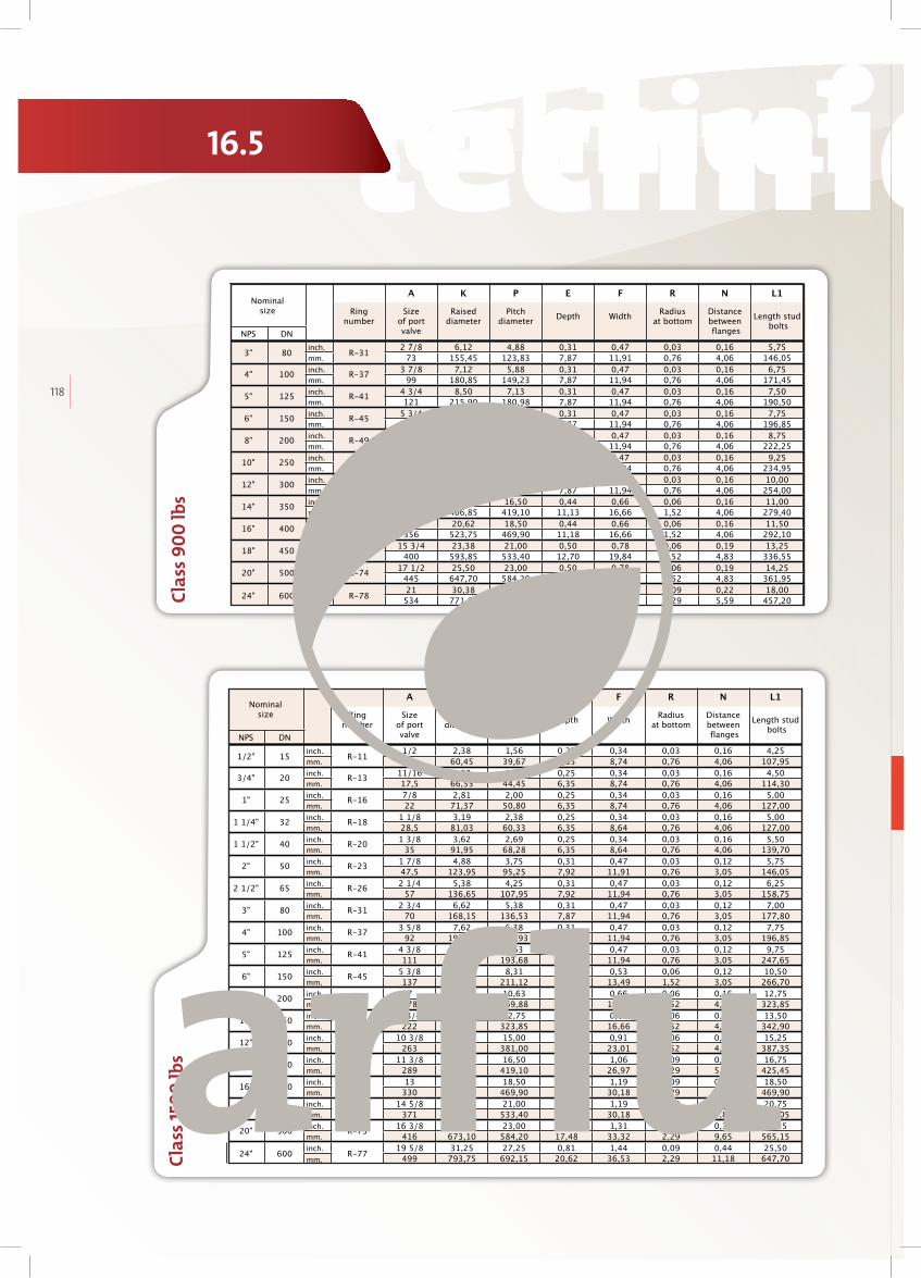
technical datastechnical datas technical datastechnical datas
118
Clas
s 90
0 lb
s
Flanges ASME B 16.5 RTJ Class 900 lbs
Nominal size
A K P E F R N L125,4
Ring number
Size of port valve
Raised diameter
Pitch diameter
Depth WidthRadius
at bottomDistance between flanges
Length stud bolts
NPS DN
3" 80inch.
R-312 7/8 6,12 4,88 0,31 0,47 0,03 0,16 5,75
mm. 73 155,45 123,83 7,87 11,91 0,76 4,06 146,05
4" 100inch.
R-373 7/8 7,12 5,88 0,31 0,47 0,03 0,16 6,75
mm. 99 180,85 149,23 7,87 11,94 0,76 4,06 171,45
5" 125inch.
R-414 3/4 8,50 7,13 0,31 0,47 0,03 0,16 7,50
mm. 121 215,90 180,98 7,87 11,94 0,76 4,06 190,50
6" 150inch.
R-455 3/4 9,50 8,31 0,31 0,47 0,03 0,16 7,75
mm. 146 241,30 211,12 7,87 11,94 0,76 4,06 196,85
8" 200inch.
R-497 1/2 12,11 10,63 0,31 0,47 0,03 0,16 8,75
mm. 191 307,64 269,88 7,87 11,94 0,76 4,06 222,25
10" 250inch.
R-539 3/8 14,25 12,75 0,31 0,47 0,03 0,16 9,25
mm. 238 361,95 323,85 7,87 11,94 0,76 4,06 234,95
12" 300inch.
R-5711 1/8 16,50 15,00 0,31 0,47 0,03 0,16 10,00
mm. 283 419,10 381,00 7,87 11,94 0,76 4,06 254,00
14" 350inch.
R-6212 1/4 18,38 16,50 0,44 0,66 0,06 0,16 11,00
mm. 311 466,85 419,10 11,13 16,66 1,52 4,06 279,40
16" 400inch.
R-6614 20,62 18,50 0,44 0,66 0,06 0,16 11,50
mm. 356 523,75 469,90 11,18 16,66 1,52 4,06 292,10
18" 450inch.
R-7015 3/4 23,38 21,00 0,50 0,78 0,06 0,19 13,25
mm. 400 593,85 533,40 12,70 19,84 1,52 4,83 336,55
20" 500inch.
R-7417 1/2 25,50 23,00 0,50 0,78 0,06 0,19 14,25
mm. 445 647,70 584,20 12,70 19,84 1,52 4,83 361,95
24" 600inch.
R-7821 30,38 27,25 0,63 1,06 0,09 0,22 18,00
mm. 534 771,65 692,15 15,88 26,97 2,29 5,59 457,20
Clas
s 150
0 lb
s
Flanges ASME B 16.5 RTJ Class 1500 lbs
Nominal size
A K P E F R N L125,4
Ring number
Size of port valve
Raised diameter
Pitch diameter
Depth WidthRadius
at bottomDistance between flanges
Length stud bolts
NPS DN
1/2" 15inch.
R-111/2 2,38 1,56 0,25 0,34 0,03 0,16 4,25
mm. 13 60,45 39,67 6,35 8,74 0,76 4,06 107,95
3/4" 20inch.
R-1311/16 2,62 1,75 0,25 0,34 0,03 0,16 4,50
mm. 17,5 66,55 44,45 6,35 8,74 0,76 4,06 114,30
1" 25inch.
R-167/8 2,81 2,00 0,25 0,34 0,03 0,16 5,00
mm. 22 71,37 50,80 6,35 8,74 0,76 4,06 127,00
1 1/4" 32inch.
R-181 1/8 3,19 2,38 0,25 0,34 0,03 0,16 5,00
mm. 28,5 81,03 60,33 6,35 8,64 0,76 4,06 127,00
1 1/2" 40inch.
R-201 3/8 3,62 2,69 0,25 0,34 0,03 0,16 5,50
mm. 35 91,95 68,28 6,35 8,64 0,76 4,06 139,70
2" 50inch.
R-231 7/8 4,88 3,75 0,31 0,47 0,03 0,12 5,75
mm. 47,5 123,95 95,25 7,92 11,91 0,76 3,05 146,05
2 1/2" 65inch.
R-262 1/4 5,38 4,25 0,31 0,47 0,03 0,12 6,25
mm. 57 136,65 107,95 7,92 11,94 0,76 3,05 158,75
3" 80inch.
R-312 3/4 6,62 5,38 0,31 0,47 0,03 0,12 7,00
mm. 70 168,15 136,53 7,87 11,94 0,76 3,05 177,80
4" 100inch.
R-373 5/8 7,62 6,38 0,31 0,47 0,03 0,12 7,75
mm. 92 193,55 161,93 7,87 11,94 0,76 3,05 196,85
5" 125inch.
R-414 3/8 9,00 7,63 0,31 0,47 0,03 0,12 9,75
mm. 111 228,60 193,68 7,87 11,94 0,76 3,05 247,65
6" 150inch.
R-455 3/8 9,75 8,31 0,38 0,53 0,06 0,12 10,50
mm. 137 247,65 211,12 9,53 13,49 1,52 3,05 266,70
8" 200inch.
R-497 12,50 10,63 0,44 0,66 0,06 0,16 12,75
mm. 178 317,50 269,88 11,13 16,66 1,52 4,06 323,85
10" 250inch.
R-538 3/4 14,62 12,75 0,44 0,66 0,06 0,16 13,50
mm. 222 371,35 323,85 11,13 16,66 1,52 4,06 342,90
12" 300inch.
R-5710 3/8 17,25 15,00 0,56 0,91 0,06 0,19 15,25
mm. 263 438,15 381,00 14,27 23,01 1,52 4,83 387,35
14" 350inch.
R-6111 3/8 19,25 16,50 0,63 1,06 0,09 0,22 16,75
mm. 289 488,95 419,10 15,88 26,97 2,29 5,59 425,45
16" 400inch.
R-6513 21,50 18,50 0,69 1,19 0,09 0,31 18,50
mm. 330 546,10 469,90 17,48 30,18 2,29 7,87 469,90
18" 450inch.
R-6914 5/8 24,12 21,00 0,69 1,19 0,09 0,31 20,75
mm. 371 612,65 533,40 17,48 30,18 2,29 7,87 527,05
20" 500inch.
R-7316 3/8 26,50 23,00 0,69 1,31 0,09 0,38 22,25
mm. 416 673,10 584,20 17,48 33,32 2,29 9,65 565,15
24" 600inch.
R-7719 5/8 31,25 27,25 0,81 1,44 0,09 0,44 25,50
mm. 499 793,75 692,15 20,62 36,53 2,29 11,18 647,70
16.5

technical datastechnical datas technical datastechnical datas
arfl
uIN
DU
ST
RIA
L V
AL
VE
S
119
Clas
s 250
0 lb
s
Flanges ASME B 16.5 RTJ Class 2500 lbs
Nominal size
A K P E F R N L125,4
Ring number
Size of port valve
Raised diameter
Pitch diameter
Depth WidthRadius
at bottomDistance between flanges
Length stud bolts
NPS DN
1/2" 15inch.
R-117/16 2,56 1,69 0,25 0,34 0,03 0,16 5,25
mm. 11 65,02 42,88 6,35 8,74 0,76 4,06 133,35
3/4" 20inch.
R-139/16 2,88 2,00 0,25 0,34 0,03 0,16 5,25
mm. 14,5 73,15 50,80 6,35 8,74 0,76 4,06 133,35
1" 25inch.
R-163/4 3,25 2,38 0,25 0,34 0,03 0,16 5,50
mm. 20 82,55 60,33 6,35 8,74 0,76 4,06 139,70
1 1/4" 32inch.
R-181 4,00 2,84 0,31 0,47 0,03 0,12 6,00
mm. 25,5 101,60 72,24 7,92 11,91 0,76 3,05 152,40
1 1/2" 40inch.
R-201 1/8 4,50 3,25 0,31 0,47 0,03 0,12 6,75
mm. 28,5 114,30 82,55 7,92 11,91 0,76 3,05 171,45
2" 50inch.
R-231 1/2 5,25 4,00 0,31 0,47 0,03 0,12 7,00
mm. 38 133,35 101,60 7,92 11,91 0,76 3,05 177,80
2 1/2" 65inch.
R-261 7/8 5,88 4,38 0,38 0,53 0,06 0,12 8,00
mm. 47,5 149,35 111,13 9,53 13,49 1,52 3,05 203,20
3" 80inch.
R-312 1/4 6,62 5,00 0,38 0,53 0,06 0,12 9,00
mm. 57 168,15 127,00 9,53 13,49 1,52 3,05 228,60
4" 100inch.
R-372 7/8 8,00 6,19 0,44 0,66 0,06 0,16 10,25
mm. 73 203,20 157,18 11,13 16,66 1,52 4,06 260,35
5" 125inch.
R-413 5/8 9,50 7,50 0,50 0,78 0,06 0,16 12,25
mm. 92 241,30 190,50 12,70 19,84 1,52 4,06 311,15
6" 150inch.
R-454 3/8 11,00 9,00 0,50 0,78 0,06 0,16 14,00
mm. 111 279,40 228,60 12,70 19,84 1,52 4,06 355,60
8" 200inch.
R-495 3/4 13,38 11,00 0,56 0,91 0,06 0,19 15,50
mm. 146 339,85 279,40 14,27 23,01 1,52 4,83 393,70
10" 250inch.
R-537 1/4 16,75 13,50 0,69 1,19 0,09 0,25 20,00
mm. 184 425,45 342,90 17,48 30,18 2,29 6,35 508,00
12" 300inch.
R-578 5/8 19,50 16,00 0,69 1,31 0,09 0,31 22,00
mm. 219 495,30 406,40 17,48 33,32 2,29 7,87 558,80
Flanges ASME B 16.47 Serie A
Class 150 lbs | Class 300 lbs | Class 600 lbs | Class 900 lbs
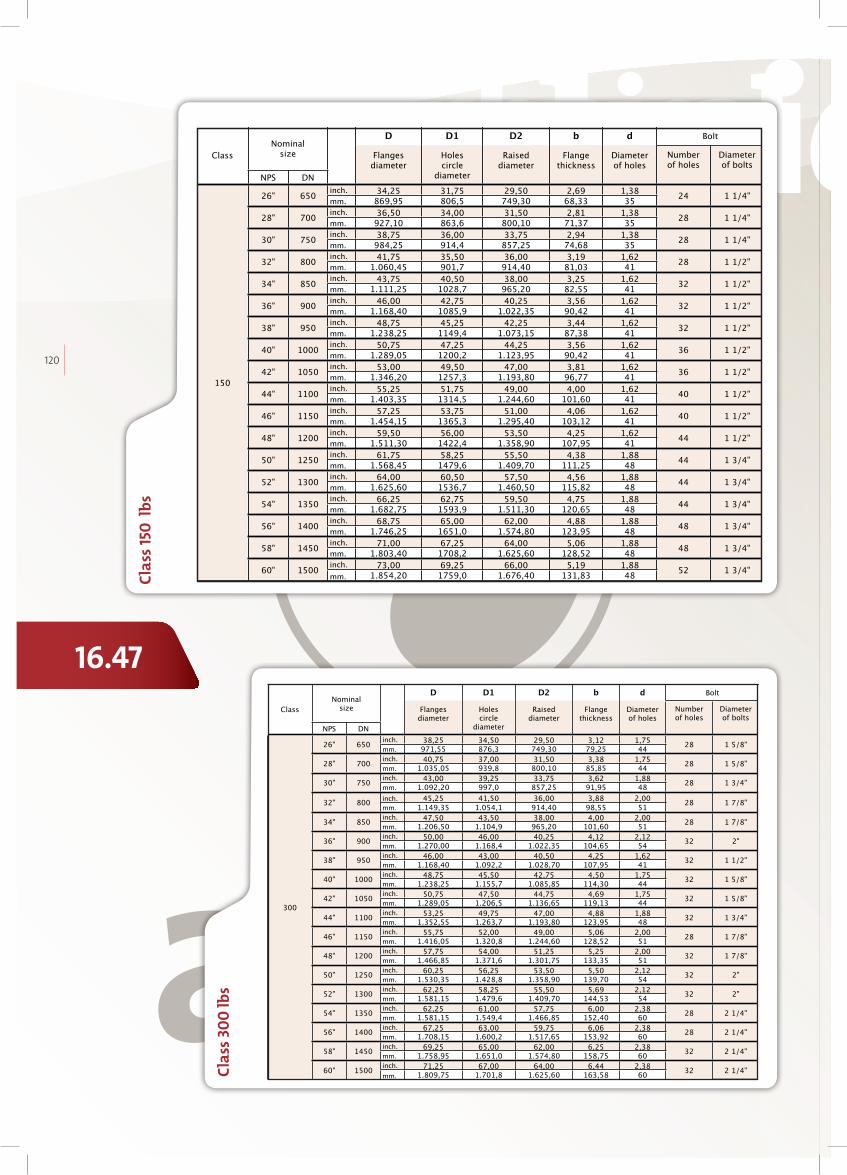
technical datastechnical datas technical datastechnical datas
120
Clas
s 30
0 lb
s
Flanges ASME B 16.47 Serie A
Class 300 lbs
Class
Nominal size
D D1 D2 b d Bolt25,4
Flanges diameter
Holescircle
diameter
Raised diameter
Flange thickness
Diameterof holes
Number of holes
Diameterof bolts
NPS DN
300
26" 650inch. 38,25 34,50 29,50 3,12 1,75
28 1 5/8"mm. 971,55 876,3 749,30 79,25 44
28" 700inch. 40,75 37,00 31,50 3,38 1,75
28 1 5/8"mm. 1.035,05 939,8 800,10 85,85 44
30" 750inch. 43,00 39,25 33,75 3,62 1,88
28 1 3/4"mm. 1.092,20 997,0 857,25 91,95 48
32" 800inch. 45,25 41,50 36,00 3,88 2,00
28 1 7/8"mm. 1.149,35 1.054,1 914,40 98,55 51
34" 850inch. 47,50 43,50 38,00 4,00 2,00
28 1 7/8"mm. 1.206,50 1.104,9 965,20 101,60 51
36" 900inch. 50,00 46,00 40,25 4,12 2,12
32 2"mm. 1.270,00 1.168,4 1.022,35 104,65 54
38" 950inch. 46,00 43,00 40,50 4,25 1,62
32 1 1/2"mm. 1.168,40 1.092,2 1.028,70 107,95 41
40" 1000inch. 48,75 45,50 42,75 4,50 1,75
32 1 5/8"mm. 1.238,25 1.155,7 1.085,85 114,30 44
42" 1050inch. 50,75 47,50 44,75 4,69 1,75
32 1 5/8"mm. 1.289,05 1.206,5 1.136,65 119,13 44
44" 1100inch. 53,25 49,75 47,00 4,88 1,88
32 1 3/4"mm. 1.352,55 1.263,7 1.193,80 123,95 48
46" 1150inch. 55,75 52,00 49,00 5,06 2,00
28 1 7/8"mm. 1.416,05 1.320,8 1.244,60 128,52 51
48" 1200inch. 57,75 54,00 51,25 5,25 2,00
32 1 7/8"mm. 1.466,85 1.371,6 1.301,75 133,35 51
50" 1250inch. 60,25 56,25 53,50 5,50 2,12
32 2"mm. 1.530,35 1.428,8 1.358,90 139,70 54
52" 1300inch. 62,25 58,25 55,50 5,69 2,12
32 2"mm. 1.581,15 1.479,6 1.409,70 144,53 54
54" 1350inch. 62,25 61,00 57,75 6,00 2,38
28 2 1/4"mm. 1.581,15 1.549,4 1.466,85 152,40 60
56" 1400inch. 67,25 63,00 59,75 6,06 2,38
28 2 1/4"mm. 1.708,15 1.600,2 1.517,65 153,92 60
58" 1450inch. 69,25 65,00 62,00 6,25 2,38
32 2 1/4"mm. 1.758,95 1.651,0 1.574,80 158,75 60
60" 1500inch. 71,25 67,00 64,00 6,44 2,38
32 2 1/4"mm. 1.809,75 1.701,8 1.625,60 163,58 60
Clas
s 150
lbs
Flanges ASME B 16.47 Serie A
Class 150 lbs
Class
Nominal size
D D1 D2 b d Bolt25,4
Flanges diameter
Holescircle
diameter
Raised diameter
Flange thickness
Diameterof holes
Number of holes
Diameterof bolts
NPS DN
150
26" 650inch. 34,25 31,75 29,50 2,69 1,38
24 1 1/4"mm. 869,95 806,5 749,30 68,33 35
28" 700inch. 36,50 34,00 31,50 2,81 1,38
28 1 1/4"mm. 927,10 863,6 800,10 71,37 35
30" 750inch. 38,75 36,00 33,75 2,94 1,38
28 1 1/4"mm. 984,25 914,4 857,25 74,68 35
32" 800inch. 41,75 35,50 36,00 3,19 1,62
28 1 1/2"mm. 1.060,45 901,7 914,40 81,03 41
34" 850inch. 43,75 40,50 38,00 3,25 1,62
32 1 1/2"mm. 1.111,25 1028,7 965,20 82,55 41
36" 900inch. 46,00 42,75 40,25 3,56 1,62
32 1 1/2"mm. 1.168,40 1085,9 1.022,35 90,42 41
38" 950inch. 48,75 45,25 42,25 3,44 1,62
32 1 1/2"mm. 1.238,25 1149,4 1.073,15 87,38 41
40" 1000inch. 50,75 47,25 44,25 3,56 1,62
36 1 1/2"mm. 1.289,05 1200,2 1.123,95 90,42 41
42" 1050inch. 53,00 49,50 47,00 3,81 1,62
36 1 1/2"mm. 1.346,20 1257,3 1.193,80 96,77 41
44" 1100inch. 55,25 51,75 49,00 4,00 1,62
40 1 1/2"mm. 1.403,35 1314,5 1.244,60 101,60 41
46" 1150inch. 57,25 53,75 51,00 4,06 1,62
40 1 1/2"mm. 1.454,15 1365,3 1.295,40 103,12 41
48" 1200inch. 59,50 56,00 53,50 4,25 1,62
44 1 1/2"mm. 1.511,30 1422,4 1.358,90 107,95 41
50" 1250inch. 61,75 58,25 55,50 4,38 1,88
44 1 3/4"mm. 1.568,45 1479,6 1.409,70 111,25 48
52" 1300inch. 64,00 60,50 57,50 4,56 1,88
44 1 3/4"mm. 1.625,60 1536,7 1.460,50 115,82 48
54" 1350inch. 66,25 62,75 59,50 4,75 1,88
44 1 3/4"mm. 1.682,75 1593,9 1.511,30 120,65 48
56" 1400inch. 68,75 65,00 62,00 4,88 1,88
48 1 3/4"mm. 1.746,25 1651,0 1.574,80 123,95 48
58" 1450inch. 71,00 67,25 64,00 5,06 1,88
48 1 3/4"mm. 1.803,40 1708,2 1.625,60 128,52 48
60" 1500inch. 73,00 69,25 66,00 5,19 1,88
52 1 3/4"mm. 1.854,20 1759,0 1.676,40 131,83 48
16.47

technical datastechnical datas technical datastechnical datas
arfl
uIN
DU
ST
RIA
L V
AL
VE
S
121
Clas
s 60
0 lb
s Flanges ASME B 16.47 Serie A
Class 600 lbs
Class
Nominal size
D D1 D2 b d Bolt25,4
Flanges diameter
Holescircle
diameter
Raised diameter
Flange thickness
Diameterof holes
Number of holes
Diameterof bolts
NPS DN
600
26" 650inch. 40,00 36,00 29,50 4,25 2,00
28 1 7/8"mm. 1.016,00 914,4 749,30 107,95 51
28" 700inch. 42,25 38,00 31,50 4,38 2,12
28 2"mm. 1.073,15 965,2 800,10 111,25 54
30" 750inch. 44,50 40,25 33,75 4,50 2,12
28 2"mm. 1.130,30 1.022,4 857,25 114,30 54
32" 800inch. 47,00 42,50 36,00 4,62 2,12
28 2"mm. 1.193,80 1.079,5 914,40 117,35 54
34" 850inch. 49,00 44,50 38,00 4,75 2,38
28 2 1/4"mm. 1.244,60 1.130,3 965,20 120,65 60
36" 900inch. 51,75 47,00 40,25 4,88 2,62
28 2 1/2"mm. 1.314,45 1.193,8 1.022,35 123,95 67
38" 950inch. 50,00 45,75 41,50 6,00 2,38
28 2 1/4"mm. 1.270,00 1.162,1 1.054,10 152,40 60
40" 1000inch. 52,00 47,75 43,75 6,25 2,38
32 2 1/4"mm. 1.320,80 1.212,9 1.111,25 158,75 60
42" 1050inch. 55,25 50,50 46,00 6,62 2,62
28 2 1/2"mm. 1.403,35 1.282,7 1.168,40 168,15 67
44" 1100inch. 57,25 52,50 48,25 6,81 2,62
32 2 1/2"mm. 1.454,15 1.333,5 1.225,55 172,97 67
46" 1150inch. 59,50 54,75 50,25 7,06 2,62
32 2 1/2"mm. 1.511,30 1.390,7 1.276,35 179,32 67
48" 1200inch. 62,75 57,50 52,50 7,44 2,88
32 2 3/4"mm. 1.593,85 1.460,5 1.333,50 188,98 73
50" 1250inch. 65,75 60,00 54,50 7,75 3,12
28 3"mm. 1.670,05 1.524,0 1.384,30 196,85 79
52" 1300inch. 67,75 62,00 56,50 8,00 3,12
32 3"mm. 1.720,85 1.574,8 1.435,10 203,20 79
54" 1350inch. 70,00 64,25 58,75 8,25 3,12
32 3"mm. 1.778,00 1.632,0 1.492,25 209,55 79
56" 1400inch. 73,00 66,75 60,75 8,56 3,38
32 3 3/8"mm. 1.854,20 1.695,5 1.543,05 217,42 86
58" 1450inch. 75,00 68,76 63,00 8,75 3,38
32 3 3/8"mm. 1.905,00 1.746,5 1.600,20 222,25 86
60" 1500inch. 78,50 71,75 65,25 9,19 3,62
28 3 5/8"mm. 1.993,90 1.822,5 1.657,35 233,43 92
Clas
s 90
0 lb
s
Flanges ASME B 16.47 Serie A
Class 900 lbs
Class
Nominal size
D D1 D2 b d Bolt25,4
Flanges diameter
Holescircle
diameter
Raised diameter
Flange thickness
Diameterof holes
Number of holes
Diameterof bolts
NPS DN
900
26" 650inch. 42,75 37,50 29,50 5,50 2,88
20 2 3/4"mm. 1.085,85 952,5 749,30 139,70 73
28" 700inch. 46,00 40,25 31,50 5,62 3,12
20 3"mm. 1.168,40 1.022,4 800,10 142,75 79
30" 750inch. 48,50 42,75 33,75 5,88 3,12
20 3"mm. 1.231,90 1.085,9 857,25 149,35 79
32" 800inch. 51,75 45,50 36,00 6,25 3,38
20 3 3/8"mm. 1.314,45 1.155,7 914,40 158,75 86
34" 850inch. 55,00 48,25 38,00 6,50 3,62
20 3 5/8"mm. 1.397,00 1.225,6 965,20 165,10 92
36" 900inch. 57,50 50,75 40,25 6,75 3,62
20 3 5/8"mm. 1.460,50 1.289,1 1.022,35 171,45 92

technical datastechnical datas technical datastechnical datas
122
Clas
s 150
lbs
Flanges ASME B 16.47 Serie B
Class 150 lbs
Class
Nominal size
D D1 D2 b d Bolt25,4
Flanges diameter
Holescircle
diameter
Raised diameter
Flange thickness
Diameterof holes
Number of holes
Diameterof bolts
NPS DN
150
26" 650inch. 30,94 29,31 28,00 1,62 0,88
36 3/4"mm. 785,88 744,5 711,20 41,15 22
28" 700inch. 32,94 31,31 30,00 1,75 0,88
40 3/4"mm. 836,68 795,3 762,00 44,45 22
30" 750inch. 34,94 33,31 32,00 1,75 0,88
44 3/4"mm. 887,48 846,1 812,80 44,45 22
32" 800inch. 37,06 35,44 34,00 1,81 0,88
48 3/4"mm. 941,32 900,2 863,60 45,97 22
34" 850inch. 39,56 37,69 36,25 1,94 1,00
40 7/8"mm. 1.004,82 957,3 920,75 49,28 25
36" 900inch. 41,62 39,75 38,25 2,06 1,00
44 7/8"mm. 1.057,15 1.009,7 971,55 52,32 25
38" 950inch. 44,25 42,12 40,25 2,12 1,12
40 1"mm. 1.123,95 1.069,8 1.022,35 53,85 28
40" 1000inch. 46,25 44,12 42,25 2,19 1,12
44 1"mm. 1.174,75 1.120,6 1.073,15 55,63 28
42" 1050inch. 48,25 46,12 44,50 2,31 1,12
48 1"mm. 1.225,55 1.171,4 1.130,30 58,67 28
44" 1100inch. 50,25 48,12 46,50 2,38 1,12
52 1"mm. 1.276,35 1.222,2 1.181,10 60,45 28
46" 1150inch. 52,81 50,56 48,62 2,44 1,25
40 1 1/8"mm. 1.341,37 1.284,2 1.234,95 61,98 32
48" 1200inch. 54,81 52,56 50,75 2,56 1,25
44 1 1/8"mm. 1.392,17 1.335,0 1.289,05 65,02 32
50" 1250inch. 56,81 54,56 52,75 2,69 1,25
48 1 1/8"mm. 1.442,97 1.385,8 1.339,85 68,33 32
52" 1300inch. 58,81 56,56 54,75 2,75 1,25
52 1 1/8"mm. 1.493,77 1.436,6 1.390,65 69,85 32
54" 1350inch. 61,00 58,75 56,75 2,81 1,25
56 1 1/8"mm. 1.549,40 1.492,3 1.441,45 71,37 32
56" 1400inch. 63,00 60,75 58,75 2,88 1,25
60 1 1/8"mm. 1.600,20 1.543,1 1.492,25 73,15 32
58" 1450inch. 65,94 63,44 60,75 2,94 1,38
48 1 1/4"mm. 1.674,88 1.611,4 1.543,05 74,68 35
60" 1500inch. 67,94 65,44 63,00 3,00 1,38
52 1 1/4"mm. 1.725,68 1.662,2 1.600,20 76,20 35
Class 150 lbs | Class 300 lbs | Class 600 lbs | Class 900 lbs
Flanges ASME B 16.47 Serie B

technical datastechnical datas technical datastechnical datas
arfl
uIN
DU
ST
RIA
L V
AL
VE
S
123
Flanges ASME B 16.47 Serie B
Class 300 lbs
Class
Nominal size
D D1 D2 b d Bolt25,4
Flanges diameter
Holescircle
diameter
Raised diameter
Flange thickness
Diameterof holes
Number of holes
Diameterof bolts
NPS DN
300
26" 650inch. 34,12 31,62 29,00 3,50 1,38
32 1 1/4"mm. 866,65 803,1 736,60 88,90 35
28" 700inch. 36,25 33,75 31,00 3,50 1,38
36 1 1/4"mm. 920,75 857,3 787,40 88,90 35
30" 750inch. 39,00 36,25 33,25 3,69 1,50
36 1 3/8"mm. 990,60 920,8 844,55 93,73 38
32" 800inch. 41,50 38,50 35,50 4,06 1,62
32 1 1/2"mm. 1.054,10 977,9 901,70 103,12 41
34" 850inch. 43,62 40,62 37,50 4,06 1,62
36 1 1/2"mm. 1.107,95 1.031,7 952,50 103,12 41
36" 900inch. 46,12 42,88 39,75 4,06 1,75
32 1 5/8"mm. 1.171,45 1.089,2 1.009,65 103,12 44
38" 950inch. 48,12 44,88 41,75 4,38 1,75
36 1 5/8"mm. 1.222,25 1.140,0 1.060,45 111,25 44
40" 1000inch. 50,12 46,88 43,88 4,56 1,75
40 1 5/8"mm. 1.273,05 1.190,8 1.114,55 115,82 44
42" 1050inch. 52,50 49,00 46,00 4,69 1,88
36 1 3/4"mm. 1.333,50 1.244,6 1.168,40 119,13 48
44" 1100inch. 54,50 51,00 48,00 5,00 1,88
40 1 3/4"mm. 1.384,30 1.295,4 1.219,20 127,00 48
46" 1150inch. 57,50 53,75 50,00 5,06 2,00
36 1 7/8"mm. 1.460,50 1.365,3 1.270,00 128,52 51
48" 1200inch. 59,50 55,75 52,25 5,06 2,00
40 1 7/8"mm. 1.511,30 1.416,1 1.327,15 128,52 51
50" 1250inch. 61,50 57,75 54,25 5,44 2,00
44 1 7/8"mm. 1.562,10 1.466,9 1.377,95 138,18 51
52" 1300inch. 63,50 59,75 56,25 5,62 2,00
48 1 7/8"mm. 1.612,90 1.517,7 1.428,75 142,75 51
54" 1350inch. 65,88 62,12 58,25 5,38 2,00
48 1 7/8"mm. 1.673,35 1.577,8 1.479,55 136,65 51
56" 1400inch. 69,50 65,00 60,50 6,06 2,38
36 2 1/4"mm. 1.765,30 1.651,0 1.536,70 153,92 60
58" 1450inch. 71,94 67,44 62,75 6,06 2,38
40 2 1/4"mm. 1.827,28 1.713,0 1.593,85 153,92 60
60" 1500inch. 73,94 69,44 65,00 5,94 2,38
40 2 1/4"mm. 1.878,08 1.763,8 1.651,00 150,88 60
Clas
s 60
0 lb
s
Flanges ASME B 16.47 Serie B
Class 600 lbs
Class
Nominal size
D D1 D2 b d Bolt25,4
Flanges diameter
Holescircle
diameter
Raised diameter
Flange thickness
Diameterof holes
Number of holes
Diameterof bolts
NPS DN
600
26" 650inch. 35,00 31,75 28,62 4,38 1,75
28 1 5/8"mm. 889,00 806,5 726,95 111,25 44
28" 700inch. 37,50 34,00 30,88 4,56 1,88
28 1 3/4"mm. 952,50 863,6 784,35 115,82 48
30" 750inch. 40,25 36,50 33,12 4,94 2,00
28 1 7/8"mm. 1.022,35 927,1 841,25 125,48 51
32" 800inch. 42,75 38,75 35,25 5,12 2,12
28 2"mm. 1.085,85 984,3 895,35 130,05 54
34" 850inch. 45,75 41,50 37,50 5,56 2,38
24 2 1/4"mm. 1.162,05 1054,1 952,50 141,22 60
36" 900inch. 47,75 43,50 39,75 5,75 2,38
28 2 1/4"mm. 1.212,85 1104,9 1.009,65 146,05 60
38" 950inch. 50,00 45,75 41,50 6,00 2,38
28 2 1/4"mm. 1.270,00 1.162,1 1.054,10 152,40 60
40" 1000inch. 52,00 47,75 43,75 6,25 2,38
32 2 1/4"mm. 1.320,80 1.212,9 1.111,25 158,75 60
42" 1050inch. 55,25 50,50 46,00 6,62 2,62
28 2 1/2"mm. 1.403,35 1.282,7 1.168,40 168,15 67
44" 1100inch. 57,25 52,50 48,25 6,81 2,62
32 2 1/2"mm. 1.454,15 1.333,5 1.225,55 172,97 67
46" 1150inch. 59,50 54,75 50,25 7,06 2,62
32 2 1/2"mm. 1.511,30 1.390,7 1.276,35 179,32 67
48" 1200inch. 62,75 57,50 52,50 7,44 2,88
32 2 3/4"mm. 1.593,85 1.460,5 1.333,50 188,98 73
50" 1250inch. 65,75 60,00 54,50 7,75 3,12
28 3"mm. 1.670,05 1.524,0 1.384,30 196,85 79
52" 1300inch. 67,75 62,00 56,50 8,00 3,12
32 3"mm. 1.720,85 1.574,8 1.435,10 203,20 79
54" 1350inch. 70,00 64,25 58,75 8,25 3,12
32 3"mm. 1.778,00 1.632,0 1.492,25 209,55 79
56" 1400inch. 73,00 66,75 60,75 8,56 3,38
32 3 3/8"mm. 1.854,20 1.695,5 1.543,05 217,42 86
58" 1450inch. 75,00 68,76 63,00 8,75 3,38
32 3 3/8"mm. 1.905,00 1.746,5 1.600,20 222,25 86
60" 1500inch. 78,50 71,75 65,25 9,19 3,62
28 3 5/8"mm. 1.993,90 1.822,5 1.657,35 233,43 92
Clas
s 90
0 lb
s
Flanges ASME B 16.47 Serie B
Class 900 lbs
Class
Nominal size
D D1 D2 b d Bolt25,4
Flanges diameter
Holescircle
diameter
Raised diameter
Flange thickness
Diameterof holes
Number of holes
Diameterof bolts
NPS DN
900
26" 650inch. 40,25 35,50 30,00 5,31 2,62
20 2 1/2"mm. 1.022,35 901,7 762,00 134,87 67
28" 700inch. 43,50 38,25 32,25 5,81 2,88
20 2 3/4"mm. 1.104,90 971,6 819,15 147,57 73
30" 750inch. 46,50 40,75 34,50 6,12 3,12
20 3"mm. 1.181,10 1035,1 876,30 155,45 79
32" 800inch. 48,75 43,00 36,50 6,31 3,12
20 3"mm. 1.238,25 1092,2 927,10 160,27 79
34" 850inch. 51,75 45,50 39,00 6,75 3,38
20 3 3/8"mm. 1.314,45 1155,7 990,60 171,45 85
36" 900inch. 53,00 47,25 40,50 6,81 3,12
24 3"mm. 1.346,20 1200,2 1.028,70 172,97 79
Clas
s 30
0 lb
s

technical datastechnical datas technical datastechnical datas
124
BUTT
-WEL
DIN
G E
NDS
ACC
/AN
SI B
16.2
5
BUTT-WELDING ENDS ACC/ANSI B16.25
Nominal size
Schedule number
Outside DiameterNominal
inside diameterMachined
inside diameterNominal
wall thickness 25,4
A
Wrought or fabricated components
A
Cast steel valves B C T
NPS DN inch mm inch mm inch mm inch mm inch mm
2 1/2 65
40
2,88 73 2,96 75
2,469 62,5 2,479 62,93 0,203 5,1680 2,323 59 2,351 59,69 0,276 7,01
160 2,125 54 2,178 55,28 0,375 9,53
XXS 1,771 45 1,868 47,43 0,552 14,02
3 80
40
3,50 88 3,59 91
3,068 78 3,081 78,25 0,216 5,4980 2,900 73,5 2,934 74,53 0,300 7,62
160 2,624 66,5 2,692 68,38 0,438 11,13
XXS 2,300 58,5 2,409 61,19 0,600 15,24
4 100
40
4,50 114,3 4,62 117
4,026 102 4,044 102,73 0,237 6,0280 3,826 97 3,869 98,28 0,337 8,56
120 3,624 92 3,692 93,78 0,438 11,13
160 3,438 87,5 3,530 89,65 0,531 13,49
XXS 3,152 80 3,279 83,3 0,674 17,12
5 125
40
5,56 141,3 5,69 144
5,047 128 5,070 128,8 0,258 6,5580 4,813 122 4,866 123,58 0,375 9,53
120 4,563 116 4,647 118,04 0,500 12,7
160 4,313 109,5 4,428 112,47 0,625 15,88
XXS 4,063 103 4,209 106,92 0,750 19,05
6 150
40
6,62 168,3 6,78 172
6,065 154 6,094 154,82 0,280 7,1180 5,761 146,5 5,828 148,06 0,432 10,97
120 5,501 140 5,600 142,29 0,562 14,27
160 5,187 132 5,326 135,31 0,719 18,26
XXS 4,897 124,5 5,072 128,85 0,864 21,95
8 200
40
8,62 219,1 8,78 223
7,981 203 8,020 203,75 0,322 8,1860 7,813 198,5 7,873 200,02 0,406 10,31
80 7,625 193,5 7,709 195,84 0,500 12,7
100 7,437 189 7,544 191,65 0,594 15,09
120 7,187 182,5 7,326 186,11 0,719 18,26
140 7,001 178 7,163 181,98 0,812 20,62
XXS 6,875 174,5 7,053 179,16 0,875 22,23
160 6,813 173 6,998 177,79 0,906 23,01
10 250
40
10,75 273 10,94 278
10,020 254,5 10,070 255,74 0,365 9,2760 9,750 247,5 9,834 249,74 0,500 12,7
80 9,562 243 9,670 245,55 0,594 15,09
100 9,312 236,5 9,451 240,01 0,719 18,26
120 9,062 230 9,232 234,44 0,844 21,44
140 8,750 222 8,959 227,51 1,000 25,4
160 8,500 216 8,740 221,95 1,125 28,58
12 300
STD
12,75 323,8 12,97 329
12,000 305 12,053 306,08 0,375 9,5340 11,938 303 11,999 304,72 0,406 10,31
XS 11,750 298,5 11,834 300,54 0,500 12,7
60 11,626 295 11,725 297,79 0,562 14,27
80 11,374 289 11,505 292,17 0,688 17,48
100 11,062 281 11,232 285,24 0,844 21,44
120 10,750 273 10,959 278,31 1,000 25,4
140 10,500 266,5 10,740 272,75 1,125 28,58
160 10,126 257 10,413 264,45 1,312 33,32
14 350
STD
14,00 355,6 14,25 362
13,250 336,5 13,303 337,88 0,375 9,5340 13,124 333,5 13,192 335,08 0,438 11,13
XS 13,000 330 13,084 332,34 0,500 12,7
60 12,812 325,5 12,920 328,15 0,594 15,09
80 12,500 317,5 12,646 321,22 0,750 19,05
100 12,124 308 12,318 312,86 0,938 23,83
120 11,812 300 12,044 305,93 1,094 27,79
140 11,500 292 11,771 299 1,250 31,75
160 11,188 284 11,498 292,07 1,406 35,71
16 400
STD
16,00 406,4 16,25 413
15,250 387,5 15,303 388,68 0,375 9,5340 15,000 381 15,084 383,14 0,500 12,7
60 14,688 373 14,811 376,21 0,656 16,66
80 14,312 363,5 14,482 367,84 0,844 21,44
100 13,938 354 14,155 359,53 1,031 26,19
120 13,562 344,5 13,826 351,18 1,219 30,96
140 13,124 333,5 13,442 341,43 1,438 36,53
160 12,812 325,5 13,170 334,5 1,594 40,49
18 450
STD
18,00 457,2 18,28 464
17,250 438 17,303 439,48 0,375 9,53XS 17,000 432 17,084 433,94 0,500 12,7
40 16,876 428,5 16,975 431,19 0,562 14,27
60 16,500 419 16,646 422,82 0,750 19,05
80 16,124 409,5 16,318 414,46 0,938 23,83
100 15,688 398,5 15,936 404,78 1,156 29,36
120 15,250 387,5 16,553 395,03 1,375 34,93
140 14,876 378 15,225 386,77 1,562 39,67
160 14,438 366,5 14,842 376,99 1,781 45,24
20 500
STD
20,00 508 20,31 516
19,250 489 19,303 490,28 0,375 9,53XS 19,000 482,5 19,084 484,74 0,500 12,7
40 18,812 478 18,920 480,55 0,594 15,09
60 18,376 467 18,538 470,88 0,812 20,62
80 17,938 455,5 18,155 461,13 1,031 26,19
100 17,438 443 17,717 450,02 1,281 32,54
120 17,000 432 17,334 440,29 1,500 38,1
140 16,500 419 16,896 429,17 1,750 44,45
160 16,062 408 16,513 419,44 1,969 50,01
22 550
STD
22,00 558,8 22,34 567
21,250 539 21,303 541,08 0,375 9,53XS 21,000 533 21,084 535,54 0,500 12,7
60 20,250 514 20,428 518,86 0,875 22,23
80 19,750 501 19,990 507,75 1,125 28,58
100 19,250 488,5 19,553 496,63 1,375 34,93
120 18,750 476 19,115 485,52 1,625 41,28
140 18,250 463 18,678 474,41 1,875 47,63
160 17,750 450,5 18,240 463,3 2,125 53,98
24 600
STD
24,00 609,6 24,38 619
23,250 590,5 23,303 591,88 0,375 9,53XS 23,000 584 23,084 586,34 0,500 12,7
30 22,876 581 22,975 583,59 0,562 14,27
40 22,624 574,5 22,755 577,97 0,688 17,48
60 22,062 560,5 22,263 565,49 0,969 24,61
80 21,562 547,5 21,826 554,38 1,219 30,96
100 20,938 532 21,280 540,49 1,531 38,89
120 20,376 517,5 20,788 528,03 1,812 46,02
140 19,876 505 20,350 516,91 2,062 52,37
160 19,312 490,5 19,857 504,37 2,344 59,54
BUTT-WELDING ENDS ACC/ANSI B16.25

technical datastechnical datas technical datastechnical datas
arfl
uIN
DU
ST
RIA
L V
AL
VE
S
125
BUTT-WELDING ENDS ACC/ANSI B16.25
TECHNICAL HELP

technical datastechnical datas technical datastechnical datas
126
CAST IRON
CAST IRONS
CHEMICAL REQUIREMTS ( % ) MECHANICAL PROPERTIES
Carbon Manga-
nese
Phos- phorus Sulfur Silicon Nickel
Chro- mium
CopperAlloying
Ele- ments
Tensile Strength Transverse Test Load
Transverse Test Deflection at
Center
Ksi Mpa lbs kN in mm.
HI-STRENGTH CAST IRONHI-STRENGTH CAST IRON UNS F12102 ASTM A126, Clase B ASTM A126, Clase B
Min. Max
,,,, ,,,,
,,,, ,,,,
…. 0.75
,,,, 0.15
,,,, ,,,,
,,,, ,,,,
,,,, ,,,,
,,,, ,,,,
,,,, ,,,,
31 ,,,,
214 ,,,,
3300 ,,,,
14.65 ,,,,
0.12 ….
3.0 ,,,,
3% NICKEL IRON3% NICKEL IRON
Min. Max
,,,, ,,,,
,,,, ,,,,
…. 0.40
,,,, 0.12
,,,, ,,,,
2.75 3.25
,,,, ,,,,
,,,, ,,,,
,,,, ,,,,
31 ,,,,
214 ,,,,
3300 ,,,,
14.65 ,,,,
0.12 ….
3.0 ,,,,
AUSTENITIC GRAY IRON. (Ni-Resist)AUSTENITIC GRAY IRON. (Ni-Resist)AUSTENITIC GRAY IRON. (Ni-Resist) ASTM A436, Type 2 ASTM A436, Type 2
Min. Max
…. 3.0
0.50 1.50
,,,, ,,,,
,,,, 0.12
1.00 2.80
18.0 22.0
1.5 2.5
,,,, 0.50
ASTM A126, Clase B
25 ….
172 ,,,,
,,,, ,,,,
,,,, ,,,,
,,,, ,,,,
,,,, ,,,,
,,,, ,,,,
CAST DUCTILE IRONS AND MALLEABLE IRONS
CHEMICAL REQUIREMTS ( % ) MECHANICAL PROPERTIES
Carbon Manga-
nese
Phos- phorus Silicon Nickel
Chro- mium
Tensile Strength
Yield Strenght
Elongation in 2" (50 mm)
Ksi Mpa Ksi Mpa
FERRITIC DUCTILE IRONFERRITIC DUCTILE IRON UNS F32800 ASTM A395 ASTM A395
Min. Max
3.0 ,,,,
,,,, ,,,,
…. 0.08
,,,, 2.50
,,,, ,,,,
,,,, ,,,,
60 ,,,,
414 ,,,,
40 ,,,,
276 ,,,,
18% ….
DUCTILE IRON *DUCTILE IRON * UNS F33100 ASTM A536, Grade 65-45-12 ASTM A536, Grade 65-45-12 ASTM A536, Grade 65-45-12
Min. Max
,,,, ,,,,
,,,, ,,,,
,,,, ,,,,
,,,, ,,,,
,,,, ,,,,
,,,, ,,,,
65 ,,,,
448 ,,,,
45 ,,,,
310 ,,,,
12% ….
AUSTENITIC NODULAR IRON *AUSTENITIC NODULAR IRON *AUSTENITIC NODULAR IRON * UNS F43000 ASTM A439, Type D-2 ASTM A439, Type D-2
Min. Max
…. 3.0
0.70 1.25
,,,, 0.8
1.5 3.0
18.0 22.0
1.75 2.75
58 ….
400 ,,,,
30 ,,,,
207 ,,,,
8% ,,,,
FERRITIC MALLEABLE IRON *FERRITIC MALLEABLE IRON *FERRITIC MALLEABLE IRON * UNS F22200 (ASTM A47, Grade 32510(ASTM A47, Grade 32510
Min. Max
,,,, ,,,,
,,,, ,,,,
,,,, ,,,,
,,,, ,,,,
,,,, ,,,,
,,,, ,,,,
50 ….
345 ,,,,
32.5 ,,,,
224 ,,,,
10% ,,,,
MALLEABLE IRON *MALLEABLE IRON * ASTM A197 ASTM A197
Min. Max
,,,, ,,,,
,,,, ,,,,
,,,, ,,,,
,,,, ,,,,
,,,, ,,,,
,,,, ,,,,
40 ….
276 ,,,,
30 ,,,,
207 ,,,,
5% ,,,,
* Chemical requirements
are subordinate
to the mechanical properties.
CHEMICAL REQUIREMTS ( % ) MECHANICAL PROPERTIES
FORGED STEEL STANDARDS COMPARISONCOMPARACION DE NORMAS DE ACERO FORJADO COMPARACION DE NORMAS DE ACERO FORJADO COMPARACION DE NORMAS DE ACERO FORJADO COMPARACION DE NORMAS DE ACERO FORJADO
FORGED STEEL STANDARDS COMPARISON
ASTM UNS/AISI DIN AFNOR BS JIS
A105AISI
1020C22 1.0402
A48 -XC18S
1503-221-490 (En 3A)
SF50 (SC30)-(S28C)
A182-F1 K1282215 Mo 3 1.5415 - 1503-240-420
SFHV 12 B -G 3213
A182-F5 K4154512 CrMo 19.5
1.7733Z 12 CD.5 1503-625-520
SFHV 25 -G 3213
A182-F11 K1157224 CrMoV-55
1.773315 CD 5.05 1506-661-440
SFHV 23 B -G 3213
A182-F22 K2159010 CrMo9.10
1.738012 CD 9.10 1503-622-490
SFHV 24 B -G3213
A182-F304 S30400X5 CrNi 18.9
1.4301Z6 CN 18.09 1503-304-S15
SUS 304 -G 4303
A182-F304H S30409X5 CrNi 18.9
1.4301Z6 CN 18.09 1503-304-S49
SUS 304H -G 4303
A182-F304L S30403X2 CrNi 18.9 1.4306 Z2 CN 18.10 1503-304-S12
SUS 304L -G 4303
A182-F316 S31600X5 CrNiMo 18.9
1.4401Z6 CND 17.11 1503-316-S16
SUS 316 -G 4303
A182-F316H S31609X5 CrNiMo 18.12 - 1503-316-S49
SUS 316H -G 4303
A182-F316L S31603X2 CrNiMo 18.10
1.4404Z2 CND 17.12 1503-316-S12
SUS 316L -G 4303
A182-F321 S32100X10 CrNiTi 18.9
1.4541Z6 CNT 18.10 1503-321-S31 SUS 321
A182-F347 S34700X10 CrNiNb 18.9
1.4550 Z6 CN Nb 18.101503-347-S17 SUS 347
A193-B6(A276 - Type 410)
AISI 410 S41000
X10 Cr 13 1.4006Z10 C 13
410-S21SUS 410 -G 4303
A193-B7 AISI 414042 CrMo 4 1.7225
42 CD 41506-621-A
SNB 7 - G 4107 (SMC 4)
A193-B8 AISI 304X5 CrNi 18.9
1.4301 Z6 CN 18.091506-801-B
SUS 304 -G 4303
A193-B8M AISI 316X5 CrNiMo 18.10
1.4401 Z6 CND 17.111506-845
SUS 316 -G 4303
A193-B16 -24 CrMoV55 1.7733
38 CDV 4.051506-661
SNB 16 G4107
A194-2H -C45
1.0503 A60/CC451506-162 S45C - G4051
A194-Gr. 4 -24 CrMo 5 1.7258
40 D21506-240 -
A194-Gr. 8 AISI 304X5 CrNi 18.9
1.4301 Z6 CN 18.091506-801-B
SUS 304 - G 4303
A194-Gr. 8M AISI 316X5 CrNiMo 18.10
1.4401 Z6 CND 17.111506-845
SUS 316 - G 4303
A276-Type 420AISI 420 S42000
X30 Cr 13 1.4028Z30 C13
420-S45 SUS 420 J2
A320-L7 AISI 414042 CrMo 4 1.7225
42 CD 41506-621-A SCM3 - G4105
A350-LF2 -TT St E 36 1.0508
A48 FP1 (A 36-208)
1503-223-410 (32A LT50)
-
A276-Type 420AISI 303 S30300
X10 CrNiS 18.9 1.4305
Z10 CNF 18.09 303-S21 SUS 303
Type 416AISI 416 S41600
X12 CrS 13 1.4005 Z12 CF13 416-S21 SUS 416
ASTM UNS/AISI DIN AFNOR BS JIS

technical datastechnical datas technical datastechnical datas
arfl
uIN
DU
ST
RIA
L V
AL
VE
S
127
FERRITIC STEELS
FERRITIC STEELS
CHEMICAL REQUIREMTS ( % ) MECHANICAL PROPERTIES
Carbon Manga-
nese
Phos- phorus Sulfur Silicon Nickel
Chro- mium
Molyb- denum
Tensile Strength Yield
Strenght Elongation in
2" (50 mm)
Reduction of
Area Ksi Mpa lbs kN
CAST CARBON STEELCAST CARBON STEEL UNS J03002 ASTM A216, Grade WCB ASTM A216, Grade WCB ASTM A216, Grade WCB
Min. Max
,,,, 0.30
,,,, 1.00
…. 0.040
,,,, 0.045
,,,, 0.60
,,,, 0.50
,,,, 0.50
,,,, 0.20
70 95
485 65536 ,,,
,250 ,,,
,22% ….
35% ….
FORGED CARBON STEELFORGED CARBON STEEL UNS K03504 ASTM A105
Min. Max
,,,, 0.35
0.60 1.05
…. 0.040
,,,, 0.05
,,,, 0.35
,,,, 0.40
,,,, 0.30
,,,, 0.12
70 ….
485 ….36 ,,,
,250 ,,,
,22% ….
30% ….
CAST CARBON STEEL FOR LOW TEMPERATURES CAST CARBON STEEL FOR LOW TEMPERATURES CAST CARBON STEEL FOR LOW TEMPERATURES CAST CARBON STEEL FOR LOW TEMPERATURES UNS J03003 ASTM A352, Grade LCB*ASTM A352, Grade LCB*
Min. Max
,,,, 0.30
,,,, 1.00
…. 0.040
,,,, 0.045
,,,, 0.60
,,,, 0.50
,,,, 0.50
,,,, 0.20
65 90
450 62035 ,,,
,240 ,,,
,24% ….
35% ….
CAST 2 1/2% NICKEL STEEL FOR LOW TEMPERATURESCAST 2 1/2% NICKEL STEEL FOR LOW TEMPERATURESCAST 2 1/2% NICKEL STEEL FOR LOW TEMPERATURESCAST 2 1/2% NICKEL STEEL FOR LOW TEMPERATURES UNS J22500 ASTM A352, Grade LC2*ASTM A352, Grade LC2*
Min. Max
,,,, 0.25
0.50 0.80
…. 0.040
,,,, 0.045
,,,, 0.60
2.0 3.0
…. ….
…. ….
70 95
485 65540 ,,,
,275 ,,,
,24% ….
35% ….
CAST 3 1/2% NICKEL STEEL FOR LOW TEMPERATURESCAST 3 1/2% NICKEL STEEL FOR LOW TEMPERATURESCAST 3 1/2% NICKEL STEEL FOR LOW TEMPERATURESCAST 3 1/2% NICKEL STEEL FOR LOW TEMPERATURES UNS J31550 ASTM A352, Grade LC3*ASTM A352, Grade LC3*
Min. Max
,,,, 0.15
0.50 0.80
…. 0.040
,,,, 0.045
,,,, 0.60
3.0 4.0
…. ….
…. ….
70 95
485 65540 ,,,
,275 ,,,
,24% ….
35% ….
CAST 1 1/4% CR-1/2% MO ALLOY STEELCAST 1 1/4% CR-1/2% MO ALLOY STEELCAST 1 1/4% CR-1/2% MO ALLOY STEEL UNS J12072 ASTM A217, Grade WC6ASTM A217, Grade WC6
Min. Max
0.05 0.20
0.50 0.80
…. 0.040
,,,, 0.045
,,,, 0.60
…. 0.60
1.00 1.50
0.45 0.65
70 ….
485 ….
40 ,,,,
275 ,,,,
20% ….
30% ….
FORGED/ROLLED 1 1/4% CR-1/2% MO ALLOY STEELFORGED/ROLLED 1 1/4% CR-1/2% MO ALLOY STEELFORGED/ROLLED 1 1/4% CR-1/2% MO ALLOY STEELFORGED/ROLLED 1 1/4% CR-1/2% MO ALLOY STEEL UNS K11572 ASTM A182, Grade F11ASTM A182, Grade F11
Min. Max
0.10 0.20
0.30 0.80
…. 0.040
,,,, 0.040
0.50 1.00
…. ….
1.00 1.50
0.44 0.65
70 ….
485 ….
40 ,,,,
275 ,,,,
20% ….
30% ….
CAST 2 1/4% CR-1% MO ALLOY STEEL CAST 2 1/4% CR-1% MO ALLOY STEEL CAST 2 1/4% CR-1% MO ALLOY STEEL UNS K21890 ASTM A217, Grade WC9ASTM A217, Grade WC9
Min. Max
…. 0.18
0.40 0.70
…. 0.040
,,,, 0.045
,,,, 0.60
,,,, 0.50
2.00 2.75
0.90 1.20
70 95
485 65540 ,,,
,276 ,,,
,20% ….
35% ….
FORGED /ROLLED 2 1/4% CR-1% MO ALLOY STEELFORGED /ROLLED 2 1/4% CR-1% MO ALLOY STEELFORGED /ROLLED 2 1/4% CR-1% MO ALLOY STEELFORGED /ROLLED 2 1/4% CR-1% MO ALLOY STEEL UNS K21590 ASTM A182, Grade F22ASTM A182, Grade F22
Min. Max
…. 0.15
0.30 0.60
…. 0.040
,,,, 0.040
,,,, 0.50
…. ….
2.00 2.50
0.87 1.13
75 ….
515 ….45 ,,,
,310 ,,,
,20% ….
30% ….
CAST 4-6% CR ALLOY STEELCAST 4-6% CR ALLOY STEELCAST 4-6% CR ALLOY STEEL UNS J42045 ASTM A217, Grade C5ASTM A217, Grade C5
Min. Max
…. 0.20
0.40 0.70
…. 0.040
,,,, 0.045
,,,, 0.75
,,,, 0.50
4.00 6.50
0.45 0.65
90 115
620 795
60 ,,,,
415 ,,,,
18% ….
35% ….
FORGED /ROLLED 4-6% CR ALLOY STEELFORGED /ROLLED 4-6% CR ALLOY STEELFORGED /ROLLED 4-6% CR ALLOY STEEL UNS K42544 ASTM A182, Grade F5aASTM A182, Grade F5a
Min. Max
…. 0.25
... 0.60
…. 0.040
,,,, 0.030
,,,, 0.50
,,,, 0.50
4.00 6.00
0.44 0,65
90 ….
620 ….65 ,,,
,450 ,,,
,22% ….
50% ….
CAST 12-14% CR STAINLESS STEELCAST 12-14% CR STAINLESS STEELCAST 12-14% CR STAINLESS STEEL UNS J91150 ASTM A217, Grade CA15ASTM A217, Grade CA15
Min. Max
…. 0.15
…. 1.00
…. 0.040
,,,, 0.040
,,,, 1.50
,,,, 1.00
11.5 14.0
,,,, 0.50
90 115
620 795
65 ,,,,
450 ,,,,
18% ….
30% ….
FORGE/ROLLED 12-14% CR STAINLESS STEEL FORGE/ROLLED 12-14% CR STAINLESS STEEL FORGE/ROLLED 12-14% CR STAINLESS STEEL FORGE/ROLLED 12-14% CR STAINLESS STEEL ASTM A182, Grade F6a, Class 3ASTM A182, Grade F6a, Class 3
Min. Max
…. 0.12
…. 1.00
…. 0.040
,,,, 0.030
,,,, 1.00
,,,, 0.50
11.5 14.0
…. ….
110 ….
760 …..
85 ,,,,
585 ,,,,
15% ….
35% ….
FEE-MACHINING 12-14% STAINLESS STEEEL BARSFEE-MACHINING 12-14% STAINLESS STEEEL BARSFEE-MACHINING 12-14% STAINLESS STEEEL BARSFEE-MACHINING 12-14% STAINLESS STEEEL BARS UNS S41600 ASTM A582, Type 416ASTM A582, Type 416
Min. Max
…. 0.15
…. 1.25
…. 0.06
0.15 ….
,,,, 1.00
…. ….
12.0 14.0
…. 75†
110‡515† 760‡
40† 85‡
275† 585‡
30% † 18 % ‡
60% † 55 % ‡
RESULFURIZED STEEL BARS RESULFURIZED STEEL BARS UNS G11170 AISI Type C1117AISI Type C1117
Min. Max
0.14 0.20
1.00 3.00
…. 0.04
0.08 0.13
…. ….
…. ….
…. ….
…. ….
…. ….
( 121 BHN) …. ….
…. ….
23% ….
47% ….
* Usual minimum service temperatura:LCB at -50F (-45,6C). LC2 at -100 f (-73.3 C). LC3 at -150 F (-101.1C)
† Annealed representive mechancal properties.
‡ Temperaed representive mechanical properties.
CAST DUCTILE IRONS AND MALLEABLE IRONS
CHEMICAL REQUIREMTS ( % ) MECHANICAL PROPERTIES
* Usual minimum service temperatura:LCB at 50F (45,6C). LC2 at 100 f (73.3 C). LC3 at 150 F (101.1C) † Annealed representive mechancal properties.‡ Temperaed representive mechanical properties.
CAST IRONS
CHEMICAL REQUIREMTS ( % ) MECHANICAL PROPERTIES
Carbon Manga-
nese
Phos- phorus Sulfur Silicon Nickel
Chro- mium
CopperAlloying
Ele- ments
Tensile Strength Transverse Test Load
Transverse Test Deflection at
Center
Ksi Mpa lbs kN in mm.
HI-STRENGTH CAST IRONHI-STRENGTH CAST IRON UNS F12102 ASTM A126, Clase B ASTM A126, Clase B
Min. Max
,,,, ,,,,
,,,, ,,,,
…. 0.75
,,,, 0.15
,,,, ,,,,
,,,, ,,,,
,,,, ,,,,
,,,, ,,,,
,,,, ,,,,
31 ,,,,
214 ,,,,
3300 ,,,,
14.65 ,,,,
0.12 ….
3.0 ,,,,
3% NICKEL IRON3% NICKEL IRON
Min. Max
,,,, ,,,,
,,,, ,,,,
…. 0.40
,,,, 0.12
,,,, ,,,,
2.75 3.25
,,,, ,,,,
,,,, ,,,,
,,,, ,,,,
31 ,,,,
214 ,,,,
3300 ,,,,
14.65 ,,,,
0.12 ….
3.0 ,,,,
AUSTENITIC GRAY IRON. (Ni-Resist)AUSTENITIC GRAY IRON. (Ni-Resist)AUSTENITIC GRAY IRON. (Ni-Resist) ASTM A436, Type 2 ASTM A436, Type 2
Min. Max
…. 3.0
0.50 1.50
,,,, ,,,,
,,,, 0.12
1.00 2.80
18.0 22.0
1.5 2.5
,,,, 0.50
ASTM A126, Clase B
25 ….
172 ,,,,
,,,, ,,,,
,,,, ,,,,
,,,, ,,,,
,,,, ,,,,
,,,, ,,,,
CAST DUCTILE IRONS AND MALLEABLE IRONS
CHEMICAL REQUIREMTS ( % ) MECHANICAL PROPERTIES
Carbon Manga-
nese
Phos- phorus Silicon Nickel
Chro- mium
Tensile Strength
Yield Strenght
Elongation in 2" (50 mm)
Ksi Mpa Ksi Mpa
FERRITIC DUCTILE IRONFERRITIC DUCTILE IRON UNS F32800 ASTM A395 ASTM A395
Min. Max
3.0 ,,,,
,,,, ,,,,
…. 0.08
,,,, 2.50
,,,, ,,,,
,,,, ,,,,
60 ,,,,
414 ,,,,
40 ,,,,
276 ,,,,
18% ….
DUCTILE IRON *DUCTILE IRON * UNS F33100 ASTM A536, Grade 65-45-12 ASTM A536, Grade 65-45-12 ASTM A536, Grade 65-45-12
Min. Max
,,,, ,,,,
,,,, ,,,,
,,,, ,,,,
,,,, ,,,,
,,,, ,,,,
,,,, ,,,,
65 ,,,,
448 ,,,,
45 ,,,,
310 ,,,,
12% ….
AUSTENITIC NODULAR IRON *AUSTENITIC NODULAR IRON *AUSTENITIC NODULAR IRON * UNS F43000 ASTM A439, Type D-2 ASTM A439, Type D-2
Min. Max
…. 3.0
0.70 1.25
,,,, 0.8
1.5 3.0
18.0 22.0
1.75 2.75
58 ….
400 ,,,,
30 ,,,,
207 ,,,,
8% ,,,,
FERRITIC MALLEABLE IRON *FERRITIC MALLEABLE IRON *FERRITIC MALLEABLE IRON * UNS F22200 (ASTM A47, Grade 32510(ASTM A47, Grade 32510
Min. Max
,,,, ,,,,
,,,, ,,,,
,,,, ,,,,
,,,, ,,,,
,,,, ,,,,
,,,, ,,,,
50 ….
345 ,,,,
32.5 ,,,,
224 ,,,,
10% ,,,,
MALLEABLE IRON *MALLEABLE IRON * ASTM A197 ASTM A197
Min. Max
,,,, ,,,,
,,,, ,,,,
,,,, ,,,,
,,,, ,,,,
,,,, ,,,,
,,,, ,,,,
40 ….
276 ,,,,
30 ,,,,
207 ,,,,
5% ,,,,
* Chemical requirements
are subordinate
to the mechanical properties.
CHEMICAL REQUIREMTS ( % ) MECHANICAL PROPERTIES
* Chemical requirements are subordinate to the mechanical properties.

technical datastechnical datas technical datastechnical datas
128
COPPER ALLOYSCOPPER ALLOYS
CHEMICAL REQUIREMTS ( % ) MECHANICAL PROPERTIES
Cooper Tin Lead Iron Nickel Manga-
neseAlum- inum
Zinc Silicon Other
Tensile Strength
Yield Strenght Elongation in 2" (50
mm)
Ksi Mpa Ksi Mpa
STEM OR VALVE BRONZE CASTINGS STEM OR VALVE BRONZE CASTINGS STEM OR VALVE BRONZE CASTINGS UNS C92200UNS C92200 ASTM B61, Alloy 922 ASTM B61, Alloy 922 ASTM B61, Alloy 922
Min. Max
86.0 90.0
5.5 6.5
1.0 2.0
,,,, 0.25
,,,, 1.0
,,,, ,,,,
,,,, 0.005
3.0 5.0
,,,, 0.005
,,,, 0.05*
34 ,,,,
235 ,,,,
16 ,,,,
110 ,,,,
24% ,,,,
COMPSOTION BRONZE CASTINGS COMPSOTION BRONZE CASTINGS COMPSOTION BRONZE CASTINGS UNS C83600UNS C83600 ASTM B62, Alloy 836 ASTM B62, Alloy 836 ASTM B62, Alloy 836
Min. Max
84.0 86.0
4.0 6.0
4.0 6.0
,,,, 0.30
,,,, 1.0
,,,, ,,,,
,,,, 0.005
4.0 6.0
,,,, 0.005
,,,, 0.05*
30 ,,,,
205 ,,,,
14 ,,,,
95 ,,,,
20% ,,,,
COMPOSTION CAST BRONZE RODCOMPOSTION CAST BRONZE RODCOMPOSTION CAST BRONZE ROD ASTM B62, MODIFIED ASTM B62, MODIFIED ASTM B62, MODIFIED
Min. Max
82.20 83.50
4.0 6.0
4.0 6.0
,,,, 0.30
,,,, 1.0
,,,, ,,,,
,,,, ,,,,
4.0 6.0
,,,, ,,,,
,,,, 1.5
50 ,,,, ,,,,
25 ,,,, ,,,,
14%
SEMI-RED BRASS CASTINGS SEMI-RED BRASS CASTINGS SEMI-RED BRASS CASTINGS UNS C84800UNS C84800 ASTM B584, Alloy 848 ASTM B584, Alloy 848 ASTM B584, Alloy 848
Min. Max
75.0 77.0
2.0 3.0
5.5 7.0
,,,, 0.40
,,,, 1.0
,,,, ,,,,
,,,, 0.005
13.0 17.0
,,,, 0.005
,,,, 0.80**
28 ,,,,
193 ,,,,
12 ,,,,
83 ,,,,
16% ,,,,
SILICON BRONZE CASTINGSSILICON BRONZE CASTINGSSILICON BRONZE CASTINGS UNS C87600UNS C87600 ASTM B584, Alloy 876 ASTM B584, Alloy 876 ASTM B584, Alloy 876
Min. Max
88.0 ….
,,,, ,,,,
,,,, 0.50
,,,, ,,,,
,,,, ,,,,
,,,, ,,,,
,,,, ,,,,
4.0 7.0
3.5 5.5
,,,, 0.50**
60 ,,,,
414 ,,,,
30 ,,,,
207 ,,,,
16% ,,,,
LEADED MANGANESES BRONZE CATINGS LEADED MANGANESES BRONZE CATINGS LEADED MANGANESES BRONZE CATINGS LEADED MANGANESES BRONZE CATINGS UNS C86400UNS C86400 ASTM B584, Alloy 864 ASTM B584, Alloy 864 ASTM B584, Alloy 864
Min. Max
56.0 62.0
0.5 1.5
0.5 1.5
0.4 2.0
,,,, 1.0
0.1 1.0
0.5 1.5
32.0 427.0
,,,, ,,,,
,,,, 1.0**
60 ,,,,
414 ,,,,
20 ,,,,
138 ,,,,
15% ,,,,
ALUMINUM BRONZE CASTINGS ALUMINUM BRONZE CASTINGS ALUMINUM BRONZE CASTINGS UNS C95400UNS C95400 ASTM B148, Alloy 954 ASTM B148, Alloy 954 ASTM B148, Alloy 954
Min. Max
Balance ,,,, ,,,,
,,,, ,,,,
3.0 5.0
,,,, 1.5
,,,, 0.5
10.0 11.5
,,,, ,,,,
,,,, ,,,,
,,,, ,,,,
75 ,,,,
515 ,,,,
30 ,,,,
205 ,,,,
12% ,,,,
NAVAL BRASS ROD/BARNAVAL BRASS ROD/BAR UNS C48200UNS C48200 ASTM B21, Alloy 482, Hard Temper ASTM B21, Alloy 482, Hard Temper ASTM B21, Alloy 482, Hard Temper ASTM B21, Alloy 482, Hard Temper
Min. Max
59.0 62.0
0.5 1.0
0.4 1.0
,,,, 0.15
,,,, ,,,,
,,,, ,,,,
,,,, ,,,,
Balance ,,,, ,,,,
,,,, 1.0**
‡ …..
‡ …..
‡ …..
‡ …..
‡ …..
NAVAL BRASS ROD/BARNAVAL BRASS ROD/BAR UNS C46400UNS C46400 ASTM B21, Alloy 464 ASTM B21, Alloy 464 ASTM B21, Alloy 464
Min. Max
59.0 62.0
0.5 1.0
…. 0.20
,,,, 0.15
,,,, ,,,,
,,,, ,,,,
,,,, ,,,,
Balance ,,,, ,,,,
,,,, 1.0**
‡ …..
‡ …..
‡ …..
‡ …..
‡ …..
FREE CUTTING BRASS ROD/BARFREE CUTTING BRASS ROD/BARFREE CUTTING BRASS ROD/BAR UNS C36000UNS C36000 ASTM B16, Alloy 360 ASTM B16, Alloy 360 ASTM B16, Alloy 360
Min. Max
60.0 63.0
,,,, ,,,,
2.5 3.7
,,,, 0.35
,,,, ,,,,
,,,, ,,,,
,,,, ,,,,
Balance ,,,, ,,,,
,,,, 0.50**
‡ …..
‡ …..
‡ …..
‡ …..
‡ …..
FORGING BRASS FORGING BRASS UNS C37700UNS C37700 ASTM B.124, Alloy 377 ASTM B.124, Alloy 377 ASTM B.124, Alloy 377
Min. Max
58.0 61.0
,,,, ,,,,
1.5 2.5
,,,, 0.30
,,,, ,,,,
,,,, ,,,,
,,,, ,,,,
Balance ,,,, ,,,,
,,,, 0.50**
,,,, ,,,,
,,,, ,,,,
,,,, ,,,,
,,,, ,,,,
,,,, ,,,,
MANGANESE BRONZE ROD/BARMANGANESE BRONZE ROD/BARMANGANESE BRONZE ROD/BAR UNS C67500UNS C67500 ASTM B124, ALLOY 675 ASTM B124, ALLOY 675 ASTM B124, ALLOY 675
Min. Max
57.0 60.0
0.5 1.0
…. 0.20
0.8 2.0
,,,, ,,,,
0.05 0.5
…. 0.25
Balance ,,,, ,,,,
,,,, 0.50**
,,,, ,,,,
,,,, ,,,,
,,,, ,,,,
,,,, ,,,,
,,,, ,,,,
LEADED RED BRASS ROD/BARLEADED RED BRASS ROD/BARLEADED RED BRASS ROD/BAR UNS C32000UNS C32000 ASTM B140, Alloy 320 ASTM B140, Alloy 320 ASTM B140, Alloy 320
Min. Max
83.5 86.5
,,,, ,,,,
1.5 2.2
,,,, 0.10
…. 0.25
,,,, ,,,,
,,,, ,,,,
Balance ,,,, ,,,,
,,,, ‡ …..
‡ …..
‡ …..
‡ …..
‡ …..
COPPER SILICON ALLOY WIRECOPPER SILICON ALLOY WIRECOPPER SILICON ALLOY WIRE UNS C65100UNS C65100 ASTM B99, Alloy 651, eighth-Hard ASTM B99, Alloy 651, eighth-Hard ASTM B99, Alloy 651, eighth-Hard ASTM B99, Alloy 651, eighth-Hard
Min. Max
Balance ,,,, ,,,,
.... 0.05
,,,, 0.8
,,,, ,,,,
,,,, 0.7
,,,, ,,,,
,,,, 1.5
0.8 2.0 †
,,,, 0.50**
50 65
.344 448
,,,, ,,,,
,,,, ,,,,
20%
COPPER-ZIN SILICON ALLY RODCOPPER-ZIN SILICON ALLY RODCOPPER-ZIN SILICON ALLY ROD UNSC69400UNSC69400 ASTM B371, Alloy 694 ASTM B371, Alloy 694 ASTM B371, Alloy 694
Min. Max
80.0 83.0
.... 0.30
,,,, 0.20
,,,, ,,,,
,,,, ,,,,
,,,, ,,,,
Balance 3.5 4.5
,,,, ,,,,
75 ….
515 …
35 ,,,,
240 ……
15%
LEADED SEMI-RED BRASSLEADED SEMI-RED BRASS UNS C84400UNS C84400 ASTM B584, Alloy 844 ASTM B584, Alloy 844 ASTM B584, Alloy 844
Min. Max
78.0 82.0
2.3 3.5
6.0 8.0
,,,, 0.40
,,,, 1.0,
,,,, ,,,,
,,,, 0.005
7.0 10.0
,,,, ,,,,
,,,, 0.80**
29 ….
200 …
13 ,,,,
90 ……
18%
* Also may include maximum of 0.05/phosphrus. † Maximum of 2.6% silicon permissible provinding sum of all elements other than copper, iron , and silicon
Also may include maximum of 0.25, antimony, 0.08% sulfur, and 0.02% phosphorus. does not exceed 0.3%.
** Maximun percent of elements permissible other than those indicated. ‡ Deppends on diameter of thickness (surface to surface) of material; data on request.
CHEMICAL REQUIREMTS ( % ) MECHANICAL PROPERTIES
* Also may include maximum of 0.05/phosphrus. Also may include maximum of 0.25, antimony, 0.08% sulfur, and 0.02% phosphorus. ** Maximun percent of elements permissible other than those indicated.† Maximum of 2.6% silicon permissible provinding sum of all elements other than copper, iron , and silicon does not exceed 0.3%. ‡ Deppends on diameter of thickness (surface to surface) of material; data on request.
CHEMICAL REQUIREMTS ( % ) MECHANICAL PROPERTIES NICKEL ALLOYS
CHEMICAL REQUIREMTS ( % ) MECHANICAL PROPERTIES
Carbon Manga-
nese
Phos- phorus Sulfur Silicon Nickel
Chro- mium
Molyb- denum
IronTensile Strength
Yield Strenght
Elongation in 2" (5
0 mm)
Reduction of
Area Ksi Mpa lbs kN
CAST NICKEL-MOLYBDENUM ALLOY (HASTELLOY B*)CAST NICKEL-MOLYBDENUM ALLOY (HASTELLOY B*)CAST NICKEL-MOLYBDENUM ALLOY (HASTELLOY B*)CAST NICKEL-MOLYBDENUM ALLOY (HASTELLOY B*) UNS N10001 ASTM A494, Grade N-12MV ASTM A494, Grade N-12MV ASTM A494, Grade N-12MV
Min. Max
,,,, 0.12
,,,, 1.00
…. 0.04
,,,, 0.03
,,,, 1.00
Balance….
1.0026.0 30.0
4,00 6,00
76 …
525 ….
40 ….
275 ….
6% ….
* ….
…. ….
CAST NICKEL-MOLYBDENUM-CHROMIUM ALLOY (HASTELLOY C*)CAST NICKEL-MOLYBDENUM-CHROMIUM ALLOY (HASTELLOY C*)CAST NICKEL-MOLYBDENUM-CHROMIUM ALLOY (HASTELLOY C*)CAST NICKEL-MOLYBDENUM-CHROMIUM ALLOY (HASTELLOY C*)CAST NICKEL-MOLYBDENUM-CHROMIUM ALLOY (HASTELLOY C*) ASTM A494, Grade CW-12MWASTM A494, Grade CW-12MWASTM A494, Grade CW-12MW
Min. Max
,,,, 0.12
,,,, 1.00
…. 0.04
,,,, 0.03
,,,, 1.00
Balance15.5 17.5
16.0 18.0
4.50 7.50
72 …
495 ….
40 ….
275 ….
4% ….
* ….
…. ….
CAST NICKEL UNS N02100 ASTM A494, Grade CZ-100ASTM A494, Grade CZ-100ASTM A494, Grade CZ-100
Min. Max
,,,, 1.00
,,,, 1.50
…. 0.03
,,,, 0.03
,,,, 2.00
95.0 ….
…. ….
…. ….
…. 3.00
50 ….
345 ….
18 ,,,,
125 ,,,,
10% ….
…. ….
CAST NICKEL-CHROMIUM-IRON ALLY (Inconel**)CAST NICKEL-CHROMIUM-IRON ALLY (Inconel**)CAST NICKEL-CHROMIUM-IRON ALLY (Inconel**)CAST NICKEL-CHROMIUM-IRON ALLY (Inconel**) UNS N06040 ASTM A494, Grade CY-40ASTM A494, Grade CY-40ASTM A494, Grade CY-40
Min. Max
,,,, 0.40
,,,, 1.50
…. 0.03
,,,, 0.03
,,,, 0.03
Balance14.0 17.0
…. ….
…. 11.00
70 ….
485 ….
28 ,,,,
195 ,,,,
30% ….
…. ….
* Hastelloy is a trademark of Cabot Corporation.* Hastelloy is a trademark of Cabot Corporation.* Hastelloy is a trademark of Cabot Corporation.* Hastelloy is a trademark of Cabot Corporation.
** Incotel is a trademark of International Nickel Company.** Incotel is a trademark of International Nickel Company.** Incotel is a trademark of International Nickel Company.** Incotel is a trademark of International Nickel Company.** Incotel is a trademark of International Nickel Company.
NICKEL-COPPER ALLOYS
CHEMICAL REQUIREMTS ( % ) MECHANICAL PROPERTIES
Copper TinIron
Nickel Manga-
nesePhos- phorus
Silicon Sulfur CarbonTensile Strength
Yield Strenght
Elongation in 2" (5
0 mm)Ksi Mpa Ksi Mpa
CAST MONEL *CAST MONEL * ASTM A494, Grade M-35-1 ASTM A494, Grade M-35-1
Min. Max
26.0, 33.0
…. ….
…. 3.5
remainder,,,, 1.5
…. 0.03
…. 1.25
…. 0.03
…. 0.35
65 …
450 ….
25 ….
170 ….
25% ….
* ….
NICKEL COPPER ALLOY RODNICKEL COPPER ALLOY ROD ASTM A494, Grade M-35-1 ASTM A494, Grade M-35-1
Min. Max
28.0, 34.0
…. ….
…. 2.5
63.0 ….
…. 2.0
…. ….
…. 0.50
0.025 0.060
…. 0.030
85 …
585 ….
50 ….
345 ….
15% ….
* ….
* Monel is a resitered trade mark of the International Nickel Company, Inc.* Monel is a resitered trade mark of the International Nickel Company, Inc.* Monel is a resitered trade mark of the International Nickel Company, Inc.* Monel is a resitered trade mark of the International Nickel Company, Inc.* Monel is a resitered trade mark of the International Nickel Company, Inc.* Monel is a resitered trade mark of the International Nickel Company, Inc.
NICKEL ALLOYS
* Hasteeloy is a trademark of Cabot Corporation.** Incotel is a trademark of International Nickel Company.

technical datastechnical datas technical datastechnical datas
arfl
uIN
DU
ST
RIA
L V
AL
VE
S
129
AUSTENITIC STEELS
CHEMICAL REQUIREMTS ( % ) MECHANICAL PROPERTIES
AUSTENITIC STEELS
CHEMICAL REQUIREMTS ( % ) MECHANICAL PROPERTIES
Carbon Manga-
nese
Phos- phorus Sulfur Silicon Nickel
Chro- mium
Molyb- denum
Copper and
Colum- bium
Tensile Strength
Yield Strenght
Elongation in 2" (5
0 mm)
Reduction of
Area Ksi Mpa lbs kN
STAINLESS STEEEL WITH MOLYBDENUM BARSTAINLESS STEEEL WITH MOLYBDENUM BARSTAINLESS STEEEL WITH MOLYBDENUM BARSTAINLESS STEEEL WITH MOLYBDENUM BAR UNS S31600 ASTM A216, Type 316 ASTM A216, Type 316 ASTM A216, Type 316
Min. Max
,,,, 0.08
,,,, 2.00
…. 0.045
,,,, 0.030
,,,, 1.00
10.0 14.0
16.0 18.0
2.0 3.0
…. ….
* ….
* ….
* ….
* ….
* ….
* ….
* ….
STAINLESS STEEEL WITH MOLYBDENUM BARSTAINLESS STEEEL WITH MOLYBDENUM BARSTAINLESS STEEEL WITH MOLYBDENUM BARSTAINLESS STEEEL WITH MOLYBDENUM BAR UNS S31600 ASTM A479, Type 316ASTM A479, Type 316
Min. Max
,,,, 0.08
,,,, 2.00
…. 0.045
,,,, 0.030
,,,, 1.00
10.0 14.0
16.0 18.0
2.0 3.0
…. ….
75 ….
515 ….
30 ,,,,
205 ,,,,
30% ….
40% ….
CAST STAINLESS STEELCAST STAINLESS STEEL UNS J92600 ASTM A351, Grade CF8*ASTM A351, Grade CF8*
Min. Max
,,,, 0.08
,,,, 1.50
…. 0.040
,,,, 0.040
,,,, 2.00
8.0 11.0
18.0 21.0
…. 0.50
…. ….
70 ….
485 ….
30 ,,,,
205 ,,,,
35% ….
…. ….
CAST STAINLESS STEELCAST STAINLESS STEEL UNS J92710 ASTM A351, Grade CF8CASTM A351, Grade CF8CASTM A351, Grade CF8C
Min. Max
,,,, 0.08
,,,, 1.50
…. 0.040
,,,, 0.040
,,,, 2.00
9.0 12.0
18.0 21.0
…. 0.50
**70 ….
485 ….
30 ,,,,
205 ,,,,
30% ….
…. ….
CAST STAINLESS STEEL WITH MOLYBDENUMCAST STAINLESS STEEL WITH MOLYBDENUMCAST STAINLESS STEEL WITH MOLYBDENUMCAST STAINLESS STEEL WITH MOLYBDENUM UNS J92900 ASTM A351, Grade CF8MASTM A351, Grade CF8MASTM A351, Grade CF8M
Min. Max
,,,, 0.08
,,,, 1.50
…. 0.040
,,,, 0.040
,,,, 1.50
9.0 12.0
18.0 21.0
2.0 3.0
…. ….
70 ….
485 ….
30 ,,,,
205 ,,,,
30% ….
…. ….
CAST LOW CARBON STAINLESS STEELCAST LOW CARBON STAINLESS STEELCAST LOW CARBON STAINLESS STEEL UNS J92500 ASTM A351, Grade CF3ASTM A351, Grade CF3
Min. Max
,,,, 0.03
,,,, 1.50
…. 0.040
,,,, 0.040
,,,, 2.00
8.0 12.0
17.0 21.0
…. 0.50
…. ….
70 ….
485 ….
30 ,,,,
205 ,,,,
35% ….
…. ….
CAST LOW CARBON STAINLESS STEEL WITH MOLYBDENUMCAST LOW CARBON STAINLESS STEEL WITH MOLYBDENUMCAST LOW CARBON STAINLESS STEEL WITH MOLYBDENUMCAST LOW CARBON STAINLESS STEEL WITH MOLYBDENUMCAST LOW CARBON STAINLESS STEEL WITH MOLYBDENUM UNS J92800 ASTM A351, Grade CF3MASTM A351, Grade CF3MASTM A351, Grade CF3M
Min. Max
,,,, 0.03
,,,, 1.50
…. 0.040
,,,, 0.040
,,,, 1.50
9.0 12.0
17.0 21.0
2.0 3.0
…. ….
70 ….
485 ….
30 ,,,,
205 ,,,,
30% ….
…. ….
CAST ALLOY 20 STAINLESS STEEL CAST ALLOY 20 STAINLESS STEEL CAST ALLOY 20 STAINLESS STEEL UNS J95150 ASTM A351, Grade CN7MASTM A351, Grade CN7MASTM A351, Grade CN7M
Min. Max
,,,, 0.07
,,,, .1.50
…. 0.040
,,,, 0.040
,,,, 1.50
27.5 30.5
19.0 22.0
2.0 3.0
3.0 4.0
62 ….
425 ….
25 ,,,,
170 ,,,,
35% ….
…. ….
ALLOY 20 STAINLESS STEEL BAR ALLOY 20 STAINLESS STEEL BAR ALLOY 20 STAINLESS STEEL BAR UNS N08020 ASTM B473
Min. Max
,,,, 0.07
,,,, 2.00
…. 0.045
,,,, 0.035
,,,, 1.00
32.0 38.0
19.0 21.0
2.0 3.0
3.0*** 4.0
80 ….
550 ….
35 ,,,,
240 ,,,,
30% ….
50% ….
CAST STAINLESS STEEL WITH MOLYBDENUM AND COPPERCAST STAINLESS STEEL WITH MOLYBDENUM AND COPPERCAST STAINLESS STEEL WITH MOLYBDENUM AND COPPERCAST STAINLESS STEEL WITH MOLYBDENUM AND COPPERCAST STAINLESS STEEL WITH MOLYBDENUM AND COPPER UNS J93370 ASTM A351, Grade CD-4MCUASTM A351, Grade CD-4MCUASTM A351, Grade CD-4MCU
Min. Max
,,,, 0.04
,,,, 1.00
…. 0.04
,,,, 0.04
,,,, 1.00
4.75 6.00
24.5 26.5
1.75 2.25
2.75 3.25
100 ….
690 ….
70 ,,,,
485 …
16% ….
…. ….
STAINLESSS STEEEL WITH FREE MACHININIG BARSTAINLESSS STEEEL WITH FREE MACHININIG BARSTAINLESSS STEEEL WITH FREE MACHININIG BARSTAINLESSS STEEEL WITH FREE MACHININIG BAR UNS S30300 ASTM A582, Type 303ASTM A582, Type 303
…. 0.15
... 2.00
…. 0.20
0.15 ….
,,,, 1.00
8.00 10.00
17.00 19.00
…. ….
…. ….
…. ….
…. ….
…. ….
…. ….
…. ….
…. ….
…. ….
CAST STAINLESS STEEL FREE MACHINING CAST STAINLESS STEEL FREE MACHINING CAST STAINLESS STEEL FREE MACHINING UNS J92701 ASTM A743, Grade CF16FASTM A743, Grade CF16FASTM A743, Grade CF16F
…. 0.16
…. 1.50
…. 0.04
,,,, 0.040
,,,, 2.00
9.00 12.00
18.00 21.00
…. ….
…. ….
70 ….
485 ….
30 ,,,,
205 ,,,,
25 ….
…. ….
NICKEL-COPPER ALLOYS
CHEMICAL REQUIREMTS ( % ) MECHANICAL PROPERTIES
NICKEL ALLOYS
CHEMICAL REQUIREMTS ( % ) MECHANICAL PROPERTIES
Carbon Manga-
nese
Phos- phorus Sulfur Silicon Nickel
Chro- mium
Molyb- denum
IronTensile Strength
Yield Strenght
Elongation in 2" (5
0 mm)
Reduction of
Area Ksi Mpa lbs kN
CAST NICKEL-MOLYBDENUM ALLOY (HASTELLOY B*)CAST NICKEL-MOLYBDENUM ALLOY (HASTELLOY B*)CAST NICKEL-MOLYBDENUM ALLOY (HASTELLOY B*)CAST NICKEL-MOLYBDENUM ALLOY (HASTELLOY B*) UNS N10001 ASTM A494, Grade N-12MV ASTM A494, Grade N-12MV ASTM A494, Grade N-12MV
Min. Max
,,,, 0.12
,,,, 1.00
…. 0.04
,,,, 0.03
,,,, 1.00
Balance….
1.0026.0 30.0
4,00 6,00
76 …
525 ….
40 ….
275 ….
6% ….
* ….
…. ….
CAST NICKEL-MOLYBDENUM-CHROMIUM ALLOY (HASTELLOY C*)CAST NICKEL-MOLYBDENUM-CHROMIUM ALLOY (HASTELLOY C*)CAST NICKEL-MOLYBDENUM-CHROMIUM ALLOY (HASTELLOY C*)CAST NICKEL-MOLYBDENUM-CHROMIUM ALLOY (HASTELLOY C*)CAST NICKEL-MOLYBDENUM-CHROMIUM ALLOY (HASTELLOY C*) ASTM A494, Grade CW-12MWASTM A494, Grade CW-12MWASTM A494, Grade CW-12MW
Min. Max
,,,, 0.12
,,,, 1.00
…. 0.04
,,,, 0.03
,,,, 1.00
Balance15.5 17.5
16.0 18.0
4.50 7.50
72 …
495 ….
40 ….
275 ….
4% ….
* ….
…. ….
CAST NICKEL UNS N02100 ASTM A494, Grade CZ-100ASTM A494, Grade CZ-100ASTM A494, Grade CZ-100
Min. Max
,,,, 1.00
,,,, 1.50
…. 0.03
,,,, 0.03
,,,, 2.00
95.0 ….
…. ….
…. ….
…. 3.00
50 ….
345 ….
18 ,,,,
125 ,,,,
10% ….
…. ….
CAST NICKEL-CHROMIUM-IRON ALLY (Inconel**)CAST NICKEL-CHROMIUM-IRON ALLY (Inconel**)CAST NICKEL-CHROMIUM-IRON ALLY (Inconel**)CAST NICKEL-CHROMIUM-IRON ALLY (Inconel**) UNS N06040 ASTM A494, Grade CY-40ASTM A494, Grade CY-40ASTM A494, Grade CY-40
Min. Max
,,,, 0.40
,,,, 1.50
…. 0.03
,,,, 0.03
,,,, 0.03
Balance14.0 17.0
…. ….
…. 11.00
70 ….
485 ….
28 ,,,,
195 ,,,,
30% ….
…. ….
* Hastelloy is a trademark of Cabot Corporation.* Hastelloy is a trademark of Cabot Corporation.* Hastelloy is a trademark of Cabot Corporation.* Hastelloy is a trademark of Cabot Corporation.
** Incotel is a trademark of International Nickel Company.** Incotel is a trademark of International Nickel Company.** Incotel is a trademark of International Nickel Company.** Incotel is a trademark of International Nickel Company.** Incotel is a trademark of International Nickel Company.
NICKEL-COPPER ALLOYS
CHEMICAL REQUIREMTS ( % ) MECHANICAL PROPERTIES
Copper TinIron
Nickel Manga-
nesePhos- phorus
Silicon Sulfur CarbonTensile Strength
Yield Strenght
Elongation in 2" (5
0 mm)Ksi Mpa Ksi Mpa
CAST MONEL *CAST MONEL * ASTM A494, Grade M-35-1 ASTM A494, Grade M-35-1
Min. Max
26.0, 33.0
…. ….
…. 3.5
remainder,,,, 1.5
…. 0.03
…. 1.25
…. 0.03
…. 0.35
65 …
450 ….
25 ….
170 ….
25% ….
* ….
NICKEL COPPER ALLOY RODNICKEL COPPER ALLOY ROD ASTM A494, Grade M-35-1 ASTM A494, Grade M-35-1
Min. Max
28.0, 34.0
…. ….
…. 2.5
63.0 ….
…. 2.0
…. ….
…. 0.50
0.025 0.060
…. 0.030
85 …
585 ….
50 ….
345 ….
15% ….
* ….
* Monel is a resitered trade mark of the International Nickel Company, Inc.* Monel is a resitered trade mark of the International Nickel Company, Inc.* Monel is a resitered trade mark of the International Nickel Company, Inc.* Monel is a resitered trade mark of the International Nickel Company, Inc.* Monel is a resitered trade mark of the International Nickel Company, Inc.* Monel is a resitered trade mark of the International Nickel Company, Inc.
* Monel is a resitered trade mark of the International Nickel Company, Inc.

technical datastechnical datas technical datastechnical datas
130
PRESSURE - TEMPERATURE RATINGS
* Also may include maximum of 0.05/phosphrus. Also may include maximum of 0.25, antimony, 0.08% sulfur, and 0.02% phosphorus. ** Maximun percent of elements permissible other than those indicated.† Maximum of 2.6% silicon permissible provinding sum of all elements other than copper, iron , and silicon does not exceed 0.3%. ‡ Deppends on diameter of thickness (surface to surface) of material; data on request.
Pressure - Temperature Ratings ( comply with ansi b16,34-1981- Standard Class)
STEEL, NICKEL ALLOY and OTHER SPECIAL ALLOYS
WORKING PRESSURE, PSIG
CLASS TEMP
ºF
A216 WCB A105
A217 C5
A217 WC6 A182 F11
A217 WC9 A182 F22
A352 LCB
A352 LC3
A350 LF3
A351 CF8M A182 F316
A351 CF3M
A351 CF8
A182 F304
A351 CF3
A351 CF8C
A351 CN7M
CLASS 150
-20 to 100 º 285 290 290 290 265 290 275 275 275 275 275 230
200 260 260 260 260 250 260 240 245 235 235 245 215
300 230 230 230 230 230 230 215 215 205 205 225 200
400 200 200 200 200 200 200 195 195 180 180 200 –
500 170 170 170 170 170 170 170 170 170 170 170 –
600 140 140 140 140 140 140 140 140 140 140 140 –
650 125 125 125 125 125 125 125 125 125 125 125 –
700 110 110 110 110 – – 110 110 110 110 110 –
750 95 95 95 95 – – 95 95 95 95 95 –
800 80 80 80 80 – – 80 80 80 80 80 –
850 651 65 65 65 – – 65 65 65 – 65 –
900 501 50 50 50 – – 50 – 50 – 50 –
950 351 35 35 35 – – 35 – 35 – 35 –
1000 201 20 20 20 – – 20 – 20 – 20 –
1050 – 202 202 202 – – 202 – 202 – 202 –
1100 – 202 202 202 – – 202 – 202 – 202 –
1150 – 202 – – – – 202 – 202 – 202 –
1200 – 202 – – – – 202 – 202 – 202 –
1250 – – – – – – 202 – 202 – 202 –
1300 – – – – – – 202 – 202 – 202 –
1350 – – – – – – 202 – 202 – 202 –
1400 – – – – – – 202 – 202 – 202 –
1450 – – – – – – 202 – 152 – 202 –
1500 – – – – – – 152 – 102 – 152 –
CLASS 300
-20 to 100 º 740 750 750 750 695 750 720 720 720 720 720 600
200 675 750 710 715 655 750 620 620 600 600 635 555
300 655 730 675 675 640 730 560 560 530 530 590 525
400 635 705 660 650 620 705 515 515 470 470 555 –
500 600 665 640 640 585 665 480 480 435 435 520 –
600 550 605 605 605 535 605 450 450 415 415 490 –
650 535 590 590 590 525 590 445 445 410 410 480 –
700 53 570 570 570 – – 430 430 405 405 470 –
750 505 530 530 530 – – 425 425 400 400 460 –
800 410 500 510 510 – – 415 415 395 395 455 –
850 2701 440 485 485 – – 405 405 390 – 445 –
900 1701 355 450 450 – – 395 – 385 – 430 –
950 1051 260 380 380 – – 385 – 375 – 385 –
1000 501 190 225 270 – – 365 – 325 – 365 –
1050 – 140 140 200 – – 360 – 310 – 360 –
1100 – 105 95 115 – – 325 – 260 – 325 –
1150 – 70 – – – – 275 – 195 – 275 –
1200 – 45 – – – – 205 – 155 – 170 –
1250 – – – – – – 180 – 110 – 125 –
1300 – – – – – – 140 – 85 – 95 –
1350 – – – – – – 105 – 60 – 70 –
1400 – – – – – – 75 – 50 – 50 –
1450 – – – – – – 60 – 35 – 40 –
1500 – – – – – – 40 – 25 – 35 –
CLASS 600
-20 to 100 º 1480 1500 1500 1500 1390 1500 1440 1440 1440 1440 1440 1200
200 1350 1500 1425 1430 1315 1500 1240 1240 1200 1200 1270 1115
300 1315 1455 1345 1355 1275 1455 1120 1120 1055 1055 1175 1045
400 1270 1410 1315 1295 1235 1410 1030 1030 940 940 1110 –
500 1200 1330 1285 1280 1165 1330 955 955 875 875 1035 –
600 1095 1210 1210 1210 1065 1210 905 905 830 830 985 –
650 1075 1175 1175 1175 1045 1175 890 890 815 815 960 –
700 1065 1135 1135 1135 – – 865 865 805 805 935 –
750 1010 1065 1065 1065 – – 845 845 795 795 920 –
800 825 995 1015 1015 – – 830 830 790 790 910 –
850 5351 880 975 975 – – 810 810 780 – 890 –
900 3451 705 900 900 – – 790 – 770 – 865 –
950 2051 520 755 755 – – 775 – 750 – 775 –
1000 1051 385 445 535 – – 725 – 645 – 725 –
1050 – 280 275 400 – – 720 – 620 – 720 –
1100 – 205 190 225 – – 645 – 515 – 645 –
1150 – 140 – – – – 550 – 390 – 550 –
1200 – 90 – – – – 4103 – 3103 – 345 –
1250 – – – – – – 365 – 220 – 245 –
1300 – – – – – – 275 – 165 – 185 –
1350 – – – – – – 205 – 125 – 135 –
1400 – – – – – – 150 – 95 – 105 –
1450 – – – – – – 112 – 70 – 80 –
1500 – – – – – – 85 – 50 – 70 –
1 Permissible, but not recommeded for prolonged usage above about 800ª C1 Permissible, but not recommeded for prolonged usage above about 800ª C1 Permissible, but not recommeded for prolonged usage above about 800ª C1 Permissible, but not recommeded for prolonged usage above about 800ª C1 Permissible, but not recommeded for prolonged usage above about 800ª C
2 For Welding End Valves only, flanged and ratings terminate al 1000 º C2 For Welding End Valves only, flanged and ratings terminate al 1000 º C2 For Welding End Valves only, flanged and ratings terminate al 1000 º C2 For Welding End Valves only, flanged and ratings terminate al 1000 º C
1 Permissible, but not recommeded for prolonged usage above about 800a C 2 For Welding End Valves only, flanged and ratings terminate al 1000 o C
CLASS 150 -300- 600
WORKING PRESSURE, PSIG
Pressure - Temperature Ratings ( comply with ANSI B16,34-1981- Standard Class)STEEL, NICKEL ALLOY and OTHER SPECIAL ALLOYS
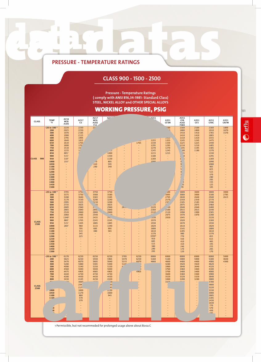
technical datastechnical datas technical datastechnical datas
arfl
uIN
DU
ST
RIA
L V
AL
VE
S
131
PRESSURE - TEMPERATURE RATINGS
WORKING PRESSURE, PSIG
* Also may include maximum of 0.05/phosphrus. Also may include maximum of 0.25, antimony, 0.08% sulfur, and 0.02% phosphorus. ** Maximun percent of elements permissible other than those indicated.† Maximum of 2.6% silicon permissible provinding sum of all elements other than copper, iron , and silicon does not exceed 0.3%. ‡ Deppends on diameter of thickness (surface to surface) of material; data on request.
Pressure - Temperature Ratings ( comply with ANSI B16,34-1981- Standard Class)
STEEL, NICKEL ALLOY and OTHER SPECIAL ALLOYS
WORKING PRESSURE, PSIG
CLASS TEMP
ºF
A216 WCB A105
A217 C5
A217 WC6 A182 F11
A217 WC9 A182 F22
A352 LCB
A352 LC3
A350 LF3
A351 CF8M A182 F316
A351 CF3M
A351 CF8
A182 F304
A351 CF3
A351 CF8C
A351 CN7M
CLASS 900
-20 to 100 º 2220 2250 2250 2250 2085 2250 2160 2160 2160 2160 2160 1800
200 2025 2250 2135 2150 1970 2250 1860 1860 1800 1800 1910 1670
300 1970 2185 2020 2030 1915 2185 1540 1540 1410 1410 1765 1570
400 1900 2115 1975 1945 1850 2115 1540 1540 1410 1410 1665 –
500 1795 1995 1925 1920 1745 1995 1435 1435 1310 1310 1555 –
600 1640 1815 1815 1815 1600 1815 1355 1355 1245 1245 1475 –
650 1610 1765 1765 1765 1570 1765 1330 1330 1225 1225 1440 –
700 1600 1705 1705 1705 – – 1295 1295 1210 1210 1405 –
750 1510 1595 1595 1595 – – 1270 1270 1195 1195 1385 –
800 1235 1490 1525 1525 – – 1245 1245 1180 1180 1370 –
850 8051 1315 1460 1460 – – 1215 1215 1165 – 1330 –
900 5151 1060 1350 1350 – – 1180 – 1150 – 1295 –
950 3101 780 1130 1130 – – 1160 – 1125 – 1160 –
1000 1551 575 670 805 – – 1090 – 965 – 1090 –
1050 – 420 410 595 – – 1080 – 925 – 1080 –
1100 – 310 290 340 – – 965 – 770 – 965 –
1150 – 205 – – – – 825 – 585 – 825 –
1200 – 135 – – – – 6203 – 465 – 515 –
1250 – – – – – – 545 – 330 – 370 –
1300 – – – – – – 410 – 245 – 280 –
1350 – – – – – – 310 – 185 – 205 –
1400 – – – – – – 225 – 145 – 155 –
1450 – – – – – – 175 – 105 – 125 –
1500 – – – – – – 125 – 70 – 105 –
CLASS 1500
-20 to 100 º 3705 3750 3750 3750 3470 3750 3600 3600 3600 3600 3600 3000
200 3375 3750 3560 3580 3280 3750 3095 3095 3000 3000 3180 2785
300 3280 3640 3365 3385 3190 3640 2795 2795 2640 2640 2940 2615
400 3170 3530 3290 3240 3085 3530 2570 2570 2350 2350 2770 –
500 2995 3325 3210 3200 2910 3325 2390 2390 2185 2185 2590 –
600 2735 3025 3025 3025 2665 3025 2255 2255 2075 2075 2460 –
650 2685 2940 2940 2940 2615 2940 2220 2220 2040 2040 2400 –
700 2665 2840 2840 2840 – – 2160 2160 2015 2015 2340 –
750 2520 2660 2660 2660 – – 2110 2110 1990 1990 2305 –
800 2060 2485 2540 2540 – – 2075 2075 1970 1970 2280 –
850 13401 2195 2435 2435 – – 2030 2030 1945 – 2220 –
900 8601 1765 2245 2245 – – 1970 – 1920 – 2160 –
950 5151 1305 1885 1885 – – 1930 – 1870 – 1930 –
1000 2601 960 1115 1340 – – 1820 – 1610 – 1820 –
1050 – 705 685 995 – – 1800 – 1545 – 1800 –
1100 – 515 480 565 – – 1610 – 1285 – 1610 –
1150 – 345 – – – – 1370 – 980 – 1370 –
1200 – 225 – – – – 10303 – 770 – 855 –
1250 – – – – – – 910 – 550 – 615 –
1300 – – – – – – 685 – 410 – 465 –
1350 – – – – – – 515 – 310 – 345 –
1400 – – – – – – 380 – 240 – 255 –
1450 – – – – – – 290 – 170 – 205 –
1500 – – – – – – 205 – 120 – 170 –
CLASS 2500
-20 to 100 º 6170 6250 6250 6250 5785 6250 6000 6000 6000 6000 6000 5000
200 5625 6250 5930 5965 5470 6250 5160 5160 5000 5000 5300 4640
300 5470 6070 5605 5640 5315 6070 4660 4660 4400 4400 4900 4360
400 5280 5880 5485 5400 5145 5880 4280 4280 3920 3920 4620 –
500 4990 5540 5350 5330 4850 5540 3980 3980 3640 3640 4320 –
600 4560 5040 5040 5040 4440 5040 3760 3760 3460 3460 4100 –
650 4475 4905 4905 4905 4355 4905 3700 3700 3400 3400 4000 –
700 4440 4730 4730 4730 – – 3600 3600 3360 3360 3900 –
750 4200 4430 4430 4430 – – 3520 3520 3320 3320 3840 –
800 3430 4145 4230 4320 – – 3460 3460 3280 3280 3800 –
850 22301 3660 4060 4060 – – 3320 3320 3240 – 3700 –
900 14301 2945 3745 3745 – – 3280 – 3200 – 3600 –
950 8601 2170 3145 3145 – – 3220 – 3120 – 3220 –
1000 4301 1600 1860 2230 – – 3330 – 2685 – 3330 –
1050 – 1170 1145 1660 – – 3000 – 2570 – 3000 –
1100 – 860 800 945 – – 2685 – 2145 – 2685 –
1150 – 570 – – – – 2285 – 1630 – 2285 –
1200 – 370 – – – – 1715 – 1285 – 1430 –
1250 – – – – – – 1515 – 915 – 1030 –
1300 – – – – – – 1145 – 685 – 770 –
1350 – – – – – – 860 – 515 – 570 –
1400 – – – – – – 630 – 400 – 430 –
1450 – – – – – – 485 – 285 – 345 –
1500 – – – – – – 345 – 200 – 285 –
1 Permissible, but not recommeded for prolonged usage above about 800ª C1 Permissible, but not recommeded for prolonged usage above about 800ª C1 Permissible, but not recommeded for prolonged usage above about 800ª C1 Permissible, but not recommeded for prolonged usage above about 800ª C1 Permissible, but not recommeded for prolonged usage above about 800ª C
Pressure - Temperature Ratings ( comply with ANSI B16,34-1981- Standard Class)STEEL, NICKEL ALLOY and OTHER SPECIAL ALLOYS
1 Permissible, but not recommeded for prolonged usage above about 800a C
CLASS 900 - 1500 - 2500

Absolute Regulation of Fluids
arflu
WAT
ER
DIV
ISIO
N
SOLA
RD
IVIS
ION
MAR
INE
DIV
ISIO
N
PETR
OCH
EMIC
ALD
IVIS
ION
GAS
DIV
ISIO
N