Embed Size (px)
Citation preview

Performance Optimization of a Photovoltaic Generator
with an Active Power Filter Application
Ayman Blorfan, Patrice Wira, Damien Flieller, Guy Sturtzer, Jean Merckle
To cite this version:
Ayman Blorfan, Patrice Wira, Damien Flieller, Guy Sturtzer, Jean Merckle. Performance Op-timization of a Photovoltaic Generator with an Active Power Filter Application. InternationalJournal on Engineering Applications, 2013, 1 (2), pp.106-112. <hal-00984994>
HAL Id: hal-00984994
https://hal.archives-ouvertes.fr/hal-00984994
Submitted on 29 Apr 2014
HAL is a multi-disciplinary open accessarchive for the deposit and dissemination of sci-entific research documents, whether they are pub-lished or not. The documents may come fromteaching and research institutions in France orabroad, or from public or private research centers.
L’archive ouverte pluridisciplinaire HAL, estdestinee au depot et a la diffusion de documentsscientifiques de niveau recherche, publies ou non,emanant des etablissements d’enseignement et derecherche francais ou etrangers, des laboratoirespublics ou prives.

1
Performance Optimization of a Photovoltaic
Generator with an Active Power Filter Application
Ayman Blorfan *, Patrice Wira *, Damien Flieller **, Guy Sturtzer **, Jean Mercklé *
* MIPS Laboratory, Université de Haute Alsace, 4 rue des Frères Lumière, 68093 Mulhouse, France
{ayman.blorfan; patrice.wira; jean.merckle}@uha.fr
** GREEN Laboratory, INSA de Strasbourg, 24 boulevard de victoire, 67084 Strasbourg, France
{damien.flieller; guy.sturtzer}@insa-strasbourg.fr
Abstract-- Maximum Power Point Tracking (MPPT) for
photovoltaic (PV) systems maximizes the power that can be
transferred from the PV system to an electrical system here we
use the active power filter. To maximize the PV panel output
power, perturb and observe (P&O) maximum power point
tracking (MPPT) has been implemented into the PV system.
Through a boost DC-DC converter, for rapidly changing solar
irradiance the (P&O) method is unable to carry out the
maximums power point values. This paper presents an
intelligent method for the purpose of MPPT, based on fuzzy
logic controller (FLC), and applied to a converter circuit. The
fuzziness determines the size of the perturbed voltage when
there is a rapid changing in solar irradiation. A control scheme
is presented which allows better control of the converter current
reference using voltage and current from the PV system as
inputs to the MPPT perturb and observes method. The
performance of the proposed FLC is tested by simulation and
the results show that the FLC is faster in finding the maximum
power point than the conventional perturbation and observation
method. In order to avoid the problems and difficulties of
regulation and variation of the DC bus due to losses in the active
power filter (transistors and the output filter), a constant voltage
on the DC side of the inverter was proposed, it is a photovoltaic
generator which is used to ensure constant amount of power
force required to maintain the DC voltage side around its
reference value.
Index Terms- Photovoltaic; PV system; MPPT; fuzzy logic;
perturb & observe.
NOMENCALTURE
APF Active Power Filter
PID Proportional-integral-derivative
controller
PI Proportional-integral controller
pvsupP photovoltaic power stocks gain
GPV photovoltaic generator
h harmonic Range
MPPT Maximum Power Point Tracking
PV Photovoltaic
PVi Output current (solar cell)
pvv Output voltage (solar cell)
dI Diode dark current
SCI Short circuit current
i Overall current
Ppv , Pideal , Pout
Photovoltaic, ideal and output
power
Vboost Boost voltage
Voptimal(t) Optimal voltage
Vdc Dc voltage
Vs1, Vs2, Vs3 Three phase Source voltage
P, q active and reactive Power
Ic1, Ic2, Ic3 Load currents
1I , 2I , 3I Source currents
sV , sV Alpha-Beta voltage Components
h1I , h2I , h3I Harmonic Currents
cI , cI Alpha-Beta current Components
refI , refI Alpha-Beta current reference
ref1I , ref 2I , ref 3I abc current reference
I. INTRODUCTION
Recently, there is an increasing concern about the
environment pollution. The need to generate pollution-free
energy has trigger intensive considerable effort toward
alternative source of energy. Solar energy, in particular, is a
promising option. Some researcher had spent their effort in
developing the combined system of an Active Power Filter
(APF) and a photovoltaic (PV) system [1]. However, existing
hybrid APF configurations with their benefits are not yet
implemented for the PV application. Power output of a solar
PV module changes with change in direction of sun, changes
in solar insolation level and with varying temperature [2].
Hence maximization of power improves the utilization of the
solar PV module and increases the interest of the APF.
A. BLORFAN, P. WIRA, D. FLIELLER, G. STURTZER, J. MERCKLE
"Performance Optimization of a Photovoltaic Generator with an Active Power Filter Application,"
International Journal on Engineering Applications, vol. 1, no. 2, pp. 106-112, (2013).

2
Table 1: Table of various MPPT methods
MPPT Method
1 Perturbation & Observation
2 Hill Climbing
3 Incremental Conductance
4 Power Feedback Control
5 Fractional Short Circuit Current
6 Fractional Open Circuit Voltage
7 Computational & Lookup Table
8 Current Sweep
9 Fuzzy Logic
10 Array Reconfiguration
pvV
pvI
dcI
pv
C
refI_ref FLI0 5 10 15 20 25 30
0
0.2
0.4
0.6
0.8
1
dE
De
gree
of
mem
be
rsh
ip
GN MN P N Z PP MP GP
0
0.0
01
0.0
02
0.0
03
0.0
04
0.0
05
0.0
06
0.0
07
0.0
08
0.0
09
0.0
1
0
0.2
0.4
0.6
0.8
1
E
De
gre
e o
f mem
ber
shi
p
GN MN PN Z PP MP GP
0 1 2 3 4 5 6
0
0. 2
0. 4
0.6
0.8
1
C ontrol
Deg
ree
of
me
mbe
rship
TGN MN PN Z PP MP TGP
outV
h1I
h 2I
h3I
1I 2I 3I
c1I c2I c3I
Figure 1. Configuration of the optimal PV system with an
APF scheme.
The block diagram of an APF fed by a PV module is shown
on Figure 1. A Maximum Power Point Tracking (MPPT)
strategy is used for extracting the maximum power from the
solar PV module and transferring that power to the load.
Optimal control can be achieved using a DC-DC power
converter with a controller capable of MPPT [3]. Techniques
for MPPT vary. Some techniques for maximum power point
tracking employ changing the bias point and measuring
changes in output, while others use predetermined PV models
for estimating the MPP. Table 1 show all the MPPT methods
referred to in this paper.
The Perturbation and Observation Method (P&O) is one of
the most popular MPPT methods because of its simplicity.
The P&O method operates by making small incremental
changes in voltage and measuring the resulting change in
power. By comparing the current power measurement to the
previous power measurement, the P&O method selects the
direction for the next perturbation. The P&O MPPT method
can be implemented using a minimal amount of components;
however its speed is limited by the size and the period of the
perturbation [4]. The P&O method also has the problems of
erroneous responses to quick changing conditions, and in
steady state conditions will oscillate around the MPP causing
losses. Figure 2 shows the flowchart of this algorithm.
Figure 2. Flowchart of the P&O algorithm
In a situation where the irradiance changes rapidly, the MPP
also moves on the right hand side of the curve. The algorithm
takes it as a change due to perturbation and in the next
iteration it changes the direction of perturbation and hence
goes away from the MPP as shown by Figure 3.
Figure 3. Curve showing wrong tracking of MPP by P&O
algorithm under rapidly varying irradiance
II. MPPT USING FUZZY LOGIC
CONTROLLER
The oscillation in the P&O method can be minimized by
reducing the perturbation step size [5, 6]. But, a smaller
perturbation size slows down the MPPT. Another problem is
MPPT failure under rapidly changing atmospheric conditions.
Fuzzy logic has been used for tracking the MPP of PV
systems [7] because it has the advantages of being robust,
relatively simple to design and do not require the knowledge
A. BLORFAN, P. WIRA, D. FLIELLER, G. STURTZER, J. MERCKLE
"Performance Optimization of a Photovoltaic Generator with an Active Power Filter Application,"
International Journal on Engineering Applications, vol. 1, no. 2, pp. 106-112, (2013).
3
of an exact model. The main components in a FLC are
fuzzification, rule-based inferences and defuzzification as
shown in Figure 4. The input variables to the FLC are the
current from the Perturbe and Observe box in PV array power
(E) and the current (dE) whereas the output of FLC is the
current reference of boost converter current reference
(Iref_FuzzyLogic). The current reference is the current that must be
drawn from the PV to the boost converter [8].
Figure 4. Components of a fuzzy logic controller
The universe of discourse for the first input variable (E) is
assigned in terms of its linguistic variable by using seven
fuzzy subsets which are denoted by GN,MN, PN, Z, PP, MP
and GP. The membership functions for the variable are shown
in Figure 5. Figure 6 shows the universe of discourse for the
second input variable (dE) which is classified into 7 fuzzy
sets, namely as the first. Figure 7 depicts the universe of
discourse for the output variable, Iref_FL.
The fuzzy system rule base is created as shown in Table 1
with (E) and (dE) as inputs while Iref_FL is the output. The
fuzzy inference of the FLC is based on the Mamdani’s
method which is associated with the max-min composition.
The defuzzification technique is based on the centroid method
which is used to compute the crisp output, Iref_FL. The surface
of FLC is shown in Figure 8.
Figure 5. Membership Functions of the 1st Input
De
gre
e o
f m
em
be
rsh
ip
Figure 6. Membership functions of the 2nd input variable
Figure 7. Membership functions of the output variable
Figure 8. Surface of the fuzzy logic controller
III. SOLAR CELL MODEL USING
MATLAB
The simplest solar cell model consists of diode and current
source connected parallel. Current source current is directly
proportional to the solar radiation. Diode represents PN
junction of a solar cell.
PV SC Di I i (5)
0
0
( 1)
( 1)D
T
eV
KTL
V
V
D
i I e I
i I e I
(6)
Figure 9. Model of PV using Simulink
A. BLORFAN, P. WIRA, D. FLIELLER, G. STURTZER, J. MERCKLE
"Performance Optimization of a Photovoltaic Generator with an Active Power Filter Application,"
International Journal on Engineering Applications, vol. 1, no. 2, pp. 106-112, (2013).

4
The proposed model of photovoltaic using Matlab is shown
by Figure. 9. The photovoltaic system consists of:
a) A 6-module (85 W each) PV array with full sun (1,000
W/m2 insolation);
b) A Boost DC-DC converter that steps-up a DC input
voltage;
c) A capacitor C_Dc that provides necessary energy storage
to balance instantaneous power delivered to the grid.
IV. RELATIONSHIP BETWEEN THE
BLOCKS OF THE SYSTEM [9, 10]
A typical MPPT controller consists of a DC-DC boost
converter, chopper controller. A boost converter is designed
to step up a fluctuating solar panel voltage to a higher
constant DC voltage. The maximum power point of a PV
module can be detected by a program carry out using Matlab
which is driven by an MPPT algorithm. Once the MPP is
obtained, a triggering signal with a specific duty cycle is
generated, represented by the reference current and used to
trigger the boost converter switches in order to ensure that the
converter operates as close as possible to the PV MPP. The
system total is shown in the Figure 10.
B e g in P & O
A lg o r it h m
M e a s u r e
V ( k ) , I( K )
P ( k ) =V (k )x I( k )
? P = P ( k )- P ( k - 1 )
? P > 0
V ( k ) - V (k - 1 ) > 0V ( k ) - V ( k - 1 ) > 0
D e c r e a s e
M o d u le
V o lt a g e
I n c r e a s e
M o d u le
V o lt a g e
D e c r e a s e
M o d u le
V o lt a g e
I n c r e a s e
M o d u le
V o lt a g e
U p d a t e H is t or y
V (k - 1 ) =V (k )
P (k - 1 ) =P (k )
Y e sN o
N o N o
Y e s Y e s
Perturbe and
Observe
Figure 10. Functional block for all this system using
the fuzzy logic technique
V. METHODOLOGY
The proposed MPPT scheme employing FLC has been
modeled and simulated using the MATLAB/Simulink
software. Figure 8 shows a block diagram of the developed
PV system consisting of PV array, boost converter circuit
connected to a load and an MPPT controller. The PV array
with a capacity of 1 kW consists of 6 PV modules. The fuzzy
logic based MPPT controller is simulated with the
conventional P&O under the operating conditions of
temperature 25 0C with varying insolation (0 to 1000 W/m2).
The MPPT controller consists of two main parts, namely, the
P&O part then the FLC current controller as depicted in
Figure 11.
The FLC with MPPT using P&O algorithm is effective in
terms of its tracking capability at a standard condition with
fast changing irradiance and ambient temperature of 250C. It
can be observed that the power of the boost converter tracked
by P&O method is approximately less than the power
achieved by the combination of FLC and the P&O method.
Therefore, the results show good performance of the
proposed MPPT using FLC in both transient and steady-state
operations.
Figure 11. Model of the PV system developed with
Matlab/Simulink
Figure 14 show the performance of the PV system using FLC
and P&O algorithms under constant temperature of 25°C and
fast changing irradiance ([0 400 850 950 1000 950 850 400 0]
W/m2) at times ([0 0.01 0.02 0.03 0.04 0.05 0.06 0.07 0.08]).
The simulation results show that the performance of the P&O
and the proposed FLC method are quite similar under these
two conditions.
The results of simulation of (FLC_PO) for the MPPT are
shown in Figure 12, 13, 14 without MPPT, then with Perturb
and Observe (P&Q) method, at the end with a fuzzy logic
controler. The variable universe fuzzy control has stronger
anti-interference performance than the conventional one, and
finds the maximum power point in time of 0.01 seconds. We
can see that the variable universe fuzzy control can achieve
higher level control precision, better speed tracking
performance.
Figure 12. The power of PV systems without MPPT
A. BLORFAN, P. WIRA, D. FLIELLER, G. STURTZER, J. MERCKLE
"Performance Optimization of a Photovoltaic Generator with an Active Power Filter Application,"
International Journal on Engineering Applications, vol. 1, no. 2, pp. 106-112, (2013).

5
Figure 13. The power of PV systems MPPT using P&O
Figure 14. The power of PV systems MPPT using both the
P&O and FLC
I. DC ENERGY STORAGE
The DC capacitor serves two main purposes:
1) It maintains a DC voltage with a small ripple in steady
state and
2) It serves as an energy storage element to supply the real
power deference between load and source during the
transient period [11].
DC link voltage should be higher than maximum peak of the
source voltage. DC link voltage can be controlled using
proportional-integral (PI) controller [12], proportional-
integral-derivative (PID) controller and neural network or a
fuzzy logic [13], the control bloc diagram is shown in the
Figure 15.
In Figure 15-(a) we can always maximize the value of the
reference voltage needed to regulate the terminal voltage of
the capacitor, however in Figure 15-(b) provides for return to
the case of equilibrium between the source and the load when
the load is polluting. By which we can start the regulator
optimally to inject additional power from the load side need
to compensate reactive power and return to the balancing
energy.
In [14], DC link is fed from separate voltage source to
stabilize DC-side voltage within a certain range. Switched
capacitor APF that brings new dimension to APF as it
reduces components and ratings (particularly capacitor) while
performing at low switching frequency is evaluated in [15]. A
DC link is used instead of a capacitor and as a battery pack,
which is charged from a photovoltaic array in [16]. In Figure
16, the DC voltage after the regulation becomes stable and
converges towards the optimal value of the voltage.
refi
refi
1refi
2refi
3refi
refi
refi q~
q
q
pp
~
p
sVsV
ci ci
1sV
2sV
3sV
2ci
3ci
1ci
32tT
32tT
_ supP pv
boostV
( 1)optimalV t pvV
dcV
Figure 15. Optimized reference voltage on the DC capacitor
Figure 16. The DC voltage side around its reference value
Figure 17. The Ipv current as a function of the Vpv voltage
using the P&O method and for many values of the
illumination
___ Pout
_____ Ppv
____ Pideal
___ Pout
_____ Ppv
____ Pideal
A. BLORFAN, P. WIRA, D. FLIELLER, G. STURTZER, J. MERCKLE
"Performance Optimization of a Photovoltaic Generator with an Active Power Filter Application,"
International Journal on Engineering Applications, vol. 1, no. 2, pp. 106-112, (2013).
6
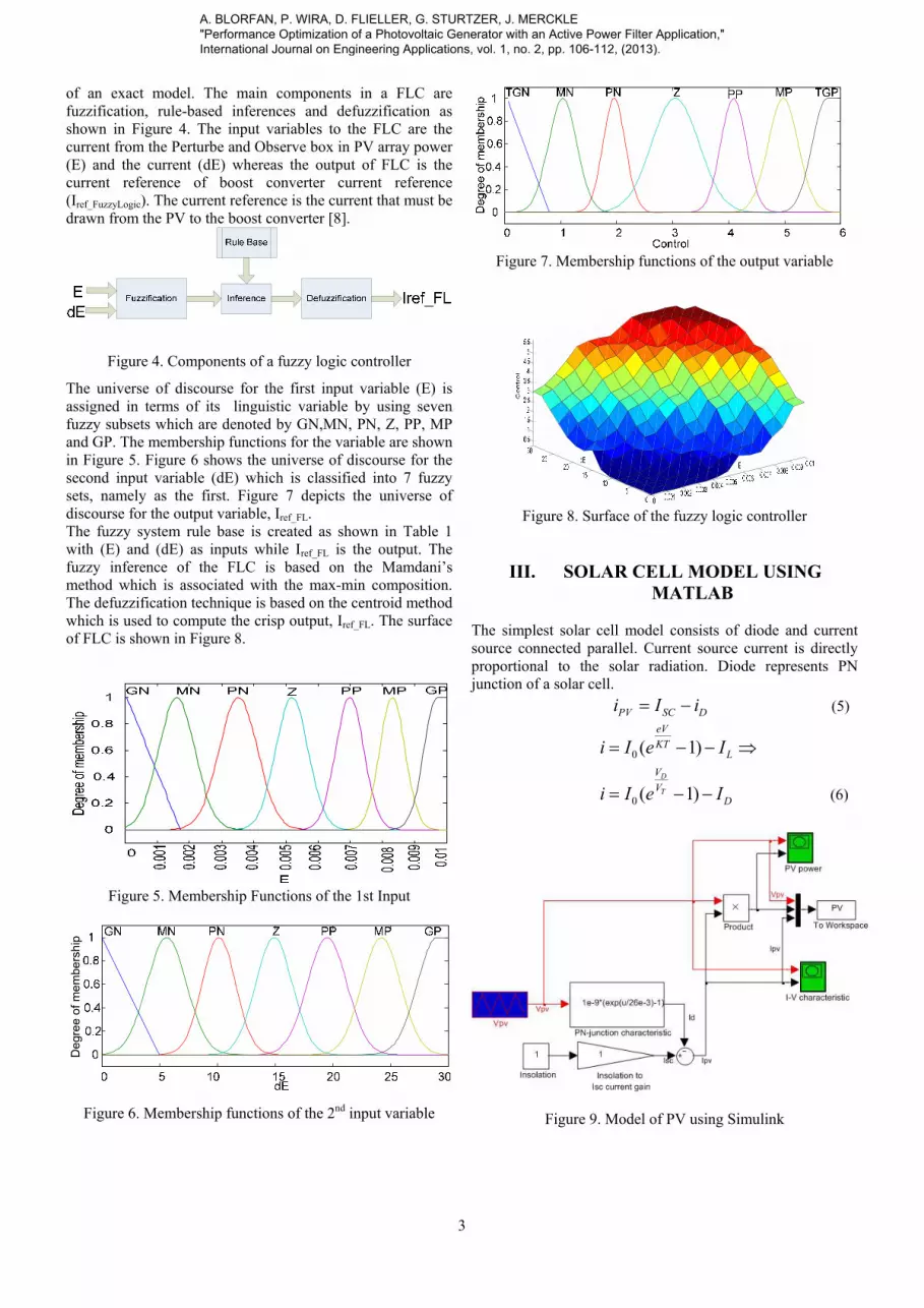
Figure 18. The Ipv current as a function of the Vpv voltage
Using the (P&O_FLC) method
Figure 19. The Ppv power as a function of the time
Using the (P&O_FLC) method
Figure 20. The current of the load before and after the
compensation scheme using the active power filter with an
optimal PV system
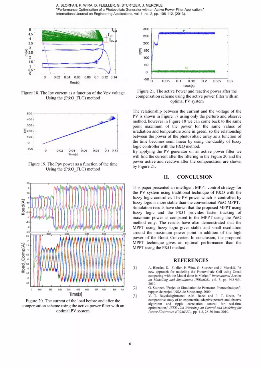
Figure 21. The active Power and reactive power after the
compensation scheme using the active power filter with an
optimal PV system
The relationship between the current and the voltage of the
PV is shown in Figure 17 using only the perturb and observe
method, however in Figure 18 we can come back to the same
point maximum of the power for the same values of
irradiation and temperature zone in green, so the relationship
between the power of the photovoltaic array as a function of
the time becomes semi linear by using the duality of fuzzy
logic controller with the P&Q method.
By applying the PV generator on an active power filter we
will find the current after the filtering in the Figure 20 and the
power active and reactive after the compensation are shown
by Figure 21.
II. CONCLUSION
This paper presented an intelligent MPPT control strategy for
the PV system using traditional technique of P&O with the
fuzzy logic controller. The PV power which is controlled by
fuzzy logic is more stable than the conventional P&O MPPT.
Simulation results have shown that the proposed MPPT using
fuzzy logic and the P&O provides faster tracking of
maximum power as compared to the MPPT using the P&O
method only. The results have also demonstrated that the
MPPT using fuzzy logic gives stable and small oscillation
around the maximum power point in addition of the high
power of the Boost Converter. In conclusion, the proposed
MPPT technique gives an optimal performance than the
MPPT using the P&O method.
REFERENCES
[1] A. Blorfan, D. Flieller, P. Wira, G. Sturtzer and J. Mercklé, "A
new approach for modeling the Photovoltaic Cell using Orcad
comparing with the Model done in Matlab," International Review
on Modelling and Simulations (IREMOS), vol. 3, pp. 948-954,
2010.
[2] G. Sturtzer, "Projet de Simulation de Panneaux Photovoltaïques",
rapport de projet, INSA de Strasbourg, 2009.
[3] V. T. Buyukdegirmenci, A.M. Bazzi and P. T. Krein, "A
comparative study of an exponential adaptive perturb and observe
algorithm and ripple correlation control for real-time
optimization," IEEE 12th Workshop on Control and Modeling for
Power Electronics (COMPEL), pp. 1-8, 28-30 June 2010.
___ Iout
___Ipv
__ Iideal
A. BLORFAN, P. WIRA, D. FLIELLER, G. STURTZER, J. MERCKLE
"Performance Optimization of a Photovoltaic Generator with an Active Power Filter Application,"
International Journal on Engineering Applications, vol. 1, no. 2, pp. 106-112, (2013).

7
[4] M. Veerachary, T. Senjyu and K. Uezato, "Voltage-based
maximum power point tracking control of PV system," IEEE
Transactions on Aerospace and Electronic Systems, vol. 38, pp.
262-270, 2002.
[5] N. Femia, G. Petrone, G. Spagnuolo and M. Vitelli, "Increasing
the efficiency of P&O MPPT by converter dynamic matching," in
2004 IEEE International Symposium on Industrial Electronics 4-7
May 2004, pp. 1017-1021 vol. 2.
[6] D. Menniti, A. Pinnarelli and G. Brusco, "Implementation of a
novel fuzzy-logic based MPPT for grid-connected photovoltaic
generation system," presented at the 2011 IEEE Trondheim
PowerTech, 19-23 June 2011.
[7] N. Patcharaprakiti and S. Premrudeepreechacharn, "Maximum
power point tracking using adaptive fuzzy logic control for grid-
connected photovoltaic system," in Power Engineering Society
Winter Meeting, 2002. IEEE, 2002, pp. 372-377 vol.1.
[8] S. H. Hosseini, S. Danyali, G. Yazdanpanah and M.
Sarhangzadeh, "Three-phase four-wire grid-connected PV power
supply with accurate MPPT for unbalanced nonlinear load
compensation," in IEEE International Symposium on Industrial
Electronics, 2009. ISIE 2009, 5-8 July 2009, pp. 1099-1104.
[9] S. Lalouni and D. Rekioua, "Modeling and Simulation of a
Photovoltaic System Using Fuzzy Logic Controller," in
Developments in eSystems Engineering (DESE), 2009 Second
International Conference on, 2009, pp. 23-28.
[10] A. Blorfan, P. Wira, D. Flieller, G. Sturtzer and J. Mercklé, "A
three-phase hybrid active power filter with photovoltaic
generation and hysteresis current control," IECON 2011 - 37th
Annual Conference on IEEE Industrial Electronics Society, pp.
4316-4321, 7-11 Nov. 2011.
[11] M. I. M. Montero, E.R. Cadaval and F.B. Gonzalez, "Comparison
of Control Strategies for Shunt Active Power Filters in Three-
Phase Four-Wire Systems," IEEE Transactions on Power
Electronics, vol. 22, pp. 229-236, 2007.
[12] G. K. Singh, A.K. Singh and R. Mitrab, "A simple fuzzy logic
based robust active power filter for harmonics minimization under
random load variation," Electric Power Systems Research, vol.
77, pp. 1101-1111, 2007.
[13] B. Brahim, B. Chellali, D. Rachid and F. Brahim, "Optimization
of shunt active power filter system fuzzy logic controller based on
ant colony algorithm," Journal of Theoretical and Applied
Information Technology, 2010.
[14] A. Luo, S. Zhikang, Z. J. Shen, Z. Wenji, and Xu. Xianyong,
"Design Considerations for Maintaining DC-Side Voltage of
Hybrid Active Power Filter With Injection Circuit," IEEE
Transactions on Power Electronics, vol. 24, pp. 75-84, 2009.
[15] M. A. M. Radzi and N. A. Rahim, "Neural Network and Bandless
Hysteresis Approach to Control Switched Capacitor Active Power
Filter for Reduction of Harmonics," IEEE Transactions on
Industrial Electronics, vol. 56, pp. 1477-1484, 2009.
[16] P. Flores, J. Dixon, M. Ortuzar, R. Carmi, P. Barriuso and L.
Moran, "Static Var Compensator and Active Power Filter With
Power Injection Capability, Using 27-Level Inverters and
Photovoltaic Cells," IEEE Transactions on Industrial Electronics,
vol. 56, pp. 130-138, 2009.
Authors’ information
Ayman BLORFAN was received the B.Sc in 1997 and
M.Sc degrees in 2007 from the Polytechnic School of
Nantes in France, In 2009 He joined to the laboratory of
MIPS and ERGE to work in the research in domain of
power electronics, automatic, photovoltaic for the
renewal energy, DC/AC and DC/AC inverters.
Patrice WIRA received the Ph.D. degree in 2002 and the "Habilitation à
Diriger des Recherches" (French HDR degree) in 2009
in electrical engineering both from the Université de
Haute Alsace, Mulhouse, France. From 2002 to 2011,
he was an Associate Professor at the Université de
Haute Alsace, France. Since 2011, he is a Full Professor
of Electrical and Computer Engineering at the same
university. His main interests are in computational
neuroscience, intelligent control, learning systems and theoretical and
practical aspects of artificial neural networks.
Damien FLIELLER was born in Epernay, France, on October 15, 1966. He
received the M.Sc. degree in electrical engineering from
the Ecole Normale Supérieure (Cachan), France, in 1988
and the Ph.D.degree in Electrical Engineering from the
University of Paris, France, in 1995 till 1995. He is an
Associate Professor in the Department of Electrical
Engineering at INSA (Institut National des Sciences
Appliquées), Strasbourg, France. He is now director of the
ERGE laboratory, INSA. His research interests are in the field of modeling
and control of synchronous motors, power system, active filter, and induction
heating DC-AC converters.
Guy STURTZER received the Ph.D. degree in electrical engineering from
the Ecole Normale Supérieure, Cachan, France, in 2001.
He joined the Department of Electrical Engineering,
INSA de Strasbourg, France, where he is an Associate
Professor. His main interests include electrical machines,
power converters and renewable energies.
Jean MERCKLE received the M.Sc. and Ph.D. Degrees in electrical from
University Nancy I, Nancy, France, in 1982 and 1988,
respectively.
In 1988, he joined the MIPS Laboratory, University of
Haute Alsace, Mulhouse, France, where he participated in
several adaptive signal processing projects. From 1991 to
1993, he was with the department of Electrical and
Computer Engineering, University of California and San
Diego, contributing to a 3-D optoelectronic neural
architecture with efficient learning. He is currently a
professor of Electrical and Computer Engineering. His research interests
include adaptive neural computation with application to power electronic
systems control and digital hardware implementation.
A. BLORFAN, P. WIRA, D. FLIELLER, G. STURTZER, J. MERCKLE
"Performance Optimization of a Photovoltaic Generator with an Active Power Filter Application,"
International Journal on Engineering Applications, vol. 1, no. 2, pp. 106-112, (2013).


