Embed Size (px)
Citation preview
Performance Analysis of AODV Routing for Wireless Sensor Network in FPGAHardware
Namit Gupta1,*, Kunwar Singh Vaisla2, Arpit Jain3, Adesh Kumar4 and Rajeev Kumar3
1Department of Computer Science & Engineering, Uttarakhand Technical University, Dehradun, 248007, India2Department of Computer Science, B T Kumaon Institute of Technology Dwarahat, India
3Faculty of Engineering & CS, Teerthanker Mahaveer University, Moradabad, India4Department of Electrical & Electronics Engineering, School of Engineering, University of Petroleum and Energy Studies,
Dehradun, 248007, India*Corresponding Author: Namit Gupta. Email: [email protected]
Received: 01 May 2021; Accepted: 03 June 2021
Abstract: Wireless sensor network (WSN) is a group of interconnected sensornodes that work wirelessly to capture the information of surroundings. The rout-ing of the network is a challenging task. The routing of WSN is classified asproactive, reactive, and hybrid. Adhoc on-demand distance vector (AODV) rout-ing is an example of reactive routing based on the demand route formationsamong different nodes in the network. The research article emphasizes the designand simulation of the AODV routing hardware chip using very-high-speed inte-grated circuit hardware description language (VHDL) programming in Xilinxintegrated synthesis environment (ISE) 14.7 software. The performance of thechip is studied based on the field-programmable gate array (FPGA) hardwareparameters such as slices, lookup table (LUTs), input/output block (IOB), flip-flops, and memory for the different configurations of the network (N = 10,20 ….100). The delay and frequency are also estimated on the Virtex-5 FPGA.The performance of the WSN with AODV routing is also analyzed based onthe packet delivery ratio, throughput, delay, and control overhead. The simulationtest cases verified the 8-bit, 64-bit, and 128-bit data communication withinthe nodes.
Keywords: Wireless sensor network; FPGA synthesis; AODVrouting; simulationand synthesis; VHDL simulation
1 Introduction
The wireless sensor network is an infrastructure-less organized wireless network [1], used in a largespace by deploying the wireless sensors in an ad-hoc way that can be used to monitor the physical,system, or environmental conditions. The WSN consist of several nodes with the onboard processor tomanage and monitor the environmental conditions in a specific area. The nodes are connected to the mainprocessing unit or the base station in the WSN System. The base station is connected to the internet toshare the information among the nodes. The Components of WSN are sensors, radio nodes, wireless local
This work is licensed under a Creative Commons Attribution 4.0 International License, whichpermits unrestricted use, distribution, and reproduction in any medium, provided the originalwork is properly cited.
Computer Systems Science & EngineeringDOI:10.32604/csse.2022.019911
Article
echT PressScience
area network (LAN) access points [2], and evaluation software. The sensor nodes capture the environmentalparameters which can be used for data acquisition. The signals are converted to electrical signals. The radionodes receive the information processed by the sensors and process it into the wireless LAN access points. Itis a transceiver, power source, microcontroller-based system, or a memory element. The wireless LAN accesspoints receive the data of radio nodes through the internet. The evaluation software process the data ofwireless LAN access points. The software process the data to the destination and users for furthermonitoring, storage, analysis, processing, or mining. The sensor nodes are limited in computationalcapabilities, power, and memory.
The main challenges of the WSN are energy efficiency, performance, quality of service (QoS),scalability over large-scale deployment, node failure, routing, security, network throughput, cross-layeroptimization, and capability to cope with node failure. The topology of a WSN changes very regularly.The major applications of WSN [3] are in monitoring environmental parameters such as temperature, airpressure, and humidity. Other applications are agriculture, landslide detection, weather forecasting, theinternet of things (IoT), medical science as patient monitoring, security, and threat detection.
The routing protocol [4] is a method to choose the appropriate route for processing data from source todestination. The method meets numerous problems while deciding the route that probably depends on thechannel characteristics, type of network, and WSN performance metrics. The sensors forward the senseddata to the base station and connect the sensor networks to the specific network using the internet inwhich the data is gathered, analyzed, and processed accordingly in WSN. The design work routingmethods for WSN are relatively thought because of several characteristics of the network that distinguishthem from wireless infrastructure-less networks. Different types of routing concerns are involved in WSN.
Most of the time it is difficult to allocate a common identification method for a large-scale network inwhich multiple sensor nodes are working together. Therefore, wireless sensor nodes are not capable of usingconventional IP-based protocols. The data flow of the detected node is necessary from a large number ofsources to a definite base station. It is not occurring in the usual communication networks. The trafficpackets have substantial redundancy in all of the cases. The reason is that multiple nodes can create thesame data while sensing the environmental parameters. Therefore, it is required to exploit the cause ofsuch redundancy with the help of routing protocols and make them feasible to utilize more bandwidthand efficient energy as required. Furthermore, the nodes are firmly limited in the relations of transmissionenergy, capacity, storage, bandwidth, and onboard energy. Due to such differences, several new routingprotocols are to manage the routing issue and challenges in WSNs.
The routing protocols of WSNs are categorized as network structure-oriented protocols (Flat, location,and Hierarchical), route dispensation protocols (reactive, proactive, and hierarchical), and networkoperations-oriented protocols (Queue based, multipath, coherent, QoS, and negotiation). The reactiveprotocols are activated based on the demand and do not follow the exact network topology. The route iscreated based on the demand raised by the node when a source node wishes to send the packets to thedestination. The commonly used reactive protocols are dynamic state routing (DSR) and Ad-hoc on-demand distance vector routing system (AODV). On the other hand, the proactive protocols are table-oriented and keep a routing table when data packets are transferred from the source node to thedestination node. The generally used proactive protocols are optimized link state routing (OLSR) anddestination sequenced distance vector (DSDV) protocol [5]. Moreover, the hybrid routing protocol (HRP)is having the quality of proactive routing and reactive routing. These protocols are applied to choose thepath for optimum network solutions and the data transfer requirements for the state of network topology.The behavior of routing protocols depends on the network performance matrices which are
Packet delivery ratio (PDR) - It is a ratio of the number of packets received by destination to the numberof the packet sent by the source.
1074 CSSE, 2022, vol.40, no.3
End to end Delay (EoD) - End to end delay (seconds) is the time it takes a data packet to reach thedestination. In the network layer, the end-to-end delay is calculated by the sum of processing delay,transmission delay, packet, propagation delay, and queuing delay. The end-to-end delay is estimated asthe sum of the node delay at each node and the link delay on each link in the path.
Routing Overhead (RH) - Routing overhead is the total number of routing packets divided by the totalnumber of delivered data packets.
RH= Full number of routing packets/Full number of packets delivered.
Throughput - The rate of successfully transmitted data per second in the network during the simulation.It is a measure of the date rate (bits per second) experienced in the network.
2 Related Work
The performance of the WSN [6] depends on the three major parameters throughput, packet deliveryratio, and energy levels. WSN faces the issue of jamming and quick battery energy depletion. The authorsworked on the sensor mechanism used for rechargeable WSNs, in which anchor points are moved alongwith the intended trajectory and recharge the placed sensors using wireless power transmissions. WSNhas different security concerns and algorithms for WSN. The WSN system and more vulnerable toattacks [7]. Therefore, security systems are primarily required to secure the network and confirm thenetwork security threats. Cryptography plays a very important role and leading protocols are used toaddress the security concerns in WSN. They discussed different protocols such as security protocols forsensor networks (SPIN), low entropy authentication (LEA), regular and predictable times (RPT), tinysecurity, lightweight mutual authentication, etc protocols for WSN security. Several routing methods areapplicable for data transmission in WSN. They mainly considered the widespread methods AODV and(DSR) [8]. To compare the performance based on the calculation of, throughputs packet delivery ratio,and end to end delay. They used a network simulator version-2 (NS2) software simulation to evaluate theperformance of the system. AODV is much better than DSR in terms of packet delivery ratio and DSR ismuch better than AODV in terms of throughput. The comparative analysis of AODV and DSDVprotocols [9] in terms of packet delivery ratio, routing overhead, end-to-end delay, and throughput. It hadbeen analyzed that AODV is better than DSDV in terms of packet delivery ratio, throughput, and routingoverhead. The DSDV is a proactive routing protocol and having an optimal end-to-end delay incomparison to AODV. The energy responsive green cluster-based routing system [10] is used to avoid theearly death of large-scale dense WSNs. In clustered-based networks, clustering forms inadequate loaddistribution from cluster heads and cluster member nodes. They focused on the fuzzy rule-based methodto classify the clustering approach. The main advantage of the method is in the selection of effectivecluster heads and their distribution among other nodes so that it can prevent the overhead in large denseareas. The suggested routing method balances the traffic load among all sensors. The most suited routingprotocols for WSN [11] are AODV, Bellman-Ford, OLSR, and dynamic mobile Adhoc network on-demand routing. The performance of these protocols depends on the parameters such as average end-to-end delay, average throughput, and average energy consumption. The simulation work proved thatrouting is best among all in terms of end-to-end delay, throughput, and energy consumption. The routingprotocols of WLAN are reactive [12] and proactive. In the network of 40 nodes, it is estimated the OLSRprovides a minimum delay in comparison to AODV and DSR. DSR provides the highest value ofpresented throughput. WSN sensor and device should have optimal energy consumption [13] and fastoperating speed. The network should be designed in such a manner that it can maintain network lifetime,enhance network capacity, and optimize delay. So, the designer should decide the simulation platform inwhich all constraints can meet. They introduced the CASTALIA simulation software that works on theobjective modular network testbed in C++(OMNeT++) platform for the low-power sensor devices in
CSSE, 2022, vol.40, no.3 1075
WSN. TheWSN nodes follow the tier-based energy efficient (TBEE) protocol [14] and cluster-based energy-efficient (CBEEP). In TBEE protocol, all nodes are distributed into three areas based on their distance fromthe base station, usually identified as tires. Energy is divided homogeneously among all sensor nodes in thenetwork and a minimum spanning tree is formed. A head node is decided from each tier group that has themaximum energy to send the sensed data to the base station. In the CBEEP protocol, the full function device(FFD) is the cluster head and sends data to the base station. Both protocols are much helpful for thecalculation of the lifetime and energy consumption in the network. The routing algorithm is maximizingbased on the quality [15] of WSN. Authors compared the network based on different algorithms such asAODV, Genetic algorithm (GA) based AODV, Dijkstra algorithm, and GA based Dijkstra algorithm. Theconcept of faulty nodes is also considered that 50% of nodes may be faulty among dynamic functioningnodes. The GA has proved the better performance in WSN when embedded with the algorithm. The energy-efficient clustering protocol (EECP) can be applied for heterogeneous wireless sensor networks (HWSN)[16]. The suggested protocol is designed with three types of nodes and their communication namely general,advanced, and excellent, respectively. The protocol improved, lifetime, stability, throughput, and energy ofthe network. The algorithm outperforms other than other protocols. The WSN nodes are based on internetprotocol version 4 (IPv4) addressing [17] in the AODV protocol. The work was carried for 50, 100, 150,200, and 250 nodes with a simulation time of 10 minutes. It was based on used for battery chargemonitoring model for 60 seconds using 1200 mill ampere-hour (m.A.h) battery. In this way, the behavior ofWSN and AODV is justified for transport and physical layer applications in WSN. The WSN protocols [18]are limited limitations for energy-saving points of view. They focused on the concept that a routing protocolis said to more energy-efficient if it accomplishes one or more aspects of the following: reducing the numberof data transmissions, reducing total energy consumed in the network, exploiting the maximum number ofalive nodes in overtime and balancing the load among different sensor in WSN.
The research work has been done in the direction of study theWSN performance with different routing andperformance indices. The limited work is reported in which the routing algorithm is designed using hardwaredescription language in the form of chip and performance is estimated on the hardware. The problem statementof the work is to design the chip of AODV algorithm and performs simulation with different cluster size anddata size with the verification on FPGA. The state of the art of the work is that the successful data transfer willprovide a new hardware platform in which the WSN nodes and security features can be integrated.
3 Ad-hoc on Demand Distance Vector (AODV) Routing System
AODV [19] is reactive on request protocol used for mobile infrastructure-less networks. It works based on thedemand routing method for route formations among different nodes in the network. The protocol does not retainany routes but builds the path as per requirements. AODVis used to limit the disadvantages of DSR Protocol as therouting keeps information between the source node and destination node which makes it slow. In a large-scalenetwork, it becomes very difficult to keep complete information of data packets header as multiple routes areexisting from source node to destination node. Fig. 1 presents the sample of the AODV routing.
The behavior of AODV can be understood by considering a network consisting of 5 nodes that are ‘S’,‘A’, ‘B’, ‘C’, and ‘D’, placed at unit distance from each other. The node ‘S’ is the source node and node ‘D’ isthe destination node as depicted in Fig. 2. In AODV routing [20], two things are required to maintain oneis sequence number and another is broadcast identity document (ID). The information of the destinationID is already. So, it is easy to maintain the destination sequence number and updated the route fromsource to destination. Route request (RREQ) and route response (RRES) are two signals used to send therequest from source to destination as route discovering and reply from destination to source as responserespectively. The IP addresses of the source and destination nodes are already known. The routing inAODV is based on the following fields. RREQ (Destination_IP, Destination_Sequence_Number,Source_IP, Source_Sequence_Number, Hop_Count).
1076 CSSE, 2022, vol.40, no.3
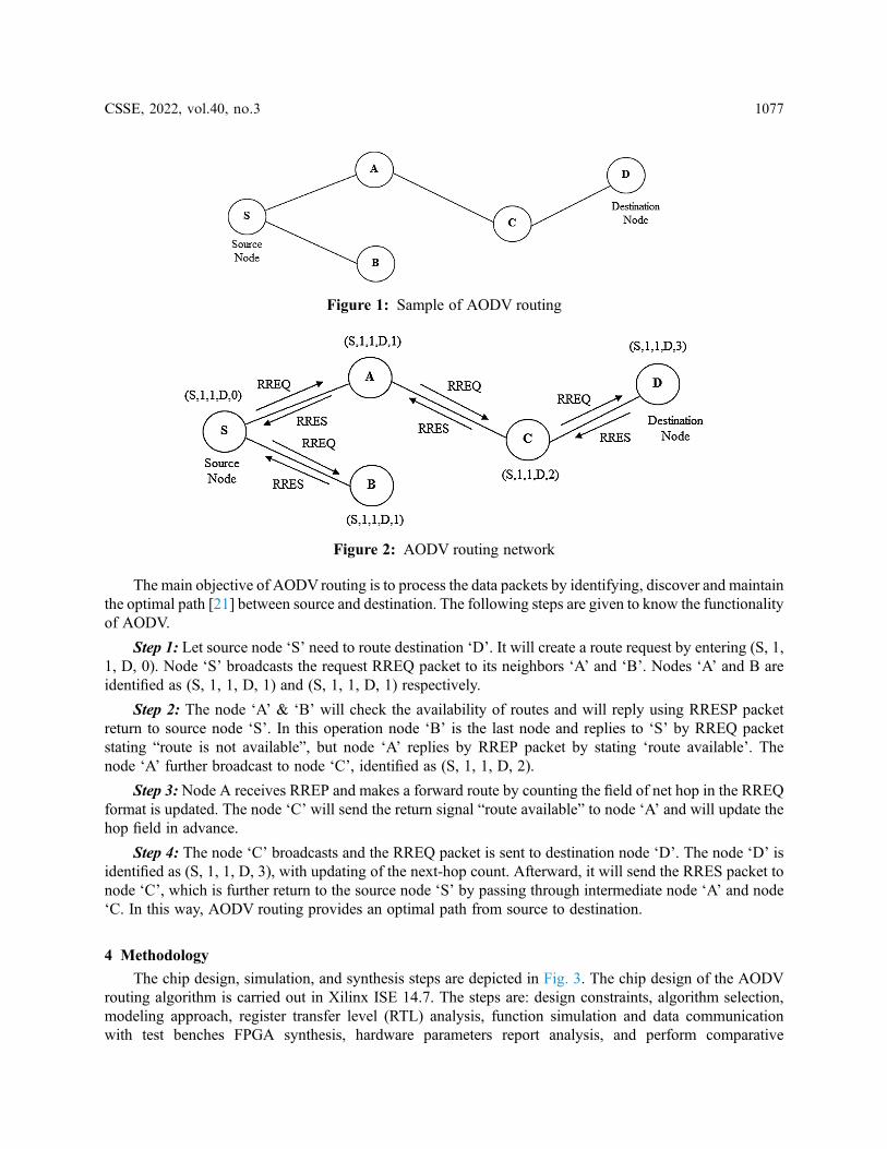
The main objective of AODVrouting is to process the data packets by identifying, discover and maintainthe optimal path [21] between source and destination. The following steps are given to know the functionalityof AODV.
Step 1: Let source node ‘S’ need to route destination ‘D’. It will create a route request by entering (S, 1,1, D, 0). Node ‘S’ broadcasts the request RREQ packet to its neighbors ‘A’ and ‘B’. Nodes ‘A’ and B areidentified as (S, 1, 1, D, 1) and (S, 1, 1, D, 1) respectively.
Step 2: The node ‘A’ & ‘B’ will check the availability of routes and will reply using RRESP packetreturn to source node ‘S’. In this operation node ‘B’ is the last node and replies to ‘S’ by RREQ packetstating “route is not available”, but node ‘A’ replies by RREP packet by stating ‘route available’. Thenode ‘A’ further broadcast to node ‘C’, identified as (S, 1, 1, D, 2).
Step 3: Node A receives RREP and makes a forward route by counting the field of net hop in the RREQformat is updated. The node ‘C’ will send the return signal “route available” to node ‘A’ and will update thehop field in advance.
Step 4: The node ‘C’ broadcasts and the RREQ packet is sent to destination node ‘D’. The node ‘D’ isidentified as (S, 1, 1, D, 3), with updating of the next-hop count. Afterward, it will send the RRES packet tonode ‘C’, which is further return to the source node ‘S’ by passing through intermediate node ‘A’ and node‘C. In this way, AODV routing provides an optimal path from source to destination.
4 Methodology
The chip design, simulation, and synthesis steps are depicted in Fig. 3. The chip design of the AODVrouting algorithm is carried out in Xilinx ISE 14.7. The steps are: design constraints, algorithm selection,modeling approach, register transfer level (RTL) analysis, function simulation and data communicationwith test benches FPGA synthesis, hardware parameters report analysis, and perform comparative
Figure 1: Sample of AODV routing
Figure 2: AODV routing network
CSSE, 2022, vol.40, no.3 1077
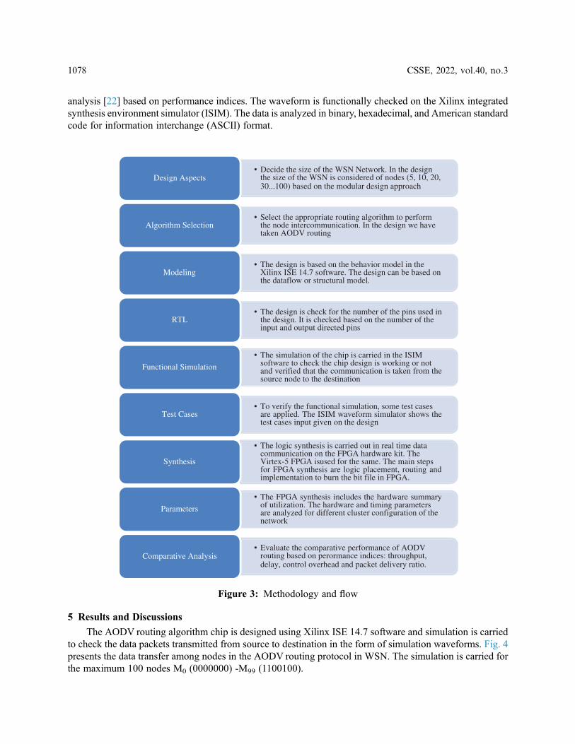
analysis [22] based on performance indices. The waveform is functionally checked on the Xilinx integratedsynthesis environment simulator (ISIM). The data is analyzed in binary, hexadecimal, and American standardcode for information interchange (ASCII) format.
5 Results and Discussions
The AODV routing algorithm chip is designed using Xilinx ISE 14.7 software and simulation is carriedto check the data packets transmitted from source to destination in the form of simulation waveforms. Fig. 4presents the data transfer among nodes in the AODV routing protocol in WSN. The simulation is carried forthe maximum 100 nodes M0 (0000000) -M99 (1100100).
• Decide the size of the WSN Network. In the designthe size of the WSN is considered of nodes (5, 10, 20,30...100) based on the modular design approach
Design Aspects
• Select the appropriate routing algorithm to performthe node intercommunication. In the design we havetaken AODV routing
Algorithm Selection
• The design is based on the behavior model in theXilinx ISE 14.7 software. The design can be based onthe dataflow or structural model.
Modeling
• The design is check for the number of the pins used inthe design. It is checked based on the number of theinput and output directed pins
RTL
• The simulation of the chip is carried in the ISIMsoftware to check the chip design is working or notand verified that the communication is taken from thesource node to the destination
Functional Simulation
• To verify the functional simulation, some test casesare applied. The ISIM waveform simulator shows thetest cases input given on the design
Test Cases
• The logic synthesis is carried out in real time datacommunication on the FPGA hardware kit. TheVirtex-5 FPGA isused for the same. The main stepsfor FPGA synthesis are logic placement, routing andimplementation to burn the bit file in FPGA.
Synthesis
• The FPGA synthesis includes the hardware summaryof utilization. The hardware and timing parametersare analyzed for different cluster configuration of thenetwork
Parameters
• Evaluate the comparative performance of AODVrouting based on perormance indices: throughput,delay, control overhead and packet delivery ratio.
Comparative Analysis
Figure 3: Methodology and flow
1078 CSSE, 2022, vol.40, no.3
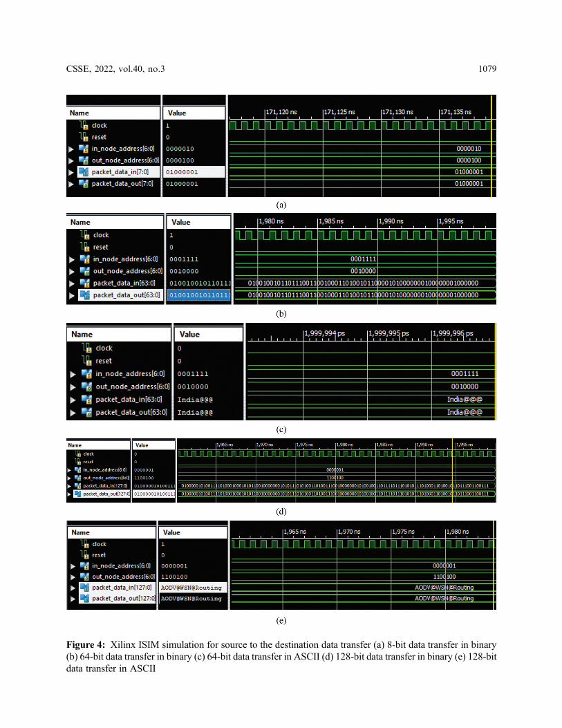
Figure 4: Xilinx ISIM simulation for source to the destination data transfer (a) 8-bit data transfer in binary(b) 64-bit data transfer in binary (c) 64-bit data transfer in ASCII (d) 128-bit data transfer in binary (e) 128-bitdata transfer in ASCII
CSSE, 2022, vol.40, no.3 1079
Test Case- 1: The AODV data (8-bit) communication is verified from source node M2 to node M4.In_node_address [6:0] = “0000010”, Out_node_address [6:0] = “0000100”, Packet_data_in [7:0] = 1’h41(hexadecimal) = “01000001” (binary) = A (in ASCII). The verified data packet is Packet_data_out[7:0] = 1’h41 (hexadecimal) = “01000001” (binary) = A (in ASCII) with PDR=1.
Test Case- 2: The AODV data (64-bit) communication is verified from source node M15 to node M31.In_node_address [6:0] = “0001111”, Out_node_address [6:0] = “0010000”, Packet_data_in[63:0] = 1’h496E646961404040 (hexadecimal) = “01001001 01101110 01100100 01101001 0110000101000000 01000000 01000000” (binary) = India@@@ (in ASCII). The verified data packet isPacket_data_out [63:0] = 1’h496E646961404040 (hexadecimal) = “01001001 01101110 0110010001101001 01100001 01000000 01000000 01000000” (binary) = India@@@ (in ASCII) with PDR=1.
Test Case- 3: The AODV data (128-bit) communication is verified from source node M1 to node M99.In_node_address [6:0] = “0000001”, Out_node_address [6:0] = “1100100”, Packet_data_in[127:0] = 1’h414F44564057534E40526F7574696E67(hexadecimal) = “01000001 01001111 0100010001010110 01000000 01010111 01010011 01001110 01000000 01010010 01101111 01110101 0111010001101001 01101110 01100111” (binary) = AODV@WSN@Routing (in ASCII). The verified data packetis Packet_data_out [127:0] =1’h414F44564057534E40526F7574696E67 (hexadecimal) = “0100000101001111 01000100 01010110 01000000 01010111 01010011 01001110 01000000 01010010 0110111101110101 01110100 01101001 01101110 01100111” (binary) = AODV@WSN@Routing (in ASCII)with PDR =1.
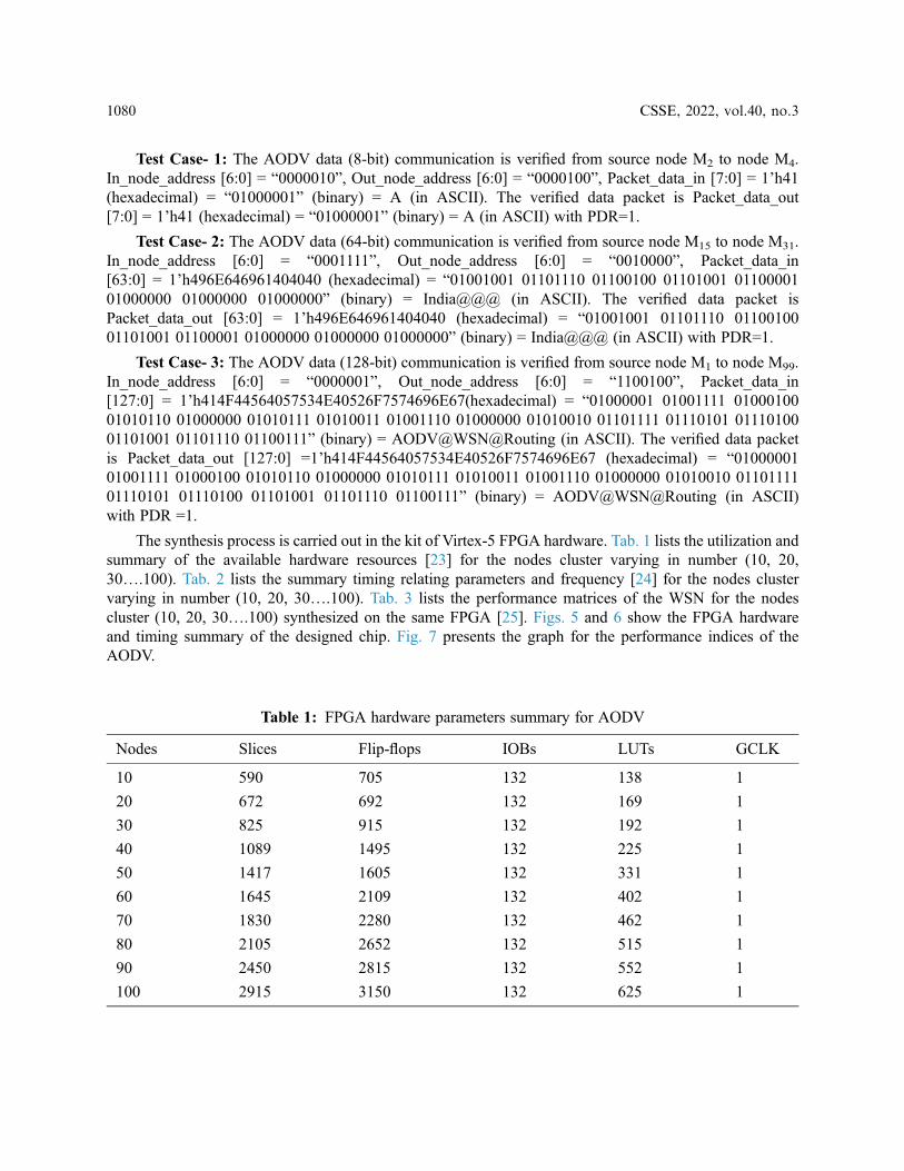
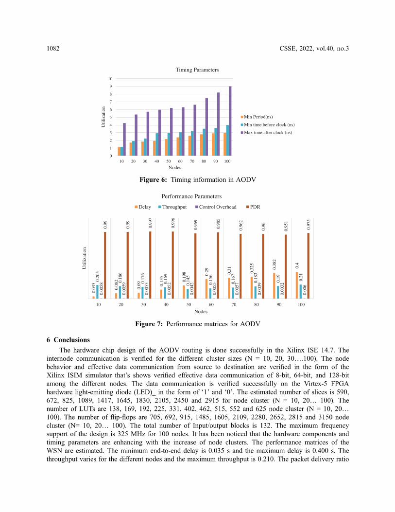
The synthesis process is carried out in the kit of Virtex-5 FPGA hardware. Tab. 1 lists the utilization andsummary of the available hardware resources [23] for the nodes cluster varying in number (10, 20,30….100). Tab. 2 lists the summary timing relating parameters and frequency [24] for the nodes clustervarying in number (10, 20, 30….100). Tab. 3 lists the performance matrices of the WSN for the nodescluster (10, 20, 30….100) synthesized on the same FPGA [25]. Figs. 5 and 6 show the FPGA hardwareand timing summary of the designed chip. Fig. 7 presents the graph for the performance indices of theAODV.
Table 1: FPGA hardware parameters summary for AODV
Nodes Slices Flip-flops IOBs LUTs GCLK
10 590 705 132 138 1
20 672 692 132 169 1
30 825 915 132 192 1
40 1089 1495 132 225 1
50 1417 1605 132 331 1
60 1645 2109 132 402 1
70 1830 2280 132 462 1
80 2105 2652 132 515 1
90 2450 2815 132 552 1
100 2915 3150 132 625 1
1080 CSSE, 2022, vol.40, no.3
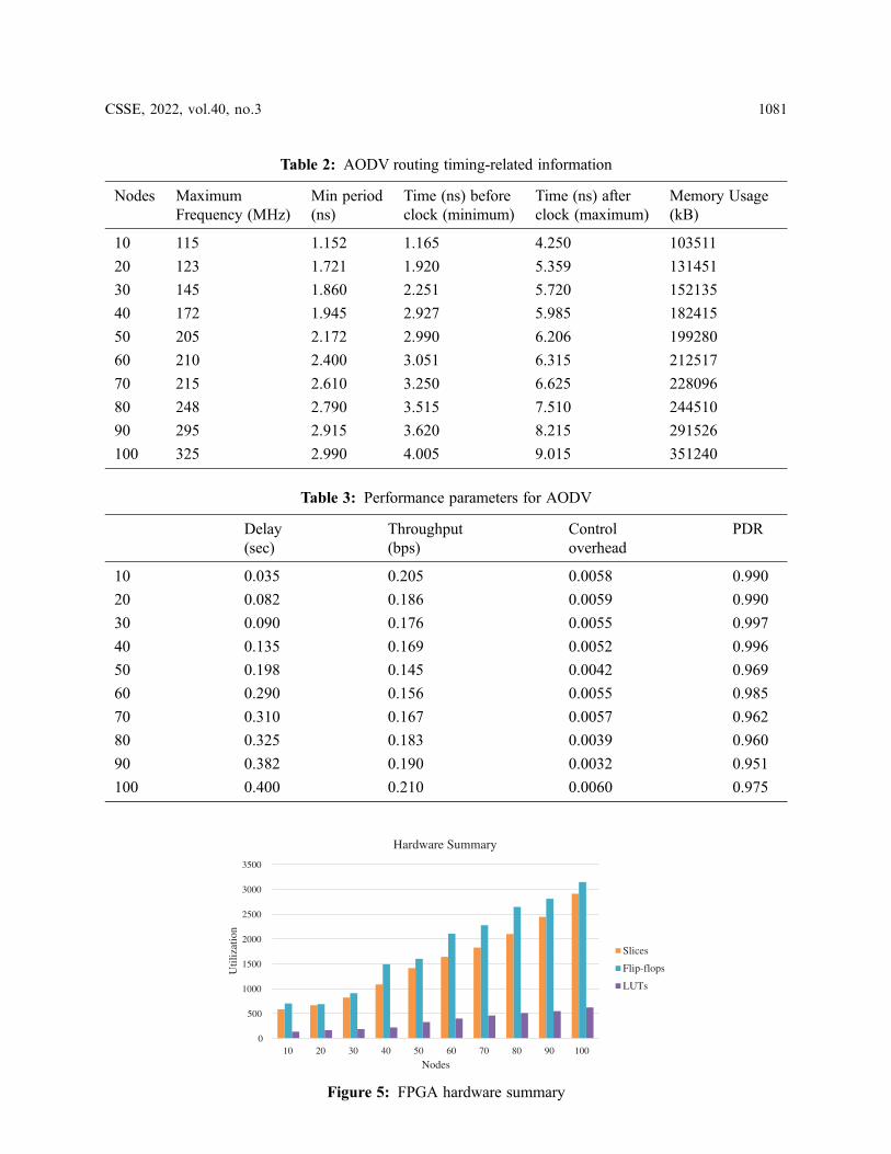
Table 3: Performance parameters for AODV
Delay(sec)
Throughput(bps)
Controloverhead
PDR
10 0.035 0.205 0.0058 0.990
20 0.082 0.186 0.0059 0.990
30 0.090 0.176 0.0055 0.997
40 0.135 0.169 0.0052 0.996
50 0.198 0.145 0.0042 0.969
60 0.290 0.156 0.0055 0.985
70 0.310 0.167 0.0057 0.962
80 0.325 0.183 0.0039 0.960
90 0.382 0.190 0.0032 0.951
100 0.400 0.210 0.0060 0.975
Table 2: AODV routing timing-related information
Nodes MaximumFrequency (MHz)
Min period(ns)
Time (ns) beforeclock (minimum)
Time (ns) afterclock (maximum)
Memory Usage(kB)
10 115 1.152 1.165 4.250 103511
20 123 1.721 1.920 5.359 131451
30 145 1.860 2.251 5.720 152135
40 172 1.945 2.927 5.985 182415
50 205 2.172 2.990 6.206 199280
60 210 2.400 3.051 6.315 212517
70 215 2.610 3.250 6.625 228096
80 248 2.790 3.515 7.510 244510
90 295 2.915 3.620 8.215 291526
100 325 2.990 4.005 9.015 351240
0
500
1000
1500
2000
2500
3000
3500
10 20 30 40 50 60 70 80 90 100
Util
izat
ion
Nodes
Hardware Summary
Slices
Flip-flops
LUTs
Figure 5: FPGA hardware summary
CSSE, 2022, vol.40, no.3 1081
6 Conclusions
The hardware chip design of the AODV routing is done successfully in the Xilinx ISE 14.7. Theinternode communication is verified for the different cluster sizes (N = 10, 20, 30….100). The nodebehavior and effective data communication from source to destination are verified in the form of theXilinx ISIM simulator that’s shows verified effective data communication of 8-bit, 64-bit, and 128-bitamong the different nodes. The data communication is verified successfully on the Virtex-5 FPGAhardware light-emitting diode (LED)_ in the form of ‘1’ and ‘0’. The estimated number of slices is 590,672, 825, 1089, 1417, 1645, 1830, 2105, 2450 and 2915 for node cluster (N = 10, 20… 100). Thenumber of LUTs are 138, 169, 192, 225, 331, 402, 462, 515, 552 and 625 node cluster (N = 10, 20…100). The number of flip-flops are 705, 692, 915, 1485, 1605, 2109, 2280, 2652, 2815 and 3150 nodecluster (N= 10, 20… 100). The total number of Input/output blocks is 132. The maximum frequencysupport of the design is 325 MHz for 100 nodes. It has been noticed that the hardware components andtiming parameters are enhancing with the increase of node clusters. The performance matrices of theWSN are estimated. The minimum end-to-end delay is 0.035 s and the maximum delay is 0.400 s. Thethroughput varies for the different nodes and the maximum throughput is 0.210. The packet delivery ratio
0
1
2
3
4
5
6
7
8
9
10
10 20 30 40 50 60 70 80 90 100
Util
izat
ion
Nodes
Timing Parameters
Min Period(ns)
Min time before clock (ns)
Max time after clock (ns)
Figure 6: Timing information in AODV
0.03
5
0.08
2
0.09 0.
135
0.19
8 0.29 0.31 0.32
5
0.38
2
0.4
0.20
5
0.18
6
0.17
6
0.16
9
0.14
5
0.15
6
0.16
7
0.18
3
0.19 0.21
0.00
58
0.00
59
0.00
55
0.00
52
0.00
42
0.00
55
0.00
57
0.00
39
0.00
32
0.00
6
0.99
0.99
0.99
7
0.99
6
0.96
9
0.98
5
0.96
2
0.96
0.95
1
0.97
510 20 30 40 50 60 70 80 90 100
Util
izat
ion
Nodes
Performance Parameters
Delay Throughput Control Overhead PDR
Figure 7: Performance matrices for AODV
1082 CSSE, 2022, vol.40, no.3
is approximate ‘1’ in all the cases that signify the successful packet transfer from source to destination. In thefuture, we are planning to integrate the concept of cryptography and network security with data encryptionand decryption algorithms in the designed hardware chip.
Funding Statement: The authors received no specific funding for this study.
Conflicts of Interest: The authors declare that they have no conflicts of interest to report regarding thepresent study.
References[1] B. Rashid and M. H. Rehmani, “Applications of wireless sensor networks for urban areas: A survey,” Journal of
Network and Computer Applications, vol. 60, pp. 192–219, 2016.
[2] G. Xu, W. Shen and X. Wang, “Applications of wireless sensor networks in marine environment monitoring: Asurvey,” Sensors, vol. 14, no. 9, pp. 16932–16954, 2014.
[3] S. Mohapatra and P. Kanungo, “Performance analysis of AODV, DSR, OLSR and DSDV routing protocols usingNS2 Simulator,” Procedia Engineering, vol. 30, pp. 69–76, 2012.
[4] H. Kumar, H. Arora and R. K. Singla, “Simulation analysis of optimized link-state routing protocol in wirelesssensor networks,” in Proc. ETNCC, Udaipur, India, pp. 192–194, 2011.
[5] H. M. Jawad, R. Nordin, S. K. Gharghan, A. M. Jawad and M. Ismail, “Energy-efficient wireless sensor networksfor precision agriculture: A review,” Sensors, vol. 17, no. 8, pp. 1781, 2017.
[6] M. Angurala, M. Bala and S. S. Bamber, “Performance analysis of modified AODV routing protocol with lifetimeextension of wireless sensor networks,” IEEE Access, vol. 8, pp. 10606–10613, 2020.
[7] D. E. Boubiche, S. Athmani, S. Boubiche and H. T. Cruz, “Cybersecurity issues in wireless sensor networks:current challenges and solutions,” Wireless Personal Communications, vol. 117, no. 1, pp. 177–213, 2021.
[8] V. K. Kashyap, R. Astya, P. Nand and G. Pandey, “Comparative study of AODV and DSR routing protocols inwireless sensor network using NS-2 simulator,” in Proc. ICCCA, Greater Noida, India, pp. 687–690, 2017.
[9] A. A. Chavan, D. S. Kurule and P. U. Dere, “Performance analysis of AODV and DSDV routing protocol inMANET and modifications in AODV against black hole attack,” Procedia Computer Science, vol. 79, pp.835–844, 2016.
[10] P. Chanak, I. Banerjee and R. S. Sherratt, “A green cluster-based routing scheme for large-scale wireless sensornetworks,” International Journal of Communication Systems, vol. 33, no. 9, pp. e4375, 2020.
[11] P. Joshi, G. Singh and A. S. Raghuvanshi, “Comparative study of different routing protocols for IEEE 802.15.4-enabled mobile sink wireless sensor network,” Lecture Notes in Electrical Engineering, vol. 587, pp. 161–170,2020.
[12] N. Shabbir and S. R. Hassan, Routing protocols for wireless sensor networks (WSNs). in Wireless SensorNetworks-Insights and Innovations, 1st ed., vol. 1. London, U.K: Intech Open, pp. 21–37, 2017.
[13] P. Kumar, M. N. Babu and V. Jain, “Analysis of energy efficiency in WSN by considering SHM application,” IOPConf. Series: Materials Science and Engineering, vol. 225, no. 1, pp. 12231, 2017.
[14] M. S. Bandral and S. Jain, “Energy-efficient protocol for wireless sensor network,” in Proc. ICRAIE, Jaipur, India,pp. 1–6, 2014.
[15] N. Muruganantham and H. El-Ocla, “Routing using genetic algorithm in a wireless sensor network,” WirelessPersonal Communications, vol. 111, no. 4, pp. 2703–2732, 2020.
[16] S. V. Purkar and R. S. Deshpande, “Energy-efficient clustering protocol to enhance performance of heterogeneouswireless sensor network: EECPEP-HWSN,” Journal of Computer Networks and Communications, vol. 2018, no.2078627, pp. 1–12, 2018.
[17] V. K. Verma, S. Singh and N. P. Pathak, “Analysis of scalability for AODV routing protocol in wireless sensornetworks,” Optik, vol. 125, no. 2, pp. 748–750, 2014.
[18] S. Yadav and R. S. Yadav, “A review on energy-efficient protocols in wireless sensor networks,” WirelessNetworks, vol. 22, no. 1, pp. 335–350, 2016.
CSSE, 2022, vol.40, no.3 1083
[19] G. Mujica, J. Portilla and T. Riesgo, “Performance evaluation of an AODV-based routing protocol implementationby using a novel in-field WSN diagnosis tool,” Microprocessors and Microsystems, vol. 39, no. 8, pp. 920–938,2015.
[20] D. G. Zhang, X. D. Song, X. Wang and Y. Y. Ma, “Extended AODV routing method based on distributedminimum transmission (DMT) for WSN,” AEU-International Journal of Electronics and Communications,vol. 69, no. 1, pp. 371–381, 2015.
[21] T. Yang, L. Barolli, M. Ikeda, F. Xhafa and A. Durresi, “Performance analysis of OLSR protocol for wirelesssensor networks and comparison evaluation with AODV protocol,” in Proc. ICNBIS, Indianapolis, USA, pp.335–342, 2009.
[22] N. Gupta, A. Jain, K. S. Vaisla, A. Kumar and R. Kumar, “Performance analysis of DSDV and OLSR wirelesssensor network routing protocols using FPGA hardware and machine learning,” Multimedia Tools andApplications, vol. 80, no. 14, pp. 22301–22319, 2021.
[23] A. Kumar, P. Sharma, M. K. Gupta and R. Kumar, “Machine learning-based resource utilization and pre-estimation for network on chip (NoC) communication,” Wireless Personal Communications, vol. 102, no. 3,pp. 2211–2231, 2018.
[24] A. Kumar, G. Verma, M. K. Gupta, M. Salauddin and B. K. Rehman, “3D Multilayer Mesh NoC communicationand FPGA synthesis,” Wireless Personal Communications, vol. 106, no. 4, pp. 1855–1873, 2019.
[25] S. Abba and J. A. Lee, “FPGA-based design of an intelligent on-chip sensor network monitoring and control usingdynamically reconfigurable autonomous sensor agents,” International Journal of Distributed Sensor Networks,vol. 12, no. 2, pp. 4246596, 2016.
1084 CSSE, 2022, vol.40, no.3


