Embed Size (px)
Citation preview

Pervasive and Mobile Computing 7 (2011) 611–626
Contents lists available at ScienceDirect
Pervasive and Mobile Computing
journal homepage: www.elsevier.com/locate/pmc
A quality based routing protocol for wireless mesh networksAmitangshu Pal ∗, Asis NasipuriElectrical & Computer Engineering, The University of North Carolina at Charlotte, 9201 University City Blvd., Charlotte, NC 28223-0001, United States
a r t i c l e i n f o
Article history:Available online 1 December 2010
Keywords:Wireless mesh networksOn-demand routingQuality based routing
a b s t r a c t
Wirelessmesh networks can provide low-cost solutions for extending the reach ofwirelessaccess points by using multi-hop routing over a set of stationary wireless routers. Therouting protocol for these networks may need to address quality considerations to meetthe requirements of the user. In this paper, we present a quality based routing protocol forwireless mesh networks that tries to maximize the probability of successful transmissionswhile minimizing the end-to-end delay. The proposed routing protocol uses reactive routediscoveries to collect key parameters from candidate routes to estimate the probabilityof success and delay of data packets transmitted over them. To achieve accurate routequality assessments, a new route quality metric is proposed that uses performancemodelsof data packet transmissions as opposed to estimating route quality from the transmissionof control packets, which have different transmission characteristics. These models aredeveloped after careful evaluations of multi-hop wireless transmissions and validatedby computer simulations. Relevant parameters that can be used to assess the routequality metric using these models are explained. Extensive performance evaluations of theproposed quality based routing protocol are presented and its benefits in comparison tosome other known routing protocols are discussed.
© 2010 Elsevier B.V. All rights reserved.
1. Introduction
Wireless mesh networks (WMNs) have emerged as a promising approach for extending the reach of wireless accesspoints, making them attractive for providing reliable wireless Internet access across wide areas. A WMN typically consistsof a set of static mesh routers that usemulti-hop transmissions to form a backbone network for facilitating communicationsbetweenmesh clients. A client can be aWiFi card, aWiFi phone, or any device that hasWiFi connectivity built into it. One ormore of the mesh nodes may have wired connections to the Internet, and serve as gateways to the mesh clients. Because oftheir dynamic self-configuration and self-organization capabilities, WMNs typically have low installation and maintenancecosts, and provide reliable service [1]. WMNs have been adopted by numerous academic and industrial deployments, suchas Champaign-Urbana CommunityWireless Network (CUWiN) [2], SMesh [3], SolarMESH [4], Wireless Mesh Network for NextGeneration Internet (WING) project [5] etc. In home applications, WMNs can be used to create a low-cost, easily deployable,high performance wireless coverage throughout the home, eliminating radio frequency (RF) dead-spots. They are alsoeffective in small and large offices, manufacturing plants, university campuses, government buildings, and health careestablishments, where Ethernet cabling does not exist or its installation is economically prohibitive.
In recent times, rich media and multimedia applications such as voice over IP (VoIP) and video on demand (VOD) arebecoming increasingly popular inmobile wireless devices. Consequently, in addition to the ease of deployment,WMNsmustprovide support for multimedia applications, which require that themulti-hop communicationsmeet quality requirements.This motivates the development of routing protocols for WMNs that try to improve the quality of communications, such
∗ Corresponding author. Tel.: +1 980 229 3383.E-mail addresses: [email protected] (A. Pal), [email protected] (A. Nasipuri).
1574-1192/$ – see front matter© 2010 Elsevier B.V. All rights reserved.doi:10.1016/j.pmcj.2010.11.009

612 A. Pal, A. Nasipuri / Pervasive and Mobile Computing 7 (2011) 611–626
as the end-to-end probability of success (POS) and delay in the network. Since interference is a key factor that affects datatransmissions in multi-hop wireless networks, there is a need for investigating mechanisms by which routing decisions arebased on interference considerations in addition to the path length, which is often the primary factor considered for routingin dynamic multi-hop wireless networks.
In this paper, we present a quality based routing protocol that tries to optimize the end-to-end POS and delay in allactive routes in the network by using a novel quality based routing metric. Although a lot of work has been reported onquality based routing for multi-hop wireless networks, most existing approaches rely on the usage of control packets toestimate the route quality. But control (broadcast) packets differ from actual data packets as they are smaller in size andare sent at a lower transmission rate than data packets. Consequently, the data transmission performance using routingprotocols that estimate route quality from control packets only may be poorer than expected. To avoid this problem, wepropose a scheme that tries to obtain the predicted route quality by applying interference models that are obtained usingoffline measurements of actual data packet transmissions. The proposed quality based routing protocol uses control packetsto determine relevant parameters of candidate routes, such as hop count and node IDs, which are utilized by the routingmetric to provide accurate estimates of the route quality. It is assumed that all communication requests are directed towardsthe gateway, which serves as the centralized manager for all routing decisions based on global knowledge of node locationsand activities. We presented some initial results on this work in [6], where the basic IEEE 802.11 MAC was consideredwith RTS/CTS and ACK packets disabled for simplicity. Here, we derive the interfence models and the corresponding routequality metric for the more general case including RTS/CTS and ACK packets. The major contributions of this paper are asfollows. Firstly,wedevelopmathematicalmodels for estimating key factors that influence the quality of communication overa multi-hop wireless network, such as channel access probability, POS, and delay. These factors are obtained from carefulevaluations of the effect of interference in 802.11 networks with andwithout the RTS/CTS option and ACK packets. Secondly,we propose a route quality metric that is based on the established models for POS and delay and can be evaluated by thegateway node under the knowledge of node locations. The proposed quality metric relies on quality estimates of actual datapacket transmissions rather than control packets. We propose a new Interference and Delay Aware Routing (IDAR) protocolbased on our proposed qualitymetric that improves the ratio of the end-to-end POS over delay. Finally,we performextensiveevaluation of IDAR under a variety of conditions and metrics. We demonstrate the benefits of the proposed approach usingsimulation experiments.
The rest of the paper is organized as follows. In Section 2, we discuss related work on quality based routing in meshnetworks. In Section 3, we present the assumed networkmodel, the problem statement, and explain our proposed approachfor quality based routing. In Section 4, we present the analysis and modeling of wireless transmissions in 802.11 networksthat forms the basis for the development of a route quality metric. Section 5 describes our proposed quality based routingprotocol (IDAR). In Section 6, we present performance evaluations of IDAR and its comparison with a popular shortest-pathbased routing protocol (AODV ) and another quality based routing protocolMARIA [7]. Conclusions are presented in Section 7.
2. Related work
A number of routingmetrics have been proposed for achieving quality based routing inWMNs. In [8] the authors proposea metric named expected transmission count (ETX) that uses the expected number of transmissions a node requires tosuccessfully transmit a packet to a neighbor. The minimum loss (ML) metric proposed in [9] computes the delivery ratiowith the objective of choosing the route with the lowest end-to-end loss probability. The expected transmission time (ETT)metric proposed in [8] is based on the time a data packet requires to be transmitted successfully to each neighbor. In [10], themodified ETX (mETX)metric is proposed that computes the bit error probability using the position of the corrupted bit in theprobe and the dependence of these bit errors throughout successive transmissions. The interference aware (iAWARE)metricin [11] uses signal to noise ratio (SNR) and signal to interference and noise ratio (SINR) to continuously reproduce neighboringinterference variations onto routing metrics.
Several routing protocols have been proposed that try to improve network quality by estimating parameters relatedto wireless interference. In [7], the authors propose an interference aware quality based routing protocol MARIA, wherenodes involved in a route discovery estimate the residual bandwidth in its neighborhood and forward the information overthe route request packet (RREQ ). MARIA uses conflict graphs to characterize interference. The destination selects the routebased on the highest minimum residual bandwidth, i.e. the least interference. An algorithm that chooses the route withthe minimum commitment period of the bottleneck node is presented in [12]. Commitment period is defined as the sumof the time the node spends in transmission/reception and the time a node has to reserve to be idle for enabling the flowof interfering traffic. Thus reducing the commitment period results in reduced interference. In the DARE protocol [13], allnodes in a path reserve time slots for flows and all nodes near the reserved path abstain from transmissions during thereserved time slots, thus minimizing the possibility of interference. The length and periodicity of reservation are chosenaccording to the needs of the application. In [14], the authors propose an algorithm where each mesh router periodicallymeasures the RSSI, average SINR, average number of transmission rounds, average residual block error rate and the actualspectral efficiency of the transport channel. Four classes of services are defined where each class has its minimum toleratedlevel of each QoS metric. The scheme chooses the route that meets the minimum tolerable levels of all these metrics.
Other approaches to quality based routing have also been explored. In [15], a Genetic Algorithm (GA) for QoS multicastrouting has been defined. In this proposed scheme a multicast tree from each source to a set of receivers is constructed

A. Pal, A. Nasipuri / Pervasive and Mobile Computing 7 (2011) 611–626 613
Fig. 1. Wireless mesh network architecture.
such that each edge in the tree has a minimum available bandwidth and the total delay of all the edges is less than themaximum delay that can be tolerated. A genetic algorithm is proposed to construct the multicast tree with minimum hopcount. QUORUM [16] uses reactive route discovery and reservation based QoS provisioning. It estimates route robustnessby counting the frequent HELLO packets that are received during a given time. It estimates the end-to-end delay by sendingDUMMY-RREP packets, which have the same size, priority, and data rate, as the actual data packets. This helps in emulatingreal data traffic on a data path. The source selects the route for which the average delay of the DUMMY packets is withinacceptable bounds and starts transmitting data traffic.Wireless Mesh Routing (WMR) [17] uses a novel bandwidth estimationalgorithmwhere the required bandwidth and delay constraints are embedded in the route discoverymessage by the source.All the intermediate nodes forward the route discovery message if they can fulfill the bandwidth requirements and dropotherwise. Among all the routes satisfying the bandwidth requirement, the source chooses the shortest route that satisfiesthe maximum delay requirement. In [18], the authors propose an Integrated QoS Routing (IQoSR) procedure, where eachintermediate node averages previous one-hop delay, link throughput and packet error rate measurements and piggybacksthis information in the request packet. After getting the reply from destination, the source chooses the best route bycalculating the integrated QoS performance metric.
Most of the above approaches use control packets for estimating the link quality, which can lead to inaccurate link qualityestimation for data packet transmissions. For instance, a good link quality measurement method should be able to identifywireless link asymmetry that results from interference. If there is interference in the vicinity of node A, then the signals fromnode B to A might be disrupted, whereas signals from node A to B might be strong enough to overcome the interference.Many of the routing metrics in schemes that use control packets such as ETX (defined as 1
pf pr, where pf and pr are the
forward and reverse link packet reception ratios, respectively) give the same link quality in both directions, which is nottrue [19]. Our scheme is different from the perspective that we use control packets during route discovery to obtain relevantparameters from candidate routes, which are fed to a centralized route quality estimator for quality comparison and routeselection. Since the estimator is based on performancemodels that are developed using offlinemeasurements of data packettransmissions, the actual performance of data packet transmissions using this methodwould be closer to that predicted.Weillustrated the principle using the basic IEEE 802.11 MAC without RTS/CTS and ACK packet options in [6]. In this paper weextend the quality metric proposed in [6] to support RTS/CTS and ACK. The contributions of this paper compared to [6] areas follows. First, we propose a new analytical model to measure the delay in the presence of RTS/CTS and ACK. Second, wedevelop a new interference aware POS model in the presence of control packets. Third, we propose a new route qualitymetric and finally validate the performance of our proposed quality model through simulations.
3. Problem formulation
3.1. Network model
We assume a network model that resembles a scenario where a WMN comprising of a set of static mesh routers is usedto extend the reach of a wireless Internet gateway for a set of mobile users (see Fig. 1). The mesh routers dynamically formmulti-hop routes between the mobile users (mesh clients) and the Internet gateway. Mesh routers have two interfaces, onefor communicating with the mesh clients and another for communicating with other mesh routers. We focus on routingwithin the mesh routers only, i.e. the mesh clients do not participate in multi-hop routing. Only single channel operation isassumed, i.e. all mesh nodes operate on the same channel for transmitting mesh traffic. Although the use of multiple radiosper node operating on multiple orthogonal channels would reduce interference effects, we focus on the quality of singlechannel networks in this work. It is assumed that the gateway is aware of the locations of the mesh routers, and keeps trackof all active nodes and neighborhood information. In that sense, the assumed model for performing route selection in thispaper is centralized, sincewe assume that the gateway node uses global information on node locations, their neighborhoods,and channel usages for routing. Such information can be obtained in a static network by employing appropriate channelprobing techniques, which is not addressed in this paper.

614 A. Pal, A. Nasipuri / Pervasive and Mobile Computing 7 (2011) 611–626
Table 1Simulation environment.
Parameter Values used
Max node queue length 200Propagation model Two ray groundReceiver antenna gain 0 dBNoise floor −101 dB mSINRPreamblecapture 4 dBModulation scheme BPSKData packets size 1000 bytesTransmitter antenna gain 0 dBTransmit power 20 dB mSINRDatacapture 10 dBPowerMonitor threshold −86.77 dB mTraffic generation Exponential
3.2. Problem statement
With these assumptions, we consider that at any point of time a mesh router S seeks a multi-hop route to the gatewaynode.We consider an on-demand framework for routing, where S broadcasts a route request packetwhen it requires a routeto the gateway. The route request packet reaches the gateway node via various routes, and carries relevant parameters ofeach of the paths traced. The gateway node considers these inputs and existing traffic conditions from all active nodes in thenetwork to determine the best route for S. Note that all communications are directed to the same gateway node, and hence itis practically possible to implement a centralized routing solution under the assumed network model. Although technicallyany ad hoc routing protocol can be applied here, such routing protocols usually try tominimize path lengths, which does notnecessarily give the best quality. The problem here is to determine the route that provides the best communication quality, interms of the end-to-end POS and delay. Hence, the main problem addressed in this work is to determine a suitable routingmetric that accurately captures the quality of communication over a candidate route.
3.3. Proposed approach for quality based routing
Our approach for solving the above problem is to develop accurate models for the POS and delay in multi-hop wirelessnetworks using a simple set of measurable parameters, and incorporate these models into a route quality metric. Our goal isto implement an on-demand routing scheme that evaluates various routes based on the quality metric and selects the best.The proposed routing scheme is structured in a manner similar to AODV except that the control packets collect essentialinformation to evaluate the quality metric, which forms the basis for route selection.
In order to develop a route quality metric, we start with extensive performance evaluations of a wireless link in a multi-hop network to determine important parameters that affect the characteristics of a link. We assume IEEE 802.11 as theunderlying MAC protocol, and develop its performance models with and without the RTS/CTS option. Our objective hereis to develop a performance model that is suitable for incorporating into a route quality metric, which can be evaluatedfor routing decisions by the gateway node. In particular, we show that when the 802.11 MAC is used without the RTS/CTSand ACK options, the primary factors influencing the throughput and delay in a test link at a given offered load can beeffectively captured by twomeasurable quantities: (a) the number of active neighbors of the transmitter, and (b) the numberof interferers of the receiver, along with a number of other parameters such as locations and interplay of neighboringnodes. These parameters can be easily obtained by the gateway node to evaluate the communication qualities of candidateroutes. The evaluation is somewhat more complex when the RTS/CTS and ACK packets are enabled, since it involvesmore parameters. However, we obtain appropriate models for capturing the link performance using a measurable set ofparameters for this case as well, which are described in Section 4.
4. Development of the route quality metric
We now present the characterization of wireless transmissions inmulti-hop networks leading to the development of theproposed route quality metric. These are obtained from simulation experiments using the network simulator-2 (ns2) [20].For the sake of explanations and performance evaluations, we consider a network where the nodes are placed on a uniformgrid, as shown in Fig. 3. However, our analysis applies to any deployment scenario. The parameters used in the simulationsare listed in Table 1. As stated before, we assume the IEEE 802.11 CSMA/CA MAC with and without the RTS/CTS option. Wefocus on the key link-level performance issues, which include (a) the channel access ratio (CAR), i.e. the ratio of the offeredload that is actually transmitted, (b) the link-level probability of success, i.e. the probability that a transmitted packet issuccessfully received by the receiver, and (c) the average transmission delay of a packet in the MAC layer.
4.1. Channel access ratio
A transmitting node has to contend with its active neighbors to gain access to the channel. Consequently, the CAR for atransmitter depends on the number of active neighbors and their level of activity, which is dependent on the traffic load.

A. Pal, A. Nasipuri / Pervasive and Mobile Computing 7 (2011) 611–626 615
Fig. 2. Variation of CAR with respect to distance from an active neighbor.
Fig. 3. Simulation environment to evaluate the effect of active neighbors on the test link 14 → 15. The dotted line shows the carrier sensing range.
It does not depend on the distance from the active neighbors as long as they are within the carrier sensing range. Theseobservations are validated in Fig. 2, which depicts the variation of the CAR in a test link with respect to the distance from anactive neighbor for different loads of the active neighbor. The figure also shows that with the chosen parameters, the carriersensing range (CSR) is 155 m.1
When multiple active neighbors are involved, the CAR depends on a complex interaction of carrier sensing, back-offs,and transmission activities from all contending nodes, whose numbers vary from one node to another. Consequently, weattempt to determine the effect of the number of active neighbors on CAR from simulation experiments. We consider thetest link 14 → 15 in a network of 30 nodes that are placed in a uniform grid as shown in Fig. 3 and determine the variation ofCAR in the test link with increasing number of active neighbors (i.e. by incrementally activating transmissions from nodes 7,8, 9, 13, 19, 20 and 21). The results, depicted in Fig. 4(a) for the casewhere RTS/CTS packets are disabled, indicate that the CARis not noticably affected by the active neighbors for loads lower than 150 KBps, but it drops significantly and non-linearlyat higher loads, especially for higher numbers of active neighbors.
Fig. 4(b) shows the same results when the RTS/CTS is enabled. The CAR in the presence of RTS/CTS is lower than withoutRTS/CTS, which is reasonable, since data packets are transmitted (i.e. the channel accessed) only when the channel is clearat both the sender and receiver node locations.
4.2. Transmission delay
The transmission delay in 802.11 channels depends on a number of components, of which the queuing and access delaysare significant. The queuing delay Qd is the property of the transmitting router, which is the time that a packet has to wait inits transmission queue before it actually reaches the head of the queue and starts contending for the channel. Qd is directly
1 The fact that the transmission range and CSR turn out to be be equal here is coincidental. Our analysis is quite general and is applicable even when theyare different.

616 A. Pal, A. Nasipuri / Pervasive and Mobile Computing 7 (2011) 611–626
a b
Fig. 4. Variation of CAR (a) without RTS/CTS, (b) with RTS/CTS.
a b
Fig. 5. Variation of delay (a) with number of active neighbors of sender without RTS/CTS, (b) with number of active neighbors of sender and receiver withRTS/CTS.
related to the length of the queue and the arrival rate of the packets entering in the queue. On the other hand, the accessdelay Qa is the time that a packet at the head of the transmission queue has to wait before the contention in the channel isresolved by CSMA/CA and the packet gets access to the channel and starts transmission. The sum of the average queuing andaccess delays, referred to as total delay td, is an important factor affecting the quality of a communication link. Again, weconsider the test link 14 → 15 and obtain the variation of the total delay in the test link with different numbers of activeneighbors. When the RTS/CTS packets are disabled, the delay of the test link 14 → 15 is found to fit a quadratic polynomial:
Td(na) = An2a + Bna + C (1)
where na is the number of active neighbors of the sender and A, B and C are the best fit coefficients that depend on the offeredload. Simulationswere run at several different offered loads, and the best-fit coefficientswere found to beA = −3.57×10⁻⁷,B = 4.814 × 10⁻⁶, and C = 0.001443 for 5 KBps; A = 1.88 × 10⁻⁶, B = 9.54 × 10⁻⁶, and C = 0.00146 for 35 KBps; andA = −7.023 × 10⁻⁷, B = 5.25 × 10⁻⁵ and C = 0.001425 for 65 KBps. Delays obtained from simulations and the best fitcurves described above are shown in Fig. 5(a), which validates the quadratic approximation.
If we enable RTS/CTS packets, then the time for a packet to reach the destination depends on the active neighbors of thesender (na) as well as of the receiver (which we denote by nb) since a data packet is not transmitted unless the receiver hasaccess to the channel to send the CTS. The total delay can be expressed as:
T RTS/CTSd (na, nb) = TCA_sender + RTSperiod + SIFS + TCA_receiver + CTSperiod + SIFS + TData_Tx (2)

A. Pal, A. Nasipuri / Pervasive and Mobile Computing 7 (2011) 611–626 617
Fig. 6. Variation of POS with respect to distance from an interferer.
Table 2Probability of overlapping transmission with the test packet.
Data rate (KBps) Number of interferers1 2 3 4 5
5 0.0079 6.29 × 10⁻⁵ 5 × 10⁻⁷ 3.96 × 10⁻⁹ 3.15 × 10⁻¹¹
35 0.048 0.0023 0.00011 5.36 × 10⁻⁶ 2.5 × 10⁻⁷
65 0.09 0.00828 0.00075 6.85 × 10⁻⁵ 6.24 × 10⁻⁶
where RTSperiod and CTSperiod are the transmission times of RTS and CTS packets, respectively, which can be calculated fromtheir sizes (assumed to be 20 bytes and 14 bytes, respectively), and SIFS is the short interframe spacing length, which is takenas 16 µs. TCA_sender is the time for the sender to get access to the channel, which, from the previous section, is expressed asTCA_sender = An2
a + Bna. TData_Tx is the data transmission delay, which is equal to C . Similarly, the channel access delay at thereceiver TCA_receiver = An2
b + Bnb. Then the expression for the total delay T RTS/CTSd (na, nb) in the presense of RTS and CTS can
be written as:
T RTS/CTSd (na, nb) = A(n2
a + n2b) + B(na + nb) + 1.0324C + 0.000032. (3)
We validate this model using simulations by evaluating the total delay with varying number of active neighbors. Theseresults are shown in Fig. 5(b), where the sample point (i, j) on the x-axis implies that na = i and nb = j.
4.3. Probability of success
We now evaluate the probability of successful reception of a transmitted packet on the test link. Since the POS (definedas the fraction of the transmitted data packets that are received successfully) is very different for the cases when RTS, CTS,and ACK packets are disabled and when they are enabled, we consider these two cases separately.
4.3.1. POS with RTS/CTS disabledWith RTS/CTS packets disabled, the POS is only dependent on the probability of successful reception of the data packet
at the receiver. A data packet is received correctly if its signal to interference-plus-noise ratio (SINR) does not fall below theminimum SINR threshold at the receiver at any time during the reception of the packet. When the receiver has only oneinterfering node, a packet transmission can be unsuccessful if the distance of the interferer is smaller than a limit, which isoften termed as the interfering range. In Fig. 6, we depict the variation of the POS in the test link 14 → 15with RTS/CTS turnedoff, with respect to the distance from an interfering node from the receiver. The figure shows that for the chosen parameters,the interfering range is 235 m. When an interferer is within this range, the POS depends on the load, which determines theprobability that a transmission from the interferer overlapswith the test packet. Note that if the transmissions frommultipleinterferers overlap, the aggregate interferencewill increase, thereby causing the interfering range to increase. However, thatprobability is usually lowunless the offered load is very high. For instance, the probabilities that transmissions frommutlipleinterferers overlap with a test packet at different transmission loads are shown in Table 2. Based on these data, we ignorethe possibility of overlapping transmissions in our calculations. For the rest of the paper, we assume the grid spacing to be150 m, with which a receiver can have up to 5 interferers.

618 A. Pal, A. Nasipuri / Pervasive and Mobile Computing 7 (2011) 611–626
Fig. 7. Experimentally obtained POS versus load in the presence of one interferer.
Generally, a link in a wireless network comes under the influence of a number of interferers whose transmissionsmay bedependent or independent of one another. Independent interferers are thosewhose transmissions are not in anyway affectedby one another, i.e. each node’s transmissions occur independently of those from the others. So the combined interferencefrom a set of independent interferers can be calculated easily. On the other hand, if the transmissions of any interferingnode are in some way dependent on transmissions from other nodes that are also located within the interfering range ofthe test node, then the combined interference is more difficult to model. We term such nodes dependent interferers, whichare addressed later.
If S is the transmitter and D is the receiver in a test link, then the POS of the link S → D in the presence of a set of Nindependent interferers I with transmitted load L (L is given by CAR × offered load) can be written as:
PS(I) =
N∏k=1
PS(ik) (4)
where I = {i1, i2, . . . , iN} is the set of N interferers of D and PS(ik) is the probability of success of the test link when ik istransmitting.2 Our simulation experiments demonstrate that the probability of success in the presence of a single interferercan be modeled by a quadratic function of L which is very consistent over a wide range of loads. Thus, we write
PS(ik) = Q .L2 + R.L + T (5)
where Q = −1.49184 × 10⁻⁶, R = −0.00128499 and T = 0.998588 are the coefficients that best fit the resultsobtained from simulations. The simulation results and the best fit curve are shown in Fig. 7. As expected, the POS decreasesconsistantly with increasing load, which is due to an increasing amount of interference from transmitting nodes.
It must be noted that although the set I can be estimated by the set of nodes that are located within the interferingrange of the receiver, some additional factors affect the accuracy of Eq. (4). For instance, wireless propagation can behighly non-isotropic because of shadowing, multipath reflections, and other long term fading effects. This can make itdifficult to estimate the actual interference from a source from its distance from the receiver. However, because of thethreshold effect of the interference from any source, we find that using the interfering range to identify interferers isgenerally acceptable. This issue needs additional considerations if RTS/CTS and ACK packets are assumed, which is discussedlater.
To validate the POS model in Eq. (5), we compare results obtained from Eq. (5) with those obtained from simulations inFig. 8, where all the nodes have the same load and, hence, the same PS(ik) for all ik. The actual POS values obtained fromsimulations closely match the values obtained from the model. This confirms our claim that the POS of a test link for a givenload can be approximately estimated from the number of active neighbors of the transmitter and the number of interferersof the receiver using the models developed above.
We now address the issue of independence of transmissions from interferers in the set I . We show with an examplethat not all nodes located within the interference range of a test receiver can transmit independently. For instance, consider
2 Note that PS(ik) = 1− Pt (ik), where Pt (ik) is the probability that a transmission from interferer ik overlaps with the test packet from S and depends onthe transmitted load L.

A. Pal, A. Nasipuri / Pervasive and Mobile Computing 7 (2011) 611–626 619
Fig. 8. POS versus number of interferers of D: model and simulation results.
Fig. 9. An example for getting the number of independent interferers for test link S → D: the dotted circles show the carrier sensing range.
Fig. 9, where the test link S → D has three active interferers, nodes 1, 2, and 3. Now, with the RTS/CTS option disabled,the maximum number of independent interferers is two, as only nodes 1 and 3 can transmit data packets at the same time.Hence, for this case, although there are three active nodes within the interfering range of D, we assume that the effectivenumber of interferers is two, since one of them is dependent on the others. The case is slightly different when the RTS/CTSoption is used, since a successful RTS/CTS exchange between either nodes 1 and 2 or nodes 3 and 4 will silence the othernodes through the duration of that transmission. So, the number of independent (or effective) interferers for this case is one.From the above discussion, it is clear that for analyzing the POS we only need to consider the number of effective interferers.From this section onwards, the term interferer means effective number of interferers.
4.3.2. POS with RTS/CTS and ACK enabledWhen the RTS/CTS option is enabled, a data packet is only transmitted when the RTS/CTS exchange is successful, i.e. the
channel is found to be clear both at the transmitting and receiving nodes. However, the transmitted data packet can still belost due to interference caused to the data packet or the ACK packet. Here, we analyze the possible events that can causethese transmission failures, which are explained with the help of Fig. 10. In the figure, S → D represents the test link, ∆RTSand∆CTS denote the regionswhere the RTS and CTS packets for the test link can be received, and∆CS denotes the area aroundS where nodes can sense the transmission from S. For any node i, I(i) denotes the area from where a transmission from anynode j ∈ I(i) can interfere with a packet being received at i. Our approach is to explore various cases where events can leadto the loss of the DATA or the ACK packet, both of which can cause the data transmission from S → D to be unsuccessful.For each of these cases, we evaluate the factors that affect the POS, as outlined below.Case-1. The transmitted data packet is unsuccessful due to interference from nodes that are within the interference rangeof the receiver but outside its transmission range, i.e. range of reception of the CTS packet. These nodes are marked as PCiin Fig. 10, of which we assume p nodes are sending and r nodes are receiving. Since both events can generate interferingpackets, we consider the probability of success of the test data packet in the presence of both these events. Note that thesending nodes can interfere by transmissions of either RTS or data packets. However, since the length of the RTS packetis much smaller than that of the data packets, its effect on the POS of the data packet at D will be much smaller, and sowe only consider the interference of data packet transmissions from the p sending nodes among PCi. In the absence of anyother interferer that can affect the reception of the test data packet, the effect of a single interfering node among PCi can beevaluated as follows. We assume that the length of data packet is DLEN (in bits) and all the nodes generate packets based

620 A. Pal, A. Nasipuri / Pervasive and Mobile Computing 7 (2011) 611–626
Fig. 10. Effect of interferers in the presence of RTS/CTS for test link S → D.
a b
Fig. 11. POS with (a) number of sending nodes among PCi(p), (b) number of receiving nodes among PCi(r).
on a Poisson process. B is the bandwidth of the channels in bits/seconds or bytes/seconds and λ is the arrival rate of the datapackets.
P(DATA is received successfully | DATA is transmitted)= P(DATA is received successfully | RTS is received successfully at D)
=P(DATA and RTS are received successfully)
P(RTS is received successfully at D)
=PPCi does not send DATA in vulnerable period
2×DLENB
of S
PPCi does not send DATA in vulnerable period
DLENB
of S
=
e−2×λ×DLEN
B
e−λ×DLEN
B= e
−λ×DLENB . (6)
For p independent senders (PC1, PC2, . . . , PCp) in this region, the probability of success of the DATA packet is given by
e−λ×DLEN×p
B .The receiving nodes among PCi can interfere by the transmission of CTS packets during the transmission of the test DATA
packet; thus the probability of success in the presence of r such nodes is e−λ×DLEN×r
B .

A. Pal, A. Nasipuri / Pervasive and Mobile Computing 7 (2011) 611–626 621
a b
Fig. 12. POS with number of active nodes among NCi (n) (a) with m = 1, (b) with m = 2.
To validate these models, we perform simulations to study the effect of p senders among PCi and r receivers among PCiindependently. These are depicted in Fig. 11(a) and (b), respectively, which show that our models are reasonably accurate.Case-2. The test data packet is unsuccessful due to interference from nodes that are within the transmission range of Dbut fail to receive the CTS packet. A node located in the ∆CTS that is outside the ∆CS of S (marked as NCi in Fig. 10) maynot receive the CTS from D correctly due to an overlapping transmission from MC i
j (refer to Fig. 10). The probability of this
event is 1 − e−λ×DLEN
B , which is the probability that MC ji transmits in the vulnerable period (DLENB ) of the CTS transmission
from D.3 In general, if there are m such interferers among MC ji , then the probability that the CTS is not received by NCi is
1 −∏m
i=1 e−λ×DLEN
B = 1 − e−λ×DLEN×m
B .The probability that NCi, having failed to receive the CTS from D, interferes with the reception of the DATA packet at
D is then given by (1 − e−λ×DLEN
B ), which is the probability that an RTS transmission from NCi overlaps with the test DATApacket atD. Consequently, the probability that theDATA transmission from S toD is successful in the presence of unsuccessfulreception of the CTS packet atNCi is given by 1−(1−e
−λ×DLENB ) (1−e
−λ×DLEN×mB ). If there are n such nodes (NC1,NC2, . . . ,NCn),
then the DATA transmission will be successful with a probability of∏n
i=1 1 − (1 − e−λ×DLEN
B ) (1 − e−λ×DLEN×m
B ).To validate the above POS model, we perform simulations by first varying n keeping m = 1, i.e. assuming that each of
NCi, i = 1, 2, . . . , n, has one interferer MC ji only. These results are compared with the proposed POS model in Fig. 12(a).
Fig. 12(b) depicts the results where the number of interferers for each NCi is doubled, i.e. m = 2. These results are in closeagreement with our POS model.Case-3. The transmitted ACK packet is unsuccessful due to interference from nodes that are within the interfering range ofS. This interference can be caused by a transmitted RTS or DATA packet. A node in this regionmay send an RTS packet duringthe transmission of the ACK packet on the test link, if it has missed the RTS packet from S. But as the packet sizes of both ACKand RTS are very small in comparison to a DATA packet, the vulnerable period is also small. So, the probability of collision ofan RTS and ACK is negligible and we ignore this possibility.
We next consider the possibility of interference of a data transmission from a node located within the interference rangeof S on the ACK being received at S. In particular, we are interested in the interference from the nodes marked as QCi inFig. 10. Now, the transmission of an ACK packet fromD to S implies that the corresponding RTS/CTS exchangewas successful,which implies that the nodes QCi, i = 1, 2, . . . , did not transmit during the vulnerable period of the CTS transmission.These nodes would be unsuccessful in exchanging RTS/CTS packets during the following period of DATA transmission fromS. Consequently, after successful completion of the DATA transmission from S, the only packets that can be transmitted froma node QCi that can interfere with the reception of the ACK packet at S are RTS or CTS and not DATA, which results in a smallprobability of overlap. Hence, we can ignore the effect of this case as well.
By taking into account all the factors described above, the probability of success of a transmitted data packet using theRTS/CTS handshake is given by
POS =
n∏
i=1
1 − (1 − e−λ×DLEN
B )(1 − e−λ×DLEN×m
B )
× e
−λ×DLEN×pB × e
−λ×DLEN×rB . (7)
3 As before, we ignore the effect of interference of the smaller RTS and CTS packets in favor of a data packet from MC ji , since those probabilities are
comparatively smaller.

622 A. Pal, A. Nasipuri / Pervasive and Mobile Computing 7 (2011) 611–626
In order to evaluate the POS using the above expression, we note that for any given load, the POS in the presence of a singleinterferer with the RTS/CTS disabled is given as:
PS(ik) = Pik does not send DATA in vulnerable period
2 × DLEN
B
of S
= e
−2×λ×DLENB . (8)
Consequently, we have e−λ×DLEN
B =√PS(ik), where PS(ik) can be evaluated using Eq. (5). Hence, Eq. (7) may be evaluated
from
POS =
n∏
i=1
1 − (1 − P1/2S (ik))(1 − Pm/2
S (ik))
× Pp/2
S (ik) × P r/2S (ik). (9)
It must be noted that some additional factors affect the POS and hence, the accuracy of Eq. (7). Firstly, Eq. (7) is based onthe assumption that all interferers in case-1 transmit independently of interferers in case-2 and case-3. But this is not exactlytrue as there are dependencies among these interferers. The number of interferers whose transmissions are independent ofeach other is often hard to obtain. Secondly, in Eq. (7) we assume that the arrival rates of all the interferers are the same.However, the rate of transmissions of DATA packets depends on successful reception of CTS at the sender, which dependson the nodes that interfere with it. Again these interferers depend on other interferers as well. Thus, obtaining an accurateestimate of the POS becomes intractable. Nevertheless, ourmodel gives a good estimate of the POS for a test link consideringthe various measurable parameters in a static multi-hop wireless network, such as the number of interferers m, n, p, and rin different scenarios.
4.4. Route quality metric
Wenowapply the abovemodels of the estimated POS and delay of a test link to define an end-to-end route qualitymetric.We consider that the end-to-end POS of a multi-hop route is given as the product of the POS of every individual link on theroute and the end-to-end delay is given as the sum of the individual link delays. Consequently, based on the objective ofmaximizing the end-to-end POS and minimizing the end-to-end delay, we define the route quality Q (r) metric for route rof length v operating at load L as follows:
Q (r) =
v∏
f=1
PS(If )
v−f=1
Td(naf ) without RTS/CTS (10)
=
v∏
f=1
PS(If )
v−f=1
Td(naf , nbf ) with RTS/CTS. (11)
Here, f is a link on the route from source to destination, PS(If ) is the POS of link f , If is the set of interferers, and Td(naf ) isthe delay experienced by a packet with naf active neighbors at the sender. Similarly, Td(naf , nbf ) is the delay with naf andnbf active neighbors at the sender and the receiver end respectively.
5. Interference and delay aware routing
In this section we describe the proposed quality based routing protocol IDAR that uses the quality metric derived in theprevious section. IDAR is a reactive routing protocol that tries to select routes with the highest ratio of the end-to-end POSand delay based on parameters collected and conveyed by RREQ packets. We present two versions of IDAR, which differ inthe contents of the propagating RREQ packets and how the quality metric is calculated. These are described in detail below:IDAR_v1: Protocol functionality of our proposed routing protocol IDAR_v1 can be divided into the following different phases.
• Route discovery.When the source does not have a route to the destination, it broadcasts a route request packet (RREQ ) toits neighbors. In addition to many other fields, the RREQ contains a RREQ ID, the destination address, the source address,the number of active neighbors of the sender (A), the accumulated POS on the current route (PS), the accumulated delayin the current route (Td), and a timestamp. These quantities A, PS , Td and the timestamp are initialized at the source tothe number of active neighbors of the source, PS = 1, Td = 0, and timestamp = the time when the RREQ packet wasgenerated. Every intermediate node updates the accumulated POS and delay based on the number of active neighborsof the previous node and its active interferers before forwarding it. The RREQ ID combined with the source addressuniquely identifies a route request. This is required to ensure that the intermediate nodes rebroadcast a route requestonly once in order to avoid broadcast storms. If any intermediate node receives a RREQ more than once, it just discardsit. All intermediate nodes do the same thing until the RREQ reaches the destination. The timestamp is used to reduceunnecessary flooding of RREQ packets throughout the network.

A. Pal, A. Nasipuri / Pervasive and Mobile Computing 7 (2011) 611–626 623
Table 3Best routes on both calculated and simulated scenarios.
Order of RREQ packets for0 → 29
Calculated quality for0 → 29
Simulated quality for0 → 29
1 4 42 3 13 5 34 2 25 1 5
• Route selection. For every RREQ packet, the destination calculates the quality metric Q = PS/Td. The destination waitsfor the first ten packets and forwards a route reply packet (RREP) back on the route that has the highest Q value. Allthe intermediate nodes forward the RREP back to the source and update their routing table entry. The source then startssending the data packets via this route.
• Routemaintenance. If a routing table entry is not used for a long time, that entry is erased. This is required as the networkscenario changeswith time, thus after a long time if a source needs a route to the gateway, it has to start a route discoveryto get a good quality route.
In IDAR_v1, the intermediate nodes are required to calculate the POS and delay, for which the nodes must know theiractive neighbors and interferers. One way to achieve this is for the gateway to forward this information to all nodes atperiodic intervals, which causes additional overhead.IDAR_v2: In order to avoid the overhead problemmentioned above, we propose another version of the IDAR routing protocol,named IDAR_v2 and the different phases are described as follows.
• Route discovery. Here, instead of carrying A, PS and Td as in IDAR_v1, the RREQ simply carries the sequence of nodes thatit has traversed. The rest of the route discovery procedure is similar to IDAR_v1.
• Route selection. The destination (gateway) uses the node location and neighborhood information to calculate the end-to-end POS and delay, and hence the Q for each route. In addition to solving the problem of providing all nodes withnode location information, IDAR_v2 also calculates the route quality more accurately because it can use global locationinformation to determine dependent and independent interferers based on the information conveyed by each RREQpacket.
• Route maintenance. Route maintenance is the same as for IDAR_v1.
But the disadvantage of this scheme is that as the intermediate routers have to append their own IDs, the size of the RREQpacket gets larger as it propagates along the network, which can be a problem for large networks.
6. Performance evaluation of IDAR
We perform extensive performance evaluations to determine the effectiveness of the proposed route quality metric andthe IDAR routing schemes. The quality of the routes are determined by obtaining the averageUDP end-to-end packet deliveryratio and delay using ns-2 and comparing them with a traditional shortest-path reactive routing protocol (AODV ) and thequality based routing schemeMARIA [7].
6.1. Validating the new quality metric for a route
We first validate the benefits of using our new quality metric Q (r) with the help of a specific simulation experiment.For this experiment, we disabled the RTS/CTS option and ACK packets in the MAC. We consider the same grid network of30 nodes (Fig. 3) and apply our quality metric to multiple candidate routes from 0 → 29 when the flow 5 → 24 is activeand fixed as depicted in Fig. 13. The chosen candidate routes are those that are traced by the 1st, 2nd, 3rd, 4th and 5thRREQ packets that reach node 29 from a route discovery initiated at node 0, as obtained from an ns-2 simulation using theAODV routing protocol. We assume that both flows are running UDP with a transmission rate of 35 KBps. The relative ordersof these routes in terms of the calculated values of the proposed route quality metric as well as their qualities obtainedfrom simulations of UDP data flows on these routes are shown in Table 3, with the highest values at the top. The simulatedqualities are obtained by taking the ratio of the achieved end-to-end POS over the delay on each route. Column 2 shows therelative order of the values of Q (r) of 0 → 29 as calculated and column 3 shows the order of the achieved quality along thecorresponding routes as obtained from simulations. From Table 3 we can see that the order of best routes as calculated fromthe proposed quality metric is very different from the order in which they arrive at the destination. Consequently, while theAODV routing protocol would use the first route, the route that would be selected using the proposed IDAR protocol in thisscenario is route 4, i.e. the route taken by the fourth RREQ packet. Also, the relative order of the qualities of these routes asestimated by the proposed Q (r) metric is very similar to the order of quality performance figures actually obtained fromdata transmission simulations. This indicates that the proposed qualitymetricQ (r) is effective in determining the route thathas the highest end-to-end POS over delay ratio.
624 A. Pal, A. Nasipuri / Pervasive and Mobile Computing 7 (2011) 611–626
Fig. 13. Routes taken by the 1st, 2nd, 3rd, 4th and 5th RREQ to reach their destination for the pair 0 → 29 when 5 → 24 (shown as solid black arrows) isfixed.
a b c
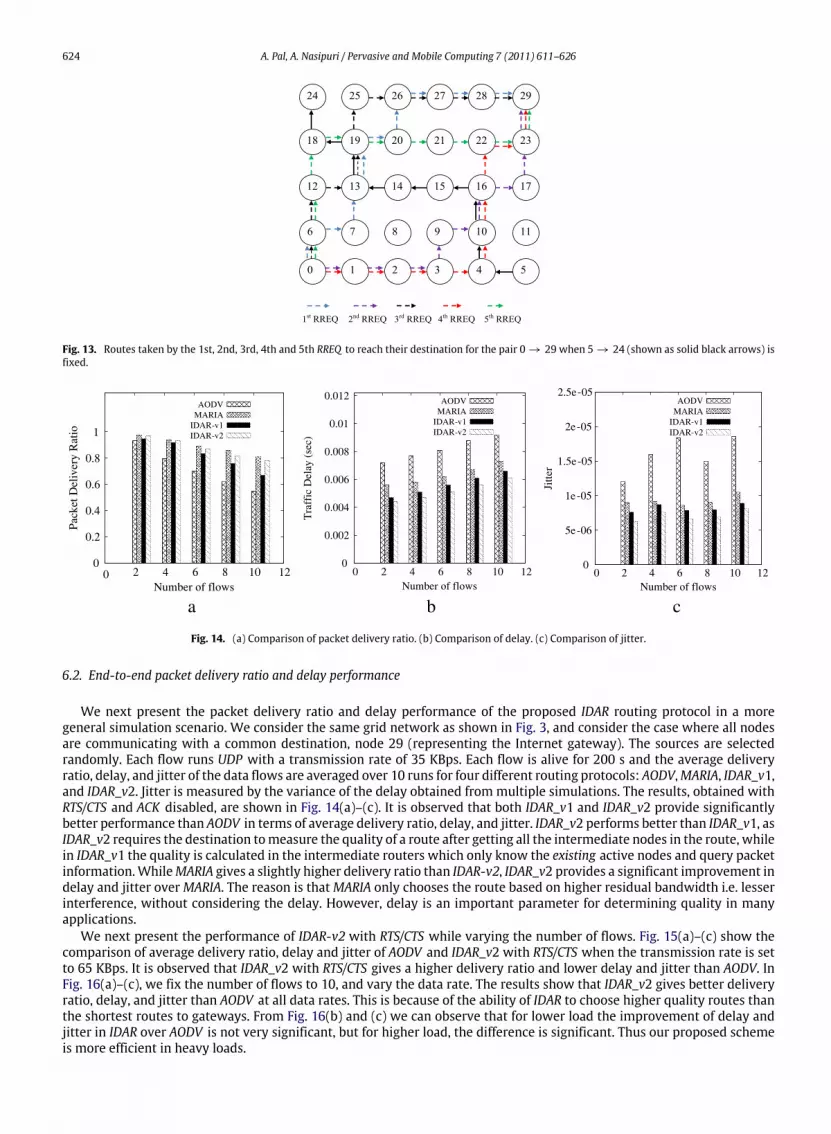
Fig. 14. (a) Comparison of packet delivery ratio. (b) Comparison of delay. (c) Comparison of jitter.
6.2. End-to-end packet delivery ratio and delay performance
We next present the packet delivery ratio and delay performance of the proposed IDAR routing protocol in a moregeneral simulation scenario. We consider the same grid network as shown in Fig. 3, and consider the case where all nodesare communicating with a common destination, node 29 (representing the Internet gateway). The sources are selectedrandomly. Each flow runs UDP with a transmission rate of 35 KBps. Each flow is alive for 200 s and the average deliveryratio, delay, and jitter of the data flows are averaged over 10 runs for four different routing protocols: AODV,MARIA, IDAR_v1,and IDAR_v2. Jitter is measured by the variance of the delay obtained from multiple simulations. The results, obtained withRTS/CTS and ACK disabled, are shown in Fig. 14(a)–(c). It is observed that both IDAR_v1 and IDAR_v2 provide significantlybetter performance than AODV in terms of average delivery ratio, delay, and jitter. IDAR_v2 performs better than IDAR_v1, asIDAR_v2 requires the destination tomeasure the quality of a route after getting all the intermediate nodes in the route, whilein IDAR_v1 the quality is calculated in the intermediate routers which only know the existing active nodes and query packetinformation.WhileMARIA gives a slightly higher delivery ratio than IDAR-v2, IDAR_v2 provides a significant improvement indelay and jitter overMARIA. The reason is thatMARIA only chooses the route based on higher residual bandwidth i.e. lesserinterference, without considering the delay. However, delay is an important parameter for determining quality in manyapplications.
We next present the performance of IDAR-v2 with RTS/CTS while varying the number of flows. Fig. 15(a)–(c) show thecomparison of average delivery ratio, delay and jitter of AODV and IDAR_v2 with RTS/CTS when the transmission rate is setto 65 KBps. It is observed that IDAR_v2 with RTS/CTS gives a higher delivery ratio and lower delay and jitter than AODV. InFig. 16(a)–(c), we fix the number of flows to 10, and vary the data rate. The results show that IDAR_v2 gives better deliveryratio, delay, and jitter than AODV at all data rates. This is because of the ability of IDAR to choose higher quality routes thanthe shortest routes to gateways. From Fig. 16(b) and (c) we can observe that for lower load the improvement of delay andjitter in IDAR over AODV is not very significant, but for higher load, the difference is significant. Thus our proposed schemeis more efficient in heavy loads.

A. Pal, A. Nasipuri / Pervasive and Mobile Computing 7 (2011) 611–626 625
a b c
Fig. 15. (a) Comparison of packet delivery ratio. (b) Comparison of delay. (c) Comparison of jitter.
a b c
Fig. 16. (a) Comparison of packet delivery ratio. (b) Comparison of delay. (c) Comparison of jitter.
Table 4Comparison of packet delivery ratio.
Load (KBps) MARIA IDAR_v2
5 0.988 0.979915 0.969 0.9625 0.945 0.93635 0.923 0.917
Table 5Comparison of delay (s).
Load (KBps) MARIA IDAR_v2
5 0.0176 0.005815 0.0176 0.005825 0.01765 0.005835 0.01769 0.0058
Finally, we take a specific example to demonstrate the potential of IDAR in controlling the end-to-end delay, whichis not achieved in MARIA. We consider the scenario shown in Fig. 17, where node 16 has already established the route16 → 22 → 28 → 29 when node 5 starts looking for a route to 29. In this scenario, because of the existing interferencefrom the nodes on the route from 16 to 29, MARIA chooses a really long route (5 → 4 → 3 → 2 → 1 → 7 → 13 →
19 → 25 → 26 → 27 → 28 → 29), suffering from a very high delay in comparison to the route chosen by IDAR_v2(5 → 11 → 17 → 23 → 29), whose delivery ratio is only slightly smaller. These results are shown in Tables 4 and 5. Thus,the proposed IDAR routing protocol does not sacrifice delay in trying to achieve a high delivery ratio, which is important inmany applications.

626 A. Pal, A. Nasipuri / Pervasive and Mobile Computing 7 (2011) 611–626
Fig. 17. Routes chosen byMARIA and IDAR_v2 when the source–destination pair is 5 → 29 and 16 → 22 → 8 → 29 is the background traffic.
7. Conclusion and future work
Wepropose a quality based routing for wirelessmesh networks to improve the packet delivery and delay performance ofmulti-hop communications. The proposed routing protocol IDAR is interference-aware and relies on a quality metric that isbuilt on offlinemeasurements of characteristics of data packet transmissions in amulti-hop network. IDAR takes two qualityparameters into account: POS and the end-to-end delay. Performance evaluations obtained from simulation experimentsdemonstrate that the proposed routing protocol is effective in improving both the packet delivery and delay performancein multi-hop environments where the route selection is done by a gateway node that has global activity information of thenetwork.
Since the proposed routing protocol relies on precalculated models of POS and delay, it is somehwat constrained by theparameters underwhich suchmodels are based. This includes the assumed channel capacity, the offered transmission loads,etc. Although for the ease of representation, we assumed equal loads for all nodes, in practice loads may differ from node tonode. This can be considered by the gateway node for incorporation into the corresponding quality metric as long as it hasthe models for those loads and the specific load information in the network.
The proposed quality based routing scheme can be extended to a network model that involves multiple gateway nodes,requiring anycast routing. In addition, our future work on this topic includes the extension of this quality based routingapproach to incorporate multiple channels with multiple radios for each mesh router to reduce co-channel interference.
References
[1] I.F. Akyildiz, X. Wang, W. Wang, Wireless mesh networks: a survey, Computer Networks 47 (4) (2005) 445–487.[2] Cuwin webpage, http://www.curwireless.net/.[3] Smesh webpage, http://smesh.org/.[4] Solarmesh webpage, http://owl.mcmaster.ca/todd/SolarMESH/.[5] Wing webpage, http://www.wing-project.org/.[6] A. Pal, S. Adimadhyam, A. Nasipuri, Qosbr: a quality based routing protocol for wireless mesh networks, in: ICDCN, 2010.[7] X. Cheng, P. Mohapatra, S.-J. Lee, S. Banerjee, Maria: interference-aware admission control and qos routing in wireless mesh networks, in: ICC, 2008,
pp. 2865–2870.[8] R. Draves, J. Padhye, B. Zill, Routing in multi-radio, multi-hop wireless mesh networks, in: MOBICOM, 2004, pp. 114–128.[9] D. Passos, D.V. Teixeira, D.C. Muchaluat-saade, L.C.S. Magalhes, C.V.N. Albuquerque, Mesh network performance measurements, in: International
Information and Telecommunication Technologies Symposium, 2006.[10] C.E. Koksal, H. Balakrishnan, Quality-aware routing metrics for time-varying wireless mesh networks, IEEE Journal on Selected Areas in
Communications 24 (11) (2006) 1984–1994.[11] A.P. Subramanian, M.M. Buddhikot, S. Miller, Interference aware routing in multi-radio wireless mesh networks, in: IEEEWorkshop of Wireless Mesh
Networks, 2006, pp. 55–63.[12] V. Kolar, N.B. Abu-Ghazaleh, A multi-commodity flow approach for globally aware routing in multi-hop wireless networks, in: PerCom, 2006,
pp. 308–317.[13] E. Carlson, H. Karl, A. Wolisz, C. Prehofer, Distributed allocation of time slots for real-time traffic in a wireless multi-hop network, in: European
Wireless, 2004.[14] L. Romdhani, C. Bonnet, Cross-layer qos routing framework for wireless mesh networks, in: International Conference on Wireless and Mobile
Communications, 2008, pp. 382–388.[15] Z. Ke, L. Li, Q. Sun, N. Chen, A qos multicast routing algorithm for wireless mesh networks, in: SNPD vol. 1, 2007, pp. 835–840.[16] V. Kone, S. Das, B.Y. Zhao, H. Zheng, Quorum — quality of service in wireless mesh networks, MONET 12 (5–6) (2007) 358–369.[17] Q. Xue, A. Ganz, Qos routing for mesh-based wireless lans, IJWIN 9 (3) (2002) 179–190.[18] C.H. Liu, K.K. Leung, A. Gkelias, A novel cross-layer qos routing algorithm for wireless mesh networks, in: Information Networking, 2008. ICOIN 2008.
International Conference on, 2008, pp. 1–5.[19] K. han Kim, K.G. Shin, On accurate measurement of link quality in multi-hop wireless mesh networks, in: In ACMMobiCom 06, 2006, pp. 38–49.[20] The network simulator — ns-2, http://www.isi.edu/nsnam/ns/.


