Embed Size (px)
Citation preview
72 Warner Electric 800-825-6544 ......P-1264-WE 12/15
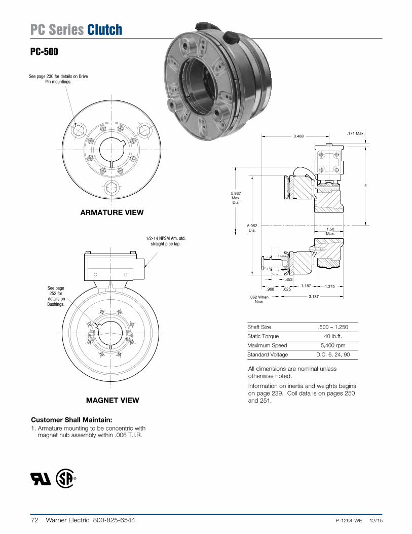
Shaft Size .500 – 1.250
Static Torque 40 lb.ft.
Maximum Speed 5,400 rpm
Standard Voltage D.C. 6, 24, 90
Customer Shall Maintain:1. Armature mounting to be concentric with
magnet hub assembly within .006 T.I.R.
ARMATURE VIEW
MAGNET VIEW
.171 Max.
4
1.50 Max.
.625.968
.062 When New
5.937 Max. Dia.
5.062 Dia.
3.468
.453
1.187 1.375
3.187
See page 230 for details on Drive Pin mountings.
See page 252 for
details on Bushings.
1/2-14 NPSM Am. std. straight pipe tap.
All dimensions are nominal unless otherwise noted.
Information on inertia and weights begins on page 239. Coil data is on pages 250 and 251.
PC Series ClutchPC-500
73.P-1264-WE 12/15..... Warner Electric 800-825-6544
4
4-1
7
3
1-2
1-1
2-1
2
1(Shipped Assembled)
5
6
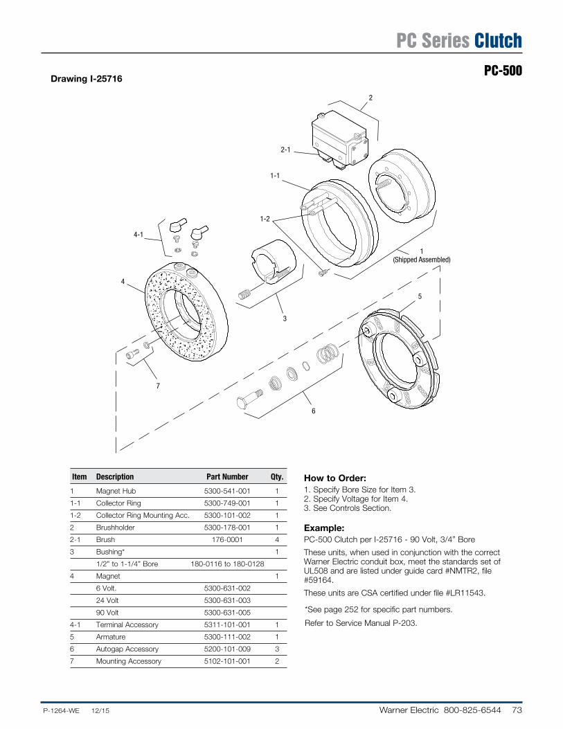
How to Order:1. Specify Bore Size for Item 3.2. Specify Voltage for Item 4.3. See Controls Section.
Example:PC-500 Clutch per I-25716 - 90 Volt, 3/4” Bore
These units, when used in conjunction with the correct Warner Electric conduit box, meet the standards set of UL508 and are listed under guide card #NMTR2, file #59164.
These units are CSA certified under file #LR11543.
Item Description Part Number Qty.
1 Magnet Hub 5300-541-001 1
1-1 Collector Ring 5300-749-001 1
1-2 Collector Ring Mounting Acc. 5300-101-002 1
2 Brushholder 5300-178-001 1
2-1 Brush 176-0001 4
3 Bushing* 1
1/2” to 1-1/4” Bore 180-0116 to 180-0128
4 Magnet 1
6 Volt. 5300-631-002
24 Volt 5300-631-003
90 Volt 5300-631-005
4-1 Terminal Accessory 5311-101-001 1
5 Armature 5300-111-002 1
6 Autogap Accessory 5200-101-009 3
7 Mounting Accessory 5102-101-001 2
* See page 252 for specific part numbers.
Refer to Service Manual P-203.
Drawing I-25716
PC Series ClutchPC-500
74 Warner Electric 800-825-6544 ......P-1264-WE 12/15
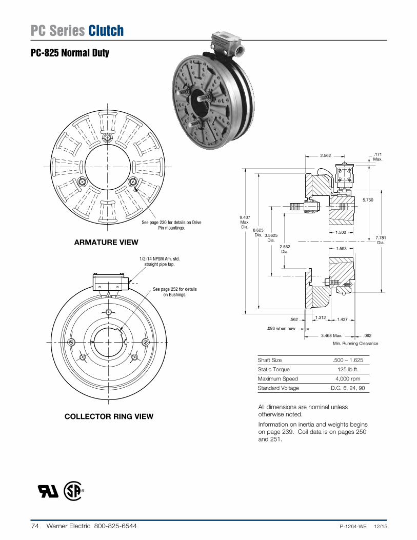
Shaft Size .500 – 1.625
Static Torque 125 lb.ft.
Maximum Speed 4,000 rpm
Standard Voltage D.C. 6, 24, 90
ARMATURE VIEW
COLLECTOR RING VIEW
.062
.171 Max.
5.750
1.312
.093 when new
.562
Min. Running Clearance
2.562
9.437 Max. Dia.
8.625 Dia. 3.5625
Dia.
2.562 Dia.
1.5007.781 Dia.
1.593
1.437
3.468 Max.
See page 230 for details on Drive Pin mountings.
See page 252 for details on Bushings.
1/2-14 NPSM Am. std. straight pipe tap.
All dimensions are nominal unless otherwise noted.
Information on inertia and weights begins on page 239. Coil data is on pages 250 and 251.
PC Series ClutchPC-825 Normal Duty
75.P-1264-WE 12/15..... Warner Electric 800-825-6544
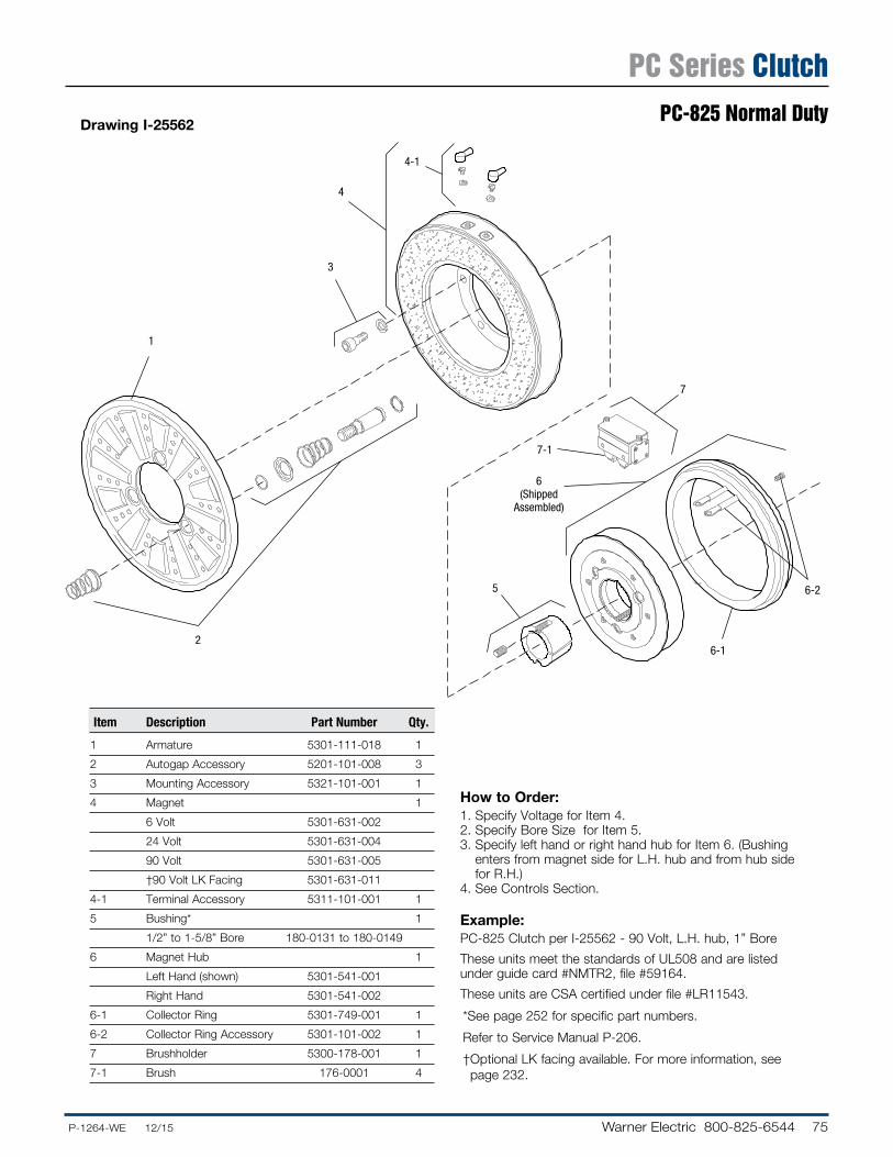
Drawing I-25562
How to Order:1. Specify Voltage for Item 4.2. Specify Bore Size for Item 5.3. Specify left hand or right hand hub for Item 6. (Bushing
enters from magnet side for L.H. hub and from hub side for R.H.)
4. See Con trols Section.
Example:PC-825 Clutch per I-25562 - 90 Volt, L.H. hub, 1” Bore
These units meet the standards of UL508 and are listed under guide card #NMTR2, file #59164.
These units are CSA certified under file #LR11543.
1
3
4
4-1
2
6(Shipped
Assembled)
7-1
7
5
6-1
6-2
Item Description Part Number Qty.
1 Armature 5301-111-018 1
2 Autogap Accessory 5201-101-008 3
3 Mounting Accessory 5321-101-001 1
4 Magnet 1
6 Volt 5301-631-002
24 Volt 5301-631-004
90 Volt 5301-631-005
†90 Volt LK Facing 5301-631-011
4-1 Terminal Accessory 5311-101-001 1
5 Bushing* 1
1/2” to 1-5/8” Bore 180-0131 to 180-0149
6 Magnet Hub 1
Left Hand (shown) 5301-541-001
Right Hand 5301-541-002
6-1 Collector Ring 5301-749-001 1
6-2 Collector Ring Accessory 5301-101-002 1
7 Brushholder 5300-178-001 1
7-1 Brush 176-0001 4
* See page 252 for specific part numbers.
Refer to Service Manual P-206.
† Optional LK facing available. For more information, see page 232.
PC Series ClutchPC-825 Normal Duty
76 Warner Electric 800-825-6544 ......P-1264-WE 12/15
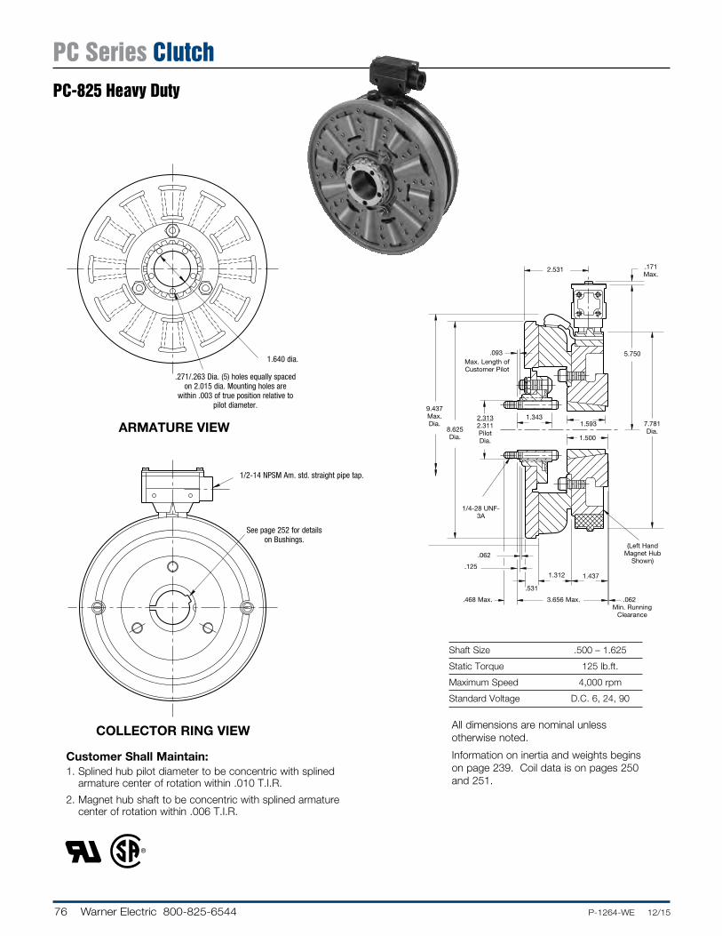
Shaft Size .500 – 1.625
Static Torque 125 lb.ft.
Maximum Speed 4,000 rpm
Standard Voltage D.C. 6, 24, 90
COLLECTOR RING VIEW
ARMATURE VIEW
Customer Shall Maintain:1. Splined hub pilot diameter to be concentric with splined
armature center of rotation within .010 T.I.R.
2. Magnet hub shaft to be concentric with splined armature center of rotation within .006 T.I.R.
1.3431.593
5.750.093
.062
.171 Max.
.125
.468 Max.
.531
1.312 1.437
.062
1/4-28 UNF-3A
Max. Length of Customer Pilot
(Left Hand Magnet Hub
Shown)
Min. Running Clearance
9.437 Max. Dia.
8.625 Dia.
2.313 2.311 Pilot Dia. 1.500
7.781 Dia.
2.531
3.656 Max.
See page 252 for details on Bushings.
1/2-14 NPSM Am. std. straight pipe tap.
.271/.263 Dia. (5) holes equally spaced on 2.015 dia. Mounting holes are
within .003 of true po si tion relative to pilot diameter.
1.640 dia.
All dimensions are nominal unless otherwise noted.
Information on inertia and weights begins on page 239. Coil data is on pages 250 and 251.
PC Series ClutchPC-825 Heavy Duty
77.P-1264-WE 12/15..... Warner Electric 800-825-6544
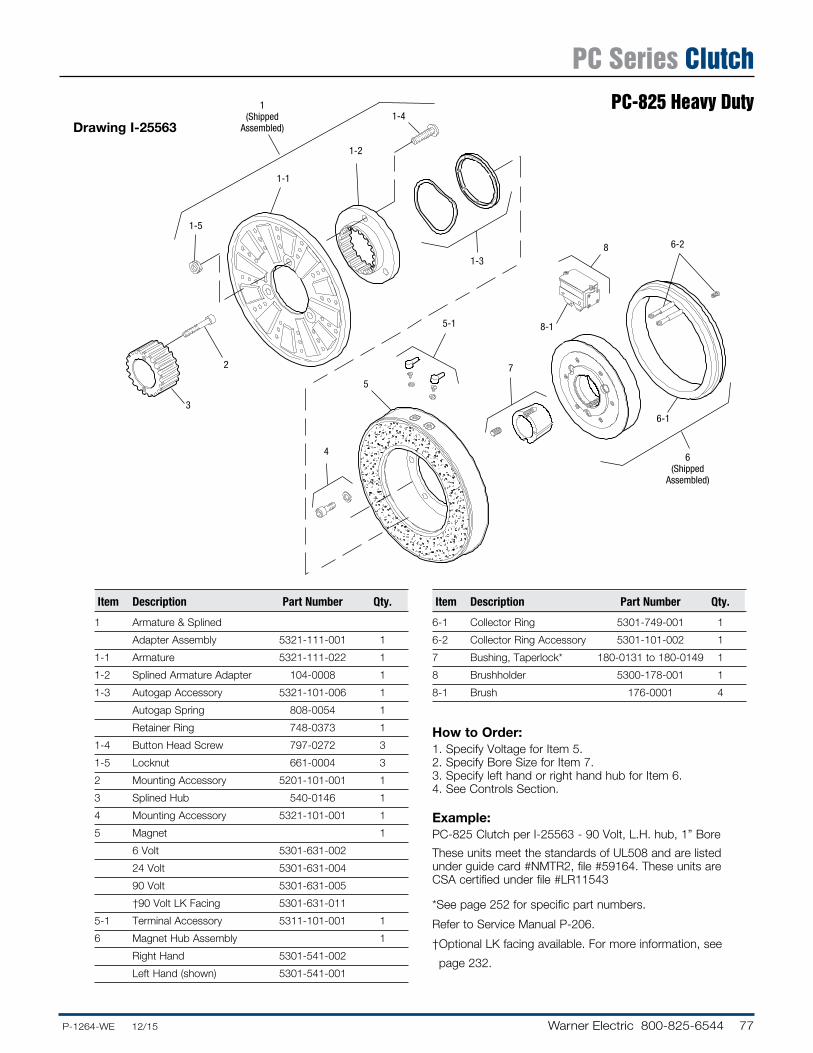
Drawing I-25563
How to Order:1. Specify Voltage for Item 5.2. Specify Bore Size for Item 7.3. Specify left hand or right hand hub for Item 6.4. See Controls Section.
Example:PC-825 Clutch per I-25563 - 90 Volt, L.H. hub, 1” Bore
These units meet the standards of UL508 and are listed under guide card #NMTR2, file #59164. These units are CSA certified under file #LR11543
* See page 252 for specific part numbers.
Refer to Service Manual P-206.
† Optional LK facing available. For more information, see
page 232.
1(Shipped
Assembled)
1-5
1-1
1-2
1-4
3
2
1-3
4
5
5-1
7
8-1
6-1
6-28
6(Shipped
Assembled)
Item Description Part Number Qty.
1 Armature & Splined
Adapter Assembly 5321-111-001 1
1-1 Armature 5321-111-022 1
1-2 Splined Armature Adapter 104-0008 1
1-3 Autogap Accessory 5321-101-006 1
Autogap Spring 808-0054 1
Retainer Ring 748-0373 1
1-4 Button Head Screw 797-0272 3
1-5 Locknut 661-0004 3
2 Mounting Accessory 5201-101-001 1
3 Splined Hub 540-0146 1
4 Mounting Accessory 5321-101-001 1
5 Magnet 1
6 Volt 5301-631-002
24 Volt 5301-631-004
90 Volt 5301-631-005
†90 Volt LK Facing 5301-631-011
5-1 Terminal Accessory 5311-101-001 1
6 Magnet Hub Assembly 1
Right Hand 5301-541-002
Left Hand (shown) 5301-541-001
Item Description Part Number Qty.
6-1 Collector Ring 5301-749-001 1
6-2 Collector Ring Accessory 5301-101-002 1
7 Bushing, Taperlock* 180-0131 to 180-0149 1
8 Brushholder 5300-178-001 1
8-1 Brush 176-0001 4
PC Series ClutchPC-825 Heavy Duty
78 Warner Electric 800-825-6544 ......P-1264-WE 12/15
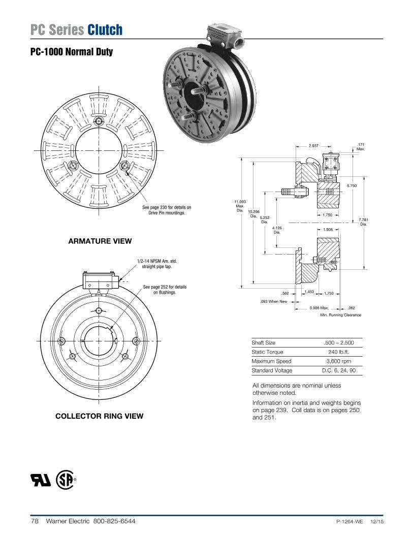
Shaft Size .500 – 2.500
Static Torque 240 lb.ft.
Maximum Speed 3,600 rpm
Standard Voltage D.C. 6, 24, 90
ARMATURE VIEW
COLLECTOR RING VIEW
See page 230 for details on Drive Pin mountings.
See page 252 for details on Bushings.
1/2-14 NPSM Am. std. straight pipe tap.
.062
.171 Max.
5.750
1.453
.093 When New
.562
Min. Running Clearance
2.937
11.093 Max. Dia. 10.296
Dia. 5.252 Dia.
4.125 Dia.
1.7507.781 Dia.
1.906
1.750
3.906 Max.
All dimensions are nominal unless otherwise noted.
Information on inertia and weights begins on page 239. Coil data is on pages 250 and 251.
PC Series ClutchPC-1000 Normal Duty
79.P-1264-WE 12/15..... Warner Electric 800-825-6544
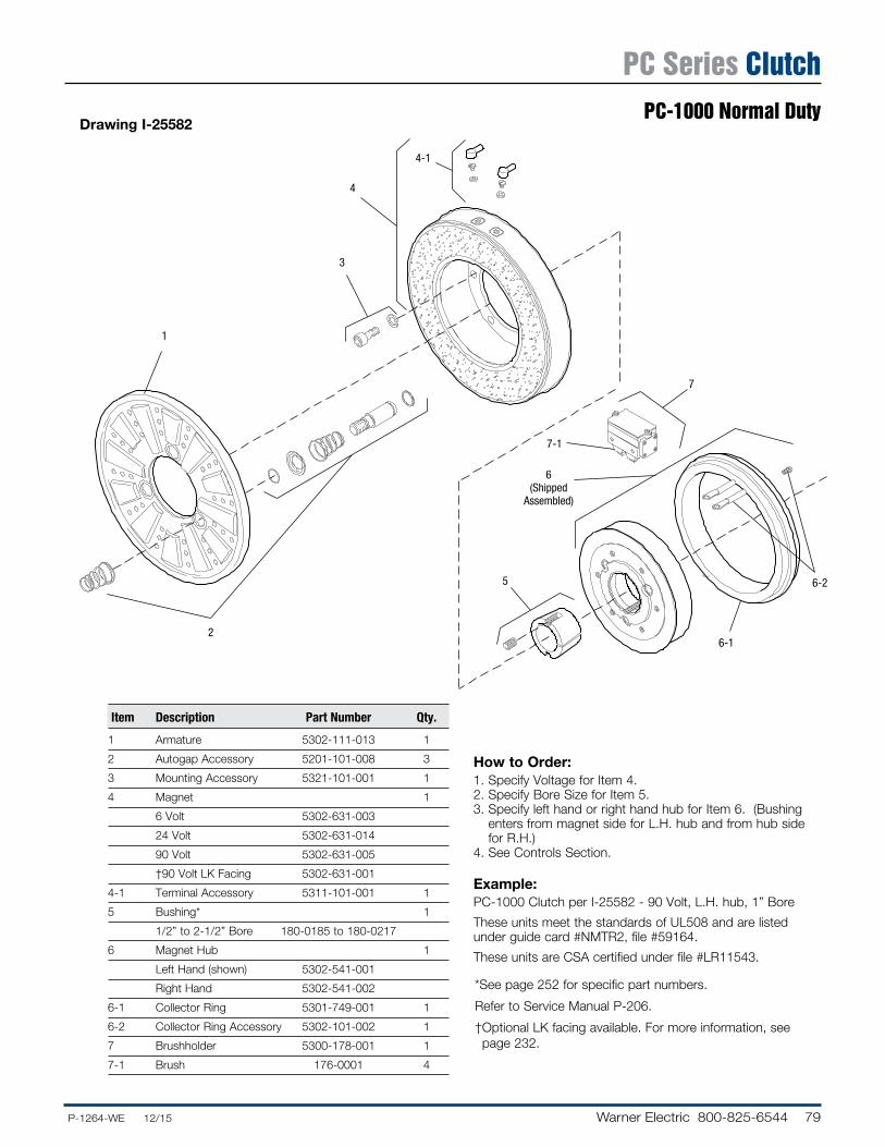
Drawing I-25582
How to Order:1. Specify Voltage for Item 4.2. Specify Bore Size for Item 5.3. Specify left hand or right hand hub for Item 6. (Bush ing
enters from magnet side for L.H. hub and from hub side for R.H.)
4. See Controls Section.
Example:PC-1000 Clutch per I-25582 - 90 Volt, L.H. hub, 1” Bore
These units meet the standards of UL508 and are listed under guide card #NMTR2, file #59164.
These units are CSA certified under file #LR11543.
1
3
4
4-1
2
6(Shipped
Assembled)
7-1
7
5
6-1
6-2
Item Description Part Number Qty.
1 Armature 5302-111-013 1
2 Autogap Accessory 5201-101-008 3
3 Mounting Accessory 5321-101-001 1
4 Magnet 1
6 Volt 5302-631-003
24 Volt 5302-631-014
90 Volt 5302-631-005
†90 Volt LK Facing 5302-631-001
4-1 Terminal Accessory 5311-101-001 1
5 Bushing* 1
1/2” to 2-1/2” Bore 180-0185 to 180-0217
6 Magnet Hub 1
Left Hand (shown) 5302-541-001
Right Hand 5302-541-002
6-1 Collector Ring 5301-749-001 1
6-2 Collector Ring Accessory 5302-101-002 1
7 Brushholder 5300-178-001 1
7-1 Brush 176-0001 4
* See page 252 for specific part numbers.
Refer to Service Manual P-206.
† Optional LK facing available. For more information, see page 232.
PC Series ClutchPC-1000 Normal Duty
80 Warner Electric 800-825-6544 ......P-1264-WE 12/15
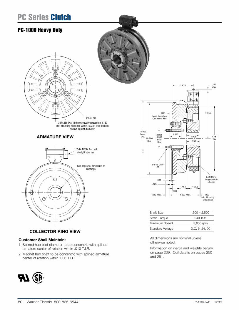
Shaft Size .500 – 2.500
Static Torque 240 lb.ft.
Maximum Speed 3,600 rpm
Standard Voltage D.C. 6, 24, 90COLLECTOR RING VIEW
ARMATURE VIEW
Customer Shall Maintain:1. Splined hub pilot diameter to be concentric with splined
armature center of rotation within .010 T.I.R.
2. Magnet hub shaft to be concentric with splined armature center of rotation within .006 T.I.R.
See page 252 for details on Bushings.
1/2-14 NPSM Am. std. straight pipe tap.
.397/.388 Dia. (3) holes equally spaced on 3.187 dia. Mounting holes are within .003 of true po si tion
relative to pilot diameter.
2.562 dia.
1.3751.906
5.750.093
.062
.171 Max.
.125
.843 Max.
.500
1.453 1.750
.062
3/8-16 UNF-2A
Max. Length of Customer Pilot
(Left Hand Magnet Hub
Shown)
Min. Running Clearance
11.093 Max. Dia.
10.296 Dia.
4.001 3.999 Pilot Dia. 1.750
7.781 Dia.
2.875
4.093 Max.
All dimensions are nominal unless otherwise noted.
Information on inertia and weights begins on page 239. Coil data is on pages 250 and 251.
PC Series ClutchPC-1000 Heavy Duty
81.P-1264-WE 12/15..... Warner Electric 800-825-6544
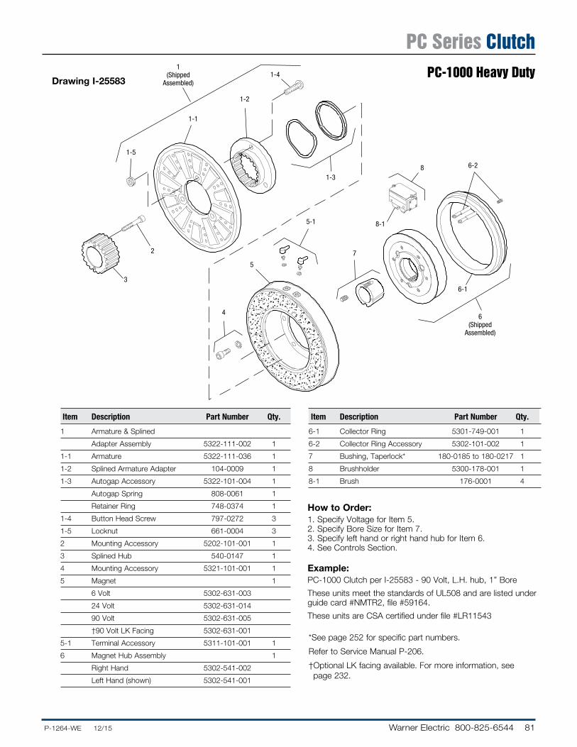
Drawing I-25583
How to Order:1. Specify Voltage for Item 5.2. Specify Bore Size for Item 7.3. Specify left hand or right hand hub for Item 6.4. See Controls Section.
Example:PC-1000 Clutch per I-25583 - 90 Volt, L.H. hub, 1” Bore
These units meet the standards of UL508 and are listed under guide card #NMTR2, file #59164.
These units are CSA certified under file #LR11543
1(Shipped
Assembled)
1-5
1-1
1-2
1-4
3
2
1-3
4
5
5-1
7
8-1
6-1
6-28
6(Shipped
Assembled)
Item Description Part Number Qty.
1 Armature & Splined
Adapter Assembly 5322-111-002 1
1-1 Armature 5322-111-036 1
1-2 Splined Armature Adapter 104-0009 1
1-3 Autogap Accessory 5322-101-004 1
Autogap Spring 808-0061 1
Retainer Ring 748-0374 1
1-4 Button Head Screw 797-0272 3
1-5 Locknut 661-0004 3
2 Mounting Accessory 5202-101-001 1
3 Splined Hub 540-0147 1
4 Mounting Accessory 5321-101-001 1
5 Magnet 1
6 Volt 5302-631-003
24 Volt 5302-631-014
90 Volt 5302-631-005
†90 Volt LK Facing 5302-631-001
5-1 Terminal Accessory 5311-101-001 1
6 Magnet Hub Assembly 1
Right Hand 5302-541-002
Left Hand (shown) 5302-541-001
Item Description Part Number Qty.
6-1 Collector Ring 5301-749-001 1
6-2 Collector Ring Accessory 5302-101-002 1
7 Bushing, Taperlock* 180-0185 to 180-0217 1
8 Brushholder 5300-178-001 1
8-1 Brush 176-0001 4
* See page 252 for specific part numbers.
Refer to Service Manual P-206.
† Optional LK facing available. For more information, see page 232.
PC Series ClutchPC-1000 Heavy Duty
82 Warner Electric 800-825-6544 ......P-1264-WE 12/15
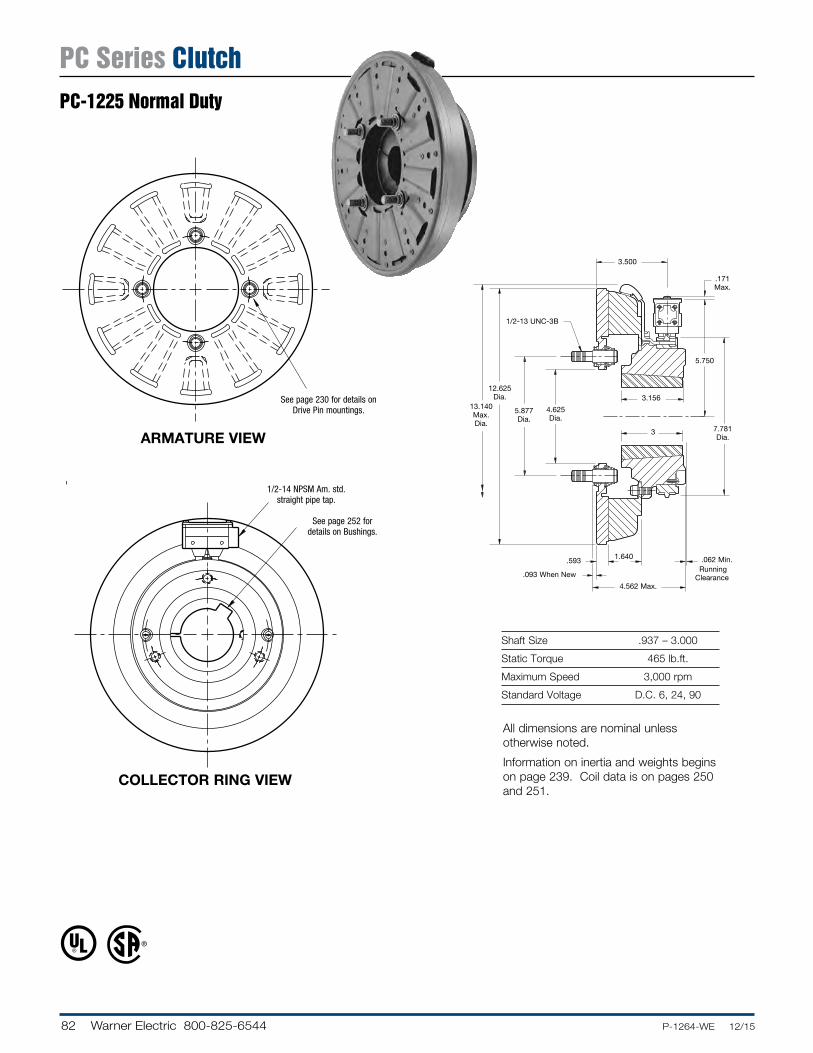
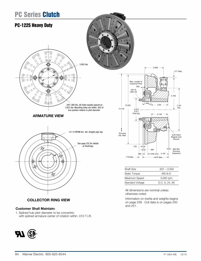
Shaft Size .937 – 3.000
Static Torque 465 lb.ft.
Maximum Speed 3,000 rpm
Standard Voltage D.C. 6, 24, 90
COLLECTOR RING VIEW
ARMATURE VIEW 3
5.750
.171 Max.
.093 When New
.062 Min.1.640.593
1/2-13 UNC-3B
Running Clear ance
4.562 Max.
13.140 Max. Dia.
12.625 Dia.
5.877 Dia.
4.625 Dia.
3.500
7.781 Dia.
3.156
See page 252 for details on Bushings.
1/2-14 NPSM Am. std. straight pipe tap.
See page 230 for de tails on Drive Pin mountings.
All dimensions are nominal unless otherwise noted.
Information on inertia and weights begins on page 239. Coil data is on pages 250 and 251.
PC Series ClutchPC-1225 Normal Duty
83.P-1264-WE 12/15..... Warner Electric 800-825-6544
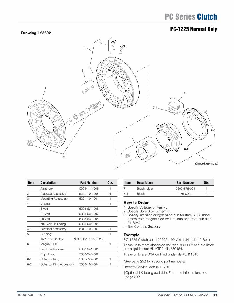
Drawing I-25602
How to Order:1. Specify Voltage for Item 4.2. Specify Bore Size for Item 5.3. Specify left hand or right hand hub for Item 6. (Bushing
enters from magnet side for L.H. hub and from hub side for R.H.)
4. See Con trols Section.
Example:PC-1225 Clutch per I-25602 - 90 Volt, L.H. hub, 1” Bore
These units meet standards set forth in UL508 and are listed under guide card #NMTR2, file #59164.
These units are CSA certified under file #LR11543
* See page 252 for specific part numbers.
Refer to Service Manual P-207.
† Optional LK facing available. For more information, see page 232.
1
2
3
4
4-1
5
7-1
6-1
6-2
6(Shipped Assembled)
7
Item De scrip tion Part Number Qty.
1 Armature 5303-111-009 1
2 Autogap Accessory 5201-101-008 4
3 Mounting Accessory 5321-101-001 1
4 Magnet 1
6 Volt 5303-631-005
24 Volt 5303-631-007
90 Volt 5303-631-008
†90 Volt LK Facing 5303-631-001
4-1 Terminal Accessory 5311-101-001 1
5 Bushing* 1
15/16” to 3” Bore 180-0262 to 180-0295
6 Magnet Hub 1
Left Hand (shown) 5303-541-001
Right Hand 5303-541-002
6-1 Collector Ring 5301-749-001 1
6-2 Collector Ring Accessory 5303-101-004 1
Item De scrip tion Part Number Qty.
7 Brushholder 5300-178-001 1
7-1 Brush 176-0001 4
PC Series ClutchPC-1225 Normal Duty
84 Warner Electric 800-825-6544 ......P-1264-WE 12/15
Shaft Size .937 – 3.000
Static Torque 465 lb.ft.
Maximum Speed 3,000 rpm
Standard Voltage D.C. 6, 24, 90
Customer Shall Maintain:1. Splined hub pilot diameter to be concentric
with splined armature center of rotation within .010 T.I.R.
ARMATURE VIEW
COLLECTOR RING VIEW
1.500
4.3134.311
Pilot Dia.
5.750
.093
12.625
Running Dia. Max.
Max. Length of Customer Pilot
13.140
.171 Max.
.062
.125
.718 Max.
.062 Min. Running
Clearance
3/8-16 UNC-2A
(Left Hand Magnet Hub
Shown)
1.640 2.187
4.875 Max.
.562
3.156
7.781 Dia.
3.00
3.468
See page 252 for details on Bush ings.
1/2-14 NPSM Am. std. straight pipe tap.
All dimensions are nominal unless otherwise noted.
Information on inertia and weights begins on page 239. Coil data is on pages 250 and 251.
.397/.388 Dia. (8) holes equally spaced on 3.625 dia. Mounting holes are within .003 of
true po si tion relative to pilot diameter.
3.062 dia.
PC Series ClutchPC-1225 Heavy Duty
85.P-1264-WE 12/15..... Warner Electric 800-825-6544
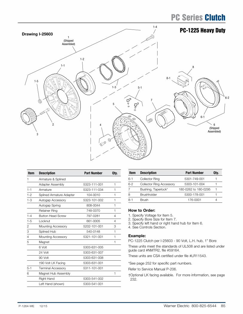
Drawing I-25603
How to Order:1. Specify Voltage for Item 5.2. Specify Bore Size for Item 7.3. Specify left hand or right hand hub for Item 6.4. See Con trols Section.
Example:PC-1225 Clutch per I-25603 - 90 Volt, L.H. hub, 1” Bore
These units meet the standards of UL508 and are listed under guide card #NMTR2, file #59164.
These units are CSA certified under file #LR11543.
* See page 252 for specific part numbers.
Refer to Service Manual P-206.
† Optional LK facing available. For more information, see page 232.
1(Shipped
Assembled)
1-5
3
2
1-1
1-2
1-3 5-1
4
57
8-1
8
6-1
6(Shipped
Assembled)
6-2
1-4
Item De scrip tion Part Number Qty.
1 Armature & Splined
Adapter Assembly 5323-111-001 1
1-1 Armature 5323-111-034 1
1-2 Splined Armature Adapter 104-0010 1
1-3 Autogap Accessory 5323-101-002 1
Autogap Spring 808-0044 1
Retainer Ring 748-0370 1
1-4 Button Head Screw 797-0281 4
1-5 Locknut 661-0005 4
2 Mounting Accessory 5202-101-001 3
3 Splined Hub 540-0148 1
4 Mounting Accessory 5321-101-001 1
5 Magnet 1
6 Volt 5303-631-005
24 Volt 5303-631-007
90 Volt 5303-631-008
†90 Volt LK Facing 5303-631-001
5-1 Terminal Accessory 5311-101-001
6 Magnet Hub Assembly 1
Right Hand 5303-541-002
Left Hand (shown) 5303-541-001
Item De scrip tion Part Number Qty.
6-1 Collector Ring 5301-749-001 1
6-2 Collector Ring Accessory 5303-101-004 1
7 Bushing, Taperlock* 180-0262 to 180-0295 1
8 Brushholder 5300-178-001 1
8-1 Brush 176-0001 4
PC Series ClutchPC-1225 Heavy Duty
86 Warner Electric 800-825-6544 ......P-1264-WE 12/15
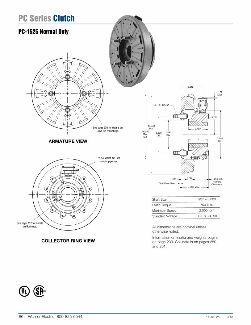
Shaft Size .937 – 3.000
Static Torque 700 lb.ft.
Maximum Speed 2,000 rpm
Standard Voltage D.C. 6, 24, 90
ARMATURE VIEW
COLLECTOR RING VIEW
See page 230 for de tails on Drive Pin mountings.
3
5.750
.171 Max.
.093 When New
.062 Min.1.750.593
1/2-13 UNC-3B
Running Clear ance
4.796 Max.
16.250 Max. Dia.
15.578 Dia.
8.500 Dia.
7.093 Dia.
3.812
7.781 Dia.
3.187
See page 252 for details on Bushings.
1/2-14 NPSM Am. std. straight pipe tap.
All dimensions are nominal unless otherwise noted.
Information on inertia and weights begins on page 239. Coil data is on pages 250 and 251.
PC Series ClutchPC-1525 Normal Duty
87.P-1264-WE 12/15..... Warner Electric 800-825-6544
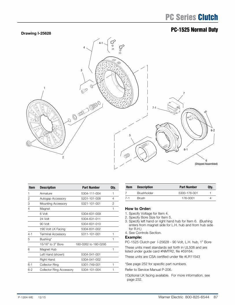
Drawing I-25628
How to Order:1. Specify Voltage for Item 4.2. Specify Bore Size for Item 5.3. Specify left hand or right hand hub for Item 6. (Bushing
enters from magnet side for L.H. hub and from hub side for R.H.)
4. See Con trols Section.Example:PC-1525 Clutch per I-25628 - 90 Volt, L.H. hub, 1” Bore
These units meet standards set forth in UL508 and are listed under guide card #NMTR2, file #59164.
These units are CSA certified under file #LR11543
* See page 252 for specific part numbers.
Refer to Service Manual P-206.
† Optional LK facing available. For more information, see page 232.
1
2
3
4
4-1
5
7-1
6-1
6-2
6(Shipped Assembled)
7
Item De scrip tion Part Number Qty.
1 Armature 5304-111-004 1
2 Autogap Accessory 5201-101-008 4
3 Mounting Accessory 5321-101-001 2
4 Magnet 1
6 Volt 5304-631-009
24 Volt 5304-631-011
90 Volt 5304-631-010
†90 Volt LK Facing 5304-631-002
4-1 Terminal Accessory 5311-101-001 1
5 Bushing* 1
15/16” to 3” Bore 180-0262 to 180-0295
6 Magnet Hub 1
Left Hand (shown) 5304-541-001
Right Hand 5304-541-002
6-1 Collector Ring 5301-749-001 1
6-2 Collector Ring Accessory 5304-101-004 1
Item De scrip tion Part Number Qty.
7 Brushholder 5300-178-001 1
7-1 Brush 176-0001 4
PC Series ClutchPC-1525 Normal Duty

88 Warner Electric 800-825-6544 ......P-1264-WE 12/15
Shaft Size .937 – 3.000
Static Torque 700 lb.ft.
Maximum Speed 2,000 rpm
Standard Voltage D.C. 6, 24, 90
Customer Shall Maintain:1. Splined hub pilot diameter to be concentric
with splined armature center of rotation within .010 T.I.R.
ARMATURE VIEW
COLLECTOR RING VIEW
1.500
4.3134.311
Pilot Dia.
5.750
.093
15.578
Running Dia. Max.
Max. Length of Customer Pilot
16.250
.171 Max.
.062
.125
.718 Max.
.062 Min. Running
Clearance
3/8-16 UNC-2A
(Left Hand Magnet Hub
Shown)
1.750 2.312
5.109 Max.
.562
3.187
7.781 Dia.
3.00
3.781
.397/.388 Dia. (8) holes (hub) equally spaced on 3.625 dia.
Mounting holes are within .003 of true po si tion relative to pilot
diameter.
3.062 dia.
See page 252 for details on Bush ings.
1/2-14 NPSM Am. std. straight pipe tap.
All dimensions are nominal unless otherwise noted.
Information on inertia and weights begins on page 239. Coil data is on pages 250 and 251.
PC Series ClutchPC-1525 Heavy Duty
89.P-1264-WE 12/15..... Warner Electric 800-825-6544
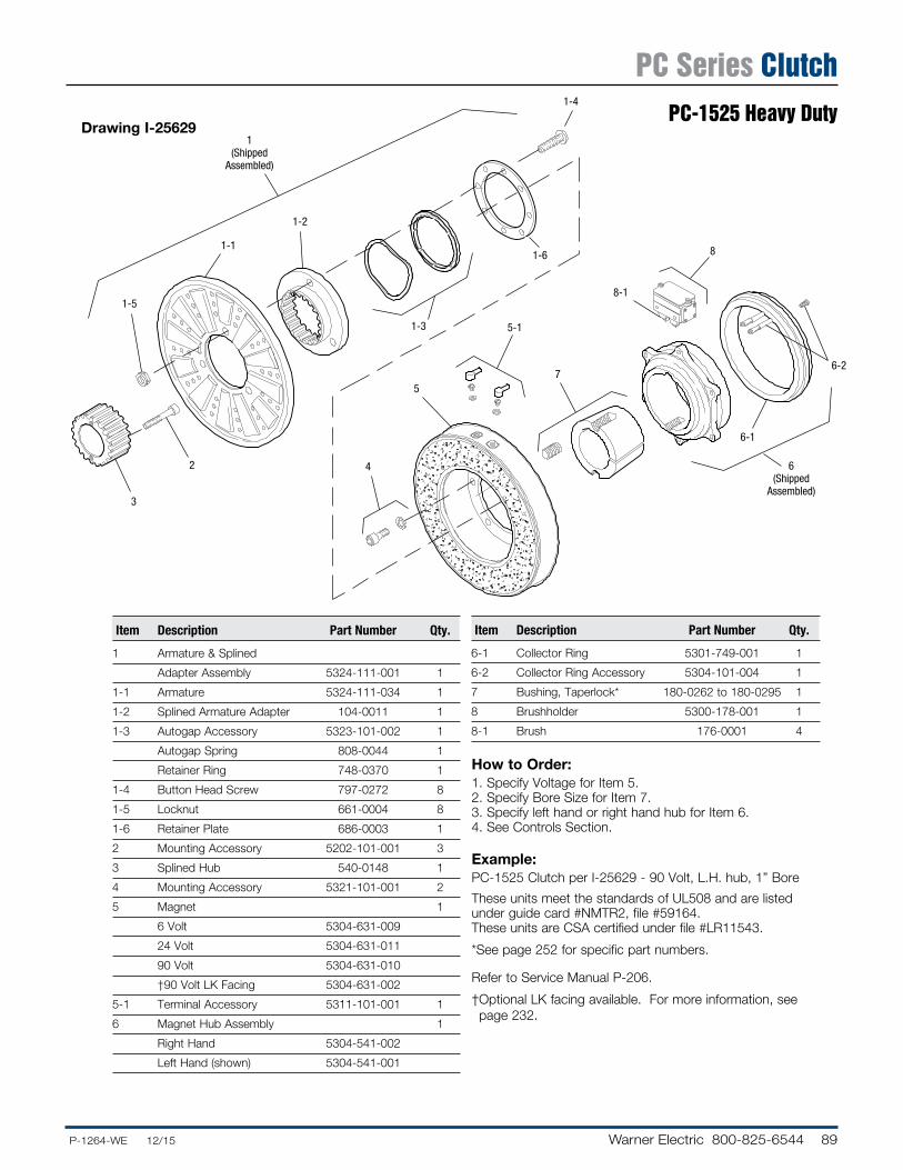
Drawing I-256291
(ShippedAssembled)
1-5
3
2
1-11-6
1-2
1-3 5-1
4
57
8-1
8
6-1
6(Shipped
Assembled)
6-2
1-4
How to Order:1. Specify Voltage for Item 5.2. Specify Bore Size for Item 7.3. Specify left hand or right hand hub for Item 6.4. See Con trols Section.
Example:PC-1525 Clutch per I-25629 - 90 Volt, L.H. hub, 1” Bore
These units meet the standards of UL508 and are listed under guide card #NMTR2, file #59164. These units are CSA certified under file #LR11543.
* See page 252 for specific part numbers.
Refer to Service Manual P-206.
† Optional LK facing available. For more information, see page 232.
Item De scrip tion Part Number Qty.
1 Armature & Splined
Adapter Assembly 5324-111-001 1
1-1 Armature 5324-111-034 1
1-2 Splined Armature Adapter 104-0011 1
1-3 Autogap Accessory 5323-101-002 1
Autogap Spring 808-0044 1
Retainer Ring 748-0370 1
1-4 Button Head Screw 797-0272 8
1-5 Locknut 661-0004 8
1-6 Retainer Plate 686-0003 1
2 Mounting Accessory 5202-101-001 3
3 Splined Hub 540-0148 1
4 Mounting Accessory 5321-101-001 2
5 Magnet 1
6 Volt 5304-631-009
24 Volt 5304-631-011
90 Volt 5304-631-010
†90 Volt LK Facing 5304-631-002
5-1 Terminal Accessory 5311-101-001 1
6 Magnet Hub Assembly 1
Right Hand 5304-541-002
Left Hand (shown) 5304-541-001
Item De scrip tion Part Number Qty.
6-1 Collector Ring 5301-749-001 1
6-2 Collector Ring Accessory 5304-101-004 1
7 Bushing, Taperlock* 180-0262 to 180-0295 1
8 Brushholder 5300-178-001 1
8-1 Brush 176-0001 4
PC Series ClutchPC-1525 Heavy Duty


