Embed Size (px)
Citation preview
Date of issue: 03/01/2017 GB Revision: 1 24/10/2017 GB U:\EngUsers\ProduktDoku\1AAA_Einbauerklärung_Montage-und Wartungsanleitung_Konformitätserklärung\1AAA_Montage- und Wartungsanleitungen\Orginal_Worddatei\M1070E_1_RIZ_RINZ_RIZ..G1G2_RIZ..G2G7_RINZ..G5G5_RIZ..G2G3_RIZ..G3G4_RIZ..ESG2_RIZ..ELG2.docx
Assembly and Maintenance Manual
Types RIZ/ RINZ/ RIZ..G1G2/ RIZ..G2G7/
RINZ..G5G5/ RIZ..G2G3/ RIZ..G3G4/
RIZ..ESG2/ RIZ..ELG2
Hatschekstr. 36 69126 Heidelberg Germany Phone +49(0)6221 30470 Phone +49(0)6221 304731 [email protected] www.stieber.de
Stieber Clutch Page 2/36
M1070E_1 Assembly and maintenance manual
WARNING
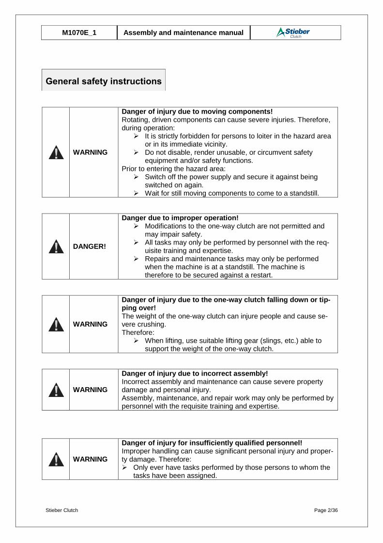
Danger of injury due to moving components! Rotating, driven components can cause severe injuries. Therefore, during operation:
It is strictly forbidden for persons to loiter in the hazard area or in its immediate vicinity.
Do not disable, render unusable, or circumvent safety equipment and/or safety functions.
Prior to entering the hazard area: Switch off the power supply and secure it against being
switched on again. Wait for still moving components to come to a standstill.
DANGER!
Danger due to improper operation! Modifications to the one-way clutch are not permitted and
may impair safety. All tasks may only be performed by personnel with the req-
uisite training and expertise. Repairs and maintenance tasks may only be performed
when the machine is at a standstill. The machine is therefore to be secured against a restart.
WARNING
Danger of injury due to the one-way clutch falling down or tip-ping over! The weight of the one-way clutch can injure people and cause se-vere crushing. Therefore:
When lifting, use suitable lifting gear (slings, etc.) able to support the weight of the one-way clutch.
WARNING
Danger of injury due to incorrect assembly! Incorrect assembly and maintenance can cause severe property damage and personal injury. Assembly, maintenance, and repair work may only be performed by personnel with the requisite training and expertise.
WARNING
Danger of injury for insufficiently qualified personnel! Improper handling can cause significant personal injury and proper-ty damage. Therefore: Only ever have tasks performed by those persons to whom the
tasks have been assigned.
General safety instructions

Stieber Clutch Page 3/36
M1070E_1 Assembly and maintenance manual
Table of contents Page
General safety instructions ................................................................................................ 2
1 General .......................................................................................................................... 5
1.1 Information relating to the assembly and maintenance manual ............................... 5
1.2 Explanation of symbols ........................................................................................... 5
1.3 Manufacturer ........................................................................................................... 6
1.4 Labeling .................................................................................................................. 6
1.5 Environmental protection ......................................................................................... 6
2 Safety ............................................................................................................................ 6
2.1 Intended use ........................................................................................................... 6
2.2 Responsibility of the operator .................................................................................. 7
2.3 Assembly and maintenance personnel .................................................................... 8
2.4 Personal protective equipment ................................................................................ 8
2.5 Limitations of use .................................................................................................... 8
3 Structure and function ................................................................................................14
3.1 Structure ................................................................................................................14
3.2 Functionalprinciple .................................................................................................18
4 Transport and packaging ............................................................................................19
5 Storage .........................................................................................................................19
5.1 Short-term storage .................................................................................................19
5.2 Long-term storage ..................................................................................................20
6 Installation ...................................................................................................................20
6.1 Checking the direction of rotation ...........................................................................20
6.2 Changing the direction of rotation ...........................................................................21
6.3 Lubrication .............................................................................................................21
6.4 Assembly ...............................................................................................................22
6.4.1 Installation of one-way clutch RIZ/ RINZ ..........................................................22
6.4.2 Installation of RIZ..G1G2 one-way clutch ........................................................23
6.4.3 Installation of RIZ..G2G7 one-way clutch ........................................................24
6.4.4 Installation of RINZ..G5G5 one-way clutch ......................................................25
6.4.5 Installation of RIZ..ELG2 one-way clutch .........................................................25
6.4.6 Installation of RIZ..ESG2 one-way clutch ........................................................28
7 Maintenance ................................................................................................................28
7.1 Test criteria in case of need for maintenance .........................................................29
7.2 Assembly in case of need for maintenance ............................................................30
Stieber Clutch Page 4/36
M1070E_1 Assembly and maintenance manual
7.3 Maintenance and replacement of the elastic elements of the EL clutch ..................32
7.4 Maintenance and replacement of the elastic elements of the ES clutch..................33
8 Disassembly ................................................................................................................34
9 Disposal .......................................................................................................................35
10 Faults ...........................................................................................................................36
11 Spare parts ..................................................................................................................36
Stieber Clutch Page 5/36
M1070E_1 Assembly and maintenance manual
1.1 Information relating to the assembly and maintenance manual
This assembly and maintenance manual provides important information regarding the installation and start-up of the one-way clutches of the types RIZ/ RINZ/ RIZ..G1G2/ RIZ..G2G7/ RINZ..G5G5/ RIZ..G2G3/ RIZ..G3G4/ RIZ..ESG2/ RIZ..ELG2.
The prerequisite for safe operation is compliance with all of the stated safety and operating instructions.
Moreover, the relevant local accident prevention regulations and general safety provisions for the field of application of the one-way clutch are to be complied with.
Read the assembly and maintenance manual carefully prior to installation and start-up. This manual is a product component and must be kept in the immediate vicinity of the installation site and be accessible to personnel at all times. Furthermore, all safety instructions stated in the assembly and maintenance manual are to be observed.
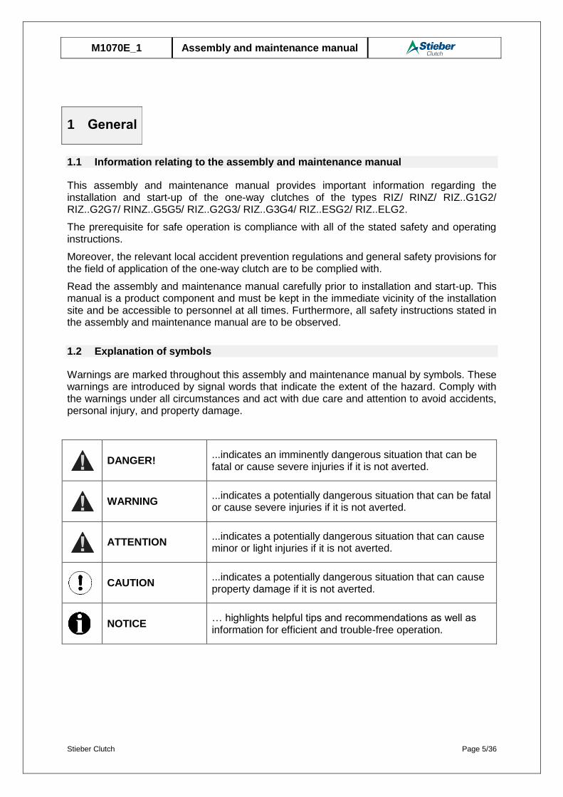
1.2 Explanation of symbols
Warnings are marked throughout this assembly and maintenance manual by symbols. These warnings are introduced by signal words that indicate the extent of the hazard. Comply with the warnings under all circumstances and act with due care and attention to avoid accidents, personal injury, and property damage.
DANGER!
...indicates an imminently dangerous situation that can be fatal or cause severe injuries if it is not averted.
WARNING
...indicates a potentially dangerous situation that can be fatal or cause severe injuries if it is not averted.
ATTENTION
...indicates a potentially dangerous situation that can cause minor or light injuries if it is not averted.
CAUTION
...indicates a potentially dangerous situation that can cause property damage if it is not averted.
NOTICE
… highlights helpful tips and recommendations as well as information for efficient and trouble-free operation.
1 General
Stieber Clutch Page 6/36
M1070E_1 Assembly and maintenance manual
1.3 Manufacturer
STIEBER GMBH, D-69126 Heidelberg, Hatschekstr. 36, Germany Phone +49 (0) 6221 3047-0, Fax -31
1.4 Labeling
External surface of the outer race
Manufacturer
Type designation
Date of manufacture (coded)
1.5 Environmental protection
Energy: The one-way clutch does not use any electrical energy.
Materials: Steel
Recycling: Steel parts are up to 100% recyclable.
2.1 Intended use
One-way clutches of types RIZ/ RINZ/ RIZ..G1G2/ RIZ..G2G7/ RINZ..G5G5/ RIZ..G2G3/ RIZ..G3G4/ RIZ..ESG2/ RIZ..ELG2 are automatically switching couplings dependent on the direction of rotation. They are used as overrunning clutches, backstops, or switching clutches in machines and systems.
One-way clutches may only be operated within the limitations of use outlined in Section 2.5.
All of the specifications stated in the assembly and maintenance manual must be strictly adhered to.
Any claims due to damage arising from improper use are excluded. The operator bears sole liability for all damage arising from improper use.
Driving operation of an overrunning clutch:
When the driving machine elements are operated in the pulling direction, the driving machine element and the torque-supporting machine element are connected to each other in a force-locked manner by the overrunning clutch. In this operating state, output can be transmitted.
Overrun operation of an overrunning clutch:
The overrunning clutch automatically releases the force-locked connection of the driving machine element and the driven machine element if the torque of the driven machine element is higher than that of the driving machine element.
2 Safety
Stieber Clutch Page 7/36
M1070E_1 Assembly and maintenance manual
Lockout operation of a backstop:
When the machine shaft is operated in the reverse direction, the machine shaft and the torque-supporting machine element are connected to each other in a force-locked manner by the one-way clutch. In this operating state, a torque is transmitted.
Overrun operation of a backstop:
The one-way clutch automatically releases the force-locked connection between the machine shaft and the torque-supporting machine element, providing the machine shaft is operated in the overrun direction.
Driving operation of an indexing clutch:
When the machine shaft is operated in the pulling direction, the machine shaft and the torque-supporting machine element are connected to each other in a force-locked manner by the one-way clutch. In this operating state, an output is transmitted.
Idling operation of an indexing clutch:
The one-way clutch automatically releases the force-locked connection between the machine shaft and the torque-supporting machine element, providing the machine shaft is operated in the idling direction.
2.2 Responsibility of the operator
The operator of the system in which the one-way clutch is installed is subject to the legal obligations concerning occupational safety.
The valid provisions for the site of operation as well as the safety and accident prevention regulations of the trade association are to be observed. In particular, this means that the operator:
is aware of the valid occupational safety provisions.
implements at the site of operation the necessary behavioral requirements for
operation of the machine in which the one-way clutch is installed.
clearly defines responsibilities for installation, operation, maintenance, and cleaning
of the system in which the one-way clutch is installed.
ensures that all staff members who work at or with the system in which the one-way
clutch is installed have read and understood the operation manual. Moreover, the
operator must, at regular intervals, provide training for personnel on how to handle
the system in which the one-way clutch is installed, and inform them of the potential
dangers. In addition, the operator is responsible for ensuring that the system in
which the one-way clutch is installed:
o is always in perfect technical condition.
o is maintained in accordance with the specified maintenance intervals.
o has all its safety equipment checked regularly for completeness and
functionality.
Stieber Clutch Page 8/36
M1070E_1 Assembly and maintenance manual
2.3 Assembly and maintenance personnel
WARNING
Danger of injury for insufficiently qualified personnel! Improper handling can cause significant personal injury and proper-ty damage. Therefore: Only ever have tasks performed by those persons to whom the
tasks have been assigned.
Qualified personnel are those persons who, owing to their training, experience, and instruction as well as their knowledge of relevant standards, provisions, accident prevention regulations and operating conditions, have been authorized by the person responsible for the safety of the system to perform the requisite tasks and are able to recognize and avoid potential dangers in doing so. Knowledge of first-aid measures and on-site emergency equipment is also required.
2.4 Personal protective equipment
In order to minimize health risks, it is necessary to wear personal protective equipment when handling the system in which the one-way clutch is installed.
Above all, the necessary protective equipment such as work shoes, gloves, safety goggles, etc. is to be put on prior to all tasks and kept on during the task.
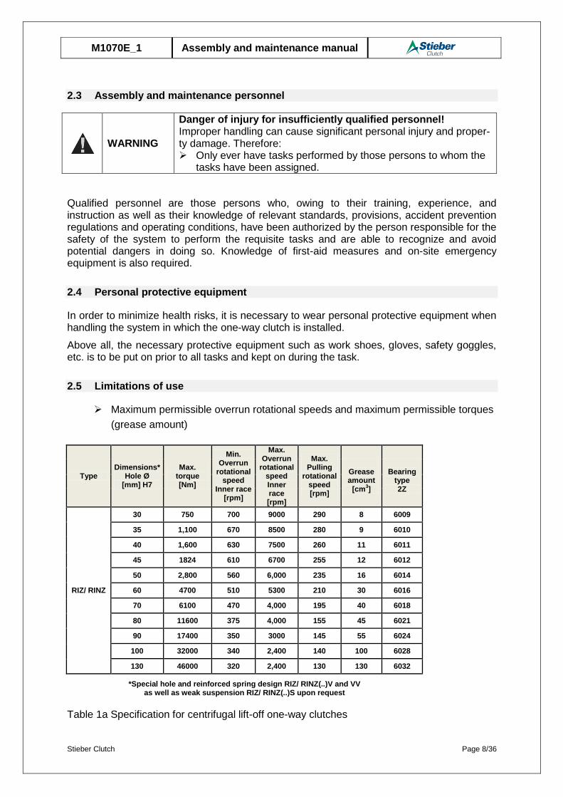
2.5 Limitations of use
Maximum permissible overrun rotational speeds and maximum permissible torques
(grease amount)
Type Dimensions*
Hole Ø [mm] H7
Max. torque [Nm]
Min. Overrun
rotational speed
Inner race [rpm]
Max. Overrun
rotational speed Inner race [rpm]
Max. Pulling
rotational speed [rpm]
Grease amount
[cm3]
Bearing
type 2Z
RIZ/ RINZ
30 750 700 9000 290 8 6009
35 1,100 670 8500 280 9 6010
40 1,600 630 7500 260 11 6011
45 1824 610 6700 255 12 6012
50 2,800 560 6,000 235 16 6014
60 4700 510 5300 210 30 6016
70 6100 470 4,000 195 40 6018
80 11600 375 4,000 155 45 6021
90 17400 350 3000 145 55 6024
100 32000 340 2,400 140 100 6028
130 46000 320 2,400 130 130 6032
*Special hole and reinforced spring design RIZ/ RINZ(..)V and VV as well as weak suspension RIZ/ RINZ(..)S upon request
Table 1a Specification for centrifugal lift-off one-way clutches

Stieber Clutch Page 9/36
M1070E_1 Assembly and maintenance manual
NOTICE
If the hole diameter is smaller than the maximum, the maximum torque to be transmitted depends on the fitting key connection.
Type Dimensions*
Hole Ø [mm] H7
Max. torque [Nm]
Min. Overrun
rotational speed
Inner race [rpm]
Max. Overrun
rotational speed Inner race [rpm]
Max. Pulling
rotational speed [rpm]
Grease amount
[cm3]
Bearing
type 2Z
RIZ..G1G2 RIZ..G2G7
RINZ..G5G5
30 750 700 9000 290 8 6009
35 1,100 670 8500 280 9 6010
40 1,600 630 7500 260 11 6011
45 1824 610 6700 255 12 6012
50 2,800 560 6,000 235 16 6014
60 4700 510 5300 210 30 6016
70 6100 470 4,000 195 40 6018
80 11600 375 4,000 155 45 6021
90 17400 350 3000 145 55 6024
100 32000 340 2,400 140 100 6028
130 46000 320 2,400 130 130 6032
*Special hole and reinforced spring design RIZ /RINZ(..)V and VW as well as weak suspension RIZ/ RINZ (..)S upon request
Table 1b Specification for centrifugal lift-off one-way clutches
Type Dimensions*
Hole Ø [mm] H7
Max. torque [Nm]
Min. Overrun
rotational speed
Inner race [rpm]
Max. Overrun
rotational speed Inner race [rpm]
Grease amount
[cm3]
Bearing
type 2Z
RIZ..G2G3 RIZ..G3G4
30 750 700 9000 8 6009
35 1,100 670 8500 9 6010
40 1,600 630 7500 11 6011
45 1824 610 6700 12 6012
50 2,800 560 6,000 16 6014
60 4700 510 5300 30 6016
70 6100 470 4,000 40 6018
80 11600 375 4,000 45 6021
90 17400 350 3000 55 6024
100 32000 340 2,400 100 6028
130 46000 320 2,400 130 6032
*Special hole and reinforced spring design RIZ /RINZ(..)V and VW as well as weak suspension RIZ/ RINZ (..)S upon request
Table 1c Specification for centrifugal lift-off one-way clutches

Stieber Clutch Page 10/36
M1070E_1 Assembly and maintenance manual
NOTICE
If the hole diameter is smaller than the maximum, the maximum torque to be transmitted depends on the fitting key connection.
Type Dimensions*
Hole Ø [mm] H7
Max. torque [Nm]
Min. Overrun
rotational speed
Inner race [rpm]
Max. Overrun
rotational speed Inner race [rpm]
Max. Pulling
rotational speed [rpm]
Grease amount
[cm3]
Bearing
type 2Z
Clutch size ES
RIZ..ESG2
30 10 300 700 9000 290 8 6009
35 16 500 670 8500 280 9 6010
40 25 800 630 7500 260 11 6011
45 40 1,250 610 6700 255 12 6012
50 63 2000 560 6,000 235 16 6014
60 100 3,200 510 5300 210 30 6016
70 160 5000 470 4,000 195 40 6018
80 400 11600 375 4,000 155 45 6021
90 630 17400 350 3000 145 55 6024
100 1,000 32000 340 2,400 140 100 6028
130 1,600 46000 320 2,400 130 130 6032
*Special hole and reinforced spring design RIZ..ESG2 V and VW as well as weak suspension RIZ..ESG2 upon request
Table 2a Specification for centrifugal lift-off one-way clutches with ES clutch and cover G2
Permissible ES clutch displacement
Radial alignment Angular alignment Axial alignment
Fig. 1 Alignment tolerances of ES clutches
Size 4 6.3 10 16 25 40 63 100 160 250 400 630 1,000 1,600 2,500 R max [mm] 0.3 0.3 0.3 0.3 0.3 0.4 0.4 0.4 0.4 0.5 0.5 0.6 0.7 0.8 0.8 U max [mm] 0.3 0.3 0.3 0.4 0.4 0.4 0.5 0.6 0.7 0.8 0.9 1 1.1 1.2 1.2
S 1max [mm] 18±1 20±1 17±1 19±1 22±1 26±1 30±1 35±1 41+1.2
-1 47+1.5-1 56+1.5
-1 64+1.5-1 75+1.5
-1 85+2-1 110+2
-1
Table 2b Alignment tolerances of ES clutches
Mounting Instructions and Alignment Tolerances Coupling KMS
Install the elastic coupling and key the coupling hub to the associated shaft.The specified alignment tolerances should only be considered as approximate values in order to keep the assembly work involved within reasonable limits and in view of the fact that the compensating capability of the coupling depends to a large extent on the rotational speeds and loads applied. Precise alignment of the coupling halves contributes to a long service life of the flexible coupling elements.
SIZE 46,3101625406310016025040063010001600
R max [mm] 0,30,30,30,30,30,40,40,40,40,50,50,60,70,8
U max [mm] 0,30,30,30,30,40,40,50,60,70,80,911,11,2
S 1max [mm] 18±120±117±119±122±126±130±135±1 41+1,2!1 47+
1,5!1 56+1,5
!1 64+1,5!1 75+2
!1 85 +2
!1
Screw sizeM6M8M10M12M16M20M24M27M30
Tightening torque [Nm]1025498621041071010501450
When mounting the flexible elements care shall be taken to ensure that the coupling halves are not mounted too close to each other in order to protect the flexible elements from being subjected to lateral pressure and to maintain the axial flexibility of the coupling in operation. Likewise, the coupling halves shall not be mounted too far from each other so that the rubber blocks are capable of transmitting over the entire width between the coupling claws.
For easier positioning of the retaining cap when the saddle elements are inserted we recommend to previously coat their periphery with talcum or soft soap (no grease or oil). A threaded rod may be used as an aid for pushing the retaining cap into position. Before starting initial operation, all screws of the coupling shall be checked for their correct tightening torque using a torque wrench. Only correctly tightened screws are secured against loosening. If an additional screw lock is required we recommend to use anaerobic adhesive (e.g. Loctite or equivalent). The tightening torques for slotted headless screws with metric threats and head contact, such as DIN 912,913, 6912 with coarse-pitch threads, shall be chosen according DIN 13, material 8.8.
CAUTION! It is customer’s and user’s responsibility to provide proper guards over rotating
machinery and to observe the national and international safety rules and laws. Check all
screwed connections for proper fit preferably after the test run.
Stieber Clutch Page 11/36
M1070E_1 Assembly and maintenance manual
Type Dimensions*
Hole Ø [mm] H7
Max. torque [Nm]
Min. Overrun
rotational speed
Inner race [rpm]
Max. Overrun
rotational speed Inner race [rpm]
Max. Pulling
rotational speed [rpm]
Grease amount
[cm3]
Bearing
type 2Z
Clutch size EL
RIZ..ELG2
30 5 750 700 9000 290 8 6009
35 6 1,100 670 8500 280 9 6010
40 6 1,600 630 7500 260 11 6011
45 6 1824 610 6700 255 12 6012
50 7 2,800 560 6,000 235 16 6014
60 8 4700 510 5300 210 30 6016
70 10 6100 470 4,000 195 40 6018
80 11 11600 375 4,000 155 45 6021
90 12 17400 350 3000 145 55 6024
100 14 32000 340 2,400 140 100 6028
130 16 46000 320 2,400 130 130 6032
*Special hole and reinforced spring design RIZ..ELG2 V and VW as well as weak suspension RIZ..ELG2 upon request
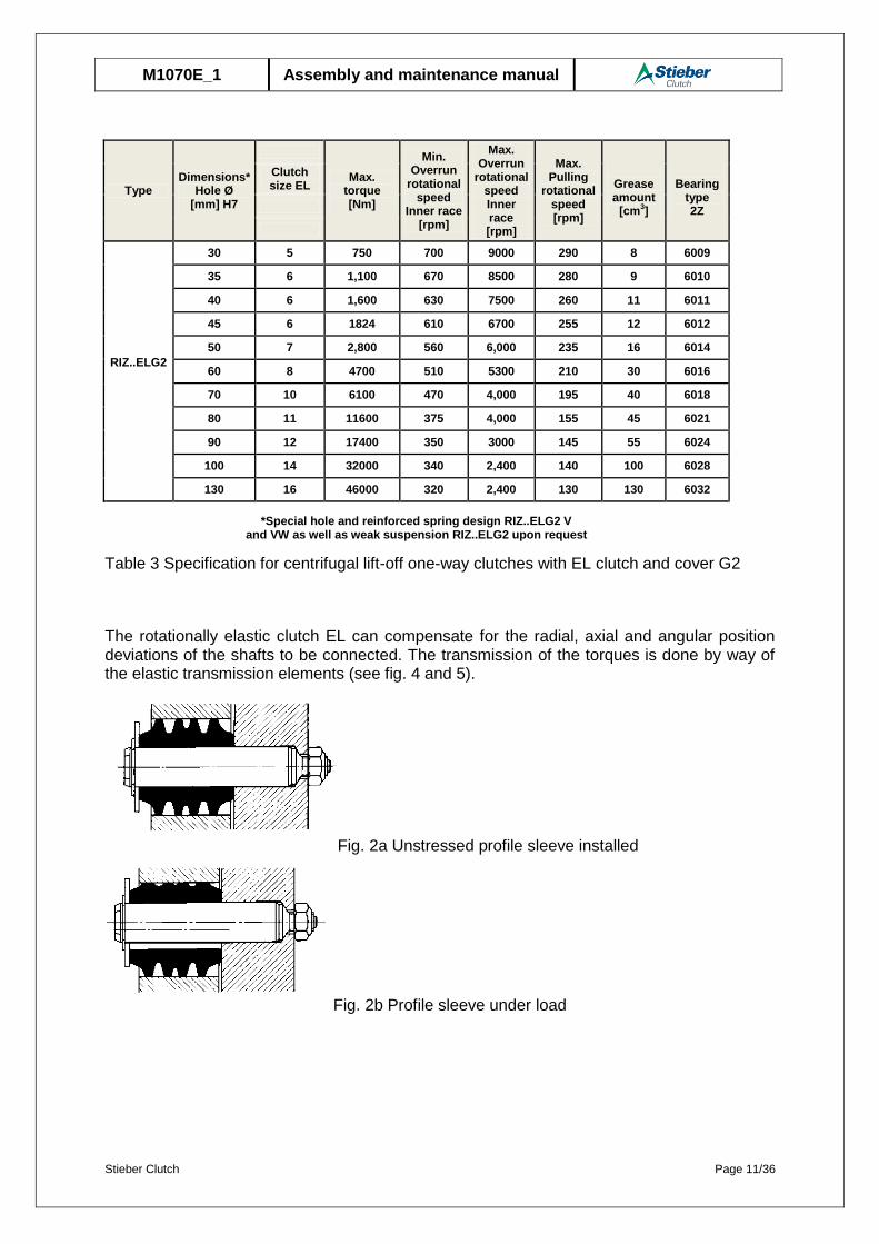
Table 3 Specification for centrifugal lift-off one-way clutches with EL clutch and cover G2
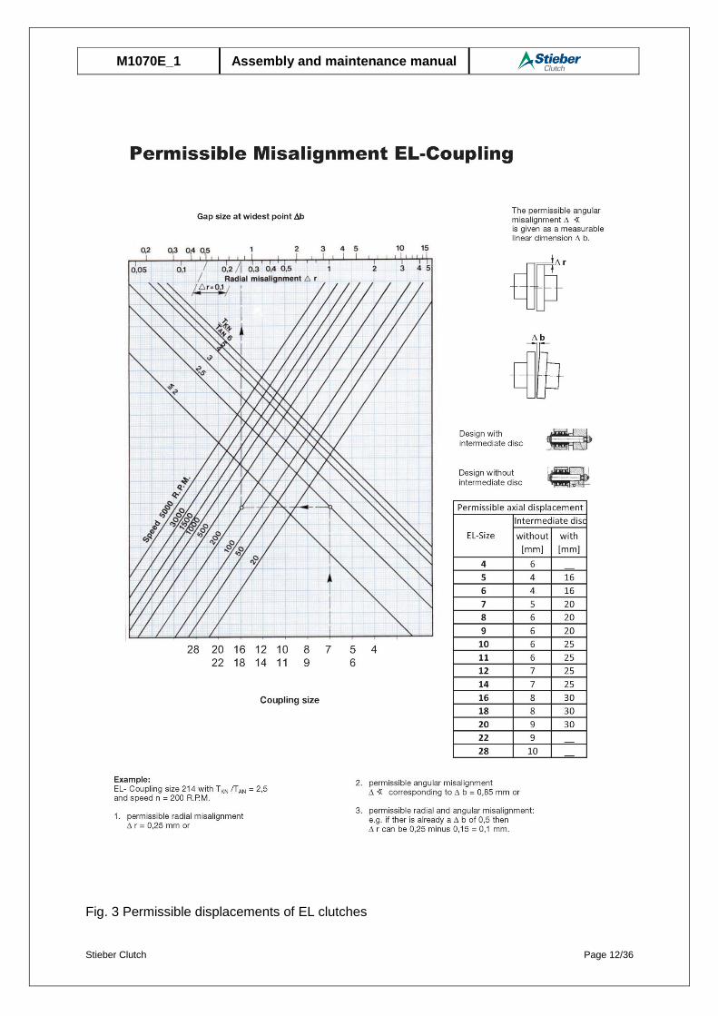
The rotationally elastic clutch EL can compensate for the radial, axial and angular position deviations of the shafts to be connected. The transmission of the torques is done by way of the elastic transmission elements (see fig. 4 and 5).
Fig. 2a Unstressed profile sleeve installed
Fig. 2b Profile sleeve under load
Stieber Clutch Page 12/36
M1070E_1 Assembly and maintenance manual
Fig. 3 Permissible displacements of EL clutches
Stieber Clutch Page 13/36
M1070E_1 Assembly and maintenance manual
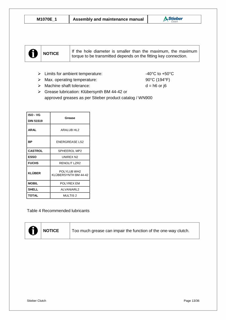
NOTICE
If the hole diameter is smaller than the maximum, the maximum torque to be transmitted depends on the fitting key connection.
Limits for ambient temperature: -40°C to +50°C
Max. operating temperature: 90°C (194°F)
Machine shaft tolerance: d = h6 or j6
Grease lubrication: Klübersynth BM 44-42 or
approved greases as per Stieber product catalog / WN900
ISO - VG Grease
DIN 51519
ARAL ARALUB HL2
BP ENERGREASE LS2
CASTROL SPHEEROL MP2
ESSO UNIREX N2
FUCHS RENOLIT LZR2
KLÜBER POLYLUB WH2
KLÜBERSYNTH BM 44-42
MOBIL POLYREX EM
SHELL ALVANIARL2
TOTAL MULTIS 2
Table 4 Recommended lubricants
NOTICE Too much grease can impair the function of the one-way clutch.
Stieber Clutch Page 14/36
M1070E_1 Assembly and maintenance manual
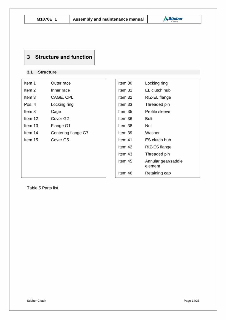
3.1 Structure
Table 5 Parts list
3 Structure and function
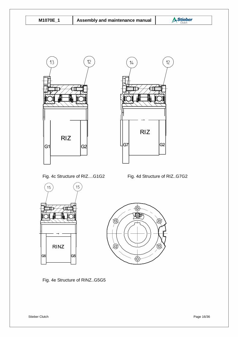
Item 1 Outer race
Item 2 Inner race
Item 3 CAGE, CPL
Pos. 4 Locking ring
Item 8 Cage
Item 12 Cover G2
Item 13 Flange G1
Item 14 Centering flange G7
Item 15 Cover G5
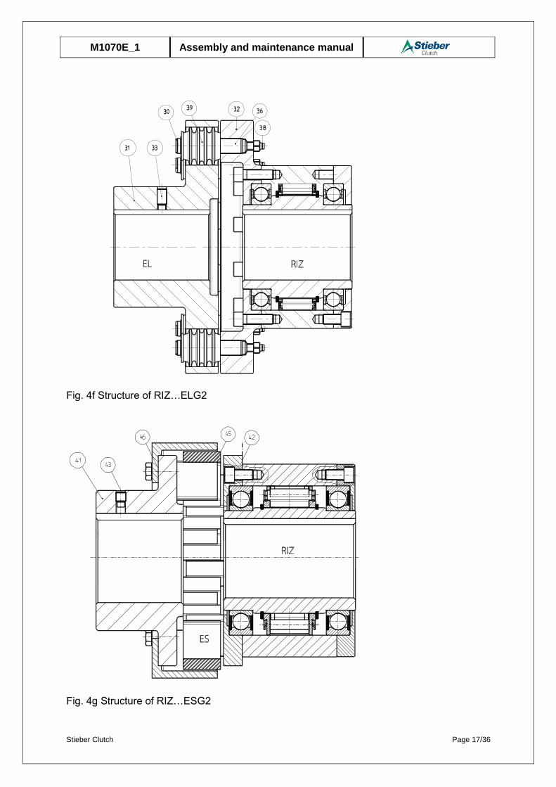
Item 30 Locking ring
Item 31 EL clutch hub
Item 32 RIZ-EL flange
Item 33 Threaded pin
Item 35 Profile sleeve
Item 36 Bolt
Item 38 Nut
Item 39 Washer
Item 41 ES clutch hub
Item 42 RIZ-ES flange
Item 43 Threaded pin
Item 45 Annular gear/saddle element
Item 46 Retaining cap
Stieber Clutch Page 15/36
M1070E_1 Assembly and maintenance manual
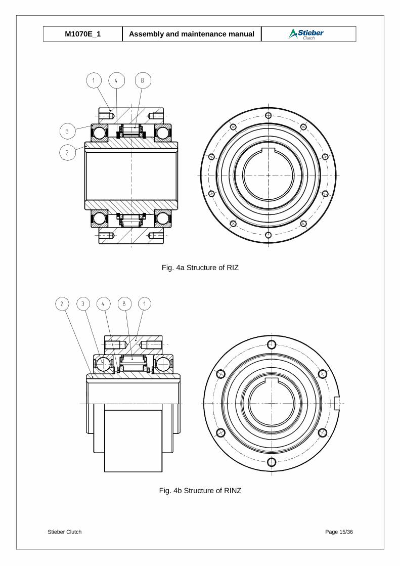
Fig. 4a Structure of RIZ
Fig. 4b Structure of RINZ
Stieber Clutch Page 16/36
M1070E_1 Assembly and maintenance manual
Fig. 4c Structure of RIZ....G1G2 Fig. 4d Structure of RIZ..G7G2
Fig. 4e Structure of RINZ..G5G5
Stieber Clutch Page 17/36
M1070E_1 Assembly and maintenance manual
Fig. 4f Structure of RIZ…ELG2
Fig. 4g Structure of RIZ…ESG2

Stieber Clutch Page 18/36
M1070E_1 Assembly and maintenance manual
3.2 Functionalprinciple
When the torque is transmitted via the one-way clutch, the outer race and the inner race are coupled in a force-locked manner. For this purpose, sprags are used whose outer contours effect the force-locked coupling. The sprags are integrated into a cage and are pressed by springs into contact with the outer and inner race. The springs ensure rapid responding behavior of the one-way clutch at the start of torque transmission.
Fig. 5 Torque transmission
In overrun operation, above the minimum permissible overrun rotation speed, the centrifugal force, in connection with the geometry of the sprags, effects a recentering torque which turns the sprags against the spring force. A contactless position is brought about in this way so that wear-free operation of the one-way clutch can be achieved. The minimum permissible overrun rotation speed may only be lower for a short period during the start-up or shut-down stage of the machine as otherwise the damage to the contact partner caused by wear and tear may lead to the failure of the one-way clutch.
Fig. 6 Contactless position
» WWW.STIEBER.DE 9
1
24
3
5
1
2
3
BAUART RSCI, RIZ
Die Klemmkörper dieser Bauarten werden in einem Käfig
geführt, der mit dem überholenden Ring verbunden ist.
Die Klemmkörper sind so gestaltet, dass der Schwerpunkt
außerhalb ihrer Drehachse liegt.
Die Zentrifugalkraft erzeugt ein abhebendes Dreh-
moment gegen das Anfederungsdrehmoment. Wenn das
Drehmoment aus der Zentrifugalkraft größer ist als das
Drehmoment der Anfederung, schwenken die Klemm-
körper in eine berührungsfreie Position.
Aufgrund der Höhe der Klemmkörper und der Länge
der Klemmfläche kann dieser Freilauf mit wesentlich
größeren Exzentrizitätstoleranzen und allen Arten von in
der Antriebstechnik üblichen Schmierstoffen eingesetzt
werden.
BAUART DC
Eine große Anzahl von Klemmkörpern ist platz sparend in
zwei konzentrischen Käfigen angeordnet. Das zulässige
Drehmoment ist hoch, verglichen mit dem erforderlichen
Einbauraum. Durch den Doppelkäfig gehen die Klemm-
körper synchron in Eingriff und sind jedoch durch die
Spezialfeder individuell angefedert.
Dieses Prinzip wird auch bei den Baureihen CSK, GFK
und RSBW angewendet.
DrehmomentübertragungLeerlauf1 Außenring 2 Käfig 3 Feder 4 Klemmkörper 5 Innenring
1 Außenring 2 Klemmkörper 3 InnenringKLEMMKÖRPER-FREILÄUFE
Einzeln angefederte Klemmkörper befinden sich
zwischen einem Innen- und Außenring. Dreht der
Außenring im Uhrzeigersinn (siehe Abbildung), stellen die
Klemmkörper eine kraftschlüssige Verbindung zwischen
den beiden Klemmflächen her. Die Klemmkörper, die in
einem Käfig geführt sind, ermöglichen ! abhängig von der
Bewegung ! Drehmomentübertragung oder Leerlauf der
Ringe.
Die Ausführung von Klemmkörpern und Käfig kann
den verschiedenen Anforderungen an den Freilauf
angepasst werden. So ist es zum Beispiel möglich, für
den Leerlauf Klemmkörper zu verwenden, die entweder
im Kontakt mit den Ringen bleiben oder berührungsfrei
überholen.
STIEBER » KONSTRUKTION
Leerlauf
LeerlaufDrehmoment-übertragung
Drehmoment-übertragung
Stieber Clutch Page 19/36
M1070E_1 Assembly and maintenance manual
NOTICE
The local provisions regarding the disposal of transport and packaging materials are to be observed.
One-way clutches of Type RIZ/ RINZ/ RIZ..G1G2/ RIZ..G2G7/ RINZ..G5G5/ RIZ..G2G3/ RIZ..G3G4/ RIZ..ESG2/ RIZ..ELG2 are packed in air cushion foils.
The one-way clutch are shipped in a box or on a pallet.
Transport damage to the packaging and/or the one-way clutch is to be reported to the respective transit company without delay.
The one-way clutch must be unpacked in a clean and dry environment.
5.1 Short-term storage
RIZ/ RINZ/ RIZ..G1G2/ RIZ..G2G7/ RINZ..G5G5/ RIZ..G2G3/ RIZ..G3G4/ RIZ..ESG2/ RIZ..ELG2 one-way clutches come with an oil film as corrosion protection. This corrosion protection is to be renewed at regular intervals. The frequency of these renewal intervals is dependent on the environmental conditions (temperature, moisture, salt content of the air, etc.) at the storage site.
The maximum storage period (short-term storage) is 6 months. Moreover, the one-way clutch must have long-term storage corrosion protection applied to it.
Store packages under the following conditions:
Do not keep outdoors.
Keep dry and free from dust.
Do not expose to aggressive media.
Keep away from direct sunlight.
Avoid mechanical shocks and vibrations.
Storage temperature: −10 to +60°C (14°F to 140°F)
Relative humidity: max. 95%, non-condensing
4 Transport and packaging
5 Storage

Stieber Clutch Page 20/36
M1070E_1 Assembly and maintenance manual
5.2 Long-term storage
For long-term storage, the one-way clutch must be shrink-wrapped with a desiccant and provided with a hygroscope. The corrosion protection must be checked after a period not exceeding one year or else depending on the environmental conditions (temperature, moisture, salt content of the air, etc.) at the storage site.
Store packages under the following conditions:
Do not keep outdoors.
Keep dry and free from dust.
Do not expose to aggressive media.
Keep away from direct sunlight.
Avoid mechanical shocks and vibrations.
Storage temperature: −10 to +60°C (14°F to 140°F)
Relative humidity: max. 95%, non-condensing
6.1 Checking the direction of rotation
WARNING
Danger of injury due to incorrect assembly! Incorrect assembly and maintenance can cause severe property damage and personal injury. Assembly, maintenance, and repair work may only be performed by personnel with the requisite training and expertise.
WARNING
Danger of injury due to moving components! Rotating, driven components can cause severe injuries. Therefore, during operation:
It is strictly forbidden for persons to loiter in the hazard area or in its immediate vicinity.
Do not disable, render unusable, or circumvent safety equipment and/or safety functions.
Prior to entering the hazard area: Switch off the power supply and secure it against being
switched on again. Wait for still moving components to come to a standstill.
WARNING
Danger of injury due to the one-way clutch falling down or tip-ping over! The weight of the one-way clutch can injure people and cause se-vere crushing. Therefore:
When lifting, use suitable lifting gear (slings, etc.) able to support the weight of the one-way clutch.
6 Installation

Stieber Clutch Page 21/36
M1070E_1 Assembly and maintenance manual
WARNING
Danger of injury for insufficiently qualified personnel! Improper handling can cause significant personal injury and proper-ty damage. Therefore: Only ever have tasks performed by those persons to whom the
tasks have been assigned.
Before installation, the direction of rotation of the one-way clutch must be checked.
6.2 Changing the direction of rotation
For RIZ / RINZ/ RINZ..G5G5 models, the direction of rotation is changed by reversing the one-way clutch.
For RIZ..G1G2/ RIZ..G2G7/ RIZ..G2G3/ RIZ..G3G4/ RIZ..ESG2/ RIZ..ELG2 models, the direction of rotation is changed by swapping the flange and cover or clutch and cover.
Procedural steps:
Remove the cylinder screws from the covers and remove the ccovers.
Place the flange and cover onto the opposite side and insert the cylinder screws
with Loctite and tighten (see Table 6 Tightening torques).
Tightening torques [Nm]
One-way clutch size
Size Strength
class 10.9 Oil filling plugs
30 to 35 M6 14 7
40 to 50 M8 34 9
60 to 80 M10 68 15
90 M12 118 63
100 to 130 M16 290 150
Table 6 Tightening torques
Check overrunning. The one-way clutch must be easy to turn in the overrun
direction of rotation.
6.3 Lubrication
The one-way clutch base unit may only be lubricated in a lubricated state. It is lubricated with Klübersynth BM 44-42 in the factory.

Stieber Clutch Page 22/36
M1070E_1 Assembly and maintenance manual
6.4 Assembly
WARNING
Danger of injury due to incorrect assembly!
Incorrect assembly and maintenance can cause severe property damage and personal injury.
Assembly, maintenance, and repair work may only be performed by personnel with the requisite training and expertise.
WARNING
Danger of injury due to moving components! Rotating, driven components can cause severe injuries. Therefore, during operation:
It is strictly forbidden for persons to loiter in the hazard area or in its immediate vicinity.
Do not disable, render unusable, or circumvent safety equipment and/or safety functions.
Prior to entering the hazard area: Switch off the power supply and
secure it against being switched on again. Wait for still moving components to come to a standstill.
WARNING
Danger of injury due to falling components!
Falling components can lead to serious injuries to persons.
Secure the one-way clutch against falling down.
WARNING
Danger of injury for insufficiently qualified personnel! Improper handling can cause significant personal injury and proper-ty damage. Therefore: Only ever have tasks performed by those persons to whom the
tasks have been assigned.
6.4.1 Installation of one-way clutch RIZ/ RINZ
Procedural steps:
Insert the supporting fitting key according to DIN 6885 Sheet 1 over the entire
length of the one-way clutch in the shaft. To transmit the torque on the outer race,
the RINZ version is additionally fitted with a parallel keyway. Push one-way clutch
onto the oiled machine shaft, attaching suitable lifting equipment if necessary
Tighten the machine element with the outer race. To do so, use fastening screws
(e.g. as per standard DIN EN ISO 4762 and with screw quality 10.9) (see Table 6
Tightening torques in Section 6.2).
Fasten the inner race axially.
Stieber Clutch Page 23/36
M1070E_1 Assembly and maintenance manual
Check overrunning. After the assembly, the one-way clutch must be easy to turn in
the overrun direction of rotation.
NOTICE Use screw quality 10.9 only!
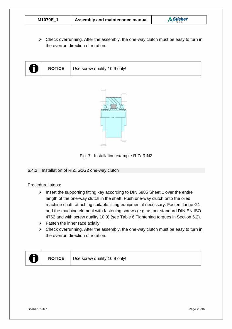
Fig. 7: Installation example RIZ/ RINZ
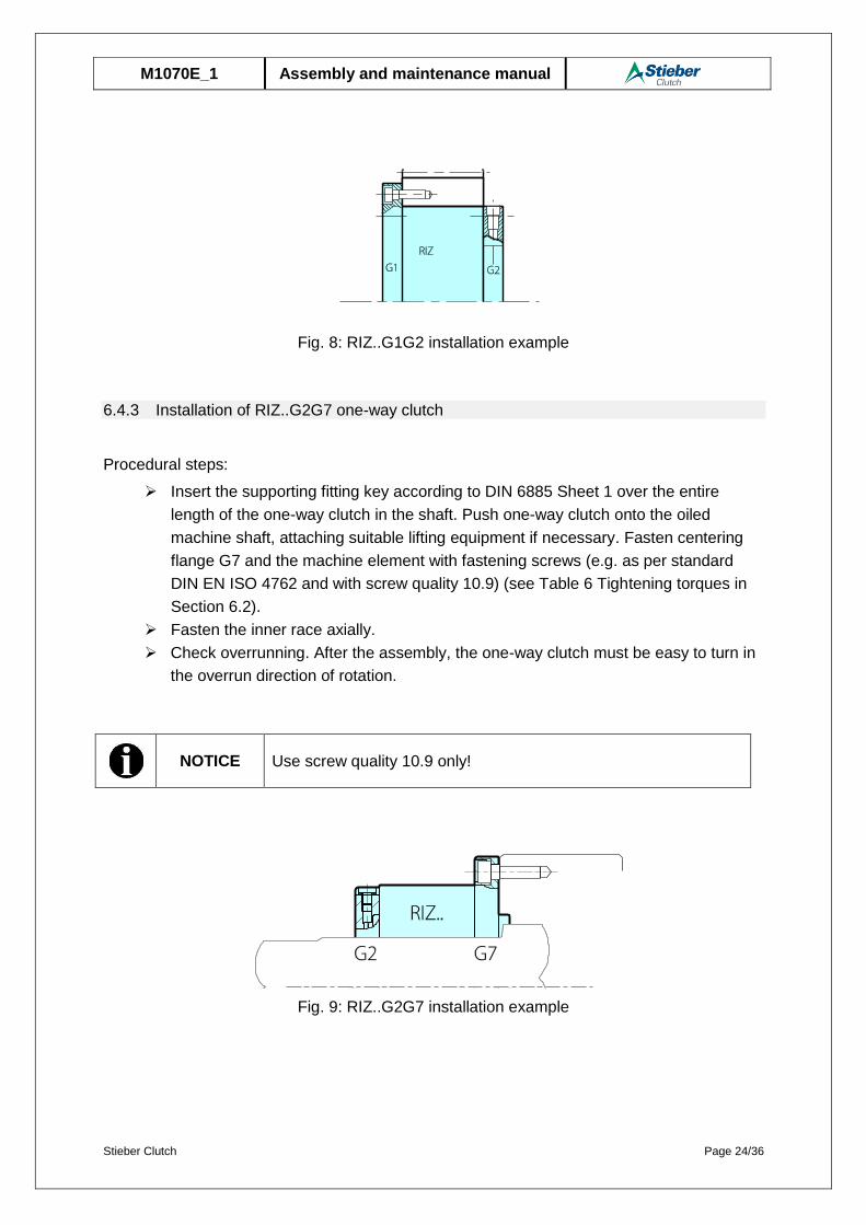
6.4.2 Installation of RIZ..G1G2 one-way clutch
Procedural steps:
Insert the supporting fitting key according to DIN 6885 Sheet 1 over the entire
length of the one-way clutch in the shaft. Push one-way clutch onto the oiled
machine shaft, attaching suitable lifting equipment if necessary. Fasten flange G1
and the machine element with fastening screws (e.g. as per standard DIN EN ISO
4762 and with screw quality 10.9) (see Table 6 Tightening torques in Section 6.2).
Fasten the inner race axially.
Check overrunning. After the assembly, the one-way clutch must be easy to turn in
the overrun direction of rotation.
NOTICE Use screw quality 10.9 only!
Stieber Clutch Page 24/36
M1070E_1 Assembly and maintenance manual
Fig. 8: RIZ..G1G2 installation example
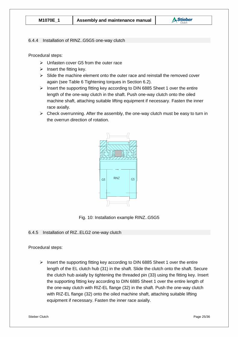
6.4.3 Installation of RIZ..G2G7 one-way clutch
Procedural steps:
Insert the supporting fitting key according to DIN 6885 Sheet 1 over the entire
length of the one-way clutch in the shaft. Push one-way clutch onto the oiled
machine shaft, attaching suitable lifting equipment if necessary. Fasten centering
flange G7 and the machine element with fastening screws (e.g. as per standard
DIN EN ISO 4762 and with screw quality 10.9) (see Table 6 Tightening torques in
Section 6.2).
Fasten the inner race axially.
Check overrunning. After the assembly, the one-way clutch must be easy to turn in
the overrun direction of rotation.
NOTICE Use screw quality 10.9 only!
Fig. 9: RIZ..G2G7 installation example
Stieber Clutch Page 25/36
M1070E_1 Assembly and maintenance manual
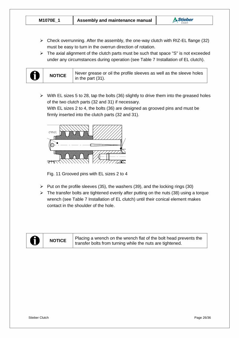
6.4.4 Installation of RINZ..G5G5 one-way clutch
Procedural steps:
Unfasten cover G5 from the outer race
Insert the fitting key.
Slide the machine element onto the outer race and reinstall the removed cover
again (see Table 6 Tightening torques in Section 6.2).
Insert the supporting fitting key according to DIN 6885 Sheet 1 over the entire
length of the one-way clutch in the shaft. Push one-way clutch onto the oiled
machine shaft, attaching suitable lifting equipment if necessary. Fasten the inner
race axially.
Check overrunning. After the assembly, the one-way clutch must be easy to turn in
the overrun direction of rotation.
Fig. 10: Installation example RINZ..G5G5
6.4.5 Installation of RIZ..ELG2 one-way clutch
Procedural steps:
Insert the supporting fitting key according to DIN 6885 Sheet 1 over the entire
length of the EL clutch hub (31) in the shaft. Slide the clutch onto the shaft. Secure
the clutch hub axially by tightening the threaded pin (33) using the fitting key. Insert
the supporting fitting key according to DIN 6885 Sheet 1 over the entire length of
the one-way clutch with RIZ-EL flange (32) in the shaft. Push the one-way clutch
with RIZ-EL flange (32) onto the oiled machine shaft, attaching suitable lifting
equipment if necessary. Fasten the inner race axially.
Stieber Clutch Page 26/36
M1070E_1 Assembly and maintenance manual
Check overrunning. After the assembly, the one-way clutch with RIZ-EL flange (32)
must be easy to turn in the overrun direction of rotation.
The axial alignment of the clutch parts must be such that space "S" is not exceeded
under any circumstances during operation (see Table 7 Installation of EL clutch).
NOTICE
Never grease or oil the profile sleeves as well as the sleeve holes in the part (31).
With EL sizes 5 to 28, tap the bolts (36) slightly to drive them into the greased holes
of the two clutch parts (32 and 31) if necessary.
With EL sizes 2 to 4, the bolts (36) are designed as grooved pins and must be
firmly inserted into the clutch parts (32 and 31).
Fig. 11 Grooved pins with EL sizes 2 to 4
Put on the profile sleeves (35), the washers (39), and the locking rings (30)
The transfer bolts are tightened evenly after putting on the nuts (38) using a torque
wrench (see Table 7 Installation of EL clutch) until their conical element makes
contact in the shoulder of the hole.
NOTICE
Placing a wrench on the wrench flat of the bolt head prevents the transfer bolts from turning while the nuts are tightened.

Stieber Clutch Page 27/36
M1070E_1 Assembly and maintenance manual
Clutch size EL
Nominal instal-lation dimen-
sion Snom= 0.5 Smax
[mm]
Thread Width across
flats
Tightening torque in [Nm]
2 3 _ _ _
3 3 _ _ _
4 3 _ _ _
5 2 M8 Width 13 11
6 2 M8 Width 13 11
7 2.5 M8 Width 13 11
8 3 M10 Width 17 22
10 3 M12 Width 19 39
11 3 M12 Width 19 39
12 3.5 M16 Width 24 95
14 3.5 M16 Width 24 95
16 4 M20 SW30 184
18 4 M20 SW30 184
22 4.5 M24 SW36 315
28 5 M30 Width 46 635
Table 7 Installation of EL clutch
After the installation of the transfer elements, gap “Snom” must be checked again
(see Table 7 Installation of EL clutch).
Fig. 11: RIZ..ELG2 installation example
» WWW.STIEBER.DE 97
RIZ..ELG2
S nom
Stieber Clutch Page 28/36
M1070E_1 Assembly and maintenance manual
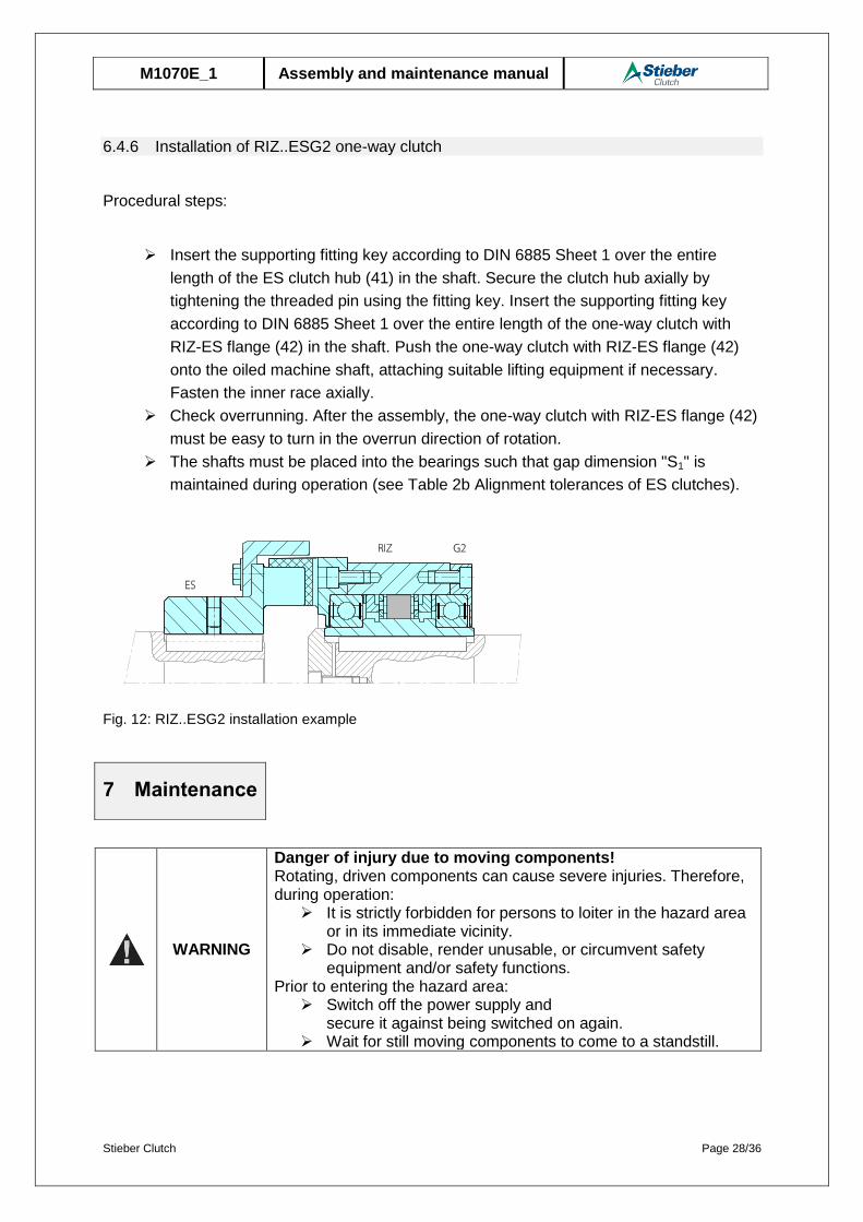
6.4.6 Installation of RIZ..ESG2 one-way clutch
Procedural steps:
Insert the supporting fitting key according to DIN 6885 Sheet 1 over the entire
length of the ES clutch hub (41) in the shaft. Secure the clutch hub axially by
tightening the threaded pin using the fitting key. Insert the supporting fitting key
according to DIN 6885 Sheet 1 over the entire length of the one-way clutch with
RIZ-ES flange (42) in the shaft. Push the one-way clutch with RIZ-ES flange (42)
onto the oiled machine shaft, attaching suitable lifting equipment if necessary.
Fasten the inner race axially.
Check overrunning. After the assembly, the one-way clutch with RIZ-ES flange (42)
must be easy to turn in the overrun direction of rotation.
The shafts must be placed into the bearings such that gap dimension "S1" is
maintained during operation (see Table 2b Alignment tolerances of ES clutches).
Fig. 12: RIZ..ESG2 installation example
WARNING
Danger of injury due to moving components! Rotating, driven components can cause severe injuries. Therefore, during operation:
It is strictly forbidden for persons to loiter in the hazard area or in its immediate vicinity.
Do not disable, render unusable, or circumvent safety equipment and/or safety functions.
Prior to entering the hazard area: Switch off the power supply and
secure it against being switched on again. Wait for still moving components to come to a standstill.
7 Maintenance
Stieber Clutch Page 29/36
M1070E_1 Assembly and maintenance manual
WARNING
Danger of injury due to incorrect assembly! Incorrect assembly and maintenance can cause severe property damage and personal injury. Assembly, maintenance, and repair work may only be performed by personnel with the requisite training and expertise.
WARNING
Danger of injury due to falling components!
Falling components can lead to serious injuries to persons.
Secure the one-way clutch against falling down.
WARNING
Danger of injury for insufficiently qualified personnel! Improper handling can cause significant personal injury and proper-ty damage. Therefore: Only ever have tasks performed by those persons to whom the
tasks have been assigned.
WARNING
Danger of scalding due to hot surfaces! There is a risk of burns and danger of scalding during operation due to hot surfaces. Therefore:
Do not touch one-way clutches during operation!
The one-way clutches RIZ..G1G2/ RIZ..G2G7/ RINZ..G5G5/ RIZ..G2G3/ RIZ..G3G4/ RIZ..ESG2/ RIZ..ELG2 must be checked for damage and serviced after a maximum of 5 years of operation.
7.1 Test criteria in case of need for maintenance
Procedural steps:
Unfasten cover / flange combination (G1, G2, G3, G4, G5, G7) from the RIZ or
RINZ base unit
Uninstall the grooved ball bearings (3) on both sides
Uninstall the outer race and the cage
NOTICE
New grooved ball bearings must be installed after all maintenance operations.
Preclean the inner race (1), outer race (1) and cage (8) with a petroleum-based
industrial cleaning agent and degrease with an acetone-based cleaning agent.

Stieber Clutch Page 30/36
M1070E_1 Assembly and maintenance manual
Check for damage, wear and cracks (see test criteria)
o The outer race track must not exhibit any signs of damage / ruptures
o Increased diameter due to wear in the outer race track maximum 0.05
mm compared to unworn area
o Traces of deformation / indentations to the track diameters of the inner
and outer race maximum 0.05 mm deep
o Completeness of all spring elements (2 per sprag)
o Spring elements free of damage / deformation
o Smooth rotation of the sprags from stop to stop
o maximum width of the wear facet on the sprag (see fig. 13)
Fig. 13: Wear zones
o The one-way clutch can continue to be used only if all of the test
criteria are met
7.2 Assembly in case of need for maintenance
Procedural steps:
Place the cage (8) on the inner race (2) and fasten axially with locking rings (4)
grease the outer race track with a layer thickness of roughly 1 mm
o Klübersynth BM 44-42 grease or approved greases as per Stieber
product catalog / WN900 tab. 4
o Grease amounts according to tab. 1 or tab. 2 or 3
Secure the sprags of the one-way clutch in lift-off position with an assembly aid (O-
ring / cable connector) (see figures 14 and 15)
Area of wear under the lift-off speed
Area of wear under torque
Permissible face widths:
1 mm
Permissible face widths:
1 mm
Stieber Clutch Page 31/36
M1070E_1 Assembly and maintenance manual
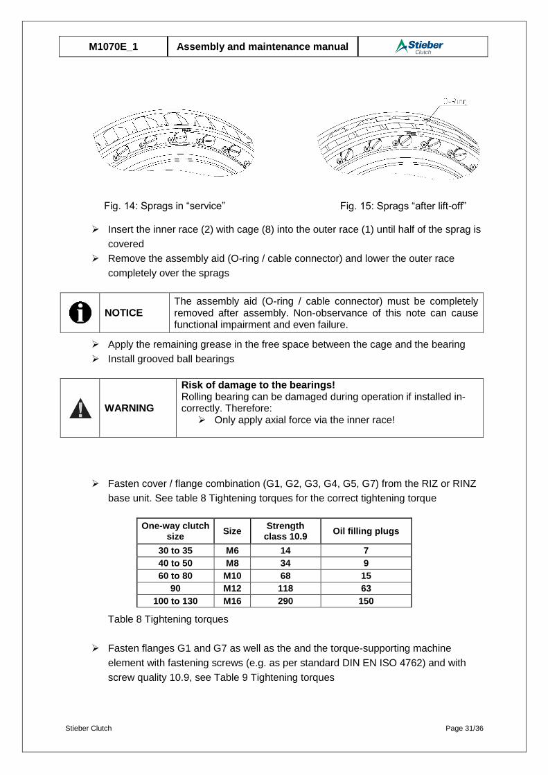
Insert the inner race (2) with cage (8) into the outer race (1) until half of the sprag is
covered
Remove the assembly aid (O-ring / cable connector) and lower the outer race
completely over the sprags
NOTICE
The assembly aid (O-ring / cable connector) must be completely removed after assembly. Non-observance of this note can cause functional impairment and even failure.
Apply the remaining grease in the free space between the cage and the bearing
Install grooved ball bearings
WARNING
Risk of damage to the bearings! Rolling bearing can be damaged during operation if installed in-correctly. Therefore:
Only apply axial force via the inner race!
Fasten cover / flange combination (G1, G2, G3, G4, G5, G7) from the RIZ or RINZ
base unit. See table 8 Tightening torques for the correct tightening torque
One-way clutch size
Size Strength
class 10.9 Oil filling plugs
30 to 35 M6 14 7
40 to 50 M8 34 9
60 to 80 M10 68 15
90 M12 118 63
100 to 130 M16 290 150
Table 8 Tightening torques
Fasten flanges G1 and G7 as well as the and the torque-supporting machine
element with fastening screws (e.g. as per standard DIN EN ISO 4762) and with
screw quality 10.9, see Table 9 Tightening torques
Fig. 15: Sprags “after lift-off” Fig. 14: Sprags in “service”
Stieber Clutch Page 32/36
M1070E_1 Assembly and maintenance manual
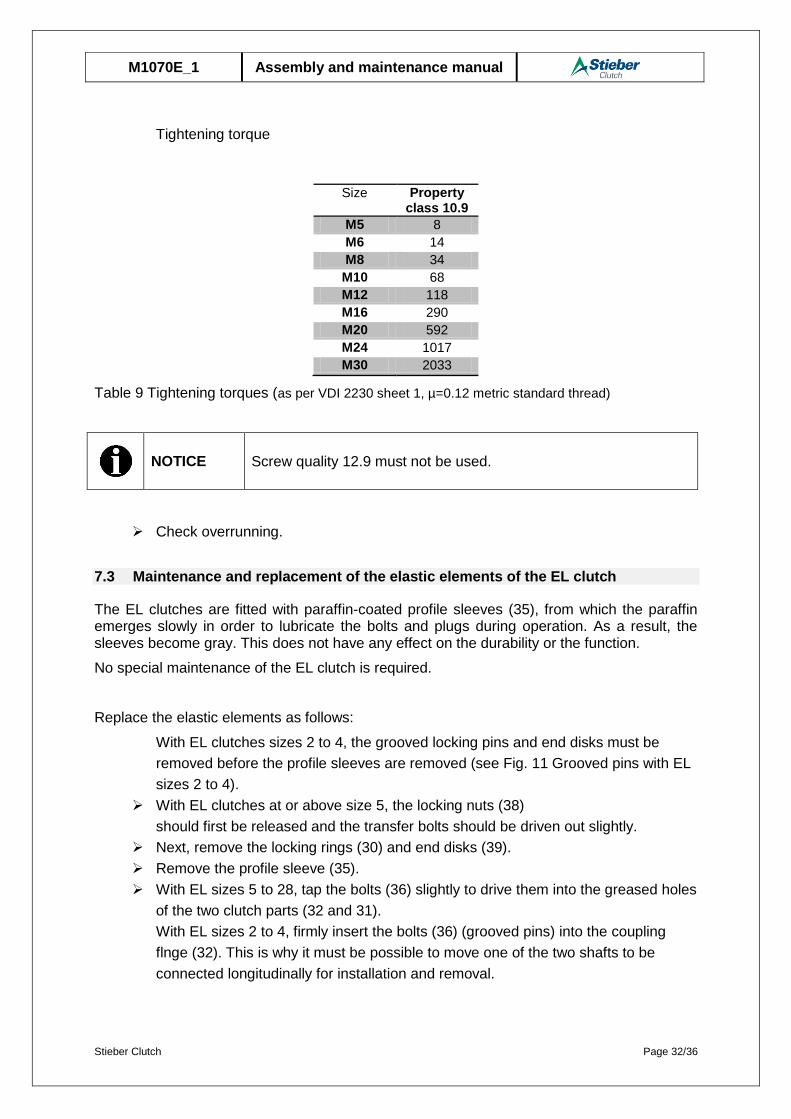
Tightening torque
Size Property class 10.9
M5 8
M6 14
M8 34
M10 68
M12 118
M16 290
M20 592
M24 1017
M30 2033
Table 9 Tightening torques (as per VDI 2230 sheet 1, µ=0.12 metric standard thread)
NOTICE Screw quality 12.9 must not be used.
Check overrunning.
7.3 Maintenance and replacement of the elastic elements of the EL clutch
The EL clutches are fitted with paraffin-coated profile sleeves (35), from which the paraffin emerges slowly in order to lubricate the bolts and plugs during operation. As a result, the sleeves become gray. This does not have any effect on the durability or the function.
No special maintenance of the EL clutch is required.
Replace the elastic elements as follows:
With EL clutches sizes 2 to 4, the grooved locking pins and end disks must be
removed before the profile sleeves are removed (see Fig. 11 Grooved pins with EL
sizes 2 to 4).
With EL clutches at or above size 5, the locking nuts (38)
should first be released and the transfer bolts should be driven out slightly.
Next, remove the locking rings (30) and end disks (39).
Remove the profile sleeve (35).
With EL sizes 5 to 28, tap the bolts (36) slightly to drive them into the greased holes
of the two clutch parts (32 and 31).
With EL sizes 2 to 4, firmly insert the bolts (36) (grooved pins) into the coupling
flnge (32). This is why it must be possible to move one of the two shafts to be
connected longitudinally for installation and removal.
Stieber Clutch Page 33/36
M1070E_1 Assembly and maintenance manual
Put on the profile sleeves (35), the washers (39), and the locking rings (30)
NOTICE
To achieve a uniform transmission of force, the entire set of profile sleeves should always be replaced.
The transfer bolts are tightened evenly after putting on the nuts (38) using a torque
wrench (see Table 7 Installation of EL clutch) until their conical element makes
contact in the shoulder of the hole.
NOTICE
Placing a wrench on the wrench flat of the bolt head prevents the transfer bolts from turning while the nuts are tightened.
7.4 Maintenance and replacement of the elastic elements of the ES clutch
No special maintenance of the ES clutch is required.
NOTICE
When mounting the elastic elements, ensure that the clutch halves are not mounted too close, in order to prevent the elastic elements from being exposed to lateral pressure and to ensure that the clutch remains flexible in the axial direction during use.
NOTICE
The clutch halves must not be mounted too far from each other; this ensures that the rubber blocks are capable of transmitting over the entire width between the coupling claws.
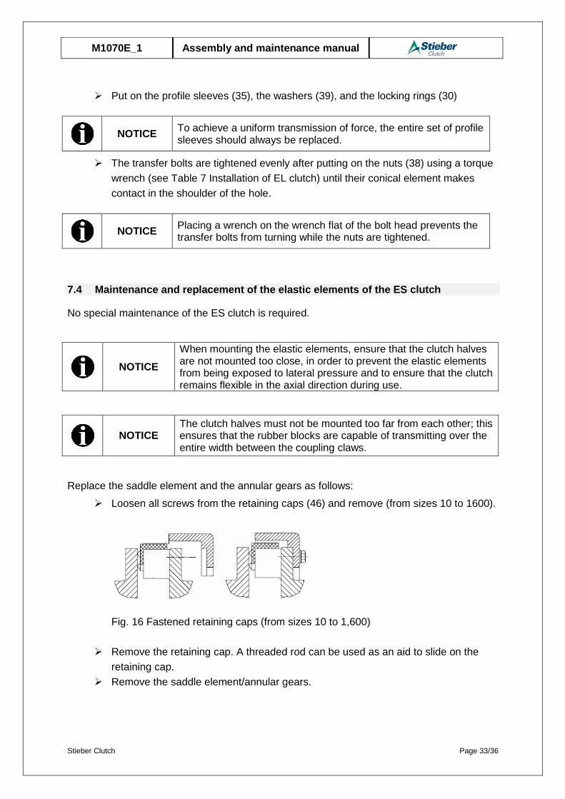
Replace the saddle element and the annular gears as follows:
Loosen all screws from the retaining caps (46) and remove (from sizes 10 to 1600).
Fig. 16 Fastened retaining caps (from sizes 10 to 1,600)
Remove the retaining cap. A threaded rod can be used as an aid to slide on the
retaining cap.
Remove the saddle element/annular gears.
Stieber Clutch Page 34/36
M1070E_1 Assembly and maintenance manual
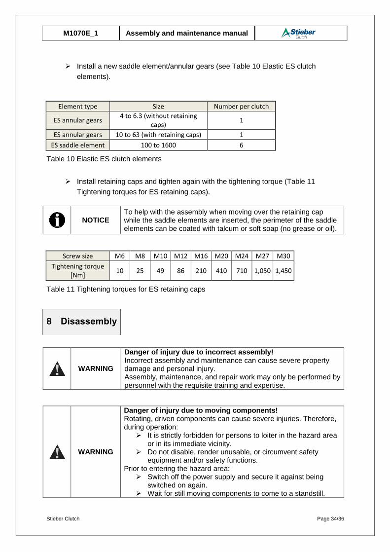
Install a new saddle element/annular gears (see Table 10 Elastic ES clutch
elements).
Element type Size Number per clutch
ES annular gears 4 to 6.3 (without retaining
caps) 1
ES annular gears 10 to 63 (with retaining caps) 1
ES saddle element 100 to 1600 6
Table 10 Elastic ES clutch elements
Install retaining caps and tighten again with the tightening torque (Table 11
Tightening torques for ES retaining caps).
NOTICE
To help with the assembly when moving over the retaining cap while the saddle elements are inserted, the perimeter of the saddle elements can be coated with talcum or soft soap (no grease or oil).
Screw size M6 M8 M10 M12 M16 M20 M24 M27 M30
Tightening torque [Nm]
10 25 49 86 210 410 710 1,050 1,450
Table 11 Tightening torques for ES retaining caps
WARNING
Danger of injury due to incorrect assembly! Incorrect assembly and maintenance can cause severe property damage and personal injury. Assembly, maintenance, and repair work may only be performed by personnel with the requisite training and expertise.
WARNING
Danger of injury due to moving components! Rotating, driven components can cause severe injuries. Therefore, during operation:
It is strictly forbidden for persons to loiter in the hazard area or in its immediate vicinity.
Do not disable, render unusable, or circumvent safety equipment and/or safety functions.
Prior to entering the hazard area: Switch off the power supply and secure it against being
switched on again. Wait for still moving components to come to a standstill.
8 Disassembly
Stieber Clutch Page 35/36
M1070E_1 Assembly and maintenance manual
WARNING
Danger of scalding due to hot surfaces! There is a risk of burns and danger of scalding during operation due to hot surfaces. Therefore:
Do not touch one-way clutches during operation!
WARNING
Danger of injury due to falling components!
Falling components can lead to serious injuries to persons.
Secure the one-way clutch against falling down.
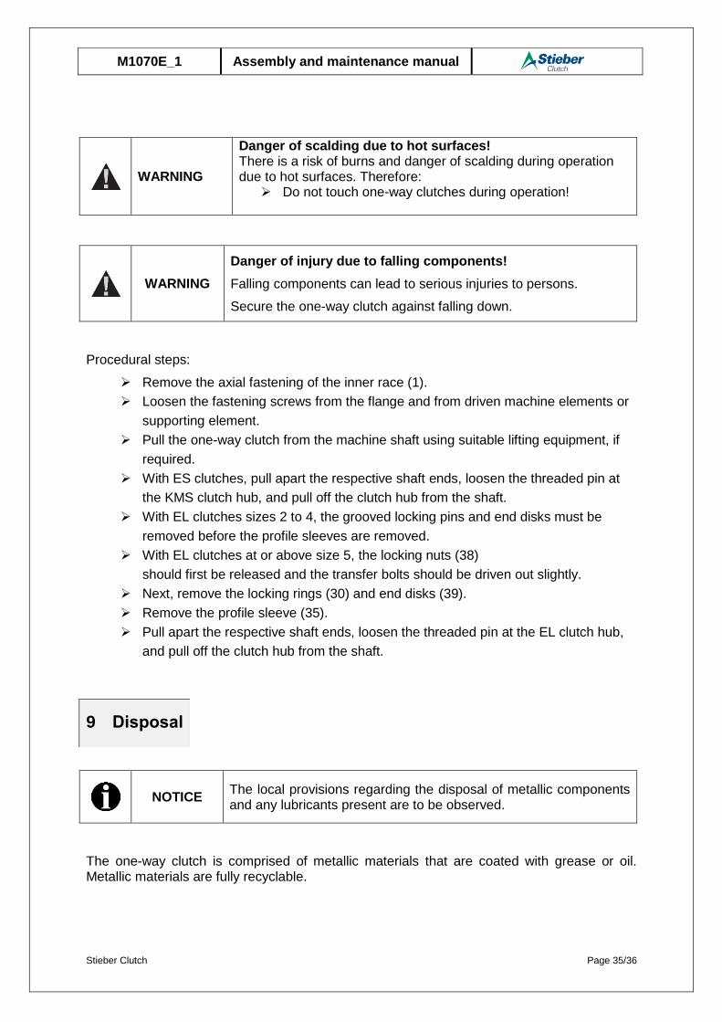
Procedural steps:
Remove the axial fastening of the inner race (1).
Loosen the fastening screws from the flange and from driven machine elements or
supporting element.
Pull the one-way clutch from the machine shaft using suitable lifting equipment, if
required.
With ES clutches, pull apart the respective shaft ends, loosen the threaded pin at
the KMS clutch hub, and pull off the clutch hub from the shaft.
With EL clutches sizes 2 to 4, the grooved locking pins and end disks must be
removed before the profile sleeves are removed.
With EL clutches at or above size 5, the locking nuts (38)
should first be released and the transfer bolts should be driven out slightly.
Next, remove the locking rings (30) and end disks (39).
Remove the profile sleeve (35).
Pull apart the respective shaft ends, loosen the threaded pin at the EL clutch hub,
and pull off the clutch hub from the shaft.
NOTICE
The local provisions regarding the disposal of metallic components and any lubricants present are to be observed.
The one-way clutch is comprised of metallic materials that are coated with grease or oil. Metallic materials are fully recyclable.
9 Disposal
Stieber Clutch Page 36/36
M1070E_1 Assembly and maintenance manual
Lubricants and anticorrosive agents are to be disposed of separately.
The local disposal provisions are to be observed in this regard.
The manufacturer is to be contacted immediately should any faults arise.
STIEBER GMBH, D-69126 Heidelberg, Hatschekstr. 36, Germany Tel +49 (0) 6221 3047-0, Fax -31
WARNING
Danger of injury due to incorrect spare parts! Incorrect or faulty spare parts can cause damage, malfunctions, or total failure as well as impair safety . Therefore:
Only use OEM parts from the manufacturer.
Procure spare parts only from authorized dealers or from the manufacturer directly.
10 Faults
11 Spare parts


