Embed Size (px)
Citation preview
CL-1
CLUTCH
C TRANSMISSION/TRANSAXLE
CONTENTS
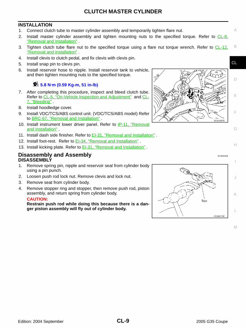
D
E
F
G
H
I
J
K
L
M
SECTION CLA
B
CL
Edition: 2004 September 2005 G35 Coupe
CLUTCH
PRECAUTIONS .......................................................... 2Caution ..................................................................... 2Precautions for Battery Service ................................ 2
PREPARATION ........................................................... 3Special Service Tools ............................................... 3Commercial Service Tools ........................................ 3
NOISE, VIBRATION AND HARSHNESS (NVH) TROUBLESHOOTING ................................................ 4
NVH Troubleshooting Chart ..................................... 4CLUTCH ................................................................ 4
CLUTCH PEDAL ........................................................ 5On-Vehicle Inspection and Adjustment .................... 5Removal and Installation .......................................... 6
REMOVAL ............................................................. 6INSPECTION AFTER REMOVAL ......................... 6INSTALLATION ..................................................... 6
CLUTCH FLUID .......................................................... 7Bleeding ................................................................... 7
CLUTCH MASTER CYLINDER .................................. 8Removal and Installation .......................................... 8
REMOVAL ............................................................. 8INSTALLATION ..................................................... 9
Disassembly and Assembly ..................................... 9DISASSEMBLY ..................................................... 9INSPECTION AFTER DISASSEMBLY ............... 10ASSEMBLY ......................................................... 10
OPERATING CYLINDER ...........................................11
Removal and Installation ........................................ 11REMOVAL ........................................................... 11INSTALLATION ................................................... 11
Disassembly and Assembly .................................... 11DISASSEMBLY ................................................... 11INSPECTION AFTER DISASSEMBLY ................ 11ASSEMBLY ......................................................... 11
CLUTCH PIPING ....................................................... 12Removal and Installation ........................................ 12
CLUTCH RELEASE MECHANISM ........................... 13Removal and Installation ........................................ 13
REMOVAL ........................................................... 13INSPECTION AFTER REMOVAL ....................... 13INSTALLATION ................................................... 14
CLUTCH DISC, CLUTCH COVER ............................ 15Removal and Installation ........................................ 15
REMOVAL ........................................................... 15INSPECTION AND ADJUSTMENT AFTER REMOVAL ........................................................... 15INSTALLATION ................................................... 16
SERVICE DATA AND SPECIFICATIONS (SDS) ...... 17Clutch Control System ............................................ 17Clutch Master Cylinder ........................................... 17Clutch Operating Cylinder ...................................... 17Clutch Disc ............................................................. 17Clutch Cover ........................................................... 17Clutch Pedal ........................................................... 17
CL-2
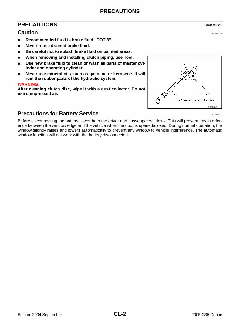
PRECAUTIONS
Edition: 2004 September 2005 G35 Coupe
PRECAUTIONS PFP:00001
Caution ACS004NY
● Recommended fluid is brake fluid “DOT 3”. ● Never reuse drained brake fluid.● Be careful not to splash brake fluid on painted areas.● When removing and installing clutch piping, use Tool.● Use new brake fluid to clean or wash all parts of master cyl-
inder and operating cylinder.● Never use mineral oils such as gasoline or kerosene. It will
ruin the rubber parts of the hydraulic system.WARNING:After cleaning clutch disc, wipe it with a dust collector. Do notuse compressed air.
Precautions for Battery Service ACS006DZ
Before disconnecting the battery, lower both the driver and passenger windows. This will prevent any interfer-ence between the window edge and the vehicle when the door is opened/closed. During normal operation, thewindow slightly raises and lowers automatically to prevent any window to vehicle interference. The automaticwindow function will not work with the battery disconnected.
SBR686C
PREPARATION
CL-3
D
E
F
G
H
I
J
K
L
M
A
B
CL
Edition: 2004 September 2005 G35 Coupe
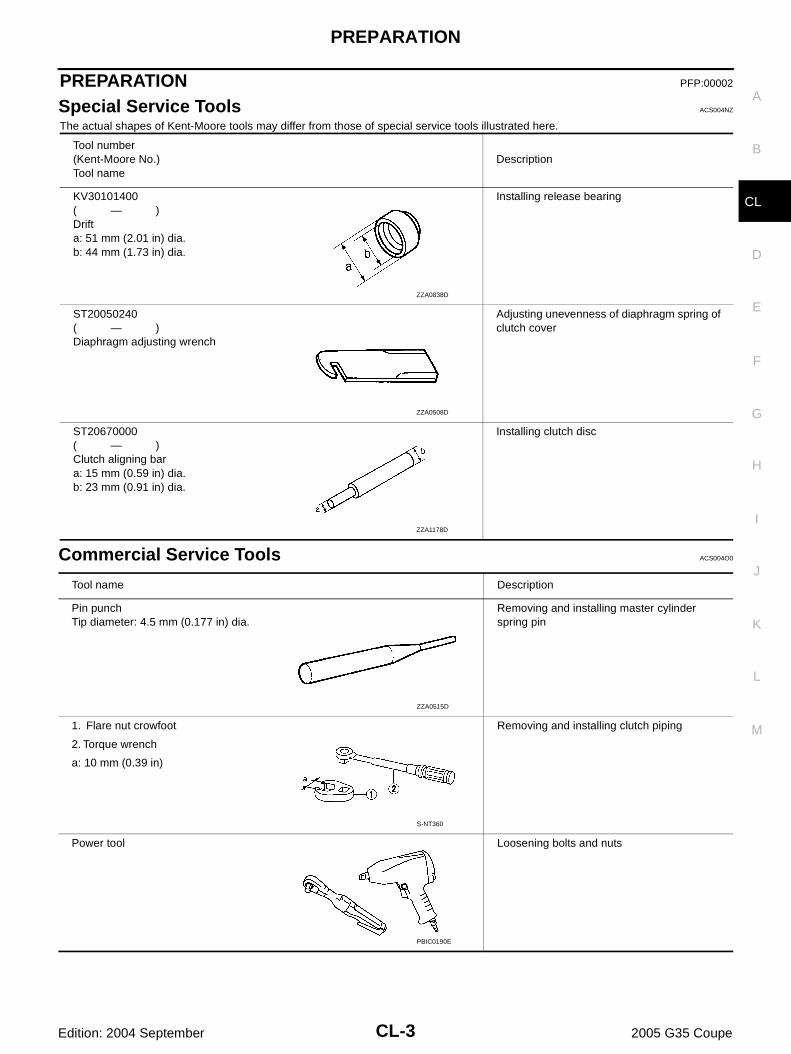
PREPARATION PFP:00002
Special Service Tools ACS004NZ
The actual shapes of Kent-Moore tools may differ from those of special service tools illustrated here.
Commercial Service Tools ACS004O0
Tool number(Kent-Moore No.)Tool name
Description
KV30101400( — )Drifta: 51 mm (2.01 in) dia.b: 44 mm (1.73 in) dia.
Installing release bearing
ST20050240( — )Diaphragm adjusting wrench
Adjusting unevenness of diaphragm spring of clutch cover
ST20670000( — )Clutch aligning bara: 15 mm (0.59 in) dia.b: 23 mm (0.91 in) dia.
Installing clutch disc
ZZA0838D
ZZA0508D
ZZA1178D
Tool name Description
Pin punchTip diameter: 4.5 mm (0.177 in) dia.
Removing and installing master cylinder spring pin
1. Flare nut crowfoot
2. Torque wrench
a: 10 mm (0.39 in)
Removing and installing clutch piping
Power tool Loosening bolts and nuts
ZZA0515D
S-NT360
PBIC0190E
CL-4
NOISE, VIBRATION AND HARSHNESS (NVH) TROUBLESHOOTING
Edition: 2004 September 2005 G35 Coupe
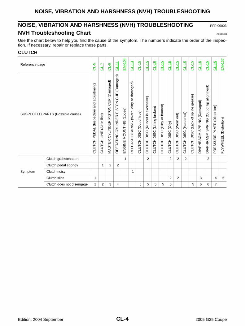
NOISE, VIBRATION AND HARSHNESS (NVH) TROUBLESHOOTING PFP:00003
NVH Troubleshooting Chart ACS004O1
Use the chart below to help you find the cause of the symptom. The numbers indicate the order of the inspec-tion. If necessary, repair or replace these parts.
CLUTCH
Reference page
CL-
5
CL-
7
CL-
9
CL-
11
EM
-104
CL-
13
CL-
15
CL-
15
CL-
15
CL-
15
CL-
15
CL-
15
CL-
15
CL-
15
CL-
15
CL-
15
CL-
15
EM
-137
SUSPECTED PARTS (Possible cause)
CLU
TC
H P
ED
AL
(Ins
pect
ion
and
adju
stm
ent)
CLU
TC
H L
INE
(A
ir in
line
)
MA
ST
ER
CY
LIN
DE
R P
IST
ON
CU
P (
Dam
aged
)
OP
ER
AT
ING
CY
LIN
DE
R P
IST
ON
CU
P (
Dam
aged
)
EN
GIN
E M
OU
NT
ING
(Lo
ose)
RE
LEA
SE
BE
AR
ING
(W
orn,
dirt
y or
dam
aged
)
CLU
TC
H D
ISC
(O
ut o
f tru
e)
CLU
TC
H D
ISC
(R
unou
t is
exce
ssiv
e)
CLU
TC
H D
ISC
(Li
ning
bro
ken)
CLU
TC
H D
ISC
(D
irty
or b
urne
d)
CLU
TC
H D
ISC
(O
ily)
CLU
TC
H D
ISC
(W
orn
out)
CLU
TC
H D
ISC
(H
arde
ned)
CLU
TC
H D
ISC
(La
ck o
f spl
ine
grea
se)
DIA
PH
RA
GM
SP
RIN
G (
Dam
aged
)
DIA
PH
RA
GM
SP
RIN
G (
Out
of t
ip a
lignm
ent)
PR
ES
SU
RE
PLA
TE
(D
isto
rtio
n)
FLY
WH
EE
L (D
isto
rtio
n)
Symptom
Clutch grabs/chatters 1 2 2 2 2 2
Clutch pedal spongy 1 2 2
Clutch noisy 1
Clutch slips 1 2 2 3 4 5
Clutch does not disengage 1 2 3 4 5 5 5 5 5 5 6 6 7
CLUTCH PEDAL
CL-5
D
E
F
G
H
I
J
K
L
M
A
B
CL
Edition: 2004 September 2005 G35 Coupe
CLUTCH PEDAL PFP:46540
On-Vehicle Inspection and Adjustment ACS004O2
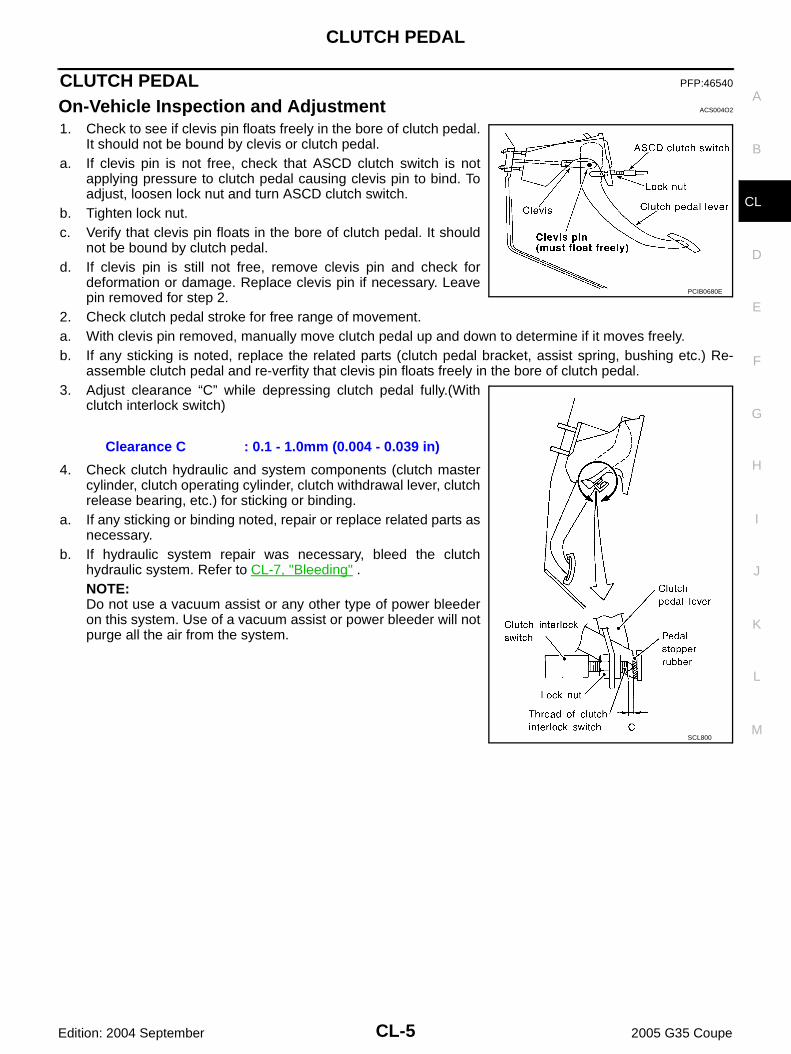
1. Check to see if clevis pin floats freely in the bore of clutch pedal.It should not be bound by clevis or clutch pedal.
a. If clevis pin is not free, check that ASCD clutch switch is notapplying pressure to clutch pedal causing clevis pin to bind. Toadjust, loosen lock nut and turn ASCD clutch switch.
b. Tighten lock nut.c. Verify that clevis pin floats in the bore of clutch pedal. It should
not be bound by clutch pedal.d. If clevis pin is still not free, remove clevis pin and check for
deformation or damage. Replace clevis pin if necessary. Leavepin removed for step 2.
2. Check clutch pedal stroke for free range of movement.a. With clevis pin removed, manually move clutch pedal up and down to determine if it moves freely.b. If any sticking is noted, replace the related parts (clutch pedal bracket, assist spring, bushing etc.) Re-
assemble clutch pedal and re-verfity that clevis pin floats freely in the bore of clutch pedal. 3. Adjust clearance “C” while depressing clutch pedal fully.(With
clutch interlock switch)
4. Check clutch hydraulic and system components (clutch mastercylinder, clutch operating cylinder, clutch withdrawal lever, clutchrelease bearing, etc.) for sticking or binding.
a. If any sticking or binding noted, repair or replace related parts asnecessary.
b. If hydraulic system repair was necessary, bleed the clutchhydraulic system. Refer to CL-7, "Bleeding" . NOTE:Do not use a vacuum assist or any other type of power bleederon this system. Use of a vacuum assist or power bleeder will notpurge all the air from the system.
Clearance C : 0.1 - 1.0mm (0.004 - 0.039 in)
PCIB0680E
SCL800
CL-6
CLUTCH PEDAL
Edition: 2004 September 2005 G35 Coupe
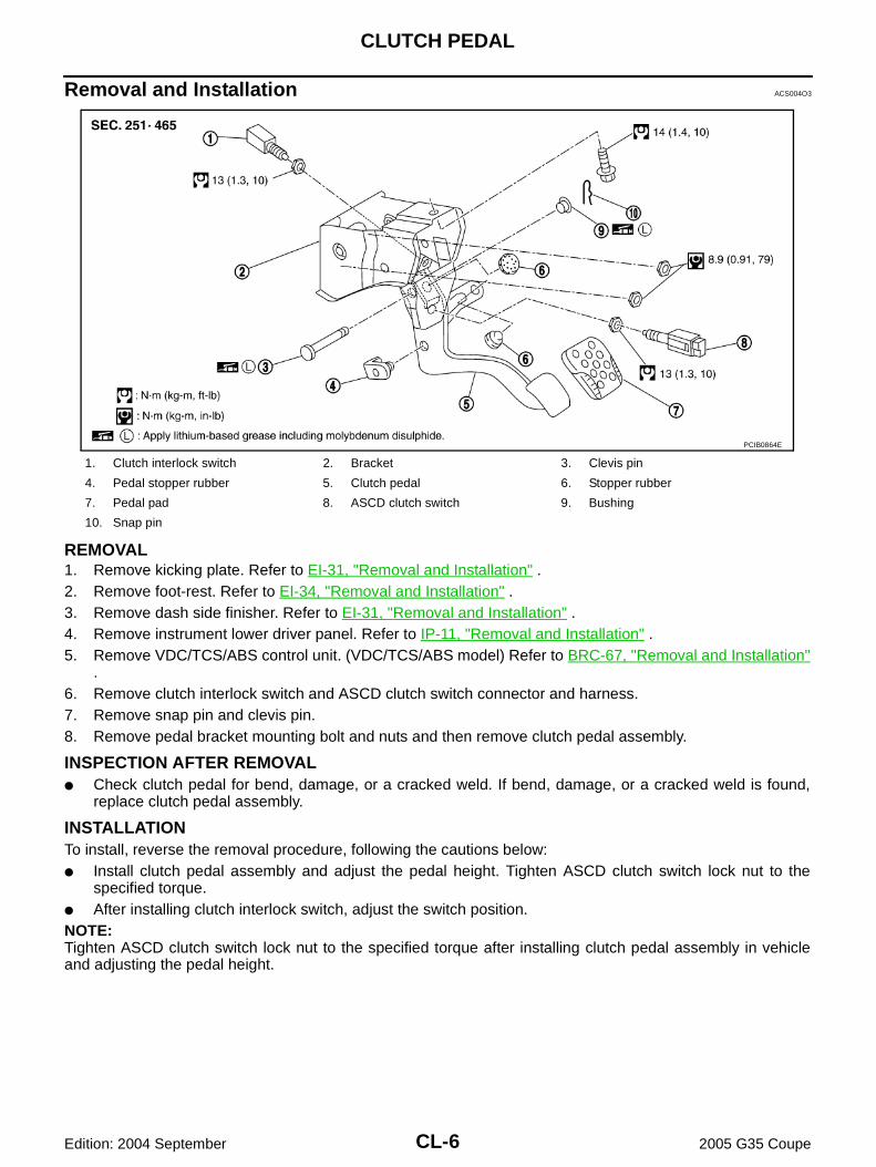
Removal and Installation ACS004O3
REMOVAL1. Remove kicking plate. Refer to EI-31, "Removal and Installation" .2. Remove foot-rest. Refer to EI-34, "Removal and Installation" .3. Remove dash side finisher. Refer to EI-31, "Removal and Installation" .4. Remove instrument lower driver panel. Refer to IP-11, "Removal and Installation" .5. Remove VDC/TCS/ABS control unit. (VDC/TCS/ABS model) Refer to BRC-67, "Removal and Installation"
.6. Remove clutch interlock switch and ASCD clutch switch connector and harness.7. Remove snap pin and clevis pin.8. Remove pedal bracket mounting bolt and nuts and then remove clutch pedal assembly.
INSPECTION AFTER REMOVAL● Check clutch pedal for bend, damage, or a cracked weld. If bend, damage, or a cracked weld is found,
replace clutch pedal assembly.
INSTALLATIONTo install, reverse the removal procedure, following the cautions below:● Install clutch pedal assembly and adjust the pedal height. Tighten ASCD clutch switch lock nut to the
specified torque.● After installing clutch interlock switch, adjust the switch position.NOTE:Tighten ASCD clutch switch lock nut to the specified torque after installing clutch pedal assembly in vehicleand adjusting the pedal height.
1. Clutch interlock switch 2. Bracket 3. Clevis pin
4. Pedal stopper rubber 5. Clutch pedal 6. Stopper rubber
7. Pedal pad 8. ASCD clutch switch 9. Bushing
10. Snap pin
PCIB0864E
CLUTCH FLUID
CL-7
D
E
F
G
H
I
J
K
L
M
A
B
CL
Edition: 2004 September 2005 G35 Coupe
CLUTCH FLUID PFP:00017
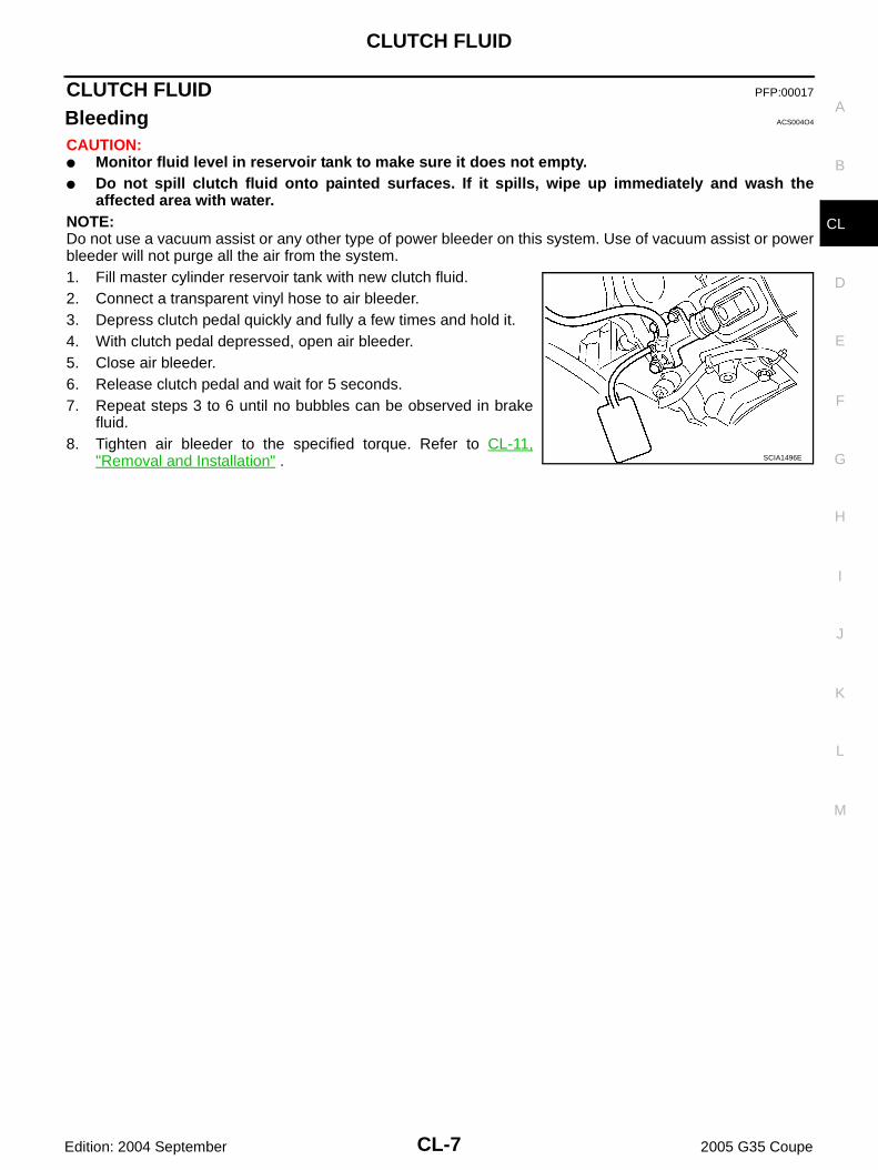
Bleeding ACS004O4
CAUTION:● Monitor fluid level in reservoir tank to make sure it does not empty.● Do not spill clutch fluid onto painted surfaces. If it spills, wipe up immediately and wash the
affected area with water.NOTE:Do not use a vacuum assist or any other type of power bleeder on this system. Use of vacuum assist or powerbleeder will not purge all the air from the system.1. Fill master cylinder reservoir tank with new clutch fluid.2. Connect a transparent vinyl hose to air bleeder.3. Depress clutch pedal quickly and fully a few times and hold it.4. With clutch pedal depressed, open air bleeder.5. Close air bleeder.6. Release clutch pedal and wait for 5 seconds.7. Repeat steps 3 to 6 until no bubbles can be observed in brake
fluid.8. Tighten air bleeder to the specified torque. Refer to CL-11,
"Removal and Installation" . SCIA1496E
CL-8
CLUTCH MASTER CYLINDER
Edition: 2004 September 2005 G35 Coupe
CLUTCH MASTER CYLINDER PFP:30610
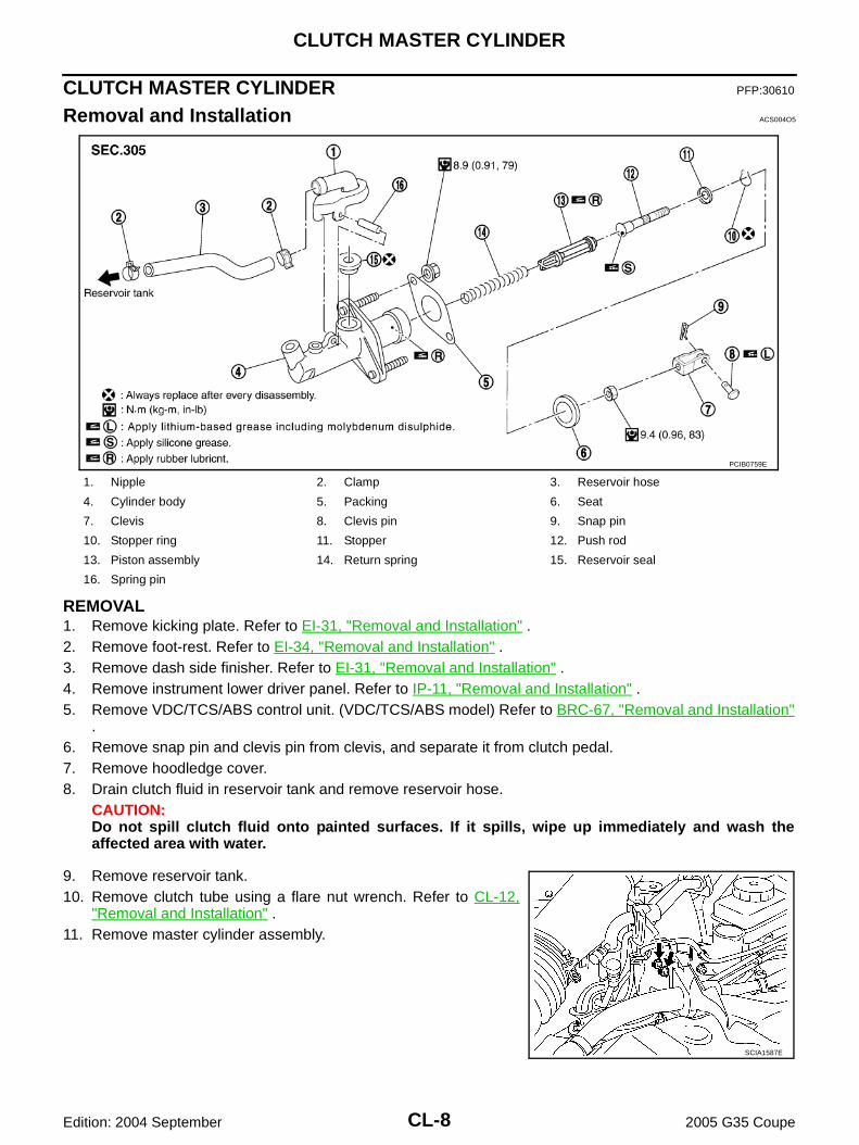
Removal and Installation ACS004O5
REMOVAL1. Remove kicking plate. Refer to EI-31, "Removal and Installation" .2. Remove foot-rest. Refer to EI-34, "Removal and Installation" .3. Remove dash side finisher. Refer to EI-31, "Removal and Installation" .4. Remove instrument lower driver panel. Refer to IP-11, "Removal and Installation" .5. Remove VDC/TCS/ABS control unit. (VDC/TCS/ABS model) Refer to BRC-67, "Removal and Installation"
.6. Remove snap pin and clevis pin from clevis, and separate it from clutch pedal.7. Remove hoodledge cover.8. Drain clutch fluid in reservoir tank and remove reservoir hose.
CAUTION:Do not spill clutch fluid onto painted surfaces. If it spills, wipe up immediately and wash theaffected area with water.
9. Remove reservoir tank.10. Remove clutch tube using a flare nut wrench. Refer to CL-12,
"Removal and Installation" .11. Remove master cylinder assembly.
1. Nipple 2. Clamp 3. Reservoir hose
4. Cylinder body 5. Packing 6. Seat
7. Clevis 8. Clevis pin 9. Snap pin
10. Stopper ring 11. Stopper 12. Push rod
13. Piston assembly 14. Return spring 15. Reservoir seal
16. Spring pin
PCIB0759E
SCIA1587E
CLUTCH MASTER CYLINDER
CL-9
D
E
F
G
H
I
J
K
L
M
A
B
CL
Edition: 2004 September 2005 G35 Coupe
INSTALLATION1. Connect clutch tube to master cylinder assembly and temporarily tighten flare nut.2. Install master cylinder assembly and tighten mounting nuts to the specified torque. Refer to CL-8,
"Removal and Installation" .3. Tighten clutch tube flare nut to the specified torque using a flare nut torque wrench. Refer to CL-12,
"Removal and Installation" .4. Install clevis to clutch pedal, and fix clevis with clevis pin.5. Install snap pin to clevis pin.6. Install reservoir hose to nipple. Install reservoir tank to vehicle,
and then tighten mounting nuts to the specified torque.
7. After completing this procedure, inspect and bleed clutch tube.Refer to CL-5, "On-Vehicle Inspection and Adjustment" and CL-7, "Bleeding" .
8. Install hoodledge cover.9. Install VDC/TCS/ABS control unit. (VDC/TCS/ABS model) Refer
to BRC-67, "Removal and Installation" .10. Install instrument lower driver panel. Refer to IP-11, "Removal
and Installation" .11. Install dash side finisher. Refer to EI-31, "Removal and Installation" .12. Install foot-rest. Refer to EI-34, "Removal and Installation" .13. Install kicking plate. Refer to EI-31, "Removal and Installation" .
Disassembly and Assembly ACS004O6
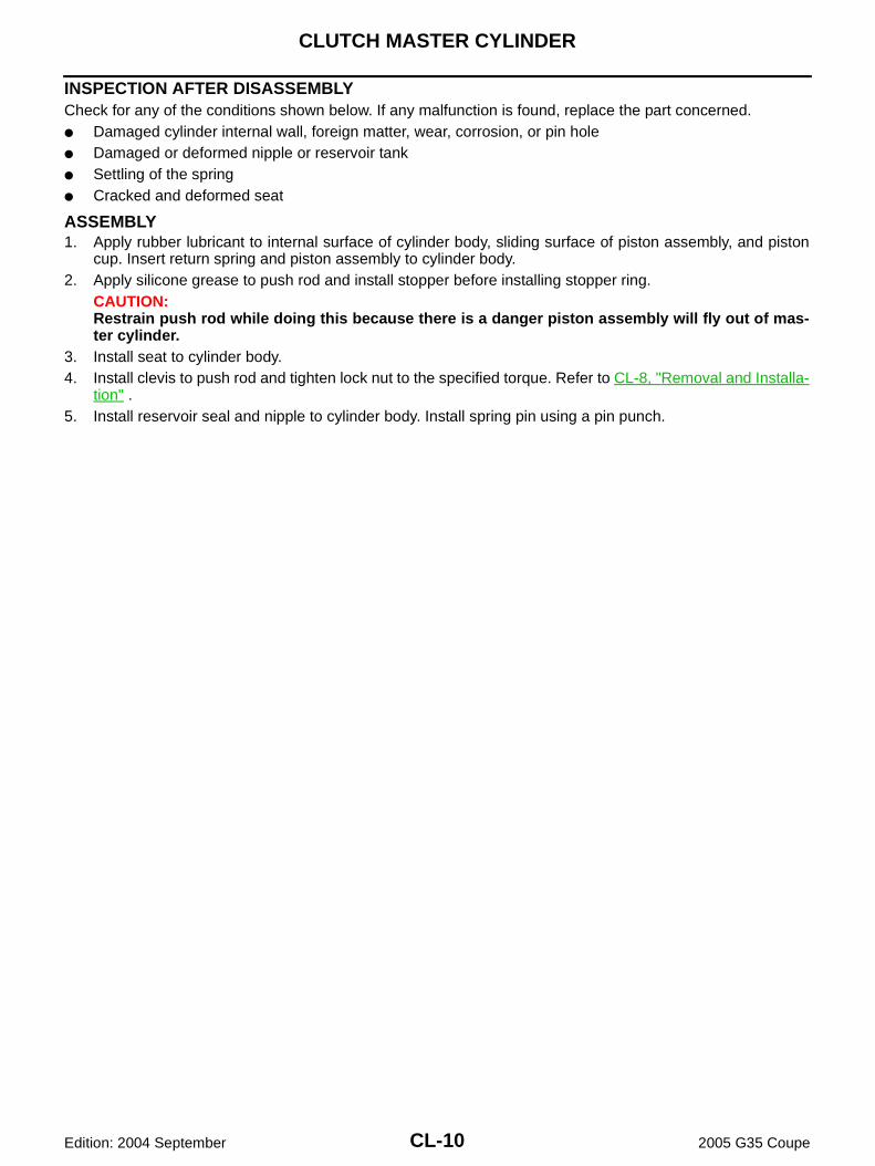
DISASSEMBLY1. Remove spring pin, nipple and reservoir seal from cylinder body
using a pin punch. 2. Loosen push rod lock nut. Remove clevis and lock nut.3. Remove seat from cylinder body.4. Remove stopper ring and stopper, then remove push rod, piston
assembly, and return spring from cylinder body.CAUTION:Restrain push rod while doing this because there is a dan-ger piston assembly will fly out of cylinder body.
: 5.8 N·m (0.59 Kg-m, 51 in-lb)
SCIA1587E
PCIB0274E
CL-10
CLUTCH MASTER CYLINDER
Edition: 2004 September 2005 G35 Coupe
INSPECTION AFTER DISASSEMBLYCheck for any of the conditions shown below. If any malfunction is found, replace the part concerned.● Damaged cylinder internal wall, foreign matter, wear, corrosion, or pin hole● Damaged or deformed nipple or reservoir tank● Settling of the spring● Cracked and deformed seat
ASSEMBLY1. Apply rubber lubricant to internal surface of cylinder body, sliding surface of piston assembly, and piston
cup. Insert return spring and piston assembly to cylinder body.2. Apply silicone grease to push rod and install stopper before installing stopper ring.
CAUTION:Restrain push rod while doing this because there is a danger piston assembly will fly out of mas-ter cylinder.
3. Install seat to cylinder body.4. Install clevis to push rod and tighten lock nut to the specified torque. Refer to CL-8, "Removal and Installa-
tion" .5. Install reservoir seal and nipple to cylinder body. Install spring pin using a pin punch.
OPERATING CYLINDER
CL-11
D
E
F
G
H
I
J
K
L
M
A
B
CL
Edition: 2004 September 2005 G35 Coupe
OPERATING CYLINDER PFP:30620
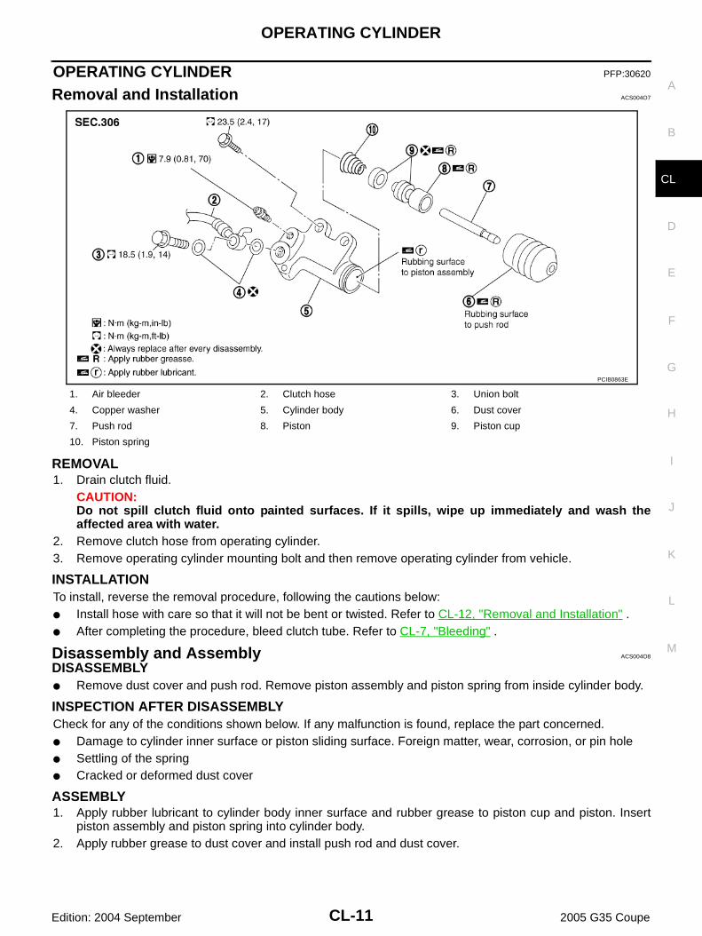
Removal and Installation ACS004O7
REMOVAL1. Drain clutch fluid.
CAUTION:Do not spill clutch fluid onto painted surfaces. If it spills, wipe up immediately and wash theaffected area with water.
2. Remove clutch hose from operating cylinder.3. Remove operating cylinder mounting bolt and then remove operating cylinder from vehicle.
INSTALLATIONTo install, reverse the removal procedure, following the cautions below:● Install hose with care so that it will not be bent or twisted. Refer to CL-12, "Removal and Installation" .● After completing the procedure, bleed clutch tube. Refer to CL-7, "Bleeding" .
Disassembly and Assembly ACS004O8
DISASSEMBLY● Remove dust cover and push rod. Remove piston assembly and piston spring from inside cylinder body.
INSPECTION AFTER DISASSEMBLYCheck for any of the conditions shown below. If any malfunction is found, replace the part concerned.● Damage to cylinder inner surface or piston sliding surface. Foreign matter, wear, corrosion, or pin hole● Settling of the spring● Cracked or deformed dust cover
ASSEMBLY1. Apply rubber lubricant to cylinder body inner surface and rubber grease to piston cup and piston. Insert
piston assembly and piston spring into cylinder body.2. Apply rubber grease to dust cover and install push rod and dust cover.
1. Air bleeder 2. Clutch hose 3. Union bolt
4. Copper washer 5. Cylinder body 6. Dust cover
7. Push rod 8. Piston 9. Piston cup
10. Piston spring
PCIB0863E
CL-12
CLUTCH PIPING
Edition: 2004 September 2005 G35 Coupe
CLUTCH PIPING PFP:30650
Removal and Installation ACS004O9
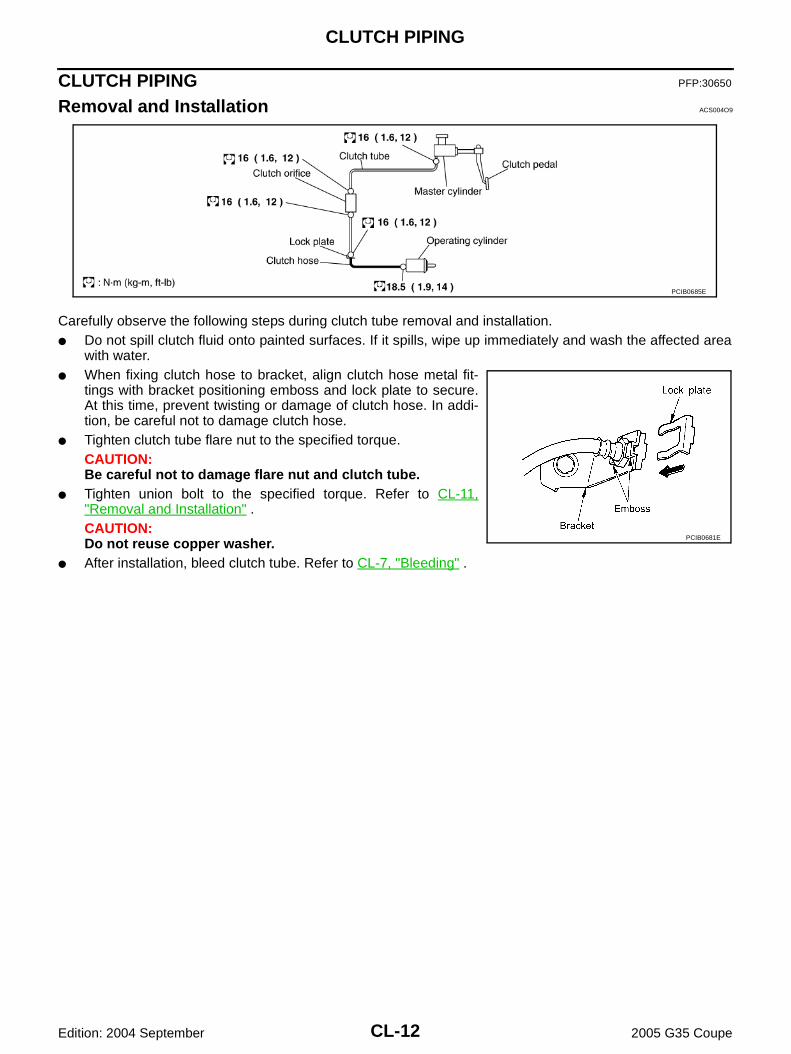
Carefully observe the following steps during clutch tube removal and installation.● Do not spill clutch fluid onto painted surfaces. If it spills, wipe up immediately and wash the affected area
with water.● When fixing clutch hose to bracket, align clutch hose metal fit-
tings with bracket positioning emboss and lock plate to secure.At this time, prevent twisting or damage of clutch hose. In addi-tion, be careful not to damage clutch hose.
● Tighten clutch tube flare nut to the specified torque. CAUTION:Be careful not to damage flare nut and clutch tube.
● Tighten union bolt to the specified torque. Refer to CL-11,"Removal and Installation" .CAUTION:Do not reuse copper washer.
● After installation, bleed clutch tube. Refer to CL-7, "Bleeding" .
PCIB0685E
PCIB0681E
CLUTCH RELEASE MECHANISM
CL-13
D
E
F
G
H
I
J
K
L
M
A
B
CL
Edition: 2004 September 2005 G35 Coupe
CLUTCH RELEASE MECHANISM PFP:30502
Removal and Installation ACS004OA
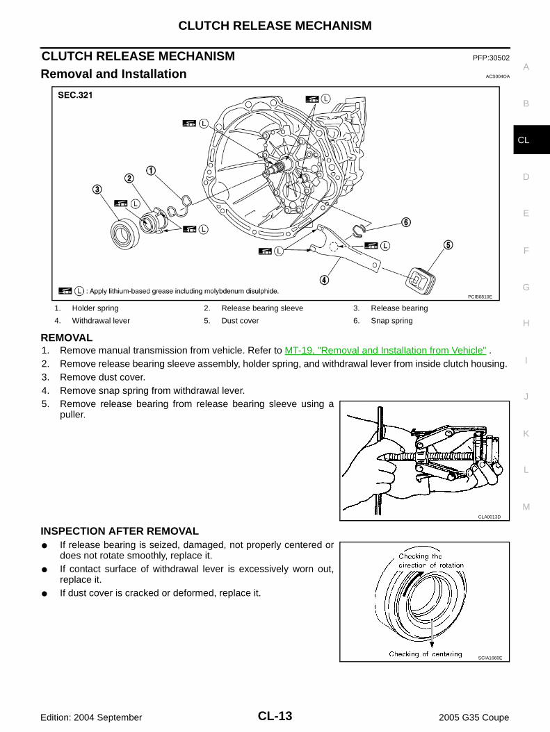
REMOVAL1. Remove manual transmission from vehicle. Refer to MT-19, "Removal and Installation from Vehicle" .2. Remove release bearing sleeve assembly, holder spring, and withdrawal lever from inside clutch housing. 3. Remove dust cover.4. Remove snap spring from withdrawal lever.5. Remove release bearing from release bearing sleeve using a
puller.
INSPECTION AFTER REMOVAL● If release bearing is seized, damaged, not properly centered or
does not rotate smoothly, replace it.● If contact surface of withdrawal lever is excessively worn out,
replace it.● If dust cover is cracked or deformed, replace it.
1. Holder spring 2. Release bearing sleeve 3. Release bearing
4. Withdrawal lever 5. Dust cover 6. Snap spring
PCIB0810E
CLA0013D
SCIA1660E
CL-14
CLUTCH RELEASE MECHANISM
Edition: 2004 September 2005 G35 Coupe
INSTALLATIONCAUTION:● Be sure to apply grease to the points specified. Otherwise, noise, poor disengagement, or damage
to the clutch may result. Excessive grease may cause slip or quiver. Wipe off any grease oozingfrom the parts.
● Be careful not to bring any grease into contact with clutch disc facing, pressure plate surface, orflywheel surface.
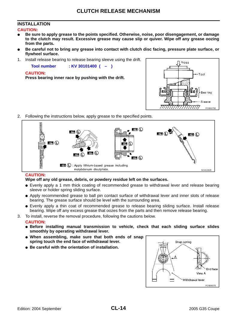
1. Install release bearing to release bearing sleeve using the drift.
CAUTION:Press bearing inner race by pushing with the drift.
2. Following the instructions below, apply grease to the specified points.
CAUTION:Wipe off any old grease, debris, or powdery residue left on the surfaces.● Evenly apply a 1 mm thick coating of recommended grease to withdrawal lever and release bearing
sleeve or holder spring sliding surface.● Apply recommended grease to ball pin contact surface of withdrawal lever and inner slots of release
bearing. The grease surface should be level with the surrounding area.● Evenly apply a thin coat of recommended grease to release bearing sliding surface. Install release
bearing. Wipe off any excess grease that oozes from the parts and then remove release bearing.3. To install, reverse the removal procedure, following the cautions below.
CAUTION:● Before installing manual transmission to vehicle, check that each sliding surface slides
smoothly by operating withdrawal lever.● When assembling, make sure that both ends of snap
spring touch the end face of withdrawal lever.● Be careful with the orientation of installation.
Tool number : KV 30101400 ( – )
PCIB0275E
SCIA1362E
PCIB0837E
CLUTCH DISC, CLUTCH COVER
CL-15
D
E
F
G
H
I
J
K
L
M
A
B
CL
Edition: 2004 September 2005 G35 Coupe
CLUTCH DISC, CLUTCH COVER PFP:30100
Removal and Installation ACS004OB
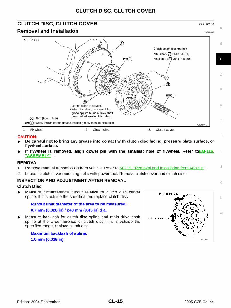
CAUTION:● Be careful not to bring any grease into contact with clutch disc facing, pressure plate surface, or
flywheel surface.● If flywheel is removed, align dowel pin with the smallest hole of flywheel. Refer toEM-116,
"ASSEMBLY" .
REMOVAL1. Remove manual transmission from vehicle. Refer to MT-19, "Removal and Installation from Vehicle" .2. Loosen clutch cover mounting bolts with power tool. Remove clutch cover and clutch disc.
INSPECTION AND ADJUSTMENT AFTER REMOVALClutch Disc● Measure circumference runout relative to clutch disc center
spline. If it is outside the specification, replace clutch disc.
● Measure backlash for clutch disc spline and main drive shaftspline at the circumference of clutch disc. If it is outside thespecified range, replace clutch disc.
1. Flywheel 2. Clutch disc 3. Clutch cover
PCIB0686E
Runout limit/diameter of the area to be measured:0.7 mm (0.028 in) / 240 mm (9.45 in) dia.
Maximum backlash of spline:1.0 mm (0.039 in) SCL221
CL-16
CLUTCH DISC, CLUTCH COVER
Edition: 2004 September 2005 G35 Coupe
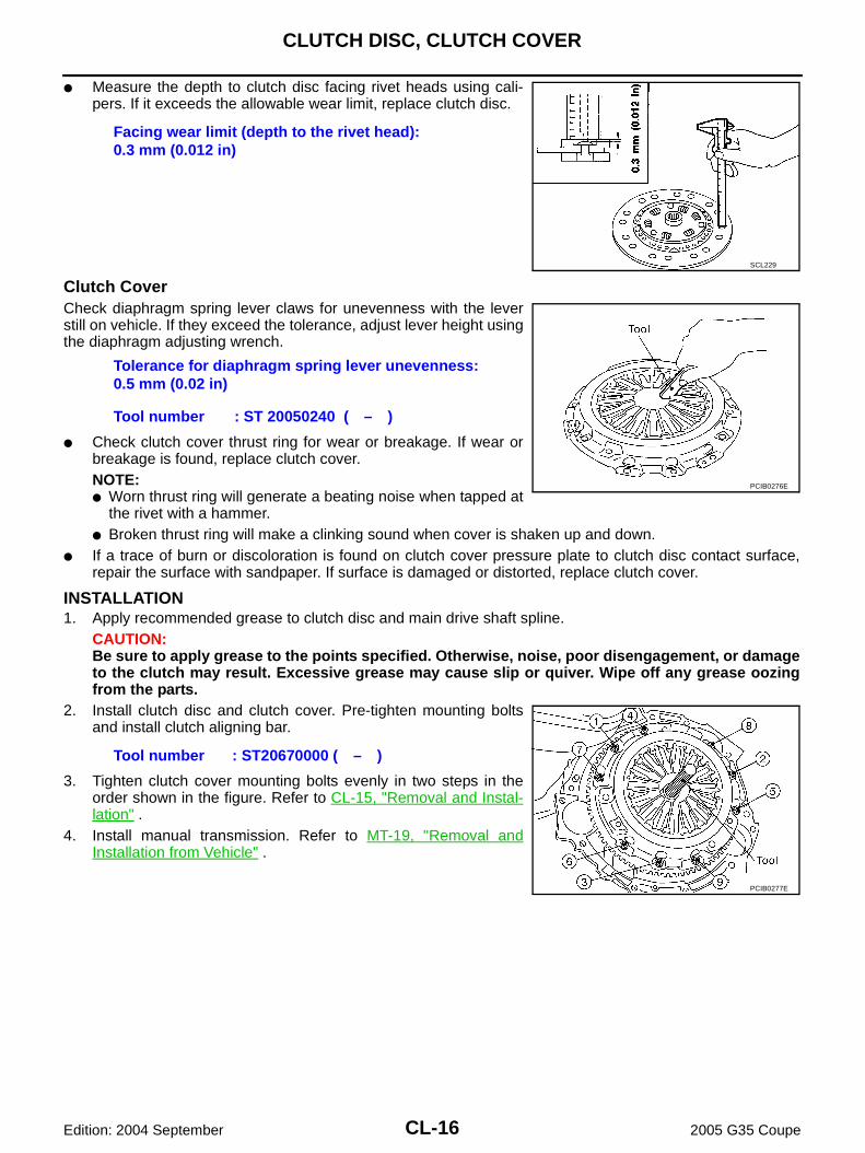
● Measure the depth to clutch disc facing rivet heads using cali-pers. If it exceeds the allowable wear limit, replace clutch disc.
Clutch CoverCheck diaphragm spring lever claws for unevenness with the leverstill on vehicle. If they exceed the tolerance, adjust lever height usingthe diaphragm adjusting wrench.
● Check clutch cover thrust ring for wear or breakage. If wear orbreakage is found, replace clutch cover.NOTE:● Worn thrust ring will generate a beating noise when tapped at
the rivet with a hammer.● Broken thrust ring will make a clinking sound when cover is shaken up and down.
● If a trace of burn or discoloration is found on clutch cover pressure plate to clutch disc contact surface,repair the surface with sandpaper. If surface is damaged or distorted, replace clutch cover.
INSTALLATION1. Apply recommended grease to clutch disc and main drive shaft spline.
CAUTION:Be sure to apply grease to the points specified. Otherwise, noise, poor disengagement, or damageto the clutch may result. Excessive grease may cause slip or quiver. Wipe off any grease oozingfrom the parts.
2. Install clutch disc and clutch cover. Pre-tighten mounting boltsand install clutch aligning bar.
3. Tighten clutch cover mounting bolts evenly in two steps in theorder shown in the figure. Refer to CL-15, "Removal and Instal-lation" .
4. Install manual transmission. Refer to MT-19, "Removal andInstallation from Vehicle" .
Facing wear limit (depth to the rivet head):0.3 mm (0.012 in)
SCL229
Tolerance for diaphragm spring lever unevenness:0.5 mm (0.02 in)
Tool number : ST 20050240 ( – )
PCIB0276E
Tool number : ST20670000 ( – )
PCIB0277E
SERVICE DATA AND SPECIFICATIONS (SDS)
CL-17
D
E
F
G
H
I
J
K
L
M
A
B
CL
Edition: 2004 September 2005 G35 Coupe
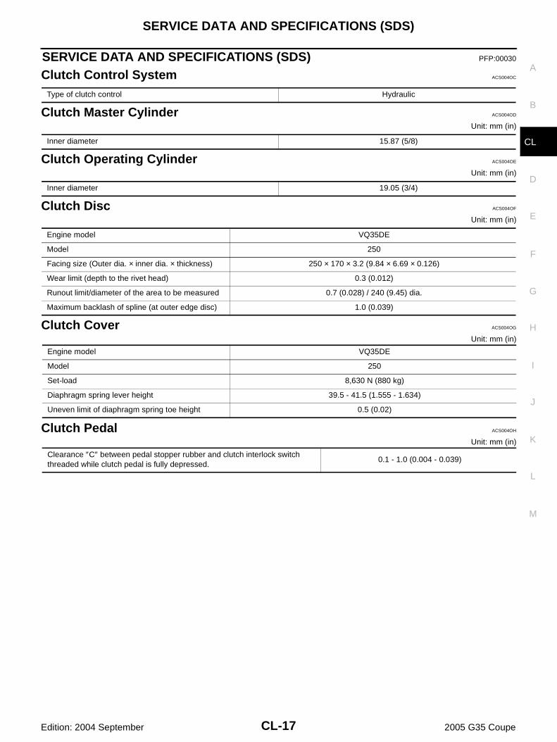
SERVICE DATA AND SPECIFICATIONS (SDS) PFP:00030
Clutch Control System ACS004OC
Clutch Master Cylinder ACS004OD
Unit: mm (in)
Clutch Operating Cylinder ACS004OE
Unit: mm (in)
Clutch Disc ACS004OF
Unit: mm (in)
Clutch Cover ACS004OG
Unit: mm (in)
Clutch Pedal ACS004OH
Unit: mm (in)
Type of clutch control Hydraulic
Inner diameter 15.87 (5/8)
Inner diameter 19.05 (3/4)
Engine model VQ35DE
Model 250
Facing size (Outer dia. × inner dia. × thickness) 250 × 170 × 3.2 (9.84 × 6.69 × 0.126)
Wear limit (depth to the rivet head) 0.3 (0.012)
Runout limit/diameter of the area to be measured 0.7 (0.028) / 240 (9.45) dia.
Maximum backlash of spline (at outer edge disc) 1.0 (0.039)
Engine model VQ35DE
Model 250
Set-load 8,630 N (880 kg)
Diaphragm spring lever height 39.5 - 41.5 (1.555 - 1.634)
Uneven limit of diaphragm spring toe height 0.5 (0.02)
Clearance ″C″ between pedal stopper rubber and clutch interlock switch threaded while clutch pedal is fully depressed.
0.1 - 1.0 (0.004 - 0.039)
CL-18
SERVICE DATA AND SPECIFICATIONS (SDS)
Edition: 2004 September 2005 G35 Coupe


![vf[ky Hkkjrh; vk;qfoZKkuLakLFkku] jk;iqj ¼NRrhlx](https://img.dokumen.tips/doc/110x75/631c5a277051d371800f6fbb/vfky-hkkjrh-vkqfozkkulaklfkku-jkiqj-nrrhlx.jpg)


![ksx] mÙkjk[kM yksd lsok vk](https://img.dokumen.tips/doc/110x75/632717e85c2c3bbfa8040199/ksx-mukjkkm-yksd-lsok-vk.jpg)


