Embed Size (px)
Citation preview
Numerical Simulation of Seismic Ground Motion Isolation Using Fully CoupledNonlinear Response in Saturated Sands
Mahdi Taiebat1, Boris Jeremic2, Zhao Cheng3, and Yannis Dafalias4
1Graduate Student Researcher, Department of Civil and Environmental Engineering, University ofCalifornia, Davis, CA 95616; email: [email protected] Professor, Department of Civil and Environmental Engineering, University of California,Davis, CA 95616; email: [email protected] Engineer, Earth Mechanics Inc. Oakland, CA 946214Professor, Department of Civil and Environmental Engineering, University of California, Davis, CA95616 and Department of Mechanics, National Technical University of Athens, Zographou 15780,Greece;
ABSTRACT: A fully coupled nonlinear dynamic numerical approach and an advancedconstitutive model have been implemented in a three dimensional finite element computercode to predict the response of saturated porous media under different types of loading condi-tions including earthquake loading. The formulation and implementation are already verifiedand validate, and were then applied to the problem of sand liquefaction and cyclic mobilityphenomena for investigation on a specific configuration of layered soil column, where liq-uefaction of the deeper loose elements prevents transmission of earthquake induced shearstresses to the upper layers.
INTRODUCTION
Modeling and simulations of soil behavior induced by earthquakes, that can be relatedto liquefaction and cyclic mobility, continue to challenge engineering research and practice.Such behavior commonly occurs in loose to medium dense sands which are fully saturatedand will result in almost complete loss of strength (liquefaction), or partial loss of strength(cyclic mobility). Fully coupled transient response of the saturated system and the con-stitutive behavior of the soil skeleton play equally important roles in successful numericalsimulation of soil liquefaction. To model these complex phenomena one needs to utilize, a)a consistent and efficient coupled formulation, and b) an accurate single-phase constitutivemodel for soil. In addition to these the numerical tool should be capable to do all the simu-lations in three-dimensional geometry which is what engineers really need for simulation ofthe real life systems.
Geotechnical Earthquake Engineering and Soil Dynamics IV GSP 181 © 2008 ASCE
Copyright ASCE 2008 Geotechnical Earthquake and Engineering and Soil Dynamics IV Congress 2008
Having a reliable tool for realistic simulation of saturated sands, a number of challeng-ing issues can be investigated. The results rely on verified formulation and implementationof behavior of a porous media fully coupled with pore fluid, and on validated constitutivematerial modeling. Issues of verification and validation are fundamental to the process ofprediction of mechanical behavior in computational science and engineering (Jeremic et al.,2007; Oberkampf et al., 2002). Prediction of mechanical behavior comprises use of compu-tational model to foretell the state of a physical system under consideration under conditionsfor which the computational model has not been validated. Confidence in predictions reliesheavily on proper Verification and Validation (V&V) process. In the current paper an inter-esting issue about isolation of system from transmission of earthquake induced shear wavesis briefly examined. A 1D sand column example is used as the system of interest in thisexample.
GENERAL FORMULATION
Three general continuum formulations (Zienkiewicz and Shiomi, 1984) are possible formodeling of the fully coupled problem (soil skeleton – pore fluid) in geomechanics, namelythe (a) u ! p, (b) u ! U , and (c) u ! p ! U formulations. Here, the unknowns are thesoil skeleton displacements u; the pore fluid (water) pressure p; and the pore fluid (water)displacements U . In this paper coupled dynamic field equations with u! p!U formulationare used to determine pore fluid and soil skeleton responses (Zienkiewicz and Shiomi, 1984;Argyris and Mlejnek, 1991). Each node of the u ! p ! U element has thus seven degrees offreedoms in three dimensions (three for solid displacements, one for pore fluid pressures andthree for pore fluid displacements). It should be noted that it is possible to use same shapefunctions for both displacement and pore pressure unknown field as u ! p ! U formulationwith compressible fluid allows that without volumetric locking (Zienkiewicz and Shiomi,1984). Despite it’s power, the u! p!U formulation has rarely been implemented into finiteelement code. Details of the formulation, finite element discretization, and implementationcan be found in Jeremic et al. (2007). In addition to that a set of verification examples arepresented there to determine that formulation and the implementation accurately representconceptual description of porous media behavior.
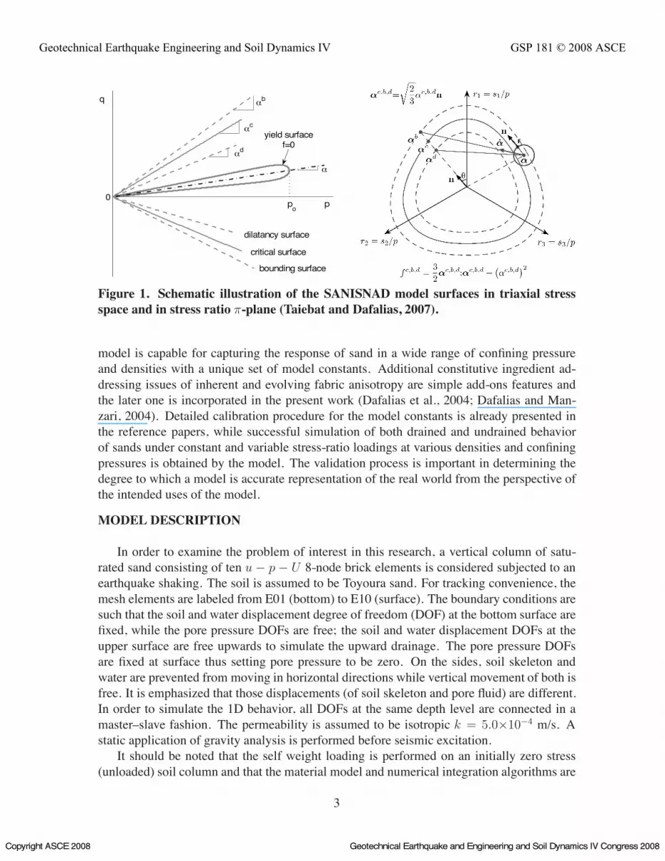
Development and evaluation of comprehensive constitutive models which can reliablysimulate complex stress-strain behavior of sands and yet are conceptually simple and com-putationally efficient is an iterative process. SANISAND is the name used for a familyof Simple ANIsotropic SAND constitutive models (the name resulting from the foregoinguppercase letters) developed over the past few years (Manzari and Dafalias, 1997; Li andDafalias, 2000; Dafalias and Manzari, 2004; Dafalias et al., 2004), within the frameworkof critical state soil mechanics and bounding surface plasticity. The latest members of theSANISAND family of models are implemented and used in the current research (Taiebatand Dafalias, 2007). It is basically a critical-state plasticity model within the concept of thebounding surface. The model consists of a close-ended narrow yield surface in p ! q spacewhich can capture the plastic response for constant and variable stress-ratio loading. Figure1 shows the yield, critical, bounding and dilatancy surfaces of the model both in p! q spaceand in general stress-ratio !-plane. Using the concept of critical state soil mechanics, the
2
Geotechnical Earthquake Engineering and Soil Dynamics IV GSP 181 © 2008 ASCE
Copyright ASCE 2008 Geotechnical Earthquake and Engineering and Soil Dynamics IV Congress 2008
0
dilatancy surface
bounding surface
critical surface
αc
αb
αd
yield surfacef=0
po p
α
q
Figure 1. Schematic illustration of the SANISNAD model surfaces in triaxial stressspace and in stress ratio !-plane (Taiebat and Dafalias, 2007).
model is capable for capturing the response of sand in a wide range of confining pressureand densities with a unique set of model constants. Additional constitutive ingredient ad-dressing issues of inherent and evolving fabric anisotropy are simple add-ons features andthe later one is incorporated in the present work (Dafalias et al., 2004; Dafalias and Man-zari, 2004). Detailed calibration procedure for the model constants is already presented inthe reference papers, while successful simulation of both drained and undrained behaviorof sands under constant and variable stress-ratio loadings at various densities and confiningpressures is obtained by the model. The validation process is important in determining thedegree to which a model is accurate representation of the real world from the perspective ofthe intended uses of the model.
MODEL DESCRIPTION
In order to examine the problem of interest in this research, a vertical column of satu-rated sand consisting of ten u ! p ! U 8-node brick elements is considered subjected to anearthquake shaking. The soil is assumed to be Toyoura sand. For tracking convenience, themesh elements are labeled from E01 (bottom) to E10 (surface). The boundary conditions aresuch that the soil and water displacement degree of freedom (DOF) at the bottom surface arefixed, while the pore pressure DOFs are free; the soil and water displacement DOFs at theupper surface are free upwards to simulate the upward drainage. The pore pressure DOFsare fixed at surface thus setting pore pressure to be zero. On the sides, soil skeleton andwater are prevented from moving in horizontal directions while vertical movement of both isfree. It is emphasized that those displacements (of soil skeleton and pore fluid) are different.In order to simulate the 1D behavior, all DOFs at the same depth level are connected in amaster–slave fashion. The permeability is assumed to be isotropic k = 5.0"10!4 m/s. Astatic application of gravity analysis is performed before seismic excitation.
It should be noted that the self weight loading is performed on an initially zero stress(unloaded) soil column and that the material model and numerical integration algorithms are
3
Geotechnical Earthquake Engineering and Soil Dynamics IV GSP 181 © 2008 ASCE
Copyright ASCE 2008 Geotechnical Earthquake and Engineering and Soil Dynamics IV Congress 2008

powerful enough to follow through this early loading with proper evolution. Input accelera-tion time history (Figure 2) is taken from the recorded horizontal acceleration of Model No.1of VELACS project by Rensselaer Polytechnic Institute (Arulanandan and Scott, 1993). Thepeak acceleration of the motion is close to 0.2 g, while main shaking lasts for about 12 sec-onds (from 1 s to 13 s). Two distinct cases are considered in this study. In the first case thewhole soil column is assumed to be uniformly dense Toyoura sand with e = 0.75. In thesecond case, however, the deepest two elements of the soil column are assumed to be at veryloose state with e = 0.95. The rest of the soil column, i.e. the upper eight element are atthe same density as the first case (e = 0.75). The formulation and implementation takes intoaccount velocity proportional damping (usually called viscous damping) by proper modelingof coupling of pore fluid and solid skeleton, while the displacement proportional damping isappropriately modeled using the advanced material model. No additional damping is used inFEM model.
0 5 10 15 20−0.3
−0.2
−0.1
0
0.1
0.2
0.3
Time (s)
g
Figure 2. Input earthquake ground motion for the soil column.
SIMULATION RESULTS AND DISCUSSIONS
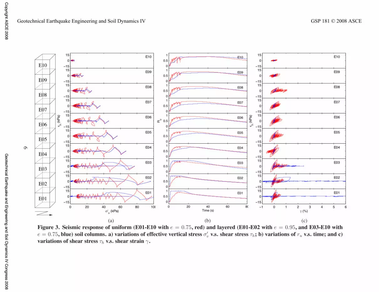
Results of the analysis for both cases of interest are presented in Figure 3. Three sets ofplots are shown in this figure: a) variations of effective vertical stress ""
v v.s. shear stress #h;b) variations of ru
1 v.s. time; and c) variations of shear stress #h v.s. shear strain $.For Case 1, where all ten elements are initially in dense state (e = 0.75), this figure shows
the typical mechanism of cyclic decrease in effective vertical stress. Signs of the partialbutterfly shape in the effective stress path can be observed from early stages of shaking.The butterfly is more evident in the upper layers with the lower confining pressures, i.e.more dilative response. In later stages of the shaking, i.e. when the confining pressurereduces to smaller values the butterfly shape of the stress path gets more pronounced due tohaving more dilative response in the lower confining pressure based on Critical State SoilMechanics concept. It can be observed that the vertical effective stress in most of the upper
1ru = [(!!
v)in
! !!
v] / (!!
v)inand therefore is equal to 0 for zero excess pore pressure and is equal to 1 for
the fully liquefied state, i.e. when the vertical effective stress is negligible.
4
Geotechnical Earthquake Engineering and Soil Dynamics IV GSP 181 © 2008 ASCE
Copyright ASCE 2008 Geotechnical Earthquake and Engineering and Soil Dynamics IV Congress 2008

layers gets pretty much close to zero and as a result the value of ru approaches to 1. Althoughbecause of having partial segments of dilative response sand column has not completely lostits strength, one can still observe some horizontal strains in a number of the layers due topartial liquefaction.
For Case 2, as mentioned before elements E01 and E02 are very loose (e = 0.95) andelements E03-E10 are at same density as what they are in case 1 (e = 0.75). The very looseinitial state of elements E01 and E02 causes very fast decrease in the effective stress ratioand brings these two elements to fully liquefied state almost at the end of the first cycle. Inthe first half-cycle when E01 and E02 are still not liquefied the stress path in the upper layerslook similar to what it used to be in case 1, however once E01 and E02 approach the fullyliquefied at the end of the first cycle, almost no shear stress can be transmitted to the upperlayers and so the value of shear stress in these elements remains very close to zero. This isisolation of the upper layers from transmission of earthquake induced shear waves comingfrom the base. The shear stress-strain path clearly shows that for the second case where theupper layers do not feel the shear stresses after the first cycle of loading, the resulting shearstains are almost negligible comparing to case 1. Of course the very loose elements E01and E02 (and their adducent element E03) show considerable value of shear strain due toliquefaction.
Despite the absence of transmission of earthquake loading to the upper layers after thefirst cycle, one can still observed decrease in the effective vertical stress for the upper lay-ers after this point. This indeed is due to the transient pore water flux that enters theseelements from the liquefied bottom elements and forces the upper elements toward low ef-fective stresses. After all, looking at the middle plot for variations of ru it can be observedthat the outcome of isolation in one way and water flux in the other way still keeps the upperlayer more away from the ru = 1 comparing to what they used to behave in case 1.
Regardless of the mentioned distinctions between the two cases of simulations, the topsection of the model has remained closer to liquefied well past the end of shaking. This isexplained by the large supply of pore fluid from lower layers, for which the dissipation startsearlier. For example, for the lowest layer, the observable drop in excess pore pressure startas soon as the shaking ends, while, the upper layers then receive this dissipated pore fluidfrom lower layers and as a result their effective stress keep approaching to (or remain at)smaller values well past end of shaking (which happens at approximately 13 seconds). It isvery important to note the significance of this incoming pore water flux on the pore waterpressure of the top layers.
CONCLUSIONS
Using fully coupled nonlinear finite element analysis, it was shown that in a specificconfiguration of the layered system liquefaction of the deeper loose elements prevents trans-mission of the earthquake induced shear stresses to the upper layers. Absence of these shearstresses in the upper layers during the earthquake helps in having almost negligible shearstrain in these layers, however on the other hand the water flux coming from the liquefiedbottom layers will force the upper layers toward lower effective stress even in absence ofearthquake induced shear stresses.
5
Geotechnical Earthquake Engineering and Soil Dynamics IV GSP 181 © 2008 ASCE
Copyright ASCE 2008 Geotechnical Earthquake and Engineering and Soil Dynamics IV Congress 2008
E10
A
B
C
D
F
G
H
I
J
K
E
E01
E02
E03
E04
E05
E06
E07
E08
E09
−15
015 E10
−15
015 E09
−15
015 E08
−15
015 E07
−15
015
τ h (kPa
) E06
−15
015 E05
−15
015 E04
−15
015 E03
−15
015 E02
0 20 40 60 80 100−15
015
σ′v (kPa)
E01
00.5
1
E10
E10
00.5
1 E09
00.5
1 E08
00.5
1 E07
00.5
1
R u E06
00.5
1 E05
00.5
1 E04
00.5
1 E03
00.5
1 E02
0 20 40 60 800
0.51
Time (s)
E01
−15
015 E10
−15
015 E09
−15
015 E08
−15
015 E07
−15
015 E06
τ h (kPa
)
−15
015 E05
−15
015 E04
−15
015 E03
−15
015 E02
−1 0 1 2 3 4 5 6−15
015 E01
γ (%)
(a) (b) (c)Figure 3. Seismic response of uniform (E01-E10 with e = 0.75, red) and layered (E01-E02 with e = 0.95, and E03-E10 withe = 0.75, blue) soil columns. a) variations of effective vertical stress ""
v v.s. shear stress #h; b) variations of ru v.s. time; and c)variations of shear stress #h v.s. shear strain $.
6
Geotechnical Earthquake Engineering and Soil Dynamics IV GSP 181 © 2008 ASCE
Copyright ASCE 2008G
eotechnical Earthquake and Engineering and Soil Dynamics IV Congress 2008
ACKNOWLEDGMENTSThe work presented in this paper was supported in part by grants NSF–EEC–9701568,
NSF–CMS–0337811, and NSF–CMS–0201231 from National Science Foundation. Thesesupports are gratefully acknowledged.
REFERENCES
Argyris, J. and Mlejnek, H.-P. (1991). “Dynamics of Structures”. North Holland in USAElsevier.
Arulanandan, K. and Scott, R. F., eds. (1993). “Verification of Numerical Procedures for theAnalysis of Soil Liquefaction Problems”. A. A. Balkema.
Dafalias, Y. F. and Manzari, M. T. (2004). “Simple plasticity sand model accounting forfabric change effects.” Journal of Engineering Mechanics, 130(6), 622–634.
Dafalias, Y. F., Papadimitriou, A. G., and Li, X. S. (2004). “Sand plasticity model accountingfor inherent fabric anisotropy.” Journal of Engineering Mechanics, 130(11), 1319–1333.
Jeremic, B., Cheng, Z., Taiebat, M., and Dafalias, Y. F. (2007). “Numerical simulationof fully saturated porous materials.” International Journal for Numerical and AnalyticalMethods in Geomechanics. DOI: 10.1002/nag.687. (In press).
Li, X. S. and Dafalias, Y. F. (2000). “Dilatancy for cohesionless soils.”Geotechnique, 54(4),449–460.
Manzari, M. T. and Dafalias, Y. F. (1997). “A critical state two–surface plasticity model forsands.” Geotechnique, 47(2), 255–272.
Oberkampf, W. L., Trucano, T. G., and Hirsch, C. (2002). “Verification, validation and pre-dictive capability in computational engineering and physics.” Proceedings of the Founda-tions for Verification and Validation on the 21st Century Workshop, Johns Hopkins Uni-versity / Applied Physics Laboratory, Laurel, Maryland. 1–74.
Taiebat, M. and Dafalias, Y. F. (2007). “SANISAND: simple anisotropic sand plasticitymodel.” International Journal for Numerical and Analytical Methods in Geomechanics,DOI: 10.1002/nag.651. (in press).
Zienkiewicz, O. C. and Shiomi, T. (1984). “Dynamic behaviour of saturated porous media;the generalized Biot formulation and its numerical solution.” International Journal forNumerical Methods in Engineering, 8, 71–96.
7
Geotechnical Earthquake Engineering and Soil Dynamics IV GSP 181 © 2008 ASCE
Copyright ASCE 2008 Geotechnical Earthquake and Engineering and Soil Dynamics IV Congress 2008


