Embed Size (px)
Citation preview
nuclear fusion fusion nucleaire
flnepHMft enures fusion nuclear
(Supplement to the journal Nuclear Fusion)
VOLUME 6
I N T E R N A T I O N A L A T O M I C E N E R G Y A G E N C Y , V I E N N A , 1995
A G E N C E I N T E R N A T I O N A L E DE L 'ENERGIE A T O M I Q U E , V I E N N E . 1 9 9 5
ME>KflyH APOflHOE ATEHTCTBO nO ATOMHOft 3 H E P T H H , BEHA, 1995
O R G A N I S M O I N T E R N A C I O N A L DE E N E R G I A A T O M I C A , V I E N A . 1 9 9 5 m
The following States are Members of the International Atomic Energy Agency:
AFGHANISTAN ALBANIA ALGERIA ARGENTINA ARMENIA AUSTRALIA AUSTRIA BANGLADESH BELARUS BELGIUM BOLIVIA BOSNIA AND
HERZEGOVINA BRAZIL BULGARIA CAMBODIA CAMEROON CANADA CHILE CHINA COLOMBIA COSTA RICA COTE DIVOIRE CROATIA CUBA CYPRUS
CZECH REPUBLIC DENMARK DOMINICAN REPUBLIC ECUADOR EGYPT EL SALVADOR ESTONIA ETHIOPIA FINLAND FRANCE GABON GERMANY GHANA GREECE GUATEMALA HAITI HOLY SEE
HUNGARY ICELAND INDIA INDONESIA IRAN, ISLAMIC REPUBLIC OF IRAQ IRELAND ISRAEL ITALY JAMAICA JAPAN JORDAN KAZAKHSTAN KENYA KOREA, REPUBLIC OF KUWAIT LEBANON LIBERIA LIBYAN ARAB JAMAHIRIYA LIECHTENSTEIN LITHUANIA LUXEMBOURG MADAGASCAR MALAYSIA MALI MARSHALL ISLANDS MAURITIUS MEXICO MONACO MONGOLIA MOROCCO MYANMAR NAMIBIA NETHERLANDS NEW ZEALAND NICARAGUA NIGER NIGERIA NORWAY PAKISTAN PANAMA PARAGUAY
PERU PHILIPPINES POLAND PORTUGAL QATAR ROMANIA RUSSIAN FEDERATION SAUDI ARABIA SENEGAL SIERRA LEONE SINGAPORE SLOVAKIA SLOVENIA SOUTH AFRICA SPAIN SRI LANKA SUDAN SWEDEN SWITZERLAND SYRIAN ARAB REPUBLIC THAILAND THE FORMER YUGOSLAV
REPUBLIC OF MACEDONIA TUNISIA TURKEY UGANDA UKRAINE UNITED ARAB EMIRATES UNITED KINGDOM OF GREAT
BRITAIN AND NORTHERN IRELAND
UNITED REPUBLIC OF TANZANIA
UNITED STATES OF AMERICA URUGUAY UZBEKISTAN VENEZUELA VIET NAM YEMEN YUGOSLAVIA ZAIRE ZAMBIA ZIMBABWE
The Agency's Statute was approved on 23 October 1956 by the Conference on the Statute of the IAEA held at United Nations Headquarters, New York;
it entered into force on 29 July 1957. The Headquarters of the Agency are situated in Vienna. Its principal objective is "to accelerate and enlarge the contribution of atomic energy to peace, health and prosperity throughout the world".
© IAEA, 1995
Permission to reproduce or translate the information contained in this publication may be obtained by writing to the Division of Publications, International Atomic Energy Agency, Wagramerstrasse 5, P.O. Box 100, A-1400 Vienna, Austria.
Printed by the IAEA in Austria December 1995
ATOMIC AND PLASMA-MATERIAL INTERACTION DATA FOR FUSION
(Supplement to the journal Nuclear Fusion)
VOLUME 6
INTERNATIONAL ATOMIC ENERGY AGENCY, VIENNA, 1995
The volumes of ATOMIC AND PLASMA-MATERIAL INTERACTION DATA FOR FUSION are published by the International Atomic Energy Agency as supplements of the journal NUCLEAR FUSION.
For these supplements, papers, letters and reviews are accepted which deal with the following topics:
— Elementary collision processes in fusion plasmas involving photons, electrons, ions, atoms and molecules; — Collision processes of plasma particles with surfaces of fusion relevant materials; — Plasma-material interaction phenomena, including the thermophysical response of materials.
Each submitted contribution should contain fusion relevant data and information in either of the above areas. Original contributions should provide new data, using well established methods. Review articles should give a critical analysis or evaluation of a wider range of data. They are normally prepared on the invitation of the Scientific Editor or on prior mutual consent. Each submitted contribution is assessed by two independent referees.
Every manuscript submitted must be accompanied by a disclaimer stating that the paper has not been published and is not being considered for publication elsewhere. If no copyright is claimed by the authors, the IAEA automatically owns the copyright of the paper.
Guidelines for the preparation of manuscripts are given on the inside back cover. Manuscripts and correspondence should be addressed to: The Editor, NUCLEAR FUSION, International Atomic Energy Agency, Wagramerstrasse 5, P.O. Box 100, A-1400 Vienna, Austria.
Publisher:
Scientific Editor:
Editor:
Editorial Board:
International Atomic Energy Agency, Wagramerstrasse 5, P.O. Box 100, A-1400 Vienna, Austria
R.K. Janev, Atomic and Molecular Data Unit, Division of Physical and Chemical Sciences
C. Bobeldijk, Division of Publications
V.A. Abramov (Russ. Fed.) R. Behrisch (Germany) H.-W. Drawin (France) W.B. Gauster (USA) H.B. Gilbody (UK) A. Kingston (UK) Yu.V. Martynenko (Russ. Fed.)
A. Miyahara (Japan) R.A. Phaneuf (USA) D.E. Post (USA) H.P. Summers (JET) H. Tawara (Japan) W.L. Wiese (USA)
Annual subscription price (one issue): Austrian Schillings 350,— Airmail delivery (optional): Austrian Schillings 40,— to any destination
ATOMIC AND PLASMA-MATERIAL INTERACTION DATA FOR FUSION, VOLUME 6 IAEA, VIENNA, 1995 STI/PUB/023/APID/06
EDITORIAL NOTE
The present volume of Atomic and Plasma-Material Interaction Data for Fusion includes critical reviews and results of original experimental and theoretical studies on inelastic collision processes among the basic and dominant impurity constituents of fusion plasmas. The processes considered in the present volume include: electron impact excitation of excited helium atoms, electron impact excitation and ionization of plasma impurity ions and atoms, electron-impurity-ion recombination and excitation, ionization and electron capture in collisions of plasma protons and impurity ions with the main fusion plasma neutral components H, He and H2 (the latter being always present in the plasma edge or introduced into the plasma by neutral beam injection for heating, fuelling or diagnostic purposes).
The majority of the contributions included in the present volume are the result of a three year Co-ordinated Research Programme on "Atomic Data for Medium- and High-Z Impurities in Fusion Plasmas", conducted by the International Atomic Energy Agency in the period 1991-1994. However, the content of the volume has been significantly expanded by the contributions of many other experts from the atomic physics community who have kindly agreed to perform supplementary cross-section measurements, calculations or critical data assessments for the above mentioned processes of fusion relevant collision systems.
The International Atomic Energy Agency expresses its appreciation to all the contributors to this volume for their dedicated effort and co-operation.
November, 1995 Vienna
CONTENTS
F.J. de Heer, I. Bray, D.V. Fursa, F.W. Bliek, H.O. Folkerts, R. Hoekstra, H.P. Summers: Excitation of He(2J'3S) by electron impact 7
V.P. Shevelko, H. Tawara: Spin-allowed and spin-forbidden transitions in excited He atoms induced by electron 27
P. Defrance: Recommended data for electron impact ionization of noble gas ions 43 M. Stenke, K. Aichele, D. Hathiramani, G. Hofmann, M. Steidl, R. Volpel,
E. Salzborn: Electron impact ionisation of Tungsten ions 51 A. Muller: Dielectronic recombination and ionization in electron-ion collisions:
data from merged-beams experiments 59 V.P. Shevelko, H. Tawara: Multiple ionization of atoms and positive ions by
electron impact 101 M.S. Pindzola, D.C. Griffin, N.R. Badnell, H.P. Summers: Electron-impact
ionization of atomic ions for ADAS 117 W. Fritsch: Theoretical studies of slow collisions between medium-Z metallic
ions and neutral H, H2, or He 131 R.K. Janev: Excitation of helium by protons and multiply charged ions: analytic
form of scaled cross sections 147 M. Gargaud, R. McCarrolI: Electron capture from H and He by Al+2'3, Si+2,3'4,
Ar+6 and Ti+4 in the eV to keV energy range 163 D.R. Schultz, P.S. Krstic: Inelastic processes in 0.1-1000 keV/u collisions of
Neq+ (q=7-10) ions with atomic hydrogen 173 H.B. Gilbody: Charge transfer and ionization studies involving metallic species 197 R. Hoekstra, J.P.M. Beijers, F.W. Bliek, S. Schippers, R. Morgenstern:
Fusion related experiments with medium-Z multiply charged ions 213 M. Druetta, D. Hitz, B. Jettkant: Charge exchange collisions of multicharged
Ar5'6+, Kr5'6+, Fe7'8+ and Ni17+ ions with He and H2 225 C. Cisneros, J. de Urquijo, I. Alvarez, A. Aguilar, A.M. Juarez,
H. Martinez: Electron capture collision processes involving multiply-charged Si, Ni, Ti, Mo, and W ions with H, H2 and He targets 247

EXCITATION OF HE(213S) BY ELECTRON IMPACT
F.J. DE HEER1, I. BRAY2, D.V. FURSA2, F.W. BLIEK3, H.O. FOLKERTS3, R. HOEKSTRA3, H. P. SUMMERS4
1 FOM Institute for Atomic and Molecular Physics, PO Box 41883,1009 DB Amsterdam, The Netherlands
2 Electronic Structure of Materials Centre, The Flinders University of South Australia, Adelaide, Australia.
3 K.V.I., Atomic Physics, Zemikelaan 25, 9747 AA Groningen, The Netherlands
4 JET Joint Undertaking, Abingdon, Oxon, 0X14 3EA, U.K.
ABSTRACT
Theoretical data for electron impact excitation of neutral helium in the He (2US) states are reviewed and a preferred data set is established for excitation to the He (nuL) states with n=2-4. Such a set of data was presented in a FOM report. The present work is an improvement made possible by new theoretical data, in particular the convergent close coupling data of Bray and Fursa, valid for the entire impact energy range of interest.
1. INTRODUCTION
A new assessment of electron impact cross section data for excitation of helium from the metastable He(2uS) states is presented. This study is connected with the use of 3He° and 4He° neutral heating beams on the JET tokamak. It is known that these beams contain a small fraction metastables [1] and so next to our study of excitation from the He ground state [2], the assessment of cross sections is also wanted for excitation of metastable He atoms. Whereas for excitation of He(11S) we could make use of many experimental results, in the case of excitation of He(21,3S) very little experimental material is available and we are mainly dependent on theory [3].
The assessment of data presented here for excitation to (n1,3L) states of He (n=2-4) must be seen as the continuation and revision of previous work (see e.g. the first two references quoted in [2]) and an improvement of the assessment of the relevant cross sections in FOM-report 95 0653 [4]. This improvement is connected with new theoretical data, in particular the convergent close coupling data (CCC) of Bray and Fursa evaluated for this work, and valid for the entire impact energy range of interest. Their first results for excitation of the He 23S state to n=2-4 He triplet states at a few energies were presented in reference [5]. Further we have Coulomb-Born Exchange (CBE) data of Shevelko and Ta-wara [6] and distorted wave approximation (DWA) data of Cartwright and Csanak [7]. All these new results provide more data, in particular for spin changing collisions and n=2-4 transisions where only few theoretical results were available (scaling was used in the previous publication [4] for excitation to the n=4 levels with respect to n=3).
7
Data are presented as cross sections, a, and collision strengths, Q, as defined in reference [2]. For a transition from an initial state /'to a final higher excited state/, we have
(Ej \ ay Q=wi T ~ V" J *»o
where wi is the statistical weight of the initial state / of the atom, aH is the excitation cross section, and £,is the energy of the free projectile electron with the atom in its initial state /'.
2. THEORETICAL DATA AND ASSESSMENT OF CROSS SECTION DATA.
In order to establish the cross section data, see the FOM report [4], different theoretical approximations had to be considered. For the low impact energy region (i.e. below the ionization threshold, 3.97 eV for 21S and 4.77 eV for 23S), the standard close coupling calculations that couple only the helium discrete energy states may be used (except for elastic transitions that usually require treatment of the continuum). At the higher impact energies, above about 50-100 eV, the first Born approximation (FBA) becomes valid. The intermediate energy region (from the ionization threshold up to energy where FBA becomes valid) requires the most sophisticated treatment. Until recently theoretical methods applied at this energy range have been limited to various versions of the distorted-wave and eikonal-type approximations. For spin-changing (singlet-triplet or vice-versa) transitions the theoretical calculations have been rather scarce and the least reliable. This is specially true in the intermediate energy region where the non-pertubative treatment of the exchange interaction is clearly desirable. At these energies the Ochkur approximation (valid at higher energies) has been used [4] to calculate cross sections for spin-changing transitions.
In this paper we use the results of the CCC method, which covers the entire energy range and so can be compared with all approximations. A full account of this method has been given by Fursa and Bray [8]. The CCC method is a non-perturbative approach to electron-atom scattering that treats both the discrete and continuum target subspaces to a demonstrable level of convergence. The multi-channel expansion of the total wave function is performed with target states obtained by diagonalising the target Hamiltonian in a Laguerre basis. The use of such bases ensures that completeness of the expansion is approached by simply increasing the basis size. In the case of the helium target the frozen-core approximation is used for the description of the target structure, see [8] for comparison of this approximation with experiment and other calculations. No approximations are made in the treatment of exchange. The CCC method is therefore equally valid in the low, intermediate, and high energy regions. The method demonstrated the ability to accurately describe electron-He(11S) scattering between 1.5 and 500 eV and gives in addition a very good account of electron-impact coherence parameters for the relevant excited He levels. The method has also been applied to scattering from He(23S) [5]. A total of 75-states have been included in the CCC calcultions. States up to the n=5 shell are good target discrete states. Given the overall consistent agreement of the CCC results with experiment for the excitations from the helium ground state we are confident in the
8
Recommended cross section
• Bray and Fursa (1995), CCC, this work
a Burke et al. (1969), R(5), [10]
T Fonetal. (1981), R(5), [9]
O Berrington et al. (1981), R(11), [11]
A Kingston et al. (1992), R(29), [4]
0 Kim and Inokuti (1969), FBA, [12)
<5> Ton-That et al. (1997), FBA, [12)
D Ochkur and Brattsev (1966), Ochkur, [17]
• Shevelko and Tawara (1995), CBE, (6)
• Flannery and Mc Can (1975), MET, [18]
O Mansky et al. (1990,1992), OMET, [19,20]
ta Mathuretal. (1987), DWA, [21]
• Badnell (1984), DWA, EDW, [22]
v Khuranaetal. (1987), DWA, [23]
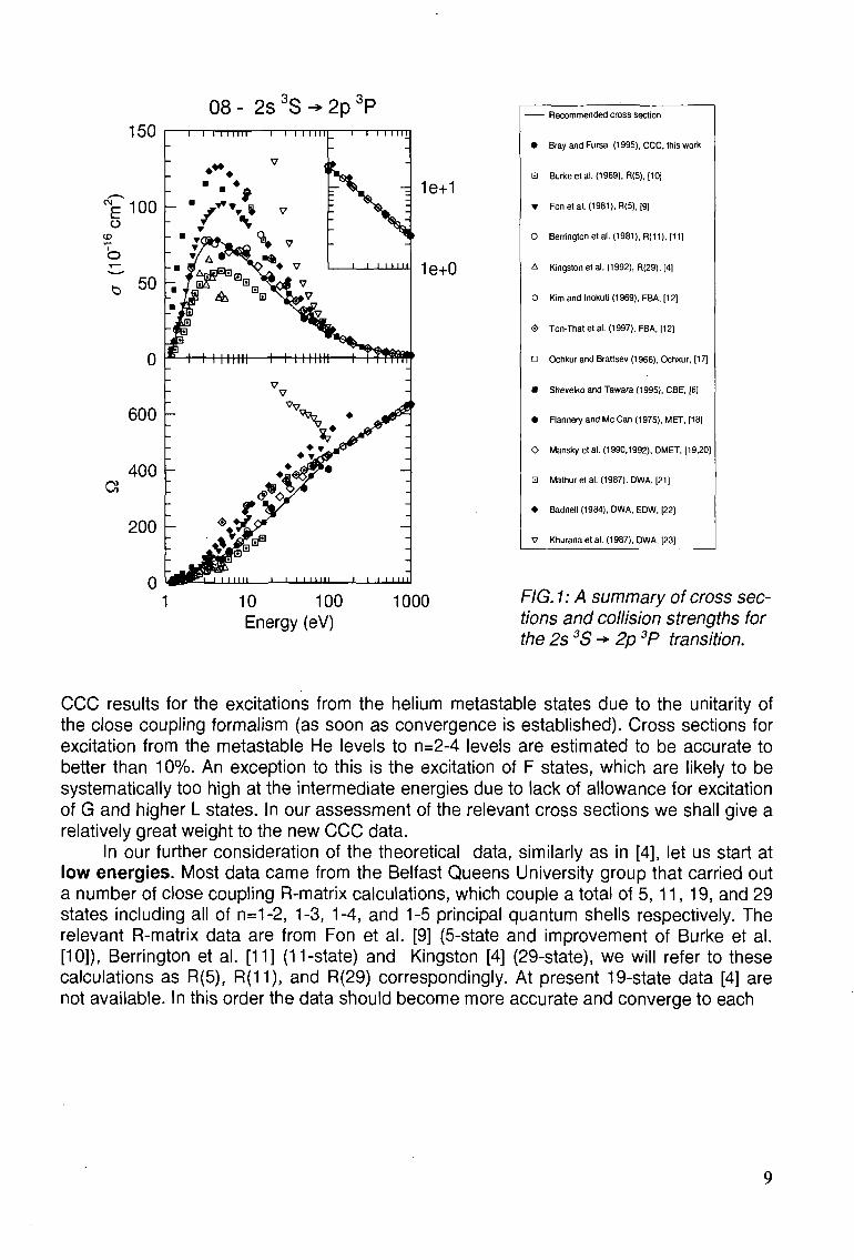
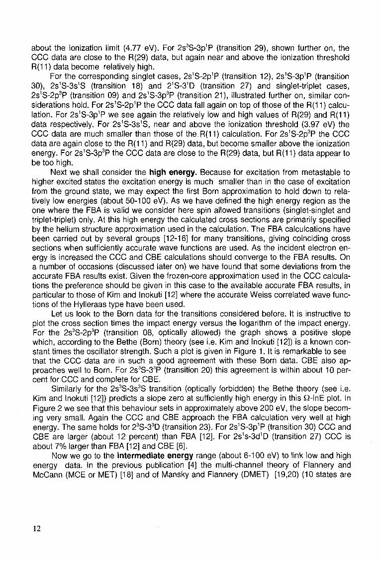
FIG. 1: A summary of cross sections and collision strengths for the 2s 3S -» 2p 3P transition.
CCC results for the excitations from the helium metastable states due to the unitarity of the close coupling formalism (as soon as convergence is established). Cross sections for excitation from the metastable He levels to n=2-4 levels are estimated to be accurate to better than 10%. An exception to this is the excitation of F states, which are likely to be systematically too high at the intermediate energies due to lack of allowance for excitation of G and higher L states. In our assessment of the relevant cross sections we shall give a relatively great weight to the new CCC data.
In our further consideration of the theoretical data, similarly as in [4], let us start at low energies. Most data came from the Belfast Queens University group that carried out a number of close coupling R-matrix calculations, which couple a total of 5, 11, 19, and 29 states including all of n=1-2, 1-3, 1-4, and 1-5 principal quantum shells respectively. The relevant R-matrix data are from Fon et al. [9] (5-state and improvement of Burke et al. [10]), Berrington et al. [11] (11-state) and Kingston [4] (29-state), we will refer to these calculations as R(5), R(11), and R(29) correspondingly. At present 19-state data [4] are not available. In this order the data should become more accurate and converge to each
08 - 2s 3S -> 2p 3P 150 "1 I I I I IMI I I I I I I II "1 I l l l 111
l ' ' " I I I I l l I II
1e+1
1e+0
10 100 1000 Energy (eV)
9
14- 2s3S^3s , 3S
a
s a a aperxBi
' T I I I I I | ' '
1e-1
10 100 Energy (eV)
1000
•
0
A
<S>
D
•
•
o
•
V
A
0
0
Recommended cross section
Bray and Fursa (1995), CCC, this work
Berrington etal. (1981), R(11), [11]
Kingston et al. (1992), R(29), [4]
Ton-That et al. (1997), FBA, (12)
Ochkur and Brattsev (1966), Ochkur, [17]
Shevelko and Tawara (1995), CBE, [6]
Flannery and McCan (1975), MET, [18]
Mansky et al. (1990,1992), DMET, [19,20)
Mathur et al. (1987), DWA, [21]
Khurana et al. (1987), DWA, [23]
Cartwright and Csanak (1995), DWA, FOMBT, [7]
Khayrallah et al. (1978), GLAUBER, [25]
Rail etal. (1989), Exp., [26]
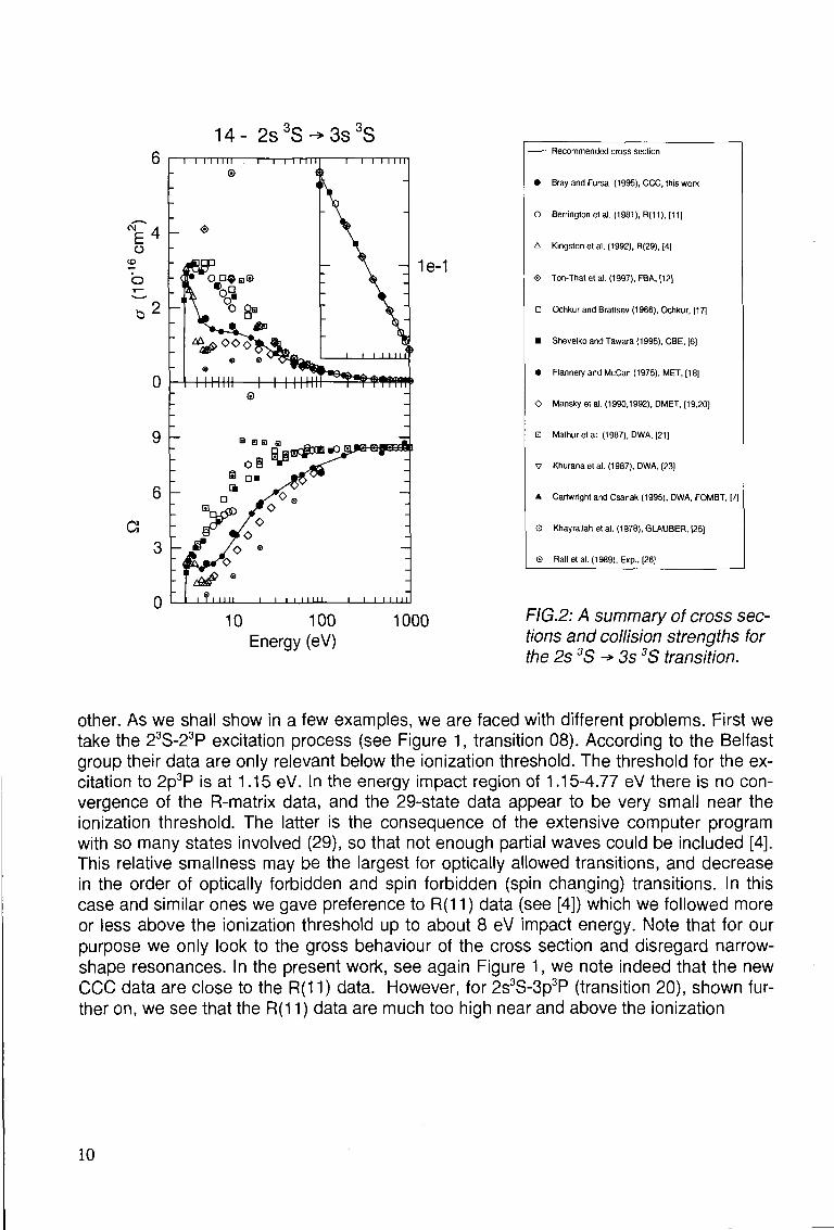
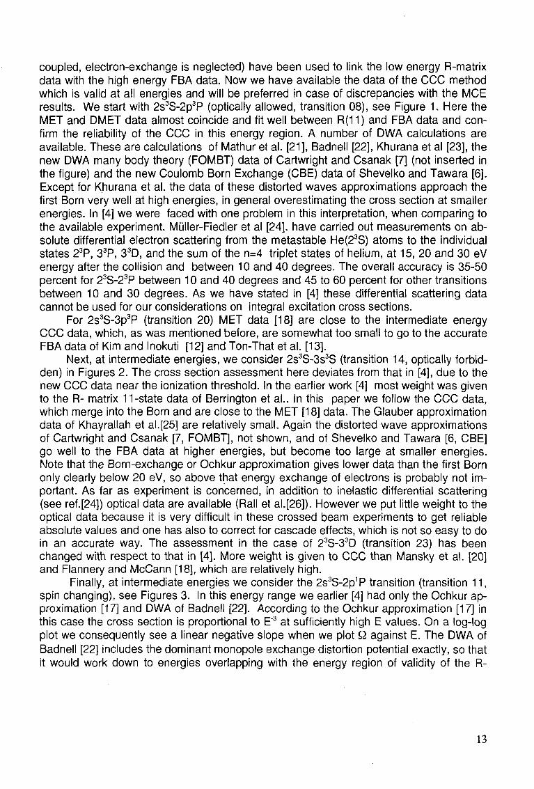
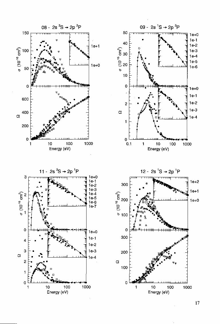
FIG.2: A summary of cross sections and collision strengths for the 2s 3S -> 3s 3S transition.
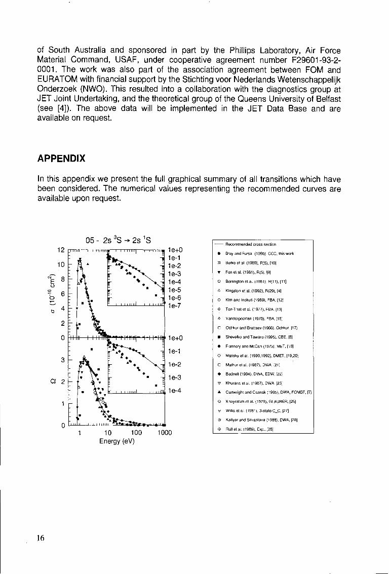
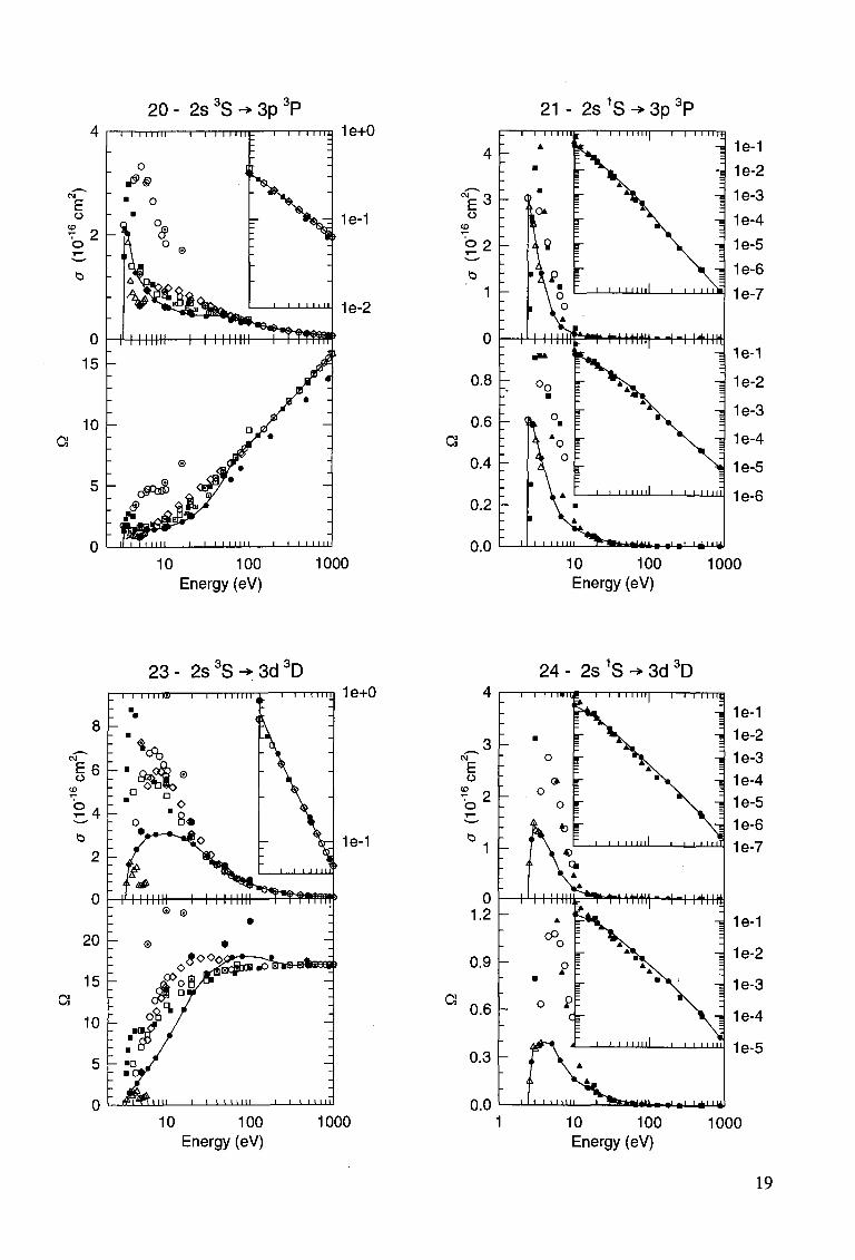
other. As we shall show in a few examples, we are faced with different problems. First we take the 23S-23P excitation process (see Figure 1, transition 08). According to the Belfast group their data are only relevant below the ionization threshold. The threshold for the excitation to 2p3P is at 1.15 eV. In the energy impact region of 1.15-4.77 eV there is no convergence of the R-matrix data, and the 29-state data appear to be very small near the ionization threshold. The latter is the consequence of the extensive computer program with so many states involved (29), so that not enough partial waves could be included [4]. This relative smallness may be the largest for optically allowed transitions, and decrease in the order of optically forbidden and spin forbidden (spin changing) transitions. In this case and similar ones we gave preference to R(11) data (see [4]) which we followed more or less above the ionization threshold up to about 8 eV impact energy. Note that for our purpose we only look to the gross behaviour of the cross section and disregard narrow-shape resonances. In the present work, see again Figure 1, we note indeed that the new CCC data are close to the R(11) data. However, for 2s3S-3p3P (transition 20), shown further on, we see that the R(11) data are much too high near and above the ionization
10
Recommended cross section
• Bray and Fursa (1995), CCC, this work
T Fonetal. (1981), R(5), [9]
O Berrington et al. (1981), R(11), [11]
A Kingston et al. (1992), R(29), [4]
D Ochkur and Brattsev (1966), Ochkur, [17]
• Shevelko and Tawara (1995), CBE, [6)
• Badneli (1984), DWA, EDW, [22]
A Cartwright and Csanak (1995), DWA, FOMBT, [7]
0 Rail et al. (1989), Exp., [26]
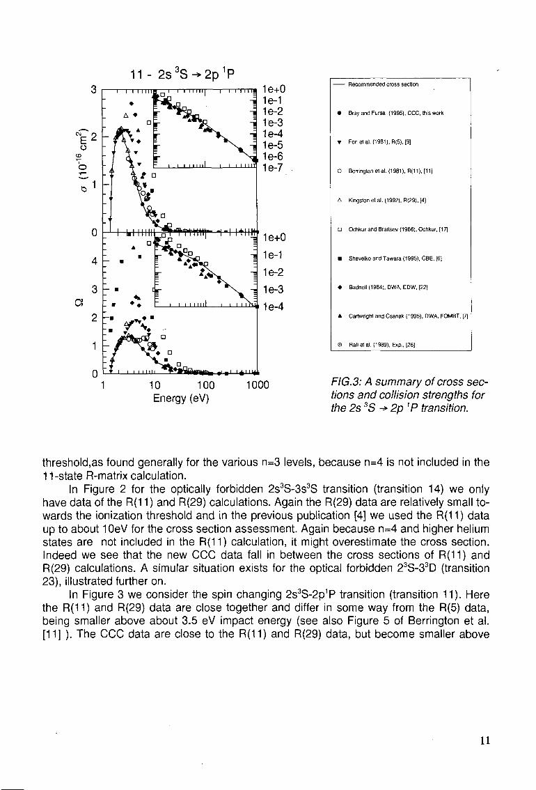
FIG.3: A summary of cross sections and collision strengths for the 2s 3S •* 2p 1P transition.
threshold,as found generally for the various n=3 levels, because n=4 is not included in the 11-state R-matrix calculation.
In Figure 2 for the optically forbidden 2s3S-3s3S transition (transition 14) we only have data of the R(11) and R(29) calculations. Again the R(29) data are relatively small towards the ionization threshold and in the previous publication [4] we used the R(11) data up to about 10eV for the cross section assessment. Again because n=4 and higher helium states are not included in the R(11) calculation, it might overestimate the cross section. Indeed we see that the new CCC data fall in between the cross sections of R(11) and R(29) calculations. A simular situation exists for the optical forbidden 23S-33D (transition 23), illustrated further on.
In Figure 3 we consider the spin changing 2s3S-2p1P transition (transition 11). Here the R(11) and R(29) data are close together and differ in some way from the R(5) data, being smaller above about 3.5 eV impact energy (see also Figure 5 of Berrington et al. [11] ). The CCC data are close to the R(11) and R(29) data, but become smaller above
11 - 2s 3 S^2p 1 P
rtnttHj" 'i i mm' 1e+0
-i 1e-1 -I 1e-2
10 100 1000 Energy (eV)
11
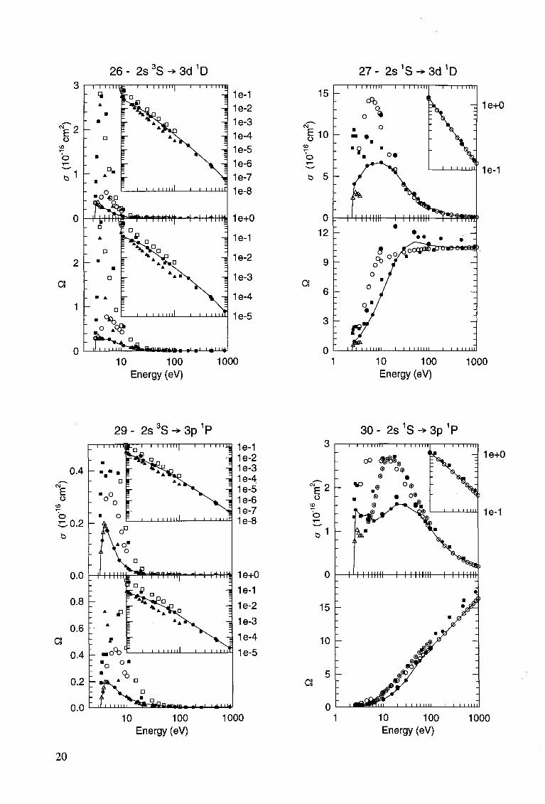
about the ionization limit (4.77 eV). For 2s3S-3p1P (transition 29), shown further on, the CCC data are close to the R(29) data, but again near and above the ionization threshold R(11) data become relatively high.
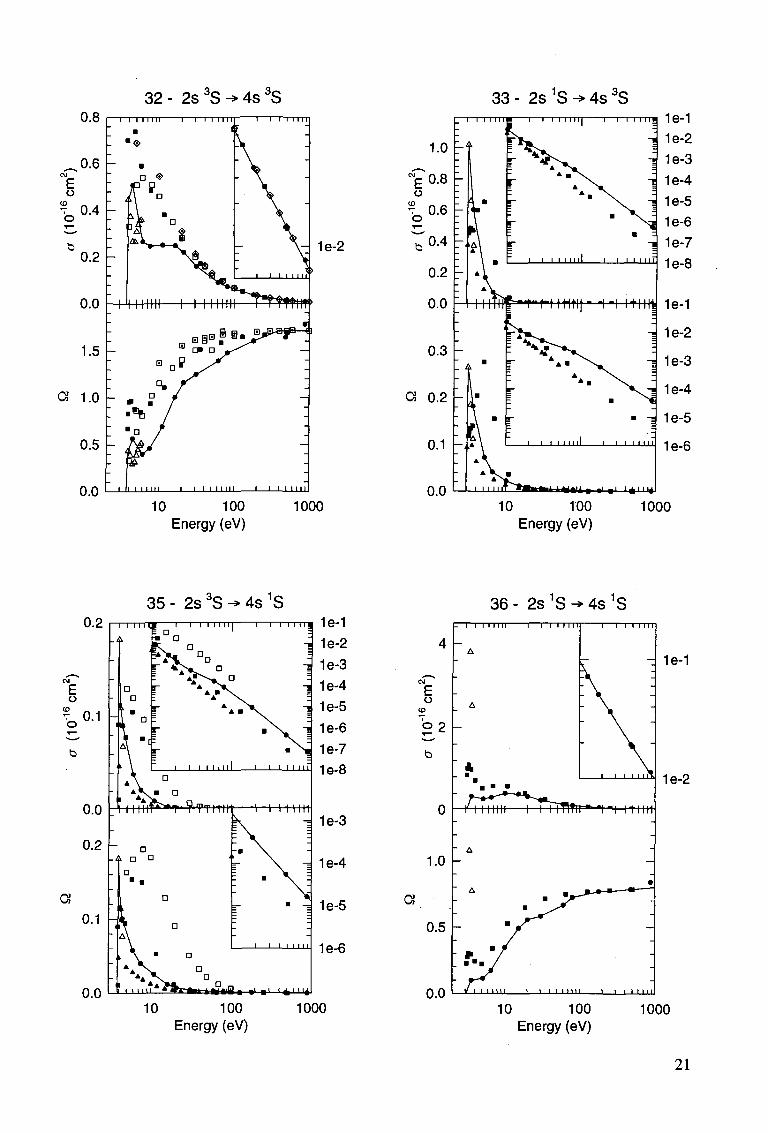
For the corresponding singlet cases, 2s1S-2p1P (transition 12), 2s1S-3p1P (transition 30), 2s1S-3s1S (transition 18) and 21S-31D (transition 27) and singlet-triplet cases, 2s1S-2p3P (transition 09) and 2s1S-3p3P (transition 21), illustrated further on, similar considerations hold. For 2s1S-2p1P the CCC data fall again on top of those of the R(11) calculation. For 2s1S-3p1P we see again the relatively low and high values of R(29) and R(11) data respectively. For 2s1S-3s1S, near and above the ionization threshold (3.97 eV) the CCC data are much smaller than those of the R(11) calculation. For 2s1S-2p3P the CCC data are again close to the R(11) and R(29) data, but become smaller above the ionization energy. For 2s1S-3p3P the CCC data are close to the R(29) data, but R(11) data appear to be too high.
Next we shall consider the high energy. Because for excitation from metastable to higher excited states the excitation energy is much smaller than in the case of excitation from the ground state, we may expect the first Born approximation to hold down to relatively low energies (about 50-100 eV). As we have defined the high energy region as the one where the FBA is valid we consider here spin allowed transitions (singlet-singlet and triplet-triplet) only. At this high energy the calculated cross sections are primarily specified by the helium structure approximation used in the calculation. The FBA calculations have been carried out by several groups [12-16] for many transitions, giving coinciding cross sections when sufficiently accurate wave functions are used. As the incident electron energy is increased the CCC and CBE calculations should converge to the FBA results. On a number of occasions (discussed later on) we have found that some deviations from the accurate FBA results exist. Given the frozen-core approximation used in the CCC calculations the preference should be given in this case to the available accurate FBA results, in particular to those of Kim and Inokuti [12] where the accurate Weiss correlated wave functions of the Hylleraas type have been used.
Let us look to the Born data for the transitions considered before. It is instructive to plot the cross section times the impact energy versus the logarithm of the impact energy. For the 2s3S-2p3P (transition 08, optically allowed) the graph shows a positive slope which, according to the Bethe (Born) theory (see i.e. Kim and Inokuti [12]) is a known constant times the oscillator strength. Such a plot is given in Figure 1. It is remarkable to see that the CCC data are in such a good agreement with these Born data. CBE also approaches well to Born. For 2s3S-33P (transition 20) this agreement is within about 10 percent for CCC and complete for CBE.
Similarly for the 2s3S-3s3S transition (optically forbidden) the Bethe theory (see i.e. Kim and Inokuti [12]) predicts a slope zero at sufficiently high energy in this Q-lnE plot. In Figure 2 we see that this behaviour sets in approximately above 200 eV, the slope becoming very small. Again the CCC and CBE approach the FBA calculation very well at high energy. The same holds for 23S-33D (transition 23). For 2s1S-3p1P (transition 30) CCC and CBE are larger (about 12 percent) than FBA [12]. For 2s1s-3d1D (transition 27) CCC is about 7% larger than FBA [12] and CBE [6].
Now we go to the intermediate energy range (about 6-100 eV) to link low and high energy data. In the previous publication [4] the multi-channel theory of Flannery and McCann (MCE or MET) [18] and of Mansky and Flannery (DMET) [19,20) (10 states are
12
coupled, electron-exchange is neglected) have been used to link the low energy R-matrix data with the high energy FBA data. Now we have available the data of the CCC method which is valid at all energies and will be preferred in case of discrepancies with the MCE results. We start with 2s3S-2p3P (optically allowed, transition 08), see Figure 1. Here the MET and DMET data almost coincide and fit well between R(11) and FBA data and confirm the reliability of the CCC in this energy region. A number of DWA calculations are available. These are calculations of Mathur et al. [21], Badnell [22], Khurana et al [23], the new DWA many body theory (FOMBT) data of Cartwright and Csanak [7] (not inserted in the figure) and the new Coulomb Born Exchange (CBE) data of Shevelko and Tawara [6]. Except for Khurana et al. the data of these distorted waves approximations approach the first Born very well at high energies, in general overestimating the cross section at smaller energies. In [4] we were faced with one problem in this interpretation, when comparing to the available experiment. Muller-Fiedler et al [24]. have carried out measurements on absolute differential electron scattering from the metastable He(23S) atoms to the individual states 23P, 33P, 33D, and the sum of the n=4 triplet states of helium, at 15, 20 and 30 eV energy after the collision and between 10 and 40 degrees. The overall accuracy is 35-50 percent for 23S-23P between 10 and 40 degrees and 45 to 60 percent for other transitions between 10 and 30 degrees. As we have stated in [4] these differential scattering data cannot be used for our considerations on integral excitation cross sections.
For 2s3S-3p3P (transition 20) MET data [18] are close to the intermediate energy CCC data, which, as was mentioned before, are somewhat too small to go to the accurate FBA data of Kim and Inokuti [12] and Ton-That et al. [13].
Next, at intermediate energies, we consider 2s3S-3s3S (transition 14, optically forbidden) in Figures 2. The cross section assessment here deviates from that in [4], due to the new CCC data near the ionization threshold. In the earlier work [4] most weight was given to the R- matrix 11-state data of Berrington et al.. In this paper we follow the CCC data, which merge into the Born and are close to the MET [18] data. The Glauber approximation data of Khayrallah et al.[25] are relatively small. Again the distorted wave approximations of Cartwright and Csanak [7, FOMBT], not shown, and of Shevelko and Tawara [6, CBE] go well to the FBA data at higher energies, but become too large at smaller energies. Note that the Born-exchange or Ochkur approximation gives lower data than the first Born only clearly below 20 eV, so above that energy exchange of electrons is probably not important. As far as experiment is concerned, in addition to inelastic differential scattering (see ref.[24]) optical data are available (Rail et al.[26]). However we put little weight to the optical data because it is very difficult in these crossed beam experiments to get reliable absolute values and one has also to correct for cascade effects, which is not so easy to do in an accurate way. The assessment in the case of 23S-33D (transition 23) has been changed with respect to that in [4]. More weight is given to CCC than Mansky et al. [20] and Flannery and McCann [18], which are relatively high.
Finally, at intermediate energies we consider the 2s3S-2p1P transition (transition 11, spin changing), see Figures 3. In this energy range we earlier [4] had only the Ochkur approximation [17] and DWA of Badnell [22]. According to the Ochkur approximation [17] in this case the cross section is proportional to E"3 at sufficiently high E values. On a log-log plot we consequently see a linear negative slope when we plot Q against E. The DWA of Badnell [22] includes the dominant monopole exchange distortion potential exactly, so that it would work down to energies overlapping with the energy region of validity of the R-
13
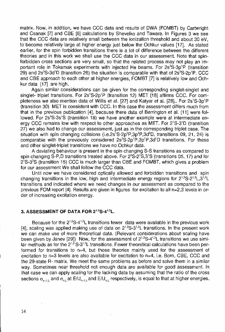
matrix. Now, in addition, we have CCC data and results of DWA (FOMBT) by Cartwright and Csanak [7] and CBE [6] calculations by Shevelko and Tawara. In Figures 3 we see that the CCC data are relatively small between the ionization threshold and about 30 eV, to become relatively large at higher energy just below the Ochkur values [17]. As stated earlier, for the spin forbidden transitions there is a lot of difference between the different theories and in this work we shall use the CCC data in our assessment. Note that spin-forbidden cross sections are very small, so that the related process may not play an important role in Tokamak experiments with injected He beams. For 2s3S-3p1P (transition 29) and 2s3S-3d1D (transition 26) the situation is comparable with that of 2s3S-2p1P. CCC and CBE approach to each other at higher energies, FOMBT [7] is relatively low and Ochkur data [17] are high.
Again similar considerations can be given for the corresponding singlet-singlet and singlet- triplet transitions. For 2s1S-2p1P (transition 12) MET [18] affirms CCC. For completeness we also mention data of Willis et al. [27] and Katyar et al. [28].. For 2s1S-3p1P (transition 30) MET is consistent with CCC. In this case the assessment differs much from that in the previous publication [4], because there data of Berrington et al. [11] were followed. For 2s1S-3s1S (transition 18) we have another example were at intermediate energy CCC remains low with respect to other approaches as MET. For 21S-31D (transition 27) we also had to change our assessment, just as in the corresponding triplet case. The situation with spin changing collisions (i.e.2s1S-2p3P,3p3P,3d3D, transitions 09, 21, 24) is comparable with the previously considered 2s3S-2p1P,3p1P,3d1D transitions. For these and other singlet-triplet transitions we have no Ochkur data.
A deviating behaviour is present in the spin changing S-S transitions as compared to spin changing S-P.D transitions treated above. For 23S-21S,31S (transitions 05, 17) and for 21S-33S (transition 15) CCC is much larger than CBE and FOMBT, which gives a problem for our assessment We shall follow the CCC data.
Until now we have considered optically allowed and forbidden transitions and spin changing transitions in the low, high and intermediate energy regions for 21,3S-21'3L,31,3L transitions and indicated where we need changes in our assessment as compared to the previous FOM report [4]. Results are given in figures for excitation to all n=2,3 levels in order of increasing excitation energy.
3. ASSESSMENT OF DATA FOR 213S-413L.
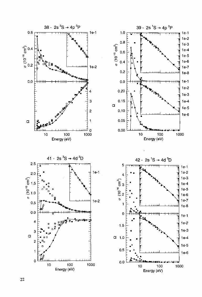
Because for the 21'3S-413L transitions fewer data were available in the previous work [4], scaling was applied making use of data on 21,3S-31,3L transitions. In the present work we can make use of more theoretical data. (Relevant considerations about scaling have been given by Janev [29]) Now, for the assessment of 21,3S-41'3L transitions we use similar methods as for the 21,3S-31,3L transitions. Fewer theoretical calculations have been performed for transitions to n=4, but those theories mainly used for the assessment of excitation to n=3 levels are also available for excitation to n=4, i.e. Born, CBE, CCC and the 29-state R- matrix. We meet the same problems as before and solve them in a similar way. Sometimes near threshold not enough data are available for good assessment. In that case we can apply scaling for the lacking data by assuming that the ratio of the cross sections on+1 L and anLat E/Un+Uand E/UnL respectively, is equal to that at higher energies.
14
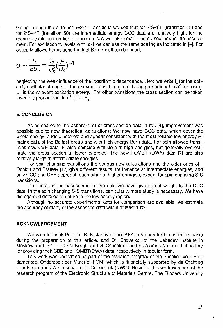
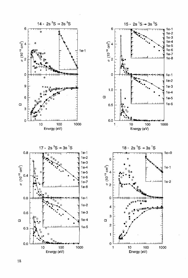
Going through the different n=2-4 transitions we see that for 21S-41F (transition 48) and for 23S-43F (transition 50) the intermediate energy CCC data are relatively high, for the reasons explained earlier. In these cases we take smaller cross sections in the assessment. For excitation to levels with n>4 we can use the same scaling as indicated in [4]. For optically allowed transitions the first Born result can be used,
EU„ U£u„>
neglecting the weak influence of the logarithmic dependence. Here we write fn for the optically oscillator strength of the relevant transition n0 to n, being proportional to n"3 for n»n 0 . Un is the relevant excitation energy. For other transitions the cross section can be taken inversely proportional to n3Un
4 at En.
5. CONCLUSION
As compared to the assessment of cross-section data in ref. [4], improvement was possible due to new theoretical calculations: We now have CCC data, which cover the whole energy range of interest and appear consistent with the most reliable low energy R-matrix data of the Belfast group and with high energy Born data. For spin allowed transitions new CBE data [6] also coincide with Born at high energies, but generally overestimate the cross section at lower energies. The new FOMBT (DWA) data [7] are also relatively large at intermediate energies.
For spin changing transitions the various new calculations and the older ones of Ochkur and Bratsev [17] give different results, for instance at intermediate energies, and only CCC and CBE approach each other at higher energies, except for spin changing S-S transitions.
In general, in the assessment of the data we have given great weight to the CCC data. In the spin changing S-S transitions, particularly, more study is necessary. We have disregarded detailed structure in the low energy region.
Although no accurate experimental data for comparison are available, we estimate the accuracy of many of the assessed data within at least 10%.
ACKNOWLEDGEMENT
We wish to thank Prof. dr. R. K. Janev of the IAEA in Vienna for his critical remarks during the preparation of this article, and Dr. Shevelko, of the Lebedev Institute in Moskow, and Drs. D. C. Cartwright and G. Csanak of the Los Alomos National Laboratory for providing their CBE and FOMBT(DWA) data, respectively in tabular form.
This work was performed as part of the research program of the Stichting voor Fun-damenteel Onderzoek der Materie (FOM) which is financially supported by de Stichting voor Nederlands Wetenschappelijk Onderzoek (NWO). Besides, this work was part of the research program of the Electronic Structure of Materials Centre, The Flinders University
15
of South Australia and sponsored in part by the Phillips Laboratory, Air Force Material Command, USAF, under cooperative agreement number F29601-93-2-0001. The work was also part of the association agreement between FOM and EURATOM with financial support by the Stichting voor Nederlands Wetenschappelijk Onderzoek (NWO). This resulted into a collaboration with the diagnostics group at JET Joint Undertaking, and the theoretical group of the Queens University of Belfast (see [4]). The above data will be implemented in the JET Data Base and are available on request.
APPENDIX
In this appendix we present the full graphical summary of all transitions which have been considered. The numerical values representing the recommended curves are available upon request.
3 o . O „ 1 P
Recommended cross section
• Bray and Fursa (1995), CCC, this work
Q Burke etal. (1969), R(5), [10]
T Fonetal. (1981), R(5), (9)
O Berrington etal. (1981), R(11), [11]
A Kingston et al. (1992), R(29), [4]
0 Kim and Inokuti (1969), FBA, [12]
<$> Ton-That et al. (1977), FBA, [13]
A Vanderpoorten (1970), FBA, [15]
• Ochkur and Brattsev (1966), Ochkur, [17]
• Shevelko and Tawara (1995), CBE, [6]
• Flannery and McCan (1975), MET, [18]
O Manskyetal. (1990,1992), OMET, [19,20]
• Mathuretal. (1987), DWA, [21]
• Badnell (1984), DWA. EDW, [22]
V Khurana etal. (1987), DWA, [23]
A Cartwright and Csanak (1995), DWA, FOMBT, [7]
O Khayrallah et ai. (1978), GLAUBER, [25]
V Willis et al. (1981), 3-state C_C, [27]
© Katiyar and Srivastava (1988), DWA, [28]
© Rail etal. (1989), Exp., [26]
Energy (eV)
16
08- 2s 3 S- *2p 3 P 150
-- 1e+1
1e+0
1 10 100 1000 Energy (eV)
09 - 2s 1S -» 2p 3P 50
40
o 30
o ^ 2 0
10
a 1 -
i i i nun—i i i nun
»fnmn| i mini'
i ilimin ' L «!•' '*"d 0.1 1 10 100 1000
Energy (eV)
11 - 2 s 3 S ^ 2 p 1 P 1 2 - 2 s 1 S ^ 2 p 1 P 1e+0
10 100 1000 Energy (eV)
1 10 100 1000 Energy (eV)
17
14- 2 s 3 S ^ 3 s 3 S 15- 2 s 1 S ^ 3 s 3 S
o i • ^^
a
1e-1
10 100 Energy (eV)
1000
E o
b
a
1.0
0.5
0.0 W.B «'•' '*l'^l
10 100 Energy (eV)
1000
17- 2 s 3 S ^ 3 s 1 S 18- 2s 1 S-*3s 1 S 0.8
E o CD
v o 0 .4
C3
0.0
0.6
0.3
0.0
i iiinf^T"iB-gfmif- -i-i itin^
itilMB . ,1 . 1 I * I 114
1e-1
1e-2
1e-3
1e-4
1e-5
10 100 Energy (eV)
1000
1e+0
1e-1
1e-2
1 10 100 1000 Energy (eV)
18
2 0 - 2 s 3 S - » 3 p 3 P
E o
2 b 2
0
15
10
a
I I I I I I I ! 1 1 I I I III
ll i i i n i l | i i i i m i I—I I I I III
1e+0
1e-1
1e-2
10 100 Energy (eV)
1000
21 - 2s 1S •* 3p 3P
a
E o
0 2
to 1
0
0.8
0.6
0.4
0.2
0.0
~i i i 111MI i i 1111 j.
MVlm «l • ' I^H^I
10 100 Energy (eV)
1000
23 - 2s 3S ^ 3d 3D
E6 o
T- 4
2
0
20
15
a 10 F-
5
0
~ l T T T T T T ® I I I I M i l l 1 I I l t l l l l
•OS*"5" D
I T I I I I I i i i i i i m l i i i i i n
1e+0
1e-1
10 100 Energy (eV)
1000
24 - 2s 1S ^ 3d 3D I l * l l£—l—I I I I I I I ! I I I I I I M
10 Energy (eV)
100 1000
19
26- 2 s 3 S ^ 3 d 1 D i 1 1 1 1 1 i , t — i — i 1 1 1 i n | — i — i 1 1 1 i n
- ?
E o
CD
b
,r a
2 -
a 1 -
T'Wtmn1- i- i itint
a i i i i 11
Mflfclft, ,1 . 1 I < t n i 4
1e+0
-4 1e-1
1e-2
-J 1e-3
j 1e-4
1e-5
10 100 Energy (eV)
1000
27 - 2s 1S -> 3d 1D
1e+0
1e-1
1 10 100 1000 Energy (eV)
29- 2 s 3 S ^ 3 p 1 P i 1 1 1 1 1 i n . — i — i 1 1 1 1 n | — i — i i n i j
mtmu »i » i i * ' i i 4
1e-1 1e-2 1e-3 1e-4 1e-5 1e-6 1e-7 1e-8
10 100 Energy (eV)
1000
30- 2 s 1 S ^ 3 p 1 P
CM o E 2
o to
b
15
10
a 0
1 1 I I Mil l 1 1 I I Mi l i I TTTTTT
MI inun—i i i i i i
I I I I INI I I I M
1e+0
1e-1
1 10 100 1000 Energy (eV)
20
32 - 2s 3S H> 4s dS 0 . 8 I—i i i 11 in 1—i i i i mi 1—i i i i in
33 - 2s 1S ^ 4s 3S
1e-2
10 100 Energy (eV)
1000
1.0
<£o.8 o
% 0.6
^ 0 - 4
0.2
0.0
I I I I I I I B 1 1 I I I Mil 1 1 I I I M
I I I I I I 11
i iiTiir—t"t-nwi|- •!•! unif
« 4 i A » .i , i i ^ n y
1e-1
1e-1
1e-2
1e-3
1e-4
1e-5
1e-6
10 TOO Energy (eV)
1000
35 - 2s 3S -> 4s 1S
0.0
0.2
0.1 H
0.0
I I lllf^^T'T-TTH-Ht "I -I Mi l l
Mm >' • ' H H H
10 100 Energy (eV)
1000
36- 2s1S-*4s1S
£
o 2
to
a
1.0
0.5
o.o
"T I I I M11 I I I I M i l
V I 11-1111
i l i n i l i i i i i m i i i i i i i n
1e-1
1e-2
10 100 Energy (eV)
1000
21
38 - 2s 3S •* 4p 3P i 1 1 1 i n — i — i i 111 i i k . — i — i 1111in 1 e - 1
1e-2
10 100 Energy (eV)
1000
39 - 2S 1S ^ 4p 3P 1 .0 I—1_ I I 111 i i
E o
a
0.8
0.6 >
' 0.4
0.2
0.0
0.20
0.15
0.10
0.05
0.00 « « I I , «l • ! H I I H
10 100 Energy (eV)
1000
41 - 2s 3S ^ 4d 3D
1e-1
1e-2
10 100 Energy (eV)
1000
1
0
1.5
G 1.0
0.5
0.0
42 - 2s 1S -> 4d 3D ~1 Pi I i 11-
_l I I I I I I I ! I i i i i i n
m-my »r M inti|—I-I itim
ir i liTriT—t*fct, —I I W t ' l l »l • ' I^MI4
1e-1
1e-2
1e-3
1e-4
1e-5
1e-6
1e-7
1e-8
10 100 Energy (eV)
1000
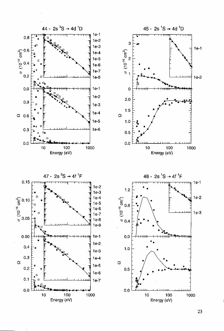
44- 2s 3 S^4d 1 D 45 - 2s 1S -* 4d 1D
0.2
0.0
0.9
a o.6
0.3
0.0
l™Wuff"tttitn-f—-i -i u n i t
- D ,_
_l I I '
A • .
wimwuttB »' • ' I * I 114
1e-1
1e-2
1e-3
1e-4
1e-5
1e-6
10 100 Energy (eV)
1000
- 1e-1
1e-2
10 100 Energy (eV)
1000
47- 2s 3 S^4f 1F 0.15 ~l 1 1 1 ! I l | I I I I' T ITS
•I 1e-2 -I 1e-3
waawittta •> • ' I *MI4 10 100
Energy (eV) 1000
48- 2s1S-*4f1F
1.2
E °0 .8
CO
O
b 0 . 4
0.0
1.0
a
I I I I MM 1 1 I I I I I I
I •
~1 1 I I I I I t
\ I I I I I I |
1e-1
1e-2
1e-3
-mm>
0.5
Q Q I II I I I 1111 I i i i i I I i n
10 100 Energy (eV)
1000
23
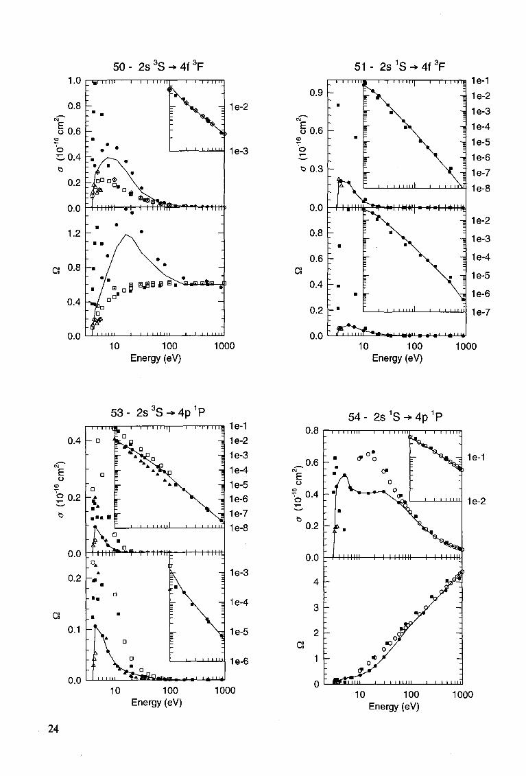
5 0 - 2 s 3 S ^ 4 f 3 F 51 - 2s 1S ^ 4f 3F 1.0 n -
1e-2
1e-3
10 100 Energy (eV)
1000
0.9 -
t n , , i , i 1*11141
10 100 Energy (eV)
1000
5 3 - 2 s 3 S ^ 4 p 1 P
0.4
0.2 -'
0.0
0.2
0.1
0.0
' 1 1 1 1 1 1 1
«n>m • »' • ' 1 * 1114
10 100 Energy (eV)
1000
5 4 - 2 s 1 S ^ 4 p 1 P U . O I i i 1 11111 1 1 1 1 11111 r~~i 1 i i i i r
0.6 -E o
?o0.4
0.2 -
0.0
C3
11111 1 "
1e-1
1e-2
10 100 Energy (eV)
1000
REFERENCES
1] HEMSWORTH, R..TRAYNOR, N., (1990) JET Joint Undertaking Internal Report JET-DN(90)86 and HOEKSTRA, R., DE HEER, F.J., MORGENSTERN, R., KVI Report, available on request.
2] DE HEER, F.J., HOEKSTRA, R., KINGSTON, A.E., SUMMERS.H.P., Supplement to Nuclear Fusion, Volume 3 (1992) 19.
;3] See for example: KATO, T., ITIKAWA, Y.t SAKIMOTO, K. in "Compilation of Excitation Cross Sections for He Atoms by Electron Impact", NIFS-DATA-15, National Institute For Fusion Science, Nagoya 464-01, Japan.
[4] DE HEER, F.J., FOLKERTS, H.O., BLIEK, F.W..HOEKSTRA, R., KATO, T., KINGSTON, A.E., BERRINGTON, K.A., SUMMERS, H.P., FOM-REPORT 95 0653, April 1995, available on request.
[5] BRAY, I., FURSA, D.V., J. Phys., B (Londen). At. Mol. and Opt. Phys. 28 (1995) L197. [6] SHEVELKO, V.P., TAWARA, H., private communication and see this volume of the
journal Nuclear Fusion. [7] CARTWRIGHT, D.C., CSANAK, G., Phys. Rev., A 51 (1995) 454. [8] FURSA, D.V., BRAY, I., Phys. Rev., A 52 (1995) , in press. [9] FON, W.C., BERRINGTON, K.A., BURKE, P.G., KINGSTON, A E., J. Phys., B (Lon
den). At. Mol. Phys. 14 (1981) 2921 [10] BURKE, P.G., COOPER, J.W., ORMONDE, S., Phys. Rev.183 (1969) 245. [11] BERRINGTON, K.A., BURKE, P.G., FREITAS, L.C.G., Kingston, A.E., J. Phys., B
(Londen). At. Mol. Phys. 18 (1985) 4135. [12] KIM, Y. K., INOKUTI, M., Phys. Rev. 181 (1969) 205. [13]TON-THAT, D., MANSON, S T., FLANNERY, M R., J.Phys., B (Londen). At. Mol.
Phys. 10(1977)621. [14] FLANNERY, M.R., MORRISON, W.R., RICHMOND, B.L, J. Appl. Phys. 46 (1975)
1186. [15] VANDERPOORTEN, R., Physica 48 (1970) 254. [16] MOISEIWITSCH/B.L, Monthly Notices Roy. Astron. Soc. 117 (1957) 189. [17] OCHKUR, V.I., BRATSEV, V.F., Soviet Astronomy-A J 9 (1966) 797. [18] FLANNERY, M.R., McCANN, K.J., Phys. Rev., A 12 (1975) 846. [19] MANSKY, E.J., in Nonequilibrium Processes in Partially Ionized Gases (1990) p 349.
Edited by M.Capitelli and J.N.Bardsley, Plenum Press, New York. [20] MANSKY,.E.J., FLANNERY, M.R., J. Phys., B (Londen). At. Mol. Phys. 23 (1990)
4573. [21] MATHUR, K.C., McEACHRAN, R.P., PARCELL, LA., STAUFFER.A.D., J. Phys., B
(Londen). At. Mol.Phys.20 (1987) 1599. [22] BADNELL, N.R., J. Phys., B (Londen). At.Mol. Phys. 17 (1984) 4013. [23] KHURANA, I., SRIVASTAVA, R., TRIPATHI, A.N., J. Phys., B (Londen). At. Mol.
Phys. 20(1987)3515. [24] MULLER-FIEDLER, R., SCHEMMER, P., JUNG, K., HOTOP, H., EHRHARDT ,H., J.
Phys., B (Londen). At. Mol. Phys. 17 (1984) 259. [25] KHAYRALLAH, C.A., CHEN, ST., RAMBLE, J.R.Jr., Phys. Rev., A 17(1978)513.[24] [26] RALL, LA., SHARPTON , F., SCHULMAN, M.B., ANDERSEN, L.W., LAWLER, J.E.,
LIN, C.C., Phys. Rev. Lett. 62 (1989) 2253.
25
[27] WILLIS, S.L, HATA, J., McDOWELL, M.R.C., JOACHAIN, C.J., BYRON, F.W., J.Phys., B (Londen). At. Mol. Phys. 14 (1981) 2687.
[28] KATIYAR, A K , SRIVASTAVA, R., Phys. Rev. 38 (1988) 2767. [29] JANEV, R K., Private Communication and to be published in Phys. Rev., A.
26
SPIN-ALLOWED AND SPIN-FORBIDDEN TRANSITIONS IN EXCITED He ATOMS INDUCED BY ELECTRON IMPACT
V.P. SHEVELKO * and H. TAWARA National Institute for Fusion Science, Nagoya 464-01, Japan
Abstract
Cross sections a and the corresponding maxwellian rate coefficients <va> have been calculated for spin-allowed and spin-forbidden n - n' transitions between excited states with the principal quantum numbers n, n' = 2, 3 and 4 in He induced by electron impact. Calculations have been performed using the Coulomb-Born approximation with exchange (CBE) in the partial wave representation with orthogonalized wavefunctions of the initial and final states for the incident electron energies from threshold up to 2000 eV for spin-allowed transitions (AS=0) and up to 200 eV for spin-forbidden (intercombination, AS=1) transitions where the corresponding cross sections are still relatively large. The fitting parameters for a and <va> of spin-allowed transitions have been calculated as well. The results are compared with experimental data and other calculations available.
1. INTRODUCTION
A knowledge of excitation cross sections and rate coefficients of He atoms from the ground and excited states is required for many physical applications: gaseous discharges, rare-gas lasers [1], fusion [2] and astrophysical [3] plasmas, diagnostics and heating of plasma by neutral He beams [4,5], etc. While the information about excitation cross sections in He from the ground state is quite extensive (see, e.g., [5-8]), relatively little is known about transitions between excited states with the principal quantum numbers n>2, especially only very few experimental data are available. That is why theoretical calculations are of special interest.
Our aim in this work is to calculate the excitation cross sections and the corresponding rate coefficients between excited (n, n' = 2, 3 and 4) states in He in a wide electron-impact energy range: from threshold up to 2000 eV for spin-allowed transitions (AS=0) and up to 200 eV for spin-forbidden (intercombination, AS=1) and to compare our results with available experimental data and other calculations.
* On attachment from: P.N. Lebedev Physics Institute, Russian Academy of Sciences, 117924 Moscow, Russia
27
2. THEORETICAL APPROACHES
2.1 Partial wave method
One of the most reliable and relatively simple methods of calculation of excitation cross sections of atoms and ions by electron impact is the Coulomb-Born approximation with Exchange (CBE). This method is based on the expansion of wavefunctions of the incident and scattered electrons on partial waves. Let us consider the excitation of an atom or ion by electron impact:
X2+e(E,A0) - > x ; + e ( £ ' , 4 ) ,
(1) where z is the spectroscopic symbol (z = 1 for neutrals, and z > 1 for positive ions), Xo and X] denote the orbital momenta of the incident and scattered electrons (partial waves), E and E' are the corresponding free electron energies, respectively. In the first order of the perturbation theory the excitation cross section for transition 0 -1 can be written in the form:
°= £&(<>- ite(W) + Ee:(o- itecw) K K
(2) The first sum in (2) describes the contribution of direct and interference terms for which the angular parts Q are exactly the same, while the second sum is related to the exchange excitation. The angular coefficients Q depend only on the angular (orbital and spin) momenta of an atom or ion and a type of the coupling scheme (see, e.g., [9]). The values aK are the one-electron cross sections depending on the principal and orbital quantum numbers nl of the bound electron and the incident electron energy E. For intercombination transitions (AS=1) the first sum in (2) is zero, so the transitions take place mainly due to the electron exchange effects.
The cross sections cK can be written in the form [10] }:
< ( ^ / ^(2/ 0 + l ) ( 2 . + l ) ^ g ^ ) 2 [ ^ ]
(3)
(4)
K^(-1)'Q+'1+K"(2K+\)\
(5)
*' Atomic units are used: e = m = ti =1.
28
where RKd and RK
e are the direct and exchange radial integrals:
#=[(24+ 1X2/,+1X24+ 1X24+1)] .000J Looo
allF^WF^inj^P^nP^dr'dr*,
ReK.= [(24+1X2/, +1X2^, + 1X2^ +1)]
000
• v (6)
000
a\lFk^(r')FkA(r")^P0(r")Pl(r')dr'dr'
and
-2---L = E-E' = AE
(7) Here P(r) are the radial wavefunctions of the bound electron, F(r) are the radial wavefunctions of the incident and scattered electrons, ko and ki are their impulses. The indexes K and K" are changed in the limits given by the properties of 3j- and 6j-symbols :
^min- ** -^maxJ
**n = m a x ( l / 0 - AU4> ~ \\)> *max = m m ( ' o + W + \ \
(8)
(9)
(10) Eqs. (1-10) represent the Coulomb-Born approximation if the wavefunctions of the incident
and scattered electrons are the Coulomb functions the radial parts F^r) of which satisfy the following equations:
d2 A(j+1) z -1 2 — 2 + + ^ dr r r
Fu(r)=0t FkX{0) = 0,
r Fu(r)*k-ll2su{kr + - ^
z -1 l n ( 2 ^ ) - y + ^ j , r 00
(11) where 5j, is the phase shift. For neutral targets (z = 1) the function F^r) corresponds to the radial component j\(kr) of the plane wave (ji(x) is the spherical Bessel function) and the CB approximation becomes the Born approach in the partial wave representation.
At threshold electron energy E=Eth=AE, cross sections (1-10) are zero for neutral atoms (ath=0) and ath=constant for positive ions. The CBE method is known to provide the following asymptotics for excitation cross sections at E -> 00:
29
QnE)/E, aaciE-1,
AS = 0, A/ = ±1
AS = 0, A/*±1
AS = 1 (12)
In general, the total wavefunctions of the electron+ion system in the initial and final states are not orthogonal because the bound P(r) and continuous F(r) wavefunctions correspond to the different potentials of z/r and (z-l)/r types. This disadvantage can be removed by introducing the orthogonalized wavefunctions ^ ( r ) [11]:
*M 00 = F M (r)-< FkiM(r)\P0 > P0S^ (13)
The CBE method defined this way provides for intercombination transitions (AE=1) the same accuracy as the Born approximation for spin-allowed transitions (AS=0). For multicharged ions (z » 1) the functions F and O practically coincide because
< Fu.\p*i > x z~ (14)
2.2 Ochkur approximation
For spin-forbidden transitions with AS=1 in neutral atoms the Ochkur approximation [12] is used:
ro = I^ j ^e r (0- l )af(U I ) , '2(25,+1)
(15) where
<^(W) (2^ + 1)**
J V •*
fr i J\_2
(16)
R°(q) = [(2K + l) (2l0 + l) (2ll + l)f2 LIK '0*1
v 000^ 0 0 TTiPoi^irhA^dr
(17)
,2 ;,2
2 2 £0 ±*,= yf2E(l± Jl-AE/E),
K ~ ^min' ^min + 2,---, 4 + Ai ^min ~ \k h\
(18)
30
Here q = ko - kx is the momentum transfer, S} is the spin of the target atom in the final state and S O/
p is the spin of the parent ion. As seen from (17) the integral RK (q) does not contain a term with the 8-function which describes the interaction of the incident electron with a target nucleus and is of the order of ko"2. Due to the additional factor q2/ko2 the exchange cross section decreases at large E as E"3 (see Eq. (12)).
2.3 Model dipole cross sections
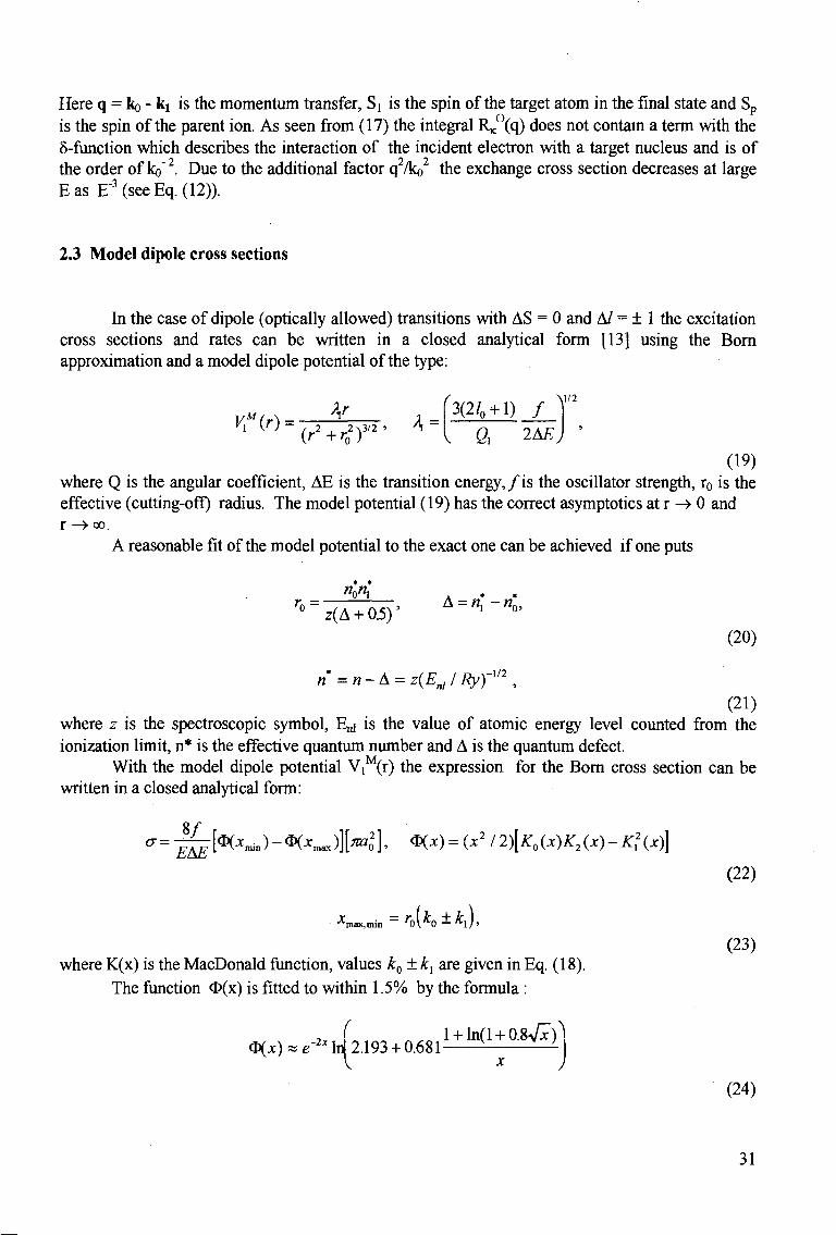
In the case of dipole (optically allowed) transitions with AS = 0 and A/ = ± 1 the excitation cross sections and rates can be written in a closed analytical form [13] using the Born approximation and a model dipole potential of the type:
V"{r)-{r2+rZf2' K~
^3(2/0 + l) / ^
. 6, 2A£ (19)
where Q is the angular coefficient, AE is the transition energy,/is the oscillator strength, r0 is the effective (cutting-off) radius. The model potential (19) has the correct asymptotics at r -» 0 and r ->oo.
A reasonable fit of the model potential to the exact one can be achieved if one puts
"X A . .
(20)
n=n-A = z(Enl/RyyV2,
(21) where z is the spectroscopic symbol, E„i is the value of atomic energy level counted from the ionization limit, n* is the effective quantum number and A is the quantum defect.
With the model dipole potential V ^ r ) the expression for the Born cross section can be written in a closed analytical form:
8 / (T-
EAE [ * ( * . » ) - <&(*max fro ] , <*< X) = (X2 I 2)[K0 (X)K2 (X) - K? (X)]
•*max,min - r 0\" : 0 — * l ]»
where K(x) is the MacDonald function, values k0 ± kx are given in Eq. (18). The function O(x) is fitted to within 1.5% by the formula :
, ( l + ln(l + Q.%Jx)\ <&(x) * e2x Id 2.193 + 0.681 ^ ^ _ i
(22)
(23)
(24)
31

At high electron-impact energies E » AE, Eq.(22) gives
8 / , 1.36 £ 1/2
cr=———In E AE r0AE
-[ml], E»AE
that corresponds to the rate coefficient (25)
fOm AF/T 1.26z
zAE AEro0 1/2 [1(T cm' s~l], 0 = z2Ry/T
(26) For transitions no - n i , i.e. averaged over the quantum numbers / and m, one can use the
corresponding oscillator strength/(no-ni). In the case of high n-values the Kramers formula is used:
1C / ( « o - " i ) = - T
( "o"i
Y
Min^ + n,)) , An = n{-n0, C = 1 6 / 3 v 3 # « l , « 0 , « j » A n » l
(27)
3. COMPARISON WITH EXPERIMENTAL DATA AND OTHER CALCULATIONS
In this work calculations of the excitation cross sections between excited states in He have been performed by the ATOM code described in [10] using the CBE approximation Eqs. (1-10) in the partial wave representation. The results for some transitions are shown in Figs. 1- 4 in comparison with available experimental data and other calculations. All 153 cross sections in He between excited states with n, n'=2, 3 and 4 calculated by the ATOM code are presented in the paper [14].
The calculated CBE excitation cross sections o and the corresponding rate coefficients <va> for spin-allowed transitions (AS = 0) are fitted by approximation formulae [10]:
mn cr = 2l0 + l\DEJ
Ry V (i- v / 2
c V^oV
M/2
u + q> \u + aJ (28)
\3/2 10-VmV RyE
<va>=———:—1 ; | e , , -a,, Af3y\p+\)
2/0 + l VDEE0 09+*) (« / ?+1) 1/2
a = AE/DE, u = (E-AE)/DE, J3 = DE/T,
(29)
(30)
32
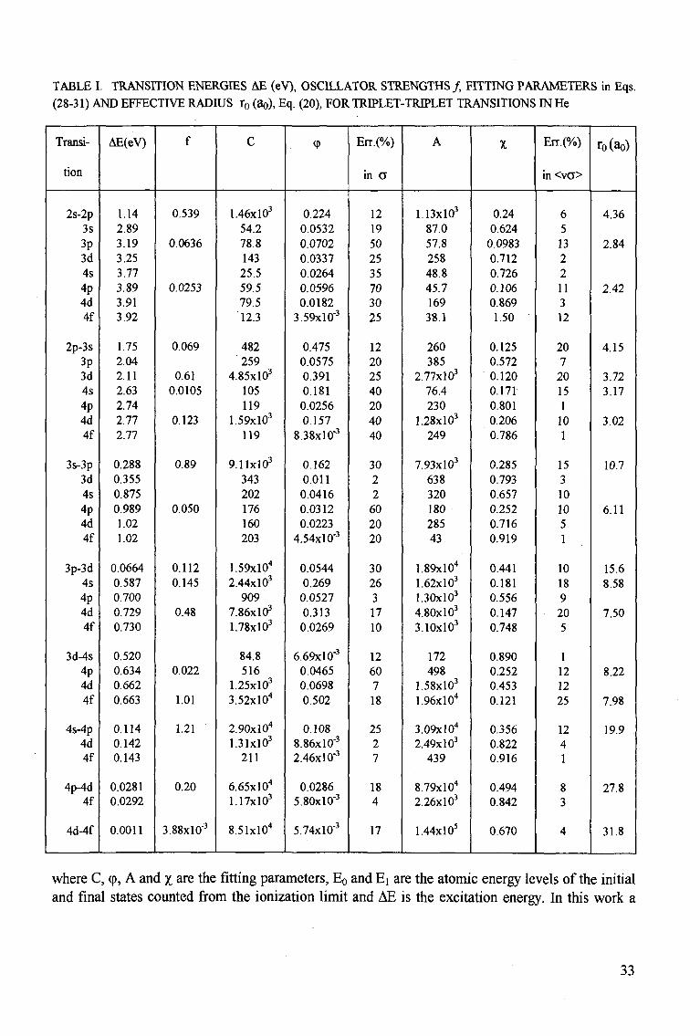
TABLE I. TRANSITION ENERGIES AE (eV), OSCILLATOR STRENGTHS/, FITTING PARAMETERS in Eqs. (28-31) AND EFFECTIVE RADIUS r0 (8o), Eq. (20), FOR TRIPLET-TRIPLET TRANSITIONS IN He
Transi
tion
2s-2p 3s 3p 3d 4s 4p 4d 4f
2p-3s
3p 3d 4s 4p 4d 4f
3s-3p 3d 4s 4p 4d 4f
3p-3d 4s 4p 4d 4f
3d-4s 4p 4d 4f
4s-4p 4d 4f
4p-4d 4f
4d-4f
AE(eV)
1.14 2.89 3.19 3.25 3.77 3.89 3.91 3.92
1.75 2.04 2.11 2.63 2.74 2.77 2.77
0.288 0.355 0.875 0.989 1.02 1.02
0.0664 0.587 0.700 0.729 0.730
0.520 0.634 0.662 0.663
0.114 0.142 0.143
0.0281 0.0292
0.0011
f
0.539
0.0636
0.0253
0.069
0.61 0.0105
0.123
0.89
0.050
0.112 0.145
0.48
0.022
1.01
1.21
0.20
3.88x10"'
C
1.46x10' 54.2 78.8 143 25.5 59.5 79.5 12.3
482 259
4.85x10' 105 119
1.59x10' 119
9.11x10' 343 202 176 160 203
1.59xl04
2.44x10' 909
7.86x10' 1.78x10'
84.8 516
1.25x10' 3.52xl04
2.90xl04
1.31x10' 211
6.65xl04
1.17x10'
8.51xl04
<P
0.224 0.0532 0.0702 0.0337 0.0264 0.0596 0.0182
3.59x10-'
0.475 0.0575 0.391 0.181 0.0256 0.157
8.38x10-'
0.162 0.011 0.0416 0.0312 0.0223
4.54x10''
0.0544 0.269 0.0527 0.313 0.0269
6.69x10"' 0.0465 0.0698 0.502
0.108 8.86x10"' 2.46x10"'
0.0286 5.80x10"'
5.74x10"'
Err.(%)
in CT
12 19 50 25 35 70 30 25
12 20 25 40 20 40 40
30 2 2 60 20 20
30 26 3 17 10
12 60 7 18
25 2 7
18 4
17
A
1.13x10' 87.0 57.8 258 48.8 45.7 169 38.1
260 385
2.77x10' 76.4 230
1.28x10' 249
7.93x10' 638 320 180 285 43
1.89xl04
1.62xl03
1.30x10' 4.80x10' 3.10x10'
172 498
1.58x10' 1.96xl04
3.09xl04
2.49x10' 439
8.79xl04
2.26x10'
1.44xl03
1
0.24 0.624 0.0983 0.712 0.726 0.106 0.869 1.50
0.125 0.572 0.120 0.171 0.801 0.206 0.786
0.285 0.793 0.657 0.252 0.716 0.919
0.441 0.181 0.556 0.147 0.748
0.890 0.252 0.453 0.121
0.356 0.822 0.916
0.494 0.842
0.670
Err.(%)
in <vO>
6 5 13 2 2 11 3 12
20 7 20 15 1 10 1
15 3 10 10 5 1
10 18 9 20 5
1 12 12 25
12 4 1
8 3
4
ro(ao)
4.36
2.84
2.42
4.15
3.72 3.17
3.02
10.7
6.11
15.6 8.58
7.50
8.22
7.98
19.9
27.8
31.8
where C, (p, A and % are the fitting parameters, E0 and E[ are the atomic energy levels of the initial and final states counted from the ionization limit and AE is the excitation energy. In this work a
33
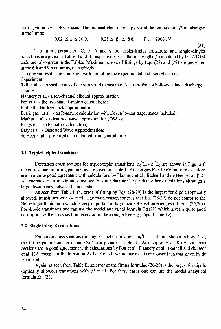
scaling value DE = 5Ry is used. The reduced electron energy u and the temperature fi are changed in the limits:
0.02 < u < 16.0, 0.25 < P < 8.0, ^ 2000 eV (31)
The fitting parameters C, q>, A and x for triplet-triplet transitions and singlet-singlet transitions are given in Tables I and II, respectively. Oscillator strengths/ calculated by the ATOM code are also given in the Tables. Maximum errors of fittings by Eqs. (28) and (29) are presented in the 6th and 9th columns, respectively. The present results are compared with the following experimental and theoretical data. Experiment: Rail et al. - crossed beams of electrons and metastable He atoms from a hollow-cathode discharge. Theory: Flannery et al. - a ten-channel eikonal approximation; Fon et al. - the five-state R-matrix calculations; Badnell - Hartree-Fock approximation; Berrington et al. - an R-matrix calculation with eleven lowest target states included; Mathur et al. - a distorted wave approximation (DWA); Kingston - an R-matrix calculation; Bray et al. - Distorted Wave Approximation; de Heer et al. - preferred data obtained from compilation.
3.1 Triplet-triplet transitions
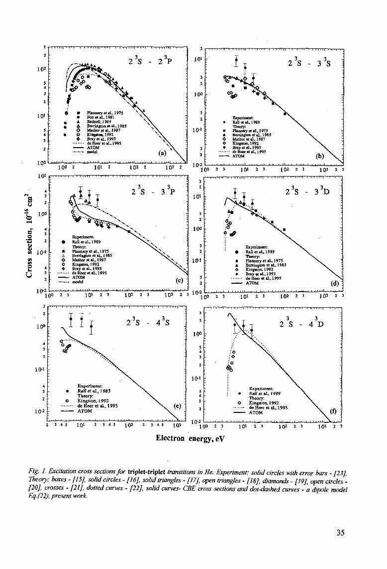
Excitation cross sections for triplet-triplet transitions no3Lo - n^Lj are shown in Figs.la-f; the corresponding fitting parameters are given in Table I. At energies E > 10 eV our cross sections are in a quite good agreement with calculations by Flannery et al., Badnell and de Heer et al. [22]. At energies near maximum cross sections our data are larger than other calculations although a large discrepancy between them exists.
As seen from Table I, the error of fitting by Eqs. (28-29) is the largest for dipole (optically allowed) transitions with A/ = ±1. The main reason for it is that Eqs.(28-29) do not comprise the Bethe logarithmic term which is very important at high incident electron energies (cf. Eqs. (25,26)). For dipole transitions one can use the model analytical formula Eq.(22) which gives a quite good description of the cross section behavior on the average (see e.g., Figs, la and lc).
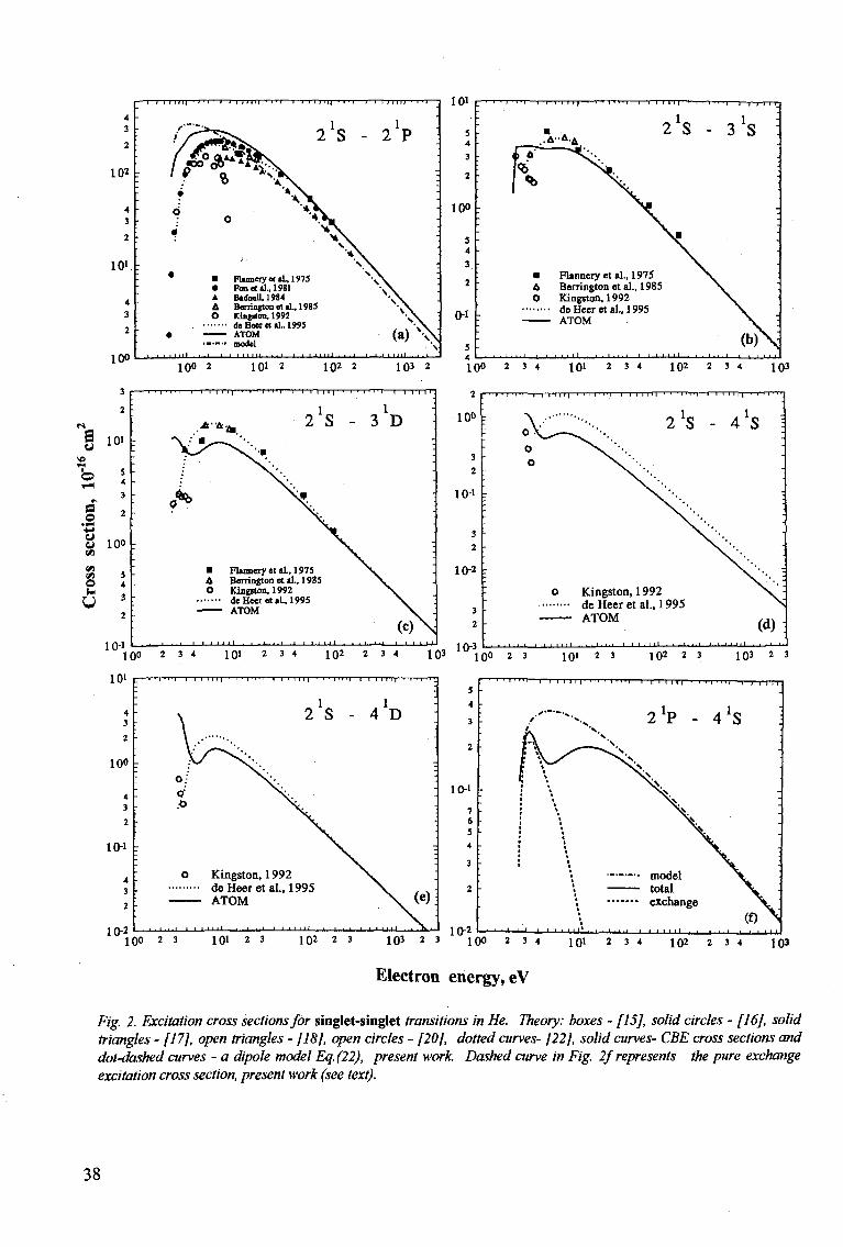
3.2 Singlet-singlet transitions
Excitation cross sections for singlet-singlet transitions n^Lo - n^Li are shown in Figs. 2a-f; the fitting parameters for a and <va> are given in Table II. At energies E > 10 eV our cross sections are in good agreement with calculations by Fon et al., Flannery et al., Badnell and de Heer et al. [22] except for the transition 2s-4s (Fig. 2d) where our results are lower than that given by de Heer et al.
Again, as seen from Table II, an error of the fitting formulae (28-29) is the largest for dipole (optically allowed) transitions with A/ = ±1. For these cases one can use the model analytical formula Eq. (22).
34
3
2
102
5 4
3 2
101
5 4 3
2
1 no
-1 m i l ' i • i .—i—i i i i i n < • • i — i — n -
-
•''Z^aJtA ..
//°tf» ^ f£j> «> ^ ^ t
: i * 6 • Flinnery et aL, 1975
: • Fon et ai, 1981 « A B*<fasU,1984 • A Benington et aL, 198!
O Mathurotal.,1987 • O Kingston, 1992
+ Bray et aL, 1993 deKeer etal., 1995 ATOM
•-—•• model
i i n | • • • i — r -
2
s N
3
s -
>
\V • \
\
1 . , . 1 1
1 II H i t ' I T - •
3 ^ 2 P
\
. •
•
. \
< \
*\ . *yv
(a) \
100 2 101 2 102 2 103 2 2 3 1Q1 2 3 1Q2 2 3 1QJ 2 3
s
a o
• PM
V <*i
o u
u
101
100 .
10-1
4 3
2 -
10-2
; - r - T « | ' I - q
'-
•
\
•
•
• : A
O o +
•—T 1 1 TTT| ' 1 'TT'i 1
AIU C-'1I 2 V ^>. v*w£ Experiment: Rail etal.. 1989 Theory. Flannery et al, 1975 Berringtos et aL, 19*5 Mathur etal.. 1987 Kingnon, 1992 Bray Mil, 1993 deHeeretaL.1995 ATOM model
r-r-mi '-T-i-rMT T-TTTIII ' - I . J M ;
3 3
2 S - 3 P •
^^w**-
> i j N ,
N A x>.
>i>
( c ) : [_] I l . j j L 1 . 1 . 1 . 1 1 1 1 1 1 1.1 . 1 . 1 .»•!•»
10-2 1Q0 2 3 101 2 3 102 2 3 1Q3 2 3 1 V r1 Q 0 2 3 1 Ql 2. 3 102 2 3 1Q3 2 3
2
100
4 3
2
10-1
4
3
2
10-2
• " ' i " l —i—r-1 l i J""'"' * i ' ' ' i i i " r -
>
Experiment: • Rail etal., 1985
Theory: O Kingston, 1992
- ATOM
- . . . t i i i i 1 1 1 . ± . . i . . . i i . . i i
r r i i
2
_i.i i
3s - 4 3s
• -i i
M i • -
;
:
(e)
3
2
100
5 4 3 2
10-1
5 4 3 2
2 3 4 5 1Q1 2 3 4 5 1Q2 2 3 4 5 1Q3 10-2
I I I I l l | • I ' I " M I I I I I l |
3 3
2 S - 4 D
: 0
Experiment: Kail etal., 1989 Theory: Kingston, 1992 deHeeretal., 1995 ATOM
100 2 3 101 2 3 1 0 2 2 3 103 2 3
Electron energy, eV
Fig. 1. Excitation cross sections for triplet-triplet transitions in He. Experiment: solid circles with error bars - [23]. Theory: boxes - [15], solid circles - [16], solid triangles - [17], open triangles - [18], diamonds - [19], open circles -[20], crosses - [21], dotted curves - [22], solid curves- CBE cross sections and dot-dashed curves - a dipole model Eq. (22), present work.
35
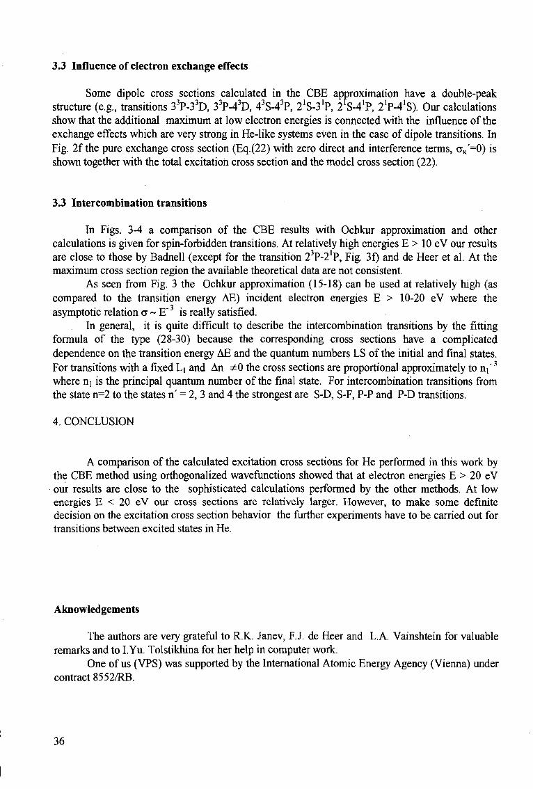
3.3 Influence of electron exchange effects
Some dipole cross sections calculated in the CBE approximation have a double-peak structure (e.g., transitions 33P-33D, 33P-43D, 43S-43P, 21S-31P, 21S-41P, 21P-41S). Our calculations show that the additional maximum at low electron energies is connected with the influence of the exchange effects which are very strong in He-like systems even in the case of dipole transitions. In Fig. 2f the pure exchange cross section (Eq.(22) with zero direct and interference terms, aK'=0) is shown together with the total excitation cross section and the model cross section (22).
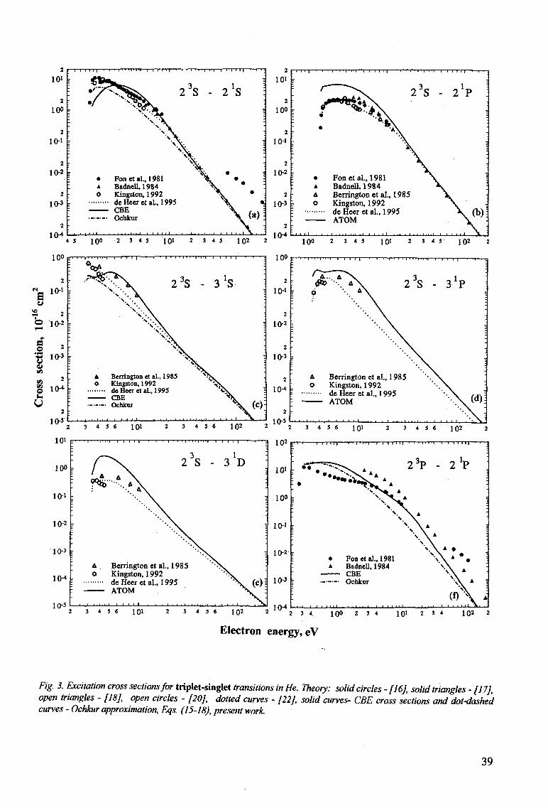
3.3 Intercombination transitions
In Figs. 3-4 a comparison of the CBE results with Ochkur approximation and other calculations is given for spin-forbidden transitions. At relatively high energies E > 10 eV our results are close to those by Badnell (except for the transition 23P-2'P, Fig. 3f) and de Heer et al. At the maximum cross section region the available theoretical data are not consistent.
As seen from Fig. 3 the Ochkur approximation (15-18) can be used at relatively high (as compared to the transition energy AE) incident electron energies E > 10-20 eV where the asymptotic relation a ~ E" is really satisfied.
In general, it is quite difficult to describe the intercombination transitions by the fitting formula of the type (28-30) because the corresponding cross sections have a complicated dependence on the transition energy AE and the quantum numbers LS of the initial and final states. For transitions with a fixed Li and An ^0 the cross sections are proportional approximately to nf3
where ni is the principal quantum number of the final state. For intercombination transitions from the state n=2 to the states n' = 2, 3 and 4 the strongest are S-D, S-F, P-P and P-D transitions.
4. CONCLUSION
A comparison of the calculated excitation cross sections for He performed in this work by the CBE method using orthogonalized wavefunctions showed that at electron energies E > 20 eV our results are close to the sophisticated calculations performed by the other methods. At low energies E < 20 eV our cross sections are relatively larger. However, to make some definite decision on the excitation cross section behavior the further experiments have to be carried out for transitions between excited states in He.
Aknowledgements
The authors are very grateful to R.K. Janev, F.J. de Heer and L.A. Vainshtein for valuable remarks and to I. Yu. Tolstikhina for her help in computer work.
One of us (VPS) was supported by the International Atomic Energy Agency (Vienna) under contract 8552/RB.
36
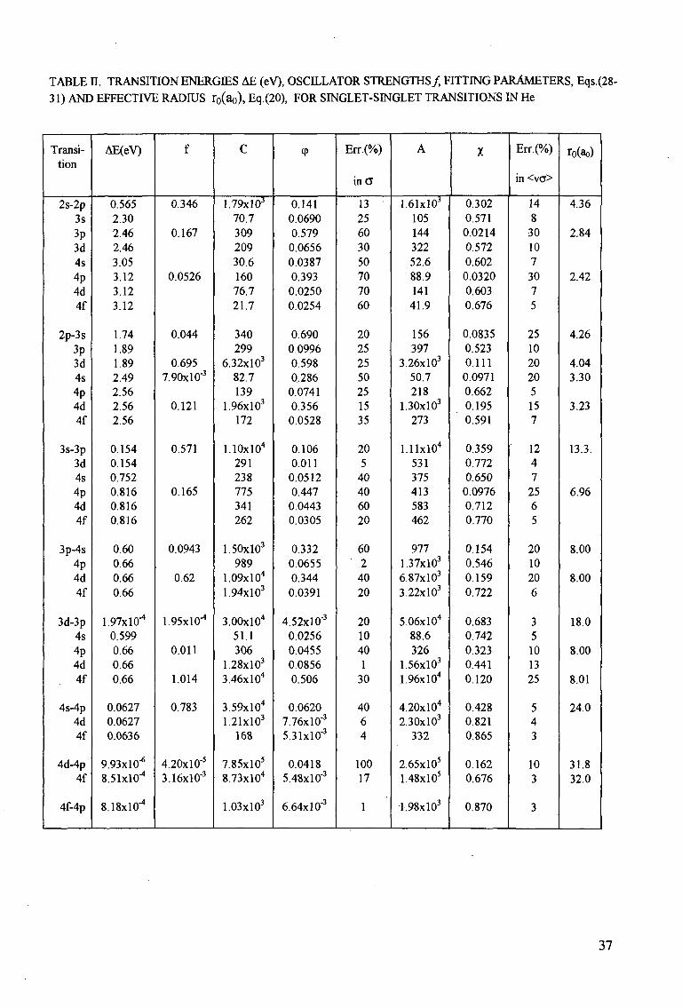
TABLE II. TRANSITION ENERGIES AE (eV), OSCILLATOR STRENGTHS/ FITTING PARAMETERS, Eqs.(28-31) AND EFFECTIVE RADIUS r0(ao), Eq.(20), FOR SINGLET-SINGLET TRANSITIONS IN He
Transition
2s-2p 3s 3p 3d 4s 4p 4d 4f
2p-3s 3p 3d 4s 4p 4d 4f
3s-3p 3d 4s 4p 4d 4f
3p-4s 4p 4d 4f
3d-3p 4s 4p 4d 4f
4s-4p 4d 4f
4d-4p 4f
4f-4p
AE(eV)
0.565 2.30 2.46 2.46 3.05 3.12 3.12 3.12
1.74 1.89 1.89 2.49 2.56 2.56 2.56
0.154 0.154 0.752 0.816 0.816 0.816
0.60 0.66 0.66 0.66
1.97X10⁻⁴
0.599 0.66 0.66 0.66
0.0627 0.0627 0.0636
9.93X10"6
8.51X10"4
8.18X10⁻⁴
f
0.346
0.167
0.0526
0.044
0.695 7.90xl0-3
0.121
0.571
0.165
0.0943
0.62
1.95X10"1
0.011
1.014
0.783
4.20xl0-5
3.16xl0-3
C
1.79xl03
70.7 309 209 30.6 160 76.7 21.7
340 299
6.32xl03
82.7 139
1.96xl03
172
LlOxlO4
291 238 775 341 262
1.50xl03
989 1.09xl04
1.94xl03
3.00xl04
51.1 306
1.28xl03
3.46x10⁴
3.59xI04
1.21xl03
168
7.85xl05
8.73xl04
1.03xl03
<P
0.141 0.0690 0.579 0.0656 0.0387 0.393 0.0250 0.0254
0.690 0.0996 0.598 0.286
0.0741 0.356
0.0528
0.106 0.011
0.0512 0.447
0.0443 0.0305
0.332 0.0655 0.344 0.0391
4.52x10° 0.0256 0.0455 0.0856 0.506
0.0620 7.76xl0'3
5.31xl0"3
0.0418 5.48xl0'3
6.64xl0-3
Err.(%)
inCT
13 25 60 30 50 70 70 60
20 25 25 50 25 15 35
20 5
40 40 60 20
60 2
40 20
20 10 40 1
30
40 6 4
100 17
1
A
1.61xl03
105 144 322 52.6 88.9 141 41.9
156 397
3.26xl03
50.7 218
1.30xl03
273
l.llxlO4
531 375 413 583 462
977 1.37xl03
6.87xl03
3.22xl03
5.06xl04
88.6 326
1.56xl03
1.96xl04
4.20xl04
2.30xl03
332
2.65xl05
1.48xl05
i.98xl03
X
0.302 0.571 0.0214 0.572 0.602 0.0320 0.603 0.676
0.0835 0.523 0.111 0.0971 0.662 0.195 0.591
0.359 0.772 0.650 0.0976 0.712 0.770
0.154 0.546 0.159 0.722
0.683 0.742 0.323 0.441 0.120
0.428 0.821 0.865
0.162 0.676
0.870
Err.(%)
in <va>
14 8
30 10 7 30 7 5
25 10 20 20 5 15 7
12 4 7
25 6 5
20 10 20 6
3 5 10 13 25
5 4 3
10 3
3
ro(ao)
4.36
2.84
2.42
4.26
4.04 3.30
3.23
13.3.
6.96
8.00
8.00
18.0
8.00
8.01
24.0
31.8 32.0
37
100 2 101 2 102 2 103 2 100 2 3 4 101 2 3 4 10^ 2 3 4
T - ' - T n [—I T l | - f |—' • • • r - ' I ' • ' !
101
100 :
0-1 :
1 I ' i ' J — 1 — 1 I I 1 > | — ' " ' ' I • ' •
• Flanneryetal., 1975 A Berrington et al., 1985 O Kingston, 1992
doHeeretal., 1995 ATOM
103
2
100
3 2
10-1
3 2
10-2
3 2
1 n-3
- i | i , i M | - | -
: o \ o o
r
-
1 M i l l • ' ' P ' H - T TT 1 T 1 | 1
2 ^ •
x. '*.
\ \
o Kingston, 1992 de Heer et al., 1995 ATOM
, , . i , 1 . . . i . , . , i i J i i l l . . i J - l . . i^ i_ ._L
- 4's ]
-
1 ii1
11
•.
\ ' - ,
\ j - . . -.
( d ) -, , 1 1 . . .
2 3 4 101 2 3 4 102 2 3 4 103 " j Q0 2 3 101 2 3 102 2 3 103
T T T l 1 I I I I I
5
4
3
2
10-1
7 6 5 4
3
2
2 3
10-2
' ' • 1 ' i • 1 t f I M l | — ' •"i—»- T m
*
*- \ 's
c * r *
* \ • * • »
• »
•
> 1 r J _ I _ I j i i i * . . . i . . .
T 1—l-T' t I l " | — • — r -
2*P -
\ S \
No, NX,
N \
I—1—1 J-IJ.IJ. , ,
• l ' i
4
i -r n r
!S
(f)
rrri -
:
--
:
-
2 3 IQl 2 3 102 2 3 1Q3 2 3 1Q0 2 3 4 1 Ql 2 3 4 102 2 3 4 103
Electron energy, eV
Fig. 2. Excitation cross sections for singlet-singlet transitions in He. Theory: boxes - [15], solid circles - [16], solid triangles - [17], open triangles - [18], open circles - [20], dotted curves- [22], solid curves- CBE cross sections and dot-dashed curves - a dipole model Eq. (22), present work. Dashed curve in Fig. 2f represents the pure exchange excitation cross section, present work (see text).
38
z 101
2
100
2
10-1
2
10-2
2
10-3
2 t n-4
i
[
•
F
-F
--: : -* = :
,
i 1 1 1 1 - •
•>y •f
• A
o
1 1 1 1 1 .
'\v*. *k
s T.
Fonetal.,1981 BadneU, 1984 Kingston, 1992
• deHeeretal., 1995 • CBE
Ochkur
. . . - i . i . i . i i i 1 1 1 1 .
2 3s -
Vkr
K>,
2*s : i
•
\ •
• •
SK. • \ . * \ (a)!
i i 1 1 1 1 \ , . .
i ioi
2
100
2
10-1
2
10-2
2
10-3
2
10-*
I I I I — ' — i ' I • ' • I • i ' i — l — I I I : I — ' — ' ' i • i • i M ' i — r — i i i i |
Fonctal., 1981 BadneU, 1984 Berringtonctal., 1985 Kingston, 1992 deHeeretal., 1995 ATOM
4 5 100 2 3 4 5 101 2 3 4 5 102 2 1 Q0 2 3 4 5 101 2 3 4 5 102 2
1 0 ° b • ' • I " I — ' I I ' I • — • ' I • ' ' • " ' — I I i I I • — i — ' " 3 1 0 °
a o
•*->
u
en O u
10-i ^
2
10-2
2
10-3
2
10-*
2
10-5
p
: :
' r> ' ' i iM
V 's.
A O
^ _ -
I 1—I -"!1 I J — ' r i i i l i | i i i | M « | | 1 1 1 |
> \ 23S - 3 *S \ \ s Oy
\ \^ \ N ' . \ K ' . \
\ • \ N \ \ S - . \
s ' - \ \ ' \ s \
V V V»L
vv Berrington et aL, 1985 ^5v Kingston, 1992 ^v deHeeretal., 1995 Cv CBE ^ Ochkni ^
i 1 J i . !_ . i . . . . J . - • • 1 . . i ^ i ^ i — 1 — t i l l —
:
; ••
•
•
•
: • * •
: •
-.
: -
\(C)
2
10-1
2
10-2
2
10-3
2
10-4
2
10-5
i — i i i i i I ' l ' I ' I " > l 1 1 I I | > T -
23S - 3LP
A Berringtonet al., 1985 O Kingston, 1992
de Heer et al., 1995 ATOM
Electron energy, eV
Fig. 3. Excitation cross sections for triplet-singlet transitions in He. Theory: solid circles - [16], solid triangles - [17], open triangles - [18], open circles - [20], dotted curves - [22], solid curves- CBE cross sections and dot-dashed curves - Ochkur approximation, Eqs. (15-18), present work.
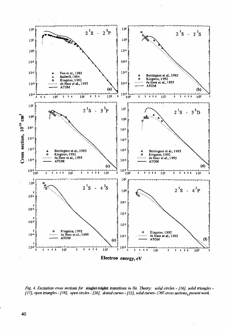
39
a
a to +3 o v «> on «> o
Electron energy, eV
Fig. 4. Excitation cross sections for singlet-triplet transitions in He. Theory: solid circles - [16], solid triangles [17], open triangles - [18], open circles - [20], dotted curves - [22], solid curves- CBE cross sections, present work.
40
REFERENCES
[I] FLANNERY, MR., MORRISON, W.R., RICHMOND, B.L., J. Appl. Phys. 46 (1975) 1186. [2] SUMMERS, H P , Adv. At. Mol. Opt. Phys. 33 (1994) 275. [3] TULLY, J.A., SUMMERS, HP., Astrophys. J. 229 (1979) LI 13. [4] SASAKI, S, TAKAMURA, S„ MASUZAKI, S, WATANABE, S„ KATO, T , KADOTA, K„ Rep. NIFS-346,
National Institute for Fusion Science, Nagoya, Japan (1995). [5] de HEER, F.J., HOEKSTRA, R., T , KINGSTON, A.E, SUMMERS, H P , Atomic and Plasma-Material
Interaction Data for Fusion (Suppl. Journ. Nuclear Fusion), Vol. 3 (1992) 19. [6] KATO, T., JANEV, R.K., Atomic and Plasma-Material Interaction Data for Fusion (Suppl. Journ. Nuclear
Fusion), Vol. 3 (1992) 33 . [7] KATO, T„ ITIKAWA, Y, SAKTMOTO, K., NIFS-DATA-15, National Institute for Fusion Science, Nagoya,
Japan (1992). [8 ] BERRTNGTON, K.A., SAWEY, P.M.J, At. Data and Nucl. Data Tables, 55 (1993) 81. [9] VAINSHTEIN, L A , SOBELMAN, I.I, YUKOV, E. A, Excitation of Atoms and Broadening of Spectral Lines,
Springer, Berlin (1995) (2nd edition). [10] SHEVELKO, V.P, VAINSHTEIN, L A , Atomic Physics for Hot Plasmas, IOP Publishing, Bristol (1993). [II] BEIGMAN, I.L, VAINSHTEIN, L.A, JETP 25 (1967) 119. [12] OCHKUR, V.I, JETP 18 (1964) 503. [13] SHEVELKO, V.P, Phys. Scripta 43 (1991) 266. [14] SHEVELKO, V.P, TAWARA, H. NIFS-DATA-28. National Institute for Fusion Science, Nagoya, Japan
(1995). [15] FLANNERY, MR., McCANN, K.J, Phys. Rev. A 12 (1975) 846. [16] FON, W.C, BERRINGTON, K.A., BURKE, P.G, KINGSTON, A.E., J. Phys. B 14 (1981) 2921. [17] BADNELL, N.R, J. Phys. 8 17(1984)4013. [18] BERRINGTON, K.A, BURKE, P.G, FREITAS, L.C.G, KINGSTON, A.E, J. Phys. B 18 (1985) 4135. [19] MATHUR, K.C, McEACHRAN, R.P, PARCELL, L A , STEUFFER, A D , J. Phys. B 20 (1987) 1599. [20] KINGSTON, A.E, (private communiation, 1992); unpublished. [21] BRAY, I , MCCARTHY, I E , Phys. Rev. A47 (1993) 317. [22] DE HEER, F.J, FOLKERTS, H O , BLJEK, F.W, HOEKSTRA, R, KATO, T, KINGSTON, A.E,
BERRINGTON, K.A, SUMMERS, H P , FOM-report 0653, FOMInstitute, Amsterdam(1995). [23] RALL, D.L.A, SHARPTON, F.A, SCHULMAN, M B , ANDERSON, L.W, LAWLER, J.E, LIN, C.C, Phys.
Rev. Lett. 62 (1989) 2253.
41

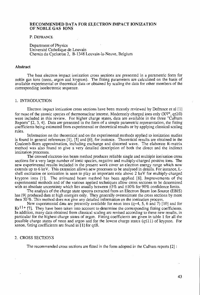
RECOMMENDED DATA FOR ELECTRON IMPACT IONIZATION OF NOBLE GAS IONS
P. DEFRANCE
Department of Physics Universite Catholique de Louvain Chemin du Cyclotron 2, B-1348 Louvain-la-Neuve, Belgium
Abstract
The best electron impact ionization cross sections are presented in a parametric form for noble gas ions (neon, argon and krypton). The fitting parameters are calculated on the basis of available experimental or theoretical data or obtained by scaling the data for other members of the corresponding isoelectronic sequence.
1. INTRODUCTION
Electron impact ionization cross sections have been recently reviewed by Defrance et al [ 1] for most of the atomic species of thermonuclear interest. Moderately charged ions only (X1+, q<10) were included in this review. For higher charge states, data are available in the three "Culham Reports" [2, 3, 4]. Data are-presented in the form of a simple parametric representation, the fitting coefficients being estimated from experimental or theoretical results or by applying classical scaling rules.
Information on the theoretical and on the experimental methods applied to ionization studies is found in general references [1], [5] and [6], for instance. Theoretical results are obtained in the Coulomb-Born approximation, including exchange and distorted wave. The elaborate R-matrix method was also found to give a very detailed description of both the direct and the indirect ionization processes.
The crossed electron-ion beam method produces reliable single and multiple ionisation cross sections for a very large number of ionic species, negative and multiply-charged positive ions. The new experimental results included in the present work cover an electron energy range which now extends up to 6 keV. This extension allows new processes to be analysed in details. For instance, L-shell excitation or ionization is seen to play an important role above 2 keV for multiply-charged krypton ions [7]. The animated beam method has been applied [8]. Improvements of the experimental methods and of the various applied techniques allow cross sections to be determined with an absolute uncertainty which lies usually between ±5% and ±10% for 90% confidence limits.
The analysis of the charge state spectra extracted from an Electron Beam Ion Source (EBIS) has [9] produced data at high energies only. They generally overestimate the cross sections by more then 30 %. This method does not give any detailed information on the ionization process.
New experimental data are presently available for neon ions (q=4, 5, 6 and 7) [10] and for K r l l + [7]. They have been taken into account to determine the corresponding fitting coefficients. In addition, many data obtained from classical scaling are revised according to these new results, in particular for the highest charge states of argon. Fitting coefficients are given in table 1 for all the possible charge states of neon and argon and for the lowest charge states (q< 11) of krypton. For xenon, fitting coefficients are found in [1] for q<8.
2. CROSS SECTIONS
The recommended cross sections are fitted in the form adopted in the Culham reports [2] :
43
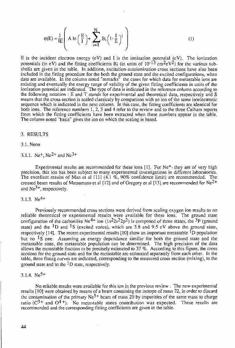
°(E)=JE
( N A
(i)
E is the incident electron energy (eV) and I is the ionization potential (eV). The ionization potentials (in eV) and the fitting coefficients Bi (in units of 10" 13 cm^eV^) for the various sub-shells are given in the table. In addition, excitation-autoionization cross sections have also been included in the fitting procedure for the both the ground state and the excited configurations, when data are available. In the column noted "remarks" the cases for which data for metastable ions are existing and eventually the energy range of validity of the given fitting coefficients in units of the ionization potential are indicated. The type of data is indicated in the reference column according to the following notation : E and T stands for experimental and theoretical data, respectively and S means that the cross section is scaled classicaly by comparison with an ion of the same isoelectronic sequence which is indicated in the next column. In this case, the fitting coefficients are identical for both ions. The reference numbers 1, 2, 3 and 4 refer to the review and to the three Culham reports from which the fitting coefficients have been extracted when these numbers appear in the table. The column noted "basis" gives the ion on which the scaling is based.
3. RESULTS
3.1. Neon
3.1.1. Ne+, Ne2 + and Ne3 +
Experimental results are recommended for these ions [1]. For Ne+> they are of very high precision, this ion has been subject to many experimental investigations in different laboratories. The excellent results of Man et al [11] (4.1 %, 90% confidence limit) are recommended. The crossed beam results of Matsumuto et al [12] and of Gregory et al [13] are recommended for Ne2+ and Ne3+, respectively.
3.1.3. Ne4+
Previously recommended cross sections were derived from scaling oxygen ion results as no reliable theoretical or experimental results were available for these ions. The ground state configuration of the carbonlike Ne^+ ion ( l s ^ s ^ p 2 ) is composed of three states, the 3p (ground state) and the *D and ^S (excited states), which are 3.8 and 9.5 eV above the ground state, respectively [14]. The recent experimental results [10] show an important metastable ^D population but no I s one. Assuming an energy dependance similar for both the ground state and the metastable state, the metastable population can be determined. The high precision of the data allows the metastable fraction to be precisely estimated to 37 %. According to this figure, the cross sections for the ground state and for the metastable are estimated separately from each other. In the table, three fitting curves are indicated, corresponding to the measured cross section (mixing), to the ground state and to the ^D state, respectively.
3.1.4. Ne5+
No reliable results were available for this ion in the previous review . The new experimental results [10] were obtained by means of a beam containing the isotope of mass 22, in order to discard the contamination of the primary Ne^+ beam of mass 20 by impurities of the same mass to charge ratio (C3+ and 0^+). No metastable states contribution was expected. These results are recommended and the corresponding fitting coefficients are given in the table.
44
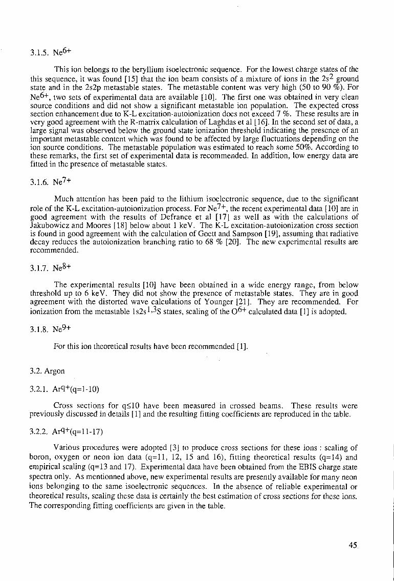
3.1.5. Ne6+
This ion belongs to the beryllium isoelectronic sequence. For the lowest charge states of the this sequence, it was found [15] that the ion beam consists of a mixture of ions in the 2s^ ground state and in the 2s2p metastable states. The metastable content was very high (50 to 90 %). For Ne "1", two sets of experimental data are available [10]. The first one was obtained in very clean source conditions and did not show a significant metastable ion population. The expected cross section enhancement due to K-L excitation-autoionization does not exceed 7 %. These results are in very good agreement with the R-matrix calculation of Laghdas et al [16]. In the second set of data, a large signal was observed below the ground state ionization threshold indicating the presence of an important metastable content which was found to be affected by large fluctuations depending on the ion source conditions. The metastable population was estimated to reach some 50%. According to these remarks, the first set of experimental data is recommended. In addition, low energy data are fitted in the presence of metastable states.
3.1.6. Ne 7 +
Much attention has been paid to the lithium isoelectronic sequence, due to the significant role of the K-L excitation-autoionization process. For Ne7 + , the recent experimental data [10] are in good agreement with the results of Defrance et al [17] as well as with the calculations of Jakubowicz and Moores [18] below about 1 keV. The K-L excitation-autoionization cross section is found in good agreement with the calculation of Goett and Sampson [19], assuming that radiative decay reduces the autoionization branching ratio to 68 % [20]. The new experimental results are recommended.
3.1.7. Ne 8 +
The experimental results [10] have been obtained in a wide energy range, from below threshold up to 6 keV. They did not show the presence of metastable states. They are in good agreement with the distorted wave calculations of Younger [21]. They are recommended. For ionization from the metastable ls2s^^S states, scaling of the 0 ^ + calculated data [1] is adopted.
3.1.8. Ne9+
For this ion theoretical results have been recommended [1].
3.2. Argon
3.2.1. Arq+(q=l-10)
Cross sections for q<10 have been measured in crossed beams. These results were previously discussed in details [1] and the resulting fitting coefficients are reproduced in the table.
3.2.2. Arq+(q=ll-17)
Various procedures were adopted [3] to produce cross sections for these ions : scaling of boron, oxygen or neon ion data (q=l 1, 12, 15 and 16), fitting theoretical results (q=14) and empirical scaling (q=13 and 17). Experimental data have been obtained from the EBIS charge state spectra only. As mentionned above, new experimental results are presently available for many neon ions belonging to the same isoelectronic sequences. In the absence of reliable experimental or theoretical results, scaling these data is certainly the best estimation of cross sections for these ions. The corresponding fitting coefficients are given in the table.
45.
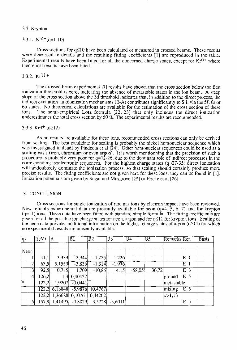
3.3. Krypton
3.3.1. Krq+(q=l-10)
Cross sections for q<10 have been calculated or measured in crossed beams. These results were discussed in details and the resulting fitting coefficients [1] are reproduced in the table. Experimental results have been fitted for all the concerned charge states, except for Kr6+ where theoretical results have been fitted.
3.3.2. Kr 1 1 +
The crossed beam experimental [7] results have shown that the cross section below the first ionization threshold is zero, indicating the absence of metastable states in the ion beam. A steep slope of the cross section above the 3d threshold indicates that, in addition to the direct process, the indirect excitation-autoionization mechanisms (E-A) contributes significantly to S.I. via the 5f, 6s or 6p states. No theoretical calculations are available for the estimation of the cross section of these ions. The semi-empirical Lotz formula [22, 23] that only includes the direct ionization underestimates the total cross section by 50 %. The experimental results are recommended.
3.3.3. Krq+ (q>12)
As no results are available for these ions, recommended cross sections can only be derived from scaling. The best candidate for scaling is probably the nickel homonuclear sequence which was investigated in detail by Pindzola et al [24]. Other homonuclear sequences could be used as a scaling basis (iron, chromium or even argon). It is worth mentionning that the precision of such a procedure is probably very poor for q= 12-26, due to the dominant role of indirect processes in the corresponding isoelectronic sequences. For the highest charge states (q=27-35) direct ionization will undoubtedly dominate the ionization process, so that scaling should certainly produce more precise results. The fitting coefficients are not given here for these ions, they can be found in [1]. Ionization potentials are given by Sugar and Musgrove [25] or Fricke et al [26].
3. CONCLUSION
Cross sections for single ionization of rare gas ions by electron impact have been reviewed. New reliable experimental data are presently available for neon (q=4, 5, 6, 7) and for krypton (q= 11) ions. These data have been fitted with standard simple formula. The fitting coefficients are given for all the possible ion charge states for neon, argon and for q<l 1 for krypton ions. Scaling of the neon data provides additional information on the highest charge states of argon (q>l 1) for which no experimental results are presently available.
q
Neon 1 2 3 4
*
5
I(eV)
41,1 63,5 92,5
126,2 122,2 122,2 122,2 157,9
A
3,333 5,1559 0,785
1,3 1,9207
6,13848 1,36688 1,41495
Bl
-2,944 -3,836 1,709
0,40432 -0,0441 -5,9876 0,10761 -0,8029
B2
-1,225 -1,314 -10,85
10,4767 0,44202
3,5728
B3
1,226 -1,976 •41,5
-3,6011
B4
-58,05
B5
30,72
Remarks
ground metastab mixing x>l,13
Ref.
E 1 E 1 E 3 E 5 e E 5
E 5
Basis
46
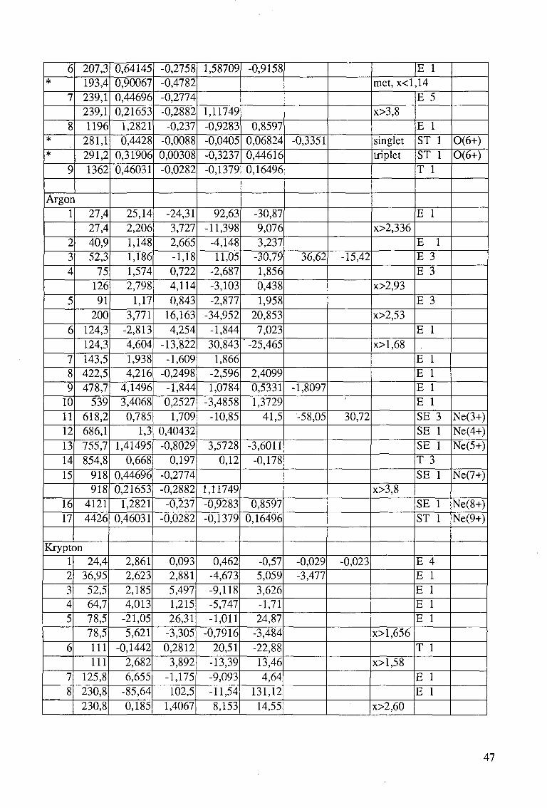
6 *
7
8 *
*
9
207,3 193,4 239,1 239,1 1196
281,1 291,2 1362
Argon 1
2 3 4
5
6
7 8 9
10 11 12 13 14 15
16 17
27,4 27,4 40,9 52,3
75 126 91
200 124,3 124,3 143,5 422,5 478,7
539 618,2 686,1 755,7 854,8
918 918
4121 4426
Krypton 1 2 3 4 5
6
7 8
24,4 36,95 52,5 64,7 78,5 78,5 111 111
125,8 230,8 230,8
0,64145 0,90067 0,44696 0,21653
1,2821 0,4428
0,31906 0,46031
25,14 2,206 1,148 1,186 1,574 2,798
1,17 3,771
-2,813 4,604 1,938 4,216
4,1496 3,4068 0,785
1,3 1,41495
0,668 0,44696 0,21653
1,2821 0,46031
2,861 2,623 2,185 4,013
-21,05 5,621
-0,1442 2,682 6,655
-85,64 0,185
-0,2758 -0,4782 -0,2774 -0,2882
-0,237 -0,0088 0,00308 -0,0282
-24,31 3,727 2,665 -1,18 0,722 4,114 0,843
16,163 4,254
-13,822 -1,609
-0,2498 -1,844 0,2527
1,709 0,40432 -0,8029
0,197 -0,2774 -0,2882
-0,237 -0,0282
0,093 2,881 5,497 1,215 26,31
-3,305 0,2812
3,892 -1,175 102,5
1,4067
1,58709
1,11749 -0,9283 -0,0405 -0,3237 -0,1379
92,63 -11,398
-4,148 11,05
-2,687 -3,103 -2,877
-34,952 -1,844 30,843
1,866 -2,596 1,0784
-3,4858 -10,85
3,5728 0,12
1,11749 -0,9283 -0,1379
0,462 -4,673 -9,118 -5,747 -1,011
-0,7916 20,51
-13,39 -9,093 -11,54 8,153
-0,9158
0,8597 0,06824 0,44616 0,16496
-30,87 9,076 3,237
-30,79 1,856 0,438 1,958
20,853 7,023
" -25,465
2,4099 0,5331 1,3729
41,5
-3,6011 -0,178
0,8597 0,16496
-0,57 5,059 3,626 -1,71 24,87
-3,484 -22,88 13,46 4,64
131,12 14,55
-0,3351
36,62
-1,8097
-58,05
-0,029 -3,477
-15,42
30,72
-0,023
E 1 met, x<l,14
x>3,8
singlet triplet
x>2,336
x>2,93
x>2,53
x>l,68
x>3,8
x>l,656
x>l,58
x>2,60
E 5
E 1 ST 1 ST 1 T 1
E 1
E 1 E 3 E 3
E 3
E 1
E 1 E 1 E 1 E 1 SE 3 SE 1 SE 1 T 3 SE 1
SE 1 ST 1
E 4 E 1 E 1 E 1 E 1
T 1
E 1 E 1
0(6+) 0(6+)
Ne(3+) Ne(4+) Ne(5+)
Ne(7+)
Ne(8+) Ne(9+)
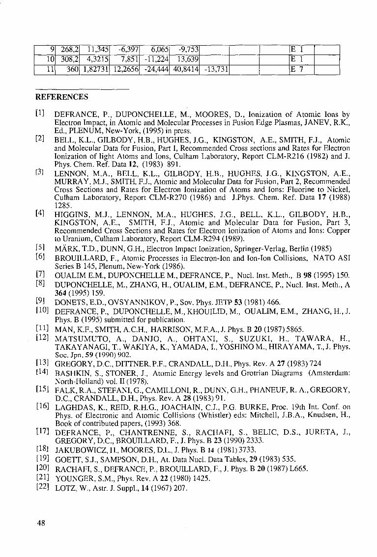
9 10 11
268,2 308,2
360
11,345 4,3215
1,82731
-6,397 7,851
12,2656
6,065 -11,224 -24,444
-9,753 13,639
40,8414 -13,731
E 1 E 1 E 7
REFERENCES
[!] DEFRANCE, P., DUPONCHELLE, M., MOORES, D., Ionization of Atomic Ions by Electron Impact, in Atomic and Molecular Processes in Fusion Edge Plasmas, JANEV, R.K., Ed., PLENUM, New-York, (1995) in press.
[2] BELL, K.L., GILBODY, H.B., HUGHES, J.G., KINGSTON, A.E., SMITH, F.J., Atomic and Molecular Data for Fusion, Part I, Recommended Cross sections and Rates for Electron Ionization of light Atoms and Ions, Culham Laboratory, Report CLM-R216 (1982) and J. Phys. Chem. Ref. Data 12, (1983) 891.
tfl LENNON, M.A., BELL, K.L., GILBODY, H.B., HUGHES, J.G., KINGSTON, A.E., MURRAY, M.J., SMITH, F.J., Atomic and Molecular Data for Fusion, Part 2, Recommended Cross Sections and Rates for Electron Ionization of Atoms and Ions: Fluorine to Nickel, Culham Laboratory, Report CLM-R270 (1986) and J.Phys. Chem. Ref. Data 17 (1988) 1285.
[4] HIGGINS, M.J., LENNON, M.A., HUGHES, J.G., BELL, K.L., GILBODY, H.B., KINGSTON, A.E., SMITH, F.J., Atomic and Molecular Data for Fusion, Part 3, Recommended Cross Sections and Rates for Electron Ionization of Atoms and Ions: Copper to Uranium, Culham Laboratory, Report CLM-R294 (1989).
[5] MARK, T.D., DUNN, G.H., Electron Impact Ionization, Springer-Verlag, Berlin (1985) [6-1 BROUILLARD, F., Atomic Processes in Electron-Ion and Ion-Ion Collisions, NATO ASI
Series B 145, Plenum, New-York (1986). [7] OUALIM E.M., DUPONCHELLE M., DEFRANCE, P., Nucl. Inst. Meth., B 98 (1995) 150. [8] DUPONCHELLE, M., ZHANG, H , OUALIM, E.M., DEFRANCE, P., Nucl. Inst. Meth., A
364(1995)159. [9] DONETS, E.D., OVSYANNIKOV, P., Sov. Phys. JETP 53 (1981) 466. [!0] DEFRANCE, P., DUPONCHELLE, M., KHOUILID, M., OUALIM, E.M., ZHANG, H., J.
Phys. B (1995) submitted for publication. [H] MAN, K.F., SMITH, A.C.H., HARRISON, M.F.A., J. Phys. B 20 (1987) 5865. t1 2] MATSUMUTO, A., DANJO, A., OHTANI, S., SUZUKI, H., TAWARA, H.,
TAKAYANAGI, T., WAKIYA, K., YAMADA, I., YOSHINO M., HIRAYAMA, T., J. Phys. Soc. Jpn, 59 (1990) 902.
[!3] GREGORY, D.C., DITTNER, P.F., CRANDALL, D.H., Phys. Rev. A 27 (1983) 724 t14l BASHKIN, S., STONER, J., Atomic Energy levels and Grotrian Diagrams (Amsterdam:
North-Holland) vol. 11(1978). [!5] FALK, R.A., STEFANI, G., CAMILLONI, R., DUNN, G.H., PHANEUF, R. A., GREGORY,
D.C., CRANDALL, D.H., Phys. Rev. A 28 (1983) 91. [!6] LAGHDAS, K., REID, R.H.G., JOACHAIN, C.J., P.G. BURKE, Proc. 19th Int. Conf. on
Phys. of Electronic and Atomic Collisions (Whistler) eds: Mitchell, J.B.A., Knudsen, H., Book of contributed papers, (1993) 368.
t1 7] DEFRANCE, P., CHANTRENNE, S., RACHAFI, S., BELIC, D.S., JURETA, J., GREGORY, D.C., BROUILLARD, F., J. Phys. B 23 (1990) 2333.
[18J JAKUBOWICZ, H, MOORES, D.L., J. Phys. B 14 (1981) 3733. [19] GOETT, S.J., SAMPSON, D.H., At. Data Nucl. Data Tables, 29 (1983) 535. [20] RACHAFI, S., DEFRANCE, P., BROUILLARD, F., J. Phys. B 20 (1987) L665. [21] YOUNGER, S.M., Phys. Rev. A 22 (1980) 1425. [22] LOTZ, W., Astr. J. Suppl, 14 (1967) 207.
48
[23] LOTZ, W., Z. Phys 216, (1968) 241. [24] PINDZOLA, M.S., GRIFFIN, D.C., BOTTCHER, C, BUIE, M.J., GREGORY, D.C., report
ORNL/ TM-11202, Oak Ridge National Lab., Tennessee, U.S.A. (1990). [25] SUGAR, J., MUSGROVE, A., J. Phys. Chem. Ref. Data 20 (1991) 859. [26] BLANKE, J.H., FRICKE, B., FINKBENER, Database "Plasmarelevante Atomare Daten",
University of Kassel, Germany, (1992).
49

Electron Impact Ionisation of Tungsten Ions
M. Stenke, K.Aichele, D.Hathiramani, G.Hofmann, M.Steidl, R.V6lpel and E.Salzbora
Institut fur Kernphysik, Justus—Liebig—Universitat Giessen, D-35392 Giessen, Germany
Abstract: Electron impact ionisation cross sections for the single and multiple ionisation of tungsten ions have been measured by employing the "crossed-beams" technique. For W?+ions in charge states q=\...\0 cross sections for single ionisation were determined. For ions in charge states q=3...7, excitation-autoionisation from the ground state as well as from excited, metastable states strongly contributes to the cross sections. This results in a strong underestimation of the measured cross sections compared to the semiempirical Lotz formula in the energy range between the ionisation threshold and the cross section maximum. The ionisation cross section for W?+ions was measured in the case of double ionisation for q=\...6 and of triple ionisation up to q=4. The multiple ionisation cross sections indicate no considerable contributions of indirect processes.
1. Introduction
Electron impact ionisation of ions plays an important role in all kinds of plasmas. For future fusion devices, the use of tungsten as a material for divertor plates is under consideration [1]. Despite the strong disadvantages of the high-Z tungsten, if encountered as an impurity element in the hot central plasma, the use of a highly refractory metal with very low sputter yields has the benefit of a minimized divertor plate erosion and extended operation time. For divertor modeling and plasma radiative cooling studies, it is necessary to know the cross sections for electron impact ionisation of tungsten ions [2]. So far only the single ionisation of singly-charged ions has been investigated [3]. In order to expand the available atomic database, extensive measurements of cross sections for the electron impact ionisation of W#+ ions in charge states q=l...\0 for single, q=l...6 for double and up to q=A for triple ionisation have been carried out.
2. Experimental Technique
The measurements were performed at the Giessen electron-ion crossed-beams setup [4, 5]. The tungsten ions were produced by a 10 GHz Electron-Cyclotron-Resonance (ECR) ion source [6] using two different methods. The first method used the tungsten compound W(CO)6, which is solid and sublimates easily without dissociation at a vapour pressure sufficient to operate the ion source. Employing this method, ion currents of a few hundred enA for W+ up to W4+ were extracted. In the second method a bundle of thin tungsten wires (0.5 mm diameter) was used which was brought axially to the edge of the ECR plasma. By sputtering and evaporation, tungsten atoms were fed into the plasma and ionised. With this method, much higher ion currents of 1-3 euA of W+ to W10+ ions have been obtained. In both methods an acceleration voltage of 10 kV was applied. After magnetic separation of the desired mass to charge state ratio and a tight collimation to typically 1 mm beam diameter, which reduced the ion current by a factor of roughly 100, the ion beam was crossed with an intense electron beam. For these measurements two electron guns were employed. One electron gun delivers a ribbon-shaped electron beam at energies between 10 and 1000 eV with electron currents up to 450 mA (high-current electron gun) [7]. For the ionisation of higher charge states, an electron gun with energies between 50 and 6500 eV and electron cur-
51
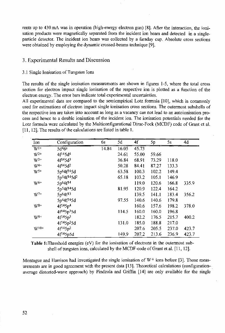
rents up to 430 mA was in operation (high-energy electron gun) [8]. After the interaction, the ioni-sation products were magnetically separated from the incident ion beam and detected in a single-particle detector. The incident ion beam was collected by a faraday cup. Absolute cross sections were obtained by employing the dynamic crossed-beams technique [9].
3. Experimental Results and Discussion
3.1 Single Ionisation of Tungsten Ions
The results of the single ionisation measurements are shown in figures 1-5, where the total cross section for electron impact single ionisation of the respective ion is plotted as a function of the electron energy. The error bars indicate total experimental uncertainties. All experimental data are compared to the semiempirical Lotz formula [10], which is commonly used for estimations of electron impact single ionisation cross sections. The outermost subshells of the respective ion are taken into account as long as a vacancy can not lead to an autoionisation process and hence to a double ionisation of the incident ion. The ionisation potentials needed for the Lotz formula were calculated by the Multiconfigurational Dirac-Fock (MCDF) code of Grant et al. [11,12]. The results of the calculations are listed in table 1.
Ion
W'+ W2+
W3+
w 4 +
W5+
W6+
W7+
W8+
W9+
• \ V 1 0 +
Configuration
5d46s
4f145d4
4f*45d3
4fi45d2
5p64f*45d 5p54f145d2
5p64f14
5p54f145d 5p64f13
5pMf145d 4f'45p4
4fi45p35d 4f145p3
4f145p25d 4f145p2
4f145p5d
6s 5d 14.84 16.05
24.61 36.84 50.28 63.58 65.18
81.95
97.55
114.5
131.0
149.9
4f
45.73 55.00 68.91 84.41 100.3 103.2 119.0 120.9 139.5 140.6 160.6 160.0 182.2 185.0 207.6 207.2
5p
59.66 73.29 87.27 102.2 105.1 120.6 122.4 141.1 140.6 157.6 160.0 176.5 188.8 205.5 213.6
5s
118.0 133.3 149.4 146.9 166.8 164.2 183.4 179.8 198.2 196.8 215.7 217.0 237.0 236.9
4d
335.9
356.2
378.0
400.2
423.7 423.7
Table l:Threshold energies (eV) for the ionisation of electrons in the outermost sub-shell of tungsten ions, calculated by the MCDF-code of Grant et al. [11, 12].
Montague and Harrison had investigated the single ionisation of W+ ions before [3]. Those measurements are in good agreement with the present data [13]. Theoretical calculations (configuration-average distorted-wave approach) by Pindzola and Griffin [14] are only available for the single
52
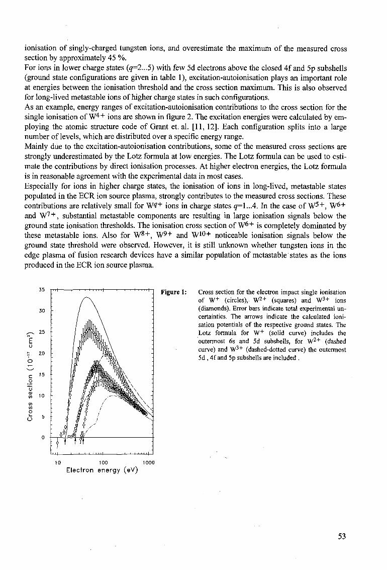
ionisation of singly-charged tungsten ions, and overestimate the maximum of the measured cross section by approximately 45 %. For ions in lower charge states (q=2...5) with few 5d electrons above the closed 4f and 5p subshells (ground state configurations are given in table 1), excitation-autoionisation plays an important role at energies between the ionisation threshold and the cross section maximum. This is also observed for long-lived metastable ions of higher charge states in such configurations. As an example, energy ranges of excitation-autoionisation contributions to the cross section for the single ionisation of W 4 + ions are shown in figure 2. The excitation energies were calculated by employing the atomic structure code of Grant et. al. [11,12]. Each configuration splits into a large number of levels, which are distributed over a specific energy range. Mainly due to the excitation-autoionisation contributions, some of the measured cross sections are strongly underestimated by the Lotz formula at low energies. The Lotz formula can be used to estimate the contributions by direct ionisation processes. At higher electron energies, the Lotz formula is in reasonable agreement with the experimental data in most cases. Especially for ions in higher charge states, the ionisation of ions in long-lived, metastable states populated in the ECR ion source plasma, strongly contributes to the measured cross sections. These contributions are relatively small for W?+ ions in charge states q=\..A. In the case of W 5 + , W6+ and W7"*", substantial metastable components are resulting in large ionisation signals below the ground state ionisation thresholds. The ionisation cross section of W 6 + is completely dominated by these metastable ions. Also for W 8 + , W 9 + and W 1 0 + noticeable ionisation signals below the ground state threshold were observed. However, it is still unknown whether tungsten ions in the edge plasma of fusion research devices have a similar population of metastable states as the ions produced in the ECR ion source plasma.
Cross section for the electron impact single ionisation of W+ (circles), W2"1" (squares) and W3+ ions (diamonds). Error bars indicate total experimental uncertainties. The arrows indicate the calculated ionisation potentials of the respective ground states. The Lotz formula for W+ (solid curve) includes the outermost 6s and 5d subshells, for W2"1" (dashed curve) and W3+ (dashed-dotted curve) the outermost 5d , 4f and 5p subshells are included .
10 100 1000
Electron energy (eV)
53
j ^ >
30 -
25
20
15
o % 10
V) V)
o e>
5 -
Figure 1:
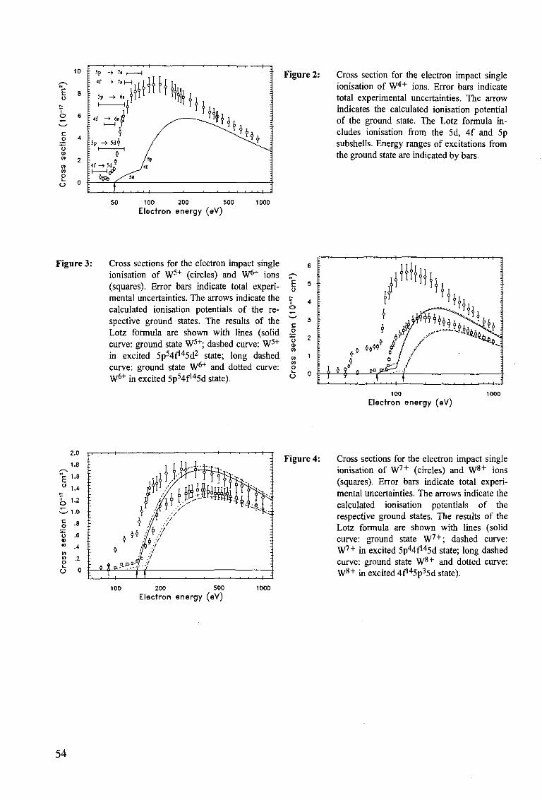
10
c o
~o <u w w 10 o 1-
o
Figure 2: Cross section for the electron impact single ionisation of W4 + ions. Error bars indicate total experimental uncertainties. The arrow indicates the calculated ionisation potential of the ground state. The Lotz formula includes ionisation from the 5d, 4f and 5p subshells. Energy ranges of excitations from the ground state are indicated by bars.
50 100 200 500 Electron energy (eV)
1000
Figure 3: Cross sections for the electron impact single ionisation of W5+ (circles) and W6+ ions (squares). Error bars indicate total experimental uncertainties. The arrows indicate the calculated ionisation potentials of the respective ground states. The results of the Lotz formula are shown with lines (solid curve: ground state W5+; dashed curve: W5+
in excited 5p54f145d2 state; long dashed curve: ground state W6+ and dotted curve: W6+ in excited 5p54f145d state).
£
c o
~o Q> w V) w o
100 1000 Electron energy (eV)
Figure 4: Cross sections for the electron impact single ionisation of W7 + (circles) and W 8 + ions (squares). Error bars indicate total experimental uncertainties. The arrows indicate the calculated ionisation potentials of the respective ground states. The results of the Lotz formula are shown with lines (solid curve: ground state W 7 + ; dashed curve: W7 + in excited 5p44f145d state; long dashed curve: ground state W 8 + and dotted curve: W8 + in excited 4f145p35d state).
100 200 500 Electron energy (eV)
1000
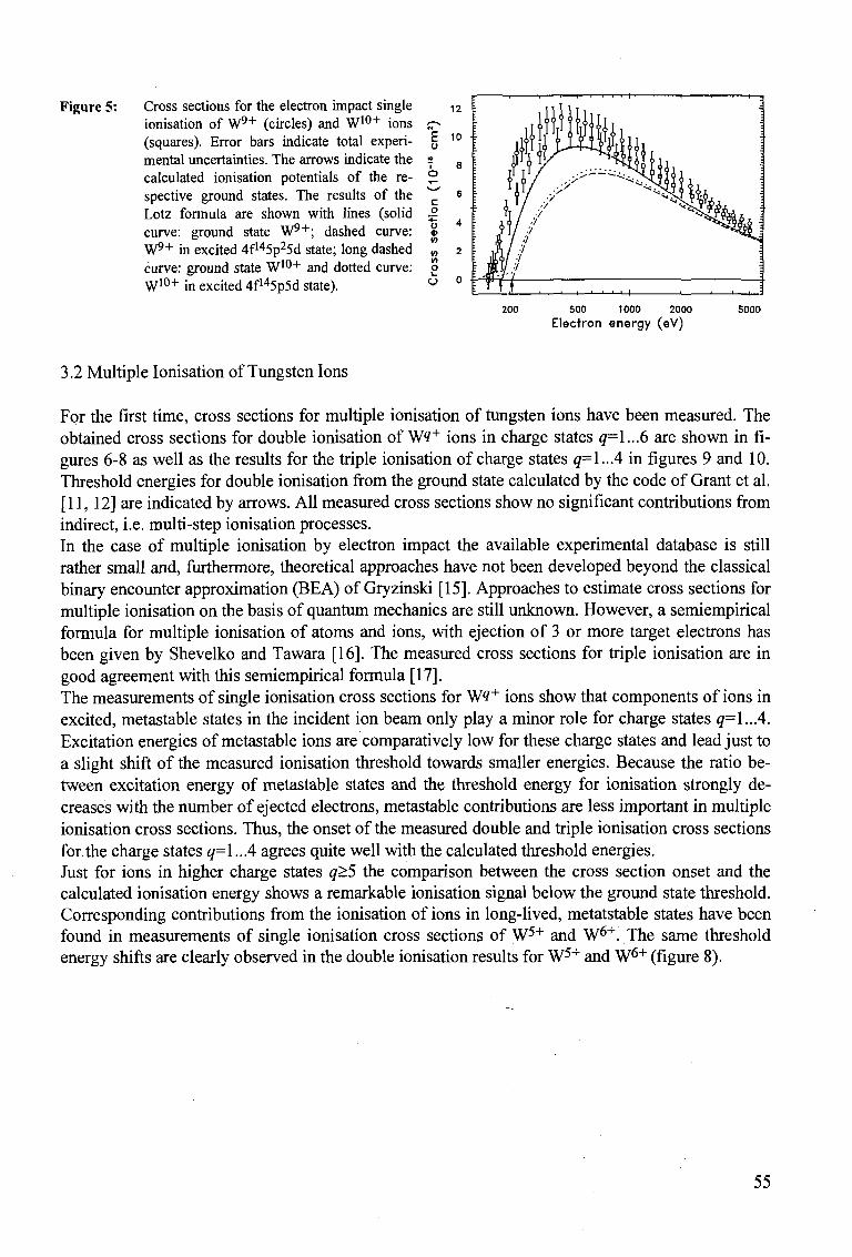
Figure 5: Cross sections for the electron impact single ionisation of W9"1" (circles) and W1 0 + ions (squares). Error bars indicate total experimental uncertainties. The arrows indicate the calculated ionisation potentials of the respective ground states. The results of the Lotz formula are shown with lines (solid curve: ground state W9"1"; dashed curve: W9"1" in excited 4f145p25d state; long dashed curve: ground state W1 0 + and dotted curve: W1 0 + in excited 4f145p5d state).
<n o
o
200 500 1000 2000 Electron energy (eV)
sooo
3.2 Multiple Ionisation of Tungsten Ions
For the first time, cross sections for multiple ionisation of tungsten ions have been measured. The obtained cross sections for double ionisation of Wtf+ ions in charge states <7=1...6 are shown in figures 6-8 as well as the results for the triple ionisation of charge states q=\..A in figures 9 and 10. Threshold energies for double ionisation from the ground state calculated by the code of Grant et al. [11,12] are indicated by arrows. All measured cross sections show no significant contributions from indirect, i.e. multi-step ionisation processes. In the case of multiple ionisation by electron impact the available experimental database is still rather small and, furthermore, theoretical approaches have not been developed beyond the classical binary encounter approximation (BEA) of Gryzinski [15]. Approaches to estimate cross sections for multiple ionisation on the basis of quantum mechanics are still unknown. However, a semiempirical formula for multiple ionisation of atoms and ions, with ejection of 3 or more target electrons has been given by Shevelko and Tawara [16]. The measured cross sections for triple ionisation are in good agreement with this semiempirical formula [17]. The measurements of single ionisation cross sections for W^+ ions show that components of ions in excited, metastable states in the incident ion beam only play a minor role for charge states q=\..A. Excitation energies of metastable ions are comparatively low for these charge states and lead just to a slight shift of the measured ionisation threshold towards smaller energies. Because the ratio between excitation energy of metastable states and the threshold energy for ionisation strongly decreases with the number of ejected electrons, metastable contributions are less important in multiple ionisation cross sections. Thus, the onset of the measured double and triple ionisation cross sections for the charge states q=\..A agrees quite well with the calculated threshold energies. Just for ions in higher charge states q>5 the comparison between the cross section onset and the calculated ionisation energy shows a remarkable ionisation signal below the ground state threshold. Corresponding contributions from the ionisation of ions in long-lived, metatstable states have been found in measurements of single ionisation cross sections of W5+ and W6+. The same threshold energy shifts are clearly observed in the double ionisation results for W5+ and W6+ (figure 8).
55
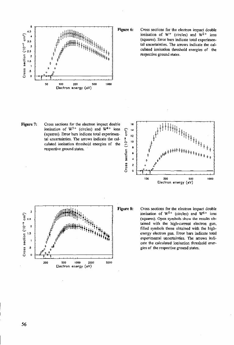
5
4.5
4
3.5
3
•2.5
I 2 " o 1 . 5 V <n , «o « .5 O
}f
! * i 0 D
o n
:—o p ° n OQH
•s: I
Figure 6: Cross sections for the electron impact double ionisation of W+ (circles) and W2-1" ions (squares). Error bars indicate total experimental uncertainties. The arrows indicate the calculated ionisation threshold energies of the respective ground states.
50 100 200 500 1000 Electron energy (eV)
Figure 7: Cross sections for the electron impact double ionisation of W3+ (circles) and W4+ ions (squares). Error bars indicate total experimental uncertainties. The arrows indicate the calculated ionisation threshold energies of the respective ground states.
100 200 500 Electron energy (eV)
1000
3 -
O 2-5
c 1.5
o "t> 1 In
in .5 in
I 0
Figure 8: Cross sections for the electron impact double ionisation of W5+ (circles) and W6+ ions (squares). Open symbols show the results obtained with the high-current electron gun, filled symbols those obtained with the high-energy electron gun. Error bars indicate total experimental uncertainties. The arrows indicate the calculated ionisation threshold energies of the respective ground states.
200 500 1000 2000 Electron energy (eV)
5000
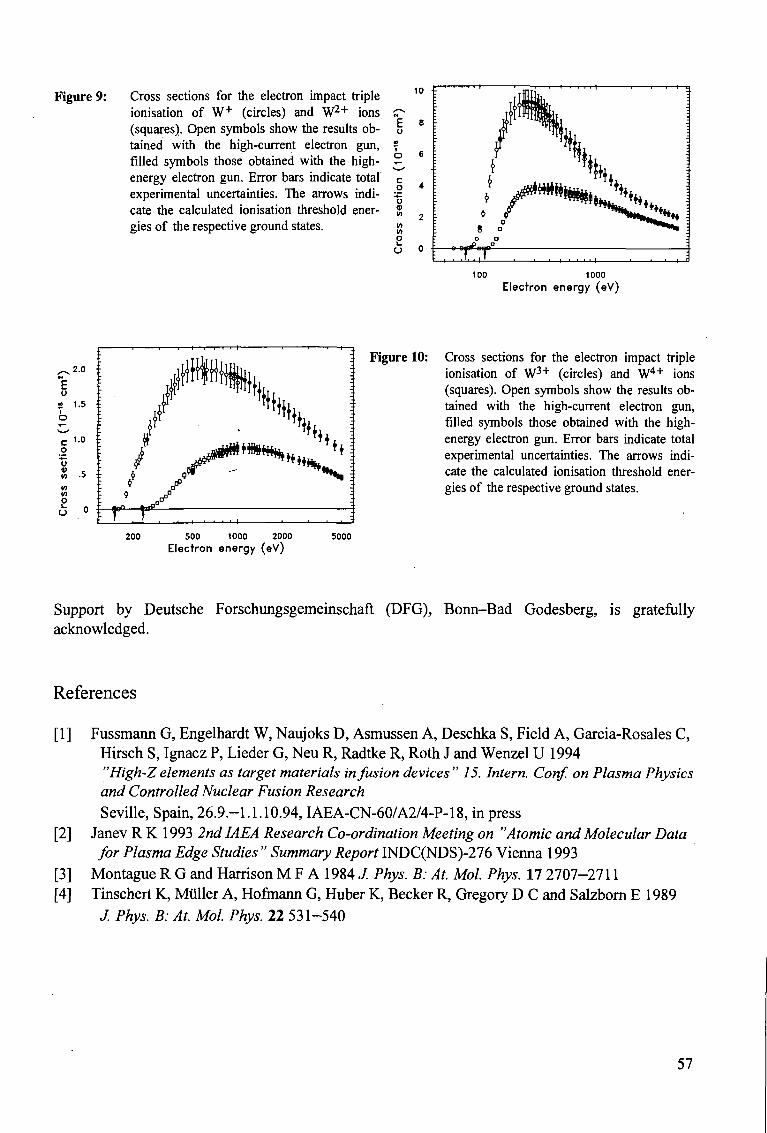
Figure 9: Cross sections for the electron impact triple ionisation of W+ (circles) and W2"*" ions (squares). Open symbols show the results obtained with the high-current electron gun, filled symbols those obtained with the high-energy electron gun. Error bars indicate total experimental uncertainties. The arrows indicate the calculated ionisation threshold energies of the respective ground states.
c o "o in
m in o o
100 1000 Electron energy (eV)
2.0
1.5
c o 13 v in
in in O t_
O
1.0
Figure 10: Cross sections for the electron impact triple ionisation of W3+ (circles) and W4+ ions (squares). Open symbols show the results obtained with the high-current electron gun, filled symbols those obtained with the high-energy electron gun. Error bars indicate total experimental uncertainties. The arrows indicate the calculated ionisation threshold energies of the respective ground states.
200 500 1000 2000 Electron energy (eV)
5000
Support by Deutsche Forschungsgemeinschaft (DFG), Bonn-Bad Godesberg, is gratefully acknowledged.
References
[1] Fussmann G, Engelhardt W, Naujoks D, Asmussen A, Deschka S, Field A, Garcia-Rosales C, Hirsch S, Ignacz P, Lieder G, Neu R, Radtke R, Roth J and Wenzel U 1994 "High-Z elements as target materials infusion devices " 15. Intern. Conf. on Plasma Physics and Controlled Nuclear Fusion Research Seville, Spain, 26.9.-1.1.10.94, IAEA-CN-60/A2/4-P-18, in press
[2] Janev R K 1993 2nd IAEA Research Co-ordination Meeting on "Atomic and Molecular Data for Plasma Edge Studies " Summary Report INDC(NDS)-276 Vienna 1993
[3] Montague R G and Harrison M F A 1984 J. Phys. B: At. Mol. Phys. 17 2707-2711 [4] Tinschert K, Muller A, Hofmann G, Huber K, Becker R, Gregory D C and Salzborn E 1989
J. Phys. B: At. Mol. Phys. 22 531-540
57
[5] Hofmann G, Miiller A, Tinschert K and Salzborn E 1990 Z Phys. D 16 113-127 [6] Liehr M, Schlapp M, Trassl R, Hofmann G, Stenke M, Volpel R and Salzborn E 1993
Nucl. Instr. Meth. in Phys. Res. B79 697-700 [7] Becker R, Miiller A, Achenbach A, Tinschert K and Salzborn E 1985
Nucl. Instrum. Meth. in Phys. Res. B 9 385-388 [8] Stenke M, Aichele K, Hathiramani D, Hofmann G, Steidl M, Volpel R and Salzborn E 1994
Proceedings of the 7. International Conference on the Physics of Highly Charged Ions
Vienna, Sept. 19-23 1994, Nucl. Instrum. Meth. in Phys. Res. B, Special Issue, in press [9] Miiller A, Tinschert K, Achenbach C and Salzborn E 1985
Nucl. Instr. Meth. in Phys. Res. B10/11 204-206 [10] Lotz W 1968 Zeitschriftfur Physik 216 241-247 [11] Grant I P, McKenzie B J, Norrington P H, Mayers D F and Pyper N C 1980
Comp. Phys. Comm. 21 207-231 [12] McKenzie B J, Grant IP and Norrington P H 1980 Comp. Phys. Comm. 21 233-246 [13] Stenke M, Aichele K, Hathiramani D, Hofmann G, Steidl M, Volpel R and Salzborn E
J. Phys. B: At. Mol. Phys., in press [14] Pindzola M S and Griffin D C 1992, Phys. Rev. A 46 2486-2488 [15] Gryzinski M 1965 Phys. Rev. A 138 336-358 [16] ShevelkoVP and TawaraH 1995
Physica Scripta, submitted [17] Stenke M, Aichele K, Hathiramani D, Hofmann G, Steidl M, Volpel R, Shevelko V P,
Tawara H and Salzborn E J. Phys. B: At. Mol. Phys., submitted
58
D I E L E C T R O N I C R E C O M B I N A T I O N A N D I O N I Z A T I O N I N E L E C T R O N - I O N
COLLISIONS: DATA F R O M M E R G E D - B E A M S E X P E R I M E N T S
A. MULLER Institut fur Strahlenphysik Universitat Stuttgart Stuttgart, Federal Republic of Germany
ABSTRACT. This article reviews dielectronic recombination and electron-impact ionization cross section and rate data obtained in accelerator-based merged-beams experiments with atomic ions and cold electron beams. The experimental data are compared with theories. The amount of information contained in measurements of resonance features is critically discussed.
1. INTRODUCTION
Colliding beams of electrons and ions [1,2] have been used since 1961 [3] for studies of electron-ion collision processes. By far the most of the available data were obtained with small-scale equipment, i.e. with an ion source on an electrostatic potential of typically several kV, providing beams of slow ions, and with an (intersecting) electron beam of eV to keV energies in combination with the necessary equipment to characterize the beams and their overlap and to accomplish signal recovery. With these techniques a considerable body of data has been accumulated particularly for electron-impact ionization of ions in low and intermediate charge states [4]. Data have also become available for electron-impact excitation [5,6] and for electron-ion recombination in experiments with low-energy ion beams [7].
By the combination of the well known merged-beams approach [8] with ion accelerator and ion storage ring technology a new era of electron-ion collision studies began little over a decade ago. After pioneering work [9,10] on dielectronic recombination at London, Ontario, and at Oak Ridge single-pass merged-beams experiments have been set up at the university of Aarhus [11] and at GSI in Darmstadt [12]. In addition, heavy ion storage rings equipped with electron-cooling devices such as TSR in Heidelberg [13], ESR in Darmstadt [14], CRYRING in Stockholm [15], TARN in Tokyo [16], and ASTRID in Aarhus [17] are providing excellent opportunities to study interactions of electrons with atomic or molecular ions [18]. Within little over a decade the field of recombination of highly charged ions with free electrons has reached an unforeseen level of maturity. Not regarding the first and only DR measurement at Western Ontario, where an energy spread as low as 0.045 eV was claimed [9] but not explicitly demonstrated, improvements of the collision-energy resolution by more than a factor 100 have been accomplished since the "early days" and the luminosity of the colliding-beams experiments could be increased by even larger factors. Similar advances have been made also in the field of electron-impact ionization of ions [19] in low to moderate charge states by using crossed-beams techniques and low-energy ion beams. Recently, the first experiments on electron-impact ion-
59
ization of ions employing a storage ring were successfully started and they yielded data with a quality unrivaled in previous measurements with highly charged ions [20]. Two major technical developments have facilitated the enormous progress: the design of cold and yet dense electron targets and the construction of heavy ion storage rings providing extremely intense high-quality ion beams. Traditionally, electron-ion collision experiments had been suffering from low counting rates and high backgrounds, a consequence of the diluteness of charged-particle beams relative to conventional gas or solid targets [21]. In order to overcome this problem, the first merged-beams experiment on recombination of electrons with multiply charged ions [22] was equipped with a magnetically compressed electron beam of density close to 1.5-109 c m - 3 . This high density was obtained at the expense of electron-energy resolution. By the magnetic compression the transverse electron-beam temperature was raised to 5 eV/k while the longitudinal electron-beam temperature was 60meV/k where k is Boltzmann's constant. (The meaning of these temperatures is explained in chapter 2.2.) Substantial progress was achieved when cold electron beams for ion beam cooling in storage rings had to be designed. With the cathode of the electron gun already in a strong magnetic field and proper focusing of the electrons, very parallel beams could be obtained with transverse temperatures as low as 0.1 to 0.15 eV/k and longitudinal temperatures in the sub-meV/k range. Measurements of recombination rates and cross sections with substantially improved energy resolution could be performed [23,24].
More recently the technique of adiabatic expansion of electron beams in a decreasing magnetic field [25] was introduced at the storage rings in Stockholm, Heidelberg and Aarhus. Thereby transverse electron-beam temperatures of 10 to 15 meV/k could be obtained and also the longitudinal electron-beam temperatures could unexpectedly be reduced to a level of 0.05 to 0.1 meV/k thus improving the energy resolution at very low center-of-mass energies by another factor of about 10. New recombination measurements with unprecedented quality have become possible (see Fig.21 for an example).
The range of very low electron-ion collision energies can be covered even with ions such as 60 GeV U9 2 + (available at the ESR in Darmstadt). The velocity of such energetic ions is matched by electrons with an energy of only about 140 keV and thus, electron-ion center-of-mass energies E c m of less than 1 eV are accessible. The finite temperatures in the available electron beams result in an energy spread which can be as low as 10 meV. Useful information on collisions at center-of-mass energies below 1 meV can be extracted from electron-ion merged-beams experiments. On the other hand, center-of-mass energies up to several keV have been accessed and hundreds of keV would be possible with an electron target at the ESR with anti-parallel electron and ion beams.
The present paper reviews experimental cross section and rate data for atomic ions colliding with free electrons. The report is restricted to dielectronic recombination and electron-impact ionization work employing energetic ions in merged-beams experiments. The ions which have been studied to date by such techniques (as far as the experiments have become known to the author) are
(a) with respect to dielectronic recombination: He+, B 2 + , C+, C 2 + , C 3 + , C4+, C 5 + , N 2 + , N3+, N 4 + , N5+, 0 3 + , 0 4 + , 0 5 + , 0 6 + , 0 7 +, F 3 + , F 4 + , F 5 + , F6+, F7+, Ne 7 + , S i n + , Si1 2 + , P 4 + , S 5 + , S1 5 + , Cl6+, Cl1 4 + , Ar1 3 + , Ar15+, Fe1 5 + , Cu26+, Se2 3 + , Se25+, Au76+, U2 8 + , U89+; (b) with respect to ionization (and detachment from negative ions): D " , Si1 1 + , Cl 6 + , Cl14+, Fe15+, Se23+.
60
The ion species listed above have not all been studied with equally precise techniques nor are the energy ranges of the different investigations comparable. For some of the ions information was obtained for collisions involving metastable initial states. The references to all the existing measurements are given in chapters 3 and 4, where the experimental results are reviewed.
2. BASIC CONSIDERATIONS
2 . 1 . M e c h a n i s m s
In all the experiments with projectiles Aq+ reported here, the ions which have changed their charge state either by recombination or electron removal are detected behind a charge separator downbeam from the merge path, i.e. behind the interaction region. The normalized counting rate of these ions is measured as a function of the electron laboratory energy. With the known ion energy the electron-ion center-of-mass energy is determined. Absolute total cross sections and rates are measured. Since photons or electrons are not detected, the observation of recombination and ionization comprises a number of different processes which all lead to the same net production of ions in a new charge state, A^g~^+ or A^q+1^+, respectively. While these charge states are identified in the measurements, the different mechanisms producing these charge states are not experimentally distinguished from each other and thus, they all contribute to the measured cross sections and rates [26].
Mechanisms of recombination, i.e. net production of A^ _ 1 ^ + ions from A , + ions, are:
• radiative recombination (RR)
e + Aq+ -» A ( ? _ 1 ) + + hv , (1)
where the excess energy released by the binding of an initially unbound electron is carried away by a photon in a direct process. After radiative recombination the captured electron can be in a highly excited state and hence, further radiation will be emitted until the electron is in its ground level
• dielectronic recombination (DR)
e + A « + - [ A * ' - 1 * ] " , (2)
where, in a first step, the excess energy released by the capture of the electron is absorbed within the ion by the excitation of a core electron; and where, in a second step, the intermediate multiply excited state decays by the emission of photons
[Aiq-1)+]** -» [A(q-1)+] + photons . (3)
The first step of the DR process, the dielectronic capture (Eq.(2)), can only occur if the kinetic energy of the projectile electron matches the difference Ei — Ej of total binding energies of all electrons in the initial and final states of the ion
61
• three-body (or ternary) recombination (TR)
e + e + Aq+ -> A{q~l)+ + e, (4)
where one of the two electrons can carry away the excess energy released by the recombination. TR becomes important at high electron densities and low energies.
None of the present experiments provides the electron densities and the electron temperatures for which TR to low lying bound levels of the recombined ions would be expected with measurable rates. TR into high Rydberg states is conceivable at low electron energies, however, the v x B fields (v: ion velocity, B: magnetic flux density) present in the experiments strip off the Rydberg electrons of such states. And yet, some of the observations indicate a strong involvement of TR in the recombination rates measured at Ecm = 0 eV.
Although not experimentally distinguished, the different recombination mechanisms lead to very characteristic energy dependences in the measured cross sections and rates. DR produces narrow resonances and can thus easily be identified in a measured recombination spectrum. The RR rate coefficient has its maximum at ECTO = 0 eV and drops off as a smooth function of energy. Additional recombination possibly involving ternary processes in high Rydberg states is only observed at relative energies below about 10 meV.
Similarly, different ionization mechanisms leading to net production of A^+1^+ from A9+
ions produce distinct features in the total cross section allowing to quantify individual contributions [4]. The most important single-ionization processes are
• direct ionization (DI)
e + Aq+ - • A{q+1)+ + 2e (5)
proceeding in a single "knock-on" event
• excitation-autoionization (EA)
e + Aq+ -* [Aq+]** + e (6)
[Aq+]** - • Aiq+V+ + e (7)
involving direct excitation of an inner-shell electron to a bound configuration of the Aq+
ion and subsequent autoionization of the intermediate multiply excited [A?+]** ion
• resonant-excitation-double-autoionization (REDA)
e + Aq+ -» [A(q-V+]** (8)
[A<«-1>+]** -> A<9+1>+ + 2e (9)
involving a radiationless (dielectronic) capture of the incident electron by the Aq+ ion and subsequent sequential emission of two electrons. REDA proceeds via intermediate compound states of the projectile electron and the parent ion and thus is closely related to the DR process (in fact, Eqs.(2) and (8) are identical).
62
2.2. Measurement of Cross Sect ions and Rate Coefficients
When electrons with a spatial density ne(r) and ions with a spatial density rii(f) interact in a volume r via a cross section <r(v), where v is the vector of relative velocity between the collision partners and v — \v\ its absolute value, then the rate R of interactions is given by
R= [ [ne(f)ni{f)a(v)vf(v)d3vd3r (10)
For the deduction of cross sections from measured counting rates R the spatial density distributions of the particles and the distribution function f(v) of the relative velocities have to be determined. In the equation it has been assumed that / is independent of the location r. In electron-ion colliding-beams experiments the integral over spatial density distributions is usually taken into account by introducing a form factor [27].
In the present type of experiments with very homogeneous magnetic fields guiding the electron beams the situation is usually simpler. The density ne(r) of the electrons is uniform in space with negligible variations across the electron beam throughout the whole interaction region. With uniform electron density n e , Eq. (10) can be simplified considerably since the two integrations are assumed to be independent of each other and ne(f) can be taken out of the integral. Integration over n,- just yields the number of ions present at a time in the interaction volume. In case the ion beam is completely inside the uniform electron beam, this number is simply given by Ii£ejj/(qevi), where /, is the electrical ion current, q the ion charge state, e the charge of an electron, £e/f the length of the interaction path, and V{ the ion velocity.
The integral over the velocity distribution f{y) can be carried out separately by introducing a rate coefficient a. In plasma experiments, f(v) is determined by the temperature of the plasma electrons and is often described by a Maxwellian distribution. In colliding-beams experiments with electrons and ions, / is usually a distribution centered at an average relative velocity vrei of the colliding particles. Thus, the rate a is determined by
a(vrei) =<avre[>= a(v)vf(vrei,v)d3v. (11)
Eq. (10) can now be written in the form
R = ane£effIi/(qevil2) . (12)
In Eq. (12) an additional factor f2 — [1 — (i>,/c)2] -1 has been introduced to account for the relativistic transformation between the laboratory and the center-of-mass frames. The factor a occuring above is usually only then called a "rate coefficient" in the literature, when f(v) is an isotropic Maxwellian distribution characterized by a temperature T. In a merged-beams experiment a has a slightly different meaning. Its definition is given by Eq. (11). Here, vre\ and / still have to be specified in order to provide an unambigous physical quantity a accessible to experimental evaluation.
For the energy-analyzed ion beam in the present type of experiments, the experimental energy spread at low Erei is predominantly determined by the electron-velocity distribution function / . At high center-of-mass energies also the energy spread of the ion beam can influence the experimental resolution. This is particularly true when the ion beam cannot be cooled intermittently during a rate measurement (which typically happens at high Erei).
63
With respect to the kinematics in the experiments and the axial symmetry of the electron and ion beams, two velocity coordinates are necessary to describe the electron-velocity distribution: U||, the velocity component in electron-beam direction, and v±, the velocity component perpendicular to the electron-beam direction. The energy (or velocity) spreads are therefore characterized by two corresponding temperatures Tjj for the longitudinal and T± for the transverse direction. In the accelerated electron beam these temperatures are quite different with T\\ <C T±, so that f(v) is highly anisotropic and is therefore often called a "flattened" electron-velocity distribution. Its mathematical form is given by
tt -\ m e ( rnevl\ I me ( me{v\\ - vrei)2\
/ ( w ) = 2^expy-2kf-J v ^ ; e x p { — m [ — ) ' (13)
where m e denotes the electron rest mass. The quantity ure/ in this formula is the average longitudinal center-of-mass velocity
Vrel = | «e,|| - t7t-,|| | / ( 1 + | «,-,|| Ve,|| | / C2), (14)
where ve<\\ and i^y are the longitudinal velocity components of the electron and ion beams, respectively. They are determined from
T>e,|| = cy/1 - [1 + Ee/(mec2)}-2 (15)
and
t;,-,|| = c v / l - f l + E . / K - c 2 ) ] - 2 . (16)
The ion rest mass is represented by m,. The energies Ee and Ei are determined by acceleration voltages and do not include additional kinetic energy (with randomly oriented velocity vectors) arising from the finite beam temperatures. Therefore, the relative velocity vrei, as defined by Eq. (14), can be different from the velocity vcm in the electron-ion center-of-mass frame. This is especially true for low energies, where Ecm comes close to fcTj. and kT\\. At high center-of-mass energies i? c m , one clearly gets vre\ = vcm and Erei = Ecm. At low Ecm, vrei can be much less than vcm. Since it is the only one of the two quantities directly accessible to a measurement, experimental data are usually displayed as a function of the relative energy ETei. Therefore cross section or rate data in the literature are displayed for energies ETe\ reaching as far down as to 10 - 3 eV, although the energy spread in the center-of-mass frame may be 10 - 1 eV or more (which becomes visible e.g. by the energy spread in the measured resonance peaks). Because of the lack of an alternative, rates and cross sections are plotted as a function of Erei in all examples given in this review.
By the experiments, normalized rates a are determined from
«{Erd) = R;*»/Viqe (17)
The number of recombinations per unit time R is determined from the counting rates ReXp = R £ of appropriate particle detectors. Detection efficiencies e are usually close to 1. In single-pass experiments the total electrical ion current / , is measured by collecting the parent ions in a Faraday cup. In storage ring experiments the current of the circulating ion beam is determined from the magnetic-field signal of a ferrite ring detector surrounding the ion beam.
64
When ETei » kT±,kT\\ the velocities v and vre\ approach Vcm and hence Eq. (11) can be rewritten as
a(vrei) « vrel / <r(v) f{vTe},v) d3v = vTel <japp (18)
The apparent cross section aapp results from the convolution of the real cross section a with the experimental velocity (or energy) distribution. This quantity makes physical sense when the width of the distribution function is much smaller than vrei (or Ere{, respectively). At high center-of-mass energies apparent cross sections
<7app = Oi(vrel) I Vrd (19)
are often presented in the literature instead of rates a. Systematic uncertainties of measured rates a and (apparent) cross sections a are typically
±20 %. Apart from the uncertainty of the measured rates a, the possible error of the collision energy is also important. Inherently, the merged-beams technique has the potential for high-precision measurements of energy differences. In the experiments, uncertainties of the energy scale increase with energy and depend on the particular experiments. Progress in the energy resolution of merged-beams measurements leads to a still ongoing improvement of level-energy determinations.
For the understanding of the experimental results it is necessary to discuss the influence of external electromagnetic fields on the measured rates [28]. Electric and magnetic fields are present already inside the electron beam, i.e. in the interaction region. Electric fields may be due to the space charge potential distribution inside the target or due to non-zero field components of the magnetic guiding field with respect to the ion beam. Beyond the interaction region, the ions have to pass through the transverse magnetic field component of the electron-target arrangement. The resulting motional electric field is usually quite strong and cuts off high Rydberg states by field ionization. Electric fields with different directions and strengths are then felt by the ions when they pass through the beam optical elements and the charge analyzer. Usually, the most severe cuts in a possible Rydberg state distribution of the product ions occurs in the charge analyzer. At the ESR, motional electric fields experienced by the ions in the dipole magnets can be several 106 V/cm.
Electric fields have a number of effects on the measurements. For high Rydberg states the rate of DR itself can be enhanced when electric fields are present. Lifetimes of atomic states change with the presence of fields and, depending on the slew rates of the fields seen by the ions, there may be. a rearrangement of states when an ion "collides" with an electric field. As already mentioned, field ionization will occur in an electric field F stripping off Rydberg electrons with quantum numbers n > nmax. In reality, there is no sharp cutoff in the Rydberg state distribution, however, the often used formula [28,29]
/ 6 . 8 - 1 0 V Vcm-'V14
nmax = ( 1 J (20)
gives a reasonable estimate of the range of principal quantum numbers up to which an ion state can survive a given electric field F. For each individual experiment this issue has to be considered. Application of measured rates and cross sections to collision processes in a different physical environment equally requires consideration of the possible influence of the fields
65
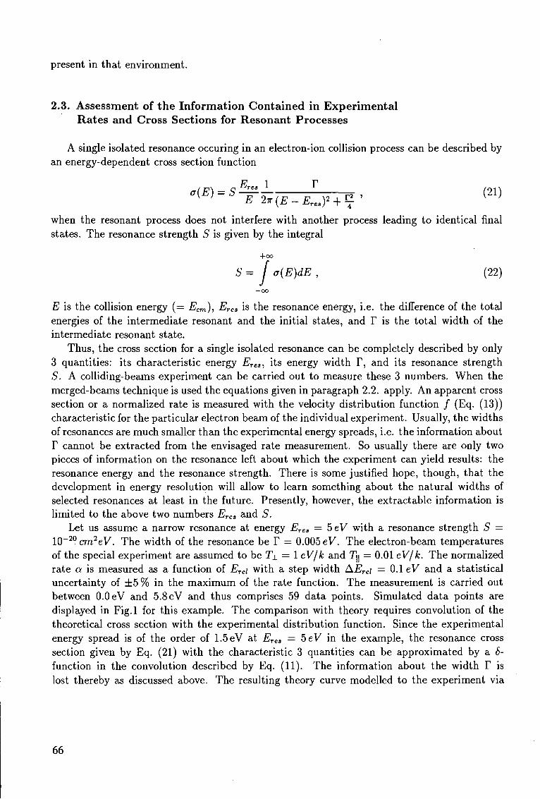
present in that environment.
2.3. Assessment of the Information Contained in Experimental Rates and Cross Sect ions for Resonant Processes
A single isolated resonance occuring in an electron-ion collision process can be described by an energy-dependent cross section function
w-s^hiB-Zw (21)
when the resonant process does not interfere with another process leading to identical final states. The resonance strength S is given by the integral
+ 0 0
S= f a(E)dE , (22)
—00
E is the collision energy (= Ecm), Erea is the resonance energy, i.e. the difference of the total energies of the intermediate resonant and the initial states, and Y is the total width of the intermediate resonant state.
Thus, the cross section for a single isolated resonance can be completely described by only 3 quantities: its characteristic energy ETes, its energy width T, and its resonance strength S. A colliding-beams experiment can be carried out to measure these 3 numbers. When the merged-beams technique is used the equations given in paragraph 2.2. apply. An apparent cross section or a normalized rate is measured with the velocity distribution function / (Eq. (13)) characteristic for the particular electron beam of the individual experiment. Usually, the widths of resonances are much smaller than the experimental energy spreads, i.e. the information about T cannot be extracted from the envisaged rate measurement. So usually there are only two pieces of information on the resonance left about which the experiment can yield results: the resonance energy and the resonance strength. There is some justified hope, though, that the development in energy resolution will allow to learn something about the natural widths of selected resonances at least in the future. Presently, however, the extractable information is limited to the above two numbers ETes and S.
Let us assume a narrow resonance at energy Erea — beV with a resonance strength S = IO - 2 0 cm2eV. The width of the resonance be T — 0.005 eV. The electron-beam temperatures of the special experiment are assumed to be T± = 1 eV/k and Ty = 0.01 eV/k. The normalized rate a is measured as a function of Erei with a step width AErei — 0.1 eV and a statistical uncertainty of ± 5 % in the maximum of the rate function. The measurement is carried out between 0.0 eV and 5.8 eV and thus comprises 59 data points. Simulated data points are displayed in Fig.l for this example. The comparison with theory requires convolution of the theoretical cross section with the experimental distribution function. Since the experimental energy spread is of the order of 1.5 eV at Erea — 5eV in the example, the resonance cross section given by Eq. (21) with the characteristic 3 quantities can be approximated by a 8-function in the convolution described by Eq. (11). The information about the width T is lost thereby as discussed above. The resulting theory curve modelled to the experiment via
66
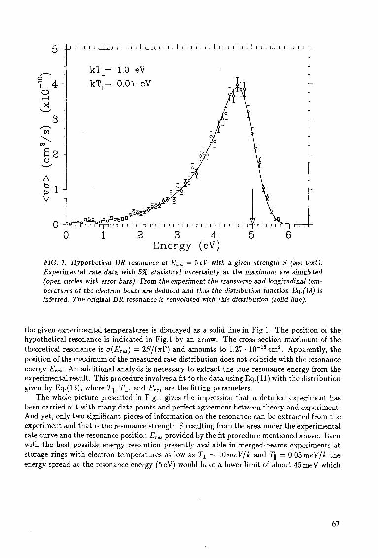
' I I I I I I I I I I I I I I I I I I I I I I I I I 1 I I I I I I I I I I I I I I
0 1 2 3 4 5 6 Ene rgy (eV)
FIG. 1. Hypothetical DR resonance at Ecm — 5eV with a given strength S (see text). Experimental rate data with 5% statistical uncertainty at the maximum are simulated (open circles with error bars). From the experiment the transverse and longitudinal temperatures of the electron beam are deduced and thus the distribution function Eq.(13) is inferred. The original DR resonance is convoluted with this distribution (solid line).
the given experimental temperatures is displayed as a solid line in Fig.l . The position of the hypothetical resonance is indicated in Fig.l by an arrow. The cross section maximum of the theoretical resonance is a(Eres) = 2S/(TTY) and amounts to 1.27 • 10 _ 1 8 cm 2 . Apparently, the position of the maximum of the measured rate distribution does not coincide with the resonance energy Eres. An additional analysis is necessary to extract the true resonance energy from the experimental result. This procedure involves a fit to the data using Eq . ( l l ) with the distribution given by Eq.(13), where Jj|, 7 j . , and Eres are the fitting parameters.
The whole picture presented in Fig.l gives the impression that a detailed experiment has been carried out with many data points and perfect agreement between theory and experiment. And yet, only two significant pieces of information on the resonance can be extracted from the experiment and that is the resonance strength S resulting from the area under the experimental rate curve and the resonance position Eres provided by the fit procedure mentioned above. Even with the best possible energy resolution presently available in merged-beams experiments at storage rings with electron temperatures as low as T± = 10 meV/k and 7j| = 0.05 meV/k the energy spread at the resonance energy (5eV) would have a lower limit of about 45meV which
67
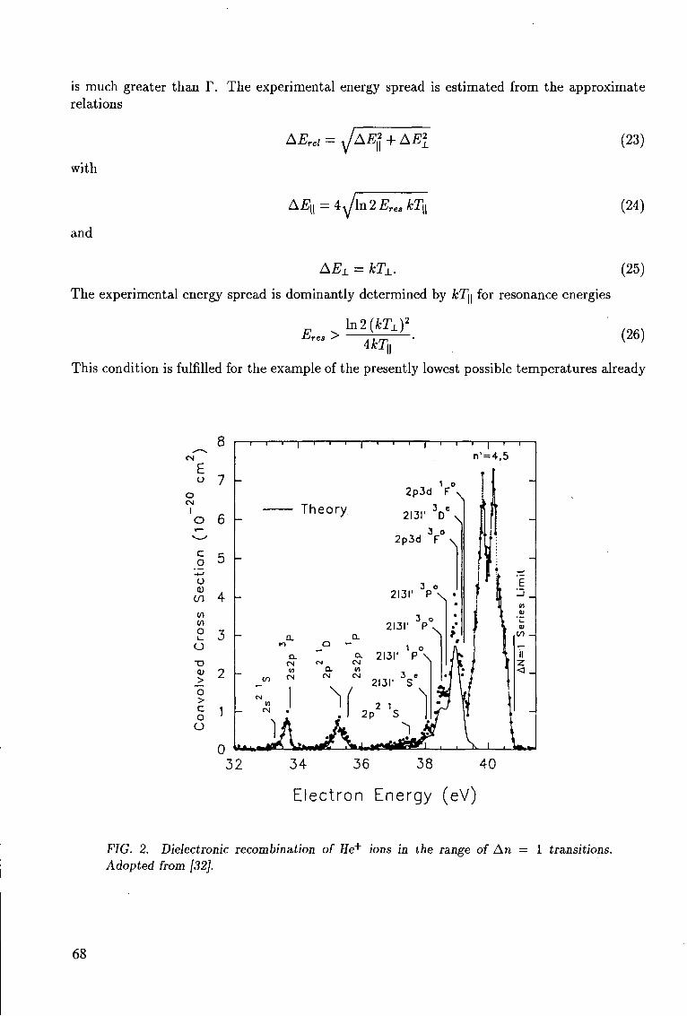
is much greater than T. The experimental energy spread is estimated from the approximate relations
AErel = yjAE* + AEl
with
and
A£i = 4\/m" 2 Eres kTu
(23)
(24)
AEL = kTL. (25)
The experimental energy spread is dominantly determined by kT\\ for resonance energies
In 2 ( H I ) 2
l-Jres ^ 4kn
(26)
This condition is fulfilled for the example of the presently lowest possible temperatures already
E u
o CM
I
c o
-*-» u <u
m
(n tn O i_
a V
j> o > c o o
34 36 38 40
Electron Energy (eV)
FIG. 2. Dielectronic recombination of He+ ions in the range of An — 1 transitions. Adopted from [32].
68
when Eres > 0.35 eV. Beyond this limit with ETes >• 0.35 eV the experimental energy distribution function can be expressed by a Gaussian with the width AE\\ (provided the ion energy spread is still negligible; otherwise the total energy spread has to be calculated from the quadrature sum in the sense of Eq.(23) of all contributing experimental spreads). Ultra-low transverse temperature of an electron beam does not necessarily lead to a significant improvement of energy resolution except for extremely low resonance energies.
For the artificial resonance at 5eV studied in Fig.l the present record in low temperatures is still not sufficient to learn anything about the width T. The information that would be obtained for the resonance is not much different from what can be extracted from the simulated measurement shown in Fig.l . Only the determination of the resonance energy is potentially more precise and the counting rate in the experiment at resonance would be greatly enhanced (more than a factor 30). However, the improvement gained by low experimental energy spreads becomes strikingly obvious when many resonances occur at different energies. Then the information that can be obtained by the measurement of resonance cross sections and rates with high resolution increases drastically compared with measurements that cannot resolve fine details and average out resonance strengths over broad energy ranges. Examples for this are shown in the subsequent data section of this paper.
3. DIELECTRONIC RECOMBINATION
In this chapter, data which have been obtained for DR in electron-ion merged-beams experiments are presented and discussed. The subchapters deal with different isoelectronic sequences of the ions for which experimental information is available.
3.1 . Hydrogen-l ike Ions
Merged-beams data for DR were obtained for H-like He + [30-32], C5+ [13], 0 7 + [24], and S15+ [33] ions. Experimental and theoretical results for He + , C 5 + , and 0 7 + are displayed in Figs.2-5, respectively. The oxygen measurement was made in the first DR experiment ever carried out at a storage ring (at the TSR in the spring of 1989). The helium data displayed here were obtained at CRYRING [32] subsequent to two previous measurements with He + , one at TARN [31] and one at the Indiana cooler ring [30], both, however, with considerably lower energy resolution and lower statistical significance.
The dielectronic resonances investigated with H-like ions are of the type
e + (Is)-> (2£n?) (n = 2,3, . . . ,oo). (27)
Some experimental information was also obtained for DR associated with
e + (Is)-> (3ln£!) (n = 3, . . . ,oo) . (28)
The latter type of transitions is shown separately in Fig.3 for He+ ions and is included in Fig.5 for 0 7 + ions. The cross sections are about a factor 20 smaller than those for the main DR resonance series.
69
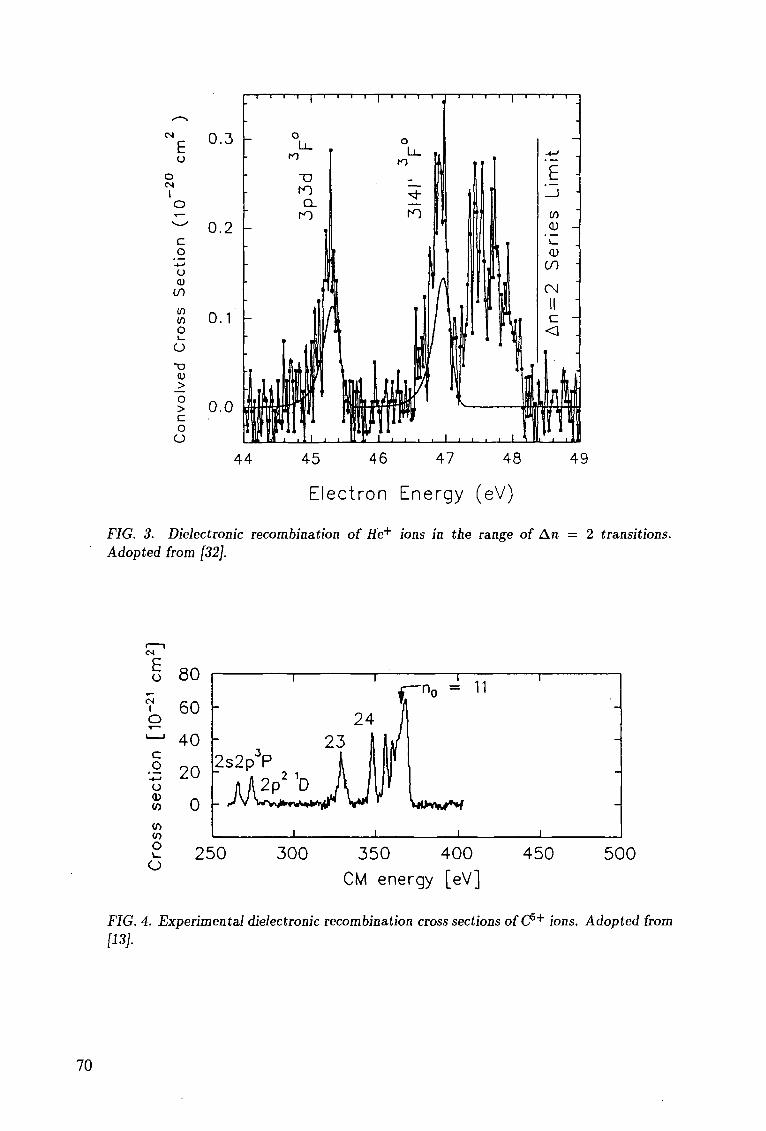
E o
o CM
I
C o o <u
to 0) tn
o i_
O
• o (U
_> o > c o o
0.3
0.2 -
0.1
0.0
T — i — I — i — I — i — i — r T^" -i—i—i—i—r
44 45 46 47 48
E l e c t r o n Energy (eV)
49
FIG. 3. Dielectronic recombination of He+ ions in the range of An = 2 transitions. Adopted from [32].
£ o
CM I
o
C o
-t-J
o (0
to (0
o O
250 300 350 400
CM energy [eV]
450 500
FIG. 4. Experimental dielectronic recombination cross sections ofC5+ ions. Adopted from [13].
70
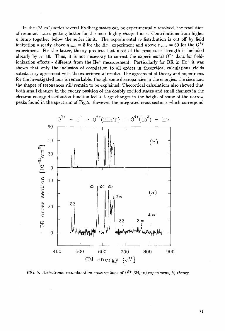
In the (2£, nl') series several Rydberg states can be experimentally resolved, the resolution of resonant states getting better for the more highly charged ions. Contributions from higher n lump together below the series limit. The experimental n-distribution is cut off by field ionization already above nmax = 5 for the He+ experiment and above nmax = 69 for the 0 7 +
experiment. For the latter, theory predicts that most of the resonance strength is included already by n—40. Thus, it is not necessary to correct the experimental 0 7 + data for field-ionization effects - different from the He+ measurement. Particularly for DR in He+ it was shown that only the inclusion of correlation to all orders in theoretical calculations yields satisfactory agreement with the experimental results. The agreement of theory and experiment for the investigated ions is remarkable, though some discrepancies in the energies, the sizes and the shapes of resonances still remain to be explained. Theoretical calculations also showed that both small changes in the energy position of the doubly excited states and small changes in the electron-energy distribution function led to large changes in the height of some of the narrow peaks found in the spectrum of Fig.5. However, the integrated cross sections which correspond
o I
0 7 + + e" - 06+(nlnT) -> 06+(ls2) + hi/ 60
40 -
20 -
0
40
o CD W W
8 20
u o
0
1 1
1
1 . J 1
23
22
: 1 k^0 i
i i
24
u 1
1 1
lil (b) " I
1 1
25
1 ft 2 °°
y i
_
4 oo
33 3°°
1 1
400 500 600 700 800 900
CM energy [eV]
FIG. 5. Dielectronic recombination cross sections of 07+ [24]; a.) experiment, b) theory.
71
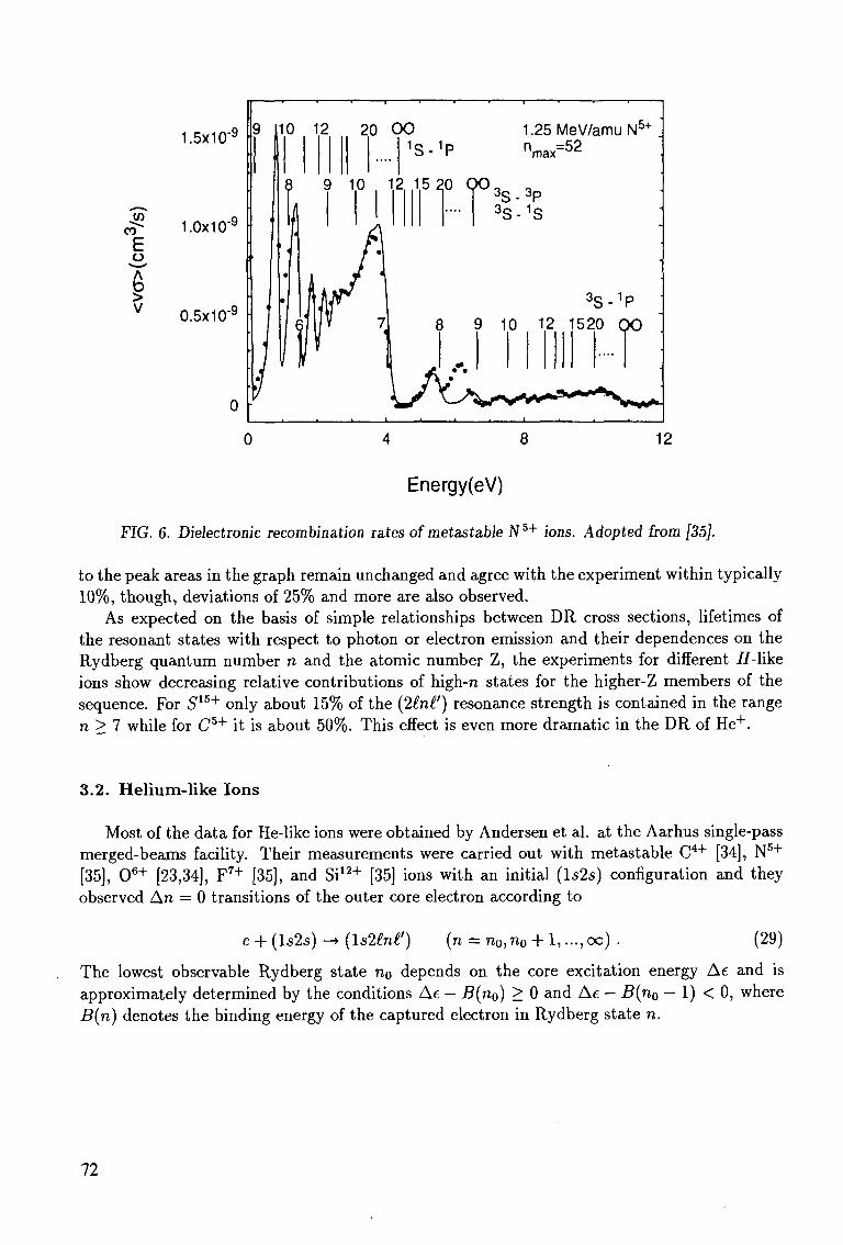
y> CO
E A
> v
1.5x10"9
1.0x10"9
0.5x10"9
9 110 2 20 0 0 1 S- 1 P
1.25MeV/amuN5+
nmax=52
8 9 10 2 15 20 QO 3 s . 3 p 3 S- 1 S
3 S . 1 P
9 10 12 1520 QO
0 4 8 12
Energy(eV)
FIG. 6. Dielectronic recombination rates of metastable Nb+ ions. Adopted from [35].
to the peak areas in the graph remain unchanged and agree with the experiment within typically 10%, though, deviations of 25% and more are also observed.
As expected on the basis of simple relationships between DR cross sections, lifetimes of the resonant states with respect to photon or electron emission and their dependences on the Rydberg quantum number n and the atomic number Z, the experiments for different H-\ike ions show decreasing relative contributions of high-n states for the higher-Z members of the sequence. For S15+ only about 15% of the (2£n£') resonance strength is contained in the range n > 7 while for C 5 + it is about 50%. This effect is even more dramatic in the DR of He + .
3.2. Helium-like Ions
Most of the data for He-like ions were obtained by Andersen et al. at the Aarhus single-pass merged-beams facility. Their measurements were carried out with metastable C 4 + [34], N 5 +
[35], 0 6 + [23,34], F 7 + [35], and Si1 2 + [35] ions with an initial (1525) configuration and they observed An = 0 transitions of the outer core electron according to
e + (1525) -» (UMnH) (n = n0,n0 + 1,..., oo) . (29)
The lowest observable Rydberg state n 0 depends on the core excitation energy Ae and is approximately determined by the conditions Ae - B(n0) > 0 and Ae - B(n0 - 1) < 0, where B(n) denotes the binding energy of the captured electron in Rydberg state n.
72
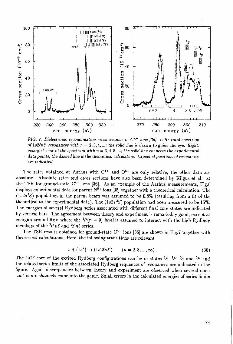
100 -
01
fl O
01 1 O i-H
G o
• l - <
-(-> o <n m m w u f-. O
80
60
40
«0
-] 1 i 1 1 . 1 1 I 1 1 r
|ls2s(3S) | | | l s 2 s ( ' S )
nmisspcp) -
J i I ,.—.i I . I i I i L
i—i—i—I—i—i—i—i—I—n
l I I L_l l I I I I M I U n=3 4 5 6 8 >8
• ' i _ l i i ' i I ' i i i I ' ' i i I
220 240 260 280 300 320 cm. energy (eV)
270 280 290 300 cm. energy (eV)
310
FIG. 7. Dielectronic recombination cross sections of C 4 + ions [36]. Left: total spectrum ofls2£n£' resonances with n = 2,3,4,...; the solid line is drawn to guide the eye. Right: enlarged view of the spectrum with n = 3,4,5,...; the solid line connects the experimental data points; the dashed line is the theoretical calculation. Expected positions of resonances are indicated.
The rates obtained at Aarhus with C 4 + and 0 6 + are only relative, the other data are absolute. Absolute rates and cross sections have also been determined by Kilgus et al. at the TSR for ground-state C 4 + ions [36]. As an example of the Aarhus measurements, Fig.6 displays experimental data for parent N5+ ions [35] together with a theoretical calculation. The (ls2.s 15) population in the parent beam was assumed to be 0.8% (resulting from a fit of the theoretical to the experimental data). The (ls2s3S) population had been measured to be 15%. The energies of several Rydberg series associated with different final core states are indicated by vertical bars. The agreement between theory and experiment is remarkably good, except at energies around 6 eV where the lP(n = 9) level is assumed to interact with the high Rydberg members of the 3Pn£ and xSn£ series.
The TSR results obtained for ground-state C 4 + ions [36] are shown in Fig.7 together with theoretical calculations. Here, the following transitions are relevant
e + ( l s 2 ) -+{\s2lnl') (n = 2 ,3 , . . . , oo) . (30)
The ls2f core of the excited Rydberg configurations can be in states 1 5 , V , 3S and 3P and the related series limits of the associated Rydberg sequences of resonances are indicated in the figure. Again discrepancies between theory and experiment are observed when several open continuum channels come into the game. Small errors in the calculated energies of series limits
73
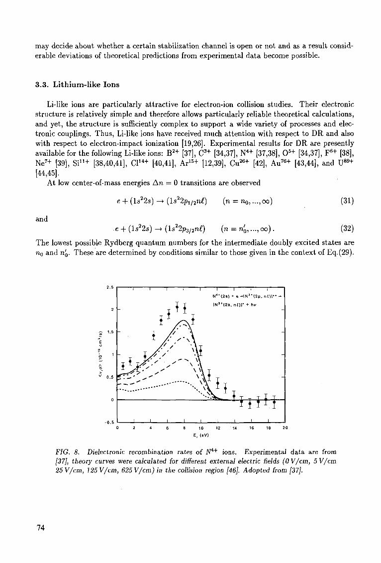
may decide about whether a certain stabilization channel is open or not and as a result considerable deviations of theoretical predictions from experimental data become possible.
3.3. Lithium-like Ions
Li-like ions are particularly attractive for electron-ion collision studies. Their electronic structure is relatively simple and therefore allows particularly reliable theoretical calculations, and yet, the structure is sufficiently complex to support a wide variety of processes and electronic couplings. Thus, Li-like ions have received much attention with respect to DR and also with respect to electron-impact ionization [19,26]. Experimental results for DR are presently available for the following Li-like ions: B2 + [37], C3+ [34,37], N4+ [37,38], 0 5 + [34,37], F 6 + [38], Ne7+ [39], S i u + [38,40,41], Cl14+ [40,41], Ar15+ [12,39], Cu26+ [42], Au76+ [43,44], and U89+
[44,45]. At low center-of-mass energies An = 0 transitions are observed
and
e -+- (ls22.s) —• (ls22pi/2n£) (n = n0, ...,oo)
e + (ls22s) -» (ls22p3/2n£) (n = n0,..., oo)
(31)
(32)
The lowest possible Rydberg quantum numbers for the intermediate doubly excited states are no and n0. These are determined by conditions similar to those given in the context of Eq.(29).
- 0 .5
T I I I I
N**(2B) + e-IN3*(2p, nt>r
[N3*(2s, nOl* + h^
"••AM liiii.l
_L _L 8 10 12
E, (oV)
20
FIG. 8. Dielectroaic recombination rates of N4+ ions. Experimental data are from [37], theory curves were calculated for different external electric fields (0 V/cm, 5 V/cm 25 V/cm, 125 V/cm, 625 V/cm) in the collision region [46]. Adopted from [37].
74
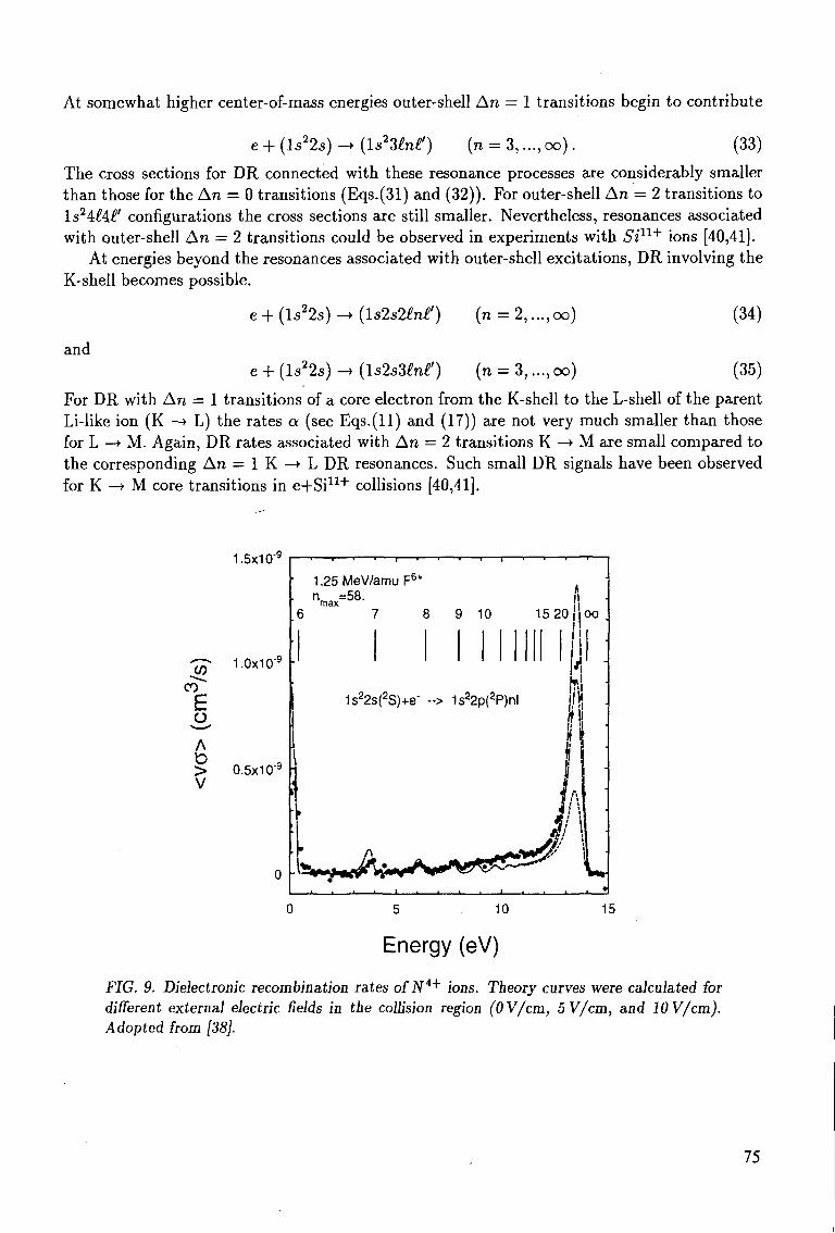
At somewhat higher center-of-mass energies outer-shell An = 1 transitions begin to contribute
e + (ls22s) -> {IsHlnt!) (n = 3,...,oo). (33)
The cross sections for DR connected with these resonance processes are considerably smaller than those for the An = 0 transitions (Eqs.(31) and (32)). For outer-shell An = 2 transitions to ls24:H£' configurations the cross sections are still smaller. Nevertheless, resonances associated with outer-shell An = 2 transitions could be observed in experiments with Si11+ ions [40,41].
At energies beyond the resonances associated with outer-shell excitations, DR involving the K-shell becomes possible.
e + (ls22s) -» (U2s2int) (n = 2,..., oo) (34)
and e + (ls22s) -» (ls2sMnt) (n = 3,... , oo) (35)
For DR with An = 1 transitions of a core electron from the K-shell to the L-shell of the parent Li-like ion (K —> L) the rates a (see Eqs.(ll) and (17)) are not very much smaller than those for L —> M. Again, DR rates associated with An = 2 transitions K —> M are small compared to the corresponding An = 1 K - » L DR resonances. Such small DR signals have been observed for K —• M core transitions in e+Si11+ collisions [40,41].
E
A > V
1.5x10'9
1.0x10⁻⁹
0.5x10"9
i i r i i ' - r | i i f i
1.25MeV/amuF6+
n =58. max
6 7 8 9 10 15 20 11| oo .
1s*2s(*S)+e- --> Is^p^PJnl
M
lit
J\ L 0 5 10 15
Energy (eV)
FIG. 9. Dielectronic recombination rates of N4+ ions. Theory curves were caiculated for different external electric fields in the collision region (OV/cm, 5V/cm, and lOV/cm). Adopted from [38].
75
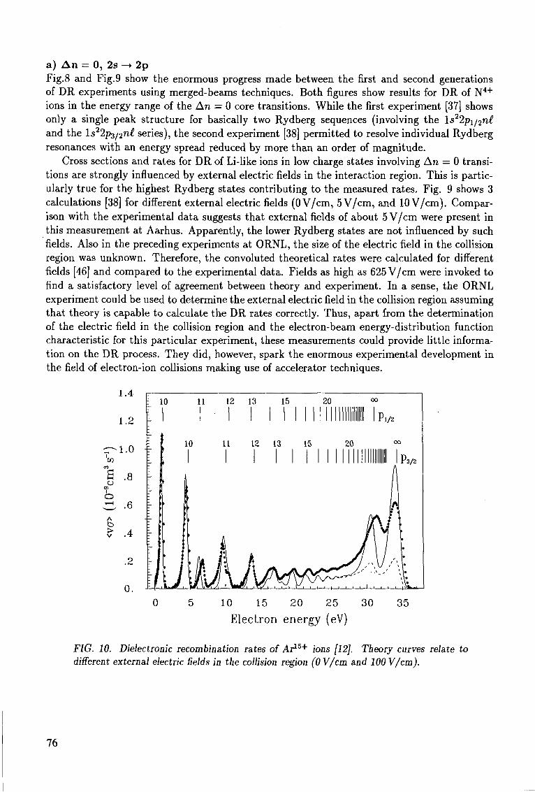
a) An = 0, 2s - • 2p Fig.8 and Fig.9 show the enormous progress made between the first and second generations of DR experiments using merged-beams techniques. Both figures show results for DR of N4+
ions in the energy range of the An = 0 core transitions. While the first experiment [37] shows only a single peak structure for basically two Rydberg sequences (involving the ls22pi/2n£ and the ls22p3/2n£ series), the second experiment [38] permitted to resolve individual Rydberg resonances with an energy spread reduced by more than an order of magnitude.
Cross sections and rates for DR of Li-like ions in low charge states involving An = 0 transitions are strongly influenced by external electric fields in the interaction region. This is particularly true for the highest Rydberg states contributing to the measured rates. Fig. 9 shows 3 calculations [38] for different external electric fields (0 V/cm, 5 V/cm, and 10 V/cm). Comparison with the experimental data suggests that external fields of about 5 V/cm were present in this measurement at Aarhus. Apparently, the lower Rydberg states are not influenced by such fields. Also in the preceding experiments at ORNL, the size of the electric field in the collision region was unknown. Therefore, the convoluted theoretical rates were calculated for different fields [46] and compared to the experimental data. Fields as high as 625 V/cm were invoked to find a satisfactory level of agreement between theory and experiment. In a sense, the ORNL experiment could be used to determine the external electric field in the collision region assuming that theory is capable to calculate the DR rates correctly. Thus, apart from the determination of the electric field in the collision region and the electron-beam energy-distribution function characteristic for this particular experiment, these measurements could provide little information on the DR process. They did, however, spark the enormous experimental development in the field of electron-ion collisions making use of accelerator techniques.
c -'OJ
CO
£
o 1—1
<vcr
>
1.4
1.2
1.0
.8
.6
.4
.2
0.
0 5 10 15 20 25 30 35
Electron energy (eV)
FIG. 10. Dielectronic recombination rates of Ar15* ions [12]. Theory curves relate to different external electric fields in the collision region (OV/cm and 100 V/cm).
76
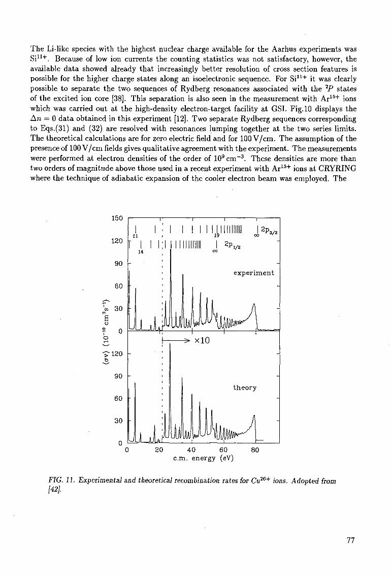
The Li-like species with the highest nuclear charge available for the Aarhus experiments was Si11+. Because of low ion currents the counting statistics was not satisfactory, however, the available data showed already that increasingly better resolution of cross section features is possible for the higher charge states along an isoelectronic sequence. For Si11+ it was clearly possible to separate the two sequences of Rydberg resonances associated with the 2P states of the excited ion core [38]. This separation is also seen in the measurement with Ar15+ ions which was carried out at the high-density electron-target facility at GSI. Fig. 10 displays the An = 0 data obtained in this experiment [12]. Two separate Rydberg sequences corresponding to Eqs.(31) and (32) are resolved with resonances lumping together at the two series limits. The theoretical calculations are for zero electric field and for 100 V/cm. The assumption of the presence of 100 V/cm fields gives qualitative agreement with the experiment. The measurements were performed at electron densities of the order of 109 cm - 3 . These densities are more than two orders of magnitude above those used in a recent experiment with Ar15+ ions at CRYRING where the technique of adiabatic expansion of the cooler electron beam was employed. The
150
120
90
60
7cn 30 n
a o
7 0 o
-£•120
90
60
30
0
0 20 40 60 80 cm. energy (eV)
FIG. 11. Experimental and theoretical recombination rates for Cu26+ ions. Adopted from [42].
77
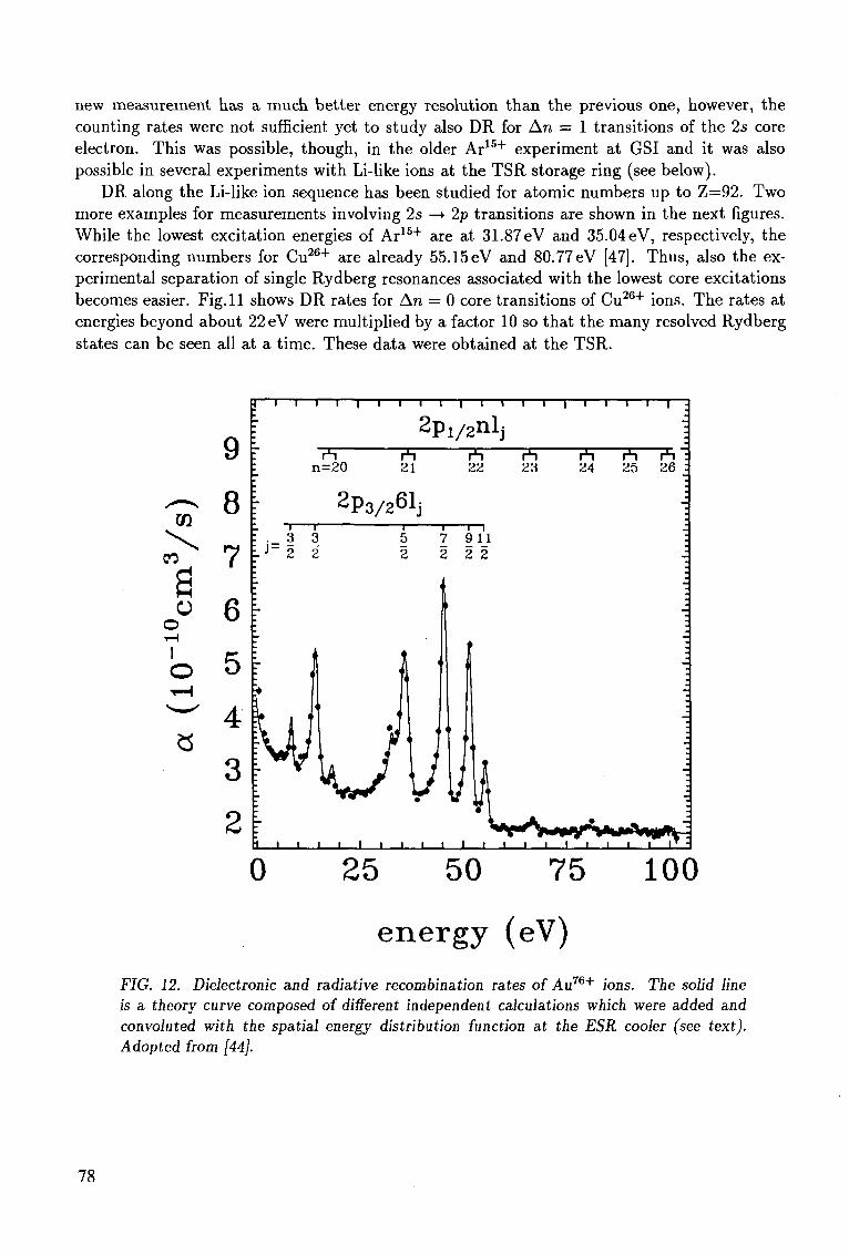
new measurement has a much better energy resolution than the previous one, however, the counting rates were not sufficient yet to study also DR for An = 1 transitions of the 2s core electron. This was possible, though, in the older Ar1 5 + experiment at GSI and it was also possible in several experiments with Li-like ions at the TSR storage ring (see below).
DR along the Li-like ion sequence has been studied for atomic numbers up to Z=92. Two more examples for measurements involving 2s —• 2p transitions are shown in the next figures. While the lowest excitation energies of Ar1 5 + are at 31.87 eV and 35.04 eV, respectively, the corresponding numbers for Cu2 6 + are already 55.15eV and 80.77eV [47]. Thus, also the experimental separation of single Rydberg resonances associated with the lowest core excitations becomes easier. Fig. 11 shows DR rates for An = 0 core transitions of Cu2 6 + ions. The rates at energies beyond about 22 eV were multiplied by a factor 10 so that the many resolved Rydberg states can be seen all at a time. These data were obtained at the TSR.
CQ
00
a o
o I
o
9
8
7
6
5
4
2
_ i
: . 3 J LJ=2 \
r
! | w i i .
i i i — i — i — i — i — | — i — r
2p 1 / 2 n l j
1=20 21 22
2 P 3 / 2 6 1 j • i
1 5 7 < 2 2 2 S
I i ' uy
i — i
l 2
• 1 1
• 1 1 1 1 1 1 1 1 1
1 1
r1! 23
1 l l
24
1 I
i l l -
rh r*i : 25 26 :
J
-j
-.
i i i T •
0 25 50 75 100
energy (eV)
FIG. 12. Dielectronic and radiative recombination rates of Au76+ ions. The solid line is a theory curve composed of different independent calculations which were added and convoluted with the spatial energy distribution function at the ESR cooler (see text). Adopted from [44].
78
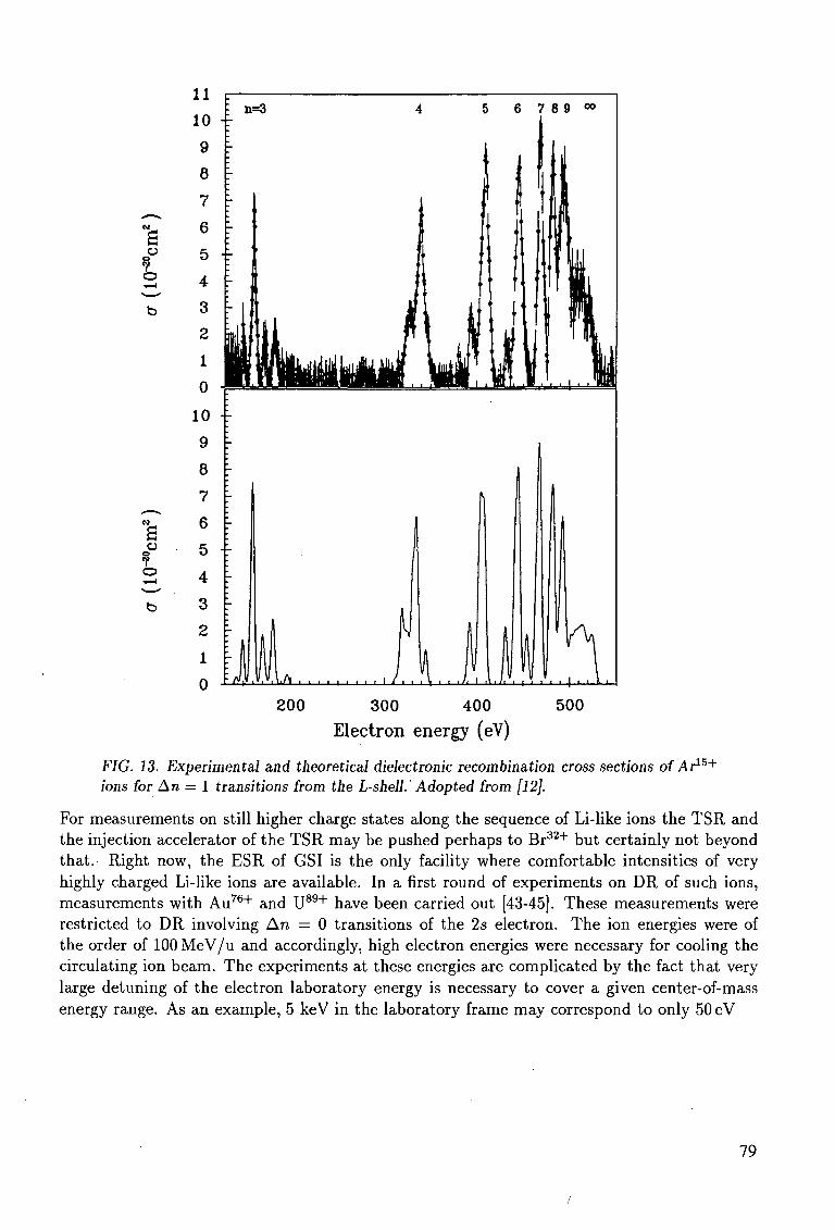
*—».
"s a
V o **—' b
— « > » _ .
H o
7 O ^ ^ b
11 10
9
8
7
6
5 4
3 2
1
0
10
9
8
7
R
5 4
3 2
1
0
j n = 3 4 5 6 7 8 9 0 0
I
~ \ "~
!_ 1
M l Hi
l i 1) fl I
| u \\ m liu i J
i •
•
1
",
i ,, ,
ll 1 n H wuyiuiyy^ ^m j yi u r
- 7
. .. 1.... 1.. l
ll
lI
M
p
J fl l/.v.U — , — , ) . .
i
1
Ull'l
1 H» v i l l i
I TLIJ
' ' f i l l fflnU U A
lli
. , , 1 ,,1ffl
1 "U
1,1 200 300 400 500
Electron energy (eV)
FIG. 13. Experimental and theoretical dielectronic recombination cross sections of Ar15+
ions for An = 1 transitions from the L-shell. Adopted from [12].
For measurements on still higher charge states along the sequence of Li-like ions the TSR and the injection accelerator of the TSR may be pushed perhaps to Br3 2 + but certainly not beyond that. Right now, the ESR of GSI is the only facility where comfortable intensities of very highly charged Li-like ions are available. In a first round of experiments on DR of such ions, measurements with Au7 6 + and U8 9 + have been carried out [43-45]. These measurements were restricted to DR involving An = 0 transitions of the 25 electron. The ion energies were of the order of 100 MeV/u and accordingly, high electron energies were necessary for cooling the circulating ion beam. The experiments at these energies are complicated by the fact that very large detuning of the electron laboratory energy is necessary to cover a given center-of-mass energy range. As an example, 5 keV in the laboratory frame may correspond to only 50 eV
79
i
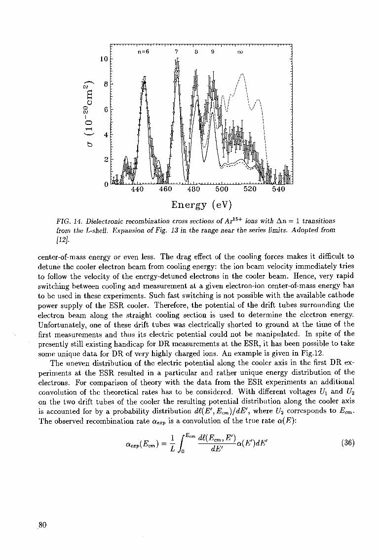
n=6 7 8 9 oo
440 460 480 500 520 540
Energy (eV)
FIG. 14. Dielectronic recombination cross sections of Ar15+ ions with Arc = 1 transitions from the L-shell. Expansion of Fig. 13 in the range near the series limits. Adopted from [12].
center-of-mass energy or even less. The drag effect of the cooling forces makes it difficult to detune the cooler electron beam from cooling energy: the ion beam velocity immediately tries to follow the velocity of the energy-detuned electrons in the cooler beam. Hence, very rapid switching between cooling and measurement at a given electron-ion center-of-mass energy has to be used in these experiments. Such fast switching is not possible with the available cathode power supply of the ESR cooler. Therefore, the potential of the drift tubes surrounding the electron beam along the straight cooling section is used to determine the electron energy. Unfortunately, one of these drift tubes was electrically shorted to ground at the time of the first measurements and thus its electric potential could not be manipulated. In spite of the presently still existing handicap for DR measurements at the ESR, it has been possible to take some unique data for DR of very highly charged ions. An example is given in Fig. 12.
The uneven distribution of the electric potential along the cooler axis in the first DR experiments at the ESR resulted in a particular and rather unique energy distribution of the electrons. For comparison of theory with the data from the ESR experiments an additional convolution of the theoretical rates has to be considered. With different voltages Ui and U2
on the two drift tubes of the cooler the resulting potential distribution along the cooler axis is accounted for by a probability distribution d£(E',Ecm)/dE', where U2 corresponds to Ecm. The observed recombination rate aexp is a convolution of the true rate a(E):
aexp(Ecm) = \ JQECm de{E™;E']a(E')dE' (36)
80
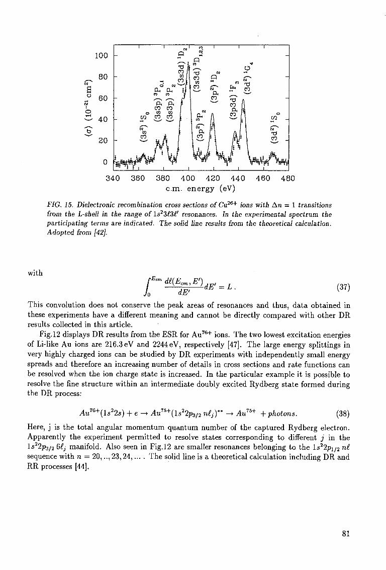
100
^ 80 CM
a » 60 CM
I O
40
20 -
_
ftffi;
1
o
CM
CO
hfiijiir M T ^
o
CO
"ft CO OT
CO
/ i
1
CM
co
' f t CO
CO
CM
Q t - l
xTI CO / Kl 1
CO
H
".
CO
x^ CO
i CO
OH I CO
CM
ft CO
1
CM
Q CM
ft CO
In
i
i
CO
X^ CO ft
CO
iJ
1
•*
CM
X I CO
i I
i r^r
1
_
o CO
CM
X) CO _
1 0
340 360 380 400 420 440 460 480 cm. energy (eV)
FIG. 15. Dielectronic recombination cross sections ofCu26+ ions with An = 1 transitions from the L-shell in the range of l<s23^3^' resonances. In the experimental spectrum the participating terms are indicated. The solid line results from the theoretical calculation. Adopted from [42].
with rEc
Jo dE' dE' (37)
This convolution does not conserve the peak areas of resonances and thus, data obtained in these experiments have a different meaning and cannot be directly compared with other DR results collected in this article.
Fig. 12 displays DR results from the ESR for Au7 6 + ions. The two lowest excitation energies of Li-like Au ions are 216.3 eV and 2244 eV, respectively [47]. The large energy splittings in very highly charged ions can be studied by DR experiments with independently small energy spreads and therefore an increasing number of details in cross sections and rate functions can be resolved when the ion charge state is increased. In the particular example it is possible to resolve the fine structure within an intermediate doubly excited Rydberg state formed during the DR process:
Au76+(ls22s) + e - • Au75+(ls22p3/2 nltf* - • Au75+ + photons. (38)
Here, j is the total angular momentum quantum number of the captured Rydberg electron. Apparently the experiment permitted to resolve states corresponding to different j in the ls22p3 /2 6£j manifold. Also seen in Fig.12 are smaller resonances belonging to the ls22pi/2 nt sequence with n = 20,.. , 23,24,. . . . The solid line is a theoretical calculation including DR and RR processes [44].
81
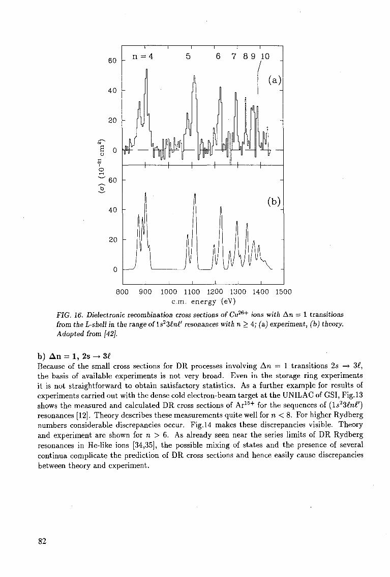
60
40
20
1 °
60 I-
40 -
20
0
800 900 1000 1100 1200 1300 1400 1500 cm. energy (eV)
FIG. 16. Dielectronic recombination cross sections of Cu26+ ions with An = 1 transitions from the L-shell in the range of ls23tnl' resonances with n > 4; (a) experiment, (b) theory. Adopted from [42].
b) A n = 1, 2s -» 3£ Because of the small cross sections for DR processes involving An = 1 transitions 2s —+ 3£, the basis of available experiments is not very broad. Even in the storage ring experiments it is not straightforward to obtain satisfactory statistics. As a further example for results of experiments carried out with the dense cold electron-beam target at the UNILAC of GSI, Fig.13 shows the measured and calculated DR cross sections of Ar1 5 + for the sequences of (ls23£n£') resonances [12]. Theory describes these measurements quite well for n < 8. For higher Rydberg numbers considerable discrepancies occur. Fig. 14 makes these discrepancies visible. Theory and experiment are shown for n > 6. As already seen near the series limits of DR Rydberg resonances in He-like ions [34,35], the possible mixing of states and the presence of several continua complicate the prediction of DR cross sections and hence easily cause discrepancies between theory and experiment.
82
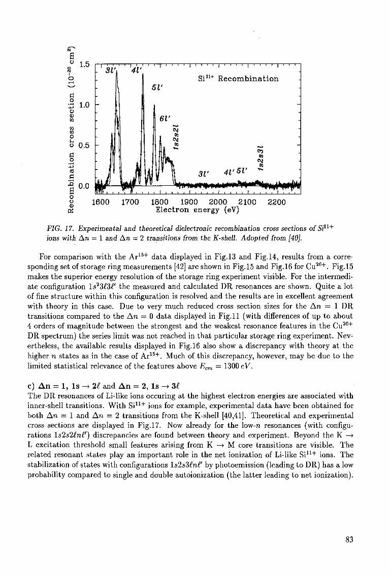
o N I
o
o
1.5
•7} 1 . 0 o CD w
m m O (-. o
a o (d
a
B O o <u K
0.5 -
0.0
1600 1700 1800 1900 2000 2100 2200 Electron energy (eV)
FIG. 17. Experimental and theoretical dielectronic recombination cross sections of Sill+
ions with An = 1 and An = 2 transitions from the K-shell. Adopted from [40].
For comparison with the Ar1 5 + data displayed in Fig. 13 and Fig. 14, results from a corresponding set of storage ring measurements [42] are shown in Fig.15 and Fig.16 for Cu2 6 + . Fig.15 makes the superior energy resolution of the storage ring experiment visible. For the intermediate configuration ls23£3£' the measured and calculated DR resonances are shown. Quite a lot of fine structure within this configuration is resolved and the results are in excellent agreement with theory in this case. Due to very much reduced cross section sizes for the An = 1 DR transitions compared to the An = 0 data displayed in Fig. 11 (with differences of up to about 4 orders of magnitude between the strongest and the weakest resonance features in the Cu2 6 +
DR spectrum) the series limit was not reached in that particular storage ring experiment. Nevertheless, the available results displayed in Fig.16 also show a discrepancy with theory at the higher n states as in the case of Ar1 5 + . Much of this discrepancy, however, may be due to the limited statistical relevance of the features above Erm = 1300 eV.
c) A n = 1, I s -> 2£ and A n = 2, I s -* U The DR resonances of Li-like ions occuring at the highest electron energies are associated with inner-shell transitions. With Si1 1 + ions for example, experimental data have been obtained for both An = 1 and An = 2 transitions from the K-shell [40,41]. Theoretical and experimental cross sections are displayed in Fig.17. Now already for the low-n resonances (with configurations Is2s2£n£') discrepancies are found between theory and experiment. Beyond the K —» L excitation threshold small features arising from K —• M core transitions are visible. The related resonant states play an important role in the net ionization of Li-like Si1 1 + ions. The stabilization of states with configurations Is2s3£n£' by photoemission (leading to DR) has a low probability compared to single and double autoionization (the latter leading to net ionization).
83
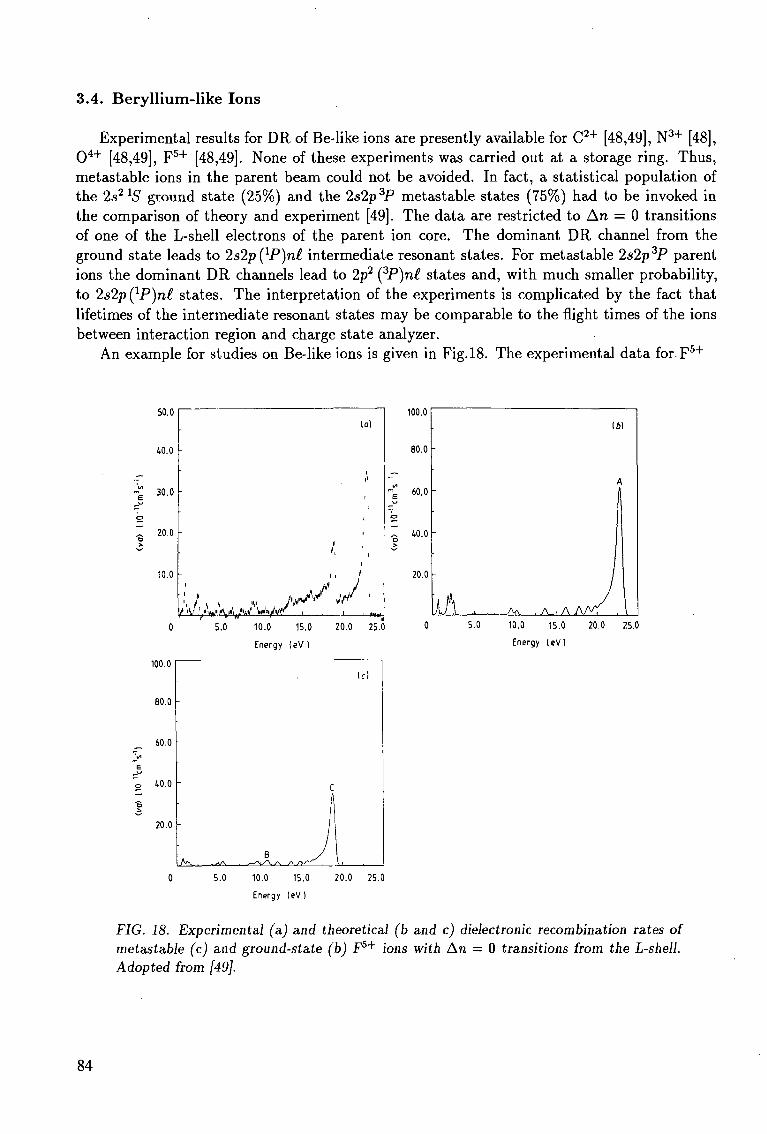
3.4. Beryll ium-like Ions
Experimental results for DR of Be-like ions are presently available for C 2 + [48,49], N 3 + [48], 0 4 + [48,49], F 5 + [48,49]. None of these experiments was carried out at a storage ring. Thus, metastable ions in the parent beam could not be avoided. In fact, a statistical population of the 2s2 XS ground state (25%) and the 2s2p3P metastable states (75%) had to be invoked in the comparison of theory and experiment [49]. The data are restricted to An = 0 transitions of one of the L-shell electrons of the parent ion core. The dominant DR channel from the ground state leads to 2s2p(1P)n£ intermediate resonant states. For metastable 2s2p3P parent ions the dominant DR channels lead to 2p2 (3P)n£ states and, with much smaller probability, to 2s2p (lP)n£ states. The interpretation of the experiments is complicated by the fact that lifetimes of the intermediate resonant states may be comparable to the flight times of the ions between interaction region and charge state analyzer.
An example for studies on Be-like ions is given in Fig.18. The experimental data for F 5 +
40.0
30.0
~ 20.0
100.0
80.0
60.0
40.0
20.0
-
-
if] . A \ . A . , A A/ \
161
A
/
J\ 5.0 10.0 15.0 20.0 25.0
Energy leV)
5.0 10.0 15.0 20.0 25.0
Energy leV)
100.0
80.0
60.0
40.0
20.0
-
-
A"v , .*J\ B
>. /N/V-"
C
,
I f )
5.0 10.0 15.0
Energy (eV)
20.0 25.0
FIG. 18. Experimental (a) and theoretical (b and c) dielectronic recombination rates of metastable (c) and ground-state (b) F5+ ions with An = 0 transitions from the L-shell. Adopted from [49].
84
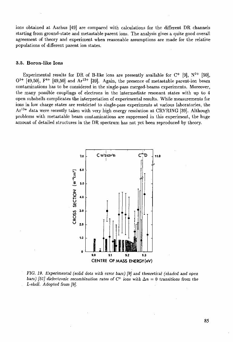
ions obtained at Aarhus [49] are compared with calculations for the different DR channels starting from ground-state and metastable parent ions. The analysis gives a quite good overall agreement of theory and experiment when reasonable assumptions are made for the relative populations of different parent ion states.
3.5. Boron-like Ions
Experimental results for DR of B-like ions are presently available for C+ [9], N2+ [50], 0 3 + [49,50], F 4 + [49,50] and Ar13+ [39]. Again, the presence of metastable parent-ion beam contaminations has to be considered in the single-pass merged-beams experiments. Moreover, the many possible couplings of electrons in the intermediate resonant states with up to 4 open subshells complicates the interpretation of experimental results. While measurements for ions in low charge states are restricted to single-pass experiments at various laboratories, the Ar13+ data were recently taken with very high energy resolution at CRYRING [39]. Although problems with metastable beam contaminations are suppressed in this experiment, the huge amount of detailed structures in the DR spectrum has not yet been reproduced by theory.
11.0
9.0 9.1 9.2 9.3
CENTRE OF MASS ENERGY(eV)
FIG. 19. Experimental (solid dots with error bars) [9] and theoretical (shaded and open bars) [51] dielectronic recombination rates of C" ions with An = 0 transitions from the L-shell. Adopted from [9].
85
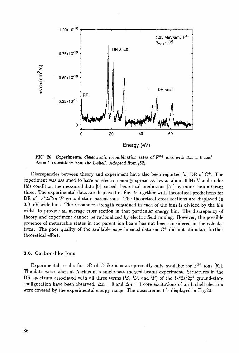
V) CD
E A D > V
1.00x10"10
0.75x1 Cr10
0.50x10"10
0.25x1 O"10
0 -
1.25MeV/amuF3* n
max = 3 5
DR An=0
RR DR An=1
1 • '
20 40 60
Energy (eV)
.FIG. 20. Experimental dielectronic recombination rates of F3+ ions with An — 0 and An = 1 transitions from the L-shell. Adopted from [52].
Discrepancies between theory and experiment have also been reported for DR of C + . The experiment was assumed to have an electron-energy spread as low as about 0.04 eV and under this condition the measured data [9] exceed theoretical predictions [51] by more than a factor three. The experimental data are displayed in Fig. 19 together with theoretical predictions for DR of ls22s22p 2P ground-state parent ions. The theoretical cross sections are displayed in 0.01 eV wide bins. The resonance strength contained in each of the bins is divided by the bin width to provide an average cross section in that particular energy bin. The discrepancy of theory and experiment cannot be rationalized by electric field mixing. However, the possible presence of metastable states in the parent ion beam has not been considered in the calculations. The poor quality of the available experimental data on C + did not stimulate further theoretical effort.
3.6. Carbon-like Ions
Experimental results for DR of C-like ions are presently only available for F 3 + ions [52]. The data were taken at Aarhus in a single-pass merged-beams experiment. Structures in the DR spectrum associated with all three terms QS, lD, and 3P) of the ls22s22p2 ground-state configuration have been observed. An = 0 and An = 1 core excitations of an L-shell electron were covered by the experimental energy range. The measurement is displayed in Fig.20.
86
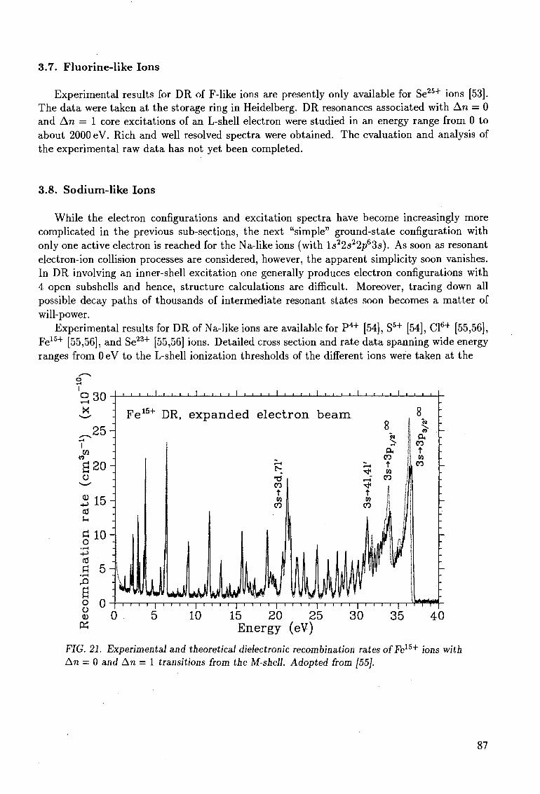
3.7. Fluorine-like Ions
Experimental results for DR of F-like ions are presently only available for Se25+ ions [53]. The data were taken at the storage ring in Heidelberg. DR resonances associated with An = 0 and An = 1 core excitations of an L-shell electron were studied in an energy range from 0 to about 2000 eV. Rich and well resolved spectra were obtained. The evaluation and analysis of the experimental raw data has not yet been completed.
3.8. Sodium-like Ions
While the electron configurations and excitation spectra have become increasingly more complicated in the previous sub-sections, the next "simple" ground-state configuration with only one active electron is reached for the Na-like ions (with ls22s22p63.s). As soon as resonant electron-ion collision processes are considered, however, the apparent simplicity soon vanishes. In DR involving an inner-shell excitation one generally produces electron configurations with 4 open subshells and hence, structure calculations are difficult. Moreover, tracing down all possible decay paths of thousands of intermediate resonant states soon becomes a matter of will-power.
Experimental results for DR of Na-like ions are available for P 4 + [54], S5 + [54], Cl6 + [55,56], Fe1 5 + [55,56], and Se2 3 + [55,56] ions. Detailed cross section and rate data spanning wide energy ranges from 0 eV to the L-shell ionization thresholds of the different ions were taken at the
i i ) i i i i i i i i i i i _
" i I I i [—I I i i | I I I i - ] p - T i i ] i I I I I i i i ? I - 1 i i i I i i"
5 10 15 20 25 30 35 40 Energy (eV)
FIG. 21. Experimental and theoretical dielectronic recombination rates ofFe15+ ions with An — 0 and An = 1 transitions from the M-shell. Adopted from [55].
87
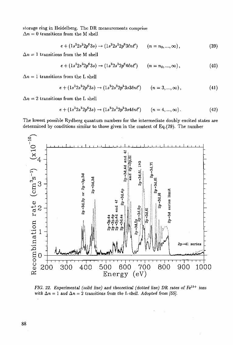
storage ring in Heidelberg. The DR measurements comprise An = 0 transitions from the M shell
e + (ls22s22p63s) - • {ls22s22p63£n£') (n = n0,..., oo),
An = 1 transitions from the M shell
e + ( ls22s22/3s) -> ( ls 2 2s 2 2p 6 4^ ' ) (n = n0,..., oo),
An = 1 transitions from the L shell
e + (ls22s22/3s) -> (ls22s22p53s3£n£') (n = 3,..., oo),
An = 2 transitions from the L shell
e + {ls22s22p63s) -*• (ls22s22p53sUn£') (n = 4,..., oo).
(39)
(40)
(41)
(42)
The lowest possible Rydberg quantum numbers for the intermediate doubly excited states are determined by conditions similar to those given in the context of Eq.(29). The number
O H X ' 4 -
w CO
3 -o
CD
Cti
o • I—I
ctf
2 -
So o o CD
PS
J I I I I I I I—L J I I L J I I I I I I I L J I I L
co P,
CO t p.
N
O
P. CO •o CO t P.
T3 CO_
•a" CO t ft
CM
so •alt
ft::cd
•a
St
p.
CO
t P.
CNi
^ ^ ^ ^ p, p, a, -d
CO CO CO CO t T t t a, a, a, a. N N N N
CO Al
in • •d \ CO 5 t 5
a:;
IP :
CO t p.
02 CO
CO t P.
2p-»41 series
-i—i—i—i—i—i—i—i—i—i—i—i—i i—I—i—i—i i I i—i—i i I i i i r ~\—i—i—i—I—i—i—i—r
200 300 400 500 600 700 800 900 1000 Energy (eV)
FIG. 22. Experimental (solid line) and theoretical (dotted line) DR rates of Fe15+ ions with An = 1 and An = 2 transitions from the L-shell. Adopted from [55].
88
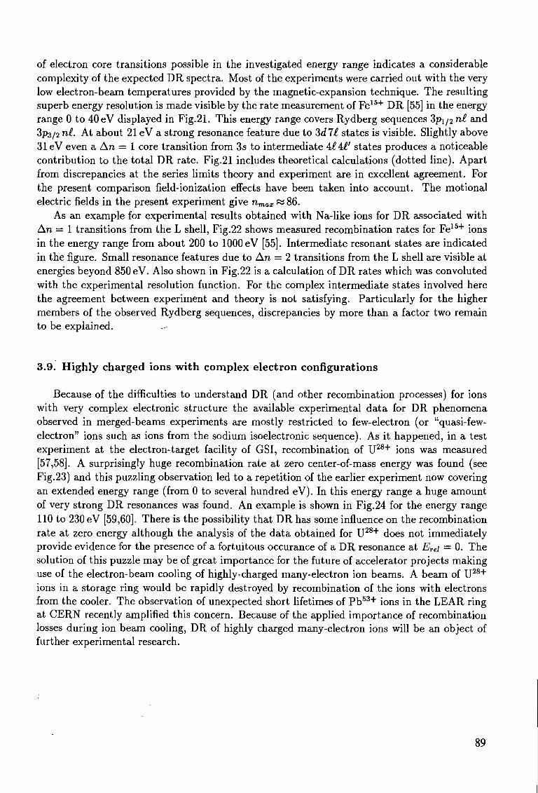
of electron core transitions possible in the investigated energy range indicates a considerable complexity of the expected DR spectra. Most of the experiments were carried out with the very low electron-beam temperatures provided by the magnetic-expansion technique. The resulting superb energy resolution is made visible by the rate measurement of Fe1 5 + DR [55] in the energy range 0 to 40 eV displayed in Fig.21. This energy range covers Rydberg sequences 3pi/2 n£ and 3p3/2 n£. At about 21 eV a strong resonance feature due to 3d7£ states is visible. Slightly above 31 eV even a An = 1 core transition from 3s to intermediate A£A£' states produces a noticeable contribution to the total DR rate. Fig.21 includes theoretical calculations (dotted line). Apart from discrepancies at the series limits theory and experiment are in excellent agreement. For the present comparison field-ionization effects have been taken into account. The motional electric fields in the present experiment 86.
As an example for experimental results obtained with Na-like ions for DR associated with An = 1 transitions from the L shell, Fig.22 shows measured recombination rates for Fe1 5 + ions in the energy range from about 200 to 1000 eV [55]. Intermediate resonant states are indicated in the figure. Small resonance features due to An = 2 transitions from the L shell are visible at energies beyond 850 eV. Also shown in Fig.22 is a calculation of DR rates which was convoluted with the experimental resolution function. For the complex intermediate states involved here the agreement between experiment and theory is not satisfying. Particularly for the higher members of the observed Rydberg sequences, discrepancies by more than a factor two remain to be explained. -
3.9. Highly charged ions wi th complex e lectron configurations
Because of the difficulties to understand DR (and other recombination processes) for ions with very complex electronic structure the available experimental data for DR phenomena observed in merged-beams experiments are mostly restricted to few-electron (or "quasi-few-electron" ions such as ions from the sodium isoelectronic sequence). As it happened, in a test experiment at the electron-target facility of GSI, recombination of U2 8 + ions was measured [57,58]. A surprisingly huge recombination rate at zero center-of-mass energy was found (see Fig.23) and this puzzling observation led to a repetition of the earlier experiment now covering an extended energy range (from 0 to several hundred eV). In this energy range a huge amount of very strong DR resonances was found. An example is shown in Fig.24 for the energy range 110 to 230 eV [59,60]. There is the possibility that DR has some influence on the recombination rate at zero energy although the analysis of the data obtained for U2 8 + does not immediately provide evidence for the presence of a fortuitous occurance of a DR resonance at Ere\ = 0. The solution of this puzzle may be of great importance for the future of accelerator projects making use of the electron-beam cooling of highly-charged many-electron ion beams. A beam of U2 8 +
ions in a storage ring would be rapidly destroyed by recombination of the ions with electrons from the cooler. The observation of unexpected short lifetimes of P b 5 3 + ions in the LEAR ring at CERN recently amplified this concern. Because of the applied importance of recombination losses during ion beam cooling, DR of highly charged many-electron ions will be an object of further experimental research.
89
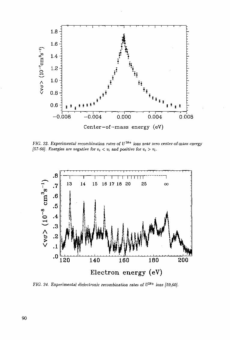
I w
TO
O r-I O
1.8 H
1.6
1.4-
1.2-j
1.0-A b V 0.8-1
n 1 1 r - i 1 i r - - i 1 1 r i l l r
0 . 6 ^ s i i i i * ~~i—i—i—i—|—i—i—i—i—|—i—r-
-0.008 -0.004 0.000 i ] i i i r
0.004 0.008
Center—of—mass energy (eV)
FIG. 23. Experimental recombination rates of U28+ ions near zero center-of-mass energy [57-60]. Energies are negative for ve < V{ and positive for ve > «,-.
,—"S
1 m
m III
O CO
1 O i H
W
A b > V
.8
.7
.6
.5
A
.3
.2
.1
-1—I I I—I I I I—I I I ' I I I
~1 I I I I I I M I N I '
13 14 15 16 17 18 20 25
•°120
00
140 160 180 200
Electron energy (eV)
FIG. 24. Experimental dielectronic recombination rates of lP8+ ions [59,60].
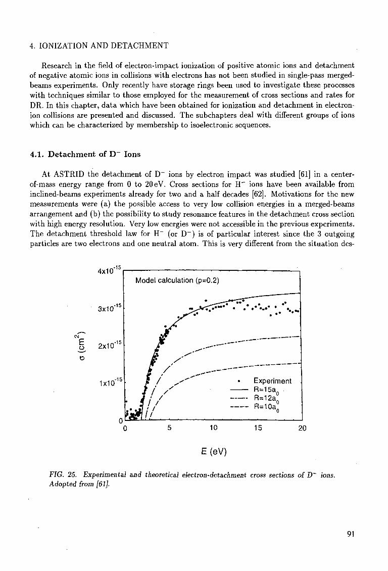
4. IONIZATION AND DETACHMENT
Research in the field of electron-impact ionization of positive atomic ions and detachment of negative atomic ions in collisions with electrons has not been studied in single-pass merged-beams experiments. Only recently have storage rings been used to investigate these processes with techniques similar to those employed for the measurement of cross sections and rates for DR. In this chapter, data which have been obtained for ionization and detachment in electron-ion collisions are presented and discussed. The subchapters deal with different groups of ions which can be characterized by membership to isoelectronic sequences.
4.1. De tachment of D~ Ions
At ASTRID the detachment of D _ ions by electron impact was studied [61] in a center-of-mass energy range from 0 to 20 eV. Cross sections for H" ions have been available from inclined-beams experiments already for two and a half decades [62]. Motivations for the new measurements were (a) the possible access to very low collision energies in a merged-beams arrangement and (b) the possibility to study resonance features in the detachment cross section with high energy resolution. Very low energies were not accessible in the previous experiments. The detachment threshold law for H~ (or D~) is of particular interest since the 3 outgoing particles are two electrons and one neutral atom. This is very different from the situation des-
4x10"15
3x10"15
" l 2x10'15
D
1X10-15
0 0 5 10 15 20
E (eV)
FIG. 25. Experimental and theoretical electron-detachment cross sections of D~ ions. Adopted from [61].
Model calculation (p=0.2)
91
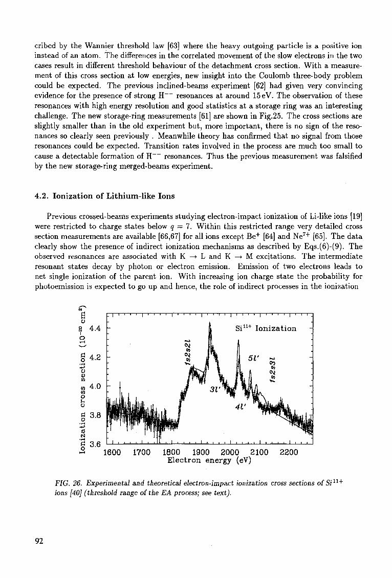
cribed by the Wannier threshold law [63] where the heavy outgoing particle is a positive ion instead of an atom. The differences in the correlated movement of the slow electrons in the two cases result in different threshold behaviour of the detachment cross section. With a measurement of this cross section at low energies, new insight into the Coulomb three-body problem could be expected. The previous inclined-beams experiment [62] had given very convincing evidence for the presence of strong H resonances at around 15 eV. The observation of these resonances with high energy resolution and good statistics at a storage ring was an interesting challenge. The new storage-ring measurements [61] are shown in Fig.25. The cross sections are slightly smaller than in the old experiment but, more important, there is no sign of the resonances so clearly seen previously . Meanwhile theory has confirmed that no signal from those resonances could be expected. Transition rates involved in the process are much too small to cause a detectable formation of H resonances. Thus the previous measurement was falsified by the new storage-ring merged-beams experiment.
4.2. Ionization of Lithium-like Ions
Previous crossed-beams experiments studying electron-impact ionization of Li-like ions [19] were restricted to charge states below q — 7. Within this restricted range very detailed cross section measurements are available [66,67] for all ions except Be+ [64] and Ne 7 + [65]. The data clearly show the presence of indirect ionization mechanisms as described by Eqs.(6)-(9). The observed resonances are associated with K —» L and K —> M excitations. The intermediate resonant states decay by photon or electron emission. Emission of two electrons leads to net single ionization of the parent ion. With increasing ion charge state the probability for photoemission is expected to go up and hence, the role of indirect processes in the ionization
i i I i r i
1600 1700 1800 1900 2000 2100 2200 Electron energy (eV)
FIG. 26. Experimental and theoretical electron-impact ionization cross sections of Si11+
ions [40] (threshold range of the EA process; see text).
92
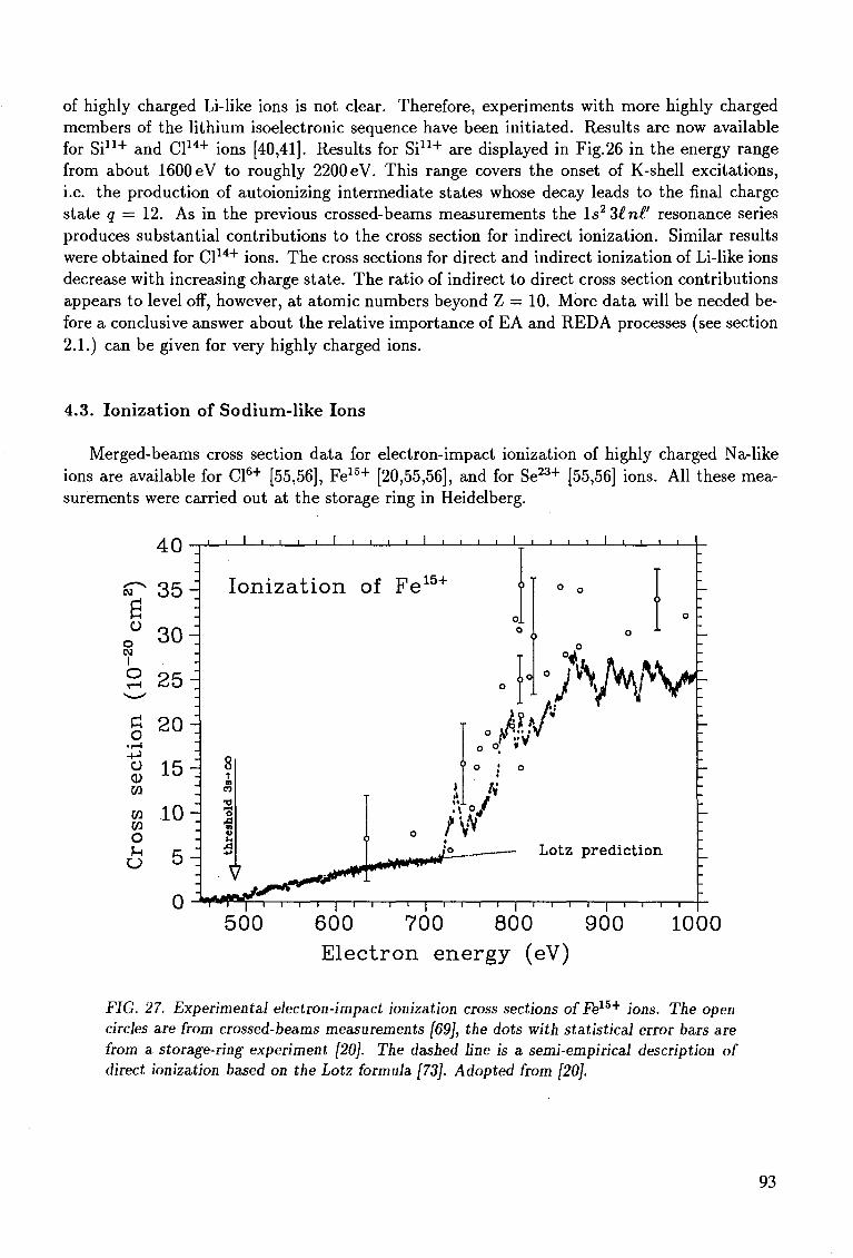
of highly charged Li-like ions is not clear. Therefore, experiments with more highly charged members of the lithium isoelectronic sequence have been initiated. Results are now available for Si1 1 + and Cl1 4 + ions [40,41]. Results for Si11+ are displayed in Fig.26 in the energy range from about 1600 eV to roughly 2200 eV. This range covers the onset of K-shell excitations, i.e. the production of autoionizing intermediate states whose decay leads to the final charge state q — 12. As in the previous crossed-beams measurements the ls23£nt' resonance series produces substantial contributions to the cross section for indirect ionization. Similar results were obtained for Cl1 4 + ions. The cross sections for direct and indirect ionization of Li-like ions decrease with increasing charge state. The ratio of indirect to direct cross section contributions appears to level off, however, at atomic numbers beyond Z = 10. More data will be needed before a conclusive answer about the relative importance of EA and REDA processes (see section 2.1.) can be given for very highly charged ions.
4.3. Ionization of Sodium-l ike Ions
Merged-beams cross section data for electron-impact ionization of highly charged Na-like ions are available for Cl6 + [55,56], Fe1 5 + [20,55,56], and for Se2 3 + [55,56] ions. All these measurements were carried out at the storage ring in Heidelberg.
40
CM
B O
o CM
| O * — i
v—'
rt u • l - l
•4->
o W
W
w o
3 5 -
30 -i -
2 5 --
?,0 -
15-
.10-
5^
1
8 t m
T) i—i o 01
I-,
XI
_l I I L. i I \ I
Ion iza t ion of Fe15+
o V f 8 ^
_ i i i i • i • i _
o.. o
° ;* \
o o or
J
?.l / ,\ o /
a
Lotz prediction
500 ~ i i i 1 i i i i I i i i i 1 i i i i [ i i i r
700 800 900 1000 600 E lec t ron ene rgy (eV)
FIG. 27. Experimental electron-impact ionization cross sections of Fel5+ ions. The open circles are from crossed-beams measurements [69], the dots with statistical error bars are from a storage-ring experiment [20]. The dashed line is a semi-empirical description of direct ionization based on the Lotz formula [73]. Adopted from [20].
93
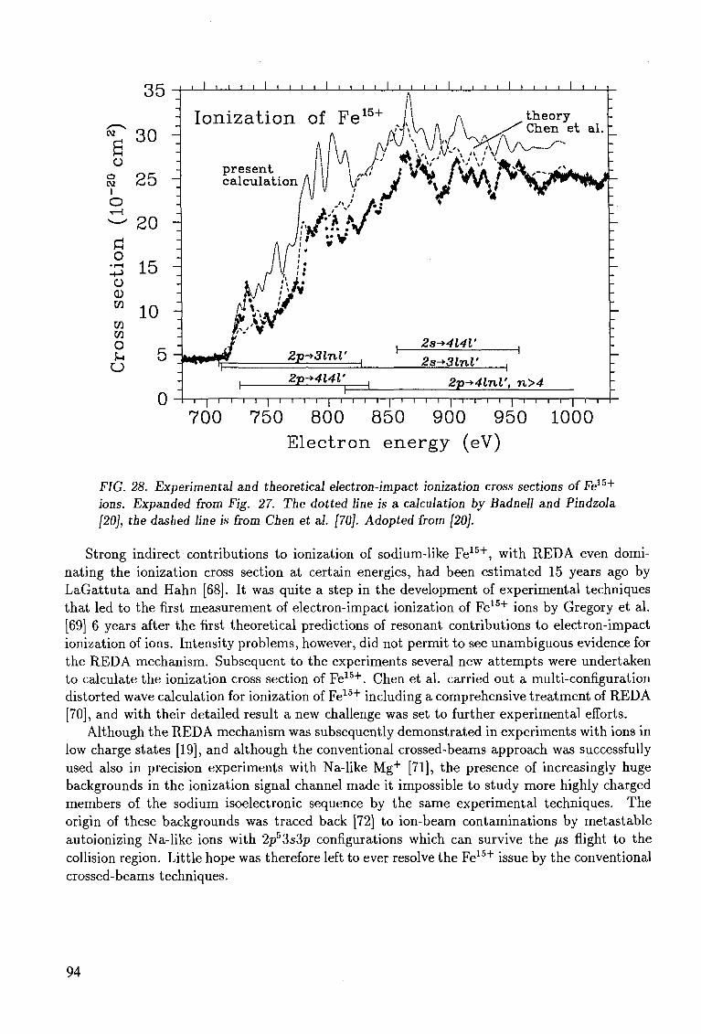
o •i-H
o CD
35
- 3 0 o
20
15 -
10 -d
!H 5 ~
o
' I ' I ' ' I ' ' I I I ' ' I I I I I I I I
Ioniza t ion of Fe15+ l\ rt A
JL I I I I I I I I I I l_
pre sen t ca lcu la t ion /u w
theo ry Chen e t al.
/v~~/"-
/ „ . ;
if A* /
(H»J|fT7 2p-+3lnl'
0
2s-*4l4V
2s^3lnl' 2y-+4l4V 2p-*4lnl', n>4
— i — | — i — i — i — i — | — i — i — i — i — | — i — i — i — i — I — i — i — i — i — I — i — i — i — i — | — i — i — i — i — | — i — i
700 750 800 850 900 950 1000 Electron energy (eV)
FIG. 28. Experimental and theoretical electron-impact ionization cross sections of Fe15+
ions. Expanded from Fig. 27. The dotted line is a calculation by Badnell and Pindzola [20], the dashed line is from Chen et al. [70]. Adopted from [20].
Strong indirect contributions to ionization of sodium-like Fe1 5 + , with REDA even dominating the ionization cross section at certain energies, had been estimated 15 years ago by LaGattuta and Hahn [68]. It was quite a step in the development of experimental techniques that led to the first measurement of electron-impact ionization of Fe1 5 + ions by Gregory et al. [69] 6 years after the first theoretical predictions of resonant contributions to electron-impact ionization of ions. Intensity problems, however, did not permit to see unambiguous evidence for the REDA mechanism. Subsequent to the experiments several new attempts were undertaken to calculate the ionization cross section of Fe1 5 + . Chen et al. carried out a multi-configuration distorted wave calculation for ionization of Fe15+ including a comprehensive treatment of REDA [70], and with their detailed result a new challenge was set to further experimental efforts.
Although the REDA mechanism was subsequently demonstrated in experiments with ions in low charge states [19], and although the conventional crossed-beams approach was successfully used also in precision experiments with Na-like Mg+ [71], the presence of increasingly huge backgrounds in the ionization signal channel made it impossible to study more highly charged members of the sodium isoelectronic sequence by the same experimental techniques. The origin of these backgrounds was traced back [72] to ion-beam contaminations by metastable autoionizing Na-like ions with 2p53s3p configurations which can survive the fis flight to the collision region. Little hope was therefore left to ever resolve the Fe1 5 + issue by the conventional crossed-beams techniques.
94
With the advent of heavy ion storage rings, however, an entirely new approach to the problem has become feasible. The two main drawbacks of previous measurements with multiply charged sodium-like ions - the low signal rate and the high background due to decaying metastable ions- can be circumvented by using a storage ring equipped with an electron cooler. Thus, even within short storage times of the order of only 1 s before the measurement, practically all metastable ions in the injected beam decay, which avoids the background problems inherent in the previous small-scale colliding-beams experiments. Furthermore, signal rates are substantially enhanced as compared to conventional experiments. Therefore, the Heidelberg storage ring TSR was used to measure electron-impact ionization of Na-like ions and particularly also of Fe1 5 + ions. For the latter, an energy range between 450 and 1030 eV was investigated. This range covers the ground-state ionization threshold and the energies corresponding to the most important EA and REDA cross section contributions.
The experimental results [20] are shown in Fig.27 by the solid dots. Within total error bars (±20 %) the new results and the previous data of Gregory et al. (open circles) [69] are in agreement. Relative uncertainties of the storage ring measurements are about a factor 40 lower than those of the previous work and the density of the data points clearly reveals the rich structure caused by EA steps and REDA peaks in the cross section function. Between the threshold of direct outer shell ionization at 489 eV and the onset of EA processes at about 710 eV the ionization cross section follows the Lotz formula [73], which can describe only the direct process. Above 710 eV the indirect ionization mechanisms begin to contribute and soon dominate the ionization cross section of Fe15+ ions.
The present data allow for the first time a detailed comparison of theory with experiment for ionization of a highly charged Na-like ion. Fig.28 shows the experimental data in the energy range 680 to 1030 eV in comparison with two detailed calculations. Although the theoretical results are in good agreement with the overall magnitude of the experimental cross section, they disagree with each other and with the experiment with respect to the fine details of the ionization spectrum.
5. SUMMARY AND PERSPECTIVES
Ionization and recombination of ions has been studied in experiments making use of merged-beams accelerator facilities. In particular, the availability of several new heavy ion storage rings which are at least partially devoted to atomic physics has greatly enhanced the possibilities to study electron interactions with highly charged ions. DR has recently been measured with unprecedented energy resolution and the first ever use of a storage ring for electron-impact ionization of ions provided new experimental precision data. The related research program will be continued with ions up to the highest possible atomic numbers and ion charge states.
The DR measurements are promising for a precision spectroscopy of intermediate excited states formed by the dielectronic capture process. In particular, DR studies of very highly charged few-electron ions with highest energy resolution may lead to the development of a competitive spectroscopic tool to study quantum electrodynamic effects on the 2s - 2p transition energies in high-Z lithium-like ions and even Lamb-shifts in hydrogen-like ions up to U9 1 + . Electron targets additional to the electron cooler are envisaged for such purposes.
95
6. ACKNOWLEDGEMENTS
The author wants to express his gratitude for fruitful scientific interaction and collaboration with W. Spies, J. Linkemann, 0 . Uwira, A. Frank, T. Cramer, J. Kenntner, A. Wolf, D. Habs, M. Grieser, D. Schwalm, R. Becker, M. Kleinod, C. Kozhuharov, P. H. Mokler, N. Angert, F. Bosch, M. Steck, P. Spadtke, S. Schennach, B. Franzke, M. S. Pindzola, N. R. Badnell, P. Zimmerer, N. Grim, W. Scheid, K. J. Reed, and many others who have been involved in the work presented in this review. Support by the Gesellschaft fur Schwerionenforschung (GSI), Darmstadt, by the Max-Planck-Institut fur Kernphysik, Heidelberg, and by the German Ministry of Education, Science, Research and Technology (BMBF) is gratefully acknowledged.
R E F E R E N C E S
[1
[2:
F. Brouillard and J. W. McGowan (eds.), Physics of Ion-Ion and Electron-Ion Collisions, Plenum, New York and London,1983
F. Brouillard (ed.), Atomic Processes in Electron-Ion and Ion-Ion Collisions, Plenum, New York and London, 1986
[3] K. T. Dolder, M. F. A. Harrison, P. C. Thonemann, Proc. Roy. Soc. A 264, 367 (1961)
[4] A. Muller, in Physics of Ion Impact Phenomena, D. Mathur (ed.), Springer-Verlag, Berlin, Heidelberg, New York, 1991, pp. 13-90
[5] R. A. Phaneuf, in The Physics of Electronic and Atomic Collisions, T. Andersen et al. (eds.), AIP Conference Proceedings 295, American Institute of Physics, New York, 1993, pp. 405 - 414
[6] R. A. Phaneuf, in Atomic Processes in Electron-Ion and Ion-Ion Collisions, F. Brouillard (ed.), Plenum, New York and London, 1986, pp. 117-156
[7] G. H. Dunn, in Recombination of Atomic Ions, W. G. Graham et al. (eds.), NATO ASI Series B: Physics Vol. 296, Plenum, New York, 1992, pp. 115-132
[8] D. Auerbach, R. Cacak, R. Caudano, T. D. Gaily, C. J. Keyser, J. W. McGowan, J. B. A. Mitchell, and S. F. J. Wilk, J. Phys. B 10, 3797 (1977)
[9] J. B. A. Mitchell, C. T. Ng, J. L. Forand, D. P. Levac, R. E. Mitchell, A. Sen, D. B. Miko, J. Wm. McGowan, Phys. Rev. Lett. 50, 335 (1983)
[10] P. F. Dittner, S. Datz, in Recombination of Atomic Ions, W. G. Graham et al.(eds.), NATO ASI Series B: Physics Vol. 296, Plenum, New York, 1992, p. 133
[11] L. H. Andersen, in The Physics of Electronic and Atomic collisions, T. Andersen et al. (eds.), AIP Conference Proceedings 295, American Institute of Physics, New York, 1993, p. 432
96
[12] S. Schennach, A. Miiller, 0 . Uwira, J. Haselbauer, W. Spies, A. Frank, M. Wagner, R. Becker, M. Kleinod, E. Jennewein, N. Angert, P. H. Mokler, N. R. Badnell, M. S. Pindzola, Z. Phys. D 30, 291 (1994)
[13] A. Wolf, J. Berger, M. Bock, D. Habs, B. Hochadel, G. Kilgus, G. Neureither, U. Schramm, D. Schwalm, E. Szmola, A. Muller, M. Wagner, R. Schuch, in Physics of Highly-Charged Ions, E. Salzborn, P. H. Mokler, and A. Muller (eds.), Suppl. Z. Phys. D 21, 69 (1991)
[14] B. Franzke, K. Beckert, F. Bosch, H. Eickhoff, B. Franczak, A. Gruber, 0 . Klepper, F. Nolden, P. Raabe, H. Reich, P. Spadtke, M. Steck, J. Struckmeier, in Proceedings of the 1993 Particle Accelerator Conference, Washington D.C., 17-20.05.1993
[15] K. Abrahamsson et al., in Proceedings of the 4th European Particle Accelerator Conference, London, England, 1994, V. Stiller and Ch. Petit-Jean-Genaz (eds.), World Scientific, Singapore, 1994, p. 380
[16] T. Katayama, in Cooler Rings and their Applications, T. Katayama and A. Noda (eds.), World Scientific, Singapore, 1991, pp. 21 - 30; and T. Tanabe, K. Noda, T. Honma, M. Kodaira, K. Chida, T. Watanabe, A. Noda, S. Watanabe, A. Mizobuchi, M. Yoshizawa, T. Katayama, H. Muto, and A. Ando, Nucl. Instrum. Meth. Phys. Res. A307 (1992) 7
[17] S. P. M0ller, in Conference Record of the 1991 IEEE Particle Accelerator Conference, San Francisco, K. Berkner (ed.), 1991, 2811 NATO ASI Series B: Physics Vol. 296, Plenum, New York, 1992, p. 133
[18] A. Muller, in X-Ray and Inner-Shell Processes, L. Sarkadi, D. Berenyi eds., Nucl. In-str. and Meth. B 87, 34 (1994)
[19] A. Muller, Comments At. Mol. Phys. 27, 1 (1991)
[20] J. Linkemann, A. Muller, J. Kenntner, D. Habs, D. Schwalm, A. Wolf, N. R. Badnell, M. S. Pindzola, Phys. Rev. Lett. 74, 4173 (1995)
[21] A. Muller, Nucl. Instr. and Meth. A 282, 80 (1989)
[22] P. F. Dittner, S. Datz, P. D. Miller, C. D. Moak, P. H. Stelson, C. Bottcher, W. B. Dress, G. D. Alton, N. Neskovic, Phys. Rev. Lett. 51, 31 (1983)
[23] L. H. Andersen, P. Hvelplund, H. Knudsen and P. Kvistgaard, Phys. Rev. Lett. 23, 2656 (1989)
[24] G. Kilgus, J. Berger, P. Blatt, M. Grieser, D. Habs, B. Hochadel, E. Jaeschke, D. Kramer, R. Neumann, G. Neureither, W. Ott, D. Schwalm, M. Steck, R. Stokstad, E. Szmola, A. Wolf, R. Schuch, A. Muller and M. Wagner, Phys. Rev. Lett. 64, 737 (1990); theory: M. S. Pindzola, N. R. Badnell, D. C. Griffin, Phys. Rev. A 42, 282 (1990)
[25] H. Danared, G. Andler, L. Bagge, C. J. Herrlander, J. Hilke, J. Jeansson, A. Kallberg, A. Nilsson, A. Paal, K.-G. Rensfelt, U. Rosengart, J. Starker, and M af Ugglas, Phys. Rev. Lett. 72, 3775 (1994)
97
[26] A. Muller, in Recombination of Atomic Ions, W. G. Graham et al. (eds.), NATO ASI Series B: Physics Vol. 296, Plenum, New York, 1992, pp. 155 - 179
[27] T. D. Mark and G. H. Dunn (eds.), Electron Impact Ionization, Springer-Verlag, Wien, New York, 1985
[28] A. Miiller, D. S. Belie, B. D. DePaola, N. Djuric, G. H. Dunn, D. W. Mueller, C. Timmer, Phys. Rev. A36, 599 (1987)
[29] E. P. Kanter, D. Schneider, Z. Vager, D. S. Gemmell, B. S. Zabransky, Gu Yuan-zhuang, P. Arcuni, P. M. Koch, D. R. Mariani, W. Van de Water, Phys. Rev. A 29, 583 (1984)
[30] R. R. Haar, J. A. Tanis, V. L. Piano, K. E. Zaharakis, W. G. Graham, J. R. Mowat, T. Ellison, W. W. Jacobs, and T. Rinckel, Phys. Rev. A 47, R3472 (1993)
[31] T. Tanabe, M. Tomizawa, K. Chida, T. Watanabe, M. Yoshizawa, H. Muto, K. Noda, M. Kanazawa, A. Ando, A. Noda, Phys. Rev. A45 (1992) 276
[32] D. R. DeWitt, E. Lindroth, R. Schuch, H. Gao, T. Quinteros, W. Zong, J. Phys. B 28, L147 (1995); and D. R. DeWitt, R. Schuch, T. Quinteros, Gao Hui, W. Zong, H. Danared, M. Pajek, N. Badnell, Phys. Rev. A 50, 1257 (1994)
[33] A. Wolf, report MPI H-V15-1992 (unpublished)
[34] L. H. Andersen, J. Bolko, P. Kvistgaard, Phys. Rev. A 41, 1293 (1990)
[35] L. H. Andersen, G.-Y. Pan, H. T. Schmidt, N. R. Badnell, M. S. Pindzola, Phys. Rev. A 45, 7868 (1992)
[36] G. Kilgus, D. Habs, D. Schwalm, A. Wolf, R. Schuch, N. R. Badnell, Phys. Rev. A 47, 4859 (1993)
[37] P. F. Dittner, S. Datz, P. D. Miller, P. L. Pepmiller, C. M. Fou, Phys. Rev. A 35, 3668 (1987)
[38] L. H. Andersen, G.-Y. Pan, H. T. Schmidt, M. S. Pindzola, N. R. Badnell, Phys. Rev. A 45, 6332 (1992)
[39] D. R. DeWitt, R. Schuch, C. Biedermann, Gao Hui, W. Zong, S. Asp, Phys. Rev. A, to be published; and Nucl. Instr. and Meth. B, in print; see also: CRYRING Status Report, March 24, 1995
[40] J. Kenntner, J. Linkemann, N. R. Badnell, C. Broude, D. Habs, G. Hofmann, A. Muller, M. S. Pindzola, E. Salzborn, D. Schwalm, A. Wolf, in Physics of Highly Charged Ions, Conference Proceedings 7th Intern. Conf. on the Physics of Highly Charged Ions (HCI-94), F. Aumayr, G. Betz and HP. Winter (eds.), special issue of Nucl. Instr. and Meth. B 98 (III) (1995), in print
[41] J. Kenntner, C. Broude, D. Habs, D. Schwalm, A. Wolf, J. Linkemann, A. Muller, N. R. Badnell, M. S. Pindzola, to be published
[42] G. Kilgus, D. Habs, D. Schwalm, A. Wolf, N. R. Badnell, A. Miller, Phys. Rev. A46, 5730 (1992)
[43] W. Spies, A. Mfiller, J. Linkemann, A. Frank, M. Wagner, C. Kozhuharov, B. Franzke, K. Beckert, F. Bosch, H. Eickhoff, M. Jung, 0 . Klepper, W. K6nig, P. H. Mokler, R. Moshammer, F. Nolden, U. Schaaf, P. Spadtke, M. Steck, P. Zimmerer, N. Griin, W. Scheid, M. S. Pindzola, N. R. Badnell, Phys. Rev. Lett. 69, 2768 (1992)
[44] W. Spies, 0 . Uwira, A. Mfiller, J. Linkemann, L. Empacher, A. Frank, C. Kozhuharov, P. H. Mokler, F. Bosch, 0 . Klepper, B. Franzke, M. Steck, in Physics of Highly Charged Ions, Conference Proceedings 1th Intern. Conf. on the Physics of Highly Charged Ions (HCI-94), F. Aumayr, G. Betz and HP. Winter (eds.), special issue of Nucl. Instr. and Meth. B 98 (III) (1995), in print
[45] W. Spies, A. Miiller, J. Linkemann, C. Kozhuharov, K. Beckert, F. Bosch, H. Eickhoff, B. Franzke, M. Jung, 0 . Klepper, W. Koenig, P. H. Mokler, R. Moshammer, F. Nolden, U. Schaaf, P. Spadtke, M. Steck, GSI Scientific Report 1992, GSI-93-1, p. 190
[46] D. C. Griffin, M. S. Pindzola, C. Bottcher, Phys. Rev. A 33, 3124 (1986)
[47] Y.-K. Kim, D. H. Baik, P. Indelicato, J. P. Desclaux, Phys. Rev. A 44, 148 (1991)
[48] P. F. Dittner, S. Datz, H. F. Krause, P. D. Miller, P. L. Pepmiller, C. Bottcher, C. M. Fou, D. C. Griffin, M. S. Pindzola, Phys. Rev. A 36, 33 (1987)
[49] N. R. Badnell, M. S. Pindzola, L. H. Andersen, J. Bolko, H. T. Schmidt, J. Phys. B 24, 4441 (1991)
[50] P. F. Dittner, S. Datz, H. Hippler, H. F. Krause, P. D. Miller, P. L. Pepmiller, C. M. Fou, Y. Hahn, I. Nasser, Phys. Rev. A 38, 2762 (1988)
[51] K. LaGattuta, Y. Hahn, Phys. Rev. Lett. 50, 668 (1983)
[52] H. T. Schmidt, G.-Y. Pan, L. H. Andersen, J. Phys. B 25, 3165 (1992)
[53] A. Lampert, D. Habs, G. Kilgus, D. Schwalm, A. Wolf, N. R. Badnell, M. S. Pindzola, in Atomic Physics of Highly-Charged Ions, AIP Conference Proceedings 274, P. Richard, et al. (eds.), American Institute of Physics, New York, 1993, p. 537
[54] P. F. Dittner, S. Datz, P. D. Miller, P. L. Pepmiller, C. M. Fou, Phys. Rev. A 33, 124 (1986)
[55] J. Linkemann, J. Kenntner, A. Miiller, A. Wolf, D. Habs, D. Schwalm, W. Spies, 0 . Uwira, A. Frank, A. Liedtke, G. Hofmann, E. Salzborn, N.R. Badnell, M.S. Pindzola, in Physics of Highly Charged Ions, Conference Proceedings 7th Intern. Conf. on the Physics of Highly Charged Ions (HCI-94), F. Aumayr, G. Betz and HP. Winter (eds.), special issue of Nucl. Instr. and Meth. B 98 (III) (1995), in print
[56] J. Linkemann et al., to be published
[57] S. Schennach, A. Muller, M. Wagner, J. Haselbauer, 0 . Uwira, W. Spies, E. Jennewein, R. Becker, M. Kleinod, U. Probstel, N. Angert, J. Klabunde, P. H. Mokler, P. Spadtke, B. Wolf, in Physics of Highly-Charged Ions, E. Salzborn, P. H. Mokler, and A. Muller (eds.), Suppl. Z. Phys. D 21, 205 (1991)
[58] A. Muller, S. Schennach, M. Wagner, J. Haselbauer, 0 . Uwira, W. Spies, E. Jennewein, R. Becker, M. Kleinod, U. Probstel, N. Angert, J. Klabunde, P. H. Mokler, P. Spadtke, B. Wolf, Phys. Scripta T37, 62 (1991)
[59] 0 . Uwira, A. Muller, W. Spies, A. Frank, J. Linkemann, L. Empacher, P. H. Mokler, R. Becker, M. Kleinod, S. Ricz, in Physics of Highly Charged Ions, Conference Proceedings 7th Intern. Conf. on the Physics of Highly Charged Ions (HCI-94), F. Aumayr, G. Betz and HP. Winter (eds.), special issue of Nucl. Instr. and Meth. B 98 (III) (1995), in print
[60] 0 . Uwira, A. Muller, W. Spies, A. Frank, J. Linkemann, L. Empacher, N. Angert, P. H. Mokler, S. Schennach, R. Becker, M. Kleinod, S. Ricz, GSI Scientific Report 1993, GSI-94-1, p. 145
[61] L. H. Andersen, D. Mathur, H. T. Schmidt, L. Vejby-Christensen, Phys. Rev. Lett. 74, 892 (1995)
[62] D. S. Walton, B. Peart, K. T. Dolder, J. Phys. B 3, L148 (1970); J. Phys. B 4, 1343 (1970); and B. Peart, K. T. Dolder, J. Phys. B 6, 1497 (1973)
[63] G. H. Wannier, Phys. Rev. 90, 817 (1953)
[64] D. H. Crandall, R. A. Phaneuf, D. C. Gregory, A. M. Howald, D. W. Mueller, T. J. Morgan, G. H. Dunn, D. C. Griffin, R. J. W. Henry, Phys.Rev. A 34, 1757 (1986)
[65] P. Defrance, S. Chantrenne, S. Rachafi, S. D. Belie, J. Jureta, D. Gregory, F. Brouillard, J. Phys. B 23, 2333 (1990)
[66] A. Muller, G. Hofmann, K. Tinschert, E. Salzborn, Phys. Rev. Lett. 61, 1352 (1988)
[67] G. Hofmann, A. Muller, K. Tinschert, E. Salzbom, Z. Phys. D 16, 113 (1990)
[68] K. J. LaGattuta, Y. Hahn, Phys. Rev. A 24, 2273 (1981)
[69] D. C. Gregory, L.-J. Wang, F. W. Meyer, K. Rinn, Phys. Rev. A 35, 3256 (1987)
[70] M. H. Chen, K. J. Reed, and D. L. Moores, Phys. Rev. Lett. 64, 1350 (1990)
[71] A. Muller, G. Hofmann, K. Tinschert, B. Weiflbecker, and E. Salzborn, Z. Phys. D 15, 145 (1990)
[72] A. M. Howald, D. C. Gregory, F. W. Meyer, R. A. Phaneuf, A. Muller, N. Djuric, G. H. Dunn, Phys. Rev. A 33, 3779 (1986)
[73] W. Lotz, Z. Phys. 220, 466 (1969)
100
MULTIPLE IONIZATION OF ATOMS AND POSITIVE IONS BY ELECTRON IMPACT
V.P. SHEVELKO* and H. TAWARA National Institute for Fusion Science, Nagoya 464-01, Japan
Abstract
Semiempirical formulae for multiple-ionization (MI) cross sections an of atoms and ions by electron impact for ejection three or more electrons n > 3 have been deduced on the basis of available experimental data and the assumption of the Born-Bethe dependence of on on the incident electron energy E. A comparison of the semiempirical formulae suggested with experimental data for atoms and positive ions shows that the formulae can be used for estimation of MI cross sections an , n > 3, from ionization threshold up to high electron-impact energies E « 105 eV for an arbitrary atomic or ionic target.
A double-peak srtucture of the triple-ionization cross section in neutral Ar has been also discussed.
1. INTRODUCTION
The problem of the multiple ionization (MI) arising in electron-atom and ion-atom collisions is of great interest both for our understanding of many-electron processes, e.g., multi-electron transitions, electron correlation effects [1,2] and for different physical applications [3,4] such as plasma kinetics problems, charge-state evaluation of atoms exposed to an electron beam, a contribution of Auger and shake-off processes and others .
In the case of MI of atoms and positive ions by electron impact the available experimental data on the cross sections an are often not consistent and complete, and sometimes large discrepancies exist among the data, in particular for large numbers of the ejected electrons n (see a compilation [5]). The quantum mechanical calculations of MI cross sections even for n > 2 are still unknown, therefore analytical semiempirical formulae constitute a special interest. A semiempirical formalism to predict double- and triple-ionization cross sections in the vicinity of ionization threshold of some specific atomic targets is applied in [6]. Scaling laws of multiple-ionization cross sections and semiempirical formulae for an have been recently discussed in [7].
On attachment from: P.N. Lebedev Physics Institute, Russian Academy of Sciences, 117924 Moscow, Russia
101
Our aim in this work is to investigate the multiple-ionization process in electron-atom and electron-ion collisions
(*+«)+ e + Az+ -+ e + A(Z+n>+ + ne, n > l
and to obtain semiempirical formulae for MI cross sections to describe their behavior on the average in a wide range of the incident electron energy.
2. BASIC FORMULAE
The measured threshold energy E^ for MI cross section an coincides to within 20% with the minimal ionization energy In required to remove n outmost target electrons (see, e.g., [7-9]):
L i=0
(1) where I +i is the one-electron ionization energy from the charge /' to i+1. The values for In can be estimated from the tables [10,11]. For example, the minimal energy I6 required to ionize six electrons in Kr atom is: I6 = I(Kr) + KKi+) + l(K?+) + i(Kr3+) + I(Kr4+) + I(Kr5+) = 14.0 eV + 27.89 eV + 41.78 eV + 55.67 eV + 70.31 eV + 84.52 eV = 294.17 eV.
Each target atom or ion is characterized by its own set of the minimal ionization energies In, so it is natural to choose In as a scaling parameter for the incident electron energy E similar to the case of a single ionization:
u=E/In-l (2)
Our analysis of the experimental data available on MI cross sections an for atoms and ions by electron impact has shown [12-14] that the majority of the cross sections has a similar electron-impact energy dependence for all targets and all cases with n > 3 and is described by a universal Born- Bethe type formula :
°"=TuW iu)[ cml '
F{u) = ( u Yln(« + 1)
(3)
\U+\J U + l
(4) where lRy = 13.6 eV; the constant c = 1 for neutral targets (z = 0) and c = 0.75 for positive ions (z > 1). Unfortunately, the energy dependence of double-ionization cross sections (n = 2) can not be properly described by Eqs. (3,4) and will be considered separately.
We note that in [7] the shape of the MI cross sections instead of (4) is described by another semiempirical formula (see also Section 3):
102
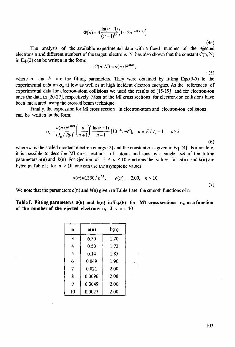
(4a) The analysis of the available experimental data with a fixed number of the ejected
electrons n and different numbers of the target electrons N has also shown that the constant C(n, N) in Eq.(3) can be written in the form:
C(n,N)=a(n)NKm), (5)
where a and b are the fitting parameters. They were obtained by fitting Eqs.(3-5) to the experimental data on an at low as well as at high incident electron energies. As the references of experimental data for electron-atom collisions we used the results of [15-19] and for electron-ion ones the data in [20-27], respectively. Most of the MI cross sections for electron-ion collisions have been measured using the crossed beam technique.
Finally, the expression for MI cross section in electron-atom and electron-ion collisions can be written in the form:
°^VJW^)~^~{™ cml U=EII»-X> *-3' (6)
where u is the scaled incident electron energy (2) and the constant c is given in Eq. (4). Fortunately, it is possible to describe MI cross sections of atoms and ions by a single set of the fitting parameters a(n) and b(n). For ejection of 3 < n < 10 electrons the values for a(n) and b(n) are listed in Table I; for n > 10 one can use the asymptotic values:
a(«)*1350/«57, b(n) = 2.00, n>\0 (7)
We note that the parameters a(n) and b(n) given in Table I are the smooth functions of n.
Table I. Fitting parameters a(n) and b(n) inEq.(6) for MI cross sections an as a function of the number of the ejected electrons n, 3 < n < 10
n
3
4
5 6
7
8
9
10
a(n)
6.30
0.50
0.14
0.049
0.021
0.0096
0.0049
0.0027
b(n)
1.20
1.73
1.85
1.96
2.00
2.00
2.00
2.00
103
3. COMPARISON WITH EXPERIMENTAL DATA
A comparison of the MI cross sections described by the semiempirical formula (6) with experimental data available for neutral atomic targets from Ne up to U and ejection up to 13 electrons and with those for positive ions are given in Figs. 1- 4. The figures are presented in the order of increasing of the target nuclear charge. The minimal ionization potentials In calculated from [10,11] for some atomic and ionic targets are given in Tables II and III.
Figs. 1-2 show typical MI cross sections of neutral atoms by electron impact. In the case of triple-ionization cross section of Ne atoms (Fig. la), the discrepancy among different experimental data is estimated to be a factor of 2 although the energy dependence seems to be the same. Similar discrepancy is observed between the present result and experiments. The dashed curve in Fig. la represents the result of semiempirical formalism [6]. The present calculations of o4 and as have also shown the large discrepancies from experiment. For instance, in the case n = 5 the present semiempirical formula Eq. (6 ) gives results which overestimate experimental data [28] more than one order of magnitude. In general, the agreement for the Ne target is the "worse" one as compared to the other targets.
Fig. lb shows the triple-and quadruple-ionization cross sections of Mg. The agreement of the semiempirical formula (6) with experiment is quite good, except for a region of maximum of an where the discrepancy is estimated to be within a factor of 2.
MI cross sections (n = 3, 4 and 5) of Ar atoms are shown in Fig. lc. It is noted that we have chosen these experimental data as the reference to obtain the constant C(n,N) in Eq.(6). The experimental triple-ionization cross section shows a double-peak structure which is later discussed in Section 4.
Experimental triple-, quadruple- and quintuple-ionization cross sections of Fe and Cu (Figs. Id and le) have been also chosen as the reference. These cases is an example of non rare gas targets.
Triple-ionization cross sections of Ga are shown in Fig.If where our results are compared with experimental data and semiempirical formalism by Deutsch et al. [6].
Fig. 2a represents MI cross sections of Kr atoms. The open circles are the experimental data [26] for n = 6, 7 and 8. The crosses represent the experimental data [33] for n = 6 - 9. All experimental data are quite consistent with each other as well as with our prediction. Fig. 2a shows also a comparison of MI cross sections (n=6-8) with semiempirical formulae recently proposed in [7] (see also Eq. (4a)). In the incident electron energy range E < 1000 eV there is a quite good agreemnent with the present results, but, in general, we think that our formula (6) is more easy to be used for estimation because it gives a systematic dependence of the proportional coefficient C(n, N) on the atomic parameters in the closed analytical form (Eq.(5) and Table 1) and therefore can be applied for an arbitrary atomic target.
Triple ionization of In is shown in Fig. 2b; the situation is similar to ionization of Ga atoms (Fig. If). Multiple-ionization cross sections of Xe atoms are given in Figs. 2c-2e. The observed data are quite consistent among differenet experiments. The behavior of the cross sections in the region of maximum is clearly related with autoionization processes which can not be described by the semiempirical formula (6). It is quite surprising that our prediction is in agreement with experimental data [33] in such many-electron ionization processes as with ejection n =11 and 13 electrons.
104
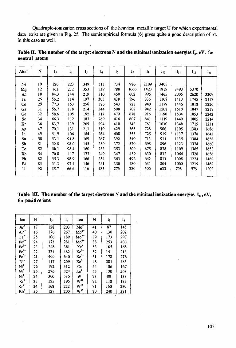
Quadruple-ionization cross sections of the heaviest metallic target U for which experimental data exist are given in Fig. 2f. The semiempirical formula (6) gives quite a good description of a4
in this case as well.
Table Q. The number of the target electrons N and the minimal ionization energies I„, eV, for neutral atoms
Atom
Ne Mg Ar Fe Cu Ga Ge Se Kr Ag In Sn Sb Te Xe Pb Bi U
N
10 12 18 26 29 31 32 34 36 47 49 50 51 52 54 82 83 92
h
126 103 84.3 56.2 77.3 56.7 58.6 66.3 83.7 70.1 51.9 53.1 52.8 58.1 70.8 55.3 51.3 35.7
L.
223 212 144 114 153 118 105 112 139 131 106 94.8 98:0 98.4 117 98.9 97.4 66.6
Is
349 353 219 197 256 214 192 183 209 211 184 169 155 160 177 166 156 116
h
513 539 310 305 386 344 317 269 294 310 284 267 250 233 249 254 241 185
I7
734 788 450 438 543 508 479 416 410 429 408 392 372 353 347 363 350 275
18
986 1066 602 596 728 707 678 607 542 568 555 540 520 500 459 492 480 380
I9
2109 1423 996 836 940 942 916 841 763 728 725 713 695 675 630 642 631 500
I10
3405 1819 1465 1107 1179 1208 1190 1119 1030 906 919 911 896 878 832 813 804 633
In
3490 2006 1410 1446 1510 1504 1440 1348 1105 1137 1135 1123 1109 1064 1008 1000 798
I12
5370 2620 1745 1818 1847 1853 1805 1715 1383 1378 1384 1378 1365 1328 1224 1219 979
I»
3309 2117 2226 2218 2242 2214 1231 1686 1643 1658 1660 1653 1656 1462 1462 1202
Table HI. The number of the target electrons N and the minimal ionization energies In, eV, for positive ions
Ion
Ar+
A^+
Fe+
Fe2+
Fe3+
Fe4+
Fei+
Ni+
Ni2+
Ni 3 +
Ni 4 +
Kr+
Ki*+
Rb+
N
17 16 25 24 23 22 21 27 26 25 24 35 34 36
I3
128 176 106 173 248 324 400 117 192 276 360 125 168 127
L.
203 267 189 281 381 482 640 209 312 424 536 196 252 200
Ion
Mo+
Mo 2 +
Mo 3 +
Mo 4 +
Xe+
Xe2+
Xe3+
Xe6+
Cs+
La2+
W+ W2+
w 3 +
W4"
N
41 40 39 38 53 52 51 48 54 55 73 72 71 70
I3
87 130 173 253 105 141 178 381 106 130 80 118 160 240
I4
145 202 297 400 165 213 276 583 167 208 133 185 280 381
105

4 3
2
1CH»
4 3
2
J0-2U
4 3
10-21
: i I T i • i •
e + •
•7 ^ n
•if •JJ «S
•; •* «
• o L L J . I 1 , i . i
Ne • » • •
?A^ .*y*"
X A T • • o
1 1 1 I ' l l ' " ' ' T - ^ ' ' I ' l ' l 1 1
* ~>e + Ne3+
T T " _ X T " •
T _ *;
Schnuetil . , 1966 QkudinettL, 1967 Vin dei Wiel et «L, 1969 Milt, 1982 Kriihaakamtr et tL, 1988 Ubiweti l . , 1989 D«aUchettl.,199S prateat
— < 1 l - l i l - . 1 . . . . . . . . . 1 1
r ' i 1
+
X X
• T •
T
, , i
3e : •
-•
-;
^ \ ^ -^ s ^
X X
-! • "*
•
(a) j
3 2
10-1 a
3 2
lO-l'
3 2
10-20
• McCtllion et al„ 1992
1Q2 2 3 4 5 103 2 3 4 5 1Q4 2 3 ^ lQ2 2 3 4 S lQ3 2 3 4 S lQA 2 3
• v i — n - r n - r i * i •T" , I , I—r-r-n
.0+ e + Mgw - > e + Mgni" + ne
*********
2
10-is
S « 2
B 10-19
o '"8 2
8 0 10-20 <*> «i O « - 2
U l0.2t
2
10-22
2
10-17
2
1018
2
1019
2
10-20
2
10-21
i n n ir"' ''' '"•"'''—i i'i i M I •
,0+ e + Ai1" - > e + AT n+
+ ne
X Scbnm.1966 0 Kriihnitimnrctil. 1988 • McOUlioocttL.1992 A Sytfc, 1992
— prefeflt (C) *l*i 1 I I I I I I . t l I .1.1 i . • i i i l . . ' || •» i » . , i
2
10-17
4 3
2
10-18
4 3
2
10-19
1
r
r
-
|
-
—1—T"
e i n
+
. • • I
T - T ••> T r - i -q , 1 1 l l l | •* I ' H - T ' l • " 1 - T - T - I 1 T T"T "• "T _ T~
Fe0* -->e + Fen+ + ne •
in
11
1
/ ^ ^ \ ' / • Shah etaL, 1993 ^ " s
/ prcscn (d) : . . . 1 . . . 1 1 l l l .J 1 1 . . i . 1 . J...J 1 _ l _ l 1 -J_Ll . - i .
102 2 3 103 2 3 10* ! 3 105 3 4 5 1Q2 2 3 4 5 103 2 3 4 5 10* 2
2 Tf—'—I • |'' I • |»«' l—T-TTTTT—' • ' I ' ' ' I ' " I 1—TTTTT ' ' ' I
e + Cu0* - > e + Cun+ + ne
• Bolorizadeh et aL, 1994 —— present
00
10-17
1018
6 5 4
-TTT ' 1 1 I I I I ' I ' i ' i ' i — 1 — r r
e + Ga0+ -> e.+ Ga3+ + 3e
O FrenndetaL, 1990 Deottch et al,1995 present
M I I I I I I
(0
102 2 3 4 5 103 2 3 4 5 104 2 3 5 6 1Q2 2 3 4 5 6 103 2 3 4 5 6 10*
Electron energy, eV
Fig. 1. MI cross sections of Ne, Mg, Ar, Fe, Cu and Ga atoms. Symbols correspond to the experimental data, the dashed curves in Figs. J a and Ifrepresent the semiempirical formalism [6] and the solid curves are the present result, Eq. (6). (a): crosses - [28], open triangles - [29], solid triangles - [30], boxes - [31], solid circles - [32], open circles - [26]; (b) : solid circles - [15]; (c) ; crosses - [33], open circles - [32], solid circles - [16], triangles - [34]; (d): circles-[17]; (c) : circles-[18]; (1). circles-[19]
106
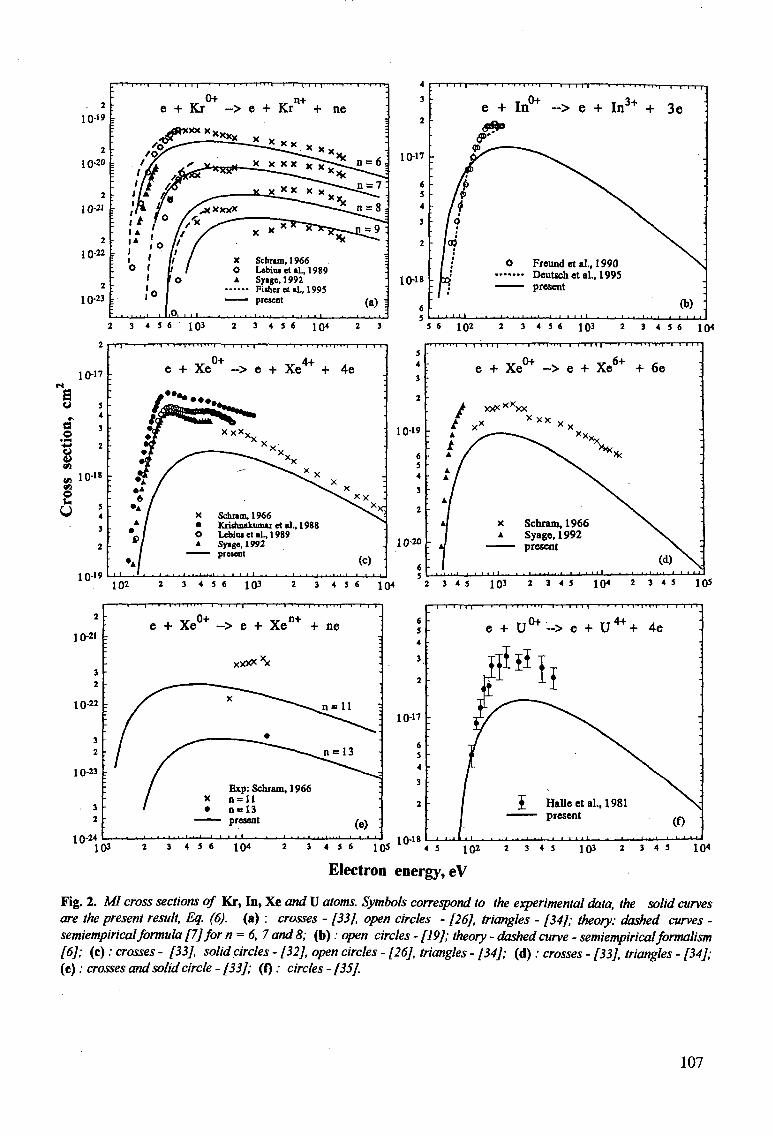
10-"
6 5 4
3
2
10-18
2 3 4 S < ' 103 2 3 4 5 6 1Q4 2 3
•
/ p
• h> I •
- Ia> 1 *
- i ^
. i . u j i
e
• l ' " I ' i ' l r i l l 1 | - • i ' i ,
+ I n * ~> e + In3+ +
0 Freundetal., 1990
present
. i . . . i ^ i . i . i — i . 1 i i 1 1 . . i . i . . . i . . . i
— i — i i i i-
3e
:
•
N .
:
ft) : i t i i i
5 6 1Q2 2 3 4 5 6 103 2 3 4 5 6 1 Q4
10-17
s O 5
*
§ '
1 ' « io-i» on O u < U 4
3
2
10-19
- 1 1 - • - • ' 1
e + Xe
1 V T ' l l | • - i—' l ' 1 r ' T i ' i
3+ AA-
-> e + Xe + .«*••.
/ * « • • . « - ' . tf^SZ
•jf ^ - —
*? /"" •A / • A / * / •A /
/ x A / •
: V ? • A /
1 1 .1 . . J . . . . . 1 . 1 . 1 ^
X x X x X „ x x
^ ^ ^ ^ x " ^ - v > < X
^ • • s ^ X
Schnm.1966 Kridinakumu et si.. 1988 LebiuietiL, 1989 Syage, 1992 present
1 I I • 1 . . . . . . . . .
T T ( • • ! — n -
4e
-
" .
•
'
-X
*\><x ^^vj'x;
^ K ^ i
, .
(c)
s 4
3
2
0-19
6 5 4 3
2
0-20
6
-T-T^T'» , I ' T
:
. /
A4
A
A /
A / A /
A /
' A l
; J |
1 M M ' ' ' 1 ' T^T^-t—1 1 1 T I ] -•—' • I -* -!'
e + X e * -> e + Xe6+ +
xx**xxx X x X X v
X X X ** - ^ X x x
x Schram, 1966 N
A Syage, 1992 — present
- • • • • ' ' 1 - - - L 1 - 1 - . . • 1 . . .
6e ; .
„
. -
•
•
•
V
^ V
(d) N^ i L A , i _ I 1 > J-i
102 2 3 4 5 6 1Q3 2 3 4 5 6 1Q4 2 3 4 5 1Q3 2 3 4 5 1Q« 2 3 4 5 105
10-21
10-22
10-23
1 0 - "
- | • I • | • I > 11 PH T" •n—i—r- i T
e + Xe0+ ~> e + Xen + + ne
xxxx*x
6 5 4
3
2
10-17
10-1*
- i — i T i n — • — i < i • i > i M M -
e + U°*'-> e + U^H- 4e
Electron energy, eV
Fig. 2. M cross sections of Kr, In, Xe and U atoms. Symbols correspond to the experimental data, the solid curves are the present result, Eq. (6). (a) : crosses - [33], open circles - [26], triangles - [34]; theory: dashed curves -semiempirical formula [7] for n = 6, 7 and 8; (b): open circles - [19]; theory - dashed curve - semiempirical formalism [6]; (c): crosses - [33], solid circles - [32], open circles - [26], triangles - [34]; (d): crosses - [33J, triangles - [34]; (e): crosses and solid circle - [33]; (f): circles - [35].
107
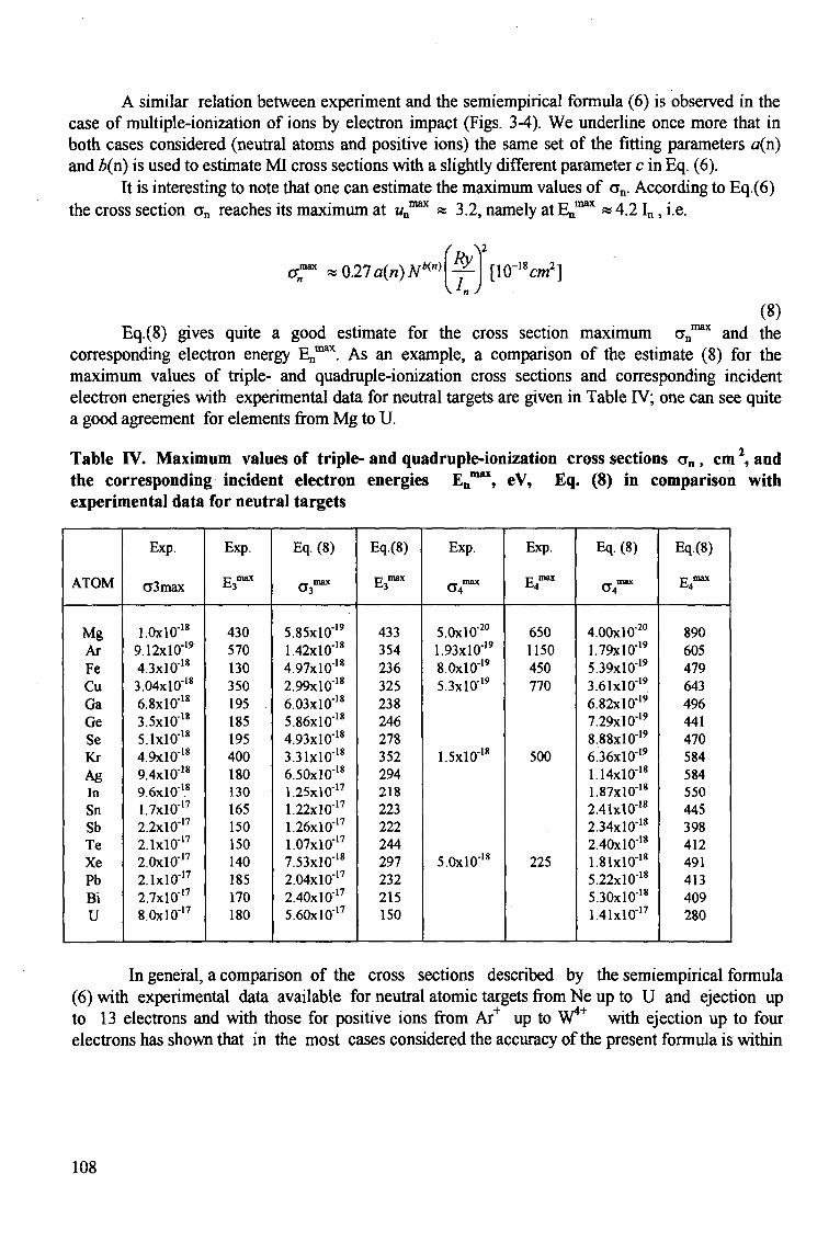
A similar relation between experiment and the semiempirical formula (6) is observed in the case of multiple-ionization of ions by electron impact (Figs. 3-4). We underline once more that in both cases considered (neutral atoms and positive ions) the same set of the fitting parameters a(n) and b(n) is used to estimate MI cross sections with a slightly different parameter c in Eq. (6).
It is interesting to note that one can estimate the maximum values of an. According to Eq.(6) the cross section an reaches its maximum at wn 3.2, namely at En .4.2 ^ . U .
027a(n)Nm Ry
\In J [l<r"W]
(8) estimate for the cross section maximum an
max and the "^ As an example, a comparison of the estimate (8) for the
Eq.(8) gives quite a good corresponding electron energy En' maximum values of triple- and quadruple-ionization cross sections and corresponding incident electron energies with experimental data for neutral targets are given in Table IV; one can see quite a good agreement for elements from Mg to U.
Table IV. Maximum values of triple- and quadruple-ionization cross sections an , cm , and the corresponding incident electron energies En
max, eV, Eq. (8) in comparison with experimental data for neutral targets
ATOM
Mg Ar Fe Cu Ga Ge Se Kr Ag In Sn Sb Te Xe Pb Bi U
Exp.
C3max
1.0x10"" 9.12xlO"'9
4.3x10"'* 3.04x10"'* 6.8x10"'* 3.5x10''* 5.1x10-'* 4.9x10"'* 9.4xl0"18
9.6x10"'* 1.7xl0"17
2.2xl0"17
2.1xl0"17
2.0xl0"17
2.1xl0"17
2.7xl017
8.0xl0"'7
Exp.
c max E-3
430 570 130 350 195 185 195 400 180 130 165 150 150 140 185 170 180
Eq. (8)
a 3m i x
5.85xl0"'9
1.42x10"'* 4.97x10"'* 2.99x10"'* 6.03x10"'* 5.86x10"'* 4.93x10''* 3.31x10"'* 6.50x10"'* 1.25xl0"17
1.22xl0-'7
1.26X10"'7
1.07xl0"'7
7.53x10"'* 2.04xl0"17
2.40xl0"'7
5.60xl0"17
Eq.(8)
T7 max E.3
433 354 236 325 238 246 278 352 294 218 223 222 244 297 232 215 150
Exp.
_ max
5.0xl0"20
1.93xl0"19
8.0xlO"19
5.3xl0-'9
1.5x10"'*
5.0xl0"18
Exp.
•c max fc4
650 1150 450 770
500
225
Eq. (8)
O*""
4.00xl0"20
1.79xl0"'9
5.39xl0"'9
3.61xl0"19
6.82xl0"'9
7.29xl0"19
8.88x10"19
6.36xl0"19
1.14x10"'* 1.87xl0"18
2.41xl0"18
2.34x10"18
2.40x10"'* 1.81xl0"'8
5.22x10"'* 5.30x10"'* 1.41xl0"17
Eq.(8)
c max E4
890 605 479 643 496 441 470 584 584 550 445 398 412 491 413 409 280
In general, a comparison of the cross sections described by the semiempirical formula (6) with experimental data available for neutral atomic targets from Ne up to U and ejection up to 13 electrons and with those for positive ions from Ar+ up to W4* with ejection up to four electrons has shown that in the most cases considered the accuracy of the present formula is within
108
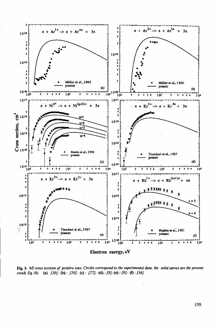
10-"
1019
10-20
- I • T '-f~rj •n—n-rr
e + Ar1 +-> e + Ar4+ + 3e
Mailer etal., 1980 present
(a) ' • • - • • • • • • • • '
102 2 3 4 5 6 1Q3 2 3 4 5 6
5 4
3
2
10-19 -
7 6 5 4
3
2
,10-20
10-17
U 10-20
10-21
— I • — | I 1 i - 1 — f 1~1'l • — r 1 ' T •'"' ' M i ' i ' i ' l I—r~1 1
l ( H i v 1 02
1017
' i ' I ' i • i « i M » T » I i m i • " i - - r , v i • i ' i ' i • i i | i t -
e + Ar 2 + -> e + Ar5+ + 3e
/ • • • • ^""""^v.
/ ** ^ S \ / • / • / •
/ *
| • /•# • MiilleretaL, 1980 1 present la
— • — i — • 1 ' * • • i — i — • i • i - ~ - . ' - i . i . . . i
- i — i i i
•
.
•
.
(b)
3 4 5 6 103 2 3 4 5 6 10<
e + N i q + ~>e + Ni(*+3)+ + 3e
I • Stenke etal., 1994
— present
(c) • - • - • - • • ' • ' i • ' - • . i - . - i . . . i . . . » i i
- n — • i - i • • | - H ' " ~ * — i • i «-r • i " « l » i ' i
e + Kr 1 + -> e + Ki4+ + 3e
102 2 3 4 5 6 1Q3 2 3 4 5 6
5 4 3
2
10-18
5
4 3
10-1»
1 i | i T i | « I M ' I ' I l - T T T 1 * 1—' 1 • I ' I ' I » | ' l» | 1 I I
e + Kr2 +-> e + Kr5+ + 3e
10-20 10< 102
10-17
L Tinschert etal., 1987 present
(d) • - ' - • - ' - • • • '
2 3 4 5 6 1Q3 2 3 4 5 6 {Q*
V**1**
Tinschert etal., 1987 present
(e) . • • i • • • • - • • • i—i i 1 1
4 3 •
2
10-1*
10-19
4 3
2 r
T—• i • r i i • 11 i n n — I I I I I I • i • I • I M " i | 1 — I I I .
e + Rb -> e + Rb + ne
illS&i
102 2 3 4 5 6 1Q3 10-20
2 3 4 5 6 104 * 1Q2 2 3 4 5 6 1Q3 2 3 4 5 6 10*
Electron energy, eV
Fig. 3. MI cross sections of positive ions. Circles correspond to the experimental data, the solid curves are the present result. Eq. (6). (a) : [20]; (b) : [20]; (c) : [27]; (d) ; [9]; (e) ; [9J; (I) ; [36].
109
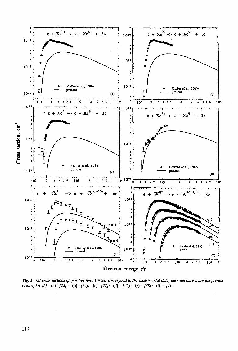
3
2
10-17
4
3
2
1 0 1 8
4
3
2
10-19
10-17
- I I I •
* » *
M
M
,1
11
1
1 = 1'
1 1 1
e + Xe1 +-> e + Xe4+ + 3e
• Miilleret al.,1984 present
' • • • » * ' ' i i . _ j . i . i . i - ^ j — i _
"T/T 1 I"
•
' :
.
•
•
(a) : 1 l _ l 1
2
10-17
4
3
2
1018
4
3
2
10-19
102 2 3 4 5 6 1Q3 2 3 4 5 6 \Q4
- I 1—I I I I ' '—' I ' " I 1 " ! 1 !—I I |
e + Xe -> e + Xe + + 3e
• Miilleret al.,1984 present
(b) <i . . . ) • • , i i i I J . l . l . . . - ^ i
1Q2 2 3 4 5 6 1Q3 2 3 4 5 6 1Q4
T-r-T-n-T ,—|—|—T 10-18
1 0 1 9
6 5 4
3
2
10-M
T T T 1 1 I | — 1 — i — i i i • i -i i • i • ; 11 • i — i — r — r
e + Xe6 +-> e + Xe9+ + 3e
• Howaldetal., 1986 —— present
(d)
3 4 5 6 7 1Q3 2 3 4 5 6 7 \Q4
3
2
10-17
4
3
2
10-1"
4
3
2
1019
T * I — 1 ~ T r n i—•—i-
e + Wq + -> e + W(q+3)+ + 3e
' ' ! ' ' . . . I . . . . . . . . | | I I • I
« 10* * 3 4 5 6 103 2 3 4 S 6 1 ( H " ' " l V 2 ' i 45 103 2 3 4 5 10< 2
Electron energy, eV
Fig. 4. MI cross sections of positive ions. Circles correspond to the experimental data, the solid curves are the present results, Eq. (6). (a): [22]; (b): [22]; (c): [22]; (A): [25]; (e); [38]; (f): [4].
110
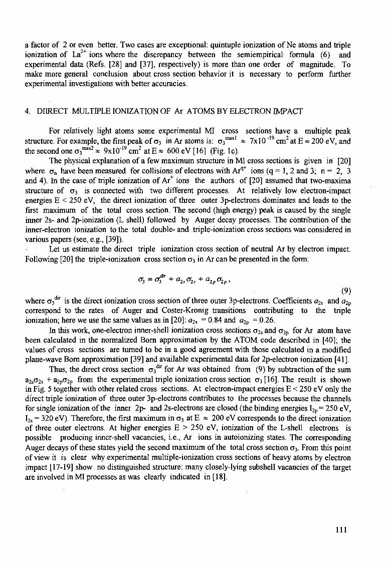
a factor of 2 or even better. Two cases are exceptional: quintuple ionization of Ne atoms and triple ionization of La2+ ions where the discrepancy between the semiempirical formula (6) and experimental data (Refs. [28] and [37], respectively) is more than one order of magnitude. To make more general conclusion about cross section behavior it is necessary to perform further experimental investigations with better accuracies.
4. DURECT MULTIPLE IONIZATION OF Ar ATOMS BY ELECTRON IMPACT
For relatively light atoms some experimental MI cross sections have a multiple peak structure. For example, the first peak of a3 in Ar atoms is: a^1 « 7x10 "19 cm2 at E «200 eV, and the second one o^*2 * 9xl0"19 cm2 at E * 600 eV [16] (Fig. lc).
The physical explanation of a few maximum structure in MI cross sections is given in [20] where an have been measured for collisions of electrons with Arq+ ions (q = 1, 2 and 3; n = 2, 3 and 4). In the case of triple ionization of Ar+ ions the authors of [20] assumed that two-maxima structure of o3 is connected with two different processes. At relatively low electron-impact energies E < 250 eV, the direct ionization of three outer 3p-electrons dominates and leads to the first maximum of the total cross section. The second (high energy) peak is caused by the single inner 2s- and 2p-ionization (L shell) followed by Auger decay processes. The contribution of the inner-electron ionization to the total double- and triple-ionization cross sections was considered in various papers (see, e.g., [39]).
Let us estimate the direct triple ionization cross section of neutral Ar by electron impact. Following [20] the triple-ionization cross section a3 in Ar can be presented in the form:
0-3 = ofr + a2sa2s + a2pa2p,
(9) where 03^ is the direct ionization cross section of three outer 3p-electrons. Coefficients a2s and a2p
correspond to the rates of Auger and Coster-Kronig transitions contributing to the triple ionization; here we use the same values as in [20]: a2s = 0.84 and a2p =0.26.
In this work, one-electron inner-shell ionization cross sections a2s and a2p for Ar atom have been calculated in the normalized Born approximation by the ATOM code described in [40]; the values of cross sections are turned to be in a good agreement with those calculated in a modified plane-wave Bom approximation [39] and available experimental data for 2p-electron ionization [41].
Thus, the direct cross section a^ for Ar was obtained from (9) by subtraction of the sum a2s 2s + a2pa2p from the experimental triple ionization cross section a3 [16]. The result is shown in Fig. 5 together with other related cross sections. At electron-impact energies E < 250 eV only the direct triple ionization of three outer 3p-electrons contributes to the processes because the channels for single ionization of the inner 2p- and 2s-electrons are closed (the binding energies I2p = 250 eV, I2s = 320 eV). Therefore, the first maximum in a3 at E « 200 eV corresponds to the direct ionization of three outer electrons. At higher energies E > 250 eV, ionization of the L-shell electrons is possible producing inner-shell vacancies, i.e., Ar ions in autoionizing states. The corresponding Auger decays of these states yield the second maximum of the total cross section a3. From this point of view it is clear why experimental multiple-ionization cross sections of heavy atoms by electron impact [17-19] show no distinguished structure: many closely-lying subshell vacancies of the target are involved in MI processes as was clearly indicated in [18].
I l l
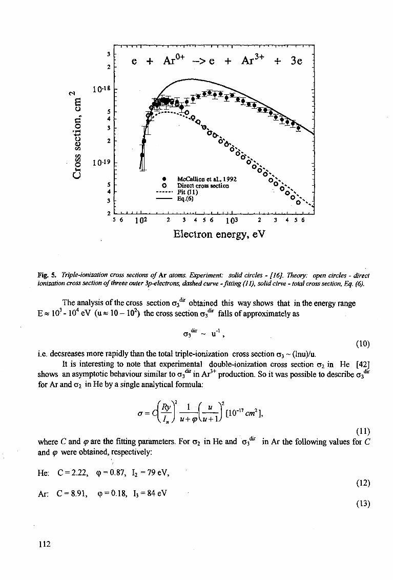
ts 10-18
e o c o
• r-i +-» o o oo CO CO
O
u 10-19
I i i r~T™ • • « • i • i • • 1—i—i i i I • i '1 i ' i • I 1—I—r
„o+ 3+ e + Aru+ ~>e + ArJ+ + 3e
• 1 1 1
• McCallionetal., 1992 oJS O Direct cross section A*»
Fit (U) ° o * \ Eq.(6) OjK
. i . • . i • i • i ' i i , i i i , i . i . . . i . . . i i • !
5 6 102 2 3 4 5 6 103 2 3 4 5 6
Electron energy, eV
Fig. 5. Triple-ionization cross sections of Kr atoms. Experiment: solid circles - [16]. Theory: open circles - direct ionization cross section qfthreee outer 3p-electrons, dashed curve -fitting (11), solid cirve - total cross section, Eq. (6).
The analysis of the cross section 03^ obtained this way shows that in the energy range E * 103 -104 eV (u « 10 - 102) the cross section 03^ falls of approximately as
CT3 ~ U ,
(10) i.e. decsreases more rapidly than the total triple-ionization cross section o3 ~ (lnu)/u.
It is interesting to note that experimental double-ionization cross section CT2 in He [42] shows an asymptotic behaviour similar to a-^ in Ar3+ production. So it was possible to describe as** for Ar and a2 in He by a single analytical formula:
a-Ry) 1
J„) u+<p\u+l u [ lO- 'W] ,
where C and q> are the fitting parameters. For o2 in He and 03^ in Ar the following values for C and <p were obtained, respectively:
He: C = 2.22, (p = 0.87, I2=79eV,
Ar: C = 8.91, (p = 0.18, I3 = 84eV (12)
(13)
112
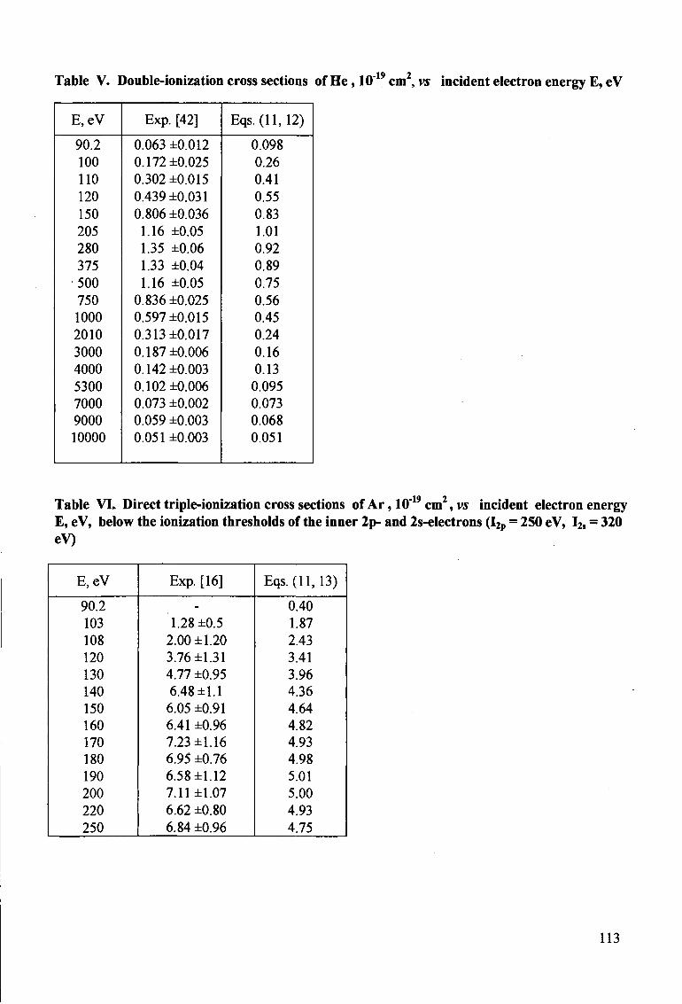
Table V. Double-ionization cross sections of He, 10"19 cm2, vs incident electron energy E, eV
E,eV
90.2
100 110 120 150 205 280 375 500 750 1000
2010
3000
4000
5300 7000 9000 10000
Exp. [42]
0.063 ±0.012
0.172 ±0.025
0.302 ±0.015
0.439 ±0.031
0.806 ±0.036 1.16 ±0.05
1.35 ±0.06
1.33 ±0.04
1.16 ±0.05 0.836 ±0.025
0.597 ±0.015
0.313 ±0.017
0.187 ±0.006 0.142 ±0.003
0.102 ±0.006 0.073 ±0.002 0.059 ±0.003 0.051 ±0.003
Eqs.(ll,12)
0.098
0.26
0.41
0.55
0.83 1.01
0.92
0.89
0.75
0.56
0.45
0.24
0.16
0.13 0.095 0.073
0.068 0.051
Table VL Direct triple-ionization cross sections of Ar, 10"19cm2, vs incident electron energy E, eV, below the ionization thresholds of the inner 2p- and 2s-electrons (I2p = 250 eV, I2s - 320 eV)
E,eV
90.2
103 108 120 130 140 150 160 170 180 190 200 220 250
Exp. [16]
-
1.28 ±0.5
2.00 ±1.20 3.76 ±1.31
4.77 ±0.95 6.48 ±1.1 6.05 ±0.91 6.41 ±0.96 7.23 ±1.16 6.95 ±0.76 6.58 ±1.12 7.11 ±1.07
6.62 ±0.80
6.84 ±0.96
Eqs.(ll, 13)
0.40
1.87
2.43 3.41
3.96 4.36 4.64 4.82 4.93 4.98
5.01 5.00
4.93
4.75
113
The maximum error of the fitting by Eqs. (11-13) is estimated to be about 30% (Tables V and VI). It is worth noting here that the experimental double-ionization cross section in He (as well as the direct ionization cross section of three outer electrons in Ar) decreases more rapidly than the Bethe asymptotic (lnu)/u that is probably related with the fact that in both cases the correlation effects between the ionizing target electrons play an important role and close encounter collisions mainly contribute to the simultaneous ionization of two in He (or three in Ar case) electrons. However, this question would require future consideration.
5. CONCLUSION
It has been found semiempirically that the MI cross section an is given as a function of the three atomic parameters: the minimal ionization energy In , the total number of the target electrons N and the number of the ejected electrons n. For large n » 1, one has the following asymptotic behavior of the MI cross sections:
N2
n
where F(u) is the universal function Eq. (4) for all cases with n >3. Of course, the present semiempirical formula (6) based on the Born-Bethe approximation is
unable to describe properly the energy dependence below the cross section maximum where the indirect processes are known to play a significant role. However, the formula suggested is very simple and can be used for estimation of multiple-ionization cross sections for an arbitrary atomic or ionic target in a wide range of the incident electron energy.
In this work it was also possible to estimate the direct triple-ionization cross section of Ar and to describe it by the analytical formula with two fitting parameters. The double-peak structure of <T3
was explained to be due to the direct ionization of three outer electrons at low energies (E < 250 eV) and Auger processes caused by single ionization of the L-shell electrons.
Acknowledgements
The authors would like to appreciate very much valuable remarks by B.N. Chichkov, R.K. Janev, A. Mtiller, D.B. Uskov and J. Ullrich.
The research described in this publication was made possible in part by Grant MK1000 from the International Science Foundation (ISF) and was supported by the International Scientific-Technological Center (ISTC), contract 076.
One of us (VPS) was also supported by the International Atomic Energy Agency (Vienna) under contract 8552/RB.
114
REFERENCES
[1] McGUIRE, J.H., Adv. At. Mol. Opt. Phys. 29(1992)217. [2] McGUIRE, J.H., BERRAH, N., BARTLETT, R.J., SAMSON, JAR., TANIS , J.A., COCKE, C.L.,
SALZBORN, E., J. Phys. B 28 (1995) 913. [3] MULLER, A., Phys. Lett. 113 A (1980) 415. [4] STENKE, M., AICHELE, K., HATHIRAMANI, D.H., HOFMANN, G, STEIDL, M., VOLPEL, R., SHEVELKO,
V.P., TAWARA, H., SALZBORN, E., J. Phys. B (1995); submitted. TAWARA, H., KATO, T., At. Data and Nucl. Data Tables, 36 (1987) 167. DEUTSCH, H., BECKER, K., MARK, T.D, Plasma Physics (1995); accepted. FISHER, V., RALCHENKO, Yu., GOLDRICH, A., FISHER, D., MARON, Y., J. Phys. B 28 (1995) 3027. WETZEL, R.C., BAIOCCHI, F.A., HAYES, T.R., FREUND, R.S., Phys. Rev. A 35 (1987) 559. TINSCHERT, K., MULLER, A., BECKER, R., SALZBORN, E., J. Phys. B 20 (1987) 1823 . LOTZ, W., J. Opt. Soc. Am., 58 (1968) 915; ibid 60 (1970) 206. CARLSON, T.A., NESTOR, Jr., C.W.,WASSERMAN, N„ McDOWELL, J.D., At. Data Tables, 2 (1970) 63. SHEVELKO, V.P., TAWARA, H., Physica Scripta (1995); accepted. SHEVELKO, V.P., TAWARA, H., J. Phys. B (1995); accepted. SHEVELKO, V.P., TAWARA, H., SALZBORN, E., Multiple-ionization cross sections of atoms and positive ions by electron impact, Rep. NIFS-DATA-27, National Institute for Fusion Science, Nagoya, Japan (1995).
McCALLION, P., SHAH, M B , GILBODY, H.B., J. Phys. B 25 (1992) 1051. McCALLION, P., SHAH, M.B., GILBODY, H.B., J. Phys. B 25 (1992) 1061. SHAH, M B , McCALLION, P., OKUNO,, K, GILBODY, H.B., J. Phys. 8 26(1992)2393. BOLORIZADEH, M.A., PATTON, C.J., SHAH, MB., GILBODY, H.B. J. Phys. B 27 (1994) 175. FREUND, R.S., WETZEL, R.C., SHULL, R.J., HAYES, T.R., Phys. Rev. A 41 (1990) 3575. MU LLER, A., FRODL, R., Phys. Rev. Lett., 44 (1980) 29. MU LLER, A., GROH, W., KNEISEL, U., HEIL, R., STROHER, H., SALZBORN, E., J. Phys. B 16 (1983) 2039. MU LLER, A., ACHENBACH, C, SALZBORN, E., BECKER, R., J. Phys. B 17 (1984) 1427. PINDZOLA, MS., GRIFFIN, D C , BOTTCHER, C , CRANDALL, D.H., PHANEUF, R.A., GREGORY, D C , Phys. Rev. A 29 (1984) 1749. MU LLER, A., TINSCHERT, K., ACHENBACH, C, BECKER, R., SALZBORN, E., J. Phys. B 18 (1985) 3011. HOWALD, A.M., GREGORY, D C , PHANEUF, R.A., CRANDALL, D.H., PINDZOLA, M.S., Phys. Rev. Lett. 56 (1986) 1675. LEBIUS, H., BINDER, J., KOSLOWSKI, H.R., WIESEMANN, K., HUBER, B.A., J. Phys. B 22 (1989) 83 . STENKE, M., K., HATHIRAMANI, D., HOFMANN, G., SHEVELKO, V.P., STEIDL, M., VOLPEL, R., SALZBORN, E., Nucl. Instrum. Meth. Phys. Res. B 98 (1995) 138. SCHRAM, B.L., BOERBOOM, A.J., KISTEMAKER, J., Physica (Utrecht) 32 (1966) 185. GAUDESf, A., HAGEMAN, R.J., J. Chem. Phys. 64 (1967) 1209. VAN der WIEL, M.J., EL-SHERBINI, Th. M., de VRIENS, L., Physica 42 (1969) 411. MARK, T.D., Beitr. Plasmaphysik 22 (1982) 257. KRISHNAKUMAR, E., SRTVASTAVA, S.K., J. Phys. B 21 (1988) 105. SCHRAM, B.L., Physica (Utrecht) 32 (1966) 197. SYAGE, J.A., Phys. Rev. A 46 (1992) 5666. HALLE, J.C., LO, H.H., FITE, W., Phys. Rev. A 23 (1981) 1708. HUGHES, D.W., FEENEY, R.K., Phys. Rev. A 23(1981)2241 . MU LLER, A ., TINSCHERT, K., HOFMANN, G, SALZBORN, E., DUNN, G.H., Phys. Rev. A 40 (1989) 3584. HERTING, DR., FEENEY, R.K., HIGHES, D.W., SAYLEII, W.E., J. APPL. PHYS. 53 (1982) 5427. HELMS, S., BRINKMANN, U., DEIWIKS, J., HIPPLER, R., SCHNEIDER, H., SEGERS, D. AND PARIDAENS, J., J. Phys. B 27 (1994) L557. SHEVELKO, V.P., VAINSHTEIN, L.A., Atomic Physics for Hot Plasmas, IOP Publishing, Bristol (1993). CHRISTOFZIK, H.J., Thesis, University of Munster (1970); unpublished. SHAH, MB., ELLIOT, D.S., McCALLION, P., GILBODY, H.B., J. Phys. B 21 (1988) 2751.
115

Electron-Impact Ionization of Atomic Ions for ADAS
M. S, Pindzola
Department of Physics, Auburn University, Auburn, AL
D. C. Griffin
Department of Physics, Rollins College, Winter Park, FL
N. R. Badnell and H. P. Summers
Department of Physics and Applied Physics, University of Strathclyde, Glasgow, UK
Abstract
A progress report is made on efforts to calculate LS term and LSJ level
resolved electron-impact ionization cross sections and rate coefficients for all
the major impurity ions. This effort will extend the existing electron ion
ization data base found in the suite of computer codes for atomic data and
analysis stucture (ADAS) developed at JET.
I. INTRODUCTION
The atomic data and analysis structure (ADAS) is an interconnected set of computer
codes and data collections developed at JET for modelling the radiating properties of ions
and atoms in plasmas and for assisting in the analysis and interpretation of spectral measure
ments [1]. An international consortium has been formed recently to distribute the entire set
of codes, in a user friendly unix workstation format, to selected laboratory and astrophysical
plasma research facilities. A key component of ADAS is its extensive atomic database. The
fundamental part of the database includes electron-ion excitation, ionization, and recombi-
117
nation cross sections and rate coefficients, as well as atom-ion charge exchange recombination
cross sections and rates. The database has a tiered structure, the lowest level inhabited by
general semi-empirical formulae which provide at least some estimate of a scattering cross
section or rate coefficient for any atomic ion, progressing through to the highest levels which
contain the current best theoretical calculations and experimental measurements on selected
atomic ions. Not infrequently, the validity of a given plasma spectral diagnostic will depend
directly on the accuracy of the underlying atomic data.
In this paper we report on our efforts to calculate electron-impact ionization cross sections
within the distorted-wave approximation for all the major impurity ions. The semi-empirical
expression due to Burgess and Chidichimo [2] forms the current baseline for the ADAS
atomic database, supplemented by cross sections for a small number of ions from either
distorted-wave theory or experiment. For maximum predictive power over a variety of
plasma conditions, the collisional-radiative modelling codes found in the ADAS package
require LS term and LSJ level resolved ionization cross sections and rates coefficients. Since
most experimental measurements count charge-changing events and thus sum over all final
states of the ion, the distorted-wave codes developed in support of those experiments have
had to be extensively modified to generate final state resolved ionization cross sections in
the ADAS format. What remains of this paper is partitioned as follows: in Sec. II we review
distorted-wave theory as applied to electron-impact ionization of atomic ions, in Sec. Ill we
present results for 0 3 + in the ADAS format, while in Sec. IV we summarize our plans for
the completion of the project.
II. THEORY
Major contributions to the electron-impact single-ionization cross section are made by
the following two processes:
c- + Aq+ -> 4 ( 9 + 1 ) + + e~ + e- , (1)
and
118
e~ + Aq+ -+ (A^)* + e~ -)• 4 ( 9 + 1 ) + + e~ + e~ , (2)
where A represents an arbitrary ion with charge q. The first process is direct ionization
while the second is excitation-autoionization. The total ionization cross section is given by:
om = X!ai°ri(i -»• / ) + Yl Ylaexc(i ->• j)Baut0{j -» / ) , (3) / j f
where ai0n(i —> f) is the direct ionization cross section from an initial LS term or LSJ level i
of the N-electron ion to a final term or level / of the (N-l)-electron ion, and aexc(i —>• j) is the
inner-shell excitation cross section from an initial term or level i to a particular autoionizing
term or level j . The branching ratio for autoionization from a term or level j is given by:
BaUt°{j ^f) = ZmAa(j^m) + EnAr(j^n) ' ( 4 )
where Aa(j —> m) is the autoionizing rate from a term or level j to a final term or level m,
and Ar(j -» n) is the radiative rate from a term or level j to a final bound term or level n.
A theoretical calculation of the total electron-impact ionization cross section for an arbi
trary ion divides into three parts. The first part is a collisional ionization calculation for aim,
the second part is a collisional excitation calculation for aexc, and the third part is an atomic
structure calculation for Baut0. We note that rate coefficients for an atomic database may
be separately catalogued for (7;on and aexc and then put together for applications. Future
updates to the database are also easier due to the natural three part division.
The direct ionization cross sections are first calculated in a configuration average
distorted-wave approximation, which is described in detail in the proceedings of a NATO
advanced study institute [3]. The configuration average cross sections are resolved as to ini
tial and final LS terms or LSJ levels by purely algebraic transformations [4]. Experimental
threshold energies are then incorporated using a simple energy scaling of the resolved cross
sections.
The inner-shell excitation cross sections may be calculated in a configuration average
distorted-wave approximation. Although there is no pure algebraic transformation, the
configuration-average cross section may be statistically partitioned over all terms or levels
119
of the final excited ion. For Fe5+ only 10 inner-shell configuration-average excitation cross
sections were distributed over more than 5000 levels to produce a total ionization cross
section in good agreement with crossed-beams experimental measurements [5].
More accurate inner-shell excitation cross sections may be calculated in a multi-
configuration LS term or LSJ level resolved distorted-wave approximation. For some years
we have calculated inner-shell excitation cross sections using an LSJ level resolved collisional
excitation code [6] based on Cowan's atomic structure program [7]. For this project we have
written an LS term and LSJ level resolved collisional excitation code based on Fischer's new
atomic structure package [8].
The most accurate inner-shell excitation cross sections are calculated in a multi-
configuration LS term or LSJ level resolved close-coupling approximation. We use the
Breit-Pauli R-matrix codes [9] developed for the Iron Project [10]. The close-coupling for
mulation automatically includes the additional process of dielectronic capture followed by
double autoionization:
e~ + Aq+ -> (A^1)+)** -»• (A«+y + e" -> A^+1>+ + e~ + e~ . (5)
This process may enhance the total ionization cross section by as much as 50% in the
threshold energy region. We have recently modified the Breit-Pauli R-matrix codes to in
clude radiation-damping [11] and to eliminate pseudo-resonances associated with the use of
approximate target wavefunctions [12].
The branching ratios for autoionization are calculated in a configuration interaction LS
term or LSJ level resolved distorted-wave approximation using the AUTOSTRUCTURE
code [13,14]. The ADAS format entails an added level of complexity since the branching
ratios need to be resolved as to final LS term or LSJ level. For comparisons with experiments
that measure charge-changing events, only branching ratios summed over all final states are
required; i.e. J2fBautoU -> / ) in Eq.(3). Previously, to provide dielectronic recombination
cross sections and rates in the ADAS format, we had to deal with the same increase in
complexity. In that case, the branching ratio for radiative stabilization needed to be resolved
120
as to final state, although all ion storage-ring experiments to date require only the summed
branching ratio.
III. RESULTS FOR 0 3 +
The total electron-impact ionization cross section for light impurity ions is dominated
by the contribution from the direct ionization process of Eq.(l). As an example, we con
sider in detail the electron ionization of 03 + . The ground LS term is 2s22p 2P and the
first metastable term is 2s2p2 iP. We first calculated configuration-average distorted-wave
cross sections for 2s22p -> 2s2, 2s22p ->• 2s2p, 2s2p2 -> 2s2p, and 2s2p2 ->• 2p2 at about
10 incident energies extending to 5 times the threshold energies. The cross sections were
extrapolated to higher energies by calculation of Bethe constants from the energy-integrated
configuration-average photoionization cross sections. Ionization cross sections for the tran
sitions 2s22p 2P -¥ 2s2 lS,2s2p 3P,2s2p lP are shown in Fig. 1, while the transitions
2s2p2 4 P —> 2s2p 3P, 2p2 3P are shown in Fig. 2. The LS term resolved ionization cross
sections have been energy-scaled using experimental ionization potentials.
To compare with experiment, the LS term resolved ionization cross sections for the
ground and metastable states of 0 3 + are summed over all final states. In Fig. 3 the ground
and metastable ionization cross sections are compared with ORNL crossed-beams measure
ments [15]. For most electron ionization experiments, the fraction of metastables in the
incident ion beam is unknown. As shown in Fig. 3, comparing theory and experiment has
shed little light on the unknown metastable fraction problem.
The LS term resolved ionization cross sections for 0 3 + are entered into the ADAS atomic
database in the form of Maxwell-averaged rate coefficients. Ionization rates for the tran
sitions 2s22p 2P -> 2s2 1S,2s2p 3P,2s2p lP are shown in Fig. 4, while the transitions
2s2p2 4 P -¥ 2s2p 3P, 2p2 3P are shown in Fig. 5. The numerical entry format for the 0 3 +
rates in the ADAS database is presented in Table I. Initial and final states are identified by
configuration, 25 + 1, L, WJ (statistical weight = 2WJ + 1), and relative energy in cm-1.
121
Ionization rates in cm3 sec -1 from each initial LS term to each final LS term are tabulated
as a function of electron temperature in Kelvin. Each entry format is signed and dated at
the bottom with a short description of the theoretical or experimental procedure used to
generate the atomic data.
IV. SUMMARY
In addition to 0 3 + , we have completed direct ionization cross section calculations in the
ADAS format for all the light impurity ions; i.e. members of the Be, B, C, N, and 0 isonu-
clear sequences. We are currently engaged in calculating direct ionization and excitation-
autoionization contributions to the total ionization cross section for Na- and Mg-like ions
of the transition metal impurity ions; i.e. Ti, Cr, Fe, and Ni. Excitation-autoionization
contributions for these ions are quite large. For example, the ionization cross sections for
Ni16+ from the ground LSJ level 3s2 ^ o and the metastable levels 3s3p 3P0 and 3s3p 3P2
are enhanced by a factor of 3 due to excitation-autoionization contributions [16].
In summary, the atomic data needs of the current generation of plasma modelling codes,
as found in ADAS, have pushed the data envelope beyond the accumulation of total ioniza
tion and recombination rate coefficients for each ionization stage of an important impurity
ion. For population flows in non-equilibrium plasmas, LS term and LSJ level resolved rates
are now needed for all the major impurity ions. This much more comprehensive atomic
database seems only feasible in a purely electronic form. In addition, the turn towards level
resolved ionization and recombination rate coefficients has forced us to make substantial
changes in the way we carry out our theoretical calculations. In the future it may have an
impact on the way electron-ion scattering experiments are carried out to test those theoret
ical predictions.
122
V. ACKNOWLEDGMENTS
This work was supported in part by the U.S. Department of Energy under Grant No.
DE-FG05-86-ER53217 with Auburn University and Grant No. DE-FG05-93-ER54218 with
Rollins College, and by U.K. EPSRC under Contract GR/K/14346 with the University of
Strathclyde.
123
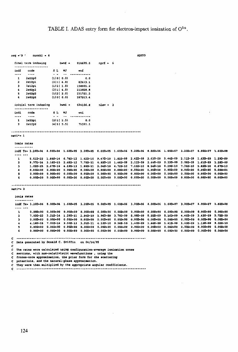
TABLE I. ADAS entry form for electron-impact ionization of 0 3 + .
ADF23
final
indf
1 2
3 4
5 6
term indexing
code
2s22p0
2sl2pl
2sl2pl 2s02p2 2s02p2 2s02p2
initial tern indexine
indi
1 2
meti*»
ionis
indf
1 2
3 4
S 6
code
2s22pl 2el2p2
1
rates
Te- 3.20D+04
5.S1D-22 9.770-24 1.020-25 O.OOD+00 O.OOD+00 0.00D+00
8.
1. 3 2. 0. 0. 0,
bwnf - 918625.3
S L WJ wnf
(1)0(
(3)11
(1)K (3)1( <1)2< (1)0(
0.0) 0.0
4.0) 82413.1
1.0) 158801.2 4.0) 213928.8 2.0) 231721.2 0.0) 287913.4
[ bvni • £24106.8
S L WJ vmi
(2)1( (4)1(
.00D+04
.860-14
.160-15
.670-16
.000+00
.000+00
. 00D+00
2.5) 0.0
5.5) 71331.1
1.60D+05 3.20D+05
6.780-12 1.420-10 2.480-12 7.75D-11 4.19D-13 1.B6D-11 0.0OD+0O 0.00D+00 0.000+00 0.00D+00 0.00D+00 0.00D+00
nprf -
nlev •
8.000+05
9.47D-10 6.82D-10 2.04D-10 O.OOD+00 0.0OD+O0 0.00D+00
6
2
1.
1. 1, 4. 0. 0. 0.
.60D+06
.810-09
.460-09
.72D-10
. 00O+00
. 00D+00
.000+00
3
2. 2 7.
0. 0
0,
.200+06
.420-09
.110-09
.15D-10
. 00D+00
.000+00
.00D+00
6
2. 2 8 0. 0
0.
.00D+06
.630-09
.44D-09
.540-10
.000+00
.00D+00
.OOD+00
1
2 2 8. 0. 0. 0
.60D+07
.440-09
.330-09
.290-10
.OOD+00
.000+00
. OOD+00
3
2. 2. 7.
0. 0. 0.
.20D+07
.110-09
.060-09
.380-10
.OOD+00
. 000+00
.OOD+00
8
1. 1
5. 0 0. 0.
.000+07
.620-09
.610-09
.820-10
.000+00
.000+00
.000+00
1.60D+08
1.290-09 1.28D-09 4.67D-1C
0.OOD+00 0.OOD+00 0.OOD+00
meti*- 2
ionia rateo
c c c c c c c c c
indf Te- 3.20D+04
1 O.OOD+00
2 7.03D-22 3 0.00O+00 4 4.18D-25 5 O.OOD+00 6 0.OOD+00
Data generated by
8.00O+04
O.OOD+00 3.21D-14 O.OOD+00 7.00O-16 O.OOD+00 0.00D+00
Donald C.
1.60D+05
0.OOD+00 1.29D-11
O.OOD+00 9.50D-13
0.00D+00 0.OOD+00
Griffin
3.20D+05 8.00D+05 1.60D+06
0.OOD+00 O.OOD+00 O.OOD+00
2.84D-10 1.96D-09 3.7BD-09 O.OOD+00 O.OOD+00 O.OOD+00 3.91D-11 4.10O-10 9.36D-10 O.OOD+00 0.OOD+00 O.OOD+00 O.OOD+00 O.OOD+00 O.OOD+00
on 04/14/95
3.20D+06
O.OOD+00
5.09D-09 0.00D+00 1.40D-09 0.00D+00 0.00D+00
The rates were calculated using configuration-average ionization cross sections, with non-relativistic wavefunctions , using the frozen-core approximation. potentials, and the natural
the prior form for the scattering -phase approximation.
They were then multiplied by the appropriate angular coefficients.
8.
0.
5. 0 1.
0. 0
.000+06
.OOD+00
.550-09
.00D+00
.660-09
.000+00
.000+00
1.
0. 5.
0. 1. 0.
0.
.60D+07
.000+00
.160-09
.00D+00
.61D-09
.00D+00
.000+00
3
0
4.
0 1. 0. 0
.20D+07
.OOD+00
.46D-09
.000+00
.43D-09
.000+00
.OOD+00
8.
0.
3. 0 1. 0. 0
.000+07
.000+00
.430-09
.000+00
.130-09
.OOD+00
.000+00
1.
0.
3. 0. 9. 0. 0.
.600+08
.00D+00
.720-09
.000+00
.02D-10
.000+00
.000+00
124
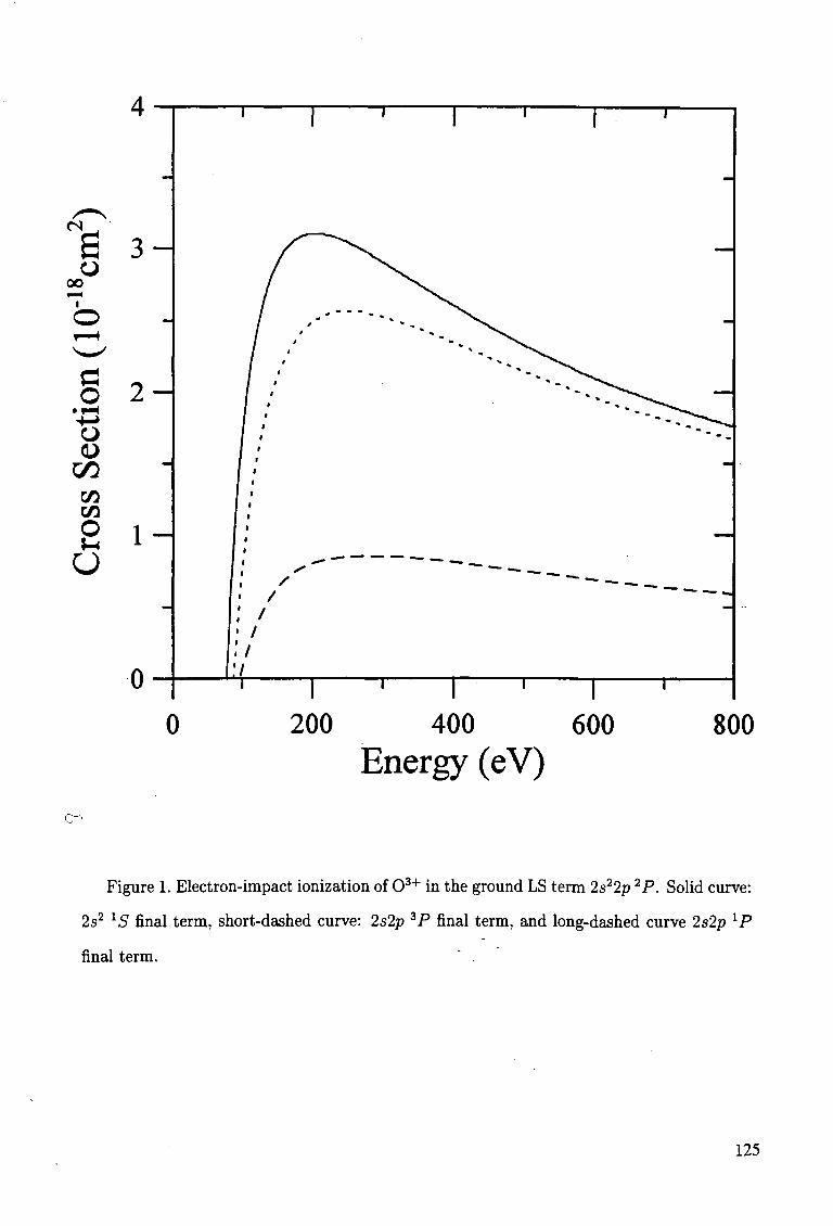
cs
00 O
o +^ o
00 CO
O
H-
3 -
2 -
1 -
n u
i i i i i | . i
P^ / /
f /" —-" • /
:/ . | . | • i | .
0 200 400 600 800 Energy (eV)
C '
Figure 1. Electron-impact ionization of 0 3 + in the ground LS term 2s22p 2P. Solid curve:
2s2 15r final term, short-dashed curve: 2s2p 3P final term, and long-dashed curve 2s2p lP
final term.
125
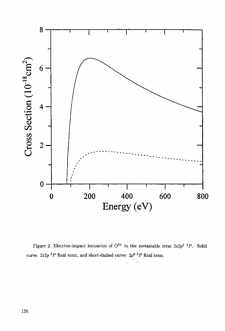
0 i ' r
200 400 600 Energy (eV)
800
Figure 2. Electron-impact ionization of 0 3 + in the metastable term 2s2p2 4P. Solid
curve: 2s2p 3P final term, and short-dashed curve: 2p2 3 P final term.
126
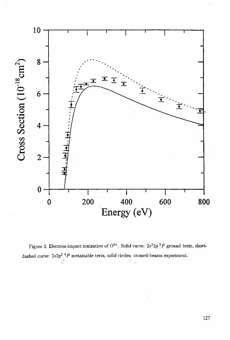
<N
00 o
o +-» o
00 CO CO
O
O
U
8 -
6 -
4 -
2 -
u
1 1 1 1 1
/ to
i / • / • / • / • / i / • /
11
• 1
T i l if f| if
1 ' 1 ' 1 '
1
±'~-
1
1
"±-
1
^
-
0 200 400 600 Energy (eV)
800
Figure 3. Electron-impact ionization of 03 + . Solid curve: 2s22p 2P ground term, short-
dashed curve: 2s2p2 4P metastable term, solid circles: crossed-beams experiment.
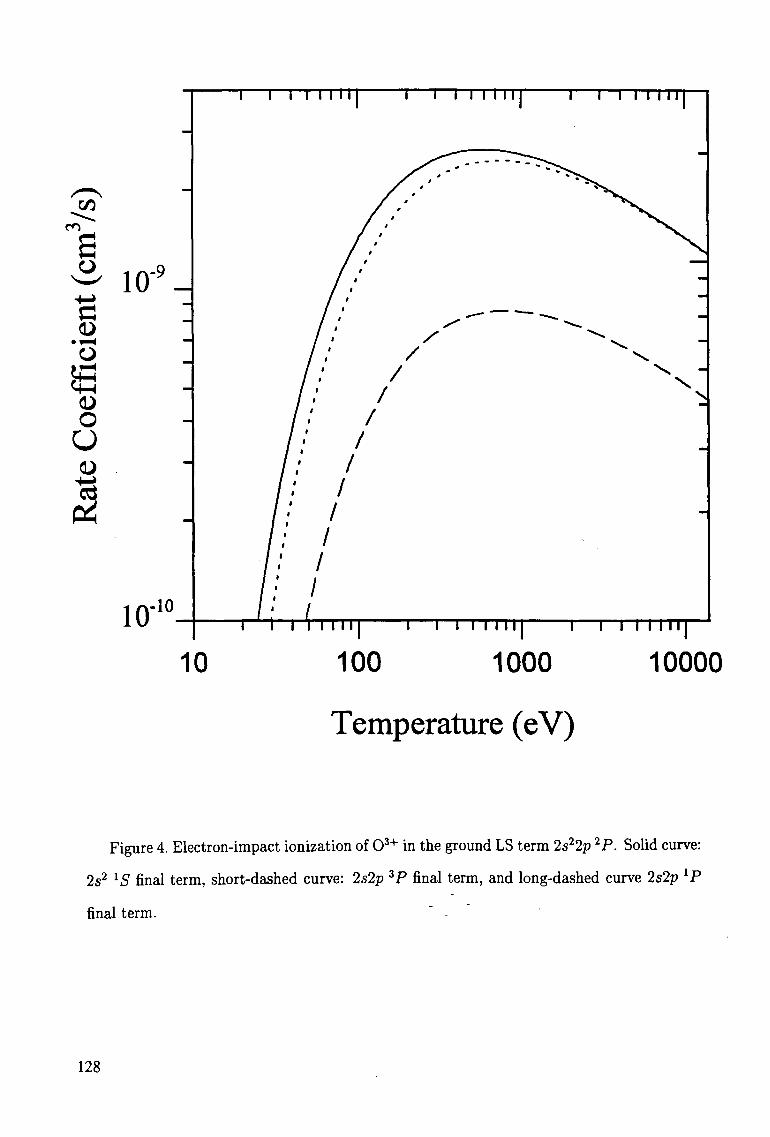
Cfl
m
O
o
o u
10 -9
10 10
i—i i 111ii
10
1—I I I 11II T 1 I I I I II
100 1000 I I I I l l l l
10000
Temperature (eV)
Figure 4. Electron-impact ionization of 0 3 + in the ground LS term 2s22p 2P. Solid curve:
2s2 XS final term, short-dashed curve: 2s2p 3P final term, and long-dashed curve 2s2p lP
final term. " -
128
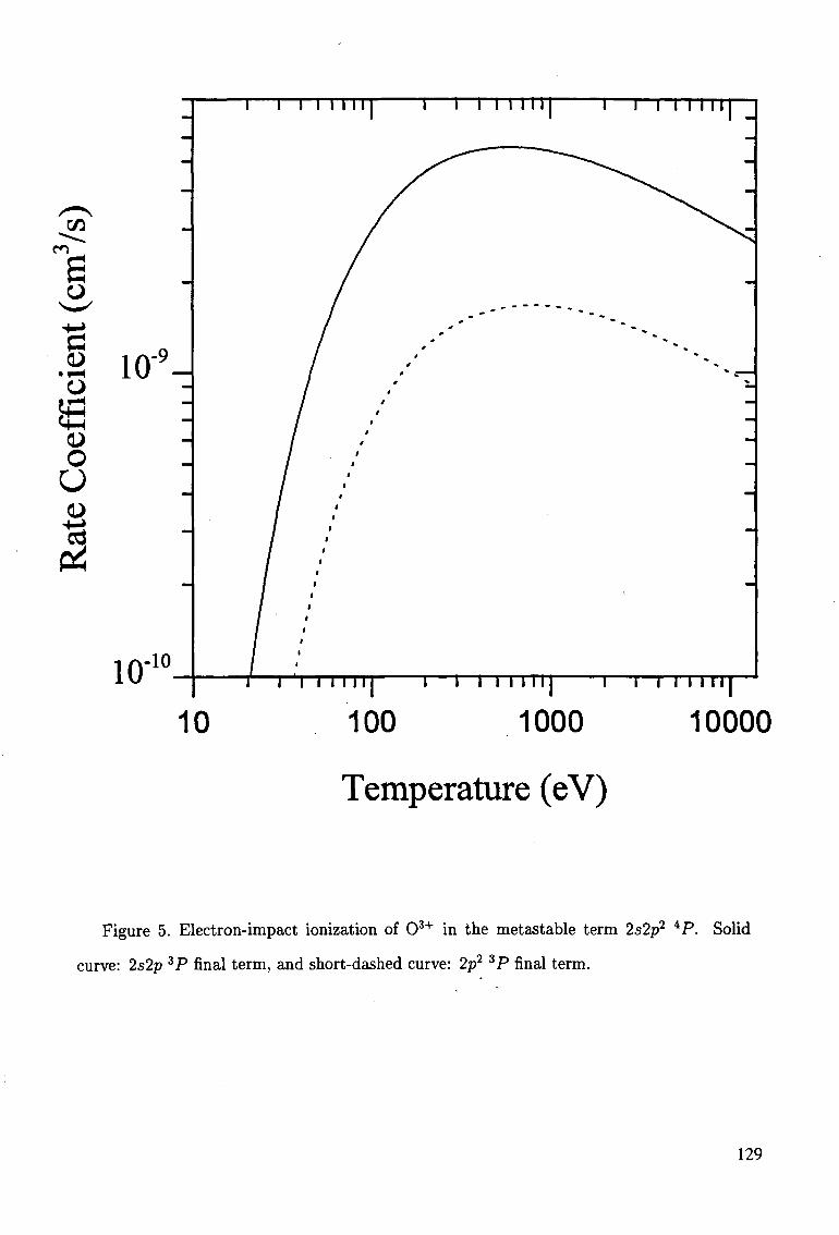
CA
CO
o
o
10 100 1000 mr
10000
Temperature (eV)
Figure 5. Electron-impact ionization of 0 3 + in the metastable term 2s2p2 iP. Solid
curve: 2s2p 3P final term, and short-dashed curve: 2p2 3P final term.
REFERENCES
[1] H. P. Summers, Atomic Data and Analysis Structure User Manual, JET-IR(94)06.
[2] A. Burgess and M. C. Chidichimo, Mon. Not. R. Astron. Soc. 203, 1269 (1983).
[3] M. S. Pindzola, D. C. Griffin, and C. Bottcher, in Atomic Processes in Electron-Ion and
Ion-Ion Collisions, ed. F. Brouillard, NATO ASI B 145, 75 (1986).
[4] D. H. Sampson, Phys. Rev. A 34, 986 (1986).
[5] M. S. Pindzola, D. C. Griffin, and C. Bottcher, Phys. Rev. A 34, 3668 (1986).
[6] D. C. Griffin, M. S. Pindzola, and C. Bottcher, Phys. Rev. A 36, 3642 (1987).
[7] R. D. Cowan, The Theory of Atomic Structure and Spectra, (U. Calif. Press, 1981).
[8] C. F. Fischer, Comput. Phys. Commun. 64, 369 (1991).
[9] P. G. Burke and K. A. Berrington, Atomic and Molecular Processes: an R-matrix Ap
proach, (IOP Press, 1993).
[10] D. G. Hummer, K. A. Berrington, W. Eissner, A. K. Pradhan, H. E. Saraph, and J. A.
Tully, Astron. Astrophys. 279, 298 (1993).
[11] F. Robicheaux, T. W. Gorczyca, M. S. Pindzola, and N. R. Badnell, Phys. Rev. A 52,
1319 (1995).
[12] T. W. Gorczyca, F. Robicheaux, M. S. Pindzola, D. C. Griffin, and N. R. Badnell, Phys.
Rev. A (in press).
[13] W. Eissner, M. Jones, and H. Nussbaumer, Comput. Phys. Commun. 8, 270 (1974).
[14] N. R. Badnell, J. Phys. B 19, 3827 (1986).
[15] D. H. Crandall, R. A. Phaneuf, and D. C. Gregory, Electron Impact Ionization of Mul-
ticharged Ions, ORNL/TM-7020 (1979).
[16] D. C. Griffin and M. S. Pindzola, J. Phys. B 21, 3253 (1988).
130
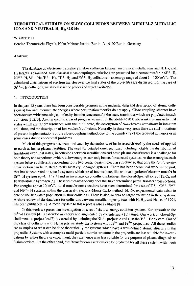
THEORETICAL STUDIES ON SLOW COLLISIONS BETWEEN MEDIUM-Z METALLIC IONS AND NEUTRAL H, H2, OR He
W. FRTTSCH
Bereich Theoretische Physik, Hahn-Meitner-Institut Berlin, D-14109 Berlin, Germany
Abstract
The database on electronic transitions in slow collisions between medium-Z metallic ions and H, H2, and He targets is examined. Semiclassical close-coupling calculations are presented for electron transfer in Si4+-H, Ni10+-H, Si4+-He, Ti4+-He, Ti4+-H2, and Fe8+-H2 collisions in an energy range of about 1 - 100 keV/u. The calculated distributions of electron transfer over the final states of the projectiles are discussed. For the case of Si 4 + - He collisions, we also assess the process of target excitation.
1. INTRODUCTION
In the past 15 years there has been considerable progress in the understanding and description of atomic collisions at low and intermediate energies where perturbation theories do not apply. Close-coupling schemes have been devised with increasing complexity, in order to account for the many transitions which are populated in such collisions [ 1,2, 3]. Among specific areas of progress we mention the ability to describe weak transitions to final states which are far off resonance with the initial state, the description of two-electron transitions in ion-atom collisions, and the description of ion-molecule collisions. Naturally, in these very areas there are still limitations of present implementations of the close-coupling method, due to the complexity of the required numerics or in some cases due to conceptual problems.
Much of this progress has been motivated by the curiosity of basic research and by the needs of applied research at fusion plasma facilities. The need for detailed cross sections, including notably the distribution of transitions over final states, in collisions between metallic ions and basic plasma constituents is a challenge for both theory and experiment which, at low energies, can only be met for selected systems. At those energies, each system behaves differently according to its two-center quasi-molecular structure so that only the total transfer cross section can be related directly from equi-charged systems. There has been theoretical work in the past, that has concentrated on specific systems which are of interest here, like an investigation of electron transfer in Si9+-H systems (q=4. ..14) [4] and an investigation of collisions between the closed-3p-shell ions of Ti, Cr, and Fe with atomic hydrogen [5]. These studies are the only ones that have determined partial transfer cross sections. For energies above 10 keV/u, total transfer cross sections have been determined for a set of Tiq+, Cr9"1", Fe9+
and Ni 9 + - H systems within the classical-trajectory-Monte-Carlo method [6]. No experimental data exists to date on the final-state population in slow collisions. There is also no data on target excitation in these systems. A short review of the data base for collisions between metallic impurity ions with H, H2, and He, as of 1991, has been published [7]. A recent update to this report is also available [8].
In this work we present an investigation on a set of six low-energy collision systems. Earlier work on the Si4+-H system [4] is extended in energy and augmented by considering a He target. Our work on closed-3p-shell metallic projectiles [5] is extended by including the Ni10+ projectile and also the Ti4+-He system. Out of the class of collisions with H2 targets we study the systems with Ti4+ and Fe8+ projectiles. All these studies are examples of what can be done theoretically for systems which have a well-defined atomic structure in the projectile. Systems with a complex multi-particle atomic structure in the projectile are less suitable for investigations by either theory or experiment, they are hence also less suitable for the purpose of plasma diagnosis at fusion devices. On the other hand, total transfer cross sections can be predicted for all these system, with much
131
less effort than is needed in this investigation.
In the following section we will give a short outline of the methods and calculational procedures used in this work. The results of the calculations will be presented and discussed in a third section. We conclude with a short summary and outlook.
2. THEORY
All calculations in this work have been performed within the semiclassical close-coupling model of atomic collisions [2] with travelling atomic orbitals adopted in the basis expansion of that method. Details of the method need not be repeated here. We adopt straight-line trajectories for the interatomic motion and plane-wave trans-lational factors in the basis sets. The basis set will be further specified, for each collision system, in the next section when the results are given and discussed. In general, choosing the basis at the projectile center involves these steps:
(i) As the potential for one electron in the field of the metallic ion, we take the general form used by Szy-dlik et al. [9] which has the correct behavior at very small and very large separations from the nucleus. The parameters for the screening function have also been taken from that work, except for the depth parameter of the potential, which has been adjusted for each ion in order to fit the energy of the highest bound s state. In the original work [9], the parameters have been chosen to optimize the total binding energy of all electrons.
(ii) For each value of the orbital angular momentum I, a set of hydrogenic orbitals <Pntmp> w ^ n ^ ree c n a r g e
parameters p,•, has been adopted. The parameters /?,• have been varied for an optimal representation of the atomic states in the potential. In the case of 5 states, usually two hydrogenic orbitals are needed for a satisfactory representation of a given atomic state. For the representation of / states, just one state is sufficient.
(iii) In the dynamical calculation, we keep all atomic states which result from the diagonalization procedure of the ionic potential within the basis, including the pseudostates at positive energies, but excluding the lowest bound state which is occupied initially.
In the calculations for He targets, both electrons are represented explicitly in what is termed the two-electron version of the close-coupling method [2]. The initial state, the ground state of helium, is expressed as an anti-symmetrized product state of type 1 sPx Is^. Besides this state, excited target states are represented by antisymmetrized product states of type nlPi 1 sPl where both hydrogenic states are positioned at the target center. Transfer states are expressed similarly except that in these the first product state is positioned at the projectile. By the choice of such basis states we assume that one of the electrons is always left in the ground state of the He+
ion after the collision. For reasons of efficiency, we have not used pseudostates for a representation of molecular binding effects or ionization.
The calculations for H2 targets have been performed within the simple model [10, 11] which has been developed recently. This model uses only one-electron coupling matrix elements but treats both electrons explicitly in the coupled equations. It hence combines the simplicity of a one-electron potential model with a cooperative transition mechanism which conserves the unitarity of the electron wavefunction. This model has been used successfully in a description [11 ] of single transfer in collisions between various multiply charged ions with H2
molecules.
132
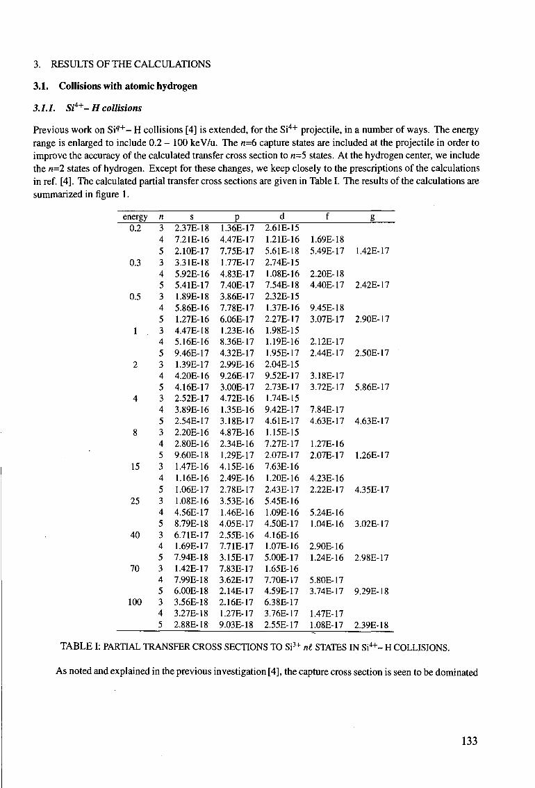
3. RESULTS OF THE CALCULATIONS
3.1. Collisions with atomic hydrogen
3.1.1. Si'4+- H collisions
Previous work on S i 9 + - H collisions [4] is extended, for the Si4+ projectile, in a number of ways. The energy range is enlarged to include 0.2 - 100 keV/u. The n=6 capture states are included at the projectile in order to improve the accuracy of the calculated transfer cross section to n=5 states. At the hydrogen center, we include the n=2 states of hydrogen. Except for these changes, we keep closely to the prescriptions of the calculations in ref. [4]. The calculated partial transfer cross sections are given in Table I. The results of the calculations are summarized in figure 1.
energy 0.2
0.3
0.5
1
2
4
8
15
25
40
70
100
n 3 4 5 3 4 5 3 4 5 3 4 5 3 4 5 3 4 5 3 4 5 3 4 5 3 4 5 3 4 5 3 4 5 3 4 5
s 2.37E-18 7.21E-16 2.10E-17 3.31E-18 5.92E-16 5.41E-17 1.89E-18 5.86E-16 1.27E-16 4.47E-18 5.16E-16 9.46E-17 1.39E-17 4.20E-16 4.16E-17 2.52E-17 3.89E-16 2.54E-17 2.20E-16 2.80E-16 9.60E-18 1.47E-16 1.16E-16 1.06E-17 1.08E-16 4.56E-17 8.79E-18 6.71E-17 1.69E-17 7.94E-18 1.42E-17 7.99E-18 6.00E-18 3.56E-18 3.27E-18 2.88E-18
P 1.36E-17 4.47E-17 7.75E-17 1.77E-17 4.83E-17 7.40E-17 3.86E-17 7.78E-17 6.06E-17 1.23E-16 8.36E-17 4.32E-17 2.99E-16 9.26E-17 3.00E-17 4.72E-16 1.35E-16 3.18E-17 4.87E-16 2.34E-16 1.29E-17 4.15E-16 2.49E-16 2.78E-17 3.53E-16 1.46E-16 4.05E-17 2.55E-16 7.71E-17 3.15E-17 7.83E-17 3.62E-17 2.14E-17 2.16E-17 1.27E-17 9.03E-18
d 2.61E-15 1.21E-16 5.61E-18 2.74E-15 1.08E-16 7.54E-18 2.32E-15 1.37E-16 2.27E-17 1.98E-15 1.19E-16 1.95E-17 2.04E-15 9.52E-17 2.73E-17 1.74E-15 9.42E-17 4.61E-17 1.15E-15 7.27E-17 2.07E-17 7.63E-16 1.20E-16 2.43E-17 5.45E-16 1.09E-16 4.50E-17 4.16E-16 1.07E-16 5.00E-17 1.65E-16 7.70E-17 4.59E-17 6.38E-17 3.76E-17 2.55E-17
f
1.69E-18 5.49E-17
2.20E-18 4.40E-17
9.45E-18 3.07E-17
2.12E-17 2.44E-17
3.18E-17 3.72E-17
7.84E-17 4.63E-17
1.27E-16 2.07E-17
4.23E-16 2.22E-17
5.24E-16 1.04E-16
2.90E-16 1.24E-16
5.80E-17 3.74E-17
1.47E-17 1.08E-17
g
1.42E-17
2.42E-17
2.90E-17
2.50E-17
5.86E-17
4.63E-17
1.26E-17
4.35E-17
3.02E-17
2.98E-17
9.29E-18
2.39E-18
TABLE I: PARTIAL TRANSFER CROSS SECTIONS TO Si3+ nl STATES IN Si4+- H COLLISIONS.
As noted and explained in the previous investigation [4], the capture cross section is seen to be dominated
133
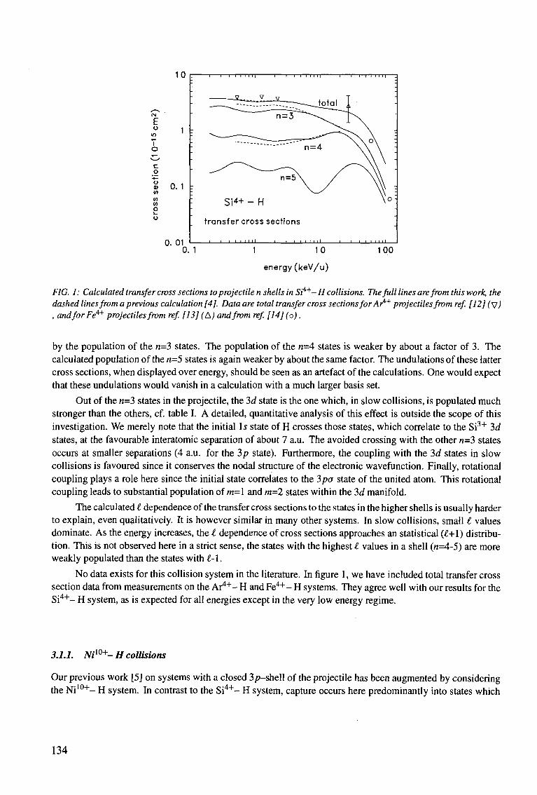
10
E ° 1
m T O
C o
1 0.1 w w o o
0. 01 0. 1 1 10 100
energy (keV/u)
FIG. 1: Calculated transfer cross sections to projectile n shells in Si4+-H collisions. The full lines are from this work, the dashed lines from a previous calculation [4]. Data are total transfer cross sections for Ar4+ projectiles from ref [12] fvJ , and for Fe4+ projectiles from ref. [13] (A) and from ref. [14] (o).
by the population of the n=3 states. The population of the n-A states is weaker by about a factor of 3. The calculated population of the n=5 states is again weaker by about the same factor. The undulations of these latter cross sections, when displayed over energy, should be seen as an artefact of the calculations. One would expect that these undulations would vanish in a calculation with a much larger basis set.
Out of the n=3 states in the projectile, the 3d state is the one which, in slow collisions, is populated much stronger than the others, cf. table I. A detailed, quantitative analysis of this effect is outside the scope of this investigation. We merely note that the initial Is state of H crosses those states, which correlate to the Si3+ 3d states, at the favourable interatomic separation of about 7 a.u. The avoided crossing with the other n=3 states occurs at smaller separations (4 a.u. for the 3p state). Furthermore, the coupling with the 3d states in slow collisions is favoured since it conserves the nodal structure of the electronic wavefunction. Finally, rotational coupling plays a role here since the initial state correlates to the 3pa state of the united atom. This rotational coupling leads to substantial population of m=l and m=2 states within the 3d manifold.
The calculated I dependence of the transfer cross sections to the states in the higher shells is usually harder to explain, even qualitatively. It is however similar in many other systems. In slow collisions, small t values dominate. As the energy increases, the t dependence of cross sections approaches an statistical (^+1) distribution. This is not observed here in a strict sense, the states with the highest I values in a shell (n=4-5) are more weakly populated than the states with l-\.
No data exists for this collision system in the literature. In figure 1, we have included total transfer cross section data from measurements on the Ar4"1"- H and Fe 4 + - H systems. They agree well with our results for the Si 4 + - H system, as is expected for all energies except in the very low energy regime.
3.1.1. Niw+- H collisions
Our previous work [5] on systems with a closed 3/?-shell of the projectile has been augmented by considering the Ni 1 0 +- H system. In contrast to the Si 4 + - H system, capture occurs here predominantly into states which
T 1 1—I I I I I | 1 1 1 I I I I I | I I 1 I I I I I |
transfer cross sections
J I 1 • • ' ' ' ' L _ 1 I • t > i i I 1 1 1 i i i i i I
134
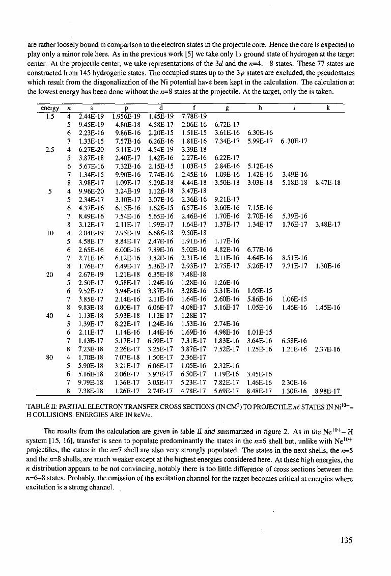
are rather loosely bound in comparison to the electron states in the projectile core. Hence the core is expected to play only a minor role here. As in the previous work [5] we take only Is ground state of hydrogen at the target center. At the projectile center, we take representations of the 3d and the n=4.. .8 states. These 77 states are constructed from 145 hydrogenic states. The occupied states up to the 3p states are excluded, the pseudostates which result from the diagonalization of the Ni potential have been kept in the calculation. The calculation at the lowest energy has been done without the n=8 states at the projectile. At the target, only the is taken.
energy 1.5
2.5
5
10
20
40
80
n 4 5 6 7 4 5 6 7 8 4 5 6 7 8 4 5 6 7 8 4 5 6 7 8 4 5 6 7 8 4 5 6 7 8
s 2.44E-19 9.45E-19 2.23E-16 1.33E-15 6.27E-20 3.87E-18 5.67E-16 1.34E-15 3.98E-17 9.96E-20 2.34E-17 4.37E-16 8.49E-16 3.12E-17 2.04E-19 4.58E-17 2.65E-16 2.71E-16 1.76E-17 2.67E-19 2.50E-17 9.52E-17 3.85E-17 9.83E-18 1.13E-18 1.39E-17 2.11E-17 1.13E-17 7.23E-18 1.70E-18 5.90E-18 5.16E-18 9.79E-18 7.38E-18
P 1.956E-19 4.80E-18 9.86E-16 7.57E-16 5.11E-19 2.40E-17 7.32E-16 9.90E-16 1.09E-17 3.24E-19 3.10E-17 6.15E-16 7.54E-16 2.11E-17 2.95E-19 8.84E-17 6.00E-16 6.12E-16 6.49E-17 1.21E-18 9.58E-17 3.94E-16 2.14E-16 6.00E-17 5.93E-18 8.22E-17 1.14E-16 5.17E-17 2.26E-17 7.07E-18 3.21E-17 2.06E-17 1.36E-17 1.26E-17
d 1.45E-19 4.58E-17 2.20E-15 6.26E-16 4.54E-19 1.42E-16 2.15E-15 7.74E-16 5.29E-18 1.12E-18 3.07E-16 1.62E-15 5.65E-16 1.99E-17 6.68E-18 2.47E-16 7.89E-16 3.82E-16 5.36E-17 6.35E-18 1.24E-16 3.87E-16 2.11E-16 6.06E-17 1.12E-17 1.24E-16 1.44E-16 6.59E-17 3.25E-17 1.50E-17 6.06E-17 3.97E-17 3.05E-17 2.74E-17
f 7.78E-19 2.06E-16 1.51E-15 1.81E-16 3.39E-18 2.27E-16 1.03E-15 2.45E-16 4.44E-18 3.47E-18 2.36E-16 6.57E-16 2.46E-16 1.64E-17 9.50E-18 1.91E-16 5.02E-16 2.31E-16 2.93E-17 7.48E-18 1.28E-16 3.28E-16 1.64E-16 4.08E-17 1.28E-17 1.53E-16 1.69E-16 7.31E-17 3.87E-17 2.36E-17 1.05E-16 6.50E-17 5.23E-17 4.78E-17
g
6.72E-17 3.61E-16 7.34E-17
6.22E-17 2.84E-16 1.09E-16 3.50E-18
9.21E-17 3.60E-16 1.70E-16 1.37E-17
1.17E-16 4.82E-16 2.11E-16 2.75E-17
1.26E-16 5.31E-16 2.60E-16 5.16E-17
2.74E-16 4.98E-16 1.83E-16 7.52E-17
2.32E-16 1.19E-16 7.82E-17 5.69E-17
h
6.30E-16 5.99E-17
5.12E-16 1.42E-16 3.03E-18
7.15E-16 2.70E-16 1.34E-17
6.77E-16 4.64E-16 5.26E-17
1.05E-15 5.86E-16 1.05E-16
1.01E-15 3.64E-16 1.25E-16
3.45E-16 1.46E-16 8.48E-17
i
6.30E-17
3.49E-16 5.18E-18
5.39E-16 1.76E-17
8.51E-16 7.71E-17
1.06E-15 1.46E-16
6.58E-16 1.21E-16
2.30E-16 1.30E-16
k
8.47E-18
3.48E-17
1.30E-16
1.45E-16
2.37E-16
8.98E-17
TABLE II: PARTIAL ELECTRON TRANSFER CROSS SECTIONS (IN CM2) TO PROJECTILE n£ STATES INNi l0+-H COLLISIONS. ENERGIES ARE IN keV/u.
The results from the calculation are given in table II and summarized in figure 2. As in the Ne 1 0 + - H system [15, 16], transfer is seen to populate predominantly the states in the n=6 shell but, unlike with Ne10+
projectiles, the states in the n=l shell are also very strongly populated. The states in the next shells, the n=5 and the «=8 shells, are much weaker except at the highest energies considered here. At these high energies, the n distribution appears to be not convincing, notably there is too little difference of cross sections between the n=6-8 states. Probably, the omission of the excitation channel for the target becomes critical at energies where excitation is a strong channel.
135
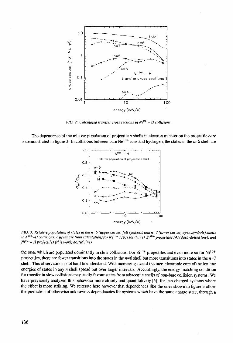
E o
i o
10
1 -
c q o a) <" 0.1 t 10 (0
o o
0.01
-I 1 1 1—I I I | • ' — T - -1 1 1—P-T-T
/ n = 8 Ni 1 0 + - H
transfer cross sections
n=4
• ' ' ' i ' " " ' ' _l I L_J ' ' ' '
10
energy (keV/u)
100
FIG. 2: Calculated transfer cross sections in Niw+- H collisions.
The dependence of the relative population of projectile n shells in electron transfer on the projectile core is demonstrated in figure 3. In collisions between bare Ne10+ ions and hydrogen, the states in the n=6 shell are
1.0
0.8
% 0.6
\ b 0.4
0.2
0.0
A ,0+ - H relative population of projectile n shell
n=7
10
energy(keV/u)
100
FIG. 3: Relative population of states in then=6 (upper curves, full symbols) and n=7 (lower curves, open symbols) shells inAw+-H collisions. Curves are from calculations for New+ [16] (solid line), 5/10+ projectiles [4] (dash-dotted line), and Nil0+- Hprojectiles (this work, dotted line).
the ones which are populated dominantly in slow collisions. For Si10+ projectiles and even more so for Ni10+
projectiles, there are fewer transitions into the states in the n=6 shell but more transitions into states in the n=l shell. This observation is not hard to understand. With increasing size of the inert electronic core of the ion, the energies of states in any n shell spread out over larger intervals. Accordingly, the energy matching condition for transfer in slow collisions may easily favour states from adjacent n shells of non-bare collision systems. We have previously analyzed this behaviour more closely and quantitatively [5], for less charged systems where the effect is more striking. We reiterate here however that dependences like the ones shown in figure 3 allow the prediction of otherwise unknown n dependencies for systems which have the same charge state, through a
136
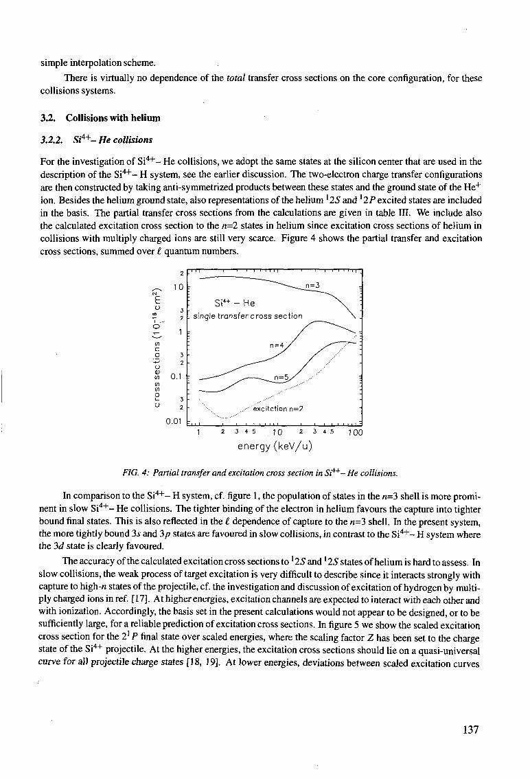
simple interpolation scheme.
There is virtually no dependence of the total transfer cross sections on the core configuration, for these collisions systems.
3.2. Collisions with helium
3.2.2. Si4+- He collisions
For the investigation of S i 4 + - He collisions, we adopt the same states at the silicon center that are used in the description of the Si 4 + - H system, see the earlier discussion. The two-electron charge transfer configurations are then constructed by taking anti-symmetrized products between these states and the ground state of the He+
ion. Besides the helium ground state, also representations of the helium 125 and ' 2P excited states are included in the basis. The partial transfer cross sections from the calculations are given in table in. We include also the calculated excitation cross section to the n=2 states in helium since excitation cross sections of helium in collisions with multiply charged ions are still very scarce. Figure 4 shows the partial transfer and excitation cross sections, summed over £ quantum numbers.
2
,-^ CM
fc o
to
o x —
* • — '
CO
c o
-*-> o CO
CO CO O i _
o
10
3 2
1
3 2
0.1
3 2
0.01
FIG. 4: Partial transfer and excitation cross section in Si4+- He collisions.
In comparison to the Si 4 +- H system, cf. figure 1, the population of states in the n=3 shell is more prominent in slow Si 4 + - He collisions. The tighter binding of the electron in helium favours the capture into tighter bound final states. This is also reflected in the £ dependence of capture to the n=3 shell. In the present system, the more tightly bound 3^ and 3p states are favoured in slow collisions, in contrast to the Si 4 + - H system where the 3d state is clearly favoured.
The accuracy of the calculated excitation cross sections to '25 and *2S states ofhelium is hard to assess. In slow collisions, the weak process of target excitation is very difficult to describe since it interacts strongly with capture to high-n states of the projectile, cf. the investigation and discussion of excitation of hydrogen by multiply charged ions in ref. [17]. At higher energies, excitation channels are expected to interact with each other and with ionization. Accordingly, the basis set in the present calculations would not appear to be designed, or to be sufficiently large, for a reliable prediction of excitation cross sections. In figure 5 we show the scaled excitation cross section for the 21 P final state over scaled energies, where the scaling factor Z has been set to the charge state of the Si4+ projectile. At the higher energies, the excitation cross sections should lie on a quasi-universal curve for all projectile charge states [18, 19]. At lower energies, deviations between scaled excitation curves
TTT 1 1 ' '—I I I I | 1 1 1 1—I I I I |
...••'excitation n=2
U-JJ I I 1 I I I I I I I I I I -
1 2 3 4 5 10 2 3 4 5 100
energy (keV/u)
137
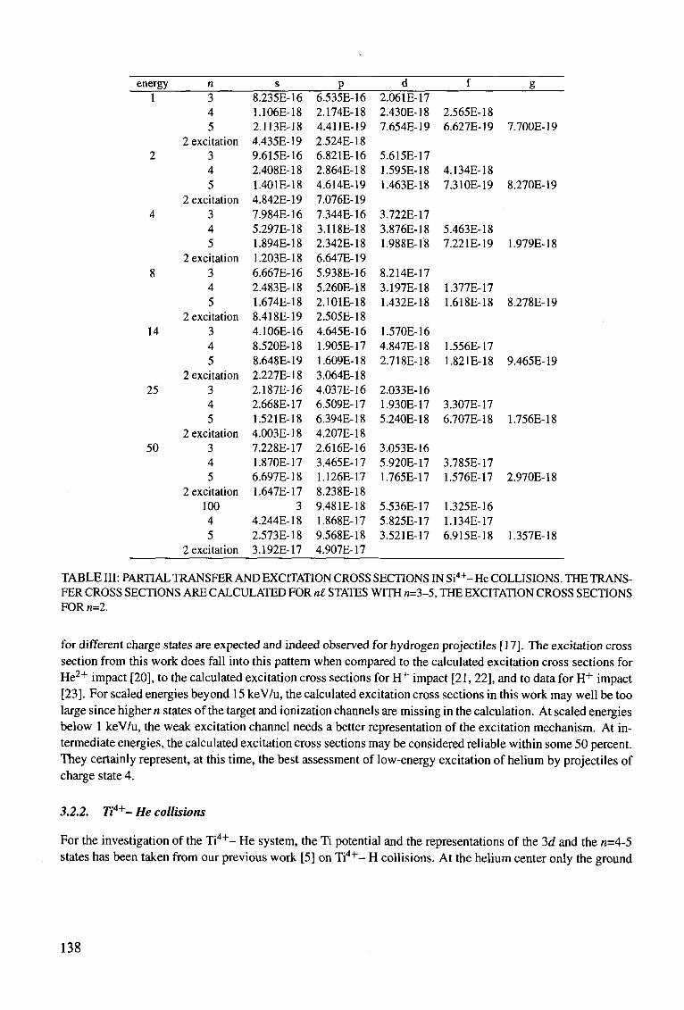
energy 1
2
4
8
14
25
50
3 4 5
2 excitation 3 4 5
2 excitation 3 4 5
2 excitation 3 4 5
2 excitation 3 4 5
2 excitation 3 4 5
2 excitation 3 4 5
2 excitation 100 4 5
2 excitation
8.235E-16 1.106E-18 2.113E-18 4.435E-19 9.615E-16 2.408E-18 1.401E-18 4.842E-19 7.984E-16 5.297E-18 1.894E-18 1.203E-18 6.667E-16 2.483E-18 1.674E-18 8.418E-19 4.106E-16 8.520E-18 8.648E-19 2.227E-18 2.187E-16 2.668E-17 1.521E-18 4.003E-18 7.228E-17 1.870E-17 6.697E-18 1.647E-17
3 4.244E-18 2.573E-18 3.192E-17
6.535E-16 2.174E-18 4.411E-19 2.524E-18 6.821E-16 2.864E-18 4.614E-19 7.076E-19 7.344E-16 3.118E-18 2.342E-18 6.647E-19 5.938E-16 5.260E-18 2.101E-18 2.505E-18 4.645E-16 1.905E-17 1.609E-18 3.064E-18 4.037E-16 6.509E-17 6.394E-18 4.207E-18 2.616E-16 3.465E-17 1.126E-17 8.238E-18 9.48 IE-18 1.868E-17 9.568E-18 4.907E-17
2.06 IE-17 2.430E-18 7.654E-19
5.615E-17 1.595E-18 1.463E-18
3.722E-17 3.876E-18 1.988E-18
8.214E-17 3.197E-18 1.432E-18
1.570E-16 4.847E-18 2.718E-18
2.033E-16 1.930E-17 5.240E-18
3.053E-16 5.920E-17 1.765E-17
5.536E-17 5.825E-17 3.521E-17
2.565E-18 6.627E-19
4.134E-18 7.310E-19
5.463E-18 7.221E-19
1.377E-17 1.618E-18
1.556E-17 1.821E-18
3.307E-17 6.707E-18
3.785E-17 1.576E-17
1.325E-16 1.134E-17 6.915E-18
7.700E-19
8.270E-19
1.979E-18
8.278E-19
9.465E-19
1.756E-18
2.970E-18
1.357E-18
TABLE III: PARTIAL TRANSFER AND EXCITATION CROSS SECTIONS IN Si4+- He COLLISIONS. THE TRANSFER CROSS SECTIONS ARE CALCULATED FOR nt STATES WITH n=3-5, THE EXCITATION CROSS SECTIONS FOR n=2.
for different charge states are expected and indeed observed for hydrogen projectiles [17]. The excitation cross section from this work does fall into this pattern when compared to the calculated excitation cross sections for He2+ impact [20], to the calculated excitation cross sections for H+ impact [21, 22], and to data for H+ impact [23]. For scaled energies beyond 15 keV/u, the calculated excitation cross sections in this work may well be too large since higher n states of the target and ionization channels are missing in the calculation. At scaled energies below 1 keV/u, the weak excitation channel needs a better representation of the excitation mechanism. At intermediate energies, the calculated excitation cross sections may be considered reliable within some 50 percent. They certainly represent, at this time, the best assessment of low-energy excitation of helium by projectiles of charge state 4.
3.2.2. Ti4+- He collisions
For the investigation of the Ti4 +- He system, the Ti potential and the representations of the 3d and the n=4-5 states has been taken from our previous work [5] on Ti 4 + - H collisions. At the helium center only the ground
138
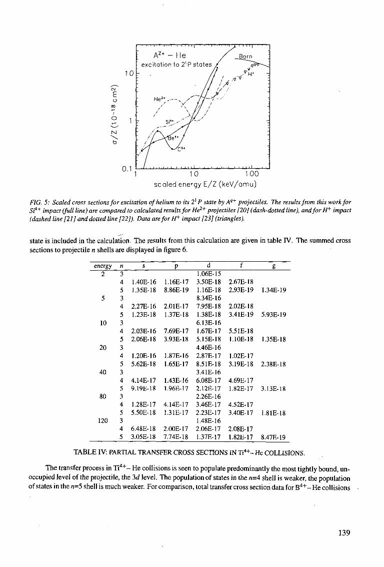
o CO
T o
N \ b
10
r 1
0.1
I I 111 l " l — I I I I I ' 111 I I I ] — 1 I I I I I
Az+ - He excitation to 2'P states
1 10 100 scaled energy E/Z (keV/amu)
FIG. 5: Scaled cross sections for excitation of helium to its 21 P state by Aq+ projectiles. The results from this work for Si4+ impact (full line) are compared to calculated results for He2+ projectiles [20] (dash-dotted line), and for H+ impact (dashed line [21] and dotted line [22]). Data are for H+ impact [23] (triangles).
state is included in the calculation. The results from this calculation are given in table IV. The summed cross sections to projectile n shells are displayed in figure 6.
energy 2
5
10
20
40
80
120
n 3 4 5 3 4 5 3 4 5 3 4 5 3 4 5 3 4 5 3 4 5
s
1.40E-16 1.35E-18
2.27E-16 1.23E-18
2.03E-16 2.06E-18
1.20E-16 5.62E-18
4.14E-17 9.19E-18
1.28E-17 5.50E-18
6.48E-18 3.05E-18
P
1.16E-17 8.86E-19
2.01E-17 1.37E-18
7.69E-17 3.93E-18
1.87E-16 1.65E-17
1.43E-16 1.96E-17
4.14E-17 1.31E-17
2.00E-17 7.74E-18
d 1.06E-15 3.50E-18 1.16E-18 8.34E-16 7.95E-18 1.38E-18 6.13E-16 1.67E-17 5.15E-18 4.46E-16 2.87E-17 8.51E-18 3.41E-16 6.08E-17 2.12E-17 2.26E-16 3.46E-17 2.23E-17 1.48E-16 2.06E-17 1.37E-17
f
2.67E-18 2.93E-19
2.02E-18 3.41E-19
5.51E-18 1.10E-18
1.02E-17 3.19E-18
4.69E-17 1.82E-17
4.52E-17 3.40E-17
2.08E-17 1.82E-17
g
1.34E-19
5.93E-19
1.35E-18
2.38E-18
3.13E-18
1.81E-18
8.47E-19
TABLE IV: PARTIAL TRANSFER CROSS SECTIONS IN Ti4+- He COLLISIONS.
The transfer process in Ti 4 + - He collisions is seen to populate predominantly the most tightly bound, unoccupied level of the projectile, the 3d level. The population of states in the n=A shell is weaker, the population of states in the n=5 shell is much weaker. For comparison, total transfer cross section data for B 4 + - He collisions
139
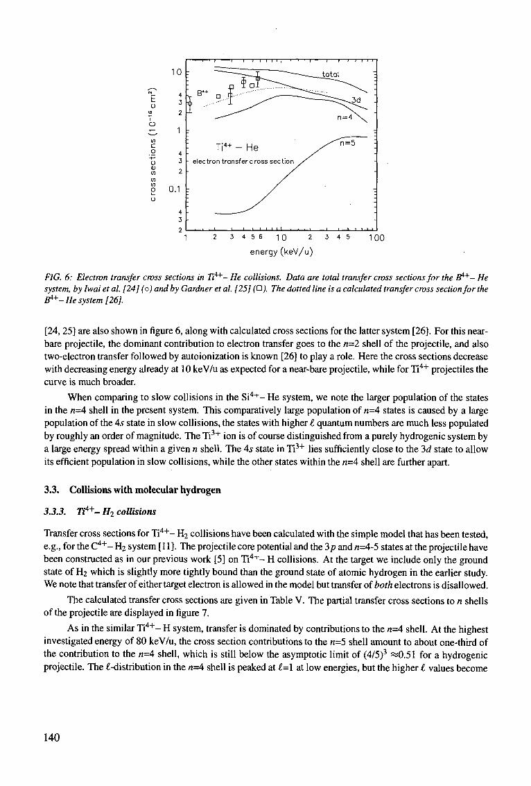
CM
E o
<o
T o
in c o
'-*-> u (U in in in O t_
o
energy (keV/u)
FIG. 6: Electron transfer cross sections in 7}"4+- He collisions. Data are total transfer cross sections for the B 4 + - He system, by Iwai et al. [24] (o) and by Gardner et al. [25] ( • J. The dotted line is a calculated transfer cross section for the B*+- He system [26].
[24,25] are also shown in figure 6, along with calculated cross sections for the latter system [26]. For this near-bare projectile, the dominant contribution to electron transfer goes to the n=2 shell of the projectile, and also two-electron transfer followed by autoionization is known [26] to play a role. Here the cross sections decrease with decreasing energy already at 10 keV/u as expected for a near-bare projectile, while for Ti4+ projectiles the curve is much broader.
When comparing to slow collisions in the Si 4 + - He system, we note the larger population of the states in the n=A shell in the present system. This comparatively large population of n=4 states is caused by a large population of the 4s state in slow collisions, the states with higher t quantum numbers are much less populated by roughly an order of magnitude. The Ti3+ ion is of course distinguished from a purely hydrogenic system by a large energy spread within a given n shell. The 4s state in Ti3+ lies sufficiently close to the 3d state to allow its efficient population in slow collisions, while the other states within the n=A shell are further apart.
3.3. Collisions with molecular hydrogen
3.3.3. Ti4+- Hi collisions
Transfer cross sections for Ti4 +- H2 collisions have been calculated with the simple model that has been tested, e.g., for the C 4 + - H2 system [11]. The projectile core potential and the 3p and /z=4-5 states at the projectile have been constructed as in our previous work [5] on Ti 4 + - H collisions. At the target we include only the ground state of H2 which is slightly more tightly bound than the ground state of atomic hydrogen in the earlier study. We note that transfer of either target electron is allowed in the model but transfer of both electrons is disallowed.
The calculated transfer cross sections are given in Table V. The partial transfer cross sections to n shells of the projectile are displayed in figure 7.
As in the similar Ti 4 + - H system, transfer is dominated by contributions to the «=4 shell. At the highest investigated energy of 80 keV/u, the cross section contributions to the n=5 shell amount to about one-third of the contribution to the n=4 shell, which is still below the asymptotic limit of (4/5)3 ^0.51 for a hydrogenic projectile. The £-distribution in the w=4 shell is peaked at l=\ at low energies, but the higher I values become
10 :
0.1
; 7 ^ ° ^ I B ..M•• •" '^ 1 ^^-^
\ Ti4+ - He - electron transfer cross sec
: y
1 — 1 1 1 1 1 1 1 1 \,i-
1 1 1 .
tion y
1 . . .
1 1 1 1 1 1
-___total
n = 4 \
^ ^ T = 5
1 1 1 1 1 1
-
-TT
TT
I IT
_
-
-
9 T i. * R '\ f\ O •* 4 R 1 nn
140
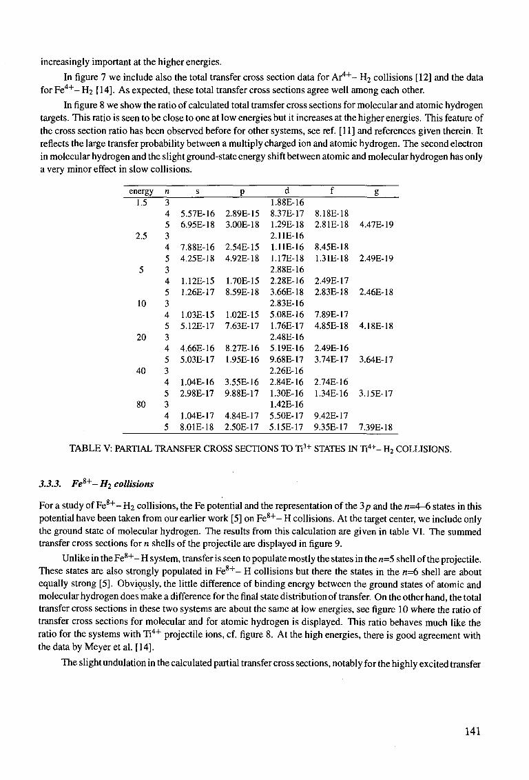
increasingly important at the higher energies.
In figure 7 we include also the total transfer cross section data for Ar4"*"- H2 collisions [12] and the data for Fe 4 + - H2 [14]. As expected, these total transfer cross sections agree well among each other.
In figure 8 we show the ratio of calculated total tramsfer cross sections for molecular and atomic hydrogen targets. This ratio is seen to be close to one at low energies but it increases at the higher energies. This feature of the cross section ratio has been observed before for other systems, see ref. [11] and references given therein. It reflects the large transfer probability between a multiply charged ion and atomic hydrogen. The second electron in molecular hydrogen and the slight ground-state energy shift between atomic and molecular hydrogen has only a very minor effect in slow collisions.
energy 1.5
2.5
5
10
20
40
80
n 3 4 5 3 4 5 3 4 5 3 4 5 3 4 5 3 4 5 3 4 5
s
5.57E-16 6.95E-18
7.88E-16 4.25E-18
1.12E-15 1.26E-17
1.03E-15 5.12E-17
4.66E-16 5.03E-17
1.04E-16 2.98E-17
1.04E-17 8.01E-18
P
2.89E-15 3.00E-18
2.54E-15 4.92E-18
1.70E-15 8.59E-18
1.02E-15 7.63E-17
8.27E-16 1.95E-16
3.55E-16 9.88E-17
4.84E-17 2.50E-17
d 1.88E-16 8.37E-17 1.29E-18 2.11E-16 1.11E-16 1.17E-18 2.88E-16 2.28E-16 3.66E-18 2.83E-16 5.08E-16 1.76E-17 2.48E-16 5.19E-16 9.68E-17 2.26E-16 2.84E-16 1.30E-16 1.42E-16 5.50E-17 5.15E-17
f
8.18E-18 2.81E-18
8.45E-18 1.31E-18
2.49E-17 2.83E-18
7.89E-17 4.85E-18
2.49E-16 3.74E-17
2.74E-16 1.34E-16
9.42E-17 9.35E-17
g
4.47E-19
2.49E-19
2.46E-18
4.18E-18
3.64E-17
3.15E-17
7.39E-18
TABLE V: PARTIAL TRANSFER CROSS SECTIONS TO Ti3+ STATES IN Ti4+- H2 COLLISIONS.
3.3.3. Fe*+- H2 collisions
For a study of Fe 8 + - H2 collisions, the Fe potential and the representation of the 2>p and the n=4-6 states in this potential have been taken from our earlier work [5] on Fe 8 + - H collisions. At the target center, we include only the ground state of molecular hydrogen. The results from this calculation are given in table VI. The summed transfer cross sections for n shells of the projectile are displayed in figure 9.
Unlike in the Fe 8 + - H system, transfer is seen to populate mostly the states in the n=5 shell of the projectile. These states are also strongly populated in Fe 8 + - H collisions but there the states in the n=6 shell are about equally strong [5]. Obviously, the little difference of binding energy between the ground states of atomic and molecular hydrogen does make a difference for the final state distribution of transfer. On the other hand, the total transfer cross sections in these two systems are about the same at low energies, see figure 10 where the ratio of transfer cross sections for molecular and for atomic hydrogen is displayed. This ratio behaves much like the ratio for the systems with Ti4+ projectile ions, cf. figure 8. At the high energies, there is good agreement with the data by Meyer et al. [14].
The slight undulation in the calculated partial transfer cross sections, notably for the highly excited transfer
141
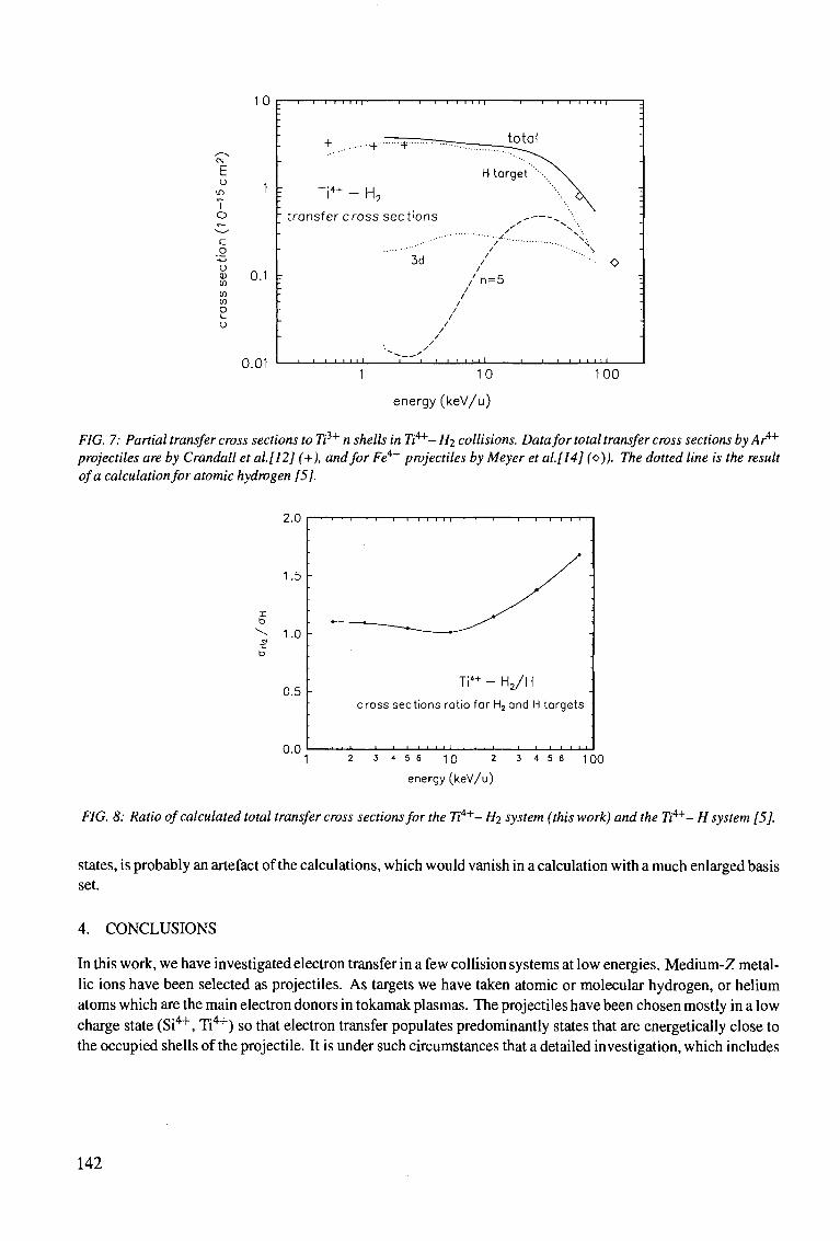
10
o m T o
c o
-4-»
o D V) V) en O
0.1
0.01
Ti 4 + - H2
transfer cross sections
3d
/ n = 5
_i i i i 111
10
energy (keV/u)
100
FIG. 7: Partial transfer cross sections to Tii+ n shells in 7i'4+- Hi collisions. Data for total transfer cross sections by ArA+
projectiles are by Crandall et al.[12] (+), and for Fe4+ projectiles by Meyer et al.[14] (o)). The dotted line is the result of a calculation for atomic hydrogen [5].
2.0
2 3 4 5 6 10 2 3 4 5 6 100
energy (keV/u)
FIG. 8: Ratio of calculated total transfer cross sections for the 7i'4+- Hi system (this work) and the 7i4 +- H system [5].
states, is probably an artefact of the calculations, which would vanish in a calculation with a much enlarged basis set.
4. CONCLUSIONS
In this work, we have investigated electron transfer in a few collision systems at low energies. Medium-Z metallic ions have been selected as projectiles. As targets we have taken atomic or molecular hydrogen, or helium atoms which are the main electron donors in tokamak plasmas. The projectiles have been chosen mostly in a low charge state (Si4+, Ti4+) so that electron transfer populates predominantly states that are energetically close to the occupied shells of the projectile. It is under such circumstances that a detailed investigation, which includes
142
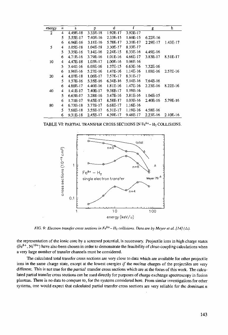
energy n 2
5
10
20
40
80
4 5 6 4 5 6 4 5 6 4 5 6 4 5 6 4 5 6
4.49E-18 5.55E-17 6.96E-16 1.05E-18 3.35E-16 4.7 IE-16 4.47E-18 3.44E-16 1.96E-16 4.07E-18 1.57E-16 4.88E-17 1.41E-17 6.63E-17 1.71E-17 6.73E-18 7.68E-18 9.31E-18
3.33E-18 7.40E-16 3.11E-16 1.04E-18 7.14E-16 3.79E-16 1.03E-17 6.03E-16 5.27E-16 1.06E-17 5.35E-16 4.40E-16 7.40E-17 3.28E-16 9.45E-17 3.77E-17 3.55E-17 2.45E-17
1.92E-17 2.33E-15 5.78E-17 3.30E-17 2.24E-15 1.01E-16 1.00E-16 1.37E-15 1.47E-16 7.57E-17 6.34E-16 1.81E-16 9.38E-17 3.47E-16 8.58E-17 6.68E-17 6.31E-17 4.39E-17
3.92E-17 1.60E-15 3.31E-17 8.33E-17 8.33E-16 4.66E-17 1.06E-16 6.63E-16 1.14E-16 8.31E-17 5.14E-16 1.47E-16 1.19E-16 3.81E-16 1.03E-16 1.16E-16 1.19E-16 9.48E-17
6.22E-16 2.29E-17
4.49E-16 3.83E-17
7.32E-16 1.03E-16
7.64E-16 2.23E-16
1.04E-15 2.40E-16
4.58E-16 2.23E-16
1.43E-17
8.51E-17
2.57E-16
8.22E-16
5.79E-16
2.10E-16
TABLE VI: PARTIAL TRANSFER CROSS SECTIONS IN Fe 8 + - H2 COLLISIONS.
E o
V) c o
'•4-1
o <D in m in O
0.1
Meyer 79
J i i i i i i i
10
energy (keV/u)
100
FIG. 9: Electron transfer cross sections in Fe 8 + - H^ collisions. Data are by Meyer et al. [14] (A).
the representation of the ionic core by a screened potential, is neccessary. Projectile ions in high charge states (Fe8+, Ni10+) have also been chosen in order to demonstrate the feasibility of close-coupling calculations when a very large number of transfer channels must be considered.
The calculated total transfer cross sections are very close to data which are available for other projectile ions in the same charge state, except at the lowest energies if the nuclear charges of the projectiles are very different. This is not true for the partial transfer cross sections which are at the focus of this work. The calculated partial transfer cross sections can be used directly for purposes of charge exchange spectroscopy in fusion plasmas. There is no data to compare to, for the systems considered here. From simlar investigations for other systems, one would expect that calculated partial transfer cross sections are very reliable for the dominant n
143
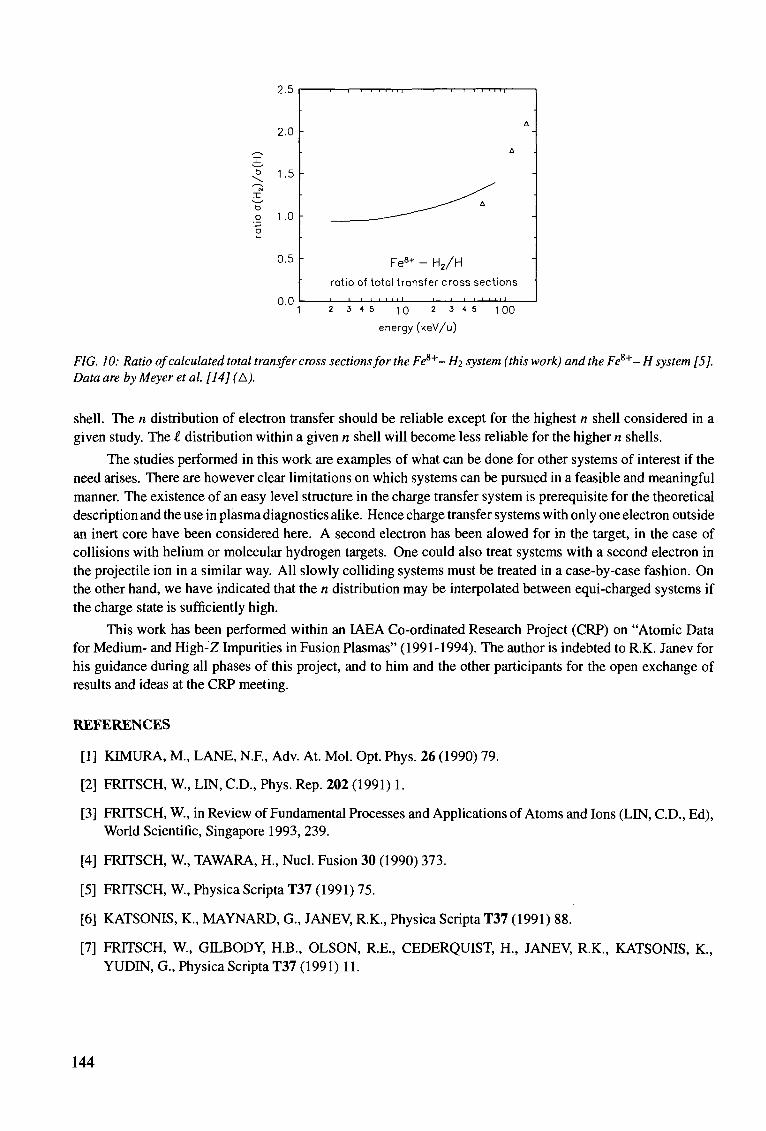
X
o
2.5
2.0
1.5
.0 -
0.5
0.0
Fe8+ - H2/H rotio of total transfer cross sections
2 3 4 5 10 2 3 4 5
energy (keV/u)
100
FIG. 10: Ratio of calculated total transfer cross sections for the Fe8+- Hi system (this work) and the Fc 8 + - H system [5]. Data are by Meyer et al. [14] (A).
shell. The n distribution of electron transfer should be reliable except for the highest n shell considered in a given study. The I distribution within a given n shell will become less reliable for the higher n shells.
The studies performed in this work are examples of what can be done for other systems of interest if the need arises. There are however clear limitations on which systems can be pursued in a feasible and meaningful manner. The existence of an easy level structure in the charge transfer system is prerequisite for the theoretical description and the use in plasma diagnostics alike. Hence charge transfer systems with only one electron outside an inert core have been considered here. A second electron has been alowed for in the target, in the case of collisions with helium or molecular hydrogen targets. One could also treat systems with a second electron in the projectile ion in a similar way. All slowly colliding systems must be treated in a case-by-case fashion. On the other hand, we have indicated that the n distribution may be interpolated between equi-charged systems if the charge state is sufficiently high.
This work has been performed within an IAEA Co-ordinated Research Project (CRP) on "Atomic Data for Medium- and High-Z Impurities in Fusion Plasmas" (1991-1994). The author is indebted to R.K. Janev for his guidance during all phases of this project, and to him and the other participants for the open exchange of results and ideas at the CRP meeting.
REFERENCES
[1] KIMURA, M., LANE, N.F., Adv. At. Mol. Opt. Phys. 26 (1990) 79.
[2] FRTTSCH, W., LIN, CD., Phys. Rep. 202 (1991) 1.
[3] FRITSCH, W., in Review of Fundamental Processes and Applications of Atoms and Ions (LIN, CD., Ed), World Scientific, Singapore 1993, 239.
[4] FRITSCH, W., TAWARA, H., Nucl. Fusion 30 (1990) 373.
[5] FRITSCH, W., Physica Scripta T37 (1991) 75.
[6] KATSONIS, K., MAYNARD, G., JANEV, R.K., Physica Scripta T37 (1991) 88.
[7] FRITSCH, W., GILBODY, H.B., OLSON, R.E., CEDERQUIST, H., JANEV, R.K., KATSONIS, K., YUDIN, G., Physica Scripta T37 (1991) 11.
144
[8] GJLBODY, H.B., BOTERO, J., CISNEROS, C, DEFRANCE, P., FRITSCH, W., HAVENER, C.C, JANEV, R.K., KATSONIS, K., SHEVELKO, V.R, TAWARA, H., IAEA Rep. INDC(NDS)-292 (1994) 5.
[9] SZYDLIK, P.P., GREEN, A.E.S., Phys. Rev. A 9 (1974) 1885.
[10] FRITSCH, W., Phys. Lett. A 166 (1992) 238.
[11] FRITSCH, W., Phys. Rev. A 46 (1992) 3910.
[12] CRANDALL, D.H., PHANEUF, R.A., MEYER, F.W., Phys. Rev. A 22 (1980) 379.
[13] GARDNER, L.D., BAYFIELD, J.E., KOCH, P.M., KIM, H.J., STELSON, PH., Phys. Rev. A 16 (1977) 1415.
[14] MEYER, F.W., PHANEUF, R.A., KIM, H.J., HVELPLUND, P., STELSON, PH., Phys. Rev. A 19 (1979) 515.
[15] BENDAHMAN, M., BLIMAN, S., DOUSSON, S., HITZ, D., GAYET, R., HANSSEN, J., HAREL, C, SALIN, A., J. Phys. (Paris) 46 (1985) 561.
[16] FRITSCH, W., unpublished.
[17] FRITSCH, W., Proc. Vlth Int. Conf. on the Physics of Highly Charged Ions, AIP Conf. Proc. 274 (RICHARD, P., STOCKLI, M., COCKE, C.L., LIN, CD., Eds.) American Institute of Physics 1993, 24.
[18] JANEV, R.K., PRESNYAKOV, L.P., J. Phys. B 13 (1980) 4233.
[19] FRITSCH, W., SCHARTNER, K.-H., Phys. Lett. A 126 (1987) 17.
[20] FRITSCH, W., J. Phys. B 27 (1994) 3461.
[21] FRITSCH, W., Phys. Lett. A 160 (1991) 64.
[22] SLIM, H.A., HECK, E.L., BRANSDEN, B.H., FLOWER, D.R., J. Phys. B 24 (1991) 1683.
[23] PARK, J.T., SCHOWENGERDT, F.D., Phys. Rev. 185 (1969) 152.
[24] IWAI, T, KANEKO, Y, KIMURA, M., KOBAYASHI, N., OHTANI, S., OKUNO, K., TAKAGI, S., TAWARA, H., TSUBURUCHI, S., Phys. Rev. A 26 (1982) 105.
[25] GARDNER, L.D., BAYFIELD, J.E., KOCH, P.M., SELLIN, I.A., PEGG, D.J., PETERSON, R.S., MAL-LORY, M.L., CRANDALL, D.H., Phys. Rev. A 20 (1979) 766.
[26] FRITSCH, W., LIN, CD., Phys. Rev. A 45 (1992) 6411.
145

EXCITATION OF HELIUM BY PROTONS AND MULTIPLY CHARGED IONS: ANALYTIC FORM OF SCALED CROSS SECTIONS
R.K. Janev International Atomic Energy Agency, P.O. Box 100
A-1400 Vienna, Austria
ABSTRACT. The cross sections for excitation of n*L (L=S,P,D) states of He from its ground state in collisions with protons and multiply charged ions are presented in scaled and closed analytic form. The scaling includes all the relevant dynamic and atomic parameters (collision energy, transition energy, ionic charge) and is based on the existing theoretical models for the process at low and high energies. A few parameters in the analytic scaled excitation cross sections are determined from the experimental data. The scaled cross sections for transitions from excited states are also briefly discussed.
1. INTRODUCTION
Excitation of helium atoms by protons and multiply charged ions is an important process affecting the attenuation dynamics of neutral helium beams injected into fusion plasmas for diagnostic or heating purposes [1,2]. At beam energies above ~ 50 keV/amu, the collision times of excited helium atoms in plasmas having densities of ~ 1014 cm"3 can become comparable to (or greater than) their radiative decay times. Under such conditions (radiative-collisional regime), the multistep process (such as excitation followed by ionization or charge exchange) may significantly reduce the beam penetration into plasmas. First demonstrated on the enhancement of hydrogen neutral beam stopping into fusion-grade plasmas [3], this effect has been recently qualitatively shown also for energetic helium beams [4]. The main reason for the beam stopping enhancement effect is the increase of electron loss (combined ionization and electron capture) cross section of excited atoms in their collisions with plasma protons and impurity ions with respect to that for ground state beam atoms. For beam energies in the keV region and above, the collisions of beam atoms with plasma protons and impurity ions are the dominant contributors to the beam excitation. In the further redistribution of beam excitation among the excited atomic levels of beam atoms, the electron-impact induced transitions may also play a very important role [3,4].
The excitation collisions of He atoms with protons and other multiply charged ions have been subject of numerous experimental and theoretical studies in the past. They have been reviewed recently by Fritsch [5], de Heer et al [6] and Anton et al [7]. The experimental excitation data by proton impact span the energy range from a few keV to about 1 MeV, and include the 1*S -> n*L transitions with n=2-5 and L=S,P,D [5,6]. The data for helium excitation by multiply charged ions cover the energy range ~ 10q-200q keV/amu, where q is the ionic charge with values between q=2 and q=45 for different species, and include the transitions 1*S -> n*L, with n=2-5 and L=S,P,D [7].
The use of this data information in various plasma (and other) applications would be much facilitated if it is rendered into a compact analytic form. The prediction of the q-scaling of excitation cross sections for atoms colliding with multiply charged ions [8] has proved to be a useful step in that direction (see e.g. [7]). It has been recently shown [9] that the excitation cross sections can also be scaled with respect to the transition energy coln (or in n) in a wide energy range.
In the present paper we shall present simple analytic expressions for the scaled (in both q and
147
coln) excitation cross sections of He atoms colliding with protons and multiply charged ions valid from the adiabatic to high energy region. The physical basis for the cross section scalings will be outlined in the next section. In Section 3 we present the scaled cross sections for proton impact, while in Section 4 we present the scaling results for excitation by multicharged ion impact. In Section 5 we give some concluding remarks.
Atomic units (e=me=fi =1) will be used throughout unless otherwise explicitly stated.
2. THEORETICAL BASIS FOR THE CROSS SECTION SCALING
We shall briefly discuss the scaling relationships for excitation cross sections following Ref. [9]. The discussion will be given for the general case of multiply charged ions (q > 2), and at the end of the section we shall consider the specifics of the proton impact case (q=l).
The general form of the cross section scaling relationship for excitation can be written as
S=sr(g, w l n ,£ )o(£) =F{E) , E^h{E,q,^lnl\\) C1)
where a(E) is the unsealed cross section as function of collision energy E, q and o l n are the ion charge and transition energy, respectively and £ and r\ collectively designate other parameters of the process and collisional system (e.g. the oscillator strength for optically allowed transitions, effective charge of the atomic ion core, etc). The function g and h in Eq. (1) specify the cross section and energy scaling and provide the basis for the scaling relationship o = F(E). a and E are called reduced (or scaled) cross section and reduced (scaled) enery, respectively.
On the basis of "advanced" adiabatic (or "hidden crossings") theory of ion-atom collisions [10] and the dipole close-coupling approximation (DCC) for excitation at intermediate and high energies [8], it has been shown [9] that the scaled energy function h is the same for both dipole-allowed and dipole-forbidden transitions and has the form
Win
The cross section scaling function g, however, differs for dipole-allowed and dipole-forbidden transitions. For dipole-allowed transitions, the function g, derived from the hidden crossings theory and DCC approximation, is of the form [9]
a = -^k. (3) ^ Q f,n
where fln is the oscillator strength for the 1*S -> n*P transition. For dipole-forbidden transitions, the form of the g-function can be derived from the hidden crossings theory and classical impulse approximation and has the form [9]
148
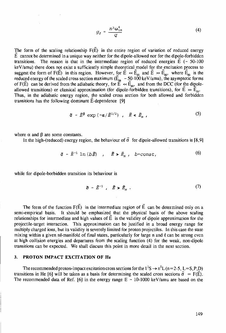
gf = n " ^ (4)
The form of the scaling relationship F(E) in the entire region of variation of reduced energy E cannot be determined in a unique way neither for the dipole-allowed nor for the dipole-forbidden transitions. The reason is that in the intermediate region of reduced energies E (~ 50-100 keV/amu) there does not exist a sufficiently simple theoretical jnodel for the^excitation process to suggest the form of F(E) in this region. However, for E « Em and E » Em, where Em is the reduced energy of the scaled cross section maximum (Em ~ 50-100 keV/amu), the asymptotic forms of F(E) can be derived from the adiabatic theory, for E « Em, and from the DCC (for the dirjole-allowed transitions) or classical approximation (for dipole-forbidden transitions), for E » Em. Thus, in the adiabatic energy region, the scaled cross section for both allowed and forbidden transitions has the following dominant E-dependence [9]
a ~ E* exp (-a/E1/2) , E < Em , (5)
where a and p are some constants. In the high-(reduced) energy region, the behaviour of a for dipole-allowed transitions is [8,9]
5 ~ E'1 In {bE) , E > Em , b=const, (6)
while for dipole-borbidden transition its behaviour is
5 ~ E'1 , E > Em . (7)
The form of the function F(E) in the intermediate region of E can be determined only on a semi-empirical basis. It should be emphasized^ that the physical basis of the above scaling relationships for intermediate and high values of E is the validity of dipole approximation for the projectile-target interaction. This approximation can be justified in a broad energy range for multiply charged ions, but its validity is severely limited for proton projectiles. In this case the state mixing within a given nC-manifold of final states, particularly for large n and i can be strong even at high collision energies and departures from the scaling function (4) for the weak, non-dipole transitions can be expected. We shall discuss this point in more detail in the next section.
3. PROTON IMPACT EXCITATION OF He
The recommended proton-impact excitation cross sections for the 1!S ->n1L(n=2-5, L=S,P,D) transitions in He [6] will be taken as a basis for determining the scaled cross sections a = F(E). The recommended data of Ref. [6] in the energy range E ~ 10-1000 keV/amu are based on the
149
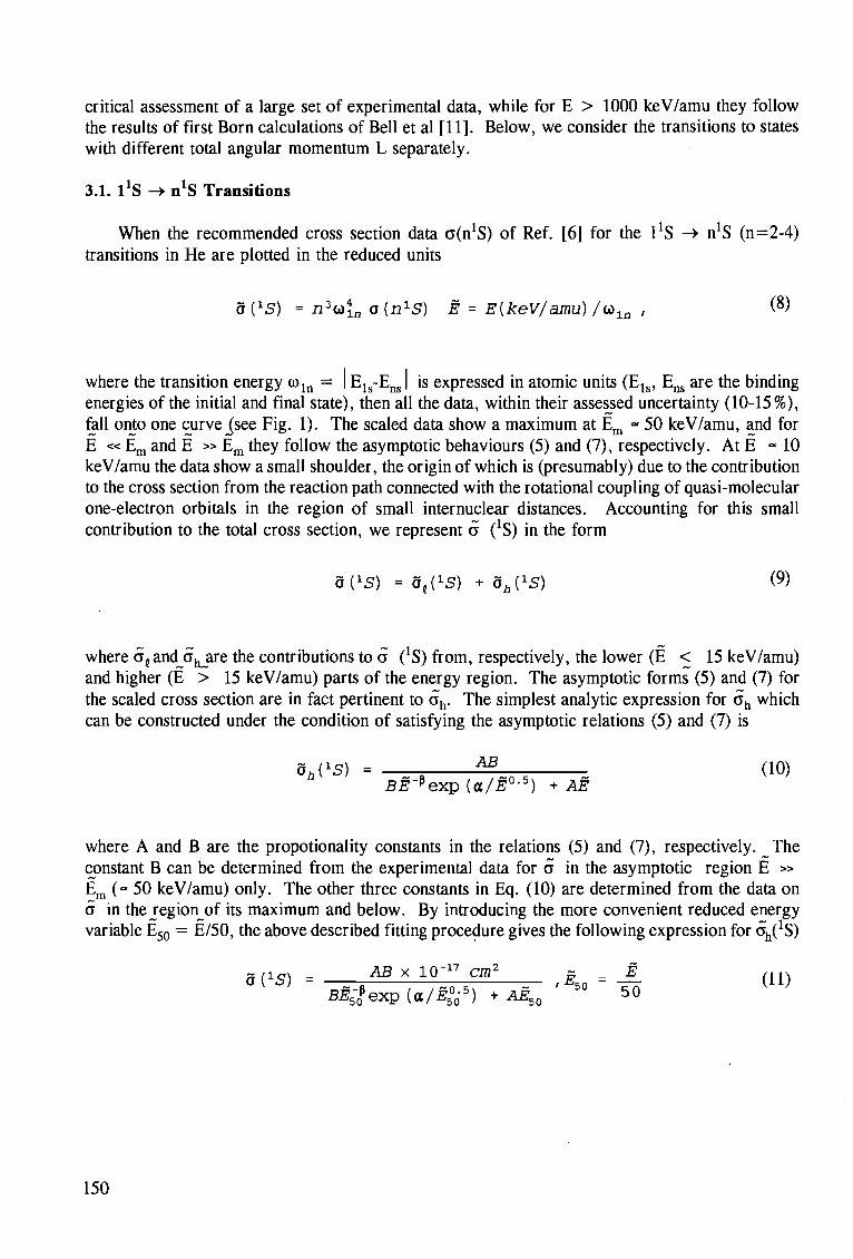
critical assessment of a large set of experimental data, while for E > 1000 keV/amu they follow the results of first Born calculations of Bell et al [11]. Below, we consider the transitions to states with different total angular momentum L separately.
3.1. 1*S -> n*S Transitions
When the recommended cross section data a(n!S) of Ref. [6] for the 1*S -» n*S (n=2-4) transitions in He are plotted in the reduced units
o(15) = n3(x>{n o(n1S) E = E{keV/amu) /co ln , (8)
where the transition energy o l n = | E^-E^ | is expressed in atomic units (Els, Em are the binding energies of the initial and final state), then all the data, within their assessed uncertainty (10-15%), fell onto one curve jsee Fig. 1). The scaled data show a maximum at Em « 50 keV/amu, and for E « Em and E » Em they follow the asymptotic behaviours (5) and (7), respectively. At E "10 keV/amu the data show a small shoulder, the origin of which is (presumably) due to the contribution to the cross section from the reaction path connected with the rotational coupling of quasi-molecular one-electron orbitals in the region of small internuclear distances. Accounting for this small contribution to the total cross section, we represent a (lS) in the form
a r^ = d^s) + d^s) (9)
where o andjj^are the contributions to a (*S) from, respectively, the lower (E < 15 keV/amu) and higher (E > 15 keV/amu) parts of the energy region. The asymptotic forms (5) and (7) for the scaled cross section are in fact pertinent to ah. The simplest analytic expression for ch which can be constructed under the condition of satisfying the asymptotic relations (5) and (7) is
ah(1S) = ^ (10)
BE"pexp {a/E°-B) + AE
where A and B are the propotionality constants in the relations (5) and (7), respectively. _The constant B can be determined from the experimental data for a in the asymptotic region E » Em (" 50 keV/amu) only. The other three constants in Eq. (10) are determined from the data on a in the jegionjrf its maximum and below. By introducing the more convenient reduced energy variable E50 = E/50, the above described fitting procedure gives the following expression for 6^(!S)
d ( l g ) = AB* 10-" cm> ,E50 = 4 (ID BE~? e x p (a/i?5
00-5) + AE50 50
150
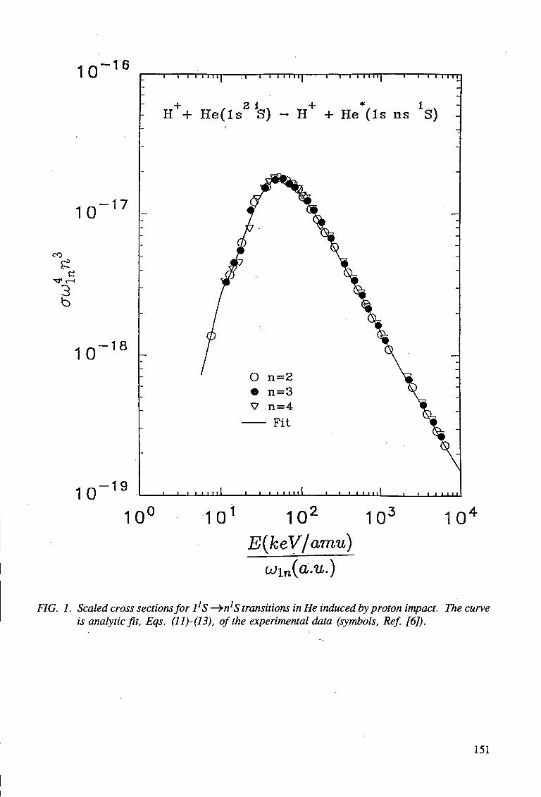
10 - 1 6
10 17
CO
£ -*}<<-< 3
b
10 18
10 - 1 9
T 1—I I I I M l "T 1 — I I I I I I I 1 1—I I I I I I I 1 1 — I I I I I I
H++ He( ls 2 S) - H+ + He*(ls ns *S)
o •
V
n=2 n=3 n=4
- Fit
J I I I I I I I I I • I I I I I I I I 1 I I I I I I I I I I I I 111
10 o 1 0 1 10z
E(keV/amu) ojin(a.u.)
10 10
FIG. 1. Scaled cross sections for 1]S -^n]S transitions in He induced by proton impact. The curve is analytic fit, Eqs. (11)-(13), of the experimental data (symbols, Refi [6]).
151
A = 5 . 7 8 , B = 3 . 0 , a = 0 . 2 5 , p = 1 . 7 5 .
In determining the form of o^S) we shall be guided by practical fit motivations only. Choosing, for convenience, a new reduced energy E10 = E/10 we represent a^S) in the form
a^S) = ( A + A V 1 , (12)
with a^ and 8^ designating the asymptotics of a{ for E10 « 1 and E10 » 1, respectively. Using power representations for a^ (E10) and of' (E10), we obtain the following fits
0^ = 8 ^ x 10"19 cm2, 5|= 20E~$ x 10"19cm2 , E1Q = — . (13)
The full curve in Fig. 1 represents the results of the analytic fit (9), (11)-(13) of the scaled cross section. The fit represents the experimental data with an r.m.s. deviation of ~ 5 %, i.e. well within their experimental uncertainty.
3.2. 1*S -> n*P Transitions
The recommended experimental cross section data of Ref. [6] for proton-impact 1TS -> nxP (n=2-5) transitions in He, scaled according to the relations
a(ip) = - ^ o(nip) , E = B(kev/amu) (14)
are given in Fig. 2. As before, the transition energy coln is expressed in atomic units, and fln is the oscillator strength of the transition. All the scaled cross section data follow one curve which has a broad maximum around E = Em ~ 150 keV/amu, and a shoulder in the region around E ~ 20 keV/amu. The low-energy shoulder on the scaled curve clearly indicates the existence of a low-energy excitation mechanism which is the same for all n-states. This mechanism operates between the ground and first excited molecular state of the H+-He system in the region of small internuclear distances during the incoming part of the collision trajectory and its effect is furter transmitted to all the np:P states during the outgoing part of the trajectory through a series of radial couplings. This explains the fixed energy position of the low-energy cross section shoulder and the scalability of its contribution to the total cross section.
Having in mind the structure of the scaled cross section in Fig. 2, we represent a(1P) in the form
152
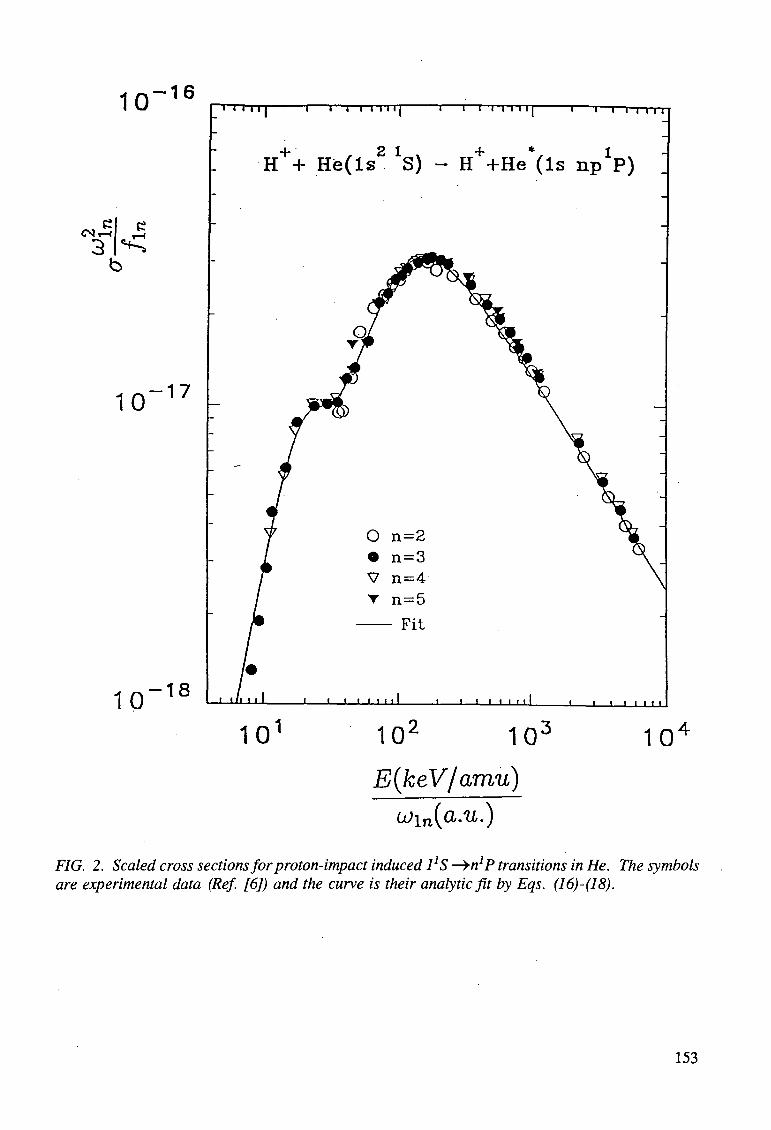
10 - 1 6
C4
~» i i | 1 1—i i i 1 1 1 | 1 1—r i i i 1 1 | 1 1—i i i i i
H++ H e ( l s 2 *S) - H++He*(ls npXP)
10 - 1 7
10 - 1 8 i in 111 1—i—i i 11111 i i i i 11111 i
10 10 10
E(keV/amu)
u)in(a.u.)
i 1 1 1 1 1
10
FIG. 2. Scaled cross sections for proton-impact induced 1JS —»n7P transitions in He. The symbols are experimental data (Ref. [6]) and the curve is their analytic fit by Eqs. (16)-(18).
153
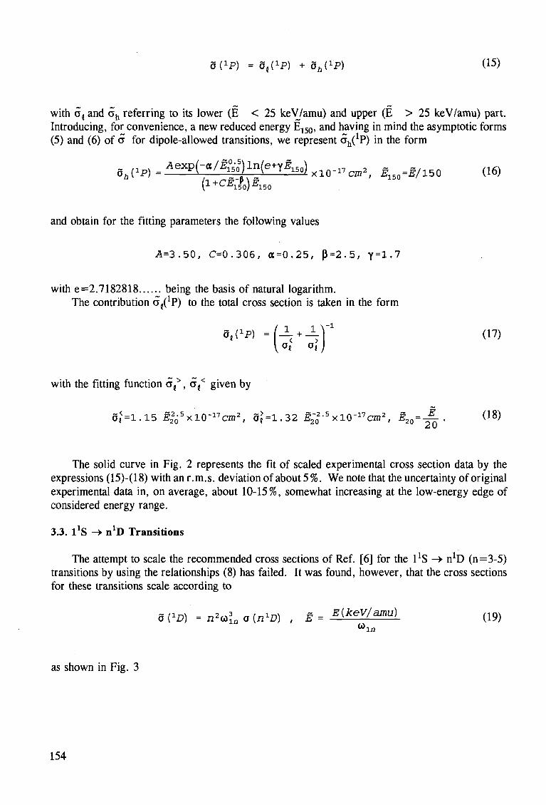
a^P) = a^P) + 5A(1P) (15)
with a{ and ah referring to its lower (E < 25 keV/amu) and upper (E > 25 keV/amu) part. Introducing, for convenience, a new reduced energy E150, and having in mind the asymptotic forms (5) and (6) of a for dipole-allowed transitions, we represent o^P) in the form
d a ( i P ) = A e x p ( - « / ^ ) l n ( e n ^ 1 5 , ) x l 0 - 1 7 c m 2 / E150=E/150 (16) (l + CE-iQ)E150
and obtain for the fitting parameters the following values
A=3.50, C=0.306, <X=0.25, P=2.5, y=l ,7
with e=2.7182818 being the basis of natural logarithm. The contribution c^P) to the total cross section is taken in the form
(17)
with the fitting function af, of given by
Oj=1.15 £220-
5xlQ-17C2n2, S{=1.32 f2_
02-5xl0-17cm2, E2Q = -~ . (18)
The solid curve in Fig. 2 represents the fit of scaled experimental cross section data by the expressions (15)-(18) with an r.m.s. deviation of about 5 %. We note that the uncertainty of original experimental data in, on average, about 10-15%, somewhat increasing at the low-energy edge of considered energy range.
3.3. 1*S -> n*D Transitions
The attempt to scale the recommended cross sections of Ref. [6] for the 1*S -» n!D (n=3-5) transitions by using the relationships (8) has failed. It was found, however, that the cross sections for these transitions scale according to
a ( ^ ) = n*o\na{^D) , E = ^xev/amu) ( 1 9 )
as shown in Fig. 3
154
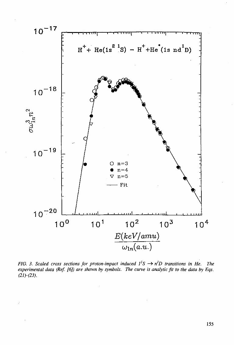
10 - 1 7
10 - 1 8
(N
CO:
3 b
10 - 1 9
10 - 2 0
i i i i 11 HI 1—i i i i m i 1—i i i i m i 1—i- i i i i i
H++' He( ls 2 lS) - H++He*(ls nc^D)
« i 1 1 1 H I i i i 1 1 1 H I i i i 1 1 ' • • ' i i i 1 1 1 I I
10 o 10 10 10 10 E(keV/amu)
u>in{a.u.)
FIG. 3. Scaled cross sections for proton-impact induced 1]S —> n*D transitions in He. The experimental data (Ref. [6]) are shown by symbols. The curve is analytic fit to the data by Eqs. (21H23).
155
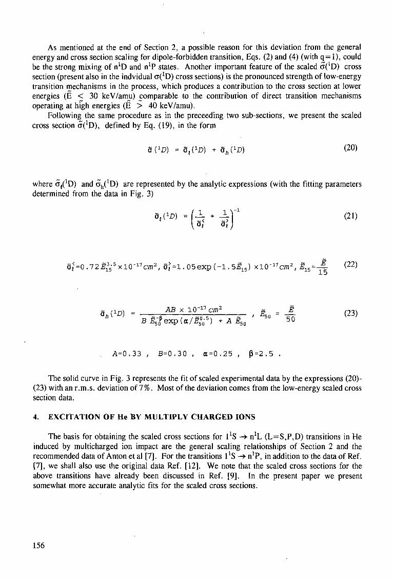
As mentioned at the end of Section 2, a possible reason for this deviation from the general energy and cross section scaling for dipole-forbidden transition, Eqs. (2) and (4) (with q= 1), could be the strong mixing of n*D and n*P states. Another important feature of the scaled c^D) cross section (present also in the indvidual a(1D) cross sections) is the pronounced strength of low-energy transition mechanisms in the process, which produces a contribution to the cross section at lower energies (E < 30 keV/amu) comparable to the contribution of direct transition mechanisms operating at high energies (E > 40 keV/amu).
Following the same procedure as in the preceeding two sub-sections, we present the scaled cross section 6:(1D), defined by Eq. (19), in the form
a(1D) = S^D) + ah(1D) (20)
where o^D) and o:h(
1D) are represented by the analytic expressions (with the fitting parameters determined from the data in Fig. 3)
a{<=0.72#1
35-
5xl(r17C7n2, 8 |=1.05exp(-1.5^ 1 5) x 10-17 cm2, E15 = — (22) 15
a , ™ = ABxlO-^cm 2 g __ ± ( 2 3 )
BE5-Pexp(a/f50
05) ^ B 5 o 5° 50
A=0.33 , B-0.30 , a=0.25 , P=2.5 .
The solid curve in Fig. 3 represents the fit of scaled experimental data by the expressions (20)-(23) with an r.m.s. deviation of 7%. Most of the deviation comes from the low-energy scaled cross section data.
4. EXCITATION OF He BY MULTIPLY CHARGED IONS
The basis for obtaining the scaled cross sections for ^S ->• n!L (L=S,P,D) transitions in He induced by multicharged ion impact are the general scaling relationships of Section 2 and the recommended data of Anton et al [7]. For the transitions ^S -> n1?, in addition to the data of Ref. [7], we shall also use the original data Ref. [12]. We note that the scaled cross sections for the above transitions have already been discussed in Ref. [9]. In the present paper we present somewhat more accurate analytic fits for the scaled cross sections.
156
4.1. 1*S -> n*S Transitions
The recommended data of Ref. [7] for the excitation transitions 1*S -> n*S (n=3,5) in He by impact with multiply charged ions Aq+ (q > 2), scaled by the relations
8( i 5 ) = ^2£a{n^S) , E = E[keV/amuL) (24) <7 ?"ifl
are shown in Fig. 4. The data cover the reduced energy range E «* 15-220 keV/amu. In the same figure we show also the high-energy proton impact data for the 1*S -> 3XS [6], reduced by a factor of 0.8. We should note that the multicharged ion impact data for the transition 1!S -» 4*S for reduced collision energies above 100 keV/amu are below the scaled curve by about 10-15%. (The proton impact data for n=4, however, when reduced by a factor of 0.8, scale in the same way as the n=3 data). The maximum of the scaled cross section in Fig. 4 is around E ~ 50 keV/amu and it is convenient to introduce the reduced energy E50 = E/50 when representing the data by an analytic expression. In accordance with the required asymptotic behaviour of a at low and high values of E50, Eqs. (5) and (7), we represent a(1S) in the form
5 (iS) = ABx 10-" cm» E50 = J- (25) B ^ f e x p ( a / ^ ° o 5 ) +AE50
5° 50
with the following values of fitting parameters (determined from exprimental data)
A=4.55, B=2.45, CC=0.25, p=1.5 .
The solid curve in Fig. 4 represents the fit (25) to experimental data. The r.m.s. deviation for this fit is about 4%, which is well within the claimed overall uncertainty of the data (15-20%).
4.2. 1*S -> n*P Transitions
The experimental data of Ref. [7] for the 1!S -> nxP (n=3) transition in He induced by multicharged ions Aq+ (q > 2) are shown in Fig. 5 in the scaled form
0(ip) = " ^ o{nip), E= EikeV/amu) _ (26) <3T f m Q <*m
Reference [12] provides cross section data also for 1!S —> 4XP transition in He induced by Cr5+, Ni16+ and U33+ ion impact for a few energies which also satisfy the scaling (26). In Fig. 5 also shown are the scaled recommended proton impact data for the ^S -> 3!P transition for reduced energies above 400 keV/amu. In accordance with the required asymptotic behaviour, we represent o(1P) in the form
157
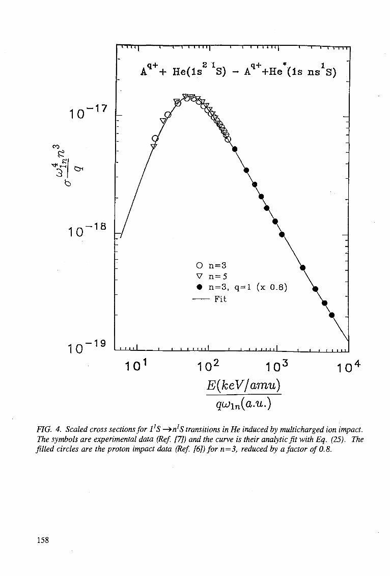
10 - 1 7
1 1 1 1 1 i i i i 1 1 1 1 1 i i i n i i | 1 1—r t r i - r i
Aq ++ He(ls S) - Aq++He (Is n s ^ )
CO
^
5?
3 Cr<
10 - 1 8
10 - 1 9
10
O n=3 V n = 5 • n=3 , q= l (x 0.8)
Fit
i 11 i i 1 i • i t i < t i J — i i i 11 i i i i • • i • 11
10 10 10 E(keV/amu)
qujin{a.u.)
FIG. 4. Scaled cross sections for 1*S -^nJS transitions in He induced by multicharged ion impact. The symbols are experimental data (Ref. [7]) and the curve is their analytic fit with Eq. (25). The filled circles are the proton impact data (Ref. [6]) for n=3, reduced by a factor of 0.8.
158
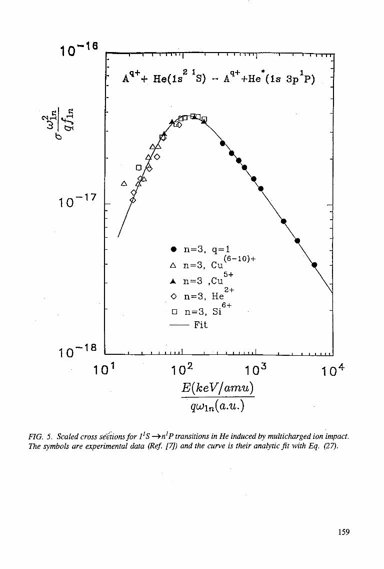
10 -16 T i i i r T T T ] 1 1—I I I I I I "i i ' r i i i i
(NT
10 - 1 7
10 - 1 8
A q + + H e ( l s 2 *S) - A q + +He*( ls S p 1 ? )
• n = 3 , q = l (6-10) +
A n = 3 , Cu 5+
A n=3 ,Cu 2+
O n=3, He 6+
n n=3, Si Fit
• • • • i 1 1 1 ' j _ i i ' i 1 1 1 1 - i — i i i t 1 1 1
10 10 10 E(keV/amu)
qu>in(a.u.)
10
FIG. 5. Scaled cross sections for 1!S —»n;P transitions in He induced by multicharged ion impact. The symbols are experimental data (Ref. [7]) and the curve is their analytic fit with Eq. (27).
159
5 ( l p ) __Aexv(-«/E?-) ln(e + yE150) {xlQ.llcm2) ^ _ | _ ( 2 7 )
(I + CE;!0)E150 I S O
where e=2.7182818 and the fitting constants have the values
A=3.70, C=0.28, a = 0 . 1 5 , P = 2 . 2 , y=l.l .
This fit represents the data well within their average experimental uncertainty (20-30%), with a few somewhat more significant deviations at very low energies.
4.3. 1*S -» n*D Transitions
The recommended experimental cross section data of Ref. [7] for the 1!S -» n*D (n=3-5) transitions in He induced by multicharged ion impact are shown in Fig. 6 in the scaled form
5( i0) = i ^ o(n*D), S= *(*ey/aiDu) _ (28)
The cross section data for individual n*D transitions have a maximum in the region E ~ 50-60 keV/amu, but show a larger dispersion than in the case of n*S and n*P transitions. This dispersion is, however, still within the claimed 20% uncertainty of the data. The larger dispersion of the scaled data for different n is connected with the state mixing within a given n-manifold. In Fig. 6 we have plotted also the scaled high-energy proton-impact experimental data for the 1!S -» 4*D transition, multiplied by a factor of 1.5.
The data were fitted to the expression
a ™ = o - 6 A S X 1 0 - 1 W 4 S ( 2 9 )
Bi?5-O0exp(a/I?5o
o-5) +AE50 50
where the fitting constants have the values
A(t f=3)=4.5 , A(r !=4)=5.4 , A{nz5) = 6 . 2 , B=2.5, a = 0 . 2 , p = 1 . 5
The analytic fits to the data are also shown in Fig. 6. The value A(n=4) = 5.4 gives a good average fit to all the data.
It is worth noting that the values of fitting parameters for the n=3-curve are close to those of the analytic fit for the a(1S) cross section. The additional factor of 0.6 in Eq. (29) then gives the ratio of a(1D) and a(1S) cross sections.
The constant value of this ratio suggests that q- and n-scaled excitation cross sections are subject of an unrevealed L-scaling. Experimental or theoretical data for transitions to L > 3 states would be highly useful in this respect.
160
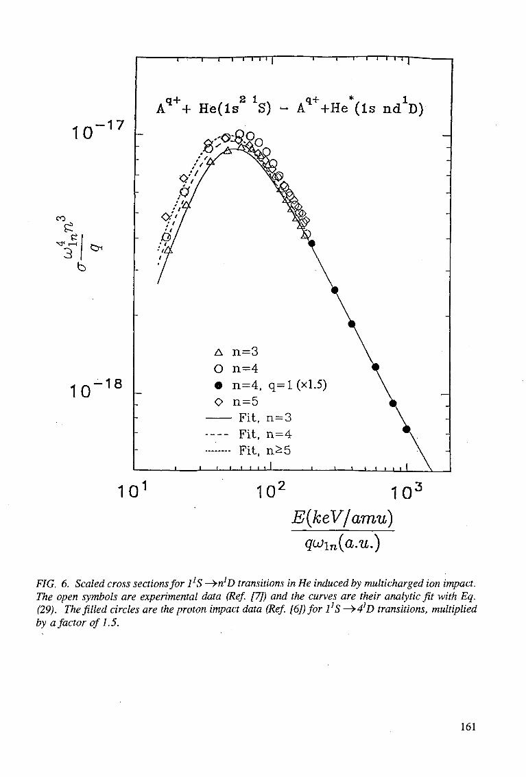
10 - 1 7
CO
^ , 3
c^
10 - 1 8
10
-I 1 1 I I I T
A q ++ H e ( l s 2 *S)
T 1 1 1 I I I I
Aq++He*(ls nc^D)
102 10 3
E(keV/amu) qu)in{a.u.)
FIG. 6. Scaled cross sections for 1*S -^r^D transitions in He induced by multicharged ion impact. The open symbols are experimental data (Ref. [7]) and the curves are their analytic fit with Eq. (29). The filled circles are the proton impact data (Ref. [6]) for 1JS -^^D transitions, multiplied by a factor of 1.5.
161
5. CONCLUSIONS
The presented scaled cross sections for the transitions 1*S -> n*L (L=S,D,S) in He induced by proton and multicharged ion impact describe the existing recommended experimental data for n=2-5 with an accuracy well within the uncertainty of the data (10-15% for H+ impact, and about 20% for Aq+ ion impact). The analytic form of presented scaled cross sections allows extension of the existing data information to states with n > 5. The absence of either experimental or theoretical cross section data for excitation to states with L > 3 precludes establishment of the cross section scaling also with respect to angular momentum quantum number L.
On the basis of classical mechanics arguments, one can also infer the cross section scaling for the nQ *S ->• n *L transitions (n > %, L=S,P,D) with respect to %, at least at high energies. The classical mechanics shows that the dependence on i^ of the a(nQ -> n) cross section is (see e.g. Ref. [9])
where co n is the transition energy. If we retain the definition of scaled energy as before, i.e. E = E/(q co n), then in the cross section scaling function g, Eqs. (3) and (4), an additional r$ scaling factor should be introduced. We may, however, redefine the scaled energy for these transitions as E = E/(n^ q co n), in which case the additional scaling factor in the expressions for g is n . Considerations of the no-scaling in the adiabatic region favour the second choice.
REFERENCES
1. JANEV, R.K., Comments At. Mol. Phys., 26 (1991) 83. 2. SUMMERS, H.P., VON HELLERMANN, M., DE HEER, F.J., HOEKSTRA, R., At.
Plasma-Mater. Int. Data Fusion, 3 (1992) 7. 3. BOLEY, CD., JANEV, R.K., POST, D.E., Phys. Rev. Lett., 52 (1984) 534. 4. KOROTKOV, A.A., At. Plasma-Mater. Int. Data Fusion, 3 (1992) 79. 5. FRITSCH, W., At. Plasma-Mater. Int. Data Fusion, 3 (1992) 41. 6. DE HEER, F.J., HOEKSTRA, R., SUMMERS, H.P., At. Plasma-Mater. Int. Data Fusion,
3 (1992) 47. 7. ANTON, M., DETLEFFSEN, D., SCHARTNER, K.-H., At. Plasma-Mater. Int. Data Fusion,
3 (1992) 51. 8. JANEV, R.K., PRESNYAKOV, L.P., J. Phys. B, 13 (1980) 4233. 9. JANEV, R.K., Phys. Rev. A (1995) in press. 10. SOLOVEV, E.A., Sov. Phys. Uspekhi, 32 (1989) 228. 11. BELL, K.L., KENNEDY, D.J., KINGSTON, A.E., J. Phys. B, 1 (1968) 1037. 12. REYMAN, K., SCHARTNER, K.-H., SOMMER, B., Phys. Rev. A, 38 (1988) 2290.
162
ELECTRON CAPTURE FROM H AND He BY Al+2'3, Si+2'3'4, Ar+6
AND Ti+4 IN THE eV TO keV ENERGY RANGE
M. GARGAUD Observatoire de l'Universite' Bordeaux I (INSU/CNRS URA 352) B.P. 89, F-33270 FLOIRAC, FRANCE.
R. MC CARROLL Laboratoire de Dynamique Mol6culaire et Atomique (CNRS URA 774) University Pierre et Marie Curie, F-75252 PARIS CEDEX 05, FRANCE.
A B S T R A C T . Cross-section data for ion-atom collisions which play an important role in the edge plasma of magnetically confined fusion devices are reviewed. This paper is devoted to collisions between low and medium Z plasma impurity ions (Si, Al, Ar, Ti) and plasma neutrals (H, He). Charge exchange reactions being the most important ion-atom processes occurring in the edge plasma we limit our study to these charge transfer reactions in the particular ion energy range leV-lkeV/amu.
I. INTRODUCTION
The aim of the present work is to provide a compilation of theoretical calculations of charge transfer cross sections involving a representative selection of multi-charged ions with Ne-like, Mg-like or Ar-like cores. The main theoretical problem in dealing with electron capture process by such complex ions arises from the necessity to represent the energy difference of initial and final states to within an accuracy of about 0.1 eV. Since inital and final states involved in electron capture reactions have very different electron configurations, purely ab-initio methods are not very satisfactory for treating complex ions beyond the second row of the periodic table. However, in many cases, it may reasonably be assumed that the inner shell electrons only play a passive role in the non-adiabatic process. Model potential techniques can then be used to represent satisfactorily the closed shell contribution to the ionic cores. In this way, it becomes possible to have a reliable theoretical model in which the reaction energies are close to their experimental values. This guarantees an accurate determination of the position of the avoided adiabatic crossings which to a very large extent determines the electron process. The simplest cases to deal with are complex ions with closed shell (or closed sub-shell) configurations of the 2p6 or 2p63s2 type. The single electron capture process then reduces to a one-electron problem, although care must be exercised when treating a multi-electron target like He.
We have chosen to present in this work the results pertaining to the following reactions :
Al+3 (2s22p6)1S + H (ls)2S —> Al+2(2s22p6nl) + H+
Si+2 (2s22p63s2)1S + H (ls)2S —> Si+(2s22p63s2 3p)2P + H+
Si+4 (2s22p6)1S + H (ls)2S —> Si+3 (2s22p6nl) + H+
Ar+6 (2s22p63s2)1S + H (ls)2S —> Ar+5 (2s22p63s2 nl) + H+
Ar+6 (2s22p63s2)1S + He (ls2)2S —> Ar+5 (2s22p63s2 nl) + He+ (ls)2S Ti+4 (2s22p63s23p6)1S + H (ls)2S —> Ti+3 (2s22p63s23p6 nl) + H+ nl = 4s, 4p (6)
In order to illustrate how a combination of model potential and ab-initio techniques can be used to treat the case of open-shell ions we also include some calculations on
Si+3 (2s22p63s)2S + He (ls2)2S—> Si+2(2s22p63s2)1S + He+(ls)2S (7) —> Si+2 (2s22p63s 3p) L3P + He+ (ls)2S (8)
Al+2 (2s22p63s)2S + H (ls)2S —> Al+ (2s22p63s3p)2P + H+ (9)
nl = 3s, 3p
nl = 3d, 4s nl = 4d, 4f, 5s, 5p nl = 3d, 4d, 4p
(1) (2) (3) (4) (5)
163
As the basic theoretical methods have already been developed elsewhere [1, 2] we just recall very briefly in section 2 the main features of the general method. In section 3 we will present the specific aspects of each system and discuss the results.
2. METHOD
Except for Si+3/He system where an ab-initio method with configuration interaction was used, model potential techniques have been adopted in all the other systems. For each ion A^+, a parametrized model potential is optimized to reproduce the electronic states of the A^"1^ which are likely to be involved in the electron capture process. For closed shell ions, the ground and excited states of all symmetries (s,p,d...) can usually be reproduced by a fairly simple model potential to within 0.1 eV. In the case of open-shell cores, the procedure is less satisfactory but when capture takes place into excited states, the method is also acceptable.
The model Hamiltonian is then constructed as a superposition of the ionic core and the target atom. This is simple in the case of a hydrogenic target. The electronic Hamiltonian of the molecular ion is diagonalized in a set of Slater-type orbitals to generate the electronic adiabatic states of the ion-neutral system. The only interactions taken into account are the electrostatic potentials from the two ionic cores. For the description of the A<i+ ionic core we use a model potential of the general form:
yAAr)= -i+is{i(^yl«pRr) r i=l I y=0
(10)
where n and m are finite integers and where the parameters qj and d; are optimised to reproduce as well as possible the asymptotic energies of A+fa_1). In the special case of He target, the model potential method has been modified [3] using an idea introduced first by Grice and Herschbach [4] to treat the long range ionic-covalent interaction in neutral atom-atom systems. In that way it is possible to take account of the electronic correlation and symmetry effects in the entry channel.
The coupled equations are solved in a fully quantal formulation. Prior to integration the adiabatic states are transformed to a diabatic representation [1]. Galilean invariance is insured by the use of appropriate reaction coordinates [2]. These coordinates are equivalent to the use of the common translation factor in a semi classical formulation [5].
3. RESULTS AND DISCUSSION
3.1 AI+3/H.
Over a wide range of incident ion energies from a few eV up to about 10 keV, the charge transfer process takes place via electron capture into the (2p63p) 2P state of Al+2 (figure 1). The primary capture mechanism is due to the radial non adiabatic coupling in the vicinity of the avoided crossing between the two £ states (one correlated to the entry channel, the other to the final 2P channel). However, the rotational (Coriolis) coupling between the £ and II states contributes appreciably not only to the orientation of the final state but also to the actual magnitude of the electron capture cross section (figure 2). Indeed, in common with a few other analogous systems involving capture to p-states, the Al+3/H system furnishes an excellent example of how the interference of radial and rotational can lead to an enhancement of the Landau Zener probabilities when both £ and TI states are involved in the electron capture process [6]. It also explains why there is a strong propensity for orientation of the 2P state at small scattering angles [7].
164
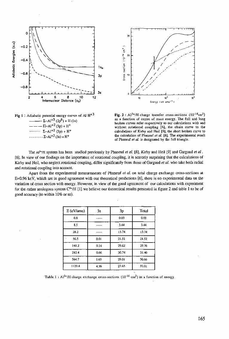
*
o O
0
0.2
0.4
0.6
0.8
.11 U 1 | . . . , . . . , . 1 1 | 1 1 1
-\\ \
• \ \ \ - \ \ \
', \ vs. ; 1- \ ^v
1 1 i l l ! i I...1 L.J 1 1 t_ l l_ l_ 1 7 '
1sH
3p
3s
30
-e
= 20
^ c o
S 10 o
0
.'
•
.
--
" _ . -
^
' " I
/ / m l
1 1 1 1 l -TTTf •-' T " 1 I f I 1 I IJ
/ ^ / , __;
/ y / ^ • - ' '
/ / --*"''" / ---' " ' "
/--'" / / y
/ / •
/ 7 '' / / .'
/ ' / / / "
2 4 6 8 10 12 Internucleor Distance (a0)
10 10'
Energy { eV amu~ )
Fig 1 : Adiabatic potential energy curves of Al H
Z-A1+3 (2p6) + H (Is)
n - A l + 2 (3p) + H+
Z-A1+2 (3p) + H+
Z-A1+2 (3s) + H+
+3 Fig. 2 : Al3+/H charge transfer cross-sections (10"16cm2) as a function of centre of mass energy. The full and long broken curves refer respectively to our calculations with and without rotational coupling [6], the chain curve to the calculations of Kirby and Heil [9], the short broken curve to the calculation of Phaneuf et al. [8]. The experimental result of Phaneuf et al. is designated by the full triangle.
The AI3+/H system has been studied previously by Phaneuf et al. [8], Kirby and Heil [9] and Gargaud et al. [6]. In view of our findings on the importance of rotational coupling, it is scarcely surprising that the calculations of Kirby and Heil, who neglect rotational coupling, differ significantly from those of Gargaud et al. who take both radial and rotational coupling into account.
Apart from the experimental measurements of Phaneuf et al. on total charge exchange cross-sections at E=0.96 keV, which are in good agreement with our theoretical predictions [6], there is no experimental data on the variation of cross section with energy. However, in view of the good agreement of our calculations with experiment for the rather analogous system C4+/H [1] we believe our theoretical results presented in figure 2 and table 1 to be of good accuracy (to within 10% or so).
E (eV/amu)
0.8
8.5
28.2
56.5
141.2
282.4
564.7
1129.4
3s
0.01
0.14
0.66
1.65
4.36
3p
0.03
3.44
13.74
21.51
29.62
30.74
29.01
27.65
Total
0.03
3.44
13.74
21.52
29.76
31.40
30.66
32.01
Table 1 : Al3+/H charge exchange cross-sections (10"16 cm2) as a function of energy.
165
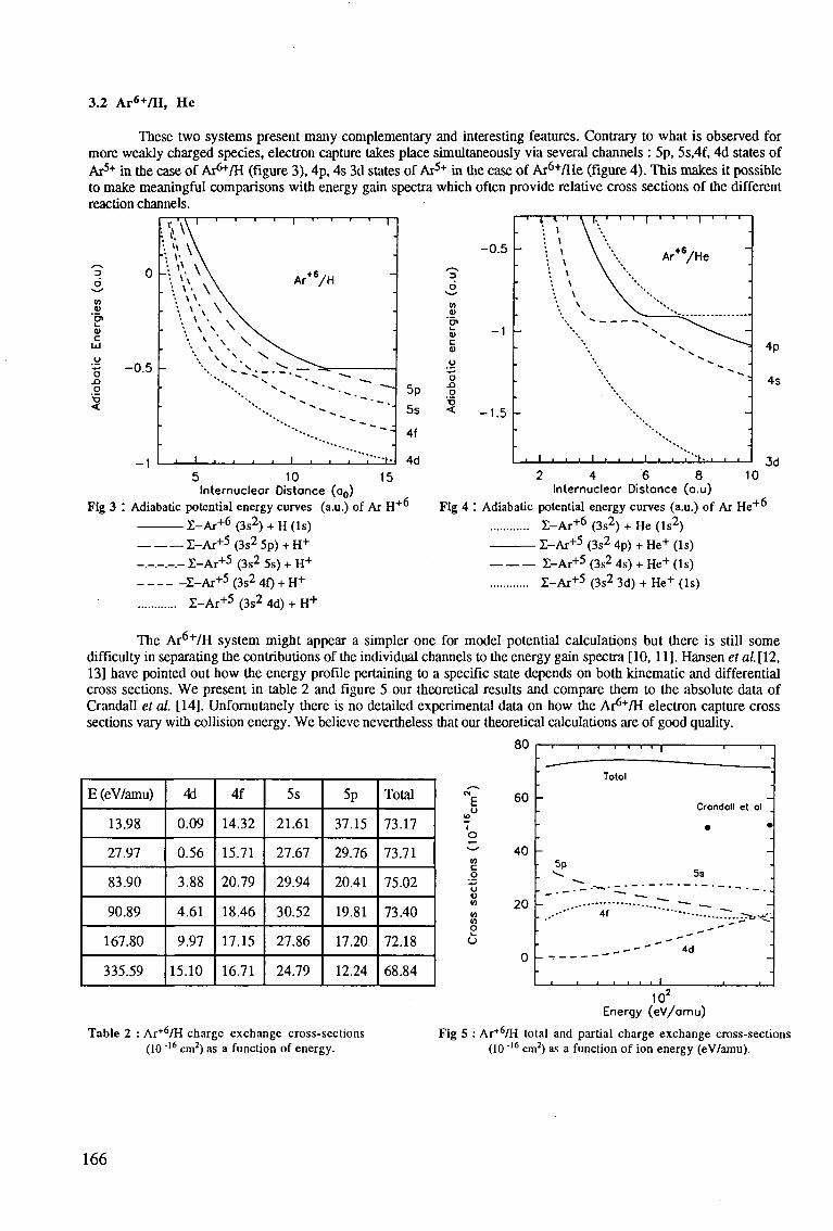
3.2 A r 6 + / H , He
These two systems present many complementary and interesting features. Contrary to what is observed for more weakly charged species, electron capture takes place simultaneously via several channels : 5p, 5s,4f, 4d states of AT5-1" in the case of Ar^/H (figure 3), 4p, 4s 3d states of Ar5"1" in the case of Ar6+/He (figure 4). This makes it possible to make meaningful comparisons with energy gain spectra which often provide relative cross sections of the different reaction channels.
3 6 V>
v C" <u c
Id
2 I
0
0.5
_ i
ii\y \ 'J A
. \ \ \ \ \ \ \
\ \ \ ^
s
1
\ s
— 1
. . . . . . ^
.
Ar+6/H
\ ^ ^ ^ ^ ^^~.
i 1 • • i i * * K
5p
5s
4f
4d 15
Fig 3
5 10 Internucleor Distance (o0)
Adiabatic potential energy curves (a.u.) of Ar H + °
E-Ar + 6 (3s2) + H (Is)
Z-Ar + 5 (3s2 5p) + H+
- . - . - . - . - Z-Ar+5 (3s2 5s) + H +
X-Ar+5 (3s2 4f) + H+
Z-Ar + 5 (3s2 4d) + H +
3
6
o JO
o
<
- 0 . 5 -
- 1 -
- 1 . 5
—r
-
•
•
•
•
I 1 ' \ I. ' ': * \ '*• '• ' \ ' •
'• K \ '
• * \ '• \ \
\
I i i • 1 i
- i — i — | — i — i — i — | — r • i i
Ar+ 6 /He "
\ \ **'*»
, . i . , *.'•••.., , ,
4p
4s
Jd 2 4 6 8 10
Internuclear Distance (a.u)
Fig 4 : Adiabatic potential energy curves (a.u.) of Ar He + "
E -Ar + 6 (3s2) + He (Is2)
I - A r + 5 (3s2 4p) + He+ (Is)
I - A r + 5 (3s2 4s) + He+ (Is)
Z-Ar+5 (3s2 3d) + He+ (Is)
The Ar6+/H system might appear a simpler one for model potential calculations but there is still some difficulty in separating the contributions of the individual channels to the energy gain spectra [10, 11]. Hansen et al. [12, 13] have pointed out how the energy profile pertaining to a specific state depends on both kinematic and differential cross sections. We present in table 2 and figure 5 our theoretical results and compare them to the absolute data of Crandall et al. [14]. Unfornutanely there is no detailed experimental data on how the Ar6+/H electron capture cross sections vary with collision energy. We believe nevertheless that our theoretical calculations are of good quality.
E (eV/amu)
13.98
27.97
83.90
90.89
167.80
335.59
4d
0.09
0.56
3.88
4.61
9.97
15.10
4f
14.32
15.71
20.79
18.46
17.15
16.71
5s
21.61
27.67
29.94
30.52
27.86
24.79
5p
37.15
29.76
20.41
19.81
17.20
12.24
Total
73.17
73.71
75.02
73.40
72.18
68.84
E o
in c o o <0 in
V) in o i_
O
O<J
60
40
20
0
_
5p
-i 1
1
Totol
Crondoll et ol
• •
_
5s "
.— — - .
_ - - ' ' " 4d
1 1 1 1 1—1 J 1
Table 2 : Ar+6/H charge exchange cross-sections (10 "16 cm2) as a function of energy.
10" Energy (eV/omu)
Fig 5 : Ar+6/H total and partial charge exchange cross-sections (10 "'6 cm2) as a function of ion energy (eV/amu).
166
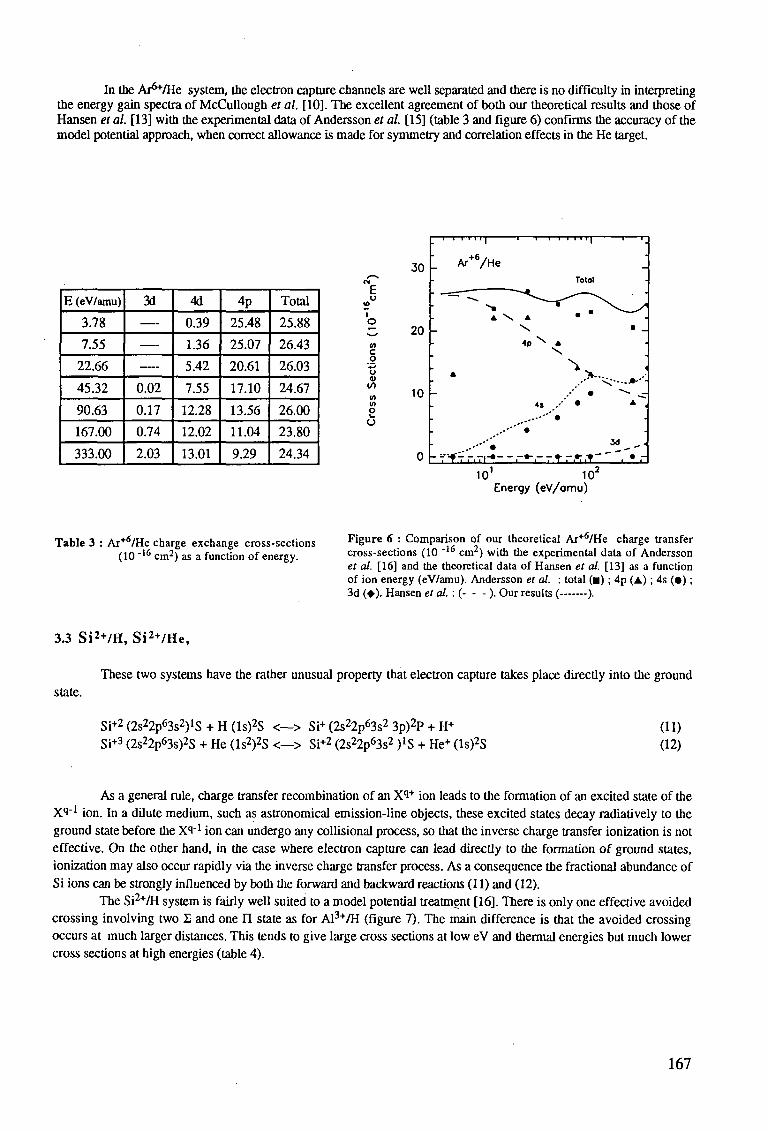
In the Ar^/He system, the electron capture channels are well separated and there is no difficulty in interpreting the energy gain spectra of McCullough et al. [10]. The excellent agreement of both our theoretical results and those of Hansen et al. [13] with the experimental data of Andersson et al. [15] (table 3 and figure 6) confirms the accuracy of the model potential approach, when correct allowance is made for symmetry and correlation effects in the He target.
E (eV/amu)
3.78
7.55
22.66
45.32
90.63
167.00
333.00
3d
—
—
—
0.02
0.17
0.74
2.03
4d
0.39
1.36
5.42
7.55
12.28
12.02
13.01
4p
25.48
25.07
20.61
17.10
13.56
11.04
9.29
Total
25.88
26.43
26.03
24.67
26.00
23.80
24.34
E
V) c o
'£> o 4>
<f> V)
o I . O
30
20
10
0
1 Ar+6/He TotOl
• " " - ~ - - * ^ - * ~ ~ * ^
"" ** • A \ A
\ 4 p \ A
\ V •
L 4 S .-• • .-"•'" •
• • • * " ' •
- f fV r.Ti-*- - .-•".- r * r * * -
_ •
-• _
.
< ^ • - . * . - -
"^ ^ * ,
-.
_ i i .
10 10 Energy (eV/omu)
Table 3 : Ar+6/He charge exchange cross-sections (10- I 6cm2) as a function of energy.
Figure 6 : Comparison of our theoretical Ar+<5/He charge transfer cross-sections (10 "16 cm2) with the experimental data of Andersson et al. [16] and the theoretical data of Hansen et al. [13] as a function of ion energy (eV/amu). Andersson et al. : total ( • ) ; 4p (A); 4s ( • ) ; 3d (•). Hansen et al. : ( ). Our results ( ).
3.3 Si2 + /H, Si2 + /He,
These two systems have the rather unusual property that electron capture takes place directly into the ground
state.
Si+2 (2s22p63s2)1S + H (ls)2S <—> Si+ (2s22p63s2 3p)2P + H+
Si+3 (2s22p63s)2S + He (ls2)2S <—> Si+2 (2s22p63s2 )»S + He+ (ls)2S (11) (12)
As a general rule, charge transfer recombination of an Xi+ ion leads to the formation of an excited state of the XI"1 ion. In a dilute medium, such as astronomical emission-line objects, these excited states decay radiatively to the ground state before the Xi"1 ion can undergo any collisional process, so that the inverse charge transfer ionization is not effective. On the other hand, in the case where electron capture can lead directly to the formation of ground states, ionization may also occur rapidly via the inverse charge transfer process. As a consequence the fractional abundance of Si ions can be strongly influenced by both the forward and backward reactions (11) and (12).
The Si2+/H system is fairly well suited to a model potential treatment [16]. There is only one effective avoided crossing involving two £ and one II state as for Al3+/H (figure 7). The main difference is that the avoided crossing occurs at much larger distances. This tends to give large cross sections at low eV and thermal energies but much lower cross sections at high energies (table 4).
167
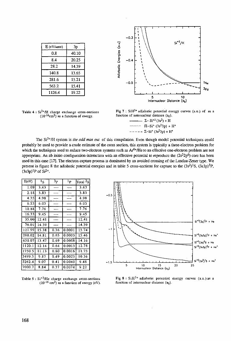
E (eV/amu)
0.8
8.4
28.2
140.8
281.6
563.2
1126.4
3p
40.10
20.25
14.39
13.65
15.21
15.41
19.22
V c
Id
O
O
0.3
0.4
0.5
• 1 l l
- 1
. I
.
i |
• .
i
"
r— 11 • | i i -i
\ \
\y
i i i i i
1 i
Si+2/H
^
'"*
1
-
•
•
' * - - • , * " » - ^ 1s„
3ps,
5 10 Internucleor Oistance (o0)
Table 4 : Si2+/H charge exchange cross-sections F i 8 7 : s i H 2 + adiabatic potential energy curves (a.u.) of as a (10-16cm2) as a function of energy. function of internuclear distance (ao).
I - Si+2 (3s2) + H
n - S i + (3s23p) + H+
Z-Si+(3s23p) + H+
The Si3+/H system is the odd man out of this compilation. Even though model potential techniques could probably be used to provide a crude estimate of the cross section, this system is typically a three-electron problem for which the techniques used to reduce two-electron systems such as Ar^/He to an effective one-electron problem are not appropriate. An ab initio configuration-interaction with an effective potential to reproduce the (2s22p6) core has been used in this case [17]. The electron capture process is dominated by an avoided crossing of the Landau-Zener type. We present in figure 8 the adiabatic potential energies and in table 5 cross-sections for capture to the Qs2)^, (3s3p)3P, (3S3P)1? of Si2+.
E(eV)
1.09
2.18
4.35
6.53
10.88
16.33
35.00
70.01
121.99
280.02
630.07
1120.1
1750.5
3499.3
5262.4
7000.7
is 3.63
3.83
4.98
6.03
7.76
9.45
12.41
14.39
15.38
14.81
13.47
12.14
11.13
9.87
9.07
8.84
3 P
—
—-—
—
—
—
—
—
0.36
0.65
0.69
0.64
0.60
0.49
0.41
0.37
!p —
—
—
—
—
—
—
—
0.0001
0.0003
0.0008
0.0013
0.0016
0.0023
0.0040
0.0074
Total 2S
3.63
3.83
4.98
6.03
7.76
9.45
12.41
14.39
15.74
15.46
14.16
12.78
11.73
10.36
9.48
9.22
S i " (3p)T + He
Si*2(3s3p)V + He*
Si*5(3s)2S + He
Si*2(3s3p)3P + He*
SI*2(3»2)'S + He*
10 15 20 Internucleor Distance (o0)
25
Table 5 : Si+3/He charge exchange cross-sections (10"16 cm2) as a function of energy (eV).
Fig 8 : SiH3 + adiabatic potential energy curves (a.u.) as a function of internuclear distance (ag).
168
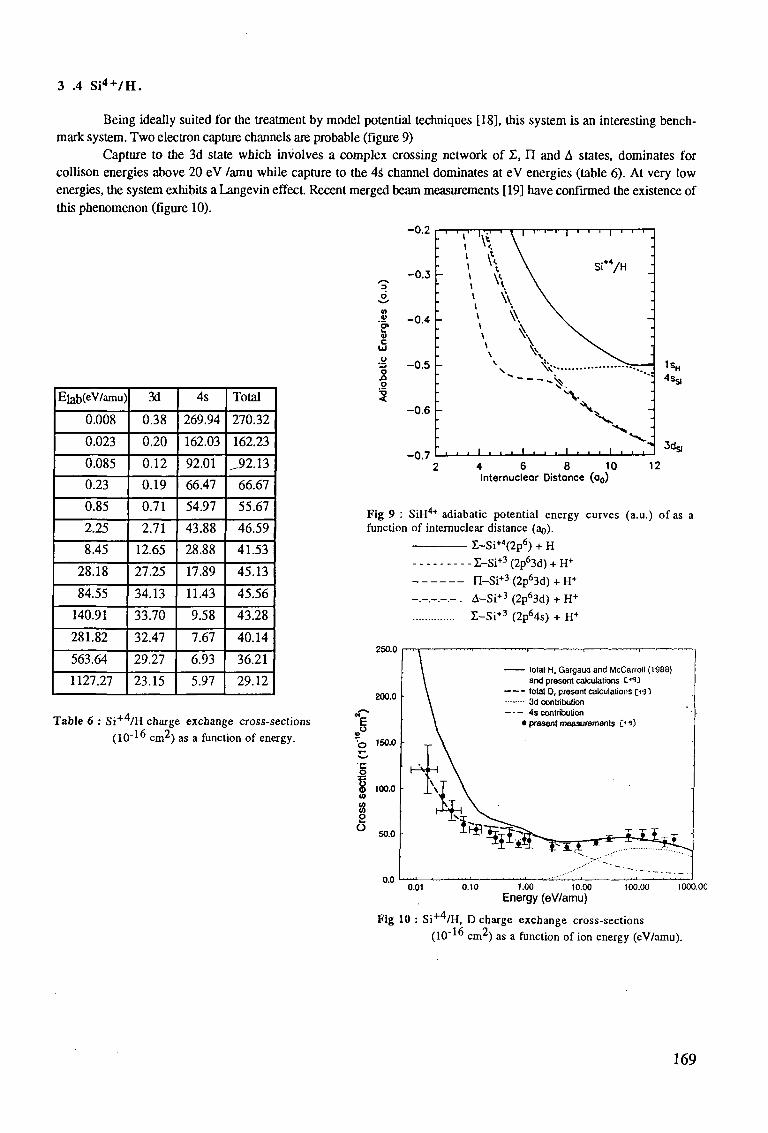
3 .4 S i 4 + /H .
Being ideally suited for the treatment by model potential techniques [18], this system is an interesting benchmark system. Two electron capture channels are probable (figure 9)
Capture to the 3d state which involves a complex crossing network of X, U and A states, dominates for collison energies above 20 eV /amu while capture to the 4s channel dominates at eV energies (table 6). At very low energies, the system exhibits a Langevin effect. Recent merged beam measurements [19] have confirmed the existence of this phenomenon (figure 10).
-0.2
-0 .3 -
Elab(eV/amu)
0.008
0.023
0.085
0.23
0.85
2.25
8.45
28.18
84.55
140.91
281.82
563.64
1127.27
3d
0.38
0.20
0.12
0.19
0.71
2.71
12.65
27.25
34.13
33.70
32.47
29.27
23.15
4s
269.94
162.03
92.01
66.47
54.97
43.88
28.88
17.89
11.43
9.58
7.67
6.93
5.97
Total
270.32
162.23
^92.13
66.67
55.67
46.59
41.53
45.13
45.56
43.28
40.14
36.21
29.12
Table 6 : S i + v H charge exchange cross-sections (10"1" cm2) as a function of energy.
2 -0 .4 -
••§ -0.5 h o o
I -0.6
-0 .7
—1—1
•
-
-
• > \
* v. \
. 1 . , • 1 , . .
I ' ' ' 1 ' ' ' .
si+4/H j
.
\
\ ^ •
S>.
1sH
4Scj
•» 3d*
2 4 6 8 10 IS Internucleor Distonce (o0)
Fig 9 : SiH4+ adiabatic potential energy curves (a.u.) of as a function of internuclear distance (ao).
£-Si+4(2p6) + H
--- I -Si+ 3 (2p 63d) + H+
n-Si + 3 (2p63d) + H+
- . - ._ . - . - . A-Si+3 (2p63d) + H+
E-Si+ 3 (2p64s) + H+
250.0
200.0
E o ' 0 150.0
'C o
100.0
2 O
50.0 •
0.01 0.10 1.00 10.00 Energy (eV/amu)
100.00 1000.0C
Fig 10 : Si+4/H, D charge exchange cross-sections
(10"1" cm2) as a function of ion energy (eV/amu).
169
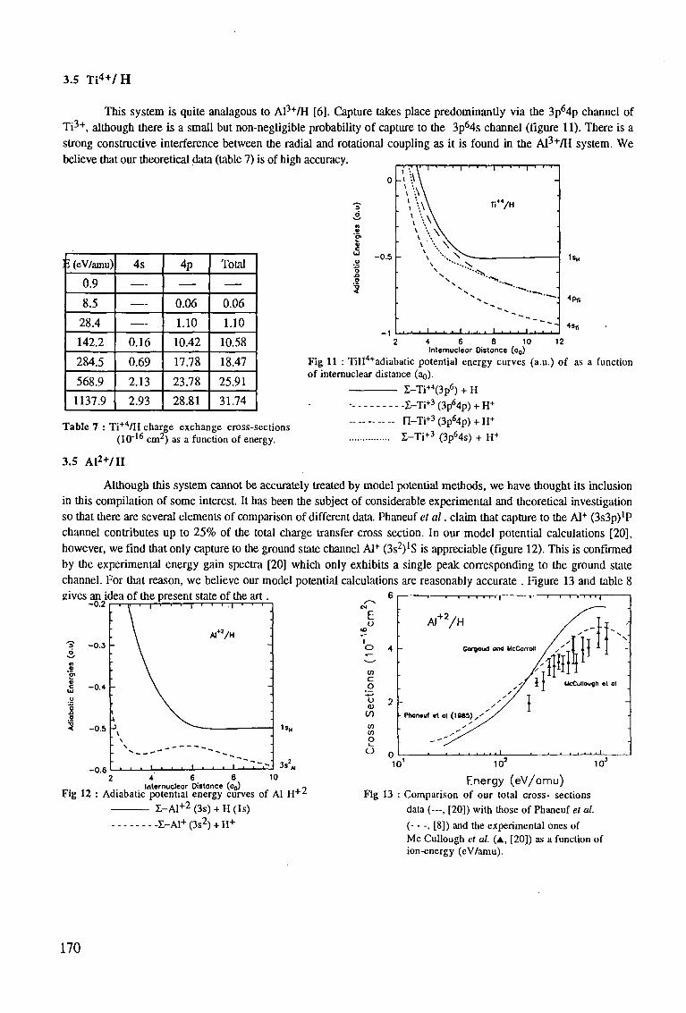
3.5 T i 4 + /H
This system is quite analagous to Al3+/H [6]. Capture takes place predominantly via the 3p64p channel of Ti3+, although there is a small but non-negligible probability of capture to the 3p64s channel (figure 11). There is a strong constructive interference between the radial and rotational coupling as it is found in the Al3+/H system. We believe that our theoretical data (table 7) is of high accuracy.
i (eV/amu)
0.9
8.5
28.4
142.2
284.5
568.9
1137.9
4s
—
— —
0.16
0.69
2.13
2.93
4p
—
0.06
1.10
10.42
17.78
23.78
28.81
Total
—
0.06
1.10
10.58
18.47
25.91
31.74
- 0 .5
I ' ' ' I ' ' ' I ' ' ' I
' • • • ' • • • ' • • • '
1 s H
4f>Ti
Table 7 : Ti+4/H charge exchange cross-sections (10"16 cm2) as a function of energy.
3.5 A l 2 + / H
2 4 6 8 10 12
Internucleor Distance (o0)
Fig 11 : TiH4+adiabatic potential energy curves (a.u.) of as a function of internuclear distance (an).
I-Ti+4(3p6) + H
• l -Ti+ 3 (3p64p) + H+
- - - n-Ti + 3 (3p64p) + H+
I - T i + 3 (3p64s) + H+
Although this system cannot be accurately treated by model potential methods, we have thought its inclusion in this compilation of some interest. It has been the subject of considerable experimental and theoretical investigation so that there are several elements of comparison of different data. Phaneuf et al. claim that capture to the Al+ (3s3p)'P channel contributes up to 25% of the total charge transfer cross section. In our model potential calculations [20], however, we find that only capture to the ground state channel Al+ (3s2)1S is appreciable (figure 12). This is confirmed by the experimental energy gain spectra [20] which only exhibits a single peak corresponding to the ground state channel. For that reason, we believe our model potential calculations are reasonably accurate . Figure 13 and table 8
6 gives an idea of the present state of the art. -0.2 r
- 0 . 3 -
-0.4
- 0 . 5
-0.6
- i • ' • i
AI+7H
ISH
E o
CO c o o 0)
(/) w CO
o o
- 1 1—i—i i i v 1 1 T—
AI + 2 /H
Corooud ond McCorroil
- Phoiwuf «t ol ( IMS)
3s<
4 6 8 Internuclear Distance (oo)
10 Internuclear Distance (o,)) ~
Fig 12 : Adiabatic potential energy curves of Al H + z
Z-A1+2 (3s) + H (Is) £_A1+ (3s2) + H+
Fig 13
10 10 10"
Energy (eV/omu) Comparison of our total cross- sections data (—, [20]) with those of Phaneuf et al.
( . [8]) and the experimental ones of Mc Cullough et al. (A, [20]) as a function of ion-energy (eV/amu).
170
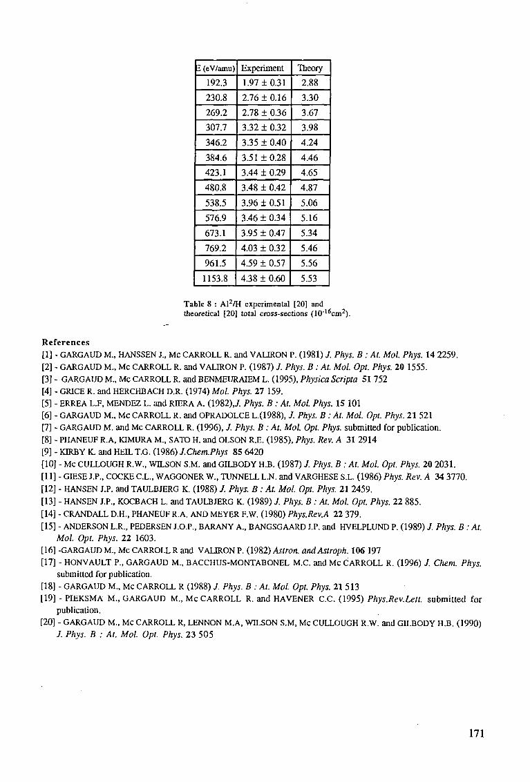
1 (eV/amu)
192.3
230.8
269.2
307.7
346.2
384.6
423.1
480.8
538.5
576.9
673.1
769.2
961.5
1153.8
Experiment
1.97 ± 0.31
2.76 ±0.16
2.78 ± 0.36
3.32 ± 0.32
3.35 ± 0.40
3.51 ±0.28
3.44 ± 0.29
3.48 ± 0.42
3.96 ± 0.51
3.46 ± 0.34
3.95 ± 0.47
4.03 ± 0.32
4.59 ± 0.57
4.38 ± 0.60
Theory
2.88
3.30
3.67
3.98
4.24
4.46
4.65
4.87
5.06
5.16
5.34
5.46
5.56
5.53
Table 8 : Al2/H experimental [20] and theoretical [20] total cross-sections (10"16cm2).
References [I] - GARGAUD M., HANSSEN J., Mc CARROLL R. and VALIRON P. (1981) J. Phys. B: At. Mol. Phys. 14 2259. [2] - GARGAUD M., Mc CARROLL R. and VALIRON P. (1987) J. Phys. B : At. Mol. Opt. Phys. 20 1555. [3] - GARGAUD M., Mc CARROLL R. and BENMEURAIEM L. (1995), Physica Scripta 51 752 [4] - GRICE R. and HERCHBACH D.R. (1974) Mol. Phys. 27 159. [5] - ERREA L.F, MENDEZ L. and RIERA A. (1982),/. Phys. B: At. Mol. Phys. 15 101 [6] - GARGAUD M., Mc CARROLL R. and OPRADOLCE L.(1988), J. Phys. B : At. Mol. Opt. Phys. 21 521 [7] - GARGAUD M. and Mc CARROLL R. (1996), J. Phys. B : At. Mol. Opt. Phys. submitted for publication. [8] - PHANEUF R.A, KIMURA M., SATO H. and OLSON R.E. (1985), Phys. Rev. A 31 2914 [9] - KIRBY K. and HEIL T.G. (1986) J.ChentPhys 85 6420 [10] - Mc CULLOUGH R.W., WILSON S.M. and GILBODY H.B. (1987) J. Phys. B : At. Mol. Opt. Phys. 20 2031. [II] - GIESE J.P., COCKE C.L., WAGGONER W., TUNNELL L.N. and VARGHESE S.L. (1986) Phys. Rev. A 34 3770. [12] - HANSEN J.P. and TAULBJERG K. (1988) / . Phys. B: At. Mol. Opt. Phys. 21 2459. [13] - HANSEN J.P., KOCBACH L. and TAULBJERG K. (1989) / . Phys. B : At. Mol. Opt. Phys. 22 885. [14] - CRANDALL D.H., PHANEUF R.A. AND MEYER F.W. (1980) Phys.Rev.A 22 379. [15] - ANDERSON L.R., PEDERSEN J.O.P., BARANY A., BANGSGAARD J.P. and HVELPLUND P. (1989) J. Phys. B: At.
Mol. Opt. Phys. 22 1603. [16] -GARGAUD M., Mc CARROLL R and VALIRON P. (1982) Astron. andAstroph. 106 197 [17] - HONVAULT P., GARGAUD M., BACCHUS-MONTABONEL M.C. and Mc CARROLL R. (1996) J. Chern. Phys.
submitted for publication. [18] - GARGAUD M., Mc CARROLL R (1988) J. Phys. B : At. Mol. Opt. Phys. 21 513 [19] - PIEKSMA M., GARGAUD M., Mc CARROLL R. and HAVENER C.C. (1995) Phys.Rev.Lett. submitted for
publication. [20] - GARGAUD M., Mc CARROLL R, LENNON M.A, WILSON S.M, Mc CULLOUGH R.W. and GILBODY H.B. (1990)
J. Phys. B : At. Mol. Opt. Phys. 23 505
171

INELASTIC PROCESSES IN 0.1-1000 keV/u COLLISIONS OF Ne«+ (q=7-10) IONS W I T H ATOMIC HYDROGEN
D.R. Schultz and P.S. Krstic Controlled Fusion Atomic Data Center Oak Ridge National Laboratory Oak Ridge, Tennessee 37831-6373, USA
Abstract: Owing to the potential use of neon as an intentionally introduced radiating impurity in fusion reactor divertors, we present here cross sections for (i) ionization, (n) state-selective excitation, and (Hi) state-selective charge transfer in 0.1-1000 keV/u collisions of Ne ? + (q=7-10) with H. The cross sections may be used in modeling and diagnosing the distribution and state of these ions as well as other parameters of the core, edge, and divertor regions of the plasma. We have utilized the theory of hidden crossings in the low energy portion of the energy range considered and the classical trajectory Monte Carlo method throughout the high energy portion.
1. I N T R O D U C T I O N
The previous decades have shown an ever closer approach to the goal of break-even in fusion reactors. As this goal is obtained, the direction of research will turn more and more towards the physics and engineering study of burning plasmas. Therefore, with the production of significant quantities of fusion-product helium, and significant fusion energy, it is necessary to consider how to exhaust this helium ash, how to recycle hydrogen, and how to remove heat from the plasma. Cooling is required both to extract heat to run turbines producing electricity (obviously the ultimate practical goal of fusion research) and to prevent the temperature of the plasma facing components from reaching too high a temperature.
Thus, much effort is being devoted to devising, engineering, and modeling reactor divertors through which these goals may be achieved, particularly for experimental devices already in existence (e.g. JET) and for the proposed International Thermonuclear Experimental Reactor. One of the primary difficulties has been that the early schemes for such a divertor would have potentially subjected the divertor plates to a very large amount of energy (e.g. 20 to 40 M W / m 2
or more [1]). In contrast, current designs call for the reduction of this tremendous heat and particle flux by using atomic processes in a rather open region, often referred to as a "gaseous divertor" and by spreading the load over a much larger surface area than originally envisioned. In particular, charge transfer, hydrogen and impurity radiation, ionization, and elastic collisions between the recycling gas and the divertor plasma are predicted to disperse the heat [2, 3].
In addition, it is estimated that the radiation from hydrogen will not be sufficient and some impurity species will have to be introduced into the divertor region to increase the radiation
173
losses. Since these losses increase with increasing nuclear charge, Z, and since any large contamination of the core plasma by high-Z impurities will quench the plasma, a delicate balance in the choice of what species to introduce must be made. It is predicted that impurities introduced by puffing into the edge or divertor become entrained to some extent, and that this will therefore limit the potential deleterious radiation losses.
One suitable impurity for this task seems to be neon. Its nuclear charge is high enough to induce a significantly increased amount of radiation in the divertor, potentially without reaching a fatal fraction in the core. In addition, since neon would not ordinarily be present in a reactor as would species composing the plasma facing walls (Ni, Fe, Be, C, etc.) or occuluded gases (e.g. oxygen), neon would be a good diagnostic species. If detected, it could have only originated from the point of injection, and only in the amount injected. Thus techniques such as charge exchange recombination spectroscopy could be used to track the motion of the neon ions and their spatial and charge state distributions to determine the parameters of the plasma such as temperature, density, and rotation.
Therefore, in order to provide a preliminary database for modeling and diagnosis that incorporates the inelastic collisions involving neon ions and atomic hydrogen, we present here the (i) ionization, (n) state-selective excitation, and (ra) state-selective charge transfer cross sections in 0.1-1000 keV/u collisions of Ne9 + (q=7-10) with H. We apply two methods which have been shown to provide reliable results over complementary energy ranges, the theory of hidden crossings (HC), and the classical trajectory Monte Carlo (CTMC) technique. Since each of these methods treats an ion-atom collision as possessing transitions of only a single electron, we cover a range of ionic charge states of neon for which we can be assured that there is little effect of electrons contained by the projectile exchanging with that of the target, or being ionized or excited. Further, we apply the models only to those charge states where the computed charge transfer cross section is not appreciably affected by capture to unphysical states. That is, for the partially stripped ions, if the model results in capture to principal quantum levels that are in actuality filled, then a clear signal that a more robust model must be employed is present.
In the following sections we quite briefly summarize the CTMC and HC methods and then present and tabulate our results for the inelastic cross sections.
2. T H E O R Y
A large body of work has shown that the CTMC method provides a reasonable and accurate estimate of these cross sections for intermediate collision velocities for bare ions colliding with H, H2, and He. Some results have also been obtained for partially stripped impinging ions with reasonable agreement found with experiments, but with less overall certainty, since a full treatment would have to include the multielectronic transitions possible in such a case. Since theoretical methods with which a large range of ionic charges and collision energies could be covered more robustly is not readily available, the CTMC results provide a first estimate of the required processes.
That is, the complete quantum mechanical treatment of an arbitrary ion, carrying possibly several electrons, colliding with atomic or molecular hydrogen, is a difficult, multi-electron, many-state calculation. The CTMC technique, in its one-active-electron, many-active-electron, or model-potential formulations serves as a very useful tool to produce a broad range of required
174
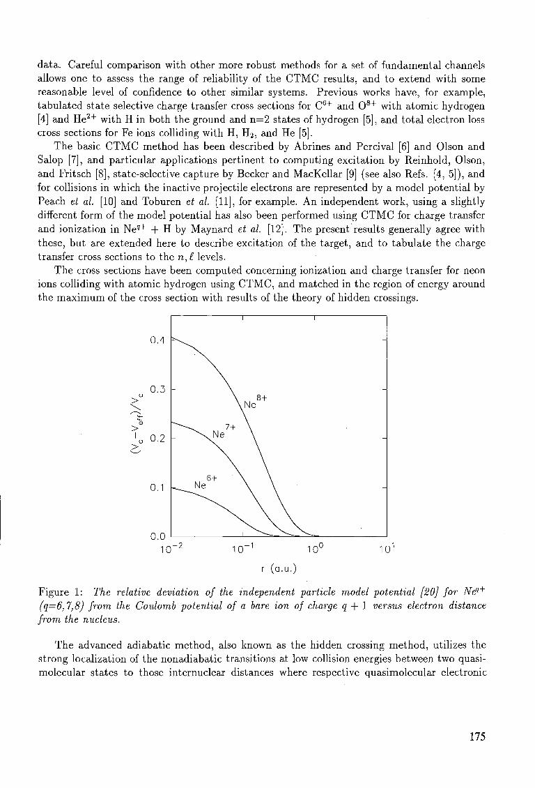
data. Careful comparison with other more robust methods for a set of fundamental channels allows one to assess the range of reliability of the CTMC results, and to extend with some reasonable level of confidence to other similar systems. Previous works have, for example, tabulated state selective charge transfer cross sections for C 6 + and 0 8 + with atomic hydrogen [4] and He 2 + with H in both the ground and n—2 states of hydrogen [5], and total electron loss cross sections for Fe ions colliding with H, H2, and He [5].
The basic CTMC method has been described by Abrines and Percival [6] and Olson and Salop [7], and particular applications pertinent to computing excitation by Reinhold, Olson, and Fritsch [8], state-selective capture by Becker and MacKellar [9] (see also Refs. [4, 5]), and for collisions in which the inactive projectile electrons are represented by a model potential by Peach et al. [10] and Toburen et al. [11], for example. An independent work, using a slightly different form of the model potential has also been performed using CTMC for charge transfer and ionization in Ne9 + + H by Maynard et al. [12]. The present results generally agree with these, but are extended here to describe excitation of the target, and to tabulate the charge transfer cross sections to the n,£ levels.
The cross sections have been computed concerning ionization and charge transfer for neon ions colliding with atomic hydrogen using CTMC, and matched in the region of energy around the maximum of the cross section with results of the theory of hidden crossings.
0.4
0.3 >
Q>
> 'o 0.2
>
0.1
0.0 10~2 1 0 _ 1 10° 101
r (a.u.)
Figure 1: The relative deviation of the independent particle model potential [20] for Neq+
(q=6,7,8) from the Coulomb potential of a bare ion of charge q + 1 versus electron distance from the nucleus.
The advanced adiabatic method, also known as the hidden crossing method, utilizes the strong localization of the nonadiabatic transitions at low collision energies between two quasi-molecular states to those internuclear distances where respective quasimolecular electronic
175
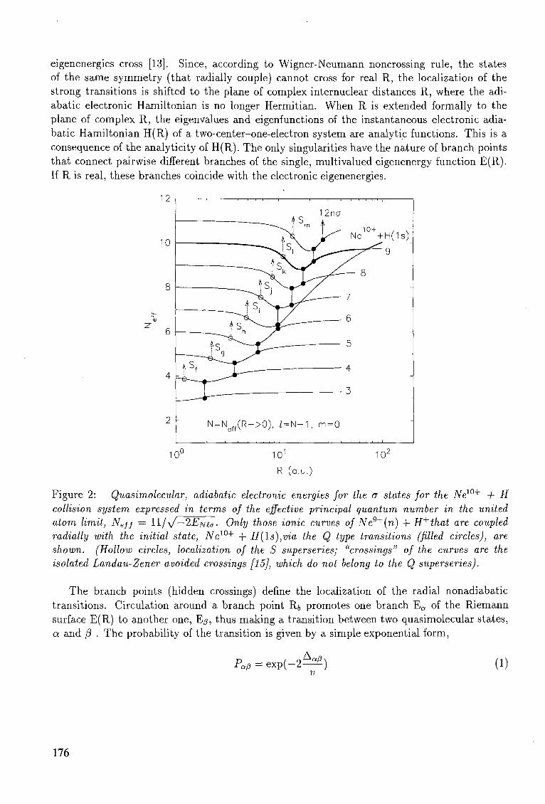
eigenenergies cross [13]. Since, according to Wigner-Neumann noncrossing rule, the states of the same symmetry (that radially couple) cannot cross for real R, the localization of the strong transitions is shifted to the plane of complex internuclear distances R, where the adi-abatic electronic Hamiltonian is no longer Hermitian. When R is extended formally to the plane of complex R, the eigenvalues and eigenfunctions of the instantaneous electronic adia-batic Hamiltonian H(R) of a two-center-one-electron system are analytic functions. This is a consequence of the analyticity of H(R). The only singularities have the nature of branch points that connect pairwise different branches of the single, multivalued eigenenergy function E(R). If R is real, these branches coincide with the electronic eigenenergies.
A ' N = Ne f f(R->0), Z = N - 1 , m=0
1 1 i , . . . . i , , , , , i i i i
10° 101 102
R (a.u.)
Figure 2: Quasimolecular, adiabatic electronic energies for the a states for the New+ + H collision system expressed in terms of the effective principal quantum number in the united atom limit, Nejj — Wjyf—2Em^. Only those ionic curves of Ne9+(n) + H+that are coupled radially with the initial state, New+ + H(Is),via the Q type transitions (filled circles), are shown. (Hollow circles, localization of the S superseries; "crossings" of the curves are the isolated Landau-Zener avoided crossings [15], which do not belong to the Q superseries).
The branch points (hidden crossings) define the localization of the radial nonadiabatic transitions. Circulation around a branch point R;, promotes one branch E a of the Riemann surface E(R) to another one, Ep, thus making a transition between two quasimolecular states, a and /3 . The probability of the transition is given by a simple exponential form,
PaP = e x p ( - 2 ^ ) (1)
176
where v is the collision velocity and
Ace = Imf ^-dR Ja/3 VR/V
(2)
is the generalized Massey parameter. The integral in Eq.(2) is taken along a contour around the point R(,, starting from real R at an energy Ea and ending at real R, at E/j. Finally, VR is the radial velocity of the nuclear motion.
Thus, following in succession the pairwise transitions in the complex R plane, while the system evolves along the real R axis, one can obtain the probability of transition from an arbitrary initial to an arbitrary final state. These are the basic ideas of the hidden crossing theory [14, 15, 16, 17], which has been shown to be successful [18, 19] in calculation of total and partial cross sections for ionization, charge transfer, and excitation of one electron atoms in slow collisions with multicharged ions. The theory is exact in the low velocity limit, and its applicability extends to approximately the maximum of the cross section. The latter depends upon the system and the inelastic process in question.
Two principal kinds of branch points, those of the so-called S and Q types, have been defined according to different radial selection rules [15]. These were found to form superseries. The S superseries are localized in a narrow domain of the complex R plane, at small Re{R}, and constitute the transitions which pairwise, and in succession, connect the states (N,£,m), (JV+1,£, m) , (N + 2,£,m),... ((N,£,m) are the spherical united atom quantum numbers). This localized set of transitions constitutes a strong mechanism which almost diabatically promotes the state (N, N — 1, m) into the continuum during the incoming phase of the collision. These superseries have a limiting point when n —> oo, and are associated with passing the centrifugal barrier. The Q transitions are the main mechanism for charge transfer and excitation, and these connect (TV, £, m) and (N + 1, £ + 1, m) states. They also constitute superseries which in succession can promote a state to the continuum in the receding phase of the collision. The Q branch points are associated with passing the top of the Coulomb barrier and are found at larger internuclear distances.
The hidden crossing theory was originally developed for systems of the form (.2/2, e, Zi). In principle, the method can be generalized to systmes containing more than one electron, but this has not yet been accomplished in a reliable way. Nevertheless, it can be applied in its original formulation to the collisions of multielectron ions with one-electron atoms if the effective potential of the ion is Coulombic for those internuclear distances where the transitions are localized. In Figure 1 we show the relative deviation of the effective multielectron potential from the Coulomb potential, (Vc — Vejf)/Vc, for the ions Neq+ ,q = 6, 7, 8, where Ve// is defined as the effective one-electron potential of the multielectron atom given by Szydlik and Green [20]. A similar potential is used in our CTMC calculations to model the Neq+ ion. From the figure it is obvious that the electron moves in an almost pure Coulomb potential if its distance from the nucleus is larger than about one atomic unit.
This can be applied to the collision of these neon ions with hydrogen, whose electron can be captured by the ion already at larger internuclear seperation. When the internuclear distance R > 1 , the overlap of the active electron wavefunction in the initial hydrogenic and final ionic state is that of Coulombic functions. Figure 2 shows the electronic energy diagram of the (NeH)w+ system, for the manifold of a states. The adiabatic energy curve of the initial New+ + H(ls) state is shown by the thick solid line. The Q transitions and the S superseries
177
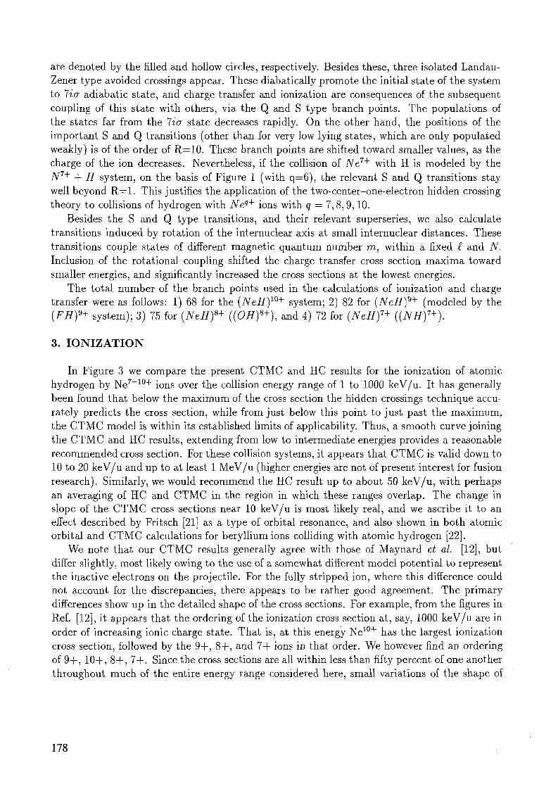
are denoted by the filled and hollow circles, respectively. Besides these, three isolated Landau-Zener type avoided crossings appear. These diabatically promote the initial state of the system to 7icr adiabatic state, and charge transfer and ionization are consequences of the subsequent coupling of this state with others, via the Q and S type branch points. The populations of the states far from the 7ia state decreases rapidly. On the other hand, the positions of the important S and Q transitions (other than for very low lying states, which are only populated weakly) is of the order of R=10. These branch points are shifted toward smaller values, as the charge of the ion decreases. Nevertheless, if the collision of Ne7+ with H is modeled by the ./V7+ + H system, on the basis of Figure 1 (with q=Q), the relevant S and Q transitions stay well beyond R = l . This justifies the application of the two-center-one-electron hidden crossing theory to collisions of hydrogen with Neq+ ions with q = 7,8,9,10.
Besides the S and Q type transitions, and their relevant superseries, we also calculate transitions induced by rotation of the internuclear axis at small internuclear distances. These transitions couple states of different magnetic quantum number m, within a fixed £ and TV. Inclusion of the rotational coupling shifted the charge transfer cross section maxima toward smaller energies, and significantly increased the cross sections at the lowest energies.
The total number of the branch points used in the calculations of ionization and charge transfer were as follows: 1) 68 for the (NeH)w+ system; 2) 82 for (NeH)®+ (modeled by the (FH)9+ system); 3) 75 for (NeH)8+ ((OH)8+), and 4) 72 for (NeH)7+ ((NH)7+).
3. I O N I Z A T I O N
In Figure 3 we compare the present CTMC and HC results for the ionization of atomic hydrogen by Ne 7 _ 1 0 + ions over the collision energy range of 1 to 1000 keV/u. It has generally been found that below the maximum of the cross section the hidden crossings technique accurately predicts the cross section, while from just below this point to just past the maximum, the CTMC model is within its established limits of applicability. Thus, a smooth curve joining the CTMC and HC results, extending from low to intermediate energies provides a reasonable recommended cross section. For these collision systems, it appears that CTMC is valid down to 10 to 20 keV/u and up to at least 1 MeV/u (higher energies are not of present interest for fusion research). Similarly, we would recommend the HC result up to about 50 keV/u, with perhaps an averaging of HC and CTMC in the region in which these ranges overlap. The change in slope of the CTMC cross sections near 10 keV/u is most likely real, and we ascribe it to an effect described by Fritsch [21] as a type of orbital resonance, and also shown in both atomic orbital and CTMC calculations for beryllium ions colliding with atomic hydrogen [22].
We note that our CTMC results generally agree with those of Maynard et al. [12], but differ slightly, most likely owing to the use of a somewhat different model potential to represent the inactive electrons on the projectile. For the fully stripped ion, where this difference could not account for the discrepancies, there appears to be rather good agreement. The primary differences show up in the detailed shape of the cross sections. For example, from the figures in Ref. [12], it appears that the ordering of the ionization cross section at, say, 1000 keV/u are in order of increasing ionic charge state. That is, at this energy Ne1 0 + has the largest ionization cross section, followed by the 9+, 8+, and 7+ ions in that order. We however find an ordering of 9+, 10+, 8+, 7+. Since the cross sections are all within less than fifty percent of one another throughout much of the entire energy range considered here, small variations of the shape of
178
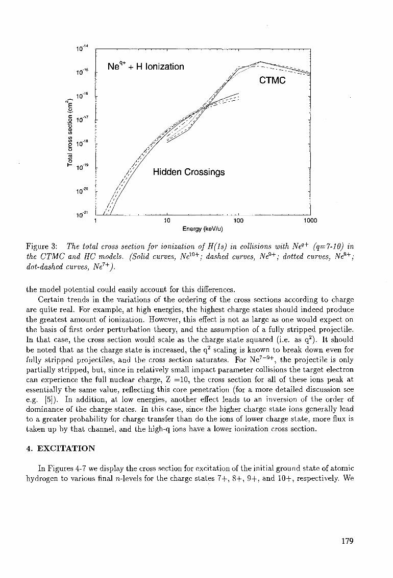
10"
10"
_ 10"'°
E
J 10-17
** o a> CO CO CO . - - 1 8 g 10 o "5 • * — '
o 10"
10'
10"'
Neq+ + H Ionization ^
ft / ^
• //^<<?:
S^^'" •lJ&' '
•••/?//// .-&?• /'/
• • • ^ • • • • " /
••*X'.----:y
4^y^ - Ay Ay
Ay ./>'/
/;/ Hidden Crossings / /
- v / /
• i>!
/ ' / •
-<z^~- --^^^^^^-^i -
CTMC ^" l
-
-
-
10 100
Energy (keV/u)
1000
Figure 3: The total cross section for ionization of H(ls) in collisions with Neq+ (q=7-10) in the CTMC and HC models. (Solid curves, Ne10^; dashed curves, Ne9+; dotted curves, Ne8+; dot-dashed curves, Ne7+).
the model potential could easily account for this differences. Certain trends in the variations of the ordering of the cross sections according to charge
are quite real. For example, at high energies, the highest charge states should indeed produce the greatest amount of ionization. However, this effect is not as large as one would expect on the basis of first order perturbation theory, and the assumption of a fully stripped projectile. In that case, the cross section would scale as the charge state squared (i.e. as q2). It should be noted that as the charge state is increased, the q2 scaling is known to break down even for fully stripped projectiles, and the cross section saturates. For Ne 7 _ 9 + , the projectile is only partially stripped, but, since in relatively small impact parameter collisions the target electron can experience the full nuclear charge, Z =10, the cross section for all of these ions peak at essentially the same value, reflecting this core penetration (for a more detailed discussion see e.g. [5]). In addition, at low energies, another effect leads to an inversion of the order of dominance of the charge states. In this case, since the higher charge state ions generally lead to a greater probability for charge transfer than do the ions of lower charge state, more flux is taken up by that channel, and the high-q ions have a lower ionization cross section.
4. E X C I T A T I O N
In Figures 4-7 we display the cross section for excitation of the initial ground state of atomic hydrogen to various final n-levels for the charge states 7+, 8+, 9+, and 10+, respectively. We
179
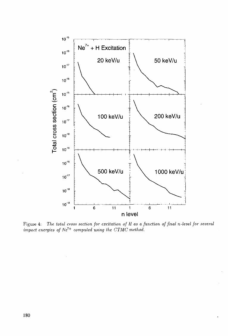
10"
-16 10
10"
101
011 -15
£ 10
o 10 '•I—I
o W 1 0
1 7
<n w
§ io"18
~S P 10"15
10"'
10"
10"
10" 11 1 6
n level Figure 4: The total cross section for excitation of H as a function of final n-level for several impact energies of Ne7+ computed using the CTMC method.
180
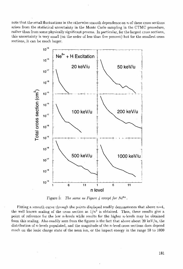
note that the small fluctuations in the otherwise smooth dependence on n of these cross sections arises from the statistical uncertainty in the Monte Carlo sampling in the CTMC procedure, rather than from some physically significant process. In particular, for the largest cross sections, this uncertainty is very small (on the order of less than five percent) but for the smallest cross sections, it can be much larger.
£
c o o CD CO CO CO O s_
o "en o
,-18
,-18
8+ Ne + H Excitation
20 keV/u
-I 1 1 H - } 1 1 1 1 1 1 1 1 :: 1 1 1 1 1 1 1 1 1 1
100keV/u
500 keV/u
50 keV/u
200 keV/u
H 1 1 1 1 1 1 1 1 1 1 1 1 :: 1 1 1 1 1 1 1 1 1 1 1 1 H
1000 keV/u
11 11
n level
Figure 5: The same as Figure 4 except for Ne8+.
Fitting a smooth curve through the points displayed readily demonstrates that above n=4 , the well known scaling of the cross section as 1/n3 is obtained. Thus, these results give a point of reference for the low n-levels while results for the higher n-levels may be obtained from this scaling. Also readily seen from the figures is the fact that above about 20 keV/u, the distribution of n-levels populated, and the magnitude of the n-level cross sections does depend much on the ionic charge state of the neon ion, or the impact energy in the range 50 to 1000
181
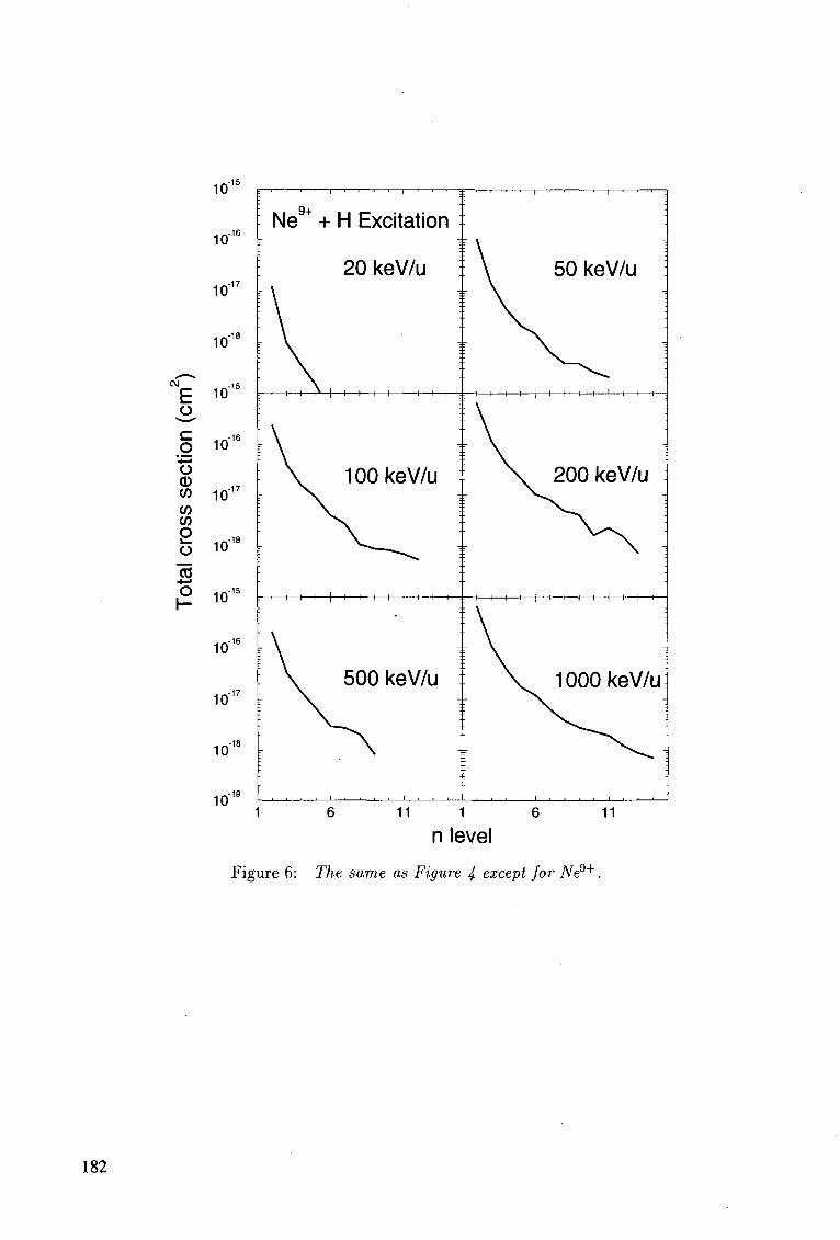
9+ Ne + H Excitation
20 keV/u
-t 1 1 i»—\ 1 1 1 1 1 1 1 1 :: 1 1 1 1 1 1 1 1 1 1 1 1 H
50 keV/u
100 keV/u 200 keV/u
H 1 1 1 1 1 1 1 1 1 1 1 H H 1 1 1 1 1 1 1 1 1 1 1 H-
500 keV/u 1000 keV/u
11 1 6
n level 11
Figure 6: The same as Figure 4 except for JVe9+.
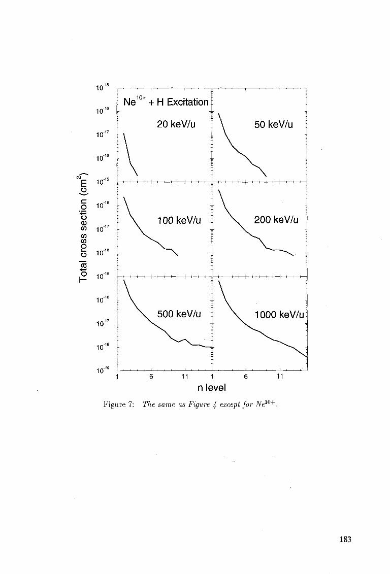
10"
10"
10
10"
E o c o o <D CO CO CO o o
10 IJ
^ ^-16 10
10"
10" I B
P 10"15
10"
10"'
10"
10 11 1 6
n level
Figure 7: The same as Figure 4 except for Ne10+.
183
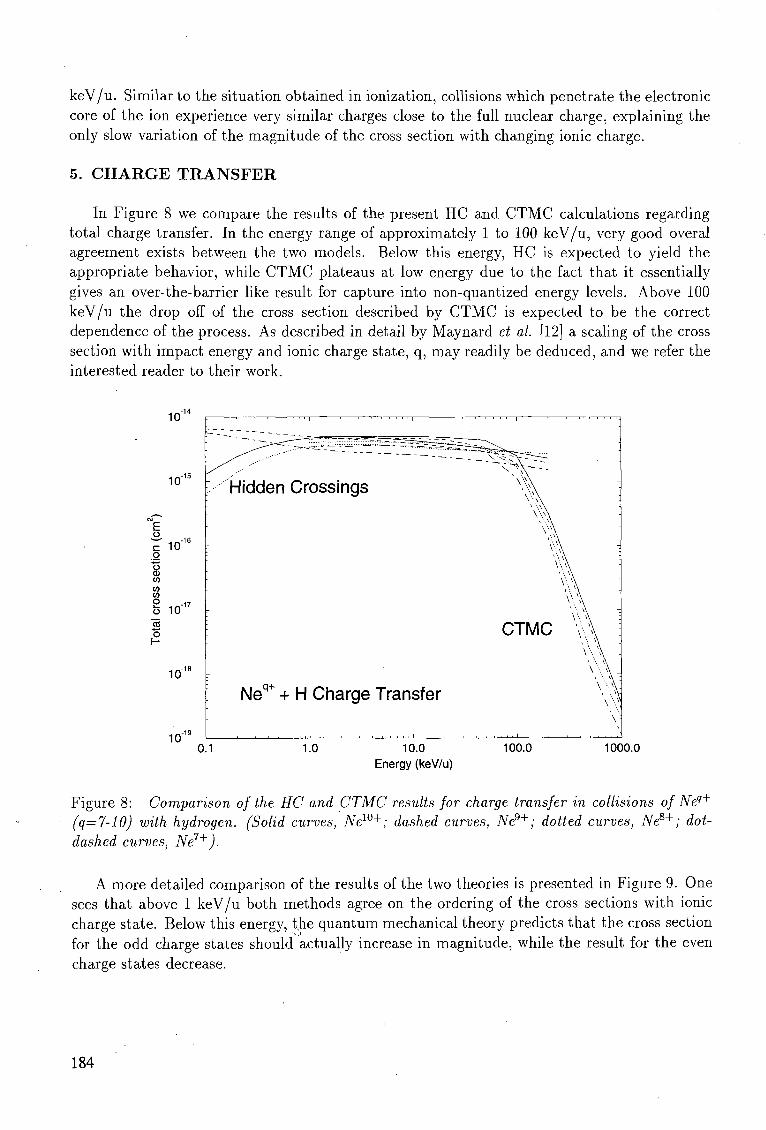
keV/u. Similar to the situation obtained in ionization, collisions which penetrate the electronic core of the ion experience very similar charges close to the full nuclear charge, explaining the only slow variation of the magnitude of the cross section with changing ionic charge.
5. C H A R G E T R A N S F E R
In Figure 8 we compare the results of the present HC and CTMC calculations regarding total charge transfer. In the energy range of approximately 1 to 100 keV/u, very good overal agreement exists between the two models. Below this energy, HC is expected to yield the appropriate behavior, while CTMC plateaus at low energy due to the fact that it essentially gives an over-the-barrier like result for capture into non-quantized energy levels. Above 100 keV/u the drop off of the cross section described by CTMC is expected to be the correct dependence of the process. As described in detail by Maynard et al. [12] a scaling of the cross section with impact energy and ionic charge state, q, may readily be deduced, and we refer the interested reader to their work.
10"'
10"'
c 10 o o CD (/> <f) (0 P -1 u 10 2 o H
10"
io-
—^—-ss ' H i d d e n Crossings
-
Neq+ + H Charge Transfer
_s5??\ ~
X. \
' ^ \
CTMC v \ ; 'f\ :
\ ;
0.1 1.0 10.0 Energy (keV/u)
100.0 1000.0
Figure 8: Comparison of the HC and CTMC results for charge transfer in collisions of Neq+
(q=7-10) with hydrogen. (Solid curves, New+; dashed curves, Ne9+; dotted curves, Ne8+; dot-dashed curves, Ne7+).
A more detailed comparison of the results of the two theories is presented in Figure 9. One sees that above 1 keV/u both methods agree on the ordering of the cross sections with ionic charge state. Below this energy, the quantum mechanical theory predicts that the cross section for the odd charge states should actually increase in magnitude, while the result for the even charge states decrease.
184
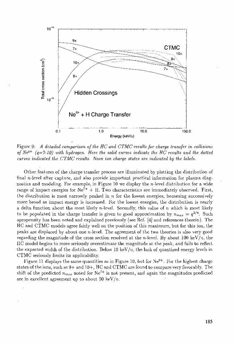
10-
c q o <D in to (0
o
o H io-15
9+
/ 8+ /
/ Hidden Crossings
• Neq+ + H Charge Transfer
CTMC
~~~- " ^ ^ - i : 9 + '"••
•
0.1 1.0 10.0 100.0 Energy (keV/u)
Figure 9: A detailed comparison of the HC and CTMC results for charge transfer in collisions of Neq+ (q=7-10) with hydrogen. Here the solid curves indicate the HC results and the dotted curves indicated the CTMC results. Neon ion charge states are indicated by the labels.
Other features of the charge transfer process are illuminated by plotting the distribution of final n-level after capture, and also provide important practical information for plasma diagnostics and modeling. For example, in Figure 10 we display the n-level distribution for a wide range of impact energies for Ne7 + + H. Two characteristics are immediately observed. First, the distribution is most narrowly peaked in n for the lowest energies, becoming successively more broad as impact energy is increased. For the lowest energies, the distribution is nearly a delta function about the most likely n-level. Secondly, this value of n which is most likely to be populated in the charge transfer is given to good approximation by nmax = q3/4. Such apropensity has been noted and explained previously (see Ref. [4] and references therein). The HC and CTMC models agree fairly well on the position of this maximum, but for this ion, the peaks are displaced by about one n-level. The agreement of the two theories is also very good regarding the magnitude of the cross section resolved at the n-level. By about 100 keV/u, the HC model begins to more seriously overestimate the magnitude at the peak, and fails to reflect the expected width of the distribution. Below 10 keV/u, the lack of quantized energy levels in CTMC seriously limits its applicability.
Figure 11 displays the same quantities as in Figure 10, but for Ne 9 + . For the highest charge states of the ions, such as 9+ and 10+, HC and CTMC are found to compare very favorably. The shift of the predicted nmax noted for Ne 7 + is not present, and again the magnitudes predicted are in excellent agreement up to about 50 keV/u.
185
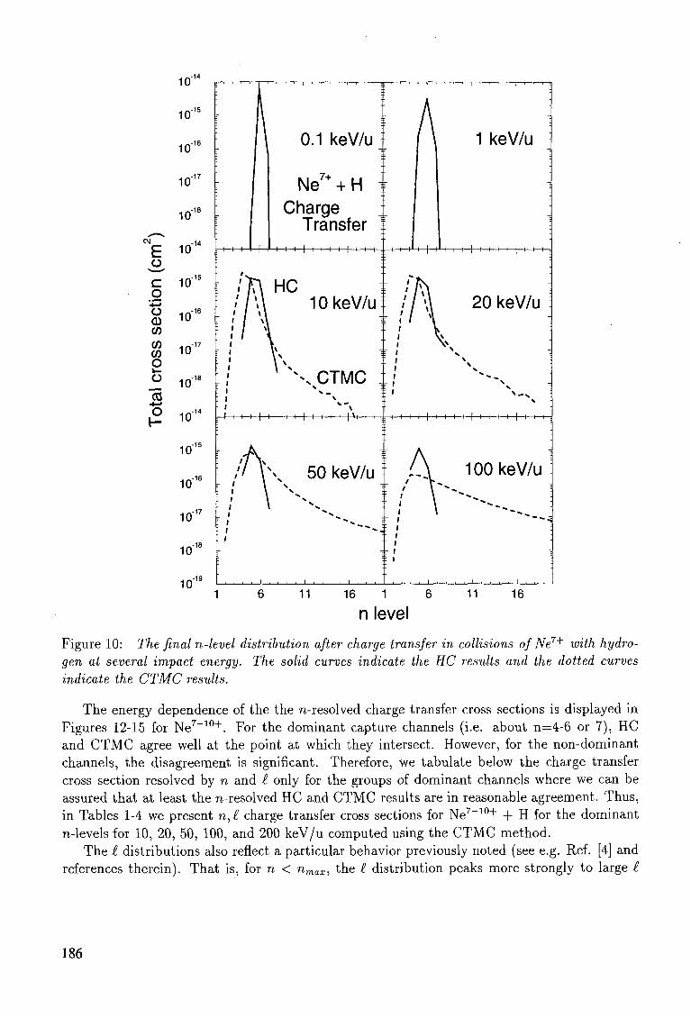
CM
CO
10"
10"
10
10'1
10"'
E io"
C 10"1
o 10 o
CD CO CO 1 f 1 - i 7 CO 1 0
O O 1 0 1 8
10"
10"
10"
10"'
10"
10"
0.1 keV/u
Ne7+ + H Charge
Transfer H—I—I—|—I—I—I—I | I I — b ^ r
r\ HC 1 * 10 keV/u
X CTMC
i—|—I—I—I—I—|—I—I—I—I—)-^—I—I-
// \ \ 50keV/u
1 keV/u
H—I—I | !—I—I—I—|-H—I—t-
20 keV/u
H—I—I—I—|—I—I—I—I—|—I—I—I—I—|—I—I—H
100 keV/u
11 16 1 6
n level 11 16
Figure 10: The final n-level distribution after charge transfer in collisions of Ne7+ with hydrogen at several impact energy. The solid curves indicate the HC results and the dotted curves indicate the CTMC results.
The energy dependence of the the n-resolved charge transfer cross sections is displayed in Figures 12-15 for Ne 7 _ 1 0 + . For the dominant capture channels (i.e. about n=4-6 or 7), HC and CTMC agree well at the point at which they intersect. However, for the non-dominant channels, the disagreement is significant. Therefore, we tabulate below the charge transfer cross section resolved by n and £ only for the groups of dominant channels where we can be assured that at least the n-resolved HC and CTMC results are in reasonable agreement. Thus, in Tables 1-4 we present n,£ charge transfer cross sections for Ne 7 _ 1 0 + + H for the dominant n-levels for 10, 20, 50, 100, and 200 keV/u computed using the CTMC method.
The £ distributions also reflect a particular behavior previously noted (see e.g. Ref. [4] and references therein). That is, for n < nmax, the £ distribution peaks more strongly to large £
186
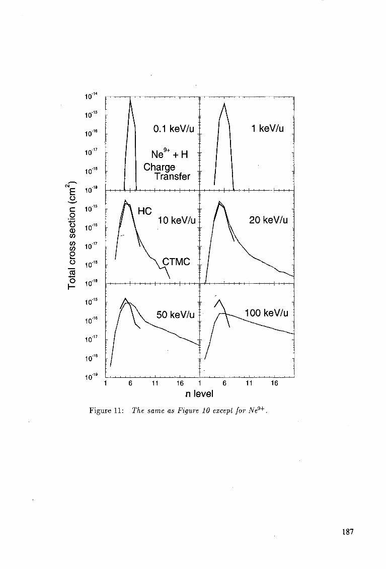
10"
10"'
10"
10"
10"
10
10"
g -10
E J" o, c o o CD w w CO
o
10
10"
-16
CO
o I -
10
10"
10"
10"
10"
10"
10"
0.1 keV/u
Ne9+ + H Charge
Transfer H—|—I—I—I—I—\—t—H-+-
1 keV/u
H—H—i—i—i—i——i—i—*-
20 keV/u
11 16 1 6
n level 11 16
Figure 11: The same as Figure 10 except for Ne9+.
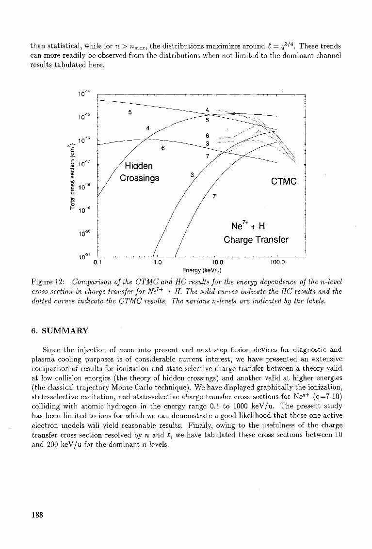
than statistical, while for n > nmax, the distributions maximizes around £ = q3^. These trends can more readily be observed from the distributions when not limited to the dominant channel results tabulated here.
10"
10"
_ 10"° e ,0 ,
o CD CO CO CO . , - . - 1 8
O 10 O
•Jo o
10"
10"
10" 0.1
CTMC
Ne7+ + H
Charge Transfer
100.0 10.0 Energy (keV/u)
Figure 12: Comparison of the CTMC and HC results for the energy dependence of the n-level cross section in charge transfer for Ne7+ + H. The solid curves indicate the HC results and the dotted curves indicate the CTMC results. The various n-levels are indicated by the labels.
6. S U M M A R Y
Since the injection of neon into present and next-step fusion devices for diagnostic and plasma cooling purposes is of considerable current interest, we have presented an extensive comparison of results for ionization and state-selective charge transfer between a theory valid at low collision energies (the theory of hidden crossings) and another valid at higher energies (the classical trajectory Monte Carlo technique). We have displayed graphically the ionization, state-selective excitation, and state-selective charge transfer cross sections for Ne9 + (q=7-10) colliding with atomic hydrogen in the energy range 0.1 to 1000 keV/u. The present study has been limited to ions for which we can demonstrate a good likelihood that these one-active electron models will yield reasonable results. Finally, owing to the usefulness of the charge transfer cross section resolved by n and £, we have tabulated these cross sections between 10 and 200 keV/u for the dominant n-levels.
188
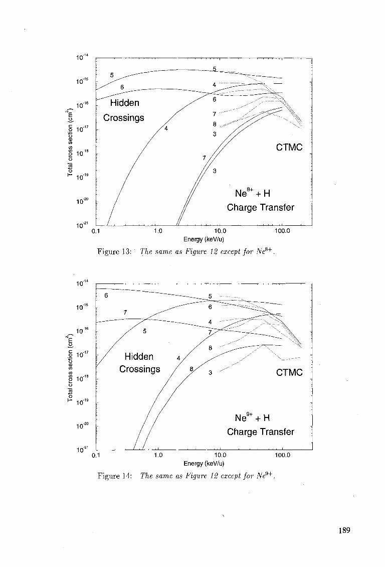
10"1
10-
10-E
.2 1017 •4—> o CD CO CO CO . , , , - 1 8 O 10 o "5
H- Hn-1 10
10"
10"
5 ^
: ^ ^ fi
Hidden
Crossings /
/
'. / /
J
^ _ _ _ _ 5 ' \ - ^ ~ ^ _ ^ _ _ ^
4 ^ ^—' ;'..., :
/ ^ 6 ....••;;;:::::::::::%.
3 // }
// CTMC :
7 / /
// 3 "
/ Ne8+ + H
/ Charge Transfer
0.1 1.0 10.0 Energy (keV/u)
Figure 13: The same as Figure 12 except for Ne8+.
100.0
10"
CTMC
Ne9+ + H
Charge Transfer
10.0 Energy (keV/u)
Figure 14: The same as Figure 12 except for Ne9+.
100.0
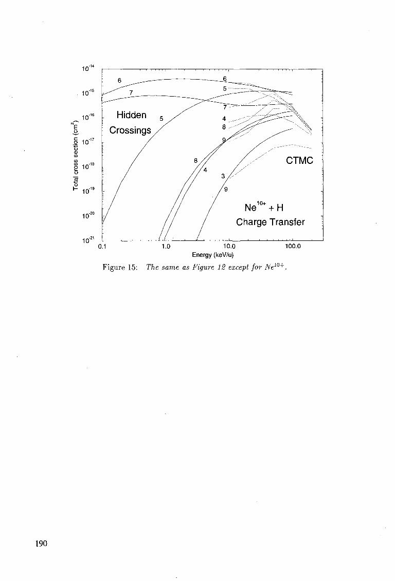
\ ' 6 ^____———
\ Hidden 5 s^
Crossings^/
: /
! / /
r / / /
• / / /
6
5
^ 7
4 8 .-
8 / /
/ / 4 / 3 /
/ 9
' :
~~ ...-><; :?C~^ i
S^ss'' ^--^^* '••.'— -
//.--'""" CTMC
-
Ne10+ + H
Charge Transfer
0.1 1.0 10.0 Energy (keV/u)
Figure 15: The same as Figure 12 except for New+
100.0
190
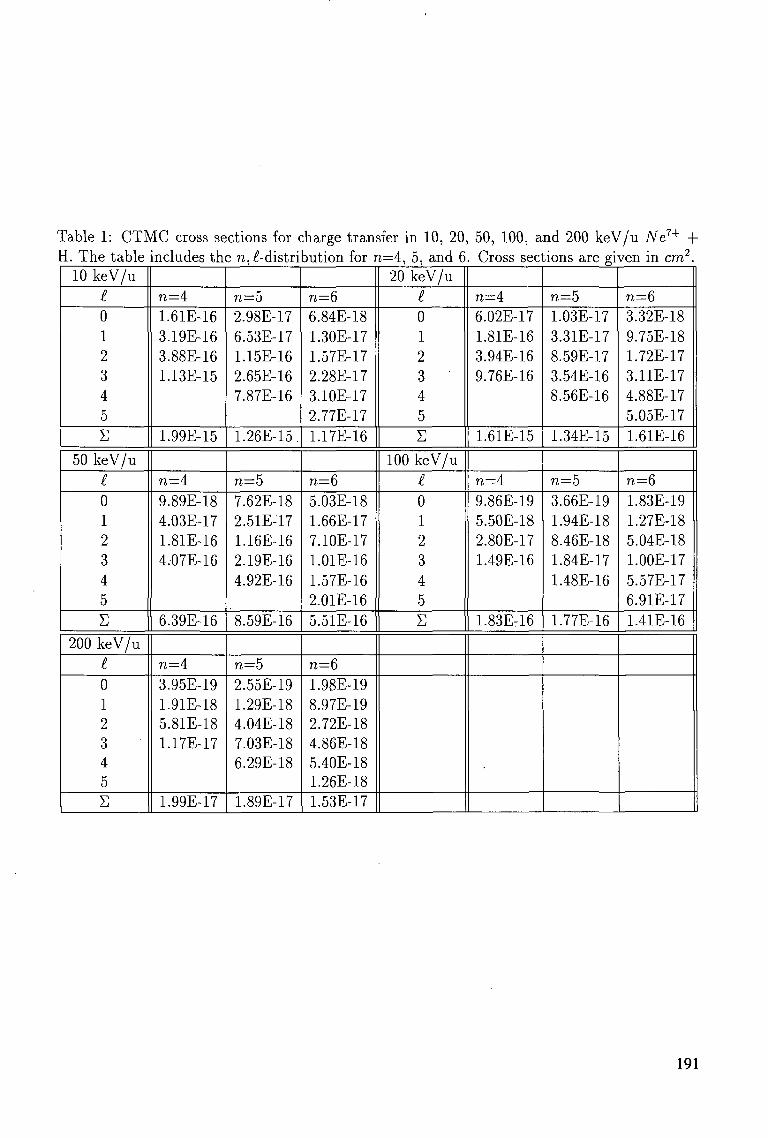
Table 1: CTMC cross sections for charge transfer in 10, 20, 50, 100, and 200 keV/u Ne7+ + I. The table includes the n, -distribution for n=4, 5, and 6. Cross sections are given in cm2.
10 keV/u £ 0 1 2 3 4 5 E
50 keV/u £ 0 1 2 3 4 5 £
200 keV/u £ 0 1 2 3 4 5 E
n=4 1.61E-16 3.19E-16 3.88E-16 1.13E-15
1.99E-15
n=4 9.89E-18 4.03E-17 1.81E-16 4.07E-16
6.39E-16
n=4 3.95E-19 1.91E-18 5.81E-18 1.17E-17
1.99E-17
n=5 2.98E-17 6.53E-17 1.15E-16 2.65E-16 7.87E-16
1.26E-15.
n=5 7.62E-18 2.51E-17 1.16E-16 2.19E-16 4.92E-16
8.59E-16
n=5 2.55E-19 1.29E-18 4.04E-18 7.03E-18 6.29E-18
1.89E-17
n~6 6.84E-18 1.30E-17 1.57E-17 2.28E-17 3.10E-17 2.77E-17 1.17E-16
n=6 5.03E-18 1.66E-17 7.10E-17 1.01E-16 1.57E-16 2.01E-16 5.51E-16
n=6 1.98E-19 8.97E-19 2.72E-18 4.86E-18 5.40E-18 1.26E-18 1.53E-17
20 keV/u £ 0 1 2 3 4 5 E
100 keV/u £ 0 1 2 3 4 5 £
n=4 6.02E-17 1.81E-16 3.94E-16 9.76E-16
1.61E-15
n=A 9.86E-19 5.50E-18 2.80E-17 1.49E-16
1.83Er16
n=5 1.03E-17 3.31E-17 8.59E-17 3.54E-16 8.56E-16
1.34E-15
n=5 3.66E-19 1.94E-18 8.46E-18 1.84E-17 1.48E-16
1.77E-16
n=6 3.32E-18 9.75E-18 1.72E-17 3.11E-17 4.88E-17 5.05E-17 1.61E-16
n=6 1.83E-19 1.27E-18 5.04E-18 1.00E-17 5.57E-17 6.91E-17 1.41E-16
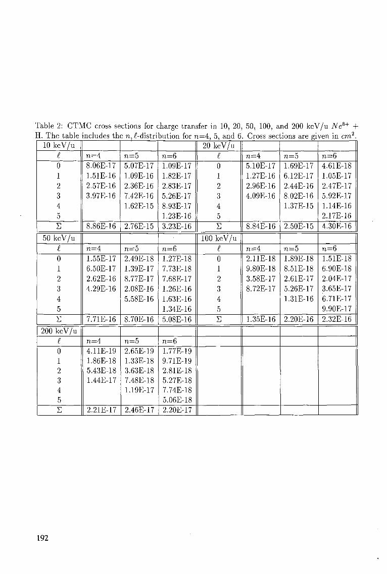
Table 2: CTMC cross sections for charge transfer in 10, 20, 50, 100, and 200 keV/u Ne8+ + I. The table includes the n,£-distri
10 keV/u
t 0 1 2 3 4 5 S
50 keV/u £ 0 1 2 3 4 5 S
200 keV/u £ 0 1 2 3 4 5 E
n=4 8.06E-17 1.51E-16 2.57E-16 3.97E-16
8.86E-16
n=4 1.55E-17 6.50E-17 2.62E-16 4.29E-16
7.71E-16
n=4 4.11E-19 1.86E-18 5.43E-18 1.44E-17
2.21E-17
n=5 5.07E-17 1.09E-16 2.36E-16 7.42E-16 1.62E-15
2.76E-15
n=5 2.49E-18 1.39E-17 8.77E-17 2.08E-16 5.58E-16
8.70E-16
n=5 2.65E-19 1.33E-18 3.63E-18 7.48E-18 1.19E-17
2.46E-17
Dution for n=4, 5, and 6
n=6 1.09E-17 1.82E-17 2.83E-17 5.26E-17 8.93E-17 1.23E-16 3.23E-16
n=6 1.27E-18 7.73E-18 7.68E-17 1.26E-16 1.63E-16 1.34E-16 5.08E-16
n=6 1.77E-19 9.71E-19 2.81E-18 5.27E-18 7.74E-18 5.06E-18 2.20E-17
20 keV/u I 0 1 2 3 4 5 S
100 keV/u I 0 1 2 3 4 5 S
. Cross sections are given in cm2.
n=4 5.10E-17 1.27E-16 2.96E-16 4.09E-16
8.84E-16
n=4 2.11E-18 9.80E-18 3.58E-17 8.72E-17
1.35E-16
n=5 1.69E-17 6.12E-17 2.44E-16 8.02E-16 1.37E-15
2.50E-15
n=5 1.89E-18 8.51E-18 2.61E-17 5.26E-17 1.31E-16
2.20E-16
n=6 4.61E-18 1.05E-17 2.47E-17 5.92E-17 1.14E-16 2.17E-16 4.30E-16
n=6 1.51E-18 6.90E-18 2.04E-17 3.65E-17 6.71E-17 9.90E-17 2.32E-16
192
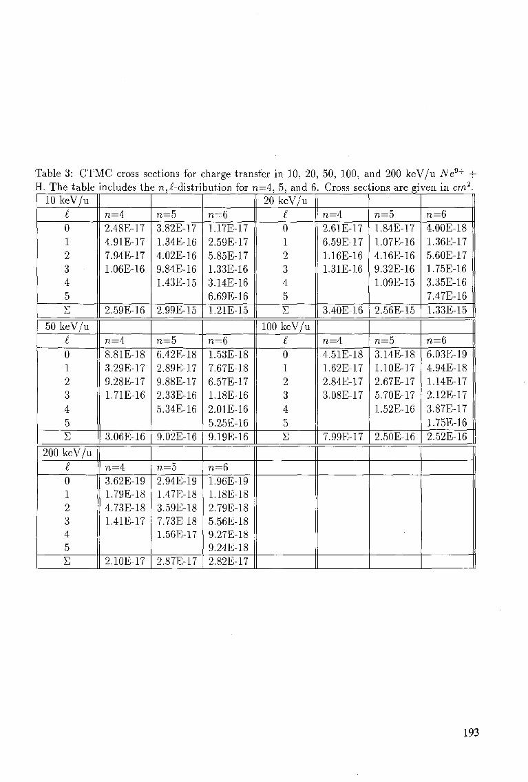
Table 3: CTMC cross sections for charge transfer in 10, 20, 50, 100, and 200 keV/u Ne9+ + H. The table includes the re,l-distribution for re=4, 5, and 6. Cross sections are given in cm2.
10 keV/u £ 0 1 2 3 4 5 E
50 keV/u £ 0 1 2 3 4 5 E
200 keV/u £ 0 1 2 3 4 5 E
n—4 2.48E-17 4.91E-17 7.94E-17 1.06E-16
2.59E-16
n=4 8.81E-18 3.29E-17 9.28E-17 1.71E-16
3.06E-16
n=4 3.62E-19 1.79E-18 4.73E-18 1.41E-17
2.10E-17
n~5 3.82E-17 1.34E-16 4.02E-16 9.84E-16 1.43E-15
2.99E-15
n=5 6.42E-18 2.89E-17 9.88E-17 2.33E-16 5.34E-16
9.02E-16
n=5 2.94E-19 1.47E-18 3.59E-18 7.73E-18 1.56E-17
2.87E-17
n=6 1.17E-17 2.59E-17 5.85E-17 1.33E-16 3.14E-16 6.69E-16 1.21E-15
n=6 1.53E-18 7.67E-18 6.57E-17 1.18E-16 2.01E-16 5.25E-16 9.19E-16
n=6 1.96E-19 1.18E-18 2.79E-18 5.56E-18 9.27E-18 9.24E-18 2.82E-17
20 keV/u £ 0 1 2 3 4 5 E
100 keV/u £ 0 1 2 3 4 5 E
n=4 2.61E-17 6.59E-17 1.16E-16 1.31E-16
3.40E-16
n=4 4.51E-18 1.62E-17 2.84E-17 3.08E-17
7.99E-17
n=5 1.84E-17 1.07E-16 4.16E-16 9.32E-16 1.09E-15
2.56E-15
n=5 3.14E-18 1.10E-17 2.67E-17 5.70E-17 1.52E-16
2.50E-16
n=6 4.00E-18 1.36E-17 5.60E-17 1.75E-16 3.35E-16 7.47E-16 1.33E-15
n=6 6.03E-19 4.94E-18 1.14E-17 2.12E-17 3.87E-17 1.75E-16 2.52E-16
193
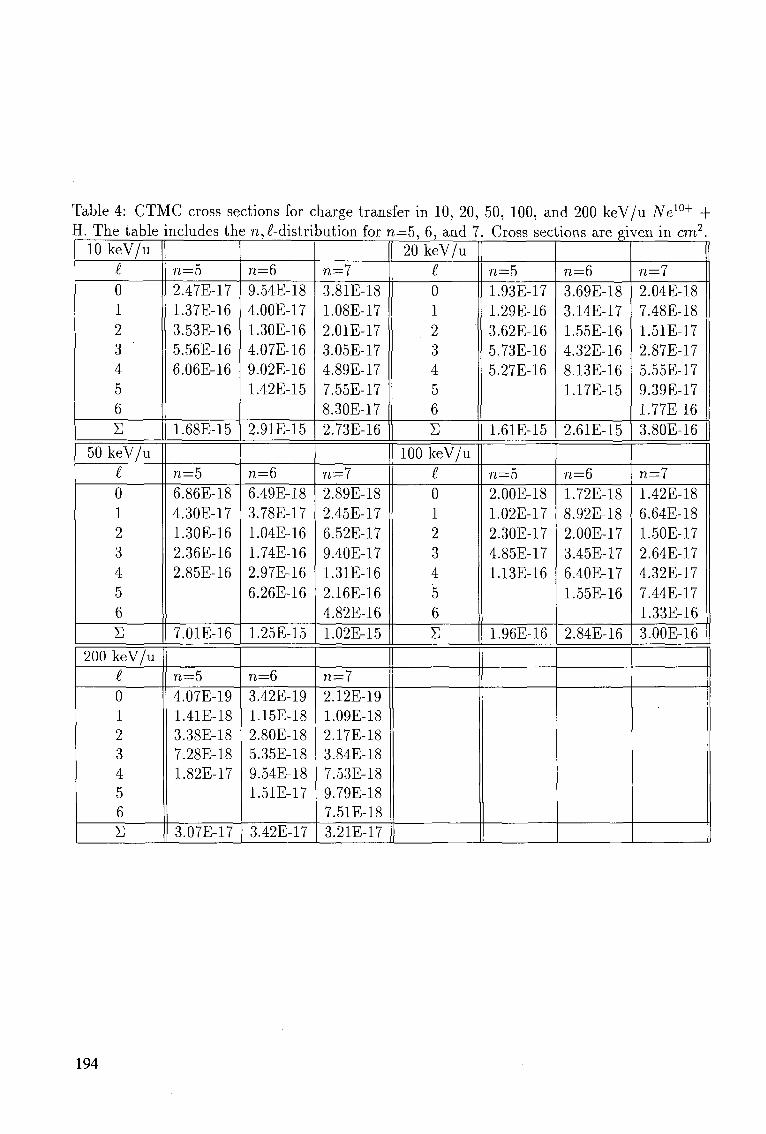
Table 4: CTMC cross sections for charge transfer in 10, 20, 50, 100, and 200 keV/u New+ + H. The table
10 keV/u I 0 1 2 3 4 5 6 S
50 keV/u £ 0 1 2 3 4 5 6 S
200 keV/u £ 0 1 2 3 4 5 6 E
includes the n,£-distri
n=5 2.47E-17 1.37E-16 3.53E-16 5.56E-16 6.06E-16
1.68E-15
n=5 6.86E-18 4.30E-17 1.30E-16 2.36E-16 2.85E-16
7.01E-16
n=5 4.07E-19 1.41E-18 3.38E-18 7.28E-18 1.82E-17
3.07E-17
n=Q 9.54E-18 4.00E-17 1.30E-16 4.07E-16 9.02E-16 1.42E-15
2.91E-15
n=6 6.49E-18 3.78E-17 1.04E-16 1.74E-16 2.97E46 6.26E-16
1.25E-15
n=6 3.42E-19 1.15E-18 2.80E-18 5.35E-18 9.54E-18 1.51E-17
3.42E-17
^ution for n=5, 6, and 7
n=7 3.81E-18 1.08E-17 2.01E-17 3.05E-17 4.89E-17 7.55E-17 8.30E-17 2.73E-16
n—7 2.89E-18 2.45E-17 6.52E-17 9.40E-17 1.31E-16 2.16E-16 4.82E-16
L1.02E-15
n=7 2.12E-19 1.09E-18 2.17E-18 3.84E-18 7.53E-18 9.79E-18 7.51E-18 3.21E-17
20 keV/u £ 0 1 2 3 4 5 6 S
100 keV/u I 0 1 2 3 4 5 6 E
. Cross sections are given in cm2.
n=5 1.93E-17 1.29E-16 3.62E-16 5.73E-16 5.27E-16
1.61E-15
n=5 2.00E-18 1.02E-17 2.30E-17 4.85E-17 1.13E-16
1.96E-16
n—6 3.69E-18 3.14E-17 1.55E-16 4.32E-16 8.13E-16 1.17E-15
2.61E-15
n=6 1.72E-18 8.92E-18 2.00E-17 3.45E-17 6.40E-17 1.55E-16
2.84E-16
n=l 2.04E-18 7.48E-18 1.51E-17 2.87E-17 5.55E-17 9.39E-17 1.77E-16 3.80E-16
n—1 1.42E-18 6.64E-18 1.50E-17 2.64E-17 4.32E-17 7.44E-17 1.33E-16 3.00E-16
194
ACKNOWLEDGEMENTS
The authors gratefully acknowledge the support for this work from the US Department of Energy, Office of Fusion Energy, through contract number DE-AC05-84OR21400 with Oak Ridge National Laboratory, managed by Lockheed Martin Energy Systems, Inc.
References
[1] REBUT, P.-H., BOUCHER, D., GAMBIER, D.J., KEEN, B.E., AND WATKINS, M.L., The ITER Challenge, 17th Symposium on Fusion Technology, Rome (1992).
[2] POST, D.E., J. Nucl. Mat. 220-222, 143 (1995).
[3] "Atomic and Molecular Processes in Fusion Edge Plasmas," JANEV, R.K., editor (Plenum Press, New York, 1995).
[4] OLSON, R.E. AND SCHULTZ, D.R., Physica Scripta T28, 71 (1989).
[5] SCHULTZ, D.R., MENG, L., REINHOLD, CO., AND OLSON, R.E., Physica Scripta T37, 89 (1991).
[6] ABRINES, R. AND PERCIVAL, I.C., Proc. Phys. Soc. London 88, 861 (1966).
[7] OLSON, R.E. AND SALOP, A., Phys. Rev. A 16, 531 (1977).
[8] REINHOLD, CO., OLSON, R.E., AND FRITSCH, W., Phys. Rev. A 41, 4837 (1990).
[9] BECKER, R.L. AND MACKELLAR, A.D., J. Phys. B 17, 3923 (1984).
[10] PEACH, G., WILLIS, S.L., AND MCDOWELL, M.R.C, J. Phys. B 18, 3921 (1985); WILLIS, S.L., PEACH, G., MCDOWELL, M.R.C, AND BANERJI, J., J. Phys. B 18, 3939 (1985).
[11] TOBUREN, L.H., DUBOIS, R.D., REINHOLD, CO., SCHULTZ, D.R., AND OLSON, R.E., Phys. Rev. A 42, 5338 (1990).
[12] MAYNARD, G., JANEV, R.K., AND KATSONIS K., J. Phys. B 25, 437 (1992).
[13] LANDAU, L.D. AND LIFSHITZ, E.M., Quantum Mechanics: Non-Relativistic Theory, Pergamon, Oxford (1977).
[14] SOLOV'EV, E.A., Zh. Eksp. Teor. Fiz. 81, 1681 (1981) [Sov.Phys.JETP 54, 893 (1981)].
[15] SOLOV'EV, E.A., Usp. Fiz. Nauk 157, 437 (1989) [Sov.Phys.Usp. 32, 228 (1989)].
[16] OVCHINNIKOV, S.YU. AND SOLOV'EV, E.A., Comments At. Mol. Phys. 22, 69 (1988).
195
[17] GROZDANOV, T.P. AND SOLOV'EV, E.A., Phys. Rev. A 42, 3865 (1990).
[18] KRSTIC, P.S. AND JANEV, R.K., Phys. Rev. A 47, 3894 (1993).
[19] KRSTIC, P.S., RADMILOVIC, M., AND JANEV, R.K., At. Plasma-Mater. Int. Data Fusion 3, 113 (1993).
[20] SZYDLIK, P.P. AND GREEN, A.E.S., Phys. Rev. A 9, 1885 (1974).
[21] FRITSCH, W., in Review of Fundamental Processes and Applications of Atoms and Ions, LIN, C.D., editor (World Scientific, Singapore, 1993), p. 239.
[22] SCHULTZ, D.R., KRSTIC, P.S., and REINHOLD, CO., Physica Scripta (1995) to be published.
196
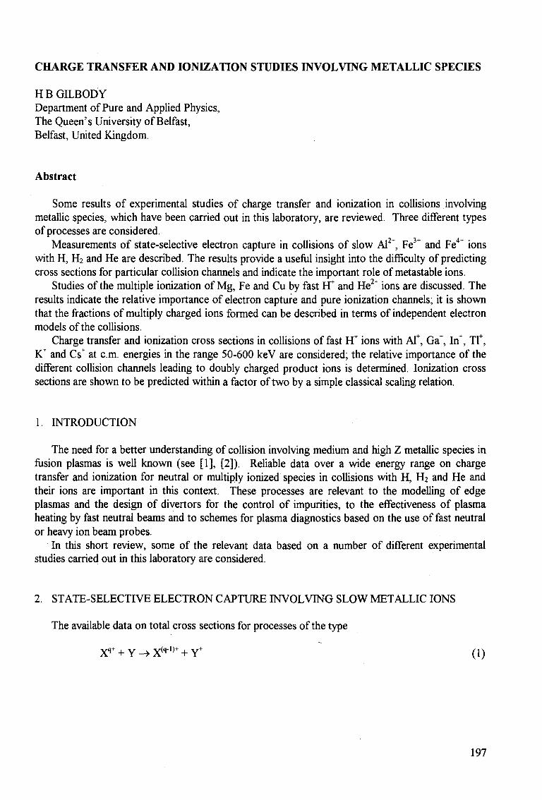
CHARGE TRANSFER AND IONIZATION STUDIES INVOLVING METALLIC SPECIES
H B GILBODY Department of Pure and Applied Physics, The Queen's University of Belfast, Belfast, United Kingdom.
Abstract
Some results of experimental studies of charge transfer and ionization in collisions involving metallic species, which have been carried out in this laboratory, are reviewed. Three different types of processes are considered.
Measurements of state-selective electron capture in collisions of slow Al2+, Fe3+ and Fe4+ ions with H, H2 and He are described. The results provide a useful insight into the difficulty of predicting cross sections for particular collision channels and indicate the important role of metastable ions.
Studies of the multiple ionization of Mg, Fe and Cu by fast Yf and He2+ ions are discussed. The results indicate the relative importance of electron capture and pure ionization channels; it is shown that the fractions of multiply charged ions formed can be described in terms of independent electron models of the collisions.
Charge transfer and ionization cross sections in collisions of fast HT ions with Al+, Ga+, In+, Tf, K+ and Cs+ at cm. energies in the range 50-600 keV are considered; the relative importance of the different collision channels leading to doubly charged product ions is determined. Ionization cross sections are shown to be predicted within a factor of two by a simple classical scaling relation.
1. INTRODUCTION
The need for a better understanding of collision involving medium and high Z metallic species in fusion plasmas is well known (see [1], [2]). Reliable data over a wide energy range on charge transfer and ionization for neutral or multiply ionized species in collisions with H, H2 and He and their ions are important in this context. These processes are relevant to the modelling of edge plasmas and the design of divertors for the control of impurities, to the effectiveness of plasma heating by fast neutral beams and to schemes for plasma diagnostics based on the use of fast neutral or heavy ion beam probes.
In this short review, some of the relevant data based on a number of different experimental studies carried out in this laboratory are considered.
2. STATE-SELECTTVE ELECTRON CAPTURE INVOLVING SLOW METALLIC IONS
The available data on total cross sections for processes of the type
X*1" + Y -> X(q-1)+ + Y+ (1)
197
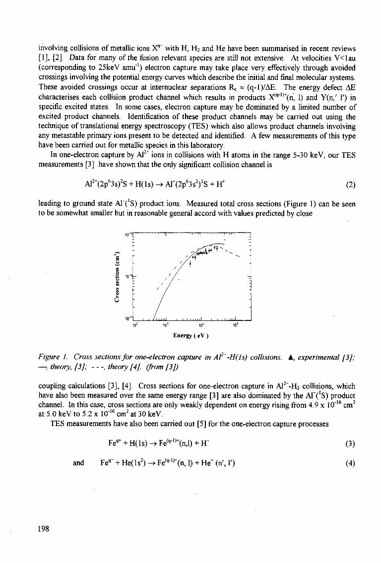
involving collisions of metallic ions Xq+ with H, H2 and He have been summarised in recent reviews [1], [2]. Data for many of the fusion relevant species are still not extensive. At velocities V<lau (corresponding to 25keV amu"1) electron capture may take place very effectively through avoided crossings involving the potential energy curves which describe the initial and final molecular systems. These avoided crossings occur at internuclear separations Re « (q-l)/AE. The energy defect AE characterises each collision product channel which results in products X^ ' ^n , 1) and Y(n,' 1') in specific excited states. In some cases, electron capture may be dominated by a limited number of excited product channels. Identification of these product channels may be carried out using the technique of translational energy spectroscopy (TES) which also allows product channels involving any metastable primary ions present to be detected and identified. A few measurements of this type have been carried out for metallic species in this laboratory.
In one-electron capture by Al2+ ions in collisions with H atoms in the range 5-30 keV, our TES measurements [3] have shown that the only significant collision channel is
Af+(2tf3syS + H(ls) -> AlW^sYS + FT (2)
leading to ground state AT('S) product ions. Measured total cross sections (Figure 1) can be seen to be somewhat smaller but in reasonable general accord with values predicted by close
Energy (eV )
Figure 1. Cross sections for one-electron capture in A?*-H(ls) collisions. A, experimental [3]; —; theory, [3]; , theory [4J. (from [3])
coupling calculations [3], [4]. Cross sections for one-electron capture in Al2+-H2 collisions, which have also been measured over the same energy range [3] are also dominated by the A1+(!S) product channel. In this case, cross sections are only weakly dependent on energy rising from 4.9 x 10"16 cm2
at 5.0 keV to 5.2 x 10"16 cm2 at 30 keV.
TES measurements have also been carried out [5] for the one-electron capture processes
Feq+ + H( 1 s) -» Fe(q-1,+(n,l) + FT (3)
and Feq+ + He( 1 s2) -> Fe(q"1)+(n, 1) + He+ (n\ 1') (4)
198
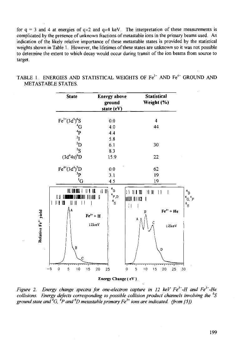
for q = 3 and 4 at energies of qx2 and qx4 keV. The interpretation of these measurements is complicated by the presence of unknown fractions of metastable ions in the primary beams used. An indication of the likely relative importance of these metastable states is provided by the statistical weights shown in Table 1. However, the lifetimes of these states are unknown so it was not possible to determine the extent to which decay would occur during transit of the ion beams from source to target.
TABLE 1. ENERGIES AND STATISTICAL WEIGHTS OF Fe3+ AND Fe4+ GROUND AND METASTABLE STATES.
State Energy above ground
state (eV)
Statistical Weight (%)
3+ 5\6<: Fe J (3dyS
. 2 OS
4G
lD
(3d44s)6D
Fe4+(3d4)5D 3p !G
0.0 4.0 4.4 5.8 6.1 8.3 15.9
0.0 3.1 4.5
I I I I U I III mi mi! mi i imii ini i i i i i i i i i II
i in in II in II i
1 AA
Fe3++H
12keV
VB
J ^ L
D
*P.D
4 44
30
22
62 19 19
i ' ' ' ' i ' ' ' • i • •
10 15 20 25 30
Energy Change ( eV )
Figure 2. Energy change spectra for one-electron capture in 12 keV Fe}+-H and Fe3+-He collisions. Energy defects corresponding to possible collision product channels involving the 6S ground state and 4G, 4P and 6D metastable primary Fe3+ ions are indicated, (from [5])
199
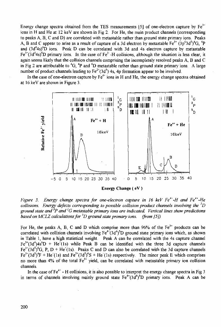
Energy change spectra obtained from the TES measurements [5] of one-electron capture by Fe3+
ions in H and He at 12 keV are shown in Fig 2. For He, the main product channels (corresponding to peaks A, B, C and D) are correlated with metastable rather than ground state primary ions. Peaks
3+ j 5 \ 4 , A, B and C appear to arise as a result of capture of a 3d electron by metastable Fe (3p 3d ) G, P and (3d44s)6D ions. Peak D can be correlated with 3d and 4s electron capture by metastable Fe3"(3d44s)6D primary ions. In the case of Fe3+-H collisions, although the situation is less clear, it again seems likely that the collision channels comprising the incompletely resolved peaks A, B and C in Fig 2 are attributable to 4G, 4P and 6D metastable rather than ground state primary ions. A large number of product channels leading to Fe2+(3d5) 4s, 4p formation appear to be involved.
In the case of one-electron capture by Fe4+ ions in H and He, the energy change spectra obtained at 16 keV are shown in Figure 3.
!
4i
Si
>
PS
iiiiiim IIIIIIII Hill 111 lllllllll in HI in I I
Fe4+ + H
16keV
D
I i 11 rjTT u 11111] i I'I 111 ri I11111111 i rj 1111 111
- 5 0 5 10 15 20 25 30 35 40 0 5 10 15 20 25 30 35 40
Energy Change ( eV )
Figure 3. Energy change spectra for one-electron capture in 16 keV Fe4+-H and Fe4+-He collisions. Energy defects corresponding to possible collision product channels involving the 5D ground state and 3P and 'G metastable primary ions are indicated. Vertical lines show predictions based on MCLZ calculations for 5D ground state primary ions, (from [5])
For He, the peaks A, B, C and D which comprise more than 96% of the Fe3+ products can be correlated with collision channels involving Fe4+(3d4)5D ground state primary ions which, as shown in Table 1, have a high statistical weight. Peak A can be correlated with the 4s capture channel Fe3+(3d4)4s6D + He+(ls) while Peak B can be identified with the three 3d capture channels Fe3+(3d5)4G, P, D + He+(ls). Peaks C and D can also be correlated with the 3d capture channels Fe3+(3d5)4F + He+(ls) and Fe3+(3d5)6S + He+(ls) respectively. The minor peak E which comprises no more than 4% of the total Fe3+ yield, can be correlated with metastable primary ion collision channels.
In the case of Fe4+ - H collisions, it is also possible to interpret the energy change spectra in Fig 3 4+/ J4X5 T in terms of channels involving mainly ground state Fe (3d ) D primary ions. Peak A can be
200
correlated with a number of 4p capture channels Fe3+(3d4)4p + H+ while peak B can be identified with thirteen 4s and 4p capture channels Fe3+(3d4)4s, 4p + FT.
Since the TES data for Fe4+-He and Fe3+-H collisions do not appear to be greatly influenced by metastable primary ion channels, McLaughlin et al [5] have carried out multi-channel-Landau-Zener calculations for Fe4+(3d4)5D ground state ions and obtained cross sections for the main product channels. No other theoretical predictions are available. To facilitate comparison with experiment, relative values of the MCLZ cross sections are shown as vertical lines in Figure 3 with the largest calculated value normalised to the largest observed peak in the energy change spectrum. In He, the MCLZ calculations do correctly predict the dominant channels but the relative magnitudes of the minor channels are not well described. In H, while the MCLZ calculations correctly identify the main product channels corresponding to peak A, they fail to predict those corresponding to peak B.
TES studies of the type described, allow (within the limits of the available energy resolution) the main excited product states to be identified and the relative cross sections determined. Individual cross sections for specific channels can, in principle, then be easily obtained if total cross sections are known. However, a detailed analysis of TES data is precluded where there is evidence of collision channels involving unknown fractions of metastable primary ions. This is a major complicating feature since many partially ionized metallic species of fusion interest (as in the case of Fe3+) have metastable states of high statistical weight. This implies that many published measurements of cross sections for one-electron capture by slow metallic ions require cautious interpretation. For example, the measurements by Phaneuf [6] of total cross sections for one-electron capture in 10-95 eV amu"1
Fe3+-H and Fe3+-H2 collisions were carried out with Fe3+ ions in unspecified initial states and may therefore be dominated by contributions from metastable primary ion collision channels. At the same time, the corresponding total cross sections measured by Phaneuf [6] for electron capture by Fe4+ ions in H and H2 would seem likely, on the basis of the TES data, to be dominated by ground state primary Fe4+ ion collision channels. In the absence of detailed theoretical calculations, the MCLZ calculations[5] carried out for Fe4+-H, and Fe4+-He collisions indicate that this approach may not provide a reliable identification of even the major collision channels.
In future work it is important that experimental methods be developed to allow measurements in which the initial state of the primary ions is defined unambiguously.
3. ELECTRON CAPTURE AND IONIZATION IN COLLISIONS OF FAST H+ AND He2+ IONS WITH METALLIC ATOMS
In a recent series of measurements in this laboratory [7], [8], [9], [10], a crossed beam technique incorporating time-of-flight spectroscopy and coincidence counting of fast ion/slow ion and slow ion/electron collision products has been used to study the separate processes involved in the formation of multiply charged metallic ions in collisions of fast FT and He2+ ions with Mg, Fe and Cu atoms.
For FT impact, cross sections ioaoq for the one-electron capture process
H+ + X ^ H + X<l+ + (q-l)e (5)
leading to metallic ions in specified states q have been determined. Here q=l corresponds to simple charge transfer while q >1 corresponds to transfer ionization where one-electron capture is
201
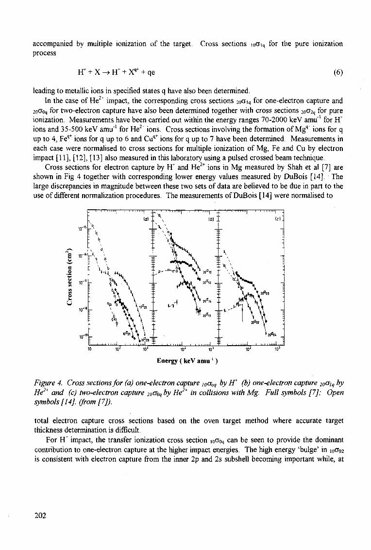
accompanied by multiple ionization of the target. Cross sections ioCfiq for the pure ionization process
FT + X -» H+ + Xq+ + qe (6)
leading to metallic ions in specified states q have also been determined. In the case of He2" impact, the corresponding cross sections 2oOiq for one-electron capture and
2oO"oq for two-electron capture have also been determined together with cross sections 2oO"2q for pure ionization. Measurements have been carried out within the energy ranges 70-2000 keV amu'1 for FT ions and 35-500 keV amu"1 for He2+ ions. Cross sections involving the formation of Mgq+ ions for q up to 4, Feq+ ions for q up to 6 and Cuq+ ions for q up to 7 have been determined. Measurements in each case were normalised to cross sections for multiple ionization of Mg, Fe and Cu by electron impact [11], [12], [13] also measured in this laboratory using a pulsed crossed beam technique.
Cross sections for electron capture by FF and He2+ ions in Mg measured by Shah et al [7] are shown in Fig 4 together with corresponding lower energy values measured by DuBois [14]. The large discrepancies in magnitude between these two sets of data are believed to be due in part to the use of different normalization procedures. The measurements of DuBois [14] were normalised to
_ I—r-TTTTTTT T -
-v lo
: '<?
- *! " —K : vi 6
- M % i \ • \ i\ • ^
i •>% 9 \
°P £V. — V"
: "S -
vP
: 1 ' ' ' " " ' '
i i i m n
(a) '.
Kl0°02
JU > \
^ \ivyi E 1 1 l l l l l l -
Z—'—i i 11 m i — - X
\ _ \ \
v °» * \ i i \ .
\\{L
r rs : \\
: ^ - - ° - T ^ \
M
1 • 1
- i — i I I I I I I -
(6) \
M ™°13 -
X. \A
y* 2o°u .
TT ,00 , , =
1—II I I
_ \
\ rv : 1 \
i j
• t J r l '
ITTT 1—i i i i n i j ;
(c)~
: ---•
• ^ _ ^ • \ i \
V \thu \ 2 r f , ° 3 " wT\ \
\ \ \ ' \ Y\ -\ \ \ I *Pm \ »
\ htftii
: "•1 ' ' •"-—i—i. i i nii i ' ' ' *** ' ' I ml T i i i 11 ml i—i i i mil
10 102 103 102 X)3 102 103
Energy ( keV amu')
Figure 4. Cross sections for (a) one-electron capture loooq by FT (b) one-electron capture 2o^iq by He2+ and (c) two-electron capture 2oCFoq by He2+ in collisions with Mg. Full symbols [7]; Open symbols [14]. (from [7]).
total electron capture cross sections based on the oven target method where accurate target thickness determination is difficult.
For H+ impact, the transfer ionization cross section i0aoq can be seen to provide the dominant contribution to one-electron capture at the higher impact energies. The high energy 'bulge' in ioO"o2 is consistent with electron capture from the inner 2p and 2s subshell becoming important while, at
202
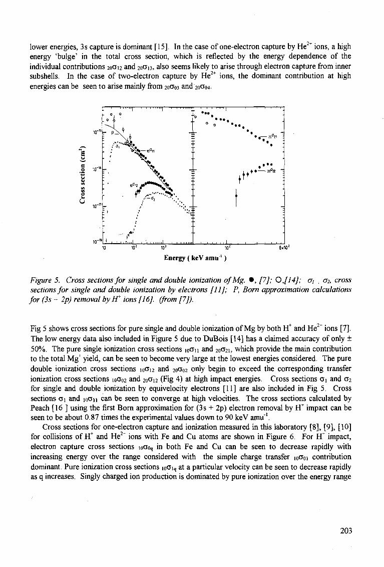
lower energies, 3 s capture is dominant [15]. In the case of one-electron capture by He " ions, a high energy 'bulge' in the total cross section, which is reflected by the energy dependence of the individual contributions 20CJ12 and 2OO"B, also seems likely to arise through electron capture from inner subshells. In the case of two-electron capture by He2+ ions, the dominant contribution at high energies can be seen to arise mainly from 20 03 and 2o<7o4-
10 L ! 1 ' 1 1 t i l l ! 1 1 • 1 m i l 1 1 1 1 m i l . I 1 1 l _ J L_LJ
10 10! 10! 10! 8x10!
Energy ( keV amu1)
Figure 5. Cross sections for single and double ionization o/Mg. • , [7]; OJ14J; o~i , o~2, cross sections for single and double ionization by electrons [11]; P, Born approximation calculations for (3s + 2p) removal by IT ions [16]. (from [7]).
Fig 5 shows cross sections for pure single and double ionization of Mg by both it and He2+ ions [7]. The low energy data also included in Figure 5 due to DuBois [14] has a claimed accuracy of only ± 50%. The pure single ionization cross sections loan and 20CT21, which provide the main contribution to the total Mg+ yield, can be seen to become very large at the lowest energies considered. The pure double ionization cross sections 10O12 and 20O02 only begin to exceed the corresponding transfer ionization cross sections 10002 and 20 12 (Fig 4) at high impact energies. Cross sections Oi and C2 for single and double ionization by equivelocity electrons [11] are also included in Fig 5. Cross sections Oi and IOOH can be seen to converge at high velocities. The cross sections calculated by Peach [16 ] using the first Born approximation for (3 s + 2p) electron removal by it impact can be seen to be about 0.87 times the experimental values down to 90 keV amu'1.
Cross sections for one-electron capture and ionization measured in this laboratory [8], [9], [10] for collisions of H* and He2+ ions with Fe and Cu atoms are shown in Figure 6. For it impact, electron capture cross sections ioa0q in both Fe and Cu can be seen to decrease rapidly with increasing energy over the range considered with the simple charge transfer 10O01 contribution dominant. Pure ionization cross sections loOiq at a particular velocity can be seen to decrease rapidly as q increases. Singly charged ion production is dominated by pure ionization over the energy range
203
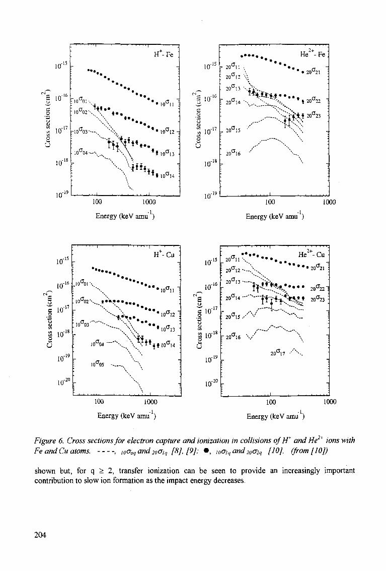
10"
5 10
o
S io-17
O
u 18 10 r
10 19
:
•
.
•
fioaoi-
• 10a02"
•
-10a03"
• 10°04-
\
' , . , .
"T
* • . .
' < • • X' \
— .
~*'y
.J- t l
« .
• •
\ " • • . . N V .
Tt^i«..
\vi»*
i ' — , —
H+-Fe ;
-:
•
' • • i o a n ] :
,
• • • 1 0 ° 1 2 ,
* * 10 a i3 '•
J * i i o c i 4 :
i . .
,-15
100 1000
Energy (keV amu )
10'
= io-16
O 4) « .17 B. 10 O
u
10 18
10' ,-19
i i i i i
2 0 a U v
2 0 a i 2 \ \
20u13 •• --•-
H e ' + - Fe
• 20u21
20CT14
20CT15 •'
20 a i 6
| 20u22
- - - ^ ^ 2 ° a 2 3
I I I J J I
100
Energy (keV amu )
1000
10"
T " i m 11 •" 1 p-
i o 1 6 1 -
£
o o 4)
,-n
o u
10 ,-18
10'
10'
,-19
20
' • • •
ioaoi \
H+-Cu
•• • a -i
10U02V. t • • • • • • • • •
• • • .
10CT03
10CT12 1
« 10CT13
10CT04
10a05
'
15 10"IJ -
10"i6 fc-
s g'lff o o <u t o
S3 10
17
u
10'
10'
,-19
20
_ 20<T11
• 20CT12
' 20°13
: 2 0 a i 4
: 20CT15
T 20CT16
:
i
1
. . . . . . He
. / ' ' " " " x - " \
20ai7 ' \
I J 1 1 L
20a21 !
20°22"1
20CT23 ;
-
•
•
100 1000
Energy (keV amu )
100
Energy (keV amu )
1000
Figure 6. Cross sections for electron capture and ionization in collisions of IT and He2+ ions with Fe andCu atoms. , i0ooqand2oOiq [8], [9]: • , lQaiqand2oo-2q [10]. (from [10])
shown but, for q > 2, transfer ionization can be seen to provide an increasingly important contribution to slow ion formation as the impact energy decreases.
204
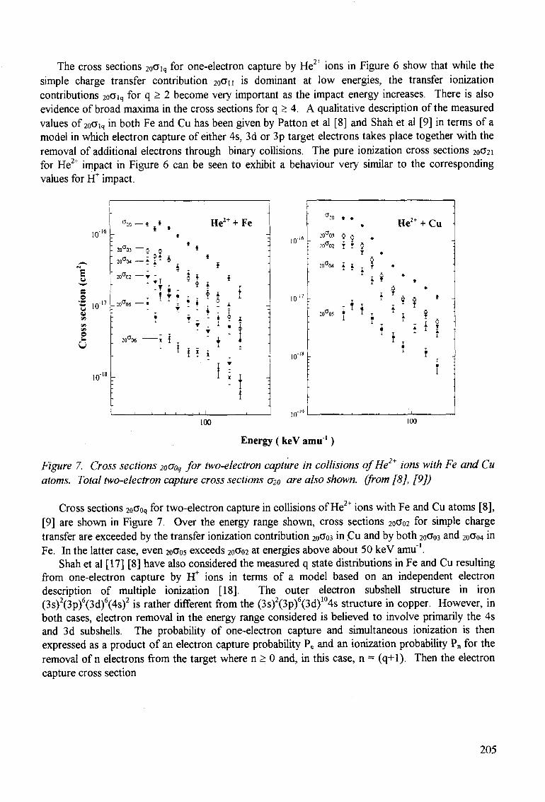
The cross sections 2oO"iq for one-electron capture by He2" ions in Figure 6 show that while the simple charge transfer contribution 2oO"n is dominant at low energies, the transfer ionization contributions 2oO"iq for q > 2 become very important as the impact energy increases. There is also evidence of broad maxima in the cross sections for q > 4. A qualitative description of the measured values of 2oCJiq in both Fe and Cu has been given by Patton et al [8] and Shah et al [9] in terms of a model in which electron capture of either 4s, 3d or 3p target electrons takes place together with the removal of additional electrons through binary collisions. The pure ionization cross sections 20CT2I
for He2+ impact in Figure 6 can be seen to exhibit a behaviour very similar to the corresponding values for Ff impact.
S
Z 10
©
lO"
CT:o-* § i , H e 2 + + F e i
,oM—if* 4 20"04 » J
20°02 • T
m°n.
* I t I $ * I
1 * T i *
T T
T f ' t '
T _ - i • _ L
• i ' f ! i i 11
10"
10"
10"
i o -
He2+ + Cu :o a03 $ Q .
:oa02 { T 5
: o ^ • i r I f T x i i i
1
100 100
Energy ( keV amu ' )
Figure 7. Cross sections 2oOoq for two-electron capture in collisions of He2+ ions with Fe and Cu atoms. Total two-electron capture cross sections 020 are also shown, (from [8], [9])
Cross sections 2oOoq for two-electron capture in collisions of He2+ ions with Fe and Cu atoms [8], [9] are shown in Figure 7. Over the energy range shown, cross sections 2oao2 for simple charge transfer are exceeded by the transfer ionization contribution 20 03 in Cu and by both 20CT03 and 2oa04 in Fe. In the latter case, even 20ao5 exceeds 2oa02 at energies above about 50 keV amu"1.
Shah et al [17] [8] have also considered the measured q state distributions in Fe and Cu resulting from one-electron capture by FT" ions in terms of a model based on an independent electron description of multiple ionization [18]. The outer electron subshell structure in iron (3s)2(3p)6(3d)6(4s)2 is rather different from the (3s)2(3p)6(3d)104s structure in copper. However, in both cases, electron removal in the energy range considered is believed to involve primarily the 4s and 3d subshells. The probability of one-electron capture and simultaneous ionization is then expressed as a product of an electron capture probability Pc and an ionization probability Pn for the removal of n electrons from the target where n > 0 and, in this case, n = (q+1). Then the electron capture cross section
205
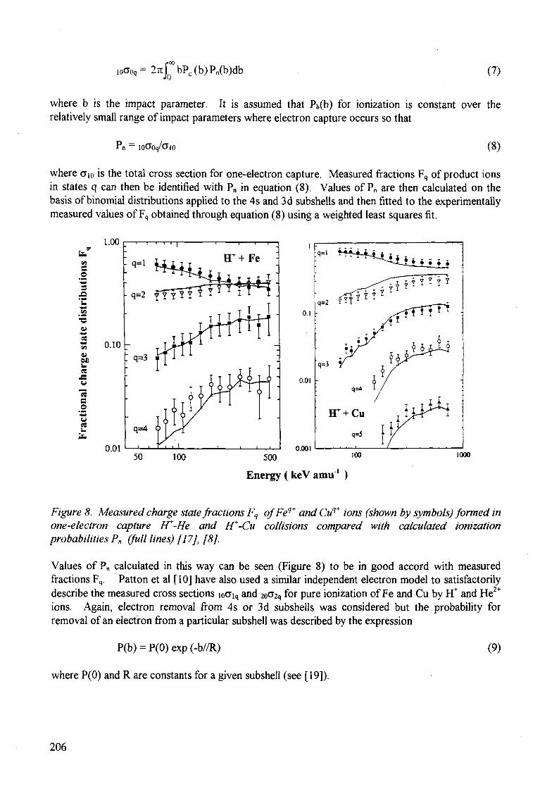
r00
ioOoq=27tfn bPc(b)Pn(b)db (7)
where b is the impact parameter. It is assumed that Pb(b) for ionization is constant over the relatively small range of impact parameters where electron capture occurs so that
Pn — I0O"0q/O"l0 (8)
where Oio is the total cross section for one-electron capture. Measured fractions Fq of product ions in states q can then be identified with Pn in equation (8). Values of Pn are then calculated on the basis of binomial distributions applied to the 4s and 3d subshells and then fitted to the experimentally measured values of Fq obtained through equation (8) using a weighted least squares fit.
1.00
e o
1
- 1 1 I
- q=l
S 0.10
I 1
0.01
q=2 ffT?Y * Y
q=3
q=4
• i f i i
50
o.i
0.01
0.001
500
Energy ( keV amu1 )
1000
Figure 8. Measured charge state fractions Fq ofFeq+ and Cuq+ ions (shown by symbols) formed in one-electron capture FT-He and fT-Cu collisions compared with calculated ionization probabilities P„ (full lines) [17], [8].
Values of P„ calculated in this way can be seen (Figure 8) to be in good accord with measured fractions Fq. Patton et al [10] have also used a similar independent electron model to satisfactorily describe the measured cross sections i0aiq and 2oa2q for pure ionization of Fe and Cu by H+ and He2+
ions. Again, electron removal from 4s or 3d subshells was considered but the probability for removal of an electron from a particular subshell was described by the expression
P(b) = P(0) exp (-b//R) (9)
where P(0) and R are constants for a given subshell (see [19]).
206
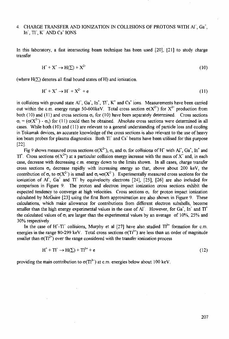
4 CHARGE TRANSFER AND IONIZATION IN COLLISIONS OF PROTONS WITH Al+, Ga+, In+, Tr, K+ AND Cs" IONS
In this laboratory, a fast intersecting beam technique has been used [20], [21] to study charge transfer
FT + X" -^ H(S) + X2+ (10)
(where H(Z) denotes all final bound states of H) and ionization.
H+ + X ' - > H f + X2+ + e (11)
in collisions with ground state AT, Ga+, In+, Tl+, K+ and Cs+ ions. Measurements have been carried out within the cm. energy range 50-600keV. Total cross section a(X2+) for X2+ production from both (10) and (11) and cross sections oc for (10) have been separately determined. Cross sections Gj = (CT(X2+) - ac) for (11) could then be obtained. Absolute cross sections were determined in all cases. While both (10) and (11) are relevant to a general understanding of particle loss and cooling in Tokamak devices, an accurate knowledge of the cross sections is also relevant to the use of heavy ion beam probes for plasma diagnostics. Both Tl+ and Cs+ beams have been utilised for this purpose [22].
Fig 9 shows measured cross sections a(X2+), ac and o; for collisions of FT with AT, Ga+, In+ and Tl+. Cross sections a(X2+) at a particular collision energy increase with the mass of X* and, in each case, decrease with decreasing cm. energy down to the limits shown. In all cases, charge transfer cross sections oc decrease rapidly with increasing energy so that, above about 200 keV, the contribution of cc to cr(X2+) is small and a; «o(X2+). Experimentally measured cross sections for the ionization of Al+, Ga+ and Tf by equivelocity electrons [24], [25], [26] are also included for comparison in Figure 9. The proton and electron impact ionization cross sections exhibit the expected tendency to converge at high velocities. Cross sections cr* for proton impact ionization calculated by McGuire [23] using the first Born approximation are also shown in Figure 9. These calculations, which make allowance for contributions from different electron subshells, become smaller than the high energy experimental values in the case of AT. However, for Ga+, In+ and Tf the calculated values of a, are larger than the experimental values by an average of 10%, 25% and 30% respectively.
In the case of FF-T1+ collisions, Murphy et al [27] have also, studied Tl3+ formation for cm. energies in the range 80-299 keV. Total cross sections a(Tl3+) are less than an order of magnitude smaller than CT(T12+) over the range considered with the transfer ionization process
IT + TF -» H(Z) + Tl3+ + e (12)
providing the main contribution to CT(T13+) at cm. energies below about 100 keV.
207
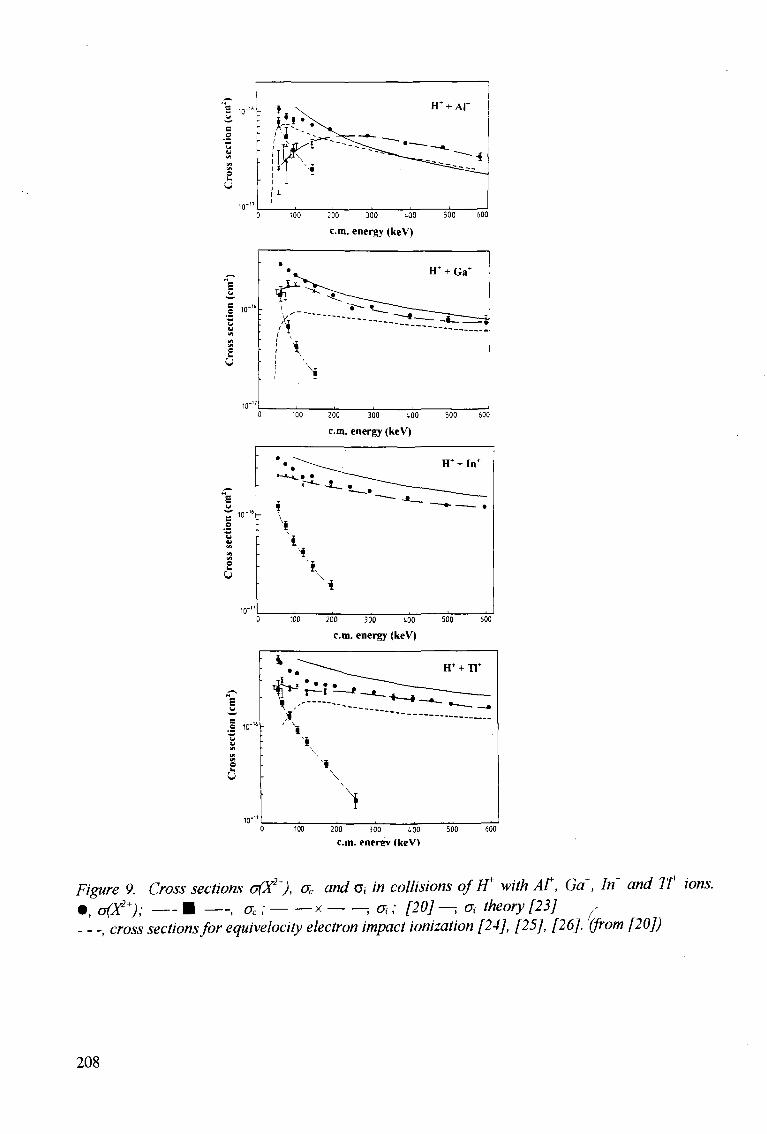
0 100 200 300 tOO 500 600
cm. energy (keV)
o 10"
5
100 ZOO 300 400 500 600
cm. energy (keV)
0 100 200 300 400 500 600
cm. energy (keV)
200 300 tOO
c.m. energy (keV">
Figure 9. Cross sections o(X2+), uc and a in collisions of IT with At, Ga\ In+ and Tt ions. • , o(X2+); • , ac; x ; oi; [20]—, oj theory [23] ,
, cross sections for equivelocity electron impact ionization [24], [25], [26]. '(from [20])
208
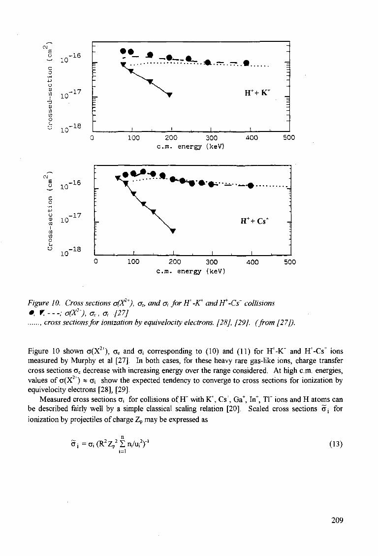
CM
o -16 — 10 c o -p u CD CO I
T J (1) CO en o
10 -17
10 -18
100 200 300 c m . energy (keV)
400 500
CM E O
c o
• H -p (J <u CO I
co CO o u
10 -16
10 -17
10 -18
100 200 300 c m . energy (keV)
400 500
Figure 10. Cross sections o(X2+), ac, and a, for IT-lC andIT-Cs+ collisions ; r,---;o(X2+),aCl a, [27]
cross sections for ionization by equivelocity electrons. [28], [29]. (from [27]).
Figure 10 shown a(X2+), ac and O; corresponding to (10) and (11) for FT-K+ and FT-Cs+ ions measured by Murphy et al [27]. In both cases, for these heavy rare gas-like ions, charge transfer cross sections oc decrease with increasing energy over the range considered. At high cm. energies, values of a(X2+) « o"i show the expected tendency to converge to cross sections for ionization by equivelocity electrons [28], [29].
Measured cross sections o"; for collisions of H+ with K+, Cs+, Ga+, In+, Tl+ ions and H atoms can be described fairly well by a simple classical scaling relation [20]. Scaled cross sections 5 j for ionization by projectiles of charge Zp may be expressed as
2\-l 5 i-CT i(R2Zp2Zn,/u i
2) i=l
(13)
209
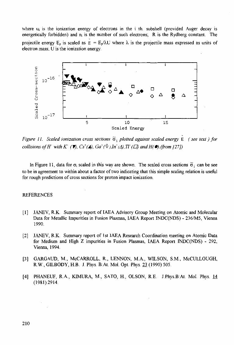
where Uj is the ionization energy of electrons in the i th. subshell (provided Auger decay is energetically forbidden) and n; is the number of such electrons; R is the Rydberg constant. The
projectile energy Ep is scaled as E = Ep/XU where X is the projectile mass expressed as units of electron mass; U is the ionization energy.
1 1 1
o o A $ A -
J I I I 5 10 15
Scaled Energy
Figure 11. Scaled ionization cross sections Oj plotted against scaled energy E (see text) for
collisions of IT withKT (f), Cs+(A), Ga+(0 )Jn(A),Tt(0) and HO. (from [27])
In Figure 11, data for o; scaled in this way are shown. The scaled cross sections a; can be see to be in agreement to within about a factor of two indicating that this simple scaling relation is useful for rough predictions of cross sections for proton impact ionization.
REFERENCES
[1] JANEV, R.K. Summary report of IAEA Advisory Group Meeting on Atomic and Molecular Data for Metallic Impurities in Fusion Plasmas, IAEA Report INDC(NDS) - 236/M5, Vienna 1990.
[2] JANEV, R.K. Summary report of 1st IAEA Research Coordination meeting on Atomic Data for Medium and High Z impurities in Fusion Plasmas, IAEA Report INDC(NDS) - 292, Vienna, 1994.
[3] GARGAUD, M., McCARROLL, R., LENNON, M.A., WILSON, S.M., McCULLOUGH, R.W., GILBODY, KB. J. Phys. B:At. Mol. Opt. Phys. 23 (1990) 505.
[4] PHANEUF, R.A., KIMURA, M., SATO, H., OLSON, RE. J.Phys.B:At. Mol. Phys. 14 (1981)2914.
210
c o
o CD CO
I w o u u
10 •16
a w 10
£Yv
5] MCLAUGHLIN, T.K, HODGKINSON, J.M, TAWARA, H , MCCULLOUGH, R.W., GILBODY, H.B. J. Phys. B:At. Mol. Opt. Phys. 26 (1993) 3587.
6] PHANEUF, R.A. Phys. Rev. A28 (1983) 1310.
7] SHAH, MB., McCALLION, P., ITOH, Y., GILBODY, H.B , J. Phys. B: At. Mol. Opt. Phys 25(1992)3693.
8] PATTON, C.J., BOLORIZADEH, M A , SHAH, MB., GILBODY, H.B., J. Phys. B: At. Mol. Opt. Phys. 27 (1994) 3695.
9] SHAH, MB., PATTON, C.J., BOLORIZADEH, MA, GEDDES, J., GILBODY, H.B. J. Phys. B: At. Mol. Opt. Phys. 28, (1995) 1821.
10] PATTON, C.J., SHAH, MB., BOLORIZADEH, M.A., GEDDES, J., GILBODY, H.B. J. Phys. B: At. Mol. Opt. Phys. (1995) - in course of publication.
11] McCALLION, P., SHAH, MB., GILBODY, H.B., J. Phys. B: At. Mol. Opt. Phys. 25 (1992) 1051.
12] SHAH, M B , McCALLION, P. OKUNO, K., GILBODY, H.B., J. Phys. B: At. Mol. Opt. Phys. 26(1993)2393.
13] BOLORIZADEH, M.A., PATTON, C.J., SHAH, MB., GILBODY, H.B., J. Phys. B: At. Mol. Opt. Phys. 27 (1994) 175.
14] DUBOIS, R.D., Phys. Rev A34, (1986) 2738.
15] MAPLETON, R.A., GROSSBARD, N., Phys. Rev. A188 (1969) 228.
16] PEACH, G, J. Phys. B: At. Mol. Phys. 3 (1970) 328.
17] SHAH, MB., PATTON, C.J., GEDDES, J., GILBODY, H.B., Nuc. Inst. Methods B (1995) -in course of publication.
18] McGUIRE, J.H. Advances in At. Mol. and Opt. Physics, Vol 29 (eds. DR. Bates and B Bederson) Academic Press: New York .1991, p.217.
19] MATSUO, T., TONUMA, T., KUMAGAI, H., TAWARA, H.H., Phys. Rev. A50 (1994) 1178.
20] WATTS, M.F., HOPKINS, C.J., ANGEL, G.C., DUNN, K.F., GILBODY, H.B., J. Phys. B: At. Mol. Phys. 19 (1986) 3739.
211
[21] MURPHY, J.G., DUNN, K.F., GILBODY, H.B., Am. Inst. Phys. Conf. Ser. No.274 (1993) 183.
[22] SCHWELBERGER, J.G., CONNOR, K.A. IEEE Trans, on Plasma Science, 22 (1994) 418.
[23] McGUIRE, E.J., Phys. Rev., A29 (1984) 3429 and cited in [20],
[24] MONTAGUE, R.G., HARRISON, M FA., J. Phys. B: At. Mol. Phys. 16 (1983), 3045.
[25] ROGERS, W.T., STEFAN! G, CAMILLONI, R., DUNN, G.H., MSEZANE, A.A., HENRY, R.J.W., Phys. Rev. A25 (1982) 737.
[26] DIVINE, T.F., FEENEY, RK, SAYLE, W.E., HOOPER, J. W., Phys. Rev. All (1976) 54
[27] MURPHY, J.G., DUNN, K.F., GILBODY, KB., Am. Inst. Phys. Conf. Ser., (1993), 183.
[28] PEART, B., DOLDER, K., J. Phys. B. (Proc. Phys. Soc.) 1 (1969) 240.
[29] PEART, B., DOLDER, K., J. Phys. B: At. Mol. Phys. 8, (1975) 56.
212
FUSION RELATED EXPERIMENTS WITH MEDIUM-Z MULTIPLY CHARGED IONS
R. HOEKSTRA, J.P.M. BEIJERS, F. W. BLIEK, S. SCHIPPERS, R. MORGENSTERN
KVI Atomic Physics, Zernikelaan 25,9747 AA Groningen, The Netherlands
ABSTRACT An overview is given on spectroscopic investigations of keV/amu collisions between medium-Z multiply charged ions and Li and He targets, which have been performed at the KVI during the last years. Line emission cross sections relevant for fusion plasma diagnostics have been experimentally determined and are compared with theoretical predictions based on CTMC, Close-Coupling and Landau-Zener calculations. It is found that for Li-targets the large cross sections for visible light emission are practically independent of the projectiles' core structure and that these cross sections are reliably predicted by close coupling and CTMC calculations. For He targets very low cross sections for visible light emission are found, related theoretical data are not yet available; here also the dominant rection channels - giving rise to VUV light emission - have been investigated, and it is found that there is still unsatisfactory agreement between experimental and theoretical data.
1. INTRODUCTION Fusion plasmas inevitebly contain medium- or high-Z impurities, which arise from
plasma wall interactions or which are deliberately introduced to influence various plasma properties, e.g. to decrease the plasma temperature in the outer regions. Due to the high plasma temperatures these impurities are generally highly ionized. During collisions with (externally injected) neutral species these highly charged impurities can capture electrons into excited orbitals, and subsequently decay via emission of characteristic radiation. This radiation is often used for diagnostic purposes, e.g. at "Joint European Torus" (JET) to determine the spatial density distribution of impurities, or plasma parameters such as ion temperature or rotation velocity.
A precise knowledge of light emission cross sections for interaction of the various collision partners, including their dependence on the collision energy is the basis of "Charge Exchange Spectroscopy" (CXS) plasma diagnostics. Especially cross sections for the emission of visible light are relevant for diagnostics purposes, since in the practical applications optical fibers are used to guide the light from the fusion reactor to the light detectors. Three species are of special interest as electron "donors" for CXS, namely atomic hydrogen (c.q. deuterium), helium and lithium atoms. D-beams are being used since a long time for plasma heating and parasitical diagnostics. More recently also He beams have been introduced which may penetrate deeper into the core region of fusion plasmas because of the high He ionization potential. Beams of Li atoms on the other hand are -due to the low Li ionization potential - especially suited for studying the outer plasma regions, i.e. the divertor region and the scrape-off layer of the plasma. As electron
213
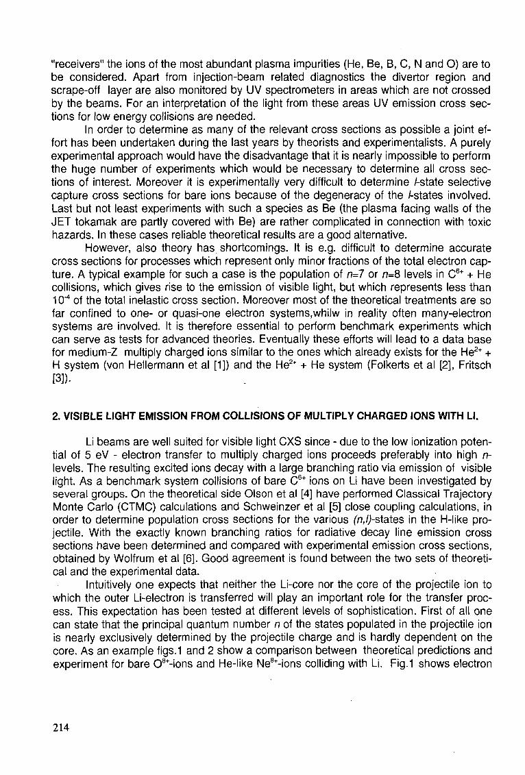
"receivers" the ions of the most abundant plasma impurities (He, Be, B, C, N and O) are to be considered. Apart from injection-beam related diagnostics the divertor region and scrape-off layer are also monitored by UV spectrometers in areas which are not crossed by the beams. For an interpretation of the light from these areas UV emission cross sections for low energy collisions are needed.
In order to determine as many of the relevant cross sections as possible a joint effort has been undertaken during the last years by theorists and experimentalists. A purely experimental approach would have the disadvantage that it is nearly impossible to perform the huge number of experiments which would be necessary to determine all cross sections of interest. Moreover it is experimentally very difficult to determine /-state selective capture cross sections for bare ions because of the degeneracy of the /-states involved. Last but not least experiments with such a species as Be (the plasma facing walls of the JET tokamak are partly covered with Be) are rather complicated in connection with toxic hazards. In these cases reliable theoretical results are a good alternative.
However, also theory has shortcomings. It is e.g. difficult to determine accurate cross sections for processes which represent only minor fractions of the total electron capture. A typical example for such a case is the population of n=7 or n=8 levels in C6+ + He collisions, which gives rise to the emission of visible light, but which represents less than 10"4 of the total inelastic cross section. Moreover most of the theoretical treatments are so far confined to one- or quasi-one electron systems.whilw in reality often many-electron systems are involved. It is therefore essential to perform benchmark experiments which can serve as tests for advanced theories. Eventually these efforts will lead to a data base for medium-Z multiply charged ions similar to the ones which already exists for the He2+ + H system (von Hellermann et al [1]) and the He2+ + He system (Folkerts et al [2], Fritsch [3]).
2. VISIBLE LIGHT EMISSION FROM COLLISIONS OF MULTIPLY CHARGED IONS WITH LI.
Li beams are well suited for visible light CXS since - due to the low ionization potential of 5 eV - electron transfer to multiply charged ions proceeds preferably into high n-levels. The resulting excited ions decay with a large branching ratio via emission of visible light. As a benchmark system collisions of bare C6+ ions on Li have been investigated by several groups. On the theoretical side Olson et al [4] have performed Classical Trajectory Monte Carlo (CTMC) calculations and Schweinzer et al [5] close coupling calculations, in order to determine population cross sections for the various (77,/J-states in the H-like projectile. With the exactly known branching ratios for radiative decay line emission cross sections have been determined and compared with experimental emission cross sections, obtained by Wolfrum et al [6]. Good agreement is found between the two sets of theoretical and the experimental data.
Intuitively one expects that neither the Li-core nor the core of the projectile ion to which the outer Li-electron is transferred will play an important role for the transfer process. This expectation has been tested at different levels of sophistication. First of all one can state that the principal quantum number n of the states populated in the projectile ion is nearly exclusively determined by the projectile charge and is hardly dependent on the core. As an example figs.1 and 2 show a comparison between theoretical predictions and experiment for bare 08+-ions and He-like Ne8+-ions colliding with Li. Fig.1 shows electron
214
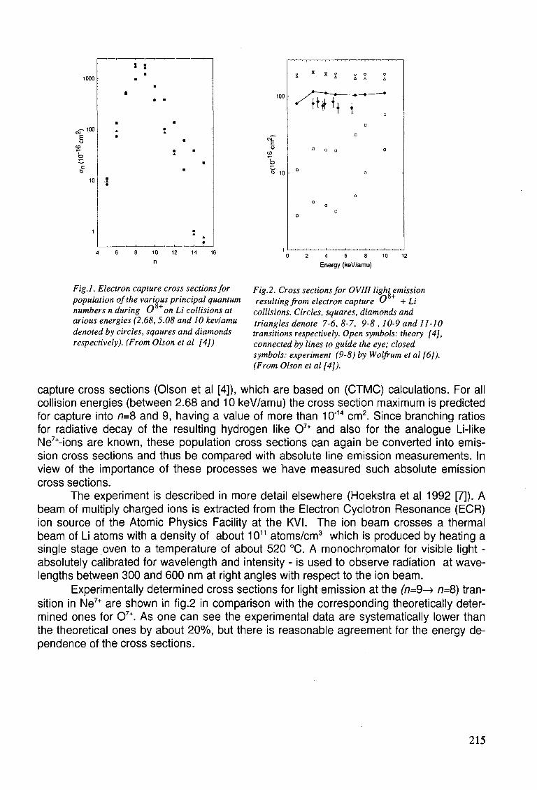
1000
^ , 0 0
CO
o
0
10
1
I
m A
•
1
X
•
t •
•
* •
• A
m
• A
m
•
•
•
•
A
• 10
n
100
6 10
X x *
0 2 4 6 8 10 12
Energy (keV/amu)
Fig.l. Electron capture cross sections for population of the various principal quantum numbers n during 0 on Li collisions at arious energies (2.68,5.08 and 10 kevlamu denoted by circles, sqaures and diamonds respectively). (From Olson et al [4])
Fig.2. Cross sections for OV1II light emission resulting from electron capture O + Li collisions. Circles, squares, diamonds and triangles denote 7-6, 8-7, 9-8 ,10-9 and 11-10 transitions respectively. Open symbols: theory [4], connected by lines to guide the eye; closed symbols: experiment (9-8) by Wolfrum et al [6]). (From Olson et al [4]).
capture cross sections (Olson et al [4]), which are based on (CTMC) calculations. For all collision energies (between 2.68 and 10 keV/amu) the cross section maximum is predicted for capture into n=8 and 9, having a value of more than 10'14 cm2. Since branching ratios for radiative decay of the resulting hydrogen like 07+ and also for the analogue Li-like Ne7+-ions are known, these population cross sections can again be converted into emission cross sections and thus be compared with absolute line emission measurements. In view of the importance of these processes we have measured such absolute emission cross sections.
The experiment is described in more detail elsewhere (Hoekstra et al 1992 [7]). A beam of multiply charged ions is extracted from the Electron Cyclotron Resonance (ECR) ion source of the Atomic Physics Facility at the KVI. The ion beam crosses a thermal beam of Li atoms with a density of about 1011 atoms/cm3 which is produced by heating a single stage oven to a temperature of about 520 °C. A monochrpmator for visible light -absolutely calibrated for wavelength and intensity - is used to observe radiation at wavelengths between 300 and 600 nm at right angles with respect to the ion beam.
Experimentally determined cross sections for light emission at the (77=9-> n=8) transition in Ne7+ are shown in fig.2 in comparison with the corresponding theoretically determined ones for 07+. As one can see the experimental data are systematically lower than the theoretical ones by about 20%, but there is reasonable agreement for the energy dependence of the cross sections.
215
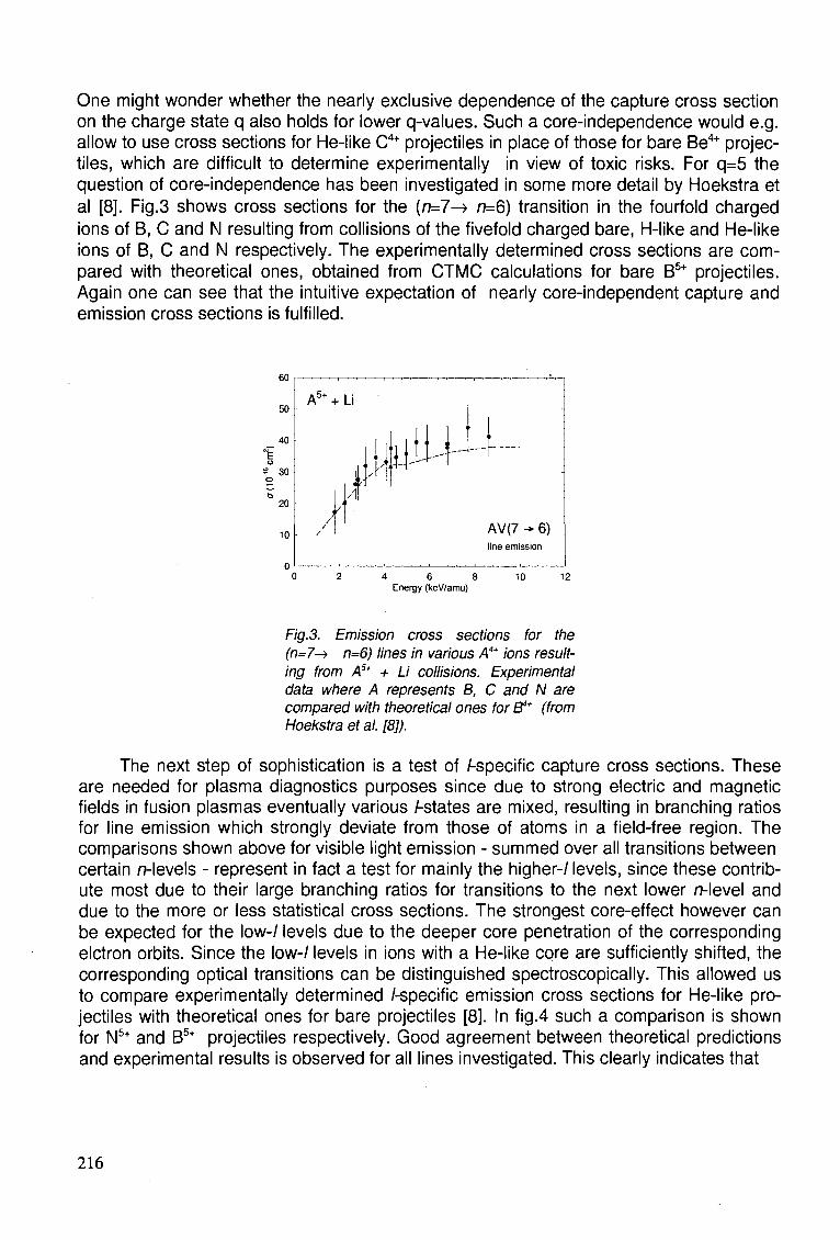
One might wonder whether the nearly exclusive dependence of the capture cross section on the charge state q also holds for lower q-values. Such a core-independence would e.g. allow to use cross sections for He-like C4+ projectiles in place of those for bare Be4+ projectiles, which are difficult to determine experimentally in view of toxic risks. For q=5 the question of core-independence has been investigated in some more detail by Hoekstra et al [8]. Fig.3 shows cross sections for the (n=7-> n=6) transition in the fourfold charged ions of B, C and N resulting from collisions of the fivefold charged bare, H-like and He-like ions of B, C and N respectively. The experimentally determined cross sections are compared with theoretical ones, obtained from CTMC calculations for bare B5+ projectiles. Again one can see that the intuitive expectation of nearly core-independent capture and emission cross sections is fulfilled.
jllji-l--
AV(7^6) line emission
0 2 4 6 8 10 12 Energy (keV/amu)
Fig.3. Emission cross sections for the (n=7^> n=6) lines in various A4+ ions resulting from A5+ + Li collisions. Experimental data where A represents B, C and N are compared with theoretical ones for B4* (from Hoekstra et al. [8]).
The next step of sophistication is a test of /-specific capture cross sections. These are needed for plasma diagnostics purposes since due to strong electric and magnetic fields in fusion plasmas eventually various /-states are mixed, resulting in branching ratios for line emission which strongly deviate from those of atoms in a field-free region. The comparisons shown above for visible light emission - summed over all transitions between certain /7-levels - represent in fact a test for mainly the higher-/ levels, since these contribute most due to their large branching ratios for transitions to the next lower n-level and due to the more or less statistical cross sections. The strongest core-effect however can be expected for the low-/ levels due to the deeper core penetration of the corresponding elctron orbits. Since the low-/ levels in ions with a He-like core are sufficiently shifted, the corresponding optical transitions can be distinguished spectroscopically. This allowed us to compare experimentally determined /-specific emission cross sections for He-like projectiles with theoretical ones for bare projectiles [8]. In fig.4 such a comparison is shown for N5+ and B5+ projectiles respectively. Good agreement between theoretical predictions and experimental results is observed for all lines investigated. This clearly indicates that
50
40
u s 30 o
b 20
10
A5+ + Li
/
i >
]
216
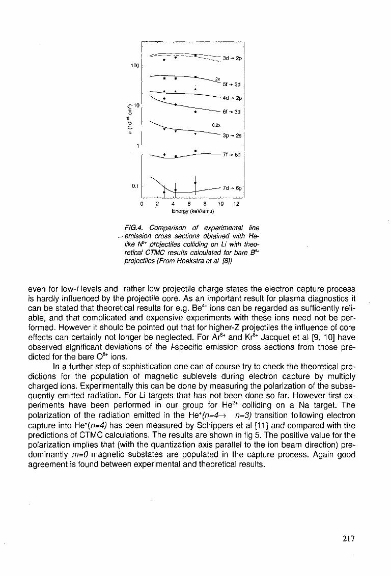
100
«-10 E o
b
b
0.1
0 2 4 6 8 10 12 Energy (keV/amu)
FIG.4. Comparison of experimental line emission cross sections obtained with He-like A/5* projectiles colliding on Li with theoretical CTMC results calculated for bare fi5* projectiles (From Hoekstra et al [8])
even for low-/ levels and rather low projectile charge states the electron capture process is hardly influenced by the projectile core. As an important result for plasma diagnostics it can be stated that theoretical results for e.g. Be4+ ions can be regarded as sufficiently reliable, and that complicated and expensive experiments with these ions need not be performed. However it should be pointed out that for higher-Z projectiles the influence of core effects can certainly not longer be neglected. For Ar8+ and Kr8* Jacquet et al [9, 10] have observed significant deviations of the Aspecific emission cross sections from those predicted for the bare 08+ ions.
In a further step of sophistication one can of course try to check the theoretical predictions for the population of magnetic sublevels during electron capture by multiply charged ions. Experimentally this can be done by measuring the polarization of the subsequently emitted radiation. For Li targets that has not been done so far. However first experiments have been performed in our group for He2+ colliding on a Na target. The polarization of the radiation emitted in the He+(n=4-> n=3) transition following electron capture into He+{n=4) has been measured by Schippers et al [11] and compared with the predictions of CTMC calculations. The results are shown in fig 5. The positive value for the polarization implies that (with the quantization axis parallel to the ion beam direction) predominantly m=0 magnetic substates are populated in the capture process. Again good agreement is found between experimental and theoretical results.
217
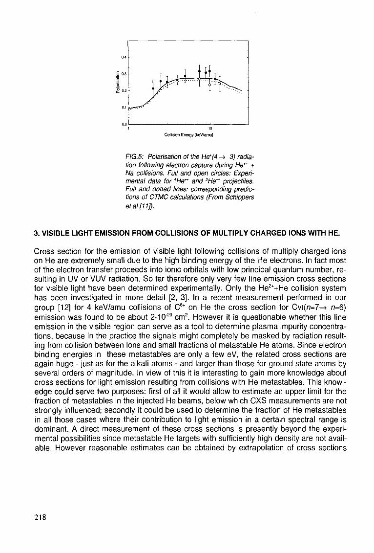
0.4
§ 0.3
2 0-2
0.1
0.0 1 10
Collision Energy [keV/amu]
FIG.5: Polarisation of the He*(4 -> 3) radiation following electron capture during He*+ + Na collisions. Full and open circles: Experimental data for 4He" and 3He++ projectiles. Full and dotted lines: corresponding predictions of CTMC calculations (From Schippers etal[11]).
3. VISIBLE LIGHT EMISSION FROM COLLISIONS OF MULTIPLY CHARGED IONS WITH HE.
Cross section for the emission of visible light following collisions of multiply charged ions on He are extremely small due to the high binding energy of the He electrons. In fact most of the electron transfer proceeds into ionic orbitals with low principal quantum number, resulting in UV or VUV radiation. So far therefore only very few line emission cross sections for visible light have been determined experimentally. Only the He2++He collision system has been investigated in more detail [2, 3]. In a recent measurement performed in our group [12] for 4 keV/amu collisions of C6+ on He the cross section for Cvi(n=7-> n=6) emission was found to be about 2-10"20 cm2. However it is questionable whether this line emission in the visible region can serve as a tool to determine plasma impurity concentrations, because in the practice the signals might completely be masked by radiation resulting from collision between ions and small fractions of metastable He atoms. Since electron binding energies in these metastables are only a few eV, the related cross sections are again huge - just as for the alkali atoms - and larger than those for ground state atoms by several orders of magnitude. In view of this it is interesting to gain more knowledge about cross sections for light emission resulting from collisions with He metastables. This knowledge could serve two purposes: first of all it would allow to estimate an upper limit for the fraction of metastables in the injected He beams, below which CXS measurements are not strongly influenced; secondly it could be used to determine the fraction of He metastables in all those cases where their contribution to light emission in a certain spectral range is dominant. A direct measurement of these cross sections is presently beyond the experimental possibilities since metastable He targets with sufficiently high density are not available. However reasonable estimates can be obtained by extrapolation of cross sections
218
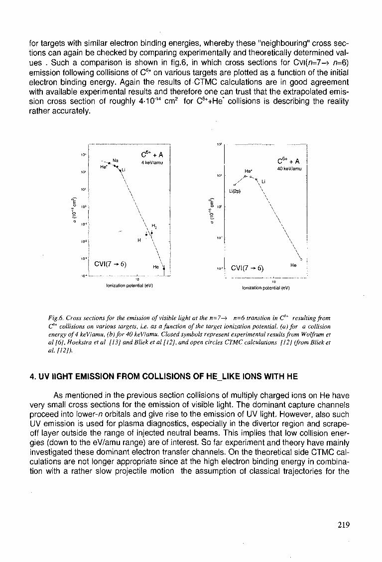
for targets with similar electron binding energies, whereby these "neighbouring" cross sections can again be checked by comparing experimentally and theoretically determined values . Such a comparison is shown in tig.6, in which cross sections for Cvi(n=7^ n=6) emission following collisions of C6+ on various targets are plotted as a function of the initial electron binding energy. Again the results of CTMC calculations are in good agreement with available experimental results and therefore one can trust that the extrapolated emission cross section of roughly 4-10"14 cm2 for C6++He* collisions is describing the reality rather accurately.
10»
10*
10'
10°
10 1
10-*
10 3
10-*
C6+ + A ~---*. N a 4 keWamu He" > . > u
\ \ \ \ \ \ \ \ \
\ \ \ \ \ H,
H n \ \ \
C V K 7 - 6 ) H e \
E " 10°
He* -*>-e^
/ \ Li a '
Li(2p)
CVI(7 -*
\ \ \ \ \ \ \ \
6)
C6+ + A 40 keV/amu
\ \ \ \ \ \ \ \ \ \ \ \ \ \ \ \
D
He
Ionization potential (eV) Ionization potential (eV)
Fig.6. Cross sections for the emission of visible light at the n=7—> n=6 transtion in C5* resulting from C5* collisions on various targets, i.e. as a function of the target ionization potential, (a) for a collision energy of 4 keV/amu, (b)for 40 keVlamu. Closed symbols represent experimental results from Wolfrum et al [6], Hoekstra et al [13] and Bliek et al [12], and open circles CTMC calculations [12] (from Bliek et al. [12]).
4. UV IIGHT EMISSION FROM COLLISIONS OF HE LIKE IONS WITH HE
As mentioned in the previous section collisions of multiply charged ions on He have very small cross sections for the emission of visible light. The dominant capture channels proceed into lower-n orbitals and give rise to the emission of UV light. However, also such UV emission is used for plasma diagnostics, especially in the divertor region and scrape-off layer outside the range of injected neutral beams. This implies that low collision energies (down to the eV/amu range) are of interest. So far experiment and theory have mainly investigated these dominant electron transfer channels. On the theoretical side CTMC calculations are not longer appropriate since at the high electron binding energy in combination with a rather slow projectile motion the assumption of classical trajectories for the
219
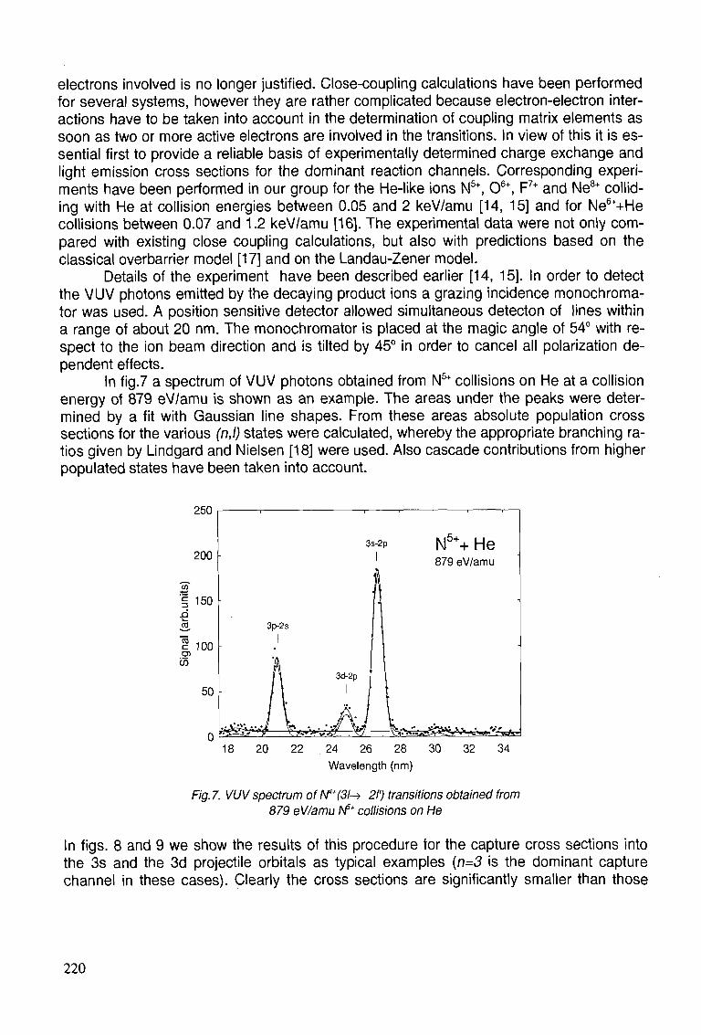
electrons involved is no longer justified. Close-coupling calculations have been performed for several systems, however they are rather complicated because electron-electron interactions have to be taken into account in the determination of coupling matrix elements as soon as two or more active electrons are involved in the transitions. In view of this it is essential first to provide a reliable basis of experimentally determined charge exchange and light emission cross sections for the dominant reaction channels. Corresponding experiments have been performed in our group for the He-like ions N5+, 06+, F7+ and Ne8+ colliding with He at collision energies between 0.05 and 2 keV/amu [14, 15] and for Ne6++He collisions between 0.07 and 1.2 keV/amu [16]. The experimental data were not only compared with existing close coupling calculations, but also with predictions based on the classical overbarrier model [17] and on the Landau-Zener model.
Details of the experiment have been described earlier [14, 15]. In order to detect the VUV photons emitted by the decaying product ions a grazing incidence monochroma-tor was used. A position sensitive detector allowed simultaneous detecton of lines within a range of about 20 nm. The monochromator is placed at the magic angle of 54° with respect to the ion beam direction and is tilted by 45° in order to cancel all polarization dependent effects.
In fig.7 a spectrum of VUV photons obtained from N5+ collisions on He at a collision energy of 879 eV/amu is shown as an example. The areas under the peaks were determined by a fit with Gaussian line shapes. From these areas absolute population cross sections for the various (n,l) states were calculated, whereby the appropriate branching ratios given by Lindgard and Nielsen [18] were used. Also cascade contributions from higher populated states have been taken into account.
250
200
"35" 1 150
3. 1 100 g>
w
50
0 18 20 22 . 24 26 28 30 32 34
Wavelength (nm)
Fig.7. VUV spectrum of N*+(3l-) 21') transitions obtained from 879 eV/amu /V5* collisions on He
In figs. 8 and 9 we show the results of this procedure for the capture cross sections into the 3s and the 3d projectile orbitals as typical examples {n=3 is the dominant capture channel in these cases). Clearly the cross sections are significantly smaller than those
3s-2p N5++ He 879 eV/amu
3p-2s
y<^>-vv; '•-y-^J^^VVsv^ifrftAsfc;
220
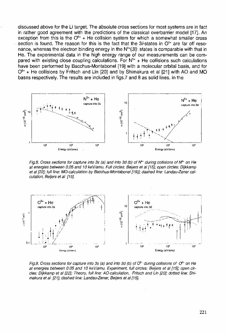
discussed above for the Li target. The absolute cross sections for most systems are in fact in rather good agreement with the predictions of the classical overbarrier model [17]. An exception from this is the 06+ + He collision system for which a somewhat smaller cross section is found. The reason for this is the fact that the 3/-states in 05+ are far off resonance, whereas the electron binding energy in the N4+(3/j. states is comparable with that in He. The experimental data in the high energy range of our measurements can be compared with existing close coupling calculations. For N5+ + He collisions such calculations have been performed by Bacchus-Montabonel [19] with a molecular orbital basis, and for 06+ + He collisions by Fritsch and Lin [20] and by Shimakura et al [21] with AO and MO bases respectively. The results are included in figs.7 and 8 as solid lines. In the
^ 10 f fUi j j * *• *
102 103
Energy (eV/amu)
N5+ + He capture into 3s 10
10" 103
Energy (eV/amu)
N5+ + He capture into 3d
Fig.8. Cross sections for capture into 3s (a) and into 3d (b) of N4* during collisions of N5* on He at energies between 0.05 and 10 keV/amu. Full circles: Beijers et al [15]; open circles: Dijkkamp et al [22]; full line: MO-calculation by Bacchus-Montabonel [19)]; dashed line: Landau-Zener calculation, Beijers et al [15].
0.1
10 06 + + He capture into 3d
102 103
Energy (eV/amu) 10"
Fig.9. Cross sections for capture into 3s (a) and into 3d (b) of O5* during collisions of Cf* on He at energies between 0.05 and 10 keV/amu. Experiment, full circles: Beijers et al [15]; open circles: Dijkkamp et al [22]; Theory, full line: AO-calculation, Fritsch and Lin [20]; dotted line: Shimakura et al [21]; dashed line: Landau-Zener, Beijers et al [15].
221
higher energy region the theoretical predictions are in reasonable agreement with the experimental data. With decreasing collision energies however pronounced discrepancies between theory and experiment can be observed. Clearly in this energy region theory has to be improved, especially in view of the relevance for plasma diagnostics.
In order to get an indication whether the main trends of the experimental data can already be reproduced by much simpler means we have performed Landau-Zener calculations, which are described in more detail by Beijers et al [15]. The results of these calculations are included as dashed lines in figs.8 and 9. For capture into the 3s states these calculations show a remarkable agreement with the experimental data. For capture into 3d however the Landau Zener calculations predict a decreasing cross section with increasing collision energy, whereas the experiment and also the close coupling calculations clearly show an increasing cross section. The failure of the Landau-Zener model in this case is not too surprising since rotational coupling, which is of increasing importance with increasing collsion energy, is not taken into account in this model.
5. CONCLUSION
Light-emission cross sections for collisions of medium-Z multiply charged ions with Li and He have been studied during the last years. For Li targets emission cross section for visible light are large and are reproduced by GTMC calculations with sufficiently high accuracy to render difficult experiments e.g. with Be ions unnecessary. For ion-He collisions on the other hand emission cross sections have not yet reached the same state of maturity. For plasma diagnostic purposes more experimental and theoretical investigations are necessary. Special attention has to be given to the role of metastable He atoms, since even extremely small fractions of less than 0.01% of such metastases can already dominate light emissionin the visible range, especially for low collision energies.
ACKNOWLEDGEMENT
This work is part of the research program of the 'Stichting voor Fondamenteel Ontderzoek der Materie' (FOM) with financial support from the 'Stichting voor Nederlands Weten-schappelijk Onderzoek' (NWO). It also receives financial support from EURATOM via an article 14 contract between JET Joint Undertaking and KVI.
REFERENCES
[1] Hellermann, M.von, Mandl, W., Summers, H.P., Boileau, A., Hoekstra, R., de Heer, F.J., Frieling, G.J., Plasma Phys. and Contr. Fusion 33 (1991) 1805
[2] Folkerts, H.O., Bliek, F.W., Meng, L., Olson, R.E., Morgenstern, R., von Hellermann, M., Summers, H.P., Hoekstra, R., J.Phys.B: At.Mol.Opt.Phys. 27 (1994) 3475
[3] Fritsch, W., J.Phys.B: At.Mol.Opt.Phys. 27 (1994) 3461 [4] Olson, R.E., Pascale J., Hoekstra, R., J.Phys.B: At. Mol. Opt. Phys. 25 (1992) 4241 [5] Schweinzer, J., Wutte, D., Winter, HP., J.Phys.B: At.Mol.Opt.Phys. 27 (1994) 137
222
[6] Wolfrum, E., Hoekstra, R., de Heer, F.J., Morgenstem, R., Winter, HP., J.Phys.B: At.Mol.Opt. Phys. 25 (1992) 2597
[7] Hoekstra, R., Wolfrum, E., Beijers, J.P.M., de Heer, F.J., Winter, H., Morgenstern, R., J.Phys.B: At.Mol.Opt.Phys. 25 (1992) 2587
[8] Hoekstra, R., Olson, R.E., Folkerts, H.O., Wolfrum, E., Pascale, J., de Heer, F.J., Morgenstern, R. Winter, H., J.Phys.B: At.Mol.Opt.Phys. 26 (1993) 2029
[9] Jacquet, E., Boduch, P., Chantepie, M., Druetta, M., Hennecart, D., Husson, X., Le-cler, D., Olson, R.E., Pascale, J., Wilson, M., Stolterfoht, N., Physica Scripta 47 (1993)618
[10] Jacquet, E., Boduch, P., Chantepie, M., Druetta, M., Hennecart, D., Husson, X., Le-cler, D., Martin-Brunetiere, F., Olson, R.E., Pascale, J., Wilson, M., Physica Scripta 49(1994)154
[11] Schippers, S., Boduch, P., van Buchem, J., Bliek, F.W., Hoekstra.R., Morgenstern, R., Olson, R.E., J.Phys.B: At.Mol.Opt.Phys.28 (1995) 3271
[12] Bliek, F.W., Folkerts, H.O., Morgenstern, R., Hoekstra, R., Meng, L, Olson, R.E., Fritsch, W., von Hellermann, M., Summers, H.P., Nucl.lnstr. and Methods in Phys.Res.B98 (1995) 195
[13] Hoekstra, R., Ciric, D., de Heer, F.J., Morgenstern, R., Phys.Scripta T28 (1989) 81 [14] Beijers, J.P.M., Hoekstra, R., Schlatmann, A.R., Morgenstern, R., de Heer, F.J.,
J.Phys.B: At.Mol.Opt.Phys.25 (1992) 463 [15] Beijers, J.P.M., Hoekstra, R., Morgenstern, R., Phys.Rev. A49 (1994) 363 [16] Beijers, J.P.M., Hoekstra, R., Morgenstern, R., de Heer, F.J., J.Phys.B:
At.Mol.Opt.Phys.25 (1992) 4851 [17] Niehaus, A., J.Phys.B: At.Mol.Opt.Phys.19 (1986) 2925 [18] Lindgard, A., Nielsen, S.E., At.Data Nucl.Data Tables 19 (1977) 533 [19] Bacchus-Montabonel, M., Phys.Rev. A 40 (1989) 6088 [20] Fritsch, W., Lin, CD., J.Phys.B: At.Mol.Opt.Phys. 19 (1986) 2683 [21] Shimakura, N., Sato, H., Kimura, M., Watanabe.T., J.Phys.B: At.Mol.Opt.Phys. 20
(1987) 1801 [22] Dijkkamp, D., Gordeev, Yu.S., Brazuk, A., Drentje, A.G., de Heer, F.J., J.Phys.B:
At.Mol.Opt.Phys. 18 (1985) 737
223

CHARGE EXCHANGE COLLISIONS OF MULTICHARGED Ar^+ , Kr5>*+, Fe7»*+ and Ni17+ IONS WITH He AND H2
M. DRUETTA*, D HTTZ+, B. JETTKANT+
* Laboratoire TSI, URA CNRS 842, Universite Jean Monnet, 23 rue du Dr Paul Michelon, 42023
Saint-Etienne cedex 2, France
+ CEA/Departement de Recherche Fondamentale sur la Matiere Condensee, Laboratoire Plasmas et
Sources d'lons, CENG, 17 rue des Martyrs, 38054 Grenoble cedex 9, France
Abstract The low energy charge exchange collisions between Ar5+, Ar6*, Kr5+, Kr6"1-, Fe7+, Fe^+,
and Ni17+ projectiles and He or H2 targets have been studied by vacuum ultra violet spectroscopy.
Emission cross sections of the observed transitions have been measured. When possible,
absolute cross sections of the n and 1 projectile excited states formed during the capture have been
deduced, as well as the total capture cross section.
In addition to single electron capture, one electron capture with excitation of a core electron
and two electron capture followed by autoionization have been observed and measured. The
influence of a metastable beam fraction is discussed.
1. INTRODUCTION
In magnetic confinement fusion energy devices the need for data on collisions between
metallic impurity ions comming from the vessel, injected atoms further ionized in the plasma and
the main plasma constituents has been recognised as a priority [1] [2]. In particular electron capture
collisions between multiply ionized ions and He or H2 are relevant to a better understanding of the
plasma edge and to the diagnostics (electron density and temperature...). Charge exchange
spectroscopy has shown to be a powerful method for such diagnostics [3].
We present in this paper some of our results on the collisions between Ar5+, Ar6*, Kr5+,
Kr&", Fe7+, Fe8+ and Ni17+ ions and He or H2. Results are obtained by optical spectroscopy in the
vacuum ultra violet (VUV).
The X1+ ion beam extracted from the 10 GHz Caprice electron cyclotron resonance (ECR)
source in Centre d'Etudes Nucleaires Grenoble is charge and mass analysed by two bending
magnets, and sent into the target gas cell filled with He or H2. The gas cell pressure is kept
generally at 5.10"5mbar in order to minimize multiple collisions.The gas cell has an entrance hole
of 8mm diameter.
225
Photons are analysed at 90° to the ion beam direction with a 3m grazing incidence
spectrometer equipped with 300 lines/mm and 600 lines/mm gratings blazed at 51.2 and 25.6nm
respectively. The detector is a either set of micro-channel plates (MCP) coated with MgF2 in order
to improve the VUV efficiency, and with a resistive anode or a channel electron multiplier (CEM).
Spectra have been obtained by charge exchange spectroscopy between X<1+ ions and He and
H2 gas targets at energies of 10-20qkeV depending of the ions.
The absolute cross section calibration is made with the three C IV lines (k = 312A
2s2S-3p2P°, X = 384A 2p2P°-3d2D, X = 419A 2p2P°-3s2S) obtained by the C4++H2 collision at
40keV for which the emission cross sections have been measured [4, 5]. By this method we only
have to measure the ion beam currents in the vacuum. During the experiment we only have to take
into account the small instabilities of the ion current after passage through the gas cell. We also use
as secondary standards, collisions like N4+, 06+> N5+ + He(H2) for which emission cross-sections
have been measured and which cover a wide spectral range [6]. A conservative value of the error bar
on emission cross-sections may then be evaluated to 30%. Of course, for intense lines where the
photon statistics are good, this error may be smaller. This estimated error bar does not include any
possible polarization effect of the emitted radiation and a possible metastable ion beam fraction.
Due to possible blending in KrV and NiXII the spectra of which are not well known, the error bar
may be higher (= 40%).
The first work in charge exchange spectroscopy measurements is to identify lines of spectra.
For this purpose we have used the compilations of Bashkin and Stoner [7] and Kelly [8] and
published papers for each ion spectrum. The particularity of the charge exchange excitation has
been also used to confirm or to help the identification :
- selectivity of the capture and possible prediction of the populated nl sublevels using the Niehauss
model [9] and the extension made by Burgdorfer et al [10].
- variation of the excited n level by change of the target ionisation potential.
The possible processes [11] which can occur to populate excited levels are in our case of a
two electron gas target (T):
a) processes involving electron capture :
- single electron capture (SEC) with core conservation of the incident ion
Xq+(nl)+T->X(q"1)+(M,nT) + T+
- one electron capture with excitation of a core electron (transfer - excitation (TE) process)
Xq+ (nl) + T -> X(q_1)+ (n^, n2l2)+T+
- atomic configuration interaction [12] [13]
226
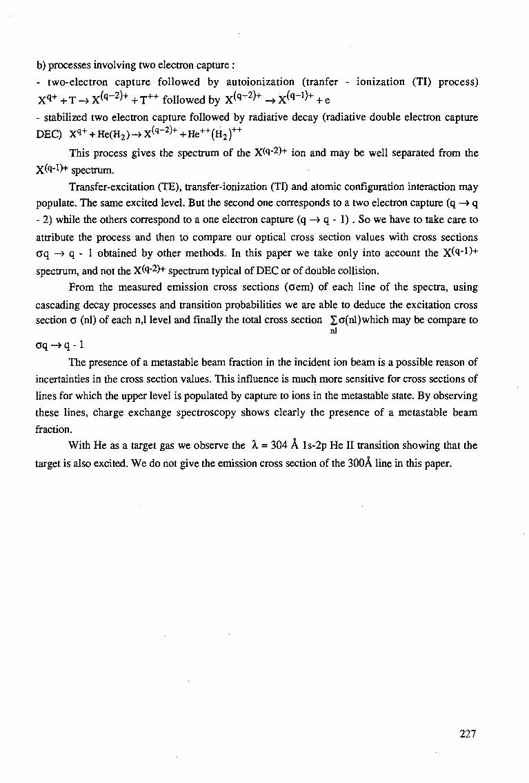
b) processes involving two electron capture :
- two-electron capture followed by autoionization (tranfer - ionization (TI) process)
x<i+ + T -* x(q~2)+ + T++ followed by X ^ 2 ) + -» X (q -1)+ + e
- stabilized two electron capture followed by radiative decay (radiative double electron capture
DEC) X*+ + He(H2)-> X<q_2)+ +He++(H2)++
This process gives the spectrum of the X "2)"1" ion and may be well separated from the
Xto"1)-1- spectrum. Transfer-excitation (TE), transfer-ionization (TI) and atomic configuration interaction may
populate. The same excited level. But the second one corresponds to a two electron capture (q —> q
- 2) while the others correspond to a one electron capture (q -» q - 1). So we have to take care to
attribute the process and then to compare our optical cross section values with cross sections
cq -» q - 1 obtained by other methods. In this paper we take only into account the Xfa-1)"1"
spectrum, and not the Xfa-2)+ spectrum typical of DEC or of double collision. From the measured emission cross sections (aem) of each line of the spectra, using
cascading decay processes and transition probabilities we are able to deduce the excitation cross section a (nl) of each n,l level and finally the total cross section £o(nl) which may be compare to
nl
aq -> q -1
The presence of a metastable beam fraction in the incident ion beam is a possible reason of
incertainties in the cross section values. This influence is much more sensitive for cross sections of
lines for which the upper level is populated by capture to ions in the metastable state. By observing
these lines, charge exchange spectroscopy shows clearly the presence of a metastable beam
fraction.
With He as a target gas we observe the A. = 304 A ls-2p He II transition showing that the
target is also excited. We do not give the emission cross section of the 300A line in this paper.
227
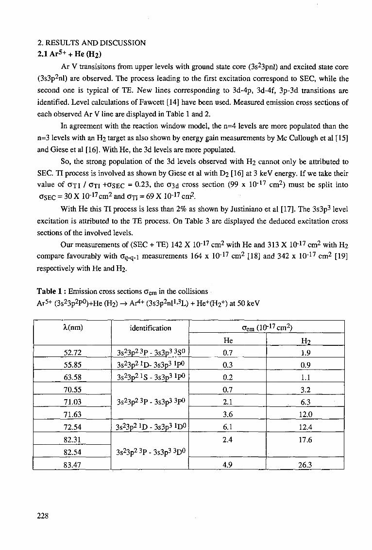
2. RESULTS AND DISCUSSION 2.1 Ar5+ + He (H2)
Ar V transisitons from upper levels with ground state core (3s23pnl) and excited state core
(3s3p2nl) are observed. The process leading to the first excitation correspond to SEC, while the
second one is typical of TE. New lines corresponding to 3d-4p, 3d-4f, 3p-3d transitions are
identified. Level calculations of Fawcett [14] have been used. Measured emission cross sections of
each observed Ar V line are displayed in Table 1 and 2.
In agreement with the reaction window model, the n=4 levels are more populated than the
n=3 levels with an H2 target as also shown by energy gain measurements by Mc Cullough et al [15]
and Giese et al [16]. With He, the 3d levels are more populated.
So, the strong population of the 3d levels observed with H2 cannot only be attributed to
SEC. TT process is involved as shown by Giese et al with D2 [16] at 3 keV energy. If we take their
value of GTI / O~TI +GSEC = 0-23, the 03d cross section (99 x 10"17 cm2) must be split into
GSEC = 30 X 10"17cm2 and a n = 69 X 10"17 cm2.
With He this TI process is less than 2% as shown by Justiniano et al [17]. The 3s3p3 level
excitation is attributed to the TE process. On Table 3 are displayed the deduced excitation cross
sections of the involved levels.
Our measurements of (SEC + TE) 142 X 10"17 cm2 with He and 313 X 1(H7 cm2 with H2
compare favourably with cq-q-i measurements 164 x 10"17 cm2 [18] and 342 x 10~17 cm2 [19]
respectively with He and H2.
Table 1: Emission cross sections c e m in the collisions Ar5+ (3s23p2P°)+He (H2) -> Ar4* (3s3p2nl1>3L) + He+(H2
+) at 50 keV
A.(nm)
52.72
55.85
63.58
70.55
71.03
71.63
72.54
82.31
82.54
83.47
identification
3s23p2 3p_3 s3p3 3S0
3s23p2 lD- 3s3p3 lp0
3s23p2 IS - 3s3p3 lp0
3s23p23p-3s3p3 3p0
3s23p2 ID - 3s3p3 1D0
3s23p23p-3s3p3 3D0
cem(10-17cm2)
He
0.7
0.3
0.2
0.7
2.1
3.6
6.1
2.4
4.9
H2
1.9
0.9
1.1
3.2
6.3
12.0
12.4
17.6
26.3
228
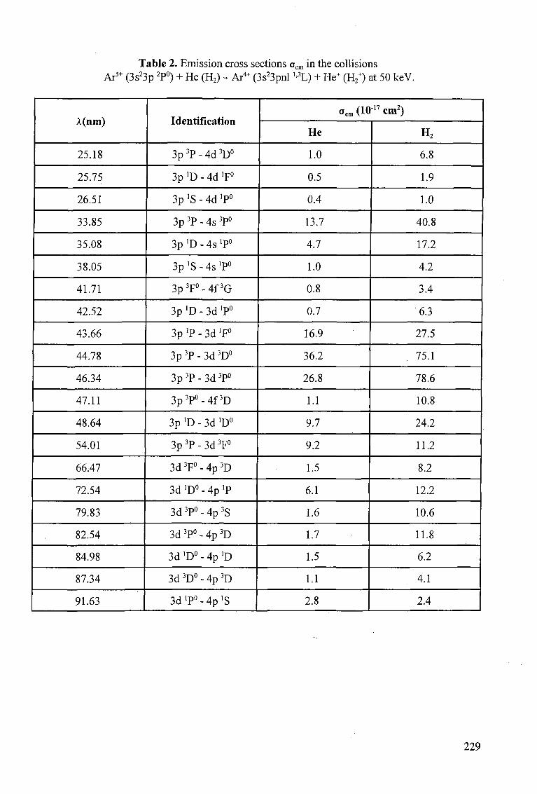
Table 2. Emission cross sections oem in the collisions Ar5+ (3s23p 2P°) + He (H2) - Ar4+ (3s23pnl ''3L) + He+ (H2
+) at 50 keV.
A(nm)
25.18
25.75
26.51
33.85
35.08
38.05
41.71
42.52
43.66
44.78
46.34
47.11
48.64
54.01
66.47
72.54
79.83
82.54
84.98
87.34
91.63
Identification
3p 3P - 4d 3D°
3p 'D - 4d 'F°
3p ]S - 4d ]P°
3p 3P - 4s 3P°
3p 'D - 4s 'P0
3p 'S - 4s 'P0
3p3F°-4f3G
3p 'D - 3d 'P°
3p 'P - 3d 'F°
3p 3P - 3d 3D°
3p 3P - 3d 3P°
3p3P°-4f3D
3p 'D - 3d 'D0
3p3P-3d3F°
3d 3F° - 4p 3D
3d 'D0 - 4p >P
3d 3P° - 4p 3S
3d 3P° - 4p 3D
3d 'D0 - 4p 'D
3d 3D° - 4p 3D
S d ' P ^ p ' S
oem (1017 cm2)
He
1.0
0.5
0.4
13.7
4.7
1.0
0.8
0.7
16.9
36.2
26.8
1.1
9.7
9.2
1.5
6.1
1.6
1.7
1.5
1.1
2.8
H2
6.8
1.9
1.0
40.8
17.2
4.2
3.4
6.3
27.5
75.1
78.6
10.8
24.2
11.2
8.2
12.2
10.6
11.8
6.2
4.1
2.4 |
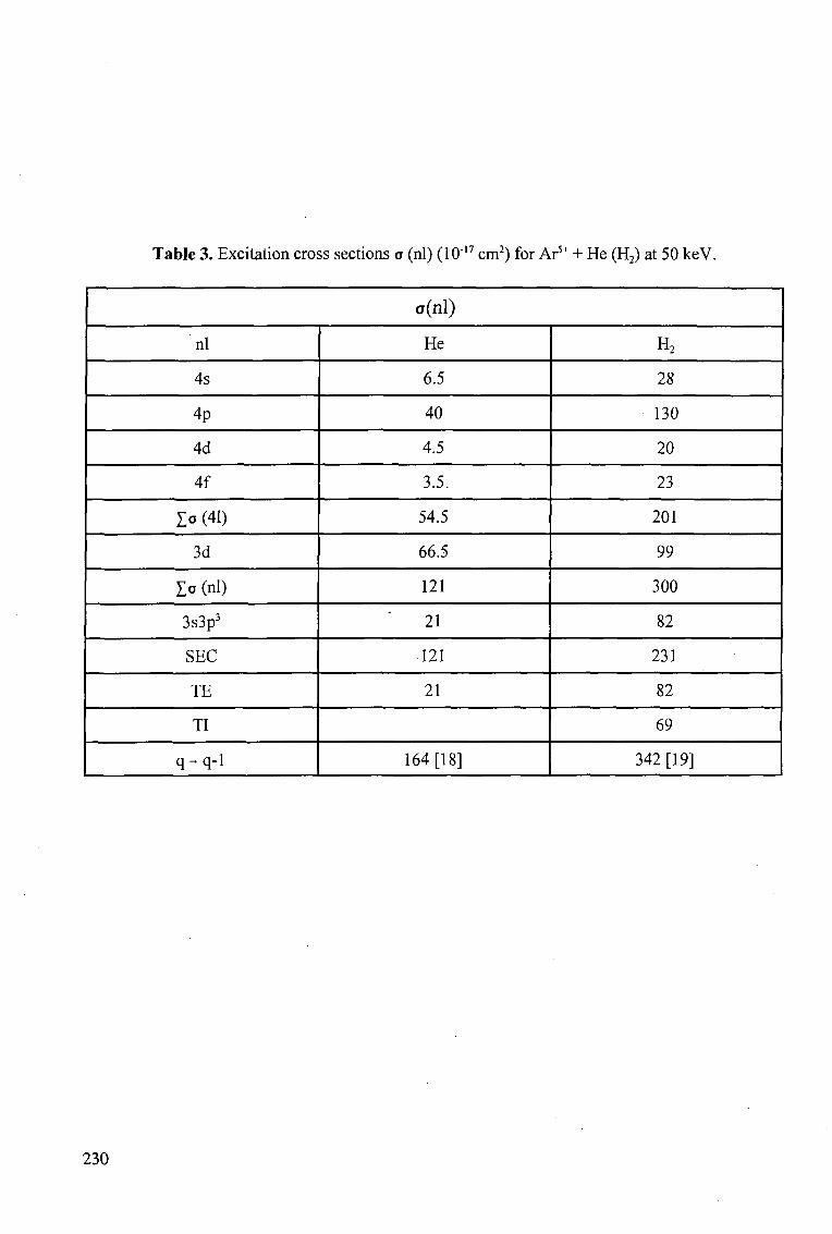
Table 3. Excitation cross sections o (nl) (1017 cm2) for Ar5+ + He (H2) at 50 keV.
c(nl)
nl
4s
4p
4d
4f
X° (41)
3d
l o (nl)
3s3p3
SEC
TE
TI
q-q-1
He
6.5
40
4.5
3.5.
54.5
66.5
121
21
121
21
164 [18]
H2
28
130
20
23
201
99
300
82
231
82
69
342 [19]
230
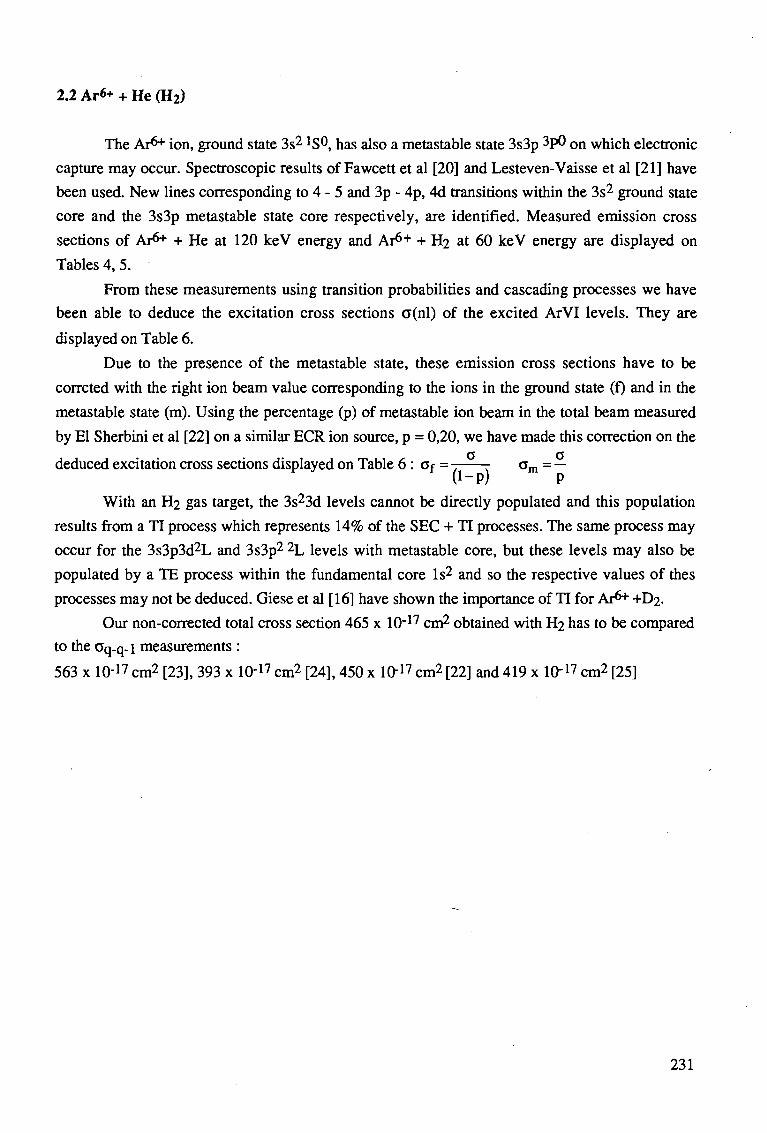
2.2 Ar«+ + He (H2)
The Ar6* ion, ground state 3s2 lS®, has also a metastable state 3s3p 3P0 on which electronic
capture may occur. Spectroscopic results of Fawcett et al [20] and Lesteven-Vaisse et al [21] have
been used. New lines corresponding to 4 - 5 and 3p - 4p, 4d transitions within the 3s2 ground state
core and the 3s3p metastable state core respectively, are identified. Measured emission cross
sections of Ar6* + He at 120 keV energy and Ar6"1" + H2 at 60 keV energy are displayed on
Tables 4, 5.
From these measurements using transition probabilities and cascading processes we have
been able to deduce the excitation cross sections a(nl) of the excited ArVI levels. They are
displayed on Table 6.
Due to the presence of the metastable state, these emission cross sections have to be
corrcted with the right ion beam value corresponding to the ions in the ground state (f) and in the
metastable state (m). Using the percentage (p) of metastable ion beam in the total beam measured
by El Sherbini et al [22] on a similar ECR ion source, p = 0,20, we have made diis correction on the
deduced excitation cross sections displayed on Table 6 : ov = - cm = — * (1-P) P
With an H2 gas target, the 3s23d levels cannot be directly populated and this population
results from a TI process which represents 14% of the SEC + TI processes. The same process may
occur for the 3s3p3d2L and 3s3p2 2L levels with metastable core, but these levels may also be
populated by a TE process within the fundamental core Is2 and so the respective values of thes
processes may not be deduced. Giese et al [16] have shown the importance of TI for Ar6* +D2.
Our non-corrected total cross section 465 x 10"17 cm2 obtained with H2 has to be compared
to the Cq.q-i measurements :
563 x 10-17 cm2 [23], 393 x 10'17 cm2 [24], 450 x 10"17 cm2 [22] and 419 x 10"17 cm2 [25]
231
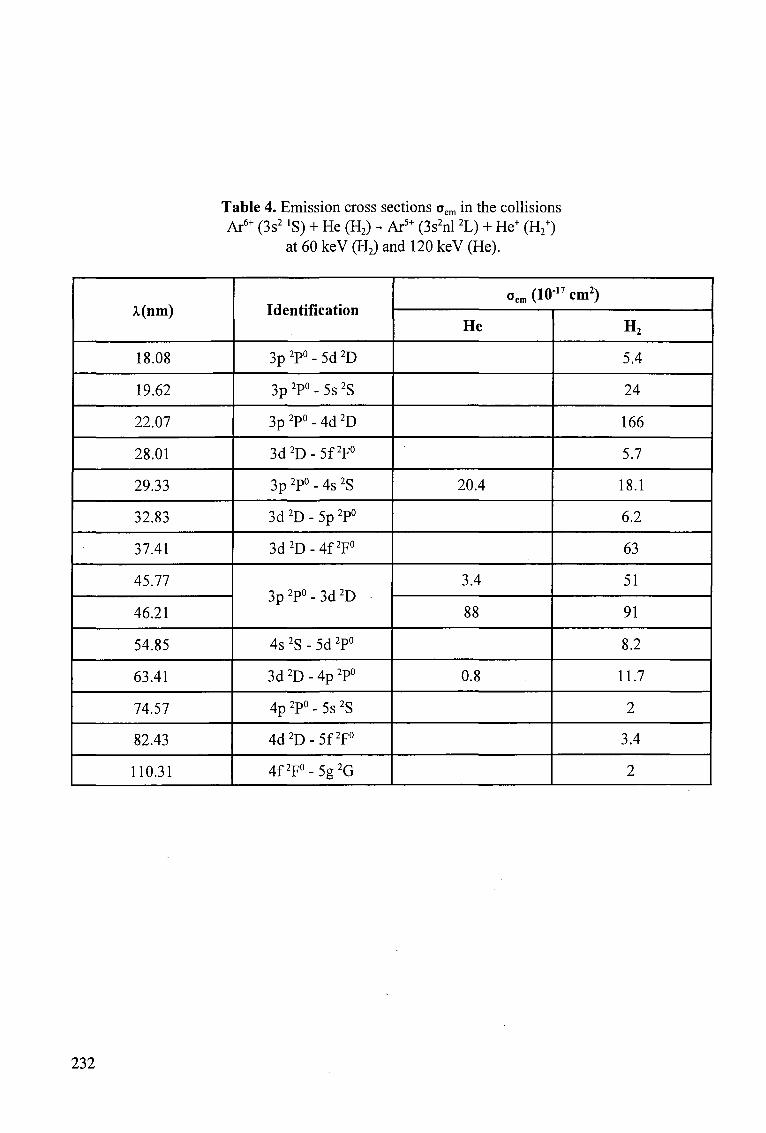
Table 4. Emission cross sections oem in the collisions Ar6+ (3s2 »S) + He (H2) - Ar5+ (3s2nl 2L) + He+ (H2
+) at 60 keV (H2) and 120 keV (He).
X(nm)
18.08
19.62
22.07
28.01
29.33
32.83
37.41
45.77
46.21
54.85
63.41
74.57
82.43
110.31
Identification
3p 2P° - 5d 2D
3p 2P° - 5s 2S
3p 2P° - 4d 2D
3d2D-5f2F°
3p 2P° - 4s 2S
3d 2D - 5p 2P°
3d2D-4f2F°
3p2P°-3d2D
4s 2S - 5d 2P°
3d 2D - 4p 2P°
4p 2P° - 5s 2S
4d2D-5f2F°
4f2F°-5g2G
oem (1017 cm2)
He
20.4
3.4
88
0.8
H2
5.4
24
166
5.7
18.1
6.2
63
51
91
8.2
11.7
2
3.4
2
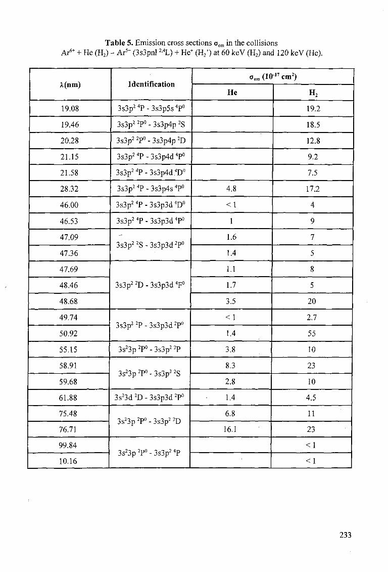
Table 5. Emission cross sections oem in the collisions Ar6+ + He (H2) - Ar5+ (3s3pnl 2'4L) + He+ (H2
+) at 60 keV (H2) and 120 keV (He),
A.(nm)
19.08
19.46
20.28
21.15
21.58
28.32
46.00
46.53
47.09
47.36
47.69
48.46
48.68
49.74
50.92
55.15
58.91
59.68
61.88
75.48
76.71
99.84
10.16
Identification
3s3p24P-3s3p5s4P°
3s3p2 2P° - 3s3p4p 2S
3s3p2 2P° - 3s3p4p 2D
3s3p24P-3s3p4d4P°
3s3p24P-3s3p4d4D°
3s3p2 4P - 3s3p4s 4P°
3s3p24P-3s3p3d4D°
3s3p2 4P - 3s3p3d 4P°
3s3p2 2S - 3s3p3d 2P°
3s3p2 2D - 3s3p3d 4F°
3s3p22P-3s3p3d2P°
3s23p 2P° - 3s3p2 2P
3s23p 2P° - 3s3p2 2S
3s23d 2D - 3s3p3d 2P°
3s23p 2P° - 3s3p2 2D
3s23p 2P° - 3s3p2 4P
oem(1017cm2)
He
4.8
< 1
1
1.6
1.4
1.1
1.7
3.5
<1
1.4
3.8
8.3
2.8
1.4
6.8
16.1
H2
19.2
18.5
12.8
9.2
7.5
17.2
4
9
7
5
8
5
20
2.7
55
10
23
10
4.5
11
23
<1
<1
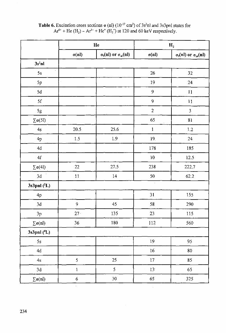
Table 6. Excitation cross sections o (nl) (10"1? cm2) of 3s2nl and 3s3pnl states for Ar6+ + He (H2) - Ar5+ + He+ (H2
+) at 120 and 60 keV respectively.
3s2nl
5s
5p
5d
5f
5g
Xo(51)
4s
4p
4d
4f
I°(41)
3d
3s3pnl L)
4p
3d
3p
Zo(nl)
3s3pnl (4L)
5s
4d
4s
3d
Zo(nl)
He
o(nl)
20.5
1.5
22
11
9
27
36
5
1
6
o,(nl) or om(nl)
25.6
1.9
27.5
14
45
135
180
25
5
30
H>
o(nl)
26
19
9
9
2
65
1
19,
178
10
238
50
31
58
23
112
19
16
17
13
65
o,(ni) or om(nl)
32
24
11
11
3
81
1.2
24
185
12.5
222.7
62.2
155
290
115
560
95
80
85
65
325
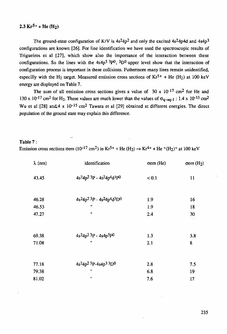
2.3 Kr5+ + He (H2)
The ground-state configuration of KrV is 4s24p2 and only the excited 4s24p4d and 4s4p3
configurations are known [26]. For line identification we have used the spectroscopic results of
Trigueiros et al [27], which show also the importance of the interaction between these
configurations. So the lines with the 4s4p3 3P°, 3D° upper level show that the interaction of
configuration process is important in these collisions. Futhermore many lines remain unidentified,
especilly with the H2 target. Measured emission cross sections of Kr5+ + He (H2) at 100 keV
energy are displayed on Table 7.
The sum of all emission cross sections gives a value of 30 x 10~17 cm2 for He and
130 x 10"17 cm2 for H2. These values are much lower than the values of aq-^ . i : 1.4 x 10~15 cm2
Wu et al [28] and.4 x 10 - 1 5 cm2 Tawara et al [29] obtained at different energies. The direct
population of the ground state may explain this difference.
Table 7 .
Emission cross sections aem (10"17 cm2) in Kr5+ + He (H2) -* Kr4"1- + He +(H2)+ at 100 keV
A, (nm) identification aem (He) aem (H2)
43.45 4s24p23p-4s24p4dlp0 <0.1 11
46.28 4s24p23p-4s24p4d3D0 1.9 16
46.53 " 1.9 18
47.27 " 2.4 30
69.38 4s24p23p-4s4p3p0 1.3 3.8
71.08 " 2.1 8
77.18 4s24p23p-4s4p3 3D0 2.8 7.5
79.38 " 6.8 19
81.02 " 7.6 17
235
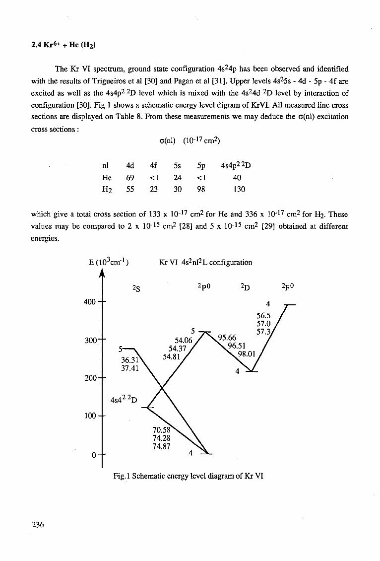
2.4 Kr6+ + He (H2)
The Kr VI spectrum, ground state configuration 4s24p has been observed and identified
with the results of Trigueiros et al [30] and Pagan et al [31]. Upper levels 4s25s - 4d - 5p - 4f are
excited as well as the 4s4p2 2D level which is mixed with the 4s24d 2D level by interaction of
configuration [30]. Fig 1 shows a schematic energy level digram of KrVI. All measured line cross
sections are displayed on Table 8. From these measurements we may deduce the o(nl) excitation
cross sections: o(nl) (lO-^cm2)
nl 4d 4f 5s 5p 4s4p22D He 69 < I 24 < I 40
H2 55 23 30 98 130
which give a total cross section of 133 x 10"17 cm2 for He and 336 x 10"17 cm2 for H2. These
values may be compared to 2 x 10~15 cm2 [28] and 5 x 10"15 cm2 [29] obtained at different
energies.
E (10 cm"1) Kr VI 4s2 nl2 L configuration
400
300
200
100
0
Fig.l Schematic energy level diagram of Kr VI
236
2g 2p0 2j) 2p0
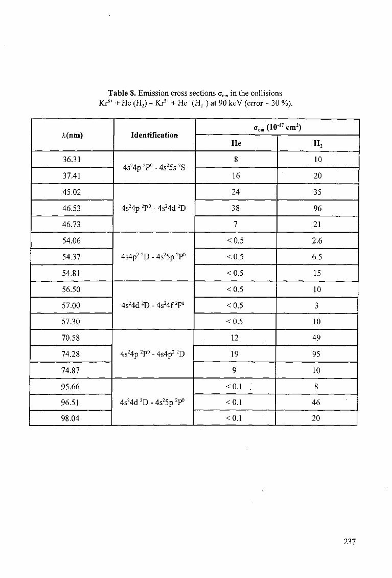
Table 8. Emission cross sections oem in the collisions Kr6+ + He (H2) - Kr5+ + He+ (H2
+) at 90 keV (error ~ 30 %).
A.(nm)
36.31
37.41
45.02
46.53
46.73
54.06
54.37
54.81
56.50
57.00
57.30
70.58
74.28
74.87
95.66
96.51
98.04
Identification
4 S 2 4 p 2P0 . 4 s 2 5 s 2 S
4s24p 2P° - 4s24d 2D
4s4p2 2D - 4s25p 2P°
4s24d2D-4s24f2F°
4s24p 2P° - 4s4p2 2D
4s24d 2D - 4s25p 2P°
oem(10I7cm2)
He
8
16
24
38
7
<0.5
<0.5
<0.5
<0.5
<0.5
<0.5
12
19
9
<0.1 .
<0.1
<0.1
H2
10
20
35
96
21
2.6
6.5
15
10
3
10
49
95
10
8
46
20
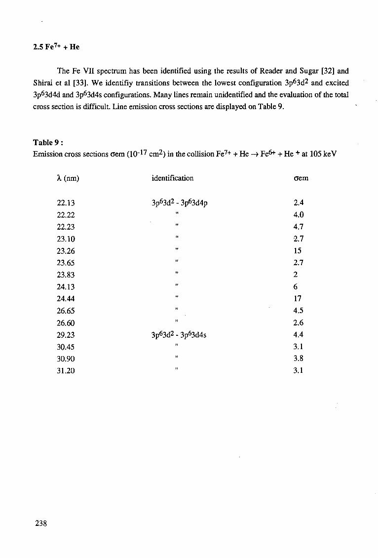
2.5 Fe7+ + He
The Fe VII spectrum has been identified using the results of Reader and Sugar [32] and
Shirai et al [33]. We identifiy transitions between the lowest configuration 3p63d2 and excited
3p63d4d and 3p63d4s configurations. Many lines remain unidentified and the evaluation of the total
cross section is difficult. Line emission cross sections are displayed on Table 9.
Table 9 :
Emission cross sections cem (1(H7 cm2) in the collision Fe7+ + He -» Fe6* + He + at 105 keV
X (nm)
22.13
22.22
22.23
23.10
23.26
23.65
23.83
24.13
24.44
26.65
26.60
29.23
30.45
30.90
31.20
identification
3p63d2 - 3p63d4p
3p63d2 3p63d4s
aem
2.4
4.0
4.7
2.7
15
2.7
2
6
17
4.5
2.6
4.4
3.1
3.8
3.1
238
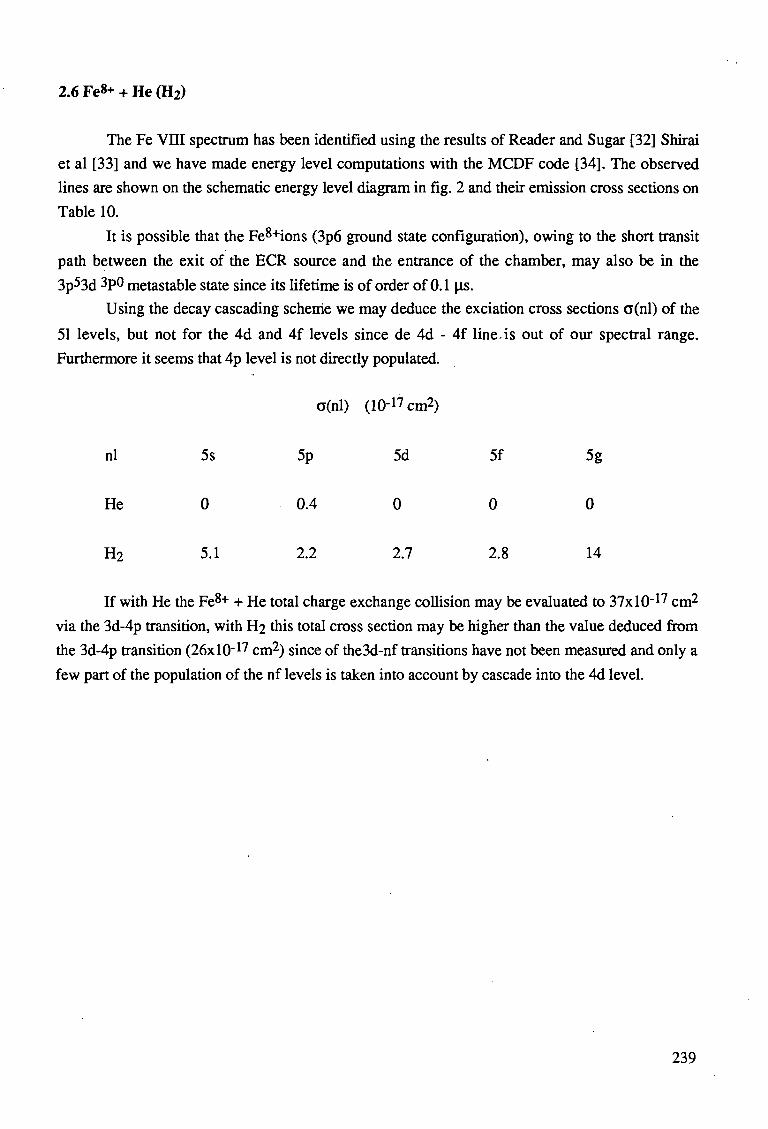
2.6 Fe«+ + He (H2)
The Fe VIII spectrum has been identified using the results of Reader and Sugar [32] Shirai
et al [33] and we have made energy level computations with the MCDF code [34]. The observed
lines are shown on the schematic energy level diagram in fig. 2 and their emission cross sections on
Table 10.
It is possible that the Fe8+ions (3p6 ground state configuration), owing to the short transit
path between the exit of the ECR source and the entrance of the chamber, may also be in the
3p53d 3P° metastable state since its lifetime is of order of 0.1 (is.
Using the decay cascading scheme we may deduce the exciation cross sections a(nl) of the
51 levels, but not for the 4d and 4f levels since de 4d - 4f line, is out of our spectral range.
Furthermore it seems that 4p level is not directly populated.
a(nl) (10"1? cm2)
nl 5s 5p 5d 5f 5g
He 0 0.4 0 0 0
H2 5.1 2.2 2.7 2.8 14
If with He the Fe8+ + He total charge exchange collision may be evaluated to 37xl0-17 cm2
via the 3d-4p transition, with H2 this total cross section may be higher than the value deduced from
the 3d-4p transition (26xl0~17 cm2) since of the3d-nf transitions have not been measured and only a
few part of the population of the nf levels is taken into account by cascade into the 4d level.
239
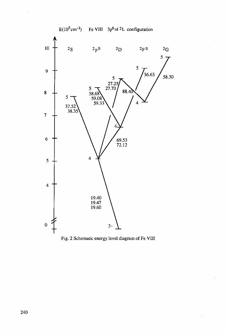
EQO^m'1) Fe VIII 3p6nl 2L configuration
10
8 --
6 "-
5 --
0 *
58.30
19.40 19.47 19.60
Fig. 2 Schematic energy level diagram of Fe VIII
240
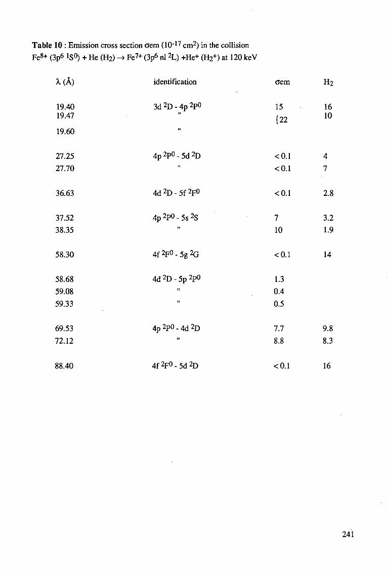
Table 10 : Emission cross section aem (10"1' cm2) in the collision
Fe8+ (3p6 1S0) + He (H2) -> Fe7+ (3p6 nl 2L) +He+ (H2+) at 120 keV
X(k) identification aem H2
19.40 19.47
19.60
27.25
27.70
3d 2D - 4p 2P°
4p 2P° - 5d 2D
15 {22
<0.1
<0.1
16 10
4
7
36.63 4d2D-5f2F° <0.1 2.8
37.52
38.35
4p 2P° - 5s 2S 7 10
3.2 1.9
58.30
58.68
59.08
59.33
4f2F<>-5g2G
4d 2D - 5p 2P0
<0.1
1.3
0.4
0.5
14
69.53
72.12
4p 2P° - 4d 2D 7.7
8.8
9.8
8.3
88.40 4f2F°-5d2D <0.1 16
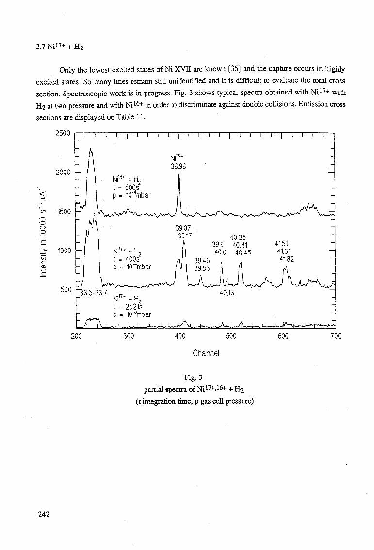
2.7 Ni17+ + H2
Only the lowest excited states of Ni XVH are known [35] and the capture occurs in highly
excited states. So many lines remain still unidentified and it is difficult to evaluate the total cross
section. Spectroscopic work is in progress. Fig. 3 shows typical spectra obtained with Ni1 7 + with
H2 at two pressure and with Ni1&+" in order to discriminate against double collisions. Emission cross
sections are displayed on Table 11.
2500
2000
<
'</> o o o o
c CD
1500
i—r
Ni18+ + H, t = 500s p = 10"4mbar
1000 -
500
Ni17+ + H2
t = 400s D = 10"Vibar
33.5-33.7 Ni17+ + K,
I
B15+
1 i r 1 1 r "i—r
Ni': 38.98
A
39.07 39.17 40.35
39.9 40.41 40.0 40.45
39.46 39.53
41.51 41.61 41.82
' ' W ^ V^A^v/
40.13
200 300 400 500 600 700
Channel
Fig. 3
partial spectra of Ni174"-1^4" + H2
(t integration time, p gas cell pressure)
242
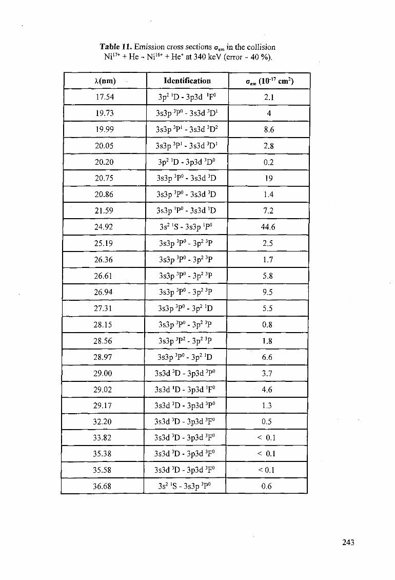
Table 11. Emission cross sections oem in the collision NiI7+ + He - Ni16+ + He+ at 340 keV (error ~ 40 %).
A.(nm)
17.54
19.73
19.99
20.05
20.20
20.75
20.86
21.59
24.92
25.19
26.36
26.61
26.94
27.31
28.15
28.56
28.97
29.00
29.02
29.17
32.20
33.82
35.38
35.58
36.68
Identification
3p2 >D - 3p3d 'F°
3s3p 3P° - 3s3d 3D"
3s3p 3P' - 3s3d 3D2
3s3p3P'-3s3d3D'
3p2 'D - 3p3d 3D°
3s3p 3P° - 3s3d 3D
3s3p 3P° - 3s3d 3D
3s3p 'P° - 3s3d >D
3s2 »S - 3s3p 'P0
3s3p 3P° - 3p2 3P
3s3p 3P° - 3p2 3P
3s3p 3P° - 3p2 3P
3s3p 3P° - 3p2 3P
3s3p 3P° - 3p2 'D
3s3p 3P° - 3p2 3P
3s3p 3P2 - 3p2 3P
3s3p 3P° - 3p2 'D
3s3d 3D - 3p3d 3P°
3s3d 'D - 3p3d >F°
3s3d 3D - 3p3d 3P°
3s3d 3D - 3p3d 3F°
3s3d 3D - 3p3d 3F°
3s3d 3D - 3p3d 3F°
3s3d3D - 3p3d 3F°
3s21S-3s3p3P°
oem (lO17 cm2)
2.1
4
8.6
2.8
0.2
19
1.4
7.2
44.6
2.5
1.7
5.8
9.5
5.5
0.8
1.8
6.6
3.7
4.6
1.3
0.5
< 0.1
< 0.1
<0.1
0.6
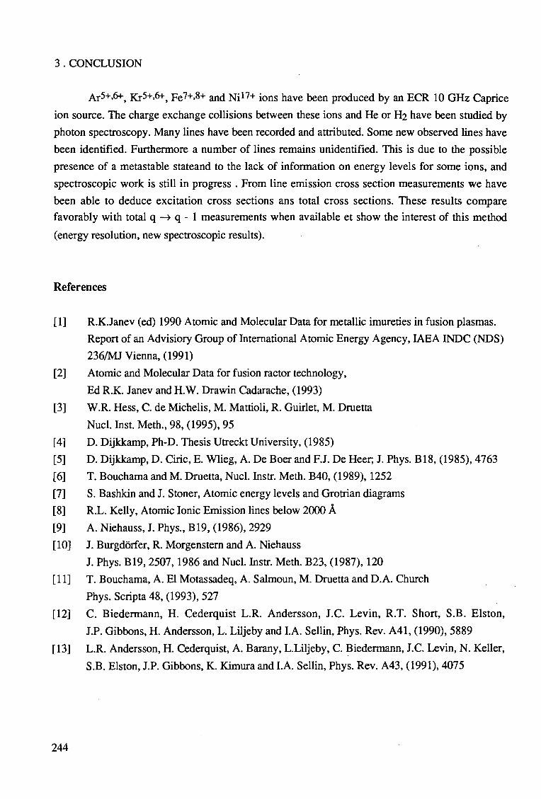
3 . CONCLUSION
M5+.6+, Ki5+M t Fe7+.8+ and Ni17+ ions have been produced by an ECR 10 GHz Caprice
ion source. The charge exchange collisions between these ions and He or H2 have been studied by
photon spectroscopy. Many lines have been recorded and attributed. Some new observed lines have
been identified. Furthermore a number of lines remains unidentified. This is due to the possible
presence of a metastable stateand to the lack of information on energy levels for some ions, and
spectroscopic work is still in progress . From line emission cross section measurements we have
been able to deduce excitation cross sections ans total cross sections. These results compare
favorably with total q —» q - 1 measurements when available et show the interest of this method
(energy resolution, new spectroscopic results).
References
[I] R.KJanev (ed) 1990 Atomic and Molecular Data for metallic imureties in fusion plasmas.
Report of an Advisiory Group of International Atomic Energy Agency, IAEA INDC (NDS)
236/MJ Vienna, (1991)
[2] Atomic and Molecular Data for fusion ractor technology,
Ed R.K. Janev and H.W. Drawin Cadarache, (1993)
[3] W.R. Hess, C. de Michelis, M. Mattioli, R. Guirlet, M. Druetta
Nucl. Inst. Meth., 98, (1995), 95
[4] D. Dijkkamp, Ph-D. Thesis Utreckt University, (1985)
[5] D. Dijkkamp, D. Ciric, E. Wlieg, A. De Boer and F.J. De Heer, J. Phys. B18, (1985), 4763
[6] T. Bouchama and M. Druetta, Nucl. Instr. Meth. B40, (1989), 1252
[7] S. Bashkin and J. Stoner, Atomic energy levels and Grotrian diagrams
[8] R.L. Kelly, Atomic Ionic Emission lines below 2000 A
[9] A. Niehauss, J. Phys., B19, (1986), 2929
[10] J. Burgdorfer, R. Morgenstern and A. Niehauss
J. Phys. B19, 2507,1986 and Nucl. Instr. Meth. B23, (1987), 120
[II] T. Bouchama, A. El Motassadeq, A. Salmoun, M. Druetta and D.A. Church
Phys. Scripta 48, (1993), 527
[12] C. Biedermann, H. Cederquist L.R. Andersson, J.C. Levin, R.T. Short, S.B. Elston,
J.P. Gibbons, H. Andersson, L. Liljeby and I.A. Sellin, Phys. Rev. A41, (1990), 5889
[13] L.R. Andersson, H. Cederquist, A. Barany, L.Liljeby, C. Biedermann, J.C. Levin, N. Keller,
S.B. Elston, J.P. Gibbons, K. Kimura and I.A. Sellin, Phys. Rev. A43, (1991), 4075
244
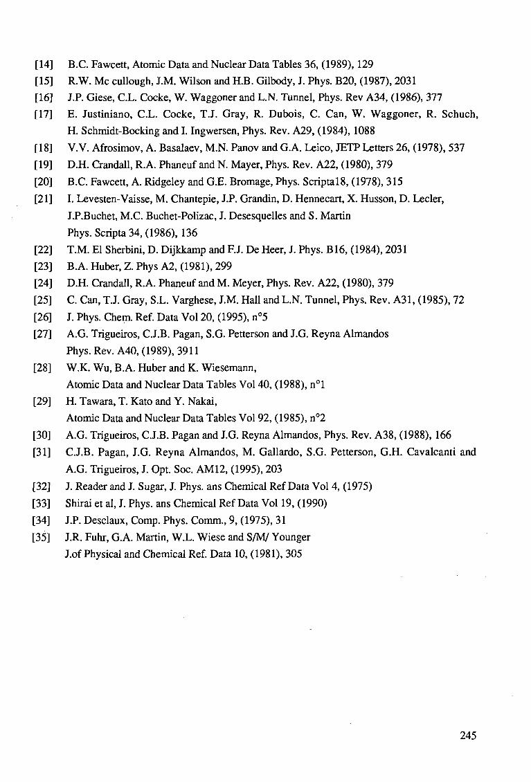
[14] B.C. Fawcett, Atomic Data and Nuclear Data Tables 36, (1989), 129
[15] R.W. Mc cullough, J.M. Wilson and H.B. Gilbody, J. Phys. B20, (1987), 2031
[16] J.P. Giese, C.L. Cocke, W. Waggoner and L.N. Tunnel, Phys. Rev A34, (1986), 377
[17] E. Justiniano, C.L. Cocke, T.J. Gray, R. Dubois, C. Can, W. Waggoner, R. Schuch,
H. Schmidt-Bocking and I. Ingwersen, Phys. Rev. A29, (1984), 1088
[18] V.V. Afrosimov, A. Basalaev, M.N. Panov and G.A. Leico, JETP Letters 26, (1978), 537
[19] D.H. Crandall, R.A. Phaneuf and N. Mayer, Phys. Rev. A22, (1980), 379
[20] B.C. Fawcett, A. Ridgeley and G.E. Bromage, Phys. Scriptal8, (1978), 315
[21] I. Levesten-Vaisse, M. Chantepie, J.P. Grandin, D. Hennecart, X. Husson, D. Lecler,
LP.Buchet, M.C. Buchet-Polizac, J. Desesquelles and S. Martin
Phys. Scripta 34, (1986), 136
[22] T.M. El Sherbini, D. Dijkkamp and F.J. De Heer, J. Phys. B16, (1984), 2031
[23] B.A. Huber, Z. Phys A2, (1981), 299
[24] D.H. Crandall, R.A. Phaneuf and M. Meyer, Phys. Rev. A22, (1980), 379
[25] C. Can, T.J. Gray, S.L. Varghese, J.M. Hall and L.N. Tunnel, Phys. Rev. A31, (1985), 72
[26] J. Phys. Chem. Ref. Data Vol 20, (1995), n°5
[27] A.G. Trigueiros, C.J.B. Pagan, S.G. Petterson and J.G. Reyna Almandos
Phys. Rev. A40, (1989), 3911
[28] W.K. Wu, B.A. Huber and K. Wiesemann,
Atomic Data and Nuclear Data Tables Vol 40, (1988), n°l
[29] H. Tawara, T. Kato and Y. Nakai,
Atomic Data and Nuclear Data Tables Vol 92, (1985), n°2
[30] A.G. Trigueiros, C.J.B. Pagan and J.G. Reyna Almandos, Phys. Rev. A38, (1988), 166
[31] C.J.B. Pagan, J.G. Reyna Almandos, M. Gallardo, S.G. Petterson, G.H. Cavalcanti and
A.G. Trigueiros, J. Opt. Soc. AM12, (1995), 203
[32] J. Reader and J. Sugar, J. Phys. ans Chemical Ref Data Vol 4, (1975)
[33] Shirai et al, J. Phys. ans Chemical Ref Data Vol 19, (1990)
[34] J.P. Desclaux, Comp. Phys. Comm., 9, (1975), 31
[35] J.R. Fuhr, G.A. Martin, W.L. Wiese and S/M/ Younger
J.of Physical and Chemical Ref. Data 10, (1981), 305
245

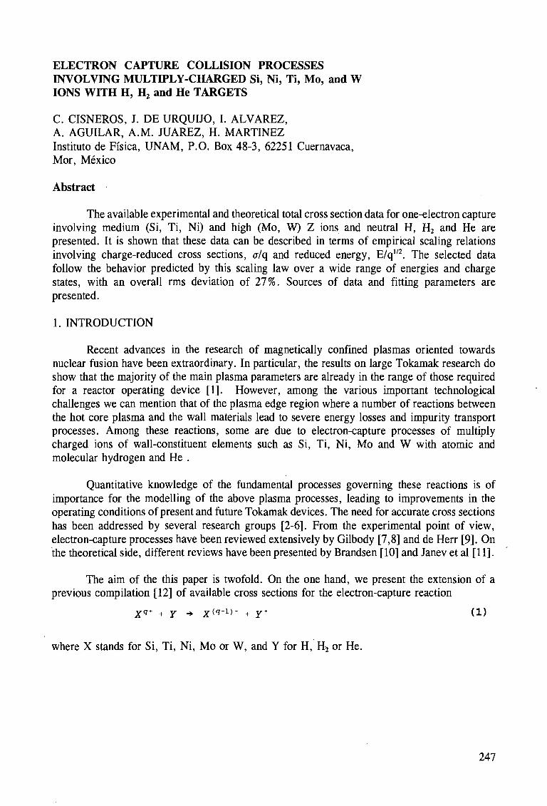
ELECTRON CAPTURE COLLISION PROCESSES INVOLVING MULTIPLY-CHARGED Si, Ni, Ti, Mo, and W IONS WITH H, H2 and He TARGETS
C. CISNEROS, J. DE URQUIJO, I. ALVAREZ, A. AGUILAR, A.M. JUAREZ, H. MARTINEZ Institute) de Fisica, UNAM, P.O. Box 48-3, 62251 Cuernavaca, Mor, Mexico
Abstract
The available experimental and theoretical total cross section data for one-electron capture involving medium (Si, Ti, Ni) and high (Mo, W) Z ions and neutral H, H2 and He are presented. It is shown that these data can be described in terms of empirical scaling relations involving charge-reduced cross sections, a/q and reduced energy, E/q1/2. The selected data follow the behavior predicted by this scaling law over a wide range of energies and charge states, with an overall rms deviation of 27%. Sources of data and fitting parameters are presented.
1. INTRODUCTION
Recent advances in the research of magnetically confined plasmas oriented towards nuclear fusion have been extraordinary. In particular, the results on large Tokamak research do show that the majority of the main plasma parameters are already in the range of those required for a reactor operating device [1]. However, among the various important technological challenges we can mention that of the plasma edge region where a number of reactions between the hot core plasma and the wall materials lead to severe energy losses and impurity transport processes. Among these reactions, some are due to electron-capture processes of multiply charged ions of wall-constituent elements such as Si, Ti, Ni, Mo and W with atomic and molecular hydrogen and He .
Quantitative knowledge of the fundamental processes governing these reactions is of importance for the modelling of the above plasma processes, leading to improvements in the operating conditions of present and future Tokamak devices. The need for accurate cross sections has been addressed by several research groups [2-6]. From the experimental point of view, electron-capture processes have been reviewed extensively by Gilbody [7,8] and de Herr [9]. On the theoretical side, different reviews have been presented by Brandsen [10] and Janev et al [11].
The aim of the this paper is twofold. On the one hand, we present the extension of a previous compilation [12] of available cross sections for the electron-capture reaction
Xq+ + Y -* x ( q " 1 ) + + y* ( D
where X stands for Si, Ti, Ni, Mo or W, and Y for H, H2 or He.
247
On the other hand, use has been made of a semiempirical scaling law [13] to fit the data. This law has been shown previously to be very useful in describing the dependence of charge exchange cross sections with energy and different charges states of ions colliding with the above target gases. Indeed, the present work is mainly based along the lines of Ref.[13].
2. SOURCES OF DATA
We have compiled all available experimental and theoretical cross sections for the single electron-capture reaction described by Eq. 1. In most cases we have found that no coincidence analysis with respect to the charge states of the target ions after the collision has been carried out. Therefore, the experimental data may also be influenced by the contribution of transfer ionization processes. Other processes, such as those due to H2 targets, dissociative collision channels which may involve charge transfer or ionization, or two electron process with capture and ionization for the case of He must be considered; however, no detailed information could be found in the literature.
There are comprehensive compilations of data for multiply charged ions colliding with atomic hydrogen [14-16]. For the case of collisions with H2
+, data have also been compiled by Tawara [16]. Data for He have been compiled by Wu et al [17,18]. The current bibliographic files at the ORNL Controlled Fusion Atomic Data Centre provided further data over the range 0.001-1000 keV/amu. The comments appearing on Refs. 19 and 20 with regard to reaction (1) for other ions are equally valid for the ion species discussed here.
All experimental data were obtained by the fast ion beam-gas method thoroughly described by Gilbody [8] and Phaneuf et al [13], and merge beam technique [65] and are summarized in Table I of this paper. This table indicates that experimental data are in fact scarce, particularly for the case of He as a target. As regards theoretical calculations, these have been described by Brandsen [6] and Phaneuf [13], and merge beam technique [65]. For instance, for fully stripped ions, it has been pointed out that the results of the multichannel Landau-Zener method with rotational coupling (MLZRC) agree within 30% or better with the measurements of Meyer et al [21] for bare ions of charge states Z=6-10. These calculations were performed by Janev [11] for charge state values q up to 74. This work also presents comparisons with other theoretical calculations such as the classical trajectory Monte Carlo method (CTMC) [22], and the unitarised distorted wave approximation (UDWA) [23,24]. A more comprehensive description of the theoretical methods which are commonly applied in the treatment of charge exchange and ionization processes is given by Brandsen [6] and Janev et al [25]. Among the most recent calculations dealing with partially stripped ions are those of Fritsch [26,27], Katsonis et al [28], and Uskov et al [29].
The theoretical data relevant to this study are also presented in Table I. As it can be observed from Table I, on the whole, cross section data for the processes under study, and particularly for He as a target, again, is far from complete.
248
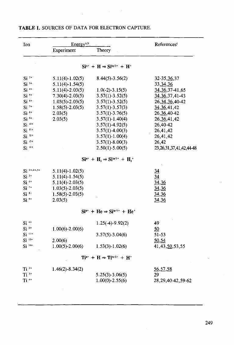
TABLE I. SOURCES OF DATA FOR ELECTRON CAPTURE.
Ion Energya'b References0
Experiment Theory
Si"" + H => Si'"-"" + H"
Si2" Si3" Si4" Si5" Si6" Si7" Si8" Si9" Si10" Si"" Si'2" Si13" Si14"
Si2"'4"-5" Si3" Si6" S i ' " Si8+
Si9"
Si4+
Si8" S i"" Si13" Si14"
Ti2" Ti3" Ti4"
5.11(4)-1.02(5) 5.11(4)-1.54(5) 5.11(4)-2.03(5) 7.30(4)-2.03(5) 1.03(5)-2.03(5) 1.58(5)-2.03(5) 2.03(5) 2.03(5)
Si""
5.11(4)-1.02(5) 5.11(4)-1.54(5) 5.11(4)-2.03(5) 1.03(5)-2.03(5) 1.58(5)-2.03(5) 2.03(5)
Si""
1.00(6)-2.00(6)
2.00(6) 1.00(5)-2.00(6)
Ti""
1.46(2)-8.34(2)
8.44(5)-3.56(2)
1.0(-2)-3.15(5) 3.57(l)-3.52(5) 3.57(l)-3.52(5) 3.57(l)-3.57(3) 3.57(l)-3.76(5) 3.57(1)-1.40(4) 3.57(l)-4.92(5) 3.57(l)-4.00(3) 3.57(1)-1.00(4) 3.57(l)-8.00(3) 2.50(l)-5.00(5)
+ H2 =* Si("-1)+ + H2"
+ He => Si'""1'" + He"
1.25(-4)-9.92(2)
3.57(5)-3.04(6)
1.53(3)-1.02(6)
+ H => Ti("-1,+ + H"
5.25(3)-3.06(5) 1.00(0)-2.55(6)
32-35,36,37 33,34,36 34,36,37-41,65 34,36,37,41-43 26,34,36,40-42 34,36,41,42 26,36,40-42 26,36,41,42 26,40-42 26,41,42 26,41,42 26,42 23,26,31,37,41,42,4448
34 34 34,36 34,36 34,36 34,36
49 50 51-53 50,54 41,43,50,53,55
56,57,58 29 28,29,40-42,59-62
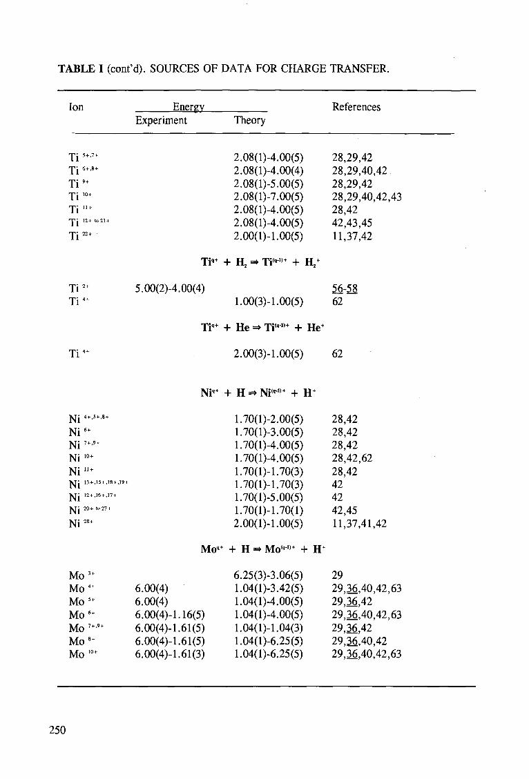
TABLE I (cont'd). SOURCES OF DATA FOR CHARGE TRANSFER.
Ion
Ti5"'7" T i 6+,8+
Ti9" Ti10" Ti11" n p i 12+ to 21 +
T j 22+
Ti2" Ti4"
Enerev Experiment
5.00(2)
Ti""
-4.00(4)
Ti'"
Theory
2.08(l)-4.00(5) 2.08(l)-4.00(4) 2.08(l)-5.00(5) 2.08(l)-7.00(5) 2.08(l)-4.00(5) 2.08(l)-4.00(5) 2.00(1)-1.00(5)
+ !!,=• Ti"1)+ + H,"
1.00(3)-1.00(5)
+ He «• Ti"1)+ + He"
References
28,29,42 28,29,40,42 28,29,42 28,29,40,42,43 28,42 42,43,45 11,37,42
56-58 62
Ti4" 2.00(3)-l.00(5) 62
Ni'" + H =* Ni('J,+ + H"
N i 4 + ,5+,8 +
Ni6+
Ni7"'9" Ni10" Ni11" •NTj 13 + ,15+,18+,19 +
T ^ j 12+,16 + ,17 +
XTj 20+ 10 27 +
Ni28"
Mo3" Mo4" Mo5" Mo6" Mo 7"9" Mo8" Mo10"
6.00(4) 6.00(4) 6.00(4)-1
Mo,+
.16(5) 6.00(4)4.61(5) 6.00(4)-1.61(5) 6.00(4)-l.61(3)
1.70(l)-2.00(5) 1.70(l)-3.00(5) 1.70(l)-4.00(5) 1.70(l)-4.00(5) 1.70(1)-1.70(3) 1.70(1)-1.70(3) 1.70(l)-5.00(5) 1.70(1)-1.70(1) 2.00(1)-1.00(5)
+ H -» Mo('-1)+ + H
6.25(3)-3.06(5) 1.04(l)-3.42(5) 1.04(l)-4.00(5) 1.04(l)-4.00(5) 1.04(1)-1.04(3) 1.04(l)-6.25(5) 1.04(l)-6.25(5)
28,42 28,42 28,42 28,42,62 28,42 42 42 42,45 11,37,41,42
29 29,36,40,42,63 29,36,42 29,36,40,42,63 29,36,42 29,36,40,42 29,36,40,42,63
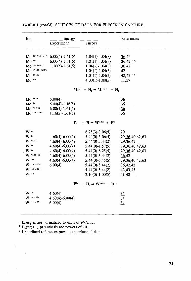
TABLE I (cont'd). SOURCES OF DATA FOR ELECTRON CAPTURE.
Ion
J y J Q 11+I0 13 + .W +
Mo , 4 +
Mo 16+1018+
Mo I9+,2I+ lo29+
Mo 20+'30+
Mo42+
Mo 4+5+
Mo s +
M o 7 + t o l 5 +
Mo 16+ to 18+
W3 +
W4 +
\ y 5+.7 +
W6 +
. W8+
Y l f 9+.11 + .12 +
W10+
•tlT 13+ to 15 +
• « T 16+ '"30 +
W74+
W4+
\Y 5+ l°12+
\y 13+ tol5+
Energy Experiment
6.00(4)-1.61(5) 6.00(4)-1.61(5) 1.16(5)4.61(5)
Moq
6.00(4) 6.00(4)-1.16(5) 6.00(4)-1.61(5) 1.16(5)4.61(5)
W>+
4.60(4)-6.00(2) 4.60(4)-6.00(4) 4.60(4)-6.00(4) 4.60(4)-6.00(4) 4.60(4)-6.00(4) 4.60(4)-6.00(4) 6.00(4)
W'+
4.60(4) 4.60(4)-6.00(4) 6.00(4)
Theory
1.04(1)-1.04(3) 1.04(1)-1.04(3) 1.04(1)-1.04(3) 1.04(1)-1.04(3) 1.04(1)4.04(3) 4.00(1)4.00(5)
References
36,42 36,42,45 36,42 42 42,43,45 11,37
f + H, =» Moq 1,+ + H2+
+ H => W'1,+ + H+
6.25(3)-3.06(5) 5.44(0)-3.06(5) 5.44(0)-5.44(2) 5.44(0)-4.57(5) 5.44(0)-6.25(5) 5.44(0)-5.44(2) 5.44(0)-6.45(5) 5.44(0)-5.44(2) 5.44(0)-5.44(2) 2.10(0)-1.00(5)
+ H, =» W('-,,+ + H /
36 36 36 36
29 29,36,40,42,63 29,36,42 29,36,40,42,63 29,36,40,42,63 36,42 29,36,40,42,63 36,42,45 42,43,45 11,48
34 34 34
" Energies are normalized to units of eV/amu. b Figures in parenthesis are powers of 10. c Underlined references present experimental data.
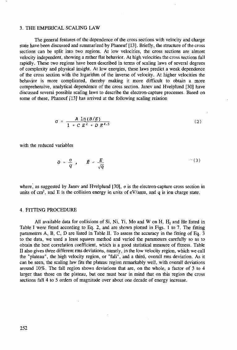
3. THE EMPIRICAL SCALING LAW
The general features of the dependence of the cross sections with velocity and charge state have been discussed and summarized by Phaneuf [13]. Briefly, the structure of the cross sections can be split into two regions. At low velocities, the cross sections are almost velocity independent, showing a rather flat behavior. At high velocities the cross sections fall rapidly. These two regions have been described in terms of scaling laws of several degrees of complexity and physical insight. At low energies, these laws predict a weak dependence of the cross section with the logarithm of the inverse of velocity. At higher velocities the behavior is more complicated, thereby making it more difficult to obtain a more comprehensive, analytical dependence of the cross section. Janev and Hvelplund [30] have discussed several possible scaling laws to describe the electron-capture processes. Based on some of these, Phaneuf [13] has arrived at the following scaling relation
1 + C E2 + D J?4-5
with the reduced variables
where, as suggested by Janev and Hvelplund [30], a is the electron-capture cross section in units of cm2, and E is the collision energy in units of eV/amu, and q is ion charge state.
4. FITTING PROCEDURE
All available data for collisions of Si, Ni, Ti, Mo and W on H, H2 and He listed in Table I were fitted according to Eq. 2, and are shown plotted in Figs. 1 to 7. The fitting parameters A, B, C, D are listed in Table II. To assess the accuracy in the fitting of Eq. 3 to the data, we used a least squares method and varied the parameters carefully so as to obtain the best correlation coefficient, which is a good statistical measure of fitness. Table II also gives three different rms deviations, namely, in the low velocity region, which we call the "plateau", the high velocity region, or "fall", and a third, overall rms deviation. As it can be seen, the scaling law fits the plateau region remarkably well, with overall deviations around 10%. The fall region shows deviations that are, on the whole, a factor of 3 to 4 larger than those on the plateau, but one must bear in mind that on this region the cross sections fall 4 to 5 orders of magnitude over about one decade of energy increase.
252
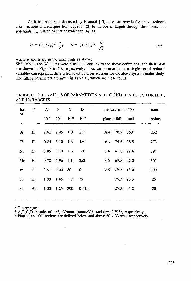
As it has been also discussed by Phaneuf [13], one can rescale the above reduced cross sections and energies from equation (3) to include all targets through their ionization potentials, I0, related to that of hydrogen, IH, as
5 = (IJIH)2 £, E = (I0/IH)2 - ^ (4)
where a and E are in the same units as above. Siq+, Moq+, and Wq+ data were rescaled according to the above definitions, and their plots are shown in Figs. 8 to 10, respectively. Thus we observe that the single set of reduced variables can represent the electron-capture cross sections for the above systems under study. The fitting parameters are given in Table II, which are those for H.
TABLE II. THE VALUES OF PARAMETERS A, B, C AND D IN EQ.(2) FOR H, H2 AND He TARGETS.
Ion Ta Ab B C D rms deviation0 (%) nom. of
1016 106 10" 1023 plateau fall total points
Si
Ti
Ni
Mo
W
Si
Si
H
H
H
H
H
H2
He
1.01
0.85
0.85
0.78
0.81
1.00
1.00
1.45
3.10
3.10
5.96
2.00
1.45
1.25
1.0
1.6
1.6
1.1
80
1.0
200
255
180
180
253
0
75
0.615
18.4
16.9
8.4
8.6
12.9
70.9
74.6
41.8
63.8
29.2
26.3
25.8-
36.0
38.9
22.6
27.8
15.0
26.3
25.8
232
273
294
305
300
25
20
a T target gas. b A,B,C,D in units of cm2, eV/amu, (amu/eV)2, and (amu/eV)4 5, respectively. c Plateau and fall regions are defined below and above 20 keV/amu, respectively.
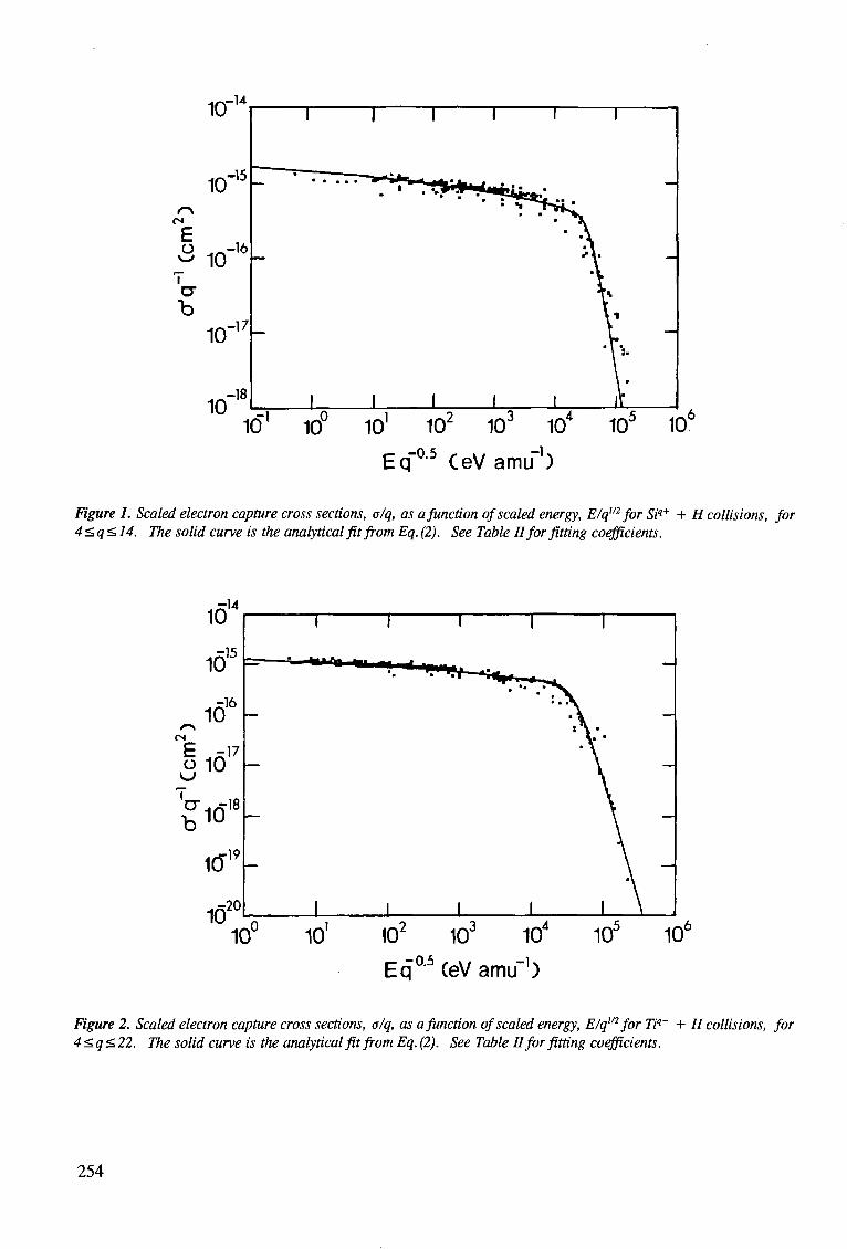
•x-U
Eq'0,5 CeVamu'1)
Figure 1. Scaled electron capture cross sections, alq, as a function of scaled energy, E/q1'2 for Siq+ + H collisions, for 4<q<14. The solid curve is the analytical fit from Eq. (2). See Table II for fitting coefficients.
-0.5 .-!• EqUJ(eVamiT)
Figure 2. Scaled electron capture cross sections, o/q, as a function of scaled energy, Elqm for Tiq+ + H collisions, for 4<q<22. The solid curve is the analytical fit from Eq. (2). See Table II for fitting coefficients.
254
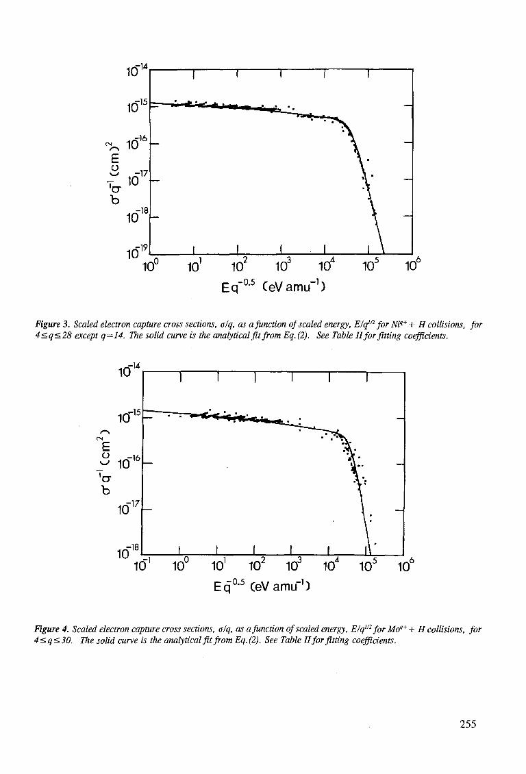
•0.5 -1 Eq"u-° CeVamu"')
Figure 3. Scaled electron capture cross sections, a/q, as a function of scaled energy, Elqm for Niq+ + H collisions, for 4<q<28 except q=14. The solid curve is the analytical fit from Eq. (2). See Table II for fitting coefficients.
^0.5 H-Equ-° CeVamif)
Figure 4. Scaled electron capture cross sections, a/q, as a function of scaled energy, E/qm for Moq+ + H collisions, for 4<q<30. The solid curve is the analytical fit from Eq. (2). See Table II for fitting coefficients.
255
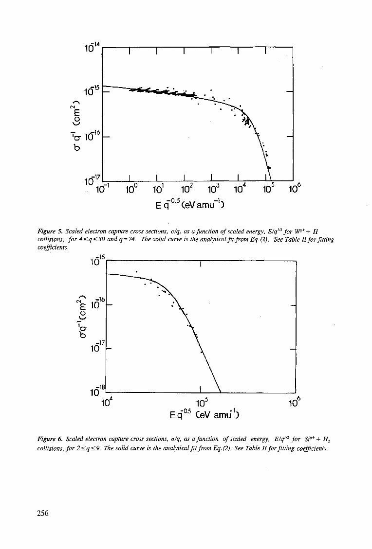
._ - 0 . 5 , v / -K
Eq CeVamu )
Figure 5. Scaled electron capture cross sections, a/q, as a function of scaled energy, E/q"2 for W+ + H collisions, for 4<q<30 and q=74. The solid curve is the analytical fit from Eq. (2). See Table II for fitting coefficients.
16'5
E o ^ 'CT b
io1 6
io'V
16" 10
EqQ5 CeVamu1)
Figure 6. Scaled electron capture cross sections, a/q, as a function of scaled energy, E/q"2 for Siq+ + H2
collisions, for 2<q<9. The solid curve is the analytical fit from Eq. (2). See Table II for fitting coefficients.
256
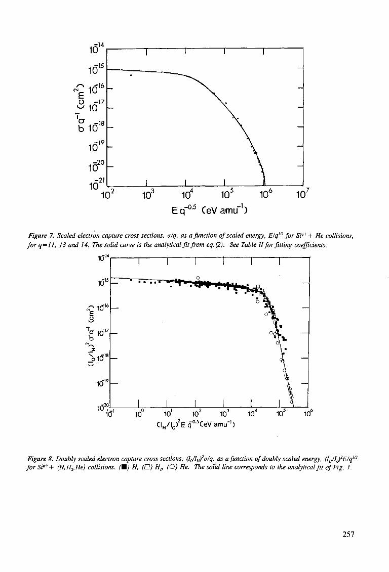
10 10 10 10 Eq~05 CeVamu"1)
10Q 10'
Figure 7. Scaled electron capture cross sections, a/q, as a function of scaled energy, E/q"2 for Siq++ He collisions, for q=ll, 13 and 14. The solid curve is the analytical fit from eq. (2). See Table II for fitting coefficients.
1(TM
10° -
E 3
1 t f ' 6 -
Cl7 °"10 b _ i x i n 1 8
r l9 10,Y —
10 •20
—
—
—
" •
I
•
I
• • m m m
I
•
I o
I
1
1 •
^«
1
•
1
•
o
1
o\
\
A
•^
—
,(~1 10 10 10' 10'
-0.5 10J 10"
CIH/I0> Ec f CeVamu"1)
10J 10"
Figure 8. Doubly scaled electron capture cross sections, (I,/IH)2a/q, as a function of doubly scaled energy, (IH/I^2E/ql/2
forSi9++ (H,H2,He) collisions. (M) H, (D) H2, (O) He. The solid line corresponds to the analytical fit of Fig. 1.
257
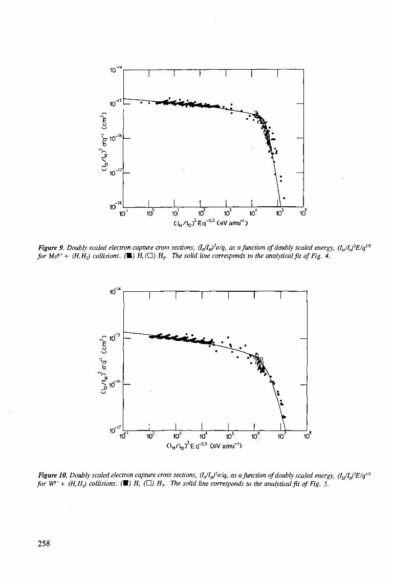
CIH / lo)2Eq"a5CeVamuH)
Figure 9. Doubly scaled electron capture cross sections, (Ig/I^a/q, as a function of doubly scaled energy, (IE/I()2E/q1/2
for Mcfl* + (H.H^ collisions. (M) H, (H) H2. The solid line corresponds to the analytical fit of Fig. 4.
CIH/lo) Eq CeVamu")
Figure 10. Doubly scaled electron capture cross sections, (IJl^alq, as a function of doubly scaled energy, (I^l^Elq112
for W++ {H,H^ collisions. (M) H, (O) H2. The solid line corresponds to the analytical fit of Fig. 5.
258
5. SUMMARY AND CONCLUSIONS
Several semiempirical formulas have been developed, and in particular that due to Nakai et al [64], who could fit total cross sections for single electron-capture with 30% overall accuracy, with a formula bearing a considerably larger number of free parameters than the one introduced by Phaneuf [13], who has discussed the usefulness of the present scaling law for the case of Fe. Katsonis [28] has reported the A-D coefficients for different projectiles, including Ni and Ti on H over the 3-100 keV/amu qI/2 range, having found that the coefficients are the same for both Ni and Ti ions, which is also our case.
Finally, a point must be made from Table I that more experimental and theoretical data are needed for these systems. For instance, electron-capture collisions cross section data for He with Ti, Ni, Mo and W ions must be encouraged since He constitutes the ash of an ignited D-T plasma, and it will be abundant at the plasma edge. However, with the available data and the good fitting with the semiempirical formula, one is already able to make some good estimates of the cross sections over a wide collision energy range for q>4, with only four adjustable parameters, leading to about the same degree of fitting accuracy as that reported in Ref. 64.
Acknowledgements This work has been supported by IAEA, Research Contract No. 6720/R1/RB,
CONACYT and DGAPA.
REFERENCES
[I] JANEV, R.K. Comments At. Mol. Phys., 26 (1991) 83. [2] JANEV, R.K., HARRISON, M.F.A., DRAWIN, H.W., Nuclear Fusion 29 (1989)
109. [3] POST, D.E., PHANEUF, R.A., in "Meeting on Atomic and
Molecular Data for Fusion", Rep. INDC(NDS) 277 IAEA, Vienna (1993) 9. [4] PHANEUF, R.A., Atom and Plasma Mat. Inf. Data for Fusion, Vol. 2, IAEA,
Vienna,(1992) 75. [5] JANEV, R.K., Phys. Scripta, T37 (1991) 11. [6] FRITSCH, W., GILBODY, H.B., OLSON, R.E., CEDERQUIST, H., JANEV R.K.,
KATSONIS, K., YUDIN, G., Phys. Scripta, T37 (1991) 11. [7] GILBODY, H.B., Phys. Scr. 23 (1981) 143. [8] GILBODY, H.B., "Advances in Atomic and Molecular Physics" 22 (1986) 143. [9] De HEER, F.J., in "Atomic and Molecular Physics of Controlled Thermonuclear
Fusion" (JOACHAIN C.J., POST D.E. Eds.) Plenum Press, New York, (1983) 269. [10] BRANDSEN B.H. in "Atomic and Molecular Physics of Controlled Thermonuclear
Fusion" (JOACHAIN C.J., POST D.E. Eds.) Plenum Press, New York, (1983) 245. [II] JANEV, R.K., BELIC, D.S., BRANSDEN, H.B., Phys. Rev. A28 (1983) 1293. [12] CISNEROS, C , ALVAREZ, I., MARTINEZ, H., De URQUIJO, J., in AIP,
Conference Proc. 274 (1992) 124. [13] PHANEUF, R.A., JANEV, R.K., HUNTER, H.T., in Recomended Data on Atomic
Collision Processes Involving Iron and its Ions, Nucl. Fusion, Special Supplement, (1987) 7.
[14] JANEV, R.K., BRANDSEN, B.H., GALLAGHER, J.W., J. Chem. Phys. Ref. Data 12 (1983) 829.
[15] GALLAGHER, J.W., BRANDSEN, H., JANEV, R.K., J. Chem Phys. Ref. Data, 12 (1983) 873.
[16] TAWARA, H., Research Report, NIFS-DATA-20, Japan (1993). [17] WU, W.K., HUBER, B.A., WIESEMANN, K., At. Data Nucl. Data Tables 40
(1988) 58. [18] WU, W.K., HUBER, B.A., WIESEMANN, K., At. Data Nucl. Data Tables 42
(1989) 157. [19] JANEV, R.K., PHANEUF R.A., HUNT, H.T., At. Data Nucl. Data Tables 40
(1988) 249. [20] GILBODY, H.B., SALIN, A., AUMAYR, R., BARANY, A., BELKIC, DZ. S., de
HEER,F.J., HOEKSTRA, R., JANEV, R.K., NAKAI, Y., RIVAROLA, R.D., TAWARA, H., WATANABE, T., Phys. Sr. T28 (1989) 8.
[21] MEYER, F.W., HOWALD, A.M., HAVENER, C.C., PHANEUF, R.A., Phys. Rev. Lett. 54 (1985) 2663 and Phys. Rev. A32 (1986) 3310.
[22] OLSON, R.E., Phys. Rev. A24 (1981) 1726. [23] RYUFUKU, H., WATANABE, T., Phys. Rev. A20 (1979) 1828. [24] RYUFUKU, H., WATANABE, T., XI International Conference on the Physics of
Electronic and Atomic Collisions, Kyoto, Japan, Invited Lectures, North Holland (1979) 449.
[25] JANEV, R.K., PRESNYAKOV, L.P., SHEVELKO, V.P., "Physics of Highly Charged Ions", Springer Verlag, Heidelberg (1985).
[26] FRITSCH, W., TAWARA, H., Nucl. Fusion, 30 (1990) 327. [27] FRITSCH, W., Phys. Lett. A166 (1992) 238. [28] KATSONIS, K., MAYNARD, G., JANEV, R.K., Phys. Scr. T37 (1991) 80. [29] USKOV, D.B., BOTERO, J., JANEV, R.K., PRESNYAKOV, L.P., IAEA Cross
Sections for Electron Capture and Ionization in Collisions of Fusion Plasma Impurity Ions with Atomic Hydrogen, INDC(NDS)-291 IAEA Vienna (1993).
[30] HVELPLUND, P., JANEV, R.K., Comments At. Mol. Phys. 11 (1981). [31] GROZDANOV, T.P., J. Phys. B13 (1980) 3835.
[32] BATES, R.D., MOISEWITSCH, B.L., Proc. Phys. Soc. 9A (1957) 805. [33] DUBROVSKII, G.B., Sov. Phys. JETP 20 (1969) 429. [34] KIM, H.J., PHANEUF, R.A., MEYER, F.W., Phys. Rev. A17 (1978) 854. [35] GARGAUD, M., McCARROLL, R., VALIRON,P.,Astron.Astrophys.106(1981)197. [36] MEYER, F.W., PHANEUF, R.A., KIM, H.J., HVELPLUND, P., STELSON,P.H.,
Phys. Rev. A19 (1979) 515. [37] OLSON, R.E., SALOP, A., Phys. Rev. A14 (1976) 529. [38] GARGAUD, M., McCARROLL, R., J. Phys. B21 (1988) 513. [39] TAWARA, H., FRITSCH, W., Phys. Scr. T28 (1989) 58. [40] SVELKO, V.P., Proc. Levedev Inst. 119 (1980) 108. [41] GROZDANOV, T.P., JANEV, R.K., Phys. Rev. A17 (1978) 880. [42] DUMAN, E.L., SMIRNOV, B.M., Sov. J. Plasma Phys. 4 (1978) 650. [43] CHIBISOV, M.I., JETP Lett. 24 (1976) 46. [44] JANEV, R.K., Phys. Scr. T3 (1983) 208. [45] PRESNYAKOV, L.P., USKOV, D.B., JANEV, R.K., Phys. Lett. 84A (1981) 243.
[46] SALOP, A., OLSON, R.E., Phys. Rev. A13 (1976) 312. [47] KOIKE, F., XIV International Conference on the Physics of Electronic and Atomic
Collisions, Palo Alto, USA (1985) 503. [48] BOTTCHER, C , J. Phys. BIO (1977) L213. [49] OPRADOLCE, L., McCARROLL, R., VALIRON, P., Astron. Astrophys. 148
(1985) 229. [50] HIPPLER, R., DATZ, S., MILLER, P.D., PEMPMILLER, P.L., DITTNER,
P.F.,Phys. Rev. A35 (1987) 585. [51] CLARK, M., BRANDT, D., SHAFROTH, S.M., SWENSON, J.K., XIII
International Conference on the Physics of Electronic and Atomic Collisions, Berlin, (1983) 527.
[52] CLARK, M., BRANDT, D., SWENSON, J., SHAFROTH, S., Phys. Rev. Lett. 54 (1985) 544.
[53] WETMORE, A.E., OLSON, R.E., Phys. Rev. A38 (1988) 5563. [54] BRANDT, D., Nucl. Instrum. Methods, Phys. Res. 214 (1983) 93. [55] TAWARA, H., Phys. Lett. A71 (1979) 208. [56] NUTT, W.L., McCULLOUGH, R.W., GILBODY, H.B., J. Phys. Bll (1987) L181. [57] McCULLOUGH, R.W., NUTT, W.L., GILBODY, H.B., J. Phys. B12 (1979) 4159. [58] NUTT, W.L., McCULLOUGH, R.W., GILBODY, H.B., XI International
Conference on the Physics of Electronic and Atomic Collisions, Kyoto, Japan, North Holland (1979) 590.
[59] KIMURA, M., OLSON, R.E., Nucl. Instrum. Methods Phys. Res. B10-11 (1985) 207.
[60] GARGAUD, M., McCARROLL, R., OPRADOLCE, L., J. Phys. B21 (1988) 521. [61] SATO, H., KIMURA, M., WETMORE, A.E., OLSON, R.E., J. Phys. B16 (1983)
3037. [62] FRITSCH, W., Phys. Scr. T37 (1991) 57, FRITSCH, W., 1st IAEA Co-ordination
Meeting on "Atomic Data for Medium and High-Z Impurities in Fusion Plasmas" INDC(NDS)292(1994)31.
[63] SHEVELKO, V.P., Z. Physik, A267 (1978) 19. [64] NAKAI, Y., SHIRAI, T., TABATA, T., ITO, R., Phys. Scr. T28 (1989) 77. [65] PIEKSMA M., GARGAUD M., McCARROL R., HAVENER C , to be published in
Phys. Rev. Lett.

Contents of previous volumes of Atomic and Plasma-Material Interaction Data for Fusion
Volume 1
R. Behrisch: Particle bombardment and energy fluxes to the vessel walls in controlled thermonuclear fusion devices 7
W. Eckstein: Reflection 17 K.L. Wilson, R. Bastasz, R.A. Causey, D.K. Brice, B.L. Doyle, W.R. Wampler,
W. Moller, B.M.U. Scherzer, T. Tanabe: Trapping, detrapping and release of implanted hydrogen isotopes 31
W. Eckstein, J. Bohdansky, J. Roth: Physical sputtering 51 J. Roth, E. Vietzke, A.A. Haasz: Erosion of graphite due to particle impact 63 E.W. Thomas: Particle induced electron emission 79 H. Wolff: Arcing in magnetic fusion devices 93 J.B. Whitley, W.B. Gauster, R.D. Watson, J.A. Koski, A.J. Russo: Pulse heating and
effects of disruptions and runaway electrons on first walls and divertors 109 R.K. Janev, A. Miyahara: Plasma-material interaction issues in fusion reactor design and
status of the database 123
Volume 2
W.L. Wiese: Spectroscopic data for fusion edge plasmas 7 S. Trajmar: Electron collision processes with plasma edge neutrals 15 G.H. Dunn: Electron-ion collisions in the plasma edge 25 H. Tawara, Y. Itikawa, H. Nishimura, H. Tanaka, Y. Nakamura: Cross-section data for
collisions of electrons with hydrocarbon molecules 41 M.A. Cacciatore, M. Capitelli, R. Celiberto: Dissociative and energy transfer reactions
involving vibrationally excited H2/D2 molecules 65 R.A. Phaneuf: Assessment of ion-atom collision data for magnetic fusion plasma edge
modelling 75 T. Tabata, R. Ito, T. Shirai, Y. Nakai, H.T. Hunter, R.A. Phaneuf: Extended scaling of
cross-sections for the ionization of H, H2 and He by multiply charged ions 91 P. Reinig, M. Zimmer, F. Linder: Ion-molecule collision processes relevant to fusion
edge plasmas 95 X. Bonnin, R. Marchand, R.K. Janev: Radiative losses and electron cooling rates for carbon
and oxygen plasma impurities 117
Volume 3
H.P. Summers, M. von Hellermann, F.J. de Heer, R. Hoekstra: Requirements for collision
data on the species helium, beryllium and boron in magnetic confinement fusion 7 F.J. de Heer, R. Hoekstra, A.E. Kingston, H.P. Summers: Excitation of neutral helium
by electron impact 19 T. Kato, R.K. Janev: Parametric representation of electron impact excitation and ionization
cross-sections for helium atoms 33 W. Fritsch: Helium excitation in heavy particle collisions 41 F.J. de Heer, R. Hoekstra, H.P. Summers: New assessment of cross-section data for helium
excitation by protons 47
263
M. Anton, D. Detleffsen, K.-H. Schartner: Heavy ion impact excitation of helium: Experimental total cross-sections 51
H.B. Gilbody: Review of experimental data on electron capture and ionization for collisions of protons and multiply charged ions with helium atoms and ions 55
R. Hoekstra, H.P. Summers, F.J. de Heer: Charge transfer in collisions of protons with helium 63
R.K. Janev: Cross-section scaling for one- and two-electron loss processes in collisions of helium atoms with multiply charged ions 71
A.A. Korotkov: Sensitivity of neutral helium beam stopping in fusion plasmas to atomic collision cross-sections 79
K.A. Berrington, R.E.H. Clark: Recommended data for electron impact excitation of Beq+ and Bq + ions 87
D.L. Moores: Electron impact ionization of Be and B atoms and ions 97 M.S. Pindzola, N.R. Badnell: Dielectronic recombination rate coefficients for ions of the
Be and B isonuclear sequences 101 R.A. Phaneuf, R.K. Janev, H. Tawara, M. Kimura, P.S. Krstic, G. Peach, M.A. Mazing:
Status and critical assessment of the database for collisions of Beq+ and Bq + ions with H, H2 and He 105
P.S. Krstic, M. Radmilovic, R.K. Janev: Charge exchange, excitation and ionization in slow Be4+ + H and B5 + + H collisions 113
Volume 4
R.K. Janev, J.J. Smith: Cross sections for collision processes of hydrogen atoms with electrons, protons and multiply charged ions 1
1. Electron impact processes 1 2. Proton impact processes 41 3. Collision processes with He2+ 83 4. Collision processes with highly charged ions 123
Volume 5
W.B. Gauster, W.R. Spears and ITER Joint Central Team: Requirements and selection criteria for plasma-facing materials and components in the ITER EDA design 7
D.E. Dombrowski, E.B. Deksnis, M.A. Pick: Thermomechanical properties of Beryllium 19 T.D. Burchell, T. Oku: Material properties data for fusion reactor plasma-facing
carbon-carbon composites 77 T. Tanabe: High-Z candidate plasma facing materials 129 R.F. Mattas: Recommended property data for Mo, Nb and V-alloys 149 S.J. Zinkle, S.A. Fabritsiev: Copper alloys for high heat flux structure applications 163 A. Hassanein, I. Konkashbaev: Erosion of plasma-facing materials during a
tokamak disruption 193 H.-W. Bartels, T. Kungugi, A.J. Russo: Runaway electron effects 225 M. Araki, M. Akiba, R.D. Watson, C.B. Baxi, D.L. Youchison: Data bases for
thermo-hydrodynamic coupling with coolants 245
»t vn CO CO o in en
264
INFORMATION FOR AUTHORS
General
Atomic and Plasma-Material Interaction Data for Fusion (APMIDF) publishes papers, letters and reviews which deal with elementary atomic collision processes in fusion plasmas, collision processes of plasma particles with surfaces and plasma-material interaction phenomena, including the thermophysical and thermomechanical response of candidate fusion reactor plasma facing materials. Each contribution submitted to APMIDF should be highly fusion relevant and should contain a significant amount of quantitative data information in one of the above fields. Review articles are normally prepared on invitation of the Scientific Editor or with his prior consent. APMIDF is a regular Supplement to the journal NUCLEAR FUSION (NF) and its abbreviation for the purpose of referencing is: At. Plasma-Mater. Interact. Data Fusion.
Manuscripts, which may be submitted in Chinese, English, French, Russian or Spanish, will be published in English. For a manuscript submitted in a language other than English, a translation into English of technical terms should be provided. Manuscripts must be submitted in triplicate and typewritten double spaced on good quality standard size paper. All copies should include the main text, an abstract, tables, references, figures, captions and appendices, as appropriate. One set of glossy prints or reproducible transparencies of the figures should also be provided. Final manuscript versions may be submitted in camera ready form or on diskettes (see NF's Note for Authors, available on request from the NF Office).
Every manuscript submitted must be accompanied by a disclaimer stating that the paper has not been published and is not being considered for publication elsewhere. If no copyright is claimed by the authors, the IAEA automatically owns the copyright of the paper.
Authors will receive proofs of the text of accepted manuscripts. Proofs of figures are sent only if requested. Rejected manuscripts will not be returned unless this is expressly requested within six weeks of rejection.
Fifty reprints are provided free of charge; additional reprints may be ordered at the time the author returns the proofs. Manuscripts and correspondence should be addressed to: The Editor, NUCLEAR FUSION (A+M Supplement), International Atomic Energy Agency, Wagramer-strasse 5, P.O. Box 100, A-1400 Vienna, Austria.
Manuscript preparation
Authors are referred to any recent issues of APMIDF or NF for examples of format and style.
All submitted articles should be concise and written in a clear style. The description of the methods used for obtaining the presented original data information should be kept to a reasonable minimum. The review papers should provide a critical analysis of a broader class (or classes) of data or processes together with a set of recommended data of specified accuracy.
Titles should be as concise as possible but sufficiently informative to describe the subject of the paper.
Abstracts must briefly summarize the contents of the article. They should state the principal objectives, mention the methodology employed, summarize the results (emphasizing the new findings) and present the main conclusions. They should be concise and self-contained so that they can be used by the International Nuclear Information System (INIS) and other abstracting systems without changes. General, well known information should be avoided in the abstract and accommodated in the introduction.
Letters to APMIDF are short communications of net sets of data obtained with a standard, highly accurate method. As a rule, they should be not longer than ten typewritten double spaced standard pages, including references and figures.
Guidelines for bibliographical citations can be found in issues 2, 3 and 4 of NF 28 (1988). In short, references should be accurately described in sufficient detail for easy identification. In the text, they should be indicated consecutively by Arabic numerals in square brackets. All references should be listed on a separate page at the end of the text. In this list, the names of all authors (or, if there are more than six, of the first three authors plus 'et al.') should be given. All unpublished material, e.g. laboratory reports, doctoral theses or papers in proceedings that have not yet been published, should be cited with full titles, place and year; citations of reports should also contain the laboratory prefix and number, date of issue, etc. References to periodicals should contain the name of the journal, volume number, page number and year of publication; the title of the article is not needed. References to books should contain the full title of the book, names of editors (if any), name and location of the publisher, year of publication and page number (if appropriate). References to personal communications should be avoided if possible. For journal citations use the list of abbreviations given in "IAEA-INIS-11, INIS: Authority List for Journal Titles".
Russian names should be transliterated according to "IAEA-INIS-10, INIS: Transliteration Rules for Selected Non-Roman Characters". Examples of the style followed by NF for references are:
REFERENCES
[1] SHAH, M.B., GILBODY, H.B., J. Phys., B (Lond.). At. Mol. Phys. 14 (1981) 2361.
[2] WILSON, K.L., BASTASZ, R.A., CAUSEY, R.A., et al., At. Plasma-Mater. Interact. Data Fusion 1 (1991) 31.
[3] BRANSDEN, B.H., Atomic Collision Theory, 2nd edn., Benjamin, New York (1982).
[4] MARK, T.D., DUNN, G.H. (Eds), Electron Impact Ionization, Springer-Verlag, Berlin, Heidelberg, New York, London (1985).
[5] MOLLER, W., ROTH, J., in Physics of Plasma-Wall Interactions in Controlled Fusion (POST, D.E., BEHRISCH, R., Eds), Plenum Press, New York (1986) 45.
[6] McGRATH, R.T., Thermal Loads on Tokamak Plasma Facing Components During Normal Operation and Disruptions, Rep. SAND89-2064, Sandia National Laboratories, Albuquerque, NM (1990).
[7] TRUBNIKOV, B.A., in Problems of Plasma Theory, Vol. 1 (LEONTOVICH, M.A., Ed.), Gosatomizdat, Moscow (1963) 98 (in Russian). (English translation: Reviews of Plasma Physics, Vol. 1, Consultants Bureau, New York (1965) 105.)
[8] HUBER, B.A., Zum Elektronentransfer zwischen mehrfach geladenen Ionen und Atomen oder Molekiilen, PhD Thesis, Ruhr-Universitat, Bochum (1981).
[9] de HEER, F.J., HOEKSTRA, R., KINGSTON, A.E., SUMMERS, H.P., Excitation of neutral helium by electron impact, to be published in At. Plasma-Mater. Interact. Data Fusion.
[10] MOORES, D.L., Electron impact ionisation of Be and B atoms and ions, submitted to At. Plasma-Mater. Interact. Data Fusion.
All figures should be on separate sheets and numbered consecutively with Arabic numerals, e.g. Fig. 1. A separate list of captions must be provided (see also General above).
Tables must carry a heading and be numbered consecutively with Roman numerals in the order in which they are mentioned in the text, e.g. Table II. Footnotes to tables should be indicated by raised letters (not numbers or asterisks) and set immediately below the table itself. Tables should be typed clearly for possible direct reproduction.
Footnotes to the text should be numbered consecutively with raised Arabic numerals; excessive use of footnotes should be avoided.
All equations should be typed as carefully as possible, with unavailable Greek letters and other symbols clearly inserted by hand. Specifically:
(1) To eliminate confusion between symbols with similar appearance (e.g. between ones, ells and primes), make them as distinct as possible, if necessary marking them clearly by hand. In manuscripts with handwritten formulas, all further sources of confusion (such as n's and u's, u's and v's, e's and l's, J's and I's) should also be marked.
(2) Indicate a vector by an arrow on top rather than by bold face lettering.
(3) Tensors of second rank should bear two arrows on top; if higher rank tensors are required, choose an appropriate symbol and explain it.
(4) Indicate the normal algebraic product by simple juxtaposition of symbols, i.e. without multiplication sign. _. _
(5) Write scalar products of vectors with a raised point, e.g. A B . (6) Use the multiplication sign (x) solely to designate: (i) a vector
product, (ii) an algebraic (but not a scalar) product in the case where an equation has to be split over two lines, and (iii) in expressions like 3 cm x 3 cm or 2 x 106 cm.
(7) The nabla operator (V) does not carry an arrow. (8) When equations are split over two or more lines, place operational
signs only at the beginning of each new line, not at the end of the preceding line. For direct reproduction of an equation, the length of the lines should not exceed 9 cm.
(9) Where it is impossible to split long fractions over two lines, use negative exponents: similarly, replace root signs by fractional exponents where appropriate.
(10) Do not use symbols, abbreviations and formulations that are recognizable only in a particular language.
Use SI units as far as possible; where this is not possible, please give the appropriate conversion factor.