Embed Size (px)
Citation preview

Nuclear Instruments and Methods in Physics Research B 239 (2005) 16–26
www.elsevier.com/locate/nimb
Neutron and X-ray characterisation of themetallurgical properties of a 7th century BC Corinthian-type
bronze helmet
E. Pantos a,*, W. Kockelmann b, L.C. Chapon b, L. Lutterotti c, S.L. Bennet a,M.J. Tobin a, J.F.W. Mosselmans a, T. Pradell d, N. Salvado d, S. Butı e,
R. Garner f, A.J.N.W. Prag f
a Daresbury Laboratory, Keckwick Lane, Warrington WA4 4AD, UKb Rutherford Appleton Laboratory, ISIS Facility, Chilton OX11 0QX, UK
c Dipartimento di Ingegneria dei Materiali, e delle Tecnologie Industriali, Univ. di Trento, 38050 Trento, Italyd Dept. de Fısica i Enginyeria Nuclear, Universitat Politecnica de Catalunya, 08036 Barcelona, Spaine Dept. d’Enginyeria Quimica, Univ. Politecnica de Catalunya, 08800 Vilanova i la Geltru, Spain
f The Manchester Museum, University of Manchester, Manchester M13 9PL, UK
Available online 8 August 2005
Abstract
Neutron and synchrotron X-ray diffraction, X-ray fluorescence and FTIR were used to examine a Corinthian-typebronze helmet which is now on display at The Manchester Museum, UK. This type of helmet was manufactured out ofa single piece of bronze, probably on a rod-anvil, and like all body-armour it was made to measure. Neutron diffractionsampling of the bronze volume in different areas was used to study the composition, microstructure and crystallo-graphic texture of the alloy in order to draw conclusions about the manufacturing processes. The neutron data revealedthe presence of microstrains and non-random distributions of bronze grains hinting at annealing-hammering workingcycles in order to harden and shape the alloy. X-ray fluorescence showed that the main body of the helmet is a copper–tin alloy, while the noseguard contains zinc in high abundance. This key compositional difference confirms that thenoseguard is not the original but is a modern substitute fabricated for restoration purposes. SR XRD and FTIR fromseveral spots on the head and noseguard identified several surface corrosion products and showed a variation of theCu–Sn or Cu–Zn percentage compositions, and of the mineral phases. Small samples of corrosion flakes extracted fromthe outside and inside of the helmet were used to obtain powder XRD patterns.� 2005 Published by Elsevier B.V.
0168-583X/$ - see front matter � 2005 Published by Elsevier B.V.doi:10.1016/j.nimb.2005.06.077
* Corresponding author.E-mail address: [email protected] (E. Pantos).
E. Pantos et al. / Nucl. Instr. and Meth. in Phys. Res. B 239 (2005) 16–26 17
Keywords: Bronze helmet; Texture analysis; Microstrains; Corrosion phases
1. Introduction
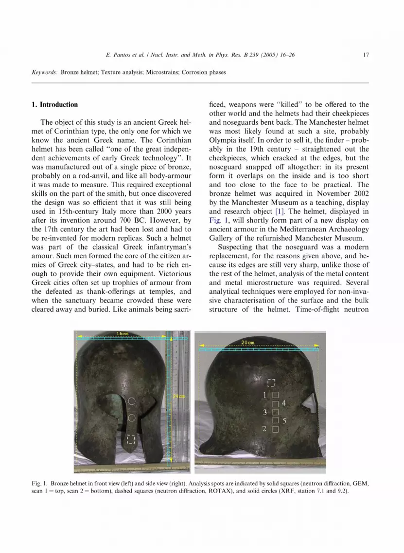
The object of this study is an ancient Greek hel-met of Corinthian type, the only one for which weknow the ancient Greek name. The Corinthianhelmet has been called ‘‘one of the great indepen-dent achievements of early Greek technology’’. Itwas manufactured out of a single piece of bronze,probably on a rod-anvil, and like all body-armourit was made to measure. This required exceptionalskills on the part of the smith, but once discoveredthe design was so efficient that it was still beingused in 15th-century Italy more than 2000 yearsafter its invention around 700 BC. However, bythe 17th century the art had been lost and had tobe re-invented for modern replicas. Such a helmetwas part of the classical Greek infantryman�samour. Such men formed the core of the citizen ar-mies of Greek city–states, and had to be rich en-ough to provide their own equipment. VictoriousGreek cities often set up trophies of armour fromthe defeated as thank-offerings at temples, andwhen the sanctuary became crowded these werecleared away and buried. Like animals being sacri-
Fig. 1. Bronze helmet in front view (left) and side view (right). Analysiscan 1 = top, scan 2 = bottom), dashed squares (neutron diffraction,
ficed, weapons were ‘‘killed’’ to be offered to theother world and the helmets had their cheekpiecesand noseguards bent back. The Manchester helmetwas most likely found at such a site, probablyOlympia itself. In order to sell it, the finder – prob-ably in the 19th century – straightened out thecheekpieces, which cracked at the edges, but thenoseguard snapped off altogether: in its presentform it overlaps on the inside and is too shortand too close to the face to be practical. Thebronze helmet was acquired in November 2002by the Manchester Museum as a teaching, displayand research object [1]. The helmet, displayed inFig. 1, will shortly form part of a new display onancient armour in the Mediterranean ArchaeologyGallery of the refurnished Manchester Museum.Suspecting that the noseguard was a modern
replacement, for the reasons given above, and be-cause its edges are still very sharp, unlike those ofthe rest of the helmet, analysis of the metal contentand metal microstructure was required. Severalanalytical techniques were employed for non-inva-sive characterisation of the surface and the bulkstructure of the helmet. Time-of-flight neutron
s spots are indicated by solid squares (neutron diffraction, GEM,ROTAX), and solid circles (XRF, station 7.1 and 9.2).
18 E. Pantos et al. / Nucl. Instr. and Meth. in Phys. Res. B 239 (2005) 16–26
diffraction at the ISIS facility of the RutherfordAppleton Laboratory was used to provide an over-view of the bulk structural properties of the alloy,as well as of microstructural features arising fromprocesses involved in producing the helmet. Neu-tron diffraction is a non-destructive diagnostic toolfor obtaining average structural information fromthe interior of large, undisturbed archaeologicalobjects. Neutrons penetrate through coatings andcorrosion phases deep into the thickness of the hel-met�s wall and illuminate a considerable volumeportion, thus delivering representative microstruc-tural information and avoiding problems associ-ated with single-spot analyses. It should beemphasized that neutron diffraction is a ‘‘phaseand structure sensitive method’’ that discriminatesbetween the microstructures and crystal structuresof different phases in ceramic and metal objects[2,3]. A particularly promising application is tex-ture analysis that is used for determining the grainorientations in artefacts. The orientations of crys-tallites change in a characteristic way if a materialundergoes plastic deformations or thermal treat-ments during manufacturing. Mapping of the grainorientation distributions by neutron texture analy-sis in terms of pole figures may therefore provideimportant clues to the deformation history andmay help to confirm or to refute details of the his-toric production steps [4–7]. The pole figures arethe maps of the grain orientation distribution andcan be regarded as fingerprints of the workingprocesses involved in producing the object. Polefigures can also be obtained by high-energy syn-chrotron radiation to characterise local [8] andbulk [9] textures. Present-day time-of-flight (TOF)neutron diffractometers [10,11] provide uniqueand new possibilities for non-destructive quantita-tive texture studies of bulky and complex archaeo-logical objects. A new approach was introduced forneutron texture analysis on the materials sciencediffractometer GEM at the ISIS facility, forcollection of pole figures without any samplemovements or rotations.SR-XRD, SR-FTIR, and SR X-ray fluores-
cence were carried out at the SRS facility at theDaresbury Laboratory to characterise the cop-per–tin composition of the bronze, to identify thecorrosion products and to establish whether the re-
paired noseguard was made of the same materialas the rest of the object. Small corrosion flakes,sampled on and inside the helmet, were studiedby X-ray diffraction to identify corrosion prod-ucts.
2. Experimental details
The SR-XRD station 9.4 at the SRS synchro-tron source at the Daresbury Laboratory was usedto collect diffraction data in flat-plate geometry,i.e. with the beam striking the surface of the helmetat a small incident angle (�3 deg). A solid statedetector was stepped along an arc collecting highresolution data at a rate of 0.01 deg/s with thewavelength tuned in the range of 0.7–1.5 A, allow-ing collection of data for different penetrationdepths into the corroded surface. Powder XRDon fragments extracted from various locations onand inside the helmet was performed at station9.6 at the SRS. The XRD patterns were collectedin transmission geometry by a QUANTUM-4CCD area detector. A microscope alignmentsystem allowed the location of the beam on thedesired part of the sample. The fragments wereheld on an adhesive tape or supported in a0.5 mm quartz capillary which could be oscillatedby a given angle about the phi-axis duringexposure. Diffraction data were collected in lessthan 30 s at a fixed wavelength of 0.87 A on a verysmall (100 lm) beam footprint defined by theaperture of a cylindrical collimator.SR-FTIR was utilised on beamline 11.1 which
has a NEXUS FTIR spectrophotometer equippedwith a Nicolet Continulm microscope and aMCT detector with a measuring range of 4000–650 cm�1. The collimated synchrotron beam wasintroduced directly into the spectrophotometerand directed towards the IR microscope. Theinfrared beam was very stable, with a highbrilliance and could be focused on a 10 · 10 lmspot. In order to measure spectra directly fromthe reflected helmet surface, a reflection attach-ment was employed which allows beam focusingwith the same spatial resolution as in transmissionmode. For a reflection measurement no specialpreparation was required. Thus, this system
E. Pantos et al. / Nucl. Instr. and Meth. in Phys. Res. B 239 (2005) 16–26 19
allowed the analysis of pieces of different geomet-ric shapes and large objects that could not be ana-lysed directly under the microscope.X-ray fluorescence analysis of the helmet was
carried out on beamlines 7.1 and 9.2. On 7.1 theincident energy of the X-ray beam was 10 keVand the beam size was a 2 mm diameter spot. Spec-tra were collected for 2 min using one element of anine-element Ortec monolithic germanium detec-tor. On 9.2 the energy of the incident X-ray beamwas 30 keV and spectra were collected using a beam3 mm wide by 1 mm high for 2 min on one elementof a 13-element Canberra germanium detector. Theenergy of the spectra was calibrated with referenceto the spectra of foils of pure elements.Neutron diffraction patterns were collected
from several spots on the helmet at the ISIS neu-tron spallation source on the time-of-flight diffrac-tometers GEM and ROTAX. On GEM, fivedifferent spots on a 7 cm vertical line on the sideof the helmet (Fig. 1) were analysed to determinethe compositional variation of the bronze and toinvestigate peak broadening and texture effects.For the collection of diffraction patterns, the hel-met was free-standing on a platform with the spotto be illuminated aligned in the centre of the GEMsample area. In this set-up the neutron beam hitthe side wall of the helmet at a right angle. The ori-entation of the helmet is of importance in order tointerpret the texture diffraction data. The neutronbeam size was 10 · 10 mm. The first of five analy-sis spots chosen on the side of the helmet was at15.5 cm from the collar (Fig. 1, ‘‘scan 1’’). Stripsof aluminium foil of 0.25 mm thickness wereplaced on the outside and inside surfaces of theilluminated areas. The foil produces Al Braggpeaks in the neutron patterns that can be used ascalibration markers for the lattice parameter deter-mination of the bronze for correcting a possiblemisalignment of the helmet on the sample table.Neutrons scattered by the helmet side wall wereregistered in the neutron detectors surroundingthe GEM sample position whereas neutrons scat-tered from the second side of the helmet were ab-sorbed by a radial collimator. GEM is equippedwith six detector banks housing a total of 6500detector elements, bank-1 and bank-6 being posi-tioned at forward and backscattering angles,
respectively [10]. For the time-of-flight (TOF)method each detector element provides a diffrac-tion pattern and �views� the sample from a differentdirection. This multidetector instrument with alarge angular coverage provides rapid data collec-tions, robust quantitative phase and structureanalyses, as well as the assessment of microstruc-ture and bulk texture properties.For the phase analysis with the program GSAS
[12] the detector elements of each of the six bankswere combined to give six diffraction patterns foreach scan. The observed patterns were analysedaccording to the Rietveld method [13] that is basedon an iterative fitting process used to model themeasured diffraction patterns in terms of the crys-tal structures of identified mineral or metal phases.Phase fractions, lattice parameter of the alloy, oneoverall Debye–Waller parameter and one commonabsorption parameter for all six banks and fivescans were refined. For the linewidth analysis onlythe backscattering bank-6 was used which hadthe best instrumental resolution, i.e. provides thesharpest Bragg peaks. The peak widths were exam-ined by a single-peak profile analysis as well as byfitting a microstrain parameter in the Rietveldanalysis. For the texture analysis with the programMAUD [14] 160 separate detector groups weregenerated from 6500 detector elements represent-ing 160 different orientations. The unique advan-tage of GEM for texture analysis is that thesample does not need to be rotated. The choiceof the detector groupings as well as the construc-tion of pole figures from recorded Bragg intensitieswill be described in a forthcoming paper. Addi-tional neutron diffraction patterns were collectedon the ROTAX diffractometer at ISIS in orderto obtain information on the alloy compositionof the helmet�s noseguard. ROTAX is equippedwith three detector banks and is suitable for anal-yses of multiphase materials.
3. Results
3.1. Phase analysis and element identification
Several corrosion products were identifiedby SR-FTIR in the reflection mode. The main
20 E. Pantos et al. / Nucl. Instr. and Meth. in Phys. Res. B 239 (2005) 16–26
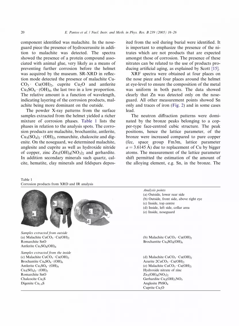
component identified was malachite. In the nose-guard piece the presence of hydrocerussite in addi-tion to malachite was detected. The spectrashowed the presence of a protein compound asso-ciated with animal glue, very likely as a means ofpreventing further corrosion before the helmetwas acquired by the museum. SR-XRD in reflec-tion mode detected the presence of malachite Cu-CO3 Æ Cu(OH)2, cuprite Cu2O and antleriteCu3SO4 Æ (OH)4, the last two in a low proportion.The relative amount is a function of wavelength,indicating layering of the corrosion products, mal-achite being more dominant on the outside.The powder X-ray patterns from the surface
samples extracted from the helmet yielded a richermixture of corrosion phases. Table 1 lists thephases in relation to the analysis spots. The corro-sion products are malachite, brochantite, antlerite,Cu3(SO4)2 Æ (OH)2, romarchite, chalcocite and dig-enite. On the noseguard, we determined malachite,anglesite and cuprite as well as hydroxide nitrideof copper, zinc Zn3(OH)4(NO3)2 and gerhardite.In addition secondary minerals such quartz, cal-cite, hematite, clay minerals and feldspars depos-
Table 1Corrosion products from XRD and IR analysis
Samples extracted from outside
(a) Malachite CuCO3 Æ Cu(OH)2Romarchite SnOAntlerite Cu3SO4(OH)4
Samples extracted from the inside
(c) Malachite CuCO3 Æ Cu(OH)2Brochantite Cu4SO4 Æ (OH)6Antlerite Cu3SO4 Æ (OH)4Cu3(SO4)2 Æ (OH)2Romarchite SnOChalcocite Cu2SDigenite Cu1.8S
ited from the soil during burial were identified. Itis important to emphasize the presence of the ni-trates which are not products that are expectedamongst those of corrosion. The presence of thesenitrates can be related to the use of products pro-ducing artificial aging, as explained by Scott [15].XRF spectra were obtained at four places on
the nose piece and four places around the helmetat eye-level to ensure the composition of the metalwas uniform in both parts. The data showedclearly that Zn was detected only on the nose-guard. All other measurement points showed Snonly and traces of iron (Fig. 2) and in some caseslead.The neutron diffraction patterns were domi-
nated by the bronze peaks belonging to a cop-per-type face-centred cubic structure. The peakpositions, hence the lattice parameter, of thebronze were increased compared to pure copper(fcc, space group Fm3m, lattice parametera = 3.6145 A) due to replacement of Cu by biggeratoms. The measurement of the lattice parametershift permitted the estimation of the amount ofthe alloying element, e.g. Sn, in the bronze. The
Analysis points
(a) Outside, lower rear side(b) Outside, front side, above right eye(c) Inside, top centre(d) Inside, left side, collar area(e) Inside, noseguard
(b) Malachite CuCO3 Æ Cu(OH)2Brochantite Cu4SO4(OH)6
(d) Malachite CuCO3 Æ Cu(OH)2Azurite 2CuCO3 Æ Cu(OH)2(e) Malachite CuCO3 Æ Cu(OH)2Hydroxide nitrate of zincZn3(OH)4(NO3)2Gerhardite Cu2(OH)3NO3Anglesite PbSO4Cuprite Cu2O
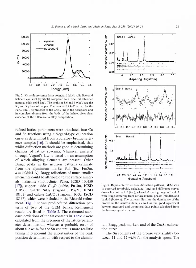
Fig. 2. X-ray fluorescence from noseguard (thick solid line) andhelmet�s eye level (symbols) compared to a zinc foil referencematerial (thin solid line). The peaks at 8.6 and 8.9 keV are theKa and Kb lines of copper. The peak at 6.4 keV is that for theFeKa line. The presence of the ZnKa line in the noseguard andits complete absence from the body of the helmet gives clearevidence of the difference in alloy composition.
Fig. 3. Representative neutron diffraction patterns, GEM scan1: observed (symbols), calculated (line) and difference curves(lower line) of bank 3 (top), selected d-spacing range of bank 3with Bragg scattering from surface mineral phases (middle), andbank-6 (bottom). The patterns illustrate the dominance of thebronze in the neutron data, as well as the good agreementbetween measured and theoretical data points calculated fromthe bronze crystal structure.
E. Pantos et al. / Nucl. Instr. and Meth. in Phys. Res. B 239 (2005) 16–26 21
refined lattice parameters were translated into Cuand Sn fractions using a Vegard-type calibrationcurve as determined from laboratory bronze refer-ence samples [16]. It should be emphasised, thatwhilst diffraction methods are good at determiningchanges of lattice spacings, �chemical analysis�through Vegard�s law is based on an assumptionof which alloying elements are present. OtherBragg peaks in the neutron patterns originatefrom the aluminium marker foil (fcc, Fm3m,a = 4.08441 A). Bragg reflections of much smallerintensities could be attributed to the surface miner-als malachite (monoclinic, P21/a, ICSD 100150[17]), copper oxide Cu2O (cubic, Pn-3m, ICSD31057), quartz SiO2 (trigonal, P3221, ICSD18172) and calcite CaCO3 (trigonal, R-3c, ISCD18166), which were included in the Rietveld refine-ment. Fig. 3 shows profile-fitted diffraction pat-terns of two of the GEM banks. Refinementresults are listed in Table 2. The estimated stan-dard deviations of the Sn contents in Table 2 werecalculated from the precision of the lattice param-eter determination, whereas a probable error ofabout 0.2 wt.% for the Sn content is more realistictaking into account the uncertainties of the peakposition determination with respect to the alumin-
ium Bragg peak markers and of the Cu/Sn calibra-tion curve.The Sn contents of the bronze vary slightly be-
tween 11 and 12 wt.% for the analysis spots. The
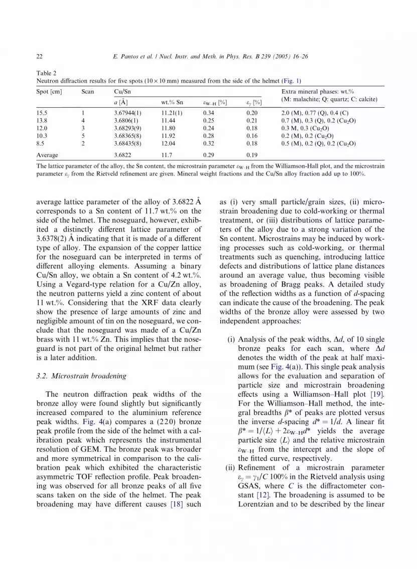
Table 2Neutron diffraction results for five spots (10 · 10 mm) measured from the side of the helmet (Fig. 1)
Spot [cm] Scan Cu/Sn Extra mineral phases: wt.%(M: malachite; Q: quartz; C: calcite)
a [A] wt.% Sn eW–H [%] ec [%]
15.5 1 3.67944(1) 11.21(1) 0.34 0.20 2.0 (M), 0.77 (Q), 0.4 (C)13.8 4 3.6806(1) 11.44 0.25 0.21 0.7 (M), 0.3 (Q), 0.2 (Cu2O)12.0 3 3.68293(9) 11.80 0.24 0.18 0.3 M, 0.3 (Cu2O)10.3 5 3.68365(8) 11.92 0.28 0.16 0.2 (M), 0.2 (Cu2O)8.5 2 3.68435(8) 12.04 0.32 0.18 0.5 (M), 0.2 (Q), 0.2 (Cu2O)
Average 3.6822 11.7 0.29 0.19
The lattice parameter of the alloy, the Sn content, the microstrain parameter eW–H from the Williamson-Hall plot, and the microstrainparameter ec from the Rietveld refinement are given. Mineral weight fractions and the Cu/Sn alloy fraction add up to 100%.
22 E. Pantos et al. / Nucl. Instr. and Meth. in Phys. Res. B 239 (2005) 16–26
average lattice parameter of the alloy of 3.6822 Acorresponds to a Sn content of 11.7 wt.% on theside of the helmet. The noseguard, however, exhib-ited a distinctly different lattice parameter of3.6378(2) A indicating that it is made of a differenttype of alloy. The expansion of the copper latticefor the noseguard can be interpreted in terms ofdifferent alloying elements. Assuming a binaryCu/Sn alloy, we obtain a Sn content of 4.2 wt.%.Using a Vegard-type relation for a Cu/Zn alloy,the neutron patterns yield a zinc content of about11 wt.%. Considering that the XRF data clearlyshow the presence of large amounts of zinc andnegligible amount of tin on the noseguard, we con-clude that the noseguard was made of a Cu/Znbrass with 11 wt.% Zn. This implies that the nose-guard is not part of the original helmet but ratheris a later addition.
3.2. Microstrain broadening
The neutron diffraction peak widths of thebronze alloy were found slightly but significantlyincreased compared to the aluminium referencepeak widths. Fig. 4(a) compares a (220) bronzepeak profile from the side of the helmet with a cal-ibration peak which represents the instrumentalresolution of GEM. The bronze peak was broaderand more symmetrical in comparison to the cali-bration peak which exhibited the characteristicasymmetric TOF reflection profile. Peak broaden-ing was observed for all bronze peaks of all fivescans taken on the side of the helmet. The peakbroadening may have different causes [18] such
as (i) very small particle/grain sizes, (ii) micro-strain broadening due to cold-working or thermaltreatment, or (iii) distributions of lattice parame-ters of the alloy due to a strong variation of theSn content. Microstrains may be induced by work-ing processes such as cold-working, or thermaltreatments such as quenching, introducing latticedefects and distributions of lattice plane distancesaround an average value, thus becoming visibleas broadening of Bragg peaks. A detailed studyof the reflection widths as a function of d-spacingcan indicate the cause of the broadening. The peakwidths of the bronze alloy were assessed by twoindependent approaches:
(i) Analysis of the peak widths, Dd, of 10 singlebronze peaks for each scan, where Dddenotes the width of the peak at half maxi-mum (see Fig. 4(a)). This single peak analysisallows for the evaluation and separation ofparticle size and microstrain broadeningeffects using a Williamson–Hall plot [19].For the Williamson–Hall method, the inte-gral breadths b* of peaks are plotted versusthe inverse d-spacing d* = 1/d. A linear fitb* = 1/hLi + 2eW–Hd* yields the averageparticle size hLi and the relative microstraineW–H from the intercept and the slope ofthe fitted curve, respectively.
(ii) Refinement of a microstrain parameterec = c1/C 100% in the Rietveld analysis usingGSAS, where C is the diffractometer con-stant [12]. The broadening is assumed to beLorentzian and to be described by the linear
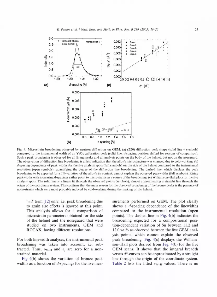
Fig. 4. Microstrain broadening observed by neutron diffraction on GEM. (a) (220) diffraction peak shape (solid line + symbols)compared to the instrumental width of an Y2O3 calibration peak (solid line: d-spacing position shifted for reasons of comparison).Such a peak broadening is observed for all Bragg peaks and all analysis points on the body of the helmet, but not on the noseguard.The observation of diffraction line broadening is a first indication that the alloy�s microstructure was changed due to cold-working. (b)d-spacing dependence of peak widths for the five analysis spots (full symbols) on the side of the helmet compared to the instrumentalresolution (open symbols), quantifying the degree of the diffraction line broadening. The dashed line, which displays the peakbroadening to be expected for a 1%-variation of the alloy�s Sn content, cannot explain the observed peakwidths (full symbols). Risingpeakwidths with increasing d-spacings rather point to microstrains as a source of the broadening. (c) Williamson–Hall plots for the fiveanalysis spots. The solid line is a linear fit through the observed points (symbols), almost approximating a straight line through theorigin of the coordinate system. This confirms that the main reason for the observed broadening of the bronze peaks is the presence ofmicrostrains which were most probably induced by cold-working during the making of the helmet.
E. Pantos et al. / Nucl. Instr. and Meth. in Phys. Res. B 239 (2005) 16–26 23
�c1d� term [12] only, i.e. peak broadening dueto grain size effects is ignored at this point.This analysis allows for a comparison ofmicrostrain parameters obtained for the sideof the helmet and the noseguard that werestudied on two instruments, GEM andROTAX, having different resolutions.
For both linewidth analyses, the instrumental peakbroadening was taken into account, i.e. sub-tracted. Thus, eW–H and ec are zero for a non-strained material.Fig 4(b) shows the variation of bronze peak
widths as a function of d-spacings for the five mea-
surements performed on GEM. The plot clearlyshows a d-spacing dependence of the linewidthscompared to the instrumental resolution (openpoints). The dashed line in Fig. 4(b) indicates thebroadening expected for a compositional posi-tion-dependent variation of Sn between 11.2 and12.0 wt.% as observed between the five GEM anal-ysis points, which cannot explain the observedpeak broadening. Fig. 4(c) displays the William-son–Hall plots derived from Fig. 4(b) for the fiveGEM scans. It shows that the integral breadthversus d*-curves can be approximated by a straightline through the origin of the coordinate system.Table 2 lists the fitted eW–H values. There is no
24 E. Pantos et al. / Nucl. Instr. and Meth. in Phys. Res. B 239 (2005) 16–26
significant variation of the peak broadening forthe different scans. The average strain parameteris eW–H = 0.29(1)% whereas the average intercept1/L = 0.0015(7) is small considering the scatter ofthe b* values (Fig. 4(c)), indicating that broaden-ing effects due to grain sizes can be neglected. Itis concluded that the observed peak broadeningis predominantly due to microstrains.The Rietveld refinement yields an average
microstrain broadening parameter of about ec =0.2%. The ec and eW–H values are somewhat differ-ent but the two different analytical approachesconfirm the general trend and the order of magni-tude of microstrains. For the noseguard, a muchsmaller, almost insignificant broadening parameterof ec = 0.03% was obtained, confirming the differ-ent properties of helmet and noseguard materialsregarding composition and treatment.Hence, it is concluded that the diffraction peak
broadening indicates the presence of residualmicrostrains. It is to be noted that the alloy peaksdisplay smooth distributions of lattice planes, i.e.smooth Bragg profiles (Fig. 4(a)), in contrast totypical structured Bragg peak shapes of as-castmaterials. It is therefore reasonable to assume thatthe helmet alloy was subjected to both annealingand working processes such as hammering forhardening. Hammering may have been used toshape the helmet and to harden the alloy. Sincethorough annealing would wipe out microstrainsthe helmet was probably produced by repetitiveannealing–hammering cycles. The presence ofmicrostrains indicates that the last working stepinvolved hammering or lamination of the alloy,in agreement with studies on bronze referencematerials [3].
3.3. Texture analysis
The neutron diffraction data contain informa-tion on the volume texture of the alloy, i.e. the ori-entations of grains. Well-defined textures areproduced by specific conditions during primarycrystallization from a melt, and by thermal andmechanical treatments of the cast, such as anneal-ing, drawing, rolling, and hammering [20]. Anypreferred orientation manifests itself in Braggintensity changes when the sample is rotated, or
equivalently, when the scattered neutrons are col-lected at different detector angles. In terms of theGEM multi-detector arrangement this means thatintensity ratios do not vary from bank to bank fora texture-free sample. The conventional Rietveldanalysis, in fact, assumes a random distributionof grains in the bulk. Thus, intensity misfits inthe Rietveld fits may indicate the presence of a pre-ferred orientation, as was observed, systematicallyfor all five scans in GEM bank-6, for the (220)peak at 1.3 A (Fig. 3), whilst at the same time thereis no misfit for the same lattice plane (220) in thebank-3 pattern.The texture evaluation of GEM data from 160
detector groups, representing 160 different sampleorientations, was performed on the five analysisspots. The texture is displayed in terms of pole fig-ures of representative lattice planes (111), (200),and (220). Fig. 5 shows the pole figures recon-structed from the orientation distribution func-tions (ODF�s) using the E-WIMV formalism inthe program MAUD [14] for the highest (scan 1)and the lowest (scan 2) analysis points on the hel-met. Maximum pole densities are between 1.6 and1.8, indicating a rather weak texture for thebronze. There is no systematic variation of the tex-ture strengths detectable on the five spots. The(220) pole figures are characterised by elevatedpole density in the centres, demonstrating prefer-ential alignment of (220) lattice planes parallelto the wall of the helmet, in agreement with thesystematic enhancements of the (220) peaks inthe backscattering bank (Fig. 3). The (220) poledensity maxima are complemented by minima inthe centres of (111) and (200) texture maps. Thetexture maps show ring-like features reminiscentof (110) fibre textures although densities are un-evenly spread over the rings. Asymmetries of poledensities along the vertical for some of the analysisspots may indicate a working direction from top tobottom of the helmet, or vice versa. The texturehas the hallmarks of fcc metals that are workedin one direction or uni-axially compressed [21].The texture is likely to be the result of the harden-ing processes which, through plastic deformations,preferentially aligned the copper/tin (220) planesperpendicular to the working direction. The tex-ture of the noseguard was not assessed.

Fig. 5. (111), (200), and (220) recalculated pole figures obtained from neutron diffraction data of scan 1 (top) and scan 2 (bottom).These texture maps indicate a non-random distribution of Cu/Sn grains due to plastic deformation of the alloy with characteristic poledensity maxima in the centre of (220). �mrd� stands for �multiples of a random distribution� where mrd = 1 marks the average densityfor a random grain distribution. The observed type of texture, typical for face-centred cubic metals worked in one direction, thussupports the assumption that the alloy underwent hardening and plastic deformations during manufacturing.
E. Pantos et al. / Nucl. Instr. and Meth. in Phys. Res. B 239 (2005) 16–26 25
4. Conclusions
Neutron and synchrotron X-ray analytical tech-niques were used to characterize a Corinthian-typebronze helmet from the Manchester Museum.The alloy of the helmet consists predominantlyof Cu with a varying Sn content between 11 and12 wt.%. The neutron data contain clear indica-tions of the working processes involved in the pro-duction of the helmet. The observed degree ofmicrostrain broadening hints at repetitive anneal-ing–hammering working cycles in order to hardenthe alloy. The last step was most probably a hard-ening step. The preferred orientation of grains, asdisplayed in the texture maps, agrees with ham-mering of the bronze sheet in one direction. Theobject was more than likely cast as a �skull-cap�[22], then beaten and heated in an interactive cycleand dressed down to its final thickness and shapeto fit the customer�s head. Considerable effortwas undertaken by the makers of the helmet toharden the alloy. Hence, the object was surely pro-duced for battle rather than just cast for ceremo-nial purposes.The noseguard of the helmet is made of a differ-
ent alloy, namely Cu/Zn. One can assume that the
noseguard, being made of a different material, ismost likely not part of the original helmet but isa later replacement, maybe by the 19th century fin-der of the object. This confirms suggestions madeearlier [1] that the shape of the noseguard is un-usual and that the present angle at which it is setis impractical and not authentic, and that the edgesof the noseguard itself and of the holes for fixingthe lining are much sharper than on the rest ofthe helmet. The process of attachment was notpart of this study and may be investigated later.It should be pointed out that although conven-
tional XRF would have been sufficient in estab-lishing the difference in alloy composition in thenoseguard, other important aspects of the materialproperties of the object relating to key issues for itsfuture conservation – the nature and stability ofthe corrosion products – and the archaeologicalquestion about the method of manufacture, re-quired the use of non-destructive techniques notnormally encountered in cultural heritage studiesand with which archaeologists and museum cons-ervators are not familiar in detail. We believe thatthis study will open up new methodological per-spectives for the non-destructive examination ofmuseum objects.
26 E. Pantos et al. / Nucl. Instr. and Meth. in Phys. Res. B 239 (2005) 16–26
Acknowledgment
We thank J.W. Dreyer and C.M. Goodway forcontinued technical support during the neutrondiffraction experiments at ISIS.
References
[1] The helmet has been studied by Dr. Alastar Jackson,Manchester University, for publication in the Annual ofthe British School at Athens 99 (2004), forthcoming.
[2] W. Kockelmann, A. Kirfel, E. Hahnel, J. Archaeol. Sci. 28(2001) 213.
[3] S. Siano, W. Kockelmann, U. Bafile, M. Celli, M. Iozzo,M. Miccio, O. Moze, R. Pini, R. Salimbeni, M. Zoppi,Appl. Phys. A 74 (Suppl.) (2002) S1139.
[4] G. Artioli, M. Dugnani, I. Angelini, Proc. Archaeometal-lurgy in Europe, Vol. 2, 2003, p. 19.
[5] W. Kockelmann, A. Kirfel, E. Jansen, R. Linke, M.Schreiner, R. Traum, R. Denk, Proc. ‘‘Numismatics andTechnology’’, Kunsthistorisches Museum, Wien, 2003, p.113.
[6] S. Siano, L. Bartoli, W. Kockelmann, M. Zoppi, M.Miccio, Physica B: Condens. Matter 350 (2004) 123.
[7] Yanxia Xie, L. Lutterotti, H.-R. Wenk, F. Kovacs, J.Mater. Sci. 39 (2004) 3329.
[8] F. Heidelbach, C. Riekel, H.-R. Wenk, J. Appl. Cryst. 32(1999) 841.
[9] O.V. Mishin, E.M. Lauridsen, N.C. Krieger Lassen, G.Bruckner, T. Tschentscher, B. Bay, D. Juul Jensen, H.F.Poulsen, J. Appl. Cryst. 33 (2000) 364.
[10] P. Day, J.E. Enderby, W.G. Williams, L.C. Chapon, A.C.Hannon, P.G. Radaelli, A.K. Soper, Neutron News 15 (1)(2004) 19.
[11] H.-R. Wenk, L. Lutterotti, S. Vogel, Nucl. Instr. andMeth. A 515 (2003) 575.
[12] A.C. Larson, R.B. VonDreele, GSAS, Generalized Struc-ture and Analysis Software. Available from: <http://www.ccp14.ac.uk>.
[13] R.A. Young (Ed.), The Rietveld Method, InternationalUnion of Crystallography, Oxford University Press, 1993.
[14] L. Lutterotti, MAUD, Material Analysis using Diffraction.Available from: <http://www.ing.unitn.it/~luttero/maud/index.html>.
[15] D.A. Scott, Getty Publications, 2002, p. 250.[16] S. Siano, L. Bartoli, M. Zoppi, W. Kockelmann, M.Daymond, J.A. Dann, M.G. Garagnani, M. Miccio, Proc.Archaeometallurgy in Europe, Vol. 2, 2003, p. 319.
[17] ICSD, Inorganic Crystal Structure Database, Fachinfor-mationszentrum Karlsruhe, Germany and National Insti-tute of Standards and Technology, USA, 2004.
[18] H.J. Bunge, Texture and structure of polycrystals, in: R.L.Snyder, J. Fiala, H.J. Bunge (Eds.), Defect andMicrostructure Analysis by Diffraction, InternationalUnion of Crystallography, Oxford University Press, 1999,p. 405.
[19] G.K. Williamson, W.H. Hall, Acta Metall. 1 (1953) 22.[20] W. Schafer, Eur. J. Miner. 14 (2002) 263.[21] A.D. Rollet, S.I. Wright, Typical textures in metals, in:U.F. Kocks, C.N. Tome, H.-R. Wenk (Eds.),Texture and Anisotropy, Cambridge University Press,1998, p. 181.
[22] The possibility of such helmets having started as a castbronze bowl was discussed earlier by Judith Swad-dling, Antiquaries� Journal 57(2) (1987) 348, pls XXVI.