Embed Size (px)
Citation preview
!!t
ilIol
t!ilI
PRINCIPTES OF
METATCASTING
ru
PHrrolfrlo. ot lriGaa,r C.etlaA
Principlesof MetalCasti.g
second edition
Richard V. Heine
Cbairman, Departmrnt of Minerak and Metals Engineering
Uniaersity of lVisconsin, Madison
Carl R. Loper, Jr.A ssociate Profes sor of M etall urgical Engineering
Uniaersity of lYisconstn, Madison
Philip C. Rosenthal
Dean, College of Applied Science and Engineering
Unioersity of lYisconsrn, Miluauh.ee
McGraw Hill Education (lndia) Privateffi
LimitedCHENNAI
McGraw Hill Education Ollices
Chennai NewYork StLouis SanFrancisco Auc*land BogotA Caracas
Kuala Lumpur Lisbon London Madrid Mexico City Milan Montreal
SanJuan Santiago Singapore Sydney Tokp Toronto

McGraw llill Education (India) Private Limited
Principle of Metal Casting
Copyright O 1955, 1967 by The McGraw-Hill Companies, Inc.
49th reprint 2017RLAYYRCMDRCZA
All rights reserved. No part ofthis publication may be reproduced, stored in a retrieval
system, or transmitted, in any form or by any means, electronic, mechanical,photocopying, recording, or otherwise, without the prior written permission of the
publisher.
McGraw Hill Education (India) Edition 1976
Reprinted in lndia by arrangement with McGraw-Hill Global Education Holdings, LLC,New York
Sales territories: India, Pakistan, Nepal, Bangladesh, Sri Lanka and Bhutan
ISBN-I3 : 978-0-07-099348-8
ISBN-10: 0-07-099348-3
Published by McGraw Hill Education (India) Private Limited, 4441 | , Sn Ekambara
Naicker Industrial Estate, Alapakkam, Porur, Chennai 600 116, Tamil Nadu, India, andprinted at A P Offset P\4. Ltd., Delhi I l0 032
Visit us at: www.mheducation.co.in
Preface
The 6rgt editiou oI this boot (published iD 1955) r8s writt€n as a tcxtbook Iorcollege-level courses in metel casthg for metallurgiarl strd mechadcal-eDgheerina
studetrts. Since that ti&e, therc b.sve b€en Eany advences in the eagineering
Bciences. Msior leorga,DirstioD of etrgineeiing curricula in collegee has cooplet€lyaltered the solueDce of Ee*Dtatioa of engineering Bubjects aod cour8es. Metalcssting in Eoroe 6chool8, for exsEple, m.sy be studied in coutses uoder such hesdingB
as traD-cport pheaomenr., aolidifcatioo, soilB 8nd aggregstes, the solid st8te, atrd
xxotaials s-ien€.. 1r, other schools, .aetol-prace6sing or meteriale-procesehg
c.rur&s :,rc ofien d which iur,,rde '.incir,les ol metai casting. Under thrxe circunr-
8t8trc€6, it is difrcult t., write I text wirich will Baiisfy ihese diilerent ailproaches tothe t4chitrg of met6l cs8dng. Iu croeultatio,r with the TorhEical.Diiectu' of tfieAmericao Foundrymea'8 Society it was decided thst the contpnts ur t:.is .d,tiotr.!:.ruld be eimilar to those of the first editiotr so that it migiri appe,,l t( relr.,E6 itrthe e.ducational field and to those active in metsl-crsting practice io tolaa.'ier
"ndbe ueeful as a general reference. This iB the obiective oI the pres,:at edltior,.
This t€xtbook has been spoasoted by the Americao For.ndrytqien': Society.
Thao.ke er€ due to its Technicsl Director, M!. S. C. Ma*ari, oud raany othermembera of the Ameics,D Fou.od4rmen's Society for their assfetsncc with illugtra-tione s.nd muDEI-'
We hgve rcceived excelleut 0s6i8tsDce ftom the Ame catr gociety for Metals, the,
Aoerican Society for T€sting Moteriala, the Amelican Institrte of Mioing and
Metallurgical Engineer8, the Gmy and Ductile Irr,n Founden Society, the Mallea-
ble Imn Foraders' Society, aad the Si,eel Foundern' So.riety of Americs. We
wish €specially to ackD,rlrledge Lucille L. Buss, Serr€tary to the Depsrtmelt ofMinerals aud Metale Eagitreerilg, for he.. n'-ajor corttribution to our maauscript.
Achowledpent ir ako givea hero to thc help ob{,aiued from foundies, fouadryequipmetrt and supply companies, and t,he "rulrlishing companies which have
furoished illustrstions Ior the taxt.
Richard V. Eeitx.a
C.orl R. Iapcr, lr.Plrj'lip C, Rorrntlrot
Contents
Prclue o
1. Introduction I A4. Copper-base Casting
2. Patterns 8 Alloys 358
3. Molding Processes and 16. 'pt€el Castings 384
'I\{aterials 23 16. Steel Melting in thr:
4. IVlolding Rroeesses Equie Foundry 425
ment and Mechaniza. 17. Metallurgy of Cast
tion 53 Steel 467
6. MoldingSande E4 18" The Family of Cast
6. Cores 123 Itons 491
7. Core Moterials 151 19. Melting of Cast Irong 507
a. Solidification of Metele 2Q. Gray-iron Foundry
178 Practice 557
9. Pouring and Fe@ing 21. Metollurgy of Gray
Castings 210 Iron 575
10. Metals Cast in the 22. Ductile Iron 614
Foundry 254 23.. IVlalleable Iron 642
11. Aluminum and Magnesium 24. Qlssning and
FoundryPractiee 259 Inspection 664
12. Aluminum and N{agneqium 26. Castingdesign Considers-
Casting Alloys 292 tions 691
13. Copper-ailoy FoundryPractice &i4 Iile 796
1
Introduction
)t<gsting may be defiaed as a "metal object, obtaiued by allowing molteumetal to seiidify in a ruold," tbe shape of the object being determined bythe strape of thc-&old cavity. Foundiug, or casiing, is the procees offorming metal objects- by.-ruelting nretsl and pouring it into molds. AfoundrJr is a commercial estab)iahment ftrr fouriding, or producing cast-ing8. Signific8nt in these definitions rs the uee of liquid metal to cast,
the shape of the object directly, producing casi metal. llrrought metelproducte difier lrom cast metal producte in that the metql hae leccivedmechanical working ireatment such as forgitrg, rolling, or e;rlru(iinq.Practicalty all metal is iuitially cast. Csstings obtain thcir shape print-;pally when moltcn metal eolidifies in the desired forrn. 'Wrought
objects,however, are cast as ingots and theu plastically worked to approximrfelythe desired shape.
METAL CASTING, A PROCESS OF SIIAPING
The strength of the fouudry industrlr rests on the fundamental natureof castiug as a process for caueing metals to take shapes that will servethe needs of man. Tbere are other methoda of shaping: machining,Iorging, welding, stsmping, hot working, etc. Each has applications inwhich it, is unexcelled and others for which it, is unsuited. Rarely rc anengineeriug product completed which doee not use several or all of thelundauental metal-proceBoing methods. The foundry industry is thusbuilt on one of the truly basic methode available for shaping metala touseful ends.
Certain advantages arc inhereDt iD the rDetrl-castiDg proceee. TheseD&y form the baois for choosing casting aB a proceEE to be prelerred overother shaping proceases in a psrticular caee. Stome of the reaeons fbrtbe guccese of the casting process follow:
1. lt€ DGt iDtric8lo of shapee, botb ext€md a,Dd interD8l, may be cost Aos t€Bult, raory other operatioDs, such as E&chining, forgiag, end wolding,ray be miaimized or eliminated.
Prircipb ol Mal Unq
2. Ftecsure oI their metellurgical Dstur€, sobe Bets,l6 can oDly be cast to
6hrpe sinc€ tiey caDDot be hot-vorked iDto bsrs, rods, plat s, or other
shapes from ingot forB as a prclimioary to othe! proc€ssin8. The highly
useful and low-co6t cast iroDs, which exc€ed the total of all ot}er metsls
iD ioDDage crst, illustrst€ ttris fa4t.
3. Construction mey be simplified. Objects may be cast in a siogle piece vhich
rrould otherwise require construction in several piecee sDd subrequeot
aeeerobly if made by other methods.
4. Metsl ca6ting is & proce6s highly adsptsble to the rcquircmetrk oI Eass
productioD. Lrrge mrmbers of a given castiDg msy be produced very
rapidy. The u6e oi csatiDgs in the automotive industry provide! sEple
illustrstioa of thi8 poiDt.
5. ExtremelyJarge, heavy Ectsl objects may be cast when they vould be
dificult or econoEicolly impo6sible to produce otherwise. I4Be puEp
houeings, valves, sDd hydroelectdc plaDt psrts weighing up b 2m toDB
illustrak tEis appticatioa.
6. Some enginoering ptopefties src obtsin€d more favorobly iu csst Eotals.
Examplt*iie:a. Mechinabiliiy and vibration delqpilg cspaaity in crst iroDs.
6. More uaiform properties Ircm a directioa&l staodpoint; i.e., prope y
ca6t Elgt8l8 caD exhibii the same ploperti€s regardless oI which directiol
is select d tllative, t the original castiDg for the test piece. This is Dot
geneBlly true for wrcughi metals.
6. gtr€ngth eud lightness itr c€rtsin light metol alloye which caD hi pro'
duced only as ca,stin88.
d. Good bearing quslities are obtaiDed in cast be.ariog metala.
h general, r wide ra,qe of alloy compooiiion aDd propertied is produced
i! c{at [email protected]. A decidcd .con@ic rdvsEtage may exist aa a Esult of sny otre or a
cmbioation of pointe l to 6. The pic€ a,Dd ssles factor is s doEoinr,Dt one
vhich continually weigbs the advaDtsges sDd limitatiols of a.ny procea
ued in a competitive systaD of etrterprise.
The list ol sdvaDtages accruing to l,he Betal-csstiDg process may be
expsDded beyond that given above. It is also true that condiiious may
be stated where the casting process must give way to other methods oI
shaping. Such couditions are those in ihe area of the principal advan-
tages to be gaiued by the other metsl-processing methods. For example,
nachining produces smooth surfaces &nd dimensional acctuacy not ob-
tcinable in any other way; forging aids in developing the ultimate of
fibered streugth atrd toughness in steel; welding provides a convenient
method oI joining or fabricating wrought or cast products inio mole
complex structures; and etamping produces lightweight sheet-metal parts.
Thua the engineer msy select from a number oi metal-processing method-
tlot oue or combination which is most suited to the Deeds ol his work.
Inbdud&n 3-
TIE FOUNDNY INDUSTBY
The scope of the foundry industry encompasses I maior se@ent of our
national economy. It has been described as an 8.5 billion dollar industry,
employing directly and indirectly 475,0fl) people; one which produces
about 14 to 18 per cent of all ferrous production annually and feeds
caetings into 90 per cent of all machine shops, produces about 18 million
tons of salable casting annually, and itself sustains the subsidiary busi-
nesses of foundry equipment and material supplies. The indust'ry'sproduct, castings, entprs into every field in which metels Berve maD.
Castings aie used iu transportation, communication, construction, agri-
culture, power generators, in aerospace and atomic energy applications,
and in other activities too numerous to describe. Because of their wide-
spread use, castings are produced almost ever5rwhere that manufactur-
ing occurs.
Ty*t of Foundrilx
tr'oundries may be classified as ferrous or nouferrous, gray iron, steel,
malleable, brass and bronze, or light metal (aluminum, magnesium).
The uumber of foundries in each field is given in the table below.
Foutdrbe in tlw United Statesr
Gray cast iron 1896
Steel 367
Malleable iron 90
Nonferroue and othere 3i121
Totel foundries -5674
'F-rom Fouttdrg, April, 1963,
compiled by the Penton PublishingCo., Cleveland.
Nonferrous foundries, which usually cast more than one group of alloys,are shown as a separate entry and are not further subdivided in the table.Some foundries cast more than one kind of metal.
Foundries are further classified according to the nature of their workand their organizatioual framework. A jobbing foundry is one haviug a
physical plant that usually contracts to produce a casting or a smallnumber of castings of a given kind. A production foundry, howe'rer,
is a highly mechanized shop which requires thatr large numbers of a given
kinri of casting be made in order to produce them at a low cost Semi-prqduction shops are those in which a portion of r,he work is of a jobbing
natrue and the balance is production casting. A captive foundry is one
4 Priru,ipb.t ol Metal Casting
which is an integr&l part of some manufacturing company and whoee
castings are consruned mainly in the products of the parent organizatioD.An independent foundry, however, is usually a separate company thatproduces castings for any nrrmber of customers. The largcst foundries,those employing more than 1000 people, are usually captive; but thegreatest number of foundries, the smaller shops employing fewer than1(X) people, are usually independent.
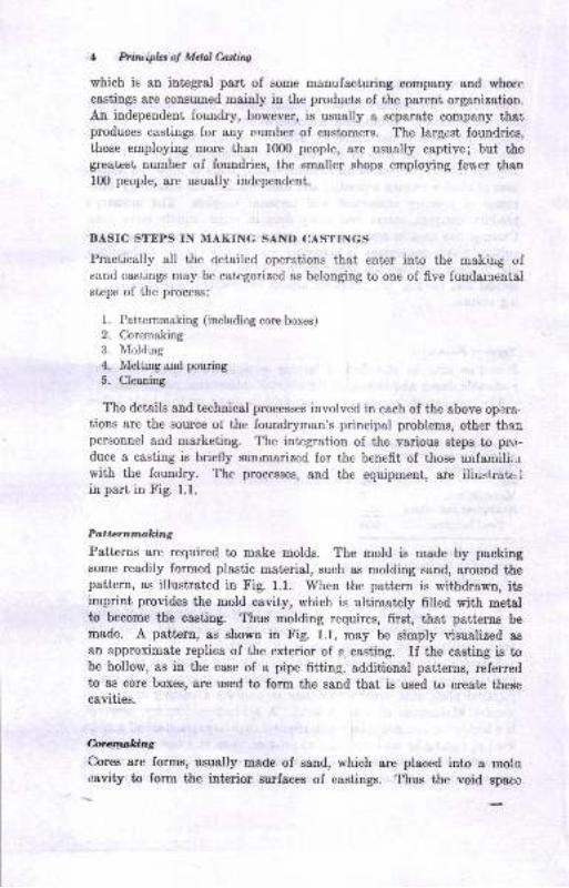
BASIC STEPS IN MAKING SAND CASTINGS
Practically all the oetailed operations that enter into the makirig ofsand castings may be categorized as belonging to one of five fundarnentalsteps of the process:
1. Patternmaking (inrrludiog core boxes)
2. Coremaking
3. Nlolding
4. Melting and pouring
5. Cleaning
The details and technical processes involved in each of the above opera.tions are the source of the foundryman's principal problems, other tha,npersonnel and marketing. The integration of the various steps to pro-duce a casting is briefly sunrmarized for the benefit of those urrfamili,lrwith the foundry. The processes, and the equipment, are iliustrate,.lin part in Fig. 1.1.
Pattcrnmking
Patterns are required to make molds. The mold is made by packingsome readily formed plastic material, such as molding sand, around thepattern, as illustrated in Fig. 1.1. When the pattern is withdrawn, itsimprint provides the mold cavity, which is ultimatqly filled with metalto become the casting. Thus molding requires, first, that patterns be
made. A pattern, as shown in Fig. 1.1, may be simply visualized as
an approximate replica of the exterior of a casting. If the casting is tobe hollow, as in the case of a pipe fitting, additional patterns, referredto as core boxes, are used to form the sand that is used to create thesecavities.
brcrwkiag.
Cores are forms, usually made of sand, which are placed into a rnolocavity to form the interior surfaces of castings. Thus the void space
Itudwlian
a
a;$PATTERN
@ORAG
(LOWER HALF OFMOLD)
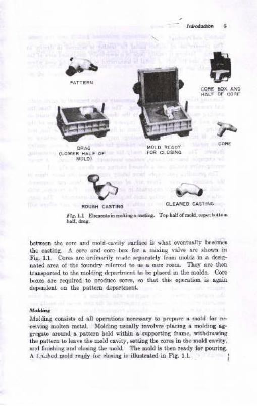
between the core and mold-cavity surface is what eventually becomes
the casting. A core and core box for a mixing valve are shown in
Fig. 1.1. Cores are ordinarily made separately from molds in a desig-
nated area of the foundry referred to as a core room. They are then
transported to the molding department to be placed in the molds. Core
boxes are required to produce eoree, so that this operation is again
dependent on the pattern departmenl,.
Molding
Molding consists of all operations necessary to prepare a mold for re-
ceiving molteu metal. Molding usually involves placing a molding ag-
gregate around. a-pattern held within a srrpporting frame, withdra\ring
the pattern to leave the mold cavity, setting the cores in the mold cavity,and finishing and closing the mold. The mold is then ready for pouring.
A f..ri:hed-uold reedy for elosing is illustrated in Fig. 1.1.
CORE BOX ANDHALF OF COiiE
$'\rCORE
MOLD REAOY
FOR CLOSING
ROUGH CASTING
Fig.l.l Elements in mating q caatinS.half, drag.
CLEANEO CASTING
Top half of mold, cope; bottom
'Y'-.,
6 PrirvipL, of Mdal C.a.ding
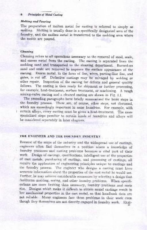
Melting antd Pouring
The preparation of molten metal fir casting is referred to simply asrnelting. Melting is usually done in a specifically designated area of thefoundry, and the molten metal is transferred to the molding area wherethe molds are poured.
Cbaning
Cleaning refers to all operations necessary to the removal of sand, scale,and excess metal from the casting. The casting is separated from themolding sand and transported to the cleaning department. Burned-oasand and scale are removed to improve the zurface appearance of thecasting. Excess metal, in the form of fins, wires, parting-line fins, andgates, is cut off. Defective castings may be salvaged by welding orother repair. Inspection of the casting for defects and general qualityfollows. The casting is then ready for shipment or further processing,for example, heat-treatment, surface treatment, or mechining. A roughmixing-valve casting and a cleaned casting are shown in Fig. 1.1.
The preceding paragraphs have briefly summarized the basic steps inthe foundry process. There.are, of course, other steps, not discussed,which are exceedingly important in some foundries. For example, withcertain alloys, every casting must be given a heat-treatment. The morespecialized steps peculiar to certain kinds of foundries and alloys willbe considered separately in Iater chapters.
TIIE ENGINEEN AND TTIE FOUNDRY INDUSTRY
Because of the scope ol the industry and the wjdespread use of castings,engineers often find themselves in a positior, rhere a knowledge offoundry processes and casting problems becorues a vital part of theirwork. Design of castings, specifications, intelligent use of the propertiesof cast metals, purchasing of castings, and processing of castings, allrequire the application of engineering principles unique to castings andthe foundry process. The engineer who deslgns a casting must haveaccurate information about the properties of the cast metal he would use.Further, he may achieve considerable economies by selecting a design thatfacilitates molding, coring, and other foundry problems. When specifi-cations are more limiting than necessary, foundry problems and costsrise. Designs which make it difficult to obtain sound castings result inIov: mechanical properties in the cast metal, so that handbook data arenot rellable. Many engineers face these problens in their work eventhough they themselves are not directly engaged in foundry work. Engr-

Idtdwtbn 7
neers are also finding increasing opportunity for professional work in
the foundry field itself. 1'o provide a foundation for work in this field,
indirectly or directly, course work in the principles of metal casting frnds
a place in the educational preparation of s[udent eugineers. Irr ad<hhion,
certain principles of materials science and engineering are best studied
in the foundry processes.
Patterns
Patteroa src the foundrJrmen'e mold-Iormilg tool. The mold csvity,qrd tfierefore ultimately tie caatrag, is made from the pEtterD. Evetr ifody one casting is desired, it is Decessary to hsve a paitern, but a greatmany castings uay be made from a eingle pattern, Obtsining auitablcpsttern equipueDt ig tiue the firat, etep in making caetings.
PATTERNMAItING
Pstterirnaking is divided betweeu that which is done within foundriessrd that whicb is dooe by separst€ busiDesses c0llled pattern thapr,Fouldries often have psttern departEent€. For example, EO pet ceut,approxiuately, of the 6674 fouodriee in the United Stst€8 have pattemdepartments. Some loundries have both wood- and metal-patteru facil!ties. Eowever, Eost pattertr departmeate in foundriea ane more co[-cerned with mddifying exiEtilg psrt€m equipment and preparing it, Iormolding (work knowa as rigging) than with producing uew patterqs.The vast majority oI pstt€rD8 are made by pstt€rn shops which areindependent of the foundry and operate as separat€ busineeees.
PsttemEakiug, the art of making patt€rDs which wiu produce tbedesired casting dimenaioue, is not within ttre scope oI thie book. C€r&rinprinciples wbich are applied to patterta, however, should be comuouknowledge to sll who may be concerned witb castinge.
TYPES OF PATTENNS
Several tSpea oI patterna arc used ic foundries. DepeldiDg on the c88t-ing rcquirementa, the pattem msy conform to one of the Iolloviag typel:
1. Si4le ot loc pattems
2. Gated potteras (loe)3. Mstch-plstc potterDs
t
Pallma 9
4. Cope and drag patterns
5. Special pattems and devicee
Each of the pattern types hae characteristic uses.
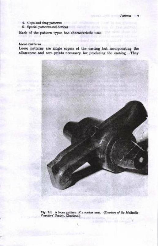
Looe Pattcrtrc
Loose patteros ere single copies of the casting but incorporating theallowances and core prints uecesssry for produciug the casting. .They
lig. 2.f A Ioce patt€rn of a roc,Ler arm. (huba ol llu MdlaileFowderi fuW,Clrlrloll.d.,
t-
ir
I
ll, Principla of Mtulfuine
generally are of wood construction but may be made of metal, pl&ster,
plastics, w8x, or any other suitable material. Relatively few castings
are made from any one loose pattern si[ce hand molding is practicedand the process is slow and costly. The parting surface may be hand-formed. Gating systems are hand-cut in the eand. Drawing the patternfrom the saud, after rappiog it to loosen it from the sand, is also done
by hand. Consequently, casting dimensions vary. A looge pattern iashown in Fig. 2.1. Such a pattern might be used for producing pmto-type castings.
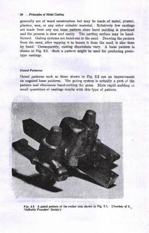
Gatd Po,tttntr-
Gated patterns such as those shown in Fig. 2.2 are an improvementon ungated loose patterns. The gating system is actually a part of thepattern and eliminates hand-cuttiug the gates. I\Iore rapid molding oismall quantities of caotings results with thie type of psttern.
!'ir:z.? 4 g.t"d-palt.ry 9f the rocler arm shown in [ig. 2.1. <hwfay of tt. IM alLahh F otnfu s' &cidy.\
ia
:IC
Paflcrnt
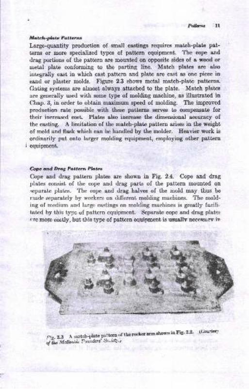
Matzh-plata Pa,ttcns
Large-quantity production of Bmall castings requires match-plate pat-
tprns or more specialized types of pattenn equipmeut. The cope and
drag portions of the pattern are mounted on oppoeite sides of a wood or
metal plate conforming to the parting line. Match platee are also
integrally cast in which cast pattern and plate are cast as one piece in
sand or plaster molds. Figure 2.3 shows metal match-plate patterns.
Gating systems are almost always attached to the plate. Match plates
are generally used with some t5rpe of molding machiue, as illustrated inChap. 3, in order to obtain maximum speed of molding. ffus improved
productiou rate possible with these pstt€ms serves to compensate fortheir increased cost. Plates also increase the dimensional accuracy ofthe casting. A limitation of the matrch-plate pattern arises in the weight
of mold and flask which cau be handled by the molder. Eeavier work isordinarily put onto larger molding equipment, employiug other pattern
i equipment.
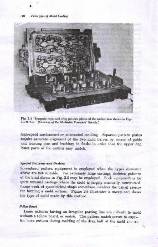
Cop atd Drag Pottarrc Pbtcs
Cope and drag pattern plates are shown in Fig. 2.4. Cope and &agplates consist of the cope and drag parts of the pat'"ern mounted on
separate plates. The cope and drag halves of the mold may thus be
r,:ade separately by workers on different ngolding machines. The mold-iug of medium and large castings on molding machines is greatly faclli"tated by ihis type of pattern equipment. Separate cope and drag platee
rre mor€ cos'tly, but this type of pattern equipment is ususllv necessarv in
o:a 2-!, A rnatch-plate pa"'tero of thorocLetarmrhowninFrS' 22 ('bt'!1q
b 7i" Urlt^'* ! oNtu s' Sc'i*'"7
ffi
,..'t't . t,
Sft#. r*sf+.
e&,{
*#-f.*)fo*
*r
1.
Prilcipla of MdalMing
t\
!i_5. Z.! Separate cope ani drag pstftm plates of the rocker arm ahown io Figa.2.L tn 2.3. <Co.t ier! ol Uu Mallablc Foutderi Socil1r)t
high-speed mechanized or automated molding. Separate pattern platesrequire accurat€ alignment of the two mold halves by means of guideand locating pins and bushiugs in flasks in order that the upper endlower parts of the casting msy matrh.
Sreia,l Po,ttz;tns and Deoius
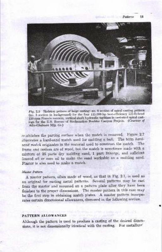
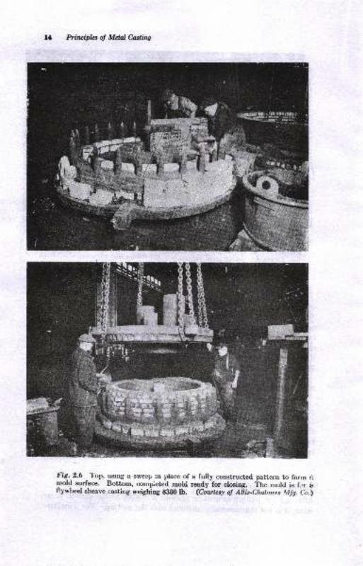
Specialized pattern equipment is employed when the types discussc:labove are not suitable. X'or extremely large caetings, skeleton patternsof the kind shown in Fig. 2.5 may be employed. Such equiprnent is lorquitc unusual castings where the mold is largely manually constructlC.Large work of symmgffisal shape sometimes involves the use of swe,jplfor foming a mold Burface. figure 2.6 illustrates s Bweep and sho$rsthe type of mold made by this method.
FaUuWta
Loose patterns having an irregular parting line are difrcult to moldwithout a follow board, or match. The pattern match serves to supi,.i.the looee pattern during molding of the drag half of the mold an.j ai:
Pallenu 13
Fis.2.5 skeleton pattern of large casting: no- 6 section of spiral casting pattern
i"3. S .""ti." in baclground) foi the four 115O00-hp best-efliciency.S25-ft-head
iSO-"p* Francis runnek, vertical-shaft hydraulic turbines in cast-steel spiral cast-
iG f.; the U.S. Bureau of Reclamation Boulder Canyon Project. (Courtesy o!
Allis4lnlmers Mfg. Co.)
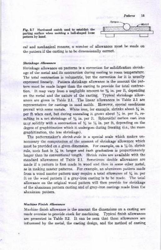
esiablishes the parting surface when the match is removed. Figure 2.7
illusl;rates a hard-sand match used for molding a ball. The term hord-
sand metch originates in the material used to construct the match. The
frame and bottom are of wood, but the match is sometimes made with a
mixture of 25 parts dry molding sand, 1 part litharge, and sufrcient
linseed oil or eore oil to make the sand workable as a molding sand.
Plaster is also used to make a match.
Moster Paltern
A master pattern, often made of wood, as that in Fig' 2'1, is used as
an original for casting metal patterns. Several patterns may be cast
from the master and mounted on a pattern plate after they have been
finisheo to the proper dimensions. The master pattern in this case may
be the first step in obtaining match plates. A master pattern incorpo-
rates certain dimensional allowances, discussed in the following section.
PATTERN ALLOWANCES
Although the pattern is used to produce a, casting of the desired dimer-
sions, it is not dimensionally identical with the casting. 1'or metalhlrp'
Prituipht of Mdal Castitrg
l'ig-.-2.6 -'lbp, usrng a swecp :n place of a fully construct€d pattern to form ,:
pold surface. Bottom, oonrpieted mold ready-for closing. 'ihe mold is f.,r b0ywheel sheave casting weighing S3B0 lb. @6*t"ry oy 1,fr;s-Cfunwrs Mlg. Co.i
fl}'
Pallcnu 15
Fis.2.7 Hard-eand match uged to establish theparting surface when molding a balleha@ looee
patiern by hand.
cal and mechanical re&sons, a nirmber of allowances must be made on
the pattern if the casting is to be rlimsagioa6lly correct'
Shrinkage Albuatlce
Shrinkage allowance ou patterne is a correction for solidification shrink-
age of the metal Bnd its contractiou during cooling to room temperature.
The total contraction is volumetric, but the correction for it is usually
expressed linearly. Pattern shrinkage allowance is the amount the pat-
tern must be made larger than the casting to provide for total contrac-
tion. It may vary from a negligible amount to 5l in. per ft, depeuding
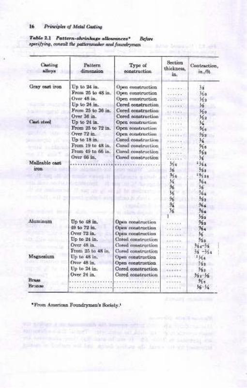
on the metal and the nature of the casting. Typical shrinkage allow-
ances are given in Table 2.1. The linear allowances in Table 2.1 are
representative for castings in sand molds. However, special conditions
prevail with some metalo. White iron, for example, shrinks about /a in.
per ft when cast, but during annealing it grows about /s in. per ft, re-
sulting in a net shrinkage of /6 in. per ft. Spheroidal carbon cast iron
may solidify with a contraction of Y+ to /s in. per ft, depending on the
<legree of graphitization which it undergoes during freezing (i.e', the more
graphitization, the less shrintage).
The patternmaker's shnnlc rule is a special scale which makes un-
necessary the computation of the amount of shrinkege allowance which
must be provided on a given dimension. For example, on a rl-in. shrink
rule, each foot is /6 in. longer and 6ach graduation is proportionately
longer than its conventional length. Shrink rules are available with the
standard allowances of Table 2.1. Sometimes double allowances are
made if a pattern is first made in wood and then in some other metal,
as in making master patterns. For example, sn aluminum pattern made
from a wood master pattern may require a totel gllowance ol la in'. per
ft on the wood pattern if a gray-iron casting is to be made. The total
allowance on the original wood pattern will then provide for shrinkage
of the aluminum pattern casting and of gray-iron castings made from the
aluminum patteru.
M aehine Finish Allouarlce
Machiue finish allowance is the amount the dimensions on a casting are
made oversize to provide stock for machining. Typical finish allowances
are presented in Table 2.2. It can be seen that these allowances are
inf.uenced by the metal, the castir\g design, aud the method of casting
16 Prir.ipla ol Me, e-attint
fo&a 2.1 Pd.b.7,.rrEinl.,,re o,I,,tl,lr.aar. Bclq..pi!!ing, drntuA 0t FUdEobt ond loa/l{lrrmatt
Crstiugdloys
Patt€rodimeraion
lype ofcoDrtruction
S€ctiou
ihicloess,i4
Cortr&ctioD,ir./tb
Gtsy csst ircr
e,rst st€el
Malleeble cartilon
Aluminua
Mqn€sium
BrreBrca*
Irp to 2,1 in.tr}oE 25 to 48 iD.
Over 48 i!.Up to 24 in.Frcm 25 t 36 itr.Over 36 itr-Up to 24 ia.ItoD 25 to 79 in.Ovet 72 in.Up to lE in.FroB l9 t 48 itr.trIom 40 to 66 iD-
Over m iD"
Up t r18 ir-49 lb 72 in-Oaer 72 in-Up to 24 i!.Over 4t iuIlom 25 to 48 iD.
Up b {a in.Over {E ia.Up to 24 i!"Over 24 iD-
OpeD coDstructiotrOpetr coutructionOpen coDstruction
Cored coortructionCored coDstructioo
Coted coDstructiouOp€r coDstructionOpetr coDstructionOpen const uctiotrCoEd coostructionCoted constnrctionCorcd construction
Coftd construction
Open coD.stnrctiotr
Ofpr coDltructionOpetr coDsimciionCoEd constructionC,oled coD.stnrction
Cored coD-structior
OpeD coostiuctionOpen coustructioa
Cored constructioDCored constnrction
XoxXa%>a
,7x7.%
1
,6XoXzxXoXt%Xt97t,7Xc912
xtXt9lz
rXzt9ltx'%t
XtXtIXz9lzlltx9iz
%r'zl% -XerXc9lz9lz
%rXXct{-%
'From Americro Foundqmen's 8oci6ty.r
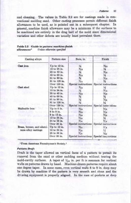
and cleaDirg. The values in Tablc 22 are for castiags made in con-
ventional moldiug saud. Other caeting processes permit difierent filiehallowauces to be used, ae is poiuted out in a gubs€quent chapter. Inge:neral,machine finieh allowauce may be a miuimum if the surfsces to
be machined are entirely in the drag half of the mold since dimeusional
vadation and other defects are usually least prwalent there.
To'bb 2.2 Gviab to pt:Gn .r?darn E-{an hr,k rcrlntsr' UnLtt allslrb .FiH
Crstiog slloys
Cast iron
Cs€t st€€l
Malleable iron
)lt,6%a%%o2A
Special instructioD!
%%cXcn%c%
Specirl hstn ctious
XoXc95tN
Special iD.structioo.s
Xa,6'%z
Special inri,,-uctionr
Bnrs, bronre, sDd alumiDum-auoy ca3titrgs
rftotlr AItroricln Fourdrymetr's Society.r
Pott rr.Irrat.Draft is the taper allowed on vertical faces of a patt€rn to permit itgrernoval lrom the eand or other molding medium without tearing thenold-cavity surfaces. A taper of ){6 in. per It is com.Eon for verticalwalis on patterns drawn by hand. Machine-drawn patterne require gbout
oDe degree taper. In aome cares, eveD vertical wslls 6 to 9 in. deep maybe drawn by machine if the psttern is very smooth and clean ald the&awing equipment is properly aliged. In the case of pockeb or deep
%Xc%%a
'Xc
Special iastructioDs
XcvXc
t6%
gDecisl instructiorg
Xa)lt91t5lz
XoSpecisl instructions
)42
%oXa
Special iastructions
Up to 12 io.13 t,o 24 iL
to 12 i.4it tD 60 in.6r to 80 iD"
8l to 120 in.Over 120 itr.
Up to 12 h.13 ta i.25 10 {, i\.,$ to 60 itr.
61 to 80 itr-
81 to r20 itr-Over rm io-Up to 6 itr.
0 tD I i-tr.
S to 12 in-12 ta i^.24 to 36 itr.
Over 36 ir,Up io 12 in.13 to 2,1 iD.25 to 36 in-
Ovet 36 in.
Pstt€m Bire Bore, in. Fi Bh
18 Principb of Mdal Caslirq
cavities in the pattern, cotrsiderably more draft is necessary to avoidtearing the mold during wittrdrawal of the pattern.
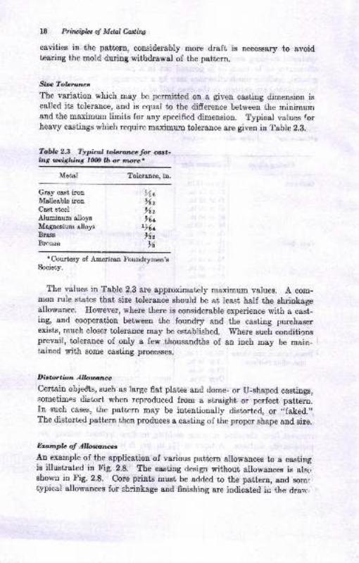
Size Tolarance
The variation which may be permitted on a given casting dimension iscalled its tolerance, and is equal to the difference between the minimumand the maximum limits for any specified dimension. Typical values forheavy castings which require maximurn tolerance are given in Table 2.8.
Tablo 2.3 Typical tobrancetor ast-ing rnighing 7Nfi lb or more.
Metal Tolerance, in.
Gray cast ironMallesble ironCast steel
)ia962
962
962
,6
Brass
Rronze
Aluminum allop 96+Magneeium a,lloys r)da
rCourteay of American Foundr5rmen'eSociety.
The values in Table 2.3 are approximat€ly maximum values. A com-mon rule states that size tolerance should be at least half the shriokagpallowance. However, where there is considerable experience with a cast-ing, and cooperation between the foundry and the casting purchaserexists, much closer tolerance may be established. 'Where
such conditioDgprevail, tolerance of only a few thousandths of an inch may be main- i
tained with Bome casting processeE.
Dittortiana Allouarce'Certain objedts, such es Iarge flat plates and dome- or U-shaped castings,sometimes distort when reproduced from a straight or perfect pattern.In such cases, the pattern may be intentionally distorted, or ,,faked.,,
The distorbed pattern then produces I cssting of the proper shape and size.
Eranpla of Allotru;rces
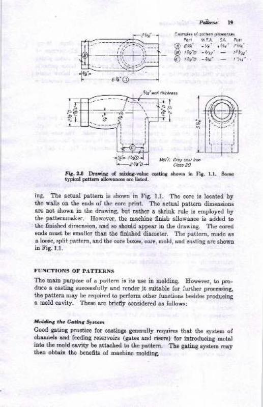
An example of the application of various pattern allowances to a castingis illustmted in Fig. 2.8. The casting design without allowances is alst':shown in Fig. 2.8. Core prints must be added to the pattern, and somcitypical allowancee for shrinkage and finishing are indicated in the drarv
Pdena 19
Exomples ot poliern ollowonces
Port M,EA. SA Pott
@ Otle" *t/a" *ho" 7Uo"
@ tzle"D -sttz" t21/tz"
@ t ,ta"o - tt s" t :,he"
546" rolt thb*ness
rT,.! sN'i<t-rJ
llol'/: 6roy cost ironCloss 20
Fig.2.8 Dawing 6f ridng-value caeting shown iu lig. 1.1. Som6tgical pettern allowaaces are listed.
iog. The actual pattern ie shown in Fig. 1.1. The core is located bythe walls o.u the ends of the core print. The actual patt€rn dimensionsare not shown in the drawing, but rather a ehrink rule is employed bythe'patternmaker. However, the machine finish allowance is added to.the finished dimensiou, and so should &ppear in the drawing. The eoredends must be smaller than the finished diameter. The pattern, made as
a loose, split pattern, and the core bxes, core, mold, and castiug are shownin Fig. 1.1.
T.UNCTIONS OF PATTERNS
The main purpose of a pattern is its use in molding. However, to pro-duce a castiug successfully and render jt suitable for further processing,
the pattern may be required to perform other functions besideo producinga mold cavity. These are briefly considered as follows:
Mokling tlw Gatin1 Syr;tcm
Good gating practice for castings generally requires that the system ofchannels and feeding reservoirs (gates and risere) for iutroducing metalinto the mold cavity be attached to the pattern. The gating system maythen obtain the benefits of machine moldi.g.
oVe'@
(I-=-l ),--
I ir-r il
&t{0]d,&'tuq t,.e Pdftittrg IirBOn a flat pattern plate, the paning surface is a simple plane. Meuycastiuga, however, require curved parting surlacee (Fig 22) because oftbeir shape, 8trd thece stt established by the patteru where Estch plates
or cope and drag platee are ueed (Figs. 2.2 alld,2.l). Loos€ pattems
require that the parting surlace be cut by hand or that a follow board I
or matah be construsted lor egtablishing the parting eurface in zuccessil'e
molds.
Mo*ing C.ore Printt'S/heu
a casting requires coree, provisiou is made on't&e-pa&ern for corepriDto. Core prints sre portiou of the pEtt€m and mold cavity whichserve to anchor tbe core in proper position iu the mold. The core printie added to the patteru, but do€s not appesr oD the casting because it ie
blocked ofr by the core. Core printo are illustrated iu Fig. 1.1 and onthe pattern in tr'ig. 2.3.
Et rblirt iDg Lo<r.ir.g Poirltr
The fouudry, pattern shop, or machiue ahop employs locating points orsurfaces on the casting to check the casting dimensions. Machinirigoperations may also use the locating points in estabtishing the poeit)ion
of machiued surlaces relative to the balanse of the casting.
lJli,ni,r,,i.i'ag Cas.idg lrcf@t Attributabla tD.lv P.'..crn
Properly coostruct€d, clean, and smooth sutlaced patterns are a uecessiiyin making good castings. Patt€ms with rough, nicked surfaces andundercuts, loosely mount€d, and in a generally poor condition contributeBubstaotislly to defective castings containing sand inclusions and otherimperfections.
Prooiditus Jor R.rm-up Care!
Sometimes a pari of a mold cavity is made wiih cores which are posi-tioned by the pattern before the molding sand is rammed. The ram-upcore then is held by the sand which has been packed around it.
I'Iotidir.C Dco.tomy iL Moldi..t
ihe patterD should be constructed io achieve all possible savings in cosr,
ol the casting. Here euch it€m8 may be considered as the number oI
Pateta 2l
castings in the mold, the proper sire of tle pattern plate to fit available
mdlding equipment, method of molding, and other factort.
CORE BOXES
Core boxes, although not refemed to as patterns, are an essential part ofthe pattern equipment for a casting requiriig cores. Core boxes are
constructed of wood or metal. The eimplest type of box is the dump box
illustrated in Fig. 1.1. The top of the box is flat, and the core is removed
by placing a plate over the box and inverting it. A split box is a two-piece box risually having a flat parting surface. A simple gang core
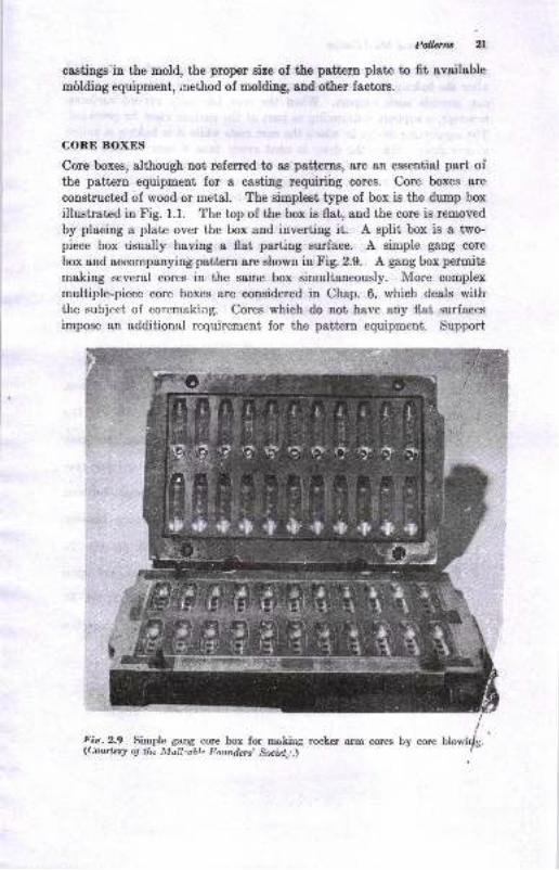
box and acr:ompanyingpattern are shown i. Fig. 2.9. A gang box permits
making several cores in the same box simultaneously. More complex
multiple-piece core boxes are considered in Chap. 6, which deals withthe subject of coremaking. Cores which do not have any flat surfaces
impose an additional requirement for the pattern equipment. Support
Fie.2.9 Simple gang core box for making rocter arm cores by corelL;ottttis! oJ t)rc llla!! ^abt^ Itqnndcrc, &niet,,,,\
tt
'l 'uli:ii
,'A -t -a "-.l. t- 1. -r,,I, {}, q

Z2 Prilviplct of Mdal Caslittg
must be provided during the baking of cores since ttre sand io weak until
after the baking process. A flat core surface and flat plate (core plate)
can provide such support. When the core has only curved surfaces,
however, a support conforming to part of the surface must be provided.
The supporting device in which the core rests while it is baking is called
a core drier. Since the drier is used every time a core is baked, the
number of driers needed equals the number of cores baked as a batch.
Some core boxes require provisions for electrical or gas heating if they
are to be used for shell coremaking or hot-box coremaking (Chap. 6).
The importance of good pattern equipment cannot be overemphasized.
Patterns which take into account the problems of molding and core-
making, proper gating and risering, ease of cleaning, and further process-
ing promote quality in castings. As was pointed out earlier, the subjecb
is one for detailed treatment, beyond the scope of this tcxt. Further
information on construction and principles of patterns may be obtained
from some of the references listed in the Bibliography.
BIBLIOGRAPHY
l. American Found4men's Society, "Patternma,ker'B Ma,nu&I," Dea Plainea,
IU., 1953.
2. American Foundr5mren's Society, "Cast Metals Eandbook," 4th ed., Des
Plainee, Ill., 1957.
3. O. Benedict, Jr., "Manual of Foundry and Pattem Shop Practice," McGraw-Ilill Book Company, New York, 1947.
4. J. R. Hall and C. L. Webber, "Practical Wood Patternmaking," McGraw-Trilt Book Company, New yort, 1948.
5. B. R. Eall and H. E. Kile5 "Pattera De8igr.," Internationsl TextbookCompany, Scranton, Pa., 1941.
6. C. R. $immsns, Liquid Phenolic Casting Beins for Foundry Patterns,Trons. AFS, vol. 55, p. 517,1947 .
7. E. Bremer, Pressure CasCing Matchplatcs, Fotrulry, vol. 75, pp. l?'l{--126,
April, 1947.
8. W. E. Tharp, Pattcrn and Allied Equipment, Deaigu, R€d€sign, and Inter-cirangeability, Trau. AFS, vol.53, p.368, 1945.
0. W. C. Manwell, Patterns in the Jobbing Foundry, Trau- AlvS, vol. 5j],p.168.
lrt A. J. Eowarth, Gating Principltx Applied to Gray Iron Castingg Pmductionon Match Plat,a, Am. Foundryman, vol. S, no. 1, p. 2[1, JuIy, 1951.
Molding Processes
and Materials
Good castings cannot be made without good molds. Because of the
importance of the mold, casting processes and castings are often describedby the materials and methods employed in molding. The term molilingproce$s refers to the method of making the mold aud the materials used.
Tire term casting process conveys a broader meaning, often including themolding process, the method of introducing the metal into the motdoavity, or all the processes used in making the casting. A brief descrip-tion of the more common molding and casting process€s is given in thtschapter. Additional details of each process are given in references listedin the Bibliography.
Molding processes have certain features in common:
1. The use of pattem (or core boxes)
2. Some type of aggregate mixture comprising a granular refractory andbinders
3. A means of forrripg the aggregate mixture around the pattern+. Hardening of the aggregate or developing its bond while in contast with
the pattern
"i. Withdrawal of the pattern from the hardened aggregate mold5. Asseurbly of mold and core p:eces to make a complete mold, metal then
being poured into the mold
The various molding processes differ primarily in the method of formingthe mold and in the granular refractory and method of bonding it.
Forming the mold is done by:
l. Compaction of the aggregate around the psttern2. Free flow of.dry aggregate around the pattern, illustrated by the shell-
molding process
3. Free flow of a slurry or fluid aggregate around the pattenx, illustrated byiavestment and phster molding
4. Variants of the above mold forming methods

E
3z
9
E3
.E f E B
-,t?-a
ii:E iE ;ii€Eli$
; E€ie6;&
,;3ijil q :95 E"
E!oi
:.9r.53 E: sqEJ,E.H
tss, TO
z
9',663
6-
.!E
5E
E
7-
: E tp-* 3iE.;T B"'.3E
:" {6it;"EEE-a$5EsrFEES-i5r'sFEE
--! : ::,o h E
6& g E3 E E
d - : :! E5I:EiIrE E T.E'EghEtsI
6;
i: .rga ? r9=
i iNo.g;
a{lBi:-a 5 aH e; E
Z,'
E
{ 9
!r3
'i -1"3 r :-i's*+;o*bBgib"i?.-i E g?
E P.E,etE 9 Ei
'
$i=i E
-o :i -9 3
oad4ol
:
;
a
:
.d
g
)
- 9J?
= Eg e
=oaiE - 3'r"a d d.=
dooldd
U)
o 3 .-Br o c o ==tr dd= 9lx k o 6 -= a
ExitEE=Ej, a5'd.! e H
?h
t eE r! :!= h
i'ae€
Es .-EP B,E E.;.- a
=e !;HEE€
^a d d o>
E Ee> -dl.E e b.E.134d!.l: E
a
,'9
-= o
db€gie
.9!d
i -s^Ld= x
>, ao
uI
=E
s
B
ji:ot-
5i3;EEE.E ilaEi E Ei
XE
? c"oN59
Y.=i r
3ooltr!dda
.9m .o
sFi'EbE*n€ u eE!.EE-ab 85€EI
=x.s . E . E.i.6 uE- f c-
;ag a $; titf;" .o,i B-
;;;EEse*E
u:€EEbE
C)
IU9l!€
@o>Ec
o
a
!o
oa
a
f,uda'6 1E
ri-nQ c9Ei;3o;6 E
o
h "-*--U.-t:E,3S'i= *t
E"e€E E
aa
EE 8=
t
.c
.l-'€ q!
€sE:q >o i-h!Cr:E
Blliso F.= E-iv:
488.8N
doc
Tbz<g{;
i,
ii(,
E
dda
-
d
&8sI eog!R
-tr*'= >,E
a
do
dda
oPo'd-adq
-da otr
EE:iAEE.E-&€€EE-8.9
EoE:3dda
o--3 e3
-i ;.c a
d
E
=o I atc ooH9
Bo! E i - F
E.E.6' P O';
$e E':il988ddq>
dd9g=u*d
E E g =E
SEEE:ooAd
eo
(t)
o
o
o
q
b\c o
;E 8? ;'aN
J6
b36E{9
-utrQ
EBbE*EgEB-r.
d=do
E,oltr!ddD
6EEe xko; -EiiBm

PriEipb, o! Md.al Caains
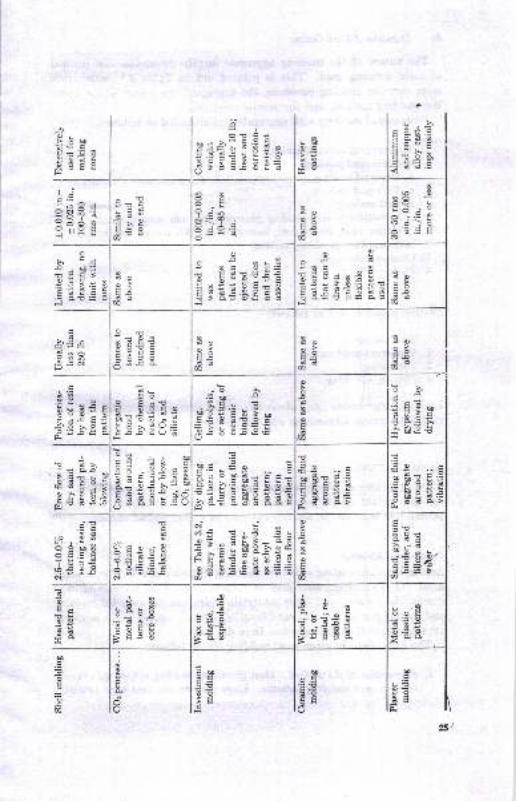
The uature of the molding aggreget€ largely determines the methodof mold forming used. This is pointed out in Table 3.1, which listssome commolr molding processes, the sggregate, the nB,ture of the bond,the molding method, and the results produced.
Processes of molding with aggregates are classified as follows:
1. Sand moldirrg (or sand easting)
o. Green-sand molding6. Dry-sand moldingc. Core-sand moldingd. Shell moldirge. Milcellaneous sand-molding processes: pit ard Iloor molding, cameDt-
bolded sand, eir-set sand, loam molding, CO, process, hot box, etc.2. Investment (or precision) moiding3. Ceramic molditrg4. Plast€r oolditrg5. Graphite molding
Casiing processes are as follows:
1. Sand casthg2. Permenent-mold casting
3. Die casting
4. Cetrtlifugal cssting
Each of the prccesses listed aboye has a field of most, appropriat€ applic8-tion, with certain ady4ntsges and limitsuoD!.
SAND CASTINGS
Molding proceesea where a saud aggregate is used to make the moldproduce by fer ihe largesi quantity of castings. Whatever the metalpoured ini,o saDd molds, the product may be called a sand casting.
Gtcen-rr,nd Molding
Among the saud-casting processes, molding is most often done with greensard. Greetr xoolding saDd msy be defined s6 a plastic mixture of-sandgraim, clay, wster, and other msterials which can be used for moldingand castitrg proces8e8. The saod is called ,,greeu,,
because of ure moistulepreseDt aud is thus distiuguiebed lrom dry sand.
The basic stepr iD greeD-ssnd EoldiDg dre 8s followe:
l. Prcparctbfi ol the patrerr. Most grcetr-s8Dd Eolding is done Fitll mstch-Ir6t€ or cope sDd drag p&tterDs. Irose pstt ms are used when reletively
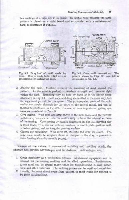
rew caatinss or a rype are to b. made.Mf;fffJ:"ffiT" rJpatt€m is placed on a mold bosrd and surlounded with I suitsble€iz€d
fla.sk, ss illustrated itr Frg.3.1.
fig. 3,1 DraA half ol mold oarle byhand. Drag iB ready to be rolled ov€r inprepsration for rnaliDg ttre cope.
Intt Itr ahown in Frgs. 3.I and 3,2 iB
rhown elso in Frg. 1.1.
Making the mold. Moldtrlg requirce the raroming of esDd stound thepattern. As the lrnd ir pacled, it &velope etrength and becoBe6 rlgidwithin the flask. Ramming may be done by hald, aE in the simple Beiup
ilustrsted h Fig. 3.1. Both cope sDd drag are molded in the sa,oe way, butthe cope raust provide for the spnre. I'he gating-system parts ol the moldcavity are simply channels for the entry of the molten metal, and can bo
molded as illustrated itr Fig.32. Bec&use of bheir ioportance, gating sys-
tees sre coDsidered in Chap.9.Corc setting. With cope and drsg halv€B of tlle mold mode and the pattemwithdra*n, cotcs are set into the mold csvity to form the int€rnsl surf&ces
of the cssting. Core settiDg by hsrd is illustrat€d in Fig. 33, showing also
a 6old made by a squeeze-molding machine, a match-plate patt€m withattarhed gating, aDd an illegula,r parting surface.
Chring and, ue'ighting. With cores set, the cope a.nd drag are closed. Thecope loust usually be weighted down or clamped to i[e drag to pleveDi iifroE flosting wheD the Eetal i6 poured.
Because of the nature of green-sand molding and molding sands, theprocess has certain sdvsniages and limitatioDs. Advantages are:
Great flexibility a.s a production process. Mechanical equipmedt can beutilized for performing motding and its allied operations. Furthermore,greetr saad can be reused many time6 by recondiiioDilg ii lMith $at4r,.lay, a,nd othe natedals. The moldilg proc€s8 cs[ bo Bpid and r€ptitive.Uzually,'he most dilcct iout€ frolo prttem to mold rcady for pouliog i8
by green -sanri nolding.
PoliE., / -- - --- - 'Gole
ris.3.2 C.op€ mold rammed up. The
A P"iruipL, of MdalC,adirrlg
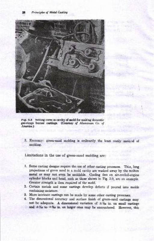
t.t. {.'it !€tttrg cores in cavity o[ mold for -a]ing domesticgas-raDge burner castings. <huil.ry o! Ahunirunt Co. ofAm*ia.)
3. Economy: greetr-sand 6elding is ordinarily the least costly mettnd ofmolding.
Limitations in the use of green-sand molding are:
1. Some casting designs require the use of other casting processes. Thin, longprojections of green sand in a mold cavity are washed away by the moltenmetal or may trot even be moldable. Cooling fins on air-cooled-enginecylinder blocks and head, such as those shown in Fig. 3.g, *r. 611 sxlmple.Greater strength is then required of the mold.
2. Certain metals and some castings develop defects if poured into moldscontsining moisture.More intricate cas'tinge can be made by some other casting proce&rcs.
The dimensional accuracy and surface 6nish of green-sand castings maynot be adequate. A dimeneional variation of i}6{ in. on mall castinggand +Xc b *rh ia. on larger ones may be encountered. Eowever, t\is
3.
4.
MoWirw Preesscs atd Malerial* 29
variation on many castiDgs may be much ]ess than that cited if adequa'"e
control is exercised.
5. Large castings require greater mold strength and resistance to erosion than
are available in green sands.
Dry-sand Molds
Dry-sand molds are actually made with molding sand in the green
condition. The sand mixture is modifled some\rhat to favor good
strength and other properties after the mold is dried. Dry-sand molding
may be done the same way as green-sand molding on smaller sizes ofcastings. Usually, the mold-cavity surface is coated or sprayed with a
mixture (Chap. 5) which, upon drying, imparts greater hardness or
refractoriness to the mold. The entire mold is then dried in an oven
at 300 to 650 F or by circulating heated air through the mold. The
time-consuming drying operation is one inherent disadvantage of the
dry-sand mold.
Skin-dried Molls
The effect of a dry-sand mold may be partially obtained by dryingthe mold surface to some depth, /a to I in. Skin drying may be per-
formed by torches, a bank of radiant-heating larnps, or electrical heating
elements directed at the mold surface. Skin-dried molds must be poured
shortly after drying, so that moisture from the undried sand will notpenetrate the dried skin.
Floor and Pit Molding
The production of large intricate castings weighing from 1 to over 100
tons is, of course, one of the special advantages of the casting processes.
An example is given in Fig. 3.4. Consider how difficult it would be tomake large intricate shapes in some other way. The surface finish and
dimensional accuracy of these large castings in ferrous alloys are notas good as in smaller ones, dimensional tolerance.s of -+-y4 in. being ac-
ceptable unless special experience permits closer control. The problems
of mold construction, handling, coring, gating, pouring, and cleaning ofIarge castingr: require much engineering effort and control.
When the molds are medium to large in size, considerable heavy equip-
ment, floor space, and time must be allocated to the molding operation.Floor molding is done on the floor of bays of the foundry set aside forthese heavy molding jobs. A molding floor is shown in Fig. 3.5. Thesize of work handled is revealed by comparison with the men in thefigure. A completed floor mold, dried, with dry-sand core in place andready for closing, is shown in Fig. 3.6.
30 Principbt oJ Mdal Caslittg
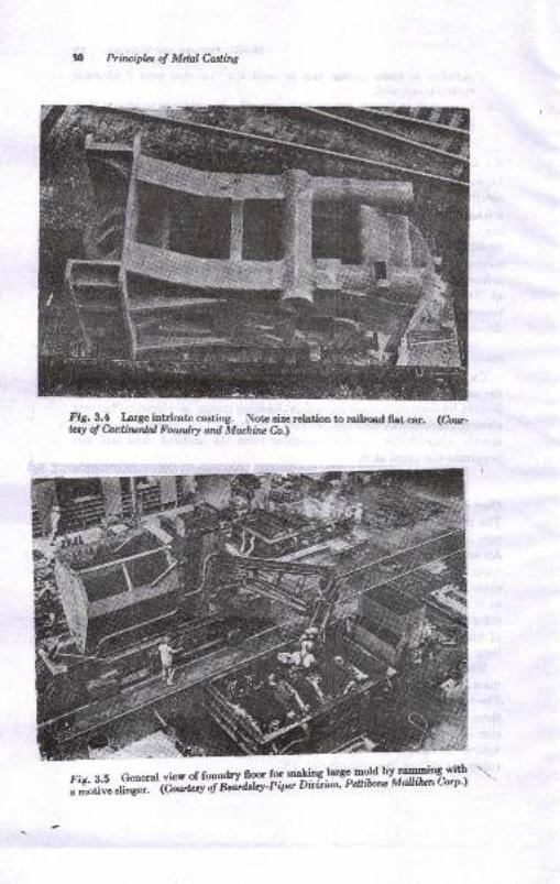
fig. !.! Large intricate carting. Note size relatiou to railroad IIat car. (hu-lay of hntilunlal Fowdry ail Muhiru Ca)
fiz. 3.5 General vier of foundry lloor for mqling largB Eold by rammiog wit'b
; H#;: di;;:* (h,,,r"q ';;';'i;w'itp"' ou{"a"' Pcttibotle Muttihencorp'l
..L.
ffi
--5
Mold,iltg Prlarcaccs and Malcrials
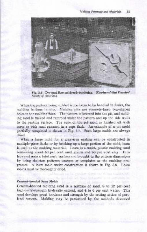
Fig.3.6 Dry+and floo moldreadyfcelmirg. (Cawl,csy ol Stzz;l ltowful&aiely of Amcri.ca,)
When the patt€rn being molded is too large to be handled in flasks, the
molding is done in pits. Molding pits are concrete-lined box-shaped
holes in the molding floor. The patteru is lowered into the pit, and mold-
ing sand is tucked and rammed under the pattern and up the side walls
to the parting surface. The cope of the pit mold is fiuished off withcores or with sand rammed in a cope flask. An olample of a pit moldpartially completed is shown in Fig. 3.7. Such large molds are always
dried.'When a large mold for a gray-iron casting can be constructed in
multiple-piece flasks or by bricking up I large portiou of the mold, loam
is used as the moldiug material. Loam is a moistl plastic molding sand
containing about 50 per cen't, sand graina and 50 per cent clay. It is
troweled onto a brickwork surface and brought to the pattern dimensions
by using skeleton patterns, sweeps, or templates as the molding pro-gtresses. A loam mold under construction is shown in Fig. 3.8. Loammolds must be thoroughly dried.
Cemant-bottdcd fund MoUs
Cement-bouded molding sand is a mixture of sand, 8 to 12 per centhigh-early-strength hydraulic cement, and 4 to 6 per cent water. Thissand develops great hardness and strength by the setting action of port-land cement. Molding may be performed by the methods discussed
IL-g #
\
t. '--.-
a.'
EEk-
hinripla ol Mdaleadiro
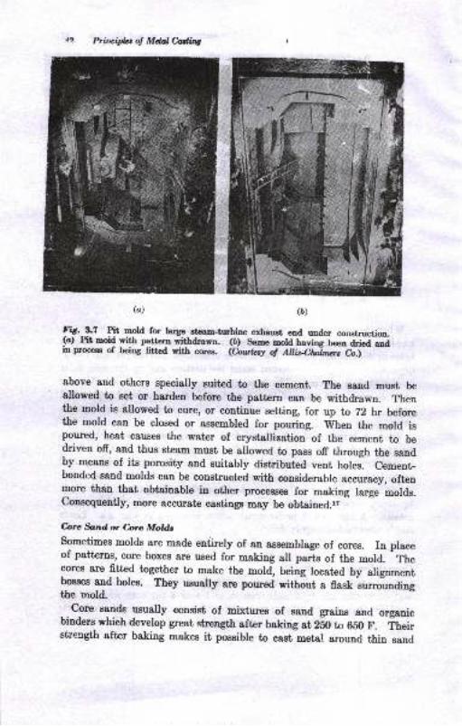
(D)(a)
Ftg- t.7 Plt mold for large ctest&turbin€ esad, end under construction.(cl Ptt noiq wifi pgttaru withdrarn. (D) Sene nold having b*" d"tJ;iin prooess of bein6 ftted with oores. @*t q of Ahisertnos-Crj - --
above aud others specially suited to the cement rhe sand must beallowed to set or harden before the pattern can be withdrawn. Thenthe mold is allowed to cure, or continue setting, for up to 72 hr beforethe mold can be closed or assembred for pouring. Ttrhen the mold ispoured, heat causes the water of crystallization of the cement to bedriveu off, and thus steam must be arlowed to pass off through the sandby means of its porosity and suitabry distributed vent holes. cement-bondcd sand molds can be constructed with considerable accuracy, oftenmore than that obtainable in other procesEes for making large molds.C.oaeequently, more accurate castings may be obtained.l,
&rc *tdot hrc Motds
sometimes molds are made entirely of an assemblage of cores. rn placeof patterns, core boxes are used for making all parts of the mold. Thecores 8re fitted together to make the mold, being located by alignmentbosees and holes. They usually are poured without a flask *"*roaiogthe mold.
. .C.o"* sauds usually consist of mixtures of sand grains and organicbiudere which develop great strengtl after baking at 280 to 650 F. in.i,strength after baking makes it possible to cast metal around thin sand
Moklin4 P6rrc, ard Malerbls
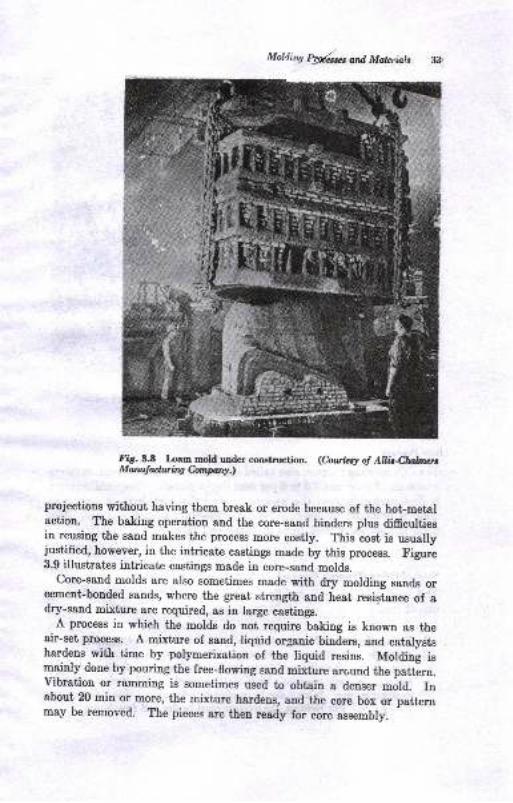
Fir. 3.8 Loam rDold under construction. (hu.le:y of Aht4lurbnenMarulduinghprq.t
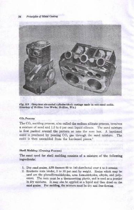
projections without having them break or erode because of the hot-metalaction. The baking operation and the core-ssnd binders plus difficurtiesin reusing the sand makes the process more costly. This cost is usuallyjustified, however, in the intricate castings made by this process. Figure3.9 illustrates intricate castings made in core-sand molds.
core-sand molds are also sometimes made with dry molding sands orcement-bonded sands, where the great strength and heat resistance of adry-sand mixture are required, as in large castings.
A process in which the molds do not require baking is knowu as theair-set process. A mixture of sand, liquid organic binders, and catalystshardens with time by polymerization of the liquid resins. Moldin! ismainly done by pouring the free-flowing sand mixture around the pattern.vibration or ramming is sometimes used to obtain a denser mold. Inabout 20 min or more, the mixture hardens, and the core box or pattenrmay be removed. The pieces are then ready for core assembly.
g Priluipbs of Mdal Ca.dittg
lig.3.9 Gray-iron air-oooled cylinder-block castinga made in core-eand molds.(Cro.ntzsl of Brillbn lron Workt, Brillbn, Wit.)
COz Procecs
The CO, molding process, also called the sodium silicate process, involvesa mixture of sand and 1.5 to 6 per cent liquid silicate. The sand mixtureis first packed around the pattern or into the core box. A hardenedmold is produced by passing CO, gas through the sand mixture. Themold is then assembled from the hardened pieces.l
Slrrell Molding (Croning Procest)
The sand used for shell molding consists of a mixture of the followingingredientsi
1. Dry sand grains, A-FS frneness 60 to 140 distributed over 4 to 5 screens.
2. Synthetic resin binder, 3 to 10 per cent by weight. Resins which may be
used are the phenolformaldehydes, urea formaldehydes, alkyds, and poly-esterc. The resin must be a thermosetting plastic, and is used as a powderin dry mixtures. It may also be applied as a liquid and then dried on thesand grains. For molding, tbe mixture must be dry and free-flowing.
/, '{r \-';ai
Molding Prorcestes ard Maleials
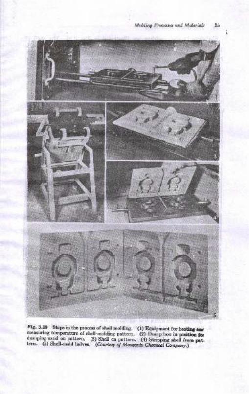
fig. 3.|0 Stepe in the process of ahe-ll molding. (l) Equipmeut for tr6grini .rtp*Irog temlrrature of sh_e!!-molding pattern. -<il
O",irp bo, itr pci6o ao--
fumnin_q-rygd--on pattern, (B) Shell oi^pattern. iil St ippi"s .n"fi i---nltern. (5) Shell-mold halves. (Court*x oi tWonanli Ct*rrii[ 6^wrw.>- --
Y,-,L' ffi-x
fi Priruifut of MdalCadilq
The steps in shell molding are illustrated in Fig. 3.10. The sheU is
cured in two steges. When the sand mixtue drops onto a pattera
heated to about 350 to 700 F, the plastic partially thermosets and
builds up a coherent sand shell next to the pattern. The thickness of
this shell is about Y+ ta 3/+ in. and is dependent on the pattern tempera-
ture, dwell time on the pattern, and the sand mixture. The shell, still ou
the pattern, can then be cured by heating it to 450 to 650 F for 3 to 1 miu,
as, for example, by the method shown iu Fig. 3.10. Stripping the shell
from the mold presents a problem since the shell is very strong and
grips the mold tightly. A mold-release agent, or parting agent; is used
to obtain clean strippiug when the eiector pins push the shell ofr the
pattern. Silicone parting solutions, sprayed on the pattern, have been
found satisfactory. The shell halves may then be assembled and poured.
Shell molding is probably used more for making cores than molds.
A variaut of the process, known as the hot-box process' employs a heated
core box. The molding mixture again contains 1.5 to 4.0 per cent resin
of the furane or furfuraldehyde type. Heat from the core box causes
the catalysts to stert an exothermic polymerization process. As the
sand temperature rises, the resin polymerizes and the mass hardens.
I[olds are made by assembling the hot-box cores.
Advanteges claimed for shell molding are exceptionally good surface
iinieh and dimensional accuracy, and heace the possible elimination of
some machining operations, decreased casting-weight variation, and less
cleaniug cost.l,2,t
IITVESTMENT CASTING
Investment casting is a process also known as the "lost-w&x" process,
or ttprecision" castiug.1,3,3' The tnrm inuestment telers to a cloak, or
special coveriog apparel, in this case a refractory mold, surrounding a
1 refractory-covered wax pattern. In this process a wax patt€rn must
lbe made for every casting and gating system; i.e., the pattern is ex-
I pendable.
A number of variants of the process exist, but they have the following
points in common:
t. Disposable or eSpendable patterns are used.
2. Molding is done with a fluid aggregate or slurry.
3. The aggregate is hardened in contact with the pattern, providing precise
reproduction of the pattern.,1. The aggregate is bonded with an inorga.nic eermic binder.
.r. The mold is heated to drive ofr all gases.
Moldirq Processes and. Malerir)s X7
0. Pouring is perforrned with the mold preheated to a controlled t€mperatureiu order to poui thin sections which would not otherwise fill out.
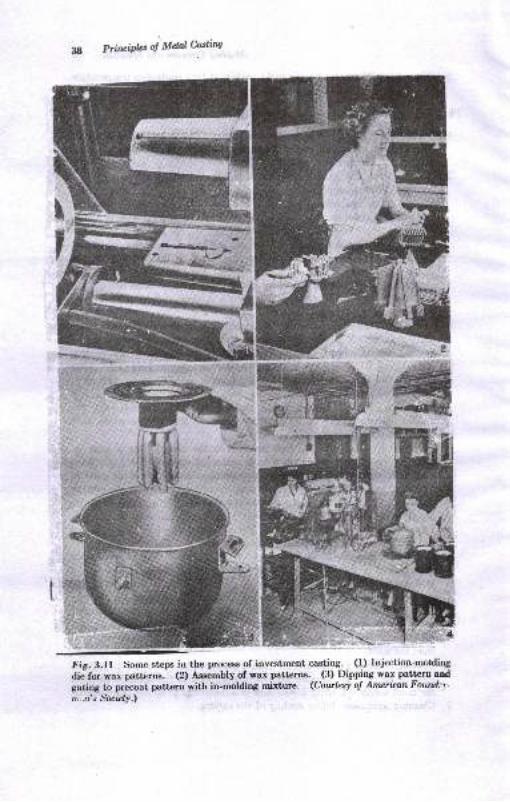
Ihe steps in thc process, as shown in l-ig.3.11, are as follows:
1. A die for casting the wax patterns is made. The metal die must make
allowance for shrinkage of both wax and later the metal casting, about0.011 to 0.015 in. per in. total.
2. Wax patterns and gating systems are produced from the metal dies byinjection. Waxes employed are blends of beeswax, carnauba, ceresin, acra-
wax, parafHn, and other resins usually obtained as proprietary mixtures.The wax is injected into the mold at 150 to 170 F and at a pressure of 500 to100 psi. Polystyrene plastics are also used, but require a mold temperatureof 300 to 600 F, pressure up to 12,000 psi, and iron or steel dies. Mercurymay be rrsed in place of wax pa+"terns but must be frozen to retain theshape desired. Patterns and gating system must be assembled if cast
separately. They can be joined by heating the surfaces to be attached inthe case of wax or moistening them with a solvent, carbon tetrachlorido,in the case of polystyrene patterns.
3. Precoating. The wax a.ssembly is dipped into a slurry of a refractorycoating material. A typical slurry consists of 825-mesh silica flour suspended
[r ethyl si]icote solution of suitable viscosity to produce a uniform coatingafter drying. Some typical coating materials are listed in Table 8.2. Afterdipping, the assembly is coated by sprinkling it with 40 to 50 AFS sili,:..sand and allowed to dry. Sometimes precoating is not used, and the w:.xpattern is directly invested in the molding material. In this case, themolding mixture must be vacuumed to remove air bubbles which mavlodge next to the pattern.
4. The coated-wax a.sembly is next invested in the mold. This is done byinverting the wax assembly on a table, surrounding it with a paper-linedsteel flask, and pouring the investment-molding mixture around the pattern.The mold material settles by gravity and completely surounds the patternas the work table is vibrated. Some typical investment-molding mixturesare given in Table 32. The molds are then allowed to air-set.
5. Dewaxing and preheating. Wax is meited out of the hardened mold byheating it in an inverted position at 200 to 800 F. The wax may be re-claimed and reused. Molds with polystyrene patterns in them are preferablvdried at 140 to 160 F. For burnout and preheating, the molds are heatedat the rate of 100 to 160 F per hr from about 800 F to 1600 to 1900 F for
,
ferro'rs alloys and 1200 F for aluminum alloys. The finishing temperatureof preheatiag is controlled so that the mold is at a temperature desirable '
for pouring the particular alloy and casting design. The burnout andpreheating cycle must completely eiiminate wax and gas-forming materie,lfrom the mold.
6. Pouring. \[hen the mold is at temperature, the metal is gravity-pouredinto the sprue. Air pressure may then be applied to the spme to force-frilthe mold cavity. Pouring is also done in a centrifuge to 6ll out thir sectior,s.'i. Cleaning operations follow cooling of the casting.
PrinciPb o! MtuIMing
l';g. 3.lf Some steps io the process of iovestment casting. (1) Injectionarolding,lie. for wax petkrn8. (2) Assembly of wax patt€rns.
-(3) Dipping wax pattern aod
gating to precoat pattero with in-molding mixture. (Cowtcsy o! Ameritnn Fourul;v'
n;,n's Society.\
""ttI
L---__ i
5-d
tru-',fu,
M&iig Ptdrt ., and Mdaiob 39
&tur,,.ia-rha,l MoU,
A varisnt of investment molding iB ceranic-Ehell Eoldiug. Such moldemay be made by alt€rnately dipping the patter! iu a coatiog slurryand soatiDg with Bilica or other refractory. A shell of ya ',Jl.. otmore thickness may be built up iD tiis woy. The p8ttem i8 thenmelted out, and the mold procesoed as described previously.r,rr,rr,rr,rc
C-",rornia Mowng
Ceramic molding ig an ofrshoot ol the inyestmeot-molding process-
Reusable patterns are used for thie process, as in Band molding, Themolding aggregate consists generslly of s BlurrJr composed of rcfractorygrains aad ceramic binder. In one process, silica grains plus ethylsilicate, wak,', alcohol, aud a gelling agent such as HCI sre used. Theslurry is poured around ihe patt€rn and allowed to gel in about 4 to 7
miu. The pattern ie then removed. The mold is fired by ignititrg t}realcohol in the aggregate. After the mold has cooled, it is aseembled and,if deeired, preheated belore pouring. ID another pmcesB oI the same type,the refractory grain slurry is bonded by calcium and amuoniumphophst€s, Theee proceaaes Eay be used for uaking cores as wellaE molds.F '
Certain advaniagee charasteriatic of the ilveohnent aDd ceraloiccasting procese€s are:
l' Castiog high-pouring-temperatrure alloys to aacurat€ diEeDsions. ThnEetsllic-mold prcoes&s src not suit ble for Bt€el 8nd other slloys whichxoust be pouEd st high tropcrstuE. Accurocy of 10.003 in. per in. iapeible in some castings. Maohiuitg on caatings of many difficult-to-ma-chine alloy's is rcduced or olimhst d. gimiDatioD of DachiniDg is ooe ofthe grcat virtues of the proc€ss.
2. Ca6tings of g.est ext€rior atrd iatedor itrtricacy may be achieved.3. Thin sectiois msy be cast, even in the high-pouriry-t€Bperature alloys,
becsuBe of the hested molds. Wire folos doyD to 0.fi2 in. in dismeter and2 ia. long have been cast.
PLASTER MOLDS
Casting in plaeter molds, or plaster-booded molda, has become a ueefulcasting process.r,.l Copper- and 8luliDun-b8se alloys may be castin plaster molds, but ferrous 8lloys msy not Plasters used for moldingconeist of Eixhrres of rypsun or plsBter oI psris, CaSOa.%E,O, 8ndii:!'.rediente euch as talc, asbestoe fiber, Bilics flour, aud othem, tocontrol the coDtrsctioo charactaristice of fhe mold a!d. setiins rime

f,g;sriE EE $
@
d
3oEita
AEn
abb60d.Eud.=gt&E
c
E
d
eda
5
:6\olnE€NoE
oN@
s5€EE E: e ! E
i €; €.,8 6e.e' iB s= AEE ' z;,
er iE *€c te r s ;€: E titti l; f;$g 3te! i " E;s*iE qlE-b; EE ??; RS.EE s,EEEee€; 2ZZE! ;€{ aEEe€t{fit:# BE E ::f; E=L=sR
si # sE fr'Ss s =
e$3sss*sSSS.3 s S: 5 u e FN- 6 @ O O()D>Oa\o\a\>$ a@ ca i cO cONiPOOOdPi q
o
aoa
aB
s
t)
aP
B
I
Bna'tt),ot
z
. € . €, f . fit 5 -t, a'O AP a=d;r5=d=6o.io.+ifr Fl d Sri ,lc;6 Fi
$

L
lr
66t
q)
s-tr
o
+6oE9
H-€ gE
! d€.EEs.Ea s g9
E€EE _€ €€E3€Eg3 33,aEe'g sE 55
o
E
{e
='aE
tcE
q
c.9
q-e5tCatr!EE
=Ldc
1l) 6:
=€56a:f it
E A E -E$I E c 8'a.Ee e .e HEsg€ E.e E s.E x
€g!E i EEE
BqBSE *EtE: [95= ssS$R $$:g
Fi * E
ed
B
No ro xO5\-b\cPoNr
^l-:d:s
ood
ofr
haoqldo'a
36ocd-L.=+
E.6!6 d d -q* g $*€E
!o *a< cil O6\ 6\ b\ l:0-6t q eEmIo olrro o cDi
€ad@
6\t6d6A
oc
NN N N C\@mco co 6 aad
4l
1, Ptincid., ol Mdal Catlvtl
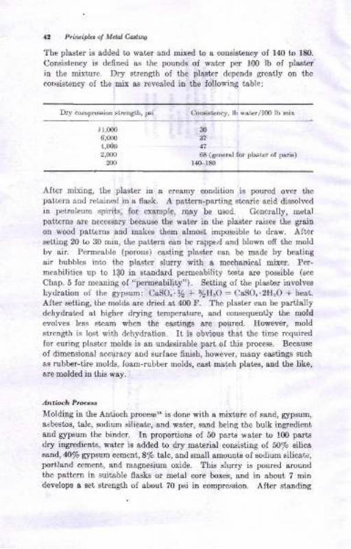
The plaster is added to wat€r and mixed to a consistency of 14O to 180.
Consistency is defned sB ihe pounds of wat€r per 100 tb of plasterin the mixture. Dry strength of the plaster depends greatly on the
corrsist€ncy of the mix ae revealed in the followiug table:
Dry compr€ssion strcnath, p6i Consistency, lb wst€r/rm lb mix
r l,(m610m
4,0d0
2,000
m
30gt47
68 (general for plaster of psrh)t40-180
After mixing, the plaster in a creamy condition ig poured over thepattern and retained in a flask. A pattero-partiDg st€aric acid dissolvedin petroleum spirits, for example, may be used. Generally, metalpatt€rDs are necessary because the wster iu the piaeter raises the grain
on wood patt€rns and makee them almost impossible to draw. AItcrEetting 20 to 30 min, the patt€m can be reppe.{ and blown off the moldbv gir. Permeable (porous) casting plaster can be made by beatingair bubbles into the plaster slurry with a mechanical Bixer. Per-
meabilities up to 1q0 in standard permeability tests are poseible (see
Chap. 5 for mesuing of "permeability"). Setting of the plaster involveshydration of the gypsum: CaSO.. % + yzH,O: CaSO..2I{.O'l heai.
After seiting, the molds are dried at 40O F. The plaster cau be parttallydehydrated at, higher drying t€mperaiure, aDd consequeDtly the moNevolves less steam when the csstings sre poured. However, moldstrength is losl with dehydratio!. It is obvious that the tilne required
for curing plaster molds is an uodesirable psrt of this process. Because
oI dimensional accuracy and surface finish, however, many castings such
as rubber-iire molds, foam-rubber molds, cssi uratch platcs, and the like,are molded iu this way.
An.ioch Pro.je',
l{olding in the Antioch processrs is done with a mixture of sand, gpsum,asbestos, talc, sodium silicate, and water, sand being the bulk iugredientand rypsum the binder. In proportions of 50 psrts wster to 10O psrt€
dry ingredients, water ig added to dry material consisting of 5olo eilicasand, 40/o rypsum cetue\|,8% talc, and small amounts of sodium silicsit,portland cement, and magnesium oxide. This slurry ie poured aroundthe patterD iD suitabl€ flasks or metal core boxe8, gnd in about 7 mindevelops a set, streug:th of about 70 psi in compression. After etaudiug
M iq Prw anl Mbiab a,l
about 6 hr, tbe molds ate aEsembled aDd autoclaved iD Etesm at sbout 2
atm pressure. They then are dried in air for about 12 hr, aud frully iu
au oven lor 12 to 20 hr at 45O F. Ttre autoclsviqg and dr5riag procesa
produces permeability, sbout to 50 AFS permeability. The molda are
then ready to be poured.
The advantages of plast€r molds are that nonlerrous casiings can be
made with good surface finish and dimensional accuracy. Tolerances oI
*0.005 in. on small castings and +0.015 in. on large castings such as
rubber-tire molda can be obtained. Metallugical quality iu slumiuum
castiuge is aleo claimed for the Antioch process, because metal chills can
be embodied in tie uold.
GRAFIIITE MOI,DS
Some reactive metals, such as titanium alloys, Ior example, can be poured
ouly.iato inert molds such aB tlpse Eade of graphite. Graphite molds
are used either as exp€ndable or as permanent molds. The former are
molded with I plastic aggregsta consisting 70 per cent oI graphite grains
of sbout 85 AIS fineness and 30 per cent oI biDders compoo€d ol pitch,
carbonaceoue cement, starch, snd wster.'&3o The mat€rial ie molded
by squeering it arourd the pattern 8t 60 to 120 psi. It is then dried and
fred in a reducing atmosphere 8t 18@ to 2000 I' to form solid mold or
core pieces. After asembliug the mold, poudng is done uader a vacuuE
to prevent contaminatiou of the metal. Refereuces 28 to 30 provide
examples of molds and castiags made by this process.
Permaneut gaphite molds are made by machining the mold cavity
iuto solid blocks o{ graphite, These molds are theD used in permanent
mold.cssting ptocesses. Graphitr begina to oxidize above 75O F, aud
the mold then begiDs to show wear. A mold coating of ethyl siticate
which deposite silica on heatiag increases the number of castinge which
may be made before the mold ia usatiafactory. Graphite mold liners
are used cousiderably in centrifugally ca8tiug brass and bronze bushings,
sleevea, and other 8hape8.s They may also be ueed for limited runs of
permanent mold-t1pe castinge. R.ecently, railroad car wheels have been
csst in graphite molde accuratrcly, 8o that ao machining is required.l
PEf,MANENT MOLDS
Molds which can be reueed mauy ljmes sre made oI metal, uzually gray
oast irou or ateel, though sometimes of bmnrc. The mold cavity (or die
cavity) in a permanent mold is often esst to its rough contour aud then
is mschin€d to iis finished dimelsione G8tiry-rystem sE vell 88 mold
* Prttrrlipbt of Mdal Cadilq
cayities 8re machined. The machined mold makes it possible to obteinvery good 6nish and dimensional accruacy in the castings. Aluminum,maguesium, zinc, lead, copper-base alloys, and cast irons are the principal
alloys so cast. The extremely high temperatures of casting and conse-
quent mold attrition usually make it unsuitable for most steel castings.
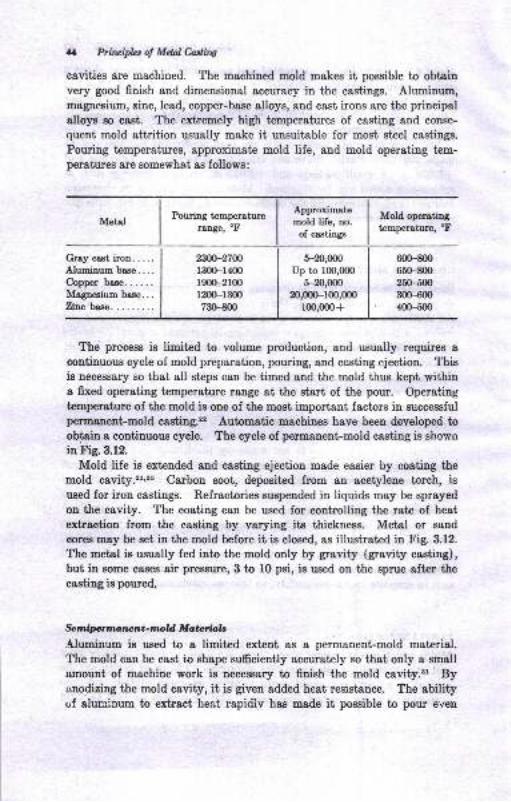
Pouring temperatures, approximate mold life, and mold operating tem-per8tur6 are Bomewhat ae follows:
Mold operatingtemperaturo, "F
2W-27Wr300-14001900-2r00
D00-r3007ffim
t-20,000
Up to 1fi),000
5-20,m020,ilx)-100,000
100,000+
mx)-800
6ffi00250-500
30Hm400-500
The process is limited to volume production, and usually requires a
continuous cycle of mold preparation, pouring, and casting ejection. Thigie necessary so that all steps can be timed and the mold thus kept withina fixed operating lsmperature rauge at the start of the pour. Operating
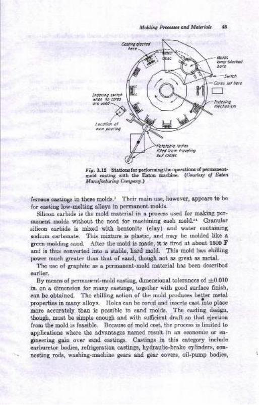
temperature of the mold is one of the most important factors in successfulpermanent-mold casting.22 Automatic machinee have been developed toobtain a contiuuous cycle. The cycle of permanent-mold caeting ie showo
in Fig. 3.12.
Mold life is ext€nded and casting ejection mede easier by coating the
mold cavity.21'E6 Carbon soot, deposited from an acetylene torch, isueed for iron castings. Refractories suspended in liquids may be sprayed
on the cavity. The coating can be used for controlling the rate of heat
extraction from the caeting by varying its thicknese. Metal or sand
corcB may be set in the mold before it is closed, as illuetrated in Fig. 3.12.
The metal is uzually fed into the mold only by gravity (gravity casting),but in some cases air preseure,3 to f0 psi, is used on the sprue after the
casting is poured.
fu tnipcrmatrrnt - rmold M atsbb.ilqpiarrm is used to a limited exteut as a permanent-mold material.The mold cau be cast io shape sufrciently accurately so that only a small
amount of machine work is necessary to fiuish the mold cavity.'r Byanodizing the mold cavity, it is given added heat resigtance. The abilityof alurcrum to extract heat rapidlv has made it possible to pour even
Potrring temperoturerange, 'F
Approximatemold life, no.
of castings
Metal
Gray cast iroo. ....Aluminum base....Copper base......Magnesium base...Zinc base.
MoWinc hpcaxt ond Malqials 45
Cosh:ng ejectedhere
Ltoldslomp-bloctcdherc
+Suilch'Corcs set hcre
t_lIndetingmechonism
mon pouring
filled lron trovelhgbull lodles
Fig. 3.12 Stations for performing the oper'atioos of permaneut-
mold casting with the Eaton machine- (hwhsl ol E&nMattuttring ConParry.l
feroue castings in these molds.r Their main use' however, appesrs to be
for casting low-melting alloys in permanent molds.
Silicon carbide is the mold material in a process used for making per-
manent molds without the need for machining each mold.8l Granular
silicon carbide is mixed with bentonite (clay) &nd water containing
sodium carbonate. This mixture is plastic, and may be molded like agreen molding saud. After the mold is mad€, it is fued at about 1500 Fand is thus converted into a stable, hard mold. This mold has chillingpower much greater than that of sand, though not as great as metal,
The use of graphite as a permanent mold material has been described
eerlier.By means of permanent-mold casting, dimensional tolerances of -f0.010
in. on a dimension for many castings, together with good surface finish,
can be obtained. The chilling action of the mold produces bettcr metal
properties in many alloys. Holes cau be cored and inserts cast into place
more accurately than is possible in sand molds. The casting design,
r,hough, must be simple enough and with sufrcient draft so that ejectiou
from the mold is feasible. Because of mold cost, the process is limited to
applications where the advantages named result in an economic or eu-
gineering gain over sand castings. Castings in this category include
carburetor bodies, refrigeration castings, hydraulic-brake cylinders, con-
necting rods, washing-machine gears and gear covers, oil-pu-p bodies,
6 Ptin ip,.r o! Mdal Costiru
typewriter segments, vacuum-pump cylinders, smell crankshafts, ffalironbases, valve bodies, and many other csstings.,',3 ,r
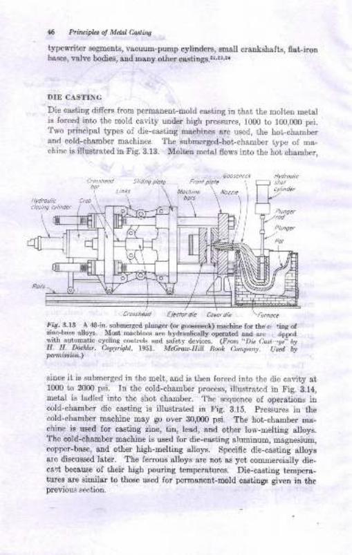
DIE CASTING
Die casting difrers from permanent-mold casting in that thc molten metalis forced into the mold cavity under high pressures, 1000 io 100,000 psi.Two principal typcs of die-castiug machites are used, the hot-chamberand cold-chamber machincs The submerged-hot-chamber type of ma-chine is illustrated in Fig. 3.13. Molien metal flows into the hot chamber,
\lIi"i\
Ejbcrol dic Core. dic
fig. 3.I3 A 48-in. submcrgEd pluDS€! (or Speeriec.L) machine for r.he c, linA ofrim-base alolB. Most rnachinB are hydEdicatl)' olEated aod arc ,ipp"dwir,h__automati€ cyclitrg controls and safety devic€s. (Fron',Dn Cast,-gi'1 AyII. H. tu h..r'. C,oWrisN. l95t- M&mu-Eill B@k Conpary. U;d WWfiittiarn.,
since it is submerged in ihe melt, and is then forced into the die cavity at10m to 2{00 psi. In the cold-chamber process, illustrated in Fig. 3.14,metal is ladled into the shot chamber. The sequence of operations iucold-chauber die casting is illustrated in Fig. 3.15. Pressures iD thecold-chamber machine may go over 30,000 psi. The hot-chamber ma-chine is ueed for caeting zinc, tin, lead, and other low-melting alloys.The cold-chamber machine is uEed for die-caeting aluminum, magnesium,copper-base, and other high-metting alloys. Specific die-casting alloyaare discussed later. The ferrous alloys are not aa yet commercislly die-cast becauee of their high poutiDg tempersturee. Die-casting tempera-tures are similar to thoge ueed for permsnent mold castings given in tleprevious section.
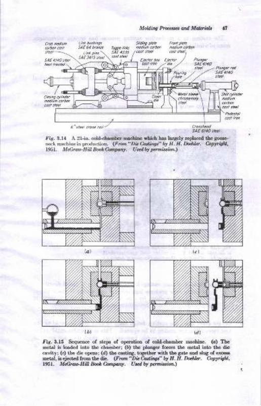
M ing Pttxcrret ard Makriolt
5AE 4JJ5
Fig. 3.14 A 2r-in. cold-chanber machine rbich bss largEly r€plac€d l,h€ goco-neck macbine in prodnctiou (Frtrn"Di.Cadinsl' br II. H. Mtla, bpyrirfiL1951. Md)ruEHiU B@hc,iunI,,try. UrdW pcrmbrbn.t
fig.3.t5 Seque&e of steps of operatiotr of cold-cbarober machine. (o) 'Ibemetsl is loaded into th€ chamberi (6) the pluryer fon:ea the metal into tho di6cavity; (c) th€ Cie opens; (d) the castios, toeether with the 8at ard slua of erc€$metal, is ejectad from the dia, (Fro,n"Di.C,attingr" W H. H. Ddnz. Copyrbha,195t. M&rarD-EiA Bo.L C,ornpry. Utdby pamision.)
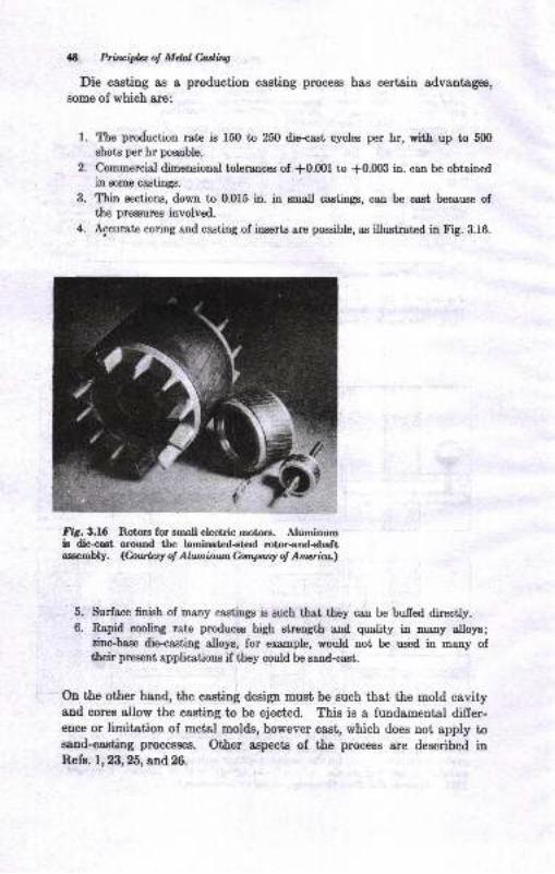
48 h&vifuot Meltuins
Die casting as I production casting pnocess has certain advantages,
eome of whioh sre:
Ite production rate is 150 to 250 die-csst cycles per hr, witl up to 500
shoto per hr possible.
Commercial dimensional tolerances of *0.fi)l to +0.003 in. can be obtainedin some castings.
Thin sections, down to 0Of5 h. in mall castinp, can be cast because ofthe pressures involved.
Accurate coring and casting of inserts are poosible, as illustrat€d in Fig. 3.f6.
Fig. A.16 Rotorg for small electric motore. Aluminumis die-ca8t around the laminatcd+teel rotor-and-shaftassembly. (hwhsy of Alwnhun Conpony of Amaim.l
Surface finish of many castings is zuch that they can be buffed directly.
Rapid cooling rate produces high strength and quality in many alloye;zinc-base die'casting alloys, for example, would not be used in many oftheir prcsent applications if they could be sand-cast.
On the other hand, the casting design must be euch that the mold cavityand cores allow the casting to be ejected. This is a fundamental differ-ence or limitation of metal molds, however cast, which does not apply tossDd-casting processes. Other aspects of the process are described inRefs. 1,23,25, and 26.
t.
2.
3.
4.
D.
6.
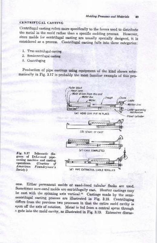
Milfiq processet ard, Mateials q,
CENTRIFUGAL CASTING
centrifugal casting refers more Bpecifically to the forces used to distributethe metal in the mold rather than a specific molding process. However,since molds for centrifugal casting are usually rpu.rutty designed, it isconsidered as a process. centrifugal casting falls into ih"ee itego.ies:
l. True centrifugal casting
2. Semicentrifugal casting.
3. Centrifuging
Production of pipe castings using equipment of the kind shown sche_matically in Fig. 3.lZ is probably the most familiar example of this pro_
(a) HEAD coRE pur tN pLAcE
lrorel cylnder
.Lodle
llollen iron
Fig. 3.17 Schematic dia-gram of De[.cvaud pipe-casting machine and castingoperatious. (Courhw ofAmerican Foundry'men"sfui.ty.)
gess' Either permanent molds or sand-lined tuburar flasks are used.sometimes core-sanJ molds are centrifugaily cast. shorter castings ;aybe c1{ with the spinnilg axis vertical.i. bastings made by the- semi_centrifu*al casting process are illustrated h Fig. A.18. 6""1;;f"girgdiffers from the previous two processes in that thJenfire *"ral""iii'i,spun ofr the axis of rotation. Metal is fed from a centrar sprue trrougha gate into the mold cavity, as ilrustrated in Fig. 3.1g. Exteusive discus-
(D) sranr or casr
(cl casr co[RETED
(dI PIPE EXTRACIED, LAoLE REFILLEo
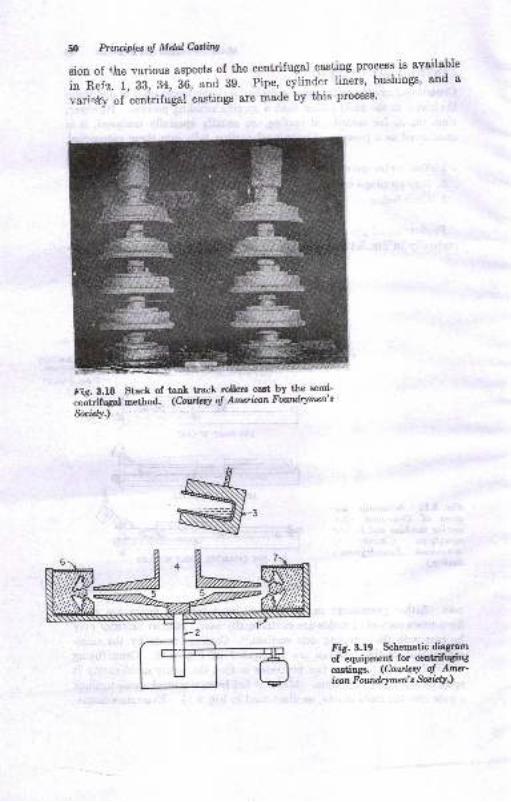
50 Prilipfuol Mtulfutatng
sion of +Jne various aspects of the centrifugsl casting process is available
in Refq. 1, 33, 34, 36, and 39. Pipe, cylinder liners' bushings' and a
vari+.ty of 'centrifugal
castings are made by this process'
Fie- 3.18 Stack of tsn} track rollem cast by tLe semi-
;&.ifrg"l method. (Cntttrq o! Am*ban Fowdrymen's
Socrlcty.)
Fig. 3.19 Schematic diagram
of equipment for entrifqiugcaetinge. (CourlcsY o! Aour-icon F ounilry men'e Soc 4Y)
ffi
M itg Ptw ud Motaiailt SI
BIBLIOCNAPEY
L {pericln__ FoundVmea,B Sociery, "MoldiDg Metods aod Matoriala,,, DeePlaioee, Ill., 196:1.
2, R. q _L. -{ldrews, "Shell Process Fouldry practice,,, Americao Foundry-
men's Society, Des Plainee, II., 1963.3. US. Naval AvioDics Iacility, Fundamentels of Itrvestmetrt C*ting,Indbn-
apol*,Ind-, Tech. Publ.6t, LgiB.4. Stael Foutrdem'Society of America, ,,gt€el
CsstinSs Eandbook," Clevelaod,3d d., 1960.
6. Gray Iron Founders, Society, ,,The Gray Irotr CastingB Eardbool,,, Cleve_lrd, 1958.
6. Malleable Fouoders' Society, ,,Malleable Irou CastiDss,,, Clevelsd. 1960.7. t. Uperhall, ()elsmic Shell, trozndrg, vol.96, p.6g, October, l95g.'8. W. C. Truckpp{uller, Evslustiotr of Sheli
-Molding ?roces Capability,
?r@rr. /fS, vol. 66, p. 81, tg58.L T. A. Dckinson, New Platrt produe Mercury hvestneDt Ca.stiags,
_- Fwnlry,lol.M, p.133, November,1956. '10.. R. GreeDwood, Cera,mic Mold ptof{,I,, I?anndry. JuDe. 1959. D- g4-It. -ti. tsr€her, New Proceeses U8ed 8t New Itvegtnent Cajing Foundry,
.Folrdry, Octabet , 195? , D. 94.12. A. Dunlop, Preciaion Castlngs h a figg€r Way, Moden Caatii1r, November,
1956, p. SO.
13.'I. C. QuiSf:ey and B. Bovamick, Sintered Atunios Molds lor IDyestrae
- . tlasting of Steels, ?roru. /fS, vol. 66, p. Z4Z, tg5f,14. I. Lubalir-and.R. J. C_lrist€lsea, Sh;; prc,;6s priociplee aud production,
'l rdL. ,{.t'S, vol. 68, p. 599, 1960.15. R. EerrrraDn, Itrv€stnent Sbell proceaa, pozzdry, December, 1g5g, p. g4.ro. rJ. J. l(entry, atld p. A. Rutt, Thickaes of precoat for Invesimeof iastilg,
.romdry, .tebruary, 1959, p.82.17. K.L. Mountain, Ccoeat Moldiry at Chr,Dberl*rwg, Foundry,,to: ,p.1@,Ncvenber, 1956.18. K. L. MouDtaiD, The Antioch procesa for MrliDg IDtricat€ plaster Mold_ - Yaty$, t'ourdry, rot.83, p. 101, Novehber, tg55.I9. C. W. Yaw, CastiDS lron p;tterd ilr Zir({,n'Sat1d,, fotnlry, vol. 86, p. 24,
October,1958.Z). R. Eerrmann, Duct e floo Tire Molds Cast by Complex process, Ioundry,
August, 1S60, p. m.
31 * YU:, Permanenrltfold Castilg8, poundry, January, 1960, p. 66.,2. U. L. (ioodritr .atrd E. y. Er.uxieker, Cyclic feroaneot Mili Op".atioo,
_ - uoEe 'lhemal Aaw.is, Trun$.,{]t's, vol. 67, p. ,131, lg5g.21. E. C. L€Eis, Low pressure Die Casting, rraru: rfs; ;;i-68, p. 268, 1960.2z. C. B. C\rt€s, Peroanenr Mold Castiri of nil;;, f;;';
";'i'st,i. gr,
Jatruary, 1958.%. M: !. Teneabaum, Selestiotr 8Dd Meltiry of Die Castilg Ntoys, Fotndry,
vol. 84, p. 92, Febmarv. 1956.26
P^.^Y:SJo"t"-, Prci;s" itr Vacuum Die CulbirlA, IruN..{fS, vol. 66, p.190, 1958.
'J:|;,1"Tliffr&-,'*.r,H;*"HxJffi [W:'il,a,iff ;:,*i.70, ao. 4, pp. 92-46, October, 1956.
5, Pfi,luipLrot Mddeadte
29. A.L.Feild, Jr., and R. E. Edetnan, The Use of Expendable Graphito {I3!dsin Production of Sor"a Ductile Tiianium Castings, Trarc' AFS, vol' &5' p'
517,L91i7.
30. E. w. A"tes, J. T. Norton, and R. E. Erlelman, Foundry chsrasteristics of
a Ra,mmed draphitic Mold M8t€ri8t for casting Titanium, ?rons. .r{.8S, vol.
66, p. 135, 1958.
31. J.'8. Mclntyre, Refractory Pemanent Molds, Foundry, vol' 80, p' 1(I2'
August, 1952.
s2. w.-F. Davenport and A. Strott, Investments for the Precision castinc
Process, Famdry, vol.80, JulY, 1952.
83. M- i. SL,muels i,ia l. p. Schuh, Some Recent Developments in Centrifugal
Castings, F oundrg, vol. 79, July, 19.51.
gl. i. Putix"*t"i, Castins Centriiuga[y in Graphite Molds, Foundry, vo1' 78,
Febmary, 1950.
35. t. L. Eiitkson, Die Coating for Permanent Mold Castings, Foutdry, vol'
X7, Febmary, 1949.
36. R. Nieman, Gntrifugal Casting, Trans- AFS, vol' 52, p' 349, 1944'
,t. K. G"i"t *a n. IrA. -Kerr,
Jr., Principles of Precision Investment CastingB,
Trarc. AFS,vol. 55, P. 17, 1947.g8. Diete* Process toiirecisio" Molds,.r{m. Foundrgman, vol' 25, p' 50, July,
1953.
3g. American Foundr5men,s society, "symposium on centrifugal casting,"
pubI.4437.
nO. if. noee"tlal and S. Lipeon, Inveshent Casting of Aluminum, Traru. AFS,
vol.60, 1952.
41. R. r.'Darton, some Practical Applications of Permeable Metal casting
Plaster, Trau. AFS,vol. 0, P- 351, 1952-
A. J.B. Mclntyre, Casting in Cement Bonded S*td, Fouttdry, vol' 80, p' 90,
December, 1952.
13. Anerican'FoundrJrmen's Society, "Cast Metals Eandbook," 4t'h d', 1957'
U. W . G, Lawrence, hecision Casting Mold Mrteriale , Tratu' d/S, vol' 68, p'
456, 19fl).
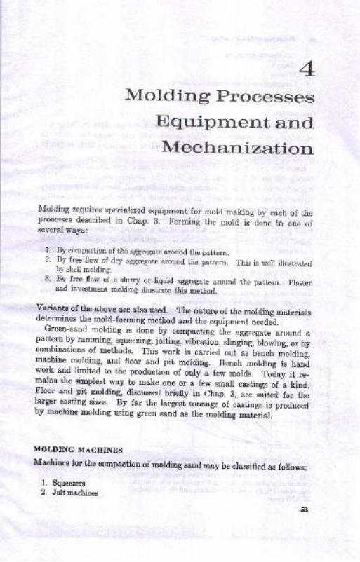
Motding ProcessesEqr.ipnr.err.t andMeckrartization
Molding requires specialized equipment for mold making by each of theprocesses described in chap. B. Forming the mord is done in one ofseveral ways:
1.. By compaction of the aggregate around the pattern.2. By free flow of dry aggregate around. the pattern. 'r-his is well illustrated
by shell molding.3' By free flow of a slurry or liquid asgregate around the pattern. praster
and investmenl pn6lrting illustrate tlis metlod.
variants of the above are arso used. The nature of the molding materiarsdetermines the mold-forming method and the equipment neede=d.
Green-sand molding is done by compacting the aggregate around ap"tt3 by ramming, squeezirrg, iolting, vibration, slinging, -Ulowing,
or bycombinations of methods. This work is carried out as bench *otaiog,machine molding, and floor and pit molding. Bench molding is handwork and limited to the production of only a few molds. foiay it .e_mcins the simplest way to make one or a few small castings of a kind.tr'loor and.pit molding, discussed briefly in Chap. 3, are suited for theIarger casting sizes. By far the largesi tonnage of castings is proauceaby machine molding using green sand as the molding mate-rial.
MOLDINC MACHINES
Machines for the compactiou of mording sand may be classified as foilows:
1. Squeezers
2. Jolt pashinss
5:l
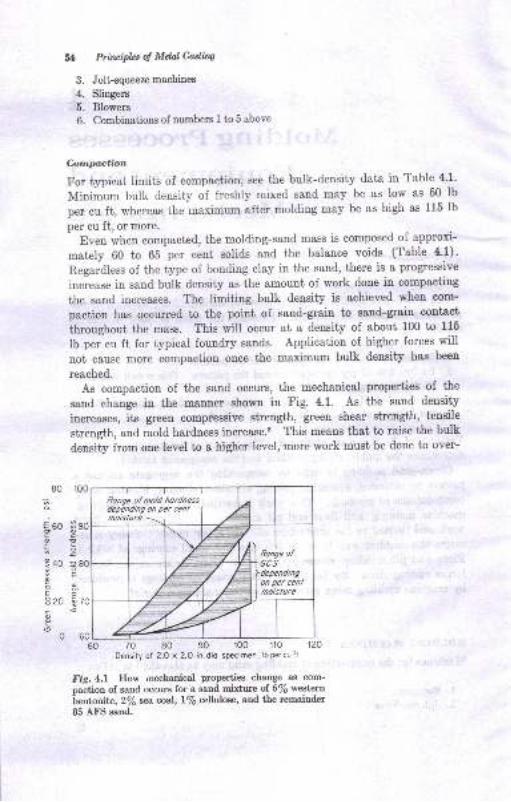
Prircipla o! MdalCadiq
Jolt-squeeze machines
Slingers
Blowers
Combinations of mrmbers 1 to 5 above
hnpaction
For typical limits of compaction, see the bulk-density data in Table 4'1'
Minimum bulk density of freshly mixed sand may be as low as 50 lb
per cu ft, whereas the maximum after molding may be as high as 115 lb
per cu ft, or more.
Even when compacted, the molding-sand mass is composed of approxi-
mately 60 io 65 per cent solids and the balance voids (Table 4'1)'
Regardless of the type of bonding clay in the sand, there is a progressive
increase in sand bulk density as the amount of work done in compacting
the sand increases. The limiting bulk density is achieved when com-
paction has occu$ed to the point of sand-grain to sand-grain contsot
lhroughout the mass. This will occur at a density of about 100 to 115
Ib per cu ft for typical foundry sauds. Application of higher forces will
not cause more compaction once the maximum bulk density has been
reached.
As compaction of the sand occurs, the mechanical properties of the
sand change in the manner shown in Fig. 4.1. As the sand density
iucreases, its green compre8sive strength, green shear strength, tensile
strength, and mold hardness increase.e This meaus that to raise the bulk
density from oue level to a higher level, more work must be done to over-
80 r00
70 80 90 100 110 120
Density of 2.O x ?.O in. dio specimen, lb per cu fl
#
J.
4.
5.
6.
,a
560 B,cc
940 0';oaF
hx920 ;c<
0 60L60
Fis.4.l How mechanical properties change as com-
oaction of sand occurs for a eand mixture of 6/6 western
Lentonite, 27o*.aqst,l% cellulose, and the remainder
85 AFS satrd,
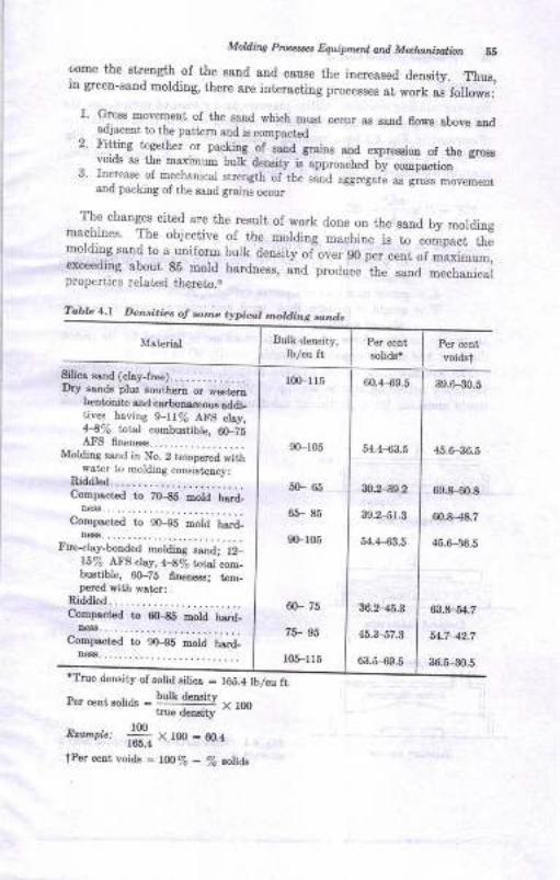
Moldi.a ptrtrrw Equipn1ctt arut Matunirditr. 55
come the Btreogth of the 8and aDd cause the increased density. Thur,iu greeu-aand molding, there are interacting processes at work
"i i"ff"r",
1. Gross DoveneDt of the sa.od which must occur as eaod florrg abor.o aodadjacent to tbe patt€rtr ard is compacted
2. Fittirg ti8ether or pacting of 8a,Dd graiD8 aod exprecion of the crGvoids as tbe EaximurD bulk delsity t"pp-*h"d ;, ;p";;- "'*
3. Incrcase of mechanical strcngth of-the sand ,gg"g*'" ; gG-.-"""_*,and packing of the sand graim occur
The cbanges cited are the result of work done on the saud by moldiugmachjnes. The objective of Lhe molding .".hio" i" to;;pJ;"molding ;aud to a uniform bulk density of-over gO pe";; Jil;;;,exceedilC about
_85 mold hardness, and produce the ,*a .""fr-*ilf
Propertres related tltereto.r
?ablc 1.1 DeBi.ics of som? t tpi@, notding ,o..ds
'True deDsity of solid silics = t68.4 lblcu ftPer cetrt solids = l* **l," , ,oo
IrUO deDaty
E*'"rr", #iX rfl) - 60.4
tPer cort voids - t@7o - Zo ,r(,li&
Material Bult deDsity,
lblcu ft soiids.Per centvoidst
Eilice BsDd (cley-lt€e).D5r eaade plus Bouth6rn or restem
beDtoDito snd csrbolrceols rddi-tives haviDs 9-lr% A.I'f, clsy,H% tal,sl coEbustible, 6(FZsAFII 6neneas. . . . . . . . . . . . . . . . . .
MoldiDa 6and in No. 2 teDpered witlwater Lo Eolding coD.sisteDcv:
Riddt6d.. . .... ....... ........--Compoct6d to Zo-ES Eold h!rd.
De6S_..,......................CoDpactad to gO-9S mold b.srd_
,r€€a..,.,......................Fire-clay-bonded motding saDd; t2_
15% AFg c.lay, +.E% rotul c!m_butible, @-75 f.tretress; teD_pered irith wster:
Ridd16d........................CoDpoctod to €{H6 Dold hrrd_
,18........,..,...........--.Coepr.ted to g{H5 hold h.srd-
De44............_.............
lm lr5
90-105
60_ 65
65- 85
0G105
N- 75
75- 95
105-l 15
60.4-$9.5
54.4 {i3.5
30.2-39_2
39.2--51.3
54.443.5
36.2-45.3
45.347.3
6:].S69.5
39.6 30.5
45.6-36.6
691-00.8
60.8-48.7
45.6-36.5
63.8--5{.7
54.7-42.7
36.5-30.5
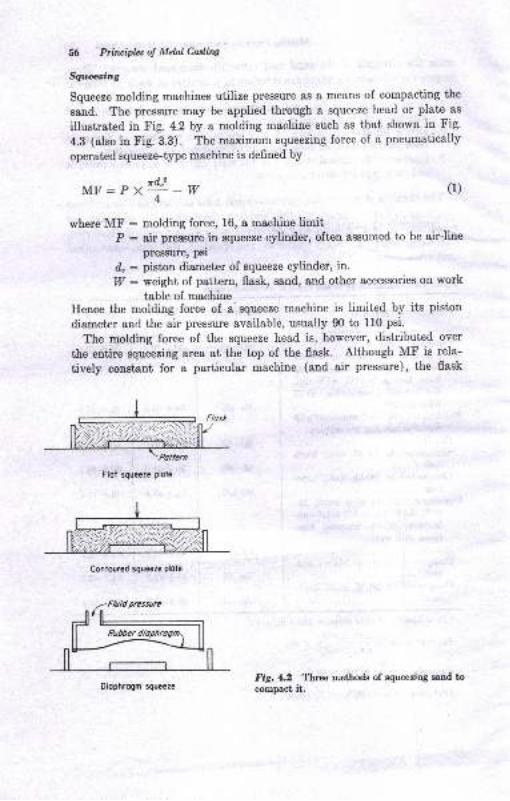
56 Priruiphs oJ Metal Casting
Sqrcezing
Squeeze molding machines utilize pressure as a means of compacting the
sand. The pressure may be applied through a squeeze head or plate as
illustrated in Fig. 4.2 by a molding machine such as that shown in Fig'
4.3 (also in Fig. 3.3). The maximum squeezing force of a pneumatically
operated squeeze-type machine is deflned by
MF:P "*-*
(1)
where MF : molding force, 16, a machine limitP : air pressure in v;ueeze cylinder, often assulned to be air-line
pressure, psi
d" : piston diameter of squeeze cylinder, in.
I;I/ : weight of pattern, flask, sand, and other accessories on work
table of machineHence the molding force of a squeeze machine is limited by its piston
diameter and the air pressure available, usually 90 to 110 psi.
The molding force of the squeeze head is, however, distributed over
the entire squeezing area at the top of the flask. Although MF is rela-
tively constant for a particular machine (and air pressure), the flask
Flot squeeze plole
Coniour€d squeeze plote
Fig. 4.2 Threo methods of squeedog sand tocompact it.
Flos*
Diophrogm squeeze
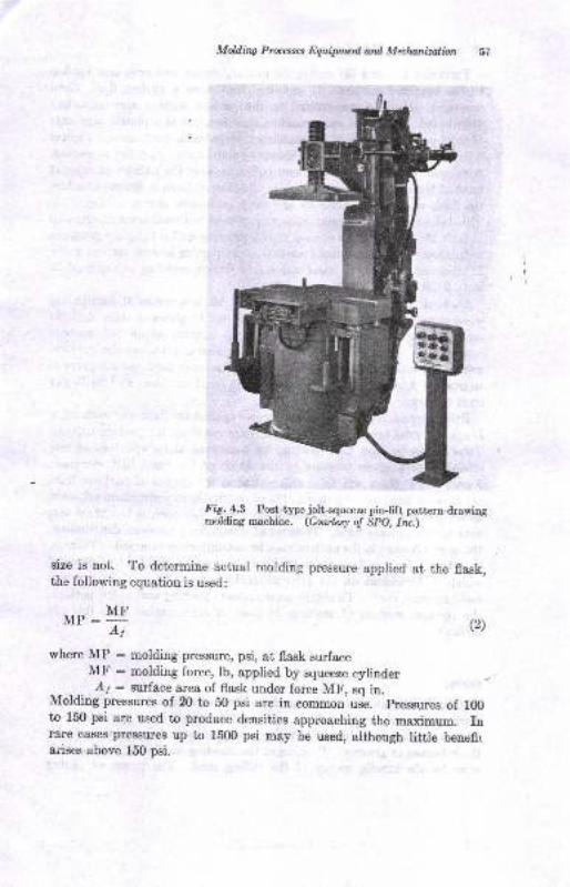
Molding Processes Equipmeil and Meclnnizotion DI
Fi g. 4.3 Post-type jolt-squeezc pin-lift patterndrawingmolding machine. (Courtesy oJ SPO, lru.)
size is not. To determine actual molding pressure applied at the flask,the following equation is used:
MP:YI,rr, - A, (2)
where MP : molding pressure, psi, at flask surfaceMF : molding force, lb, applied by squeeze eylinder
_ _ _ -. Ar: surface area of flask under force MF, sq in.Molding pressures of 20 to 50 psi are in common use. pressues of 100to 150 psi are used to produce densities approaching the maximum. Inrare cases pressures up to 1500 psi may be used, although little benefirarises above 150 psi.
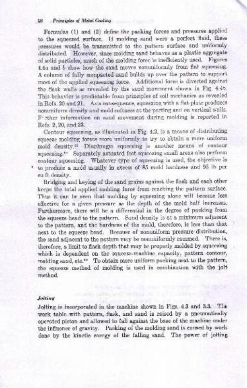
58 Priuipbs ol Mel Culitw
Formulas (1) and (2) define the packing forces and pressures applied
to the squeezed surface. If molding sand were a perfect fluid, these
pressures would be transmitted to the pattern surface and uniformly
disiributed. Ilowever, since molding sand behaves as a plastic aggregate
of solid particles, much of the molding force is inefficiently used. Figures
4.4a arid b show how the sand moves nonuniformly from flat squeezing'
A column of fully compacted sand builds up over the pattern to suppori
most of the applied squeezing force. Additional force is diverted against
the flask walls as revealed by the sand movement shown in Fig. 4.4b.
This behavior is predictable from principles of soil mechanics as revealed
in Refs. 20 arld2l. As a consequence, squeezing with a flat plate produces
nouuniform density and mold softness at the parting and on vertical walls.
F'rther information on sand movement during molding is reported in
Refs. 2,20, and 23.
Contour squeezing, as illustrated in Fig. 4.2,is a means of distributing
squeeze molding forces more uniformly to try to obtain a more uniform
mold density." Diaphragm squeezing is another means of contour
squeezing.le Separately actuated feet squeezing small areas also perform
contorr squeezing. Whatever type of squeezing is used, the objective is
to produce a mold usually in excess of 85 mold hardness and 95 lb per
cu ft density.
Bridging and keying of the sand grains ageinst the flask aud each other
keeps the total applied molding force from reaching the pattern surface.
Thus it can be seen that molding by squeezing alone will become less
effective for a given pressure as the depth of the mold half increases.
Furthermore, there will be a differential in the degree of packing from
the squeeze head to the pattern. Sand density is at a minimum adjacent
to the pattern, and the hardness of the mold, therefore, is less than th$t
next to the squeeze head. Because of nonuniform pressure distribution,
the sand adjacent to the pattern may be nonuniformly rammed. There is,
therefore, a limit to flask depth that may be properly molded by squeezing
which is dependent on the squeeze-machine capacity, pattern contour'
molding sand, etc.ls To obtain more uniform packing next to the pattern,
the squeeze method of molding is used in combination with the ioltmethod.
lolting
Jolting is incorporated in the machiue shown in Figs. 4.3 and 3.3. Tire
work table with pattern, flask, and send is raised by a pneumatically
operated piston and allowed to fall against the base of the machine under
the influence of gravity. Packing of the molding sand is caused by work
done by the kinetic energy of the falling sand. The power of ;olting
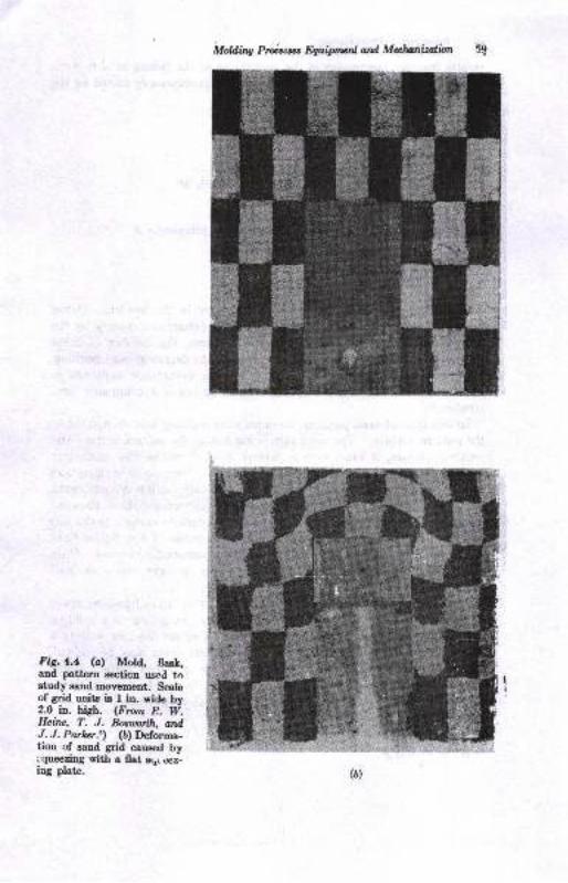
Moldilw Proicttcs fuiiprrun ard Mahonizalion
Fig.4.4 (a) Mold, flas}.,and pattern secticn uscd tastudy sand movement. Scaleof grid units is I in. wide by2.0 in. high. (Frcrn t!. W.Heine, T. J. Bosu:orlh, ordJ. J. Parher.r) (b) Deforma-tion of eand grid caused byrqueezing with a flat sqr.rz-iog plate.
';'- iltl
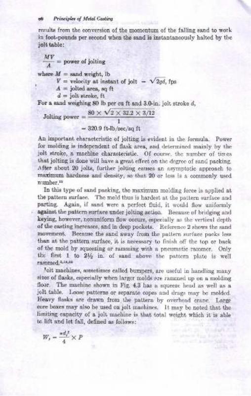
a1t PlituipLt o! Mdal Castinq
reflrlts from the conversiotr oI the momeDtum of ihe falling sand io workia foot-poundr per secoud when the Band iB i.ustantaDeously halted by tlrejolt toble:
IfiV-----:- = prower of jolting
where M : soud weight, lby : velocity rt i*taot oi iolt, : l2gd, lps/ : iolted sres, Eq ftI : j6lt stroke, ft
For o saud weighing 80 lb per cu ft and 3.Gin. jolt stroke d,
' Jolting power =80x./2xgL2xVtz
: 320.9 ft-lb,/seclsq ft
Aa important characteristic of joltiug ie evident in ihe Iormula. Powerfor molding ie iadependent of flask area, and determined mainly by thejolt stroke, a machine characieristic. Of course, thc number of iin,esthat jolting ia done will have a great efieci or the degree of sancl packing.Aft€r 8bout 20 jolts, further jolting cauees an aslrmptotic approach tomaximum hardness and density, so thet 20 or Iess is a commonly usednumber-22
Ia this type of sand packing, the maximum molding Iorce is applied atthe patteru surfsce. The motd thus is hardest at the patiern surface andpsrting. Ag8in, if sand were a perfect fluid, it would flow uuiformlysgaiDst t}te psttern suriace under ,iolting actioa. Because of bridging andkeying, however, r.onuniform flow occurs, especially as the vertical depthof the castiag increases, and in deep pockets. Reference 2 shows the sand
movement. Because the Bsnd away lroE thc peitem surfacc packs less
tlan at the patiern surface, it is necessary tr., finish ofi the top or backof the mold by squeezing or ramming with e pneumatic rarnmer. Onlyth€ first, 1 ta 2t/2 ir.. oI sand above the pattern pllte is wetlramEed.,tle',,
.Ioit machines, sometimes called bumpers, are useful in handling manysizes of flasks, especially when larger molds ere rammed up on a moldingfloor. The machine shown in Fig. 4.3 has a squeeze head as well as ajolt table. Loos€ patterne o! separate copes and drags may be rnolded.Heavy flasks are drawn from the pattern by overhead crane. Largecore boxes may also be used on jolt machines. It may be noted thst thelimiting capacity of a jolt machiue is that total weight which it is atrletc lift aod let fall, defiued as follows:
W,: J\ P
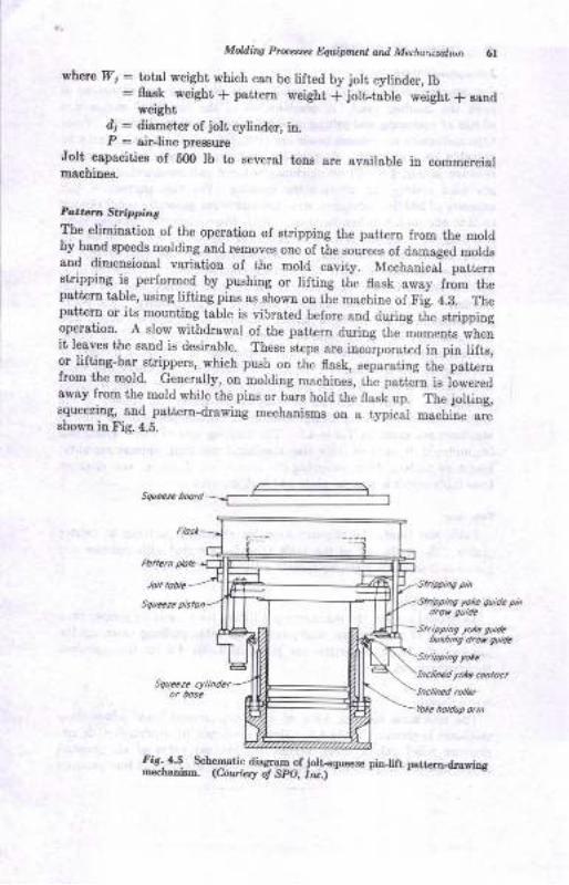
M V p&aa, huiprq! o,rtt Marla..irnlu1 6l
where 71 : total weight which can be lifted by jolt cylinder, lb: Reek weight * pattern weight f jolt-table weight t g*od
Eeightd; : ,Iirmstep e1 ;oltr cylinder, itr.P : air-line preesure
0olt capacitiee of 600 lb to geveral tons ere availsble in codmercialmachines,
Po.t rr. St irtpintThe elimilation of the operation of etripping the pattero lrom the moldby hand speeds molding and removes one of the sou"ces ol damsged moldsand dirueueioual variatiou of the mold cavity. Mechanical patterntrpohg j: p€rformrd by pushiug or liltiug the flask away from thepattera table, ueiag lilting pins as shown on the machine of Fi;. 4.8. Thepattern or its mounting table ie vibrated belore and duiug the strippiogoperatiou. A slow wiihdrawal of the pattern durirg the io-euta wheoit leaveg the sand ie deeirable. These stepa are incorporatrcd in pin liIts,or liftiag-bar strippera, which push on the flask, separating the patternfrom the mold- Generally, on moldiug machinei, ttie patt in ie loweredaway from the mold while the pins or bars hold the flask up. The joltiug,squeezing, aud pstt€ro-drawiDg mechanismr on a typical machine greehowu ia tr'ig. 4.6.
Sclrcrz. beld -{::::_=
Stripping )/otc guideblshilrg dro, guidc
Inclmcd lctc coDloct
fir. 4.5 Scb€rnatic diaAram of jolr-€queez€ piD_lifr pstt4rlrdlariDAB€cDaD]rnr. (Courlet! ol SPO, tN.\
6,, Prhuipbt of MdalMirq
lolt-sqtac* Mochitws
Jolt-squeeze mechines utilize a combination of jolting and squeezing to
pack the molding sand. A combination of the beneficial compaction
effects of squeeziDg and jolting on sand density is then obtained. Post-
type and cantilever Bqueeze heads are available, aqd the machines may be
portable or stationary. A portable post type squeeze-head machine
is shown in Fig. 4.3. These machines, without pattern-drawing features,
are used mainly for match-plate molding. For this purpose a joltcapacity of 500 lb is adequate, since the molds are generally small enough
so that one man can handle them. With the matchplate between cope
and drag, the drag half is molded first, using the jolt action. The bottom
board, fitting inside the flask, can be jolted against the sand to seat it.Then the assembly is rolled over and the cope molded. On most match-
plate work this is done by squeezing with a Bqueeze plate that fits inside
the flask. Thus cope and drag are squeezed simultaueously. The pour-
ing basin can be molded by a pattern attached to the squeeze board, and
the sprue may be cut by hand or attached to the pattern. IVlatch-plate
moldiug using jolt-squeeze machines is perhaps the simplest method of
speediug up the molding. If a pair of jolt-squeeze machines are used,
one machine may be used for making copes and one for drags, to speed
up molding. A third mau can function as core setter and helper. Some
typical machine-capacity characteristies of certain jolt-squeeze pin-liftmachines are given in Table 4.2. The limiting gize of,mold which can
be produced depends on table size, maximum jolt load, squeeze capacity,
height of pattern draw, stripping-pin center-line distance, and distance
from table center to squeeze plate and back support.
Tabb Sizz-
Table size limite the effeciive area for attaching patterns or bolster
piates. Thc undeisidsdi tire work table rs provided with recesses and
plaees to bolt the pattern equipment solidly to the table.
Moilmun JoA l-nad
As defiued earlier, the maximum jolt lifting force must be greater than
the weight 61 sllipatterns, flask, sand, and table pushing down ou thejolt piston. These capacities are given in Table 4.2 for the machines
being considered.
Sqweze Capadly
The maximum molding force of some typieal p,mall-size jolt-sqtreeze
machines is given in Table 4.2. Many machincs Te equipped with air-pressure relief valves which permit any desired value of air pressure
below that of line pressure to be applied. For example, if line pressure
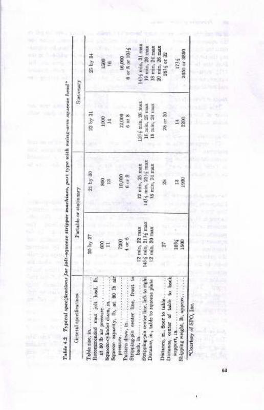
E,,t
siiiifs-Efis
oa
*8
5
55
3
E
x
o E* E
! '- E? F*x - -8N I': F
! -9
- ES E
l "- e! sn8 - x8N EEE
&
:!::;;:s:aa :t::.t .::..E .5:' i: i:,i,r!.i;.;g ti it' ! E! . .= o a d
.EEi;.,f;:*;;:ii
reiisafu;Hi liB*gffffasg;;E j;*g
{
I
q
E
!
'1.!t:t
trl
63
G Principlcs ol Melal Costiw
is 80 psi, the relief valve may be set to bypass anything over 50 psi in
the squeeze cylinder. Then the actual molding force is some value. less
than lhe *r*i^u*, and can be calculated by Eq. (1). Thus, by adiust-
ing the air-pressure relief valve, the molding force can be adapted to the
flask size to result in a sq':eeze pressure [actual molding pressure, Eq'
(2) ] suitable to the casting requirements. Currently recommended
squeeze pressures vary from 25 to 150 psi, depeoding on the casting size
and metal cast.2'
HeigW o! Paltern Drau
This dimension limits the pattern depth which can be drawn free and
clear of the mold. If addit onal lifting straight up can be done with
hoists, much deeper patterns can be drawn.
Strippirq-pin Cenler-line Distarce
The stripping pins are adjustable through a swing of 3600 and in several
positions. The pin center-line distances determine the mimimum and
maximum size flask for which the machine is intended. This is indicated
in Table 4.2 lor sonre typical machines. Bars, frames, or yokeS may be
used' in place of stripping Pins.
Cartype folt-squeeze Stripperc
Large-size jolt-squeeze stripping machines are often used in high-produc-
tion work for medium-size castings. A car-type jolt-squeeze stripper,
having a 21-in.-diameter squeeze piston, is shown in Fig. 4.6. The jolt-
squeeze action is similar to that of the machines already considered. The
squeeze plate consists of a car mounted on wheels and a track' In the
squeeze position, the car is rolled over the mold before squeezing and
funetions as the squeeze plate. Stripping is accomplished by lowering
the pattern away from the mold while the strip frame or stripping rails
hold up the flask. The flask is removed from the machine when the
squeeze-platen car is rolled out of the squeeze position. Lifting hooks
on the car engage the flask, carry it out, and deposit it on a roll-out eon-
veyor. The machine is used for making copes and drags, although drags
must be rolled over outside the machine. It is especially suited to pro-
duction work when only one size of flask is used, so that the roll'out
conveyor and stripping frame are standardized.
I olt -rocleooer P ottzr n D r au
The jolt-rockover pattern draw is a machine used for separate cope snd
drag work, molding the drag only. The drag is jolted and then finished
off by pneumatic ramming and beddiug in of a bottom board. The drag
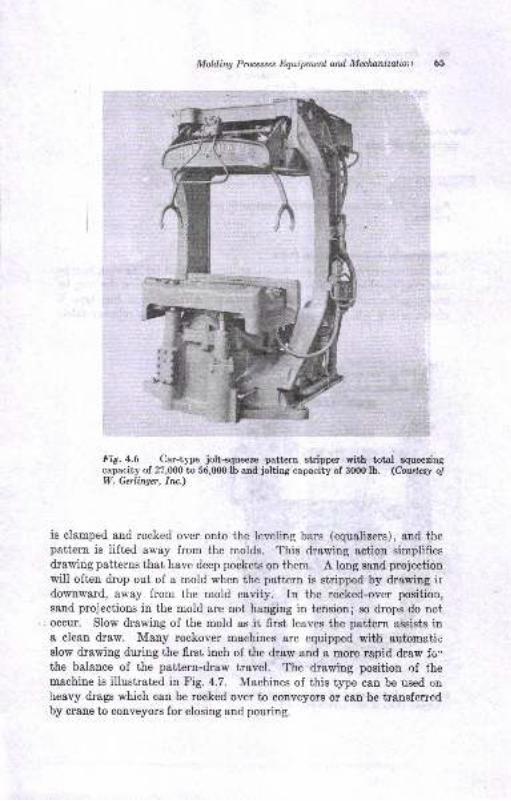
Mokliw Processes Dquipmenl ard Metlunizalini t
Fig.4.6 Car-t1'pe jolt+queeze pattern stripper with total squeezingcapacity of 27,000 to 56,000 lb and jolting capacity of 3000 lb. (Courtesy o!W. Gerlinger, Iru.)
is clamped and rocked over onto the leveling bars (equalizers), and thepattern is lifted away from the molds. This drawing action simplifiesdrawing patterns that have deep pockets on them. A long sand projectionwill often drop out of a mold when the pattern is stripped by drawing irdownward, away from the mold cavity. In the rocked-over position,sand projections in the mold are not hanging in tensionl so drops do notoccur. SIow drawing of the mold as it first leaves the pattern assists ina cle&n draw. Many rockover machines are equipped with automatir:slow drawing during the first inch of the draw and a more rapid draw fo'.
the balance of the pattern-draw travel. The drawing position of themachine is illustrated in Fig. 4.7. Machines of this type can be used onheavy drags which can be rocked over to conveyors or can be transferredby crane to conveyors for closing and pouring.
"ffi
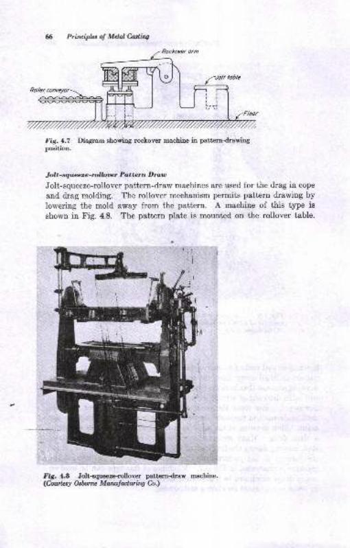
Printiplns ol Mctal Casling
Fig. 4.7 Diagram showing rockover machine in patterndrawingposition.
J olt - squeeze -rolbwr P atter n D rau
Jolt-squeeze-rollover pattern-draw machines are used for the drag in cope
and drag molding. The rollover mechanism permits pattern drawing by
lowering the mold away from the pattern. A machiue of this type is
shown in Fig. 4.8. The pattern plate is mounted on the rollover table.
Fig. La Jolt<queeze.rollover patterndraw machine.
<hurlzsy Osbrne Matldwilq h,)
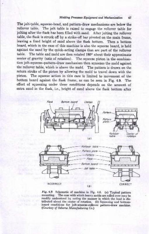
Mohli,q Pft",t t E$ript ot atd Mds iration AI
The jolt-{able, squeeze-head, and pattern-draw uechaniens are below therollover table. The jolt table is raieed to engage the rollover table forjoltiug after the flask hae been filled with s8Dd. After jolting the rollovertable, the flaek is struck ofi by a strike-ofr bar pivoted on the main frame,leaviag a fixed height of sand above the flaEk bottom. Then s bottoEboard, which in the case of thie machine is also the squeeze board, is heldsgaiDst the sand by tbe quick-acting clamps that ale part of the rollovertable. The table and mold are then rotated 18Oo about their approximatecenter oI grevity (axis of rotation). The squeeze pieton it the combina-iio! iolt-squeere-psttern-draw mechaoism then squeezes the mold againstthe rollover table, which is above the mold. The patteru is drawu on ihereturn etroke of the piston by allowing the mold to travel dowa with thepiston. The squeere sction in this case is limited to movement of thebottom board sgaiD8t the flask frame, as can be seen iu Fig. 4.9. Theeffeci of squeezing under these conditions depends on tbe amount ofextra saod in the flask, i.e., height of sand above the flask bottom after
lat
INCORRECT COFRECT(D)
fig,4.9 Scbematic of rnachine iD llg. 4.8. (o) Typicaf pattemmoutrtil,g. The e€.s€ rit"b which hearl motds are rolled over moy bereadily urdeEtood by Dotitr8 rh€ mair:er is whicb r,be load is'djs-lribut d about the cert€I of rotation. (b) SqueeziEg &Dd bottom-iDard cooditions for .iolt-squeeze{olloyer pattamdiay macbiae.(CadlLrr o! O.b u MaNr|adurins Ca.,
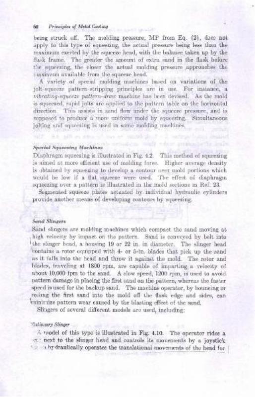
Od Prin ipbt o! Melal Catling
being struck off. The molding pressure, MI: irom Eo^. (2), docs nor
apply to this type oI squeezing, the actual pressure being less than ihe
maximum exerted by the squeeze head, with the balance taken up by the
fl rsk frame. The greeter the amount ol extra sand in the flssk belore
tle squeezing, the closer the aciual molding pressure approaches th€
irraxirnrrm available from the squeeze head.
A varieiy of special rnolding machines based on variations of thejoli-squecze pattern-stripping principles are in use. tr'or instance, auibrating-squeeze pattern-drau machine h:rs bccn devised. As the mold
is squeezed, rapid jolts arc applied to the pattcrn table on the horizontaldireciion. This assists in sand flow under thc squeeze pressure, and issupposed to produce a more unifonn mold by squeezing. Simultaneouejolting and,squeezing is used in some rnolding maehines.
Spociol S qutnzins M achin es
Diaphragm squeczing is illustrated in Fig. 4.2. This method of squeezing
is timed at more emcient use of molding lorcc. Highcr average density
is,rbtained l-y squeezing to develop & contour over mold portions whichlrculd be low il a flat squeeze were used. The eflcct of diaphragrn
squeezing ovcr a pattern is illustrated in the moid sections ia llef. 23.
Segmcnted squeeze plates tictusted by individual hydraulic cylindersplovide auoiher means of developing contoun by squeezing.
jond Sriaserr
Sand slingers are molding machincs which compact the sand moving si
,high veJocity by impact on the pattem. Sand is conveyed by belt intor,ihe slinger head, a housing 19 or 22 in. in diameter. The slinger head'contains a rotor equipped with 4- or S-in. blades that pick up the sand
as it falle into the head and throw it against the mold. The rotor aodblades, traveling at 1800 rpm, are capable of imparting a velociiy ofabout 10,000 fpm to the sand. A slow speed, 1200 rpm, is used to avoidpattern damege in placing ihe flrst sand on the pattern, rrhereas the f&st€rspeed is used for the backup sand. The machine operator, by bouncing or
,r'orlrng the first sand inbo the mold ofr the flask edge and sides, canhinir rize pattern wear caused by the blasting effect of the sand.
Sliirgers of seyeral difrerent models are used, including:
s!, ionar! Slingct
.". uodel of this type is illustratcd in Fig. 4.10. The operator rides acl uert to the slinger head and controls its movelreDls by a ,joysticrr
r r r hydraulically operates ihe translatioaal movements of thc head for
Moldiru Pruesses fuuipnlenl ard Mqlunizatlon G
Fig.4.l0 Stationary speed slinger. (Courtesy oJ Beardsby-Piper Dioision,Pettibore M ullih"en Corp.)
filling the flask. The slinger is fixed in its location and is used for ram-ming up molds that pass under its head on a conveyor or conveyors.
Other stationary models may be operated from remote-control positions.
Tractor Sand Sltnger
A tractor slinger can do its own sand conditioning by picking up sand
from windrows, reconditioning it, and feeding it back to the slinger head
which travels behind. The tractor slinger can ram up molds which are
within reach of the slinger head.
lllotiu Slingers
These are fed with conditioned molding sand in tanks. The unit travelsoil rails and can ram up molds anywhere within reach of the arc ofslinger-head rotation (Fig. 3.5). Motive slingers are genera,lly used inproducirg medium and larger sizes of castings, for floor and pit worklocated along the track traveled by the unit. Especially in large work.tirey have the advantage of filling the flask rapidly and ramming the sendat the same time.
r"'tl !i.-fr
"..;EN:"t,EH
ffi$t',.
-a
!.
o{ff -
: *u..*=.tt1
ffi
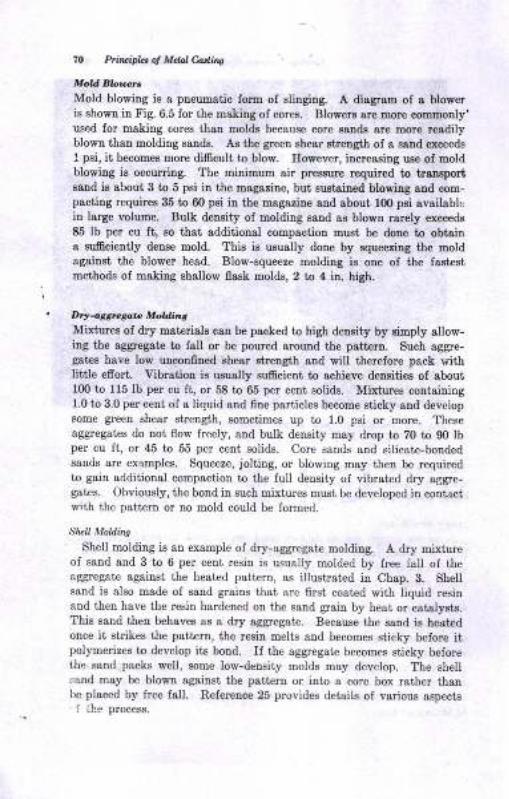
7O Pzlnriplrl 6 Mdal Cadilrq
i/old EbtnnMold blowiug is a pneumatic form ol slinging. A diagram of a blow€ris shown in Fig. 6.5 lor the making of cores. Blowers are uorc comDody'used lor making eores than oolds because core sglds are Dore r€adilyblown than molding sands. As the green ahear strength of a sand exceeds
1pei, it becomes more dificutt to blow. However, increaeiag uee of moldblowing ie occuring. The minimum air prrssure requhed to trsDsportsrnd iB about 3 to 5 psi in the magaziue, bui aurtained blowing aDd com-psctitrg requireo 35 to 60 psi iu tbe magaaine and about l0O psi availablcin large volumri. Bulk denaity of uolding saDd 8s blos! rarely exceeds
E5 lb per cu ft, oo that additional coupaction must, be done to obtain8 sufrcieDtly deuee mold. This ia usuatly done by squeezing the uoldagainrt, the blower head. Blow-squeeze molding is orc of the fssie8tmethode of making ehallow fl8sk molds, 2 to 4 in. high.
DrJattrceat DlokEnt
Miriuree of dry materials cau be paoked to high deuity by aimply 8llow-ing the aggrcgate to fall or be poured around the pattern. Such sggre-gat€s have low ulconfined ahear atrength aud will ttrerelore p&ck withlittle efrort. Yibration ie uaually sufrcient to achieve deueitieB of about100 to 115 lb per cu ft, or 58 to 65 per cent solide. Mirtures containing1.0 to 3.0 per cent oI a tiquid and fine particles become gticky aud developsome green shear strength, sometimes up to 1.0 psi or more. Theseaggreget€s do rot flow freely, and bulk densiiy may drop to 70 to 90 lbper cu ft, or 45 to 55 per cent eolids. Core sands and silicate-bondedsands are examplee. Squeeze, jolting, or blowing may theu be requiredto gain additional compoction to the lull deasity of vibrsted dry a[gre-g8tes. Obviously, the bond in such mixtures must be developed itr contactwiih the pattem or no rnold could be Jormed.
SheU Moldins
Shell molding ie au example of dry-aggregat€ molding. A dry mixtureoI sand aud 3 to 6 per cent rcsiu is usually molded by Jree fall of the&ggregate sgsiDst the heated pattern, as illustrated in Chap, B. Shellsand is also made of seud grains that are 6rst coated with liquid resinand theu have the resin hardened on the sand grain by heat or catalysts.This eand tbeu behaves as a dry aggregate. Becsuse the ssnd is heat€donce it strikes the patt€m, the resin melts and becoxoes sticky belore itpolymerizes to develop its boad. If the aggregaie becomes sticky beforethe sand packs well, some low-deusity molds may develop. The ahellsnnd may be blown againsi the pattelD or into a core box rathe! thanbe placed by lree fall. Relerence 25 provides details of various ospects1 ih-- proces8.
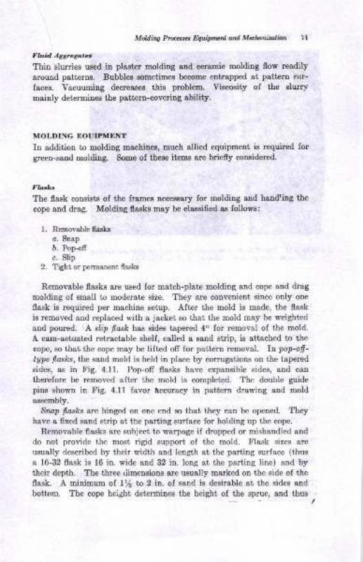
Moldirtg fuutt t Eq,.lipttulrl ad Matanizalbn ? I
Fh.id A6grego.e,
Thin islurries used in plasier moldiug 8Dd cerauic moldiDg flow readily
alound patterDs. Bubble8 Bometixoes b€coEe entlapped at pstt€rD silr-
faces. Vacuuming decreases ihie problem. Viscosity ol the sturymaiuly determines the patteru-coveriug ability.
MOLDING NOUIPMENT
In addition to moldiug machinee, much allied equipment is required forgreen-sand molding. Some of these items ale briefly coosidered.
The flask consists of the frames necessery for molding and handling the
cope and dreg. Molding flaske may be claeeified ae followe:
1. Removable flasks
o. Snap
b. Pop-ofr
c. Slip2. Tight or permanent flasks
Removable flasks are used for m&ich-plate molding and cope and drag
molding of small to moderate size. They are convenient since only one
flask is required per machine setup. After the mold is made, the flask
is removed and replaced with a jacket so that the mold may be weighted
and poured. A. slip flask has sides tapered 4" for removsl of the mold.
A cam-actuated retractable shelf, called a sand sirip, is attached to the
copc, 60 that the cope may be lifted ofr for pattern removal. 7n pop-ofi-
type f,asks,lhe sard mold is held in place by corrugations on ihe tapered
sides, as in fig. 4.11. Pop-ofi flasks have expansible sides, and can
therefore be removed alter the mold is completed. The double guide
pins shown in Fig. 4.11 favor lccuracy in pattero drawing and mold
assembly.
Srwp flasks are hinged on one end so that they can be opened. Theyhave a frxed sand strip at the psrting sur{ace for holding up the cope.
Removable flasks sre subject to warpage if dropped or mishandled and
do noi provide the most rigid support of the mold. Flask sizes sre
usually described by their width and length at the psrting surface (thus
I 16-32 flask is 16 io. wide and 32 in. Iong at the parting line) and bytheir depth. The three riimensions are usually marked on the side of the
flask. A minimum of ly2 t& 2 in. of send is desirable at the sides and
bottom. The cope hcight deterrhines the height of the sprue, and thus
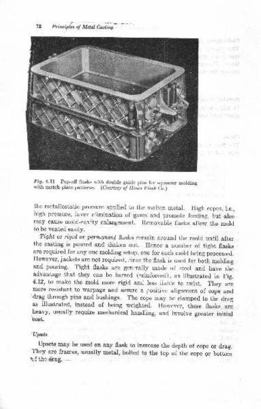
Priruiplcs oJ Mdal Casling
Fig-. 4.ll _
Pop-ofl flasks with double guide pins for squeezer moldingwith match-plate patterns. (Courtesy o! Hiis Flask io.)
the metallostatic pressure applied to the molten metal. High ccpes, i.e.,high pressure, favor elirnination of gases and promote feeding, but alsomay cause mold-cavity enlargement. Removable flasks allow the moldto be vented easily.
Tight or rigid or perntcnen.t flasks remain around the mold until afterthe casting is poured and shalien out. Hence a number of tight flasksare required for any one molding setup, one for each mold being processed.However, iackets are not required, ;'ince the flask is used for botir moldingand pouring. Tight flasks are genrrally made of steel and have theadvantage that they can be barred ("einforced), as illustrated in trig.4.12, ta make the mold more rigid ani less iiable to twist. They aremore resistant to warpage and assure a positive alignment of cope and
"drag through pins and bushings. The cope may be clamped to the dragas illustrated, instead of being weighted. However, these flasks areheavy, usually require mechanical handling, and involve greater initialbost.
'Up*dc
Upsets may be used on any flask to increase the depth of cope or drag.'rhey are frames, usualiy metal, boltcd to the top of the cope 9r bottorrrbf +he *&{g,
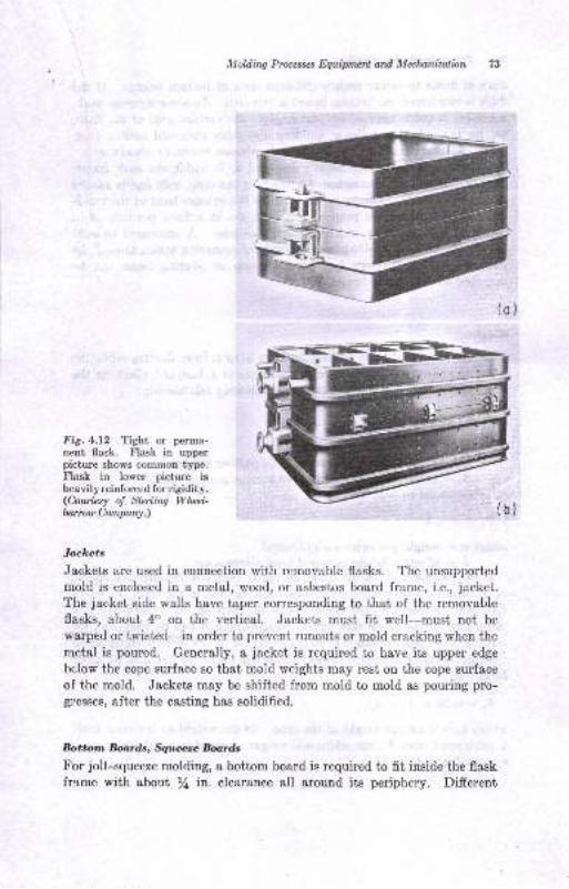
Moldin4 Pruesses Equipmed and Mahanizalion 73
Fig. 4.12 Tight or permanent flask. Flask in upperpicture shows common type.Flask in lower picture isheavily reinforced for rigidity.(Courlcsy o! Slerling Wluzl-balow Company.)
Jackets
Jackets are used in connection with removable flasks. The unsupported
mold is enclosed in a metal, rrood, or asbestos board frame, i.e., jacket.
The jacket side walls have taper corresponding to that of the removable
flasks, about 4" on the vertical. Jackets must fit well-must not be
warped or twist€d-in order to prevent runouts or mold cracking when the
metal is poured. Generally, a jacket is required to have its upper edge
below the cope surface so that mold weights may rest on the cope surface
oI the mold. Jackets may be shifted from mold to mold as pouring pro-glesses, after the casting has solidified.
Bottorrn Bornds, furdsFor jolt-squeeze molding, a bottom board is required to fit inside the flaskfrs.me with about /4 in. clearance all around its periphery. Different
71 Priaipbt ol Mdal Cadhs
sires of flasks therefore require difrerent sizes of bottoxo boards. If tieflask is reinforced, no bottom board is required. In some squeeze work,a bottom board is used which iust engages the bottom edge of the flask,as, for example, the rollover molding operaiion discussed earlier (Fig.4.9). Bottom boards are made of wood, asbestos board, or aluminum.
Squeeze boards also are usually required to fit ioside the flask frame.Ilowever, since the squeeze board ie used lor the cope, only one is neededper molding setup. It may be attached to the squeeze head of the rnold-ing machine, where l,he patt€rtr aDd flaek are in a 6xed position as incope aDd drsg molding or iolt-squeeze machines. A contoured squeeze
board may be used to obtaio a more unilorm squeezing action around thepatt€rtr.re'', The pattern lor the sprue cup or pouring basin can bemounted on the equeezc board.
Veight
I'he cope mold half musi be held down to keep it Irom floaiing when themetal is poured. Metallostatic pressure exerts a buoyant efiect on thecope, whicb an be cslculated from the following relaiionship:
F.:F"x A.
v, here I'" : force pushing upon copeP" : metoUostaiic pr€ssure et cope perting surface/. : projeqted mold-cavity ares st cope parting surface
P" is calculated as followe:
where t, : weight per cubic inch of metal/l : effective height of metal hea.d above cope
If the casting is all in the drag, the sprue height is the efiective heightof metal head above the cope. 'With
some casting in the cope, the effec-iive head is less than the sprue above the parting line. However, thelatter may be used as s safe 6gure. Simplifying, it can be seen thst, forl'errous castings, assuming 0.26Ib per cu in. for o, the force pushing up onihe cope is 0.26 per square inch of projected cope &rea per inch of sprueheight, or
F.:0.26xA"xh.rvhere I, is the sprue height in the cope. If the weight, of the cope itselfis subtracted from 1", the additioual weight required to resist si&tic pre8-sure is obtaiued.
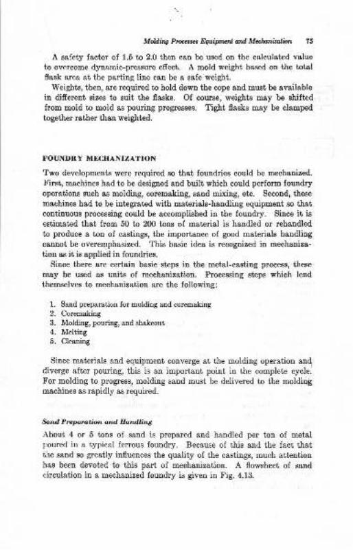
Mehg Pr@s*, F4aipnml ord Malwiral tn 7A
A salety lactor of 1.5 to 2.0 then can be used on the calculat€d vslueto overcome dynamic-pressure effect. A mold weight baeed on the totalflesk area ai the parting lirc can be a eafe weight.
Weights, then, are required to hold down the cope and must be availablein difereut sizes to suit the flasks. Of course, weight€ may be shifted
from mold to mold ag poudng progresses. Tigbt flasks may be clauped
together rather theu weighted.
FOT]NDRY MECIIANIZA?ION
Two developments were required so that foundries could be mechauized.
!'irsi, machines had to be desigued and buili which could perform loundryoperatioas such as molding, coremaking, sand mixing, etc. Second, the6e
machines had to be integrated with materials-handliug equipment so thatconliinuous processiug could be accomplished in the foundry. Since it ie
estimated that from 50 to 200 tons of material is handled or rehandled
to produce a ton of castings, the impo ance of good materials handling
caDnot be overemphasized. Thie basic idea is recognized in mechaniza-
tion as ii is applied in foundriee.
Siuce there are certain basic steps in the meial-casting process, th€Be
msy be used as units of mechanization. Processing steps which lend
themselves to mechanization are the following:
Sand preparatioa for molding aad coremaking
Coremakiag
Molding, pouriry, aad sha.keout
MeltingCleaaing
Since materials &nd equipment converge at the molding operation and
diverge aft€r pouring, this is au important point in the complete cycle.
For molding to progress, molding sand must be delivered to the moldingmachiues as rapidly as required.
*r.d Preporc.ior. ond. EandEng
r\bout 4 or 5 tons oI sand is prepared and handled per toD of metalpoured iu a typical ferous foundry. Because of this and the fact thatthe sand so greatly iuflueDces the quality of the castings, much att€utionhas been devoted to thie part of mechanization. A flowgheet of sand
circulatiou ia a mechanized foundry is givetr in tr'ig. 4.13.
1.
2.
4.
5.
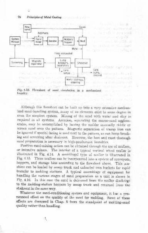
bir-ipla ol Mdal Ca.rlins
tri9.4.13 Flowsheet of sand ci.culation in a mechanizedloundry.
Alihough this flovsheet, can be built up into s very extensive mechan-ized saud-handliug system, many oi its elements exist to some degree iueven tire simplest syst€m. Mixing of the sand with water and clay isrequired in all systems. Aeration, separatiog the coarse-sand egglom-erates, may be accomplished by having ihc molder manually riddle orscreen send onto the patterD. Magnetic separation of trsmp iron ceube ignored if special facing is used next to the pattem, as can lump break-ing and screening after shakeout. However, the best and most thoroughsand preparation is necessary in higlt-production foundries.
Positive sand-mixing action can be obtained through the use of mullers,or iDtensive mixers. The interior of a typicol vertical wheel muller ieillustrated in Fig. 4-14. A centrifugal type oI muller is illustrated inFig.4.15. These mullers can be incorporated into a, system of conveyors,hoppers, and storage bins according to the flowsheet above. This oa-chine can be loaded by scoop truck and unloaded into buckets lor rapidtr&nsfer to molding stations. A typical assemblage oI equipment forhandling the various stages of sand preparation as a udt, is showu intr'ig. 4.16. In ihis case the sand is delivered from the muller dischargeto the moldiug-statior hoppers by Bcoop truck atrd returned from theshakeout in '!he same wey.
Whatrever the sand-conditioniDg syst€m aud equipment, it has & pro-nouoced effect on the quality of the sand for molding. Some of theseefrects are discussed in Chap. E from the standpoint of molding-sandquality rather than handling.
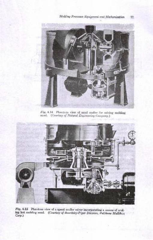
Molding Proc*ses Equipmenl ard Mulnnization
Fig.4.l4 Phantom view of. satrd muller for mixing moldingsand. (Corzrlesy o! Nalwal Enginering Comporry) -
Fig- 4.15 Phantom view of a speed mrrller mixer incorporating a means of ctrcr-ilrg hot molding sand. (Cowkst of Beardslq-piper OiiAton, Fehibu', U"ti;i,,Co"p.)
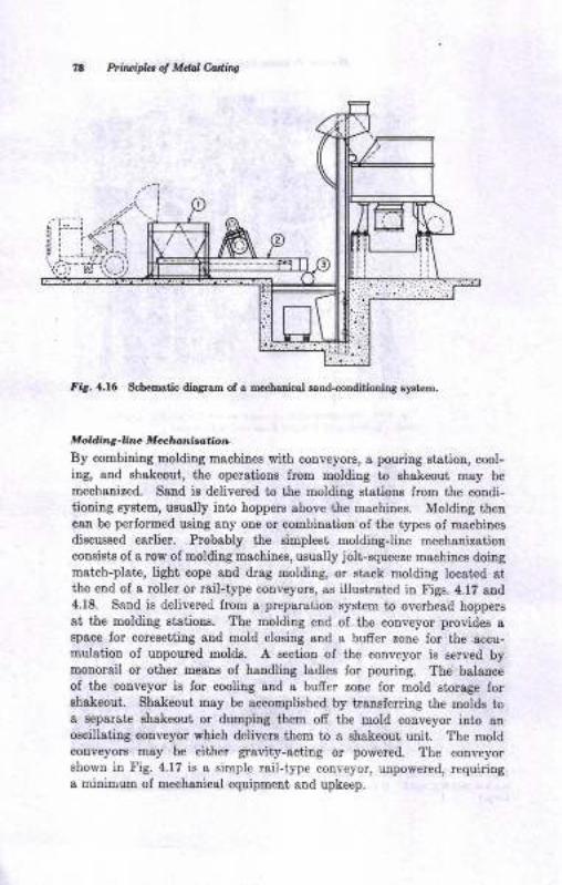
PtircipL, ol Mtul Culiis
flg. {.16 Schematic diagram of a oechaaicel gand.conditioliDg systcm,
Moklin|-Ena Me+l'd,lrotioD
By combining moldilg machines with conveyors, a pouring Btation, cool-ing, and shakeout, the operationr lrom molding to shakeout may be
mechanired. Sand io delivered to the molding eiations from the condi-tiotriug Byst€m, ususlly into hoppera above the machiues. Molding thencan be perlormed using any one or combination of the types of macbines
diecussed earlier. Probably the eimplest moldingJine mechanizationconsists of a row of Bolding machines, usually jolt-squeeze machiDes doitgmstch-pl8te, light cope aud drag molding, or stack molding located atthe end of a rollet or rail-type conveyors, ss illushated in Figs. 4.17 aud4.18. Sand is delivered from a preparation system to overhead hoppersat the molding etatious. The molding eud of the conveyor provides aEpace for coresetiing and mold closing and a bufrer zone for the accu-mulatiou of unpoured molds. A e€ction of the couveyor is served bymonorail or other means of handling ladles ior pouriog. The balanceof the conveyor is for cooling and a bufrer zone for mold storage lorehakeout. Shakeout may be accomplished by trauslerring the molds toa sepsrat€ ehakeout or dumping them off the mold couveyor into auoscillatiug conveyor which delivers them to a Bhskeout unit. The moldconveyors may be either gravity-acting or powered. The couveyorshown in Fig.4.17 is a simple rail-type conveyor, unpowered, requidnga miaiuue oI mechauical equipmeDt aud upkeep.
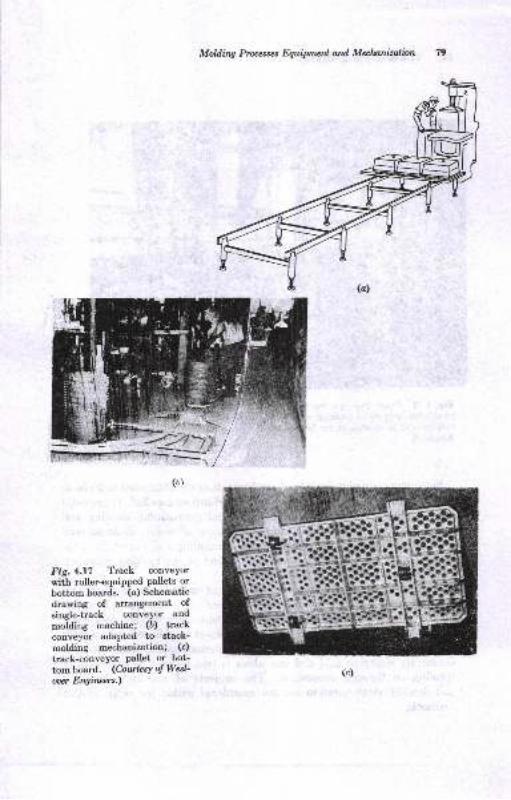
Moldirq Pnocesses Equipnwnl and Mulunizalinn
Fig.4.l7 Track corveyor
with roller.equipped Pallets or
bottom boards. (a) Scherrratic
drawing of arrangement ofsingle-track conveYor and
molding machine; (b) trackconveyor adapted to gtack-
moldiug mechanization; (c)
track-conveyor pallet or bot-
tom board. (Courlc*Y of Wcal-
ooer Engircers.)
i,*,,r'l I
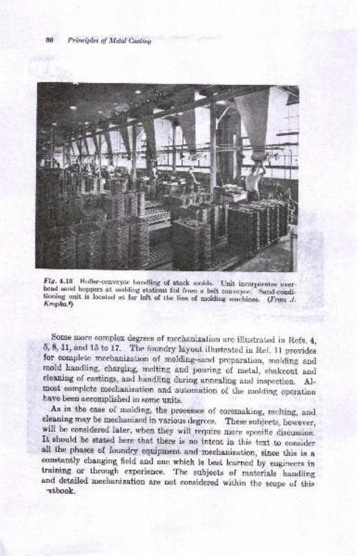
&) Printiplcs o! Metal Casling
Iiq14J8, noler-conveyor.handring of stack mords. unit incoryrorates over-Dead s{md boppers at molding stations fed from a belt conveyor. Sand-coudi_tioning unit is locat€d at far left of the line of molai.g -."hiou". (Fmnj.Ktopha.)
some more complex degrees of mechanization are illustrated in Refs. 4,5,8, ll, and 15 to 17. The foundry layout illustrated in Ref. 1l providesfor complete mechanization of molding-sand preparation, mording andmold handling, charging, melting and pouring of metal, shakeoul andcleaning of castings, and handling during uoourliog and inspection. Al_most complete mechanization and automation of the molding operationhave been accomplished in some units.
As in the case of molding, the processes of coremaking, melting, andcleaning may be mechanized in various degrees. These subjects, ho#eve.,will be considered later, when they will require more specific discussion.rt should be ststed here that there is no intent in this text to considerall the phaaes of foundry equipment and mechanization, since this is aconstantly changing field and one which is best learned by engin-eers intrainiug or through experience. The subjects of materials handlingaud detailed mechanization are not considered within the scope of this.x[book.
-(
>_*1-.
a':<ur-
*I:1.9'
,.2
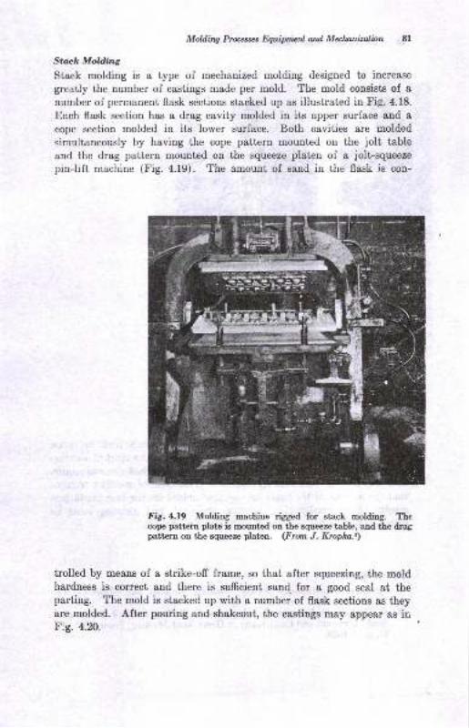
Mddilq Ptocesses fuoipntctrl and Malwnizalbn 8l
Sttck MoWng
Stack molding is a type of mechanized molding designed to increase
greatly the number of castings made per mold. The mold consists of snumber of permanent flask sections stacked up as illustrated in Fig. 4.18.
Each flask section has a drag cavity molded in its upper surface and a
cope section molded in its lower surface. Both cavities are molded
simultaneously by having the cope pattern mounted on the jolt table
and the drag pattern mouDted on the squeeze platen of a jolt-squeeze
pin-lift machine (Fig. a.19). The amount of sand in the flask is con-
Fig.4.l9 Molding machine rigged for stack molding. Thecope pattern plate is mounted on the squeeze table, and the dragpattcro oD the squeeze platen. (From J. Kropka.)
trolled by means of a strike-ofr frame, so that after squeezing, the moldhardness is correct and there is sufrcient sand. for a good seal at thepartiug. The mold is stBcked up with a number of flask sections as theyare molded. After poruing and shakeout, the castings may appear as irF:g. 4.20.
\J
qI"-'--l,*-'#T
t..-t,
J)
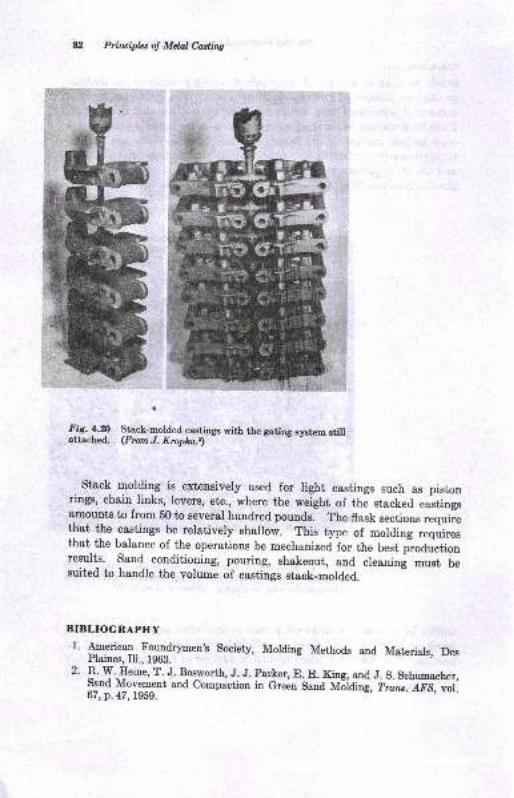
Prirciplu of Mdnl Coding
Fiq. !.4 qfr*-e.U", castings wirh the gating eystem etillattached. (FromJ. Kropka.r)
Stack molding is extensively used for light castings such as pis,r,onrings, chain links, levers, etc., where the weight of the stacked castingsamounts to from 50 to several hundred pounds. The flask sections requirethat the castings be relatively shallow. This type of molding ,uqri.u,that the balance of the operations be mechanized for the best p-roductionresults. Sand conditioning, pouring, shakeout, and cleanini must besuited to handle the volume of castings stack-molded
BIBLIOGNAPIIY
I' American Foundrvmen's society, Molding Methods and Materia.ls, DesPlaines, Ill., 196g.
2. B.W.Eeine, T. J. Bosworth, J- J. par.ker, E. E. King, anC J. S. Schumachcr,Sand Movement and Compaction in Green Sand U"iairi frr^.-afS, ,if67, p.47, L959.

3.
4.
5.
6.
8.
9.
10.
11.
13.
14.
15.
16.
17.
18.
Moldhq P$a.tc. EquiP'raenl ard Mdtsnirdion 8:l
J. Kropk&, Multiple Molditrg in a Malleable Shop, /rt. Foundrymm, 'toi.24, p.44, Msrch, 1953.
E. W. Zimnawoda, Mechaaical Equipment for Medium Sired Groy Iro!Foundry, froru.,4IS, vol. 59, p. 56, 1951.
L. B. Kdght, Moderdzatioo ol the Suall Fot:rdry, ?rat6.,{-PS, vol.56, p.
297,1948.E. A. Clake, Molding M*htae*', Am. Foundryman, vol. 55, Sept mber, 1947.
lY. K. Gude, Modem Facilities Incorporeted iD Nerq Alebama Pipe-fouDdry,
tr'ozndrg, vol. 60, October, 1952.
E. A. Swensotr, Limit€d MechaDization in the Jobbiag Fortr,dry, Foundry,
v(i 80, Malch, 1952.
G. E. Miller, Trends in Molding Mschirres and Core Blowers, Foundry, tol,m, Malch, 1952.
C. A. Gehrman, Eow to Select ond Maintain Flssks, Io&ndry, vol. 80,
February, 1952.
L. B. Knight, Modemizaiion with Mechadz al'ron, Foundry, .gol.80, February,
t952.W. G. Gude, New Process Casts Soil Pipe, Fouoiry,,tol.78, May, 1950,
R. Shi:e, Care of Molding Machines, Pozndry, vol. 77 , September, 1949.
R. II. Herrmann, IlandliDg Mst€lials in Metst Chorghg, Found,ry' vol. 76,December, 1948.
C. O. Bartlett, Mechanized Foundry Desigu aDd Op€ratilg Phases, ?ron .
.4fS, vol.55, p.546, 1947.
E. lY. Ziiros{odo, Sand and Mold Trlndling Equipaetrt, Fwndry, vol, 80,
p.88, April, 1952.
E. W. Zianawode, Six Ways to Mechaoize a Foundry, .4m. Foundrymat4
vol. 15, April, 1949.
R. E. Heinoaan, Eow to Specily Conv<|or Belting lor Foundry Applica-liottg, Foundry, vol.81, p. 86, August, 1953.
R. W. Eeine, Mixing aod Moldhg Green Sand, tr'o&?dry, October, 1961, p.6t.D. C. Williams, Grauul&r Movement during Squeezing, Trarc. AFS, vol.69,p.8, 1961.
K. Terzaghi, "Theoretical Soil Mechaoics," John Wiley & Soas, Inc., New
Yo!k, 1943.
R. W. Eeine, Molding Sands, Molding Methods and Casting Dimeusions,
Truns. AF5,1956.R. W. Eeine, J. S. Schumacher, &nd E. H. King, The Jott Test, Mod,enr
Carriflrs, April, 1956, p. 59.
R. W. Eeine, J. S. Schumarher, and E. E. King, SpringbacL in Greeu Sand
Moldiog, ?mzr. AFS, vol.71,1963.R. S. L. Andrews, "Shell PrcceEs Foudry Pr&ctice," AmedcsE Found4rretr'sSocieiy,1963.
19.
m.
21.
.
,
l)Molding Sands
Ite major production of caetings is in sand molds. Molda for makinga tou of castings may require 4 to 5 tons of molding sand. The ssnd_metsl r&tio may vary from l0:l to 0.28:1, depending on the type 8ndaize of castings and molding method employed.
- Iu an! case, the?nnage
of saud which must be handled in r sand-casting foundry is large, audits quality must be controlled to make good castings.
Several difierent types of sand are used for moldiug. Sand_cartiugproceaees involvitg molds made ol greeo sand, dry sond, core sa,,d,cement-bonded sand, ehell-molding sand, and othere have been describedin an earlier chapter,
CENERAL PROPERTIES OT MOLDINC SANDS
tr'rom a general viewpoint, the molding sand muei be readily moldableand p-roduce defect-free castings if it is L qualify as a good onl.
-C""t"i,specific properties have been identified, ."a *"tiog pio"edu"eu adaptedfor.t}Ieir quantitative desoiption. The AFS ,,f,-ourary S*a ffiia_bookD sels forth the etandard conditions of testing ihu ;""J ;;op;;;..Thore propertics of moet obvious importanoe inchide:
1. Gl€er strrDgth. The greet saud, after wster hss been Eired into it, must
_ hsve adequst€ stretgth and plasticity lor E"ti"g *a hanaft iiiiJ-"U.2. Dry- strength. As a castiog is poured, sand adaceat to ti" loi."tuf
quickly lo6es it€ wster as stcsm. The dry sanj must heve strength or€sist ero6ion, atrd also the metallcstotic pressure of the molten mJta! orelse the mold may enlrrge.
3. Eot streDSth. After the Doisture has evepoBted, the 6atrd msy be je.qtrired to pocsess streDgth st 6ome elevat€d temperature,
"U""J il-Z f.
Mets[o6tatic pre6sxre of the liquid_Eetal f""rl"g'rgrirJif" .ii-rrff"may cause mold enlargemeot, or if the metal is stili flowing, erosion, cracls,or breatage aay occur unleas the sand possesse" d"q""t ;;;;;;;;:
4. Pemeability. flest frcm the casting causes a green'-sand mofa J'evolr"s gest desl ol stea,m and other gase€. The moid must b" ;;;1",;.",,u
8.
9.
Malditq satub &;
porous, to perEit the gases to pass ofr, or the castiDg will coEtaitr gas
holee.
Therosl stability. Ileot frcm the cssting c&uses lapid expansion of thee4nd surfaae st the mold-Eetal ht€rface. The mold surface m&y thencrack, bucklq or f-ake ofl (scab) unless the molding sand is rclativelystr.ble dimensionally uoder rapid heatilg.Rcfractorinees. Eigher pouring temperatures, such as tho8€ for ferrousalloys 8t 2400 to 3200 F, rcquire grcat€r relractodness of the sand. Low-pouring-tempeleture metals, for example, aluminum, poured at 1300 I,do trot requirc a high degree of refractoriness from the sand.Flowability. The sand Bhould respond to molding processes.
P$duc€s good c.sstiDg finish.Collapsibiliiy. Eeated sand lrhich becomes hard and rocklike is dificultto remove from the c{stitg and msy caus€ the contracting metal to tearor cr&'.k.
10. Is reueable.
11. Ofrers ease of sand prepaBtion aDd contrcl.12. Xemoves heet from the cooling casting.
ThiB li6t by no me8[s includes all the properties which might be desirable.Obviouely, the most important characteristic of a molding sand is th&t itfacilitate the economic productiou oI good castings.
INGREDIENTS OF MOLDINC SANDS
Molding eauds &re mixtulea ol three or more ingedients. A green sandcontains clay aud water, as well as the principal sa[d constituent, SiO,.These three components provide the bulk and plasticity required of themolding sand. Other materials may be added to the sand mixture toeuhance certain oI tbe properties.
Sr,.d
Granular particles ol sand, that ie, $iO, principally, comprise 50 io gbper cent of the totsl materisl in a moldiug saud. In difrerent moldiugsands, these eand particles may difrer iu the lollowing ways:
l. Average graia size, grain sire distribution, and grain shape2- Chemicolcompoeitioo3. Ilefmctorinees and ihenael stability
The chemical composition of the sand-grain portion of typical moldia;sand is given iu Tebie 5.1. Geuerally. the prrrest glllcg sand. 9g.g_._
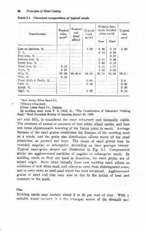
86 Priruifui ol MdalCadhg
Tabb 5.1 Cherrdal ompocitbn ol ttrytilyl sand,
Constituents
Loss on ignition, %......c, %.Freeiron, %......Ferrous fuon,/e.... .... .
Ferric iron, %. .... .. . . . . ..Total iron, %.. ....NzOt, 7o
SiOz, Vo.
TiOz, Vo.
Total Al:Oa* FezOr, Vo.....CaO, Vo.
AJ.kali, %.MBo,7o.
Western ben- |
tonite bonded I Typicalsilica eandg I trrc
-i
sndr.r"* | u'"a
i
Washed
silicasand *
Typicalbank
eand I
,,.,:,.
92.09
0.280.13
o.t20.590. 97
0.68o.t21.770. 63
95. 54
0.80
95.0+
2.O
0.600.200.40
i
0.440.000. +4
r.3295.79
6.090.58
o.22
rNew Jeraey Silica Sand Co.
tOttawa silica sand.
fGreat Lake Sand Co., Juduts.
$A molding sand, from F. L. Orell, Jr., "The Constitution of Discarded MoldingSend," Steel Fouuders.Society of Americe Report 23, f950,
per cent SiOr, is eonsidered the most refractory and thermally stable.The presence of excessive amounts of iron oxide, alkali oxides, and limecan c&use objectionable lowering of the fusiou point iu sands. Averagefineuess of the sand grains establishes the fineness of the molding sandas I whole, and the grain size distribution affects many of the sandproperties, as pointed out later. The shape of sand grains mey berounded, angular, or subangular, depending on their geologic history.Typical sand-grain shapes are illustrated in Fig. b.l. Compoundedgrains are agglomerated particles of angular or subangular sands. Inmolding sands as they are used in fouudries, the sand grains are ofmixed origiu. Some came initially from new molding s&nd, others sscdditions of new silica sand, still others as sand from disintegrated cores,and in some cases as used sand which has been reclaimed. Agglomeratedgrains of sand and clay may also be due to the actiou of heat andrnoisture in the mold.
Clry
Molding sstrds may contain about 2 to b0 per cent of clay. With aeuitable water content. it is the nrincipal source of the strength aud
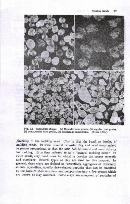
Mdlfiw &trlds 87
I rC. S.f Sand grain ehapes. (c) Rounded sand grrim, (D) angular -aod greine,(c) compounded eaud grains, (d) subangular eand grains. (frctn r{FS.r) -
plasticity of the molding sand. Clay is thus the bond, or biniler, of.moldiug sands. In some miueral deposits, clay and sand occur mixedin proper proportions, so that the sand can be mined and used directlyfor moldiog. It is then referred to as a ,,natural molding sand.', Inother sands, clry bond must be added to develop the proper strengthand plasticity. Several types of clay are used for this purpose. Ingeneral, these clays are defiued as ,(essentially
aggregates of extremelymirute crystalline, u;'lally flake-shaped partieles that can be classifiedorl the basis of their stnioture and composition into a few groups whichare known as clay minerals. some clays are composed of particles of
U Piruipbt ol Mdal Codins
a siugle clsy miDeral, whereas otlers are mixtures of clsy minerals.Some clays are composed entirely of clay minerals, whereas others containsdmixtures of quartz, pyrit€, organic matter, eic.",
CIay minerals used as bonding additions to sands include the followiogtype8:
W6tetD atrd Bouthem betrtonit€s (moDtmorillotrit€s)
Fire clays (kaotiait€s)
Special clays (hauoysitc, iltite, Bttapulgite)
The first two types ere the most commonly used. Table 5.2 lists someof their difierences in chemical compositiou, atomic structure, base cx-change characteristics, swelling and shrinkage tendencies, and refractori-ness. A clay coaiing of the sand gmine couiributes many of the claypropedies to the molding-sand aggregste.
Voaer'Watcr,
present in amounts of ebout 1.5 to 8 per ceDt, activates ihe clayin the sand, causing the aggregaie to develop plasticity and strengthWater in molding sands is often referred to ss tempering watet. Thewater is adsorbed by the clay up to a limiting amount. Only thst waterrigidly held (adsorbed) by the clay appears to be effective in developingstrength.'? The rigid clay coatings of the grains may be forced togcther,causing a wedging action and thus developing streogth., Additionalwat€r, however, c&n act as a lubrica[t, and makes the saud more plasticand more moldable, though the strength may be lowered. Thus controlof the water percentage in the aggregate iB very important. Water mayengage in ion exchanges wiih the clay if dissolved minerala are present.
Srrccial .4ddi.i@s
Besidee the three basic iugredients, other materials may be preseut iumolding sands. They are oiten relerred to as additiues aud are usedio develop some specific property. These materials will be briefly de-f.neC here.
Cercab
Cereal binder, as used in the fouadry, is finely ground corn 6ouror gelatinized aud ground starch fmm com. Cereals m8y be u8ed innLolding sands for increaeed greeu or dr5r strengdr or collapsibility inemounts up to 2.0 per ceDt.
1.
3.

oda
P-i66I H.* - S
r' sEjeS-es
l€AiaiEHeE
o.cl
O i';.! e-*O
^V s86iiilE
b0
o
o.E
.! E-@4?
.v 9X
b0
o
jl
.PEE€b*u
.s {.=
6
N
A
N
'o.iodizE$
€lMdUiidq
ob0
d
xoo3
oNO
o!VaeEd:*
o
?st rEEst249'a
mcOL
=eQ59Ee4>
'ie
E gs:E E*
oIA
o;lz
qd
I
r.i
Eo
eAc!
t
odo
+I
a
6l)
zb0
zo
fr{
E
o
B
o
.id
Ea16
oq
^o
EO:E
:eEf;ar ^
;rO C
^cO O
x ;:.E
:>
UP
d=
63lo
IH
co
e'oo@oO,d,
Gl=
g- 9t
.=4,863H
€'aJO.
ots .2'e o.9-9m.:>=H =o :S?sB6XJ d!,
5() .nA
bA-trdHE.siEA
4..,4 -
E E.i5I
ao
.l ot;E<5HEE-do(,
d
o
AO
E.EI
^ E.:
-oOcIDtr.?B<elo:!
gfre
oo
I
@
a
o
do
E
d
in
a!0c't!
!0
o
t)q
aB
q)
:aE
TJ
N
s.B
ecc
Ai
f;se
+tt\
ro6l
f-r-OocH il'J
re>( Fb95
14
I
+3o
o 9=lc6&j
b0
+tu
I@
i^a Xi5
;.E I
frr6€E'E?do.
Eao
d
BQ
od
97o-.-il ea!?
?TS.:6 tlEcO'r,i Z
Fl
90 Prirwipla of Mtu! Codins
Ground Pilch
Pitch is a by-product of cokemakiag, beiug distilled from soft coale
at about 600 F and above. Pitch is used in anounts up to 3.0 per cetrt
to improve irot sirength or castiug floish on ferrous castings.
Arplnl
Asphalt, ie I by-product of the dieiillation oI petroleum. It i8 used
for tbe same purpose8 a8 pitch.
Sa C@t
Sea coal is a frnely ground soft coal used in molding Bands lor cast
irons, principally for the purpose of improving the surf&ce finish and
ease of cleaning the castings. Sea coal may be specified by proximate
and ultimate analyses colventiooally used for coal. A typical exaupleis given iu Table 5.3. The sea coal is ueually ground to a fineness sieilarto that, ol the molding eand in which it is used. Percentages employediu sands are about 2 to 8 per ceut.
Gmphilz
Synthetic or Dstural graphite may be used in percentages of O.2 tD 2.O
per cent for the purpose of improving the moldability of the sand atrdthe sruface firish of the castings.
Cilsonili
?hie mat€rial is a solid asphaltic mineral, miued in Utah and Colorado,suficienily volatile so th&t it functiotrs much &s eea coal does in causiogimproved castiug finish.
Ft zl Oil
Fuel oil is sometimes used in very small percentages, of 0.01 to 0.10per cent, and seems to coufer improved moldabiliiy to the sand.
Wui Flau
Ground wood flour or other cellulose materiels such as cob flour, cerealhulls, and carbouized cellulose may be added in a&outrta of 0.5 to 2.0per cent to molding saads. They may futrction io control the expansionof the sand by burning out st elevat€d teoperature. They also canimprove collapsibility and flowability of the eand.
Silie Flau,
Putverized silica, 6uer than 20O mesh, ie called eilica flour. Ii maybe used in amounts up to 35 per cent for the purpose of increasing hot
EtreDgth of the 88Dd. It also iDcrease€
resisting Eetal penetrstio&
To,bb'.a En ','pL
ot .'r.cdtr,,.F[{]i,,.,,.bn
Prourrr Ar,rer,rars ( Morsruar-t8EB), %
Ur,toalrE ANlryals
II..........................6.670c.................... .......fi-siyoN................... .......1-s7oo................... .......0-8%8... .. . . . . . . . . . . . . . . . . . . . . . .O.EEo \N,Ash................. .......2-6%Arh firsiotr poi[t,. -...........2780 F
Mdding W.
the density of the sand
9l
for
Iron Ozilt
Fine iron oxide is ured in emall pereentages in some 8alds to obtsinsdded hot strengtl.
PrcliL
Perlite is 8n expsnded alumiDuo silicate mineral, uaeful ia suall per-ceDtsger, 0.5 to l.5O per ceut, to obtain bett€r thernal stability of tiesaad. It mey aleo be uaed as 8 riser iEul8tor..
Molot-t, Drz,tin
Csne or blackstrsp molaases, unrefned and containiug 60 to ZO peroeut Bugar solids, Eay be used for increaeed dry streugth of the sand agdedge hsrdreEs of uoldg. Dextrins oay be ured for the aa,me purpose.
The foregoing list of Band additives ia by no m€alE oonplote, 8nd auumber of others may be uoed.
Rtudrltr,,'When
moldiug Eauds are i8 conduual reuce, matedals are added duringesch BsDd-prepsrstio[ qycle to coDp€Dsate for the material burned orotherwiae decrepitated by heat lrom the caatiugs. Eenoe the ingrcdientsoI the ssDd as it is used in foundriee tnsy consist ol burDed or par-tially burned materials, EoEe psrtiol€s of metsl snd alag, and other
Yolstile e.stt€r (VCM). . ... . .3&.{0.0Fired csbor (FC)...........6H0&h........................&.5
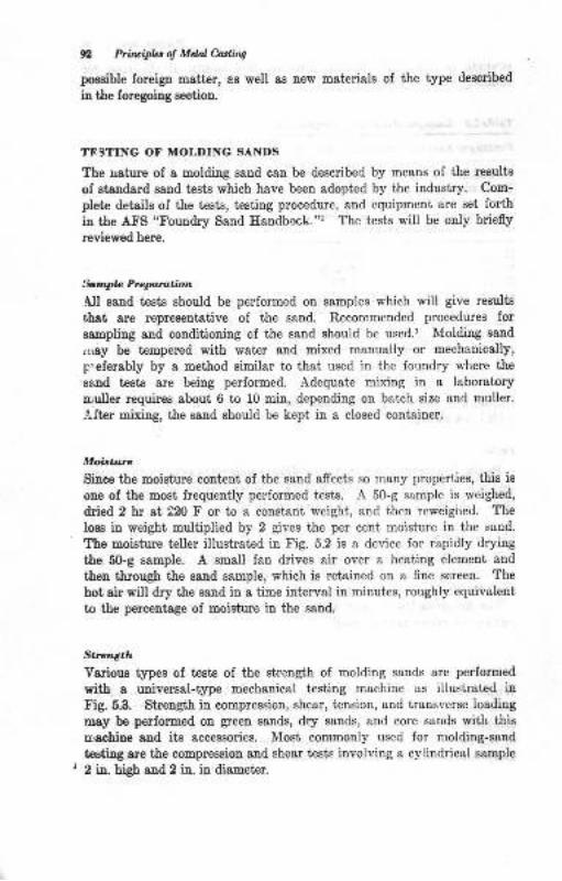
9 Priruiph, d Mdal hdits
possible foreigu Batter, as well as aew materials ol the type deseribed
in the Ioregoing section.
TESTING OT MOLDING SANDS
The uature of a moldiug saud can be described by means of the results
of stsDdsrd ssnd test€ which have been adopted by the industry. Com-
plete detaile oI the te8te, testing procedure, snd equipment are set fo hin the AFS "Foundry Sand Haudbock."' The tcsts will be only briefly
reviewed here.
:btnflo Prcpratbn
All sard tes'ts ghould be performed on samples which will give resulte
that are representative ol the sand. Recommended procedures Ior
saupling and couditioning of the sand should be used.' Moldiug saDd
,nay be tempered with wst€r and mixed monually or mechanically,
p"eferably by a met'hod similar to thai used in the foundry where the
Batrd tests are being performed. Adequate mixing io a laboratory
uruller requires sbout 6 to 10 min, depending on batch size and muller.
Alter mixiug, the sand ahould be kept in a closed container.
MoitaDe
Siuce the moisture coDtent of the sand afrects so many properties, this is
one of the most frequently performed tests. A 50-g sample is weighed,
dried 2 hr at 220 F or to a constant weight, and then reweigired. The
loes iu weight multiplied by 2 gives the per cent moisture in the seud.
The moietue teller illustreted in Fig. 5.2 is a device for rapidly drying
the 50-g eample. A small fen drives air over a heating element and
theu tbrough the sand sample, which is retained on a fine screen. The
hot oir vill dry tJre sand io a time inteNal in minuies, roughly equivalent
to the percentage of moisture in the saud.
Str",'I'g.h
Yarious types of trcete of the sirength of moldiog ssnds are performed
rith a uaiversal-type mechanical testing machioe ae illustrated inFig.5.3, Streugth in eompression, shear, tensicn, and transverse loading
may be perlormed on green sands, dry eands, and core sands with tbis
nachine and ite accessoriee. Most commonly used lor moldiug-sand
testing are tbe compressioo and shear tests involving a cylinddcal 6&mple
2 in. high and 2 in. in diemeter.
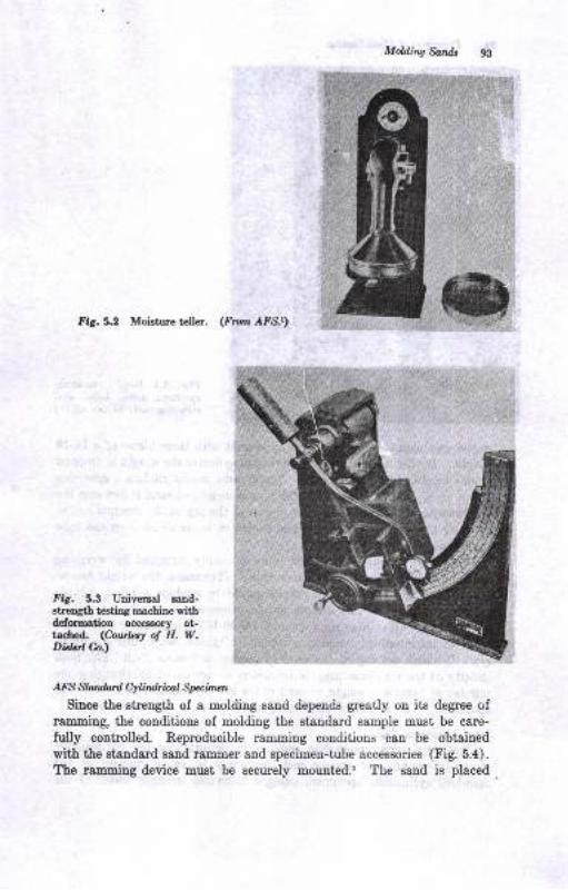
Molding So;ndt 9g
Fig.5.2 Moisture teller. (I?iom AfS,r)
Fig. 5.3 Universal ssnd-Btrength t€sting machine withdeformation acc€ssorlr at-tached. (Courlery o! H. W.Didcrt Cn.)
A.?8 Standail Cylindrical Specimen
Since the strength of a rnolding sand depends greatly on its degree ofr&mming, the conditions of molding the standard sample must be care-
fully controlled. Reproducible ramming conditions can be obtained
with the standard sand rammer and specimen-tube accessories (Fig. 5.4).
ffus lamming device mugt be securely moutrted.r 'fhe sand is placed
ffi
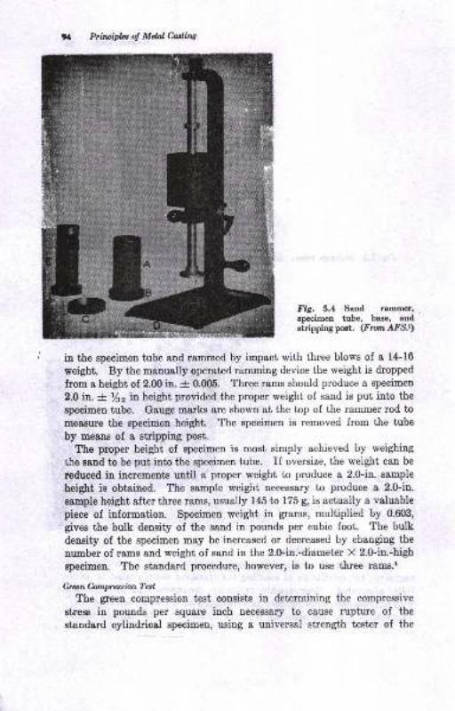
% Prilui*: ol Mdal Casting
Fig. 5.4 Sand rammer'specimen tube, base, atrdstripping pet, (From,AFS.r)
in the specimeu tube and rammed by impact with three blows of I 1+16
weight. By the manually operat€d rammiug device the weight is dropped
from e height of 2.fi) in. -+- 0.005. Three rams should produce a specimen
2.0 in. -+ /s2 in height provided the proper weight of sand is put into the
specimen tube. Gauge marks are shown at the top of the rammer rod to
measure the specimen height. The specimen is removed from the tube
by means of a stripping post.
The proper height of specimen is most simply achieved by weighing
lhe s8trd to be put into the specimen tube. If oversize, the weight can be
reduced in increments until a proper weight to produce a 2.0-in. sample
height is obtained. The sample weight necessary to produce a 2.0-in.
sample height after three rams, usually 145 ta 175 g, is actually a valuable
piece of information. Specimen weight in grams, multiplied by 0.603,
gives the bulk density of the sand in pounds per cubic foot. The bulk
density of the specimen may be increased or decreased by changing the
number of rams and weight of sand in the 2.0-in.-diameter X 2.0-in.-high
specimen. The standard procedure, however, ie to use three rams.1
Green Compresion TatThe green compression test consists in determining the compressive
stress in pounds per square inch necessary to cause rupture of the
standard cylindrical specimen, using a universal strength tester of the
LilJlJ
)
Mdninq $ndt 95
type shomr in Fig. 5.3. Qreen compreesive streDgth i8 ususlly simplyreferred to ae |.he green strenqth ol the sand. It is important in thiaaud other geen-stretrgth tests thst the tast be performed immediatelyalt€r the Bpecimeu is stripped from the tube. The strength of green
ssnds iucreases when the eaud rpecimen begiDs to air-dry, Greenmoldiug saud8 rur from about 5.O to 22.0 psi green compr€Bsive streDgth,dependiag on theb type.
Crun Srlrl.. T.4Green shear BtreDgth c8n be determined with the staudsrd specimeu
8!d universal testing machine. This is accomplished by chauging theloading zurfacea ou the t€8ting BschiDe from compreesion platee toehear plates. The BpecimeD theu rtrpiures in ehear along its longitudinalaxis wher suftcieutly loaded, Gredn molding eandr usually have about1.6 to 7,0 psi greeu ehear strength
Dry bry**ion and Ahcor Tedt
If sisndard speciuens are dried at nO b 2N F for 2 hr before they8re tested, the dry compression or dry shear strength of the sand may beobtaiued. Siuce dry compression etrength is uzually much greater thangreen strmgth, higher loade are required on the universal strengthmachine. Tmical dry-compreeeiou valuee on green saud8 are n b 2fipsi, dependiDg on their tlpe.
D.!@nalion (Stroi^)
Greeu molding saud hae the ability to deform under toad. If thesand delorms too readily under low loads, the mold csvity may notreEsin true to shape. If ihe sand has too little sbility to deform underload, it thetr iB brittte or lacks toughnees. Drawing of patterne theu maybecome difrcult. This property may be measured by means of adeformatioo accessory for the universal strength machine (Fig. 5.3).This deyice meaflues iD inchee the amount that the spe€imen iB com-pressed before it ruptures under compressioD loading. Deformation of0.010 to 0.mO in. per in. is observed in mauy molding BaDdE. Thedeformatiou tcst is, however, considered a nongtaudard test.r Some-times the deformation value is used, together with the greeu compressionsheugth, to describe toughnees of the sand, according to the followingformulc:
STN:DXGSx1000where STN : sand toughness oumber
D = deformatiou, 0.001 in.Q$ : geeu strength
Cran Teruile Slrcrqth
The tensile strength of a green moldiug sand ueing a modified specimentube for ramming may be determined with the uaivereal saud-streDgth
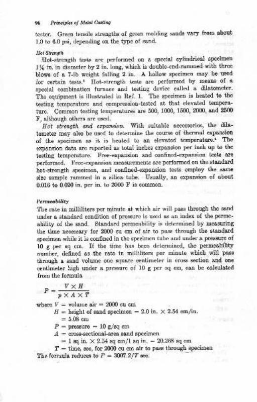
Principlcr ol Mdal Cotliw
test€r. Greeu t€uaile stlengths of green molding Eands vary from about
I.0 to 6.0 psi, dependiug on the type of sand.
Hot Sl't.nsth
Eot-streugth te6ts sre performed on a special cylindrical apecimen
l/s in. in diameter by 2 in. long, which ie double-eud-rarnmed with three
blovs of a 7-lb weight falling 2 in. A hollow specimen may be used
for certain teste.s Ilol.streugth teets are periormed by meaus ol a
special combination furnace and testing device called a dilstomet€r'
?he equipment is illustrat€d iu Ref. 1. The specimen is heated to t'he
te8tiug tremperature and compression-tested at that elevat€d tempera-
iure. CommoD t€8tiDg t€mperstures are 500, 1000, 1500,2000, &nd 25m
F, although others are used.
Eot stren4th and erparxian. With suitable accessories, the dila-
tomet€r may also be used to determine the course oI thermal e:<pansion
of the specimen as it is heated to au eleveted tenperature.l The
expansiou data are reported s8 total itrches expausion per inch up to the
t€sting t€mperatue. Free-expansion end confined-expaosion tests are
perlormed. Free-erpansion measuremeuta are performed on the standard
hol.strength specimen, and confiDed-expsnsion tests employ the eame
size sample rammed in a silica tube. Usually, an expansion of about
0.016 to 0.020 in. per iD. to 2000 F is coEmon.
Pert e,biBq
The rate in milliliters per minut€ at which air will pass through the sand
under g standard condition of pressure i8 used as an index ol the perme-
ebility of the sand. Standard permeabiliiy is determined by measuring
the time necessary for 2000 cu cm of air to pass through the standard
specimen while it is confined in the specimen tube and under a pressure oI
10 g per sq cm. II the time has beeu deiermined, the permeability
number, defined ae the rat€ in milliliters pe! minute which will paas
through 8 sand volume one aquare dentimet€r in cross eectiou and one
centimeter high under a ptessure of 10 g per sq cm, c&n be calculated
Irom the formula
vxHpxAxT
where Y : volume air : ZX)O cu cm
Il : height of sand epecimen : 2.0 in. X 2.54 cmlh.: 5.08 cm
P : prrc8urt : l0 g/8q cm
.A : cro8-Bection&l-grea ssnd apecimen
: 1 sq in. X 2.54 sq cm/l so in. : 20.268 8q cm
? : time, sec, for 2000 cu cm air to pasE through specimen
The fornrul8 reduces lo P = Wl -2/T w
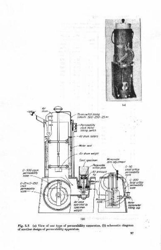
Permeobiltycloct molorlining sritch
Ah drum rollers
Woter seol
Air drum ucight
Sond spectmcn Lfonomelqzero o4/ulmenl
0-5OO clockperneobililyscole-
0-90snoll orificepemeobililyscole
O-25xO-25Oclockperneoffiilyscole
Atr volveopero.ted byspfftmen
(D)
fig. 5,5 (o) View of ooe type of permeability apparatus, (b) echematic diagram
of atrother design of permeability apparatus.
o-800lotge orifiieNmilbtWscolc
(o)
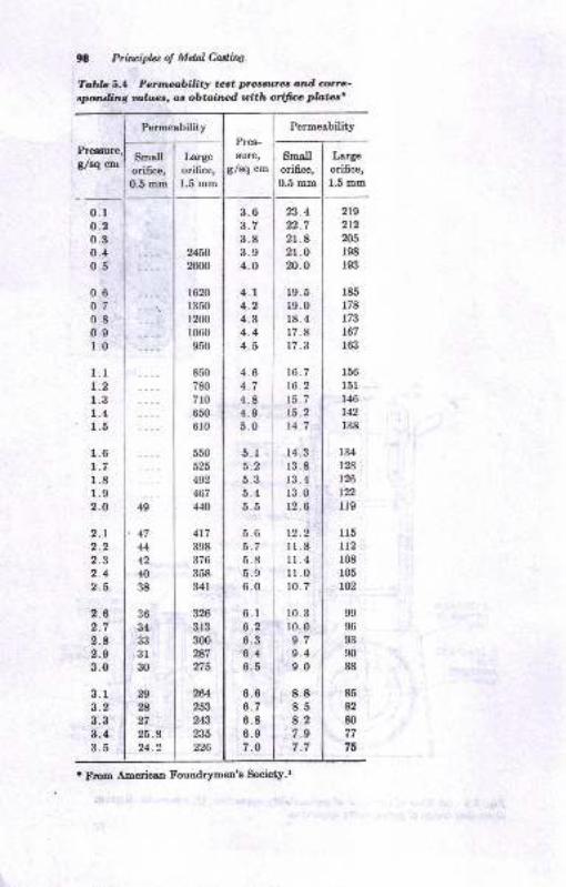
98 Priripla o! Mdal Cdirw
To,bb 5.4 Penrz,cr,bility teat pr.esau"es and artc'eponding oa,hrae, an obtainr,d roith ori{rce plotz,s'
Permeability
B/tq cnl
0.1o.20.30:40.5
0.6o.70.80.91.0
l.lt.21.31.41.5
1.61.71.81.92.O
2.12.22.32.42.6
2.62.72.82.93.0
8.13.23.33.13.5
49
36
34
333r30
29
I27
26.824.2
Smallori6ce,0.5 mm
Largeorifice,1.5 mm
219
2L2n5198
193
185
178
r73167
163
156
l5l146
r42r38
134
t28126
r22lr9
115
tt2r08r05102
99
96
93
90
88
85
82
80
77
76
,4744
42
40
38
Permeability
Small I Large
ori6ce, I orifice,
0.S -- | t.5 mm
1060
950
850
780
7r0650
6r0
550
525
492
467
4{0
3263r3300
2A7
275
264253
243
235226
3.6 | 23.4
3.7 I n.78.8 I 21.83.9 I 2l .04.0 l2o.o
4.r 119.54.2 | 19.0
4.3 | 18.44.4 I 17.8
4.5 | 17.3
4.6 | 16.7
4.7 | 16.2
4.8 I 15.74.9 | 15.2
5.0 | t4.7
5.1 | 14.3
5.2 l 1385.3 | 1345.4 I13.05.5 | 12.6
5.6 i tZ.Z5.7 I Il.85.8 I 11.4
5.0 i lr.06.0 i 10. 7
6.r | 1036.2 110.06.3 I e.76.4 i 9.46.5 I 9.0
6.6 I 8.86.7 I 8.56.8 I A.z6.e I 7.s7.O I 7.7
' From America,n Foundrymen'e Society.r
Pres-
EUFE,
g/Bq cm
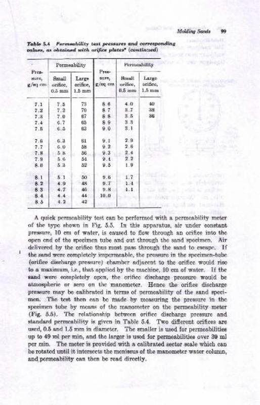
Permeability
Small I Large
orifice, I ori6ce,0.5 mm | 1.5 mm
I .t
7.27.0b. /
6.5
6.36.05.8o.o5.3
5.r4.94.74.44.2
73
70
67
bo
63
6l58
56
54
52
50
48
I44
42
Mddl,q So,rdt
To,bla 5.1 Penlaability tart prerc;ulre, otd onacptdinguhlrrlc, as obtr;ilrad uith ofitw pbteer (oln;tin'.lcd;
Permeability
Pres-
BUre,
g/sq cm
Pres-
8Ure,
g/sq cmSmallorifice,0.5 mm
Largeorifice,1.5 mm
7.t7.27.37.4I .D
7.67.77.87.98.0
8.r8.28.38.48.5
8.68.78.88.99.0
9.r9.29.39.49.5
9.69.79.8
ro.0
4.03.73.53.33.1
2.92.62.4q,
r.9
1.71.4l.l
N38
36
A quick permeability test can be performed with a permeability meter
of the type shown in Fig. 5.5. In this apparatus, air under constantpressure, 10 cm of water, is caused to flow through an orifice into theopen end of the specimen tube and out through the sand specimen. Airdelivered by the orifice thus must pass through the sand to escape. Ifthe sand were completely impermeable, the pressure in the specimen-tube(orifice discharge pressure) chamber adjacent to the orifice would rise
to a maximum, i.e., that applied by the machine, 10 cm of water. If theBand were completely open, the orifice discharge pressure would be
atmospheric or zero on the manometer. Hence the orifice dischargepressure may be calibrated in terms of permeability of the sand speci-
men. The test then can be made by measuring the pressure in theBpecimen tube by means of the manometpr on the permeability meter(Fig. 5.5). The relationship between orifice dischsrge pressrue and
standard permeability is given in Table 5.4. Two different orifices are
used, 0.5 and 1.5 mm iu diameter. The smaller is used for permeabilitiea
up to 49 ml per min, aud the larger is used for permeabilities over 39 mlper min. The meter is provided with a calibrated sector Bcale which can
be rotated until it intersects the meniscus of the manometer water column,
8n4 permeability can then be read directly.
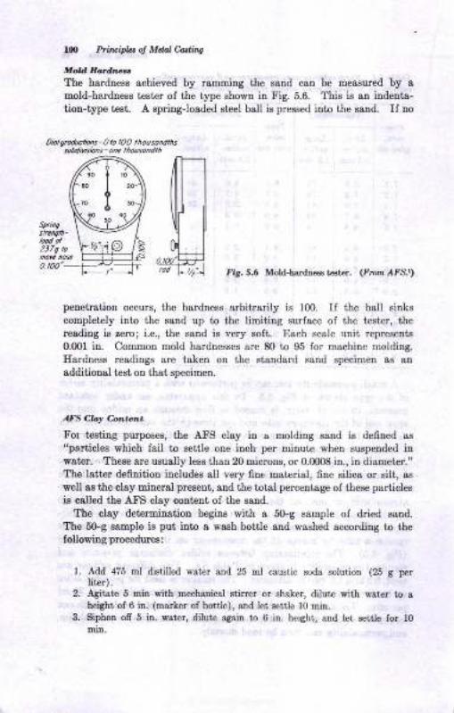
100 Prirlajfu ol Mdal Carlins
Mold HodnzcrThe hardness achieved by ramming the satrd can be measured by Imold-hnrdness tester of the type shown in Fig. 5.6. This is an indenta-
tiou-type t€81. A spring-loaded steel ball is pressed into the sand. If no
0tbl grodlotbls - 0 to lO0 thou sondthssuMirisbns - onc lh ouso n dh
Sprkg
o. t00'fig. 5.6 Mold-hafltrcss t€st€r. (F orn /{fs.r)
penetration occurs, the hardness arbiharily is 100. If the ball sinkg
completely into the eand up to the limitiug surface of the tester, thereading is zero; i.e., the sald is very 8oft. Each scale unii representB
0.fl)l in. Common mold hardnesses are 80 io g5 for machine molding.
Ilardneee readings are taken on the staDdard 8&ud specimen a8 sD
additional test oD that qrecimen.
AFS Clq 6*tcnt
For teating purpoees, the A.FS clay in a molding sand is defned es
"partiolee vhich fsil to settle one inch per Eiuut€ wheu Bu8pended iD
water. Theoe are uaually less than 20 microaa, or 0.0008 in., iD dismeter."The latter defnition includea all very fine mat€!i&I, fiDe silice or ailt, as
well 8s the olsy miueral present, and the total percentage oI these particlea
is c8lled the Atr'S clay coutent of the sand.
lte clay determiuation begine with a 5Gg sample of dried satrd.
The 5G.g sample i8 put iDto a waeh botile and washed according to thefoUowing procedureo:
1. Add 475 El di.stilled wat€r &Dd 25 El caustic sods solution (25 g perliter).
2, fuitst€ 5 EiD with mechanical stirtlr or 6hoker, dilute with Fater to a
heiSht of 6 itr. (matker of bottle), aod let settle 10 mir!.3. Biphon ofr 5 ir. est ., dilute aaain to 6 in. height, 8trd let settJe for l0
niD.
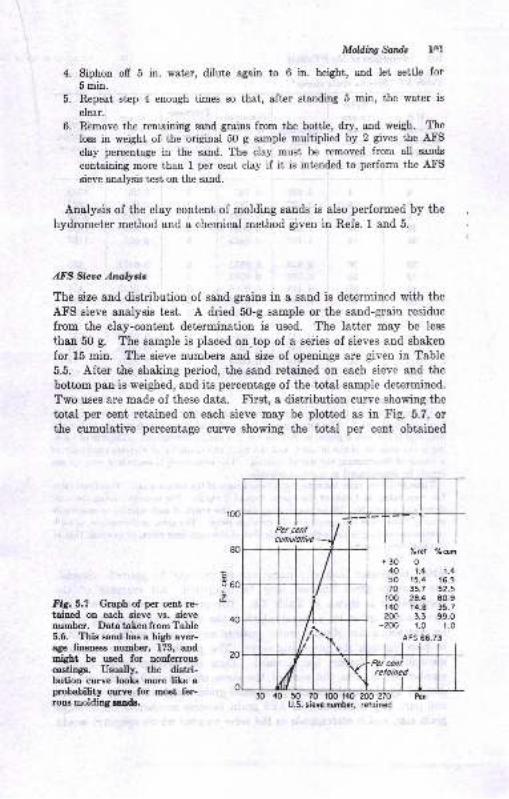
4.
D.
6.
Mddittg fSail, l4l
Siphon off 5 in. water, dilute again to 6 in. height, and let settle for5min.Repeat step 4 enough times so that, after standing 5 min, the water is
clear.
Remove the remaining sand grains from the bottle, dry, and weigh. The
loss in weight of the original 50 g sa,mple multiplied by 2 gives the AtrS
clay percentage in the sand. The clay must be removed from all gands
contaiaing more than 1 per cent clay if it is intended to perforrn the AtrIlsieve analysis test on the sand.
Analysis of the clay content of molding sands is also performed by the
hydrometer method and a chemical method given in Refs. 1 aud 5.
AFS Sictc Ana,lyeis
The size and distribution of sand grsins in a sand is determined with the
AFS sieve analysis test. A dried 50-g sample or the sand-grain residue
from the clay-content determination is used. The latter may be less
than 50 g. The sample is placed on top of a series of sieves and shaken
for 15 min. The sieve numbers and size of openings are given in Table
5.5. After the shaking period, the sand retained on eaeh sieve and the
bottom pan is weighed, and its percentage of the total sample determined.
Two uses are made of these data. tr'irst, a distribution curve showing the
total per cent retained on each sieve may be plotted as in tr'ig. 5.7, orthe cumulative perceutage curve showing the total per cent obtaioed
80
c3eo
EFig.5.7 Graph of per cent re-taiued on each sieve vg. sievenumber. DatatakenfromTable5.6. This eatrd has a high aver-agt fineness number, 173, andmight be used for nonferrouscastinga. Usually, the dietri-bution curve lools more lite aprobability curve for most fer-rous rnolding unde.
'hrel ohdn
+3O O
40 1.4 1.450 r5.4 16.370 35.7 5?.5
!00 29.4 80.9140 t4.8 ,5.720(| 3.3 99.0
-200 r.o r.0
A FS 66.73
30 40 50 70 r00 140 200 ?70U.S. sieve numbcr, retoined
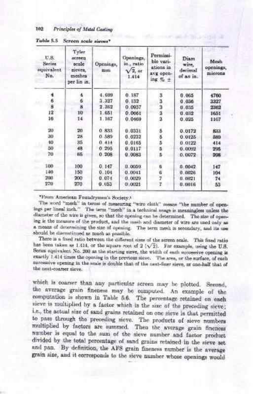
lU, Pti\cid.t ol Mdal Ca'lins
Tabra 5.5 Screl... r.f,L .i<'s'.
u.8.Scriee
€quivdcntNo.
Tyler
rcale
per lin in.
Opcnings,urm
Openinge,
in., Etio
\fr, *1.114
Permi!.i-ble vrri-stione inav8 op€n-ina ?o !
Dism
decimalof rn in.
M.rhopeoina!,
1
68
t2l6
N30
40
5070
l@140
200
270
46
tl0t4
b2A
35
{t86
lm150
N270
4.699
3.3272.362l 65rl 167
0. &33
0.5890. 41,1
0.2r)50.208
0.1470. r04
o.o740.053
0. 187
0. r32
0.09370.066 r0.0469
0.033ro.02320.0165
0.01170.008i1
0.00590.00410 0029
0.0021
333
3
655
6
5
67?
0.0G5
0.0360.0350. o,i2o.026
o.ot720.0r 25
o.it220. m1,2
o.u)72
0.00{20.00260 u)210.0016
{760st2723,82
l86ll167
til36804l{29tN
t17104
74
63
'From Americstr FoutrdrymsD,s Society.lThe word "m6h" in t€rEs of measuriDg ',wirc cloth,, moaDs ,,the number of op€a-
iDSs p€r liDesl inch." The t€rh ,,m€sh,, itr & tachnical usage is mer"i"gl€ss u e3s thodiameter of the wfue is giveq so thst the openiDg caa be determined. The sire of op6r_iDg is the measue ol the prcduct, atrd the mesh a[d dismet r of wiro are uaed ouly esa- m€ars of determining the size of opedng. The t€rm mesh j.s s€cotrdsry, sod it&ur6sLould be dbcotrtiEued as much as pcsible.
There i.s s 6xed rstio betwoeE the difrereat siz€s oI tbe scre€n scale. Thir 6r6d rstiohsa beer tsken ss 1.414, or the square root of 2 (Vr). For ex&uple, ruiag the U.S.S€rie6 eqrdvalent No- 2OO as tho stsrting sieve, the width of each succeaaive-opening iaet"rctly 1.414 tim€s the opedtrg ir the preyious sieve. The sIea, or th6 gurfar.e, ot eLlsucc€sive opedng in the scale is double thst of the trext-finer sieve, or ono_balf thst, oftho Dext-cosrser sieve.
which is coarser thau any particular Bcreen may be plotted. Spcond,the average grsin fineness may be comput€d.- An example oI thecoEputation ie shoEn in Table b.6. The percentage ret&iu;d otr eschsieve is multiplied by 8 fsctor which ie the size oI ihe preceding 8ie;e;i.e., the actual eize of sand grsius retained on oue sieye is ttrat, pelrmitteato psss thlough the preceding sieve. The products of Bieye numbersmuli,iplied by lactors are summed. Then ihe sverage grain 6nene88number ig equal to the sum of the eieve number and factor productdivided by the total percentage of sand graius retained in the sieve setanrl pan. By- definition, the AFS grain fineuess number is the averagegrain size, and it correspouds to the sieye lunber whose openinge wouid
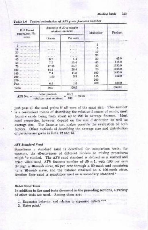
U.S. Seri€8
equivslent No.
sieve
Amounts of 50-g saEple
retai[od oa eievoNfultiplier Product
Grarna Per c€nt
6...............12...........-...m...............30...............40...............50...............70...............lm...............140...............2m...............270...............PeD..............
?o1a1.............
0.77.7
17.85
14.2
7.41.65
o.5
t.415.4
35.7
.4
14.8
;.0
3
5r0m30
fi50
701@
145
2m300
a.D6r6.0
r785.0
1988.0
1480.0
462.0
50.0 t00.0 6673.0
Molding Sandt
To,ble 5.6 Typical cal.ula.ioi ol AFS srojn fwnesa number
-tl'gNo. - ,bd Pduot, , =9-*.r,_-- _--- total tEr cent lstaitrGd tm
just pass all the saud graius if all were of tfie eame eize. This number
iE a convenieut meane of describiug the relstive fnenese of 8aDd8, most
formdrJr esnds being from sbout ,t0 to 220 in average 6neDes8. Most
BaBd properties, however, rlepend on the sire dietdbution 88 well a8
overage size. Tbe fiueness t€st, makes possible the evaluation of both
Iactors. Other methods of describiug the aversge size and distributiou
of particles are given ia Refs. 12 aud 13.
,lIS Ston&rd Slad
Sometimes .. staDdard eand is described for comparisou tesis; for
example, lhe efiectiveness of difrerent bindere or mixing procedures
might re studied. The Atr'S esnd staudard is defined as a washed aDd
clried silica sand, AFS finenesa uumber of 50 11, with lm per celttb-.rugh u 4O-ueeh eieve, 95 per cent through a SGmesh and rcmaining
.a a TGmesh eieve, and the balauce retained on a l0Gmeah sieve.
Aaother 6aer Eand is sometimes ur€d a8 a secondary staDdsrd.'
Odot &,nd Tat,.
Iu addition to the esnd tests discussed in the ptcoeding aectionr, a vsriety
of otlrcr teEtE are used- ADong them are:
l. Expslsiotr behevior, and relatioD to erpaosiou defects.r'"
2. ght ! point.'

llx Prituipla ol Mda, &ding
3. DuBbility. The sEount of cLsy rcquired fo! lebooding the sand to a cotr-statrt greeD streDgth during repeated cycles of ue for pouring castings caD
be used to study the life or durobiliiy of clayo.rn
4. IUold-g8s evolution. The tendency of molding 6snds to give ofr gas€s can
be studied by specisl procedures]''5. Metal petretrstioE. Metsl penetratiotr has occurred {hen the molt€tr Det&l l
seeps ilto the sard as though it pere porous to the liquid. This results itr IIused mass of metal and sand which adheres tightly to the cssting. A t€st '
used to study this tendency has beea proposed.r"
6. Loss oa ignitioo. Combustible materisl in the satrd is deteroined by theper cetrt loss oD ig ition of the dry ss,od.
Many other Band t€sts have been devised to study Eolding-Bcndploperties.
PROPERTIES OF GNEEN SANDS
The properties of green molding sauds snd their behavior in the rnoldare depetrdent on sever&l factors ol major importance. They include:
1. Tte ssnd ingr€dieata
2. The methods of preperiry the sand foi moldiDg
3. The methods oI molding employed
4, Yaiables relsl€d to the casting, such as weight, shape, kind of cstilg8lloy, gsting design, etc.
A eynthetic green molding sand should be viewed es an aggrega'ld
composed of silica partigles, clay, water, and special additives. Thebulk of the aggregate is supplied by the silica particles. The silicacomes irom the bo€e sord, to which the other ingredients are added.
Ba,e tunol
The base sand may be a clay-free, washed, white silica sand or a less
pure, tan-colored sand coniaiDing some small percettage of clay. Asid"from considerations of purity snd clay content, the average fiueuess
number and psrticle size distribution are properties of the base sand oimajor importance. To illusirete, consider the sieve analysis of I typicalBilica sand as reported in Fig. 5.7 according to the standard methods or
sieve anslysis of the AFS.' The average fineness number is calculateC
lrom the sieve analysis, in this case 66.6. The sieve analysis is graphi.
cally presenied either as the percentage retained on each sieve or or,
cumulatiye perceutsge ret&iued on successive sieves as shown in tr'ig.5.i'[a either case there are three major fractione of the sieve analysis to t,-
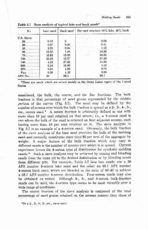
No. Lake send Bank sand Per cent retained: 60% lske, 40% bank
U.S.Sieve:.....'..'.
30..... .. . ..,l{)..........60..... ... . .
70..........100..........140.... .. . .. .
200..........270..........Psr..........
AI8No........
0.r30.67
2.33
r6.02
45.42
33.28
0.r00.01
0.3956
00.03
0.06
1.48
13.30
43.27
27.66
r0.901.89
1.42
88.1
0.08
0.41
1.4i}
10.20
32.81
37.24
11.m4.42
0.76
0.80
68.7
Molding Sofilt
Tabb 5.7 Sie* ",nt tsis oJ .wical laka and bo,.k ,,'nns'
+Tbe6e are sanab which are Dined mriD]y ilr the Gr€s.t Lskes regioD of ihe Udt€d
Sbt€s.
considered, the bulk, the coarse, and the fine fractions. The bulk
fraction is that perceuiage of sand grains represented by the middle
portion of the curves (I'ig. 5.7). The saud may be defined by ihe
number of screens over which the bulk fraction i8 spread ss s 2-,3-, 4-, 5-,
etc., Bcreen sand.' A screen fraction is arbitrarily defined as one with
more than 10 per cetrt retained on that screen I i.e., a 4-screen sand is
one where the bulk of the sand is retained ort four adjacent screena, e&ch
having more than 10 per cent retained on ii. The sieve analysis in
Fig. 5.7 is aD example of a 4-screen saud. Obviously, the bulk fraction
of the sieve analysis of the base saud provides the bulk ol the moldiug
sand and normally constitut€s more than 80 per cent oI the ag$egate by
weight. A major feature of ihe bulk fraction which may vary indiffcrent sands is the number oI screeus over which it is spread. Curreut
experieDce Ievors the 4-screeD type of distribution for synthetic molding
satrds.1s Such a sieve analysis may be achieved by mining and blending
sands from the seme pit to the desired distributiou or by blending sauds
from difrerent pits. For example, Table 5.7 lists two sands, one a 56
AFS number 3-screen lake sand snd the other an 88.1 AFS number
4-screen bank saud, which are blended in the ratio of 60:40 to achieve
I 68.7 AFS number 4-screen distribution. tr'out-gcreen Bands may also
be obtained as mined. Although 3-, 5-, and 6-screeu bulk-fraction
eands can be used, the 4-screen type seems to be most versatile over a
wide range oI conditioue.
The coarse fraction of the siev€ snalysis ie composed of the toialpercentage of sand grains reiained on the screeue coarser than ihose of
'Or a 2-, U, +, G, etc., sievo ss,trd.
106 P rlcipb d Maal CaAiry
the bulk fraction, and iu amounts of le88 than 10 per cent. The totcl
coarge lraction must be limited iu amouut, wually to leEs than 4 per cent
for a saud of the 4-screeu dieiribution iype. Thie limitaiion is neceesary
since an excesg of coorse psrticles contributes to a poor casting surface
finish. In addition, cosrse particles are easily dislodged from the mold-
cavity sulf8ce and become dirt in the castiog. Itr the case ol a t,?ical60 to 70 Af'S sand of the 4-screetr type, the coarse lraction occurs on the
No. 40 or coar8er sieve aDd must be limited to less thaa 4 per cent.
In s sand of higher Atr'S fineness number, the coarse fraction might be
that on the No. 50 or 70 Ecreens.
The fine fractiou of the sieve analyeis is compoeed of the total per-
centage oI sand graine retained otr screens finer than those of the bulk
fraction and iu amounts of lese ihsn 10 per cent. The total fine
fractiou must be limited in amount, ususlly to le88 thsn about 5 per cent
for a sand of the ,1-ecreen t1ae. This limitation ie necessary siuce an
excess of fine particles causes baltirg to occtu during mulling. When
water is added, the fines and clay agglomerate to form balts during
mulling and thus pleveui the clay from being ihoroughly disgeuinated
thrcughout the mass. Although the percentage of flnes must be limited
to & maximum percentage as stated above, there is also a miuimump€rcentage desired. In ihe absence oI the fines, cley balling can occur.
Mulling causes the clay and wate! to form balle if there are no 6ne8
preseot aod again agglomerat€8 of uniformly dispersed ingredients are
noi formed from mulling. The ability properly to mull the aand and
disseminate the ingredients requires this balauce oI coaree, bulk, and fine
sand particles iu the base saud.
&ni Craint arul P* nab ilily
Coarser sande with greater void space have greater permeability th6finer sande. A base permeability for silics sand (no clay) of one mesh
eize hae been reported in Ref. 18, and is recorded graphically in Fig. 5.8.
The fiuer sand grain sizes show a very low permeability. In additioDto average grain size, the graiu size disiributioq has a prououoced efrect
on permeability. A Bsnd with mauy fines aud a wide rauge of particlegizes will have low permeability whea compared with one of the eame
average fiueness but having only one size of grains present.re
Sandc int a d R.lgdqirurt
Refractorinees, i.e., highest fusioa point, seems to be obtaiued in thos€
sand graias oI maximum purity 8Dd size. Washed and dried whitceilica sands of A.tr'S uumber 30 to 45 are regarded as haviug Lighest
refractorioess, with fueion poilt sbove 3000 F. Impurities sush as ironoxide, feldspar, and limeetone, which discolor, lower its fusion poiut.
Finer graios appesr to be more easily fused than coare€r ones. Where
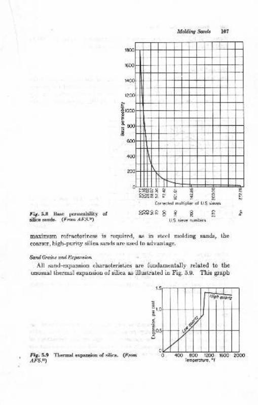
Mohling Sands
.:oo
o
o6
Fig. 5.8 Base permeability ofsilica sandE. (From AFS.ts)
- Corrected multiplier ol U.Ssieves
ooooooooodoc6FoqoFNN
U.S. sieve numberc
maximum refractoriness is required, as in steel molding Bands, the
coarser, high-purity silica sands are used to advantage.
Sand Grail* and Ecpa.rcion
All sand-expansion characteristics are fundamentally related to the
unusual thermal expansion of silica as illustrated in Fig. 5.9. This graph
400 800 1200 1600Temperoture, oF
c
d
i.oC0d
U
oo N
N
, FiS.5,9 Tlicrmnl expaDsion of silica. (FmmAFS.U)

,6o;oct
.9
goEoc
eo
l0B Principbs o! Mdal Caslins
shows that major expansion occurs in the temperature range of 1000 to1200 F because of the allotropic transformation of silica.'8
Cby and Vatet
The influence of clay content and percentage of tempering water on thegreeD compression strength of a molding sand is illustrated for western
bentonite iu Fig. 5.10. The effect of clay and water content on drycompressive stength is shown in Fig. 5.11. Similar curves exist for the
0.5 r.0 1.5 2.O 2.5 3.0 3.5 4.O 4.5Per cent tempering woter
Fig. 5.10 Relationship ofgreen strength, clay, and per-centage of tempering water forthe AFS standard sand bondedwith western bentonite. (FromR. E.Grimand F. L.Ailhberl.2)
5.0 5.5
other clays. For a given clay type and content, there is an optimumwat€r content with reference to Figs. 5.10 and 5.11. Too much watercauses excessive plasticity and dry strength. Too little water fails todevelop adequate strength and plasticity. Control of moisture in themolding sand so that the best properties are developed is a.necess&rybasis of saud control,
Cloy
Green sands may be considered as clay-saturated or unsaturated ag-gregetes &ccording to the clay percentage preseut. A clay-saturatedgreen sand is defined as one containing a high enough percentage ofcley so that any further increase in clay content will not cause an increase
iu maximum green compressive strength of the aggregate. This defini-
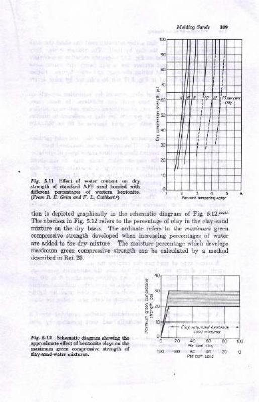
fig. 5.U Efrect of water conteut on drystrength of etsndard AFS eatrd bonded withdifrerent perceutages of western bentonite.(fm,n E. E. Grim and F. L. Ailhbrt.)
Moldiw funds r09
2345fur cetrt lempering x,oier
tion is depicted graphically in the schematic diagram of Fig. 5.12.22'23
The abscissa in Fig. 5.12 refers to the percentage of clay in the clay-sandmixtue on the dry basis. The ordinate refers to the marimum gteen
compressive strength developed when increasing percentages of waterare added to the dry mixture. The moisture percentage which develops
maximum green compressive strength can be calculated by a methoddescribed in Ref.23.
Fig.S.lz Schematic diagram showing theapprorimate ellect of bentonite clays on themarimum green compreseive strength ofclay-oand-water mixtures.
,2
oE.;31HbicoEE6
.Eo
o 20 40 60 80 100Per cenl cloy
100 80 60 40 20 0Per cenl sond
ll0 Principbt ol Mel Cadine
Figue 5.12 poiots out thst I cl8y-satursted eand has sbout {}le Bame
compressive streEgth as the clay by iteell. The mixture iq,thus fullybonded. The shaded area on Fig. 5.12 represeuts. variatiog in maximum
streugth of the clay-eand mixture due to clay purity and eource, sieve
analyais of the baee-eand mixing efficiency, and otlel lactors. Iligheretrengths than indicated in t'ig. 5.12 can be achieved by more severe
mixiug.The specific percentage of clay required for saturatioD depends on
purity and type of clay, base sand, and additivee. Io most cases,
however, about 8 to 12 per cent oI bentouitris (either sodium or oalciumbertoniteo) or about 20 to 25 per cent rfe clay is sufrcieut to produce
a clay-saturated mixture with the./ud fineuess oI @ to 100 AFSnumber.
The nature ol ihe bonding action betweeu l,he clay aud saud particlea
ig discuesed iu Refe.40 snd 41. This subject is not congidered here.'Wiih
reference to clay content there are three m8jor types of syathetic-sand practices. Firet, the clsy-saturated sauds may be considered.These are mixturee coutaining a percentage of beDtonit€ type of claycorrcspoodiug to the Baturatioo poiut, thst is, 8 to 12 per cent.' ByAFS clay analyeis, the percentage of AFS clay is common.ly from g to14 per cent, or true-clay particles ol sbout, 8 to 12 per ceDt (see Ref. ?
Ior true-clay eualysia), The clay-eaturatcd type of sand ia curentlyr.widely used in irou foundriee and in loundrieg producing the heaviernolferroue alloys. Clay-saiutated sands are probably the most versatilegreeu-saud mixtures for a wide range of castiug weight and alloy types.Casting defects due to sand expansion, eroeion, and cuts and washes areeither eliminated or reduced to a aegligible perceDiage attributable tothe molding eend itself. Siace such sauds are normally of high streugth(f4.0 to 20.0 psi green compressive strength), they require adequatrcramming to develop their properties (preferably over 8b mold hardnesa).
A e€coud type of Band practice involves the use of clay in amountswhich are slightly but definitely less ihau the saturatiou p€rcentage.The amounts actually carried in Eaud systems ere about 6 to 9.0 percent Atr'S clay in bentouite-bonded s8ud, or sbout the equivslent amoultof 10 to 15 per ceut fire clay. Such sande are used more Ior lightercastings where expansion defecte, erosion oI cuts, and washee are lisserproblems.
A third practice ie a low-clay-coutent practice involving about 4per ceut western (aodium) beutouite and ueed primarily by eteel
'SJ.nthetic moldiDA seods sstuBt€d with fue clsy sre Dotr comeoDly us6d. Tho m b25 per o6nt 610 clsy Equirod for saturstioD producE s .eDd of lo*-pormeebility aadh.gb.Doi.tur€ r€quL€moDts.
Mold q sandt lll
foundries. Expsnsion probleme are at a maximum with thie type of
aand. Eowever, because of ite low green etrength, 6 to I psi, and higb
moieture content, it can be readily molded to high density. Cereal io
used to ofrs€t the expaDsion problem.
Clq Typ"
Weetern bentonitee are used in sands requiring a higher level of dry
compressive strength, iu excees ol 80 psi, for example. Southern benton-
ites ore us€d in sands where a lower dry compressive strength is accepL'
sble, 40 to 8O psi, for example. Fire clay produces Boderat€ drystrength in the sands in which it is used. Maximum dry compreseive
Btrengths over 200 p8i astr be obtained wiih mixtures oi fire clay aud
westerD beDtouitrc.'o
WaLt
The moieiure required to produce the desired properties in a green
saud caa be calqulat€d. The method is based ou first computing the
total perceutage of water absorbed by all the ingredient's of the s8nd.
The uariuum adeorbed moisture cont€trt is associated with the develop-
ment of maximu.m, or peak, green strength, as poioted out in Fig. 5.10.
Additional water, called tree water, is required to develop dry com-
pressive strength aud plasticity, or deformation. The method of comp[.tetion is giveu in Ref. 23, aod examples of ite use are described in ReI.
2. The final eelection oi moisture cont€nt to be used in the molding
sand is usually a compromise based on many practical factors operating
iu a giver gand foundr;r. These are uot usually accountable in auy
caleulation method.
Addiliu,
The additives ueed in moldiug salds were defined earlier. Reference
23 may be studied for more inlormaiiou ou this eubject.
Wet o, ttoldil'' o,t tund Prcprttct
The foregoing discussion has dealt with the principles of proportioning
the ingredients of synthetic moldiug sands. Although the ultimatcpropertiee of the saud are fxed by its ingredieuts, the properties displayed
il a mold are in a large neaeure determined by the molding operatione.
As the ssud ie molded, it is compacted. Compaction, measurcd aB
iucreaaed bulk density, is accompanied by an increase in the mold
hardness, green compressive, shear, aud ten8ile sheugths, 8Dd dry 8ud hotstrengtle. Examples of the rauge of.bulk densitles exisiing in sanda
from minimriu to maximum were govided iu Table 4.1, When the
llt Prircipl* o! Mctd Cad q
molding process is flnished, the sand is at some level of butk densitybetweeu the minimum and the maximum listed in Table 4.1. The bulkdeDsitv at which molding stops then largely determines the properties
which the molded sand aggregate displays. It is extremely importantto be able io express the propedies of sand over a range ol bulk densities
ard molding or ramming eflort. tr'udher, some meaDs of relating theproperties measured with laboratory specimens to properties in thertrold i8 trecessary.
Mold Hardrcss
The mold-hardness test provides a convenient measurement for relat-ing properties in the AFS 2.0- by 2.0-in.-diameier specimen to properties
in the mold. Fortunately, the mold-hardness test is an indirect measure-.-nent of bulk deusity of a particular saod. In addition, green propertiesare related to mold hardness in a way similar to that, of bulk density.Hetrce it caD be recognized that mold hardness starting at about 60 andincreasing to 95+ mesns that the bulk density of ihe sand is increasingIrom the lower to the higher values in Table 4.1, and strength propertiesare also increasing. Comparison between laboraiory specimens aodmold then requires that specimens be prepared over a wide hardneso
ratrge eo that any mold hardness measured in a mold can be comparedwith equivaleni hardness in the specimen.l. Figure 5.13, for example,shows how mold harduess and green compressive strength are relatedover the hardness range of 60 to 95 MH for new sand mixtures contain-ing 3, 6, 8, and 12 per cent westen. bentooii" The grapli shows aprogressive increase of green compressive strength with mold hardness.
The graph also demonstrates that green complessive strengih at a given
mold hardness depeuds on clay conteni in unsaiurated sands.3o Inclay-satursted BaDds, greeu compressive strength reaches & m&x.:numvalue at any given mold hardness, and is not fudher increased by increasing clay contcnt. The upper curve in tr'ig. 5.13 therefore represent8 themaximum MII-GCS relationship for all clay-saturated sands, regardless
of clay type. tr'urther, this relationship is not afrected by moisturepercentage iu the sand within the normal moisture percentaees ofmoldiug sands.
To correlate specimen properties with the mold, the hardness of themold is measured. Since mosi molds are nonuniform in hardness,
readiugs must be taken on the parting surface and on vertical surlacesat varying distance from the parting to ga,in a picture of the degrce ofmold-hardness variatiou withiu the mold. As in the case of the specimen,
when the mold is rammed to high densiiy, it will be uniformly hard.The object ol good molding technique is to achieve a unilorm and high
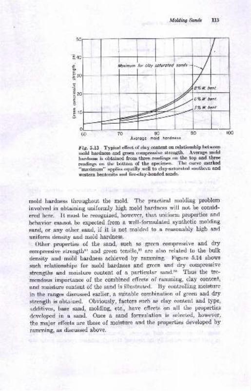
Molding fuilds ll3
Averoge mold hordness
Fig, S.lt Typical eltect of clay cotrtent oo relationship between
mold na"dness-and gteen compreeoive strengtlh' Average mold
hardnese is obtained from.three readings on the top and three
readings on the bottom of the specimen. The curve- marked
"maxifoum" applies egually well to clay-saturated southern and
weat€rn bentonite and fire-clay-bonded sands.
mold hardness throughout the mold. The practical molding problem
involved in obtaining uniformly high mold hardness will not be consid-
ered here. It musb be recognized, however, that uniform properties and
behavior cannot be expected from a well-formulated synthetic molding
sand, or aDy other sand, if it is not molded to a reasonably high and
uniform density and mold hardness.
Other properties of the saud, Buch as gteen compressive and dry
compressive strengthsl and green tensile,so are also related to the bulk
density and mold hardness achieved by ramming. Figure 5.14 shows
such relationships for mold hardness and green and dry compressive
strengths and moisture content of a particular sand.23 Thus the tre-
mendous importance of the combined effects of ramming, clay content,
and moisture content of the sand is illustrated. By controlling moisture
in the ranges discussed earlier, a suitable combination of green and dry
strength is obtained. Obviously, factors such as clay conten-t and type,
additives, base sand, molding, etc., have effects on all the properties
developed in a sand. Once a sand formulation is selected, however,
the major effects are those of moisture and the properties developed by
ramming, as discussed above.
'ao'
;
.=
E
c
o
Moilmum for cloy soluroted sonds
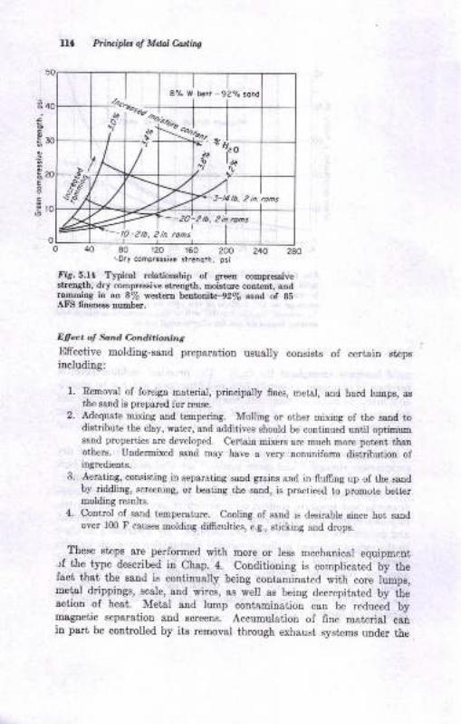
fllffi,*8% lV b€nr - 92%
PtirripLr o! Mdal Corlint
e
i20E
OL0 40 80 120 160 200 240 280
\ory compmssiva strcnori. psi
fiA.s,f4 Typical rclrtioD.hip of greea comprtoaivestreDgth, dry comprBsivo rtr.engtl, m<i:ture content, andrsmmiDg in ao 8/6 Yatan btu 2-9270 lstrd of BsAFtl fmene. aumbcc.
Efiect d tuI4.d C-orrditi(nnt,,g
Efrective molding-sand preparstion usually cousists of certain stepaiacluding:
1. Removal of loieigrr Eaterial, priocipally 6!es, metal, and hard luop, asthe saud is prepared for reuse.
2. Adequstc Eixing and t4mpeliDg. Mulling or othe! mixiDg of the satrd todistdbut€ the cl8y, water, and additives should be continued ultil optimuDssnd prcpertie€ &rc developed. Certain mixers erc much Erore pot€nt thstotherg. Undermixed saad may have a very nonuniform distribution ofiDgredietrts.
3. Aer8titr8, cotrsisting in Beparaling sand grains and in fluffing up of the sandby riddling, screeDiDg, or besting the 6aDd, i.s prscticed to promote bette!molding results.
4. Cotrtrol of sand teeper&ture. Cooliag of saod is desirable eince hot sondover 100 F causes molding difficulties, eg., sticking and drops,
,These Btaps are perlormed with more or less mechauical equipmcnt..rf the type described in Chap. 4. Conditioning is complicated by thefact that the eaud is continually being contaminatrcd with core lumpe,mets,l drippings, 8cale, atrd wires, as well as beiog decrepitated by theaction of heat. Metal and lump contamiDaiion can be reduced bymaguetic eeparation aud screens. Accumulation of 6ne material caniu pari be controlled by its removal tirough exhaust syst€ms under the
MoWiw funds ll5
dusty conditions of the shakeout. However, burnt clay and dilution by
core sand can be corrected only by additions of clay and other additives
to keep the sand properties at the desired level. Green strength and
other properties and the combustible material in the sand are lost
as the sand is reused unless such additions are made to recover
the losses. The clay and other materials added for each cycle of midug
is about 0.15 to 1.00 per cent of the weight of the sand or about 2 ta 20
lb of clay per 20fi)-lb batch, depending on the size of castings being
made. The returued sand is of unknown moisture content, and addi-
tions for tempering at the proper water percentage must be made.
Adequate mixing requires the proper use of mixers. A mulling time
of 4.5 to 6.0 min is required for mullers of the type shown in Fig. 4.14
to develop the bond for the clay. The centrifugal-type muller (Fig.
4.15) requires about 1.0 to 2.0 min. Ovelmulling can result in excessive
heating of the sand, but more often the sand is hot, and mulling willcool it by water evaporation, especially if the muller is equipped with
cooling blowers. Other types of mixers have optimum mixing periods.
Any of the equipment must be properly adjusted. After mulling, some
sand systems contain storage facilities to take advantage of the fact that
some sands seem to improve with time. The mulling effect is considered
in Ref.42.Belore use in molding, aeration is a helpful practice. Aeration may
be accomplished by riddling on /a-in. mesh screens, mechanically, by
vibrating screens, or by other devices. Aeration improves the molding
qualities of the sand and the casting finish.
MOLDING-SAND TYPES
Sands are classified as natural or synthetic molding sands on the basis
of their clay bonding material. A natural sand is one containing sufficient
AFS clay as mined from the sand pit so that it can be used directly,
needing only to be tempered and conditioned. A synthetic sand, how-
ever, is one artificially compounded by mixing sand grains and clay of
the selected types considered. Natural sands came first in the chrono-
logical development of the foundry industry. Their present advantage-'
consist in the simplicity of their preparation, handling, and use. Syn-
thebic sands have the advantages of lower eost in large volume, wide-
spread availability, and the possibilities of sand reclamation and reuse.
Some typical specifications for natural sands are given in Table 5.8.
Listed in Table 5.9 are some properties and mixtures of synthetic
saods. A more complete description of one ferrous molding sand is
provided in Table 5.10 in which many properties are given quantitative
values supposed to be favorable for producing good lightweight gray-
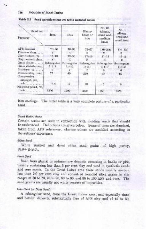
116 Priruipb.s of Metal Castiry
Tobb 5.8 *td e1lecifico,tions on rr.tnc natural rrlnds
Sand use Heavybrass or
ironProperty
A-FSfineness......Finenessclass.....CJ,ty eon.tr:tt, /o. . .
Clay content class.Grainshepe.......Grain distribution.Moisture, %......Permeability, min.Cornpressive
strength, psi,
mitr....Sintering point, 'C,
min....
70-804
r5-r8F
Subangular5:4:3
6
It
1200
70-804
22-30G
Subangular3 :4:3
40
t2
1200
23-278
l7-r9F
Subangularl:1:7
250
l0
1250
No. il)Albany,
amall 8ndmedium
brass
180-20u,
I 1-13E
Subangular7:4:0
6
10
D
r050
No. tAlbany,
brass andsmall iron
lr0-1303
12-r5E
Subangular2:4:2
6
r5
8
r075
iron castings. The latter table is a very complete picture of a particularsaod.
Send Definitions
Certain terms are used in connection with molding sands that shouldbe understood. Definitions are given belo\il. Some of them are standard,taken from AFS references, whereas others are modified according tothe authors' experience.
Silica Sand
White washed and dried silica sand grains of high purity,99.8+% SiO,.
Bank &nd
Sand from glacial or sedimentary deposits occurring in banks or pits,usually conteining less than 5 per cent clay and used in synthetic sandsand core sands. In the Great Lakes area these sands usually containless than 2.0 per cent clay and consist of rounded silica grains in sizerangcs of 60 to 70, 70 to 80, 80 to 90, and g0 to 100 AFS and over. Thesaud graim are usually not white because of impurities.
Iahz Sc;nd (or Durc Sand)
A subangular sand, from the Great Lakes area, and especially duneand bottom deposits, substantially free of AFS ctay and of 4E to 50,
Iron Iron
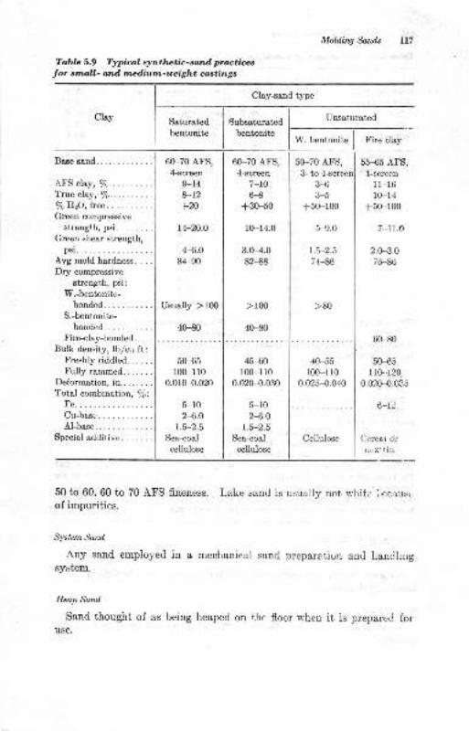
Moldin4 Sanils lt7
Table 5-9 Typical synthetic-sand practices
Jor smtll- and medium-ueight castings
Clay-sand type
Saturatedbentonite
60-70 AFS,4-ecreen
9-14&-12
fx)
t+-20.o
4.-6.0
84-90
Usually )Ifi)
4H
Subsaturated
bentonite
60-70 AFS,4-screen
7-10H
+30-50
10-14.0
3.H.082-88
> r00
40-80
Unsaturated
W. bentonite Fire clay
5{F7O AFS,Base sand.
.AFS clray, %..........Trueclay, %..........7o HrO, tree .
Green compressive
strength, psi........Green shear strength,
psi... ..Avg mold hardness. . . .
Dr5r compressive
strength, psi:
W.-bentonite-bonded-
S.-bentonite-bonded.
Fire-clay-bonded . . . .
Bulk density, lblcu ft:Freshly riddled......Fullyrammed.......
Deformation, in..... . . .
Total combination, afi:
Fe.....Crr-base.
Al-base.
Special additive. . ... ..
5M5r00-110
0.0rH.020
5-102-6.0
1.5-2.5
Sea-coal
cellulose
45-60100-1 l0
0.02H.030
5-102-S.0
1.5-2.5
Sea-coal
cellulose
3- toH3-5
+5(F100
5-9.0
1.5-2.5
74-86
40-55100-r l0
0.025{).040
Cellulose
55-65 AFS,
4-screen
1 1-16
l0-14+50-100
7-11.0
2.0-3.0
76-86
60-80
50-€5110-.120
0.020-{.0e5
6-1)
Cereat or
ciex.in
50 to 60, 60 to 70 AFS fineness. Lake sand is usually not white Lecauso
of impurities.
Sysiem Sand
Any sand employed in a mechanical sand preparation and handhngsylrtem.
Hap Sand
Sand thought of as being heaped on thc floor when it is prepared foruse.
Clay
>80
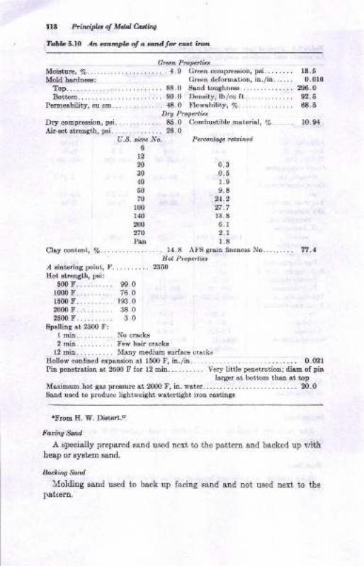
lr8 P'it&ipla d Mdal edin!
TobbS,lO An aampb ol o.aadtor d.r. itort
Grerrl Prop.tti.,Moi&trrc,7o.......-.. 4.9 Greetrcompr$sioD,psi........ rt.5Mold brrdrexs: Green deformstion, in./ir.. ... . 0.018
Top..........-...............88.0 Sand tou8hne8s.. . . . . . .... 206-0
Bottom....... . . ......... m.0 Density, lb/cu ft . . . . . . . . . . . . . . 92.6Permeability, cu cm... 48.0 Flowsbility, Ea . - . . . . . . . . . . . . . 6.6
Dry Prcperties
Dry compressioa, psi.. 85.0 Combustihle mli.enol, %...... 10.91
Ai-€€t Btreasth, psi. . . . . . . . . . . . . . 28.0U.S. ticuc No. Pe,cdtat. fttai,.cd
6t220 0.330 0.5.r0 1.950 9.870 24.2100 27.7140 l:r.8zn 6.r2?O 2.rPen 1.8
Clay contert, %......... -....... 14.8 AI'S grsir Gnereea No......... 77.lHot Piope ie,
/ EiAhriDg poitrt, F... ....... 50
IIot stretrgth, psii
5m r.......... s9.01000 F.......... 76.01500 F.......... 193.02000 F..,........ 38.025m F. 3.O
spa[iDs st 2500 F:I min No crek82 min....... .. Few heir crackB
l2 min.. .... Mary medium surface ffsrksHollow corined expaDsion at l50O F, iD./iD.. ... -. .......... o.(DrPin peretrstion at 2600 F for 12 mid... .. . . . . . Very little p€netrr.tiotr; disE of pir
Iarger st bottom thstr at topMsximum hot 8os pressure
"t 2000 F, in. f,,st€ ...... N.0
Sand used to produce lightw€iaht watertight iron cs.stings
'Froxtr E. W. Diet€rt,'
Facing &nd
A specially prepared Batrd used nexi to the pattern snd backed up lrithheap or eystem sand.
hckins Sand
lv(olding sand used to bsck up facing sand and not used next io ihe
Ist[erD.
MoAiq Sandt
8..,d,tt'&ad
Sand higb in clsy c.utent used to add clay to a molding sand.
Sicrp,Sod
A sand substsntially free o{ bond. The term has Do teference tograin ahape. Lake eande are sometimes referred to ae eharp sande.
M Additiac
A:ry material added to moldiug Bands for a Bpecisl efrect.
L@rn
A mixture of sand, silt, and clayey particles in zuch proportions as to
erhibit about 50 per cent sand grains and 50 per cent silt 8ud clay. Amaterial ua€d for loam Eoldiug of large gray-iron castiogs,
D"r *^drheoeding sections were limited iu discussion to the nature of green
molding sande. Dry-sand molds have certaiu desirable features, aamely,
gre8ter strength and rigidity, thermal stabiliiy, and the elimination oldefects attributable to water in tbe sands. Large aud heary castiugs,
becauee of metallostatic pressure ou the mold and the long peniod during
whicb they may remain molten, require exceptional thermal etability of
the mold. Certain metal defects, such as pinholiug, caa be eliminated
iu troublesome caetiugs iI the mold is dried.
Since the sand ia green lor molding, its propedies are eimilar to tlose
diecussed fqr greeu sands. Usually, the saud is tempered on the wet
side because this brings out 8dditiousl dry strength, as was illustratedin Fig. 5.11. Ceriain ingredieuta uay be added for special efrects.
Sitica flour ia extensively us€d for added hot streDgth and resistatce to
erosion. Pitch ie often used for greater strength aod improved surlace
finigh of iron castitge. Some oI these variatione are indicated in Table
5.11, where eome dry-sand molding mixtures are liet€d. These sande
are greatly depeudent for their dry strength on their cley and wat€r
content and the hardness to which they are rammed.
f,lold C,attagt
tr'or some castings, the sand surface of a mold is alt€red aft€r the patteru
is drawn by applying a mold surfacing material. This material is called
a mold wash, mold coating, spray, blacking, or similar name. The
benefite claimed lor their use iDclude better aurlace 6nish, greater ease
of cleaning the castiug, aud lewer casting-surfsce defects. Application
to l,he mold surface is uually done by epraying, swabbing, or paioting
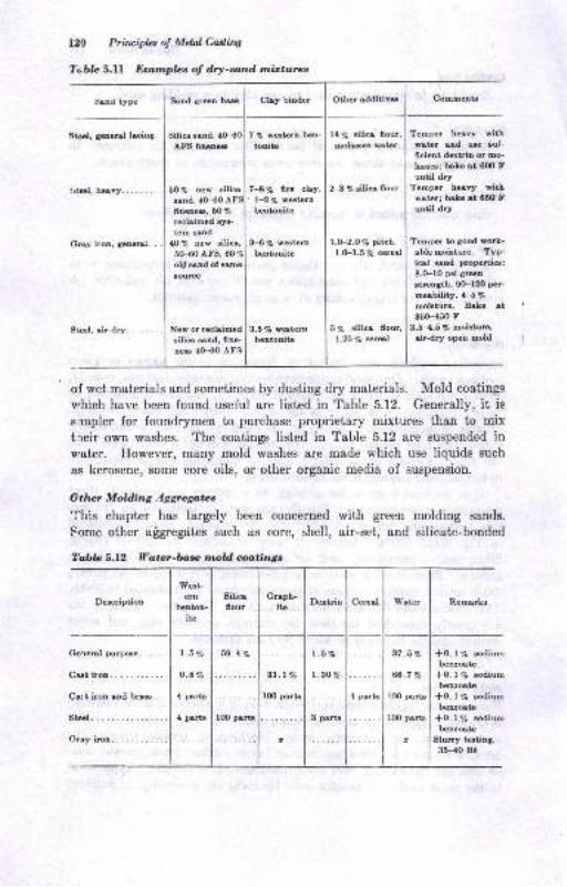
120 Priruifus o! MtuI Cutiw
?obte 5.ll Eranpbs ol dry-satd rnirtu,rca
Sand type Sood greu bse Clsy biDder
,Stel, genen! frinl. Silica ocad,
Othc additive Co66eats
AFS finonea
5O7o new silica
aand, 4(H0 A6nen8. 60 %
recleimed sye-
tem seod,10 % Dew silic&,
sHOAFS,old aand of oame
toutce
New or rwlcimodailica sand, fine-
nes 40-{O AfS
7 % vEtarn ben-
toDite
7-8Eo fle clLv,L'2 q" w@ternbeutonite
3-{ 70 wBterDbeDtonito
14% Eilics flou.,Eolrc wrlrr
2-3 % sili6 Aour
r.(F2.O70 pit h,
l.(F1.5 70 @resl
Tenper bury withw8t€r and uo iuf-ficient dertrin or mo-
lsse; bake rt 6fi) Funtil dry
Temper hovy withwatar; baLc at 650 Funtil dry
Temper to good woth-able moistw. Typ-ical sand ptopertiea:
8.O-10 pei grealtreDgth, 0O-l2O pet-
meability, 4-5 %
ooiature. Bske rt35(F450 F
3.54.6 7o Eoisturc,airdry open mold
Gray iroo, general. . .
Geeeral
C&t
Steel
Stel, ait-dry.
of wet materials and sometimes by dusting dry materials. Mold coatings
u'hich have been found useful are listed in Table 5.12. Generally, it is
simpler for foundrymen to purchase proprietary mixtures than to mix
treir own washes. The coatings listed in Table 5.12 are suspended in
water. Ilowever, many mold washes are made which use liquids such
as kerosene, some core oils, or other organic media of suspension.
Otlwr Molding Ag grcgctec
I'his chapter has largely been concerned with green molding sands.
Some other afgregdtes such as core, shell, air-set, snd silicate-bonded
?'abla 5.12 Vatehbase rnold coatinge
g.5Uo wqtonbeotoDito
5% sili6 Oour,
l-25 vo @r@l
DercriptioD
Wst-ern Silico
6ourGraph-
itoDertrio Cereal Yfrter RemarLs
ite
t.5%
o.avo
4 parts
4 pBrt!
59.47o
10O part!
3t.t%
l0O parts
t.5%
l.3o%
3 psrts
4 psrts
37.5y. I +0.1% lodiuI beoroate
66.?r" l*o.r% rodiuI beuoaio
l00partol+O.l% Bodiu
I bsuortalooparte l*o.l% eodirr
I beuroctez I Slurry tating.
| 3H0 86tGray
eodirrm
iron oud brs. . .

1
2.
3.
4.
6.
7.
8.
Moldhs Sald, l3l
8and8 will be considered under the general topic of core materials,although they may be used for moldiog as well.
BIBLIOCRAPHY
American Foundr5tnen's Society, "Foundry Sand Handbook," 7th d., 1963.R. E. Grim and F. L. Cuthbert, The Bonding Action of CI&ys, Part 1, Clsysin Green Molding Sands, Ur.io. Ibnois Eng. Etpt. Sta. 8u11,.357,1945.R. E. Grim and F. L. Cuthbert, The Bondiq Actior of Clays, Psrt 2, Ctsysin Dry Molding Sands, Uaiu. Ilhnoi* Eng. Eipt. Sta. 81i1.362, 194$.E. D. Boyle and H. B. I[olfer, Mioeral Peilit€ and Its Use in the Foundry,?roru. .4FS, vol.60, 1952.B. C. Yearley, Efrect of Ee&t ad Additive€ oD Green Sand, Forndry, ]|ol.91, no.8, p.50.II. I[. Dietert Co., Tools for Contrcl, catalogue 118, &n industrisl bulletin.E. G. Lievelink and E. van deu Berg, Green Ssnd Scabbing Tendency Tesi-iag by Shock Heating , T rana. AF S, t ol. 70, p. 152, 1962.R. W. Ileine, J. S. Schumacher, W. F. Shav, and E. E. King, Ramming rl,1CIsy Content Effect on Eot Compression Strength of Molding Sald, Trar,.r,41S, 1960.
R. W. Heine, J. S. Schumacher, ond E. E. King, A New Approach to Moiriing and Core Sand High Tempemture Strength Testing, T?o11.s. AFS, lllliR. W. Eeine, J. S. Schumacher, and E. H. King, Thermal Expansion, H,Deforotation, and Associat€d Defects in Casting, Ttuns. AFS, !gti2.E. W. Dietert, Surlace Gas Pressule of Molding Sands and Corcs, ?ro?r"',4-PS,1948.
M. Granlund, Miclometrics as Applied to Foundry Sands, Trone. /fS, vol.70, D. 37 , 1962.C. H. Bowen, Application of Phi Scale to the Description of IndustdatGranular Materials, Mining 8n4., 1,pr,1, 1956, p. 42O.J. Schumacher, Fool Proof Sand Works for Wide Range of Cestings, /nL.Foundrgman, June, 1952, p. 54.C. A. Sanders and A. G. Clem, Eo\r the One-to-ten Ram Test MeasurceSand and Mold Properties, Am. Fotnd,ryman, vol. 22, Octob€r, 1952.I1. If. Dietert and A. L. Grahao, Raxlnirg of Molding Sands, Ircnr..4tr'S,vol.61, 1953.
17. IL W. Dietett, Surface Gas Pressurc of Molding Sands and Cores, Traru./f3, vol. 56, 1948.
18. E. W. Dieteft, "Foundry Core Practice," American Foundrymen's Society,1950.
19. J. Schumacher, Fool Proof Saod Works for Wide Range of Castings, /rz.Foutdryman, vol. 21, p. 54, June, 1952.
20. N. J. Dunbeck, Sy'nthetic Sand itr Notrferrous Foundries, r(m. Fovndryma*,vol. 8, July, 1945.
21. W. F. Bradley, The Green Compression Strength of Natur&l Betrtonitr€s, iD
"Clay and CIay Minerals," p.41, National Academy of Sciences ond Nationa!Research Council, WashingtoD, D.C., publ.456, 1956.
22. A. H. Zimse-k and R. W. Eeine, Ctay, Fines and Watcr Relationshipo forGreen Strength in Molding Sands, ?roar. /fS, 1955, p. 575.
23. R.I[. Eeine, J. S. Schumacher, aud E. E. Kiog, Green Sand Principtea Coa-troUlD8 Casti!8 Quslity, Modern Castinft, Lpriuuly, 1960.
9.
r0.
ll.
12.
14.
15.
16.

l2t2
24.
25.
26.
27.
28.
29.
30.
31.
Priraipbs o! Mdal Castirq
R. IV. Ileine, E. II. King, and J. S. Schumacher, Ilow to Determine MoistureRequirements of Molding Sands, ?rans. ,4F'S, vol. 65, p. ll8, 1957.
N. J. Dunbeck, American Synthetic Sand Practice, Trans. AFS, vol. 49, 1941.
G. J. Yingas and A. H. Zrimsek, Systematic Approach to Sand Design and
Controi, Report Number 6, Trans.,41S, vol. 70, p.321, 1962.B. C. Ycarley, A New Look at Green Sand l{olding, Foundrg, vol.91, no.8,July, 1963.
R. D. Cadle, "Particle Size Determination," Interscience Publishers, Inc.,New York, 1955.
H. H. Fairfield, Expansion of Silica Sand, Found,ry, vol. 76, p. 128, May,1948.
R. W. Heine, E. H. King, and J. S. Schumacher, Mold Hardness: What It\l[eans, Trons. .41S, vol. 65, p. 123, 1957.
R. lY. Heine, E. H. King, and J. S. Schumacher, Green Tensile and Shear
Strengths of Molding Sands, Ameriean Foundrymen's Society, preprint 59-55,
1959.
R. W. Heine, E. H. King, and J. S. Schumacher, Correlation of Green
Strength, Dry Strength and l\{old Ilardress of Molding Sands, ?rans. .AFS,
vol. 66, p.59, 1958.
J. S. Schumacher, Clay Test for Used Sands, Am. Foundryman, vol.27, no.3, p. 41, Nlarch, 1955.
R. W. Heine, E. H. King, and J. S. Schumacher, Sand Movement and Com-paction in Green Sand N{olding, American Foundrymen's Society, preprint59-32, 1959.
R. W. Heine, Molding Sands, Molding Methods and Casting Dimensions,
Trans. AF9, vol. 64, p. 398, 1956.
R. W. Ileine, E. H. King, and J. S. Schumacher, The Probiem of IIot MoId-ing Sands, ?rans. AFS, vol.66, 1958.
R. E. Morey and C. G. Ackerlind, This Mold Wash Works with All Common
Alloys, .4m. Foundrgman, January, 1952.
R. E. Morey', C. G. Aekerlind, and W. S. Pellini, Effects of Binders and
Additives on the High Temperature Properties of Molding Sand, ?rons. AFS,
1952.
J. S. Schumacher, Clay Test for Used Sands, Am. Foundryman, vol. 27, r:,o.
3, p. 41, March, 1955.
E. F. Taylor and L. M. Diran, The Nature of Bonding in Clays and Sand
Clay Mixtures, Trans. z{FS, vol. 60, p. 356, 1952.
R. A. Flinn, "Fundamentals of Metal Casting," Addison-Wesley hrblishingCompany, Inc., Reading, Mass., 1963.
G. J. Vingas and A. J. Zrimsek, The Mulling E;ffect, Trans. r{FS, vol. 69,p. l0l, 1961.
JO.
34.
35.
36.
ol -
38.
39.
40.
41.
42.
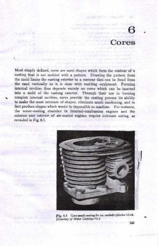
Cores
!
Most simply defined, cores are sand shapes which form the contour of acasting that is not molded with a pattern. Drawing the pattern fromthe mold limits the casting exterior to a contour that can be freed fromthe sand vertically as it is done with molding equipment. Formingintprnal cavities thus depends mainly on cores which can be insertedinto a mold of the casting exterior. Through their use in formingcomplex iuternal cavities, cores provide the casting process its abilityto make the most intricate of shapes, eliminate much machining, and infact produce shapes which would be impossible to machine. For iustance,the water-cooling chamber in internal-combuetion engines and theex0erior and interior. of air-cooled engines require intricate coring, as
revealed in Fig. 6.1.
8ir. 6.1 C.oreeand castins for airooled cyliuder blcck"
ldwksto! MenCutin$h)un
Irr-GL-. J
I
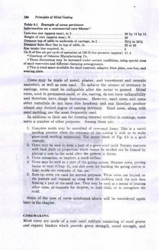
14 P.iacipla of Mda! Carliv
Tar'L 6.r Drartlple ol rohtc pct.i^4nb$ornotion or o tlonrmarciol aru blouel*Core.Sox si,e (spprox tDax), ia.t.... ... _. _.. 38by r3 by tlWeight ol core (spprox nsx), lb.. -....... _. _................... SO
DiltsDce top of tsble tD urdeEide of carriege, iD.t.. _ _ ........... 2SN to g816
Dietance from floor line tD tDp of table, in...... _. . . .. .. . . _. . . 25 to lgsir. int Le line rcquircd, in. . - . . . . . . . . . . . . . . . . _ _ . . _ . . . . . . . . . _ . . . 3Cu ft of free eir per cycle of op€rstioD at 120 lb line pressure (spprox) ll.4
' Crurt€€y of Osbome Msrufacturing Co.
t Tbese dimeDsiotrs Ersy be increas€d under certain coDditioDs, uaing rpecial aizerof ssrd re6ervoirs snd difrereDt clamping srangements.
lThfu is t tsl spsce avgilable for ssnd Esersoir, sdapter, blow plste, core box, aDdrerriag plst .
Cores may be made of metal, plaetcr, and investmelt and cemmicDat€risls, ss well as core saud. To achieve the utmost of intricacy incastings, cores must be collapsible sfter the metal is poured. Metalcores, used in permanent-mold, or die, casting, do not have collapsibilityaud therefore have shape limitations. However, saod cores and some
other materials do not have this handicap and can therefore producealnost atry desired degree of cesting intricacy. Sand core6, along withsaDd molding, are the most frequently used.
In addition to their use for forming internal cavities in castings, coresserve a nuruber of other purposes. Among them are:
1. Complete moids may be assembled of core-,.and forms. This is a useluimoldirg l)ractice lvhen the intricacy of the clsting is such as to makegrcen-s3Dd moldiog impractical. The motor block of Fig. 6.1 is a good
example.
2. C.ores may be us€d to forrtr a part of a green-srnd rlold. Pattern coniourswith back draft or projections which cannot be molded can bc lomred byplacing a corc in the mold &fter the pattem is dra$in.
3. Corcs strengthen o! improve a mold surface.
4. Cores may be used as a pert oI the gating syst.m. Struiner cores, pot,dngbasins or cups (Chap.9), and slab cores for building the gating syst,rm inlarge molds arc ex&nples of this use.
5. n-am-up cotes are used for several purposes. Thes. cores are locrted onthe pattertr and rammed up along with the molding sand, the core thenforming a part of the mold face. They may be us.d as a means of locatingother cores, a.6 supports for chaplets, to hold chills, or to strengthen themold.
Some of the uses of cores mentioned above will be considered againlater in the chapt€r.
COREMAKING
Most cores are made of a core sand mixture consisting of sand grainsand organic binders which provide green sirength, cured strength, and
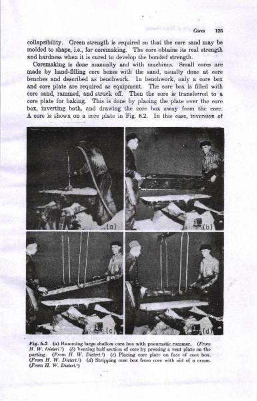
Coret
collapsibility. Green strength is required so that the core sand may be
molded to shape, i.e., for coremsking. The core obtains its real strength
and hardnees when it is cured to develop the bonded strength.
Coremaking is done manually and with machines. Small cores are
made by hand-filling core boxes with the sand, usually done at core
bencheg and described as benchwork. In benchwork, only a core box
and core plate are required as equipment. The core box is filled withcore sand, rammed, and struck ofr. Then the core is transferred to a
core plate for baking. This is done by placing the plete over the core
box, inverting both, aud drawing the core box away from the core.
A core i1 sh1_w:r on a core plate in Fig. 6.2. In this case, inversion of
Fig.6.2 (o) Ramming large shallow core box with pneumatic rammer. (FromH. W. Di.d.cri.r) (b) Venting half section of core by pressing a vent plate on theparting. (From H. W. Diclerl.t\ (c) Placing core plate on face of core box.(From H. W. Dblcrt.r) (d) Stripping core box from core with aid of a crane.(Fron H. W. Dielnt.t)
t
{il. t.
nwvtIG
***
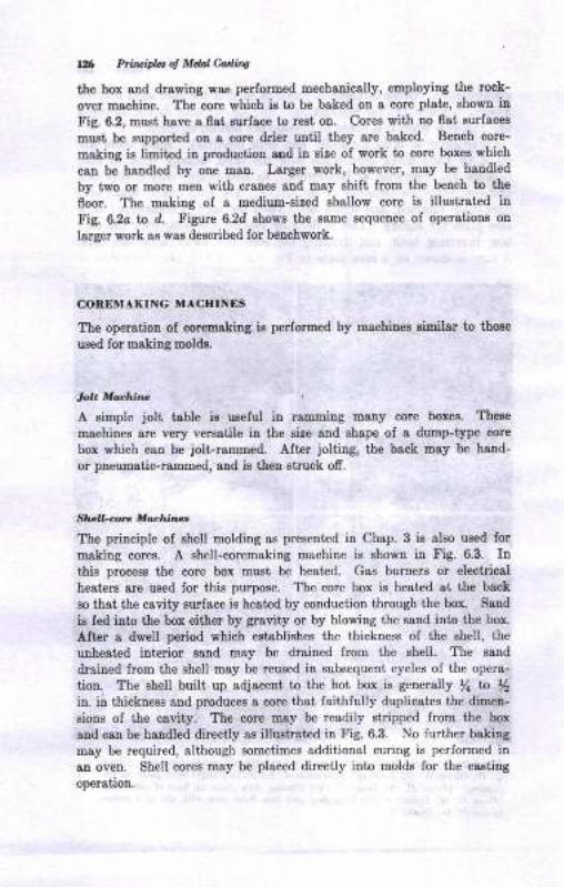
YX Ptirbifu ol Mdal Minq
the box gnd &awing wae performed mechanicelly, euployiug the rock-
over machiue. The core which i8 to be bsked on a core plate, showu inF ig. 6.2, nust have a flat surfrce to rest oo. Corea with no flat surfaces
must be support€d ou 8 core drier until they are baked. Bench core-
making is limited in production aod in 'eire ol work to core boxes which
cau be handted by one man. Larger work, however, may be handled
by two or more meu with craneE aud may shift from the bench to the
floor. The making of a medium-eized shallow core is illustrated in
Fig. 6,2o to d. Figure 6.2d shows the same eequeuce of operations on
larger work as was described ior beuchwork.
COREMAKING MACHINES
The operation of corenaking ie performed by machines similar to thoee
used for making molds.
lolt Moctnne
A simple jolt table ie uceful in ramming tDany core boxes. These
machioee are very versatile in the size and shape oI a durap-type core
box which c&tr be ,iolLrammed. Altcr jolting, the back may be hand-
or pneumatic-rammed, and is then struck ofr.
Sho,l-corc Mochiile.
The principle of shell molding as presented in Chap. 3 is also used for
making cores. A shell-coremaking machine is shown in Fig. 6,3. Inl,his process the core box must be heated. Gas burners or electrical
heatcrs are used lor this purpose. The core box is,heated at the back
80 that the cavity surface is heatcd by conduction ihrough the box. Saud
ie fed into the box either by gravity or by blowing the sand into the box.
After a dwell period which establishes the thickness of the shell, the
unheated interior sand may be drained Irom the shell. The sand
drsined from the shell may be reused in subsequent cycles of the opera-
tion. The shell built up adjaceDt to the hot box is generally /a to Iin. in thickness and produces a core thai faithlully duplicates the dimeu-
sions of the cavity. The core may be readily stripped from the box
and cau be handled direcily as illustreted in Fig. 6.3. No lurther baking
may be required, although sometimes additional curing is performed in
an oven. Shell corcs may be placed directly into molds for the csetilgoperation.
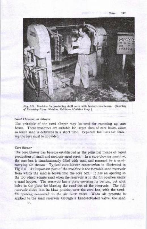
Cons t27
Fig. 6.3 Machine for producing shell cores with heated core boxes. (Cowbryol Beafislsy-Piper Ditisian, Petlibrc Mulliken C'orp.)
Sand Throtnr, or Slinger
The principle of the sand slinger may be used for ramming up core
boxes. These machines are suitable for larger sizes of core boxes, since
so much sand is delivered in a short time. Separate facilities for draw-
iug the dore must be provided.
Core Blotw
The core blower has become established as the principal means of rapidproduction of small and medium-sized cores. In a core-blowing machine,
the core box is simultaneously filled with sand and rammed by a sand-
csrrying air stream. Typical core-blower construction is illustrated inFig. 6.4. An important part of the machine is the movable sand reservoir
from which the sand is blown into the core box. It has an opening atthe top which admits sand when the reservoir is in the fill position under
a sand hopper. The reservoir has a plate covering its bottom, but withholes in the plate for blowing the sand out of the reservoir. The fullreservoir slides into its blow position over the eore box, with the sand-
fill opening conuected to the air blow valve. When air pressure is
applied to the saud regervoir through a hand-actuated valve, the sand
:.-
7-
Fi
E
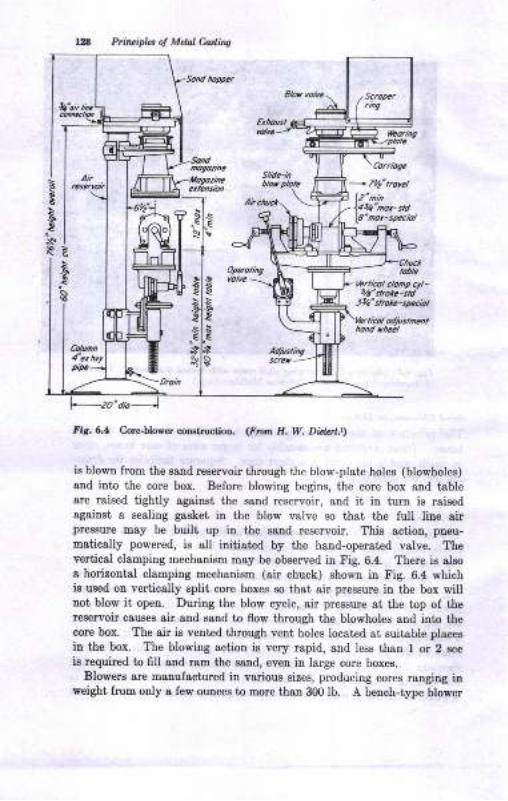
Pti,t ipkt o! Mdil Cartins
S/idc-tnCorriogc
E
\B E
a-
Ii,. 6.4 Coelrlowa oouructioa. <F'fir. H. W. Did2r't.tt
is blown lrom the sand reservoir through the blow-plste holes (blowhotes)
and into the cole box. Before blowing begins, the core box 8ud tableare raised tightly against the eaud reservoir, and it in turn is rsi8edagainst s sealing gaeket in the blow valve so that the lull liue airpre8sure may be built up iu the sand reservoh. Thie action, pneu-
matically powered, ie all initiated by the hand-operated valve. Theyerticsl cla&ping mechauism may be observed in Fig. 6.4. There ie a[Bo
a horirontal clampiag mechanism (air chuck) ehown iu Fig. 6.4 whichis used on vertically split core boxes so that air pressure in the box willtrot blow it open. During the blow cycle, air pressure at the top of thereaeryoir causes air and saud to flow through the blowholes and into thecore box. The air iB veDtad through vent holes located at suitable places
iu the box. The blowing action h very rapid, snd less than I or 2 see
is required to fiU aud ram the eand, eveu in large core boxe8.
Blowere are maDufactured iu various sizes, producing cores ranging inweight from only a few ouoces to more thau 300Ib. A bench-type blower
i
G
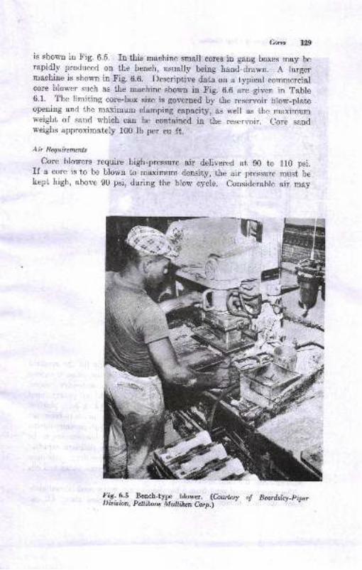
t29
is shown in Fig. 6.5. In this machine small cores in gang boxes may berapidly produced on the bench, usually being hand-clrawn. A largernrachine is shown in Fig. 6.6. Descriptive data on a typical commercialcore blower such as the machine showu in Fig. 6.6 are given in Table6.1. The limiting core-box size is governed by the reservoir blow-plateopening and the maximum clamping capacity, as well as the maximumweight of saird which can be contained in the reservoir. Core sandweighs approximately 100 Ib per cu ft.
Air Requiremenls
Core blowers require high-pressure air delivered at g0 to 110 psi.If a core is to be blown to maximum density, the air pressure musL bekept high, above g0 psi, during the blow cycle. Considerable air may
drg
+-Y.t ir*.
{r.S: 9.S _Bench-type blower. (Cburteyy o! Beardslcy_piperDioisian, Pellibnc Multibn Corp.i
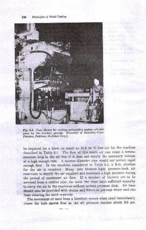
130 Prfiwipla of Melal Caslina
FiS.6.6 Core blower for making automotive gngine-cylinder
-.L Uy the hot-box process. (Courtesy of Bearilsley-Piper
Dio isian, Peltibone M ullibn Cor p.)
be required for a blow, as much as 11.4 cu ft free air for the machine
described in Table 6.1. The flow of this much air can cause a serious
pressure drop in the air line if it does uot supply the necessary volume
ut u t igt enough rate. A narrow-diameter pipe would not permit rapid
unough flo*. In the machine considered in Table 6'1, a 3-in' pineline
for ihe air is required. Many core blowers have pressure-tank air
reservoirs to supply the air required and maintain a high pressure during
the period of maximum air flow. If a number of blowers are to be
serviced from a central pipe, the main line must have sufficient capacity
to carry the air to the machines without serious pressure drop. Air lines
should also be provided with drains and filters to prevent water and oils
from entering the sand reservoir.
The movement of sand from a blowhole occurs when sand immediateil'
gl,ove the hole movee first as i,he air pressure reaches about 5.0 psi.
I
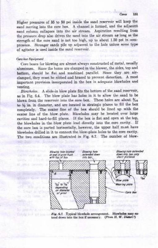
Iligher preszures of 35 to 50 psi inside the gand reservoir will keep the
eand moving into the core box. A channel is formed, 8ud the sdisc€nt
sand columu collapses into the air streatu. Aspiration resulting from
the preszure drop also drives the sand iuto the 8ir stream 8t loDg 88 the
streugth of the core sand is not too high, up io sboui 1.50 pei in com-
prcssion. Stronger eandr pile up adjacent to the hole unless some tSrpe
of agitetor is used inoide the gand reservoir.
C-;*c4nc Equiprru
Core boxes for blowing are almost always constructad of metal, usually
sluminum. Since the boxes are clamped iu the blower, the sides, iop and
bottom, ahould be flet and machined parallel. Since they are air-
clamped, they muet be ribbed and brsced to prevent distortion. A most
importaDt provisiou iucorporated itr the box is adequaie blowholes and
venting.Blouhotes. A elide-ia blow plate fits tle boitom of the eand reservoir,
aa in Fig. 6.4. The blow plate has holes in it, to sllow the s8nd to be
blown from the reservoir into the core box. These holee 8re sbut %o
to $ in. in diameter, and are locsted in atrategic places to fill the box
completely. The center line of the box should be lined up with the
center liDe of the blow plate. Blowholes may be located over large
caviiies snd hard-to-filt places. If the box is flat aud opeu at the top,
the blowholee in the blow ptate lead directly iato the core cavity. Ifthe core box is parted horizontally, however, the upper half must have
blowholee &illed in it to conuect the blow-plate holee to the core cavity.
The two couditious are iltustrat€d in Fig. 6.7. The number oI blow-
Sbring hole ldoEd
fi6. 6,? Typical l:lowhote atransEmrt. BlothoL. uny cx-
t€Dd do'rtr ioto the bot if rcc..sary. (Ftom E. V/. D M!)
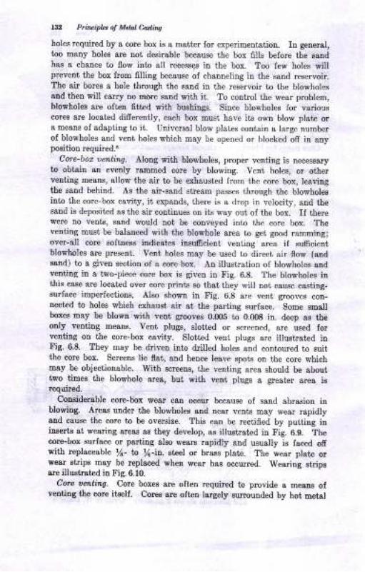
l3:l Prioipltt o! Mctal Ca4i^s
holes required by a core box is a mstter for experimentstion. In getreral,
too many holes are not deeirable because the box fills before the eaadhas a chance to flow into all recessge in the box. Too few holes willprevent the box from filling because oI channeling in tlte sand reservoir,The air bores a hole through the eand in the reservoir to the blowholesand then will carry no rtrore sand with it. To control the wear problem,blowholex are often fitted with bushings. Siace blowholes for yarious
cores are located difrereuily, each box must have its own blow plate ora meaus of adapting to it. Universal blow plates contain a large numberof blowholes and veut holes which may be opened or blocked ofr in anypoeition required.o
Corc-bot uentinq. Along with blowholee, proper v€niing is uecessaryto obtain aa evenly rammed core by blowing. Vent holes, or otherI'enting means, allow the air to be exhausted from the core box, leavingthe sand behind. As the air-sand st eam passes through the blowholeeinto the core-box cavity, it expands, there is a drop in velocity, and thesaud is deposited as the air contiques on its w&y out of the box. If therewere no vent€, gand would not be conveyed into ihe core box. Theveniing must be balanced with the blowhole sres to gei good ramming;over-all core softness indioate8 insu6cient venting area if sumcientblowholes are present. Vent holes may be used to direct sir 0ow (endsand) to I givea section of a core box. An illustration of blowholes audveutitrg in a t*o-piece core box ig given in Fig. 6.8. The blowholes inthis case are located over core prints 80 that they will not cause castiDg-sulace imperfections, Also shom in Fig. 6.8 are vent grooves con-uectcd to holes which exhauet air at the p8rting surface. Some smallboxee may be blown with vent grooves 0,005 to 0.m8 in. deep as theody veDtitrg meam. Vent plugs, slotted or screened, are used forvetrtiDg oD the core-box csvity. Slott€d vent plugs are illuetrated iuFig. 6.8. They may be driven into drilled holes and contoured to suitthe core box. Screeos lie flat, and hence leave spots ou the core whichmay be objectionsble. With screeue, the veuting area ehould be abouttwo timee the blowhole area, but with veut plugs a gr€ater area i8required.
Couiderable core-box wegr can occur because of sand abrasioD iublowing. Areae under the blowholee and near yeuts may wear rapidlysnd cauee the core to be overgize. This can be rectifred by putting ininrertr at weariug areae as they develop, aa illustrstrd in Fig. 6.9. Thecore-box surface o! pafting also weare rapidly and ususlly is fsced ofiwith replaceable /a- to lt-it. eteel or brass plat€. The wear plate orwear Etrips may be replaced wheD wear hae occured. Weariug strips8re itlu8hsted in Fig. 6.10.
Core let titlg, Core boxes are often required to provide e meanE olventiDg the corr itself. Cores are ofteu largely eurounded by hot metal
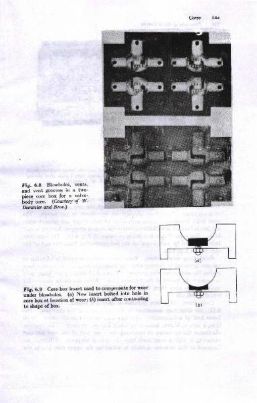
Fis. 6.A Blowholes, vents'
and vent grooves in a two-oiece core box for a valve-
Lo.ly -"". (CourtesY of W.
Dqunbt ard. Bros.)
Fit.6.9 Core-box insert used to compensate for wegr
""io lU*not"". (a) New insert bolted into hole in
"-" Lr, at location oi wear; (b) iosert after contouriog
to ehape of box.
-l itJ
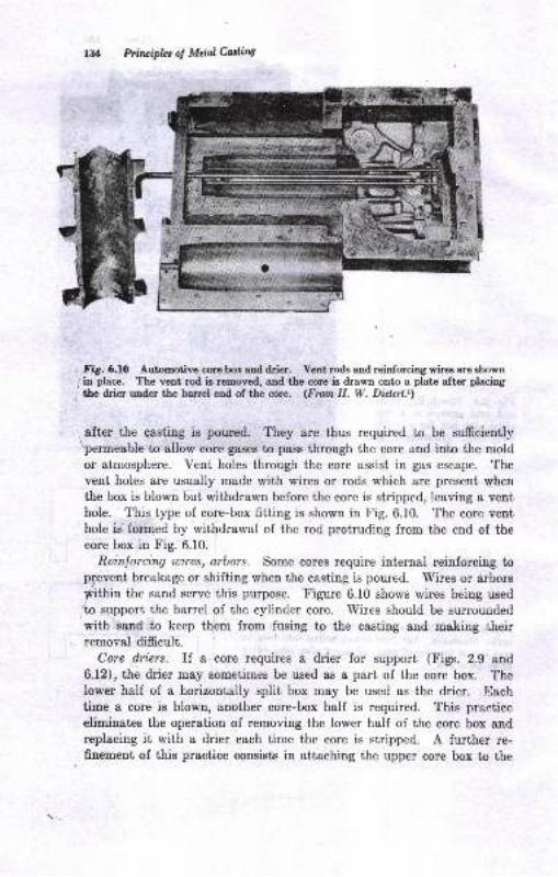
lil Priruiphs of Metol Cor,littg
r Fig. 6.10 Automotive cce box and drier. Vent rodg and reinforcirg wircs ar€ sbowtr
1 ia place. The vent rod b removed, and the core is drawn onto a plate aftcr placing
1 the drier under the barrel end of the cce. (Frcm H. W. Diokrl.r)
, after the casting is poured. They are thus required to be sufrciently\permeable to allow core gases to pass through the core and into the moldor atmosphere. Vent holes through the core assist in gas escape. Thevent holes are usually made with wires or rods which are present wherthe box is blown but withdrawn before the core is stripped, leaving a venthole. This type of core-box fitting is shown in Fig. 6.10. The core venthole is formed by withdrawal of the rod protruding from the end of the
core box in Fig. 6.10.
Reinlorcing wires, arbors. Some cores require internal reinforciug toprevent breakage or shifting when the casting is poured. Wires or arbors
fithin the sand serve this purpose. Tigure 6.10 shows wires being wed/to support the barrel of the cylinder core. Wires should be surrounded'with saud to keep them from fusing to the casting and making theirremoval difficult.
Cme diers. If a core requires a drier for support (Figs. 2.9 and
6.12), the drier may sometimes be used as a part of the core box. Thelower half of a horizontally split box may be used as the drier. Each
time a core is blown, another core-box half is required. This praetice
eliminates the operation of removing the lower half of the core box andreplacing it with a drier each time the core is stripped. A further re-fiuement of this practice consists in attaching the upper core box to the
i.E
,
!'
I
Caru
saDd reservoir and positioning the lower half below it' The operator
then may only need to siide in the drier and remove the blown core
and drier after the blow cycle. This practice requires shallow cor€s or
cta-piog mechanisms wittr- sufficieni travel to clear the core and drier'
Stock-core Mochines
Cores may be made by extrusion through a die with a stock-core machine
operating on the meat-g.irrJ.. principll' Small cylinders and hexagonai
aod recta.rgular cross-sectioned cores may be extruded' Stock cores are
made in standard sizes and stored for luture use' They may be cut to
length and taPered if desired.
CORE BAKING
cores are baked at temperatures up to about 650 F to develop the
strength obtainable from the organic binders in the core sand. During
bakin"g, moisture is driven off flrst, holding the core temperature lo 212 F-
Then lhe core oil or other binder changes chemically and molecularly
from a liquid to a solici by oxygen absorption ancl polymerization as the
temperature rises to 400 to 500 F or more. The importance of tempera-
ture and time of baking is illustrated by its influence on core tensile
strength as revealed in Fig. 6.11. Baking cycles of 2 to 6 hr at 400 to
460 F are quite commonly used. Proper baking is essentiai if a core is to
perform salisfactorily when the metal is poured. Underbaked cores give
onmuchgasandcancauseavarietyofdefects.overbakedcoresmpycollapse too soon and break or erode before the casting is solidified.
when baked, a core-oil-bonded core assumes a nut-brown color, darkness
indicating overbaking and lightness underbaking. Proper baking de-
pends upou good baking equipmeut if the core sand mixture is correct'
bre-baking Eqwipment
Eqrripment for baking cores may be classified as follows:
I. Core ovens
d. Batch-tyPe
8. Continuous
l. Horizontal2. Vertical
II. Dielectric bakers
III. Radiant bakers
The various types of baking equipment are used to advantage in
different ways.
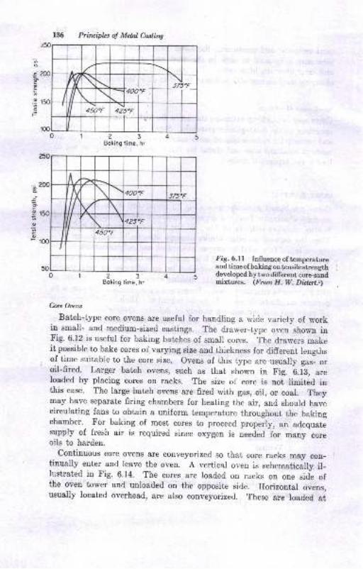
Prinriplcs o! Melal Casting
';o
j
oce
-9'acP
23Eoking lime, hr
o
c
g
cF
23Boking time, hr
Fig.6.Ll Inlluence of temperatueand time ofbaking on tensilestrengthdeveloped by twodifferent core-sandmixtures. (From H. W. Dielart.r)
Core Oem
Batch-type core ovens are useful for handling a wide variety of workin small- and medium-sized castings. The drawer-type oven Bhown inFig. 6.12 is useful for baking batches of small cores. The drawers makeit possible to bake cores of varying size and thickness for different lengthsof time suitable to the core size. Ovens of this type are usually g".- o,oil-fired. Larger batch ovens, such as that shown in Fig.
'6.13, *."
Ioaded by placing cores on racks. The size of core is not limited inthis case. The large batch ovens are fired with gas, oil, or coal. Theymay have separate firing chambers for heating the air, and should havecirculating fans to obtain a uniform temperature throughout the bakingchamber. For baking of most cores to proceed p.op.ily, an adequatesupply of fresh air is required since oxygen is needed
-for many
-core
oils to harden.
continuous core ovens are conveyorized so that core racks may con-tinually enter and leave the oven. A vertical oven is schematically il-It:strated in Fig. 6.14. The cores are loaded on racks on one side ofthe oven tower and unloaded on the opposite side. Horizontal ovens,usually located overhead, are also conveyorized. These are loaded at
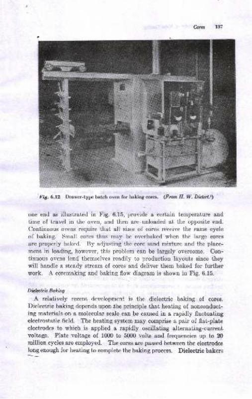
i Fts.6.tz Drawer-type batrch oven for bating corea. (Frut H. W. Diltel],
one end as illustrated in Fig. 6.15, providc a certain temperature aud
time of travel in the oven, and then are.unloaded at the opposite end.
Continuous ovens require that all sizes of cores receive the same cycle
of bakiug. Small cores thus may be overbaked when the large cores
are properly baked. By adjusting the core sand mixture and the place-
ment in loading, however, this problem can be largely overconrc. Con-
tinuous ovens lend themselves readily to production layouts since theywill handle a steady stream of cores and deliver them baked for furtherwork. A coremaking and baking flow diagram is shown in Fig. 6.15.
Diclatric Bakiry
A relatively recent development is the dielectric baking of coreg.
Dielectric baking depends uponthe principle that heating of noncouduct-
ing materials on a molecular scale can be caused in a rapidly fluctuatingelectrostatic field. The heating system may comprise a pair of flat-platcelectrodes to which is applied a rapidly oscillating alternating-curentvoltage. Plate voltage of 1000 to 5000 volts and frequencies up to 20
million cycles are employed. The cores are passed between the electrodeslong enough for heating to complete the baking process. Dielectric bakers
Cores 13?
E+'-EB:.rr =l-*r,*=*
t
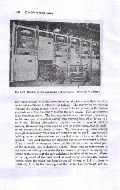
138 lrhrcipbs o! Mdal Culitts
Fig. 6.13 Batch-type core oven loaded with corp racls. (Fron H, W- Didrit.t)
ane eonveyorized, with the'cores traveling at such a rate that the time,
uDder the electrodes is sufficient for baking. The conveying belt passing
through the baking tunnel is made of steel links and is used as the bottom
electrode as well as a means of moving the core plates. The top electrode
is an aluminum plate. The belt may be driven at 0 to 10 fpm, depending
on the core size, with actual baking time varying from 20 to 30 sec to 2
or 3 min. Baking dielectrically requires the use of special binders,
namely, thermosetting resins such &s urea or phenolformaldehyde, mela-
mines, resorcinols, or blends of these. The thermosetting resins develop
strength immediately when they are heated to 200 to 300 F. An extended
holding period at temperatures such as that required for eore oils is not
needed. Core sand mixtures for dielectric baking are considered in Chap.
7, but it should be recognized here that the mixture is an important part
of the successful use of dielectric bakers. ' Since time at temperature is
not required, baking time under the electrodes is governed mainly by the
period required to heat the core sufrciently to drive off its water. Water
is the ingredient of the sand which is most easily dielectrically heatcd.
Ileuce, when the water has been driven off (steam at 212 F), there is
relatively littl-- further heating and the binder hes thermoset anC dc-
:
-
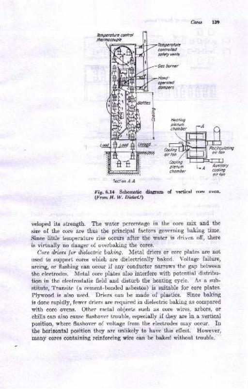
hrcs r39
orymteddonpers
q@
Section ,{-,{
Fig.6.l1 Schematic diagran of vertical @rte oven-(From II. W. Dilni],
veloped its strength. The water percentage in the core mix and the
size of the core are thus the principal factors governing baking time.
Siuce little temperature rise occurs after the wster is driven ofr, there
is virtually no danger of overbaking the cores.
Core ilriers lor ilielectric baking. Metal driers or core plates are not
used to eupport cores which are dielectrically baked. Voltage failure,
arcing, or flashing can occur if any conductor narrows the gap between
the electrodes. Metal core plates also interfere with potential distribu-
tion in the electrostatic field and disturb the heating cycle. As a sub-
stitute, Transite (a cement-bonded asbestos) is suitable for core plates.
Plywood is also used. Driers can be made of plastics. Since baking
is done rapidly, fewer driers are required in dielectric baking as compared
with core ovens. Other metal objects such as core wires, arbors, or
chills can also cause flashover trouble, especially if they are in a vertical
position, where flashover of voltage from the electrodes may occur. Inthe horizontal position they are unlikely to have this effect. Ilowever,
many cores containing reinforcing wire can be baked without troublt,.
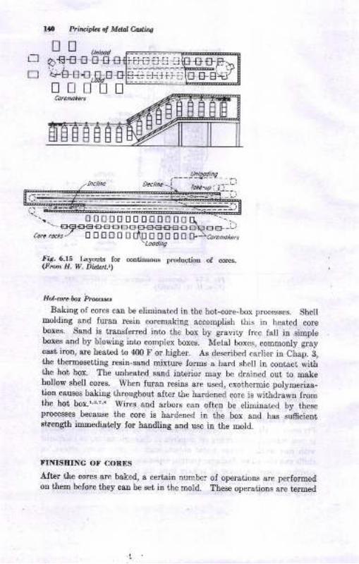
Pri!rr.i,L, ol Maal Codi'ns
fiS. 6.15 tsyouE for cortitruous Droductioa of cores.<Ftun fl. W. Di*rt-t)
Eo!-NceE Pwrtt tBaking of cores can tre eliminated in the hot-core-box processes. Shell
moldiug aDd Iuran resiu coremaking accomplish this in heated coreboxes. Ssnd is trausferred into the box by gravity free fall in simpteboxes ald by blowing iuto complex boxes. Metal boxes, commonly graycast iron, are heated to 400 F or higher. As described earlier in Chap. 3,the thernosetting reein-eand mixture forms a hard shell in contact withthe hot box. The unheated saud interior may be drained out to makehollow ehell core8. When furarr resins sre used, exothermic polymeriza-tion caueea baking throughout after the hardened core is withdrawn fromthe hot box.l'!'?,s Wires aud &rbo$ can often be elimin8t€d by tbeseprocesses because the core ie hardened iu the box and has suficientstrength immediatcly for haadling erd us€ in the mold.
FINISITING OF COBES
After the corea are baked, a certain aumber of operations are performedon tlen before they can be set iu the mold. ?be* operations are termed
0080000O00008
DEOOEE EEOOO
L-l
E
Cores
core fini.shing. Finishing work may be classified as follows:
Cleaning
Sizing (making it dimensionally accurate)
Core assembly
Inspection
Cleaning Opratione
Cleaning operations include all work done ou the core except sizing orassembly of cores. Work included in this category is trimming, brushing,
venting, coating, and mudding. Trimming consists in removing fins,bumps, or other sand projections by rubbing them or filing with an emerystone, core file, or other abrasive tool. Fins arise from loose joints orIoose pieees in the core box. Blowholes and vent plugs often leave marks
on the core which must be smoothed off. Brushing cores with a brush
of moderate stiffness is performed to remove loose sand. Brushing isrequired on cores which, before baking, have been bedded in sand ratherthan on a core drier.
Cores may be coated with refractory or protective materials whicl.improve their resistance to molten metal or produce a better casting.These coatings may be applied by spraying, dipping, or swabbing. Thesubject of core coating will be considered in Chap. 7. Mudding is a
localized coating used to make the core completely smooth. Graphiteor red talc moistened with wflter to a putty consistency may be used tofill up any cavities, rough spots, soft rammed areas, or the joint lines ofassembled cores. Another mud consists of.94/c silica flour, 3/o westernbentonite, and 3/o dextrin moistened to a putty with water. The mudis applied by hand, rubbed into the cavities, and smoothed off. Coreswhich have been coated or rubbed may cause trouble with defects in thecasting because of steam evolution when the metal is poured. Drying ina core oven for 20 min to I hr can eliminate this problem. With some
core coatings, air drying is often adequate.
Venting of cores is sometimes included as a cleaning operation. Bakedcores which are to be assembled may be vented into the core prints byscratching grooves on the surfaces to be joined. More often grooves orvent holes are put into the core before it is baked, as, for example, inFigs. 6.2b and 6.8. Then it may be desirable to inspect the vents to see
that they are open. Small holes may be reamed open with a wire orrod. Wax vent holes are made by ramming up a string of wax in thecore. The wax melts out when the core is baked and leaves a vent hole.It is frequently necessary during cleaning to open this hole to completethe vent.
1.o
J.
4.
112 Prircipb of Mdai l;adilts
Sia;ing OFrctbra
Sizing is done to make cores dimensionally accurate. Sizing usually
involves gauging the core to see if its size is correct and then removing
material. Sizing'is thus in part dimensional inspection. Gauges may
be used to check critical dimensions. Templates, pieces of sheet metal
cut out to the contour required of the core, may be used to determine
whether the core has sagged or slumped during baking. The cores may be
inserted in a gauging fixture which will check a number of dimensions
at once. In some cores with large flat surfaces exact height is necessary
so that casting-wall thickaess and location are accurate. Such cores
may be made slightly oversize and ground to correct height. This may
be done by hand filing with a scr&per or on I core-grinding machine. Ineither case the core is put into a fixture which positions the core and
the excess material is removed. Hand-sizing operations may be per-
formed on cores whieh are slightly out of shape. Crooked core plateg
or driers, vibration during baking, 'and weak sands or ramming may
cause cores to be off dimension and are good reason for gaugiug and sizing.
6rc Assetnbly
Some cores are of one piece and may be set directly into the mold after
cleaning and sizing. Other cores are assembled of two or more pieces
before they can be used. Core assemblies may be held together bypasting, bolting, or leading.
Pasting is most commonly used on small work. A core paste, usually
a proprietary mixture of talc, dextrio, flour, molasses, water, or other
ingredients, is applied to the surfaces to be joined. The paste may be
put on with a paste bulb, brush, the finger, or by means of dipping witha pasting fixture. A pasting fixture consists of a metal rack which islowered into a tank of paste and then raised against the prepositioned
eore, depositing paste at the desired points. Care must be exercised to
avoid sealing off vent holes aud grooves when cores are pasted. Thepasted surfaces are pressed together and allowed to dry so that a strong
assembly results. Often it is desirable to mud the joint lines to prevent
metal penetration and give a smoother casting surface. Pasted and
mudded cores are best if dried to avoid the danger of blow defects in the
castings.
Cores may be bolted together if pasting does not produce a sufEciently
strong assembly. Bolting is useful in larger core work. Recessed holes
are left in the cores so that they may be bolted together. The bolt and
nut heads are covered over with a core plug or mud.
Joining cores by leading is occasionally used where a strong joint is
desired in small cores. Cavities are left in the core parts to be joined.
143
Thesearefilledwithmoltenlead'Whentheleadfreezes'itholdsthecoretogether, just as a bolt wouid.
IiTffi finishing operation, the cores may be inspected before they
are scnt to the molding floor or core storage. Sometimes gauging is done
,i1fri. point to checklhe final dimensional accuracy' The cores should
be smooth, frce of loosc sand or projections, mudded if necessary' and
dry, to be reacly fol the core-setting operation'
CORE SETTI.\-G
Core setting is the operation of placing cores in molds' Cores must
be of correct size and positioned prlpetly with respect to the rnold cavity
so that cored-out cavities ate in tl.'"ir required location in the casting'
Cores are positioncd in the mold by core prints' When the rnetal is
polr..a, .o.". u.. buoyecl up and may- rise unless they are securely
anchorcd. Good core setting then involves advance planning so that
the cores will be correctly po'titioned and firmly held when the metal is
poured.
Small cores are placed in the mold by hand' as in Fig' 3'3' T'arger
corcs may require hoist or crane service as in Fig' 6'16b' Sometimes a
number of cores are assembled and set in at one time' This usually
..qri.". an assernbly fixture such as that shown in Fig' 6'16o for auto-
motive-motor-bloek cores. The core assembly may be bolted together
or held together by the flxture, as in Fig' 6'16b, when it is.transferred
to the mold. when a number of cores are assembled, dimensional errors
are additive and some kind of fixture or gauge' as in Fig' 6'16o' is
necessary.
Location oJ Cores
Cores may require po:itive location in three directions' one vertically, and
twohorizontally.Horizontallocationcanbebasedonlocatingsurfacesin the mold cavity or on the flask pins' In Fig' 6'l6b' the cores are
positioned by the assembly fixture relative to the flask pins' Locating
co.e. in that way requires it,t tf't mold cavity also bear a fixed position
relative to'the Iiask pins and so must the pattern' Thus the flask pins
and bushing are reference points for locating both mold cavity and cores'
This usualfi requires rigii or tight flasks and constant attention to flask
lrinsandbushings.Loo,-sepirrsandbushingswillallowshiftsofthecopeand core-settirrgl*t.rr. *rrd .oo,"q"tntly tause dimensional inaccuracy of
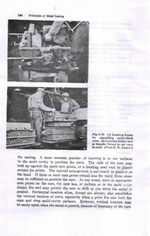
l4
i
Prinifu of MdalC,ading
fig.6.l6 (o) tocating fixturefor assembling motor-blockcores. (D) tocating fixture usedas traDsfer fixture to set coresin mold. (Frcm H. W. Diotqt.t)
the casting. A more common practice of locating is to use surfacesin the mold cavity to position the cores. The e.r.rds of the core maybutt up Bgainst the mold core prints, or a locating 6ead may be placedaround the prints. The tapered a*angement is not nearly .o posiiiv" asthe bead. rf three or more core prints extend into the morrr, these alonemay be sufrcient to position the core. In any eveut, worn or ru&ccuratecore prints on the core, the core box, or pattern or in the mold cz.,.ir,esloppy fits and may permit the core to shilt or rise when the metal ispoured. Horizontal location often, though not arways, arso establishesthe vertical location of cores, especially roh.o * prini fits into both thecope and drag mold-cavity surfaces. However, vertical location maybe easily upset when the metal'is poured, because of buoyancy of the core.
ffiaill \
l_i$
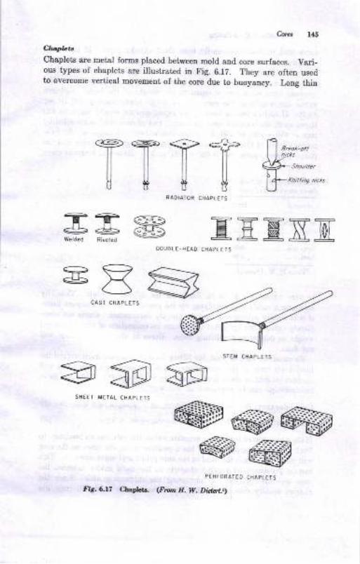
C}(r.LtChaplets are metal forns placed between mold and core surfaces. Vari-ous types of chaplets are illustratcd in Fig. 6.12. They are often usedto oyercome vertical movemeDt of the core due to buoyancy. Long thin
TTTTfi uo^-.,
ff,,.,0,,U*K
ttiDe nt'ct'
RADIATOR CHAPLEIS
@@@@@
PERFORATEO CHAPLETS
<FIo.n H. W. Di.t rr.tl
T?<==>+e@Welded Rivered EEENtr
OOUALE.HEAD CHAPLE T 5
EAScasrcraDLLTs
-4? -4w-ffi=;! ;@ @
srEr'cHAPLETS
ShEET METAL CH APLETS
fir.6.17 Chapi€ts.
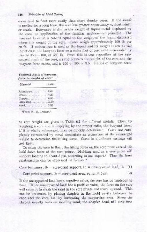
16 Ptitnipl"t ol Mdale.ading
cores tend to float more easily than short chunky cores. If the metal
is molten for a long time, the core has greater opportunity to float, shift,
or erack. Buoyaucy is due to the weight of liquid metal displaced by
the core, an application of the familiar Archimedes' principle. The
buoyant force on a eore is equal to the weight of the liquid displaced
minus the weight oi the core. Cores weigh approximately lfi) lb per
cu ft. If molten iron is used as the liquid and its weight taken as 450
Ib per cu ft, the buoyant force on a cubic foot of core sand surrounded by
iron is 450 - 100, or 350 lb. Since this is true regardless of the sub-
merged depth of the core, a ratio between the weight of the core and the
buoyant force exists, and is 350 -- 100, or 3.5. Ra'uios of buoyant force
Table 6,2 Ratio ol buoyont
t"r." * *t* "t ."rd
Material
rFrom H. W. Dietert.t
to core weight are given in Table 6.2 for different metals. Thus, by'
weighing a core and multiplying by the proper ratio, the buoyant force,
if it is wholly submerged, may be quickly determined. Cores not com-
pletely surrounded by metal necessitate an estimation of the submerged
weight to determine the lifting force. Cores in aluminum castings will
not float.To cause the core to float, the lifting force on the core must exceed the
hold-down force of the core prints. Molding sand in a core print willsupport loading to about 5 psi, according to one expert.l Thus the force
relationships can be expressed as follows:t
Core buoyancy, lb - core-print support, lb : unsupported load, Ib (1)
Core-print support, ,O - .ots.print are&, sq in. X 5 psi (2)
If the unsupported load has a negative value, the core has no tendency to
float. If the unsupported load has a positive value, the force on the core
will cause it to crush the sand in the core prints and move upward. This
can be prevented by placing chaplets in the mold cavity between the
eope and the core, i.e., by inereasing the supporting are&. Since the
chaplet usually rests on molding sand, the chaplet head will sink into
Ratio
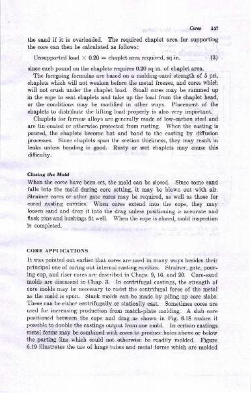
Corct 1.17
the sand if it is overloaded. The required chaplet area for Bupporting
the core c8n then be calculated as follows:
Unsupported load X 0.20 : chaplet, area required, sq in. (3)
since each pound on the chaplets requires 0.20 sq in. of chaplet area.
The foregoing formulas are based on a molding-sand strength of 5 pei,
chaplets which will not weaken before the metal freezes, and cores which
will not crush under the chaplet load. Small cores may be rammed upin the cope to seat chaplets and take up the load from the chaplet head,
or the conditions may be modified in other ways. Placement of the
chaplets to distribute the lifting load.properly is also very important.Chaplets for ferrous alloys are generally made of low-carbon steel and
are tin-coated or otherwise protected from rusting. IVhen the casting ispoured, the chaplets become hot and bond to the casting by difrusionprocesses. Since chaplets span the section thickness, they may result inleaks unless bonding is good. Rusty or wet chaplets may cause thisdifficulty.
Clbsing tha Mold
When the cores have been set, the mold can be closed. Since some sand
falls into the mold during core setting, it may be blown out with air.Strainer cores or other gate cores may be required, as well as those forcored casting cavities. When cores extend into the cope, they mayIoosen sand and drop it into the drag unless positioning is accurate andflask pins and bushings fit well. When the cope is closed, mold inspection
is completed.
CORE APPLICATIONS
It was pointed out earlier that cores are used in many ways besides theirprincipal one of coring out internal casting cavities. Strainer, gate, pour-ing cup, and riser cores are described in Chaps. 9, 16, and 20. Core-sandmolds are discussed in Chap. 3. In centrifugal castings, the strength ofcore molds may be necessary to resist the centrifugal force of the metalas the mold is spun. Stack molds can be made by piling up core slabe.
These can be either centrifugally or statically cast. Sometimes cores are
used for increasing production from match-plate molding. A slab corepositioned between the cope and drag as shown in Fig. 6.18 makes itpossible to doutrle the castings output from one mold. In certain castingsmetal forms may be combined with cores to produce holes above or belowthe parting line which could not otherwise be readily molded. Figure6.19 illustrates the use of hinge tubes and metal forms which are molded
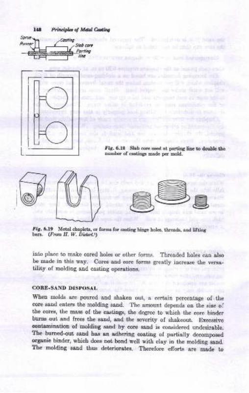
Prn&bb ot Mdd cddiae
!:omw
fi6. 6.18 Slab cort ured at paniDS tiD. to double theour.ber of caetiogs made per mold.
@M Beefir. 6.19 Merd chaplets, or f6n for castiDa hiDSe holes, tble{ds, and liftiD8b6re. (Fron H. W. Did.d.tt
into place to make cored holes or other forms. Thresded holes can alsobe made in this way. Cores and core forme greatly increase the versa-tility oI molding and cssting operations.
CONE.SAND DISPOSAL
Wheu molds are poured snd shaken out, a certaiD percentage of thecore Batrd enterf the molding saud. The amount depends ou the size olthe cores, the mass of the castiDgo, the degree to which the core binderburns out and frees the sand, and the severity of shakeout. ExcessivecontaniDation of molding aand by core eand is cousidered undesirable.The burned-out, eand has 8tr adhering coating oI partially decompoaedorgadc binder, which doee Dot boDd well with clay in the molding eaud.The molding saqd thue deteriorates. Therefore efforta gre msde to
H
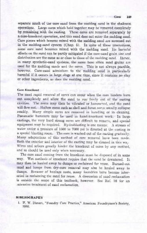
C,ores 149
separat€ much of the core ssnd from the molding sand iD the shakeoutoperations. Large cores which hold together may be removed completelyby remaini.g with the casting. These cores are removed separately bya core-knockout operation, and this sand does not eni€r the molding sand.
Core pieces which become mixed with the molding sand are screened outin the molding-sand system (Chap. 5). In spite of these orecarrtions,some core sand becomes mixed with the molding sand. Its harmfuleffects on the sand can be partly mitigated if the core-sand grain size anddistribution are the same as or close to those of the molding sand. Heuce,in many synthetic-sand systems, the same base silica sand grains areused for the molding sands and the cores. This is uot always possible,
however. Core-sand admixture to the molding sand is particularlyharmful if it occurs in large slugs at one time, since it contains no clayor other ingredients, as does the molding sand.
C-orc Knockout
The most rapid removal of cores can occur when the core binders burnout completely and allow the sand to run freely out of the castingcavities. The cores may then be vibrated or hammered, and the sandtill flow out. Hollow cores such as shell and furan cor\)s usually collapsereadily. Many simple cores are removed in handling or in cleaning.Pneumatic hammers may be used in hand-knockout work. In largecastings, the very hard strong cores are difficult to remo.,-c, and specialequipment may be required. Hydroblasting is one means: A stream ofwater under a pressure of 1500 to 7000 psi is directed at the casting ina special blasting roorn. The core is washed out of the casting gradually.Many adaptations of this method of core removal have been made.Both the exterior and interior of the casting may be cleaned in this wa-,Wires and arbors greatly hinder the knockout of cores by any meihod,and so should be used only when necessary.
The core sand coming from the knookout must be disposed of in someway. Wet methods of kuockout require that the sand be dewatered. Itmay then be hauled away to dumps or reclaimed for reuse. Burned-outsand and lumps from dry-core removal may also be hauled away todrtmps. Because of haulage costs, many foundries have become inter-ested in reclaiming the sand for reuse. A discussion of sand reclamationis outside the scope of this textbook, however. See Ref. 16 for anextensive treatment of sand reclamation.
BIBLIOGRAPIIY
1. H. W. Dietert, "Foundry Core Practice," American Foundrymen,s Society,1950.

':"--
150 Prituifu ol Mdal&dine
2. R. L. S. Andrews, "Shell Prccess Foundry Practicea," Americao Founor
men's Society, 1964.
3. W. E. Mr"oi, Uut*t Core Box Equipment, Trans. AFS, vol. 65, p. 443, t.*7 '4. A. M. Clark,'Principles of Core Btowing, Traru. AFS, vol. 64, p. 577, 1956'
5. Z. Madacey,'Pattarn and Core Box Equipment for Blowing Foundry Sauds,
Trcru. AFS, vol. 68, p. 193, 1960.
6. W. E. Sicha, Aluminum Pattern Castings, Troru. AFS, vol. 69, p. 479, 19h1'
7. E. E. Earkess, Eot Core Box Design and Engineering, TranE. df,$, vsl 69,
p. 123, 1961.
8. P. Jasson, Core Production in Eot Core Boxes, Trans. AFS, vol.69, 9.1N,1961.
9. C. A. Bamett, Moderu Foundry Corc and Mold Ovens, Truru. AFS, vo1. 57,
1949.
10. E. Blake, Design of Core Boxes and Driera for Core Blowers, Fout\ilr!,vol. 79, June, 1951.
11. Z. Madacey, Core Blowing as a Factor in a Semiproduction Foun(ry,?oundrg, vol. 71, JuneJuly, 19{i}.
12. J. W. i"bt., n ..ot Advanc,es in Dielectric Qsrc $alring, ?raru. dfS, vo\.
59, p. 159, 1951.'13. R. F. Lincoln, Arrangements of Corcs, Blowholes, and Vents for Blowing
Purpoees, Traru. AF9, vol. 51, June, 194i1.
14. E. M. Gade, Core Blowing, Fowd,ry, vol. 78, May, 1950.
15. E. J. Jory, Core Practice as Relrrtcd to Malleable Foundry Iosses, frans.z{tr'S, vol.59, p. 300, 1951.
16. American Foundrymen's Soeiety, Sympeium on Sand Rnclrmation, ?roru.
z{F$ vol.61, 1953.
17. American Foundrymen's Society, "Molding Methods and Materials," 1963.
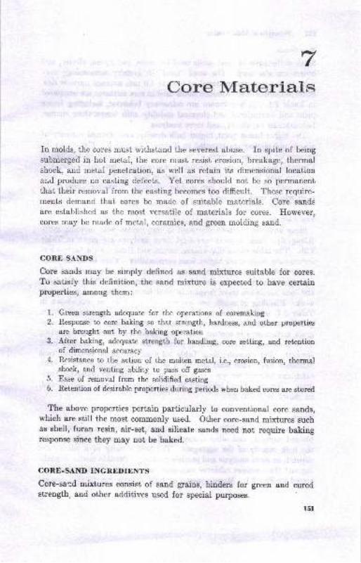
Core Materials
In molds, tire cores must withstand the severest abuse. In spite of being
submergcd in hot metal, the core must resist erosion, breakage, thermalshock, and metal penetration, as well as retain its dimensional location
and produce no casfing defects. Yet cores should not be so permanent
that their removal from the casting becomes too difficult. These require-
tnents demand thai cores be made of suitable materials. Core sands
are established as the most versatile of materials for cores. However,cores may be made oI metal, ceramics, and green moiding sand.
CORE SANDS
Core sands may be simply defined as sand mixtures suitable for cores.
To satisfy this definition, the sand mixture is expected to have certainproperties, among ihem:
l. Green strength adequate for the operations of coremaking2. Response to core baking so that strength, hardness, and other properties
are brought out by the baking operation3. After baking, adequate strength for handling, core setting, and retention
of dimensional accuracy
4. Resistance to the action of the molten metal, i.e., erosion, fusion, thermalshock, and venting ability to pass off gases
5. Ease of removal from the solidified casting6. Retention of desirable properties during periods when baked cores are stored
The above properties pertain particularly to conventional core sands,which are still the most commonly used. Other core-sand mixtures suchas shell, furan resin, air-set, and silicate sands need not require bakingresponse since they may not be baked.
CORE.SAND INGREDIENTS
Core-sard mixtures consist of sand grains, binders for green and curedstrength, and other additives used for special purposes.
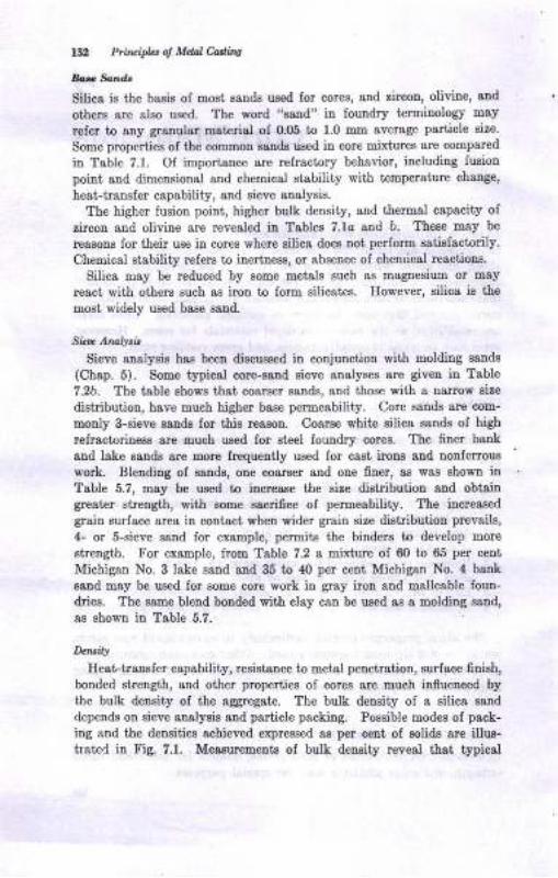
152 Pri@i*t ol Mdal Cadinq
4... Sond.
Silica ie the basie of most sands used for cores, and zircou, olivine, and
othera are also used. The word "sand" in loundry terminologr may
refer to auy granular material of O.O5 to 1.0 mm average particle size.
Some properties of the common sanda uaed in core mixtures are compared
in Table ?.1. Of importance are refraciory behavior, including fusion
point 8ud dimeoeional and chemical stsbility witi t€mpereture chsrrge,
heat-tranefer capabiliiy, and sieve anslysis.
The higher fusion poiut, higher bulk density, and thernal capacity of
zircon and olivine are revealed ia Tables 7.1o and b. These may be
reasons for their use in coree where silica does noi perform satiefactorily.
Chemical stability refers to inertness, or absence of chemical reactious.
$ilica may be reduced by some metals such as magnesium or may
react with others such ss iron to form silicates. Ilowever, silica is the
most widely used base sand-
Sic'. Anal!.i,
Sieve analysie hae been dieculsed in coujunction with molding aande
(Chap. 5). Some typical core-saud eieve analyses are giveu in Table
7.2b. The table shows that coaraer sands, aud those with a narrow size
distribution, have much higher base permeability. Core sande are com-
monly 3-sieve sands lor thie reason. Coarse white eilica sauds of high
refractorin€ss are much used for ateel foundry coree. The finer bank
aud lake sands are Eore frequeDtly used lor cast irous and nonferroue
work. Blending of sands, one coarger aad one finer, as was sbowD inTable 5.7, may be used to iacrease the eize digtribution and obtaiugrester strength, with mme sscrifice of permeability. The increaeed
graiu surface area in co[tact when wider gr&in size distribution prevails,
4- or 5-sieve sand Ior example, permits the bindere to develop more
strength. For example, from Table 7.2 a mixture of 60 to 65 per cent
Michigan No. 3 lake saud and 35 to !l() per cent Michigan No. 4 bauk
aand may be used for aome core work iu gray iron and malleable loun-
drieg. The aame bleud bouded with clay cao be used as a molding sand,
as shown in Table 5.7.
D.t|'ity
Heat-iranefer capability, resistance to meisl peuetrstiou, surface finieh,
bonded strength, and other properties of cores are much influenced bythe bulk deneity of the aggregate. The bulk density of a silics sand
depends on sieve analysis and particle packing. Poseible modes of pack-
ing and the deneitiee acbieved expressed as per cent of solids ar€ illus-trated in Fig. 7.1. Measurements of bulk density reveal that typical
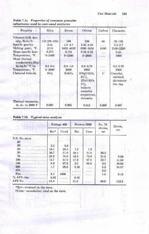
be MoLri4h lS3
Tobb 1.la Prq'ertia, ol co,m',"on grunubtr!,n ctoric. utd in core-*^d r,ljtau'.c.
Property Silica Zn$\ Olivine C&rbon Chomotte
Vibrrted bulk den-6ity, lblcu ft. . . .
Spe{ific grsvity. . .
Melting point, "F.Mean specific heatTempemture, 'F. .
Mean therm&l
conductivity,Btuhr/sq ftl "F/in. .
Temperstur€, "F. .
Chemicsl formuls
Tbermal exparsion,in./iD. to 2Om F
rr0 (95-125)
2.65
3ll90.n5
G24m
0.3 0.60 2800
sio!
0.020
188
4.64.7u52-422
0.13rG2(n
0.9-1.02fi)O
ZrSiOr
0.005
t2a3.25{.4032d'-94mo.t24.330-2gn
0.6-0.70m
2MsO.SiO'
84%,2FeO.SiOr
e%,bsltncoeD3tstitoserpeDtin6,
chroeitD
0,0r5
6E
6400
C
0.m8
00-rr0
310(H3m0
0.25
l&n
0.6{.7020m
calcined,
aluminous
6re clry
0.007
TablcT.tb Typical sieoe onolysis
Portage 4Z) Wedron 5030 No. 70
olivine,
rcl
Zirco4rct
R€t' Cumi Ret Cum
U.S. No. sieve
mm..................40..................
70.................r00.................140.................:xn..................270..................Pan.-................
%AIS clay. .........AFS No................
l8.ln.723.2
t5.76.0
1.7
0.4
0.50
51.3
20.3
51.0
76.2gl.9
97.9
99.6
1(m
1.2
30.4
48.2
r7.8
2.O
:10.50
51.6
1.2
3r.679.8
s7.6
99.6
26.2
3r.0
9.5
5.8
2.2
1.6
69.0
0.mI1.66
48.02
39.57
0.15
112.3
'Ret-retaircd on the sieve.
tc\m--<umubtive; totsl on the sieve.

.fi6_9=9l-oEa9
o oooooooo60{{i@d<6dioo. ' ' . .6 .Ooio!ir$oro H{
aN6n
; *3 #I
ts{iao6
-40€6H
:: : -r.6ooo o 1
' 'oooooN@llt4o _ ots .N .
. .HtsN@@loo o< r iE:: ooi : ;t3:: '6a-
cq-
It,odc
!aO-
aa'oaY:1911q9191o1o: -dE'oo6(@NorQ@-@ : r;5:. ddN 6 i c iaLo:: : rao- -
!?O'E
ONO E{ 6 d -:ON a o >!
! rn6; s6s. 6ec =ooooo = a a
1:11?1:1c!il13i E 3e-!f;x-oeo oHi ";-iet ! 6i \
a S5.dE
LA
:EotsE.ET6{
qo_
EE
::,,s ;5 I-Ef: : : : . & t66-
6
t"
io?a
::: :.!:99!?"?q90to' iN6{N6oooo!: : iiNr
::
ooo!19n99a!
IiT
Idtr
I
am
{g
6
aa
a
@
F
tso
F
o
d
oe
6?
N
o
o
qd
g
q
9
d2
ia-'i3-E?9i.^ooooooooo oE
' -NOiQtsOtQF^E@ HNdHfr
@<
q
6!d
FN
I
\@
@
o
.o
.N
.o:
oo
q
E
iz ..i
*doot5Efii.Ea
H>,sfEE
adxo
doE!<Oa+
:;:=
Ess
EE
E3<o
6Ao
aa!Baoot)
Baa>i
o'a
B
E!
Bth
cFoa.Blr154
A
h
ao
a
nis€3oo
E
o
E
o
ua
q
,a
ts
pa
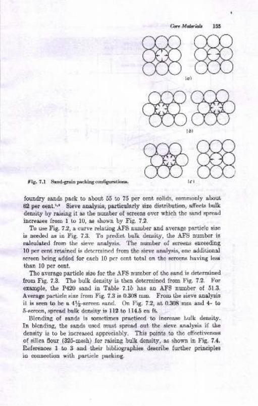
be Malaials 155
(a)
(0)
lct
ffiffiffiffi
Iig. ?.1 Sandgraio packiDg confgurationr.
foundry sands peck to about 55 bo 75 per cent solids, commonly about
62 per cent.r,' Sieve snalysis, particularly size distribution, afrects bulk
density by raising it as the uumber of screens over which the sand spread
increases from 1 to 10, as shown by Fig. 7.2.
To use Fig. 7.2, a curve relating AFS number and average particle size
is needed as iu Fig. 7.3. To predict bulk density, the AFS number is
calculated from the sieve analysis. The number of screeus exceeding
10 per cent retained is determined from the sieve analysis, one additional
screen being added for each 10 per cent total on the screens having less
than 10 per cent.
The average particle size for the AFS number of the sand is determined
from Fig. 7.3. The bulk density is then determined from Fig. 7.2. Forexample, the P420 sand in Table 7.1b has an AFS number of 51.3.
Average particle size from Fig. 7.3 is 0.308 mm. From the sieve analysis
it is eeen to be a 4/2-screen sand. On Fig. 7.2, at 0.308 mm and 4- to5-screen, spread bulk density is 112 to 114.5 cu ft.
Blending of gands is sometimes practiced to increase tulk density.
In blending, the sands used must spread out the sieve analysis if the
density is to be increase<i appreciably. This points to the effectiveness
of silica flour (325-mesh) for raising bulk density, as shown in Fig. 7.4.
Beferences I to 3 and their bibliographies desuibe further principles
in connection with particle packing.
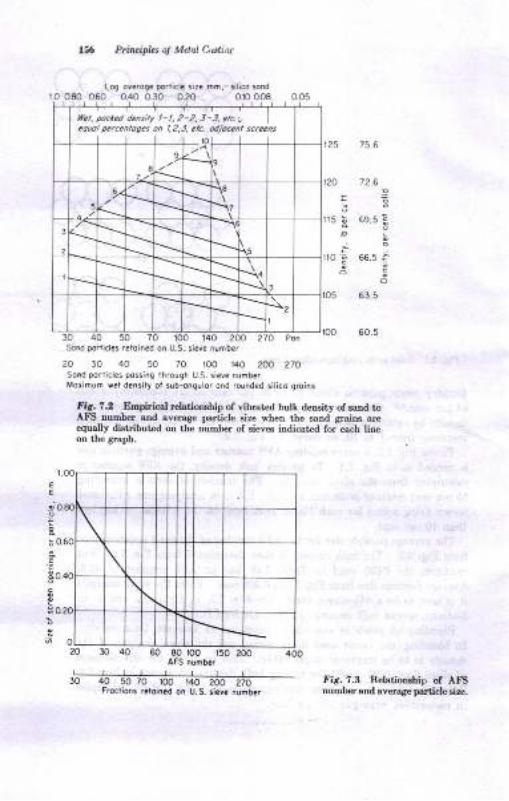
lLt. pocred densiry t- l, 2-2, 3 -J. etc."equol lErc.ntoget oh 1,2,3. ctc. odjoc.tt sc.ccos
Ptitlriph.s oj M.tat C,l'tinc
Do.ticl. 3ir. mh,-rilico sond
72.6
5 69.5 !o;
'; 665:6:
63.5
60.5
EE
jo.9
ho
,g
3o.
go
1O0 140 200 270 PorSond podicl.s retoin.d on U.S. si?ve numbe.
20 30 40 50 70 r00 r40 200 270Soltd po.licles possi.g rhrough US. siey€ nunbe.Morimum r.t daoaily ol aub-ongulo. ond .ounded 3ilico grEins
fi3. 7J Eapirkrl rdationrhip of yibratad bult deDsity ol sand toAfS aumbet end average porticle size wheD Oe saod greiD! ar€equally diotributed on r.he numbe. of sieves indicated foieacb lioeon Lbe grapi.
20 30 40 60 80 tOO 15O 2m 4@AFS nomb.r
50 40 50 70 1@ t4O 2@ 27OF.octioni rctoioad on U.S. sicya ruhbar
fir. ?.3 Relationshil, of AFSnumb€. and average po.ticlc si zc.
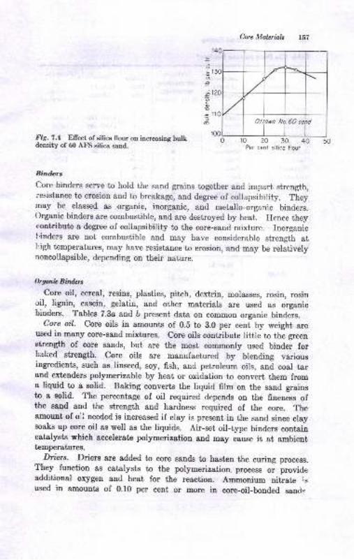
Core Malerials
5
oo
;.tc
=fo
ltig. 7.4 Ellect of silica flour on increasing bulkdensity of 60 AFS eilica sand.
Bindcrs
0102030Per cent silico tlour
40 50
Core binders serve to hold the sand grains together and impart strength,resistance to erosion and to breakage, and degree of collapsibility. Theyrnay be classed as organic, inorganic, and metallo-organic binders.()rganic binders are combustible, and are destroyed by heat. Hence theycontribute a de$ee of collapsibility to the core-sand mixture. Inorganicl.inders are not combustible and may have considerable strength atl,igh tremperatures, may have resistance to erosion, and may be relativelynoncollapsible, depending on their nature.
Orgar.i. Bind$s
Core oil, cereal, resins, plastics, pitch, dextrin, molasses, rosin, rosinoil, lignin, casein, gelatin, and other materials &re used as organicbinders. Tables 7.3o and b present data on common organic binders.
Core oil. Core oils in amounts of 0.5 to 3.0 per cent by weight areused in many core-sand mixtures. core oils contribute little to the greenstrength of core sands, but are the most commonly used binder forbaked strength. Core oils are manufactured by blending variousingredients, such as linseed, soy, fish, and petroleum oils, and coal tarand extenders polymerizable by heat or oxidation to convert them froma liquid to a solid. Baking converts the liquid film on the sand grainsto a solid. The percentage of oil required depends on the fineness ofthe sand and the strength and hardness required of the core. Theamount of orl needed is increased if clay is present in the sand since claysoaks up core oil as well as the liquids. Air-set oil-type binders containcatalysts which accelerate polymerization and may cause it at ambienttemperatures.
Diers. Driers are added to core sands to hasten the curing process.They function as catalysts to the polymerization. process or provideadditional oxygen and heat for the reaction. Ammonium nitrate is
used iu amounts of 0.10 per cent or more in core-oil-bonded sancl:,
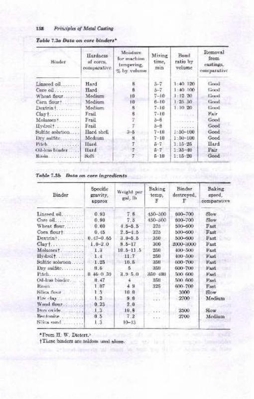
158 Ptituipltt ol Mdal Ca.ditg
Tablc 7.b Datt on core bin&n'
BinderHerdness
of cores,
comparative
Moisturefor mschinetempering,
% by volume
Mixingtime,min
Bondratio byvolume
Removalfrom
c88tings,
comparativc
Table 7.3b Data on core ingred,ients
Specificgravity,&pprox
Linseed oil... . . . . .
C,ore oil.Whestflour.......Cornflourt.......Dextrin i.Clayt..Ilolasses t . . . . . . . .
Hydrol t.Sulfite solution.. . .
Drysulfite........Pitch. . .
Oillessbinder.....Rosin. .
Binder
HardHsrdMediumII{ediumMediumFrailFrailFrailHard shell
MediumHardHardSoft
8
8
l0l08
8
7
7
3-58
7
7
Weight per
gel, lb
I :40.-120
I :40-1fi)l:12 2O
I :25'5O1: 10-20
60(F7006fi)-700500-600
50H0050H00
2000-3000
400-500
400-500
6fiF7006m-700500-60050H00600-700
3000
2700
2500
2700
5-73-77-r06-r07-r07-ro5-85-87-107-105-75-75-10
Bakingtemp,
F
BakingEpeed,
comparative
Good
Good
Good
Good
Good
FairGood
Good
Good
Good
HardFairGood
Slow
Slow
FastFastFastFastFastFastFastFastFastFastFastSlow
Medium
SlowMedium
0. s3
0. 90
0600. 45
0. 47-0. 65
r.0-2.01.31.41.25
0.60 46-0.59
0.47t.o7r.31.2
o.231.30.5l 3
7.81.5
4. 5-5. 5
2.5-4.53.9-5.58 5-17
r0.5-11.5rt.7r0.5
5
3 . 9-5.04
4-9r0.09.62.O
10.8
l0-13
45(F500
450-500
325325
350
300
260
250
350
350
350-4m350
325
rProm If. W. Dietert.5
tTlese binders are seldom used alone.
Linseedoil........Core oil.Wheatflour........Corn flouri........Dextrin t .
Clayt. .
Molassest. .......Hydrol f .
Sulfite solution.. . . .
Dry sulfite.Pitch. . .
Oil-lessbinder...-..Rosin..Silica flour.Fire r:lay.
Wood flour........Iron oxide.Berrl.onite.
Silica sand.

Corc Moleriak r59
Sodium perborate, mangaDese dioxide, manganese oleate, and othermetallo-organic compounds are used with liquid oils and resins forthis purpose. Baking time may be redueed by 20 to 80 per cent by driers.
Cereol onil woter-soluble binders. Cereal is the binder commonly
used for green strength. An amount of 0.5 to 2.0 per cent by weightis used to provide 1.0 to 2.5 psi green compressive strength. The per-
centage used generally must be less than three times the percentage
of core oil in the mixture or there will be a reduction in hardness and
strength after baking. Starches, dextrin, and to a limited extent other
dry biuders such as casein provide some green strength. One virtueof a water-soluble binder is its ability to air-dry or air-harden rapidlyto resist sagging during handling. In all cases, the proper water additionis required to develop the green-strength and baked-strength potential
of the binder. For cereal this amounts to about two to five times thepercentage cereal in the sand. At the lower water percentages, less
baked tensile strength and scratch hardness are developed. Completelywater-soluble binders such as sugar, molasses, and dextrin require
water to about one to three times their percentage in the sand. Again,higher moisture percentages develop higher baked scratch and edge
hardness and tensile strength.
Sulfite binder. Sulfite, or lignin, binders are water-soluble compounds
of wood sugars produced as a by-product of papermaking. They are
used as a liquid containing 60 to 70 per cent solids or dried as a brownpowder. They provide strength on evaporation of water and produce
very high surface hardness during baking. Lignin binders are uselulin green-sand or dry-sand core mixtures because they are readily com-patible with clays and water. Up to 1.50 per cent may be used. Theyunfortunately readsorb water readily, and therefore the cores soft€D
on standing. Sulfite binders are used as an ingredient of pitch com-pounds for large dry sand cores.
Pitch. Pitch is a solid-coal-tar by-product of the making of coke. Itis used as a ground powder in percentages up to 3 per cent or sometimesmore. Pitch core compounds contain pitch and other ingredients suchas clay and sulfite lignin. The pitch portion fuses and partially distillsat temperatures of 300 to 600 F during baking, leaving a solid film whichbinds the rand grains together. Upon casting the metal around theeore, the pitch cokes and develops hot strength to resist the metal.
Wood fl.our. Ground hardwood cellulose is used in core sands inpercentages of usually less than 1.0 per cent, rarelf up to 3.0 per cent.\\'ood flour is useful in decreasing hot strength of any core or moldingsand. A mix of 2 per cent wood flour in a 4 per cent western bentonite-silica sand lowers hot strength and dry strength to B0 to 40 per cent ofthat of the wood flour-free mixtures over the entire temperature range.
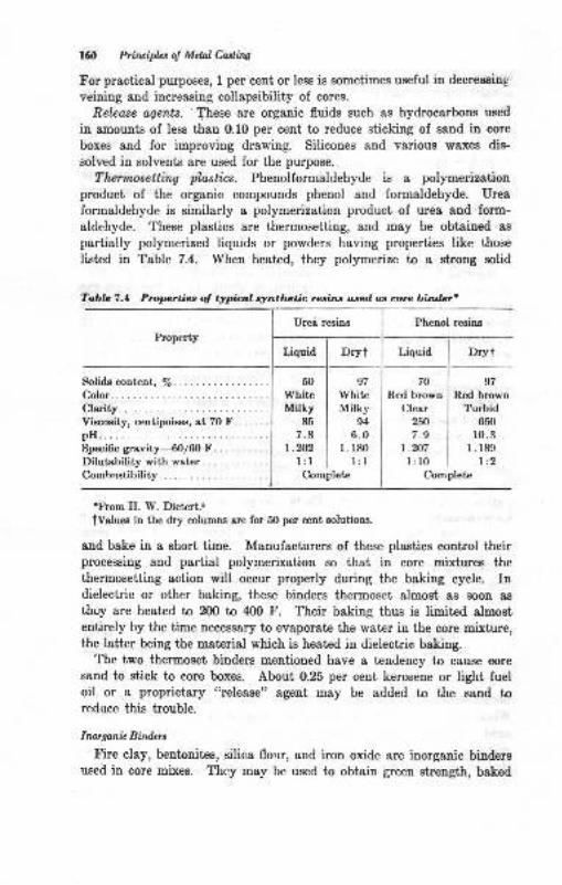
160 Prilrciplcs ol Mdal Castirw
For practical purposes, 1 per cent or less is sometimes useful in decreasing,
veining and increasing collapsibility of cores.
Releose agents. These are organic fluids such as hydrocarbons used
in amounts of less than 0.10 per cent to reduce sticking of sand in core
boxes and for improving drawing. Silicones and various waxes dis-
solved in solvents are used for the purpose.
Thermosetting plastics. Phenolformaldehyde is a polymerization
product of the organic compounds phenol and formaldehyde. Urea
formaldehyde is similarly a polymerization product ol urea and form-
aldehyde. These plastics are thermosetting, and may be obtained as
partially polymerized liquids or powders having properties like those
listed in Table 7.4. When heated, they polymefize to a strong solid
Phenol resins
PropertyLiquid Drvt Drvt
Soli& content, %. . .. ... ..Color... .........
Viscoeity, centipoisee, at 7O F. .... . .
plr.. . . .
Specific gravity-60/60 F. .. . . . ... .
Dilutability with water.Combrrstibility
50
WhiteMilky
85
7.8r.202
1:l
97
WhiteMilky
g4
6.0l. r80
l:l
70
Red brown
Clearzffi7.9
1.207l: l0
Com
s7
Red brownTurbid
650
10.3r.189
l:2pleteComplete
'From E. W. Detert..tValuee in the d4r columnn are for 50 per cent golutions.
and bake in a short time. Manufacturers of these plastics control theirprocessing and partial polymerization so thBt in core mixtures the
thermosetting action will occur properly during the baking cycle. Indielectric or other baking, these binders thermoset almost as soon 88
thcy are heated to 200 to 400 F. Their baking thus is limited almostentirely by the time necessary to evaporate the water iu the core mixture,the lattpr being the material which is heated in dielectric baking.
The two thermoset binders mentioned have a tendency to cause core
sand to stick to core boxes. About 0.25 per cent kerosene or light fueloil or a proprietary "rele&se" agent may be added to the sand toreduce this trouble.
Inorganit Bind*t
Fire clay, bentonites, silica flo,rr, and iron oxide are inorganic bindersused in core mixes. Thcy may be used to obtain green strength, baked
Tobla 7.4 Propertiea of typical syntlwtic resins used u core bhtdcr'
Urei resins
C,orc Mdaials 16l
strength, hot strength, or I smooth finish. Since they are all finelypulverized ma,terials, they greatly increase the amount of oil whichis necessary in oil-sand mixes. Fire clay is used sparingly, in the smallestamounts which will give the strength desired, under 2.0 per cent. If afine sand is added to a coarser sand, added strength can be obtained, andthis may be due in part to the fine material and clay present in it.Bentonite, 0.5 to 2.0 per cent, may be used to gain green strength, buta substantial increase in core oil is required when this is done. Bentoniteretards collapsibility. However, about 0.80 per cent southern bentoniteis reported to reduce sagging of cores during baking.rs Iron oxide isused to obtain added hot strength or prevent veining (cracking). Silicaiiour in amounts up to 30 per cent in core sands is used to obtain hotstrength in cores of large castings which remain molten for a long timeor in small thin cores which must resist erosion. cores which havehigh hot strength and do not collapse sufrciently can cause tears in acasting as it shrinks around the core.
Waler
Water ie not usually thought of as a binder. Other bind,ers andadditives, however, do not seem to function properly unless a.,.r optimumpercentage of water exists in the mixture, usually somewllere between2.5 and 7.0 per cent. Failure to use enough water results in not developinggreen strength from cereals and poor scratch hardnes;, edge hardness,e,nd low baked tensile strength after baking. Excesr.ive *"t", ."r..,stratification of binders by seepage, stickiness, and surface r:rusting andllso causes coremaking and drawing probiems and prblongs baking time.
CORE-SANI} MIXTURES
The simplest core-sand mixture commonly used i:omprises sand, l/ocore oil, l/o cereal, and 2.5 to 6.0 per cent water. other mixtures forcoring purposes are listed in Table z.b. The ingredients are varied tosuit the needs of the cores as determined by the alloy being cast andits temperature, the size and shape of the casting, the method of makingthe.core, and any special requirements of the,core. The weights oftypical core-sand ingredients are given in Table 7.6.
CORE-SAND MIXING
sand for cores requires adequate storage and proper mixing if the bestcores are to be obtained. storage out of the weather is desired uo keepmoisture and dirt out of the sand. Bins, tanks, and silos are used. If
I
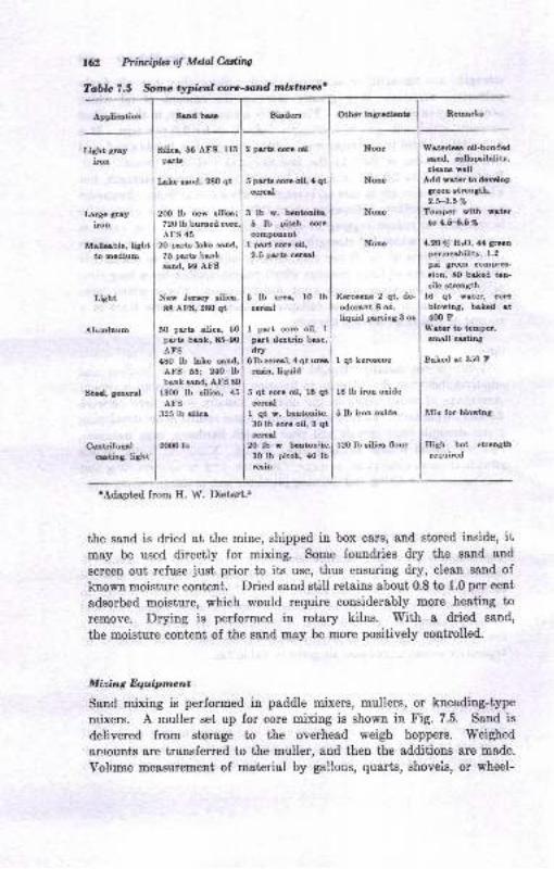
162 Priuifu: of Mdal Cadillg
Tabta 7.5 $ne tylldl:al core-und rtr;ittures'
Appliotioo Srud be Other ir3rediotc Reorrks
Largc grtyircn
Malleble, lightto modium
Light
Alumiauo
Stesl, Beaersl
CeatrifugslcEting, liaht
20 part lrLe srnd,75 prrt€ bukod. 90 AFS
Nov Jenev silica,
88 AFB, 280 qt
50 parts eilie, 5O
ptrt btDt' 85.'00
AFSl8o lb laLc md,AFS 55i 24O Ibbanlmd, AFS &)
l3m lb !ili6, 15
AFS
325 lb lilie
2[mlb
Nonc
Keroceus 2 qt, deodo8nt 8 or,liquid perting 3 or
1 qt ker@eoe
16 lb iroo oride
5 lb iron oride
l2O lb silica flour
Waterla oil-bonded
Esd, ourplibility,cleau vdl
Add Etcr to d.%lopSrsr ltrength,2.fi.5%
Tcop€r rith [tarbLfi.6%
4-2O% ErO,,l.1 Su!porBobility, 1.2
pei grun compr&rion, 80 baled tan-aile atrogth
16 qt rat€r, @Eblowing, brled at400 F
W.tor to t Dpc,lEall @tiog
Bcked et 350 F
Mir for blorlu3
Eiah hot ltrcDathrequired
Silio, 66 AFg, 113
prrt!
IrLe und, 280 qt
2oO lb Dew Eilica;
2 parts @ro oil
5 plrts @re oil, ,( qtcetol
3 lb w. bGrtoDit€.
6 lb pitch orecompoDeDt
I p.rt @re oil,2.5 parts cereal
5 lb ure, l0 lbcerol
1 pert core oil, 1
pert dertriu bse,drv
6lb ceral, ,l qt u.6ruir, tiquid
5 qt @re oil, 16 qtcereal
1 qt w, boatoDite,
30 lb corc oil, 3 qt@16l
20 lb r beoton
30 lb pitcb, 40 lbrein
720 lb burDedAFS ,(5
'Adapted from E. W. Dietert.r
the sand is dried at the mine, shipped in box cars, and stored inside, itmey be used directly for mixing. Some foundries dry the sand and
screen out refuse just prior to its use, thus ensuring dry, elean ssDd of
known moisture conteni. Dried sand still retains about 0.8 to 1.0 per cent
adsorbed moisture, which would require considerably more heating to
remove. Dryiug is performed in rotary kilns. With a dried sand,
the moisture content of the sand may be more positively controlled.
Miring Dquipmont
Sand mixing is performed in paddle mixers, mullers, or kneading-type
mixers. A muller set up for core mixing is shown in Fig. 7.5. Sand is
delivered from storage to the overhesd weigh hoppers. Weighed
amounts are transferred to the muller, and then the additions are rnade.
Vohrme measurement of material by gallons, quarts, shoveis, or wheel-
Biodem
Aht gEyiroa
Lisht
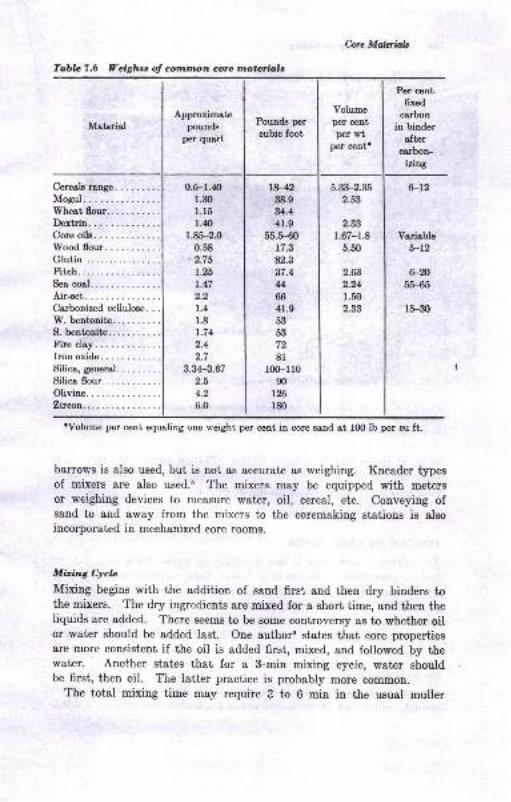
Tabb 7.6 Yeighu of cotnmon corc rnatorio,ls
'Volume per cent equaling one weight per cent in core sand at 100 lb per cu ft.
Pounds per
cubic foot
Volumeper centper s't
per cent'
Corc Maloiab
MaterialApproximate
pounds
per quart
6.3&-2.35
2.53
2.33
1.67-1.8
5.60
Per centfixed
carbonin binder
afterca,rbon-
' iztl,g
6-12
Variable
5-r2
Cereals range.
Mogul..Wheat flour.Dextrin.
W'ood flour.Glutin .
Pitch. ..Sea msl.Air-set. .
Carbonized cellulose. . .
W. bentonite.S. bentonite.
Fire clay.Iron oxide.Silica, general.
Silica flour.
Olivine.Zircon..
0.6-r.40r.30l.t5l.ltt}
1.85-2.0
0.58-2.75
1.26
1.47
2.2
1.4
1.8
t.742.4
2.7
3.3.{-3.67
2.5
4.2
6.0
rH23{t.9
94.4
41.9
55.H017.3
82.3
37.4
u66
41.9
53
53
72
81
r00-l 10
mr26r80
6-2055-$5
15-30
2.63
2.24
r.502.33
bamows is also used, but is not as accurate as weighing. Kneader typesof mixers are also used.5 The mixers may be equipped with metersor weighing devices to measure wat€r, oil, cereal, etc. Conveying ofsand to and away from the mixers to the coremaking stations is alsoincorporated in mechanized core rooms.
Mbing Cycb
Mixing begins with the addition of saud firsl and then dry binders tothe mixers. The dry ingredients are mixed for a short time, and then theliquids are added. There seems to be some controversy as to whether oilor water should be added last. One authore states that core propertiesare more consistent if the oil is added first, mixed, and followed by thewater. Another states that for a 3-min mixiDg cycie, water shouldbe first, then oil. The latter practice is probably more common.
The total mixing time may require 3 to O min in the usual muller
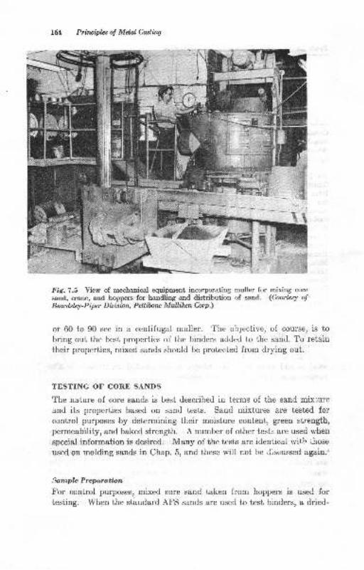
t& Principlo^s o! Mda.l Castirry
Fig. 7.5 Yiew of mechanical equipmeut incorporating muller for mixing core
sand, crane, and hoppers for handling and distribution of sand. (Courtesy otBeodsley-P iper Dioision, Pdlibru Mullihcn Corp ;)
or 60 to 90 sec in a centifugal muller. The objective, of course, is tobring out the best properties of the binders added to the sand. To retain
their properties, mixed sands should be protected from drying out.
TESTING OF CORE SANDS
The nature of core sands is best described in terms of the sand mixlureand its properties based on sand tests. Sand mixtures are tested forcontrol purposes by determining their moisture content, green strength,
permeability, and baked strength. A number of other tests ai'e used when
special information is desired. Many of the tests are identical witb i.irose
used on molding sands in Chap. 5, and these will not he i.lisr:ussed Bgain.'
Srntplc Preporotbn
For control purposes, mixed core sand taken from hoppers is used for
testing. lYhen the staudard AFS sands are used to test binders, a dried-
I1.,1
I
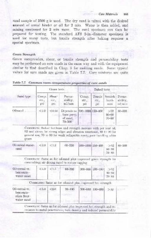
Core Malzriuls 165
sand sample of 2500 g is used. The dry sand is rnixed with tire desired
amount of cereal binder or oil for 2 min. 'Water is then added, andmixing continued for 2 min more. The sand specimen can then be
prepared for testing. The standard AFS 2-in.-diameter specimen isused for many tests, but tensile strength after baking requires a
special specimen.
Green Strength
Green compression, shear, or tensile strength and permeability testsmay be performed on core sands in the same way and with the equipmentsimilar to that described in Chap. 5 for molding sands. Some typicalvalues for core sands are given in Table 7.7. Core mixtures are quite
Baked tests
Sand type Shear
str.,psi
< 1.0 <0.60
Comp.str.,psi
Tensile
str.,psi
Scratch
hard-
ness
Perme-
ability,ml/min
Depends on
base perm.
of sand,
70-300
150-400 80-300>9280-9070-80
Couupnts: Baked hardness and strength increase with per cent oil,92 and above for strong edges and abrasion resistance, 80 to 90 forgeneral use, 70 t,o 80 for weak collapsible cores; poor handling rvhengreen
otsand I I I I I lso-eol| | I i I l;08,, I
CoMlrsr.lrs: Same as for oil-sand plus improved green strength forcoremakingl air dryiag rapid to reduce sagging
300-800
Couurxr:s: Same as for oil-sand plus improved hot
<5.0 <2.O 20-100 300-800 100--{00 >92
Colrurxrs: Same ss for oil-sand plus improved hot strength and rc-sist&nce to metal penetrationl bulk density and reduceC permcebility
Oil-cereal-w.bentonite-water-sand
Oil-cereal-w.bentonite-silica flour-water-sand
>9280-907(F80
strength
Table 7.7 Common room-tempetature ptoperties oJ core sands
Comp.
str.,psi
<r.5 | 60-300
Green tests
Perme-
ability,ml/min
Oil+and.
<4.0 100{00
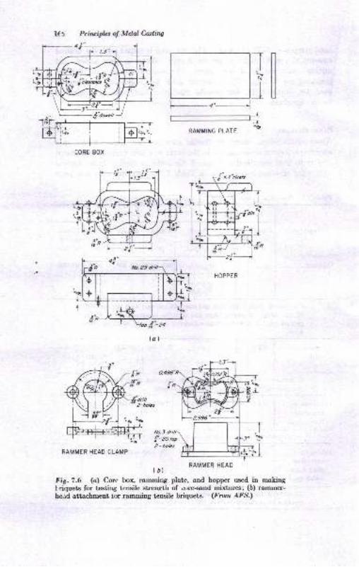
lf 5 Prircipbs of Melal Castirtg
l-4"1
-J
L______________J .TRAMMING PLATE
-1S
,b.3 driil-
t-zo top
2 - holcsRAMMER HEAD CLAMP
(,) RAMMER HEAD
Fit.7.6 (o) Core box, ramming plate, and hopper used in makingi riquets for testiug tensile strength of ore-sand mixtures; (b) ramrner-head attachment tor ramnring tensile briquets. (fiom AFS.)
CORE BOX
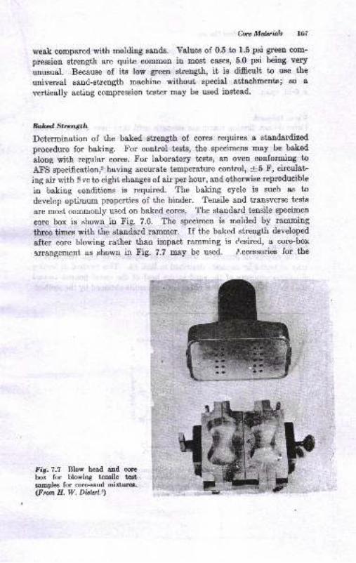
C,;uc Mdaiab 16I
weak compared with molding sauds. Values of 0.5 to 1.5 psi green com-
pression strength are quite common in most cases, 5'0 psi being very
unusual. Because of its low green strength, it is difficult to use the
universal sand-strength machine without special attachments; so avertically acting compression tester may be used instead.
DolczdSrll,ngtla
Determination of the baked strength of corts requires a staudardized
procedure for baking. For control tcsts, the specimens may be baked
along with regular cores. For laboratory tests, an oven conforming to
AFS speeification,' having accurate temperature control, -+5 F, circulat-
ing air with fi ve to eight changes of air per hour, and otherwise reproducible
in baking conditions is required. The baking cycle is such as to
develop optimum properties of the binder. Tensile and transverse tests
are most comnionly used on baked cores. The standard tensile specimeu
core box is shown in Fig. 7.6. The specimen is molded by ramming
three times with the standard rammer. If the baked strength developed
after core blowing rather than impact ramming is Cesired, a core-box
rrrangement as shown in Fig. 7.7 may be used. .l.ccessories for the
Fig.7.7 Blow head aqd corebox for blowing tensile tertsamples for core-sand mixturea.(From H. W, DietqLl)
f
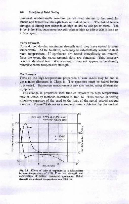
168 Ptin ipla d Mad e hq
univeraal salrd-shength machine peroit tbat device to be uled fortenaile and trauveroe streogth teeto on baked coree. The baked tensileatrength of shong corc mixes is ss high as 250 to 300 pa or Dore. Thel- by 1- by &in. iraueverse bar will take as high aa 15O to 20O lb load ona 6-in. epan.
Vo n Stre.l't.hCores do not develop maximum strength until they have cooled to room
temperatue. At 150 to 300 F, cores may be subetantially weaker t,han atroom t€mperature. If specimens sre teeted immediately on rcmovalfrom the oveu, the warm-sirength data cre obtsined. This, however,is not a staDdsrd t 8t. Wsrm etreugth does not sppear to be directlyrelated to room-tempersture BtreDgth.
Eoa Strct.'itl.Tests on the high-temperature properties of core ssnds may be rua inthe manner diecur€ed in Chap. 5. The epecimea must be baked before
it ie tested. Expaneion rDeaaurements are also uade, uting dilatometcrequipmentr
The change in properties witb time of exposure to high temperaturemay be tested by methocls deecribed in Ref. 13. This method of testiugBimulates exposure of the saod io the heat ol the metal poured arou.nd
the core. Figure 7.8 rhows an example oI results obtaiued by the method.
'-- 200
A 100E
30 ci
,9
ror
00 5_ rO 15
tma. mrnutas
fit, ?.0 Efr€ct of tim6 of erlEur€ to a dilatom€trrol l7so F on hot str€Dgti atrd
delormation of hollow cacand epecimer.s. BaleditrenStn at arDhicat tsmpclaturt vas 1000 p6i.
Corc sond -1.75%oil, 2.0% cer.ol,4.0% HO, 68AFS sond
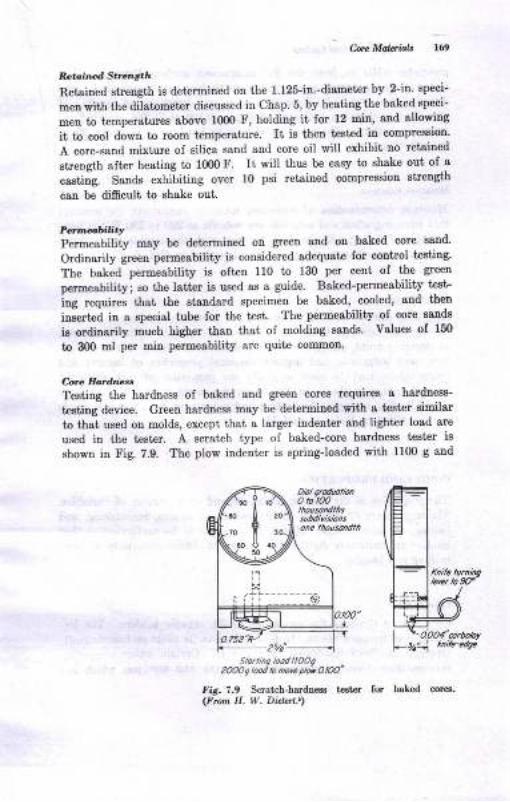
C8. Mdaiol, t64
Rct,iilnA Sr,'l 6ah
Retsined streugth is determined on the 1.125-in.-diameter by 2-in' speci-
men with the dilstorletsr discussed in Chap. 5, by heaiing the baked speci-
Deu to temperatur€s above l0OO F, holding it for 12 Din, aud allowing
it to cool down to room temperature. It is thea tested in compression'
A core-sand mixture ol silicl sand and core oil will exhibit no retained
streDgth aft€r heating to 10fl)F. It will tbue be easy to shake out of a
castiig. Sande exhibiting over 10 psi retained compressiou streDgth
cau be difisult to ghake out.
P.'rl.t,biu.yPermeabiliiy may be determined on green snd on baked core sand-
Ordinarily green permeability is considered sdequat€ lor control testilg'
The baked permeability ie oftrcn 110 to 13O per ceut of t'he greetr
permeability; so the latter is used as a guide. Baked-permeability test-
iug r"quires that the stsndard specimen be baked, cooled, and then
i"ee"t"d in a epecial tube for the t48t. The permesbility of core eands
ia ordinarily much higher tfiaD thst of molding eand8. Valueg oI 150
to 300 nl per min permeability are quite commoo-
C-orc EodteuTestiug the hardness of baked aud green coreE rcquiree a hardness-
testiug device. Green hardness m8y be det€rmined with a tester similar
to that used on molds, except that a larger indenter and lighter load are
ured in the t€ster. A scratch type of baked-core hardnese t€st€r ie
shown in Fig. 7.9. The plow indenter is springJoaded with 1100 g and
Sro.inq tord llooq2OOO 9 lood tD nor. pkr AlN"
fir. 7.9 Scrat h-hardrc€a test€r(Frcn H. W. Dietat.t)
for baLed cores.
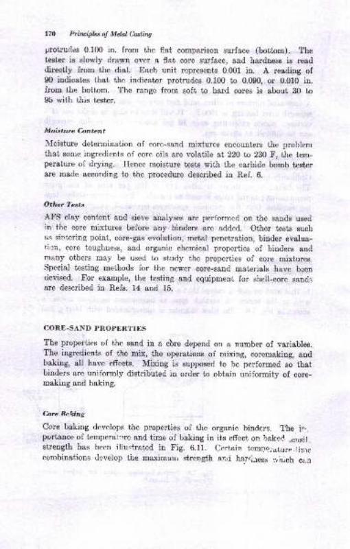
170 Principla o! Metal Casting
protrud.es 0.100 in. from the flat comparison surface (bottom). Thetester is slowly drawn over a flat core surface, and hardness is readdirectly from the dial. Each unit represents 0.001 in. A reading of90 indicates that the indicator protrudes 0.100 to 0.090, or 0.010 in.from the bottom. The range from soft to hard cores is about 30 to95 rvith this tester.
Moisture Content
Moisture determination of core-sand mixtures encounters the problemthat some ingredients of core oils are volatile at 220 ta 230 F, the tem-perature of drying. Hence moisture tests with the carbide bomb testerare made according to the procedure described in Ref. 6.
Othnr ?'ests
AFS clay content and sieve analyses are performed on the sands usedin the core mixtures before any binders are added. Other tests suchas sintering point, core-gas evolution, metal penetration, binder evalua-ticn, core toughness, and organic chemical properties of binders andmany others may be used to study the properties of core mixtures.Special testing methods for the newer core-sand materials have beentievised. tr'or example, the testing and equipment for shell-core sandr;are described in Refs. 14 and 15.
CORE-SAND PROPERTIES
The properties of the sand in a cbre depend on a number of variables.The ingredients of the mix, the operations of mixing, coremaking, andbaking, all have effects. Mixing is supposed to be performed so thatbinders are uniformly distributed in order to obtain uniformity of core-making and baking.
Core Bcking
Core baking develops the properties of the organic binders. The ir-pr.rrtance of temperar'rre and time of baking in iis effect on baked ,ensi!,strength has been illusi"rated in Fig. 6.11. Certain t€mDa.,.ature.ij.recombinations develop the maximuui strength ar'j har..iress :,hich c:.n
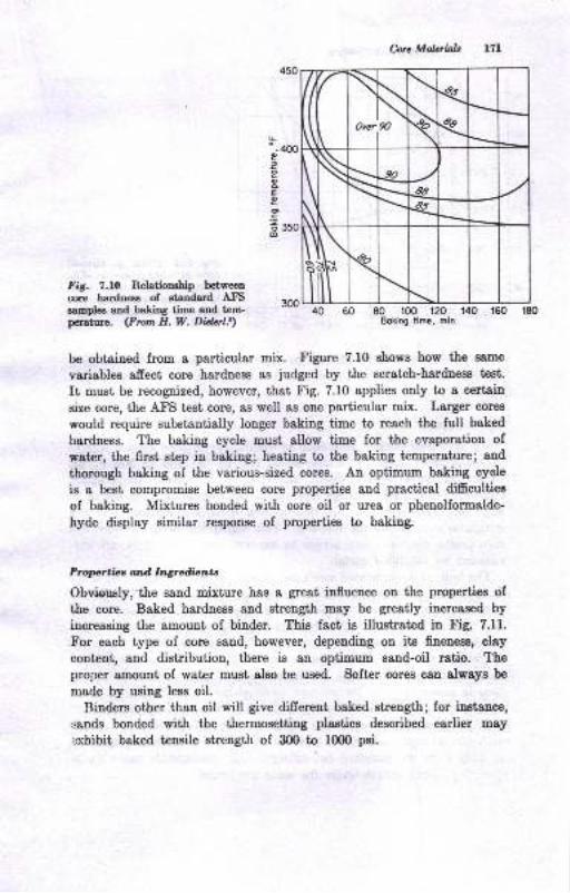
L"-coo?:eooEoo.si 35o6
Carc Malerizls
40 60 80 ro0 120 r40 160 .l80
Boking time, min
Fig. 7.lO Relationahip bctweencore hardsess of statrdard AtrS amsamples and baliog time and tem-pof,ature. (Frorn H. W. Didal.')
be obtained from a particular mix. Figure 7.10 shows how the same
variables afrect core hardness as judged by the Bcratch-h8rdne8s test.
It must be recogpized, however, that Fig. 7.10 applies only to a cerbain
size core, the Atr'S test core, as well as one particular mix. Larger cores
would require substantially longer baking time to reach the full baked
hardness. The baking cycle must allow time for the evaporatiou ofwat€r, the first step iu baking; heating to the baking tremperahuel aud
thorough baking of the various-sized cores. An optimum baking cycle
is a best compromise between core properties and practical difrculties
of baking. Mixtures bonded with core oil or urea or phenolformalde-
hyde display similar response of properties to baking.
Proprtiot ard Ingrdbnta
Obvieusly;the sand mixture has a gteat influence on the properties ofthe core. Baked hardness and strength may be greatly increased by
inoreasing the amount of binder. This fact ie illustrated in Fig. 7.11.
For each type of core sand, however, depending on its finenees, clay
content, and distribution, there is an optimum sand-oil ratio. Theproper amount of water must also be used. Softer cores 08n always be
made by using less oil.
Binders other thao oil will give different baked strengthl for instauce,
sands bonded with the thermosetting plastics described earlier may
exhibii baked tensile strength of 300 to 1000 psi.
,a
)Ovcr
\90
\\
\\
€?_aa
€,
Ns(
llilR.
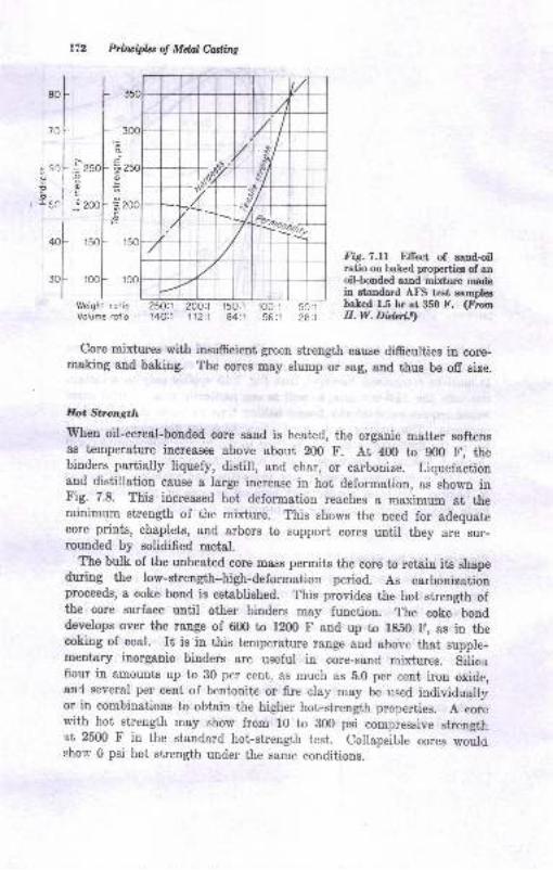
,rfI
701
i
.3,)[
Ptol
I
f'l-_.,li
= zsol- 62tolb
q l::2@t =-2(
le,ro[- r:
I
,ool- 1c
I
Weight rotioVolume roiio
Prbuipht of Mdal Catling
,/t
r'I-.lX
{cobt)II --r{<
2OOt1 t50:1 100:l112:l 84:t 55:l
50:128:1
250X140:1
Fig.1.ll Effect of eandoilratio on baked properties of anoil-bonded sand mixture madein etandard AFS test sampleebaked 1.5 hr at 350 F. (FroynH.W. Didqt.s)
Core mixtures with insufrcient green strength cause difficulties in core-making and baking. The cores may slump or Bag, and thue be ofr siz,e.
Eot Strength
when oil-cereal-bonded core sand is heated, the organic matter softensas temperature increases above about 200 F. At 400 to 900 F, thebinders partially liquefy, distill, and char, or carbonize. Liquefactionand distillation c&use a lerge increase in hot deformation, as shown inFig. 7.8. This increased hot deformation reaches a maximum at theminimum strength of the mixture. This shows the need for adequatecore prints, chaplets, and arbors to support cores until they are sur-rounded by solidified metal.
The bulk of the unheated core mass permits the core to retain its shapeduring the low-strength-high-deformation period. As carbonizationproceeds, a coke bond is established. This provides the hot strength ofthe core surface until other binders may function. The coke bonddevelops over the range of 600 to 1200 F and up to fg50 F, as in thecoking of coal. It is in this temperature range and above that supple-mentary inorganic binders are useful in core-sand mixtures. silicnffour in amounts up to 30 per cent, as much as 5.0 per cent iron oxide,ond several per cent of bentonite or fire clay may be .sed individuall;ror in combinations to obtain the higher hot-strength properties. A corewith hot strength may show from 10 to 800 psi compressive strengthat 25t10 F in the standard hot-strength test. collapsible .o.u. *oulcshot' 0 psi hot sr,rength under the same conditions.
Cqe Molaial"t 173
bllarpsibility
Rapid loss of core strength after the metal is poured is promoted by
the use of organic binders and nonuse of inorganic binders. Of course,
low binder concentrations are helpful. Cellulose and starches are effec-
tive in promoting burnout. Cereals may reduce burnout time and hotstrength by 50 per cent or more when used in amounts up to 2.0 per cent.
Rosin and urea formaldehyde also promote eollapsibility. Collapsibilityis really a combination of two faetors, the absence of hot strength and
the rate of loss of strength with heating. Lack of collapsibility maycause hot-tear defecLs, war,page, and difficulty in shaking out. Reta'ined
strength is present in unheated parts of a core or in cores which contact,
very little hot metal. Retained strength from organic binders which are
not thermally decomposed leaves the core at close to its baked strength,
and therefore uot collapsible.
C-ote Density
Core-sand density is an important factor related to collapsibility and
hot strength. A core rammed to high density resists collapse and dis-plays more hot strength. The density of the base sand, as discussed
earlier, approximates the limiting density which a core can have.
Relractorinass
The starting point for refractoriness in cores is the sand-grain base
of the core moisture. Washed and dried, white, high-purity silica sand
in coarser sizes seems to have a maximum fusion point of about 3100 F.The less pure, discolored bank and lake sands in finer sizes have fusion
points of 2900 to 3000 F. In addition to the sand base, however, certainthiugs may be done to improve the heat resistance of cores. Core
coatings which change the properties of surface layers of the core maybe used. These may prit additional refractories on the surface or mayreinforce the surface by applying more binders to the surface. Resistance
of the core surface to the heat of the metal determines the coatin"surface quality.
CONE COATINGS
Core coatings are more commonly known as core washes, core dips, black-ing, or facing. Core coatings may be applied as liquids by spraying,
dipping, or brushing and. as solids by dusting. Core coatings are us,rallyproprietary materials formulated by the manufacturer for use on certain
types of castings. Some mixtures which may be used for coatings ere
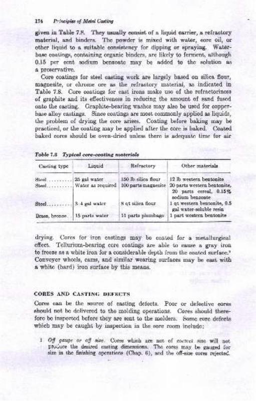
171 Priwipbot M&dCdins
given in Table 7.E They usuolly consist of a liquid oarrier, s refrsctory
Dat€rial, and bindere. The powder ie Bixed wit'h water, core oil, or
other liquid to a suitsble conEistency for dipping or spraying. Water-
baae coatings, containing organic binders, are likely to ferment, although
0.15 per cent sodium benzoate may be added to the solution as
a preaervative.
Core coatings for steel casting work are largely based on silica flour,
magnesite, or chrome ore as the relractory materiai, as indicat€d inTable 7.8. Core coatings for cast irons make use of the refractoriness
of graphite and its efrectiveness in reducing the amount of sand fused
onto the casting. Graphitre-bearing washes may also be ueed for copper-
base alloy castings. Since coatings are most commonly applied as liquids,the problem of drying the core arisee. Coating before baking may be
praeticed, or the coating may be applied after the core ig baked. Coated
baked cores should be oven-dried unless there is adequate time for air
Tabb 7.8 Typicz,l corc-cr,oting ma,terialc
Casting type Refractory Other materialr
Bteel.. .
Brase, bronze. .
Liquid
25 gal water
\Yater as required
3-4 gal water
l5 parts water
150 lb eilica flourlfi) ports magnesite
8 qt silica flour
11 parts plumbago
12 lb western bentonite20 parts western bentonite,20 parts cereal, 0.157o
sodium benzoate
I qt weatern bentonite, 0.5gal water-soluble reain
1 psrt westera bentonite
drying. Cores for iron eastings may be coated for a metallurgicalefrect. Tellurium-bearing core coatings are able to cause I grsy iroDto freeze as a white iron for a considerable depth from the coated surface.e
Conveyor wheels, carns, and similar wearing surfaces may be cast witha white (hard) iron zurface by this means.
CONES AND CASTING DEFECTS
Cores can be the source of casting defects. Poor or defective cores
should not be delivered to the molding operstions. Cores should there-fore be inspected before they are sent to the molders. Some core defects
which may be caught by inspection in the core room include:
1. Ofi galqe or ofi ti,ze. Cores which arr not of correci; size will notpruriuce the desired casting dimensions. The cores mey be gauged forsize itr the finishing operations (Chap. 6), and the ofi-size cores rejectC.
Corc Mabials t75
2. core sti.cker. some core-sand mixtures give trouble by sticking to the core
box. The sand sticking to the box gives the core a rough, pitted surface
which will be transferred to the casting. Such cores can be rejected'
3. Irwccurate core assembliz.s.. core assemblies may be shifted or not well
fitted together, causing dimensional errors.
4. Fir*. All fins and projections on the core will definitely show up as cavities
in the casting unless they have been cleaned off in core-finishing operations.
5. Craclced cores. Some cores will show eraeks on their surfape af[er they are
baked. Metal mey run into these cracks and produce 6ns on the casting'
In spite of delivering good, cleon, dimensionally accruat€ cores to the
molder, cores may still be the source of casting defects other thau those
coDsidered ebove. The core-sand mixture and the method of locating
8nd securing cores iu the mold c&n cause trouble. when the metal is
poured, thermal efrects cause the core to burn out, and buoyancy or
lhe momentum of the metal can cause it to shift from where it was set
into the mold. some of the defects which cau be encountered from
these sources include:
Blora. Since cores give off gases, they may cause blows or gas cavities
in the casting. one of the chief reasons for core blows is underbaked cores.
Cores which are underbaked and have green centers may give off sub-
stantial amounts of gas.
Dirt. Loose or easily eroded sand may result in dirt defests in castings
Core raise. This defect occurs when the core floats and moves up elose
to the cope. It may even touch the cope surface and seal ofi the section'
A weak core or one which is not properly zupported with chaplets may
be the cause of this defect. An undersize core not held tightly by the
core prints may also raise.
4. Core shilt. A. core may shift horizontally if it is not securely held by
chaplets or prints or if it was not centered when set' The characteristic
evidence of a core shift is that one casting wall is thinner and the opposite
one thicker than required.
5. Crackeil core, firts. A core may crack because of buoyancy efreck. A
stronger core or better support with prints or chaplets is indicated.
Cracks or fins c&n seal off intemal pa.ssages.
6. Metal, penetrotion. This defect is especially troublesome in large castings
where cores become heated up to the melting point of the metal beforo
it freezes. Metal then seeps into the core, developing an adhering mass
of sand and metal. This defect is a very troublesome one to remove from
the casting. Soft ramming and sand with a low sintering point eeem to
aggravate this defect.
7. Core uuh, cut (see Chap. 5, wash defect in moldi.E sand). A core will
wash (erode) when the surface collapses too fast. Washes may be pre-
vented by using a refractory coating on the core or strengthening it by
the use of more binder. Sand additions which increase hot strength, eilica -'
flour or clay, for exa,mple, develop more resist&nce to washing.
1.
2.
J.
I?6 hi,.iCa ol Mdol cadi,t!
8. Eot tar.. 1hi8 defect is amply ilustrat d in Ch8pB. g rnd 23. A hsrdcore *hich does oot allow the castilg to coDtrsctr m.sy luptule or lDsr tleEet8l. Too high 8 hot, strength of tLe sstrd Dixtur€, obtoiaed urullythrough inorganic bildera, moy cause this defect. The defect is m€tcommon ia malleable, steel, and trotrfe'touE castilg8.
9. yar'ar. Veim on castings 8!€ fn-Bhsped protuberaac€s h cor€d arers. Itsppe8rs that a crack-sbsped opeailg develope in the coE ,s it bec@esheahd by the metal. The crgcL ie then 6lled with moltea metsl, and avein sppesE on the casting wheo it iB clesaed. C€rtain mat€rials addedto core 8andB, guch as iroo oxide, that flnx the s8trd and make it, ioughst high taEperature seee to ol/ercoltre this defect. Eowever, it is kaownto be-csused by sever8l sand corditiona, de6criH i! R.ef. 6. The defeci,is Eost often etrcountered itr ferrous castings i?hele a @sll or thii corcis surmrrnded by e substsntrisl tos38 of meial.
lO. Sc?,L t oad Dact&_. Sand+rpaa;iiD delects of the type considered forDoldiDg :llid in Chap. 5 are aho encouatered on cored crstiDg surfsces,
Ll- .:.'i/a,h. A crusli i8 EoEt coDirhoDly e der'eci in the motd which is causedduring the coro oelting or cloaing of the hold. ID a crush, aand on themold caviiy ia displac,ed by the coie6. If a core is oversize, when tbe ooldie closed, the cot€ pritrt8 will be eularged by the core, 8trd this c&D flalesaad of the mold F3lls. The defect shows up oD the cd&ing as a depreo-siotr where the mold rrall is crushed in toward the mold cavity. Careleos.:lc"ir,g oi r,le orold or oooi ttask guide pins may also cause the trouble.
12. !'iosrrer. Fissures sppsr as roug[, gteinylooking Dasses &tiached directlyto corcd suQceo oI ttre csstiDg8. They epp@r to be locatiotls where thecorc saod b!6 colla@ and has be€D pushed aside by the still BolteoDetal.
It is evident that &e defecte which may be related to coreg are inpart mechanicsl probleE8 and iu part problems aesociated with tleproperties of core-BaDd mixtures. A c8reful contrcl oI the core-sandproperties can rcduce defects lrom thst source.
OTEER CORE Pf,OCESSES
A uumber of specisl coremaking processee have soue iDto generaluse. These usually involve s combiDatiou ol core-sand mixture andcoremsking €quipment that oEers BoEe special ad\,aDtage either iDmsking the core or in the osstilg.
Shell corrs require 8 hest€d core box and a Eand mixed with about2 to 5 per ceut thermos€ttitrg resiD, commonly the phenotic type. Sande I
precostcd witJr the rcain are most frequeutly uaed. The sand is eitherblowo into the box or led in by gravity. After a dwelt period, toproduce a hardened shetl, the uohardened eand is &ained out, producinga ho[ow cor€. CurioC 01.-t.|e shell is continued for a short time longer.
C-0t, Mdaiob lli
The ehell core is tlrcn extracted from tlre box, The procees producee
hardeued cores thst require no further baking. Thue driere are uotneeded. The shell-core process is fully described in Ref. 15.
The hot-box process produces solid corea lrom a mixture of 2 to 4per cent fur&n resins, a catalyst, and sand. The cores are blown usiugcoree boxes heated to 400 to 600 F. Ileat from the box initiatee exoiherDicpolyrrerization of the resiu. After lese than a minute, the core may be
removed from the box, aud it ie cured outside the box blr continuationoI the exothermic reaction. Baking is agaiu not required. The silicateprocess, referred io in Chap. 3 for making molds, may also be ueed forhardening a core sand withia the core bor,
The proceeses above have the colomon feature of hardeniug the cortwithir the core box. Thie step produces an sccurate reproduction ofthe core-box cavity, and coneequently leads to sccuately cored caatiugs,
BIBLIOCRAPIIY
1. J. Cohe aod C. MacQuiston, Theoreticel Cotrcepts of Packing Smell Prr-liclef, Trcns. .d.t'S, vol. 66, p. 36, 1958, a.rd accompaoyiag bibliogruphy.
2. J, Grott, Particle Packing: Principles aad Linitatiotrs, ?roru,,{f8, vol.66,p.553, 1958.
3. B. W. Eeine and T. W. S€atoD, DeDsity of Sand Grain Fra,ctione of the Atr'ilSieve Analyrsis, Trdrls. AFS, vol. 66, p. 4O, 1958.
4. C. W. Biggs (ed.), "Fuodameolols ol Core Sands snd Bindert," Bt€eltrounderB' Society of America, Clevelaad, 1961.
5. E. W. Dietort, "Fouldry C,ore Practrice," Americau Fouadrymen's Society,1950.
6. Americap Foundr5zuetr's Society, "Formdry Sald Eandbook," 1963.7. E. K. Selzberg, Plastic Binders for Fouadry Saad Practice, Ttuts. AIS,
vol. 60, 1952.
8. J. E. McMillan and J. A. Wickett, Pbeaolic R:sh Corc Bhders, Trullo- AIS,vol. 58, 1950.
0. O. J. Myere, Which Comes First, Orl or Watet? Fanndry, vol. 77, Sept€D-ber, 1949.
10. C. R. Austetr, UsiDg Tellurium io Proootiry Chills on Gray Imn, foradry,vol. 77, July, 1949.
11. R. E. Morey, G. G. Ackerlind, aad W. S. Pellini, Efects of Biaders ardAdditives otr the Eigh TempeBture Properties of Foundry Srnd.s, ?ron .
.{.PS, Yol. 60, 1952.
12. A. E. Murton, E. H. Fairfield, and B. nichardson, Corc Orl EvaluatiouMethod, ?ror.r. .dIS, vol. 59, p. 2?6, 1951.
13. R. IY. Eeine, E. H. King, and J. S. Schuoocher, A New Approach in Teatingthe l{igh Temperatrurc Strength of Molding aod Core Saod, T'ozo. AFS,vol. 69, p. 410, 1961.
14. II. W. Dier€ft Co., Tools for Control, Bullr. ll8, 3U, Lnd. }ffi; Foundry-me's N elts Letter, rrol. 2, Detmit, I962.
15. R. S. L. Andreor, "Shell Proceae Foundly Practice," Amelicstr Foundry-rtreD's Society, 1964.
16. J. Peleg, Corc Binder Properti€s, Tmu. AFS, vol. 70, p.57, 1962.
Solidification of Metals
INTRODUCTION
It is the purpose of this chapter to consider the major fundamental prob-
lems in connection with the solidification of foundry alloys. Before doing
so, however, it will b€ helpful to review briefly some of the more importantfactors involved.
If attention is confined for the time being to binary alloy systems,' it ie
apparent i-mediately that solidification proceeds:
1. At constant temperature (pure metals and eutectic alloys)
2. Over 4 temperature range (solid solutions)
3. By a combination of solidification over a temperature range followed
by constant-temperature freezing (proeutectic-plus eutectic-type freezing)
Solidificatiou occurs by the nucleation of minute grains or crystals,
which then grow under the infuence of the crystallographic and thermalconditions that prevail. The eize and character of these grains are con-
trolled by the composition of the alloy and by the cooling rate. Growtheeases when all the available liquid metal has solidified.
Other changes are also taking place during the freezing procese. Ileatis being extracted from the molten metal as soon as the metal enters the
mold. This heat is often referred ta as wperheof, since it represents thatwhich must be removed before solidification can begin. The latent heof
of fusi.on is also evolved. This must be transferred to the surroundingmold before complete solidification can be achieved. Finally, the solid
metal transfers heat to the mold, and then to the atmosphere as it cools
to room temperature.
During the three stages of cooling, i.e., liquid, liquid-solid, and solid,shriukage is also occurring. Thus the metal contracts as it loses super-
'It ie assumed tbat the studeut hm been iutroduced to the physical metellurry ofbinary alloya. If not, it will be well at this point to review the subject. Sources of thisfuformation are numeroua, and iaclude, among others, Clark and Varney, "PhysicalMetollurry for Engineers," D. Yan Nostra,nd Company, Inc., Princeton, N.J., 1962;AJbert G. Guy, "Elements of Phyeical Metallur5r," Addison-Weeley PubXBhiDg
Company, Cambridge, Mass., 1959; Committee on Metallurry, "Engineering Metal-lurgr'," Pitmqn Pubtnhing Corporation, New York, 1957.
178
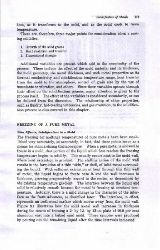
9l li@br d Mdib lr9
he8t, as it traDBloros to the golid, and as the Eolid cool8 to rooB
teEperaturo.
Thele are, tberefore, tlree major points for conoideration wheD a caat-
iug solidifiea:
l. Giowth of the sotid graiDs
2. Eert evolutioa otrd traEfer3. Dimeoaiooal chaogea
Additional variables 8re preeent which add to the complexity of ttreproceos. These iaclude the efiect of tle mold material aud ite tltioknees,
the mold geometry, the metal thicloess, aud euch metsl properties 8E itstlermal conductivity aDd solidific8tioD teEpersture range, heat translerfrom the mold to the atmosphere, coutrol oI grain eize by the use ofinoculante or vibration, aad others. Since these vlriables operate thrcugh
their efreci ou the solidifcstion pnoc€Es, msjor sttention ir giveu to the
process itself. The efrect of the variablee is considered secondarily, or can
be deduced from tie diacuesion. The reletiouship of other propertiea,
such as fluidity, hot-teariag terdeucies, aud gas evolution, to tbe solidifica-
tion procees is alao coverrd iu this chapter.
FBEEZING OF A PURE METAL
S}.,,.n Qfiatt; $Edijution in a MoU
The freezing (or melting) temperatures of pure metals have beeu estab-
lished very accurately, so accurately, in fact, that these poiuts eerve as a
EeaDs for statrdardizing thermoeouples. When a pure metal ia allowed to
Ireeze in a mold, that poriiou of the liquid which first, reaches tIe freezing
temperatue begins to solidify. ThiB ususlly occure next to the mold wall,where heat €xtractioD is greatest. The chilling sction of the mold wallresults in the formation of a thin "skin," or shell, of aolid metal gurround-
ing the liquid. 'With sumcient extractioD of heat through this thin IrsU
of metal, the liquid begine to lreeze onto it and the wall iucreaees irthicknese, growing progrereively inward to the ceuter, as determimd bythe existing temperatue gradient. The interlace between the liquid and
eolid is relatively smooth because the metal is freedng at couatsDt tem-persture. Actually, there is a mild change in tle character of the inter-face as tle front advances, ae deecribed later. Tte iaterface, in efect,represents an ieothermal surface which moves away from the mold wall.Figure 8.1 iltustratee how tle solid metat wall increases iD thickress
duriug the couree of freezing s 2- by 12- by 12-in. ptate of 90.8 per cent
aluurinum cast into a baked sand mold. These ssmples were pmduced
by pouring out the r€msiuing liquid sfter the tiue intervala indicatBd.
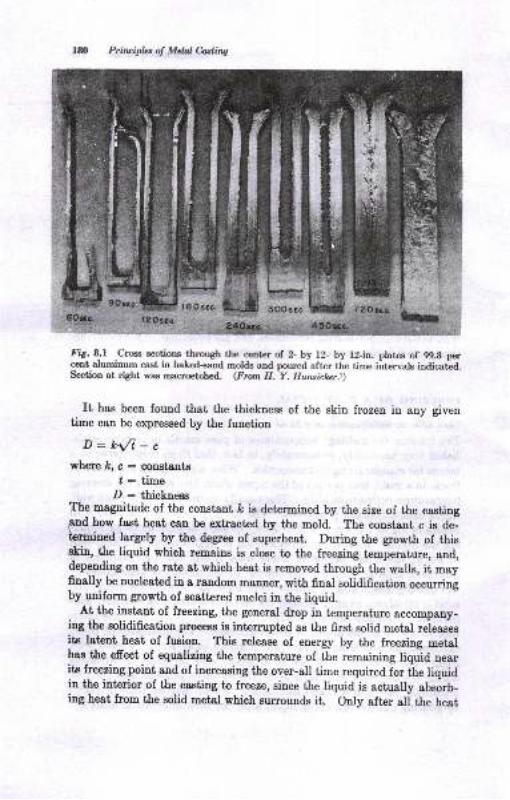
l8O Prfivipla of Mdal Costing
Fig. 8.1 Croes s€ctions through the center of 2- by 12- by l2-in. plates of 99.8 percent aluminum cast in bal.ed+and molds and poured after the time intervals indicatcd.Section at right was macroetched. (From H.-Y. Huruichzr.r)
It has been found that the thickness of the skin frozen in Bny giventime can be expressed by the function
D:k{i-cwherekrc:coDsts,ntg
I : timeD : thicknees
The mapitude of the constant lc is determined by the size of the castingaad how fast heat can be extracted by the mold. The constant c is de-termined Iargely by the degree of superheat. During the growth of thisskin, the liquid which remains ie close to the freezin! temperature, and,depending on the rate at which heat is removed through the walls, it mayfinally be nucleated in a random manoer, with final solidification occurnngby uniform growth of scatt€red nuclei in the liquid.
At the ins[ant of freezing, the general drop in temperature accompany-ing the solidification process is intemrpted as the first solid metal r.i."rttite lat€nt heat of fusion. Thie release of enerry by the freezing metalhas the efrect of equalizing the temperature of the remaining liquid nearits freezing point and of increasing the over-all time required for the liquidin the interior of the casting ta fteeze, since the liquid is actually absorb-ing heat from the solid metal which su,rounds it. only after all the heat
it
JIffit,
6Osec. l2OsEc.
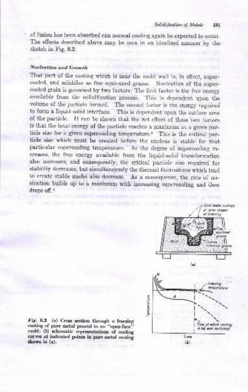
hlidifialiono! Mdds l8l
of fusion has been absorbed can normal cooling again be expect€d to occur.The effects described above may be seen iu an idealized mauner by thesketch in Fig. 8.2.
Nuclcation and Grouth
That part of the casting which is near the mold wall is, in effect, super-cooled, and solidifies as fine equi-axed grains. Nucleation of the super-cooled grain is governed by two factors: The first factor is the free enerryouuilable from the solidification process. This is dependeut upon thevolume of thd particle formed. The second factor is the energy requireilto form a liquid-solid interface. This is dependent upon the surface areaof the particle. rt can be shown that the uet effect of these two factorsis that the total energy of the particle reaches a maximum at a given par-ticle size for a given supercooling temperature.2 This is the critical par-ticle size which must be created before the nucleus is stable for thatparbicular supercooling temperature. As the degree of supercooling in-creases, the free enerry available from the liquid-solid transformationalso increases, and consequently, the critical particle size required forstability decreases, but simultauqously the thermal fluctuations which tendto create stable nuclei also decrease. As a consequence, the rate of nu-cleation builds up to a maximum with increasing supereooling and thendrops ofr.'
E
F
Fig.8.2 (c) Cres section through a freezingcasting of pure retal poured in an "open-face;mold; (b) schematic repreaentations of coolingc-urves
-ut indicat€d points in pure-metal casting
Sown in (c).
, z fteziog
l{-!!o"otu'"| --!\-
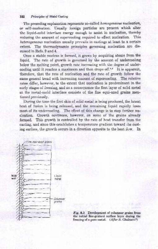
l&l Priluifut of Mdal Culitrg
The preceding explanation represents so-called homogerwotn r.ufrl,eotiatu,
or self-nucleation. Usqally foreign particles are preEent which elter
the liquid-solid interface energy enough to assist in nucleation, thereby
reducing the amount of supercooling required to effect nucleation. This
hetetogenaotu nucleation usually prevails iu castings at least to a certain
extent. The thermodynamic principles governing nucleation are dis-
cussed in Refs.2 and 4.
Once a stable nucleus is formed, it grows by acquiring atoms from the
liquid. The rate of growth is governed by the amount, of undercooling
below the melting point, growth rate increasing with the degree of under-
cooling until it reaches a naaximum and then drops off.t,5 It is apparent,
therefore, that the rate of nucleation and the rate of growth follow the
same general tlend with increasing amount of supercooling. The relative
rates differ, however, to the exteut that nucleation is predominant in the
early stages of freezing, and as a consequence the firet Iayer of solid metal
at the metal-mold interface cousists of the frne equi-axed graius men-
tioned previously.
During the time the first skin of solid metal is being produced, the latentheat of fusion is being released, and the remaining liquid rapidly loses
most of its rrldercooling. The effect of this change is to stop further nu-
cleation. Growth continues, however, on some of the grains already
forrned. This growth is controlled by the rate of heat transfer from the
castiug, and since this establishes a temperature gradieut toward ,.he cast-
ing surface, the growth occurs in a direction opposite to the heat rlow. In
Fig.8.3 Development of eolumnar grains fromthe initial finegrained surface layer during thefreezing of a pure metal. (Albr B. Clwburs.r)
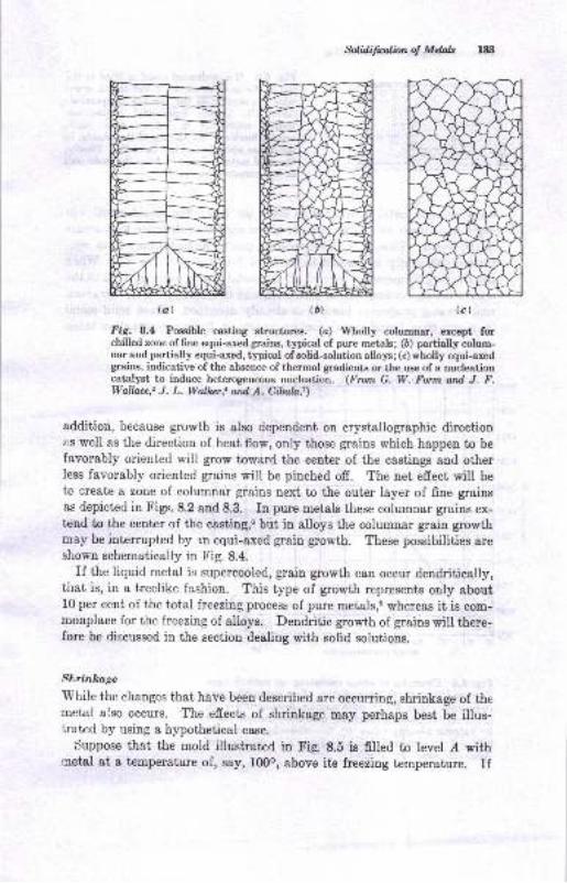
Nffi@l
tulidifudbnot Mdals l&t
Fig. 8.4 Pcsible casting structur€8. (c) Wholly columnar, except forchilled zone of fine equi-axed grains, typical of pure metals; (6) partially colum-nar and partially equi-axed, typical of solid-solution alloys ; (c) wholly equi-axedgrains, indicative of the absence of thermal gradients or the use of a nucleationcatalyst to induce heterogeneons rucleation. (Frmt G, W. Form ard J. F.Wallacc,2 J. L. llalbr,t ail,.A. Cibrful)
addition, because growth is also dependent on crystallographic directionas well as the direction of heat flow, only those grains which happen to be
favorably oriented will grow toward the eenter of the castings and otherless favorably oriented graius will be pinched off. The net effect will be
to create a zone of cohrmnar grains trext to the outer layer of fine grainsas depicted in Figs. 8.2 and 8.3. In pure metals these columnar grains ex-tcnd to the center of the casting,G but in alloys the columnar grain growthmay be intermpted by rn equi-axed grain g3owth. These possibilities areshown schematically in Fig. 8.4.
If the liquid metal isi supercooled, grain growth can occur dendritieally,tirat is, in a treelike fashion. This type of growth represents only about10 per cent of the total freezing process of pure metals,6 whereas it is com-monplace for the freezing of alloys. Deudritic growth of grains will there-fore be discussed in the section dealing with solid soluiions.
Sl;.ritll1ugs'While
the changes that have been described are oceuning, shrinkage of themetal also occurs. The effects of shrinkage may perhaps best be illus-lrated by using a hypothetical case.
Suppose that the mold illustratcd in Fig. 8.S is filled to level d with.ccetal at a temperature of, say, l(X)o, above its freezing temperature. If
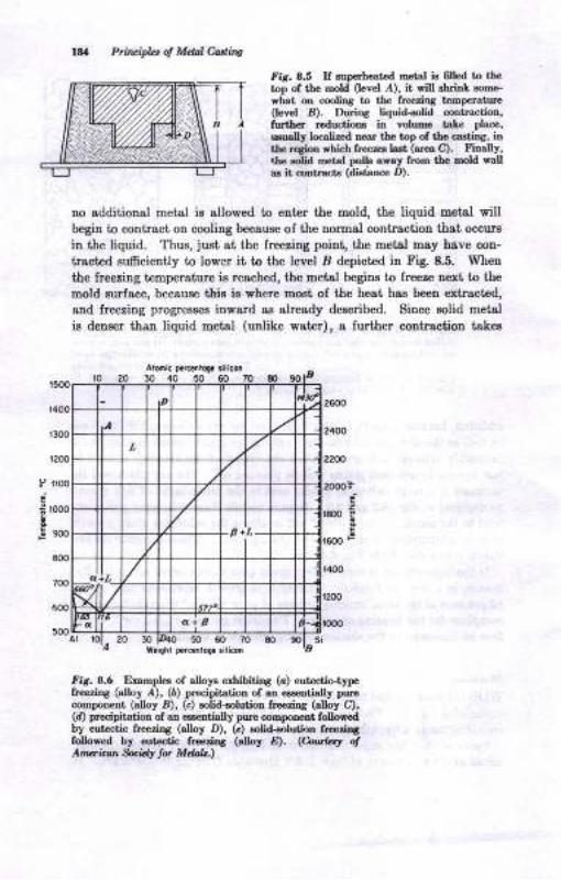
t000
900
EOO
700
600
50011
t€c
Prirlciplct ol Mdal Cdiq
fir. 8.5 II suprLeatad @tal is 6lled b rbctop ol tle Dold 0evel ,{), it ril shitrL sortrG.
vhat oE cooliDg fo the lreezir8 temperature(Ievel B). During liquid-oolid co6tractio!,furthE roductfuD, itr voluhe tale place,
rxudly localized oear the top of the castiDg, iD
tle rogtun rhich frceza lest (aIca C)- Iinally,|}e iolid ml^ot pulh away ftom t.hc nold rallss it cookacts (distsEce D).
no additioDal metal is allowed to enter the mold, the liquid uetal willbegin to contract on cooliDg because of the normal contraction that occurs
in the liquid. Thus, juot at the freezing poiut, the metal may have con-
tracted sufrciently to lower it to the level I depicted in Fig 8.5. When
the lreezing temperature ie reached, the metal begins to freere uext to the
mold surface, because thig ia where mogt of the heat haa been extracted,
aud freezing progresees iDward aB already deacribed. Since eolid metsl
ir deneer thau liquid metal (unlike water), e lurther contrrction tsker
Armi. D.rcaioC. tiliconto20304050m
trir. 8.5 Examples of aloys erhibitinA (a) eutactic-typefrcezing (alloy ,4), (6) precipitatioa of aa €*seotialy purocompon€trt (aloy B), (c) eolid-eolution &cezirg (alloy C),(d) precipitation of an eas€ntially pure comporent folloredby eutectic freezing (altoy D), (c) eolid-enlutioa freeriogfoltrof,ed by €ut€ctic fr€€zioa btb! D). <Coorlr! olAruricM tuW tu Mdab.)
P
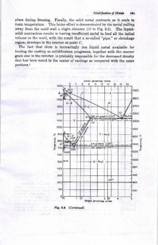
$lidifialiottot Md& 185
place during freezing. Finally, the solid metal contracts as it cools toroom temperature. This latter efiect is demonstrated b;, the metal pullingaway from the mold wall a slight distance (D in Fig. 8.5). The liquid-solid contraction results in having ins''fficient metal to feed all the iuitialvolume in the mold, with the result that a so-called "pipe," or shrinkageregion, develops in the interior at point C.
The fact that there is increasingly less liquid metal available forfeeding the casting as solidification progresses, together with the coarsergrain size in the interior, is probably responsible for the decreased densrtythat has been noted in the center of cas0ings as compared with the outerporUions.l
Atmic pcrcc0togc corbO
68r01?t416
EP
600
500
400
300
200
too
Fis.8.6 (Coilirud)
o.
EF
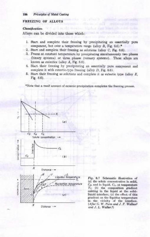
t.9
!!,g
lf Pi.ida of Mdal Cadiry
Ff,,EDZING OF ALLOYS
cbdtad.Alloys c8n be divided iuto thoee which:
1. Stsrt 8nd cotlplete thoit froedry by pEcipitstiDg an emtidly puro
comporcnt, but over s ta@perature range (alloy A, Fig. 8.6)!2. Sisrt ond GoEplete their ttrerilg as elutions (alloy C, Fig.8.6).3. F!€ero 8t ooDsta[t teBpersturc by pEcipitatiD8 siEult{oeously iyo pha&!
(biaary syst€@B) or tille phaaes (tcmsry s,'rtaos). TheE s[o]E {,roklovn I eutcctit (8[oy /, Fig. 8.6).
4. strlt their freezing by precipitstiDg ao eaaentially purc o@potreut .,Dd
complet it with eutectic-type lreeziDg (atloy D, Fi8.8.6).6. Strrt tleir freezirg as solutioDr aad cooplete it as eutectic type (alloy E,
ris. 8.6).
tNot6 thst s lrEA .moutrt of eutoctic prEcipitstio! coEplotd tho fr€orina ploc€€s.
!
EI
tria. 8.? ScherDatic illushatioo ol(a) tbe solutu corcenlration ia rolid,Cs, and in Uquid, Cr,, at t€DDeratuET,r (d) tbe compositiotr aradieBtertutina in the liquid at th€ solid-liquid interfac€; (c) r,he etrect of thirgradi€nt on the ]iquidus t€mpc.aturei,t tbe vicinity of the intcrlace.(Altar C, W, Fonn ad J, P. Wolla*,and. J. L. Walbt.t)
Solui€ concentration +
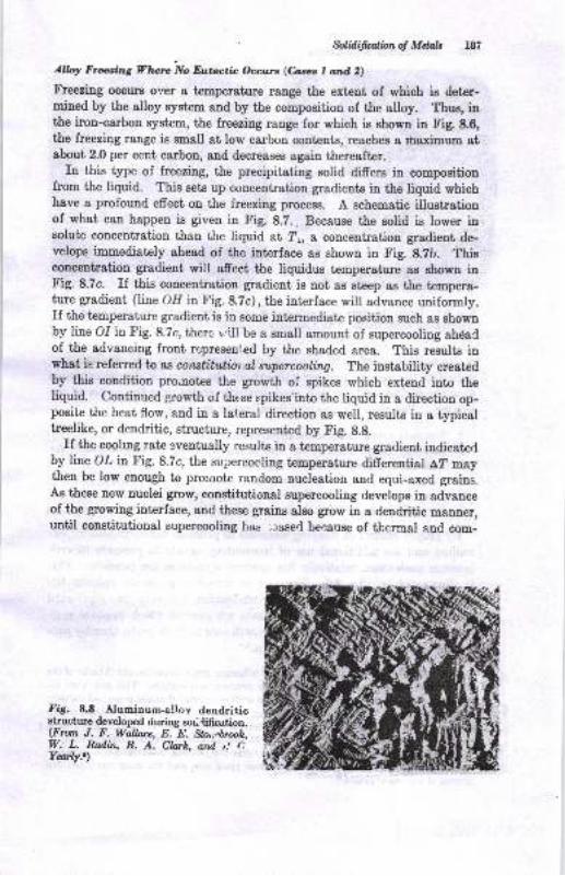
$lidifwlbnot Mdab l8t
Allolr Frering Vlure No Eutatic t}ccurt (&*t l and 2)
tr'reezing occlut or.,er a temperahrre range the extent of which ie deter-mined by the alloy system and by 1[s sqmposition of irhe alloy. Thus, inthe iron-carbon system, the freeziug range for which ie shown in Fig. 8.6,the freezitlg range is small at low carbon contents, reaches a haximum atabout 2.0 per cent carbon, and decreases again thereafter.
In this type of freezing, the precipitating solid differs in compositionfrom the liquid. This sets up coucentration gradients in the liquid whichhave a profound effect on the freezing process. A schematic illustrationof what can happen is giveu in Fig. 8.7.. Because the solid is lower itrsolute concentration than the liquid at ?r, a concentration gradient de-velops immsdiately ahead of the interface as showo in Fig. 8.2b. Thieconcentration gradient will afreet the liquidus temperature as shown inFig. 8.7c. If this concentration gradient is not as steep as the tempera-ture gradient (line OIl in Fig. 8.7c), the interface will advance uniformly.rf the temperature gradient is in some intermediate positiou such as shownby line O.I in Fig. 8.7c, ther,, v'ill be a small amouut of supercooling ahdadof the advancing front r...:presented by the shaded area. This results inwhat ie referred to as constitutior.al supercooling. The instability oreatedby this condition pro.notes the growth oi spikes which extend into theliquid. Continued g,rowth of the se spikes'into the liquid in a direction op-posite the heat flow, and in a lat.eral direction as well, results in a typicaltreelike, or dendritic, structure, represented by Fig. 8.8.
If the coohng rate eventually results in a temperature gradient indicaterlby line OZ in Fig. 8.7c, the supercooling temperature differential A? maythen be low enough to promote random nucleation and equi-axed grains.As these new nuclei grow, constitutional supercooling develops in advanceof the growing interface, and these grains also grow in a dendritic manner,until constitutional supercooling has .:aserl beeause of thermal and com-
fig. 8.8 Aluminum-allov dendriticstructure developed during sor,dfication.(From J. F. Wallace, E. E. Slo,,ebmoh,W. L. Rudin, R. A. Clafi, ard. i AYanly.t)
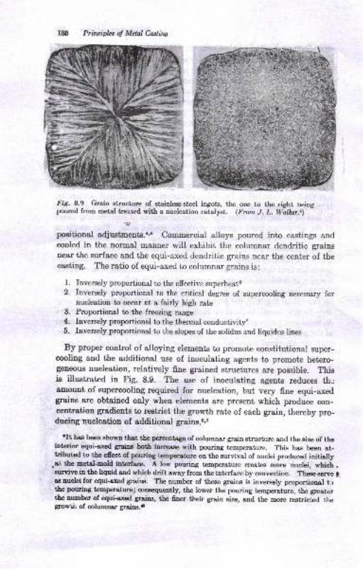
Prinaiples of Mclal Caslirq
Fig. 8.9 Grain gtructure of stainless-st€el ingots, the one to the right beirypoured from retal treated with a nucleation catalyEt. (From J. L. Walb.r.t)
-5'
positional adjushents.',6 Commercial alloys porued into castings andcooled in the normal manner will exhibit the columnar dendritic grainsnear the surface and the equi-axed dendritic grains near the center of thecasting. The ratio of equi-axed to columnar grains is:
Inversely proportional to the efrective superheat*Inversely proportional to the critical degree of supercooling necessary iornucleation to oecur at a fairly high rateProportional to the freezing range
Inverely proportional to the thermal conductivitlInversely proportional to the slopes of the solidus and liquidus lines
By proper control of alloying elements to promote constitutional super-cooling and the additional use of inoculating agents to promote hetero-geneous nucleation, relatively fine grained structures are possible. Thisis illustrated in Fig. 8.9. The use of inoculating agents reduces th.;amount of supercooling required for nucleation, but very fine equi-axedgrsins are obtained only when element^s are present which produce con-centration gradients to restrict the growth rate of each grain, thereby pro-ducing nucleation of additional glains.e,z
trt has beeu showr that the percentage 6f solrmnrl gm,in Btructure and the size of theintorior equi-axed greing botr hcrease with pouring temperature. This hrs been at-tributed to the efiect of pouring temperature on the eurvival of nuclei produced initiolly
,et the metal-mold interface. A low pouring temperature crcat€s more nuclei, which .suwive in the liquid and which drift away from the interface by convection. Theoe serve g.
ag nuclei for equi-axed grains. The number of these graiDs i8 inversely proportional t.rthe pouring tenperature; consequently, the lower the pouring temporature, the greatertbe number of equi-a'xed grains, the 6ner their grain size, and the more restricted thegtowiir of @lumno' graios.o
1.
2.
3.
1.
5.
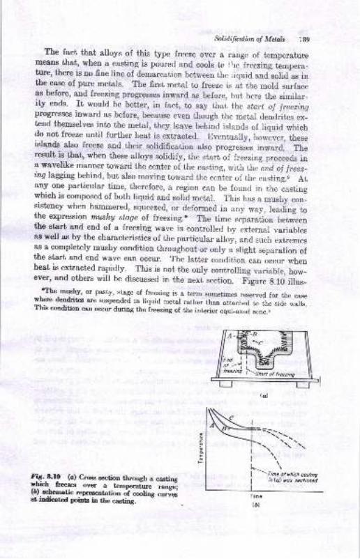
$lidificalian oJ Mdnls
The fact that alloys of this type freeze over a range of temperaturemett. that, when a casting is poured and cools to tlrelreezing t"*p"ru-ture, there is no fine line of demarcation between the riquid andlolid as inthe case of pure metals. The first metal to freeze is at the mold surfaceas before, and freezing progresses inward as before, but here the similar-ity ends. It would be better, in fact, to say thai the stort oJ lreeaingpnogresses inward as before, because even though the metal dendrites ex-tend themselves into t'he metal, they reave brhind isrands of riquid whichdo uot freeze until further heat is extracted. Eventually, however, ttreseislands also freeze and their solidification also progresses inward. Theresult is that, when these alloys solidify, the start of freezing proceeds ina wavelike manner toward the center of the casting, with the end ol freez-inq laggjng behind, but also moving toward the center of the casting." AtaDy one particular time, therefore, a region can be found in the castingwhich is composed of both liquid and sorid metal. This has a mushy con-sistency when hammered, squeezed, or deformed in any way, lead"ing tothe expression rntshg stage of freezing.* The time ."prr"iio, bet#eenthe start and end of a freezing wave is controlled by external variablesas well as by the characteristics of the particular alloy, and such extremesas a completely mushy condition throughout or only a slight separation oft'he start' and end wave can occur. The latter condition can occur whenheat is extracted rapidly._. This is not the only controlling variable, how_ever, and others will be discussed in the next section. Figure g.1o illus-
-trhe mushy, or past'y, stage of freezing is a term sometimes reserved for the casewhere dendritcs a,re suspended in riquid metal rather than attached to the side walls.ltb condition can occur during the ireezing of the interior equi_axed zone.o
fiq._0.f! (c) Cre section through a castingy_lich freea over a temperature range-;(D).schematic repreaentation
"i "-li"g ;;;;
at indicated poiDtr iD the casting.
E
F
:iri \:ffirretni f--fi
l9o Priwifu ol Mel Cdiig
trates schematically ihe relationship between the conditions exiotiag dur-
ing the freezing of thie type of alloy and the coolirg curves at vadous
poiuts iu the casiiug. Tbis figue showe that there is no siagle tempero-
ture of aolidificatioD, aB was the case for purt metale. Ilowever, the ef-
fect of the latent heat of fudon is such that the leuaiDitrg liquid is held
virtuslly at con8tant temperature alt€r lrceriDg begins. Only the metal
uear the surface (point.4) i8 cooled rapidly enough to avoid the extreme
thermal lag evideni in the iaterior. The geueral aimilarity in the curv€s
for poiuts B and C in Figs. 8.2 and 8.10 illustratee the inadequacy of uring
cooling-curve data alone to study solidification characteristiqe. Metsl-
logaphic examination of castiags intermpted in iheir freering process is
also esseutial to reveal the exact nature of tle procees. This i8 demou-
strat€d iD the diecussion of eutectic alloya in a later sectiou.
Yotidble, Aiecting t:lE Start dnd Drrd of Frcezing lot &*. I ord 2
The foregoing information bas egisblished the lsct thst alloys freere
difrerenily from pure metals in that they develop a band where both solid
e,nd liquid metal coexisi. The width of tlis band is 8frect€d by a large
uumber oI variablea, including;
The solidification range of the alloy
Thermal characteristics of the mold
Conductivity of the solidifying metal
Temperature level of solidification
TID Sdidilarlbl Ranae o! UE ALW
If cooling dat& taken at various points in a casting are resllanged togive I plot of distauce ftom ihe Eold-csstiug interface agsiDst time iD
minutes, the effect of thege variables can be readily revealed. Such eo-
called f?7 curvee' (tine-tempersture-transformation) are illustrat€d inFig. 8.11 for steel o{ several cerboD conteots cast in chill and green-sand
molds. These curves show that solidiflcstioo proceeds by the simuliane-
ous travel of stort-ol-treeze aD.d ea-d-ot-freeze uoues. Since an increase iucarbon contant increases the soliditcation range, ihe efiect of this variable
iB made apparent by comparing the three sets of curves and the graphic
representations below. tr'or a given mold msterial, the efrect of increas-
iag the solidification range ie to increase the separation beiween etart and
end of freezing.
'It Bhould be poiat€d out thst the f?? curv€6 hereiD d€scribed t'o not tbc .rrDe .stlro I?I curves frcm the h€aLtreatina proce88.
1.
4.
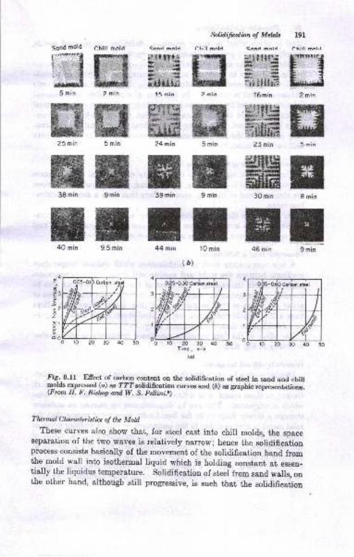
$lidifuolbnot Mdals l9l
t32 miq
HI5 min
trI min
E9 min
- ltllt{
-,i i!llrFl6 min
f!lfltlr+,'.1.{.{!Ttllllrt
23 min
HIffiH-F.-irHtarx.l {aat
ffifiE30 min
E46 min
t3ruE
5 min
H9 min
I10 min
#J#:r5
ry^#EFrsfitF-', 1+-i
flG24 min
H39 min
E44 mrn
Chill mald
HE2 min
ffit5 min
ffi9 min
H9.5 min
(D)
,4
.Eg2
3l
3
2
I
SoVl I
or020
Itig. 8.u Ellect of carbon content ou the solidification of gteel in sand and chiltmolds or_pressed (a) as TT?solidiffcation curves and (6) as graphic reprrxentatiors.(From H. F. Bislap atd W. 8, Pellini.o)
Tlurmal Claraclerblics o! thc Mold
These curves also show that, for steel cast into chill molds, the spaceBeparation of the two waves is relatively nano\r; hence the solidificationprocess consists basically of the movement of the solidification band fromthe mold wall into isothermal liquid which is holding constant at esgen-tially the liquidus temperature. solidification of steel from sand walls, onthe other hand, althougb still progressive, is such that the solidifica[iou
5 min
25 min
38 min
4O mln
-O6O Corbon sfel
Y, Priicipta oJ Mdal h.diw
Saud is much wider or never develope, Solidification in sand nolds,therefore, is mort general throughout the csstirgro
Thickless oI the mold waUe wil sfrect the poeition of the currea ahorain Fig. 8.11. Up to s cerisin point, inueasiug the ttrickaeas of s chill-mold wall will increase solidification ratee. Beyond that' point, litdeadditiouel efrect ig realized. In the case of saod molda, heat-removalrates are increased by s d€creo.se in mold tiickneas below a certsitr criticalthickuess. Above thia thickrcss little efrect from mold-thickaess vsd-ation is experienced. Increasing the superheat, ol the metal has the tend-ency of moving the start snd end curvea eoEewhat to tie right in bothehill and sand mold8.lo
Tlwtnal buhdioily of 0E $liililrins Mdal
The efiect of a high thermal conductivity of the metol is to decreas€
thermal gradiente in the caetiag, thus favoriug a wide separation between
the etsrt and end of freering, even in alloys that have a short rclidifica-tion rauge.
tr'or example, a 90 per ceut aluminum alloy w8s found to havc 8pprcli-mately a 4Gmin spread betweel the stsrt and eDd oI Aeeaiag whea cast
ia a eand mold eveu though the solidifieation range was oDly l0 f,'J
Tcmpaduc l-al o! $lidifwlbtA low teoperature level oI solidification which reducea temperahrre
gradiente between the mold and casting rrill decrcase ttre temperrturegradient within the castiug. The efrect of this last v8riable can also be
revealed by comparing the eand casting of tbe aluminum alloy refened toabove with tfiat of tie low-carbon gteel (Fig. 8.ll). Eere bottr alloyshave a low eolidification range, but the steel Ehow8 much better prrgreeaive solidificatiou than the aluminum atloy.
The efrect of the lour yariableg meutioued previously i.E shovtr rche-matically in l'ig. 8.12.
Dadilh Gmdn and furc4t./ialDendritee grow by extendiug their main epines into tie liquid aud reud-
iug out lateral branchee, ae previoualy explained. Tte metal whichfreelee ou these spinee is of difrereut compositiou fium the liquid ftomwhich it origiaated. This cau be demousirsted by pasaing an ieothermthrough a binary diagrem in the liquid-eolid regiou and notirg ttrat thesolid metsl ie always richer in the componeut of higher melting point as
comparrd with the liquid rith which it ie in equilibrium. Tte result ofthie difierence in composition between liquid and solid is oegreSstioD ofelements in the final casting. Thie segregation of elemente ie really oftwo type8. tr'ir8t, there is a geueral, ot ingot, typ ol eegrcgatiou, whichreeults iu a elightly difrerent composition on the outer portious of ttre casL
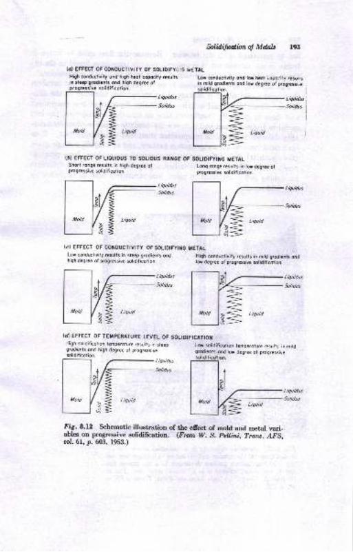
tuliditwlbnoJ Mdals 193
(a} EFFECT OF CONOUCTIV|TY OF SOLIOIFYii:G i.ETALHiri corlductivit, ondin stccp
solidificolion.
Ligur'dus
Solidus
)nd high hlot copftily rcsults Lor @ductivity ond lfr h?ot Lopoaily ,?su,rsond hiqh dcArce ol in mitd giodiots ond tu dcgtc. ol pogrcssi,e
liquidu t,
Sodas i
I
I
I
(D) EFFECT OF LIOUIDUS TO SOLIOUS RAI{GEShort rohge resulrs in high dag.c? olp@gressive solidilicoiion.
OF SOUDIFYIiIC IETALL@9 rcnga rcsulis in lr dcgraa otprogrcssive solidilicotion.
TstT'*'@::I l'taI u,o l/* | ,".,I IS=r rdi<
(c) EFFECT OF CONoUCTtvtTy 0FSOLtDtFytilGLor conductivity .csults in 5reep g.odienrs ondhigh degree of p.ogEssive $lidificotion.
{d EFFECT OF TET'PERATURE LEVEL OF SOLIOIFICATIOT
Fig.8.l2 Schematic illustration of the efrect of mold and metal vari-ables on progressive solidiffcation. (Fron W. S. patlrni, Trans. AFS,ool.6L, p.603, 1953.)
ITETAL
High c$ductirit, rcsults in mitd grcdiat3 oodlff drgraa ol p.ogrcssiva olidili@lim
ond lor degree ot p/ogressive
Liquid
High solidilicotion lemperoture resutts in sfeepg.odi€nts ond high degree ot progressiv€
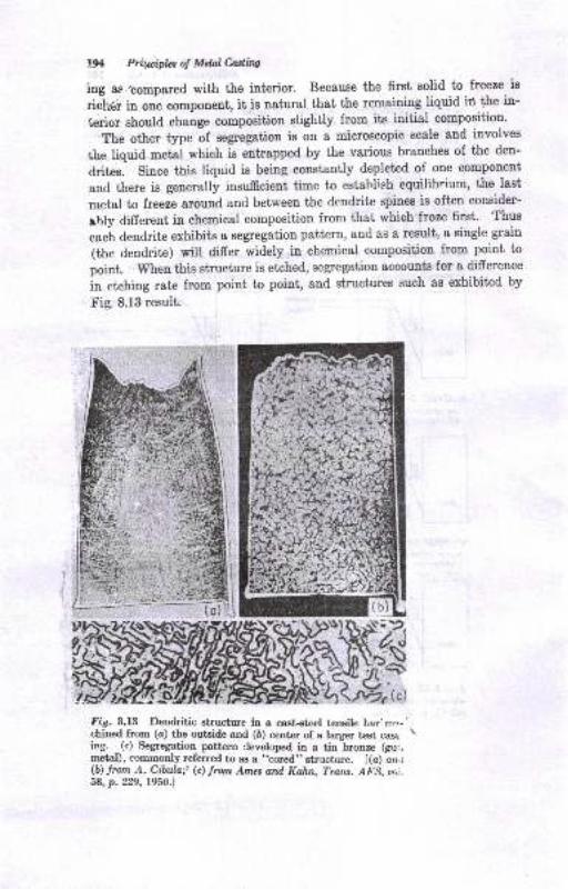
l% Prirpipfu of Mtulhdtns
ing as ,se6pared with the interior. Because the first solid to freeze is
ricker in one component, it is natural that the remaining liquid ir the in-
krior should change composition slightly from its initial composition.
The other type of segregation is on a microscopic scale and involves
the liquid metai which is entrapped by the various branches of the deu-
drites. since this liquid is beiug constantly depleted of one component
and there is generally insufficient time to estahlish equilibrium, the last
metal to freeze around and between the dendrite spines is often consider-
ebly difierent in chemical composition from that which froze flrst. Thus
eac-h dendritre exhibits a segregation pattern, aud as a result, a single grain
(the dendrite) will differ widely in chemical composition from point to
point. wheu this structure is etched, segregation accounts for a difference
in etching rate from point to point, and structures such as exhibited by
-t'ig. 8.13 result.
Filr. 8.tB Dentiritic 8tructure io a cast+t€el tcnsile bar'm.-chined from (o) the outside and (6) center of a larger t€st caslitrg. (c) Segregation pattern Ceveloped in a tin bronze (gu.,metal), commonly referred to as a "cored" structure. [(a) an t(b) lrom A. Cibala! (c) trorn Ames and, Kahn, Trarc. Org, or,i.58, p. 229, 19s0.1
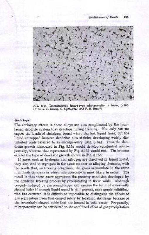
$lilli{paiitnol M&h r95
, ')(
n,l' Irfi.,.lr'4
II
,i'' r't.n+t,r
' ).'.
A.i.:Fig. 8.14 Interdendritic fseure'type microporosity in hrass' Xlm-(From J. F. Euing, C. Upthqrooe, ard F. B. Rolc.s)
Shfinletge
The shrinkage effects in these alloys are also complicated by the iuter-
lacing den&ite system that develops during freezing. Not only can we
expect the localized shrinkage found where the last liquid froze, but the
Iiquid entrapped between dendrites also shrinks, developing widely dis-
tributed voids referred to as micrtporosity (Fig. 8.1a.) Thus the den-
dritic growth illustrated in Fig. 8.15o would develop subs[sutial miero-porosity, whereas that represented by Fig. 8.15b would not. Tin bronzes
exhibit the type of dendritic growth shown in Fig. 8.15o.
If gases such as hydrogen and nitrogen are dissolved in liquid metal,
they also tend to segregate in the same m&nner as alloying elements, withthe result that, as freezing progresses, the gases accumulate in the same
interdendritic areas in which microporosity ie most, likely to occur. The
result is that these gases aggravate the porosity condition developeC bythe dendritic freezing process by precipiteting in these voids. Althoughporosity induced by gas precipitation will assume the form of sphericolly
shaped holes if enough liquid metal is still present, once ample solidifica-
tion has occurred, it is difficult or impossible to distinguish the effects ofgas segregation from that caused solely by localized shrinkage because ofthe irregularly shaped voids that are formed in both cases. Frequeutly,microporosity can be attributed to the combined efrect of gas precipitation
J,
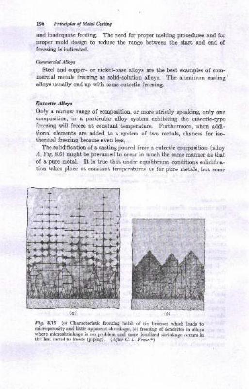
196 Frinciples of Melal Cdi.ttg
and inadequate feeding. The need for proper melting procedures and foiDroper mold design to reduce the range between the start aod end offreezing is indicated.
hmnercial Allays
Steel and copper- or nickel-base alloys are the best examples of com-mercial metals freezing as solid-solution alloys. The aluminum castinsalloys usually end up with some eutectic freezing.
$utcctic Alloys
Only a narrow range of composition, or more strictly speaking, only one
cpmposition, in a particular alloy system exhibiting the eutectic-typetltezing will freeze at constant temperature. Furthermore, when addi-
lional elements are added to a system of two metals, chauces for iso-thermal freezing become even less,
The solidification of a casting poured from a eutectic composition (alloy,4, Fig. 8.6) might be presumed to occur in much the same manner as thatof a pure metal. It is true that under equilibrium conditions solidifica-tion takes place at constant temperatures as for pure metals, but some
fig. 8.15 (a) Characteristic freeing habit of tin bronzes which leads tomicroporosity and little appar€nt sbrintage, (b) freezing of dendrites in alloysuhere micrmhrinLage is no problem and more localized shrinkage occurs inthe last metal to freeze (prpi"e). @fto C, L. Frear.%)
(b)

$lidifirnrlion ol Mdals 19?
difierences should be noted. The grain size of tle two precipitating
phases, for example, is much finer than that of a pure metal, and freezing
starts at a lower temperature than that of either component in the alloy.
The shape of the precipitating particles can be quite varied, and in'.'ludes such morphologies as:
1. La,rrellarstructure
2. Rodlike precipitation of one phase in the other
3. Globular precipitation of a phase
4. Precipitation of polyhedrally shaped particles of one phase in the other''"
It has been showu that the morphology of the eutpctic structure in Al-Sialloys is dependent upon the temperature at which the silicon phase nu-
cle&tes,16 the order in terms of decreasing nucleation temperature being
polyhe&ally shaped silicon greins, coarse silicon plates, fine silicon plates,
and globular silicon particles. The globular structure is produced most
readily by arr addition of a modifying agent such as sodium. The re-
sultant alloy is referred to as a modified alloy. A type of globular eutec-
tic can als. be produced by chill casting.
From a casting standpoint, the eutectic alloys are known to freeze eithererogenotnly, that is, from the surface to the center of the casting,or ew
dogenously, represented by a more or less random nucleation of eutcctic
cells or colonies consisting of individual clusters of the two phases grow-
ing in the liquid as essentially spherical solid masses. The resuh, of ex-
bgenous freezing is to provide a wair-.^ke solidification from the surface to
the center of the casting. Endogenous solidification leads to a mushy, orpasty, condition during the solidification process due to the liquid sur-
rounding each eutrectic cell. Modified Al-Si alloys are found to freeze ex-
ogenously whereas the normal Al-Si alloys freeze endogenously, as demon-
strated in Fig. 8.16.'?
Normal eutectic alloys will freeze in the endogenous cellularlike fashion
which tends to produce the mushlr condition; nevertheless, the greater nu-cleation of cells near the surface cf the casting does cause the solidificationto progress in a wavelike fashion, with the start of eutectic freezing ad-
vancing toward the interior some distance in advance of the cornpletion
of freezing.
Near the surface of a casting more and finer cells are found than inthe interior. If the cell gro*'ih is uniform throughout, the finer and more
nurnerous cells must complete their freezing before the larger, less numer-
ous cells in the interior; in the latter, the cells would have to grow for a
longer time before they would meet other growing cells. This mechanism
cf freezing would explain the fact that freezing does not occur along a
"irarp interface between solid and liquid, and would also explain the al-mosi eomplete lack of temperature gradients during eutectic solidification
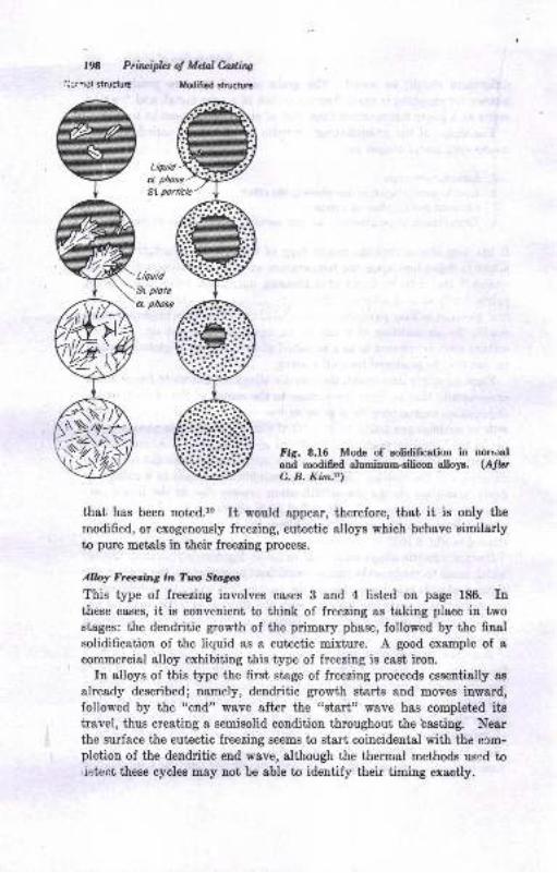
Fig. 8.f6 Mode of eolidification itrand modifed aluminu6-silicos alLr.C. B. Kim.t7)
that has been noted.le It would appear, therefore, that it is only the
modified, or exogenously freezing, eutectic alloys whieh behave similarlyto pure metels in their freezing process.
Alloy Freeing in Tuo Stngcs
This type of freezing involves cases 3 and 4 listed on page 186. Inthese cases, it is convenient to think of freezing as taking place in twostages: the dendritic growth of the primary phase, followed by the finalsolidification of the liquid as a eutectic mixture. A good ex&mple of scommercial alloy exhibiting this type of freezing is cast iron.
In alloys of this type the first stage of freezing proceeds essentially as
already described; namely, dendritic growth starts and moves inward,followed by the "end" wave after the "start" wave has completed itstravel, thus creating a semisolid eondition throughout the basting. Nearthe surface the eutectic freezing seems to start coincidental with the com-pletion of the dendritic end wave, although the therrral methods used to,iekrro these cycles may not be able to identify their timing exactly.
UOrr,ral(Alb
190 Priruiples of Mdal CdhgiJcraol slruclule Modified struciura
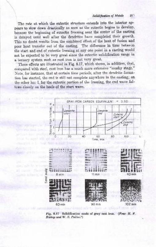
$liilifrdilmot Mtub l9r
The rate at which the eutectic structure extends into the interior ap-
pears to elow dowD drastically a8 soon as the eutectic begins to develop,
i"r"rr." the beginning of eutectic freezing near the center of the casting
is delayed until well after the dendrites have completed their growth'
This no doubt results from the combined effect of the heat of fueion and
poor heat transfer out of the casting. The di-ffereuce in t'ime betwe'3n
lhe start and end of eutectic freezing at any one point in a casting would
not be expected to be very great since the eutectic solidification range in
a ternary system such as cast iron is not very gteat.
These efrects are illustrated in Fig. 8.17, which shows, in addition, that,
compared with steel, cast iron has a much more exbensive "mushy stage'"
Note, for instance, that at certain time periods, after the dendrite forma-
tiou has starbed, the end is still not complete anywhere in the casting; on
the other har,l, for the eutectic portion of the freezing, the end wave fol-
lows closely on the heels of the start wave.
4
3
2
,|
c
o
EI
o
o
*'lllIIl:ts' il {r|-}- i -*ai+. . ,.-i
-- I ..i,ta| --lr
;,i,t ll lun1l min
_rltlrtrrl'-
60Time. min
::E irlllii-ii;E Bmin!co
U)
Fig. 8.17 Solidification mode of gray cast iron. (Fror. H. F.Biiop ord W. S. Pellini.r)
GRAY IRON CARBON EOUIVALENT = 3.50
,i,4;t,,if,,
90 min
40 min
n Prirciplaol Maalhning
As has already been diecussed, the initiar freezing resurts in the forma-tion of an interlacing network of crystals that grows in a treelike manner.The eutectic, however, although it apparentry begins forming first nearthe gurface of the casting, is not, so prone to L innuenced inlts nuclea-tion by the mold wall. Nucleation apparently appears throughout theliquid, and the eutectic cells grow outwardry in ai airectioor] Thi, i,probably because the liquid is very close to being isothermal. There ap-pear to be more nuclei near the mold wall and fewer as the center of thecasting is approached. As di'cu'sed for eutectic aloys, this may result infreezing of the eutectic liquid taking longer in the eenter than on theoutside.
Efrds of Yafiabht
The effect of composition is demonstrated by Fig. g.1g, which showsthat, in cast iron, as the carbon or silicon contents or both increaee (equiv-alent to an increase in ,,carbon equivalent,, valuel see Chap. 2l), the timerequired for completioa of dendritic freezing is shortened *h...". the timereqryed for completing the eutectic freezingis increased. superheat tendsto delay the start and end of freezing, whereas an addition of sea coal tothe molding sand speeds up the solidification process.
&gr.Nlbt dd Slvi,tfue
- As in the preceding casee that have been discussed, segregation and
shrinkage accompany the solidification process. The exteni and severityof these effects are controlled by variables such as zuperheat and cooling
.rate, which have already been discussed, as well as by the type of alloybeing formed. Th,s it would be expected thit a casiiroo oi
" composi-
tion close to that of the eutectic would ehow a 6inimrrm of segregationand microporosity, whereas one having an extended temperatrie
-range
of solidification would be more likely to exhibit these efrects.
- In-the_case of gray cast iron, graphitization of the iron occurs during
the freezing proce's. Graphitization resurts in an expansion of the ironwhich can, in part at least, nulify the shrinkage that normally *oolJ b"gxpeot€d. The graphitization mechanism is considered in greater detailin Chap.2l.
i}fIIEN PROPERTIES RELATEDTO THE FREEZING MECHANISM
Fluillity
The term flui.ili.ty, as used by the foundryman, does not mean the reciprc-.'d of viscosity. what is meant by fluidity in the foundry sen6e is'ihr
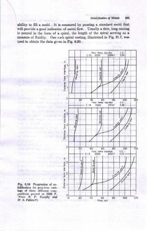
. Sotiilifubnol Mdab 201
ability to fill a mold. It is neasured by pouring a staudard mold thatwill provide a good indicatior. of metal flow. Usually a thin, long castiug
is poured in the form of a spiral, the length of the spiral eerving as a
meafllre of fluidity. One sT ch spiral casting, illustrated in Fig. 21.7, waa
used to obtain the data gi,ren in Fig. 8.20.
.=
o
.s
Eo
t
.2o
2
1
.iat3o
.E
E2
i5
0
.a
B3o
.E
E2o
co
i5Fig. 8.f8 hogression of ao-lidification ior gray-iron cast-ings of three dillerent com-positions poured at 2500 F.',Frotn R. P. Drnphy ardW. S. Pellini.a)
40 60 80Time, min
c-rf, 2500 2246F
Pou. l.mp liquidus C.E.
c-14 2500 2215F 3.86
40 50 80Pour t.mp liquidus C.E.
c- 2 2500 ?134F 4.13

w Pri&ipla of Mdalcadbto
BotI metol and mold characterirtics are iavolved in determining
fluidity, AE f8r s8 metal characterigtics are conceroed, the followiug
metallurgical factorB csn be list€d aa tioBe which have a grester or lesser
effect, oo fluidity :
1. Met8l composition, Fith paniculrr €orph8si8 otr its rtlation to the frcozilgproc€68
2. Superheat
3. Metal Yi8ooBity
4- Surfsc€ tension
5. Surfare oxide 6los6. Adsorbed gas filmr7. Su6peoded iDclu8ioD8
8. InclusioDs precipii&tiq dunng freezing
Of ttrese factors, the firet two are Eost importsnt With regard to
Bup€rheat, it, stands to rea8otr that meial thai is heat€d to a higher tem-perature will have a louger period in the mold in which it is liquid and
heoce it will flow farther than metal uot so highly heated.
It has been a6ply demonstrat€d that changes in metal composition,
insofar as theee changes are reflected by changee in the eolidificationprocees, caD markedly afrect fluidity. Consider, for example, Fig. 8.19,
which shows a plot of fluidity superimposed over the coDstitution diagrsmfor the lead-antimony and antimony-cadmiuu syeteme. Not€ that best
fluidity is attained for pule compoDeDts, eutectics, or phases that freeze
congruently (at constant, tenperature), rrhereas poorest fluidity iu had
wher the aolidification range is the greatest. Sioce a long solidificationrange ir indicative of a condition where the metel is in a mushy couditiol,consieting of htcrlacing dendrites flrro\rnded by liquid at practically itsfreeliDg temperatue, it, wou.td seem only tatural that this condition wouldreshict fluidity. OD the othe! hand, if pure mel,al freezes, it doee so bya gradual inward $owth of solid metal which does not re8trict the florrof the stil liquid interior metal. Likewiae, freeziog of I modified euiec-tic cau be considered iD somewhat the same light (I'ig. 8.16).
Itr a study of the fluidity of a group of aluminum alloys as comparedwith their solidifiration characteristics, it was found that there was adirect correlation between the fluidity of the alloys and their lreeziagratrge. Those alloys heving the longer freezing range were lower influidity than those with a ehort freezing range. Io fact, it was poeeible tocalculate with reasouable accuracy the fluidity of various alloys eiuplyfrom inlormation regarding their lreezing range.
Another example showing the close correlation betweeu fluidity andsolidification ieraperature, a,r well s8 with superhest trloperature, is giv€n
by tr'ig. 8.20, which shoqg data obtaiued for gray aud malleabte cast iron.
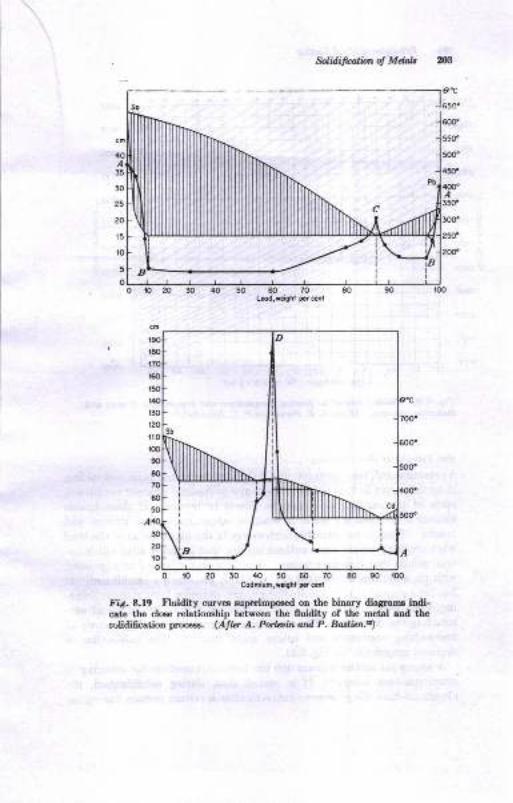
Solidifialbn oJ Mdab
35
30
z5
20
t5
lo
5
?o
o !0 20 l0 40. 50 60 70 Eo 90 r00CodniuF,t ialtt ,,.ri
fir.8.l9 nuidity curv€6 6uperiEpfi.d on tbe binary diasraE iadi-cate the clee relatioDsbip b€tweer tho fluidity of the metal and thcEolidifcation proc.€s. (Atto A. Po ahdrd P. Bodicn.n
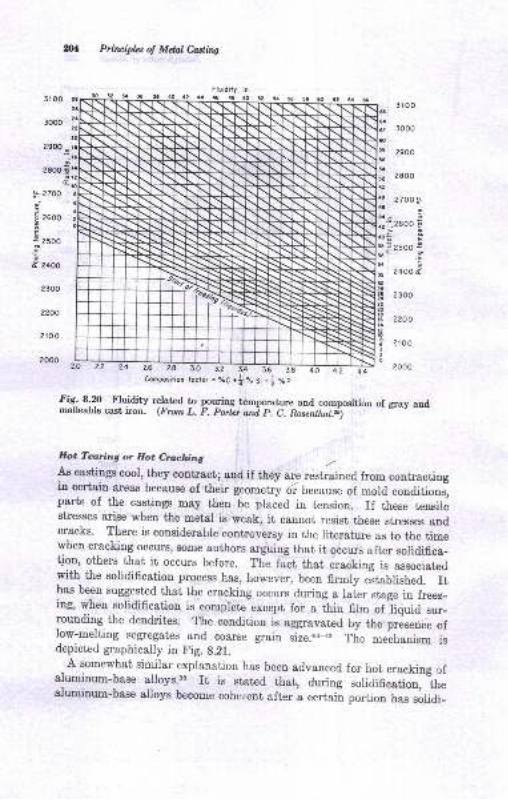
n1 Prhcipbs of Mdal Casting
Fluidily, in.4! !O 5ao62sB3r oo
3000
31 00
3000
2900?9OO.; I
2sooE
E
5l
56
flt2sal
4.;
a?-
aoG
$E!6
!a
t2
I
IC
12toI6
zo
l- 2700
3
E 2600
Et zsoo
E zooo
2300
2200
2lo 0
2000
2 300
2200
2roo
2000
2800
2 7oo "Ej
.2500 E
E
2500 g
.E
24oO 3
Composition focror = loc *| V. 5i . I V. e
Fiq, 8,p Fluidity nelted to pouring tomllerature and composition of gray andmalleable cast iron. (From L.F. porte ani p, C. nosenltal.i)
flotTarh4or&otCtrrl:kilq ,/
As castiugs cool, they contract; aud if they are restrained from contractingin ceriain area' becau.e of their geometry6i because of mold conditions,parts of the castings may then be placed in tension. If these tensilestresses arise when the metal is weak, it cannot resist these stresses audcracks. There ie considerable controversy in the literature as to the timewhen cracking occur., sore authors erguing that it occurs after solidifica-tion, others ttrat it occurs before. Trie tact tnat cracking i. ,..o.i"aayrth- the solidification process has, however, been firmly .itublirhud. Ithas been suggested that the cracking occurs during a hLr st,ge in freez-ing, when solidification is complete except for
" thio fir* of
-tiquid sur-
rounding the dendrites. The conditiou is aggravated by the presence oflow-melting segregates and coarse grain size.4o{z The mechanism isdepicted graphically in Fig. 8.21.
A somewhat similar explanation has been advanced for hot cracking ofaluminum-base alloys.ss rt is stated that, during soridification,
-the
slrrminrrm-[gse alloys become coherent after a certain portion has soiidi-
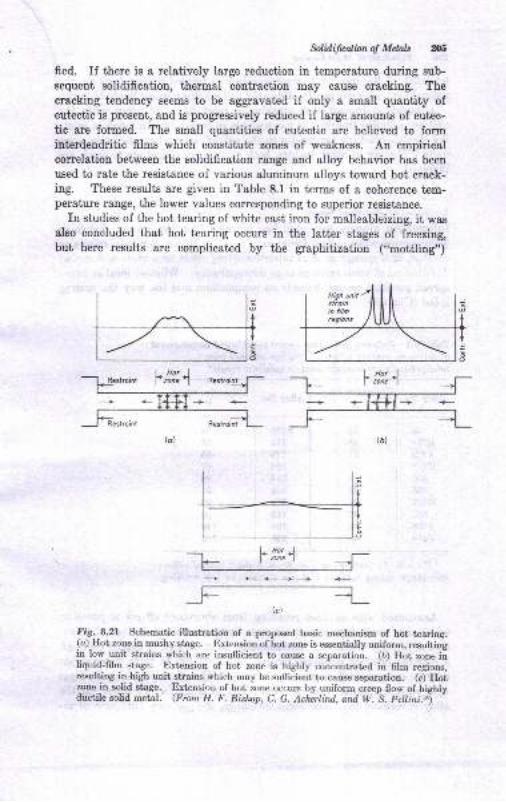
&lidifualbn of Mdals ZX;
fied. If there is a relatively large reduction in temperature during sub-
sequent solidification, thermal contraction may cause cracking. Thecrscking tendency seems to be aggravated if only a small quantity ofeutectic is present, and is progressively reduced if large amounts of eutec-
tic are formed. The small quantities of eutectic are believed to forminterdendritic films which constitute zones of weakness. An empiricalcorrelation between the solidification range and alloy behavior has been
used to rate the resistance of various aluminum alloys toward hot crack-ing. These results are given in Table 8.1 in terms of a coherence tem-perature range, the lower values corresponding to superior resistance.
In studies of the hot tearing of white cast iron for malleableizing, it wasalso concluded that hot tearing occurs in the latter stages of freezing,but here results are complicated by the graphitization ("mottling,,)
+ ++'+
Fig.8.2l Schematic illustration of a proposed basic mechanism of hot tearing.(c)-Hot zone in mushy stage. Extension of hot mne is essentiatly uniform, resultingin low unit strains which are insuflicient to cause a separation. (b) Hot z,one inliquld;film stage. Extension of hot zone is highly concentrated in film regions,resulting in high unit strains which may be sullicient to cause separation. G) Hotzone in solid etage, Extension of hot zone occrrs by uniform cieep flow of bighlyductile solid metal. (From H. F. Bishop, C. G. Ackcrlind, and W. S. Pellini.$j
-
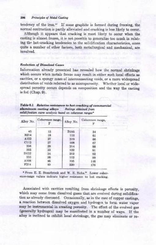
M Pti,|cipla of Mdal Ui,q
tendency of the iron.'7 If eome graphite is fonoed duiag frceriag, thenormal contractiou is partly alleviated and cracking ie lese likely to ocour.
Although it, appears that crackiug is most likely to occur when thecaeting is almost frozeu, it ia not, poeeible to generalize too much ia relat-ing thc hot-cracking teudencies to the eolidification charact€ristics, Biucequite a number of other factors, both metallurgicat ald mechanical, areinvolved.
E@trIr&'n o, I|ir{oId co,€,
Iaformation slready preseDt€d haa revealed how the aormal shdnkagewhich occurs wben metale lreeze may result ia either such local efiect8 8s
cavitiee, or a spongr maeE oI intercomecting voids, or a more widespreaddistribution of void8 referred to as microporosity. Whether local or rride-Bpread porosity occurs depends oD composition sud the w8y tbe castingis fed (Chap. 9).
.h.nnlarltm rzrdla,g.rbr. Ralingt &,iru.t h@ntolili{aliott cqt a;lalyi h*l or. @ttnne mry.t
Alloy No. Cohereoce rcnge,F
Coherenc€ Bnge,F
Alloy No.
{3Bzt4al32cll3
356
355
Dt32
Ar08F2l4
Bl95l133rgr082141?2212
r95220
l5l8
27
n
34
36
449
5{6r66
67
88sl92
99146
r76
* From E. E. StoDebroo! and W. E. sicha.. Loper coher-ence-range valuea iDdicste higher rcsistaDc€ to hot crackiDa.
Associated with cavities resulting from shrinkage efiecte is pomeity,which may come from diseolved gases that are evolved during solidifiea-tion as already discussed. Occasionslly, as iu the case of copper castings,a reaction between diesolved oxygen and hydroqen to form water vapormsy b€ iDstruneutsl iu creatiag porosity. The efrect of the evolved gae(generally hydmgen) msy be Dadfest€d iu a number of ways. If thealloy is inclined io exhibit, local shrinkage, the gas may eliminate or re-
wSoliltflrntbn ol Mdnlt
duce it by preventing liquid metsl from feeding the casti.ug in the normal
maoner, thereby leading to widespread microporosity rather thau the local
ehrinkage usually occurring. If the altoy ie iaclined toward microporos-
ity, gas evolutiou will acceutuate this form of defect by creating a back
pressure, makiug it more diEcult to leed through the nushy range.'! The
problem of dissolved gases and their wolution during freezing is discussed
ia greater detail in courectiou with apecific alloye cousidered in subse-
queut chapters,
Efiat ol Inxulation
Another problem counectad with the solidification chsracteriatics of alloys
is the modificaiion of the structure aud properties by the addition of asmall amount of ¬her metol to the alloy before pouring. Examplee of
thig are the 8ddition of sodirrm io aluminum-l2 per cent eilicoa alloys, of
titaDium to alumitrum, aud of magnesium to c&st iroD. In the latter case,
r nodular-type graphite etructure developr (Chap.22).
In all caeee, the additions act to delay and alter precipitstion of the
solid from tie liquid, ae previoutly diecuseed for modified Al-Si alloye.
Varioue explanations have been advanced for these efrects, but none has
been universally accepted, lae efects may be related to the questiou of
homogeueous vs. heterogeneoue nucleation. The modiflcation ol the
aluminum-l2 per cent silicon alloy by sodium and of tbe cast irons by
magueeium h88 been attribut€d to the additioo efrectiug a chauge in the
interfacial tensions between the two eolid phases (aluminum and silicon
in the firet case and austenite anil carbon in the second).15 Grgin re,6ne-
ment by vibraiiou is aleo poesible."
BIBLIOCRAPEY
1. E. Y. HunsicLer, Solidifcation Rates of Aluminum in Dry Sard Mokls,frdn ,.4-tr'S, Yol.55, p.68, 1947.
2. G. W. Form ind J. F. Wallace, Solidification ol Meta| Trrnt..4IS, vot. 66,p. 145, 1960.
3. R. F. Mehl, The Growth of Met&l Cryst&ls, p. 24 in "The Solidifcation ofMetols aod Alloyr," Amedcan Il8titute of IUechanicrl EngineeE, 1951.
4. J. L. Walker, Stnrcture of Ingots atrd Castings, p. 319 ln "Liquid Metals aDd
Solidification," American Society for Metals, 1958.
5. W. K. Bock, Solidifcation oI Meiols, Trcra. AFS vol. 68, p. 691, t960.ti. B. Chalmere, Meltirg aud Freeziog, J. Mcralr, vol.200, p.519, May, 1954.7. A. Cibulo, 'Ihe Mechnnim oI Gmin Re6r-elren'i of Sand Castings in
Alumiaum Alloys, Part 4, J. I^st- Metah, 1'ol. 76, p. 321, 1949.
J. F. Wallece, E. E. StoneblooL, W. L. Rudlr, R. A. Clark, and p GYeatly,Solidiicstiotr and Eeot Treatmeot, founrirr: vol 87, p. BL9{6t€mber, 195S.

UIB Prhciphs of Mdal Castina
9. {. I.Bishop and W. S. Pellini, Solidification of Metals, Fout.td,ry, vol. g0, p.87, February, 1982.
10. g. q. Br1h9n, F. .4,. Brandt, and W. S. pellini, Solidifi.cation of Steel againstSand and Chill Walls, Trans. AFS, vol. 89, p. aBE, tOst.
lf. J. F.^Wall1.., J.E Savage, and E. F. Tiylor,'Mechrnical properties ofCast Steel, Trau. AE9,vol.59, p. 22B,lg5l.
12. J. F. Ewing, C. Upthegrove, ana f. B. Bote, Melt euality and FractureCharacteristics of 8E-5-5-5 Biass, ?rcns. z{FS, vol. SZ, i. a3i, tOeg.
13. ry. A.-Tiller, Grain S-ize Control during Ingoi Solidification, .I . iitol*, vol.11, p.512, August, lg5g.
14. \ry. A. lller, Grain size control duriag Ingot solidification, part 2, col,m-nar-equiaxed Transition, Traru. Met. Soc. AIME,vol.2?1,p. AS, Jr*, teO2.
15. y. A. Tiller, Polyphase Solidification, p. 276 in ,,Liquid'Iiletals snd Slidi-&49"i'American Society for Metals, ig5g.
16. {. Weart, The Eutectic Reaction in Certain Binary Metallic Systcms, ph.D.
-_ 9ry,_l]oiversity of Wisconsin, Madison, Wis., 1962.17. C- B. Kim, A Study of the Solidification and Eutectic Modification of Al_Si
fUgrs, _fn !a.thesis,' University of IVisconsin, Madison, Wis., 1962.
|!. A. poVles, "The Structure of Cast Iron,,, American Society for Metals, lg47.19.
P: W: Ru{dle, A preliminary Study of ihe Solidification of CrrtinmJ. }^t.M etals, vol. 77, p. l, lg50.
20. D. Jaffee and M. B. Bever, Solidification of. /d-Zt Alloys, ?rons. AIltE, vol.&5, p.972, 1956.
21. B.T.Ruddle, The Solidification of Castings,Inst. Metals Monogr. Rept.Ser-7, L957 .
n. M. C. Flemings, S. Z. Urem, and H. F. Taylor, Solidifcation of AluminumCastings, AFS Trans.,vol.68, p.620, 1960.
23. A- Cibula, The Grain Refinement oi Alumin,,- Alloy Castings by Additionof Titanium and Boron, J. Inst. Metals, vol. g0, p. t, tSSt.
* -
21. J-P. Dennison and E. v. Turl, The Refinement o] cast Grain size in cu-AlAlloys ContainngT-g7o Aluminum, J.Inst. Metals, vol. gE,
"o.JZiZ, fSSO.
%. 9. L. Frear, Shrinkage in Tin Bronze Castings, Found,ry, vol. g5, p. gl,December, 1957.
26. W. A. Tiller and J. W. Ritter, Effect of Growth Conditions upon theSolidification of a Binary Nloy, ian. J. phys., vol. 84, p. S6, .Iarr&. lgiO.
27 . K. A. Jackson and B. Chalmers, Kinetics ot"Sofafiratio ",
Cii. i.-Fiu'r., ia34,p.473,May, lg56.
28' {'A'Reynolds and c. R. Tottle, Nucleation of cast Metars at the MordFane, J. Itut. Metals, vol. 80, p. $; 1g5l.
29. W-. C. I[inegard and B. Cholmers, Supercooling and Dendritic Freezing inAlloys, Tra?r.s. /SM, vol. nA,p. tZtl,,$il.
30. D._Walton, IV'. A. Tiller, J. W. Ruiter, and W. C. Winegard, Instability ofl^[m*-tl trldlUquid Interface during Solidifi cation, 7 rarc. ii ttt n,-'
"ot.203, p. 1023, 1955.31. g.s..Pertlini, solidification of various Metals in Ingot and sand Mords,
Electric Furnace Steel Conferen ce, AIME preprint, Oei. S_i, igSO. - - ----
32. E. P. DynBhy and W. S-. pellini, Solidifcation of Gray Iron in Sand Molds,
- Trqo. z{FS, vol.59, p.428, lg5l.33. A. Portevin and P. Bastien, Fluidity of rernary Aroys, "/. Irxt. Metars, vor.
61, 1934.34. E. E. stonebrook and w. E. sicha, correration of cooling curve Data with

&lidifubnot Mtub Ai,
Casting Characteristics of Aluminum Alloys, ?rcns. z{fS, vol. 57, p. 489,
1949.
35. L. F. Porter and P. C. Rosenthal, Factort Afiecting tr'luidity of Gray Castlron, Tran*. z{FS, vol. ffi , p. 7?5, 1952.
36. E. F. Bishop, C. G. Ackerlind, and W. S. Pellini, Metallurgy and Mecbanics
of Eot Tearing, Trans. r{FS, vol. 60, p. 818, 1952.
37. E. A. Lange and R. IV. Eeine, A Test for Eot Tearing Tendency, ?ranr.z{I8, vol. 60, p. 182, 1952.
38. D. C. G. L€es, Factors Controlling the Eot Tearing of Aluminum CastinsNloys, Found,ry Trade t., vol. 87, p. 211, Aug.8, 1949.
39. C. W. Briggs, Solidification of Steel Castings, Trans.l{fS, vol.68, p. 158,
1960.
40. C. F. Christopher, Eot Tearing Characteristics of Acid and Basic Steel
Castingl Determined by EiSh Temperature Testing, Trau. AFS, vol. 04, p.
293, 1956.
41. E. F. Bishop, C. G. Ackerlind, and W. S. Pellini, Investigation of Metal-lurgical and Mechanical Effects in the Development of Eot Tezittg, Trara.z{18, vol. ffi , p. 247, L957.
CI. R. A. Dodd, W. A. Pollard, and J. W. Meier, Eot Tearing of MagnesiumAlloys, ?rcns. z{FS, vol.65, p. 100, 1S57.
4il. L. W. Eastwood, "Gas in Light Alloys," John Wiley & Sons, Inc., NewYork, 1(X6.
44. l.C. E. Eughes, K. E. L. Nicholas, A. G. Fuller, and T. J. Szajda, Factors
Influencing Souadness of Gray Iron Castings, Mod,ern Castinqs, vol. 35,p.73, March, 1959.
45. P. Bastien, J. C. Armbnxter, and P. Azou, Flowability and Viscocity,Mod,ern Cutin4s, vol. 41, p. 72, Jtne,L962.
4(i. A. E. Freedman and J. F. Wallace, The Influence of r/ibration on SolidifyingMetals, Tran*. AFS, vol.65, p. 578,1957.
47. R. G. Garlick and J. F. Wallace, Grain Befnement of Solidifying Metalsby Yibration, Trans. AF9, vol. 67, p. 366, 1959.
tl8. R. S. Richards and W. Rostoker, The Influence of Vibration on tle Solidifi-cation of an Aluminum Alloy, r{SM Trons., vol. rE, p. 8&1, 1956.
49. B. Ch&lmers, The Structure of Ingots, J. Australian Inst. Metals, vol.8, p.255, August, 1963.
Pouring andFeeding Castings
INTRODUCTION
fhe goundness of a casting depen& upon hon ihe metsl eutere a mold
rnd eolidifiee. At fust glance, it would appear to be a relatively eimple
procedure to pour a castiDg; actually, many factors must be controlled ifo good casiing is to be obtained. A sound knowledge oI the behavior of
trhe varioue alloya in the molten stat€, of the flow of liquids, eud ol$lidificeiion characterietice is necessary. The importance of these
physical properties is considered io the followiog discussions.
If metsls were perfectly ilert chemically, iI they absorbed uo gaeea,
if they exhibited no shrinkage on cooling, and ii they were not erosive
to the mold and ol various speci0c gravities, it would be much aimpler
to make a casiing. Unfortunately, the reverse is true, and those factors,
plus others, mugt all be accounted for wheu designing for castings,
POURINC LADLES
It is uzually easier to transport metal lrom the melting furnace to the
rnold than vice versa. Therefore 6ome me&ne of handling tbe molten
metal must be available. Often, the molten met&l ie temporarily stored
io, large holding ladles, from which it is tspped ofr as needed. These
holding ladles are construct,ed of steel plate lined with a euitable
refractory such as flrebrick. They are usually desigued to receive
metal lrom the meltiog furnace simultaneously with ihe pouriug ofr oI
metal from them into smaller ladles.
Other ladles thst 8re used include bull, or crana, ladlet lhzl' *ehaudled by crane or monorail, two-man ladles handled by either haud,
crane, or monorail, ar,d hand ladles, usually carried by hand (Fig. 9.1).
Ladles also difrer as to the facilities Bvailabte for preventing impurities
such as slag or dross from entering the mold. In otdirro'ry Lip-pouin4
,odr€s, metal at the pouring lip is skimmed clean before pouring by means
of metal skimmir,g bars. Some ladles are equipped with a refractory
210
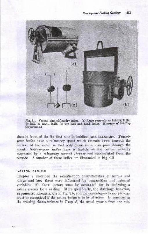
Pauino ortd Fdittg Miltgt 2lr
{c)
tsig. 9.1 Various sizes of foundry ladlea. (o) Larse resenoh, or holding, ladle;(b) bull, or oane, ladle; (c) two-man and hand ladles. (hwlesy o! WhilitrgCorporalion.)
dam in front of the lip that aids in holding back impurities. Teapot'pour ladles have a refractory spout which extends down beneath the
surface of the metal so that only clean metal can pass through the
spout. Bottom-pou.r ladles have a taphole at the bottom suitably
stoppered by a refractory-covered stopper rod manipulated from the
outside. A number of these ladles are illustrated in tr'ig. 9.2.
GATING SYSTEM
Chapter 8 described the solidification characteristicd of metals and
alloys and how these were influenced by composition and external
variables. All these factors must be accounted for in designing a
gating system for a casting. More specifically, the shrinkage behavior,
as presented schernatically in Fig. 8.5, and the erystal-growth morphology
must be recognized if the gating design is to be effective. In considering
the freezing characteristics in Chap. 8, the usual growth from the out-
(
i!
b
'rl [.mrc
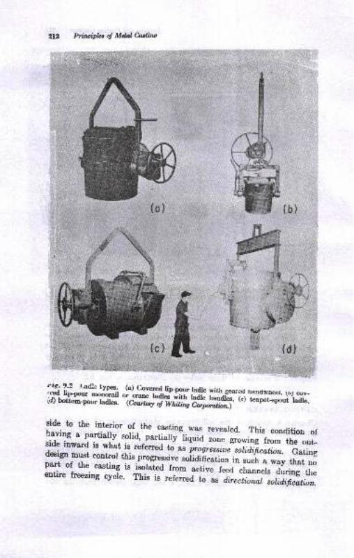
Prircipbs oJ ltIdoJ Culim
**...
(b)
;.
(d)
m;"ffi,"m{ffi,*i#fl Hffi+,ff :rllffi ;,,sr.yr:;:
side to the interior of-the casting was reveared. This condition oIlYy a partialty solid,-partially'fiqJi ,oo. g.o*iog from the out_side iuward ie what is refened
^ ^;;;n;iue sotidificotion. Gatingdesign must eontrol this progressive soiidihcation in such a way that nopart of the casting is isolat€d rro- ".ti".
-]eea channets during theentire freezing cyele. This is rururrlJ to'
" s directional sokdifi,catbn.
(o )
,*
(c )
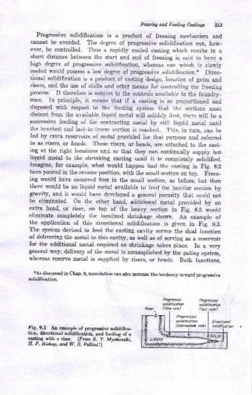
Pouaing and Fedhg Caslitrgt 2lB
Progressive solidification is a product of freezing mechanism andcannot be avoided. The degree of progressive solidification can, how-ever, be controlled. Thus a rapidly cooled easting which rezults in ashort distance between the start and end of freeziug is said to have ahigh degree of progressive solidification, whereas one which is slowlycooled would possess a low degree of progressive solidification.' Direc-tional solidification is a product of casting design, locatiou of gates andrisers, and the use of chills and other means for contro[ing the freezingprocess. rt therefore is subject to the controls available to the foundry-man. In priuciple, it means that if a easting is so proportioned anddisposed with respect to the feeding system that the sections mostdistant from the available liquid metal will solidify first, there will be asuccessive feeding of the contracting metal by still liquid metal untilthe heaviest and last-to-freeze section is reached. This, in turn, can befed by extra reservoirs of metal provided for that purpose and referredto as rzsers, or heads. These risers, or heads, are attached to the cast-ing at the right locations and so that they can continually supply hotliquid metal to the shrinking casting until it is compretely solidified.Imagine, for example, what would happen had the casting in Fig. g.2
been poued in the reverse position, with the small section on top. Freez_ing would have occurred first in the small section, as before, but thenthere would be no liquid metal available to feed the heavier section bygravity, and it would have developed a general porosity that could notbe eliminated. On the other hand, additional metal provided by anextra head, or riser, on top of the heavy section in Fig. g.5 wouldeliminate completely the localized shrinkage shown. An example ofthe application of this directional solidification is given in fig. S.a.The system devised to feed the casting cavity serves the dual functionof delivering the metal to this cavity, ae well as of serving as a reservoirfor the additional metal required as shrinkage takes place. In a verygeneral way, delivery of the metal is accomplished by the goting system,,whereas reserve metal is supplied by risers, or heads. Both iunctions,
rAs discussed in Qhep. 8, inoculation can also increaae the tendency toward progressivesolidification.
hogressircsolAlicolionlslo* role)
Prog.esiresolidilicotion
Progrcssitesolidilicolionlinlerndbte rute)
DircclioDolsolidilicdlionFig.9.3 An example of prqgressive solidiffca-
tion, directional solidification, und feeding of acasting with a riser. (From E. T. Myshanski,H. F. Bislnp, ard W. S. Peltini.t)
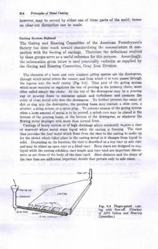
ia Ptir&,ifuot M&l Mittt
however, may be serYed by either one of theEe parts of the mold; hence
no clerr-cut digtiaction can be made.
Caring S!...n D.findThe Gating and Rieering Committee of the American tr'oundrymen's
Society has done much toward atandardizing the uouenclature in con-
nection with the feeding of castings. Therefore the defiuitions evolved
by theee groups serve ag a useful refereoce for this purpoBe. Accordingly,
the informatiou given below is used praciically verbatim as supptied by
the Gating and Risering Committ€e, Gray Iron Division.
The eleEents of a basic and very common gatino eAstenl arc ile da uwpnu,
through which metal enters the rutm"r, 8trd from which it in tura passes tirough
the ingaies into the r@ld cauitU 1Fi8.9.41. That part of the gating syst€m
which most restdcts or regulates the late of pouliDg is the pimary choke, D.orc
oftetr csued sibply the choke. Ll lhe iop ol the downsprue may be a pouiag
.iltp or pourhtg 6orin to miDitdre splash aad tu uletrce &td proDote the
entry of clesE metal oDly into the dovasprue. To further plevetrt the etriry of
dirt or slsg iDto the downsprue, the pouring basitr mey contsin a alctm corc, o
sttai.ner, a ileldu sareen, or a tpruc pl:tq. To preveot erosion of the 88tiDg s.vttem
rrhen a large a,Dount of meiel is to be poured , a splaah core fiay b plsaed h the
boitom of the pouing bssin, 8t the boi,tom of the dowuprue, or whercver ihe
flowi4 metal impinges with more than Domal lorce.
Castinge of heavy 6ectioD or of high shrinkage alloys commonly require a rileror reservoir where metel stays liquid while the casting is freezing. The riser
thus provides the ,eod araial nhich 6ows from tlle riser to ihe caatiDg to Dake up
for the siria,lc which ta.tes plsce iD the cssting metal as it changes from liquid to
solid. Depending on the location, the riser is des.ribed as a top riJer or ade ri*tand may be either an open riser or a bliad riser. Since ri&rs sre desigDed to stat
liquid while the casting solidifies, rise, iaigit ar,d riaer nzcL ate rntportstrt dime[-
sions a.6 are tho6e of the body oI the riser itftr-fi. niser distarwe s\d the shape of
the riler baae are additional importalt detail8 thrt pertaitr oDly to side riseis.
FiDgEr{at€d cnst-fiow-ofr. (Cowkty
Caliw oad Ri$ins
F,s.9.1i"s -ithol AFSConmitbe.)
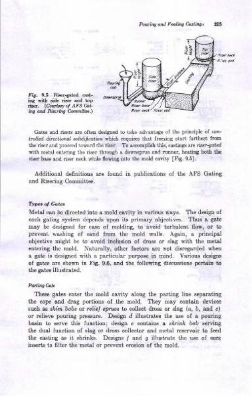
Pol/ci,?!! ard Fedirq Corlilqt
tria. 9.5 Riser{atcd cast-ing Yith side riser and top,i!fr. (CowLty of AFS Go!-iw ord Rb.riq Comti 2..\
G&t€s and riseE sle oft€D desi$ed to take advsatage of the principle of cor-tro pd rlitectbaal eoldifuation which requires that fr€€ring stsrt larthest fro!tr
the riser aod proceed toward the riser. To accomplish this, caetings aN iseraotedwith meial enterinS the riser through a downsprue and ruDtrer, hesting both thoriser base and riser neck while flowing into the loold cavity [Ft. 95].
Additional definitione are found in publicatious of the Atr'S Gstilgand Ri8eriDg Committee.
Typt of Gaut
Metal can be directed into I mold csvity in variouo ways. The deoign ofeach gating system depeDds upon ils primary objectivee. Thue a gate
may be designed for eage of molding, to Bvoid tubulent flow, ot toprevent washiog of sand fmu the uold wall8. AgaiD, s principsl
objective might be to evoid inclusion oI dross or slag with ttre metalentering the mold. Naturally, otfier factors 8re Dot dieregarded when
8 gste is designed with a particular purpooe in uind. Yarious designs
of gctee are shown in Fig. 9.6, and tlre following discussiono pertsitr tothe gates illuatrated.
Pa ingeoL
Theee gates enter the mold oavity slong tie parting line aeparating
the cope and drag portionr of the mold. They Day contsiu devices
6uch as sr{im bobe or relial r?ruec to collect dross or slag (c, b, aud c)
or relieve pouriug pressure. Desigu d illustratee the use of e pouring
basin to Berve this function; deaign e contains a slrriurh bob aewing
the dual firnction of elag or dross collector and metal reservoir to feed
the castiug as it ehriDke. Desigue I and g illustrate tlre use oI core
inserte to filter the metal or prevetrt erosion of the mold.
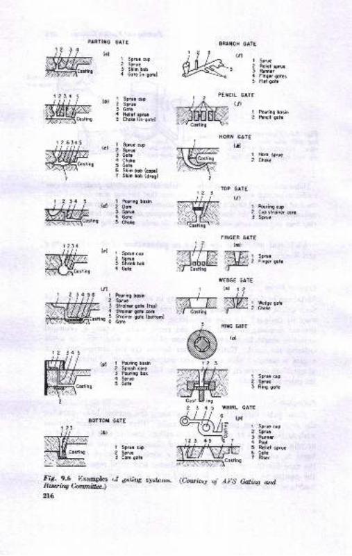
PARTIiIG GATE
'l Sgrua cl,2 Soruo3 Stin hob4 coh (in-gorcl
I Sp.rx op2 Sp.ua3 Go?.4 R.tial rmx5 Chotc (in.gorrl
I fut in! bosin2 Don5 Se.[4 Gsia5 Chor.
8N ilCX GATE
(il
PEICIL GATE
ttl
I Sprua
2 RGlicl ffic3 Runncr4 Fitrgcr Cqlas5 Rol gota
t Pering bosin2 Prncil qolc
3 Runn64 Pool
5 Ralilf sprua5 Goh? Ris..
ffi(a)2t
12 I
FIXGER GATE
') i (r)
X,-Tfrffffi ,,-.ffiE, s,^.
l#.:,H"?H' iffi 2 Finec'eorc
I
.;.E....T+-7,,i::j:::jiil-.-ljiiilii:., coirine
Cost
23
T.,iiffiffiffiffi*o'no
#ffi
(b)
rct | fficun3 Gor.4 Chol.5 Got!5 Stio boD (m)7 SUm bob (drcsl
HORiI GATE
. (l)
I Hoin lpruc2 Chol!
1234,...,,. / Ul
(a) i sp.uc cupirJ!ti:;i.l ,Jiir:1ia,ii,i 2 Sorur
, 3 Sirinr bob
I fo.ri rg borin2 Soruc3 Srroiffi got (to9)
4 SlrliE loia @5 Slrciq qot! (Donm)6 Goh
t 2 34 5
lol I Pqrring bosin2 59lGh cm3 Pd.ing lor4 S?.uc5 Got
*C. ?.0 _itrxamples rf 6aring Byctenrs.Riscrir.C kruni&oc.)
2t6
TOP GATE
(r)
I Pouiing cup2 Cup si.oiner coc3 Spruc
, I W.dqG Eotr' 2 Chok.
sR''{GGATE
I Sp.ua cup2 Spru!3 Ring goi.
ino
45
I S9.u! cuo2 Seruc3 C@ lorc
UED6E GATE
(Coutt:y oJ AilS Galirq and
tufitootd?dtuhfiry ,!z
bb'DA bThe bottom gate euter8 the castiug cavity ot the bottom oI the drag
hall of the mold. It is illuetrated by design i in Fig. 9.6, atttrroughother vgriatioos are also ueed. For example, a well 8t the base of the8prue or a'chatrge ia the directiou of Eow of the metsl may be incorpo-rated to reduce flow ratea io the systeme. A bottom g8t€ is advoaEt€dfor steel castinge in pa{icular to reduce erosion and gas entrspmentand to preveni splaahing, which cau result in cold ehots.
Brorr.iCmL
A branch gate is de8igned either to feed a aingle casthg at severalpoiut8 or a number of individual castings (i, Fig. 9.6).
II*nCalt
I'his is a variety of bottom gate (/c, Fig. 9.6). One obiectioD to it6uee is a teudency for producing a lountain efrect in the csating. How-ever, it ie a metns of bottom gatiug without the aecessity of a core forthe gate.
dla'With
the exception ol lbe whirl gate, the remaining gste types illus-trated in Fig. 9.6 are e8EeDtially variations of a top-gatiug system sincethe metal enters the mold from above. The designe are intended tobreak up the metsl stream Bo that it enters the Eold with a Eirrimum ofturbulence and erosive actiou. The whirl gate accompliehee eomewhatthe same purpoee a8 the psrtitrg gates illustrated in c, b, and c. Thestep gate is intended to have hot metal enter succeEsively the variousgsl€s from bottom to top of the castiug. If this objective were accom-plished, the eiiuation would prcmot€ directionsl sotidification. Unleesthe step gates are properly dbeigned, however, thie gating system doernot function as deeired. Each gete must b€ elanted upward and prop-erly proportioned relative to the other gates to attain the desired-goal.
--
--
DESIGN OF GATINC SYSTEM
Llold Molalio'b'Wherever
possible, the gating syetem ig made of the aaue moldingmaterial as that used for the mold cavity. There are occesiotrs, how-ever, where, Irom the standpoint of couveoience or for other rcasoDs,Bome oiher r'aterial ie used for a part of the gating system. Thus thepouring basin or pouring cups are lrequelfly made as 6sked-a8!d cores.Skim gates or Btrainer coree ard Eplseh corc8 ar" ,t.o -ea" oi UJea
21.8 PriraipbotMdalMhg
sand since they must withstand a considerable &mount of erosive actionand pressure from the metal which could nbt be sustained by similarconstructions made of green sand. Strainers, downsprues, and gate
cores may also be obtained in ceramic materials called tile. Occa-
sionally, a certain portiou of the gating system may be constructed ofa high-density sand such as zircon sand to prevent washing or metalpenetration.
Fluid FIou
Such problems as gas contaminatioo, inclusion of dross or slag, andaspiration of gas are factors that must be recognized when designing agating system. A little reflection will show that these problems areconnected with the major problem of haviirg the metal enter the moldin quiet aud uniform msnner. In other words, these are problems con-
. cerned with fluid flow, and the laws governing fluids can be studied' prolitably to improve any design.- tr'irst of all, it should be recognized that liquids flow either in a stream-
li:r.ed lamina,r fashion or in a h.ubulent manner. Whether smooth orturbulent flow results depends upon the velocity of the liquid, the crosssection of the flow channel, and the viscosity of the liquid. The relation-ship is expressed as the Reynolds.number
12 _ mean velocity of flow X diameter of tube X density of liquida":
When the Reynolds number reaches a certain critical value, turbulentflow prevails. Apparently, most metals reach turbulent-flow conditionsquite readily. Investigations show that steel always flows under turbu-lent conditions (8, > 3500)., Turbulent flow creates such problems asinclusion of dross or slag, aspiratiou of air into the metar, erosion of themold wall, and roughening of the casting surface.
The flow of a liquid in a mold is also governed by a number of uthervariables, best summed up in terms of Bernoulli's theorem, which statesthat the sum of the potential energy, the velocity enerry, the pressureenergy, and the frictioual euergy of a flowing liquid is equal to aconstant.s rhis theorem can be expressed in the following equation:
wz*wPa+#*wF:K
where ur : total weight of fluid flowing, lbZ : heieht of liquid, ftP : ststic pre$ure in the liquid, lb/sq ftu : speeific volume of the liouid, eu ftllb
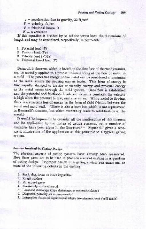
PartqoilFdfued@ tr9
g : accderation due to gravity, 32 ft/wz7: velocity,ft/wF : frictional lo€ses, ftK : 8 const€ot
If this equation is divided by u, all the terms have the dimensious oflength and may be considered, respectively, to represent:
1. Potcntiathead (Z)2. Pressurchead (Pu)
3. Velocity head ]Pnc)4. Frictional loss of head (P)
Bernoulli's theorem, which is based on the first law of themodynamics,can be usefully applied to a proper understanding of the flow of metal ina mold. The poteutial enerry of the metal can be considered a maximumas the metal euters the pouring cup or basin. This fom of enerry isthen rapidly changed to kinetic or velocity ener5r and pressure enerryas the metal passes through the mold systrcm. Once flow is establishedand the potential and frictional heads are virtually constant, the velocityis high wheo the pressure is low, and vice versa. While metal is flowing,there ie a constant loss of energy in the fom of fluid friction between themetal and mold wall. (There is also a heat loss which is not reprrsentediu Bernoulli's theorem, but which eventually leads to solidification of themetirl.)
It would be impossible to consider all the implications of thie theoremand its applicatiou to the desigo of gating systems, but a number ofexamples have
-been given in the literature.8-E Figure 9.7 gives a sche-
matic illustrati6n of the application of this prinoiple to a typieal gatingsystem.
Foctor.s lz;ooldin Gating Design
The physical aspects of gating systems have already been considered.How these gates are to be used to produce a sound casting is a questionof gating design. Improper design of a gating system can cause'one ormore of the following defects in the casting:
1, Ssnd, Blag, dross, or other impurities2. Rough zurface
3. Entrap@gases4. Exceeaivelyoxidizedmetal5. Localized shrinkage (pipe shrinka,ge, or macroshrinkage)6. Dispersed porooity, or microporosity7. Incopplete fusion of liquid metal where two strcrms meet (cold clwt )
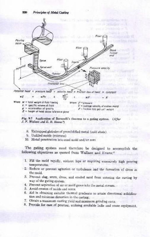
zm Prli,rciplao, Mdaledir,s
frichbnol loss
futcnliol hcod + pressure heoi +
yZ-+rpy-#+vF= conslont
=KWherr l. = lotol rcight ol fluid flowing Where p
=pressure7 = speciric volune ol lluid I/ = overoge velocity o, molten metolg = occelerotion of grovity ie= lrictio-n loss per unit weighiZ = hew ot hcod obore ref€rence plone
F_iC:9:1_ -lpp[cation of Bernoulli's theorem to a gating syatem. (AJbrJ. F.WatiauililE. B. Euru.t)
Entrapped globules of presolidified metal (col,il shots)Unfilled molds (misruns)
Metal penetration into sand mold and/or core
The gating Bystem must therefore be designed to accomplish thefollowing objectives as quoted from 'Wallace
and Evans:6
l. Fill the mold rapidly, without laps or requiring excessively high pouringt€mperatures.
2. Reduce or prevent agitation or turbulence aqd the fomation of dross inthe mold.
3. Prevent slag, scum, dross, and eroded sand from entering the casting byway of the gating system.
4. Prevent aspiration of air or mold gases into the metal stream.5. Avoid eroeion of molds and cores.6. Aid in obtaining suitable thermal gradients to attain directional solidfica-
fi61 snd minffize distortion in the casting.7. Obt^in a maximum casring yield and miaimum grinding costs.8. Provide for ease of pouring, utilizing available ladle and crane equipment.
8.
9.
10.
Poruliag and Fdirq Cartingt gfIt is evideDt that not 8ll theEe requiremente are compstible, artd com-
prcmis€s Eay have to be msde to get sB clo8e as possible to the desiredgoal.
P@rhg Tirn
A elight hickle of metal or Eetal poued too cold ie undesirablebecause the metal would freeze too fast to fln out the mold or woulddevelop cold shuts. Very rapid filling of the mold also would preseni,such problems as having an adequatrc gating system to handle a largevolume of metal in a short iime, erosion of the mold wall, rough surface,exceeeive ehrinkage, and other possible defects. There is, therefore, auoptimum pouriug rate, or pouring-rate range, for most casiings that mustbe estsblished by experience. In die castings or special casting tech_uiques where metal ie forced into a mold under fressure, this upperlimit is probably set by the fluidity of the rDetsl it€;ll.
. In conventional sand caeting, establishing the optimum pouriug rateiE the first step in the desigu of the gating syst€m. Once ihis is-doue,the next step ia the proper proportioning atrd distribution of the varioueparb of the gsting sysiem io order to achieve thie rat€. The character-igtice of the various foundr5r alloys have a rtroug influence on theirnportance of thie first step. Geonetry of the casting is, of course,&lso a fsctor-
Some metals like cast iron are not so sensitive to pouing.rate asothere. Yet even lor cast iroD sn optimum pouring rate, *-hi"h iu ufiDctiotr of the castitg size 8nd Bhape,? is advocated. A m;t8l like Bt€elmuat of necessity be pour.ed fast to avoid premature freezing because it$ I !l* freezing range compared with Eost other caJing alloys.Metals like alumiuum or magnesium alloys can be poured morl slowivand here the problem is one of av6iding turbrl"#, ;;;;;;;; g;;pickup.
EEective pouring rates for all commercial casting alloys heve not beeDplblished. These would be expected to reflect to soDe ext€Dt the prsc-ticee in a given foundry or the limitations of the available equipment,a8 well 8s the cssting geometry. Some dats are available for casi iroosteel, brass, and bronze:6,s,0
1. G!8y-iroD csstiDgr <1000 lb:
Porrtils tine r, sec =x(o.ss+ T \.,/w-\ 0.853/
where K ia a fluidity factor detormiaed by dividing the fluidity ol the specifcioa obtaioed frcm Fig. 8.20 by aO (the Auidity vaiue for iron of Ce : l.g ,ta t€Epersture of 26m F). As seea from Fig. g.20, this Iactor is afiected byirctr compoBition s,nd pouring teoperature. ? ie the average thicLuees iairchea, and IP ir the weight in pounds
Xn Principbs ol Mdal Casting
2. Gray-imn castingo > 1000 lb:
Pouring time !, sec : r(o.os. #) *3. Shell-molded ductile imn (vertical pouring):
Pouring time l, sec : Kr\,/W
where Kr = 1.8 sections tromsA to 1 ir., 1.4 for tbiqner sections, and 2.0 for
heavier sections.
4. Steel castings:
Pouring time I, sec : h\/W
where K varies from about 1.2 for 100-lb castings to about 0.4 for 100,000-lb
casti.gs, when casting weight is plotted on a log scale,
Comparing these statistics for a 400-lb casting of 1 in. average wallthickness, the following pouring-time values would be obtaiued:
1. Gray csst iron of 4.0 carbon equivalent poured et 270o fr:/ r \
-, = 1(0.e5 * **/ t/+m = +z*c
2. Shell-molded ductile iron:
t : 1.8\/M: 36 eec
3. Steel:
t : r.Oa/4N : X) **
For comparison, a pouring time of 15 to 45 sec is recommended forbrass or bronze castings of less than 300 lb.ro
With the optimum pouring time established by whatever means are
available, the next step is to proportion the gating system properly toachieve the desired rate while complying as closely as possible with the
other desired characteristics of the gating system previously enumerated.
Pouring Basin
The ideal situation is to establish the proper flow system as rapidlyas possible. This means that, when a metal enters the sprue, it should
be flowing under conditions that are as nearly as possible those whichare present when full flow has been established. Good results can be
accomplished by:
1. .Strea,rrlining the pouring basin and providing a dam so that essentially
constant conditions are established when the metal enters the sprue
2. Use of a strainer core in the pouring basin
3. Use of a delay screen or sprue plug
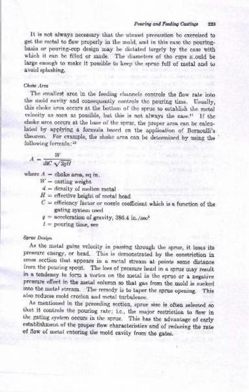
PowittCandFdiltg&ri,lrngr ZB
It ie not always necessary that the utmost precaution be exercised toget the metal to flow properly in the mold, and in this case the pouring-basin or pouring-cup design may be dictated largely by the ease withwhich it can be filled or made. The diameters of the cups s,l.ould belarge enough to make it possible to keep the sprue full of metal and toavoid splashing.
CloAz Area
The smallest area in the feeding channels controls the flow rate intothe mold cavity and consequently controls the pouring time. Usually,this choke area occurs at the bottom of the sprue to establish the metalvelocity as soon as possible, but this is not always the case.rl If thechoke area occurs at the base of the sprue, the proper area can be calcu-latcd by applying a formula based on the application of Bernoulli,etheorem. For example, the choke &rea c&n be determined by using thefollowing formula:12
where.A : choke area, sq in.I;I/ : casting weightd : density of molten metal
.EI : effective height of metal headC : efficiency factor or tozzle coefrcient which ie a function of the
gating system usedg : acceleration of gravity, 386.4 in./seclI : pouring time, sec
Spnu Destgm
As the metal gains velocity in passing through the sprue, it loses itgpress*re energr, or head. This is demonstratcd by the constriction incross section that appears in a metal stream at points some distancefrom the pouring spout. The loss of pressure head iu a sprue may resultin a tendency to form a vortex on the metar in the sprue or a iegativepressure efreet in the metal column so that gas from the mold ie suckedinto the metel stream. The remedy is to taper the sprue opening. Thisalso reduces mold erosion and metal turbulence.
As meutioned in the preceding section, sprue size ie often selected iothat it controls the pouring rate; i.e., the-major restriction to flow inthe gating system occurs in the sprue. This has the advantage of earlyestablishmeut of the prop€r flow charactcristics and of redubiig the rateof flow of metal entering t&e mold eavity from the gates.
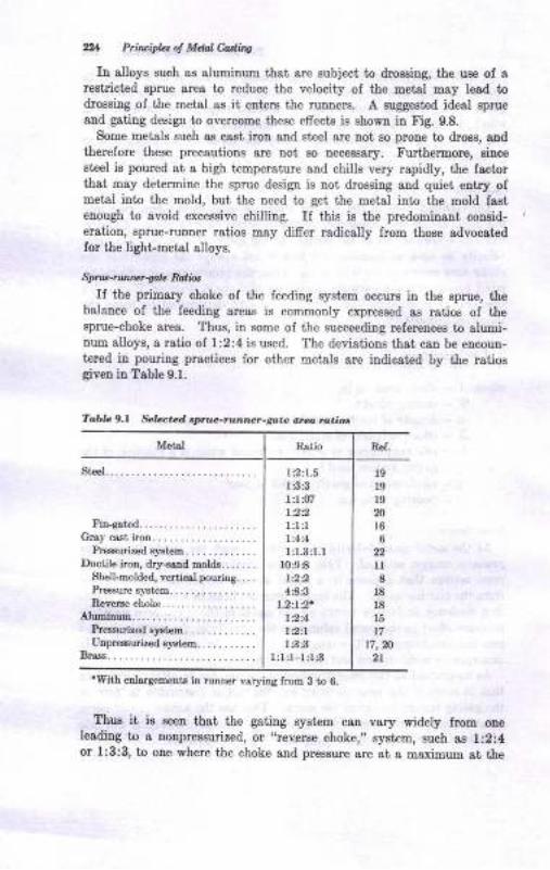
ZU P.in ida d Mdal hdtng
Iu alloys such as aluminum that sre zubrect, to droeeiug, the uee oI a
reetricted sprue area to reduce the velocity ol the metsl m8y le8d todrossiug of the metal as it euters the runners. A suggested ideal sprue
8nd gatiug design to overcome these efrects ie shown iu Fig. 9.8.
Some meials such gs cast iron snd 8t€el are not Bo prone to dross, andtherefore thege precautione are oot Bo necessary. Furihermore, siuceeteel is poured at a high temperature and chills very rapidly, the factorthst msy determine the sprue design is not drossing and quiet entry ofmetal ilto the mold, but the need to gei the metal into the mold fasteuough to avoid excessive chiling. II this is the predomiuant coaaid-eration, sprue-runner ratios may differ radically from those advocatedfor the light-metal alloys.
SprlJ!.tt rvta-goL Rdio,
If tlte primary choke of the feeding system occurs io the 8pme, thebalance of the feediag areas is commonly expressed as ratios of tlesprue-choke area. Thus, in some of the succeeding referencee to alumi-num alloys, a ratio of 1:2:4 is used. The deviations that can be encoun-tered in pouring practices for other metals are indicated by the ratiosgiven in Table 9.1.
Metal
Fintst d.....-................Gtaycastirctr........
PE€surirod system. . .. . . .. -. . ..Ductilo iroq drjr-sstrd molds.......
Shell-molded, verticrl poulirg. . . .
Pr€€sure slstem... ... . ... ,. . ,. .
RsYeIre cLoke..................4JurDitruE............
Preerurirod rptam. . .. . .. . .. . ..Utrpr€surired q/st€D......... -.
Bmss. .. . .. .. . .. . .. .-
l9l919
Nl66
ll8
l818
15
t7fi,m
2t
Thus it is seen that the gaiing system can vary widely lrom oneleSditrg to a nonpreesurized, or r'reverse
choke,,, system, such as l:2:4or l:3;3, to one where ihe choke and pressure are at a maximum at the
Table 9.1 *lated ayt@-ntntGr-gota arco rditios
'With enlr,rgemoDts in runne. vs,ryitrg frcm 3 to 6.
lr:1.5laa1:l ,1221:l:l1.414
l:1.3:1.11094
4AA1.2|r2.
l2..4l2tll:3 3
l:l:l-l:1,3
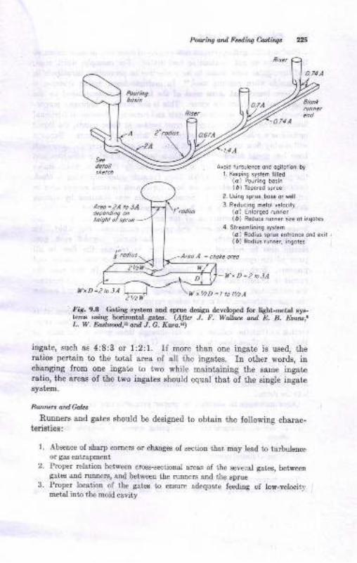
Pouri/,.g and F.diig Cading,
Avoid nrrbulenc! ond oqitoiioi by1. Keeping srst m lill.d
(a) Pou.ing bosi.(r) Topff.d sprue
2- t sing sp.ua bosa oreall
3. Reducing m€lol velocity(a) E.lorOed runne.(6) R.duc. runner si.e ot iiqotes
4 Sireomlini.q syslam(o) Rodius sgrue lnlronce ond erii(t) Rodios.un..r, ingoles
AreoA = chote oreo
t{xD=2toJA
VxtiD = I to l,/2A
FiS. 9.8 GatiDa systam aad 6p.ue d€sign developed for liaht-m€tal sys-tams usiry hori"DBtal Eat€f,. (Alb J. F. Watla.e ard E. B. Eoan*,.L. W. Dortud,t and J. G. Kum.!)
ingate, such as 4:8:3 or l:2:1. ll more than one ingste is used, theratios pertain to the totsl area of all the ingat€s. In other words, inchanging from one ingate to two while maintaiuing the ssroe iugaieratio, the areas of the two ingates should equal that of the single ingatesystem.
Runrun andGola
Runners and gates should be designed to obtaiu the following charac-ieristics:
1 . Absence of sharp comers or changes ol section tha.t may lead to turbuletrc€oa gas entrapmetrt
2. Proper relation between cross-sectional areas of the seyeial gates, betweengates aDd rironem, aDd between the runners ond tlre sprue
3. Proper location of the gates to ensure adequate feeding of low-velocitvmetal into the mold cavity
Sce
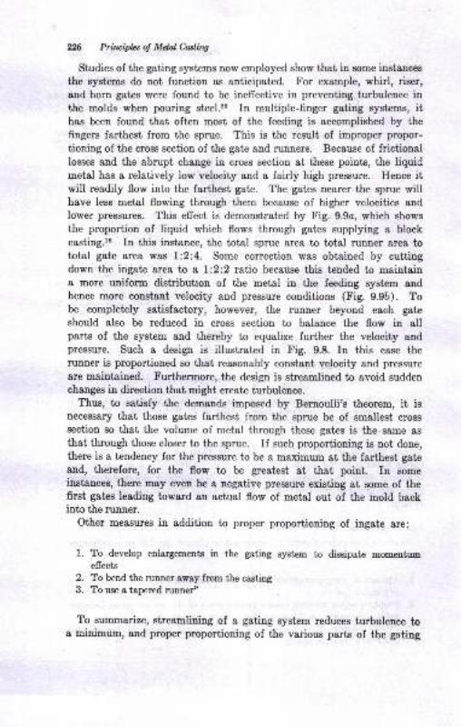
X26 Priluipks of Mdal Culia
Studies of the gating systems now employed show that in some instances
the systems do not function as anticipated. For example, whirl, rieer,
aud horn gates were found to be inefrective in preventing turbulence inf,he molds when pouring steel.'3 In multiple-finger gating systems, ithas been found that often most of the feeding is accomplished by the
fingers farthest from the sprue. This is the result of improper propor-
tioning of the croes section of the gate and runners. Because of frictionallosses and the abrupt change in cross section at these points, the liquidmetal has a relatively low velocity and a fairly high pressure. Hence itwill readily flow into the farthest gate. The gates nearer the sprue willhave less metal flowing through them because of higher velocities and
lower pressures. This effect is demonstrated by Fig. 9.9o, which shows
the proportion of liquid which flows through gates supplying a blockcasting.ls In this instance, the total sprue area to total runner area tototal gate area was 1:2:4. Some correction was obtained by cuttingdown the ingate area tn a t:2:2 ratio because this tended to maintaina more uniform distributron of the metal in the feeding system andhence more constant velocity and pressure conditions (Fig. 9.9b). Tobe completely satisfactory, however, the runner beyond each gate
should also be reduced in cross section to balance the flow in allparts of the system and thereby to equalize further the velocity andpressure. Such a design is illustrated in Fig. 9.8. In this case therunner is proportioned so that reasonably constant velocity and pressure
are maintained. Furthermore, the design is streamlined to avoid sudden
changes in direction that might create turbulence.Thus, to satisfy the demands imposed by Bernoulii's theorem, it is
Decessary that those gates farthest from the sprue be of smallest crosssection so that the volume of metal through these gates is the.same as
that through those closer to the sprue. If such proportioning is not done,
there is a tendency for the pressure to be a maximum at the farthest gate
and, therefore, for the flow to be greatest at that point. In someinstances, there may even be a negative pressure existing at some of thefirst gates leading toward an actual flow of metal out of the mold backintc the runner.
Other measures in addition to proper proportioning of ingate are:
I. To develop enlarg"mslts in the gating system to dissipate mometrtumeffects
2. To bend the runner away fmm the casting
3. To use a tapered runnef
To summarize, streamlining of a gating system reduces turbulence toa minimum, and proper proportioning of the various parts of the gating
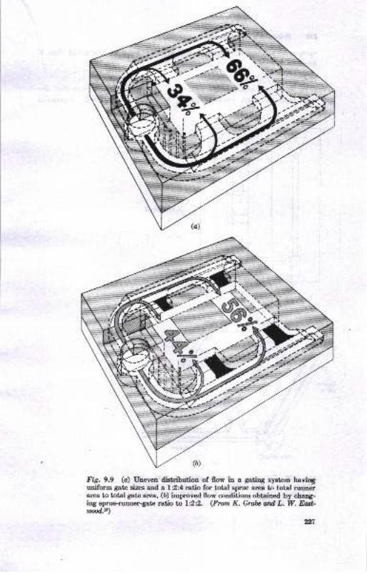
Fig.9.9 (c) Uneven distribution of {Iov in a gatiDg eyetem haviryuniform gate sizes and a l:2:4 ratio for total Eprue arlea to total ruun6rarea to total gato ar€a, (b) improved flow conditiong obtained by chaog-irg eprue-runner{ate ratio ta L:22. (From K. Grtfu ard, L. W. FnA-id.L.)
gn
wffi
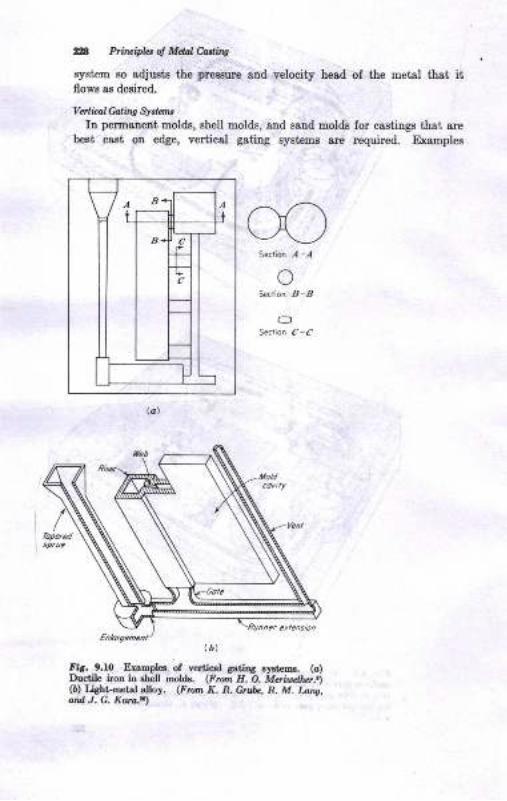
ZA Prircipb: ol Mel Codbq
system so Bdjusts the pres8ure and velocity he8d of the metal ihat itflowe ae desired.
VDlial Caling SlrtansID permsnent molds, shell molds, and saud molds for castings thai, are
best cast on edge, vertical gating systams are required. Examples
S€ctio. .,1-,{
oSect on B-B
OSedion C_f
fir. 9.10 Exaoples of v€.tical gatiDg systems. (o)Ducrile iron ia eLell moldr. (Froa IL O. Mcrid):l;.)(6) tisht-@t€l aloy. (Frun K. R. Cnb, R. M. Lans,ard, .1. C. Kura.r)
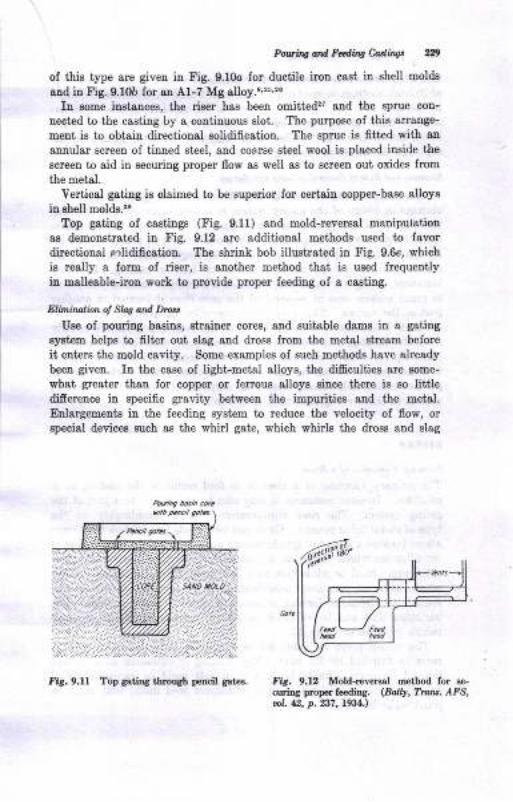
PwnqdtFdnqtuiry gr9
of this type are given iD Fig. 9.10o for ductile iron cast iu shell moldr
and in tr'ig. 9.10b for an Al-7 Mg alloy.&$,'?6
Ia oome inrtauces, tlle riser has been omittedfl and the aprue cou-
neeted to the c8sting by a coutinuous slot. The purpose of this arrange-
ment is to obtain directional solidification. The sprue is fitied with an
annular screeu of tinned steel, aDd cosrse eteel wool is placed inside the
screeo to aid iu eecuring proper flow s8 well as to screen out oides from
the metal.
Vertical gating ia claimed to be superior for certaiu copper-bese alloys
in shell mold8.':r
Top gating of caotinge (Fig. 9.11) ond mold-reversal manipulation
as demonstrated iu Fig. 9.12 8re sdditionsl methode used to favordirectional mlidification. The shrink bob illustrated in Fig. 9.6e, which
ia really a form of riser, is another method ihat is used lrequently
iu malleable-irou work to provide proper feeding of a casting.
Elininali<n ol SW ard Dtut
Use of pouring basins, strainer cores, and suitable dams in a getiDg
syatem helps to flt€r out slag and dross from the metal streao before
it erters the mold cavity. Some examples of such methods have already
been given. In the case of light-metal alloys, the diEcultiee are some-
whst greater thau for copper or ferrous alloye eince there is so littledifiererce in specific gravity between the impurities and the metal.
Enlargemento in the feeding system to reduce the velocity of flow, orspecial devices such ae the whirl gate, which whirls the dross and elag
F;& 9.12 Mold-reYeng] malod fol le_crrriDg proper feediDg. (Bdty, T'{.u. AFa,t. A, p. 237, L934.,
fir. 9.11 Top satiDA tirouSh peacil gat €.
Zn Prfilluiplrl ol Mdal Cnslb.s
inJo the center of the rieer, are other means of cleansing the metal. Foraluminum castings it has been recommended that the runners be placedin the drag with the ingate in the cope of the mold to reduce the inclu-eion of dross in the mold cavity. For ferrous metelo, on the otherhand, the reverse situation has been suggested, with the runner in thecope and the ingate in the drag.
Ecorcny and Euc of Renonl of Gales and Spnrt
In additiou to the factors already discussed, it is quite obvioug thatchanges in design of the gating system to reduce costs without affectingthe quality of the casting are something for which one should strive.Quitc frequently it is found that some modifications in practice, such as,for example, the inclusion of a chill in a strategic location, may grestlyreduce the amount of metal required to feed a casting. In otherinstances, it may be found that gating in a particular location will resultin much greater ease of removal of the gate than if located in anotherpart of the casting. The immediate connection between the ingate andthe mold is sometimes reduced to permit the gate to be removed readilyfrom the casting; or a neck-dotrryl, or 'Washburn,
core may be used forthis purpose. There are so many factors in connection with each metarand each particular casting that it is still necessary that each particularjob be studied individually with the viewpoint of improving the gatingsystcm to achieve a quality caeting at a minimum cost.
NISERS
Pfiman1 Funrtion of a RirrrThe primary function of a riser is to feed metal to the casting as itsolidifies. In some instances, it may also be considered as a part of thegatiug syetem. The riser requirements depend considerably on thetype of metal being poured. Gray cast iron needs less feeding than somealloys because a period of graphitizatiou occurs during the final stages ofsolidification which causes an expansion that tends to counteract metalshrinkage. steel or white cast iron, and many of the nonferrous alloyswhich have an extended solidification range, require excessive andsometimes elaborate feeding systems to obtain sound castings. Thevariation that can be expected in the volumetric shrinkage of .o*emetals is shown in Table 9.2.
The values given in Table g.2 represent minimal requirements thatmust be satisfied by the riser. Any bulging or extension of a castingbeyond its normal limits because of a soft mold or excessive metalpressures in the mold will require additional feed metal that must beproviCed by the riser.
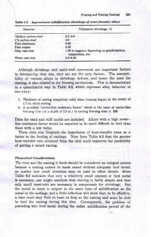
Powitr4od&dtngc,atlttw Ell
Tcbreg.2 Approimata colitlifirr,tion *hfinlrz,gc ol otne fowrdtlr &ye
Material Volumetric ahrinkage, /6
Medium esrbon et€el
l% ca.rbon st€el
Pure alumiaunPure copper
Gray cast iron
White cast iron
2.5-3.04.0
6.60
4.92
1.90 to negative depending on graphitiaation,
compoaition, etc.
4.0-5.50
Although shrinkage and mold-wall movemeut ere important factore
in determining riser size, they are not the only factors. The suscepti-
bility of v&rious alloys to shrinkage defects, and hence the need for
risering, is also relatcd to the freezing mechanism. This is demonstrated
in a quantitative way in Table 9.3, which exPresses alloy behavior in
two ways:
l. Thickness of casting completely solid when freezing begins at the center of
a 7-in.-thick casting
2. A so-called "center-line resista.nce factor" which is the ratio of center-line
freezing time (at a depth of 3.5 in.) to casting freezing time X lfi)
Data for Band snd chill molds are included. Alloys with e high cente-line resistance factor would be expected to be more rlifficult to feed than
those with a low value.
These data also illustrate the importance of heat-transfer rates as afactor in the feeding of castings. Note from Table 9.3 that the grc&t€r
heat-transfer rate obtained from the chill mold improves the possibility
of getting a sound casting.
T leore tiaal hnsidarations
The riser and the casting it feeds should be considered an integral Bystem
because a casting cannot be made sound without adequate feed metal,no matter how much attention may be paid to other details. Since
Table 9.2 indieates that only a relatively small amount oi ieed metalis necessary, one might conclude that risering is fairly simple and thatonly small reservoirs are necessary to compensate for shrinkage. Butthe mel"al in risers is subject to the same laws of solidification ae themetal in the castings, and a little reflection will show that, to be effective,
a riser must stay fluid at least as long as the casting and must be ableto feed the casting during this time. Consequently, the problem ofproviding this feed metal during the entire solidification period of the
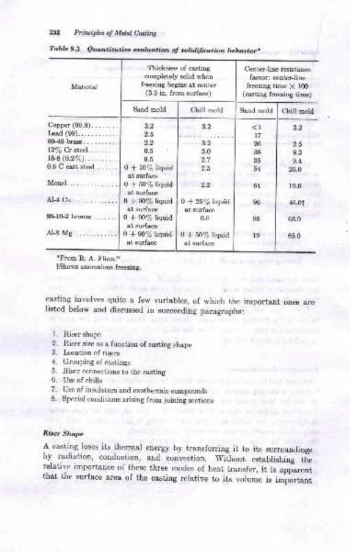
AP hiruiplct d Mdalefilq
Table 9.3 Quztntito;tie ealhur;tbn o! rrrlidiflmtion Drlluloior.
aFrom R. A. Flinn.il
tShows anomalous freezing.
casting involves quite a few variables, of which the important ones arelisted below and discussed in succeeding paragraphs:
l. Riser shape
2. Riser size as a function of casting shape3. Location of risers
4. Grouping of castings5. Riser connections to the casting6. Use of chills
7. Use of insulators and exothermic compounds8. Special conditions arising from joining sections
Riser Shape
A casting loses its thermal energy by transferring it to its surroundingsIiy radiation, conduction, and convection. without establishing therelative importance of these three modes of heat transfer, it is app-arentthat the surface area of the casting relative to its vorume is rmportant
Meterial
Thickness of castingcompletely soLid when
freezing tregins at center(3.5 in. from surface)
Center-Iine resistance
facrcr: center-linefreezing time X 100
(casting freezing time)
Sand mold Chill mold Sand mold Chill mold
Copper(99.8)........Ircad (99).
6G40 brass.
l27oCrsteel.........r844o.2%).0.6 C cast steel.......
Monel..
AI-4 Cu.
8&10-2bron2e........
Al-8 Mg.
3.2
2.5
2.2
0.5
0.5
0 * 10% liquidat surface
0 * 50% liquidat surface
0 * 90% liquidat surface
0 * 90% liquidat surface
0 * 90% liquidat surface
2.2
o *2i%nryidat surface
0.6
0 * 50% liquidat eurface
3.2
3.2
3.0
2.7
2.5
<117
26
3t|
35
54
64
96
95
r9
3.2
2.5
9.3
9.4
25.O
19.0
46.01
63.0
65.0
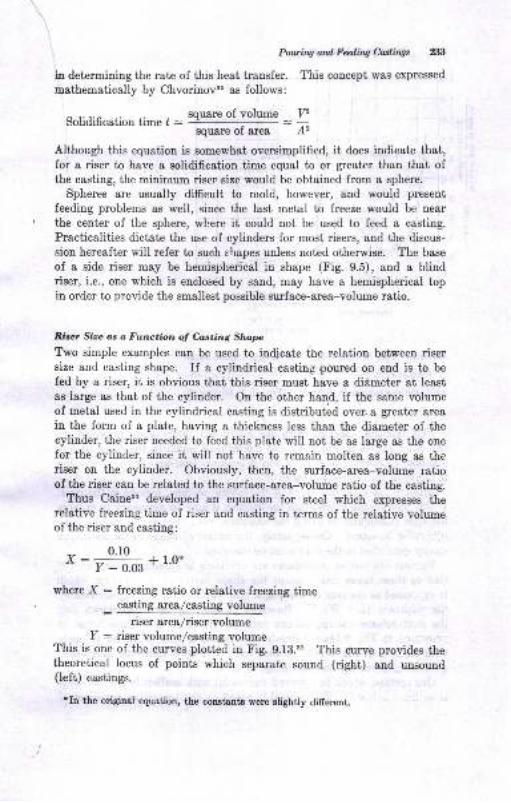
Potting and Fding Cutings z|:t
in detcrmining the rate of this heat transfer. This concept was expressed
methematically by Chvorinovso as follows:
Solidification time [ : Bqusre of volume
squ&re of &rea
Although this equation is somewhat oversimplified, it does indicate that,for a riser to have a solidification time equal to or greater than that ofthe casting, the minimum riser eize would be obtained from a sphere.
Spheres are usually difficult to mold, however, and would present
feeding problems as well, since the last metal to freeze would be near
the center of the sphere, where it could not be used to feed a casting.
Practicalities dictate the use of cylinders for most risers, and the discus-
sion hereaft€r will refer to such shapes unless noted otherwise. The base
of a side riser may be hemispherical in shape (Fig. 9.5), and a blindriser, i.e., one which is enclosed by sand, may have a hemispherical topin order to provide the smallest possible. surface-area-volume ratio.
Rirer Sire os a Functbn of Canting Shap
Tko simple examples can be used to indicate tfie relation between risersize and casting shape. If a cylindrical casting poured on end is to be
fed by a riser, it is obvious that this riser must have a diirmeter at least
as large as that of the cylinder. On the other hanp, if the same volume
of metal used in the cylindrical casting is distributed over. a greater area
in the forrn of a plate, having a thickness less than the diameter of thecylinder, the riser needed to feed this plate will not be as large as the onefor the cylinder, since it will not have to remain molten as long as theriser on the cylinder. Obviously, then, the surface-area-volume ratioofthe riser can be related to the surface-area-volume ratio of the casting.
Thus Caiuesl developed an equation for steel which expresses therelative freezing time oI riser and casting in terms of the relative volumeof the riser and casting:
0.10
' :7
- o.oe + l'o*
where X : freezing ratio or relative freeziag time
_ casting area/casting volume
riser arear/riser volumeI : riser volume/casting volume
This is one of the curves plotted in Fig. g.13.3, This suve provides thetheoretical locus of points which separate sound (right) and unsound(left) castings.
?Io the original equrtion, the constants were alightly difrerent.
v,A2
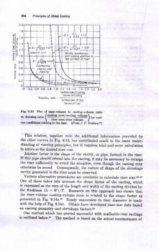
?.o
Prhviplzs of Mdtl Castittg
l;H;-L
I l- r It -x=
-Jkz -
(e/cclric orcl
rl
wL*=;#at' * ol,
Mi/d/y ercthermic
ltlr
.*l f]-.or,b.o\Erothermic I
,- sleeves ond-\ r ,oorr,
lop surloce ol riser
\,r-lr
1.8
il- t edt.Eat--'l g 1.4
'ilo L--lE "-.t:EIs t.o9l
r 0.8
EP 0.6
! 0.4
o.2
oLo o.2 0.4 0.6 0.8 1.0
Freezing rotio -
1.2 1.4 1.6 1.8 2.O ?.2 2.4Surloce orco ol costing
Volume ol cosling
Slrtoce oroo o, risar
Volumc of risar
Fig. 9.13 Plot of riser-volume to costing-volume ratio
vs. freezing ra1;o (castlne a"eafclsti"S -"o[me) ro" ,*i-\ nser area/n8er volume I
ous conditions eriering in the riser. (From J. F. Walls.e.a)
_ This relation, together with the additional information provided by
the other curves in Fig. g.l3, has contributed much to the Laeic under-standing of risering principles, but it requires trial-and-enor calculationto arrive at the desired riser size.
Another factor is the shape of the cavity, or pipe, formed in the riser.If this pipe should extend into the casting, it may be necessary to enlargethe riser srrfrsisn1l, to avoid the situation, even though the castiug mayotherwise be sound. consequently, the nature of shape of the shrinkagecavity generated in the riser must be obeerved.
various alternative procedures are available to calculate riser size.ss-stone of these takes into account the shape factor of the casting, whichis expressed as the sum of the length and width of the casting aiviaea tythe thickness (L + w)/7. Research on this approach has shown that,lhe riser-volume-casting-volume ratio is reloted to the shape factor aspresented in Fig. 9.14o.s6 Ready conversion to riser diameter is madewith the help of Fig. g.14b. others have developed riser-size data basedon casting geometry aud shrinkage factors.sl
one method which has proved successful with malleable-iron castingsis outlined below.st rhe method is based on-the aciual measurement of
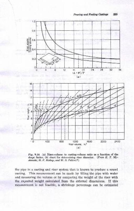
Powurg and Fditg Mittgt 23,t;
15 ?O
(L + ttl/Tlal
1200 1600Riser volume, in.3
(a)
Fig. 9.L4 (o) Riser-volume to ca.sting-volume ratio as a function of theshape factor, (6) chart for determining riser diamet€r. (From E. T. My-skou:shi, H. F. Bislup, and W. S. Pellini.$)
the pipe in a casting end riser system that is known to produce a sound
casting. This measurement can be made by filling the pipe with waterand measuring the volume or by comparing the weight of the riser withthe expected weight calculated from the external dimensions. If thismeasurement is not feasible, a shrinkage percentage can be estimatpd
elE 0..:IE>lo5I.E
#lE on
.i to;c.38-.9^EO
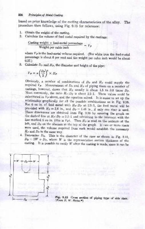
,fi Pfiuifuol Mdaledilq
based on prior knowledge of the casting characteristics of the alloy. Theprocedure then follows, using Fig. g.l5 for reference:
l. Obtri. the weight of the casting.2. Calculate the volume of feed metel requir€d by the castings:
Casting weight v feed-metal pereentage _ ,-Weight per cubic inch - r t
where Yp is the feed-metal volume required. (For white iron the feed-rneterperceatqge is about 6 per cent and the weight per cubic inch would be about0.n.)
3. Calculate Dp and IIr, the diameter and height of the pipe:
v,: r(b)' x u,
Obviously, a number of combinations of Dr and. Hp could supply therequired [. Measurement of Dp and I/p of piping risers on a o,rrobe. ofcastings, however, shows that Ilp usually is about 1.5 to 8.0 times Dr.Most commonly, the ratio Hp:Dp is about 2.5:r. These values could besubstituted in 7p above, and the equation solved. It is easier to set up therelationship graphically for ail the possible combinations as in rig.
^g.16.
For 6 cu in. of feed metal with Hp:Dp at 2.5:1, the feed metal *ru U"provided with lfp - 3.6 itr., and Dp - 1.48 il., if only one riser is used.These dimensions are obtained from Fig. g.16 by entering the graph onthe dashed line at Hp:Dp =2.b:r and advancing to the inLrcept-wiih theline marked 6 cu ia. (this is yF). Then llp is rlad on the ordinate at theleft, and Dp on the abscissa at the top of the graph. If two or more riserswere used, the volrrme required from each would establish the necessaryIlr and Dr in the s,une way.
4. Determine Dr. This is the diameter of the riser as shown in Fig. g.l5,Dp=2W f Dp, where 7 is the representative section thicknu." of ttucasting. It, is possible to verify W after the casting is made, since it can be
-I\q
_js
]T(s_rl
l_
I\q
li
ri!r
w i, o-*Lrilllt
[._-zr---J !!C. e4S Croes secrion of prprng type of eide ris€r.(Frun R. W. Heilv.$)
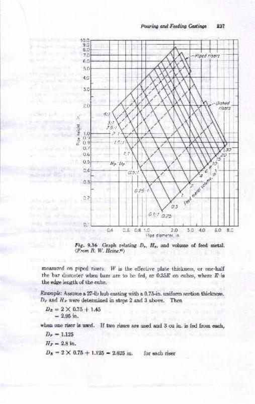
Poutiw ard Fedilw Castings 237
0.4 0.6 0.8 1.0 2.O 3.0 4.O 6.0 8.0Pipe diometer, in.
Fig. 9.16 Graph relating Da, H, and volume of feed metal.(From R. W. Heirc.$)
measured on piped ris€rs. I7 is the effective plate thickness, or one-half
the bar diameter when bars are to be fed, or 0.358 on cubes, where E is
the edge length of the cube.
Example: Aastme a ?7-lb hub casting with a 0.75-in. unifslrn sssfisa thickness.Dp end I/r wor€ determined in steps 2 and 3 above. Then
Da:2X0.75+1.45: 2.95 in.
whetr one riser is used. If two risers are used arrd 3 cu in. is fed from each,
Dp : L.L25
Hp : 2,8 rn.
Dn:2 X 0.75 + 1.125 : 2.625it. for each riser
.=
E
ii
r.00.90.8o.7
0.5
o.4
0.3
al: t q25
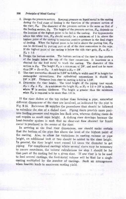
W Prituiph.s o! Mdd Cuting
5. Design the pressure section. Keeprug prassure ou liquid metal in the castingduring the final stage of feeding is the function of the pressure section ofthe riser, Ilr. The diameter of the pressure section is the ssme as that ofthe feeding section, Dn. The hqight of the pressure section, /11, depends onthe location of the highest point to be fed in the casting. For hypoeutecticalloys like white iron, I1r should usually be a minimum of 1 in. above thehighest point of the casting to maintain positive pressure in the 6nal stagesof feeding. When the highest point to be fed is above the parting line, fiI1can be decreased by putting part or all of the riser connection in the cope.If the highest point of the casting is below the side riser gate, Hn : Hp *Ila * l-0.
6. Design the bottom section. The bottom section of the riser is that portiouof the height below the top of the riser connection. It functiors as achannel for the feed metal to reach the casting. The diameter of thissection is Dn. ?he height Ils is a minimum of 2lA, and, need not be morethan2W * Dp or Dn. A safe height ts H o - BW .
7. The riser connection should be 2.5W r,o 0.8De in width and II in height forrectangular connectiong. For cylindrical connections it should be2W X 2W. Distance from riser to casting is 0.S to l.Ef.
8. Detcrmine the riser height. The total height of the piping riser equalsHp * Hy { 116. As a minimum the height }/r = Hp * 1.0 + glf in inches,where P is section thickness. The height is greater than the minimrrmwhen IIr is required to be more than 1.0 in.
If the riser dishes at the top rather than forming I pipe, somewhatdifferent dimensions of the riser are involved, as indicated by the plot inFig. 9.16. Reference 38 supplies the procedures that should be followedto calculate the size of a dished riser. Piping risers provide more posi-tive feeding pressure and require less flask area, whereas dishing risers donot require as much cope height. A dishing riser develops because theheat-transfer system is such that no clear-cut flow channel for liquidmetal is produced in the center of the riser.
In arriving at the final riser dimensions, one should make certainthat the bottom of the pipe lies above the level of the highest point ofthe casting. Also, to allow for variations in casting volume or pipeheight, an additional inch or two should be added to the riser height.fn general, the riser height must exceed 1.5 times the diameter to getpiping. For complicated castings where several risers may be ou.u.r"ryto assure soundness, the volume calculations for step 1 should be forthat part of the easting fed by a given riser. If one riser is to be usedto feed several castings, the feed-metal volume wilr be that for a singlecasting multiplied by the .number of castings. such an ur."nguro.-ntwhen feasible leads to maximum casting yield.
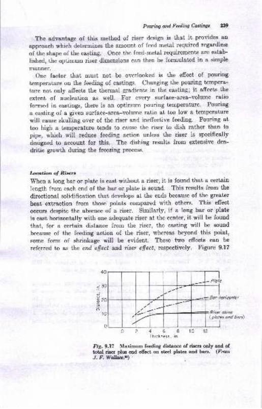
Pourhrg ad Fccdilw Castirtgs 239
The advantage of this method of riser design is that it proYides an
approach which determines the amount of feed metal required regardless
of the shape of the casting. Once the feed-metal requirements are estab-
lished, the optimum riser dimeusions can then be formulated iu a simple
manner.
One factor that must not be overlooked is the effect of pouring
temperature on the feeding of castings. Changing the pouring tempera-
ture not only affects the thermal gradients in the casting; it affects the
extent of nucleation as well. For every surfsce-area-volume ratio
formed in castings, there is an optimum pouring temperature. Pouring
a casting of a given surface-area-volume ratio at too low a temperature
will cause skulling over of the riser and iueffective feeding. Pouring at
too high a temperature tends to cause the riser to dish rather than to
pipe, which will reduce feeding action unless the riser is specifically
designed to account for t'his. The dishing results from extensive den-
dritic growth during the freezing process.
Loation of Risert
When a long bar or plate is cast without a riser, it is found that a certain
length from each end of the bar or plate is sound. This results from the
directional solidification that develops at the ends because of the greater
heat extraction from those points compared with others. This efrect
occurs despite the absence of a riser. Similarly, if a long bar or plate
is cast horizontally with one adequate riser at the center, it will be found
that, for a certain distance from the riser, the casting will be sound
because of the feeding action of the riser, whereas beyond this point,
some form of shrinkage will be evident. These two efrects can be
referred to as the end efiect aud nser efiect, rcspectively. Figure 9.17
a3o
o.
E?o'6
10
0
I
I
Riser olone( plotes ond borsl
o 2 4 6 8 l0 12
Thickness, in.
Fig.9.l7 Maximum feeding distarce of ris$s only and oftotal riser plus end efresi on steel plates and bars. (FlomJ. F.Wallae.a)
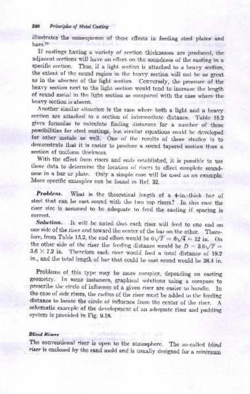
2& Priuipht of Mdal Cadits
illustrates the consequence of these effects in feeding steel plates andbars.r2
ff castings having a variety of section thicknesses are produced, theadjacent sections will have an effect on the soundness of the casting in aspecific section. Thus, if a light section is attached to a heavy section,the extent of the sound region in the heary section will not be as greatas in the absence of the light sec.tion. conversely, the presence of theheavy section next to the light section would tend to increase the lengthof sound metal in the light section as compared with the case where iheheavy section is absent.
Another similar situation is the case where both a light and a heavysection are attached to a section of intermediate distance. Table 1b.2gives formulas to calculate finding distances for a number of thesepossibilities for steel castings, but similar equations could be devblopedfor other metale as well. one of the results of these studies is todemonstrate that it is easier to produce a sound tapered section than asection of uniform thickness.
with the effect from risers and ends established, it is possible to usethese data to determine the location of risers to effect complete sound-ness in a bar or plate. only a simple case will be used as an example.More specific examples can be found in Ref. 82.
Problern. What is the theoretical Iength of a 4-in.-thick bar ofsteel that can be cast sound with the two top risers? In this case theriser size is assumed to be adequate to feed the casting if spacing iscorrect.
Solution. It will be noted that each riser will feed to one end onone side of the riser and toward the center of the bar on the other. There-fore, from Table 15.2, the end effect would be 6/F: 6/4: 12 in. Onthe other side of the riser the feeding distance would be D : Z.6t/T :3.6 X 7.2 in. Therefore each riser wourd feed a total distance of 1g.2in., and the total length of bar that courd be cast sound would be Btl.4 in.
Problems of this type may be more complex, depending on castinggeometry. In some instances, graphical solutions using a compass toprescribe the circle of influence of a given riser are easier to handle. rnthe case of side risers, the radius of the riser must be added to the feedingdistance to locate the circle o{ influence from the center of the riser. Aschematic example of the development of an adequate riser and paddingsystem is provided in Fig. 9.18.
Blind Rirrlr:r
The eonventional riser is open to the atmosphere. The so-called bh'zdriser ie enclosed by the sand mold and is usually designed for a minimun
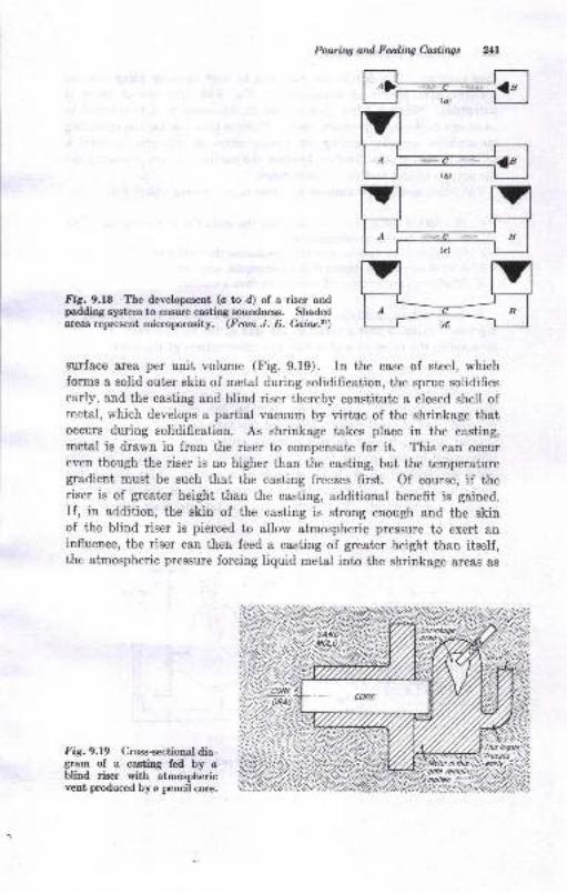
Pouring and Feding Castings ?/Ll
Fig.9.l8 The development (c to d) of a riser andpadding system to ensure casting soundness. Shadedareaa represent microporoeity. (From J. E. Cairu,il)
surface area per unit volume (Fig.9.l9). In the case of steel, whichforms a solid outer skin of metal during solidification, the sprue solidifiesearly, and the casting and blind riser thereby constitute a closed shell ofmetal, which develops a partial vacuum by virtue of the shrinkage thatoccurs during solidification. As shrinkage takes place in the casting,metal is drawn in from the riser to compensate for it. This can occureven though the riser is no higher than the casting, but the temperaturegradient must be such that the casting freezes first. Of course, if theriser is of greater height than the casting, additional benefit is gained.
If, in addition, the skin of the casting is strong enough and the skinof the blind riser is pierced to allow atmospheric pressure to exert aninfluence, the riser can therr feed a casting of greater height than itself,the atmospheric pressure forcing liquid metal into the shrinkage areas as
Fig. 9.19 Cross-sectional dia-gram of a casting fed by ablind riser with atmosphericvent produced by e pencil core.
(o)
tr7LHMMUI A ..c B ImMMUH
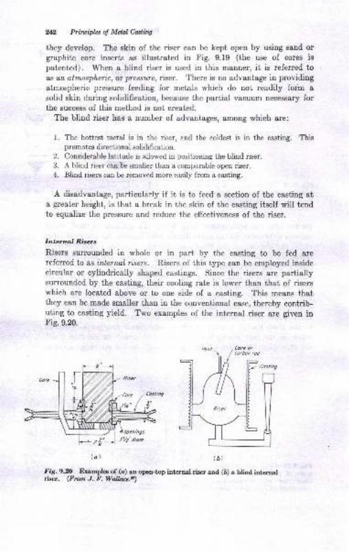
2{2 Priruiples o! Mdal Coriting
they develop. The skin of the riser can be kept open by using sand orgraphite core inserts as illustrated in Fig. 9.19 (the use of cores ispatented). When a blind riser is used in this manner, it is referred to
as at atmospheric, or pressure, riser. There is no advantage in providing
atrnospheric pressure feeding for metals which do not readily forh a
solid skin during solidification, because the partial vacuum necessary forthe success of this method is not created.
The blind riser has a number of advantages, among which are:
1. The hottest metal is in the riser, end the coldest is in the casting. Thispromotes directional solidifisation.
2. Considerable latitude is allowed in positioning the blind riser.
3. A blind riser can be maller than a comparable open riser.
4. Blind rimrs can be removed more easily from a casting.
A disadvantage, particularly if it is to feed a section of the casting ata great€r height, is that a break in the skin of the casting itself will tendto equalize the pressure and reduce the effectiveness of the riser.
Interrul Risers
Risers sunounded in whole or in part by the casting to be fed arereferred.to as intemol risers. Risers of this type can be employed insidecircular or cylindrically shaped castings. Since the risers are partiallysuuounded by the cssting, their cooling rate is lower than that of riserswhich are located above or to one side of a casting. This means thatthey can be made smaller than in the conventional case, thereby contrib-uting to casting yield. Two examples of the internal riser are given inFig.9.20.
Fig.9.fi Examples of (a) an open-top internal riser and (b) a blind internalris€r. (From J. F. Wallace,a)
tbtla)
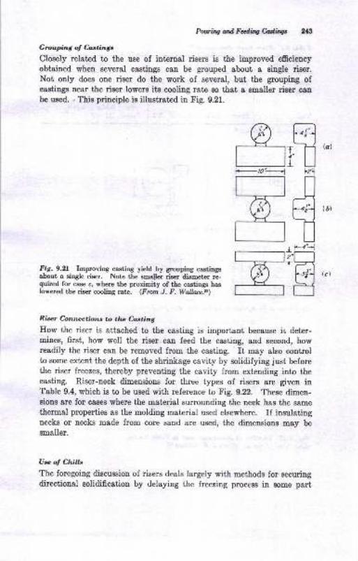
PowutgandFdiqMbW 213
Gtouping of &etingc
Closely related to the use of internal risers is the improved efrciency
obtained when several castings can be grouped about a siugle riser.
Not ouly does one riser do the work of several, but the grouping ofcastings near the riser lowers its cooliug rate so that a smaller riser can
be used. - This principle ie illustrat€d in Fig. 9.21.
Fig.9.2L Improving casting yield by grouping castingaabout a single riser. Note the emaller rieer diameter re-quired for case c, where the proximity of the castings haslowered the riser cooling rate. (Frorn J. F. Walla&.a)
Riser Connrvctions to thc C-asting
IIow the riser is attached to the casting is important because ii; deter-mines, first, how well the riser can feed the casting, and second, howreadily the riser can be removed from the casting. It may also controlto some extent the depth of the shrinkage cavity by solidifying just beforethe riser freezes, thereby preventing the cavity from extending into thecasting. Riser-neek dimensions for three types of risers &re given inTable 9.4, which is to be used with reference to Fig. 9.22. These dimen-sions are for cases where the material surrounding the neck has the same
thermal properties as the molding material used elsewhere. If insulatingnecks or necks made from core sand are used, the dimensions may be
smaller.
U* of Chitls
The foregoing discussion of risers deals largely with methods for securingdirectional solidification by delaying the freezing process in some part
,frlzl
#
E
&F_ro?
Etr
(bt
(c)
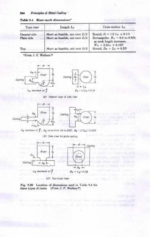
Top.............
2+l Priu'ipbt ol Mdal Mins
Tobr. 9.4 Rir.t-rEck dime^tio,rr'
T]rpe rfu€r
tD1T____________- T
1",", ll1,, I lt,L\ 4
c".,cl !,.1- |
t , ,o,ir,. ot t(c) Iop round ris.r
fir. 9.2 t cetioD of dimenaioDs u:ed in Table 9.4 forthree typ€8 ol rii€rE. (P,wn J. F. Wdlbt .n\
ClGs sectiotr ,{
Round, D = 1.2 Lr *O.rDR€otsnguiar, Iiv : 0.6 to 0.8D;
.s neck letrgth incr€{s€s,
wd=2.5Lx+O.BDRouad, D,v = Ir * 0.2D
ghort !s fersible, not over D/2SLori !s foasiblc, not ov€I D/3
thort ss fessible, Dot over D/2
.From J. F. ffallace.!
,rrrrffi)lu
Ltt no,idn ot ? Dx=t-zly+atD
(a) Generol tfp. of side ris6r
-D1
,r ao,in@ ot t I Hx w.i.stM A6 ro\dtt trx=z-5Li+aBD
(r) Sid. ris.. to. ptor. coninq
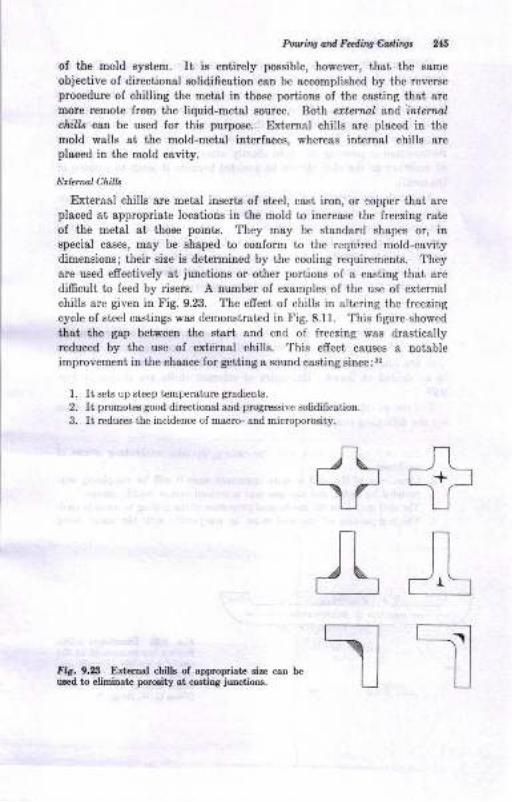
Puviag Nd Fdi'q edin$
of tlrc mold syEtem. It is entirely possible, however, that the same
objective of directional solidi0cstion can be accomplished by the reverseprocedure ol chilling the metsl in those portions of the casting that are
more reEot€ from the liquid-metal source. Both ertennl and intenalclrills can be used for this purpose. External chills are placed in themold walle at the mold-metal interfaces, a,hereas inttrnal chills are
placed in the mold cavity.
hbmal ChilLt
&terflal chills are metal inserb of steel, cast iron, or copper that are
placed 8t eppropriate lccations in the mold to increase ihe freezing rat€
of the metal si those poinis. They may be gtandard shapes or, iD
special cases, may be shaped to conform to the requircd mold-cavitydimensions; their size is determiued by the cooling requirements. Theyare used efrectively at junctions or other portions of 8 casting thst are
dilficult to feed by risers. A number of examples of the use of external
chills are given in Fig. 9.23. The efrect of chills in altedng the freezing
cycle of steel castings w&s demonstrated in Fig. 8.11. This figure showed
that the gap between the stert sDd end of freezing was drasticallyreduced by the use of external chille. This effect causes a notable
improvement in the chaoce ior geiting a sound casting since : 3,
It sets up steep t€mpemture gr&dients.
It promotDs good directional end prcgrcssivc solidificatrion.
It reduces the incidence of macro- and microporosity.
1.
=LUIr1:
EiL]
+&TIir. 9.23 Exr€rnal chillB of app.op.iatz siza can be
used tD elimiDat€ prooity at castitrg junctioDs.
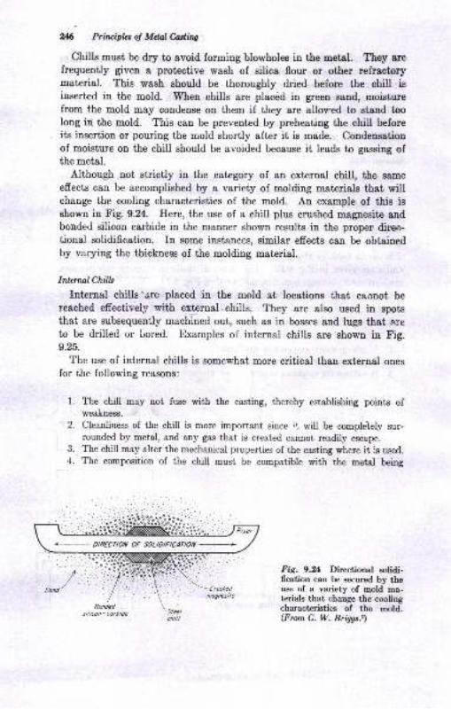
26 Priviphs of MtulMiry
Chills must be dry to avoid forming blowholes in the metsl. They arcfrequently given a protective wash of silica flour or other refractorymaterial. This wash should be thoroughly dried before the chill isinserted in the mold. When chills are placdd in green sand, moisturefrom the mold may condense on them if they are allov.ed to stand toolong in the mold. This can be prevented by preheating the chill beforeits insertion or pouring the mold shortly after it is made. Condensatiouof moisture on the chill should be avoided because it leads to gassiug ofthe metal.
Although not strictly in the category of an external chill, the same
effects can be accomplished by a variety of molding materials that willchange the cooling characteristics of the mold. An example of this isshown in Fig. 9.24. Here, the use of a chill plus crushed magpesite andbonded silicon carbide in the manner shown results in the proper direc-tional solidification. In some instances, similar effects can be obtainedby varying the thickness of the molding material.
Inlenwl Chills
Internal chills'are placed in the mold et iocations that caanot be
reached efrectively with external ehiila. They are also used in spots
that are subsequently machined out, such as in bosses and lugs that a,re
to be drilled or Lored. Examples of internal chills are shown in Fig.9.25.
The use of internal chills is somewhat more critical than external ones
for the following reasoffr:
1. The chill may not fuse with the casting, thereby establishing points ofweakness.
Cleanliness of the chill is more important since it rdll be completely sur-rounded by metal, and any gas that is created cannot readily escape.
The chill may alter the meehanical properties of the casting where it is used.The composition of the chill must be compatible with the metal being
Fig. 9.rl Directional solidi-fication can be secured by theuse of a variety of mold ma-terials that change the coolingcharacteristics of the mold.(From C. W. Briggs.z)
3.
4.
+ ARECNOil OF SOL\OIFEATDil
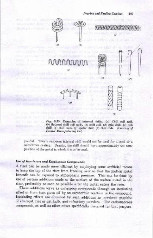
Potting ard Fcding CastiWs
P{a)
Mtd)
T(6)
ffitc)
YVI
lllffi
le)
ng(i)
Fig. 9.21i Examples of internal chills. (c) Chill coit nail,(6) flathead chill coil naile, (c) chill coil, (d) edd chill, (e) hubchill, (/) chill nails, (g) spider chill, ([) chill rods. (Courtzs! olF a.wur Marwladwirq Cn.)
pcured. Thus a cast-iron internal chill would not be used for a steel or anouferrous casting. Usually, the chill should have approximately the com-position of the metal in which it is to be used.
U* oJ Inaula,toro and Eroth,ennic C.ornpundt
A riser can be made more efficient by employing some artificiBl meansto keep the top of the riser from freezing over so that the molten metslbeneath can be exposed to atmospheric pressure. This can be done byuse of certain additions made to the surface of the molten metal in theriser, preferably as soon as possible after the metal enters the riser.
These additions serve as antipipin4 compounds through an insulatingefrect or from heat given off by an exothermic reaction in the compound.Insulating efrects are obtained by such additions as powdered graphiteor charcoal, rice or oat hulls, and refractory powders. The carbonaceouscompounds, as well as other mixes specifieally designed for that purpose
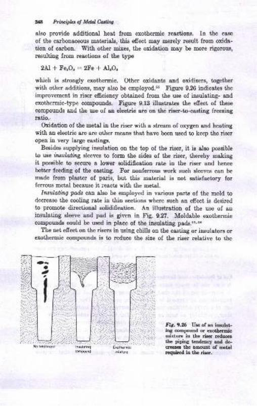
2*8 Priripbtof MdalMhg
also provide additional heat from exothermic reactioDs. In the case
of the carbonaceous materials, this effect may merely result from oxida-tion of carbon. T[ith other mixes, the oxidation may be more rigorous,
resulting from reactions of the type
2Al t FeaOs :2Fe * AleOs
which is strongly exothermic. Other oxidants and oxidizers, together
with other additions, may also be employed.s5 Figure 9.26 indicatee the
improvement in rieer efficiency obtained from the use of insulating- and
exothermic-type compounds. Figure 9.13 illustrates the efrect of these
compounds aud the use of an electric arc on the riser-to-castiug freezingratio.,
Oxidatiou of the metal in the riser with a stream of oxygen and heating
with an electric &rc are other means that have been ueed to keep the riseropen in very large castings.
Besides supplying insulation on the top of the riser, it is also possible
to ruse in^sulolldzg sleeves to form the sidee of the riser, thereby makingit possible to secure a lower solidification rate in the riser aud hence
better Jeeding of the casting. For nonferrous work guch sleeves can be
made from plaster of paris, but this material is not satisfactory forferroue metal because it reacts with the metal.
Iwtiloting pads can also be employed in various parts of the mold todecrease the cooling rate in thin sections where such an effect is desiredto promote directioual solidification. An illustration of the use of aninsulating sleeve and pad is given in Fig. 9.27. Moldable exothermiccompounds could be used in place of the insulating pads.ez'oe
The net effect on the rieers in using chills on the casting or insulators orexotherTic compounds is to reduce the size of the riser relative to the
Exothermic
mixluc
Fig.9.% Ue€ of an insulating compound or erothermiimixture in the riser reducesthe piping tendency aod de-creae€s the amount of metalrcquired in the riger.
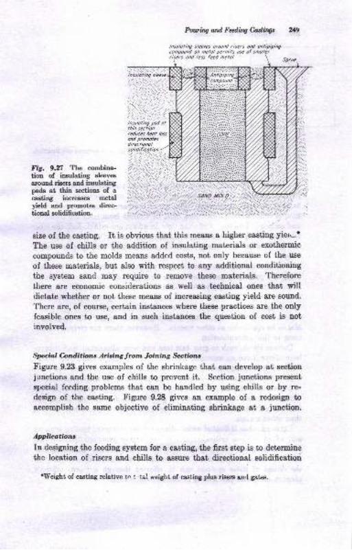
Powutg ail Fdhg Culings 219
/nsoloti1q sleges oround risers ood onlipipirrgcompouad oo nelol pcrmils uil of soollclrisers ond lcss fccd mclol
/osulolng slccvc
Fig. 9.n The combina-tion of insulating eleeves
around risere and insulatingpads at thin sections of acesting increas€s metalyield and promotes direc-tional solidiffeation.
size of the casting. It is obvioue that this me&trs a higher casting yier-.*
The use of chills or the addition of insulating materiak or exothermic
compounds to the molds means added costs, not only because of the use
of these materiale, but also with respect to any additional conditioning
the system Bend msy require to remove these materials. Therefore
there are economic considerations as well ae technical ones thst willdictate whether or not these means of increasing castiug yield are sound.
There are, of course, certain instances where these practices are the onlyfeasible ones to use, and in such instances the question of cost iB uot
iuyolved.
Special C,onditbtts Arising from Joining Sectiozr
Figure 9.23 gives examples of the shrinkage that csn develop at sectioujunctions and the use of chills to prevent it. Section junctions pnesent
special feeding problems that can be handled by using chills or by re-
design of the casting. Figure 9.28 gives an orample of a redesip toaccomplish the same objective of eliminating shrinkage at a junction.
Applieatbru
In designing the feediug system for a casting, the first step is to determiue
the location of risers and chille to assure that directional solidificatiod
rVf,eight of castjng relaUvo t^ t .tal reighi, of casting plus rigers ao,l gatee.
.;,:rii,:iiililtii]i Ilosulolinq pod ottho sectioorcdmes let loss
solidificotioo
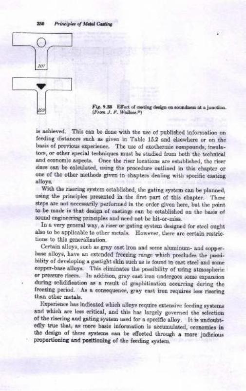
,5O tuivipL, ol Mdal Cadtne
Fir. 9.28 Ellect of csstils desiSn on souId.tr€ss st a juEction.(Fro,n J, F. Wauaa.a)
ie achieved. This can be done with the uae of published iuformation onfeeding distancee such as given iu Table 15.2 and elsewhere or oD thebaeie of previous experience. The use of exothermic conpounds, itr8uls-tors, or other specisl techliquer muet be studied from both the techuicaland economic aspecte. Once the riser locaiions are established, the risersizee cau be calculated, using the procedure outlined itr this chspter oroue ol the other roeihode given in chaptere dealiug wiih specific castiugslloys.
With the risering system establiehed, the gating syst€m catr be planned,using the priuciplee presented iD the 6rst, part of thie chapter. TheseBt€ps are not uecesEarily performed in the order given here, but the pointto be made io that dedgn oI casting8 csn be estsbliahed on the baeis ofrouud engineering priuciples and need not be hit-or-mise.
Iu a very general wsy, 8 ris€r or gstiDg system designed for steel oughialso io be applicable to otber loetals. However, there are certain restric-tiona to this geueralization.
- Certain alloys, such 8s gray cast iron atrd sone alumiDum- and copper-base alloys, have an extended freering range which precludes the posei-bility of developiug a gestight skil such ss iB fouud in cset steel and eomecopper-base alloys. Thie eliminates the poeeibility of using atmosphericoJ pressure risers. In addition, grsy caat iron undergoes some expansiouduriug solidification ss a result of glsphitization occurring during thelreeziug period. As a consequeuce, gay caat iron requiree less riseringthan other metela.
trlxperience has iodicst€d which 8lloyo require extensive feeding eystemesnd which are leee critical, aud thie has largely governed the seiectionof l.he riseriug and gaiing oystem ueed for a specific alloy. It ig undoubt-edty t,rue th8t, as more basic information is accunulated, econouies i[the design of these syrt€ms can be efrectrd through a Eore iudiciousproportioning 8nd posidoping of the feeding syrtem.
1::

l.
4.
5.
6.
8.
9.
10.
11.
12.
13.
14.
15.
16.
1?.
t8.
19.
.
21.
.
Poviry atd Faniry Mirlt
BIBLIOCRAPHY
E. T. Myakowski, E. F. Bilhop, and 'W.
S. Pellini, Applicatioo of Cbills ioIncreaeing the Feeding RsDge of Risers, ?roar. .{-tr'S, vol. 60, p. 389, 1952.
C. W. B.i8gE, "The Metallurgy of Sieel Castings," McCnv-Eill BoohCoopany, Ner York, 1e46.M. J. Berger ard C. Locke, A Theoretical Basis fo! the Deaigo oI Gatee,
?otnd,ry, rol- 79, p. 112, Febn sry, 1951.
M. J. Berger and C. Iacke, "Fluid Flow Mechenicr of Molten St el," ArmourReearch Foundatioa, Chic8ao, Ap!. 12, 1951.
J. F. Wallace and E. B. Evaos, Principleo ol Cstig, Foud,ry, vol. 87, p.
74, October, 1959.
J. F. \{allace and E. B. Evans, GatiDg of Groy Iron Castings, Ironr. .4FS,
vol. 05, p.267, 1957.
E. If. Dietert, Eol[ Fast ghould a Mold Be Poured? Fotndry, vol. 81, p.
205, August, 1955.
E. O. Meriwether, Shell Molded Ductile Iror Castirgs Gating aod RiseriDg
for Verticsl Pouring, ?ron*. ,{P3, vol. 68, p, 516, 1960.
E. A. Lange and A. T. Buko*ski, Pouring Tioes for Ste€l Caslilgs, US.Naval Research Laboratory n port, WashiDgtoD, D.C., 1958.
C. Y. Knobeloch, Choke'lhal Gslr-, Modetu Coetiaga, vol. 84, p. 48, Decem-
be!, 1956.
D. M. March, Gating and Ris€ ng Ductile IrcD Castings Poured il DrySond Molds, ?raru. ,{IS, vol. 68, p. 512, 196O.
Xrport of IBF Subcommittee TS24, Ingots, Fonndry Trade J., vol. 99, p.
691, Dec. 15, 1955.
L. W. Eastwood, TeDt&tive Design of florizotrtal Gating Syst€rn Ior LiShtA.lloys, in "Slmpoeium on the Principles of Gatiry," p. 25, American Foun.dryDetr's Society, 1951.
J. G. Kura, Colcul&tiotr of Horizootal Gating Systems, Arn. Folfl.drytuan,vol.27, p. 123, May, 1955.
K. Grube ond L. W. Eastwood, A Study of the Principtes of Gating, Tralt..4fS, vol. 58, p. 76, 1950.
T. FiDlay, Iin Gatitrg: New Cost-cutting St€el Tetfuiqt(f,, Modem Cthlinqc,vol. 40, p.53, September, 1961.
M. C. Flemings and II. F. Taylor, Gating Aluminum Cactittgs, Eoundry,vol.88, p.72, April, 1960.
R. W. Whit€, Gating of Ductile l.on Castings, foundry, vol. 88, p. 101,
February, 1960.
C. W'. BriggB, GotiDg Steel Crstings, Iorndry, vol.88, p. 124, JuDe, 1960.
R. F. Polich, A. Saunden, Jr., and M. C. FleminBt, Gating Premium QualttyCastinSs, Trafu. ,l4,"S, vol.7l, p.418, 1963.
C. W. Ward, Jr., and T. C. Jacobs, Kis GatinS Bras6 Castilgs, Trura. A?5,vol. 70, p.865, 1062.
E. BjorLlund, Calculating Ingate Dimelsioos for Grey lroa Casting, froar..4P8, vol. 70, p. 193, 1962.
J. G. Mezofr 8trd E. E. Elliott, A Study of Factors Atrecting the PouringR"etes of Caatings, ?rans. l{.tr'S, vol. 56, p. 279, 19,18.'Itr. E. Johson, W. O. Baker, end W. S. Pellini, Principles of Gating Desigo:Factors Influencing Molten Steel !'lor from FiDger GsiilA Syst!@, ?rors../.IS, vol.58, p.661, 1950.K. R. Gmbe aod J. G. Kura, Principles Appl.ic*ble to Vertical Geting,froru. .4I8, vol. 8il, p. 35, 1955.
Prhuifus o! Mclal Cortitrg
26. K. R. Grube, R. M. Lang, and J. G. Kura, Modifications in Vertical GatingPrinciples, Trans. AFS, vol.64, p.54, 1956.
27. E.E. Elliott and J. G. Mezofr, Efrect of Gating Design on Metal FlowConditions in the Casting of Magnesium Alloys, ?rons. r{FS, vol. 56, p.n3,lg4g.
28. F. E. Murphy, G. J. Jaekson, and R. A. Rosenberg, Bronze Valve YerticalCating in Shell Molds, Modern Castings, vol.40, p.51, July, 1961.
29. R. A. Flinn, Quantitative Evaluation of the Susceptibility of Various Allol,sto Shrinkage Defects, Trarx. AFS,vol.64, p.665,1956.
30. N. Chvorinov, Theory of the Solidifieation of Castings, Geisserei, vol.27,pp.177-225,1940.
31. J. B. Caine, Risering Castings, Trans. AFS, vol. 57, p.66, 1949.32. J. F. Wallace (ed.), "Fundamentals of Risering Steel Castings," Steel
Founders' Society, 1960.
33. J. T. Berry and T. Watmough, Factors Afrecting Soundness in Alloys withLong and Short Freezing Range, Trans..A/S, vol. 69, p. ll, 1959.
34. II. D. Merchant, Dimensioning of Sand Casting Pcisers, Mod,em Casti,ngs,vol.35, p. 73, February, 1959.
35. E. T. Myskowski, II. F. Bishop, and W. S. Pellini, A Simplified Method forDetemrining Riser Dimensions, Trans. /1S, vol. 63, p.271, 1955.
J6. J. F. TVallace, Risering of Castings, Foundry, vol.87, p.74, November, 1959.
37. C. W. Briggs, Risering of Commercial Steel Castings, Trans. AFS, vol. 63,p.287, 1955.
}8. R. W. Eeine, Piping Risers for White Iron Castings, Mallcablc Found,ers'Soc. T ech. Bull. 63-3, 1963.
;19. II. F. Bishop, Risering Steel Castings, Foundry, vol.88, p.75, August, Ia50:p. 116, September, 1960; p. 114, October, 1960.
40. R. W. White, Risering of Ductile Iron Castings, Fowtdry, vol. 88, p. 96,March, 1960.
{1. J. F. Bishop and W. II. Johnson, Risering of Steel, Foundry, vol.84, p.70,February, 1956; p. 136, March, 1956.
42. II. F. Taylor, M. C. Flemings, and T. S. Piwonka, Risering AluminumCasttngs, F urndry, vol. 88, p. 216, May, 1960.
43. D. Miller, Feeding Systems for Permanent Moid Castings, Found,ry, vol. 86,p.70, December, 1958.
44. R. W. Ruddle, Risering of Copper Alloy Castings , Foundry, vol. 88, p. 78,January, 1960.
45. J.Yarga, Jr., A New Mettrod for Studying Riser Requirements lor Castings,Foundry, vol.85, p. 106, JuIy, 1957.
46. II. F. Bishop and C. G. Ackertind, Dimensioning of Risers for Nodular IronCastings, Foundry, vol.84, p. 115, December, 1g56.
47. Gating and Feeding for Light Metal Castings, American Foundrymen'sSociety, 1962.
48. E. Chappie, Gating Affects Quality in Production of Steel Castings,Foundry, vol.84, p. 90, April, 1956.
49. R. Namur, Calculation of Riser-necks for Sand Castings, Giesserei, vol. 44,p. 665, Oct. 24,7957.
50. C. W. Briggs, Neckeddown Risers for Production Steel Castings, SFSABes. Rept.11, March, 1947.
51. C. W. Briggs, R. A. Gezelius, and G. R. Donaldson, Steel Casting Designrbr the Engineer and Foundryman, Trans.,4FS, vol. 46, p. 605, lg38.
5!. V. Pulsifer, Gray Iron Chilling Practice, ?oundrg, vol.86, September, lgl8.

53.
54.55.
56.
57.
58.
59.
60.
61.
62.
Powing ord Fding C.astingt 253
Y. Pascbkis, Bange of Efiectiveness of Chills, Trans. AFS, vol. 63, p. 13,
1955.
C. Iocke, Application of Indirect Chills, frons. r{FS, vol. 63, p. 29i, 1955.
S. L. Gertman, A Study of Insulating and Mildly Exothermic AntipipingCompounds Used for Steel Ca.stings, Trarc. AFS, vol.57, p.332, 1949.
J. Gotheridge and D. H. Snelson, How to Use Moldable Exothermic Com-pou&, Fmnilrg, vol.84, p. 150, May, 1956.
E. F. Bishop, II. F. Taylor, and R. G. Powell, Risering'of Steel Castings
with Exothermic Sleeves, Foundry, vol.86, p.54, June, 1958.
T. C. Bunch and G. E. Dalbey, Feeding of Castings, Trans. AFS, vol. 63,
p.5&3, 1955.
W. A. Mader, Application of Insulated Risers to Production of AlumimrmAlloy Sand Castings, Trans. AFS, vol. 63, p. 553, 1955.
D. L. Gertman and R. K. Buhr, Use of Rice and Oat Eulls as RiserInsulation, Foutdry, vol. &3, p. 92, February, 1955.
A. J. Stone, E. B. Kinneer, and A. R. Fraser, Better Castings with Less
Melal,Fundry, vol.83, p. 118, JuIy, 1955.
I[. A. Mader, Make Small Risers Do the Work of Large, Moilem Castings,vol.83, p.32, Septe.mber, 1955.
63. E. Present and E. Rosenthal, Feeding Disturbance of Bars in InvestmentMolds, ?rons. r4.F8, vol.69, p. 138, 1961.
64. M. C. Flemings, R. W'. Strachan, E. J. Poirier, ;rnd E. F. Taylor, Perform-ance of Chills on Eigh Strength Magnesium Alloy Sand Castings of VariousSection Thicknesses, Modem Cutin4s, vol. 34, p. 336, July, 1958.
10Metals Cast intkre Foundry
?he precediug niue chapters bave dealt largely witl general principlxapplicable to all types of castiug alloys. For an understanding of howtherc principles can be applied, it is now recessary that attention be giveu
to rpecific alloys and the specifio probleos aeeociated with these alloys.Jugt 8s our industri8l complexity lequir$ certain combitatioag of pmper-tieB to neet certa,in requireuents, so it ie that selectiou can be made fromc wide varieiy of available alloye to obtaiu the neceesary combination ofproperties to meet specified conditions. Each of these alloye or gmup6
of alloys possesses certaiu Ioundry charaoteristicE that aecessitato givingtheu special consideration beyond tbat possible in a discuseion of generalprinciplee,
Accordingly, the succeeding chapters deal with the various coromerciallyimportant castiug alloys. To prepate the EtudeDt Ior this section of.thebook, a classificatiot of these alloye is given here, together with a l,abula-tion of some oI the more important properties of theae alloys.
CLASSIFICATION OF FOUNDNY ALLOYS -
Castiuge are frequently claseified ae lerrols (iron-barr6) arld ro$errou.Subdivisionr of these major groupings are given in 1he following outline.
I. Fermus
.tr Steel
1.' Plait carbou steol
2. l.ow-aloy steel
3. Iligh-alloy steel
B. Crst irou1. Gray cast iron2. Ductile or oodular cqst iroa3. Wlite c!8t irou4. Malleeble iroa; pea itic Dellerble ilotr
2

Mdab Con i^ U|. Foduld
II. NonJerroug
/,. AluriDum$ae8. Copper-boee
C. Leryl-baeo
D. Magneaiu-boeE. NicLel-b{se
f. TiD-bose
6. Zinc-bae.8. Ittrtscolla,D€ou8
The nonferroua alloy clstiDgB c8u be divided,'tlto heoty-metal crr,tittgs
(copper-, dnc-, lead-, and nickel-bue) atd light-matal cattdngs (al"ni-num- and magneeium-base alloya).
It would be impossible to preeeDt s conpl€k ' st oI all the casi alloye
thst c8n be produced aad that do not lall irrrn any of the other claeEi-
fications given in preceding paragrapha. Ilowever, a few are worthy ofmeution:
l. Eigh-tenperctute ollogr. Although these psrt6 ca,D be fabricatpd by otherprcc€ases, oDe of the coomercialty useful oethods of produciag the com-
pler hth-t€Eperature alloys is by apptyiDg pr€cisioD-rrstiag methods
(Chsp.3). A discussioE of ihe vsrious slloy types is outside tbe limitatioosof this book, but elemetrts such as cobslt, chtoDium, columbium (aiobiuD),
tr.ntstum, tungEt€tr, nickel, aad tita,aiuE e used in a wide ysriety of
diferent combinations.
2- Cq,ilqs lor aaomit-eneqy uorh. Vadous specisl alloys thai are peculiarty
suited to &tomic-energy opplications have been produced.
3. Deatol dloyt- These are cast by the precisiol-castilg procoss, They
rsDt with the high-t€Dperature alloys in cost, base elements used, ald mm-plexity of coEpositioD.
1. Prcciott-netol c6rirg!. Prrts of silver, gold, or platiaum can be fabricated
by castiog where the treed for the high corrosion aad oxidatiou resilt ,Dce
or &€sthetic qu&lities of these metals is indicslad.
Each group of alloys iu the preceding lists can be further suMividedinto a number of alloy variatione. In some caees these vsristions 8requite extosive. This seeming complexity iD the number of alloys cast inthe foundry and available to tbe deaiguer rerults from a large number offactors, m; one or more of which may be responsible for the 6aal e€lec-
tior of eD alloy for a given applieation. Factors tfrst determiae tbeaelection ol g cssting alloy i[clude:
Cost
CoEosior resistsnce
StreDgth
Tougboees
1.
4.
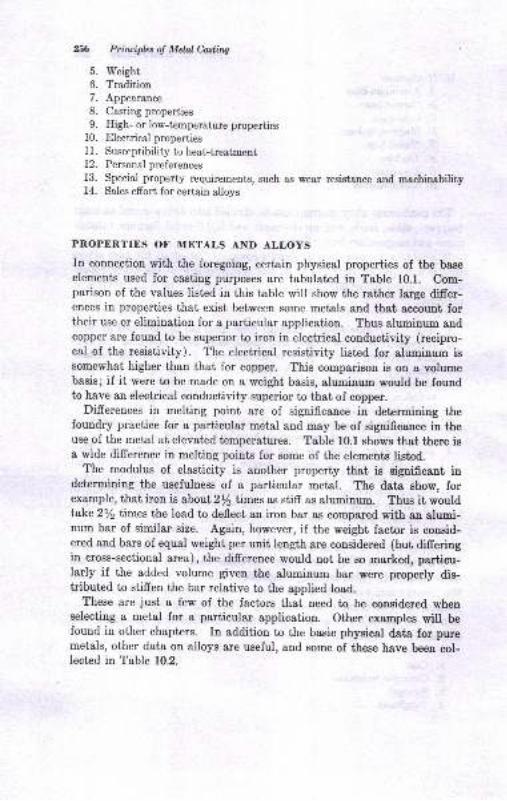
296 Prhaipbs of Metnl &stittg
5. Weight,
6. Tradition7. Appearance
8. Casting properties
9. Eigh- or low-temperature properties10. Electrical properties11. Susceptibility to heat-treatment12. Personalpreferences
13. Special property requirements, such as wear resista,nce and machinability14. Sales effort for certain alloys
PROPERTIES OF METALS AND ALLOYS
In connection with the foregoing, certain physical properties of the baee
elements used for casting purposes are tabulated in Table 10.1. Com-parison of the values listed in this table will show the rather large difier-ences in properties that exist between some metals and that account fortheir use or elimination for a particular application. Thus aluminum andcopper are found to be superior to iron in electrical conductivity (recipro-cal of the resistivity). The electrical resistivity listed for aluminum issomewhat higher than that for copper. This comparison is on I volumebasis; if it were to be made on a weight basis, aluminum would be foundto have an electrical conductivity superior to that of copper.
Differences in melting point are of signiflcance in determining thefoundry practice for a particular metal and may be of eignificance in theuse of the metal at elevated temperatures. Table l0.l shows that there isa wide difrerence in melting points for some of the elements listed.
The modulus of elasticity is another property that is sigaificant indetermining the usefulness of a particular metal. The data show, forexample, that iron is about2/2 times as stiff as gtuminrrm. Thus it wouldtake 212 times the load to deflect an iron bar as compared with an alumi-num bar of similar size. Again, however, if the weight factor is consid-ered and bars of equal weight per unit length are considered (but difieringin cross-sectional area), the difrerence would not be so marked, particu-larly if the added volume given the aluminum bar were properly dis-tributed to stiffen the bar relative to the applied load.
These are just a few of the factors that need to be considered whenselecting a metal for a partieular application. Other examples will befound in other chapters. In addition to the basic physical data for puremetals, other data on alloys are useful, and some of these have been col-lected in Table 10.2.
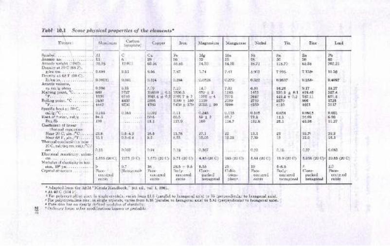
'l'abl I Some physical properties of the elcm,entsr
Element Aluminum Csrbon(grephite) Copper Iron I\Iagnesium Illanganese Nickel Tin Zidc Leod
SymbolAtomicno.,, \Atomic weisht (1947)... -..Denrity ot 20 C (68 F),
g/cu cm. .
DeBity at 68 F (20 C),lb,/cu in..
Atomio volume,cu cm/g atom.
M€lting point,'C. ........'F.......
Boiling point, "C. .........oF.......Specific heat at 20 C,
cal/sfC.Ileet of fueion, cal/g.. .,. . ,
Btu/lb. . .
Coe6cient oI linerthermal expansion:
Ner 20 C, An.fC.. . . ..Ner 68 F, lrn.fF.... . . .
Thermal conductivity near20 C, call(sq cm/cm) /C/a&_. _ -..
Electricsl regirtivity, pohm-cm......
Muiulus of elarticil,y in ten-rion, 10i pai. . .
Crystal structure .
AIl326.98
2.699
0.09751
9.996660122024fi4442
0.2t594.5170
23.6r3.1
0.53
2.655 (20 C)
I[ace-
centeredcubic
c612.011
2,25
0.081
5.333727o74048308730
ilil ,,
0.6-4.30.3-2.4
0.057
1375 (0 c)
0.7
+Iexsgonal.
Cu29
63.54
8.96
0.324
7.091083.0 t O.t1981.4 t 0.225954703
0.09250691.1
16.59.2
0.94
1,673 (20 C)
10
Face-centeredcubic
Fe2655.86
7.87
0.284
7.101536.52797.7 * 2
3000 t 150
5430 t 27t)
0.11b5.5117.9
11.766.53
0.18
9.71 (20 C)
28.5 t 0.5Body-
centoredcubic
Mg12
24.32
L.74
0.0628
14.0
65012t202 x 41110
2026 *.20
o.24689 12160
27.115.05
0.367
4.45 (20 c)
6.35Cloe-
packedheraSonal
Mn2554.93
7.43
0.1 15
o3.7tl4.7
o.270
7.391245
21503900
185 (20 C)
23Cubic
(com-plex).
Ni2868.7r
8.902
o.822
13.37.39
6.591453
264727304950
0.10573.8132.8
o.22
0.t4 (20 c)
30Fsce-
c6ntarodcubio
Sn50I 18.70
7.258
o.26?7
10.20231.9{49.4 :
22704120
0.05414.620.1
t 0.1
t 0.2
23l3
0.16
r1.0 (20 c)
6-6.5Body-
ceni€rodt€tragousl
Xn3065.38
7.138"
0.258.
9.17419.46787.1r9061663
0.091524.O9
43.36
39.7r22.O
o,27
5.s16 (20 c)
d
Cloee-pmkedhexagonal
Pb82207.21
r1.36
0.4097
t4.27s27.4621.417263137
0.0316.26Lt.27
29.316.3
0,083
20.06 (2O c)
2.0Face-
centcrcdcubio
'Adepted from the AgM "Nletals llandbook," 8th ed., vol. 1, 1961.. At 40 C (104 F).5 For polycrystallioe zinc; in eingle cryetals, varies from 61.5 (parallel to hoxogonal axie)
'For polycryltalline zinc; in eiuglo crystals, v&lieE from 6,16 (parallol to hexagonel axis). Pure zinc has no clerly defined modulus of eleoticity.
'Ordir,ary fom; oiber modifications known or prcbabte.
to 15 (perpendicular to bexogonal axis).to 5,89 (perpe.ndiculu to hexagonal axis).
h9
{
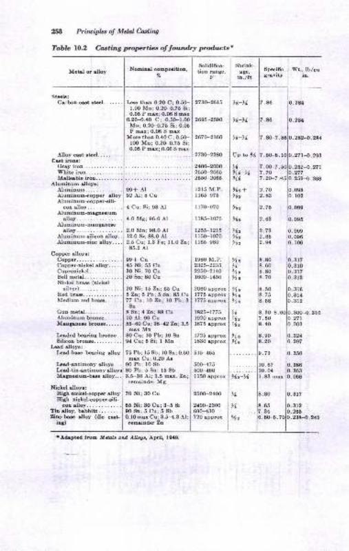
258 Prfiuipb o! Mdal C'adhq
Tabb lO.2 Casting propertiln of toun&y pro&ntst
Mctd or elloy
Alloy crt .tal. .... . . . .
Cst irou:Gny irou,.............Whitc iron.............Mdlqble iron....,.... .
AluEioum dloy!;Aluminum,.,,.........Aluminum<opper dloyAluuirum+opper-cili-
col alloy- .
Alumioum-maSaaiumalloy.....
Alumiauo-manguadloy.....
Alumiaum-ailicol alloy,.Alumiaum-rioc rlloy....
Coppet alloyc:CoDper..,...Copper-nickcl rlloy.....Cupronickal............Bell metsl. .
Nickel bru (nickelsilver)....,... .. -.
Redbrs.,..,......Mediua red btu. . .
I*edod bearing brouc.Silicon broue.,,......
kod dloyr:Irad-bu beuing allov
Nominrl compcitioo,
9e+ Al92 At; 8 Cu
4 Cu; Sir 93 Al
4.0 Ms: 96.0 Al
2.0 Mn: 98.0 Al12.0 Si; 88.0 At2.5 Cu: 1.3 Fe: ll.0 Zn:85.2 Al
99t Cu45 Ni; 55 Cu30 Nil 70 Cu20 Ba; 80 Cu
...1 ZO tti; 15 Zo;65 Cu5 2n; 5 Pb;5 SD;85 Cu
...177 Cu; lO Zn; l0 Pb; 3
IEs thu 0.20 C; 0.5O-l.0O Mn; 0.2G-0.75 Si;0.05 P mar; O.O6I oar
2730-2613
o.2o-0.40 c; 0.5(Fr.0ol zoes-zseoMn; 0.20-{.75 8i; 0.05P mrx: 0.06 8 mar
Moro thro 0.,10 C; 0.50-100 Mn; 0.2O-0.75 Si;
:::i::::1T:T::
267(F2r60
Sotidi6ca-tioD raDge.
F
2730-228IJ
2400-20002550-20652550-2065
1215 M.P.I 165-975
117(F970
r r85-1075
1255-1215I 150-r070r165-980
1980 M.P.2325-22352250-21401600-r450
Guo oetol..... I 8%n; I Za; 88 Cu
2060 opprox1775 epprox1775 appror
r825-t7751920 approx1675 spp.or
I725 approxl8il0 appror
515-465
500-47550(Fr60llSO appror
2500-2400
2{00-23006e0-{30720 approx
Aluminuo broure. .....1 lO Al; 90 CuMusauw broure..... . I SS-tO Cu; 38-42 Zt:3.5
mat M[E0 Cu; 10 Pbl l0 8o0,1 Cu; 5 Si; I Mn
Iad-antimony alloya. . .
75 Pb; 15 8b; l0 8n;max Cu; 0.2O Ao
90 Pb: r0 8b80 Pb; 5 Sn; 15 8bI-d-tiD-utiEony
Magpaiuo-bu alloy, 3.5-10 Al; 3.5 mar. Znlremaiuder M8
Nickel alloyr:7o Ni;30 Cu
65 Ni; 30 Cu; 3-5 8i00 8n;5 Cu; 5 8b0.10 oar Cul3.5-{.3 Al;remdnder Za
lAdrptad tro6 l{d,al. and AUou., April, l9{9.
Wt., lb/cuiu.
.0e9
.098
. 106
Speci6cgr&vity
thrink-age,iD./tt
,(-y
,1-X
tt-N
Vp to ,6
i;-iYt
%
2U
w24.2U
27r{.!93
2524.ytr277259-0.208
.oo-7
.70
.20-7
.40
.65
.34
.6H.
317310317313
.386
.363
.000
10.07r0.041.83 msr
316314
.312
.312
.70
.8:t
-63
.80
.60
.80
.70
.50
.ln
.68
.3(F8.
.50
.40
-90.20
73650,1
t6)l'o-Ytx6
Xt't9b
97t
9lz
9{zl{z9lz
Xo%>\.llc
)lcXcXc
,6V7z
112
XcXc
2652384.2129$
Steb:CiiboBcst!t41...... 7.A6
7.86
7 . 80-7.81
l02
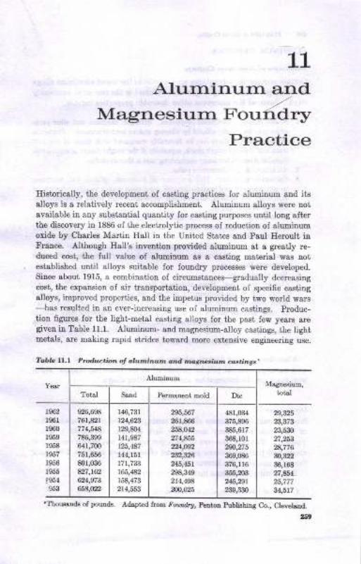
1_1
Alurninurn andMagnesiurn voud6r*y
Practice
Historically, the developmeut of castiug practices for aluminum and itsalloys is a relatively recent sccompliehment. Aluminum alloys were notavailable in aoy substantial quantity for casiing purposee until loug alterthe discovery in 1886 of the electrolytic process of reduciion of aluminumoxide by Charles Martitr Hall in the Uuited States and Paul Heroult inFrance. Although Eall'e i.nvention provided aluminum at a $eatly re-duced coBt, the full value of aluminum as I casting material was aotestabliehed until alloys suitable for loundr5r processes were developed.
Siuce about 1915, s combination of circumstances-gradually decreasing
cost, the expansioD of air traDsportation, development of speciflc castingalloys, improved properties, and the impetus provided by two world wars
-has rezulted in an ever-increasing use of aluminum casiings. Produc-
tiou figures for the light-metal casting alloys for the past few years aregiveu in Table 11.1. Aluminum- and magnesium-alloy castings, the lightmetals, are making rapid strides toward mole exteusive engineering use.
Toble l,..l Ptod;t,c.ion ol olwninun onit ma/rr'alt .tn cdrtin,g'.
{IhouaDds of poutrds. Adspt€d from ioom&r, Pentaa Publiehing Co., Ctevol^(L
159
YearAluminum
Magne6ium,
totslTot&l Sand Permonetrt mold Dio
1962
1961
1060
1959
r958
1957
r956
1955
ls5{953
926,698
761,821
774,54a
786,399
641,7m75r,656
801,036
827,162
624,97A
65A,tzz
r46,731
|u,623lm,8o4r4r,s87125,487
144,r51
tit,733165,482
r58,473
214,553
295,567
261,866
258,042
2? 4,A55
224,@2
232,326
245,451
298,A49
21,1,408
N,025
481,034
375,896
385,617
368,101
2{,275369,086
376,116
355,m3245,291
239,r30
2s32523,473
23,530
27,253
28,776
m32236,168
27,454
25,777
34,517
2fi Principbs of Mdal Cadhg
ALUMINUM CASTINGS
Adoantagct ol Alutninutn Co,stingc
Certain engineering advautages arc inherent in the use of aluminrrc alloysfor castings. Light weight (per unit volume) is the one most commonlycit€d. Some of the numerous other desirabl,: properties include:
t. A wide range ol rnechoni.cal properties. Strength, hardness, and other prop-erties may be greatly altered by alloying andlor heat-treatment. Propertiesof the strongest alloys can be favorably eompared with those of the castirons aod lower-strcngth steels, eepecially if the weight factor is considered.Suitable strength for many engineering uses is thus ava.ilsble.
2. Architectural and decorathte ualuc.3. Conoeimt resistanr.e. This property is, of course, relative, but resista,nce
to atmospheric- and water-corrosion conditions makes possible the use ofaluminum for building constmction, outboard-motor parts, food-handling-equipment castings, etc.
4. Nontoxicitg. The use of aluminlm castings for cooking utensils and otherfood-handling equipment requires that no chemical-reaction products toxicto humans be formed by action of the food on the aluminum alloy.
5. Elcctriral con&rctivitg. Botor bars in induction motors are cast of alumi-num becsuse of its desirable electrical conductivity. See F8. 8.16, whichillustrates this point.
6. Ease of machining.7. Casting properti.es. Since aluminum has a relatively low melting point,
about 1200 F, the problems of melting and pouring are greatly simplifredwhen compared with steels and cast irons. Pennanent metal molds maybe used, and die casting is extensively practiced. problems with fumacerefractories and molding sands are rcduced because of the lower pouringtemperatures.
8. Lawer cutin4 shippin4 coats per piacc.
A number of other factors relating to the characteristics of aluminumas I castings material will be considered in the following chapter, alongwith more specific information about the casting alloys.
IitnitttbnsSince the cost of aluminum alloys in cents per pound is great€r than thatof cast irons and many Bteels, this fact is oftrcn considered a disad-vantage. However, the cost in cents iler pound is misleading unless it isrecogpized that the volume per poun{- sf sluniarrm is about 2.g0 timesthat of a pound of the ferrous alloys.
Engineering limitations include the following:
1. Lack of resistance to abrasion and wear.
Alwnirun ond Magncsiun Foardry Prulbe 26'l
2. Absence of aluminu.n alloys which can develop the combination of high
tensile strength, toughness, and irardrress obtainable in ferrous alloys'
3. Lack of resistance to severe corrosion to the degree ofiered by numerous
copper- and nickel-base alloys and stainless steels'
Obviously, the selection of aluminum as a castings materiai demalds
that its advantsges outweigh its limitations in any perticular applicatiou.
As in the production of other casiings, the basic processes of molding,
coring, melting, and cleaniug are necessary' These processes, however,
must be mod.ified in aluminum founding to suit the metallurgical proper-
ties characteristic of the alloY.
MELTING UF ALUMINUM
One of the most easily controlled processes, although frequently over-
looked in importance, is melting. certain casting problems are directly
related to failure to exercise adequate control during the melting process.
These problems will be discussed in terms specifically related to the melt-
ing of aluminum, but the reader should recognize that there is a more
extensive application of the principles to other metals.
Melting Furno,ces
The type! of melting furnaces2 employed in e,luminum foundries include
the following:
1. Crucible furnaces, lift-out type
2. Pot furnaces
a. Stationary, fuel-fired
6. Tilting, fuel-ired3. Reverberatory furnaces, fuel-fired, stationary, and tilting types
4. Barrel.-type furnaces, fuel-fi red
5. Induction furnaces, electrically operated
o. Low frequency
6. Iligh.frequency
Each of these furnaces has certain advantages. Fuel-fired furnaces are
of trvo types: the indirect-flame type, in which the products of combus-
tion do not come into direct contact with the metal, and the direct-flarue
type, in which there is direct contact of the eombustion products and metrl
charge. Pot furnaces are usually indirect-flame or electrical-resistance
furnaces whereas reverberatory furnaces are direct-flami furnaces. How-
ever, some constructions of pot and crucible furnaces approach the direct-
flame conditions.
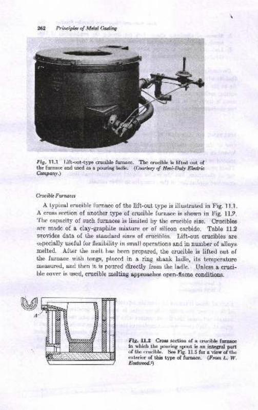
Prirciplcs o! Melal Cuting
fig. ll.l Lift{ut-type crucible furnace. The crucible is lifted out ofthe furnace and used as a pourirg ladte. (Courlzsy of Heoi-Dul.y Ebdrichmpany.)
Cruai.blc FtDna&s
A typical crucible furnace of the lift-out type is illustrated in Fig. 11.1.
A cross section of another type of crucible furnace is shown in Fig. 11.2.
The capacity of such furuaces is limited by the crucible size. Crucibleeare made of a clay-graphite mixture or of silicon carbide. Table 11.2provides data of the standard sizes of crucibles. Lift-out crucibles areespecially useful for flexibility in small operations and in number of alloysmelted. After the melt has been prepared, the crucible is lifted out ofthe furnace with tongs, placed in a ring shank ladle, its temperaturemeasured, and then it is poured directly from the ladle. Uuless I cruci-ble cover is used, crucible melting approsches open-flame conditions.
fig. ll.2 Croes section of a crucibh furuacein which the pouring epout is an intcgrul pattof the crucible. See Fig. 11.5 for a view of theexterior of this type of furoace. (Fron L. W.Eartud:)
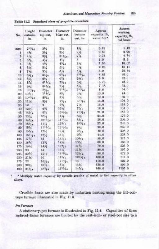
Tabb lI^.2 Stoindllrd cizes of gtaphitt cnwibbs
Alwnirum ail Mqwium Fourdry Practicc
Eeightoutside,
in.
Diametertop out,
in.
Dirmeterbilge out,
in.
2r.6
3NSrXa416
4%.a
6%5%6%e6%7%a7N7r%a8%8%95lae%
rot6lorXatt16lltXat2%al2t l(a1316
r3r4vlTaL4'%
r52{at6t416121 a
1791 a
t7r34ut8>4t9rxe
Diameterbottomout, in.
t%2%2%3
3t63%4%4r%.0
sXe5>1
616
5r%.a
6t(6N6rBz{a
7r(7%.a
7t%.a8%8%.a
8r5:1e
sN9sr{a
s%ro%ar0%tLxLL71
l2%.el2rXal3t3%l4%.s
Approxcapecity, lb,
water full'
0.250.500.751.0,.502.253.04.815.05.757. 18
8.6r0.012.o14.016.018.02t.024.028.032.036.040.044.050.060.070.080.090.0
100.0
110 .0120. 0
r60.0
Approx
workingcopacity, lb,
red brass
1. l92.904.748.5
10.0715.41
20.7436.042.O
48.053.064.074.089.0
104. 0
1r9.0134. 0
157.0r79.0209.0239.0269.0
298.0
328.0373.4468.0
523.0597 .0672.O
747.O
822.0
896.01195.0
00m1
2
34
68
l0t2l416
l820
25
30
35
40
45
50
60
70g)90
r00125
150
175
2(n225
250
275
300
400
2t%.a3%4N6%5%6N716
8Xa8N8%e%9r%e
tol{.aLOr%a
rtNt2rzvl33Aa
t3%t4%.e
lSXat5%l6sAa
l6tXet7%18%
ts%20
20%2191
22
22N2454a
2%
3%
!Ye,
4%4%
6r/,5%6Xa6%6rrz{a
6rg(a7%eTrXa83rla
8%Is%e%
to%lor%.att%LILXa12t6
t2Nl3t3%t41615
15t'16
16%.a
t674r8%.e
'Multiply water capacity by specifrc gravity of metal to 6nd capacity in other
alloys.
Crucible heats are also made by iuduction heating using the liftcoil-type furnace illustrated in Fig. 11.3.
PolFwruaes
A stationary-pot furnace is illustrat€d in Fig. 11.4. Capacities of these
indirect-flame furnaces are limited by the cast-iron- or Bteel-pot size to a
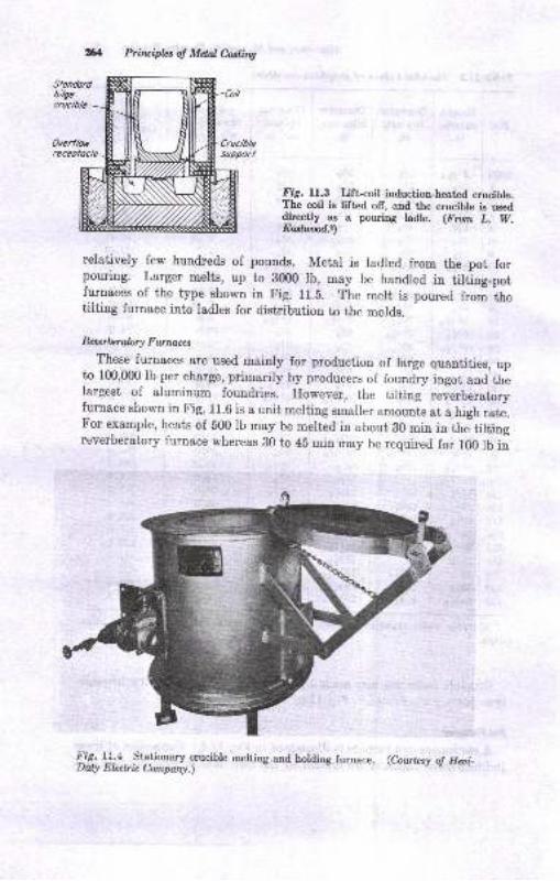
2G Prirciplzs o! Mdal Casting
^Fig. lI.3 Lift-coil induction-heated crucible.The coil is [fted ol[, and the crucible is useddirectly as a pouring ladle. (Fron L. W.Eatfu:ad.r)
relatively few hundreds of pouuds. Metal is ladled from the pot forpouring. Larger melts, up to BOm lb, may be handled in tilting_potfurnaces of the type shown in Fig. 11.5. The mert is poured trom itretilting furnace into ladles for distribution to the molds.
Reurbtal,ory Fwnaes
These furnaces are used mainly for production of large quantities, upto 100,000 lb per charge, primarily by producers of foundry ingot and thelargest of aluminum foundries. rrowever, the tilting revlrberatoryfurnace shown in Fig. 11.6 is a unit merting smailer amounts at a high rate.For example, heats of 800 lb may be melted in about B0 min in theltiltingreverberatory furnace whereas B0 to 4b min may be required for lfi) lb in
,:'r4 l]:{ fqtionary crucible melting.and holding furnace . (Cowtzsy o! Hai_Duly Ebclric Company.)
----*
?t:;Y
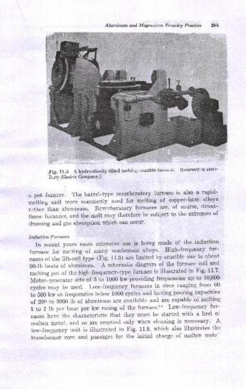
Altuilnwn arl lllognesium ?o4nflry Pradbe
Fie. ll.5 A hydraulically tilted melti45 ur'rcible l-uiua3e' \t;otl usy oJ rTeol'
\t Jv El,eclr ic ComPanY.)
& pot iurrace. The barrel-type reverberatony furnace is also a rapid-
,r"ltirrg unit more cornmonly- used for melting ol copper-base alloys
ratherlhan aluminum. Reverberatory furnaces are, of course, direct-
llamefurnaces,andthemeltmaythereforebesubjecttotheextremesofdrossing and gas absorption which can occur'
Ind.urtian Furnaces
In recent years more extensive use is being made of the induction
furnace for melting of many nonferrous alloys' Iligh-frequency .fur-naces of the lifl-coil type (Fig. 11.3) are limited by crucible size to.about
g0-lb heats of aluminum. ischematic diagram of the furnace coil and
melting pot of the high-frequency-type furnace is illustrated in Fig' 11'7'
14o6.Ig..r..utor sets of 5 6 1000 kw providing frequencies up to 10'fiX)
cycl", muy be used. Low-{requency furnaces in sizes ranging from 60
to soo t * at frequencies below 1000 cycles and having pouring capacities
of 20n to 5000 lb of aluminum are available and are capable of melting
5 to 7 lb per hour per kw rating of the furnace'" Low-frequency fur-
naces have the characteristic that they must be started with a heel oi
molten metal, and so are emptied only when cleaning is necessary' A
low-frequency unit is illustrated in Fig. 11'8, which also illustrates th'r
transformer core and passages for the initial charge of molten mets'
-L-Eii.14
%t
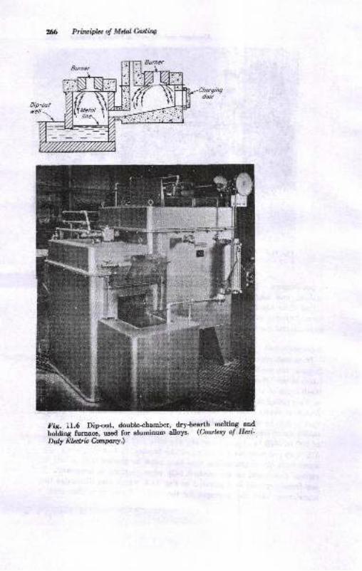
Prfiuiplct d Mdal M.ing
Fig. il.6 Dipout, double-chamber, dry-hearth peltiry--aufhoiding furnac;, us€d for alumiuum alloys. (Courtesy of Hai'Duty Eb*ir CompanY.)
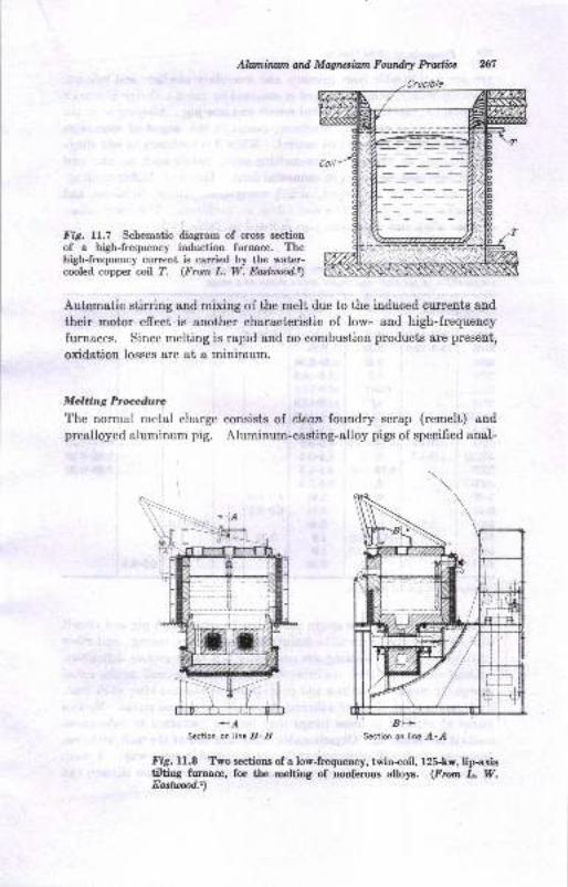
Ahvniruvn arl Mqruiiwn Fourdry Praalicc
Fig. lI-.7 Scbematic diagram of crms gection
of a high-frequency induction furnace. Thehigh-frequency cunent is carried by tbe water-cooled copper coil ?. (From L. W. Easttd.,)
Automatic stirring and mixing of the melt due to the induced currents and
their motor effect is another characteristic of low- and high-frequency
furnaces. Since melting is rapid and no combustion products are present,
oxidation losses are at a minimum.
Melting Procedure
The normal metal charge consists of clean foundry scrap (remelt) and
prealloyed aluminum pig. Aluminum-casting-alloy pigs of specified anal-
Fig. U.8 Two sections of a low-freguency, twin-coil, 125-kw, lip-axietiltiug furnace, for tbe melting of nouferous alloys. (From L. W.Eostud.')
+,4Seciion on line B-B Seciion on liae A-A
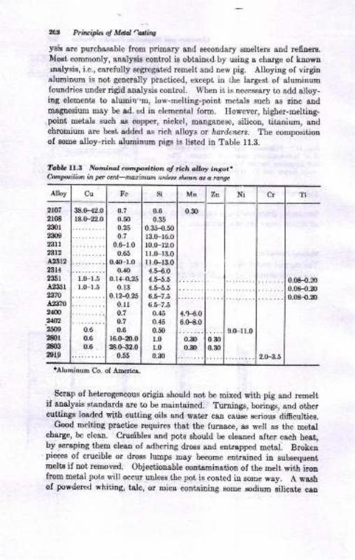
,61 &irvid.5 q Menl "adine
y8h are purchss8ble lroxo prirnary aud secoDdary smelterg and re6!era.Moat commonly, aualyais controt is obtained.by usiug a charge of knownualysie, i.e., carefully segregated remelt snd new pig. Alloying of virginalumiDum is not generally practiced, except in the largest of aluminumfoundriee under rigid analysie control. When it is necessary to add slloy-ing elemente to alumirl'.m, low-melting-point metols such as zinc audmaguesium may be ad. ed in elemeotal form. However, higher-melting-point metals euch as copper, oickel, manganese, silicon, titanium, andchromium are best add€d as rich alloys ot hard.nals. The compositiouof some alloy-rich sluuinum pigs is listed iu Table 11.3.
Tdc ll.t Nor'.il[. l c,.,'p'lritio,n of r',a'h o o! in3o..Conptilion ia pcr ca
-tuEimurn unLr, tl,,,/,, ot a r&g.
Alloy Cu Fe si Mn Zn Cr Ti
0.08-{.9)0.08-0.20
0.08-o.20
2lo72toE
mlm23lrnt2AA122314
236r4235r23,70
a%i702N24U2
2W2801
2dxl2erg
38.H2.0
::*"1
1.(F1.5
t.0-1.5
0.70.50
0.25
0.7
0.6-1.0
0.65
0.ro-1.00.40
0.14-{250.13
0.124.0.ll0.7
o.7
0.6r6.F20.028.0-32.0
0.55
0.6
0.35
0.35-O,50
13.0-16.0
t0.(F12.0rr.(F13.0I l.o-13.04.5-€.O
{.5-5.64.5-5.5
4.6-7.56.5-7.5
0.45
0.45
0.60
1.0
1.0
0.30
0.m
0m0.30
2.(F3.5
0.6
0.6
0.8
4.H.06.(H.0
0.30
0.30
9.(F1r.0
'AJumiaum 'Co. ol Amrica"
. Scrap of heterogeneous origin should not b€ mixed with pig aud remelt,if analysis standards are to b€ maiDtained. Turnings, borings, and othercuttings losded vith cuttilg oils atrd wster caD cause serious .di6cultiee.
Good melting practice requires that the furnsce, as vell as the metalcharge, be clean. Cruolbles and pots should be cleaned slt€r esch he8t,by aoraping them clean of adhering dross 8Dd entrspped metal. Brokenpiecee of cmcible or drose lumps may become entraiued in subsequentmelts if not remoyed. Objectionable coutaminatiou of the melt with ironfrom metal pots will occur uuless the pot ie coated in some way. A washof powdered whiting, telc, or mica containing some sodiuu silicate can
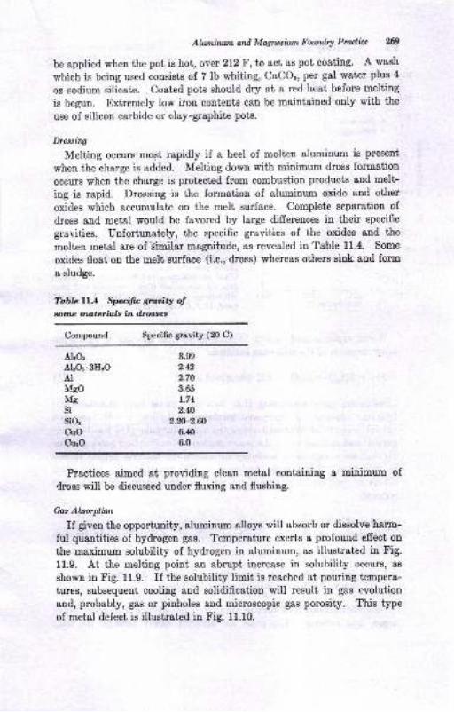
Alaninwn ard Ma4twirtttr Fourdry Prulicc 2n9
be applied when the pot is hot, oYet 212 F, to act as pot costing. A wash
which is being used consists of 7lb whiting, CaCOr, per gal water plus 4
oz sodium silicate. Coated pots should dry at a red hcat before melting
is begun. Extremely low iron contents can be maintained only with the
use of silicon carbide or clay-graphite pots.
Droo,sin4
Melting occurs most rapidly if a heel of molten aluminum is present
when the charge is added. Melting down with minimum dross formation
occurs when the charge is protected from combustion products and melt-
ing is rapid. Drossing is the formation of aluminum oxide and other
oxides which accumulate on the melt surface. Complete separation of
dross and metal would be favored by large differences in their specific
gravities. Unfqrtunately, the specific gravities of the oxides and the
molten metal are of Bimilar maguitude, as revealed in Table 11.4. Some
oxides float on the melt surfece (i.e., dross) whereas others sink and form
a sludge.
Tabte lil'.4 Speific gruoity ofsotna mttefials in drosrc,s
Compound Specific gravity (20 C)
ALO:Alror.SHrOAIMsoMgsisio:CUO
CurO
3.90
2.42.70
3.65
1.74
2.q2.m-2.ffi
6.40
6.0
Practices aimed at providing clean metal containing a minimum of
dross will be discussed under fluxing and flushiug.
Cas Akorplion
If given the opportunity, aluminum alloys will absorb or dissolve harm-
ful quantities of hydrogen gas. Temperature exerts a profound effect on
the maximum solubility of hydrogen in aluminum, as illustrated in Fig.
11.9. At the melting point an abrupt increase in solubility occurs,, as
shown in Fig. 11.9. If the solubility limit is reached at pouring tempera-
tures, subsequent cooling and solidification will result in gas evolution
and, probably, gas or pinholes and microscopic gas porosity. This type
of metal defect is illustrated in Fig. 11.10.
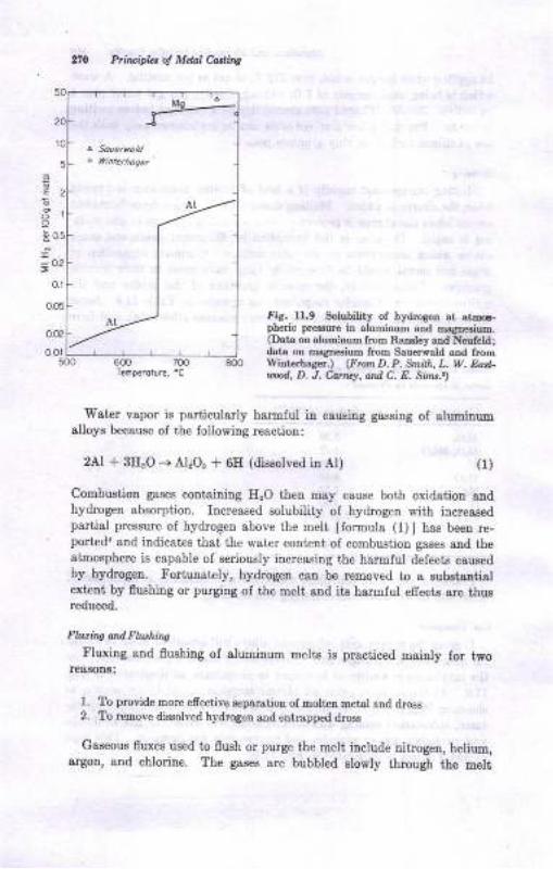
6
E
Principbt oJ Mclal Cortha
fig. rI.9 Soiubility of hydmgen at atm6-pheric pr€ssur€ in aluminum ard magnesium.(Data oo alumiDum from Baosley a-od Neufeldldats oo magresium from Sauerwald and ftomWint€rba8er.) (Ftun D. P. Smith, L, W. Eort-uad, D. J. Cartcr, and C. E. Sins.)
'Water vapor is particularly harmlul in cauEing gassiDg of aluminunalloys because ol the following reaction:
2At * 8H'O -+ Al"O3 + 6E (dissolved h Al) (t)
Combustion gaees containing EzO then dsy csua€ both oxidation andhydrogen absorption. Increased sotubility of hydrogen with iacreaeedpartial pressure of hydrogeD above the melt [formula (1) ] has been re-porteda aad iudicat€s thai the wat€r coutent of coDbustion gases aud theatuosphere is capable of oeriously increasing the harmful defects causedby hydmgen. Fortunately, hydrcgeu can be removed to a eubstsntialextcnt by flushing or purging ol the melt 8nd it8 harElul effecte are thusreduced.
Fhuitts o'd Ftushins
Fluriag aud flushiug of alumiouu melts iB prsciiced maiuly for twoBeSAODa:
To provide more efrective sepsr&tion of moltetr metel end drcssTo remove dissolved hydrogen and entrapped dross
1.
Gaseous fluxes used to flush or purge the melt include nitroget, helium,argon, and chlorine. The ga6es sre bubbled slowly through the melt
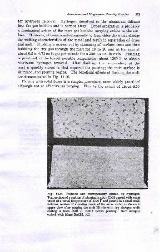
Aluminan ad Mryteiun Foudra Protliu nlfor hydrogen removal. Hydrogen disgolved in the ah,minum diffusesinto the gas bubbles and is carried away. Dross separation is probablya mechanical action of the inert gas bubbles carrying oxides to the sur-face. However, chlorine reacts chemically to form chlorides which changethe wetting characteristics of the metal and result in separatiou of dross
and melt. Flushing is carried out by skimming off surfqce drose and thenbubbling the dry gas through the melt for 10 to 20 min at the rate ofabout 0.5 to 0.75 cu ft gas per minute for a 300- to 400Jb melt. Flushingis practiced at the lowest possible temperature, about 1250 F, to obtainmaximum hydrogen removal. After fluehing, the temperature of themelt is quickly raised to that required for pouring; the melt surface isskimmed, and pouring begins. The beneficial effects of flushing the meltare demonstrated in Fig. 11.10.
Fluxing with solid fluxes is a simpler procedure, more widely praotieedalthough not so effective as purging. Flux to the extent of about 0.10
t t,"' g
*'r g' t +'i' \.r
{*&"rt
f-:
. ."ll.>
t"*' ;''
\,*
i.r
't
lr
'r
\rt+
,t,* c,!
(sl,I
ertt
illl
t
Fig. ll.l0 Pinboloe a-nd micf,opormty caused Dy oyorlgpn.Top, section of a castiog of aluminum alloy CS4l! gaased with watcrvapor at a metal temperature of 15fi) F aud poured in a sand mold.Bottom, gection of a casting made of the eame metal as slrowtr inupper view after purging the melt 15 min with dry nitrogen whilecooling it from 15fi) to 1300 F before pouring. Botb samplesetched with dilute NaOH, X2.
1.
2.
3.
n2 Plrruiplet o! Mdnl Costing
lb per lfi) lb of metal is added to the melt by forcing it to the bottom ofthe bath in a perforated container. Aluminurn and zinc chlorides, as wellas a number of proprietary compositions containing these compounds, are
used as solid fluxes. Solid fluxes serve to facilitate separation of themetal and oxides through their chemical action.
Grain Refining
Several procedures have been discovered which will cause a minimtrmgrain size to be developed during freezing of the casting. These methodsinclude:
Chill casting, as in metal molds
Temperature adjustmentLate additions to the melt!
Rapid solidification, of course, c&uses a smaller grain size in all cas,,ingalloys. Boron, titanium, chromium, columbium, and sodium may be usedas grain-reflning additions to the melt shortly before pouring. It hasbeeu pointed out thet pouring at the lowest possible pouring temperatureaids in obtaining a fine-grained casting.
Portring Temperalu.re
When the melt has been properly prepared, a final checking of temper.r-ture for pouring is essential. Immersion thermocouples consisting of No.8 gauge asbestos-covered chromel-alumel wire are suitable for this meas-urement. The bare couple is satisfactory for rapid temperature measure-ment. A pouring temperature of l2b0 to 1400 F may be employed, de-peuding on casting size, alloy composition, and a number of other factors.selection of the proper temperature is essential to producing the mostdesirable eastings.
Melting Procedures-- Sulrr maty
Aluminum melting practices aimed at producing the most favorable re-sults may include the following measures:
l. Start with clean materials of known analysis.2. Use clean melting practice.3. Keep temperature of melt low until pouring is imruinent.4. Use a minimunr holding time in the molten condition.5. Avoid water vapor or hydrogen-Searing gases whenever possible.6. Do not agitate or stir melt more than is absolutely necessary.7. Use adequate flushing or fluxing practices.8. Skim only when ready to pour.
Ahnnirwn atd Mag.lr,iwn Fowdry Practicc tl|9. Avoid turbulence when pouring the molten aluminum to minimize drocsing
and hydrogen pickup.10. Use a proper pouring temperature and pouring praatice.
The nature of aluminum is such that excessive turbulence and sloppyand erratic pouring csn ruin an otherwise properly prepared melt.
MOLDING FOR ALUMINUM CASTING
Ah,minum alloys can be cast by any of the commonly used processes:Band casting, plaster molding, permanent mold, and die casting. Becauseof the low pouring temperature and specific $avity of alrrminum alloys,molds are less affected by heat than in the case of iron and steel. Conse-quently, excellent surface finish and dimensional accuracy may be ob-tained even in large sand castings. The minimum section thickness foraluminum castings produced by the commonly used processes is illustratedin Table 11.5. Sand castings weighing several tons have been made.Permanent-mold castings weighing 650 lb and die castings up to Z0 lbsre in use.
An important effect of the casting process used for aluminum alloysis its influence on the properbies of the metal. One author6 gives thefigures in Table 11.6 to illustrate the effect of casting method on themechanical properties of AI-Cu-Si and Al-Si alloys.
Undoubtedly, the rapid chilling of the metal mold, and in the case ofdie casting, the effect of casting under pressure, produces the improvedproperties' Data for the effect of casting process on the mechanicalproperties of specific alloys will be considered in the next chapter. At thispoint, however, it should be recognized that mere chemical specificationof a certain alloy is no guarantee of mechanical proper.ties. castingprocess, casting design, melting practice, and the complete history offoundry processing must be considered. In spite of the improved me-chanieal properties obtained with metal molds, sand casting remains as amajor process because of its inhereut qdvantages. A comparison ofannual production by the three processes can be obtained from Table ll.l.
fund &ating
casting in molds made by any of the usual sand-molding processes ispracticed with aluminum alloys. Green-saud molding with conventioualmolding equipment is used to the greatest extent, although dry-sand moldsare preferred where large or intricate work is involved. Lo* sq.r"ezepressures, 20 to 30 psi, are used in machine molding, since a high moldhardness is not required as a rule.
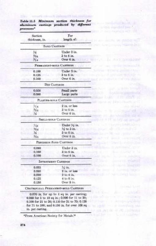
TablG ll.5 Mirn nLmoht,,,,i',,um car.ing,
,P'ctio, tlnct rla,, lotp.&,.cd W .fifr.r. t
SectioD
tbickne6s, iD"
ForleDgth of:
s^MD C^smNog
t6112
%o
Utrder 3 itr.
3to6in.Ov6r 6 in.
PEsx,rxENr.roLD Casrnlca
0.lm0.125p.r60
Under 3 iD-
StoOin"Over 6 iD.
DrE CasrrNcs
0.050
0.08{)
Small pa s
Iarge psrtg
Pr,es, En-Mor,l ClrsnNcs
llo96,t
t<
2 iD- or le€g
3to6ia.Over 6 in.
SEELr-MoLD C^smNos
)1allz,6962
Uder ,, iD-
ti ttt 3 i.n-
3to6iD.Over 6 in-
PEEcrsroN S^ND C^smNcs
0.080
0.100
0.100
UDder 3 in.
3to6iD-Over 6 ir
Il.YEsrvENT CasrrNos
0.035
0.060
0.090
0.r250.r50
>4. io-2 iu. or l€6s
2to4iD-4to8in-Over 8 in.
Cprrnrruo,rr, PenurxENT-MoLD C,r.srrNos
0.070 in. for up to 4 Bq iD- per crating;
0.080 for 5 to I0 sq iE.; 0.000 for I I to 20;
o.lm Ior 2l to 30; 0.110 for 3l to 70; 0.1mfo! 7l to 100; strd 0.156 h. for ove! lm 3q
h. per castiDg.
'From American Society for Metsb.!'
ttl
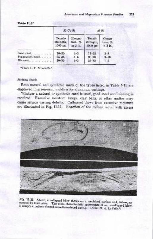
Tabb ll.6'
tFrom L. F. Mondolfo..
Teneile I Elonga- | Tensileatrength, I lioo,, Vo I etrength,rmo psi J in 2 iq. I rmO psi
m-25 I 1-3 lt7-25?,6-35 l 1-5 ln-2a30-351 l-3 125-32
Ailuninwn ard Mqrctilun Fow&l Prulicc
Elonge-lion, /sin 2 io..
Sand cast.Permanent mold. .. .....Die ca.st.
3-83-10l-5
Molding &nds
Both natural and synthetic sands of the types list€d in Table b.ll areemployed in green-sand molding for aluminum castings.
Whether a natural or synthetic sBnd is used, good sand conditioning isrequired. Excessive moisture, lumps, clay balls, or other matter msycause serious casting defects. Collapsed blows from excessive moistureare illustrated in Fig. 11.U. Reaction of the molten metal with excesa
FiS. U.ll Above, a collamed blow ehown ou a machined surfaoe and, below, aa
I,tffi l}ltm*'sft ";;;h;;#i,,;i#XH;.i*#[#f,;;:f Xi"T
AI-Cu-Si At-si
,?.
t' ."
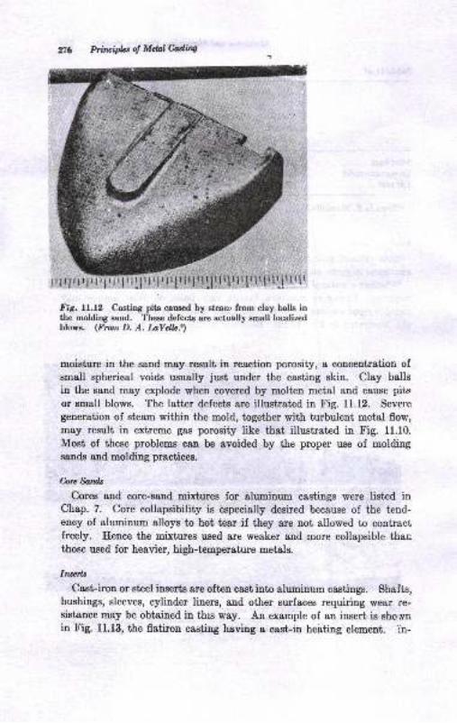
Princifu o! Mdolfuing
.f';9. U.l2 Castirg pits caused by steanr from clay balls inthe molding sand. These defects are actually gmall localizedblows. (Fmm D. A. LaYellc.')
moisture in the sand may result in reaction porosity, B concentration ofsmall spherical voids usually just under the casting skin. Clay balls
in the sand may explode when covered by molten metal and cause pits
or Bmall blows. The latter defects are illustrated in Fig. 11.12. Sevele
geDeration of steam within the mold, together with turbulent metal flow,
may result in extreme gas porosity like that illustrated in Fig. 11.10.
Most of these problems can be avoided by the proper use of moldingsands and molding practices.
hre&nfu
Cores and core-sand mixtures for aluminum castings were listed inChap. 7. Core collapsibility is especially desired because of the tend-ency of aluminum alloys to hot tear if they are not allowed to contractfreely. Hence the mixtures used are weaker and more collapsible thar:those used for heavier, high-temperature metals.
Iwerlt
Cast-iron or stcel inserts are oftpn cast into aluminum castings. Shafts,bushiugs, sleeves, cylinder liners, and other surfaces requiring lrear re-sistance mey be obtained in this way. An example of an insert is sho.ryn
in Fig. 11.13, the flatiron casting having I cast-in heating element. in-
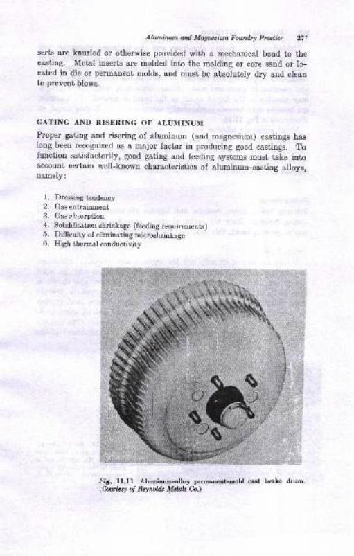
Alunirurmard Mqusiwt Fowdry Prlclice nlserts are kaurled or otherwise provided with a mechanical bond to thecasting. Metal inserts are molded into the moldiug or core sand or lc-catred in die or pemancnt molds, and must be absolutely dry aud cleanto prevent blows.
GATING AND RISERING OF ALUMINUM
Proper gating and risering of aluminum (and magnesium) castings haslong been recognized as a major factor in producing good castings. Tofunction satisfactorily, good gating and feeding systems must take intoaccount certain well-known characteristics of aluminum-casting alloys,namely:
1. Drossing tendency
2. Qn5 sltlsinmsal3. Gas eh.;orption4. Solidrfication shrinkage (feeding reqr,rirements)
5. Difhculty of eliminating mieroshrinkage6. High thermal conductivity
^{'dt. ll.ll Aluminum-alloy peruaneat-mold cast brale drum.
\CutLs! oj RqrcUs Mdals h.)
i$
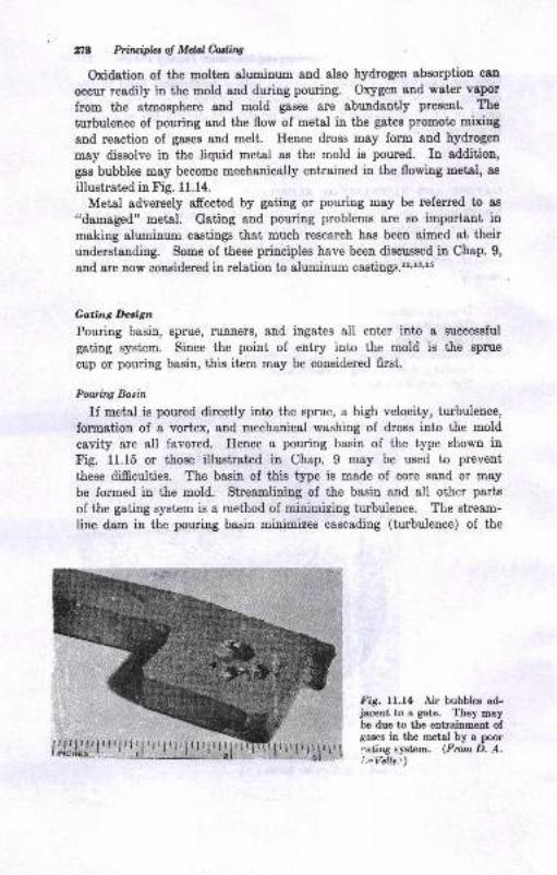
ng Priruifuol MdalMrrw
Oxidetiou of the molten aluminum and aleo hydrogen absorption can
occur readily in the mold and during pouring. Orygen and water vapor
from the atmosphere and mold gasee are abundantly present. The
turbulence of pouring and the flow of metal in the gates promote mixing
and reaction of gases and melt. Heuce dross may form aad hydrogen
may dissolve in the liquid metal as the mold is poured. In addition,
gas bubbles may become mechanically entrained in the flowing metal, as
illustrated in Fig. 11.14.
Metal adversely affected by gating or pouring may be referred to as
"damafied" metal. Gating and pouriug problems are so important inmaking aluminum castings that much research has been aimed at their
uuderstanding. Some of these principles have been discussed in Chap. 9,
and are now considered in relation to aluminum castings.r2'1s,r5
Gating Decign
Pouring basin, sprue, runners, and ingates all enter into a successful
gating system. Since the point of entry into the mold is the sprue
cup or pouring basin, this item may be considered first.
Pourhg Bacin
If meLd is poured directly into the sprue, a high velocity, turbulence,
formation of a vortex, and mechanical washing oI dross into the mold
cavity are all favored. Hence a pouring basin of the type shown inFig. 11.15 or those illuetrat€d in Chap. 9 may be used to prevent
these diffculties. The basin of this type is made of core sand or may
be formed in the mold. Streamlining of the basin and all other parts
of the gating system is a method of minimizing turbulence. The stream-
line dam in the pouring basin minimizes cascading (turbulence) of the
Iig. 11.14 Air bubbles ad-jacent to a gate. They maybe due to the entrainment oIgases in the metal by a poor.ating system. (From D. A.i n Velle:)
b=-
3'i ;-!
*
lil'l.iiiri::, 3\/,'JJiJl', I' I' l',l_u' I' I, |, I | [ll,l-
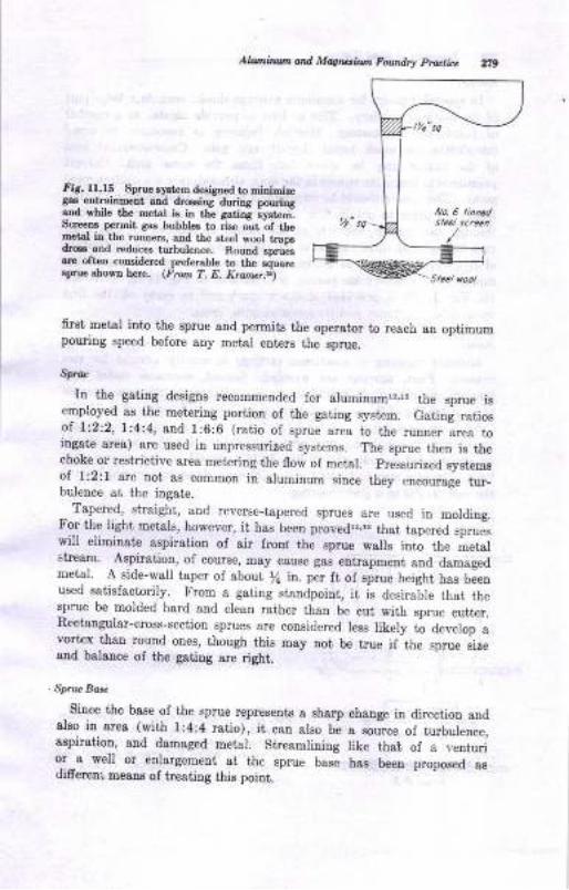
Fi8. lI.I5 Sprue syst"m designed to midmirega8- edratnm€Dt aDd drcsiDg duriq pouringarrd wbile the netal b itr th€ sariDa ;yshm.ScreeD8 permit gaa bubbles to rise out of lbemetal ia rlte runners, and t-be steel wool tlap6drcs and reduces rurhul€nce. Round sDru€sar€ oftcn coDsidered preferable to the squeeBprue sbowo h€re. (Fron T. E. Kratw.n)
6rst Fetsl into the sprue 8nd permito the operator to re&ch aD optimumpouriDg speed before any metal eDter8 the spue,
Sp.c
In the gating designs recommended for slumitrurorr,l5 the sprue isemploJed 8s the met€riug portion of the gating systrcm. Gating ratiosol Li2t2, l:4.4, and 1:6:6 (ratio of sprue area to the runner
-area to
ingat€ area) are used in unpressurized systems. The eprue then is thechoke-or reetrictive area metering the flow of metal. pressurized systemsol l:2:l are trot as commotr in aluminum siuce they ur"o*"{" fu"_bulence at the iugate.
_ Tapered, straight, aud reverse-tapered sprues are used in molding.Fo-r the light metals, however, it h8s been provedlz,rs that tap"rea
"frue"will elimiuate aspiratio! ol air frod the sprue walls into the metslstream. AsliratioD, of course, may cause gas entrapmeli and daEagedmetal. A side-wall taper of about /a in. per ft of sprue height hae beeuused eatisfactorily. tr'rom s gating standpoint, it is desirable that thesprue be molded hard and clean rather than be cut with sprue cutter.Rectangular-cross-section sprues are considered lees likely to develop avortex tbau round ones, ihough this may not be true if the ,p*u
"irusud balance of the gatiug are right
S,,,uc Bo*
. Since the base of the sprue repreEeDis a eharp change in direction and
alao in- area (witl l:4;4 ratio), it c8u also be a source of turbuleuce,aspirstioD, aud damaged metal. Streamliaing like that of a yenturio-r--a well or etrlargemeDt at the Eprue base hae been propoeed eadifiereni meaDs oI trestilg this poilt.
Ah,,tjtutm aad Mqrutin Founnry prutice ng
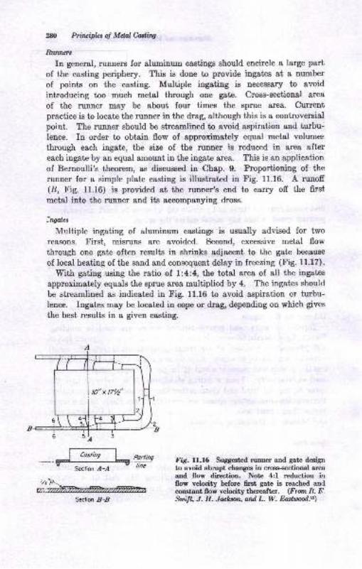
2N Prircifua of Mdql hdinl
Runtuts
In general, runners for aluminum castings should encircle a large part
of the casting periphery. This is done to provide ingates at a number
of points on the casting. Multiple ingating is necessary to a'roid
introducing too much metal through one gate. Cross-sectional area
of the runner may be about four times the sprue area. Curentpractice is to locate the runner in the drag, although this is a controversial
point. The runner should be streamlined to avoid aspiration and turbu-lence. In order to obtain flow of approximately equal metal volumes
through each ingate, the size of the rurner is reduced in area aftereach ingate by an equal amount in the ingate area. This is an application
of Bernoulli's theorem, as discussed in Chap. 9. Proportioning of the
runner for a simple plate casting is illustrated in Fig. 11.16. A runoff(8, Fig. 11.16) is provided at the runner's end to carry off the first
metal into the runner and its accompanying dross.
Ingales
Mrrltiple ingating of aluminum castings is uzually advised for two
reasons. First, misruns are avoided. Second, excessive metal flow
through one gate often results in shri.ks adjacent to the gate because
of local heating of the sand and consequent delay in freezing (Fie. f 1.17).
With eating using the ratio of 1;4;4, lhe total area of all the ingates
approximately equals the sprue area multiplied by 4. The ingates should
be streamlined as indicated in Fig. 11.16 to avoid aspiration or turbu-lence. Ingates may be located in cope or drag, depending on which gives
the best results iu a given casting.
P!!!!!sline
Fig. ll.16 Sugg€st€d runner and gate designto avoid abrupt changes in croes-sectional ar€aand flow directioo. Note 4:l reduction iuIIow velocity before ffrst gate is reached andconstant flow vclocity thereaflcr. (From R. triSwift" J. H. Jachson, ond L. W. Eashnod.r2)
Section l-,{
Section .B-,
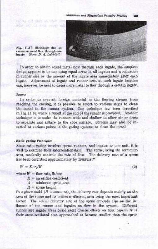
Ahtmirunatd Mqrcthun Fowdn prvr:ti.c
Fig. ll.l7 Shrinkage due toexcessive metal flow througb oneingate. (From D. A. LaVelb.l)
In order to obtain equal mer,sr trow tirougb,each iDgste, the'sinpicstdesign appears to be one using equal aress in all ingates and I reductioniu runner size by the amount of the ingate arss immsfigtely after each
ingate. Adjustment of ingate and runner area at each ingate location
can! however, be used to qause more metal to flow through I certain ingate.
&ruru
In order to prevent foreign material in the flowing str€am fronre&ching the casting, it is possible to resort to various steps to clean
thb metal in the runner system. One technique has been descriMin Fig. 11.16, where a runoff atthe end of the rurner is provided. Another
tcchnique is to meke the runners wide and shallow to allow air or dross
to separate and adhere to the cope surface. Screens may also be in-sert€d at various points in the gating systems to clean the metal.
, Ratio- go,ting Principbs
Since ratio gating involves sprue, runoers, and ingates as one unit, it ie
well to examine their interrelationships. The sprue, being the minimum
area, markedly controls the rate of flow. The delivery rate of a sprue
has been described approximately by formula:L
w: KA\/E (2)
where P : flow rate, lb,/sec
K : an orifice coefrcient
z{ : minimum sprue area
I[': sprue heightIn a giuen molil (H is constant), the delivery rate depends -ainly on thearea of the sprue and its orifice coefficient, area being the most importantfactor. The actual delivery rate of the sprue depends also on the in-fluence of the runner and ingates on flow in the system. Differentrunner and ingate areas could exert drastic dects on flow, especially iftheir crose-sectional aree approached or became smaller than the sprue
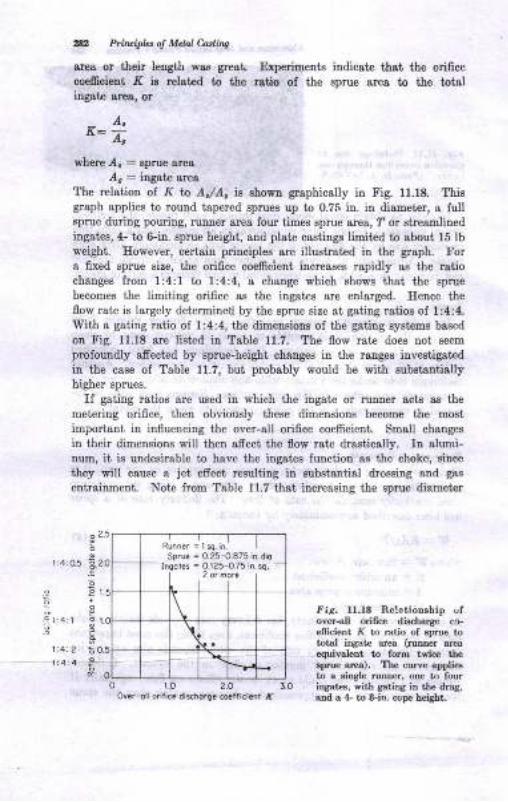
a2 Pitkipbt ol Mclal Cadina
ares or their length wa8 grest. Experiments indicste that the orificecoeficient K ie related to the ratio o{ the sprue area to the totaliugate area, or
where .4. : spme area
/, : ingatc area
The relation ol R I'o A,/Ao ie sbown graphically in Fig. 11.18. Thisgraph applies to rouud tapered sprues up io 0.75 in. in diameter, a lultsprue during pouring, runoer area four times spme area, ? or streamlinediagatcs, 4- to 6-in. sprue height, aud ptate castinge liuited to about 15 lbweight. E<rwever, certaiu priuciples are illuetrated in the graph. Fora fixed eprue size, ihe orifice coemcient increases rapidly ss the rstiochanges from 1:4:1 to l:4:4, a change which shows thai the sprue
becomes the limiting orifice as the ingates are enlarged. HeDce theflow rat€ is Iargely determiued by the sprue size at gating ratios of 1:4:4.With I g&titrg ratio of 1:4:4, the dimensione of the gating systems based
ou Fig. U.18 are listed ia Table 11.7. The flow ratc does trot seem
profoundly afrected by eprue-height changes in the raages iuveetigat€d
in the case of Table 11.7, but probably would be with eubstantiallyhigher sprues.
If gating ratios are used iq which the iugate or runner acts as the
metering orifice, then obviouely these dimensione become the most
important in influencing the over-all orifice coefficieut. Small chauges
in their dimensione will theu affect the flow rate drasticalty. In alumi-num, it iB undesirable to have the ingatee lunctiou as the choke, siuce
they will cause a jet effect resulting iiL substantial drorsiog and gas
entrginment. Not€ frcm Table 11.7 that increasing the sprue diamet€r
f iS. ll.18 Relationship oloYcr-sll orifice discharge ca-efficieDt }( to ratio of sprue tototal ingatD area (rutrner arcaequivelent to form twice thesprue ar$). The curve appliesto a sinSle ruDner, oDe to fouriDaat€s, with gaiina in the drag,and a 4- to &iY,. cope height.
A,K=4
2_5
2_O
E
6
1:4:05
.-: I:4 r I
Sprue = 0.25-0.875 in.dioI.goles = O.125-O75 in. sq,
over-oll orific. dischorg. co.flicir rf
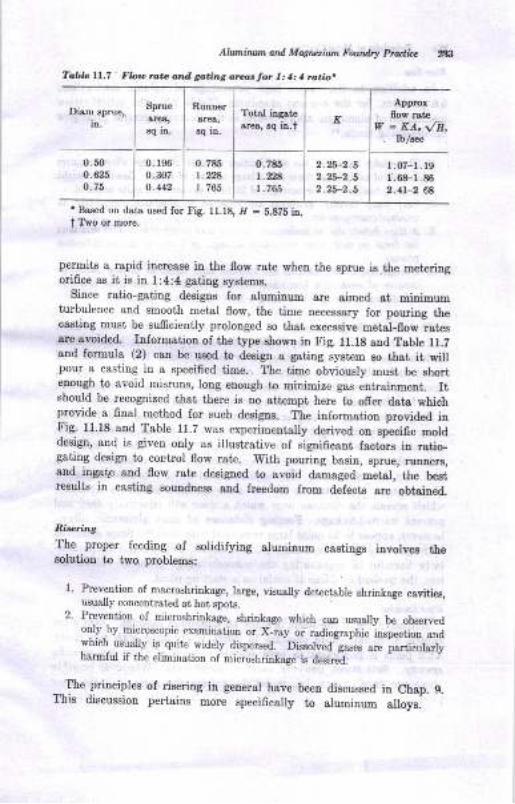
Atulztint ^
owl Magr.tiun Fouttlry hditz ltg
TdlG ll,7 tlo., rc.. d^d aa.int ar.,,.lor 1: 1: I ro,tto.
Diam eprue,
itr.
Sprue
Bq itr.
Runner
3q ir.
Tohl inaatsarea, sq in.f K
Approiflow Ist€
V - KA, \/8,. lb/aec
o.500.625
0. 196
o.N70.442
0.7851.28r.765
0.785t.rBI . 765
2. -2.52.25-2.52 .25-2.5
1.07-r.19r .68-l .862.41-2 e8
r Bssed on ds,ts us€d for Fig. ll.t8, I/ - b.878 ia.t Two or more.
permits a rapid iocrease in the flow rat€ whetr the sprue is the meteringorifice es it is in 1:4:4 gating Bystems.
Since ratio-gaiing designs {or aluminuu are aimed at minimumturbulence and smooth metal flow, the time necessary for pouring thecasting must be sufficiently prolooged so that excessive metal-flow ratesare avoided. InformstioD of the type shown in trig. 11.18 aod Table l1.Zand formula (2) can be used to design & gstiDg system so thst it s,iltpour a casting in a specified time. The time obviously musi be shortenough to avoid misruns, long enough to minimize gas entrainmeni. Itshould be recognized th&t there is no atteDopt here to offer data whichprovide a final nethod for such designs. The information provided inFig- 11.18 and Tsble 11.2 was experimentally derived on sjecifrc molddesign, and is given only as illustrative of significant factors in ratio-gBting design to control flow rate. With pouring basin, sprue, r,unner8,and ingatp and flow rate designed to avoid damaged."t"l, th" be.tresults in casting soundness atrd freedom from defecte are obtained.
Riseri'ng
The proper feeding of Bolidifying aluminum castings itrvolves thesolutioD to iwo problems:
1. Prevention of macroshrinksge, Iarge, visually detectable shrinkage cavities,Lisuall]' con ccn t rated ai ho[ spoLs.
2. Prevention of microshrin_kage, shriDkage which can usually be obeen edonly by microscopic examination or X_ray or radiographic tspection aIIdwhich_ usually is quite widely dispersed. Dissolved-gr."s are pa"ti"ula.lyharmlul il the elimination of microshrinkage is desire-tl.
_..'lhe _principles of sering ill general have beeu discussed in Chap. 9.
ltris discussion pertains more specificelly to alumiuum alloys.
8l Prituipla d Mdalhdfiq
Ritc, Sizc
In addition to the rather high percentsge of volume contraction,6.6 per cent, for the element aluminum (Table 9.3), the solidification
mechanism of alumiuum alloys results in the following general principles
for designing risers:lz
1. The mushy nature of the solidifieation of most aluminum alloys requiree
the use of fairly large risers and a large number of risers. Based on weightpoured, casting yield percentages oI 25 to 45 per cent are quite collmon.
2. Yery steep thermal gradients are required to eliminate completely all
, tracesofmicroporosity.3. Surface defects due to inadequate risering may occur since a solid skin does
not fom oD most aluminum-alloy castings until late in the solidificationproc€ss.
4. Overheating of the sand in one location may result in surfaee shrinkage
because of weak skin formation. Overheating may result from excessive
metal flow in one area or placing a riser too close to the casting.
The size of risers necessary to feed aluminum castings is at present
shll largely a matter of experieuce. Naturally, the riser must remain
rrolten longer than the section it is to feed, and the principles ofdirectional solidification must be obeyed. The principles of riseringdiscussed in Chap. 9 may be used, although the necessary graphs aati
data for aluminum castings have not appeared in the literature.Simple riser and casting combinations having volume and freeziug-
ratio values to the right of the curve in Fig. 9.14 can be sound withrespect to macroshrinkage. Microshrinkage, however, can be eliminatedonly with the most favorable of temperature gradients within the casting
and from casting to riser. The application of Caine's method to riseringof aluminum is limited in its use since no information is availablewhich reveals the distauce over which a riser will effectively feed andprevent microshrinkage. Feeding distances of most aluminum alloys,however, appear to be quite large compared with steel.,7 Since dissolvedhydrogen may be evolved during solidification, this gas can be particu-larly hamful in aggravating the microshrinkage problem. Neverthe-less, thg method of Caine is useful as a starting point.
RixrLulionExtensive use of top risers is made on aluminum eastings. Maxim.um
benefit of metallostatic pressure in risers is obtained with top risers.1'his point is important in light metals because of their low speoifiogavlt . Sde risers, however, must ofteu be used. 'Whenever possible
theee are t'hot" risersl i.e., metal flowe from the gates into the riser
Alunintlll.atd Mqrctfint Fowdry Mit, N
and then iuto the castingo. Difrculties with microshrinkage oan be
minimized by close spacing of risers, development of s€vere temperature
gradients, and use of directional solidifi.cation to the fullest extent.
Radiographic, or X-ray, study of the effect of changes in the gatiug and
risering system is probably the most positive method of arriviag ata suitable gating and feeding system.
ALUMINUM PERMANENT.MOLD CASTINGS
Permanent metal molcis are made of steel or cast iron. Coring maybe done with metal cores iD permanent molds, but these must be remova-
ble after the metal has solidified. More intrieate coriog may be done
by using sand cores in the permanent mold. The mold Burface iB
coated by spraying the hot mold with a suspension of a fine-particle-size refractory in water. The mold coating can be used to promote
direetional solidification. Sections required to freeze more Blowly o8tr
be given a thicker coating of refractory. Mold coatings serve to preventsticking of the casting to the mold, provide a smooth surface, andassist in controlling solidification so that souud castings are obtained.The castings shown in Fig. 11.13 are typical permaneut-mold castingsproduced for their surface finish and dimensional accuracy. Productionof quality permanent-mold castings requires a careful control of pouringtemperature, mold temperature (600 to 800 F), mold Goetiug, gatiag,pouriDg, mold manipulation, and continuity of operation. Ouly certaiualloys are favorably cast in permanent or die-casting molds, because ofhot tearing and other problems, which are discussed in Chap. 12.
MAGNESIUM CASTINGS
Magnesium-base casting alloys have undergone their greatest develop-ment through the growth of air transportation. The use of magpesium-alloy castings in this field is of coune based on the very low specificgravity of these alloys, about 1.74 to 1.82 in difrerent alloys, the lowestof commercial casting alloys. In fact, the cagt form represents themajor consumption of mapeeium alloys.
tround4r Praullnes
Green- and dry-sand molding, permanent molds, and die-casting methodeare all suitable for magnesium-castings production. Castings weighing
% Prirwipb 6 Mdal CaAins
over l(m lb have been produced. In addition to aircraft castings, pa;ts
for portable hand tools, typewriters, appliances, X-ray machines, and
other plsces wheri lightuess is desired have been losde by these i,luee
casiing processes. The casting properties of magneeium require that epe-
cial precautions be obseryed in molding, melting, and processitrg.'6,'z3''e
MoUina
Sand molding requires provieion for the reactiveness of moltenmagnesium with the moisiure in the sand and the need Ior correctgoting practices. Synthetic oandr are preferred. They consist of eilicasand or bank eand bonded with 3 to 4 per cent westerD beDtonit€.
Sande of AIS fineness of 60 to m eDd permeability of 80 to 150 nol per
min are bonded to a green sbrength ol 7 io 10 psi with a minimummoisture content for molding. A protective agent, is added to the BaDd
to inhibit the following reaction britweeu water iu the sand and themolten msgnesium:
Mg (molten) * H,O (vapor) + MgO (dross) * 2II (diesolved in melt)
TSo harmful efrecis accompany this rcaction: oxide inclusionr may be
eDtrapped in the ca6ting, and hydrogeu-gas defects, pinholes, maydevelop. The inhibitors miDimize these efrecte. Sulfur and boric aoid,
about I per cetrt or more of each, may be used. Ammonium fluoridecompounds, ammouium fluoborate, for example, also are employed.Sometimes I per cent of diethylene glycot (a sirupy liquid) is employed.the latter decreasiug the amount of water needed and also the dryiag-out tendency oI the sands. A totol of 3 to 6 per ceni oI the foregoingprot€ctiye sgents is used in the sand. Since the mettiug poiut ofmagnesium is 1202 F, thermal requirements of the sand are similarto those of aluminum alloys.
Core sands are required to be relatively collapsible because magnesi,,um
alloys are susceptible to hot tearing during solidification. Soue tyficalsaDd nixtures aud their properties are giveD iD Table 11.8. Protgbtiveageute (hhibitors) are also added t, core ssnda to prevent oxidEtioD.The uea-formaldehyde-resin-bonded sand (Tabte 11.8) is use/ul inproviding collapsibility and also, beoause of its low baking tempgfature,prevelts the inhibitors from being lost during baking. ./
It is very important that adequat€ venting be provided in all moldsand cores and th&t opportunity for contamination of the,,rnold withruoisture be minimized. Venting is exceedingly importaDt because thevery low metallostatic pressures developed by molt€n magnesiutD orenpt guffcient to overcome much back pressure from mold or core gases.aoleal he(iause of their cereal colrteDt, msy pick up water if not,
stored undcr dry and warm conditions. 85 tn too F
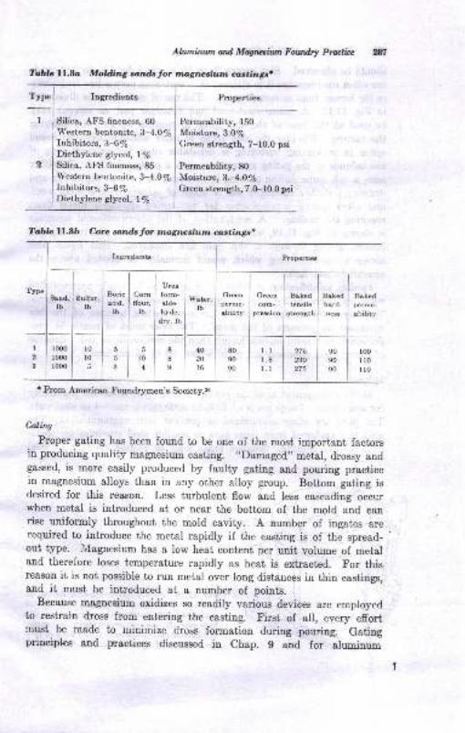
Alwni;nl,n od Mqtufin ltowdrl Pruticc
?oDlc ll.8o Molding so;rdsJol. tna,gtwahtm clntinge.
ryp" I_-t Ingredients Properties
t j Silica, AFS fineness, 60
I Western bentonite, 3-4.Oyo
Inhibitors, 3-6leDietlrylene gly col, | ls
2 | Silica, AFS fineness,8E
Permeability, 150
Moisture, 3.0/6Green strength, 7-10.0 psi
Permeability, 80
Moisture, 3.4.0%Green strength, 7.0-10.0 psi
Western bentonite, 3-4.O%Inhibitors,3-6%Diethylene glycol, llo
Ttblc ll..8b Core sands for magnesiutn castings|
Incredietrts Properties_tI
Ureaform-
alde-hyde,
dry, lb
I ."u"o8end,lb
Sulfur,tb
Boricacid.
lb
5
5
Cornflour,
lb
Watcr,lb
Greenperme.
obility
Greencom-
premioo
Bakedhard-nes
Bekedperme-
abilitytensile
streDgth
I2
3
1000
1000
lo00
r0lo5
l_I
l,oln
8
8
I
4020
l6
8090
90
l.l1.81.1
275230
275
90
9090
loo1r0llo
I From American Foundr5rmen's Society.,
Galing
Proper gating has been found to be one of the most important factorsin producing quality magnesium casting. ,tDamaged,, metal, drossy andgassed, is more easily produced by faulty gating and poudng practicein magnesium alloys than in any other alloy group. Bottom gating isdesired for r,his reason. Less turbulent flow and less cascading occurwhen metal is introduced at or near the bottom of the mold and canrise uniformly throughout the mold cavity. A number of ingates arerequired to introduce the metal rapidly if the casting is of the spread-out type. L,lagnesium has a low heat content per unit volume of metaland therefore loses temperature rapidly as heat is extracted. For thisreason it is not possible to run metal over long distances in thin castings,snd it must be introduced at a number of points.
Because magnesium oxidizes so rcadily various deviees are employedto restrain dross from eut€ring the casting. First of all, every efrortmust be made to minimize Cross lormation during pouring. Gatingprinciples and practices discussed in Chap. g and for aluminum
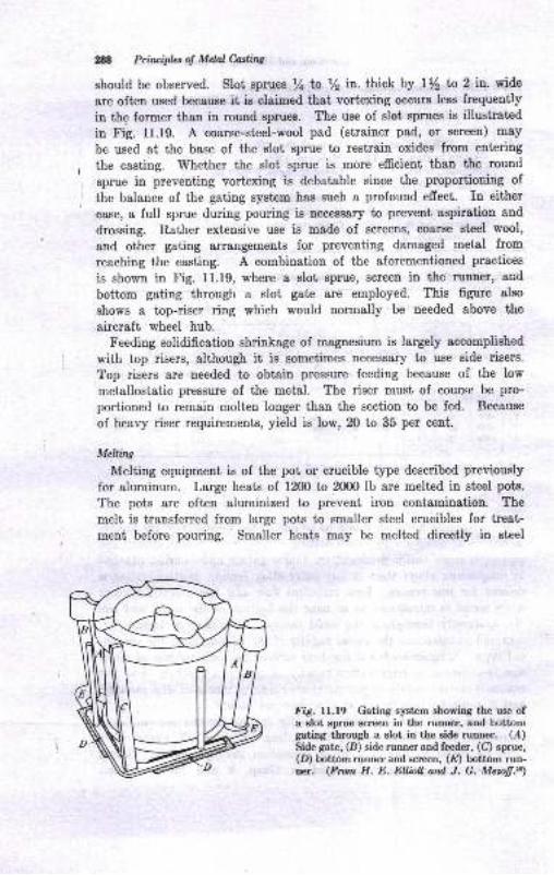
N Priruiplet ol Mdal Cading
should be observed. Slot sprues Y+ b /z in. thick by t/, to 2 in. wide
are often used because it is claimed that vortcxing occurs less frequently
in the former than in round sprues. The use of slot sprues is illustrated
in Fig. 11.19. A coarse-steel-wool pad (strainer pad, or screen) m8y
I be used at the base of the slot sprue to restrain oxides from entering
I the easting. Whether the slot sprue is more efficient than the round
sprue in preventing vortexing is debatable since the proportioning ofI the balance of the gating system has such a profound efrect. In either
case, a full sprue during pouriug is necessary to prevent aspiration and
drossing. Rather extensive use is made of screens, coarse steel wool,
and other gating arrangements for preventing damaged metal from
reaching the casting. A combination of the aforementioned practices
is shown in Fig. 11.19, where a slot sprue, screen in the'runner, and
bottom gating through a slot gate are employed. This figure also
shows a top-riser ring which would normally be needed above the
aircraft wheel hub.
Feeding solidification shrinkage of magnesium is largely accomplished
with top risers, although it is sometimes necessery to use side risers.
Top risers are needed to obtain pressure feeding because of the low
metallostatic pressure of the mebal. The riser must of coutse be pro-
portioned to remain molten longer than the section to be fed. Because
of heavy riser requirements, yield is low, 20 to 35 per cent.
MekirW
Melting equipment is of the pot or crucible type described previously
for aluminum. Large heats of 1200 to 2000 lb are melted in steel pots.
The pots are often aluminized to prevent iron contamination. The
melt is transferred from large pots to smaller steel crucibles for treat-
ment before pouring. Smaller heats may be melted directly in steel
F;9. ll.l9 Gatiog system showing the use ofa slot sprue screen in the runner, and bottomgating through a slot iu the side ruoner. (A)Side gate, (B) side runner and feeder, (C) sprue,(D) bottom runner and screen, (@ bottom run-ner. (Fran H. E. ElliDil. ond J. G. Mczofi.*)
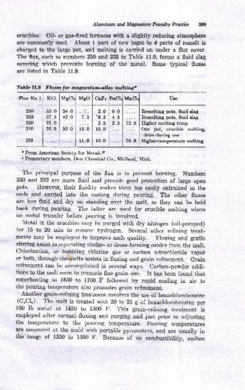
A/znilwn and Magnaiun Fowdry Pructici W)
crucibles. Oil- or gas-fired furaaces with a slightly reducing atmosphere
are commonly used. About I part of new ingot to 4 parts of remelt ischarged to the large pot, and melting is carried on under a flux cover.
The flux, such as numbers 230 and 232 in Table 11.9, forms a fluid slag
covering which prevents burning of the metal. Some typical fluxes
are listed in Table 11.9.
Flux No.f Mso CaFr BaCl
230
232
250
310
320
KCI
55 .037.523.O
20.0
34.042.O
2.O\8.5
2.515.0
r3.0
9.04.52.5
Remelting pots, fluid slag
Remelting pots, fluid slag
Higher melting tempOne pot, erucible melting,dries during use
Higher-temperature melting76.0
r From American Society for Metals,,
t hoprietary numbers, Dow Chemical Co., Midland, Mich.
The principal purpose of the flux is to prevent burning. Numbers230 and 232 arc more fluid and provide good protection of large openpots. Ilowever, their fluidity makes them too easily entraiued in themelt and carried into the casting during pouring. The other fluxesare less fluid and dry on standing over the melt, so they can be heldback during pouring. The ]atter are used for crucible melting whereno metal transfer before pouring is involved.
Metal in the crucibles may be purged with dry nitrogen (oil-pumped)for 15 to 20 min to remove hydrogen. Several other refining treat-ments may be employed to improve melt quality. Fluxing and gentlestirring assist in separating sludge- or dross-forming oxides from the melt.Chlorination, or bubbling chlorine gas or carbon tetrachloride vaporor both, through th*nelts assists in fluxing and grain refinement. Graiorefinement can be accomplished in several ways. Carbon-powder addi-tions to the melt seem to promote fine grain size. rt has been found thatsuperheating to 1650 to 1700 F fotlowed by rapid cooling in air tothe pouring temperature also promotes grain refiuement.
Another grain-refining treatment involves the use of hexachlorobenzine(cuclu). The melt is treated with 20 to 25 g of hexachlorobenzine perf00 lb metal at 1450 to lb00 F. 1.his grain-refining treatment isemployed after normal fluxing and purging and just prior to adjustiugthe temperature to the pouring temperature. pouring temperaturesare measured at the mold with portable pyrometers, and are usually inthe range of 1350 tu r50o F. Because of its combustibility, *oit o
Tabb lI-.9 Flures for mtgnesiurn.o,lloy mcltingt
MgCl UseTYIDUI
l.b
is. o
1r .0
,N Prin ipht ol Mdal Cadirq
magnesium must be protect€d from air during pouring. This ie accom-
plished with SO21 geuerated by spriukling a mirture of sulfur aud boric
acid powder on the metal in the crucible during pouring. Gentle
pouring, with pourirg lip close to pouring cup, to avoid turbuleuce,
and ladle skimming, to avoid drossy-slag entrapment, are desirable'
Cbanins
The castings are allowed to cool in thc mold until ihere is no darger
of developing cracks during shekeout. This may require au hour or
more for largcr castings. After shaLeout, the castings are sand-blasted
wiih a sand of &bout 35 Atr'S fineness to reveal surface defects. Gates
and risers are lemoved by band sawing (Chap. 24). Grinding and
rotary filing are employed to remove 6ns and excess meial. In allrnetal-cutting operaiions, the fire and explosion hazard of magaesium
chips or powder must be recognized. For example, at grinder stations
dust washers, in which exhaust air is wet down with water, remove the
magnesium as a 0re hazard. After cleaning, a flnal sand or grii bl&sting
is used to provide a unilorm &ppearance. Impregnation, or sealing,
may be used on a casting which must be leakproof. The castings are
given a chrome-pickle trcatment belore shipment. This is primarily
for protection against corrosion during shipment and storage before
machining. The pickling treatment consists in dipping for a short time
iu an aqueous solution o{ 1.5 lb per gal of sodium dichromaie end 1.5
pt per gal of concentrat€d nitric acid, Thc dip is followed by rinsing
in hot water. The castings &re given a bronze color by this trcatment.
Coatings suiiable for more permanent corrosion proiection may be
applied alter the pa is finished, the latter treatuents being described
in Ref. 27.
BIBLIOGNAPHY
1. F, A. Lewis, Aluminum Alloy Castigs, Foundry, voll' 75 aod 76, December,
1947-November, 1948.
2. L. W. Esstwood, Melting Alumimrm and Nlagnesium-base Alloys, fta74.,lrs, vol. 59, 1951.
3. D. P. Smith, L. W. Eastwood, D. J. Camey, and-C. E. Sims, "Gases inMetals," American Society for tr{etals, 1953.
4. W. R. Opie aod N. J. Gr&ni, Eydrogen Solubility in Aluminum and Some
A.lnminnm Alloys, J. Inat. Metols, vol. 188, p. 1237, October, 1950.
5. W. Bonsack and O. Tichy, Grain Reining of AI and Its Efrects on Properties,Ttuns. AF S, vol. 57 , 1s49 -
6. L. F. Mondolfo, "Metallography of Alumimur. Alloys," p.22, John Yy'iley &Sons,Inc., New York, l94ii.
7. Aluminum Co. of America, "Casting Alcoa Alloys," 1952.
8. A.rnerican Foundrymen's Society. "Recomrnended Practices for Sstrd Casting
NotrIeEou6 A.llo)ts," 1948,

9.
10.
t1.
12.
13.
14.
15.
16.
17.
18.
20.
25.
26.
Alltmi,,,.tm nad Mqr6iui Fou ry pficlice ,tlD. A. LaYelle, Aluminun Ssod Casting Delects : Their Identi-ficatioD, Causes,aDd CoEectioDa, Troru- ,{.PS, vol. 60, 1952.II. IV. Dietert, "Fouodry Core P!&ctice," Anericrn Foundrymen,s Society,1950.
ra.mericaa Society for Metals, "The Physical Metsllurg/ of AlnnirsuoAlloys," 1949.
R-. P. SmIt, J. E. Jackson, and L. W. Eastwood, A Study of the priDciples
yl qtlrg, fro*. 1{FS, vol. 57, Ig49; conrinued in subsequent transactions,H. E. Elliou and J. G. Mezofr, Eflecl of Gating Design on Metal fiow Con-ditioD.s h the Casting of Magresium Alloys, ?rans. ifS, vol. 56, 19,18.
".-lilr*, Determination ol Sprue Sire ia Aluminuo C..6L:jIl8f,, Fountry,
vol. 72, p. 88, November, 1944.American Foundrymen's Society, "Ssrmposium on Principles of Gating,,,1951.
AElerican Society farMetals, "Metals Eandbook,,,Sth ed., vol. l, 1961.E, F. Taylor, M. C. Flerrings, and T. S. Piwooka, Risering AluminumCasLi[ig, Fotnd.ry, I'.oL 88, p. 216, Msy, 1960M. C. Flemings aad H. F. Taylor, Gatiag Alumioum Castings, foundry,vol. 88, p. 72, April, 1960.
IY. N. BrarDmer, Melting Praclice for Alurniaum CastiDg Alloys, Trorr..4tr'S, vol. 66, p.497, 1958.
J. P. Moehling, Alumioum Meltiog Praciice in the Die CastiDg and Peroa-nent Mold Fields, Tm*. AFS, vol. 66, p. 533, 1958.V Cr Rrid lnduction Meltilg iD a Nonferroua Jobbi4 Fourdry, tr'ozadry,Apil, 1353.
E.X.qoa L. C. Banon. Low-frequency Induction Hearing in tbe DieCasting thop, Marhizery, Scpr. 24-Oct. 29, 1954.E. lY. Rearwin, Gating of Alumhum Die CsstiL[iga, Foundry, vol. 88, p. 106,NoveBber, 1960.
R. K. Owens, E. W. Antes, and R. E. Edeirnan, Efrect of Nitrogen &ndYacuum Degassing on Propertiea of a Cast d.Si-Mg Aloy (Type 356),?roru. .4f.S, vol. 65, p . 4!A,1957.A. F. Toylor et al., Efrect of Pressure during Solidification oD Microporosityin Alumirum Alloya, ?rono. .dlg, vol. 66, p. 129, 1958.American Foundryoeo's Society, "Rccommended Practice for Sand CastingAlumiuum and Magnesium Base Alloys," 194{1.
American Society for Metals, "Metals flandbook," 1948.E:t E. Illliott and J. G. Mezoff, A New Gatilg Technique for MagnesiumAlloy Castings, fra s.,{FS, vol.55, 1947.
E E. f'airteld and A. E. Ifurton, Some Causes of Pinholes in MagoesiumAlloy CastiDgs, TrarJ. ,4trS, vol.55, 194?.
AtrS Light Meta.l6 Division, Magoesiuu Alloy Chararcteristics, u4m. Foundry-
27.
28.
30.
na,q vol.23, p. 156, Ap l, 1953.31. R. M. Blick, R. B. Gordon, and A. Phillips, "Structure and Properties of
Alloys," 3ded., McGraw-HillBook Company, New York, 1965.32. K. E. Nelson and F. P. St eter, Casfing of Magnesium-Rare Earth-Zirco-
nium Allots in Sand M4ds. I/drs AFS, vol.5b. p. 400, 1050.33. P. F. George, l\fetallogtaphy of Cast Masnesium Alloys, Irans. .{LS, vol.
57, p. t 33, 1919.
34. C. E. Nelson, Grain Size Behavior in trIagnesium Casting Alloys, ?roms..4IS, vol.56, p. 1, 1948.
35. T. E. Kramer, Gating Alumilum Castings in "Slroposium on Principles ofGeting," American Foundrya&n's Society, 1951.
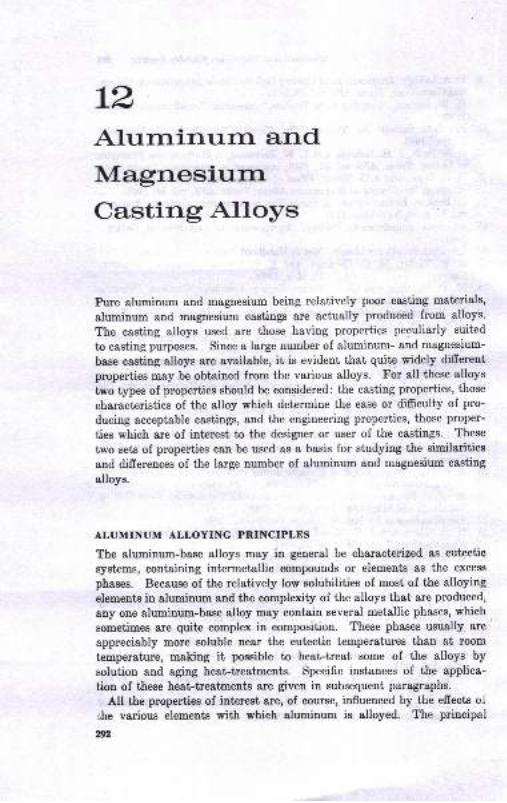
L2Altrrninurn andMagnesiurnCasting Alloys
Pure aluminum and magnesium being relatively poor casting materials,
aluminum and magnesium castings are actually produced from alloys.
The casting alloys used are those having properties peculiarly suited
to casting puposes. Since a large number of aluminum- and maguesium-
base casting alloys are available, it is evideut that quite widely different
properties may be obtained from the various alloys. For all these alloys
two types of properties should be considered: the casting properties, those
characteristics of the alloy which determine the ease or difficulty of pro-
ducing acceptable castings, and the engineering properties, those proper-
ties which are of interest to the designer or user of the castings. These
two sets of properties can be used as a basis for studying the similarities
and differences of the lerge number of aluminum and magnesium casting
alloys.
ALUMINUM ALLOYING PRINCIPLES
The aluminum-base alloys may in general be characterized as eutectic
systems, containing intermetallic compounds or elements as the excess
phases. Because of the relatively low solubilities of most of the alloying
elements in aluminum and the complexity of the alloys that are produced,
any one aluminum-base alloy may contain several metallic phases, which
sometimes are quite complex in composition. These phases usually are
appreciably more soluble near the eutectic temperatures than at room
temperature, making it possible to heat-treat some of the alloys by
solution and aging heat-treatmeuts. Specifie instances of the applica-
tion of these heat-treatments are given in subsequent paragraphs.
All the properties of interest are, of Qourse, influeuced by the effects ol
she various elements with which aluminum is alloyed. The principal
gn

Alumilutm ad Magruiam C,ading AlWt ,n
alloying elements in aluminum-base casting alloys are copper, silicon,
magnesium, zinc, chromium, manganese, tin, and titanium. Iron is au
element normally present and usually considered as an impuri,ty. Some
of the simpler effects of alloying can be considered.
C.pp.,
The structural effects of copper in Cu-Al-base alloys are presented inthe equilibrium diagram in Fig. 12.1. The diagram shows solubility ofcopper in aluminum increasing in the solid state from less than 0.50per cent at room temperature to 5.65 per cent at 1018 F. Copper above
the solubility limit at any temperature appe&rs microstructurally as thed phase. The latter phase has a compositipn approximating the formulaotA.l, (46.b/o L1453.5% Cu) and is.a hard brittle constituent. Bycomparison the solid-solution phase is relatively soft and ductile. Thetwo phases are illustrated in Fig. 12.2. Structurally, then, increasingcopper content in Cu-Al-base alloys results in an increasing percentag'e
of the hard d phase. The mechanical properties of hardness and strengthcan then be expected to increase as copper content increases while theductility decreases. These property trends are illustrated in Fig. 12.3.
A limited percentage of copper thus has a beneficial efrect of strengthel-ing and hardening in Cu-Al-base alloys. However, Fig. l2.B also showsthat an excessive copper percentage will cause tensile properties to fallbelow the maximum values obtained. Furthermore, ductility is reducedto a very low level and brittleness results in alloys of high copper coutent.Therefore copper percentages do not exceed 12 per cent in most aluminumcasting alloys. Actually, the copper perceutages in aluminum castingalloys are adjusted so that the lower eontents, 2 to 5 per cent, are usedin alloys required to have optimum ductility (or toughness), whereas thehigher percentagq are used when greater hardnees and strength aredesirqd.
Heol-trealmenl o! Cu-N Altoys
The mechanical-property curves of Cu-Al alloys in Fig. 12.3 areshown to be markedly shifted by solution heat-treatment and age harden-ing. In fact, the degree of strengthening obtainable by heat-treatmentis greater than that gained by alloying alone. A few elements, namely,Cu, Mg, Zn, and. combinations of Mg and Si confer heat-treating po-bentialities to Al-base alloys in which they are present. These arereferred to as "heat-treatable" grades of aluminum alloys, and theygreatly extend the range of properties available in aluminum castings.
1
Detailed study of the metallurgical principles of solution heat-treat-ment and aging phenomena is outside the scope of this book. However,
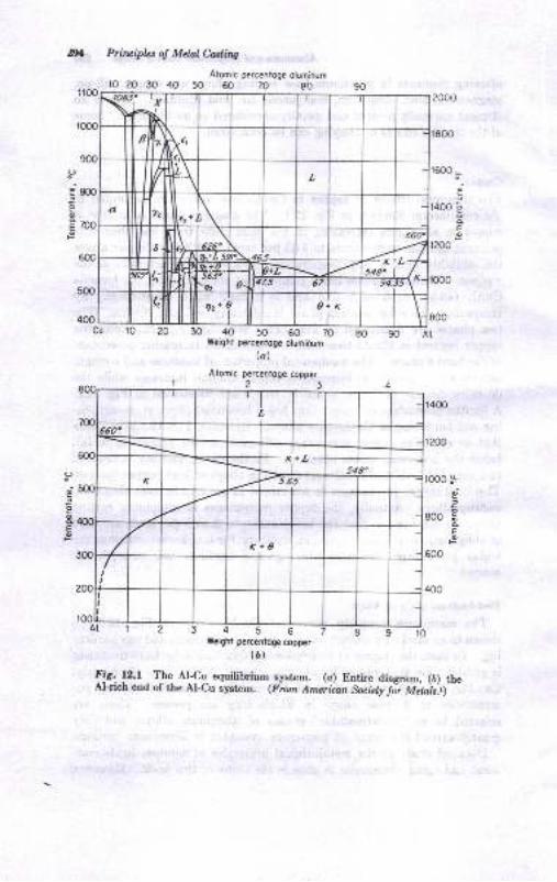
Prircipbs of Mdal Cuting
Atomic p€rcentoge oluminumr0 20 30 40 50 60 70 80
ro
P
oE
F
uo',o
oE
F
o
ifo
d
EF
30 40 50 60 70 80 90Weighi perceniog€ oluminum
lal
Aiomic percentoge copper
Weight percentoge copper
(a)
lis..1Z.t.11r". AL-9f equilibrium system. (a) Entire diagram, (b) theAl-rich end of the Al-Cu system. (From Anuritnn Saciely Jir M;bis'.r)
o
a;)o
oEP
Cu 10 20
6
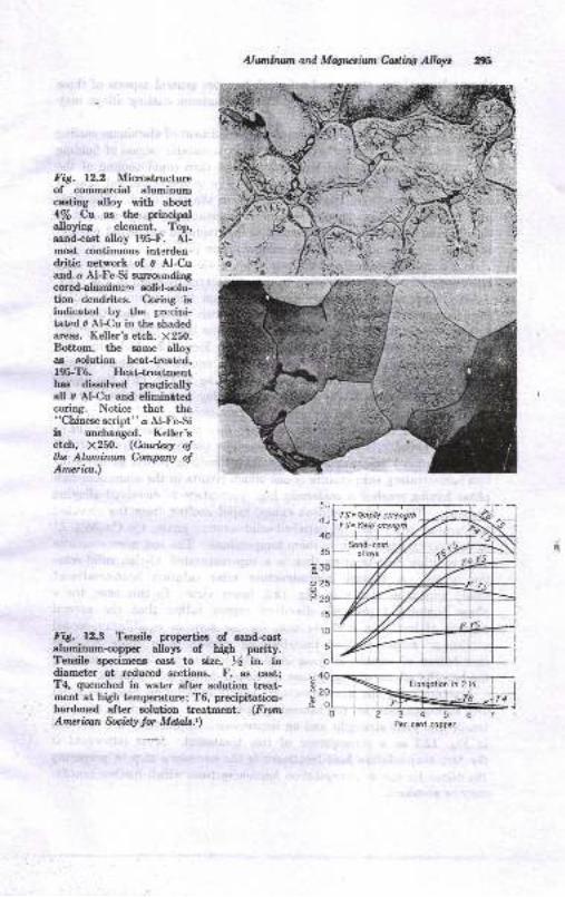
Aluirunt ud, Mqrcsiwn Culing Allqrt
Fig. 12.2 Microstructureof commercial aluminumcasting alloy with about4/q Gt as the principalalloyrng elemeot. Top,saod-cast alloy 195-F. AJ-most continuous interdeu.&itic network of 0 Al-Cuand a Al-FeSi surrorrrrdingcored-aluminun solirl-solu-tion dendrites. Corirrg isildicated by the prr:cipi-tat€d 0 Al-Cu in the shadedareas. Keller'e etch. X250.Bottom, the same alloyae nolution beat-treated,195-T6. HeaLtreatmenthas dissolved praqticallyaII 0 AI{u ard eliminttedcoring. Notice that the"Chinese script" o Al-FeSiis unchanged. Keller'setch, X250. (Cou,rltsy o!tlw Abmiruun Company otAmerica.)
Fig. 12.3 Tensile properties of sand-caet
Fluminum-copp€r alloye of high purity.Tensile epecimens cast to size, th ir.. indiameter at reduced sections. F, as cast;T4, quenched in water after solution treat-ment at high temperature; T6, precipitation-hardened after solution treatment. (FnlnAnwri.can Socicly tor MdalsJ)
o
Per cenl copper
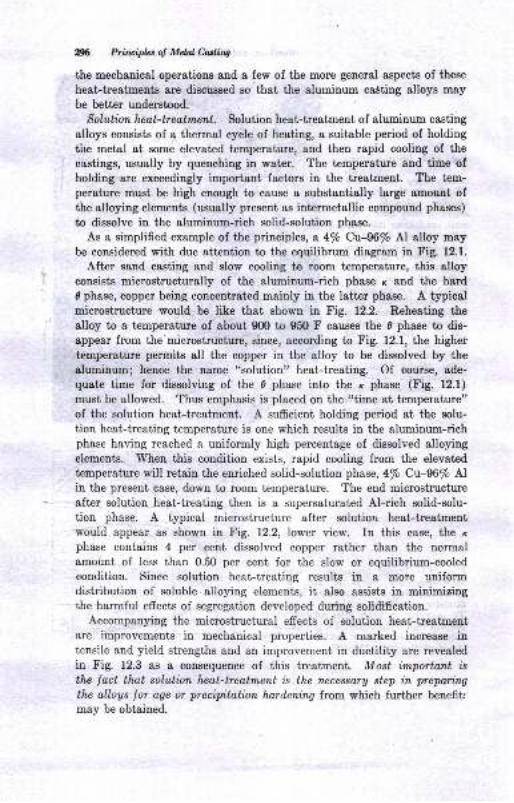
2X Primipb of MdalMing
the mechenical operations and I few of the more general Bspects of these
heat-treatments are discussed so that the aluminum casting alloys may
be better understood.
Soluti.on heot-beotment. Solution heat-treatment of aluminum casting
alloys consists of a thermal cycle of heating, a suitable period of holding
the metal at some elevated temperature, and then rapid cooling of the
castings, usually by quenching in water. The temperature and time ofholding are exceedingly important factors in the treatment. The tem-
perature must be high enough to cause a substantially large amount ofthe alloying elements (usually present as intermetallic compound phases)
to dissolve in the aluminum-rieh solid-solution phase.
As a simplified example of the principles, a 4/o Cu-%/o Al alloy maybe considered with due attention to the equilibrum diagram in Fig. 12.1.
After sand casting and slortr cooling to room temperature, this alloyconsists microstructurally of the aluminum-rich phase ,( and the hardd phase, copper being oonceutratcd mainly iu the latter phase. A typicalmicrostructure would be like that shown in Fig. 12.2. Reheating the
alloy to a temperature of about 900 to 950 F ceuses the 0 phase to dis-sppesr from the microstructure, since, aecording to Fig. 12.1, the higher
temperature permits all the copper in the alloy to be dissolved by "healuminum; hence the name "solution" heat-treating. Of course, ade-
quate time for dissolving of the 0 phase into the r phase (Fig. 12.1)
must be allowed. Thus emphasis is placed on the "time at temperature"of the solution heat-treatment. A sufficient holding period at the solu-
tion heat-treating temperature is one which results in the aluminum-richphase having reaehed a uniformly high percentage of dissolved alloyingelements. When this condition exists, rapid cooling from the elevated
temperature will retain the enriched solid-solution phase,4/o Cu-96% Alin the present case, down to room temperature. The end microstructureafter solution heat-treating then is a supersaturated Al-rich solid-solu-tion phase. A typical microstructure after solution heat-treatmentwould appear as shown in Fig. 12.2, lower view. In this case, the x
phase contains 4 per cent dissolved copper rather than the normalamount of less than 0.50 per cent for the slow or equilibrium-cooledcondition. Since solution heat-treating results in a more uniformdistribution of soluble alloying elements, it also assists in minimizingthe harmful effects of segregation developed during solidification.
Accompanying the microstructural effects of solution heat-treatmentare irnprovements in mechanical properties. A marked increase intensile and yield strengths and an improvement in ductility are revealedin Fig. 12.3 as a consequence of this treatment. Most important isthe lact that, solution heat-treatment is the rlecessar1y step in prepari.ng
the alloys lor age or precipitation hordedng from which further benefitr
may be obtained.
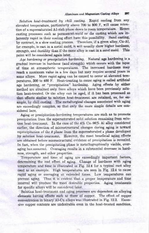
AhniruvnardMqtutunhdiq AIW gn
Solution hedt-treatment by chill cost:ing. Rapid cooling from any
elevatpd temperature, particularly above 7fi) to 8fi) F, will cause reten-
tion of e supersaturated Al-rich phase down to room temperature. Hence
casting processes such 8s permanent-mold or die casting which are in-
herently rapid in their cooling effect have this possibility. Sand cssting,
by conirast, is a slow cooling process. Therefore, if a given alloy, Cu-Al,
for example, is cast in a metal mold, it will usually show higher hardn:ss,
strength, and ductility than if the same alloy is cast in a gand mold. This
point will be considered again later.
Age horileraing or precipitatbn hotdering. Natural age hardeuiug ie a
gradual increase in hardness (and strength) which occurs with the lapse
of time at atmospheric temperatures. The increased hardnees may
reach a maximum value in a few days but may require several yeara in
some alloys. More rapid aging can be caused to occur at elevated tem-
peratures, 300 to 400 F. Heat-treating to cause aging is called artificial
age hardening, or "precipitation" hardening. Aging efrects by either
method are obtained only from alloys which have been previously solu-
tion heat treated. Or the alloy can be aged, if it has been processed ao
thst efrects similar to solution heat-treatment are retained, as, for ex-
ample, by chill casting. The metallurgical changes associated with aging
are exceedingly complex, eo that only the more simple detaile are con-
eidered here.
Aging or precipitation-hardening temperatures are such as to promote
precipitation from the supersaturated solid solutiou remaining from solu-
tion heat-treatment. In the case ol lhe 4/o Ct-96/o Al alloy considered
earlier, the direction of microstructural changes during aging is toward
reprecipitatioo of the d phase from the supersaturated x phase develope<i
by solution heat-treatment. However, the most beneficial aging effects
are obtained before microstructural evidence of precipitation is revealed.
In fact, when the precipitating phase is metallographically visible, over-
aging has occurred. Overaging results in a substantial decrease in hard-
ness, strength, and other properties.
Temperature and time of aging are exceedingly important faetort,
determining the end efrect of aging. Change of hardness with aging
temperature and time is illustratcd in Fig. L2.4 lor a typieal cast alloy
used as an example. High temperatures are seen in Fig. 12.4 to cause
rapid aging or overaging at extended times. Low temperatures can
prevent aging. Thus it is evident that a proper temperature and time
interval will produce the most desirable properties. Aging treatmeuts
for specific alloys will be considered later.
Solution heat-treatment and aging processes are dependent on alloying
elements having efrects such as those of copper. The effect of copper
concentration in binary Al-Cu alloys was illustrated in Fig. 12.3. Exces-
aive copper contents are undesirable even in the heat-treated coudition,
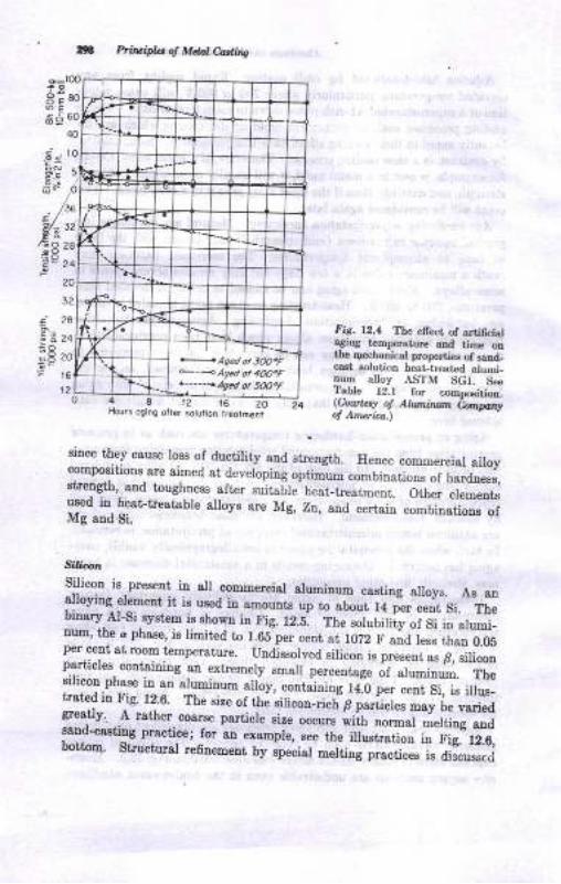
Pti,t ipla q Mdat Co'titr4
_E9
20
32
2A
24
20
l6
124812 16
Fig. 12,1 Tbe e,Tecr of artilicial38iog terDperatue atrd tiD€ onOe qechadcal ploperti€s of saDd-csat solutioD heat-tr€at€d alumi_num alloy ASTM SGr. SeeTlble l2.t for c.mpo€itioo.(uoulL4 o! AlLunirutn bnmntof Anctira^)Hoors oging olrer sotutlon riaorrnen_i
:^T:^*I^::T_: i".* of altiri-tv 8nd srreosth. Hence commerciat a oy
compo8rtrons-are aimed at developing optimum combinatione of hard;e"",strength, 8!d toughness aftf,r €uitable heat_treatmeut. Otfr"i
"i"-i"*used in heat-trestsble slloys are Mg, Zt, and certair ,r.ilr"ti-"*'"fMg and Si.
Slicon
S.ilicoll is preeeut in all comuercial aluminum csstiog slloys. As 8Dalloying elemeut it is ured i! Bmou.Ets up to about 14 p-*."JSi. tiubilary Al-Si,ryscem f etrown in Fig. r2.8. The *fuUifiiy oi-S1" ii-"f *oi-uum, tie d pha8e, i8 limited to l.65 per cetrt at 1022 F a;d less than OOOper sent at room teuperature. Uud.igeolved silicon is preseJ
", i, "ifi_,particles, containirg an extremely small percertage
"f ,1"_i;#.";;"
sulcon phase iD atr alumiuu-m alloy, containiug 14O per ceut Si, ie illus-irsted in Fig. 12.6. The size of rh".ifi"oo_"i"t-B pJi;;;;il; #:d111rll. ,.A
rather. cosr.e particte size """;;;h ;;-;.i.rl"ij.*1laEano-caaung practice; for an example,.see the illustration iu fig: l2O,bottoq. Structural refiaement fy epeciat ."fUog p.orti*.-i. Aii*.".f
+Agedot 3tu.F*'< ACed ot 4m.F.-"-'<Aqed ot 50O"F
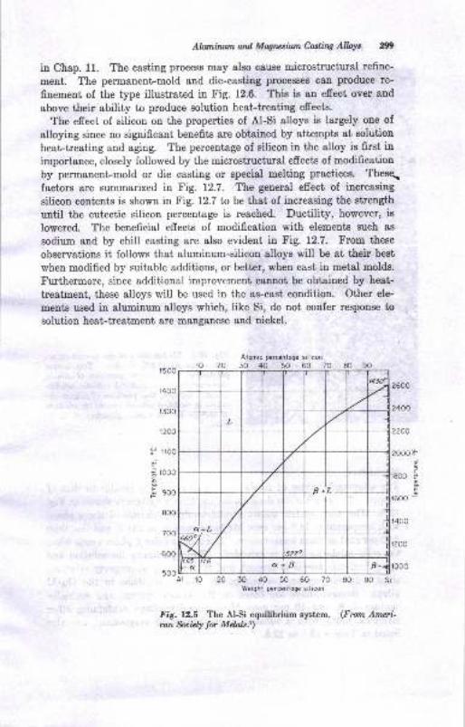
A/luniluan ard MWrcsilm Cutirq Alloyt gn
in Chap. ll. The casting process may also cause microstructural refine-
ment. The permanent-mold and die-casting processes can produce re-
finement of the type illustrated in Fig. 12.6. Thie is an effect over aud
above their ability to produce solution heat-treating effeck.
The effect of silieon on the properbies of AI-Si alloys is largely one of
alloying since no signiflcant benefits are obtained by attempts at solution
heat-treating and aging. The percentage of silicon in the alloy is first in
importance, closely followed by the microstructural effects of modification
by permanent-mold or die casting or special melting practices. These.
factors are summarized in Fig. 12.7. The general effect of increasing
silicon contents is shown in Fig. 12.7 to be that of increasiug the strength
until the eutectic silicon percentage is reached. Ductility, however, is
lowered. The beneficial effects of modification with elements Buch ag
sodium and by chill casting are also evident in Fig. 12.7. From these
observations it follows that aluminum-silicon alloys will be at their best
when modified by suitable additions, or better, when cast in metal molds.
Furthermore, since additional improvement cannot be obtained by heat-
treatment, these alloys will be used in the as-cast condition. Other ele-
ments used in aluminum alloys which, like Si, do not confer response to
solution heat-treetment are manganese and nickel.
10 20
Aimic p€rcentoge silicon
30 40 50 60 701 500
r400
r300
r200
I iloo
i! rooo
8.
$ soo
800
20 30 40 50 60 70 80Weighl percentoqe silicon
Fig. l2.S The AISi equilibrium system. (From Ameri-an fuiaty lor Mdok.r)
.t
EP
700
600
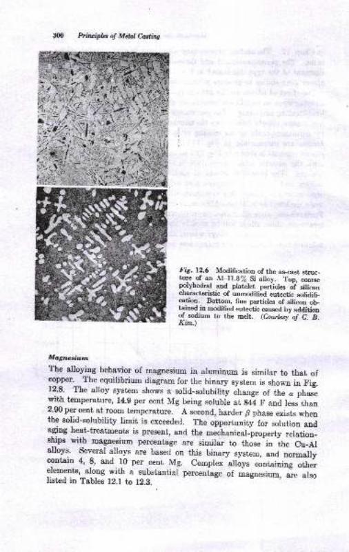
Prituip&l of Mdal Caslittg
Fig.12.6 Modiffcation of the as-cast struc-tqe.of- an AI-ll.B/, Si alloy. Top, coarsepglVhedral and platelet pa"iicles ot ,ili*ocharacteristic of unmodified eutectic solidifi_cation. Bottom, fine particles o[ silicon oLtained in modified eutectic csusd by additiongf .*$r- to the melt. (Coutpsy o! C. B.Kim.)
Magnoaiurn
The alloying behavior of magnesium in aluminum is similar to thet ofcopper. The equilibrium diagram for the binary system is shown iu Fig.l?.9. The alloy sy'tem shows a solid-solubility .hurrgu of the c phasewith temperature, l4.g per cent Mg being solubre at saa F and less thau2.90 per cent at room temperature. A second, harder B phase exists whenthe solid-solubility limit is exceeded. The opportunity for solution andaging heat-treatments is present, and the mechanicar-property ,etatioo-ships with magnesium percentage are similar to those-in ihe cu-etalloys. several alloys are based on this binary system, and normalrycontain 4, 8, and l0 per
-cent Mg. Complex'alloys containing Jher
elements, along with a substantiar p"r..nt-"g. of magnesium, io-;Lolisted in Tables l2.l to 12.8.
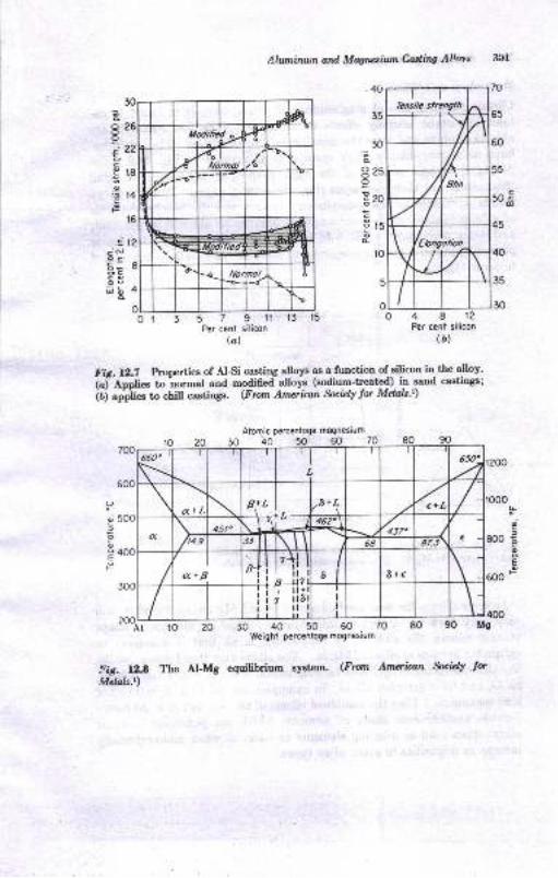
65
50
'ao
8o;c
g
cF
:ioor 3 5 7 9 ll 13 15
Per cenl silicon
lal
Alwninwn ard Magrctiwn Cad,ing Al'mt 3Cl
.40
35
30
o
8259
!zoc
!rsc
4812Per cent silicon
(D)
Fig.12.7 hoperties of AlSi casting q!oy" T afunction of gilicon in the alloy'
i"f ,fppft* to'norrnal and modifiedalloys (sodium-treat"d) T F"d castinss;
iAj uppUo to chill castings. (From Arneri.can Socicly lor Mdz,ls'r)
Alomic percentoge mognesium
30 40 50 60 70
40 50 60weight percentoge moqnesium
lig. 12.8 The Al-Mg equilibrium system. (Fmm Amaian fuicly torMelals.t)
O
.o
E
ts
J400ll990
.a l2iNoc6;86C
trb 4o
ii; iiji
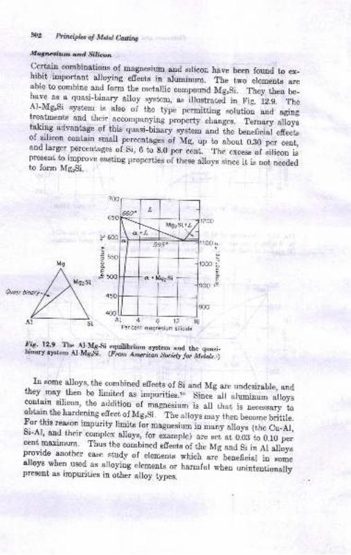
3tt2 Flbuipb o! Mdal C,ading
tfiqruaitm and Siilirrrlr.
Certain combinations of magn.esirrm and srlicoa have been found to ex_hibit important alroying effects in aruminum. The two element' areable to combine and form the metallic compound MgrSi. Th.y th;; ;_l?v.1 ".^.u
quasi-binary alloy system, as illustrated in Fig. 12.9. TheAl-Mg,Si system is also of the type permitting solutiol and agingtreatments and their accomparyinj p"operty cha-nges. T.ro;; ;il;.tqkiy advantage of this quasi-Linary ryst.* and the beneficial effectsof silicon contain small percentages of Mg, ,rp to about 0.80 per cent,and larger.percentages of si, 6 to s.o p"r .-.ot. ,h. excess of silicon ispresent to improve casting properties oi thu.u alloys since it is not neededto form Mg,Si.
o
o
EF
I
o
o
EF
Quosibinory.
481216Per cenf mognesium silicide
Fig._12.9 . The,AI-M_g-Si
_eguilibrium system and the quasi_DrDarlr r)rEtem A-MglSi. (Fmm Ameriain gritlli'ia"i.t".l
.. In some alloys, the combined effects of Si and Mg are undesirable, audthey may then be limited as impurities.ii Sio.u all aluminrrm alleyscontain silicou, the addition of magnesium is all that i. o";;";-L
obtain-the hardening efrect of MgrSi. The alloys may then become brittle.For^ this reason impurity limits f* *"gou.iu* io rrruny alloys (the Cu_Al,Si-AI, and their'compler alloys, ior uiu*pi"j are set at 0.08 to 0.10 perceut maximum' Thus the combiued uff".i, oi the Mg uua si in-ei aiJysprovide another case study of elements which are beneficial in someallovs when used as alroying elements o. r,u.-iur *ff;;il;#";riiypresent as impurities in other alloy types.

,56l
8€*"
Ed E
s e:
EO E
E: E
6: X
U.i-.
a
.AEES is"
o*! *
<=E
L" -i
dE:6A
E65-1.*.1
Eg g'5" b
< ?o
tua a.- 6
EA
g.
a
A)
A.v).i6 ii5 i,5 N .ir
. >:q a<>29 3!(,L)I5
b96iILc,
..,-F$ B$ESfrm g ft B::$ A
O CO6O6O C O 6 : :6 -
?!
EEC)!
.- :o? :'> > --1-4o o X.o?::u:S+t'S ;::3HEE?E
E Td6: FF
E
6!
&
z
F..!
O
z
rere..'4.tooo<Nooq9: :qcqqo: .3oN+
.!o9ooQ o?olcco:!)6r)
orJl oooo : :i : : :<'!!,l o33N . .O . . .r
< g3:sdE E.E Da<<<i<<d
@@@IDNNNNN
'..-::.::-.:::.:
.:.d<ra \a .aqg6;.i i{Xci.. -i6Z;5:9EE:P3OOoUOO()OdsiA
<(.)
it
h
I
a
103

,twzerqroJ olqalmf 22222228e58* 222* g g# #
-tunlJe^rroJ
^tlIqal!ns6a+:nNCO<{rOtn3rHC\6\|N6ti. {. r{.{. .{.
,dure1 pelraala1r q13ue4g sedHGOaON o 6aCO$tirN(€c\.(OrO rO rorO rO
,(uor?c7|ord)lurlroc
epFo larrEaqcao{r$co<{idid(\NNcaNN60 N 6a€6 ca
r(aou8rBadds)Surzpouy 6lCACOaOcrrHHiNrOO<r:t \ntiN N 6t6l N
.tuqqdo.rlcelg rHi6tC\lo!nrOi.6lNd.\lCia6tN cO CaN N
Futqqtod 6l€{NcaNdHic\l|orOcO{irO6i i HH
6Eupgcry4l NdN(O6liir6l1r!roc66a$!li - ri
/uoIsoIJoto] eou"l$se crrnr{rSrorr-H6lcaolmcoc\N ct Nc{ N
I@
d
.oI
palBe4lreq {11aulo1 g,q g * EEi, EEaEr-# # # $?$?g $fli
lcuepual I
eSrlur.rqs I
uorltcgrprloglmco$NCa6rO!l!iidi6t:Hr$ <{ lrrni {.
,,{llp!nu cOgOC€(\lNrOrnlo6rHidNHH!i <. <t<. r{r
sseulqtrleJnsserA nt60cr6il6arororo<{HHHN:H(r! 60 06(O @
,8ur1cr.rc 1oq I
01 acusrslTul $S{.NcA$NmOiiiN-iE 6 6rO @
oai€U6CEFX uIr
<E
EE3EE3R3RRe8RBs3 I 3B 3
s**E**:ieeee*H$e* * ** *
,ry/_'u1 'eauraopeoEr{uuqs ure}l"d sssSsss33S3S333S 3 33 3
o
sEAa$eEEarnsggE$ $ $E E
taU
t
ot)B
E
tl'tt6a.s
$sqP
St'sEBXcS:a..IsdBE,9S 'tr!.=
3:.lJ:l
!PE6Et
Nelo.Sl.a:ld:l
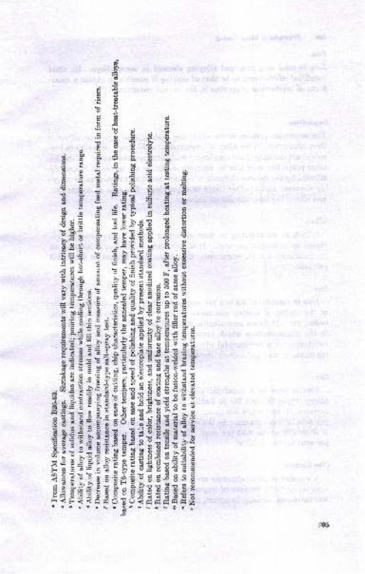
$o
aabs.88!Or
Eg E.rSgstEHE>IO'
E H e: :! g
EiEs-a;if,: 5 ; sE'i a E :
tstEiiftae*E;E:tti;f,iesiE€eI ?tiEE EiiE
iigiigiiiiiiiEi$
Ei3iiiiifiiilii3!i:05
306 Prircipbt o! Mctal Ca,/.,/9
Zin
Zinc is used es a plincipal alloying elemetrt in sooe alloys. Its chieibeneficial effect seems to be that of making it possible to obtsiD I msxi-mum oI mechanical properties in the as-cast conditiol.rl
Inputitkn
The impurities present in the aluminum casting alloys glea y iufluencetheir properties. Two alloy characteristics which may be seriously im-paired are ductility (and toughness) and corrosion resistance. Althoughother propedies may also be afiected, the latter are the most frequentlysflicted by the various elements which are someiimes looked on as alloy-ing elements snd at other times as impurities. The case of magnesiumand silicon has been considered above.
Srrrcon
Silicon as an impurity in most aluminum castirg alloys can be tol-erated up to several per cent. It i6 only when brittleness is induced, asby combination with magnesium, th8t it must, be limited to 0.2 to 0.8per cent.
Irou in amounts of 0.8 to 2 per ceut is an omnipresent impurity becauseof the ability of molten aluminum to diosolve iron from furuace pois,ladles, etc. It forms iron-aluminum and iron aluminum_silicoo ph".""i! ihe microstructure which cause embdttlement aud loss of corrosionresistance. Auother hetmlul effeci of excessive iron conteut is a coarsen-ing of the as-cast grain size of the metal.
Zin
Zinc is used as a beneficial alloying element in a certain group ofalloys; types ZC aod ZG in Tables 12.1 to 12.8. In other alloy types,however, it may cause loss in corrosion resistance if it exceeds O.l to 0,8per cent in some grades. In the copper-Iree, silicoo-aluminum alloys itis allowable up to 0.50 per ceot. In other alloys amounts up io 2.50per cent are permissible.
Other Ebncntt
A number of other elements are oftren given limits of 0.0b to O.1O pcrcent individually because of impurity efrects. These may include lead,tin, autimony, areeuic, cadmium, etrc.

rla
9_6dt
aa
i+i SgB 8B
,E+s t3OO
B$s666
gEB :ts
:
-9€i
o133oo() T E gS
e 6 663O
33OO
ol,
*,Ias*53!- .E-iEi.E E
+ic.5,t) o
lq
A!
5
E
F
O
d
z
Or-6o6.noiEoc,iooict
1
!i6?o?,?eaan,?qc!oq:ae9!i6rioi !r!a!!
Oqqn nqc.=-*
.oNoo6? q\\9,?:qc\
(oi Fcto
<Eq>sPri ti=b aFa
:::::E6s axSFxx",-,= seiEXs*=:xsa2A 33;2;S*E;'l PP@=rr:-,Dd..+u.-- --hhBH?ikxiiS
.9
:5
&
8E
!c'68
o-b
i6a
3oo-E458E
F. Xo-gEEJ,".?
* r.iia^"9
'r"ii5 SE
,d" 1
E*EF E.:
.c! E
<!Y
307

o
o
dd
o
.lurz"rqroj elq8llns
o o o o o o o o oE! o o o o o o o o E E E Ezzzzzzzzz sazzzzzzzz>>>>,turple^r
.ro; ,(1qrqe1mg+r < $ $ $ o $ 6 6 i i 6t N ar N N N N N + <1 S n1
,'dura1 pe.1raa1e
}ts q€ua4s H i 6l N (n N 6 6A CO ni $ N c\l m m N CO C€ N 6 rO rO rO
,(uo11ce1o.rd)
tuqroc eprxo
IEcruleqc
$ 6O N cr, <r rO x i i N N Ci N Cn aO c\l N N N C\r N 6-l N
,(ecu"r"add€)turzrpouy m N m.({ m <i i N i {t $ nr nr <r ro ro !r g ro i : : :
,tu11e1do.r1ce1g d i i N N D 6 6 {t N N N N N c6 m H i ir N N ca cO
aEu1qs11o4 N N N N C.l N - i n $ $ m.r, q? S rO 6, m rO H - i i
/3ururqctstr^l d N 66 C6 C-l N r : : 6 6 (O (i! Cr' 6t tl. aO 60 !r d d i d
,uotsoxoco] ecutsl$seu
rO :li ii rO lo rO H - : N (O m cO c6 C6 gO C{ 6| ca N N N g{
o
dd&0
tq
11
pel"eJl-l"aq{11uuuo1i1
i iBio ooog g g g EEaaEEEYg g Eg,s g g EEE9
,{cuepuele8elur.rqs
uorltscgrprlos<r $ 6a (€ (O (€ rO $ <r N N N N 6€ N (O - i m lo 6 lo ro
,d?!ptnld m co cr: m N c\| u) nr ro E d c\. N N : i 6l 6l| r <. nr <r <r
ssaulqEll
-aJnsg)Jdlri $ m crl ca a€ lo <{ E H : i i N 6l N i - N $ nr $ $
*turlcrlc 1oqc4 ecualsrseu $ $ 5 c\l 6a N <r $t <. r i i i N : H i i - rO rO rO rO
oI utr'xE
S
E.HE
3pee8e3e8RR88R88HB88BB3idii<iiii:OOHiOi-iH
*g*A**dd*es**g**$$*d**$iidHiiH
o
E*xsxEFxx , ,=;;;$@Ni<$vJm6t)AaaaaAAN,:=.iuutrLrt (J(J(J90(h(n
i iooid**<m*<'d<;Jm66@;rrri€,6(a$GGO()UC)(J()OZUQOOoaQ@aaoa@@NNNN I
ql
B
B
o
q)
t)
L
h
r3tt
s>
la,
rC
lso .-
r$tstLS
^s !'
Ner.S
-8.=
3C8

lio
E€!ro'[
ragE-3=
; Ib d aE
f ExEf g
8 tef tg#I 3 dEi E E EE H eIB E .E EE,i B Eg>uT E E
I+HilEEeiE
EE E €IgEE *gH
Eaui?*Etra?€e
ia;teEIiai;E!EgEEf{EEE€EEgEE
EiiiEEigiEiiiii
gnEiitiitiEIiii
Ef$a$E$tgiisfli#I . - o ! . \ €..'-
3U'
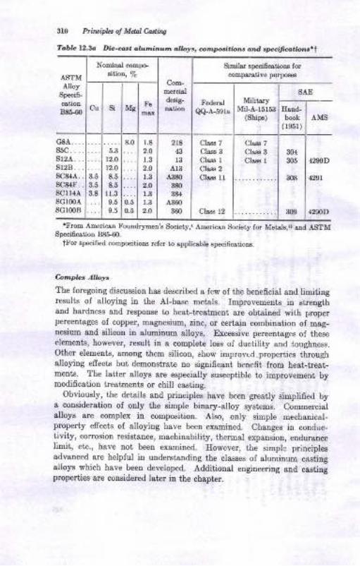
3IO Prtwifu ol Mdal Cadins
Toblc 12.3o Di.-ca.. ahL,,nltr.ur'o aW., cor,.pori.io . a .t ,,f,,cit.,,ti"! ..t
ASTM.dlloy
Speci6-
B85-60
Nominal compoBifion, 7a
Com-mercbldetig-
Simil$ specifcstioDs forcomparativo purpo€€B
Cu si MgFe Federel
Q+A-59rs
MititaryMiLA-15r53
(Ships)
SAE
IIand-book
( r951)AMS
c8A....85C....8r2A.. .
sl2B. . .
sc84a. .
8C84F .
R(.]I l,1A
3.5
3.5
3.8
8.0
0.;0.5
1.8
2.O
r.32.O
1.3
2-O
1.3
1.3
2.O
2t843
l3413
A380
380
384
A.360
360
Clrrs 7Cbs3 3
Chss rChss 2
Chs3 lr
Cbss 12
Cls33 7
Cla.ss 3
Clsss I304
m5
308
309
4,9,JD
42Al
42S0D
5.3
12.0
12.0
8.5
8.5rl-39.5
9.5
SGIMAsclmB
tFrom AmericsD Fouodrymetr's Society,. ArDericatr Society for Metals,{ sod ASTMSpeci6catioD 88&60.
ttrbr BlEcified compositioDs refer to spplicsbh specificstioDs.
6npLaAW.The foregoing discussion ha6 described s few of the beneficial aud limitingresults of alloying in the Al-base metsls. ImproveEeDts itr streDgthand hardness and re8pouse to hest-treatDeot are obtaiBed with properperceDtages ol copper, magnesium, zinc, or certain combination of mag-nesium aud ailicon in aluminum alloys. Excessive p€rceDtages ol theseelements, however, rezult in a complete loss of ductility end tougbtress.Other elemeuts, smoug them silicoD, show improvrd. properties ihroughalloying efrects but demonstrate !o signifrcsDt benefit from heat-tre8t-ments. The latter alloye are especislly susceptible to improvement byEodifieation beahoents or chill caeting.
Obviously, the details aDd priuciples have been grestly sinplified bys consideration of ouly the simple binary-alloy systems. CommercialalloyE are couplex in composition. Aleo, only simple mechanical-properiy effects oi alloying have been examined. Chauges in condtrc-tivity, corrosiou resistauce, machinsbility, thermal expansion, eDdursncelimit, etc., have uot been examined. However, the simple ptinciplesadvanced are helpful in uDderstsndiDg the classes of aluminuB c&stingalloys which have beeD developed. Additional eugiueering and castingproperties are con8idered later in the cbapter.

E!tE.
9
.:d?
HE E$Bg E E.E;
aE gII5s 4E gI = c !i.: ai E ClE! E
6 E t}E< E
; E IEEa gJ .: ;lErr a
i E €6fri iE C BEiE ;y 3 E;3Es!Eri ;EE;E;
i:i *E#iii.E5 ! E.E,E NEi E
IE E i;sE€i IE:S 3-^o 6- E;
s:E {€EE 3HE3->" ! 5i X I45
IIE :; friFti5€:. -iEFsf eE
E!? ==ErgFEI
if ;- E i-ri En E
€gEEeiI€gEEEbE 3E.iiE r s.5br'+:; lEaii v.o -o c c d 6 0-o c, d d<<tr btcoo<Ec€'""s'
i
,a
5It_
F!
s
tI
,s
ba.!,s
.s
Ir
.E
I
!
,l
!
olat6il
-6 I
3
o
tqz3rqro] atqsrFs zzzzzzzzz
suIpta.t.
rol elqslrns zzzzzzzzz
pelB^ela
ls q13 uarls
(uorrcerord)
ltrqlaoc eFxo
IBCruaqc
recr-rsr"eddgEurzeouV
,SuIrletd-o4aelg
/tulqqtod
sururqcir{ - !, r{r rr .a .o sa .o .r)
ol acm$rEeu
,{[BurroN
r,{qcadRotu!tgietC
ss€urqttr
n
&
E
,tur{c8.rc toqo] ecuaFsall
'i qF
<E
8P8888833:=99=:9==*EEEs**eE
<tri88
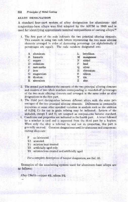
lYL Prfiuiplcs oI Mclal Catiw
ALLOY DESIGNATION
A standard four-part system of alloy designation for aluminum- and
rnagnesium-base alloys was first adopted by the ASTM in 1948 and is
used for identifying approximate nominal compositions of casting alloys.3s
1. The first part of the code indicates the two principal alloying elements.
This consists in using tu/o code letters representing the two main alloying
elements arranged in order of decreasing percentage (or alphabetically ifpercentag$ are equal). The code numbers designated are:
A aluminum
B bismuth
C copper
D cadmiumE rare earths
F iron
G magnesium
H thoriumK zirconium
L berylliumM nranganese
N nickel
P lesd
a silver
R chromium
S silicouT tinZ durc
2. The second part indicates the amounts of the two principal alloying elements
and consists of two whole numbers corresponding to rounded-off percentages
of the two main alloying elements and arranged in the same order as alloydesignations in the 6rst part.
3. The third part distinguishes between different alloys with the same per-
centages of the two principal alloying elements. Differences in permissible
impurities or some other specified variation in analysis such as the additionof 0.25/o Cr for use in grain refining may be indicated. Letters of the
alphabet, except I and O, are assigned as composiuions become standard.4. Conditions and properties are indicated in the fourth part. A letter followed
by a number is used and is separated from the third part by a hyphen.
When only the alloy is referred to, and not its properties, this part is
generally omitted. Common designations used for aluminum a.nd magnesium
casting alloys are:
F as fabricated
T2 annealed
T4 solutionheat-treatedT5 artificially aged onlyT6 solution heat-treated and artificially aged
For a complete description of temper designation, see Ref. 33.
Examples of the numbering system used for aluminum-base alloys are
as follows:
Alloy CS4SAiopper 4/e,silicon 3/a
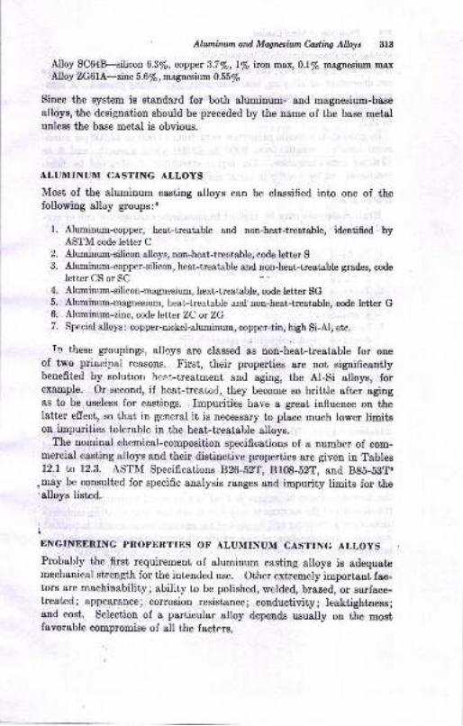
Afuniruun and Magrusilnn Cuting Alloy* 313
Alloy SC64B--stlicon 6.3/e, coppet 3.7Vo, l/o iron max, OlVo magnesi'rm maxAlloy ZG6IA-zilc 5.6Vo, magnesium 0.55l,
Since the system is standard for both aluminum- and magnesium-base
alloys, the designation should be preceded by the name of the base metalunless the base metal is obvious.
ALUMINUM CASTING ALLOYS
Most of the aluminum casting alloys can be classified into one of thefollowing alloy groups:3
l. Aluminum-copper, heat-treatable and non-heat-treatable, identified byASTM code letter CAluminum-silicon alloys, non-heat-treatable, code letter SAluminnm-copper-silicon, heat-treatable and non-heat-treatable grades, code
letter CS or SC
Aluminum-silicon-magnesium, heat-treatable, code letter SGAlrrmilsa-6sguesium, heat-treatable and non-heat-treatable, code letter GAluminum-zinc, code Ietter ZC or ZGSpecial alloys : copper-nickel-atrrm i1g1a, copper-tin, high Si-Al, etc.
k' these goupings, alloys are classed ae non-heat-treatable for oneof two prilcipal reasons. First, their properties are not significantlybenefited by solutrou heat-treatment and agiug, the Al-Si alloys, forexample. Or second, if heat-treatod.they become so brittle after agingas to be useless for castings. Impuritieg_ have a great influence on thelatter effect, so that in general it is necessary to place much lower limitson impurities tolerable in the heat-treatable alloys.
The nomiual chemical-composition specifications of a number of com-mercial casting alloys and their distinctive properties Bre given in Tablesl2.l to 12.3. ASTM Specifications B2G-5y1, B108-52T, and B85-5BT8
.may be consulted for specific analysis ranges and impurity limits for the'alloys listed.
Lr*"r,*r"^rNc pRopERTrEs oF ALUMTNUM casrrNc ALLoys
Probably the flrst requirement of aluminum casting alloys is adequatemechanical strength for the intended use. Other extremely important fac-tors are machinability; ability to be polished, welded, brazed, or snrface-treated; appearance; corrosion resistancel conductivity; leaktightness;and cost. Selection of a particular alloy depends usually on the mostfavorable compromise of all the factors.
t
3.
4.
D.
6.
7.
311 Prirciph: ol Mchl Cottins
Mechonial Properties
As discussed previously, the mechanical properties ol the casting alloysare depetrdeni on alloying, hest-tteatment, snd casting process. A 6um-mary of the typical tensile-property ranges for the ihree casiing processee
&ud different conditions of heat-trestmeDt is preseuted in Tabtes 12.4to 12.6.
In general, the tensile properties vary from 12,000 to 43,000 psi mim!murn tensile strength, from 9000 to 48,000 yield strength, snd 0 to12.0 per cent elongation. The higher strengths are obtained by heat-treatmetrt and by casiing in metal molds.
Ileat-treatments may be applied to alumilum castings for one or sey-eral of the Iollowing reasons:
l. To obtai[ the most favorable or desired mechanical propertieso. Strcngthening6. Toughening
2. To obtain dimensional stability of castingso. Minimize or preveDt growthb. Stress relief
3. To stabilize mechanical properties and uncontrolled change of propertiesduring use (room-temperaturc aging)
The alloys which usually receive heat-treatments are indicated inTables 12.1 to 12.3.
Solution and aging heat-beatmerlts. The desired rnechanical proper-ties are usually obtained by some combination of solution heat-treatmentand age- or precipitation-hardening treatment ernbodying the principlesdiscussed earlier. The temperatures and time required 1or these heat_treatments are given in Table 12.2. Addiiional data of the type foundin Table 12.7 may be found in Ref. 1. Conventional heat-treatingfurnaces of the air-chamber type may be used. Molten salt, baths arealso possible. Temperature control is essential, and variations withinthe furnacc should be within 5 F of the required temperature. Sincethe strength of the castings is very low at solution heat-treating tempera_tures, careful stacking and support of the castings are desirablelo prevent r
warpage. Overshooting of the solution heat_treating temperature canbt disastrous, since melting begins at temperatures only a little sbcvetltose oI heat-treaiment. Quenching of the castings from the solutionheat-treating temperatures is done in hot water or in air. Cold watercauses cracking or serious distortion of the castings.
. To obtain improved ductility or toughness with increased streugtrh,
ihe castings may be left iu the solution heat-treat€d condition. ior
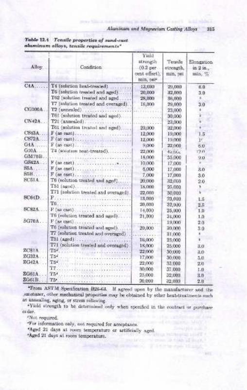
Aluntuun ond Mdgvtiun C&rtiry Alkty
TabL 12.4 Ten ilo p.oprtie. oJ .ond-c*.,,lur,.i}nu'm ollolr, tensile require@nts.
315
Condition
T4 (solution herLheeted).... -.....T6 (solution tr€ated snd sCed). . . . . .
T62 (solution trested and ag€d. . . . -
T7 (aolution trested and overaged).T2 (snnealed).
TOt (solution trested snd s,Bed). . .
T21 (ann€aled).
T6l (solutioD treated snd sged). . . . .
r(asc$t)...........F (as cast) . . . . . . . . . . .F(ascast)................T4 (soiurron heat-treated).. .. -....
F (as crst). . . .
F (Bs cast). -.........F (rs cast) . . . . . . . . . . .
T6 (solutiotr tr€sted rtrd aged).... - .
T51 (ased) ..........T71 (solution hea,ted aDd ove.ased).r. .............. .
T6...... ... . ..F (ss cast) . . . . . . . . . . .
T6 (solution treat€d end ased). .
F (as c€.st)...... -....T6 (solutior treat€d end aged). . . . . .
fi (solutior treat€d sDd overaSed). .
T5r (a.ged) ..........T7l (solution treated &nd oversSed) .
T5.. . .........
Tia ............ _
T7..... .. ...Tsd. . . . . . . . . . . . . .
T5.. . . . . . . . . . . . . . . . .
Elongatior.
in 2 in.,I,,iL, oita
zc8lA ..zc32a. . .
ZG42A, , ,
r3,000
20,000
28,0m
llt*
20,000
r2,000
12,U)0
9.0(n
22,Ur18,000
10,000
6,000
7,000
20,000
r8,000
n,w)13,000
20,000
1,1,000
21,000
20,000
16,000
18,000
22,$n17,000
22,OU)
30,000
25,ofi)
?o,000
2S,000
32,0O0
36,000
29,000
23,000
m,00023,000
32,000
r9,m0rs,000
22,(N
35,000 I
tz,om I
17,000
17,m0
32,00o
25,000
30,000
23,000
32,000
25,000
34,000
19,000
30,000
31,000
23,000
25,000
30,000
30,00033,000
37,000
32,0m
6.0
3.0
3.0
1.5
t"6_0
9.0
3.0
3.0
2.O
1.5
2.5
1.0
t.02.0
3.0
3.0
3.0
5.0
2.O
r.0
3.0
2.0
'From ASTM Specificstion 82G63. If s,greed upon by the msnufactur€r end thc,,urehaa€r, other mechrnical prolErti€s msy be obtsined bl. other heat-trestments suchas aDnealing, sging, or stre$ relieying.
.Yield strenath to be determin€d only when specified in the conrract or purch!*.order.
tNot required.
"tr'or inlorms,tion oDly, not requirod for scceptance.dAged 2l da]ts st room t€mperoture or lrtificially s8ed.'Aged 21 dsrts st room tempenture.
YieldBtretr8th(0.2 p€r
cent ofiset),
sc64D. .
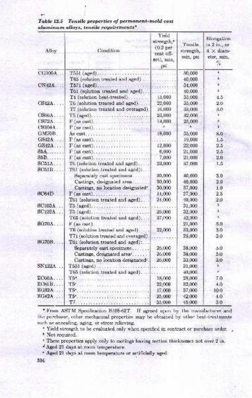
i
TabbI.2.S Teruib propertiaa ol prtnanent-moW ca,st
lrlutninutn allolrs, tansilc requiremantt'
Condition
Yield
Etrength,"(0.2 per
cent off-
set), min,
Tensilestrength,min, psi
f,l6ngrtionin 2 in., or4 X diam-et€r, min,
/o
cs66A. . ..cs72A....cs104A...GM708...GS424. . . .
G'.l42L. ...s5A.... . . .
s58.. . ... .
sc5rA....sc5rB....
30,000
40,000
34,000
40,000
$,0m35,000
33,000
32,000
23,000D
35,000
19,000
22,OOO
21,000
2r,00037,000
40,0m
40,000
37,m027,O@
40,000
31,000
32,Un12,W2r,000
33,000
25,000
38,000
38,000
33,000
31,000
40,000
28,m032,000
37,000
42,mO
tb
D
6
4.5
2.O
3.06
D
D
8.0
1.5
2.5
2.5
2.O
1.5
3.0
3.0r.02.5
2.Olb
D
3.0
3.0
3.0
5.0
5.0
3.0D
i
7.O
4.0
r0.04.0
3.0
r From ASTM Specification Bf0&62T. If agreed upon by the manufacturer and
lh.: purcharser, other mecharrical properties may be obtained by other heat-troatmentssur:h a.s annealing, aging, or stress relieving.
" Yield strength to be evaluated only u'hen specified in contract or purcha.se order. ,D Not required.
" These properties apply only to castings having section thicknesses not over 2 in.dAged 2l days at room temperoture.
' Aged 2l days at room temperature or artificially aged.
3t6
Alloy
T65 (solution treated and aged).,TR?r /-dl\
T6l (sglution treated and aged)..T4 (solution heat-treated). . . . . . ..T6 (solution tre.ated and ased). . . .
fi (solution treated and overaged)
T5 (aged).
15,000
22,ON
16,000
25,000
r4,000d
18,000
12,ofi)
6,000
7,000
23,000
30,000
30,000
30,Ofi)
r4,000
24,OOO
sc64D...
sclosA. .
scrt2[..
S(:TNA
F (as ca.st).
T6 (solution treated and aged)..T6l (solution treated ond aged):
Seperately cast specimens. . . .
la-o+inm,lmianoiazl oroa
Castings, no locetion designated"
T6l (solution treated and aged).
T5 (aged).
T&l (solution treated and aged).It /op noot\
26,000
37,m0
sG708...
sNr22A. .
ZCffiA...TCRI R
TG (solution treated and aCed).. .
T7l (solution treated and overaged).
T6l (solution treated and aged):. . .
Separately cast specimens. . . . . . .
Castings, designated &re&.... . .. .
Castings, no location designated'.'l.(Rr r/0lr,1\
22,000
26,000
26,000
26,000
T65 (solution treated and aged).T(d r8,000
22,0N
17,000
25,000
35 fiYt
'n.6.
v.c:2, A T(.7,(].L'A 'T_(.
T7
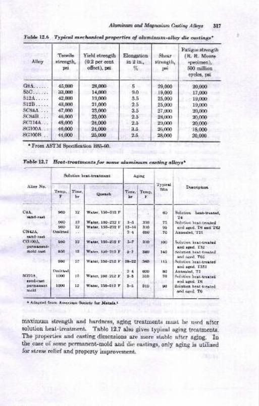
AlloyTeDsile
Btrength,psi
Yield strength(0.2 per cent
offset), psi
Elongationin 2 in.,
7o
Shear
streDgth,psi
Fatigue stnength(R. R. Moore
specimen),g0O milliqa
eycleE, p8l
G8A..... .
ssc. . . ...sr2A. . ...sr2B. . ...sc84A.. . .
sc&18....scrr4A...sG100A...sG100B.. .
45,U)0
3:t,(m42,W4:],(m47,W46,(m48,0m46,(x)0
44,(n0
28,fi)O
14,(no
19,(n0
21,m023,m023,mo24,,W24,W25,0(x)
a
9.0
3.5
2.5
3.5
2.5
2.5
3.5
2.5
29,000
19,0m25,0m25,m027,W28,m029,m026,000
28,(n0
20,(mu,0m19,m019,m020,m020,m020,(m18,0m
m,w)
Al1llminltn and Magusium C,uling Albyt 3l?
Tabb 12.6 Typiul rneclunieu,l lmprties of alutninutn-o,lloy die aatingc,
'From ASTM Specification 88&60.
Tablc 12.7 Hat-tratmcnts for nnc aluninulm casting alloys.
Alloy No.
SolutioD h6t-tr6tEeat Agiog
TypicalBhn
DecriptionTemp,
Fllme,
hr QueachTime,
hrTemp,
F
!Md-cst
N42A,
!8nd-cetG100A,
fErmanent'oold cst
Nd-cstpermahent
mold
960
960
960
Omitt d
950
950
950
t2
t2t2
t2
t2
l2
l2
t2
f,rotar, l5G-212 F
Wrier, l5G-212 FWotcr, l5{F212 F
X/ater, l5(F212 F
Weter, l5{F212 F
X/ater, l5O-212 t'
S/atcr. l5O-212 F
Wetcr, 15O-212 F
3-5t2-1621
5-7
5-7
t*22
242-5
3-5
3ro3ro650
3lo
340
3!(l
6{X)
3ro
3ro
60
7595
70
loo
l,to
ll5
8070
90
Solution hest-trcotad,T4
Solution hert-treatedand aged, T6 eod T02
Annealed, T2l
Solution heat-tre.tadaod aged, T52
Solution heei-trestadand aged, T65
Solutioo heat-troatedaod aged, T55l
Anuealed, T2SolutioD beat-trest€daad aged, T6
Solutioa heat-ttotcdud s8ed, To
lux)
r000
. Adapted from Amorican Sciety fot Metdc.r
maximum strength and hardness, agrng treatmenLs must be used aftersolution heat-treatment. Table 12.7 also gives typical aging treatments.The properties and casting dimensions are more stable after aging. Inthe case of some permanentFmold and die castings, only aging is utilizedfor stress relief and propeny improvement.
cG100A,

Principles oJ Mdd Codha
Anneoling. Annealing may be accomplished by heatin! the castirrgs
to about 650 F lor I to 4 hr aDd thetr air or furn&ce 9o6ling. Maximum
ductiliiy 8nd low hardness and strength are th1ltrlobtained. However,
the csBting dimensions and properties wi}l-tre most stsble. In the
unannealed coldition, Al-Si alloys can grdw 0.0016 in. per in. because of
gradual precipitation of eilicon from tLe aluminum-rich solution promoted
by die atrd pernanent-mold castirgs. Dimeusional changes of this order
cen be objectionable buf can be avoided by heating at 400 to 45O tr'
for 10 to 2O hr.
Foundry uarial>les and, heat-treatm,erlt As with other propeties, the
resulis of heal-treatments are susceptible to the foundrJr history of the
alloy. For example, in Table 12.7 the hardness aft€r heat-treatment
cI alloy SG70A is shown to be dependeni on the casting process. The
Dp..nanent-mold caBt alloy has a Brinell hardness numbet (Bhn) of 90
as compared with 70 for the same alloy sand-cast even though both.eceive the same hest-treatment. Hence the heat-treatment used must
account lor the influence of loundry variables and be adjusted to develop
the desired properties.
Othe, Mcchanical Prcpc i.s
The properties of shear strength, endurance limit, and compressive
strength sre of importance in some applications. Endurance limits of6500 to 10,000 psi based on 500 million cycles with the R. R. Moore type
of testing equipment are common for many aluminum casting alloys.
Shear strengths of 16,000 to 32,000 psi are obtained, being higher in heat-treated alloys and generally increasing with the yield and tensite streugths.
Compressive yield strengths of 10,000 to 46,000 psi are developed, thehigher values always being obiained in the higher-teosile-strength alloys.Young's modulus ol 10,300,000 psi, modulus of rigidity of 3,850,00O psi,
and Poisson's ratio of 0.33 apply to most alloys. Specific values lorthese properties may be obtained lor some alloys Irom Refs. 1 and 5,
Imp ane o! Tert Barr
Because the mechanical properties of aluminum alloys are markedlyinfluenced by the casting process, it is necessary that mechanical-propertytests be made ou test bars represent8tive of the casiing process. A typicalsand-cast tensile test bar is illustrated irl Fig. 12.10. A 8etup for castiugpenoanentmold t€st bars is illustrat€d in Fig. 12.11. A number of otherfaciors such a.9 pouring rate, mold temperature, metal tcmperature, audtime in the mold, all afrecting cooling rate, have been found to alter tleproperties.G llence it is evident that, auy evaluatiou of the mechanicalproperties of an aluminum alloy used for cesting purposes requires care-ful 8tt€ntiotr to tlre detaile of obtaining a represeniative test bar (Fig.t2.12).
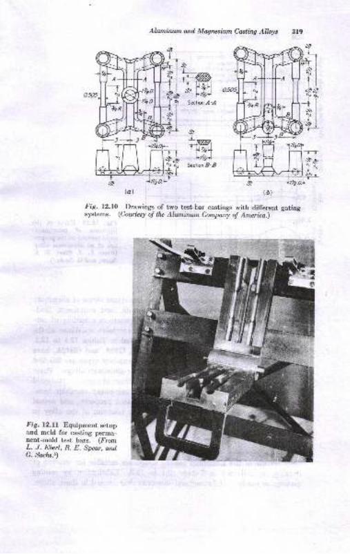
Alwninwn and Magrcsiun Castirq Alloys 319
Fig. 12.10.^Drawings of two test-bar castings with different gatingsystems. (Coute^ry o! lhe Aluninwn Company o! America.)
LwJ" lt zrl*'
FthtSstion ,4 -,4
L-*,| )-)2,-L
lt4lScct-Dn B B
Fig. l2.ll Eguipment setupand mcld for casting perma-nent-rnold test bars. (FrornL. J. Eltert, R. E. Spear, andG. Socns.9
n\
h1-\l
-il.\.1"
+Tsl__tlil+l
fl"SrS:
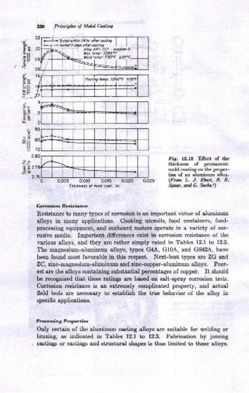
b1< fcsbd tl dols olrercosliog I I
, -T- il':!l:[-,"7*a?,'*'tlold temp: 73O"F trO'F-
:t20 Prircipb: o! MdaI Carrlitwi
,;c'ZgooooOE9c.,q;!ooopo
=
.9==iEto5[U
ic9-o3
o=
.9>=.:oo
o.oo5 0.0ro 0.0t5 0.020Thickness ol mold cool, in.
Fig. 12.12 Ellect of thethiclneas of permanent-mold coating on the proper-ties of an aluminum alloy.(From L. J. Ebrl, R. E.Spa.t,adG. Satit.9
&rtoabn Resistarue
Resistance to many types of corrosiou is an important virtue of aluminum
alloys in many applications. Cooking uteusils, food containers, food-
prcceosiDg equipment, and ouiboard motors operete in a variety of cor-
rosive media. Important differpnceg exist, in corrosion resist&nce of the
various alloys, and they are "str6$
RimFly rated in Tables f2.1 to 12.3.
The magnesium-aluminum alloys, types G4A, G10A, and GS42A, have
been found most favorable in thie respect Next-best types are ZG and
ZC, zitc-aagaesium-alirminum and tinc-copper-alrrminum alloys. Poor-
eot 8re the alloys containing substsntial percentages of copper. It should
be recopized that these ratings arc b88ed on salt-spray comosioD tests.
Corrosion resistance is an extremely complicated property, and actual
field tests are necessary to establish the true behavior of the alloy inspecific applications.
Ptoceradng Proprtiac
Only cerUain of the aluminum casting alloys are suitable for welding ortrrazing, as indicated in Tables l2.l ta 12.3. Fabrication by joining
castings or castings and structursl shapes is thus limit€d to those alloys.
AlumiluunailMqtlrlinCarllitrg AlWc :l,ll
Machinability of most of the aluminum alloys is excellent. In geueral,
ttre high-copper-content alloys have better machinability whereas the
high-silieon-content alloys have poorer machinability. Specific machin-
ing practices are given in Ref. 7.
&$aaTralnuitSeveral surface treatments may be applied to aluminum'castinge.
Anodizing to obtain a bright silvery luster may be performed. The
eleaned casting is immersed for 15 to 45 min in an electrolyte of 15 to18 per cent HrSO. as the anode at 14 to 30 volts and a curent deusity
of 12 to 15 amp per sq ft. A chemical coating may be obtained bytlipping the cleaned casting in a solution of 2 per cent sodium carbonate0.10 per cent potassium dichromate at 160 to f80 tr.. Either the ano-
dized or chemical coatings may be sealed for added corrosion resistsnce
by dipping in hot 5 per cent potassium dichromate. Maximum proteo-
tion from corrosion can be obtained if the sealed easting is theu painted.
Other treatments sueh as polishing and electroplating are possible, buttheir consideration is outside the scope of this text. Ilowever, Tables12.1 to 12.3 indicate the relative response of the various alloys to these
treatmeuts.
ALUMINUM.ALLOY CASTING PROPERTIES
The production of good castings requires that the casting alloys possess
favorable foundry properties. Those considered of importance for alumi-num casting alloys are:
Minimum solidification shrinkage. (and maximum yield)
Adequate fluidityFreedom from hot tearing or glacking
Minimum difrculty in producing pressuretight casti.gsMinimum problems with gas absorption and drossing
The metallurgical principles relating to these properties have been
discussed iu Chap. 8. However, some of the more notable effects iualuminum alloys are briefly considered.
Shrinka,ge
Shrinkage problems are at a minimum in the Si-Al alloys containing b
or 13 per cent Si according to Tables 12.1 to 12.3. Accordingly, loundry
,yield is at a maximum, and difficulties with hot tearing and microporosityare minimized. It may be noted in the tables that alloys having iow
1.o
3.
4.
o.
*n Prinriplcs of Melal Casting
shrinkage tendencies accompanied by a narrow freezing temperaturehave the better ratings of resistance to tearing, pressuretightness, andfluidity. This follows the general principle related to solidification mech-anisms described in Chap. 8. Rated second to the Si-AI alloys are thehigh-silicon-low-copper-aluminum alloys, the SC types. Because of theirfavorable casting properties, the silicon-rich aluminum alloys are exten-sively used for permanent-mold and die castings. Percentages of. 5,7,9,and l2/o Si are used in combination with other elements for castingsmade by the metal-mold processes. Since most of the same alloys canbe heat-treated, it is evident that this class of alloys is good for general-purpose use.
Patternmakers' shrinkage for the various alloys is given in Table 12.1.A low value of patternmakers' shrinkage, however, does not mean thatthe shrinkage problems of microporosity, pressuretightness, and crackingwill be low. The mechanism of freezing rather than the total contractionis a dominant lactor in the latter problem. For example, alloy G10Ahaving a long freezing range is troublesome in leaktightness, even thoughits pattern shrinkage is a minimum.l3
Fluidity
Few quantitative s+,uciies have been reported of the fluidity of aluminumalloys using fluidity spirals of the type desuibed in Chap. g. A ribbon_type spiral has been used successfully and is reported in Ref. g. However,the generaiized ratings reported in the tables are based primarily onfoundry experience in running thin and intricate sections in practicalcastings. The silicon-rich alloys favor fluidity and resistance to tearing.Table 12.3 shows that most all die-casting alloys are silicon-rich alloys.Figure 12.13 illustrates a variety of die castings rvhich require fluirr.ityand tearing resistance if they are to be successfully cast. Thus it appearsthat silicon improves many of the casting properties of the aluminumalloys' This appears to be the reason that the general-purpose castingalloys contain substantial amounts of silicon, arong with smaller per-centages of copper or other elements.
Drossing and Gas Absorption
The drossing problems of the different alloys vary somewhat. The morcoxidizable element, magnesium, causes extensive drossing in the high_magnesium-content alloys G4A, Gl0A, and GS42A. Gas absorption, ihedissolving of hydrogen, has been said to be more serious in some of thealloys. However, the few experimental results available seem to indicate
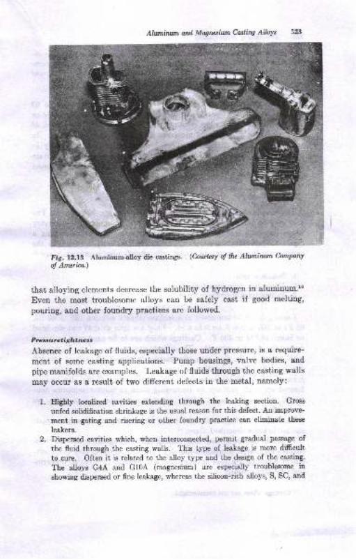
Alwninnn ard Mqnzsiun Castitq AWs
Fig. 12.13 Aluminum-alloy die castings. (Cowtcsy oJ lhe Ahnninwn Company
o! Americo.)
that alloying elements decrease the solubility of hydrogen in aluminum.'"
Even the most troublesome alloys can be safely cast if good melting,
pouring, and other foundry practices are followed.
Pressuretightnesa
Absence of leakage of fluids, especially those under pressure, is a require-
ment of some casting applications. Pump housings, valve bodies, and
pipe mani.folds are examples. Leakage of fluids through the casting walls
may occur as a result of two different defects in the metal, namely:
1. Eighly localized cavities extending through the leaking section. Gross
unfed solidification shrinkage is the usual reason for this defect. An improve-
ment in gating and risering or other foundry practice can eliminate these
leakers.
2. Dispersed cavities which, when interconnected, pemlit gradual passage of
the fluid through the casting walls. This type of leakage is more difrcult
to cure. Often it is related to the alloy type and the design of the casting.
The alloys G4A and Gl0A (magnesium) are especially troublesome in
showing dispersed or fine lealiage, whereas the silicon-rich alloys, S, SC, and
d
32tL Prineipl* o! Mdnl Casling
SG types, are less difficult to cast leaktight.,. Dispersed shrinkage is re-duced to a minimum in any alloy type by po.uring at a minimum tempera-ture (1250 F), making every effort to obtain directional solidifcation, propergating and metal flow, and use of the best melting practices.
Leaks may be detected by pressure testing. Air pressure, 40 to g0
psi, is applied to the casting, and it is immersed iu warm soapy wet€r orsprayed with a warm soap solution (1.6 oz neutral soap per gallon ofwater). If leaks ere found, measures may be taken to seal them. Inspite of the best of foundry practices, leakers* occur and many may bemade usable by sealing. Indeed, sealing is almost a necessity for certaincombinations of castiug designs and casting alloys to produce leakproofcsstings even with the best foundry practices.
&alilw
The simplest sealing method for localized leakage is peening. Theerea mey be hammered to close trp the leak. Impregnation is necessarywhere dispersed leakage is found. Impregnation consists in causing aliquid to penetrate the shrinkage holes. After being forced into thecavities, the liquid tlrrns into a solid. Commonly used impregnants are:rl
Sodium silicateDrying oils: tung, linseed oil, etc.Various types of synthetic resins
Castings may be immersed in a sodium silicate solution (80 to 40 86,65 F) at f50 to 200 F for 2 to 4 hr. They are then washed and air-driedor baked at 215 to 300 F. Castings which are to be aged may be bakedduring the aging treatment. The silicate can be more effctively appliedwith pressure. In this case, the casting is closed off, except fo. oneopening, the silicate solution is introduced to its interior, aud then airpressure, about 30 psi, is applied. Pressure silicating may also be per-formed on small castings by immersing them in silicate solutions con-tained in pressure tanks. After pressure silicating, the castinge areair-dried or baked.
various types of'synthetic resins may be used as sealers using methodssimilar to those described above.l.
rt should be recognized that searing and impregnation are not sub-stitutes for correct aluminum-foundry practice. Rather, they are meth-ods of handling problem castings that are diffieult to produce pressure-tight by other means.
' Casting! which arc uot preanrretight.
I.,3.
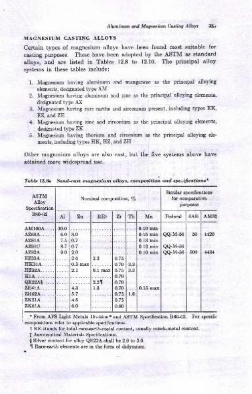
Ahanirusn ard Mqncsiun Cuting Allsls 3rJ
MAGNESIU]U CASTING ALLOYS
Certain types of magnesium alloys have been found most suitable for
casting purposes. These have been adopted by the ASTM as standard
alloys, and are listed in Tables 12.8 to 12.10. The principal alloy
systems in these tables include:
1. Magnesium having aluminum and manganese as the principal alloying
elements, designated type AM2. Magnesium having aluminum and zinc as the principal alloying elements,
designated type AZ
3. Magnesium having rare earths and zirconium present, including types EK,EZ,and.ZE
4. Magnesium having zinc and zirconium as the principal alloying elements,
designated type ZK5. Magnesium having thorium and zirconium as the principal alloying ele-
ments, including types HK, EZ, all,d,ZH
Other magnesium alloys are also cast, but the five systems above have
attained more widespread use.
Tablc it2.b Sand-crst magnesiunt alloys, cotnpositio; and speeificoltionst
ASTMAlloy
Specification
B8&62
$imilor sp€cificotieng
for comparativepurposes
AMSl
AM100A....42634.... ..428rA......429rc......42W4......EZ3ilA......IrKSrA. . ...B'z,32A... . . .
Kr4........QE22A! ....7,84tA... . . .
2H62A..... .
zI('tA... .. .
?,Id.6tA......
r From AfE Lisht Metsls Dvisionrt and ASTM Specification B8G'62. For specifi<
compoeirions refer to applicable specificatiotrs,
t RE stands for total rare-earth-motal content, ruually misch-metel content,
I Aeronautical Materials Specificetions.
I Silver eonteut for alloy QE22A ehall be 2.0 t,o 3.0.
t[ R"areeirth elements are in the form of didymium-
Nominal compcition, /p
AI Zn REi Zr Th Mn Federal SAE
r0.0
6.0
8.7
9.0
0.10 min
0.15 min0.13 min0.13 min0.10 min
n 1(
QQ-M-56
Qq.M-56Q+M-56
50
5{n
&m
44 1
3.0
o.7
o.7
2.O
2.6at2
3.3 o.75
0.70
o.75
0.70
0.70
0.70
o.75
o.75
0.80
3.3
3.32.1 nl
2.2nr.34.3
5.7
4.6
6.0
r.8
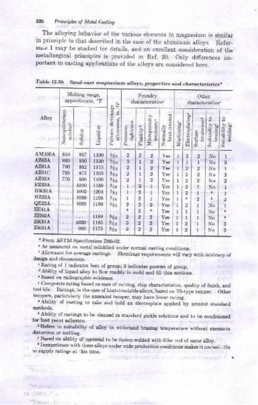
&!6 Ptin ipL, ol Mctal Cattiig
The alloying behavior oI the various elements in magnesium is similarin principie to that, described iu ihe case of the aluminu-m alloys. Refer_euLe 1 msy be siudied for details, and an excellent consideration of themetallurgical priuciples ie provided in Ref. 20. Only differences im-portant to casting applications of ihe alloys are considered here,
'I}om ASTM Spesifcarion B&42.. As Eeasured on metsl solidified under normsl csstitrg conditioDs.
. '.Allowance for &verag€ castiDs8. Shritrkase requiEm;nts will yary with intricscy ofd6iga and dim€Dsiols.
. Rsti-trg of f iDdicstes b€st oI group; g itrdicst€ poorest of group.
'Abiliry of tiquid atloy to fow resdily iD mold snd 6ll r,hin lactiotrs.. Based on rsdiogrphic e\'idence., Compo6it€ rsthg bs.sed on €ase of cutting, chip cbarsct€ristics, qur,lity of finirh, end
tool life. Ratings, in the case of h8t-trestsble dLys, bas€d ." TGiype ,i-o*. O,fr*tDhpela, p$ticularly the elllr€sled teDper, Iosy hsve low6r ratin8.
, Ability of crsting to tste sDd hold en electroph,te epplied-by preseot stendarJEethods.
. Ability of castings to b€ cl€snod in st{,ndard picklo solutioE eDd to b€ condiiiotr€dt6 bEt psjrt adhesion.
--.n {trs t,o suitsbility of slloy Io pithltsnd br4ring tsDpeEtur€ rithout exces.ivo
didprtioD o. helti4g., Bar6d otr ability of-qrterisl to be fusioi-weld6d with 6ller rod of ssme slloy.r In+perieDce with these alloyB under wide Eoductioa conditioD! m.skes it ua"jesir.,ble
r,o 6upply rstiDgs st ,bis time.
Table l2.Ab Sand-cas. ,nog,r'.e,iiun att ,ys, prolar.ies ond ct6roc.eris.icr.
Alloy
Meltina range,approximat€.'F
Foundry
chslscteristiOther
cbalactsristics.
E
zsal :l F6r it ;t.e
.E.5
z
B
I
E]
".E
E:
sb&
=_5
s
;'AMIOOAA?i3AA7,8IAazgrcAZ92AEZ?'SA
HXSTAHA2A.qEz2aZE4IA,ZH62A
ZIi6IA2I<6ta
810
6E5
790
785
770
867
850
882
875
830
l0r01092
t026
I',.l(Do985
llm1130
lll5r105
Irmrr89t2041198
r r90
ll6sI185tt75
212
962
z
91c14z
llaV6z
%z
952
s lrlsz ltl z2ltl2z lrl z
r lzlrr lzl r
r lzl t
z lzl zr l"l.zlilzt lzl zz lzl z
i_es
Ye6
Y€€
Ye6
Ye3
Y€s
Yes
Ye6
Yes
Ye3
Y€s
Yes
III1
I1
II1
tIII
2
I
2
2
2
I1
2I2
2
II
IIItI
NoNoNoNoNo
No
NoNoNoNoNo
I
I2
2
II
1
3
3
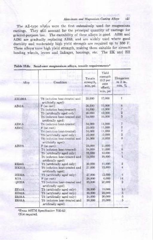
- All,/|.riuun and Mqrutiun Cailing AtW ;}27
,/The AZ-type all/ys were the fust extensively used Ior magnesiuDr
castings, They qtiil accoult for the principal quantity of csstings Ior
general-purpose Lse. The castability ol these alloys is good. AZ9l anrl
AZ81 are gradually replacing A263, and are widely used where good
ductiiity aud. moderately high yield strength are required up to 350 I'.These atloyg nave high yield strength, meking them suitable for aircraft
laading vheels, levers and linlages, housings, etc' The ZK and ZII
Table l2l8c Son.l-@rt mdgtue'ium dlloys' tensile requirements'
.Uloy ConditioD
Tens e
strength,
min, psi
Yieldstreagth(0.2 per
c€ntofiset),nin, psi
ElongstioD
in 2 il.,in, ?o
A2814.......A29rC.........
L?A3A.........HK3rA........
Il2324.........KlA...........r1E22A.........
ZElr!\.........2H62L.........2Ii514........zx6rA.........
TO (solution he&t-treated and
artiflcially aged)
F (as cast)
T4 (solution hesttested)T5 (artificislly ssed only)
T6 (solulion hesLtrested snd
artificially aged)
T4 (solution hest-trested)
F (as cast)
T4 (solution heet-trest€d)
T5 (arti6cially ased only)
T6 (solution heattr8ted and
artifrcialy sged)
F (as cest)
T4 (solution h4t-beated)T5 (artificially ssed only)T6 (solution heat-treet€d and&Itiffci!.lly ased)
T5 (&rtificialty ased only)T6 (solution heet-trest€d and
Artificislly Bsed)
T5 (artificisly aged o y)F (a.6 cast)
T6 (solution hat-trest€d Bnd
ertificiall]' ag€d)
T5 (&rtificislly ased only)T5 (artificislly ased only)T5 (artificislly aged only)T6 (solutioD beat-treated sndartificisly ssed)
35,00o
26,000
34,(m26,000
34,ofi)
34,(m23,0m34,m023,0m
34,0m
23,000
34,mO
23,UX)
34,(m
m,00027,Un
27,W)24,000
35,000
2a,m)35,000
34,m0
39,0m
17,000
ll,0mr1,000
r2,000
r6,000
11,0m11,000
1r,000
12,000
16,000
11,m011,m0
12,000
r8,000
14,m013,000
13,0m
6,000
25,000
19,0m22,o$20,000
26,000
4
t
47
7
i7
2
3
t6
tI
4
l42
5
5
5
'Frorlr ASTM Specificstion 83062.tNot required.
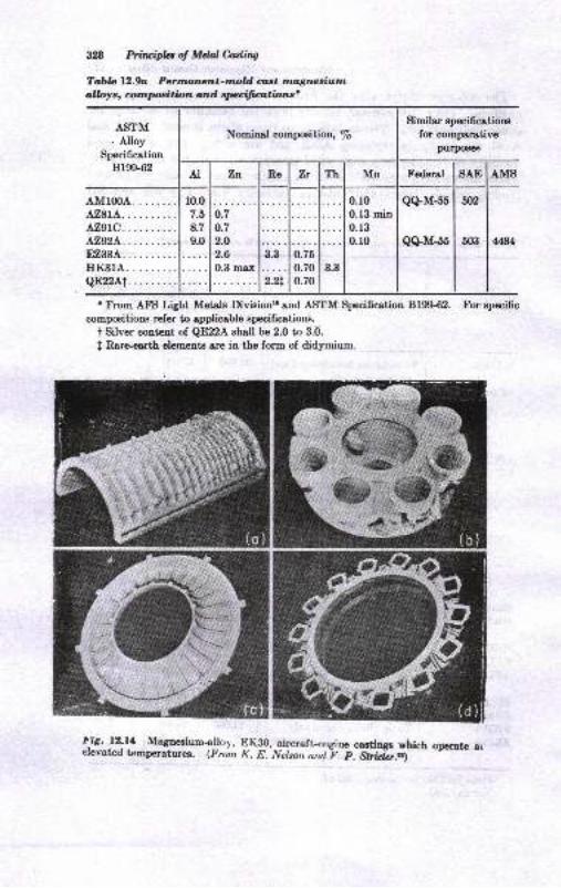
3n Prhuiplel of MdalCastiw
Tabb 12.'9a Pennanernt-tnold aat ruognadumallolrs, cornpoaition and apecificatbns'
ASTM. Alloy
Specification
Bl9$62
Nominal compoeition, /6
Similar apecifications
for comparativepurpoEeE
AI Zt Re 7n Th Mn Federal SAE AMS
AMrooA. . ......az8rA.L?,SLC.AZ9A.E,Zil|3A.
HK3IA.QE22Ai.
10.0
/.o
8.7
9.0
o.;'o.7
2.O
2.6
0.3 max3.3
2.2t
0.r00.lB miu0.13
0.10
Q+M-55
Q+M-55
w2
503 &o.75
0.70
0.70
3.3
r From AtrS Light Metals Divisiontr and ASTM Specificetion 8199-62. For specific
compositions refer to applicable apecifications.
t Silver content of QE22A shall be 2.0 to 3.0.
I Rareq,rth elements Bre in the form of didymium.
l:ig. !2:ll Magneaium-allo1, EKS0, aircraft_engine cagtin*s which orcrate arelevated temperaturea. (Fron K. E. Nelson and F. p. Stridrl.r)
^t--*-'f 'tri
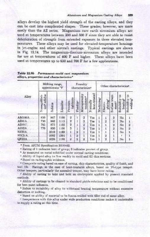
Allanirun atd Magrusilrn CaslirW AlWt 319
alloys develop the highest yield strength of the casting alloys, and theycan be cBst into complicated shapes. These grades, however, are more
costly than the AZ series. Magnesium-rare earth-zirconium alloys arc
used at temperatures between 350 and 5(X) F since they are able to resist
deterioration of strength from extended exposure to these elevated tem-peratures. These alloys may be used for elevated-temperature housings
in jet-engine and other aircraft castings. Typical castings are Bhown
in Fig. 12.14. The magnesium-thorium-zirconium alloys are intendedfor use at temperatures of 4fi) F and higher. These alloys have been
used at temperatures up to 650 and 7fl) F for a few applications.
Tabb 12.9b Perrrtanant-nold cast rna,gnaciwrntlloya, propcrties ond chaructcristics'
t From AS?M Specification 819S62.
" Rsting of I indicatcs best of group; 3 indicatcs poorest of group.I As measured on metel solidified under normal casting conditions.. Ability of liquid alloy to flow readily in mold aad fill thiu sections.d Based on radiographic evidence.. Composite rating based on ease of cutting, chip characteristics, quality of finish, and
tool life. llatingF, in the case of heat-treatable alloys, based on T6-type temper.Other tempera, particularly the annealed temper, may have lower rating.
, Ability of casting'to take and hold an electroplote applied by preseut strndordmethods.
e Ability of castinSF to be cleaned in standsrd pickle solutious and to be conditiouedfor bet paint adhesiou.
r Refers to euitability of alloy to withgtand brazin{ temperature without excessive
diatortion or melting.r Based on obility of motcrial to be fusion-welded with fiIler rod of same alloy.i Inexperience with this alloy under wide production conditions makes it undeirable
to eupply a ratiag 8t r,his time.
Alloy
Melting renge,
approximate oFFoundry
characteristics.Other characteristicsP
E4'aEa@d-OE6az a
a
r,
Fl
g
'Ooc
ad6i5
E
!
tr
.!rRhox
.EEA
od
>g?JcdFOOAz
U
dz
ba1E
oo.
t
o
do!Ea
d
a
sr? u)
E.6€oE7a
8r0790
785
770
867
882
875
830
1010
r092
1020
1100
1l r5I 105
1100
1189
l2[,4rr90
q
2o
3
II,
1
1
1
1
q
o
,
2
2
2
3
1
I2
Yes
Yes
Yes
Yeg
Yes
Yes
Yes
IIIIIII
I2
III2
2
2
2
2
2
III
NoNoNoNoNoi
No
1
I2
2
I1
I
4M100A.... ..tr,,$a........a29rc........42v2A........EZ3:]A... .. ...HK3rA.......Qn22a. . .. ....
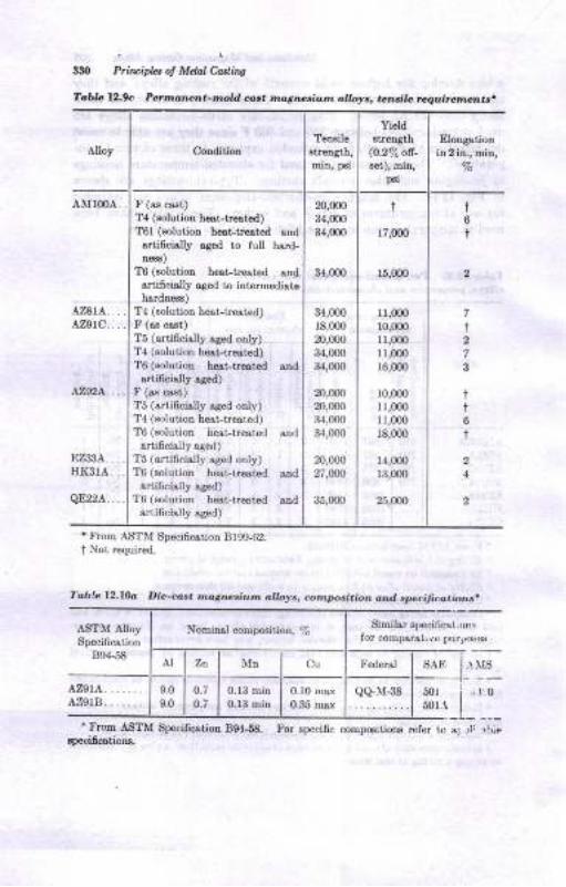
.q.lloy ConditionTerlsile
strength,min, trgi
Yieldstrength
@.2% oa-8et), min,
p3i
Etongationin2in., min,
%
AtrITMA .
A2,8rA. . . .
azatc.. . .
L7,92A. . . .
F (as caat)T{ (solution hqt-trce,tcd)T61 (solutioD h6Ltr€atod strdartidcbly aged to full bard-D€38)
TO (solutioo hest-troatod andsrtifchlly sged to int€rmediatabsrdne$)
T! (solution hest-ti6utod)F (ss cost)
T5 (Brtifcislly rged only)T4 (Bolutiotr h€eLtl! t€d)T6 (solution h€st-tr€atad snd
ertiocialy agcd)F (rs cs3t)T5 (ertiGcially aged only)T4 (eolution hest-h6ated)T6 (Bolution h€st-trcsted &nd
$tificielly a.sed)
T5 (artiicislly sged only)TO (solutiot hoat-b€atcd snd
rrtificielly ased)T6 (solution L€st-tr€ated &Dd
ertificislly aaed)
34,000
34,000
18,0m
m,(m34,000
34,(m
z),gn20,m031,000
34,000
20,000
27,W
35,(m
20,000
34,(m34,(m
i
17,0(n
15,(m
11,0@
r0,000
11,0m1r,flx)r6,0m
10,000
lr,(m[,m0r8,000
14,000
r3,000
25,000
2
2
4
t6
t
7
I
7
3
it
t
330 PriwipLt ol Mdal hd.ing
Tabb Ur.9c P*moneao-nold ant ,,tr,,6rtr,.i.,rn dW., .crrtir. t q./.ir.rn ^t
.
' From ASTM Specification 8199-62.
t Not, rcquired.
! from ASTM Specificstioa 894-58. Por spccific compcitions rcIer tc st rI 1he
Toble l2.l0o Die-cos. magneriu'm al/4rys, comtnsi.ion aad spe.ii.:.r.ion..
ASTM AlloySpeci6cetion
B94-5ti
Nominsl composition, %Similsr speci,icat,on!
for compsBtr r0 purposes
AI Zn Mn Cu Federal s,rE .{ IS
AZ9IA. .......A:]?,grB........
9.0
9.0
0.7
0.7
0.r3 min0.13 min 0.35 rnsx
QqM-38 50r
50r.t,,1,0
speoidcations.
EZ33A...IINSTA, ,
QE2A . .
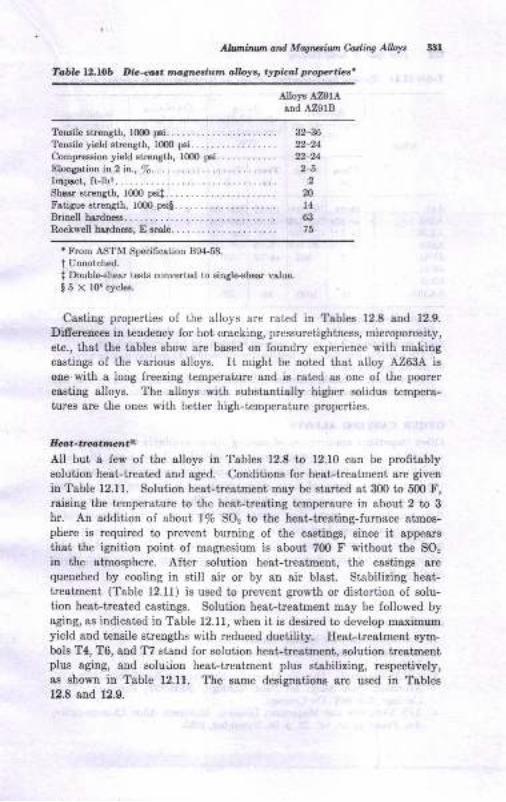
Ah,ttur od Mqrsiao edhe Allor.
Ic6r. lr.116 l|lo-ant ruganlun olloy, tylt&d poprtier'
AIoF Az91Arnd AZ91B
TeDsile Etleaglb, 1000p€i........ .. 32-36
Teffile yield st ength, lom p6i. . . . . . . . . . . . . . . . . 22-24
Compresaiotr yield strength, lom p6i............ !2-24Elongetion in 2 in., %........... -.... -........ 2nklpact, ft.lb+........ 2
Shtrt strength, 1000 p€il... -.................. nFstigue strength, rom psi!... ..-..-.......... 14
B nell hardDess... ........ ................... 63
Rockwell hlrdn€es, Escale........ -...... -..... 75
' From ASTM Spocific&tioD 894.58.
I Unnotched.
I Doubleah€ar t€sts conve.t€d to single-shear value.
!5 x lor cycle6.
Castiug properties ol the alloys are rated io Tabtes 12.8 8ud 12.9.
Difierencee in tendency for hot cracking, pressuretightness, microporosity,
eta., thst the tables show sre based on louodry experieuce with rosliitrg
castiDgs of the various slloys. It might be noted t}lat, alloy A263A isole.with a loug freezing t€mperature snd is r8t€d as one of the poorer
caetiug alloys. The alloys with substantistly higher solidus tempera-
turer are the ones with better high-temperatue propediee.
Eaa-t r,'arrte,ttAll but a iew of the alloys in Tables 12.8 to 12.10 can be profitablysolution heat-treated Bnd aged. Condiiious for hest-treatmetrt are givcn
in Table 12.11. Solutiotr heat-treatneut m8y be Etarted 8t 300 to 500 F,raieing the t€mperature to the hert-treating temperaure in about 2 to 3
hr. AD addition ol abou1 1% gO, to the beat treating-furnace atmos-phere ia lequired to prevent burning of the caaiings, eince it appeare
that the ignition point of magnesium i8 ebout ?00 F without the SOr
in the atmosphere. After solution heat-treatment, the castinge arequenched by cooling in still air or by an air blast. Stabilizing heat-treatEeut (Table 12.1f) is used to prevettt grolth or distortion oI solu-tion heat-treated castings. Soluiion heat-treatment may be followed byagiug, as indicated in Table 12.11, when it is desired to develop maximumyield and tensile strengths with reduced ductility. Eest ireatment sym-bols T4, T6, and T7 stand lor solutiou heat-trestment, solution treatmentplus agiDg, and soluijion heat-treatmeDt plus stabilizing, resp€ctiyely,ar Bhown iD Tablc 12.11. The eame designations are uBed io Tables12.8 and 12.9.
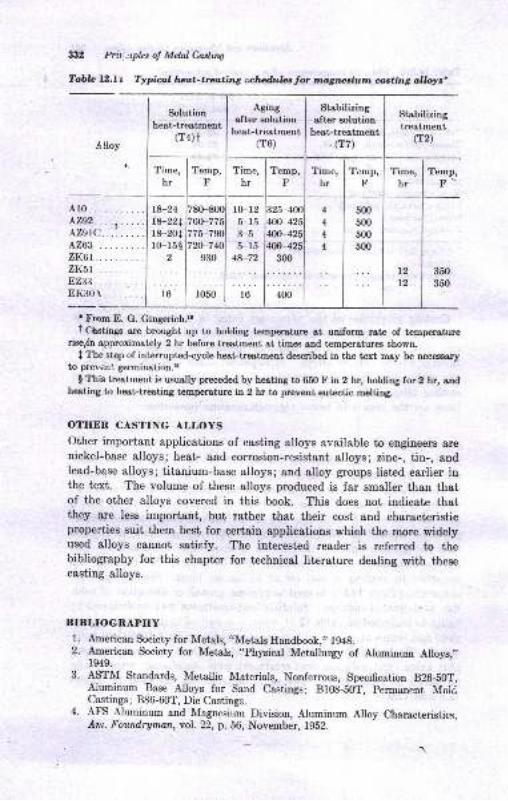
3:12 Pril ;ryles oJ Melal Caslur4
Tabb LZ.l t Typial lrrzat-trating schrudulat for mtgnesium casting albye'
Solutionheat-treatment
(T4)t
Stabilizingtreatment
(T2)
Time,hr
Temp,F
t212
Temp,F-
Ar0. . .. .. ..A292....1...AZgt(:...'. . ..LZ63 .. . ..zri-6t.... ..zKSr .....8,2,33........8K30r......
5fl)500
500
500
350
350
'Frtrm E. G. Gingerich.roi C6stings are brought up to holding tempera,ture at uniform rate of temperature
risefn approximately 2 hr before treotment at timee and t€Eperatures Bhown,
I The step of intemrpted-cycle heet-treatment described in the text may be neceesaryto prevent germination.{
! This treatment is usually preceded by hecting to 680 F in 2 hr, holding for 2 hr, andheating to heat-tresting temperature in 2 hr to prevent eutectic DeltiDg.
OTHER CASTING ALLOYS
Other important applications of casting slloys available to engineers arenickel-base alloys; heat- and corrosion-resistant alloys; zinc-, tin-, andlead-base alloys; titanium-base alloys; and alloy groups listcd earlier inthe text. The volume of these alloys produced is far smaller than thatof the other alloys covered in this book. This does not indicate thatthey are less importaat, but rather that their cost and characteristicproperties suit them best for certain applications which the more widelyused alloys cannot satisfy. The interest€d reader is referred to thebibliography for this chapter for techaical literature dealing with thesecasting alloys.
BIBLIOGRAPHY
l. Arnerican Society for Metals, "Metals Handbook," 1948.2. American Society for Metols, "Ph1'sical Metallurgy of Alrrminum Alloys,,,
1949.
3. 4PTM Standards, Metallic Materials, Nonferrous, Specffication B2G5OT,
{luminum Base Alloys for Ssnd Ca.stings; Bl08-S0t, persranent MoldCastings; 886-60T, Die Castings.
4. AFS Aluminum and Itlagnesium Division, Aluminum Alloy characteristics,Atn. Foundryman, vol. !2, p. 56, November, 1g52.
Aging I StaUitizingafter solution I after solution
heat-treatment I heat-treatment(T6) I .trzt
Time,hr
r0-125-153-55-15
:8-72
16
Temp, | fime,Flhr_t_
328-4ml 4
400-4251 4
4oo-4281 4
{oo-4251 4.
3mlI
t8-2418-221r8-201l0-15$
t
l6
a,Time,
hrTemp,
F
78G800760-775775-75{)
930
1050 400
/,lloy

5.
6.
7.
8.
L
10.
ll.
12.
13.
14.
15.
16.
17.18.
19.
n.
21.
22.
o9
24.
25.
AlumirumailMWuiwnCdhs AW :lilil
American Foundrymen's Society, "Cast Metals Elandbook," 4th d., 1944.
L. J. Ebert, R. E. Spear, and G. Sachs, The Development of a PermanentMold for .Alrrminum Tensile Tegt Bars, ?ranr. z{FS, vol. 56, 1948.
Alumimrm Co. of America, "Machining Aluminum and Its Alloys," 1952.
TV. E. Sicha and R. C. Boehm, A Fluidity Test for Aluminum Casting Alloys,Trwu. AFS, vol.56, 1948.
D. A. La Velle, Al,minum Sand Casting Defects: Their Identification,Causes, and Corrections, Trans. z{FS, vol. 60, 1952.
E. E. Stonebrook and \[. E. Sicha, Correlation of Cooling Curve Data withCasting Characteristics of Aluminum Alloys, frans. z{fS, vol. 57, 1949.
W'. Bonsack, Eigh Strength Non-heat-treated Aluminum Casting Alloys,Trau. AFS, vol. 60, 1952.
R. A. Quadt and E. C. Reichard, Corrosion and Stress Corrosion of a EighStrength Al-Zn-Mg-Cu Casting lrlloy, Trans.l{FS, vol. 58, 1950.
R. A. Quadt and J. J. Adams, Eflect of Mg on Al-Cu-Si Casting Alloys,Foundry, vol.77, July, 1949.
E. V. Blackmun, Impreguation of Alumimrm and Maguesium Castings,Trau. AFS, vol. 55, 1947.
R. E. Eeyer, "Engineering Physical Metallurgy," D. Yan Noetrand Com-parry, Inc., hincetoo, N.J., 1939.
lV. R. Opie and N. J. Grant, Ilydrogen Solubility in duminum and Some
Alrrminum Alloys, J. Metdx, vol. 188, p. 1237, October, 1950.
R. E. Dyke, Modification of Al-Si Alloys, Trans. z{PS, vol. 59, p. 28, 1951.
AFS Light Metals Division, Magnesium Alloy Characteristics, dm. FoutdTg-man,vol.23, p. 156, April, 1953. i
E. G. Gingerich, Ileat Trcatment of Magnesium Alloy Castings, Trans. AFS,vol. 60, p.641, 1952.
R. M. Brick, B. Gordon, and Arthur Phillips, "Stnrcture and Properties ofAlloys," Sd ed., McGraw-Hill Book Company, New York, 1965.
R. C. Cornell, Die Casting lV[agnesium Alloys, ?raas. r{FS, vol. 59, p. 398,1951.
K. E. Nelson and F. P. Strieter, Casting of Magnesium-Rare Earth-Zirco-nir,- Alloys in Sand Molds, Trons. z{FS, vol. 58, p.400, 1950.
R. C. Lemon and E. Y. Ilunsicker; New Aluminum Permanent Mold CastingAlloys C355 and 4356, Trans. AF9, vol.64, p.255, 1956.
R. C. Lemon and C. R. Ilowle, Premium Strength fumfurrrm Casting Alloys354 and 359, ?raru. /FS, vol. 71, 1963.'K.
E. Nelson and F. P. Striet€r, A Castability and Property Comparison ofSeveral Magnesium-Rare Earth-Sand Casting Alloys, ?rons. dFS, vol. 59,p.532, 1951.
J. W. Meier and M. W. Martinson, Development of Iligh-strength Mag-nesium Casting Alloy ZK6l, Trans. AFS, vol. 58, p. 742, 1950.
D. W. Grobecker, An Investigation of Melting and Casting Procedurcs forEigh Purity Nickel, fnns.l{FS, vol. 58, p. 720, 1950.
Internationel Nickel Co., "Eleat Resistant and Corrosion Resistsnt Castingsin Industry," 1952.
The New Jersey Zinc Co., "Die Casting for Engineers," 1946.
E. E. Doehler, "Die Casting," McGraw-Ilill Book Company, New YorL,1951.
J. TV. Smith and T. A. Ilamm, Factors Contributing to the Soundness ofTitanium Castings, Trans. AFS, vol.68, p. 337, 1960.
G. D. Chandley and D. G. Flack, Uranium Foundry Practice, Found,ry,Febnrary, 1960, p.76.American Society for Metals, "Metals Handbook," 8th ed., vol. 1, 1961.
26.
27.
28.
,o30.
31.
ao
33.
13Copper-alloyFoundry Practice
Historically, copper-alloy castings were among the earliest metallic ob-
iecis made by man from molten metal. Since copper could be found as
naiive metal, it has been worked into artifacts, far back iuto antiquiiy.Ite melting point and thst of its alloys with gold, tin, and zinc are low€nough to be within the renge of temperatures which can be reached bywood and charcoal fires. Copper melting and casting by artisans are
known to have occurred as early as 300O s.c. The lull value of copper
alloys as cssting materials, however, had to arvait the meiallurgicaldevelopmeots of ihe past several hundred years, discoveries which made
the metal more abundant, with a grcater variely ol useful properties,
Foundry-productiou data for copper-alloy castings during ihe past fewyears are presented in Table 13.1. It may be noted that sand-casiingprocesses account Ior the greater percentage of castings produced in ihese
alloys.
Adoontases ol Coppet AaWs
Certain engineering advantages are inherent in the use of copper alloyefor castings. Some of these include:
1. Electrical and thermal conductivity2. Corrosion resistance
3. AppeaEnc€
4. Noutoxicity5. Beaing qualities
Although the above items are all lavorable to the use of copper-basecastiug alloys, it must be recognized ihat certsin limitations prevail.Cost is a factor of great import, being sufficiently high so that copper-base,:astings are not used unless their special advantages, as listed above,present a real engineering or economic advantage over otlrer metals.Figure 13.1 shows some characteristic uses of copper-base castings.
3:ra
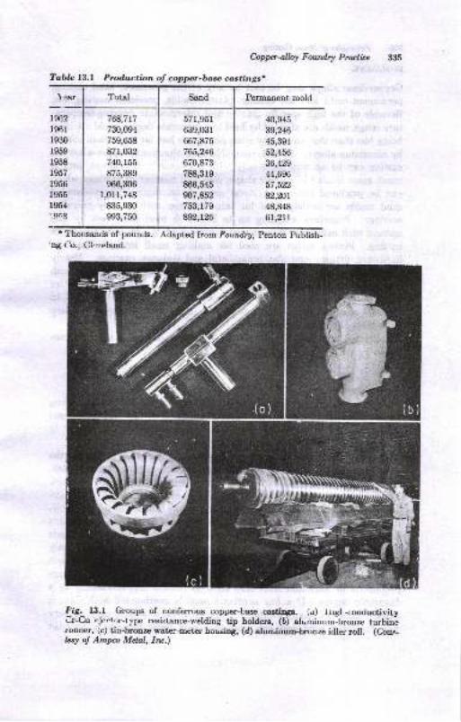
Tablc I.3,l Prod.uction of copper-bue costings.
1".ar
hppcrnlW Foutdry Pruticc 335
Perrnanent mold
{l{),945
39,246
45,391
52,456
36,425
44,696
57,522
82,20r48,848
61,2il
t9c2196r
r930
r959
1958
1957
1956
1955
1954
19(3
768,717
730,094
759,658
871,032
740,155
875,389
966,3&i
1,0u,748
835,930
993,750
57r,951
639,03r
667,875
765,246
670,873
788,3r9
866,545
fi7,852753,179
8W,t26
* Thotreands of pounds.
ng ()o., CltveLend-
Adapted fron Foundry, Penton Pubtish-
Fd& l3.f Groups of non-ferrous copper-baee crstitrSE. (u) irrgl -conductivityCr{u eienr5p-1ype resisl,ance-r"elding tip holders, (b) a[minum-bronze turbinirunner, (c) ti.o-bronze water-nictcl hor,sing, (d) alumiaum-bronze idler roll. (Cour-tety of Amp Mdal, Iw.)
Totel Sand
(c)
lltr
il36 btrcW of Mdal?.adi,,g
MOLDING
Copper-base alloys may be cast by any of the processes: sand casting,
petuanent-mold and die casting, plaster molds, precision casting, etc.
Because of the high specific gravity and intermediate pouring-tempera-
ture range, molds are affectpd by heat to a moderate degree, mold attritionbeing Iess than that caused by irons aod eteels but far more than caused
by aluminum alloys. In fact, compared with aluminum, copper-alloy die
casting can be accomplished only with a relatively few alloys, and ismuch more limited in easting shape, size, and number of castings which
can be produced before the metal mold deteriorates. Cement bonded
sand molds are widely used for large castings such as ship-propeller
castings. Propellers weighing up to 35,0fi) lb have been cast by thismethod with maximum dimensional variation ol /s2 in. over the entire
casting. Plaster molds are used for making small intricate castings,
hardware, fittings, and also ornamental and statuary csstings. Nearlyall the copper-base alloys may be cast by the centfifugal process, with)astings varying in size from a few ounces to over 50,000 lb, the latterbeing perforated -6ylinders for the wood-pulp and paper industry.l8 Ingeneral, however, green-sand molding accounts for the major quantityof castings of copper-base alloys.
Suggested dimensional tolerances for copper-base alloy castings pro-
duced by various molding methods are presented in Table 13.2.
Molding funds
Molding sands employed for copper-base alloys vary somewhat, dependingon the alloy type, weight, and section thickness of the casting. Some
values for sand permeability, green strength, and moisture as related tocasiiug weight and sectiou thickness are listed in Table 13.3.
The unusual emphasis on permeability in Table 13.3 is due to theobservsble connection between that property and casting-surface finish.Many copper-alloy castings require excellent surface finish ae cast.For example, plumbing fittings which are chromium-plated or must haveaccuracy, valves, for exemple, need good surface finish. Low-permeabil-ity sands have been found to give a more desireble finish. Of course, finesand, AFS l2O tD 270, will have a lower permeability than coarse sands
when both are bonded with clay. However, fineness is not the onlyfactor. tr'lowability is required so that a uniformly dense and smoothmold-cavity surface will be developed. Naiural sands having a largeproportion of fines aud AFS clay seem to possess this flowability to afavorable degree. If a fine synthetic sand is overbonded with clay, itusually does not have flowability. Hence, even though it may be veryfine, the latter sand does not produce a good finish because it does not
C.dpp-alb Futdry Prutb :xr,
p8ck (flow) well duing moldiDg. Its permesbility will, of course, be
high by comparison beqause of ite tack of flowsbility.
Higher permeebilit'y may be required on the larger oizee ol castinga.
Gas formation is more pronounced when the casting maat ia large.
Blows, piuholee, and similar gas defects c&n be more rcadily avoided in
sands wben permeability is higher and moisture lower (Table 13'3).
Coarser sands may be required to achieve this eDd, with e cons€queDt
reduction in eurface-finish quality. Furthermore, c€rt8i! copper-base
alloye require higller perrneability. For iuiance, leeded lickel brsss€o
and brouzeg give trouble with pinholes urder the casting skin sod other
gas-hole defecta unless poured in molds of higher permeability than that
listed in Table 13.3. The motding-saud permeability and otler property
requiremente of the various copper-base casting alloye cast in diferentsection eizes are set fortb in Ref. I and Tables 13.3 and 13.4.
Facing materiats may be used in copper-base sande to improve the
eurfece 6nish oI large castings. In some cases, cereal, flour, plumbago,
or very fine sea coal may be added to a specially prepared lacing sand.
Plumbago, graphite, or flour may be dusted directly on the mold-cavity
face to improve surface finish. Malor emphasis for aurface finish, how-
ever, ie placed on the permeability and fiueness of the eand itself.
C.qe tu drCorea for copper-base castiogs are made by conventional methods, using
core sands which are required to allow for the properties of theae alloyo,
IIot t€8riDg cs! occur if the cores are too hald snd resistant to collapae
alter the metol is poured. Typical mixtures sre given in Chap. 7. Core
coatings employing graphite, mica, or other washes may be employed
for gmoother surfacee.
Gartn',
Gating of copper-base alloys involves many of the principlee diecussed
in Chaps.9, 11, snd 20. In copper-base alloys, however, these principlee
haye been largely applied through experience. Applicatione of ratiogating have not thus far been reported in the literature. In many small,
thiu, uniform section castings the runner and gates may also eerve to feed
tlrc castiug. tr'igure 13.2 shows a simple gatiDg arrsngenenr witll thechoke (minimum closs-s€ctionsl area) in the ingate. The choke coD-
trols the rat€ ai which the casting can be filled and also makeo renovsloI the gates during cleaning easier. Since all metal in the casting paees
through the ingate, it is rapidly heated to tlte metal temperature. Thisfact causes it often to be the last part of the caatiug to lreere and makerit poeeibte to feed the casting from the runner. Al arrargemeut which

.Etcre:xi'9
E
!o
e
Q
A
3
t-,
8
8
8
8
E
A
o
tr
;
FI
s
a
5z
3 e5
E6
Q9orEa<is
aaEd
q
!-
EE
ti
F
.i95SEJ,E E
<!Ed i
E
e
E
8i...
€=:::-9 s.- E'-! - c.E;d; E.E E-:< i I o^ e< .- !t-o =
o
=tBi3E E
e! E
,EE 5
EsE
E*.E-lE ..1:6 : P ;
j-E;: ;A! fr
:f;E sefs
3
F,
a
I
H
g
o
E
A
P
T
,s
I
16
!
3:18

.i !P
:Ex.E
>E,1"
2--
bts
66-
8
.!6tE o.:oE{
-1.9,d3,6 o=oqds:5
Er
E
31
6
2
A
to
I
*
Ei.;-d4.:
i 6.:
e
o-
9E
*.:6a
*z
-'9a:E
Q
I
A
c
?
A
E
:t39
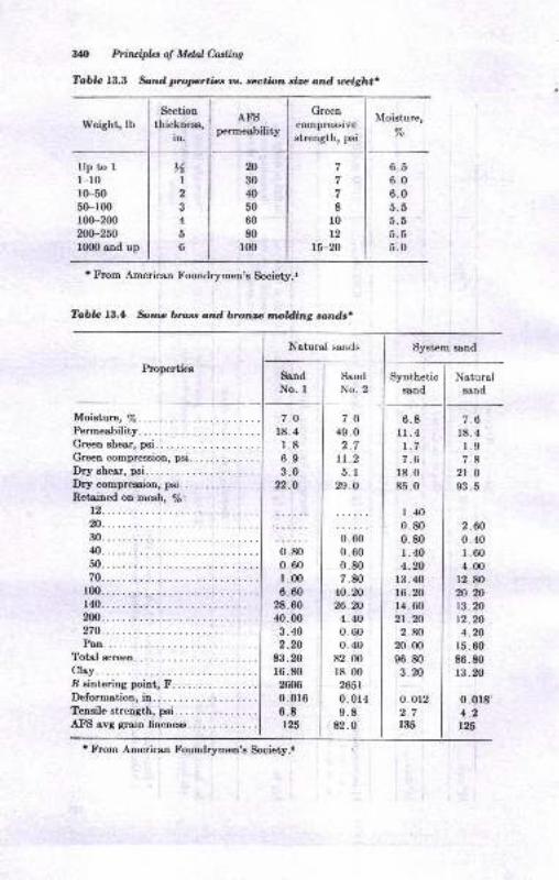
W Priruipla of M&l0astitrg
?oDle 13.3 *td proprtics oe. *ctiotr. sire ar.d treight
Weight, lb
Uptorl-r0r(F5050-r00rfi)-200200-zfi1000 and up
Moisture, %.............Permeability. .. .........Green shear, psi.....Creen compression, psi.
Dry eheer, psi.....Dry compression, psi...Retained on mesh, /6:
12.. . .. .
m......30... . . .
40. . ... .
50... . . .
70..... .
100. . ...1,t0. . .. .
2n.....270.....Pan ...
Total screen.
Clry....I aintering point, F. . . .. . - .
Deformation,in......,..:....Tensile strrngth, psi.. .
AFS avg grain fineness.
Section
thickness,in.
AFSpermeability
I cr"ocompresslve
strength, psi
7
7
7
8
l0t2
78-20
Moisture,
%
%1
2
3
4
5
6
6.56.06.05.55.5b.b
5.0
Tabb 13.1 Some bross anrd bronze tnolding sands.
Natural sands
Properties
System sand
Ssnd
No. ISand
No.2Synthetic
sond
Natrrrelsond
7.O
18. 4
r.86.93.0
22,.O
7.O
49.02.7
tt.25.1
%.o
6.8ll.4t.77.6
18.085.0
I .400.800.80I .404.20
13.4016.2014.602t.202.80
20.00
96.803.20
0.0r22.7r35
7.618. 4
1.9
7.82t.o93.5
0.800.601.006.60
28.6040.0o
3.402.20
83.2016.8020m0.016
6.8125
0.600.600.807.80
40.2026.204.400.600.40
82.00r8. 00
2651
0.0r49.8
82.0
2.600. 40
r.604.00
12.8020.2013.2012.204.20
15. 60
86.8013 .20
0.018'4.2ti25
n30
40
50
60
80
100
t From American f'oundrymen's Society.t
r From American Foundrymen's Society.r
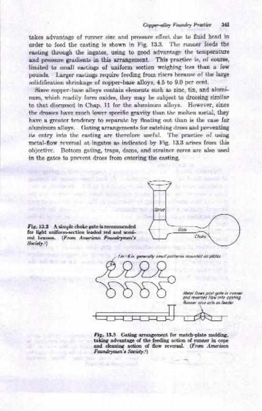
hppdW Fowdry Prulicc :t4I
takes advantage of runner size and pressure effect due to fluid head in
order to feed the casting is shown in Fig. 13.3. The runner feeds the
easting through the ingates, using to good advantage the temperature
and pressure gradients in this arrangement. This practice is, of course,
limited to small castings of uniform section weighing less than a few
pounds. Larger castings require feeding from risers because of the large
solidification shrinkage of copper-base alloys,4.5 to 9.0 per cent.
Sinee copper-base alloys contain elements such as zinc, tin, and alumi-
num, which readily form oxides, they may be subject to drossing similar
to that discussed in Chap. 11 for the *luminum alloys. However, since
the drosses have much lower specific gravity than the molten metal, they
have a greater tendency to separate by floating out than is the case for
aluminum alloys. Gating arrangements for catching dross and preventing
its entry into the casting are therefore useful. The practice of using
metal-flow reversal at ingates as iudicated by Fig. 13.3 arises from this
objective. Bottom gating, traps, dams, and strainer cores are also used
in the gates to prevent dross from entering the casting.
Fig.13.2 A simple cbole gate ie recommendedfor light uniform*ection Ieaded red and semi-red braes€s. (Froor Amcrican Fourdrymcn's&"iet!.,)
lin-5n. generolly smoll potterns mounled on ploles
Lfetol floys posl qole h runncrond reveaes flot inlo coslingRunner olso ocls os feedcr
fig. 13.3 Gatiry anangement for match-plate molding,6ling advantage of the feeding action of runner in copeand cleaning action of flow reversal. (From AmerianFoutfl4nncn' t Socid!.,)
-boE-^1---
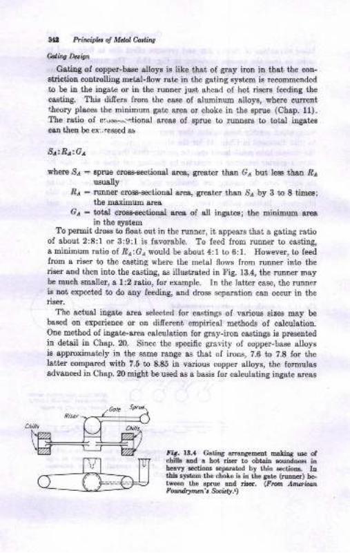
lal Ptituipla 4 Mdal Adhq
Utit Datc
Gating of copper-base alloys is like th8t of grsy iron in that the con-sbiction controlling metal-flow rate in the gating syatem is recommended
to be il the ingate or in the runner just ahead of hot risers feedilg tbec88ting. This difrers from the case of sluminum alloys, where currentiheory places the minimum gat€ area or choke in the sprue (Chap. ll).The ratio oI cr.,ll-"r4tioD&l areaa of sprue to runners to totsl ingstescgn then be ex'.; ressed s!
St':Rt:Gt
where 81 : aprue croas-sectioral arcs, grest€r than Gr but lees thsn .Be
ususlly.Er : ruruer clowctional area, great€r thsn 8e by 3 to 8 times;
the raximum area
Ge: totel crogs-€€ctioDal a,rea of all ingatea; the minimum a,rea
in tbe syBtemTo permit drom to float out iu the runner, it appeelr that I gstiog rstio
of sbout 2:8:l or 3:9:l ie favorable. To feed from runner to casting,a miuimum ratio of Rr;Ge would be about 4:1 to 6:1. However, to leedlrom a riser to the cssting where the metsl flow8 from ruuDer into theriser 8Dd then ilto the casting, as illustrated in Fig. 13.4, the runuer maybe much smaller, a 1:2 ratio, lor example. In the latter case, the runuerie uot expected to do aDy feeding, and dross separation can ocsur in theriser.
The actual ingate area selected lor castings ol various sizea may bebaeed on experience or on difrerent empirical methode of calculation.Oae method of ingate-area calculation for gray-iron castings is pres€ut€d
in detail in Chap. 20. Since the specific gravity of copper-bare alloysie appmximately in the eeme range as that of irous, ?.6 to 7.8 for thelstter compsred with 7.5 to 8.85 in various copper alloys, the formulaeadvanced in Qhap. 20 might be used ae a basis for calculatiug itrgate areag
fir. lt.{ C'atiDS arraDsEmnt matiry uro ofchilb lDd 6 hot rirer to obtair louDdDes! inheavy etione soFrated by thin 6ectioE. Ini,hi! .J.t.ltr ttrG chole is io th€ gare (ruour) be-tv€eD the 6prue aad rieer. (Fron AzrerrbnFqrrdrlnun't &c tf.t)
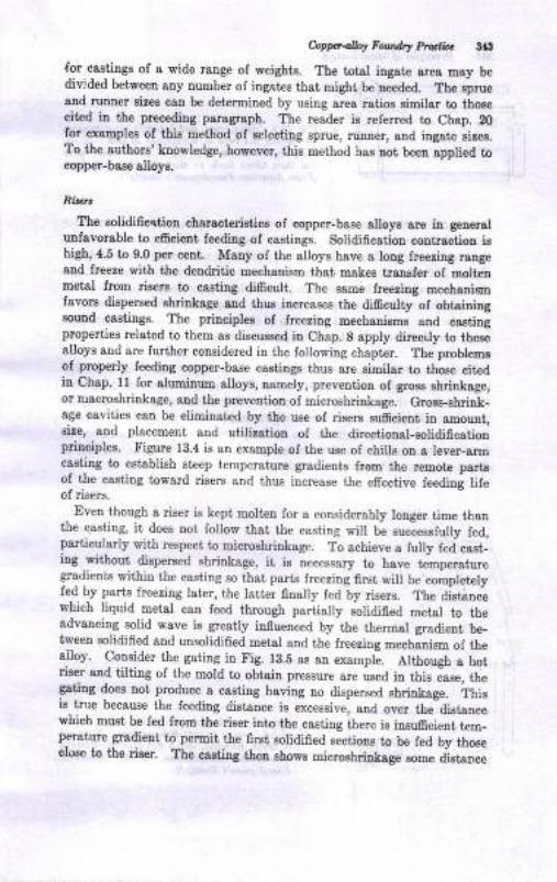
App-allay Fwdry Ptdb 3aS
{or castings of a wide raDge of weights. The toisl iDgste area may bedivided between auy number oI iDg8t€s that might be ueeded. The sprueand runaer sizee can be determined by using area r8tios similsr to thosecit€d in the preceding paragraph. The reader ie refened to Chap. 20for examples of this method of selectiug Eprue, nurne!, aud iDgate rires.To the authors' knowledge, however, ihis method h&8 Dot been applied tocopper-base alloya.
Rirlz.,
The solidificction cbaractaristics of copper-base alloys are in generalunfavorable to eficient feeding oI castings. Solidification contractiou ishigh,4.5 to 9.0 per cetrt. Many of the alloys hsve a long freezing raugeaud freeze f,,ith the deDdritic mechanism that makes tranefer of moltenmetal from riaere to casting di6cult. The same lreezing EechsDismfavora dispersed ehrinkage aud thus increaees the difrculty of obtsiningeound castinge. The principles of freezing mechanisms aud castiugproperties related to them as discussed in Chap. 8 apply direci.ly to thesealloys and are further considered in the follorring chaptcr. ThJ problemsof properly leeding copper-base castings thus are simil$ to those citedin Chap. l1 for sluminum alloys, oamely, prevention of gross shrinksge,or ruecroshrilkage, and the preveutiou of microshrinkage. Grosg-ahriuk-age cevities can be eliminatcd by the use of risere suftcieut in amount,rize, and placement and utilization of the directional-solidificatiouprinciples. Iigure 13.4 is an example of the use of chills ou a leyer-armcastiog to establish steep tempersiure gradients from the remot€ p&fisoI the casting toward risers and thus iucrease the effective feedini lileof risers.
- Even though a riser is k€pt molieu for a considerably longer time than
the casting, it does not follow thai the casting will be successlully fed,particularly with respect to microshrinkage. To achieve a fully fed cast-ing
_without dispereed shrinkage, it is necessary to have temperatureCirsdienis within the casting so that, psrts freezing first will be completelyfe! by parLs freezing later, the latter finally fed by risers. The distancewhich liquid metal can feed through partially solidified metel to theadvancing solid wsve is greatly influenced by ihe thermal gradient be_tweeu solidified and unsolidified metsl aad the freezing mechanism of thea.lloy. Co_nsider the gating in trig. 18.5 as an exampl-e. Although a hotriser and tilting of the mold to obtain pressure are ueed in this iase, thegatiog does noi produce I csstiDg hsving no dispersed ehrinkage. ihisie-true because the feeding distance is eicessive, aad over the-dietancewhich must be fed from the riser into the casting ihere is insufrcient t€m_perature gradieDt to pennit the first eolidified sectionr to be fed by thoseclose to the fiser. The casting then showe Bicroehri.nkag" *-" O.t*ao
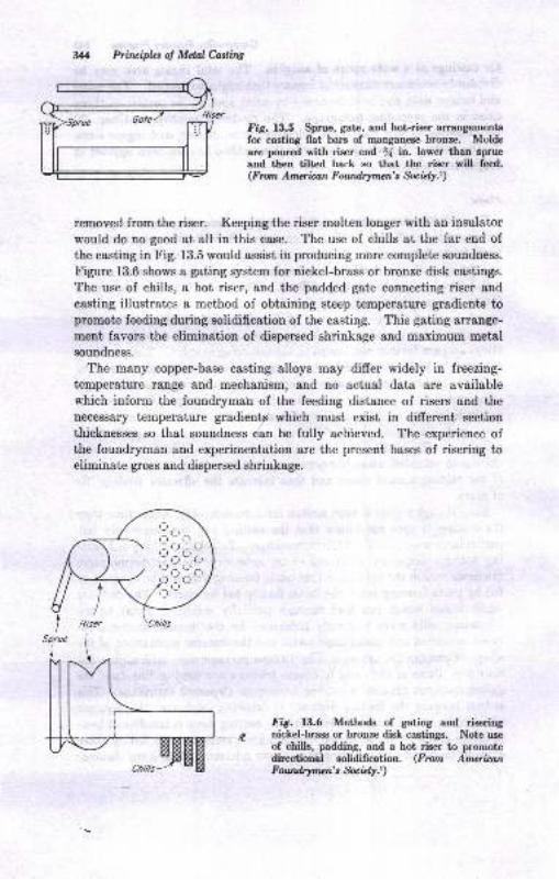
Prircipbs of MdalCasliw
Iig. 13.5 Sprue, gate, and hot-riser arrangementgfor casting flat bars of manganese bronze. Moldsare poured with riser end I in. lower than sprueand then tilted back so that the riser will feed.(F mn Amcrimn Foundrymcn's Socury.)
removed from the riser. Keeping the riser molteD longer with an insulator
would do no good at all in this case. The use of chills at the far end of
the casting in Fig. 13.5 would assist in producing more complete soundness.
Figure 13.6 shows a gating system for nickel-brass or bronze disk castings.
The use of chills, a hot riser, and the padded gate connecting riser and
casting illustrates a method of obtaining steep temperature gradients topromote feeding during solidification of the casti4g. This gating arrange-
ment favors the elimination of dispersed shrinkage and maximum metalsoundness.
The many copper-base casting alloys may differ widely in freezing-
temperature range and mechanism, and no actuel data are availablewhich inform the foundrymah of the feeding distance of risers and the
necessary temperature gradienta which must exist in different section
thicknesses so that soundness can be fully achieved. The experience ofthe foundryman and experimentation are the present bases of risering toeliminate gross and dispersed shrinkage.
Fig. 13.6 Methods of gating and risering
-.-e nickel-brass or bronze dis}. castings. Note useof chills, padding, and a hot riser to promotedirectioual solidification. (From Am*itanFowdrywn\ S*,bry.)
r-r ' r]r _rl (,
^ r_t ^ (-l
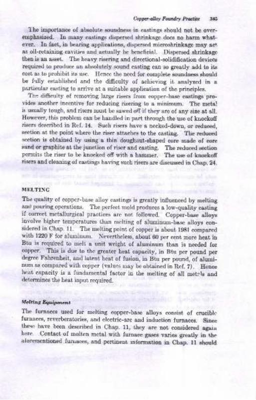
Oopp.alloy Faadry Prdfu :talt
the importance ol Bbsolute Eoundness in castings ehould not be over-empbssis€d. In many castinge dispersed shrinkage does no harn what.ever- In fact, in bearing applications, dispersed microshdDkage mey sct,
as oil-retaining cavities and sctually b€ beueficial. Dispersed shriuk8gctheu is an ae8et. The heary risering aod directionsl-8olidificaiion devicetrequired to produce an absolutely souod casting cstr so gre8tly add to it8cost as to prohibit its use. Hence the need for complete souadnees shouldbe f'rlly established and the difficulty of achieving it snalyzed in &
psrticulsr c&sti[g to arrive at a suitable gpplication of the principles.The difrculty of removing large risers lrom copper-baee csstingB pro-
videE another incentive for reducing riserilg to a minimum. The meta!is usually tough, and ris€B must be E&wed oII if they are of any sire at all.However, this problem can be handled in psrt through the u8e ol krrockofrrisers described in Ref. 14. Such risers have a necked-down, or reduced,seciion st the poiDt where the riEer atteches to the caeting. The reducedsection is obtained by uaing a thin doughuut-Bhsped core made of coressnd or gsphite at the junction of riser aDd casting. The reduced e€ctionperuils the dser to be knocked off with a hammer. The use of knockofrrieers and cleauing oI castings having such riserE are dissusc€d in Chap. 24.
MELTING
The quality of copper-base alloy castings is grestly influeuced by mettiagand pouring operations. The perfect mold produces s low-quality castiugif correct metallurgical practices are not followed. Copper-b8se slloyginvolve higher t€mperatures than melting of alumioum-base alloye con-sidered iu Chap. 11. The melting point ol copper is about 1981 comparcdwith 1220 F for aluminum. Neverthelees, about 60 per cent nore heat irlBtu i8 requircd to melt a unit weight of aluminum thsu i8 aeeded forcopper. This ir due to the gre&t€r beat capacity, in Btu per pound perdegree Fahrenheit, 8nd lsteDt heat of fusion, iu Btu per pouud, of alumi-num as compated with copper (values may be obtained in Ref. i). Hencehcat capacity is a fundamental factor iD the melting of all metlls anddetermiues the heat input required.
AGltir.t &,r*tn na
The furnacea used for melting copper-base olloye coneist oI cruciblefuruaces, reverberatories, and electric-arc and iaduction furnacee. Sinoethege have been descdbed iD Ch8p. U, ihey are not cousidered agaiuhere. Contact ol molten metal with furnace gaeea variea greatty iolhealbreoentioned fur.uaces, aud pertiuent ialormatiou ia Chap. fi rhould
346 Priruifu of MdalC.adhg
be reviewed because of the very importanf reactions which may occur
The reverberatories and crucible furnaces permit varying degrees of direst
contact of furnace combustion atmosphere and melt. Induction furnaces
may be covered, have no combustioir products, and have a virtuallyrtapant atmosphere over the melt. This, then, is a marked difrerence
in the two types of furnaces. The possible effects of melting-furne.ce
atmospheres will be considered.
l|Iclting Proce,dure
, The normal metal charge consiste of cleen foundry scrap (remelt) and pig
or ingot of the desired analysis. The metal is melted dowu, generally
urrder ao oxidizing atmosphere if a fuel-fired furnace is employed.
An oxidizing atmosphere implies that free oxygen, about 0.50 per cent,
is present in the products of combustion. After meltdown, additions
such aB alloying elements, zinc, tin, lead, or special hardeners are mrdeas needed to achieve the desired analysis. The metal can then be heated
to its pouring temperature plus 50 to 100 F, and is then ready for transferfrom the furnace to the pouring operation. Temperature readings mustbe taken with base-metal thermocouples so that the pouring temperature
may be accurately controlled. A minimum time at temperatures in themolten range decreases the danger of damaged metal due to gas absorp-tion or composition changes.
Drcrrhg
Most, though not all, copper alloys contain readily oxidizable elements,
such as zinc, tin, aluminum, magnesium, and manganese. The oxides
separate more or less completely from the melt and form a dross. Ium&ny cases, the oxide has a low specific gravity and would be expectedto float out of the melt. However, surface tension and other effects makethe separation difficult in some alloys, such as high-zinc brasses andaluminum bronze. The dross may then entrap considerable metal andcause high melting losses. Sometimes fluxes or eharcoal covers are em-ployed to minimize drossing. A cover of bottle glass thinned with boraxis fluid and helps keep the metal surface clean. Charcoal as a protectivecover is often used to minimize oxidation. Proprietary fluxes may bepurchased whieh are claimed to cleanse the metal of oxides and prepareit for pouring. Uudoubtedly, a minimum of agitation and melting underfavorable cornbustion conditions decreases drossing.
Oqgen inCoppcr Melting
Copper as an element is a metal which is readily oxidized in the mcltencondition. This possibility is illustratcd in Fig. 18.7, which shows thatthe solubilty of orygen in molten copper increases rapidly with tempera-
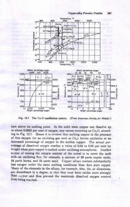
&pp.albf Fouadrf P'oElie ?lI
va,,*
[-{.**.ll?L lr40o E
E;'tclo
!
E
fi6. 13.7 Thc CuO cquilitrium ayst2E,. (Fto,l Aruriat *id! lt Mdalr-l)
turc above itr melting point. In the solid etat€ copper can diseolve upto about 0.065 per cent oI oxygen, any exceu occurring as Cu"O, adcord-ing to Fig. 13.7. Ilence it is evident that meltiug copper in the preoence
of free oxygen (or an oxidizing gas such as C,o") favors oddation or aniucreased percentage of orygen in the molten copper. The actual per-centste of dissolved oxygen reaches a value of 0.(X to 0.05 per ceut byreight, when pure copper is melted uuder oxidizing atmospheree. Aoothern:caua of raieiug the oxygeD content of the Detsl is to cover the meltwitL ao oxidizing flux, for example, a mixture oI 20 psrts cupric oxide,e4 partE bor8x, snd 54 psrts eaud. Copper alloys contain eubstaltiallyless oxygen under the same melting conditions than doee pure copper.lvlauy of the elemeuts iu the alloys, for example, zinc, tin, or aluminum,
-are deoxidi!€rE to a degree, iu that they may form oxides more strongly
lhan.r"..nner aad thue prevent the maximum dissolved orygen contintri:!m beDg !ea,"'hd.
LI
I
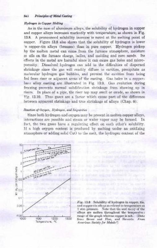
341 Fli//,ifu 4 Man haiq
Etdrq.n in Copp McAnq
Ar in the case of aluminum alloys, the solubility of hydrogen iu copper
and copper rlloys increaseE markedly with t€mpersture, as shown in t'ig.13.8. A pronounced sotubility increas€ is noted at the melting poiat of
copper. tr'igure 13.8 slso Ebows that the solubility of hydrogen ie lowerlD copper-tin alloys (broolee) thao in pure copper. Ilydrogen pickup
by the molten metsl catr oome lrom the furnace atmosphere, moisture
or oils on the furnace charge, ladles, and molding aod core sauds. Itseffccts iu rhe metal &re harmful since it carr cause gas holes and micro-porosity. Dissolved hydrogen can add io the difficulties oI dispersed
shriDkage since the gas will readily difruse to cavities, precipitat€ ss
molecular hydrogen gas bubbles, and prevent the cavities from being
fed from riser or adjacent areas of the casting. Gas holes in u copper-
bate alloy cssting are illustrated in Fig. 13.9. Gas evolution duringireezing prevents normal solidification shrinkage from showing up inri8er8. Itr place of a pipe, the riser top may swell or exude, ae shol a inEig. 13.10. Thus gases are a factor which cause part of the difrereuce
between &ppsrent shrirkage and true shrinkage of alloys (Chap. 8).
Rcadian ol Otysen, HydNNcn, and Inpuritiar
Since both hydrogen and oxygen may be present in molten copper alloys,
interactioos are possible and steam or wat€r v&por may be formed. InIatt, the two gases have a rcgulating effeci on each other's solubiliiy.If a high oxygeu co[tent is produced by melting under an oxidizingatrnosphere or adding solid CuO to the melt, the hydrogen content of the
fl00 1200
rts. 13.8 Solubility of hydrogen in copper, tio,and copp€r-tin alloys as related to t€mp$ature atI atm pmssule. Not€ thal, ttu and many of ihealloys are moltrn throughout the temf,eratuJ.ange of the graph whereas coppff is trot. (DaLrfron Bever and Floe, and Sieverts. tr'^rrAneican &.U! lor Melolr.t)
E
E
P
E
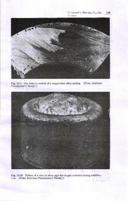
('|.-ry-ail,.: Ilot,-dr! ?t*_!!ce 319
Fig. 13.9 Gas holes in eectiod of a copper-base alloy casting. (Fron Amerfucnb'outdrymcn' t Soculy.r)
Fig. 13.10 Failure of a riser to sbow pipe due to gas evolution during solidiGca.1ir)n. (Frctn Americon Foundrymen's &cit$.r)
',''hrh
,4
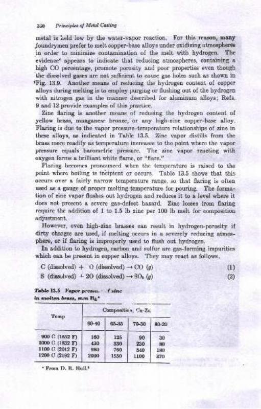
35O Prircipht of Mdal Catliw
metal is held low by the water-vapor reaction. For this reaaon, tnony
Joundr5men prefer to melt copper-bsse alloys under oxidizing atmosphercs
in order to minimize contaminatiou of the melt with hydrogen. The
evidence8 appesrs to indicate that redlucing atmospheres, containing ahigh CO percentage, promote porosity and poor properties even though'tle diseolved gaseE 8re not sufrcient to cause gas holes such ae shown inlFig. 13.9. Another means of reducing the hydrogen content of copper
alloys during melting is to employ purgrng or flushing out of the hydrogen
with nitrogen gas in the manner described for aluminum alloys; Refs.
9 and 12 provide examples of this practice.
Zinc flaring is another means of reducing the hydrogen content ofyellow brass, raanganese bronze, or any high-zinc copper-base alloy.Flaring is due to the vapor preszur+temperature relationships of zinc inthese alloys, as indicated in Table 13.5. Zinc vapor disti[s from thebrase more readily as temperature increases to the point where the vaporpressure equals barometric pressure. The zinc vapor reacting withoxygen foms a brilliant white flame, or "flare."
Flaring becomes pronounced when the temperature is raised to thepoiut where boiling is in'cipient or occurs. Table 13.5 shows that thisoccurs over a fairly n&rrow temperature range, so that flaring is oftenused as I gauge of proper melting temperature for pouriug. The forma-tion of zinc vapor flushes out hydrogen and reduces it to a level where itdoes not present a severe gas-defect hazard. Zinc losses from flaringrequire the addition of I to 1.5 lb zinc per lfi) lb melt for compositi,on
adjustment.Ilowever, even high-zinc brasses can result in hydrogeu-porosity if
dirty charges are used, if melting occurs iu a severely reducing atmos-phere, or if flaring is improperly used to flush out hydrogen.
In addition to hydrogen, carbon and sulfur are gas-forming impuritieswhich can be preseut in copper alloya. They may react as follows.
C (dissolved) * C (dissolved) + CO (s) (1)
S (disil,lved) l2O (dis&{ved) -'SOr (C) @)
Tobla l.iln Yqt* ptllll.u.',l.ireln rmolton Drucrr mm Il&'
Conyxitiou, Cu,ZnTemp
9m c (1652 F)rmo c (1&i2 r)1r0o c (2012 F)ran c (2re2 F)
30
80
r80
370
90
230
640r100
'tr}om D. R. Hull.t
60-40 6S35 7G30 80-20
160
430
980
2000
126
330
760
r550
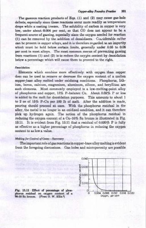
f.oppetfiwAry*A;e 351
The gaseous rcaction products of Eqs. (l) and (2) may cause gas-hole
defects, eepecially since these reactions occur mone readily as temperature
drops while a cssting lreezes. The eolubility of carbon in copper is very
low, urder about 0.0O4 per cent, so that CO does not appear to be a
frcquent source of gassing, especially eince the oxygen needed for rtaction(l) can be removed by the additiou of deoxidizers. Cor.siderable sulfur
cau be present in copper alloys, and it is therefore regarded as an impurity
which must be held below certain limits, generaily under 0.05 to 0.OB
per ceut in most alloys. The most common mee.,ae of preventing gassing
from reactions (1) and (2) is to reduce the orygbn content by .leoxidatiou
below a percentage which will cause them to proceed to the right.
MidaliorlElements which combine more efrectively with orygen than copper
does can be used to remove or decrease the oxygen content of a molteu
copper-base alloy melted uuder oxidizing conditions. Phosphorus, lith-ium, boron, calcium, magnesium, aluminum, silicon, and berylliuro are
such elements. Most commonly employed is a low-melting-point alloyof phosphorus and copper, l5/o P-balance Cu. Lborfi O.M/o P or less
ie added to the melt for deoxidation purposes. This amounts to about Ita 2 oz of l5/o P-Cu per 100 lb of melt. Aftcr the addition is made,
pouring should proceed at once. With the phosphorus residual in the
alloy, the metal is no longer in an oxidized condition, and it can therefore
pick up hydrogen again. The action of the phosphonrs residual inreducing the orygen content of a Cu-l0/o Sn bronze is illustrated in Fig.
13.11. It is evident from Fig. 13.11 that a residual of 0.U20/o P is fullyas effective as a higher percentage of phosphorus in reducing the oxygeu
content to as low a value.
Mchittg t* Cor.hpl ol G\ocll-Sturunal-t
The importantrole of gasreactionsin copper-base alloy meltingis eviden[
from ihe foregoing discussions. Gas holes and microporosity are possible
Fig. l3.ll Efiect of percentag€ of pha-phorus rceidual on oxygctr content of a9G.10 Sn bronze. (From O. W. EIJ,is.t)
0.008 0.012 0.016 0.020
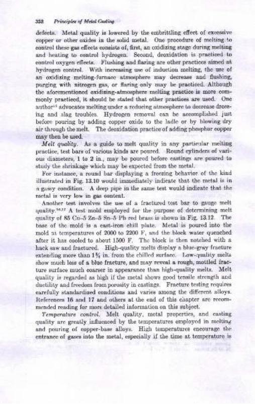
3li2 Prircipla 4 Mdal Coiinc
defects. Metsl quality i8 lowered by the embrittliug efrect oI er<rssive
copper or other oxiCes in the solid metal. One procedure of melting +o
control these gas efrects con8istE of, fir8t, an oxidizing atage during melting
and heeting to control hydrcgen. Second, deoxidatiou i8 pr&cticed to
control orygen efrecte. Flushiug aud flaring are other practices simed at
hy<irogen control. With increasing ue€ of inductiou meliing, the use of
an oxidizing meltiug-fumace atmosphere may decreaee and fluahing,
purgiug with nitrogen gas, or flaring only may be practiced. Although
the alorementioned oxidiaing-atmosphere melting practice ig more com-
mouly practiced, it ehoutd be stated that other practices are used. One
arrthorr5 advocates melting under a reducing atmosphere to decrease droBs-
irg and slag troubles. Hydrogen removal can be accomplished ,iust
before pouring by adding copper oxide to the ladle or by blowing dry
air through the melt. The deoxidation practice of adding phosphor copper
may then be u.eed.
Melt qqlity. As a guide to melt quality in any partict ar melting
practice, test bars of various kinde are poured. Round cylinders of vari-
ous diametere, l to 2 in., may be poured before csstings ere poured to
etudy the shrinkage which may be expected from the metal.
For instaace, a round bar displaying a freeziug behavior of the kind
illustrat€d iu Fig. 13.10 would immediately indicate that the metal i8 in
'r gassy condition, A deep pipe in the same iest would indicate that the
metal is very low iu gas content.
Another test involves the use of a fractured test bsr to gauge melt
quality.''" A test mold employed for the purpose of determining melt
quality of 85 Cu-5 Zn-5 Sn--5 Pb red brass is shown in Fig. 13.12. The
base of the mold is a caet-iron chill plate. Metal is poured into the
mold 3t t€mperatures of 2000 to 2200 F, and the block water quenched
alt€r it has cooled to about 1500 F. The block is then notched with ahack saw and fractured. High-quality melts displsy s blue-gray frecture
extencling more than lfl in. from the chilled surface. Low-quality melt6
show much less of a blue ftacture, 8nd may reveal a rough, mottled frac-
ture surf&ce much coarser in appearance than high-quality melts. Meltquality is regarded as high if the metal shows good teusile strength aud
ductility aud lreedom from porosity in castings. Fracture testing requires
carefuliy standardized conditione and varies among the different alloya.
keferences 16 sod 17 and others st the eud of thia cirapter are recom-
mended reading for more detailed information on this eubject.
Tenperahoe colttrol. Mell quality, metal prcperties, and castiug
quality ore greatly influenced by the t€mperstures employed i[ melting
and pouring of copper-base alloys. High temperatures encourage th{-'
entrance of gases into the met8l, especially if the time at t€mperatue is
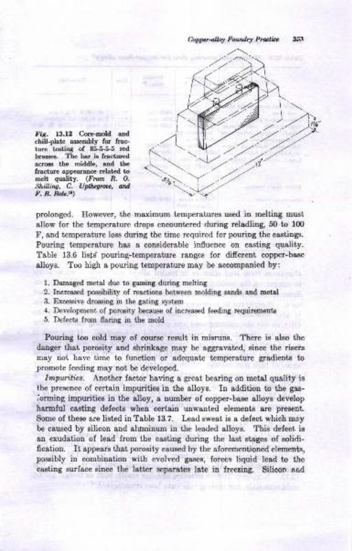
Co p pa -olloy F oudty Prutl:c
\ -...
fir. 13.12 Cor€-hold a.dchill-plats a8ser$ly fo. f.ac-tule ra€tio8 of 8 5-5-5 rcdbrass€s. The bar is
'racturedacrca the middle, end rleftacture appearaEc€ relatad tom€lt quelity. (Fon R. O.
ShiLi/w, C. U$qttu, NrdF. B. RoL.t t
prolonged. Ilowever, the maximum temperatures ued in melting musl
allow for the t€mpereture drops encouniered durhg reladling, 50 to 100
F, and temperature lose duriDg the time required for pouing the castings.
Pouriug tempersture has I considerable infuence oD castiDg quslity.
Table 13.6 lists' pouring-temperature ranges for diferent copper-base
alloye. Too high a pouring temperature may be accompauied by:
1. Da,maged metal due to gessing durint meltitrg
2. Incleased poseibility of resctioDs between Eoldiry sstrds 8nd EetEl
3. Excessive dro€€ing itr the gating syst€E4. Development of porosity bec&use of iDcreas€d feeding requircBetrio
5. Defects from flaliDg ia the eold
Pouring too cold may of course result in misrune. There is also tttedauger that poroeity rnd ahrinkage may be aggavsted, eiuce the rieere
mey not have time to functioD or adequate t€mperature gradieuts topromote feeding may not be developed.
Impurities. Another fsctor having a great bearing on metal quality is
the preaence of certsin impurities in the alloys, In addition to the ga8-
iorming impurities iD the 8lloy, g number of copper-base alloys developharmlul caeting defectr when certaiD uDwauted elements are pres€Bt,
Some of these gre list€d in Table 13.7. Lead sweat ie a defect which oaybe caueed by silicon and alumiuum in the leaded alloys. This delect is
an exudation of lead from the casting during the last stages of eolidi-ficatiotr. It app€srs that porosity cauEed by the sforementioned elementq,possibly in combination with evolved gases, forces liquid tead to tiecuting eurface siuce the lait€r Eeparates lst€ in freezing. Silicon ar.d
J' z'.,1)z' :2
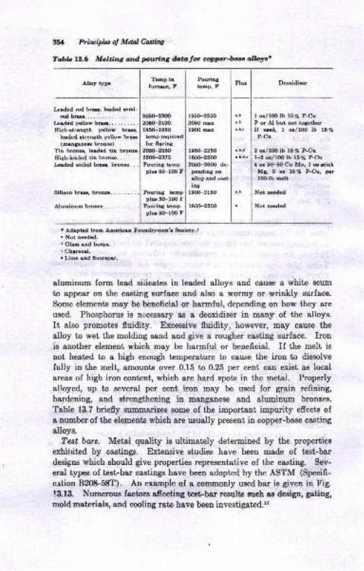
tlil Priluipb: of Mdal hslir.g
TabL l!.6 Mclting atd pvring datator optrrcr-fu allolrc'
Alloy typ.Temp in
furc, FPouriag
tamp, F
fz.ded red bu, lodcd roi-rsd bro.....
ladcd yello* bm..........Ilishrtraogth yollor bru,
t6dcd ltretrgth yollor bru(m.D!.D6 brcDro)
Tio brcnre, lrtded tiD bronrs
205{F2300
20t(F2loor8t0-r060tcmp rcquindfor 0rria8
205(F2350
22N-2575Pourint t mpplu 50-1fi) F
PouriDa t6opplu 5O-l0O F
Pouri[8 tempplu 5(Flfl) F
r050-22s02050 url9OO ur
r05(F2250
r850-2200205(F26fi) de-
pendiag on
I o,/l0o lb l5% P-CuP or Al but Dot to8othcrIf u!od. 1 o!/lOO lb 157.
P-Cu
2 orl10o lb 15 % P-Cu
l-2 ot/lO0 lb l570 P-Cu,( or 5O-50 Cu Mn! I or dickMg, 3 or 15 % P-Cu, per
loclb Eclt
Not necded
Noi acdcd
HighJerded tia brouG. .
Isled nicLel bru, brouro . . .
elloy aadiDs
r9(xF2l50
. Adaptrd lrcm Amcriu Foundtlrucn'r Eeiety.r
. Not Dedod.r Glu ud bonr,. [email protected] Lime rad 0uonps.
aluminum form lead eiiicat€s iu leaded alloys and cause a whibe scum
to appear on the csstitrg Eurface Bnd also a woflny or wrinkly surface.
Some elements may be beneficial or harmful, depending on how they are
used. Phosphorus is necessary as a deoxidizer in many of the alloys.
It also promotes fluidity. Excessive fluidity, however, may cause the
alloy to wet the molding sand snd give a rougher casting surface. Ironis another element which may be harmful or beneficial. If the melt isnot heat€d to a high enough temperature to cause the iron to dissolve
fully in the melt, amounts over 0.15 to 0.25 per cent can exist as local
areas of high iron content, which are hard spots in the metal. Properlyalloyed, up to several per cent iron may be used for grain refining,hardening, and strengthening in manganese end aluminum bronzes.
Table 13.7 briefly summarizes some of the important impurity effects ofs uumber of the elements which are usually present in copper-base casting
alloys.
Test bars. Metal quality is ultimately determined by the properties
exhil)ited by caetings. Extensive studies have been made of test-bar
designs which should give properties representative of the casting. Sev-
eral types oftest-bar castiugs have been adopted by the ASTM (Specifi-
cetion B208-58T). An example of a commonly used bar is given in Fig.13.13. Numemue factors a,fiecting test-bar results sueh 8s design, gstiDg,
mold materials, and cooling rate hsve been investigated.l?
Flur Doridirr
Silion btu, brcm..-......
AlumiDum brcDt.
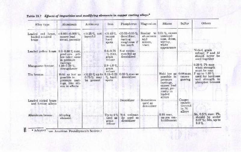
Toble Ll.1 E;ffectt o! i,,nputiti1Js ond nodifying .ll/Jmenta in coppr ot'sti,,g alloys'
Antimony I
Iron
<o.26Vo, r,ot | <o.no Z,harmful I causee
I hard
I enots
Alloy type
Leaded red brass,leaded scnriredbrass
Leoded yellow brass
Menganese hronzo . .
Tinbronze....
Leadod nickel brassend bronze alloys
Aluminum brorrzt.. . .
Aluminum Phosphorus Magnesium
<0.001-.0.003 %,carrsee lesdEweEt, poroBity
0.3-0.50 % max,nroduces vel-low color; nbnein pressurecestinSs
1.5lU_.7.5070,strengthener
Held as low aspossible inDreaaure cast-ings, like sili-con in effects
<o.o24.o5%,deoxidizer,castilBroughnees iftoo much
Not recom-mended asdeoxidized
Deoxidizer
Not ordinar-ily used asdeoxidizer
Similer toaluminumandsilicon,tr8ce
Sometimesused agdeoxidizer
Alloyingelement
. i o.u-o.ru| % max,I grain
I refiner
Up to 4/quscd aegrainrefiner
I ldeptcn :'om Amcrican Foundrymen's Soeietv.r
Silicon
0.01 %, cauunsound-ness, dross,wormy,whiteeppe&r&nce
0.05 max,collses em-brittlement
Held low aspossible inpreasurecsSttngE,causee loadBrveat, p(Fro$ty lnleededolloys
0.08max,causeSgassing
Caueesembrit-tlementin Nialloys
Sulfur Othere
Nickel, graiurefiner; P and Alshorrld never beused together
0.20% Pb maxwhen strengthmust be mex
P uo to 1.00%usid for hardnessand strength inphosphor bronzes
Bn, 0.5% max; Pb,ghould be under0.07%; Mn,upto3.5Vo
1O.25VolptoO.75Vo maybe present
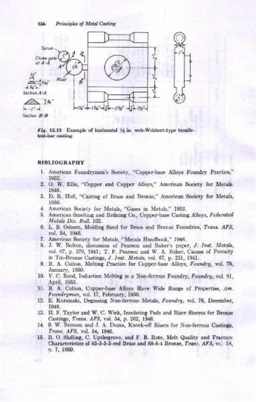
Priruipb ol Mdol Cadiw
ot ,l -i
?,i,,Section,{-,,!
.//^:at "
It1S€ation 8-,
1tu4
f,g. 13.13 Elanple of hodrootrl % ia. {.b..Wobb€rt-typc rtDlib-ta.t-ber cadiDS.
BIBLIOGRAPHY
l. Americln Fouodryme.D's Socieiy, 'Copper-b&se Alloys Fouudry Practice,"1952.
2. O. W. Etlis, "Copper and C,opper Alloye," Americstr Society for Metdg.1948.
3. D. R. Ilull, "Casting of Brass md Brcnze," American Society for Moteh,1950.
4. AmericaD Society for Metals, "Gases in Metals," 1953.
5. Anerican Smelting and Refniag Co., Coppet-base Csstirg Alloy8, Fcde?oldMetdt Div. Bull. 1t2-
6. L. B. Osbom, Moldiq Ssnd for Brass and Brooze Fouadriea, lrant. A.FS,vol. 54, 19{6.
7. A.De.icatr Society for Metala, "Mctals lfuDdbook," f948.8, J. W. Bolton, discussion of Pecttos aod Baker's paper, J. Int. MctoL,
vol.67, p.370, 1941; T. F. Pear8on and W. A. BaLer, Ceuseo of Porocityin Tin-Bronze Castings, J. In t. Metols, vol. 67, p. 231, lg4l.
9. R. A. ColtoD, Meltitrg Prrctice for Copper-base Nloya, Fondry, vol. ?8,J8nuary, 19.50.
10. V. C. R d, Induction Melting in a Norferrous Foundry,.Ponadry, vot. 81,April, 1953.
U. R. A. Coltotr, Copper-ba* Alloys Erve Wide Raoge oI Properties, /4111.
Foumlrytw, vol. 17, Febmsly, 1950.
12. E. Kurziaski, DeSrsssiDg No!-ferrous Me,,olg, Foundry, vol. 76, Dec€rober,1948.
13. E. F. Taylor and W. C. Wick, Insulating Pads ard Riser Sleeves for BroueCastings, ?raar. r{fS, vol. 54, p. 262, 194{'.
14. S. W. Briuon rnd J. A. Dume, Ktrock-ofr Ri!€rs for Nou-ferrou.e Castingr,Tnu. AFS, vol, 54, 19$.
f5. R. O. Shillirg C. Upthegrcve, and F. B. Rote, Melt Quslity aDd FrsctursCharacteriatics of 8ffind Brrss sDd 88-8-4 Brotrre, ? n . 1{FS, 1'o;. 58,D. 7, 1950.
,)B

16.
17.
18.
19.
20.
21.
24.
.
ApwawFou&rMicc its?
M. Glassenberg, L. F. MondolIo, aod A. E. Hesse, Refning of Secondary
Copper Alloys, Trar:A. AF3, vol 59, p.465, 1951.
G Ii. Clome;, Te€tbars ior 85-5-5-5 Allov, Tbeir Design, aDd Some Foctors
AfiectiDE Their Desirn. ?ranr. rFS, vol.54, 1946
Aoericai Society fot Mutals, "Metals Eandbook," 8th ed, vol l, 196l -
C. L. F ""t,
ShriDkage Prevetrtiotr itr BroD"z Castin8s, Foxtdry, vol' 86'
Scntemher-November. 1958.
Wl H. Jobn.oo, H. F. Bishop, and W. S. Pellini, Methods for Imp-roving
Soundness of Guu-metel Brolze Castings, Fonndry, rol. 83, p l2l0, Novem-
ber, 1955.
v. if. futtto"pe and F. M. Burbury, Producing High-conductivity Coppe'
CastiDgs, Foundr!, vol. 89, p.84, Marcb, 1961.
i. f. tfr"rlv, G-.'J. Jackson, and R. A. Ros"nberg, Bronze Valve Verticat
Gating in Shell Molds, ?rans.,{FS, vol.69, p.313, 1961.
n. el ffi"" ei al., Ii.esearch Reports, Brass and Brooze Division, AIS
T and R IDst., Ttana. AFS, vols. 66-70, 1958-1962
H. St. Jol.o, Ooting atrd Riserug in tbe Brass Foundry, Folndry, vol u,o. 108. November. 1956.
i. W.'nuad", Risering Copper Atloy Castings, Fotndrv, vol.87, p 78'
JsDuary, 1960.
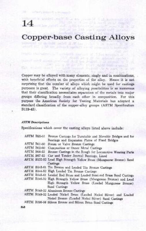
L4
Copper-base Casting Alloys
Copper may be alloyed with many elements, singly and in combinations,with beneficiel effects on the properties of the alloy. Hence it is notsurprising that the number of alloys which might be used for castingspurposes is great. The variety of alloying possibilities is so numeroug
that their classification necessitates separation of the metals iuto majorgroups differing broadly from each other in composition. For thispurpose the American Society for Testing Materials has adopted a
standard classification of the copper-alloy groups (ASTM SpecificationBUe-45).
ASTM De*riptialtu
Specificatious which cover the casting alloys listed above include:
ASTM 822-61 Bronze Castings for Turntable and Movable Bridges and forBearings and Expansion Plates of Fixed Bridges
ASTM BOl40 Ste'm or Valve Bronze CastingsASTM 862$0 Composition or Ounce l{etal CastingsASTM 86C52 Bronze Castings in the Rough for Loeomotive Wearing PartsASTM 867-52 Car and Tender Journal Bearings, LinedASTM 8f32.52 Lcad Eigh Strength Yellow Brass (Manganese Brouze) Sand
Castingg
ASTM 8143{1 Tin Bronze and Leaded Tin Bronze CastingsASTM 8144.52 High Leaded Tin Bronze CasiingsASTM 8145-61 Leaded Red Brass and I*aded Semi-red Brass Sand CastingsASTM 8146-52 Eigh Strength Yellow Brass (Manganese Bronze) and Lead
Eigh Strength Yellow Brass (Leaded l\{4nganese Brouze)Sand Castings
ASTM Bl48-52 Aluminum Bronze CastingsASTM 8149-52 Leaded Nickel Brass (Leaded Nickel Silver) and Iialed
Nickel Bronze (Leaded Nickel Silver) Sand CastingsASTM Bf98-58 Silicon Bronze and Silicon Brass Sand Castings
3$8
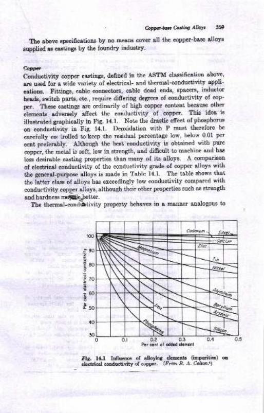
' CnPP"fuMilq AlbYt lig'
The above epecifications by no meaos cover sll the copper-base alloys
supplied as csstings by the foundry industry.
Co14*r
Conductivity copper castings, defined in the ASTM claesification above,
8ne u'ed fora wide variety of electrical- and thermal-conductivity appli-
c8tion8. Fittiuge, cable connectors, cable dead ends, Epace$i, inductor
heads, switch parts, etc., require difrering degrees of conductivity of cop-
per. These castings are ordinarily of high copper content because other
elemente adversely afrect the conductivity of copper. This idea is
illuetrated graphically in Fig. 14.1. Note the drastic efrect of phosphorus
on conductivity in Fig. 14.1. Deoxidation with P must therefore be
carefully cot irolled to keep the residual percentage low, below 0'01 per
cent preferably. Although the best conductivity is obtained with pure
copper, the metal is soft, low in strength, and difrcult to machine and haa
lese desirable casting properties than many of its alloys. A comparison
of electrical conductivity of the eonductivity grade of copper alloys with
the general-putpose alloys is made in Table 14.1. The table shows that
the lattrr class of alloys has exceedingly low conductivity compared with
conductivity copper alloys, although their other properties such as strength
and hardnese Bnfiie:.letter.The thermal-condbtivity property behaves in a manner analogous to
I
Codmium -I
Silver-
N Zinc
!i,
\ \ Nt-- ,yrtti-
N\t- +w\t)
\.t
% d
100
.a so
,E80o
E.3 70
g
;@o
Eso
40
30o.t o.? 0.3
Por ccnt ol oddcd ehrlcnl
fi5. l4.l Inllueoce of alloying elements (impuritiea) metectrica couductivity of copper. (Frmt R. A. h&on.')
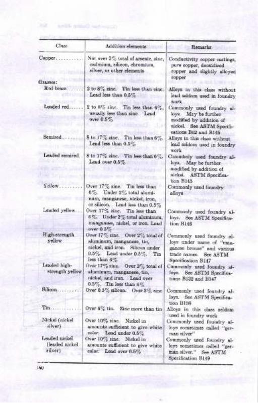
Not over 29; total of &nenic, zinc,csdmium, 3ilicon, chromium,Bilver, or other elemerts
2ln 8Va tiac. Ti! l€ss th&n rinc.I-cad le6s tbso 0.5%
2 tn 87o zi,lc. Tin l€ss rhsn 67.,usua,lly l€ss thsr rinc. L€adovef 0.5En
8 to r77o zllc. Th l€ss than67;.Le{d l€ss thatr 0.5%
8 ro l77o z,i[c. Tia l€€s th.sn 6%.Ld ovu O.5/6
Over lTqa rir.c. Tin less thsn6%, Under 291 totEl slumi-num, maDgane8e, nickel, iron,or silicon. Lesd l€ss th.en 0.5%
Ovet t77a zin.c. Tin less tlsn6%. Under 2% totsl sluminum,maDganede, dckel, oi iron. Le&loyer O.|Va
Over r77ozinc. Over 27a total otaluminum, msngsnede, tin,nickel, end iron. Silicon uader0.5%. I?ad under 0.5%. Tinless than 6%
Oyet L77a rin.c. Over 27o total otalumilruE, m.sngsne6o, tiD,dckel, snd iron. Lead over0-5%. Tin le.s thr,n 6%
Over 0.5% silicoD. Ovet STa zinc
Over 6% tin. Zinc more thstr tin
Over t0% rinc. Nickel itramoutrls suftcietrt to Sivo whit€color. L€d uader 0.5/6
Over r0% rinc, Nickel inamouEt3 8ufrci6at to giv€ whitecolor. Lcsd over 0.5%
L€rsded B€Eired..
Silicon
II iah*treqthyellow
L€sded hish-strength yellow
Remarkr
Conductivity c{pper castings,pure copper, deoxi&r.dcopper aad BliShtly slloyodcopper
Alloys itr thi! cla$ Fithoutledd BeldoE usod itr fouodry
Commonly us€d foun&y al-loys. Mry b€ fufthe}modif.d by addition ofnickel. S€. ASTM Spocif-cetioB 862 snd Bl{s
AUo]|8 in tbis clss3 Eithoutlead seldom used in foundrywork
Commbnly used touDdry sLloF. Msy be furthernodifr€d by sddition oItrickoi. ASTM Spoci6c&fion Br45
Comrsoi y used foundtyslloy3
Commonly ued foundr"Jr sLloya. See ASTM Specificetiotr 8146
CommoDly used fouldry ,lloys under name of ,,mao-
8sa€s€ bronze" snd varioustrade Dsme. Se€ ASTMSpecificatiotr Bl47
CommoDly used foundry cLloj€. See ASTM Speifics-ljon! Bl32 rlld Bl47
CommoDly lrsed foutrdry sl-loye. See ASTM Speci6cs-tion Bl98
Alloys itr thtu chss r€ldomuE€d in fouDdry work
Commonly uaed foundry s.l-loyE sometim€€ csll€d ,,ger-
maD silvor"Commonly used foundry al-loJa EoEetimed called .!ger-
Batr silv6r." Seo ASTMSpeci6cstioD Bl{o
Th.... ........
Niakel (nickel
-rilver)
Lrcrded nickel(leaded njckelsilrer)
Clqs..
Copper...........
Semired.
r-cllow.. -......

2 Lo m% iitL Zinc le€s thta tin.L€ad l€E tbr,Ir 0.5%
Vpl62oTon!.. Zinc leea tLan tin.Iad over 0.5 ard urder 670
VpbmEoiD. Zirc ls tbatrtirr-Ld oac! 8%
L{,d, oa.r Wo. Zincla th.ntiD- Tin undor l07o
Ovd f0% lick L Zirc 16 tLinnicl(6l Urder f0% ti.o" Uid.r0.5% l@n
Ovt' f0% dcLel. Ziac lee tbaoni&€|" Urdd f0% ti!" Ov.t0.6%td
5 to f5% duDiDnttr. Upl,D lO%iro+ *itl or ritbout -'"8.--eor dckol L.6 tt!,D 0.6%silicon
Ovcr0.6%.ilicotr Not oYct 3%riDc. Not ovar 95% copper
Ovor 2% boryliurd or beryliumplue metr,b other tban copper
Bronreg:
High-leeded ti[..
R,orD.arkB
Commonly used fouodry el-loys. Msy b€ furthermodifed by eddiiior oI
some nickel ot phaphonr6
or both. Soc AATM Spoci-
fic.tioDs Bzl rDd 8142
Commooly ueed foundry rl-lo}€. Msy b6 futibormodii€d by sdditioa ofsome nickel or ph@phoru!
or both. ses ASTM Speci-
GcdioDs 86l .dd Bu4Conmouly ured foudry al-loys. Msy ba furth6rmodited by sdditioD ofsome nickd or phcphoru!or both. see ASTM Bpecitu
cstions B2, 866, 867,
strd Bl{4Us€d tor 6p€cisl boarina sppli-c3tioDs
Commonly ured foundry el-
loys. Soraetiro6crllod
"german rilvo/' or "aiclretsilYe/
ColoDody urod fouudry sl-loys. Sometimd call€d
"SemrsD 6ilv€1' o! "dckelsilver." 8ee AIITM Specigcstion Bl49
Com.hoaly u!€d fouadry el-
loJ,s. Som6 &!y be heat-
tlestcd. May b6 furthorhodified by rdditior ofsom6 ,ricket or tin or boti.8e6 ASTM specfi..etiorBl4a
Conmonly ured four&y al-loF. Somo are roadily
h6aLtr€stad- S€o AgfMSpecifcatioa B19t
Mo6t of th€6e dloF lra h6t-he$tsblo
:t5l
Cbss

ri65f8{i€ alr 6'E
gAEI
I €Goor a€qc -o iEr i 6Ro- N- aoII
I
I .6oFo
.E .i:dldq.<
fi*ao
o. i + +ooaoaaaor di{r
+o+.+o6000 0nao-a-46. i
-9di>g-
+ + +
eE.EqEEE EEEAE AqeE E.E AEcooo9ao Facots aoaa o.J ooaatsolal FiN-i 6!!!
-ed
.E t?tst
+ + +s.s.s.E as.s. 3.E E E E s.s.E.E r.Esod60co €600@ oeDE o6€o-Fotso 66aQ6 €OtsO d6
E. E.NO6N
!o
oa€E€ g6{i-
'.2!: q>: ai : 6686
Aia : 1C?qaa: ooin
4o@onor
d.O o
a eraaNol6{
Atr
G
--co-d
e@
,o
: 11.:9 Iqoi ,c o €oo6@ oF66N60?!iEo@ .o o 60006 00000000006
o
-a
. .5
. ...,
.E'o
::::.: : : :l.9
TiEE,IiAOAExo6al
Eeaei.=.2 _2.2 &
t o o o-io40e E
:::. : :::::iiiii,,,',it:: : :::::i. .....o- ... -.=:::: : :::::'
95l::: : :::::3? i : : : .. : : : : :E
I! : : : I ! I I i . o32.;.; ; 6 r ?tori- a
=' = E
d.E E{ E E '
': {;teqe I a::a:
=--bAi n I::i I€-reEs e Eiig.:=.E3::; i i++i;zHi:';.!'E ; +9?;P >5
igi.i i j;rsEi-{
jIc
Io
A
E
a2
a2
=
,
iE
!o
-otrtEAo0tsAr+
3 * e g. t.5= iaaaetxoool
!-occ9
ElaEaid=-===O5 E===:!t o o o,i.!oEcE 6I>
A
IoAoo
t
t,a3IEq
oso
!otIa
b6otT6o.
$o
tao
$f&
isa-BFr
xtz
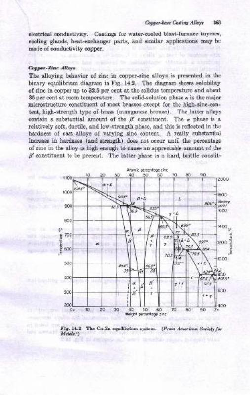
hpptaaxMing Alb$ 363
electrical conductivity. Castings for water-cooled blaat-fumace tuyeres,
cooling glands, heat-exchanger parts, Ind similar applications may be
made of conductivity copper.
rb1ryrcr-Ziru Alloys
The alloying behavior of zinc in copper-ziuc alloys is preseuted in the
binary equilibrium diagram in Fig. 14.2. The diagram shows solubilityof zioc in copper up to 32.5 per cent at the solidus temperature and about
35 per cent at room temperature. The solid-solution phase a is the major
microstructure constituent of most brasses except for the high-zinc-con-
tent, high-strength type of brass (manganese bronze). The latter alloyscontain a substantial amount of the fl constituent. The c phase is arelatively soft, ductile, and low-strength phase, and this is reflected in the
harduess of cast alloys of varying zinc content. A really zubstantialincrease in hardness (and strength) does not occur until the percentage
of zinc in the alloy ia high enough to cause an appreciable amount of the
fl constituent to be present. The latter phase is a hard, brittle constit-
ro 20 30 40 50 60 70 80 90Wbight percenfoge zinc
Fi6. 11.2 Tte Cu-Zn equilibrium sptem. (frorn Am*irrrn &cidy t*Mdob.r)
t,dt
e
EF
d
E
x 400Zn
Atomic p€rcentoge zinc
tttl Ptntifu ol Mdal tuitt
u€Dt, which, attbough it increas€s the strength of c + ff uixtures, r.. -fortulately also reduc€s ductility to the point of destroying the uselulnesr
ofthe alloys iI the rioc content ie too high. Ilence it ie evident thet ure
,inc coDtent of cssting alloys is limited to a maximum of that whichproduces a desirable combinstion of harduess and strength without 8
harmful loss of ductility. The maximum ziuc content iB about 36 per ceut,
Characteristics other than microstructure and properties are exceed-
ingly import8nt, iD certain applications.
CdD
The color of copper-lioc elloys is greatly influenced by linc contcntof the alloys. Color ig related to ,iDc coDtent approximately ae follows:
98% Cu; chsra.teristic copper colorCtrl0y'6 Zn; dark bronze yellov or antique gold color
8% Cr-157o Zn, {% Cv-nVo Zn; rcd brs.ss, copper color70% At-nflo Zn, 65% Cr-5y'6 Zn; yellow brass, bright yellosffiVo Ct -&Vo Zn; yellow, tendeDcy towsrd ltht€! or rhiter yelloe bras8
color
Sometime8 color is an importsnt reason for usiug yellow braases forcastiugs. A particular casting may be required to blend in color withwrought brass parts, for example, Yellow brasses are primarily used fo!emall caetings because the mechsoicsl properties are not especidly good
aod casting dificulties due to shriuksge are aggravated it larger casiings.
Fl,,in!
Vaporizatiou ol zinc (flaring) increae€e with ,itrc contett at anl,particular tempersture of meltiug snd pouring. The relationship waspointed out, iD Table 13.5. Flaring can cause surface-finish diEculties,wriukles aud pinholes, for example, if it is necessary to pour the csstings8t high tempersture.
'Eldd.ol d n Tbmol Co.iAtdh rTheEe propedieE decreaee with increaeiug ,inc content, a8 pointed out
earlier in lig 14.1.
- Eczin!-lcmp.ralurc Rarqc
As cau be Been iD tr'ig. 14.2, the liquidue is lowered and temperaturerar,ge of freezing i8 iucreased 8E the zinc contrcnt of the alloys iucreases.
Sorle liquidue and solidus temperatureo for various alloys are listed inTabre 14.2. The alloye iu Table 14.2 are aot simple Cu-Zn brass€s audhave freering raugee difer€ut from the diagram in Fig. 14.2.
l.
3.
4.
5.
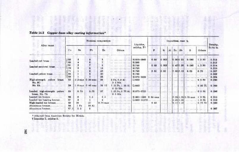
Tabb 14.2 C.oppcr-bou o,lloy curting l4formatbn
Nomind oonrporition
6
6
7
08
8
I0.20 mrr
0. rl0 rnrx
0.75
1.5I
l0l0 AlI
Impuritiq, E.r 7o
Alloy nrEa
Irdld rd bru......,.....
krdcd rcmi-rcd bm... . . .
Iadcd ycllow bru....,....
Iliah{tmnSth yollow brurNo. tCNo. t4...
kulcd hljbrtrcnith ycllor'bru, No. ?A
Lrdrd tin brcnrG...........Lrdrd ti[ borins btonrc. . .
Ilth-lcrdcd tin bronrc......,Aluminum brcntG.......,.,.,Ahrminum hrcnrc.,...,.....,
. Adsptsd from Americon Sociciy ior Metrb.I Liquidur L, rolidu 8.
""1
{sl{;; I
{*l02 I
"lorlsrlr7 I
sol88 I
t751
Sn
Liquidur,rolidur, Ft
LI
s1810-18{O
srtoo8176081725
8l 700
91700
9r075-r925Lr650
L1660
8r075-1725
s1800-18!10
DcD.ity,lb/ou ln.
0.81t0.Er20.8t10.8100.8(}70.8080.80r0.2E6
0.209
o.290
0.8160. grt0.820
o.167
6
7
Il525
30
3t36
39. 15
3?
{.51
0. 75 mrx
6
I3
3
II1
0. 6 mox
I .0 rnrr
0.75
6
tlolFe3.5
lo
lo
10.05
o6ln
15'6 Ptin ipla ol Mdol c.ali,e
bt 4y
?he density of copper-ziuc alloya decreare8 with incrcasiug rinc coDtent
and decreaaiag copper coDtent but does depend on the preeence of otherelements 8uch as lead 8!d tia. Table 14.2 lists deDsity in pounda per
cubic inch of commoa copper-baae castiag alloys.
brqA aolid-solution-type olloy erhibits the microstructural phenomeuou of
coring. Coring ie due to the dendritic frceriag mechaaiem illustrat€d inFig.8.12, which cause aegregation of the alloyiug elemeuts. The higher-freering-t€mperature aolid-Bolution phase, ueually lower in alloy conteat,forme the dendritic 8tructure as lreezing begins, and the lower-freeling-t€Epereture eolid-solution alloy completer the freedng and filling iu ofthe dendrite. Thia resutts in s nonuniform chemicsl compositioD withinthe grains which can be brought out by metallogrsphic means as in Fig,14.4. A wide freeting-tenperatue range accentuates coring Coring inalloye ie accompanied by lees favorable corrosion resigtance and uechaDi-cal properties than when it ie abseut"
Bto.r't &ttiag AlbltActual castiug brasses are not simple Cu-Zn alloya, nor do they have
eimple a or a * fr structures referred to earlier. Inetead, the compoei-tiou may be complicated by the preseuce of tin, lead, antimouy, irou,sullur, nickel, silicon, alumihum, matgsuese, phosphorus, and otherelements. The io.fluence oI eome of i,hese elenetrts and also oI othercopper alloya will become more undergtaodable ae other alloy eyst€n8 arecotr8idered. The analyses and properties of some typical castingtiraeses are included in Tables 14.3 and 14.4. I! these brssses, the copperi6 alloyed with tiD snd copper ao well s8 zinc. The tiu providee increas€dstreDgth, 8Bd the lead, improved caating characterisiics with respect toiouBdness, and aleo better machinability, The latter esects ol lead ar€discuseed again l8ter, under the subject oI copperJead 8lloys. Theinfluence of lead and ol the other alloye to be diesuss€d on caating charac-terigtics ie demonatrat€d in Tsble 14.5. The terms used here ehould notbe coufued. Fluidity is the ability of a molten metal to fill 8 moldcsvity conpletely in every detail, whereas castability ie tlte e8s€ withwhich an alloy respoud8 to ordioary foundry practice, without uudueEttentiou to gsting, rieering, melting, eaud couditions, and any oI theottrrer factorg involved in making good caatinge. Fluidity iurproves rnaayof ttrerc aspecto of c8st8bility.r
The leaded red brssses are very commonly ueed for valvee, valve seete,handles, plumbing firturea, nuts, hardware, lock parts, etc. In thiegoup E5% Cu, 6% SD, 5ft Pb, and 5/o Zt tlloy i8 tie Eost corDrnoDly
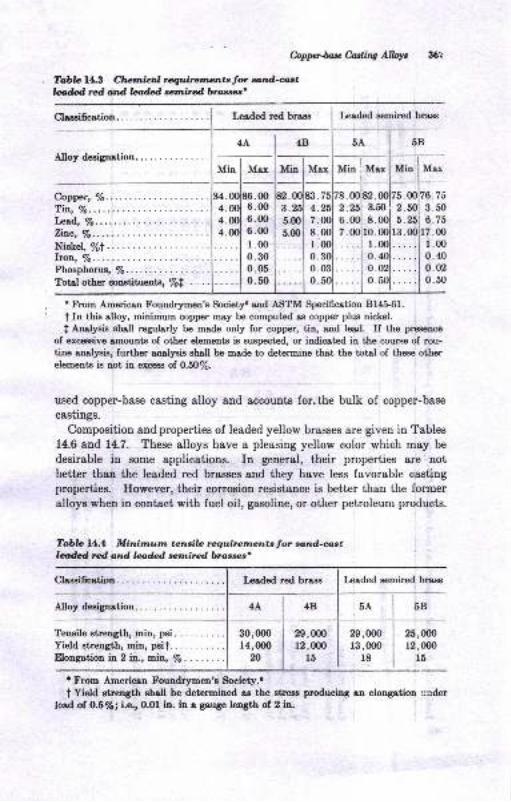
&pphtcMins AW,
Tob& fl.g Clrclnicill rcquircrrrrla,tstol. fu.tlffitdotd bM *nilrdbtoarct'
*7
Leaded red brass keded eemired brsss
5B
Alloy deeignatiou... .. . .
Copper, %......'tin, lo,bd, Vo"Zin.c,7o..
Nickel, 7otlroq lo.Phoephorua, %......Total other cooatituonts, Vot . . .
Tenaile strength, min, psi.Yield etrength, min, pslt.trXongation ir 2 in., min, 7o.
Mia I Max Min lMrx
r From American Foundr5men's Society. aod ASTM Specifiotion Bl4t6f.t In this aUoy, minimum copper Eay be computed as copper plus nickel.
I Analyaia shall regularly be made only for copper, tin, and lead If the preaence
of exceasive rmouDtE of other elements is auspected, or indicated in the course of rou-11a6 mnlJnig, further aoalysis ehsll be made to determine thet the total of thoss otherelements is Dot iu exc€ss of 0.5O%.
used copper-base casting alloy and accouDts for,the bulk of copper-base
casiing8.
Composition and properties of leaded yellow brasses are giyen in Tables
14.6 and 14.7. These alloys have a pleasing yellow color which mey be
desirable in some applications. In general, their properties are notbetter thau the leaded red braeses and they have Iess favorable caoting
properties. Eowever, their oorroeion resistaace is better than the formeralloyswhen in contact with fuel oil, gasoline, or other petroleum products.
Tdbla 14.4 Minirnurn tcnsib requirctrn,en,tslol. cand-astldd rcd and laM *tnircd brorser'
Lea<led red brase
Alloy degignation
3.5.00
:*
30,0m14,(m0
n
29,00012,mo
l5
29,m0r3,000
r8
Mox
7i3 .50
6.757.00I .00
0.400.020.50
5B
25,m012,000
l6
Lesded semired bra$
4B
: From American Foundr;rmen's Slociety..
t Yield gtrength gha[ be determined as the str€ss producing an elongation ';aderloed. of 0.6Voi i.e., 0.01 in. in a gauge length of 2 in.
Claasification.
4AlnS
Claesificetion.
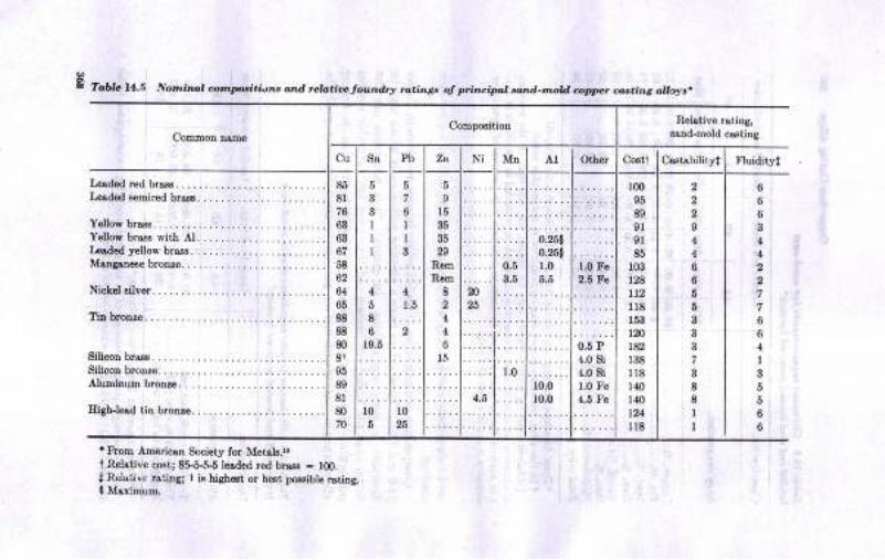
E foAf" tl.S Nornitu, cornpriti.',ts dnd rcla.i& loundrr tu.ings of ',ri'rcipoa
tudd-tuotd coppr co$.ing auort.
t trtoD Arnoricsn Society for Metdls.trt Rel&tiv€ co€t; 8&^6+6 losdod r6d breE - tm.t Relstivc rs',iDg; I iN highe6t or b€6i, p,6siblo rstiog.I MsritnuD,
Cornpo€itionRolative .sting,
BsDd-mold caatitrg
c, ls" Pb ZD Ni Mn AI Other Coetl C03t'bilityl Fluidityl
Loaded red brass .
Leaded eemired bras
Yellow brass...Yellow braas wiib AL . .......L€slod yellow brals . .
Manganeeebronze.....
Silicon brare
Silicon bronro.........Aluminum bronze
85 l68lt3z6 lg6elroslr67 ll5E l....a2 t_ _..ollr86 l58sls88 l6m I rg.BI'l
3sI81 1....80t10?ol6
6
II3
4
1.5
2
10
25
Il536
35b
RtrrrR.h
8
4
4
l6
z0
4.5
0.5
3.5
1.0
0.25!0.%!1.0
10.0
r0.0
1.0 Fe2.5 Fe
0.5 P4.0 si{.0 si1.0 Fo4.6 F6
100
95
83
91
.9185
103
DAtt2118
153
tmr82r38
118
140
140
124
118
2
I4
4
6
6
5
5
37
3
88
II
6
6
6
4
4
7
7
6
6
4
I
5
5
6
6
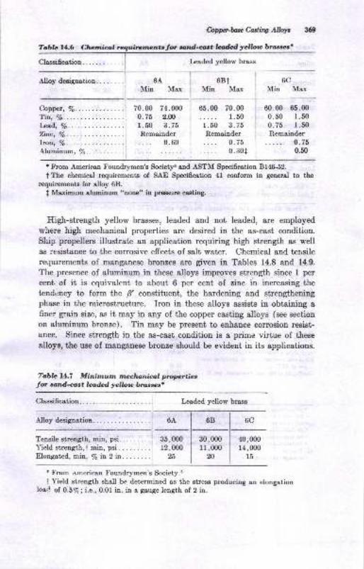
hpph*Corrtir Albr *9
Tabb 11.6 Cfunio,l rqtli;rcnrrlnutor arltd-ant l& yellou bratrr,s'
Lcaded yellow brass
68tMin Max Min Max
6AMin Max
Copper, Vo......Tin, 16.
l*ad, /s.Zinc, lq.Iton, /6.Aluminum, %....... .. . .
70.00 74.ofi)0.75 2.00
1 .50 3 .75
Remainder0.60
65.00 70.001.50
1 .50 3 .73Remainder
o.75
60.00 65.000.50 1.500.75 1.50
Remainder0.750.50i o.BoI
t trlom American Foundrymen's Society6 rnd ASTM Specificrtion Bf4S52.
tThe chemicol rcquirements of SAE Specifcation 4l conform in generel to therequirements for alloy 68.
I Maximum elumiaum 'uone' fur prwure casting.
High-strength yellow brasses, Ieaded and not leaded, are employed
where high mechanical properties 8re desired in the as-cast condition.
Ship propellers illustrate an application requiring high strength &s wellas resistance to the corrosive effects of salt water. Chemical and terlsile
requirements of manganese brouzes are given in Tables 14.8 and 14.9.
The presence of aluminum in these alloys improves strength since 1 per
cent of it is equivalent to about 6 per cent of zinc in increasing the
tendency to form the fl constituent, the hardening and strengtheningphase in the microstructure. Iron in these alloys assists in obtaining afiner grain size, as it may in any of the copper casting alloys (see section
on aluminum bronze). Tin may be present to enhance corrosion resist-
ance. Since strength in the as-cast condition is a prime virtue of these
alloys, the use of manganese bronze should be evident in its applications.
To,bla 14.7 Minirnutn mz,chanical proprtiacfor *ttd-caet lea&d yelloto bra,srls'
Clossification.
6B 6C
40,00014,fi)o
l5
Tensile strength, min, psi.
Yield strength, t min, psi .
Eltrngeted, mirr-, /s h 2 in
35,00012,000
25
30,m011,m0
20
t From american Foundrymen's Society.c
I Yield strength shall be determined ae the stress producing an elongationload. ol oi.B%; i.e., 0.01 in. in a gauge length of 2 in.
Claseification.
Leaded yellow brass
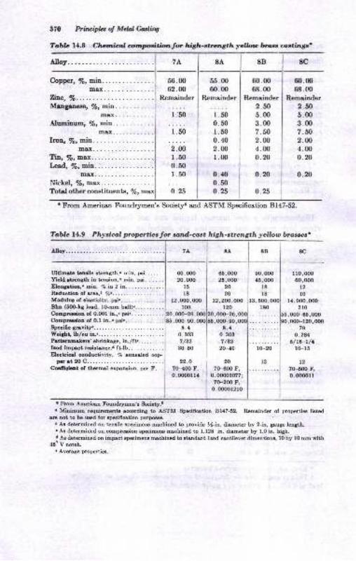
7L 8A 8B 8c
Copper, !s, min.max....
Zitc, Vo..Maoganeae, /s, min.
max...,....-..{luminum, /s, min.
m8x.........-.
56.0062.00
Remainder
1 .50
i;o
2.001.500.50r.50
o.25
55.0060.00
Remainder
r.500.50r.500.402.001.00
0.400.500.25
60.0068.00
Rcmainder2.fi5.003.007.802.N4.000.20
0.20
o.25
60.0068.00
R,emainder
2.505.003.007.502.004.000.20
0.20
t From American Foundqrmen's Society6 and ASTM Specification Bl47-52.
370 Prbt ipla of Mdal C.iuling
Tabb 14.8 Charilncnl onlxtdtfomlor high-strcngth ycllou brue crctingo'
05,(no25,000
20
20r2,200,(mo
120
,mo-26,,oo(Ho.
8.,1
0.30:t7/A2
20-40
20
7H{n F,0.0000r(n7;
7(F200 tr,0.000012ro
m,000a5,o@
l8l8
rto,(x)o00,000
t2lo
l{,000,q)o2to
,00(H5,fix),mo-t20,o00
?9
0.28{6/ro-t/a
l(Fl5
t2.7(H00 r,o.dx,oll
3,5{n,180
8.{0.3Gt7 /32
3(F50
22.O
7(HOO F,
0.fimua
r Froo Amcim Foudr1mcn'r Socict5r.t. MiDiEu rrquimantr @rdiry to A8IM Spei6etion Bf47-52. Rouinder of propotia liatad
rG not to bc ued for rp*iiotion purpo.r Ar dotamincd on t€ruile .peimeu Emhined to prcvide !-in. dieeter by 2-in. gaugc lcoath-. Aa determincd on oopmion rpccimem mhined to 1.128 in. diamctcr by f.O h. high.a Aa detemined on iEpqct lpaiD@ tuhilad to lt&d8d Ircd cutilevq dimcnriou, l0 by l0 om vith
{6' V trotoh.. AvsaSs prcp€rtiE.
Table 14.9 Physial propertics Jor so,nd-cast high-strength yelloro brassesr
00,ooo20,00o
l5l8
12,fi)o,fi)o100
,oqF26
m8x... .
Ti\, Vo, ttrax. . . .
Lp;ad., %, min....max....
Ninlral o7- mov
Totel other constituents, /e,
7A 8A 8B 8C
Ultiutc tcuilo ltrength," r:in, pri..... .
Yicld etnngth in teuioo,n miu. pri. . . . .
Eon8ttioD," EiD, 7. in 2 in............Rcduotiou of rret.r 7o........Modulu rrf cluticitv, p.i.. . . . .
BhD (6r0G.Ls lod, lG.mm brll)........ ..Compuion ol O.0Ol iu.,. p!t...........
sfuiG- 6drr.
r0-20
l:
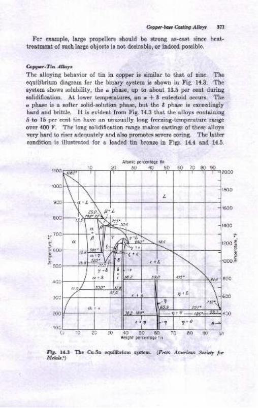
Copp'huGadtry AW 371
Fcr example, large propellers should be strong as-cast sinee heat
treatment of such large objects is not desirable, or indeed possible.
hppr-Tin Alloyc
The alloying behavior of tin in copper is similar to that of zinc. Theequilibrium diagram for the binary syst€m ia ehown in Fig. 14.3. Thesystem shows solubility, the c phase, up to about 13.5 per cent duriugeolidification. At lower temperatures, 8n c * 8 eutectoid occurB. Thec phase is a Bofter solid-solution phase, but the I phase is exceedingly
hard end brittle. It is evident from Fig. 14.3 that the alloys coutaining5 to 15 per cent tin have an unusually long freeziug-temperature range
over 4fl) F. The long solidification range makes castings of these alloysvery hard to riser adequately and also promotes severe coring. The lattercondition is illustrated for a leaded tin bronze in Figs. 14.4 and 14.5.
Atomic pcrcentoge tin
20 30 40 50 60 70 80 90
Cu 10 ?O 30 40 50 60 70 80 90 SnWeight percenloge tin
Fig. 14.3 The CuSn equilibrium system. (Frun American fuicly torMclals.r)
oot
E
F
'r00
o
dE
F.
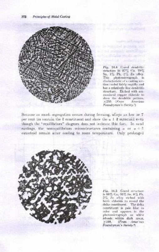
Priruiplcs o! Nlctal Caslin4
Fig. 14.4 Cored dendriticstructure h 877o Cu, 10/6Sn, lVo Pb, 27o Zn alloy.This photomicrograph ischaracteristic of a casting sec-
tion cooled fairly rapidly andhas a relatively fine dendriticstructure. Etched with am-moniacal copper chloride ioshow the tlendritic pattern,X250. (From AmericanFoutdrymen's Socrely.!
Because so much segregstion occurs during freezing, alloys as low as 7per cent tin contain the 6 constituent and show the a * 6 eutectoid even
though the "equilibrium" diagram does not indicate this fact. In san.1
castings, the nonequilibrium microstructures containing a or a * 6
eutectoid remain after cooling to room temperature. Only prolongt:d
Fig. l4.S Cored st.uctureis 88/6 Cu, lU/sSn, O7o Pb27o Zn alloy etched withferric chloride to reveal thedelta constituent. The deltaconstituent is pale blue incolor and appears in thephotomicrogtaph as whiteislands within daik areus,
X f 00. (From Amer:cdnFoundrymen's Suiety.\
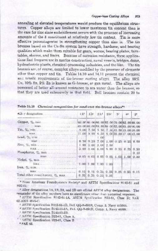
Coppcrtase Casling Alloys 373
anneBling at elevated temperatures would produce the equilibrium struc-tures. Copper alloys are limited to lower maximum tin content than isthe case for zinc since embrittlement occurs with the presence of increasingamounts of the I constituent at relatively low tin content. Tin is moreeffective percentagewise in strengthening copper than zinc is. The tinbronzes based on the Cu:Sn system have strength, hardness, and bearingqualities which make them suitable for gears, worms, bearing plates, turn-tables, sleeves, and liners. Because of corrosion resistance, these applica-tions find frequent use in marine construction, naval vessels, bridges, dams,hydroelectric plants, chemical-processing industries, and the like. Thetinbronzes are, of course, complex alloys modified by the presence of elementsother than copper and tin. Tables 14.10 and 14.11 present the chemicalarrtl tensile requirements of tin-bronze casting alloys. The alloy 88/oCu, l0/o Sn,2/o Zn is known as G-bronze, or gun metal. The alloys arepossessed of better all-around resistance to sea water than the brasses, so
that they are used extensively in that field. Bell bronzes contain 20 to
Copper, !6, min. .00.00
Tin, /r, min.max.
e.0ol 7.501 s r0.00ll.ool e.ooJ 6. 2.00
0.30i 0 301 2
m&x. . 189 . 00189. 00jS9.
Zitc,/e, min.... .....1 r.Ool s.Ool e
max.... .. . .l 3.001 5.001 5.Phosphorus, 7o, mirn.
0.
0.
1.00
0.50
0.500.100.30
Phosphorus, 7o, min. I I I
max.... .......1 0.051 0.0b1 0,Nickel,/e,min.... ..........l I Imax.... . .l r ool r.ool l.bon,/o,min.... . I I I
max.... .....1 O.l5i g.rbl 0.I'otal other constituenrs, To, max.
I O *i 0.251 0.
l.
0.0.
. FromB22i1.
American Foundrymen's Society6 and ASTM Specifications 814&61 e,nd
" rllloy designations 1A, tB,24, and 28 are official ASTM alloy designations. f.iroremainder of the alloy numbers have no significance other than numqrical sequence.
D ASTM Specification B14&61-1"{, ASTM Sprcification 822-61, Cless D; S.{E62-AMS 484SC.
" ASTM Specification 814&61-18, Fed. ee-B-691B, Comp. 5, Navy 46M6h.dASTM Specification 8143-61-2A, Fed. QQ-B-691B, Comp. l, Navy 46B8i.' ASTM Specification 814&61-2B./ ASTM Specification 822-61, Class A.
' , r\STM Specification 822.61, Class B.r sAE 65.
Table l4.IO Chcmical cornposition Jor nnd-cast tin-bronze alloyst"
0.251 0.15
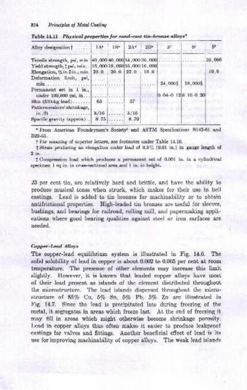
371 Prbuipla ol Mdal Corrairw
Tabb l4.ll Phycial propcttiee for sand-czst tin-btorcc o,lloys'
1B" zlplzs.l--t-l zrla"40,00018,00020.0
34,0O0i36, mol16,00ol 16,0001
22.0 118.0 10.0
24,mol
0.04.{ . 12
18,000$
0.lc-{).205;
3/L68.70
'Ftom Americen Foundrymen'a Societl end ASTM Specificotions 8143-6I and
B,?26t.
t For meaning of superior lettere, see footnotce under Trble 14.10.
f Strras producing an elongatioo under loaA ol O.57o (0.01 in.) in geuge length of2 in-
I Compresaion load which producee s pormr,netrt set of 0.(X)1 in. in a cylindricalepecimen 1 sq in- in croes-sectioDal area and I in io heighL
23 per cent tia, are relatively hard and brittle, 8nd have the ability toproduce musical tonee when struck, which makes for their use in bellcastings. Lead is added to tin bronzes for machinability or to obtain
antifrictional properties. HighJeaded tin bronzes are useful for sleeves,
bushings, and bearings for railroad, rolling mill, and papermaking appli-cations where good bearing qualities agsinst steel or iron surfaces are
needed.
bppcrlad Alloyt
The copper-lead equilibrium system is illustrat€d in Fig. 14.6. The
solid solubility of lead in copper is about 0.002 to 0.005 per c,ent st room
temperature. The presence of other elements may increase thie limitslightly. However, it is known that leaded copper alloys have most
of their lead present as islands of the element distributed throughoutthe microstructure. The lead islands dispersed throughout the micro-structure of 85/o Cu, 5/o Sn, 5/o Pb, 5% Zt are illustrated inFig. 14.7. Since the lead is precipitated late during freezing of the
metal, it segregates in areas which freeze last. At the end of freezing itmay fill in areas which might otherwise become shrinkage porosif.Lead in copper alloys thus often makes it easier to produce leakproof.castings for valves and fittings. Another beneficial efrect of lead is itsuse for improving machinability of copper alloys. The weak lead islands
Tensile atrength, psi, min.Yield strength,| psi, min. .
Elongation, 7e in 2 in., mio.Deformation lirnit, psi,
min... .
Permanent set in I in.,under 100,000 psi, in..
Bhn (50}ksload)......Patternmakers' shrinkage,
in fi.r...Specific grevity (approx).
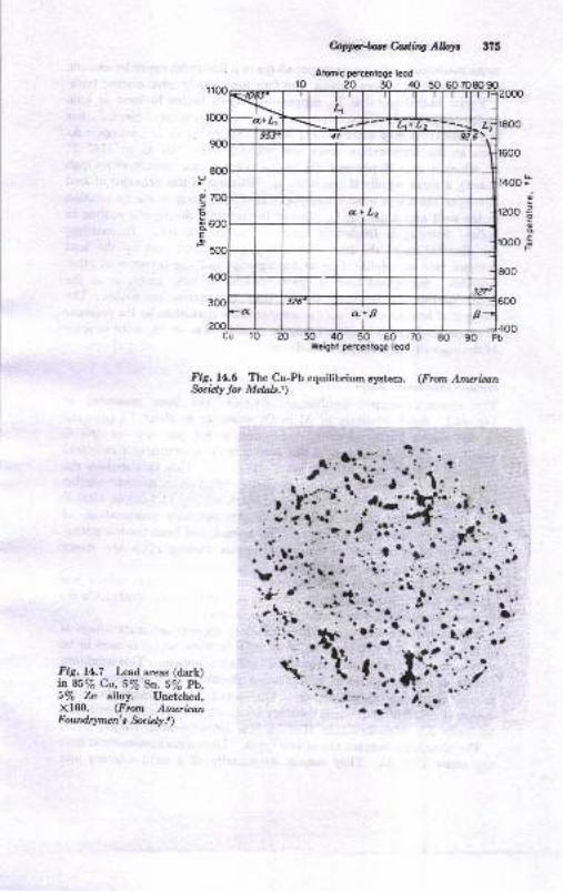
Fig.14.7 Lead areas (dark)in 85/q Clu., |Vo So. 57o Pb.5/6 Zn alloy. Unetched,X100. (Fron AmericanFoutd4rmen's.$eely.)
bpg*tchdiA Albyt
Alomic pcrctnlogc lcod
ro ?o 30 40 50 60
40 50 60 70Weight percentoge leod
t.-'a
r600
t400 ra;ao
eEF
a
";to
d
E
\ig. U.6 The Cu-Pb eguilibrium rystera. (Fron Amaian$cidy lor Melal"s])
alr
aJ
!r-?..
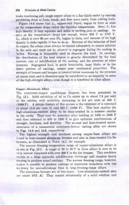
176 Ptin ipLt o! Mdat-fuil|
make machiniDg soft, tough copper alloye to a fine finish easier by caus'ng
merhiuiug chips to form, break, and flow more easily from cuttiog tools'
Figurr 14.6 shows thst 2,, copper-rich liquid, begine to form as sootr
as the t€mperatwe dropa betow the liquidus temperaiure. Since L' has
hig\ density, it may Eeparat€ and eettle in metting pots or castings. As
eoor ae the temperature drops low enough, belorr 953 C or'1747 F,
,Lr, which is over 90 per cent Pb, begins to form, a[d because of its high
density it siuks rapidly if free to do so. Because of this b€havior oI lead
in copper, the alloys must always be heated adequately to ensure soluiion
in the melt atrd must not be allowed to segregste during the cooling in
laCles. Stirring is frequently used to disperse the le8d. I1 csstings,
the distribution of the lead islands is greatlv determined by the lead
content, rste of solidification of the casting, snd the presence of other
elemerts. Segregated lead, in grain boundories, large blobs, or in the
lower portion of caetings, causes poor mechanical properties. The
sirength of brasses and brouzes ie lowered below maximum by ihe preseoce
of excess [ead, &nd it therefore may be considered ss an impuity in some
of the high-strength alloys, even though it is beueficigl in other alloya'
Coppt-Alu,,inz.n AlW,The aluminum-copper equilibrium diagram has been preseuted iu
Fig. 12.1. Solid solubility of AI in Cu exists up to sboui 7.4 per ceut
st the solidus, with aolubility increasing to 9.4 per cent 8t 565 C
(1O49 F). A unique feature oI this system is the existence of a eut€ctoid
at qbout 11.8 per cent Al 8Dd 565 C (1049 F). This fact enables the
high-aluminum-conteut alloy to be heat-treatcd in a mauner similar
to the sieels. They may be queuched aftcr holding at 1450 to 1600 F
and then reheated to 650 to 1250 F to give optimum combin&t'ions of
strength, harduees, and ductility, The ae-cast atrd he&t-treated micro-
structures of a commercial aluminum-bronzc casting alloy are shown
iu Fig. 14.8 and 14.9, respectively.
The highest strength and hardness among copper-base alloys are
fc und in heat-treated aluminum brouzee and BIso in he8t-trest€d Cu-Be
bronzes, as illuetrated in Table 14.1, for example.
The narrow freetiDg-temperature range of copper-aluminum alloys is
sh.rwn in !ig. 12.1. A rauge of 20 to 50 F in tLese alloys is seen to be
very narrow compared with over 400 F iu the tin bronzea. Thie condition
reeults iu a targe apparent solidificatiou shrinkage and requires heary
risgring to produce sound castings. The namow lreezing range, however,
n akes it possible to produce castings of maximum eoundness with lese
ter dency for microshrinkage than in long-freezing-rauge alloys.
'lhe aluminum bronzeg are of two types. Low-aluminuo-content onee
arc under 10% At. They consist structurally ol d solid solutioo aud
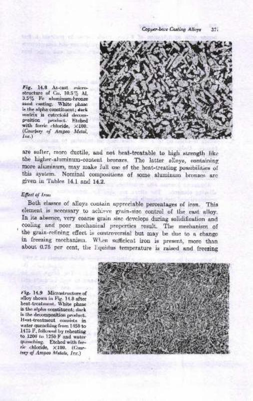
&ppriase Cutirw AlWt .37'i
FiS. 14.8 As-cast micro-structure of Cu, 10.5/e Al,3.5/s Fe aluminum-bronzesand casting. White phaseis the alpha constituent; Carkmatrix is eutectoid decom-g)sition pmduct. Etchedwith ferric chloride, Xlfi).(Coutlesy of Ampa Metal,1rc.)
are softer, more ductile, and not heat-treatable to high etrength likcthe higher-aluminum-content bronzes. The latter alloys, containingmore aluminum, may make full use of the heat-treating possibilitiee ot'this system. Nominal compositions of some alrrmiuum bronzes aregiveu in Tables 14.1 and 14.2.
Efccl of Iron
Both class€e of alloys contain appreciable percentages of iron. Thiselement is necessary to achieve grain-size control of the cast alloy.Iu its absence, very eoarse grain size develops during solidification andcooling and poor mechanical properties result. The mechanism ofthe grain-refining effect is controversial but may be due to a changein freezing mechanisrn. WLen sulfcienb iron is present, more thanabout 0.75 per cent, the l:quldus temperature is raised aud freezing
Ilig. 14.9 Microstructure ofalloy shown in Fig. 14.8 afterheat-treatment. White phaseis the alpha constituent; darlis the decompooition product.Heat-treatment consiets inwater quenching from 1450 to1475 F, followed by reheatingro 1200 to 1250 F aud waterqucnching. Etched with fer-ric chloride. X100. (Cou-tery of Ampa nAcbls, lrc.)
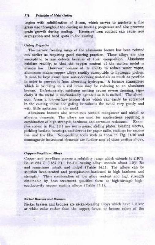
3?8 Ptitwipbt of Meal Miq
l-regins with aolidification of 8-irou, which serves to nucleat€ a fiue
grain eize throughout the casting as lreezing progresses and slso prevents
grain growth during cooling. Excessive iron coDt€Dt can cause iton
segregation aud hard epots in the casting.
Coding Prcp bt
The larrow freezing range of the aluminuo bronze has been poiutcd
out earlier as requiring good rieering practice. These alloys are also
susceptible to gas defect€ because of their composition. Aluminum
oxidizes readily, so that ihe oxygen corteni ol the molten meisl is
always low. However, because ol its ability to reduce wat€r v&por,
aluminum makes.copper alloys readily susceptible to hydrogen pickup.
Ii must b€ kept away lrom water-forming materials as muoh as poseible
in order to prevent it from absorbing hydrogen. A furnace atmosphere
which is oxidizing to a red brass may be reducing to an alumiuum
bronze. Unforiunately, oxidizing mell,ing causes severe drossing, espe-
cially il the metal is mechanically agitated as ii is melied. The alumi-num forms a low-surface-tension dross which can easily be entrained
iu the casting unless the gating introduces the metal very gently and
with little agitation in the mold.
Aluminum bronzes also sometimes contain manganese snd nickel as
alloying elements. The alloys are used for applications requiring a
combinaiion oI high strength, hardness, and corrosion resistance. Exam-ples shown in Fig. 13.1 arc worm ge&rs, sliding plates, bea ng sleeves,
pickling baskets, bearings, and sleeves for paper mills, castings lor marine
use, and the like. Nonsparking tools such as those in Fig. 14.10 and
nonmagnetic instrument elements are lurther uses of these casting alloys.
Cap pe. - Be.! I liu m A rL,y,
Copper and beryllium possess a solubility range which extends to 2.10/o
Be at 864 C (1587 F). Be-Cu casting alloys contain about 1.0/o Be
and soruetimes cobalt and nickel (Table 14.1). The alloys can bc
eolul,ion heat-trested and precipitatiol-hardened to high hardness and
strength.' Their combination of low alloy content and high strength
obtainable by heai treatment quaiifies them as high-strength high-
conductivity copper casting alloys (Table 14.1).
Nbkcl Btamet arul Brunzez
Nickel brasses and bronzes are nickel-bearing alloys which havc a silver
or white color rather than the copper, brass, or bronze colors of the
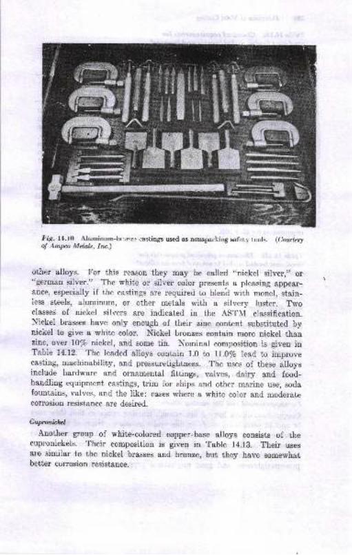
Fig. ll.i0 Aluminum-hr,nz.' ,.astings used as nonsparking safcti. lt:ols. (CourtesyoJ .4mpa Metals, |rc.)
other alloys. For this reason they may be called ,,nickel silver,,t or"german silver." The white or silver color presents a pleasing appear-ancc, especially if the castings are requireri to blend with monel, stain-iess steels, aluminum, or cther metals with a silvery luster. Twoclasses of nickel silyers are indicated in the ASTN{ classification.Nicliel brasses have only enoqgh of their zinc content substituted bynickel to give a white color. Nickel bronzes contain more nickel thanzinc, over l0/o nickel, and some tin. Nominal composition is given inTable 14.12. The leaded alloys contain 1.0 to ll.0/o lead to improvecasting, machinability, and pressuretightness. The uses of these alloysinclude hardware and ornamenfal fittings, valves, dairy and food-handling equipment castings, trim for ships and othcr marine use, sodafountains, valves, and the like: cases where a white color and moderatecorrosion resistance are desired.
Cupronickcl
Another group of white-colored copper-base alloys consists of thecupronickels. Their composition is given in Table 14.13. Their usesat'e similar to the nickel brasses and bronze, but they have somewhatbetter corrosion resistance.
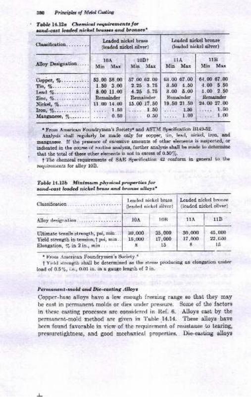
3U) Prituipht of Mdal Culing
Tabb l4.lb Chenicol requiretncnts lorrptnd-crlst le&d nickc,l bros'Ed o.rd bronzcs'
Copi"", %. ......... .
Tir., Vo.
l*rd Vo..Zitc, Vo.
Nickel, 7o.
lron, 7o....Manganese, Vo. -.., . . .
Leaded nickel bronze(leaded nickel silver)
nBMin Max
64.00 67.004.00 5.501.00 2.50Remainder
24.@ 27.OO
1.501.00
t From American Foundrymen's Society'snd ASTM Specification Bl4g52.
Analysis shall regularly be made only for copper, tin, lead, nickel, iron, and
matrgenese. If the presence of excessive amounts of other elernents is suspected, or
indicated in the course of routine analysis, further analysis shall be mAde to determine
that the total of these other elements is not in excess of 0.50%.
t The chemical requirements of SA-E Specification 42 conform in general to the
requirements for alloy l0B.
Tablc l4.7..2b Minirnum physical properties forsand-cast leaded nickel bross and bronze allolrs*
Leaded nickel brass
(leaded nickel silver)
Leaded niekel bronze(leaded nickel silver)
l0A l0B llA llB
Ultimate tensile strength, psi, mip. . .
Yield strength in tension,t psi, min..Elongation, Vo h 2 in., min. . . .....
30,m0r5,000
8
35,000r7,000
l5
30,00017,000
8
45,00022,AOO
l5
I From Americen Foundrymeri's Society.'
I Yield strength shall be determined as the strese producing en elongation under
loed of O.57o, i.e., 0.01 in. in e geuge length of 2 in.
Penna nz;nt-tnold and Dic-wting Alloyc
Copper-base alloys have a low euough freezing range so that they may
be cast in permanent molds or dies under pressure. Some of the factors
in these casting processes are considered in Ref. 6. Alloys cast by the
permanent-mold method are given in Table.14.14. These alloys have
been found favorable iu view of the requiremeDt of resistauce to tearing,pressuretightness, and good mechanical properties. Die-caeting alloys
Lcaded nickel brass
(leaded oickel silver)
53.00 58.00 I 57.0O 62.00
r.50 3.oo | 2.25 3.758.00 ll.oo | 4.2,5 5.75Remainder I Remainder
lr.0o 14.00 | 15.00 17.50
1.501..... 1.500.50 1..... 0.50
tlAMin Msx
6i1.00 67.00
3.50 4.503.00 5.00Rcmainde.r
19.50 21.501.50
1.00
Classification. . . .. .. .
Alloy Deeignation... . .10A
Min Maxl0Bi
Min Max
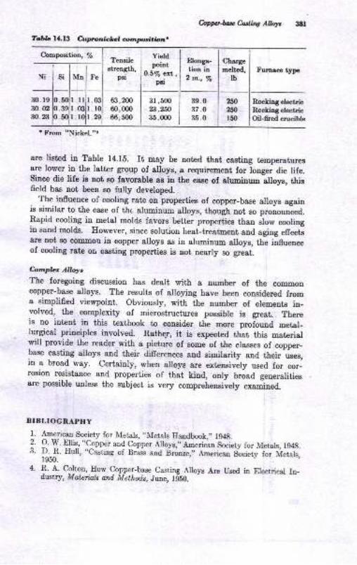
Table 14.13 Cwprcnickel crrnpdtion
hpp-h*futtns AlWt :t8l
Composition, /eElonga-tion in
2 rr.., ls
Charge
melted,
tbFuraam t5rpe
30. l9:t0.0230.23
lrlmlr0l
39.037.O
35.0
Rocking electricRncking electricOil-fired crucible
t From "Nickel."r
are listed in Table 14.15. It may be noted that casting temperaturesare lower in the latter group of alloys, a requirement for Ionger die life.since die life is not so favorable aB in the cas€ of aluminum alloye, thisfield has not been so fully developed.
The influence of cooling rate on properties of copper-base alloys againis similar to the case of the aluminum alloys, though not so pronounced.Rapid cooling in metal molds favors better properties than slow coolingin sand molds. However, since solution heat-treatment and aging effectsare not Bo corumou in copper alloys as in alrrmin,m alloys, the influenceof cooling rate on casting properties is not nearly * g.""t.
hmpb Allqrs
The foregoing discussion has dealt with a number of the commoncopper-base alloys. The results of alloying have been considered froma simplified viewpoint. Obviously, with the number of elements in_volved, the complexity of microstructures possible is great. Thereis no intent in this textbook to consider the more profound metal-lurgical prineiples involved. Ratheg, it is expected that this materialwill provide the reader with a picture of some of the classes of copper-base casting alloys and their difrerences and sipilarity and their uses,in a broad way. certainly, when alloys are extensively used for cor-rosion resistance and properties of that kind, only broad generalitiesare possible unless the subject is very comprehensively examined.
BIBLIOGRAPHY
l. 1.::r.:1. Society for Metals,,,IUetals Eandbook,,, Ig48.
? 9 Y E]h9, "!9nner and gopper Alloys,,,American Society for Metals, lg4{t.3. D_.-F. HuII, "Casting of Brass and 6ronze,,, American Soeiety f;. ir1;;"h,
1950.
4' +.A. cgtton, Eow copper-base casting Allovs Are used in Erectricar In-drl*r'iry, Materinls and Method,s, June, ld50.
Tensilestrength,
p8i
Yiddpornt
O.6/s ett ,psi
Ni si Mn Fe
).5().3().5(
63,20060,fix)66,500
3r ,50023,2fi35,(m
2ffi?,fi150
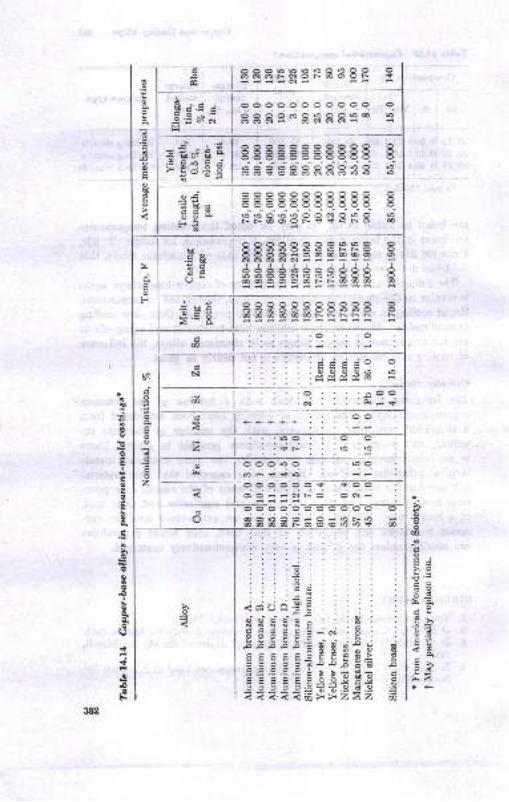
EAra
lassFRBFBBtRldiiiNd
ri
o
N
+++++
-o
o o o-o o-$----:-SE, oO)Oi-NNO .ONi
ooooooooooo ooooomotoooro@ ro66Ni 6NNNd
$;.s ;-E € slirq
ooooooooooo oEEB83=t88t8 I- dd'to do o ddo ,.t6aosoAoNNmrOrO 6
=€ssE# EEE ia-
oooooooC'coo o88888888888 I"i"id"i,.to o e.io,.td ''tNN@OrON<1 <rrONcr) 6
i
'6 bo'=
F,@
88BB8BBBPP8 t66oo:o@@@6o oNNNNNii-iFH
JAJJIAAAJJJ A6660N666000 O@60006rNO@6 00dii-iiiiiii
looooooooooo o160600moo|o60 0166@@@@NNTNN Nliir
aad
a
@o
oo
do
d
otr
ou6
bo
.Essa
-- = sioc=aq
. looo6o 6ot\ l;-${; : : : :J;
o
;o
6oAE
o
dg
Eoz
iae
6o
E
B
q)q
a5
Boa6se)9.q;
a
e)
€.Bl.l
>a
oIo
CD
a
otsc>,o
co<dhA odu*>,.E?c!.
Jd-Atrxodfra
.dod-<i-idsd66NO@@rOrOS
.o
. .N .
N .O'
d-i! L
FBsB55 gEt o uoy.y c!
=9d9;2>2
o@d
A
::..:oxo.tre_N&cUo
o-dio7,E,d
tro
=E<a
<tqOAooooNNNN
ooooD.oA.O
trtrcltrtrtrtr

hppuhe &dins AWTo'bla 14.1tu Chalai@, r.4uir.rr,r/'^, ,lor caplEr-bre 0lllor. die .rrtiag..
. rrom ^STM
spucj6o,iio" BlTd;r--]"P::alojjf^,g*1.-T l:ro :tlrisbod in eccordance with ASrM D€sisusr,iotr8275, RtcorDme'ded p*ctice for c"ae*u* .iitgriri""il;*iil;:if il;WmWhtt hior to 1052 th€ee auoys were d€sigllatad as A, B, sDd C, r€spectively.
TobL ll.lsb Miair'swr'/. phyrico, prcp.rtj.e,tor coplEr-brc ouo! dia car.inss.
Alloy d€sisnatioD7"s144A
Utixost€ t6nsil€ streDgth,p6i, min......._...............
Yield streDsrh (ofset :0.2?,),p€I, mrnr .,..,..,... ......
uongation in 2 iD., Eo, toin. . . . . . . . . .
' From ASTM Specificsrion Bl7G62-T Yield streDgth as determined by the ofiset method.
90,000
50,0m
6.
8.
9.
10.
i;rl;tf^t Eigh couductivitv copper csstilgr, Ttaar. aFS, vol. 6?, p.
Am*erican loundrymetrh Socier,y,,,Copper-base Alloys tr.ouDdiy practicc,,,
*,1;,.ff'H:;"!:ff;im"#i#n*'" wide Range or Properties, /n.
["';*:]tr1#ix.1Hffi ,i*.T, {ifl f,"1ffi ;"r s,,,sro
Aeenca! sociery lor Metals, ,.Mer,.is Eatrdboot," gtb ed., vol. l, 1961.
.{loy designatioDt. . _.. . zSoAt zssSlAt 7At41Al
Min Max ur" I u". Min Mrr
8ii.mo.25
0.15inder. 0.r5
0.15
4.25
Coprftr, Vo.............T\\,%............._.r^4, 7o...............Zie, %................h@, 7o. ..... .. . ... .. .
Msogr,ms€, %..........Silicon, %..............
:'j'.m
6i1.00 I 67.m......1 o.zs
'''I o.zsncrhlitrder. . .t o.rs......1 o-rso.zs I r.zs
45,000
25,0mt0
58,010
30,000
l5
i.mr.50
0.50
o.25
o.25
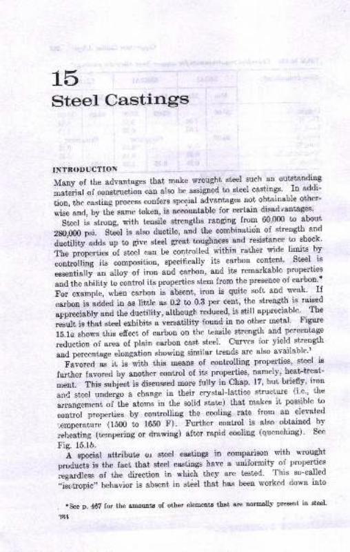
15Steel Castings
TNTRODUCTION
Many of the advantages that make wrought steel such an outstanding
grateiial of construction can also be assigned to steel castings' In addi-
tion,thecastingprocessconfersspecialadvantagesnotobtainableother-wiseand,byttre-sametoken,isaccountableforcertaindisadlantages.
Steel i, *t.oog, with tensile strengths ranging frou-r 60'000 to about
ZSO,Oq0 p.i. Sti"t i. also ductile, "oa
th" combinatidn of strength and
a".iifitv adds up to give steel great toughness and resistance to shock'
it. p.opurtiu, of .t""t can be controlled within rather wide limits by
.""t-ffiirg its composition, speciflcally its carbon content' Steel is
"..."ti"ffi an alloy of iron and c&rbon, and its remarkable properties
and the ulitity to control its properties stem from the presence of carbon-t
For example, wheo carbonis abse"t, iron is quite soft and-weak'. If
carbon is sadea in as little as 0.2 to 0.3 per cent, the strength is raised
appreeiably and the ductility, although reduced, is still appreciable' The
result is that stcel exhibits a versatility found in no other metal' Figure
15.1o shows this effect of carbon on the tensile strength and percentage
reduction of area of plain carbon cast steel. curves for yield strength
and percentage elongation showing similar trends are also available''
Favored ".
it i. with this means of controlling properties, steel is
further favored by another control of its properties, namely, heat-treat-
ment. This subject is discussed more fully in Chap' 17, but briefly' iron
and steel underlo a change in their crystal-lattice structure (i.e., the
arrangement of ihe atoms in the solid state) that makes it possible to
contro"l properties by controlling the cooling rate from aa elevated
iemperature (1500 to 1650 F). Further control is also obtained by
reheating (tempering or drawing) after rapid cooling (quenching)' See
Fig. 15.1b.
L special attribute or steel castings in comparison with wrought
producl is the fact that steel castings have a uniformity of properties
iegardless of the direction in which they are tested. This so-called
,,is"ctropic,' behavior is absent in st6el that has been worked down irrto
,.seep.46Tforthea.mou,ttsofotherelementsthotgrenormallypreaentinsteel.'tM
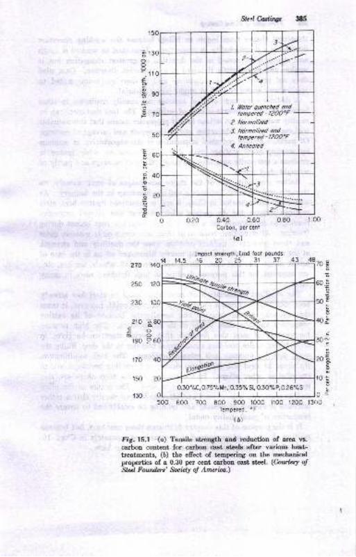
Src.l Gastdrus 385
14'r40i
?10 'ao-Eo(Do
!90 9
5OO 600 700 8OO 900 l0O0 ll0o 1200 l3(t0Tempered, oF
la)
Fig. l5.l {o) Tensile chilgth and reduction of area w.carbon content for carboo dast dcels aftcr variouE heat-treatments, (b) the efrect of teqrerirg oo the mechaoicalpropertiee of a 0.30 per cent carboa cast srfrl. (hnhtl otSlzl Fotnden' fucidy oJ Amaia.)
ooo:1Eoc
g
cF
dooc.9
Et
48270
?50
230
o
N
.9
9
d
70
50
40
30
20
r0
0
170
150
r30
L tloter quenchcd ondtenpered - |2OO"F
2. Normolbed
3. Alornolaed ondlenpered - |ZOO"F
4. Anneoled
0.30'/"C, 0.75%Mn, 0.35%Si, O.3O%P, 0.26%S
0.20 0.40 0.60Corbon, per cenl
(a)
lool pounds
31
ill6 Pria.ipla ol Mdal hdnv
8tluctural shapes fmm ingots or billets becguse the working operatiolintroduces a directionality il properties. Thus steel eo worked is toughaDd stroDg when teeted iu the direction of greatest elongatiou but isseaker and more brittle if test€d iD a trsnaverse direction. Cast steetdoes uot l,o8s€88 this directionality and ia therefore better suited toapplications where this e6ect might prove harmful.
A distiDct advantage of steel castings not readily realizable in otherfer:our fouudry products ie ease oI welding. The fact thqt et€el can bereadily welded with oo aerious loss of properties meaus tbat this valuabletool qstr be used iu fabrication 8nd irt the repair and ealvage ol caetitgo.Of perhaps grester pot€Dtial importaace is the opportunity to combineby welding steel castiugs with shapes fabricated by other rnesns toproduce a composite Btructure qomposed psrtly of csstirlgs and par y ofwrought-steel p8rts.
Rather ironically, oue of the major advantages of steel, namely, itsBtreDgth 8Dd ductility, becomes a defrnite handicap in the foundry. Aawae discussed Bomewhst iu Chap. 9 and ie considered further here, steelcaatiugs require (ss do certsi[ other castiugs and alloys) extensiverisering to compeD6ste for a rather large shrinkage that occurs duringfreezing. After cssting, reEovsl of the8e sometiEes quite mss8ive gatesaud risers preseuts a definite problem since the ductility and strelgthof the metal preclude their being merely haomered ofr ag in the case ofbrittle allo5rs like caet iron. Saws, abrasive cutofr wheels, t6rche8, etc.,are required for this purpose, leading to high finishiug costo in manyca8ea.
. The excellent combination of properties found iu st€el has alreadybeen mentioued. From e fouadr5r-practice staudpoint, however, it l,axesthe ingenuity of the desiguer snd metallurgist because of its csstingpmperties aud the close limits of iis composition. The high pouringtemperature of steel also demands that special atteotion be given torefractories, ladles, molding sands, metal transfer in the shop, filling themold with no misruns, and related problems. The high solidificationshrinkage of steel also introduoee design aud molding problems seldomexceeded in other alloye. In tbe meltiug of this alloy tbere are aleospecial problems more or le8a uDique to steel. The Dsture of the alloysnd its resctivity with oxygen snd other impurities require that a ratheriutricate procedure of melting and re6Ding be established to ensure th€production of good-quality metal.
I1, ie the p'jrpose of this chspter to discuss these problems, but becausemelting ol st€el iB so specialized, it is considered separately in Chap. 16,sud ody I brief survey oI melting methods is giveo here.'
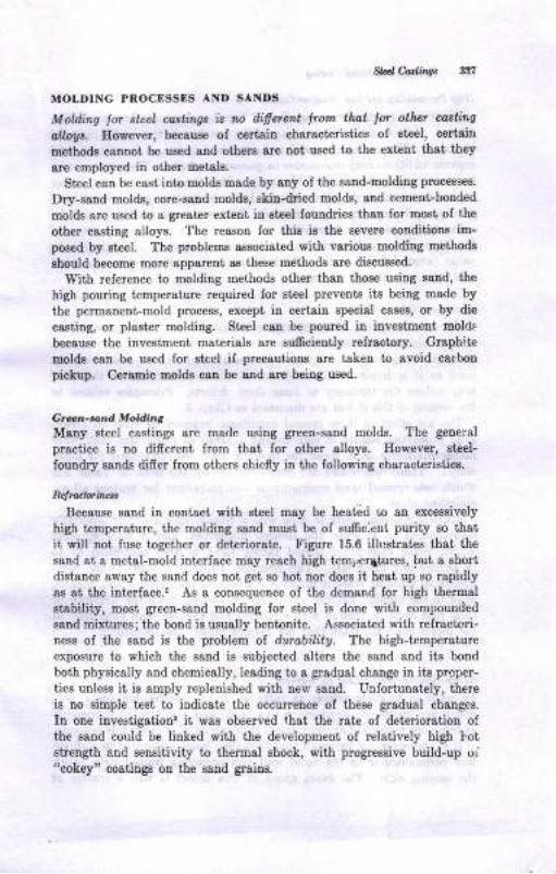
M htlitwt 3:r7
MOLDING PNOCESSES AND SANDS
Moklin4 lor steel castingE is rc ilifierat trom that tot othat carth,g
ct&4lr. Hovever, becauee of certail charscteristics oI steel, ceriairr
methods cannot be u.Bed and otherg are Bot used to the exieut tttst they
are employed in other metals.
Steel cso be cast into molds made by any of the sand-molding processes.
Dry-sand molds, core-sand molds, ekin-dtied molde, and cexoent-bonded
molds are used to s grealer extent iD gteel louadries than for uost of lhe
other casting alloye. The reason for this ie the severe conditions ie-posed by steel. The problems associated with vcrious molding methoda
ehould become more apparent aE these metllods are discussed.
With relerence to motding methods other ihan those using sand, the
high pouring temperature required for stcel prevents its beiDg Eede by
the permaDent-mold process, except iu certsitr speciel casee, or by die
castiug, or plaster molding. Steel can be poured in ioveetmeut molds
because the investmeut materials are sufrciently refractory. Graphite
molds csn be used ior eteel if precautions are taken to avoid carbon
pickup. Ceramie molds can be ard are being used.
Gran-rp'nd Mohlins
Mauy steel castings are made using green-sand molds. The general
pr&ctice is no difrerent from that for other alloya. Eowever, eteel-
foundry sauds difrer from others chiefly in the following characteristice.
R4,u.bi,ut
Because sgnd in contact with steel may be heatdci to ao excessively
high temperature, the motding ssnd must be of su.t6clent purity eo thaiit will noi luse together or deteriorate. Figurc 15.6 iltrutrates that the
sand at a metal-mold interface may reach high temperltures, but I short
distance away the sand does not get so hot nor does it heat up so rapidlys8 8t tle int€rface.' As a consequence of the demand for high thermal
stsbility, most green-sand molding for 8t€cl i8 done with compounded
sand mixtures;the bond is usually bentonit€. Associsted with refracicri-ness oI the saud is ihe problem of furability. The high-temperature
exposure to which the saud is subjected altere t}re sand and ite bond
both physically and chemically, leading to a grsdusl change in its prcper-
tiee unless it is amply replenished with new saud. Unfortun&t€ly, there
is uo simple test to iodicate the occurrence oI thes€ gradual changes.
In one investigatiols it was observed rhat the rate of deterioration oIthe saud could be linked with the development of relatively high hotstrength and sensitivity to thermal shock, with progressive build-up oi"cokey" coatiugs on the eaud graias,
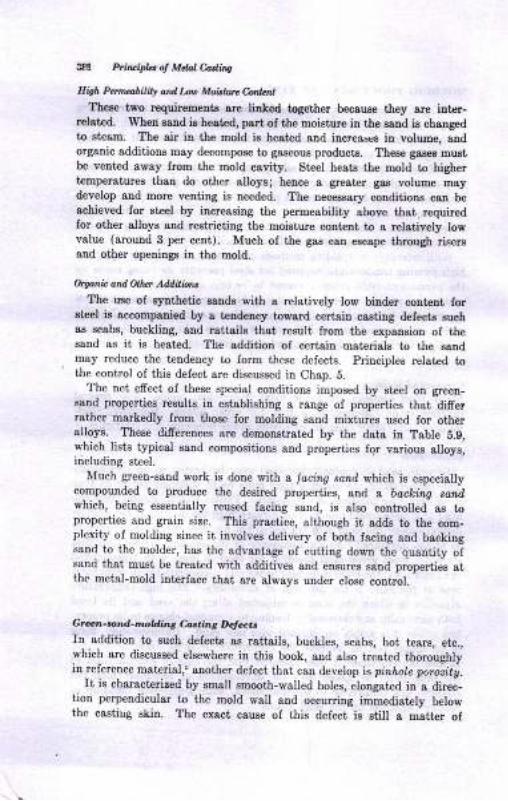
3af pircipla { Mchl Cadha
Ili9h Pdtabiw d l Ld, Moblwc btlcnlTheee two requirements are linked together becauee they are inter-
relat€d. Whetr EaDd ia heated, part of the moigturc in the ssDd is changedto st€Em. The air il the mold ia heated and iacreqtcg iu volume, andorganic additious may decompose to gaseous products. Theee gasea mustbe vented avay from the mold cavity. Steel hest€ the motd to highertemperatures than do other alloyel hence a greater gs8 voluue maydevelop and more venting is needed. The necersary conditions csD be
achieved ior sieel by increasing the permeability above that. requiredfor other alloye 8od restricting the moisture coDt€nt to a relatively lowvalue (around 3 p€r c€nt). Much of the gsB can eEcspe through risersaud other opeuiugs iu tho mold.
&sania and d hr Addil iutt
The we of synthetic ssud8 with a relatively low binder coDtelt lorsteel ie accompanied by s tendency toward certaiD caatiug defects aucbas scabs, buckling, End rsttails that reeult lrom the expansion of thesand as it is heated. The addition of certain meterialg to the satdmay reduce the teudency to form these defects. Principles related tothe control of this defect are diecussed in Chap. 5.
The rlet efrect of these special couditions imposed by etcel on green-6snd propertie8 results ia estsblishing a range of properties that difietratlter markedly from those lor motding sand mixtures ueed for otherslloys. These difierences are demonstrated by the dato in Table 8.9,which lists typical sand compositions and properties fgr various alloys,including steel.
Much green-sand work is done wilh a lacing sond which is especia[ycompounded to produce the desired properties, arld, a bacbin4 sandwhich, being essentially reused facing sand, is also controlled as toproperties and grain size. This practice, although it gdds to the com-plexity of molding since it involves delivery of both facing and backitrgsand to the molder, has the advantage of cuttiDg down the quantity ofsanci that must be treated with additives and etrsules ssnd properties atthe metal-mold ioterface that are always uuder close control.
Gren-a nd-t,,{.ldiag C.d.ain6 Dalccu
In addition to such defecto s8 rsttails, buckles, scabs, hot tears, eta.,which are diecussed elsewhere in this book, atrd &lso treated thoroughlyin reference material,o another defect th&t c&n develop is prrrhole pototitg-
It is characterized by small smooth-walled holes, elongated in a direc-tion perpeudicular to the mold wall and occurring immediately belowthe castiug skin. The exact cau6e of l,his defect, is still 8 mstter of
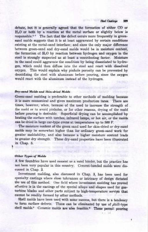
,gad C.dnp illt
debete, but it ia generally agre€d thst the formatiou of eitber CO orE,O or botb by a reoction st the metsl gurface or slightly below irrespoosible.G? ?he lact that the defect occurs more frequertly in greeu-
eaDd molda suggeEts tist it iB st least aggravated by certaiu couditiontexisiing 8t the metal-sand interface; snd siuce the ooly major difiereuce
between greeu-sand and dry-saud moldr would be iu moisiure coutent,the lormation oI H:O by reactiotr between hydrogen and orygen in theeteel is rtrongly Euspecl€d ss at least a coutributiug factor. Moishrrcin the sand could aggrsvate the conditiou by beiug diasociated to hydro-gen, which could then difruse into the steel snd react with dissolvedoxygen. This would explain why pinhole porosity can be prevented bydeoxidizing the st€el with alumilum belore pouring, since the orygenwould react with the aluDiuum iutead of the hydrogen.
Dry-and Moldr ottd Stin-drtud MoUt
Green-saud molding is preferable to other methoda of molding becauae
it i8 more economical and gives maximum production ratas. Ttere sretiuee, however, wheu, because of the ueed to increaee the sirength ofthe mold or to avoid pinholes, or for other reasons, drying of tlrc moldbefore pouring is desirable. Superficial dr5ring can be accomptiehed byheating the eurface with torches, infrared lamps, or hot air, or the moldacan be dried in large car-t]rpe ovens at temperstures up to 50O F.
The moisture coutent of the green sand ue€d Ior skin-dried or dry-aandmoldt may be some*hat higher than lor ordinary greea-sand work forgreater moldability, ead also because a higher moieture content leadato grester dry strength. These dry-sand propertiea haye been illustrst€din Chap. 5.
O.h.t Ttp. of hlold.
A few fouudries have used cerueDt as a sand biuder, but the prsctice hagnot been very popular in this country, Cemeot-bonded molde were dis-cussed in Chap. 3.
Inve8tment moldiug, also discussed in Chap. 3, haa been uaed forsp€cialty csstings where close tolerances or intricacy of design dictatedthe us€ oI thie method. One field where investment molding has provedeffectiye is in the castinge of the special alloya and shapes ueed for gas-turbine blodee and othei parts Bubject to bigh-tempersture gervia thatcsnoot be readily formed by other methods.
Shell molde have been used with Bome 8uccesa, but there ie 8 tendensyto fonn surface defects. Them can be eliminated by use of ihill-typeeheil molds.s Cersmic molde arc alao fea^eible.' There permit. pouriug
tirinner gectioDs th8D with coDvcntional Estrd oolds. A apecial pmceee
combi[ilg graphite mol& 8Dd 8ir-pressure pouriag baa been ured to
^.r-
oduce steel car wheels aDd other 8bapee.to
lldlEag MotdtThe usual methode of molding, such as hand ramuing, jolt ramming,squeeritrg, aad sand-elinger ramming, are used oa Et€el sands; no difier-eDce exists in the ramming methods used for st€el in compsrisoD rithother caatiug alloya.
CORES
Corcmaking aud core mst€rial8 were diecusred iu Chapa. 6 8nd Z, re-spectively. Outgide of the need to provide for higher operating tempera-turea, there ig little basic digtinction between ooree for eteel castings as
comp$ed with those used for other alloye, and the principlee diacuaeed
in the aforemeutiooed chapters are readily applicable to ateel-fouadrypractice.
Becauee of the extreme conditions that develop from the f,igh pouriDgtenperature used for ateel, certain eprecial probleme ehould be meutioned.One efiect, for example, of the high puriag temperature is that cores areheoted faeter snd to higher tenperatures than cores for eimilar-Eiledcasting pouring in lower-melting alloys. Tte result is that, larger volumeeof core gases &re generst€d sud must be reuoved from the mold. Thisneces8itates cores of higher permeability for Bteel csBtiDg8 and moreventing than may be required for most cast-iron or uonlerrous castiuga.Data in Table 7.2 show the markedly grest€r permeability in eauderecommended for steel cores. The us€ of hollow shell-molded coree hasaided considerably iu eliminatiug ga8 problems that origin8ta from corts,
Other efects associated with cores iu steel-casting work are discussedin the folloriag paragraphs.
Eot-u',. ForrrBtion
Steel. is poured 8t I high t€Eperature, but, this temp€rsture is lowrclativp to the high-freedug-temperature range lor steel. The reeult iethst steel begine to freeze very soon after being poured, and in some
inetances before the cores heve been heated to the poini where they haveloet their bortd strength. The combination of a relatively rigid core anda weak contracting metal oitan resultE in the formation of crackg iu thecastiug, refered tn u hot teart- Steel is uot the oniy metal subjectzd
W cd,ditrgt JDr
to hot teare-they are al8o formed in other metals-but the problem
csn be quit€ acute iu certaitr st€€l caatiDgo, and lor that reasou thecauses of hot tears have beeu the eubject of coDsiderable study. Norcan it be eaid that cores are the ouly cause of hot tears, since a rigidmold ie aleo 8 poteutial caue of hot tear.8.5,11 Since cores generallyofrer grester rigidity than molda, the hot-t€8r der'ect ig discussed withrelation to cores.
The defect, which ie illurtraied lor malleable irons iu Fig.23.12, isasEociated with both metallurgical variablee and gand varisbles. One
opinion regarding the cause of this phenomenol is that hoi t€aring occursduriug the last stages of freezing of steel when the solid metal graius arrstill surrouDded by a thir tiquid film.t,,r!,16'r? The teariug occurg whentbe natural coutractior of the steel is inhibited either by the geometryoI the castiq or by the mold. Othere have submitted evidence iudicatinfthst tesring csn occur after BolidificatioD.s's Iu this case, the tearsmay be fine, hairliae fractures, not readily visible iyithout tlre lae ofBpecial techdques such as magnafluxing or etching. IIot tearing is moreli&ely to occur if the casting contsins local sreas that freeze at a latelperiod thsn the balance of ihe surrounding metal. These so-called ,,hot
epots" which remaiu fluid longer than tbe surrounding metal serve as
a focal point for the conceutration ol coutrsctual etraine. Becausehot tearing is associated with the freezing characteristics of metal, as
well as variables iatroduced by the mold, there coo be no establiehed ruleregarding the probability and intensityr of hot-tear formation. Forexample, a giveu core mix may prove perfectly acceptable in one applica-tion snd completely unaccepiable in atrothe!. Again, a specific com-position of st€el may not crack io oue type of casting snd yet showcracking iu another case. The probability oI attack may be eyen morecritical than in ihe examples just giveu. A padicular core-sand mixmay cause cracking only if tlre metal is poued above a certain tempera-ture, whereas another mix miy or may not crack regardleee of pouringt€mperature. II theee iuterrelationships are kept" in mind, it csn beehowo, hovever, thst the probehility aud intoaeir.v of tearing 8re rel8t€dto core compoeition aDd propprtiAs :rs toiiows:
l' gtroDg, hsd cores and moldr tbst cLUspse slowly un\ar.hrat are r,ol=l.iL-J;; to cruoe hot tcars r,hau wea.k, easill ,,ollapible cores or miiiG.Ilrcrl.Ed cole deiLity hcreaE the itteDsit] (ieogth) of hot tearing..
As f8r 8s metsllurgical variables ere concemed, r. appea:s lhat hoitearing is aggravated by elements such as sulfu-r aDd i,ioonhor-u.
r,.r'
In otre iDvestigation, aluminum deoxidation was fuund to git. ,nore i\_
'hobsbility: qhether or rot a-t*r fi[ appesr; rqteDsity: Bize or leEath of the cra, ,)
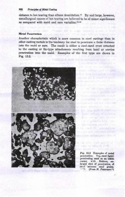
I
ln htuiilaq Mdaledfu
gistsnce to hot tcaring than silicon deoxidation.r. By and large, however,meallurgical causes of hot tearing are believed to be of minor significauceas compared with mold aDd core variables.l!'r.
Llctoil Panaf}a;fuia
Another characteristic which is more common in steel castings than inother casting metals is the teudeney for steel to penetratc a finite distanceinto the mold or core. The result is either a steel-gand crust attachedto the casting or fin-type attachments resulting from local or crevicepenetration into the mold. Examples of the first type are shown inFig. r5.2.
Fig. 15.2 Examplea of metalpenetration. Top,steel (light)peneirating eand at an insideoorner: X10. Bottom, en-Iarged view of peuetration ofsteel between eand grains,'-'o. (Fron H. Pellrallr.l,n.n)
Std hdbv t93
Factors whicb have beet lound to sfiect metel peDetratior are:rcr6
1. The longer raolten st€.I is held ir contsct rith s{,trd, the grestor the chaace
for Eetsl perctratioD.
2. I,,.cre({,ed metol pres&hre increos€s metal penetrstion. giDce Detsl DorEah'
does Dot peDetrrt aed becauae of surfacete!8iou etrects, the efr€ct olprtenrre ir to oYerc@o thc aomrl resistadce o6eEd by surfate teraiol'
Iligh Betsl prts8ut€d 8re, of course, directly rel,atod to the difietent'isl Detslprcasure head (h"igrr11 15u1
";",, t the moltel gteel.
3. Iligh porino t.rr.pcrdur..ld lp Dt.,,etrr,'ltoD.
4. Ircregsed peaetrsiion occutt nilh i*rcutl groitt tizc or prcDr laDtniDg oI
the sand.
5. Mold tDatherraudto prev€Dt peDetr.tiotr.
6, Iltcreased peDetrstion octurs ,i1,h ircteor?d c4rbols caitcrtt.
7. I'atge mclal man coEpsr€d Eith 8 @sll ssnd Eoss ilrcrtts€s the poDetrr-
tion.8. Mobtxrc ot o,hct o@4r iD the ssDd Dsy rlaot sith the sarrd or metsl to
opeu chrunels lor peoetratiol,
Mold washes are prob8bly efrective i[ reduciDg n€t8l peDetrstion by
cloaing tbe porea iu the eand mold and also by reducing the anourt, of
oridation that occurs oD the metgl surfac€,
Beeidea tle ure of mold ot cort rtahpr, uess that are troublesome
from tbe stoadpoint of toetst peDetrstion can be improved by using
zircon (zirconium silicate) oaad mixhres as s facing malerial.n"'Zircon saude are highly tefrsctory, bave a high heat conductivity and a
high deneity, and are not wet by uetals. These lactorE are all iutru-mental in reducing metal peaetratiou. Becauee of the cost, lircon eand
is used only ia aevere cases where the cost is juoti6ed"
Bt,'ltr,{,/t
Burn-on ie difiereotiated from metal peDetration by tbe fact that it irrelatcd to oxidatiou of the castiug surface. Thie results in penetration
oI the sand by the molten oxide which wete the sard grainr. Progresdve
oxidation at the metal surlace develope a pitted couditiou, with eu-
cruatationr lormed by ttre tiquid-oride peuetration into the sand clinging
to tbese are8s because of tle rougb casting eurlace created by the oxida-
tion.!,n Although burn-on may have the appearance of metal penetra-
tioD, it ie eeseutially oxide penetration iDto the c8stiug Eurlsce (coupled
with oxide penetration hto the rand) ra$er than uetal penetratiotr.
*r*r-Closely related to burn-on ie the accumulatiou of nonoetallic particles
thet mrmally occur oD the cope surlace of steel castilgs. The* particlea,
394 Prirlcipb ol Mtul Cadins
low-melting mixtures of oxide8 of siiicotr, lDatrganese, iron, and alumioumoI variablc composition, are called ceroxides. They solidify as a glasrymaterial freque[tly intermingled with sand graitrs. They are attribu-table to the following factors:rFlo
l. Pd1in0 proatice. Botlolo. pouing causes fewer c€roxides tha[ lip pouring.2. Cornposition ol larlb An;n4s. A high alumiDa liniDg results in less ceroxide
o! the crstiDg surf&ce than a silics ladle lining.3. Gating practice- A streamlined geting pra.tice produces less ceroxide than
other methods tried, although a whirl gate is quit€ efrective.4. MoLd atmosphere. If the mold &tloosphere is made more reducing, ceroxide
forrration is reduced, but erosion of the mold may increase.5. Cornposition ol the steel. Itrcreasing mengaDese iD the st€el hcrea6es the
amouDt of ceroxide formed, and aluminun may resct witrh fre-clay refrac_todes to folm a viscous product which may erode lrom the relrectorylining surfaces and enter the mold c&vity.
Arc ard Motd Vdrhe.
The greater difrculty in achieving good surface finish and avoiding metalpenetration iD st€el castitrgs suggest€ the use oI mold or core washes to sgreater degree than with other casting alloys. The functions of moldor core w&shes, as listed by Briggs,r3 8re:
l To prcvent metal penetratioD
2. To eliminat€ cutting (send ero6ioD)3. To prevent scabbing
4. To 8ir'e sooth casting &ppes!&nce
5. To obtaitr cleal casting surface€
6. To oodify the mold atmospherc7. To assist in cleaning the casti!8
Core coatings are discrrrscd in Chap. Z, 8nd typical costiDg mat€rielsfor steel-casting molds are given in Table Z.g.
SOLIDIFICATION FACTORS
P-rinciples.of gating strd feeding castings have been discussed in Chap. g.
However, it is evide[t from Chaps. 1l aud 13, otr sluminun and copper_base castiags, thai each altoy goup hes certain inhereni characteristio"which require special treatment for proper gatiDg aqd feeding to exist.Steel, likerise, has certain properties which must be correctly iiendlert iug8tiDg aDd ri8€riDg of steel caetirg.
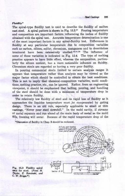
W edir0, Srs
Fn tAW'Tte epiral-type fluidity test is ueed to describe the 0uidity of molten
caat eteel. A apiral p8tterD i8 Ehostr iD Fig. 15.3.r? Pouriug t€mperature
and compoeition are inportant factors influencing the inqhee of 0uidityobtaioed with the epir8l te8t. Accursta temper8ture det€rminetion ie one
of the most important lactors iu any spiral-fluidity .test. Difrerences influidity at aoy particular t€Eperature due to compositiou variables
such as carbon, silicon, sulfur, chromium, mangaDese 8trd to deoxid8tio!
treatmeDt have beeu exteoaively 6tudied.lr,'?,3t The influence olsome of theee vgriables is i.ndicated iu Fig. 15.4. The type of melting
practice app€ar8 to hsye littte efrect, whereas the composition, particu-
larly the silicou cooteDt, has a more noticeable in0uence ou fluidity.
Chromiun steele are regarded as having a very poor fluidity.In pouring commercial Bt€els linit€d to cerisiD analysis rangea it
appesrs that temperature rsther than aualysie may be viewed as the
msjor fsctor which ahould be controlled to obtaiu the best conditions.
Thie ia noi io imply thst chemical-compoeition variablee, mold condi-
tioos, melting practice, etc., can be ignored. Rather, from au engineeriug
viewpoint, it ehould be €mphasized that ladling, pouriag, and handliug
of the st€el should be done with a miniuum of temperature drop inorder to retaiu fluidity.
The relatively tow fluidity of steel and its rapid loss of fluidity ao itapproaches the liquidur tempersture musi,be compenoated by gating
deig'r. Ttere ie an old rule, espeeielly applicable to emall or thincastings, "Never pour ateel downhill." In the mold cavity, if streams
oI metal sepsrate aud ruu ahead ol the main body oI metal as the moldfills, lreeziag will occur. Because of the rspid temperstue drop of the
''DieursioD of fluidity ir Ctap. 8 ahoufd be reviewed.
Mfir. ts.s Ftuidity qir.r #1,rard 16 rt:.I. (Ffia Ir. s6r,6 r-,T.yb, E. R,/nirl!,Li" o d,c. w. Brb.e,
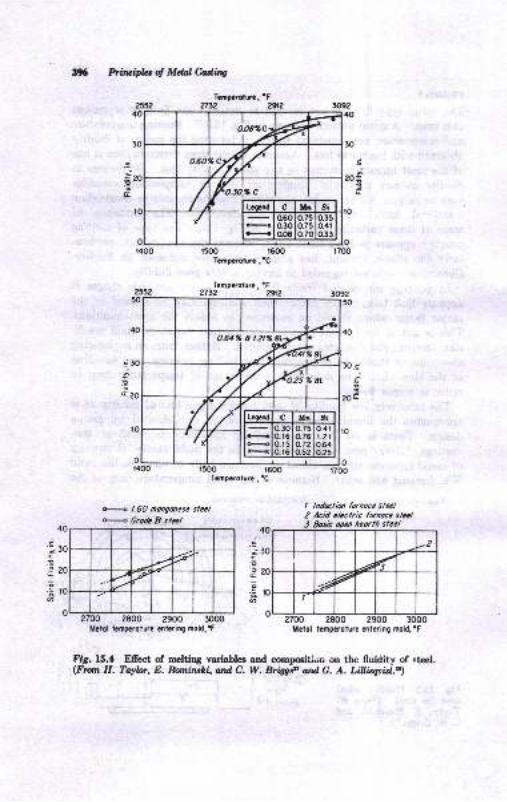
396 Fiuidrlot Mdaledns
tr
Tamparotura , 'F2712 ?gtz
1500 1600
Tanpdolun .'C
Tcmpaoturc . 'F2Ta2 a2
4 1.60 nongorresc slccl
* GrodcD stel
!oajtP
208
I lnduclidt funocc steal2 Acid clcctric fuDoc. sLcl3 Sosic opci hcorth ttccl
2900 3000
40
.aj30:'a
zo
E€10@
Trnpc.olurc,'C
?700 2800 2900Mctol lcmpcrolure cnlcring mold,'F llclol tcmpcrolure cf, trring mold,'F
Fig. f5.4 Efiec't of meltiog variabka and compcition on the lluidity of eteel.(Fmn E. Tayb, E. Eornrnrtr, and C. W. Briag'P atd C. A. LiUiqtU..)
{T
1
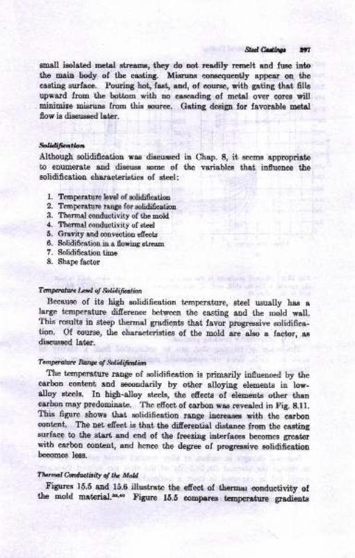
,9,clffio irlsmall isolated metd strerms, they do not r=adily rrNBeIt aad fuse intothe -qin body of the casting Migmn8 consequently sppesr on thecasting eurface. Pouriog bot, fast, and, of Gourse, with gating that fillsupward from the bottom with no cascading of metal over eorrs vill
. minimize Eisrurs from this s)uroe. Gating deaip for favorable metslflow ie discussed later.
ffifia,tiottAlthough solidification was diocussed in Chap. 8, it seems approprieteto enumerate and discugs some of the variableg that influence thesolidification characteristics of steel:
1. Temperahrre levol of oMification2. Temperaturc taDge for eolidificotion3. Thermal conductivity of the mold4. Thermal conductivity of steel
5. Gravity aod convestion €ffests
6. Solidification in a floring strea,m
7. Solidification time8. Shape factor
Taninalut l*tz;l of $liilifwlimlBecause of its high solidification temperature, steel usually has a
Iarge temperature difference between the casting and the mold wall.This results in steep thermal gradients that favor progressive solidifica-tion. Of coume, the characteristics of the mold are also a factor, aadiscussed later.
Tanpdun Rory of $liilifafinThe temperature range of solidifieation is primarily influenced by tle
carbon content and Becondarily by other alloying elements in low-alloy ateels. In high-alloy steels, the efrects of elements other thancarbon may predominate. The efiect of csrbon was revealed in Fig. 8.11.?his figure showe that solidification range increasea with the earboucontent. The net efieet is trat tre difierential distsnce from the castinggurface to the gtari and eud of the frpezing intnrfaces beeomes greaterwith carbon content, and hence the degree of progrrasive solidiicstioobecomes less.
Tlumlh&rdirity oltlu M&E'igures 15.5 and 15.6 iuushat€ the efiect of theru, conduotivity of
the mold matcrial.tD''o Figue li.E comparee temperet,re gr&dientE
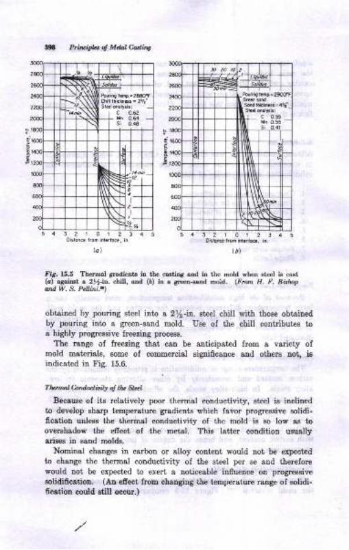
Prilcifu d Mclal Caairy
je&
tt
t-"il[x--ts
tIs3l .:
lt\\
5432101234oirror. lrod inrrroe, in.
lbllal
ftr. lS.5 Tbarmal gradtutrts iD the ca.tiDg aod itr th€ mold rh€n lt€€l i! calt(o) s3airt 6 2ttrb. e , and (6) in a green-.s.od mold. (Fr.ut H. F. Bn!4.ard W, 3, P.Uini..l
obuined by pouring steel ilrla a 212-ir.. gteet chill with those obtsinedby pouing into a green-sand mold. Use of ttre chitl contdbut€8 toa highly proglessive freezing proceee.
The range of freeriag that can be snticipsted from a varieiy ofmold materials, aome of commercial signifrcance 8trd other8 not, isiudicsted in tr'ig. 15.6-
TLrnd Andudbiv ol ll2 SI,,'l
Becauee of its relatively poor ihermal coDductivity, stcel is inclinedto develop shsrp temperature gradients which favor progressive eolidi-ficatiol unless the thermal couduciivity of the mold is 60 lorr a8 tooverahadow the efiect of the metal. This Iatt€r condition uruallyarieee in ssnd molds.
Nominal changee iD carbon or alloy content would uot be expeoted
to change the thermal coDductivity of the steel per se aud thereforewould not be expected to exert a noticeable infueuce ou progressive
solidificstion (AD etrect from changing the temperature range oI rclidi-6oetibn oould stiU ocour.)
2101230ir,on.. i.om inr.rto.., in.
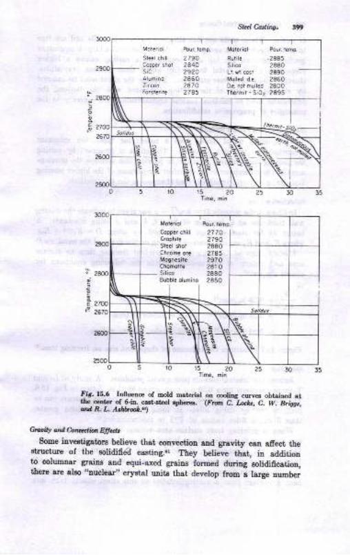
Sk t Cattingt
E
5 r0 15 20 25 30 35Tine, rhin
15 20
fir. 15.6 Inlluence of mold naterial on coolirg curvea obtaiD€d ai,the cclta. of Gia. cast{t€cl !I[€rc.. (pran C.-Luhc, C. W- Biggr,atd R. L. A,r'atr'oD|.')
CrwiIX ml e.on,''jlia,r EfldtSome iaveatigatore believe that corvection snd grsvity c8u sfrect, the
structure of the sotidifid castiDg..r They betieve that, in additionto columnat graiDs and equi-rxed graius formed dudug solidificatiou,there are alao "nuclear" crystal ulits t}lst develop from a large nuuber
Moteriol Pour remp.
steer chrrr 2790Copper shot 2840sic 2920Alumino 2860Z,rcon 2A7Arorste.ile 2785
Motariol Pou. taoA
flutil. .2445Silico 2880Ll. ri. cost 2890Mulled da 28500.a .ot mull.d 2800Tn .mil _ Si02 2895
'-r-X.-t-\l
Mol.riol Pour.t€hp_
Copp.r cnill 2770 l'Grophare 2790Steel shot 2880Chromc or€ 27A5Mognlsii. 2970Chomorte 2810Silico 2880Sobble olumino 2850
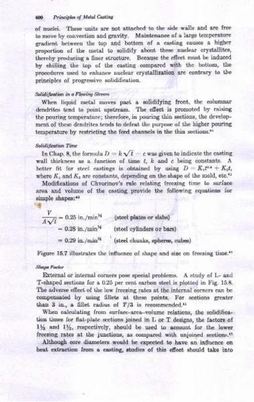
N Pti,,'ipht ol Mdol Athts
of Duolei. These units sr€ troi sttsched-to the side walle and are free
to move by convectioD snd grsvity. MaiDt€DaDce of a large temperature
gradient between the top and bottom of a castiug causee a higher
pmporiion of the metal to eolidify sbout these nuclear crystallitea,
thereby producing a finer structure. Because the e6ect must be induced
by chilting the top of the cssting compared with the bottom, the
procedures us€d to eohance nuclear cryetalliation art coDbary to tleprinciples of progreesive solidification.
$lilifwliat ia a Fbtin4 &*atn
When liquid metal moveE paet a solidifying front, the columaar
dendrites t€ud to point upstream. The efreet io promoted by raising
the pouring temperatue; therelore, in pouring thin sectionr, the develop-
ment of these den&ites tends to defest the purpose of the higher pourhg
t€Bperature by restricting the feed channelr in the thin 8€ctioDs."
M lilatio,t Ti,w
In Chap. 8, the formnla D : k \,/t - c vas given to indicate the caeting
wall thickneee as a fuDction of time ,, Ic and c being cotrstalt€. Abetter fit for steel castings is obtaiued by usiug D = K,f'i Krt,where I(, rud X, are coDstants, depending ou the ohape ol the mold, etc."
Modificrtione oI Chvorinov'e rule relatiug lreezing time to surfcce
area and volume ol the castiug provide tle followiug equatione for
aimple ehapes:0r
v ..
7V: O.25 h./mtn' (steel plateo or slabo)
: 0.28 in./roinx (steel cylinders or bars)
: O.N it./a;# ' 1"tol "huor",
Ephe.!€s, cub€E)
Figure 15.7 illustrates the iDflueDce oI shape and sire on freezing time."
Sl?[I' Fo.lar
External or intrcrual comers pose special problems. A study of L- and
T-shaped sections lor a 0.25 per cent carbon steel is plotted in Fig. 15.8.
l'he adverge efrect of the low lreezing ratea at the internal comere can be
compensated by uaiug fillets at theee pointe" For eectiour greai:er
tban 3 ir., a 6llet radiue of ?/3 is recommended..r'When calculating from surface-area-volume relations, the solidifics-
tion times for flat-pl8te aections joircd in L or T designs, the facton of
Ua atd lYz, respectively, should be u8ed to sccou.ut for the lowerfreeriog rat€8 at the juactions, aa compared with unjoined sectioDs..l
Although core diameters rould be expected to have an iD.0uence orbeat extractiou Irom a casting, studies ol 4ii. efiect should take irto
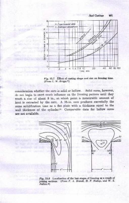
o Etperimenlol dolo\ Anologue colculolons
Sta;lCoglliw 401
b
5
4
3
4 567810 20Time, min
40 6c 80 100
Fig.t5.7 Efrect of casting shape and size on freezing time'(Fron C. W. Bri4gt!)
consideration whether the core is solid or hollow. solid cores, however,
do not begin to exert much influence on the freezing pattern until they
reech a size of about 8 in., at which point a measurable smount of
heat is extracted by the core. A l6-in. core produces essent'i8lly t'he
same solidification time 8s a fl8t plate with a thickness equal to t'he
wall thickness of the cylinder.as Comparable data for hollow cores
are not svailable.
.g
E.9o
.9
=
Fig. 15.8 Localization of the last atagee of frtezilg as a result ofjoiiing 8€ctioD8. (Fmm F. A. Brandl, H. F. Bislop' ard W. S.
Pdlini.$)
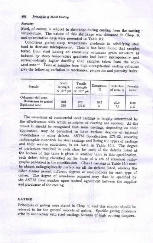
*, bir*ifu g Mtut Cdhs
Steel, of course, iE subject to ehririoge during coolirg lrom tlrc caetiugtemperature. The ngture of this rhrinkage wa" Odused i" bl"p. s,and quartitstive data were pre8etrted itr T;ble g.2.
. ?lditioDs givitrg staep teElrerature gradiente in solidifyiug steeltend 1o- decrrase microporoEity, Thue it has beeu fouud tfr"f ,-";pi*tret€d Jrou steel having an essentially columrar grain ,t"u"i*Il.iuduced by steep tempersture gradiente had lo*"" Li.ropo.o"ity
-"od
correspoudingly higher ductility than sanples taken from the eoui-
T"d i":.1 Tests of sanples from high-streogth_eteel casting cylirjersgive the following variatiou ia mecbanical profrties aoa po"oiity ioaex:
SampleYield
BtreDgth
X r0_r pei
Tensile
streDgth
X l0_, pai
Elongution, Reductiotrol $q,,7o
Porosity
iodex
C,olumner chill zone(traDlveEe to aEim)
Equi-aied ,ooe218
2r8no to-7
6n.o
7.1
0.38
t.L7
The souudness o{ commercial steel castinge is largely determiued bythe efectiv-ene$ with which principles of rieering
"i" ,ppii"a. eitl"
outset it should be recogDired tbat eone caetings, depeniing ou iheirapplication, Esy be peruitted to have various' d"siu"" oi lot""i"ruasoundness or oiher defects. ASTM Speciflcatioo
-fZf_SZ, *r""iog
rsdiogrsphic Bt&ldards for steel castings and listing the typ", of "".iiogusud thcir.service conditions, i8 set Iorth in Taijc fS.l. tf," a"gru"
of perfection required in each class for each of ttr" detei,ts ii"ted- atthe. bottom of this table is giveu in another table i. tf,l.
"p""ih""iio",each delect being classified on the basis of a get of .troOurJ oaio-grapha published in the specification. Class I castiugs iu Table f5.f mustbe almost radiographically perfect for all the defectl [sted, *he"eas th"other. classes permit di-frerent degreee of unsoundness io.
"aJ type'ot
defect. The degree of souudnees lequired Day thus be speci0ed bythe_ AST]vI clasa nunber upou mutual ,gr*."ot betweeo tie supplierard purchsEer of tbe castiDg.
CATING
Principles of gating were stated in Ch8p. 9, and this chapter should berelerred to for the geueral aspecte ol gating. Specific g"tiog p"JL_"Brise iu coDDection with steel cestiugs becauee of-ngU piu"in! Lmpera_
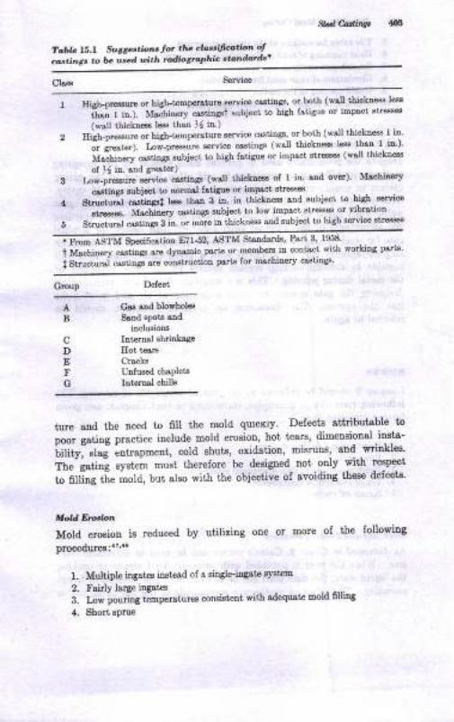
gd Canin!,
Tab|e ].5-r S'r';sge..io'nr ior tha cld'si,'(ft',n ot
ca..ing. .o l* ured t irh rudio,rcphic t',ndard"
Class
3
4
5
HiEh-oEssuE or high-tempdBtur€ servico csstings, or both (wsu thickDess lesi
tJ,- r i".1. MscbiDery cr.ctingst subjec[ l,o hiSh fatiSue or impact stresse€
(f,,s[ tbickne€s less tbso ], in.)
Hlgh-pr€ssuE or high_tcmperaiue service c{stitrgs, or both (wsll thickn66 I iD'
.-. i"**O. Lo*-preesu.e service cagtinss (wsl thicLn€ss l6s thAa- l. h')'lf"ili"".y
"rrti"s; *fject to high fstiguo o' impsct stress€o (wsll t'hickna
of ), in. snd grestor)
Lo*-p-*ot eelce cestingr (wdl thichec of I iD snd ov6) Mt'hiaery
orstitrls s'rbi@t to trorErl fstrguo or ilapact 3tr€a!43
Stnuct;;l """iiosrt
I€s tbar 3 in. in thickness snd subject l'o hiSh sorvice-
strtases. lvtaclioery caatiag subiect to low impsct Btresses or vibratiotr
Struciursl csstinga 3 in. or mor€ in thickDess slrd subject to high service 3tr€ss€3
C;ffi'8p""i6-ti"" E?tJ,, ASTM Sisdar&, Part 3' 1958'
t Ufa"hl"e.y ostin8s ate dynamic psrts or membeE-in contact wit'b workiDg part4'
i Structurai ca.eungr sre coDstnrctioo pdts fo! Drchinery ca3tiDgs'
Group Defect
AB
cDEFG
Csr snd blorholdSend apote and
iDclusioDa
Intam-sl sh-ri age
IIot tcar8
Cracks
UDJused chaplets
Int m.sl cbills
ture aDd the ueed to 6ll the mold qurcKly' Defects attributsble to
poor gsting practice include mold erosion, hot tears, dimeosional -itrsta-
iifityi "f"J
entrapment, cold Bhuts, oxidstion, misruns, and -wriukles'
The" iatin! syst€m must therefore be designed noi only with respect
t" nffiog t[" mold, but also with the objective of avoidiug these defects'
Mold floaion
Mold erosiou is reduced by utilizing one or more of the followiug
procedures :'? ''3
1. Multiple itr88tes inst€ed of & Bhgleingste systeid
2. Fairly large ingates
a. m* poo.i"g t"-pratures consiatent with adequat' Bold fllilrg
4. Short sprue
Prircipla g Mdal Cading
Tile tubes for sections of the sprues or run[enIlard ramming of sand in the vicinity of the gatesSmooth gate surfacea
Elimination of loose sand from the systemUphil pouring of the casting when possible
Selection of prrper sprue.runner4ate ratio
Sla,g Entr.otprment
Despite the precautions used to prevent mold erosiou by the foregoingmethods, it etill may be necessary to add other featurer to tn. gutiogsystem to avoid entrance of slag, sand, aud dirt into the mold *"ity.Thls ca1 be done by the use of such devices as gtrainer .o."., g"Lwells, whirl gates, and slag traps. opinion is not unanimor. r"g".Iiogthe advantages of the whirl or swirl gate..?,." One design for I whirlgate for steel castings which is advocated is found in Ref. 47. Althoughslag-entrapment may be achieved with a given gate design, it is sdIpossible to develop casting surfaee defects by excessive oxidation ofthe metal during pouring. This is a situation that can be remedied bydesigning the gate system to avoid aspiration of air and mold gasesinto the system. The discussion on ceroxide formation shoulf bereferred to agaiu.
NISERS
Chapter g should be referred to for general principles of risering. Thefollowing riser design principles, introduced in that chapter, are givenfurther attention here:
M
5.
6.
7.
8.
9.
10.
l.2.
3.
4.
5
Riser size and feeding distanceRiser necks
Padding sections to gain directional solidificationUse of exothermic riser sleevesKnock-off risers.
Rirer Si:c and Feeding Distance
As discussed in chap. g, caine's curves can be used to determine risersize. when the riser is provided with some artificial means to prorongthe liquid state, the riser need not be as large as when alowed to freezenormally. The effect of exothermic compounds or the use of an arc to
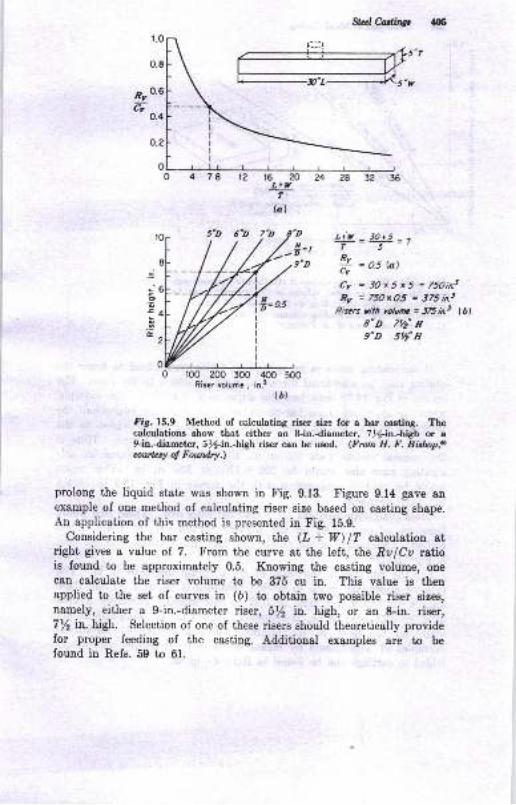
r.o
0.8
n:ro'66
0.4
t2 16 20 24L+y
flal
5'D 6'D rb'H.
-,,9,D
Slrr,l Cadir.e, {r}5
L+t{ 3O+5T5R,,
7i = a5 tat
Cv = 3Ox5 xS = 75oinrRv = 75OxO.5 = 375 in.3
Riscrs rith yotutttc = J6in.t lbl8'D 7'/'r9"D 5,// n
o.2
c
..co
-(r
r00 200 300 400 500Riser volume, in.3
(bl
Fig. 15.9 Method of calculating riser size for a ber caetiDS. Thecalculations ehow that either an &in.diameter, 1)g-h.-higS u af-in.dametcr, S%-iln..-bdry:h riser caD be uEed. (Frortt H. F. Bblmp,oauby of Fow*a.)
prolong the liquid state was shown in Fig. 9.13. Figure 9.14 gave anexample of one method of calculating riser size based on casting sh8pe.An application of this method is presented in Fig. 15.9.
Considering the bar casting shown, the (Z + W) lT calculation atright gives a velue of 7. From the curve at the left, the Ra lCa ruttois found to be approximately 0.5. Knowing the casting volume, ouecan calculate the riser volume to be 3?5 cu in. Thie value is thenapplied to the set of curves in (b) to obtain two possible riser sizes,
namely, either a f-in.-diameter riser, 5/2 ilo.. high, or an S-in. riser,7/2 in. high. Selection of one of these risers should theoretically providefor proper feeding of the casting. Additional examples are to befound in Refs. 59 to 61.
0
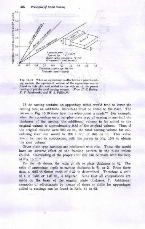
Prituipht ol Mclal Caslins
1.2
E
E
e
€:
I
I
l.o
0.8
o.6
0.4
o.2
olo
rror.nt botlotoh.
"srd i, cotcutotbnt, Fig. t59
YC = nluro. I - O.4O tohn. X
03 0.6 08 1.O 1.2 r.4 t.6 l_8Thiclnass opp.,rdoge section
Thickn.ss po.ent saclion
air. 15.10 Wlen an app€trdage is attacbed to a parent cast-iDg €ection, the equivalenf volurne of the appendage caa belouDd io this flot aad added to thc volume of the parcDtceltiDg to 8et thc lolal casting yolume. (Fnn H. E. Bblnp,E. ?. Mr}r,rl,li, atd 9f . S. Prl.ni..)
If the casting contains atr appendsge which would tend to lower thecooling rate, sa additioual increment must be added to the riser. The
curves iD Fig. 15.10 ehow how this adjustment is made.G! For example,
when the appeudage on a bar-plus-plate type of casting is one-half the
thickness of the cesting, the additional volume to be added to theoriginal volume is approximately 0.85 of ihe original volume. Thus, ifthe original volume were 200 cu in., the total cseting volume for cal-
culating riser Biue would be 200 + 170, or 370 cu in. This valuewould be used in coDjunction with the curves in Fig. 15.9 to obiginthe riser voluue.
Oft€D plst€-type castiugs are reinforced witll ribs. These ribe wouldhave an adverse efrect on the fieezing patt€rD iD the plate rEle8s
chilled. Calculating of the proper chill size can be made with the help
ol Fis. 15.U.'!For the rib showa, the ratio of rib to plst€ thickDess ie fi. The
ratio of appeDdage depth to casting thickness is /a, or 2. From these
data a chitl-thickaess ratio of 0.32 is determined. Therefore a chillof 4 X 0.32, or 1r8 in., ie required. Note that, all comparisone are
msde oL tfie basia of the original pl&t€ thickness, 7. Additionglexamples of adjustments by means of risers or chills for appendsges
sdded to castilgs can be found in Refs. 61 to 63.
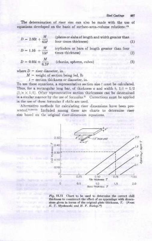
StalCadin$ 147
The determination of riser size can also be made with the use ofequ8tions developed on the basis of surface-area-volume relations:"'
p : 2.6n1 a L lplates or slabs of length and width greater than' 651, four times thickness) (i)
D:|.rc + Y13t,
(cylinders or baIS of length greaier thso fourtimes thickness) (2)
MD : 0.93, + _ (chunks, spheres, cubes) (3)
6 /1.
where D : riser diameter, in.M : weight of section being fed, lb
I : section thickness or diameter, in.
To use these equatio[s, a representative section size I must be calculated.Thus, for a rectangular long bar, of thickness o and width b, l/t : l/2(lio X 1/b). Othcr reprcsentative section thicknesses can be determinedin a similar manner by the use of formula,s.6r Corrections must be a,pplied
in the use of these formulas if chills are uscd.
Alternativc nreihods for calculating riser dimensions have been pre-
sented.5o'0{-66 Included among these are charts to determine risersize based on the original riser-dimension equations.
0.50
* o.qo
i 0.30
= o2a
0.10
i-sto
t\
o.75 r.o0
1.5 2.O
o_25
o.5
o50Rib lhlclness f
1_0
fiS. ls.U Chart to be used L det€rmine the conect chillthickness to coutrt€mct the efi€ct of an app€nda8E eith dimen-sions gi\,en in terms of the original plate thiclne€s, T. (FnnE, T. Myrhouthi and H. F. Bisl&p.6t)
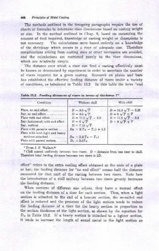
M Prhvipbs of Mdal Castirw
The methods outlined in the foregoing paragraphs require the use of
charts or formulas to detprmine riser tiimensions based on casting weight
or size. In the method outlined in Chap. 9, based on measuring the
amount of feed required, knowledge of casting weight or dimensions is
not necessary. The calculations were based entirely on a knowledge
of the shrinkage which occurs in a riser of adequate size. Therefore
complications arising from casting sizes or other intricacies are avoided,
and the calculations are restricted purely to the riser dimensions,
which are relatively simple.
The distance over whieh a riser can feed a casting effectively must
be known or determined by experiment in order to ascertain the number
of risers required for a given casting. Research on plates and bars
has established the effective feeding distance of risers under a verietyof conditions, as tabulated in Table 15.2. In this table the term "end
Condition With chill
Plate, no end efrect. . ......Bar, no end effect.......... :. : :
Plste with end effect.Bar (horizontal) with end effect. .
Bar, vertical.Plate with parasite Bection. .. . . .
Plate with both light and heavysections atteched.
Plate with parent section. . . . . . .
D : A.6 \/TD :3.6 \/TD : ll.6 J-r - s.zO:Ur/TD : ?.t5 \/T
Pr:g(Tu-Tr)*4.5
Dy=3.5(Ta-Tt)Dr = 3.5Tn
D : 1r.6 t/T - s.z1
D-6\/T+TD : 11.6 t/T - a.z
D:6\/i+r
t From J. F. W'allace.lr
t Chill spaced uniformly between two risers. D : distance from one riser to chill.Therefore totrd feeding distance between two riserg is 2D.
efrect" refers to the extra cooling effect obtained at the ends of a plateor ber; the feeding distance for "no end effect" means half the distancemeasured for that part of the casting between two risers. Note howthe introduction of a chill midway between two risers greatly increasesthe feeding distance.
When sections of different size adjoin, they have a mutual effecton the feeding distance of a riser for each section. Thus, when a lightsection is attached to the end of a heavier section, the so-called endeffect is reduced and the presence of the light section..tends to reducethe feeding distance of a riser for the heavy section in proportion tothe section thickness of the light section, as shown by the equation forDry in Table 15.2. If a heavy section is attached to a lighter section,it tends to increase the length of sound metal in the light section as
Tabla 16.2 Feeding d,istances of risers in terms of thickness T'
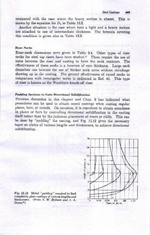
StdCadis &t
compared with the case where the heavy sectiou is absent. Thig isshown by the equation for Dr, in Table 152.
Another situation is the case where both a light and a heavy sectioD
are attached to one of intermediate thickness. The formula coveringthis condition is given also in Table 15.2.
Rirer Neclcr
Riser-neck dimensions were given iu Table 9.4. Other types of risernecks for steel top risers have been studied.ol These require the uee ofcores between the riser and casting to form the neck contorus. Theeffectiveness of these neeks is a function of core thickness. Large neckdiameters can tolerate the use of thicker neck cores without shrinkageshowing up in the casting. The greater effectiveness of round uecks incomperison with rectangular necks is indicated in Ref. 61. This typeof riser ie known as the Washburn knock-off riser.
Pding *ctions to Go;in Directioml $lidifuoltionPrevious discussion in this chapter and Chap. g has indicated whatprocedures can be used to obtain sound castings when casting regularplates, bars, or rounds. On occasion, ii is expedient to obtain soundnessin plates or bars by controlling directional solidification in the castingitself rather than by the judicious plecement of risers or chills. This canbe done by "padding" the casting, and Fig. 1b.12 gives the necessarytaper on plates of various lengths and thicknesses, to achieve directionalsolidificatioa.
.9 16
it2I
L]i20
Fig. 15.12 Metal "padding" required to feedcompletely plate castings of various lengths andthicknesses. (From S. W. Brfi*on and J. A.Duna.d) Toprr, in. par in,
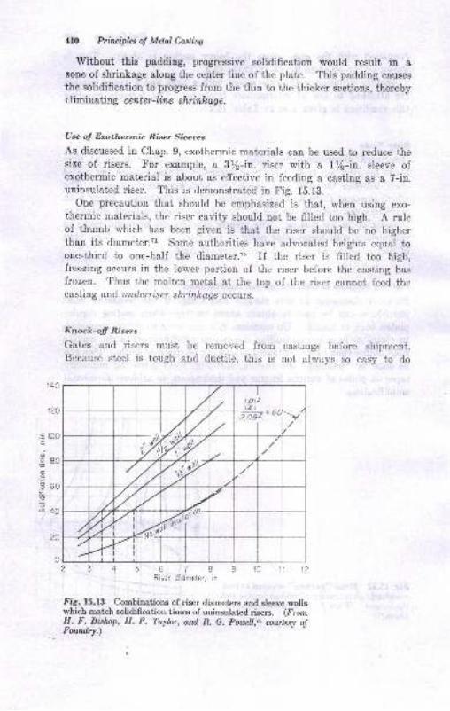
.E 100E
o
s80
.E 60
!oa40
410 Principlcs o! MeIal Casling
Without this padding, progressive solidification would result in a
zone of shrinkage along the center line of the plate. This padding causes
the solidification to progress from the thin to the thicker sections, therebyelimiuating center-line shrinleag e.
Use of Exothermic .Riser Sleeres
As discussed in Chap. 9, exothermic materials can be used to reduce thesize of risers. For example, a 3/2-in. riser with a lt/2-in. sleeve ofexothermic material is about as effective in feeding a casting as a 7-in.uninsulated riser. This is demonstrated in Fig. 15.13.
One precaution that should be emphasized is that, when using exo-thermic materials, the riser cavity should not be filled too high. A ruleof thumb which has been given is that the riser should be no higherthan its diameter.?1 Some authorities have advocated heights equal toone-third to one-half the diameter.T, If the riser is filled too high,freezing occurs in the lower portion of the riser before the casting hasfrozen. Thus the molten metal at the top of the riser cannot feed thecasting and, untlerriser shrinkaqe occrlrs.
Knock-off Risers
Gates and risers must be removed from castings before shiprnent.Because steel is tough arrd ductile, this is not always so easy to do
89in.
567Riser diometer,
fig. 15.f 3 Combinations of riser diameters and sleeve wallswhich match solidification times of uninsulated risers. (FromH. F. Bishop, H. F. Taylor, and R. G. Pouell,Tr nwtesy o!Foutdry.)
t D\2\4 I - -t 2.og?'uuti
', i/
4rIF]20
0
SkdCastinss 4ll
Eerely by breaking ihem off, as in the case oI more b ttle elloys. Thedesign of the connection between',lre gare or riser and the castingtherelore becomes a matter of concern, and some examples of riserconnections were provided in Chap. 9 as well as in this chapt€r. Itshould be obvious, also, that if cxothermic mate als are used to reducethc size of the riser, the riser connections can be reduced in size, therel-ryreducing the cleaning costs. A recent study of riser connectious ad-vocates that the knock-off core used to make the connection shouldprovide a diameter of about l0 per cent of the riser diameter plus 0.2 in.A radius-tipped cross-shaped neck provides the best breekability.'"
STEEL MELTING
Steel melting is discussed in more deiail in the next chapter, but a briefsurvey is given here to complete the study of steel castings. Steelmelting is substantially difierent from the melting of most other alloysin that a definite part of most steel-melting cycles is a refining actionthat is necessary to ensure good-quality steel. Refining operationsare also employed in melting down other metals, but not to the extentanJ with the degree of control usually exerciscd with steel. Broadlyspeaking, the melting cycle consists of an oxidation period extendingthrough and beyond the melting period in rqhich certain impurities areremoved by oxidation and collected in a slog. This is followed by areducing period (deoxidation) in which the oxygen content of the molteumetal is lowered (in one process, sulfur is also lowered). The steet isthen adjuited in composition and poured.
The various steel-melting processes, classified according to furuaceiype, are:
l. Open-hearth (acid and basic)2. Electric-arc (acid snd basic)
3. Electric induction (acid or basic)
The choice of a particular melting method is governed by a largenumber of factors, some of which are enumerated in Chap. 16. Theopen-hearth lurnaces are preferred Ior l&rge tonnages, whereas theelectric furneees offer greater versatility in the type of metal to bemelted snd grester flexibility of operatious.
Opcn-hao'rtl' McltilgIliusirations of open-hearth-furnace construction are given in Chap. 16.These furnaces are charged with scrap and pig iron (an impurc ironproduced in blast fuusces) and heated with oil, gas, or powdered coal.
112 Primipbt of Mdal Casting
The air used for combustion is heated in preheat chambers, calledchecker chambers, where it picks up heat from a brick checkerwork. Thechecker chambers are heated by the exhaust gases from the open hearth.Two chambers are required so that combustion air and waste gases canbe alternately cycled between them. preheating the air is uecessaryto obtain the high temperatures required.
Tbe refractories in the melting zone of the furnace are either oad(SiO,-base) or basic (Mgo-base). The type of refractory controls thetypes of reaction that are possible during the refining period and thenature of the slag product.
During meltdown and after the steel is melted, silicon, manganese,iron, and carbon are oxidized. The oxidation products of the first threeelements become a part of the slag, whereas the oxidized carbon leavesthe furnace as CO or COr. Additional slag-makiug materiels (lime inthe case of. the basic process, and sand in the case of the acid process)may be added to the furnace. The carbon content of the charge isadjusted so that after meltdown the carbon conteut of the molteumetal is higher than desired in the final analysis. As the temperatureof the metal rises, this carbon is gradually Lliminated as CO, whichbubbles up through the bath. This is known as the ,,carbon boil.,, Theoxidation of carbon produces heat, and the bubbling action stirs thebath and aids in the removal of impurities. when the desired carboncontent is reached or when it has reached a low value, additions aremade to rid the steel of a large part of its dissolved oxygen and toadjust the manganese, silicon, and carbon contents. while the carbonboil is proceeding, the slag which floats on top of the steel is adjustedin composition to control the rate at which carbon is removed from thebath. This control is aehieved through iron or manganese ore additionsto the bath. Gaseous oxygen may also be used. When the bath hasreached the desired pouring temperature, the slag has been adjusted bythe melter to the proper viscosity for tapping. The refining periodthus represents a proper balancing of metal composition, slag composi-tion, time, and temperature so that metal of the desired quality andtemperature is available for castings.
The acid practice is not capable of removing phosphorus from thesteel;- hence the charge must be low in phosphorus to meet the usualIimit of 0.05 per ceut phosphorus in the finished steel. Basic slags,on the other hand, are capable of dissolving the oxidized phosphorus,and phosphorus removal is therefore a part of the refining operation.As a consequence, there is not the restriction on phosphorus contentof the charge as in the case of the acid practice. some sulfur elimina-tion is also obtained, but it is not very much, amounting to about0.fiX to 0.007 per cent.
,9d CattinCs qli3
Cthat Mehing Methda
Eosentially the same proeedure outlined for the open-hearth furnacesis followed in arc-furnace melting, except, of course, that electricalpower is used to melt the charge.
In the basic electric-arc furnace, it is possible to remove the initialoxidizing slag after the desired degree of oxidation has occurred {indkt add slag-making constituents thet will create a reducing basic slag.This promotes the removal of sulfur. The basic erectric
-furnace can
therefore be used to remove both phosphorus and sulfur. The acidelectric furnace removes neither element; consequently, the chargemust be srrffisisntr1, low in both these impurities.
Reference should be made to chap. 16 for discussions of melting in aconverter and electric-induction furnace.
Deoxido,tion
The primary purpose of deoxidation is to lower the d.issolved oxygeneontent of steel to improve its quality. This is accomplished ly aaai"gelements such as silicon and manganese shortly before the metal istapped and adding alrrminurn to the ladle during tapping. The oxidesof silicon and mauganese tend to float out of the steei an-rl become partof the slag. The allm!1qm oxide products may also float out, butregardless of whether silicon plus manganege alone or silicon plusmanganese and aluminum additions are made, some of the deoxidationproduct invariably is visible upon microscopical examination of a solidi-fied casting. Incomplete removal from the metar is one reason forthis entrapment of these nonmetallic inclusions, but it is uot the only_one. Actually, the deoxidation reactions occur while the metal iscooling, and this efreet would naturally not allow time for all thereaction product to leave the molten steel. rn fact, the reactions aregoing on during the freezing process, making it impossible to rid thesteel completely of thdse deoxidation products.
In addition to deoxidizing the steel, aluminum additions cause certainside reactions of extreme interest to steel foundrymen. These reactiongane:
l. Prevention of pinhole porosity, described in an eerlier section2. Control of the sulffde distribution as descnlbed in Chap. lZ3. Control of austenitic grain size (of interest during heat_treatment)4. Etrect, on fluidit3'
-. The efrect of temperature and of various alloy erements on fluidity was
diecussed in an earlier section of this chapter. In addition to ihese
lL F,itu pb d M.bl Codiiq
factors, deoxidation has been fourd to affect fluidity, both insu6cieut
deoxidation and overdeoxidation causing decreaaed fluidity. Over-
deoxidation refers to the addition of so much deoxidirer, such aa alu-
minum, to the strel i,hat eubstsntial residual quantities remain in eolutiou.
Thus it is apparent that the physical metallurgy essociat€d with casL
steel productiou is quitc involved and complex. A complek discuseioa
of thiE subject goes far beyond the scope of this book.
Tappins aad Pottrias
Tanpcmlun M.ott rdnai
The st€el-fuuace melter sttempts to regulste conditions so thgt the
steel is up to pouring temp€rsture at the time of final deoxidation.
Temperature control and determination are important iD that I cold
heat would lead to misruns or even the loss of an entire heat. At the
elevated temperatures at which 8t€el i8 t8pped, t€mperature measure-
ment becomes a resl problem, aud various devices have been ueed which
give either I true reading or a relative meaEute of temperature.u
Tappine
The sile ol the tsphote in the open-hearth lurnace should be snsllenough so that no slag eoters the ladle with the metal. ThiE is
neceEeary Eo that thc tadle deoxidizers, such as alumiuum, will oot lose
their efiectiveness by being entrapped by l,ho slag.
Tapping ie ueually msde itrto I lsdle lslgo enough to hold t}te conteots
oI an eDtire heat. From ttrere the metal nay be trsnEfe[ed to smsller
ladles lor pouriog motdr or taken directly to the molds tr be poured.
Thero ie about 8 50 to 200 F loes in each traueler of metal. Therefore
a midmum numb€r of roetal tranefers ehculd be roade. LadleE used in
the ghel foundry include bottom-pour, lip-pour, aDd teapot types.
Theee are illurtrated in Figr. 9.1 aud 9'2.
CLEANING, CEIPPINC. AND CRIITDING
Ouce costiugs are eolidified, the problem of Estrd removal, imprcvement
ol surface finish, removal of gat€e aud risers, aud rtpair oI defective
areas ariaes. This problem ie much more diftcult with steel castiDgE
than with other castiug alloyB beeaue€ of grester saud adberence,
tougher metal, and ircrtased chance for castiug defects to occur. Ttle
problemr aud methods aeEociat€d with these finishing operations are
adequately covered in Chap. 24, 8Dd the student thould refer to ttrat
ohrpter for inloroation on this iubiect.
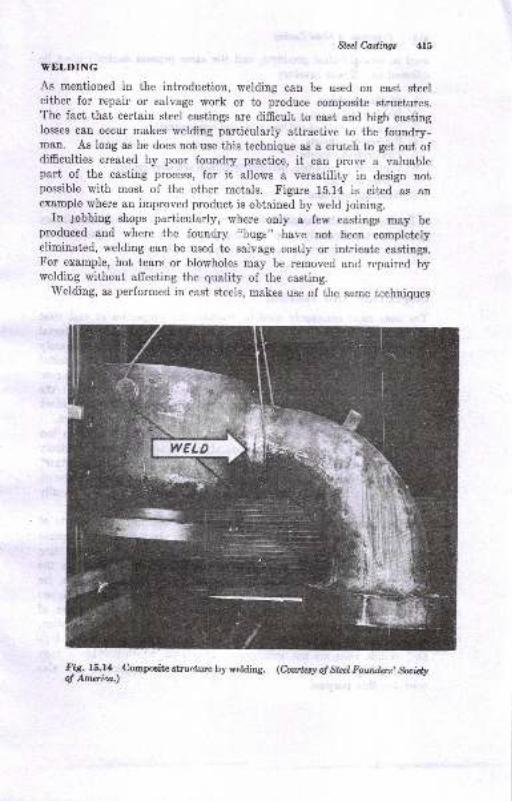
Slel Ca.ilings 415
VELDING
As mentioned in the introduction, welding cen be used on cast steeleither for repair or salvage work or to produce composite structures.The fact that certain steel castings are difficult to cast and high castinglosses can occur niakes welding pariicularly attractive to the foundry-man. As long as he does not use this technique as a crutch to get out ofdifficulties created by poor foundry practice, it can prove a valuablepart of the casting process, for it allows a versatility in design notpossible with most of the other metals. Figure 15.14 is cited as anexample where an improved product is obtained by weld joining.
In gobbing shops particularly, where only a few castings may.beproduoed and where the foundry "bugs" have not been completelyeliminated, welding can be used to salvage costly or intricate castings.For example, hot tears or blowholes may be removed and repaired bywelding without affecting the quality of the casting.
Welding, as performed in cast steels, makes use of the same techniques
fi& f5.14 -
Compoaitc etruc;tu€ [y y6tdin8. (hwhry o! Stal Fowfu$, &r:id!ol Amoin.)
l'T;'EF" C'":
I
116 Prircifui oI MdalCasliw
used in wrought-steel products, snd the same process controls must be
adhered to. These involve:
l. Ifelding methods
2. Welding techniques
3. Selection of welding-rod size, type, and composirtion
4. Pre-hest-treatmentg
5. Post-heat-treatments
6. Control of composition, particularly carbon and alloy content
7. Testing methods
8. Grinding operations
To discuss all the factors involved in welding and welding metallurgyis a subject sufficiently large for another book, and the importance oIit to the stcel foundryman can only be indicated here.
INSPECTION AND TESTING
The tests most commonly used to evaluate the properties of cast steel
are tensile, hardness, and impact tests. These are made on metalremoved from the eastings or on test bars machined from separately
cast test coupons. The latter tests give the properties of the metalunder the more or less ideal conditions preva:Lling in the test coupon.
T\ro types of keel blocks are shown in Fig. 15.15. Each leg of the
keel block provides one tensile specimen. Sometimes the keel blockis molded along with the casting as a part of the total casting system.
Impact tests are often used when the steel is to be exposed to lowtemperatures. The impact resistance of steel drops ofr rather suddenly
at certain subatmospheric temperatures. This "'transition temperature"is quite sensitive to steel composition, steel quallity, and heat-treatment,and for that reason tests over a reDge of te,mperatures are usuallyadvocated.
Microscopical examination is often used to determine the effects ofheat-treatment on the metal structure. Where production requirements
are severe or where developmental work is being done on casting
design, X-ray radiographic techniques are employed to show up theinternal defects in the casting. Castings for a:ircraft applications, forexample, may require 100 per cent inspection, and specially equippedlaboratories may be required to accomplish this important phase ofcasting iuspection. Since steel is quite resistant to X-ray penetration,
high-voltage equipment may be necessary, and iustallations of as highas I million volts are not uncommon. Betatrons, which provide X raysat mueh higher energy than conventional X-r,ay machinee, are also
used for this purpose.
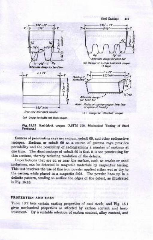
Atdr,ot d.sigh lorb.rd bor
l,,1 t't9
S c ,ir t cl b.* @up,
la) t..'fn ld dolr. tct lhcr corpon
fig. 15.15 Kal-trloct cor4mPlodoct .)
llolt: Pdius ot @ting-@!p., inte.ldo, opho,, ol lo.rnrby
(al Daiqn for 'oiloahld' conDo.l
(ASTM 3?0, M€chadcat Te.tiDg of Strel
Sources of penetrating rays are ladiuur, cobslt 60, aud other radio8ctiveieotopes. Radium or cobslt 60 aa I Eource of gsnma raye prcvideEportsbility end the poasibility of rsdiographiug a nuuber of caEtiDgs atoue time. The disadvantage of cob8lt 60 i8 th8t it i8 too peDetrsting ,orthin sections, thereby reducing resolution of the defects.
Imperfections that srr on or Dear Lhe surface, such a8 cracks or saodioclusions, cau be detectcd in magnetic Daterials by mt4twfiur teatirLg.This test involveg the uae of 6ne iron powder applied either wet or dry iothe caetiag while placed in a Dagnetic field. The powder linee up ia adefinite pattern, tendiug to ouuiuc the edges of tbe delect, 8s illustrstediu Fig. 15.16.
PROPENTIES AND USES
Table 10.2 liet8 certai! casting propertiee of csst steel8, 8rd Fig. 16.lgives mechanical properties aa afrected by carbon content sld heat-ireatmeut. By a auitable aelection of carbon content, alloy coutent, and
Std C-adingt
( D ) thsign ,o. mo[id. i..l Uocl coqo.r(4 t.9.)
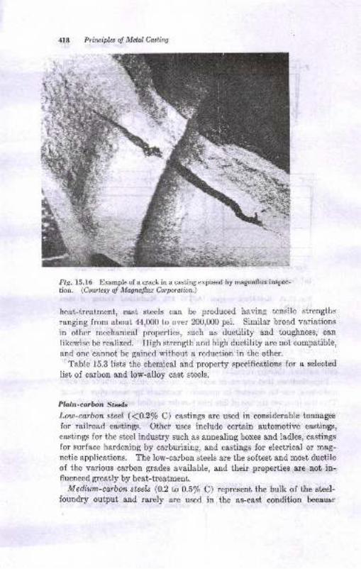
Prircipb-s oJ Melal Caslin4
tt
:i -{ri*,
Fig. 15.16 Example of a crack in a casting exposed by magnallux inspec-tion. (Cowte*.t ol Malrullw Corporalion.)
heat-treatment, cast steels can be produced having tensile strengths
ranging from about 44,0(X) to over 200,0(X) psi. Similar broad variations
in other mechanical properties, such as ductility and toughness, c&n
likewise be realized. High strength and high ductility are not compatible,
end one cannot be gaiued without a reduction in the other.
Table 15.3 lists the chemical and property specifieations for a selected
list of carbon and low-alloy cast steels.
Plo;in-corDpln Sterlb
Low-carbon steel ({0.2/o C) castings are used in considerable tonnages
for railroad castings. Other uses include certain automotive castings,
castings for the steel industry such"as annealing boxes and ladles, castings
for Surface hardeniu! by carburizing, and castings for electrical or mag-
netic applications. The low-earbon steels are the softest and most ductileof the various carbon grades available, and their properties are not iu-fluenced greatly by heat-treatment.
Mediwn-carbon steels (O.2 ta 0.5% C) represent the bulk of the steel-foundry output and rarely are used in the as-cast condition becausr
7,,.
h-E

*i>
-- (.)g-e:4
EE:Eq
:t5:3:
is,:
35 ::5 I!EeE a
EE .1
!c E
€€ 4iis ; El* : ica n;Et g'iqE 3:,-, i- ,! I,-g . !! t 56< IE'3 !:-g3g 3.r:! e ;!:
!i !l!E; }EEg'i 3iEz-.t9-6'-^il3 E
i5i.e! z
E!leg!;.Eg!Ei
i; !€ ts:€ E rl i
=.lEElr
t?
.8
!
lt
II
B
I
a
!
Ie'!
ES
.9
xE
a
E
.! so+aB
2 ESqqsqqaEEAAAA SESqEqqq€EEE €qqqqqEEEEE
28*-48q\\qqs *83
E
E
!'
I
iBi* 1{aEqo-t-
qtsEF6-F-6-66
l.5 iAAAQQEEtsEE
aeeae9tEAAEEAAQ999CQaaaa:laaaaEaaatsdrirtddd.'t!t"t"i
rEE !i
ceaQtaaaEa E g"s-E g.g.g.
38rEBg3ttt-Et-g.EEEE33e8883838
I ,E
!.o
!.izi<.
FFFF
.-idtsi!.zzzziiii<j..<'
FFFFFFFzzzzzzziaiiiii<ij.i..i<
ooFF 5 E!.
E 8i., 27;;; - ; oE-rrttk------ o t --t" oooo<<<zo<zzzzz
! zzBSSRR r88388P 88388385556
.[;? 6.:
:. E
1t9
4m hnoiplaot MdalCadhq
heat-treatment improvee their ductility strd impact registance. About60 per cent of all steel'castings are of the medinm-carbon grade, andtheir field of application is extensive and varied. Medium-carbou st€elsare used in the transportation industries, for machinery and toola, rolling-mill equipment, road and buildiug machiaery, aud many other applica-tions.
Because of their higher hardness and strength, high-corbon cast steela(0.5% C) are used for metalworking diee, rolls, and otler tools wherewear aud abrasion resigtance are necessary.
,,/
Lott-attolr Stale /
The low-alloy steels are Iimitcd to a total alloy content of 8 per cent,and differ from plain-carbon steels principally in their ability to beheat-treated to higher levels of hardness and etrength in a giveu croeesection. This ebility is meaeured by the hardenability test (discussedin Chap. 17). As a result of having increased hardenability, the low-alloy cast steels can be made with better mechanical properties thanplain carbon steels, or the same properties c8n be achieved without reeort-ing to severe heat-treating operations that might normally distort or cracka casting.
The alloying elements commonly employed for the purpose of securinghardenability, given in the approximatre order of their efrectiveneas, are:
Menganeee
Q[166lrrmlVlolybdenr'-Nickel
Silicon
CopperVanadium
various eombinations of these elements are used, resulting in the numer-oue types of alloy steels lieted under sAE (sociew for AutomotiveEngineers), AISI (American Iron and Steel Institute), or other specifi_cations. outside of the efrect of the alloys on hardenability, it may begeneralized that the low-alloy steels are otherwise intrinEically no difrereutfrom plain carbon steele. of course, there are problems in conuectionwith economy, ease of melting, availability of scrap, etc., that may dictatethe selection of one alloy or alloy combination over aoother.
fligh-o/;lo1. Stzcb
In this oategory fall those alloys of iron and carbon that have over Eper cent alloy content and have superior corrosion, heat, or wear resigt-
Sfal C,adings An
ance. The Alloy Casting Institute recogD.izes 16 standard grades ofcorrosion-resistant alloys and 12 standard grades of heat-resistant alloys.
Included in these groups are alloys of:
1. Iron and ehromium, with chromium varying from about 12 to 30 per cent
2. Iron, chromium, and nickel, with chromium varying from 18 to 32 per cent
and nickel from 8 to 20 per cent
3. Iron, nickel, and chromium, with nickel varying from 33 to 41 per cent and
chromiirm from LB to 21 per cent
4. Nickel, iron, and chromium, with nickel varying frgm 58 to 68 per cetrt andchromium from 10 to 19 per cent
Other metals, such as silicon, molybdenum, and aluminun, rray slso be
used in thesi alloys to confer special advantages.
A steel of outstanding wear resist{ince is an oustenitic rnonganese stnel,also referred to as Iladfield's manganese steel. It contains 10 to.14 per
cent manganese, and is commercially unmaehinable. It is used formining equipment, railroad-track work such as crossing and frogs, pul-verirers, quarrying equipment, and mauy other similar applications.
BIBLIOGRAPHY
l. qlq! Foundersl Society of America, "Steel Ca.stings Eandbooklt€d ed., 1960.2. g.F.Bishop, tr'. A. Brandt, and W. S. Pellini, Solidification of Stcel against
Sand and Chill W&lIs, Truns. AF1, vol. Eg, p. 458, 1951.3. p.K.Fourshou, Durability of Foundry Sands and Properties of Deteriorated
Foundry Sands, "1.
Steel Castings 8es., no. E, p. l, May, 1986.4. L. DeBoer, Steel Wheels in Green Sarrrd., Modern Cutings, vol. 80, p. 84,
October, 1956.
5. gteel Founders'Society of America, "Fundqmentals of Steel Foundry Sands,,1959.
6. C. E. Sims and C. A. Zapfre, ffis l\dec[anim of Pin-hole Fomation, ?roru.r{.tr'S, vol. 59, pp.255-281, 1941.
7. R. C. S.tvage and H. F. Taylor, A Thermodynamic Study of pin-hole Foma-tion in.Steel Castings, Tro,ns. AFS, vol. 58, pp. BgB-Bgg, 1980.
8. R. G. Powell and E. F. Taylor, Shell Molding for Steel Castings, Trans. AFS,vol.66, p.4()3, 1958.
9. D.9.Ekey and E. G. Vogel, Ceramic-mold Process for Steel Castings, ?roas.r{.FS, vol. 64, p.439, 1956.
10. H. II. Hursen, Graphite Molds plus Air Pressure pouring yields New StcelCar T9heels, Modem Castings, vol. 28, p. 26, September, 1SSS.
11. E. Chappie, Steps to Take in Elimiaating Eot Tears, Found,ry, vol. g6, p.82, July, 1958.
12. E. !. Bishop, C. G. Ackerlind, and W. S. Pellini, Metallurgy and Mechanicsof Eot Tearing, Traro. z{FS, vol. 60, pp. 818-888, lg52.
13. J. B.-CBine, Cracks and Eot Tears in St€el Castings, Fouttdry, vol. g1, p.1A), June, 1953.

E Prhu/ifu ol Melal tuiN14.
,!g. 8. Pellid, qtrsitr Theory of Eot Cracking, FMry, vol. $, p. 125,
Novmber, 1952,15. C. E. Wyman, C. A. Fsist, and G. Dr.Sylvestro, Eott€sr Itr r€8tig8tiou,
Iroar. ,{fS, vol. 60, p. 1,15, 1952.16. Y. K. Bhattacharya, C. M. Adsoo, Jr., aod E. F. Trylor, Eot-t sr Forne-
tions in Steel Castilgs, ?rcnr. /IS, vol. 60, pp. 67H86, 1952.17. C. F. Christopher, Eot-tesriDg Characteristics of Acid and Basic gkel
Castings Det€rmined by High Temperaturc TestiDg, vol. 64, p. 293, 1956.
C.I . Briggs, "The Meiallurgy of Steel Castings," MccreF-Eill Book Com-pany, New York, 1946.Y. K. Bhettacharys, C. M. Adarns, Jr., ond E. F. Tsylor, Str€6s Required taEot Tear Plain Carboo Cast Steel, ?rcnr. /fS, vol. 62, pp.557-567, 1954.
20. E. Pettersson, An Investigation of the PenetBtion of Steel into MoldingSand, ?roa.r..4I8, vol.59, pp. 35-55, 1951.S. L. Certelan and A. S. Murtou, Metal PeDetntioD, ?rcr8..4FS, vol.59,pp. 108-115, 1951.
G. J. Vingas (Ior Mold Surface Committ€e 8-E), Rlutming Superheat andAlloy8 (Type of Metal Efrecta oa Metal Penettaliott), Modem C@tinge,,rol.36, p. 671, November, 1959.A. E. MurtoD and S. L. Gertual, A Litrlsture Review of Metal Penetrs-1101, Modetu Co.stin4s, vol.33, p.37, Jarluary, 1958.R. C. Xmmons and J. Bach, St€el PeDetration, Foundrg,'to1.83, p. 108,April, 1955.D. V. Attarto!, Surface Finish of St€el Castings, Founlr!, ],ol.86, p.79,January, 1958; p. 107, February, 1958; p.92, Malch, 1958.N. M. Peterson, Zircon &trd Its Foundry Applic&tiotr, Fozrdry, vol. 81, p. 93,April,1953.II. Chappie, Use of Zircon Sond in Producing Lerge Castings, forndry, vol.83, p. 126, October, 1955.D. F. Mcvittie and T. P. Eoar, Sand Burn-on without Metal PeDettation,J. Steel Cdstin| Bes., no. 10, p.8, January, 1958.J. B. Cairc, E. H. Kbg, Bnd J. S. Schumacher, A Microscope Study ofRammed Sand Eurfaces, J. Steel Caatinls Res., no. 21, April, 1961.J. B. Caine, E. H. King, and J- S. Schumacher, A Study of the Influence ofMold Atmospherc on Ceroxide Defects in Steel Casting8, J. Steel Cestin4s-&ee., no. 24, Januery, 1962.An Investigation of Factors Producing the C,ercxide Defect on $t€et Casting8,SFSA Research Repoft 52, J. Steel Castin7r l?ei., tro. 27, Octobe!, 1962.J. B. Coine, A Study of the Bpisvior of Molding Sand Wheu in Contactwith Liquid Steel, Fanndry. vol.75, p. 72, 1947.C. A- ColiBrD, L. E. Van Vls(k, and R. A. Flinn, Factors Mecting Metal-mold Rractiong, ?rans. /FS, vol.69, p.52, 1961.
J. B. Caine, E. H. KiDg, and J. S. Schumacher, A Study of Some FouodryVarisbles Af,ectil8 the Occurrerce of Visible Nometellic Surfece Defecttin Steel CsstiDgs, "r. Steel Cdttinqs Res., oo. , October, 1961.R. A. Fli{n, W. B. Pierce, ald L. H. Van Vlack, Cast Steel NotEret llicMacroinclusions, Source6 snd Preyention, Ttant. AFS, vol. 69, p. l9g, 1961.L. H. Ven Vlack, J. P. Broklof, and R. A. Flinn, Refractories as a Sourceof Macrohclusions, lrdar. AFS, vol. 69, p. 178, 1961.E. Taylor, E. Rouiuki, and C. W. Briggs, The Fluidity ol Iagot Iron, aodCarbon and Alloy Cast Steels, Iroar. /1S, vol. g9, pp. l-93, 1O{1.G. A. Lillieqviet, Infu€nce of Tempersture on Fluidity aad Surfrce Appelr-sDce ol gteel Crstilgs, ?wn. AIS, vol. 58, p. 261, 1950.
18.
19.
21.
23.
24.
.
26.
2x.
29.
30.
31.
34.
35.
36.
38.
Stczl Castings 4'..:i
J9. H. F. Bishop and W. S. Pellini, Soiidification of tr'Ietals, Foundrg, vcl' 80, p'
86, 1952.
40. C. Locke, C. W. Briggs, and R. L. Ashbrook, Ileat Transfer of Various
Molding Materials for Steel Castings, Trans' AFS, vol. 62, p. 589, 1954' -
41. C. W. Briggs, Solidification of Ste;l Castings, Trans. ,4FS, vol. 68, p. 157,
1960.
42. C. A. Rorve, The Solidification of Steel in the Standard Fluiditl' Spiral, M'l/,Research Report, February, 1959.
43. J. F. Wallace (ed.), "Fundamentals of Risering Steel Castr^rgs," Sieel
Founders' Societv, 1960.
44. C. M. Adams, Jr., and I1. F. Taylor, Florv of Eleat from Sand Castings by
Conduction, Radiation and Convection, Trans. dFS, vol. 65, p. 170, 1957.
45. F. A. Brandt, H. F. Bishop, and W. S. Pelini, Solidification of Corner ar^d
Core Positions, Trans. AFS, vol.60, p. a51,1953.
46. S. Z flr2m, 1\{. C. Flemingo, and H. F. Ta1'lor, High Strength Cast Steel
Structttre and Microporosity Effect on Nlechanical Properties, Trans. AFS,
vol.68, p 347, 1960.
47. C.W. Briggs, Gating Steel Castings, Foundry, vol.88, p. 125, June, 1960;
p.86, July, 1960.
48. H. Chappie, Gating Affects Qualitf in Production of Steel Castings, Foundry,
vol.84, p.90, April, 1956.
49. T. Finlay, Fin Gating: Nerv Cost-cutting Steel Technique, Modern Castings,
vol.40, p.53, September, 1961.
50. Armour Research Foundation, Fluid FIow Nlechanics of N'Iolten Steel, April,1951.
51. M. J. Berger and C. Locke, A Theoretical Basis for the Design of Gatrs,Foundry, vol.79, p. ll!, Febnran',1951.
52. W. S. Pellini, W. H. Johnson, and H. F.'Bishop, Velocities and Volume Rates
of Metal Flow in Gating Systcms, Trans.,4FS, vol. 61, p. 439, f953.
53. American Foundryrnen's Society, "Syrnposium on Principles of Gating," 1953.
54. W. S. Pellini et ai., Feedirrg Range of Joined Sections, Trans. /fS, 1953,
p.302.55. E. T. Myskowski, H. F. Bishop, and W. S. Pellini, Feeding Range of Joined
Sections, Trans. AFS, vol. 61, p. 302, 1953.
56. J. Caine, A Theoretical Approach to the Problem of Dimensioning Risers,
Tran*. AFS, vol. 56, pp.492 and 501, 1948.
57. II. F. Bishop and W. S. Pellini, The Contribution of Riser and Chill-edge
Effects to Soundness of Cast Steel Plates, Trans. AFS, vol.58, p. 185.
58. W. S. Pellini, Relation of Riser Range and Feeder Adequacy, Am. FoundrE-tnoz, November, 1953, p. 58; December, 1953.
59. H. F. Bishop and W. H. Johnson, Risering of Steel, Foundry, vol.84, p.71,February, 1956; p. 136, March, 1956.
60. H. F. Bishop, Risering of Steel Castings, Found.ry, vol.88, p.75, August,1960; p. 116, September, 1960.
61. J. F. Wallace (ed.), "Fundamentals of Risering Steel Castings," Steel
Founders' Society, 1960.
52. H. F. Bishop, E. T. Myskowski, and W. S. Pellini, A Simplified Method forDetermining Riser Dimensions, Trons. .4FS, vol. 63, p. 271, 1955.
63. E. T. Myskowski and H. F. Bishop, Application of Chills for Neutralizationof Rib and Boss Hot Spots on Plates, ?rons. dFS, vol. 63, p. 295, 1955.
64. C. W. Briggs, Risering of Commercial Steel Castings, Trans. AFS, vol. 63,p.287, 1955.
65. J. F. Wallace, Riserins of Castings, Foundry, vol. 87, p. 74, November, 1959.
4U Priuipb of Mdal Castittg
66. Il.^D._M_e-rchant, Dimensioning of Sand Casting Risers, ?ranr. z{fg, vol. 67,p.93, 1959.67. s. w. Brinson and J. a Duma, studies on centerline shrinkage in steel
C+1.inas,.?rcns-. r{FS, vol. i0, p.'687, lg42.- -
ffi T:j:!S,-":* Jr., C. M. Adanns,-end E. F. Taylor, Transporr of Feed Metaloururg Sotr.r,fication of Tapered Stcel Ears, Tran*..AFS, rol. 68, p. Bg4, lg57.69. H. Present and E. nose-ntfat, feeaing Oi"tlr..
"f Bars in f"".i,il""t iiJar,
, ff:fl f{ff$;'J:'". ff;i3Slb ,. u;o ,. ".
ray,or, so,idincarion9I Sleel Castings and Ingots, Trans. AFS, vol. 69, p. +ZZ,iSiAi.7I. H...F:Bi+op, E. F. Taytor, ana n- C. powli, ni.".iog of Steel Castingswith Exothermic Sleeves, Fozndry, vol-g6, p. S+, .l*., f6d.
----- ----,.
9^.9;1".$:J: LT*"X: ana rrrir,a"i!,i.[ rr,'e*ri""_i. u"a.i*, elz.t ou?utryman, vol. lB, p. Bl0, August, 1946.73. P. K. Sandell, nreatiUitity of-K";;k-oli Ri*n, Fotndry, vol. S, p.g,
November, [email protected]. 'steel solidification Fundamentals and rheir lnportance to steel castiDcDegign," The pelton Steel Casting C"-p"ry,-fr{ifi""t*, mr.,"fbii.
--"-
16Steel Melting in
the Fotrndry
INTROI}UCTION
Four typee of furaaces are used to m8ke cast steel:
Open-hesrth (aoid and basic)Electric-arc (acid and basic)Converter (acid side.blow)Elechic induotioa (acid aod bosic)
Of theae the firgt two contribute mogt of the tonnage.The distinction between aeid and basic practic" ir io regard to the
type of refractories used in the construetion and maintpnance of the
, furnace. Furnaces operated by the acid practice are lined with eilica-
I base (SiOr) refractories, and the slags employed in the refining procesgI have a relatively high silica content. Basic furnaces, on the other hand,,'use a basic refraetory such as magnesite or dolamite base. and have ahigh lime (CaO) content in the slag.
. The acid process depends on having a good grade of serap available,
since neither phosphorus nor sulfur, both undesirable impurities, can beremoved by this process. By employing one or another of the basicrefining practices, however, either phosphorus or sulfur or both c.an bepartially eliminatcd. The choice of furnace and melting practicedepends on many variables, inclurling:
1. The plant capacity or tonnage requrrcd2. The size of the castinp3. The intricacy of the castings4. The type of steel to be produced, ie., whether plain or alloyed, high or low
carbou, etc.
5. The raw materials availsble and the prices thereof
'Magneite is MgCQ, an-d lolomita is a calcium-megneeium carbonate. The mag_nesito i8 calcined to t'he oxide form before uee or before meking brick Dolomite maybe ueed raw or in the celcined form.
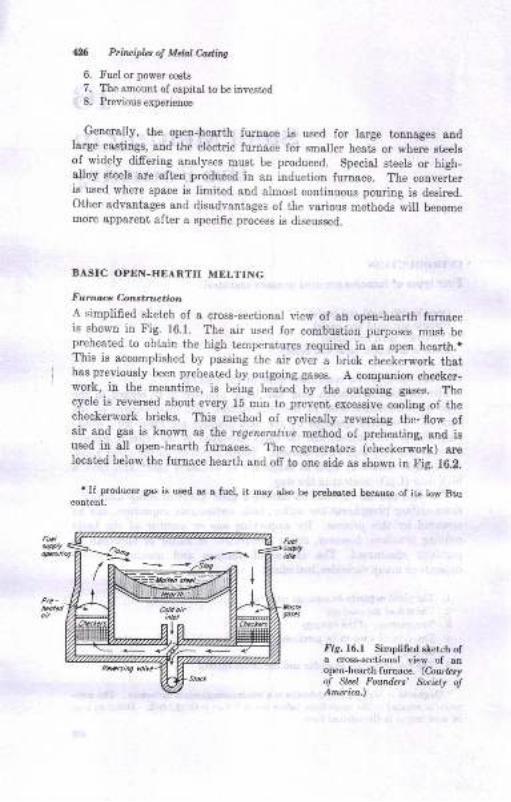
1126 Privipl2, ol Mdal Ca.ti^s
6. Fuel or power costs
7. The amount of capitsl to be iDvested
8. Previous experience
, Generally, the open-he&rth furnace is used for large tonnages andlarge castings, and the electric furnace for smaller heats or where gteels
of widely difrering analyses musi be produced. Special steels or higb-alloy steels are often produced in an induction Iurnace. The converteris used where space is limited and almost continuous pouring ie desired.Other advantages and disadvantages of the various methods will becomemore apparent after a specific process is discussed.
BASIC OPEN.Hf,ARTH MELTING
FLtnace Con truc.iotu
A simplifred sketch of a cross-sectional view of an open-hearth furnaceis shown in Fig. 16.1. The air used for combustion purposes must bepreheated to obtain the high tempeiatures required in an open hearth.*This is accomplished by passing the air oVer a brick checkerwork thathas previously been preheated by outgoing gases. A companion checker-work, in the meantime, is being heated by the outgoing gases. Thecycle is reversed about every 15 min to prevent excessive cooling of thechecker,vork bricks. This method ol cyclically reversing the, flow ofair and gas is know! as ihe rcgeneratite method of preheating, and isused in all open-hearth furnaces. . The regenerators (checkerwork) arelocsted below the furncce hearth and ofr to one side as shown in Fig. 16.2.
' If Foducer ga.s is used a.s e Iu€1, it msy slso be pr€hested b€cauBe of its low Btu
Iis.16.l SiElplH sletch ola cross-sectional view of anopen-hearth furnace. (Courrssyof Stcel Foundcrc' &cbty dAnzrica.)
lffit
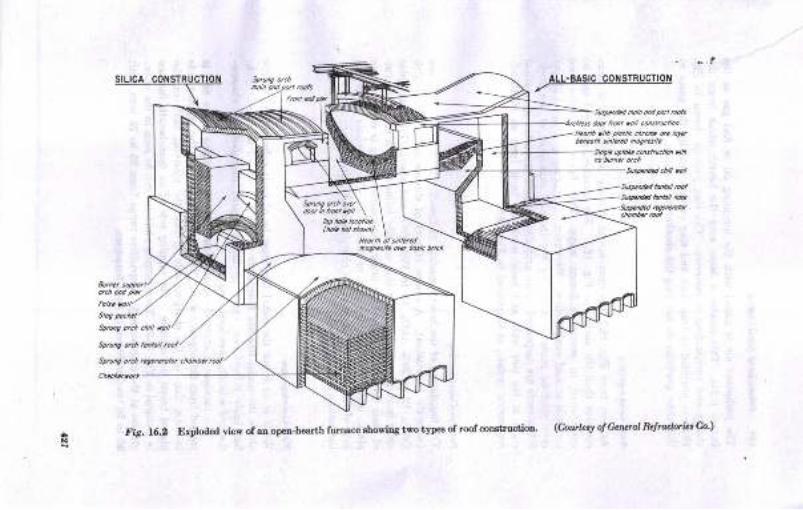
ALL.BASIC CONSTRUCTION
,,/-
dou /@t toll cartiunionlLotk ,tk ptori chrcD t. brtb...ott si"E .d nootusn
t4r/. urt t. ctusl.!.ton n6
no,nctr. M. bosic b.icl
sp,uag otch ..g@coto. .honbs
fi,. 16.3 Explodod YieY ol an oPetr-hesnh lulnace shorYiEa tyo type6 ol rool consttuction' (cout'sy o! G.luld R$Mbi.,a.,)
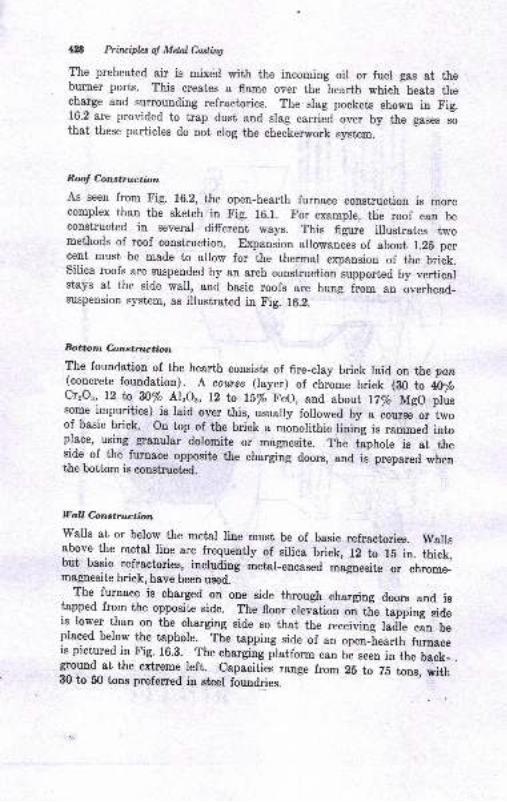
ll8 Prirvipla of MdalCadfiW
The preheated air is mixed with the incoming oil or fuel gas at theburner ports. This creates a flame over the hearth which heaLs thecharge and surrounding refractories. The slag pockets shown in Fig.16.2 are provided to trap dust and slag carried over by the gases sothat these particles do not elog the checkerwork system.
RooJ Construction
As seeu from Fig. 16.2, the open-hearth furnace construction is morecomplex than the sketch in Fig. 16.1. For example, the roof can beconstructed in several different ways. This figure illustrates twomethods of roof construction. Expansion allowances of about l.2E percent must be made to alrow for the thermal expansion of the brick.silica roofs are suspended by an arch construction supported by verticalstays at the side wall, and basic roofs are hung from an overhead-suspension system, as illustrated in Fig. 16.2.
Bottotn C,,nstruction
The foundation of the hearth consists of fire-cray brick laid or the pan(concrete foundation).
_ A. cou.rse (layer) of chrome brick (80 to iO1"
Cr,Or, 12 b n% Al,Or, 12 ta 15% FeO, and about l|/o MgO plussome impurities) is laid over this, usually followed by , *o*."'o. i*oof basic brick. on top of the brick a mlnolithic lining is rammed intoplace, using graoular dolomite or' magnesite. The taphole is at the
1]de- of the- furnaee opposite the charging doors, and is prepared when
the bottom is construct€d
Vall Constru.ction'walls at or below the metal line must be of basic refractories. wailsabove the metal line are frequently of silica brick, 12 to rE in. thick,but basic refractoyies, includiug metar-encased mago.esite or chrome-magnesite brick, have been used.
The- furnace is charged on one side through charging doors and is
lapped from the opposite side. The floor erevation oi ti" tapping siaeis lower than on the eharging side so that the receiving ladtre cin beplaced below the taphole. The tapping side of an open-"heartr, ru"nacuis pictured in Fig. 16.8. The charging pratform can be seen in the back- .ground at the extreme left. Capacities range from 25 tfr 75 t *,-*iif,30 to 50 tons preferred in steel foundries.
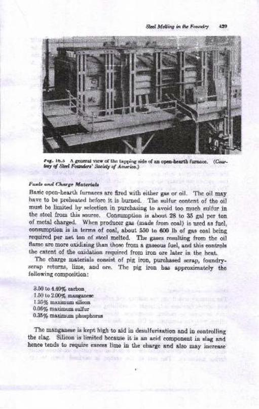
Slrd M&ine inllu Fowdry *X)
,tt. ro.i, A geoeralvrerof thetapoingsideo[anoperriearth firnace. (Cour-lq d Sld Forrtus' fuiary. of Amiia)
Fueb and Choge Matofialc
Basic open-hearth furnaces are fired with either gas or oil. The oil mayhave to be preheated before it ie bumed. The sulfur content of the oilmust be limited by selection in purchasing to avoid too much sulfur int'he steel from this Bource. Consumption is about 28 to 85 gal per tonof metal charged. When producer gas (made from coal) is used as fuel,cons-umption is in terme of coal, about 550 to 600 lb of gae coal beingrequired per net tou of steel melted. The gases resulting from the oilflame are more oxidizing than those from a gaseoue fuel, and this controlsthe extent of the oxidation required from iron ore later in the heat.
The charge matcrials consist of pig iron, purchased scrap, foundr5r-scrap retuns, lime, aud ore. The pig irpn has approximately thef ollowing ssmposition :
3.fi tD 4.0Vo carboa.
l,5Otoz.@Vo mang4nes
125fi maximum silicon0.06y'6 maximum sulfur0&5 y'e maximtrm phosphonre
The manganeee is kept high to aid in desulfurizatiou and in controllingthe slag. Silicon is limited because it is an acid component in slag andhence tends to require excess lime in the charge and also may increaee
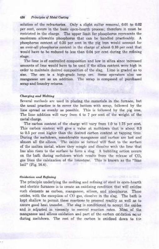
43O Prituiphr ol Mdal Corlirq
solutioD of the refractories. Only a elight sullur removal, 0.01 to 0.02
per cent, occurs in the basic open-hearth process; therefore it must be
restricted in the charge. The upper limit lor phosphorus represents the
maximum allowable phosphorus that can be handled practicably. Apbosphorus conteot oI 0.35 per cent in the pig irou would account forau over-all phosphorus pontent in the charge of sbout 0.10 per ceut tha,l,
would have to be reduced to less thsn 0.Ol per cent during ihe refining8t8ge.
The lime is of controlled composition and low in silica since increascd
amounts of lime would have to be used iI the silica content were high in
order to mailttain desired composition of the slag. Lime is graded as tosize. The ore is a high-grade lump ore. Some operstors also use
mangauese ore as ao addition. The scrap is composed of purchesed
scrap sDd louBdry returns.
Charsilt.g ond MeLi,.s
Several methods are used in placing the materials in the furnace, butthe usual practice is to cover the bottom with scrap, followed by the
lime spread as evenly as possible. This is lollowed by the pig iron.
The lime addition will vary from 4 to 7 per cent of the weight of themetal charge.
The carbon content of the charge will vary from 1.0 to 1.75 per ceut.
This carbon colteDi will give a value at meltdown that is ahout 0.3
to 0.5 per cent higher than the desired carbon conient at tapping time.Durilg the meltdown, considerable manganese and carbo! are losi and
almost all the silicou. The oxides so formed will float to the surface
of the molten metal, where they mingle and dissolve with the lime thethas also risen to the surface to form a slag. A bubbling action occurs
on the bath during me)tdown which results from the release of CO,gas from the calcination of the limestone. This is known as the "limeboil" (Fig. 16.4).
Orida.io^ dnd Refi.ri'ts
The principle underlying the melting and re6ning of steel in open-hearthand electric lurnaces is to create an oxidizing condition that will oxidizesuch elements ss carbon, manganese, silicon, and phosphorus- Theseoxides, with the exception of CO gas, dissolve in the slag. The bath is
kept shallow to permit these re&ctions to proceed readily as well as toassure good heat trsmfer. The slag is conditioned to accept the oxidesand is adjusted in viscosity to control reaction rates. Md$t. of themanganese and silicon oxidetion and part of the carbon oxidatioi oq;lurduring meltdown, The rest of the carbon is oxidized down to th!
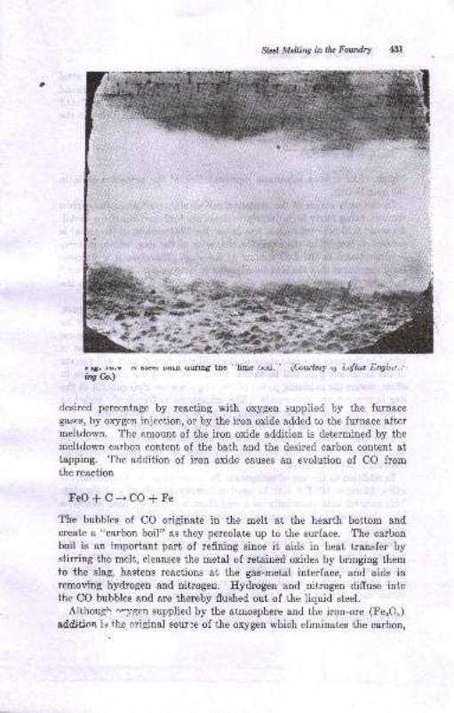
Slrial Mdling in llw FourdtY
r..rt. ru.r ^
a@r B
*12 Prtuipl., ol Mdot ediis
the resctioa actually ir l8ryely betweeu oxygen diesolved in tbe stc€tatrd the carbon. At iie t€Eper8tures used in aieel refiuiug (around2900 F), the otegl ie capable of dissolving colsidersble o:rygen ae FeO.fThis FeO is picked up from the slag or lrom a reactioD between theadded irou ore and the steel, auch as
FqOr+Fe=3FeO
Figue 16.12 giver a schematic representation of the oridatiou cycle inthe open hearth.
In the early etogea oI the oxidatiou period after meltdowa, the carboncontent, beiag fairly bigh, largely controls the FeO coDt€Dt of the metal.At about 0.10 per cent carbou and below, the FeO coDtent of the metal iscontrolled largely by the oxididng eharacter of the slag, which, in turu,is proportional to the FeO cotrtetrt of the slag. Therelore it ia particu-lstly importaDt thst the rlag be adjiratcd in compoeition, or ,,shaped up,,,to create the proper couditione when l,he carbon has'been rcduced to thedesired percentage.
Control of the oxidiling character of the slag can be ochieved, in part,by the uae oI manganeee. During tie carbon boil there is virtually nochange h the ualganeee conteut of the metal because the maDgatrese
dissolved in the metsl is protected by the carbon. If mangauese isadded to the heat, at 8 late Btsge oI the oxidiziug period, psrt will remainin the metal and psrt fill be oxidized aad dissolve in the Bl8g. Thi8, inefect, lowers the oxidizing power of ttre slag eince the FeO content of theslag is lowered proportionately. The manganeee is lrequently added aerpicgel, a pig iron containing about 15 to 30 p€r cent m&ngaDeae.
Phoephorus .emoval is favored by having an oxidizing condition anda baeic elag. Ifelce, if the manganese coutent of the steel is too high8nd thereby reduces the oxidiring character of the slag, phospborusremovsl is not 80 effective.
In addition to the use of manganeee for controlling the slag character-itlics, fluorspar (CaFr) may be used to increase the fluidity of the stag.1'his mineral acts essentially as a slag ihinner. Further lime sddiiiousnray also be used nesr the end of the refiniug period if the operator findsii necessary.
Since control of the slag is necessary il order to control the oxygeucoutetrt of the melt and ihe degree of dephosphorization, attempts havebeen made to develop t€sts thsi will reflect the conditiou of the stag.Such tests itclude chemical analysis, viscosity tests, slag-color t€sts, andvisual iuspeciion of slag samples. The purpose of these t€sts is to make
I Thir dieolvcd FeO is firquetrtly r6ptr.eDt d in chemicsl rcectioDs by t,he rymbol e.
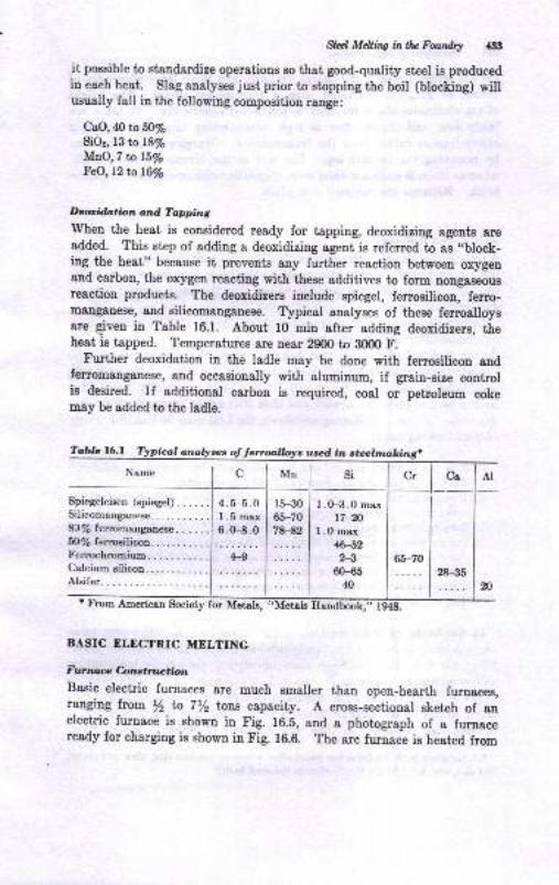
,gllll MdlinC rnllu Furrdtt *33
it possible to standardise operations so that good-quality steel is producedin each heat. Slag analyses just prior to stopping the boil (blocking) willusually fall in the following compositiou range:
CaO,40 bfifloSiO2, 13 to t8y's
M\O,7 tolSVoFeO, 12 tn t6Vo
Deorifution and Tapping
When the heat is considered ready for tapping, deoxidizing agents ereadded. This step of adding a deoxidizing agent is referred to as,,block-ing the heat" because it prevents any further reaction between oxygeoand carbon, the oxygen rcacting with these additives to form Dongaceousreaction products. The deoxidizers include spiegel, ferrosilicon, ferro-m&ng&neoe, and silicomanganese. Typical analyses of these ferroalloysare Eiven in Table 16.1. About 10 min after adding deoxidizers, theheat is tapped. Temperatures are near 2900 to 8000 F.
Further deoxidation in the ladle may be done with ferrosilicon andfe*omanganese, and occasionally with alumin.tm, if grain-size controlis deeired. If additional carbon is required, coal or petroleum cokemay be added to the ladle.
Tablc 16.l anolyses
I .0-3 .0 max17-20
I .0 max46-522-3
6H540
Society for
BASIC ELECTRIC MELTING
Futmare C.onglfrtrctbn
Basic electric furnaces are much smaller than open-hearth furnaces,ranging from, /2 ta 712 torc capacity. A cross-sectional sketch of anelectric furnace is shown in Fig. 16.5, and a photograph of a furnaceready for charging is shown in Fig. 16.6. The arc furnace ie heat€d from
4.5-5.0I .5 max6.0-8.0
Spiegeleisen (spiegel). ....Silicomanganese...... ....8llle ferromanganeae. . ...5olq ferrosilicon... ... . . . .
l'errochromiumCalcium silicon.Alsifer
used in
Mul si
l5-3065-7078-82
131 Ptittipht of Mdal Car/iag
the arc struok betwe€ri the chsrge, or bath, 8Dd three large electrodes ofcarhn or grsphite opersting lrom a three-pbase circuit. The heightof the electrodee above the bath ie controlled electrically. Yoltagea are'fairly low, aud current flow ia high, neceseitatiug large bu tlan andhealy lead-in cables from the transforrnera. Chargiug is usually doue
by removiug the lurtrace top. The roof of the lurnace is sitica brick,whereas the side walle are lined with magnesite brick or chrome-magneEit€
brick. Bottome are rammed ioto place.
Mcltins ord BrifinL.,
Although the general principles controlling the refining operation in thebasic open-hearth lurnace also 8pply to the basic electric, certain modi-ficatione io operation are possible which give the basic electric furnacegreet€r flexibility.
Unlike the open-hearth charge, ihe charge for the electric furnace mayrot necessarily include pig iron, because uot so much carbotr i8 lostduriog meltiug as in the open-hearth. Since the atmosphere in thefurnace is noi appreciably oxidizing, most of the conirol oI the oxidizingcotrdiiions cornes from the sharge itself. Lime is usually not addeduntil a pool of metal is formed, and then it is added in small incrementsIrom time to time. Following meltdown, the heat mey be handled in anyoI the following ways:
l. Iron ore is added and re6niug is accomplished by "complete oxidation,"much il tfie same manner described for the open-hearth.
2. Iron ore is omitted, or very little used, and the carbon drop during refningis less than in the preceding case.
3. Meltirg without oxidation. This method, which is applicable to high-sIoyand st&inless steels, m&y be employed if the scrap is high in manganese andchromium. The scmp is selected to be as lree oI rust and scale ss possible.
Conditions are not oxidizing during refning, but rather arc srfficiently re-ducing to return the small amouDt of manganese, chtomium, and phosphorusthet was oxidized duling meltiDg Iroxo the slag back to ttre melt.
In the heats made by methods 1 and 2, the slag is sufrciently basic8nd oidiziDg to remove the phosphorus to about 0.02 per cent or lower.When the bath and slag have been sdjusied to the proper temperetureend composition, the slag is removed, or ,,slagged off.,, This practioeis not followed in the basic open-hearth since the mechanical manipu-lation would be too difficult to carry out. Once this slag is removed, arefin'ing slag composed of lime and fluorspar is added., The purpose
' A vsriation fu to dooxidiu€ the metal s,ft€r removiDa the 6lst sLBa, then add slsked:ime as a sLsg sDd sdd Cs-MD-si rlloy to tbe st€€l bs,th.!
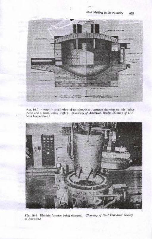
:,g. l0.:i / roac- r, r. I vic; of alr electric ar! ,urnace sho',ving an lcid linin{ri.i't) and a oasic rrnirrg irigb ). (Courksy o! American Britlge Ditisiot oJ Li.S.*..l Corporulion.\
(i!rl
f ig. 16.6 Electric furnace beiug charg€d. (Cowttsy o! Steel Fourders' Sociely
of Arnerica.)
&d, Mdtfitg in0u Fowdry 43s
*or*"it ,
I
I
tr
E6 Priruiples o! Metnl Casling
of this so-called refining slag is to remove sulfur, which can be accom-plished only by establishing basic and reducing conditions. The neces-
sary reducing agent in this case is carbon added to the top of the slag.The reaction is considered to be
C (in steel) * CaO * FeS (in steel) -+ CaS (in slag) * CO j Fe
Refining proceeds for about 1 to l/2 hr, the completion of which isindicated by the appearance of a slag sample. The metal is usuallytapped into bottom-pour ladles. Since the composition was adjustedbefore and during the reflning period, no further additions are requiredat tapping.
If the phosphorus content is sufficiently low, the first, or oxidizing, slagcan be eliminated, and a reducing slag established immediately at melt-down. The remainder of the process is similar to the refining proceduredescribed in the preceding paragraphs.
In some cases, such as in the production of stainless steel, low carboncontrents are required. Then carbon must be avoided in the refiningslag, and aluminum is substituted.
One advantage of the two-slag process used in the basic electric furnacethat cannot be realized in other melting practices for steel is the possi-bility of making alloy additions during the time the refining or reducingslag is on the bath. This is particularly important when additionsof the readily oxidizable elements manganese and chromium are to bemade. Alloys such as nickel and molybdenum can be charged with thescrap since they do not oxidize during meltdown.
As in the open-hearth practice, deoxidizers may be added b to 15 minbefore tapping. These deoxidizers may be ferrosilicon, ferromanganese,silicomanganese, ferrotitanium, and, in some instances, aluminum.
ACID OPEN.HEARTH IUELTING
Furnace Colrctruction
outside of the different refractories used, the acid open-heach furnaceis similar to the basic open-hearth. The refining process is also thesame, in that it is an oxidation process. However, sulfur and phos-phorus ca.rnot be removed and a given content of iron oxide in theslag is not so active as the same percentage in a basic slag. This isattributed to a combination of the FeO with the SiO, of the slag. Thisfeature is probably the principal reason why the production of higt -quality steel can be consistently carried out with a minimum of controls.
The bottom of the acid open-hearth furnace is built up in much the
Stzrl Mdting ia tlu Foundry $n
Bame ruanner as in the basic open-hearth, except that,sand, instead ofcalcined magnesite, is laid over the base brick. The sand is fused inplace at a temperature of about 2900 F. some foundries mix someslag, fire clay, or ferrosilicon with the sand to obtain a better bond.Monolithic construstion is used in some cases. The life of the furnaceis dependent, among other things, on the grade of steel being produeed.Low-carbon steels, because of the higher temperatures required for theirmelting and refining, cause rapid deterioration of the furnace bottome.
Funtace Change
As in the basic open-hearth, fuels are either gas or oil. The charge tothe acid open-hearth will consist of pig iron, foundry scrap, and"pur_chased scrap, with the average charge .oot"ioiog approximateiy L5 la Nper cent pig iron. The percentage of pig iron is determined by the needfor having sufficient carbon in the heat at meltdown to ensure u .,.igoror.boil when iron ore is added. rt is usualry pranned to have tht tohrcarbon content about 0.5 to 0.2 per cent above the finishing carbon value.The scrap must have a- low sulfur and phosphorus contint, preferablybelow 0;(x per cent each, since these elemenis cannot be eliminated inthe acid process.
The silicon content of the charge will be between 0.6 and 1.0 per cent.This is higher than used in the basic opeu-hearth charge. Mauganesemay vary between the wide limits of about 0.4 ta l.Zi per cent] withthe average addition being between 0.75 and 1.0 per cent.
Nelting alnd Rgndrng
The cerbon, silicon, and manganese are partly oxidized during meltdown.The carbon content at meltdown will be about 0.20 to 0.3 per cent abovethe finishing carbon. silicon will not be over 0.2 per cent. If the silieonwere much above this. figure, a vigorous boil would not be securedimmediately upon oxidation with ore or the oxygen lance.. rf too low,the_carbon drop during the boil would be faster and a higher meltdowncarbon thereby indicated. Factors which determine the silicon andmanganese content at meltdown include:
l. Amount charged
2. I[orking speed of the fumace (oxidation during meltdown)3. Compactness of the charge4. Content of the other element present, i.e., sitisgl or manganese, as the case
may be
- The manganese content of the charge will coutror the working of theheat to a certain extent. Thus a high manganese content in thJ charge
t See o. 443.
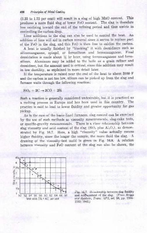
438 Prillr,ipla of Mdnl Cutins
(1.25 to 1.75 per cent) will result in a slag of high MuO content. This
produces a more fluid slag of lower FeO content. The slag is therefore
less oxidizing toward the end of the refining period and thus assisLe in
controlling the carbon drop.
Lime additions to the slag can also be used to control the heat. An
addition of lime will aid in carbon removal since it serves to replace part
of the FeO in the slag, and this FeO is then free to oxidize the carbon.
A heat is usually finished by "blocking" it with deoxidizers such as
silicomanganese, spiegel, or ferrosilicon and feromanganese. Final
deoxidation is made about /2 hr later, using ferromauganese and ferro-
silicon. Aluminum may be added to the ladle as a grain refiner and
deoxidizer, but the amount used is critical, since this addition may result
in low ductility, as explained in more detail later.
If the temperature is raised near the end of the heat to about 31m F
and the carbon is not too low, silicon can be picked up from the slag and
furrrace walls through the following reaction:
SiO, + 2C -+ 2CO * 2Si
Sueh a reaetion is generally considered undesirable, but it is practiced as
a melting process in Europe and has been used in this country. The
practice is said to lead to lower fluidity and greater opportunity for gas
pickup.
As iu the case of the basiclined furnaces, slag control can be exercised
by the use of such methods as viscosity measurements, slag-cake tests,
or specific-gravity measurements- There is a close relationship beiv;een
slag viscosity and acid cortent o{ the slag (SiO, plus Al,Or), as demon-
strated by Fig. 16.7. Here, a high "visgosity" value actually means
higher fluidity, since the longer the sample, the more fluid the slag. A
drawing of the viscosity-test mold is given in Fig. 16.8. A relation
between wiscosity and FeO content of the slag can also be shown, the
50 52 s4 56 58 60 62 64 56 68
Totol ocids ISi + At] , per cent
;rig. ^{.7 itc.auionship between slag fluidityand aciilcontent. of the slag. (From Briggs
axil B.alduir.,?rans. 4FS, ool. 50, pp. ll04-ttSz' 1942.)
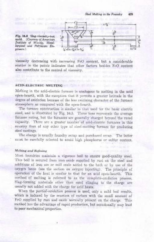
Sbd Mcting in Uv Foundry
/Fir. 16.8 Slag-1,isc*ity-t st,mold. (Coutes! oJ l\nwianI^slitur. ol Minidt, Mdd-ll,.rf,ical and Pcl$bun Ergit@t'.\
viscosity decreasing with increasing I'eO conient, but a considerablescatte! in the points indicates that other factors besides FeO conientalso contfibute to the control oI viscosity.
ACITI.ELECTRIC MELTINC
Melting in tbe acid-electric furnace is analogous to melting in the acidolen-hearth, with the exception that it permits a greater latitude in ihedegree of oxidation because of the less oxidizing character of the luroacestmosphere as comp&red with the open-hearth.
The furnace coostruction is similar to that used lor the basic electricsteel, and is illustrated by Fig. 16.5. Three tons represents the averagefuraace ratring, but the furnaces are generally charged beyond the rstedcapacity. There arc s greater number of acid-electric furnaces in thiscountry than of any otLer type of stecl-melting furnace for producingsteel csstings.
'lhe charge is usually fouldry scrap and purchased scrap. The lattermt:si be carefully selectcd to avoid high phosphorus or suifur cootent.
MeLine ond Refnitus
XIost foundries maintain a vigorous boil to ensure good-qu&lity steel.'fhis boil is secured from iron oxide supplied by rusi on the steel andadditions oI iron ore or mill scale added to the bath or by use ol theoxygen lance (see the section on oxygen injecting). The principle ofoperation of the heat is similar to that ,or an acid open-hearth. Thismethod of melting is relerred to as Lhe complete-oxidorioz process.
Slag-forming materials other than sand clinging to the charge areusually not added with the charge for acid heats.
When the partial-oxidation process is used, only a mild boil results,which is induced by the reaction of carbon with the small amount ofFeO supplied by rust and oxide normally present on the charge. Thismethod has ihe advantage of rapid production, but oqcasionally may leedto poor mechanical properties.
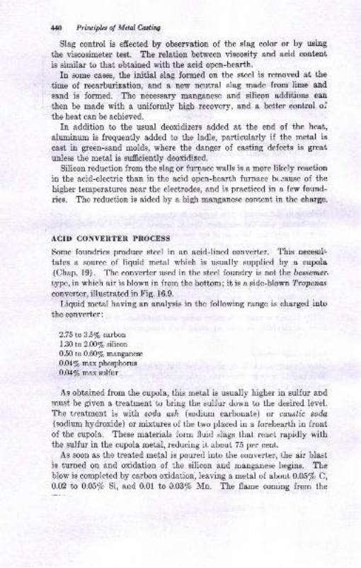
m Priluipla of MdalWW
Slag control is efrect€d by observation of the slag color or by using
the viecosimeter test. The relation between viscosity and acid content
ie similar to that obtained with the acid open-hearth.
In some cases, the initial slag formed oo the steel is removed at the
time of recarburizetion, and a new neutral slag made from lime and
sand is formed. The necessary mangauese and silicon additions can
then be made with a uniformly high recovery, and a better control ofthe heat can be achieved.
In addition to the usual deoxidizers added at the end of the heat,
aluminum is frequently added to the ladle, particularly if the metal is
cast in green-sand molds, where the danger of casting defects is great
unless the metal is sufrciently deoxidized.
Silicon reduction from the slag or furnace walls ie a more likely reaction
in the aeid-electric than in the acid open-hearth furnace bccause of the
higher temperatures near the electrodes, and is practiced in a few found-
ries. The reduction is aided by a high mang&nese content in the charge.
ACID CONYERTER PROCESS
Some foundries produce steel in an acidJined converter. This necessi:
tates a source of liquid metal which is usually supplied by a cupola(Chap. 19). The converter used iu the steel foundry is not the bessemer,
type, in which air is blown in from the bottom; it is a eide-blowt Trapenas
converter, illustrated in Fig. 16.9.
Liquid metal having an analysis in the following rauge is charged into
the converter:
2.75to3.5ofr c*rbot1.30 to 2.fi)/o silicon
0.50 to 0.60/e mang&nese
0.04/s max phosphorus
0.(X/6 max sulfur
As obtained from the cupola, this metal is usually higher in zulfur aod
must be given a treatment to bring the sulfur down to the desired level.
The treatmeat is with soda o*h (sodium carbonate) or coustic soda(sodium hydroxide) or mixtures of the two placed in a forehearth in frontof the cupola. These materials form fluid slags that react rapidly withthe sulfur in the cupola metal, reducing it about 75 per cent.
As soon as the treated metal is poured into the converterr.the air blastis turned on and oxidation of the silicon and manganese begins. Theblow is completed by carbon oxidation, leaving B metal of about 0.05% C,0.02 to 0.05% Si, aud 0.01 to 0.03/o Mn. The flame coming from the
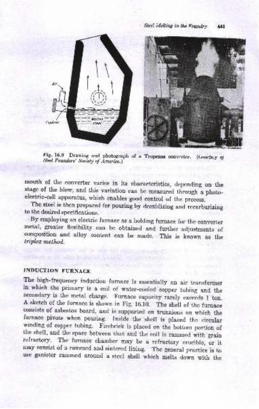
Slee! Mdling in tlu Foundry
lit--ry.e _Drawing.and photograph of a Tropeoao cotrvcri€r. (Uvb:,y ojStccl Foundcrs' futay of Arn*ia.)'
mouth of the eonverber varies in its characteristics, depending on thestage of the blow, and this variatjon can !e measured tlirough a photo_electric-cell apparatus, which enabres good control of the pro'cess.
. {he $e9l is then prepared for pouring by deoxidizing and recarburizing
to the desired specifications.By employing an electric furnace as a hording furnace for the converter
metal, greater flexibility can be obtained "od
fu"th". adjustments ofcom-position and alloy content can be made. This is known as thetripler method..
INDUCTION FURNACE
fle -tlqn-requency induction furnace is essentiaily an air transformerin which the primary is a coil of water-cooled copper tubing and theseeondary is the metal charge. Furnace capacity .arely excelas t ton.A sketch of the furnaee is shown in Fig. l6.rb. The sheil of the furnaceconsists of asbestos board, and is supported on trunnions on which thefurnace pivots when pouring. Inside the shel is placed the circurarwinding of copper tubing. Firebrick is placed on the bottom portion ofthe shell, and the space between that and the eoil is rammed with grainrefractory. The furnace chamber may be a refractory c.ucirte,
-oi it
may consist of a rammed and sintered lining. The general practice is touse ganister rammed around a steer shel which melts down with the
trf
Priuipbs o! Melal Casling
fig.16.10 Cross-sectional drawing of an in-duction furnac€. B, metal bath; C, water-cooled copper coil; D, pouring spout; f, fire-brick base; G, refractory packing; S, asbestos
lumber; 7, trunnions. (Cowtesy ol American&cidy !o, Melals.)
first heat, Ieaving a sintered lining. Basic linings are oft€n preferred,
and in this case either the lining may be rammed, using magnesia grain,
or a clay-bonded magnesia crucible may be used.
The process consists in charging the furnace with steel scrap and thenpassing a high-frequency current through the primary coil, thus inducinga much heavier secondary current in the charge, which results in heating
the metal charge by resistance. As soon as a pool of metal is fonned,
very pronounced stirring action in the molten metal takes place, whichhelps to accelerate melting. In this process, melting is quite rapid, so
much so that there is only a slight loss of the easily oxidized elements.
If a capacity melt is required, steel scrap is added continually duringthe melting-down period. As soon as melting is complete, the desired
superheat temperature is obtained and the metal is deoxidized and tappedinto ladles.
The time of melting depends upon the size of the furnace, the weightof the charge, and the power input. Since a period of only 10 or possibly
15 min elapses from the time the charge is melted down until the heat istapped, there is not sufficient time for chemical analyses. Thus thecharge is usually carefully selected from scrap and alloys of knowncomposition so as to produce the desired analyses in the finished steel.
A very close control of elements can be obtained in this manner.
In most cases, no attempt is made to melt under a slag cover, since thestirring action of the bath makes it difficult to maintain a slag blanketon the metal. However, a slag cover is not necessary since oxidation is
slight.The induction furnace is proving valuable to the steel foundry, llar-
ticularly in the production of small lots of alloy castings, where thenumber of alloy types desired may be large. The fact that high-alloy-
fuI M:lling in 0u Fowdry &g
conteDt metsl can be remelted in these furnaces without loss of the alloycootent through oxidation makes it a particularly valuable meltingfuruace.
VACUUM MELTING AND DEGASSING
Because of its compact size, the induction furnace is ideal to use formelting under a vacuum. This is a costly process because of the needfor high-capacity vacuum equipment, but the cost may be justified interms of improved properties or in the production of alloy steels.z
By melting in a vacuum, the normal deoxidation reaetion betweencarbon and oxygen to form co gas can be much more effective than inconventiorral melting, to the extent that carbon becomes a betterdeoxidizer than those elements that are normally used for this purpose.This reaction is favored by high temperatures. The result is a steelthat is virtually free oi oxide-containing nonmetallic inclusions. Harm-ful hydrogen and nitrogen gases should also be removed more effectively.Precautiou must be taken that steel is poured carefury soon after meltingto avoid gas pickup or reoxidation. pouring in a vacuum eliminatesthis possibility. one disadvantage that might occur with vacuum melt-ing is the loss by evaporation of those elements which have a relativelyhigh vapor pressure.
Another use of vacuum is vacuum degassing. This is done aftercouventional melting by pouring the metal into a specially designedladle or by enclosing the furnace in a chamber that can be-evacuatedrapidly to a low pressure. The metal might also be poured in a vacuum.
vacuum degassing and pouring reduces the residual gas content ofsteel without markedl;r altering the composition. Improved toughness,better fatigue resistance, and better ductility are claimed for steelsproducod in this manner. High-quality, superstrength alloy steels arethe most likely productss made by this ptocess.
OXYGEN INJECTION IN OPEN-HEARTHAND ELECI'RIC FURNACES
The advent of relatively cheap oxygen suppries in 1g46 resulted inconsiderable investigation of the use of oxygen as an additional controlin steel production. Although oxygen can and has been used to enrichthe fuel mixture by injecting it into the open-hearth furnace below theburaers, the principal use for oxygen has been in controlling the refiningproce88.
&7t Priluipht ol Mdal ()a.sl!1a
O.'ygen is injcct:,r! int:, the metal bath through a steel pipe or a copper-tippetl, water-cooled iance. The oxygen reacts vigorously with carbon,particularly wh,n the latter is high, and increases the rate of carbon lossto Jnzeor three times as high as normal rates with ore. Since this reaction'creates
heat, ore may be added simultaneously to keep the temperaturefrom hecoming excessively high, the oxidation of carbon with ore beingeu endothermic reaction. Use of oxygen injection saves time in workingthe heat, and this can be extremely helpful when furnaee eapacity islimited.
I:l,r addition to its use to increase production, oxygen injection is alsohelpful in curing temporary difficulties such as low temperatures orincomplete lime solution of the lime in the slag. In stainless-steelproduction, carbon can be reduced without oxidizing much chromiumby injecting the oxygen under a neutral slag at high temperature.
Besides giving increased production rates, oxygen injection gives bettereontrol, lower carbon contents without chilling the bath, and fuel savings.Disadvantages are increased fume, smoke, and splashing, the lattercausing decreased refractory life because of the erosive effect of splashed
slag and metal.
Briggsro has reproduced data from the British Steel Casting Research
Association shtrwing the amount of oxygen to inject as a function ofinitial carbon, final carbon, and injection temperature. These are pro-vided in Table 16.2.
BASrC OXYGEN (LD) PROCESS
Steel is being produced in Europe and in the United States by usinga converter similar to the one illustrated in Fig. 16.9, but using an oxygenlanue insert€d through the top of the converter rather than blowing airin through the tuyeres in the support trunnions. The lining is basic.Advantages of this procesi are an outstanding degree of dephosphoriza-tion; partial removal of sulfur; low residual contents of oxygen, hydro-gen, and nitrogen; low capital outlay; flexibility; and low upkeep duringsl utdown.ll
PHYSICAL CHEMISTRY OF STEELMAKING
The preceding descriptions of the various steelmaking processes indicatethat, generally, steelmaking can be conveniently divided into three stages,
a.though there is no clear-cut demarcation between the first two stages.
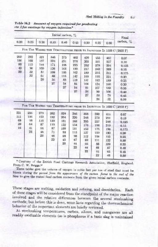
Stecl Melliw l"tt" Fm;Te.blc 76.2 Arnount of oxygen required Jor producingste ,l for costings b7r orygen injection,
Initial carbon, /e
0.20 0.25
Finalcsrbou, %
Fon Usr Wuonn rnr Truppnerunn pnron To Iw.mctrox Is lE50 C eg?2P)
260
136
83
43
n
,o,168
115
30
52
32
321
197
IMr09
81
6l29
348
t24t7t136
r08
88
56
27
375
251
r98r63135
u583
54
27
q2278n5r90162
142
rr08lu27
a9305
252
217
189
169
t37
108
8lil27
455
331
278
243
2t5r95r63r34
r07
80
53
26
48r357
m4269
24roor
189
r60r33
106
79
52
0.07
0.r00.r250.15
0.175
0.20
o.25
0.30
0.35
0.40
0.45
0.50
231
lll68
39
r6
256
r36
93
64
41
25
279
r59
r16
87
64
48
23
N2t82r39110
87
7r46
23
324
204l6l132
r0993
68
45
23
u6226
l&t154
131
lr590
o/44qq
368
248
205
176
153
737
tt289
66
Mt2
390
270
n7r98175
r59r34
llr88
66
44
4tL29t2482t9196
180
155
132
r09
87
65
43
0.07
0.10
0.r250.r50.u50.20
0.25
0.30
0.35
0.40
0.45
0.50
Fon Use Tlnpnn rso Tpuppneruno pRron To Iw.rncnrow Is 16fl)C (2gl0F)
'courtesy of the British steel castings Research Association, sheffield, England.From C. W. Briggs.ro
-. Thege tables give the volume of oxygen in cubic feet per ton of stcel that must bo
blown during thc periait Jrom lhz "jp*r"u o! thn ca.rbon flame to tt" *i ii ttnblow to give the stated Gnql calbo,, aoot"otu from the given initiar carbon contents.
These stages are melting, oxidation and refining, and deoxidation. Eachof these stages will be considered from the standfoint of the major reactioninvolved and the relative differences between the several .t""t rr"t iogmethods; but before this is done, some facts regarding the thermocheJcarbehavior of the important elements are brieflyieviewed.
A-t_ steelmaking temperatures, carbon, silicon, and manganese are allreadily oxidizable elements (so is phosphorus if a basic dagls rnaintained
ffi Prirciplcs oJ Mdal Culiw
to dissolve the PrOs which is formed). The relative amount of each of
these elements, as well a.s of iron, which is oxidized, is dependent upon
(1) its basic or fundamental oxidation tendencies; (2) the temperature,
since the oxidation tendency varies with temperature; and (3) the relative
amounts of these elements that are present, or concentration'
Strndord Free Energy
The basic or fundamental oxidation tendency is given by the stanilard
lree encrgy of farmati,on o! the oxide. The greater the negative value of
it i" tir."-oaynamic function, the greater the tendency of the element
to oxidize. Thus, at 1600 c, this value is about -126 kcal (kilogram-
calories) for Si * Oz 3 SiOz and about - 117 kcal for 2Mn + O, =
2MnO,
which means that one gram-atomic weight of silicon is more readily oxidized
by a given quantity of oxygen than are two gram-molecular weights of
ro&ng&nese.
The standard free enerry change refers to the reactants in some specific,
1'rreviously selected standard state, reacting to form products also in some
specific, previously selected standard state. Thus, for the preceding
reactions, the standard states which were arbitrarily selected were:
Si as a liquid
Oc &s a gas at 1 atm Pr€ssure
SiOz as a solid
Mn as a liquidMnO as a solid
Had some other standard state been selected, for example, oxygen at
some pressure other than 1 atm, or MnO as a liquid rather than a solid, the
standard free energy values would be different. Therefore, implied for
each of the equations is the following additional information:
Si (a.s a liquid) $ O, (as a ges, 1 atm) -r SiOz (as a solid)
AG" : -L26 kcal/mole
2MnO (as a liquid) * O, (as a gas, 1 atm) -> 2MnO (as a solid)
AGP : -117 kcal/mole
where the AGP notation signifies a standard, free energy change.
In reactions involving subst&nces of variable composition or pressure,
such as in the case of liquid or solid solutions or mixed ga,ses of variable
pressure, the standard free energy change can be related to the equ'ilibrium
culstant K for the reaction
A€: -RTlnK
Stal Melliw intlu Fourdry
where AGo : standard free enerry change
R : gas constant in callmole/deg: 1.987 callmole/deg
? : degrees Kelvinln K : natural logarithm of K
: 2.3 logarithn of K to the base 10
: 2.2log KThus, for the silicon reection at 1600oC,
-126,000: -1.987 X 1873 X2.3logK
or
_ 126.0fi)loeK:-:- :14.72' 4.5757
Now the equilibrium constant must be expressed in terms that define thethumod,ynamical erpilibriurn of the reaction. These terms are referred toss actitlitlies. Activity is a dimensionless quantity that is used to express
cheruical potent:ial, or driving force, for a given substance involved in areaction, or physical change, relative to some standard condition. Thus,if the standard state for a gas were 1 atm, an actual pressure of 2 atm wouldme&n an actiuity of 2 for this gas. The activities of the products of areaction are multiplied in the numerator of the constant, whereas theactivities of the reactants are multiplied in the denominator. This isdemonstrated as follows for the silicon reaction:
Kei :ogio,
osi X oOD
and for the manganese reaction:
Kxo :(ouoo)'
(ou")' X aoz
Note that the power of each term is determined by the number of molesin the reaction.
If pure solid or liquid substances are involved in a reaction, their refer-ence states are identical with their actual states. Consequently, theiractivity values are unity. Then the preceding equations simplify to
tKsi: -:--LXao2
Ilax,r : :-
LXaoz
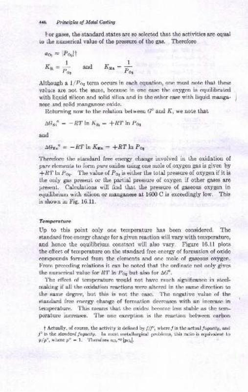
W Prirciplas oI Mdnl Casti.ttg
t or gases, the standard stetes a,re so selected that the ectivities ere equsl
to the numerical value of the preasure of the gas. Therefore
o6, : lPerlt
r., : ;L andto2 """: *
Although a L/Poz term occurs in each equation, one must note that these
valucs are not the same, because in one case the oxygen is equilibrated
with liquid silicon and solid silica and in the other case with liquid manga-
nese and solid manganese oxide.
Returning now to the relation between GP and K, we note that
AGst" : -8" ln Kg1 : fR? ln Po2
and
Therefore the standard free enerry change involved in the oxidation ofpure elements to form 'pure oxjdes using one mole of oxygen gas is given by
*RT h Poz. The value of Pe, is either the total pressure of oxygen if it isthe only gas present or the partial pressure of oxygen if other gases ere
present. Calculations will find that the pressure of gaseous oxygen inequilibrium with silicon or manganese at 16fl) C is excexdingly low. This
is shown in Fig. 16.11.
Temprature
Up to this point only one temperature has been considered. Thestandard free enerry change for a given reaction will vary with temperature,
and hence the equilibrium const&nt will also vary. Figure 16.11 plots
the effect of temperature on the standard free energy of formation of oxide
compounds formed from the elements and one mole of gaseous oxygen.
From preceding relations it, can be noted that the ordinate not only gives
the numerical value for RT ln P62 but also for AGP.
The effect of temperature would not have much significance in steel-
making if all the oxidation reections were altered in the same direction tothe same degree, but this is not the case. The negative value of thestandard free energy change of fornration decreases with an increase intenrperature. This means that the oxides become less stable as the tem-perature increases. The one exception is the reaction between carbon
t Actually, of course, the activity is defned by J/f, where t is the actual/zgroaly, and
/'is the slnnlnrd fuguity. In most metallurgical problems, thie ratio is equivalent topip', wberc p' = l. Therefore oo, - lpq[.
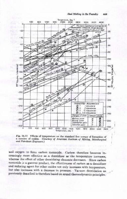
Sled M&its intluFozar&y #)
Temparoturc, drg F
1600 2@o 2400 2800 3200 3600 40@
-t00
;-t20-9o
3-rlor
Itstr -l8O
800 ro@ 1200 1400 1600Temperolurc, deg C
_1.; )
?!;aO z/ 't
Fig. l6.fl Effects of llmperature on the standard free energy of formation ofa number of oxides. (?*t"y o! Am*ican lwtilrh ol Miiing, U"t"iiii,^tard P etrohun E ng haert.)
and oxygen ',o form ca,rbon monoxide. carbon therefore becomes in-creasingly more effective as I deoxidizer es the temperature increases,whereas the effect of other deoxidizing erements decreases. since carbonmonoxide is a gaseous product, the effectiveness of carbon as a deoxidizerand reducing agent for other oxides not only increases with temperature,but also increases with a deerease in pressure. vacuum deoxidation aspreviously described is therefore based on sound thermodynamic principles.
l
I
lie is l,tpothalbol ond dp,liu I
1a ffiWutds AchplfuW-)a caloiniDq Feotie ot l,xer
su66ESr€0 AccuRAC.ES! / tilocolorie! 3 lilocolories! lO *itocolorics! >lO tilocotorics
450 Principhs of MQnl Casting
E-ffect of Conaentration
According to the third factor listed, the relative concentration of each
element must &lso be considered. This effect can be demonstrated only
for oxygen if the data in Fig. 16.11 are used. Thus, lf oxygen exceeds the
cquilibrium partial pressure given by Fig. 16.11, the metal will be oxidized.
if the oxygen partial pressure is reduced below that of the equilibrium
pressure, the oxide is reduced. Quantitatively, this effect is represented by
Ac : A6P * RT tnQ
where AC : attudl free energy change
A€ : standard free energy change
Q : quotient similar to that used to express K, but in which
the actual activity values are used
For the oxidation of silicon, it was previously established that A€ at
1600C is -126 kcal/mole. From Fig. 16.11 it can be determined that
t\e equilibrium partial pressure of oxygen in contact with silicon and silica
is about 10-r{ ?2 &tm. This value was also calculated ot page 447. Then
AG : -126,000 + Rf ktj_pr,
: -126,000 - 4.575T log Pq,
: -126,000 - 4.575T log 1Q-r
: -126,0fi) + 15 X 4.575 X T : 0
This show,i that the actual free ener&y change at equilibrium is zero' Now
if the partial pressure of the oxygen in contact with silicon and silica
were 10-ro,
\ AG: -126,0fi) + 4.575(1873) bc *
: -126,000 - 4.575(1873) log P6,
: -126,0fi) - 4.575(1873) log tO-ro
: -126,0fi) + 45.75(1873) : -40,310 callmole
A negative free enerry change indicates a spontaneous reaction and demon-
str&tes that a pressure of 10-10 atm will cause oxidation of silicon. Note
that the AG value is less negative than the Ad value. This merely means
that, for the specific condition selected, namely, 10-10 atm, the reaction
u'ould not be as spontaneous a"s it would be under standard conditions of
I atm of oxygen.
The preceding exemple illustrates the influence of concentration (partial
pressure) in the case of oxygen, In steelmaking reactions, the reactiols
actually occur between elements dissolved in steel and oxygen dissolved
gd Mdling inlar' FowdrT l15f
in steel to form a product thst will dissolve in a slag. Such a reaction
could be represented for silicon as follows:
Si (in liquid iron) * 20 (in liquid iron) ---+ SiOz (in liquid slag)
Here it can be noted that the concentration of any one or all of the three
components of the reaction can be varied rather than the partial pressune
of oxygen only. The question naturally arises as to how this situation can
be treated thermodynamically. This is done by selecting new standa,rd
states that more nearly represent the actual situation and then calculatingor determining new stendard free energy values representative of these new
standard states. The procedure required is to calculate or determine the
free enerry change involved in going from the original standard state to thenew one. It will be demonstrated for the oxidation of silicon, vhere thenew standard states for silicon and oxygen dissolved in iron are a concenitration of 1 per cdnt by weight and that for SiOr dissolved in slag is a molefraction of 1, or trfsi : 1:
(o) Si(a) - Si (in liquid iron, 1/6 by wt) AG;
(D) Oz (1 atrn) + 20 (in liquid iron, L/sby wt) act
G) SiOdr) + SiOr (in liquid slag, Ng,Or : 1) AGl""
Note thatAG " represents a situation that could not be realized in actualityinasmuch as the solubility limit for oxygen is about 0.22 per cent at 1600 C.However, this does not prevent making sueh calculations. There aremethods available for calculating each of the foregoing standard freeenergy changes which depend upon having some knowledge of the thermo-dynamic behavior of each of these solution systenu. The standard freeenergy changes for the SiOz would probably be small, relatively, because
the change of state in going from pure solid silica to liquid silica does notentail much of a change in free energy.* Using Hess,s law, the conversionfrorn the originsl oxidatioo equation to the one involving the true steel-makiug reaction is now rnade as follows:
S(s) * Oz (l atm) - SiOe(s) AGso
(c) - tSi(s) + Si (in liquid iron, l7o by wt) AG"t :Si (in liquid iron, l/6 by wt) f Oz (l atm) - Sior(s) AG$" - ACo
(D) - [O, (1 atm) + 20 (in liquid iron, 1/6 by wt) A6[] :Si (in liquid ton, l/s by wt) { 2O (in Iiquid iroa, l/6 by wt) + SiOz(g)
AGsr-AG"-AGL
k) * tSiOr(s) + SiOr (in liquid slag, Ngro, : l) LG,l :@ Si (in liquid ircn, L/6 by wt) * 2O (in liquid irct, L/s by wt) --+
SiO, (in liquid qlng, Nso, : 1)AGao : AG<.o - AG" - A6+ AG.
'Both the euthalpy and entropy of solution ahould be oEAI.
452 Principlzs o! Mdd Casting
This rrew AGa" value can now be used to establish the effect ,rf concen-
tratiou through the relation
AG" : -RT ln K : -R? In ottt
osi X (oo)2
or r.he relation
aG : aGo + BIln Q
In both K and Q, the activity values can be represented as given below,
provided that the actual compositions do not deviate too far from theselected standard states. When such deviations do occur, their effeet can
be adjusted for if there is some prior knowledge of the system. Assumingthat the deviations are moderate, t,he respective activity values are nownurnerically determined as follows:
@st : l% sil
ao : lVo Ol
asio, : lilsio,l
The advantage of these choices of standard states is obvious from theabove relations.
Standard free energy values for the oxidation of many of the elements
that are in solution in iron during steelmaking have been established andare tabulated in several sources.{'r2'r3
There is &lso some knowledge of the effect of the addition of a third com-ponent in iron on the activity of the second component, e.g., the influenceof manganese, chromium, or nickel on the activity of silicon in iron, butthese data are incomplete.
Our knowledge of slag constitution is also incomplete, although progress
is being nrade in this field. The theories of slag behavior are considered
in the section on oxidation and refining.tYith this brief corsideration of the factors associated with the oxidation
reactions, we can turn to their applications to steel melting.
Melting
During meltdorvn, oxidation of iron, manganese, silicon, and carbon occurs.
Part of the oxygen comes from the atmosphere and part from the solidoxides such as rust or ore that ma-v be charged with the metal. As soon
as a slag forms, oxidation may be bhought of as occurring between the,eralloids dissolved in the metal and the FeO dissolved in the slag, al-
gd Mdrir,s lrntL Fanary 4S3
though the original source of the oxygen in the slag could still be the at-mosphere. Typicel reactions would be
u+ 2q: tsiofi
M" + g: [MnO]
FeO, SiOz, and MnO become a part of the slag. Lr the case of the basicpracticee, the slag volurne is further increased by thc lime additioos thsthave been made with the charge or during the meltdown.
The carbon content at meltdown is governed by the amount added withthe charge and the amount lost during melting. The latter amount isdetermined to some extent by the furnace operatiorr. In the open-hearthfurnace, provision is made to have enough cerbon of meltdown to providefor a carbon boil during the refining period. Sur:h extra carbon may ormay not be pnovided in the electric furnace depending upon the particulerpractice employed. Because of the low temperature during meltdown,
manganese and silicon oxidize more revlily (for a given concentration)than carbon; so carbon is not removed so readily as these two elements.
Therefore appreciable amounts of carbon rermain after melting. Thesilicon content, on the other hand, is usually below 0.05 per cent in basicfurnaces and below 0.20 per cent in acid furnaces at meltdown. Themang&nese losses are not so great as those of silicon, and the amount whichremains at meltdown will range between 0.05 and 0.40 per cent, the lowvalue coming from well-oxidized heats starting with a low manganeee
charge, and the latter from a fairly high manganese content in the originalcharge.
O*ifution and Refifin4.
Carbn
The most important, reaction during the oxidation period is the reactionbetween carbon and oxygen to form CO gas.
c+o=co
This reaction stirs the melt, aids in removing dissolved hydrogen and nitro-gen, and brings other deoxidation products to the slag-metal interface.The reaction actually is initiated on the furnace hearth or on the surfacesof any selid components such as scrap or iron ore that may be added to thebath. Surface inegularities at these interfaces pmvide the necessary
t The designation Si and Mn mean these elementE cre iD, oWion in the metal. Thebrecket indiea&s aolution in the elag.
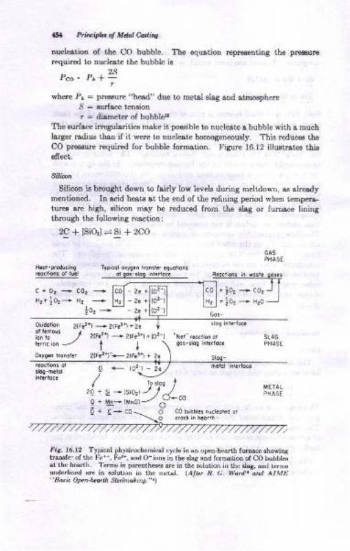
lsa hinifu of Mdol hdia
nucle&tion of the CO bubble. Tbe equ8tion representing the prraaure
required to nucleote the bubble i-e
OQ
Pco= Ptlar
\rhere Pr = preEsure "head" due to metel slag and atmosphereS : surfsae tensioD
r = diemeter of bubbletr
The eurfare irregularities make it poEsible to nucleste a bubble with a muchlarger radius than if it were to nucleete homogeneou.ely. This reduces theCO pressure requi!€d for bubble formation. Figure 16.12 illud,rates thiseffect.
Sil&oa
Silicon ie brought down to fairly low levels during meltdowr, as alreadymetrtioned. In acid heats ot the end of the refioing period wher tempers-tur€s sre high, eilicon may be reduced from the alag or furnace liningthrough the following reaction:
2C+ [SiO,] =Si + 2CO
TyOicol oryq.n r.onsle/ aquolionsor 9o._316E interioc. Rcodionr in lost qor.3
+ |02 ---+ co1
+ to. * tt.o
GAS
PHASE
c+02+c02+x.+ |0,* r. ..*
lo' *'2a+-2a+-2.+
Oridorion 2tF.21 -
2tF.!.t +2. tij"t" / zt?.21
- zrF.t\ +@;-l
lErt?icion ---./ t I \
Orygli l.o.si.. 2(F.21_+ 2{F.!i +
llog-h!rol
I'ETAIPIIASE
fi3. 16.12 Typical phlsicocbemical cycle in an oper-h.artb fumace shorinStl8Dsfe: of the lt*, F€,'*, and O- ions in lhe slaS aod to.metioo of CO bubblesat th€ hearth. Terns in parenthes8 ar€ iD the sol'rtion ir rhe slag, aDd ternBunderliued are in solutior in tbe r etAl. (Ar{"" R. G. Wordtr atd AIME"Bati. ON t orlh SL.l':|.o,hin!.".\
I
2Q+
Q+O+ C0 blbbles nucleolld cl
Sta;l Melltw in llrc FowdtX 155
Tiris action is not unexpected in view of the fact that silicon becomes
less readily oxidized and carbon more so as the temperature rises. There
apparently is no simultaneous increase in the oxygen content of the beth,
since the increased silicon content should prevent oxygen pickup. Silica
. reduction is also aided by having a high manganese content. This effect
may result either from having a higher concentration of MnO rn the slag,
thereby lowering its FeO content' or from on actual reduction of SiOz by
manganese as a result of mass action. At elevated temperaoures there
is little difierence in the standard free enersr of formation of SiOz and
, MnO; hence it is conceivable that a reduction of SiOz by manganese could
fake place if the manganese content were high enough.
Illangarcsc
The manganese distribution between slag and metal depends on:
1. The amount of manganeae in the charge
2. The amount of manganese in the ore that may have been added
3. The slag volume and slag composition
4. The carbon content of the metal
5 The oxidizing characteristics of the slag
$. Temperature
The manganese in the charge and that supplied by the ore determine
the total a,mount of manganese that will be found in either the metal or
slag. The distribution of manganese between slag and metal approaches
very close to chemical equilibrium. Obviously, then, a greater slag volume
wiII throw a larger proportion of manganese into the slag; and the extent
of thii distribution is affected by the slag composition. Both a high and
a low base-acid ratio in the slag tend to decrease the residual manganese
content of the metal. The carbon content is important because it willprotect the manganese in the metal if it is high enough. If the FeO con-
terit oI the slag is high, nranganese is oxidized to MnO, until a new balance
is struck between manganese in the metal and in the slag. I'herefore a
high MnO-FeO ratio in the slag results in a high residual m&nganese con-
tent in the metal. As with most of the other oxidizable elements in steel,
an increase in temperature shifts the equilibrium toward a higher manga-
nese residu&l in the metal. It is therefore possible that, during the refiningperiod when carbon is dropping, the increased temperature occurring
eimultaneously may compensa,te for the lack of protection from the carbon,
and manganese residuals may stay const&nt or even increase slightly.
Good manganese recovery obviously is a worthwhile objective, butsometimes this objective must be subordinated to other objectives thatcan be accomplished only by having a large percentage of the manganese
&ppear in the slag. Because rnsnganese reacts with FeO and can re:adily
. rrpl&ce FeO in a sl4g without altering the properties of the slag, manga.
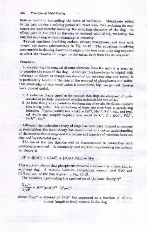
454; Ptiuiph: of Mdal Cuting
nese is useful in controlling the state of oxidation. Manganese addedto the bath during s lsfining period will react with Feo, reducing its con-centration and thereby lowering the oxidizing chsr&cter of the slag. Ineffect, part of the tr'eo in the slag is replaced with MnO, rendering theslag less oxidizing without changing its viscosity.
Typicd reactions involving gerbon, silicon, m&nganese, and iron withoxygen sre shown schematically in Fig. 16.12. The equations involvingiron transfer in the slag show the changes in the iron ions in the slag requiredto affect the transfer of oxygen to the metal bath from the atmosphere.
Phol.plioru
rn considering the removal of some elements from the melt it is essentialto consider the state of the slag. Although this knowredge is helpful withreference to silicon or m&ngenese distribution between slag and metal, itis particularly helpful in the case of the removar of phosphorus and suliur.our knowledge of slag constitution is incomplete, bqt two general theorieshave proved useful.
l. A molecular theory based on the concept ft6f rrrgg are composed of undis-socioted or partially dissocirBted complex molecules and free oxides.
2. An ionic theory which postulates the formstion of certain simple and complexions in slag melts. The iateractions of these ions contribute to specifc slagbehavior. Typical positive iom would be Ca+, Mu#, Fe#, etr., and typi_cal simple and complex negative ions would be O-, F-. SiOr*, pdi-,Feosts, etcjE
Although the molecular theory of slags has been used to good advantagein steelmaking, the ionic theory has contributed to a better understandingof the constitution of slags and the nature and kinetics of reaetions betweensiag and liquid-metal melts.
The use of the two theories will be demonstrated in connection withphosphorus removal. A commonly used equation representing the molecu-lar theory is
2P * 5[FeO] * alCaOI : [4CaO.pzOu] + rre
This equation shows that phosphorus removar is favored by a bosrc and airoridizing slag. A relation between phosphorus removal and Feo andCaO content of the slag is given in Fig. 16.13.
The equation representing the application of the ionic theory isra
lVo^.8-
ffi : l(rt, (a/fr)6/2. (Irlo-)s/2
wherc lfpo.3- : amount of pors- ion expressed as a fraction of all theanions (uegative ions) present in the slag
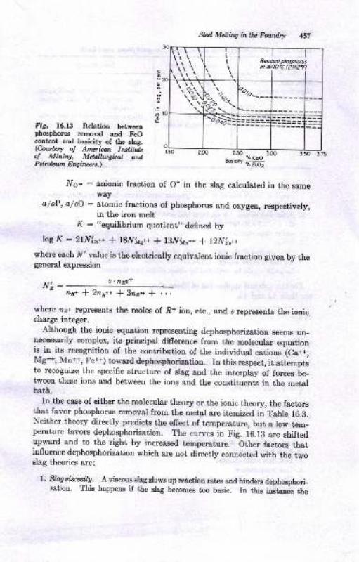
FiS. 16.13 Relation betweenphoophorus removal and FeOcontent and basicity of the slag.(Cowlesy ol Amzrban InsliluLo! MintW, Melnllwgkal ondPebolatn Erqfiuers.)
Slzr,l MeUhg in tlu Fowdry 4{t
20
\\', "
tI
.t
I
Pcsiduol ptospMaot rOtN'C 12921
I
t.i)-.i'\:iF*.'."-
.",:
-"Ar:-:l
i.50 2.50
aosic;rf rl$
;g
oL
tr[o- : anionic fraction of O- in the slag calcuiated in the sameway
a/oP, a/oO : atomic fractions of phosphorus and oxygen, respectively,in the iron melt
1( : ('squilibrium quotient,, defined by
logK : 2lN's,++ * 18.1[fu"++ * l3.l[(a"++ * l2l[f"++
where each N'value is the electrically equivalent ionic fraction given by thegeneral expression
Nh: U,nny+
nr+ $ 2nr++ * !aa.* ..1t- ...
where zp+ represents the moles of 8+ ion, etc., and u represents the ioniccharge integer.
Althorrgh the ionic equstion representing dephosphorization seems un-necessarily complex, its principal difference from the molecular equationis in its recognition of the contribution of the individ'al cetions lca+,Mg+, Mn#, Fe+) toward dephosphorization. In this respect, it attemptsto recognize the specific structure of slag and the interplay of forces Le-tween these ions and between the ions and the constituents in the metalbath.
rn the case of either the molecular theory or the ionic theory, the factorsthat favor phosphorus removal from the metal are itemized in taute to.a.Neither theory directly predicts the effect of temperature, but a low tem-perature favors dephosphorization. The curves in Fig. L6.lB are shiftedupward and to the right by increased temperature, other factors thatinfluence dephosphorization which a'e not directry connected with the twoslag theories are:
l, skg aiscosil,u. A viscous slag slowa up rtaction rates snd hinders dephosphori-zation. This happens if the slag becomes too basic. Iu this i11gt€nce the
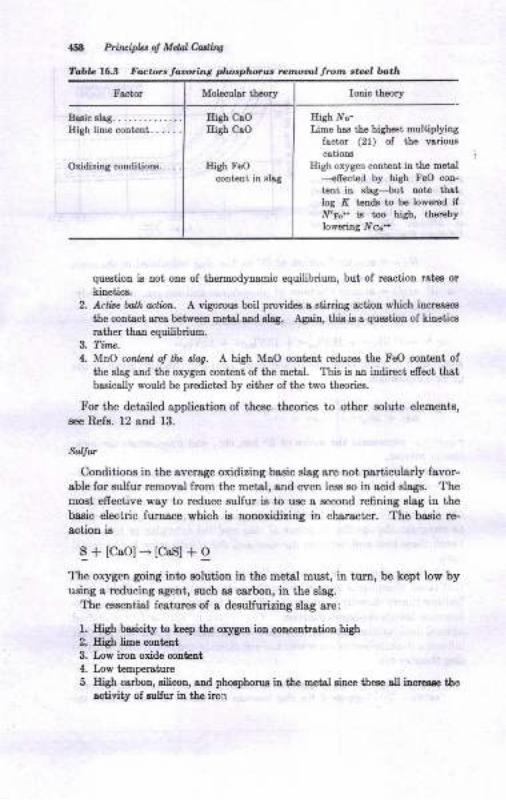
Ergh C.OEish clo
Eigh FeO
conteDt iD shg
458 Fitt ipLt d Md4l fuirq
?d,b! l5.3 Fact rr raoonng pt oaph.rll, rc,,.ots, t.o,t ste.l l,,I.h
Iotric theory
Eish .Vo-
Iime has the highe.t multiplyiigt&cturtr (21t of tLe vsriou8
cetiotra
Iligh oxySen coDteat in the m6tal----efrect€d by high FoO coD-
t€nt iu slsg-+ut noto tbttlog N t€ds to b6 lowercd ifff'r"* ir too high, tho!€bylolesring lYc.+
que8tioD is Dot orc of thermod).naBic equilibrium, but of roaction rat€s orkiDetics.
2. Attioo fullr ution. A vigoouo boil provides a stirriog actioD phich iacrcsser
the coDtsct area betweeL Beisl a,ad slrg. Again, thia ia e quetioo of kinetica
rsther thso equilibriuE.3. Tinw.
4. MnO conlent of tl* ,hr. A high MoO coltoot reduces the FeO cotrtpDt olthe slag and the orygea cotrtetrt of tho metsl. This ia an indireci efrect thrtbasicelly would be predictod by eitber of the two iheoriee.
For the detailed applicotion of these theories to other solute elementa,
8ee Rafs. 12 erd 13.
&{u,
ConditiouE i! the sversge oxidiriog basic slog are not particularly favor-
eble for 8ulfur r€moval from the metal, and even less 80 in acid elags, Themo6t efrective wsy to reduce sullul ie to u8e a second refining efu in the
basic electric furnace which is nonoxidizing in cbaracter. The bssic rc-actioll i8
S + [Cao] --+ [CaS] + O
The orygen goin! iato aolutiou in the metal must, in ium, be kept low byuaing a reducing agent, such as cerbou, in the slag.
The eaaential featurea of a desulfuriziag slag are:
1. II grl bosicity to LeA the o4'geor ioa oaceotration high2, TIiC limo cori€ot3. Lw iloD oxide cortrot4. Low teepershrE5 Eigh clrboq riloo& and phocphoruo il tle metal aince these all iacrere tle
rctivity o, arlfur iD ttrs ima
Blsic BLa. .
High lime cotrt€nt... ...
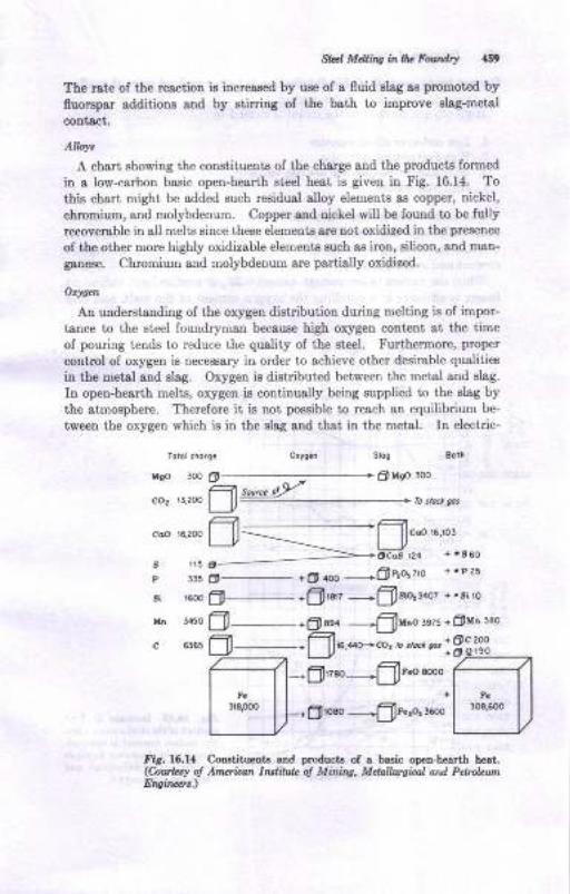
gd M&ns i,^r]t FonAry aBt
The rate oI the rea,ction is increased by use of a fluid elag as promotrd byfluorspar additions and by stirrirg of the b&th to improve slsg-metsl
contact.
Alloy.
A chsri Bhowing ihe constituent8 of ihe charge and the products formed
in a low-carbon basic open-hearth Et€€l heat is given in Fig. 16.14. To
thiB chsrt might be added zuch residual alloy elements as copper, nickel,
chromium, and molybdenum. Copper rnd nickel will be Iound to be fullyrecoverable in all melts since these elemente ere not oxidized in the pre€enc€
of the other more highly oxidizable elementa such as iron, silicon, aud mao-
ganeae. Chromium and molyMenum are partially oridiz,ed.
Otf|at
An understanding oI the orygen dietribution during melting is of impor-
tsnce to the steel found4rman because high oxygen content at the timeof pouring iends io reduce the quality of the et€el. Furthermore, proper
control of oxygen is necessary irr o.der io achieve other deeirable qualities
in the metal and elag. Oxygen ia distributed between the met'al and slag.
In open-hearth meliE, oxygen ia continually being supplied to the slsg bythe atmosphere. Therefore it is not possible to reach sn equilibrium be-
tween ihe oxygen \f,hich is in the slag and that in the metal. In electric-
Totol chorc. orye.n Sl.a Bofi
rlco i.n f,.................-..........................................*
"O" rr,r* fl@
O u@ 3oo
I'ir. 16.14 Crtrstituetrts sd fEoduct! of a basic ope&hearth heet.(hwkry o! Anqtun lratild. ol Minhg, Mdalurgiel Ntd PeltubMtEtrginar,)
tln 4450
c 6165
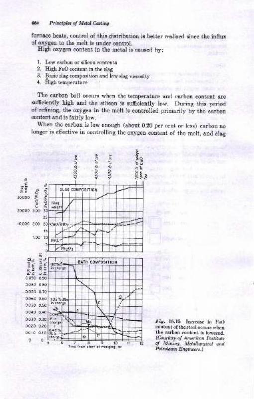
45i, Priruifuot MdalMins
furnace heats, control of this distribution is better realized since the influxcf oxygen to the melt is under control.
Eigh orygen content in the metal is caused by:
l. I,ow carbon or gilicon conteuts
2. Eigh FeO content in the slag
3. Basic slag composition and low slag viscosity4. High temperature
The carbou boil occurs when the temperature and carbon contcnt aresufrciently high and the silicon is sufficiently low. During this periodof refining, the oxygen in the melt is controlled primarily by the carboncontent and is fairly low.
'When the carbon is low enough (about 0.20 per cent or less) carbou no
longer is effective in controlling the orygen content of the melt, and slag
sss\}\6soQSSssssss95hs$$
i
tu3-ats-& Sp'2
9'-a,3Op00
20,000
ro,oo0 2.00
i.oo
oo
d
3.OO
6ols E;e:; 9.6E EEa'.E ().90.090 o.90
0.080 0.80
0.070 0.70
0.060 0.60
o.o50 0.50
0.040 0.40
0.030 0.30
oceo o.20
o0r0 0.r0
0o
Fig. 16.15 Increase in FeOcootcnt ofthesteel occurs whenthe carbon content is lowered.(Coutesy o! Amzrican Inslitulzof Mining, Metallwgical andPdrcbwt Erqircers.)
Time f.om slo.t oi chorging, hr
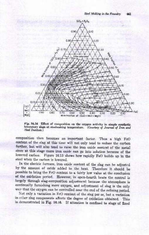
Slxl Mdling inlb Fowdry 6l
SiOr + Pr6t
o90 0.80 0.70 0.60 o'50Molelroction ot (CoO+ MnO+M90)
0.30 0.20
fig.16.16 Efiect of compooition on the orygen activity in simpre syatheticlaboratory slagr at steelmaking t€mperatule.
-lAr*:y ;f Jr;*;;t i;;;rrd
Strrll Inttilrf.)
composition then becomes sn importsnt factor. Thus a high FeOconteut of the slag at this time will not only tend to reduce the carbonfurther, but will also tend to raise the iron oxide content of the metalsince at this stage more iron oxide can go into solution because of thelowered carbon. Figure 16.18 shows how rapidly FeO builds up in thesteel when the carbon is lowered.
In the eleetric furnace, iron oxide content of the slag can be adjustedby the amount of oxide added to the heat. Therefore it should bepossible to bring the Feo content to a fairly low value at the conclusionof the oxidation period. rlowever, in open-hearth heats the control islargely through slag-composition adjustment because the atmosphere iscontinually furnishing more oxygen, and adjustment of slag is tie onlyway that the oxygen can be controlled near the end of the refining period.
Not only a variation in FeO eontent of the slag per se, but , ,".irtiooin other slag compouents affects the degree of oxidation obtained. Thisis demonstrated in Fig. 16.i6. rf attention is confined to slags of fixed
icoo I
lrlol
L,;l
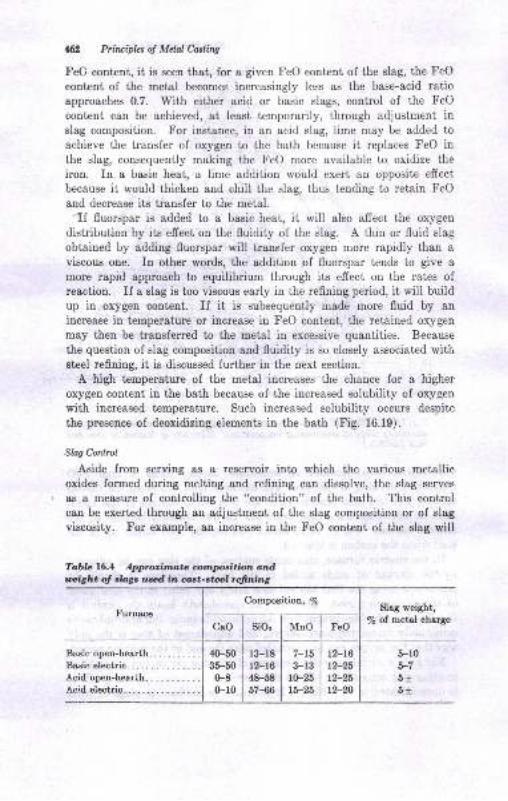
42 Prirciplcs of Melnl Casling
FeO content, it is seen that, for a given FeO content of the slag, the FeO
content of the metal becomes increasingly less as the base-acid ratioapproaches 0.7. With either acid or basic slags, control of the FeO
content can be achieved, at least temporarily, through adjustment inslag composition. For instance, in an acid slag, lime may be added to
achieve the transfer of oxygen to the bath because it replaces FeO inthe slag, consequently making the FeO more available to oxidize the
iron. In a basic heat, a lime addition would exert an opposite effect
because it would thicken and chill the slag, thus tending to retain FeO
and decrease its transfer to the metal.'If fluorspar is added to a basic heat, it will also affect the oxygen
distribution by its effect on the fluidity of the slag. A thin or fluid slag
obtained by adding fluorspar will transfer oxygen more rapidly than aviscous one. In other words, the addition of fluorspar tends to give a
more rapid approach to equilibrium through its effeet on the rates ofreaction. If a slag is too viscous early in the refining period, it will buildup in oxygen content. If it is subsequently made more fluid by an
increase in temperature or increase in FeO content, the retained oxygen
may then be transferred to the metal in excessive quantities. Because
the question of slag composition and fluidity is so closely associated witheteel refining, it is discussed further in the next section.
A high temperature of the metal increases the chance for a higher
oxygen content in the bath because of the increased solubility of oxygen
with increased temperature. Such increased solubility occurs despite
the presence of deoxidizing elements in the bath (Fig. 16.19).
SW Control
Aside from serving as a reservoir into which the various metallicoxides formed during melting and refining can dissolve, the slag serves
as a measure of controlling the "condition" of the bath. This controlcan be exerted through an adjustment of the slag composition or of slag
viscosity. For example, an increase in the FeO contcnt of the slag will
Tobb 16.1 Appuittutz .lnnlnsition atdl ig|art of tbgc td in ast-stal firtng
FurnaceSlag weight,
/e of metal charge
5-10o-l
6t6t
40-50 | l3-r835-50 I 12-16
0-8 I 48-580-10 | 57-66
Composition, /e
CaO sio, MnO FeO
Bas:c open-hearth. ...... . .
Basic electric. . . . . . . . . . . . .
Acid open-hearih.. . . .. .. ..Acid electric...
7-153-r3
1(F25
tb-25
12-16
r2-25t2-25t2-20
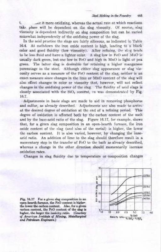
Sld Mdli,ts i^ lh. Fo&drr {6il
L -(e it more oxidizing, whereas tie actusl rate st {hich reactions
taLt place will be depeudent on the slsg viscosity. Of course, slagviscosity is dependent indirectly on elag composition but can be variedsomewhat independently of the oxidizing power of the slag.
In the acid practice the slags are fairly siliceous, as indicated !n Table16.4. At meltdown ihe iron oxide cont€nt is high, leading to e hlack
color and good fluidity (low viacosity). After refining, the sl..g t€ndsto be less fluid and have a lighter color. A alag low in FeO and MnO isusually dark green, but otre low in FeO and high iu MnO is light or pea
green. The latte! slag is desirgble for retaining a higher manganese
percentage in the steel. Although either slag appearance or slag vis-
cosity serves e8 8 messure of the FeO coDtetrt of the slag, neither is an
exact measure eince changes in the lime or MnO content of the slag willaleo effect changes in color or viecosity that, however, will not leflect
chauges iu the oxidizing power of the slag. The fluidity of acid slags ie
closely associst€d with the SiO, cont€nt, !.s was demonstratcd by Fig.
16.7.
Adjustments in basic slags are made to aid iu removing phoaphorus
and sulfur, as already described. Adjustmenk are also made to anivcat the desired degree of oxidation at the end of a refining period. Ttisdegree of oxidation ie afrected both by the carbou content ol the meltand by the base-acid ratio of the slag. Figure 16.17, for example, shows
that, Ior a giveo slag composition in an open-hearth furnace, the iron
oxide content ol the slag (and also of the metal) is higher, the lower
the carbon coDtent. It is also varied, however, by changing the base-
acid ratio. An addition of lime to the slag should therelore reault in amomentary stop in the transfer of FeO to the bath as already described,
whereas & change in the other direction should momeDtarily increase
oxidation rate8.
Changes iu slag fluidity due to temperature or composition chauges
Fis. 16.l? }'or a giyeD Blag compogitioo ia anopen-hes.rth furnace, tbe FeO coDteDt is hir-her,th€ lover the ca.bon conlent. Also, for a aiven.arboD coDt Dt, tbo FeO coDtaDt of tb€ slsa iuhigher, tLo larg€r the basicity ratjo. (Cour.!,o! Amoieu lndih'L ol Mhhs, Mdallweirrland Pdr&h Eryiwr..)
e.uty.';.-*#nq
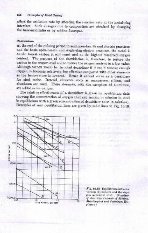
M Prblcipb of Mdal Casling
afrect the oxidation rste by afreeting the reaction rate at the metal-slaginterface. Such changes due to composition are obtained by changingthe baee-acid ratio or by adding fluorspar.
Deoridation
At the end of the refiniug period in acid open-hearth and electric practices,and the basic open-hearth and single-slag electric practices, the metal isat the lowest carbon it will reach and at the highest dissolved oxygencontent. The purpose of the deoxidation is, therefore, to restore thecarbon to the proper level and to reduce the oxygen content to a low value.although carbon would be the ideal deoxidizer if it could remove enoughonygen, it becomes relatively less effective compared with other elementsas the temperature is lowered; Hence it cannot serve as a deoxidizerfor stcel melts. Instead, elements such as manganese, silicon, andaluminum are used. These elemgpts, with the exception 6f slurniarrm,are added as ferroalloys.
The relative effectiveuess of a deoxidizer is given by equilibrium datashowiug the concentration of oxygen that can remain in solution in steelin equilibrium with a given concentration of deoxidizer (also in solution).Examples of such equilibrium lines are given by solid lines in Fig. 16.ri.
Fig. 16.f8 Equilibrium betweeuvarious deoxidizerg and tbe oxy-gen.content in steel. (Courtetyo! American Institule o! Mining,Mclallurgical and Petrolewn En-gircers.)
Alloy element. pe, cent
oo00r
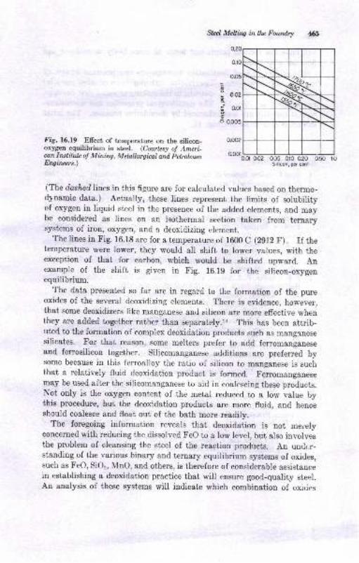
Slel Mehhg in!fu Fourdry
I o.oz
5 o.ot
o 0.005
0.oo2Fig. 16.19 Elfect of temperature on the silicon-oxygen equilibrium in steel. (Coutzsy oJ Amcri-can lrclilule oJ Mining, Melnllurgiml and PetrolewnEngintz*.)
0.02 005 010 0'20 050 roSilicon, pd cat
(The dashed Iines in this figure are for calculated values based on thermo-dynamic data.) Actually, these lines represent the limits of solubilityof oxygen in liquid steel in the presence of the added elements, and maybe considered as lines on an isothermal section taken from ternarysystems of iron, oxygen, and a deoxidizing element.
The lines in Fig. 16.18 are for a temperature of 1600 C (2912 F). If thetemperature were lower, they would all shift to lower values, with theexception of that for cartron, which would be shifted upward. Anexample of the shift is given in Fig. 16.19 for the silicon-oxygenequilibrium.
The data presented so far are in regard to the formation of the pureoxides of the several deoxidizing elements. There is evidence, howeve.,that some deoxidizers like manganese and silicon are more effective whenthey are added together rather than separately.ra This has been attrib-uted to the formation of complex deoxidation products such as manglnesesilicates. For that reason, some melters prefer to add ferromanganeseand ferrosilicon together. Siliconranganese additions are preferred bysome because in this ferroalloy the ratio of silicon to manganese is suchthat a relatively fluid deoxidation product is formed. Ferromanganesemay be used after the silicomanganese to aid in coalescing these products.Not only is the oxygen content of the metal reduced to a low value bythis procedure, but the deoxidation products &re more fluid, and henceshould coalesce and float out of the bath more readily.
The foregoing information reveals that deoxidation is not meielyconcerned with reducing the dissolved Feo to a low level, but also involvesthe problem of cleansing the steel of the reaction products. An undt.r-standing of the various binary and ternary equilibrium systems of oxides,such as FeO, SiOr, MnO, and others, is therefore of considerable assistancein establishing a deoxidation practice that will ensure good-quality steel.An analysis of these systems will indicate which combination of oxides

6 Pri,icipla 6 Mdal edhe
will have low nrelting points snd hence be more likely to coslesce and
float out of the bati.The rubject of st€el deoxidation encompaBees two practicsl phases of
steel-castings produetion. Deoxidation with aluminum or other powerful
deoxidi*rs ie a useful tool, 8ssi8tiDg in the making ol sound steel casiings,
as diocusEed in Chap. 15. The metallurgical properties and microstruc-
ture of the steel 8re also iufluenced by deoxidation practice, The lsttersubject is cousidertd in Chap. 17.
BIBI,IOGNAPHY
1. Steel Founders' Society of Ame ca, "Ste€l Castings HandbooL," 3d ed., 1960.
2. U ted Sts,tes Steel Company, "The Making, Shsping aDd Treatiry oI Steel,"7th ed., 1957.
3. C. I9. Briggs, "The Metallurgy of Steel Casting," MoGraw-Eitl Book Com-p8try, New York, 1946.
4. Americaa Institute of Mining and tr{etellurgical EDgineers, Itotr 8trd StaelDivision, Physical Chemistry of Steel$akiDg Committ€e, "Basic Open-bearth
Stceiaaking," 1951,
5. C. C. ltrismann, "Acid Electric Fumace Steelmeking Practice," AmedcanSociety fo! Metels, 1947.
6. E. J. Drmn, Jr-, Rapid Desulfurizotion to 0.0@ Per Crcnt Sulfur, ?rurx. AFS,vol. 69, p. 276, 1961.
7. P. S. Schafier, P. J. Aheam, and M. C. Flemings, Vacuum Induction MeltiDgHigh Strcngth Ste€ls, ?rcru. .{FS, vol. 68, p. 551, 1960.
8. T. F. Kaveny, !'acuum Induction Melting Alloy Quality Requirements,?roru. i{I$ vol. 69, p. 680, 1961 .
9. J. B. D8brcy, M. C. Flemings, and E. F. Tsylor, Vacuum C&st Steel Sulfurand Cetbon Efiect otr Properties, ?rans. .dfs, vol. 69, p. 778, 1961.
10. C. W. Briggs, pres€[tatioo et Elect c Fumace Conference, Cincinnati,November, 1962.
11. R. Rinesch, II. Neudecker, and J. Eibl, Basic Oxygm LD Proc€ss forFoundries, J. Steel Coatings fics., April, 1963 (condensed and translatedfrom Gi?srerei).
12. C. E. SiDs, "Electric Fumace Steeimaking," vol. II, "Theory and Funds-oental8,' Inter8cience hrblishers, Inc., Ner' York, 1963.
13. R. G. Ward, "An IDitoduction to the Phldcsl Chemistry of Iroo ard St€€l
Making," E<lward Amold (Publishers) Ltd., London, 1962.
14. E. J. Dunn, Jr., Cast St€el Deoxidstion to Vscuuttr-melted Level8 withoutVscuum Proc€ssin8, ?mnr. i{IS, vol. 70, p.7+3, 1,W2.
15. E. E. Fairield and J. A. Ortiz, Some Factors A.frecting the Toughness olMild Steel Castirgs, Modeta Costings, vol.34, p. 70, July, 1958.
18. X. T. TurLdogon and J. Pearson, Aciivi8 of ConstitueDta of Iron snd Sl€el-rdsling Slsgs, Pslt I, J. Itotu Stecl Inst., !oI- 173, p.2U,1953-
L7Metallr'rg'y of Cast Steel
COMPOSITION
Cast 6teel was defined in Chap. 15 as basically an alloy of iron and
carbon. In addition to carbon, which imparts basic properties to steel,
the other elements that are normally present in $rought steel are also
found in cast steels. These include manganese, silicon, phosphorus, and
sulfur. These elemenLs usually lall in the following ranges:
Manganese, % 0-5-1.0
Silicon, /a 0.2-{.8
Phosphorus, rnax 7a 0.05
Sulfur, max 7o 9-06
Small precentages oI other residual metals such as nickel and copper
may also bc prescnt. For plain-carbon-steel castings, the carbon content
determines one type of classification used for commercial steel.
l. Low-carbon steel (cerbon less than 0.20%)
2. 1\{edium-car}ron stcel (carbon between 0.20 and 0.50%)
3. High-carbon steel (carbon above 0.50%)
In addition to the three classes of plain carbon steels lisied &bove, two
other classes are also dcfined as:
1. Low-alloy steels (alloy content totaling less than 8%)2. Iligh-alloy steels (elloy content totaling more than 87o)
Classifications based on strength requirements are also provided fordesign purposes (Chap. 15).
L the irrportani role of carbon in controlling the properties ol cast
steel is set, asioc for the moment, the signifrcance of the other elements
commonly present may be considered.
Mdnsonore ond SiEc.r..
In carbon steels, both these elements are residuals resulting from the
deoxidation practice. They occur in solutiou i! the steel; i.e., they are
161
.168 Prinripbs ol Mebl Castitrg
dissolved in the iron and are not visible when a steel sample is examinedunder a microscope. Both elements confer strength and hardness throughtheir influence on the transformation the steel undergoes when coolinglrom an elevated temperature. In other words, they increase lhe harden-ability of the steel.
Sultur
Manganese combines with the sulfur'that is present in steel to form non-metallic sulfide inclusions in the steel. The role of deoxidation rvithaluminum in controlling the shape and distribution of these sulfides isdiscussed later. Sulfides, of course, are readily identified in a sample pre-pared for microexamination since they are not soluble in solid steel. Sinceall the sulfur appears as sulfide inclusions, the sulfur content is limited to0.06 per cent maximum to avoid the harmful effect on ductility andtoughness that would result if excessive sulfur were present.
Phospharus
Phosphorus is limited to 0.05 per cent because it tends to embrittle thesteel at iow temperatures, leading to "cold shortness.,, Like silicon andnanganese, it is soluble in iron and does not appear in the microstructure.
[It will be noted that in gray cast iron phosphorus occurs in a separatephase (steadite).1
STRUCTURE
Efiect oJ Carbon
Carbon-free iron changes its crystallographic structure twice on cooiingfrom the freezing point: once at 2538 F (1892 C) when it changes froma body-centered cubic structure (}-iron) to a face-centered cubic structure(y-iron), and again at 1670 F (910 C) when it changes ba.ck from face-centered cubic iron to body-centered cubic iron (a-iron\. It is not neces-sary to discuss these crystallographic structures further here, except topoint out that it is the allotropic transformation occurring at 1670 F,together with the effect of carbon on it, that makes it possible to controrthe properties of the steel by controlling (1) the carbon content and (2)the heat-treatment.
The iron-carbon equilibrium diagram shown in Fig. l7.l depicts thechanges effected by increasing the carbon content. It is seen that carbondissolves in 7-iron to a maximum of about 2.0 per cent at about 2110 F.This solid solution is referred to hereafter as austenite. The solution of
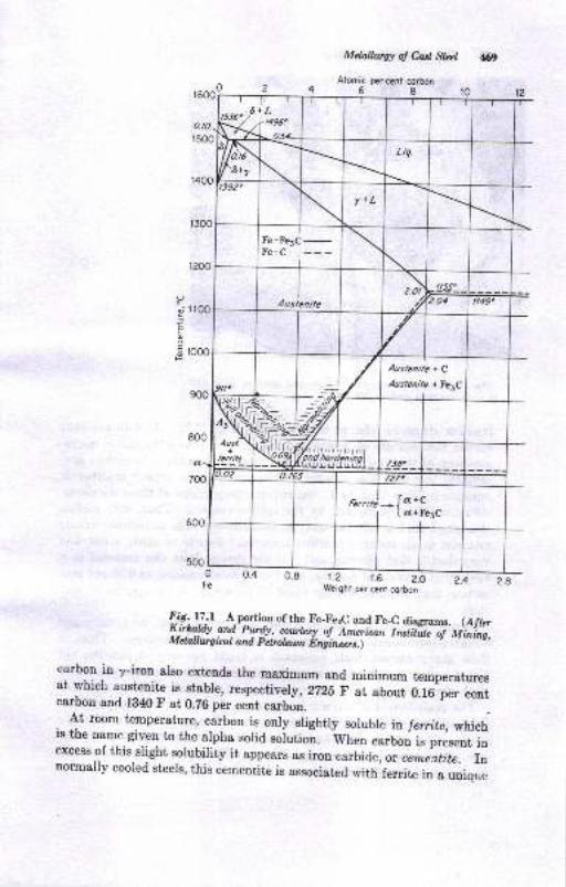
Melallwg! o! Cds, Strr:l
Alomic oercent corbon68
69
r200
O
-- r 100l
o
$ rooo
n
Fe
l:5. y:t A-portion of the Fe_FerC and FeC diagrams. (Afrar
fffi,# :#g"i"frffi :{,,* |*; i";;ii;;; i;i,,s,
carbou in y-iron also extends the maximum and minimum temperaturesat which austenite is stable, respectit-ely, 2725 F at about O.fC'p". ."otcarbon and 1840 F at 0.26 per cent carbon. '-' -"
.
- At room temperature, carbon 19
only slightly soluble ia fetrtte, whichis the name given to the alpha solid soiutioi. wt
"o carbon i. pi"..rrt io
excess of this slight solubility it appears as iron carbide, or cemintite. rnnormally cooled steels, this cementite is associatecl with ferrite in u uoio,,,,
rerrit) -
[ a'C; t a+Fe3c
t.? t.6 2.OWeight per cen, corbon
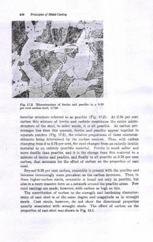
170 Prircipbs oJ Mdal Catling
t{,a aI r{
Fig.l7.2 Microstructure of ferrite and pearlite in a 0.50per cent carbon steel, X750.
lamellar structure referred tn as pearlite (Fig. 17.2). At 0.76 per cent
carhn this mixture of ferrite aud carbide constitutes the entire micro-
structure of the steel, in other words, it is all pearlite. At carbon per-
centages less than this amount, ferrite and pearlite appear together in
separate patches (Fig. 17.2), the relative proportions of these microcon-
stituents being determined by the carbon content. Thus, with carbon
changing from 0 to 0.76 per cent, the steel changes from an entirely ferriticmaterial to an entirely pearlitic materisl. Ferrite is much softer and
more ductile than pearlite, and it is the change from this material to amixture of ferrite and pearlite, and finally to all pearlite at 0.76 per cent
carbon, that accounts for the effect of carbon on the properties of cast
steel.
Beyond 0.76 per cent carbon, cementite is present with the pearlite and
becomes increasingly more prevalent as the carbon increases. Thus, in
these higher-carbon steels, cementite is found not only in pearlite, but
also in a more massive form as a network around the pearlite areas. Few
steel castingr are made, however, with carbon as high as this.
The contribution of carbon to the strergth and hardening character-
istics of cast steel is of the same degree and magnitude as in wrought
steels. Cast steels, however, do not show the directional properties
usually associated with wrought steels. The effect of carbon on the
properties of cast steel was showu in Fig. 15.1.
lt.II
!
Mdalh,sr ol en S,,'l a?r
c",'rnl6P[q!.rtiaThe relative proportiols ol ferrite and pearlitr and the fineness of thepearliuc Etructue iu steels oI le6E l,han 0.26 per cent carbon are controlledby the rate of cooliug from the aurtenite
"ooditioo. Since this effect also
makes it poesible to eontrol the properties of the csst steel, the result isthat steel castiugs are heat-treated prior to use. The specific heat_trr:at_ments are discussed in succeeding sections. The preceding discussion ofthe Etructure of st€el did lot take cognizaDce of t-he efrect ol the casungprocess on tlle etructure. However, iI it ie assumed that the efrecis of t,hecaEting proce8s are superimposed otr those microstructural conditious al_ready established, it will be easier to place the efrects of the solidificstionpmcess in the proper perspective. These solidificatiou efrects will nowbe cousidered-
Solir{/lco&ra Pmcarr
Examination of the iron-carbon diagram in Fig. lZ.1 will show that irou_carbou alloys freeze by a peitectic rezction in the carbon range of 0.10 to0-.54 per cent aud aE typical solid-solution alloys beyood the." lioit . Attlre peritectic l€mperature of 1496 C (2ZZS F), L;e first solid to freeze,8-irou, combines with liquid metal to form austenit€. The amount ofaustenite forrned and ttre amount of either 6-iron or liquid ilon remsinilg8lter this interaction are depeDdeot on the carbo[ cootetrt, S-iron being inexcege below 0.16 per cent carbotr aDd liquid iu excess above ihiecompositiou.
- Austenite apparetrtly forms rrom the 8-iron_liquid-iron combiuation by
foming an eacasement of austelit€ around each 6-dendrite. Subsequentdiffusiou during cooling should tend to promote chemical homogeneity,Just how much influence ihe peritectic reaction has oo the microsiructureand properties of caEt st€el iB uocertain. Considerilg ihe f,igt
"ute *itn
which carbon caD difruse at the peritectic temperature,it woutjUe exp"cteathat plait-iron-carbon alloys should approach au equilibrium structurequit€ readily. lfhis is not so certain, however, if the casting contains ele_mente such as phosphorus, nickel, chromium, and molybdenum, whicheegregatc aloog with carbon and which are uot uearly so ready to difruse ascarbon.
If one retains the mentsl reservation that the peritrctic reaction mayhave some influence on the structure of alloy steels, it is probably safe toconsider the lreezing of caet steel as behaviug essentialty like tiet of asolid-solution alloy.
., Solidification of a st€el casting msy be visualized as the gradual
thickening of a skin oI eolid metal that forms first, at the motj-meialiuterface and grows toward the center as heat ig extrsct€d. if," pifr-ciples of ttris eolidi6cation process were diecuesed in Chap. g. i;"'Ji.
472 Priruiplct oJ Mdal Casting
when first formed.is an arrey of interlockiug dendrites that extend iuto
the liquid and grow laterally as well. Because of heat-flow effects, the
inward growth is usually more rapid than the lateral growth, with the
result that a "mushy zone" of part-solid-part-liquid metal separates the
completely solidified skin from the interior liquid. The last liquid to
freeze in this mushy zone is found (1) between the several branches of adendrite (interbranchial areas) and (2) between separate dendrites or in
interdendritic regions.
segregation of carbon and of phosphorus and alloying elements follows
the same pattern, with the last liquid to freeze highest in these elements
and the first axes of the dendrites richest in iron.
The size and shape of the dendrites depend upon the rate of cooling(section size of the casting) and the. direction of heat flow. Outside of
these effects, there is as yet no practical way to control the size of these
dendrites, although it is claimed that deoxidation with aluminum,
vanadium, or titauium will cause some refinement.
The dendritic structure formed during the freezing process affects the
macrostructure and the microstructure of the cast steel, and is related to
the distribution of inclusions and pinhole porosity.
Mactostructu,te
The maerostructure of cast steel, as revealed by such evidence as hottears, shrinkage areas, castings bled before completely soiidified, and
by etching of sections, is a typical dendritic structure (Fig. 8.13). Thepresence of numerous interlocking and interlacing dendrites is revealed.
The fact that such structurc is apparent after etching means that thechemical segregation whieh occurred during freezing was not eliminatedby diffusion during the time the casting cooled to room temperaturB.
Microetructure
The microstructure oI cast steel can be dealt with in the same way as
that of wrought steel, provided one superimposes the effects accruing
from the dendritic freezing process and the accompanying segregation.
Thus ihe distribution and type of microconstituents present at rocm
temperature are influenced primarily by the austenitic transformationcharacteristics of the steel as controlled by carbon cont€nt and coolingrate, and secondarily by the m&nner in which the steel froze and thesegregation resulting therefrom. Since most cast steel is heat-treatedin some way before use, it will greatly simplify matters if the micro-structure is explained on this basis rather than attempting to rationaiizeall the possible as-cast structures that can be found. Such a procedure
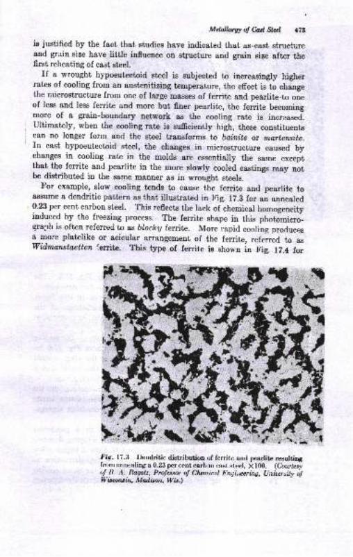
Mdalhug of M Sta:l r78
is justified by the fact that studies have indicated that as-cast structureand grain size have little iufluence on stlucture and grain size after thefirst reheating of cast steel.
If a vrought hypoeutectoid steel is zubjected to inueasingly higherrates of cooling from an austenitizing temperature, the effect is to changethe aricrostructure from one of large mssses of ferrite and pearlite.to oneof less and less ferrite and more but finer pearlite, the ferrite becomingmore of a grain-boundary network as the cooliug rate is increased.ultimately, when the cooling rate is sufrciently high, these consr,ituentsc8n no longer form and the steel transforms to bofutte or martetwite.rn cast hypoeutectoid steel, the chaages in microstructure caused bychanges in cooling rate in the molds are essentially the same exceptthat the ferrite and pearlite in the more slowly cooled castings *"y ootbe distributed in the eame manner as in wrought steels.
For example, slow cooling tends to cause the ferrite and pearlite toassume a dendritic pattern as that illustratcd in Fig. l7.B for an annealed0.23 per cent carbon steel. This reflects the lack of chemical homogeneityinduced by the fi.eezing process. The ferrite shape in this photolmicro-graph is often referred ta as bloctey ferrite. More .apid cooling prorlucesa more platelike or acicular arrangement of the ferrite, referrld to aswidmonstoetten ',eritn. This type of ferrite is shonn in F,ig. r7.4 lor
fdg. 17.3 Dendritic distribution ,;f ferritr: and gnarlite resultingfr-onr arrnealing a 0.23 per cent carbrn cast steel, X lfi). (Courlesyu! R. A. Ragalz, Prolessor o! Clunicel Engi,eaing, IJninnity o!*'baruilq fuIdison, Wit.)
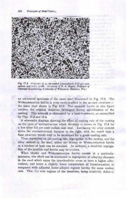
Prircipbs ol Mdnl Caslir"s
t'ig.17.1 srructure o, aD air-cooled (normalized) 0.23 per centcarbon cast s:etl, X100. (Courtcsy oJ R. A. Ragatz, Prolessor o!Clwnitul Ert4irye7i7lg, Unioersily o! Wisarcin, Madison, Wis.)
an air-cooled specimen of the same steel illustrated in Fig. 17.3. TheWidmanstaetten ferrite is even more marked in the as-cast structure clthe same steel shown in Fig. 17.5. The network ferrite in this figureoutlines the original dendrites developed during solidification of thecasting. This network is eliminated by a heat-treatment, as exernplifiedby Figs. 17.3 and 17.4.
A schematic diagram showing the effect of cooling rate of the castingon the type of microstructure which develop.s is shown in Fig. 17.6 fora low-alloy 0.3 per cent carbon cast steel. Increasing the alloy contentshifts the microstructural features to the right, with the result ihat afiner structure would tend to be developed for a given cooling rate.
Thus, depending on the cooling rate, segregation in the casting, and thealloy eontent in the steel, either the blocky or lVidmanstaetten ferriteor a mixiure of both can be obtained. In addition, a dendritic segrega-tion of the pearlite ahd ferrite may be evident.
When blocky and Widmanstaetten ferrite coexist in a particulai.specimen, this effect can be attributed to segregation of alloying elementsin the steel which cause the interdendritic areas to have a higher allol,content, and hence a slightly lower temperature of transformation as
compared with adjacent lower-alloyed regions having the same coolingrate. Thus l,ire ccre regions of the dendrites, being relatively deficir nr
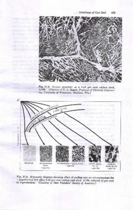
lietallurry o! Cosl Sla)
i\
NFig.l?.S As-cast structure ol a O.z3 pt cent cerbon stecl,X100. .(Courlesv o! R. A. Ragotz, Prolessor o! Chemical Dngineer-ilq, Ltnioersily o! Wisawin, Madison, Wis.)
,cifr rcrr;te
t
E
F.
Mortensileffiffi,l,idmonslotlen
lerrite+ peorliie
lviCmonstotlen + blocky lerrite Rondom blocty+ p€orlite ter;;ie
r peorlite
l'i-g- 17.-6 -schematic diagram showing elfect of cooling rate on microstructur€ fo[r hypothetical low-alloy.0.30 per ce-nt_carbon cast steel, X100, reduced 25 per cent
rrt reproduction. (Courtesy o! Stcel Fowdos, Society o! Ameri.ca.z)
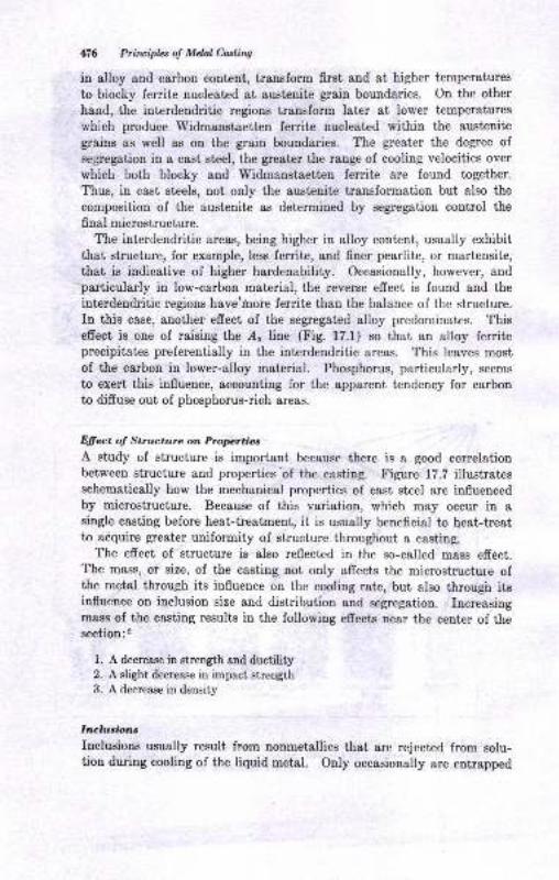
4!16 Principhs ol Mdal Cadiw
in alloy and carbon content, transform first and at higher temperatures
to blocky ferrite nucleated at austenite grain boundaries. On the other
hand, the interdendritic regions transform later at lower temperatures
which produce Widmanstaetten ferrite nucleated within the austenite
grains as well as on the grain boundaries. The greater the degree of
seg1egation in a cas[ steel, the greater the range of cooling velocities over
which both blocky and Widmanstaetten ferrite are found together.
Thus, in cast steels, not only the austenite transformation but also the
composition of the austenite as determined by segregation control the
final microstructure.The interdendritic areas, being higher in alloy content, usualiy exhibit
that structure, for example, less ferrite, and finer pearlite, or martensite,
that is indicative of higher hardenability. Occasionally, however, and'particularly in low-carbon material, the reverse effect is found and the
iuterdendritic regions have'hore ferrite than the balance of the structure.
Iu this case, another efrect of the segregated alloy predominates. Thiseffect is one of raising the d" line (Fig. 17.1) so that an alloy ferriteprecipitates preferentially in the intcrdendritic areas. This leaves most
of the carbon in lower-alloy matcrial. Phosphorus, particularly, seems
to exert this influence, accounting for the apparent tendency for carbonto diffuse out of phosphorus-rich areas.
Effect of Structure on PropttiacA study of structure is important beeause there is a good eorrelationbetween structure and properties'of the casting. Figure 17.? illustratesschematically how the mechauical properties of cast steel are influencedby microstructure. Because of this variation, which may occur in asingle easting before heat-treatment, it is usually beneficial to heet-treatto adquire greater uniformity of structure. throughout a casting.
The effect of structure is also reflected in the so-called mass effeot.The mass, or size, of the casting not only afrects the microstmcture ofthe metal through its influence on the cooling rate, but also through itsinfluence on inclusion size and distribution and segregation. Increasingmasg of the casting results in the following efrects near the center of thesection:2
l. A decrease in strength and ductility2. A slight decrease in impact strength3. A decrease in density
Irrclusionc
Inclusions usually result from nonmetaliics that are rejected from solu-tion during cooling of the liquid metal. Only occasionally are entrapped
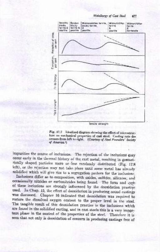
Mdalhtrry o! CaEt Stlr;l liti
Dendriticbloclyterriic &pcorlitc
tYidmodsiiirlln lWidmt.rrilr I llrritce lrgrorlii.
| oortcnd
oocEo
E3o
G
c.
E8EEU
0cOo
L
c
=.9
---r;-
Fig. 17 .7 Idealized diagram showing the efiect of microstruc_ture on-mechanical properties of cast et€el. Cooling rate de-creasee from.left to right. (Coutesy of Stcel Fowdcis, Societyol Aneica.r)
impurities the source of inclusions. The rejection of the iucrusiooa g"voccur early in the thermal history of the. cast metal, resulting in geomet-ric6lly shaped particles more or less randomly distributej (Fig. l7.gIeft), or the rejection may not take prace until some metal has alreadysolidified which will give rise to a segregation pattern for the incrusions,
Inclusions differ as to composition, with oxides, sulfides, silicates, ancioccasionally nitrides or carbonitrides being founi. The iorrn and'oy$eof these inclusions are strongly influenced by the deoxidation p.u.ii,used.
-. In Chap. rs, itre erecf oi deoxidation ti, ,."or".an'."lli ffil[:
was discussed. chaptcr 16 indicated that deoiidation ias ..qrir.J [orestore the dissolved oxygen content to the proper level in tle st€er.T'he tangible result of this deoxidation practice is the inclusions wh:,chare found in the solidified casting, and in-cast steels this is a very iropd.-tant phase in the cpntrol of the properties of the steel. ,the.eio.e it-isseen that not only is deoxidation of concern in producing castings free of
Tensile strength
bloclylerrit€ &pco,lit!
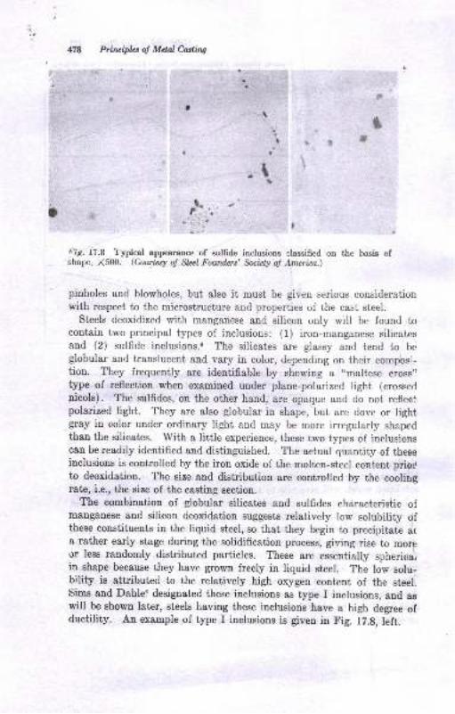
Priruipbt o! Mdal Culing
& t?il,', ''Ii
oic.17.8 l'ypical appearance of sulffde inclusions claesified on the basis ofshape, X5fi). (Corytesy oJ Slel Founilcrs' Sooiely of America.)
pinholes and blowholes, but also it must be given serious considerationwith respect to the microstructure and properties of the cast steel.
Steels deoxidized with rnanganese and silicon only will be found tocontain two principal types of inclusions: (l) iron-manganese silicatesand (2) sulfide inclusions.a The silicates are glassy and tend to, beglobular and translucent and vary in color, depending on their composi-tion. They frequently are identifiable by showing a "maltese cross,'type of reflection when examined under plane-polarized light (crosse,l
nicols). The sulfides, on the other hand, are opaque and do not refleoipolarized light. They are also globular in shape, but are dove or lightgray iu color under ordinary light and may be more irregularly shapedthan the silicates. With a little experience, these two types of inelusionscan bereadily identifled aud distinguished. The actual quantity of theEeiuclusions is controlled by the iron oxide of the molten-steel content priorto deoxidation. The size and distribution are controlled by the coolirgrate, i.e., the size of the casting section.
The combination of globular silicates and sulfides characteristic qfmanganese and silicon deoxidation suggests relatively low solubility ofthese constituents in the liquid steel, so that they begin to precipitate ara rether early stage during the solidification process, giving rise to moreor lese randomly distributed particles. These are essentialry sphericaliin shape because they have grown freely in liquid steel. The low eolu-brlity is attributed to the relatively high oxygen content of the steel,Sims and Dahle{ designated these inclusions as type I inclusions, and aewill be shown later, steels having these inslusions have a high degree ofductility. An example of type I inclusions is given in Fig. 12.g, left.
Ia ,! Jf
a
.l \
t
Mdolllrwotww 179
The additioa of a small amount of aluminum (about 0.02 to 0.05 p€r
cent) drastically changes the appearaace of the inclusions. There is a
defiuiie decrease ia the quantity of the silicate inclusions, or ihey may notsppear 8t 8ll. Aleo, the reduced oxygen content of tbe liquid steel resultsiu a sulfide which is appreciably morr soluble than io the case of straightmanganese and silicon deoxidstion, This iucreased solubility ol thesulfides in the liquid steel csuses them to precipitat€ at a late stage duringthe freezing of the steet. They arr therefote restricted ,o the sustenil€grsin bouudsries, where they appear as 6ne and elougated particles, sugges-
tive of a eutectic mode ol solidificatiou (Fig. 17.8, center). This type ofeulfide distribution w&s designst€d type II by Sims and Dehle. Clustersof fine, angular, whitish elumina particles may also be present as inclu-sions in these steels. The conceDtratior of sulfide inclusione as fine dotsor elongated particles on the grain boundaries markedly reduces theductility and toughness of the steel.
Ii the aluminum content exceeda this critical amount, more alumina ispresent as inclusions. The sul6r.ies, although still persisting on theausienite $ain boundaries, are larger, irregular in outline, &Dd fsrther8p8rt thstr the type II sulfldes. Tlrese sulfides are designated type III,and i,heir shape and distribution are attributed to the presence of alumi-num in the sulfides, which lowers their solubility in the iron, causing themto precipitate earlier in freezing. The culfides can also be duplex insiructure, being mixtures of ALS" and MnS (Fig. 17.9, right). Becauseof the absence of a fllm-type distributrou of the sulfides, the ductili!,and toughness of steels containing these sulfideg are almost ou a par withthose of steels cotrtainitg type I inclusions.
Other strong deoxidizers, such as tiianium, boron, and zirconium, arealso capable of producing the changes obtained from aluminum.s Thepercentsges of these elements required for this will not, howevor, be thesame as thai for aluminum.
The efrect ol aluminum deoidation results in property changes of ihedegree iDdicsted in Fig. 1?.9. These daia indicate tiat, if aluminumadditions are required to enhance castring characterisiics (Chap. 1i), apoor sulfide distribution can be avoided by usitrg sumcieni aluminumto exceed the critical coucentration rauge. This usually means ansddition of 2 la 2y2 lb per ton (0.10 to 0.128 per cent). It should benoted that, if tJre sulfur content is low, the changes are rlot so drastic a8wtth bigher sulfur percentages. Thus steels produced in the bseicoper-hearth furuace may not sufrer from the addition of a small quantityo{ alumiuum because of the high oxygen aud low sulfur conteni of the6t€el.
Other additions and combinations of deoxidizers have aleo been triedia an efrort to improve the ductility of cast steel. Some Iouldrymeu
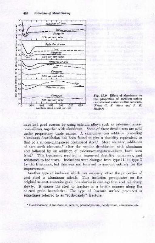
Prircipb: o! Mtul Culing
E
d
.9
.E
-9
I
.E
!
50
eo
20
50
40
to
?o
60
rtrtrlReducfto| of oreo
l,-\ /
----- -- -- --'4= ---='='--'=iV,r- ftonqotiev
0.06 per cent sullur
- Redutim of r.o
-\ /-\-/r- -E,*rr-r!q
'"'.:./'""- " " -odc- ; ;,i',,t,
\ Rc&rctb, of rco
)Etootbr
0O3 pcr cmt sltur
o04 oo8 or2 0.16 020 a?4Alumirum odded io h@t, p€r canl
Fig. 17.9 Ellect of aluminum onthe properties of medium-carboncast steels at various sulfur contents.(From C. E. Srmr ond F. B.httu.t)
have had good success by using calcium alloys such as calcium-menga-
nese-silicon, together with aluminum. Some of these deoxidizers are sold
under proprietary trade n&mes. A calcium-silicon addition preceding
aluminum deoxidation has been found to give a ductility equivalent to
that of a silicon-manganese deoxidized steel.6 More recently, additions
of rare-earth elements,r after the regular deoxidation with aluminum
and ,followed by an addition of calcium-manganese-silicon, have been
trie{.t This treatment resulted in improved ductihty, toughness, and
resiAtance to hot tears. Inclusions were changed from type III to type Ity the treatment, but this was not believed to account entirely ior the
improvement.
Another type of inclusion which can seriously affect the properhies ofcast steel is aluminum nitride. This inclusion precipitates on the
original as-cast austenite grain boundaries in castings that cool relativelyslowly. It causes the steel to fracture in a brittle manner along the
as-cast grain boundaries. The type of fracture surface produced is
sometimes referred to as ttrock-candyt' fracture.
r Combination"- of lrnthanum, cenium, praseodymium, ueod;rmium, sarnarium, etc.
MelhvwolWW aEl
EEAT.TREATMENT
It has already been mentioned that steel castings are heat-treated insome mauner. Heat-treatment can be given to aecomplish any number ofobjectives, such as:
1. To ditruse carbon and alloying elemente
2. To soften
3. To imprcve machinability4. Toharden5. Totoughen6. To inorease wear rrsistance
7. To gtrees-relieve
8. To rcmove hydrogen
So far ae the heat-treatments deaigned to alter the mechanical proper-ties are concemed, cast sl"eel can be considered in the same fgni as
wrought st€el and is subject to the same principles. As a consequence,therefore, thie subject will not be covered in detail, and standard textson the subject of heat-treating steel can be cousulted. There are, how-ever, a numb€r of additional features that should be mentioned.
Eornogcrrrdlro,tion
A rather prolonged heating at an elevated temperature to achieve abetter distribution of the segregated carbon and alloying elements isreferred to as homogen:ization. For heavy sectional eastings, segregationis such that a long time at higher than average temperatures may benecessary.
The efficacy of homogenization for alloy cast steels ie not too certainsince here we 8re concerned with difrusion of alloy segregation as wellas that of carbon. Alloy diffusion is much slower than that of carbon,and calculations show that inordinately long times at femperatures inexcess of 2000 F would be necessary to accomplish appreciable diffusion.The data available indicate that some benefit may be had in someinstances from homogenization heat-treabments, particurarly for certaincompositions aud where extremes in service requirements are encoun-tered, but by and large, they do not appesr to be justified on the basisof improved mechanical properties and the costs involved.
.,lruta,ling
The annealiug treatment is essentially the same in principle as thatp,mployed on wrought steels and involves heating to the austenitic siate
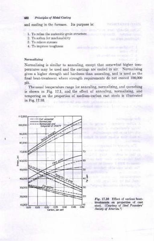
& P7itrciplt, oJ Mdal Ca:littg
aDd cooling in the fumace. Its purpose is:
1. To re6ne the arrsienitic grain struciure
2. To soften for machinability
3. To relieve siresses
4. To impmve toughness
Normalizing is similar to annealing, except that some*'hat higher tem-
peratures msy be used and the castings are cooled in air. Normalizing
gives a higher strength and hardness than anneali[g, and is used as the
final heat-treaiment where s(rength lequirements do not exceed 100,000
pai.
The usual temperature range for annealing, normalizing, and quenching
is shown in I'ig. 17.1, and the effect of annealing, normalizing, and
tempering on the properties of medium-carbon cast steels is illustrated
in Fig. 17.10.
fia. 17.10 Eflect of vadous beat-t€stm€ 3 oa properties of caststael. (Cou*ry ol Sk l Foundrrt'S.xiit! ol Anqid")
---- llotutizcd ordt.Dra.d or |ZOO'F
o25 qao o35 0.40Cobo., ,.t ait
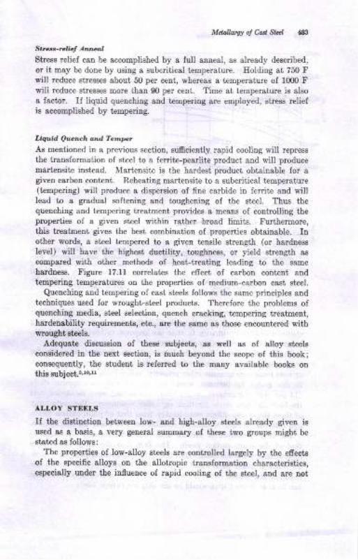
MdnllawolMW 483
Str..r-rcl f A^l.asl
Streea relief can be accomplished by a full anueal, es already described,or it may be dooe by using a subcritical temperature. Holding ai 750 Fwill reduce stress€s about 5O per ceut, rrheress a iemperature of 1000 tr'
will reduce atresses more ihan 90 per cent. Time at temper&ture is also
8 fsctor. Il liquid queuching 8nd temperiug are employed, stress r€liefis accomplished by tanperiug.
LtquLl Qu.L.h o d rertupcr'
As mentioned in a previous section, suiEciently rapid cooling will reprees
the transformation of steel to a ferrite-pearlite product and will produce
martensite instead. Martensite is the hardest product obtainable for agiveu carbon coDt€nt. Reheaiitrg martensite to a subcritical temperature(tempeling) will produce a dispersion of fine cerbide in ferrite and willlead to a grsdual soft€ning snd tougheniag oI the steel. Thus thequenching and tempering treatment provides a means of coutrolling theproperties of a given st€el within rather broad iimita. Furthermore,thie trestment gives the best combination of properties obtainable. lnother words, a sieel tempered to a given tcnsile strength (or hardnesslevel) will have the higheat ductility, toughness, or yield strengtl aB
compared wiih other methode of best-tresting leading to the Bame
hardness. Figure 17.11 couelates the efrect of csrboD coqtent &nd
tenp€ring tempersiures ou the prope ies of medium-carbon cast st€el.
Quenching and tempering of cast steels follows the same priDciples 8ndtechniques used for wrought-st€el producis. Therelore the problems ofquenching Eedi8, 8t€el selection, quench cracking, tempering treatment,hardenability requiremento, etr., are the eame as those encountered withvrought st€els.
Adequate discussion of these subjects, as well aB of alloy steels
considered in the next section, ie i:auch beyoud the ecope of this book;consequeDtly, the Etudetrt is referred to th€ maDy 8vailable book8 oD
thia subjecl.r'to'tt
ALLOY STEDLS
If the diatinctiou between low- a,nd high-8tloy eteels already given isused aa a basie, a very general aummary of theee two groups might bestst€d ae follows:
The properties of low-alloy steels are coutrolled largely by the efrecte
of the speci6c alloys ou the sllotopic tra,DsformatioD characte stics,especislly urder the iufluence of rapid cooling of the steel, aud are not
M Prircipbs o! MdaI Casting
o20 a25 0.30 035 0.40 0.45Csbo., plr mt
Fig. 17.11 Effects of carboncontent and temp€ring t€m-perature on the properties ofmedium-carbon cast steel.(Cou.rteq ol Sleel Foudcrs' bciely o! America.2)
dependent to any great degree on any intrinsic property that the particu-lar alloy might confer. In other words, in this class of steels the all<;ving
elements are used primarily to alter the response to heat-treatment, i.e.,
to increase the hardenability of the steel.
On the other hand, the high-alloy steels are designed primarily forsome specific property conferred by the alloy, such as corrosion resistance
or heat resistance or some other property, rather than for hardenability.In this group, for instance, would fall the austenitic mangenese steels
(14 per cent ma,nganese), which have outstanding wear resistance, and
the 18-8 stainless steels for their corrosion resistance. The rnetallurgyof these steels also differs considerably from that of plain carbon steels,
and reference should be made to suitable texts or books on this subject.
The heat-treatment of the low-alloy steels is basically the same as
that of the plain carbon steels. The fact that the alloy steels have
higher hardenabilities meatrs that less severe quenching practice (oil or
air quench rather than water quench) can be employed to obtain the
desirablc martensitic structure prior to.tempering, or that heavier sections
can be heat-treated than would be the case for carbon steels.
=-__Elto50Tt200FBOO'r
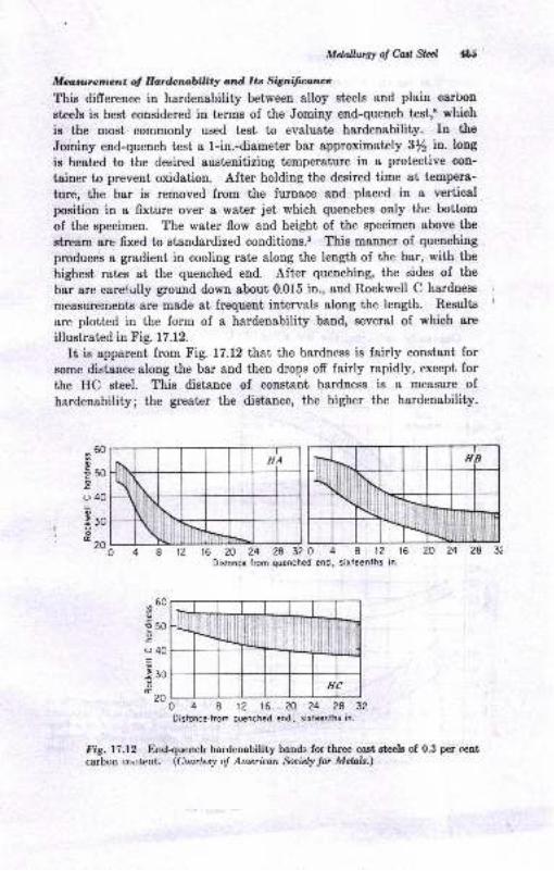
Mdnlhugy of Ca.d Stal {8.i
Mcasurernent of EordcrwbiBty and Itt Signiftcancc
This difference in hardenability between alloy steels 8nd plain carbon
steele i6 beet eonsidered in terms of the Jominy end-quench test,8 which
ie the most commonly used test to evaluate hardenability. In the
Jominy end-quench tcst a l-in.-diameter bar approximalnly 3/2 in. long
ie heated to the desired austenitizing temperature in a protective coD-
tainer to prevent oxidation. After holding the desired time at tempera-
ture, the bar is removed from the furnace and placed in a vertical
position in a fixture over a water jet which quenches only the bottom
of the specimen. The water flow and height of the specimen above thegtream are fixed to standardized conditions.3 This manner of quenching
produces a gradient in cooling rate along the length of the bar, with the
highest rates at the quenched end. After quenching, the sides of the
bar are careiully ground down about 0.015 in., and Rockwell C hardness
measurements are made at frequent intervals along the length. Results
are plotted in the form of a hardenability band, severel of which are
illustrated in Fig. 17.12.
It is apparent from Fig. 17.12 that the hardness is fairly constant for
some distance along the bar and then drops off fairly rapidly, except for
the HC steel. This distance of constant hardness is a measure of
hardeuability; the greater the distance, the higher the hardenability.
h.l I I I l I
HA
{T-rTl-\\T--n-T\=q
20o.--1--f3- 20 24 n 320 4 8 t2 16
Distonce ,rom quenched end, sixteenths in-
o48r21620242832Distonce.+rom quenched end. sirteenlhs in.
Fig. 17.12 End-quench hardenability bands for three cast steels of 0.3 per rentcarbou corrtent. (Courlesy oJ American Society tor Metals.)
50
€soo
o40
iso,E
50
€soo
o4O
-I rooa
20
I
t{c
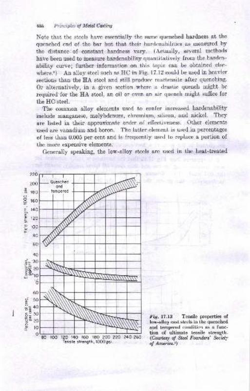
f86 Princi.ples of Melal Casting
Note that the steels have essentially the same quenched hardness at the
quenched end of the bar but that their hardenabilities as measrrred by
the distance of constant hardness vary. (Actually, Beveral methods
have been used to measure hardenability quantitatively from the harden-
ability curve; further information on this topic can be obtained else-
where.3) An alloy steel such as HC in Fig. 17.12 could be used in heavier
sections than the HA steel and still produce martensite after quenching.
Or alternatively, in a given section where a drastic quench might be
required for the HA steel, an oil or eveu an air quench might suffice for
the HC steel.
The common alloy elements used to confer increased hardenability
include manganese, molybdenum, chromium, silicon, and nickel. They
are listed in their approximate order of effectiveness. Other elements
used are vanadium and boron. The latter element is used in percentages
of less than 0.005 per cent and is frequently used to replace a portion of
the more expensive elements.
Generally speaking, the low-alloy steels are used in the heat-treated
220
200
I reooE rso
: r40cg t2o
E roo
80
60
40
do*:
, obI o-
G
50
40
30
20
ro
080 roo r20 r40 160 r80 200 2?o 240 260
Tensile strengih, 1OO0 psi
Fig.l?.l3 Tensile properties oflow-alloy cast steels in the quenched
and tempered condition as a func-tion of ultimate tensile strength.(Cottrlpsy o! Sleel Foundert' Sociefi,
of Anwica.2)
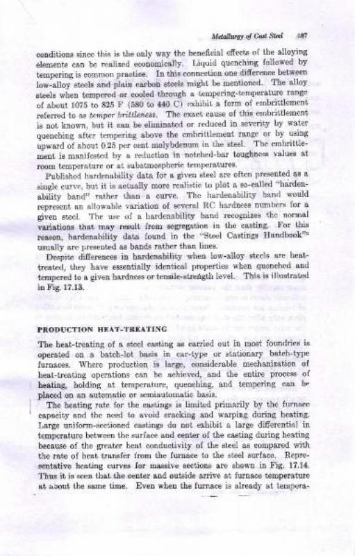
MtuUuw al M Slal lal
coDditions since this is the only way the beneficial efrects of the alloying
elements can be realized ecouomically Liquid quenching followed by
tempering is common practice. Iu this connection one difrereqce bet'ween
low-alloy sieets and plain carbon ateele might be mentioned' The alloy
eteels when tempered or cooled through a temperiog-t'empelsture range
of ebout 1075 io 825 F (580 to 440 C) exhibit a form of embrittleDent
referred to ^a
tetupet bittlerlels. The exact cause of thie embrittlement
is not known, but it can be etiminated or reduced in severity by wat€r
quenching aft,er tempering above the embriitlement range or by using
upward of about 0.25 per cent molybdenum in the steel. The embrittle-
ment is manifested by a reduction iu notched-bar ioughness values at
room temperature or ai subatmospheric iempelatures.
Published hardenability data for a giveu st€el are olt€n preaented aE a
siagle curve, bui it is actually mole realietic to plot a so-called "hardeu-
ability band" rather than a curve. The hardenability band would
represent an allowable variation of several RC hardness numbers for a
given steel. The use of a hardenability band recognizes the normal
"ari"tio* thst may result from segregatioo in the caating. For this
reaeon, hardeuability data found in the "Steel Castinge Eandbook"'
usually are presented ae bends rather than lines.
Deepite difercncee iu hardenabitity wheu low-alloy eteels are heat
treated, they have eeaentially identical properties wben quenched and
tempered to a givea hardness or teneile-streigth level. Thie ie illuetrai,ed
io Fig. 17.13.
PRODUCTION HEAT-TREATING
The heat-treating ol a steel casting as caried out in most loundries is
operated on I bstchJot basis in car-type or ststiotrsry batch-type
Iurnaces. Where production is large, considerable mechanization of
heat-treatiug operations can be achieved, and the eutirc process of
heatiug, holding at t€mpersiure, quenchiug, and tempering caa be
placed on sD automstic or semiautoBatic b&sis.
The heating rate for the castings i8 limitrd primarily by the furnace
capscity 8ud the need to avoid cracking and warping duing heating.
Large uniform-sectioued castings do not exhibit a large difrerential in
temperature between the surface and center of the caEting duing heating
because oI the greate! hest conductivity ol the steel as compared with
the rate of heat irausfer lrom the furnsce to the steel surface. Repre-
sentative heating curves for massive sectious are shown in Fig. 17.14.
Thue it ie eeen that the center aod outside arrive at furnace temperature
et about the eame iime. Eveu wheu ihe fumace is already at i€urpera-
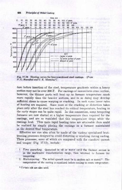
4S8 Priluiplet of Mdnl Uorlttng
0ro20oi0
5" plotc - Or{} 50 60 70 @ 90 'too 1r0 r20 130
Fig.17.14 IIeatiDS curree for hmvy<ectioned steel castiDgs. (From
ture before insertion of the steel, temperature gradients within a heavysection may not be over 200 F. For castings of nonuniform cross section,
however, the thinner parts will heat up to furnace temperature muchmore rapidly than the heavier sections, and in so doing may developsufrcient stress to cause warping or cracking. In such cases lower ratesof heating are required. Since most o{ the cracking or distortion takesplace only after the steel has reached its critical temperature, heating inthe early stages can be quite rapid. In this connection, some temperingfurnaces are now started at a higher temperature than required for thecastings, and are so regulated that this temperature drops while thecastings heat. Thus more rapid heating rates are attainable than couldbe realized by simply placing the eastings in a furnace maintainedat the desired final temperature.
Efrective use can also often'be made of the various speciahzed heat-treating processes designed to avoid distorting or cracking during cooling.These processes, some of which are compared with the standard quenchand temper (Fig. 17.15), include:
l. Time qucrching. Quenched in oil or water until the thickest section isin the martensite transfomration range, then returned to furnace fortempering.
2. Martempeing. The initial quench must be in molten salt or metal.* Thetemperature of the casting is equalized before eooling to room temperaturc.
I Certain oilg arn elso used.
Timc, nio
30 40 50 60 70 80 90 loo-3"ptorr20 30 /rc 50 60 70 80 90 too-c'ilotco20304050@7080901@
.
€
3', ,lota fir*e.fu{I frt ,2,
2ffs:;
:/,?, 7T
il i'vi
rurEr
Centel ol ploEy'4'betot erloe of ptote
-------- l;Lnil af ilD..
{ v, t:
f {'
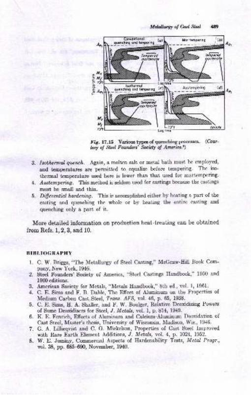
MdallwW ol Cul Stal
Fig.17.15 Various types of quenchirg processes. (Cout-
tsy d gd Fqsdat' Bocidy of Am*ica.2)
3. Icothennat guench. Again, a molten salt or metal bath must be employed,
and t€mperaturcs are permitted to equalize before tempering. The iso'
thermal temperature used here is lower than that used for martempering.
4. Awtempeing. This meihod ir seldom used for castings because the castings
must be snall and thin.5. Difrerential, hardening. This iq accomplished either by heating a part of the
casting and quenching the whole or by heating the entire casting and
quenching only a part of it.
More detailed information on production heat-treating can be obtained
from Refs. 1,2,3, and 10.
BIBLIOGRAPHY
1. C. W. Briggs, "The Il{etallurgy of St€el Ca.sting," McGraw-Eill lJook Com-pany, New York,1946.
2. St€el Founders'Society of America, "Steel Castings Handbook," 1950 and
1960 editions.3. American Society for Metals, "Metals H&ndbook," 8th ed., vol. 1, 1961.
4. C. E. $imq and F. B. Dahle, The Efrect of Aluminum on the Properties ofMedium Carbon Cast St€el, Traru. AFS, vol. 46, p, 65, 1938.
5. C. E. $ims, [. A. Shaller, and F. lY. Boulger, Relative Deoxidizing Powers
of Some Deoxidizers for Steel, J. Met&, vol. 1, p. 814, 1949.
6. K. E. Fenrich, Efrects of {lsaiarrm and Calcium-Aluminum Deoxidation of
Cast Steel, Master's thesis, University of Wisconsin, Madison, Wis., 1946.
7. G. A. Liltieqvist and C. G. Mickelscn, Properties of Cast Steel Improved
with R^are Earth Element Additions, J. Metols, r'ol. 4, p. LU24, 1952.
8. W. E. Jominy, Commercial Aspects of Eardenability Tests, Metal Progr.,
vol. 38, pp. 68&{90, Nove.mber, 194O.
L7O'Ftinc-

N Ptnqipla o! Md4t Cdttiry
9. P. C. Roeerthsl ad G. K. Msming, Eeai TrcotneDt ol Eeary Cast Steel
-- q*!,!q, Fotnd.ry, vol- ?4, August,-i946.10. D..K.
?ulleos-Bart€[e, "Sieel ioa itu U*t Treatloent,,, bth ed., vob. 1+,-- JohD Wiley & Sons, Inc., Ner york, 1H8.ll. W. Crafts and J. L. Lamont, ,,Eandenebility
aDd St€el Selection.,, pirms,DrlrblrshrD8 Oorpor&tioD, New yo*, 1949.
12. R. F. Earris ,.Dd C. D. Ch.sDdley, ir;gh g1rcost6 St€el Ca.stinss AluEioul-o
-^ Iirlidg Enbrittlemenr, franr. ,{rS, vll. Zq pl ros, roOi. :
13. C. rJ. kriC 8nd_A. R. Elses, Occurrence otlotcrgraoular fracture in Cast
-. Eleels,_ ?rcru. /fS, vol.5E, p. 160, 1947.14. U^. truhn and P. Detrez, Nitr<Eetr iD Cast St€el, ?rdn . /.!'S, \,ol. ZO, p.469,
1962.15. {. Vq Frghem and A. DeSy, Side Efrects of the Deoxidation of Steel. J.
Steel Caatings Bu., D,o. Zl, p. l, April, IgOt.
18Ttre Farnily of Cast Irons
Cast iror,s are the tonnage product of the foundry industry. Cast-iron
foundries produce over a million tons of castings monthly, and thus
aupply more than twice as much caeting weight as all other Ioundries
combined. Iron fouudries are found everywhere that manufacturing
occurg. Of the 56?4 loundries iu the United States and Canada, 2068
produce gray-iron, 350 nodular-iron, and 116 malleable-iron castings.
Theee foundriee 6end s Bt€ady stream of irou castings into every con-
ceivable industry. The demand for iron castings is based on the nature
of cast irous as engineering materials and their economic cost advantages
Cast irons ofrer a tremendous rauge of the metallic properties of strength,
hardness, machinability, wear resistauce, abrasion resistauce, and corro-
sion resietsnce and other properties. Furthermore, the foundry proper-
ties of cast iroDs in terms of yield, fluidity, shrinkage, casting soundness,
ease of production, and othere make the material highly desirable for
casting purposes. From all staudpointc, the cast-irou fomily ofiers a
variety of engineering properiies which ensure iis continucd and wide-
spread use. Since many caet irons of differeni properties are employed,
it ie desirable that a student eugineer obtein an over-all picture of ihe
euiire 6eld. This chapter ofrers such a picture and presents some of the
eimpler and more fundsmental difrerences between members of the cast-
iron family.
DEFINITIONS
Ttte term ccst irotu is a generic ooe, referring to a family oI materiale
difiering widely itr their properties. Iu general, a caet iron is an alloy
of iron, carbon (up to about 4.0 per cent), and silicon (up to ahout 3.5o
per ceuti which ordinarily ie not usefully malleable &s cast. Definitioos
of epecific types oI cast irons are giveu below.
Grau cast iron. At iron having a chemical composition 8uch that,
after rolidification, a large portion ol its carbon is distributed throughout
the castiug as free or graphic carbon in "flake form." Gray cast irou
alwaye presents 8 grsy sooty surface when fracturcd.
40t
4$fa Priwtpb ol Mdal eding ,. -
White cast iron. An iron having I compoEition Euch thst, after eolidi;fication, its carbon is present in a ehemically combined form as cementik(iron carbide). White iron presente a white crystalline surface wheD I
fractured. Figure 23.5 shows fractured surfsces of gray, whitc, and j
mottled irons.
Mottleil, iron. An iron of intermediate composition which freezespartly as a white iron and partly as I gray iron under prevailing cooling ,
conditions (Fig. 23.5).
Chilled cast iron. An iron of such composition that it would normallyfreeze as a gray iron. but which is'caused to freeze white in some locationsby rapid cooling during solidification, i.e., chilling. Fractured surfacesof chilled irons show areas of white iron where freezing was rapid andother areas of gray iron where the woling rate was normal. The appear-ance of fractured surfaces of chilled iron is illustrated in Fig. 18.2.
Malleoble iron. An iron w:th ductility, or malleability, produced byheat-treating (malleableizing) a white-iron casting of suitable chemicaloomposition. The carbon in malleable iron is present ae nodular-shapedaggregates of graphite (Fig. 23.3).
Nodular cost iron (also known as ductile cast iron, or apheroidalgraphite cast iron). A specially prepared iron treated in the moltencondition with a small percentage of magnesium, cerium, or other agentthat will cause a large proportion of its carbon to oecur as spheroidi ofgraphite rather than as flakes. Ductility is obtained in the iron ar aresult of the spheroidal type of graphite formed. This type of cast imnpresents a bright steely surface when fractured. The epheroidal typeof graphite is illustrated in Fig. 22.1.
The definitions given above suggest certain factors of major importancecontrolling the nature of cast irons. These are chemical composition,solidification process, cooling rate, and microstructure. A number ofother factors are involved, but the aforementioned ones are of primeimportance. They are considered briefly in this chapter and are dis-cussed in greater detail in Chaps. 2t tn B.
CHEMICAL COMPOSITION
-The broad limits of chemical composition of some cast irons are given\r Table 18.1. The over-all picture of the composition ranges in thetabiq with respect to carbon and silicon in cast irons is illustrated inFig. 1.r.1. The figure shows that even the terms .,gray iron', and ,,white
iron" &rc general ones ir, that they refer to a number of alloys fallingwithin brorn:l composition limits. Within the broad limits occur a numberof irons with iiurrower composition limits and difrerent properties. Typi-cal chemical co..-co$itions, specifications, and uses of a few comme.cial
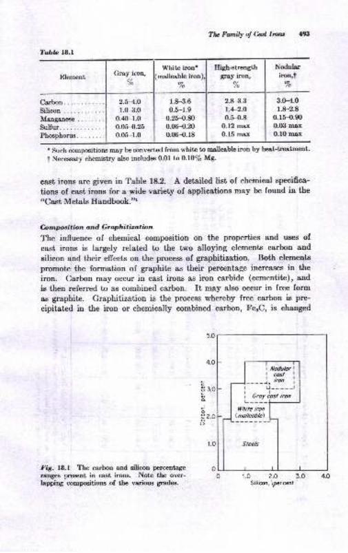
Tabb ]8.l
Element Groy iron,u/o
White iron'malleable iron),
/o
Iligh*trengthgra,y iron,
d/o
Nodul$iron t
7o
Carbon.Silicon .
Manganeae
Sulfur..Phoephorus. . . .....
2.H.Or.(}-3.0
o.40-1.00.05-0.25
0.05-r.0
1.8-3.6
0.5-1.90.25-{.m0.06-{.200.06-0,r8
2.8-3.3
1.4-2.O
0.H).8O.12 mcx
0.15 max
3.(H.0r.8-2.8
o.15-O.90
0.G| max
O.10 max
Tlu Fatnily ol Cast Ircra 493
. such compositions may be converted from white to rnalleable iroo by heaLtrtatment.
t Necessary chemistry also includes O.0l to 0.f0% Mg.
cast irons are given in Table 18.2. A detailed list of chemical specifica-
tions of cast irons for a wide variety of applications msy be found in the
"Cast Metals Handbook."t
Cnrnposition and G r aphi ti za tion
The influence of chemical composition on the properties and uses of
cast irons is largely related to the two alloying elemeDts carbon and
silicon and their effects on the process of graphitization. Both elements
promote the formation of graphite as their percentage iucreases in the
iron. Carbon m6y occur in cast irons as iron carbide (cementite), and
is then referred to as combined carbon. It may also occur in free form
as graphite. Graphitization is the process whereby free carbon is pre-
cipitatcd in the iron or chemically combined carbon, Fe"C, is changed
I i ua,ariI tcost !
)__--),;,* iI r u----JI I e-, hn i-n| .----lI White iron I
I lnotteobtl I1 - _J---'r
I
Steets I
I
',1Fig. 18.1 The carbon and silicon percentage
ranges present in cast irons. Note the over-lapping compositions of the various grades.
4.O
c3 3.0
d
io€ 2.0oo
r.o 2.o 3.0Silicon, \percerl

p
=i,B ?EEs * r .- E.ss E:-.EF Hle.a SH,"AlE
si ;ii$BE E t f€ e siiE€iff {-eE A
Eg:.oP;
aaE
aEaaa
tc
EftFs S gEHE.R E
Eg*** a{i6r* *
o
z zEt,t. e i .>' =E*e9ane,i,4e GeiilTT?: Y : i? ??oo!:!t6 x o|a u)Gq \t:-1 : q ..: qi ooo: e : o o
be
piEiiE E ? E E g I
=r)_d
ba
ai
.E ^'6-Tc'i'l c c '1 .: -l
EEEE E E E E 8?i?i r ? i i B +8893 I S 3 * d 3dcjcj<i <j d .i d c;
.,qEES q € q e E eTTTT T ? i ? T T.? o:.! q .! "? q I .-! c!
ooo
I-+YF? :? ?
d.<i c;
o
8888 I I I R R Ididididi ci di
^i dj <igqrsH [$pr E
ct ci ..i .i .i ci c,i ..i ci a5,-.3
e ." 6'983E r I iEr6 >eo i.
E
s
I
.:
!i
B
I
-t3T:,s 9: Eir c 9EI ;!;> t- q
si:E;5€f;.>E!S? O E
{E€E
II
t
!
q
(I
E
:lFI
,51
_Blil
el4A
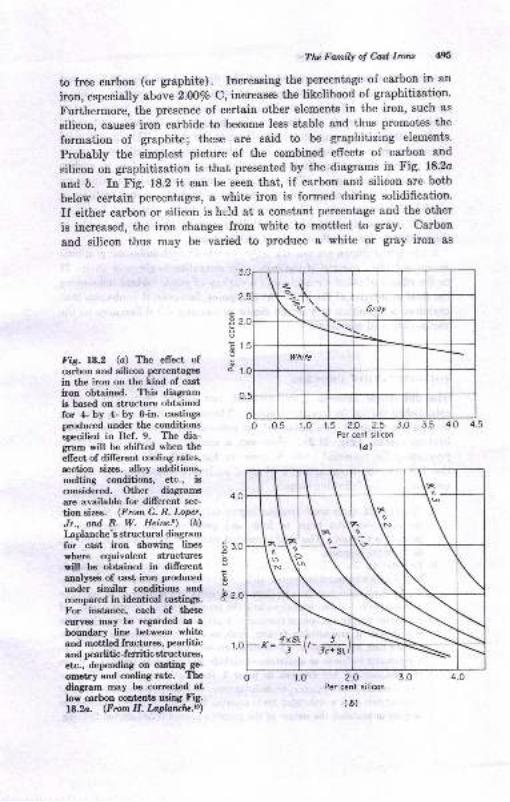
Ttv FatnilY o! hd lrc'la {95
to free carboD (or graphite). Increasing the percentage of carbon in an
iron, especially above 2.oo% c, increases the likelihood of graphitization.
Furthermore, the presence of certain other elements in the iron, such as
silicon, causes iron carbide to become less stable and thus promotes the
formation of graphite; these are said to be graphitizing elements.
Probably the simplest picture of the combined effects of carbon and
silicon on graphitization is that presented by the diagrams in Fig. 18.2o
and b. In Fig. 18.2 it can be seen that, if carbon and silicon are both
below certain percentages, a white iron is formed during solidification.
If either carbon or silicon is held at a constant percentage and the other
is increased, the iron changes from white to mottled to gray. Carbon
and silicon thus may be varied to produce a white or grey iron as
!
LFig. 18.2 (a) The elfect ofcarbon and silicon percentages
in the iron on the kind of cast
iron obtained. This diagramis bas€d on structure obtainedfor 4- by ,t- by 8-in. castingsproduced under the conditionsepecified in Ref. 9. The dia-gram will be shifted when theellect of different cooling rates,
eection sizes, alloy additions,melting conditions, etc., isconsidered. Other diagrams
are available for dillerent sec-
tion sizes. (From C. R. I-oper,
Jr., and R. W. Heinz.'g) (b)
I-aplanche's structural diagramfor ,cast iron showing lines
where equivalent structureswill be obtained in difierentanalyses of cast iron produced
under similar conditions and
compared in identical castings.
For instance, each of theee
curvea ma)r be regarded as a
boundary line be;tween whitcand mottled fractures, pearliticand pearlitic-ferritic structurer,etc., depending on caeting ge-
ometrlr and cooling rate. The
diagam may be corrected atlow carbon cont€nta ueing Fig.18.2a. (From H. l,apbrulp.n)
1.0 r.5 20 2.5Per cenf s;licon
{a)
1.0 2.o 3.0Per cent silicon
(6)
4.54.O3.5
4.0
.E so
d 2.0
't.0
.o
K=ry('r;f"
+$ Pritsifuof MdalMing
deeircd. It must te recognized that the diagrams of Fig. 18.2 do notconsider the variable of cooling rate or section size in castings. This isanother variable affecting graphitization. Slower cooling rates (heavycasting eectione) shift the lines on the diagram to the left, and rapidcooling (thin casting sections) shifts them to the right. Thus in practicalsituations, gray-iron piston rings are high in carbon and silicon percent-
agee whercae heavy machine-tool-casting gray irons are lolq in carbonand silicon percentages., Whit€ irons for making malleable castings areeven lower in carbon and silicon content, so that the carbon will be incombined form as cast. The carbides in this white cast iron, however,are still suffciently unstable so that they can be graphitized slowly inthe solid state by a malleableizing heat-treatment.
Carbon and silicon are not the only elements which influence graphiti-ation and the structure of the iron. Consideration is given in Chap. 2lto the effects of other elements and a variety of other factors influencingthe final properties of the iron. At this point, however, it is obvious thatchemical composition is a prime factor in causing the differences in thevarious types of cast irons.
SOLIDIFICATION PROCESS
The difrerences between gray, mottled, and chilled irons are largelyestablished during the freezing process. The fundamentals of the freezingprocess are related to the nature of the iron-carbide-silicon ternary equi-librium system (Fig. 21.2). However, a simplified schematic diagra-presenting the essential ideas is given in Fig. 1g.8. with reference tothe diagram, the freezing and cooling of an iron, composition r{., may bedescribed by the following steps:
z{. Liquid melt codls until freezing begins at point l. At this point solidaustenite dendrites begin to form and grow until the temperature atpoint 2 is reached. This step is omitted when the composition is eutectic,at B, on the diagram.
B- Eutectic (a liquid saturated with respect to two solids) freezing beginsas the area at point 2 is entered with decreasing temperature. The eutecticsolids which {orm may be a mixture of austenite and carbide or of austeniteand graphite. If the former occurs, the iron is freezing as white iron. Ifthe latter occurs, the iron is freezing as a gray or a nodular iron. Graphitewill prevail if graphitizing factors, such as high silicon content and slowcooling rate, are operative. Low silicon content and rapid cooling will causetlre eutectic to freeze as a mixture of carbide and austenite (whlte). wtrenthe temperature has dropped to point B, freezing is completed. Thus aniron freezes, as white, gray, or nodurar iron. Actually, trre soridification ofnodular cast iron is somewhat more complex than this." If the iron freerresas grsy or nodular, the nature of tlre graphite is esteblished during freeziag
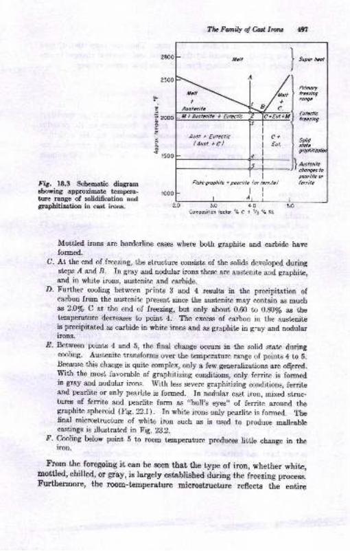
Ttu Fonily o! M lrcrc gn
2500
P 2oOO
E
r500
Fig. 18.3 Schematic diagramshowing approximate t€mpera-ture ranS€ of solidification andgraphitization in cast irons.
Comp6ilionfucfo, %C +
Mottled irons are borderline cases where both graphite and carbide haveformed.
C. At the end of freezing, the stmcture consists of the solids developed duringstefrs.d and B. In gray a^nd nodular irons these are austenite and graphite,and in white irons, austenite and carbide.
D. Further cooling between prints 3 and 4 results in the precipitation ofcarbon from the austenite present sinee the ausienite may contain as much$ 2.0Vo C at the end of freezing, but only about 0.60 to 0.80y'e as thetemperature decreases to point 4. The excess of carbon in the austeniteis precipitated as carbide in white irons end as graphite in g.ay and nodularirons.
.O. Between points 4 and 5, the fnal change occurs in the solid state duringcooling. Austenite transforrns over the temperature range of points 4 to E.
Because this change is quite complex, only a.few generalizations are oqered.Iryith the most favorable of graphitizing conditions, only ferrite is formedin gray and nodular irons. with less severe graphitizing conditions, ferriteand pearlite or only pearlite is fonned. In nodular cast iron, mixed stmc-tures of ferrite and pearlite form as ,,bull,s eyes,' of ferrite around thegraphite spheroid (Fig. 22.r). rn white irons only pearlite is forrned. Thefinal microstructure of white iron such as is used to produce malleablecastings is illustrated in Fig. 28.2.
f. cooling below point 5 to room tcmperature produces little change in theiron.
Frgq the foregoing it can be seen that the type of iron, whether white,mottled, chilled, or grby, is largely estsblishedduring the freezing process.Furthemore, the room-temperature microstructure reflects the entire
I I painc rFlote 9lophib r pcotlite h, frrr;tel fcrrile
N.ll+
Aaslenitc
Aust i EutecticlAustrCl
3.O
1% Primipb q Mdal Casling
freezing and cooling process of the iron. Thus the properties of cast
irons are greatly influenced by the thermal and chemical changes occur-
ring during its entire history from liquid melt to cooled casting.
MICROSTRUCTURE
Cast irons provide examples of alloys which are structurally sensitive;
i.e., the properties of the metal are greatly dependent on its metallo-graphic strueture and vary in a manner dependent on this structure.
The structural components of cast irons differentiate the various types
of irons, white, gray, malleable, and spheroidal carbon. The most
important components are defined below.
Graphite
Carbon in cast irons may occur in the free, or elemental, condition ssgraphite. In gray irons, flakes of graphite develop as the iron freezes
and, because of its low specific gravity, may amount to about 6 to 17
per cent of the total iron volume.
Several forms of graphite differing from the flake shape occur in castirons. Temper-carbon or graphite aggregates are developed in malleableirons by heat-treatment of white irons (Figs. 23.2 and 23.3). Spheroidalgraphite may develop when cast irons are treated with a small percentage
of magnesium, cerium, or other special element (Fig. 22.1). Other specialforms of graphite may also develop, and are discussed in later chapters.
The amount, size, shape, and distribution of the graphite in cast ironsgreatly influence their properties. The size and type characteristics offlake graphite in gray irons have been described in standards adoptedby the AFS and ASTM (Fig. 18.4). In general, type .4 graphite, randomor uniformly distributed, is desirable in gray cast irons. Flake graphiteis responsible for the lack of ductility observed in tensile tests of grayirons. Graphite as temper carbon in malleable irons and as spheroidalcarbon in "ductile" irons does not debrease ductility to the same degreeas flake graphite.
&nentiteThe carbon in cast irons may occur entirely or in part in the chemicallycombined form as Fe"C, cementite. Free or massive cementite developsduring the freezing of white or chilled cast irons (Fig. 28.2). Cementiteis very hard and brittle and confers these properties on irons in which itis a major component. Carbop will form FerC, to the extent of lb timesits weight percentage in the iron. Therefore a white iron with Z.fi% C
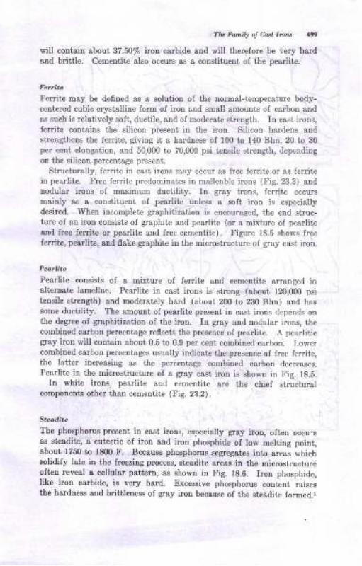
Tlv Fotnily ol M lrc,rc 4rt
will contain aboui 37.50% iron carbide aud will therefore be very hard8Dd brittle. Cementite also occura as I coDstituent of the pearlite.
Fetita
Ferrite may be defined aB a solutioD of the norroal-temperature body-
cetrt€red cubic crystalline form of iron rud small gmounts oI calbon and
as such is relstively soft, ductile, and of moderat€ strength. In cast irons,ferrite contains the silicon present in the iron. Silicon hardens andEtrengthens the ferrite, giving it a hardness of 100 to 14O Bhn, 20 to 30per ceut elongation, and 50,000 to 70,000 psi iensile strength, depending
oD the silicoD percentage preseDt.
Structurally, ferrite in cast irons may occur as free ferrite or as ferdtein pearlite. Free ferrite predomirates in malleable irons (Fig. 23.3) andnodular irons oI maximum ductility. In gray irons, ferrite occure
mainly aB a constituent of pesrlit€ unlees a soft iron is especiallydesired, When incomplete graphitization is encouraged, the end stmc-ture of an iron consists of graphite and pearlite (or a mixture of pearliteand frce ferite or pearlit€ and free cemeDtite). Figure 18.5 shows freeferrite, peirlite, and flake graphite in the microstructure of gray cast iron.
Pearlite consists of a mixture of ferrite and cementite arranged iuslteruate lamell8e. Pearlite in cast irons is strong (about 120,000 psitensile strength) aud moderately hard (about 2N ta 2W Bhn) end hassome ductility. The amount of pesrlite preseni in casi irons depends onthe degree ol graphitimtion of the iron. In gray aud nodular irons, tJre
combined carbon percentage reflects the presence of pearlite. A pearliticgray imn will contsin about 0.5 io 0.9 per cent combined carbon. Lovercombined carbon percentages usually iudicate the presence o{ free ferrite,the latter increaeing aa the percentage combined carbon decreases.Pearlitc in the microstruciure of a gray cast iron is shown in Fig. 18.5.
In whit€ irous, pearlite and cetnentite are the chief structurslcoDpoDeDts other than cementite (Fig.23.2).
Saedi..
The phosprhorus preseut in cast irons, eapecially gray iron, often occu-sas eteadite, a eutectic oI iron aud iron phosphide of low melting point,about 1760 io 1800 tr'. Becaue phosphoru,e segregates iuto areas whichaolidify late in the freezing process, steadite areae in the microstructureofte[ revesl a cellul$ patt€m, as shown in Fig. 18.6. Iron phosphide,like irou carbide, ie very hard. Exceseive phosphorus content raisesthe hardness and brittleDess of grsy iron becaus€ of the steadite iormed.r
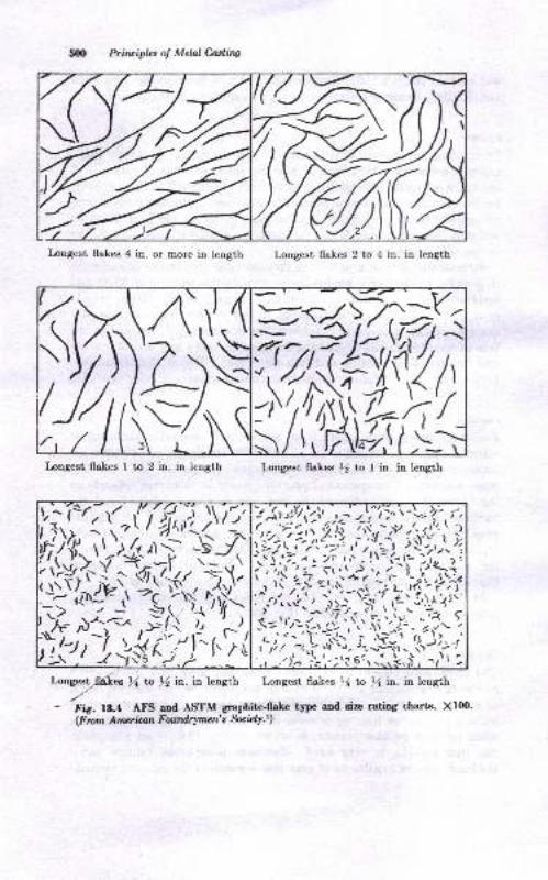
5{m Principbs ol Melal Culitw
Inngest flakes 4 in. or more in length Longest flakes 2 to 4 in. in length
Longest flakes I to 2 in. in length I,ongest Aakes )/z to I in. in length
Lorgearlb(es t4 ta ,i in. in length Longest flakes 16 to ll in. in leugth
- t-is. f8.4 AFS and ASTM graphite-flake type and size rating charts, XIfi).(F rom Amcr ian Foutdrymen's Socl€ry.!)
-r- -.<' l,/:v>,/><<
0ft^4*t,
V;i=r;1il;'r,fY!-!';
fI?-: ,s,#'))?:;j-hfr1",1'r'Ij
*:|;;|a*,\-1 .i.7 a.)r t,r --l\n/-1'- '
ii;iii=\,,'.Arild
i;irfiffi
\ l,'- -l rl'.\ ',t:l'l i- .'rlv-l =.i\,:*
i't r i rl''"72 i. 4.J\
J
'1.,-L'r'f , nl'-
Lgri$rkX
ffi
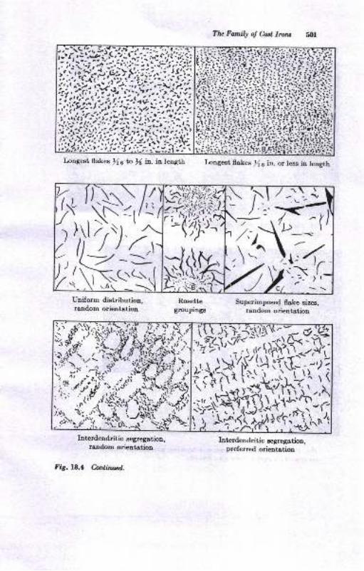
Tlu Fa,mily of ful Iruu
Longest flakq Xa ta l( in-. in length Longest fl*kes [ 6 in. or lese in length
Superimposed flaLe sires,random orientation
T; r'''.-S)/(2\ ,\N- <t/-'
rtl '/') .Q9',-!,(\5r('\
.5d;ilt;i2,'-,ryfiy
$$,x
,f't'' ,ti )''t-.'
if ">
,,,$i.t,H1J,\:"(t1,,,&,,;{.1;i;o1qfu$;ivs'GH.iY:li),i{'Kl?Yr.sili
t'Y-{i1r}iJii.rffiY\",'\Iiltr
FitbSI"-,.\-"^';\i '-\{'j.tdInterdendritic aegregation,
random orientation
Fig. 18.4 C.anliawd.
Interdendritic segregation,preferred orientation
Uniform di8tribution,rendom orientetion
Rosettegroupings
)d,r#'".l*
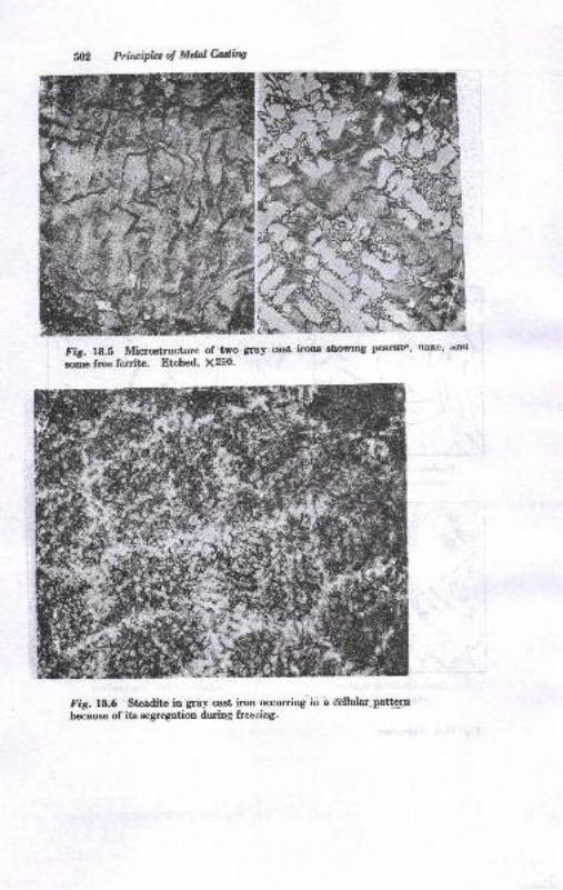
Priltipbs of Mdnl Ming
Fif. 18.5 Micratructure of two gray cast irons showtDs pearlrt'' tlaf,c' dn<r
rome free ferrite. Btrhed' X250.
Fig. 18.6 Steaditc in gray cast iron occurring in a dhilar-pat@ebecause of its segregation during freezioS-
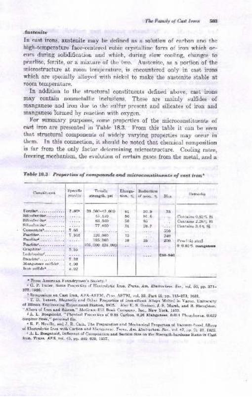
Tlu Farnily oJ Cast lrorc ,t{Lt
.lustcnite
In cast irons, austenite may be defined as a solution of carbon and thehigh-tcmperature face-centered eubic crystalline form of iron which oc-
curs during solidification and tvhich, during slow cooling, changes topearlite, ferrite, or a rnixture of the truo. Austenite, as a portion of themicrostructure at room temperature, is encountered only in cast ironswhich are specially alloyed with nickel to make the austenite stable atroom temperature.
In addition to the structural constituents defined above, cast ironsmay contain nonmetallic inclusions. These are mainly sulfides ofmanganese and iron due to the sulfur present and silicates of iron andmanganese Tormed by reaction with oxygen.
For summary purposes, some properties of the microconstituents ofcast iron are prescnted in Table 18.3. From this table it can be seen
that structural components of widely varying properties may occur inthem. In this conneciion, it should be noted that chemical compositionis far from the only factor determining microstructure. Cooling rates,freezing mechanism, the evolution of certain gases from the metal, and a
Tablc 18.3 Properties o;f compounds and microconstituents of cast irona
CoEtituetrt
tos,000-125,
61
50
502l
15
:: 0-0.80 % @naau@
t Ftom American Foundrymen's Society.r
" G. P. Fuller, Some Propertie of Elect.olytic lron, ?tau. Am. Elqbuia. Sc., vol. 50, pp. 871-377;1926.
lSympoium on Cut Iron, AFA-ASTM, Proc. ASTM, vol.38, part II, pp. lfi-273, 1983.
' T. D, Yerea, Magaetic snd Oiher Propertie of Iron-eilicon Alloyr Molted ia Vacuo, Univeroityof IllinoL Eagineria3 E{Eriment statioD, lgls. Aho E. s. Grcinor, J. s. Maruh, aud B. gtoughton,"Alloyo of lroa end 8ilicon," McGraw-Hill Book Compuy, Inc., New york, l,9BB.
r A. L. B@aehold, " Physicel Ptoperties of 0.88 Carbon, 0.26 MugE@, 0.014 phophoruc, 0.O22Eulphur Ste6l," pereoul 6le.
' R. P. Neville, aad J. R. cair, The Preparetiou and Mechsnicel progrcrtie ol vecuum-fu*d Alloyrof Eletrclvtic Iron witb carbon and Monganeee, Trare. Am. Elecbocicm, soc., vot. 42, p9. 2r-32, 1g22.
J ,1. L. Begehold, Iofluence of Comp@ition aDd Sectiou Sire oE the gtrength-hsdaq Ratio in CutIrcn, Trore. .LP8, vol.45, pp. 59H25, ,.937.
Specificgrsviiy
TeuileEtrength, pri
Elonga-
tioD, 7o
Reduction
of sw. V"
I
Bho I RemarLs
I
7sI. .. ] Contains 0.82 % Si... i Contains 2.2A% 8i
I Contaiu 3.4 % Si
550
240
2OO Pearlitic etel
39,500-42,00045, r50
63 ,50077 ,400
120.000
125,000
30.991 .685
287
l5
f.i..
7 -66,.,.0:
2.55
;.;;'4.005.02
Pearlitol......... . .
Perlitei...........Perliter...........Grephitor....--....I*deburiter..-..,...Stcadite6..._........Manganeee sulideD-.Iror sulffdet...... -.
504 Priilr,ipb oI MelOu,ing
host of variablei in the foundry prsctice may markedly alter micro-
structure, and comequently properties. The actual manipulations in the
foundry may cause drastic changes in the microstructure and properties
of the iron. For example, in gray irons, the type of graphite, whether
A, B, D, or E, may be greatly altered by many variables in the melting
practice. In nodular irons, the graphitc shape, size, distribution, and
nodule count may be varied by melting and metal-handling practice,
resulting in property variation. In malleable irons, the melting practice
and heat-treatment given the white iron are major factors affecting the
properties. In all cast irons, the influence of section size and cooling
rate is omnipresent. IMith all these factors involved, the family of cast
irons can offer widely varying structures and properties for engineering
use, each with its own advautages and limitations. It is a part of the
foundryman's technolory to produce the kind of iron desired for the
castiDg.
PROPERTIES OF CAST IRONS
Because the cast irons are a family of iron-base alloys, their propertiea
may be expected to vary over wide ranges. Furthermore, there are
charactcristic difrerences in properties of the various members of the
family because of the inherent difrerences in their structure and compo-
sition. Each member of the family of cast irons should then be consid-
ered as a series of alloys, offering a range of properties. For this reaEon,
it is not possible to consider merely the "properties of cast iron." Rather,
a broad concept of the tremendous range of properties available in the
individual members of the cast-iron family is necessary.
Engineering properties of the more widely used east irons are discussed
in Chap. 2l (gray iron), Chap. 22 (nodular iron), and Chap. 23'(malleable
iron), to which the student should refer. Two other cast irons, however,
are of importance and are considered below.
Vhite lrons
The principal use of white iron is for the manufacture of malleable-iron
castings. White irons for this use and the malleableizing process are
discussed in Chap. 23. However, some white-iron castings are used as
such because of the high hardness of the material. These properties are
related to its microstructure, which consists of pearlite and a large
percentage of iron carbide (Fig. 23.2) A hardness of 350 to 550 Bhnand over may occur in white irons. The abrasion resistance accompany-
ing this hardness is used to advantage in tumbling-mill jack stars, pulver-
iziug-mill plates, and similar applications. More common use of the
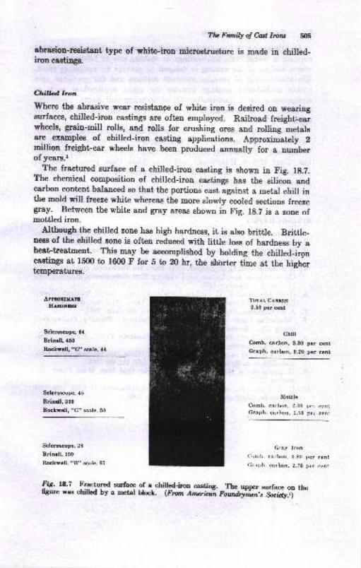
Tlu Fanily of &d lrcru
abrasion-r'esistant type of white-iron microstmcture is made in chilled-iron castings.
Chillad hon
where the abrasive wear resistange of white iron is desired on wearingsurfaces, chilled-iron castings are often employed. Railroad freight-carwheels, grain-mill rulla, and rolls for crushing ores and rolling metalgare examplee of chilled-iron casting applications. Approximately 2milliou freight car wheels have been produced annuxlly for a numberof years.l
The fractured surface of a chilled-iron casting is shown in Fig. 1g.7.The chemieal composition of chilled-iron caetings has the eilicon andcarbon eontent balanced so that the portioud cast against a metal chill inthe mold will freeze white whereas the more slowry cooled sections freezegay. Between the white and gray areas shown in Fig. lg.Z is a zone ofmottled iron.
Although the chilled rone has hlgh hardness, it is also britile. Brittle-nees of the chilled zone ie often reduced with little IosE of hardness by aheat treat'ment. This may be accomplished by holding the chilled-ironcastings at 15fi) to 16m F for b to 20 hr, the ehbrt€r time at the hightrtemperaturea.
APPtoxtxl"EIIaExGls
Sclcrompe. 6{
Brincll,160
Rckscll, "C" sle, ll
TorAL CaBloN3.60 pcr cent
chilr
Comb. carbon,8.8O par cent
Crtph. orbon,0.20 per ccnt
Mottle
Comb. carlxrn. 2.00 Jroi centGraph. carlnn. 1.50 pe. cent.
Cray lron(imrb. carbon, 0.80 Der cent
Cmph. arbon, 2.?0 pcr ctnt
ScbrGcot c, {5
Brlndl,300
RcLvcll, "C" scalc, 30
Sclcrc@D€, 28
Brln.ll,150
Itcksell. "R" rcnle, 8?
fig. 18.7 Fractured surface of a chiled-iron coeting. The upper eurface on tlheffgure was chilled by a metal blocl. (Fmn Anadn ei"A,iii,J-*i&ji *'
5{|6 Prir.ipla ol Mel &diw
A,tl alternative to heat-tr€stments where cooled caetiags are reheakd
consists in traneferring hot castings to soaking pits or holdiag furnaces
where cooling of the caeting is delayed io provide an annealing efiect.
The combination of abraeion-resistant eurlacee and the gray-iron core
makee chilled-iron caetiugs suitable for many applications such ae
sl'rdge-pump liners, iaw-crusher plotes, grinding-mill liners, camshafta,griuding balls, abrasive-mstedala-handling equipEent, ald otber8 of thistype.
Numeroua other cagt irous of specialized chemical composition, micro-structure, and propertiec are also available, but have not been coneidered
iD tJris text. The gtudent interested in rcore details is advised to studythe "Cast Metale Handbook" aod the "Alloy Cast Irous" handbookpublished by the AtrE, ae well ae the numerous relerences cited in theIollowing chapters on cast iron.
BIBLTOGNAPHY
Americetr Foutdrytretrh Socieiy, "C8st Metsl8 Eaadboot," 4th ed., 1944.Americen Foundrymen's Society, "The Cupola and Its OpeBtion," 195,i.The Gray Iron Founders' Society, "Suomary of Gray Iron Specificatione,"Clevola d, 1965.
T. E. Eagaa and C. O. Burgess, Gray Iroo: Its Mechadcst ond EDgiu,'eingChsBct€istics 8Dd Detsils for Deeigning Cast Componetts, Powdry, vol.76, August Sept€lDber, 19,4.C. E. Lorig a,nd T. E. Barlow, Gray Cast Imn, Tensile Streqth, BdnellIlardness, and Compoeition Relatiouhipo, Trant. AFg, vol. 54, 1946.
A. P. Gagnebin, Ductile Imn, Foudry, l,ol.80, June, 1952.
"Marketilg Guide to the Metal Castiry II]dt stry," Fouadry, Penton Pub-lishing Co., Clevelaad, 1964.
Americsn Society for Tesiing Msterisls, Stsndards, P&rt I, Ferrous Metals,1949, Specificstion8 448-il8 snd A15H9C.C. R. Ircper, Jr., and R. I0. Eeiae, Eeavy White Ircn Sectiors Melt Addi-tioDs Efrects on MotiliD8 Teadeooy, Tmns. /FS, vol. 68, 1960.H. Lsplenche, A New Btmotust Di{gra,m for CasL ho\ Metal Prcgr De-cember, 1947.
11. C. R. Loper, Jr., a.nd R. l,l'. Eeine, The Solidification oI Csst Ircn withSpheroidal Graphik, Trufis, ASM, vol. 56, 1963.
1.
1.
5.
6.
7.
8.
9.
1C.
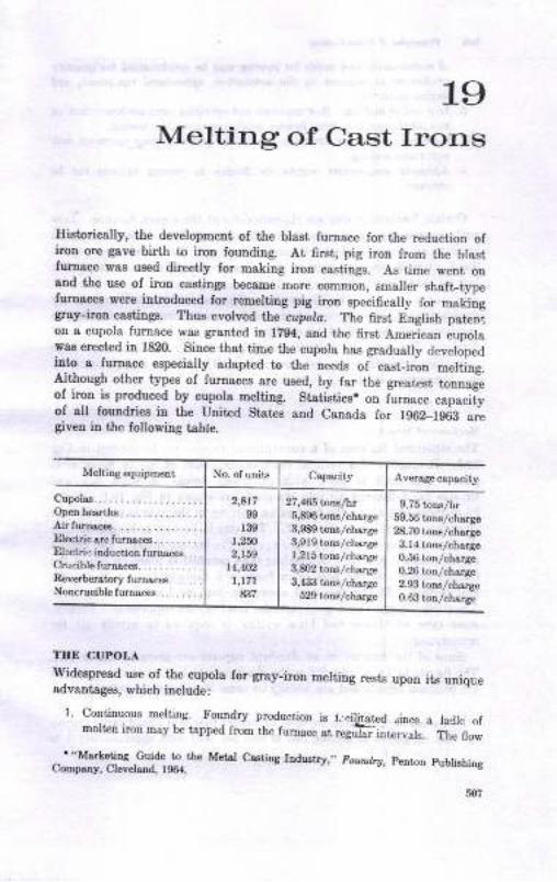
19Melting of Cast Irons
Ilistorically, the development of the trlasi furnace for the reduction ofiron ore gaye birth to iron fouuding. At 6ret, pig iron from the blastfuroace was used directly for making irou castings. As time went ouand the use of iron castings became more common, smaller shaft-typefurnacee were introduced for remelting pig iron specifically fo" ma*oggray-irou caatinge. Thus evolved lhe atlola. The first English patcnion a cupola fumace was grsnted in 1204, 8Dd the 6rst American cupolawas erect€d in 1820. Since that tine the cupola has gradually developedinto a lurnace especially adapted io the needs oi cast-iron melting.Although other types of furnaces are used, by far the greatest tonnageof iron is produced by cupola melting, St8tistiss. on furuace capacityof all loundries in the United Statrs and Canada for 1962_1968 oregiver in the following table.
Melting equipment No. of unita Capscity Average cspacity
2,A17
99
r391,2fi2,159
14,4O2
l,l7l837
27 ,485 lnlas fi\t5,896 toDs/chsrge3,989 t r8lchalge3,919 tons/chuge1,215 t,ons /charSe3,&)2 tons/chr.rge3,4311 tons/cha.ge
529 tons/charge
9.75 torlsAr59.56 tons/chuge28.70 totrs/chsrgo3.14 t nslchargo0.56 ton/ch$ge0.26 toD/charge2.93 tons/ch.ar8e
0.63 ton/ch$ge
TIIE CUPOLA
Widespread use of the cupola for gay_iron melting rests upon itr uniqueadvantages, which include:
1. Continuous melting. Foundry produclton rs l- qii.itatcd "mce a ladlr, r,f
molt€n iron may be tapped from the lumace at regu-d urtr.r,rl.. i;; n"*.
',Msrketina cuide to the Metsl Cr.sting IDdustry ,. Ftundry, penron pubtishingCompmy, ClevelsDd, 1964.
Cupolos........Openhes hs........ ....Airturnac€s.......... -.....I)lectricarcfurrleces.........Electrie induction furnaces...Crucible furn&ces. .. ....Rcverberatory f urnacesNoncrucible furnaces. . . ....
Prircipla ol Mdal Mirq
of molten metal and molds for pouring may be synchronized for quantityproduction as required by the automotive, agricultural equipment, arrd
similar iadustries.
Low cost of melting. R"aw materials and operating cost.s ar€ lower than on
any other type of melting furnace producing cquivalent tonnage.
Chemical-composition control is possible by proper furnage operatjqa-withcontinuousmehing.
4. Ad'equate temperature control fot ffuidity in pounng castings can be
obtaiaed.
'Certain limitations elso ere characteristic of the cupola furnace. Lowcarbon percentages in the iron below about 2.n% C are difficult to attainbecause of direct contact of molten iron and the carbonaceous fuel.Some alloying elements such as chromium and molybdenum are in partlost by oxidation in the cupola. Higher temperatures are obtained withpir-furnace and arc-furnace melting. The use of several furnaces by
Tduplexing, i.e., transferring of the molten metal from one furnace toanother, may be utilized to combine the advantages of each type offurnace. For example, white iron may be melted in the cupola and haveits carbon percentage lowered from about 3.0 to 2.20 ta 2.40 per cent bydecarburization in the air furnace.
Mechanical Structure
The structural features of a conventional cupola are illustrated in Fig.19.1. It consists of a vertical shaft or shell built ol /a- ta af-in. steelplate. The shell is lined with refractory brick. A wind box andtuyeres for delivering air into the shaft are shown in Fig. lg.l. About20 or.more feet above the bottom an opening in the side is provided forcharging materials into the stack. The cupola bottom is hinged so thatthe furnace may be emptied by dropping the bottom doors. The cupolabottom itself is generally of molding sand rammed in place on top of thebottom doors. At the bottom in front is a taphole and spout for themolten iron. At the rear and above the taphole level is a slag hole.The stack is topped by a spark-arreeter hood or dust suppressor. Finally,lome type of blower and blast control is required to supply air forcombqstion.
Somb.of the dimensions of standard cupolas are given in Table lg.l.The figures in Table 19.1 define the characteristics of the various sizes ofthe common cupola and are worthy of some discussion, as follows:
.1. Cuytoln sdze. Cupolas are rated by number from 0 to 12 and vary in capac-ity designated as melting rate in tons per hour from approximately I to35 tons per hr,
2.
3.
:2.
3.
4.
5.
M&ingolWlorv fr9
Shell dianeter. The outcr ehell dirmeter is tfis dimgnsisa which ultimatelylimits the capacity of the cupola. Shell diameters of common cupolas varyfrom 27 to 108 in., although they have been operated rith much mallerand larger diarneters.
Thir.knnss of lmoer Aning. T\is ig t[g lining thichess in zones r{ and B(Fig. 19.1), where the maximum a.mount of refractory erosion occurs.Dimneter, inside lining. The iaside diemeter establishes the operating cross-sestional area of the cupola,Area, hwide cross-sectioral arca in the mehing zonc. Thts dimension deter-mines the range of the melting rates of a particular cupola size. A cupola
Sportorres ler
Section / -;l
Chorgingdoor
Cotechorges
llelolchorges
Chorgiryf/nr
Lhhgshelf
0ofiomdoor indroppedposilion
Iuyerespcep
,
holes
sE
s\us
!GQss^
s\ ssrtt
bQ\
NNNG-at-a
Cokebed -
Slogspoul
8/os/pipe'
Fig. l9.lfuiclY.')
Iopping hole
Structure of the common cupola. (Frun Amaiaan Foundrytun,s
Slog ho/e
Windbot

!B
IAcA
etB3o.
?ii$o3!on€.9oa'
-!;€cri
t6. a<
{: gJ- oo xf€ :iE.E ilto *i?E 3.F
;!9E'4:: dt'EOI o-
; EO C
9 r9:,; o o.r 3 i'!EE?]6a!43li.:2D4*t >.*.Q'9 P:i "
L a2. a
;'a E;'ii34-B:
Blitt; E;iEr i:iy
- r &- E "
ii E i E:'l; !e i;:- d ^i
- d-
a ii{:EiBseiEBt'5'E : E ;a - FEA a
€.i I c:3o: os.3ii-i*:'E I t.i'! F,
i:E!3dNSEEEEE fi f;.s E.gr +*tr { I
z
zE 3 a?.5Eilis
tu€Tsir:-g5E t-93"1 I a
tile
S33EE E9P;3 83383 EE
oseeE =e{+s a$$$F ?l
iiia Qd6il ats@od ro
E;: iE 'tsNNN{ +{O@A O6600 00_
-;-a raai- ii-Nd NN
tsLth
6 -EER9889 eR888 83888 88ioci6i6i€ €{-6i N{NNts N4
;;; i6ididti ddlid6 d"i
fr{EOO6 6NNOO F666F FQ- - - - - iiNNft ol6@N F@
D
s'E
d
Io
!
Ioo
trI ..lN
t-I ..
.l 99l..-_I ..l@
c
oo
oD666 66006 66D69 66-d{{@ €@i6l 6NtsN@ O!
iNNO@ O<
I 3R9e3 3RRB9 R8888 88I a;664 a6dGN Ntsooo @{| -- ;ii- NNOO{ i4
I sBBBe Se98B eeggB BBI -da{6 60i6{ @NtsN@ @l|
-' -dN6o O<
I cBsBR R8893 88888 88I -4666 6060r {ON€O 06r irNN6 OO
I A-EEO OrO@ts r66€i iNI H'NNNo 6EOts@ ro@oQ ooI THiHN NN
EIBi g' ttFF
dNNN@ @6@@r rrr6O6{{<{ {{{iD 66648JJJJJ JJ*dT *.[TIdN66oa {{!{i l<{${
q!^3 8TEssf r1E€iE'_v
>,
\as\aq\a \a \l\aAAAAA AAAA' A AAA A{iNool l@@oQ 6FOl6 QOd iHNNN N@
o { .{ A A AA AAaaaal {4ts@o i!tso€ oFiirdN Ne
@AAAA AAAAA AAAA A
riNNo @<66ts OiOOO ONrd
@
\avu u\l us vv. d.A AA AA AAiri6 NoliE tsooQs aF
ir€jrl {6NN< {6600 0tsdr@ AN6itstsO OtsQOO OdNFF F{d<46Q @O6A@ N@<ON tsA
NNf.i! {4
Eu'Esi,O6EFR RFN6O {OORO @IrN(AO SO{{i €OOFts ts@
!l=;i;, {iits{ Ftstsoo oc600 NN
3i,FNOr- 6d€OO NO<O6 d6N60ii 194@o Fts600 00
tiro
ts.rXXXXordNN o6i6o ts@oo9 :I
tB
oqoL
d
oe)L
Eo
EoLa
o
q)
e)
€
6-B
510
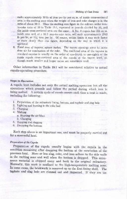
MeUiry ol Cosl lrorc 511
melts approximately l0 lb of iron per hr per sq in. of inside cross-section:J
area in the melting zone when the weight of iron and coke charges is in thel'atio of about l0: l. Thus the melting-rate figure in the column under iron-to-coke ratio of 10 in Table 19.1, expressed in pounds ciir,.ided by 10, andthe inside cross-sectional area are the same. A No.0 cupola has 254 sq in.inside area and, at a 10:1 iron-to-coke ratio, will melt approximately 2540
lb per hr, or lf tons per hr. Of course, within limits it may melt fastcror more slowly than itris figure, depending on the wa)' in which it isoperated.
6. Total area ol tuAeres, square inches. The tuyere openings serve to intro-duce air for combustion of the coke. The combined area of the tuyeres instandard cupolas is usually on the order of one-fourth to one-eighth of theinside cupola cross-sectional area of the cupola at the tuyere level, al-though much smaller and larger ratios are sometimes used.
Other information in Table 19.1 will be considered relative to actualcupola-operating piocedure.
Steps in Operation.
A cupola heat includes not only the actual melting operation but all theoperations which precede and follow the period during which iron isbeing melted. A certain cycle of events occurs each time a heat is made,including the following :
1. Preparation of the refractory lining, bottom, and taphole and siag hole2. Lighting and burning in the coke bed3. Charging4. Melting
c. Starting the air blastD. Charging
5. Tapping and slagging6. Dropping the bottom
Each step above is an important one, and must be properly canied outfor a successful heat.
Prep.ralion oJ the Cupota
Preparation of the cupola usually begins with the cupola in thecondition remaining after dropping the bottom at the conclusion of theprevious heat. More or Iess slag, coke, ancl iron adhere to the side wallsin the melting zone and well when the bottom is dropped. This extra_neous material is chipped away and back to the original refractory.Normally, this work is confined to the high-temperature merting zone.In some cases, the brickwork is removed ,rpt th"-fi..t lining shelfl Thetaphole and slag hole are cleaned out and inspected. If they are too
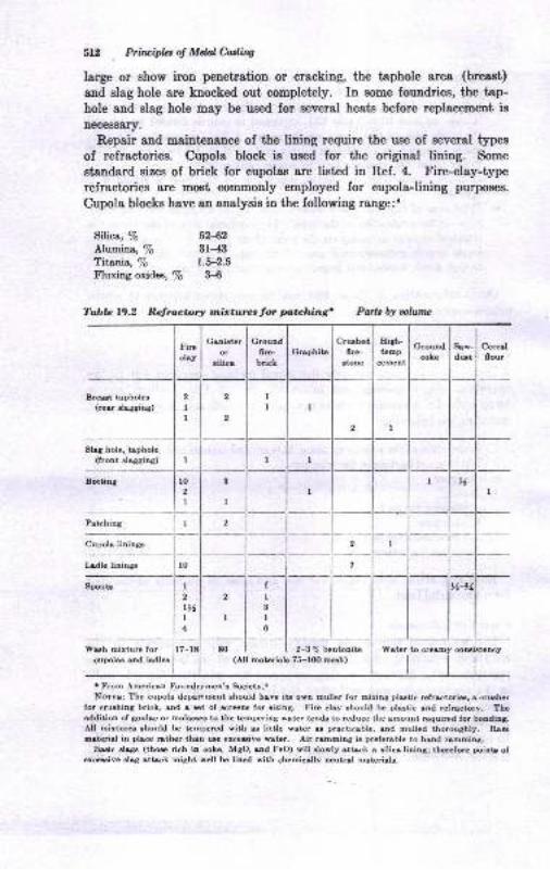
Sl:, P?itoipladMdalC.ading
large or ehow iron penetratiou or cracking, the taphole area (breast)
and slag hole are knocked out completely. In some foundries, the tap-hole and slag hole may be used for eeveral heate before replacement is
necessary.
Repair and maintenance of tihe linipg rcqui16 the use of aeveral types
of refractories. Cupola block ie used for the original lining. Some
stsndard sizes of brick for cupoles are listed in Ref. 4. Fire-clay-typerefractories are most commonly employed for cupolaJining purposes.
Cupola blocks have an aualysis in the following range:'
Silica, % 52,{,2
Alumina, % 3f-4:lTitanio, To 1.5-2.5
Fluxing oxide, To 3-6
Breut tapholec(rear aloggiag)
Sltg hole, tiphole(front elagging)
Cupola liningr
Ladle liningc
W'sh mirture forcupolu cnd ladles
2-3 % bentonite coDsistency(All materials 75-lOO meh)
I From .{,merican Foundrymen'a Seiety..Nmne: The cupola departrunt ahould have itr o*n mullet for mixing plutic refraet rie!, r cruher
for cruehiog brick, and o *t of rcreu for aiaing, Fire clay ahould be plutic rnd refrutory, Theaddition of gouloc or molrc to the tampering wat€r tend. to rcduce the amount requircd for boodiag.All mixturq rhould be tampered with e little vater e prscticable, ond mulled thoroughly, Rrmuterial in place rather thaa ure erceuive s8te.. Air remmiog ir prcferoble to h&nd rshEing,
Bsic rlrgr (th* rich iu coke, MgO, rnd FeO) will slorly sttsck a eilicr lining; thercforc poiDtr ofercwive slag sitsck might woll be lioed with chemicilty n6utr8l m8teri8k.
8rw-durt
Cercal0our
I2r>tt4
2
I
Tablc 19.2 ReJractory tni*tures lor potchingt Pads by oolume
Graphite
I
IIigh-tG6p
ceEetrt
I
Bottitrg
Petchins
Spoutr
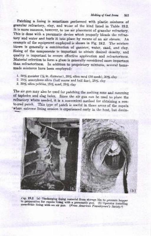
Mdlilq ol Cr.tl llvllru 5Ig
Patching a lining is sometimes performed with plastic mixtures ofgranular refractory, clay, and water of the kind listed in Table 1g.2.It is more courmon, however, to use air placement of granular refractory.This is done with a pneumatie device which properly blends the refrac-tory and water and hurls it i.nto place by means of an air stream. Anexample of the equipment eraployed is ehown in Fig. 19.2. The mixturc
ll,own is generally a combination of ganister, water, sand, and clay.sizing of the components is important to obtain desired density, andquality is important to ensure effective application and refractoriness.Material selectioo to form a g)aze is generally considered more importantthan refractoriness. rn addition to proprietary mixtures, .ur"r"l ho-"-made mixtures have been employed:
l. ioy's gantstnr (YEin. dia^meter),80/6 silica sand (50 mesh), 2O/s clay2. 75% amorphous silica (half coarse and half fine), 25/6 clay3. fi% silica pebbles, 25/o sand,25/e elay
The air gun mBy also be-used for patohing the melting zone and rammingof-tapholes and slag holes. Since the aii gun can be used to place therefractory where needed, it is a convenient.method for obtaining , .oo-
.to.red patch. This type of patch is useful in those areas of thf cupolat1!g" extreme liniug erosion is experieuced eady in the heat, mt ariio-
!ls._19.2..(c) -Di&hargiog liniqg nuterial from storage bin to pressure hoorrerrn preparauoo for cunola linig with a pneumatic er"] flJ Od;";;j;;fifi;nronolithic linios with an air gin. gri,rn *ncrira?-ir";h;;;,;Trii;i,,*
I
(b)
514 Printiplcs o! Metal Ca-stirw
ishes at later stages. As a result, less refractory lining material is
required in patching.
Tapholz and Slag Hole
Tapholes and slag holes may be construeted in several ways. Plastic
mixtures may be rammed in place by hand or with the air gun arounC
a tapered plug. Tapholes and slag-hole bricks may be employed. Anumber of rnethods of putting in tapholes and slag holes are discussed
in Ref. 4.
A dimension of importance is the vertical distance lrom the bottom ofthe taphole to the bottom of the slag hole. This distance determines
the volume of metal which may be held in the cupola well when the
slag hole is left open and the taphole is closed. Ordinarily, the dimension
is such that one to two iron charges may be held in the well except when
low-carbon-content irons are desired.
Bottom
Molding sand may be used for putting in the cupola bottom. The doors
are closed and should fit snugly. Tempered sand, having green strength
of about 6.0 psi or more, 60 or more permeability, and 3.0 to 6.0 per cent
moisture, is rammed in place. The bottom is tapered toward the tap-hole, as illustrated in Fig. 19.3o. Uniform ramming of the bottom is
important so that no iron leaks will develop.
Coke Bed
When the cupola lining is fully prepared, the heat begins with the
building of the coke bed. Essentially, "putting in the bed" means
starting a coke fire and building up a hot-burning coke pile within the
cupola to a preselected height. Often kindling wood is put down, takingcare not to damage the sand bottom. Then some coke is added and thekindling ignited. When the initial coke is burning well, more coke isadded. As the coke becomes hot, more is added until the desired heightis reached. Many foundries do not use kindling wood to start coke fires.
Gas torches inserted through openings at the side near the bottomsometimes are used. The burner ports are later closed with bottomsand. Electric-spark ignitors are also used.
Coke-bed height. The coke bed is defined as the height of the coke
above the tuyeres. Actually, then, the coke-bed height does not referto the coke below the tuyeres in the well, but only to the height of coke
above the tuyeres, because of its effect on proper combustion during rnelt-ing. A correct bed height is necessary at the outset of the heat in order tocause combustion to occur so that metal will be melted and heated to thedesired temperature. Hence the bed should be carefully put in and
measured for comect height. The height rqeasurement is ordinarily
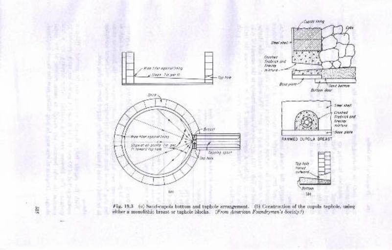
Crushcdlirebricl ondlircclol
fuad bolton
RAMMEO CUPOLA BREAST
Sltl shal
Crushedfittblicl oadtiraclo,
plole
EEii!,!t" Hloulrotd\\ l-L/l
'w:#(D)
li/let ogoinst lining
Slope ol o// poinls'I in.
ll loflotd lop holefopping spoul
Fig.19.3 (a) Sand-cupola bottom and taphole arrangement. (b) Construction of the cupola taphole, ueingeither a monolithic breast or taphole blocks. (From American Foanirymen's Socreiy.)
li//el ogoinsl linihg
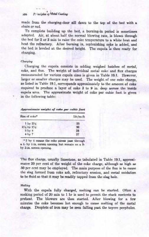
1lil6 P,';luipb otAdal hrli,.e
msde from the charging-dmr sill down to the top of the bed with achain or rod.
To complete building up ttre bed, a burning-in period is sometimesadopted. Air, at about half the normal blowing rate, is blown througbthe bed for 2 or 3 min to raise the coke temperature to a white heat andheat the refractory. After burning in, replenishing coke is added, andthe bed is leveled at the desired height. The cupola is then ready forcharging.
Claryhg
Charging the cupola consists in adding weighed batches of metal,coke, and flux. The weight of individual metal coke and flux chargesrecommended for various cupola eizeE is given in Table lg.l. However,Iarger or smaller charges may be used. The weight of one coke charge,as list€d in Table 19.1, corresponds approximately to the amount of cokerequired to produce a layer of coke 3 to I in. deep acroes the inEidecupola area. The approximate weight of coke per cubic foot is givenin the following table:
lpproritmate rnitht ol olrc pt cubia tot
Size of coke* Lblcu ft
t by 2)4316 by 2r.6
3by44by 7
r 3 by 4 means the coke piecee pass througha tl- by 4-in screen opening but remain on a &by &in. screen openiDg.
The flux charge, usually limestone, as tabulated in Table 19.1, approxi-mates 20 per cent of the weight of the coke charge, although as high as
50 per cent may be employed. The main purpose of the flux is to causethe slag fomed from coke ash, refractory erosion, and metal oxidationto be fluid so that it may be readily tapped frdm the slag hole.
MeAing
With the cupola fully charged, melting caD be started. Often asoaking period of 20 min to I hr is used to permit the stack contents topreheat. The blowers sre then etarted. After blowing for a fewminutes the coke becomes hot enough to cause melting of the metalcharge. Droplets of iron Eay be neen falling past the tuyere peepholes.
33
30
28
27
M&iig of &d l.o'u 517
After E to 10 min from "wind-on," melting progresses suficiently so thstI trickle of iron appearl at the taphole if it i8 open. The heat is usually8t8rt€d with the iaphole cloeed so ihat tirgt iron will not freeze io it.Since the first tap is ofteu cold, it rray be pigged rather thsn pour€dilto mold,s.
The time for firet iron at the iephole iB ED importent messure of thecorrectDesa of the coke-h,ed height. A time of leee thau 8 min fromwird-ou suggeeta too low a'bed and loager than 1O or 12 min sugleetstoo high o b.ll lor the air pressure strd rate employed. Inport&Dce ofthe prper bed height is sssociated with temperature of ihe molten iron.It is usually desired to have the iron issue from the taphole consistentlyLt 2760 tD 2900 F. A low or high coke bed is one reasoD for iron colderthsn this teEpersture range. Of cou$e, air at the proper rate in cubicfeet or pounis per minute is necessary for combustion of ihe coke andmelting to continue properly. Suggested ,wind-box air pressures andblower capacities are listed iu Table 19.1. Several types of blowerg aresvailable with characteristics discussed in Ref.4. As blowing continubs,melting progresses, the cupola stack coDt€nt€ 6ettle, and new chargesmust be added through the door as long aE the hest continues. Metsland slag accumulate in the well, and may be handled by a sequence oftapping and elagging operatious.
Tappin! and St.ssins
Intermittcot tapping requires that the taphole be opened at iDt€rv&lsto deliver iron to pouring ladles. The taphole is then closed with aplastic clay bott. Refrsctory botiiEg mixiures are given iu Tsble 1g.2.Opeoing the taphole is perlorned by picking out the clay plug withwedge-shaped tools. The intervale of tapping are usually predictablesince the melting rate of & particular cupols 8nd the cspscity of theladles are known. Ilence tadles of iron may be withdra*.n at regularintervala. If the well is alloved to overfill with iron, it, will drip iromthe slag hole, where it can be quickly detected. Int€rnittent tappiug iE
u6uslly accompanied by intermitteut slaggiug. As the melt levei rises,elag will ultimately flow from tbe slag hole. Upou tappiug, the drop inmetal level results in cessation of slag fow. Ordinarily, a slag hoL isfirst opeued sbout 30 to 45 min after vind-on iu order to allow time lorsuficieDt EIag to accumulate.
Cootinuous tapping of iron from the cupola is mosi commonly doneby use of some typC of dam on the spout. Such an arrangemeni ieBhown in Fig. 19.4. Critical .dimensions in the system are the heightsof the metal and slag dams above the top of tbe taphole. The formergoverns the height of the metal level in the cupots st a particular bla8tpressure whereas ihe latter controls the depth of slag layer floating on theiron. Similar principles apply to continuous tspping wii..h rear slagging.
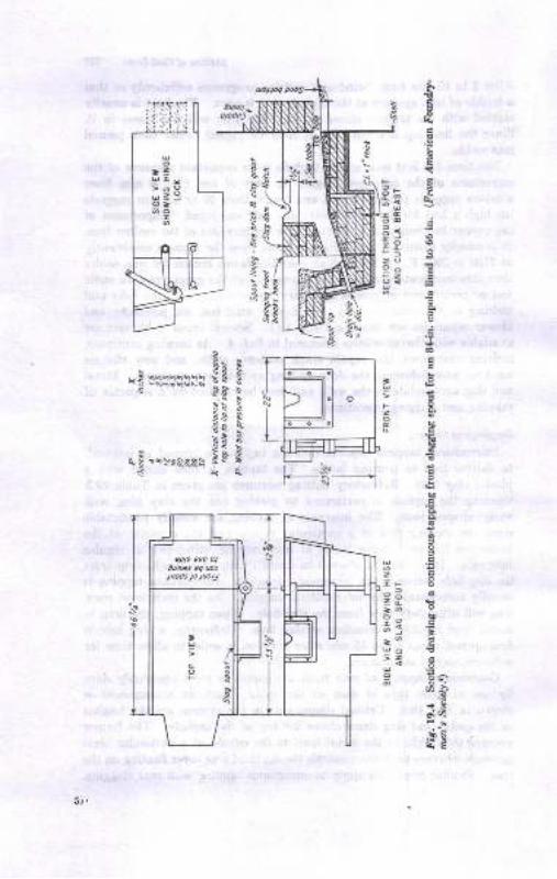
*E
€
.E
I
E
5ri
t!B
!i
e
I
8
.E
.9
.rb.f,
.? .li.:.pb
?
.i
9
R=:e.! !!taoq!! xs !
s aF .s-": !
S.. 3;e s
- :-< -\q ! *.!sR&et ! s* Ss'x(
P
:'
:is
,!st
5;
Mdling ol M. Lvltr 5f9
Drcppittg Bol.tnm
The end of a cupola heat begins with cessation of charging. The stack
contents are melted down until about one or two charges remain above
the coke bed. During this period the air blast is often reduced. 'lhe
bottom doors are then dropped, and the contents fall to the floor under
the cupola. Water is sprayed over the white-hot drop to prevent it from
damaging the cupola legs and bottom. In some cupola installations, the
drop falls into a bucket or gondola and is removed from the foundry and'
quenched with water. Metal and coke from the drop may be recovered
and worked into charges gradually in succeeding'heats.
Although the details of cupola heats may vary greatly, the more com-
mon phases of the operation are those discussed in the preceding sections.
Watpr-coolad Cupobs
Current trends in cupola operations are to increase the production period
of the cupola instead of using either larger cupolas and heavy refractory
liniags or more cupolas maintaining short runs. The latter imposes
greater service requirements on the refractory and cupola shell in the
combustion and tuyere zones. For these reasons, water-cooled cupolas
are in general use iu the industry.Two types of rvater-cooled cupolas are in use, those with an exterr'.al
spray on the sheil and those with water jackets. Water-spray cooling
is shown in Fig. 19.5. This cupola makes use of a thin, continuous water'
film to maintain a cool shell. Additional water sprays may be incorpo-rated at various places on the shell to ensure a continuous water film. Ingeneral, the cupola shell is sloped to a larger diameter just above tuyereso that the water film will adhere to the shell.
Water-jacket cooling is shown in Fig. 19.6. This type of cooling intro-duces cold water into the bottom of the water jacket while thc warmer
water is removed at the top. One advantage of water-jacket cooling isthat cooiing watcr is confined and not open to areas near molten metal.On the other hand, it is more difficult to convert an existing cupola tothis type of cooling.
Mauy water-cooled cupolas, of either of the above types, are operatedwith little or no lining on the inside cupola shell in the melting zone.
After a short period of operation a built-up layer of slag or slag plus refrac-tory is formed on the shell which protects the shell from abrasion of thecharge. If, in addition, the cupola well is lined with carbon block, thecupola may be used as either an aeid or basic melting unit, depending onthe charge material.
In order to confine combustion to a coneentrated area and thereby':rinirnize both the maximum-temperature zone (to prevent excess heat
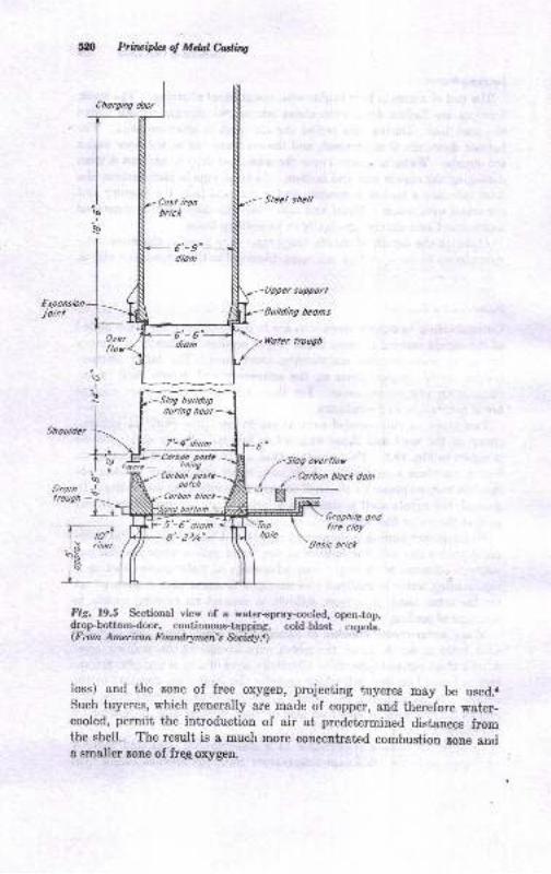
Chorginq door
himipta rli*rcrou*
fxponsbnjoit I
Sleel shell
Upper supporl
'Butlding beons
tYotcr trough
Shoulder
r6"
Grophite ondfire cloy
'&osic brict
Fig. I9.S Sectional yiew of a wat€r-spray-cooied, open-top,dropbottomdoor, continuous-tapping, cold-blast cupoli.(F nm Amcrican Foardrymen's Socirly -r)
Ioss) and the zone of free oxygen, projecting f,uyeres may be used.lSuch tuyeres, which generally are made of eopper, and therefore water-cooled, permit the introduction of air at predetermined distances fromthe shell. The result is a much more concentrated combustion zone anda smaller zone of frqe-oxygen
during heot
7'-4"dbm
- Corbon poslc
tining
Corbon postapolch
overflor
Corbon b/ock dom
6'- 6"-diom
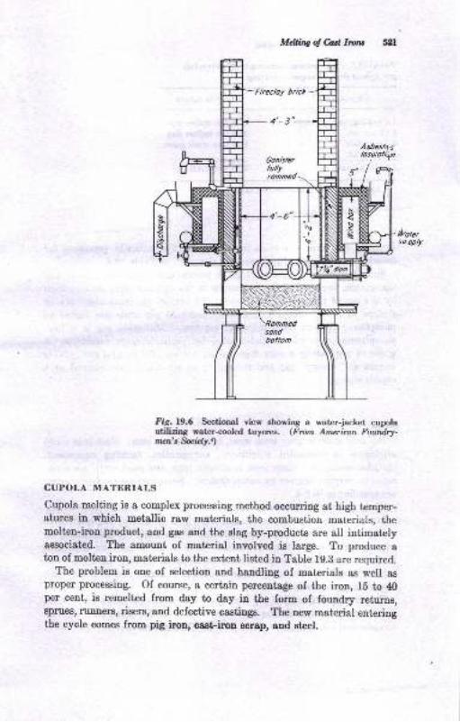
Mdlha of Carl Lon 521
Fig.19.6 Sectional view ehowing a water-jacket cupolautiliriDg water-cooled tuyer€s. (From Ameilcan Fowtdry-men\ fuidy)
CUPOLA MATERIALS
Cupola melting is a complex processing method occurriDg at high temper-atures in which metallic raw materials, the combustion marcrials, themolten-iron product, and gas and the slag by-products are all intimatelyassociated. The amount of material involved is large. To produce atou of molten iron, materials to the extent listed in Table 1g.B are required.
The problem is one of selection and handling of materials as well asproper processing. Of course, a certain percentage of the iron, 15 to 40per cent, ie remelted from day to day in the form of foundry returns,Bprues, runners, risers, and defective castin$. The new material enteringthe eycle comes from pig iron, cast iron scrap, and steel.
Asbestusins!lottv
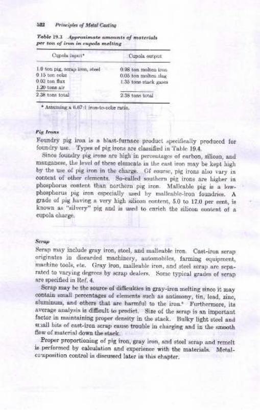
bn PrircipLt o, Mdal Casains
?abL l9,3 Approrirnat @@un,t of m@teriokIrcr .orr of iron iD cupla .nel.iLg
Cqpols input. Cupols output
1.0 ton pia, Bcrsp irco, st€61
0 15 ton coke0.03 ton flux1.20 tonr sir,JS t"* t"t l
0.S ton moltcn iron0.05 tou molten slsa1.35 ton8 Btack Eases
2.38 tom total
' Assuming s 6.67 :l iron-to-coke rstio.
Pit bon,
Fouadry pig irou is a blasLfurn&ce product speciflcally produced forfoundry use. Typee of pig irous are clsssiEed in Table 19.4,
Since ioundry pig irous are high in percentages of carbon, silicou, andmatrganese, the level of these elements in the cast iron may be kepi highby the use of pig iron in the charge. Cf course, pig iroas also vary incoDtent of other eleneuts. So-called eouthern pig irons are higher iuphosphorus cont€nt than northern pig iron. Malleable pig is a low-phosphoms pig iron espedally used by malleable-iron fouudries. Agrade of pig haviug a very high silicon content, 5.0 to lZ.0 per cent, isknown as "silvery" pig aud ie us€d to earich ttre silicon cout€nt of acupola charge.
Scrcp
Scrap may include gray iron, eteel, and malleable Lou. Casi-iron scrapo ginates in discarded machiuery, automobiles, faruiug equipment,machine tool8, etc. Gray iron, malleable iron, and steel
"c"ap a"e eepa_
rated to varying degreee by scrap dealere. Some typical grades of scrapare speci0ed iu Ref. ,1.
Scrap may be the murce of difrcultiea in gray-iron melting since it maycontain rm&U percentcges of elements such as antimony, tin, lead, zino,aluminum, and others thst sre h8rmful to the iron.. Furthermore, itsaverage analysie ie dificult to ptediet. Size of the ecrap is au importantfaeior iu maintainiug proper deDsity in the stack. Buliy light steel audereall bits of cast-irou scrap cau6e trouble in charging and in the smmthflow of materiel down the gtack-
. Proper proportioning of pig iron, grsy iron, and steel ecrap and remeltfu performed by calculation and experience with the mahrials. Metsl-cc:npoeition control is discussed later in this chapter.
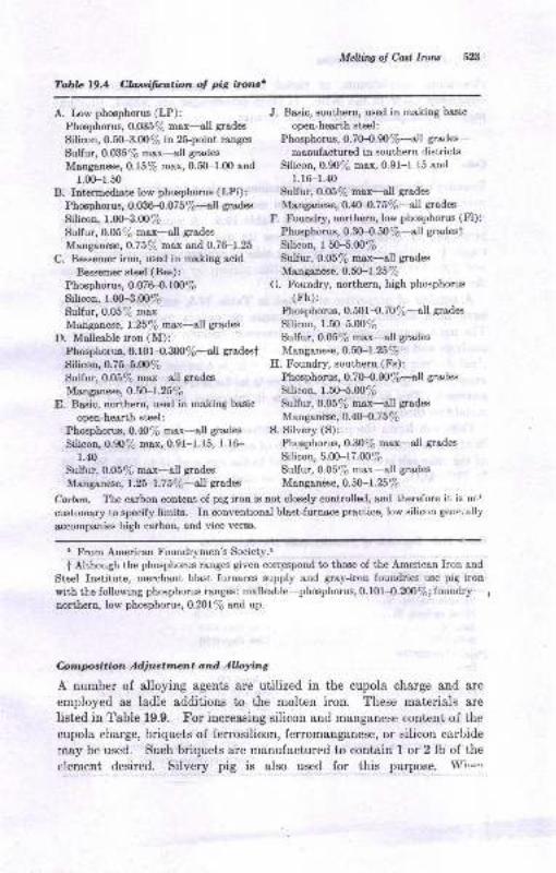
Melling oJ Casl lrorls
Table L9.4 Cbssifcation oJ pig irotts'
Silicon, 0.50-3.00/6 in 2lpoint ranges Phosphorus, O.7}4.907o-all grades-
Sulfur, 0.035% max-all grades manufactured in southern districts
Manganeoe, 0.157o max,0.50-1.fi) and Silicon, 0.90% max, 0.91-1.15 and
1.00-r.50 l.l6-1.40B. Intermediate low phosphorus (LPi): Sulfur,0.05/e max-all grades
Phoophorus, 0.036-{.075%--a[ grsdes Manganese, O.a04.7 $/o-all grades
Manganese, O.757o mox. and 0.76-1.25 Silicon, I fi'i.N%
A. Iow phosphorus (LP):Phosphorus, 0.035/2 max-all grades
Silicon, 1.fiF3.0O%
Sulfur, 0.05le max-all grades
C. Bessemer iron, used in making acid
Bessemer steel (Bes):
Phosphorus, O.O7 H.lWfloSilicon, 1.fiF3.00%Sulfur, 0.057o morManganese, 1.2516 max-all gradea
D. Malleable iron (M):
.Silicon, O.754.N7oSulfur, 0.05/6 max---sll grades
Manganese, O.50*l.25%
r.40
Sulfur, 0.05% max-all grades
Manganese, 1.25-1.7 \To-all grades
J. Basic, southern, used in making basic
open-hearth stcel:
F. Foundry, northern, low phosphorus (Fl):Phosphorus, O.}O-{,fi /o----all gradest
Sulfur, 0.05% max-all grades
Manganese, O.fi-L.257o
G. Foundry, northern, high phosphorus
(Fh):Phosphorus, 0.501-0. 709lo-all grades
Silicon, 1.50-5.00/p
Sulfur, 0.05/6 max-all grades
H. Foundry, southern (Fs):Phosphorus, O.7o4.9tl7o-all grades
Silicon, 1.50-5.fi)%
Silicon, 5.0G-17.(X)%
Sulfur, 0.05lp max--all grades
Man ganese, 0.50-l.25ok
Phosphorus, 0.f01-O.$O%-all $adest Manganese, 0.fi-l.25yo
E. Basic, northern, used in making basic Sulfur,0.05% max--all grades
open-hearth steel: Manganese, O.4M.757o
Phoophorus, 0.$% max-all srades S. Silvery (S):
Silipon,0.90% max, 0.91-1.15, l.lG- Phosphorus, 0.30% mar-all grades
Carbon. Thecarboncontentofpigironisnotcloselycontrolled,andthereforeitisnc|-custom&ry to specify limits. In conventional blast-furnace practice, low silicon gene,-ally
accompanies high carbon, and vice vers&.
' From American Foundrymen's Society.r
t Although the phosphorus ranges given corrpspond to those of the American Iron and
Steel Institute, merchant blast furnaces supply and gray-iron foundries use pig ironwith the following phosphorus ranges: malleable-phosphorus, O.1014.N7o; foundry-
1
northern, low phosphorus, 0.2D1l6 and up.
C,zlnpcition Adiustnent and Allaying
A mrmber of alloying agents are utilized in the cupola charge and are
employed as ladle additions to the molten iron. These materials are
listed in Table 19.9. For increasing silicon and manganese conteot of the
cupola charge, briquets of ferrosilicon, ferromanganese, or silicon carbide
may be used. Such briquets are manufactured to contain I or 2 lb of the
clement desired. Silvery pig is also used for this purpose. Whe'
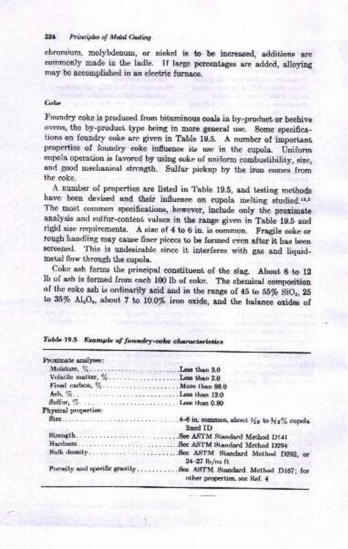
52r Priuipla of Mdal &slir.g
chromium, molybdenum, or nickel is to b€ inereased, additione arecommonly made in the ladle. If large percentages arc added, alloyingmay be accomFlished in an electric furnace.
Cokc
Foundry coke ie produced from bituminous coal. in by-product or beehiveovens, the by-product type being in morp general use. Some specifiea-tions on foundry coke are given in Table 19.8. A number of importantproperties of foundry coke influence its use in the cupola. Uniformcupola operation is favored by using coke of uniform combustibility, size,and good mechanical strength. Sulfur pickup by the iron comes fromthe coke.
A number of properties are ligted in Table 1g.5, and testing methodshave been devieed and their influelce on cupola melting gtu61.6.rr,oThe most corrmon speeifications, however, include only the proximateanalysis and sulfur-content values in the range given in Table lg.s andrigid size requirements. A size of 4 to 6 in. is Gommon. Fragile coke orrough handling may cause finer pieces to be formed even afterlt has beenscreened. This is uudesirable since it interferes with gas and liquid-metal flow through the cupola.
Coke ssh forms the principal constituent of the sleg. About 6 to 12lb of ash is formed from each lfi) lb of coke. The chemical compositionof the coke ash is ordinsrily acid and in the range of 45 to 55% SiOr,ZSto U% Alzor, about Z to lO.O% iron oxide, and the balance oxides of
Tabb19.5 Enmpb of tounfuy-dcc clrrrttr:to,rbtilr;s
Proxirnate analysea:
Moisture, %..... ...,.LGEB'ha.3.0Voletilemattnr,Vo. ....t€ssthan2.0Fixed carbon, %..... .Morethan86.0ABh,%. ......L€ss thor l!.6Sulfur, /6. ....L€sE th8n,.&)
Physical propertieo:
Size. .. . . . -. .ffi in eommon, *out)ls ln){zV, cupolalined ID
Strength. . . . . .See ASTM Standard Method Dl4lHa^rdness. . . . . .See ASTM Standard Method D294Bulkdensity. ..S€e AS.TM StEndard Method A2V2, or
24-27 lb/au ltPoroeityandspecificgravity. ...See AIITM Standard Method Dl67; for
other propertiea, see Ref. 4
MdlirvotM l10,r,6 silli
ma,nga[ese, magne8ium, snd slksline eartbs. FusioD oI ttre coke aah
occurt in the melting zone, The fueed ash has high viacosity, however,aud requires fluxee to make it fluid for eaee ia tappiag it from ile elaghole.
Fr,,,c,
tr'luxee are baaic mat€riale which will react witi tbe coke aeh snd meltedrefractory to make a 0uid alag. tr'luxing agents used Eost often arelimestone, fluorapar, and eoda aeh. Limeotoue is CaCOs of about gB perceDt purity, having a size of -2 in. and *fl in. The ..gtone,, shouldhave a low acid oxide conteut. Dolomitic limestoneE hsviug 15 to 30%MgCo3 replacing some of the CaCO" in strsight limestone are algo em-ployed. The stone begina to decompose to CoO aad CO, at a temperstureof about 1470 F aB it deEcendg in the stack. The CaO freed from theCaCO" reacts with the acid congtitueuts of the seh and refractory toproduce the fluid slag, which may be tapSred from the cupola. Additioneof fluorspar and soda aeh caus€ the slag to be more fluid dun when onlyotone ie employed. Chemical compoaitions ol typical cupola elags andfluxes are given iu Table lg.6-
,ti,firc 'r'alerials ueceseary for cupola operatiou include air about equivaleutia weight to each ton of iron produced. The air may vsry in Lmpera-tul?t lresEure, humidity, and unilormity of a delivery to the cupola.Air blowiag aud meteriry equipmetrt hsE been deviged to control the,rsteof flow. rlumidity couditioning, or dehuoidification, is practiced bysome foundri€s. Preheated air, or hot bl8st, m8y also be employed.Because of the importance of ttre sir blast, many attempts have beenmade to impmve the quality of the blast by specially desigued tuyeres,balanced blaet rith two or more towe of tuyeres, or other featuree.
-Su,lh
p-ractices are outside the scope of tJre text but may be foud exteuaiv,:lydiacuosed in tachnical literature such aB that included in the Bibliography.
PRINCIPLES OF CUPOLA OPERATION
Succegsful cupola operation hinges largely on combugtion conkol. lnorder to hsve favorable melting conditione it ia neceaury to hsve abalanced combination of coke aud air supplied at the proper ratc. .With
proper combustion, the coatrol of metal compoeitiou, temperatxre, sndrlaggiug can be accompliahed.
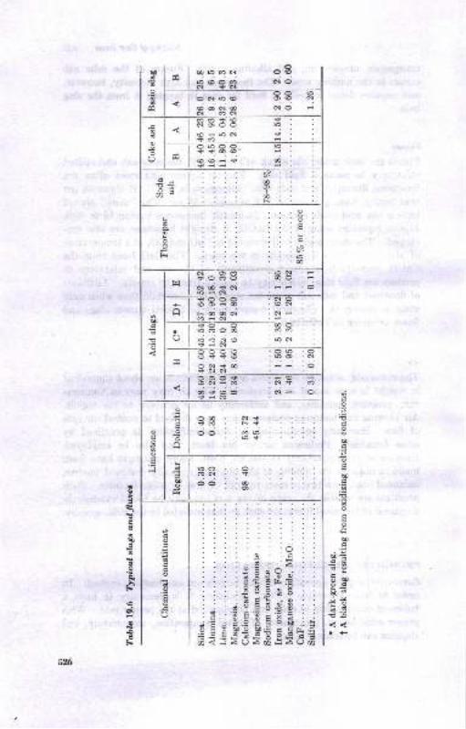
(DUdo
3tq
ol
"l
(r16cOC{ O6ro@o(n c\aoN <N
-oo @
?N'!9 q@ q@oN!Q NO
@ct
o.&
O
mm<@ tfNAOO 6,e; J rj c.i nsmOLiOO$<6@
d@@i$
d-
=h
6s00
I6N
oa
tq o@
asd@
trl
N
N(o qrj
?,1 ?6$6tiN
€N /e?.aii O
+a
NO@N
c\r Ni
!i-o6 .c66ri;n<; :,.i6i3iN
, OOCq)l€rs(oI oor=od] $NN
o&!q N
o
--o$ -9 i
':N-c! :cl 1 :mco$@o Ni oiica
o
@
-l
o
A
oco . .N$1e : :\1oo . mlo
' ro$
d
Uotr
roo.6Ndc;
,@O)
o
@
co
o
O
rtao
eu)a
o
u)INdxoa
Ud
UI:o
3uoqil?J!E!t-o
r+
aq)
H
!0E
B
e->i
\0g\
o€.E
526
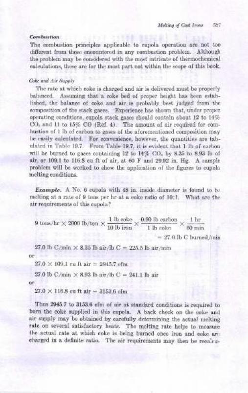
MeLtinq ol Cast Imn it i
Qtmbuxtion
The combusiion principles applicable to cupola operation are not too
difrerent from those encountered in any combustion problem. Although
the problem may be considered with the mosi intricate of thermochemical
calculations, these are for the most psrt not within the scope oI this book.
Coh and Ai Supplr
The rate at which coke is charged and air is delivered must be properly
balnnced. Assuming that a coke bed of proper height has been estab-lished, the balance of coke ond air is probably best judged from the
composition of the stsck gases. Experience has shown that, under proper
operating conditions, cupola stack gases should contain about 12 to l4/oCO. and 11 ta 15% CO (Ref. 4). The amount of air required for com-bustion of I lb of carbon to gases of the aforcmcntioned composition may
be easily calculated. F,or convenience, however, the quantities are tab-ulatcd in Table 19.7. From Table 19.7, it is cvidcnt that 1 lb of carbonwilf be lrurned to gases cont&ining 12 tn 14% CO" by 8.35 to 8.93 lb ofair, or 109.1 to 116.8 cu ft of air, at 60 F and 29.92 in. Hg. A samplcproblem will be worked to show the application of the figures to cupolernelting conditions.
Erample. A No. 6 cupola with 48 in. iuside diametcr is found to b..
meliing at a rate of 9 tons per hr at a coke ratio of 10:1. Whai are thcair requirements of this cupola?
9 ro.s,hr X 2ffx) lh/ron r l-]! "9]t" ,
0 90 lb rarbon r I hr
10 lb imn ' I lb cokc ' 60 n,in
: 27.0 lb C burned/min
27.0 lb C/min X 8.35 lb airllb C : 225.5 lb airlminor
27.0 X 109.1 cu fr air : 2945.7 cf.m
27.0 lb C/min X 8.93 lb airllb C : 241.1Ib airor
27.0 X 116.8 cu ft air : 3153.6 cfm
Thus 2945.7 to 3153.6 cfm of air &t standard conditions is required toburn the coke supplied in this cupola. A back check on the coke andair supply may be obtained by carefully determining the actual rieltiDgrate on several satisfactory heats. The melting rate helps to measurethe actual rate at which coke is being buroed once iron and coke ar,:cbarged in a definite ratio. The air requirements may then be recaitu-

:- tnr' .
!sEE IE3o;ri5>*EE
I
+
i3liP
88eR3 RSeBe 83R89 83oi60ts ooiR{ 6ts€i6 6E60600 0iili il{€6 E6
coooo ooooo ooooo 66+{i!o oot@o 64o60 <6HNel6 0600N 690@O Nioooo6 0001i n!!i9 a6
o6000@oorNNNOO6
oooooF@@OONNNNQ
6N 3--ot!
&
;E,E88888 t8t88 88r88 88r88 88oc3@o tsNtsNo ioF60 0€<6i dNd;r{ dd "iddljti do;dd,.i -.i6idi{6 €'a
iTTNq NdNNN Nd
go qq{tso{o oooao roH@@ @itsaaSFOdI FON6O d4ON@ O66<rFtsF@6 @OOOO OOOii -NNo<
;o-t4 6;ddd@oi6b r6666 {EN66 6{o@HoE @Oo€o d66&6 66octsFF ts@o@@ OOOOe Hi
'5oEtl
6Q
i dJrod {c;i-QoF FOdFe iot60r6O@i <tsi{o N@ot6l{<i6 66666 Ets660
t8r>
g:tEtr
\
@ooiN
oI
OON@4 dO6{6 --OoO O{<Ei63@@N ForF6 €oiO6 666b*o@oN@ ooNde o<oio +6o.,i6iin6s 6@oFN tso€OO OriN6
Nts
d"i
tio
i:c\
64o
?
Fi
z
oO
oo
I <rooo {ots{d drdio H66r| !6ts@o ro{€o oNa@6 i6ii6oN ia-oI ++ii+ G"i"j"i6 6dddd FFNFd dci
lsse:8 tEPRS 6985t S8B6; :8| 6i6i6i6i6i ,i;,.;-iJ ..:Ji..:..: oociod c;o
8l sl. q 8.3j. = Iooooo oooor A ddNN6 mo
F{iOO 60i6ts d@D66 {EN66tsoroi @@roe @eo€o N6oAo o6o€Ntsts FFO@@ @OOaO OO6di
3 <lI
JzlI
9l
E3=B? Bt=38 68883 SEERg t3646€o @oNEN NO@@o oooOO
==
$qRqq iq!qq qF$sB :336i sEl{i{o 46666 0€€€@ NtstsN@ @@
qq!iq qqqqe qqqaq 36Rs5 EE;; -;;6i 6i 6i 6i oi..i 6i 6i
.yd6?oqZe 2
m! ESSH$ sHPFB gEEH$ g3Ri3 8E;ciood dddcjd doddc; dcjddd c;c;
"gE&EE3 B3$Fr il8535 sBRsS N8OOOor iiNdo o<<ie €6r:i:06 AEdc;dod c;<tddd dac;c;d ddc;dcj o;
ua
z6-
8Ba-:-5N
oo@oo omoQN @6N&$ itsi-F oo..idisr dddcji ;,@@@bb 666Ei- .iIFRS PFSXI fR.;!;=s!a e!q?;d qidsdjJ o;di<;;; -j;OQOdN NNNNd
oaNo{ a@F@o oiNoi @@N@o or6N
;ca
E
i
otaE
E
L
t
tco
a
o
g
o
l)
l)
Be)L
\Be)
tr
Fsi
o
-€tr
58
ti
(.)
ONF6-
-..
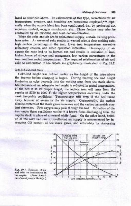
Mdling of M, Iroru 8tp
lated ae deecribed above. In calculatione 9f thi" type, corrections for 8irtemperature, pressure, and humidity are sometimes employed,r,l. espe-
cially when the cupola blast has been conditioned, i.e., by preheated air,moisture control, oxygen enrichment, etc. Those fsctorE may also be
controlled by air metering and blast dehumidification.When the coke and air are in unbalanced eupply, certain meltiug prob-
Iems arise. An excese of coke results in wasted coke, a slow melting rate,high carbon percentage in the iron, lower iron temperature, excessiverefractory erosion, and other operation difficulties. Oversupply of aireauses the coke bed to be burned out and result€ in oxidation of iron,higher losses of eilicon and manganese, low carbon percentages iu theiron, and low metal temperatures. The required relationships of air audcoke to combustion in the cupola are graphically illustrated in Fig. 1g.7.
hhc Bed and ShckGascs
Coke-bed height was defined earlier as the height of the coke abovethe tuyeres before charging is begun. During melting the bed heightfluctuates as coke descends into the melting zone from the stack above.Maintenance of an adequate bed height is reflected in metal temperature.If the bed is at its proper height, the molten iron will issue from theeupola at 2750 to 2900 F, the higher temperatures occurring under themost favorable conditions. Temperatures will drop if the bed burnsaway because of excess iu the air supply. Concunently, the carbondioxide content of the etack gases increases and the carbon monoxide con-tent decreases. Free oxygen may pass through the bed. Oxidation of theiron under these conditions results in a brown fume discharging from thecupola stsck in place of a normal white fume. Ou the other hand, build-up of the coke bed due to insufficient air supply ie accompanied by in-ereasing CO content of the stack gases, and ultimately by decreasiug
3
l@
90
80
30
25
N
r5
o
oC)
oI
I
Fig. 19.7 Relation of airand coLe to combustion inthe cupola. (Frcm Am*i-an Foundqnwn's Socrzly..)
678grortzCokc cmbustion,looo Btu p.r tD
70ft
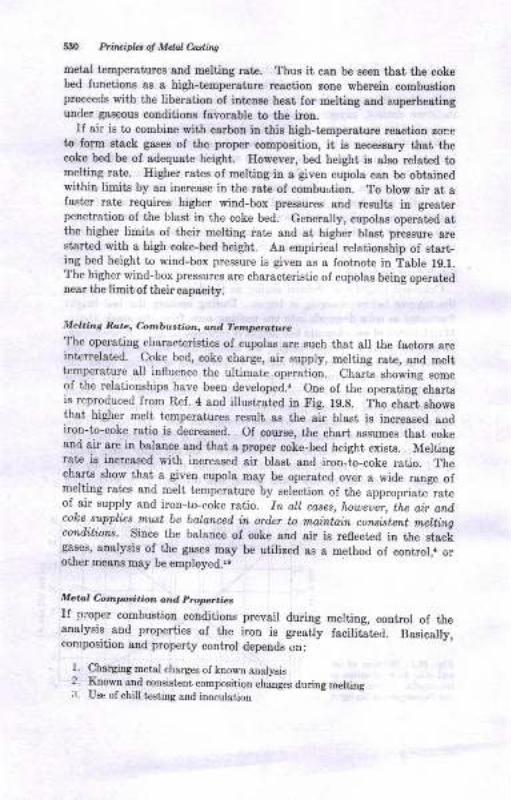
li:10 Ptiuifu ol Mdd Codins
metal temperstues 8trd meltitrg rste. Thus it can be seeD that the cokebed fuuctions as a high-temperatue reaction zone wherein combustionproceeds with the liberation of intense hest Ior melthg aad superheatinguuder gaseous couditions lavorable to the imu.
If air is to combine with carbon in thig high-temperstue rraction roreto Iorm etack gares of the proper compositioD, it i8 nec€ssary thst thecoke bed be of adequate height. However, bed height ie also related tomelting rate. Iligher rates of melting in a given cupola can be obtainedwithin limite by an increase in the rate oI combustion. To blow air at afaster rat€ requires higher wind-box pressures and rezults iD greaterpenetration of the blast in the coke bed. Generally, cupolas operated 8tthe higher limits of their melting rate and at higher blaet pressure oresisrted with a high coke-bed height. An empirical relatiouship of etart-ing bed heighi to wind-box pressure is given as a footnot€ in Table 1g.1.The higher wind-box pressures are char&ct€risiic of cupolse being operatednear tJte limit, of their capacity.
al.it,'g Ro,a, Ca.nbu.tion, ond T?/r',l,.iro,.urc
The operatiug cbaracterietice oI cupolas are Buch thst 8 the factors areinterrelated. Coke bed, coke charge, air supply, melting r8te, and melttemperature all iufluence the ultimate operatioo. Charts showing someof the relationships have been developed.. One of the operating chart€is reproduced from Rel. 4 and illustrated in Fig. f9.g. The charl rhowsthat higher melt t€mperstureE reeult as the air blast is inereased audiroq-to-coke ratio ie decreased. Of course, the chart assumes that cokeand sir are iD balanoe aDd that a pmper coke-bed height exists. Meltiugrate is increas€d with increased air blast and iron-io-coke ratio. Thecharts show that a given cupola may be operate,J over a wide range olnelting rates end melt temperature by selection of the appropriadrabof air supply and iron-to-coke ratio. fa all coaes, howeiir, ihe qir andcoke suppl,ir,s rnut be balanced in ord,er to mainiuin consistent meltingconditions. Since the balauce of coke and air is re0ected in the stackgases, aualysis of the gases may be utilized aB s method oI cotrtrol,. orother means uay be employed.rs
Metal Coiml,,,sition and Propeaiet
II proper combu.etiotr couditioos prevail during melting, coDtrol oI theanalysis and properties oI the irou is gready facili;te.i. Basically,composition and property control depends on:
l. ChargiDg metal charges ol known analysis2.
Srown 8nd consistent composition chengm during melting
:1. Use of chill t€sting and inoculstion
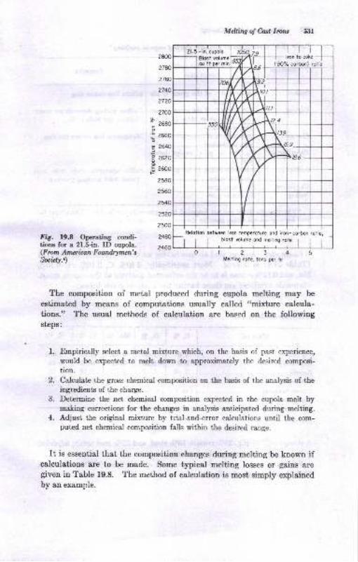
28o0
zlao
27@
?740
2720
2700
2680
2660
zw2620
2600
2580
25@
2540
EF
MeUing oJ C,osl lrons 531
lron lo coke
(90% corbon) rctio
1234Mrlting rofe, tons ,Er hr
Fie. 19.8 Operating condi-tions for a 21.5-in. ID cupola.(F rotn Anv* iran Foundrytlcn'sfuidt.t)
1.
,
o-
The composition of metal produced during cupola melting may be
estimated by means of computations usually calleri "mixture calcula-tione." The usual methods of calculation are based on the followingsteps:
F,mpirically select a metal mixture which, on the basis of past experience,
would be expected to melt dowa to approximately the desired composi-
tion.
Calculate the gross chemical composition on the basis of the analysis of theingredients of the charge.
Detemrine the net chemical composition expected in the cupola melt bymaking corrections for the changes in analysis anticipated during melting.Adjust the original mixture by tiial-and-error calculations until the com-puted net chemical composition falls within the desired range.
It is essential that the composition changes during melting be known ifcalculations are to be made. Some typical melting losses or gains aregiven in Table 19.8. The method of calculation is most simply explainedby an example.
Relotion between irm temperolu/€ ond i.on-corbon rotio,blosl rclume ond meltirq rote
21.5 -in. cupoh
-l Blost volumrI e- lr ne, mi' ffi
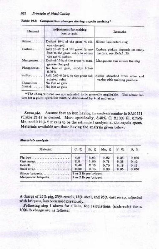
Adjustment for meltingloss or gain
Sill PrilrcifuotMddc,adhs
Iabb 19.8 rColmlloulitbn clun3cc du,{lng cupb rmclcing.
Silicon........ Deduct l0% of the gro$ % sili-con charged
Ldd, lO-20% of the gross /q car-bon to the gross value to obtainthe netle carbon
Deduct 15 % of the gross To rl,sn-ganese charged
No lom or gain, exce'pt belowO.ffi9"
Add 0.03-0.05% to the gross cal-culated volue
No loss or gainNo lose or gain
Rcmarks
Silicon loes enters eleg
Carbon pickup depends on manyfrctora; see Refe.l, 25
Manganeee loas enten the slag
Sulfur rbsorbed from coke andvaries with melting practice
P, Vo S, 7o
I The changes listed are not iatended to be geuerally Bpplicsble. The actual fac-torc for a given opention nust be determined by trial and error.
Dratnpl.e. Aseume that an iron having an analysie similar to SAE lf l(Tsble 21.4) ie desired. More specifically, B.4O/o C,2.lO% Si, O.Z5%Mn, and 0.12% S max is to be the estimated analysis at the cupola spoutMateriale availabl€ 8re those haviug the analysis given belowi
Pig iron.Cast scrap.
Rcmelt.Steel screp.
Silicon briquetsManganese briquets.
I or 2 lb per briquetI or 2 lb per briquet
c, vo
4.03.03.400.30
3.051.902.t50. r5
0.25o.250. r80.05
0.0300. 12
0. 12
0.050
A charge of 35% pig,2|/o remelt, l5/o stnel,^Dd25% csst Bcrap, adjustedwith briquets, has been used previously.
Following step I above for silicon, the calculetions (rlide-rule) for af000-lb charge are 8s follows:
Mcterio,b analysis
Material Si, % Mr, 7o
0.92o.7to.700.30
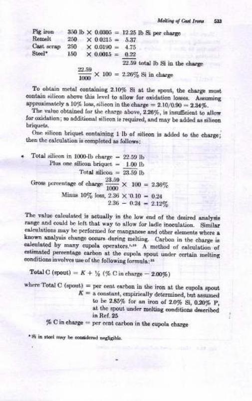
M&noodWlnu nt3
PiC iro" 350 Ib X 0.(B08 : 12.28 lb Si per chargeRsm€lt 2il X 00215: 8.3?Cest scrap 250 X 0.0f90 : 4.ZE
St€eP l5O X 0.0015 : 0.22
d.Iss bt J lb si h the chsrSe22.59
m X rm: 2.26% Si ia chrrse
To_ ob!1in metal conteiuiug Z.IO% gi st tle apout, the charge mustcontsin silicou above this level to allow for qidation loeeea, Assuningappodmately a 10/o lobE, silicon iD the ch atge : 2.lO/O-gO : Z.Uro.
_ The value obtaiDed for the charge above,226fr, is inauftcient to allow
for oxidation; ao additional ailicon is required, aDd Esy be sdded aa silicoabriqueto.
.. One silicon briquet corteining I lb of silicon ia added to the chargej
then the calculatioa ie completed as follors:
r Totgl silicon ia lOOGlb charge : "2.8C
lbPlur one rilicou briquet = 1.0 lb
Total Eilicon = 23Sd IU
- 23.59uFoca F,crcentage ot chsrge
160- X lO0 : 2.16%o
Minue l0la lcs, 2.86 X.0.10 : 0.242.86_O.zt:2.t2Vo
The value calculated is actually in the low end of tle deaired analyeiarenge and could be left thst wsy to sllow for ladle inoculatioo. Similar
-calculatiotrs Eay be performed for mangsnere snd otier elements where a
taom analysis ebange occure during meltiog. Carbou in tUe cf,arge iec8l:ul8t€d by many cupola operators.l,"5 A method ot calcuiltiii ot€Etimsted peceDtsge csrbon at the cupola 8poui, utrder
"""t"io--"iti"gconditioua involvea uae of the following formuta:'.
?otelC(epout): K+ % (% Qitchgfl* - 2.@%)
whe.re Totsl C (gpout) : per cent carbon in the iron 8t the cupol8 spout.K = a coastant, empiricslly determin€d, b;t 8ssuned
tn b 2.85% lor an iron ol Z.O/o Si,LfiS p,at the apout under melri.g conditions deecribedin Ref. 26
% C ia chrrge : per cent carbon ir ttre oupola charge
. gi in rt .l rDry bo coEddetrd D€gligiblo.
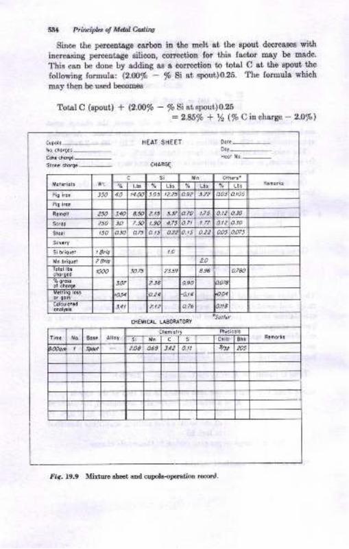
5t4 Pt,in ipla ol Mdal einq
Since the perceotoge ca,rbon in tle melt at the gpout decreas€s withincreasing perceotsge eilicon, correctiou for this fastor may be made'
This cBn be doue by adding as a correction to totsl C at the gpout the
following formula: (z.fi/" - % Si at epout)0.25' I'he lormula which
may thel be ueed becomee
Total C (epout) + (2.O0% - % Si 8t spout)0.25
= 2.85% + t/2 (/o C \n chzrge - 2.0/o)
Cupolo-to ci.rg.i-CoL cl'.r!.-Ston. cn6.e.
-
HEAT SHEET
CNARGE
ooy-
c8€HrcAt LAEORAToSY
fir. 19.9 Minure sh€ei ard cupola-oFratioD recqd-
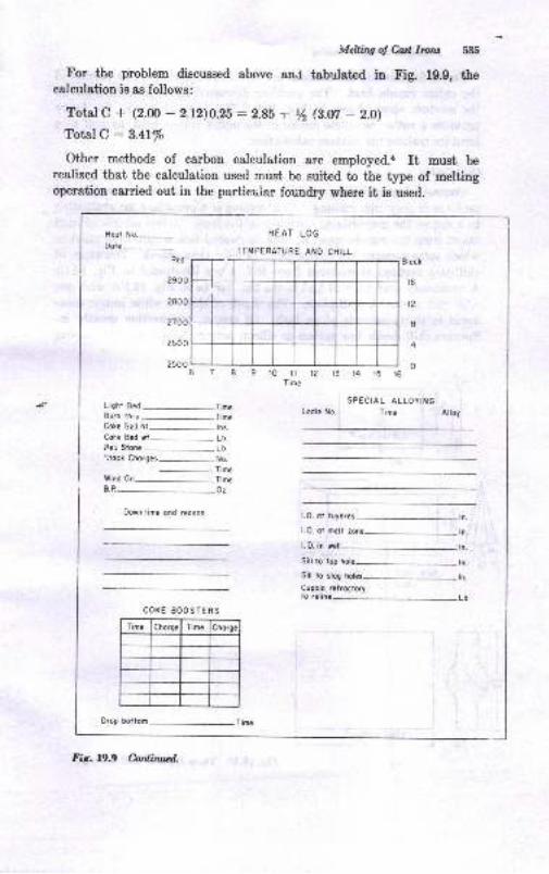
wIeUing of M, Lv,nt 535
For the problem discussed above and tabrrlated in Fig. lg.g, thecalculation is as follows:
Total C + (2.00 - 2.12)0.25 :2.85 -r Yz G.Ut - 2.0)
Total C :3.41%
Other methods of carbon calculation are employed.r It must b€realized that the calculation used must be suited to the type of meltingoperation carried out in the particuiar foundry where it is used.
HEAT LOG
TEMPERATURE ANO CHILL
t2
I
4
09iot11213t41516Time
Ligh'
Burn
Coke
Colie
3er S
',tock
Wind
B.P -
Stona
--
L
B€d-Tim.th'u
-Time
geC ht-- t.s.Bcd wt-. Lh
SPECIAL ALLOYING
Lodle No. Time Altoy
l-0. ol tuyeres
1.0. oi melt zmc
1.0. in rell
Sill to top l
Sill io slog
Cupolo relTocloryto reline
iChorges-No.
-Time
0n-Time
Down iime ond reoson
orop boltom
COXE BOOSTERS
Time Chorge Time
Fig. 19.9 Cadirurd.
Heot No._Dote-

536 Plfiu,iplrr ol Mdal0ading
Fome for mixture calculatious are useful, and may Eerve as records ofthe entire cupola heat. The problem discussed above is completed on
the mixture sheet shown in Fig. 19.9. The form shown in the figure
provides a rather complete record of the entire cupola heat, as well as a
form for making the mixture calculation.
ChiUhnbol
Control of graphitizing tendency of the gray iron is an omnipresent
problem in gray-iron melting. Chill testing is a procedure for evaluating
to a degree the graphitizing tendency in the iron. A test sample of melt
taken from the cupola spout or ladle is poured into a core-sand mold inwhich some sections are cooled more rapidly than others. Drawings ofchill-test castings reproduced from Ref. 4 are illustrated in Fig. 19.10.
A commonly used type of test is the flat bar (o in Fig. 19.10) wit'h one
edge cast against a chill plate. The depth of chill or white iron is mea-
sured in thirty-seconds of an inch. Of course, composition greatly iu-
fluences chill depth, low carbon or silicon percentages in the iron causing
l-----+r
iiFIiL]I .t I chill this locc, Iain L_s,___J
lal
Al,;l
LfiLil
T_a
.3
l_
llote -lla t - t'-)*ta urowaiog1yo2 -1! lto.chilliog.z..l chorocter6tcstlo.3 -lj )ol thc iroo
Fi6. 19.10 Three typce ofchill castinge.
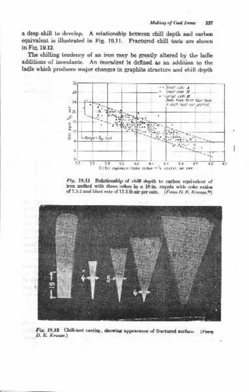
Mdling ol M Itua 5:f,
a deep chill to develop. A relationship between chill depth and earbouequivalent is illustrated in Fig. 19.11. Fractured chill tpsts are showDin Fig. 19.12.
The chilling tendency of an iron may be greatly elt€red by the ladleadditions of inoculants. An hwailont is defined as an addition to theladle which produces major changes in graphite structure and chill depth
24
-\6;16
:12
I
7 3.9 4.0 4.1 4.2 4.3 4.4 4.5Corbon equivolent (totol corbon +fr silicon), per ceni
il
lniS. l9.U Relationship of chill depth to carbon equivalent cfiron melted with three cdkes in a l0-in. cupola with-coke ratioeof 7.5:l and blast rate of 12.5 lb air per min. (Fmm D. E. Krau,se.r)
Fig.19.12 Chill-tcst casting, showing appeara.ce of fractured surface. (liortD. E. Krawc.)
o - 5mo// co*e B. - Lorge cole B
Oato from first four tops
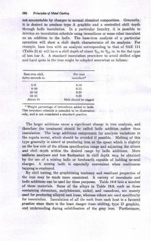
548 Prir.ifu ol M.lal hdi^s
not eccountable by chrngea in uormal chemical coroposition. Generally,it is desired to produce type A graphite and a controlled chill depth
tbough ladle inoculation. In a particular loundry, it ie possible todevelop an inoculation schedule using ferroeilicon or some other inoculantas an addition to ihe ladle. The base-iron aualyeis of a particularoperaiion will show a chitl depttt chsrsct€ristic of its analysis. Forexample, base iron with an analysis correepoodiDg to that oI SAE Ul(Table 21.4) will have a chill depth of sbout 8/sz tn s/tz in. in the flsi type
of tesi bar A. A siandard inoculation procedure to avoid chilled edgea
and hard spots in the iron might be adopted somewhat as follows:
Bss6iror chill,thirty-6econ& itr.
Per ceot
H8-r0
l(F12t2-16
Above 16
0,r00.15
0.25
0.:|:l
Melt should be piSged
' Weight p€rc€trbge of ferro€ilicon sdded to lsdle.Thb inoculant schedule is itrt€nded t, be iuustrstiveoDly, aDd is not coDsidercd s stsndard pra4tice.
The larger additions cause a eignificant chaoge in iron analyses, and
therefore the treatueut shoutd be called ladle sdditiou rather thauinoculatiou. The large additions compenrate for analyeis variations iuthe cupola metal, which ehould b€ avoided if poesible. Melting of thistype gercrally is aimed at producing iron 8t the epout which is slightlyon the low eide of the silicon specification range end adjusting tbe silicouand chill depth within the desired raoge by ladle additious. Moreuniform aualyees and less fluctuation in chill depth nrcg be obtainedby the use of a mixing ladle or forehesrth capable of holding severalcharges. A mixing ladle is eepecially colrr enient wheu continuoustappiug ie employed.
By chill testing, the graphitiziog l€ndetrcy and reauliant properties ofthe iron may be made more consistent. A variety oI inoculants andladle additiona ceo be used lor these purpos€e. Table 19.9 lists s aumberof these materials. Some of the alloys in Table 19.9, such as those
containing chrouium, molybdenum, nickel, and vanadium, are mainlyured for produciug alloyed cast irons, wheregs others are us€d specificallyfor inoculatiou. Inoculation of all the melt from each heat is a favoredpractice aince there ig the least dauger r'rom chillirg, type D graphite,and uudercooling during solidification of the grcy iron. Furthermore,

o
o
O
$s
aEo
ooEdac)sa 6lRqINor
6l 16
::
ot!5$Eo.:t:c;
oQ-N-c
*'1.8 E ic rJd
=-a-{ oxEEs'EO\o\ !Ex<b\! Iom ,+'-N*o ;N6 0 - O*0- altE6eiN.y(oO - (9 , ca rdm @r]Omi <
-6o
Ei Eg i0 ts rtL !Ecr Fi E
--EH EE 4
E ;$ s'$s:e E? e EEx
O€E :: EE* *E ii6a5i'E B rPf.^< di6\aN
EEEo@NO
6BR
N..
I
@.
xad@
I
6r<o
I
c;
I6<{
?Bs
NI
Fs I
NtoN
3N
sraN
<*o l
al
@: E i o4m ot'-ro <O N 6@No i+H-
J,,l J : : : :o! AJJJ : :JJ"!H : :
N< @ - ro(oN
6\
O
o
di.
:A-r-.v -"'t5\.mo
):oo
oooo
ER Eslo0N6
.iro:EN : :
:aJ : :
.{s??m<
IEs3
ti!EBa
obB
Eo
!Itb
bB
b
o
Goe.Eo()
B
E
zao\
saBIr
o!
aaa
J
-ooo
dU
d
o
o
o
a
o@a
dts
d
a
..t
.'..!
' +.-i a'6'^ . a+ L"a .;r M: :
ErEa;ag a a s()hOO;
a
o
a
o@o
dud
0
,a
o
atu
d
o
o
...4
'o
AAd-a
O :A'9 Fa =+
yri6'a ? E
9'AA*
5s!,
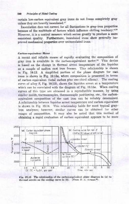
L
o,
o
oE
e
540 Priluipb ol Mdal Catlittg
certsin low-carbon equivalent gray irons do uot freeze completely gray
unless they are heavily inoculated.l'
Inoculation does not correct for all fluctuations in gray-iron properties
because of the multitude of factors which influence chilling tendency.r'2o
However, it is a control measure which serves greatly to produce a more
condstent quality. Furthermore, inoculated irons show generally im-
proved mechanical properties over uninoculated irons.
C-ar bon - e quioo,lc n t M e te rA recent and reliable means of rapidly evaluating the composition of
gray iron is available in the carboD-equivalent meter.28 This device
is based on the change in thermal arrest temperature of the liquidus
as a sample of molten cast iron freezes. This relationship is shown
in Fig. 19.13. A simplified portion of the phase diagram for cast
irons is shown in Fig. 19.13o, where composition is presented in terms
of carbon equivalent (total carbon plus one-third silicon). The cooling
curve of alloy S, Fig. 19.13b, shows the liquidus arrest at a temperature
which can be correlated with the diagram of Fig. 19.13o. When cooling
curves of this type are obtained in a reproducible manner, by using
similar molds, thermocouples, thermocouple positioning, etc., the cdrbon-
equivalent composition of the cast iron can be reliably detcrmined.
A relationship between liquidus arrest temperature and carbon equivalent
is shown in Fig. 19.14. This relationship holds for most, typical gray-
iron analyses; however, similar curves can be obtained for other
ranges of composition. It may also be noted that this method of
obtaining a rapid evaluation of carbon equivalent appears to be more
l|,\ ltat clorino 1,,". Jo,',onl,
I \ I (3.ezcEl shown or lert in )
\r LiqL_l
urdus trresl
a\ TCert\lrler TC
_tLulectuc trresl
t/a" fromsurfoce TC
I
y'\:
\
3.8 4.O 4-2 4.4
CE (TC +7rSi), percent30130230330
Time, min-sec
Corbon iquivoleni phose
Fie.19.13 The relationship of the carbon+quivalent pbase diagram in (c) tothermal arrests on the cooling curve iu (6). (From D. r). Iieouse.ft)
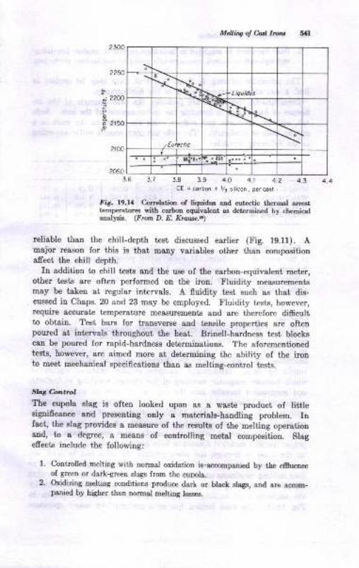
McUiag ol Corl lrurr
2250
n 22d)
6 ?150
>
\-* - Liquidi
-.{q,
\ \
,rr) \
r.ic.: i:-rrr2050
3-7 3.8 3.9 4.O 4.1 4.2 4.3CE = co.bon + ,3 siricon, perc€nt
Ii'. l9.ff Cardetio oa liquidE ard eut ctic the.mal 6rl€3ttcmperatuEs riih carbon equivabtrt as dctcrmiDed by chemicatoralysis. (F orn D. .O. XruBar)
reliable thsn the chill-depth test discussed esrlier (Fig. 19.1f). Amajor reason for thie is thst maoy variables other than compoeitionafrect the chilt depth.
In addition to chill test8 Bnd the use of the carbon-equivslent meter,other tests are oftrcn performed on the iron. Fluidity measurementsmay be takeu at regular intervale. A fluidity teBt such as that die-cussed iu Chaps. 2O ard 23 may be employed. tr'luidity tests, however,require accurate t€mperature measuremeDta and are therelore difrcultto obtain. Test bar6 for transverEe and teueile properties &re ofteupoured at intervals throughout the heat. Brinell-hardness test blockscan be poured lor rapid-hardness detenninations. The aforementionedtests, however, are aimed more at determining the ability oI the ironto meet mechanical specifications than as melting-contlol te8te.
?,bt f-ona.ol
Tte cupola elag is olteu looked upon as a waat€ product of litdeeignificance and presenting only a materiale-handling problem, Infact, tbe slag provides a measure of the rczults oI the melting operationaDd, to s degree, a means of controlliog metal composition. Slagefrect8 include the following:
l. Controlled melting with nomal oxidation is,orcoEp.nied by the efluenceof green or dark-green slags flortr the cuDolr.
2. Oxidizing melting conditions produca darl or black elegs, ond are acco-panied by higher thaa normol mehilg loeees.
3.6
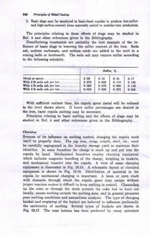
tal Prir&ifu ol M.lnl Mirg
3. Baaic elegs may be eoployed ia basic-lined cupolas t produce los-sulfur-aod high-tarbon-ooltent iroas eapecially suitcd to Dodulor-iton production.
Tbe priuciples relating to these efrects of staga may b€ Etudied irRcI.4 and other referencee given ir the Bibtiography.
Deaulfuririag treatrnents 8re probably the beEt €xample of the iD-
fuence of basic slagr in loweriag the eulfur content of the iron. Soda
aah, sodium carbonate, aDd sodiuD oxide are added to the melt iD 8
mixiug ladle or forehesrth. The eoda aeh rnay remove sulfur accordingto the following schedule:
guffur, 70
Metalrt.poui..-.....With 2lb roda ash per ton. -...........With 4lb Eod! ash p€r ton..,,...... . . .
WitL 6 lb aode ash per ton..,.,......,.
0.t70.145
0. t160.096
Il9ith suficient coDtact time, the cupola spout metal will be reduced
to the level ehown above. If lower sulfur percentages are deoired ini.he irou, basic cupola melting may be necessary.
Principles relating to basic meltiug aud the efrects of slags may be
studied in Ref. 4 and other refereDces giveu iu the Bibliography.
Clrorritt,
Becaus€ of its influence ou Eeliing control, charging the cupola muetitself be properly done. The pig iron, scrap, remelt, steel, etc., mustbe carelully E€gregrst€d in the foundry storsge yard to msintain theiridentities. In aome foundries the charge is made up 8nd put into thecupola by hand. Mechanized fouudries employ charging equipmentwhich includes msgnetic handling of the charge, weighing in buckets,and mechanicgl trsnsfer into the cupola. A view of some chargingequipnetrt is illusirat€d itr Fig. 19.15. A schematic layoui of chargingequipEeDt is ehowu in Fig. 19.16. Distribution of material in thecupola by mechanical charging is important. A loos€ or opeD stackwith channele through which the cupola gases m&y escape withoutproper reaction makes it difrcult to keep melting in control. Channelingup the Bides or through the stock permite the coke bed to burn outlocally, causes melting outside the melting zone, and in general promotespoor meliitrg cotrditions and nouuuiform aualysis. The iype of chargingbucket and emptying of the bucket &re believed to iloueoce profoundlythe uniformity of melting. Several iypes of buckets arc shown inFig. 19.17- The cone bottom has been preferred by many operatora
0.08 I 0 l00.070 I 0 085
0.060 J 0.0700.050 I 0.060
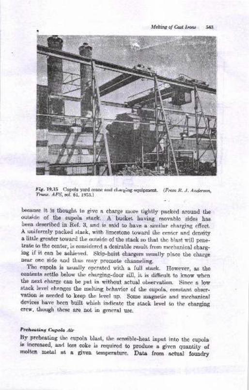
Mcllhq o! Casl Ircw
Fig. f9.f5 ^
Cupola yard crane and cLarging equipn:ent. (From R. J. Attderson,Trau. AFS, ool. 61. 1953.)
because it is thought to give a charge more tightly packed around theoutside of the eupola stack. A bucket having movable sides hasbeen described in Ref. 3, and is said to have a similar charging effect.A uuiformly packed stack, with limestone toward the center and densitya little greater toward the outside of the stack so that the blast will pene-tratn to the centcr, is considered a desirable result from mechanical charg-ing if it can be achieved. Skip-hoist chargers usually place the chargenear one side and thus may promote channeling.
The cupola is usually operated with a full stack. However, as thecontente settle below the charging-door sill, it is difHsultr to know whenthe next charge can be put in without actual observation. Since a lowstack level changes the melting behavior of the cupola, constant obser-vation is needed to keep the level up. some magnetic and mechanicaldevices have been built which indicate the stack level to the chargingcrew, though these are not in general use.
Prclwting Cupla AirBy- preheating the cupola blast, the sensible-heat input into the cupolais increased, and less coke is required to produce
" giu.o quantity of
molten metal at a given temperature. Data fron actuat louiary
il<=
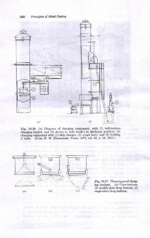
Prinriplzs oJ Melnl CastiW
Fig. 19.16 (a) Diagram of charging equipnrent, wilh (f) bell-bottom-
charging bucket, and (2) device to hold bucket in discharge position; (b)
chargini equipment lyith (l) ship charger, (2) weigh lorry, and (3) holding
U tadle. (Frorn H. W. Zimrwtda, Traw. AFS, ool. 59, p.56' f95f .)
Fie. 19.17 Three types of charg-ing buckets. (o) Cone-bottom,(b) doubledoor drop-bottom, (c)
singledoor drop-bottom.
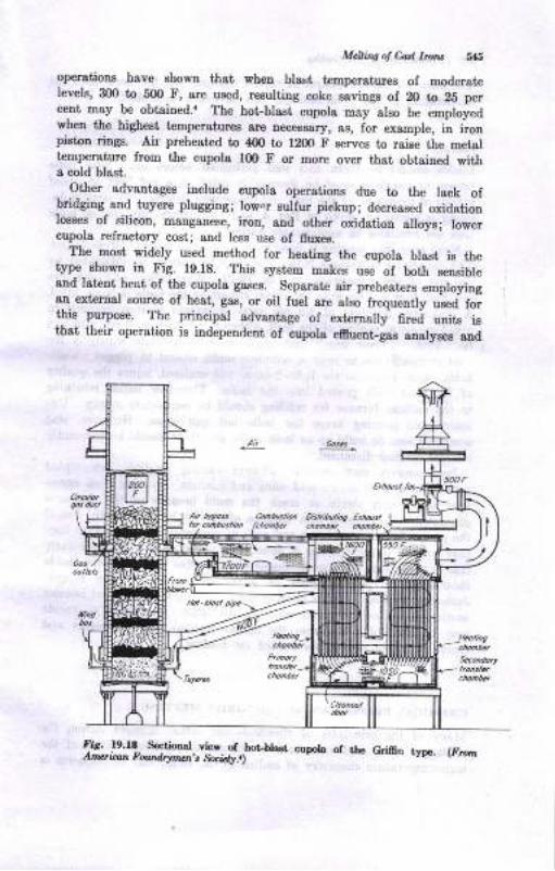
M&ins of Cad lrc,! S{;
op€rations have ehown that when blaxt tenperatures of moderatelevels, 300 io 5O0 F, are used, resulting coke savings oI 20 to 25 percent may be obtained.. The hot-blsst cupola may also be employedwlen the higheet temperatures 8rc necessary, as, for example, in ironpistotr ring8. Air preheatcd to {OO to 1200 F e€rves to raiee tie metaltemperature from the cupola l0O F or more over that obiaiued witha cold blast-
Other advantagee include cupola operatioDs due to t}re lack ofbridging and tuyere plugging; Iow.r sulfur pickup; decreased oxidationlossee of dlicon, manganese, iron, and otlrcr oxidation alloyel lowercupola refractory cosi; snd less use of fluxec.
The most widely used method for heating the cupola blast, iB thetype shown in Fig. 19.18. This system makes uB€ of both seneibleaud lst€nt hest of the cupola gases. Separate air preheaters employingar- external eource of heat, gas, or oil fuel are also frequenfly uaed forthis purpose. The principal advantage oi externally firei units iethat their operaiion is indepeudent of cupola eflueut-lae analysee and
C@hB @ A:irbuhhg E houtt
n dt chohbt'
fi6. f9.f8 S€dirod vicr of houlra* cuFb of ttG Gri6o tyD.. (tr,rorrAiv! ioo^ Fo,,.n lry@{ t Socrir..)
# Pril.ciplaotMdalcadi,tg
thus does not require control of cupola charges. At the 88ne t'ime the
temperature of the preheated gaa can be better controlled.
Pouring
Ladles should be clean and well preheeted before use. New ladle
linings or patchiug must be thoroughly dried at a red heat to avoid
pickup of hydrogen by the iron and consequent defects. Typical iadle-
iining mixtures are given in Ref. 4, and proprietary mixtures or ladle
tiles are available in considerable variety.
Most gray-iron pouring is done with opeu or covered pot-type ladles'
The capacities of various ladle sizes may be closely approximated by
the use of the nomograph in Fi6 19.19. When alloy additions are
required, they are made to the metal stream as the ladle is beiug filled.
A maximur addition of 1.0 per cent by weight is recommended to
avoid excessive cooling of the melt, although as much as 3 per cent can
r be added. "Over iroD," that remaining in the ladle which is too
.. cold or insufreient to pour a complete mold, should be pigged' Ladlei heels, metal frozen in ihe ladle bottom and oxidized, injure the quality
of the next melt poured into the ladle. Therefore ladles returning
to the melting furnace for refilling should be completely empty' Un-: interrupted po*i"g keeps the ladle hot and clean' However, slag
.".u-rrl"tioos do build up on ladle walls, and these should be frequeutly
cleaned ofr and discarded.
Iron pourers may greatly influence casting qualrty. Internrpted
pouring of a mold causes cold shuts and misruns. Pouring from exces-
sive height may strain or crack the mold because of the pressures
generated. Uoias wittr thin sectious often can be succeEEfully run ifIh" poot". fills the mold fast and with ma:<imum press.re, whereas they
mry misrun if the pouring is done more slowly. -..This is particularly
true it the gating is of questionable or borderline design Some molds
should not be poured below or above certain temperature r&nges.
Judicioue pourin! includes pouring the small castings firet and heavier
castingp tate" as the metal cools in the ladle. Overfilling of molds
**y b'" harmful if it causes the molten iron to contact weights and
freeze ofr risers and sprues needed for feeding.
CHEMICAL PNINCIPLES OF CAST.INON MELTING
Many of the principles of chemical-composition chauges during the
melting of gray cest iron8 c8n h delineated. Although much of the
high-tetpersture ehemistrv of molten metal, slags, and atmospheres is
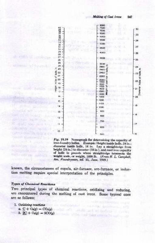
*l&try of M lroru 51il
soo75007!OO
6500
60@
5500
Fig. 19.19 Nomograph for determining the capacity ofiron-foundrlr Iadles . Ezatnplc: Height insiae haie, Zalu.;diameter inside ladle, I8 in. Lay a straight€dge fromheight (24 in.) to diameter (lB in.), and read iron Japacityof ladle in pounds where straightedge intcrsec,is thlw.eighl scale, or weight, f600 lb. (F?ont H. L. Catnpbll,Am. Fowdrynan, uot. 15, Juru, 1949.)
known, the circumstances of cupola, air-furnace, arc-fur'ace, or induc-tion meltiug require Bpecial interpretation of the principles.
Tytce ol Chr,nicr,l Renctions
Tho prineipal types of chemioal reactions, oxidizing and reducing,are encountered during the melting of cast irons. some typical onesare as follows:
l. Oxidizing reutiotua.c+o{c):cor(c)b. 2c + Ot(g,) : zCO(s)
30
29
?s
27
26
2'
24s-i2rE
zz3,g
2r€E.9o
20
50@
4500
40oo
3500
r@o26@ --2GOO
=?400 ;22oo E2000:r9oo 3t800 0rToo i1600 :15(,() .9r4oo .!foor200
lloo
rooo
9@
8@
700
coo
5@
4O393Ef73635l433a25l30292627
26
25
24
.9- 23
-- ?2
:2ro20
.E ,g
el8'.rt7
l6
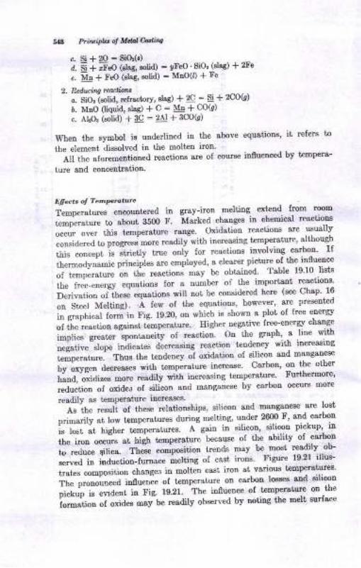
Sa8 Ptit iPb q lrelunv
c- Si + 20 = SiO(r)a. 5i + iF"O ("lr*, .ofa) = !,FeO ' SiO, (slss) * 2Fe
e. n { FeO (alag, eolid) - MoO(I) * Fe
2, Pduhg rcaliana
c. SiOr iolid, refractorv, slsg) * 2C : Si + 2CO(')
6. MrO (liqrid, slas) 1 g = Mn a COk)
c. AlOr (solid) + !q - 2Al + 3CO(r)
\{hen the symbol is uDderlined in the sbove equationr' it refers to
the elemeDt dissolved in the molten irol'---ei it
" "to""-"oiioned reactions are of cours€ iu0uenced by t€mpera-
ture snd concentratioD.
Elee., oI Tempcm.ure
Temperatures encountered in gray-iron melting extend- flom 11ntemperature to sbout 3500 F. Marked changes iu chemical reactroDa
occur over this tempersture range Oxidation reactions are usually
""r"ia*"a -o."S"ss -o"e readitylith itrcreasing t€mperature' although
ffi';;;;; i. itri"ttv true onlv for reactions iuvolving carbon' rI
ii"" "Jvt"-i.
pr""ipl"s a"" emplov"d, a clearer picture ol ff:^tifli:l-""
"l--t"-pi."trt" on th"
"eactions may be obtained Table. l9'10.1ists
the free-eDergy equations for a number of the importaDt reactlol8'
i]*lr"1i* "r1r,*i equations will not be coneidered here (see Chap' 16
;"*l;; i4;il;;i. A few of the equations, however' sre. pre.eDt€d
i" e*phi""r iorJ'in pie. 19.2o, on which is shown a plot of lree erergy
ot i'he ""actiou
ugalnBt, t€mpetature' Higher negative free-enerry change
io,oti"" o""t", -spontoneiiy of reactiou On the graph' a line with
;;;;""il; iniicute dec""asiog reactiou t€ndelcv wit'tt iuoeasing
;;Ip;;t*". Thue the tendency of oridation of eilicon and msngau€se
h., orrne. decreases witlt tempetsture increaae Csrbon' ou the other
[iJ'"?ilir* -".e readilv wiih increasing t€mperatur€ Furt'hermore'
""ar"ti"a "f oxideo of eilicon aud manganese by carbon occurc more
readily as temperature iDcreaseE'-"i"-ii," ."*ri of these r€latiomhips' silicon and maoganese are lost
p"i-a;ty at low temperature8 during melting, Y:d* 2ry I 'Ii,,::i:
ie lost at higher temperatues. A gain in eilicon, srlico! prckupl rn
the iron oocrirs at hig! temperature because of the sbitity o' carmn
fr-."a*" +ri*. - tnJ* couposition trend6 may be moet readily..ob-
""*"i-i" ioat"U"t-Iurnace melting oI cast' irons Figue l92l illus-
t"ate" compo"ition changel in moltcn cast iron at various t€mperatur€s'
ir," p-""It""a ftnuenle of temperaiure on catbon losses strd silicon
.,iolrr'o l, "-a"ot
in Fig. 19.21. The iuflueuce of temperature on -the
I;;;; ;i-;;td"; mav"be readilv observed bv noting the melt surface

o
o
H
14
o
d
ooaE
F]
caYLo=
voh&9o-
H$ X
P3 +.io!
xE I83 6
EA O\
@H>:x+sd@ V6H \\
H6
o-s IF\ 6H
*3 0t& o
o"B s
>s 6F-6 0j!r
Et 6
PC EL)g A
-I f l Ls
'( B*'riS Sts;96-aa6sEQXrsco\/;i^XXXS X5I3ooo€oe-o\\oxeroo\ro_, o\o\$ b\
E,E n , r rr X rr
'l*cn d r 6 6 U6
= 65555bQL'= oi d
*oxxxxrr x@
!!(,NNNONoUrO@L)()OO
E.E.j "{ c{'-i e i
:6il[llIttrS !vxvxva(
tr
w
oa@
c
goXoQEvo
5<-
d:
E=f3{rd.OFt+
co6
I
I6to+
^l
ol
il?'l
FI
*{
@Ord6lc.i cico
ltH
xxAN
IIVV\\ii
[.r Hc€oo$_.+c.lc€tt
ooo)O!m1l:
C{ rO++
\E*!F-E-aNNooI i- nj q il oQS $ T K O ffiTr ri + , + 6i,
- T
- caf9 I ; o N lo?ro@o:^
= ot -i d [qH E = B B sK+ r I I I tr
I
ts
il
i
\
et'
a
o
qo'!o
q)
q
Bq)Ll)
6
q)aq)
a.o-(
C.
t)a-6
s
O
+I
I
o
+()I
O+o
fEr
T
.9
+ot
SrIN
P q+o9tA
-3:=::;f&:fiS5qNcrsd-€=rr fs-u),,'lSl:..rrgoI [ ^. ^r
Yl ,@ri cr Xi ; ; .5 +
er or 6t 5l =l
at E-.icirjr,.dqor
I
ll\
Eoba
ad,o
o
aoadao
d
xo
E.Eilst6d or g 3 a
reeo-cltolccurOi.'I?*'otr- .: F F .b-{o q .E .E odq3E f r Ef E
Er; 'i't r: H:'..-'=oE-'-goqd o E A oh
s*x e g frE 5.:-"E € € 6E 5
EEr g-r 3: s;:P .!F!.iE IIs5 Ef.EE5€
EPE e c I c I co E
?a€ 3r€r€E I?l€ r€:- €r €E €€eE xttttEt
E
ooo@@adddooo
c.o.qo@o
dddv,2g
[*f..h|o6dONN6.1 H .oi616l
III T
j.F.&H
ao
z
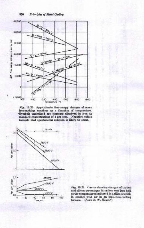
6E
!eE
o
t&
Prirtr,ipla ol Mdd edi,to
Fig. l9.D Approrimate free+nergy chang€s of some
iron-melting reactions as a fuDction of tcmperature.'Symbols underlined are elements dissolved in iron atetandard concentrations of I per cent. Negative valuesiodicate that epontaneous reaction iB litely to occur.
d
2.7
.!'a
Z?.s
2.3
&.g,= r.6p
r600
fig. 19.2t Curves showing changes o,?carbonand eilicon percentag€s in molten casr;'iron heldat the temperatures indicated in a eilica cruciblein contact with air in an induction-oeltingfurnace. (From R. W. Heine9)
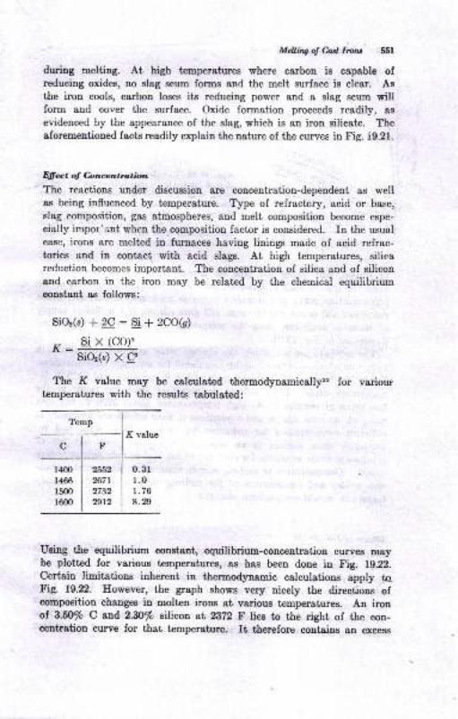
Mdting o! &d, Lllru 55f
during melting. At high temperatures where carbon is capable ofreducing oxides, no slag scum forms and the melt surface is clear. AB
the iron cools, carbon loses its reducing power and a slag scum willform and cover the surface. Oxide formation proceeds readil]r, as
evidenced by the appearance of the slag, which is an iron silirate. Theaforementioned facts readily explain the nature of the curves in Fig. i9.21.
Dffect ol Concentmtion
The reactions under discussion are concentration-dependent as wella,s being influenced by temperature. Type of refractory, acid or base,
slag composition, gas atmospheres, and melt composition become espe-
cially impor'int when the composition factor is considered. In the usualcase, irons are melted in furnaces having linings made of acid refrac-tories and in contact with acid slags. At high temperatures, silicareduction becomes important. The concentration of silica and of siliconand carbon in the iron may be related by the chemical equilibriumconstaDt as follows:
SiOz(s) +2C: Si{2Co(s)
Si X (CO)'l(- -
SiOz(s) X C'
The I{ value may be calculated f,hermodynamicallyz for varioustemperatures with the results tabulated:
Using ttre equilibrium constant, equilibrium-concentration curves m&ybe plotted for various temperatures, as hes been done in Fig. 1g.22.
Certain limitations inherent in ttrermodynamic calculations apply toFig. 19.22. However, the graph shows very nicely the directions ofcompoeition changes in molten irons at various temperatures. An irouof 3.5O/o C and 2.30/o silicoa at 2322 F liee to the right of the oon-centration curve for that temperature. It therefore contains an excess
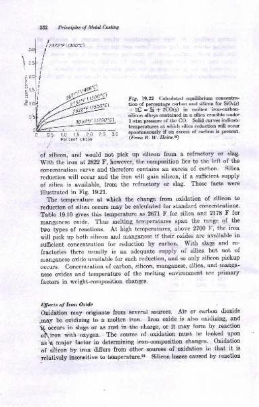
tt 2..
tIIIIt
t,l
;
I
301
552 Priluiphs of Mdal Culing
30s2"F 11700"c1
Fig. l9.Al Calculated equilibrium concentra-
tion of percentage carbon and silicon for SiOs(s)
+ 2C : Si * 2CO(g) in molten iron-carbon-silicon alloys contained in a silica crucible under
I atm pressure ofthe CO. Solid curves indicatc
temperatures at which silica reduction will occur
spontanmusly if an excess of carbon is present.
(From R. W. Heiru.z)
of silicon, and would not pick up silicon fron a refrectory or slag'
\[rith the iron at 2822F, however, the eomposition lies to the left of the
conceniration curve and therefore coDtains an excess of carbon. silica
reduction will occur and the iron will gain silicon, if a suffcient supply
of silica is available, from the refractory or slag. These facts were
illustrated in Fig. 19.21.
The temperature at which the chatrge from oxidation of silicon to
reduction of silica occurs may be calculated for standard concentrations.
Table 19.10 gives this temperature as 2671 F for silica and 2178 F for
manganese oxide. Thus melting temperatures span the range of the
two types of reactions. At high temperatures, above 2700 F, the iron
will pick up both silicon and manganese if their oxides are available in
sumcient concentration for reduction by carbon' With slags and re-
fractories there usually is an adequate supply of silica but not of
manganese oxide available for such reduction, and so only silicon pickup
ocuurs. Concentration of carbon, silicon, manganese, silica, and manga-
uese oxides and t€mperature of the melting environment are primary
factors in weight-composition changes.
li;ffu'.s oJ lron Oride
oxidation may originate from several sources. Air or carbon dioxide
.may be oxidizing to a molten iron. Iron oxide is also oxidizing, and
rrs occurs in slags or as rust in the charge, or it may form by reaction
o\iroo with oxygen. The source of oxidation must be looked upon
as h maior factor in determining iron-composition changes' Oxidation
of si\ieon by iron differs from other sources of oxidation in that it is
llqtively ineensitive to temperature.zr silicon losses cauEed by teoction
172"f (1300"c1
---l----r-------J---f --J0.5. r.0 1.5 2.O 2.5 3.0
,/ Per cent silicon
\o
;c
&
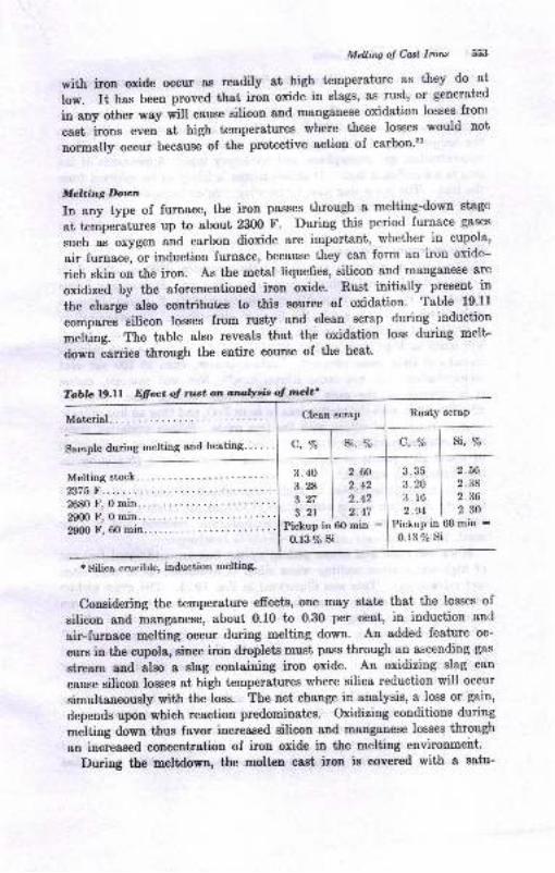
Mclliry oI Cosl lror* 553
with iron oxide occur aE readily 8t high temperature as they do at
low. It has been proved ttrat irln oxide in slags, as rust, or generated
in any other w8y will cause silicon and msnganese oxidation losses front
cast irons even at hig[ temperatures where these losses would not
normally occur because of the protective action of carbon'2l
Melting Doton
In any type of furnace, the iron passes through a melting-dowa stagc
at tremperatures up to about 23fi) F. During this period furnace gases
such as oxygen and carbon dioxide are important, whether in cupola,
air furnace, or induction furnace, because they can form an iron oxide-
rich skin on the iron. As the metal liquefies, silicon and manganese are
oxidized by the aforementioned iron oxide. Rust initially present in
the charge also contributes to this source of oxidation. Table 19.11
"o*p""""- silicon losses from rusty and clean scrap during induction
melting. The table also reveals that the oxidation loss during melt-
down carries through the entire course of the heat'
Tcrbb t9.Ll Efiat oJ nst on anttlysb ol molt'
Melting stock. ..2375 F.
Clean scrap Rusty scraP
c,% si, % c, vo si, %
3.40 I 2.60 3.35 I 2.56
3.8 | z.+z 3.20 I 2.38
3.27 | 2.42 3.16 I 2.36
3.21 | z.tt 2.e4 I 2 302680 F, 0 min..2900 F, 0 min..2900 F, 60 min.... Pickup in 6O min :
0.r3% siPickup in 60 min -0.r3% si
I Silica crucible, induction melting'
Considering the temperature efrects,.one may state that the losses of
silicon and manganese, about 0.10 to 0.30 per cent, in induction and
air-furnace melting occur during melting down. An added feature oc-
curs in the cupola, since iron droplets must pass through an ascending gas
stream and slso a slag containing iron oxide. An oxidizing slag can
cause silicon losses at high temperatures where silica reductioD will occur
simultaneously with the loss. The net ch8nge in analysis, a loss or gain,
depends upon which reaction predomitrates. oxidizing conditions during
-"ttiog down thus favor increased silicon and msnganese losses through
an increased concentration of irou oxide in the melting environmeirt.
During the meltdown, the molten cast iron is covered with a satu-
Materirll.
Semple during melting and heating" ' ' '
55,4 Priuiplet ol Mdal hdins
r8ted, solid, flaky irou silicste slag.rl,r, At 8 certain temperature; theslag disappeare because of the reducing power of carbon. For an iroucontaining alnut 2.44/o Si aud 8.40/o C, this temperaiure of slag_scumdisappearance is aboui 2E5O F in a COz or air atmoephere. However,the t€mperrture of slag disappearauce varieg with carbon and siliconconcentratioD, g&s atmosphere, and refractory type. Appearance of theslag is a significant fact: It meane silicon is likely to
-be oxidized from
the iron. The same slag also forms when molt€o irons are cooled fromhigh to low t€mperatures.
fl ig h -.e,npro.ure M e t.in g
Holding the molten iron at elevated iemperatures, 2ZO0 to 8200 F, ieaccompanied by well-defined composition changes. Molten cast irotradecerburize rapidly at temperatures above about, 2b5O F during inductioumelting when COr or air ie the furrace atmosphere. Decarburizationis..illustrated graphically in !ig. 19.21, No silicon or m&nganese los8eswill occur st high t€mperatures, 2?00 F aud above, ualess iron oxide ieintroduced from some source.,r Carbon dioxide, even at l0O per centconcentration, will not cause silicol loss.3i Nor will raw aii, unleesit is directed st, the melt surface at a high enough rate. iaw airwill then react with the molten iro[ to form FeO, and thus an iron silicateslag by reaction of eilicon with the iroo oxide. Silicou oxidation uaderthese extreme conditione is accompanied by manganese los8 in the ratioo, sbout l0-.4 points perceutagewiae and iormstion of a slag cover onthe molteu-iron surface.
, Rate of- decarburization at high temperatures is moinly afrected by
the rate of chstge of the atmosphere if CO, or air exists over the metisurface. Oxidaiion by CO, is an endotherrnic reaction and ie thusmuch milder than air oxidation, which is exothermic.
Silica reduction aud silicon pickup by the iroD are additional featureaof }igh-temperalure melting when silica is available, as in acid slagsand refractories. This w8s iltustrated in Fig. 19.21. The gross pickupol silicon is of course counterbalanced hy some oxidation- *het iroooxide i8 present. A high-iron-oxide elag may cauae a tret loss of silicou,w-hereaE low-iroD-oxide slags Eray cauae oo Lau o" even permit a gain.,rHighly reducing conditiom, for erample, the presence of cokJ aodhigh temperatures, will cauee a moet rapid increase of silicou contentof the iron.rr
. The epplicatiou of these principles to malleable-iron-fouudry meltiugrn arr tumaces has beeu well provcd.r' pickup of EilieoD betwe€D pre-llmitrary aDd final chemical analyses for a oumber of air-furnace white-ir-o1 heats is showu in Fig. 19.23. The total pickup o""u"" or"". p""iodol I ta ly2 hr ag tbe t€mperrhue ris€s from aLut 26EO f, *".1".
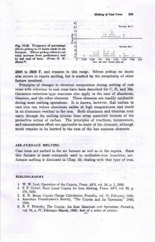
Mcllitrg ol Cdta Irclu bs
Fig.19.23 Frequency of percentage
silicon piclup in 5l heats made in airfurnaces. Silicon pickup refen to netlotal increase from preliminary tcetto tail end of heat. (Fron R. W.Heirlc?)
2800 to 29fi) F, and remaine in this range. Silicon pickup no doubt
also occurs in cupola melting, but is masked by the Gomplexity of other
factors involved.Principles of changes in chemical compositron during melting of cast
irons with reference to cast irons have been described for C, Si, and Mn.
Oxidation-reduction-type reactions also apply in the case of aluminum,
titanium, and the other elements. These elements are readily oxidizableduring most melting operations. It is known, however, that earbon incast iron can reduce aluminum oxides at high temperatures and result
in an aluminum residual in the iron. Both aluminum and titanium may
carry through the melting process from serap materials because of the
protective action of carbon. The principles of reactions, temperature,
and'concentration effect are epplicable to many of the elements, although
much remains to be learned in the case of the less common elements.
AIR-I.'UNNACE MELTING
Cast irons are melted in the air furnace as well as in the cupola. Since
this furnace is most commonly used in malleable-iron foundries, air-furnace melting is discussed in Chap. 23, dealing with that type of iron.
BIBLIOGRAPHY
W. W. Irvi, Operation of the Cupola, Trcrc. AFS, vol. 58, p. 1, 1950.S. F. Carter, Basic Lined Cupola for Irou Melting, Trans. AFS, vol. 58, p.376, 1950.
R. W. Eeine, Cupola Charge Calculttiot, Foundry, vol. 76, February, 1948.American Foundrymen's Society, "The Cupola aud Its Operation." 1946,1954.
B. P. Mulcahy, The Cupola: Its Raw Materials and Operation, Foundry,vol. 78, p. 77, February-March, 1950; first, of a series of articles.
l.2.
3.
4.
5.
oo8 0.12 0.16 0.20 0.24 0.2a o32Totol pc, ccnl silicon picl-up

556 Priuiphs of MddMing
6. H. W. Lownie, Jr., Ladle Inoculrrtion Tmproves Gray Iron Properties and
Structure, Forndry, vol. 71, November-December, 1943.
7. W. R. Jaeschke, Development of Cupola Melting Equipment, Truu. AFS,vol. 62, pp. 339-35i1, 1954.
8. C. R. Ioper, Jr., Design of a Gas fired Cupola, Trou. AF$, vol. 70, pp.
531-536,1962.
9. American Foundr5rmen's Society, "Cast Metals Handbook," 4th ed., 1944.
10. D. E. Krause and II. IV. [,ownie, Jr., Blast Eumidity as a Factor in CupoloOperation, Trarc. AFS, vol.57, 19t19.
ll. E. Loebbecke, Hot Blast, Cupola, Trulu,- A.FS, vol.64, pp. 171-196, 1956.
f2. W. L. Eeinriehs, Eot-blast CupoLr Practice, Trcu. AFS, vol. 64, pp. 532542,L956.
13. D. E. Krause and E. \{. Lownie, Jr, A Survey of Foundry Coke Cbaracter-istics, ?rons. dFS, vol.55, 1947.
14. S. A. Ileres and C. E. Lorig, Cupola Blast Control, Am. Fou,tdryman, vol.13, September, 1942.
15. "Syrnposium on Malleable Iron Melting," American Foundrymen's Society,reprint 43-47, 1943.
16. W. N. Witheridge, Cupola Dust Collection, Fowtdry, vol. 78, February-March, 1950.
17. A. Finlayson, Casting Diesel Engine Crankshafts in Gray lron, Foundry,vol. 78, Augus0-September, 1950.
18. D. E. Krause, C. T. Greenidge, and E. W. Lownie, Eow Iron ard Steel Meltin a Cupola, Trans. A?5, vol.60, 1952.
19. R. J. Taylor, Elow Thermocouples in t}e Stack Control Cupola Melting,Am. Foundrgman, vol.21, no. 6, p. 46, December, 1952.
20. D. E. Krause, Chill Tests and the Metallurgy of Gray lron, Trara. r{FS, vol.59, p.79, 1951.
21. E. A. Lange and R. W. Eeine, Some Effects of Temperature and MeltingVariables on Cheinical Composition and Structure of Gray Irons, frazs..AFS, vol.59, 1951.
22. R. W. Heine, Oxidation-Reduction Principles Controlling the Composition ofMolten Cast Iron, Trmx. AFS, vol.59, 1951.
Whiting Corp., "Usefril Infomration for Foundrymen," 1M6.D. Fleming, The Controlled-slag Hot-blast Cupola, Trar.s. AFS, vol. 66, pp.
il3-124, 1958.
T[r. W. Levi, Carbon Control in the Cupola, Am. Found,rymaz, October, 1947.
H. E. Ilenderson, Acid Cupola Melting for Ductile lron, Trara. z{FS, vol.67, pp.66l-668, 1959.
27. J. T. Williams, Basic Cupola Melting of Ductile lron, Traru. /f'S, vol. 67,
pp.669470, 1959.
28. D. E. Krause, Rapid Control Test for Carbon Equivalent, Forndry, May,1962.
24.
25.26.
20Gray-iron
Foundry Pra,ctice
Because of a fortunate combination of engineering properties, avail-
ability, excellent casting characteristics, and favorable cost, gray irons
are produced in tonnages exceeding all other castings' The basic
foundry operations of patternmaking, molding, coring, sand conditioning.
melting, cleaning, etc., have been highly developed because of the tre-
mendous amount of material and work involved in gray-iron-castings
production. In fact, it is undoubtedly true that much of the engineering
and mechanization which has developed in the foundry industry came
through the needs for these improvements in order to meet the produc-
tion demand of manufacturers for gray-iron castings. To a great extent,
the automotive, truck, bus, and tractor industries were directly and
indirectly responsible for these developments over the period of about
1915 t,o the present. Each of the millions of passenger cars presently
in use has about 6fi) to 7fi) lb of gray-iron castings in its structure.
Add the quantity in operating trucks, buses, and tractors, and it is
evident that this inductry alone accounts for a phenomenal consumption
of gray-iron castings. Similar accounts might be cited in other manu-
facturing fields. The production of gray-iron castings is, in fact, such
a large industry that twice as much gray iron is cast annually as all
other cast metals combined. To supply this tremendous quantity of
castings, all the casting processes discussed in Chap. 3 may be employed
except die casting and plaster molding. Some of the specialized tech-
niques of these processes as applied in gray-iron foundry practice are
considered in this chapter.
MOLDING
Among the sand-casting processes, green-sand molding is the method
m<rst commonly practiced. The molding and other equipment discussed
in Chap. 4 are employed, and to a large degree the foundries are
modernized and mechanized.
cJt
558 Prituipla d Mdal Casting
The characterietics of molding sands have been discussed in Chap. E.
of course, ssnd practice and related operatious are carried out withdue consideration for the unique properties of gray iron. some examplesof eystcm eands for light and medium gray-irou castings are given inTable 20.1. Theee sands have been successfully used for produeingmany castings. The properties of green compression and shear strengt!,dr5r compression strength, permeability, moisture content, and othershave not been given in Table 20.1 because they can be so greatly alteredby variations in rebonding addition, moisture, the special additives,mixing, and molding methods. Almost any values can be obtained,depending on how the various factors are put together. It may be notediu Table 20.1 that in addition to features of thermal stability, reuse,and moldabiliiy, eaae of clearing and surface finish'are consideredhighly important in molding Band mixtures.
When gray-iron castings are cooled sufrciently and shaken out, theymay under proper eand conditions separate cleanly from the sand.Then the sand is said to "peel,, from the casting. Little burned-onsand needs to be removed from the casting surface, and the work spenton cleaning is at a minimum. Light castings cool so quickly that thereis ins'fficient temperature riee to permit the sand to burn onto thecasting. When the sand is heated up to temperatures over l5(X) F,however, the possibility of chemical reaction between metal and sand, fu-sion of the sand, and firm adherence of the fused-on material to the metalincreases. The sand mixture may be modified to prevent or reduce theamount of fused-on sand-reaction products. Sea coal, gilsonite, coke,graphite, pitch, and other petroleum-base materials may be added to theeand for this purpose. Their efrectiveness depends on producing reducingatmospheres in the mold or in preventing the oxidation reactions whichoccur when sand fuses to the iron.
Sea coal8 is very commonly employed for improved casting finish andpeel (see Chap. 5 for its eharacteristics). Amounts of 2 to 8 per cent byweight have been found beneficial. The appearance of the casting is thebest criterion of the sea-coal percentage which should be maintained inthe sand. Excessive sea coal can cause blow defects from the volatileconstituents evolved on heating. The approach to this condition isoften forecast by the appearance of a blue finish on castings when theyarc shaken out. The percentage of sea coal in the sand is kept up tothe desired level by additions to the sand mixers during each cycle ofreuse. The actual percentage in the sand may be estimated by runninga proximate analysis on the dry sand to determine the percentage ofvolatile material and the percentage lost on ignition- Dead sea coalwhich has no volatile matter in it may be an undesirable ingredient inthe sand since its ability to promote peel is low.
Gilsonite is another material used to improve casting fiuish. Thisasphalt-base mineral is almost completely volatile. Hence smaller
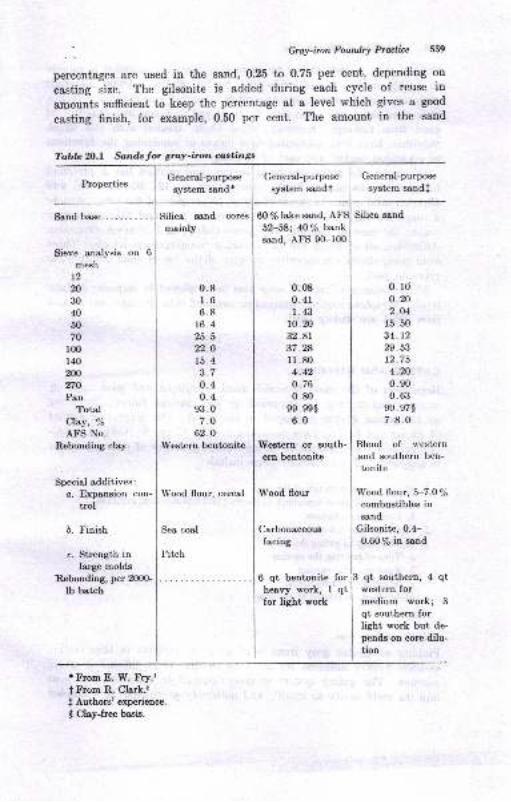
. - GrcY-imn FoudrY Pructi'e 5't9
percentages are used in the sand, 0.25 to 0.?5 per cent, depending ort
casting size. The gilsonite is added during each cycle of reuse in
amounts sufrcient to keep the percentage at a level which gives a good
casting finish, for example, 0.50 per cent. The amount in the sand
PropertiesGeneral-purpose
system sand'
Silica sand cores
qrainly
General-purpose
system sandtGeneral-purpose
system sandf
60 % lake sand, A Silica sand
52-58; 40lp banksand, AFS 90-l0O
Sand base.
Sieve analysis on 6
mesh
t220
30
40
50
70
r00r40200
270
PanTotal
Clay, 7o
AFS No.
Rebonding clay
Special additives:c. Expansion con-
trol
b. Finish
c, Strength inlarge molds
Rebonding, per 200G
Ib betch
0.81.66.8
16.425.522.0r5.4t.l
0.40.4
93 .0
7.O
62.0IVestern bentonite
Wood flour, cereal
Sea coal
I'itch
0.080. 41
1.4310. 20
32.8r37.281r.804.420.760.80
99. ee$
6.0
Western or south-
ern bentonite
Wood flour
Carbonaceous
facing
0.10o.202.O4
r5.5034.1229.5312.75
4.200. s0
0.6399. 97$
7-8.0
Blend of $'estern
and southern ben-tonite
\Yood flour, 5-7.O%combustibles insand
Cilsonite, 0.4-
0.60 7o in ssnd
6 qt bentonite forheavy work, I qtfor light work
qt southern, 4 qtwestern formedium work; 3
qt southern forlight work but de-
pends on core dilu-tion
Tobla 2O.l Sands for gray-iron costings
t From E. W. Fry.r
t From R. Clark.:
t Authors' experience.
t Clay-free basis.
560 Prilvipb of Mdal Culing
mixture may be determined by extraction siuce tr.; material is soluble
h a 50/o carbon tetrachloride-50/o benzol solutio,-. Other materials
such as soluble petroleum-base pitch dissolved in organic solvents,
pulverized coke, and pitch may be employed to favor ^iree shakeout of
sand from castings. Recently, wood flours' treated w.th oils which
volatilize, have been advocated as a means of combining &he functions
of expansion control and ease of cleaning.
Of course, the grain size basic to the sand mixture has a profound
influence on the casting finish. Amounts of 6-, l2-, 20-, 30-, 40-, and
5O-mesh sand grains in excess of about 15 per cent of the total i)romote
a rough surface. Exces,sive fines, 270-mesh, pan, and finer sizts may
reduce the ease of molding and permeability, and increase expa''sion
difficulties, all of which can cause surface roughness or defects. These
sand-grain efrects are operative in spite of tlre use of sand additivell to
promote peel.
Mold coatings (Chap. 5) may also be employed to improve surfabe
finish. Graphite coatings sprayed or swabbed onto the mold cavity and
then dried are widely used.
GATING AND RISERING
Regardless of the most favorable sand condiiions and good molding,
casting quality may be improved or the castings ruined, depending
on the gating system employed in the mold. The general principles
of gating and feeding have been discussed in Chap. 9. Certain metal-
lurgical characteristics make for specialized practices of gating peculiar
to gray iron. These characteristics include:
l. Fluidity characteristics of the iron
a. Relationships of superheat to pouring and liquidus temperatures
b. Composition factors
2. Shrinkage characteristics
3. Relationship of gating design to:a. Time of pouring the casting
b. Feeding of the casting
c. Thermal-gradient effects
4. Mold effects as related to the iron
Fluidity oJ Gray lron
Fluidity of molten gray irons is of principal interest in thin section
castings having sufrcient surface &rea so that it is difficult to avoid
misruns. The gating system is then designed to introduce the melt
into the mold cavity as rapidly and uniformly as possible at a number
Grry-imn Foailry Prulicc 551
of locations in the mold cavity so that the metal will not freeze offuntil the mold cavity is completely filled. Cover castings, housings,
and similar castings present a large surface for cooling the melt andcan cause freeze-offs before the cavity is full. Where this problem
is encountered in varying degree it is in part blamed on the gating andoften, because it is less understood, on the fluidity of the melt.
Fluidity of molten gray irons, described in terms of the spiral-fluiditytest (Fig. 21.7) as inches of spiral length for a given chemical compositionand pouring temperature, has been established, and is presented informula form in Chap. 2l and graphically in Fig. 8.19. These datashow that decreasing carbon and silicon contents, low pouring tempera-ture, and hypereutectic iron all result in a low fluidity. tr'rom a practicalviewpoint, however, maximum fluidity can be obtained more readilyby pouring at high temperature rather than overstressing the com-position factor. In general, the composition of gray irons is limited tothe kind in production by the foundry, for example, those in Table 21.1.
A carbon increase of 0.15 to 0.20 per cent in the hypoeutectic range willincrease fluidity only about 1 in. However, an increase of temperatureof Z) F will increase fluidity I in. over most of the temperature range forpouring. The fluid life of the metal covers the temperature range ofthe maximum reached during the melting operation down to the liquidus.Iron tapped from a favorably operating cupola runs about 2800 to 2900 F.The liquidus is ordinarily reached about 2050 to 2100 F for most grayirons. It can be exactly defined as follows:a
Liquidus temp, "F :2981 - 218 F
whereF : % C + yzX %P + Y+X % Si,intheiron
It is evident, however, that actual pouring temperature in the range of28fi) down to about 2100 F is the most important single factor influencingthe ability of the molten iron to run a casting. This is not to say i;hatother factors such as composition variation, the effect of sulfur,a,s andmold conditions can be ignored. Rather, from an engineering view-point, the transport and pouring of the iron must be done with aminimum of temperature drop in order to retain maximum fluidity andreduce the difficulties of pouring thin castings.
Shrinkage Clnractcris tic c
volumetric-shrinkage principles of casting alloys have been consideredin Chaps. 8 and 9. Liquid volumetric shrinkage of gray irons hasbeen found to be about 0.50 per cent per lfi) F decrease in temperaturedown to the liquidus femperature. Liquid shrinkage can be compensated
fi2 Prilr,ipb ol Mdal ediq
by transfer of molten iron from the gating system into the csstingbefore the gates freeze ofr. Solidification,shrinkage has been defiuedin Ref. 6 by the following equation:
LV, % - 2 x (%graphitic C - 2.W%)
where aY : percentage volume change, positive or negative.
. Since the percentage of graphitic carbon enters the equation, it canbe seen that readily graphitizable irons will have little or no solidifica-tion shrinkage whereas a white iron (0 per cent grephitic carbon)would have coDsiderable shrinkage, about 5.6 per cent, according to
, this equation. A normal soft iron ol 3.50/o C,z.n% Si, 0.4 io 0.60%combined carbon, 2.90 to 3.10/o graphitic carbon will have virtuallyno shrinkage or may even expand on solidification. Hence, for ordinarygray irons little or no risering is needed for the purpose of feedingsolidification shrinkage. The lower-carbon, lower-silicon, and less graph-itizable irons, for example, SAE 121 arLd 122 in Table 21.4, do requirerisering, however. This discussion does not imply that no risers areneeded on gray-iron castings. Rather, it is intended to point out thatthe metallurgical uature of gray iron is such that risers often need notbe used unless some factors other than solidification shrinkage requiretheir use.- For example, risers may be useful in providing metal ifmold-cavity enlargement occurs at some time after pouring has beencompleted. Also, pressure can be kept on the metal during solidificationby suitably placed risers. Solidification under riser pressure favorscasting soundness.
The solidification shrinkage of gray irons is not always quite as simpleas indicated above. Some irons are susceptible to microshrinkage,which is difficult or sometimes impossible to eliminate by risering.Phosphorus, molyMenum, and other elements have been found to con-tribute to this effect. The reader is directed to Ref. 6 for a discussionof this phenomenon.
Gating Dcsign
Gating design for iron castinge can be expected to accomplish thefollowing objectives: r
l. A casting without misrurs or cold shuts, i.e., fully poured.
2. A clean casting. The gating must introduce onl;r clean metal into the moldcavity.
3. A sound casting. The castiag must be fed adequately to avoid shrinkagrdefects.
t Taken in part from Ref. 7.
Grct-imnFanaryMia 568
4. A casting readily cleaned. Gate and riser removal must not unduly increase
the cleaning costs.
These objectives are considered in separate categories in the followingpsrsgraphs.
Pouring Rale
Pouring rate, in pounds per second, determines the time required tofill the gating system and mold cavity. It has been observed by manyfoundrymen that an optimum pouring time exists. Iligh-velocity pouringserves to entrain slag and drag it into the mold cavity and may cause
mold erosion, entrained gases, and straining of the mold (enlargement)
when it is abruptly filled. Low-velocity pouring, a long pouring time,may permit misruDs to develop if the melt cools too much. An inter-esting point in this connection is the relation between pouring time andmisruns. It appears that a casting which pours satisfactorily in agiven time will require an increased time for filling when misruns occur.Apparently, the path of metal flow becomes longer because of freezingofr in some spots and is reflected at first in increased pouring time. Ofcourse, the time for pouring is influenced by casting size, pouring condi-tions, gating design, and other factors. If the gating system offers
sufrcient resistance to flow, it will be full of metal or nearly so duringmost.of the pouring time. If no resistance, or choke, is offered by thegates, the gates will not remain full as the metal level rises in the moldcavity. The current .practice in most foundries favors keeping a fullsprue during pouring; i.e., during the pouring period the ladle operatoris able to keep the sprue cup or pouring basin full of iron. Thispractice is encouraged by the belief that a full sprue provides opportu-nity for some of the entrained slag to float out and remain in the spruecup. Strainer cores are often used in the sprue cup or at ttre base of thesprue for this purpose of regulating.flow and maintaining a full sprue.A number of strainer cores are pictured in Fig. 20.1. The approximatedelivery rate of these cores under a 2-in. metal head (typical if usedin the pouring cup) is listed in Table 20.2. The delivery rate of straincrcores of the same total area but used at the base of the sprue or otherlocations in the gating as illustrated in Fig. 20.2 probably is somewhatdifrerent from that in Table 20.2 because of the differences in pressure
head. However, one investigatore has reported that sprue height haslittle effect on pouring time of small rnolds (4- to S-in. cope). Thestrainer cores in Table 20.2 do provide a wide range of pouring rates,and can be used to control the flow rate and hence pouring time. Theheight of the ladle lip above the mold may greatly affect the pouring time.Pouring high above the mold and directly into the sprue encourages
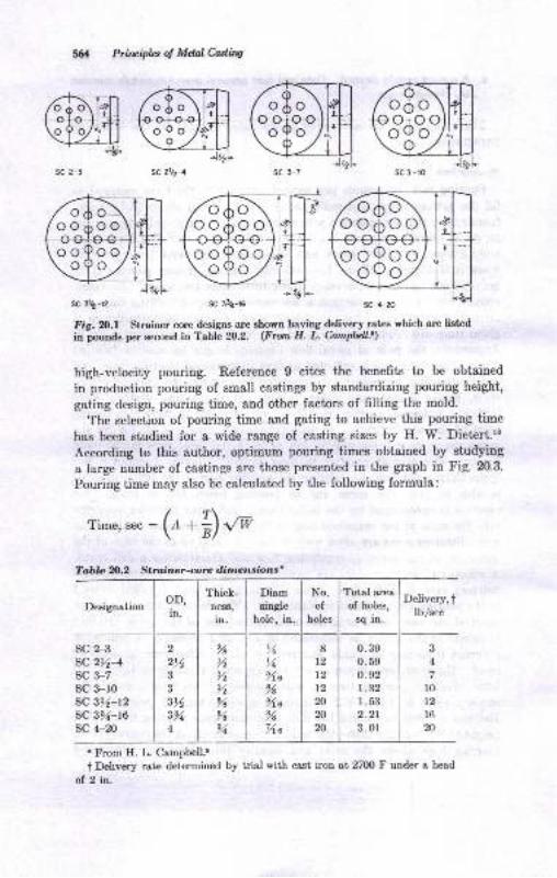
sc 2-3
@nSC 312-12
Priluiphs oJ Mdal Culing
sC 2V2-4
Designation
sc 4-20
Fi.g. fr.| Strainer core designs are Bhown having delivery rates which are listed
in pounds per second in Table 20.2. (From H. L. Catnpbll-t)
high-velocity pouring. Reference 9 cites the benefits to be obtained
in production pouring of small castings by standardizing pouring height,
gating design, pouring time, and other factors of filling the mold.
The selection of pouring time and gating to achieve this pouring time
has been studied for a wide range of casting sizes by H. W. Dietert.'o
According to this author, optimum pouring times obtained by studying
a large number of castings are those presented in the graph in Fig. 20.3'
Pouring time may also be calculated by the following formula:
/?\Time,sec:(r*il{*
3
4
10
12
l620
8t2t2t220
20
20
OD,in.
2)43
3
311
3%4
No.of
holes
Delivery,tlb/sec
SC 2-3
sc 216-4
SC 3_7
sc 3-r0sc 3t6-12SC ZBZ-16
sc 4-20
0.390.590.921.321.532.21
3. 0l
t From H. L. Campbell.8
t Delivery rate determined by trial with cast iron at 2700 F under a head
of 2 in.
ooAooooQooro9o.z
sc at-l6
Tahle 2O.2 Strainer-core dimensions+
Thick-neEa,
in.
%>4
>t>6
%%91
Diamsingle
hole, in.
%,45Aa
%%.s
78
14a
Total area
of holes,
sq in.
Orh Oo oaoooovoo
ovo
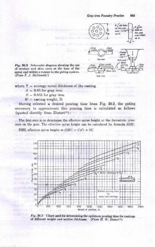
G ray-iron Fourdry Prulitc
s-!'db tt*"!-\a'l6s s-dc -l I P'Ed,b.
"*=oBzY--Vt*tm5q h. l'1 !Ly;",
L) qn.liV
Slitu ce
Fig. N.2 Schematic diagram showing the use
of strainer and skim cores at the base of thesprue and within a runner in the gating system.(From F. J. McDoruld.e)
'tfold
linc
where ? : everage metal thickness of the casting
/ : 0.95 for gray iron
B : 0.853 for gray iron,7 : ca,sting weight, lb
Having selected a desired pouring time from Fig. 20.3, the gating
necessary to approximate this pouring time is calculated as follows(quoted directly from Dietertlo) :
The first step is to detennine the effective sprue height or the ferrostatic pres-
sure on the gate. The effective sprue height can be calculated by formula ESH:
ESII, effective sprue height : (2HC - Ca') :2C
t&
ilO
6tr r r I rrrrr I rrrr r r rrrr i rr rI r rrrIM rIIrrrt'0 2@ 4oO 600 800 tooo 12@ t4oo 1600 1800 2w)
80
70
60
50
E
.E
40
30
20
ro
W.ighi of costings, lb
Fig. n3 Chart uEed for deter6ining lhe optimurr pouring time for castingsof dillerent weight and sestion thictness. (Frun H. W. Didst.to) -
Sid? vi.r
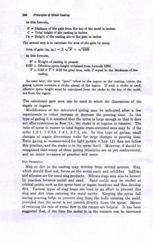
# Ptilipla ol Md &&q
Ia ttria forouLs,
Il - Dfuiaace of tle grte frcn tlre top of tle mold ir iuchea.
C - Totol height of ttre castDg itr itrch€6,
Co - Eeight of tle o.stiDC obove the gatc in irchca
Ite ecod step is to cdculate tie orea of ttre grte by usilg
Ars of gaie (eq. ia.) = X t/W + 1/rF,Y.
Ia tlia forroulr,
f - Weight of castiDg itr poud!ESE - Efieotiye Bpruo height obtaiaed from formula ESE
X = O.% X T + 2.2 lot gtsy iton, rith ? equd to the thiclocg of thocxsiirg.
Ao used herc, tlrc t€rm "gste' refer8 to the iDgat dt the crstiD8, urle6s thegstiDS s,'steE contaiE a choke chesd of the iDgat€. If zuch a choke is ued,efiective sprue height ousi be cslcutst€d from tbe choke t the t p of tle Dold,trot frcm the itrgate.
The calculated gste area can b€ us€d to eelect the dimensionr of theingate or ingatca.
Modification of the c8lculat€d gating may be indicgted after 8 lewexperimente to either iDcres8e or decrea8e the pouriug time. Iu thiatlpe of gating it, is assumed that the sprue is large enough Eo th8t, it doeg
Dot offer restriction to flow; i.e., ihe choke is at ingates or rurDer8. Theratio of sprue to ruDner to totsl ingate crose-sectioual area may h|( rf iheorder l:2;1, l:2:0.5, 1:4:1, 2:7:1, el,c. In this type of gsting, Bm8ll
changes of iagate dimeneions make ior large changes in pouring time.Ratio gating as recommended for ligbt metals (Chap. ll) does not followthia practice, and the choke iE in the sprue itself. However, it ehould berecogdzed that many of these gsting principles are a6 yet controversial,and no doubt revisions of practice will occur.
Ditt Prcenlion
SIag or dirt, in the casting may develop from several sourceo. SlaB,
which ehould float out, forma a8 the metsl cools and solidifies. Sulfideeend silicatee are the usual slag producte. Silicatrc slags may also be formedby resction between metsl aDd Eard. Sand molds may be eroded atcriticsl poiDts Buch ae the aprue bose or ingate locations aud thu8 developdirt. Yarious tlaes of slag traps are used in an efrort to prevent thissl4 and dirt from enteriug the mold cavity. Keepiug the sprue fullriuring pouring helps to prevent slag from the lsdle enteriug the mold,provided thst the met8l is not poured directly down the sprue. Meansof reducing the rate of metal flow in the runner are helpful. It has beeneuggested that, if the tiue the oetal ie in the runnere caD be iDcressed
C$f-itut Fadndr! Mn fiz
sbout I sec by enlarging the runner over the sprue area by four toseveu timee, Eost slag will float out and become lodged on the cope-ruuner aurlsc€ and will not eutrr the mold cavity. Reference g ststesthat flow velocities in the mnDer of less thsn O.Z5 fps will keep dirt fromgetting into small caetings. Slag dams, whirl gates, and runner enlarge-ments and chokes are other oeans of decreasiag dirt by providingtime lor nonmitsllice to float out. Some of these types ot Lates areillustrsted in Chap. 9.
F.edins D &raiag
- Castiugr may be regarded as spread-out, platetype csstiDgs or a8
chunky, low Eurface-area-to-voluee ratio shapes. ihe former freezequickly and are generally not riEered. The latter require varying degreesof risering, depending on the iron, pouring conditions, and molJ factors.Since t"he actual total shrinkage of gray iron is low, it is often possibteto- u8e the ruDneis for feeding purpoeee. An example is provided iuFig.20.4 in match-plate molding.lr Too small a runner lreezes ofi andwill not feed chunky castings, as shown in Fig. 20.4. A large runner re_maiDs molten, and l,be sprue keeps the liquid metal under pressue. If therunner ir in the cope and casting iu the drag, as in Fig. 4.6, then gravityhelps the ruuner to feed the csstiog- The use of -no"r, uoi'"i""""in th€ runtrer aa in Fig. 2O-4 is good from the viewpoint of tempersturegrsdieDts and pressure efiecte in compeneatiog lor possible mold-cavityenlargements. Edge gating is another meane of feeding chunky castingsfrom. runoers or muner edargements (actually rieers), ae iiluatrat€din Fig. 20.5.
. Side risers, delivering leed metal through ingates to the casting, havein a number of cas€a been found more efrective than top rieersi' Toprisers rcquir€ that the meial to fill the riser must flow through themold cavity and up into the riser. Unfavorable therraal gra"dientstheu exist A dificult caetiug, a ball 8 iu. in diameter, is sho-rn gide_risered throrrgh a small ingate in Fig. 20.6. Top rieer'ing waa unauc_ceesful iu this case b€cause of shrinks under the riser. ihe gating iuFig. 20.6 is aucceaslul because of tre thermal gradientc set up
-by "ilot"risering. Metal passing through the riser heats the sand and is itseU
cooled before entering the easting.
. 'Iop gatiug io another meane of pouring some gray-iron castinge which
tskes adeantage of the fluid life of the melt, the pre8sure efrect, atdthermal gradieuts. A pouring cup and otrainer core may be combined,as in Fig. 20.7, or the cup may be molded and a strainer core added orrammed up with the mold. The cup must be kept full duriug pouring.Feediug occurs because.the ingates become very hot duritrg pold"g ,;aule ltrasa ot the sprue is suffcieDt to cau6e it to remain molten longcrthon the casting. The same idea can be spplied 88 a siae-gate riseri
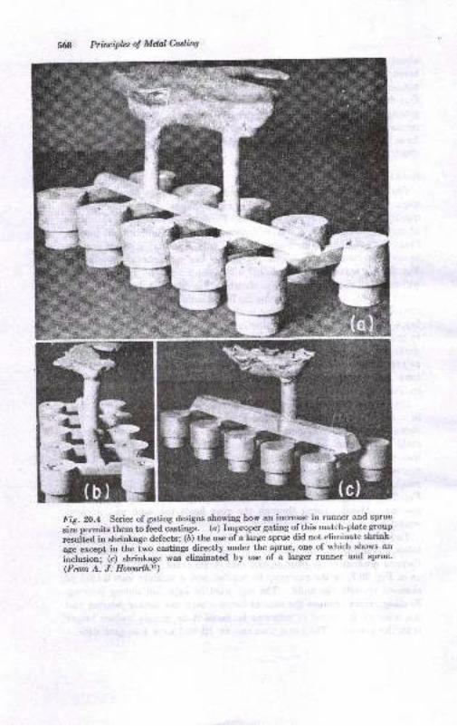
Principles ol Mdal Casaing
3Fig.2O.4 Series of gating designs ehowing how an increase in runner and sprue
sizi permits them to feed castings. (a) Improper gating of this match-plategroup
"orl't"d io
"hri.t.ge defects; 1a; tne use of a hrge sprue did not eliminate shrink-
aBe except in r,he iwo castings directly -under
the sprue, one of which shon's an
iiclusion'; (c) shrinkage was eliminat€d by use of a larger runner and sprue'
(From A. J. Houtoilh.\)
FT
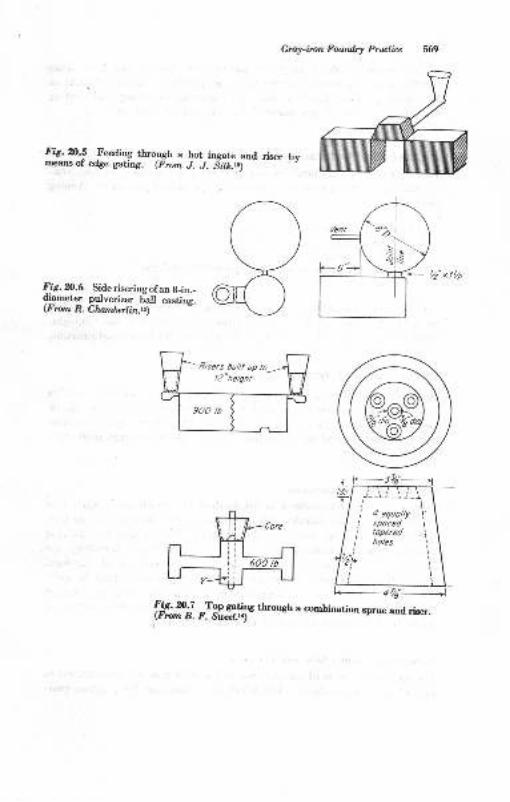
Gray-imn Fourdry Prutire
Fig. m.! Teeding through a hot ingate and riser bvmeans ol' edge gating. (Frorn J..L Sdr&.rr)
F!5.%.6 Side riseringofan B-in.-di_ameter pulverizer ball casting.(F rom R. Chotnberlin.rr)
fft#i.#*ttfn.*ough a combinarion sprue and riser.
,"1
'+.-sls
-I,, 5 put t up ro_-2,/2"height
900 /b
It
I
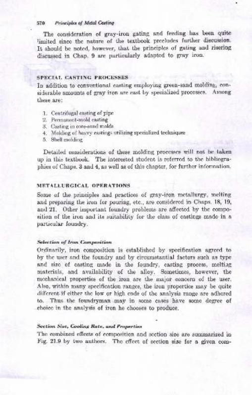
57O Prircipbol MdalMiw
The conqideration of gray-iron gating and feeding has been quite
rimited since the nature of the textbook precludes further discussion.
It should be noted, however, that the principles of gating and risering
discussed in Chap. 9 are particularly adapted to gray irou.
SPECIAL CA-STING PROCESSES
In addition to conventional casting employing green-sand molding, con-
siCerable amounts of gray iron are cast by specialized processes. Aroong
these are:
1. Centrifugal casting of pipe
2. Permanent-mold casting
3. Casting in core-sand molds
4. Molding of heavy castings utilizing specialized techniques
5. Shell molding
Detailed considerations of these molding processes will not be taken
up in this tcxtbook. The intrrested student is referred to the bibliogra-phies of Chaps. 3 and 4, as well as of this chapter, for further information.
METALLURGICAL OPERATIONS
Some of the principles and practices of gray-iron metallurgy, melting
and preparing the iron for pouring, etc., are considered in Chaps. 18, 19,
and 21. Oiher important foundry problems are Bffected by the compo-
sition of the iron and its suitability for the class of castings made in aparticular foundry.
&loction of lron Compsition
Or.dinarily, iron composition is established by specification agreed toby the user and the foundry and by circumstantial factors such as typeand size of casting made in the foundry, easting proeess, meltiegmaterials, and availability of the alloy. Sometimes, however, themechanical properties of the iron are the major concern of the user.
AIso, within many specification ranges, the iron properties may be quitedifferent if either the low or high ends of the analysis range are adhered
to. Thus the foundr5rman may in some c&ses have some degree ofchoice in the analysis of iron he chooses to produce.
Scction Size, Culing Rate, and Proprtics
The combined effects of composition and section size are summarized inFig. 21.9 by two authors. The effect of section size for a given com-
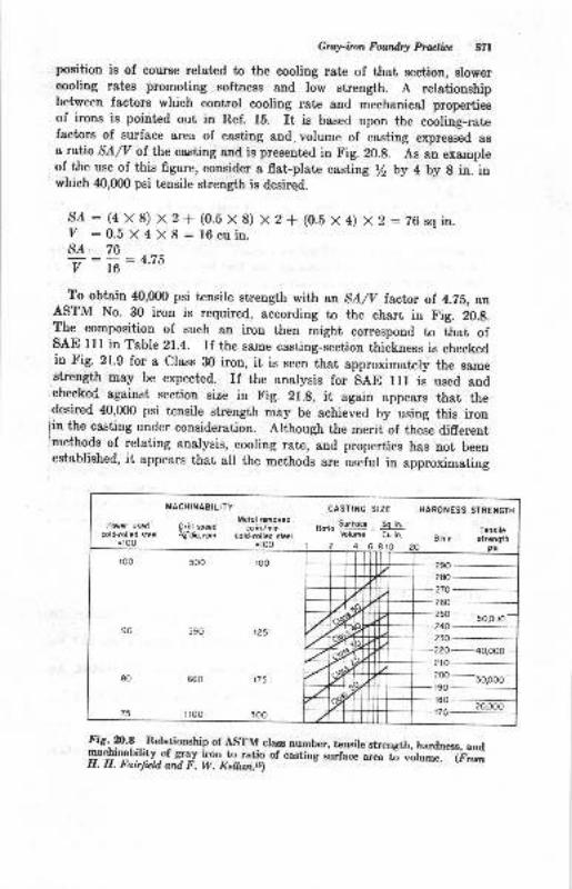
Gruy-imn Fowdry pt@licc SZI
position is of course related to the cooling rate of that section, slowercooling rates promoting softness and low strength. A relationshipbetween factors which control cooling rate and mechanical propertiesof irons is pointed out in Ref. lb. rt is based upon the cooring-ratefactors of surface area of casting and volume of casting expressed asa ratio SA/V of the casting and is presented in Fig. 20.g. As an exampleof the use of this figure, consider a flat-plate casting t/z by 4 by g in. inwhich 40,0fl) psi tensile strength is desired.
S/ : (4 X 8) x 2 + (0.b X 8) x 2 + (0.b x a) x 2 : 76sqin.V :0.5X4X8:16cuin.s/ 76
7 : 16
:4'75
To obtain 40,000 psi tensile strength with an SA/V factor of 4.75, anASTM No. 30 iron is required, according to the charb in fig. iO.S.The composition of such an iron then might correspond to that ofsAE 111 in Table 21.4. If the same casting-section thickness is checkedin Fig. 21.9 for a Class 30 iron, it is seen that approximately the samestrength may be expected. If the analysis for SAE 111 is used andchecked against section size in Fig. 21.g, it again appears that thedesired 40,000 psi tensile strength may be aehieved by using this iron
lin the casting under consideration. Although the merit of these differentjmethods of relating analysis, cooling rate, and properties has not beenestablished, it appears that all the methods are useful in approximating
Power usedcold-/olled steel
=t00
MACHINAEILITY
Metol GmovedDritl spred cu itrlminlj'dio,rpn cold-rofiedst*l
=t0O 1
cAsTrilG stzE
^ -. Surfoe So rn.
vblumc Cu in.
2 4 68tO
HARDNESS STREI{GTH
Tensilt8 h n strength
20 psi
80
75
660 175
floo 300
LZ1= ffi--r-r 20.000
--T--Fig. 20.8._.Relationship ol ASTM class number, tensile strength, hardness, andy1liryblli-ty 9f g1a1r iron ro.ratio of casting .;J"*;;* ti votume. (F,rH. H. Fairfuld ard F. W. Kellun.r6)
5O,Or)0
lopoo
A
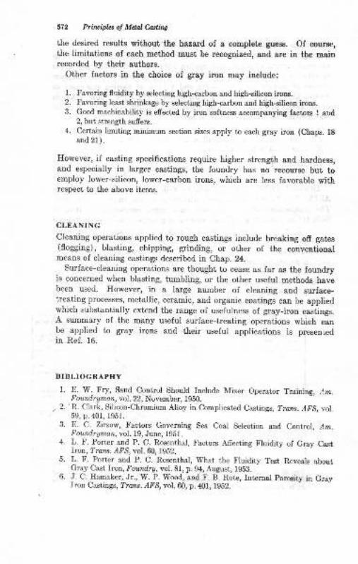
572 Pri'lfiplct o! Mdal Cdhs
the desired results without the hazard of a complete guess. Of course,the limitations of each method must be recognized, and are in the maiurecorded by their authors.
Other factors iu the choice of gray iron may iDclude:
1. Favoring fluidity by selecting high-carboo and high-silicon iron8.2. Favoring least sbrinkage by selecting high-carbon aDd high-silicon iroDs.
3. Good machinobility is effected by iron sottness accompanying lactors 1 aud2, but strength sufers.
4. Certain limiti:rg minimum section sizes apply to each groy irotr (Chaps. 18and 21).
Ilowever, iI casting specifications require higher sirength and hardness,and especially in larger castings, the loundry has no recourse but toemploy lower-silicon, lower-carbon irons, which are less favorable withrespeci to the above items.
CLEANING
Cleaning operations applied to rough castiugs include breaking ofr gates(flogging), blasting, chipping, grioding, or other of the conventioualmeans oI cleaning castings described in Chap. 24.
Surface-cleaning operations are thought to cease as far as the fouudryis concerned when blasting, tumbling, or the other uselul methods havebeen used. -[Iowever, in a large number of cleaning and surface-heating processes, metallic, ceramic, and organic coatings can be appliedwhich substantially extend the range of uselulness of gray-iron castings.A summary of the many uoeful surface-trcating operations which canbe applied to gray irons and their useful applications is presenLed
in Ref. 16.
BIBLIOGRAPHY
1. E. W. Fry, Sand Control Should Include Mixer Operator Training, r1m.F oundraman, vol.22, November, 1950.
, 2. 'R. Clnrk, Silicon-Chromium Alloy iu Complicated Castings, ?rons..4,'S, vol.50. p.401, 1951.
3, E_. C..Zirzow, Factors Goveming Sea Coal Selection and Control, ,4m.F oundryman, yol. lg, June, 195l.
4. L. F. Porter and P. C- Rosenthal, FactoE Aflecting Fluidity ol Gray Castiron, ?rcn*. .4tr'S, vol. 60, 1g52.
5. L. F. Porter and P. C. Rosenthal, 1ryhat the Fluidity Test Reveals ^boutCray Csst, Iron, Ioundry, vol.81, p.94, August, 1953.
6. J- C.IIamaker, Jr., W.T. Wood, and F. B. RotD, Internal poroeitry in GrayIron Castings, ?ron-s.,{IS, vol. 60, p.401, 1952. -
Grayimn Fourdry prulite S?B
7' \ A' Birch, Gating and Risering principres, a tark given before wisconsinChapter AFS, 1952.
i. g ! 931pU"tt, Designing Strainer Cores, Trans. z{trg, vol. 56, p. 574, lM8.9. I. J, McDonatd, Gaiing-to Controi i;,i;"; Rate and Its Effect on the- ^ _C_*tyg, Trarc. AFS, voll6t, t958.10. H.^W. Dietert, How Fast'should a Mold Be poured? Foundry, vol. gl,
p. 205, August, lg53.f 1. A. J. Eowarth, Gating principles Ap-plied to Gray Iron Castings produced
-^ gn ld1tghnlates, Am. Foundrgman,vot'. m, p. ZS, J;ly, Gl. ---12. .I..J. Sitk, Gaging Gray Iroi for'prod;;i[;t'"rre;ies,-lm. Found,ryman,vol.21, p.4I, February, tg52.13'
T. chamberlin, side riisers cut creaning Room costs on A[oy Iron castings,Am. Foundryman, vol. 21, January, lgili.14. B. F. Sweet, Core Serves as Gatl'and Fltlr'lr, Foundrg, vol. g0, September,
1952.15' H' H' Fairfield and F. T[. Keilun, casting surface: vorume Ratio predicts
lray lron properties,.z{zr.
!9,:rrrd;,a;r;:-iJ. io, p. g0, eus;;issi.---'f6. C. O. Burgess, Metaliic and Non-nietai[. a;rttr;g'f".'C.r; I;;;iourdrg,,, I.-|s:J1
,rd 78, Decembel r!s0, *a Jr"rr.v_rebruary, lg5t.rr. Amencan -Uoundrymen,s Society,.,Cast Metals Ilandblok,,,4th ed., p.4g1,
11. 1.g.rl Foundrymen's Society,,.The Cupola and Its Operation,,, 1984.19. If W- Zimnawoda, ,Mechanicai Equipmeri ior Medium_sir"d G.ry I.o,Foundry, Trans. AFS, vol.59, p. SO, iSST.
---- -
20. C. O. Burgess, Grav Iron: Molding, Cutting and Brazing, Arn. Foundryman,vol. 18, October-December, lgb0.21. H. L. C-aqrpbgll, Convert Ladle Dimensions to Iron Weight, Am. Fowtdrg_man, vol. lb, June, lg4g.n. R. J. Anderson, Mechanics of Foundry Mechanization and ImprovedMethods, Trans. AFS,
"ot. Of , fS5S.
vq'g'J rrr
23. A. W. Gregg, Mechanized Mehing Methods for Foundries, Iron Age, May8,1947.24. Modern Equipment Co., Bulletin on Cupola Charging, port .Washington,
25' G' Krumlauf, cast Fig-ure process Reduces Machining cos's, z{m. Foundrg-man, vol. 15, June, lg4g.26' w' F' Bohm, Mord Materials Are Factors in Gray Iron shrinkage, r{nr.^* Foundrgman, vol. 1g, January, lg5i.27' c'c' sigerfoos and c. A. sanders, Gray Iron shrinkage Rerated to MordingSand Conditions, Am. Foundraiii,Til $',;"iruary, rssl.28' L' F' Porter and p. c. Rosenthal, bffect or sJiu. on Fluidity of Gray castIron, Trans. /trS, vol. 60, 1952.29. Vlulsif:r, Gray Iron Chilling practice, Foundrg,vol. g6, p. 62, September,
* irl;f"rtsm.an'
Desulfurization of Iron and steel, Foundrs, vol. 86, p. 46,
:1 I 1 A^Told, Gray Iron Chemistry, Foundrg,vol. 86, p. 86, December, 19b8.,r. ftuf.
Clark, Inoculation of Gray C*t r;;;,'i;""d,ry, vot.87, p. 100, May,
33. H. H. Wilder, Inoculants for production of Eigh Strength Gray Iron,Found,ry, vol.88, p. l16, June, 1960.

514
v.
35.
36.
38.
39.{).
Ptir*ipb of Mel e*ns
W. C. FilkiDs, J. F. Wellac, rnd D. Mstt€r, ib$ TestiDS of Grsy IroDiFot dr!,,tol. 89, p. 62, December, 1061.
J. V..Drrsoa, PiDhole Polodity iD Gr8y Irotr, Faudry, YoL. 99, p. 116,
Septalder,1961.G. W. Form aod J. F. Wallece , Grsy ImD fliructurca and Properilce.
Poutdry, y/ol.90, p. 66, Septarnb.r, 1962; p.58, &ober, 1962.
W. Eiller eod R. W8lking, Idfueocc of Silicon:C,arboa Ratio oD Tensile
str€D8th of Grsy Iron, Fomdry, vol.9O, p.54, Deceober, 1962.
A. Wir.bDoer aod E. A. Krall, thriakage in Gray Iron, ?ondry, vol. N,p. 62, Jdy, 1962.
F. G. sefug, Aloyed Gr8y bona, Fwrdry,,tol. 91, p. 86, Morch, 1968.
J. f. Wdhre, Efieci of Carbon EquivsleDts a,nd Eestion Eizo oa Tengilo
Strcogth of Gr&y Irols, Fourdry, rol.9l, p.,$, Deccuber, 1908.
27Metallurgy of Gray fron
Although "gray irou" denotee a certein type of cast iron, yet ttre chemicalcomposition, etructure, snd properties of grey iron may vary over broedlimite. The rauge ol alloy compoeitions aud properties produced as grayirons may be better uoderstood by considerstion of eome of the principlesof gray-iron metallurry. Some oI the more general principlee andproperties have been presented in Chap. 18, and it ie assumed the studenthae studied that chapter before delving iuto this one.
The metallurgr ol casi irons depends iu large measure upon the natureof the iron-carbon equilibrium system. Superimposed ou the solidliuephase diagram of the Fe-C system ae demongtrated iu Fig. 8.6 is adashed-line diagram. The two diagrams show thst, iron-carbon alloyamay exist in two difrerent phase relationships. The solid lines apply tothe syst€m iroo-iron carbide, and ihe dashed lines refer to the syetemiron-graphite.
THE METASTABLE IRON-IRON CANBTDE SYSTEM
Iu the phase system iron-iron carbide, carbon in ttre alloya occurs aathe metastable compound irou carbide (Fe"C). During solidification ormeltirg and in thermal trestment€ in the solid state, the iron carbideluuctions accordiug to normat principlee of phase relationshipe as expectedfrom the equilibrium diagram. tr'or example, freedng of s hypoeutecticalloy, less thsn 4.3O per cent carbon, will begin wiur the formation ofaust€nit€ dendrites and be compteted by aolidification of the eutecticsulteuite-iroD carbide. After solidification, cooling in the solid ststeresults in transformation ol the sustenit€ to pearlitc. The room-tem-p€ratur€ Dicmstructure arising from the foregoing proceesee ie givenin F'ig.21.10, which shows the primary auet€nite den&ites as pearliteareae and the auetenite-carbide eutectic aa a peartite-carbide mixture.A eutectic Fe-C alloy containing 4.30/o C should freere without theformation of primary austeuit€ detrdrites and should cooaist only oI theeutectic-type structure as illuetrated in Fig. 21.1b. Ileating ond cooliugof alloys with the microstruotures showa in trig. 2l.l are accompanied
575
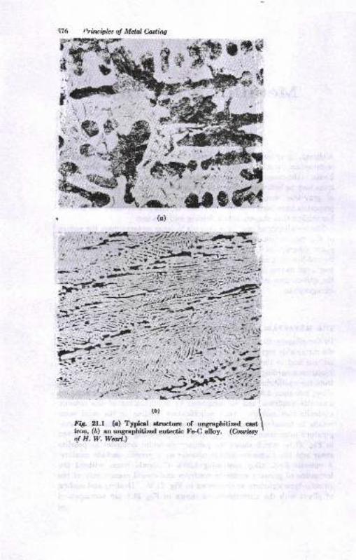
i76 t'rirciphs ol Mdal Cutittg
t*{
+'.'
#G
-.-
Ftt zt.r (c) Tuical
t]lr*,,- , ,r3""*
""o\iron, (D) aa uryraphitized eutectic Fe4 alloy. (Caduy \
o! H.W.Wul.)
,l
$'
-lti
t.
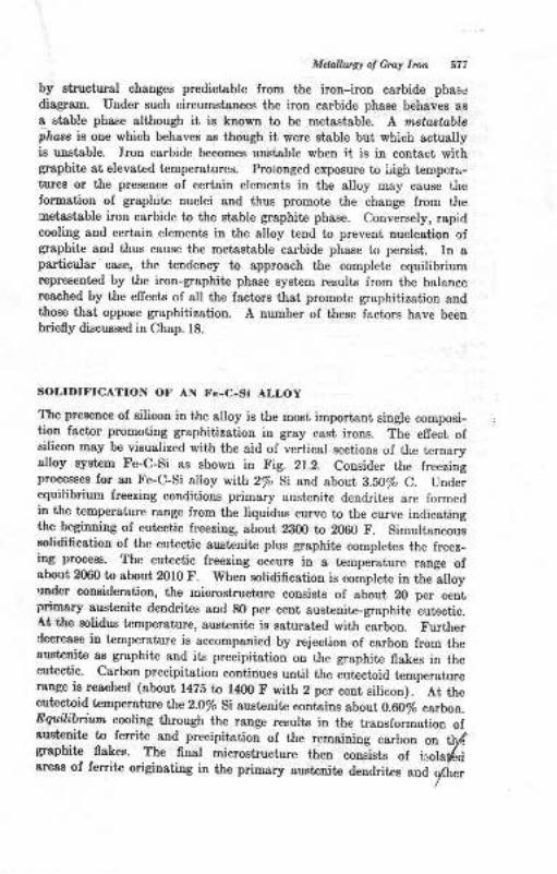
Mdalhrsy o! Cmy lron 577
by atructural changes predictoble from the iron-iron carbide phas.r
diagram. Under such circumstsnces the iron carbide phase behaves asa rtsble phare although it is known to be meiastsble. A metaatablephase iB oae which behaves as though it vere Btable but, which actuallyis unstable. Iron carbide becomes unstable when it is in contact withgraphite at elevated temperatureu. Prolonged expoEure to Ligh tempcra-tures or the presence of certain elements in the alloy may cause tircformstion of graphit€ nuclei aod thus promote the change from the',Detastsble iron carbide to the stable graphite phase. Conversely, rapidcooling and certain elements in the atloy t€nd to preveot nucleation ofgraphite 8nd thus cause the metastable carbide phase to persist. In aparticular case, the teudency to approach the complete equilibdurnrepresent€d by the iron-graphite phase system resulte from the balancereached by the effects of all the factors that promot€ graphitization andthose that oppose grapbitization. A number of these factors have beenbriefly discussed in Chap. 18.
SOLIDIFICATION OF AN Fc-C-Si ALLOY
The presence of silicon in the alloy is the most important Bingle composi-tion factor promotiug gaphitizatiou in gray cast irous. The efrect oIsilicon may be visualized with the aid of vertical sections of the tcrnaryalloy oyetem Fe-C-Si as shown in Fig. 21.2. Consider the freezingprocesses for an Fe-C-Si alloy with 2/o Si zrld about B.5O% C. Underequilibrium lreezing couditions primary austenite dendrites are formedin the temperature range from the liquidus curve to the curve indicatingthe beginning of eut€ctic freeriDg, about 2300 to 2060 F. Simultaneouseolidification of the eutectic auetenite plus graphite completas the freez_ing process. The eutectic freezing occurs in a temperature range ofsbout 2060 to sbout 2010 F. When solidificatioo is complete in the alloyunder consideration, the microstructure cousists of about 20 per centprimary austenite dendrites and 8O per cent austenite-graphite eutectic.At the solidus temperature, austeoite is saiurated with carbon. FurtherCecreaee in temperature is accompanied by rejeciion of carbon from theaustenite ae graphite and its precipiiation on the graphite flakee in theeutectic. Carbon precipitation continues until the eutectoid temperaturerange is rcached (about l47i to l40O F with 2 per cetrt silicon). At theeutrctoid temperature lhe2-O/o Si austeniie coniaius sbout 0.60/o carboo.Eqttilibriun cooliug through the range results in the transformation oIaustenite to ferrite and precipiiation of the remaining carbon on t\ldgrapbite flokes. The final microstructure tlren oone-ists of i:,olai6dareas of ferrite originating in the primary Bustanite deDdrites aud gflrer
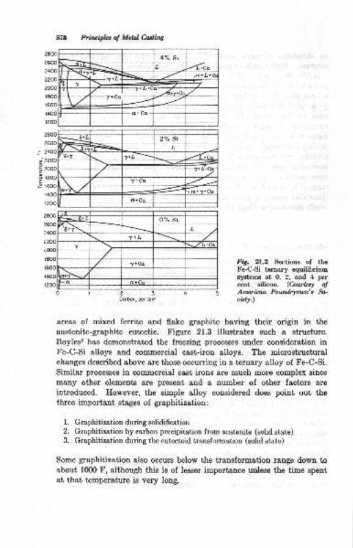
578 Priluipb of Mdal &ttittg
2000
r800
1600
t400
r200
EF
23Corbs, per cerf
FiE. 21.2 Sectioos of tLeFe-CSi ternary eguilibriumsyst€ms at O, 2, and 4 percent silicon. (Couteq otAmerican Foanlrymen's b-cuty.)
areas of mixed ferrite and flake graphite having their origin in the
austenite-graphite eutectic. Figure 21.3 illustrates such a structure.Boyles2 has demonstratpd the freezing processes under consideration inFe-C-Si alloys and commercial c&st-iron alloys. The microstructuralchanges described &bove are those occurring in a ternary alloy of Fe-C-Si.Similar processes in commercial cast irons are much more complex Bince
many other elements are present and a number of other factors are
introduced. However, the simple alloy considered does point out thethree important stages of graphitization:
l. Graphitization during solidification2. Graphitization by carbon precipitation from austenite (solid state)3. Graphitization during the eutectoid transfomration (solid state)
Some graphitization also occurs below the transformation range down toabout 10fi) F, although this is of lesser importance unless the time speutat thst temperature is very long.
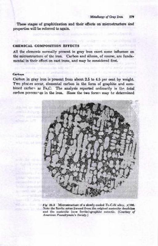
Mdailugt of Grcl lrot 5?9
Thee stsgps of graphitization 8Dd their efreots on micmstnrcture dnd
properties will be referred to again
CIIDMICAL COMPOSITION EFFECTS
AII the elements normally preeent in gray iron exert eome influence on
the microgtructure of the iron. Carbon and sihcon, of course; are funda-
mentsl in their efiect on cast irons, and may be considercd firat
Cor\nCarbon in gray iron is prcaent from about 2.5 tD 4.5 per eent by weight"Two phat'es occur, elemental carbon in the foru of graphite and com-bined carbo',r ae FesC. lhe analysis reported ordiuarily ie thc ,oralcorbon percentnge in the iron. Siuce the two foms may be determined
-q
,'l *
FA il3 Microstructure of a slowly cooled FeCSi alloy, X lfl).Note tbe Territe araas form€d from the original austenite dendriteeand the aust€nit€ (now ferrite)graphite eutectic. (hwby o!Amcr ican Fowd,rX,mcn' s Sa. i"l!.)
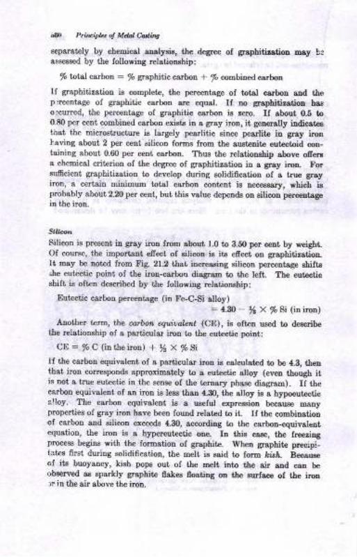
i'8ar Ptit iplzt ol Mdal C-a4ins
separst€ly by chemicsl aualyeie, the degree oI graphitiratiol may beasseesed by the fotlowiug relationahip:
% total carbon : /o graphitic carbon * /o combined carbon
If graphitization ie complete, the percentage oI totol carbon and tbep -'rcent8ge of graphitic carbon are equ8l. If no graphitintion haaoccurred, the p€rcentage of graphitic carbou ie !ero. If sbout 0.5 toO.8O per cent combined csrboD exists iD e gray iroD, it generally indicateeihat the microstructure is largely pesrlitic sinc€ pearlite in grsy ironLaving about 2 per cent silicon forme ftom the eusteEite eutectoid con-taining about 0.60 per cent carboo. Thus the relatiouhip above ofierea chemical criterion of the degree of graphitiration in a groy iron. Forsuffcient graphitization to develop during eolidification of a true grryiron, a certain minimum total carbon contcnt is neceuar5r, which ioprobably about 2.20 per cent, but thi8 value dependo on ailicon perceDtsgein the iron.
sirn n
Silicon ie preeent ir gray iron from about l.O to 3.5O per cent by weigbtOI couree, the importaut, efrect ol ailicoo is it6 efiect on graphitization.It may be noted from Fig. 21.2 that inoeaaing silicon percentage ehifte.he eutectic poiut of the irou-carboa diagram to t&e left. The eutecticshift is olt€n described by the following relationehip:
Eutectic carbon perceDtsge (itr Fe-C-Si alloy): 4- - yr X /o Si (in iron)
Another term, lhe carbon equivalant (CE), is often ued to deecribethe relationship of a particular iron to tlre eutectic point:
CD: %A (in the iron) + ysx%Si
If the carbou equivalent of a particulsr iron is calculated to be 4.3, thenth&t iron correspouds approximately to a eutectic alloy (even though itis not a tnre eutectic in the eense of the t€rnary phsse disgrsm). U thecarbon equivalent of au iron ie less than 4.30, the alloy ia a hypoeutecticelloy. The carbon equivaleDt ie a useful expreasion because manyproperties of gray iroD have been found related to it If tie combinationof carbon and eilicon exceeds 4.30, according to the carboo-equivsleotequation, the iron ie a hypereutectic oue, In thie case, the freedngprocees begins with the formation ol graphite. I[heu graphite precip!-tatee first during eolidification, the melt is Bsid to form hislr. Becauseof ite buoyaucy, kieh pope out of tlrc melt into the air aud can berrbeerwd as sparkly graphite flake8 noafing ou tle eurfsce of the iron:r in the air above tJre iron.
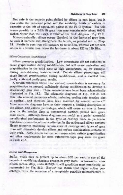
Melhrty ol Gra! Itut stl
Not only is the eutectic point, ahifted by silicoo in cast irou, but itelso ehifts the eutactoid point, and the aolubility limite of carbon insu8tenite to the left, of equivalent poi[tE in tlrc Fe-C ayatem. For thisresson pearlite io, a 2.0/o Si gray ircn may contain oDly sbout 0.60%carbon rather thao Lhe 0.76% C value oq the Fe-C diagram (Fig. fz.f).
Microstructurelly, EilicoD occur8 dissolved in the ferrite of grsy iroD,Aa euch it hardens and strengthenB the fe[ite, as poiDted out in Chap.18. Ferrite in pure iron will meeeure 8O to 90 Bhn, whereas 2.0 per centeilicon in a ferritic iron raieeg the harduess to about 12[} to 130 Bha.
Sili.o,1. Conl..nt atd cmphilizotiot
Silicon promotes graphitintion. Low perceutegea arc not sufrcient tocause graphi,ization duriug aolidificatioD, but will cauEe nucleation audgraphitization in the solid Btste 8t high t€Bperature, ae, for example,during malleableizlng heat trrstmeDt. Certain eilicon percentages willcsuse limited graphitization during solidification, and a mottled iron,partly white and partly gray, results.
A certaiu minimum silicon (and carbon) concentration is neceesary forgraphitization to proceed 6u6cieutly duriag solidificatioo to develop asatisfsctory gray iron. These concentratious have been schematicallyillugtrated in Fig. 18.2. The echematic diagrams of Fig. 18.2 do nottake into account numerous effects, including cooling rate (Bection sireof cssiiog), and therefore have been modifled by several auihors.r6More accurate diagrams have as their purpose a limiting deecription ofthe silicoa and carbon percentages which will cause aD iroD to free!€gray itr the section sizes of commercial castiDgs poured into greeneand molds. Although these diagrams are ueeful as a guide, succesefulmetallurgical performance in the type of castings made in particularfouudriee remains the ultimate criterion for the carbon and silicon cont€DtHence foundries producing certain siree of csstinge and types of grayirons will ultimately develop silicou and carbou combinationr suit&bte totheir work. Some silicon and carbon ranges which satisfy graphitirstiousEd other requirements for some automotive-type gray irour are givenin Table 21.5.
Sugut atd Moason ,c
Sulfur, which may be present up to about 0.25 per ceut, is one of theirrportant modifyiug eleEent6 presetrt iD gray irone. A low-sulfut iron_eilicon-carbon alloy, under 0.010% S, will graphitire most completcly, agrepresented by Fig. 21.3. Boyles, ha6 showu that higher zulfur Srer_ceDtages fsvor the ret€ntion ol a completely pearlitic microskucturr ir,
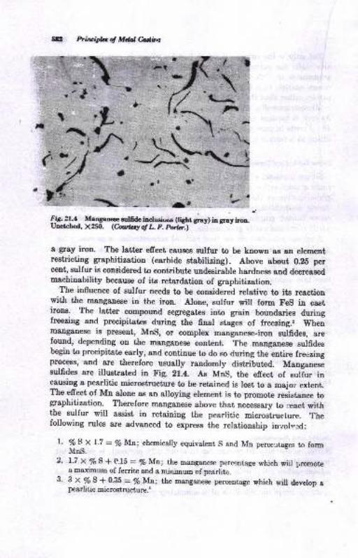
5E Ptiuiplul d Mdal Cadinp
Irt !!.1- Maqare e'lG& iDdurnoos (tttt gray) iD gray iroo.Unetched, )(ZSfi. (huby ol L. F. Pctc".)
a gray iron. The latter efrect cauees Eulfur to be known aB an elementrestricting graphitization (carbide stabilizing). Above about 0.25 pereeat, sulfur is considered to contribute undesirable hardness and decreasedmaehinability because of its retardation of graphitization.
The influence of sulfur needs to be considered relative to its reactionwith the manganese in the iron. Alone, sulfur will form Fes in cast
lrone, The latter compound segregates into grain boundaries duringfreezing and precipitates during the final stages of freezing.2 Whenmanganese is present, MnS, or complex manganese-iron sulfides, arefound, depending on the manganese content. The mangan"." ,uifidu.begin to precipitate early, and continue to do so during the entire freezingprocess, and are therefore usually randomly distributed. Manganeseeulfidee are illustrat€d in Fig. 21.4. As Mns, the efrect of suliur incaueing a pearlitic microstructure to be retained is lost to a major extent.The effect of Mn alone as an alloying element is to promote resistance tographitization. Therefore manganese above that necessary to r.'eact withthe sulfur will assist in retaining the pearlitic mi*ostrueture. Thefollowing rules are advanced to express the relationship inzol*ed:
l. ??S_X
1.7 - % Mn; chemically equivalent S and Mn perceutages to formMnS.
2. 1.7 X % S + AJ' - Vo Mn; the rranganese percentage which wiil promote4 641i1arrm of ferrite and a minimum of pearlite.
3. 3 x Vo S + 0.35 = % M!; the manganese percentage which will develop apearlitic m icrostrueture.'
a.\zl' D
ra
r"r*:{c7;
"$\
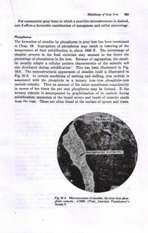
Mdall.urW of Gmy Imn 583
For commercial gray irons in which a pearlitic microstructure is desired,
rule 3 ofrers a favorable combination of manganese and eulfur percentage.
Plro,tplrolruc
The formation of eteadite by phosphorus in gray iron has been mentioned
in Chap. 18. Segregation of phosphorus may result in lowering of the
temperature of final solidification to about f800 F. The percentage ofeteadite present in the final structure may amount to tren times thepercentage of phosphorus in the iron. Because of segregation, the stead-
ite usually adopts a cellular pattern characteristic of the eutectic cell
size developed during solidification.' Thie has been illuetrated in Fig.18.6. The microstructural appearance of stradite itself is illustrated inFig. 21.5. In certain conditions of melting and chilling, iron carbide isaesociated with the phosphide in a ternary iron-iron phosphide-ironcarbide eutectic. Then an amount of the latter constituent considerablyin excess of ten times the per cent phosphorus m&y be formed. If theternary eutectic is accompanied by graphitization of its carbide duringsolidification, expansion of the liquid occurs and beads of eutectic exude
f16p the ir6a. Theee are often found at the surface of sprues and risers.
Fig. 21.3 Micretructure of steadite, the iron--iron pboe-phide eutectic, X1000. (Fmm Ameian Fourtdrvmen't,$cnty.,
544 Ptin ipl!' o! M.hl Cartins
Because it forms a eutectic as it segregates, phosphorus is often lookeiupon as incrcasing the tendetrcy for & particular iron composition to be aeutectic-type alloy. For this reason, the carbon_equivalent equation is
. eometimes modified to include a factor for phosphorus as 1ollows:
CE=%c+%(%Si+%p)
Another equatio! of this type for cast irous is giveu in Chap. g, withrespeci to the efiect of phosphorus on fluidiiy.
The phosphide of iron is hard and brit e, as is the carbide. Increasingphosphorus percentage in the iron causes a proportional increase of theh-ard constil,uent, and therelorc increasing i,arine"" and U.ittt"nu., oithe iron, especially above about 0.30% p. To & limited degree, improvedfluidity of thc molten iron is a desirable property contribute'J Ui pfrl.pfl"-rus through its influence on carbon equivaient, (Chap. g).
GRAPIIITIZATION DURING SOI,IDIFICATIONThe size, shape, and distribution of graphite flakes develop duringsolidiflcation of the gray iron. X{arked diffe"on"", in grrphit" iyi": uoasize are recognized. ?hese are classifietl according to ,"'"t*au"i-typ"and size charts adopted by thc ASTtr{ and AFS (-Fig. fS.lt. e i""ao_y'istrihution_oI fl:rkes, type A, ancl small
"ir", No. S-o, O,'i.
""*ii*"Adesrrable. However, the dendriiically segrcgatcd and cellular types areoften. encountered. Type E flakes,
'denJriticaly *g."g^;J *iii
-pr"-
ferred orientation, are most often encountered in hypoeutectic irous,where
.the ,graphite flakes precipitate in the interstices of *"-pri_u.V
austenite dendrit€s. It is more difficult to ascriLe the tvp" n f"rc" oithe.cellular pattem to a pa{icular cause. Gray irons oi ldentical com-position rnay solidify with type A or D graphite. Mr"h .t"dy-h;";"""grven to this situation. Most researcher-s associate the typ"6 gl"pf,it"with an undercooling efrect, during solidification..,..'",',r'' If ;;;';o"-T:,.":,"f-j* :rT:1,: ]. suppressed from irs normal t"_p*uiri"
"uog"or about 2lm b 2000 f, down to below this range, the type of graphiteformed changes from type A io types D aud E.
"Suppres'sio, of
'"utl"u"rreezlng, as, Ior example, by chilling to still lor.er t€mperatlre, 1g5O to1900 F, results in formstion of whib lron (or chilled ironl. tfr"'".."*r"f
-!!eas of the effects of undercooling are summarized in Table 21.1.
Sec.k ^ Si@ d^d Crophiae TyIE
The actual ehanges of graphite size, number of flakes, and their distribu-Uotr &re related Lo fundamental metallurgical nucleetion aud pgowthprinciples.. Large flakee randomly distributid originrt" ;;;rG ;;;"_tlon rat€ rs tow: there is ample time for difrusion; and g,apbitilatioa
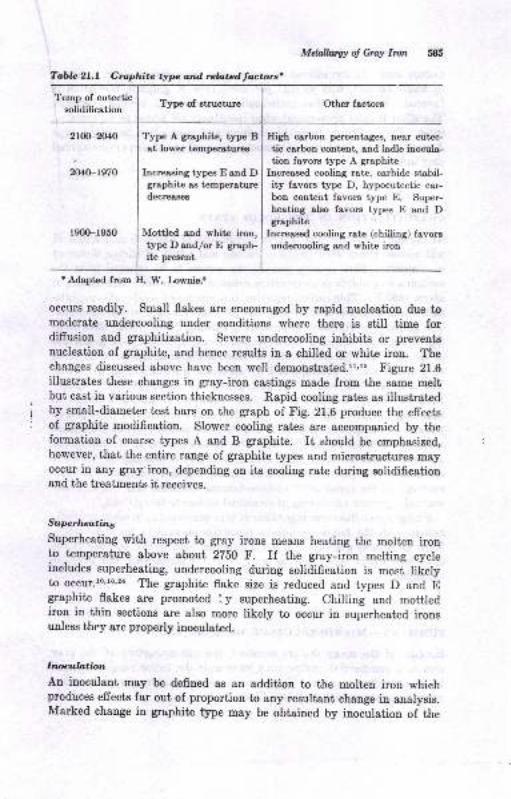
Tabla 2l,L Graphitc typc and rebtadtactors'
Type of BtructureTemp of eutectic
solidification
2t00-2040
2040-1s70
Typ" A graphite, type Bat lower temp€raturcs
Increesing typea E end Dgraphite as temperaturedecreases
Mottled end white ircn,typeDand/orE graph-ite preaent
Mdallwgy oJ Gray Ircn 585
Other factors
High carbon percent&geE, neor eutec-
tic carbon content, and ladle inocula-tion favors type A graphite
Increased cooling rate, carbide stabil-ity favore type D, hypoeutectic car-bon content favors type E. Super-
heating also favore typee E and Dgraphite
Increased cooling rate (chiiling) favoraundercooling and whit€ iron
r900-r950
I Adapted from E. W. Lowaie.t
occrus readily. Small flakes are encouraged by rapid nucleation due tomoderate uodercooling under conditions where there is still time fordiffusion and graphitization. Severe undercooling inhibits or preventonucleation of graphite, and hence results in a chilled or white iron. Thechanges discussed above have been well demonstrated.rr'rr Figure 21.6illustrates these changes in gray-iron castings made from the same meltbut cast in various section thicknesses. Rapid cooling rates as illustratedby small-diameter test bars on the graph of Fig. 2l.G produce the effectsof graphite modification. Slower cooling rat€s sre accompanied by theformation of coarse types A aud B graphite. It should [s smphasized,however, that the entire range of graphitre types and microstructures mayoccur in any gray'iroD, depending on its cooling rate during solidificationand the treatments it receives.
Suprluatins
Superheating with respect to gray irons means heating the moltcn ironto temperature above about 2750 F. If the gray-iron melting cycleincludes superheating, undercooling during solidification is mosi likelyto occur.lo'16,2{ The graphite flake size is reduced and types D and Egraphite flakes are promoted '" y superheating. Chi[ing and mottledirou in thin sections are also more likely to occur in superheated ironsrrnlsgs thsy are properly inoculated.
Inocubtion
An inoculant may be defined as an addition to tbe molten iron whichproduces effects far out of proportion to any resultant chaDge in analysis.Marked change in graphite type may be obtained by inoculation of the
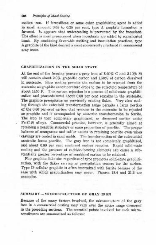
586 Pril{ipLt ol Mdal Coding
molt€B iroD. If ferrosilicou or some other grsphitizing sgeui is sdd.ed
ia small amouni, 0.05 to 0.25 per cent, type A graphite formation ig
favored. It appear8 that undercooling is prevented by the inoculaat.The efrect is most pronouaced when inoculants are added to superheatedironi. By combiuing favorable meliing and inoculatiou practices, typeA graphite of the kind desired is most consistently produced in commercialgray iroD6.
GRAPHITIZATION IN TIIE SOLID STATE
At the end of the freering process a gray iron of 3.60/o C and 2.10ft Siwill contaia zbott 2.0/o graphitic carbon e!,d l.5O% oI carbou dissclvedin auetenite. Slow cooling permits the carbon to be rejected from theaustenite as graphite as temper&ture drops to the eutectoid temperature ofsbout 1450 F. This carbon rejection is a process of solid-state graphiti-zation and proceeds until sbout 0.60 per cent remains in the austeuite.The graphite precipitates on previously eisting flakes. Very slow cool-ing through the eutectoid transformation range permits a Iarge portionof the 0.60 per ceDt c&rbou thsi remains in the austeqit€ to be reiect€das grephite aDd is eccompanied by austeniie transfolmation to ferrite,The iron is then completely graphitized, as discussed earlier underFe-C-Si alloys. Commercial praciice, however, is generally aimed atretaiDing a pearlitic siructure or some proportion of pearliie, The properbalalce of manganese ertd sulfur aaeists in retaining pearlite even wiren
' castings ere cooled in saqd molds. The tramformaiion of the eutectoidalaustenite forms pearlite. The gray iron is not completely graphitized,aud about 0.60 per cent combined csrbon remains. Rapid solid-statecooling and the presence of carbide-forming elements can cause a sub-steriially greater percentage of combined carbon to be retained.
Fine grephite flake size regardless of iype promotes solid-state graphiti-zatiou, with the flakes serving as precipitation centers for the carbon.Type D cellular graphite is often iutermixed with ferdie because of theesse nrith which graphitization may occur. Figures 18.4 and 21.6 sreexamples.
SUMMARY _ MICROSTRUCTUNE OF GRAY INON
Because of the many factors involved, the microstruciure of the grayiron in a commercial casting may vsry over the entire range discussedin the preceding sectiotrs. The essential points isvolved for e&ch micro-constitue[t are flrmmarized as follows:
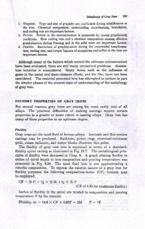
MdallwgY of GraY Imn 5f'
l. Gruphite.. tvpe and size of graphite are istahlished during solidifcstion ol
the iron. Chemical composition, undercooling, superheating, inoculrtion,
sDd sooling rate are important factors.
2. Ferrite. Ferrite in the microstructure is promoted by strong graphitizing
conditions. Slow cooling rate and a chemical composition causing efiective
graphitizetion during freezing and in the solid stat€ are important factorB.
3, Penrkte. Regtriction of graphitization during the eutectoidal transfoma.tion, cooling rate, and proper balance of manganese and sulfur in the iron are
important factors.
Although many of the factors which control the ultimate microstructure
have been evaluated, there are still many unresolved problems. Anoma-
lous behavior is encountered. Many items, such as the influence ofgases iu the metal and trace-element effects, and the like, have not been
considered. The material presented here has attempted to picture in part
the simpler phases of the present state of understanding of the metallurgy
of gray iron.
}.OUNDRY PROPERTIES OF GRAY IRONS
For eeveral reasons, gray irons are among the most easily cast of allalloys. The practical difrculties of meking castings require certainproperties to a greater or lesser extent in casting alloys. Gray iron has
many of these properties to atr optimum degree.
Fluiditlr
Gray irons are the most fluid of ferrous alloys. Intricate and thin section
castings may be produced. Bathtubs, piston ringis, electrical-resistancegrids, steam radiators, and motor blocks illustrate this point.
The fluidity of gray cast iron is expressed in terms of a standard-fluidity spiral casting as illustrated in Fig. 21.7. The metallurgical prin-ciples of fluidity were discussed in Chap. 8. A graph relating fluidity ininches of spiral length to iron composition and pouring temperature waspresented in Fig. 8.20. The most fluid iron is one approximating a
eutectic somposition. To express the eutectic nature of a gray iron forfluidity purposes, the following composition-factor (CF) formula may[s smployed:
CF:%C+ynx%S\+y2x%P(Cf'of 4.55 for maximum fluidity)
Inches of fluidity in the spiral are related to composition and pouringtemperature ? by the formula
Fluidity,in.:14.9X CF +0.05?- 155 ?: oF
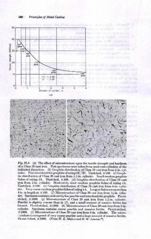
Fig.2I..6 (c) The ellect of microstructure upon the tensile strength and hardne,ssof a Class 20 cast iron. Test specimens were taken from sand-cast cylinders of theindicated diameters. (D) Graphitc distribution of Class 20 cast iron from |-in. cyl-inder. Fineintcrdendriticgrapbit€ofrating6E,7D. Unetched, Xlffi. (c)Graph-ite distribution of Class 20 cast iron from 1.2-in. cylinder. Small random graphitcfla}-es of rating 5A. Unetched, Xf00. (d) Graphite distribution of Class 20castyon from 2-in. cylinder. Moderately sized random graphite flakes of rating 4A.Unetched, Xf00. (e) Graphite distribution of Class 20 cast iron from 6-in. cylin-der. Very coarse random graphite flakesof rating lA. tongest fl akeeare more ihan4 in. in length at X f 00. 0f) Microstructure of Class 20 cast iron from !-in. cylin-der. Specimencontains moderatelyfine pearliteandintcrdendriticgraphite. Picral-
formed. Picral-etched, X f00O. (n) Microetructure of Class 20 cast iron from 2-in.
etched, X1000. (g) Microstructure of Class 20 cast iron from 1.2-in. cylinder.Pearlite is slightly coarger than in (f), and a small amount of massive ferrite has
cylinder, Specimen contains etse pearlite and magsive ferrite. Picral+tched,X f000. (0 Microetructure of Class 20 cast iron from Gin. cylinder. The miero-; Lructure is compoeed of very coaroe pearlite and a larlp amount of masEive ferrit€.Picrai-erched, X f 0(X). (fmm W. E. Mahin ard H. W. Lounic,t.)
588 Principbs of Mdtl Ming
'a
ooo30;
-zo
234oiomt€r ot crliodcr, in.
(al
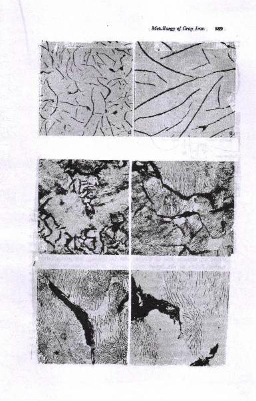
Md,thAy ol Grq Imn 58!t
")zr\.\\ ---' j)11l{$
),iiWi7']4ttl
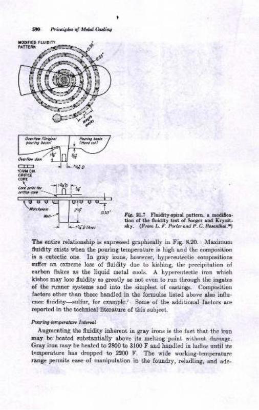
TODIFIEO FLUIDITY
590 Prircipht of Mdol &dhs
Ovu{lot doa
lOfT DIAORIFICECORE
\Cild rn:t l fvuilicc m
FiS. 21.7 Fluidity+piral pattern, a mdiffca-tion of the lluidity test of Saeger and Krynit-sly. (Frun L. F. Porhr ard P. C. Rogenllnl.a)
The entire relationship is expressed graphically in Fig. 8.20. Maximumfluidity exists when the pouring temperature is high and the compositionis a eut€ctic one. In gray irons, however, hypereutectic compositionssuffer an extreme loss of fluidity due to kishing, the precipitation ofcarbon flakes as the liquid metal cools. A hypereutectic iron whichkiehes may lose fluidity so greatly as not even to run through the ingates
of the runner systems and into the simplest of castings. Compositionfactors other than those handled in the formulas listed above also influ-ence fluidity-zulfur, for example.? Some of the additional factors arereported h f[6 f,gshnisal literature of this subject.
Pun in4"lcmprutun I nlaulAugmenting the fluidity inherent in gray irons is the fact that the iron
may be heated substantially above its melting point without darnage.
Gray iron may be heated to 2800 to 3100 F and handled in ladles until itsfnmperature has dropped to ?200 F. The wide working-temperaturerauge permits ease of manipulation in the foundry, reladling, and ade-
Zrt;
_l+tY;ohyc)
Ma&Ew ol G.r! Iro S9l ,
quat€ time for pouriag. Actual pouring temperatures rangr frou about2300 to 2800 F, dependiug ou the casting requirements.
Stuin*tge and Rbcritts
Feeding of castings to compensat€ for solidification ehrirJkage has been
discursed in Chap. 20.
Because of the favorable freezing mechanism and low ehrinkage charac-teristics, the yield percentage is high compared with other Jerrous metalg.A yield of 60 to 75 per cent may be atiaiued, and in some cases higheryields are possible. Alttrough it is true tirat high-carbon-erluivalent gray
irons have the lea6t ahriukage, it ie not alwaye true that they present thefewest probleme in riseriug. Some casiing designs are more easily castin commercially acceptable soundness wil,h lower-carbon-equivaleat irona.
ENCINEERING PNOPERTIES
tr'rom o metallurgical-eugiueering standpoint, gray iron may be viewed
as a micro8tructurally sensitive alloy. Microstructure, chemical compo-
altion, aud mechanical properties are intimately related. Of course, themsny factor8 related to the proceesiug of gray irou which iufluencemicrostructure, chemical-composition variatioDs, and cooling rate also
afiect the properties.
E$cct ol Chen.i$l C.orrlposi.i<m
Carbon and silicon are the most important composiiiou factors iDflueoc-iug mechanical properties, The carbon equivalent hae beeu relat€d to auumber of mechanical properties.t,,rs,r! A graph of csrbon equivslettaud tonsile strength is ehowu in Fig.2l.8. Decreasing carbou equivalent,brought about iD part by s reduction of carbon percentsge in the iron,re8ult€ in increased t€nsile Btrength. The practical limit of sirength bydecreasing the carbon equivalent alone is probably sbout 45,000 psi
tcneile strength. Higher streugths require epecial alloying prsctices.
I'he relstionship of hardness to t€n8ile streugth, the teDsile-streDgtlFBhn ratio, is subiect to subst&ttial variations due to ihe infuence of thevarious flake graphiie types. Table 21.2 lists the relationehips betweentensile strength snd BriDell hardnees. The importance of graphite typeand si!€ is also emphasized in Tsble 21.2. Ii may be noted from thetoble that the highest tensile sirength ie obtained at a given hardnesewhen smsll type A grsphit€ flakes exiet. On the other hand, a poortaarile etrength is obtained at a givetr herdrregs when type D grsphit€
Prcvsils.
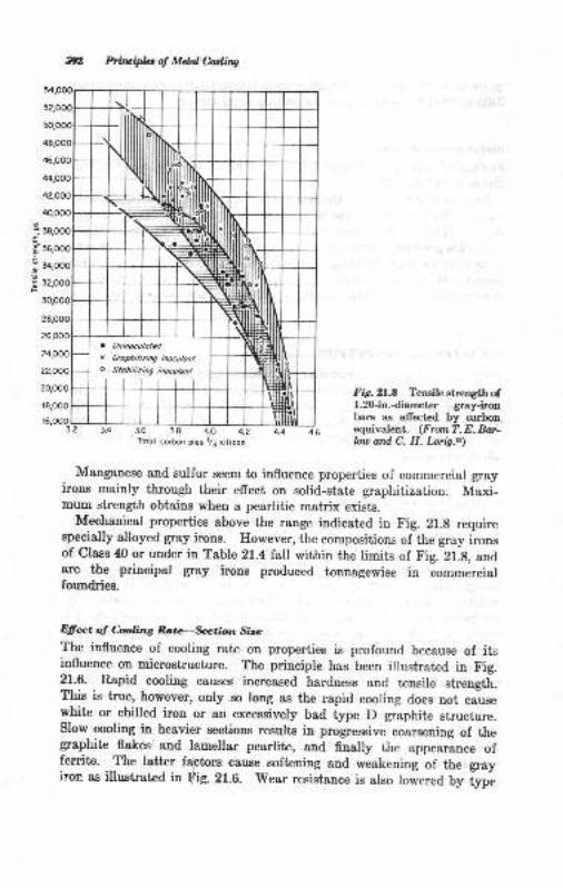
.;
g'6
F
Pzriripla ol Mdal Cadins
FA.2l.8 Tensile strength of1.20-in.diameter gray-ironbars as allected by carbonequivafent. (FromT. E. Boa.bu ard C. H. Lorig.al
Manganese and sulfur seem to influeuce properties of commercial grayirons mainly through their effect on solid-state graphitization. Maxi-mum strength obtains when a pearlitic matrix exists.
Mechanical properties above the range indicated in Fig. 21.8 requirespecially alloyed gray irons. However, the compositions of the gray ironsof Class 40 or under in Table 21.4 Iall within the limits of Fig. 21.g, andare the principal gray irons produced tonnagewise in commercialfoundries.
Dfiect oJ C.a6ng Ro,te-fution Sire
The influenee of cooling rate on properties is profound because of itsinfluence on microstructure. The principle has been illustrated in tr'ig.21.6. Rapid cooling causes increased hardness and tensile strength.This is true, however, only so long as the rapid cooling does not causewhitc or chilled iron or an excessively bad type D graphite structure.slow cooling in heavier sections results in progressive coarsening of thegraphite flakes,and lamellar pearlite, and finally the appearance offerrite. The lattrer factors cause softening and weakening oi th" g.ayiron as illustrat€d in Fig. 21.6. 'wear
resistance is also lowered by type
Uninoculotd
orolhitizit g iD@ulont
Slobiliziog iooculont
Totol corbon plus l/J silicon
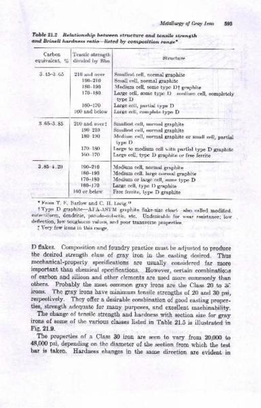
Mdallwgy of Grty Ircn
Tabla 21.2 Rel,tionship betrnan sti]u{ture ortd ton"cil/- strengthand. Brinpll htrdness rotio-listad blr compsition tange.
I f"o"ile strength
Structuredivided by Bhn
3.45-3.65
Carbonequivalent, /o
210 and over190-210
180-190
r7Gr80
r60-170160 and below
190-210
180-r90170-180
160-170
160 or below
Smallest cell, normel graphiteSmall eell, normal graphiteMedium cell, some type Dt graphiteLarge cell, some type p-66{lrrm cell, conpletelytype D
Large cell, partial type DLarge cell, complete type D
3.65-3 .85 Smallest cell, normal graphite
Smallest cell, normal graphiteMedium cell, normal graphite or smell cell, partialtype D
Large to medium cell vith partial type D graphiteLarge cell, type D graphite or free ferrite
3.85-4.20 Medituu cell, normal graphiteMedium cell. large normal graphiteMedium or large ceU, some type DLarge cell, type D graphiteFree ferrite, type D graphite
r From T. Ii. tsarlow and C. H. Lorig.rrt rype D graphite-AFA-ASTM graphite flake-size chsrt-also called modi6ed,
eutectiform, dendritic, pseudo-eutectic, etc. undesirable for wear resistence; lorvdeflection, low toughness values, and poor tra,nsverse propcrties.
I Very few irons in this range.
D flakes. Composition and foundry practice must be adjusted to producethe desired strength class of gray iron in the casting desired. Thusmechanical-properf specifications are usually considered far moreimportant than chemical specifications. However, certain combinstio:rsof carbon and silicon and other elements are used more commonly thanothers. Probably the most common grey irons are the Class 20 to :iCirons. The gray irons have minimum tensile streugths of 20 and B0 psi,respectively. They ofrer a desirable combinetion of good casting proper-ties, strength adequate for many purposes, and excellent mact inauiiity.
The change of tensile strength and hardness with section size for grayirons of some of the various classes listed in Table 2l.E is illustrated inFig.21.9.
The properties of e Class 30 iron are seen to vary from 20,000 to48,000 psi, depending on the diameter of the section from which the tpstbar ie tsken. Hardness changes in the same direction are evident in
210 and overfr90-2r0r80-r90
170-r80r60-r70
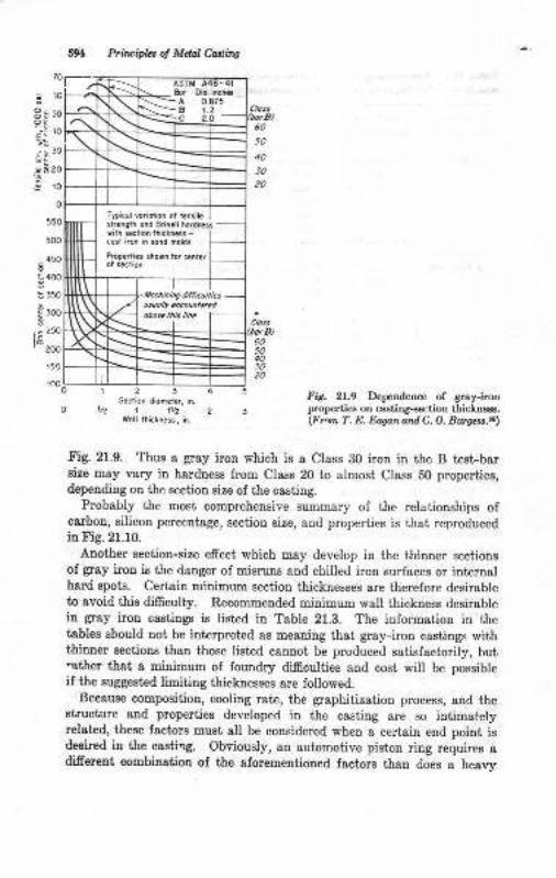
,o
ro
30
20
ro
o
550
500
450
400
350
300
|aa
50
30
123Sedio^ diobet , i..1/z 1 1V2
.B 0.8?51,?
Typi.or @rioiio. oi iensiresr'.n9ih oid Brinerl horder3rnh i&ri.n rh'.rnx.- l
Pop..ri.s thori tor canrer
Primipbs ol Mclal Cattins
fry. 21.9 DependeDce of Sray-iroDproperties on csstiog*ection tbicLD€€s.(Frrn T. E. Easan and C. O. 8{ns.rs...)
Fig. 21.9. Thus & $ay iron which is a Class 30 iron in the B test-barsize may vary in hardaess from Class 20 to slmosi Class 50 properties,depending on the sectioo size of the casting.
Probably the most comprehensive summary of the relationships ofcarbon, silicon percetrtsge, section size, and properties is that reproducedin Fig.21.10.
Anoiher section-size efrect, which may develop in the ihinner sectioneof gray irou is the danger of misruns and chilled iron surfaces or inter[elhard spots. Certain minimum section thicknesses are thelefore desirableto avoid this di$culty. Recommended midmum wall thickness desirablein gray iron castiugs is listad in Table 21.3. The informatiou in thetablee sbould not be interpreted as meaning that gray-iron castings withthinaer sections than those listed cannot be produced satisfactorily, but.ather that, a minimum oI foundry difdcutties and cost will be possibleif the suggested limiting thicknesses are followed.
Beeause composition, cooling rate, the graphitization process, and theBtructure and properties developed in the casting are so itrtimstelyrelat€d, these fact{rs must all be considered when a ceriain end point isdesircd in the cssti'rg. Obviously, an automotive piston ring requires adiferent combinatiou ol the alorementioned factors than does a heavy
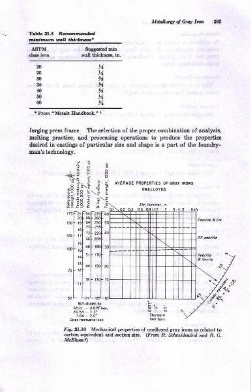
ASTMchss iron
$rggeeted minwall thicknese, in.
Teblc 21.3 Ramruerdtnfutimutrn wU thicktuca'
Mellug! of Gray l,rrt
AVERAGE PROPERTIES OF GRAY IROI{S
UI{ALLOYED
Dt,diomltar. in.
,6N,6%%%%
n25
30
35
40
50
60
t trbom "Metals Eaadbook"" I
forgrng press frame. The selection of the proper combinatioa of analysis,
melting prastice, 8nd proceosing operations to produce the properties
desircd in castings of particular size and shape is s part of the foundry-man's technolory.
*Fo
38'a--
ic,
;;t,,, L
:L
@NOciJ Gi 5Stondordtesl bors
0.r
ooo;
F'21)
zoltql
flr6l
,tl
::l
::l
M.R.
t'6
E_3NE
i:l8r,- Et; s.: .;:
fztl- rs
L::1,,l- ,=
I 'o
I r!
[:45.26.
7.
Gives
noo9r;
.9 .:
35=@
*FztsFigl- zeol-gcl- z5o[-nl zsl,rl rrolr.l-.oul-
,.L,rrltt5t F t70F
,.1 ,-L
:LJ,ividld by
- o.g75"b(- 1.2"- 2.O"svrrga lood
i[-ji8r;o- !io :!O lio.
a Fg,rol- a,
rsl- e
,"L ,
,rl'ls,
rel-l5r
:1',r[-
o,
nl
,'L,
L,M.R.di
.6'r -
.53 -
.64 -
€
=\I
t4Fz75B9F 26084l- z5o771 235
7zl zzoJ
66F 2o5
s8F rsel
5t F t70l
44F r5ol
L"t_tt.R.dividld bt6'r - 0.875"53 - r.2"
",1;.1!',,,Fig.2I..LO Mechanical propertiee of unalloyed gray irons as relatcd tocarbou equivalent and sectioo si?.. (Frofit R. &hrcillailnd and R. G.McEhaa..)
Peo.fu, A Cn
506 PfiaipLt d Mdal C,atliti.q
Othar Ptryrti<xIn additiou to tensite and transverse properties, other properties oI greyirous are significaut. Specific data ou theee properties may be obtainedfrom the "Cast Metals Ilandbook.". A few generalizatioDs are ofrerediu the following items :
Cornpcssie Slrcnglh
This is an outsianding property of gray cast irons, being three to fivetimes greater than its tensile streogth.
Torsknal Slrength
Strength in torsion is about 1.20 to 1.40 times the streugth in tensiou.
Mdulu o! Ehsticily
The elagtic modulus in tension varies lrom 12 to 22 million psi, depeud-iug on microsiructure of the iron. A deeirable microstructue of 6negraphite and pearlite favors the higher values.
Shear abenglh
The shear strength ig about 1.0 to 1.60 times the tensile strength.l
Endwance Limit
The endurance limit of gray iron is about, 35 to 50 per cent of its t€tr8ilestrength. However, because it is less sensitive to notches, its endurancelimit is as great in many applications as that of materials oI subetaltiallyhigher tensile strength..
The hardness of gray iron mey vary in much the same way as itsstrength. This is illustrated in Fig.21.9. Tensile sirength aud hardnessare approximately related by the formula,6
TS=BhaXK
where K = 160 to 210, depending on composition atrd microstructure.The hardness, transverse, aud tensile properties of automotive-type
cast irons are giveu in Table 21.4. This table shows the general relation_ship of increasing hardness accompauying increasing strength. pearliticrnicrostruciures predominate iu the higher hardnesses. Typical composi-tions for the irons are also given.
W&w Rerirtan e
Gray iron is outstanding in its resisiance to the sliding-friction type ofwear, especially lubricated. This is exemplified in its use for piston
Mdallutgy ol Gruy Imn iylringrt, cylinder liners, crankshafts, clutch plstes, brake drums, gears, andiDterDal-combustion-eugine t{ocks. T}Dical wear data are cited in the"Cast Metals llardbook,,r aDd ,.Metals Haadbook.,,l
M,t h;nan WGray iron is amoug the Eost machitrable of ferrous materiale. Best
nschinsbility in gray irous is eqcouatered iu the soft€r irons. A hard-ueas range of 130 to 210 Bhn encompaEses most g.ay irons. A combina-jio.1 of ggdgate strength and hardaess, with e-pha"i" on machinability,is liet€d in Tabte 21.4 as SAE G2000 (fto) wit'h a 187 maximum Bhu.Cbilled-iron edges or hard spots in thin eections are very detrimental tourachinability, although they should uot occi.u with proper foundrypractice.
Hal Rcsithna
Eeat resistance ia term.B of resistance to scaling and retentiou ofmoderste sirength at eleyated iemperatures ia a deeirable property ofgray irona, advantageous in the use of gray iron for furlace- and s;ke.p:*,
Pd{i* pots, gas. burtrer8, and similar applications. The propertyot ieat resrstaDce Eay be iuproved in alloyed gray irons.
Gra-y iroru which ere cycled through the mitiial rauge iu service exhibita gradual dimeusion8l '.$owth,, caused by oxidatioul Tbis growth canbe reduced by alloying the gray iron with chromium or ei[;o or ;ti".auoylDg elementt which will either increase carbide stability or raisethe critical temperature range.
Ddnpiq Cary.ilr
-.Dampiug c&pacity_is ihe ability of a material to absorb energy due to
vrbratrous. aDd .thu8
dampen the vibraiious. The ability ol gra] iron todampen vibratioDs-as compared with steels is illushaLd iu'fig. Zf.ftlor .a torsioDal vibratory impulse imparted to caeliron an-d eteelepecimens.
The -vibration damping tapacity of gray iron assiet€ markedtv iuprcductng smoothness of operation in internal_combustion engines or
otner structures where yibration is an operating characteristic.
Fig, 2l.Il.. Cuves iuuskabna tbe dampina oftorlioDal vibraLioDs in a csrbon et€el and_ a c{st,iroo. (Fntn American FoundrflE ,s &ci.ly.t)
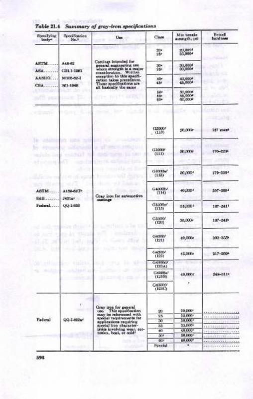
Tabb 2l,l sxtml',sl S 6rcy-ton rpiiagtiotrt
a.aa{a
Gr!.t-ta6!
Mto&it-I
$l-leadl
F!6.1 @tindi4 rrh.E dodh n. 6joroEidduon. Wnlbn.6Dt oD b 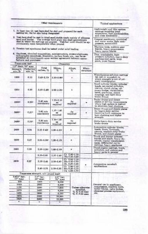
l. rtt h..r, tD (2) iot, t E r,t ll b.6rrt, .!d Dr{,D.!!d tq o!{to: i.r. trE bt aE taDt &i6t d
2. ltd! b...brll b..- iD dri{..d Eot(b E d. D.inlv ot .ilid+<I ud bifti.r. Tt. rvo!. sd E in .i!. lLrU
^;EnlBhlLc,b rAi.t Lh. -tri!a. e Frna t-!-b.r 6otd ah@ld bi.D-proti@t ly tuD t Dp.ntuts ria Dourld
A. Tdrd6 t-t qr..iE@ ihr[ h. rd.d u,irtd si.l tddirs
a. E.fthdr ob.mi6l @Eraiti.D. Bi6G!ru.lurc. Dmmrirltra!4!Fphio Mdn-r diBdoh, Err6 6ni.li, .r... 6r trc *!.Dr!rEd s r.quircoot! trpon ritr.o .ar6E.nt b.r'a DeEr&tuE ud Duronar
Liabtveiahr, .trd iLin Etiotr@tinsr r.qtrinfi rood.pparbc., Lilh mcnirbiUtr,
Ettr-towduty &fri@
]lutomotiv. @h.It
[email protected] e ir n&binB.@DpteE. ruhiD. 6ob.moi.r blela v.lvc [email protected] u€ ouiDbdr.

Table 21.4 Summar! oI gras'-iro,t ,pccifaotioru (continued)
A8'INl
ASI'E
A27a42T
sA27a
Prsu.€&nr.inins Dtr.lor teDeBtum uD to
ASTfI
A319,53.hocl'rentsnc. wh.re3i.€nsih roquiEDoDt
I
II
Ilt
u.s. IlrL C-asaAliiqi slloy lo. r6i3i3n.€
wepage, snd srodh1 120 1an
25,0OO 120-180
ASTII .{436-63
@titr5 ut€d priNilylor ih€ir rdbisnc. t
Ed. S€€ lull [email protected] lor urMrib€d hat.trslDeitt ooverin. st*
rtsbili,aiion. or.limiru-tion oI o[illod €dsa or
1, 131-183
t19-2t2
118 174
t7i 218
3, 25,00r)"" lla 159
149 212
5, s9-124
25.0OO"" t24-\71
Ofh.i!L, 9t? Natio@l P.e Bldi., Wshi*too 4, D,C.!r,ro!h St,, N€, Yort 16, N.Y...3as Esr !r7th Sr.. N.w YorL 17, N.Y,tb, 1916 Rs.e St,, Pbild€lDhia 3. Ps.el Rd., Ot(lra 7. OnBrio. Canad.. Cou llow, Ctr.*o, Ill, (sko elev€n r.cio@l omcslknnston Av.., N€F YorI i7, N.Y.Nal.y Depsrm€nt. wshinrlon 25. D,C, {or nqrs.
,ins t[o tdr-bar air6 .aruirod Io.n{di rsult i: rquir.d lor @tins6d to conlorm b thi.sEi6.aiioo.. tst b& i! not .pei6ed. Reob-
. I ndividul .Dei6cstion nuDb€r dv.n in"Cb- @luDb. Thit l!.o6stion abontrk!.h.riar@Epdi_tion @ @n.ile si,E@rb snd Bflno[ ]&dnE *@Di sblF.Ei6o ;eplidlod r.quirts ,'np.uitirul @ntioi.
/ N!* sAE numErilI svlt E sdoDbd in 1eo3: old luboE, L.; "r10." @i b6 slbr!.iive4" sd iul..dv6vu Biod Ircm 1963.
, ObEiipd lrco t-t b.E..!.E[.ly c..i bui ol ..D. ircnsdihor.Ihirn,ya.c.!tiqt. Tat-badi&!,-
600
AS:I M Tensile -bo. Dimensions

qY,."rr.H,Tt"%:r:,i--jE - 7o c + o\(vo at + vo niC.rtinr. ud bt bM Dui h..rr*r.tiv.d by Dt ciD.d e.!D.d!
v.lv. hozrid. EDfuitt dddrour, .hmi..l Dlr,€ &ui!-E.nq pl{uFv*t EriDs.
3.81-{,,rO
3.61--{.!0
3.2rL3.&
EtL.!.t unilold. ?.1v.8tidc. iubo lup.mhlrdboBid6..t66 lin6. cnt-..iov. ioD4 lurn@ hopD€r.!puDp qdna., .nd imrEU...R-,.i{r6 ro &id. qu.ric.$d 8ll -luiior niiri^"dto hai .!d @l$io4 s .bore
U-ftt* 0."a"-. .o.u -nrom to sD. nnr. ! .D*i6.d fo. t-t b.. .!d .rdl b. Lt r o! butully t6t d, €6 lull .p*in6iion fG .Ddi6.d miod!rucrur..
"J.{r,Ti:}'il'f;:"'.&'ri',Y-H,* *.$3SJ1:L5. cstilsr r.qui'i^s o,.@iolrr' ^.qud Blb.r E. it ih -r t f@rnob d r.ep!.iE l-bru.d for.u Eiiou ubdd o.!o itr.).. rr.m.fu rdi.r.u b. D d. in u.u or bn-h hr,Lo.,-u"a. u"r o.[ -,1]iu-,"iiiiiriiii ii.u*.r Mut b. @U.v.d o, tllu. by prcnb.d e!h.d. for u- b.to, alo F.r t lD.rrjd b b..peid€d in @au&L
] 9!: m, ?.6, .m1 +d l5_
e d- ootu.d, bu! rioit d ro u b.loi .60 e;ifi ffifr*i,""il#.l3d.,mm!,**. sresrh E y b. ;D6i6.d ,h@ *nri.r (uD t
Jrly,i.J:f.f .H a'o"jtt ua to ui ':c oa .tbiri,. in6ie ror .r.vrr.<r-i.hp6irrc .*i6., CL..*t rir.d by udor.ly di.tlibur.d snDLir. n Ld, oD.6bid.., ud .! lui.triii. dtrir.rtuc:ur..
.,:k,1;I."f:ilift":i:",.,1*:f"d*.J;51.._!. _*i"g "*-."ri"r. ai.i;;;;;;;il,,,.,
x Trr b.r! p.rltinGd foD t-i!. t6l bL.r 6r I 1,r wt@ .e D..!iai4 r ,.qqi,.d, * ,.. ; i.M# r;IJ{- o }.i* bv optio! of pwrr6r.
601
to -lsTM
M.iri!olLb6Ur! psUt ; te q6bidqorborl

ffi, Pria.*bol Mdcadile
L'ry+udon Retidatrc
The corrosion rcsistsnce of grsy iron is important in eome 8pplicstions.
Water maing gnd other pipe applications illustrat€ this property in uee.
Since gray imns may be porcelaia-enameled, their ueefulness msy be
€xtended to bathtubs, rinlcq, and other items ol thie type.
Elnbial Rcti.damc
The electrical resistance of gray iron is sufrciently high eo that it is
used extensively for resistance gridsJ
Abilfu to & Hcal-trcoltd
Gray iron may be hardened and tempered by heat treatments similar
to thos€ applied to steel. For example, wear resistance in cylinder liners
and sleeves is increaBed by hardening and temperiug to the range of
Rockwell45 to 55 C.
Consideriug the range of properties available in gray irons, it is easy
to uuderstaad the wide use of this material in all the basic industries.
Although the property generalizations made above apply to the usual
grades of gray irons, it should be recogaized that certain of the properties
may be enhanced by alloying or other metallurgical practices.
GraSr-bon Spncificrtbns
Because gray iron is used in so many difrerent engineering applications,
numerolur specifications covering its use in special fields have been
developed. A most comprehensive summary of these specifications has
been compiled.2z It is presented in Table 21.4. Note that Table 21.4
gives the relationship between casting-section size and test-bar size iu
the table, in footnote d.
The specifications presented in Table 21.4 illustrate the idea of sub-
dividing the wide range of properties of gray irons into smaller ranges.
Thus these specifications recognize that this engineering material can be
US- slondord
J
f---t- Cf Fig. 21.12 Standard tensile and trurs-iffi r verse test bars for gray iron with correc-i'- tion-factor table.

Mdalhry o! Gray lron 6&1
produced with a wide range of properties, and it is the foundryman,sproblem to produce an iron in the property range specified by the pur-chaser of the castiugs. Furthermore, it is the design engineer's problemto design the casting so that the foundrymsn can furnish the propertieswhich are specified for the castings of a particular section. size, and shape.
Dimeusions of the tension-test specimens and correctiou factors fortrausverse test bars are given in Fig. 21.12.
HEAT.TREATMENT OF GRAY IRON
Because gray irons may be heated into an austenitic temperature range,they are amenable to many heat-treatments applied to steels. Benefitswhich may be derived by a suitable heat-treatment are:
1. Improvedmachinability2. Improved wear resistance
3. Improved strength4. Dirnensional stability and stress relief
Machinability
Anuealing or normalizing may be utilized to soften and improve themachinability of gray irons. Subcritical annealing may be a,rcomplishedby heating to 1200 to 1250 F, holding 2 to 4 hr, followed by slow cooling.Spheroidization of pearlite and some graphitization occur during thistreatment. More complete annealing may be accomplished by heatingabove the critical range to 1Ob0 to 1700 F, holding, and slow cooling.Tbe latter treatment can accomplish complete graphitization and soften-ing of the iron to about 120 to 140 Bhn. permanent-mold castings areoften so treated. Normalizing by air cooling from the high tempeiatureis accompanied by retention of pearlite and a higher strength and Bhnafter treatment than result from annealing.
Year Resistancc
Hardening and tempering may be employed to obtain increased wearresistance in cast irons. Heating the iron to lSzs to lz00 F causes anaustenitic structure with about 0.6 to 0.80 per cent dissolved carbon tobe developed. Subsequent quenching in oil or water will produce amartensitic structure having the hardness characteristic of hardeneclstsels. The qucnched iron may then be tempered at various temperaturesto reduce hardness to that desired. An exarnpre of these heat-treatments
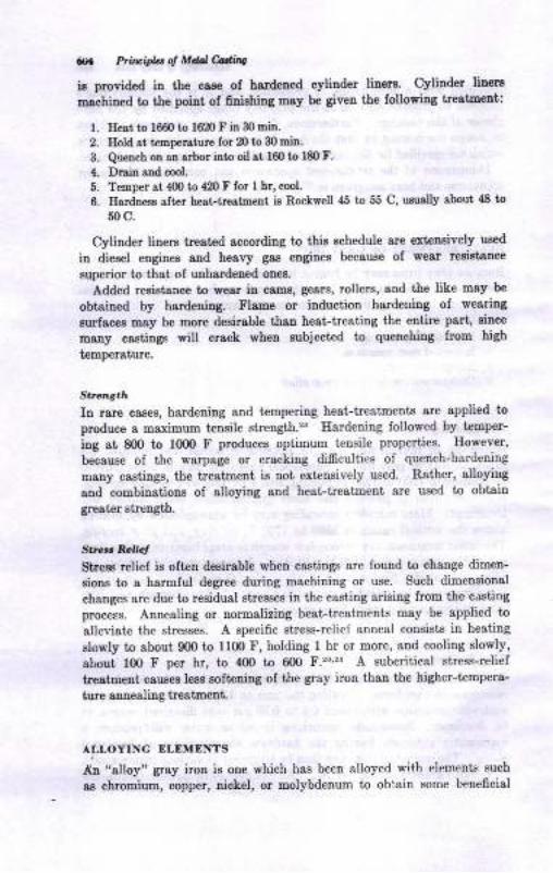
g Ftu*taod Ll&lfuta
ir provided ia the cam of bardeued cylinder linerr' Cylinder liners
Dschirod to th€ poht of 6niahi4 may be given the following tr€stment:
l. Eest to 1660 to 16i10 F itr 30 miD.
2. Eold st t4lDpersture for 20 to 30 laitr.
3. Qreuch on on orbor into oil st 160 to l8o F.
4. Drail sDd cool.
5. Tetlper d 4m b 420I for I hr, cool.
6. EardDess sft€r he8t-ir€3teent i8 Rockwell 'l5 to 55 C, usurUy about tE tu
50 c.
Clliuder liners treated according to thia echedule 8re extensively used
ia dieeel eagines and heavy gaa engines becauge of wear r€aistsnce
superior to that of unhardened onee
Added resiEtauc€ to weat in camo, gear8, rollera, and the like may be
obteined by hordenhg. Flane or induction hardeuing of weariag
nrlacea may be more deeirsble ths! hest-tresting the eotire part, since
many castirgs will crock when subjected io quenching from high
t€mpersture.
St. t.hIn rare cases, hordeuing and tempering hest-treatmeDk are applied to
produce a maximuu tensile etrength.'zs Ilardeniug Iollowed by temper-
ing at 800 to 10@ F produces optimum tensile properiies. However,
because oI the wsrpsge or cracking dificulties of quench-hardening
uaay castings, the treatment is noi extensively ueed. Rather, alloyiug
and combiaations of atloying and heat-ireaiment are used to obtain
geatar strcngth.
SEaRo,l6/
Stresd r€liel is oft€n deEirable when castings are found to change dimen-
sioDs to a harmful degree duriug machining or use. Such dimensional
changes are due to reeidual etreoses in the caeting arising from the casting
process. Annealing or normalizing hest-treatments may be applied to
alleviate the gtresses. A specific strese-relief anneal consists in heating
slowly to about 900 to l10O F, holding I hr or more, aDd cooling slowly,
about 100 F per hr, to 4OO to 600 F.m'* A subcritical stress-relief
i,rertuent cauees lesg softedng oI the gray iron ihal tbe higher-tcmpera-
tute auesling treaimetrt.
AI,LOYING ELEMENTS
An "alloy" gray iron is oue which has been alloyed with elements such
as chromium, copper, nickel, or uolybdenum to oblain some beneficial
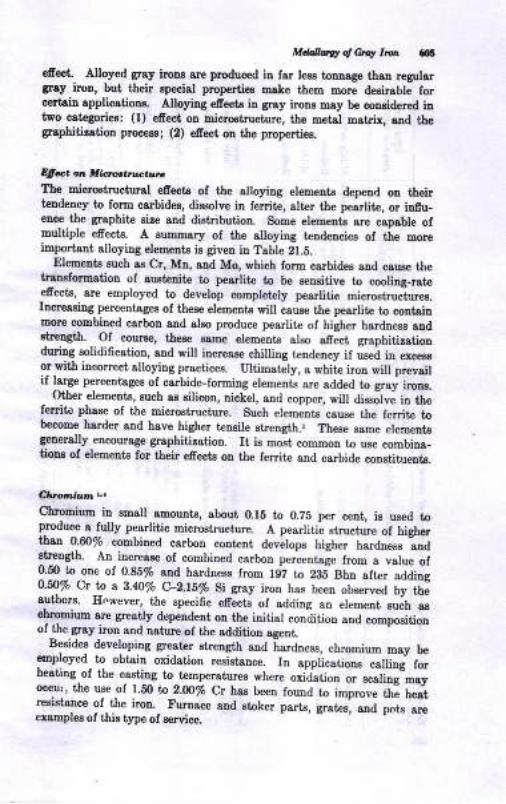
Mddvly o{ etq l'o/t g
€fioct, Alloyed gray irnns are produced iD I8r l€EE tonlsge tbaD regulargrey iron, but their specisl prcpertieE mate them more desirabte forcertain applications. Alloying efi€cts io gray irooa may be coneidered iatro categoriea: (1) efect o[ micrcatructure, the metal makix, and tbegraphitiration process; (2) edect ou the propertie-s.
qlea at t Urort'tl,.alnz
The microetructural efrecte of tbe elloying elements depend on theirtendeDcy to form carbides, dissolve il ferrite, slter the pearlite, or ilf,u-eDc€ the gr8phit€ eile sDd distribution. Some elemeuts are capable ofmultiple efrects. A surm8ry of the alloying tendencieo of the moreimportant, alloyiug elements ie given in Table 21.5.
Elements such ss Cr, Mn, and Mo, wbich form carbides aud cauEe l,hetranrformatiou of sustenite to pesrlit€ to be sensitive to cooliug-rataefects, arc employed to develop completely pearlitic microstruc-t.ues.hcressing perceniages of these elemente will caure the pearlite to coDtsinmorc combiDed carbon and also produce pearlite of bigher harduesr audehength. Of muree, theee same element€ also afiect grrphitintionduring solidifcatiou, and will increase chilling tendercy if used in excesEor vitlr incorrect, alloying prsctices. Ultimately, a white iron will prevailif large percentagee of carbide-formiug elemenG are added to gray irons.
- ()ther elements, such ar silicon, uickel, and copper, will aissitve in Ure
territc phsse of tlre m.icrostructure, Such elements csuse the fenite tobecome harder and have higher tenaile strength.r Theae same elementsgenerally encou.rage graphitirstion. It i8 most commou to use combina_tions of elements for tbeir efiects ou the ferrite and carbide cooetituents.
Ch'onium t,t
Chromium -in
emall amouats, about 0.15 to O.Z5 p€r cent, is used topmduce s fully pearlitic microstructure. A pearlitic etructure of higher|.ha,D O.ffi% combioed carbor conte nt develope higher harduess LdstreDgth. A[ increase ol combined carbon perceutale from a yalue of!.p to one of 0.85/o and harduess from fS17 to 2g5" Shn after adding
9:T% C._9 a 3.a0/o. C-2.1i/o Si gray iron has been observed by ihe
authorc. However, the epecifc efrects oI adding an element suih aschtol|lrul[ ar€ greatly depeudent ou the initial condition and coopositioaof the gray iron aud nature of the additiou agent.
Besides developing g.eat€r strclgth and hardness, chromium may beemployed to obtain oxidation resistance. Iu applicatioaa
""lfirg f*
heating,of the c-astine to temperatures where oxid-ation or scaling"mtoccltrr, tlre use of 1.50 to Z-OO% $ has been found to irprou" tti t
"-"tresistauc€ of the iron. Furnace and stoker p8rts, g"ter; ;; ;;L-;;exampler of this type oI Ecrvice.

*- g's '
€ E! f a ..3E g EE !-iE[8"8.E E =E E ;.8 'ie EE"Eili'q:'E Hr; !sAEHEqr= E ! ,E h= 6 IE E= b9eE*
= d s & 6x 2 i> 66 dEtfid
@
.vc
trod=
o€.ioo@
!{p
ddooia
S 3 3 6E3 eP E .g E
E.E.E "F;€ €; ; E T
is:sis:€: ;E E :* i*i:irEf :l*;: i; E EI tE
EEefeffet, #+;e:E:t'ncYillXt:l Oo- O=d=d Ot Ood"&"dddp.d5 &EE>.tr &d &o.
G36=eqEho-qe x'69l'E rdtcrqE
.? {i E_E r E€Eu g ;!=fE E* :€#; .= @.oo_a{ rrT bo
I ts ;E * ;E;;; ii ;t.! .! ?'d. r !:E gE..*€ g'= -Ei EHB i;*Eqi#g:Eifi ; , . L! E sE:f 6i+.s EsE
i 3' g S j\.E - co">f,*53Fr: L-s3
;;;3 ;;= iie=B;s;=s;
H
c.it6!
oorooolo€\o'j c; .i -'**AJaaedloooo
@ot
-o(oq
I@
Erl
aIoEo
dN
Ad
i
o
:B'stct
o!oID
Ec
beoEoe
btIJa)buEL
t,I
I
bbrtE
oV:
ctoa-ttlr
{ffi
E 6.EitE so! RIrl
tso-4
ct
>r!A0doE
E
ct
,dac
6i
oId
Frco
si
E'o4G
pq
t
gEA4cd
FrE{
dN
u)
o
Eo
cN
ada E
a
a
:g;i?BtRE
a
9596 f .i
6'AZH
AaEo
i3
oia
o@oducd
a
dqd
a@@@tsaFoPii666:d969)aannz6vt96aa6RaFe*Y, Z g g i: : t F g F
A Z E ; 3: : i A E A
z,do,J,
Bets.:f,f 'e
dE
IoEr IC.i5 a
I g :{.Xbra0{

Mdallurgy oJ Gray lron 6[7
Tabb 2L.6 Suggetted nickel-chrotniutn-lrlblybdrnun cotnbina ti ot*a
Cast-ironcl&ES
Composition ranget
0. 5-1 .0l . o-2.0I . 5-2.02.O-2.52. 5-3 .03.0-3.5
Optional
Optional0.3-{.40.4-0.50.5-0.60.H).7
0.2-o.40.3-0.5Optional0.20 max0.20 max0.20 max
tltom the International Nickel Co.
t Bange for 1.2 to 2.Gin.-diameter arbitrotion bars.
EiShIy alloyed irons may contain as much as fi% i:,'. However,these are white irons, and are used for very special conditionr involvingscaling or corrosion resistance.
MolSrb&ruun, l|IolXrDdelnutn -lvic&.tr'tr'rs
Molybdenum is especially efrective in strengtheuing and hardening \ronsbecause of its property of causing austenite to transform to fine pealliteor to bainite. The harder microstructures produce increased streni6h.Combinations of molybdenum and nickel have proved especially eftectivein this respect. Qqmpositions and properties of some molybdenum- arrdnickel-bearing cast irons are given in Tables 2l.G and 21.7. The eotiedesigpations of the irons in these tables are proprietary ones. Themechanical properties of the irons having 50,000 psi tensile strength orgreater 8re obtained through a low carbon equivalent and modifieationof the pearlitic structure to the acicular bainite. This is illustrated inFig. 21.13. Ifeat-treatments may be required to bring out optimumproperties in these alloyed gray irons,5,r?'18 especially the higher tcnsilestreugths listed ia Table 21.7.
Ni-rrct t,.
. Jlickel miloly promotes graphitization in gray iron. It dissolves in thetcrrik and hardens this constituent. Used alone, nickel is somewhatefrectiv,r iu reducing the amount of silicon which must be present iodevelop a gray iron, and thus may cause refinement of the graphik andpearlitic qtructure. In combination with uther elements, a wide range of;rppertles, may be developed, as lvas inrp--{_J rr, ihe prelrious section.)'tore highly alloyed grny irr.rnq-;:o.ace'g'ay imns with ausr,enitic ci
30
40
50
60
70
80
Cr
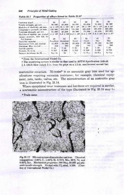
6t S Primiplcs ol Mdal Castittg
'Iable 2L.7 Propertiec of o,lbye listad in Tablc 21.6'
CEt-iroD typet....... . . .... ..Teuile strelgth, ps mio. . . .. . .
Modulus of elEticitv, Pei min. .
Comprqive atrcugth, Psi mia. .
TonioDrl Etrctrgth, psi min. . . .
Modulu of riaidity, Pei, tYPiccl
lmpet ltrea8th, irod AB, ft-lb,l tvpicel.... '..
Domping cspacity............Endurance limit, pai, typical. .
Hsdos, Bho, typical.......Speci6c gmvity. . .
Derity, lb/cu in.............Pettern rhtinkage, in./ft... -. .
60
60,ofl)t8 x ro.145, fix)00,(m
0.2 x 10.
4tCtrxl23,000
900
7.so0. s0{
){'
60
60,00020 x 10.
165, il)O?3,0oo
6.8 X ro.
62
c@d27,O@
290
7.100.268
X-)1c
70
70,mo22 X tO.
180,00087,OOO
7,4 X 10.
6lFai r
3 I ,O00320
7.400.268
16-91 a
80
80,ofl)24 X lO.2(x),000
100,(x)0
E.O X lot
70
Fiir35,000
350
i.40o.26E
I x-i"
'From the Internationrl Nickel Co.
t The numbering system is eimilar to t[at used in ASTM Specificstion 448'48'
t A f20-ft blow struck 3 in. from the gnps oD a 1.2-in. contileverod as-csst ber'
martensitic structure. Ni-resistl is an austenitic gray irOn used for ap-
plications requiring corrosion resistance, for example, chemical equip-
ment, pots, taaks, valves, etc. The microstructure of an austenitic gray
iron is illustrated in Fig. 21.14.'Where
exceptional wear resistance and hardness are required in aervice,
I martensitic microstructure of the type illustratcd in Fig. 21.15 may l'c
t Trade name.
FrS. 2f .f 3 Microstructure of an acicular cagtiron. Chemicalcompaition: 3,0O7oC, f .50% Si, O.7O16 Mn,2016 Ni, andO.6S/sN1o. Mechanical properties: 3fi) Bhn, 60,0ffi poi ulti-rnate tensile strength. Etched wifhz/outtal, X500. (Coue-
trsy of Inlzrnaliarul Nichzl Co.)
,10
40,00016 x 10.
130,00017,OOO
X
35
Excellent19, OOo
230
? .20
0.260
x
\;*i(
30
30,ooo
11o,fi)o3,1,0(x)
5Xlo.
26
Ercellentr5, ooo
200
7. 10
o.257Xo-l(
4>)
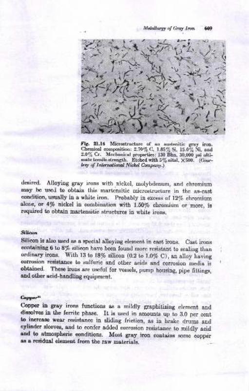
Mdalbrgt of Gmy Ircn ar09
'7''-i,
(/\-/' :"
F4. 21.11 Micrctructure of an austenitic gray iron.Chemical compcition: 2.7O7oC, I.S5%Si, 15.0/sNi, and2.07oCr. Mechanicai properties: liX) Bhn, 90,000 pEi ulti-matetenaihetrength. Et hed rith S/odd, X500. (Cour-feq 6 InlqrulitNal Nil:htl hnpny.)
deoired. Alloying gray irons with,nickel, molybdenum, and chromiummay be usod to obtain this martensitic microstructure in the as-canteondition, uzually in a white iron. Probably in excess of 12% chromiumalone, or 4/o ntckel in combination with l.E0/o chromium or more, iBrequired to obtain martensitic Btructures in white irone.
S5&pn
silicon is algo used as a special alloying element in cast irons. cast ironscoltoining 6ro8% silicon have been found more resistant to scaling thanordinary irons. Wit,h fB b B% eilicou (0.2 ta l.O% C), an alloy havingcorrosion resistsnce to sulfuric and other acids and corrosion media itobtained. These iron' are useful for vessels, pump housing, pipe fittings,and other acid-handling equipment.
CaNCopper in gray irons furctions aB a mildly graphitizing element anddissolves in the ferrite phase. It is used in amounts up to 8.0 per ceutto increase wear resistence ia sliding friction, as in brake drums andcylinde'r sleeves, and to confer added corrosion resigtance to mildly acidand to atmospheric conditions. Most gray irou contains some coppdras a r,esidusl eiement from the raw materials.
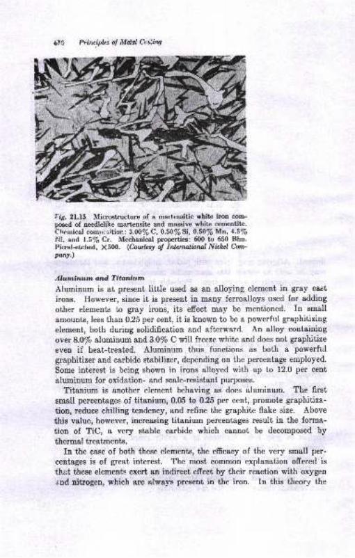
Priwipbs ol MeJal &,s:ing
r'fu. 21.15 llicrqtructure of a martrrrsitic rhite iron com-poecd of needlelike mart€nsit€ and massive white cemeotite.Chemical com;rsition : 3.O0% C, 0.50% Si, 0.50% Ma, 4.5%lli, and 1.5/6 Cr. Mechanical properties: 6fi) to 650 Bhn.Picral+tched, X.500. (Cat rhq of Intennlbrul Nirhd Corn-
phw.)
Alutninutn utd T ittniumAluminum is at present little used aB an Blloying element in gray caYt
irons. However, since it is present in many ferroalloys used for adding
other elements to gray irons, its effect may be mentioned. In small
&mounts, less than 0.25 per cent, it is kuown to be a powerful graphitizing
element, both during solidification and afterward. An alloy containing
over 8.0/o aluminum and}.O/o C will freeze white and does not graphitize
even if heat-treatcd. Aluminum thus functions as both e powerfltl
graphitizer and carbide stabilizer, depending on the percentage employed.
Some interest is being shown in irons alloyed with up to 12.0 per cent
aluminum for oxidation- and scele-resistant purposes.
Titanium is another element behaving as does aluminum. The first
small percentages of titanium,0.05 to 0.25 per cent, promote graphitiza-
tion, reduce chilling tendency, and refine the graphite flake size. Above
this value, however, iucreasing titanium percentages result in the forma-
tion of TiC, a very stable carbide which caunot be decomposed by
thermal treatments.
In the case of both these elements, the efficacy of the very small per-
eentsges is of great interest. The most common explanation ofrered is
thr:t these elements exert an iadirect effeet by their reaction with orygenand nitrogen, which are always present in the iron. In this theory the
MeUwgy ol Gray Ir* 5ll
latter two gases are held to be carbide-stabilizing, and their removsl by
aluminum or titanium results in a graphitizing efrect.
Efiaton Ptopeabt
The influence of alloying elements on properties of gray irons is complex.
The objectives of alloying these irons, however, may be simply listed
as follows:
1. Increased mechanica! strength
2. Increased resistance to we&r
3. Increased resistsnce to corrosion
4. Increased resistance to oxidation or scaling
5. Increased resista,nce to abrasron
The variety of specially alloyed irons developed to enhance these
properties is great. Some typical compositions of alloyed gray irons
and their uses are listed in Table 21.8. Detailed information of the
specific quantitative effects on properties by each alloying element and
their combination is beyond the scope of this book, and is in mauy cases
lacking. Refereuce may be made to "Alloy Cast Irons" and "CastMetals Ilandbook," AFS publicat'ions, Tronsoctbns ol z{.^tr'S, and the
metallurgical literature for such information as exists.
BIBLIOGRAPHY
1. American Society for Metals, "Metals Handbook," 8th ed., vol. 1, 1961.2. A. Boyles, The Microstructure of Cast Irons, Amprican Soeiety for Metals.3. American Foundrymen's Society, "The Cupola and Its Operation," 1954.
4. American floundrymen's Society, "Cast Metals [Iandbook," 4th ed., 1957.
5. R. A. Flinn, M. Cohen, and J. Chipman, The Acicular Structure in Nickel-Molytrdenr'- Cast Irons, Trans. ASM, December, $A,p.l2?5.
6. R. Schneidewind and R. G. McElwee, Composition and Properties of GrayIron, Trans. r{FS, vol. 58, pp. 312-330, 1950; see bibliography also.
7. L. F. Porter and P. C. Rosenthal, Efrect of Sulfur on the Fluidity of Gra3.Cast lron, Trans. A?5, vol.60, 1952.
8. E. W. Lownie, Jr., Theories of Gray Cast Iron Inoculation, Trans. AFS, vol.54, 1946.
9. R. W. Lindsay, Graphite Phase in Gray Cast lron, Trans. r{F'S, vol. 55, L947.10. E. LaPlenche, A New Structural Diagra.rr lor Cast kon, Metal Progr.,
December, 1947; New Structural Diagrams for Alloy Cast Irons, iDid.,June, 1949.
fl. S. C. Massari and R. \[. Lindsay, Some Factorc Influencing GraphitizingBehavior of Cast fron, Trans. AFS, vol. 49, p. 953, 1944.
12. T. E. Barlow and C. E. Lorig, Gray Cast Iron Tensile Strength, BrinellHardness and Composition Relationship, Trara. /F$ vol. 54, 1946.

.J
EE.
I *.r
i I Es
e O OO'E E BE siE ;' g; ag
-" B--: --E;€ g r= EIO I ' ::
E I I= t eio
la A
'6-, e E E?e* tstE
;; gg' *
o.=
d:
at!-J X ;S- oci a**t***l**
6
, .e(> :oq :q
t .4
g
*
o
I a aBa
E g EEl :<i o c;dj
I!e*;.,i
qEE q!iEi *ioci- i;
2 3ci
aR: a8Jci- J,.;,ll.t a*d d i -.:.i
q
+
AE
E cioB P 888 AtA ed d ,ic;d ci;ci -:a * *s* *E* Ei ; c;c;d c;6d J
L4E 3oo5
9*
F
ts A ;6EE X:(F IJdi 6; 6i;; ;aici d;A A A*A AAS A
; d 6i;; .icid ci
a
t
I
J A A{; 6 do
ta
a
.9
E
6I
lla
n,3Aiaf
taq)
ooo'
&ttIB!Io
aoA- -E'oq
to
aEoI
3B
3q\cq
6to€t:
'i2
13.
14.
15.
16.
17.
18.
10.
fr.21.
B.
.
.
26.
a.
Mdalhvgrdfu lto.. 613
J. T. MacKenzie, The Brhell Eardaese of Gny Iror rad Its RoLtion toSome Other Propertiea , ASTM P?oc., vol- 1$, pp. 1@5-1O36, 19{6.
J. T. Eash, Efiict of I*dle Ioocutation on the Solidiitatiou of Gny Cast
Iron, ?raar.,tI$ vol.,l9, pp. 831-819, 1941.
W, E. Mahh end E. W. IrFtrie, Micro6tructure Relrtod to Properties of
Cast Ircn, ?mrE. ,{f8, vol.54, 19{6.
B. Schneidevind and D. A. D'Auico, The Iniueace oI Uudercoolirg ol the
Grsphit€ Pstt rn io Grey Crst Irotr, ?ratu. ,{fS, vol. 47, pp. 831-8'19,I93S.
R. A. tr'linD, M. Cohen, ard J. ChipE!tr, Tt€ Aciculsr Stmeture iu Nickel-
Molybdenum Cast Imne , Truat ASM, Dec€nber, 1942, p. 1%5.
R. i. ftnn strd D. Rrese, The Development oad Contrcl of Etr8ineeritr8 CrstIroas, ?rcru. .{f3, vol. 50, Merch, 1942.
A. Fiolaysor, I}ie*l Engioe CrsDtshrft8 Cut in Grry lrotr, Foudry, to|,
78, Awust-Sept€mber, 1950.
J, IL Schonro, Strcss Relief oi Gmy Cast Iror., ?tatu,IIS, vol. 56, 19{8'
V. T. M+lcolm aod 8. I,os, g@e T€6ta on Rllaxstion of Caat IroD, ftatu..{trq vol. 58, 1950.
1Ae Gray Iron Founders' Society, Summory of Grey Iron Specificatiols,
Rev., January, 1964.
J. S. Vurick, Engineeriry Properti€s of Eeat Treated Cast Imas, ?rcar..{.F$vol. 52, 19{4.
A. W, gilvester, Glaphitizotion of Grry Cast Iron by Eeat Trestnetrt, ?ratu.
i{fS, vol. 57, 1949.
A. Boylee, Some Principlee Iovolved in tlle Eest TtestDent oI Grsy CrstIron, ?rcar, /FS, vol.56, 19{8.
G. M. Lsht, Conventional vs. gslt Bath Eandening of Cast Iroo CylhderLhers, frozc. t{fS, vol. 56, 1948.
C. K. Donoho, Mecharical TestiDS end Prope*ies of Grry Iron, fotradry,vol. 68, p. 96, June, 1940.
A. W. gchneble and J. Chipman, Fsctors Involved in the Superheoiing oI
Gr8y Cast Irctr and Their Efieck otr Its Stmctur€ r,trd Prcperti€s, ?ton .
,tIS, vot.52, pp. 113-158, 1944.
L. F. Porter and P. C. Rocenthrl, Fluidity Testing of Grry Cagt Iron, ?rszt./{trS, vol. m, 1052.
A. Boyles and C. E. Lorig, Notes on the Undercooling of Gray Cast Iron,I/dru.l{PS, vol.49, p. 769, 1941.
II. Morrough and W. J. Wi iams, Graphite Fomration itt the Cast Ironsaud iu Nickel-Cerbon and Cobalt-Csrbon Alloys, J. Iro, Sted hat. (Iorvdoa), vol. 155, p.321, January-Apil, 1947.
E. W. Uhlitzsch and A. Keller, Beitrag zur KeDtrtnis der Alumioun legietteB
Gusseisen, JYeze Grleererei, vol. , pp. 227-232, AuSust, 1949.
C. E. Lorig and R. R. Adame, Copper as an Alloying Elemelt in Steel ood
Cast lron, McGraw-Eill Book C,otupany, New York, 19,18-
J. C. Eamaker, Jr., W. R. Wood, a,nd R. B. Rote, Intemol Porcsity in GrlyIroo Castings, Trcnr. lfs, vo[. 60, p. 101, 1952.
T. E. Eagan and C. O. Buryess, Grry Imn: Its Mechonical aad Engiaeeriog
Chsractedstics ind Details for Designing Cast CoEponents, Fotrulry, vol.76, Aqust-September, 1948.
A. DeSy, Alloyed GIay Cast Iron for Mathine Compoaents, Trcat AFS,
vol. 70, p. 390, 1962.
30.
31.
22.
3ti.
u.
35.
6)6>
Ductile fron
Ductile caet iron was 6rst auounced to the foundry indurtry aE a newecgiueering material at the le{E snnull meeting oI tlrc AmericanFouldqrmen's Society. Thia revolutionary material, diecorrcred inde-peDdeDtly by the British Cagt Iron Research Aesocistion (BCIRA) andthe Iuternational Nickel Compauy (INCO), is also referred to as nodular,or spheroidal, graphite cast iron. The BCIRA process consists of anaddition of cerium to molten, hypereutectic cast irons of eesentially thesame aualysis &s grey cast iron. Cerium removea the zullur and, withabout 0.@ per cent residual cerium, produces grapbite spheroids insteadoI flakes. The INCO procese, on the other haud, similarly empioyemagnesium additions to either hlDo- or hlpereutectic c8st irctrs. Aftarinitial expoeure to these processea, the iudustry eoon realired the greaterpot€Dtial snd ecouomy of the msgnesium procese, which ie now aimostuniversally practiced.
Eesentially, ductile cast iron cousists of graphite spheroids dispersedin a matrix similar to that of gteel (Fig. 22.1). The only eignificantdifrereuce betweeu gray caet iron end ductile cast iron i8 in the ehape
of the graphite phaoe; the mstrices csn be eimilar.The eaee with which ductile iron can be processed and cast into com-
plex shapeo is very dependent on a high earbou (or carbou-equivalent)content. During eolidi0cgtion Eost, of thc carbon forms a8 grsphitespheroids which exert only a minor influence on the mechanical properties:. 'ontrast to the efrect of flake graphite in gray caat, iron. The matrixstructure then hae the greatest efrect on the propertiee of the iron.Duotile cast iroos are therefore a family of alloys which combine thepriucipal adviul*ges of gray iron (low melting point, good fluidity audcsstability, excelletrt Eschlaability, aud good weer resistance) with theengineering advstrtsges of sieel (high streugth, toughners, ductility, hotwortability, aud hardeuability). Tbe matrix ol ductile iron cau rrecoutrolled by the base composition, by foundry practice, and/or byhest-treainent to prcduce 60,000 psi minimum teusile strength, wittcver 25 per ceut elongation, up to 15O,00O psi minimum taEile strength,yet having I to 4 per cent elongation. A eummary of the principal typesoi ductile iron ie ehowD iu Table 22.1. A few examples of ductile-iron
6tr
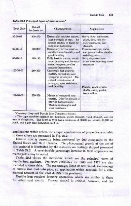
Dwlilc Ircn 615
Tabla 22.1 Prircipl types of d.wctilc irun'
fupe No.tBrinell
hardnees no.Cbaracteristics Applicstions
8{}6(}{xt
6G45-r0
6G4(lr5
1qL7o{Xt
r890{2
?0{}270
r4G2xn
l4Gl90
2{S3m
270350
Essentially pearlitic matrix,high+treDgth asqst. Reepon& rcadily to fa,me orinduction [s1d6ning
n"qentially ferritic mrtrix,excellent nrachina,bility anigood ductility
Fully ferritic matrix, maxi-mum ductility and low transition temperature (has
enelyeis limitations)Uniformly 6ne pearliticnqtriL aslmdized and
tempered or alloyed. Ex-cellent combination ofstrength, wear reoietance,
and ductility
Matrix of tempered ma,r-
tensite. May be alloyed kprovide herdenability.Maximum atrength andwesr resistsnce
Ileavyduty rnachinery,
gears, dies, rolls for .
wear resistauce, andstlength
pressure 66g1,ings, valve
a,nd pump bodie, shock-rruiotiug pErto
Navy shipboirrd ond
other uses requirhg ehock
resigtooce
Pinions, gears, crank-shafts, cams, guides,
track rollers
'Courtesy Gray aad Ductile Iron Founder,e Society.
I The type numbere indicote the minimum tensile strength, yield strength, and percent of elongation. The 8()-6048 type has a minimum of 80,000 pBi tensile, 60,000 peiyield, aod 3 per cent elongation in 2 in-
applicstiong which reflect the unique combination of properties availablein these alloye are present€d itFig. t22.
Ductile iron is currently being produced by 209 companies in theUnited States and 16 in Canada. The phenomeoal growth of the use ofthis meterial is illustrated by the statistics on eastings shipped presentedh Table x2.2. A coneiderable percentage increase in total shipments forrecent years may be noted.
Table 22.3 ehowe the industries which are the principal users ofductile-iron ca.tings. Projected estimates for lg66 and lgzl are alscincluded in these data. The percenteges listed do not include the tonnageof ductile iron cast into pipe, an applicstion which accounts for a suL-stantial amount of the total ductile ircn produeed.
Ductile iron requires foundry operations which are similar to thosefor other cast meir'.Is. Proeess control is eritical, however, and the
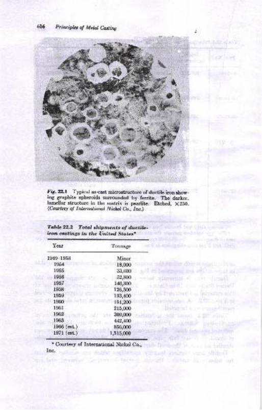
Prilcipla ol Metat Casting
FA. X2.l Typical as{att micretrusture of ductile imn rhow-ine graphite epheroids surroutrded by ferrite. The darter,lamellar structure in the matrix ie pearlite. Etched, X2SO.(C,outkst o! Idonalbrul Nichcl h, Inc.)
Tabb 22.2 Totol shipments of ductilc-ilroln coatinga in tlw Unitad Stttcsi
Yea^r Tonnage
1949-1953
rgilr955
1956
r957
1958
1959
1960
l96r1962
1963
1966 (est.)
1971 (est.)
Minorlg,00o
33,600
52,800
140,300
126,5(n
r93,400
191,200
215,(n0
300,0(x)
442,4N
856,000
1,315,000
'Courtesy of International Nickel Co.,Inc.
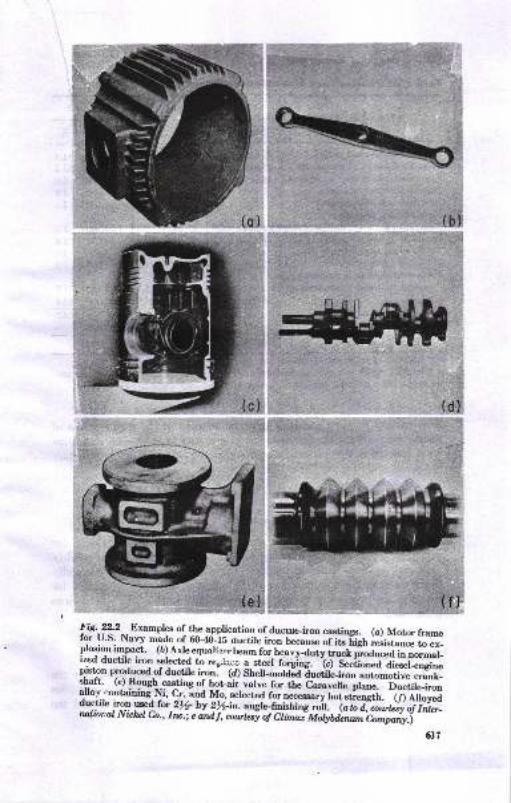
(c)
(b)
(d)
ffi!U.-*2__Examples of the a-ppli,cation of ducLrte_iron castiDgs. (a) Motc framef9r !J.S, Navy made of 60+o--i5 <iuctile iron beca-.se
"iitr[f*;&*;;;;plosion impact. (b) Axre equarizr" beam for n*-rydiv-tucr fu;*d i";.-d-ized ductile iron selected tir rc"llcg a_*cel forgiDs.
-i, dec[.;;d;IiEffiffi;
plst-on prod]@d of ductile iron. to sleu-molaiatucriri*mn automotive ffitI*t':;."eJ,*?H\ffi
*T H*,# ,:*ffi ##ffi "trffi#lk";,".ffi :,:X:Jiru,#frffi/,;J:,r"i,N,,".1;G
6t7
{e)
r.{
\\
"C
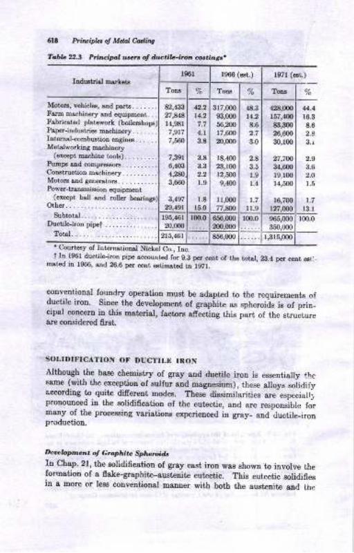
6lt hi$ipla of Mdal Uity
fobb 22., Pr,,'..ipl u*r. 4 drb iL-irun @t i,nt .
Induitrisl rnsrketsrs6l 1966 (e6t.) l97l (esl)
Tong Toru TonB
Motor., vrhicl€., aDd p6,rt8.......Farm maahircry sDd €quipEpnt_ . .
Fsbrics,tad platcworL (boil€rshoF)P.per-iadustd€s rD.scLiDery. . . ....Itrtemd-combustiotr ergitr€s......Metslworkina m".hinery
(ercept rDr.hine tools)...... _..hunps aad compreesots..,.......CoDstructioD m&hinery..........MotoE and 8eDerstoE....,...,..Power-tmDsmissiotr equipmeut
(except ball etrd rcIer b€eriDas)Oihe................
subtotsl.............._...._..Ductile-iroD pipet
&,43:|27,84r4,9al7,9r77,560
7,391
6,{O34,N3,660
3,49729,19t
4.2r4.2
4.1
3.8
3.8
3.3
1.0
1.8
t5.0
317,000
$,0m56,200
r7,6(nz),0m
18,400
23,r0012,ffi9,{0o
I r,000
77,sn
{t.3t1.2
&6
3.0
2.8
1.9
1.4
1.7
u.9
,rj18,000
157,408ii,3m26,6{n
30,r0o
27,zfi3{,6{nl9,rmr4,50o
16,700
r27,(m
4.116.3
&82.8
3.r
2.9
3.62.O
1.5
1,7
l3.lr95,46r
20,0m 1*:656,mO
200,000lm.0 965,000
350,(m100.0
2t5t4bt 856,000 I,3r5,0OO
'Coudesy of Ior€rnsri".sl Nicfel C.Jr"t ID 196l ductile-iron pipe aacountsd for g.A pel c€trt of the tots!, 2g.4 por cetrt 6t:
Dat€d iD 1366, snd 26.6 per cent EtiEtsted in f97l.
clnv€ntioual foundry operation Eust be adapt4d to the requirementE ofductile iron. Since the development of grsphite as spheroids is of prin_cipsl concern ia this material, factors afrecting this part of the structureare coDsidered frst.
SOLIDIFICATION OF DUCTILE IRON
Although the base chemistry of gray 8ud ductile iron is essentially thcsame {with the exception of sulfur and maguesium), these slloys soiidifyaccordiug to quit€ difrercut modes. Thes€ diesimilarities are especiell;pronounced in the solidification of the eut€ctic, and are responsible formsny of tbe processiag variations experienced iD gray_ aud ductile-ironproduction.
Ircoclapnen o, Craphi.c Spharoid,
In Chap. 21, the solidi6cation of gray cast iron wes shown io involve [heformatiou of a fake-graphite-aust€nite eutectic. This eutectic solidifiesin g more or IesB convetrtioDal mauuer with botb the auet€nite and ih,:
Dulib Ircn 6f9
gr&phite in contact witl the eutectic liquid. Solidification proceede bythe growth of cells of austenite and flake graphite at the expense of the
liquid. Since gray iron is essentially an Fe-C-Si alloy, the eutectic
solidifies over a temperature range, usually about 60 F. Further cooling
of the completely solidified alloy results in the rejection of carbon fromthe solid austcnite and the precipitation of graphite on the preexisting
graphitc flakes. This process continues until the eutectoid temperature
range is attained. Cooling through the eutectoid range will result in avariety of matrix structures, from all ferritc to all pearlite, depending orthe rate of cooling and/or the influence of alloying elements.
In comparison, solidification of the spheroidal graphite eutectic inductile iron starts at temperatures above those of the flake-graphiteeutectic for similar earbon equivalents. In this case the graphite spheroid
is enveloped by a shell of austenite so that only one phase, austenite, isin contact with the eutectic liquid. Solidification of this type has been
termed neoeutectic. Each unit of a graphite spheroid and austenite shellmay be considered a cell where carbon must difruse through the shell ofaustenite in order for the spheroid to grow. The result is that thisprocess is slower than that of gray-iron eutectic solidification, and theneoeutectic freezing raage is extcnded to about 120 F. Liquid metal isthen present over 8 wider temperature range and to lower temperaturesfor ductile irou than for gray iron.
No nucleation of spheroidal graphite occure once growth of the ueoeu-
tectic stsrts. The number of graphite spheroids is therefore determinedat an early stage of solidification. Subsequent cooling of the solidifiedductile iron is accompanied by graphite precipitation on the existingspheroids at temperatures down to the eutectoid range. As with graycast, iron, the cooling rate through the eutectoid range and/or alloyingtreatment determines the matrix structure. Bull's-eye patterns like those
showu ir Fig. yzJ are typical of the ferrite-plus-pearlite matrix of as-eastductile iron.
The importance of an adequate number of spheroids in obtaining fullyspheroidal graphite structureg must be stressed. When the number ofspheroids is low, there are an inadequate number of sites to which thecarbon of the Iiquid may diffuse. Depending on the composition andprocessing variables, either flake graphite or iron carbide will form fromthe liquid during further cooling. Both alternatives reeult in propertiesinferior to fully spheroidal graphite structure.
Role oJ Magnasiutn
As mentioned earlier, a magp.esium addition is the most commonlyaccepted method of obtaining spheroidal graphite in either hypo- or.
hype'eutectic analyses. Other elemeuts have been suggested, but all
6rI) Prtlcifu ol Maal hliV
thes€ have proved iDadequate. Among them are cerium, cslcium, sndyttrium. The mechanism by which maguesium causes graphite rphemids
to occur is unknown; however, l,he function of magnesium additione ig
well known. First, maguesium seryea ra a deoxidizer and desulfurirerof the molten metal. If the oxygen and/or eullur content of the meltie too high, a zubetantial amount of maguesium witl be coneumed in the
formatiou of magnesium oxideg and sul6des. Secoud, maguesium pro-
motes the development of graphite as spheroide by a mechaoism not yetdefined. Finally, maguesium preventa the nuclestion of flake graphite
during the solidification procees and thereby promorcs the growth oIgraphite spheroide. Generally, only 0.05 per cent residual maguesiumis necessary io gchieve spheroid formatiou in most ductile irons.Methode of magnesium additioD are diacueeed it a lat€r sectioa.
C,o^tro, of tlE C-onnon Bbr'. n .
Corhon
The carbon content lor commercial ductile iron is from 3.0 to 4.0 per
cent, altbough much narrower limits are usually deeired. Nodule cotmts
are directly afiected by the carbon cout€nt-greater numbere olspheroids formed et the higher corbon contants. Increasing the carbon
content rlso increases cast&bility by improving fluidity and feeding.
The carboa-content leyel should b€ correlated with the carbon-equivalentformula:
cE= %c + \%s+.. .
Carbon equivalents greatly in excess of 4.3 promote the development andgrowth of graphite spheroids. Siuce grephite is far less deme thanmolten iron, these spheroids may become buoyant and float toward thecope surface oI a casting, resulting in grose carbou s€gregstion. Flots-tion, as thie phenomenon is called, is prevalent in analyseo having carbouequivalents grest€r than 4.@ snd in section sizee greater than 1 in.
.sitriron
The normal range for oilicon in ductile irons is 1,80 to 2.80 per cent.
Since silicon affect8 the carbon-equivalent value, it also afrects theDumber of spheroide and the occurrence of flotatiou. Silicon increases
the amount of ferrite formed during the eutectoid trsmformatioo andalso streugthens the iron by strengtbening the ferrite. Additions ofeilicon are more influential in spheroidal-graphite control when the addi-Lious are made late (iuoculation). This operation iB described in a latersectioD.
Drlib lran
.9d/u,
Tte mogt important efect of sulfur iu ductile iron is to iucrease theamount of msgnesium required to achieve spheroidal graphite. Ttre levelof sulfur in the imu prior to m&gnesiun treatment is a function of t,Ite
meltiag practice ured. Sulfur coBteDt after treatEetrt ie ueualty 0,015pe! cent
Phosphorus forma the very brittle atructure known 8s steadite iD
ductile iron as well as in gray cast iron. Since phosphonr advereetya,fiecte toughness end ductility, a maximum ol 0.O5 per cent ia usuallyspecified.
Olle Ebnlcatt
In addition to the elemeute carbon, silicon, sulfur, and phoephorusdiscueeed above, a Dumber of other elemento Eay be preseDt in ductileiron. Moet alloying of ductile iron makea use ol manganese, nickel,molyHeotrm, and copper. Alloys involving these elements may bedesigned for higher 8tr€ogths, grrater toughness, or increased high-teDpersture- or corioEioD-resistant properties. Other elements, how-ever, even iu trace amounts, may be avoided beceuoe of their deleteriousefrect on the development of the ductile-iron structure. Lead, iitanium,aluminum, antimoDy, and zirconium, for iustance, have been cited aspromoting tlte developnetrt cf 6ake graphite. On the other hand,arsenic, boron, chromium, tin, and vanadium are kuorn to promote theformation oI pearlite and/or iron carbide. Accordingly, ctose controlover the quantities of these elements is usually exercised.
MELTING PRACTICES
The relatiouhip of melting practice to ttie typ€ and amouut of spheroid-izing alloy us€d is important, to casting quatity and physical propertiea.Considerable reductioa ol the amount of spheroidizing alloy and thepercentage of delective or inferior castings can be realized by payingclose atteotion to charge msterials, melting methods snd control, andirou compoeition. Ductile-iron producem have therefore found it neces-eary to improve normal meltiug practicea and to exercise a greater degreeof control then that, used for gray iron.
Cupola melting i8 the most commotr method of melting for ductileiron; however, electric induction furnaces are in uee in a number offoundriee. About ?5 p€r cent of the ductile-iron producers employ theacid cupola. In nearly all these instancea, the cupols is used ior both
6!A I'rtsTplzs of Mdd Castittg
Ire,y- and ductile-iron production. Among those foundries which haveprovided separate melting facilities for ductile iron, the basic cupola ispreferred. Approximately 70 to 85 per cent of the tonnage of ductileiron produced is melted in basic cupolas.
Acid Cupob Mehing
Since many ductile-iron producers also produce gray iron, and are
generally limited to using a common cupola for melting both materials,the acid cupola hae been adopted. Acid melting is much less costl.v
than basic melting. Estimates of the cost differential in lining and
maintenance of refractories for the basic cupola have been as high as
four to five times as much as for acid refractories. Using acid cupolas
necessitates close control over charge materials and coke since the acidslags produced are not capable of reducing the sulfur content of the iron.This results in sulfur content of 0.06 to 0.12 per cent, which, if notlowered, necessitates the use of increased amounts of spheroidizing alloy.Acid eupola melting, however, is capeble of eontrolling the more readilyoxidizable elements in the charge, such as chromium and manganese,
since it is a more oxidizing process than basic cupola operation. Because
of the moderate carbon pickup in acid cupola melting and the desired
base-iron chemistry, the use of pig iron in the eharge is required and
the use of returns is somewhat limited. Close composition control andhigh metal temperatures, however, can be produced without the need ofa hot blast.
Desu$urintiott
If lhe high sulfur content of acid-cupola iron is not reduced prior totreatment with the spheroidizing agent, an appreciable amount of thehigh-cost magnesium alloy will be consumed before graphite spheroidiza-tion can occur. A reduction of 0.01 per cent sulfur requires approxi-mately 0.01 per cent magnesium by this technique. It is thereforedesirable to desulfurize the iron by one of a number of commonly usedmethods.
Desulfurization from O.12 tn 0.02 per cent has been reported from theinjeltiolr of calcium carbide into the melt. These injections are com-r.ror:ly made either in the forehearth or in the ladle and have an effi-ciency of approximatcly 15 per ceni. The fine calcium cartride is injectedthrough a refractory tube, using dry nitrogen gas as the carrying agent.The calcium eulfide formed floats to the surface of the melt as a readilyrernovable dross.
Soda ash additions are also ueed to reduce the sulfur level of the melt,and can cause desulfurization fiom 0.14 to about 0.0G per cent Asecond treatment with soda 8sh may Iower the sulfur to between 0.080
Dwtilc Ircn 6tEl
snd 0.025 per cent. Desulfurization with lime is also used by someproducers, either alone or in coujunction with other materials.
A recent innovation of desulfurization has been the developmeno ofthe ttshaking ladle." Iu this process, desulfurization occurs by thereaction of lime with the sulfur of the melt. Shaking the ladle increasesthe contaet of the iron with the lime, resulting in sulfur levels as low as
0.(D per cent at a 70 to 75 per cent efficiency.
Basia Cupb Melting
Basic cupola melting is characterized by ttre definite advantage of sulfurcontrol. Average sulfur content of the basic melt before spheroidizingra,nges from 0.025 to 0.035 per cent. This decreased sulfur level in themelt is obtained at the expense of higher operating costs, higher siliconIosses during melting, less effective temperature and composition control,and a greater carbon pickup during melting. Attempts to reduce therefractory cost and to provide greater operating control have resultedin the widespread use of water-cooled cupolas and the incorporation ofhoGblast equipment. When operated on a steady and continuous basis,however, basic cupolas are capable of producing a high-carbon-, low-sulfur-content melt at a lower cost than acid cupola melting.
I n du,c tion -Jwr trac e M e I tin g
The most widely used induction furnaces for ductile-iron production arethe low-frequency, 60-cycle type of unit. These furnaces can be oper-atcd either for cold melting or for duplexing, i.e., using the inductionfurnace to superheat an existing melt. Very close control must beexercised over raw materials in these furnaces since the rust on scrapand other slag-forming ingredients rapidly attacks furnace linings.Extremely close control of composition and of metal temperature iepossible in these furnaces, so that quality duetile iron can be produced.Future trende in the ductile-iron industry indicate that an increased useof low-frequency induction furnaces is to be expected.
The use of melting units other than those mentioned for ductile-ironproduction is not widespread because of either their cost of operation,luck of versatility, or the degree of eontrol which can be exercised overmetal composition and temperature.
MAGNESIUM TREATMENT
Although a number of elements can be used to promote at least partialspheroidization of graphite in east irons, magneeium is by far the mostefrective and economical method. The amount of inagnesium required
5e/ Prir?!ipLr o! Mdal C.otli,ts
to prod,rce spheroidal gaphite ia deperdert largely oo the sulfur audorygen content of the base iron. In general, a minimum retained magne-sium content of 0.015 to O.050 is considered adequate.
The b&e-iron temperature at treatmeut is usually 2800 to 2850 Ffor both acid- and basic-meltiug practice, considerabty above the boilingpoint of magnesium. As a reeult, the maguesium vaporizee on coltactwith the iron, and the reaction may be quiie violent if it is not carriedout properly, Magnesium recovery is dependent on the depth of liquidiron l}lrough which ttre vapor rises before eniering the air. The timerequired to cover the alloy and the depth to which it is covered are
therefore important iu magnesium rccovery. Lower magDesium recoveryis also experienced ai higher metal t€mperatute8.
To reduce the volstility of the reaction, magneeium is usually alloyedwith other elements. A number oi alloys bave been developed for thispurpose. The pain alloy tSrpes are:
1. Magnesium-nickel alloysa. 15y'. Mg,85/6 Nib. 15% M8,55/o N| fiy'o Fn
2. Magnesium-ferrosilicon alloyso. 9% Mg, 4570 Si, 1 5/s Cz, baJarce Feb. 9/. Mg, 45Vo Si, 15/" Ca, 0 5/4 C*, bala*e Fe
3. Magnesium-silicon alloysa. 18y'6 Mg,65y'6 Si,2A%o Ca,,O.6%
Magne.sium recovery is usually higher whe! the lower-msgnesium-contentalloya are used.
Recovery is also dependent on the method by which the magnesiumalloy is added to the melt. The most common methods of adding mag-nesium are (l) the openJadle method, (2) the plunging method, and (3)the mechauical feeder.
A\e open-l,odle nethod cnr.silla in first placing the magnesium alloyin the bottom of a treatment ladle and tben tapping the melt onto thealloy. Treaiment Iadles are designed to be deep and narrow, having a
height-to-diameter ratio of 2:1. The violent reaction of ro&gnesiurnvapor with the liquid iron is therefore confrned to the ladle. Magnesiumvapor cen then prermeate s geater depth o, molteD iron thaa is possihtes'ith other ladle desigus. The reaction with magnesiun: produceE adross coataining magneeiun eulfide aad oxide which Soats to the surfaceand is then removed. The open-ladle treatment ofrers a flexible methodof treatnetrt at a low equipmeut cogt and a minimurn loss io melttemperatures.
Since the open-ladle msgnesium-trestment method is not efficient,several improvementa on it have been suggeated The nqgt oommonly
D&liL l,on 6Zi
used modific&tion is klowq ae the "sandwich" method. Here the mag-
lesium alloy is placed into a recesgion in the refractory bottom of the
ladle. The alloy ir then covered by e steel plate, iron chips, steel
punchiugs, Ierrosilicon, or an inert materisl such as sand before tappiug
the iron onto the alloy. In this manner the reaction time is delayed
until the ladle is at least partially filled with metal, thus iDcressing the
magnesium recovery to a level comparable with plunging.
Phur4itq tnchriques of magnesium treatment involve placing the
magnesium alloy into a container positioned within a vented graphite orrefractory bell fastened to a refrsctory-covered pluogirg rod. The bell
is then plunged into a ladle filled with iron. Plunging ofrere a greater
degree of control over the residual magnesium level and a higher mag-
oesium recovery than does the open-ladle method.
The third method, by which spheroidization is commonly accomplished
makes use ol a mechanical leeder whercby the magnesium alloy ie con-
tinuously added to the melt stream emittiug from the cupola or fore-
hearih. This t€chDique permits continuous and uniform treatment ofthe melt st generally greater magnesium recoveries thaD other methods.
Techniquee have also been developed penrittiag the use of metallicmagnesium; however, they are not popular in the United States and
Canada. In ihese methods, magneeium metal is added either by a
plunging technique in e covered ledle uuder several atmospheres oipressure or by injection through a refractory tube ioto the melt, using
an ioert gas as a carrier.It is apparent, then, that the total magnesium recovery is dependeui
oo a uumber of factors. Table 2.4 li8L9 approximat€ magnesium recov-
eries based only on the alloy type used and the method of addiiion.These figures cau be applied ouly after corrections ha,ve been made formagnesium cousumptiou iu desulfurizing the melt,
INOCULATION
Although the magnesium treatment is responsible for the developmentof spheroidal graphite, quality ductile iron also requires the use ofsn inoculaut. Inoculation, or postiDoculation, refers to the practice ofmaking an addition to the melt which will increase the number ofspheroids formed during eolidification. A gester number of graphitespheroids provides an increased uumber of sit€s for graphitization, there-by increasing the graphitiziag tendency ol the eolidifying melt or reduc-ing the chilling tendency. Since eut€ctic carbides .esult in great€r
herdness and generally inferior mechanical propelties, ensuring theirelimiuation by inoculation has b€corue a etandard praciice.
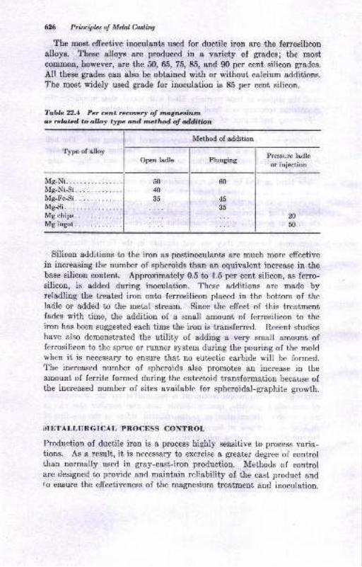
626 Principbs ol Melal CaslirW
The most effective inoculants used for ductile iron are the ferrosiliconalloys. These alloys are produeed in a variety of grades; the mostcommon, however, are the 50, 65, 75,85, and g0 per cent silicon grades.
All these grades can also be obtained with or without calcium additions.The most widely used grade for inoculation is 85 per cent silicon.
Table 22.4 Pet cent Tecwr! of mgncdutnas related, to alloy typc and method of addition
Method of addition
Type of alloy
Mg-Ni.I{g-Ni-Si.Mg-Fe-Si.
Ms-Si.Mg chips.Mg ingot.
Silicon additions to the iron as postinoculants a,re much more effectivein increasing the number of spheroids than an equivalent increase in thebase silicon content. Approximately 0.5 to 1.5 per cent silicon, as ferro-silicon, is added during inoculation. These additions &re made byreladling the treated iron onto ferrosilicon placed in the bottom of theladle or added to the metal stream. Since the effect of this treatmentfades with time, the addition of a small amount of ferrosilicon to theiron has been suggested each time the iron is transferred. Recent studieshave also demonstrated the utility of adding a very small amount offerrosilicon to the sprue or runner system during the pouring of the moldwhen it is necessary to ensure that no eutectic carbide will be formed.The increased number of spheroids also promotes an increase in theamouDt of ferrite formed during the eutectoid transformation because ofthe increased number of sites available for spheroidal-graphite growth.
iI,IETALLURGICAL PNOCESS CONTROL
Produetion of ductile iron is a process highly sensitive to process varia-tions. As a result, it is necessary to exercise a greater degree of controlthan normally used in gray-cast-iron production. Methods of controlare designed to provide and maintain reliability of the cast product andfo ensure the effeetiveness of the magnesium treatment and inoculation.
Open ladle PlungingPressure ladleor injection
50
40
35
20
50

Dwlib Iron 6n
Base-iron Atwlysis
Although the final carbon-equivalent content of ductile iron is usuall/hypereutectic, the base analysis, before magnesium treatment and inocu-
lation, is hypoeutectic. Accordingly, control over base-iron chemistryis similar to that described in an earlier chapter for gray-cast iron.
After the magnesium treatment and inoculation it is desirable to obtainsamples to determine the final chemical analysis of the iron. Methods
described for gray iron are also applicable to ductile iron, except thatspecial consideration is given to the analysis of the magnesium residual.
In this case, spectrographic analysis of a chilled, graphite-free sample
is preferred.
Test Coupons
The keel block, or Y block, shown in Fig. 22.3 is used to produce tensile-bar speeimen for routine control or customer-acceptance tests. These
castings are produced in dry-sand molds and allowed to cool to a blackheat in the mold. Tests are made in the as-cast condition or, if so
specified, after annealing, from standard 0.50S.in. test coupons machinedfrom the leg of the bar. Specifications for ductile iron referred to inTable22.l are for bars cast in this manner.
Special test coupons designed to indicate rapidly the effectiveness ofthe magnesium treatment are widely used. One such test coupon,
referred to as a "micro lug," is approximately s/+ by 3/n by Yz in., and is
Fig. X2.3 (a) Keel block for ductile-iron t€st coupons.The len6h of the keel block is 6 in. It is recommended thatthe keel block be cast in a core sand mold with a minimumof l)4 in. of sand surrounding the casting. (b) Y blockforductile-iron t€st coupotr8.
fB1
TV^,N
liUltl
f E+Va"-)
6A' Prit ipL, of Mdol etrin1
cast sdjaceDt to a heavier Eection of the caEtiDg in a oDe-pieue core sandmold. The Esmple ie allowed to cool to a black heat, is water-quenched,broken of from the heavy section, and then grouud and polished. It ienot lece8sary to reEove the scrstches to determine the acceptabiliiy ofihe iron under the metallurgical microscope 8t XloO. The entire pro-cedure can be completed in 3 min. This procedure is a control tool,aud telle the fouadryman that if the iron does not contain spheroidalgraphite iu the micro lug, the chances are that spheroidal graphit€ wiltDot be preseDt in the casting.
A number oI factors muet be controlled in ductile-irou production toavoid the occurrence of structural imperfections. Several of thesc factorsare considered iu the followiug paragraphs.
G.ophir. Sha,pe
Quality ductile iron is produced so that the graphite is developed asspheroids. A number of other types of gaphite may develop, bowever,if the process is not carried oui properly. Cbarts classifying thesegraphite shapes have been proposed, and are presented iu Figs. 22.4 and22.5. This classiflcaiion is similar to that, established for gray castiron, presented iD Chap. 18. Type I graphite is the accepted graphiteIorm iu ductile iron, altbough the preseoce oI type II graphite will havelittle efrect on propertiee. Up to 10 per cant of type III, with theremaining graphite as i5pe I or II, has been reported to have no notice-able efrect on properties. Increased amounts of type III graphiie arenot desirable. Types IV and V graphite are undesirable and havesignificantly lower mecbanical properties. Six sizes of graphite spheroidshave also been proposed in Fig. ?2.5.
The graphite shape developed in ductile iron has beeu shown to bedependent on pouring tempersture, casting section size, amount of effec-tive magnesium added, postinoculation, and base analysis of the iron.In general, the poorer graphite shapes are developed with low pouringt€mperature, heavy section sizes, insufrcient magnesium addition, lackof inoculatioa, and low carbon equivalent.
Au exccption may be uoted in high-carbon-equivalent ductile irons,ovcr 4.6 per ceDt carbon equivalent, which are subject to graphiteflotatlon and the developmeat of exploded graphitr, type V. Thisp,'oblem is magoified by healy section 8ize8. Flotstion occurs beceuse!e graphite developed early in the solidification process rapidly grows
to a large size in these analyses, and thus b€comes buoyant and floatsto the cope surface. A considerable amouut of graphite may accumu-lete if sufrciently beary sectione are cast. Thie of course resulie in aportion of the casiing contaiuing excessive graphite (up to 15 per centcarbon) and deteriorated properties.
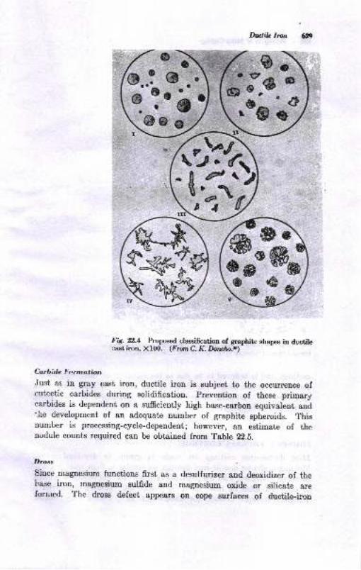
Dwltb Ircn
Fig. ?.1 hopoeed clageification of graphite ahapee in ductilecastiron, Xl{D. (PromC. K.hmto.r)
Carbide Formation
Just as in gray cast iron, ductile iron is subject to the occurence ofeutectic carbides during solidification. prevention of these primarycarbides is dependent on a sumciently high base-carbon equivalent andt,he development of an adequate number of graphite spheroids. Thisnumber is processing-cycle-dependent; however, an estimate of thenodule counts required can be obtained from Table 22.8.
I)rcss
since magnesium functions first as a desulfurizer and deoxidizer of thebase iron, msgnesium sulfide and magne.ium oxide or silieate areformed. The dross defect appears on cope zurfaces of ductile-hon
ga:,'*d
ffi-k'&sas
g.utEg- *&o-6
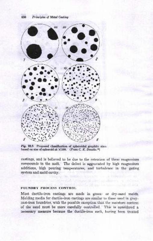
630 Prilripla ol Mdal CosaitW
mg. El",6 hoposed clasgiffcatioa of epheroidal graphite eizes
bared on sia of spheroid at Xf(X). (Frozr C. K. hwl@-a)
castings, and is believed to be due to the retention of these magnesium
compounds iu the melt. The defect is aggravated by high magnesiumadditions, high pouring temperatures, and turbulence in the gatingBystem and mold cavity.
FOUNDRY PROCESS CONTROL
Most ductile-iron castings are made in green- or dry-saud molds.
Molding media for ductiie-iron csstings are similar to those used in gray-casGiron foundries, with the possible exception that the moisture content
of the sand must be more carefully controlled. This is considered aaecessary measure because the ductile-iron melt, having been treated
r!)O.)
t':;.)t-aa
o.^'OO.O --ra .O -o.,
l.OO o
,4o-,'- '';.\.i/..-.....-. . \/, -.. ....\(;:.' :-r.;'.:: ss': :.'.ooat... t. ..aot.'
'rjii;..'.j.,..
i j::'.;::i r:
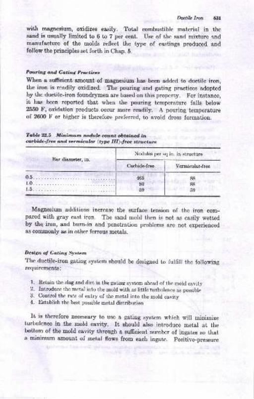
Dttctilo Imn 631
with magnesium, oxidizes easily. Total combustible material in theesnd is usually limited to 6 to 7 per cent. Use of the sand mixture andmanufacture of the molds reflect the type of castings produced andfollow the principles set forth in Chap. 5.
Poufirzg and Go,ting Prulr:ticrlt
When a sufrcient amount of mapeairrm has been added to duetile iron,the iron is readily oxidized. The pouring and gating practices adoptedby the ductile-iron foundrymen 8re based on this property. For instance,it hae been reported that when the pouring temperature falls below25,50 F, oxidation producte occur mone readily. A pouring temperatureof 2600 F or higher is therefore preferred, to avoid dross formation.
Tabb 22.5 Minitnutn ndula count obtaitrrd inanbidc-Jte and ootmiculot (typ III)-fte atrrrctu;te
Nodules per sq in. in structureBar diameter, in.
Csrbide-free Vermicular-free
Magaesium additions increase the surface tension of the iron com-pared with grsy cast iron. The sand mold then is not as easily wettedby the iron, and burn-in and penetration problems are not experiencedas coErmonly ae iu other fenous metals.
Decign ol Gating Sjtstz,m
The ductile-iron gating system should be designed to fulfill the followiugrequirements:
1. Retain the slag and dirt in the gating system ahead of the r.old cavity2. Introduce the metal into the mold with as li.ttle turbulence as possible3. Control the rate of entry of the metal into the mold cavity4. Establish the best possible metal distribution
rt ie therefore necessary to use a gating system which will minimizeturbulence in t'he mold cavity. It should also introduce metal at thebottom of the mold cavity through a sufEcient number of ingates so thata minimum amount of metal flowe from each ingate. positive-pressure
0.5.1.0.
1.5.
88
88
59
465
80
59
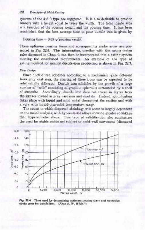
t2.o
r6.o
t4.o
.E t0.o
a
E 8.0
o5 6.0
4.O
2.O
0
63i2 Principlcs of Mdal C,or;ti.ng
systems of the 4:8:3 type are suggested. It is also desirable to provide
runners with a height equal to twice the width. The total ingate area
is a function of the pouring weight and the pouring time. It has been
established that the best average time to pour ductile iron is grven by
Pouring time : O.OS VpourinEweigE[
These optimum pouring times and corresponding choke areas ere pre-
sented in Fig. t2.6. This information, to'gether with the gating-design
rules discussed in Chap. 9, can then be incorporated into a gating system
meeting the established requirements. An example of the type ofgating required for quality ductile-iron production is shown inEig. D.7.
Riser Desiln
Since ductile iron solidifies according to a mechanism quite differentfrom gray cast iron, the risering of these irous can be expected to be
substantially different. Ductile iron solidifies by the growth of a largenumber of "cells" consisiing of graphite spheroids surrounded by a shellof austenite. Accordingly, ductile iron does not freese in layers fromthe surface inward as gray cast iron and steel do. Instead, solidificationtakes place with liquid and solid metal throughout the casting and witha very wide liquid-plus-eolid temperature range.
The extent to which dispersed shrinkage will occur is largely dependenton the metal analysis, with hypoeutectic alloys showing greater shrinkagethan hypereutectic alloys. This type of solidification also emphasizes
the need for stable molds not subject to mold-wall movement (discussed
0 4,oo0 8,ooo t2,oo0 ,t6,oo0 20,ooo 24,oooPouring weighl, lb
Fig. YL6 Chart uEed for determining optimum pouring timcs atrd respectivechoke areas for ductile iron. (From R. W. While.tt)
Choke oreo, in.z
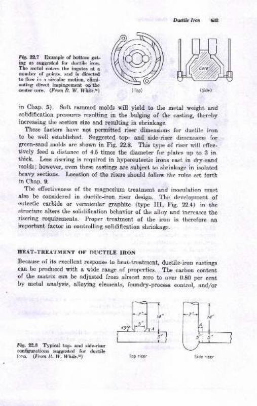
Fig. Z2.l Example of bottom gat-ing as suggestqd for ductile iron.The metal enters the ingates at anumber of points, and is directedto flow in e circular motion, elimi-uating direct imping€ment on thecent€r core. (From R. W. While.rt)
Fig. 7fl,0 Typical top- and side-riserrnnfiguratiors suggestcd for ductilei:^n. (From R. W. Whil..a)
in Chap.5). Soft rammed molds will yield to the metal weight andsolidification pressures resulting in the bulging of the casting, therebyincreasing the section size and resulting in shrinkage.
These factors have not permitted riser dimensions for ductile ironto be well established. Suggested top- and side-riser dimensions forgreen-sand molds are shown in Fig.22.8. This type of riser will effec-tively feed a distance of 4.5 times the diameter for plates up to B in.thick. Less risering is required in hypereutectic irons cast in dry-sandrnolds; however, even these castings are subject to shrinkage in isolatedheavy sections. Location of the risers should follow the rules set forthin Chap. 9.
The efrectiveness of the magnesium treatment and inoculation mustalso be considered in ductile-iron riser design. The development ofeutectic carbide or vermiculer graphite (type III, Fig. yZ.4) in thestructure alters the solidification behavior of the alloy and increases therisering requirements. Proper treatment of the iron is therefore animportant factor in controlling solidification shrinkage.
HEAT-TREATMENT OF DUCTILE IRON
Because of its excellent response to heat-treatment, ductile-iron castingscan be produced with a wide range of properties. The carbon contentof the matrix can be adjusted from almost zero ta over 0.g0 per centby metal analysis, alloying elements, foundry-process control, and/or
l; ,-1,
4*%
Dwtih Iron 6r:t
(Side)( Top)
Top riser Side riser
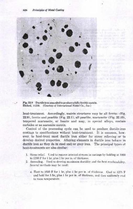
Prinripbs oI Mdnl CasliW
t
oroa
'a''
I!
ta
(a
Ftg. tl.g Ductileiron ann:aled toproduceafully fenitic matrix.Etched, X250. (hurlecy o! Inlcrnaliorul Nith,cl h. Inc.)
heat-treatment. Accordingly, matrix structures may be all ferrite t'Fig.t2.9),leritn andpearlite (Fie.yz.l\, all pearlite, martensite (Fig.22.10),
tempered martensite, or banite and may, in special alloys, contain
carbides or an austenite matrix.Control of the processing cycle can be used to produce ductile-iron
castings to specifications without heat-treatment. It is common, how-
ever, to heat-treat most ductile iron either for stress relieving or todevelop desired properties. Alloying elements in ductile iron behave inductile iron as they do in steel and/or gray iron. The principal types ufheat-treatments are also similar:
l. Stress relief. Used to remove internal stresses in castings by holding at lfil0to 1250 F for I hr, plus I hr per in. of thickness.
2. Annealilrg. Used to develop maximum ductility and the best machinability.
Several methods may be used:
a. Heat to 1650 F for I hr, plus I hr per in. of thickness. Cool to 1275 Fand hold for 5 hr, plus I hr per in. of thickness, and then uniformly ccol
to room temperature.
a
,"-\ a... a)
o:+
r o,!',,:
a
aa
It
': a'o'j:e0
!
I rlr
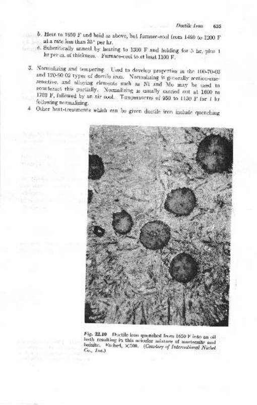
o.
Ductile Imn 6Js
b. Heat to 1650 F and hold as above, but furnace_cool from 1450 to 1200 Fat o ratc Iess than Bbo per hr.
c. Subcritically anneal by heating to lB00 F and holding for 5 hr, plus Ihr per in. of thickness. Furnace_cool to at least ll00 F.
Normalizing and tempering. Used to develop properties in the 100_20{3and 120-90{2 types of ductile iron. Nonnalizing is generally section_size_sensitive, and alloying elements such as Ni ana Mo may be used tocounteract this partially. Nomralizing is usually carried out at 1600 to17-_00
tr., followed by an air cool. Temperatures of 950 to 1lE0 F for I hrfollowing nomalizing.Other heat-treatments which can be given ductile iron include quenching
T
!i5,2:2.10 Ductile iron qucnched from 1650 F into an oilbath. resulting iq this acicular *io*" "f -u"t".#ti'riabainite. .Etche4, x500. <a*ir"y i1 i"r_ia:rrii?v ilitCu,, Ira.)
:1
!ffi
'-\..]t+
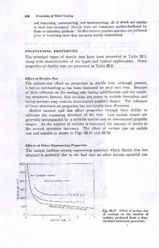
-s 4OOE
3 soo9
2 zoo
&36 Prirciplcs oI Melal Casling
and tempering, austempering, and martempering, all of which are similar
to steel heat-treatment. Ductile irons are commonly surfaceJrardened by
flame or induction methods. In this instance pearlite matrices are preferred
prior to hardening since they are more readily austenitized.
trNGINEERING PROPERTIES
The principal types of ductile iron have been presented in Table 22.1,
along lvith characteristics of the types and typical applications. Other
properties of ductile iron are presented in Table 22.6.
Elfect oJ Section Size
The section-size effect on properties in ductile iron, although present,
is not as outstanding as has been discussed for gray cast iron. Because
of their influence on the cooling rate during solidification and the result-
ing structures formed, thin sections are prone to carbide formation and
heavy sections may contain deteriorated graphite shapes. The influence
of these structures on properties has previously been discussed.
Nodule number and size affect properties through their ability toinfluence the remaining structure of the iron. Low nodule counts arc
generally accompanied by a carbidic matrix and/or deteriorated graphite
shapes. As the number of nodules is increascd, the amount of ferrite in
the as-cast structure increascs. The effect of section size on nodule
size and number is shown in Figs. 22.11 and 22.12.
Dffects o! Other Engineering Properties
The unique position among engineering materials which ductile iron has
attained is probably due to the fact that no other ferrous material can
Fig. 2:2.11 Elfect of section size
of castings on the number ofnodules prrrduced from a stan-dardized treatment procedure.
+ Corbidic molrh
Ferrilic molrit +
1?5Section site, in.
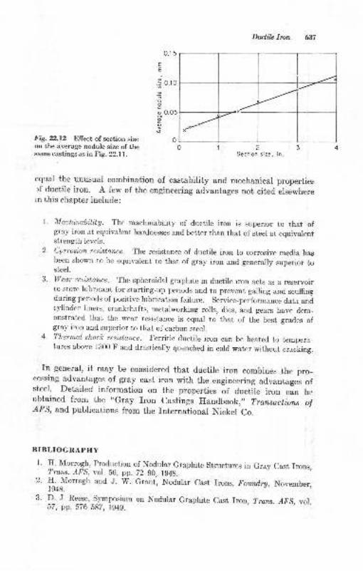
Dwtib lron 637
o.r 5
EE
.3 o.,o
I
o O.O5
Fig.22.12 Effect ofsection sizeon the average nodule size ofthesame castingsas in Fig.22.ll.
1. H. Morrogh,Trans. AFS,
2. H. Morrogh1948.
?Seciion size, in
equal the unusual combination of castability and mechanical properties-lf ductile iron. A few of the engineering advantages not cited elsewherein this chapter include:
l. MachittabilitE. The machinability of ductile iron is superior to that ofgray iron at equivalent hardnesses and better than that of steel at equivalentstrength levels.
2. corrosion resistance. The resistance of ductile iron to corrosive media hasbeen shown to be equivalent to that of gray iron and generally superior tosteel.
3. weu reristance. The spheroidal graphite in ductile rron acts as a reservoirto store lubricant for starting-up periods and to prevent galling anri scuffingduring periods of positive lubrication failure. service-performance data andcylinder liners, crankshafts, metalworking rolls, dies, and gears have dem_onstrated that the wear resistance is equal to that of the best grades ofgray iron and superior to that of carbon steel.
4. Thermal shock resistance. Ferritic ductile iron can be heated to tempera-turcs above 1300 F and drasticaly quenched in cord water without ..u&irg.
rn general, it may be considered that ductile iron combines the pro-cessing advantages of gray cast iron with the engineering advantages ofsteel. Detailed information on the properties of ductile iron can beobtained from the "Gray Iron castings Handbook,,, Transo.ctiorx ol:{,FS, and publications from the International Nickel Co.
BIBLIOGRAPHY
Production of Nodular Graphite Structures in Gray Cast Irons,vol. 56, pp. 72-90, 1g48.and J. W. Grant, Nodular Cast Irons, Foundrg, November,
3. _D_.
J. Reese, Symposium on Nodular Graphite Cast Iron, Trans. AFS, vol.57, pp.576-587, 1949.

jn: o9q\
.tdB::-d..
jql
5.-i
,,
:
:
:
:
8-
E
a!? Ea E-E E-E-aa e E-u:a dj: e^ dd @FY-_ e- ,jef t9 P< qq<E q 1:E EE EB. EEqE € E
,
aa-^tsEA5 :
q{s.q9R9R5t5=5 :
:
a^EE HE9? E{sR 88
ti
O
E
E
E
,2
tr
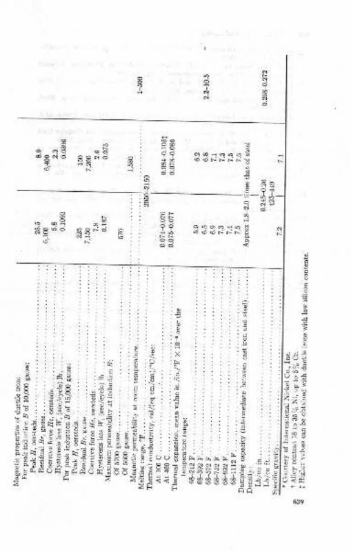
?
d
oa++ 6! q'.: c? a e+ob !o(6Fr..Nr_
!9
EPq 6?9 €b68No ggcici Ir!1 :61 6
3
E E3E 9i
B
QE+,A rid6rrN
e oq9 @PR8'o RB d e
1 Nn fr
rl!
: : ; : : :T
. ..1::::::B..c
'B. . . .9' ,:.x
::::::::6;. :.:!c :: I I :vi: ::: : ::.
brrtrr..snI S
HEBess=e,.cc]99\o+ iB-d*B**B€3
, !):o H
:! :Q ; ;x. s .: .-::ETE,,-,<.]:j
l:o- 5 o
. '
,? g
: := :>; E
9 9 8E.: O
AiF": :6:J:l .e s 5.i.i tr
-.- 9 !. i'66?oo 3.: E-.f E
a.6 9<< cAF F
..:: .- ;:: r. - Eh .==
€;::!-AH^ :t5E!i- ; >F : :-\:
-:E : :b gt : :5 V Iv^. o 9i'o c-s 3#ts c di E:trE.E:gc;n€EstiE-rE E{5f : Ed€f E
E."d5.: E;r'? 9 fl eo 1r! Yi34 -'6 e3 !E n d E 3 g, E ? ts- g 9..EF" hAl(Uiq xtrEOtr 5d-!r ri >
63.)
@ Priwiples oJ Mdal Casting
4. C. K. Donoho, Producing Nodular Graphite with Magnesium, Am' Foundrg-
man, February, 1949.
5. G. E. Holdeman and J. C. H. Stearns, Variables in Producing Nodular
Graphite Cast lron, Am. Foundtgntan, August, 1949'
6. A. i. Gagnebin, K. D. Millis, rrrd N. B-Pilling, Ductile Cast Iron: A New
Engineering Material, Iron Age, Feb. 17, 1949'
7. E.i. Myilowski and R. P.-Dunphy, iurproved Nodulizing Alloy, Steal'
Sept. 5, 1949.
8. J.'E. Rehder, An Introduction to the Annealing of Nodular Irqn, ?rans' AFS'
vol. 58, pp. 298-311, 1950.g. J. L. Yarne and w. B. sobers, Magnesium Determinations in Nodrilar cast
Iron: Sampling and Analysis Methods, Am- Foundrgmon, June, 1950'.
10. J. E. Rehder,"Effect of ihosphorus ionte.,,t^on Mechanical Properties of
Nodular Cast Iron, Trons. AFS, vol. 59, pp. 501-508, 1951'
11. H. Morrogh, Influence of Some Residual Elements and Their Neutralization
in Magnesium Treated Nodular Irons, ?rcns. /FS, vol' 60, pp' 43W52,
1952.
12. J. Keverian, C. M. Adams, and H. F. Taylor, Time of,Formation of
Spherulites in Hypo- and Hypereutectic Irons, Trans' AFS, vol' 60, pp'
849-853, 1952.
13. R. P. Iiunphy and W. S. Petlini, Solidification of Nodular Iron in Sand
Molds, Irons. ,{F'S, vol. 60, pp. 775-182, 1952.
14. c. F. Reynolds and H. F. Taylor, Mechanical Properties of spherulitic
Graphite Cast Iron, Trans. AFS, vol. 60, pp. 687-713, 1952-
15. D. i. Reese, F. B. ilote, and C. A. Conger, Chemistry and Section Size on
Properties of Ductile lron, Trans. Quart. SAE, July, 1952.
16. S. F. Carter, American Experiences with Basic Cupola Melting, Trans' AFS,
vol. 61, pp.52-60, 1953.
17. C. C. Reynolds, C. M. Adams, and H. F. Taylor, Prediction of Mechanical
Properties from chemical composition for Fully Annealed Ductile cast
Iron, Trans..dl'S, vol. 61, pp. 510-515, 1953.
18. R. i. Shnay and S. L. Geiisman, Risering of Nodular lton, Trans. AFS,
vol.62, p. 632,1954.
19. R. A. Flinn, D. J. Reese, and W. A. Spindler, Risering of Ductile Cast
Iron, Trans. ,4FS, vol. 63, pp. 720-725, 1955.
20. F. G. Sefing, Nickel Austenitic Ductile Irons, ?rons. .dFS, vol. 63, pp'
638-641, 1955.
21. 'W. S. Pellini, G. Sandoz, and H. F, Bishop, Notch Ductability of Nodular
Iron, Trans. u{SM, vol. 46, pp. 4l&445, 1954.
22. C. Reynolds, J. Maitre, and II. F. Taylor, Feed Metal Requirements for
Ductile Iron Castings, Trans. AFS, vol.65, p.336,1957.
23. J. F. Ellis and C. K. Donoho, Magnesium Content and Graphite Forms in
Cast Iron, Trans. AFS, vol. 66, pp. 203-209, 1958.
24. J.T. Williams, Basic Cupola Melting, Trans. A?5, vol.67, p.669, 1959.
25. A. H. Rauch, J. B. Peck, and G. F. Thomas, Carbon Flotation in Ductile
lron, Trarx. z{1S, vol. 67, p. 263, 1959.
26. A. H. Rauch, J. B. Peck, and E. M. McCullough, Ductile Iron As-cast and
Annealed Tensile Properties, ?rans..AFS, vol. 67, p. 187, 1959.
27. H.E. Henderson, Acid Cupola Melting for Ductile Iron, ?rons.,41S, vol.
67, p. 661, 1959.
28. W. D. McMillan, Heat Treatment of Ductile lron, Trans. u4FS, vol. 67, p'
215, 1959.
Drclik Iron 6if
29. J. A. Davis, J. C. McCarthy, D. M. Marsh, and H. O. Meriwether, Gatingand Risering of Ductile Iron, ?rons. /fS, vol. 68, p. 509, 1960.
30. C. K. Donoho, Ductile Iron Graphite Form Classification, Trans. /f.S, vol.69, p.297, 1961.
31. R. W. White, Gating of Ductile lron, Foundrg, vol. 88, p. l0l, February,1960.
32. R. W. Whit€, Risering of Ductile Iron Castings, Foundrg, vol. 88, p. 96,March, 1960.
33. S. Tunder and L. Hohle, Shaking Ladle for the Economic Production ofHigh Grade Cast Iror, Foundry Trade J., Jan. 11, 1962.
34. J. V. Dawson, Effect of Carbon Equivalent on the Soundness of NodularIron Castings, BCIRA./., vol. 10, no. 1, January, 1962.
35. C. R. Loper, Jr., Ductile Iron Solidification Study Using the ElectronMicroscope, Trans. AFS, vol. 70, p. 963, 19ti2.
36. W. Heinrichs, Magnesium Treatment of Gray Iron Melts to ProduceDuctile lron, Tran*. r{FS, vol. 70, p. 1121, L962.
37. T. E. Rieger, Production of Ductile lron, Foundry, vol. 90, p. 96, February,1962.
38. R. S. Thompson, How Do We Know It's Ductile? Foundry, vol. 90, p. 76,June, 1962.
39. T. H. Burke, Melting Ductile fron in an Acid Cupola, Foundrg, vol. 90,p.46, July, 1962.
40. Gray Iron Founders'Society, "Gray Iron Castings Handbook," Cleveland,1958.
41. R. J. Christ and I\{. J. O'Brien, Inverse Chill in Ductile lron, Trmts. AFS,vol. 71, pp. 75-80, 1963.
42. J. Pelleg, Influence of Silicon on Ductile Cast Iron, Trans. AF9, vol.7l, pp.108-116, 1963.
43. C. Vishevsky and J. F. Wallace, Effect of Heat Treatment on Impact Prop-erties of Ductile Iron, Irans. /FS, vol. 71, pp.29V295, 1963.
M. W. C. Wick, Metallurgical Properties of Continuous Cast Ductile, Gray,and High Alloy Iron Bar Stock, Trans. AFS, vol. 71, pp. 544-555, 1963.
45. D. Matter, II. H. Wilder, R. A. Clark, and R. \{. White, Factors AffectingApplication and Behavior of Magnesium Additives for Ductile lron, Trans.r{FS, vol. 71, pp. 625427, 1963.
46. R. W. White, Application of Sandwich Method to Produce Ductile Iron,Trans.. AFS, vol. 71, pp. 62&{31, 1963.
47. W. H. Dawson, Injection of Magnesium Metal, Trans.,4FS, vol.71, pp.632437,1963.
48. R. Carlson, Experiences with Plunging, Open Ladle, and Sandwich Methods,Trans. AFS, vol.7l, pp.638-{40, 1963.
49. C. R. Loper, Jr., and R. W'. Hein:, The Solidification of Cast Iron with. Spheroidal Graphite, Trans. ASM, vol. 56, pp. f35-152, 1963.
50. C. R. Loper, Jr., and R. W. Eeine, Variables Influencing Graphitization andCarbon Flotation, Grag lron News, pp. 4-16, May, 1963; pp. 4-9, June, 1g63.
51. C. R. Loper, Jr., P. Banarjee, and R. W. Heine, Risering Requirementsfor Ductile Iron Castings, Grag lron Neus, tr4ay, 1964, pp.5-16.
52. C. R. Loper, Jr., P. S. Nagarsheth, and R. W. Heine, Nodule Counts andDuctile Iron Quality, Gray lron News, June, 1g64, pp.5-f 7.
53. W. J. Dell and R. J. Christ, Chill Elimination in Ductile Iron by MoldInoculation, Trans. AFS, vol.7l, pp.40&416, 1964.
54. C. R. Loper, Jr., and R. W. Heine, Graphitization and l,he Processing Cycle' in Producing Ductile lron, Trans. AFS, vol. 71, pp. 495-507, 1964.
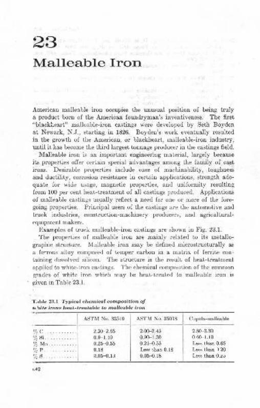
23Mallea.trle Iron
Americarr malleable iron occupies the unusual position of being trulya product born of the American foundryman's inventivenes$. The first
"blackheart" mallcable-iron castings were developed by Seth Boyden
at Newark, N.J., starting in 1826. Boyden's work eventually resulted
in the growth of the American, or blackheart, malleable-iron industry,until it has become the third largest tonnage produccr in the castings field.
Malleable iron is an important engineering material, largely because
its properties offer certain special advantages among the family of cast
irons. Desirable properties include ease of machinability, toughness
and ductility, corrosion resistance in certain applications, strength ade-
quate for wide usage, magnetic properties, and uniformity resulting
from 100 per cent heat-treatment of all castings produced. Applications
of malleable castings usually reflect a need for one or more of the fore-going properties. Principal users of the castings are the automotive and
truck industries, construction-machinery producers, and agricultural-equipment makers.
Examples of truck malleable-iron castings are shown in Fig. 23.1.
The properties of malleable iron are mainly related to its metallo-graphic structure. \,Ialleable iron may be defined microstructurally as
a ferrous alloy composed of temper carbon in a matrix of ferrite con-
taining dissolved silicon. The structure is the result of heat-treatment
applied to white-iron castings. The chemical composition of the common
grades of white iron which may be heat-treated to malleable iron is
given rn Table 23.1.
T.rble 23.1 Typical chenical composition otu\ite irons lleat-treatoble to malleable iron
ASTM No. 32510 Cupola-malleable
2.80-3.30
0.60-1.10
Less than 0.65
Less than ) 20
Less than O.zJ
ASTM No. 35018
2.OA-2.45
0.90-r.300.21-{.55Less than 0.18
0.05-o.18
2.30-2.65
0.9-1.400.25-{.550.r80.05-o.13
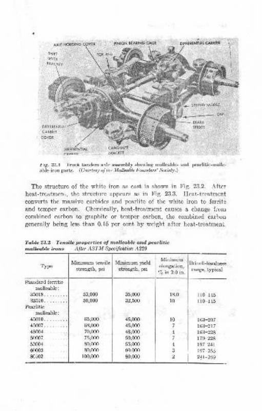
AXTE HOUSING COVEN PINION BEATING CA6E
SPRING SADOL€ .
i,-*-- cae
SRA(E
SPIDrR
DITTEiENTIAT CAMSHAFI
;RACKET
t.g. 23.1 'l ruct tandem arlr, assembly showing malleable- and pearlitic-mallc-able-iron parts. (Courlesy oJ lltt ,Ylallzable l.ounders' :iocittl.)
The structure of the white iron as cast is shown in Fig. 23.2. Afterheat-treatmenr,, the structure appears as in Fig. 23.3. Heat-treatment
converts the massive carbides and pearlite of the white iron to ferriteand temper carbon. Chemically, heat-treatment causes a change fromcombined carbon to graphite or temper carbon, the combined carbongenerally being less than 0.15 per cent by weight after heat-treatment
Toblc 23.2 Tensila properties of nallaoblc and pcarliticmlloobla irons Atter ASTM Specifrntion A220
TypeBrinell-hardqessrange, typical
Standard ferriticmallesble:
35018.......32510.
Pea,rlitic
malleable:
45010.........45007. . ... .. ..48004.........5(t007.........53004........6(1003.........8C002.........
l0
4
4
2
163-207
163-217
163-228179-228197-211
r97-25524t-269
. .. I MinimumMrmmum vreld I
srrengrh,psi l;ji'"-;li?
35,000
32,500
45,000
45,m048,000
50,000
53,000
60,0m80,0m
53,000
50,000
65,000
68,000
70,000
75,000'
80,000
80,o00
r00,000
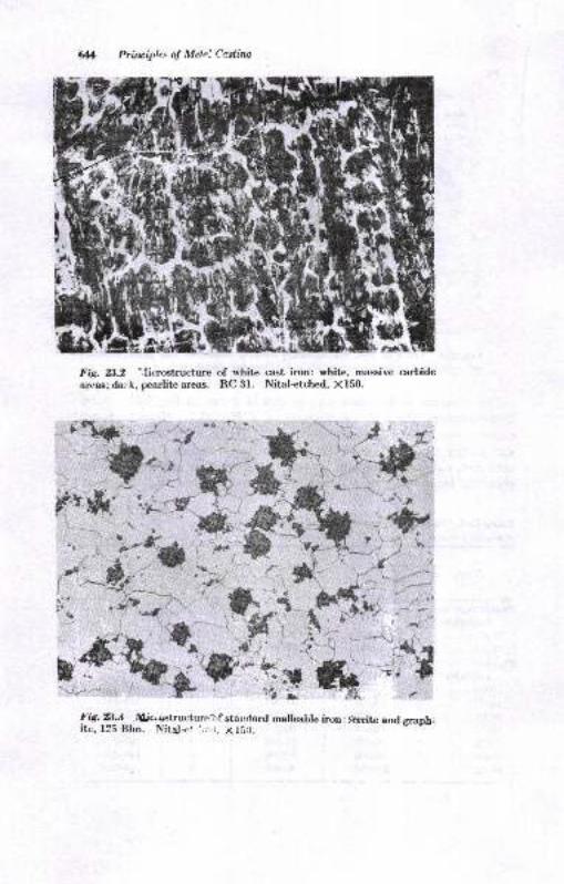
Prirciple.. oJ Melni Cr.stiw
Fig. 8.2 'Iicrostructure of white cast iron: white. massive carbideareas; dark, pearlite areas. RC 31. Nital+tched, X150.
.)-ril
l'fr--'.+l
a--;, s
l.g.rAl.t filic.{structurc::f staldard malleable iron: lerrite and graph_ite, l2i Bhn. Nita!<.r t::.;. X153.
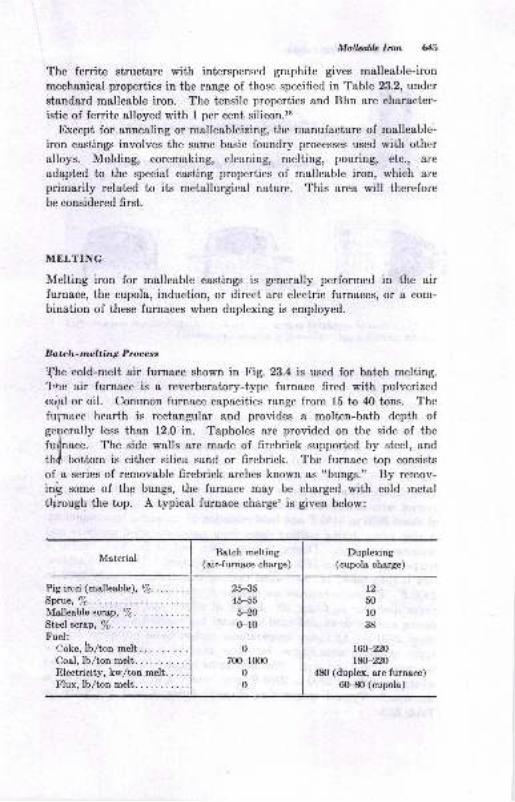
Mall& Ircn 613
The ferrite structure with interspersed graphite gives malleable-iron
mechsnical properties in the range of those specified in Table 23.2, under
etandard malleable iron. The tensile properties and Bhn are character-istic of ferrite alloyed with I per cent silicon.ls
Except for annealing or malleableizing, the manufacture of malleable-
iron castings involves the same basic foundry processes used with othcralloys. Molding, coremaking, cleaning, melting, pouring, etc., a)'e
adaptcd to the special casting properties of malleable iron, which at'e
primarily related to iLs metallurgical nature. This area will therefore
be considered first.
MELTING
Melting iron for malleable castings is generally performed in the airfurnace, the cupola, induction, or direct arc electric furnaces, or a com-
bination of these furnaces when duplexing is employed.
Batc|z-melting Pruess
f,he eold-melt air furnace shown in Fig. 23.4 is used for batch melting.1,ne air furnace is a reverberatory-type furnace fired with pulverized
crrlal or oil. Common furnace capacities range from l5 to 40 tons. T'he
fupnace hearth is rectangular and provides a molten-bath depth ofge4erally less than 12.0 in. Tapholes are provided on the side of the
furfnace. The side walls are made of firebrick supported by steel, and
thd bottom is either silica sand or firebrick. The furnace top consists
of a series of removable firebrick arches known as "bungs." By remov-inft some of thp bungs, the furnace may be charged with cold metal
t|lrough the top. A typical furnace chargel is given below:
Duplexing(cupola charge)
Pig irod (malleable), /6... . .
Sprue, /6. .. : . :
Malleable scrap,7o.Steel scrap, %. . . .
Fuei:,.-)oke, Ib/ton melt........ .
Coal, lb/ton melt...........Electricity, ku'/ton melt. . . ..Flux, lb/ton melt...... ....
t250
r038
r60-220t&-220
480 (duplex, arc furnace)6G{0 (cupola)
Batch melting(air-furnace ch"arge)
25-3545-55
5-?0
0-10
0
700-1mo0
0
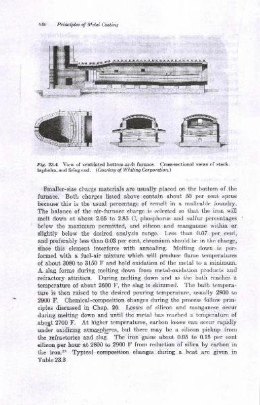
Primiples o! Meta! CasliryT
FiS. 23.4 Vicw of ventilated bottom-arch furnace. Croes-s€ctional vlews of stack.tapholes, and firing end. (Courtesy o! Vlhilirq Cnrporalian.)
Smaller-size charge materials are usually placed on the bottom of the
furnace. Both charges listed above contain about 50 per cent sprue
because this is the usual percentage of remelt in a malleable foundry.
The balance of the air-furnace charge is selected so that the iron willmelt down at about 2.65 to 2.85 C, phosphorus and sulfur percentages
below the maximum permitted, and silicon and manganese within or
slightly below the desired analysis range. Less than 0.07 per cent,
and preferably less than 0.03 per cent, chromium should be in the charge,
since this element interferes with annealing. Melting down is per-
formed with a fuel-air mixture which will produce flame temperatures
of about 3080 to 3150 F and hold oxidation of the metal to a minimum.
A slag forms during melting down from metal-oxidation products and
refractory attrition. During melting down and as the bath reaches a
temperature of about 26fi) F, the slag is skimmed. The bath tempera-
ture is then raised to the desired pouring temperature, usually 2800 to
2900 F. Chemical-composition changes during the process follow prin-
eiples discussed in Chap. 20. Losses of silicon and manganese occur
during meiting down and until the metal has reached a temperature of
abqlt 2700 f'. At higher temperatures, carbon losses can occur rapidly
under oxidizrng atrnospfores, but there may be a silicon pickup from
the refractories and slag. The iron gains about 0.05 to 0.15 per cent
silicon per hour at 2800 to 2900 F from reduction of silica by carbon in
tire iron.zt Typical composition changes during a heat are given in
Table 23.3.
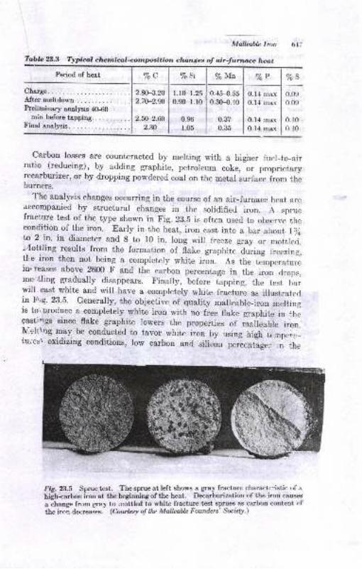
Mallcable lron
Toblc 23.3 Typical chelrtrical<omposition clunges of air-furruce heat
Period of heat %c
After meltdownPreliminary analysis 4O-60
min before tapping.Final analysis.
2.80-3.20
2.70-2.90
2.fi-z.ffi2.n
l.l0-1.250.90-r.r0
0.96
r.05
0.45-O.55
0.3H..10
0.37
0.35
0.14 max
0.14 max
0.14 :nax
0.14 max
%s
0.09
0.09
0.10
0. l0
carbon losses are counteracted by merting with a higher fuel-to-airratio (reducing), by adding graphite, petroleum coke, or proprietaryrecarburizer, or by dropping powdered coal on the metal su.face from theburners.
The analysis changes occurring in the course of an air-furnace heat arcaccompanied by structural changes in the soridified iron. A spruefracture test of the type shown in Fig. 28.5 is often uscd to observe thecondition of the iron. Early in the heat, iron cast into a bar about, l )ito 2 in. in diarneter and 8 to r0 in. long will freeze gray or mottlcti.i'{ottling results from the formation of flake graphite during freezin,l,tle iron then not being a compretery white iron. As the tJmperaturein, reases above 2600 F and the carbon percentage in the iron drops,mo'tling gradually disappears. Finaily, before tapping, the tcst barwill cast white and will have a completely white fracture as illustratcdin F,,9. 23.5. Generally,_the objective of quality malleable_iron mcltingis toi produce a completely white iron with no free flake graphite in ihegasti, gs since flake graphite lowers the properties of maieable iron.N,eltlng may be conducted to favorlvhite iron by rtsing high temp,,"r,.tu,'crr\ oxidizing conditions, Iow carbon and silir:o, p.i.rtlug.. ,n .h.
l'ig. 23.5 Sprue tcsL. The sprue at left shows a gray fracture charactc:istic of a
high+arbon iron at tbe beginning of the heat. Decarburization of the iron causes
a change from gray to .nottled to white fracture-test sprues as carbon content of
the iron decreases. (Courlesy of the Mallcablc Founders' So"iely.)
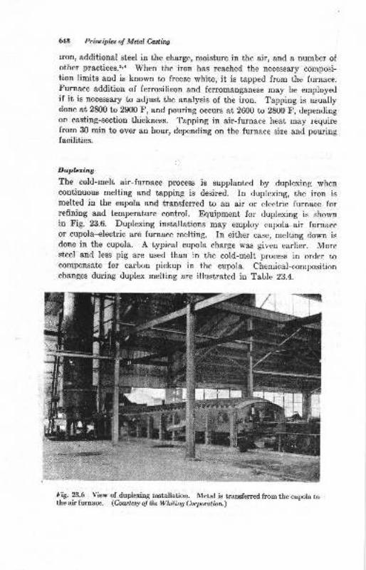
6t8 Prirciplcs of Metal Casling
iron, additional steel in the charge, moisture in the air, and a number ofother praetices.2,a When the iron has reached the necessary composi-tion limits and is known ta freeze white, it is tapped from the frrrnace.Furnace addition of ferrosilicon and fenomanganese may be employedif it is necessary to adjust the analysis of the iron. Tapping is usuallydone at 2800 to 29(n F, and pouring occurs at 2600 to 2800 F, dependingon casting-section thickness. Tapping in air-furnace heat may requirefrom 30 min to over an hour, depending on the furnace size and pouringfacilities.
Duplering
The cold-melt air-furuace process is supplanted by duplexing whencontinuous melting and tapping is desired. In duplexing, the iron ismelted in the cupola and transferred to an air or electric furnace forrefining and temperature control. Equipment for duplexing is shownin Fig. 23.6. Duplexing installations may employ cupola-air furnaceor cupola--electric arc furnace melting. In either case, melting down isdone in the cupola. A typical cupola charge was given earlier. Moresteel and less pig are used than in the cold-melt process in order tocompensate for carbon pickup in the cupola. Chemical-compositionchanges during duplex melting are illustrated in Table 23.4.
F-W. ?.^6 Yiew tdupiexing installation. Metal is transferred from the cupola tothe air furnacc. (Cowtesy o! lhc Whilirq Corporatinn.)
qI
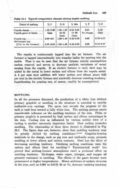
Period of metting "/. c %si o/o Mn %P '.ta s
C\pols ch!r8e............C\poh gaiB or lN€s. . . . .
Ctpols tsp. . . .. -....Air-furnsao tsp
(2 hr in tle furnece). ...
L*2-mGsio
2.6(F3.0
2.36-2.65
l-5(Fr.65I(F06)
l.rIFr.4{)
1.25-r.a)
0.5H).60r5-m0e)
0.45-{.50
0.4.5-{}.50
0.05
No clBnae
0.05
o.05
o-12
Gritr
o.12{.17
o.t?.4.r7
Mdbble Ircn
T.bb 2d.4 TrIiicn @l,tr'p{dtbn ctu,8er durin,t dapta i.2,.idt
The cupola is continuowly tspped into the air firrnsce. The air
Iurnace is tapped interrnittently iuto transfer ladles for pouring into the
molds. Thua it cau be seen that the air furnace mainly accomplishee
carbon rrmoval and aerves lo decrease enalysis variatious of uretal
coming from the eupola. If rn electric furnace ie used, steel may be
a<ided to the metal to lo\f,er carbon and eilicon from the cupola metal.
A 4 p€r ceEt steel additiou will lower carbon and eilicon about 0.05
per cent in the electric furnace and markedly decrease mottling tendency.
Superheating for pouring can, ol conrse, readily be accomplished.
MOTTLING
Iu all the processes discussed, the production oI a white iron withoutprimary graphite or mottling iu the structure i8 essential to quality
malleable-iron castings. The sprue t€st reveals the progress of the
melt in each heat toward s fully white iron. The melting process exerts
coneiderable influence ou the mottliug tendency of the iron. Flake orprimary graphite is promoted by high carbon and silicon percentsges inthe iron. Cooling rate as influenced by va ous sectiou sizee of a
casting is another extrcmely important Iactor. Slow cooling promot€s
mottling. The relationship of these three factors is illustrated in Fig.
23.7 - The figure does not, however, show that mottling tendency may
be greatly shifted by melting conditions.''s,s''z? Grephite-bcaring
materials in the charge, such as pig iron and malleable scrap, promote
,nottling st lower silicon and carbon cont€nts. Steel hss the efrect ofdecreasiog mottling tendency. Oxidizing melting condiiions raise the
carbon and silicon limit for mottliug.''a Experimental work'z, has
proved that melting-furnace atmospheres exert a profound efiect on
motiling tendency. Hydrogen, water vapor, nitrogeD, and oxygen allpromote resistance to mottling. The efrects of the gases become morepronounced at higher t€mperatures. Minor addiiione of certain elemcuts
to the iron, such as 0.001 to O,OI% Bi or Te, decrease moitling tendency
.9
c
Pri.rcipla ol Melnl Caslirq
0.304 0.60.8r.0 2 3 4 56 8lO,pe, equivoleni diom., in.
FiS- 23.7 Graph showing relaiionship ;r ri"*"t"s"-;i-bon, silicon, and section sizefor mott.ling in sand molds.(Frorn R. Schruideuind andR. G. McEhtee.n)
even in very heavy sections.26 Because of the manifold factors involved,standardization of melting practices is adopted as a control measure inthe production of white-iron castings free of mottling and with satis-factory annealing characteristics.
CASTING PROPERTIES
Foundry characteristics which require special consideration in makingwhite-iron castings are fluidity, shrinkage, hot-tearing tendency, andtemperature.
Shrinkage and Fecding
Because it freezes white, the iron has a solidification shrinkage of about3 to 6.0 per cent. This is reflected in a foundry yield of about b0 percent- Feeding the solidification shrinkage of white iron is aggravatedby its two-step solidification process. Freezing begins with formationof primary austenite dendrites as temperature decreases below 2450 tr'.It is completed by eutectic freezing in the range of 2060 to 2020 F.Figure 23.8 shows the network of interlocking dendrites which developearly in fteezitg and which make it difficult for metal to pass from afeeder into the casting. unfed shrinkage usualry results in cavitieswith a dendritic pattern because of the freezing mechanism.
t.0
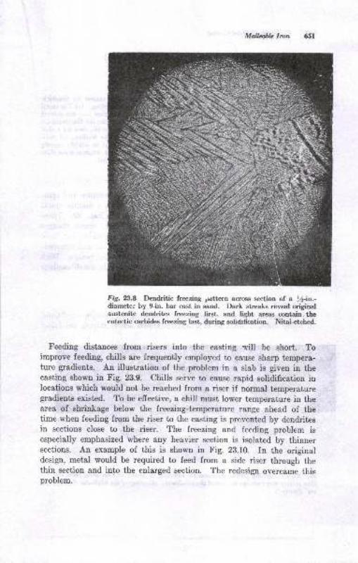
MalLdh lron
Fig. 23.A Dendritic freezing pdttern across section of a l-in.-diameter by 9-in. bar cast in sand. Dark streaks reveal originalaustcnite dendrites freezing frst, and light areas contain theeutectic carbides freezing iast, during solidrtication. Nitai-etched.
Feeding distances from risers into the casting will be short. Toimprove feeding, chills are frequently employed to eause sharp tempera-ture gradients. An illustration of the problem in a slab is given in thecasting shown in Fig. 23.9. Chills serve to cause rapid solidification inlocations which would not be reached from a riser if normal temperaturegradients existed. To be effective, a chill must lower temperature in thearea of shrinkage below the freezing-temperature range ahead of thetime when feeding from the riser to the casting is prevented by dendritesin sections close to the riser. The freezing and feeding problem isespecially emphasized where any heavier section is isolated by thinnersections. An example of this is shown in Fig. 23.10. In the originaldesign, metal would be required to feed from a side riser through thethin section and into the enlarged section. The redesign overcame thisproblem.
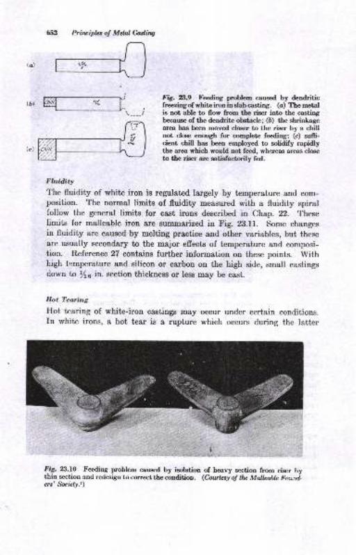
Pritrcipla of Mdal Ciading
Fig. 8.9 Fe€ding problem caused by dendriticfreezingof whiteironinslab casting. (c) The metalie not able to flow from the riser into the cqstingbecause of tbe dendrite obstacle; (6) the shrinkagearca has been moved clcer to the riser by a chillnot close. enough for complete feeding; (c) su{fi-cient chill has been employed to solidify rapidlythe area whjch would not feed, whereas areas closeto the riser are satisfactorily fed.
na
,"rffiFluidity
The fluidity of white iron is regulat€d largely by temperature and com-position. The normal limits of fluidity measured with a fluidrty spiralfollow the general limits for cast irons described in Chap. 22. Theselimits for malleable iron are summarized in Fig. 23.11. Some changesin fluidity are caused by melting practice and other variables, but theseare usually secondary to the major effects of temperature and composi-tion. R.eference 27 contains further information on these points. Withhigh t,:mperature and silicon or carbon on the high side, small castingsdown to 1/6 in. section thickness or less may be cast.
Hot Tearing
Hot tearing of white-iron castings may occur under certain conditions.In white irons, a hot tear is a rupture which occurs during the latter
:fjg. n.t.O Feeding problem caused by isolation of heavy section from riser bythin section anri redesign to correct the r:onditioa. (Cnuhsy rf tfu Mallcahk l'outd-ers' Subty.t)
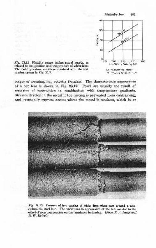
E
Mallfrb l,olt
cF- =.tdo +r /4 .losi + rtz c/.p
C.F. =Compositiff focior
"F = P@ring tcmp€roturc, oF
frg. 2$.ff fluidity range, inches spiral length, as
related to composition and temperature of white iron.The fluidity values are those obtained with the testcaeting shown it FtS- 22.7.
stages of freezing, i.e., eutectic freezing. The characteristic appearance
of a hot tear is shown in Fig. 23.12. Tears are usually the result ofrestraint of contraction in combination with temperature gradients.
Stresses develop in the metal if the casting is prevented from contracting,and eventually rupture occurs where the metal is weakest, which is at
Fig.23.12 De€rees of hot tearing of white iron wben cast round a non-collapsible steel bar. The variation8 in appearance of the tear are due to theelfect of iron composition on the resistane to tearing. (Frotn E. A. Ianqe andR. W. Heine.)
rylt -::' . .
e&n&r
W
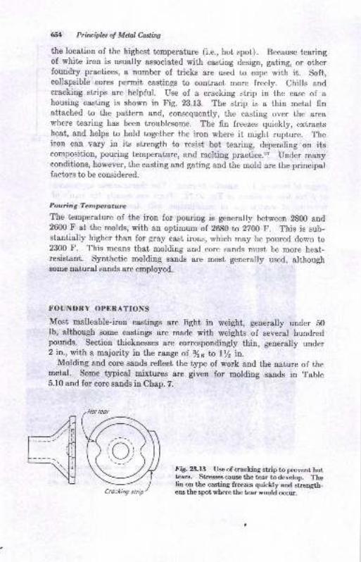
651 Principles a! Mcld Caslirq
the location of the highest temperature (i.e., hot spot). Because tearingof white iron is usually associated with casting design, gating, or otherfoundry practices, a number of tricks are used to cope with it. Soft,collapsible cores permit castings to contract more freely. Chills andcracking strips are helpful. Use of a cracking strip in the case of ahousing casting is shown in Fig. 23.13. The strip is a thin mctal finattached to the pattern and, consequently, the casting over the areawhere tearing has been troublesome. The fin freczcs quickly, extractsheat, and helps to hold together the iron where it might rupture. Theiron can vary in its strength to resist hot tearing, depending on itscomposition, pouring temperature, and melting practice.2? Under manyconditions, however, the casting and gating and the mold are the principalfactors to be considered.
Pouring Temperature
The temperature of the iron for pouring is generally between 2800 and2600 F at the molds, with an optimum of 2680 to 2700 F. This is sub-stantially higher than for gray cast irons, which may be poured down to2300 f'. This means that molding and core sands must be more heat-resistant. Synthetic molding sands are most generally used, althoughsome natural sands are employed.
FOUNDRY OPERATIONS
Most malleable-iron castings are light in weight, generally under b0lb, although some castings are made with weights of several hundredpounds. Section thicknesses are correspondingly thin, generally under2 in., with a majority in the range of. 3/16 ta l/2 in.
Molding and core sands reflect the type of work and the nature of themetal. Some typical mixtures are given for molding sands in Table5.10 and for core sands in Chap. 7.
FiS. B,l3 Use of cracking strip to prevent hottears. Streee€scause the tear todevelop. l'hefio on the casting freez:s quickly and sirength-eru the spot where the tear would occur.
(o
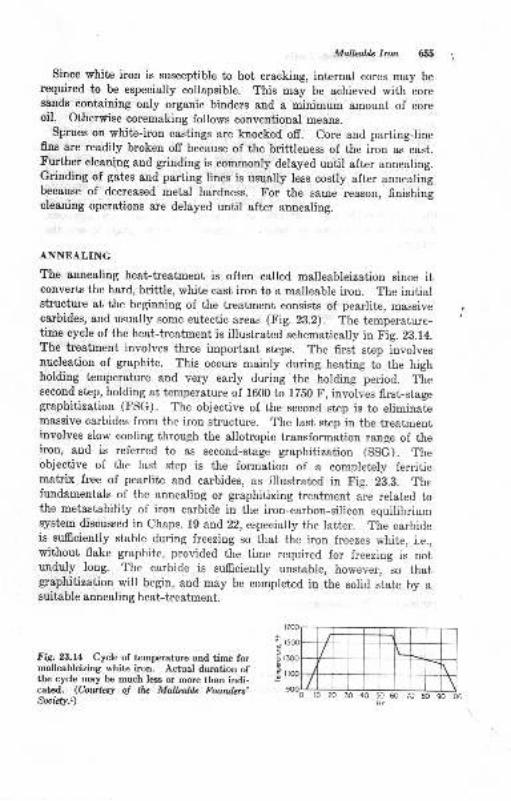
Mollabh Ircn 655
Since white iron is susceptible to hot cracking, iDternal eores may berequired to be especially collapsible. This may be achi'eved with coresands containing only organic binders and a minimum amount of coreoil. Other#ise coremaking follows conventional means.
Sprues on white-iron castings are knocked off. Core and parting-linefins are readily broken off because of the brittleness of the iron as cast.Further cleatr(ng and grinding is commonly delayed until after annealing.Grinding of gates and parting lines is usually less costly after annealingbecause of decreased metal hardness. For the sarne reason, finishingcleaning operations are delayed until after annealing.
ANNEALING
The annealing heat-treatment is often called malleableization since itconverts the hard, brittle, white cast iron to a malleable iron. The initialstructure at the beginning of the treatment consists of pearlite, massiveoarbides, and usually some eutectic areas (tr'ig. 23.2). The temperature-time cycle of the heat-treatment is illustrated schematically in Fig. 28.14.The treatment involves three important steps. The first step involvesnucleation of graphite. This occurs mainly during heating to the highholding temperature and very early during the holding period. Thesecond step, holding at temperature of 1600 to 17EO F, involves first-stagegraphitization (FSG). The objective of the second step is to eliminatemassive carbides from the iron structure. The last step in the treatmentinvolves slow cooling through the allotropic transformation range of theiron, and is referred to as second-stage graphitization (SSG). Theobjective of the Iast step is the formation of a completely ferriticmatrix free of pearlite and carbides, as illustrated in Fig. 23.3. Thefundamentals of the annealing or graphitizing treatment are related tothe metastability of iron carbide in the iron-carbon-silicon equilibriumsystem discussed in Chaps. 19 and 22, especially the latter. The carbideis sufrciently stable during freezing so that the iron freezes white, i.e.,without flake graphite, provided the time required for freezing is notunduly long. The carbide is sufficiently unstable, however,. so thatgraphitization will begin, and may be completed in the solid state by asuitable annealing heat-treatment.
t700
"- t500
Fig. 23.14 Cycle of temperature and time formalleableizing white iron. Actual duration ofthe cycle may be much less or more than indi-eatcd,. (Cowttsy o! llw Malleablc Foundcrs'Suiety.rl
EIe
010203040 7C 80 90 lo/j
6fi Privipla of Mdal C,ading
Nuclation
The success of the later phases of the heat-treatment is greatly dependenton the first step, nucleation of graphite. If srrfficient graphite nucleidevelop, the balance of the treatment will usually proceed satisfactorily.During heating, pearlite changes completely to austenite when the allo-tropic-transformation {,smperature range is exceeded. When the hightemperature of holding has been reached, the structure consists ofcarbon-saturated austenite, undissolved massive carbides, and graphitenuclei. The nuclei first appear within prior pearlite, at the interfaces ofthe iron carbide and austenite or at nonmetallic inclusion locations.Among factors known to influence nucleation of the graphite are thefollowing:
l. Heating rate.q' R^opid heating decreases the mrmber of nuclei developed.2. Section size."'' Thin casting sections develop more nuclei.3. Chemical oralysis.-" Iligh silicon percentage and the proper balance
of manganese and sulfur (2 x % S + 0.15 - % Mn) favor nucleation.4. Pretreatment." A preliminary heat-treatment of holding the iron at 600
to 1200 F for a period up to 20 hr increases nucleation upon subsequentmalleableization.
5. Prequenehing.' Eleating into the austenitic temperature range followedby quenching causes the most marked increase of all effects on nucleationwhen the iron is subsequently malleableized.
6. Slags high in FeO, over 25 per cent, drastically decrease nucleation duringmalleableization.'"
7. Ladle additions. Nucleation during malleableization is increased by theaddition of 0.001 to 0.003 per cent boron or a few hundredths per centaluminum or titanium to the molten iron.,
8. Graphite bearing materials in the melting-furnace charge promote nuclea-tion during heat-treatment..','"
9. Steel in the charge decreases nucleation.10. oxidizing melting conditions in cupola or erectric furnace decrease nuclea-
tion.t''11. Nucleation is decreased by excessive additions of Bi and Te..
other factors influence nucleation of graphite during malleableization,but these remain to be studied. In any event, graphite nuclei dewslspduring the FSG holding perio<i.
Nodule Cnunts
Because the number of graphite nodulesdeveloped during heat-treatmentis so important, methods of measuring this variable have treen employed.
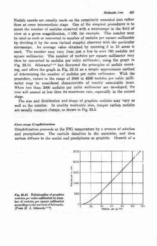
Mollfrh Imn 657
Nodule counts are ususlly made on the completely annealed iron rather
than at some intermediate stage. One of the simplest procedures is to
count the number of nodules observed with a microscope in the field of
view at a given magnification, X 100, for example. This number may
be used as such or converted to number of nodules per square millirneter
by dividing it by the area (actual sample) observed with the particular
microscope. An average value obtained by counting 5 to 10 areas is
used. The number may vary from just a few to over 150 nodules per
square millimeter. The number of nodules per square millimeter may
then be converted to nodules per cubic millimeter, using the graph in
Fig. 23.15. Schwartzl?''s has discussed the principles of nodule count-
ing, and offers the graph in Fig. 23.15 as a simple approximate method
of determining the number of nodules per cubic millimeter. With the
procedure, values in the range of 20fi) ta 42OO nodules per cubic milli-meter may be considered characteristic of readily annealable irons.
When less than 3fiD nodules per cubic millimeter are developed, the
iron will anneal at less than its maximum rate, especially in the second
stege.
The size and distribution and shape of graphite nodules may vary as
well as the number. In quality malleable iron, temper carbon nodules
are usually compact clumps, as shown in Fig. 23.3.
F b st-sta ge G raphitization
Graphitization proceeds at the FSG temperature by a process of solution
and precipitation. The carbide dissolves in the austenite, and then
carbon diffuses to the nuclei and precipitates as graphite. Growth of a
4000
E
a 3000
tg
€ aoooz
r000Fig.8.l5 Relationehip of graphite
nodulee per cubic millimeter to num-ber of nodules per square millimgtelaccordingto the metbod of Schwartz.(From H. A. $lwallz.t?'tt)
40 60 80Nodules per sq mm.
653 Printipla o! Mdnt Casting \
temper carbon Dodule during FSG occurs at the expense of the carbide,and the process is complete when the carbide has iisappeared from theaustenite. The time required for first-stage graphitizaiion is largely alunction of the number of nuclei, solution of the carbide,
"ria ifr"
difrusion rate of carbon at the temperature. The time required forFSG has been directly related to silicon content and temperature, asshown in Fig. 23.16. Additional composition factors may alter theFSG rate and its degree of completion. carbide-stabilizing erementssuch as chromiurr,
_excessive manganese, and molybden-um delayor pr.event complete FSG. over 0.03 per cent chromium is undesir-able;3 manganese should be in the proper barance with surfur, namery,% Mn:Z x % s * o.lb; excess manganese functions as a carbidestabilizer, whereas too Iittle permits sulfur to function as a stebilizer.l1,z4It is probably true that FSG is most directly influenced by nucreation ofgraphite, for if sufficient nodures develop, graphitization usuaily proceedswith ease, although there are some exceptions.
Second-sttge Gra; i nitization
I'he second sta -: of graphitization requires slow cooring through thetransformation i&nge of the iron, usually from about 1450 dowrr toabout 1300 F. 'The cooling rate must alrow time for austenite to changeto ferrite and precipitate carbon as graphite. Too rapid a rate willcause pearlite to be formed as in steels, whereas a quench will developmartensite. Cooling rates employed may vary from about B to B0F per hr; thdr higher rates are successful when sufficient temper carbonnodules are lrresent and with high silicon percentage in the lron. Theslow cooling lrrocess may be carried to temperatures as ]ow as 1200 F asa safety prettaution since pearlite deveroped during the cooling processwill graphiti{r below the transformation range. Many of the iactorsdrscussed 'rs
:rfluencing FSG will also influence ssG, but less is knownabout this stbrr. It is again true that sSG will proceed most readily if asufficient num )er of graphite nodules are present.
Annealing Opti.atiom
The practical'operations of annearing are carried out by batch or cen-tinuous procel res.
Batch anne.,ling is often done by packing the castings in metaf loxes,stacking tire b,.rxes in the furnace, anc then firing the irr.rm. accordingto the tempe*,ture-time annealing cycre. powd-erirti coar is ott* u..aae a fuel in o-' cns of this type. sinee Lire furnace and casting mass islarge, heating :::J s6elirt lre slow, aud the oycle is a lorrg u:ru. it"
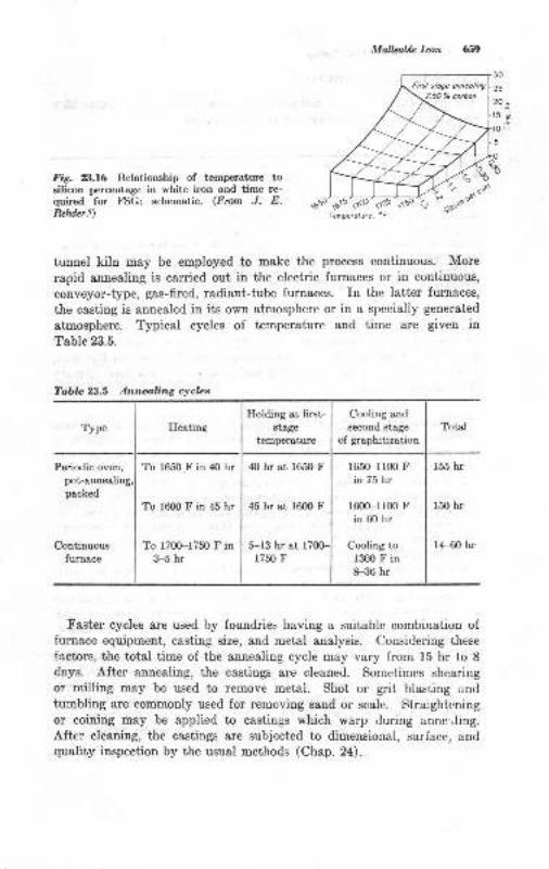
MalLahLe Iron 6.19
30
20-15 o-
E
10tr
5
Fig. 23.16 Relationship of temperature tosilicon percentage in white iron and time re-quired for FSG; schematic. (Fmm J. E.ReMer.e) lemperolure, oF
tunnel kiln may be employed to make the process continuous. More
rapid annealing is carried out in the electric furnaces or in continuous,
conveyor-type, gas-fired, radiant-tube furnaces. In the latter furnaces,
the casting is annealed in its own atmosphere or in a specially generated
atmosphere. Typical cycles of temperature and time are given inTable 23.5.
Table 23.5 Annealing cyclcs
Type Heating
Holding at first-stage
temperature
Cooling and
second stage
of graphitizationTotal
Periodic oven,
pot-annealirpaeked
Continuousfurnace
To 165OI in 40 hr
Tq 16m F in 45 hr
To 17fi)-1750 F in3-5 hr
ttO hr at 1650 F
45 hr at 1600 F
S-13 hr at l7fiF1750 F
1650-1100 Fin 75 hr
lo00-r100 Fin 60 hr
Cooling to13ffi F in8-36 hr
f55 hr
r50 hr
14-60 hr
Faster cycles are used by foundries having a suitable combination offurnace equipment, casting size, and metal analysis. Considering these
factors, the total time of the annealing cycle may vary from 15 hr to 8da.ys. After annealing, the castings are cleaned. Sometimes shearing
or milling may be used to remove metal. Shot or grit blasting and
tumbling are commonly used for removing sand or scale. Straighteningor coining may be applied to castings which warp during anne:Jing.After cleaning, the castings are subjected to dimensional, surface, andquality inspection by the usual methods (Chap. 24) .
ffi Prineiphs o! Metal Corrting
ENGINEERING PROPERTIES
The trensile properties of malleable iron were presented in Table 23.2.Other mechanical propertiesl are tabulated below:
Bhn... ... ll0-145(ll5_l3b*""1"""g;Endurance ratio... 0.4&{.SZ5Notchenduranceratio. ...... 0.85Modulus of elasticity in tension 25 X 106 psiShear strength . . .. . 0.g0 UTSCompressive strengthInrpact reistance- . . -.
Greater than UTS6.5-f6.5 ft-lb, depending on test condltions
Machinability rating.t The Malleable Founders, Society;
"o^pri"ffiBessemer screw stock with a rating of 100 per cent.
The strength of malleable iron combined with its ductility makes itsuitable for many applications. probably its greatest enginelring valuerests in the combination of its mechanical properties, ..*i." lifI, cost,a,,d suitability to many fabricating and processing operations. Amongthese advantages are:
l. Machinability. Malleable iron is among the most machinable of ferrousalloys. Especially desirabre is the fact that a high degree of uniformity ofmachinabiiity in large numbers of castings can be maintained because ei,erycasting has been heat-treated.
2. Ductility in processing. Many processing operations such as coining, crimp_ing, press fits, punching, and straightening can utilize or require ir.tiltv.
3' Ductilit'y or toughness in service. Many apprications are besi served wheuthe casting is capabre of deforming rather than fracturing when overstressed.Clamps, pipe-fitting threads, chain links, tractor bolster po.tu,
"oa ^royother cases may be cited.4. surface coatings.r'z corrosion resistance of malreable iron may be greatly
increa.sed by coatings ol zinc, ca.dmium, aluminum, and lead. fiotaipgalvanizing may be applied to clean malleable castings to provide good cor_rosion resistance to exposure in a wide variety of outdoor conditio-ns whichmay h'e encountercd by electrical conduct boxes and fittings, fence fixtures,playground-equipment castings, and numerous other applica=tions.
5. Wear resistance. Malleable iron with a ferritic structure tloes not haveinherent wear resistance other than that normal to soft^ferrous altoys.
-ttmay be hardened, however. If the metal is heated to the austeniti. t"-p".*ture range, carbon goes baek into solution and permits a hard martensiticstructure to be obtained by quenching. Caster wheels, cams, rollers, and
- 9!her itcms may be flame.or induction_hardened to give wear resistance,
6. Magnetic properties.2
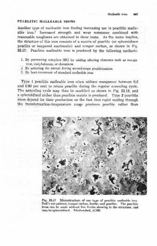
Mallailt Irun 6l
PEARLITIC MALLEABLE IRONS
Another type of malleable iron finding increasing use is pearlitic malle-able iron.2 Increased strength and wear resistance combined withreasonable toughness are obtained in these irons. As the name implies,the structure of this iron consists of a matrix of pearlite (or spheroidizeapearlite or tempered martensite) and temper carbont as shown in tr'ig.
23.17. Pearlitic malleable iron is produced by the following methods:
1. By preventing complete SSG by adding alloying elements such as morrSa-
nese, molybdenum, or chromium2. By arresting the anneal during second-stage graphitization
3. Ry heat-treatment of standard malleable iron
Type I pearlitic malleable iron often utilizes manganese between 0.5
and 0.90 per cent to retain pearlite during the regular alnealing cycle.The annealing cycle may then be modified as shown in Fig. 23.18, anda spheroidized rather than pearlitic matrix is produced. Type 2 pearliticirons depend for their production on the fact that rapid cooling throughthe transformation-temperature range produces pearlite rather than
t,:. I
a
I
Fig. 23.17 Microstructure of one type of pearlitic malleable irorr.Bull's-eye pattern, temp€r carbon, ferrite, and pearlite. The pearliticirons can be made without free ferritc showing in the structure, andmay be spheroidized. Nital-€tched, X lfi).
r-1 l" .i: .{
*,';"lYisk5 . r-1\i ..
t!'' i' ,' ax

Prinriplns o! Mdal Casting
Hr
frg. B.f8 Annealing cycle for spheroidizedmalleable iron. (Cowlesy o! the MallcabltFowtders' Society.r)
ferrite. Type 3 pearlitic irons are made by reheating a ferritic iron to atemperature just above the critical range, followed by air or liquidquenching. The quenched iron is then tempered to produce the desiredBhn and tensile properties. Since the amount of pearlite, combinedcarbon percentage, degree of spheroidization, or hardness of temperedmar0ensite may be greatly varied in pearlitic irons, the properties can becorespondingly varied by the manufacturer. The tensile requirementsof pearlitic malleable irons are listed in Table 23.2. The pearlitic ortempered-martensite matrix can be hardened by heating and quenchingto about 55 ta 62 RC for wear resistance. Surface hardening by flameor induction heating is another advantage of pearlitic irons.2 Theseproperties are reflected in the use of pearlitic irons for gears and gearblar,ks, crankshafts, camshafts, rocker arms, chain links, tractor treacls,and like applications.
OTIIER MALLEABLE IRONS
Malleable irons are sometimes alloyed with 0.2S to l.Z5% copper andup to 0.25% molybdenum for increased strength and corrosion resistance.These speeial irons are employed where additional strength and corrosionresistauce are desired in the fully annealed material. The MalleableIron castings handbookr furnishes iuformition on these irons and otherdetails of the malleable-iron-casting field.
BIBLIOGRAPHY
l. "American Malleable lron: A Handbook," The Malleable Founders, Society,t$M.
2. "Malleable Iron Castings: A Iandbook," The Malleable l'ounders, Society,Cleveland, 1903.
3. American Foundr5men's Society, Malleable Iron Melting Symposium reprir t43-37.
70 80 90

4.
5.
6.
7.
8.
9.
10.
Mallabln lmn 63
Q. Joly, Influence of Chromium on Graphitization of W'hite Cast Iron,Trara. AF9, vol.56, p.66, f948.J. E. Rehder, Silicon Pick-up in I\{alleable Iron Melting, Am. Foutdryaan,vol. 10, no.4, p.50, f946.A L. Boeghold, Some Unusual Aspects of Malleable Iron Melting, CampbellMemorial Lecture, Trans. ASM, vol. 26, 1988.Symps-ium on Graphitization of White Cast Iron, Trans. AFS, vol. b0, no. 1,p. l, July, 1942.
R. Schneidewinde and I-r. J. Reese, Influence of Rate of Heating on FirstStage Graphitization of White Cast lron, Trans. /F'S, vol. 57, p. 4gZ,lg49.J. E. Rehder, Efrect of Temperature and Silicon Content on- First' StageAnnealing of Black-heart I\falleable lron, Trans.,4FS, vol. b7, p. 173, 194-9.J. E. Rehder, Influence of Silicon Content on Critical Tempeiature Range
{911q Stow Cooling of Black-heart Malleable [ron, Trans..Af8, vol. SZ, }.549, 1949.
J. E. Rehder, Effect of Mn-S Ratio on the Rate of Anneal of Black-heartMalleable [ron, Trans..4FS, vol. i6, p. 188, 1948.R. Schneidewinde, A Summary of the Quantitative Effects of Some Factorson the-Annealing of White Cast Iron, Trans. AFS, vol. 5g, p. 202, 1g50.H. N. Bogart and G. Vennerholm, Effects of Slag Types ,r,d E"ri Treatmentof Malleable bory Trarx.,4FS, vol. 57, p. T)2, 1949.C H. Lorig and M. L. Samuels, Some Effects of Hydrogen on the Time ofMalleablization, Trarx. r{FS, vol. 50, p. 107, July, ig42.-H. A. Schwartz and W. K. Boek, Effect of the Common Alloying Elementson the Tensile Properties of Malleable lror,, Trans. /.FS, vol. 56, plasS, tg4g.R. Schneidewinde, D. L. Reese, and A. Tang, Graphitization oi'Wt it" Cr"tIron: Effect of Section Size and Annealing iemperature, Trans. AFS,.,rol.55,p.252,1947.H. A. schwartz, The Metallographic Determination of the size Distributionof Tenrper Carbon Nodules, Metak and Alloys, val.5, no. g, p. lB9, June,1934.
H. A- Sch-wartz, A Simple Approximate Method for Determining NoduleN"!!r"I, Metak and Allogs, vol.7, no. ll, p. 2Zg, November, 1956.R. W. Heine, Oxidation Reduction Principles Controlling the Compositiongf llglten Cast, Irons, Trarc. AFS, vol.59, p. 121, 1951.R. Schneidewinde and R. G. McElwee, Composition and properties of GrayIron, Trans..AFS, vol. 58, p. 312, 1980.R. W. Heine, Ilardenability of Pearlitic Malleable lron, Trarx. ,r[F'S, vol.66, p. 12, 1958.
R. W. Ifeine, Observations on Pinhole Delects in White Iron Castings,Trans. AFS, p. 31, 1958.
American Foundrymen's Society, Malleable Iron Microstructures: Efiect andCause, Trozs. z{F'S, vol. 66, p. 166, lv-S.F. B. Rote et al., Malleable Base Spheroidal Irons, ?roas. z{pS, vol. 6{., p.197, 1956.
R. W. Heine and C. R. Loper, Jr., Formation of Flake, Spheroidal, Lacy,Film, and Compact Graphite during Solidification of Casi Iron, froni. ifls',vol.69,1961.R. w. Ireine and c. R. Loper, Jr., Heavy white Iron sections Melt Addi-tions Effects on l\{ottling Te1lency, Trans. AFS, vol.6g, p. Bl2, lg6d-*!,. _w, Ileine, Melting variable Effects on Mafleabre Iron- properties, AFSbulletin, 1959.
11.
t2.
13.
74.
15.
16.
17.
18.
19.
20.
21.
22.
,2
24.
25.
26.
27.
24Cleaning and fnspection
The cleaning of castings generally refers to all the operations involvedin the removal of adhering sand, the gating system, and fins, wires,chaplets, or other metal not a part of the casting. Cleaning operationsmay also include a certain amount of metal finishing or machining toobtain the required casting dimensions, the salvage of castings havingminor defects, and the inspection of the finished castings.
CLEANING OPERATIONS AND EQUIPMENT
The series of operations performed in the cleaning department may beclassified as follows:
Removal of gates and risers,,rough cleaningSurface cleaning, exterior and interior of castingTrimming, the removal of fins, wires, and protuberances at gate and riserIocations
Finishing, final surface cleaning, giving the casting its outward appearanceInspection
sometimes heat-treatmenLs are involved which necessitate cleaningthe castings after the heat-treatment. This might be done betweensteps 3 and 4 above. often steps 1 to 5 are carried on simultaneously.Some of these, such as gate removal, may occur during shakeout opera-tions.
Remooal ol Gttce and Risers
The sprue, runners, and risers are firmly attacherl to the solidifiedcasting. rf the casting alloy is brittle, the gating system may be brokenofr by impact when the castings are dumped and librated in shakeoutand knockout devices.
&
l.2.
J.
4.
5.
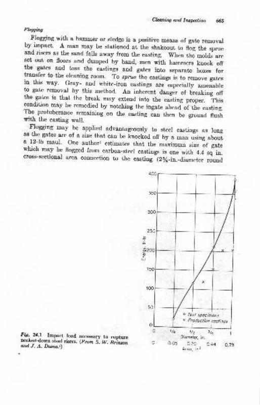
Cl&i.tg ard lrusption 65Flqsins
Flogging with a hammer or sredge is a positive means of gate removalby impact. A man may be stationed at the shakeout t" nig if,;-;;;r"and risers as the sand fails away from the casting. when the mords-areset out on floors and dumped by hand, men with hammers knock offthe gates and toss the castings and gates into separate boxes forlraryfer to the cleaning room. To sprue-the castings i. to ..*orr" gut..in this way. Gray- arld white-iron castings are especially amenableto gate removal by this method. An inherent danger of lreaking otrthe gates is that the break may extend into the ."Itiog p.opu".
-ft i.
condition may be remedied by notehing the ingate ahead oi the casting.The protuberance remaining on the cisting can then be ground flushwith the casting wall.
Flogging may be applied advantageously to steel castings as longas the gates are of a size that can be t no.tua off by a man u"sing abouta l2-lb maul. One author, estimates that the maximum size if gatewhich may be flogged from carbon-steel castings is one with l.+ sq- in.cross-sectional area connection to the casting (2/6-in.-diameter round
FE: %.! Impact load necessary to ruptureneckeddorvn steel risers. (From S. W. B;;*;;ard J. A. Dwn.t)
O t/q
o 0.05
o fesl specimensx Producltbn costings
1/2 r/cDiomefe( in.
0.20 0.44A,eo, in?
t
o.79
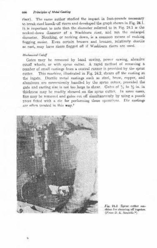
ffi Prilaipbsot MelMiw
riser). The same author studied the impact in foot-pounds neceesary
to break steel knock-ofr risers and developed the graph shown in Fig. 24'1'
It is important to note that the diameter referred to in Fig. 24.1 is the
necked-down diameter of a Washburn riser, and not the enlarged
diameter. Notching, or necking down, is a common means of making
flogging easier. Even certain brasses and bronzes, relatively ductile
as cast, may have risers flogged off if Washburn risers are used.
Meclwniral Culotl
Gates may be removed by band sawing, power sawing, abrasive
cutoff wheels, or with sprue cutter. A rapid method of removing a
number of small eastings from a central runner is provided by the sprue
cutter. This machine, illustrated in Fig. 24.2, shears off the casting at
the ingate. Ductile metal castings such as steel, brass, copper, and
aluminum are conveniently handled by the sprue cutter, provided the
gate and casting size is not too large to shear. Gates of t/s tn y2 in. in
thickness may be readily sheared on the sprue cutter. In some cases,
fins may be removed and gates cut off simultaneoltsly by using a punch
press fitted with a riie for performing these operations. Die castings
are often treated in this way.2
Fig. 2,L.2 Sprue cutter machine for shearing off ingates.(Fmm D. E. Sautellz-to)
ffi
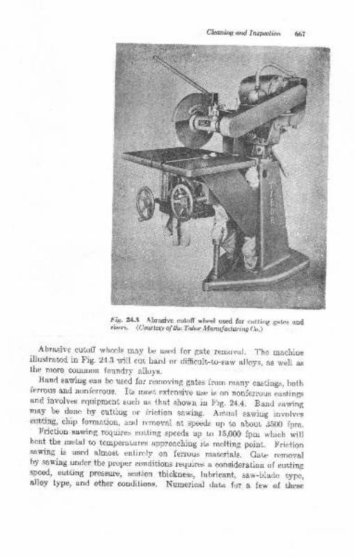
Claning ard Inswlion (67
Fig. %.8 Abragive cutoll wheel used for cutting gates andriserg. (Courlery of tle Tdor Manufactwing Co.)
- -
Abrasive cutoff wheels may be used for gate removal. The machineillustrated in Fig. 24.3 will cut hard or difficult-to-saw alroys, as well asthe more common foundry alloys.
Band sawing can be used for removing gates from many castings, bothferrous and nonferrous. Its most extensive use is on oooiu.rou. Iu.tioguand involves equipment such as that shown in tr'ig. 24.4. Band sawingmay be done by cutting or friction sawing. Actuar sawing involvescutting, chip formation, and removal at speeds up to about iSOO tp*.- Friction sawing requires cutting speeds up to rb,Ofi) fpm which wilrheat the metal to temperatures approaching its merting point. Frictionsawing is used almost entirely on ferrous materials. Gate removarby sawing under the proper conditions requires a consideration of cuttingspeed, cutting pressure, section thickness, Iubricant, sar._blade type,alloy type, and other conditions. Numerical data for a few of tlese
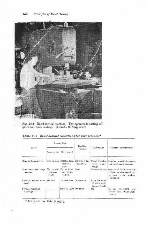
66tt Principlas ol Melal Casling
Fie. *L.r Band-sawing machine. The operator is cutting offgatesoo r brasscasting. (FromG. H. Shippartl.t)
Tablc 24.1 Band.-sauing conditions for gate remomF
Speed, fpm
Lubricant
Low speed lJigh epeed
Cenersl information
Copper-bme alloy,,.
^{luminum and mag-nesium
Ferrous (band saw
ing)
Ferroue (friction
BawinS)
4OO or less
Up to 500buttreblede
40-500
2OOO orbuttresB
typeUp to 3500
ot )6-ir.section
1500 or les
25lbtolinthicknem
Low
Modereto
2(F40 lb
Ueed if chipsweld to Baw
bladeOrdinsrily dry
I\Iay be used
if chips weid
to esw bladeNo]3ooo-1s,
Sawing speed decresesu hardues incressos
4-pitch, 0.5Gin. butl.ressblade; sa*'ing rpe.:d de-
cre&seE with 6ectio!thicknem
ll- to l-in.-*idth saw'blsde with lO-18 tccthper in.
'Adapted from Refs. 3 and 4.
I
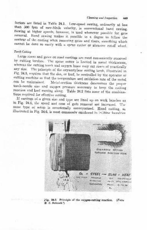
Claning ard Insptbn 69factors are listed in Table 24.1. Low-speed sawing, ordinarily at lessthan 500 fpm of saw-blade velocity, ls conventional band sawing.Sawing- at higher speeds, however, is used whenever possible i". g"t.removal' Band sawing makes it possibre to a degree to follow thecontour of the casting when removing gates and riser-s, somethrng *rri"tcannot be done so easily with a sprue cutter or abrasive cut,d wheer.
Torch Cutling
. Large risers and gates on steel castings are most convenientry removedby cutting torches. The sprue cutter is limited in metal thicknesses,wherea's the cutting torch and oxygen lance may cut risers of practicaly1ly 1i1": The principle of the oxyacetylene cutting torch, illustrated inFig.24.5, requires that the slot, or kerf, be controlled by tire operator orcutting machine so that the temperature and oxidation rate of the metalcan be maintained- Metar-section thickness determines the prqrertorch-nozzle size and oxygen pressure necessary to keep the cuttingreaction and kerf moving along. Tabre 24.2 rists some of the combina-tions required for effective cutting.
. If.castings of. a given size and type are lined up on work benches asin Fig' 24.6, the speed and "r."
oi gate removai are increased. Tiresame type of setup is occasionally conveyorized. Iland cutting, asillustrated in Fig. 24.6. is most commonlv emoloved in ia,rhinr forrndries
tr-tt€rGARO€o gE rftN
THPOUEH RCAC1,AN ZANE
FiS. Zl.5 Principle of the oxygen<utilng reaction. (Frcmi9. S. Ba6ooc[.i)
Oe+ S7€€l* gCAc" tt€At,l{*€Ar€p fro e??- tru D.ct,
aokqtftuil fi, Oi OFrt &rraprtr7€fiPEPATURE f.ror til t€, ar
f.
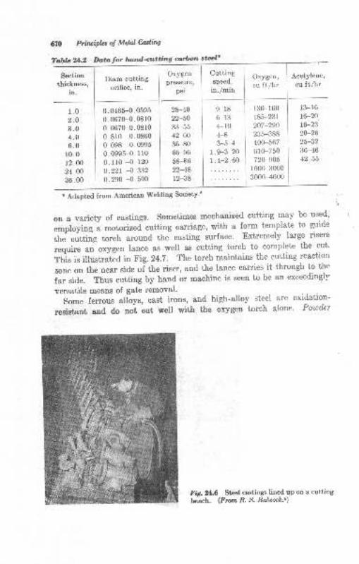
Oxygen,
cu ftlhr
130-160
r85-231207-250235-388400-567
610-750720-905
r600-3000
3000-4600
I oxvsen I cuttingDl"i-|',|"s I pr"o-r.", I speed,
orifice, in. I *"f,j--'
I r"il-li,
0.0465-{.0595 | zs-ao
0.067H.0810 | 22-50
0.0670-0.0810 | ea-ss
0.8r0 -0.0860 I 42-60
0.098 -{.0995 | ao-ao
0.099H.1r0 I 66-96
0.110 -0. r20 | sa-40
0.22r -0.332 | 22-48
0.290 -0 500 | tz-ss
Section
thicknees,itr.
en Ptlirciplrs of Mdal Car/,irW
Tab!e24.2 Dottfor lwnd<utting cwlrbon st*l'
1.02.O
3.04.06.0
10.012.0024.N36.00
13-1616-2016-232W2625-3236-46
42-55
Ftl. 21.6 Steel castings lined up on a cuttiugbeoch. (Frum fi. S. Bobcocfr.5)
Acetylene,cu ftlhr
t Adapted from American Welding Society'G ;
on a variety of castings. Sometimes mechatrized cutting may be used'
umptoyiog a motorizeJ cutting carriage, with a form template to guide
ttre cutting torch around the casting surface. Extremely large risers
requirean-orygenlaneeaswellascuttingtorchtocompletethecut.This is illustrated in Fig. 24.2. The torch maintaius the cutting reaction
zone on the near side of-the riser, and the lance c&rries it through to the
farside.Thuscuttingbyhandormachineisseentobeanexceeding.lyversatile means of gate removal.
Someferrous.alloys,castirons,andhigh-alloysteelareoxidatiort-resistsnt snd do uot cut well with the oxygen torch alone' Powder
e-r8 I
6-13 I
4-r0 I
4-8 I
3-5.4 I
le-320Ir .4-2 .60
I
I
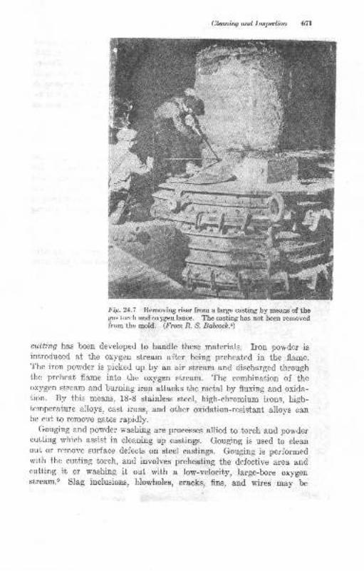
Claniq ard Irepalbn
Fig. 24.7 Removing riser from a large casting by means of thegas torch and oxygen lance. The casting has not been removedfrom the mold. (tr'rcrn R. S. Bolcoci.9
cutting has been developed to handle these materials. Iron powder isintroduced at the oxygen stream after being preheated in the flame.The iron powder is picked up by an air stream and discharged throughthe preheat flame into the oxygen stream. The combination of theoxygen stream and burning iron attacks the metal by fluxing and oxida-tion. By this means, 18-8 stainless steel, high-chromium irons, high-temperature alloys, cast irons, and other oxidation-resistant alloys canbe cut to remove gates rapidly.
Gouging and powder washing are processes allied to torch aud powdercutting which assist in cleaning up castings. Gouging is used to cleanout or remove surface defects on steel castings. Gouging is performedwith the cutting torch, and involves preheating the defective area andcutting it or washiug it out with a low-velocity, large-bore oxygenstre&m.s Slag inclusions, blowholes, cr8cks, fins, and wires may be
*il{i).,
:,fl
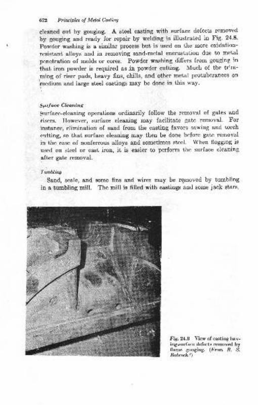
Clz Priluiplns o! Mdol Castin4
cleaned out by gouging. A steel castiug with surface defects removed
by gouging and ready for repair by welding is illustrated in Fig' 24'8'
Powder washing is a similar process but is used on the more oxidation-
resistant alloys and in removing sand-metal encrustation due to metal
penetration of molds or cores. Powder washing differs from gouging in
that iron powder is required as.in powder cutting. Much of the tr:.m-
ming of riser pads, heavy fins, chills, and other metal protuberances on
rrnedium and large steel castings may be done in this way.
S(rface Clcaning
gurface-cleaning operations ordinarily follow the removal of gates and
iisers. However, swface cleaning may facilitate gate removal. For
instance, elimination of sand from the casting favors sawing and torch
eutting, so that surface cleaning may then be done before gate removal
in the case of nonferrous alloys and sometimes steel. When flogging is
used on steel or cast iron, it is easier to perform the surface cleaning
after gate removal.
Tunhling
Sand, s,rale, and some fins and wires may be re-moved by tumbling
in a tumbling mill. The mill is frlled with castings and some jack stars.
FA.24.8 View of casting hav-ingsurface defects removed byflame gouging. (From R. S.Bohcoch.6)
" ."t"
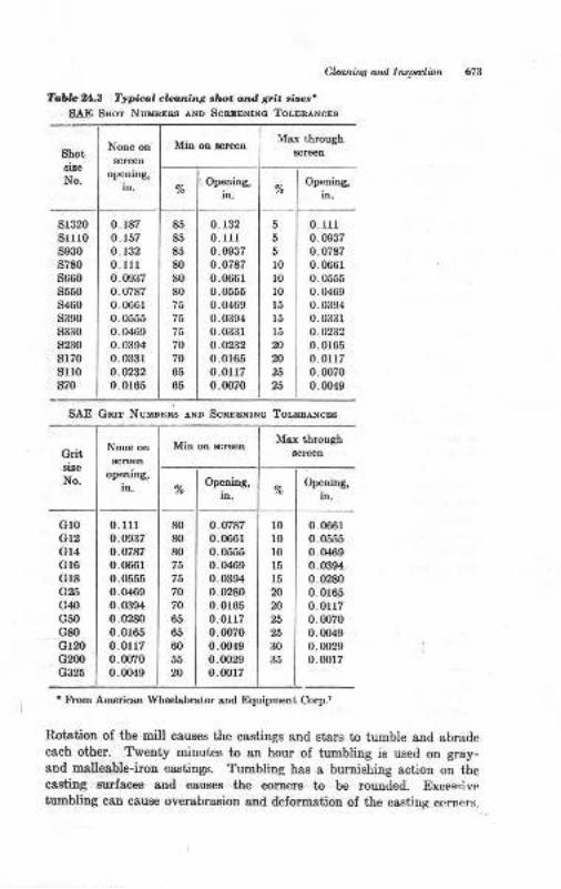
Cb^ins ard Inrln tion
Tabb .X Typial clani..g ,ho. a,td Eri. sire$'SAE SIIoa NuxBEss .r,ND ScssENrNo ToLEBANcEs
thot
No.
NoDe on
opening,in.
Msx thmugh
Opedng,in.
%Op€ring,
in.
s1320srI0s930s780
s660s550s460s390s330s230
s170s1l0s70
0. r87
0. r57
0.1320.lll0.0937
0.078?0.066ro.05550.04690.0394
0. 033ro.az320.0165
85
85
85
80
80
8075
75
75
70
70
65
65
0.1320-lll0.09370.0787
0.066r0.05550.04690.03s4o.0331o.02320.0r650.0117o.0070
5
5
5
l0l010
l5l5t520
20
23
25
0. rr10.09370.07870.0661
0.05550.04690.03940.03310.0232
0.01650.01l70.00700.0049
SAE G T NumDna ^ND
Scs.EENrNc ToLEE NcEs
Grit
No.
Noa€ on
op€ning,ir.
Msx throush
Opening,in. %
Op€niDs,
in.
Gr0Gl2Gl4G16
Gr8G25
G40
G50G80
G120Gm0G325
o.lll0.0037o.wa70. (m6t
0.05550.04690.0394
0.02800.0r650.0r170.00700.0049
80
80
80
75
?o
70
65
65
60
55
20
0.0787o.06610.05550.04690.03940.0280
0.01650.01r70.0070
0.00490.00290,0017
l0l0t015
15
20
20
25
30
35
0.06610.05550.0469
0.03940.02800.0165
0.0r170.00700.fixg0.00290.0017
' flom AmericsD Wheelrbrstor snd Equipmetrt Corp.,
Roi;ation of the mill cauees the castings and Btars to tumble aud abradeeach other. Twenty minutes to an hour of tumbling is used ou gray-aod malleable-iron castinge. Tumbling has a burnishing action on theo&sting Butfaces and cau6€s the corners to be rounded. Excerrivetumbling can cauee overabr&sion and delormatiou oI ihe castirtg ccrners.
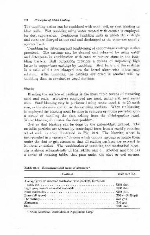
671 Prfilcipb of Mdal Mirw
The tumbling action can be combined with sand, grit, or shot blasting in
blast miils. Wet tumbling using water treated with caustic is employed
for dust suppression. Continuous tumbling mills in which the castings
and stars are charged at one end and discharged at the other are usually
operated wet.
Tumbling for deburring and brightening of copper-base castings is also
practiced. The castings may be cleaned and deburred by using water
and detergents in combination with sand or pumice stone in the tum-
bling barrels. Ball burnishing provides a means of imparting high
luster to copper-base castings by tumbling. Steel balls and the castings
in a ratio of 2:1 are charged into the barrel along with dilute soap
solution. After tumbling, the castings are dried in another mill by
tumbling them in sawdust or wood shavings.
Blasting
Blasting the surface of castings is the most rapid means of removing
sand and scale. Abrasives employed are sand, metal grit, and metal
shot. Sand. blasting may be performed using coarse sand, 6- to 30-mesh
size, as the abrasive and air as the carrying medium. When air blasting
is employed the blasting must be done in cabinets or rooms provided witha means of handling the dust arising from the disintegrating sand.
Water blasting eliminates the dust problem.
Grit or shot blasting can be done by the airless-blast method. The
metallic particles are thrown by centrifugal force from a rapidly rotating
wheel such as that illustrated in Fig. 24.9. The blasting wheel is
incorporated in a variety of devices which tumble castings or+otate them
under the shot or grit stream so that all casting surfaces are exposed to
its abrasive action. The combination of tumbling and mechanical blast-
ing is shown schematically in Fig. 24.l0a and b. Another machine has
a series of rotating tables that pass under the shot or grit stream.
Tablc 24.4 Reconnendcd sizes o! abrasioet
Castings SAE size No.
Average gray or anueoled malleable, with pockets, burned-in
sand, etc.Light gray iron or annealed mslleable
Hud malleable
Brass (all type). .
Diecastingl .:.....AluminumStcel . .
S390 shot
5330 shot5330 shot
G50 or Gl20 gritG50 gritG50 grit3390 shot
t From American Wheelabrator Equipment Corp.7
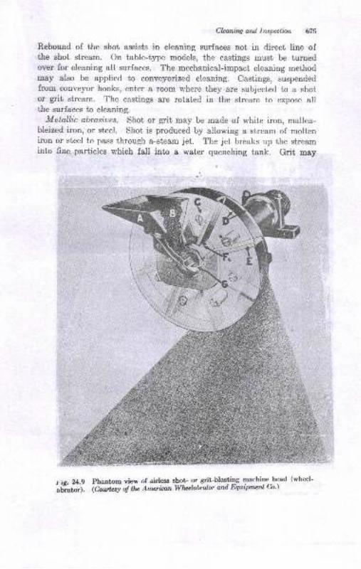
Clanilq ard lrxption {18
Rebound of the shot assists in cleaning surfaees not in direct line ofthe shot stream. On table-type models, the castings must be turnedover for cleaning all surfaces. The mechanical-impact cleaning methodmay also be applied to conveyorized cleaning. Castings, suspendedfrom conveyor hooks, enter a room where they are subjected to a shotor grit stream. The castings are rotated in the stream to expose allthe surfaces to cleaning.
Metallic abrdues. Shot or grit may be made of white iron, mallea-bleized iron, or steel. Shot is produced by allowing a stream of molteniron or steel to pass through a-steam jet. I'he jet brdaks up the streaminto fine- par[icles which fall into a water quenchiug tank. Grit may
r.h. b.9 Phantont view of airlees shot- or eEit-blasting machine head (wheel-
;;;;). alr,rrk t o! ttu Am*iltnWhal&ralor and Equipmenl &')
[3}'at!);t ta-/ wi
'I
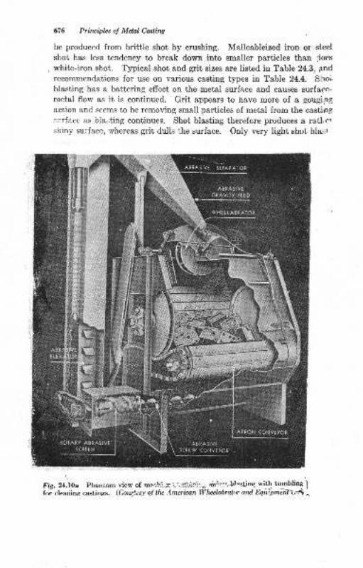
676 Prinriplzs ol Metd Casting
be produced from brittle shot by crushing. Malleableized iron or steel
shot has less tendency to break down into smaller particles than Joes
white-iron shot. Typical shot and grit sizes are listed in Table 24.3, pnd
recommendations for use on various castiug types in Table 24.4. Shou
blasting has a battering effect on the metal surface and causes surfape-
metal flow as it is continued. Grit appears to have more of a gouging
action and seems to be removing small particles of metal from the casting
li:rface as bla.,ting continues. Shot blasting therefore produces a rathe!shiny su;face, whereas grit dulls the surface. Only very light shot blasl
Fig. ?,.itpa Phantom ,isr, 6f mea!.:.,;.-t.,,l'ui;:l::. air!:=$astine yrth tumbline jfor eleanins castings. (Cour),esy of lfu Anerican lVlvelabralor ard fuu[plnsifLn i
^
SEPAIATOR
AiFAStVtcnAvr?y ttED
vHttLASftAro[
APRON {CNYIYOR
ASftASIVESCP€w CONVEYOR
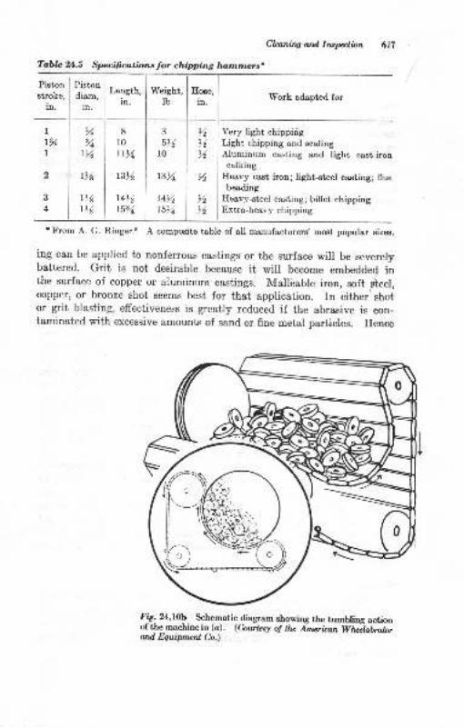
Tabla 24.5 Specifications Jor chipping lwnrmcrs.
Clcaning ard I nspoclion 6i7
Work adapted for
Very light chippiigLight chipping and scalingAluminum casting and light cast-ironcalking
Heavy cast iron; light-eteel casting; fluebeading
Heavy-steel casting; billet chippingExtra-heavy chipping
Pistonstroke,
in.
Piston
diam,in.
r16
Length,in.
Weight,Ib
It%1
2
3
4
il%I
tYt I
8
l0Lt>4
t3%
t4>61594
o
5t610
13r4,
t4r415r4,
,%,6
%
t4t6
r From A. G. Ringer.E A composite table of all manufacturers' most popular sizes.
ing can be applied to nonferrous castings or the surface will be severelybattered. Grit is not desirable because it will become embedded inthe surface of copper or aluminum castings. Malleable iron, soft pteel,copper, or bronze shot seems best for that application. In either shotor grit blasting, effectiveness is greatly reduced if the abrasive is con-taminated with excessive amounts of sand or fine metal particles. Hence
f rig. 24.f0b- Schematic diagram showing the tumbling actionof the machine in (a). (C,owlesy of he inurican Whilabrotorard fuuipmenl C;o.)
e8 bivida ol Mdal Odrlbq
tle cleaning units sre equipped with a mesns of removing the fines s8
well as recycling the shot.
Ah Typcs o.f Sutr." Cbaniw
A numbei of methods of casting-surface cleaning other thsn those
mentioled above are in use. Wire brushing, buffing, pickling, and
various polishing procedures may be applied. Simple wire brushing
can be au adequate means of takiug off surface sand of nooferrous
castings. Most ol the other means of cleaning mentioned ore used to
impart a specially desirable surface frnish for final cleaning of the
casting.
Trirnt .itus
Eiiher after, before, or during the initial surface cleaning, the castings
are trimmed to lemove fim, gate aud riser pads protruding beyond the
casting surface, chaplets, wires, partingJine flash, or other appeldagee
to the casting which are not a part of its 6ual dimensions.
Chipping
Pneumatic chipping hammers may be used io remove fins, gate and
riser pads, wires, etc., and to remove cores. A vadety oJ hammer and
chisel sizes are used for various casting alloys. A No. 2 hammer, with2-in. piston stroke, will handle most iron and steel foundry work.
Specifications for chipping ou difrerent types of castiDg are given in
'l'able ,5, Chisel types aod the relationship of air operating pressure
to air-hose setup are illusirsted in Fig. 24.11. An air-hose arrauge-
ment that causes more than about 10 per cent pressure drop Irom the
source to the pDeumatic tool seriously lowers the efrciency of ihe tool.
Air-hose combinations of length and diameter which are favorable and
uufavorable at various flow rates are listed in Table 24.7. Pneumatic
grinders or other tools are subject to the same conditions. Chipping
operations may be speeded up by having chipping staiions &t conveyorc
used to transport caetings in the cleaning room. Much chipping may be
done most convenienily by hand with a hammer. Light-gray- aud
white-iron castings are especially adaptable to hand chipping. Pueu-
matic chipping ie theu doue on the areas that are heavier and more
difficult to trim.
Ginding
Griading, or "snagging," ol castirgs is practiced to remoye excess
meial. Three principal types of griuders are employed for this purpose:
floor or bench-stand grinders, portsble gritrders, and swing-frame grind-
ers. In addiiion, specialized machines euch as disk grinders, belts, and
cutofrs may be used.
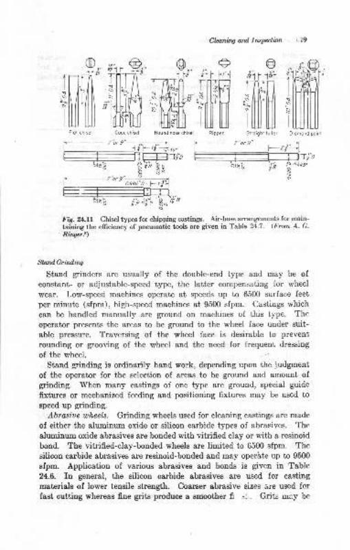
Cbniru ord lrcplinn ,i9
9*r' i'.. 9r"
ff.'ilm
e@
fffil ffiRipper Slroighl fuller
'f ...........-...........' _ 7'or 9
-jn-l
| *26 1.
ffiria
-
E,=----; .;4,,.s
Fig. Ul.ll Chisel types for chipping castings. Air-hose arrangements for main-
taining the elficiency of pueumatic tools are given in Table 24.7. (From A- G-
Ringer.t)
StandGrhdiw
Stand grinders &re usually of the double-end type and may be of
constant- or adjustable-speed type, the Iatter compensating for wheel
wear. Low-speed machines operate at speeds up to 6500 surface feet
per minute (sfpm), high-speed machines at 9500 sfpm. Castings which
can be handled manually are ground on machines of this type. The
operator presents the areas to be ground to the wheel face under suit-able pressure. Traversing of the wheel face is desirable to prevent
rounding or grooving of the wheel and the need for frequent dressing
of the wheel.
Stand grinding is ordinarily hand work, dependiug upon the judgment
of the operator for the selection of areas to be ground and amount ofgrinding. When many castings of one type are ground, special guide
fixtures or mechanized feeding and positioning fixtures may be used to
speed up grinding.
Abrasiue wheels. Grinding wheels used for cleaning castings are made
of either the aluminum oxide or silicon carbide types of abrasives. The
aluminum oxide abrasives are bonded with vitrified clay or with a resinoid
bcnd. The vitrified-clay-bonded wheels are limited to 6500 sfpm. The
silicon carbide abrasives are resinoid-bonded and may operhte up to 9500
sfpm. Application of various abrasives and bonds is given in Table
24.6. In general, the silicon carbide abrasives are used for casting
materials of lower tensile strength. Coarser abrasive sizes are used for
fast cutting whereas fine grits produce a smoother fir --1 . Grits urey be
sld
iMDiomond poinr
t-7"orgt:I o68o"D
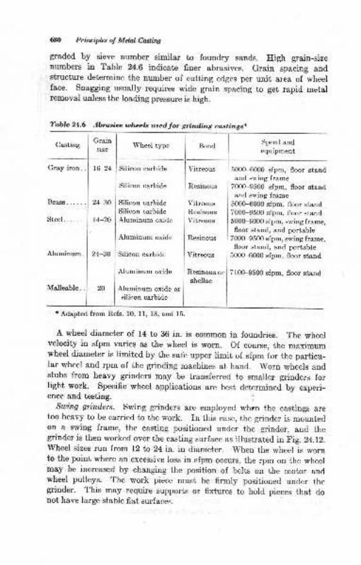
680 Principlzs of Melal Casting
graded by sieve number similar to foundry sands. High grain-sizenumbers in Table 24.6 indicate finer abrasives. Grain spacing andstructure determine the number of cutting edges per unit area of wheerface. Snagging usually requires wide grain spacing to get rapid metalremoval unless the loading pressure is high.
Casting
Brass
Steel.
Aluminum
Grainsize
l()-24
24-30
t+-20
24-30
20
Silicon carbide
Silicon carbide
Silicon carbideSilicon carbideAluminum oxide
Aluminum oxide
Silicon carbide
Aluminum oxide
Aluminum oxide orsilicon carbide
Vitreous
Resinous
Vitreous
Resinous
Vitreous
Resinous
Vitreous
Resinous orshellac
Wheel type Bond Speed andequipment
500H000 sfpm, floor standand srving frame
7000-9500 sfpm, floor standand swing frame
5000-6000 sfpm, floor stand7000-9500 sfpm, floor stand5000-6000 sfpm, swing frame,floor stand, and portable
7000-9500 efpm, swing frame,floor stand, and portable
5000-6000 sfpm, floor stand
7l00-9500 sfpm, floor stand
* Adapted from Refs. 10, ll, 13, and 15.
A wheel diameter of 14 to 86 in. is common in foundries. The wheelvelocity in sfpm varies as the wheel is worn. of course, the maximumwheel diameter is limited by the safe upper limit of sfpm for the particu-lar wheel and rpm of the grinding machines at hand. Worn wheels andstubs from heavy grinders may be transferred to smaller grinders forlight work. Specific wheel applications are best determined by experi-ence and testing.
Swing grinders. Swing grinders are employed when the castings aretoo heavy to be carried to the work. In this case, the grinder is mountedon a swing frame, the casting positioned under the grinder, and thegrinder is then worked over the casting surface as illustrated inFig.24.12.wheel sizes run from 12 ta 24 in. in diameter. when the wheel is wornto the point where an excessive loss in sfpm occurs, the rpm on the wheelmay be increased by changing the position of belts on the motor andwheel pulleys. The work piece must be firmly positioned under thegrinder. This may require supports or fixtures to hold pieces that donot have large stabie fiat surfaces.
Tablc 24.6 Abrasioe ulleels used for grinding castings.
Malleable.
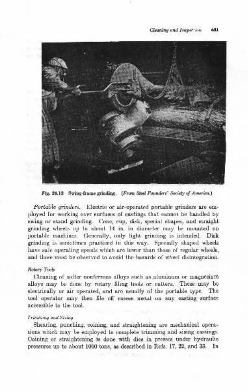
Cbning and lrupec'ron
Ftg.ill.lz Swing-frame grinding. (fmm Stal Fourden' fuizly of Amerita.)
Portable grinders. Electric or air-operated portable grinders are em-
ployed for working over surfaces of castings that cannot be handled byswing or stand grinding. Cone, cup, disk, special shapes, and straightgrinding wheels up to about 14 in. in diameter may be mounted on
portable machines. Generally, only light grinding is intended. Diskgrinding is sometimes practiced in this way. Specially shaped wheels
have safe operating speeds which are lower than those of regular wheels,
and these must be observed to avoid the hazards of wheel disintegration.
Rotary Tools
Cleaning of softer nonferrous alloys such as aluminum or magnesium
alloys may be done by rotary filing tools or cutters. These may be
electrically or air operated, and are usually of the portable type. Thetool operator may then file off excess metal on any casting surface
accessible to the tool.
Trimming and Sizing
.Shearing, punching, coining, and straightening are mechanical opera-
iions which may be employed to complete trimming and sizing castings.
Coining or straightening is done with dies in presses under hydraulicpressures up to about 1(X)0 tons, as described in Refs. 17,22, and 33. In
682 Pinriph; ol Mctal Cartina
mild-steel and malleable-iron castings, holes may be puDched out toeliminste drilling operstions. Some castings may have surfaceE which
are milled, broached, or ground to a specified accuracy a8 required by
the customer.
Finithing
The lstt€r stages of cleaning are often referred to as finishing. Manycasiings have received their final cleaning operatione when grinding is
completed. Others are given additional surface finishing such as
machining, chemical treatment, polishing, buffDg, blssting, and painting
to put them into a suiiable appearance for 8ale. Ilealtreatmeuts may
come at various stages of cleaning. Since scaling, oxidation, or dis-color&tion occurs during hest-treatmeni, steel and malleable-iron cast-iugs receive their fiual surface cleaning afier heat-treatneDt. Iu non-lerrous castings, chemical, electrolytic, and mechauical meaDs of makingthe caeting surface attractive may be utilired.
A special salt-bath cleaniug operation may be used on ferrous castingsto obtaiq maxinum freedom from scale, 8and, dirt, and gdt. Forexample, gray-iron castings may be immersed iuto g molt€n salt bath ofcluslic,91% sodium hydroxide, 5/o sodium nitraies and nitdtes, at 800
tr'Ior cleaning. The castirgs are then rin6ed, dipped in acidifled water,l5/, hydrochloric acid, hot-water-rinsed, snd treated with a soluble oil.The oil coating provides rurt prot€ciion. Treatments of this type are
utilized only wben the additional cost is iustified in a pariicular appli-cation or processing sequeuce.l€
INSPECTION
Inspection comprises thoae operationE which check the quality of thecasting8 and reeult in their acceptsnce or rejectiou. Inspection pro-ceduree Esy be ctaesed as follows:
1. Visual, su sce inspeciion for foundry defecle
2. Dimensional, requiring gauges for measureoenk3. Metslurgicsl, lequiring chemical, physical, aod other t€sts for Detal quality
Complete irapection usually embraces all theae tlpet of procedur€s.
Virlnl hlpctionQertain typea ol cs8ting defects a!€ immediately obvioue upon visualexfnination of the casting. Ctacked caatings, te8!8, dirt, blowholeir,8cab8, metal penetration, severe Bhifts, runouts, poured ehort, swells or
Cla.ni,^g Nd INPlbn 683
strsins, crscked mold or coree, and numerous ot'her defects cau be identi-
n"J fv tlru i".p".tor. Cssting defects of this type are usually asEociated
*iit i"i""ti"--otde, cores, their materials of construction, flask equip-
-"ot, thu operatione of molding and coremaking, end the rest of- the
lact6rs iu making and pouriug the mold. Many of ihe causes ol these
defelts have been discussed in previous chapters' EvidentlY, 1f exSts
amorrnts of these defects occur, faulty practicee are being employed in
ii"- io""a"y. Their correction is a necessity and can be facilitat€d. ilthe cause of the defect can be located. Inspectors identify the caeting
def ects and assign their cause to soBe loundry operation or mat'erial so
ih at corrective meaeures can be taken.
Yisual inspection ie the simplest method of inspectioq aud carried to
'its ultimaie ii will ensure a cssting that "looks" good This degree of
inspection is satisfactory for some castilgs such os sash weight-, manhole
covers, drains, and couDt€rb&lance weights. Ilowever, countless trun-
bers oi castings lor manufacturing require more exacting inspection for
dimensional accur&cy aDd metallurgical standards.
Irirtn{.Insi,.r,l I BIre c tia,.
Dimensional inspeciion of castings involves the principles of gauging as
it is applied to any machine elements. Surface plates, height end depth
gauges,'luyout tailee, dividiug heads, go and no-go gauges, snap and
ituf gu"g"t, templates, dies, contour gauges, etc., as used in staadard
i"yo"t ,"a inspection procedures may be applied io castings'- Agree-
mint between the machine shop and foundry, or purchaser and vetrdor,
is necessary so that geuging and dimensional checking may be carried
oui in a mutually acceptable way Locating points used as starting
points for machining and dimensional inspection should be seleci'ed by
co-*on corr""rrt. Castings must be sectioned io check metal-wall thick-
ness. The area of dimensional inspection and accuracy involves the
entire field of castings utilization by the machine shop. There i8 no
inteut iD thi6 textbook to discuss this mechanical-engineering field Itneeds to be poioted out, however, that the closest cooperation between
the foundry, pattern shop, and machine shop utilizing the castiug will
result in the most efrcient use ol good gauging and machiniug prac-
tice.3',35
M e ta,lu. g ic @, I ns p e c tiotu
Metallurgical inspection includes chemical analysis, mechanical-prop-
erty tests, evaluation of casting eoundness, and product t€sting of special
properties such as electrical conductivity, resistivity, magneiic effects,
corrosion resistauce, response to heat-treatment, strength in aseemblies,
surface condiiions, coatings and surl&ce treatments, and others
M Priluiplos ol Mdal &sling
Chcmizal Arnlysis
The methods of chemical analysis for many casting alloys, ferrous andnonferrous, have been developed and adopted es standa,rd through thework of the ASTII. The ASTM ,,Methods of Chemical Analysis ofMetals" sets forth the standard and tentative stendard proceduresadopted for ferrous and nonferrous metals by American industry. Manyshort-cut methods of analysis have been developed for specific castingalloys. since this textbook does not deal with chemical analyticalmethods, there will be no further discussion of this subject.
Casfing Soundness
Shrinkage cavities, blowholes, gas holes, porosity, hot tears, cracks,entrained slag, lapped or cold-shut surfaces, etc., are all considered ascontributing to lack of casting soundness when they are present. Thesedefects are of greater or lesser importance, depending on the castingapplication. Many castings with internal shrinkage, porosity, or otherdefects that do not interfere with the functioninj of tt. .".tiogs erequite acceptable to the user. where the requirements are high andfactors of safety low, however, the very highest degree of metali-urgicalquality is required. In castings for aircraft, ordnance, and other highlyprecision-engineered applications, absolute soundness and optimum prop-erties are needed. These objectives will be met onry when the castinginspection includes methods which check the casting for soundnessdefects not visibly detectable. Diverse methods of discovering sound-ness defects have been devised, and are exhaustively treated by yariousauthors.24_2?,32_31,s6,37
Pressure testing. Pressure testing is used to locate leaks in a castingor to check the over-all strength of a casting in resistance to burstingunder hydraulic pressure. Equipment for sealing off castings and find-ing the leaks is discussed in Ref. 28. proof loading b! hydraulicpressure involves introducing a fluid, oil or water, into the .r.tirrg. Thecasting is then subjected to a pressure which is in excess of the maximunr
;
stress that the casting is supposed to encounter in service. Case pipe ;or tubes are often proof-tested in this way. I
- sectioning. castings may be sawed up, and the sections examinecl
for soundness. This procedure is desiratle since the interior of tliecasting, section thickness, as well as its soundness, may be studied.IlIac-roetching may be used to locate suspected shrinkag", po.o.ity, o.'cracks.
Radiographic inspection. Nondestructive testing of casting soundnessmay be determined by X-ray radiographic means. The source of short-wavelength rays which can penetrate metars may be either an X-raytube (radiographic r.auhine), r ,a.ri.m
"ai.."rr!e. a cobalt-60 capsule,

Cla ning and lr*pation 685
hetatron, or other radioactive source. Whatever the source, X orgamma rays are passed through the test piece, and the intensity of trans-rnittred rays is recorded on a photographic film. Film is positioned
behind the casting sections being radiographed. The distance fromX-ray source to casting, section thickness, exposure, time, and manyother details must be properly selected to give satisfactory results.
Since most defects transmit the short-wavelength light bettrer than the
sound metal does, the film is darkened more where the defects are in the
line of the X-ray beam. The darkening of defective areas is shown inFig. 24.13, where an internal hot tear is revealed by radiographic exami-
natiou. Figure 24.13 is a positive print of the normal X-ray negative
film. Other internal defects can be located in this way. The penetrat-
ing power of the short-wavelength source limits the section thickness
that can be examined in this way.s?
Magneti,c-particle inspection. This method of iuspection is used on
magnetic ferrous castings for detecting invisible swface or slightly sub-
surface defects. The object is magnetized, and magnetic particlesapplied to the casting surface. When a current or magnetizing force
is passed through the metal, fields are set up as illustrated in Fig. 24.14.
Polar effects exist at the defects, which cause magnetic particles to be
aligned around the defect. The magnaflux indication is obtained wheu
magnetic particles align themselves preferentially in the flux field.
Magnaflux equipment may be of the portable type which has electrodes
that can be positioned anywhere desired on the casting. Larger unitsare stationary and have fixed electrodes which are clamped to the casting
and provide low-voltage high-curent magnetization. The magneticparticles are applied dry, by an air stream, with the portable machine,
or wet on the larger machines. Magnetic indications are not obtained
from defects alone. Certain shapes, sharp corners, fillets, and welds
Fig. 24.13 Internal hot-tear defect revealed by radiographic inspection. (c) Die-persed epongy ehrinlag€ with severe hot tear; (D) hot tear with abrinkage at aminimurn. (From W. H. Bacr.zt)
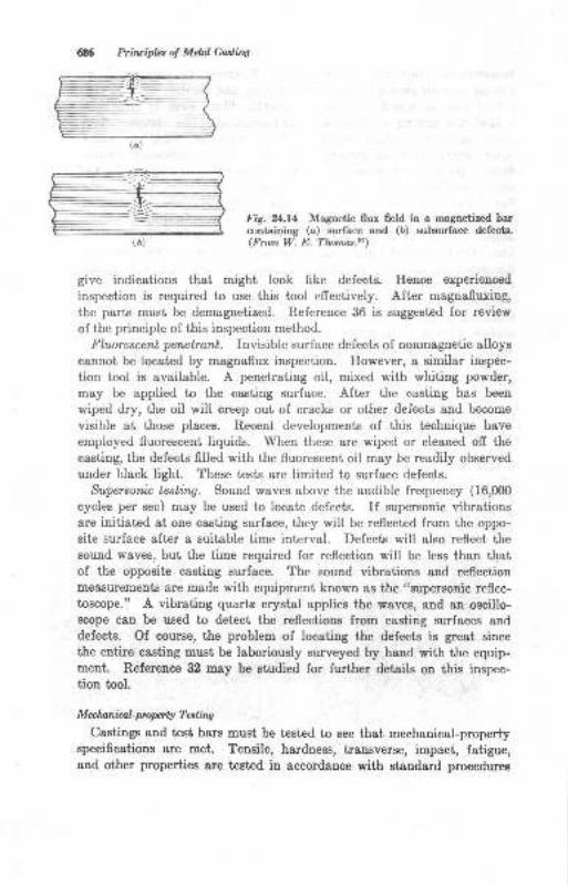
685 Priluiples ol Melal Castinq
(a)
(D)
Fig. 2*.14 Magnetic flux field in a magnetized barcontaining (a) surface and (D) subsurface defects.(Fmm W. E. Tlomas.2l)
give indications that might look like defects. Hence experienced
inspection is required to use this tool effectively. After magnafluxing,
the park must be demagnetized. Reference 36 is suggested for review
of the principle of this inspection method.
Fluorescent perwtrant. Invisible surface defects of nonmagnetic alloyscannot be located by magnaflux inspection. However, a similar inspec-
tion tool is available. A penetrating oil, mixed with whiting powder,
may be applied to the casting surface. After the casting has been
wiped dry, the oil will creep out of cracks or other defects and become
visible at those places. Recent developments of this technique have
employed fluorescent liquids. When these are wiped or cleaned off the
cesting, the defects filled with the fluorescent oil may be readily observed
under black light. These tests are limited to surface defects.
Supersoruin, testing. Sound waves above the audible frequency (16,000
cycles per sec) may be used to locate defects. If supersonic vibrationsare initiated at one casting surface, they will be reflected from the oppo-
site surface after a suitable time interval. Defects will also reflect thesound waves, but the time required for reflection will be less than thatof the opposite casting surface. The sound vibrations and reflectionmeasurements are made with equipment known as the
('supersonic reflec-
toscope." A vibrating quartz crystal applies the waves, and an oscillo-Bcope can be used to detcct the reflections from casting surfaces anddefecLs. Of course, the problem of locating the defects is great since
the entire casting muet be laboriously surveyed by hand with the equip-ment. Reference 32 may be studied for further details on this inspec-tion tool.
M ec lu,ndro,l- pro per ty T* ting
Castings and test bars must be tested to see that mechenical-propertyspecifications are met. Tensile, hardness, transverse, impact, fatigue,and other properties are tested in eceordance with standard procedures
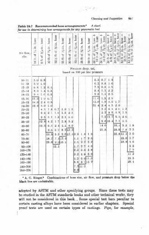
Cla,n&W otd lruPalinn
Toble?tl.T Recomtnenfudlwseanrantgemantst Achoil
lor use in determining lase onangaruenls tot any pwwnlb taol
Air flow,cfm
Pressure drop, psi,
based on 100 psi line pressure
fu.t
OE
i\l
o s*NOi
+ os8
.'r G
uOo€
ONro
+BloEl
E;l*'i I
.EAI
*tlot*Nloilrol
oao
I
o
6l
oaoa
\i
co
o
C
l(Fllll-12t2-t3t3-14l4-15
r5-16r6-18!8-2020-25
25-30
30-35
3H040-50
5(H060-70
70-80
80-90
90-100t00-120
120-140
r4(F160160-r80
r80-200200-220
s.ol o.
s.ol r.6.81 r.aol r9.31 l .
o.4
l.1
l.,2.q
3.4.6.9.
i&r8.
5.
6.
7.
8.
9.
1l-r5.2.4
I
3.4.6.
9.
a0.
o.70.1.
l.2.1
1
I2.4
5.
7.r14. 10. 4
I2
2
3
l.1.
II2.1,
I,
5
8
3.5.
9.
I2.4
3.71 6
5.31 9
z . rlrz.9 0116
4.1 1.8
2.312.
17.4
16.
I1.7
1.
2.
4.
b.
8. IrtIro
lzo
I
.0
.6
.8
.9
n.5
.4
o
2.7o.
t A. G. Ringer.e Combinrtions of hose size, air flow, and pressure drop below the
black line ere undesirable.
adopted by ASTM and other specifying groups. Since these tes0s may
be studied iu the ASTM etandards books and other technical works, they
will not be considered in this book. , Some special test bars peculiar to
certain casting alloys have been considered iu earlier chapters. Special
proof tests are used on certain typee of castings. Pipe, for example,
+ og8o-c
'? \$
eOo€*o
oo
N
oao
;
roN
o
!t
@o
o
roN
oa
6
+l+s8ls3o-q I o.q
'T \€
oeloo
od IOO6lD
688 Priruipla ol Mdal Cddiw
may be subjected to a pressure test to prove it8 relisbility. Assembliee
of cast chain links are olt€n eubjectrcd to a maximum teusile proof load
to ensure quality. Thus mechanical test€ msy be used to qualify cast-
ings for their service requirements, as well aB for deiermining the normal
streDgth propertie8.
SALVAGE
Castings which have been reiected because of failure to Eeet inspection
requirements are Dot necessarily scrapped. If the defects are not too
serious, salvage is possible iu many cases by welding or other treatment
and refinishing. Whether oalvage is permissible or economical depends
greatly on factors such as the casting alloy, casting size and ahape,
relative cost ol new castings vs. repairing the defects, difrculty of salvage,
availability of repair equipmeut ard methods, quality requirements, and
any agreements between the loundry and castings user relative to salvoge
castings. The salvaging process ordinarily consists iu welding the
defective area8. Castinge that are defective because they are leakers
under pressure tests may be reclaimed by sealing processes (Chap. 12).
WeWns
Castings reclaimed by welding delects re ordinarily heated ae follows:
1. The defective area"s are prepared lor welding by chipping, grinding, gouging,
or powder washing in the case of ferous alloys. Nonferrous alloys requiredefect removal by mechanical means such as 6ling, gdnding, o! othertooling. Cracks should be completely removed before welding.
2. By welding, the actual repair prcceas. The welding of castings is discussed
in references in the bibliogmphy of this chapt€r.3. By eleaning. The welded areas may be cleaned by t}re Eethods descriM
eorlier, and then the castings rnust be reiDspecl€d to psss the requiredstandards.
BIBLIOGRAPHY
l. S. W. Brinron and J. A. Duma, Observatious on Knock-ofi Risers ae Appliedto Sl,eel Casrings, Trura. AFS, vol. 56, p. 586, 1948.
2. D. Hannah, Die Casting Trio Die Proedure, Trarls. AFS, vol. 69, p. ?84,1961.
3. G. E. Shippard, B&nd Sewing in Foundries, T'on8. AFS, yol. 58, p. 621, 1950.4. H. J. Chamberland, Band Sawing Nonferrous Csstitrgs, ,'orrndrr, vol. 60,
September, 1952.
5_
6.
8.
9.
10.
11.
12.
13.
14.
15.
16.
17.
18.
t9.
m.
21.
23.
.
26.
I
8.
29.
30.
31.
Claniry and lns@ion 689
R. S. Babcock, Orygen Cutting Proceeses in St€el Foundriee, Trurtl. AFS,vol. 58, 1950.
American Welding Society, "Welding Handbook," vol. t, 1962.
American Wheelabrator and Equipment Corp., "Wheelobrotor Operetor6Manual," 1965.
A. G. Ringer, Use oI Portable Air Tools ia Foundry Cleaning Rooms, ?raru.,4,r'S, vol.58, p.510, 1950.
Calborundum Co., 'isafe Speeds for Grinding Wheels," 1965.
D. E. Sa*telle, Mechanized Malleable Foundry Finishing and Inspection,lrans. AFS, vol.55, p. 388, 1947.L. N. Schuman, Equipment and Methods of Struightening ,rrd DimensionalInspectiofl of Malleable Iron Castings, ?rou. .4tr'S, vol. 59, p. 418, 1951.C. Schneider and L. Ulsenheimer, Production Eardness Testing in a Msl-leable Shop, Trar*. AFS, vol. 56, p. 473, 1948.B. II. Work, Foundry Cleaning Room Abrasive Operations, Traw, APS,vol.58, p.685, 1950.
D. Van Order, Grinding Standards Eelp Eliminate Cleadog Room Bottle-necks, ?raru. .4IS, vol. 56, D. 473, 194ti.H. W. Wagner, Snagging Operations, Founlly, vol. 81, p. 112, Jatruary, 1953.R. H. Herrman, Salt Bath Cleaning of Gra.y Iron Castings, Iozndry, vol.78, August, 1950.American Foundrymen s Society, Malleeble StraighteniDg Dtex, Trana. AFS,vol.68, p.801, 1960.P. E. Kufer, Finding the Most Profitable Snagging Tgheel, /m. foundryrnatu,vol. 24, p. 32, July, 1953.
S. I(reszewski, Selection and Applicstion of Cleaning Room Equipment,?rons. rFS, vol.58, 1950.M. G. Diett, The Nonferrous Cleaning Room, An. Found,rymo4 vol. 22,p. 44, September, 1952.N. L. Smith and R. J. Wolf, Matedsl Tr&nsport in the Cleaning RooD,7'o s. /1S, vol.58, p.550, 1950.D. T. Martin, Outline of Inspection for Pearlitic Malleable Castiogs, froa-c.,41S, vol.58, p.692, 1950.K. M- Smith, Dimension&l Checking and Pressure Testitrg of Gray IronCastings, ?roru.,{IS, vol.59, p. 304, 1951.C. E. Ilastings, Choosing Equipment lor Nondestructive Testing, ?raru..4r'S, vol.59, p. 309, r95r.1V. II. Baer, Radiography of Gun Metal Ca.stings, ?rarz,s. .4F'S, vol. 55, p. 1S3,1947.E. L. La Crelius, Importance of Radiography to Inspection, Trcns. AFS,vol.55, p.375, 1947.W. E. Thomas, Castings Industry Applicaiion of Magnetic perticle Illspec-tion, ?roru. ,4IS, vol. 55, p. 482, 19{J ,
! V Lorgh, Rppeir Welding Light Metal Csstil.gi, Found,ry, vol- 72,January, 1949.
T. E. Kihlgren and L. C. Minard, Arc Welding of Cast Ircn with NickelElectrodes, ?rar?s..{FS, vol. 55, p.357, lg4?.J. H. Hall, Steel Ca6,tings in Welded Assemblies, Traru. AFS, vol. 57, p. 1,1949.
G. E. lellew, Salvage ol Castings by Welding of Defect6, ?m'lJ. ]{pS, vol.58. p.669, 1950.

6911 Pti&.t'h, ol M.tal Cas,,ins
32. 9j Il. Kellr 'lPrinciples of MetallogBphic Laboratory practice,,, 3d ed.,McGraw-Hill Book Company, New York, 1949.
iXi, American tr'oundrymen's Society, "Caat Metsls Handbook,,, 19Si.34. E. Suring, Dimensional Control of Production CasbiDgs, frors. .4FS, vol.
70, p.3U,1962.35. AFS Co@nitte€ 8 II, Surface Finish of Castings, ?ran.s. ,{fg vol. ?0, p. 584,
1062.
36. AFS CoTTittee 6 G, Magnetic Particle Testinq ,rf Malleable Castings,Truns. AF S, 'rol- 70, p. 1235, 1962.
37. L.-J. Venne, Beta-trcn R-ediography of Ee4ty Section Castings, ?rans. .4IS,vol.69, p. 74i], 1961.
38. F. Newber*, Pad W&shing with Carbon Arc I'rxrx, *o,(". .1-;'S, vol. 64,p.430, 1956.

25Casting-designConsiderations
Castings are born ou a designer's drawing board, but the final ehape is
often tltered during the course of its development. As machine elements,
tools, or other objects, their Iunciional purpose is given, first and fore-
most, stteution by the designer. Illtimately, after testing, the design, orpossible modification, is found io work. The next step is manufacturing.
If metal casting is selected as the primary metat-ehaping process, certain
featues of the design may be modified to favor the caating process.
This, of course, ie aleo true if the part is to be made primarily by welding,
forging, stamping, or aoy other procees.
For casting purposes, desiguing may include the following areas ofplanuing:
1. Functional design
2. Simplification of foundry pr&ci ices
3. Metalluryical desip; seleetion and optimum use of cl,stirrg alloy4. Economic considerations
FUNCTIONAL DESIGN
Sometimes there is ouly one desigu which will perform the serviceiutended by the designer. In this case, the foundryman may be requiredto uge all the technical abilities available to produce the casting as it is,
whether the design is a favorable or an unfavorable oue lor fouudrypractices. It is of course g unique advantage of ihe casting process thatany intricat€ shape may be casi. Often, however, several designs arepossible, and oue oI these may be especially suited to the casting process,
In many casee it is possible for tle desiguer to alter the structuralcharacteristics of the part so that a better or more economicsl castingmay be produced without interfering with functioning of the part Thelatter situ&tion is one which is Eosi advaDtageous to all, the designer,
user, and the foundr;rmau. This textbook, of course, offers no dis-
69t
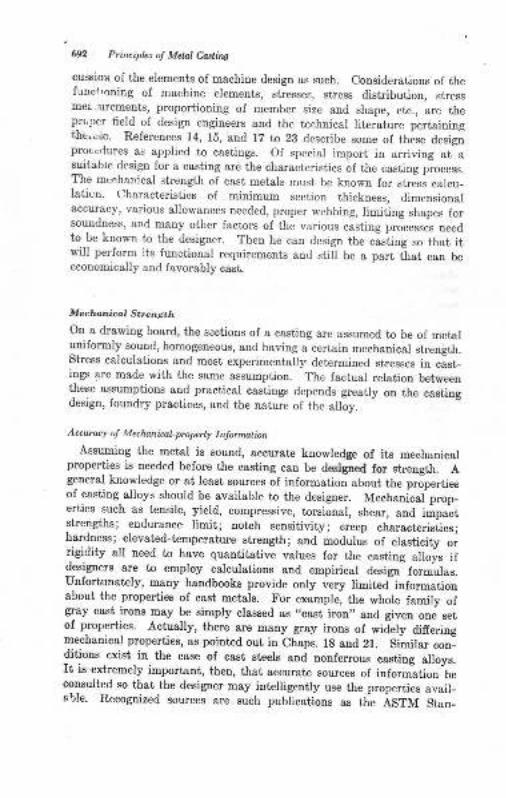
6n Pr;ncipb o! Mctat Co.rtins
cussion of the elements of macbiue desigo as such. Considerations oJ thefunct,oning oI machine elements, stresses, stress distribution, stressDqearurements, proportioning of member size and shape, etc., are theprcoer field of design engineers and tlre te.hnical literature pertainingthe."to. Relerences 14, 15, end 17 to 23 describe some of these designproccrlures as applied to castings. Of special import in arriving at aeuitabre design for a casting arc the characteristics of the casting process.The mechanical strength of cast metals must be known for stress calcu_Iaticn. L)haracteristics of minimum section thickuess, dimensionalaccuracy, various allor ances needed, proper webbing, limiting shapes forsoundness, anC many other factors of the various casting processes needto be known to the designer. Then he can design the casiing so that itwill perform its functional requirements and still be a part that can beeconomically aud lavorably cast.
Mecr@nical Sbe..Eth
On a drawing board, ttre scctions of a casting are assumed to be of metaluniformly sound, homogeneous, and having a certain mechanical strength.Stress calculatione and most experimentally determined stresses in cist-ings are made with the same assumption. The factual relation betweenthese essumptions arrd practical casiings depends greaily on the castingdesign, foundry practices, and the nature of the alloy.
Accutacy ol Mechannalpopcrty Inlomur nAssuming the metal is sound, accurate koowledge ol its mechanical
prope ies ie needed belore the casting can be deslgaed for strength. Ageneral kuowledge or &t le&st sources of information about the propertieeof casting alloys should be available to the designer. Mechanicai prop_erties such as tensile, yield, compressive, torsional, shear, and impacistrengths; endurauce limit; notch Eensitivity; creep characteristics;hardroess I elevated-t€mpersture Etrength; aDd modulus of elasticity orrigidity all need to have quantitative values lor the casting allois ifdesigners are to employ calculations and empirical desigJ formulas.Unfortunately, many handbooks provide only very limiteiinformatiooabout the properties of cast metals. For example, the whole famity ofgray cast irons may be simply claesed ag ,,cast iron,, and given one setof propelties. Actually, there are many gray irous of wid=ely dlfferingmechanical properties, as pointed out iD Chaps. 18 and 21. Sitilar cou_ditious exiet in the case of cast steels and nonferrous caeting alloye.It is extremely important, then, that accurate sources of inform-ation
-be
consulted so that the designer may intelligeofly use the properties avail-able. Recognized sources are such publicsiions as the ASTM Stan_
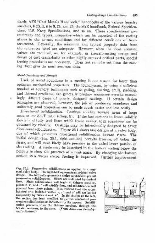
Casli.ng4.sign Coruid.erd,bru 693
dards, AFS "Cast Metals Handbook," handbooks of the various foundrysocieties, Refs. 1, 4to 8,24, and 25, the SAE handbook, Federal Specifica-tions, U.S. Navy Specifications, and so on. These specifications givemiaimum and typical properties which can be expected of the castingalloys in the as-cast conditions Bnd for different conditions of heat-treatment. Generally, the minimum and typical property data fromthe references cited are adequate. However, when the most accuratevalues are required, as, for example, in aircraft-casting design anddesign of cast crankshafts or other highly stressed critical parts, specialtesting procedures are oecessary. Then test samples cut from the cagr-ing itself give the most accurate data.
Melal $undnzss and Strength
Lack of metal soundness in a casting is one reason for lower thanoptimum mechanical properties. The foundryman, by using a sufrcientnumber of foundry techniques such as gating, risering, chills, padding,and thermal gradients, can generally produce soundness even in exceed-ingly difficult cases of poorly designed castings. If certain designprinciples are observed, however, the job of producing soundness anduniformly good properties can be made much easier and less costly.
Directional solidificatbn. castings soridify toward areas of iargemass or lov s.liv ratio (chap. 9). If the last sections to fueeze solidifyslowly and fully feed those which freeze earlier, then soundness can beobtained by risering. castings may be intentionaily designed to favordirectional solidification. Figure 2b.1 shows two designs of a valve body,one of which promotes directional solidification toward risers. Theinitial desiga (Fig. 25.1, right section) permits freezing off below therisers, and will most likely have porosity in the unfed Iower portion ofthe castiag. A circle may be inscribed in the bottom section below thepoint o to show the presence of a heat mass. By changing the bottomsection to a wedge shape, feeding is improved. Further Improvement
I'iS.-25.1 -Progressive solidification as applied to a cast_
steel valve.hody. The right halfrepresente an original valvedcsign. The left half represents a iesign modifie j b ;;tprogressive solidification. Risers are indicated bv dashedlinee. Since solidifcation will begin at tti"""" L"io*,po)nts ,, r', and. x' will solidily first, and solidification wiUprocged from these points. It is evident that the cross_hatched area included within z, e,, and { *iff
""i U. f"a
adequately by risers A and A,. In the design at the leit,the section has been modiffed to permit
"J"t oU"J pi._
gressive solidification as indicated by the arrows. Soliitifi-cation proceeds from the thinner-sections, throuch ih*heavier, sections, to the riser. (From Amer'iant f-r'irrai^.n'"
glgio.k.r)
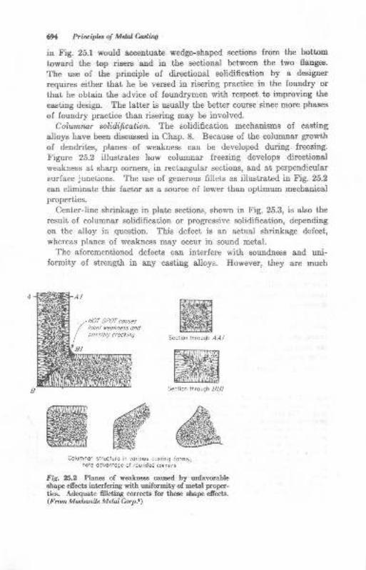
6x Pri,Eipb ol Mtul Oataiao
in Fig. 25.1 would acceutuate wedge-shsped sectioDs from the bottom
toward the top risers aud ia the sectioDal between the two flauges.
The ua€ of the principle of directional solidification by a designer
requires either that he be versed in riseriug practice in the foundry or
that he obtain the advice of foundrymen with respect io improving the
casting design. The latter ie ueually the better course since more phases
of foundry practice than riseriDg may be iuvolved.
Cola,mnar sol;difi*ation. The solidification mechanisms of casting
alloys have been discussed in Chap. 8. Because of the columnar growth
of dendrites, planee of weakness can be developed during freezing.
Figure 25.2 illustrateB how columnar freezing develops directional
weakness at sharp cornere, in rectangular sectious, aud st perpendlcular
surface junciions. The use of generous fillets as illustrated in Fig. 25.2
cau eliminatrc this factor aa a source oI lower thaD optimum mechauicalproperties,
Centerline shrinkage in plate sectious, shown iu Fig. 25.3, is also the
rtsult of columnar solidification or progressive solidification, depending
ou the alloy in question. This defect iB atr actual shrinkage defect,
whereas planes of weakness m&y occur iu sound metal.
The aforementioned defects can inierfere with soundnees and uni-formity of strength in any castiug olloys. However, they ore much
Columnor skud!re n vorious cosring ,orfrs;nore odvontoqe of rounded cor.ers
tr'rg. 25.2 Planes of *ea*nes cau3ed by oofavorableBhape eflects iot rferirS wir,h uniformity of rnetal proper-ties. Adequata Glleting corr€cts for f,h€se shap efrect6.(F run MeztunJe Mehn hr p.1)
ffiffiffi
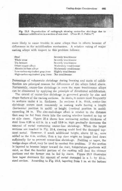
Casling4esignConsidnrations 6gn
Fig. 25.3 Reproduction of radiograph showing center-line shri.rkage due tocolumnar eolidification in a section of cast st€el. (FrcmW- S. Pellini.'r)
more likely to cause trouble in. some alloys than in others because ofdifrerences in the solidification mechanism. A relative rating of majorcasting alloys with respect to this problem follows:
Steel Severely troublesome
White irons Severely troublesome
Tin bronzes Severely troublesome
Other copper alloys Moderately troublesomeAluminum-base alloys Moderately troublesomeLow-carbon-equivalent gray irons Slightly troublesomeIligh-carbon-equivalent gray irons Not troublesome
Percentage of volumetric shrinkage during freezing and mode of solidi-fication are principsl reasons for differences of the alloys listed above.Fortunately, center-line shrinkage in even the more troublesome alloyscan be eliminated by applying the principle of directional solidification.
The extent of center-line shrinkage is governed $eatly by size andshape factors of the casting sections. In steels, it occurs most frequentlyin sections under 4 in. thickness. In sections 4 in. thick, center-liueahrinkage occurs most commonly in casting walls having a length(horizontal position in mold) or height (vertical position in mold)exceeding 16 in. The size-and-shape effect is related to the distancethat may be fed from risers into the casting whether located as top oras eide risers. Figure 25.4 shows how increasing section thickness ofeteel from 0.25 tn 4.0 in. in a wall 12.0 in. high gradually decreases theamount of metal containing ceDter-line shrinkage. When the largersections are reached in Fig. 25.4, risering could feed the damaged top-most metal. However, if much additional height, above 12 in., wereadded to the 4-in. section, then a top riser might no longer feed downsufficiently far to prevent center-line shrinkage. padding or taper, thewedge-shape effect, may be used to combat this problem. If the sectionis tapered to become larger toward the riser, temperature gradients willexist, so that the heavier portion of the casting will feed the thinnerportions and the former can be fed by risers. Figure 25.5 illustrat€show taper decreases ihc amount of metal damaged in a l- by l2-in.steel section. According to Fig.25.5, tapering from I iu. at the bottom
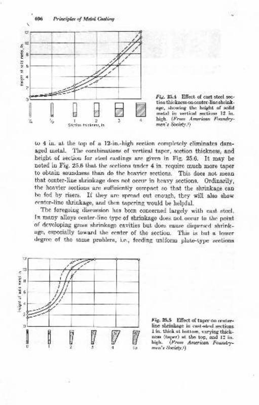
/t,2
.7r'..-7,
--- =4-
t2
!10
E8E
E36
E4.9I
2
o
696 Prirciplcs o! Meil Ciading
DA12
Siction thickness, in
Fid.25.4 Effect of cast-steel sec-
tion thickness on center-line shrink-age, showing the height of solidmetal in vertical sections 12 in.high. (From Amerban Fourd.ry-mzn's fuiety.r)
[['/" vz %D
3
t2
r0
I
6
4
E
6
to 4 in. at the top of a l2-in.-high section completely eliminates dam-aged metal. The combinations of verticsl taper, section thickness, ancl
height of section for steel castings are given in Fig. 25.6. It may benoted in Fig. 25.6 that the sections under 4 in. require much more taperto obtain soundness than do the heavier sections. This does not meanthat center-line shrinkage does not occur in healy sections. Ordinarily,the heavier sections are sufficiently compact so that the shrinkage canbe fed by risers. If they are spread out enough, they will also showcenter-line shrinkage, and then tapering would be helpful.
The foregoing discussion has been concerned largely with cast steel.In many alloys center-line type of shrinkage does not occur to the pointof developing gross shrinkage cavities but does cause dispersed shrink-age, especially toward the center of the section. This is but a lesserdegree of the same problem, i.e., feeding uniform plate-type sections
Fig.25.5 Ellect of taper on center-line slrinkage in csst+t€el sectionsI in. thick at bottom, varying thick-ness (tapr) at the top, and 12 in.higb. (Frcnt Amcritan Foundry-men's &nizly.t)
WSpW
flNWW0r23
'/.'
i/t/i
/t///
"4'
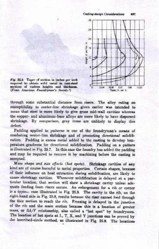
hdifu*n Czrluillrrvrtilxt
28
.i
-9
!
r6
t:
I
Fitr. ZS.6 Taper of eoction in iacbce per inchrequired to obtain solid metal in calt.declections of various heights and tLiclm.(Fmn Anuriam Fudrymen's Seidy.r)
OL0 QO4 0.O8 012 016
Topi, ir. pcr ir.
through some substsntial distance from riaers. The alloy rating oneusceptibility to center-line shrinkage given earlier was int€nded tomean thst steel ie more likely to grve gros! mid-wall cavities whereasthe copper- and aluminum-base alloys are rnore likely to have dieperaed
shrinkage. By comparison, gray irons are unlikely to display thisdefect.
Padding applied to patterns is one of the found4rman,s m€lDE ofcombating center-line shrinkage and of promoting direetioaal solidifi-cation. Padding ie exceEs metal added to ttre easting to develop tem-perature gradients for directional solidification. Padding on a pettemis illustrated in Fig. 25.7. In this case trhe fouadry has sdded the paddingand may be required to remove it by machining before the caating isaccepted.
Moss shope otd cize efiects (hot spota). Sbrinkage cavities of anykind are of course harmful to metel propertiee. Certcin ahapea, beca,uEe
of their influence on heat extrsction during solidificati,on, are tikely tocause ehrinkage cavities. Whenever solidificstioo ic delayed at a par-ticular location, that section will show a shrinkege cavity unleeg ade-quate feeding from risere occurB. An enlargement for a rib or corneris a t5picar case illustrated in Fig. 2ii.8. The cavity in the rib, on theright-hand side in Fig. 25.8, results because the rieer caDDot feed throughthe thin section to reach the rib. Freezing ia dereyed in the junetionof the rib and the main section because this is a location of greaterm8s!r, or SA/V tel*io:othip, aleo called a r,5str rpot,, by foundrymen.the location of hot epots at L, T, X, aud y jrmctioor oo U" p"orud byi^be inscribed-eircle method, as illuetrated in Fig 25.g. Tte locrtiona
\\
I
\
Ij'-
\
II
\F-
/rl2t \
/
--l-1 t-
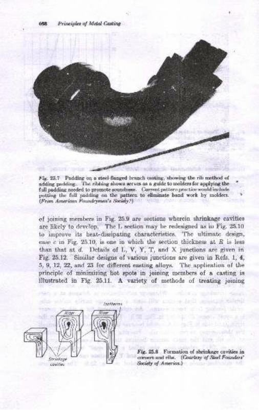
$n Priuifus of Mdal C,ading
Fig.|8.7 Padding o4 a eteel-llanged branch caeting, ehoring the rib rnethod ofaddins padding. The ribbing shown servea as a guide to moldere for applyirg thefull padding needed to promote aoundneos. Current pattern practice would includeputting the full paddirg on the pettern to eliminat hand worl by moldere.(F run Amcrinn Foudryrun'r,$cidy.r)
of joining members in Fig. 25.9 are sections wherein shrinkage cavities
aye likely to develop. The L section may be redesigned as iu Fig. 25.10
to improve its heat-dissipating charecteristics. The ultimate desip.,
case c in Fig. 25.10, is one in which the 8€ction thickness at .R is less
than that at d. Details of L, V, Y, T, and X junctions are given inFig. 25.12. Similar designs of varioue junctions are given in Refs. l, 4,
5, 9, 12, 22, all'd,23 for difrerent casting alloys. The application of theprinciple of minimizing hot spots in joiuing members of a casting isillustrated in Fig. 25.11. A variety of methods of treating joining
FiS. Xt.8 Forrnation of shrinlage cavitiee inccoere and nlrr'. C.aurkr! of Stal Foudas'Suidy of Anwia.\
L
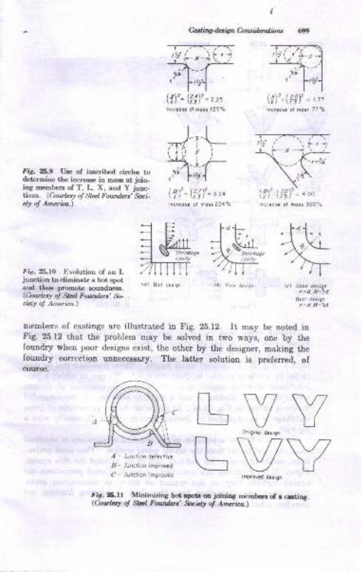
I
Carae$4., ittn Calllr;itbdrrlr
fir. 25.9 Ue of ioscdbed circl€s todet€rhirc the incl€ee iD mas at join-ins nrembere of T, L, X, and Y junc-no$s. (Coirlrr! ol SLd Fotrdert' 9ci-clf of Anurb.\
!tu. 25.10 Evolutiol of an Ljuflcliotr to eliminate a hot slxltard thus promol€ s{ruodffsr-(&\wtrrJ ol Srd F.,otdcrr' :*>ci<;y ol Atnaicu.)
l!\2-lzqY -, -,l^cr@s. ot noi: 7?%
lof-ll!), = t oo
ii...cs. or notr 100'a
I,z\2= l4\? -.,.l^o.ot. ol ho3! 125'lt
-J-,-Ll.lll j r
5-]-r-,)' l'ul\?)'= l:i)'= ,,0hct.ot. ot no.t 224'/.
urembers of cestingo are illust/ated in Fig. 26.12. It may be noted inFiE 25.12 that the problem may be mlved i! two wayo, one by thelound4r when poor designs exist, the other by the deeigner, making thefoundrJr c.orrection uDnec€saary- 'fhe letter aolution is preferred, ofcour8e.
,l - Jlnciion d.f.div.,8- Jondion inp,o{dC - Junclion :mgrovrd
Fif.3.ll Minimi,ing bot.pot oo joioios mmi..rd r c-tior.rQwlay ol M Foudot' tuidry at Artuti.a.)
w7V
fv-/V
\\,
VLL
! , r-7r- -\f'?.1 "---------* -.
,''t l-,r.
(rY)
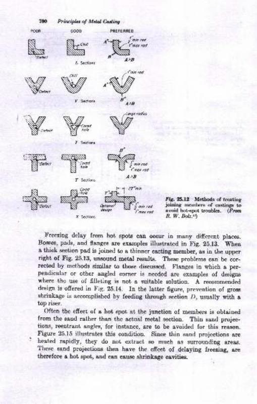
700
POOR
Prircipbt of Mdal Mhg
N',-*
M", Strtioni
wf Sactions
Y:,tW,,
"NH" $*f Seclioni
PREFERNEO
'N"rtr'
,'SA>B
A>D
frZ|"ninT1ISL- I
*,N,.,,-dcsigo
- tl".rr
rod
a'
N,,*
f Sccfids
Fir. 25.12 Metbods of treatingjnining rrembers of castir4r toavoid bot+pot troubles. (FrunR. W. Bolz.ts)
Freezing delay from hot spota can occur in many different placea.Boeees, pads, and flanges are examples illustrat€d in Fig. 2b.l3. Whena thick section pad is joined to a thinner caeting member, as in the upperright of Fig.25.13, unsound metal reeults. tt"r" problems can be cor-rected by methods similar to those discussed. Flanges in which a per-pendicular or other angled corner is needed are examples of designswhere the use of Elleting is not a suitable solution. A recommendeddesign is ofrere<i in Fig. 25.14. In the latter figure, prevention of grossshrinkage is accomplished by feeding through section D, usually wiih atop riser.
Often the effeer of a hot spot at the junction of members ie obtainedfrom the eand rather than the actual metal section. Thin sand projec-tions, reentrant angles, for instance, are to be avoided for this reason.Figure 25.15 illustratee this condition. Since thin sand projeetions areheated rapidly, they do not extract eo much as surrounding areas.These sand projectione then have the effect of delaying freezing, aretherefore a hot spot, and can eause ehrinkage cavities.
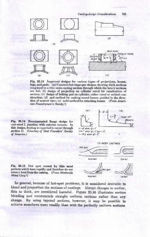
UA
ffiA
lal
@m@ru
{a)
C-aa I ingdas ig n Coru idtr ol bru
Fig. XtI3 Improved desigus for varioue types of projectione, bmses,lugE, and pad8. (c) C,ommon but impmper designe showing thic}. aectionscoqioined to a thin rnain<asting section through which the heavy sectionEare fed; (D) design of projection on cylinder cored for equalization ofsection; (c) design of bolting pad on cylinder, either cored or welded con-struction; (d) pad method for making sound boeses, padded in the direc-tion of nearest riser; (e) weld method for attaching boss€s . (Frun Ameri.can Fowd4men's Sbcrdy.r)
{c}
FiS. Zt.U Recommended flange deeign forcast-steel L junction with exterior cornere. Inthis design, feeding is expected to occur throughsection D. (hwbsy ol Stul Foundcrs' fuizlyol Amcrica.)
<1"
> l"but < J'd> !'
CASTINGS
-_JT.a*"
lal
t!)
tu_lla=d Yhcr d.
= l" whcn d=d,6 thca ,
Fis. xt.r5 Hot epot caused by thin sand /1, )llrlpockets which heat iapidty and thJrefore do not \ .//** t* .4iextract^heatfromthecasting. (FromMalnnih -*1lE4 illlil:::@Mdnl Cfip..) rncorrocr cn*r
In general, because of hot spot problems, it is coneidered desirable toblend and proportion the sections of castings. Abrupt changes in section,thin to thick, are considered harmful. Figure 28.16 illustrates Bectionblending and recommends sfuaight uniform sectiono rather than anyehange. By using tapered sections, however, it may be possible toEchieve Boundness more resdily than with the perfectly uniform sectiong.
CYLINOER
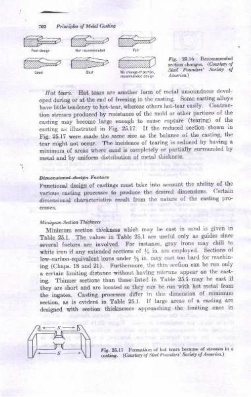
%a %> %a%=@m
Hot tll,:t. Eot tc8rg are another lorm of metal unsouudness devel-
oped duriag or at the end of freeaing in the cssting. Some-caatin-g alloys
have little teadency to hot ipar, whereas others hot-tear easily' Contrac-
tion str€ssee protluced by re8istance of the mold or other portioDs of the
casting may become large enough to cause rupture (tearing) of the
"asiiu! u" itlustrated in Fig. 25.1?. Il the reduced sectiou shown in
l'ig ZS.1Z were made the same size as the balance of the casiing, t'he
t ; night Dot occur. The incidence of teoring ie reduced by having a
ninimun oI artas where 8snd ie completely or partially surrounded by
metal and by unilorm dietribution of metal thicknese.
Di'r, !Jiorrd-d.,ln,',- Fuan
Furctional deoign ol castings must take into accouDt the abitity oI t'he
various caatinf processea to produce the deeircd dimensions' Certein
dimeoaioual charact€ristic8 result from the Dature of the cssting pro-
cesses.
Minirytn *dion Thichtut
Miuimum section thickneec which may be cast iu sand is given in
Table .1. The values in Table 25.1 are useful ouly as guides since
several factorg are iuvolved. For insiance, gray irons may chill to
white iron if ony extended sections of /11 in. are employed Sections-of
low-carbon-equivalent ircns under 12 ir. may cast too hard for machio-
iag (Chaps. 18 and 21). Furthermore, the thin secdion can be run only
a certairlimiting distance witlrcut having misruns appear on the casi-
ing. Thiuer s€ctions than those tist€d in Table 25.1 may be caet ifthey ere short and sre located so they can be run with hot metsl.Irom
the iugates. Caeting processes differ in this dimension of minimum
aection, ae ie evident in Table 25.1. Il large areas of a caeting are
deeigned with gcctiou thickness€s approachiag the limiting ones in
fi.- ,tl7 Formati.n of hot l€ars be(*use of stt€ss€s in a
&;"s. tA""k'r o! st.rl Found.ri &xi.tr 6 An'ricd ,
Prilrifla ol Mdal Cading
FE. a.$ Recommended
&ction chang€s. lCovlaY otSrr.l Foud.rs' e'.i./r otArurba.)
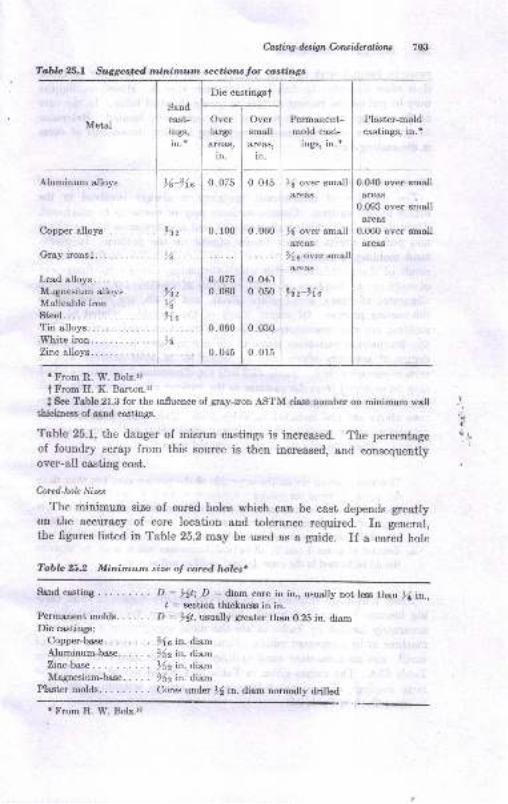
C ast i ng - dzs i4 n Co rc i.dc r al io ns
Table 25.1 Suggeqted tninirnum sections for castings
Aluminum alloys )6-%a
Copperalloys...
Grayironsf.......
Leadalloys.......Mlgnesium alloys.Malleable iron.... ..Steel. . .
Tin alloys.White iron.Zinc alloys.
Sandcast-
ings,
in.*
sAz
,6
Overlarge&re&s,
in.
0. 075
0.100
0.0750.080
0.060
0. 045
Oversmall
areas,
in.
0. 045
0.060
Permanent-mold cast-
ings, in. +
)( over smallareaa
X over small8re88
3f s oYer
&reas
5Az-94e
Plaster-moldcastings, in.t
0.O40 over small&reas
0.093 over small&re&8
0.060 over sma,ll
areaa
0.04,1
0.050
0.030
0.015
r From R- W- Bolz.ra
t From II. K. Barton.lr
f See Table 21.3 for the influence of gray-iron ASTM class number on minimum wellihickness of sand castings.
Table 25.1, the danger of misrun castings is increased. The percentageof foundry scrap from this source is then increased, Bnd consequentlyover-all casting cost.
Cored-holc Sips
The minimum size of cored holes which can be cast depends greatlyon the accuracy of eore location and tolerance required. In general,the figures listed in Table 25.2 may be used as a guide. If a cored hole
Tablc 25.2 Minimum size oJ cored. holcs.
.t'
l
Sarrd casting
Permanentmolds-.....De castings:
Copper-base.
Alurninum-base-.....Zinc-ba"se
Magnesium-ba^se.....Plaster molds.
D : ,4t; D : diam core in in., usually not less than ){ in.,I : section thickness in in.
D : >1t, rxually greater then O.25 in. diam
)(6 in. diam
962h. ilam)42 in. dtam
)(2 iw diamCores under )l in. diam normally drilled
t From R. W. Bolz.1,
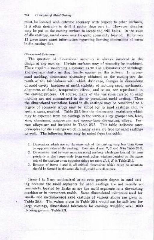
?U Prircipht o! Mctal Cosli.ng
must be located with extreme accuracy with respect to other surf&ces,
it is often desirable to drill it rather than core it. However, dimplesmay be put on the casting surface to locate the drill holes. In the case
of die castings, metal cores may be quite accurately located. Reference1l gives more exact information regarding limiting dimensions of cores
in die-casting dies.
Dimcwiotnl Toleraues
The question of dimensional accuracy is always involved in the
design of any casting. Certain surfaces may of necessity be machined.
These require a machining allowance as well as allowances for shrinkage
and perhaps drafts as they finally appear on the pattern. In green-
sand molding, dimensions ultimately obtained on the casting are theresult of the faithfulness with which shrinkage, changes in dimensions
of mold cavity, hardness of mold, stability of molding sand, mechanical
alignment of flasks, temperature effect"s, and so on, are reproduced inthe casting process. Of course, many of the variables related to sand
molding are not encountered in die or permanent-mold casting. Thusthe dimensional variations found in die castings may be considered as a
degree of accuracy which may be aimed for in sand castings and, incertain cases, reached. Table 25.3 lists the dimensional variations whichmay be expected from die castings in the various alloy groups: tin, lead,
zinc, aluminum, magnesium, and copper-base die-casting alloys. Fer-rous alloys are not ineluded in Table 25.3. This table indicates somc
principles for die castings which in many cases are true for sand castings
as well. The following itrems may be noted from the table:
Dimensious which are on the sa.me side of the parting vary less than those
on opposite sides of the parting. Compare A and, B, C and D in Table 25.3.
Dimensions tend to vary more on cored surfaces which are located (in coreprints or in dies) separately from each other, whether located on the same
side'ofthe parting or on opposite sides; see cases I1, "/,
K in Table 25.3.
Because of items I and 2, all critical dimensions which must be accurate
should be formed in the same die half, mold as well as core.
Jtems 1 to 3 are emphasized to an even greater degree in sand cast-ing because the mold segments for sand castings are not usually so
accurately located by flasks as are the mold segments in a die-castingmachirre or in permanent molds. Some dimensional tolerances used forsmall- and medium-sized sand castings of various alloys are given inTable 25.4. The values given in Table 25.4 would not be suffr,ient fc/rlarge castings, dimensional tolerances for castings weighing over t0(X)
lb being given in Table 2.3.
t.
,
J.
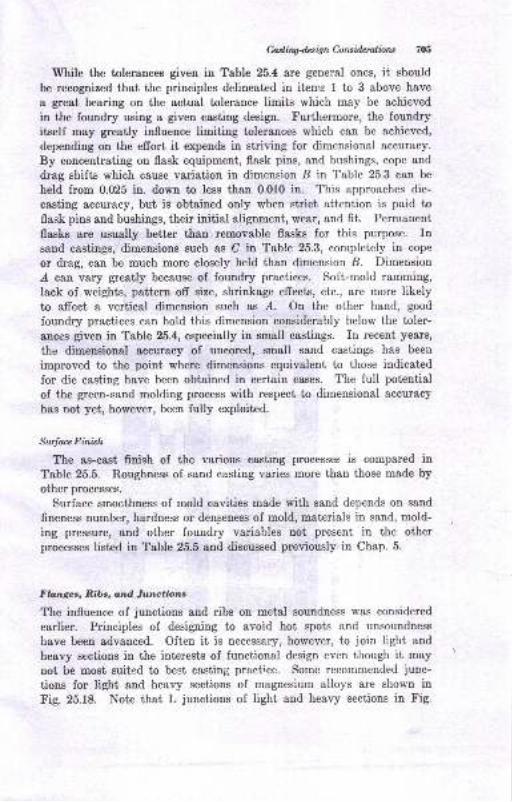
Milw4aignGt*iderolbns 705
While the tolerances given in Table 25.4 are general ones, it should
be recognized that the principles delineated in item.s I to 3 above have
a great bearing on the actual tolerance limits which may be achieved
in the foundry using a given casting design. tr'urthermore, the foundry
itself may greatly influence limiting tolerances which can be achieved,
depending on the efrort it expends in striving for dimensional accuracy.
By concentrating on flask equipment, flask pins, and bushings, cope and
drag shifts which cause variation in dimension B in Table 25.3 can be
held from 0.025 in. down to less than 0.010 in. This approaches die-
casting accuracy, but is obtained only when strict attention is paid toflask pins and bushings, their initial alignment, wear, and fit. Permanent
flasks are usually better than removable flasks for this purpose. Insand castings, dimensions such as C in Table 25.3, completely in cope
or drag, can be much more closely held than dimension B. Dimension
r{ ean vary greatly because of foundry practices. Soft-mold ramming,
lack of weights, pattern ofr size, shrinkage effects, etc., are more likelyto afrect a vertical dimension such as .d. On the other hand, good
foundry practices can hold this dimension'considerably below the toler-ances given in Table 25.4, especially in small castings. In recent years,
the dimensional accuracy of uncored, small sand castings has been
improved to the point where dimensions equivalent to those indicated
for die casting have been obtained in certain eases. The full potential
of the green-sand molding process with respect to dimensional accuracy
has not yet, however, been fully exploited.
Sudaa Finish
The as-cast finish of the various casting processes is compared in
Table 25.5. Roughness of sand casting varies more than those made by
other processes.
Surface smocthness of mold cavities made with sand depends on sand
fineness number, hardness or denseness of mold, materials in sand, mold-
ing pressure, and other foundry variables uot present in the otherprocesses listed in Table 25.5 and discussed previously in Chap. 5.
Fbnges, Ribc, ond luttctions
The iuflirence of junctions and ribs on metal soundness was considered
earlier. Principles of designing to avoid hot spots and unsoundness
have been advanced. Often it is necessary, however, to join light and
heavy sections in the interests of functional design even though it may
not be most suitL'd to best casting practice. Some recommended junc-
tions for light and heavy sections of magnesium alloys are shown in
Fig. 25.18. Note that L junctions of light and heavy seetions in Fig.
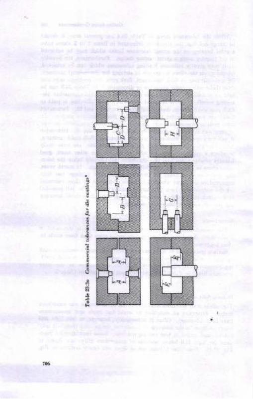
g
B
Io
IU
vi
706
mN%NZ

to
gEE+l -H
Ee-H tt
d:e.H+ .H
gBg E
rr+ I +l
88 8r^ .i+l {]
c; ci+i .H
n:99 Q
oci d+l t{
=888do+l+
888<;.i ci+.H.H
888 8ddd c;Jr+ I +l
88 8<i ci ci+l 'H
8td<;.H "H
?E
9a Qtsts Ei€; .;+t -H
!QEE-.1{a -H
E
+l
ee+t -H
888 8e;dc; d++ I +l
88 Ido d+l ]l
88c;d"H+1
888oc; d+l +l
c; citt -H
I-H
EE+-H
888 8-]-j^^
#+ | +6ci c;+l ri
88ci .,-ii +l
,i
!!Q Qtsts 5+t -H
88c;d-H rl
88 8
N.fl il
888 8ooci d+r+ | -H
88 Idc; d+l ll
88tl 11
FT
sle Q
+l +r +l +l
tsE Edc; dN+l +l +r+ | +
EEI+l -H
!?AB-i .l.H .H
€ ;6I :!
q :*
!d:j;:E
di "
Qa€
.e.E I -'
I Et:,ccq< -
c4 Z
i: BE
s e €;
8.. 4
'i F.:
P;.r
o;
;c
!;-
EE
EE
EE
izl-t ,:E
.9 5€
d q9 E
:::E
'4, 6'.
o
e 6r
Eire ".a
i *s:r!-?.i a:7.:fI
H9E"
EEgTae
o5
qE
a'd i
'6.= *
.91
!E
Eeo
E
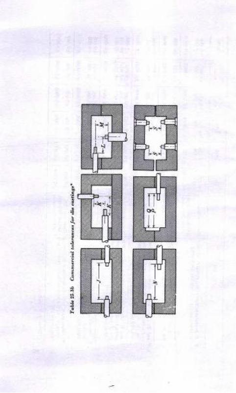
NryZ
NU
m
w
I
E
,e
ti

lo
qo
o
-fi
I
rooroooc;o+i {.1
6
qo{{
Q9eoodd+r
ro
Io{t
Ots-rOiHc)qq9ooofl+t
rooroiOOooodoo+l +l
loioo
dcj o+l +t
oqAo
C)
d
d
@d
FA
o.ictO9'a33Ed€.=
+E $E8
;iEs e2e'i 3
E;€e e€'E ErjE tdi: o o o>Z'i c-:F.
E:.E*tiE c'-- r 9
e $EEi*.w)
d 436!r o'n= X
$; 3iiEE:[email protected]
EHEE;iJriliIE E€esE&
olo
troaOt59a,o
= E.s
ErpaiuI a3o;,3 BEEEEEEe"9Eh-EEg
. oa!e
UC.;R
tu
E:a;.H9!ER- 9-.tEPtoo;!gEEE,Ei{Po
k
@o
o€€Ed.rq@
OUilge'a o
-r 6€6;OQacoxH
5irI qo.=otrosEi
q
u)
'ao
a ao
dca
E
f.a
@NOooooooJt -ll
6@oo oOiO Oooo odoc; o+{+t +
@6<r oooo
do c;+l l{
coQNO
=Qec;d ci+l +l
E
aob0d
a
s6i$o8888ciodo+l +r +{
6md30oooooooodc; o ci+l {r +r
6C88oci+t +t
m60oo
^^+l +t
@661608888dooc;+l +l +l
@
Esoo+t +t
o6$Oooooooooo+l +l
.O@NOoooooooci o+l +l
@oNoiOO9qqooo+t +t
16600oooooood c;+l +
66C\608888c;d c; c;+l +l -fi
6@6N Oooo o<icio <;+1+ I +r
rorit< @ O
8888o€; oo+l +l tt
oEeo .-c5 Eod a'a.i QEqt eq> 5Eoq='6 d-c! Tr:o
E
9';{tr5Eq=
io
d
cl
dpa
rI
d
c
dlq
T?Eo o'r q,
-a-=d dga'E '5qE> >xEo o.i='6 '6! -ct d15=Fq a<-
o.i c5Eod o';'E{qdeo>xg'6n.-dt:ca< -
to9.!
- s dEa
x,=-J
dr q? o!; i*Ir o! o
c l+ oo !?E eoqu! +'i5 Ef, " si.E-6 e c Et'-6ddaaoqoES*-e'6 ,e tr.6ETP":E a!\ ",A g ESEHoo 6.OE9E
A t$o oa= Q<
:<oE^C E.A EU
EI
6
Eo
@
g^+t
@ooOHOooo^^-+r+ I
O
e
a
N
6NO
88dd+ +t'
roP
o
cq
o@oo
-.^+l lr
$NO
888-^^+l {-l
lnloN Oooo oooo oood c;.r.r+ I +r
!io^
Fr
m600ooooooc;o o+l {{
6<NOoooooo^^^+l {r
$r/!N O
ooo odoo o+r+ I +r
oo
^
7U)
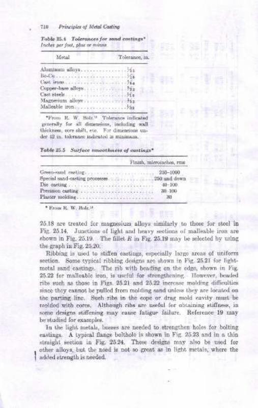
?r0 Prirlcipb ol Mdal Ootlinj
Tabla .1 T&.o.rcertot a nd crttin,''Inatus pa Jool, plut or nitn;tt
Tolersnce, in.
Alumimm alloF. ... - ... -. . . ..142Be.Cu.... ........17cCast ircns. .........96eCopper-bsse sllols.. ...... ... ..112Csst steels. .........t16Magtr€Fium alloF.... . .. ..... .)lzMallesble iron.-..... .. -. ..1rlz
'From R. W. Bolr.tt Toler$ce iDdicit dgenerelly for all dimenrions, includiag wdl
ibicka€Gs, core shift, etc. Fo. dimeGioDs utr-
der 12 iD. toleraDce iadicated is midmum.
Toble 25-S Su{aec a,l,,oo.h,cr. of co,rti,,.gr'
Finish, micrcinchB, rBB
Green-€and c€stila.. 250-1000
Specir.l Band-{astiDg ptoc€aa€s. . . . . . . . . . . . . . . 250 ard downDe c.ssting . 4O-1mPr€cision castinS .. 30 f00
I trloh R- W- Bolr-r!
25.18 sre treated for magnesium alloys Eimilarly io those for st€el inFig. 25.14. Junctions of tighi and heavy sectioos of malleable iron are
6hown in Fig. 25.19. The fillet ,8 in Fi9.25.19 may be selected by using
tlte graph in Fig. 25.2O.
Ribbing is used to 8tifren castiugs, especially large areas of uDiform
Eectiol. Some typical ribbing designs are shown in Fig. 25.21 for light-metal sand castings. The rib wiih beading on the edge, shown in Fig.
25.2 for malleable iron, is useful for etrengthening. Ilowever, beaded
ribe such aB those in Figs. 25.21 stod 25.t2 ilrcreale molding diffcultiessince they cauot be pulled from molding sand unlesB they are located oo
the p8rting line. Such ribe iu tlre cope or drag mold cavity must b€
molded with core8. Although ribe are uselul for obtaiuing 8tifrnee8, iD
some desigu8 etifrening may cause latigue failure. Reference 19 may
be studied for examples.
Iu the light meialE, bosses are needed to strengthen holes for bolting
castirgs. A typical flange boltlrcle is shown iD Fig. 25.23 and in a thiustlaight Bection h Fig. 25. . These designs may also be used for
. other alloys, but the need i8 not Bo grest 8E in light metala, where the
I added skength ie needed.
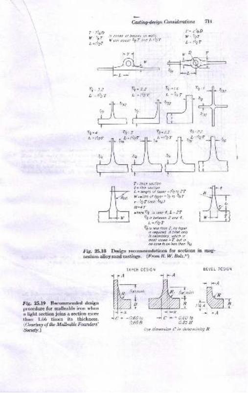
T = 2laD
"," "7i:,';, iX:: ;,i'"i';; f "nT'
i'b,
E i*aoUn C;onsidcralinrs IlL,f = 2t/4D
v= t/zr
L = l'/z?
Tr'lzL =tr2T
TAPER DESIGN
Fig. 25.19 Recommeuded designprocedure for malleable iron when
a light section joins a section more
r,han 1.66 times its thickness.(Cowtcsy o! llu Malbable Fowders't*ntcly.)
1-Aa,---....-
W{,,tW2;11l.] l-r
tcl=0.50t00.858
-l
-TR, ga\nin)
+B
__.L
= 0.60 to0.85 B
-EfJ- r#-L =tt/zl
--!l-5/,",rll"-iJt_+
T= lhic* secliont = tlin seclionL = lenglh ol toper = ll/zto 2Ttf =vidth ol topil =t4 rc 34f
r =thf lnin. 3/t6)
R=4?vherel/t is over 4, L = 2T
ryt is belrcen 2 ond 4,
r, =tt2r'IZ is less thon 2, no toper
is lequircd. A fiilel onryis necessorf, ulich inmosl coses = T bul in,o cosc to be /e;s lhon 346
I'ig. 25.1S Deaign recommendations for sections in mag-
nesium-alloy sand castings. (From R. W. Bolz.rs)
BEVEL OESiGI.I
n r-A
M=
1 r-A
L/se dimensbn C n delernining R
% =roL, =,tq?
llt= 2.2
. L=tt/zT"/t6

?
,E
a
r!
,f
4!
r1
I
Pritiples ol Melat Caslhq
ti rl
-2?
rT
Aluminum ond Mognesium
Fit. 26.m Recommended fiIlet radius to beused in casting desigrr for all joints with walleat right angles to each other and for walls ofusual thiclneeses and combinations of thick-rmrcE. (hwksy oJ tlu Mallabb Fourden,Socizl1.)
FA. 25-ZL Ribbing design for light-metalsand castings. (From R. W. Bolz.rs)
FiSr- 2!,2,2a Bead-edged rib or plate design recommended formalleable-iron castings. (C,ourtcsy o! tttc- Malteabb Founders,tuidy.)
1fb1r
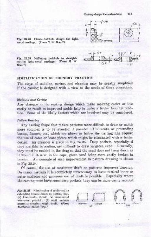
Caling4., ig n C-ow idqalbw 713
v1-$'zo"1 flLu*;
"Wru. AA Flaoge-bolthole deai*a fc ligbtretal castings. (From R. W. Bolz.tt)
Fit ?,t.rA Stifrening bolthob iD straiStrtsection light-metal castingE. @rut R. W.Bolz.u)
Fis.25.25 Elimination of undercut byextending bosses down to parting line.(o) Undercuts should be eliminatedw'herever possible; (D) ornit oulside
boss€8 to obtain straight draft. (F om
Melnnile Mdal Corp.e)
1 rtir
SIMPLIFICATION OF FOUNDRY PRACTICE
The steps of molding, soring, and cleaning may be great|pr simplified
if the casting is designed with a view to the ueeds of these operations.
Molding and Coring
Any changes in the casting desip which make molding easier or less
costly or result in improved molde help to make a better foundry prac-
tice. Some of the likely factors which are involved may be considered.
Palbrn Dmwi.rw
Any casting shape that makes patterns more difficult to draw or molds
more complex is to be avoided if possible. Undereuts or protruding
bosses, flanges, etc., which are above or below the parting line require
ttre use of cores or loose pieces which might be eliminated with a better
design. An example is given in Fig. 25.25. Deep pockets, especially ifthey are thin in section, are difficult to draw in green sand. Generally,
they must be molded in the drag so that the sand does not hang down as
it would if it were in the cope, green sand being more easily broken intension. An example of such improvement in pattern drawing is shown
in Fig.25.26.Of course, the use of maximum draft on patterns improves drawing.
On many c&stings it is completely unnecessary to have vertical inner or
outer surfaces and geuerous use of draft is possible. Especially where
the casting must have some deep pockets, they can be more easily molded
flryffiffilncorrcct Co.rect
(D)
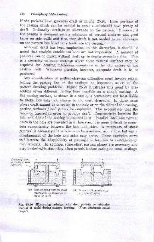
714 Prilripbt of Mdal C,aslittg
if the pockets have generous draft as in Fig. 2b.26. Inner portions ofthe casting which can be molded in green sand should have plenty ofdraft. Ordinarily, draft is an allowance on the pattern. However, ifthe cas'ling is designed with a minimum of vertical surfaces and goodtaper on side walls and ribs, then draft is not needed as ao allowanceon the pattern but is aetually built into the casting.
Although draft has been emphasized in this discussicn, it should benoted that straight outside surfaces are not impossible. A number ofp,atterns can be drawn without draft up to depths exceeding 4 in. Thisie a necessity on some castings where these vertical surfaces may berequired for locating machining operations or by the nature of thecasting itself. Whenever possible, however, adequate draft is to bepreferred.
Any consideration of pattern-drawing difficulties must involve estab-lishing the parting line on the castings, an important aspect of thepattern-drawing problems. Figure 25.27 illustrates this point by pre-senting seven different parting Iines possible on a simple casting. Aflat parting surface, as shown in a and e, is convenient and Ieast liableto drops, but may not always be the most desirable. In those cases
where draft cannot be tolerated in the hole or on the sides of the casting,parting surfaces I and g may be employed. This necessitates that thefaces be tapered in order to provide draft. Concentricity between thehole and side of the casting is ensured in o. Parallel sides and normaldraft in the hole are provided in b; however, it is more difficult to main-tain concentricity between the hole and sides. A minimum of stockremoval is necessa4r if the hole is to be machined in c and e, but againmisalignment of the hole and sides may occur. These examples serveto illustrate the adaptability of parting-line location to casting-designrequiiemenLs. In additioD, some offset parting planes are necessary andmay be desira*l-le since they often permit bottom gating on some cas[ings.
Crumb/inq ondpolching of noldnecessory
lal Poor stripping trom the moldresults when no ollowonce ismode for droft
( D) Anrp,e droft permits eosyond sore slripping
FiS. 25.26 Illostrating redesigtr with deep pockets to minimizetearing of mold during pattern drawing. (From Meehanik MelalCorp.e\
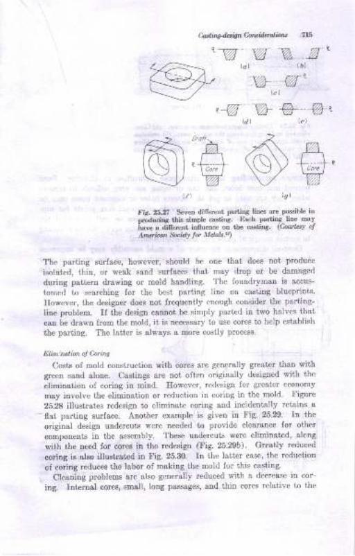
Catling-<tttig Coltsid.ralbr6
3-' ffi z ?TAv w Ya- .-u
\t)
fir.25r, Seven difrereDt PoniDs lifts are podsible iaprodudn3 thin dmple casting. Each partiDg- line rDaY
ia"e a aif,ere"t inlluence ou tho GsaliDg (C'ourLty ol
. Angia t &.A4 fu Mdal,.r)
The parting surface, however, should be one thst does not produce
ieolaied, thin, or wesk sand surfsces that msy drop or be damaged
during pattern drawing or mold handling, The foundryman is accus-
tomed to searching for the best parting line on casting blueprints.
Eowever, the designer does not frequently enough consider the parting-
line problem. Il the design cannot be simply parted in two halves that
can be drawn from ihe mold, ii i8 nec€ssary to use cores to help establish
the parting. The lsiter is always a more costly process.
Elim:nalbn oJ Coins
Coste oI mold coustruction with cores ore geoerally greater than withgreeu sand alone. Castiugs are not often o ginaliy designed with the
elimination of coring in mind. However, redesign for greater ecoDomy
may involve the eiimination or reduction in coring in the mold, Figure
25.28 illustrates redesign to eliminate coring and incidentally retains a-flat paditrg eurface. Another example is given iu Fig. 25.29. In the
original design undercuts s'ere needed to provide clearance for other
component€ in the assembly. These uudercuts were eliminated, alcug
with the need for coree in the redesign (Fig. 25.29b). Greatly reduced
coriog ia also iltushated in Fig. 25.3O. In ihe latter case, ihe reduction
of coriDg reduceE the labor of making the mold for this casting.
Cleaniug probteus are also generally reduced with a decrease in cor-
ing. IDt€rnal cores, amall, long passages, aud thin cores relative tD the
lg)
lcl (D)-w -'(c)
. -w @--@,
@60#
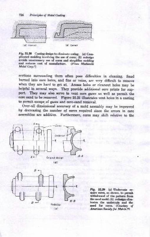
716 Principles o! Mdal fuling
(c) lncorrcct (D) Crrcf
FiS. Xt.A Casting deEiSn to eliminate coring. (a) Com-plicatcd molding involving the uee of cor€s;-(6) rednfgnavoids unreceesary use of cores and simplifea Edditrgard reduces cat of manufacture. (F,w" Mdw.itMdal hrp.t)
sections surrounding them often pose difficulties in cleaning. Sandburned into core holes, and fins or veins, are very difficult to removewhen they are hard to get at Access holes or cleanout holes may behelpful in several ways. They provide additioual core priuts for sup-pori. They may also Berve to vent core gases Bs well as permit ttrecone Band to be removed. Figure 25.31 illustrates vent holes in e castingto p6rmit escapepf gaEes and core-sand renoval.
Over-all dimdnsional accuracy of a mold assembly may be improvedby decreasing the number of cores required since the errors in coreassemblies are additiv_e. Fuithermorrc, cores may shift relative to the
Cores
Undercul
Originol design
(a)
Redesi9,,
(D)
Fig. 2fi.D (c) Undercuts re-quire cores, ae ehown, to permitwithdrawal of the pattern fromthe sand mold; (6) redesign elim-inates the undercuts and theneed for crlrra. (hultA o!Atrwian fu idy tor Mdqlr.u\
(c) lncorrcct
Iil
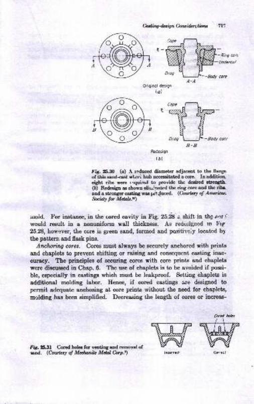
Miltg4.sign Colru,i&rcliotu
A-AOriginol design
bl
"tffi*,,",,,
B.BRedesign
(D)
ft 25.t0 (c) A reduced diametcr adjaoent to the flaoge
of tlis sand€d wt eei hub oecessitat d a core. In additioo,eigbt ribs vere r'cquiral to provide tle &dred stnogth.(6) Redesigp as slrown dii^i.oat d tle ring cff€ aad thc db.'and a atnonger casting vae gt {uoed. (hrrlq of Anrcr.irlr.Socidl tor Mdab.z)
mold. For insturnce, in the cored cavity in Fig. 25.* .i shift in thg rnr fwould result in a nonuniform wall thickness. As redesi{led rn Frg
25.28, how:ver, the core is green sand, formed and positiveiy located by
the pattern aud flask pins.
Attclwring cores. Coree must always be securely anchored with prints
and chaplets to prevent shifting or raising and consequent casting inac-
curac5r. The principles of securing cores with core prints and chaplets
were diacussod in Chap.6. The use of chaplets is to be avoided if possi-
ble, etpecially in castingo which mus0 be leakproof. Setting chaplets is
additional molding labor. Hence, if cored castings are designed topcrmit adequate anchoring at core prints without the need for chaplets,
molding has been simplified. Decreaeing the Iength of cores or increas-
Coled lolaswwFi6. r53l Cored holes for venting and removal ofsand. (Conr{zsy o! Mduttilc Mdal Cory.t)
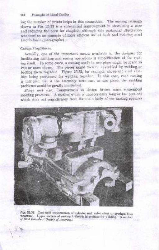
?18 Prtuiplrs of Mdal Caditrg
ing the uumber of prints helps in this connection- The casting redesigp
shown in Fig. 25.33 is a substantial improvement in shortening a core
and reducing the need for chaplets, although this particular illustration
was rred as an erample of .more efficient use of flask and molding sand
(see following paragraphs).
Caslirqs Simplifualian
Actually, one of the important means available to the designer for
facilitating molding and coring operations is simplification of the cast-
ing itself. In some casee, a casting made in one piece might be made in
two or more pieces. The pieces might then be assembled by welding or
bolting them together. X'igure 25.32, for example, shows the steel cast-
ings being positioned for welding together. In this case, each casting
is intricate, but if the assembly were cast as one piece, the molding
problems would be greatly multiplied. l
Shooe ottd siae. Compactness in design favors more econdmical
molding practices. A caiting which is unnecessarily long or has pqrtions
which stick out considerably from the main body of the casting (quires
Fit. x.32 cast-weld coostruction c,f cylinder and valve chest to pruduce linrirqrytq.l. Upper section of casting ie ef,o-rn iu pnition for reldini. G;;:";;tf Sbel Founders' fuidy oJ Amerira.)
i: '\ t'
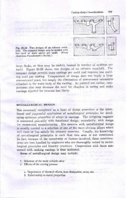
Castiq-desi$ hnsidnralbns 719
ru
HFig.2633 Two designs of an exhaust mani-
f"ii. T'he compact design may be moldedxithIess sand or more pieces per mold- (From
Amer ino n F oandrymen' s &c ietY.)
large flasks, or they may be unduly Iimited in number of castings per
mJkf. Figure 2S.B-B shows two designs of an exhaust manifold. The
compact design permits more castings per rnold and requires less mold-
ing sand per ca;ting. Compactness of design does not imply a large
concent,rated mass, but simply the elimination of unnecessary extensions
attached to the main body of the casting. As pointed out earlier, com-
pactness also may decrease the need for chaplets in coring and make
castings rejected for misruns less likely.
METALLURGICAL DESIGN
Not .eommonly recognizetl as a facet of design procedure is the inten-
tional and purposeful application of metallurgical principles for devel-
oping optimum properties of alloys in castings. The designing eugineer
is concerned prirnarily with functional design; secondarily, with design
for ecouomical manufacturing. His concern with metallurgical design
is usually t,mited to a selection of one of the more obvious alloys which
will more or lcss satisfy his primary concerns. Usually, his knowledge
of melallurgical principles is such that this area is not considered.
In fact, because of the complexity of factors involved, these considera-
tions are best handled by engineers who are thoroughly versed in metal-
lurgical principles and foundry practices. Cooperation with those con-
cerned with making castings is thus indicated.
Areas of metallurgical desip may include:
1. Selection of the most suitable alloy
2. Efrects of the casting process
o. Importance of thermal efrects, heat disqipsfi6l, mass, etc.
D. Relationship to metal properties
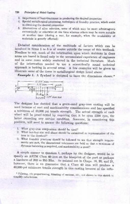
7n Prfiuipbs of Mdnl Casting
3. Importance of heat-treatment in producing the desired properties4. Special metallurgical processing, techniques of foundry practice, which assist
in obtaining the desired properties5. Alternatives of alloy selection, some of which may be more advantageous
economically or otherwise at one time whereas others may be more suitableat another time (during a war, for example, when the availability ofmaterials is greatly affected)
Detailed consideration of the multitude of factors which can beinvolved in items I to 5 is of course outside the scope of this textbook.Needless to say, much of the information upon which decisions in theseareas are based is found only in the accumulated experience of engineersand in some cases widely scattered in the technieal literature. Muchof the information needed to use a scientifically sound technicalapproach is lacking in several areas. A few examples will be given toillustratc some of the items in metailurgieal design listed above.
-Er,,rnple f. A flywheel is designed to have the dimensions shown:n
The designer has decided that a green-sand gray-iron casting will beused because of cost and machinability coneide.rations and has specifieda minimum of 40,fi)0 psi tensile strength. The actual strength of eachwheel will be proof-tested by requiring that it be spun 5flfu rpm, thelatter exceeding any service eondition. someone, in considering' thlsproblem, will need to answer the following questions:
1. lVhat gray-iron composition should be used?2. rvhat test-bar size and shape should be submitted as representative of the
iron in the flywheel?3' l{hat foundry practices should be folowed to see that strength require-
ments are met, the rrimsmisnsl tolerances are held so that a iinimum ofdynamic balancing is required, and machinability is good?
A.simple armwer to questiou l, perhaps by the designer, would be tospecify an ASTM Class- 40 iron on the Llueprint of the part or perhapsa hardness of.202 ta 285 Bhn. As pointed out in Chaps. lg, 20,
"ra Z'f,
|91:Iu.,.there is no guarantee that a Class 40 iron wili produce a40,000-psi minimum tensile strength in this casting because of th" ioflu_
* {illetins, rib proportioning, brending of sections, etc., not shown in this sketch tosir^plify calculatione.
12.375"dion.
7- a.E"a;an-j
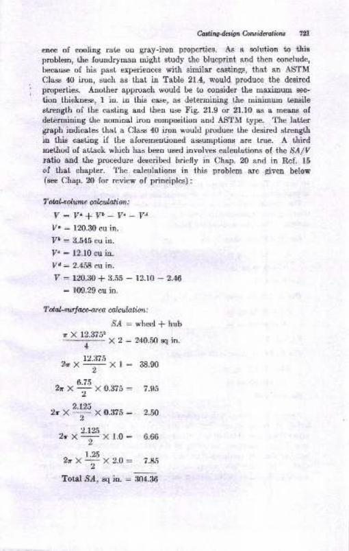
M.iry&sbnCorci.derulbru 721
ence of cooling rate on gray-iron properties. As a solution to thisproblem, the foundryman might study the blueprint and then conclude,
because of his past experiences with similar castings, that an ASTM
Class 40 iron, such as that in Table 21.4, would produce the desired
properties. Another Bpproach would be to consider the maximum sec-
tion thickness, I in. in this case, as determining the minimum tensile
strength of the casting and then use Fig. 21.9 or 21.10 as a means ofdetermining the nominal iron composition and ASTM type. The lattergraph indicates that a Class 40 iron would produce the desired strength
in this casting if the aforementioned assumptions are true. A thirdmethod of attack which has been used involves calculations of lhe SA/Vratio and the procedure described briefly in Chap. 20 and in Ref. 15
cf that chapter. The calculations in this problem are given below(see Chap. 20 for review of principles):
T otal-oolump ulaial,ion :
V:V"+Vb_V"_VdYo : 120.30 cu in.
7t : 3.545 cu in.
Y. : 12.10 cu in.
Yd : 2.458 cu in.
V : r2O.30+ 3.55 - 12.10 - 2.46
: 109.29 cu in.
T ot aLsurl ace-ar ea ca)anlati otl :
S^4:wheelfhub* X 12.3752
4 X2:240.50sqin.
12.375ZrX , Xl:38.90
t)-/j)2rX , X0.375: 7.95
2.L252*X , X0.375: 2.il
2.t252*X , X1.0: 6.66
t.25ZrX - X2.O: 7.85.)
Total Sz{, sq in. : aO+-ao
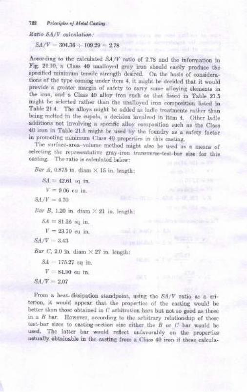
7n Prircipk* o! Mdal Cutiry
Ratio 9A/V calulattmt:
SA/V : BM.g$ -:- rN.29 = 2-7a
According to the calculated SA/V ruiio of 2.28 and the information inFig.21.10, a Cless 40 uuslloyed gray irotr should easily produce thespecified minimum tensile strength desired. On the basis of considera-tions of the type coming under item 4, it mighi be decided that it wouldprovide a greater margin of safety to carry some alloying elements irrthe iron, and a Class 40 alloy iron such as thai listed in Table 21.5eight be selected rather than the unalloyed iron composition listed inTable 21.4. The alloys might be added as ladle trestments rather thanbeing melted in the cupola, a decision involved in item 4. Other ladleadditiotrs Dot involving a specific slloy composition such a8 the Clessl() iron in Table 21.5 mighi be used by the foundry as s safety factorin promoting minimum Class 40 properties in this cB8ting.
The surfacc-area-volume method might also be used as a meang ofselecting the rcpresentative gray-ircn transvcrEe-test_bar size for thiscasting. The ratio is calculated below:
Bar A, 0.875 in. diam X t5 in. Iength:
S.4 : 42.61 sq in.
7 -= 9.06 cu in.
SA/V = 4.7O
llar Ij, l.2O in. diam X 2l in. length:
S,4 : 81.36 sq in.
Iz - 23.70 cu in.
SA/V - 3.a3
Bor C, 2.0 in. diam X 22 in. length:
S.4 : 175.22 sq iD.
I/ : 84.90 cu in.
SA/V : 2.o7
From a heat-dissipatiou standpoint, using the S_4/y ratio as a cri-terion, it would appeer that ihe propertics of the ccsting would be
better than those obtained in C arbitration bars bul, not so good eB tho6ein a B bar. However, according to the arbiirary relationship of ihesetest-bsr sizes to castiDg-s€ction size either the B or C bar would beu8ed. The laiter bar would reflect unfavorably on the propertiesaqtuslly obisinsbte in the caeting fmm a Class 40 iron if theee calcula-
Casting-d.tignh.tsiMiotw 7A
tioD8 are true. This point ig also iridicated in Fig. 21.10. Actual
experience with this casting de0nitely proved that the B bar wae morc
repreeentative of the casting thau was the C bar.
A final approach to eolution of the problem described above would
be to make test castings of the several grsy irons select€d 88 po€sibili-
ties aud subject them to mechanieal-property studies. Samples formechauical-property tests could be cut directly from the casting, and
their properties correlated with separ&tely caBt t€Et bar8.
f*tmpb 2. Suppose that the caeting considered in Example I were
io be made as a st€el geer-blauk casting and the designer required
85,000 psi yield strength, 105,000 psi tensile strength, 17 per cent elonga-
tion, and 217 Bhn as minimum mechanical properties with flame- oriuductiou-hardened gear teeth. What 8teel is required to obiaic these
properties in the light of over-all costs? These propertiee are notobtained in the 8s-cast condiiion, but muet be produced by hest-tte&t-
mtnt AseumiDg the foundry problerns are satisfactorily anewered, theselection of the proper steel requires a knowledge of ihe hardenabilitycharacteristics oI cast et€els. An.arbitrary selection might iuvolveepecification of cast steel ASTM grade 105-85 (Chap. l7). There isao guarantee, however, that s€lection of this steel will produce thedesired properties in tLiie castiug after heat-trestmeut To establiehthis, a knowledge of hardenabiiiiy (respoDse to heat-treatnent) of thest€el available is required. Ccriain tests and calculations can be per-formed tJrat will uarrow down the cboice to a relatively few steels.
These priaciples belong to the realm of advanced ferrous metallurgr,however, anri are not considered in this textbook. At any rate, it ieevident at ttris point tbst the steel may be iDtantioEally and purpoee-fully eelected and designed to fill the requirements ol the casting.
In conclusion, it is evident thai a well-engineered casting cau be theresult of much cooperation and exchange of knowledge. Eugiueersversed in mechsnical design, production, fouudry practices, metallurgi-cal principles, etc., rnay all be involved in establishing the most favor-able designs for castinge. Thie faci has become so well recognized bysome forward-looking manufacturing olganizations that stendard prac-tices for designing castings have been sei up involviug the consultstiooand cooperation of sll coDcerned.1.,u,l?-1e
BIBI,IOGRAPHY
l. American Foundrymen's Society, "Cast Metals llandbook,' 4th ed.. 19,14.2. C. T. Marek, "Funds,mentaLs in the Desigo and production of Cssrincs,,
Jobo Wiley & Sons, [nc., New York, Ig50.
7A P?l,.Wd Mddedi,e
3. J. & Crnpbell, Jr., "Ceatiq .Dd ForDiDS procec. h Mr.ut.hr.iDf,"Mccrar-Hill Book Comprny, Ne? yo*, lg50.
4. Steel Founders' Society of A-mericr, "gteel Castrngr E rdhoot,. f980.5. Tte. MellesNe Fouodere' Society, .,ioericen Mallbb Lo: i I{
"Oo.*,,,194{-
6. Americ$n FouDdrlmeo,s Society, ,,Copper-base AlloF Fourdry h..ti.r,.1952.
7. Americ.eo Foundrymen's Society, ,,psttemEalerr, Mraurl,,, l*iil.8. .Ame_ricr.n Socieiy for Testing Matcrids, St ndsrds, put6 I rtrd 2, Fcrmor
and Nonferrour Metah, lg{9.9. O. W. Smalley, "Fundamentels of Cagtinr De6iE rs lE0ucoc.d bv FdDdrv
Pncr,ice," Meehanfu Met8l Corp., Whitp ilaiDs,-N.y., tS5O.10. I1. K. Barton, Cornmercirl Tolerames for Oie Cr*irar, kdd, D^1.
vol.22, p. 169, April, 1951.ll. 8.. K. Bsrton, F,6tablbhi.g Tolenncea for Die C:.stiDCs, pr,dr,,et Bq.
vol.22, p. ll9, April, 1951.
l? llg,ny+ C,o. of Amcric.s, ,,De.igr Details for AIuDinuD,,, te(.13. R. W. Bolr, Production Procea*a: Their Infuence ol &. Nnhir. I)r._
rign, Jrnuary-December, l9l9; Sand Castinr. Auru.st. f6fri: Centriflr.fCa.6ting, Sept ober, lg,lg; PerDsnmt Mold
-Castitle. O"t"l"i- fgrg, 5i
- _ gd_hS. No!,erDber, Ig,tg: Plastcr Mold Crsting, O..i-t"., tgiS.14. I. J- Franct, Eor to Develop Caet pmductr, Fotdry,'wl. $, p. lr,
October, 1952.
15. T. !. Eagsn, Dcsi8r of Gray Iron ClstiEgs, Forndry, vol.8l, p. l@ lpril.1963.
16. C.,O Bu4e*, Metallic rnd Nonmetellic Coeting for Grry Iroo, Fo$dry,vol. 79, Deceober, I950\r8burry, t95l-
17. A. g. Crot_sd L. E. Cgrr, StsDdsrdirinS C€stin8 prrdic., A;-. Fo*rdra-i.on, yol.2l, p. 42, Juoe, lg52.
18. G-.II. Found, Desi8n Light Metsl C.sr,iDg!, Tr(,,tt. Alg, vol. 5?, p. a(E,r949.
W. T.^Bean, Jr., Simpli[cation of LiShr Metel Csstitrg D6tD rad lt Efc.tupon Servicqbility, Trsu. AFS, vol.55, p. (tr, 194i.W: I: WBl,
-Cenrrifua8t Casring in'ieroaoent Nldll, ptdlad, En1.,
vol. 21, p. l12, Norrober. l0j0.W. S.,Pellini, Fectora lnfluencing Rier R"enge e.Dd Feedilg A&qurca, lr.Fotulwttqt. ll!I. 2,1, no. 6, Noveober_Deccraber, t05BJ.
-8. Caine, "Deaigo of Ferrous Cadings,,, Aned; FoNrldiyana's gocirty,
196:t-
l-erican SociaV_for Mebls,.,CrstiDg D€si8n E trdbooL," fgE .G.ny Iron
_Fouldere' Society, .,Cray trcD Casti4r Eridhol,,, fgSS.
Mr,llesble Recrrch and Developurent Foundation, .Modcr! icrrlitic Mrf-lerble Ca8tiDEs Ei[dbooL," 1958.J. B. Csine, Wbat Foundryurca ShouH Knor rbout Crt iDS D..ko, tosrdry.vol. 87, p. 0{, Jenuery, 1959.J..B
_Ceioe, Dynemic Loediag: Its Efiect oD CldiDS De.iSD, fozrdrf,vol. 87, p. m, Mey, 1959.G-L_Werley, Die Destn lmprovca Zirc Diec.rti48, troudry, vol gg, p.109, June, 1060.
19.
m.
21.
a..
.
.
.

Index

Index
AFfl (American Foundrymen's Society), Aluminum casting alloys, alloysand standard, 103 designotion,3l2
si8ve analysis, l0f-103 alloying elemenG, copper, 2S3-298
Aeration, ll5 magnesium, 3fiF301Lggregates,24-26 and silicon, m2-3O5
fluid,7l silicon,298-300(See also Molding processes) zinc, 306
A-llowances, pat+"ern, 13-19 alloying principles, 2C2-311
distortion, 18 casting properties, 321-324
examples of, 19 drossing and gas absorption, 322
machine finish, 16, 17 fluidity, 322
shrinkage, 15, 16 pressure tightness,323-324Alloying elements, aluminum, 292 shrinkage. 321
aluminum-rich alloy composition, 268 classification, 313
gray iron, 6O4 die-cast alloys, 310-3llaluminum and titanium, 610 engineering properties, 3f3-321chromium, 605 corrosion resistance, 320effect, on microstructurer 605 mechanical properties, 314
on properties,6ll heat treatment,293-29& 314-3f8molybdenum, 6O7 irnpurities, 306nickel, 6O7 permanent-mold cast alloys, m7-309silicon, 6O9 sand-cast alloys,30{}-305
Alloys, 254-256 Aluminum gating design, 278duminum, advantages of castings,260 ingates, 280
castings production,259 pouring basin, 278foundry practice,259-285 runners,280gating and risering, 277-285 screens, 28O
gray cast iron, 610 sprue, 279mclting furnaces, 261-267 sprue base, 279
crucible, 262 American Foundrymen's Society (cec
iuduction,265 AFS)pot,263 Antioch process, 112,43
reverberatorsr 264 Asphalt as used in sands, 90
melting procedure, 267-273 Attapulgite (see Molding sands,drossing,269 ingredients)flu-ring and flushing,270 Austenite in cast irons, 50ilgas absorption,269 Austenitic manganese steel, 421grain retining, 272
pouring temperatures, 272
Srrmmery, 272
molding, 273-277 Backing sand [see Ssnd(s)lcore sands, 276 Bank sand, 116inserts, 276 Basic orygen (LD) process, 444molding eands,275 Bentonite(s), southern, lllsand casting, 273 western, 108, fl0, lllsolidifcation shrinkage, 231 southern (montmorillonites), assprue-runner-gatc rttioa,224 used in molds, 88
Aluninum-alloy ingot, compositi,on, 268 Nsrn6rrlli's theorem, 218
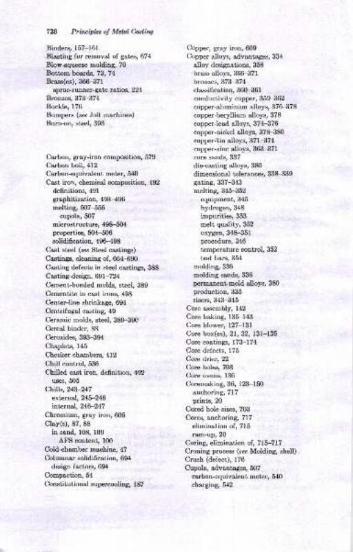
7n Priuiphsot MtulCdhg
BinderE, 157-161
Blasting for removal of gates, 674
Blow-squeeze molding, 70
Bottom boards, 73, 74
Brasa(es), 366-371
sprue-runner-gate ratse, t24Bronse& 371-374Buckls 176
Bnmpers (see Joll, machines)
Burn-on, ateel, 393
Ca,rbon, gray-iron compoeition, 579
Ca,rbon boil, 412
Ca,rbon-equivaleut meter, 5r$
Cast iron, chemical compoeition, 492
de6nitions, 491
graphitlzation, 493-496
meltiag,507+55cupola, 507
microstructur€, 498-504properties, 6ol-506solidifi cetion, 496-498
Cast st€el (sec Steel castinga)
Castinga, cleaning of, 664-690
Casting defects in steel castings, 388
Castingdesign, 691 -7 24
Cement bonded molds, steel, 389
Cemeutite iu cast irons, 498
Center-line shrinkage, 694
Centrifugal casting, 49
Ceramic molds, steel, 389-390C,ereal binder, 88
Ceroxides, 393-394
Chaplets, 145
Checker chambers, 412
Chill control, 536
Chilled cast iron, definition, 492
uses, 505
Chill*,2C3-21:7
ertemal,215-24$internal, 24.6-247
Chromium, gray iron, 605
Clay(s), 87, 88
iu sand, f08, f09AtrS content, 100
Cold-chamber machine, 47
Qelrrmncr solidifi cation, 694
desip iactora, 69(
Compaction, 54
CoDstitutionsl supercooliog 187
Copper, gray iron, 609
Copper olloys, adventages, &34
alloy desipations, 358
brass alloys, 366-371
bronzes, 373-374classifi cation, 36(H361
conductivity copper, 359ai62copper-aluminum alloys, 376-378
copper-beryllium alloys, 378
copperJearl alloys, 37G-376
copper-nickel alloys, 378-380
copper&in alloys, 371-374
copper-zinc alloys, 36iI.371
core sands, 3il7
die+asting alloys, 380
dimensional tolerancea, 338-339
gating, 3il7-343melting, 345-352
equipment, 345
hydrogeu, 348
impurities, Slii!
melt quality, 352
oxygen, 348-351procedure, 346
temperature control, 352
test bars, 354
molding,336molding saode, 336
permonent-mold alloys, 380production, 335
risers, 343-345Core assembly, 142
Core baking, 135-143
Core blower, L27-l3lCore box(es),21, 32, 131-135
Core coatings, 173-174Core defects, 175
Cort drier, 22
Core holes, 703
Core ovens, 136
Coremaking, 36, 123-150
anchoring, 717prints, 20
Cored hole sirce, 703
Cores, anchoring, 717
elimination of, 715
ram-upr 20
Coring, elimination of , 715-717Croning process (see MoldinS Bhe[)
Crush (defect), 176
Cupola, advantages, 507
carbon-equivalent meter, &l()
charging, 5{2

CuFIs, chemical principles of cast-iron
melting, 546 555
efrect of concentrstion, 551
eftects, ot iron oxide, 552
of tempersture, 8
high-t€mpersture meltiog, 554
meltins down, 553
typ€s of chemicel reaations, 547
m€chenical structur€, 508
freh€aling air, g3principles ol cupols ope.stion, 525
chill control, 536
combustion, 527, 530
melting rat€, 5mmetal composition snd properties, 530
temp€rature,530row m8teriols, ;2r-525
slag conlrot, Isteps in oper8rion, 5ll-519
bottom, 5l IchErsins,5i6coke bed, 514
dropping bottom, 519
melring,516
FeFration, 5lltaphole and slag hole, 5l{tappnrs &nd slssgi g, 517
wat€r-cooled cupol&, 5l I
Defects due to pott€rn, 20
Deformatiun in s8nd, 95
Del-evrurl pipe csting machine, (68.)
{9, mI)€ndritic Browth, l92-194
Dendritic segreaation, l92-194
Deoxidrtion of st€el, 413--{14
Design, c"lculations, 719
fol,Idry prictice simplification, 713
functional, 691-713
dhrensnrDal, 702
iunctions, 697
ma.s! €fiects, 697
mechanicul strensth, 692
mel,allurgicat, Tl9
Dcrirlfurization, 622
Dextrin. 9lDie crsting, 46, 47, 48
aluminum alloys, 3l(l3llcopper-ba^.e alloys, 380
tolerences, 706
Dielectric baktnS, 137
DimeNional coltrcl, 702
hnct 129
DimeNionol control, cored holes, 7O:l
flsnses, ?05
iunctiorB,705ribs, 705
section thickn€s, 702
Dir€ctional elidiGcrtion, 212-213
design factors, 693
Draft, design considerations, 713
Dry corlpression strensth ol plsste.
molds, {2Dry-s&nd mold!, st€€I, 389
Ductile c&st iron, 611-637
defined, 192
engineering prop€rties, 636-S9efect of section size, 636
fourdry process cont.ol, 630
design ot gotina syst€ms, 631
pourios snd gsting prrctic€s, 631;
saphit€ shape, 628
heat treatm€nt, 633
inoculstion, 625
mar$€sium trestment, 623
melting prr.tices, 62t-623
a{id cupola, 622
b"sic cupola, 623
desullurirstion, 622
induction furn&ce, 623
metouurgical process control, 626
bss€-iron anslysis, 627
csrbide formstion, 629
dross, 629graphit€ shape, 62a
t€st coupons, 627
solidification,6lS+21control of common elements, 6mdevelopm€nt of graphite spheroids,
618
role of magnesium, 619
types,6l.users,618
Ductile iron, pouing time, 222
sprue-runner-8st€ rstios, ?24
Dune ssnd (se. Lake $nd)
Engineering proprties, oluminum,
313-321
ductile iron, 636gray iron, 591
Exaoples of desiSn ctrlculetions, 72o
ExDthermic compouxds, 248
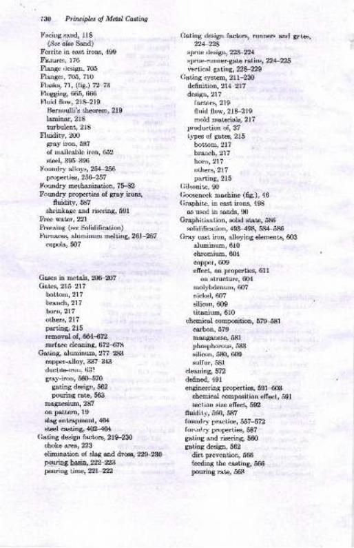
'l'il Prircipbt oJ Mehl Caslittg
Faciug sand, 118
(Sea clso Sand)
Ferrite in c&st ilons, 490
Fissures,176trlange rlesign, 705
trlanges, 705, 710
Flrrsks, 71, (fig.) 72-73Flogging, 665, 666
tr'luid flow, 218-219Bemoulli's theorem, 219
laminar, 218
turbulent, 218
Fluidity, X)O
grey iron, 587
of malleable iron, 652
steel, 39&-396Foundry alloys, 254-256
properties, 2ffi-257Foundry mechanization, 75-82Foundry properties of grey irons,
fluidity, 587
shrinkage and risering, 591
Free water, 221
Freezing (sec Solidifi cation)Furnares, aluminum melting, 261-267
cupola, 507
Gases in metsls, 206-207G*,ea,215-217
bottom, 217
branch, 217
horn, 217
others, 217
parting, 215
removal of., ffi4472surface cleaning, 672478
Gating, aluminum, 277-283copper-alloy, 3i]7-343
ducttle-trou, 63!gray-iron, 560-570
gathg desip, 562
pouring rate, 5fl3
magneEium,287
on pettern, l9slag entrapment, 4(X
steel casting, #2404Gating desip factors, 21$-230
choke area, 223
elimrnation oi slag and dross, 229-23{)
tyoy-'is.bs4li\n-ngpouring Lime, t)l-tZ)
Gating dcsign fectors, runners and gau*,?}4-y28
sprue desigrr, t2l-t24sprue-runner-ga,te rut ics, t24-X25vertical gating, 22u1t29
Gating system, 2lf-BOde6nition, 27*-217design, 217
factors, 219
fluid flow, 218-219
mold materials, 217production of, 37
types of g&tes, 215
bottom, 217
branch, 217
horn, 217
others, 217psrting, 215
Gilsonite, 9O
Gooseneck ma.chine (6S.), a6
Grophite, in cast irons, 498
as used in sands, 90
Graphitizotion, solid state, 586
solidifi cat ion, 493-498, 584-586
Gray cast iron, alloying elements, 603
alurninum, 610
chromium, 604
copper, 6Oo
effect, on properties, 6llon structure, 604
molybdenum, 6O7
nickel, 6O7
silicon, 609
titanium, 610
chemical composition, 579-581
ca,rbon, 579
manganese, 581
phosphorous, 583
silicon, 580, 6O0
sulfur, 581
cleaning, 572
defined, 491
engineering properties, 59f -€0i!chemical composition efrect, 591
section size efrect, 592
fluidity, 560, 587
loundry practice, 567 -572foundry properties, 587
gating and risering, 660gating desigo, 562
dirt prevention, 566
feeding the casting, 566pouring rst€. 5&c
Inna, iil
. (iray cast iron, graphitization during kspection, of casti.gs, 683-689
solidificetion, 584-586 and testing steel,4l&417' Craphite-type, 584 Insulating pads,248
inoculation, 585 Investment casting, 36-39, 40, 4lsection size, 5&[ Investment molds, steel,389superheoting, 585 Iron-iron carbide system, 575
graphitization in solid stete, 586 Iron oxide as used in sands, 9lheat-treatment,603 Isotropic behsvior of castings, 384-385
I 6schinssility, 60{}
stren[th, 604I stress relief, 6O4 Jackets, 73
i wear resistance,6OS Jolt mar-aine(s),60, (fiS.) 61I metallurgrcal operations, 570 cores, 126
metallurgr, 57ffi12 Jolt-rockover pattern draw, 64, 65
microstructure, 586 Jolt-squeere machine(s), 62, 64
molding, 557 pinJift petterndrawing (69.), 57molding sands,559 Jolt-squeeze.rollover pattern draw, 66-68section size efrecL,2V),57O Jolt+queeze strippers, car-t5rpe, 64,
shrinkage,561,591 (fiS.) 65
solidification, 4W98,577 Jolting, 58-61speeial casting processes,570 Junctions, 705
specification, 598-{@Gray in:,n, pouring time, ?21
shrinkage, 231 Ksolidtes (eee Molding sands, ingr€diente)
spluemnner-ga,te rut"ios, T24
Green strength of sand, 95
Grinders,678-681 LD (basic oxycetr) process, 444
Ground pitch,90 Ladles,2l0-2llLake sand, l16Loam, 119
Halloysite (sea Molding sands, ingredients) Locating points, 2X)
Ileat of fusion, 178 "Iost wax" process (see InvestmentHeat-treatment, aluminum alloys, casting)
293-298,3f4-318 Low-alloy steel, ,120
chiiled iron, 508
ductile iron, &33
gray iron,603 Machinability, gray-iron heat-treatment,magnesium, iI!1-3:I2 603
stress relief, 604 Magna.flux inepection, 4f7, 685High-a.Uoy steel, 42G421 Magnesium, castings production, 259IIot spots,697 foundry practice,285-290Hot-tear formation, 2O4-20f gating, 287
steel, 390-392 melting,288Ht,s (pa,rs, 176,7U2 molding, 286Hydrogen, solubility in aluminum and Magnesium casting alloys,
megnesium, 27O classification, 325
diecast elloys, tlilHilillheat-treatment, 3:lf , 3:|2
Illitc (see Molding sands, ingredients) permanent mold aIoys, 328-330Induction melting, 441-442 sand-cast alloys, 311F327
lnoculatioq X)7 Mallea,ble iron, 642ductile iron, 625 advantagee of,660gmy'iron,585 annealing,655
7&l Ptin i*r ol Mdal tuirlg
Mrlloabb iroq r.lrRli.g, bntch, 668-{59i.ttrDoEhre cycLE 650
..rcrti-g operetiooe, 66toastiog propsdie, 060
cbin4 651
cra.Ling Etrip, ue of, 864
d€6.nod, 4C2
duplexinS, 648
eESineeriDA properti€s, 660frststa,ge grsphitiretioD, 667iuidity, 662
limits, 6tgfoudry op.retiois, 664
SBphiti$tioq 667-O6tcompcitioD lactors, 65E
tempeBtur€, 867
hot t€edry, 662neueebiliring, 655
Doc,hrnic8t propertie3 of, 660rooltin& 064
fuDaaes, 645-046
EottliDg, 640
nodule cou.ot!, 6ffi67nucleatioD, 656
f actors iaf uencirg, 656
Frrliiic, 661
isrdenio8 of, fr62
6kuctule of, 661
poud[g t€mpersture, 6tlprcperti€s, 042*oond-€tsgo.frsphit, stion, 668sbri*sge and feediD& 6ffi61sprue fro.ture tast, 6,17
tsppina, 648typ€, 662
Manganeao, gray-iron compositiotr, 681Mrss ofiects iE design, 697
Mehsnicsl cuto4 ffi9MechaDicd proporiies, dsts a.curscy, 692
(Sce alao tr&r apecific alloy)Mechsnicsl streDgth ir dBigtr, 692MechsnirstioD, holdiry-liDe, 78Melting, air-fwnsae, 566
rluDinum, 261-273crst-im& 607-555c.h€micsl pliociptes of cast-fuon
heliiD& 8l&-666.fi€ct of coDceDtrstioa, 661.fects qf iemperature, 648high-t6mFrshre Eoltin& 664@ltiry down, tylEs of
r.eatioD& 547 -
coDpoi dloys, 34&-363
Msltio& crlpols, 5(}7
ductile iioD, 621-023
malleable imn, 6{6Metsl penettetion, stel, 372-30i1
MetsUurgicsl desigq 7r S-n4Metdlurgr, gay iron, 57F612
clemical compoeition, 570
imD-iron csrbide sy8tom, 675solidiicstio& 677
Micmpornity, 196
Molasesr 9lMold blowers, mMold coatitras, rl9, lmMold ercioD, steel, 103-404
Mold hardn€$, ll2Iuold-brdne€s t€star, 100
Molding, sluninum cestiugs, ng-mcersmic-shell, 39
CO, proc63s, 34
copper-aloy castiDgs, 3:]6
dry-aAg.egst ,70Srsy-cr.stiroo, 567mqgheeium casting8, 286
3hell, 3,t_.36
Molding pmcesses, 2&'51iggreptes, 24-26
0oor atrd pit, 2HlMolding method, for stael, 390Molding so,nds, barLing ss.D4 38{i
core sDd mold wash€s, st€el, 394deDsiti€3 (bble), 66
durability, 387
fscing Band, 388
steel, 3glgercrel propertiG, 84, 85iDgredietrts, 85-Slmoishre coDtent, 388
orsrDic rdditio$, 388peme.bitity, ?88
refrr.torin€ss, 387t€titr& C2, r04
Molda, oemeni$oadod 31, 32
core-sand, 32-$4dry-Baod, 29gephite, 43greeD4eDd, 2&-20loato, 3lmsieridq *mip€lEEDent-Illold,
4, 45, fiDoBtmorillonit€6 as usod ia, E8p.Imaoetrt, 43plastar, 39, 42
skh-dti€4 29
Inda ?il:l
MolyMenum, Ersy cast iron,607 Ph]tsicsl chemistry ol BtEoI mskina, oxi'
Montmorilodtes as ued in molds, 88 dation and rcfinitrg, slloys, 459
Moitled iron, {SD carbon, 453'454
Muller, -entrifugsl-type, 115 msngsn€€€,45H58oxyaen, 45H62
Phcphor'rs, 456-458
I icUel, l.Isy cast iron, 607 silicon, 45'H55
Nodulsr co.st iron (t . Ductile cast iron) sltg control, 462 _464
Nuclestion, heterogen€ous, 182 su[ur,458-45S
homogeneous, 182 standad frse eneryl', 441-442
of mslleabl€ iron, 666 Pinhole poroditv iD stEel cast'iags, 38&"389
Pits, motditr& 3rPlain-carbon steel, 418-419
Ori6c€ plstes (tsble), 98-99 Poro€itv in steel, 402
Oxyaen iniection, 443-444 Pouring, gsy iron, &6metal, ladles, 210-2l l
Pouring tim€, 221-222
PrddiDg lor cent€r-lire ahrinlage, 697 ductile iron, ??2
Psrting surfa.es, m gtaY hon, ?21
Pstt€m design, core elimination, 715 sltf'l,2t)simplifrcstion, 713 Power cuttitr& 670' 671
Psttem dBwiDg, ?13-715 Preci.siotr clsting (s?.Itrv6tBent
Psttern stripping, 6l castina)
latterDmskins, 8-22 Pressur€ teating, 684
Patt€ms, cope and &sg, 11, 12 Progressiv€ solidificutioo, 212-213
&*t tz Properties, 256-257
futrctions, 10-21
8rtad, 10
hsrd-ssnd mstah, 13, 16 Rsdiographic inspection, S84
loc€ (sinslc) g, r0 Ramming, ll3match, 12 Rabonding, Sr,9match-plst€, ll Refractaries, aaid, 4r2' 425
sp€cisl, 12 basic, 412, 425
typee,8,g-r2 cupols, 512
wax,37 R€Ynold-s numb€r,218
Poarlit6 in c!.st irons, 499 Rib d€€igDs, 705
Peailitic mslleable ircn, 661 Ri*ri[g, aluminum, 283-286
Perlite, gl copper-alloY, 343-345
PemEnentxnoldcasting,slurninuxn, ductile-iDn,6322S graY-imn,56o 570
atuminum auoys,307-3(x) fe€diog, 567
copper-buo elloye, 380 Risers, 213-214, 230-250
mognesium elloys,32&320 opplicatioN,24g
?bosphorus, grsy-irctr compositiotr, 583 bliDd' 245-242
Pbysicrt chexnistry of Bte€l osking, chils, 2{3-248
. activity, {,47 extarnsl' 243'246
deoxidation, {64=,$6 inlarn!.l,24$-247
efi€ct, of corcetrtBtion, 4tH52 Chvorinov's rule, 233
of t€mperature, tl4H,lg connections, 243
equilibrium coDstsnt, 44{H47 insulrra4 248
fugs.ity, 448 inflrlstors and €xotherEic compounds,
meltina, 462-.153 247-248
oxi&tioo oad re6oing, {53J6 htemd, 242
\
7U Principla of Mclal Cattittg
Risers, location, 230-24oprimary function, 23IJ-231
rclat€d to easting tocation, 243
removal of, 6611.{?2
shape, 232-233
sirc,233-239special efrects at section joints, 24$-250steel ca.stingg 404-410
exothermie, 410
feeding distance, 408-409knock-off, 4l(F4llneck size, 409padding, 40Hr0size, 4O4-409
aurface cleaning, 672-878theory,2Sl-2{2
Sand(s), coromaking, f 6l-f 56mixing, 16l-164properties of, f70-173testing for, 164-170
facing, ll8molding, 84-122
grsy-iroD, 559
dqfiniti6ng, f16-1.19
8r€en, 104-ll5Sond castings, 26Sand muller (fig.),77Sand preperation, 75Sand rammer (fig.), 94
Sand slingers, 68motive, 69
stationary, 68, 69
tractor, 69
Sand thrower, 127
gray iroq 559Sands molding, AlIl fineness number
(tsble), rogconditioning, 1 14
praqtices, l17testing, 9G-103
Scabs, 176
Ses cosl, 90, 9lSection+ize efrects, ductile iron, 636
engineering properties, 5m, 636gray iron, 57O,7nsection size and graphite type, 584
Section thickness, 702
minimum sections for aluminumcasting8, 274
gestiqning, 694lhellore machines, 126
Shell molding, 70
$a eo Moldiq6 ary-rgtr€g8te)Shell molde, steel, 389Shrinkage, 179
Silica [see Sand(e)lSilica flour, 90
Silicon, gray-iron compoeition, 6&; 609Skhdried molds, eteel, 389SIag control, 452-464
cupola, 541
SIag entrapment, 4(XSlinger,127Slurry, 37Sodium bentonite (caa Weatern bentonite)Solidification, 186-2[n
caat irons, 496-408dflpgli6nqt, 2L2_2tBductile iron, 6f8-621in flowing stream, 4{X)
graphitization, 40.?-498, 584-686gray iron, 406-4S, 577progressive, 212-2lZof steel, 396-4U2
time of, for steel, 4(X)
Solidification, alloj,s, 186-XX)
cleqification, 186
eutectic, 196-108
endogenous, 197
exogenonB, 197
modifred, 197
solid-solution type, 187-190
end of freezi.g, f89-190grain eize and ahape, 188
mushy etage, 189
start of freezing, f89-190so[d-solution variableq 190
solidification range, lg0-191thermal cha,racteristic8 of metal, lg2thormsl conductivity of mold,
t9l-r92dweetage, 198-200
segr€getio; and shrinkage, 2[X)
variablee,2[)0Solidification, properties, fluidity, 20(F
wva,riables, W2-M
g8s eyolutioo, Ufi-m7hot tea,ring or hot cracking, X.+ 2,x
iooculation, Z)7pure metals, 179-186
heterogeneous nuclection, 189
homogeneoue nucloation, l8Anuclestion,a,Dd gowth, l8l-1f;

Solidificetion, properties, pipe, 185
shrintage, l$-f85skin efiects, 179-180
eolidification in a mold, 179-180
Southern bentonite, 88, lllSpecifications, gray iron, 598-602
Spoed muller mixer (fig.), 77
SpheroiCal graphite cast iron (eoa
Ductile cast iron)Squeeze boards, 13, 74Squeezing, d&-18
contour, 58Squeezing machines
r sF€cisl,68rr
Stack molding 81, 82
, Steadit€ in cast irons, 490
I Steel, inspection ond testing, 4l&-ll7'Steel castings, advantages of, 384{86' ulloy steels, 48li|-484
burn-on,39!l i
casting problems, 386
ceramic molds, 389
ceroxides, 393-394
cleaning, 412
cold shortn€ss, 468
corrposition of, 467-468manganese, 467-468phoephorue, 468
nrlicon, 467-468
sulfur, 168
eore and mold washes, 39,1
cores, 390
. dry-ss"d moldg 389
efrect o& of carbon, 384
6niehin& 386ftuidity, 396-397gating, 402-404
mold erosion, 403-404slag entrapmen! 4(X
hardena,bility oi 48&48?heat treatmento 481-4tI!
annealing, 481-489
homogenizatiorl 481
liquid quench and temper, 4Elil
normalizing, 482gtress-relief anneal, 4tlil
higlr-.alloy, 42o-421
:tot tear formation, 390-392inclnsions, 476480ir'spection, 416-417
iavestment moldE, 889iron-ca,rbon diagra,m, 469lon-alloy, 420
Indcr
Steel castlnga, macrostructure, 472
magna,flui teating, 417
metal penetration, 390-393mierostructure, 47247 6
bainite, 473
blocky ferrite, 473
martensite, 473
Widmenstaetten ferrite, 47 347 6molding processes, 387-390mol{ing sands, 387-388pinhole porosity, 388-389plain-carbon, 418-419pouring lime,222production heat-treatment, 487-489properties ol 386, 407 42O, 476property control, 471
risers, 4O4, 410
exothermic sleeves, 410
feeding distance, 4O&-409
knock-ofr, 41(H11neck size, 409padding,40Hl0siz,e, 404-4@
sLelt. molds, 389shri;rkage, 231
skin-dried molds, 389solidifi cation f actors, 39S-402
gravity and convection efrects,399-400
porosity, 402
shape factor, 4(n-401temperature level, 397t€mperature range, 397thermal conductivity
of mold, 397-398of steel, 398
time, 40O
r;prue-runner-gate ralio, t24structure of, 46&47O
austenite, 468
cementite, 469
effect of carbon, 468
ferrite, 469
inclusions, 476-480pearlite, 470
solidifi cation efr ect, 47 1L.72
oroperty efrccts, 476
tapping and pouring, 414
temper brittleness, 437testing, 4lG-417uses, 417-420
welding 4lHl6, St€el melting, 4ll4t4
736

l Pti,I.cipLt ol Mdal eattutt
St€el m€ltiry, said coDvert€r, {'lH4la.id-€lectric. 43H4O
LEltins, 43840refinin8, 43H40rlss control, 440
sr,id op€n-hesrttr, 43H39chrrge, 43?
f umace ooDstnrctioD, 4:tH37mell,inA, 437 '1:}8
r€6ning, 437-438
silico reduction, 438
slog tasts, 438
acid process, 412, 425
bdsic eleckic proc€ss, 43H36deoxidotion, 436
fumace coD6truciion, 433-434
meltinS, 43'H36phcphorus removsl, 434
re6nin8, 434 -436
refinins slss, 434--436
sulfur removal, 436
basic open-hesrth, 42H32bottom construction, 428
chsrge, 4'2Hii0charging, 430
deondetion,433fluo.rspar, $2fuel, 129
fumace c{nst nrction, 42H28melting, 430
oxid&tion, 43H32refning, 43Hililroof cgostructioD, 428
spie8€I, 432
t&pping, {3i}wsll coostruction, 429
basic oxysen' 444
basic proc€€s, 4r2, 425
carbon boil, 412
deoxidatior\ 413-414
LD pIocels, 444
oxygen iniection, 4'{3-444
physical chemisary, 444-{66
processes, arc-fumace, 4l l_412
open-hes.rth, 4rr-'{12regenerative heat trsnder, 426
vaauum depssinS, 443
vscuum melting, 443
iJtock-core maahines, 135
Subme.sed plunger machin€ (69 ), aG
ISulfur, ssy-iron csmpo€ition, 681
Supercooling, l&7
Superhest, 1?8
Sw€ep€, 12, 15
(3r? a&o Pstt€.D& specful)
Ten-sile str€ngth in gr€en molding
slnd, 95
Testing snd inspection, st€el, 41Hl'TherxoodyoaEics of Bteel mskin&
414466(Sea abo PhyBicsl chemishY of
steel msking)
.Titanium, glsy cest irotr, 610
Tolermc6, die cg8tiDg, ?06
dimensionat, 7O4
To.ch cuitiDg, 669
T.imming, of ca.stingp, 678-682
Triplex method, 441
Tumblins, 672 s74
UpBeb, ?2
Vucuum degassing, 443
Vacuum melting, 443
Veins, 176
Venting, core-box, 132
Vibrating-squeere psttemirawmschine, 68
W&t€r, €fiects olr ssnd, 108, 100
Wesr resistsnce, Srsy-iron hest_
trestment, 603
Weishts, 74
Welding, st€el castings, 386, 4rH16WeBtern benronite, 88, 108, ll0, rr:Wlite csst ircn, chiued, 492
properties, 506-506
detned, 492
mottled, 4S2
properties, 5O4
Wlit€ ircn, structur€, 643
Wood 6our, m
X-rsy BdioSrephy, 4t6
Also from McGraw-Hill Education
GAUDIN
GRANT
AGARWAL
CAMPBELL
HICKS
JAIN
JOSHI
KAZIMI
KRISHNAMOORTHY
PRABHUDEV
SHINATH
lntroduction to Engineering Materials
Principles of Manufacturing Materials
and Processes
Principles of Mineral Dressing
Jigs and Fixtures: Non Standard
Clamping Devices
Pump Operation and Maintenance
Principles of Foundry Technology,4/e
Jigs and Fixtures, 2/e
Solid Mechanics, 1st Bevised Edition
Finite Element Analysis: Theory and
Programming,2/e
Welding and Welding Technotogy
Materialscience
Manufacturing Technology: Foundry,
Forming and Welding, 2le
Handbook of Heat Treatment of Steels
Advanced Mechanics of Solids, 2/e
LITTLE
NAFIULA
RAO