Embed Size (px)
Citation preview

FOI, Swedish Defence Research Agency, is a mainly assignment-funded agency under the Ministry of Defence. The core activities are research, method and technology
development, as well as studies conducted in the interests of Swedish defence and the safety and security of society. The organisation employs approximately 1000 per-
sonnel of whom about 800 are scientists. This makes FOI Sweden’s largest research institute. FOI gives its customers access to leading-edge expertise in a large number
of fi elds such as security policy studies, defence and security related analyses, the assessment of various types of threat, systems for control and management of crises,
protection against and management of hazardous substances, IT security and the potential offered by new sensors.
Comparison between
Swedish casting
specifi cations and MIL-STD
ELISABETH BEMM, SVANTE KARLSSON, MAGNUS BERGH
FOI-R—3234—SE Base data report Defence & Security, Systems and Technology
ISSN 1650-1942 July 2011
FOI
Defence Research Agency Phone: +46 8 555 030 00 www.foi.se
Defence & Security, Systems and Technology Fax: +46 8 555 031 00
SE-147 25 Tumba

Elisabeth Bemm, Svante Karlsson, Magnus Bergh
Comparison between Swedish casting specifications and MIL-STD
FOI, Totalförsvarets Forskningsinstitut FOI, Swedish Defence Research Agency
Avdelningen för Försvars- och säkerhetssystem
Defence & Security, Systems and Technology
Grindsjöns forskningscentrum
147 25 Tumba SE-147 25 Tumba
Titel Jämförelse mellan svenska gjutkrav och MIL-STD
Title Comparison between Swedish casting specifications and MIL-STD
Rapportnr/Report no FOI-R—3234—SE
Rapporttyp Report Type
Underlagsrapport Base data report
Sidor/Pages 26 p
Månad/Month July
Utgivningsår/Year 2011
ISSN 1650-1942
Kund/Customer FMV
Forskningsområde Programme area
Delområde Subcategory
51 VVS med styrda vapen 51 Weapons and Protection
Projektnr/Project no E26489
Godkänd av/Approved by Bengt Eiderfors

3
Summary During late sixties a number of accidents occured with grenades that were initiating at launching. A study was performed by ”Spaltgruppen” to analyse how these types of accidents could be prevented. The final report presented by ”Spaltgruppen” resulted in that the standard requirements for melt casting of TNT in Sweden is more stringent than for example MIL-STD. A comparison between these standards has been performed to being able to determine whether grenades produced according to MIL-STD conforms to the Swedish requirements and is reported on in this report.
Structural Dynamics Simulations show that initiation through shock compression can be considered highly unlikely. Furthermore, experiments suggest that broad base cavities are considered critical. However, initiation during launch is still considered highly unlikely for grenades with a round bottom and where a (close to) frictionless interface between charge and cover can be excluded. When it comes to cavities, experiments show that a radius of 3.5 mm and a constant acceleration of 20000g can lead to initiation in TNT. At the acceleration considered within this project, simulation indicates that spherical cavities do not collapse due to material strength. However, further experiments are required, preferably in combination with a more sophisticated material model. For spheroidal (oblate) cavities compression is achieved, but an estimate of the heating due to adiabatic compression suggests that the temperature in the surrounding explosive is well below the critical temperature for initiation reported in experiments performed under similar conditions.
This report is also available in Swedish as the report number FOI-R—2795—SE.
Keywords: premature initiation, TNT, base cavity, cavities, casting defects
FOI-R--3234--SE

4
Sammanfattning Efter att ett antal olyckor med granater under utskjutning i slutet på sextiotalet inträffade, genomfördes den s k spaltgruppsutredningen för att utreda hur denna typ av olyckor skulle kunna förhindras. Spaltgruppens rapport har lett fram till att de gjutkravsbestämmelser som gäller i Sverige är något hårdare än t ex MIL-STD. En jämförelse har därför gjorts i denna rapport mellan dessa standarder för att utreda om granater som tillverkats enligt MIL-STD lever upp till de svenska kraven enligt spaltgruppen.
Strukturdynamiksimuleringar visar att initiering genom stötkompression är högst osannolik. Vidare utpekas breda bottenspalter som kritiska utifrån experiment i litteraturen, men initiering anses ändå som högst osannolik för granater med rund botten och god vidhäftning mellan sprängämneskropp och hölje. Vad gäller kaviteter visar experiment att en radie av 3,5 mm under en konstant acceleration av 20000g kan leda till initiering i TNT. Beräkningarna antyder att sådan kollaps är osannolik, men här behövs ytterligare experiment i det aktuella området, gärna i kombination med en mer sofistikerad materialmodell. Sfäroidiska kaviteter kan emellertid komprimeras, men uppskattningar av värmeutveckling under adiabatisk kompression antyder att temperaturen då blir klart lägre än kritisk temperatur från experiment under likartade förhållanden.
Den här rapporten finns också tillgänglig på svenska som rapportnummer FOI-R—2795—SE.
Nyckelord: granat, spalter, kaviteter, TNT, känslighetsanalys
FOI-R--3234--SE

5
Contents
1 Introduction 7
2 Comparison between different casting specifications 8
2.1 Difference in requirements................................................................8
2.2 Differences in inspection of grenades produced.............................14
2.3 Differences in casting methods at production.................................15
2.4 Factors of importance for safety and functionality ..........................16
3 Theoretical evaluation of defects in a charge 17
3.1 Brief model description ...................................................................17
3.2 Initiation through shock compression .............................................18
3.3 Initiation through compression of base cavities ..............................19
3.3.1 Wide base cavity.........................................................................19 3.3.2 Thin base cavity ..........................................................................20 3.3.3 Spherical or spheroidal base cavities .........................................21
3.4 Comparison between TNT and Comp B.........................................23
4 Discussion 24
5 Conclusions and recommendations 25
6 References 26
FOI-R--3234--SE

6
FOI-R--3234--SE

7
1 Introduction In consequence of the accidents at Ravlunda and Gryt, where grenades were initiating at launching, a study was performed by the working group ”Spaltgruppen” to analyse how these types of accidents could be prevented. In the final report from the study were given requirements for melt casting aiming at minimizing the risk of formation of severe cracks and base cavities at melt casting of artillery ammunition1. It was concluded already at an early stage of the study that good adhesion of the high explosives (HE) to the casing was critical. This resulted in development of a special paint for coating of the interior surface of the casing. For further improving the adhesion, trinitrotoluene (TNT) was added to the paint. It was also concluded that it is important to carefully control the temperature (~80° C) of the casing at loading of TNT melt and that the casing is placed in a water bath to ensure that the solidification is starting in the base.
The recommendations stated by ”Spaltgruppen” are minimum requirements for melt casting of grenades in Sweden. When these recommendations are applied, it is regarded as possible to manufacture grenades that are safe to handle and use. These requirements have been used as a base for formulation of different standardized Technical specifications (TS) for specific grenades. The requirements in TS are often more stringent than the acceptable minimum recommendations in the report by ”Spaltgruppen”. It has also been assumed that the requirements in the Swedish TS are somewhat more stringent than those in the international standards (MIL-STD). A comparison between these standards has therefore been performed to be able to evaluate if grenades manufactured in accordance with MIL-STD also conforms to the Swedish recommendations stated in the report by ”Spaltgruppen”.
There will be a bilateral collaboration with Norway within the ARCHER-project (155 mm artillery system) and it would therefore be desirable to be able to use Norwegian grenades in the weapon system. Since the Norwegian grenades have been manufactured according to MIL-STD, the requirements and methods that have been applied at production of grenades at NAMMO in Karlskoga and NAMMO in Raufoss have been compared. The result from this comparison is presented below in this report.
Further is presented a theoretical study concerning the impact of different defects in the charge. Results from structural dynamic simulations in combination with experimental data from literature is reported on for those defects considered as most critical, i.e. cracks and cavities at the base of the grenade.
FOI-R--3234--SE

8
2 Comparison between different casting specifications
2.1 Difference in requirements
The different casting specifications that have been compared are MIL-DTL-60377A-C, Technical specification for casting of sgr m/54-77 (document number 0 808 327) and the report from “Spaltgruppen”. These documents are in this report referred to as MIL-STD, TS and report from “Spaltgruppen”. To be able to identify differences between production methods at NAMMO in Karlskoga (according to TS) and at NAMMO in Raufoss (according to MIL-STD) suitable persons working there have been interviewed.
An aggravating circumstance in comparing melt casting specifications according to the report from “Spaltgruppen” and TS with MIL-STD is that the different zones representing different segments of the grenade, from the base to the top, is not identical in these standards. In MIL-STD (figure 1a) the zones are thinner at the top of the grenade while they are thinner at the base of the grenade in the Swedish standards (see figure 1 b)
a) b)
division of segments according to MIL-STD division of segments according to the Swedish standards.
Figure 1. Zones according to a) MIL-STD and b) report from ”Spaltgruppen” and TS. The figures are collected from MIL-DTL-60377C and TS for sgr m/54-77.
FOI-R--3234--SE

9
To be able to make a relevant comparison between the Swedish standards and MIL-STD the different zones have to be made comparable. Since Zone A and B+C in MIL-STD almost corresponds to zone A+B and C+D in the Swedish specifications, we have chosen to merge these zones in table 1 giving the casting requirements of the different standards.
The different types of defects that can appear at production of grenades are described in figure 2. In the different melt casting specifications are given allowed limits for these types of defects. How these allowed limits differs between the different melt casting specifications can be seen in table 1-2. Defects are here given as projected area which facilitates the analysis of radiographic images.
Figure 2. A description of different types of defects that can appear at melt casting of the HE charge. The figure is taken from TS for sgr m/54-77.
Cavity A space anywhere within the charge. Any hollow space which does not fit any of the definitions hereunder is defined as a cavity.
Ring-shaped cavity Cavities of ring shape arise when filling in stages.
Pipe A cavity arising during the solidification sequence in a high-explosive charge; usually more pronounced close to the upper surface, but can develop lower down to a considerable depth.
Porosity Collections of minor hollows, usually caused by local irregular solidification sequence or inclusions of air, foam etc.
Crack A separation in the charge which may not amount to a complete separation. A crack can be transversal as shown in the illustration or longitudinal.
Base cavity A cavity between the high-explosive charge and the shell body at the bottom of the shell.
Base crack A crack between the high-explosive charge and the shell body where the high explosive remains attached to the shell body.
FOI-R--3234--SE

10
Tab
le 1
. A c
ompa
riso
n of
req
uire
men
ts f
or m
elt c
aste
d gr
enad
es a
ccor
ding
to M
IL-S
TD
and
the
repo
rt f
rom
“S
paltg
rupp
en”.
. A
des
crip
tion
of th
e di
visi
on o
f zo
nes
is
give
n in
fig
ure
1 a-
b. M
IL-S
TD
*
Rec
om
men
dat
ion
s ac
cord
ing
to
”S
pal
tgru
pp
en”
Typ
e o
f d
efec
t
Zon
e A
Z
one
B
Zon
e C
Z
one
D
Zon
e A
Z
one
B
Zon
e C
Z
one
D
Zon
e E
Z
one
A+
B
Zon
e C
+D
Pro
ject
ed
leng
th
of in
divi
dual
ca
vitie
s.
3.2
mm
12
.7 m
m
12.7
mm
19
mm
-
- -
- -
- -
Tot
al p
roje
cted
ar
ea o
f cav
ities
. 10
mm
2
161
mm
2
323
mm
2
323
mm
2
3.5
mm
2
16 m
m2
80 m
m2
100
mm
2
300
mm
2
19.5
mm
2
180
mm
2
Cra
cks,
rig
ht
thro
ugh
(ma
x .
wid
th)
0.1
mm
0.
3 m
m
0.5
mm
(x
2)
0.5
mm
(x2
) 1.
5 m
m
Cra
cks,
not
rig
ht th
rou
gh
(max
. w
idth
)
0.8
mm
0.
8 m
m
1.6
mm
0.1
mm
0.
3 m
m
0.5
mm
(x
2)
0.5
mm
(x2
) -
Tot
al a
rea
av
poro
sitie
s 20
2 m
m2
424
mm
2
424
mm
2
- 0
16 m
m2
160
mm
2
160
mm
2
160
mm
2
16 m
m2
320
mm
2
Pip
es (
proj
ecte
d w
idth
) 0
6.4
mm
6.
4 m
m
- -
- -
- -
- -
Pip
es (
proj
ecte
d ar
ea)
0 16
1 m
m2
323
mm
2
- 0
0 12
0 m
m2
120
mm
2
- 0
240
mm
2
Rin
g-sh
ape
d ca
vity
(m
ax.
proj
ecte
dx
wid
th)
0 0
6.4
mm
-
- -
- -
- -
-
Bas
e ca
vity
0.
38 m
m
0.
1 m
m
* T
he v
alue
s ar
e va
lid
for
eval
uati
on o
f ra
diog
raph
ic im
ages
of
gren
ades
FOI-R--3234--SE

11
Tab
le 2
. A c
ompa
riso
n of
req
uire
men
ts f
or m
elt c
aste
d gr
enad
es a
ccor
ding
to th
e re
port
fro
m “
Spa
ltgru
ppen
” an
d Sw
edis
h T
S. A
des
crip
tion
of th
e di
visi
on o
f zo
nes
is
give
n in
fig
ure
1 a-
b. Rec
om
men
dat
ion
s ac
cord
ing
to
”S
pal
tgru
pp
en”
Sw
edis
hT
S f
or
sgr
m/5
4-77
* T
ype
of
def
ect
A
B
C
D
E
A
B
C
D
E
Pro
ject
ed
leng
th
of in
divi
dual
ca
vitie
s.
- -
- -
- 0
0
6 m
m
6 m
m
10 m
m
Tot
al p
roje
cted
ar
ea o
f cav
ities
. 3.
5 m
m2
16 m
m2
80 m
m2
100
mm
2
300
mm
2
0 0
80 m
m2
100
mm
2
300
mm
2
Cra
cks,
rig
ht
thro
ugh
(ma
x .
wid
th)
0.1
mm
0.
3 m
m
0.5
mm
(x
2)
0.5
mm
(x
2)
1.5
mm
0
0 2
of m
ax.
wid
th o
f 0.5
m
m e
ach
2 of
max
. w
idth
of 0
.5
mm
eac
h
2 w
ith a
m
ax.
tota
l w
idth
of
1.5
mm
Cra
cks,
not
rig
ht th
rou
gh
(max
. w
idth
)
0.1
mm
0.
3 m
m
0.5
mm
(x
2)
0.5
mm
(x
2)
-
0 0
2 of
max
. w
idth
of 0
.5
mm
eac
h
2 of
max
. w
idth
of 0
.5
mm
eac
h
-
Tot
al a
rea
av
poro
sitie
s 0
16 m
m2
160
mm
2
160
mm
2
160
mm
2
0 0
160
mm
2
160
mm
2
160
mm
2
Pip
es (
proj
ecte
d w
idth
) -
- -
- -
- -
4 m
m
4 m
m
-
Pip
es (
proj
ecte
d ar
ea)
0 0
120
mm
2
120
mm
2
- 0
0 12
0 m
m2
120
mm
2
0
Rin
g-sh
ape
d ca
vity
(m
ax.
proj
ecte
dx
wid
th)
- -
- -
- -
- -
- -
Bas
e ca
vity
0.
1 m
m
0
*The
val
ues
are
valid
for
eva
luat
ion
of r
adio
grap
hic
imag
es o
f gr
enad
es
FOI-R--3234--SE

12
Out of the defects given in table 1-2, base cavities are the types of defects that have the most severe impact on safety. The maximum allowed length of base cavities is 0.1 mm in the report from “Spaltgruppen” while base cavities of 0.38 mm are allowed in MIL-STD (see table 1). To avoid destruction of defective grenades at production no base cavities at all are allowed in TS in contrary to the allowed base cavity of 0.1 mm in the report from “Spaltgruppen” (see table 2).
Next to base cavities, cavities positioned further up in the charge are considered as most critical according to MIL-STD. Defects positioned in the lower parts of the charge are more critical than defects positioned in the upper parts since the lower part of the grenade is subjected to the weight load from the whole grenade during acceleration. From an examination of the values in table 1 it can be concluded that a maximum projected area of 3.5 mm2, in the most critical lower parts of the charge, is allowed in the report from “Spaltgruppen” while the corresponding permitted value in MIL-STD is 10 mm2. Zone A in MIL-STD corresponds however approximately to zone A+B in the Swedish specifications. For this part of the charge the allowed projected area of 10 mm2 in MIL-STD should therefore rather be compared to an allowed projected area of 19 mm2 in the report from “Spaltgruppen”. This means that in the most critical parts of the grenade (corresponding to zone A in the Swedish specifications) the requirements by “Spaltgruppen” are more stringent than MIL-STD but in the part of the grenade corresponding to zone A in MIL-STD the requirements by “Spaltgruppen” are less stringent than MIL-STD. However in TS no defects at all are allowed in zones A or B.
In table 1 it can be seen that the requirements for the allowed collected surface area of porosities in the lower parts of the grenade are much more stringent in the Swedish specification compared to zone A in MIL-STD (202 mm2) irrespective if only the Swedish zone A (0 mm2) or the Swedish zone A + B (16 mm2) is considered.
There is not a major difference between Swedish specifications and requirement in MIL-STD for either the allowed projected surface area of pipes or the projected width of cracks (see table 1).
Since presence of base cavities is a more severe safety risk than other possible defects, the most significant difference between the melt casting specifications given in MIL-STD and TS is the requirements for allowed sizes of base cavities. The consequences of presence of base cavities in grenades are further discussed in section 3.
At a comparison of the melt casting specifications given in TS and in the report from “Spaltgruppen” (see table 2) it can be seen that the difference in
FOI-R--3234--SE

13
requirements are only minor except for the requirements concerning defects in zones A and B. In TS no defect at all are allowed in zones A and B.
According to MIL-STD no foreign material in the HE charge is allowed. According to TS, foreign materials given in table 3 are however allowed in the HE charge. In addition to the specified materials given in table 3, remnants from other HE or aluminium particles are permitted.
Table 3. Foreign materials that are allowed to be present in the HE charge according to TS.
Type of material Size Max. number/ grenade
Hard particles: Metals (magnetic and non-
magnetic) Ceramic material (sand, glass etc)
Wire shaped (max. length 4 mm, maxt. width 0,7 mm)
Grain (largest dimension 0,7 mm)
Flake (largest dimension 4 mm, maxt. width 0,7 mm)
2
Soft particles: Hard plastic Wood
Max. 5 mm 5
A comparison between the different editions of MIL-STD A-C has been performed. No differences in requirements between the different editions have been identified. Which specific standards and other documents that are referred to in the text, and thereby constitute a part of MIL-STD, differ however somewhat between the different editions (see table 4). We have not reviewed all of these documents but do not consider that the difference will have an impact of the quality of the grenades produced.
Table 4. Specifications, documents and other standards referred to in the different editions of MIL-STD
Edition Document
number
Document title
MIL-A-2550 Ammunition and Special Weapons, General Specification for Standards
MIL-STD-105 Sampling Procedures and Tables for Inspection by Attributes
MIL-STD-109 Quality Assurance Terms and Definitions
MIL-STD-453 Inspection, Radiographic
MIL-STD-1168 Lot Numbering of Ammunition
A
MIL-STD-1235 Single and Multilevel Continous Sampling Procedures and Tables for Inspection by Attributes
FOI-R--3234--SE

14
MIL-A-48078 Ammunition, Standard Quality Assurance Provisions, General Specification for Standards
MIL-STD-109 Quality Assurance Terms and Definitions
MIL-STD-453 Inspection, Radiographic
B
MIL-STD-1235 Single and Multilevel Continous Sampling Procedures and Tables for Inspection by Attributes
MIL-STD-1168 Lot Numbering of Ammunition
MIL-STD-1916 DoD preferred methods for acceptance of product
C
ASTM E 1742 Standard Practice for Radiographic Examination
2.2 Differences in inspection of grenades produced
According to both TS and MIL-STD all of the grenades produced shall be subjected to radiographic inspection to reveal possible defects listed in table 1 and 2 above.
According to TS one grenade per shift (1 shift = 200 grenades) is dissected into two equally sized longitudinal sections. At an ocular inspection of the section interface any types of visible defects can be identified and the size of them measured. According to Raufoss one grenade per shift (1 shift = 72 grenades) was inspected according to the same method when they had an active production of grenades there although this was not required according to MIL-STD. The sectioned grenades are also subjected to knock-out tests. This test is performed in a knocking-out apparatus for 12 s with an air pressure of 6 kp/cm2 and a stroke length of 10-15 mm.
According to MIL-STD the grenades shall instead be sectioned by cutting in parallel with the base approximately 10 cm up from the base to the centre of the projectile axis. The grenade should then be cut through the base toward the nose perpendicular to the former cut so as to remove a wedge of steel. Any possible base cavities or cracks in the HE charge interface can then be studied. Eight projectiles in every shift with the largest base cavities (not exceeding 0.38 mm) accepted by radiographic inspection are selected to be tested in this way. If eight grenades with base cavities cannot be found, the remaining grenades are selected randomly from the shift.
In Raufoss ballistic testing of grenades produced was performed according to MIL-STD. No unintentional ignition in the gun barrel or in the flight at firing was allowed at a pressure of 41 000 plus 3 000 psi. No such types of tests are performed at NAMMO in Karlskoga.
FOI-R--3234--SE
15
2.3 Differences in casting methods at production
Both the specifications in TS and in MIL-STD constitute minimum requirements at production. It is therefore possible that the melt casting requirements at a certain production site are more stringent than the specifications in the standard stated to be followed. In TS and MIL-STD is given only the requirements to be fulfilled and not how to comply with them. It is therefore important to make known of the actual casting and inspection methods used at a specific production site and not only rely on the specifications in the standards used. Below is following a description of the melt casting methods that are in use/were in use at NAMMO in Karskoga and Raufoss respectively.
It was stated in the report from ”Spaltgruppen” that a good adhesion of the HE to the casing is very important. A number of actions can be made to ascertain that this is accomplished. The interior surface of the casing should for example be cleaned carefully and painted prior to loading. Phosphation of the interior surface can be performed to minimize the risk for corrosion. Preheating of the shell body can be made to improve the adhesion to the HE charge. All these actions have been made both in Karlskoga and in Raufoss.
It is also important that no foreign material or particles are present in the HE charge. In Karlskoga the HE mixture is filtered prior to usage. No filtering was performed in Raufoss, they instead claimed a delivery of absolutely clean HE mixture from the supplier. The cleanness requirements on the HE charge of the grenades from production are however more stringent in MIL-STD than in TS.
Both in Karlskoga and in Raufoss hexanitrostilbene (HNS) was added to the HE mixture to minimize the risk of crack formation during the solidification process. This additive has a large impact on the quality of the grenades produced and on the amount of defects formed.
To obtain a uniform quality of the melt casting process, a major part of the casting process is automitised by process control systems at both mentioned production sites. Below is given some important process control parameters
Temperature of the casing prior to casting Temperature of the HE mixture at casting Time and pressure for vacuum treatment Time from start of casting process to cool down
FOI-R--3234--SE
16
Both in Karlskoga and in Raufoss the ” Rod program” is applied during the solidification process. The Rod program means that a hot finger is placed inside the casing. The hot finger is then elevated at a certain speed during the solidification process while the grenade is simultaneously loaded with more HE mixture. In Karlskoga the grenade is placed in a water bath for cooling down during the solidification process while the cooling down is accomplished by a flow of cold air from the floor. In USA the cooling down is accomplished by water bath despite applying the same standard as in Raufoss. The objective of applying the Rod program is to avoid formation of air gaps during the solidification process.
2.4 Factors of importance for safety and functionality
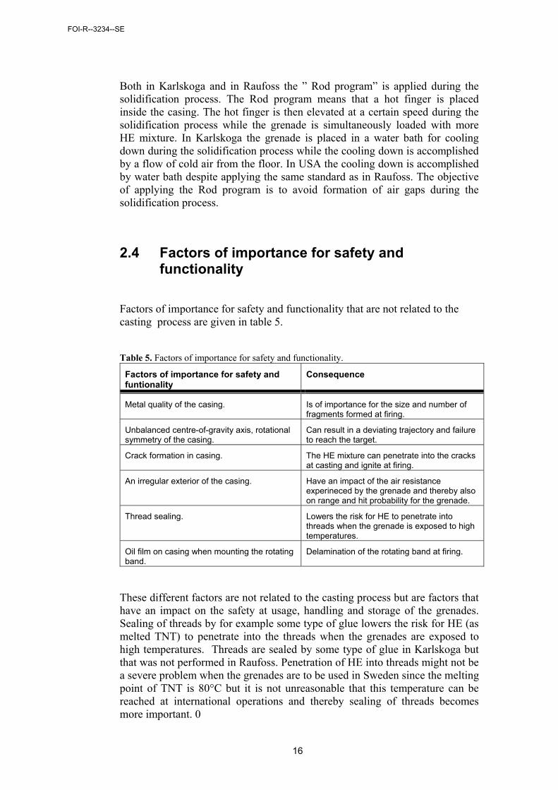
Factors of importance for safety and functionality that are not related to the casting process are given in table 5.
Table 5. Factors of importance for safety and functionality.
Factors of importance for safety and funtionality
Consequence
Metal quality of the casing. Is of importance for the size and number of fragments formed at firing.
Unbalanced centre-of-gravity axis, rotational symmetry of the casing.
Can result in a deviating trajectory and failure to reach the target.
Crack formation in casing. The HE mixture can penetrate into the cracks at casting and ignite at firing.
An irregular exterior of the casing. Have an impact of the air resistance experineced by the grenade and thereby also on range and hit probability for the grenade.
Thread sealing. Lowers the risk for HE to penetrate into threads when the grenade is exposed to high temperatures.
Oil film on casing when mounting the rotating band.
Delamination of the rotating band at firing.
These different factors are not related to the casting process but are factors that have an impact on the safety at usage, handling and storage of the grenades. Sealing of threads by for example some type of glue lowers the risk for HE (as melted TNT) to penetrate into the threads when the grenades are exposed to high temperatures. Threads are sealed by some type of glue in Karlskoga but that was not performed in Raufoss. Penetration of HE into threads might not be a severe problem when the grenades are to be used in Sweden since the melting point of TNT is 80°C but it is not unreasonable that this temperature can be reached at international operations and thereby sealing of threads becomes more important. 0
FOI-R--3234--SE

17
3 Theoretical evaluation of defects in a charge
The study of the mechanisms behind initiation of HE is an active area of research. One of the main goals is to understand how defects in an explosive charge, bad adhesion between HE and casing, cavities and cracks, affect the sensitivity. A large number of theoretical models and experimental investigations can be found in the modern literature, suggesting that the understanding of initiation is incomplete. In this section we present calculations that estimate the effect of a number of different critical defects that can lead to premature initiation during launching. Due to the difficulty of modelling these complex phenomena, we also compare with experiments reported in the literature.
We have chosen to focus on cracks and cavities at the base of the grenade, since these are considered to be critical defects (stress field is larger at the base). The defects are of the same type as those specified in MIL-STD, and the most likely mechanisms of initiation have been chosen with support from the literature, mainly from the International Detonation Symposia [4-6].
3.1 Brief model description
In this section we present a brief description of the physical models and how the results from the different types of defects can be interpreted. The results are also compared with experiments from the literature. The model is constructed based on a worst case philosophy, where various approximations should lead to an increase in the probability for initiation. The dynamics in the warhead during launch is simulated with the LS-Dyna software (utilizing axi-symmetrical geometry) where the casing is approximated with a rigid structure. To model the worst case scenario, the HE charge is allowed to slide along the interior wall of the casing. The simulated acceleration of the warhead during launch follows the specification from the ARCHER system.
TNT is modelled using an elastic material model with the following parameters [8]
Density: 1.624 g/cm3
Young´s modulus: 0.0755 Mbar
Poissons ratio: 0,293.
FOI-R--3234--SE

18
The elastic model is chosen because the simulated stress in the explosive is below the yield strength (and crush-up pressure). The grenade geometry is approximated with a cylinder with a height of 55 cm. The inner diameter is set to 12.2 cm. (This value has been varied to study the impact on sensitivity.) The adiabatic compression of the entrapped air in the defect is modelled using the ideal gas law, corrected for high pressures [2].
3.2 Initiation through shock compression
First, we estimated the possibility of initiation through pure shock compression of TNT in the presence of a base cavity. For a gap with a spherical shape, as shown in figure 3, the maximum pressure in the explosive was rather low. Width and height of the gap was varied, but the pressure field never exceeded 1 kbar. The rise time of the pressure follows the acceleration of the grenade which is 2-3 ms. The pressure history is similar to that in earlier calculations [2] and is far below (about 30 times) the critical pressure (for initiation) found in experimental investigations [2-3]. Thus, initiation through shock compression is considered highly unlikely.
Figure 3. Base cavity with a spherical shape in a simplified grenade geometry. Red and blue elements correspond to TNT and casing respectively. This type of simulation is used to estimate the maximum pressure during launch, and whether a certain base cavity is likely to collapse during launch.
A rectangular base cavity (instead of spherical) results in a more violent collapse and a slightly higher maximum pressure (just below 2 kbar), but is still
FOI-R--3234--SE

19
well below the critical pressure. Furthermore, we also note that a gap height of around 1 mm results in a maximum pressure for the given geometry.
3.3 Initiation through compression of base cavities
Our model indicates, with support from the literature, that adiabatic compression of base cavities can lead to a substantial increase in temperature. Furthermore, we see that two base cavities with identical volume but different shape, can result in significant differences in gas temperature. We describe below the most important cases for adiabatic compression.
Figure 4. Wide base cavity in simplified geometry.
3.3.1 Wide base cavity
Figure 4 shows a cross section of a wide base cavity. This type of defect has been investigated experimentally [5-6] and we can from the literature estimate the probability for initiation. Starkenberg et al. [5] shows that a mechanical stimulus just below 6 kbar during 0.5 ms can lead to initiation in TNT containing a wide base cavity with a height of 0.6 mm. In line with this, Bélanger reports probable initiation at an acceleration of 25000 g for a base cavity height of 0.5 mm. The same study indicates no initiation (experiment repeated 5 times), when the height is reduced to 0.3 mm. (Similar results are presented for Comp B.) Hence, this type of defect can be considered critical. However, we note that the experimental conditions would correspond to a situation where the explosive charge suddenly starts to glide inside the casing at the maximum acceleration. Another important factor when comparing with these experiments is that the base cavity (in the experiment) is flat, i.e. can be described by a cylindrical cavity. However, the grenade we investigate in this study has a round base. Figure 5 shows the geometry in a simulation with a round base with a 0.5 mm base cavity (height). During the simulation, the base cavity is compressed, and reaches a minimum height of 0.3 mm. Repeating the simulation with a (50%) lower modulus of elasticity (checking sensitivity) results in a minimum base cavity height of 0.1 mm. The volume change (caused by such a compression) results in a very limited increase in temperature of the entrapped air. This indicates that a round base limits the
heated region in
HE with height h
HE Base
cavity
FOI-R--3234--SE

20
compression (as a larger material deformation is required). The same conclusion holds for a height of 0.38 mm (max. accepted height in MIL-STD).
Figure 5. The computational mesh in a simulation with a round bottom. The pressure field in the explosive is also shown (yellow=high, blue=low). The base cavity has an initial height of 0.5 mm and a width of 7.7 mm. The elastic material model indicates a compression during launch, but the limited volume change does not result in a significant increase in the air temperature
In conclusion, experiments in the literature show that a wide base can lead to initiation for higher accelerations (20000 g) than in the ARCHER case (16500 g top value). However, simulations indicate that a round bottom limits the compression, resulting in a very limited increase in air temperature. In addition, if the explosive charge is adhered to the casing (no glide or free surface) the compression (and hence gas temperature) is reduced significantly.
3.3.2 Thin base cavity
If the base cavity does not extend to the (vertical) casing wall, the explosive material that rests on the grenade base will damp the movement of the explosive charge. Again, simulation has been utilized to investigate whether thin base cavities can be compressed and lead to initiation. The results show that base cavities similar to the one shown in figure 6 can be compressed under the given conditions. However, to evaluate the risk of initiation, an estimate of the temperature increase in the entrapped air is required. We use the experimental work by Beedham et al. [4] to define a critical temperature for initiation. In these experiments, initiation in TNT is tested under a combination of compression and heating. The results show that a pressure of 1.3-2.0 kbar under 1-2 ms in combination with a rapid heating to 650 °C results in 50% probability of initiation. With support from the literature [3,4], we hence
FOI-R--3234--SE

21
choose to investigate whether adiabatic compression in combination with a weak shock can lead to initiation under the specified conditions. To model the heating through compression we let the maximum pressure in the material surrounding the base cavity compress the air adiabatically. The internal energy in the compressed air subsequently heats a thin layer in the surrounding material (explosive+casing). This relatively simple model should overestimate the increase in temperature. The result indicates that the temperature increase with increasing gap height, but stays under 100 °C for a base cavity height up to 2 mm. This is far below the critical temperature defined above. Hence this type of base cavity is not considered as critical.
Figure 6. Thin base cavity in simplified grenade geometry.
3.3.3 Spherical or spheroidal base cavities
Let us consider two types of base cavities: the first one defined by a half sphere, see figure 7, and the second defined by a half spheroid, see figure 8. There are two important differences between these to cases. Firstly, the mechanical work required to compress the half-sphere will be larger (larger material deformation is required). Second, the temperature is likely to become higher in a converging geometry (sphere) [4]. Simulation indicates that spherical base cavities do not collapse/deform under the specified conditions. Simulations with reduced material strength (50 %) where performed to investigate the effect of possible thermal softening (due to deformation heating in the explosive), but no significant compression resulted.
HE
Base
cavity
FOI-R--3234--SE

22
Figure 7. Base cavity shaped as a half-sphere (converging geometry).
However, spheroidal base cavities are compressed. This only happens for very wide spheroidal gaps with a shape similar to the wide base cavity shown in figure 6. Due to this similarity, we use the maximum height for “wide base cavity” of 0.38 mm (from MIL-STD) for this defect.
Our model shows that the highest temperature in the surrounding explosive is reached when the spheroid is as thin as possible, but still wide enough to collapse under the acceleration. The worst spheroidal dimensions (with respect to initiation) occur for a height of 1 mm and a width of 18 mm, yielding a temperature of 330 °C in the explosive layer close to the compressed air. This is still well below the critical temperature. For a height of 0.38 mm, the maximum temperature is around 100 °C.
Figure 8. Spheroidal base cavity. These ”drawn out” spheres are similar to the thin base cavity depicted in Figure 6.
We note that the present material model for the explosive (TNT) may be insufficient to give an accurate description of the actual collapse. For example, experimental studies of void initiation in vacuum [5] show that the heat of deformation may be enough to initiate an explosive at 25000 g.
rcav
FOI-R--3234--SE

23
Simulations indicate that material strength limits the compression of spherically shaped base cavities (average acceleration ~12000g). However, at higher acceleration (20000 g) experiments [6] show that a spherically shaped base cavity with a radius of 3.5 mm can lead to initiation in TNT.
3.4 Comparison between TNT and Comp B
The results presented above are for TNT, but the same simulations can be performed for Comp B by changing the material parameters. LLNL Explosives Handbook [8] specifies for Comp B: density 1.726 g/cm3, Young’s modulus 0.1355 Mbar, Poisson’s ratio 0.266. Comparing with the data for TNT, we can expect a somewhat stiffer behaviour for Comp B. For comparison, we recall that a spheroidal base cavity in TNT with a height of 0.38 mm collapses when the width exceeds 13 mm. In Comp B, the width has to be 22 mm to induce collapse. This is because a thinner shape (closer to spherical shape) is less prone to collapse due to its converging geometry. Thus for Comp B which is stiffer, collapse occurs at a wider spheroidal shape compared to TNT.
FOI-R--3234--SE
24
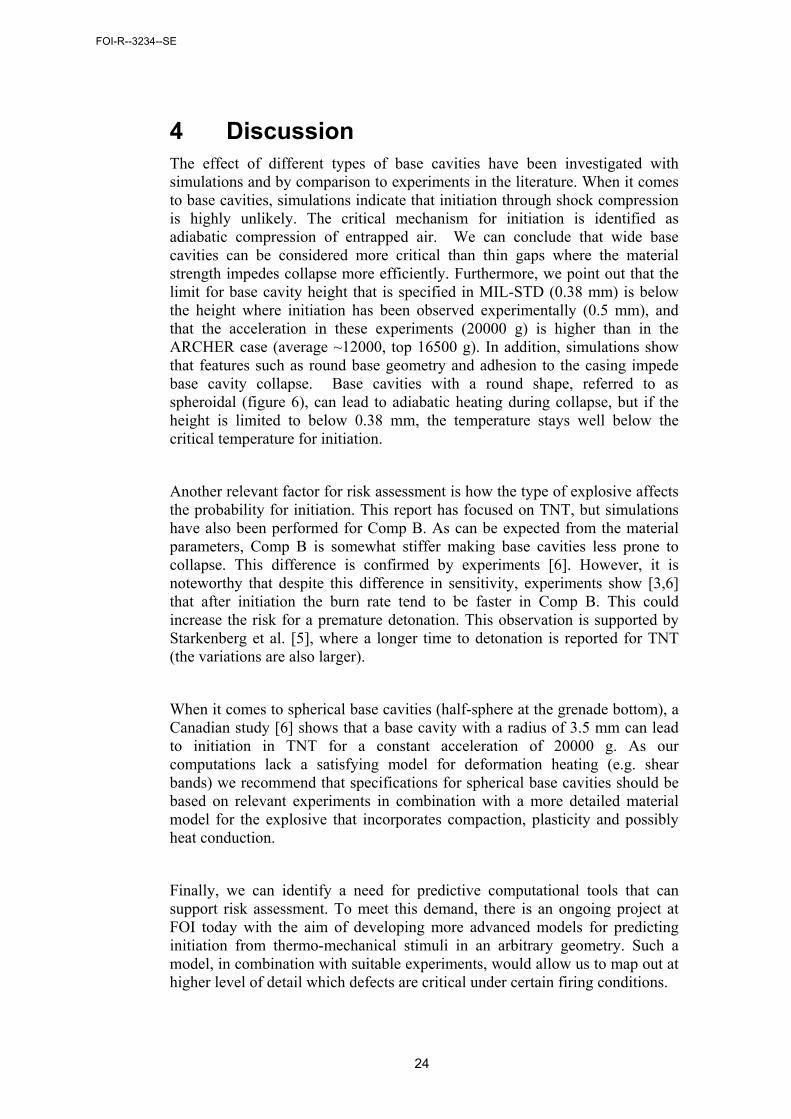
4 Discussion The effect of different types of base cavities have been investigated with simulations and by comparison to experiments in the literature. When it comes to base cavities, simulations indicate that initiation through shock compression is highly unlikely. The critical mechanism for initiation is identified as adiabatic compression of entrapped air. We can conclude that wide base cavities can be considered more critical than thin gaps where the material strength impedes collapse more efficiently. Furthermore, we point out that the limit for base cavity height that is specified in MIL-STD (0.38 mm) is below the height where initiation has been observed experimentally (0.5 mm), and that the acceleration in these experiments (20000 g) is higher than in the ARCHER case (average ~12000, top 16500 g). In addition, simulations show that features such as round base geometry and adhesion to the casing impede base cavity collapse. Base cavities with a round shape, referred to as spheroidal (figure 6), can lead to adiabatic heating during collapse, but if the height is limited to below 0.38 mm, the temperature stays well below the critical temperature for initiation.
Another relevant factor for risk assessment is how the type of explosive affects the probability for initiation. This report has focused on TNT, but simulations have also been performed for Comp B. As can be expected from the material parameters, Comp B is somewhat stiffer making base cavities less prone to collapse. This difference is confirmed by experiments [6]. However, it is noteworthy that despite this difference in sensitivity, experiments show [3,6] that after initiation the burn rate tend to be faster in Comp B. This could increase the risk for a premature detonation. This observation is supported by Starkenberg et al. [5], where a longer time to detonation is reported for TNT (the variations are also larger).
When it comes to spherical base cavities (half-sphere at the grenade bottom), a Canadian study [6] shows that a base cavity with a radius of 3.5 mm can lead to initiation in TNT for a constant acceleration of 20000 g. As our computations lack a satisfying model for deformation heating (e.g. shear bands) we recommend that specifications for spherical base cavities should be based on relevant experiments in combination with a more detailed material model for the explosive that incorporates compaction, plasticity and possibly heat conduction.
Finally, we can identify a need for predictive computational tools that can support risk assessment. To meet this demand, there is an ongoing project at FOI today with the aim of developing more advanced models for predicting initiation from thermo-mechanical stimuli in an arbitrary geometry. Such a model, in combination with suitable experiments, would allow us to map out at higher level of detail which defects are critical under certain firing conditions.
FOI-R--3234--SE

25
5 Conclusions and recommendations Computations indicate that initiation through shock compression is highly unlikely. We identify initiation through compression in combination with adiabatic heating of the entrapped air as the critical mechanism. A detailed description of the physics is a formidable challenge, and no general validated model exists today at FOI or in the open literature. Thus, no definite specifications can be provided for critical defect geometry. However, with support from experiments from the literature and approximate worst-case models, critical conditions can be identified and evaluated.
Two types of defects are considered as critical for the given conditions: wide base cavities and spherically shaped base cavities. Experiments show that for wide base cavities initiation can occur in TNT for heights somewhat larger (0.5 mm) than the MIL-STD specification (0.38 mm) for larger accelerations (20000g) than the ARCHER acceleration (average ~12000 g, top 16500 g). Round base geometry and adhesion to the casing are factors that strongly contribute to the insensitivity. Simulations show that both of these factors (independently) impede adiabatic compression. We conclude that initiation due to the collapse of a wide base cavity with a maximum height of 0.38 mm is highly unlikely if the grenade base has a round shape and the adhesion to the casing is satisfactory (i.e. not damaged). Comp B can in this respect be considered as somewhat less sensitive than TNT [6].
Finally, we point out that even if premature initiation has not been experimentally verified for ARCHER conditions, the possibility of initiation cannot be excluded since violent deflagration has been recorded at somewhat higher acceleration (20000 g) and for a spherically shaped base cavity with a radius slightly larger (0.5 mm) than what MIL-STD specifies (0.38 mm). To find a critical radius as function of acceleration we emphasize the need for further experimental and theoretical investigations.
FOI-R--3234--SE

26
6 References 1. Demin, Bo, ”Spaltgruppen, Arbetsgruppen för säkerhet hos
sprängämnen i artilleriammunition med särskild hänsyn till spalter och kaviteter, Slutrapport”. FMV, 1982.
2. H. Almström, ”Antändningsrisker vid tappade icke fördämda laddningar med tillämpning på mina F8”, FOA rapport C 20451-04, 1982.
3. B. C. Taylor, J. Starkenberg, L. H. Ervin, ”An experimental investigation of Composition-B ignition under artillery setback conditions”, Ballistic Research Laboratory, ARBRL-TR-02276, 1980.
4. K. Beedham, A. S. Dyer, W. I. Holmes, “The thermal initiation and growth of reaction in secondary explosives under transient confinement”, Proceedings of the Fifth International Symposium on Detonation”, (1970).
5. J. Strakenberg et al., “Sensitivity of several explosives to ignition in the launch environment”, Proceedings of the Ninth International Symposium on Detonation”, (1989).
6. C. Bélanger, “Study of explosive shell fillings with defects in simulated gun launch conditions”, Proceedings of the Ninth International Symposium on Detonation”, (1989).
7. S. P. Marsch, “LASL Shock Hugoniot Data” Los Angeles University of California Press, (1980).
8. B. M. Dobratz, P. C. Crawford, “LLNL Exlosives handbook”, UCRL-52997, (1985).
FOI-R--3234--SE