Embed Size (px)
Citation preview
GSPublisherVersion 0.1.100.100
Rev:
---
--- ---
Page:
Architect: Engineer:Drawn By:
Fathmath Ihudha AmirAdam Madheeh Fathmath Ihudha Amir
PROPOSED 02 STOREY BUILDING AT
2/28/2021
Client:
Ministry of Education, Maldives.
T: +960 333 3528 ,E: [email protected]: wwww.epoch.associates, A: M. Ahigasdhoshuge,Fareedhee Magu Male' Republic of Maldives
Contents1:1
MultipurposeHall, ShMaaugoodhoo
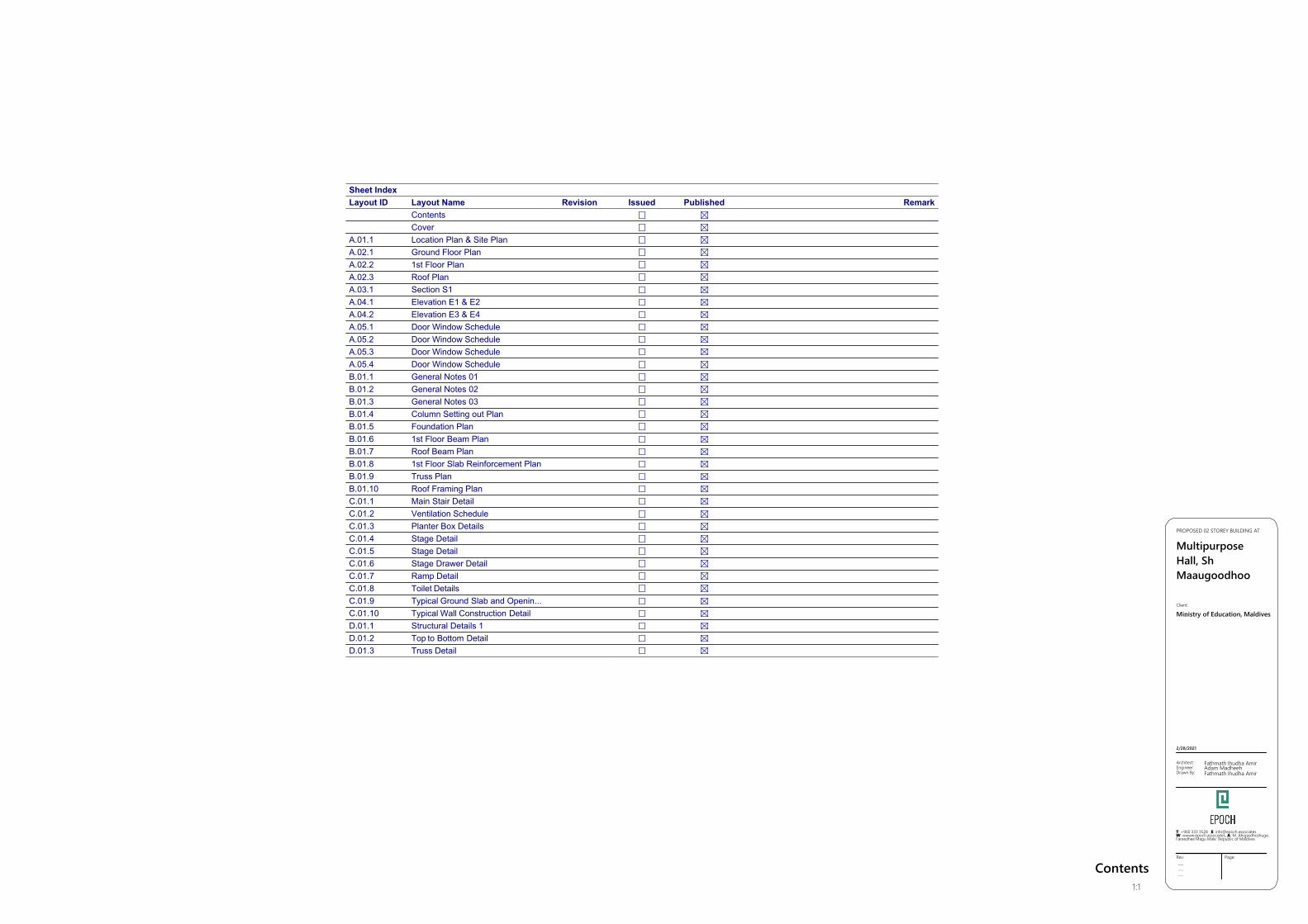
Sheet IndexLayout ID
A.01.1A.02.1A.02.2A.02.3A.03.1A.04.1A.04.2A.05.1A.05.2A.05.3A.05.4B.01.1B.01.2B.01.3B.01.4B.01.5B.01.6B.01.7B.01.8B.01.9B.01.10C.01.1C.01.2C.01.3C.01.4C.01.5C.01.6C.01.7C.01.8C.01.9C.01.10D.01.1D.01.2D.01.3
Layout NameContentsCoverLocation Plan & Site PlanGround Floor Plan1st Floor PlanRoof PlanSection S1Elevation E1 & E2Elevation E3 & E4Door Window ScheduleDoor Window ScheduleDoor Window ScheduleDoor Window ScheduleGeneral Notes 01General Notes 02General Notes 03Column Setting out PlanFoundation Plan1st Floor Beam PlanRoof Beam Plan1st Floor Slab Reinforcement PlanTruss PlanRoof Framing PlanMain Stair DetailVentilation SchedulePlanter Box DetailsStage DetailStage DetailStage Drawer DetailRamp DetailToilet DetailsTypical Ground Slab and Openin...Typical Wall Construction DetailStructural Details 1Top to Bottom DetailTruss Detail
Revision Issued Published Remark

GSPublisherVersion 0.1.100.100
ARCHITECTURAL & STRUCTURAL DRAWINGS OF
PROPOSED 02 STOREY BUILDING
MULTI-PURPOSE HALL, SH.MAAUGOODHOOFor Ministry of Education
GSPublisherVersion 0.1.100.100
A.01.1Rev:
---------
Page:
Architect:
Engineer:
Drawn By:
Fathmath Ihudha AmirAdam MadheehFathmath Ihudha Amir
PROPOSED 02 STOREY BUILDING AT
MultipurposeHall, ShMaaugoodhoo
2/28/2021
Client:
Ministry of Education,Maldives
T: +960 333 3528 ,E: [email protected]: wwww.epoch.associates, A: M. Ahigasdhoshuge,Fareedhee Magu Male' Republic of Maldives
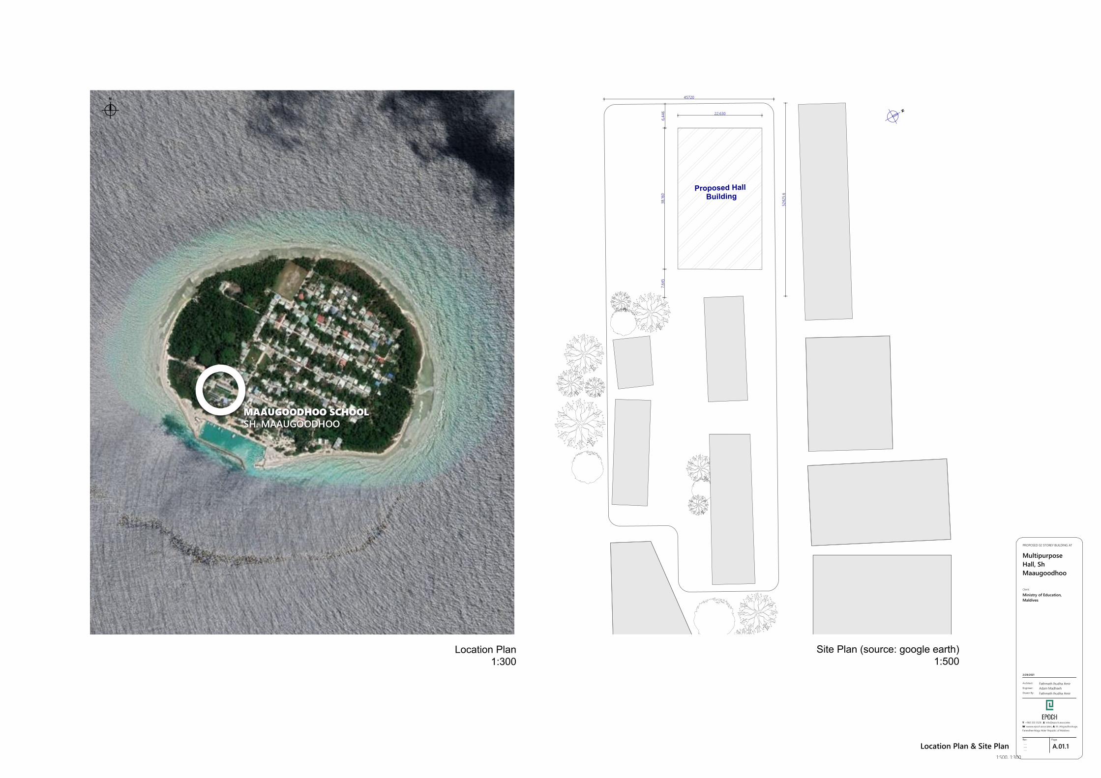
Location Plan & Site Plan1:500, 1:300
N
45720
5242
5.6
22,630
38,16
07,
645
6,44
6
Proposed Hall Building
N
Site Plan (source: google earth)1:500
Location Plan1:300
GSPublisherVersion 0.1.100.100
A.02.1Rev:
---------
Page:
Architect:
Engineer:
Drawn By:
Fathmath Ihudha AmirAdam MadheehFathmath Ihudha Amir
PROPOSED 02 STOREY BUILDING AT
MultipurposeHall, ShMaaugoodhoo
2/28/2021
Client:
Ministry of Education,Maldives
T: +960 333 3528 ,E: [email protected]: wwww.epoch.associates, A: M. Ahigasdhoshuge,Fareedhee Magu Male' Republic of Maldives
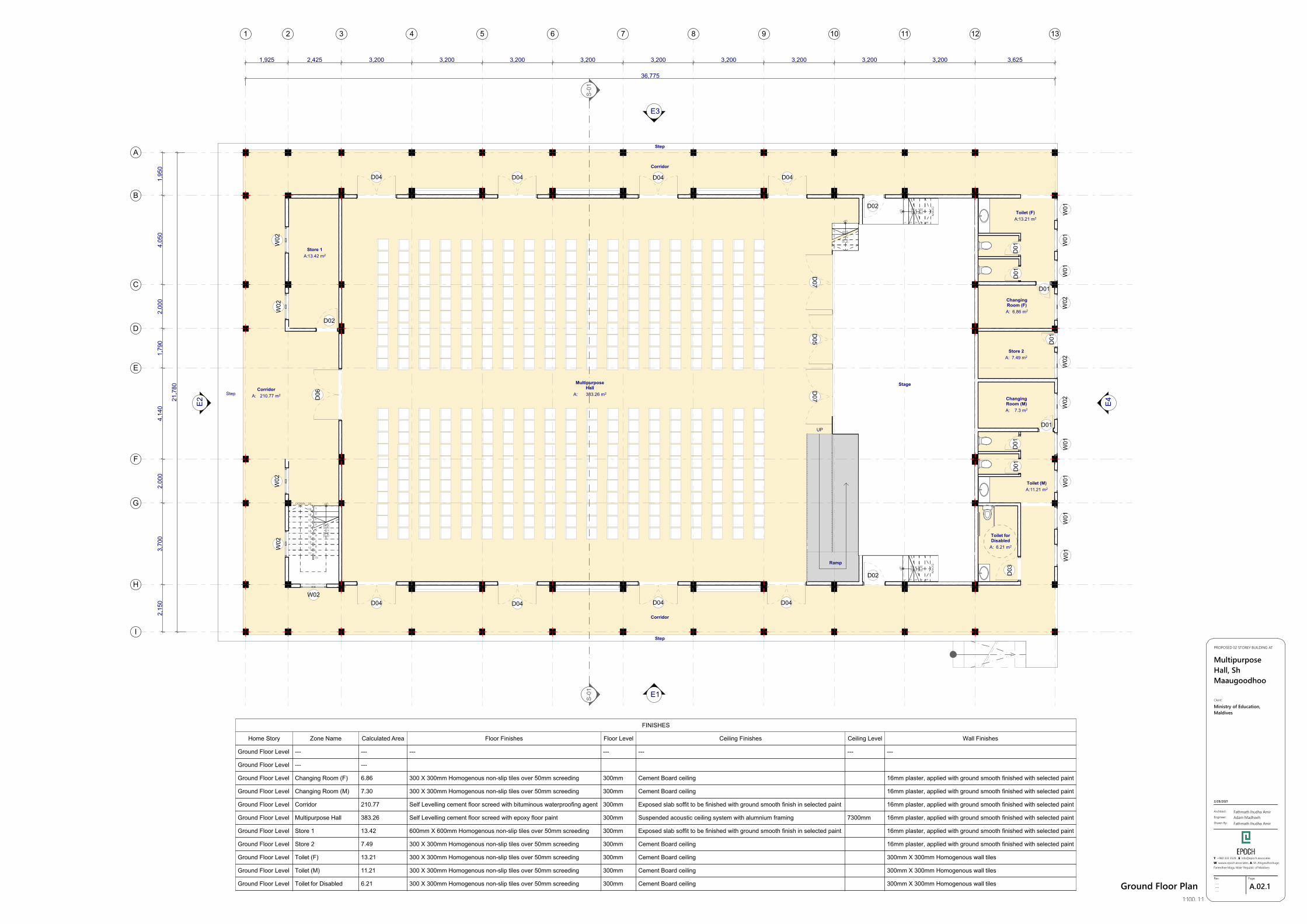
Ground Floor Plan1:100, 1:1
D07
D07
D05
1 2 3 4 5
DO
WN
UP 5R x 150
5G x 250
1 2 3 4 5
DO
WN
UP 5R x 150
5G x 250
1
2
3
4
5
DOWN
UP
5R x
150
5G x
250
1
2
3
4
5
6
7
8
9
1011
12
13
14
15
16
17
18
19
20DOWN UP
20R
x 1
7519
G x
250
D06
D02
D04 D04 D04 D04
W01
W01
W01
W01
W01
W01
W01
W02
W02
W02
D01
D01
D03
D01
D01
D01
D01
D01
W02
W02
D02
W02
W02
D02
D04 D04 D04 D04W02
1,925 2,425 3,200 3,200 3,200 3,200 3,200 3,200 3,200 3,200 3,200 3,625
36,775
2,15
03,
700
2,00
04,
140
1,79
02,
000
4,05
01,
950
21,7
80
E1
E2
E3
E4
UP
Ramp
MultipurposeHall
A: 383.26 m2
Toilet (F)A:13.21 m2
Toilet (M)A:11.21 m2
Toilet forDisabled
A: 6.21 m2
Store 1A:13.42 m2
ChangingRoom (F)A: 6.86 m2
Store 2A: 7.49 m2
ChangingRoom (M)A: 7.3 m2
CorridorA: 210.77 m2
1
S-01
S-01
Stage
Corridor
Corridor
Step
Step
Step
2 3 4 5 6 7 8 9 10 11 12 13
A
B
C
D
E
F
G
H
I
FINISHES
Home Story
Ground Floor Level
Ground Floor Level
Ground Floor Level
Ground Floor Level
Ground Floor Level
Ground Floor Level
Ground Floor Level
Ground Floor Level
Ground Floor Level
Ground Floor Level
Ground Floor Level
Zone Name
---
---
Changing Room (F)
Changing Room (M)
Corridor
Multipurpose Hall
Store 1
Store 2
Toilet (F)
Toilet (M)
Toilet for Disabled
Calculated Area
---
---
6.86
7.30
210.77
383.26
13.42
7.49
13.21
11.21
6.21
Floor Finishes
---
300 X 300mm Homogenous non-slip tiles over 50mm screeding
300 X 300mm Homogenous non-slip tiles over 50mm screeding
Self Levelling cement floor screed with bituminous waterproofing agent
Self Levelling cement floor screed with epoxy floor paint
600mm X 600mm Homogenous non-slip tiles over 50mm screeding
300 X 300mm Homogenous non-slip tiles over 50mm screeding
300 X 300mm Homogenous non-slip tiles over 50mm screeding
300 X 300mm Homogenous non-slip tiles over 50mm screeding
300 X 300mm Homogenous non-slip tiles over 50mm screeding
Floor Level
---
300mm
300mm
300mm
300mm
300mm
300mm
300mm
300mm
300mm
Ceiling Finishes
---
Cement Board ceiling
Cement Board ceiling
Exposed slab soffit to be finished with ground smooth finish in selected paint
Suspended acoustic ceiling system with alumnium framing
Exposed slab soffit to be finished with ground smooth finish in selected paint
Cement Board ceiling
Cement Board ceiling
Cement Board ceiling
Cement Board ceiling
Ceiling Level
---
7300mm
Wall Finishes
---
16mm plaster, applied with ground smooth finished with selected paint
16mm plaster, applied with ground smooth finished with selected paint
16mm plaster, applied with ground smooth finished with selected paint
16mm plaster, applied with ground smooth finished with selected paint
16mm plaster, applied with ground smooth finished with selected paint
16mm plaster, applied with ground smooth finished with selected paint
300mm X 300mm Homogenous wall tiles
300mm X 300mm Homogenous wall tiles
300mm X 300mm Homogenous wall tiles
GSPublisherVersion 0.1.100.100
A.02.2Rev:
---------
Page:
Architect:
Engineer:
Drawn By:
Fathmath Ihudha AmirAdam MadheehFathmath Ihudha Amir
PROPOSED 02 STOREY BUILDING AT
MultipurposeHall, ShMaaugoodhoo
2/28/2021
Client:
Ministry of Education,Maldives
T: +960 333 3528 ,E: [email protected]: wwww.epoch.associates, A: M. Ahigasdhoshuge,Fareedhee Magu Male' Republic of Maldives
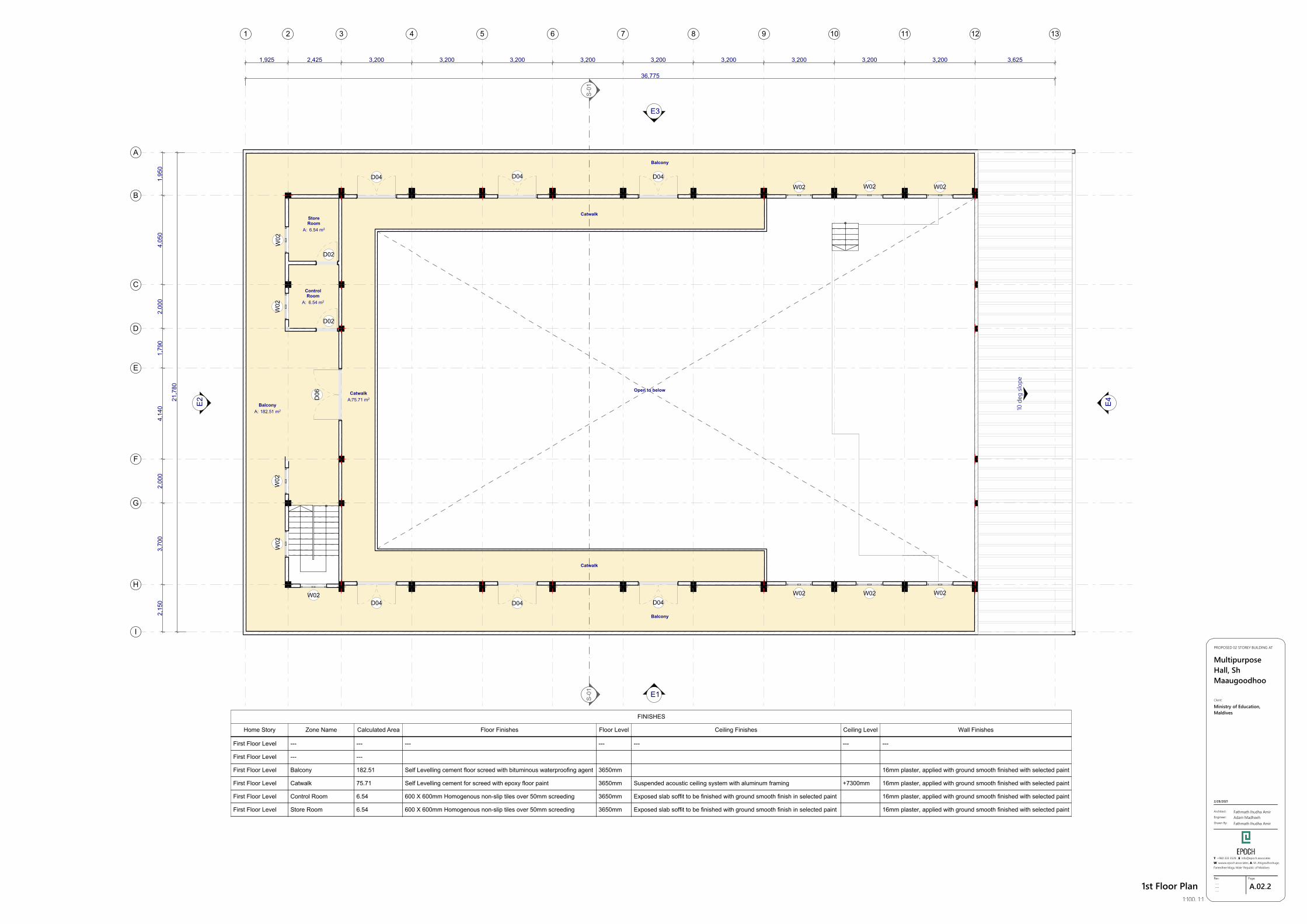
1st Floor Plan1:100, 1:1
E1
E2
E3
E4
36,775
21,7
80
1,925 2,425 3,200 3,200 3,200 3,200 3,200 3,200 3,200 3,200 3,200 3,625
2,15
03,
700
2,00
04,
140
1,79
02,
000
4,05
01,
950
CatwalkA:75.71 m2
StoreRoom
A: 6.54 m2
ControlRoom
A: 6.54 m2
BalconyA: 182.51 m2
1
D02
W02
W02
W02
W02
S-01
S-01
2 3 4 5 6 7 8 9 10 11 12 13
A
B
C
D
E
F
G
H
I
10 d
eg sl
ope
W02W02W02D04 D04 D04
W02 W02 W02D04 D04 D04
D06
W02
D02
Balcony
Balcony
Catwalk
Catwalk
Open to below
First Floor Level
First Floor Level
First Floor Level
First Floor Level
First Floor Level
First Floor Level
---
---
Balcony
Catwalk
Control Room
Store Room
---
---
182.51
75.71
6.54
6.54
---
Self Levelling cement floor screed with bituminous waterproofing agent
Self Levelling cement for screed with epoxy floor paint
600 X 600mm Homogenous non-slip tiles over 50mm screeding
600 X 600mm Homogenous non-slip tiles over 50mm screeding
---
3650mm
3650mm
3650mm
3650mm
---
Suspended acoustic ceiling system with aluminum framing
Exposed slab soffit to be finished with ground smooth finish in selected paint
Exposed slab soffit to be finished with ground smooth finish in selected paint
---
+7300mm
---
16mm plaster, applied with ground smooth finished with selected paint
16mm plaster, applied with ground smooth finished with selected paint
16mm plaster, applied with ground smooth finished with selected paint
16mm plaster, applied with ground smooth finished with selected paint
FINISHES
Home Story Zone Name Calculated Area Floor Finishes Floor Level Ceiling Finishes Ceiling Level Wall Finishes
GSPublisherVersion 0.1.100.100
A.02.3Rev:
---------
Page:
Architect:
Engineer:
Drawn By:
Fathmath Ihudha AmirAdam MadheehFathmath Ihudha Amir
PROPOSED 02 STOREY BUILDING AT
MultipurposeHall, ShMaaugoodhoo
2/28/2021
Client:
Ministry of Education,Maldives
T: +960 333 3528 ,E: [email protected]: wwww.epoch.associates, A: M. Ahigasdhoshuge,Fareedhee Magu Male' Republic of Maldives
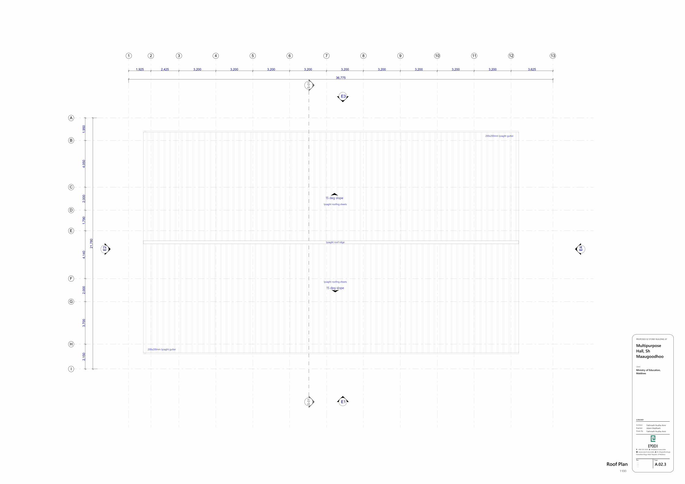
Roof Plan1:100
E1
E2
E3
E4
36,775
21,7
80
1,925 2,425 3,200 3,200 3,200 3,200 3,200 3,200 3,200 3,200 3,200 3,625
2,15
03,
700
2,00
04,
140
1,79
02,
000
4,05
01,
950
lysaght roof ridge
1
S-01
S-01
2 3 4 5 6 7 8 9 10 11 12 13
A
B
C
D
E
F
G
H
I
15 deg slope
15 deg slope
200x200mm lysaght gutter
200x200mm lysaght gutter
lysaght roof ridge
lysaght roofing sheets
lysaght roofing sheets
GSPublisherVersion 0.1.100.100
A.03.1Rev:
---------
Page:
Architect:
Engineer:
Drawn By:
Fathmath Ihudha AmirAdam MadheehFathmath Ihudha Amir
PROPOSED 02 STOREY BUILDING AT
MultipurposeHall, ShMaaugoodhoo
2/28/2021
Client:
Ministry of Education,Maldives
T: +960 333 3528 ,E: [email protected]: wwww.epoch.associates, A: M. Ahigasdhoshuge,Fareedhee Magu Male' Republic of Maldives
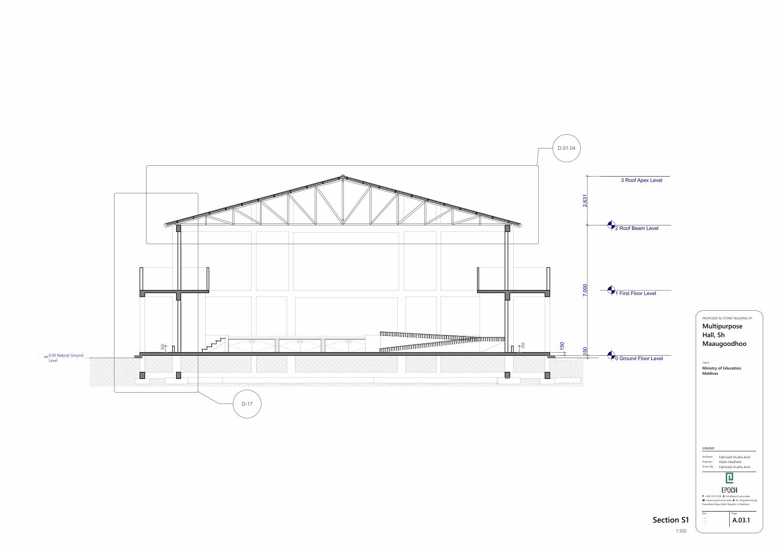
Section S11:100
D.01.04
D-17
0 Ground Floor Level
1 First Floor Level
2 Roof Beam Level
7,00
015
0150
2,63
1
350
350
3 Roof Apex Level
0.00 Natural GroundLevel
GSPublisherVersion 0.1.100.100
A.04.1Rev:
---------
Page:
Architect:
Engineer:
Drawn By:
Fathmath Ihudha AmirAdam MadheehFathmath Ihudha Amir
PROPOSED 02 STOREY BUILDING AT
MultipurposeHall, ShMaaugoodhoo
2/28/2021
Client:
Ministry of Education,Maldives
T: +960 333 3528 ,E: [email protected]: wwww.epoch.associates, A: M. Ahigasdhoshuge,Fareedhee Magu Male' Republic of Maldives
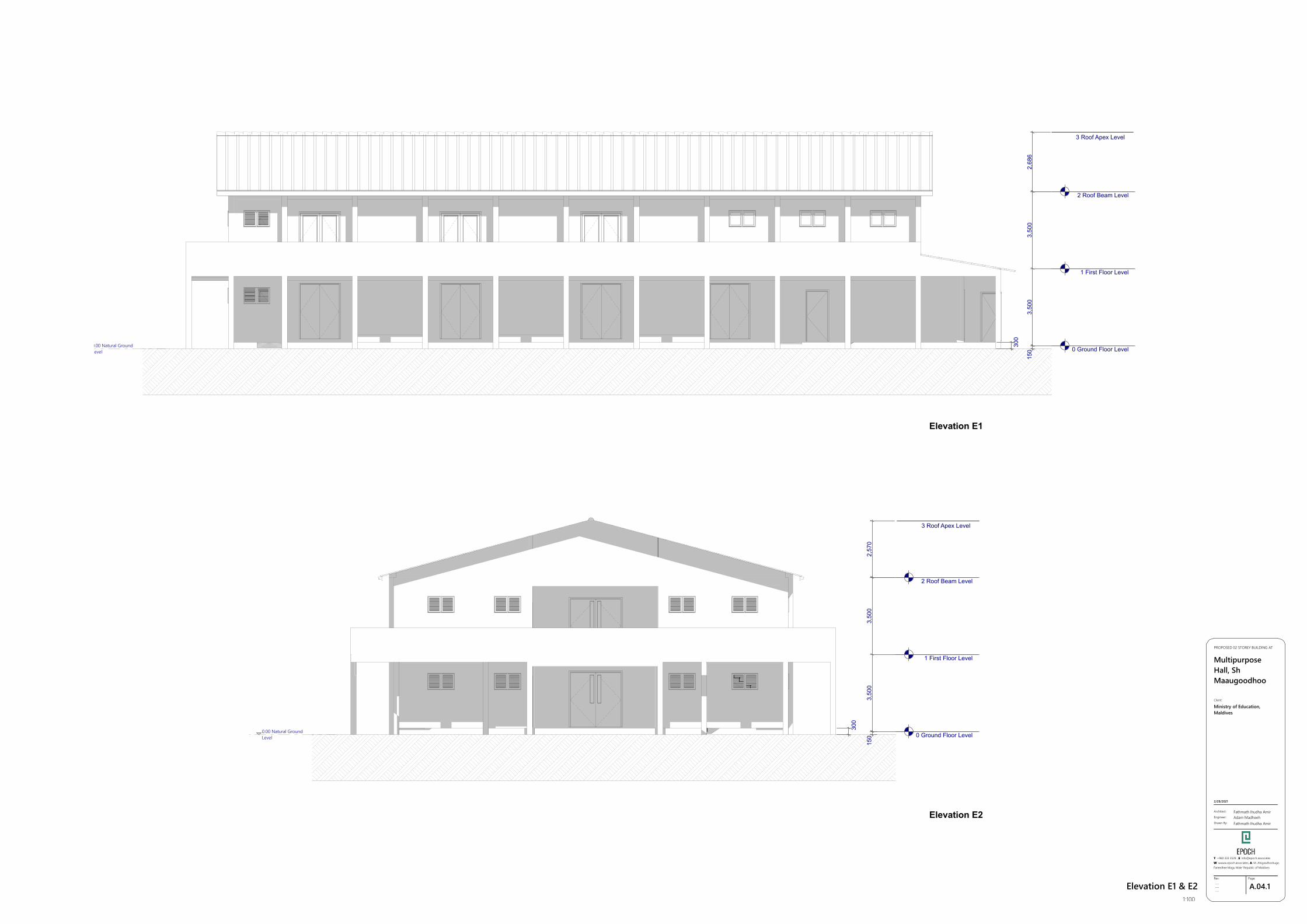
Elevation E1 & E21:100
0 Ground Floor Level
1 First Floor Level
2 Roof Beam Level
3,50
03,
500
2,68
615
0
300
3 Roof Apex Level
0.00 Natural GroundLevel
0 Ground Floor Level
1 First Floor Level
2 Roof Beam Level
3,50
03,
500
2,57
015
0
300
3 Roof Apex Level
0.00 Natural GroundLevel
Elevation E1
Elevation E2
GSPublisherVersion 0.1.100.100
A.04.2Rev:
---------
Page:
Architect:
Engineer:
Drawn By:
Fathmath Ihudha AmirAdam MadheehFathmath Ihudha Amir
PROPOSED 02 STOREY BUILDING AT
MultipurposeHall, ShMaaugoodhoo
2/28/2021
Client:
Ministry of Education,Maldives
T: +960 333 3528 ,E: [email protected]: wwww.epoch.associates, A: M. Ahigasdhoshuge,Fareedhee Magu Male' Republic of Maldives
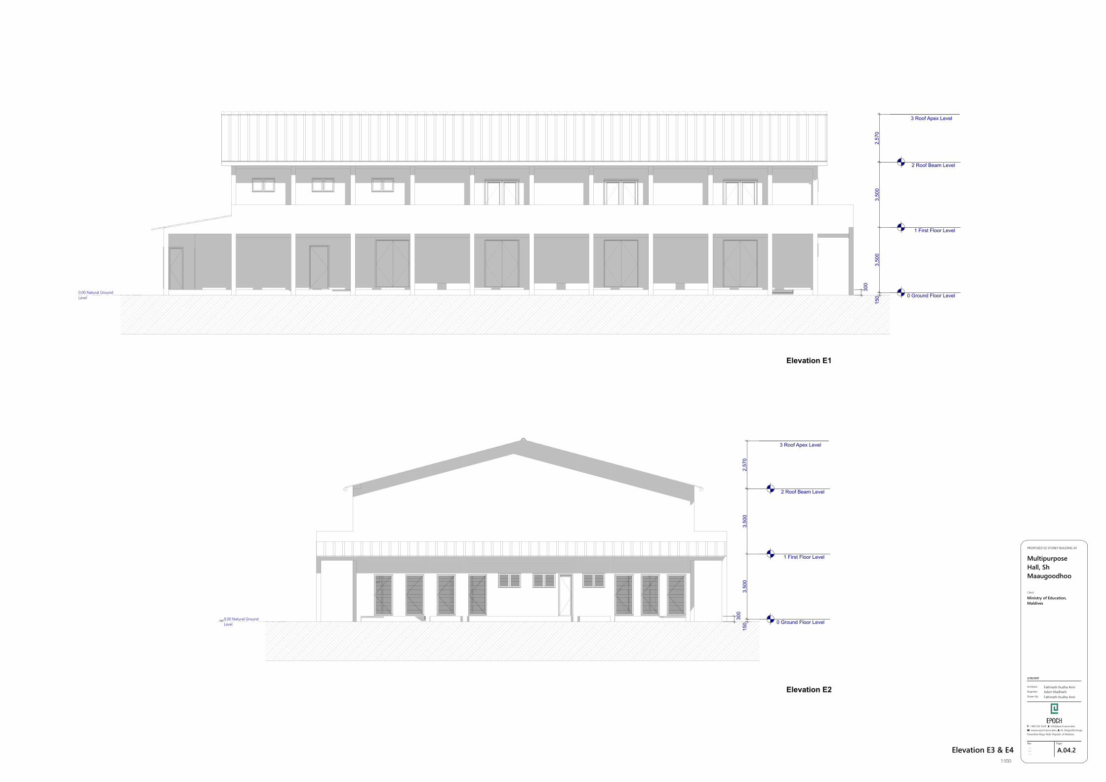
Elevation E3 & E41:100
0 Ground Floor Level
1 First Floor Level
2 Roof Beam Level
3,50
03,
500
2,57
015
0
300
3 Roof Apex Level
0.00 Natural GroundLevel
0 Ground Floor Level
1 First Floor Level
2 Roof Beam Level
3,50
03,
500
2,57
015
030
0
3 Roof Apex Level
0.00 Natural GroundLevel
Elevation E1
Elevation E2
GSPublisherVersion 0.1.100.100
A.05.1Rev:
---------
Page:
Architect:
Engineer:
Drawn By:
Fathmath Ihudha AmirAdam MadheehFathmath Ihudha Amir
PROPOSED 02 STOREY BUILDING AT
MultipurposeHall, ShMaaugoodhoo
2/28/2021
Client:
Ministry of Education,Maldives
T: +960 333 3528 ,E: [email protected]: wwww.epoch.associates, A: M. Ahigasdhoshuge,Fareedhee Magu Male' Republic of Maldives
Door Window Schedule1:10, 2:1
Door and Window Notes
Dimensions shown on DWG indicateeffective openings of frame
All frame depth are 100mmAll door panel thicknesses are 35mmAll window manel thickness are 25mmAll frame edges shall be trimmed 3mm
All wooden components should be woodstained finish
All glazing should be of 6mm unlessspecified
External units must comply the followingweather conditions:-Wind pressure: 200 kg/sqmWater tightness: 25 kg/sqm
All external frames / wall joints must besealed with silicon sealant and the wedgestrimmed with 12 X 12mm hardwoodbeading fixed to frames by brass nails
All hardware should be provided for theperformance of all functions of the units
Hinges shall confirm to1. Door size more than 700X900mm WD: 125mm X 2 sets SD: 150mm X 3 sets2. Door size less than 700 X 1900mm WD: 100mm X 2 sets SD: 125mm X 2 sets
Locks shall be cylinderical with master keysets
Door knobs shall be 1000mm above FFL
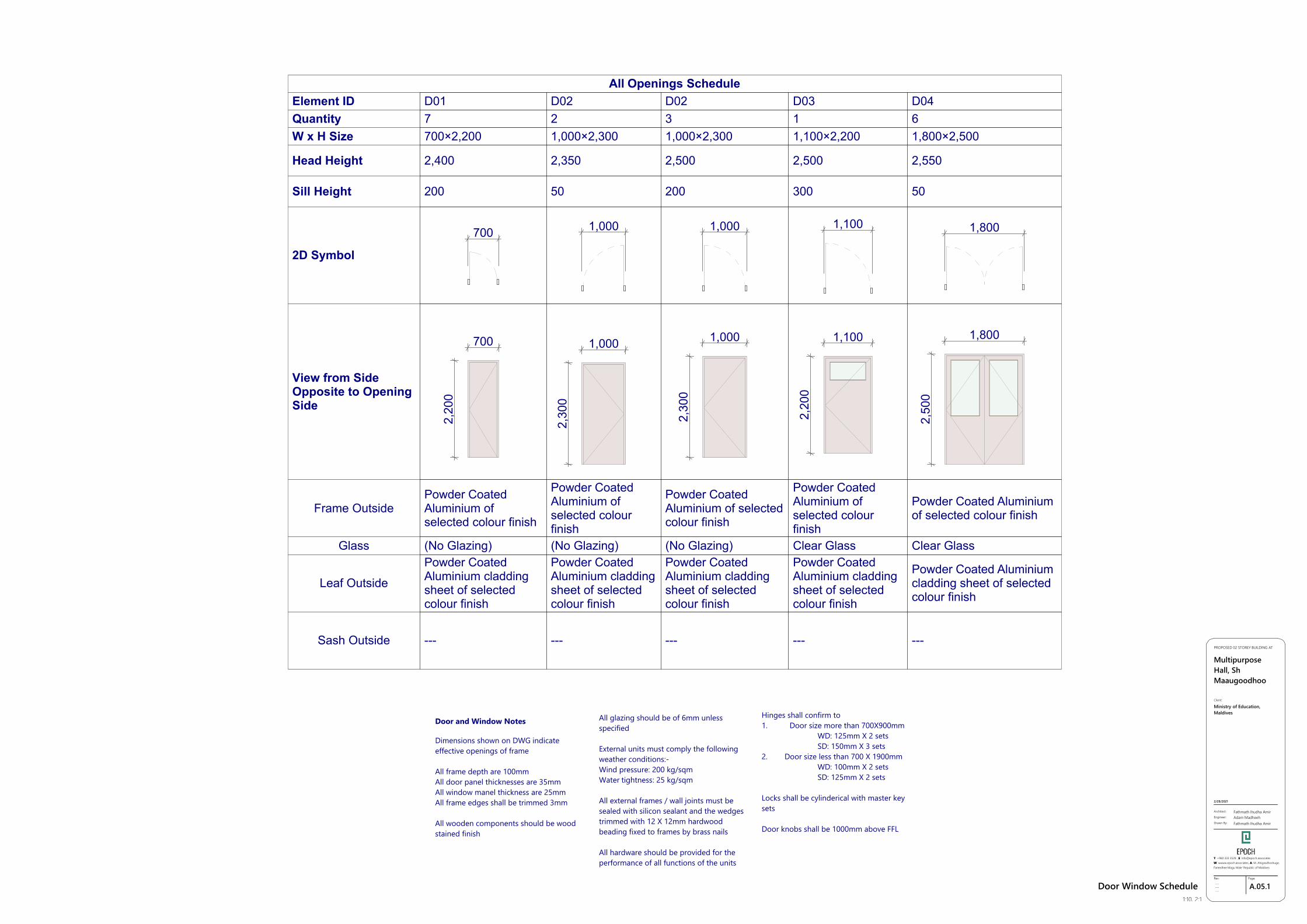
Element ID D01 D02 D02 D03 D04Quantity 7 2 3 1 6W x H Size 700×2,200 1,000×2,300 1,000×2,300 1,100×2,200 1,800×2,500
Head Height 2,400 2,350 2,500 2,500 2,550
Sill Height 200 50 200 300 50
2D Symbol
700 1,000 1,000 1,100 1,800
View from SideOpposite to OpeningSide
700
2,20
0
1,000
2,30
0
1,000
2,30
0
1,100
2,20
0
1,800
2,50
0
Frame OutsidePowder CoatedAluminium ofselected colour finish
Powder CoatedAluminium ofselected colourfinish
Powder CoatedAluminium of selectedcolour finish
Powder CoatedAluminium ofselected colourfinish
Powder Coated Aluminiumof selected colour finish
Glass (No Glazing) (No Glazing) (No Glazing) Clear Glass Clear Glass
Leaf Outside
Powder CoatedAluminium claddingsheet of selectedcolour finish
Powder CoatedAluminium claddingsheet of selectedcolour finish
Powder CoatedAluminium claddingsheet of selectedcolour finish
Powder CoatedAluminium claddingsheet of selectedcolour finish
Powder Coated Aluminiumcladding sheet of selectedcolour finish
Sash Outside --- --- --- --- ---
All Openings Schedule
GSPublisherVersion 0.1.100.100
A.05.2Rev:
---------
Page:
Architect:
Engineer:
Drawn By:
Fathmath Ihudha AmirAdam MadheehFathmath Ihudha Amir
PROPOSED 02 STOREY BUILDING AT
MultipurposeHall, ShMaaugoodhoo
2/28/2021
Client:
Ministry of Education,Maldives
T: +960 333 3528 ,E: [email protected]: wwww.epoch.associates, A: M. Ahigasdhoshuge,Fareedhee Magu Male' Republic of Maldives
Door Window Schedule1:10, 2:1
Door and Window Notes
Dimensions shown on DWG indicateeffective openings of frame
All frame depth are 100mmAll door panel thicknesses are 35mmAll window manel thickness are 25mmAll frame edges shall be trimmed 3mm
All wooden components should be woodstained finish
All glazing should be of 6mm unlessspecified
External units must comply the followingweather conditions:-Wind pressure: 200 kg/sqmWater tightness: 25 kg/sqm
All external frames / wall joints must besealed with silicon sealant and the wedgestrimmed with 12 X 12mm hardwoodbeading fixed to frames by brass nails
All hardware should be provided for theperformance of all functions of the units
Hinges shall confirm to1. Door size more than 700X900mm WD: 125mm X 2 sets SD: 150mm X 3 sets2. Door size less than 700 X 1900mm WD: 100mm X 2 sets SD: 125mm X 2 sets
Locks shall be cylinderical with master keysets
Door knobs shall be 1000mm above FFL
Door and Window Notes
Dimensions shown on DWG indicateeffective openings of frame
All frame depth are 100mmAll door panel thicknesses are 35mmAll window manel thickness are 25mmAll frame edges shall be trimmed 3mm
All wooden components should be woodstained finish
All glazing should be of 6mm unlessspecified
External units must comply the followingweather conditions:-Wind pressure: 200 kg/sqmWater tightness: 25 kg/sqm
All external frames / wall joints must besealed with silicon sealant and the wedgestrimmed with 12 X 12mm hardwoodbeading fixed to frames by brass nails
All hardware should be provided for theperformance of all functions of the units
Hinges shall confirm to1. Door size more than 700X900mm WD: 125mm X 2 sets SD: 150mm X 3 sets2. Door size less than 700 X 1900mm WD: 100mm X 2 sets SD: 125mm X 2 sets
Locks shall be cylinderical with master keysets
Door knobs shall be 1000mm above FFL
Door and Window Notes
Dimensions shown on DWG indicateeffective openings of frame
All frame depth are 100mmAll door panel thicknesses are 35mmAll window manel thickness are 25mmAll frame edges shall be trimmed 3mm
All wooden components should be woodstained finish
All glazing should be of 6mm unlessspecified
External units must comply the followingweather conditions:-Wind pressure: 200 kg/sqmWater tightness: 25 kg/sqm
All external frames / wall joints must besealed with silicon sealant and the wedgestrimmed with 12 X 12mm hardwoodbeading fixed to frames by brass nails
All hardware should be provided for theperformance of all functions of the units
Hinges shall confirm to1. Door size more than 700X900mm WD: 125mm X 2 sets SD: 150mm X 3 sets2. Door size less than 700 X 1900mm WD: 100mm X 2 sets SD: 125mm X 2 sets
Locks shall be cylinderical with master keysets
Door knobs shall be 1000mm above FFL
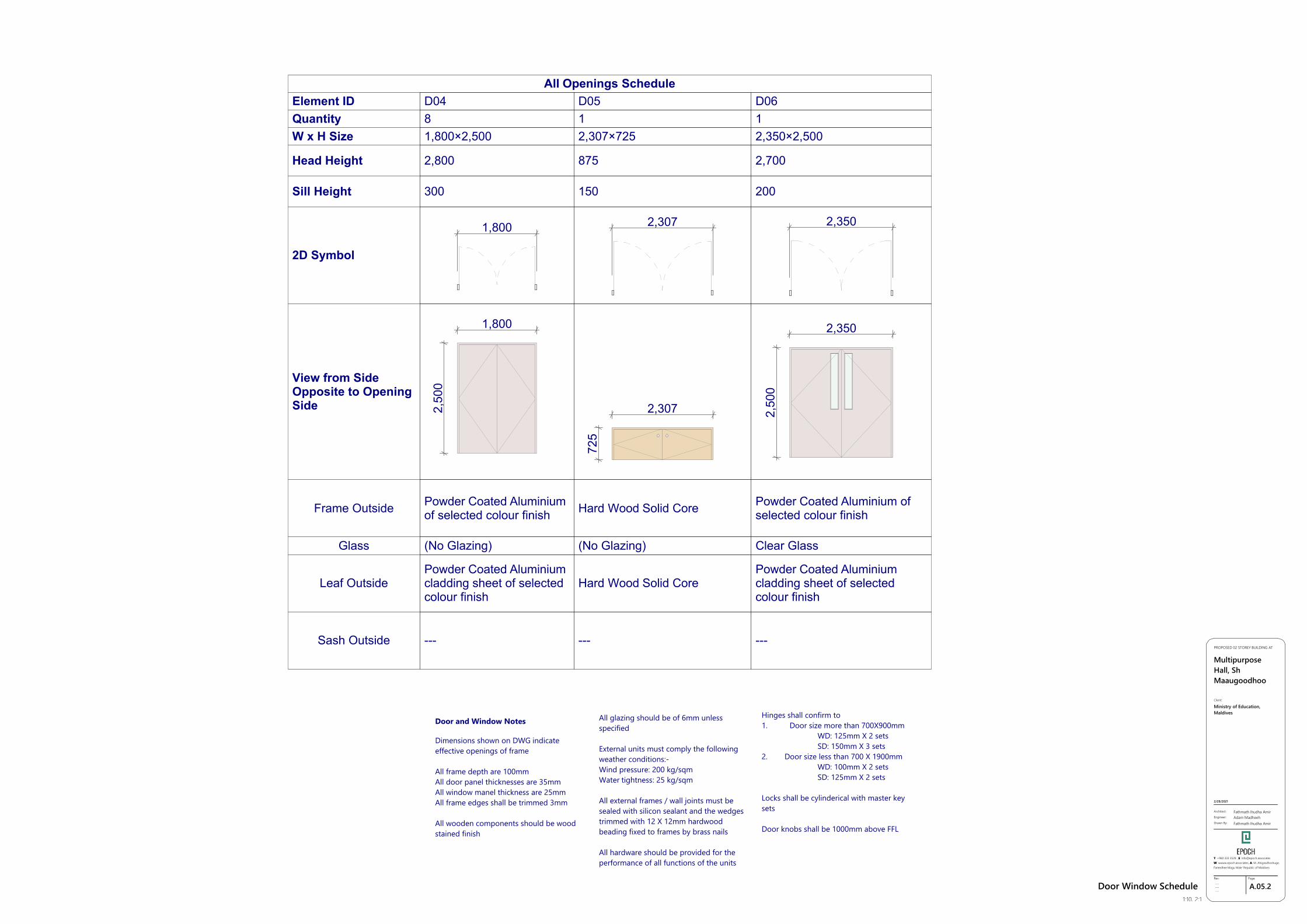
Element ID D04 D05 D06Quantity 8 1 1W x H Size 1,800×2,500 2,307×725 2,350×2,500
Head Height 2,800 875 2,700
Sill Height 300 150 200
2D Symbol
1,800 2,307 2,350
View from SideOpposite to OpeningSide
1,800
2,50
0
2,307
725
2,350
2,50
0
Frame Outside Powder Coated Aluminiumof selected colour finish Hard Wood Solid Core Powder Coated Aluminium of
selected colour finish
Glass (No Glazing) (No Glazing) Clear Glass
Leaf OutsidePowder Coated Aluminiumcladding sheet of selectedcolour finish
Hard Wood Solid CorePowder Coated Aluminiumcladding sheet of selectedcolour finish
Sash Outside --- --- ---
All Openings Schedule
GSPublisherVersion 0.1.100.100
A.05.3Rev:
---------
Page:
Architect:
Engineer:
Drawn By:
Fathmath Ihudha AmirAdam MadheehFathmath Ihudha Amir
PROPOSED 02 STOREY BUILDING AT
MultipurposeHall, ShMaaugoodhoo
2/28/2021
Client:
Ministry of Education,Maldives
T: +960 333 3528 ,E: [email protected]: wwww.epoch.associates, A: M. Ahigasdhoshuge,Fareedhee Magu Male' Republic of Maldives
Door Window Schedule1:10, 2:1
Door and Window Notes
Dimensions shown on DWG indicateeffective openings of frame
All frame depth are 100mmAll door panel thicknesses are 35mmAll window manel thickness are 25mmAll frame edges shall be trimmed 3mm
All wooden components should be woodstained finish
All glazing should be of 6mm unlessspecified
External units must comply the followingweather conditions:-Wind pressure: 200 kg/sqmWater tightness: 25 kg/sqm
All external frames / wall joints must besealed with silicon sealant and the wedgestrimmed with 12 X 12mm hardwoodbeading fixed to frames by brass nails
All hardware should be provided for theperformance of all functions of the units
Hinges shall confirm to1. Door size more than 700X900mm WD: 125mm X 2 sets SD: 150mm X 3 sets2. Door size less than 700 X 1900mm WD: 100mm X 2 sets SD: 125mm X 2 sets
Locks shall be cylinderical with master keysets
Door knobs shall be 1000mm above FFL
Door and Window Notes
Dimensions shown on DWG indicateeffective openings of frame
All frame depth are 100mmAll door panel thicknesses are 35mmAll window manel thickness are 25mmAll frame edges shall be trimmed 3mm
All wooden components should be woodstained finish
All glazing should be of 6mm unlessspecified
External units must comply the followingweather conditions:-Wind pressure: 200 kg/sqmWater tightness: 25 kg/sqm
All external frames / wall joints must besealed with silicon sealant and the wedgestrimmed with 12 X 12mm hardwoodbeading fixed to frames by brass nails
All hardware should be provided for theperformance of all functions of the units
Hinges shall confirm to1. Door size more than 700X900mm WD: 125mm X 2 sets SD: 150mm X 3 sets2. Door size less than 700 X 1900mm WD: 100mm X 2 sets SD: 125mm X 2 sets
Locks shall be cylinderical with master keysets
Door knobs shall be 1000mm above FFL
Door and Window Notes
Dimensions shown on DWG indicateeffective openings of frame
All frame depth are 100mmAll door panel thicknesses are 35mmAll window manel thickness are 25mmAll frame edges shall be trimmed 3mm
All wooden components should be woodstained finish
All glazing should be of 6mm unlessspecified
External units must comply the followingweather conditions:-Wind pressure: 200 kg/sqmWater tightness: 25 kg/sqm
All external frames / wall joints must besealed with silicon sealant and the wedgestrimmed with 12 X 12mm hardwoodbeading fixed to frames by brass nails
All hardware should be provided for theperformance of all functions of the units
Hinges shall confirm to1. Door size more than 700X900mm WD: 125mm X 2 sets SD: 150mm X 3 sets2. Door size less than 700 X 1900mm WD: 100mm X 2 sets SD: 125mm X 2 sets
Locks shall be cylinderical with master keysets
Door knobs shall be 1000mm above FFL
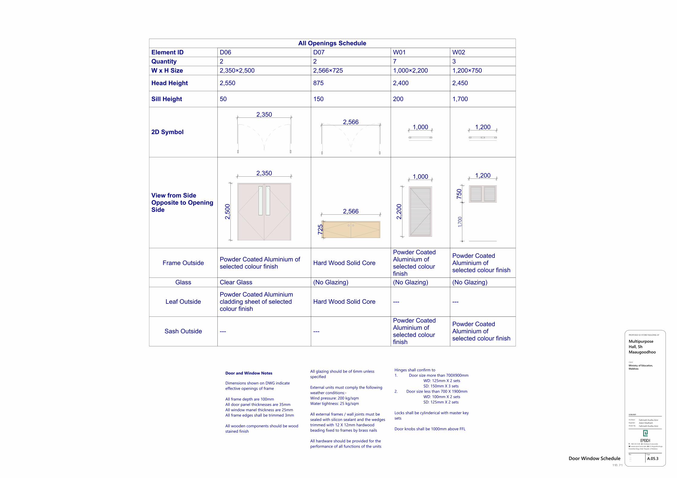
Element ID D06 D07 W01 W02Quantity 2 2 7 3W x H Size 2,350×2,500 2,566×725 1,000×2,200 1,200×750
Head Height 2,550 875 2,400 2,450
Sill Height 50 150 200 1,700
2D Symbol
2,3502,566
1,000 1,200
View from SideOpposite to OpeningSide
2,350
2,50
0
2,566
725
1,000
2,20
0
1,200
750
1,700
Frame Outside Powder Coated Aluminium ofselected colour finish Hard Wood Solid Core
Powder CoatedAluminium ofselected colourfinish
Powder CoatedAluminium ofselected colour finish
Glass Clear Glass (No Glazing) (No Glazing) (No Glazing)
Leaf OutsidePowder Coated Aluminiumcladding sheet of selectedcolour finish
Hard Wood Solid Core --- ---
Sash Outside --- ---
Powder CoatedAluminium ofselected colourfinish
Powder CoatedAluminium ofselected colour finish
All Openings Schedule
GSPublisherVersion 0.1.100.100
A.05.4Rev:
---------
Page:
Architect:
Engineer:
Drawn By:
Fathmath Ihudha AmirAdam MadheehFathmath Ihudha Amir
PROPOSED 02 STOREY BUILDING AT
MultipurposeHall, ShMaaugoodhoo
2/28/2021
Client:
Ministry of Education,Maldives
T: +960 333 3528 ,E: [email protected]: wwww.epoch.associates, A: M. Ahigasdhoshuge,Fareedhee Magu Male' Republic of Maldives
Door Window Schedule1:10, 2:1
Door and Window Notes
Dimensions shown on DWG indicateeffective openings of frame
All frame depth are 100mmAll door panel thicknesses are 35mmAll window manel thickness are 25mmAll frame edges shall be trimmed 3mm
All wooden components should be woodstained finish
All glazing should be of 6mm unlessspecified
External units must comply the followingweather conditions:-Wind pressure: 200 kg/sqmWater tightness: 25 kg/sqm
All external frames / wall joints must besealed with silicon sealant and the wedgestrimmed with 12 X 12mm hardwoodbeading fixed to frames by brass nails
All hardware should be provided for theperformance of all functions of the units
Hinges shall confirm to1. Door size more than 700X900mm WD: 125mm X 2 sets SD: 150mm X 3 sets2. Door size less than 700 X 1900mm WD: 100mm X 2 sets SD: 125mm X 2 sets
Locks shall be cylinderical with master keysets
Door knobs shall be 1000mm above FFL
Door and Window Notes
Dimensions shown on DWG indicateeffective openings of frame
All frame depth are 100mmAll door panel thicknesses are 35mmAll window manel thickness are 25mmAll frame edges shall be trimmed 3mm
All wooden components should be woodstained finish
All glazing should be of 6mm unlessspecified
External units must comply the followingweather conditions:-Wind pressure: 200 kg/sqmWater tightness: 25 kg/sqm
All external frames / wall joints must besealed with silicon sealant and the wedgestrimmed with 12 X 12mm hardwoodbeading fixed to frames by brass nails
All hardware should be provided for theperformance of all functions of the units
Hinges shall confirm to1. Door size more than 700X900mm WD: 125mm X 2 sets SD: 150mm X 3 sets2. Door size less than 700 X 1900mm WD: 100mm X 2 sets SD: 125mm X 2 sets
Locks shall be cylinderical with master keysets
Door knobs shall be 1000mm above FFL
Door and Window Notes
Dimensions shown on DWG indicateeffective openings of frame
All frame depth are 100mmAll door panel thicknesses are 35mmAll window manel thickness are 25mmAll frame edges shall be trimmed 3mm
All wooden components should be woodstained finish
All glazing should be of 6mm unlessspecified
External units must comply the followingweather conditions:-Wind pressure: 200 kg/sqmWater tightness: 25 kg/sqm
All external frames / wall joints must besealed with silicon sealant and the wedgestrimmed with 12 X 12mm hardwoodbeading fixed to frames by brass nails
All hardware should be provided for theperformance of all functions of the units
Hinges shall confirm to1. Door size more than 700X900mm WD: 125mm X 2 sets SD: 150mm X 3 sets2. Door size less than 700 X 1900mm WD: 100mm X 2 sets SD: 125mm X 2 sets
Locks shall be cylinderical with master keysets
Door knobs shall be 1000mm above FFL
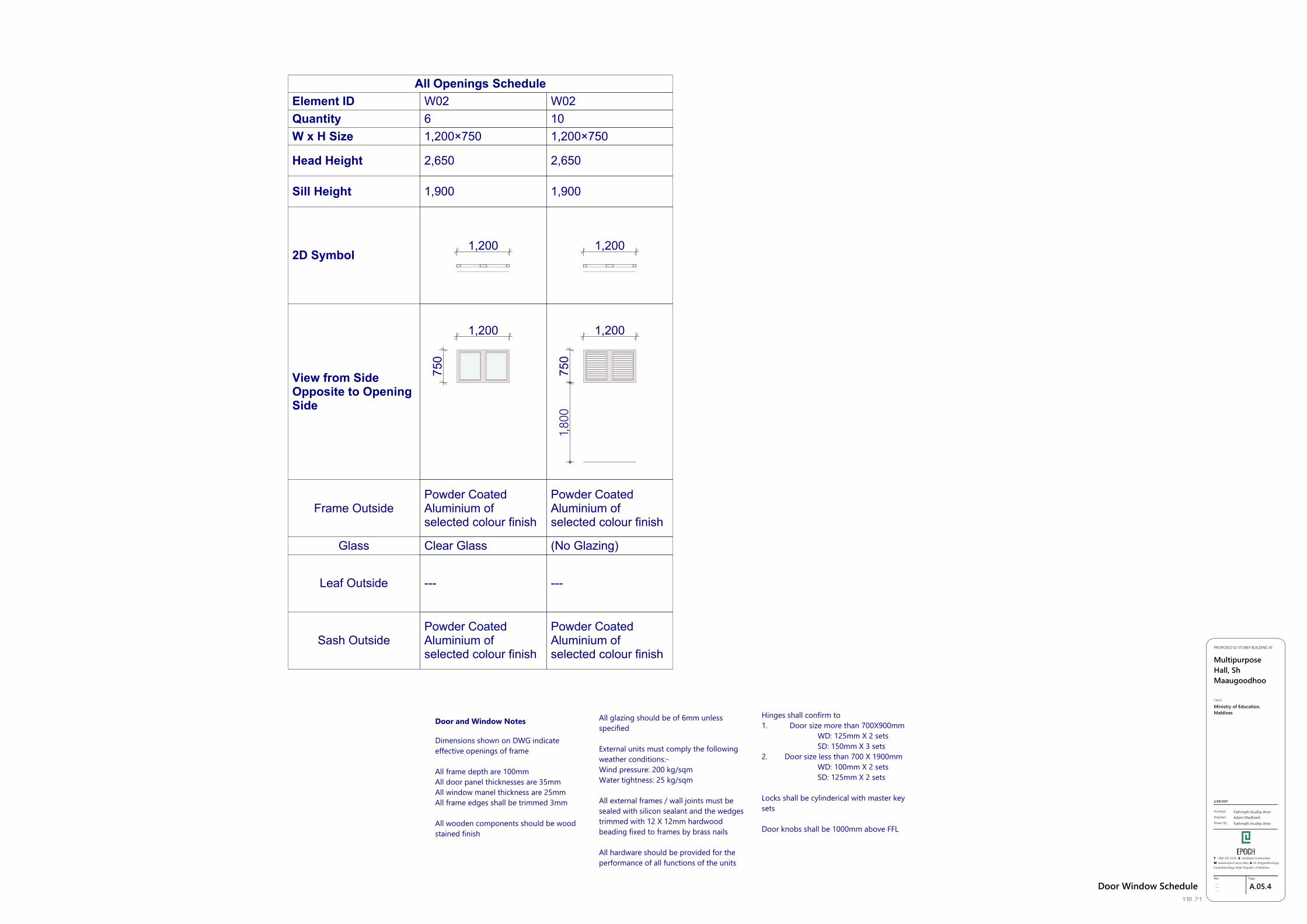
Element ID W02 W02Quantity 6 10W x H Size 1,200×750 1,200×750
Head Height 2,650 2,650
Sill Height 1,900 1,900
2D Symbol1,200 1,200
View from SideOpposite to OpeningSide
1,200
750
1,200
750
1,800
Frame OutsidePowder CoatedAluminium ofselected colour finish
Powder CoatedAluminium ofselected colour finish
Glass Clear Glass (No Glazing)
Leaf Outside --- ---
Sash OutsidePowder CoatedAluminium ofselected colour finish
Powder CoatedAluminium ofselected colour finish
All Openings Schedule
GSPublisherVersion 0.1.100.100
C.01.1Rev:
---------
Page:
Architect:
Engineer:
Drawn By:
Fathmath Ihudha AmirAdam MadheehFathmath Ihudha Amir
PROPOSED 02 STOREY BUILDING AT
MultipurposeHall, ShMaaugoodhoo
2/28/2021
Client:
Ministry of Education,Maldives
T: +960 333 3528 ,E: [email protected]: wwww.epoch.associates, A: M. Ahigasdhoshuge,Fareedhee Magu Male' Republic of Maldives
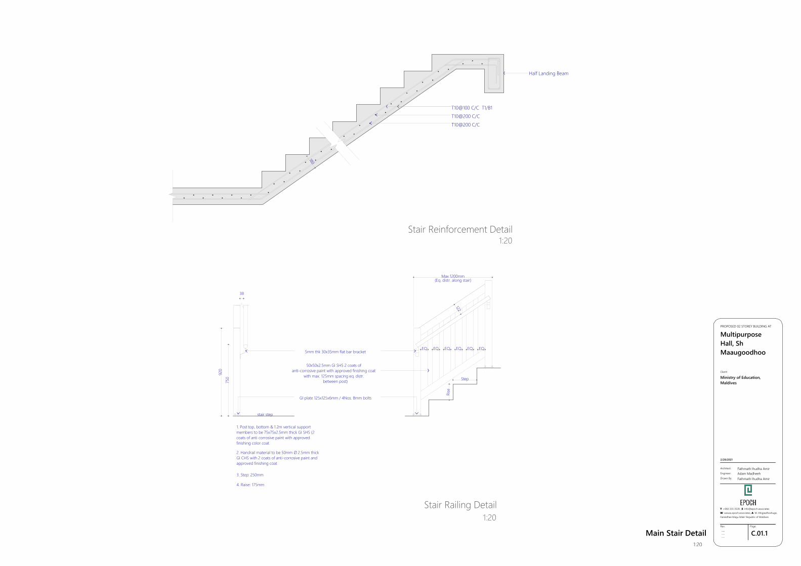
Main Stair Detail1:20
50x50x2.5mm GI SHS 2 coats ofanti-corrosive paint with approved finishing coat
with max. 125mm spacing eq. distr.between post)
5mm thk 30x35mm flat bar bracket
2. Handrail material to be 50mm Ø 2.5mm thickGI CHS with 2 coats of anti-corrosive paint andapproved finishing coat
3. Step: 250mm
4. Raise: 175mm
GI plate 125x125x6mm / 4Nos. 8mm bolts
stair step
1. Post top, bottom & 1.2m vertical supportmembers to be 75x75x2.5mm thick GI SHS (2coats of anti corrosive paint with approvedfinishing color coat
750
920
38
122
Rise
Step
EQ
Max 1200mm(Eq. distr. along stair)
EQ EQ EQ EQ EQ
T10@200 C/CT10@200 C/C
T10@100 C/C T1/B1
Half Landing Beam
180
Stair Railing Detail1:20
Stair Reinforcement Detail1:20
GSPublisherVersion 0.1.100.100
C.01.2Rev:
---------
Page:
Architect:
Engineer:
Drawn By:
Fathmath Ihudha AmirAdam MadheehFathmath Ihudha Amir
PROPOSED 02 STOREY BUILDING AT
MultipurposeHall, ShMaaugoodhoo
2/28/2021
Client:
Ministry of Education,Maldives
T: +960 333 3528 ,E: [email protected]: wwww.epoch.associates, A: M. Ahigasdhoshuge,Fareedhee Magu Male' Republic of Maldives
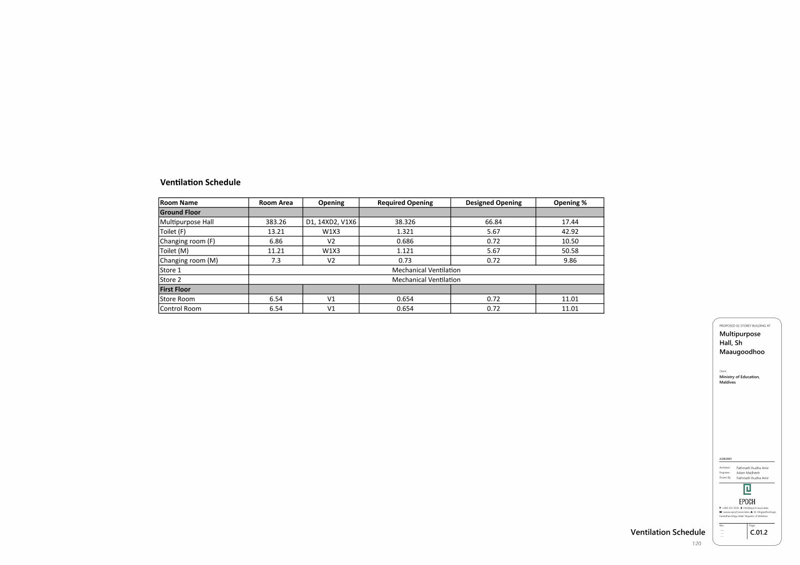
Ventilation Schedule1:20
Ven la on Schedule
Room Name Room Area Opening Required Opening Designed Opening Opening %Ground FloorMul purpose Hall 383.26 D1, 14XD2, V1X6 38.326 66.84 17.44Toilet (F) 13.21 W1X3 1.321 5.67 42.92Changing room (F) 6.86 V2 0.686 0.72 10.50Toilet (M) 11.21 W1X3 1.121 5.67 50.58Changing room (M) 7.3 V2 0.73 0.72 9.86Store 1Store 2First FloorStore Room 6.54 V1 0.654 0.72 11.01Control Room 6.54 V1 0.654 0.72 11.01
Mechanical Ven la onMechanical Ven la on
GSPublisherVersion 0.1.100.100
C.01.3Rev:
---------
Page:
Architect:
Engineer:
Drawn By:
Fathmath Ihudha AmirAdam MadheehFathmath Ihudha Amir
PROPOSED 02 STOREY BUILDING AT
MultipurposeHall, ShMaaugoodhoo
2/28/2021
Client:
Ministry of Education,Maldives
T: +960 333 3528 ,E: [email protected]: wwww.epoch.associates, A: M. Ahigasdhoshuge,Fareedhee Magu Male' Republic of Maldives
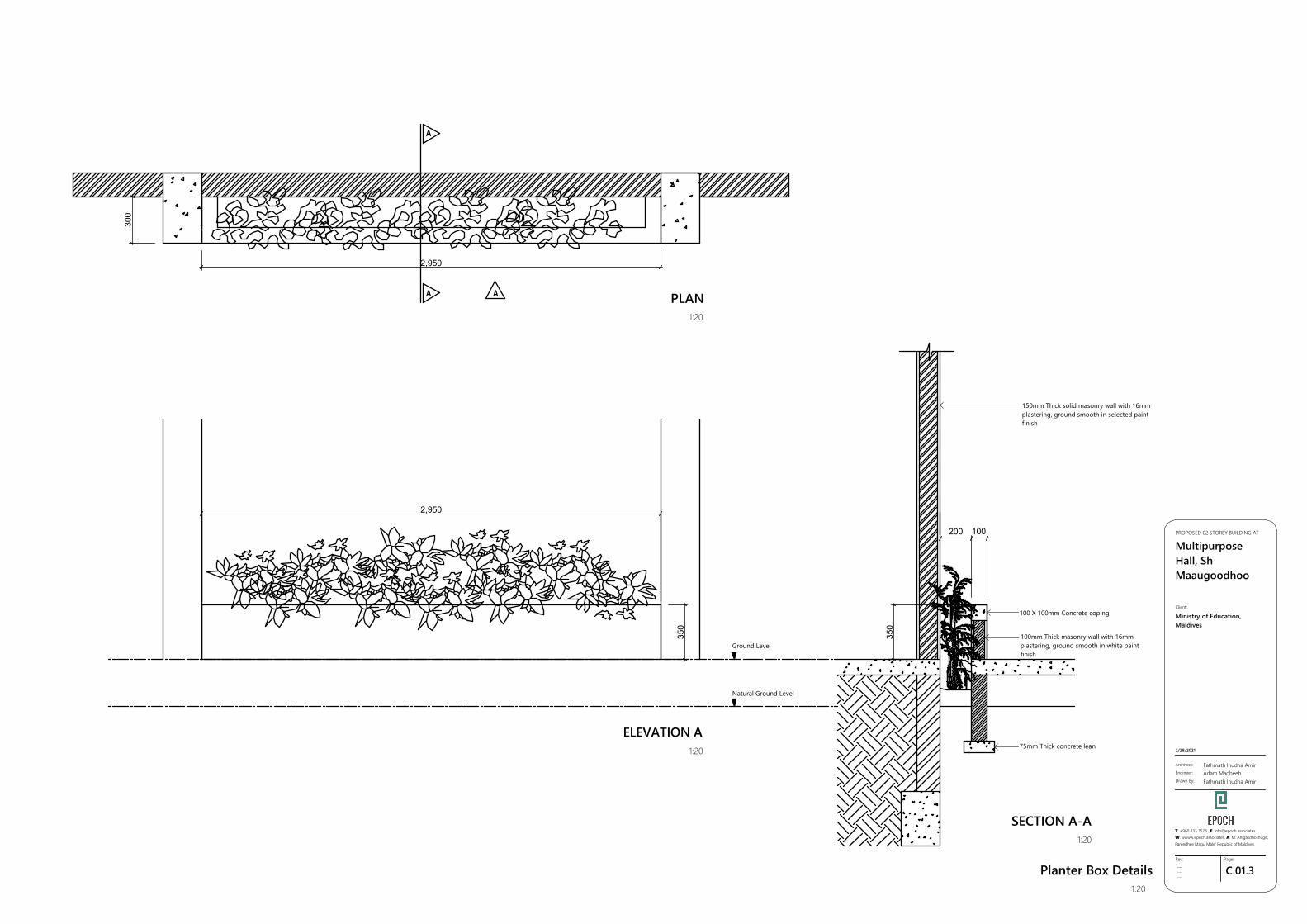
Planter Box Details1:20
A A
A
PLAN1:20
ELEVATION A1:20
SECTION A-A1:20
350
2,950
2,950
300
350
200 100
150mm Thick solid masonry wall with 16mmplastering, ground smooth in selected paintfinish
100mm Thick masonry wall with 16mmplastering, ground smooth in white paintfinish
100 X 100mm Concrete coping
75mm Thick concrete lean
Ground Level
Natural Ground Level
GSPublisherVersion 0.1.100.100
C.01.4Rev:
---------
Page:
Architect:
Engineer:
Drawn By:
Fathmath Ihudha AmirAdam MadheehFathmath Ihudha Amir
PROPOSED 02 STOREY BUILDING AT
MultipurposeHall, ShMaaugoodhoo
2/28/2021
Client:
Ministry of Education,Maldives
T: +960 333 3528 ,E: [email protected]: wwww.epoch.associates, A: M. Ahigasdhoshuge,Fareedhee Magu Male' Republic of Maldives
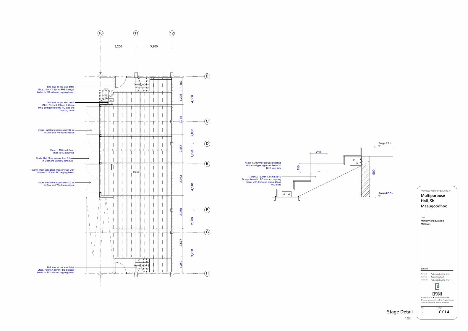
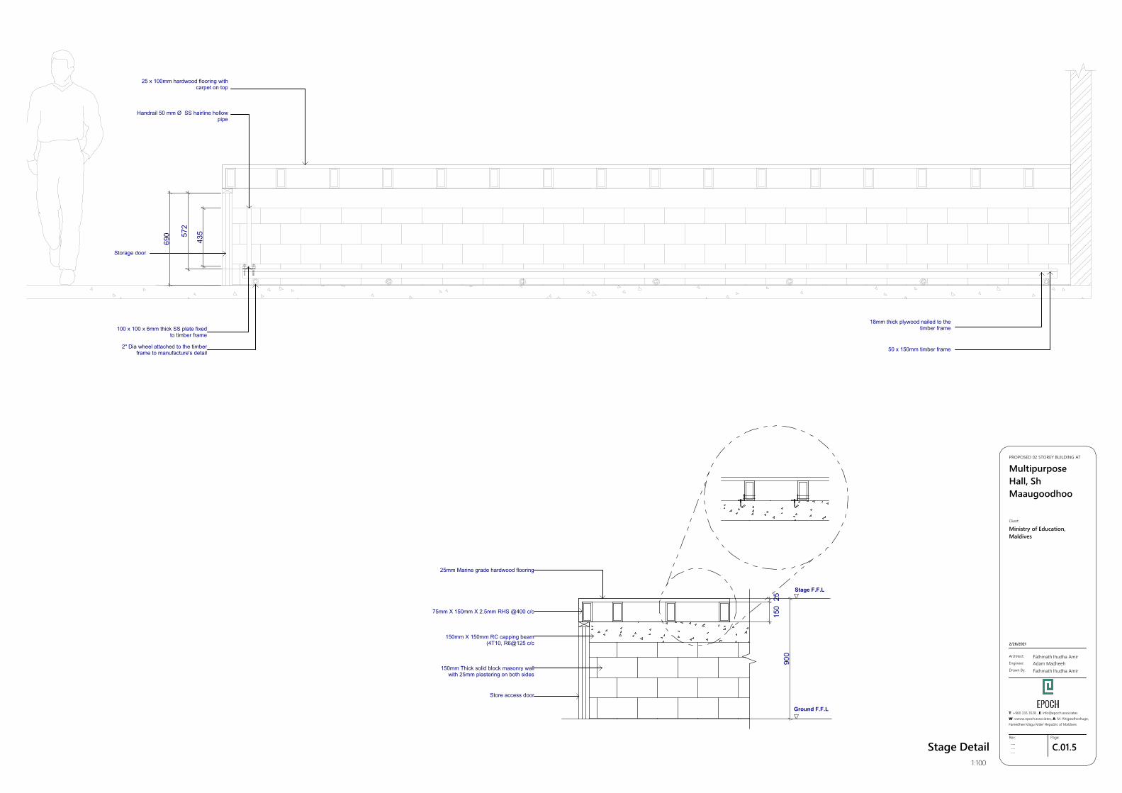
Stage Detail1:100
10
3,200
11
3,200
12
5R x 1505G x 250
Stage
5R x 1505G x 250
1 2 3 4 5
UP
UP
1 2 3 4 5
5R x
150
5G x
250
DOWN
1
2
3
4
5
UP
B
C
D
E
F
G
H
1,35
02,
577
2,95
02,
973
2,45
72,
716
1,22
51,
182
3,70
02,
000
4,14
01,
790
2,00
04,
050
250
150
900
Hall stair as per stair detail2Nos. 75mm X 150mm X 25mm
RHS Stringer bolted to RC slab andcapping beam
75mm X 150mm 2.5mmThick RHS @400 c/c
150mm Thick solid block masonry wall with150mm X 150mm RC capping beam
75mm X 150mm x 2.5mm RHSStringer bolted to RC slab and capping
beam with 6mm end plates &4nosM12 bolts
45mm X 300mm Hardwood flooringwith anti-slippery grooves bolted to
RHS step fixer
Stage F.F.L
Ground F.F.L
Hall stair as per stair detail2Nos. 75mm X 25mm RHS Stringer
bolted to RC slab and capping beam
Under Hall Store access door D2 asin Door and Window schedule
Under Hall Store access door D2 asin Door and Window schedule
Hall stair as per stair detail2Nos. 75mm X 25mm RHS Stringer
bolted to RC slab and capping beam
Under Hall Store access door D1 asin Door and Window schedule
GSPublisherVersion 0.1.100.100
C.01.5Rev:
---------
Page:
Architect:
Engineer:
Drawn By:
Fathmath Ihudha AmirAdam MadheehFathmath Ihudha Amir
PROPOSED 02 STOREY BUILDING AT
MultipurposeHall, ShMaaugoodhoo
2/28/2021
Client:
Ministry of Education,Maldives
T: +960 333 3528 ,E: [email protected]: wwww.epoch.associates, A: M. Ahigasdhoshuge,Fareedhee Magu Male' Republic of Maldives
Stage Detail1:100
690 57
2
435
150
2590
0
25 x 100mm hardwood flooring withcarpet on top
Handrail 50 mm Ø SS hairline hollowpipe
Storage door
100 x 100 x 6mm thick SS plate fixedto timber frame
2" Dia wheel attached to the timberframe to manufacture's detail 50 x 150mm timber frame
18mm thick plywood nailed to thetimber frame
25mm Marine grade hardwood flooring
75mm X 150mm X 2.5mm RHS @400 c/c
150mm X 150mm RC capping beam(4T10, R6@125 c/c
150mm Thick solid block masonry wallwith 25mm plastering on both sides
Store access door
Stage F.F.L
Ground F.F.L
GSPublisherVersion 0.1.100.100
C.01.6Rev:
---------
Page:
Architect:
Engineer:
Drawn By:
Fathmath Ihudha AmirAdam MadheehFathmath Ihudha Amir
PROPOSED 02 STOREY BUILDING AT
MultipurposeHall, ShMaaugoodhoo
2/28/2021
Client:
Ministry of Education,Maldives
T: +960 333 3528 ,E: [email protected]: wwww.epoch.associates, A: M. Ahigasdhoshuge,Fareedhee Magu Male' Republic of Maldives
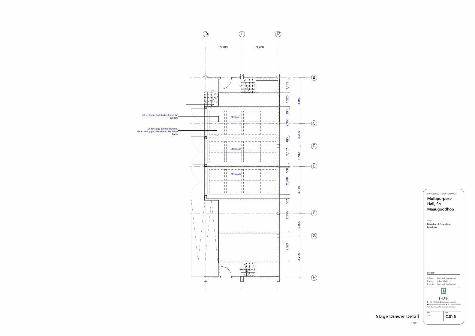
Stage Drawer Detail1:100
10
3,200
11
3,200
12
5R x 1505G x 250
5R x 1505G x 250
1 2 3 4 5
UP
UP
1 2 3 4 5
5R x
150
5G x
250
DOWN
1
2
3
4
5
UP
B
C
D
E
F
G
H
2,57
72,
950
3,70
02,
000
4,14
01,
790
2,00
04,
050
100
2,36
610
01,
225
1,18
235
72,
366
100
2,10
7
50 x 150mm thick timber frame forsupport Storage 1
Storage 2
Under stage storage drawers:18mm thick plywood nailed to the timber
frame
Storage 3
GSPublisherVersion 0.1.100.100
C.01.7Rev:
---------
Page:
Architect:
Engineer:
Drawn By:
Fathmath Ihudha AmirAdam MadheehFathmath Ihudha Amir
PROPOSED 02 STOREY BUILDING AT
MultipurposeHall, ShMaaugoodhoo
2/28/2021
Client:
Ministry of Education,Maldives
T: +960 333 3528 ,E: [email protected]: wwww.epoch.associates, A: M. Ahigasdhoshuge,Fareedhee Magu Male' Republic of Maldives
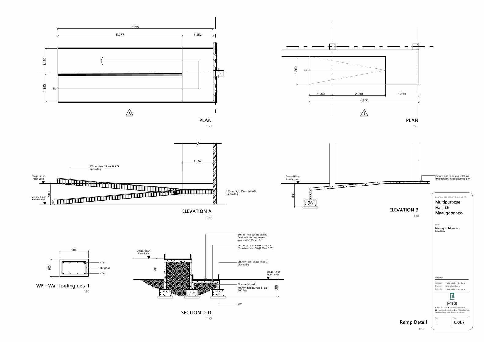
Ramp Detail1:50
WF
A
PLAN1:50
PLAN1:20
ELEVATION A1:50
B
ELEVATION B1:50
WF - Wall footing detail1:50
SECTION D-D1:50
1,15
01,
150
5,377 1,352
6,729
900
1,352
500
300
900
800
1,20
0
1,000 2,300 1,450
4,750
800
200
Stage FinishFloor Level
Ground FloorFinish Level
200mm high, 25mm thick GIpipe railing
4T12
R6 @150
4T12
Stage FinishFloor Level
50mm Thick cement screedfinish with 10mm groovesspaces @ 100mm c/c
Ground slab thickness = 100mm(Reinforcement R6@200c/c B.W)
200mm High, 25mm thick GIpipe railing
Compacted earth
WF
100mm thick RC wall T10@200 B/W
Stage FinishFloor Level
Up
Up
Ground slab thickness = 100mm(Reinforcement R6@200 c/c B.W)
Ground FloorFinish Level
200mm High, 25mm thick GIpipe railing
GSPublisherVersion 0.1.100.100
C.01.8Rev:
---------
Page:
Architect:
Engineer:
Drawn By:
Fathmath Ihudha AmirAdam MadheehFathmath Ihudha Amir
PROPOSED 02 STOREY BUILDING AT
MultipurposeHall, ShMaaugoodhoo
2/28/2021
Client:
Ministry of Education,Maldives
T: +960 333 3528 ,E: [email protected]: wwww.epoch.associates, A: M. Ahigasdhoshuge,Fareedhee Magu Male' Republic of Maldives
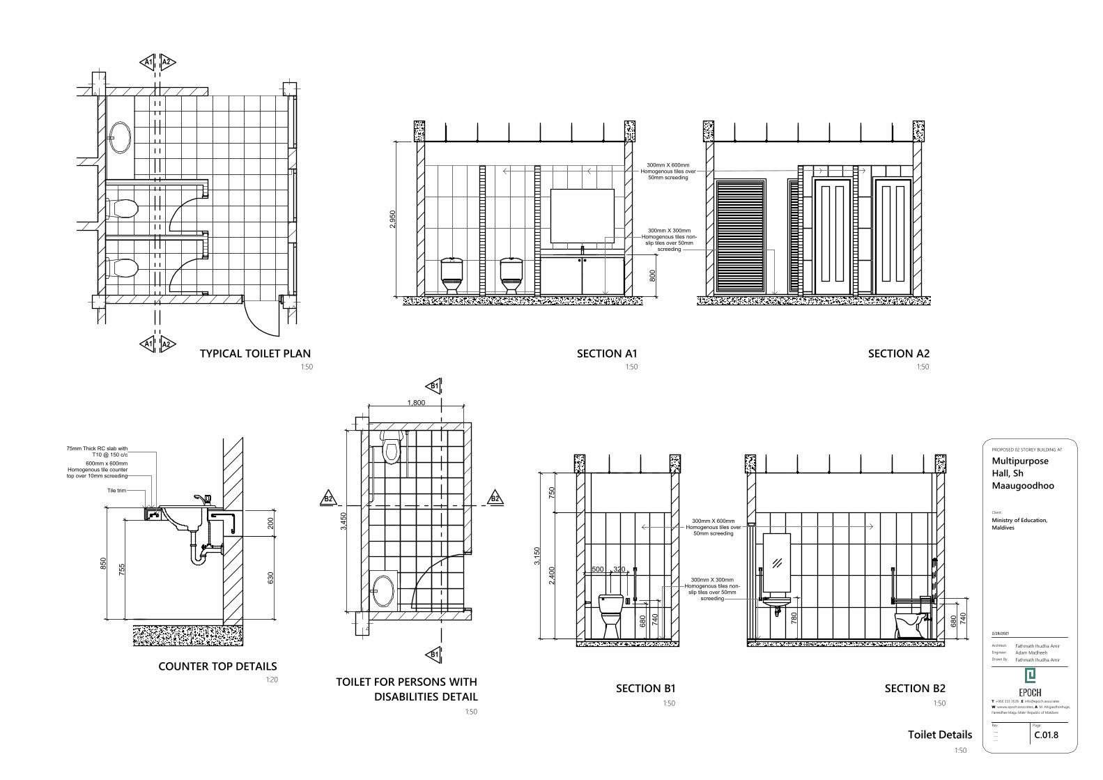
Toilet Details1:50
A2
A2
A1
A1
B1
B1
B2B2
TYPICAL TOILET PLAN1:50
SECTION A11:50
SECTION A21:50
COUNTER TOP DETAILS1:20 TOILET FOR PERSONS WITH
DISABILITIES DETAIL1:50
SECTION B11:50
SECTION B21:50
800
2,95
0
75585
0
630
200
1,800
3,45
0
500 320
680
740
2,40
075
0
3,15
0
780
680
740
300mm X 600mmHomogenous tiles over
50mm screeding
300mm X 300mmHomogenous tiles non-
slip tiles over 50mmscreeding
Tile trim
600mm x 600mmHomogenous tile countertop over 10mm screeding
75mm Thick RC slab withT10 @ 150 c/c
300mm X 600mmHomogenous tiles over
50mm screeding
300mm X 300mmHomogenous tiles non-
slip tiles over 50mmscreeding
GSPublisherVersion 0.1.100.100
C.01.9Rev:
---------
Page:
Architect:
Engineer:
Drawn By:
Fathmath Ihudha AmirAdam MadheehFathmath Ihudha Amir
PROPOSED 02 STOREY BUILDING AT
MultipurposeHall, ShMaaugoodhoo
2/28/2021
Client:
Ministry of Education,Maldives
T: +960 333 3528 ,E: [email protected]: wwww.epoch.associates, A: M. Ahigasdhoshuge,Fareedhee Magu Male' Republic of Maldives
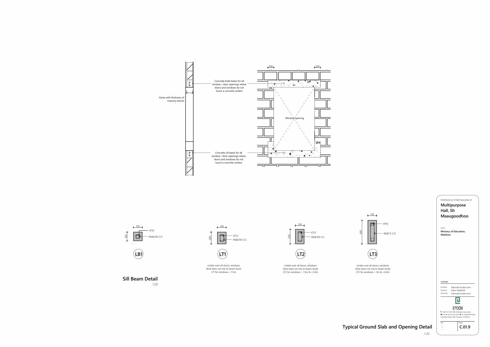
Typical Ground Slab and Opening Detail1:20
LT1 LT2 LT3
4T12R6@200 C/C
4T12
R6@100 C/C
8T16
R6@75 C/C
Lintels over all doors, windows(that does not rise to beam level)
LT1 for windows < 1.5m
Lintels over all doors, windows(that does not rise to beam level)LT2 for windows > 1.5m & <3.0m
Lintels over all doors, windows(that does not rise to beam level)LT3 for windows > 3m & <6.0m
LB1
4T10
R6@200 C/C
200
150
250
150
400
150
150
150
200 200
Varies with thickness ofmasonry blocks
Concrete lintel beam for allwindow / door openings where
doors and windows do nottouch a concrete surface
Concrete sill beam for allwindow / door openings where
doors and windows do nottouch a concrete surface
Window opening
Sill Beam Detail1:20
GSPublisherVersion 0.1.100.100
C.01.10Rev:
---------
Page:
Architect:
Engineer:
Drawn By:
Fathmath Ihudha AmirAdam MadheehFathmath Ihudha Amir
PROPOSED 02 STOREY BUILDING AT
MultipurposeHall, ShMaaugoodhoo
2/28/2021
Client:
Ministry of Education,Maldives
T: +960 333 3528 ,E: [email protected]: wwww.epoch.associates, A: M. Ahigasdhoshuge,Fareedhee Magu Male' Republic of Maldives
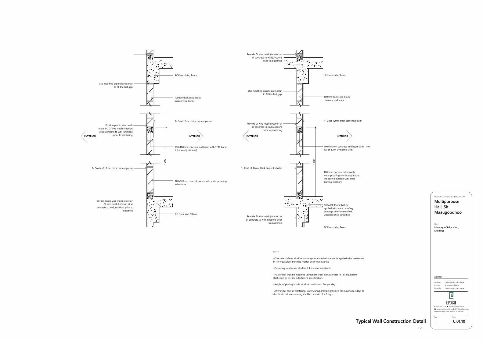
Typical Wall Construction Detail1:20
1,20
0
1,20
0
Use modified expansion mortarto fill the last gap
Provide plastic wire mesh(exterior) GI wire mesh (interior)at all concrete to wall junctions
prior to plastering
2- Coats of 10mm thick cement plaster
EXTERIOR INTERIOR
Provide plastic wire mesh (exterior)GI wire mesh (interior) at all
concrete to wall junctions prior toplastering
RC Floor slab / Beam
100mm thick solid blockmasonry wall units
1- Coat 12mm thick cement plaster
100x100mm concrete mid beam with 1T10 bar at1.2m level (mid level)
100x100mm concrete kicker with water proofingadmixture
RC Floor slab / Beam
Provide GI wire mesh (interior) atall concrete to wall junctions
prior to plastering
Use modified expansion mortarto fill the last gap
Provide GI wire mesh (interior) atall concrete to wall junctions
prior to plastering
1- Coat of 12mm thick cement plaster
Provide GI wire mesh (interior) atall concrete to wall junctions prior
to plastering
RC Floor slab / beam
100mm thick solid blockmasonry wall units
1- Coat 12mm thick cement plaster
100x100mm concrete mid beam with 1T10bar at 1.2m level (mid level)
100mm concrete kicker (withwater proofing admixture) aroundthe toilet boundary wall priorstarting masonry
All toilet floors shall beapplied with waterproofingcoatings prior to modifiedwaterproofing screeding
RC Floor slab / Beam
NOTE:
- Concrete surfaces shall be thoroughly cleaned with water & applied with mastercast141 or equivalent bonding mortar prior to plastering
- Plastering mortar mix shall be 1:4 (cement:sand) ratio.
- Plaster mix shall be modified using fibre wool & mastercast 141 or equivalentplasticisers as per manufacturer's specification.
- Height of placing blocks shall be maximum 1.2m per day
- After initial coat of plastering, water curing shall be provided for minimum 3 days &after final coat water curing shall be provided for 7 days
EXTERIOR INTERIOR
GSPublisherVersion 0.1.100.100
B.01.1Rev:
---------
Page:
Architect:
Engineer:
Drawn By:
Fathmath Ihudha AmirAdam MadheehFathmath Ihudha Amir
PROPOSED 02 STOREY BUILDING AT
MultipurposeHall, ShMaaugoodhoo
2/28/2021
Client:
Ministry of Education,Maldives
T: +960 333 3528 ,E: [email protected]: wwww.epoch.associates, A: M. Ahigasdhoshuge,Fareedhee Magu Male' Republic of Maldives
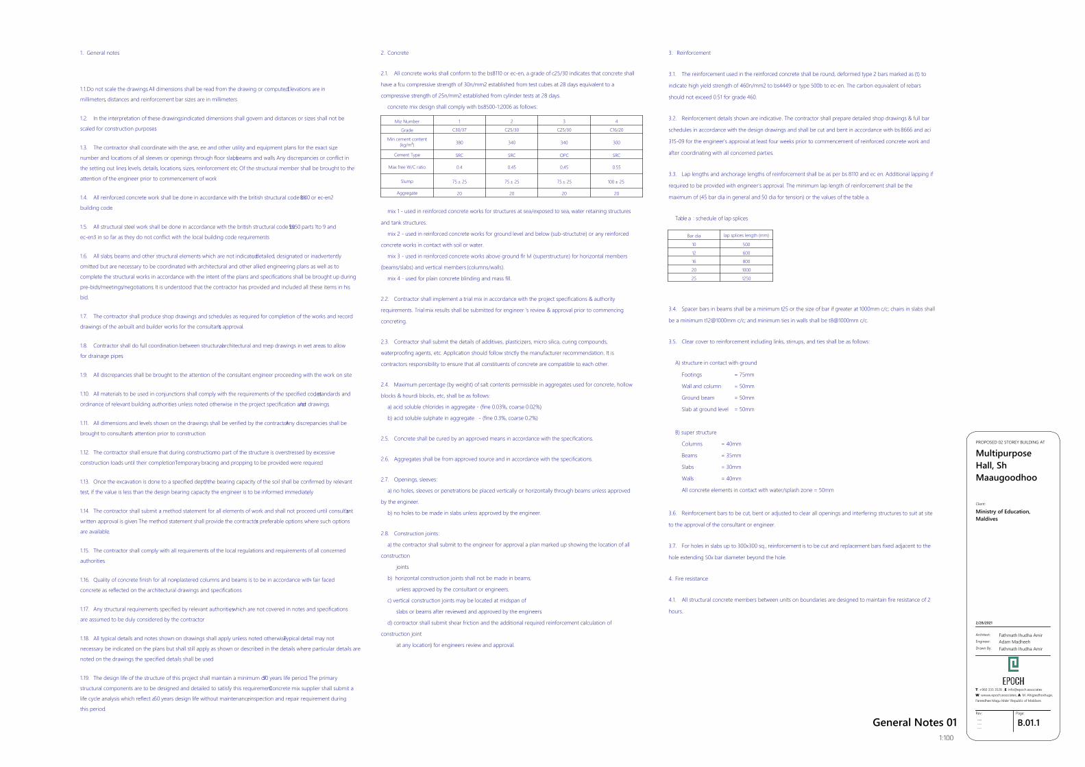
General Notes 011:100
1. General notes
1.1.Do not scale the drawings. All dimensions shall be read from the drawing or computed. Elevations are in
millimeters, distances and reinforcement bar sizes are in millimeters.
1.2. In the interpretation of these drawings, indicated dimensions shall govern and distances or sizes shall not be
scaled for construction purposes.
1.3. The contractor shall coordinate with the ar, se, ee and other utility and equipment plans for the exact size,
number and locations of all sleeves or openings through floor slabs, beams and walls. Any discrepancies or conflict in
the setting out lines, levels, details, locations, sizes, reinforcement etc. Of the structural member shall be brought to the
attention of the engineer prior to commencement of work.
1.4. All reinforced concrete work shall be done in accordance with the british structural code bs8110 or ec-en2
building code.
1.5. All structural steel work shall be done in accordance with the british structural code bs5950 parts 1to 9 and
ec-en3 in so far as they do not conflict with the local building code requirements.
1.6. All slabs, beams and other structural elements which are not indicated, detailed, designated or inadvertently
omitted but are necessary to be coordinated with architectural and other allied engineering plans as well as to
complete the structural works in accordance with the intent of the plans and specifications shall be brought up during
pre-bids/meetings/negotiations. It is understood that the contractor has provided and included all these items in his
bid.
1.7. The contractor shall produce shop drawings and schedules as required for completion of the works and record
drawings of the as-built and builder works for the consultant's approval.
1.8. Contractor shall do full coordination between structural, architectural and mep drawings in wet areas to allow
for drainage pipes.
1.9. All discrepancies shall be brought to the attention of the consultant engineer proceeding with the work on site.
1.10. All materials to be used in conjunctions shall comply with the requirements of the specified codes, standards and
ordinance of relevant building authorities unless noted otherwise in the project specification and/or drawings.
1.11. All dimensions and levels shown on the drawings shall be verified by the contractor. Any discrepancies shall be
brought to consultant's attention prior to construction.
1.12. The contractor shall ensure that during construction, no part of the structure is overstressed by excessive
construction loads until their completion. Temporary bracing and propping to be provided were required.
1.13. Once the excavation is done to a specified depth, the bearing capacity of the soil shall be confirmed by relevant
test, if the value is less than the design bearing capacity the engineer is to be informed immediately.
1.14. The contractor shall submit a method statement for all elements of work and shall not proceed until consultant's
written approval is given. The method statement shall provide the contractor's preferable options where such options
are available.
1.15. The contractor shall comply with all requirements of the local regulations and requirements of all concerned
authorities.
1.16. Quality of concrete finish for all non-plastered columns and beams is to be in accordance with- fair faced
concrete as reflected on the architectural drawings and specifications.
1.17. Any structural requirements specified by relevant authorities, which are not covered in notes and specifications
are assumed to be duly considered by the contractor.
1.18. All typical details and notes shown on drawings shall apply unless noted otherwise. Typical detail may not
necessary be indicated on the plans but shall still apply as shown or described in the details where particular details are
noted on the drawings the specified details shall be used.
1.19. The design life of the structure of this project shall maintain a minimum of50 years life period. The primary
structural components are to be designed and detailed to satisfy this requirement. Concrete mix supplier shall submit a
life cycle analysis which reflect a50 years design life without maintenance, inspection and repair requirement during
this period.
2. Concrete
2.1. All concrete works shall conform to the bs8110 or ec-en, a grade of c25/30 indicates that concrete shall
have a fcu compressive strength of 30n/mm2 established from test cubes at 28 days equivalent to a
compressive strength of 25n/mm2 established from cylinder tests at 28 days.
concrete mix design shall comply with bs8500-1:2006 as follows:
mix 1 - used in reinforced concrete works for structures at sea/exposed to sea, water retaining structures
and tank structures.
mix 2 - used in reinforced concrete works for ground level and below (sub-structutre) or any reinforced
concrete works in contact with soil or water.
mix 3 - used in reinforced concrete works above ground flr lvl (superstructure) for horizontal members
(beams/slabs) and vertical members (columns/walls).
mix 4 - used for plain concrete blinding and mass fill.
2.2. Contractor shall implement a trial mix in accordance with the project specifications & authority
requirements. Trial mix results shall be submitted for engineer 's review & approval prior to commencing
concreting.
2.3. Contractor shall submit the details of additives, plasticizers, micro silica, curing compounds,
waterproofing agents, etc. Application should follow strictly the manufacturer recommendation. It is
contractors responsibility to ensure that all constituents of concrete are compatible to each other.
2.4. Maximum percentage (by weight) of salt contents permissible in aggregates used for concrete, hollow
blocks & hourdi blocks, etc, shall be as follows:
a) acid soluble chlorides in aggregate - (fine 0.03%, coarse 0.02%)
b) acid soluble sulphate in aggregate - (fine 0.3%, coarse 0.2%)
2.5. Concrete shall be cured by an approved means in accordance with the specifications.
2.6. Aggregates shall be from approved source and in accordance with the specifications.
2.7. Openings, sleeves:
a) no holes, sleeves or penetrations be placed vertically or horizontally through beams unless approved
by the engineer.
b) no holes to be made in slabs unless approved by the engineer.
2.8. Construction joints:
a) the contractor shall submit to the engineer for approval a plan marked up showing the location of all
construction
joints
b) horizontal construction joints shall not be made in beams,
unless approved by the consultant or engineers.
c) vertical construction joints may be located at midspan of
slabs or beams after reviewed and approved by the engineers.
d) contractor shall submit shear friction and the additional required reinforcement calculation of
construction joint
at any location) for engineers review and approval.
Miz Number 1 2 3 4
Grade C30/37 C25/30 C25/30 C16/20
Min cement content(kg/m³) 380 340 340 300
Cement Type SRC SRC OPC SRC
Max free W/C ratio 0.4 0.45 0.45 0.55
Slump 75 ± 25 75 ± 25 75 ± 25 100 ± 25
Aggregate 20 20 20 20
3. Reinforcement
3.1. The reinforcement used in the reinforced concrete shall be round, deformed type 2 bars marked as (t) to
indicate high yield strength of 460n/mm2 to bs4449 or type 500b to ec-en. The carbon equivalent of rebars
should not exceed 0.51 for grade 460.
3.2. Reinforcement details shown are indicative. The contractor shall prepare detailed shop drawings & full bar
schedules in accordance with the design drawings and shall be cut and bent in accordance with bs 8666 and aci
315-09 for the engineer's approval at least four weeks prior to commencement of reinforced concrete work and
after coordinating with all concerned parties.
3.3. Lap lengths and anchorage lengths of reinforcement shall be as per bs 8110 and ec en. Additional lapping if
required to be provided with engineer's approval. The minimum lap length of reinforcement shall be the
maximum of (45 bar dia in general and 50 dia for tension) or the values of the table a.
Table a : schedule of lap splices
3.4. Spacer bars in beams shall be a minimum t25 or the size of bar if greater at 1000mm c/c; chairs in slabs shall
be a minimum t12@1000mm c/c; and minimum ties in walls shall be t8@1000mm c/c.
3.5. Clear cover to reinforcement including links, stirrups, and ties shall be as follows:
A) structure in contact with ground
Footings = 75mm
Wall and column = 50mm
Ground beam = 50mm
Slab at ground level = 50mm
B) super structure
Columns = 40mm
Beams = 35mm
Slabs = 30mm
Walls = 40mm
All concrete elements in contact with water/splash zone = 50mm
3.6. Reinforcement bars to be cut, bent or adjusted to clear all openings and interfering structures to suit at site
to the approval of the consultant or engineer.
3.7. For holes in slabs up to 300x300 sq., reinforcement is to be cut and replacement bars fixed adjacent to the
hole extending 50x bar diameter beyond the hole.
4. Fire resistance
4.1. All structural concrete members between units on boundaries are designed to maintain fire resistance of 2
hours.
Bar dia lap splices length (mm)
10 500
12 600
16 800
20 1000
25 1250
GSPublisherVersion 0.1.100.100
B.01.2Rev:
---------
Page:
Architect:
Engineer:
Drawn By:
Fathmath Ihudha AmirAdam MadheehFathmath Ihudha Amir
PROPOSED 02 STOREY BUILDING AT
MultipurposeHall, ShMaaugoodhoo
2/28/2021
Client:
Ministry of Education,Maldives
T: +960 333 3528 ,E: [email protected]: wwww.epoch.associates, A: M. Ahigasdhoshuge,Fareedhee Magu Male' Republic of Maldives
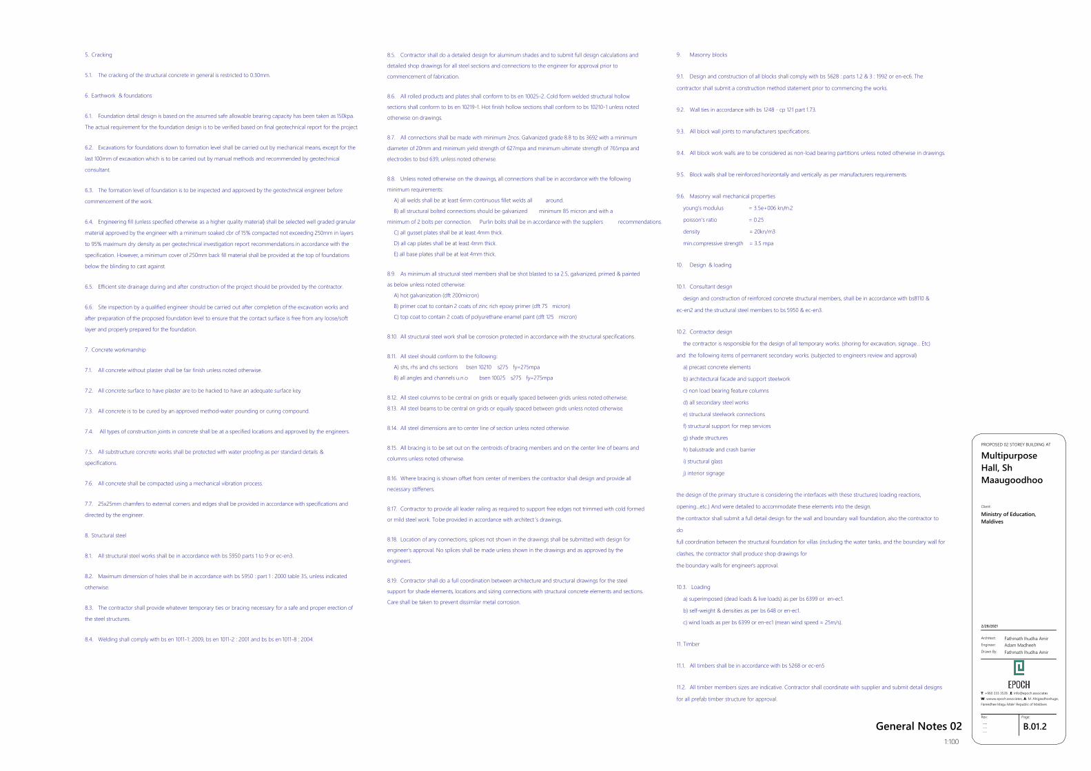
General Notes 021:100
5. Cracking
5.1. The cracking of the structural concrete in general is restricted to 0.30mm.
6. Earthwork & foundations
6.1. Foundation detail design is based on the assumed safe allowable bearing capacity has been taken as 150kpa.
The actual requirement for the foundation design is to be verified based on final geotechnical report for the project.
6.2. Excavations for foundations down to formation level shall be carried out by mechanical means, except for the
last 100mm of excavation which is to be carried out by manual methods and recommended by geotechnical
consultant.
6.3. The formation level of foundation is to be inspected and approved by the geotechnical engineer before
commencement of the work.
6.4. Engineering fill (unless specified otherwise as a higher quality material) shall be selected well graded granular
material approved by the engineer with a minimum soaked cbr of 15% compacted not exceeding 250mm in layers
to 95% maximum dry density as per geotechnical investigation report recommendations in accordance with the
specification. However, a minimum cover of 250mm back fill material shall be provided at the top of foundations
below the blinding to cast against.
6.5. Efficient site drainage during and after construction of the project should be provided by the contractor.
6.6. Site inspection by a qualified engineer should be carried out after completion of the excavation works and
after preparation of the proposed foundation level to ensure that the contact surface is free from any loose/soft
layer and properly prepared for the foundation.
7. Concrete workmanship
7.1. All concrete without plaster shall be fair finish unless noted otherwise.
7.2. All concrete surface to have plaster are to be hacked to have an adequate surface key.
7.3. All concrete is to be cured by an approved method-water pounding or curing compound.
7.4. All types of construction joints in concrete shall be at a specified locations and approved by the engineers.
7.5. All substructure concrete works shall be protected with water proofing as per standard details &
specifications.
7.6. All concrete shall be compacted using a mechanical vibration process.
7.7. 25x25mm chamfers to external corners and edges shall be provided in accordance with specifications and
directed by the engineer.
8. Structural steel
8.1. All structural steel works shall be in accordance with bs 5950 parts 1 to 9 or ec-en3.
8.2. Maximum dimension of holes shall be in accordance with bs 5950 : part 1 : 2000 table 35, unless indicated
otherwise.
8.3. The contractor shall provide whatever temporary ties or bracing necessary for a safe and proper erection of
the steel structures.
8.4. Welding shall comply with bs en 1011-1: 2009, bs en 1011-2 : 2001 and bs bs en 1011-8 : 2004.
8.5. Contractor shall do a detailed design for aluminum shades and to submit full design calculations and
detailed shop drawings for all steel sections and connections to the engineer for approval prior to
commencement of fabrication.
8.6. All rolled products and plates shall conform to bs en 10025-2. Cold form welded structural hollow
sections shall conform to bs en 10219-1. Hot finish hollow sections shall conform to bs 10210-1 unless noted
otherwise on drawings.
8.7. All connections shall be made with minimum 2nos. Galvanized grade 8.8 to bs 3692 with a minimum
diameter of 20mm and minimum yield strength of 627mpa and minimum ultimate strength of 765mpa and
electrodes to bsd 639, unless noted otherwise.
8.8. Unless noted otherwise on the drawings, all connections shall be in accordance with the following
minimum requirements:
A) all welds shall be at least 6mm continuous fillet welds all around.
B) all structural bolted connections should be galvanized minimum 85 micron and with a
minimum of 2 bolts per connection. Purlin bolts shall be in accordance with the suppliers recommendations.
C) all gusset plates shall be at least 4mm thick.
D) all cap plates shall be at least 4mm thick.
E) all base plates shall be at leat 4mm thick.
8.9. As minimum all structural steel members shall be shot blasted to sa 2.5, galvanized, primed & painted
as below unless noted otherwise:
A) hot galvanization (dft 200micron)
B) primer coat to contain 2 coats of zinc rich epoxy primer (dft 75 micron)
C) top coat to contain 2 coats of polyurethane enamel paint (dft 125 micron)
8.10. All structural steel work shall be corrosion protected in accordance with the structural specifications.
8.11. All steel should conform to the following:
A) shs, rhs and chs sections bsen 10210 s275 fy=275mpa
B) all angles and channels u.n.o bsen 10025 s275 fy=275mpa
8.12. All steel columns to be central on grids or equally spaced between grids unless noted otherwise.
8.13. All steel beams to be central on grids or equally spaced between grids unless noted otherwise.
8.14. All steel dimensions are to center line of section unless noted otherwise.
8.15. All bracing is to be set out on the centroids of bracing members and on the center line of beams and
columns unless noted otherwise.
8.16. Where bracing is shown offset from center of members the contractor shall design and provide all
necessary stiffeners.
8.17. Contractor to provide all leader railing as required to support free edges not trimmed with cold formed
or mild steel work. To be provided in accordance with architect ’s drawings.
8.18. Location of any connections, splices not shown in the drawings shall be submitted with design for
engineer’s approval. No splices shall be made unless shown in the drawings and as approved by the
engineers.
8.19. Contractor shall do a full coordination between architecture and structural drawings for the steel
support for shade elements, locations and sizing connections with structural concrete elements and sections.
Care shall be taken to prevent dissimilar metal corrosion.
9. Masonry blocks
9.1. Design and construction of all blocks shall comply with bs 5628 : parts 1.2 & 3 : 1992 or en-ec6. The
contractor shall submit a construction method statement prior to commencing the works.
9.2. Wall ties in accordance with bs 1248 - cp 121 part 1.73.
9.3. All block wall joints to manufacturers specifications.
9.4. All block work walls are to be considered as non-load bearing partitions unless noted otherwise in drawings.
9.5. Block walls shall be reinforced horizontally and vertically as per manufacturers requirements.
9.6. Masonry wall mechanical properties
young's modulus = 3.5e+006 kn/m 2
poisson's ratio = 0.25
density = 20kn/m3
min.compressive strength = 3.5 mpa
10. Design & loading
10.1. Consultant design
design and construction of reinforced concrete structural members, shall be in accordance with bs8110 &
ec-en2 and the structural steel members to bs 5950 & ec-en3.
10.2. Contractor design
the contractor is responsible for the design of all temporary works. (shoring for excavation, signage... Etc)
and the following items of permanent secondary works. (subjected to engineers review and approval)
a) precast concrete elements
b) architectural facade and support steelwork
c) non load bearing feature columns
d) all secondary steel works
e) structural steelwork connections
f) structural support for mep services
g) shade structures
h) balustrade and crash barrier
i) structural glass
j) interior signage
the design of the primary structure is considering the interfaces with these structures) loading reactions,
opening...etc.) And were detailed to accommodate these elements into the design.
the contractor shall submit a full detail design for the wall and boundary wall foundation, also the contractor to
do
full coordination between the structural foundation for villas (including the water tanks, and the boundary wall for
clashes, the contractor shall produce shop drawings for
the boundary walls for engineer’s approval.
10.3. Loading
a) superimposed (dead loads & live loads) as per bs 6399 or en-ec1.
b) self-weight & densities as per bs 648 or en-ec1.
c) wind loads as per bs 6399 or en-ec1 (mean wind speed = 25m/s).
11. Timber
11.1. All timbers shall be in accordance with bs 5268 or ec-en5
11.2. All timber members sizes are indicative. Contractor shall coordinate with supplier and submit detail designs
for all prefab timber structure for approval.
GSPublisherVersion 0.1.100.100
B.01.3Rev:
---------
Page:
Architect:
Engineer:
Drawn By:
Fathmath Ihudha AmirAdam MadheehFathmath Ihudha Amir
PROPOSED 02 STOREY BUILDING AT
MultipurposeHall, ShMaaugoodhoo
2/28/2021
Client:
Ministry of Education,Maldives
T: +960 333 3528 ,E: [email protected]: wwww.epoch.associates, A: M. Ahigasdhoshuge,Fareedhee Magu Male' Republic of Maldives
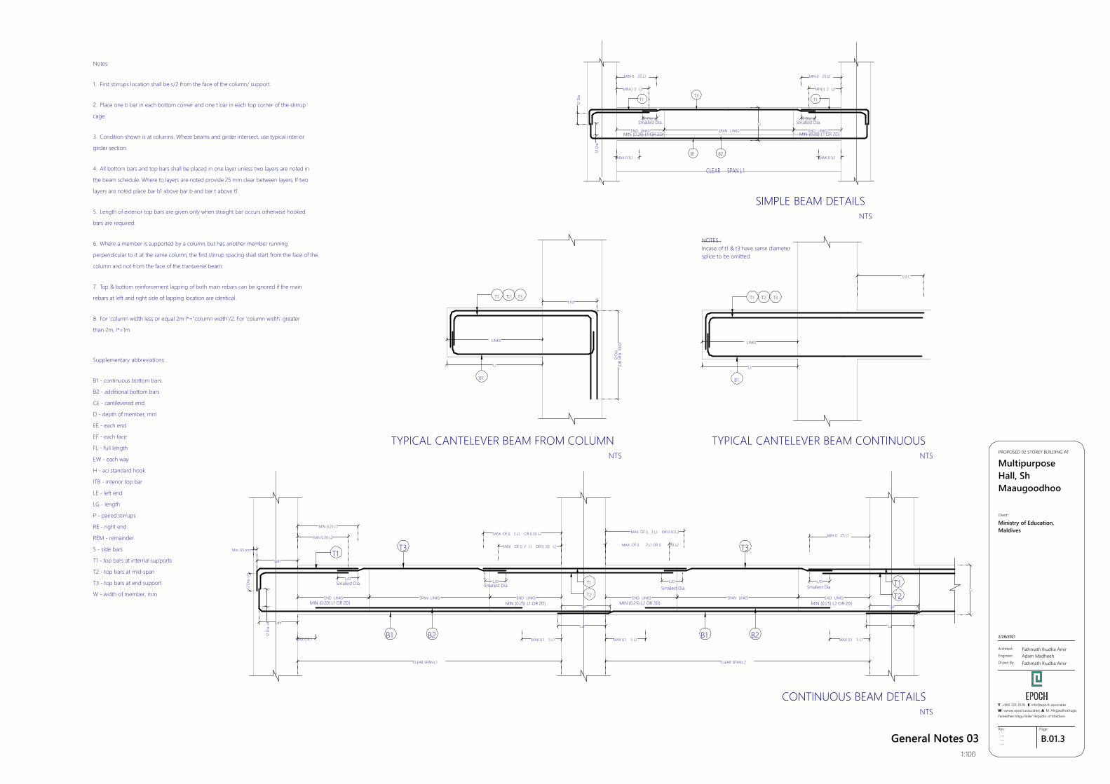
General Notes 031:100
Notes:
1. First stirrups location shall be s/2 from the face of the column/ support.
2. Place one b bar in each bottom corner and one t bar in each top corner of the stirrup
cage.
3. Condition shown is at columns. Where beams and girder intersect, use typical interior
girder section.
4. All bottom bars and top bars shall be placed in one layer unless two layers are noted in
the beam schedule. Where to layers are noted provide 25 mm clear between layers. If two
layers are noted place bar b1 above bar b and bar t above t1.
5. Length of exterior top bars are given only when straight bar occurs otherwise hooked
bars are required.
6. Where a member is supported by a column, but has another member running
perpendicular to it at the same column, the first stirrup spacing shall start from the face of the
column and not from the face of the transverse beam.
7. Top & bottom reinforcement lapping of both main rebars can be ignored if the main
rebars at left and right side of lapping location are identical.
8. For 'column width less or equal 2m l*="column width'/2. For 'column width' greater
than 2m, l*=1m
Supplementary abbreviations:
B1 - continuous bottom bars.
B2 - additional bottom bars
CE - cantilevered end
D - depth of member, mm
EE - each end
EF - each face
FL - full length
EW - each way
H - aci standard hook
ITB - interior top bar
LE - left end
LG - length
P - paired stirrups
RE - right end
REM - remainder
S - side bars
T1 - top bars at internal supports
T2 - top bars at mid-span
T3 - top bars at end support
W - width of member, mm
D
T1
30 Dia. of
MIN 0. 2 L2
T3
END LINKS SPAN LINKS END LINKSMIN (0.20) L1 OR 2D)MIN (0.20) L1 OR 2D)
T1
MAX 0.1L1 MAX 0.1L1
12Di
a.
12Di
a.
CLEAR SPAN L 1
Smallest Dia.30 Dia. of
Smallest Dia.
B1 B2
MIN 0. 25 L1
MIN 0. 2 L2
MIN 0. 25 L1
Lc
B1
T1 T2 T3
LINKS
Lhd
12Di
a.(O
R M
IN.1
000)
NOTES :Incase of t1 & t3 have same diametersplice to be omitted.
Lc
B1
T1 T2 T3
LINKS
0.3 L
T2T1
12Di
a.of
B1 B2
T1
MAX. OF 0. 3 L1 OR 0.30 L2
MAX. OF 0. 2 L1 OR 0. 20 L2
MIN 0. 25 L1
T3
D
T1
T2
12Di
a.of
MAX. OF 0. 2 L1 OR 0. 20 L2
MAX. OF 0. 3 L1 OR 0.30 L2
MAX 0.1 5 L1MAX 0.1L1
MIN 0.20 L2
MIN (0.20) L1 OR 2D)
B1
T3
B2
MIN (0.25) L2 OR 2D)END LINKS SPAN LINKS
MIN (0.25) L1 OR 2D)END LINKS END LINKS SPAN LINKS
MIN (0.25) L2 OR 2D)END LINKS
CLEAR SPAN L1 CLEAR SPAN L2
L/DSmallest Dia. L/D
Smallest Dia.L/DL/D
Smallest Dia. Smallest Dia.
Ldh
MAX 0.1 5 L1 MAX 0.1 5 L1
Ld
Ld
Ld
Ld
Ldh
Min. 65 mm
MIN 0.25 L1
SIMPLE BEAM DETAILSNTS
TYPICAL CANTELEVER BEAM CONTINUOUSNTS
TYPICAL CANTELEVER BEAM FROM COLUMNNTS
CONTINUOUS BEAM DETAILSNTS
GSPublisherVersion 0.1.100.100
B.01.4Rev:
---------
Page:
Architect:
Engineer:
Drawn By:
Fathmath Ihudha AmirAdam MadheehFathmath Ihudha Amir
PROPOSED 02 STOREY BUILDING AT
MultipurposeHall, ShMaaugoodhoo
2/28/2021
Client:
Ministry of Education,Maldives
T: +960 333 3528 ,E: [email protected]: wwww.epoch.associates, A: M. Ahigasdhoshuge,Fareedhee Magu Male' Republic of Maldives
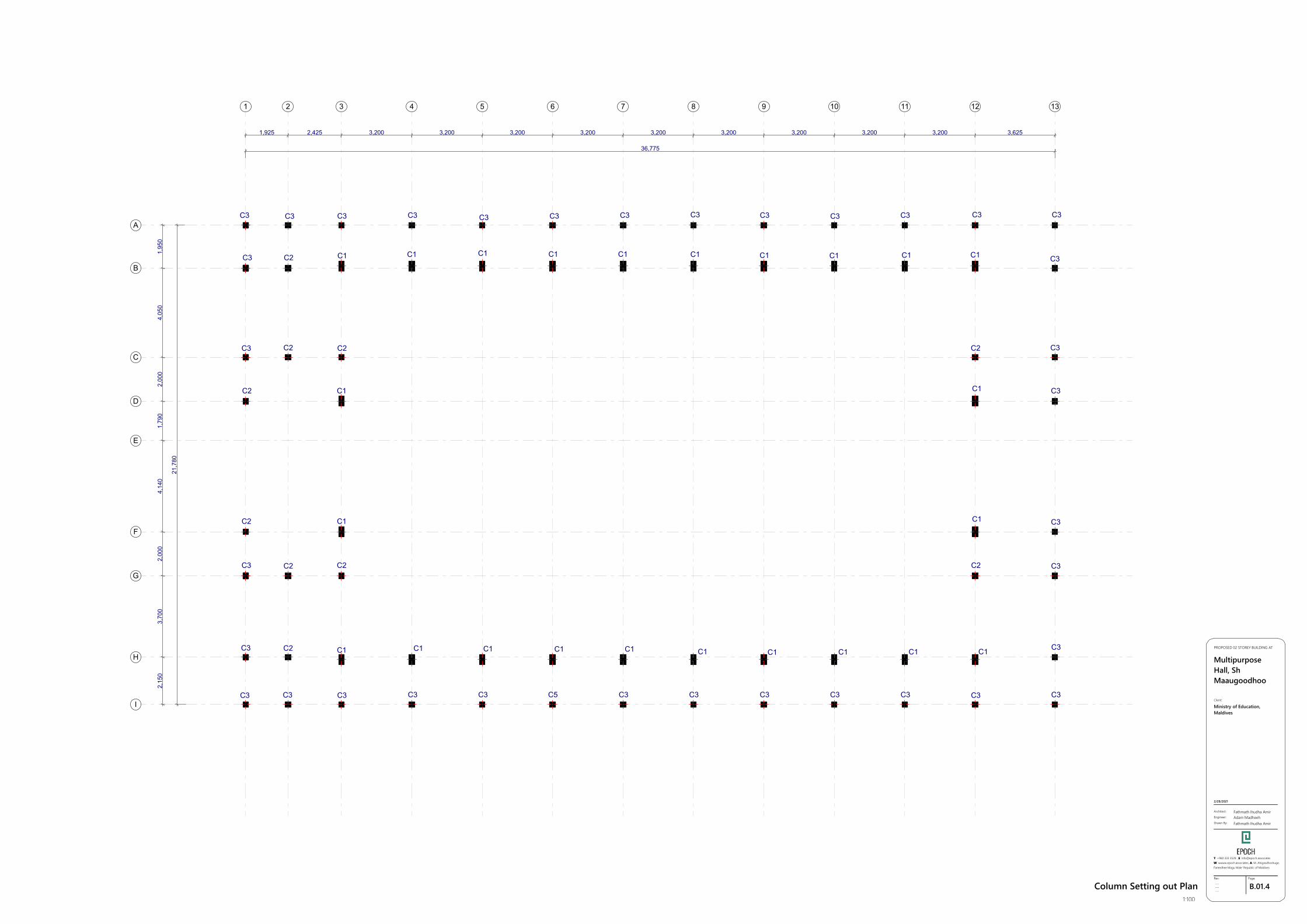
Column Setting out Plan1:100
36,775
21,7
80
1,925 2,425 3,200 3,200 3,200 3,200 3,200 3,200 3,200 3,200 3,200 3,625
2,15
03,
700
2,00
04,
140
1,79
02,
000
4,05
01,
950
C1 C1 C1 C1 C1 C1 C1 C1 C1 C1
C1 C1 C1 C1 C1 C1 C1 C1 C1 C1
C3 C3 C3 C3 C3 C3 C3 C3 C3 C3 C3 C3
C3 C3 C3 C5 C3 C3 C3 C3 C3 C3 C3
C2
C2
C2
C2
C2
C2
C3
C3
C3
C3
C3
C3
C3
C2
C2C2
C1
C1
C2
C3
C3
C3
C3
C3
C3
C1
C1
1 2 3 4 5 6 7 8 9 10 11 12 13
A
B
C
D
E
F
G
H
I
GSPublisherVersion 0.1.100.100
B.01.5Rev:
---------
Page:
Architect:
Engineer:
Drawn By:
Fathmath Ihudha AmirAdam MadheehFathmath Ihudha Amir
PROPOSED 02 STOREY BUILDING AT
MultipurposeHall, ShMaaugoodhoo
2/28/2021
Client:
Ministry of Education,Maldives
T: +960 333 3528 ,E: [email protected]: wwww.epoch.associates, A: M. Ahigasdhoshuge,Fareedhee Magu Male' Republic of Maldives
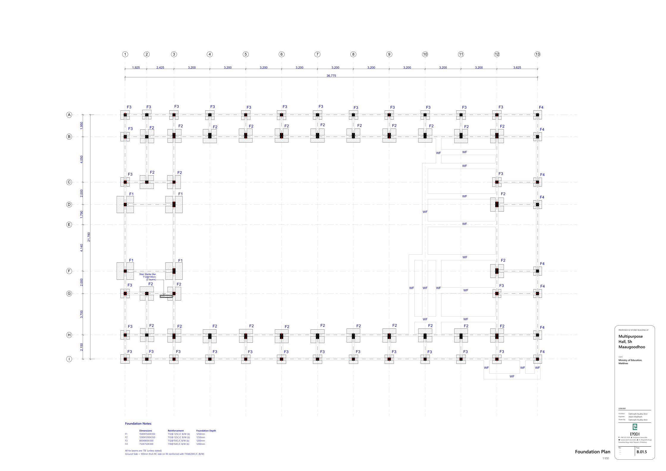
Foundation Plan1:100
36,775
21,7
80
1,925 2,425 3,200 3,200 3,200 3,200 3,200 3,200 3,200 3,200 3,200 3,625
2,15
03,
700
2,00
04,
140
1,79
02,
000
4,05
01,
950
F1 F1
F1F1
F2 F2 F2 F2 F2 F2 F2 F2 F2 F2 F2
F2F2F2F2F2F2F2F2F2F2
F2F2
F2 F2
F2
F3 F3 F3 F3 F3 F3 F3 F3 F3 F3 F3 F3
F3F3F3F3F3F3F3F3F3F3F3F3
F3
F3
F3
F3
F4
F4
F4
F4
F4
F3 F4
F4
F4
F3
F2
F2
Foundation Notes:
Dimensions Reinforcement Foundation DepthF1 1500X1500X350 T12@ 125C/C B/W (b) 1250mmF2 1200X1200X350 T12@ 125C/C B/W (b) 1250mmF3 800X800X300 T12@150C/C B/W (b) 1200mm F4 750X750X300 T10@150C/C B/W (b) 1200mm
All tie beams are 'TB' (unless stated)Ground Slab = 100mm thick RC slab on fill reinforced with T10@200C/C (B/W)
All Footings are to be laid on top of 50mm thick lean concreteApply waterproofing to all substructure (below ground elements)
Stair Starter BarT12@100c/c
(2 layers)
WFWF
WF
WF
WF
WF
WF
WF WF WFWF
WF WF
WF
WF WF WF
1 2 3 4 5 6 7 8 9 10 11 12 13
A
B
C
D
E
F
G
H
I
GSPublisherVersion 0.1.100.100
B.01.6Rev:
---------
Page:
Architect:
Engineer:
Drawn By:
Fathmath Ihudha AmirAdam MadheehFathmath Ihudha Amir
PROPOSED 02 STOREY BUILDING AT
MultipurposeHall, ShMaaugoodhoo
2/28/2021
Client:
Ministry of Education,Maldives
T: +960 333 3528 ,E: [email protected]: wwww.epoch.associates, A: M. Ahigasdhoshuge,Fareedhee Magu Male' Republic of Maldives
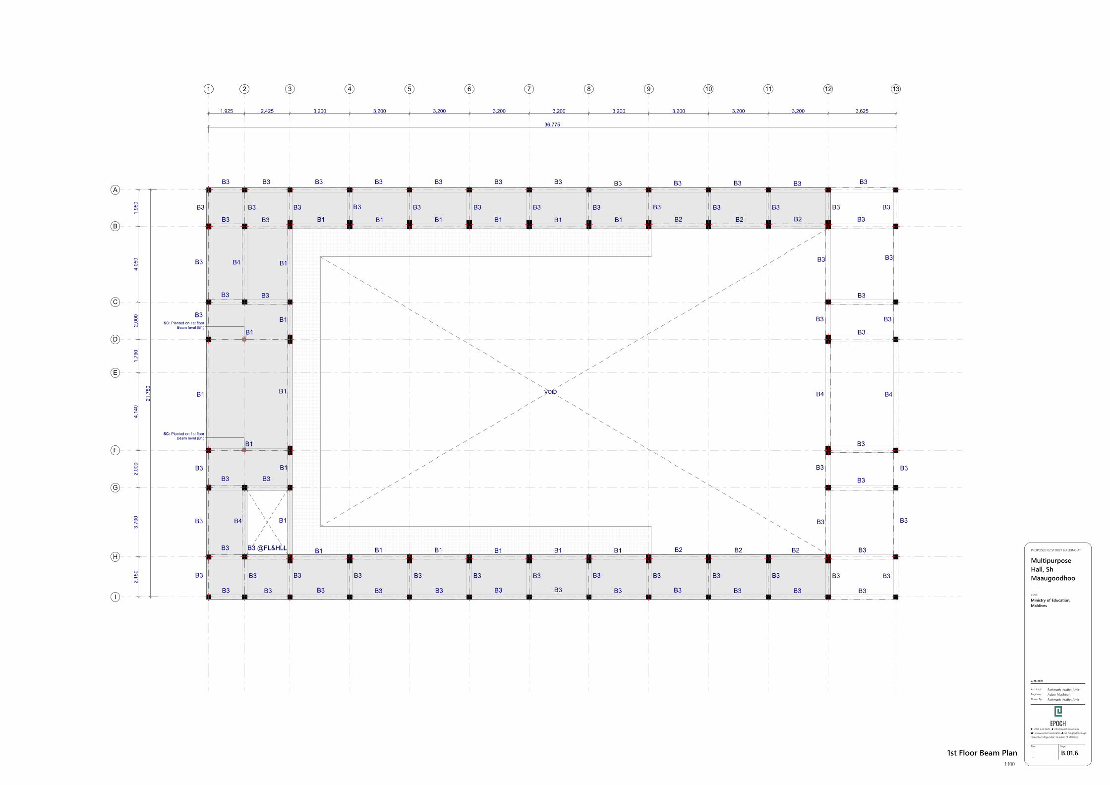
1st Floor Beam Plan1:100
36,775
21,7
80
1,925 2,425 3,200 3,200 3,200 3,200 3,200 3,200 3,200 3,200 3,200 3,625
2,15
03,
700
2,00
04,
140
1,79
02,
000
4,05
01,
950
B3
B4
B4
B3 B3 B3 B3 B3 B3 B3 B3 B3 B3 B3 B3
B3 B3 B3 B3 B3 B3 B3 B3 B3 B3 B3
B3 B1 B1 B1 B1 B1 B1 B2 B2 B2 B3
B3
B3 B3
B1
B1
B1
B1
B1
B3
B1
B1
B3 @FL&HLL B1 B1 B1 B1 B1 B1 B2 B2 B3
B3B3 B3 B3 B3 B3 B3 B3 B3 B3 B3 B3
B3 B3 B3 B3 B3 B3 B3 B3 B3 B3 B3
B3
B3
B3
B3
B4
B3
B3
B3
B3
B4
B3
B3
B3
B3
B3
B3
B3
B3
B3
B3
B3
B3
B3
B1 VOID
SC: Planted on 1st floorBeam level (B1)
SC: Planted on 1st floorBeam level (B1)
1
B2
2 3 4 5 6 7 8 9 10 11 12 13
A
B
C
D
E
F
G
H
I
GSPublisherVersion 0.1.100.100
B.01.7Rev:
---------
Page:
Architect:
Engineer:
Drawn By:
Fathmath Ihudha AmirAdam MadheehFathmath Ihudha Amir
PROPOSED 02 STOREY BUILDING AT
MultipurposeHall, ShMaaugoodhoo
2/28/2021
Client:
Ministry of Education,Maldives
T: +960 333 3528 ,E: [email protected]: wwww.epoch.associates, A: M. Ahigasdhoshuge,Fareedhee Magu Male' Republic of Maldives
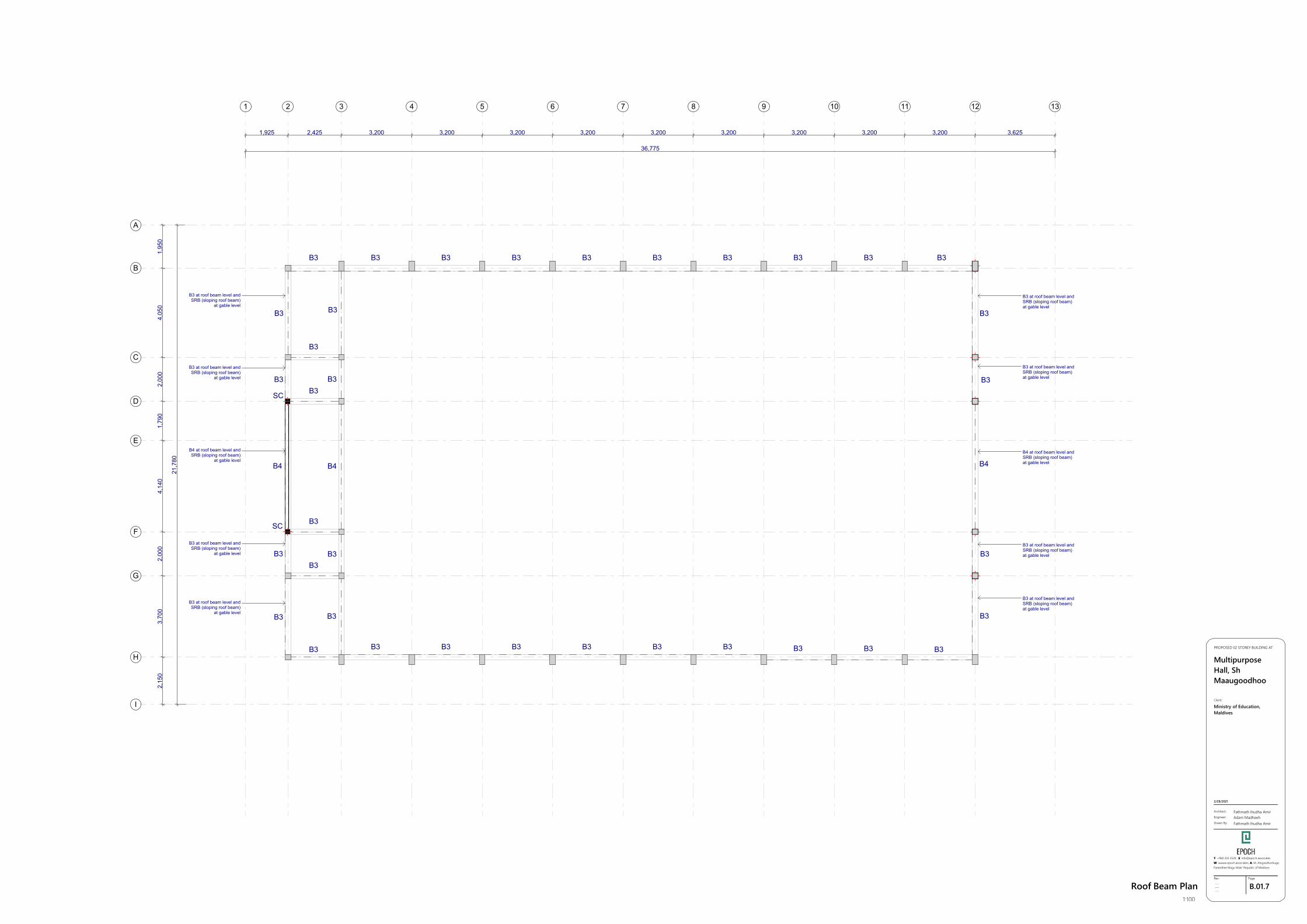
Roof Beam Plan1:100
36,775
21,7
80
1,925 2,425 3,200 3,200 3,200 3,200 3,200 3,200 3,200 3,200 3,200 3,625
2,15
03,
700
2,00
04,
140
1,79
02,
000
4,05
01,
950
SC
SC
B3 B3 B3 B3 B3 B3 B3 B3 B3 B3
B3
B3
B3
B3
B3B3B3B3B3B3B3
B3
B3 B3
B3
B4
B3
B3
B3
B3
B4
B3 B3 B3
B4
B3
B3
B3
B3
B3 at roof beam level andSRB (sloping roof beam)
at gable level
B3 at roof beam level andSRB (sloping roof beam)
at gable level
B4 at roof beam level andSRB (sloping roof beam)
at gable level
B3 at roof beam level andSRB (sloping roof beam)
at gable level
B3 at roof beam level andSRB (sloping roof beam)
at gable level
B3 at roof beam level andSRB (sloping roof beam)at gable level
B3 at roof beam level andSRB (sloping roof beam)at gable level
B4 at roof beam level andSRB (sloping roof beam)at gable level
B3 at roof beam level andSRB (sloping roof beam)at gable level
B3 at roof beam level andSRB (sloping roof beam)at gable level
1 2 3 4 5 6 7 8 9 10 11 12 13
A
B
C
D
E
F
G
H
I
GSPublisherVersion 0.1.100.100
B.01.8Rev:
---------
Page:
Architect:
Engineer:
Drawn By:
Fathmath Ihudha AmirAdam MadheehFathmath Ihudha Amir
PROPOSED 02 STOREY BUILDING AT
MultipurposeHall, ShMaaugoodhoo
2/28/2021
Client:
Ministry of Education,Maldives
T: +960 333 3528 ,E: [email protected]: wwww.epoch.associates, A: M. Ahigasdhoshuge,Fareedhee Magu Male' Republic of Maldives
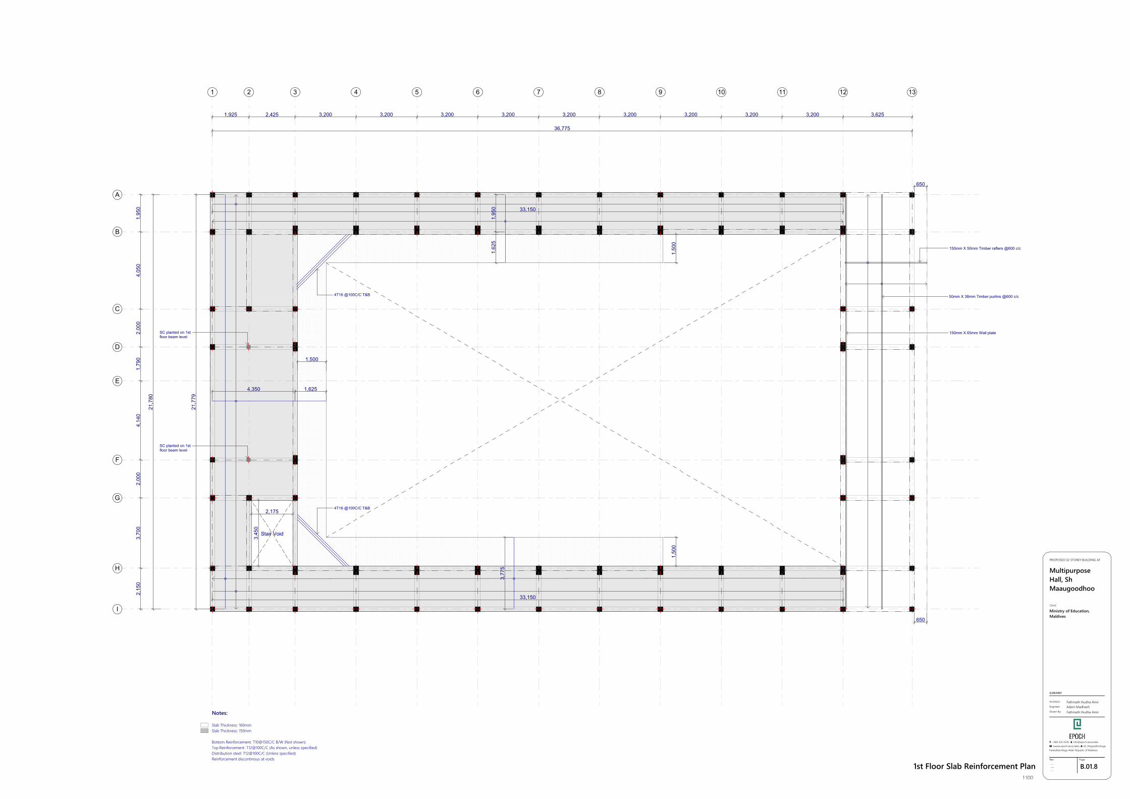
1st Floor Slab Reinforcement Plan1:100
36,775
21,7
80
1,925 2,425 3,200 3,200 3,200 3,200 3,200 3,200 3,200 3,200 3,200 3,625
2,15
03,
700
2,00
04,
140
1,79
02,
000
4,05
01,
950
4,350
21,7
79
33,150
1,95
0
33,150
3,77
5
1,625
1,62
5
1,50
01,
500
1,500
650
650
3,45
0
2,175
4T16 @100C/C T&B
4T16 @100C/C T&B
150mm X 50mm Timber rafters @600 c/c
50mm X 38mm Timber purlins @600 c/c
150mm X 65mm Wall plate
Notes:
Slab Thickness: 160mm Slab Thickness: 150mm
Bottom Reinforcement: T10@150C/C B/W (Not shown)Top Reinforcement: T12@100C/C (As shown, unless specified)Distribution steel: T12@100C/C (Unless specified)Reinforcement discontinous at voids
Stair Void
SC planted on 1stfloor beam level
SC planted on 1stfloor beam level
1 2 3 4 5 6 7 8 9 10 11 12 13
A
B
C
D
E
F
G
H
I
GSPublisherVersion 0.1.100.100
B.01.9Rev:
---------
Page:
Architect:
Engineer:
Drawn By:
Fathmath Ihudha AmirAdam MadheehFathmath Ihudha Amir
PROPOSED 02 STOREY BUILDING AT
MultipurposeHall, ShMaaugoodhoo
2/28/2021
Client:
Ministry of Education,Maldives
T: +960 333 3528 ,E: [email protected]: wwww.epoch.associates, A: M. Ahigasdhoshuge,Fareedhee Magu Male' Republic of Maldives
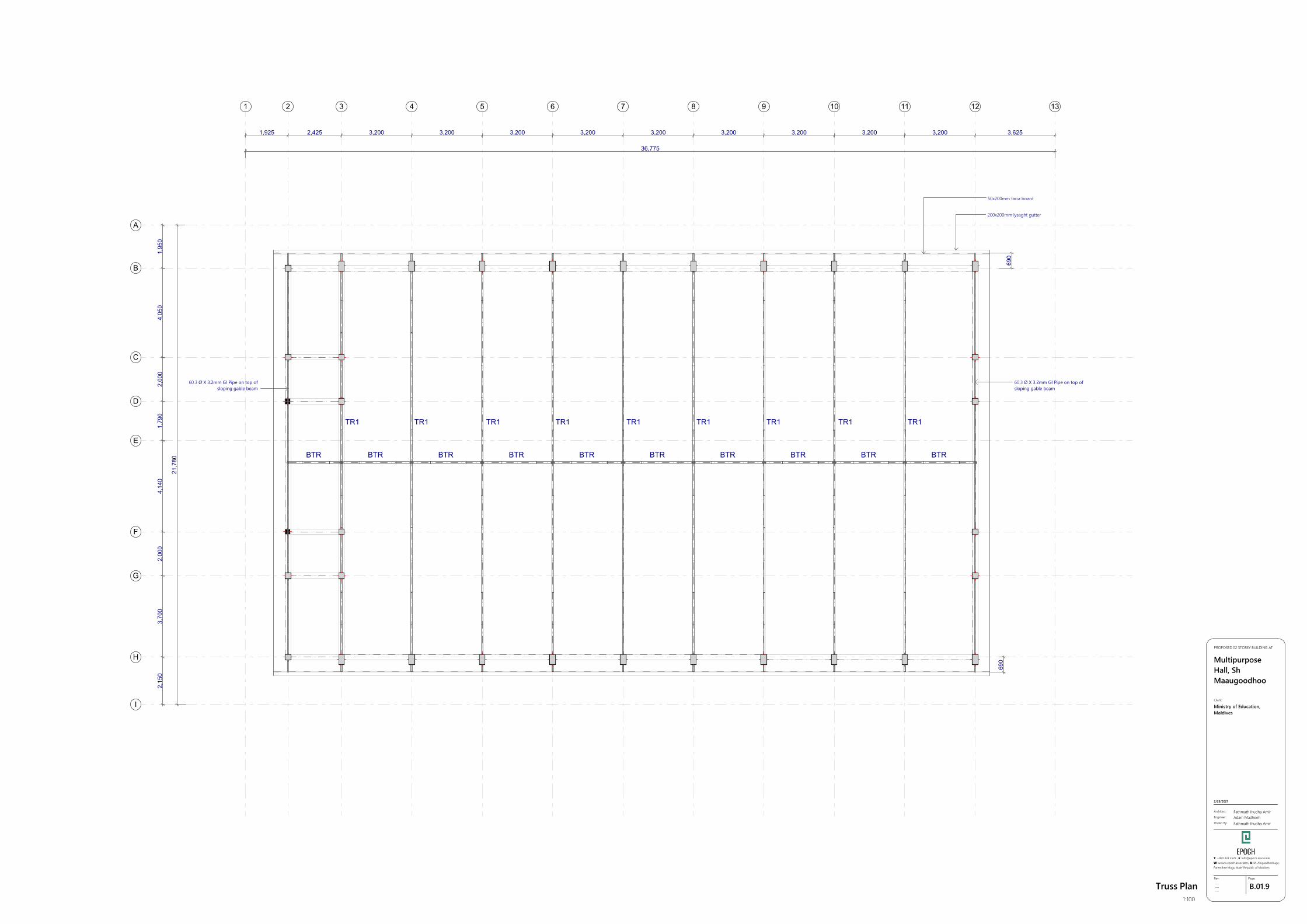
Truss Plan1:100
36,775
21,7
80
1,925 2,425 3,200 3,200 3,200 3,200 3,200 3,200 3,200 3,200 3,200 3,625
2,15
03,
700
2,00
04,
140
1,79
02,
000
4,05
01,
950
690
690
TR1TR1 TR1 TR1 TR1 TR1 TR1 TR1 TR1
BTR BTR BTR BTR BTR BTR BTR BTR BTRBTR
50x200mm facia board
200x200mm lysaght gutter
60.3 Ø X 3.2mm GI Pipe on top ofsloping gable beam
60.3 Ø X 3.2mm GI Pipe on top ofsloping gable beam
1 2 3 4 5 6 7 8 9 10 11 12 13
A
B
C
D
E
F
G
H
I
GSPublisherVersion 0.1.100.100
B.01.10Rev:
---------
Page:
Architect:
Engineer:
Drawn By:
Fathmath Ihudha AmirAdam MadheehFathmath Ihudha Amir
PROPOSED 02 STOREY BUILDING AT
MultipurposeHall, ShMaaugoodhoo
2/28/2021
Client:
Ministry of Education,Maldives
T: +960 333 3528 ,E: [email protected]: wwww.epoch.associates, A: M. Ahigasdhoshuge,Fareedhee Magu Male' Republic of Maldives
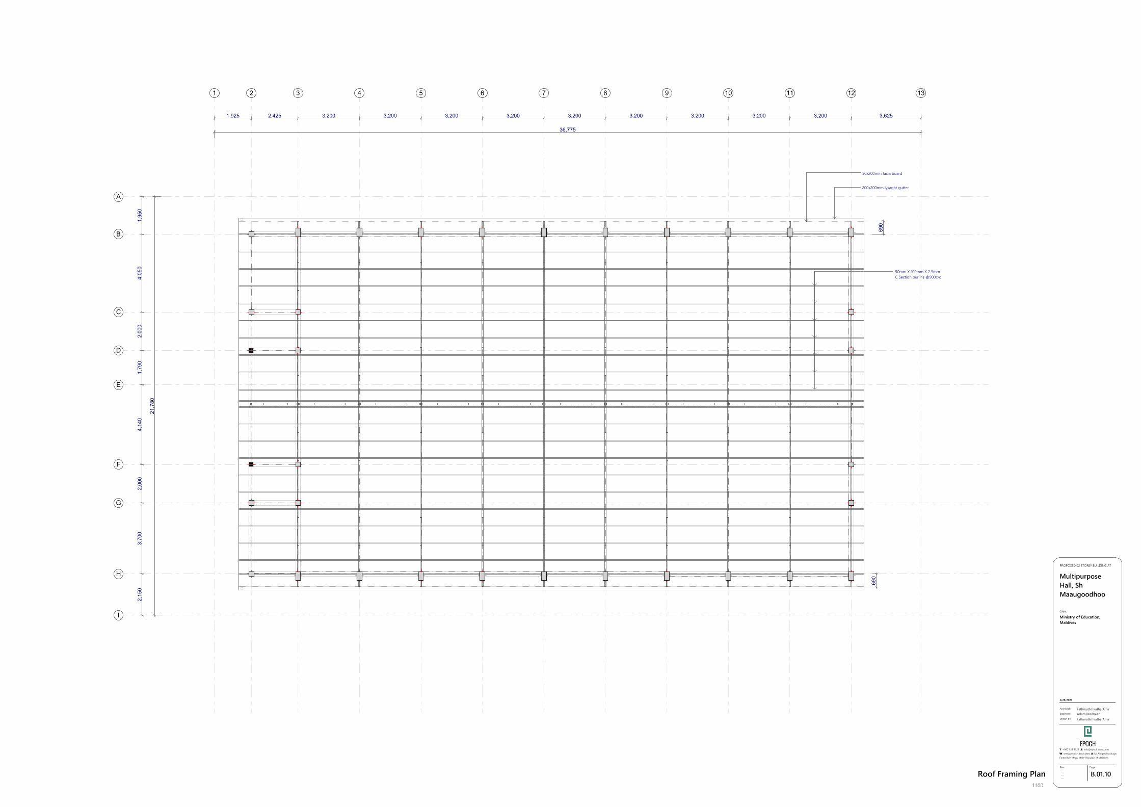
Roof Framing Plan1:100
36,775
21,7
80
1,925 2,425 3,200 3,200 3,200 3,200 3,200 3,200 3,200 3,200 3,200 3,625
2,15
03,
700
2,00
04,
140
1,79
02,
000
4,05
01,
950
690
690
50x200mm facia board
200x200mm lysaght gutter
50mm X 100mm X 2.5mmC Section purlins @900c/c
1 2 3 4 5 6 7 8 9 10 11 12 13
A
B
C
D
E
F
G
H
I
GSPublisherVersion 0.1.100.100
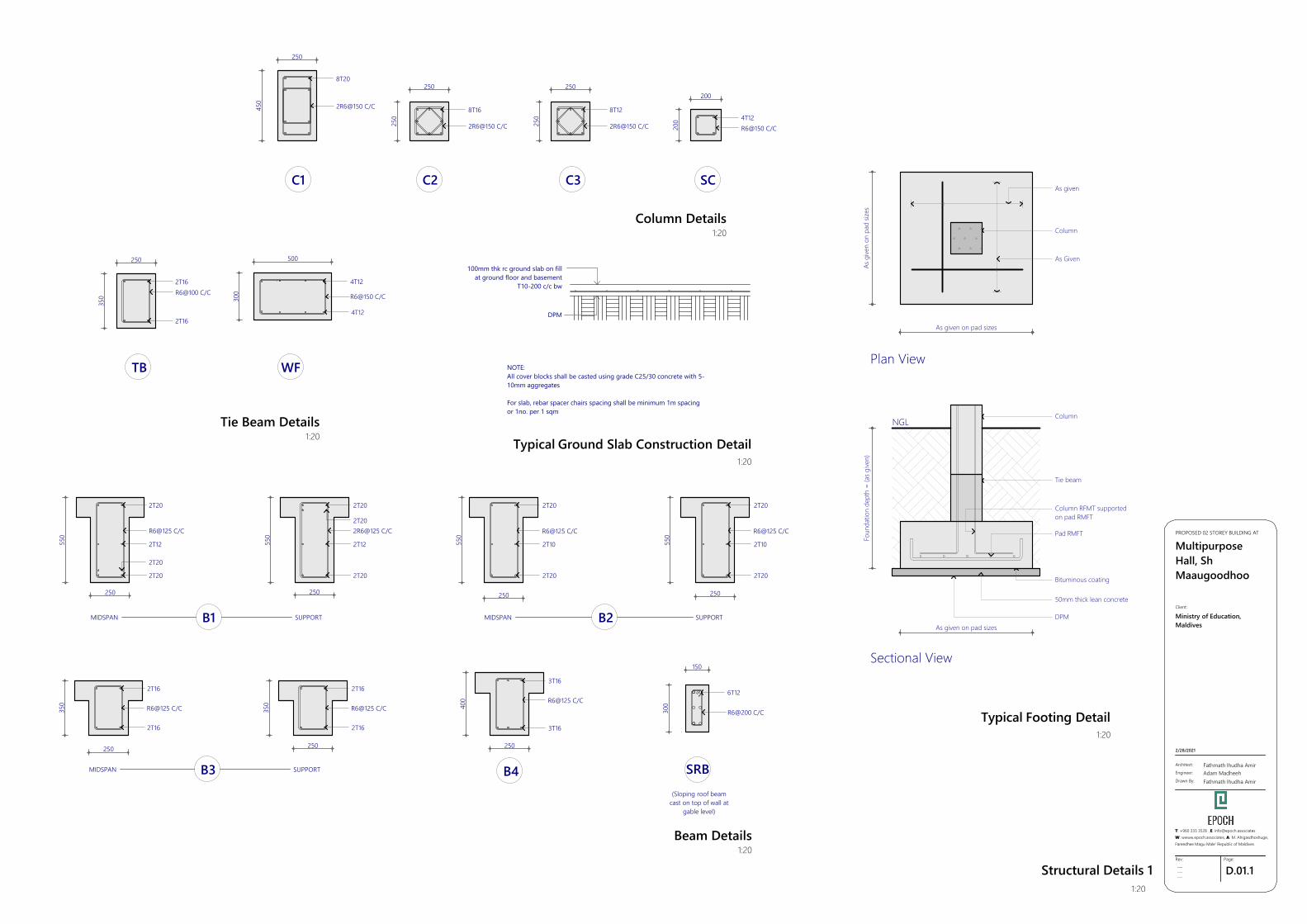
D.01.1Rev:
---------
Page:
Architect:
Engineer:
Drawn By:
Fathmath Ihudha AmirAdam MadheehFathmath Ihudha Amir
PROPOSED 02 STOREY BUILDING AT
MultipurposeHall, ShMaaugoodhoo
2/28/2021
Client:
Ministry of Education,Maldives
T: +960 333 3528 ,E: [email protected]: wwww.epoch.associates, A: M. Ahigasdhoshuge,Fareedhee Magu Male' Republic of Maldives
Structural Details 11:20
C1 C2 C3 SC
TB
2R6@150 C/C
8T20
8T16
2R6@150 C/C
8T12
2R6@150 C/C4T12R6@150 C/C
2T16R6@100 C/C
2T16
B1 B2
B3 B4
MIDSPAN SUPPORT MIDSPAN SUPPORT
MIDSPAN SUPPORT
R6@125 C/C
2T20
2T12
2T20
2T20
2R6@125 C/C
2T20
2T12
2T20
2T20
2T20
R6@125 C/C
2T10
2T20
2T20
R6@125 C/C
2T10
2T20
2T16
R6@125 C/C
2T16
2T16
R6@125 C/C
2T16
3T16
R6@125 C/C
3T16
SRB
6T12
R6@200 C/C
Column Details1:20
Beam Details1:20
WF
Tie Beam Details1:20
R6@150 C/C
4T12
4T12
(Sloping roof beamcast on top of wall at
gable level)
Typical Ground Slab Construction Detail1:20
450
250
250
250
250
250
200
20035
0
250
550
250
550
250
550
250
550
250
350
250
350
250
400
250
300
150
500
300
100mm thk rc ground slab on fillat ground floor and basement
T10-200 c/c bw
DPM
NOTE:All cover blocks shall be casted using grade C25/30 concrete with 5-10mm aggregates
For slab, rebar spacer chairs spacing shall be minimum 1m spacingor 1no. per 1 sqm
Foun
datio
n de
pth
= (a
s give
n)
As given on pad sizes
As given on pad sizes
As g
iven
on p
ad si
zes
NGLColumn
Tie beam
Column RFMT supportedon pad RMFT
Pad RMFT
Bituminous coating
50mm thick lean concrete
DPM
As Given
As given
Column
Plan View
Sectional View
Typical Footing Detail1:20
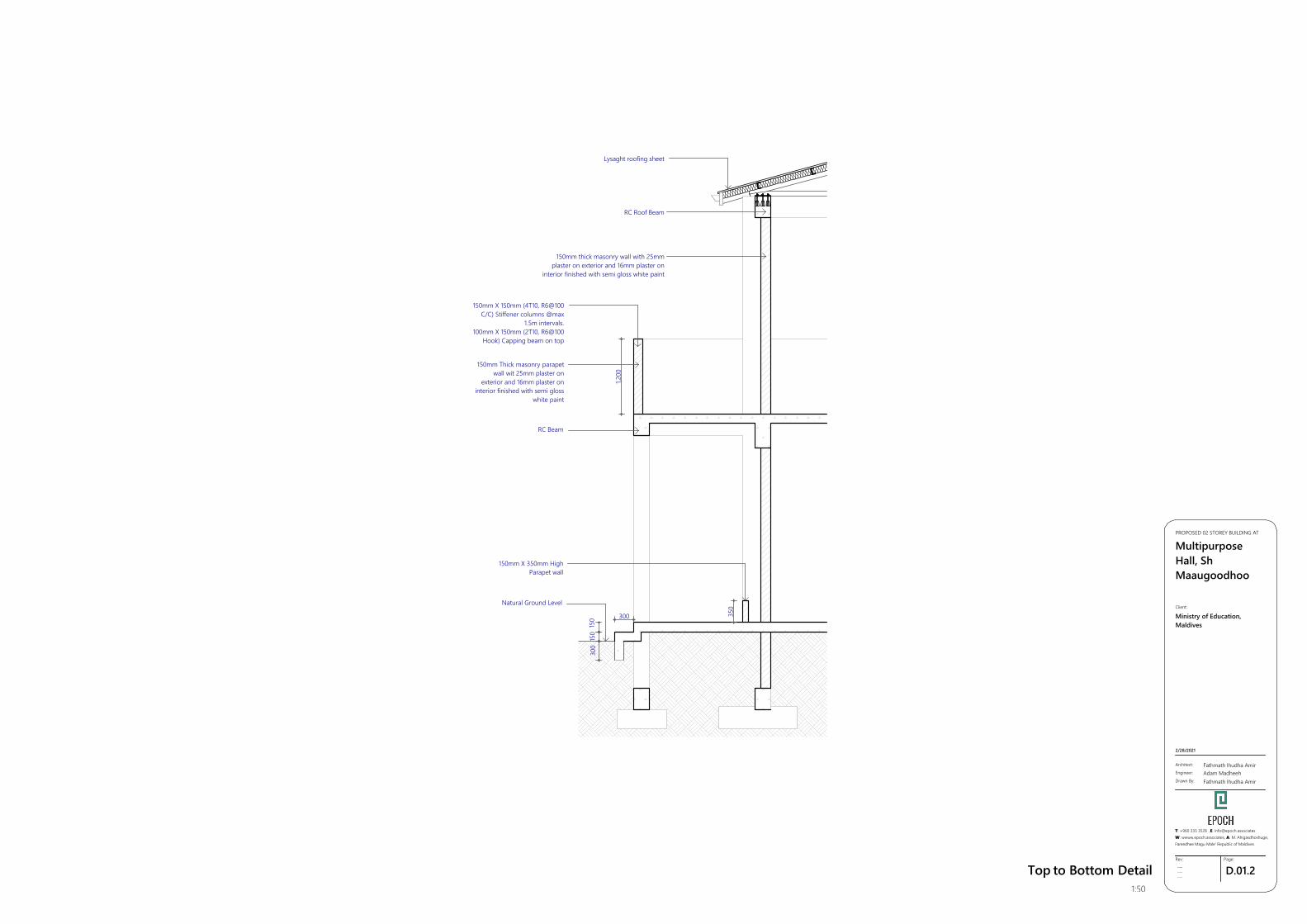
GSPublisherVersion 0.1.100.100
D.01.2Rev:
---------
Page:
Architect:
Engineer:
Drawn By:
Fathmath Ihudha AmirAdam MadheehFathmath Ihudha Amir
PROPOSED 02 STOREY BUILDING AT
MultipurposeHall, ShMaaugoodhoo
2/28/2021
Client:
Ministry of Education,Maldives
T: +960 333 3528 ,E: [email protected]: wwww.epoch.associates, A: M. Ahigasdhoshuge,Fareedhee Magu Male' Republic of Maldives
Top to Bottom Detail1:50
350
1,200
150
150
300
300
Lysaght roofing sheet
150mm thick masonry wall with 25mmplaster on exterior and 16mm plaster on
interior finished with semi gloss white paint
150mm X 150mm (4T10, R6@100C/C) Stiffener columns @max
1.5m intervals.100mm X 150mm (2T10, R6@100
Hook) Capping beam on top
RC Beam
Natural Ground Level
150mm X 350mm HighParapet wall
RC Roof Beam
150mm Thick masonry parapetwall wit 25mm plaster on
exterior and 16mm plaster oninterior finished with semi gloss
white paint
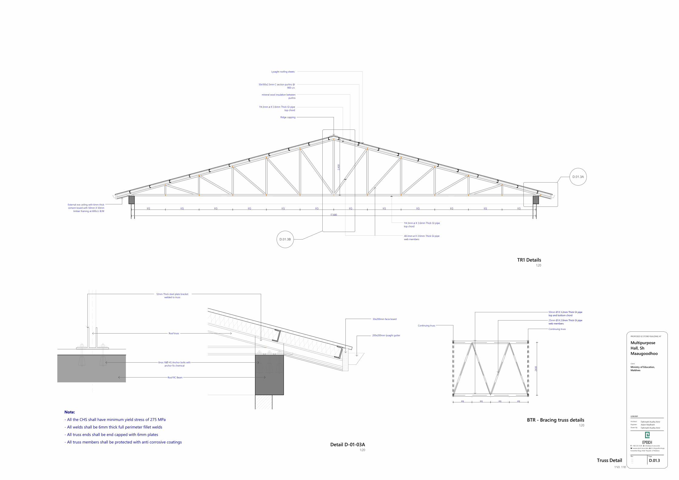
GSPublisherVersion 0.1.100.100
D.01.3Rev:
---------
Page:
Architect:
Engineer:
Drawn By:
Fathmath Ihudha AmirAdam MadheehFathmath Ihudha Amir
PROPOSED 02 STOREY BUILDING AT
MultipurposeHall, ShMaaugoodhoo
2/28/2021
Client:
Ministry of Education,Maldives
T: +960 333 3528 ,E: [email protected]: wwww.epoch.associates, A: M. Ahigasdhoshuge,Fareedhee Magu Male' Republic of Maldives
Truss Detail1:50, 1:10
D.01.3A
D.01.3B
EQ EQ EQ EQ EQ EQ EQ EQ EQ EQ EQ EQ
17,680
2,43
0
External eve ceiling with 6mm thickcement board with 50mm X 50mm
timber framing at 600c/c B/W
Ridge capping
114.3mm ø X 3.6mm Thick GI pipetop chord
48.3mm ø X 3.6mm Thick GI pipeweb members
Lysaght roofing sheets
mineral wool insulation betweenpurlins
50x100x2.5mm C section purlins @900 c/c
114.3mm ø X 3.6mm Thick GI pipetop chord
12mm Thick steel plate bracketwelded to truss
Roof truss
6nos 16Ø HS Anchor bolts withanchor fix chemical
Roof RC Beam
Note:
- All the CHS shall have minimum yield stress of 275 MPa
- All welds shall be 6mm thick full perimeter fillet welds
- All truss ends shall be end capped with 6mm plates
- All truss members shall be protected with anti corrosive coatings
50x200mm facia board
200x200mm lysaght gutter
Detail D-01-03A1:20
eq eq eq eq
2430
50mm Ø X 3.2mm Thick GI pipetop and bottom chord
25mm Ø X 2.0mm Thick GI pipeweb members
Continuing trussContinuing truss
BTR - Bracing truss details1:20
TR1 Details1:20


