Embed Size (px)
Citation preview
14. Motors
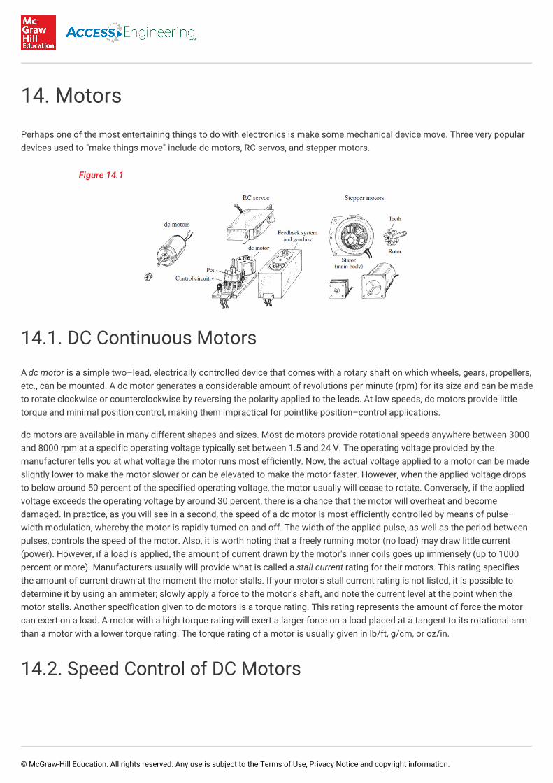
Perhaps one of the most entertaining things to do with electronics is make some mechanical device move. Three very populardevices used to "make things move" include dc motors, RC servos, and stepper motors.
Figure 14.1
14.1. DC Continuous Motors
A dc motor is a simple two–lead, electrically controlled device that comes with a rotary shaft on which wheels, gears, propellers,etc., can be mounted. A dc motor generates a considerable amount of revolutions per minute (rpm) for its size and can be madeto rotate clockwise or counterclockwise by reversing the polarity applied to the leads. At low speeds, dc motors provide littletorque and minimal position control, making them impractical for pointlike position–control applications.
dc motors are available in many different shapes and sizes. Most dc motors provide rotational speeds anywhere between 3000and 8000 rpm at a specific operating voltage typically set between 1.5 and 24 V. The operating voltage provided by themanufacturer tells you at what voltage the motor runs most efficiently. Now, the actual voltage applied to a motor can be madeslightly lower to make the motor slower or can be elevated to make the motor faster. However, when the applied voltage dropsto below around 50 percent of the specified operating voltage, the motor usually will cease to rotate. Conversely, if the appliedvoltage exceeds the operating voltage by around 30 percent, there is a chance that the motor will overheat and becomedamaged. In practice, as you will see in a second, the speed of a dc motor is most efficiently controlled by means of pulse–width modulation, whereby the motor is rapidly turned on and off. The width of the applied pulse, as well as the period betweenpulses, controls the speed of the motor. Also, it is worth noting that a freely running motor (no load) may draw little current(power). However, if a load is applied, the amount of current drawn by the motor's inner coils goes up immensely (up to 1000percent or more). Manufacturers usually will provide what is called a stall current rating for their motors. This rating specifiesthe amount of current drawn at the moment the motor stalls. If your motor's stall current rating is not listed, it is possible todetermine it by using an ammeter; slowly apply a force to the motor's shaft, and note the current level at the point when themotor stalls. Another specification given to dc motors is a torque rating. This rating represents the amount of force the motorcan exert on a load. A motor with a high torque rating will exert a larger force on a load placed at a tangent to its rotational armthan a motor with a lower torque rating. The torque rating of a motor is usually given in lb/ft, g/cm, or oz/in.
14.2. Speed Control of DC Motors
© McGraw-Hill Education. All rights reserved. Any use is subject to the Terms of Use, Privacy Notice and copyright information.
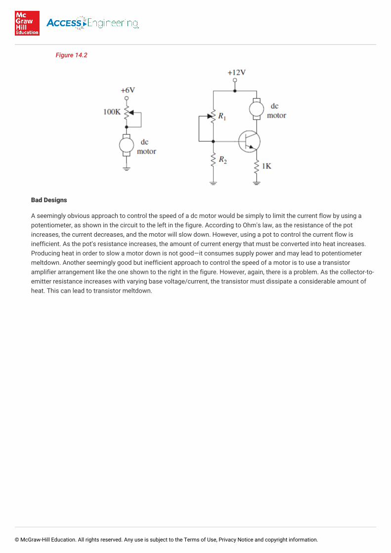
Figure 14.2
Bad Designs
A seemingly obvious approach to control the speed of a dc motor would be simply to limit the current flow by using apotentiometer, as shown in the circuit to the left in the figure. According to Ohm's law, as the resistance of the potincreases, the current decreases, and the motor will slow down. However, using a pot to control the current flow isinefficient. As the pot's resistance increases, the amount of current energy that must be converted into heat increases.Producing heat in order to slow a motor down is not good—it consumes supply power and may lead to potentiometermeltdown. Another seemingly good but inefficient approach to control the speed of a motor is to use a transistoramplifier arrangement like the one shown to the right in the figure. However, again, there is a problem. As the collector-to-emitter resistance increases with varying base voltage/current, the transistor must dissipate a considerable amount ofheat. This can lead to transistor meltdown.
© McGraw-Hill Education. All rights reserved. Any use is subject to the Terms of Use, Privacy Notice and copyright information.
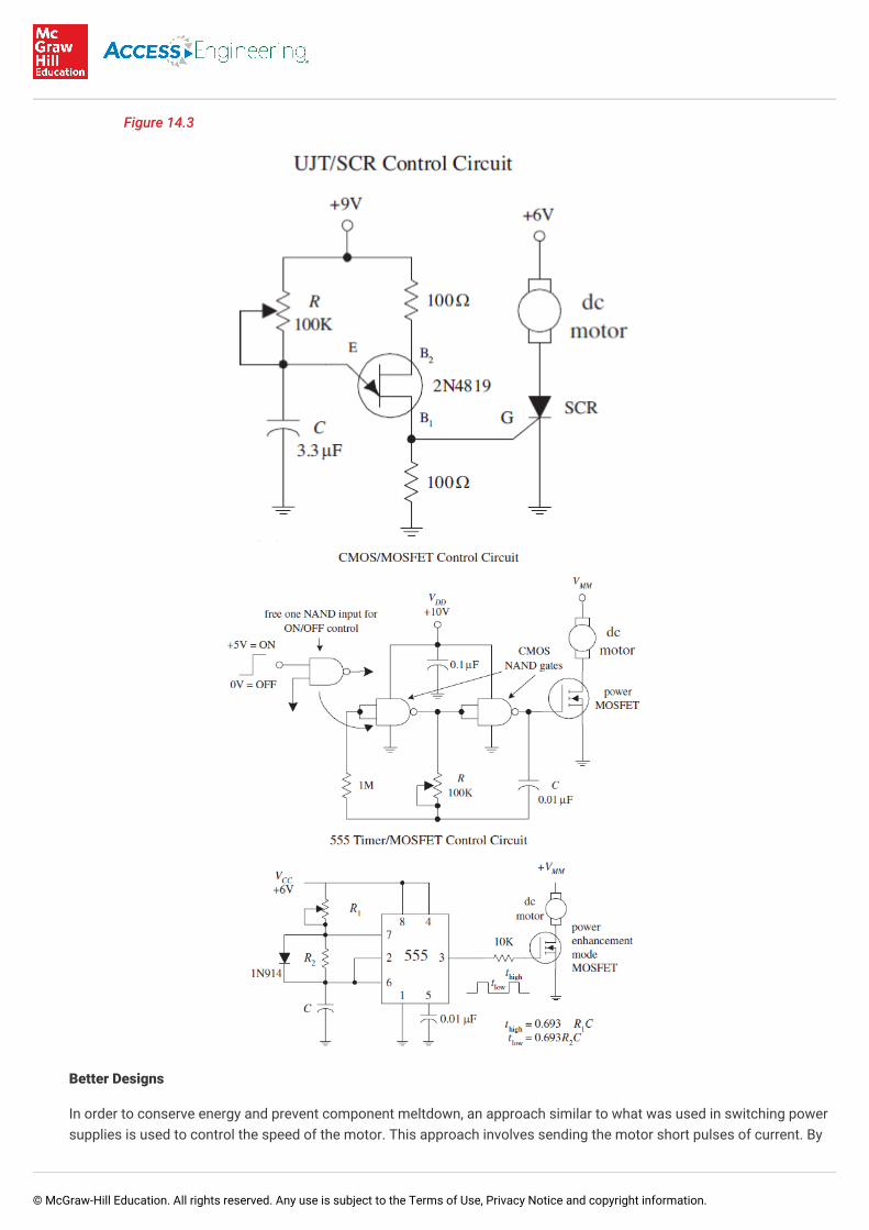
Figure 14.3
Better Designs
In order to conserve energy and prevent component meltdown, an approach similar to what was used in switching powersupplies is used to control the speed of the motor. This approach involves sending the motor short pulses of current. By
© McGraw-Hill Education. All rights reserved. Any use is subject to the Terms of Use, Privacy Notice and copyright information.
varying the width and frequency of the applied pulses, the speed of the motor can be controlled. Controlling a motor'sspeed in this manner prevents any components from experiencing continuous current stress. Figure 13.3 shows threesimple circuits used to provide the desired motor-control pulses.
In the first circuit, a UJT relaxation oscillator generates a series of pulses that drives an SCR on and off. To vary the speedof the motor, the UJT's oscillatory frequency is adjusted by changing the RC time constant.
In the second circuit, a pair of NAND gates make up the relaxation oscillator section, while an enhancement-type powerMOSFET is used to drive the motor. Like the preceding circuit, the speed of the motor is controlled by the oscillator's RCtime constant. Notice that if one of the input leads of the left NAND gate is pulled out, it is possible to create an extraterminal that can be used to provide on/off controls that can be interfaced with CMOS logic circuits.
The third circuit is a 555 timer that is used to generate pulses that drive a power MOSFET. By inserting a diode betweenpins 7 and 6, as shown, the 555 is placed into low-duty cycle operation. R , R , and C set the frequency and on/offduration of the output pulses. The formulas accompanying the diagram provide the details.
A microcontroller-based dc control circuit with speed control is found in Chap. 13.
14.3. Directional Control of DC Motors
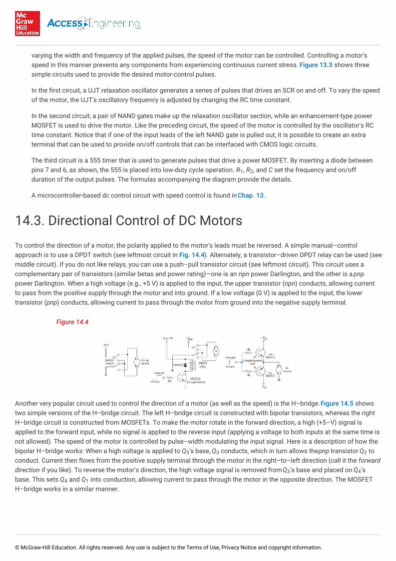
To control the direction of a motor, the polarity applied to the motor's leads must be reversed. A simple manual–controlapproach is to use a DPDT switch (see leftmost circuit in Fig. 14.4). Alternately, a transistor–driven DPDT relay can be used (seemiddle circuit). If you do not like relays, you can use a push–pull transistor circuit (see leftmost circuit). This circuit uses acomplementary pair of transistors (similar betas and power rating)—one is an npn power Darlington, and the other is a pnppower Darlington. When a high voltage (e.g., +5 V) is applied to the input, the upper transistor (npn) conducts, allowing currentto pass from the positive supply through the motor and into ground. If a low voltage (0 V) is applied to the input, the lowertransistor (pnp) conducts, allowing current to pass through the motor from ground into the negative supply terminal.
Figure 14.4
Another very popular circuit used to control the direction of a motor (as well as the speed) is the H–bridge. Figure 14.5 showstwo simple versions of the H–bridge circuit. The left H–bridge circuit is constructed with bipolar transistors, whereas the rightH–bridge circuit is constructed from MOSFETs. To make the motor rotate in the forward direction, a high (+5–V) signal isapplied to the forward input, while no signal is applied to the reverse input (applying a voltage to both inputs at the same time isnot allowed). The speed of the motor is controlled by pulse–width modulating the input signal. Here is a description of how thebipolar H–bridge works: When a high voltage is applied to Q 's base, Q conducts, which in turn allows the pnp transistor Q toconduct. Current then flows from the positive supply terminal through the motor in the right–to–left direction (call it the forwarddirection if you like). To reverse the motor's direction, the high voltage signal is removed from Q 's base and placed on Q 'sbase. This sets Q and Q into conduction, allowing current to pass through the motor in the opposite direction. The MOSFETH–bridge works in a similar manner.
1 2
3 3 2
3 4
4 1
© McGraw-Hill Education. All rights reserved. Any use is subject to the Terms of Use, Privacy Notice and copyright information.
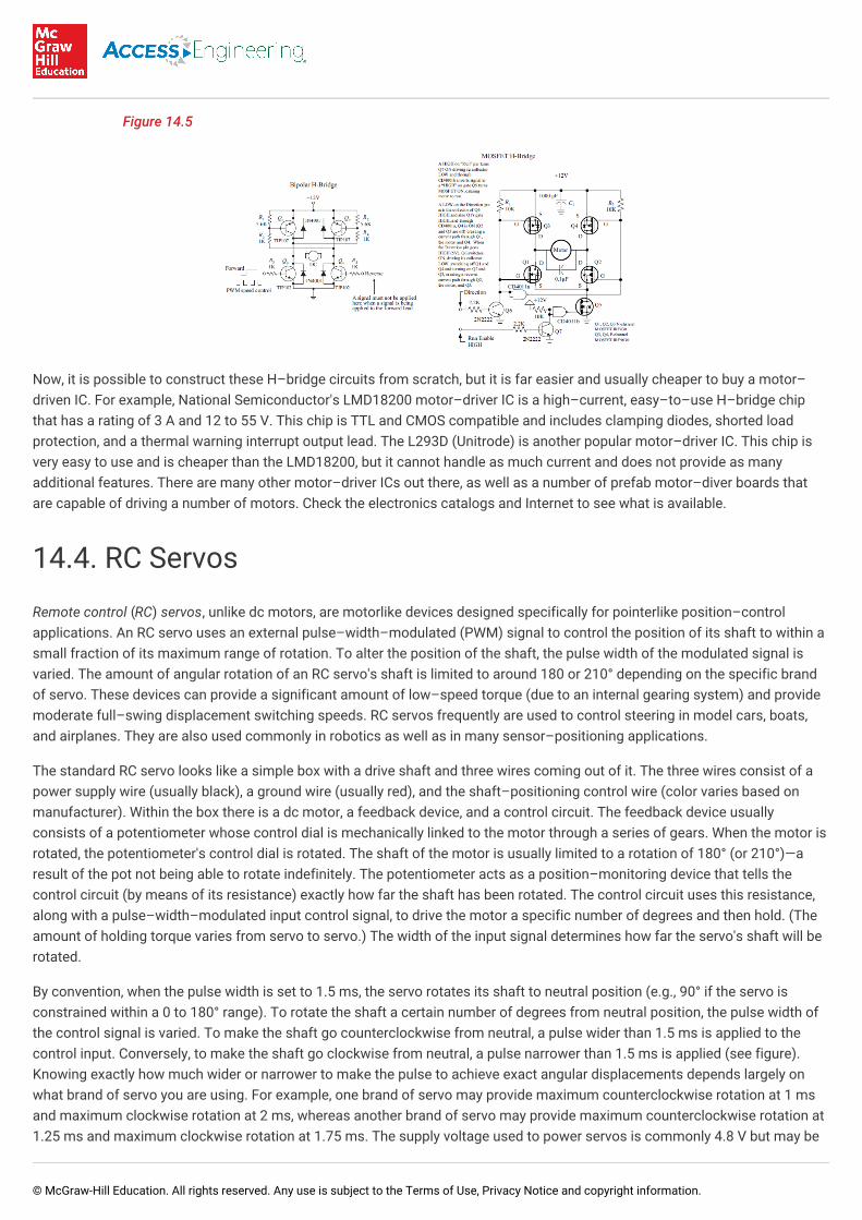
Figure 14.5
Now, it is possible to construct these H–bridge circuits from scratch, but it is far easier and usually cheaper to buy a motor–driven IC. For example, National Semiconductor's LMD18200 motor–driver IC is a high–current, easy–to–use H–bridge chipthat has a rating of 3 A and 12 to 55 V. This chip is TTL and CMOS compatible and includes clamping diodes, shorted loadprotection, and a thermal warning interrupt output lead. The L293D (Unitrode) is another popular motor–driver IC. This chip isvery easy to use and is cheaper than the LMD18200, but it cannot handle as much current and does not provide as manyadditional features. There are many other motor–driver ICs out there, as well as a number of prefab motor–diver boards thatare capable of driving a number of motors. Check the electronics catalogs and Internet to see what is available.
14.4. RC Servos
Remote control (RC) servos, unlike dc motors, are motorlike devices designed specifically for pointerlike position–controlapplications. An RC servo uses an external pulse–width–modulated (PWM) signal to control the position of its shaft to within asmall fraction of its maximum range of rotation. To alter the position of the shaft, the pulse width of the modulated signal isvaried. The amount of angular rotation of an RC servo's shaft is limited to around 180 or 210° depending on the specific brandof servo. These devices can provide a significant amount of low–speed torque (due to an internal gearing system) and providemoderate full–swing displacement switching speeds. RC servos frequently are used to control steering in model cars, boats,and airplanes. They are also used commonly in robotics as well as in many sensor–positioning applications.
The standard RC servo looks like a simple box with a drive shaft and three wires coming out of it. The three wires consist of apower supply wire (usually black), a ground wire (usually red), and the shaft–positioning control wire (color varies based onmanufacturer). Within the box there is a dc motor, a feedback device, and a control circuit. The feedback device usuallyconsists of a potentiometer whose control dial is mechanically linked to the motor through a series of gears. When the motor isrotated, the potentiometer's control dial is rotated. The shaft of the motor is usually limited to a rotation of 180° (or 210°)—aresult of the pot not being able to rotate indefinitely. The potentiometer acts as a position–monitoring device that tells thecontrol circuit (by means of its resistance) exactly how far the shaft has been rotated. The control circuit uses this resistance,along with a pulse–width–modulated input control signal, to drive the motor a specific number of degrees and then hold. (Theamount of holding torque varies from servo to servo.) The width of the input signal determines how far the servo's shaft will berotated.
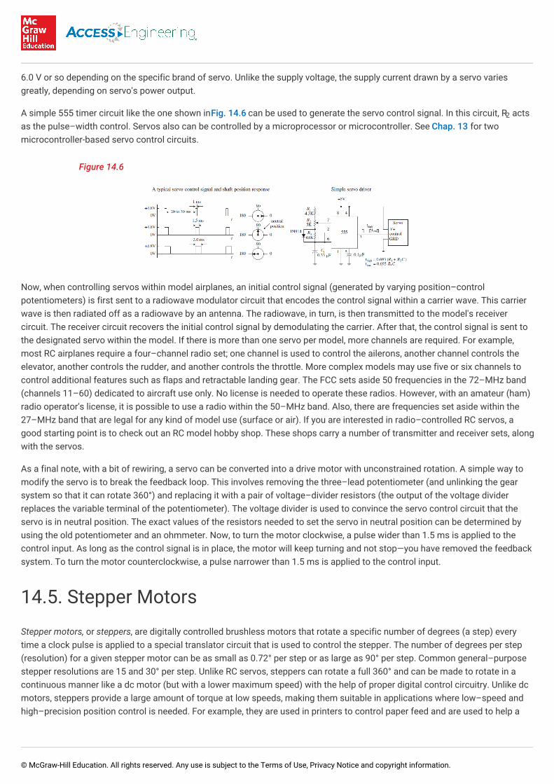
By convention, when the pulse width is set to 1.5 ms, the servo rotates its shaft to neutral position (e.g., 90° if the servo isconstrained within a 0 to 180° range). To rotate the shaft a certain number of degrees from neutral position, the pulse width ofthe control signal is varied. To make the shaft go counterclockwise from neutral, a pulse wider than 1.5 ms is applied to thecontrol input. Conversely, to make the shaft go clockwise from neutral, a pulse narrower than 1.5 ms is applied (see figure).Knowing exactly how much wider or narrower to make the pulse to achieve exact angular displacements depends largely onwhat brand of servo you are using. For example, one brand of servo may provide maximum counterclockwise rotation at 1 msand maximum clockwise rotation at 2 ms, whereas another brand of servo may provide maximum counterclockwise rotation at1.25 ms and maximum clockwise rotation at 1.75 ms. The supply voltage used to power servos is commonly 4.8 V but may be
© McGraw-Hill Education. All rights reserved. Any use is subject to the Terms of Use, Privacy Notice and copyright information.
6.0 V or so depending on the specific brand of servo. Unlike the supply voltage, the supply current drawn by a servo variesgreatly, depending on servo's power output.
A simple 555 timer circuit like the one shown in Fig. 14.6 can be used to generate the servo control signal. In this circuit, R actsas the pulse–width control. Servos also can be controlled by a microprocessor or microcontroller. See Chap. 13 for twomicrocontroller-based servo control circuits.
Figure 14.6
Now, when controlling servos within model airplanes, an initial control signal (generated by varying position–controlpotentiometers) is first sent to a radiowave modulator circuit that encodes the control signal within a carrier wave. This carrierwave is then radiated off as a radiowave by an antenna. The radiowave, in turn, is then transmitted to the model's receivercircuit. The receiver circuit recovers the initial control signal by demodulating the carrier. After that, the control signal is sent tothe designated servo within the model. If there is more than one servo per model, more channels are required. For example,most RC airplanes require a four–channel radio set; one channel is used to control the ailerons, another channel controls theelevator, another controls the rudder, and another controls the throttle. More complex models may use five or six channels tocontrol additional features such as flaps and retractable landing gear. The FCC sets aside 50 frequencies in the 72–MHz band(channels 11–60) dedicated to aircraft use only. No license is needed to operate these radios. However, with an amateur (ham)radio operator's license, it is possible to use a radio within the 50–MHz band. Also, there are frequencies set aside within the27–MHz band that are legal for any kind of model use (surface or air). If you are interested in radio–controlled RC servos, agood starting point is to check out an RC model hobby shop. These shops carry a number of transmitter and receiver sets, alongwith the servos.
As a final note, with a bit of rewiring, a servo can be converted into a drive motor with unconstrained rotation. A simple way tomodify the servo is to break the feedback loop. This involves removing the three–lead potentiometer (and unlinking the gearsystem so that it can rotate 360°) and replacing it with a pair of voltage–divider resistors (the output of the voltage dividerreplaces the variable terminal of the potentiometer). The voltage divider is used to convince the servo control circuit that theservo is in neutral position. The exact values of the resistors needed to set the servo in neutral position can be determined byusing the old potentiometer and an ohmmeter. Now, to turn the motor clockwise, a pulse wider than 1.5 ms is applied to thecontrol input. As long as the control signal is in place, the motor will keep turning and not stop—you have removed the feedbacksystem. To turn the motor counterclockwise, a pulse narrower than 1.5 ms is applied to the control input.
14.5. Stepper Motors
Stepper motors, or steppers, are digitally controlled brushless motors that rotate a specific number of degrees (a step) everytime a clock pulse is applied to a special translator circuit that is used to control the stepper. The number of degrees per step(resolution) for a given stepper motor can be as small as 0.72° per step or as large as 90° per step. Common general–purposestepper resolutions are 15 and 30° per step. Unlike RC servos, steppers can rotate a full 360° and can be made to rotate in acontinuous manner like a dc motor (but with a lower maximum speed) with the help of proper digital control circuitry. Unlike dcmotors, steppers provide a large amount of torque at low speeds, making them suitable in applications where low–speed andhigh–precision position control is needed. For example, they are used in printers to control paper feed and are used to help a
2
© McGraw-Hill Education. All rights reserved. Any use is subject to the Terms of Use, Privacy Notice and copyright information.
telescope track stars. Steppers are also found in plotter– and sensor–positioning applications. The list goes on. To give you abasic idea of how a stepper works, take a look at Fig. 14.7.
Figure 14.7
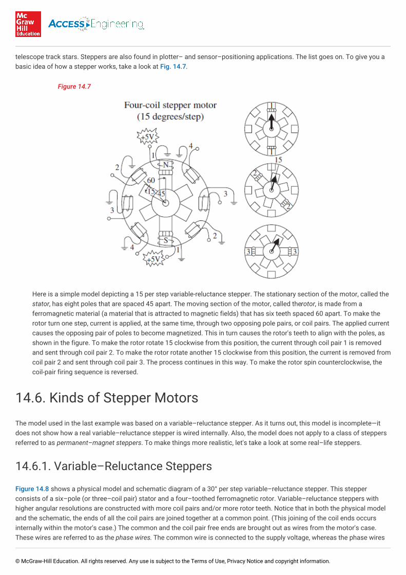
Here is a simple model depicting a 15 per step variable-reluctance stepper. The stationary section of the motor, called thestator, has eight poles that are spaced 45 apart. The moving section of the motor, called the rotor, is made from aferromagnetic material (a material that is attracted to magnetic fields) that has six teeth spaced 60 apart. To make therotor turn one step, current is applied, at the same time, through two opposing pole pairs, or coil pairs. The applied currentcauses the opposing pair of poles to become magnetized. This in turn causes the rotor's teeth to align with the poles, asshown in the figure. To make the rotor rotate 15 clockwise from this position, the current through coil pair 1 is removedand sent through coil pair 2. To make the rotor rotate another 15 clockwise from this position, the current is removed fromcoil pair 2 and sent through coil pair 3. The process continues in this way. To make the rotor spin counterclockwise, thecoil-pair firing sequence is reversed.
14.6. Kinds of Stepper Motors
The model used in the last example was based on a variable–reluctance stepper. As it turns out, this model is incomplete—itdoes not show how a real variable–reluctance stepper is wired internally. Also, the model does not apply to a class of steppersreferred to as permanent–magnet steppers. To make things more realistic, let's take a look at some real–life steppers.
14.6.1. Variable–Reluctance Steppers
Figure 14.8 shows a physical model and schematic diagram of a 30° per step variable–reluctance stepper. This stepperconsists of a six–pole (or three–coil pair) stator and a four–toothed ferromagnetic rotor. Variable–reluctance steppers withhigher angular resolutions are constructed with more coil pairs and/or more rotor teeth. Notice that in both the physical modeland the schematic, the ends of all the coil pairs are joined together at a common point. (This joining of the coil ends occursinternally within the motor's case.) The common and the coil pair free ends are brought out as wires from the motor's case.These wires are referred to as the phase wires. The common wire is connected to the supply voltage, whereas the phase wires
© McGraw-Hill Education. All rights reserved. Any use is subject to the Terms of Use, Privacy Notice and copyright information.
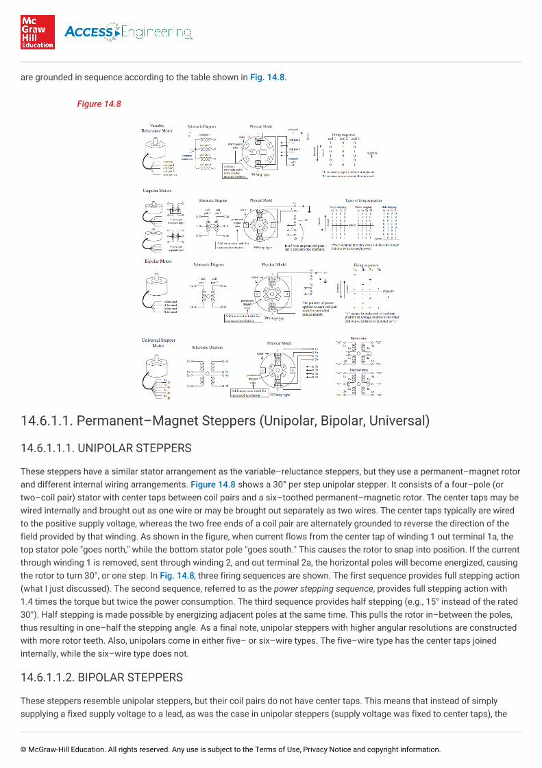
are grounded in sequence according to the table shown in Fig. 14.8.
Figure 14.8
14.6.1.1. Permanent–Magnet Steppers (Unipolar, Bipolar, Universal)
14.6.1.1.1. UNIPOLAR STEPPERS
These steppers have a similar stator arrangement as the variable–reluctance steppers, but they use a permanent–magnet rotorand different internal wiring arrangements. Figure 14.8 shows a 30° per step unipolar stepper. It consists of a four–pole (ortwo–coil pair) stator with center taps between coil pairs and a six–toothed permanent–magnetic rotor. The center taps may bewired internally and brought out as one wire or may be brought out separately as two wires. The center taps typically are wiredto the positive supply voltage, whereas the two free ends of a coil pair are alternately grounded to reverse the direction of thefield provided by that winding. As shown in the figure, when current flows from the center tap of winding 1 out terminal 1a, thetop stator pole "goes north," while the bottom stator pole "goes south." This causes the rotor to snap into position. If the currentthrough winding 1 is removed, sent through winding 2, and out terminal 2a, the horizontal poles will become energized, causingthe rotor to turn 30°, or one step. In Fig. 14.8, three firing sequences are shown. The first sequence provides full stepping action(what I just discussed). The second sequence, referred to as the power stepping sequence, provides full stepping action with1.4 times the torque but twice the power consumption. The third sequence provides half stepping (e.g., 15° instead of the rated30°). Half stepping is made possible by energizing adjacent poles at the same time. This pulls the rotor in–between the poles,thus resulting in one–half the stepping angle. As a final note, unipolar steppers with higher angular resolutions are constructedwith more rotor teeth. Also, unipolars come in either five– or six–wire types. The five–wire type has the center taps joinedinternally, while the six–wire type does not.
14.6.1.1.2. BIPOLAR STEPPERS
These steppers resemble unipolar steppers, but their coil pairs do not have center taps. This means that instead of simplysupplying a fixed supply voltage to a lead, as was the case in unipolar steppers (supply voltage was fixed to center taps), the
© McGraw-Hill Education. All rights reserved. Any use is subject to the Terms of Use, Privacy Notice and copyright information.
supply voltage must be alternately applied to different coil ends. At the same time, the opposite end of a coil pair must be set tothe opposite polarity (ground). For example, in Fig. 14.8, a 30° per step bipolar stepper is made to rotate by applying thepolarities shown in the firing sequence table to the leads of the stepper. Notice that the firing sequence uses the same basicdrive pattern as the unipolar stepper, but the "0" and "1" signals are replaced with "+" and "–" symbols to show that the polaritymatters. As you will see in the next section, the circuitry used to drive a bipolar stepper requires an H–bridge network for everycoil pair. Bipolar steppers are more difficult to control than both unipolar steppers and variable–reluctance steppers, but theirunique polarity–shifting feature gives them a better size–to–torque ratio. As a final note, bi-polar steppers with higher angularresolutions are constructed with more rotor teeth.
14.6.1.1.3. UNIVERSAL STEPPERS
These steppers represent a type of unipolar–bipolar hybrid. A universal stepper comes with four independent windings andeight leads. By connecting the coil windings in parallel, as shown in Fig. 14.8, the universal stepper can be converted into aunipolar stepper. If the coil windings are connected in series, the stepper can be converted into a bipolar stepper.
14.7. Driving Stepper Motors
Every stepper motor needs a driver circuit that can control the current flow sent through the coils within the stepper's stator.The driver, in turn, must be controlled by a logic circuit referred to as a translator. I will discuss translator circuits after I havecovered the driver circuits.
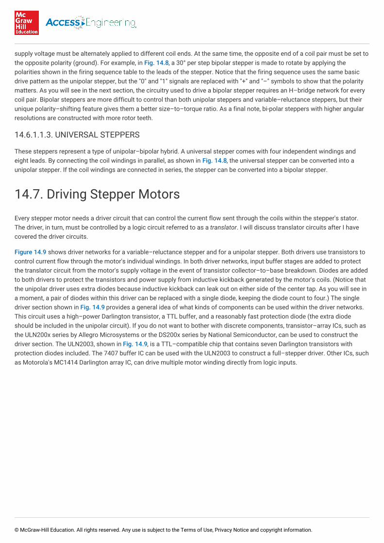
Figure 14.9 shows driver networks for a variable–reluctance stepper and for a unipolar stepper. Both drivers use transistors tocontrol current flow through the motor's individual windings. In both driver networks, input buffer stages are added to protectthe translator circuit from the motor's supply voltage in the event of transistor collector–to–base breakdown. Diodes are addedto both drivers to protect the transistors and power supply from inductive kickback generated by the motor's coils. (Notice thatthe unipolar driver uses extra diodes because inductive kickback can leak out on either side of the center tap. As you will see ina moment, a pair of diodes within this driver can be replaced with a single diode, keeping the diode count to four.) The singledriver section shown in Fig. 14.9 provides a general idea of what kinds of components can be used within the driver networks.This circuit uses a high–power Darlington transistor, a TTL buffer, and a reasonably fast protection diode (the extra diodeshould be included in the unipolar circuit). If you do not want to bother with discrete components, transistor–array ICs, such asthe ULN200x series by Allegro Microsystems or the DS200x series by National Semiconductor, can be used to construct thedriver section. The ULN2003, shown in Fig. 14.9, is a TTL–compatible chip that contains seven Darlington transistors withprotection diodes included. The 7407 buffer IC can be used with the ULN2003 to construct a full–stepper driver. Other ICs, suchas Motorola's MC1414 Darlington array IC, can drive multiple motor winding directly from logic inputs.
© McGraw-Hill Education. All rights reserved. Any use is subject to the Terms of Use, Privacy Notice and copyright information.
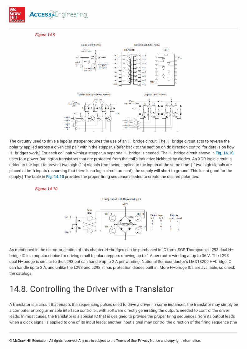
Figure 14.9
The circuitry used to drive a bipolar stepper requires the use of an H–bridge circuit. The H–bridge circuit acts to reverse thepolarity applied across a given coil pair within the stepper. (Refer back to the section on dc direction control for details on howH–bridges work.) For each coil pair within a stepper, a separate H–bridge is needed. The H–bridge circuit shown in Fig. 14.10uses four power Darlington transistors that are protected from the coil's inductive kickback by diodes. An XOR logic circuit isadded to the input to prevent two high (1's) signals from being applied to the inputs at the same time. [If two high signals areplaced at both inputs (assuming that there is no logic circuit present), the supply will short to ground. This is not good for thesupply.] The table in Fig. 14.10 provides the proper firing sequence needed to create the desired polarities.
Figure 14.10
As mentioned in the dc motor section of this chapter, H–bridges can be purchased in IC form. SGS Thompson's L293 dual H–bridge IC is a popular choice for driving small bipolar steppers drawing up to 1 A per motor winding at up to 36 V. The L298dual H–bridge is similar to the L293 but can handle up to 2 A per winding. National Semiconductor's LMD18200 H–bridge ICcan handle up to 3 A, and unlike the L293 and L298, it has protection diodes built in. More H–bridge ICs are available, so checkthe catalogs.
14.8. Controlling the Driver with a Translator
A translator is a circuit that enacts the sequencing pulses used to drive a driver. In some instances, the translator may simply bea computer or programmable interface controller, with software directly generating the outputs needed to control the driverleads. In most cases, the translator is a special IC that is designed to provide the proper firing sequences from its output leadswhen a clock signal is applied to one of its input leads; another input signal may control the direction of the firing sequence (the
© McGraw-Hill Education. All rights reserved. Any use is subject to the Terms of Use, Privacy Notice and copyright information.
direction of the motor). There are a number of stepper translator ICs available that are easy to use and fairly inexpensive. Let'stake a look at one of these devices in a second. First, let's take a look at some simple translator circuits that can be built fromsimple digital components.
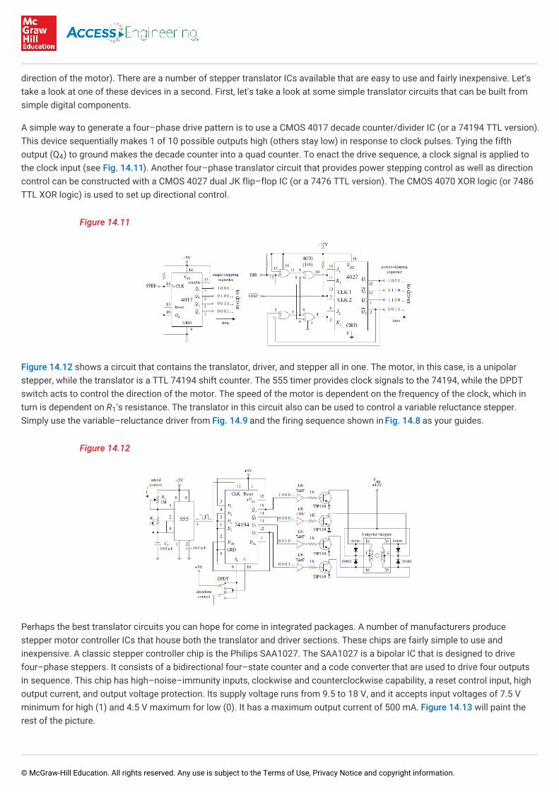
A simple way to generate a four–phase drive pattern is to use a CMOS 4017 decade counter/divider IC (or a 74194 TTL version).This device sequentially makes 1 of 10 possible outputs high (others stay low) in response to clock pulses. Tying the fifthoutput (Q ) to ground makes the decade counter into a quad counter. To enact the drive sequence, a clock signal is applied tothe clock input (see Fig. 14.11). Another four–phase translator circuit that provides power stepping control as well as directioncontrol can be constructed with a CMOS 4027 dual JK flip–flop IC (or a 7476 TTL version). The CMOS 4070 XOR logic (or 7486TTL XOR logic) is used to set up directional control.
Figure 14.11
Figure 14.12 shows a circuit that contains the translator, driver, and stepper all in one. The motor, in this case, is a unipolarstepper, while the translator is a TTL 74194 shift counter. The 555 timer provides clock signals to the 74194, while the DPDTswitch acts to control the direction of the motor. The speed of the motor is dependent on the frequency of the clock, which inturn is dependent on R 's resistance. The translator in this circuit also can be used to control a variable reluctance stepper.Simply use the variable–reluctance driver from Fig. 14.9 and the firing sequence shown in Fig. 14.8 as your guides.
Figure 14.12
Perhaps the best translator circuits you can hope for come in integrated packages. A number of manufacturers producestepper motor controller ICs that house both the translator and driver sections. These chips are fairly simple to use andinexpensive. A classic stepper controller chip is the Philips SAA1027. The SAA1027 is a bipolar IC that is designed to drivefour–phase steppers. It consists of a bidirectional four–state counter and a code converter that are used to drive four outputsin sequence. This chip has high–noise–immunity inputs, clockwise and counterclockwise capability, a reset control input, highoutput current, and output voltage protection. Its supply voltage runs from 9.5 to 18 V, and it accepts input voltages of 7.5 Vminimum for high (1) and 4.5 V maximum for low (0). It has a maximum output current of 500 mA. Figure 14.13 will paint therest of the picture.
4
1
© McGraw-Hill Education. All rights reserved. Any use is subject to the Terms of Use, Privacy Notice and copyright information.
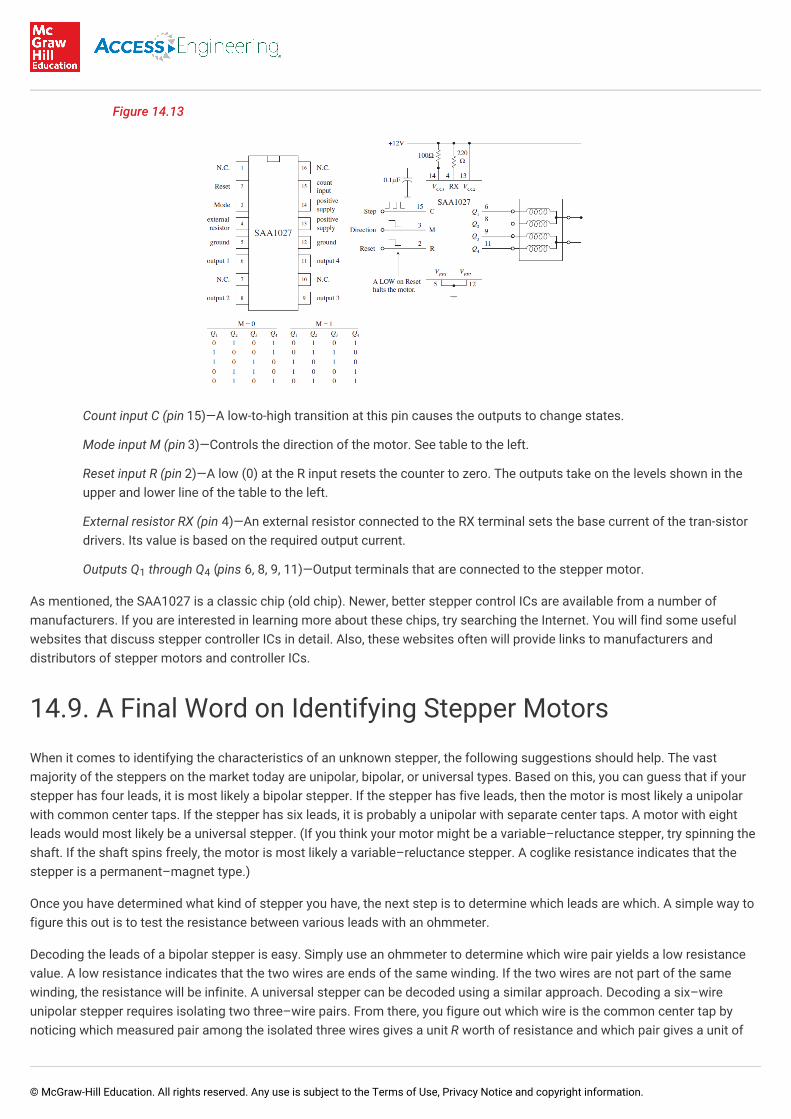
Figure 14.13
Count input C (pin 15)—A low-to-high transition at this pin causes the outputs to change states.
Mode input M (pin 3)—Controls the direction of the motor. See table to the left.
Reset input R (pin 2)—A low (0) at the R input resets the counter to zero. The outputs take on the levels shown in theupper and lower line of the table to the left.
External resistor RX (pin 4)—An external resistor connected to the RX terminal sets the base current of the tran-sistordrivers. Its value is based on the required output current.
Outputs Q through Q (pins 6, 8, 9, 11)—Output terminals that are connected to the stepper motor.
As mentioned, the SAA1027 is a classic chip (old chip). Newer, better stepper control ICs are available from a number ofmanufacturers. If you are interested in learning more about these chips, try searching the Internet. You will find some usefulwebsites that discuss stepper controller ICs in detail. Also, these websites often will provide links to manufacturers anddistributors of stepper motors and controller ICs.
14.9. A Final Word on Identifying Stepper Motors
When it comes to identifying the characteristics of an unknown stepper, the following suggestions should help. The vastmajority of the steppers on the market today are unipolar, bipolar, or universal types. Based on this, you can guess that if yourstepper has four leads, it is most likely a bipolar stepper. If the stepper has five leads, then the motor is most likely a unipolarwith common center taps. If the stepper has six leads, it is probably a unipolar with separate center taps. A motor with eightleads would most likely be a universal stepper. (If you think your motor might be a variable–reluctance stepper, try spinning theshaft. If the shaft spins freely, the motor is most likely a variable–reluctance stepper. A coglike resistance indicates that thestepper is a permanent–magnet type.)
Once you have determined what kind of stepper you have, the next step is to determine which leads are which. A simple way tofigure this out is to test the resistance between various leads with an ohmmeter.
Decoding the leads of a bipolar stepper is easy. Simply use an ohmmeter to determine which wire pair yields a low resistancevalue. A low resistance indicates that the two wires are ends of the same winding. If the two wires are not part of the samewinding, the resistance will be infinite. A universal stepper can be decoded using a similar approach. Decoding a six–wireunipolar stepper requires isolating two three–wire pairs. From there, you figure out which wire is the common center tap bynoticing which measured pair among the isolated three wires gives a unit R worth of resistance and which pair gives a unit of
1 4
© McGraw-Hill Education. All rights reserved. Any use is subject to the Terms of Use, Privacy Notice and copyright information.
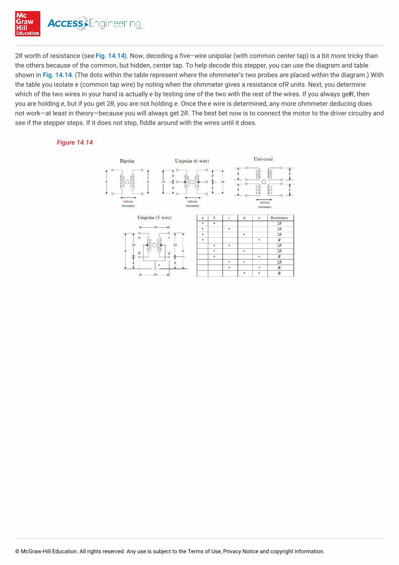
2R worth of resistance (see Fig. 14.14). Now, decoding a five–wire unipolar (with common center tap) is a bit more tricky thanthe others because of the common, but hidden, center tap. To help decode this stepper, you can use the diagram and tableshown in Fig. 14.14. (The dots within the table represent where the ohmmeter's two probes are placed within the diagram.) Withthe table you isolate e (common tap wire) by noting when the ohmmeter gives a resistance of R units. Next, you determinewhich of the two wires in your hand is actually e by testing one of the two with the rest of the wires. If you always get R, thenyou are holding e, but if you get 2R, you are not holding e. Once the e wire is determined, any more ohmmeter deducing doesnot work—at least in theory—because you will always get 2R. The best bet now is to connect the motor to the driver circuitry andsee if the stepper steps. If it does not step, fiddle around with the wires until it does.
Figure 14.14
© McGraw-Hill Education. All rights reserved. Any use is subject to the Terms of Use, Privacy Notice and copyright information.


