Embed Size (px)
Citation preview
Model-Driven Adaptation for Plastic User Interfaces
Jean-Sébastien Sottet1, Vincent Ganneau
1, 2, Gaëlle Calvary
1, Joëlle Coutaz
1,
Alexandre Demeure1, Jean-Marie Favre
1, Rachel Demumieux
2
1 Université Joseph Fourier, Laboratoire LIG, BP 53, 38041 Grenoble Cedex France
{Jean-Sebastien.Sottet, Vincent.Ganneau, Gaelle.Calvary, Joelle.Coutaz,
Alexandre.Demeure, Jean-Marie.Favre}@imag.fr 2 France Télécom R&D, 2 avenue Pierre Marzin, 22307 Lannion Cedex France
{Vincent.Ganneau, Rachel.Demumieux}@orange-ftgroup.com
Abstract. User Interface (UI) plasticity denotes UI adaptation to the context of
use (user, platform, physical and social environments) while preserving usabil-
ity. In this article, we focus on the use of Model-Driven Engineering and dem-
onstrate how the intrinsic flexibility of this approach can be exploited by de-
signers for UI prototyping as well as by end-users in real settings. For doing so,
the models developed at design-time, which convey high-level design deci-
sions, are still available at run-time. As a result, an interactive system is not
li+mited to a set of linked pieces of code, but is a graph of models that evolves,
expresses and maintains multiple perspectives on the system from top-level
tasks to the final UI. A simplified version of a Home Heating Control System is
used to illustrate our approach and technical implementation.
Keywords: User interface plasticity, user interface adaptation, context aware
systems, Model-Driven Engineering.
1 Introduction
User Interface (UI) plasticity denotes the capacity for user interfaces to adapt to the
context of use while preserving usability [32]. The context of use is a structured in-
formation space whose finality is to inform the adaptation process. It includes a model
of the user who is intended to use (or is actually using) the system, the social and
physical environments where the interaction is supposed to take place (or is actually
taking place), and the platform to be used (or is being used). The latter covers the set
of computing, sensing, communication, and interaction resources that bind together
the physical environment with the digital world. Usability expresses the useworthi-
ness of the system: the value that this system has in the real world [6].
From the software perspective, UI plasticity goes far beyond UI portability and UI
translation. Software adaptation has been addressed using many approaches over the
years, including Machine Learning [20], Model-Driven Engineering (MDE) [5, 17,
21, 23, 29, 30], and Component-oriented services [27]. Our approach to the problem
of UI plasticity is based on the following observations. First, every paradigm has its
own merits targeted at specific requirements. Thus, in an ever-changing world, one
single approach is doomed to failure. Second, software tools and mechanisms tend to
make a dichotomy between the development stage and the run-time phase making it
difficult to articulate run-time adaptation based on semantically rich design-time de-
scriptions.
Our approach to UI plasticity is to bring together Model-Driven Engineering
(MDE) and Service Oriented Approach (SOA) within a unified framework that covers
the development stage of interactive systems as well as the run-time phase. The prin-
ciples of our solution space are presented in Section 3, followed in Section 4 by the
description of an early implementation of these principles. In this article, we focus on
the MDE aspects of our implementation. Our intention is to demonstrate how the in-
trinsic flexibility of this approach can be usefully exploited for UI prototyping by de-
signers as well as by end-users (if appropriately encapsulated). To illustrate the dis-
cussion, we use a simplified version of a Home Heating Control System.
2 HHCS: a Simplified Home Heating Control System
HHCS (Home Heating Control System) enables users to control the temperature of
the home using different interaction resources. A typical task consists in checking and
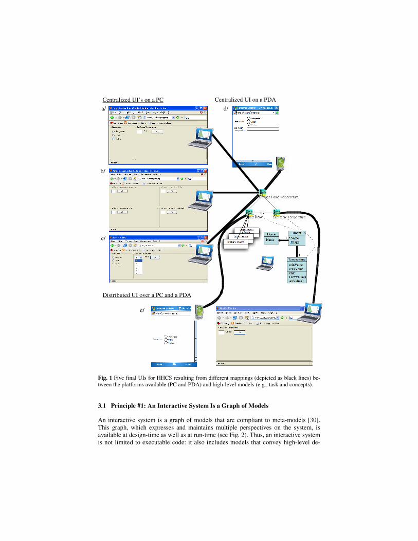
setting room temperature. As illustrated in Fig. 1, the graphical rendering of the user
interface for this task depends on the screen size (as in 1-b and 1-d), on the set of
screens that can be used simultaneously (e.g., 1-a versus 1-e), as well as on the set of
usability properties that the designers have considered as central. Switching between
these UIs is performed at run-time under human control (i.e. by the end-user in the
real setting and/or the designer while prototyping the UI).
The five UIs of Fig. 1 are functionally equivalent: they support the same set of
tasks (i.e. to access a set of rooms and, if needed, to set the room temperature between
15°C and 18°C). Some UIs are centralized on a single screen but simultaneously
mapped onto different displays whose size differs (Fig. 1 a-b-c-d). Conversely, in
Fig. 1-e, the UI is distributed over two displays: the UI that corresponds to the task
“Select room” is mapped onto the PDA, whereas the PC is used to set the tempera-
ture.
In addition, these UIs do not satisfy the same set of usability properties. In particu-
lar, prompting (cf. Bastien-Scapin’s framework [3] prevention against errors, and
minimal actions, are not equally supported. In Fig. 1-a, the range of values of the
room temperature is not observable. As a result, prompting is not fully supported.
Prevention against errors is improved in Fig. 1-c by using a menu list while Fig. 1-b
improves minimal actions by eliminating the “Select room” task.
In the rest of the article, we present the underlying technology and its principles
that enable end-users and/or designers to control the final UI.
3 Principles
Early work in the automatic generation of UIs as well as more recent work in UI
adaptation [5, 17, 21, 23, 29] adheres only partially to the MDE principles. Our ap-
proach differs from previous work according to the following five principles.
a/
b/
c/
e/
d/
Centralized UI’s on a PC Centralized UI on a PDA
Distributed UI over a PC and a PDA
Fig. 1 Five final UIs for HHCS resulting from different mappings (depicted as black lines) be-
tween the platforms available (PC and PDA) and high-level models (e.g., task and concepts).
3.1 Principle #1: An Interactive System Is a Graph of Models
An interactive system is a graph of models that are compliant to meta-models [30].
This graph, which expresses and maintains multiple perspectives on the system, is
available at design-time as well as at run-time (see Fig. 2). Thus, an interactive system
is not limited to executable code: it also includes models that convey high-level de-
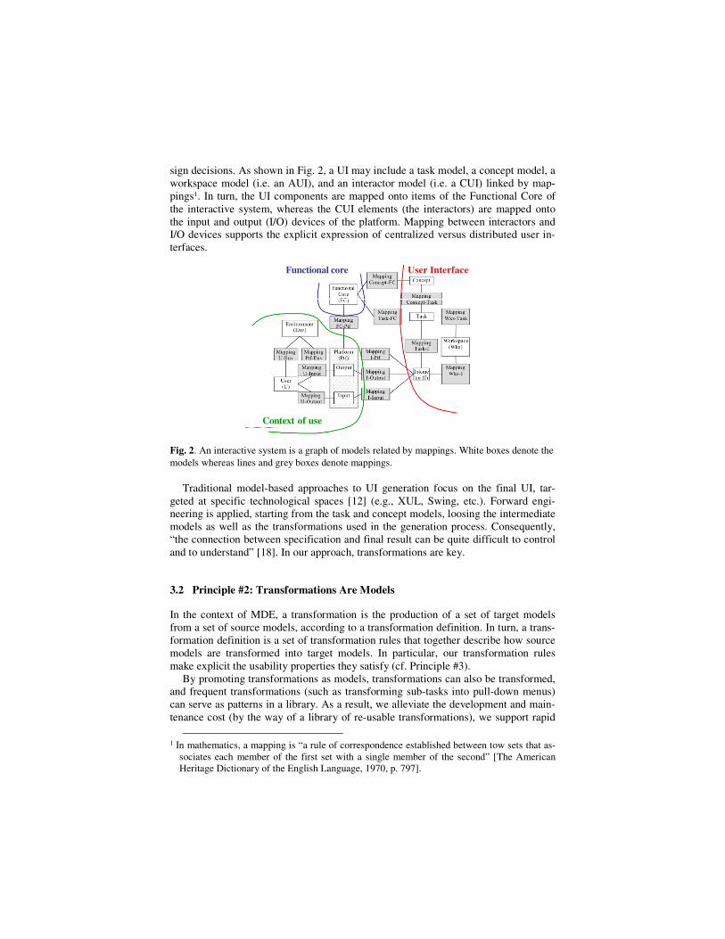
sign decisions. As shown in Fig. 2, a UI may include a task model, a concept model, a
workspace model (i.e. an AUI), and an interactor model (i.e. a CUI) linked by map-
pings1. In turn, the UI components are mapped onto items of the Functional Core of
the interactive system, whereas the CUI elements (the interactors) are mapped onto
the input and output (I/O) devices of the platform. Mapping between interactors and
I/O devices supports the explicit expression of centralized versus distributed user in-
terfaces.
Functional core User Interface
Context of use
Fig. 2. An interactive system is a graph of models related by mappings. White boxes denote the
models whereas lines and grey boxes denote mappings.
Traditional model-based approaches to UI generation focus on the final UI, tar-
geted at specific technological spaces [12] (e.g., XUL, Swing, etc.). Forward engi-
neering is applied, starting from the task and concept models, loosing the intermediate
models as well as the transformations used in the generation process. Consequently,
“the connection between specification and final result can be quite difficult to control
and to understand” [18]. In our approach, transformations are key.
3.2 Principle #2: Transformations Are Models
In the context of MDE, a transformation is the production of a set of target models
from a set of source models, according to a transformation definition. In turn, a trans-
formation definition is a set of transformation rules that together describe how source
models are transformed into target models. In particular, our transformation rules
make explicit the usability properties they satisfy (cf. Principle #3).
By promoting transformations as models, transformations can also be transformed,
and frequent transformations (such as transforming sub-tasks into pull-down menus)
can serve as patterns in a library. As a result, we alleviate the development and main-
tenance cost (by the way of a library of re-usable transformations), we support rapid
1 In mathematics, a mapping is “a rule of correspondence established between tow sets that as-
sociates each member of the first set with a single member of the second” [The American
Heritage Dictionary of the English Language, 1970, p. 797].
prototyping based on the comparative evaluation 2 of UIs produced with different
transformations, we improve run-time flexibility (since transformations, which are
available at run-time, can be transformed). For example, the UIs of HHCS differ from
the application of different transformations. Examples will be presented in more detail
in Section 4.1.
3.3 Principle #3: The Choice of Usability Frameworks Is Left Opened
A large number of usability frameworks have been proposed to better understand and
measure the usability of interactive systems. These include: Shackel [26], Dix et al.
[10], Nielsen [19], Preece [24], Schneiderman [28], Constantine and Lockwood [7],
Van Welie et al. [33], as well as Seffah et al. [25] who propose QUIM, a unifying
roadmap to reconcile existing frameworks. More specific frameworks are proposed
for web engineering (Montero et al. [16]), or for specific domains (for instance, mili-
tary applications). Closely related to UI plasticity, Lopez-Jacquero et al. propose a re-
finement of Bastien-Scapin’s framework, as a usability guide for UI adaptation [14].
Because moving to an unfamiliar set of tools would impose a high threshold on
HCI and software designers, we promote an open approach that consists in choosing
the appropriate usability framework for eliciting the properties that must, should or
may be satisfied by transformations. For HHCS, we have used Bastien-Scapin’s
framework. The transformation of a usability framework into a digital model is per-
formed according to Principle #4.
3.4 Principle #4: Humans Are Kept in the Loop
HCI design methods produce a large body of contemplative models (i.e. models that
cannot be processed by a machine) such as storyboards, and mock-ups. These models
are useful reference material during the design process. On the other hand, because
they are contemplative, they can only be transformed manually into productive mod-
els (i.e. models that can be processed by a machine). Manual transformation supports
creative inspiration, but is prone to wrong interpretation and to loss of key informa-
tion. To address this problem, we accept to support a mix of automated, semi-
automated, and manually performed transformations. Semi-automated and manual
transformations may be performed by designers and/or end-users. For example, given
our current level of knowledge, the transformation of a “value-centered model” [6] in-
to a “usability model” such as that of [3], can only be performed manually by design-
ers. Semi-automation allows designers (or end-users) to adjust the models that result
from transformations. For example, a designer may decide to map a subset of an AUI
onto UI services developed with the latest post-WIMP toolkit. By doing so, we avoid
the “low-cost, fast food” UIs as produced with automatic generation.
2 As discussed in [15], comparative evaluations are more productive than absolute evaluations.
3.5 Principle #5: Close and Open Adaptiveness Are Complementary
Designers cannot envision all of the contexts of use in which the future interactive
system will be executed. To alleviate this problem, we suggest a mix of open and
close adaptiveness. A system is close-adaptive when adaptation is self-contained. It
supports the “innate” adjustments planned at the design stage as well as new adjust-
ments produced by its own internal learning mechanisms. The system is open-
adaptive “if new adaptation plans can be introduced during run-time” [22].
By analogy, an interactive system is close-adaptive for the contexts of use that fall
within its domain of plasticity [4], that is, for the contexts of use for which this system
can adapt on its own. By design, an interactive system has an innate domain of plas-
ticity. If it is able to learn adjustments for additional contexts of use, then the domain
of plasticity extends dynamically, but this extension relies only on the internal compu-
ting capabilities of the system. An external infrastructure must be provided to support
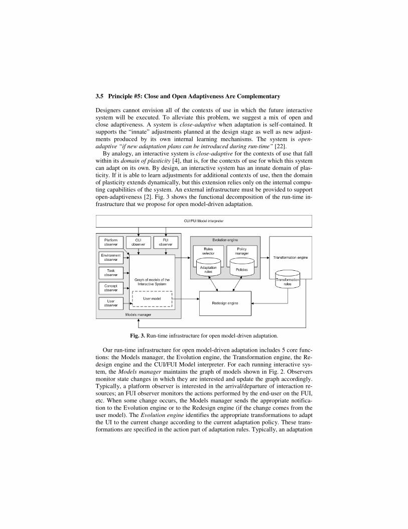
open-adaptiveness [2]. Fig. 3 shows the functional decomposition of the run-time in-
frastructure that we propose for open model-driven adaptation.
Fig. 3. Run-time infrastructure for open model-driven adaptation.
Our run-time infrastructure for open model-driven adaptation includes 5 core func-
tions: the Models manager, the Evolution engine, the Transformation engine, the Re-
design engine and the CUI/FUI Model interpreter. For each running interactive sys-
tem, the Models manager maintains the graph of models shown in Fig. 2. Observers
monitor state changes in which they are interested and update the graph accordingly.
Typically, a platform observer is interested in the arrival/departure of interaction re-
sources; an FUI observer monitors the actions performed by the end-user on the FUI,
etc. When some change occurs, the Models manager sends the appropriate notifica-
tion to the Evolution engine or to the Redesign engine (if the change comes from the
user model). The Evolution engine identifies the appropriate transformations to adapt
the UI to the current change according to the current adaptation policy. These trans-
formations are specified in the action part of adaptation rules. Typically, an adaptation
rule obeys the Event-Condition-Action paradigm where the Event part denotes the
trigger, and where the Action part makes reference to transformations or to other
adaptation rules. Examples of adaptation rules will be discussed in Section 4.3. Poli-
cies serve at favoring such and such adaptation rules based on such and such (usabili-
ty) criteria. The transformations selected by the evolution engine are then transmitted
to the Transformation engine whose role is to apply the transformations to the graph
of models. The graph of models is updated accordingly while the CUI/FUI interpreter
(e.g., a Web browser) uses the new CUI to produce the new adapted final UI (FUI).
The role of the Redesign engine is to dynamically modify the adaptation rules and
to set the current policy based on the information gathered from, or inferred by, the
User model. Typical attributes maintained in the User model include user preferences,
interests and goals, as well as interaction history (i.e. tasks in progress, completed
tasks, errors, etc.) [11]. For example, the end-user using the UI shown in Fig. 1-a may
keep entering wrong values when specifying a room temperature. From the informa-
tion provided by the CUI/FUI observers, the User model may infer the need for error
management so that the new resulting FUI be that of Fig. 1-c. The Redesign engine
then searches for the transformations in the Transformations Data Base that promote
the error management property. If a transformation is found, the Redesign engine may
create new adaptation rules, and/or suppress adaptation rules from the current set,
and/or modifies existing ones. Note that, according to Principle #2, these modifica-
tions are performed by the way of transformations.
Having presented the principles of our approach to UI plasticity, we now show
how they have been implemented and applied to HHCS.
4 From Principles to HHCS in Action
Our hypothesis is that designers produce all or a subset of the models mentioned in
Fig. 2. For HHCS, we have adopted a top-down approach starting from the task model
and the domain-dependent concepts using well-defined meta-models3. These models
are represented in a simplified manner in Fig. 2. The AUI, CUI and FUI of HHCS
have been produced with transformations. Examples of transformation are presented
in Section 4.1. At run-time, changes in the context of use may require the user inter-
face of HHCS to adapt. The context of use for HHCS is discussed in Section 4.2, and
examples of adaptation rules are provided in Section 4.3. In Section 4.4 we show how
Principle #4 (humans are kept in the loop) is implemented with a meta-UI.
The run-time infrastructure for open model-driven adaptation is implemented as a
set of OSGi services where a service encapsulates one of the core functions shown in
Fig. 3. More specifically, the Models manager is implemented in Java. We draw upon
the Eclipse Modeling Framework (EMF), which automatically generates the methods
(the API) that make it possible for the observers and the Transformation engine to
modify the graph of models. The Evolution Engine and the Redesign engine are im-
plemented in Java as well. The Transformation engine is an ATL interpreter [1].
3 Describing these meta-models would require more space than available in this paper. See
[31] for more details.
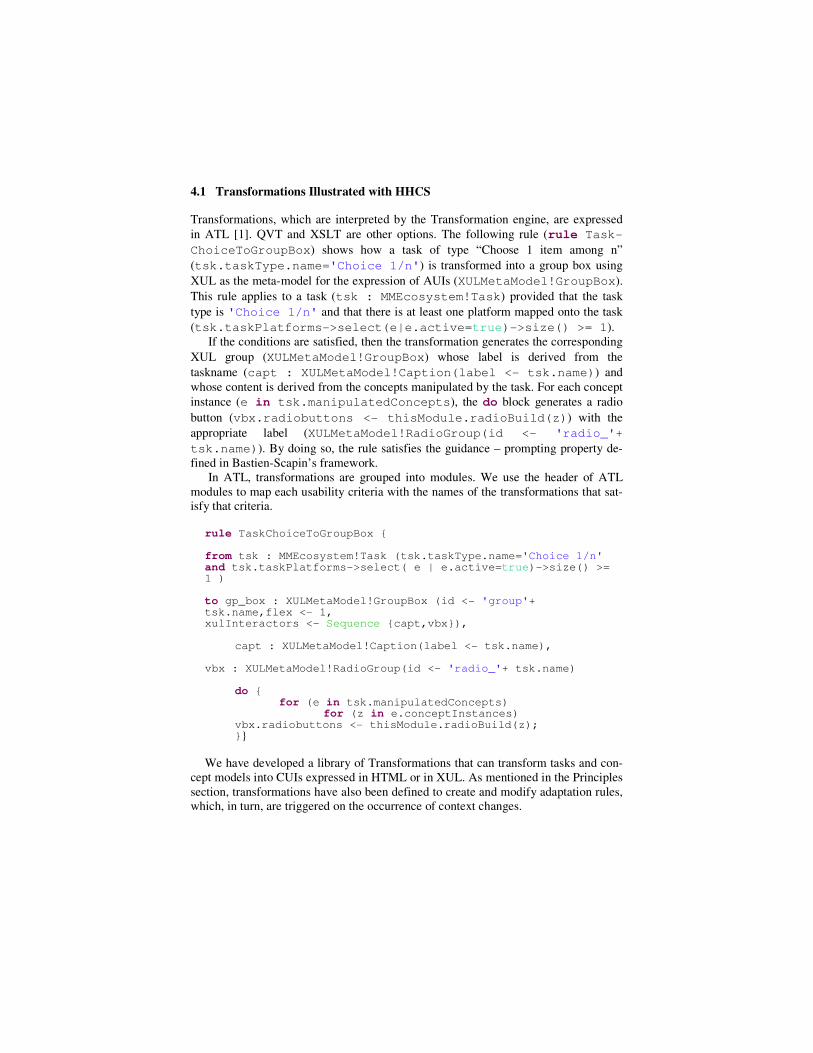
4.1 Transformations Illustrated with HHCS
Transformations, which are interpreted by the Transformation engine, are expressed
in ATL [1]. QVT and XSLT are other options. The following rule (rule Task-
ChoiceToGroupBox) shows how a task of type “Choose 1 item among n”
(tsk.taskType.name='Choice 1/n') is transformed into a group box using
XUL as the meta-model for the expression of AUIs (XULMetaModel!GroupBox).
This rule applies to a task (tsk : MMEcosystem!Task) provided that the task
type is 'Choice 1/n' and that there is at least one platform mapped onto the task
(tsk.taskPlatforms->select(e|e.active=true)->size() >= 1).
If the conditions are satisfied, then the transformation generates the corresponding
XUL group (XULMetaModel!GroupBox) whose label is derived from the
taskname (capt : XULMetaModel!Caption(label <- tsk.name)) and
whose content is derived from the concepts manipulated by the task. For each concept
instance (e in tsk.manipulatedConcepts), the do block generates a radio
button (vbx.radiobuttons <- thisModule.radioBuild(z)) with the
appropriate label (XULMetaModel!RadioGroup(id <- 'radio_'+
tsk.name)). By doing so, the rule satisfies the guidance – prompting property de-
fined in Bastien-Scapin’s framework.
In ATL, transformations are grouped into modules. We use the header of ATL
modules to map each usability criteria with the names of the transformations that sat-
isfy that criteria.
rule TaskChoiceToGroupBox { from tsk : MMEcosystem!Task (tsk.taskType.name='Choice 1/n' and tsk.taskPlatforms->select( e | e.active=true)->size() >= 1 ) to gp_box : XULMetaModel!GroupBox (id <- 'group'+ tsk.name,flex <- 1, xulInteractors <- Sequence {capt,vbx}), capt : XULMetaModel!Caption(label <- tsk.name), vbx : XULMetaModel!RadioGroup(id <- 'radio_'+ tsk.name) do { for (e in tsk.manipulatedConcepts) for (z in e.conceptInstances) vbx.radiobuttons <- thisModule.radioBuild(z); }}
We have developed a library of Transformations that can transform tasks and con-
cept models into CUIs expressed in HTML or in XUL. As mentioned in the Principles
section, transformations have also been defined to create and modify adaptation rules,
which, in turn, are triggered on the occurrence of context changes.
4.2 Context of Use in HHCS
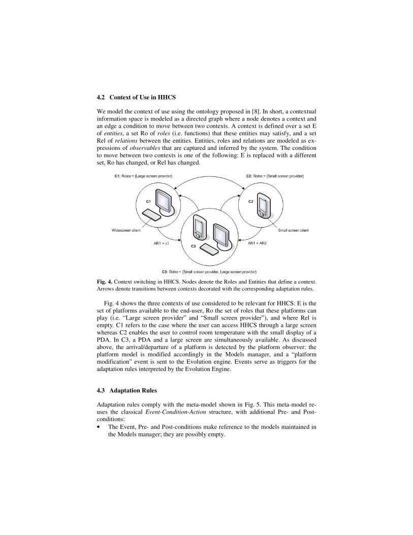
We model the context of use using the ontology proposed in [8]. In short, a contextual
information space is modeled as a directed graph where a node denotes a context and
an edge a condition to move between two contexts. A context is defined over a set E
of entities, a set Ro of roles (i.e. functions) that these entities may satisfy, and a set
Rel of relations between the entities. Entities, roles and relations are modeled as ex-
pressions of observables that are captured and inferred by the system. The condition
to move between two contexts is one of the following: E is replaced with a different
set, Ro has changed, or Rel has changed.
Fig. 4. Context switching in HHCS. Nodes denote the Roles and Entities that define a context.
Arrows denote transitions between contexts decorated with the corresponding adaptation rules.
Fig. 4 shows the three contexts of use considered to be relevant for HHCS: E is the
set of platforms available to the end-user, Ro the set of roles that these platforms can
play (i.e. “Large screen provider” and “Small screen provider”), and where Rel is
empty. C1 refers to the case where the user can access HHCS through a large screen
whereas C2 enables the user to control room temperature with the small display of a
PDA. In C3, a PDA and a large screen are simultaneously available. As discussed
above, the arrival/departure of a platform is detected by the platform observer: the
platform model is modified accordingly in the Models manager, and a “platform
modification” event is sent to the Evolution engine. Events serve as triggers for the
adaptation rules interpreted by the Evolution Engine.
4.3 Adaptation Rules
Adaptation rules comply with the meta-model shown in Fig. 5. This meta-model re-
uses the classical Event-Condition-Action structure, with additional Pre- and Post-
conditions:
• The Event, Pre- and Post-conditions make reference to the models maintained in
the Models manager; they are possibly empty.
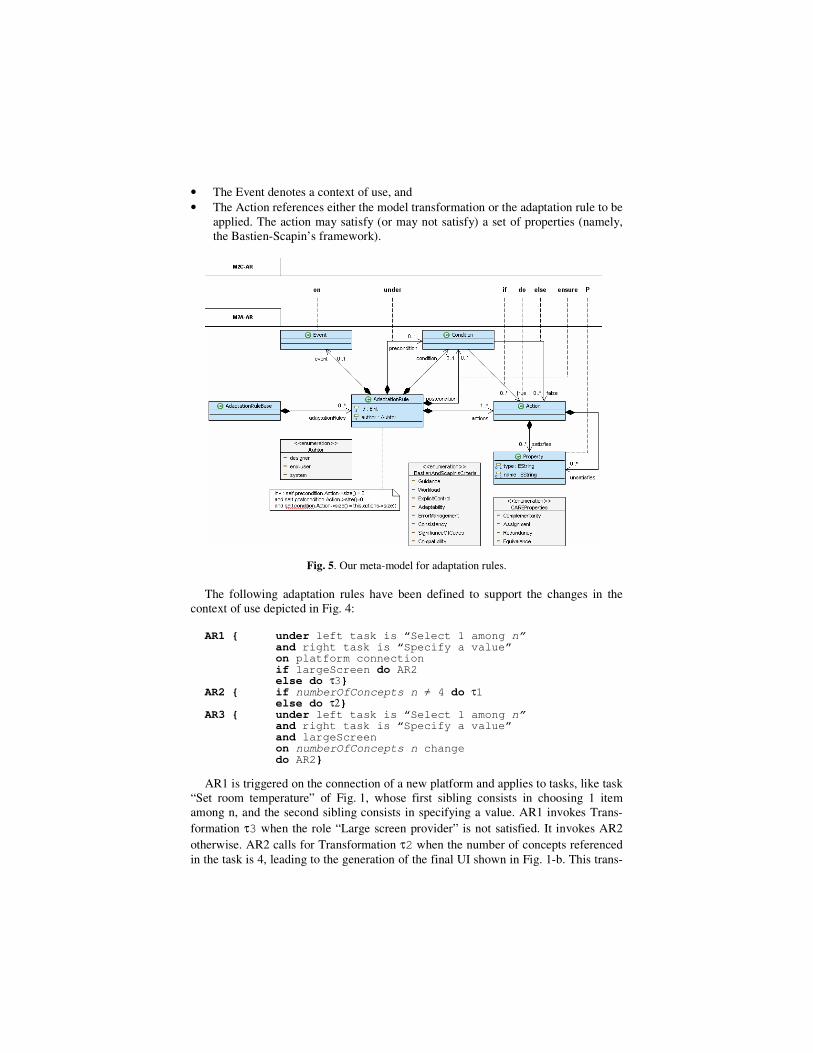
• The Event denotes a context of use, and
• The Action references either the model transformation or the adaptation rule to be
applied. The action may satisfy (or may not satisfy) a set of properties (namely,
the Bastien-Scapin’s framework).
Fig. 5. Our meta-model for adaptation rules.
The following adaptation rules have been defined to support the changes in the
context of use depicted in Fig. 4:
AR1 { under left task is “Select 1 among n” and right task is “Specify a value” on platform connection if largeScreen do AR2 else do τ3} AR2 { if numberOfConcepts n ≠ 4 do τ1 else do τ2}
AR3 { under left task is “Select 1 among n” and right task is “Specify a value” and largeScreen on numberOfConcepts n change do AR2}
AR1 is triggered on the connection of a new platform and applies to tasks, like task
“Set room temperature” of Fig. 1, whose first sibling consists in choosing 1 item
among n, and the second sibling consists in specifying a value. AR1 invokes Trans-
formation τ3 when the role “Large screen provider” is not satisfied. It invokes AR2
otherwise. AR2 calls for Transformation τ2 when the number of concepts referenced
in the task is 4, leading to the generation of the final UI shown in Fig. 1-b. This trans-
formation, which avoids users to explicitly select a room by the way of a physical ac-
tion, supports the “minimal action” criteria.
AR3 is triggered by the event “numberOfConcepts n change”. In HHCS, this cor-
responds to the case where a new thermostat is installed/removed from the home. In
HHCS, this phenomenon is detected by the concept observer. The concept model is
modified accordingly, and the corresponding event is sent to the Evolution engine.
AR4 is applied when the role “Large screen provider” is filled.
When several ARs apply, the Policy Manager makes the final decision based on
the current active policy and provides the Transformation engine with the appropriate
transformations. Interoperability between the Evolution Engine and the ATL-based
Transformation engine is ensured in the following way: Adaptation rules are produced
using an EMF (Eclipse Modeling Framework) basic editor. The output of this editor is
an XMI file (.ecore) that can be manipulated by EMF-based tools such as our ATL
Transformation engine.
So far, we have shown how the run-time infrastructure supports run-time adapta-
tion based on the specifications provided by the designers. In the next section, we
show how the end-user (and the designer) can be kept in the loop at run-time when
served by a meta-UI.
4.4 Meta-UIs to Keep Humans in the Loop at Run-time
A meta-UI is an interactive system whose set of functions is necessary and sufficient
to control and evaluate the state of an interactive ambient space [9]. This set is meta-
because it serves as an umbrella beyond the domain-dependent services that support
human activities in this space. It is UI-oriented because its role is to allow users to
control and evaluate the state of the ambient interactive space. It is to ambient compu-
ting what desktops and shells are to conventional workstations.
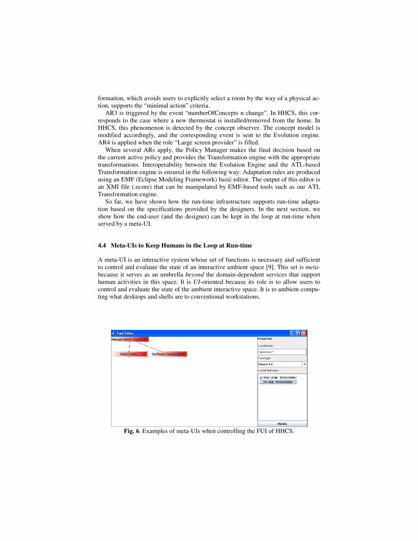
Fig. 6. Examples of meta-UIs when controlling the FUI of HHCS.
Fig. 6 shows early versions of meta-UIs illustrated HHCS. In the top example, the
AUI model of HHCS as well as that of the meta-UI is a scene graph rendered as the
display background. A subtree of the AUI is suppressed by bringing the tool-glass on
the root of the subtree followed by a click through. The FUI is updated accordingly.
Conversely, the user modift the FUI with the tool-glass and the AUI is updated accor-
dingly. In the bottom example, end-users can map the tasks “Select room” and “Set
room Temperature” respectively, to the PDA-HTML platform and to the PC-XUL
platform, resulting in the FUI shown in Fig. 1-e. These toy examples are being rede-
signed to fully exploit the flexibility provided by our approach (as well as to improve
their usability!).
5 Conclusion
This paper addresses the complexity of UI plasticity with a combination of MDE and
SOA. Model-based generation has received little acceptance due to the high threshold
of learning new languages for a low pay-off (obtaining simplistic UIs). In response to
this limitation, we propose the use of transformations as models that can be capita-
lized in re-usable libraries. Furthermore, we allow hand-coded fine-tuned portions of
a UI (such as the toolglass of our meta-UI) to be dynamically mapped onto high-level
models provided that they comply with a component-oriented service protocol (this
aspect has not been discussed in the paper). Transformations are key because they can
be dynamically transformed, either automatically by a run-time infrastructure and/or
by the end-users and designers through a meta-UI. Transformations can also be used
to improve interoperability. In particular, we have defined transformations that trans-
late UsiXML [13] meta-models into our own meta-models.
A subset of our principles has been applied to a simplified version of a Home
Heating Control System. Other applications are under way for SMS and ambient
computing to support conference participants in large conferences. Although this
serves as our validation for this work, it also leaves several opportunities for im-
provements including the study of end-user development environments such as the
concept of meta-UI.
Acknowledgments. This work has been partly supported by Project EMODE (ITEA-
if4046), the NoE SIMILAR- FP6-507609, and France-Telecom R&D.
References
1. ATL : Atlas Transformation Language. http://www.eclipse.org/m2m/atl/
2. Balme, L., Demeure, A., Barralon, N., Coutaz, J., Calvary, G.: CAMELEON-RT: a Soft-
ware Architecture Reference Model for Distributed, Migratable, and Plastic User Inter-
faces. EUSAI 2004, LNCS, Vol. 3295. Springer-Verlag Heidelberg, 2004, 291-302
3. Bastien, J.M.C., Scapin, D.: Ergonomic Criteria for the Evaluation of Human-Computer.
Technical report INRIA, N°156, June 1993
4. Calvary, G., Coutaz, J., Thevenin, D. A Unifying Reference Framework for the Develop-
ment of Plastic User Interfaces. EHCI2001, Springer Publ., LNCS 2254, 173-192
5. Clerckx, T., Luyten, K., Coninx, K. Generating Context-Sensitive Multiple Device Inter-
faces from Design. In CADUI'2004
6. Cockton, G.: A Development Framework for Value-Centred Design. Extended Abstracts
Proc. of CHI 2005, Portland, Oregon, USA, April 2-7, 2005, pp. 1292-1295
7. Constantine, L.L., Lockwood, L.A.D. Software for Use: A Practical Guide to the Models
and Methods of Usage-Centred Design, New-York, Addison-Wesley, 1999
8. Coutaz, J., Crowley, J.L., Dobson, S., Garlan, D.: Context is Key. Communication of the
ACM (CACM), Volume 48, Issue 3, ACM Press, March 2005, pp. 49-53
9. Coutaz, J.: Meta-User Interfaces for Ambient Spaces. Tamodia'06, Hasselt, October 2006
10. Dix, A., Finlay, J., Abowd, G., Beale, R. Human-Computer Interaction, Prentice-Hall,
New-Jersey, 1993
11. Johansson, P.: User Modeling in Dialog Systems. Santa Anna IT Research Institute Re-
port: SAR 02-2
12. Kurtev, I., Bézivin, J., Aksit, M. Technological Spaces: An Initial Appraisal, In Proc.
CoopIS, DOA, and ODBASE 2002, Industrial track, Irvine, CA, USA, 2002
13. Limbourg, Q., Vanderdonckt, J., Michotte, B., Bouillon, L., Lopez, V., USIXML: a Lan-
guage Supporting Multi-Path Devel-opment of User Interfaces. In Proc. EHCI-
DSVIS’2004 (Hamburg, July 11-13, 2004). Kluwer Academic Press, Dordrecht, 204.
14. Lopez-Jaquero, V., Montero, F., Molina, J.P., Gonzalez, P. A Seamless Development
Process of Adaptive User Interfaces Explicitly Based on Usability Properties, EHCI’04, pp
289-291
15. Molich, R., Ede, M., Kaasgaard, K., & Karyukin, B. Comparative usability evaluation.
Behaviour & Information Technology 23, 1 (2004), 65-74
16. Montero, F., Vanderdonckt, J., Lozano, M. Quality Models for Automated Evaluation of
Web Sites Usability and Accessibility, In proc. of the International Conference on Web
Engineering, ICWE’2004, July 28-30, Munich, 2004
17. Mori, G., Paternò, F., Santoro, C. Design and development of multidevice user interfaces
through multiple logical descriptions. IEEE Transactions on Sofware Engineering,
30(8):507–520, August 2004
18. Myers, B., Hudson, S.E., Pausch, R.: Past, Present and Future of User Interface Software
Tools. Transactions on Computer-Human Interaction (TOCHI), Vol 7, Issue 1, 2000
19. Nielsen, J. Heuristic evaluation, In Nielsen, J., and Mack, R.L. (Eds.), Usability Inspection
Methods, John Wiley & Sons, New York, NY, 1994
20. Njike, H., Artières, T., Gallinari, P., Blanchard, J., Letellier, G.: Automatic learning of
domain model for personalized hypermedia applications. International Joint Conference
on Artificial Intelligence, IJCA, Edinburg, Scotland, 2005, pp. 1624
21. Nobrega, L., Nunes, J.N., Coelho, H. Mapping ConcurTaskTrees into UML 2.0. In Ste-
phen W. Gilroy and Michael D. Harrison, editors, DSVIS 2005, vol. 3941 LNCS, Springer,
2005, 237–248.
22. Oreizy, P., et al.: An Architecture-Based Approach to Self-Adaptive Software. IEEE Intel-
ligent Systems, May-June, 1999, pp. 54-62
23. Paternò, F. Model-Based Design and Evaluation of Interactive Applications. Springer,
2000.
24. Preece, J., Rogers, Y., Sharp, H., Benyon, D., Holland, S., Carey, T. Human-Computer In-
teraction, Wokingham, UK, Addison Wesley Publ., 1994
25. Seffah, A., Donyaee, M., Kline, R. B. Usability and quality in use measurement and me-
trics: An integrative model. Software Quality Journal, 2004
26. Shackel, B. Usability-Context, Framework, Design and Evaluation. In Human Factors for
Informatics Usability, Cambridge University Press, 1991, pp 21-38
27. Sheshagiri, M., Sadeh, N., Gandon, F.: Using Semantic Web Services for Context-Aware
Mobile Applications. In Proc. of ACM MobiSys2004 Workshop on Context Awareness,
Boston, Massachusetts, USA, June 2004
28. Shneiderman, B. Designing User Interface Strategies for effective Human-Computer Inte-
raction (3rd ed), Addison-Wesley Publ., 1997, 600 pages
29. da Silva, P.: User Interface Declarative Models and Development Environments: A Sur-
vey. Proc. of DSV-IS2000, Springer, Limerick, Ireland, June 5-6, 2000, pp. 207-226
30. Schmidt, D. C. Guest editor’s introduction: Model Driven Engineering. IEEE Computer,
39(2), 2006, 25-31
31. Sottet, J.S., Calvary, G., Coutaz, J., Favre, J.M.: A Model-Driven Engineering Approach
for the Usability of Plastic User Interfaces. ECHI’2007
32. Thevenin, D., Coutaz, J. Plasticity of User Interfaces: Framework and Research Agenda.
In Proc. Interact99, Edinburgh, IFIP IOS Press Publ. , 1999, pp.110-117
33. Van Welie, M., van der Veer, G.C., Eliëns, A. Usability Properties in Dialog Models: In
6th International Eurographics Workshop on Design Specification and Verification of In-
teractive Systems DSV-IS’99, Braga, Portugal, 2-4 June 1999, pp 238-253


