Embed Size (px)
Citation preview
PLASTIC PART AND MOLD DESIGN GUIDE
BY: BEN BALADYA

NCR Confidential 2
PLASTIC PART AND MOLD DESIGN GUIDE
CONTENTS
1. INTRODUCTION………………………………….…… 32. DESIGN PROCESS….……………………………..… 43. PLASTIC MATERIALS …………………………….…. 5
3.1 Classification of Plastic Materials…………….…. 5,63.2 Defining Material Requirements…...................... 7,83.3 Common Thermoplastic Materials ………….….. 9
4. MOLD PART DESIGN GUIDELINES …………….…104.1 Parting Lines ……………………………………... 104.2 Wall Thickness …………………………………… 114.3 Draft Angle ……………………………………….. 124.4 Ribs……….……………………………………….. 134.5 Bosses …………………………………………. 14 - 164.6 Gussets …………………………………………… 174.7 Sharp Corners ……………………………………. 184.8 Holes and Cores …………………………………. 194.9 Undercuts ……………………………………… 20 - 23
4.10 Molded-in Threads ………………………….... 24 - 254.11 Lettering …………………………………………… 26
5. THERMOPLASTIC PROCESSING METHODS ……. 275.1 Injection Molding ………………………………….. 275.2 Polymer Extrusion …………………….................. 285.3 Thermoforming ……………………………………. 295.4 Extrusion Blow Molding ………………………….. 305.5 Injection Blow Molding …………………………… 31
6. PAINTING, PLATING AND DECORATING ...…….…326.1 Painting …………………………………….......32 - 336.2 Plating …………………………………………..… 34
6.2.1 Electroplating ……………………….. …..34 - 356.2.2 Vacuum Metallization…………………….... 366.2.3 EMI / RFI Shielding………………………….37
6.3 Decorating/Printing ……………………………… 386.3.1 Pad Printing ………………………………… 386.3.2 Screening ………………………………….. 386.3.3 Laser Printing ………………………………. 396.3.4 Hot Stamping ………………………………. 396.3.5 Labels and Decals …………………………. 40
7. DESIGN FOR ASSEMBLY …....................................417.1 Part Consolidation …………………………………417.2 Mechanical Fasteners ……………….................. 427.3 Snap Fit Joints ………………………………….43 - 477.4 Press Fit Assembly …………………………..….. 487.5 Adhesive Bonding ………………………………49 - 507.6 Bolts, Nuts and Machine Screws ………………..517.7 Self-Tapping Screws ……………………………..527.8 Inserts ……………………………………………...537.9 Ultrasonic Welding ………………………………54 – 557.10 Thermoplastic Staking …………………………..567.11 Electromagnetic Welding ……………………….57
NCR Confidential 3
PLASTIC PART AND MOLD DESIGN GUIDE
1. INTRODUCTION
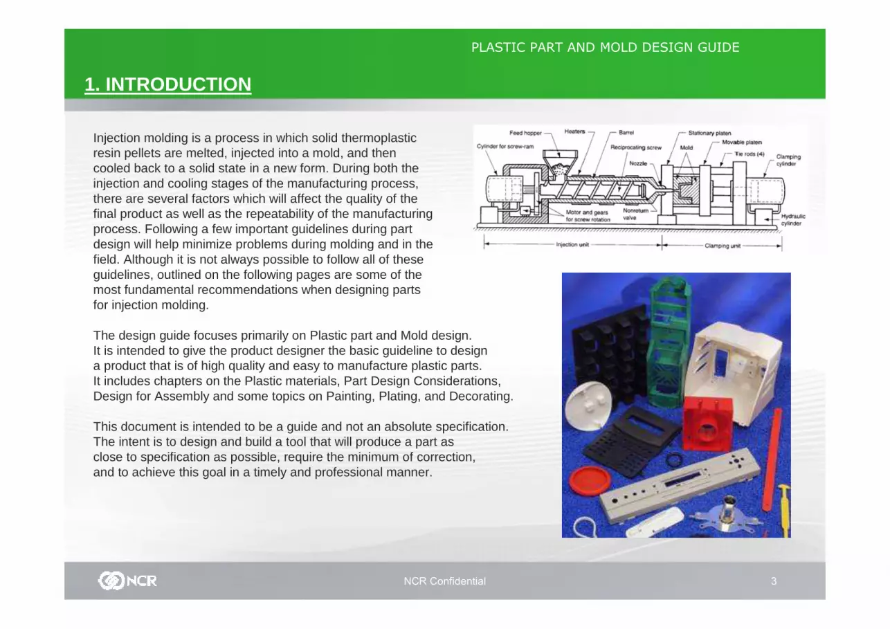
Injection molding is a process in which solid thermoplastic resin pellets are melted, injected into a mold, and then cooled back to a solid state in a new form. During both the injection and cooling stages of the manufacturing process, there are several factors which will affect the quality of the final product as well as the repeatability of the manufacturing process. Following a few important guidelines during part design will help minimize problems during molding and in the field. Although it is not always possible to follow all of theseguidelines, outlined on the following pages are some of the most fundamental recommendations when designing parts for injection molding.
The design guide focuses primarily on Plastic part and Mold design.It is intended to give the product designer the basic guideline to design a product that is of high quality and easy to manufacture plastic parts.It includes chapters on the Plastic materials, Part Design Considerations, Design for Assembly and some topics on Painting, Plating, and Decorating.
This document is intended to be a guide and not an absolute specification. The intent is to design and build a tool that will produce a part as close to specification as possible, require the minimum of correction, and to achieve this goal in a timely and professional manner.
NCR Confidential 4
PLASTIC PART AND MOLD DESIGN GUIDE
2. DESIGN PROCESS
When designing and developing parts, focus on defining and maximizing part function and appearance, specifying actual part requirements, evaluating process options, selecting an appropriate material, reducingmanufacturing costs, and conducting prototype testing. For the reasons stated above, these efforts shouldproceed simultaneously. The design process can be simplified by following a three stage approach where material, design and fabrication decisions are made in parallel. The following guidelines are reminders of good design practice aimed at producing quality injection molded parts.
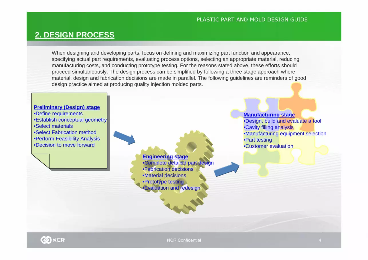
Preliminary (Design) stage•Define requirements•Establish conceptual geometry•Select materials•Select Fabrication method•Perform Feasibility Analysis•Decision to move forward
Engineering stage•Complete detailed part design•Fabrication decisions•Material decisions•Prototype testing•Evaluation and redesign
Manufacturing stage•Design, build and evaluate a tool•Cavity filling analysis•Manufacturing equipment selection•Part testing•Customer evaluation

NCR Confidential 5
PLASTIC PART AND MOLD DESIGN GUIDE
3. PLASTIC MATERIALS
3.1 CLASSIFICATION OF PLASTIC MATERIALS PLASTICS are man-made materials and it is any of a wide range of synthetic or semi-synthetic organic solids that are moldable. They are made up of long chains of large molecules. Each molecule consists of many units of organic chemicals, thus called a polymer (many units), or macromolecules. At room temperature, the material is solid and rigid, and it canwithstand significant structural load. Some of the materials retain rigidity at relatively high temperatures and can replace metallic components in such high temperature environments asautomobile underhood applications. These plastics are classifiedas Thermoplastic and Thermoset.
THERMOPLASTIC, also known as a thermosofteningplastic ,is a polymer that becomes pliable or moldable above a specific temperature, and returns to a solid state upon cooling.Most thermoplastics have a high molecular weight, whose chains associate through intermolecular forces; this property allows thermoplastics to be remolded because the intermolecular interactions spontaneously reform upon cooling.
THERMOSET materials are usually liquid or malleable prior to curing and designed to be molded into their final form, or used as adhesives. Others are solids like that of the molding compound used in semiconductors and integrated circuits (IC). Once hardened a thermoset resin cannot be reheated and melted back to a liquid form.
NCR Confidential 6
PLASTIC PART AND MOLD DESIGN GUIDE
3. PLASTIC MATERIALS
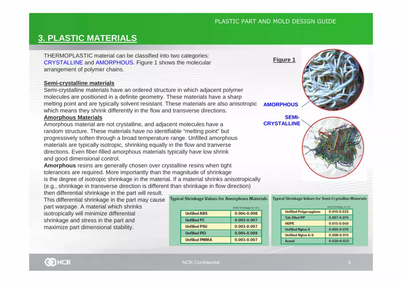
THERMOPLASTIC material can be classified into two categories: CRYSTALLINE and AMORPHOUS. Figure 1 shows the moleculararrangement of polymer chains.
Semi-crystalline materialsSemi-crystalline materials have an ordered structure in which adjacent polymer molecules are positioned in a definite geometry. These materials have a sharp melting point and are typically solvent resistant. These materials are also anisotropic which means they shrink differently in the flow and transverse directions.Amorphous MaterialsAmorphous material are not crystalline, and adjacent molecules have a random structure. These materials have no identifiable “melting point” but progressively soften through a broad temperature range. Unfilled amorphousmaterials are typically isotropic, shrinking equally in the flow and tranversedirections. Even fiber-filled amorphous materials typically have low shrink and good dimensional control.Amorphous resins are generally chosen over crystalline resins when tight tolerances are required. More importantly than the magnitude of shrinkage is the degree of isotropic shrinkage in the material. If a material shrinks anisotropically(e.g., shrinkage in transverse direction is different than shrinkage in flow direction) then differential shrinkage in the part will result. This differential shrinkage in the part may cause part warpage. A material which shrinks isotropically will minimize differential shrinkage and stress in the part and maximize part dimensional stability.
AMORPHOUS
SEMI-CRYSTALLINE
Figure 1
NCR Confidential 7
PLASTIC PART AND MOLD DESIGN GUIDE
3. PLASTIC MATERIALS
3.2 DEFINING MATERIAL REQUIREMENTS
Thoroughly ascertain and evaluate your part and material requirements, which will influence both part design and material selection. When evaluating these requirements, consider more than just the intended, end-use conditions and loads: Plastic parts are oftensubjected to harsher conditions during manufacturing and shipping than in actual use.
Mechanical LoadingCarefully evaluate all types of mechanical loading includingshort-term static loads, impacts, and vibrational or cyclic loads that could lead to fatigue. Ascertain long-term loads that could cause creep or stress relaxation. Clearly identify impact requirements.
TemperatureMany material properties in plastics -impact strength, modulus, tensile strength, and creep resistance to name a few —vary with temperature. Consider the full range of end-usetemperatures, as well as temperatures to which the part will be exposed during manufacturing, finishing and shipping. Remember that impact resistance generally diminishes at lower temperatures.
Chemical ExposurePlastic parts encounter a wide variety of chemicals both during manufacturing and in the end-useenvironment, including mold releases, cutting oils, de-greasers, lubricants, cleaning solvents, printing dyes, paints, adhesives, cooking greases, and automotive fluids. Make sure that these chemicals are compatible with your selected material and final part.
Electrical PerformanceNote required electrical property values and nature of electrical loading. For reference, list materials that areknown to have sufficient electrical performance in your application. Determine if your part requires EMIshielding or UL testing.
RadiationA variety of artificial sources — such as fluorescent lights, high-intensity discharge lamps, and gammasterilization units — emit radiation that can yellow and/or degrade many plastics. If your part will be exposed to a radiation source, consider painting it,or specifying a UV-stabilized resin.
NCR Confidential 8
PLASTIC PART AND MOLD DESIGN GUIDE
3. PLASTIC MATERIALS
3.2 DEFINING MATERIAL REQUIREMENTS
Weather ResistanceTemperature, moisture, and UV sun exposure affect p lastic parts’ properties and appearance. The end-use of a p roduct determines the type of weather resistance required. For instance, external automotive parts such as mirror housings must withstand continuous outdoor exposure and perf orm in the full range of weather conditions. Additionally, hea t gain from sun on dark surfaces may raise the upper temperature re quirementconsiderably higher than maximum expected temperatu res. Conversely, your requirements may be less severe if your part isexposed to weather elements only occasionally. For example, outdoor Christmas decorations and other seasonal pr oducts may only have to satisfy the requirements for their spe cific, limitedexposure.
AppearanceAesthetic requirements can entail many material and part-design issues. For example, a need for transparency greatl y reduces the number of potential plastics, especially if the part needs high clarity. Color may also play an important role. Pla stics must often match the color of other materials used in parts of an assembly.Some applications require the plastic part to weath er at the same rate as other materials in an assembly.
In resins, custom colors generally cost more than s tandard colors, particularly for small-order quantities. Fo r certaincolors and effects, some parts may need to be paint ed or decorated in the mold. Depending upon the applicati on,parts with metallic finishes may require painting, in-mold decorating or vacuum metallization. Surface finishe srange from high-gloss to heavy-matte. Photoetching t he mold steel can impart special surface textures for parts.Styling concerns may dictate the product shape, loo k, and feel, especially if the product is part of a compon entsystem or existing product family. Note all cosmeti c and non-cosmetic surfaces. Among other things, these ar eas may influence gate, runner, and ejector-pin positio ning.Many part designs must include markings or designs such as logos,warnings, instructions, and control labels .
In conclusion, when determining the right requireme ntsfor a certain material to be used, always consult t he supplier for the complete material specifications a ndit’s characteristics for a certain application. Mol d manufacturers should also be consulted for the compatibility of a certain material with regards to theactual manufacturing of toolings for use in injectio nprocess.
NCR Confidential 9
PLASTIC PART AND MOLD DESIGN GUIDE
3. PLASTIC MATERIALS
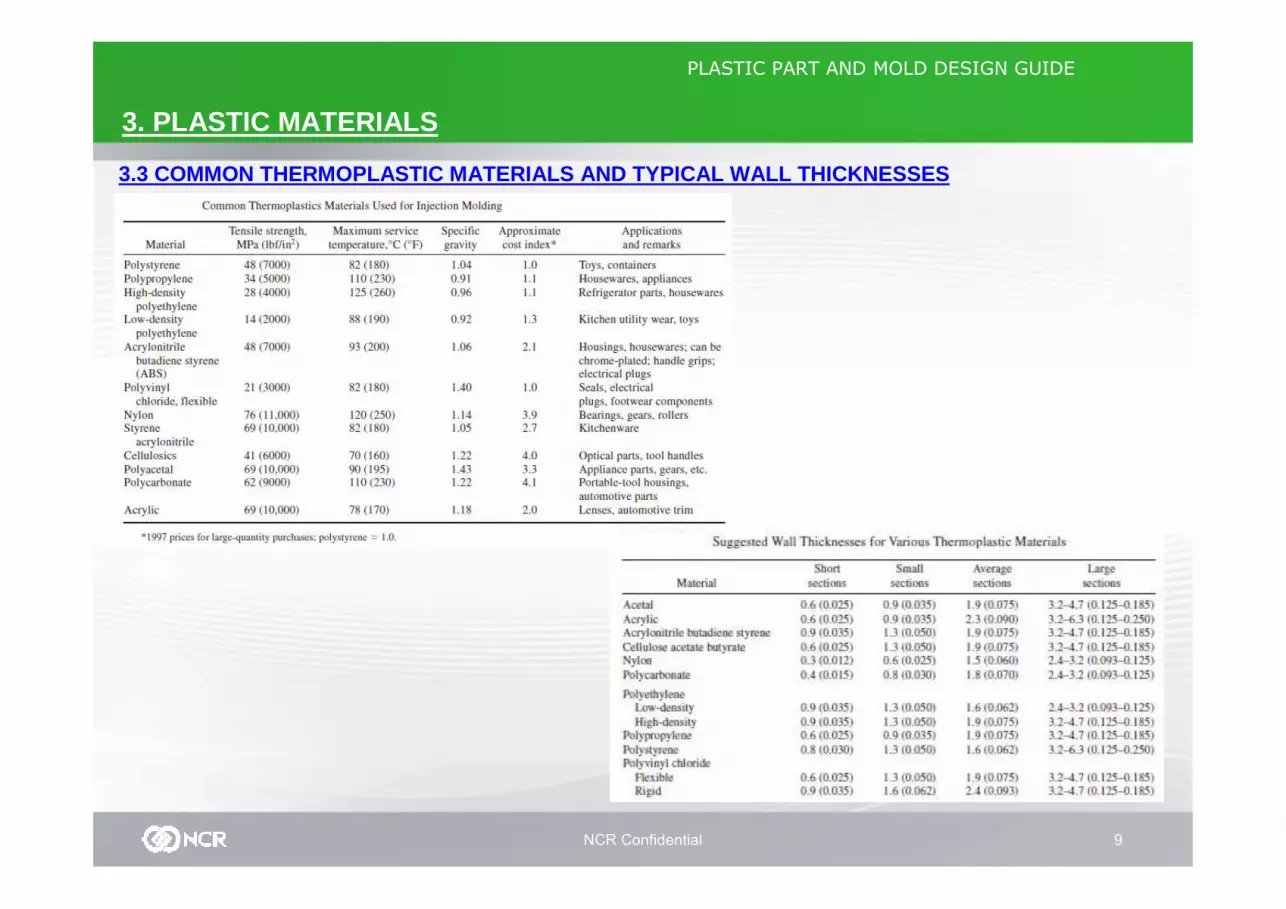
3.3 COMMON THERMOPLASTIC MATERIALS AND TYPICAL WALL THICKNESSES

NCR Confidential 10
PLASTIC PART AND MOLD DESIGN GUIDE
4. PART DESIGN GUIDELINES
4.1 Parting Lines
Parting line consideration depends upon shape and thefunction of the part. If a shaft diameter is used as a bearingsurface and is going to be injection molded, it cannottolerate a conventional parting line. In this situation,incorporating small flats on the shaft at the parting line willavoid mismatch and minimal flash conditions (see Fig. 4.1a)
FIGURE 4.1a
FIGURE 4.1b
FIGURE 4.1c
The parting line depends on the shape of the part. (Figure4.1b) illustrates an irregular parting line. Whena parting line involves two mating halves with closetolerances, the mold mating steel parts should beinterlocked for good positioning or take in an allowance forpossible mismatches. The allowance should be in the0.005 in to 0.010 in range relative to the finished dimension.
Keep features in the parting plane to simplify the part.When a stepped parting line is required, allow 7degreesfor shut-off. Minimum shut-off angle is 5degrees. See(Figure 4.1c)
NCR Confidential 11
PLASTIC PART AND MOLD DESIGN GUIDE
4. PART DESIGN GUIDELINES
4.2 Wall Thickness
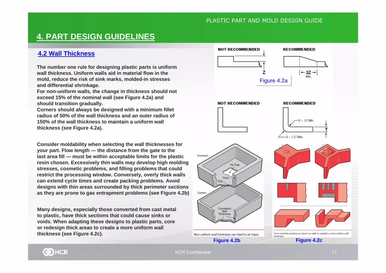
The number one rule for designing plastic parts is uniformwall thickness. Uniform walls aid in material flow in themold, reduce the risk of sink marks, molded-in stre ssesand differential shrinkage.For non-uniform walls, the change in thickness shou ld notexceed 15% of the nominal wall (see Figure 4.2a) an dshould transition gradually.Corners should always be designed with a minimum fi lletradius of 50% of the wall thickness and an outer ra dius of150% of the wall thickness to maintain a uniform wa llthickness (see Figure 4.2a).
Figure 4.2a
Many designs, especially those converted from cast metal to plastic, have thick sections that could cause si nks or voids. When adapting these designs to plastic parts , core or redesign thick areas to create a more uniform wa llthickness (see Figure 4.2c).
Consider moldability when selecting the wall thickne sses for your part. Flow length — the distance from the gate to the last area fill — must be within acceptable limits fo r the plastic resin chosen. Excessively thin walls may develop hi gh molding stresses, cosmetic problems, and filling problems t hat could restrict the processing window. Conversely, overly thick walls can extend cycle times and create packing problems. Avoid designs with thin areas surrounded by thick perimet er sections as they are prone to gas entrapment problems (see F igure 4.2b)
Figure 4.2b Figure 4.2c
NCR Confidential 12
PLASTIC PART AND MOLD DESIGN GUIDE
4. PART DESIGN GUIDELINES
4.3 Draft Angle
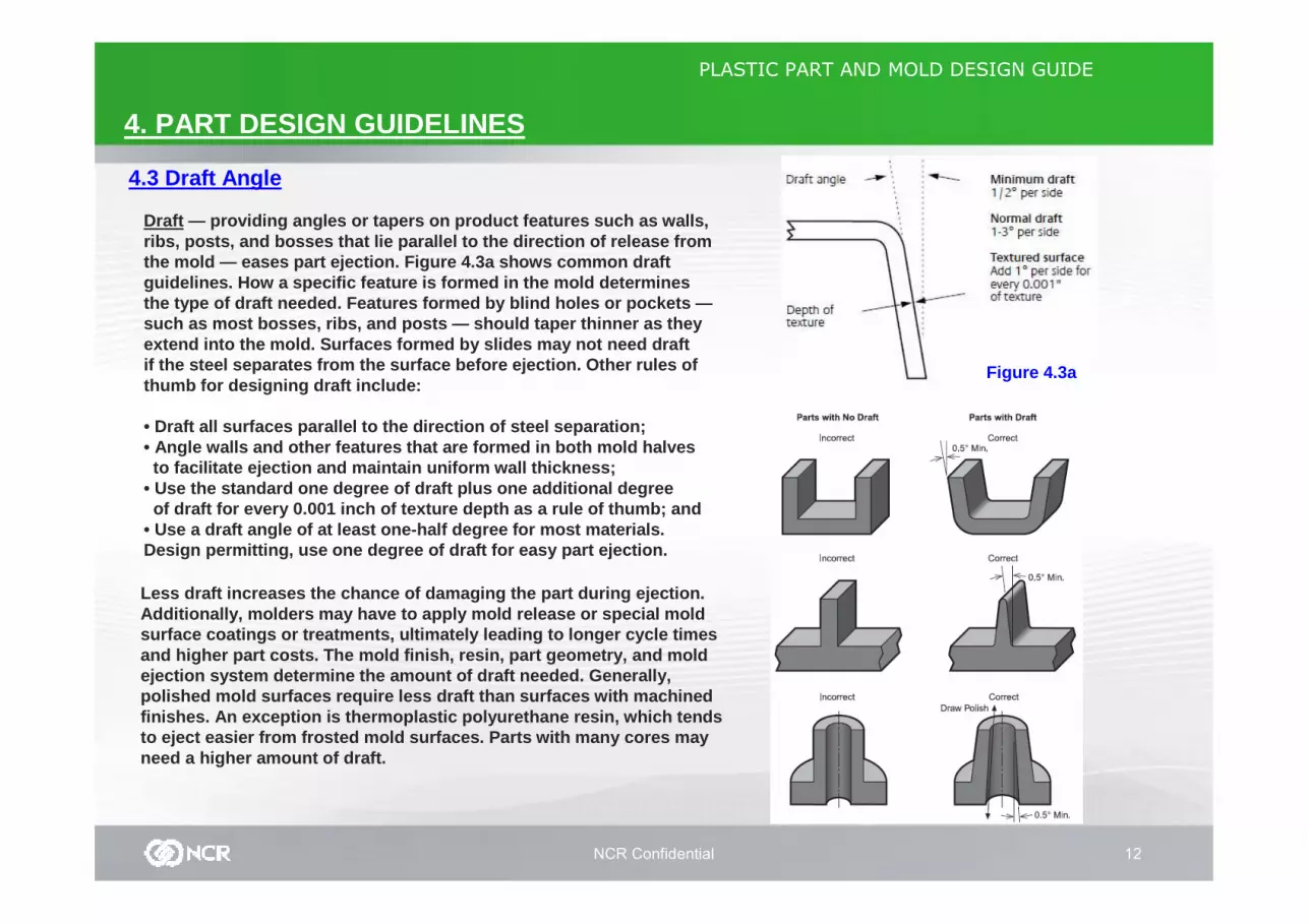
Draft — providing angles or tapers on product features suc h as walls, ribs, posts, and bosses that lie parallel to the di rection of release from the mold — eases part ejection. Figure 4.3a shows co mmon draft guidelines. How a specific feature is formed in the mold determines the type of draft needed. Features formed by blind holes or pockets —such as most bosses, ribs, and posts — should taper thinner as they extend into the mold. Surfaces formed by slides may not need draftif the steel separates from the surface before ejec tion. Other rules of thumb for designing draft include:
• Draft all surfaces parallel to the direction of st eel separation;• Angle walls and other features that are formed in both mold halvesto facilitate ejection and maintain uniform wall th ickness;
• Use the standard one degree of draft plus one addi tional degreeof draft for every 0.001 inch of texture depth as a rule of thumb; and
• Use a draft angle of at least one-half degree for most materials.Design permitting, use one degree of draft for easy part ejection.
Figure 4.3a
Less draft increases the chance of damaging the par t during ejection.Additionally, molders may have to apply mold releas e or special moldsurface coatings or treatments, ultimately leading to longer cycle timesand higher part costs. The mold finish, resin, part geometry, and mold ejection system determine the amount of draft neede d. Generally,polished mold surfaces require less draft than surf aces with machinedfinishes. An exception is thermoplastic polyurethan e resin, which tends to eject easier from frosted mold surfaces. Parts w ith many cores may need a higher amount of draft.

NCR Confidential 13
PLASTIC PART AND MOLD DESIGN GUIDE
4. PART DESIGN GUIDELINES
4.4 RibsRibs provide a means to economically augment stiffn ess and strength in molded parts without increasing ove rallwall thickness. Other uses for ribs include:• Locating and captivating components of an assembly ;• Providing alignment in mating parts; and• Acting as stops or guides for mechanisms.
Ribs usually project from the main wall in the mold-opening direction and are formed in blind holes in the mold steel. To facilitate part ejectio n from the mold, ribs generally require at leastone-half degree of draft per side (see figure 4.3a) . More than one degree of draft per side can lead to excessive rib thickness reduction and fillingproblems in tall ribs.
(Figure 4.3a)
Generally, taller ribs provide greater support. To avoid mold filling, venting, and ejection problems, standard rules of thumb limit rib height toapproximately three times the rib-base thickness. Because of the required draft for ejection, the top s of tall ribs may become too thin to fill easily. Ad ditionally, very tall ribs are prone to buckling under load. If you encounter one of these conditions, consider designi ng two or more shorter, thinner ribs to provide the sa me support with improved moldability (see figure 4.3b).Maintain enough space between ribs for adequate mol d cooling: for short ribs allow at least two times th e wallthickness.
(Figure 4.3b)

NCR Confidential 14
PLASTIC PART AND MOLD DESIGN GUIDE
4. PART DESIGN GUIDELINES
4.5 Bosses
Bosses are used in many part designs as points for attachm ent and assembly. The most common variety consists of c ylindrical projections with holes designed to receive screws, threadedinserts, or other types of fastening hardware. As a rule of thumb, the outside diameter of bosses should remain within 2.0 to 2.4 times the outside diameter of the screw or insert. (Figure 4.4a)
RECESS
TYPICAL BOSS DESIGNFigure 4.4a
screws or threadedinserts nominal diameter
To reduce stress concentration and potential breaka ge, bosses should have a blended radius, rather than a sharp e dge, at theirbase. Larger radii minimize stress concentration bu t increase the chance of sink or voids. Radii at the base shou ld be 25 to 50% of the nominal wall thickness. (Figure 4.4a)
radius
To limit sink on the surface opposite the boss, keep the ratio of boss-wall thickness to nominal-wall thickness the same as the guidelines for ribthickness (see table 4.4a).
Figure 4.4b
Table 4.4aRib or Boss thickness as aPercentage of Wall thickness
If the boss-wall thickness must exceed the recommended ratio, consider adding a recess around the base of the boss to reduce theseverity of sink.(as shown in figure 4.4b)
NCR Confidential 15
PLASTIC PART AND MOLD DESIGN GUIDE
4. PART DESIGN GUIDELINES
4.5 Bosses
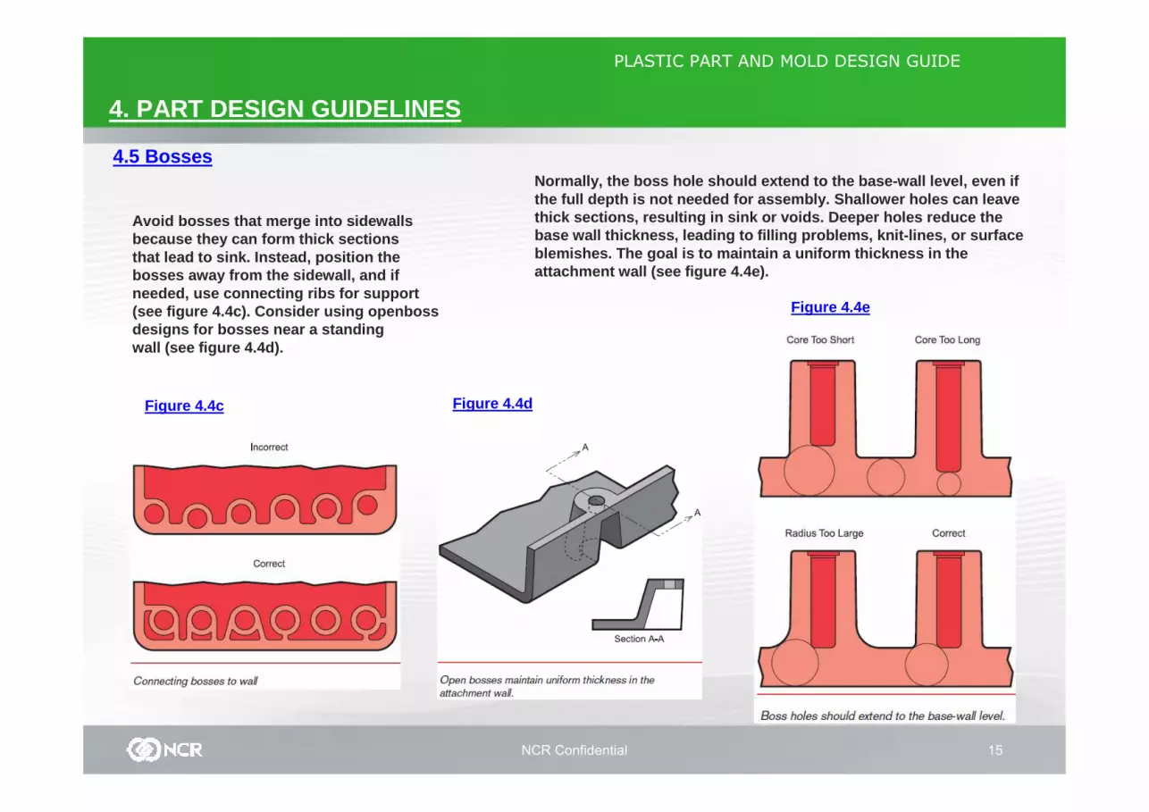
Avoid bosses that merge into sidewallsbecause they can form thick sectionsthat lead to sink. Instead, position thebosses away from the sidewall, and ifneeded, use connecting ribs for support(see figure 4.4c). Consider using openbossdesigns for bosses near a standingwall (see figure 4.4d).
Figure 4.4c Figure 4.4d
Figure 4.4e
Normally, the boss hole should extend to the base-w all level, even if the full depth is not needed for assembly. Shallowe r holes can leave thick sections, resulting in sink or voids. Deeper holes reduce the base wall thickness, leading to filling problems, k nit-lines, or surface blemishes. The goal is to maintain a uniform thickn ess in the attachment wall (see figure 4.4e).

NCR Confidential 16
PLASTIC PART AND MOLD DESIGN GUIDE
4. PART DESIGN GUIDELINES
4.5 Bosses Figure 4.4f
Because of the required draft, tallbosses — those greater than five timestheir outside diameter — can create afilling problem at their top or a thicksection at their base. Additionally, thecores in tall bosses can be difficult tocool and support. Consider coring a tallboss from two sides or extending tallgussets to the standoff height ratherthan the whole boss (see figure 4.4f).
Other alternatives include splittinga long boss into two shorter matingbosses (see figure 4.4g) or repositioningthe boss to a location where it can beshorter. Figure 4.4g
NCR Confidential 17
PLASTIC PART AND MOLD DESIGN GUIDE
4. PART DESIGN GUIDELINES
4.6 Gussets
Figure 4.6a
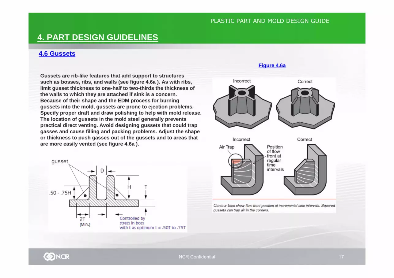
Gussets are rib-like features that add support to s tructures such as bosses, ribs, and walls (see figure 4.6a ). As with ribs, limit gusset thickness to one-half to two-thirds th e thickness ofthe walls to which they are attached if sink is a c oncern. Because of their shape and the EDM process for burn inggussets into the mold, gussets are prone to ejectio n problems. Specify proper draft and draw polishing to help wit h mold release.The location of gussets in the mold steel generally prevents practical direct venting. Avoid designing gussets t hat could trap gasses and cause filling and packing problems. Adju st the shapeor thickness to push gasses out of the gussets and to areas thatare more easily vented (see figure 4.6a ).
gusset
NCR Confidential 18
PLASTIC PART AND MOLD DESIGN GUIDE
4. PART DESIGN GUIDELINES
4.7 Sharp Corners
Figure 4.7a
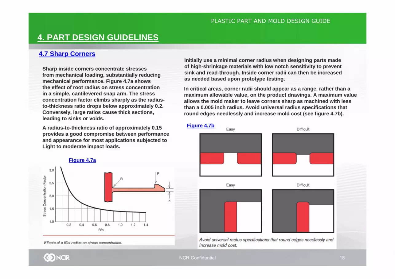
Sharp inside corners concentrate stresses from mechanical loading, substantially reducing mechanical performance. Figure 4.7a showsthe effect of root radius on stress concentration in a simple, cantilevered snap arm. The stress concentration factor climbs sharply as the radius-to-thickness ratio drops below approximately 0.2. Conversely, large ratios cause thick sections, leading to sinks or voids.
A radius-to-thickness ratio of approximately 0.15 provides a good compromise between performance and appearance for most applications subjected to Light to moderate impact loads.
Initially use a minimal corner radius when designin g parts made of high-shrinkage materials with low notch sensitiv ity to prevent sink and read-through. Inside corner radii can then be increased as needed based upon prototype testing.
In critical areas, corner radii should appear as a range, rather than amaximum allowable value, on the product drawings. A maximum valueallows the mold maker to leave corners sharp as mac hined with less than a 0.005 inch radius. Avoid universal radius sp ecifications that round edges needlessly and increase mold cost (see figure 4.7b).
Figure 4.7b

NCR Confidential 19
PLASTIC PART AND MOLD DESIGN GUIDE
4. PART DESIGN GUIDELINES
4.8 Holes and Cores
During mold filling, the advancing plastic flow can exert very high side forces on tall cores forming deep or long holes. These forces can push or bend the cores out of posi tion, altering the molded part. Under severe conditions, this bend ing can fatigue the mold steel and break the core.
Generally, the depth-to-diameter ratio for blind ho les should not exceed 3:1. Ratios up to 5:1 are feasible if fillin g progresses symmetrically around the unsupported hole core or i f the coreis in an area of slow-moving flow. Consider alterna tive part designs that avoid the need for long delicate cores , such as thealternative boss designs in figures 4.4f and 4.4g p age 15.
If the core is supported on both ends, the guidelin es for length-to-diameter ratio double: typically 6:1 but up to 1 0:1 if the filling around the core is symmetrical. The level of suppor t on the coreends determines the maximum suggested ratio (see fi gure 4.8a).Properly interlocked cores typically resist deflect ion better than cores that simply kiss off. Single cores for throug h-holes can interlock into the opposite mold half for support.
Mismatch can reduce the size of the opening in hole s formed by mating cores. Design permitting, make one core slig htly larger (see figure 4.8b). Even with some mismatch, the req uired hole diameter can be maintained. Tight tolerance holes t hat cannot bestepped may require interlocking features on the co res to correct for minor misalignment. These features add to mold construction and maintenance costs. On short through-holes that can be molded with one core, round the edge on just one si de of hole toeliminate a mating core and avoid mismatch (see fig ure 4.8c).
Figure 4.8a Figure 4.8bFigure 4.8c
NCR Confidential 20
PLASTIC PART AND MOLD DESIGN GUIDE
4. PART DESIGN GUIDELINES
4.9 Undercuts Figure 4.9a
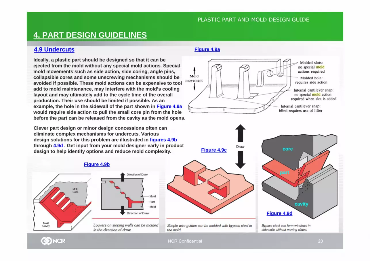
Ideally, a plastic part should be designed so that it can be ejected from the mold without any special mold acti ons. Special mold movements such as side action, side coring, an gle pins, collapsible cores and some unscrewing mechanisms sh ould be avoided if possible. These mold actions can be expe nsive to tool, add to mold maintenance, may interfere with the mol d’s cooling layout and may ultimately add to the cycle time of the overall production. Their use should be limited if possible . As an example, the hole in the sidewall of the part shown in Figure 4.9awould require side action to pull the small core pi n from the hole before the part can be released from the cavity as the mold opens.
Clever part design or minor design concessions ofte n can eliminate complex mechanisms for undercuts. Various design solutions for this problem are illustrated i n figures 4.9bthrough 4.9d . Get input from your mold designer early in produc t design to help identify options and reduce mold com plexity.
Figure 4.9b
Figure 4.9c
Figure 4.9d
cavity
core
part
NCR Confidential 21
PLASTIC PART AND MOLD DESIGN GUIDE
4. PART DESIGN GUIDELINES
4.9 Undercuts Figure 4.9e
STRIPPERPLATE
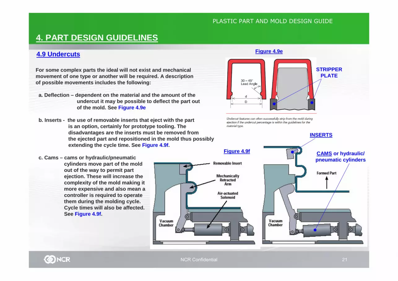
For some complex parts the ideal will not exist and mechanicalmovement of one type or another will be required. A descriptionof possible movements includes the following:
a. Deflection – dependent on the material and the am ount of theundercut it may be possible to deflect the part outof the mold. See Figure 4.9e
b. Inserts - the use of removable inserts that eject with the partis an option, certainly for prototype tooling. The disadvantages are the inserts must be removed fromthe ejected part and repositioned in the mold thus possiblyextending the cycle time. See Figure 4.9f .
c. Cams – cams or hydraulic/pneumatic cylinders move part of the mold out of the way to permit part ejection. These will increase the complexity of the mold making it more expensive and also mean a controller is required to operate them during the molding cycle. Cycle times will also be affected.See Figure 4.9f .
Figure 4.9f CAMS or hydraulic/pneumatic cylinders
INSERTS
NCR Confidential 22
PLASTIC PART AND MOLD DESIGN GUIDE
4. PART DESIGN GUIDELINES
4.9 UndercutsFor some complex parts the ideal will not exist and mechanical movement of one type or another will be required. A description of possible movemen ts includes the following:
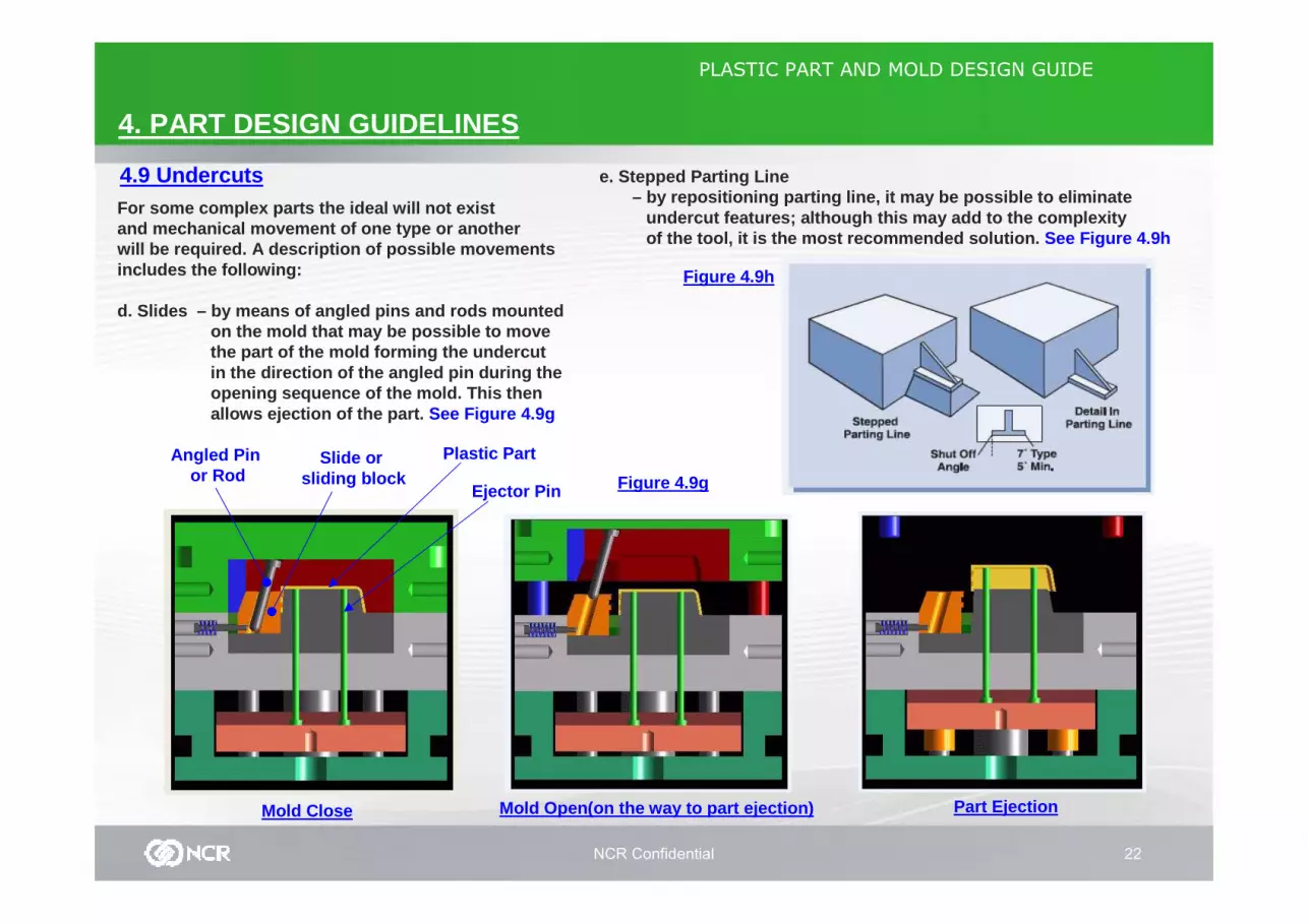
d. Slides – by means of angled pins and rods mounte d on the mold that may be possible to move the part of the mold forming the undercut in the direction of the angled pin during the opening sequence of the mold. This then allows ejection of the part. See Figure 4.9g
Mold Close Mold Open(on the way to part ejection)
Slide or sliding block
Angled Pin or Rod Figure 4.9g
Plastic Part
e. Stepped Parting Line – by repositioning parting line, it may be possible to eliminate
undercut features; although this may add to the com plexity of the tool, it is the most recommended solution. See Figure 4.9h
Part Ejection
Ejector Pin
Figure 4.9h
NCR Confidential 23
PLASTIC PART AND MOLD DESIGN GUIDE
4. PART DESIGN GUIDELINES
4.9 Undercuts
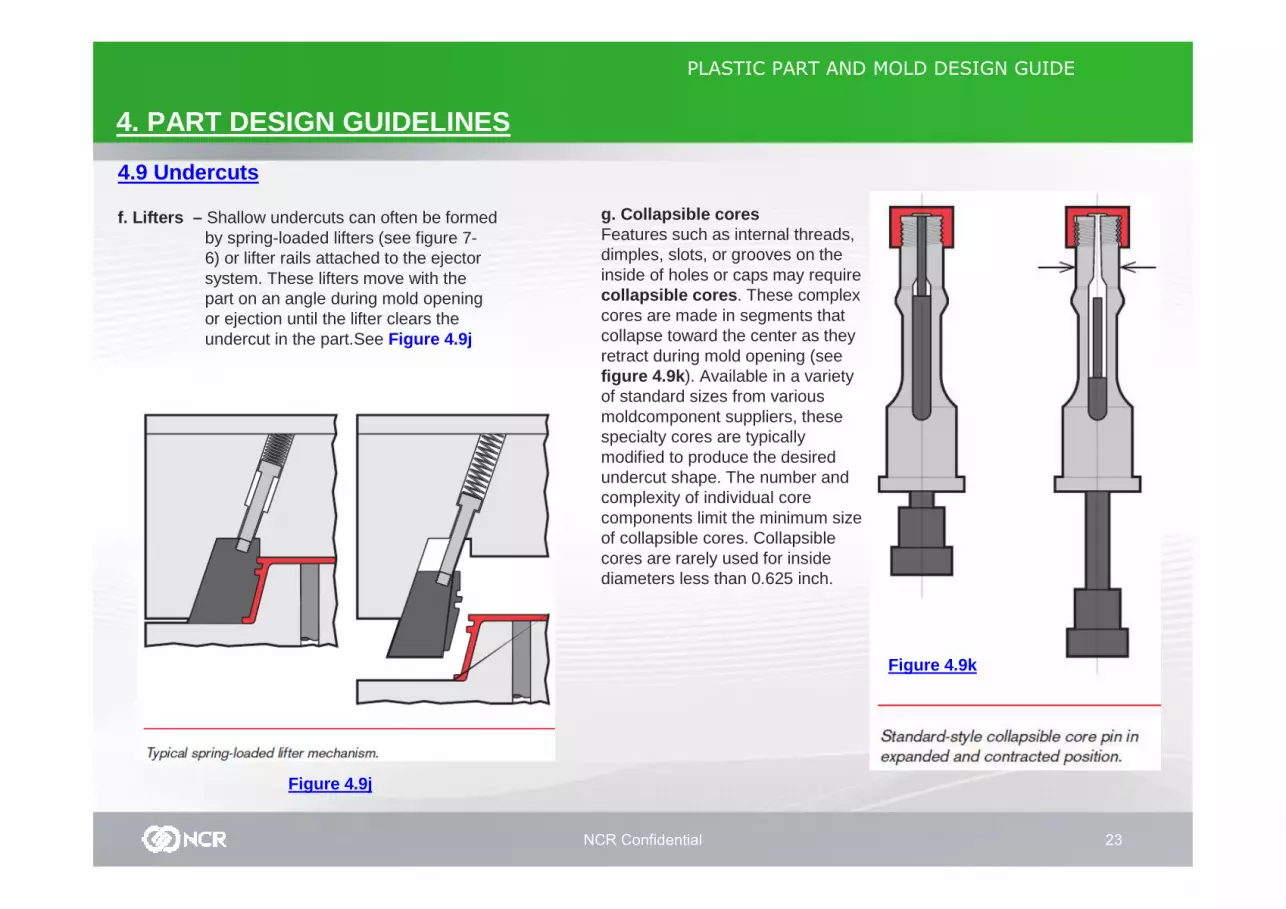
f. Lifters – Shallow undercuts can often be formedby spring-loaded lifters (see figure 7-6) or lifter rails attached to the ejectorsystem. These lifters move with thepart on an angle during mold openingor ejection until the lifter clears theundercut in the part.See Figure 4.9j
Figure 4.9j
Part Ejection
g. Collapsible coresFeatures such as internal threads,dimples, slots, or grooves on the inside of holes or caps may require collapsible cores . These complex cores are made in segments that collapse toward the center as they retract during mold opening (see figure 4.9k ). Available in a varietyof standard sizes from various moldcomponent suppliers, these specialty cores are typically modified to produce the desired undercut shape. The number and complexity of individual corecomponents limit the minimum size of collapsible cores. Collapsible cores are rarely used for inside diameters less than 0.625 inch.
Figure 4.9k
NCR Confidential 24
PLASTIC PART AND MOLD DESIGN GUIDE
4. PART DESIGN GUIDELINES
4.10 Molded-in Threads
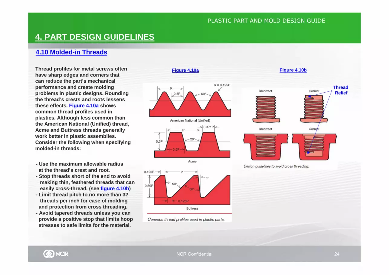
Thread profiles for metal screws oftenhave sharp edges and corners thatcan reduce the part’s mechanicalperformance and create moldingproblems in plastic designs. Roundingthe thread’s crests and roots lessensthese effects. Figure 4.10a showscommon thread profiles used inplastics. Although less common thanthe American National (Unified) thread,Acme and Buttress threads generallywork better in plastic assemblies.Consider the following when specifyingmolded-in threads:
- Use the maximum allowable radiusat the thread’s crest and root.
- Stop threads short of the end to avoid making thin, feathered threads that can easily cross-thread. (see figure 4.10b )
- Limit thread pitch to no more than 32 threads per inch for ease of molding and protection from cross threading.
- Avoid tapered threads unless you can provide a positive stop that limits hoop stresses to safe limits for the material.
Figure 4.10bFigure 4.10a
Thread Relief

NCR Confidential 25
PLASTIC PART AND MOLD DESIGN GUIDE
4. PART DESIGN GUIDELINES
4.10 Molded-in Threads Figure 4.10d
For best performance, use threadsdesigned specifically for plastics. Parts that do not have to mate with standard metal threads can have unique threads that meet the specific application and material requirements. The medical industry, for example, has developed special, plastic-thread designs for Luer-lock tubing connectors (see figure 2-37). Thread designs can also be simplified for ease of molding as shownin figure 2-38.
Tapered pipe threads, common in plumbing for fluid- tight connections, are slightly conical and tapered and can place excessiv e hoop stresses on the internal threads of a plastic part. When mating pla stic and metal tapered threads, design the external threads on the plastic component to avoid hoop stress in plastic or use straight threads and an “O” ring to produce the seal (see figure 4.10c ). Also, assure that any thread dopes or thread lockers are compatible with your selected plastic r esin. Polycarbonate resins, in particular, are susceptible to chemical attack from many of these compounds.
Figure 4.10c
Figure 4.10e
NCR Confidential 26
PLASTIC PART AND MOLD DESIGN GUIDE
4. PART DESIGN GUIDELINES
4.11 Lettering
Figure 4.11a
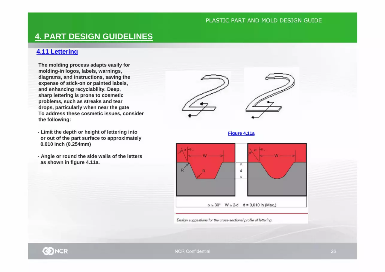
The molding process adapts easily formolding-in logos, labels, warnings,diagrams, and instructions, saving theexpense of stick-on or painted labels,and enhancing recyclability. Deep,sharp lettering is prone to cosmeticproblems, such as streaks and teardrops, particularly when near the gateTo address these cosmetic issues, consider the following:
- Limit the depth or height of lettering into or out of the part surface to approximately 0.010 inch (0.254mm)
- Angle or round the side walls of the letters as shown in figure 4.11a.
NCR Confidential 27
PLASTIC PART AND MOLD DESIGN GUIDE
5. THERMOPLASTIC PROCESSING METHODS
5.1 Injection Molding
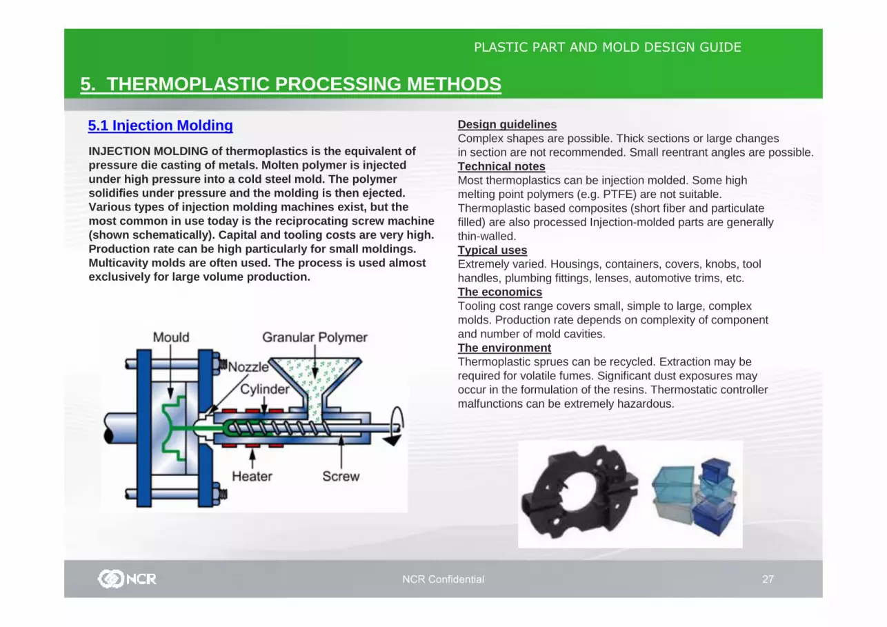
INJECTION MOLDING of thermoplastics is the equivale nt of pressure die casting of metals. Molten polymer is i njected under high pressure into a cold steel mold. The pol ymer solidifies under pressure and the molding is then e jected. Various types of injection molding machines exist, but the most common in use today is the reciprocating screw machine (shown schematically). Capital and tooling costs ar e very high.Production rate can be high particularly for small moldings. Multicavity molds are often used. The process is use d almost exclusively for large volume production.
Design guidelinesComplex shapes are possible. Thick sections or large changes in section are not recommended. Small reentrant angles are possible.Technical notesMost thermoplastics can be injection molded. Some high melting point polymers (e.g. PTFE) are not suitable. Thermoplastic based composites (short fiber and particulate filled) are also processed Injection-molded parts are generally thin-walled.Typical usesExtremely varied. Housings, containers, covers, knobs, tool handles, plumbing fittings, lenses, automotive trims, etc.The economicsTooling cost range covers small, simple to large, complex molds. Production rate depends on complexity of component and number of mold cavities.The environmentThermoplastic sprues can be recycled. Extraction may be required for volatile fumes. Significant dust exposures may occur in the formulation of the resins. Thermostatic controller malfunctions can be extremely hazardous.
NCR Confidential 28
PLASTIC PART AND MOLD DESIGN GUIDE
5. THERMOPLASTIC PROCESSING METHODS
5.2 Polymer Extrusion
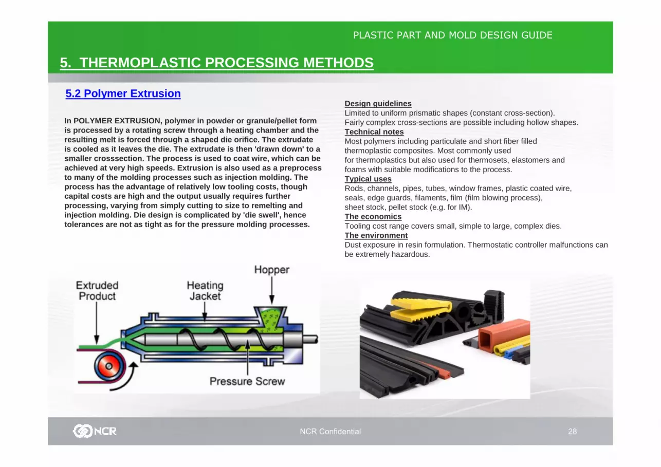
In POLYMER EXTRUSION, polymer in powder or granule/ pellet form is processed by a rotating screw through a heating chamber and the resulting melt is forced through a shaped die orifi ce. The extrudateis cooled as it leaves the die. The extrudate is the n 'drawn down' to a smaller crosssection. The process is used to coat w ire, which can be achieved at very high speeds. Extrusion is also use d as a preprocess to many of the molding processes such as injection molding. The process has the advantage of relatively low tooling costs, though capital costs are high and the output usually requi res further processing, varying from simply cutting to size to remelting and injection molding. Die design is complicated by 'di e swell', hence tolerances are not as tight as for the pressure mol ding processes.
Design guidelinesLimited to uniform prismatic shapes (constant cross-section). Fairly complex cross-sections are possible including hollow shapes.Technical notesMost polymers including particulate and short fiber filled thermoplastic composites. Most commonly usedfor thermoplastics but also used for thermosets, elastomers and foams with suitable modifications to the process.Typical usesRods, channels, pipes, tubes, window frames, plastic coated wire, seals, edge guards, filaments, film (film blowing process), sheet stock, pellet stock (e.g. for IM).The economicsTooling cost range covers small, simple to large, complex dies.The environmentDust exposure in resin formulation. Thermostatic controller malfunctions can be extremely hazardous.
NCR Confidential 29
PLASTIC PART AND MOLD DESIGN GUIDE
5. THERMOPLASTIC PROCESSING METHODS
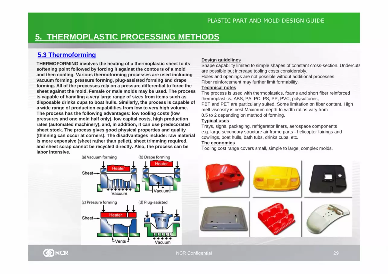
5.3 ThermoformingTHERMOFORMING involves the heating of a thermoplast ic sheet to its softening point followed by forcing it against the contours of a mold and then cooling. Various thermoforming processes a re used including vacuum forming, pressure forming, plug-assisted for ming and drape forming. All of the processes rely on a pressure di fferential to force the sheet against the mold. Female or male molds may be used. The process is capable of handling a very large range of sizes from items such as disposable drinks cups to boat hulls. Similarly, th e process is capable of a wide range of production capabilities from low to very high volume.The process has the following advantages: low tooli ng costs (lowpressures and one mold half only), low capital cost s, high production rates (automated machinery), and, in addition, it c an use predecoratedsheet stock. The process gives good physical proper ties and quality (thinning can occur at corners). The disadvantages include: raw material is more expensive (sheet rather than pellet), sheet trimming required,and sheet scrap cannot be recycled directly. Also, the process can be labor intensive.
Design guidelinesShape capability limited to simple shapes of constant cross-section. Undercuts are possible but increase tooling costs considerably. Holes and openings are not possible without additional processes. Fiber reinforcement may further limit formability.Technical notesThe process is used with thermoplastics, foams and short fiber reinforced thermoplastics. ABS, PA, PC, PS, PP, PVC, polysulfones, PBT and PET are particularly suited. Some limitation on fiber content. High melt viscosity is best Maximum depth-to-width ratios vary from 0.5 to 2 depending on method of forming.Typical usesTrays, signs, packaging, refrigerator liners, aerospace components e.g. large secondary structure air frame parts - helicopter fairings and cowlings, boat hulls, bath tubs, drinks cups, etc.The economicsTooling cost range covers small, simple to large, complex molds.

NCR Confidential 30
PLASTIC PART AND MOLD DESIGN GUIDE
5. THERMOPLASTIC PROCESSING METHODS
5.4 Extrusion Blow Molding
In EXTRUSION BLOW MOLDING, a tube (or parison) is e xtruded and clamped in a split mold. Air is then injected under pressure inside the parison, blowing the polymer against the mold w alls where it cools and freezes. The mold is opened and the part ejected. Surplus material at both ends of the part is then removed. The process uses thermoplastics of high melt viscosity and high mole cular weight.It is most widely used with PE (especially HDPE), P P and PVC.Other thermoplastics are also used. The process is capable of producing irregular shaped containers and blown han dles. Mold cost is lower than for injection blow molding.It is generally most competitive for larger contain ers (capacity > 0.5 L) and high batch sizes.
Design guidelinesUsed for thin-walled hollow or tubular articles with small openings (e.g. bottles). Irregular shapes are possible.Technical notesThermoplastics commonly used include: HDPE, LDPE, PP, ABS and uPVC. Limited level of reinforcement possible for composite materials (i.e. particulate and short fibers) The wall thickness should be as uniform as possible to ensure more rapid molding cycles and to avoiddistortion.Typical usesPrimarily bottles and containers - from small bottles to large (10000L) oil storage tanks. Useful for larger containers and irregular shapes e.g. detergent bottles, drums, tanks, toys (balls, baseball bats, etc.).The economicsTooling cost range covers small, simple to large, complex molds.The environmentWaste material is recyclable.
NCR Confidential 31
PLASTIC PART AND MOLD DESIGN GUIDE
5. THERMOPLASTIC PROCESSING METHODS
5.5 Injection Blow Molding
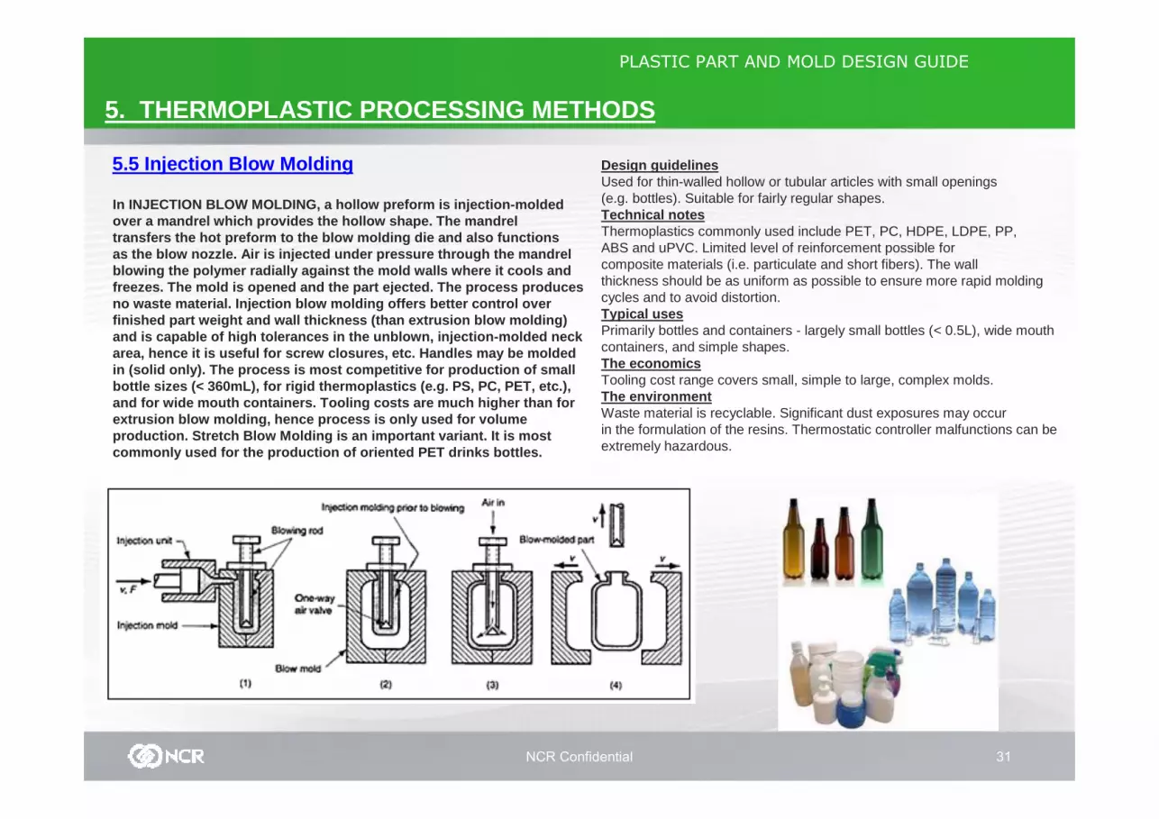
In INJECTION BLOW MOLDING, a hollow preform is injec tion-molded over a mandrel which provides the hollow shape. The mandrel transfers the hot preform to the blow molding die an d also functions as the blow nozzle. Air is injected under pressure through the mandrel blowing the polymer radially against the mold walls where it cools and freezes. The mold is opened and the part ejected. T he process produces no waste material. Injection blow molding offers be tter control over finished part weight and wall thickness (than extru sion blow molding) and is capable of high tolerances in the unblown, i njection-molded neck area, hence it is useful for screw closures, etc. H andles may be molded in (solid only). The process is most competitive fo r production of small bottle sizes (< 360mL), for rigid thermoplastics (e .g. PS, PC, PET, etc.), and for wide mouth containers. Tooling costs are mu ch higher than for extrusion blow molding, hence process is only used for volumeproduction. Stretch Blow Molding is an important va riant. It is most commonly used for the production of oriented PET dr inks bottles.
Design guidelinesUsed for thin-walled hollow or tubular articles with small openings (e.g. bottles). Suitable for fairly regular shapes.Technical notesThermoplastics commonly used include PET, PC, HDPE, LDPE, PP, ABS and uPVC. Limited level of reinforcement possible for composite materials (i.e. particulate and short fibers). The wall thickness should be as uniform as possible to ensure more rapid molding cycles and to avoid distortion.Typical usesPrimarily bottles and containers - largely small bottles (< 0.5L), wide mouth containers, and simple shapes.The economicsTooling cost range covers small, simple to large, complex molds.The environmentWaste material is recyclable. Significant dust exposures may occur in the formulation of the resins. Thermostatic controller malfunctions can be extremely hazardous.
NCR Confidential 32
PLASTIC PART AND MOLD DESIGN GUIDE
6. PAINTING, PLATING AND DECORATING
While some plastic parts require painting, plating, and/or decorating for aesthetic or functional conce rns, most do not for two reasons: first, the injectionmolding process accommodates adiversity of high-quality surface finishes and text ures;
second, thermoplastic resins can be produced in a rainbow of colors.
Some specific instances where painting or plating m ay be needed or required include: - protecting final assemblies from harsh chemicals o r UV degradation,
- shielding electronic devices from EMI/RFI radiatio n, - or adding graphics or labeling in contrasting colo rs.
6.1 Painting
Most plastics accept paint systems well, especially theamorphous resins. With special preparation of the s urfacefor better adhesion (cleaning is essential), even t he moredifficult plastics, i.e., PE, PP and Acetal, which have moreslippery surfaces and chemical resistance, can be p ainted.Nylon and PET are excellent resins for paint applic ations, especially where high-temperature curing is require d. Their ability to tolerate high temperatures for long peri ods of time without softening is a key advantage.
Some of the common reasons for painting thermoplast ics are:
- To enhance aesthetics and provide uniform color an d texture to assemblies made of different materials o r by different processes.
- They also offer colors or surface effects that res ins cannot such as certain metallic or stippled effects.
- Some perform a function such as being an electrica llyconductive paint for EMI/RFI shielding.
- Paints and coatings can also protect the plastic s ubstrate fromchemicals, abrasion, or environmental attack.
- Coatings can also prevent attack from cleaning sol vents,lubricants, and other substances encountered in-use or during manufacture.
- Commercial scratch resistant coatings commonly pro vide abrasion resistance for lenses.

NCR Confidential 33
PLASTIC PART AND MOLD DESIGN GUIDE
6. PAINTING, PLATING AND DECORATING
6.1 PaintingThe common types of paints used on plastics include polyurethane, acrylic, alkyd, epoxy, and vinyl.
* Polyurethane paints provide a flexible, durable f inish, curewithout heat, and are compatible with most plastics , includingmany chemically sensitive, amorphous plastics, such as ABS and polycarbonate blends.
* Epoxies typically produce hard, tough, glossy fin ishes.
* Vinyls tend to produce soft, rubbery finishes.
* Acrylic paints give brittle, scratch resistant fi nishes that resist most common oils.
Paint-Selection ConsiderationsSemi-crystalline plastics, such as nylons, tend to be chemicallyresistant to most solvent systems and often require special pre-treatments or primers. Acetal, polypropylene, and polyethylene, which have waxy surfaces, are chemically resistant to most solvent systems as well.Amorphous plastics, such as ABS, because they are less chemicallyresistant, achieve good adhesion with many more paint systems.Look for a system that is not too chemically aggressive: especially for polycarbonate blends. To achieve the optimum match of substrate and paint system, consult both your resin and paint suppliers before making your final selection. The cost of the paint is usually insignificant compared to the labor and overhead costs, and the cost of complying with environmental protection regulations. Be sure to consider the cost of the entire process when making your selection.
Other Design Considerations for Painting
*In all application methods, parts should be clean and free of surfacecontamination for good paint adhesion. When possibl e, design parts to release from the mold easily, so they can be eje cted without using external mold release sprays.
*Oils from hands can also contaminate the part surf ace. Considerdesigning designated handling areas or features to reduce contamination in critical painting areas. Part desi gn can have a direct impact on the ease and cost of painting.
*To achieve uniform coverage, avoid undercuts and d eep, narrow recesses, which may not coat completely. Sharp corn ers can bedifficult to coat sufficiently and may chip or wear through.
*Consider painting transparent parts on the back su rface(or second surface) to protect the paint from scrat ches and abrasion.
*Brittle coatings and paints can greatly reduce the impact performanceof painted plastic parts. Cracks in the paint or co ating act as stressconcentrators to initiate fracture in the plastic s ubstrate. Exercise extra care in the design and paint selection for pa inted parts subjected to impact loads. Flexible paint systems, such as tw opart urethanes, tend to perform better in impact applications.
NCR Confidential 34
PLASTIC PART AND MOLD DESIGN GUIDE
6. PAINTING, PLATING AND DECORATING
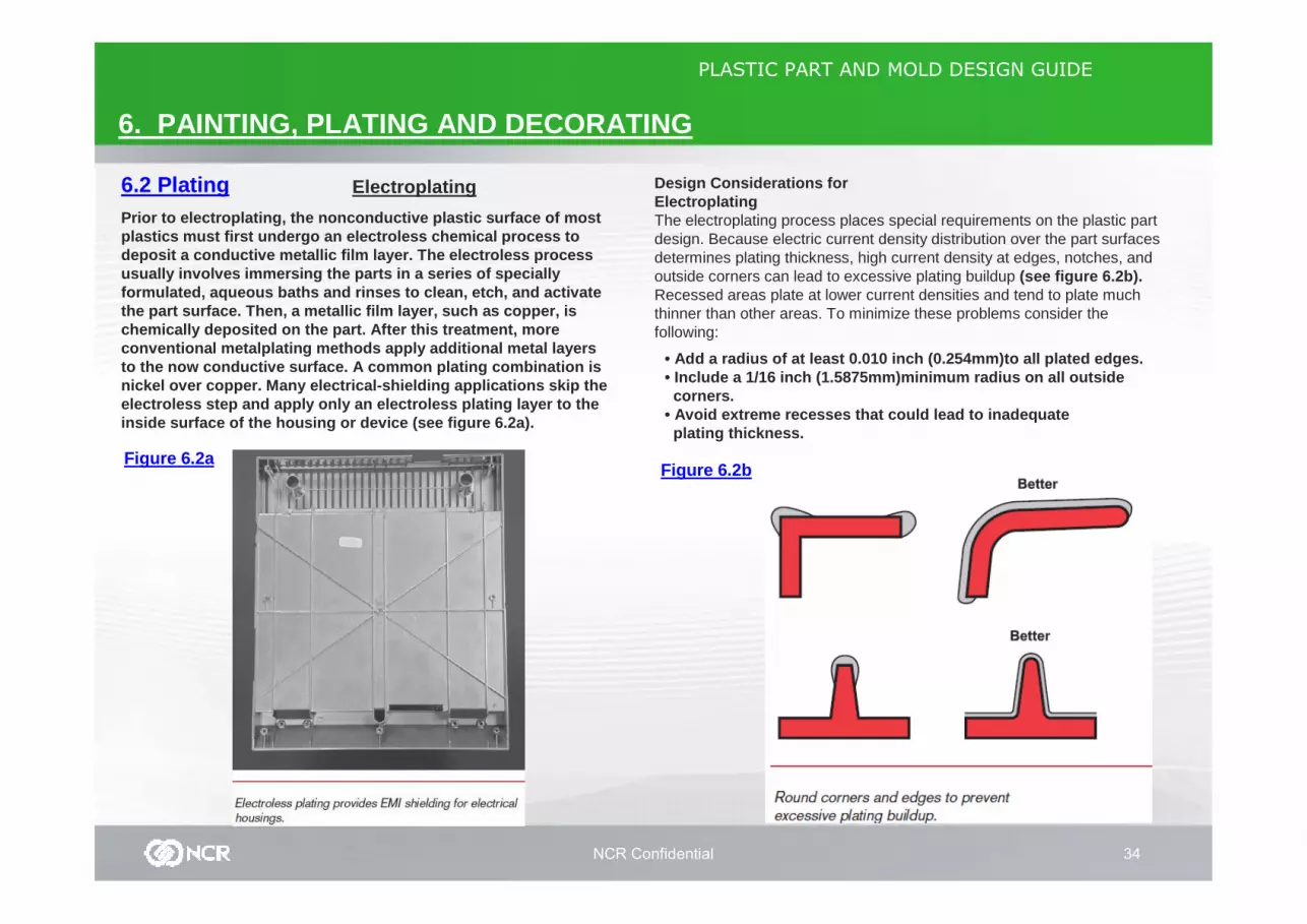
6.2 Plating Design Considerations forElectroplatingThe electroplating process places special requirements on the plastic part design. Because electric current density distribution over the part surfacesdetermines plating thickness, high current density at edges, notches, andoutside corners can lead to excessive plating buildup (see figure 6.2b).Recessed areas plate at lower current densities and tend to plate muchthinner than other areas. To minimize these problems consider the following:
Prior to electroplating, the nonconductive plastic surface of most plastics must first undergo an electroless chemical process to deposit a conductive metallic film layer. The elect roless process usually involves immersing the parts in a series of specially formulated, aqueous baths and rinses to clean, etch , and activate the part surface. Then, a metallic film layer, such as copper, is chemically deposited on the part. After this treatm ent, more conventional metalplating methods apply additional m etal layers to the now conductive surface. A common plating com bination is nickel over copper. Many electrical-shielding appli cations skip the electroless step and apply only an electroless platin g layer to the inside surface of the housing or device (see figure 6.2a).
• Add a radius of at least 0.010 inch (0.254mm)to al l plated edges.• Include a 1/16 inch (1.5875mm)minimum radius on al l outside corners.
• Avoid extreme recesses that could lead to inadequa teplating thickness.
Figure 6.2bFigure 6.2a
Electroplating
NCR Confidential 35
PLASTIC PART AND MOLD DESIGN GUIDE
6. PAINTING, PLATING AND DECORATING
6.2 Plating
Figure 6.2d
Figure 6.2c
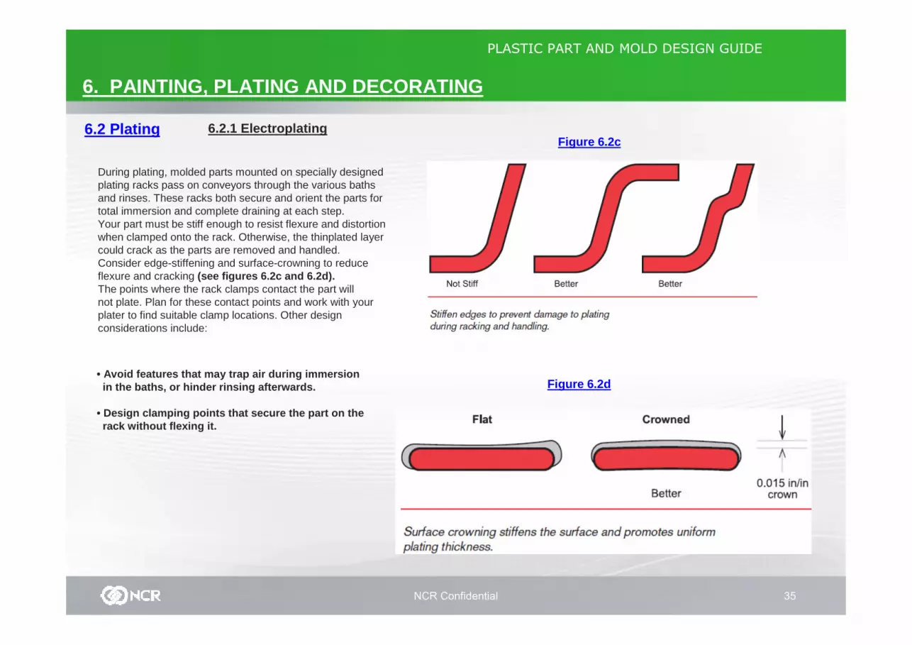
During plating, molded parts mounted on specially designed plating racks pass on conveyors through the various bathsand rinses. These racks both secure and orient the parts for total immersion and complete draining at each step.Your part must be stiff enough to resist flexure and distortion when clamped onto the rack. Otherwise, the thinplated layer could crack as the parts are removed and handled. Consider edge-stiffening and surface-crowning to reduce flexure and cracking (see figures 6.2c and 6.2d).The points where the rack clamps contact the part willnot plate. Plan for these contact points and work with your plater to find suitable clamp locations. Other designconsiderations include:
• Avoid features that may trap air during immersion in the baths, or hinder rinsing afterwards.
• Design clamping points that secure the part on the rack without flexing it.
6.2.1 Electroplating

NCR Confidential 36
PLASTIC PART AND MOLD DESIGN GUIDE
6. PAINTING, PLATING AND DECORATING
6.2 Plating
Figure 6.2d
6.2.2 Vacuum Metallization
Vacuum MetallizationThe vacuum metallizing processdeposits an extremely thin metallicfilm (typically 1.5 microns) onto plasticparts in a vacuum chamber. The processusually begins with the application of a specially formulated base coat tosmooth out surface irregularities andimprove metal adhesion. After curing,the coated parts move to special racksthat rotate within the vacuum chamberto provide the uniform coverage duringthe line-of-sight deposition process.Deposition takes place by vaporizingthe metal, usually aluminum, andthen condensing it onto the partsurface. Tungsten filaments orelectron beams typically provide theenergy to vaporize the source metalthrough direct sublimation from asolid to a vapor. After metallization,decorative parts usually receive aclear topcoat to protect the thinmetal film from abrasion. Metallizedsurfaces in protected environments,such as reflectors in sealed lightingapplications, can often skip the topcoatstep (see figure 6-10).
A related process, sputter deposition, uses mechanical displacement, rather than heat, to vaporize the coating metal. An inert gas plasma impacts the metal to provide the energy forphase transition. Sputter deposition offers thicker metallic layers, and more metal choices than traditional vacuum metallization. Commonmetals and alloys include chromium, copper, gold, tungsten, stainless steel, and brass. Sputtering also tends to provide better adhesion and abrasionperformance than conventional vacuum metallization.
Design Considerations for VacuumMetallizationBecause vacuum metallizationprocesses deposit metal films in aline-of-sight pattern, deep recessesand undercuts will not coat. Typically,the part must rotate for full coverageof surfaces and standing features.Areas “shadowed” by other elementsof the part geometry, despite beingrotated, will also not coat. Completefront-and-back coverage may requirea second racking step to reorient theparts, and an additional pass throughthe metallization process. Vacuummetallization works best on parts withrelatively simple shapes that requirecoating on just one side. The processis often limited to sizes that will fit instandard vacuum chambers.Vacuum metallizing is much lesssensitive to processing and part designthan electroplating. Adherence tostandard plastic part design guidelinesand good molding practices is usuallysufficient to obtain satisfactory results.
NCR Confidential 37
PLASTIC PART AND MOLD DESIGN GUIDE
6. PAINTING, PLATING AND DECORATING
6.2 Plating 6.2.3 EMI / RFI Shielding
EMI/RFI Shielding
With the proliferation of electronic devices such as cell phonesand portable computers, Electromagnetic Interference (EMI) and Radio Frequency Interference (RFI) become increasingly Important design considerations. EMI and RFI problems occur when electromagnetic energy escapes an electrical deviceand reaches an unintended device, causing a malfunction or interference. Untreated plastic parts generally appear“transparent” to electromagnetic energy, requiring a secondary shielding process or method when used in electronic enclosures needing EMI/RFI shielding.A variety of shielding methods exist, including coatings, sheet-metal shrouds, adhesive foils, and special conductivefillers in the molding resin. More often, manufacturers use metalliccoating. Each of the metallic-coating processes covered in this chapter thus far — painting (conductive coatings), electroless plating, electroplating, and vacuum metallization —find use in EMI/RFI shielding. A number of factors determine the best process for your application, such as part geometry andsize, masking requirements, production levels, and required shieldingperformance.
Design Considerations for EMI/RFI Shielding
Enclosure design usually affects shielding performance more than thecoating process chosen. Any openings in the enclosure assembly, whether they be intentional — holes and cooling vents —or unintentional — gaps along mating edges, can allow electromagneticradiation to escape. The length of the opening determines the frequencyof radiation that can escape. Long gaps, such as between mating halves, could release a wide range of frequencies. For proper shielding, these interfaces require a generous overlap and snug fit.
One design employs contact fingers with a slight interference fit to createa low-impedance connection and reduced gap size. The finger spacingdetermines the slot length and the minimum frequency that can escape.Consult your shielding experts for help in calculating the correct spacing for your application. Generally, do not place “noisy” circuit boards close to cooling vents and other possible weak links in the shield. Part designers and shielding experts need to work together early in the design process to assure a good combination of performance and manufacturability .
NCR Confidential 38
PLASTIC PART AND MOLD DESIGN GUIDE
6. PAINTING, PLATING AND DECORATING
6.3 Decorating/Printing
6.3.1 PAD PRINTING
Printing/Decorating is often used to apply designs, characters, and markings to parts.
Pad printing involves pressing ink ontothe part from a custom-designed softink pad. In one process, the patternedink pad picks up a film layer depositedonto a transfer plate by a roller. Inanother process, a smooth pad picks upa pattern of ink from an etched platethat was flooded with ink and thenwiped with a blade, leaving ink in theetched recesses of the pattern. In bothprocesses, the loaded ink pad thenstamps the pattern onto the plastic part.The soft pad can accommodate texturesand many irregular shapes. Irregularshapes cause distortions in the printedpattern that must be compensated byadjustments in the ink pad pattern.
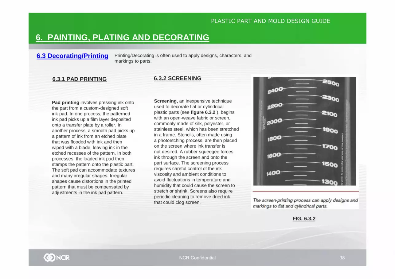
Screening, an inexpensive techniqueused to decorate flat or cylindricalplastic parts (see figure 6.3.2 ), beginswith an open-weave fabric or screen,commonly made of silk, polyester, orstainless steel, which has been stretchedin a frame. Stencils, often made usinga photoetching process, are then placedon the screen where ink transfer isnot desired. A rubber squeegee forcesink through the screen and onto thepart surface. The screening processrequires careful control of the inkviscosity and ambient conditions toavoid fluctuations in temperature andhumidity that could cause the screen tostretch or shrink. Screens also requireperiodic cleaning to remove dried inkthat could clog screen.
6.3.2 SCREENING
FIG. 6.3.2
NCR Confidential 39
PLASTIC PART AND MOLD DESIGN GUIDE
6. PAINTING, PLATING AND DECORATING
6.3 Decorating/Printing
6.3.3 LASER PRINTING
6.3.4 HOT STAMPING
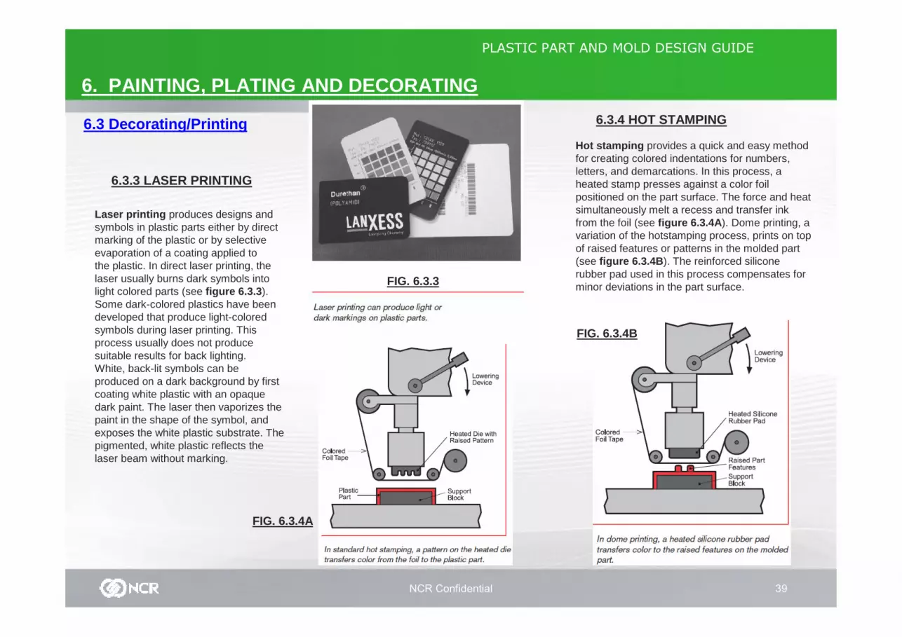
Laser printing produces designs andsymbols in plastic parts either by directmarking of the plastic or by selectiveevaporation of a coating applied tothe plastic. In direct laser printing, thelaser usually burns dark symbols intolight colored parts (see figure 6.3.3 ).Some dark-colored plastics have beendeveloped that produce light-coloredsymbols during laser printing. Thisprocess usually does not producesuitable results for back lighting.White, back-lit symbols can beproduced on a dark background by firstcoating white plastic with an opaquedark paint. The laser then vaporizes thepaint in the shape of the symbol, andexposes the white plastic substrate. Thepigmented, white plastic reflects thelaser beam without marking.
Hot stamping provides a quick and easy method for creating colored indentations for numbers, letters, and demarcations. In this process, a heated stamp presses against a color foil positioned on the part surface. The force and heat simultaneously melt a recess and transfer ink from the foil (see figure 6.3.4A ). Dome printing, a variation of the hotstamping process, prints on top of raised features or patterns in the molded part (see figure 6.3.4B ). The reinforced silicone rubber pad used in this process compensates for minor deviations in the part surface.FIG. 6.3.3
FIG. 6.3.4A
FIG. 6.3.4B
NCR Confidential 40
PLASTIC PART AND MOLD DESIGN GUIDE
6. PAINTING, PLATING AND DECORATING
6.3 Decorating/Printing
6.3.5 LABELS AND DECALS
Self-adhering printed labels anddecals provide an easy means forapplying items such as logos, modelidentification, and decorative graphics.Available in transparent, opaque,metallic, or embossed materials, theyoffer an unlimited choice of shapes andcolors. Opaque labels are particularlyhelpful for hiding trimmed sprue gates.Instead of relying upon a self-adheringbacking, heat-transfer labeling uses aheated platen to release the print froma carrier and attach it to the plasticpart. Labels and decals occasionallyhave problems with adhesion. Carefullypretest and evaluate any proposedadhesive system on actual productionparts. Also, avoid placing decals andlabels on irregular surfaces, as they willlift more easily.

NCR Confidential 41
PLASTIC PART AND MOLD DESIGN GUIDE
7. DESIGN FOR ASSEMBLY
7.1 Part Consolidation
To lessen the need for fasteninghardware and reduce the numberof assembly operations, considerconsolidating the number of partsin a given design. Closely scrutinizeyour total design for opportunities tocombine function and reduce finalassembly count. By way of example,figure 7.1 shows several options forattaching a gear to a shaft: a threepiecedesign, featuring a shaft, gear,and roll pin; a two-piece, snap-ongear design; and a one-piece shaft andgear design that needs no assembly.A variety of factors — includingrequired strength, wear properties, andmoldability — determine which of thesedesign options is most feasible.
FIG. 7.1
NCR Confidential 42
PLASTIC PART AND MOLD DESIGN GUIDE
7. DESIGN FOR ASSEMBLY
7.2 Mechanical Fasteners FIG. 7.2a
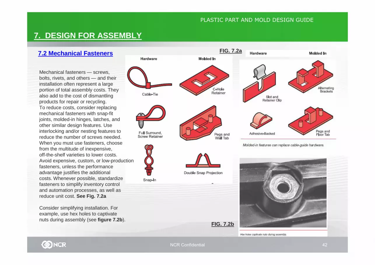
Mechanical fasteners — screws,bolts, rivets, and others — and theirinstallation often represent a largeportion of total assembly costs. Theyalso add to the cost of dismantlingproducts for repair or recycling.To reduce costs, consider replacingmechanical fasteners with snap-fitjoints, molded-in hinges, latches, andother similar design features. Useinterlocking and/or nesting features toreduce the number of screws needed.When you must use fasteners, choosefrom the multitude of inexpensive,off-the-shelf varieties to lower costs.Avoid expensive, custom, or low-productionfasteners, unless the performanceadvantage justifies the additionalcosts. Whenever possible, standardizefasteners to simplify inventory controland automation processes, as well asreduce unit cost. See Fig. 7.2a
Consider simplifying installation. Forexample, use hex holes to captivatenuts during assembly (see figure 7.2b ).
FIG. 7.2b
NCR Confidential 43
PLASTIC PART AND MOLD DESIGN GUIDE
7. DESIGN FOR ASSEMBLY
7.3 Snap Fit Joints
FIG. 7.3a
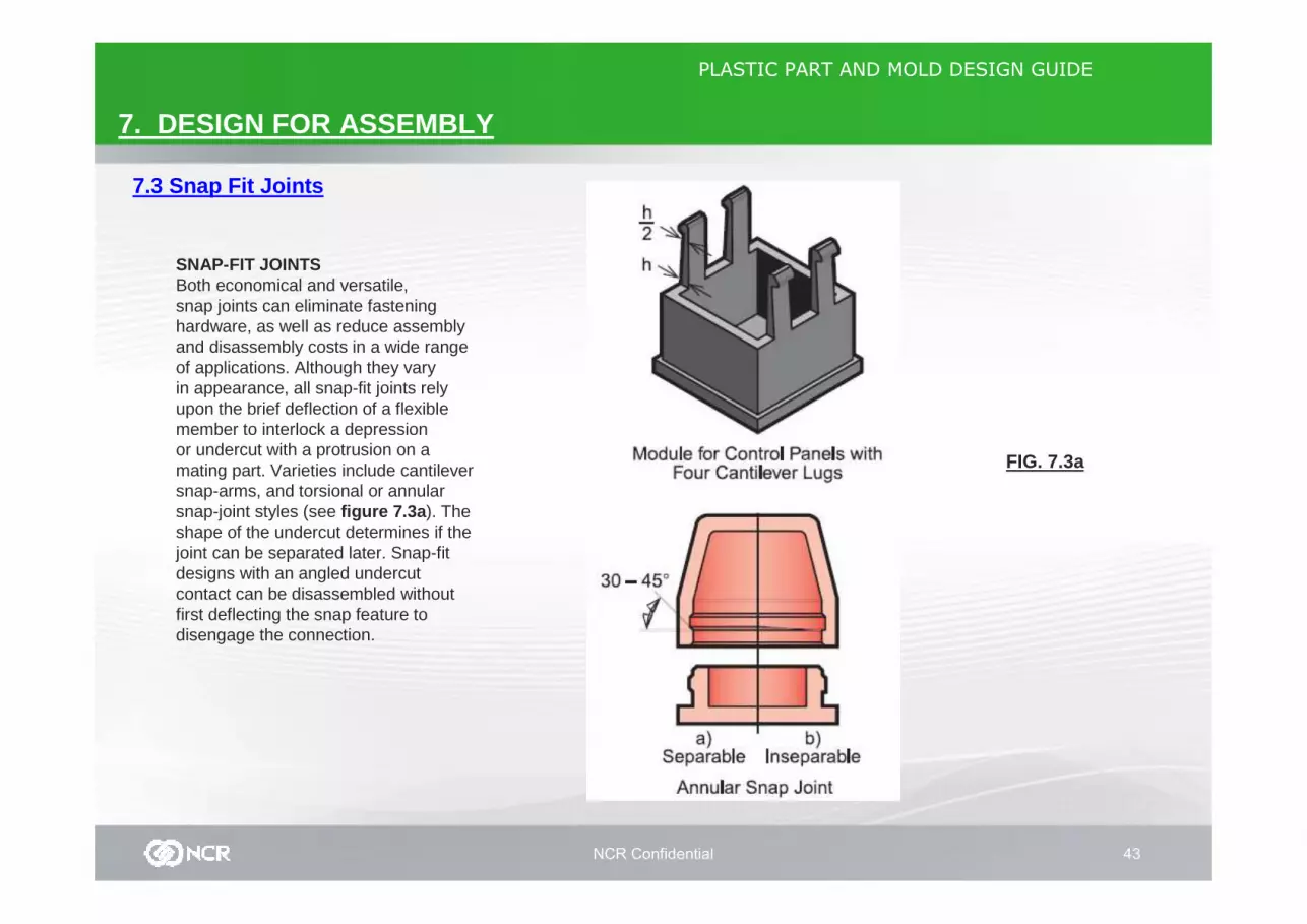
SNAP-FIT JOINTSBoth economical and versatile,snap joints can eliminate fasteninghardware, as well as reduce assemblyand disassembly costs in a wide rangeof applications. Although they varyin appearance, all snap-fit joints relyupon the brief deflection of a flexiblemember to interlock a depressionor undercut with a protrusion on amating part. Varieties include cantileversnap-arms, and torsional or annularsnap-joint styles (see figure 7.3a ). Theshape of the undercut determines if thejoint can be separated later. Snap-fitdesigns with an angled undercutcontact can be disassembled withoutfirst deflecting the snap feature todisengage the connection.
NCR Confidential 44
PLASTIC PART AND MOLD DESIGN GUIDE
7. DESIGN FOR ASSEMBLY
7.3 Snap Fit Joints FIG. 7.3b
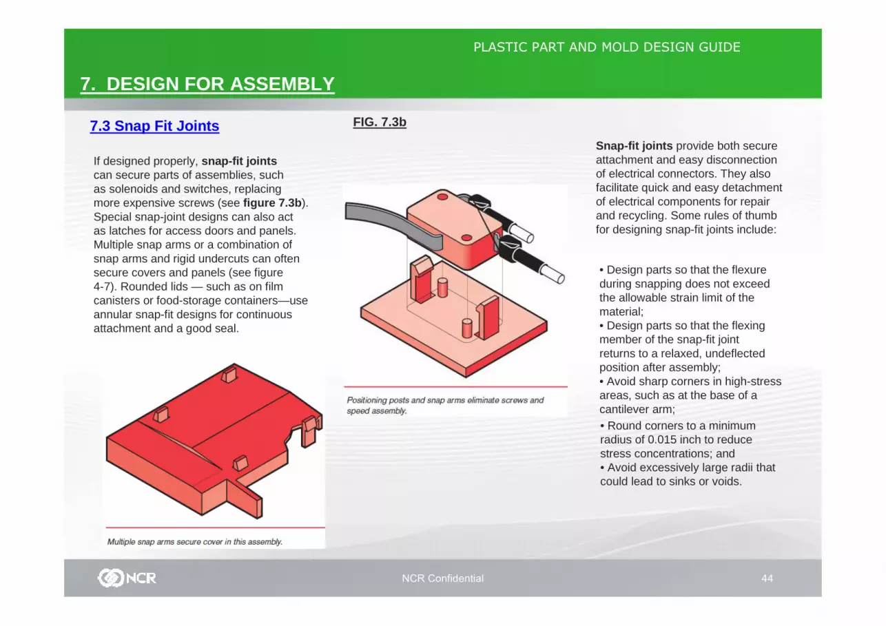
If designed properly, snap-fit jointscan secure parts of assemblies, suchas solenoids and switches, replacingmore expensive screws (see figure 7.3b ).Special snap-joint designs can also actas latches for access doors and panels.Multiple snap arms or a combination ofsnap arms and rigid undercuts can oftensecure covers and panels (see figure4-7). Rounded lids — such as on filmcanisters or food-storage containers—useannular snap-fit designs for continuousattachment and a good seal.
Snap-fit joints provide both secureattachment and easy disconnectionof electrical connectors. They alsofacilitate quick and easy detachmentof electrical components for repair and recycling. Some rules of thumb for designing snap-fit joints include:
• Design parts so that the flexureduring snapping does not exceedthe allowable strain limit of thematerial;• Design parts so that the flexingmember of the snap-fit jointreturns to a relaxed, undeflectedposition after assembly;• Avoid sharp corners in high-stressareas, such as at the base of acantilever arm;• Round corners to a minimumradius of 0.015 inch to reducestress concentrations; and• Avoid excessively large radii thatcould lead to sinks or voids.

NCR Confidential 45
PLASTIC PART AND MOLD DESIGN GUIDE
7. DESIGN FOR ASSEMBLY
7.3 Snap Fit Joints FIG. 7.3c
Consider molding issues early in partdesign. To lower mold-constructionand maintenance costs, design simple,straight-draw, snap-fit joints (seefigure 7.3c ), rather than ones that needslides in the mold. In some designs, theproximity of the snap-fit joint to otherpart or mold features does not leaveenough room for a slide mechanism.Annular designs can be particularlydifficult to mold. Some need collapsiblecores or ejector sleeves, which can beproblematic and difficult to maintain.Consult an experienced mold engineerbefore specifying any design that usesslides or other mechanisms to clear oreject undercuts. The molding process offers the
versatility to customize snap-fit designsfor each application. For example,snap arms on frequently used doorsor access panels could have fingertabs added for easier opening (seefigure 7.3d ). Limited-access doors could have hidden snap-fit joints or require special tools. Some applications may require modifications in the snap arm to prevent excessive material strain during deflection.
FIG. 7.3d
NCR Confidential 46
PLASTIC PART AND MOLD DESIGN GUIDE
7. DESIGN FOR ASSEMBLY
7.3 Snap Fit Joints
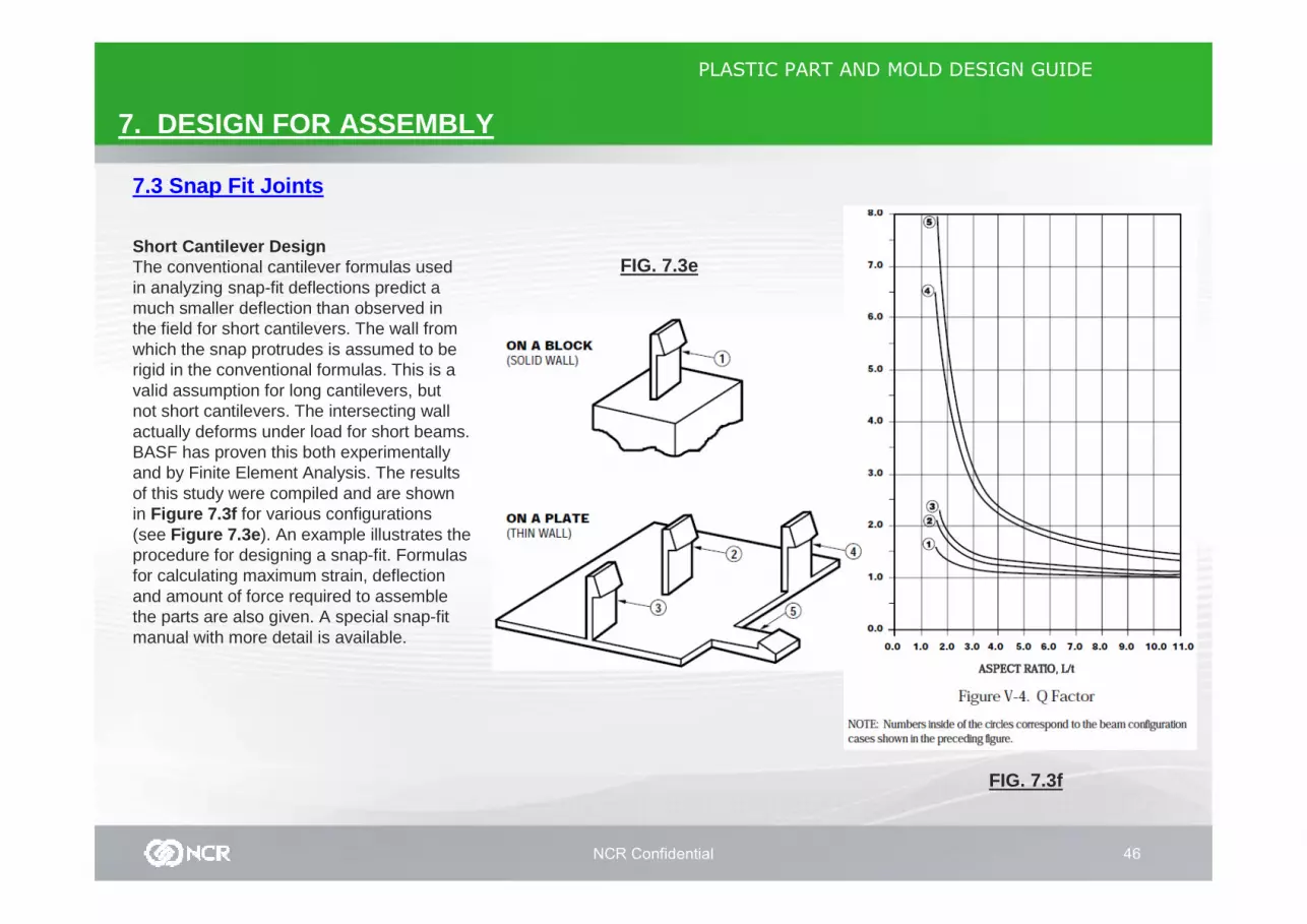
FIG. 7.3eShort Cantilever DesignThe conventional cantilever formulas used in analyzing snap-fit deflections predict a much smaller deflection than observed in the field for short cantilevers. The wall fromwhich the snap protrudes is assumed to be rigid in the conventional formulas. This is a valid assumption for long cantilevers, but not short cantilevers. The intersecting wallactually deforms under load for short beams.BASF has proven this both experimentally and by Finite Element Analysis. The results of this study were compiled and are shown in Figure 7.3f for various configurations (see Figure 7.3e ). An example illustrates the procedure for designing a snap-fit. Formulas for calculating maximum strain, deflection and amount of force required to assemble the parts are also given. A special snap-fit manual with more detail is available.
FIG. 7.3f
NCR Confidential 47
PLASTIC PART AND MOLD DESIGN GUIDE
7. DESIGN FOR ASSEMBLY
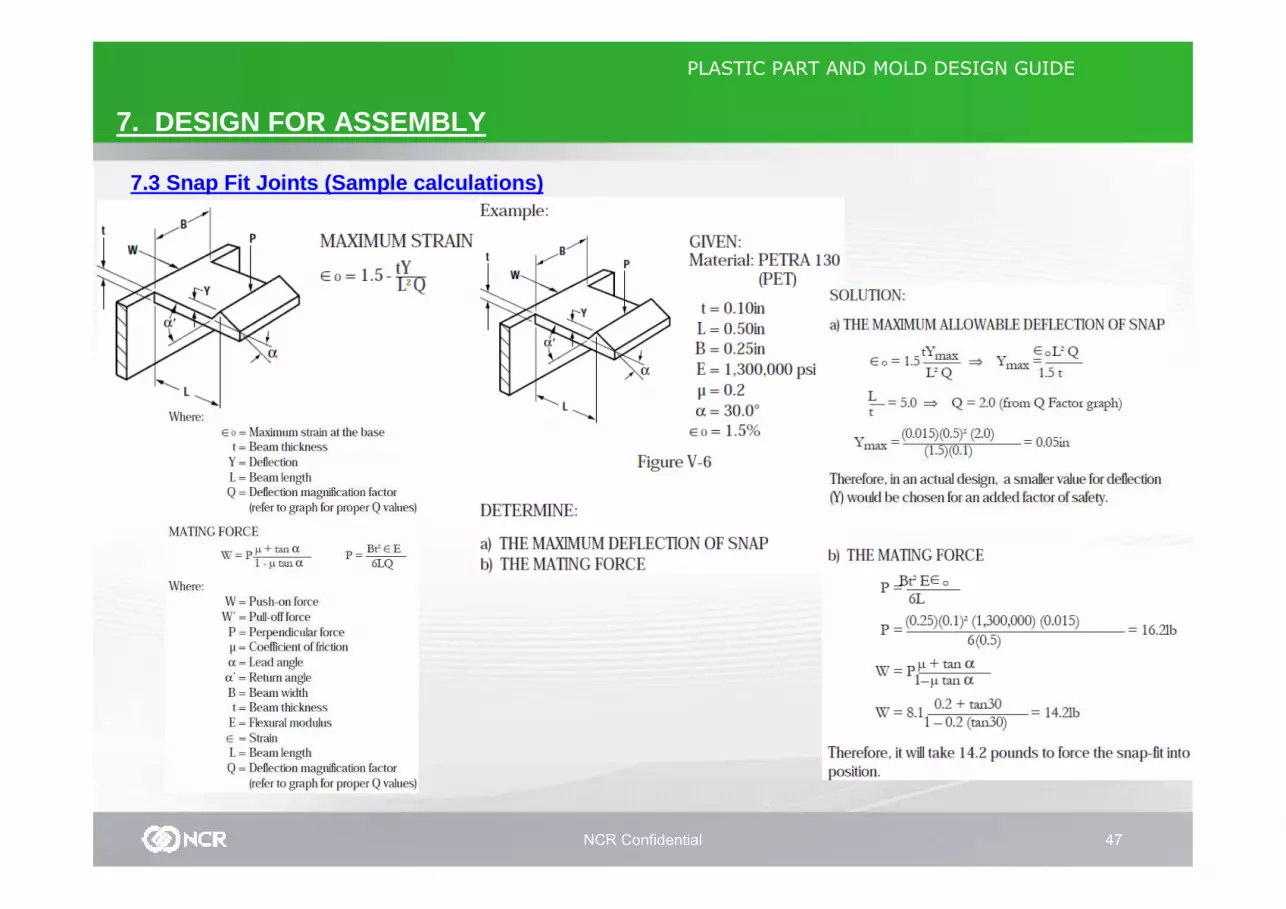
7.3 Snap Fit Joints (Sample calculations)
NCR Confidential 48
PLASTIC PART AND MOLD DESIGN GUIDE
7. DESIGN FOR ASSEMBLY
7.4 Press Fit Assembly
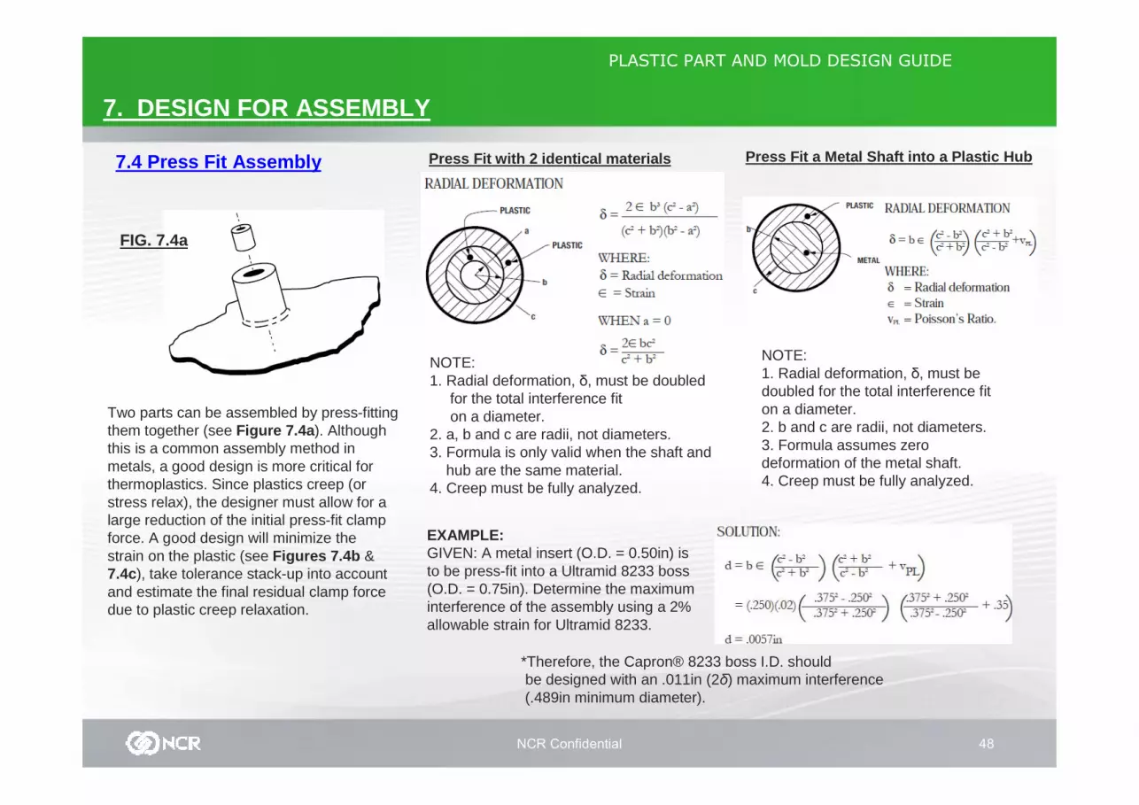
Two parts can be assembled by press-fitting them together (see Figure 7.4a ). Although this is a common assembly method in metals, a good design is more critical for thermoplastics. Since plastics creep (or stress relax), the designer must allow for a large reduction of the initial press-fit clamp force. A good design will minimize the strain on the plastic (see Figures 7.4b & 7.4c), take tolerance stack-up into account and estimate the final residual clamp force due to plastic creep relaxation.
FIG. 7.4a
Press Fit with 2 identical materials
NOTE:1. Radial deformation, δ, must be doubled
for the total interference fiton a diameter.
2. a, b and c are radii, not diameters.3. Formula is only valid when the shaft and
hub are the same material.4. Creep must be fully analyzed.
Press Fit a Metal Shaft into a Plastic Hub
NOTE:1. Radial deformation, δ, must be doubled for the total interference fiton a diameter.2. b and c are radii, not diameters.3. Formula assumes zero deformation of the metal shaft.4. Creep must be fully analyzed.
EXAMPLE:GIVEN: A metal insert (O.D. = 0.50in) is to be press-fit into a Ultramid 8233 boss (O.D. = 0.75in). Determine the maximum interference of the assembly using a 2%allowable strain for Ultramid 8233.
*Therefore, the Capron® 8233 boss I.D. should be designed with an .011in (2δ) maximum interference(.489in minimum diameter).
NCR Confidential 49
PLASTIC PART AND MOLD DESIGN GUIDE
7. DESIGN FOR ASSEMBLY
7.5 Adhesive BondingFIG. 7.5a
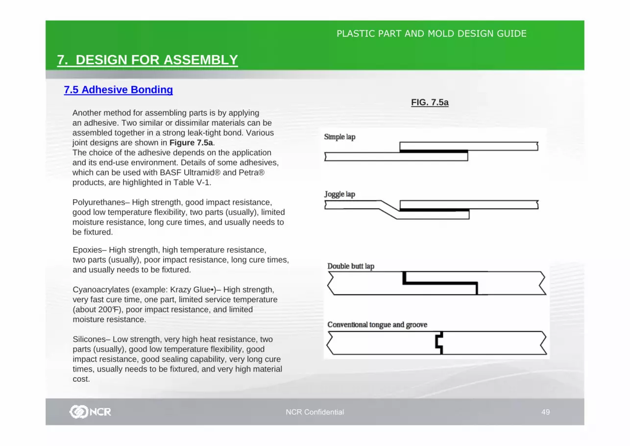
Another method for assembling parts is by applyingan adhesive. Two similar or dissimilar materials can beassembled together in a strong leak-tight bond. Variousjoint designs are shown in Figure 7.5a .The choice of the adhesive depends on the applicationand its end-use environment. Details of some adhesives,which can be used with BASF Ultramid® and Petra®products, are highlighted in Table V-1.
Polyurethanes– High strength, good impact resistance,good low temperature flexibility, two parts (usually), limitedmoisture resistance, long cure times, and usually needs tobe fixtured.
Epoxies– High strength, high temperature resistance,two parts (usually), poor impact resistance, long cure times,and usually needs to be fixtured.
Cyanoacrylates (example: Krazy Glue•)– High strength,very fast cure time, one part, limited service temperature(about 200°F), poor impact resistance, and limitedmoisture resistance.
Silicones– Low strength, very high heat resistance, twoparts (usually), good low temperature flexibility, good impact resistance, good sealing capability, very long cure times, usually needs to be fixtured, and very high material cost.

NCR Confidential 50
PLASTIC PART AND MOLD DESIGN GUIDE
7. DESIGN FOR ASSEMBLY
7.5 Adhesive Bonding
FIG. 7.5a Recommended Adhesives
NCR Confidential 51
PLASTIC PART AND MOLD DESIGN GUIDE
7. DESIGN FOR ASSEMBLY
7.6 Bolts, Nuts and Machine Screws
FIG. 7.6a
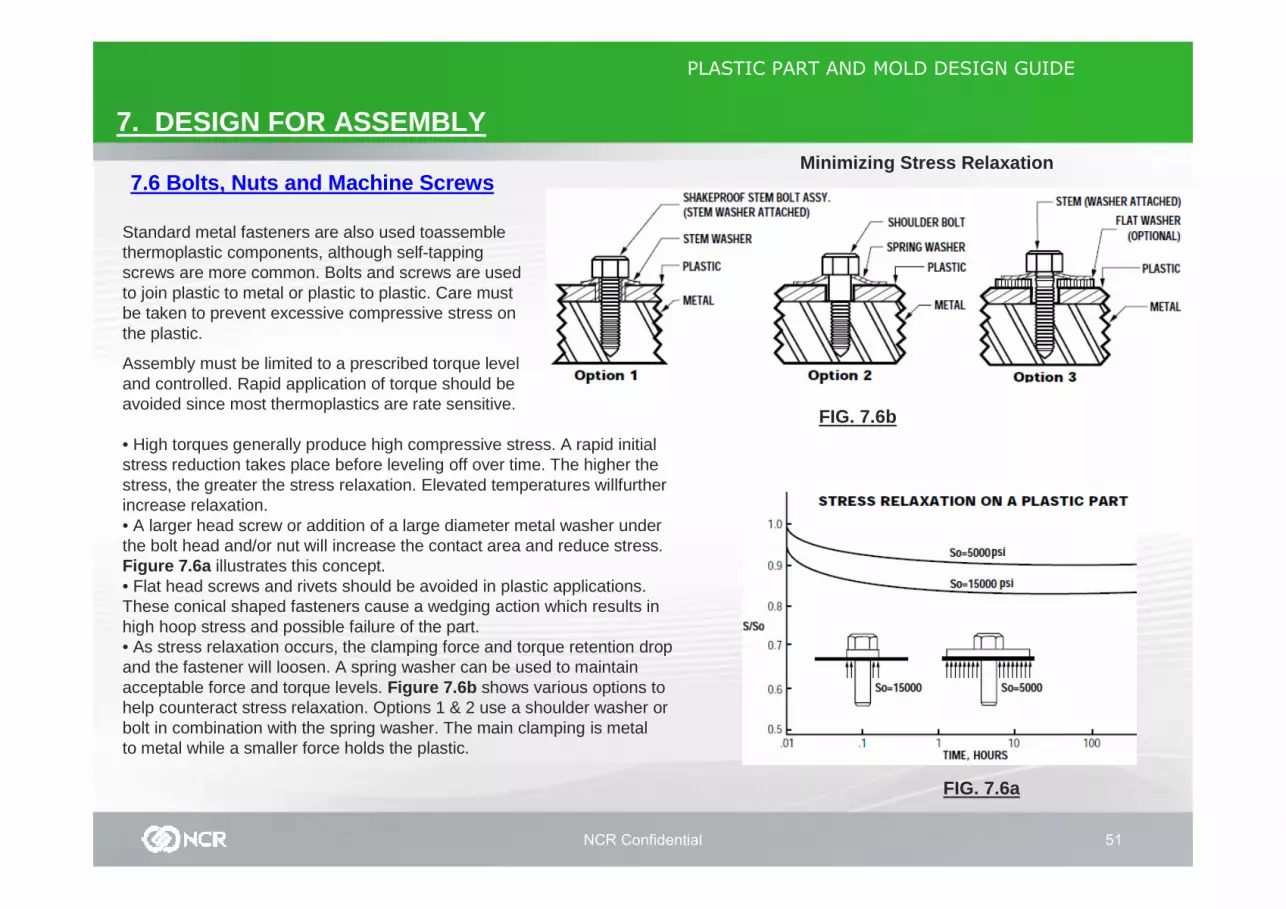
Standard metal fasteners are also used toassemblethermoplastic components, although self-tapping screws are more common. Bolts and screws are used to join plastic to metal or plastic to plastic. Care must be taken to prevent excessive compressive stress on the plastic.
Assembly must be limited to a prescribed torque leveland controlled. Rapid application of torque should beavoided since most thermoplastics are rate sensitive.
• High torques generally produce high compressive stress. A rapid initial stress reduction takes place before leveling off over time. The higher the stress, the greater the stress relaxation. Elevated temperatures willfurtherincrease relaxation.• A larger head screw or addition of a large diameter metal washer under the bolt head and/or nut will increase the contact area and reduce stress. Figure 7.6a illustrates this concept.• Flat head screws and rivets should be avoided in plastic applications. These conical shaped fasteners cause a wedging action which results in high hoop stress and possible failure of the part.• As stress relaxation occurs, the clamping force and torque retention drop and the fastener will loosen. A spring washer can be used to maintain acceptable force and torque levels. Figure 7.6b shows various options to help counteract stress relaxation. Options 1 & 2 use a shoulder washer or bolt in combination with the spring washer. The main clamping is metalto metal while a smaller force holds the plastic.
FIG. 7.6b
Minimizing Stress Relaxation

NCR Confidential 52
PLASTIC PART AND MOLD DESIGN GUIDE
7. DESIGN FOR ASSEMBLY
7.7 Self-Tapping Screws FIG. 7.6b
There are two main types of self-tapping fasteners used In plastic parts: thread cutting and thread forming . Thread cutting screws are generally used only on brittle plastics, such as thermosets and highly filled (+50%) thermoplastics. They cut threads by means of a slotted shank. Because they actually remove material when inserted, thread cutting screws should not be reinstalled and a chip reservoir should be added. Thread forming screws are generally preferred for most thermoplastic applications. These types of screws can be reinstalled a limited number of times (3-7). For repeated assembly and disassembly, some form of metal inserts should be used. There are several styles of thread Forming screws designed specifically for plastics. Three of the more widely used are:
Plastite™These screws have a trilobular cross-section which roll threads by moving material out of the way as they are installed. After installation, the material fills back around the shank lowering the residual stress in the screw boss.This feature also gives the Plastite• screws excellent resistance to loosening due to vibration. Higher hoop stress is produced with these screws.
Hi-Lo™These screws feature a dual lead with a high thread having a 30°included angle and the low thread having a 60°angle. These screws have a high strip torque to drive torque ratio which is important for small sizes. Lower hoop stress is produced but higher stress concentrations result due to acute angle threads.
PT™This thread design has a single 30°included angle which reduces hoop stress in the boss and also provides a high strip torque to drive torque ratio.
Guidelines for self-tapping fasteners :1. Thread engagement length should be 2.5 times the screw diameter.2. Boss diameter should be at least 2 times the pilot hole diameter.3. Pilot hole diameter should be based on 50%-70% thread engagement. This can vary with the material and the type of fastener (check with your Basf design representative).4. Cored holes should have 1/4°to 1/2°draft/side.5. Holes should be counterbored or chamfered to a depth of .020 in. to aid alignment and reduce the chance of boss cracking.6. Strip to drive torque ratio should be at least 3:1, but the difference in strip to drive torque is more important than the ratio.7. Seating torque should be no more than 2/3 strip torque.
NCR Confidential 53
PLASTIC PART AND MOLD DESIGN GUIDE
7. DESIGN FOR ASSEMBLY
7.8 Inserts FIG. 7.8a
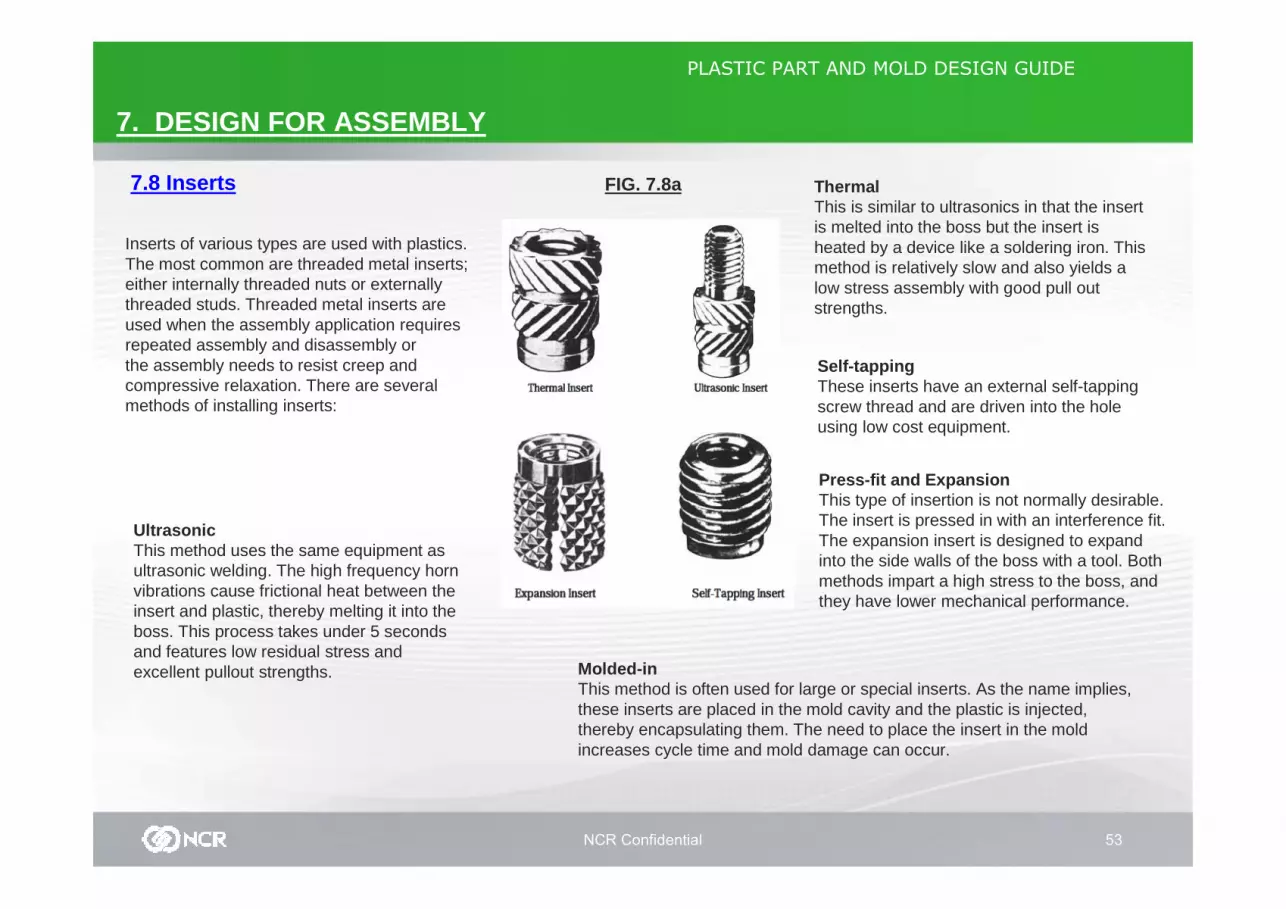
Inserts of various types are used with plastics. The most common are threaded metal inserts; either internally threaded nuts or externally threaded studs. Threaded metal inserts are used when the assembly application requires repeated assembly and disassembly orthe assembly needs to resist creep and compressive relaxation. There are several methods of installing inserts:
UltrasonicThis method uses the same equipment as ultrasonic welding. The high frequency horn vibrations cause frictional heat between the insert and plastic, thereby melting it into the boss. This process takes under 5 seconds and features low residual stress and excellent pullout strengths.
ThermalThis is similar to ultrasonics in that the insert is melted into the boss but the insert is heated by a device like a soldering iron. This method is relatively slow and also yields a low stress assembly with good pull out strengths.
Self-tappingThese inserts have an external self-tapping screw thread and are driven into the hole using low cost equipment.
Press-fit and ExpansionThis type of insertion is not normally desirable.The insert is pressed in with an interference fit. The expansion insert is designed to expand into the side walls of the boss with a tool. Both methods impart a high stress to the boss, and they have lower mechanical performance.
Molded-inThis method is often used for large or special inserts. As the name implies, these inserts are placed in the mold cavity and the plastic is injected, thereby encapsulating them. The need to place the insert in the mold increases cycle time and mold damage can occur.

NCR Confidential 54
PLASTIC PART AND MOLD DESIGN GUIDE
7. DESIGN FOR ASSEMBLY
7.9 Ultrasonic Welding
FIG. 7.9a
Ultrasonic welding is a quick and reliable way to Assemble the same or very similar thermoplastic parts. Electrical energy is converted into mechanical vibrations causing frictional heat between mating parts, thereby melting the plastic. The parts are held in a fixture under pressure while the ultrasonic energy is applied. The energy is then shut off and the pressure maintained until the weld surface has solidified. Total weld time is generally around 0.5-1.0 second. Standard welder frequencies are 20 kHz, although 40 kHz units are available for small delicate parts.
The major factor determining the quality of an ultrasonicweld is the joint design. The two major types of jointdesigns are shear joints and energy director joints. Thechoice depends on the type of material to be welded and the end use requirements.
Shear JointA shear joint is more commonly used on semi-crystalline materials such as nylon* and polyester. Due to their sharp melting points, semi-crystalline resins often do not achieve strong welds with energy director joints. The molten material flowing from the weld area quickly resolidifies before welding to the opposite interface.
In a shear joint, a small contact area is initially melted and then continues down the weld surface as one part is forced into the other. Due to the good material mixing between the welded parts, strong structural and hermetic seals can be obtained. Typical joint designs and interference guidelines are shown in Figure 7.9(a–c). As with energy director joints, flash traps can be included in the joint design.
FIG. 7.9b
FIG. 7.9c
NCR Confidential 55
PLASTIC PART AND MOLD DESIGN GUIDE
7. DESIGN FOR ASSEMBLY
7.9 Ultrasonic WeldingFIG. 7.9e
FIG. 7.9d
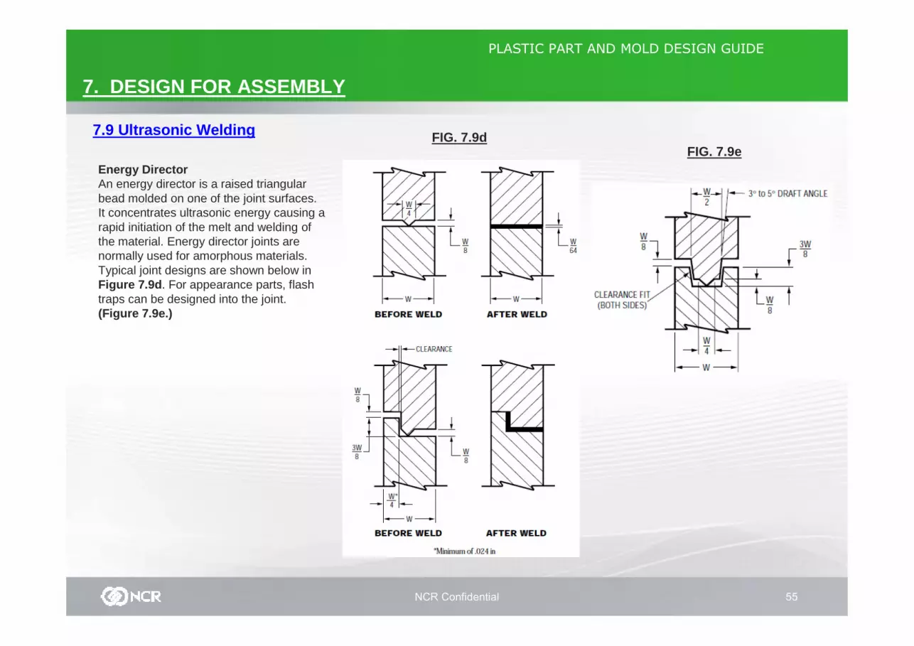
Energy DirectorAn energy director is a raised triangular bead molded on one of the joint surfaces. It concentrates ultrasonic energy causing a rapid initiation of the melt and welding ofthe material. Energy director joints are normally used for amorphous materials. Typical joint designs are shown below in Figure 7.9d . For appearance parts, flash traps can be designed into the joint. (Figure 7.9e.)

NCR Confidential 56
PLASTIC PART AND MOLD DESIGN GUIDE
7. DESIGN FOR ASSEMBLY
7.10 Thermoplastic Staking
FIG. 7.10a
FIG. 7.10b
Thermal staking is an assembly methodthat uses the controlled melting andreforming of a plastic stud or boss to captureor lock another plastic or metal componentof an assembly in place.The plastic stud protrudes through a holein the component to be locked in place.The heated thermal tip contacts the top ofthe stud, which melts and fills the volumeof the tip cavity to produce a head, lockingthe component in place. The progressivemelting of plastic under continuous pressureforms the head. When staking, theright combination of heat and pressure forthe application is critical

NCR Confidential 57
PLASTIC PART AND MOLD DESIGN GUIDE
7. DESIGN FOR ASSEMBLY
7.11 Electromagnetic Welding
FIG. 7.11
Electromagnetic WeldingElectromagnetic welding provides a simple, rapid and reliable assembly technique to produce a strong and hermetic joint. A specially designed strand is placed between the two parts to be welded. This assembly is then exposed to an induction heat field which melts the strand and plastic to form a strong bond at the interface.Our studies show the shear strength of the weld to be about 5000 psi. A variety of joints can be used as in other welding techniques. A tongue and groove joint is shown inFigure 7.11 .

NCR Confidential 58
PLASTIC PART AND MOLD DESIGN GUIDE
END OF SLIDE


