Embed Size (px)
Citation preview
MOBILE THERMAL PRINTERMODEL CMP-10
CMP-10BTUser’s Manual
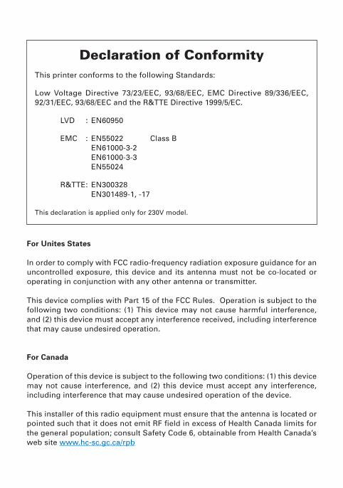
This printer conforms to the following Standards:
Low Voltage Directive 73/23/EEC, 93/68/EEC, EMC Directive 89/336/EEC,92/31/EEC, 93/68/EEC and the R&TTE Directive 1999/5/EC.
LVD : EN60950
EMC : EN55022 Class BEN61000-3-2EN61000-3-3EN55024
R&TTE: EN300328EN301489-1, -17
This declaration is applied only for 230V model.
Declaration of Conformity
For Unites States
In order to comply with FCC radio-frequency radiation exposure guidance for anuncontrolled exposure, this device and its antenna must not be co-located oroperating in conjunction with any other antenna or transmitter.
This device complies with Part 15 of the FCC Rules. Operation is subject to thefollowing two conditions: (1) This device may not cause harmful interference,and (2) this device must accept any interference received, including interferencethat may cause undesired operation.
For Canada
Operation of this device is subject to the following two conditions: (1) this devicemay not cause interference, and (2) this device must accept any interference,including interference that may cause undesired operation of the device.
This installer of this radio equipment must ensure that the antenna is located orpointed such that it does not emit RF field in excess of Health Canada limits forthe general population; consult Safety Code 6, obtainable from Health Canada’sweb site www.hc-sc.gc.ca/rpb
— 1 —
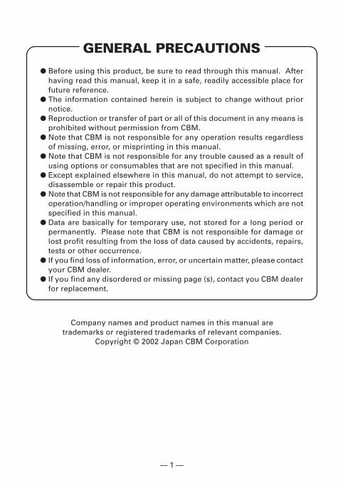
GENERAL PRECAUTIONS
� Before using this product, be sure to read through this manual. Afterhaving read this manual, keep it in a safe, readily accessible place forfuture reference.
� The information contained herein is subject to change without priornotice.
� Reproduction or transfer of part or all of this document in any means isprohibited without permission from CBM.
� Note that CBM is not responsible for any operation results regardlessof missing, error, or misprinting in this manual.
� Note that CBM is not responsible for any trouble caused as a result ofusing options or consumables that are not specified in this manual.
� Except explained elsewhere in this manual, do not attempt to service,disassemble or repair this product.
� Note that CBM is not responsible for any damage attributable to incorrectoperation/handling or improper operating environments which are notspecified in this manual.
� Data are basically for temporary use, not stored for a long period orpermanently. Please note that CBM is not responsible for damage orlost profit resulting from the loss of data caused by accidents, repairs,tests or other occurrence.
� If you find loss of information, error, or uncertain matter, please contactyour CBM dealer.
� If you find any disordered or missing page (s), contact you CBM dealerfor replacement.
Company names and product names in this manual aretrademarks or registered trademarks of relevant companies.
Copyright © 2002 Japan CBM Corporation
— 2 —
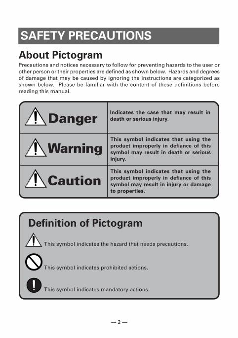
SAFETY PRECAUTIONS
About PictogramPrecautions and notices necessary to follow for preventing hazards to the user orother person or their properties are defined as shown below. Hazards and degreesof damage that may be caused by ignoring the instructions are categorized asshown below. Please be familiar with the content of these definitions beforereading this manual.
Definition of Pictogram
DangerIndicates the case that may result in
death or serious injury.
Warning
Caution
This symbol indicates that using the
product improperly in defiance of this
symbol may result in death or serious
injury.
This symbol indicates that using the
product improperly in defiance of this
symbol may result in injury or damage
to properties.
This symbol indicates the hazard that needs precautions.
This symbol indicates prohibited actions.
This symbol indicates mandatory actions.
— 3 —
Precautions in Handling Printer
WARNING� If the product is kept in use under abnormal condition such as
generation of heat, smoke, or abnormal odor, a fire may occur.Immediately turn the printer power off, remove the battery, andcontact our service agent.
� If any foreign matter (metal tip, water, liquid) enters the product,immediately turn the printer power OFF, remove the battery, andcontact our service agent. Ignoring this instruction may result ina fire.
CAUTION� Do not place the printer on a shaky table or other unbalanced
place. The printer may drop or fall resulting in injury.� Avoid using or storing in the following place. Damage to printer
may be caused.• In a car parked in a sunny place, a place exposed to direct
sunlight, near heat generating equipment, or the like.• A place where temperature or humidity is excessively high or
low, or its change is radical.• A dusty place.• A place likely to get a splash of water or liquid.
� Never drop nor give strong shock or vibration. Fault or damagemay be caused.
� Avoid entry of foreign material. Otherwise, fault may occur.� Do not use volatile liquid (thinner, benzine, etc.) or wet cloth when
cleaning the printer. Deterioration or discoloration may occur.Use a dry, soft cloth for cleaning.
� Do not move the printer or give any shock or vibration to it whilethe printer is in operation or in standby operation. The printerpower may be disconnected and the print data may be lost.
— 4 —
� Do not touch the print head or paper cutter while replacing printpaper. Heated print head may cause burn. The cutter may causeinjury to the hand.
Precautions on Using Printer
� Use of print paper other than specified may result in not onlydeteriorated print quality but shortened life of print head (printingportion).
� Do not tap or rub the print head with edged or hard material.� When dew condensation is present on the print head, dry it
completely before printing. Printing with dew condensation maydamage the print head.
� Do not use the battery other than specified.
CAUTION
WARNING
— 5 —
WARNING
DANGER� Entering battery liquid may result in loss of eyesight. Immediately
wash eyes with fresh water and get medical care.� Keep the following in mind when handling battery. Otherwise,
liquid leakage, heat generation, and explosion may result.• Do not throw battery into fire or do not apply heat.• Do not peel or scratch the external tube.• Soldering is prohibited.• Do not give strong shock to battery or throw it away.• Do not short-circuit the positive and negative terminals with a
metal such as metal wire.� Never disassemble or modify battery. Otherwise, liquid leakage,
heat generation, or explosion may occur.
Precautions on Using Battery
� If battery liquid attaches to skin or cloth, immediately wash it outwith fresh water. Otherwise, skin disorder may be caused.
CAUTION� Risk of explosion if battery is replaced by an incorrect type.� Dispose of used batteries according to the instructions.
— 6 —
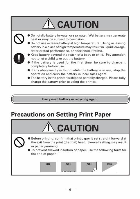
� Do not dip battery in water or sea water. Wet battery may generateheat or may be subject to corrosion.
� Do not use or leave battery at high temperature. Using or leavingbattery in a place of high temperature may result in liquid leakage,deteriorated performance, or shortened lifetime.
� Keep battery beyond the reach of a baby or child. Pay attentionnot to let a child take out the battery.
� If the battery is used for the first time, be sure to charge itcompletely before use.
� If any abnormality is found while the battery is in use, stop theoperation and carry the battery in local sales agent.
� The battery in the printer is shipped partially charged. Please fullycharge the battery prior to using the printer.
Carry used battery in recycling agent.
� Before printing, confirm that print paper is set straight forward atthe exit from the print (thermal) head. Skewed setting may resultin paper jamming.
� To prevent skewed insertion of paper, use the following form forthe end of paper.
CAUTION
Precautions on Setting Print Paper
NGOK NG NG
CAUTION
— 7 —
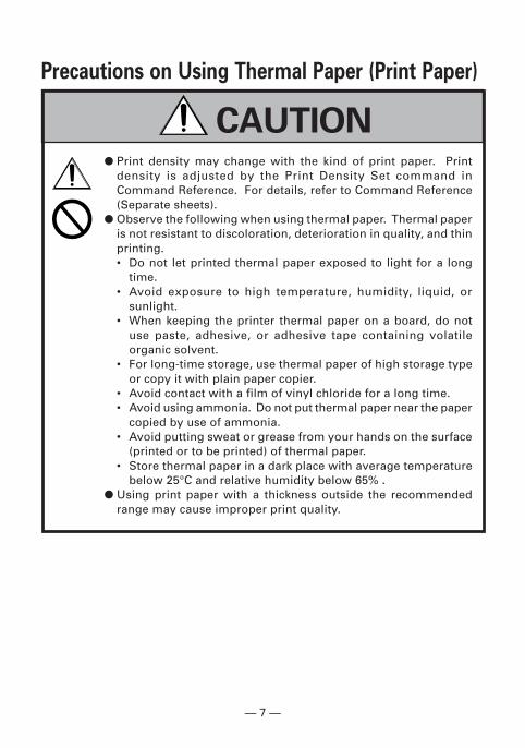
CAUTION� Print density may change with the kind of print paper. Print
density is adjusted by the Print Density Set command inCommand Reference. For details, refer to Command Reference(Separate sheets).
� Observe the following when using thermal paper. Thermal paperis not resistant to discoloration, deterioration in quality, and thinprinting.• Do not let printed thermal paper exposed to light for a long
time.• Avoid exposure to high temperature, humidity, liquid, or
sunlight.• When keeping the printer thermal paper on a board, do not
use paste, adhesive, or adhesive tape containing volatileorganic solvent.
• For long-time storage, use thermal paper of high storage typeor copy it with plain paper copier.
• Avoid contact with a film of vinyl chloride for a long time.• Avoid using ammonia. Do not put thermal paper near the paper
copied by use of ammonia.• Avoid putting sweat or grease from your hands on the surface
(printed or to be printed) of thermal paper.• Store thermal paper in a dark place with average temperature
below 25°C and relative humidity below 65% .� Using print paper with a thickness outside the recommended
range may cause improper print quality.
Precautions on Using Thermal Paper (Print Paper)
— 8 —
WARNING
CAUTION
CAUTION
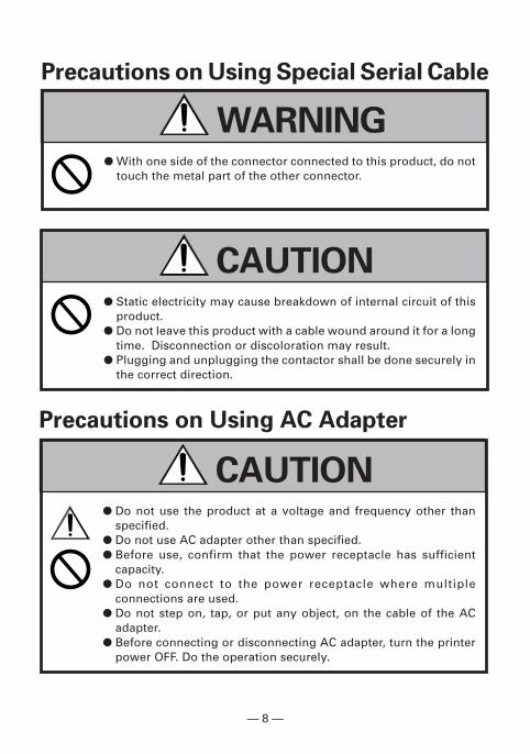
� With one side of the connector connected to this product, do nottouch the metal part of the other connector.
Precautions on Using Special Serial Cable
� Static electricity may cause breakdown of internal circuit of thisproduct.
� Do not leave this product with a cable wound around it for a longtime. Disconnection or discoloration may result.
� Plugging and unplugging the contactor shall be done securely inthe correct direction.
� Do not use the product at a voltage and frequency other thanspecified.
� Do not use AC adapter other than specified.� Before use, confirm that the power receptacle has sufficient
capacity.� Do not connect to the power receptacle where multiple
connections are used.� Do not step on, tap, or put any object, on the cable of the AC
adapter.� Before connecting or disconnecting AC adapter, turn the printer
power OFF. Do the operation securely.
Precautions on Using AC Adapter
— 9 —
THE TABLE OF CONTENTS1. INTRODUCTION ............................................................. 11
1.1 Features ............................................................................. 111.2 Included and Optional Accessories ................................. 121.3 Type Classification ............................................................ 12
2. GENERAL SPECIFICATIONS .......................................... 13
3. EXPLANATION OF PRINTER PARTS.............................. 163.1 LED Indicators ................................................................... 163.2 Communication Port and Switch ..................................... 173.3 Inside of Paper Cover ........................................................ 183.4 Buzzer ................................................................................. 183.5 Bottom Surface and Battery Cover .................................. 193.6 Dimensions and Views ..................................................... 20
4. OPERATION .................................................................... 214.1 Replacing the Paper Roll .................................................. 214.2 Method of Charging .......................................................... 224.3 Communication by IrDA ................................................... 234.4 Communication Via Serial Port (Cable) ........................... 244.5 Communication by Bluetooth .......................................... 254.6 Reading Mag Stripe Card (Only Model with
Built-in Mag Stripe Card Reader) ..................................... 254.7 Removing the Battery Pack .............................................. 264.8 Installing the Battery Pack ................................................ 274.9 DIP Switch Setting ............................................................ 28
5. FUNCTION ...................................................................... 295.1 Auto Power OFF ................................................................ 295.2 Interface Selection ............................................................ 295.3 Low Battery Detection ...................................................... 295.4 Monitoring the Print Head Overheating .......................... 305.5 Self Testing and Internal Settings .................................... 305.6 Print Area ........................................................................... 30
6. LIST OF COMMANDS .................................................... 31

— 10 —
7. MAINTENANCE AND SERVICE ..................................... 33
8. APPENDIX HANDLING BELT CLIP KIT .......................... 348.1 How to Mount Belt Clip .................................................... 348.2 Mounting Rubber Feet ...................................................... 34
— 11 —
1. INTRODUCTIONCMP-10 is a compact, full featured portable line thermal printer, whichcan be used in a large variety of job environments ranging from door-to-door sales through small and mid-sized catering establishments, car-rentals, parking lots, field services to on-board sales on land, sea andair.IrDA/Bluetooth communication with a PDA or similar device is useful forbusiness activities at the point of sale or service.Easily worn on the belt it is a highly efficient device for printing plaintext and graphic receipts on demand plus logos, bar codes and othergraphic elements.
1.1 Features� Small and lightweight.� High speed and low noise emission of the line thermal printing
mechanism.� Long-life printing head with high reliability.� Easy paper-handling, owing to the paper-drop-in style.� The large-capacity Lithium-ion rechargeable allows an extensive
amount of printing with a single charge.� Built-in IrDA.� Built-in Bluetooth function. (CMP-10BT)� Built-in mag stripe card reader. (Option)� Choice of paper-roll diameters – Max. 40 or 50 mm.
— 12 —
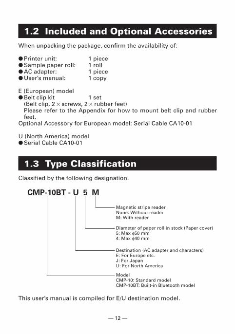
1.2 Included and Optional AccessoriesWhen unpacking the package, confirm the availability of:
� Printer unit: 1 piece� Sample paper roll: 1 roll� AC adapter: 1 piece� User’s manual: 1 copy
E (European) model� Belt clip kit 1 set
(Belt clip, 2 × screws, 2 × rubber feet)Please refer to the Appendix for how to mount belt clip and rubberfeet.
Optional Accessory for European model: Serial Cable CA10-01
U (North America) model� Serial Cable CA10-01
1.3 Type ClassificationClassified by the following designation.
CMP-10BT - U 5 M
Magnetic stripe readerNone: Without readerM: With reader
Diameter of paper roll in stock (Paper cover)5: Max φ50 mm4: Max φ40 mm
Destination (AC adapter and characters)E: For Europe etc.J: For JapanU: For North America
This user’s manual is compiled for E/U destination model.
ModelCMP-10: Standard modelCMP-10BT: Built-in Bluetooth model
— 13 —
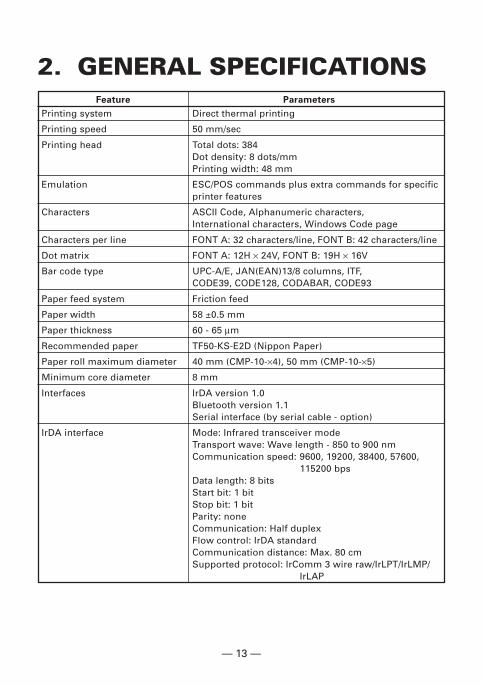
2. GENERAL SPECIFICATIONSFeature Parameters
Printing system Direct thermal printing
Printing speed 50 mm/sec
Printing head Total dots: 384Dot density: 8 dots/mmPrinting width: 48 mm
Emulation ESC/POS commands plus extra commands for specificprinter features
Characters ASCII Code, Alphanumeric characters,International characters, Windows Code page
Characters per line FONT A: 32 characters/line, FONT B: 42 characters/line
Dot matrix FONT A: 12H × 24V, FONT B: 19H × 16V
Bar code type UPC-A/E, JAN(EAN)13/8 columns, ITF,CODE39, CODE128, CODABAR, CODE93
Paper feed system Friction feed
Paper width 58 ±0.5 mm
Paper thickness 60 - 65 µm
Recommended paper TF50-KS-E2D (Nippon Paper)
Paper roll maximum diameter 40 mm (CMP-10-×4), 50 mm (CMP-10-×5)
Minimum core diameter 8 mm
Interfaces IrDA version 1.0Bluetooth version 1.1Serial interface (by serial cable - option)
IrDA interface Mode: Infrared transceiver modeTransport wave: Wave length - 850 to 900 nmCommunication speed: 9600, 19200, 38400, 57600,
115200 bpsData length: 8 bitsStart bit: 1 bitStop bit: 1 bitParity: noneCommunication: Half duplexFlow control: IrDA standardCommunication distance: Max. 80 cmSupported protocol: IrComm 3 wire raw/IrLPT/IrLMP/
IrLAP
— 14 —
Feature Parameters
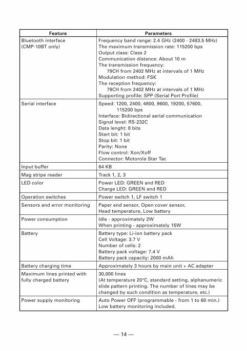
Bluetooth interface Frequency band range: 2.4 GHz (2400 - 2483.5 MHz)(CMP-10BT only) The maximum transmission rate: 115200 bps
Output class: Class 2Communication distance: About 10 mThe transmission frequency: 79CH from 2402 MHz at intervals of 1 MHzModulation method: FSKThe reception frequency: 79CH from 2402 MHz at intervals of 1 MHzSupporting profile: SPP (Serial Port Profile)
Serial interface Speed: 1200, 2400, 4800, 9600, 19200, 57600, 115200 bpsInterface: Bidirectional serial communicationSignal level: RS-232CData lenght: 8 bitsStart bit: 1 bitStop bit: 1 bitParity: NoneFlow control: Xon/XoffConnector: Motorola Star Tac
Input buffer 64 KB
Mag stripe reader Track 1, 2, 3
LED color Power LED: GREEN and REDCharge LED: GREEN and RED
Operation switches Power switch 1, LF switch 1
Sensors and error monitoring Paper end sensor, Open cover sensor,Head temperature, Low battery
Power consumption Idle - approximately 2WWhen printing - approximately 15W
Battery Battery type: Li-ion battery packCell Voltage: 3.7 VNumber of cells: 2Battery pack voltage: 7.4 VBattery pack capacity: 2000 mAh
Battery charging time Approximately 3 hours by main unit + AC adapter
Maximum lines printed with 30,000 linesfully charged battery (At temperature 20°C, standard setting, alphanumeric
slide pattern printing. The number of lines may bechanged by such condition as temperature, etc.)
Power supply monitoring Auto Power OFF (programmable - from 1 to 60 min.)Low battery monitoring included.
— 15 —
Feature Parameters
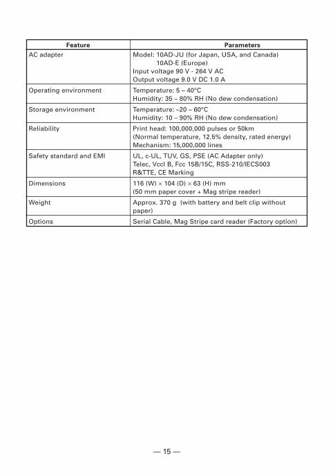
AC adapter Model: 10AD-JU (for Japan, USA, and Canada)10AD-E (Europe)
Input voltage 90 V - 264 V ACOutput voltage 9.0 V DC 1.0 A
Operating environment Temperature: 5 – 40°CHumidity: 35 – 80% RH (No dew condensation)
Storage environment Temperature: –20 – 60°CHumidity: 10 – 90% RH (No dew condensation)
Reliability Print head: 100,000,000 pulses or 50km(Normal temperature, 12.5% density, rated energy)Mechanism: 15,000,000 lines
Safety standard and EMI UL, c-UL, TUV, GS, PSE (AC Adapter only)Telec, VccI B, Fcc 15B/15C, RSS-210/IECS003R&TTE, CE Marking
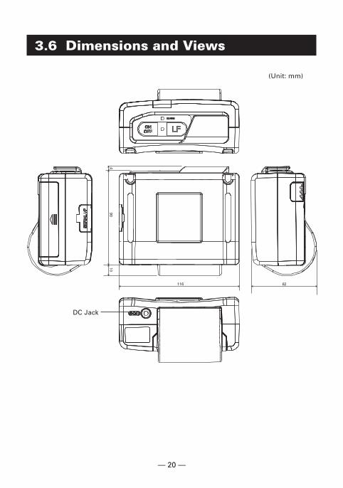
Dimensions 116 (W) × 104 (D) × 63 (H) mm(50 mm paper cover + Mag stripe reader)
Weight Approx. 370 g (with battery and belt clip withoutpaper)
Options Serial Cable, Mag Stripe card reader (Factory option)
— 16 —
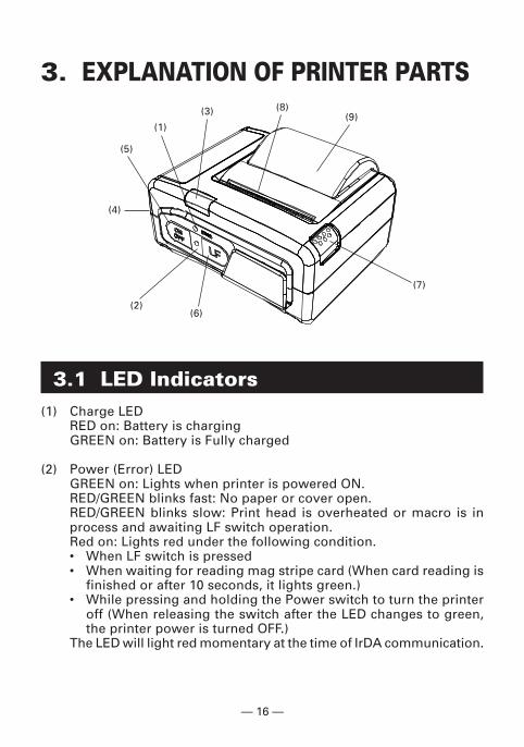
3. EXPLANATION OF PRINTER PARTS
3.1 LED Indicators(1) Charge LED
RED on: Battery is chargingGREEN on: Battery is Fully charged
(2) Power (Error) LEDGREEN on: Lights when printer is powered ON.RED/GREEN blinks fast: No paper or cover open.RED/GREEN blinks slow: Print head is overheated or macro is inprocess and awaiting LF switch operation.Red on: Lights red under the following condition.• When LF switch is pressed• When waiting for reading mag stripe card (When card reading is
finished or after 10 seconds, it lights green.)• While pressing and holding the Power switch to turn the printer
off (When releasing the switch after the LED changes to green,the printer power is turned OFF.)
The LED will light red momentary at the time of IrDA communication.
(1)
(3)
(5)
(7)
(8)(9)
(4)
(2)(6)
— 17 —
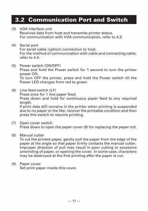
3.2 Communication Port and Switch(3) IrDA interface unit
Receives data from host and transmits printer status.For communication with IrDA communication, refer to 4.3.
(4) Serial portFor serial cable (option) connection to host.For the method of communication with cable and connecting cable,refer to 4.4.
(5) Power switch (ON/OFF)Press and hold the Power switch for 1 second to turn the printerpower ON.To turn OFF the printer, press and hold the Power switch till thePower LED changes from red to green.
(6) Line feed switch (LF)Press once for 1 line paper feed.Press down and hold for continuous paper feed to any requiredlength.If print data still remains in the printer when printing is suspendeddue to no paper or the like, recover the printable condition and thenpress this switch to resume printing.
(7) Open cover switchPress down to open the paper cover (9) for replacing the paper roll.
(8) Manual cutterTo cut the printed paper, gently pull the paper from the edge of thepaper at the angle so that paper firmly contacts the manual cutter.Improper direction of pull may result in poor cutting or excessiveunwinding of paper, or opening the cover. In some case, charactersmay be destroyed at the first printing after the paper is cut.
(9) Paper coverSet print paper inside this cover.
— 18 —
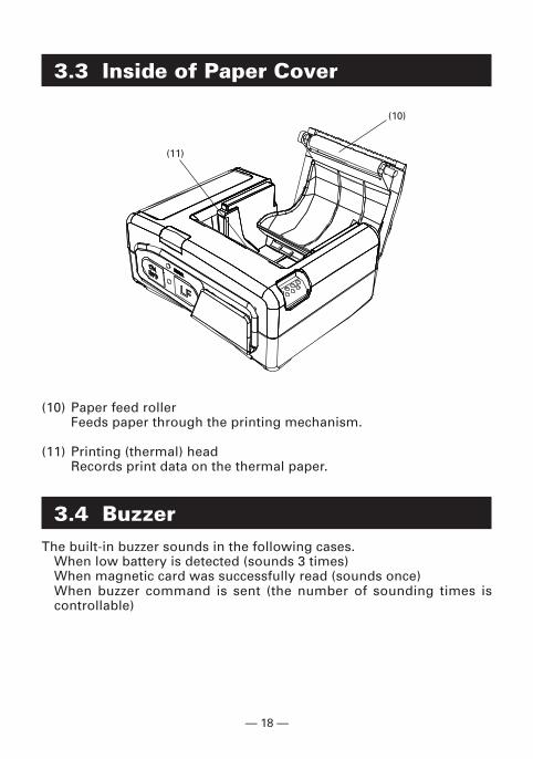
3.3 Inside of Paper Cover
(10) Paper feed rollerFeeds paper through the printing mechanism.
(11) Printing (thermal) headRecords print data on the thermal paper.
3.4 BuzzerThe built-in buzzer sounds in the following cases.
When low battery is detected (sounds 3 times)When magnetic card was successfully read (sounds once)When buzzer command is sent (the number of sounding times iscontrollable)
(11)
(10)
— 19 —
(13)
(12)
(15)
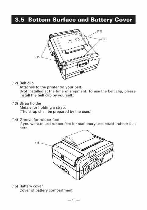
3.5 Bottom Surface and Battery Cover
(12) Belt clipAttaches to the printer on your belt.(Not installed at the time of shipment. To use the belt clip, pleaseinstall the belt clip by yourself.)
(13) Strap holderMetals for holding a strap.(The strap shall be prepared by the user.)
(14) Groove for rubber footIf you want to use rubber feet for stationary use, attach rubber feethere.
(15) Battery coverCover of battery compartment
(14)
— 20 —
3.6 Dimensions and Views
DC Jack
(Unit: mm)
— 21 —
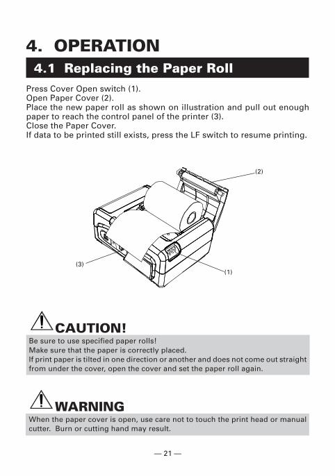
4. OPERATION4.1 Replacing the Paper Roll
Press Cover Open switch (1).Open Paper Cover (2).Place the new paper roll as shown on illustration and pull out enoughpaper to reach the control panel of the printer (3).Close the Paper Cover.If data to be printed still exists, press the LF switch to resume printing.
CAUTION!Be sure to use specified paper rolls!Make sure that the paper is correctly placed.If print paper is tilted in one direction or another and does not come out straightfrom under the cover, open the cover and set the paper roll again.
WARNINGWhen the paper cover is open, use care not to touch the print head or manualcutter. Burn or cutting hand may result.
(3)(1)
(2)
— 22 —
4.2 Method of ChargingIf any of the following conditions occur, charging the battery is required.• “Low Battery” is printed.• The buzzer sounds 3 times.
To charge the battery, plug the connector of the AC adapter to the DCjack of the printer and the AC adapter to the AC outlet. The charge LEDlights red. If the LED changes to green, charging has completed.
In case of a trouble while charging the battery, the charge is suspendedwith blinking of charge LED in red. Try unplugging and plugging ACadapter, then charge should resume and charge LED changes to continueto light red.
CAUTION!Charge the battery at room temperature (5 - 35°C).After completion of battery charging, do not try recharging. Battery performancemay be deteriorated.If printer is kept used with recharging battery, the life of battery may beshortened.When the battery is used in a cold environment, the operation time may beshortened.If the operation time is excessively shortened even after full charging, batterylife may be assumed.
— 23 —
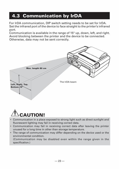
4.3 Communication by IrDAFor IrDA communication, DIP switch setting needs to be set for IrDA.Set the infrared port of the device to face straight to the printer’s infraredport.Communication is available in the range of 15° up, down, left, and right.Avoid blocking between the printer and the device to be connected.Otherwise, data may not be sent correctly.
CAUTION!• Communication in a place exposed to strong light such as direct sunlight and
fluorescent lighting may fail in receiving correct data.• Communication may fail in receiving correct data after leaving the printer
unused for a long time in other than storage temperature.• The range of communication may differ depending on the device used or the
environmental condition.(Communication may be disabled even within the range given in thespecification.)
The IrDA beam
Max. length 80 cm
Left, Right, Top,Bottom 15°
— 24 —
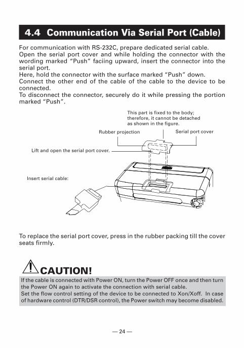
4.4 Communication Via Serial Port (Cable)For communication with RS-232C, prepare dedicated serial cable.Open the serial port cover and while holding the connector with thewording marked “Push” faciing upward, insert the connector into theserial port.Here, hold the connector with the surface marked “Push” down.Connect the other end of the cable of the cable to the device to beconnected.To disconnect the connector, securely do it while pressing the portionmarked “Push”.
To replace the serial port cover, press in the rubber packing till the coverseats firmly.
CAUTION!If the cable is connected with Power ON, turn the Power OFF once and then turnthe Power ON again to activate the connection with serial cable.Set the flow control setting of the device to be connected to Xon/Xoff. In caseof hardware control (DTR/DSR control), the Power switch may become disabled.
Lift and open the serial port cover.
Rubber projection
This part is fixed to the body;therefore, it cannot be detachedas shown in the figure.
Insert serial cable:
Serial port cover
— 25 —
4.5 Communication by BluetoothFor the Bluetooth communication, it is necessary to choose CMP-10BTand set the DIP switches for Bluetooth.As built-in Bluetooth module supports Serial Port Profile, host machineneeds to communicate with CMP-10BT based on serial port profile.Please refer to the software manual of the host machine for the details.
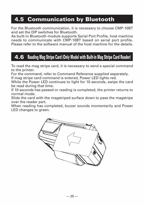
4.6 Reading Mag Stripe Card (Only Model with Built-in Mag Stripe Card Reader)To read the mag stripe card, it is necessary to send a special commandto the printer.For the command, refer to Command Reference supplied separately.If mag stripe card command is entered, Power LED lights red.While the Power LED continues to light for 10 seconds, swipe the cardbe read during that time.If 10 seconds has passed or reading is completed, the printer returns tonormal mode.Slide the card with the magstriped surface down to pass the magstripeover the reader part.When reading has completed, buzzer sounds momentarily and PowerLED changes to green.
— 26 —
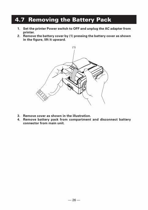
4.7 Removing the Battery Pack1. Set the printer Power switch to OFF and unplug the AC adapter from
printer.2. Remove the battery cover by (1) pressing the battery cover as shown
in the figure, lift it upward.
3. Remove cover as shown in the illustration.4. Remove battery pack from compartment and disconnect battery
connector from main unit.
(1)
— 27 —
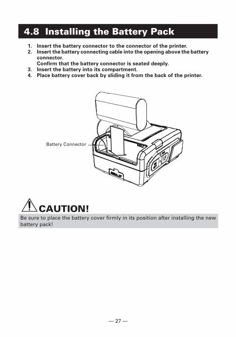
4.8 Installing the Battery Pack1. Insert the battery connector to the connector of the printer.2. Insert the battery connecting cable into the opening above the battery
connector.Confirm that the battery connector is seated deeply.
3. Insert the battery into its compartment.4. Place battery cover back by sliding it from the back of the printer.
CAUTION!Be sure to place the battery cover firmly in its position after installing the newbattery pack!
Battery Connector
— 28 —
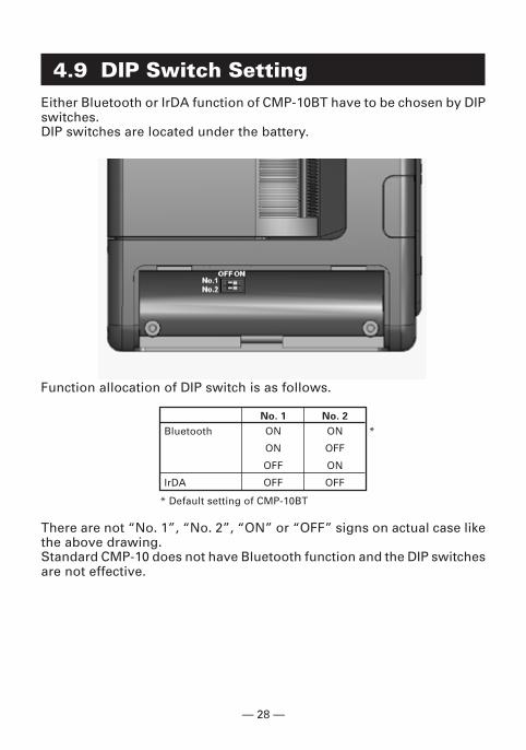
4.9 DIP Switch SettingEither Bluetooth or IrDA function of CMP-10BT have to be chosen by DIPswitches.DIP switches are located under the battery.
Function allocation of DIP switch is as follows.
No. 1 No. 2
Bluetooth ON ON *
ON OFF
OFF ON
IrDA OFF OFF
* Default setting of CMP-10BT
There are not “No. 1”, “No. 2”, “ON” or “OFF” signs on actual case likethe above drawing.Standard CMP-10 does not have Bluetooth function and the DIP switchesare not effective.
— 29 —
5. FUNCTION5.1 Auto Power OFF
Power is automatically cut off after a specified period of time, duringwhich no command is sent to the printer and the LF switch has not beenpressed.The default setting of this time duration is 10 minutes, however, the periodcan be custom set by the user with a special command to the printer.(see Command Reference List)The behavior of the printer at the operation of Auto Power OFF is thesame as that when power is turned OFF by the Power switch.
5.2 Interface SelectionThe interface is automatically selected depending on the presence orabsence of connection to the serial port with a serial cable connector.
� At POWER ON, no cable is connected, the IrDA/Bluetooth interface isselected.
� At POWER ON, the cable is connected, the Serial interface is selected.
CAUTION!If cable is connected with printer power ON, selecting IrDA/Bluetooth interfaceremains valid. If you want to use the serial interface, turn the printer powerOFF once, connect the serial cable, and then turn the printer power ON again.
5.3 Low Battery DetectionBattery charge level is monitored at Power ON, before paper feeding,and before printing.When the buzzer sounds three times or “Low Battery” is printed,immediately charge the battery.
— 30 —
5.4 Monitoring the Print Head OverheatingIf the temperature exceeds 65°C for some reason, the printerautomatically stops printing with Power LED indication of “Error” toprotect the print head.If the head temperature returns to 60°C or below, the printer is ready forprinting.
5.5 Self Testing and Internal Settings� Keep the LF switch pressed down.� Press the ON/OFF switch down.� Release the ON/OFF switch.� Release the LF switch.
Immediately after releasing the LF switch the printer will print out a SELFTEST report.At the end of the report, density, auto-power off time, head temperature,battery output voltage, communication mode, baud rate (for serialcommunication) are printed.The number of marks * in the parentheses aside battery output voltageshows a level of battery charge in 5 steps.
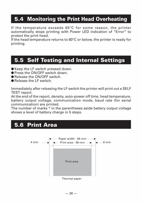
5.6 Print Area
4 mm 6 mmPaper width - 58 mm
Print area - 48 mm
Print area
Thermal paper

— 31 —
6. LIST OF COMMANDS1 BEL Sounds the Buzzer
2 HT Horizontal Tab Command
3 LF Printing and Paper Feed Command
4 CR Print one line Command
5 ESC RS Sounds the Buzzer
6 ESC SP Setting the right space amount of the character
7 ESC ! Collective Specifying Printing Mode
8 ESC $ Specifying the Absolute Positions
9 ESC % Specifying/Canceling Download Character Set
10 ESC & Define user characters
11 ESC * Specifying the Bit Image Mode
12 ESC + Switch OFF the printer
13 ESC – Specifying/ Canceling Underline
14 ESC . Printer self test
15 ESC 2 Specifying 1/6-inch line feed rate
16 ESC 3 Setting line feed rate of minimum pitch
17 ESC = Data Input Control
18 ESC > Saving current setting
19 ESC ? Reading magnetic stripe reader
20 ESC @ Initializing the Printer
21 ESC D Setting Horizontal Tab Position
22 ESC E Specifying/canceling highlighting
23 ESC G Specifying/canceling Double Printing
24 ESC J Printing and feeding paper n/203 inch
25 ESC R Selecting Code table
26 ESC S Setting serial interface communication speed
27 ESC T Printing Diagnostic information
28 ESC V Specifying/Canceling 90°-right- turned Characters
29 ESC Y Specifying print density
30 ESC Z Returning diagnostic information
31 ESC \ Specifying the relative positions
32 ESC _ Setting the printer in default state
33 ESC ` Returning the battery voltage and Printer Headtemperature
*
*
*
*
*
*
*
*
*
*
*
*
*
— 32 —
*
*
*
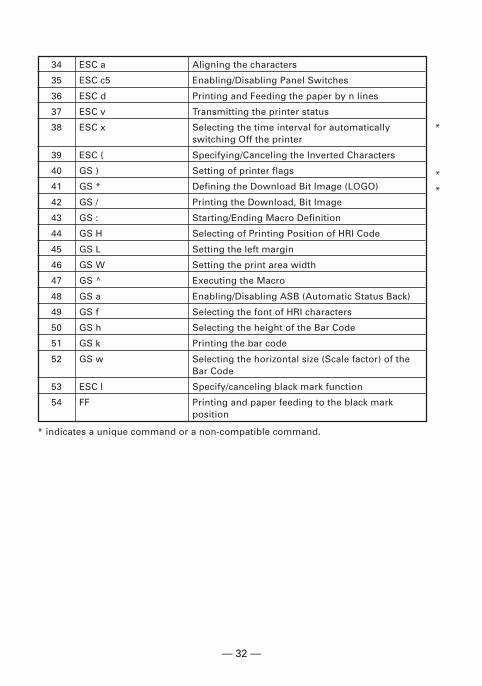
34 ESC a Aligning the characters
35 ESC c5 Enabling/Disabling Panel Switches
36 ESC d Printing and Feeding the paper by n lines
37 ESC v Transmitting the printer status
38 ESC x Selecting the time interval for automaticallyswitching Off the printer
39 ESC { Specifying/Canceling the Inverted Characters
40 GS ) Setting of printer flags
41 GS * Defining the Download Bit Image (LOGO)
42 GS / Printing the Download, Bit Image
43 GS : Starting/Ending Macro Definition
44 GS H Selecting of Printing Position of HRI Code
45 GS L Setting the left margin
46 GS W Setting the print area width
47 GS ^ Executing the Macro
48 GS a Enabling/Disabling ASB (Automatic Status Back)
49 GS f Selecting the font of HRI characters
50 GS h Selecting the height of the Bar Code
51 GS k Printing the bar code
52 GS w Selecting the horizontal size (Scale factor) of theBar Code
53 ESC l Specify/canceling black mark function
54 FF Printing and paper feeding to the black markposition
* indicates a unique command or a non-compatible command.
— 33 —
7. MAINTENANCE AND SERVICEFor information on maintenance and service, please contact your CBMdealer or at the following addresses:
Other AreasJapan CBM CorporationInformation Systems DivisionCBM Bldg. 5-68-10, NakanoNakano-ku, Tokyo 164-0001,JapanTEL: +81-3-5345-7540FAX: +81-3-5345-7541E-mail: [email protected]://www.jcbm.co.jp/
Northern AmericaCBM America Corpora-onService Center363 Van Ness WaySuite 404Torrance, CA 90501, U.S.ATEL: +1-310-781-1460FAX: +1-310-781-9157E-mail: [email protected]://www.cbma.com/
ESC/POS is a trade mark of Seiko Epson Corporation.
— 34 —
8. APPENDIXHANDLING BELT CLIP KIT
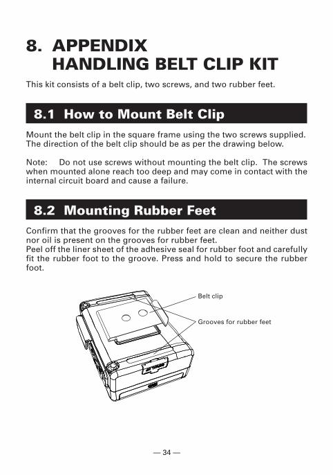
This kit consists of a belt clip, two screws, and two rubber feet.
8.1 How to Mount Belt ClipMount the belt clip in the square frame using the two screws supplied.The direction of the belt clip should be as per the drawing below.
Note: Do not use screws without mounting the belt clip. The screwswhen mounted alone reach too deep and may come in contact with theinternal circuit board and cause a failure.
8.2 Mounting Rubber FeetConfirm that the grooves for the rubber feet are clean and neither dustnor oil is present on the grooves for rubber feet.Peel off the liner sheet of the adhesive seal for rubber foot and carefullyfit the rubber foot to the groove. Press and hold to secure the rubberfoot.
Belt clip
Grooves for rubber feet

— 35 —
MEMO

— 36 —
MEMO

— 37 —
MEMO

Information Systems Division CBM Bldg., 5-68-10, Nakano, Nakano-ku,
Tokyo 164-0001, Japan
Tel: (+81-3) 5345-7540 Fax: (+81-3) 5345-7541
01E-0408 Printed in Korea


