Embed Size (px)
Citation preview

Mixing for Reaction Injection Molding I I . Impingement Mixing of Fiber Suspensions
CHARLES L. TUCKER III* and NAM P. SUH
MIT-Industry Polymer Processing Program Department of Mechanical Engineering Massachusetts Institute of Technology
Cambridge, Massachusetts 02139
The performance of confined impinging jet mixers on sus- pensions of milled glass fibers in Newtonian liquids is investi- gated experimentally. '41~0 studied are the performance of these devices in conjunction with an impingement aftermixer and a rotating mechanical mixing aid. In contrast to the be- havior of unfilled liquids, fiber suspensions exhibit significant large-scale mixing defects. Over the range of fiber lengths and loadings tested, large-scale mixing quality is found to be de- pendent on an effective Reynolds number based on the shear viscosity of the suspension at a strain rate characteristic of the mixing flow. Mixing head geometry is found to be unimportant. Extrapolating published data on the viscosity of milled fiber/ reaction injection molding resin suspensions suggest that im- pingement mixers can successfully process slurries with fiber volume fractions near the maximum value for any particular length of fibers. Both mixing aids are shown to provide im- proved mixing quality, and could be useful in situations where an impingement mixer alone is not adequate.
INTRODUCTION eaction Injection Molding, or RIM, is a process for R manufacturing large plastic parts. In this process,
two liquid resins are rapidly metered, mixed and in- jected into a mold where they react and cure to form a solid part. Recently, attention has been focused on the development of processes to mold fiber-reinforced RIM materials. The resultant increase in strength and stiff- ness and decrease in thermal expansion would make these materials very attractive for lightweight auto body parts such as fenders and doors. Reinforced RIM mate- rials in these applications would offer the additional advantages of damage resistance and corrosion resist- ance when compared to conventional sheet metal parts.
Because most of the anticipated applications for rein- forced RIM require excellent surface finish, reinforc- ing agents such as milled glass fibers (individual short glass filaments) have been considered instead of glass strands (bundles of a few hundred filaments). Milled glass fibers are small enough to be dispersed in the RIM resins to make a slurry, and this slurry can be processed through metering and mixing equipment which uses the same principles as conventional RIM equipment. How- ever, the presence of the glass fibers affects the flow and mixing of the two resins. This is true both on the macro- scopic level, where the suspension may be thought of as a homogeneous fluid with complex rheology, and on the
microscopic level, where the motions of individual fibers become important. Mixers used for RIM are de- signed by trial and error. A previous paper has dealt with the phenomenon of mixing unfilled liquids for RIM (1); this paper is concerned with the problems of mixing suspensions of short glass fibers in the impinging jet type of mixers used for reaction injection molding.
While it is hoped that the knowledge developed here will be useful in designing and operating impingement mixers, it may be that some other mixing scheme is best for reinforced RIM. A brief survey of other possible mixing techniques (2) revealed that impingement mix- ing is very attractive, as long as it can provide adequate mixing quality. There must be some limit to the amount and length of fibers that can be processed through an impingement mixer. If the limits are such that the allow- able amounts of fibers give useful mechanical proper- ties, then impingement mixing is useful. Mechanical property predictions have been undertaken to aid in making this judgment (2), but a simpler criterion is just as useful. There is a maximum volume fraction which fibers can occupy, depending on their aspect ratio (3,4). For fibers to occupy greater volume fractions than this, they must be bent, broken or aligned. Figure 1 shows that even milled glass products (which contain a distri- bution of fiber lengths) follow this rule very closely, provided that one uses the number average fiber length. If the maximum volume fractions of fibers of a given length which can be processed by a mixer is close to this
POLYMER ENGINEERING AND SCIENCE, MID-SEPTEMBER, 1980, Vol. 20, No. 13 aa7

Charles L. Tucker I l l and Nam P. Suh
0.35
0.30
x 0
2 0.25 C 0 .- c 0 0.20 :
LL al 5 0.15
> - 0
.- z OSO X 0
0.05
M
0 Key B Type Pi176 o Type 731
1 1 I I I l l I I I 0.00 0 20 40 60 80 100
Fiber Aspect Ratio, lf/df
Fig. 1 . Muximumfiber volume fruction as a function of average f iber uspect ratio (datu from ReJ (4)).
maximum packing limit, then no other mixing device can do better.
The purpose of this work was to understand the factors affecting the performance of impingement mixers on fiber suspensions, and to explore the processing limits on fiber length and loading. Since secondary mixers, or “aftermixers”, might provide some essential mixing ac- tion in marginal cases, the performance of two such mixing aids was studied. Once the limitations of impingement mixers have been defined, the importance of other types of mixers to reinforced RIM can be de- . -
tided. BACKGROUND
The definition and measurement ofmixing quality has been discussed in a previous paper (1). There, it was shown that a successful RIM mixer must provide an even distribution of the two liquids on a large scale and must also provide a certain minimum degree of small-scale mixing. The first condition insures that the proper pro- portions of reactants will be present at all points in the mixture, and the second condition insures that mo- lecular diffusion can complete the mixing process on a molecular scale in the time available. Mixing quality can be measured by extractinga number ofsamples from the mixture, measuring the concentration of one compo- nent in each sample and computing the variance of these concentrations. The smaller the variance, the better the mixing. Two different variance measures have been de- fined (1). The trend variance, S” , is a measure of large- scale mixing quality, while the increment variance, S”, is a measure of small scale mixing quality. All mixing quality measurements are limited in the fineness of mixtures which they can detect. The type of mea- surements discussed here are limited by variance in the concentration measurements due to random error.
The flow properties of a suspension of fibers are com- plicated, even when considered from a macroscopic viewpoint. Even if the suspending liquid is Newtonian, a fiber suspension can exhibit many of the rheological
phenomena common to polymer melts. Maschmeyer and Hill (5) have reviewed the experimental literature on the rheology of concentrated suspensions of fibers. They point out that even on a qualitative level there is little agreement among researchers concerning the flow behavior of fiber suspensions. They do, however, give the following general features of fiber susljensions:
a. Concentrated fiber suspensions are highly non- Newtonian and may have high yield stresses.
b. Flow properties are sensitive to fiber orientation, and depend on the flow geometry.
c. Fiber breakage can be severe and can cause changes in suspension viscosity.
d. Fibers tend to reduce die swell when suspended in viscoelastic materials, but even suspensions in Newto- nian fluids can exhibit non-zero normal stress differ- ences (e. g., Weissenberg rod-climbing behavior).
The literature on turbulent flow of fiber suspensions is sparse, and is limited to volume fractions of a percent or less. The primary subject of interest has been drag re- duction in turbulent pipe flow (6-g), and even low con- centrations of fibers can alter some features of the turbu- lent motions (6,7,10). These effects have been linked to the non-Newtonian rheology of fiber suspensions, par- ticularly to high elongational viscosities (10).
On a microscopic level, fibers can have a dramatic effect on mixing. Okine studied the laminar mixing of fiber suspensions in a modified Couette flow mixer (11). He found that mixing quality actually improved as fibers were added, up to a limiting fiber volume fraction. He attributed this effect to fluid motions and mixing as- sociated with fiber motions during shear flow. In simple $hear flow, a fiber will spin about its longest axis and rotate or tumble about the vorticity axis of the shear flow (12). The fluid motions associated with these fiber motions will have little or no effect when the striations in the fluid are large compared to the fibers, but can have a dramatic and rapid effect when the striations approach the fiber size. As more fibers are added, interactions between fibers inhibit the tumbling motions, and only the less effective axial spin remains.
ANALYSIS Very little is known about the turbulent flow of con-
centrated fiber suspensions, so the problem, was ap- proached first through dimensional analysis. The as- sumptions from the previous paper (1) (equal fluid vis- cosities and densities, identical nozzles, and no interfa- cial surface tension) were used. It was also assumed that the two streams had equal velocities and equal loadings of identical fibers. The dependent variable is Z,, a length scale characteristic of the fluid mixing quality. The vari- ables which must be added to those of the previous analysis are pf, the fiber density, lf and d,, the fiber length and diameter, and c , the fiber volume fraction. The functional dependence of I, is then
1, = f (P>Pf ,P>V>D>~pl f>C) (1)
p and are the liquid density and viscosity, V the average velocity at the nozzle exit, and D the nozzle diameter. Forming this into dimensionless groups gives
888 POLYMER ENGINEERING AND SCIENCE, MID-SEPTEMBER, 1980, V d . 20, No. 13

The first dimensionless group is the Reynolds number based on the liquid viscosity. While this parameter should be important, when fibers are present it may not be the controlling factor that it is in liquid impingement mixing. The next two parameters are the fiber aspect ratio and volume fraction. These groups describe the influence of fiber length and loading. The parameter d j D is a ratio offiber size to mixer size. In most cases this parameter is less than lo-’, and it does not vary much. The effect of this parameter was not studied. The density ratio, pIpf, was not varied either. The specific gravity of RIM resins is usually very close to 1.1, while that of the glass fibers is 2.54, so that in practice this parameter is almost constant. The foregoing analysis ignores any sur- face chemistry effects, so it strictly applies only to exper- iments in which the fluid and fiber materials are fixed and only the factors in E q 1 arc varied.
Since fiber aspect ratiaand fiber volume fraction both influence the mixing of fiber suspensions, it is reason- able to assume that some single parameter exists which combines the two influences and describes the difficulty of mixing any particular suspension. If such a parameter could be found it would greatly ease the experimental task of identifying the mixing limitations on fiber length and loading. Several parameters were proposed as candidate mixing criteria. They were:
1. The extensional viscosity of the suspension. In some cases the extensional viscosity of a fiber suspension can be orders of magnitude greater than the viscosity of the liquid. The theory of laminar mixing shows that extensional motions are very effective in mixing, but a high extensional viscosity would tend to inhibit exten- sional motions and interfere with mixing. A dimension- less parameter describing the influence of extensional viscosity would be h/3p, the ratio of the extensional viscosity of the suspension to that of the suspending liquid.
2. The maximum fiber volume fraction. The ratio clc,,, takes into account both the length and the amount of fibers present, and is often thought to be important in the rheology of solid particle suspensions.
3. The shear viscosity of the suspension. This quantity may be strain rate dependent, and would have to be measured at an appropriate strain rate. A dimensionless parameter for this quantity would be VIP, where v is the apparent shear viscosity of the suspension.
An effect which may occur in impingement mixers is fiber breakage. This would make subsequent mixing easier and would also hurt the mechanical properties of the final part. One way of including this factor in the dimensional analysis would be to add the strength of the fibers as a variable, and form an additional dimension- less group. The experiments in this work are conserva- tive with respect to the effects of fiber breakage on mixing, since the use of a low viscosity liquid reduces all of the fluid forces involved while the fiber strength remains unchanged. An easy way to check fiber break- age in practice is to take a sample from the molded part and pyrolize it to remove the polyurethane matrix. The
11. I m p i n g e m e n t Mixing of Fiber Suspensions
length of the fibers in the part can then be checked by measuring their packing density (i .e. , maximum volume fraction, c,,,) and comparing it to the packing density of as-received fibers. This experiment was performed with molded reinforced RIM material supplied by one of the sponsors. The material contained 1/16 in. milled fibers and no significant change in the length was noted. Therefore, fiber breakage should be insignificant in the experiments.
The first impingement mixing aid which was studied was an impingement aftermixer. This mixer is essen- tially the same as the static aftermixers used now in conventional reaction injection molding, except that the knowledge developed about impingement mixers in previous studies was used to improve the design. Con- ventional impingement aftermixers have as many as six nozzles. This lowers the nozzle Reynolds number, and decreases the quality of mixing. The impingement af- termixer tested in this study used only two nozzles. This gives a higher Reynolds number, so the mixing should be better. Impingement aftermixers are inexpensive to build, since the shape is simply included as part of the runner. The material in the aftermixer at the end of the pour cycle is allowed to harden, and is demolded along with the part.
Possible drawbacks to the impingement aftermixer are its dependence on a fairly high Reynolds number and the fact that it requires increased driving pressure from the metering unit. Mechanical mixers do not have these problems, so the possibility of a mechanically aided impingement mixer was considered. The mechan- ical mixer would not have to have the large chamber volume and fluid residence time required of a primary mechanical mixer, since it would act as a secondary mixer in this case.
For a fixed mechanical mixer geometry and fixed im- pingement mixing parameters, the improvement in mix- ing provided by the mechanical mixer depends on the product of rotational speed and fluid residence time, wMIQ, (M is the volume of the mixing chamber and QT the total flow rate). The mechanical mixer could be cleaned out either mechanically or by allowing the ma- terial inside it to harden and then demolding it. In either case a simple impeller geometry is required.
EXPERIMENTS All of the experiments were done using milled glass
fibers and water/glycerine mixtures. I t was found that a liquid viscosity between 35 and 50 centipoise kept the fibers from settling too rapidly, but still made it possible to achieve high Reynolds numbers.
The use of liquids which are a factor of ten lower in viscosity than RIM resins is allowed by the principle of dynamic similarity. As long as all of the dimensionless groups (Reynolds number, etc.) are the same in the experiment and the production device, then the same flow patterns and mixing occur.
The slurries were pumped into the mixing head with a twin positive displacement cylinder delivery system. The cylinders were made by smoothing and polishing the inside of extruded aluminum tubing. Brass pistons were used and were sealed with O-rings. This arrange-
POLYMER ENGINEERING AND SCIENCE, MID-SEPTEMBER, 1980, Vol. 20, No. 13 889
Charles L. Tucker Ill and N a m P. Suh
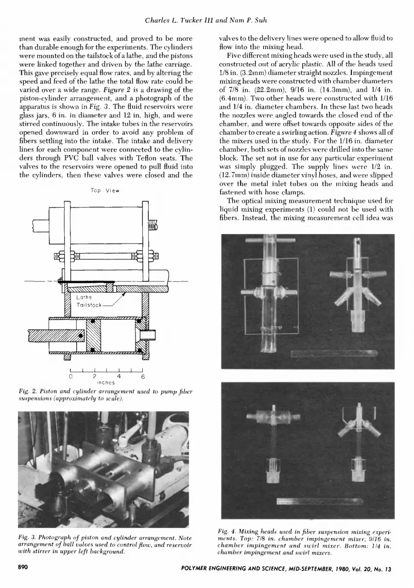
ment was easily constructed, and proved to be more than durable enough for the experiments. The cylinders were mounted on the tailstock of a lathe, and the pistons were linked together and driven by the lathe carriage. This gave precisely equal flow rates, and by altering the speed and feed of the lathe the total flow rate could be varied over a wide range. Figure 2 is a drawing of the piston-cylinder arrangement, and a photograph of the apparatus is shown in Fig. 3 . The fluid reservoirs were glass jars, 6 in. in diameter and 12 in. high, and were stirred continuously. The intake tubes in the reservoirs opened downward in order to avoid any problem of fibers settling into the intake. The intake and delivery lines for each component were connected to the cylin- ders through PVC ball valves with Teflon seats. The valves to the reservoirs were opened to pull fluid into the cylinders, then these valves were closed and the
--
Top V i e w
Ir .-
Ta I I s toc k
I I I I I I I 0 2 4 6
i n c h e s
Fig. 2. Piston and cylinder arrangement used to p u m p fiber suspensions (approximutely to scale).
valves to the delivery lines were opened to allow fluid to flow into the mixing head.
Five different mixing heads were used in the study, all constructed out of acrylic plastic. All of the heads used 1/8 in. (3.2mm) diameter straight nozzles. Impingement mixing heads were constructed with chamber diameters of 7/8 in. (22.2mm), 9/16 in. (14.3mm), and 1/4 in. (6.4mm). Two other heads were constructed with 1/16 and 1/4 in. diameter chambers. In these last two heads the nozzles were angled towards the closed end of the chamber, and were offset towards opposite sides of the chamber to create a swirling action. Figure4 shows all of the mixers used in the study. For the 1/16 in. diameter chamber, both sets of nozzles were drilled into the same block. The set not in use for any particular experiment was simply plugged. The supply lines were 1/2 in. (12.7mm) inside diameter vinyl hoses, and were slipped over the metal inlet tubes on the mixing heads and fastened with hose clamps.
The optical mixing measurement technique used for liquid mixing experiments (1) could not be used with fibers. Instead, the mixing measurement cell idea was
Fig. 4 . Mixing heads used i n f iber suspension mixing experi- ments . Top: 718 in . chamber impingement mixer, 9/16 in. chamber imp ingemen t a n d sccirl mixer . Bo t tom. 1 14 in . chamber impingement and swirl mixers.
Fig. 3. Photograph of piston and cylinder arrangement. Note arrangement of ball valves used to controlpotc, and reservoir wi th stirrer i n upper left background.
I
890 POLYMER ENGINEERING AND SCIENCE, MID-SEPTEMBER, 1980, Vol. 20, NO. 13
Mixing f o r Reaction Injection Molding. 11. lmpingement Mixing of Fiber Suspensions
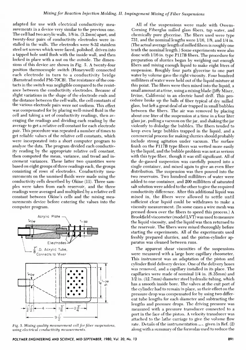
adapted for use with electrical conductivity mea- surements in a device very similar to the previous one. The cell had two acrylic walls, 1/8 in. (3.2mm) apart, and twenty-four pairs of conductivity electrodes were in- stalled in the walls. The electrodes were 8-32 stainless steel set screws which were faced, polished, driven into a tapped hole until flush with the inside wall, and then locked in place with a nut on the outside. The dimen- sions of this device are shown in Fig. .5. A twenty-four position thermocouple switch (Honeywell) connected each electrode in turn to a conductivity bridge (Barnstead model PM-70CB). The resistance of the con- tacts in the switch was negligible compared to the resist- ance between the conductivity electrodes. Because of slight variations in the shape of the electrode ends and the distance between the cell walls, the cell constants of the various electrode pairs were not uniform. This effect was compensated for by placing well-mixed fluid in the cell and taking a set of conductivity readings, then av- eraging the readings and dividing each reading by the average to get a relative cell constant for each electrode pair. This procedure was repeated a number of times to get reliable values of the relative cell constants, which were incorporated into a short computer program to analyze the data. The program divided each conductiv- ity reading by the appropriate relative cell constant, then computed the mean, variance, and trend and in- crement variances. These latter two quantities were based on eight groups of three readings each, the groups consisting of rows of electrodes. Conductivity mea- surements on the unmixed fluids were made using the conductivity cells described by Okine (11). Three sam- ples were taken from each reservoir, and the three readings were averaged and multiplied by a relative cell constant between Okine's cells and the mixing mea- surements device before entering the values into the computer program.
Acry l ic P late
-ml*
E l e c t r o d e s w
L 6 ' ' l . D . A c r y l i c Tube, Connects to M ixe r
Fig. .5. Mixing quality mecisurement cell forf iher .suspensions, using electricul conducticity meusurc~ments.
All of the suspensions were made with Owens- Corning Fiberglas milled glass fibers, tap water, and chemically pure glycerine. The fibers used were type 731, and the nominal lengths were 1/16, 1/8, and 1/4 in. (The actual average length of milled fibers is roughly one tenth the nominal length.) Some experiments were also done with 1/16 in. type P117B fibers. The procedure for preparation of slurries began by weighing out enough fibers and mixing enough liquid to make eight liters of suspension. Roughly four parts glycerine to one part water by volume gave the right viscosity. Four hundred milliliters of water were held out of the liquid mixture at this point. The fibers were then mixed into the liquid, a small amount at a time, usinga mixing blade (Jiffy Mixer, Irvine, California) in an electric hand drill. This pro- cedure broke up the balls of fiber typical of dry milled glass, but left a-great deal of air trapped in small bubbles between the fibers. The air was removed by placing about one liter of the suspension at a time in a four liter glass jar, pulling a vacuum on the jar, and shaking the jar violently to dislodge the bubbles. The fibers tended to keep even large bubbles trapped in the liquid, and a commercial process for making slurries should probably include strong agitation under vacuum. The surface finish on the P117B type fibers was wetted more easily by the liquid, and the bubble problem was not as serious with this type fiber, though it was still significant. All of the de-gassed suspension was carefully poured into a single container, and mixed again to give an even fiber distribution. The suspension was then poured into the two reservoirs. Two hundred milliliters of water were added to one container, and 200 milliliters of saturated salt solution were added to the other to give the required conductivity difference. After this additional liquid was mixed in, the fibers were allowed to settle until sufficient clear liquid could be withdrawn to make a viscosity measurement. (In some cases a wire mesh was pressed down over the fibers to speed this process.) A Brookfield viscometer (model LVT) was used to measure the liquid viscosity, and the liquid was then returned to the reservoir. The fibers were mixed thoroughly before starting the experiments. All of the experiments used freshly prepared slurries, and the piston-cylinder ap- paratus was cleaned between runs.
The apparent shear viscosities of the suspensions were measured with a large bore capillary rheometer. This instrument was an adaptation of the piston and cylinder fluid delivery device. One of the delivery hoses was removed, and a capillary installed in its place. The capillaries were made of nominal 1/4 in. (6.35mm) and 1/2 in. (12.7mm) diameter steel hydraulic tubing, which has a smooth inside bore. The valves at the exit port of the cylinder had to remain in place, so their effect on the pressure drop was compensated for by using two differ- ent tube lengths for each diameter and subtracting the lengths and pressure drops. The driving pressure was measured with a pressure transducer connected to a port in the face of the piston. A velocity transducer was attached to the lathe carriage to give the volume flow rate. Details of the instrumentation u.L given in Ref. (2) along with a summary of the formulas used to reduce the
POLYMER ENGINEERING AND SCIENCE, MID-SEPTEMBER, 1980, Vol. 20, No. 13 89 1

Charles L. Tucker 111 and Nam P. Suh
data. The suspensions used for viscometry were pre- pared as before, except that no salt was added. The hose on the inlet valve to the pumping cylinder was removed and a large funnel attached in its place. This provided a convenient reservoir for the smaller amounts of material used for viscometry. The suspensions were stirred thor- oughly by hand before every run.
The arrangement used to simulate an impingement mixer with an impingement aftermixer is shown in Fig. 6. The 7/8 in. (22.2mm) chamber impingement head was the primary mixer. The flow from it was split into two streams and fed into the 9/16 in. (14.3mm) chamber impingement head (the swirl nozzles on the second mixer were plugged for these tests), which was con- nected to the mixing quality measurement cell. Note that the flow leaving the first impingement mixer is split top and bottom. This should minimize the effects of the large scale segregatiou from the first mixer. This ar- rangement was tested using a 12 percent suspension of 1/16 in. P117B milled glass fibers.
A drawing of the mechanically aided impingement mixer is shown inFig. 7. This design uses a simple blade and a chamber size which would be reasonable for pro- duction mixers. The portion of the mixing chamber be- tween the nozzles could be cleaned by a piston, and the mixing blade would be aligned with its long axis perpen- dicular to the mold parting line before the mixture in the chamber hardened. The remaining material could then be demolded, perhaps with the aid of ejector pins. The
Fig . 6. Arrungemmt used to simulute impingement uftermixer.
Outlet
- Fig. 7. Mechunit ul ly uidrd impingement mixer (approximately to .5cde).
mixing blade was placed close to the impingement point so that turbulent motions persisting down-stream of the impingement point might be made more effective by the mechanical mixer. A photograph of the disassembled mixer is shown in Fig. 8. Also seen in this figure is a notched blade which was tested along with the straight blade. The rotating element of the mechanically aided impingement mixer was driven by a drill chuck in the headstock of the lathe. The relationship between flow rate and rotational speed could be varied by changing the feed setting on the lathe. Suspensions of 12 percent 1/16 in. P117B fibers and 2.5 percent 1/8 in. 731 fibers were used to test this mixer.
RESULTS The results of the shear viscosity measurements are
given in Fig. 9. The measurements on the clear water/ glycerine mixture indicate the accuracy of the tech- nique. All of the suspensions are shear thinning, the degree of this effect increasing with fiber length and volume fraction. The data for each suspension can be fitted by a power law for shear stress vs strain rate. The Rabinowitsch correction to find the true strain rate at the capillary wall is negligible except for the most shear thinning suspension. These measurements are in qual-
Fig. 8 . Exploded vietc of mechanically uided impingement mixer. Both struight and notched blades shotcn.
20 100 I000 l0,OOO
F i g . 9. Sheur zjiscosities of suspensions of milled glassfibers in tcaterlglycerinr. Results f r o m large borp cupillury rhc~ometer.
Shear Rate, y (secd
892 POLYMER ENGINEERING AND SCIENCE, MID-SEPTEMBER, 1980, Vol. 20, No. 13

Mixing f o r Renction Injection Molding. 11. lmpingement Mixing v f Fiber Suspensions
itative agreement with the literature on rheology of concentrated fiber suspensions.
In the mixing experiments, the fiber suspensions ex- hibited a trend variance which was usually larger than the increment variance. Figure 10 shows the measured trend variance, S;, as a function of Reynolds number for all of the suspensions and mixers tested. There is no systematic difference between the performance of vari- ous mixers, but there are clear differcnces in mixing quality between the different suspensions. As would be expected, both increased fiber length and increased volume fraction make the mixing worse at a given Reynolds number. Also as expected, increasing the Reynolds number improves the mixing quality for any particular suspension.
Based on these results, the suspensions can be ranked according to how difficult they are to mix. This is done in Table 1, which also shows the values of each of the candidate parameters for mixing difficulty. The flow- elasticity analogy (13) allows the Halpin-Tsai equations for the extensional modulus of short fiber composites (14) to be used to estimate extensional viscosity. The modulus ratio in the Halpin-Tsai equations, E/IE,, becomes the ratio between the extensional viscosities of
Key Fiber Vol, c Nom. Length
__ 0.025 I /4" 012 1/16"
- 0 0 0 2 5 1/8" _ _ _ _ 0.085 1/16"
I¶ 0.055 1/16" - 0 0 0 2 5 1/16"
Chamber
0 7/8", Impingement A 9/16", Impingement D 9/16", Swir l 0 1/4", Impingement 0 1/4", Swir l
10''
10-2 N C m a, u c 0
0
.- L
> 10-3
? t-
I00 200 500 1000
Nozzle Reynolds Number, ,,VDh
Fig . 10. Mixing results forfiber suspension. Confidence limits omitted for clarity. Arrows indicate negative quantities.
Table 1. Comparison of Parameters Which Rank Difficulty of Mixing for Fiber Suspensions.
Nominal Fiber Fiber
C in. vol fract. length, A/3y c/cmns q/p*
hardest 0.025 114 6.56 0.89 5.3 to mix 0.12 111 6 7.41 0.92 3.25
0.025 118 3.46 0.42 2.1 5.37 0.65 2.0 0.085 111 6
0.055 1116 3.74 0.42 1.9 111 6 2.21 0.19 - 1 0.025
.1 easiest to mix
*q taken at a shear rate of 1200 s-l.
the fiber and liquid for the suspension. Since the fibers are rigid this ratio goes to infinity, and the extensional viscosity is given by
h / 3 ~ = [l + 2 c ( I f / d f ) ] / ( l - C ) ( 3 ) This formula was used to calculate the values of exten- sional viscosity in Table 1 . The values of maximum vol- ume fraction were taken from Isham's paper (4), and the measured shear viscosities at a strain rate of 120 recip- rocal seconds were used. The table shows that the first two parameters do not rank the mixing behavior of the suspensions properly, while the relative shear viscosity does. This parameter is the best choice of the three parameters proposed for describing difficulty of mixing.
If the shear viscosity of the suspension is important in determining its mixing behavior, then it is reasonable to expect that the suspension behaves something like a viscous liquid, and that a Reynolds number based on the suspension viscosity might correlate all of the data. In Fig. 11 the trend variance, S",, is plotted as a function of the effective Reynolds number Rey,, defined by
Rey, = (PVD)/( r l [ P C l ) (4)
7, = V I D ( 5 )
where ye is a characteristic strain rate, given by
This value of 3 seems to correlate the data well, but the suspension viscosities are not sufficiently shear rate de- pendent to tell if a slightly different value of ye would be better. All of the data in Fig . 11 lie close to the same
I I , 8 1 1 1 , I I I I I I I YC"
10-
N + m g 10-2 C 0 P : lo-: 73
+
10-4
3u Fiber Val , c Nam Lengtt
025 1/4" 12 1/16"
085 1/16" 0 055 1/16"
chamber,swirl
V 9/16" . o m 0 025 1/16"
chamber, impingement
718''
A 9/16" 0 1/4"
0
I I , / / , / I i&mL 50 100 200 500 30
Effective Reynolds Number, pVO/7 F i g . 11. Fiber suspension mixing results correlated by apparent shear viscosity of thejbersuspensions. Confidence limits omit- ted for clarity (see F i g . 12-14), Arrows indicate negative yuun- tities.
POLYMER ENGINEERING AND SCIENCE, MID-SEPTEMBER, 1980, VOI. 20, NO. 13 893
Charles L. Tucker Ill and Nam P . Suh
lo-'
N1- v, 10-2-
ar c 0
P 10-3-
; C U
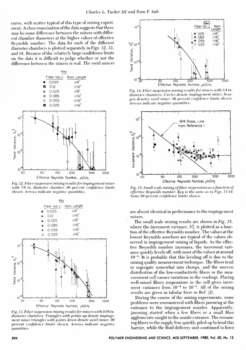
curve, with scatter typical of this type of mixing experi- ment. A close examination of the data suggests that there may be some difference between the mixers with difyer- ent chamber diameters at the higher values of effective Reynolds number. The data for each of the different diameter chambers is plotted separately in Figs . 12 ,13 , and 14 . Because of the relatively large confidence limits on the data it is difficult to judge whether or not the difference between the mixers is real. The swirl mixers
Key Fiber Vol,c Norn Length
0025 1/4" o 12 1/16"
9 0025 1/8" u 0085 1/16" 0 0055 1/16"
0025 1/16"
I I I l I ( l l , 1 , , I > -
Fiber Vol ,c Norn -
0 025 1/8" 0 085 1/16" 0 055 1/16" 0 025 1/16" -
_K_ui
Length -
' ' ' ' ' I
Effective Reynolds Number, pVD/q
Fig. 12. Fiber suspension mixing results f o r impingement mixer wi th 718 in. diumeter chamber. 90 percent confidence limits shown. Arrows indicute negatioe quuntities.
KLY Fiber Vol, c Norn Length
A 0.025 1/4" A 0.12 1/16" A 0.025 1/8" A 0.085 1/16'' A 0.055 1/16" A 0.025 1/16"
20 50 100 200 500 1000
Effective Reynolds Number, pVD/?
Fig. 13. Fiber suspension mixing results f o r mixers w i th 911 6 in . diumeter chumhers. Triungles wi th points u p denote impinge- ment mixer triangles wi th points down denote swirl mixer. 90 percent confidence l imits shocl;n. Arrows indicute negatioe quantities.
Effective Reynolds Number, pVD/?
Fig. 14. Fiber ,suspension mixing resultsfor mixcts wi th 114 in . diumeter chumbers. Circles denote impingement mixer, hexu- gon denotes swirl mixer. 90 percent confidcnce limits s h o m . Arrows indicute ncJgaticr quuntitics.
-914 Slope, Line from Reference I
c u ?! -
\ I I l l
50 100 200 500 1000 lo-!o ' ' ' ' ' ' ' ' Effective Reynolds Number, pVD/7
Fig. 1 5 . Small scale mixing o f f iber suspensions us u func t ion of effectizje Reynolds number. Key is the same us in Figs. 11-14. Some 90 percent confidence limits shown.
are almost identical in performance to the impingement mixers.
The small scale mixing results are shown in Fig . 15, where the increment variance, S", is plotted as a func- tion of the effective Reynolds number. The values at the lowest Reynolds numbers are typical of the values ob- served in impingement mixing of liquids. As the effec- tive Reynolds number increases, the increment vari- ance quickly levels off, with most of the values at around lop3. It is probable that this leveling off is due to the mixing quality measurement technique. The fibers tend to segregate somewhat into clumps, and the uneven distribution of the low-conductivity fibers in the mea- surement cell causes variations in the readings. Placing well-mixed fibers suspensions in the cell gives incre- ment variances from lop4 to All of the mixing results are given in tabular form in Ref. ( 2 ) .
During the course of the mixing experiments, some problems were encountered with fibers jamming at the entrance to the impingement nozzles. Apparently, jamming started when a few fibers or a small fiber agglomerate caught in the nozzle entrance. The remain- ing fibers in the supply line quickly piled up behind this barrier, while the fluid delivery unit continued to force
894 POLYMER ENGINEERING AND SCIENCE, MID-SEPTEMBER, 1980, Vol. 20, No. 13

Mixing fo r Reaction Injection Molding. I l . Impingement Mixing o f Fiber Suspensions
liquid through the fibers. Eventually the cylinders could no longer force fluid through the tightly packed wads of fibers, and the delivery device would fail by pushing back the tool post which held the piston drive rod. Jamming occurred for all mixers with 5 percent by vol- ume of 118 in. type 731 fibers. The 2.5 percent suspen- sion of 1/4 in. type 731 fibers flowed through the mixers with 7/8 and 9/16 in. (22.2 and 14.3mm) diameter cham- bers, but jammed in the mixer with the 114 in. (6.3mm) diameter chamber. Some intermittent jamming was also observed with the highly concentrated suspensions of 1/16 in. milled fibers. These jams always occurred after the machine had been sitting idle for 5-10 inin. The fibers in the delivery hoses would settle somewhat, and a clump of fihers formed during settling would initiate a jam. The jams were cleared by removing the delivery hose from the mixer and scraping out the plug of packed fibers, then running fresh suspension into the hose and reconnecting it.
The trend variance, S;, as a function of effective Reynolds number for the impingement mixer with im- pingement aftermixer is shown in Fig. 16 . Comparing these results to the data in Fig. 11 shows that the two impingement mixers together give large scale mixing roughly equivalent to a single impingement mixer operating at three times the effective Reynolds number.
Mixing data for the mechanically aided impingement mixer is shown in Fig. 17. As expected, the mixing quality improves as both the effective Reynolds number for the impingement mixer and the rotational speed of the mechanical element are increased. As a rough esti- mate, the mechanically aided impingement mixer gives improvements in large scale mixing equal to those of the impingement aftermixer when wM/Q, is about 18. There is virtually no difference in performance between the straight and notched mixing blades. The data for both mixing aids is tabulated in Ref. (2) .
DISCUSSION AND CONCLUSIONS The results for impingement mixing of fiber suspen-
sions show that the large scale features of mixing are a function of the effective Reynolds number, which is
20 50 100 200 500 1000 Effective Reynolds Number, pVD/q
Fig. 16. Mixing performance, of impingrmcnt mixer with im- pingemvnt uftermixer. Suspension contuins 1 5 pcrcent ~f 1 i l6 in. type P 1 1 7 R f i l ~ r r s . 90 percent c,onfidenc.e limits shown. Ar- I Y J ~ C Y indicutr ncgutiw quunti t ies .
' ' I - Key 0 Rey,, = 102
Rey, = 224
I \ I
0 10 20 30 40 wM/QT
Fig. 17. Mixing performuncr. of mechunicully aided impinge- ment mixer with both struight und notched ldudes. 90 percent confidence [imits shorcn. Arrorcs indicute ncgutiur quuntities.
based on the shear viscosity of the suspension at a strain rate characteristic of the impingement mixer. Fiber sus- pensions show significant values of trend variance up to effective Reynolds numbers of two to three hundred. This behavior is not observed in impingement mixing of liquids, so it cannot be said that fiber suspensions mix in exactly the same fashion as liquids. The fact that suspen- sion shear viscosity correlates the results should not be interpreted to mean that other unusual features of the suspension rheology do not play a role. The fact that suspensions mix differently than Newtonian liquids makes this clear. However, the influence of other rheological parameters (extensional viscosity, normal stress differences, etc.) is either relatively minor com- pared to the influence of shear viscosity, or the param- eters do not vary much between the different suspen- sions which were tested. Another possibility is that fiber orientation effects play a role. The calculations for exten- sional viscosity assume that all of the fibers are com- pletely aligned. In the mixing chamber, extensional de- formations may not persist long enough to align the fibers, or there may be fiber aggregates which retain their structure during mixing. In either case the exten- sional viscosity would be very nearly equal to three times the shear viscosity, and shear viscosity mea- surements would correlate the results as observed.
Because the mixing measurement technique is influenced by the presence of fibers, it is relatively insensitive to the small scale features of the mixtures. In Fig . 1.5 the -9/4 slope line that fitted the liquid mixing data in Ref. (1) has been drawn in. The line has been shifted to account for the differences in sample sizes between the two sets of experiments. To some extent the agreement between the line and the data may be fortuitous, since the two sets of experiments had differ- ent nozzle sizes and different degrees of subsequent laminar mixing. However, at effective Reynolds num- bers up to around 120 the data for fiber suspensions look very much like the impingement mixing data for liquids. This is not surprising, since the level at which S 2 , bot- toms out corresponds to a characteristic length of mixing close to 500 microns. Only the 1/4 in. milled fibers are
895 POLYMER ENGINEERING AND SCIENCE, MID-SEPTEMBER, 1980, Vol. 20, No. 13

Charles L. Tucker Ill and Nam P . Suh
longer than this, and as long as the length scale of mixing is larger than the fiber length it is reasonable to expect a suspension to act somthing like a continuum. Therefore, the bulk rheological properties of the suspension should determine its small scale mixing behavior in this region. The large scale features of mixing should always be controlled by bulk rheological properties, since they are determined by the largest motions of the flow.
For effective Reynolds numbers above 120 it ib difficult to guess what the small-scale mixing quality might be like. It is reasonable to expect mixing quality to improve as the effective Reynolds number is increased. Certainly it should not become worse. If the fibers are relatively free to move during mixing then the fiber motions should make small scale mixing better than it is without fibers. On the other hand, if the fibers form aggregates which retain their identity during mixing then some fluid will be trapped in the aggregates. In this case, small scale mixing could be worse than it is without fibers. Both of these effects depend on fiber length and volume fraction, so different suspensions may well have different small scale mixing behavior at high effective Reyndds numbers. Even if the small scale mixing is never much better than the 500 micron scale where the measurements bottom, extra mixing action from fiber motions may complete the mixing task. Note that im- pingement mixers can utilize this subsequent laminar mixing action more effectively than mechanical mixers, since impingement mixers provide randomly oriented interfaces.
It is now clear that the main problem in designing an impingement mixer for fiber suspensions is to achieve a high enough effective Reynolds number. There are sev- eral ways to do this. First, one may either increase the flow rate or decrease t h e nozzle diameter . The maximum flow rate which may be used is determined by the part size and mold filling considerations, while the minimum nozzle size may be limited by fiber jamming. The maximum supply pressure of the metering machine must also be taken into account. To estimate the maximum Reynolds number which might be attained, first note that the driving pressure, p , must be at least
p 2 % p V 2 (6) For a total material flow rate of seven pounds per
second, the flow through each nozzle is 97 im3/s (1589 cm3/s). Ifthe maximum supply pressure is 2500 psi, then the minimum nozzle diameter is found by substituting
V = 4QlrrD2 (7)
( 8 )
into Ey 6. Solving for D gives
D 2 0.13 in . (3 .4 mm)
If the fluid viscosity is around 300 centipoise, then the maximum Reynolds number for this flow rate and nozzle size is 1714. If an effective Reynolds number of 300 is needed for adequate mixing, then fiber loadings which increase the liquid viscosity by as much as a factor of 5.7 can be mixed. Note that this nozzle size is almost equal to the nozzle diameters of the mixers used in the exper- iments. If a lower flow rate is used. then the nozzle size
should be decreased until the driving pressure is as high as can comfortably be supplied by the metering machine. Several impingement mixing heads for liquids have nozzles which do exactly this. The ability to adjust nozzle size may be even more important for impinge- ment mixing of fibers, since the proper nozzle size can mean the difference between acceptable and unaccept- able mixing when the machine operates near its limits. The example just shown suggests that at high flow rates the nozzles will be large enough that clogging will not be a problem. (Fiber jamming should be less of a problem in production mixers than in the experiments, since the higher fluid forces are more likely to break the fibers in an incipient jam.) For low flow rates the decrease in nozzle size will eventually lead to jamming. This is probably not a serious problem, since other types of mixers already work well at low flow rates (e.g., the USM LIM machine (15)).
The supply pressure could be increased to allow the use of smaller nozzles at high flow rates and increase the Reynolds number capability of the mixer. Equations 6 and 7 show that
p - Q2/D4 (9)
R e y , = (4PQ) / (TTD) (10)
R e y , - ( Q Y ( p P 4 (11)
and the Reynolds number is
Combining these two equations to eliminate D gives
so for a fixed flow rate and decreasing nozzle size the Reynolds number increases very slowly with pressure. Increasing the supply pressure by a factor of four, a very expensive proposition in terms of the construction of a metering device, only gives a 40% increase in Reynolds number. Changing the supply pressure is not a very effective way to improve mixing quality.
Reducing the viscosity of the suspending liquid re- duces the suspension viscosity and increases the Reynolds number. This can be done either by changing the chemical formulation or by heating the liquids. The chemical formulation of the resins controls the mechani- cal properties of the matrix, so the improvement avail- able through this route may be slight. However, when several formulations are being considered for a particu- lar application, the viscosity of the raw materials should be taken into account. Raising the process temperature of the resins not only reduces their viscosity, but affects the reaction kinetics as well. Presumably the catalyst level in the material could be reduced to give the same reaction time for higher resin temperatures. The limits on increasing the temperature occur when the reaction exotherm causes high enough temperatures in the part that the material is thermally degraded. This problem is aggravated by the fact that polyurethanes have poor high temperature stability. Lee and Macosko (16) have studied reaction and heat transfer during the curing of RIM parts. They found that the temperature rise at the center of the molded part was very close to the adiabatic temperature rise of the reaction, which is often as great as 100°C (180°F). Therefore, any increase in the raw
896 POLYMER ENGINEERING AND SCIENCE, MID-SEPTEMBER, 1980, Vol. 20, No. 13

Mixingfor Reuction Injection Molding. 11. Impingement Mixing of Fiber Suspensions
material temperature will cause a corresponding in- crease i n the peak temperature in the molded part, regardlcss of reaction kinetics or heat transfer to the mold (assuming reasonable reaction times and part thickness). Lee and Macosko also point out that large temperature gradients in the part during molding may lead to poor material properties, even when the material is not thermally degraded. Bearing these difficulties in mind, it might still be worthwhile to try reducing the fluid viscosity by increasing the temperature.
Onr final way of keeping the Reynolds number high is to reduce the influence of the fibers on the suspension viscosity. This might be possible through alterations to the chemical surface treatment applied to the fibers.
The only reasonable way to estimate the effects of fibers on suspension viscosity when RIM resins are used is from experiments with the actual materials. The only published viscosity for glass fibers in RIM resins is that of Isham (4). He used a Brookfield viscometer with a T-shaped spindle, and reported one plot of suspension viscosity vs spindle speed. These data also follow a power law relationship. The strain rate in this type of viscoineter is not well defined, but the order of mag- nitude of the strain rate can be estimated. (The average strain rate should be on the order of the spindle rotation speed times the cross-bar radius, divided by the cross- bar diameter.) Extrapolating Isham’s data to a strain rate of 104 reciprocal seconds gives the apparent viscosity of the most concentrated suspensions he tested as about 650 centipoise. These suspensions contained about 15 percent by volume of 1/16 in. and 10 percent by volume of 1/4 in. P117B milled fibers. This corresponds respec- tively to about 75 and 95 percent of the maximum load- ings for those two fiber lengths. This result is very encouraging since a suspension with a viscosity of 650 centipoise would not be very difficult to mix. It also points out how misleading the type of measurements taken by Isham can be if not interpreted carefully. For the strain rates at which his data was taken, the suspen- sions have viscosities rangingfrom lo4 to lo’centipoise!
Both the impingement aftermixer and the mechani- cally aided impingement mixer can improve mixing per- formance. Their usefulness and the choice of one over the other for a particular application depend on how much effort is required to get good mixing. Neither device will be useful when the impingement mixer op- erates at very low effective Reynolds numbers. The results show that the effective Reynolds number must be at least about 150 to get significant mixing with either device. This defines the lower limit of the useful range of impingement mixers.
The costs associated with the impingement aftermixer are the extra pressure required to force the fluid through it, and the cost of the extra material which must be demolded and thrown away. If most ofthe pressure drop takes place in the impingement nozzles, then for a given geometry and Reynolds number use of the impingement aftermixer should roughly double the supply pressure. However, the data show that the impingement after- mixer gives results corresponding to roughly a factor of three increase in Reynolds number. Equation 11
suggests that to simply increase the Reynolds number of the primary impingement mixer this much by decreas- ing the nozzle size would require a factor of 81 increases in the driving pressure. This argument ignores pressure losses in the delivery lines, which may be significant, but it shows that the impingement after- mixer may be a very useful device in many reinforced RIM applications. As far as large scale mixing is con- cerned, an impingement mixer with an impingement aftermixer should give better mixing for a given flow rate and metering pressure than the impingement mixer alone.
The costs associated with the mechanically aided im- pingement mixer are mechanical complexity and mate- rial waste. I t is interesting to see what values of the operating parameter W M I Q , can be attained in a produc- tion situation. The experimental mixer had a chamber volume of about 1.2 in.3 (19.7 cm’)). An upper limit on rotational speed would be about 10,000 RPM (1047 rad/ s), and the flow rates for RIM can be as high as 7 lbsls (QT = 213 in. “1s = 3496 cm3/s). These values give
W M / Q T = 5.90 (12)
for a high flow rate production mixer. This is at the lower end of the useful range for the mechanically aided im- pingement mixer. To get a higher value of w M / Q T one would either have to decrease the flow rate or increase the mixer volume (which would waste more material). However, the mechanically aided impingement mixer should not cause any significant increase in the metering pressure. In some cases the addition of an impingement aftermixer to the impingement mixer may increase the driving pressure so much that the maximum attainable value of Rey, is below the minimum useful value. In these cases the mechanically aided impingement mixer would be the clear choice. A final judgment as to which mixing aid is better for a given case would require de- tailed information on the pressure-flow relationships for the mixers and the delivery lines, as well as rheological data on the suspension being mixed.
This study provides the following information about impingement mixing of fiber suspensions:
The dominant rheological parameter is the apparent shear viscosity of the fiber suspension, measured at a strain rate characteristic of the flow in the impinge- ment mixer. The large scale features of the mixing depend primar- ily on the effective Reynolds number of the mixer, Rey,, given by
R e y , = ( P V D ) / ( v[-Ucl) (4)
35, = V I D (5)
where the characteristic strain rate is
These parameters correlate data for suspensions with different fiber lengths and volume fractions.
For a fixed value of effective Reynolds number, mix- ing is independent of, or only very weakly dependent on, other geometrical features of the mixing head. Above an effective Reynolds number of about 300, the large scale variations in mixing quality disappear.
POLYMER ENGINEERING AND SCIENCE, MID-SEPTEMBER, 1980, Vol. 20, No. 13 897

Churles L. Tucker I l I and Nam P. Suh
At this point the length describing the small scale features of the mixing is no larger than 500 microns and is probably smaller.
In addition, fiber motions induced by shear flow of the suspension may aid laminar mixing as the suspension flows through the riinncr and into the mold.
The most important fact to bear in mind when design- ing or operating impingement mixers for reinforced re- action injection molding is to keep the Reynolds number high. This is most easily done by adjusting the nozzle diameter, and 110 suspension should be judged impossi- ble to process until the full siipply pressure capabilities of the metering unit have been used. Other ways to increase Reynolds number are to increase the flow rate, increase the supply pressure of the metering unit, and decrease the viscosity of the resins. Each of these meth- ods has its limitations and drawbacks.
Literature on the viscosity of glass fibers in RIM resins suggests that impingement mixers will be able to proc- ess between 85 and 90 percent of the maximum fiber volume fraction for any particular fiber length. The per- centage of the maximum volume fraction which can be handled should be slightly higher for longer fibers. Rheological measurements taken at low strain rates can be very misleading in this regard.
When fiber lengths and loadings are very high, aids to impingement mixing may be helpfill. The conclusion of this study regarding mixing aids may be summarized as follows:
Both the impingement aftermixer and the mcJchani- cally aided impingement mixer are useful aids to impingement mixing.
The impingement mixer/impingement aftermixer combination is probably more efficient than a single impingement mixer at the same pressure and flow rate.
The mechanically aided impingement mixer should be useful when achieving the minimum value of effective Reynolds number in the primary impinge- ment mixer requires the full pressure capabilities of the metering unit.
With either of the mixing aids, the useful operating range of impingement mixers can be extended down to an effective Reynolds number of 100 to 150.
ACKNOWLEDGMENTS This work was sponsored by the MIT-Industry Poly-
mer Processing Program. Many helpful comments and suggestions came from the industrial members. The sponsors ofthe program are: AMP, Inc.; Eastman Kodak Company; General Motors Corporation; Gleason Works; Goodyear Tire and Rubber Company; In- strumentation Laboratory, Inc.; International Tele- phone and Telegraph Corporation; Kendall Company; Lord Corporation; National Science Foundation; Rogers Corporation; USM Corporation; and Xerox Corpora- tion.
Contributions to this work by the staff and students of MIT’s Materials Processing Laboratory are also grate- fully acknowledged.
NOMENCLATURE c = fiber volume fraction cmas = maximum fiber volume fraction with random
packing df = fiber diameter D = nozzle diameter EJEm = ratio of fiber modulus to matrix modulus in
V Y Y , r) x
P P Pf w
1 . 2.
3.
4.
5.
6.
7.
8. 9.
10. 11.
12.
13. 14. 15. 16.
Halpin-Tsai equation = fiber length = length scale characteristic of small scale mixing
= volume of mechanical mixing chamber = fluid pressure = volume flow through one nozzle = total volume flow rate of mixturc = effective Reynolds number, based on apparent
= increment variance, a measure of small scale
= trend variance, a measure of large scale mixing
= average velocity of suspension at nozzle exit = shear strain rate = characteristic strain rate in impingement mixer = apparent shear viscosity of fiber suspension = elongational or extensional viscosity of fiber
suspension = liquid viscosity = liquid density = fiber density = angular velocity of rotating element in mechan-
ical mixer
quality
shear viscosity of fiber suspension
mixing quality
quality
REFERENCES C . L. Tucker and N. P. Suh, Polym. Eng. Sci., 20,875 (1980). C. L. Tucker, Ph.D. Thesis, Dept. of Mech. Engr., MIT, Cambridge, Mass. (1978). J . V. Milewski, ACS Org. Coating Plast . Cheni. Prepr. , 33. 57 (1973). A. B. Isham, “Proc. 33rd SPI RPiC Ann. Tech. Conf.,” 14-A (1978). R. 0. Maschmayer and C. T. Hill, iidc. Chum. Series, No. 134, 95 (1974). A. J . Bobkowicz and W. H. Gauvin, Chcm. E,r~.g. Sci., 22,229 (1967). R. J . Pirih and W. M. Swanson, Can. J . Chem. Eng., 50,221 (1972). E. Bilgenand R. Boulos,Can.J. Chrrn. Eng., 51,405(1973). R. C. Vaseleski and il. B. Metzner,AIChE J., 20,301 (1974). D. D. Kale and A. B. Metzner, AZChE J. , 22, 669 (1976). R. K. Okine, S. M. Thesis, Dept. of Mech. Engr., MIT, Cambridge, Mass. (1978). S. G. Mason and H. St. J . Manlcy, Proc. Royal Soc., A 238, 1165 (1975). L. E. Nielscn, J . Comp. Muter., 2, 120 (1968). J. C. Halpin, J . Cornp. Muter., 3, 732 (1969). R. P. Titlebaum, Plast . Eng., 31, 30 (1975). L. J . Lee and C. W. Macosko, “Proc. 30th SPE ANTEC,” 155 (1978).
a98 POLYMER ENGINEERING AND SCIENCE, MID-SEPTEMBER, 1980, Vol. 20, No. 13


