Embed Size (px)
Citation preview
1
Ministry of Education and Science of Ukraine
Ternopil Ivan Puluj National Technical University
Department of building mechanics
Study guide on
“Technology of Structural materials and Material Science”
Part 3
“Material Science”
for students of “Engineering mechanics” field of study 6.050502
Student ____________________________________________________
Faculty __________________________________________________
Course ______________________ Group ________________________
Ternopil
2016
2
Kramar H.M. Study guide on “Technology of Structural materials and
Material Science” Part 3 “Material science” for students of “Engineering mechanics”
field of study 6.050502 (full-time study bachelors) // H.M.Kramar, L.H. Bodrova. –
Ternopil, TNTU, 2016. – 160 p.
Authors: H.M. Kramar
L.H. Bodrova
Reviewer: Ya.O.Kovalchuk
Study guide on have been approved at the meeting of building mechanics
department (minutes 1 from 25 August 2016)
The Study guide on have been approved by the Mechanical Engineering
Faculty methodological committee (minutes 1 from 29 August 2016)
3
Contents
Labs Part 3
Pages
Safety during lab activities
Practical 2. Iron – Carbon equilibrium diagram
LW5 Plain carbon steels 16
LW6 Cast iron 30
LW7 Heat treatment of steel 36
LW8 Chemical heat treatment of steel 52
LW9 Alloy steels (low alloy steels and stainless steels) 62
LW10 Tool steel and hard alloys 80
LW11 Aluminium, copper and their alloys 89
LW12 Ceramics 107
LW13 Polymers 123
Glossary 136
Appendixs 145
Reference 160
4
Introduction
“Technology of Structural materials and Material Science” is one of the basic
technical disciplines in the syllabus for “Engineering mechanics” field of study.
During the implementation of laboratory work considerable attention is given to
the educational and experimental work for the study of materials that are used in different
branches of an industry; methods of treatment and external environments The study of the
theory and practice of different methods of materials strengthening is to provide a high
reliability and longevity of the machine’s details, devices, tools etc.
After every practical class and lab activities in the laboratory, students will fill the
laboratory report. The content of the laboratory class corresponds with the syllabus of the
course “Technology of Structural materials and Material Science” for students of the
“Engineering mechanics” field of study.
The purpose of this manual is to provide guidelines for the students in preparation
for independent laboratory work and to project its results in the laboratory reports.
5
Safety during lab activities
The laboratory classes for “Material Science” will take place in the education-
research laboratories of the department of building mechanics. The observation of the
safety requirements is necessary during labs activities.
Students who are not taking part in the lab activities, must seat at their desks.
Students can’t:
- store any unnecessary things, which are not used during the lab on the work
place;
- whirl adjustment knob of microscope, machine for tensile strength and hardness
testing and other devices, if it is not used during labs activities.
- turn on machine-tools, weld transformer, presses etc.
Students can do labs only when they are supervised by a teacher.
Labs equipment has high voltage (220 or 380 V).
To prevent danger by electrical current, it is prohibited to:
turn on equipment that is not used during labs;
open the doors of the electrical wardrobe and furnace;
transfer equipment and devices.
Before turning on an equipment student must see that it is safe to do so. When a
student observes that equipment has defects, it is prohibited to turn on voltage. The
student must report such to the teacher immediately.
During some lab classes, students will use chemical substances. When chemical
substance comes in contact with the student’s skin or eyes, it is necessary to wash with
water immediately.
During the lab classes that require equipment with heating, beware of catching fire
with your clothes and skin burn.
Violation of these safety rules may lead to unhappy accidents.
Follow these safety rules strictly!
6
Practical 2. IRON-CARBON EQUILIBRIUM DIAGRAM
Objectives
1. To learn the process Fe – Fe3C diagram analysis.
2.To learn how to apply the phase rule and inverse level rule.
Scientific principles
Fe and C are the main components of Fe – Fe3C diagram. Fe has polymorphic
modification; it’s marked by the initial letters of the Greek alphabet, beginning from low
temperatures (Feα, Feγ Feδ).
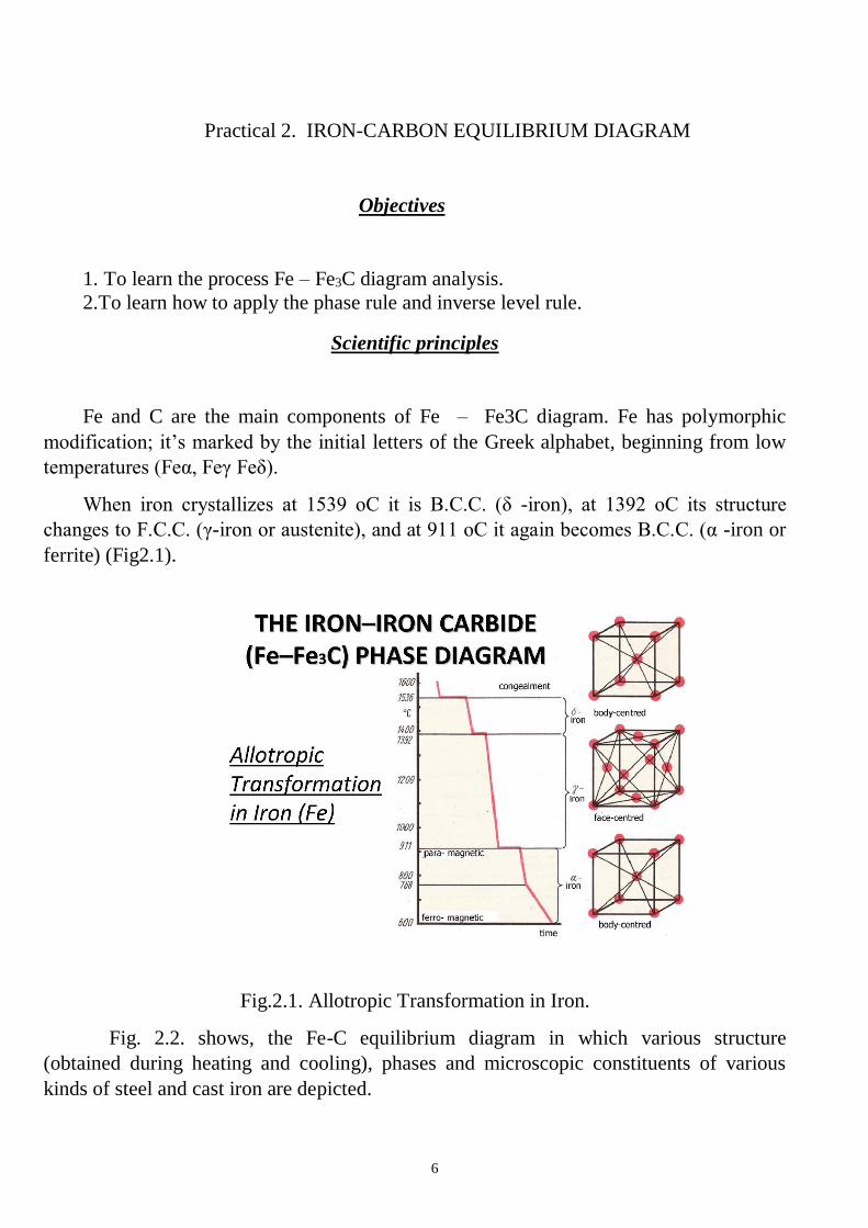
When iron crystallizes at 1539 oС it is B.C.C. (δ -iron), at 1392 oС its structure
changes to F.C.C. (γ-iron or austenite), and at 911 oС it again becomes B.C.C. (α -iron or
ferrite) (Fig2.1).
Fig.2.1. Allotropic Transformation in Iron.
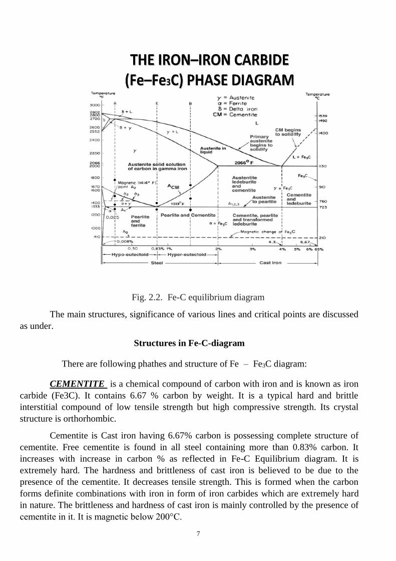
Fig. 2.2. shows, the Fe-C equilibrium diagram in which various structure
(obtained during heating and cooling), phases and microscopic constituents of various
kinds of steel and cast iron are depicted.
7
Fig. 2.2. Fe-C equilibrium diagram
The main structures, significance of various lines and critical points are discussed
as under.
Structures in Fe-C-diagram
There are following phathes and structure of Fe – Fe3C diagram:
CEMENTITE is a chemical compound of carbon with iron and is known as iron
carbide (Fe3C). It contains 6.67 % carbon by weight. It is a typical hard and brittle
interstitial compound of low tensile strength but high compressive strength. Its crystal
structure is orthorhombic.
Cementite is Cast iron having 6.67% carbon is possessing complete structure of
cementite. Free cementite is found in all steel containing more than 0.83% carbon. It
increases with increase in carbon % as reflected in Fe-C Equilibrium diagram. It is
extremely hard. The hardness and brittleness of cast iron is believed to be due to the
presence of the cementite. It decreases tensile strength. This is formed when the carbon
forms definite combinations with iron in form of iron carbides which are extremely hard
in nature. The brittleness and hardness of cast iron is mainly controlled by the presence of
cementite in it. It is magnetic below 200°C.
8
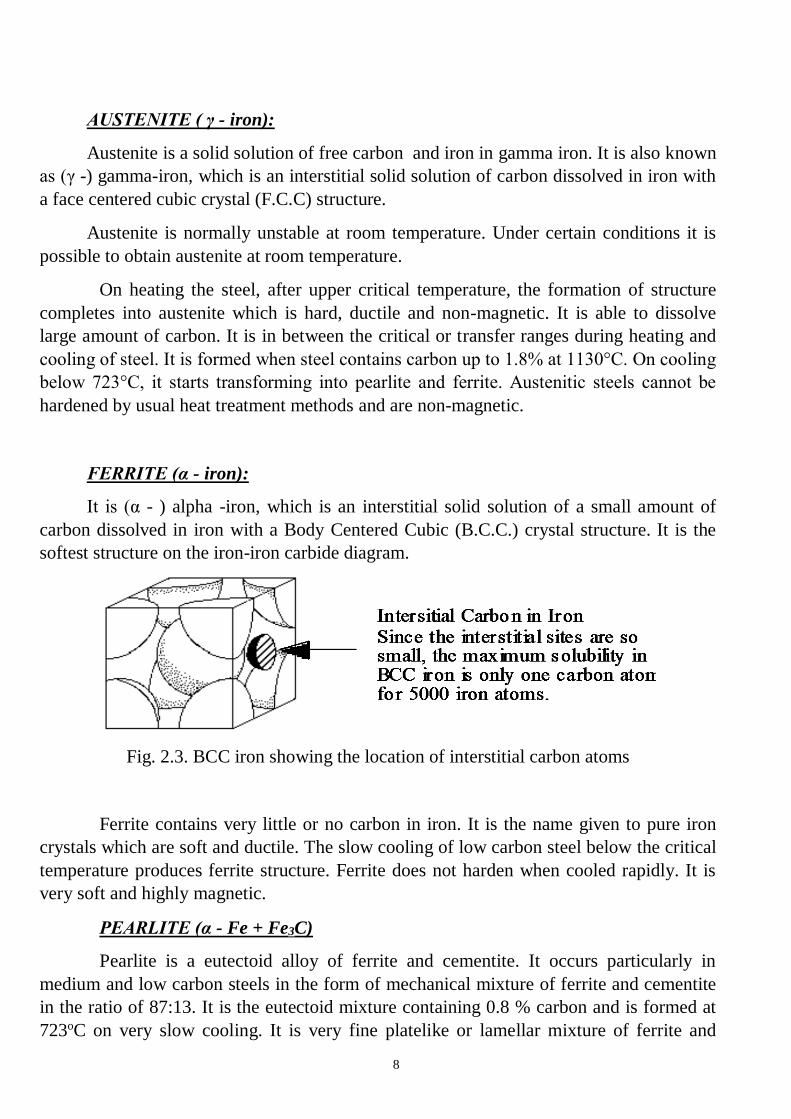
AUSTENITE ( γ - iron):
Austenite is a solid solution of free carbon and iron in gamma iron. It is also known
as (γ -) gamma-iron, which is an interstitial solid solution of carbon dissolved in iron with
a face centered cubic crystal (F.C.C) structure.
Austenite is normally unstable at room temperature. Under certain conditions it is
possible to obtain austenite at room temperature.
On heating the steel, after upper critical temperature, the formation of structure
completes into austenite which is hard, ductile and non-magnetic. It is able to dissolve
large amount of carbon. It is in between the critical or transfer ranges during heating and
cooling of steel. It is formed when steel contains carbon up to 1.8% at 1130°C. On cooling
below 723°C, it starts transforming into pearlite and ferrite. Austenitic steels cannot be
hardened by usual heat treatment methods and are non-magnetic.
FERRITE (α - iron):
It is (α - ) alpha -iron, which is an interstitial solid solution of a small amount of
carbon dissolved in iron with a Body Centered Cubic (B.C.C.) crystal structure. It is the
softest structure on the iron-iron carbide diagram.
Fig. 2.3. BCC iron showing the location of interstitial carbon atoms
Ferrite contains very little or no carbon in iron. It is the name given to pure iron
crystals which are soft and ductile. The slow cooling of low carbon steel below the critical
temperature produces ferrite structure. Ferrite does not harden when cooled rapidly. It is
very soft and highly magnetic.
PEARLITE (α - Fe + Fe3C)
Pearlite is a eutectoid alloy of ferrite and cementite. It occurs particularly in
medium and low carbon steels in the form of mechanical mixture of ferrite and cementite
in the ratio of 87:13. It is the eutectoid mixture containing 0.8 % carbon and is formed at
723oC on very slow cooling. It is very fine platelike or lamellar mixture of ferrite and
9
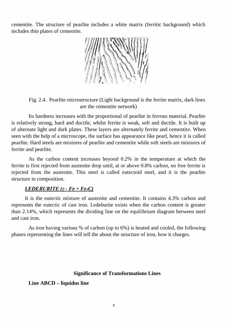
cementite. The structure of pearlite includes a white matrix (ferritic background) which
includes thin plates of cementite.
Fig. 2.4. Pearlite microstructure (Light background is the ferrite matrix, dark lines
are the cementite network)
Its hardness increases with the proportional of pearlite in ferrous material. Pearlite
is relatively strong, hard and ductile, whilst ferrite is weak, soft and ductile. It is built up
of alternate light and dark plates. These layers are alternately ferrite and cementite. When
seen with the help of a microscope, the surface has appearance like pearl, hence it is called
pearlite. Hard steels are mixtures of pearlite and cementite while soft steels are mixtures of
ferrite and pearlite.
As the carbon content increases beyond 0.2% in the temperature at which the
ferrite is first rejected from austenite drop until, at or above 0.8% carbon, no free ferrite is
rejected from the austenite. This steel is called eutectoid steel, and it is the pearlite
structure in composition.
LEDEBURITE (γ - Fe + Fe3C)
It is the eutectic mixture of austenite and cementite. It contains 4.3% carbon and
represents the eutectic of cast iron. Ledeburite exists when the carbon content is greater
than 2.14%, which represents the dividing line on the equilibrium diagram between steel
and cast iron.
As iron having various % of carbon (up to 6%) is heated and cooled, the following
phases representing the lines will tell the about the structure of iron, how it charges.
Significance of Transformations Lines
Line ABCD – liquidus line
10
The line ABCD tells that above this line melting has been completed during
heating the iron. The molten metal is purely in the liquidus form. Below this line and
above line AHJECF the metal is partially solid and partially liquid. The solid metal is
known as austenite. Thus the line ABCD represents temperatures at which melting is
considered as completed. Beyond this line metal is totally in molten state. It is not a
horizontal line the melting temperature will vary with carbon content.
Line AHJECF – solidus line
This line tells us that metal starts melting at this temperature. This line is not
horizontal and hence the melting temperatures will change with carbon content. Below
this line and above line GSEC, the metal is in solid form and having austenite structure.
Line PSK – eutectoid reaction
This line occurs near 723°C and is a horizontal line and is known as lower critical
temperature line because transformation of steels starts at, this line. Carbon % has not
effect on it that means steel having different % of carbon will transforms at the same
temperature. The range above the line up to GSE is known as transformation range. This
line tells us the steel having carbon up to 0.8% up to 0.8% will starts transforming from
ferrite and pearlite to austenite during heating.
Line ECF – eutectic reaction
It is a line at temperature 1130°C which tells that for cast iron having % of C from
2% to 4.3%. Below this line and above line SK, Cast iron will have austenite + ledeburite
and cementite + ledeburite.
Critical Temperatures
The temperatures at which changes in structure takes place is known as critical
temperatures, these are as follows:
The temperature along GSE is known as upper critical temperature. The
temperature along GS during heating as (upper critical temperature) where austenite +
alpha iron changes into austenite and vice versa. The temperature along GS during cooling
as A3 where austenite changes into austenite + alpha iron and vice versa during heating.
The temperature along line SE during heating as Acm changes into austenite from
austenite + cementite and vice versa.
The temperature along PSK is known as lower critical temperature when
pearlite changes into austenite on heating as denoted, by A1.
When a steel specimen is heated, its temperature rises unless there is change of
state or a change in structure. Fig. 2.5 shows heating and cooling curve of steel bearing
different structures. Similarly, if heat is extracted, the temperature falls unless there is
change in state or a change in structure. This change of structure does not occur at a
11
constant temperature. It takes a sufficient time a range of temperature is required for the
transformation. This range is known as transformation range. For example, the portion
between the lower critical temperature line and the upper critical temperature line with
hypo and hyper eutectoid steels, in iron carbon equilibrium diagram. This range is also
known as critical range. Over heating for too long at a high temperature may lead to
excessive oxidation or decarburization of the surface. Oxidation may manifest itself in the
form of piece of scale which may be driven into the surface at the work piece if it is going
to be forged. If steel is heated, well above the upper critical temperature, large austenite
grains form. In other words steel develops undesirable coarse grains structure if cooled
slowly to room temperature and it lacks both in ductility and resistance to shock
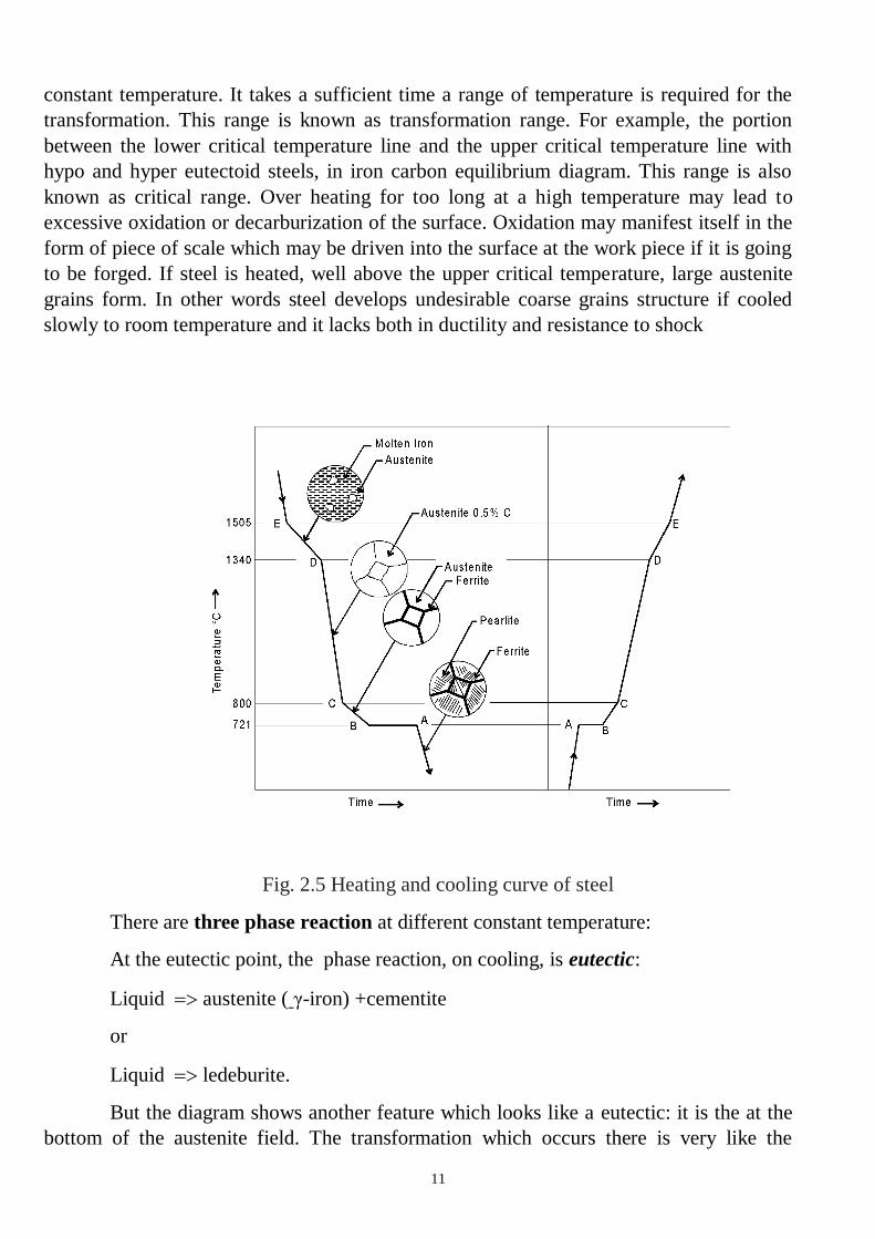
Fig. 2.5 Heating and cooling curve of steel
There are three phase reaction at different constant temperature:
At the eutectic point, the phase reaction, on cooling, is eutectic:
Liquid austenite ( γ-iron) +cementite
or
Liquid ledeburite.
But the diagram shows another feature which looks like a eutectic: it is the at the
bottom of the austenite field. The transformation which occurs there is very like the
12
eutectic transformation, but this time it is a solid, austenite, which transforms on cooling
to two other solids. The point is called a eutectoid point. The compositions of the two new
phases are given by the ends of the tie line through the eutectoid point.
At the eutectoid point, the phase reaction, on cooling, is eutectoid:
Austenite ferrite ( -iron) + cementite
or
Austenite pearlite.
At the peritectic point, the phase reaction, on cooling, is peritectic:
Liquid + ferrite (δ –iron) austenite .
Activity
1. To analyse the Fe – Fe3C diagram mark at all critical points of the Fe – Fe3C
diagram with letters.
2. Describe the lines of Fe – Fe3C diagram (liquidus, solidus, phase reactions,
lines of the solubility).
3. Identify components of alloys. List allotropic forms of the components.
4. What kinds of initial elements interaction take place there? Identify all phases
and structure which occur in the chosen alloy.
5. Describe phase reactions and write down their formula.
6. To analyse the alloy, choose it carbon contant and temperature.
Note! Your variant is your number in the group list or your number in the group list
minus 10 (20).
7. Draw alloy’s vertical, mark the point of chosen temperature and all points of
where alloy’s vertical crosses the lines of phase diagram.
8. Construct the general shape of cooling curve for chosen alloy.
9. Mark phases at every temperature period on the cooling curve.
10. Application of the phase rule. How many degrees of freedom are there at
constant p in all fields.
11. How many phases can coexist in equilibrium at constant p? Define them.
12. Describe what happens if alloy is cooled to room temperature. At which
temperatures do changes in the number or type of phases occur?
13. Application of the inverse level rule. Calculate the approximate composition
and proportions by weight of each phase that is present at chosen temperature.
13
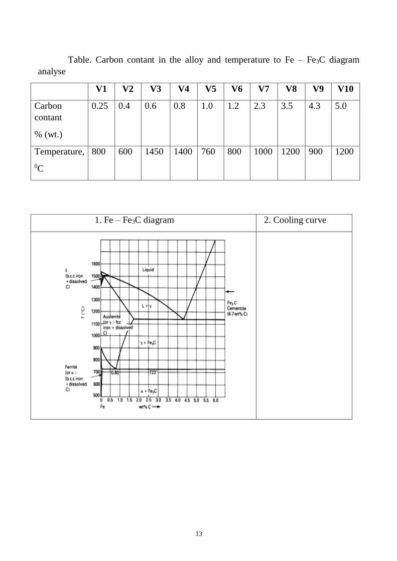
Table. Carbon contant in the alloy and temperature to Fe – Fe3C diagram
analyse
V1 V2 V3 V4 V5 V6 V7 V8 V9 V10
Carbon
contant
% (wt.)
0.25 0.4 0.6 0.8 1.0 1.2 2.3 3.5 4.3 5.0
Temperature,
0C
800 600 1450 1400 760 800 1000 1200 900 1200
1. Fe – Fe3C diagram 2. Cooling curve
14
3. Lines of the Fe – Fe3C diagram: liquidus___________________________,
solidus____________________________, phase reactions ______________________
______________________________________________________________________,
lines of the solubility ___________________________________________________
4. Components of the alloys. _________.
Allotropic forms in the components _______________________________________.
5. Kinds of initial elements interaction_____________________________________
6. Phases, which occur in the alloys_______________________________-
___________________________________.
7. Structure, which occur in the alloys
_____________________________________________________________________.
8. Chemical composition of chosen alloy__________________________________
9. Phase reactions in chosen alloy and their formulas
________________________________________________________________________
____________________________________________________________________
10. Application of the phase rule. Calculate degrees of freedom in all fields at constant p.
________________________________________________________________________
____________________________________________________________________
1. How many phases can coexist in equilibrium at constant p? Define them.
________________________________________________________________________
___________________________________________________________________
2. Describe what happens if the alloy is cooled to room temperature. At which
temperatures do changes in the number or type of phases occur?

15
________________________________________________________________________
________________________________________________________________________
__________________________________________________________________
3. Application of the inverse level rule. Calculate the approximate composition and the
proportions by weight of each phase that is present at chosen temperature.
The composition of phase 1 is ______________________________________________.
The composition of phase 2 is
What (roughly) are the proportions by weight of each phase?
Conclusion_______________________________________________________________
____________________________________________________________________
_______________________ _________________________
Studen tsignature Teacher’s signature
“____”___________20__y. “____”____________20___ y.
16
LABORATORY WORK 5
PLAIN CARBON STEELS
Objectives
1. To learn the microstructures of the steels.
2. To learn the effect of carbon and impurities on the properties of steel.
3. To learn classification of Plain Carbon Steels.
4. To learn to determine of the steel chemical composition by its SAE-AISI number.
Scientific principles
There are two types of iron-carbon alloys- steel and cast iron.
Plain carbon steel is an alloy of iron and carbon. It has good machineability and
malleability. It is different from cast iron as regards the percentage of carbon. It contains
carbon from 0.06 to 2% whereas cast iron possesses carbon from 2 to 4.2%.
Steels are an iron-carbon alloys, which contains less than 2 % carbon, impurities
Mn, Si, Al, S, P, O, H, N and alloying elements, such as Cr, Ni, Ti, W and etc..
Cast irons are an iron-carbon alloys which contains more than 2 % carbon (carbon
may be presented as carbide (connected) and as graphite (free)) and impurities S, P, Mn,
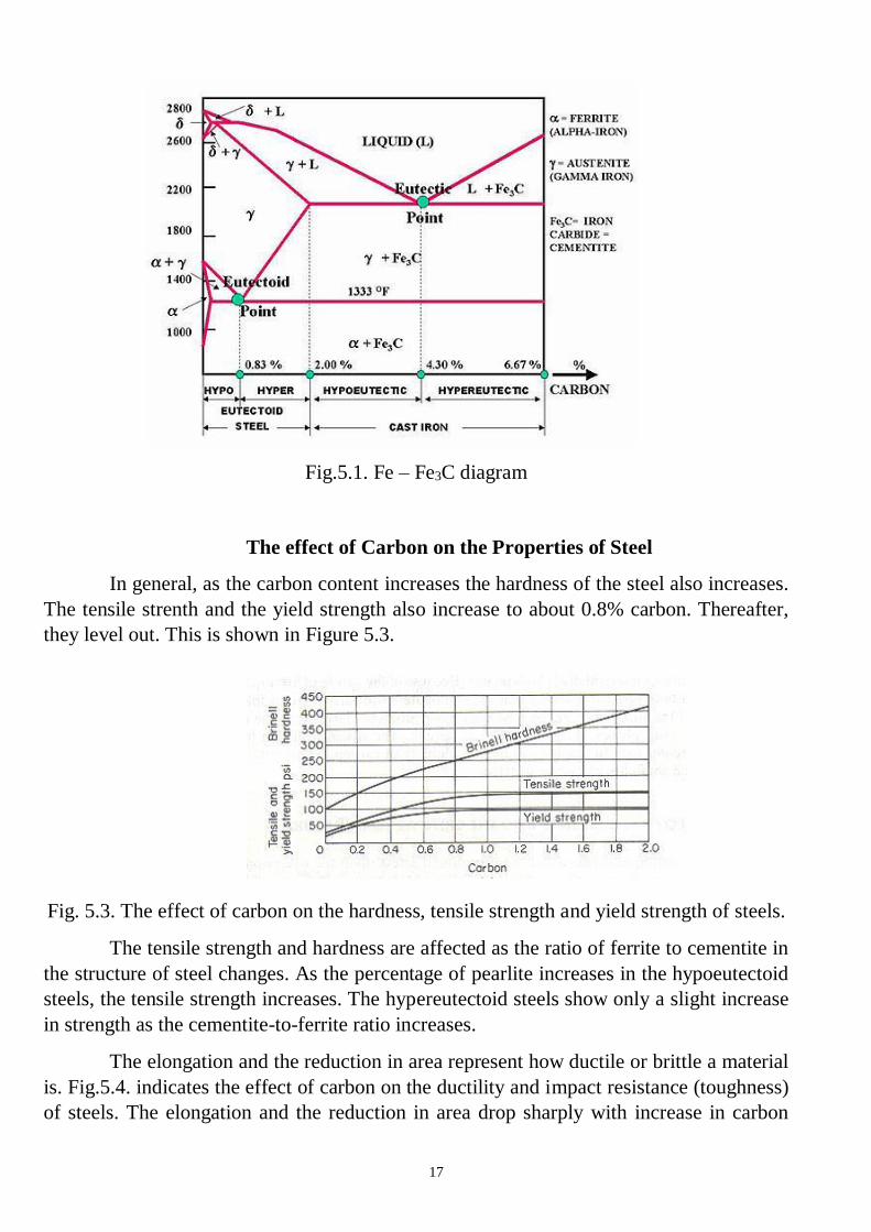
Si. The microstructure of steels and cast irons are described by Fe – Fe3C diagram
(Fig.5.1).
Plain Carbon Steels are an iron-carbon alloys, which contains less than 2.14%
carbon and impurities Mn, Si, Al, S, P, O, H, N.
As the term ‘‘plain carbon steel’’ implies, these are alloys of iron and carbon.
These steels were the first developed, are the least expensive, and have the widest range of
applications. Steel is used for making camshafts, sheets and srips for fan blades, welded
tubing, forgings, chains, stamping, rivets, nails, pipes, angle, channels, case hardening
steel, rods, tubes, valves, gears, crankshafts, connecting rods, railway axles, fish plates, etc
17
Fig.5.1. Fe – Fe3C diagram
The effect of Carbon on the Properties of Steel
In general, as the carbon content increases the hardness of the steel also increases.
The tensile strenth and the yield strength also increase to about 0.8% carbon. Thereafter,
they level out. This is shown in Figure 5.3.
Fig. 5.3. The effect of carbon on the hardness, tensile strength and yield strength of steels.
The tensile strength and hardness are affected as the ratio of ferrite to cementite in
the structure of steel changes. As the percentage of pearlite increases in the hypoeutectoid
steels, the tensile strength increases. The hypereutectoid steels show only a slight increase
in strength as the cementite-to-ferrite ratio increases.
The elongation and the reduction in area represent how ductile or brittle a material
is. Fig.5.4. indicates the effect of carbon on the ductility and impact resistance (toughness)
of steels. The elongation and the reduction in area drop sharply with increase in carbon
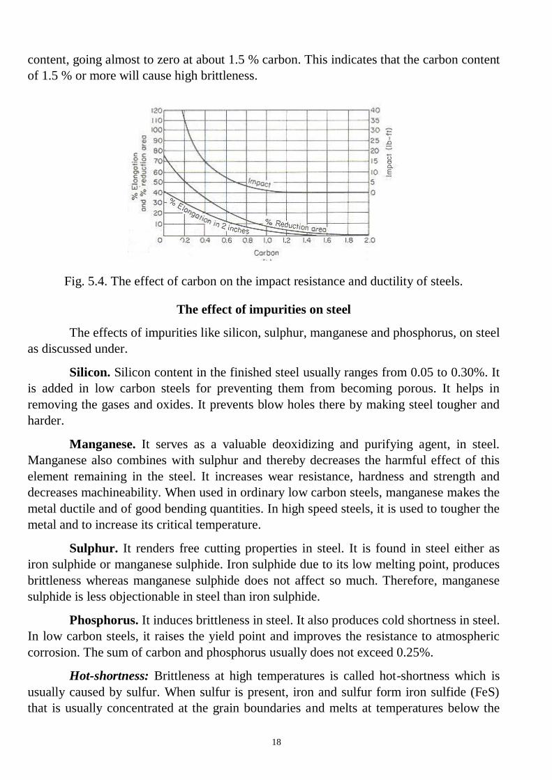
18
content, going almost to zero at about 1.5 % carbon. This indicates that the carbon content
of 1.5 % or more will cause high brittleness.
Fig. 5.4. The effect of carbon on the impact resistance and ductility of steels.
The effect of impurities on steel
The effects of impurities like silicon, sulphur, manganese and phosphorus, on steel
as discussed under.
Silicon. Silicon content in the finished steel usually ranges from 0.05 to 0.30%. It
is added in low carbon steels for preventing them from becoming porous. It helps in
removing the gases and oxides. It prevents blow holes there by making steel tougher and
harder.
Manganese. It serves as a valuable deoxidizing and purifying agent, in steel.
Manganese also combines with sulphur and thereby decreases the harmful effect of this
element remaining in the steel. It increases wear resistance, hardness and strength and
decreases machineability. When used in ordinary low carbon steels, manganese makes the
metal ductile and of good bending quantities. In high speed steels, it is used to tougher the
metal and to increase its critical temperature.
Sulphur. It renders free cutting properties in steel. It is found in steel either as
iron sulphide or manganese sulphide. Iron sulphide due to its low melting point, produces
brittleness whereas manganese sulphide does not affect so much. Therefore, manganese
sulphide is less objectionable in steel than iron sulphide.
Phosphorus. It induces brittleness in steel. It also produces cold shortness in steel.
In low carbon steels, it raises the yield point and improves the resistance to atmospheric
corrosion. The sum of carbon and phosphorus usually does not exceed 0.25%.
Hot-shortness: Brittleness at high temperatures is called hot-shortness which is
usually caused by sulfur. When sulfur is present, iron and sulfur form iron sulfide (FeS)
that is usually concentrated at the grain boundaries and melts at temperatures below the
19
melting point of steel. Due to the melting of iron sulfide, the cohesion between the grains
is destroyed, allowing cracks to develop. This occurs when the steel is forged or rolled at
elevated temperatures. In the presence of manganese, sulfur tends to form manganese
sulfide (MnS) which prevents hot-shortness.
Cold-shortness: Large quantities of phosphorus (in excess of 0.12% P) reduces
the ductility, thereby increasing the tendency of the steel to crack when cold worked. This
brittle condition at temperatures below the recrystallization temperature is called cold-
shortness.
Classification of Plain Carbon Steels
The steel may be of various kinds and few important types are explained as under.
Classification by structure
There are three kinds of plain carbon steels: hypoeutectoid, eutectoid and
hypereutectoid steels.
Eutectoid steel. In the abbreviated iron–iron carbide diagram of Fig. 5.1 the
eutectoid point is the lowest temperature and composition at which the austenite phase can
exist. It is that point corresponding to a composition of 99.2 wt% Fe 0.8 wt% C. This is
the eutectoid point of the iron–iron carbide system.
Euctectoid deals with a solid-to-solid transformation, while the eutectic region
begins with a liquid. At the eutectoid point, the eutectoid reaction takes place on cooling a
0.8 wt% C alloy composition slowly through the eutectoid temperature. At this
temperature the reaction is
Austenite → Ferrite + Fe3C
This is a reaction of a solid transforming to two different solids forming a parallel-
plate microstructure of the two phases called pearlite.
A plain carbon steel of eutectoid composition is 1080 steel, which has a tensile
strength of about 112,0 psi ( pound-force per square inch, lbf/in?) or about 772 MPa.
*Note 1psi = 6.89 MPa; 1 MPa = 0,145 psi
If the austenite contains less than 0.80% carbon (hypoeutectoid steel), free ferrite
will first be rejected on slow cooling through the critical temperature until the composition
of the remaining austenite reaches 0.80% carbon, when the simultaneous rejection of both
ferrite and carbide will again occur, producing pearlite. So a hypoeutectoid steel at room
temperature will be composed of areas of free ferrite and areas of pearlite; the higher the
carbon percentage, the more pearlite present in the steel. A 1040 steel is typical of a
hypoeutectoid steel. It will be somewhat softer than a 1080 steel and have a tensile
strength of about 75,0 psi (517 Mpa).
20
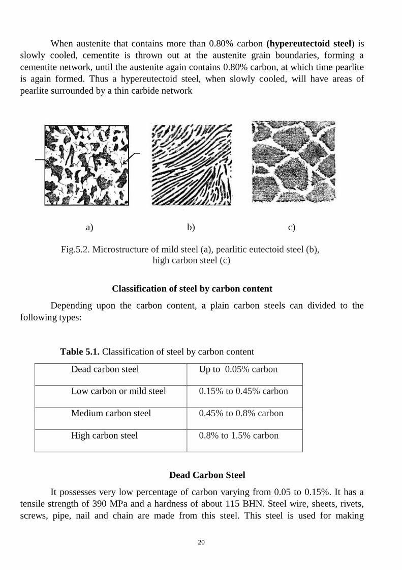
When austenite that contains more than 0.80% carbon (hypereutectoid steel) is
slowly cooled, cementite is thrown out at the austenite grain boundaries, forming a
cementite network, until the austenite again contains 0.80% carbon, at which time pearlite
is again formed. Thus a hypereutectoid steel, when slowly cooled, will have areas of
pearlite surrounded by a thin carbide network
a) b) c)
Fig.5.2. Microstructure of mild steel (a), pearlitic eutectoid steel (b),
high carbon steel (c)
Classification of steel by carbon content
Depending upon the carbon content, a plain carbon steels can divided to the
following types:
Table 5.1. Classification of steel by carbon content
Dead carbon steel Up to 0.05% carbon
Low carbon or mild steel
0.15% to 0.45% carbon
Medium carbon steel
0.45% to 0.8% carbon
High carbon steel
0.8% to 1.5% carbon
Dead Carbon Steel
It possesses very low percentage of carbon varying from 0.05 to 0.15%. It has a
tensile strength of 390 MPa and a hardness of about 115 BHN. Steel wire, sheets, rivets,
screws, pipe, nail and chain are made from this steel. This steel is used for making
21
camshafts, sheets and strips for fan blades, welded tubing, forgings, chains, stamping,
rivets, nails, pipes, automobile body etc.
Low Carbon Or Mild Steel
Low carbon steel is sometimes known as mild steel also. It contains 0.20 to 0.30%
C which has tensile strength of 555 MPa and hardness of 140 BHN. It possesses bright
fibrous structure. It is tough, malleable, ductile and more elastic than wrought iron. It can
be easily forged and welded. It can absorb shocks. It rusts easily. Its melting point is about
1410°C. It is used for making angle, channels, case hardening steel, rods, tubes, valves,
gears, crankshafts, connecting rods, railway axles, fish plates, small forgings, free cutting
steel shaft and forged components etc.
Applications
Mild steel containing 0.15 to 0.20% carbon
It is used in structure steels, universal beams, screws, drop forgings, case
hardening steel, bars, rods, tubes, angles and channels etc.
Mild steel containing 0.20-0.30% carbon
It is used in making machine structure, gears, free cutting steels, shafts and forged
components etc.
Medium Carbon Steels
Medium carbon steel contains carbon from 0.30 to 0.8%. It possesses having
bright fibrous structure when fractured. It is tough and more elastic in comparison to
wrought iron. It can be easily forged, welded, elongated due to ductility and beaten into
sheets due to its good malleability. It can easily absorb sudden shocks. It is usually
produced as killed or semi killed steels and is harden able by treatment. Hardenability is
limited to thin sections or to the thin outer layer on thick parts. Its tensile strength is better
than cast iron and wrought iron but compressive strength is better than wrought iron but
lesser than cast iron. It rusts readily. Its melting point is 1400°C. It can be easily hardened
and it possesses good balance of strength and ductility.
It is generally used for making railway coach axles, bolts, connecting rods, key
stock, wires and rods, shift and break levers, spring clips, gear shafts, small and medium
forgings, railway coach axles, crank pins on heavy machines, spline shafts, crankshafts,
forging dies, set screws, die blocks, self tapping screws, clutch discs, valve springs, plate
punches, thrust washers etc. The applications of different kinds of medium carbon steel
are given as under.
Applications

22
Plain carbon steels having carbon % 0.30 to 0.45. Axles, special duty shafts,
connecting rods, forgings, machinery steel, spring clips, turbine, rotors, gear shafts, key
stock, forks and bolts.
Plain carbon steels having carbon % 0.45 to 0.60. Railway coach axles, crank
pins, crankshafts, axles, spline shafts, loco tyres.
Plain carbon steels having carbon % 0.60 to 0.80. Drop forging dies, die blocks,
bolt heading dies, self-tapping screws, valve spring, lock washers, hammers, cold chisels,
hacksaws, jaws for vices etc.
High Carbon Steels
High carbon steels (HCS) contain carbon from 0.8 to 1.5%. Because of their high
hardness, these are suitable for wear resistant parts. Spring steel is also high carbon steel.
It is available in annealed and pre-tempered strips and wires. High carbon steel loses their
hardness at temperature from 200°C to 250°C. They may only be used in the manufacture
of cutting tools operating at low cutting speeds. These steels are easy to forge and simple
to harden. These steels are of various types which are identified by the carbon percentage,
hardness and applications.
Classification by Applications
Free cutting steel
The important features of free cutting steels are their high machinability and high
quality surface finish after finishing. These properties are due to higher sulphur and
phosphorus. Sulphur exists in the form of manganese sulphide (MnS) which forms
inclusions in steel. These inclusions promote the formation of discontinuous chips and
also reduce friction on the surface being machined so produces good surface finish easily.
Phosphorus is dissolved in the ferrite and increases hardness and brittleness. Lead up to
0.35% can be added to improve the machinability of steel. These have high sulphur
content present in form of manganese sulphide inclusions causing the chips to break short
on machining. Mn and P make steel hardened and brittle. Lead (0.2% to 0.35%) is
sometimes added to steel improving machinability properties of steel. This consists of
three Bessemer grades B1111, B1112, B1113 which differ in sulphur content and the
sulphurised steels from C1108 to C1151.
The tool life achieved in machining free cutting steels is from 2 to 2.5 times
higher than when carbon steels of the same carbon content. However, it must be noted that
23
free cutting steels have lower dynamic strength characteristics and are more susceptible to
corrosion. Free cutting steels are frequently supplied in the cold drawn or work hardened
form. These cold drawn steels have a high tensile strength and hardness but less ductile
when compared to other kind of steels.
Applications of free cutting steel
These steels are used for manufacturing axles, bolts, screws, nuts, special duty
shafts, connecting rods, small and medium forgings, cold upset wires and rods, solid
turbine rotors, rotor and gear shaft, armature, key stock, forks and anchor bolts screw
stock, spring clips, tubing, pipes, light weight rails, concrete reinforcing etc.
Structural steels
Structural steels possess high strength and toughness, resistance to softening at
elevated temperatures and enough resistance to corrosion. In addition, they should possess
weldability, workability and high hardenability. The principal alloying elements in
structural steels are chromium, nickel and manganese.
These steels has various applications. They are used for structural members of
bridges, buildings, rail road, cars etc. They are also used for manufacturing components
subjected to static and dynamic loads. These components include valves, pins, studs,
gears, clutches, bushes, shafts etc.
The Marking of Steel
According to Indian standard ISO 1570-1961, plain carbon steels are designated
by the alphabet ‘C’ followed by numerals which indicate the average percentage of carbon
in it. For example C40 means a plain carbon steel containing 0.35% to 0.45% C (0.40% on
average), although other elements like manganese may be present. In addition to the
percentage of carbon, some other specification may include e.g. C55Mn75 means the
carbon content lies between 0.50% to 0.60% and the manganese content lies between 0.60
to 0.90%. It may be noted that only average contents are specified in such designation of
steelSteel, because of its strength, formability, abundance, and low cost, is the primary
metal used for structural applications.
The Society of Automotive Engineers (SAE) has established standards for specific
analysis of steels. In the 10XX series, the first digit indicates a plain carbon steel. The
second digit indicates a modification in the alloys. 10XX means that it is a plain carbon
steel where the second digit (zero) indicates that there is no modification in the alloys. The
last two digits denote the carbon content in points. For example SAE 1040 is a carbon
steel where 40 points represent 0.40 % Carbon content.
24
The American Iron and Steel Institute (AISI) numbering system for plain carbon
steels also includes 11XX, 12XX, and 15XX. A brief description of each type of alloy is
as follows:
10XX Plain carbon, Mn 1.00% max.
11XX Plain carbon, resulfurized
12XX Plain carbon, resulfurized and rephosphorized
15XX Plain carbon, Mn range 1.00–1.65% max.
General representation of steels:
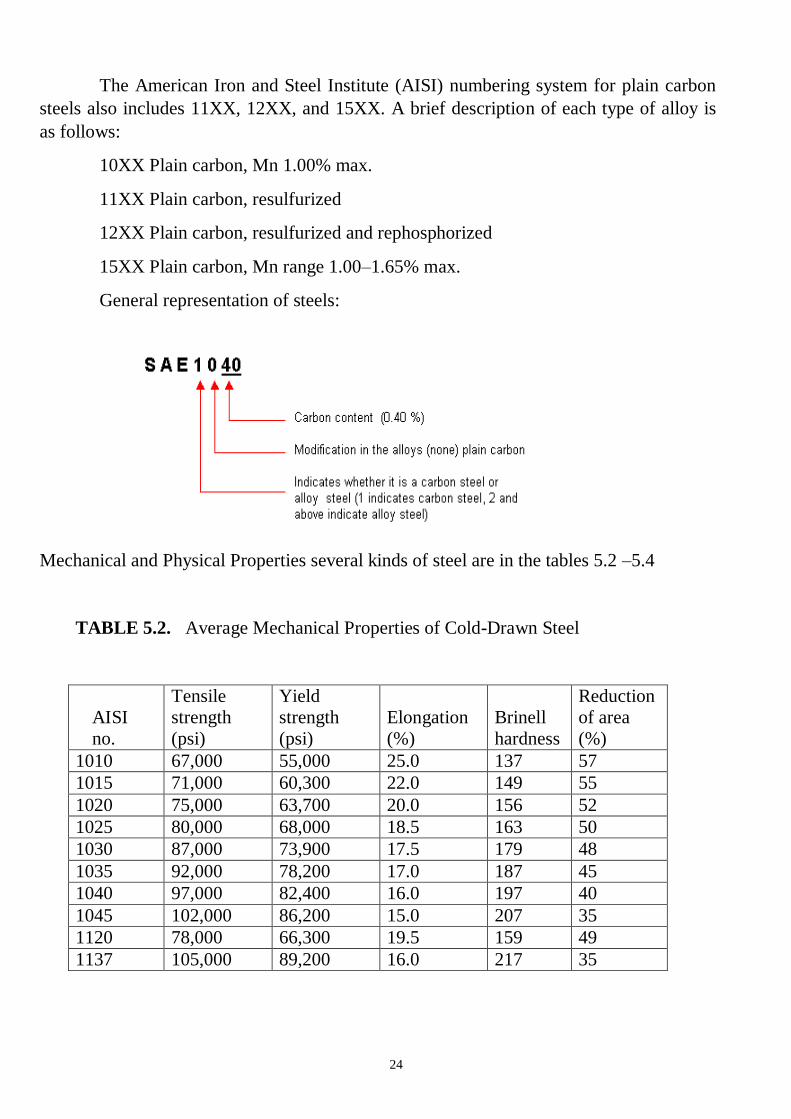
Mechanical and Physical Properties several kinds of steel are in the tables 5.2 –5.4
TABLE 5.2. Average Mechanical Properties of Cold-Drawn Steel
AISI
no.
Tensile
strength
(psi)
Yield
strength
(psi)
Elongation
(%)
Brinell
hardness
Reduction
of area
(%)
1010 67,000 55,000 25.0 137 57
1015 71,000 60,300 22.0 149 55
1020 75,000 63,700 20.0 156 52
1025 80,000 68,000 18.5 163 50
1030 87,000 73,900 17.5 179 48
1035 92,000 78,200 17.0 187 45
1040 97,000 82,400 16.0 197 40
1045 102,000 86,200 15.0 207 35
1120 78,000 66,300 19.5 159 49
1137 105,000 89,200 16.0 217 35
25
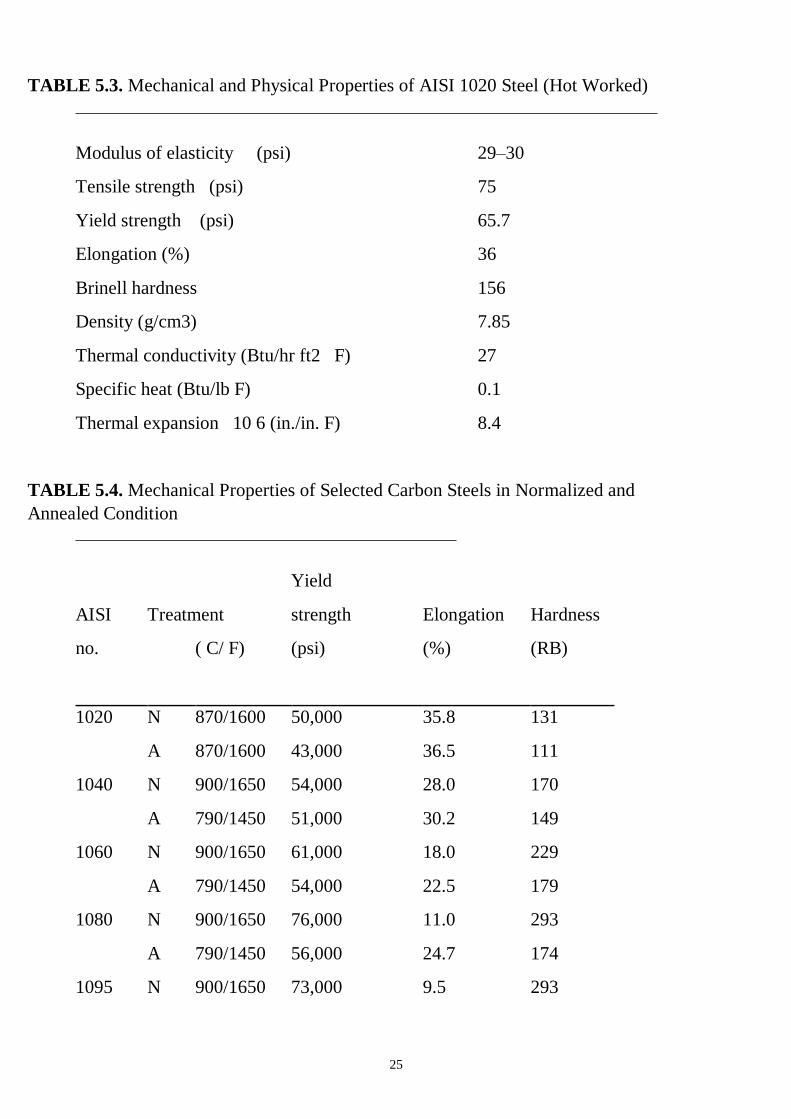
TABLE 5.3. Mechanical and Physical Properties of AISI 1020 Steel (Hot Worked)
Modulus of elasticity (psi) 29–30
Tensile strength (psi) 75
Yield strength (psi) 65.7
Elongation (%) 36
Brinell hardness 156
Density (g/cm3) 7.85
Thermal conductivity (Btu/hr ft2 F) 27
Specific heat (Btu/lb F) 0.1
Thermal expansion 10 6 (in./in. F) 8.4
TABLE 5.4. Mechanical Properties of Selected Carbon Steels in Normalized and
Annealed Condition
Yield
AISI Treatment strength Elongation Hardness
no. ( C/ F) (psi) (%) (RB)
1020 N 870/1600 50,000 35.8 131
A 870/1600 43,000 36.5 111
1040 N 900/1650 54,000 28.0 170
A 790/1450 51,000 30.2 149
1060 N 900/1650 61,000 18.0 229
A 790/1450 54,000 22.5 179
1080 N 900/1650 76,000 11.0 293
A 790/1450 56,000 24.7 174
1095 N 900/1650 73,000 9.5 293
26
A 790/1450 55,000 13.0 192
1137 N 900/1650 58,000 22.5 197
A 790/1450 50,000 26.8 174
aN = normalized; A = annealed; temperature is that to which the piece was
heated.
*Notes F = (C x 9/5) + 32; C = (F – 32) x 5/9
Materials and Equipment:
1. Specimen of the hypoeutectoid and hypereutectoid steels.
2. Microscope MM – 4.
Procedure 1. For checking microstructure of steel, its specimen is prepared by preparing a flat
mirror surface on small piece of metal through rubbing by sand papers, polishing and
buffing etc. This surface is then followed by etching with a chemical solution. The
chemical solution reacts with various constituents in varying degree to reveal crystal
structure clearly. The revealed structure is then viewed through powerful microscope.
2. Set specimen of the hypoeutectoid and hypereutectoid steels on a microscope and
look at their microstructure.
3. Draw the microstructure of the hypoeutectoid and hypereutectoid steels.
4. Determine the critical temperatures (UCT and LCT) for hypoeutectoid steel with
0.3 %C and hypereutectoid steel with 1.2%C.
5. Determine the chemical composition of the steels by its SAE-AISI number.
27
Questions:
1. What are the types of iron- carbon alloys?
2. What is steel?
3. What is cast iron?
4. Which polymorphic modifications does the iron have and at what temperatures
interval is it stable?
5. List fathes and structure of the Fe-Fe3C diagram.
6. What is cementite and what properties does it have?
7. What is austenite and what properties does it have?
8. What is ferrite and what properties does it have?
9. What is perlite and what properties does it have?
10. What is ledeburite?
11. What carbon content does the hypoeutectoid steel have?
12. What carbon content does hyperutectoid steel have?
13. What carbon content does hypoeutectic cast iron have?
14. What carbon content does hypereutectic cast iron have?
15. Discribe the effect of carbon on hardness and tensile strength of steels.
16. Discribe the effect of carbon on toughness (impact resistance) and ductility of
steels.
17. Discribe the effect of impurities on steel.
18. What is hot-shortness and cold shortness?
19. Classification of Plain Carbon Steels by structure.
20. Classification of steel by carbon content.
21. Classification of steel by by applications.
22. What does number SAE 1020 mean?
28
LABORATORY WORK 5
PLAIN CARBON STEELS
PROTOCOL 1
Hypoeutectoid steel Hypereutectoid steel
Carbon content___________% Carbon contain___________%
Critical temperature, ?C
UCT = _________ UCT = _________
LCT = __________ LCT = _________

29
PROTOCOL 2
Steel Carbon
content, %
C
Mechanical properties
Tensile
strength
(psi/MPa)
Yield
strength
(psi/MPa)
Elongation
(%)
Brinell
hardness
Reduction
of area
(%)
SAE 1010
SAE 1025
SAE 1030
SAE 1045
Conclusions:
____________________________________________________________
______________________________________________________________________
______________________________________________________________________
_____________________ ___________________
Student’s signature Teacher’s signature
“____”___________20___ y. “____”____________20___ y.
30
LABORATORY WORK 6
CAST IRONS
Objectives
1. To learn the microstructures of the cast iron.
2. To learn the advantages and disadvantages of the cast iron.
3. To learn the applications of the cast iron.
Scientific principles
Types of cast iron
Cast irons may often be used in place of steel at considerable cost savings. The
design and production advantages of cast iron include:
Low tooling and production cost
Good machinability without burring
Ability to cast into complex shapes
Excellent wear resistance and high hardness (particularly white cats irons)
High inherent damping capabilities
The properties of the cast iron are affected by the following factors:
Chemical composition of the iron
Rate of cooling of the casting in the mold (which depends on the section
thickness in the casting)
Type of graphite formed (if any)
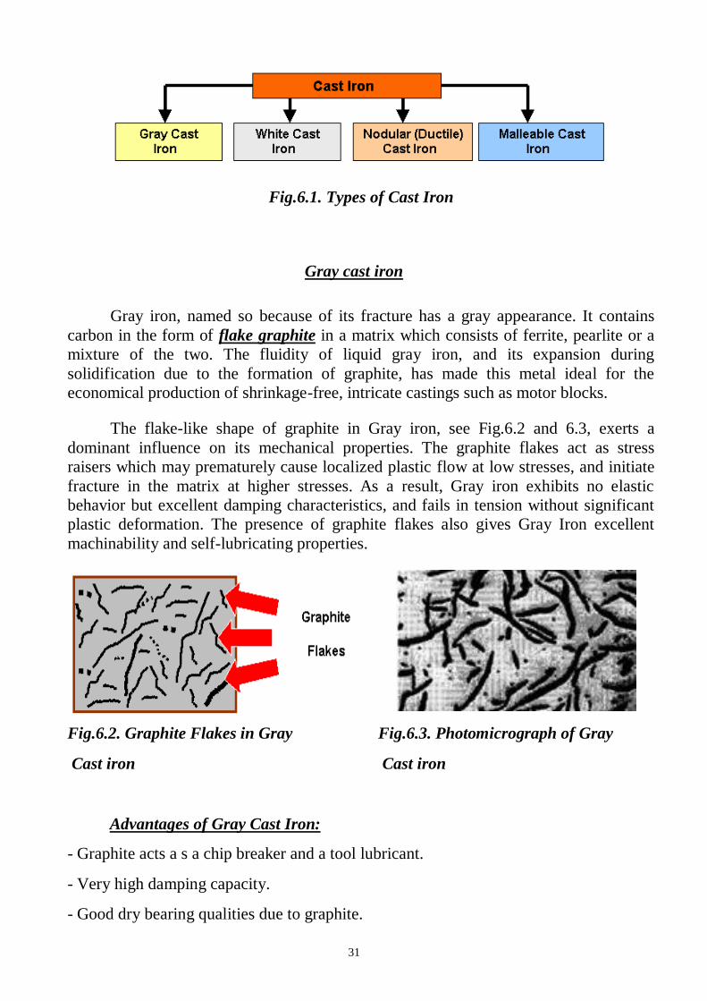
Major types of cast iron are shown in Figure 6.1.
31
Fig.6.1. Types of Cast Iron
Gray cast iron
Gray iron, named so because of its fracture has a gray appearance. It contains
carbon in the form of flake graphite in a matrix which consists of ferrite, pearlite or a
mixture of the two. The fluidity of liquid gray iron, and its expansion during
solidification due to the formation of graphite, has made this metal ideal for the
economical production of shrinkage-free, intricate castings such as motor blocks.
The flake-like shape of graphite in Gray iron, see Fig.6.2 and 6.3, exerts a
dominant influence on its mechanical properties. The graphite flakes act as stress
raisers which may prematurely cause localized plastic flow at low stresses, and initiate
fracture in the matrix at higher stresses. As a result, Gray iron exhibits no elastic
behavior but excellent damping characteristics, and fails in tension without significant
plastic deformation. The presence of graphite flakes also gives Gray Iron excellent
machinability and self-lubricating properties.
Fig.6.2. Graphite Flakes in Gray
Cast iron
Fig.6.3. Photomicrograph of Gray
Cast iron
Advantages of Gray Cast Iron:
- Graphite acts a s a chip breaker and a tool lubricant.
- Very high damping capacity.
- Good dry bearing qualities due to graphite.
32
- After formation of protective scales, it resists corrosion in many common
engineering environments.
Disadvantages:
- Brittle (low impact strength) which severely limits use for critical applications.
- Graphite acts as a void and reduces strength.
- Changes in section size will cause variations in machining characteristics due to
variation in microstructure.
- Higher strength gray cast irons are more expensive to produce.
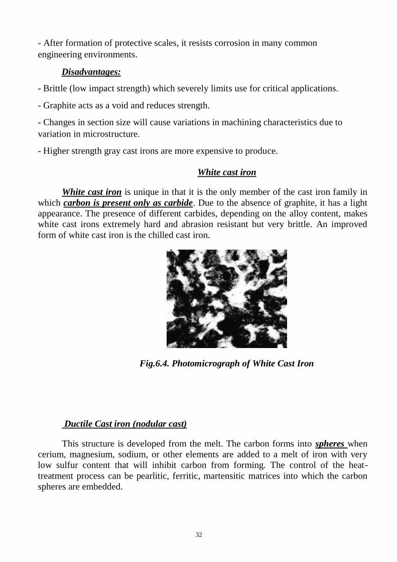
White cast iron
White cast iron is unique in that it is the only member of the cast iron family in
which carbon is present only as carbide. Due to the absence of graphite, it has a light
appearance. The presence of different carbides, depending on the alloy content, makes
white cast irons extremely hard and abrasion resistant but very brittle. An improved
form of white cast iron is the chilled cast iron.
Fig.6.4. Photomicrograph of White Cast Iron
Ductile Cast iron (nodular cast)
This structure is developed from the melt. The carbon forms into spheres when
cerium, magnesium, sodium, or other elements are added to a melt of iron with very
low sulfur content that will inhibit carbon from forming. The control of the heat-
treatment process can be pearlitic, ferritic, martensitic matrices into which the carbon
spheres are embedded.
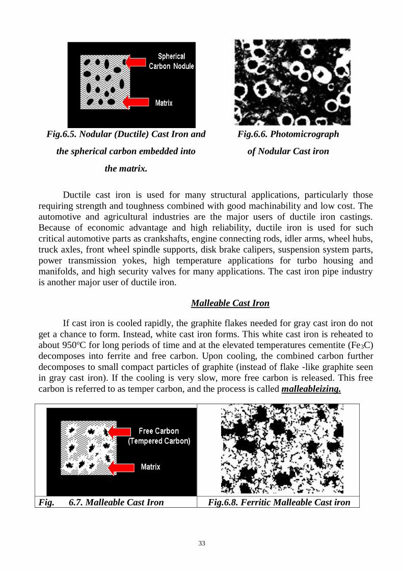
33
Fig.6.5. Nodular (Ductile) Cast Iron and
the spherical carbon embedded into
the matrix.
Fig.6.6. Photomicrograph
of Nodular Cast iron
Ductile cast iron is used for many structural applications, particularly those
requiring strength and toughness combined with good machinability and low cost. The
automotive and agricultural industries are the major users of ductile iron castings.
Because of economic advantage and high reliability, ductile iron is used for such
critical automotive parts as crankshafts, engine connecting rods, idler arms, wheel hubs,
truck axles, front wheel spindle supports, disk brake calipers, suspension system parts,
power transmission yokes, high temperature applications for turbo housing and
manifolds, and high security valves for many applications. The cast iron pipe industry
is another major user of ductile iron.
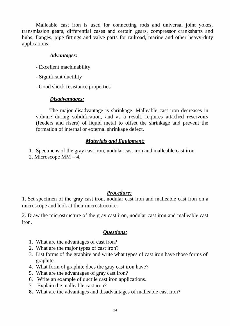
Malleable Cast Iron
If cast iron is cooled rapidly, the graphite flakes needed for gray cast iron do not
get a chance to form. Instead, white cast iron forms. This white cast iron is reheated to
about 950oC for long periods of time and at the elevated temperatures cementite (Fe3C)
decomposes into ferrite and free carbon. Upon cooling, the combined carbon further
decomposes to small compact particles of graphite (instead of flake -like graphite seen
in gray cast iron). If the cooling is very slow, more free carbon is released. This free
carbon is referred to as temper carbon, and the process is called malleableizing.
Fig. 6.7. Malleable Cast Iron Fig.6.8. Ferritic Malleable Cast iron
34
Malleable cast iron is used for connecting rods and universal joint yokes,
transmission gears, differential cases and certain gears, compressor crankshafts and
hubs, flanges, pipe fittings and valve parts for railroad, marine and other heavy-duty
applications.
Advantages:
- Excellent machinability
- Significant ductility
- Good shock resistance properties
Disadvantages:
The major disadvantage is shrinkage. Malleable cast iron decreases in
volume during solidification, and as a result, requires attached reservoirs
(feeders and risers) of liquid metal to offset the shrinkage and prevent the
formation of internal or external shrinkage defect.
Materials and Equipment:
1. Specimens of the gray cast iron, nodular cast iron and malleable cast iron.
2. Microscope MM – 4.
Procedure: 1. Set specimen of the gray cast iron, nodular cast iron and malleable cast iron on a
microscope and look at their microstructure.
2. Draw the microstructure of the gray cast iron, nodular cast iron and malleable cast
iron.
Questions:
1. What are the advantages of cast iron?
2. What are the major types of cast iron?
3. List forms of the graphite and write what types of cast iron have those forms of
graphite.
4. What form of graphite does the gray cast iron have?
5. What are the advantages of gray cast iron?
6. Write an example of ductile cast iron applications.
7. Explain the malleable cast iron?
8. What are the advantages and disadvantages of malleable cast iron?
35
Laboratory work 6
CAST IRONS
PROTOCOL 1
Gray cast iron nodular cast iron malleable cast iron
Graphite form
______________ ______________ _______________
The type of the metallic matrix
______________ ______________ _______________
Conclusions:
__________________________________________________________________
__________________________________________________________________
__________________________________________________________________
_______________________ _________________________
Student’s signature Teacher’s signature
“____”___________20___ y. “____”____________20___ y.
36
LABORATORY WORK 7
HEAT TREATMENT OF STELL
Objectives
1. To learn the major objectives of heat treatment.
2. To learn the advantages and disadvantages major types of heat treatment processes.
3. To learn how to choose temperature of different types of steel heat treatment.
4. To learn the applications of major types of heat treatment processes.
Fundamental concept
Types of heat treatment processes
Heat treatment is a heating and cooling process of a metal or an alloy in the
solid state with the purpose of changing their properties.
It can also be said as a process of heating and cooling of ferrous metals
especially various kinds of steels in which some special properties like softness,
hardness, tensile-strength, toughness etc, are induced in these metals for achieving
the special function objective.
It consists of three main phases namely heating of the metal soaking of the
metal and cooling of the metal. The theory of heat treatment is based on the fact that
a change takes place in the internal structure of metal by heating and cooling which
induces desired properties in it. The rate of cooling is the major controlling factor.
Rapid cooling the metal from above the critical range, results in hard structure.
Whereas very slow cooling produces the opposite affect i.e. soft structure. In any heat
treatment operation, the rate of heating and cooling is important. A hard material is
difficult to shape by cutting, forming, etc. During machining in machine shop, one
requires machineable properties in job piece hence the properties of the job piece may
requires heat treatment such as annealing for inducing softness and machineability
property in workpiece. Many types of furnaces are used for heating heat treatment
purposes.
Various types of heat treatment processes are used to change the following
properties or conditions of the steel:
The major objectives of heat treatment are given as under It relieves internal stresses induced during hot or cold working. It changes or refines grain size.
It increases resistance to heat and corrosion. It improves mechanical properties such as ductility, strength, hardness, toughness, etc. It helps to improve machinability.
37
It increases wear resistance It removes gases. It improves electrical and magnetic properties. It helps to improve shock resistance. It improves weldability.
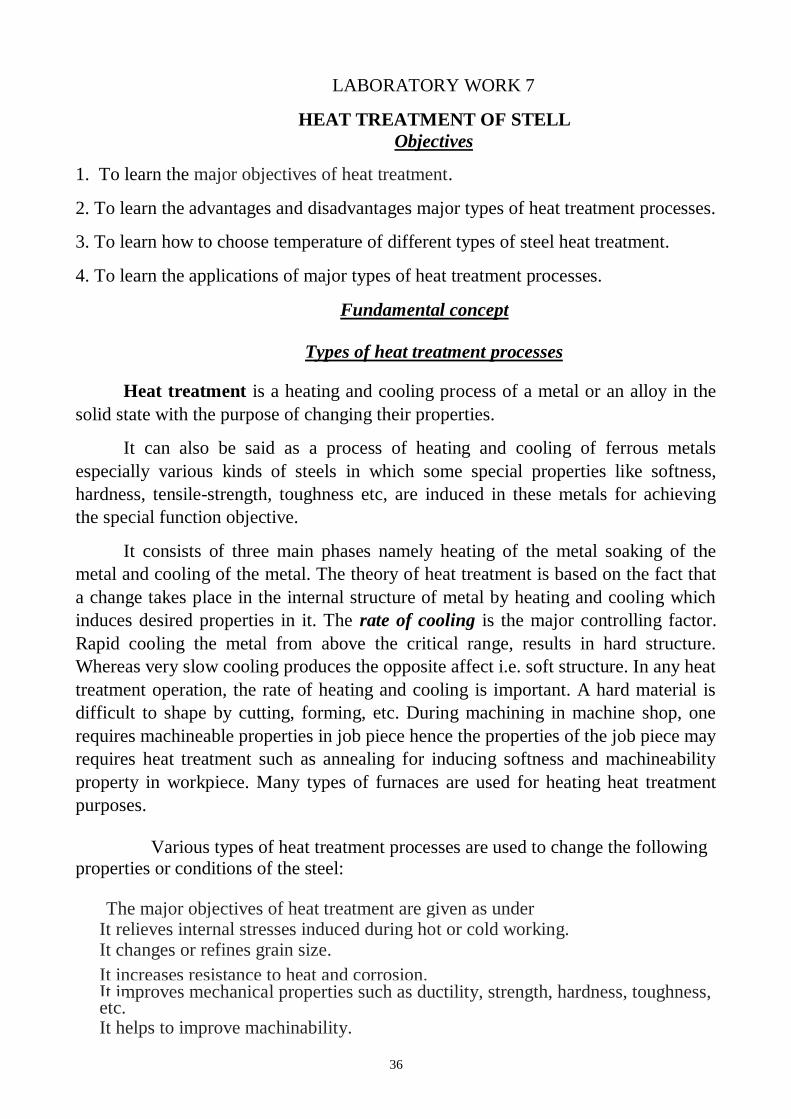
Figure 7.1 shows major types of heat treatment processes.
Fig.7.1. The Types of Heat Treatment Processes.
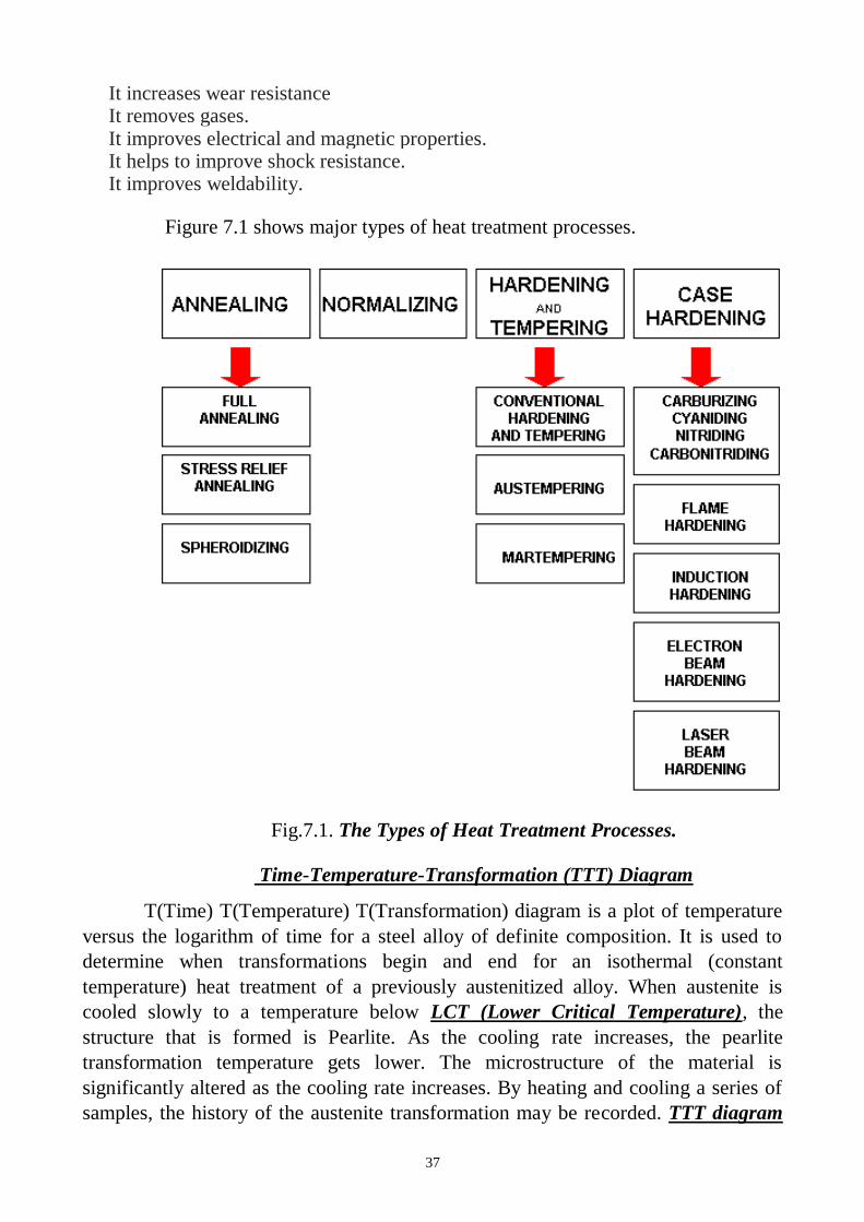
Time-Temperature-Transformation (TTT) Diagram
T(Time) T(Temperature) T(Transformation) diagram is a plot of temperature
versus the logarithm of time for a steel alloy of definite composition. It is used to
determine when transformations begin and end for an isothermal (constant
temperature) heat treatment of a previously austenitized alloy. When austenite is
cooled slowly to a temperature below LCT (Lower Critical Temperature), the
structure that is formed is Pearlite. As the cooling rate increases, the pearlite
transformation temperature gets lower. The microstructure of the material is
significantly altered as the cooling rate increases. By heating and cooling a series of
samples, the history of the austenite transformation may be recorded. TTT diagram
38
indicates when a specific transformation starts and ends and it also shows what
percentage of transformation of austenite at a particular temperature is achieved.
Cooling rates in the order of increasing severity are achieved by quenching
from elevated temperatures as follows: furnace cooling, air cooling, oil quenching,
liquid salts, water quenching, and brine. If these cooling curves are superimposed on
the TTT diagram, the end product structure and the time required to complete the
transformation may be found.
In Fig.7.2 the area on the left of the transformation curve represents the
austenite region. Austenite is stable at temperatures above LCT but unstable below
LCT. Left curve indicates the start of a transformation and right curve represents the
finish of a transformation. The area between the two curves indicates the
transformation of austenite to different types of crystal structures. (Austenite to
pearlite, austenite to martensite, austenite to bainite transformation.)
a) b)
Fig.7.2. TTT Diagram in general (a), in details (b)
If the cooling rate is very slow such as annealing process, the cooling curve
passes through the entire transformation area and the end product of this the cooling
process becomes 100% Pearlite.
39
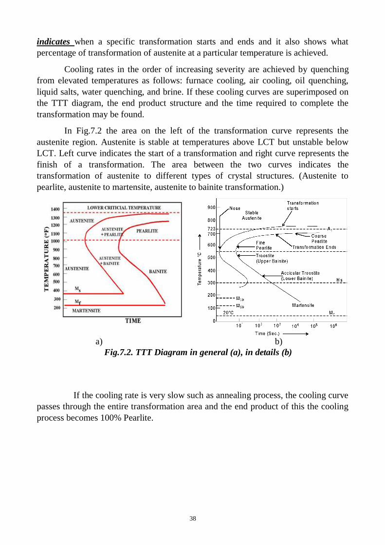
Fig. 7.3. Series of different cooling rates curves in TTT diagram
In Fig.7.4 the cooling rates A and B indicate two rapid cooling processes. In
this case curve A will cause a higher distortion and a higher internal stresses than the
cooling rate B. The end product of both cooling rates will be martensite. Cooling rate
B is also known as the Critical Cooling Rate, which is represented by a cooling curve
that is tangent to the nose of the TTT diagram. Critical Cooling Rate is defined as the
lowest cooling rate which produces 100% Martensite while minimizing the internal
stresses and distortions.
Fig.7.4. Rapid Quench
In Fig.7.5 a rapid quenching process is interrupted (horizontal line represents
the interruption) by immersing the material in a molten salt bath and soaking at a
constant temperature followed by another cooling process that passes through Bainite
region of TTT diagram. The end product is Bainite, which is not as hard as
Martensite. As a result of cooling rate D; more dimensional stability, less distortion
and less internal stresses are created.
40
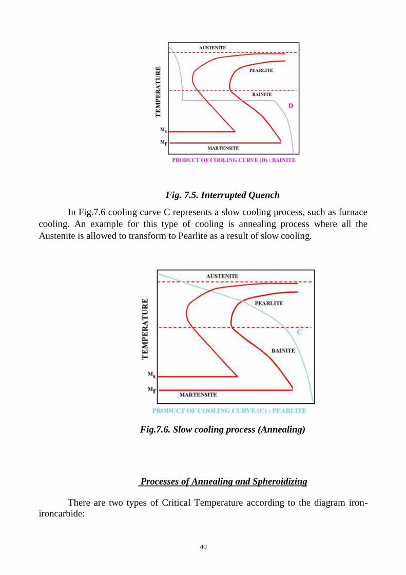
Fig. 7.5. Interrupted Quench
In Fig.7.6 cooling curve C represents a slow cooling process, such as furnace
cooling. An example for this type of cooling is annealing process where all the
Austenite is allowed to transform to Pearlite as a result of slow cooling.
Fig.7.6. Slow cooling process (Annealing)
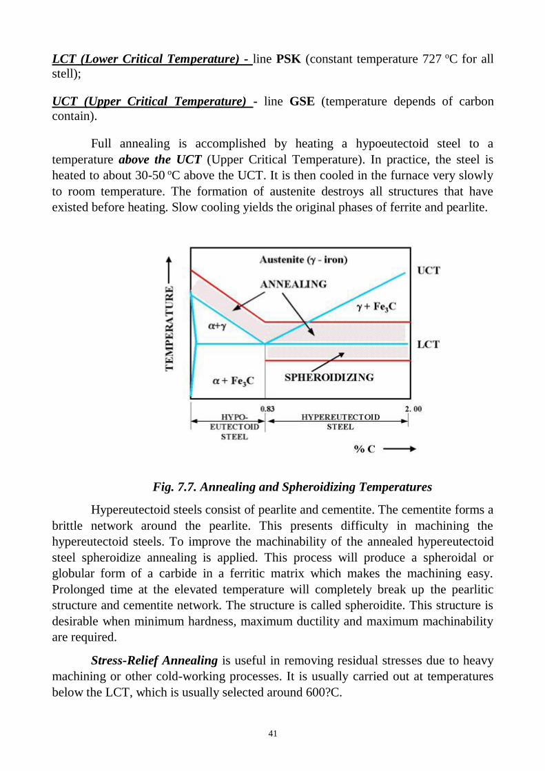
Processes of Annealing and Spheroidizing
There are two types of Critical Temperature according to the diagram iron-
ironcarbide:
41
LCT (Lower Critical Temperature) - line PSK (constant temperature 727 oC for all
stell);
UCT (Upper Critical Temperature) - line GSE (temperature depends of carbon
contain).
Full annealing is accomplished by heating a hypoeutectoid steel to a
temperature above the UCT (Upper Critical Temperature). In practice, the steel is
heated to about 30-50 oC above the UCT. It is then cooled in the furnace very slowly
to room temperature. The formation of austenite destroys all structures that have
existed before heating. Slow cooling yields the original phases of ferrite and pearlite.
Fig. 7.7. Annealing and Spheroidizing Temperatures
Hypereutectoid steels consist of pearlite and cementite. The cementite forms a
brittle network around the pearlite. This presents difficulty in machining the
hypereutectoid steels. To improve the machinability of the annealed hypereutectoid
steel spheroidize annealing is applied. This process will produce a spheroidal or
globular form of a carbide in a ferritic matrix which makes the machining easy.
Prolonged time at the elevated temperature will completely break up the pearlitic
structure and cementite network. The structure is called spheroidite. This structure is
desirable when minimum hardness, maximum ductility and maximum machinability
are required.
Stress-Relief Annealing is useful in removing residual stresses due to heavy
machining or other cold-working processes. It is usually carried out at temperatures
below the LCT, which is usually selected around 600?C.
42
Full annealing consists of (1) recovery (stress-relief), (2) recrystallization,
(3) grain growth stages. Annealing reduces the hardness, yield strength and tensile
strength of the steel.
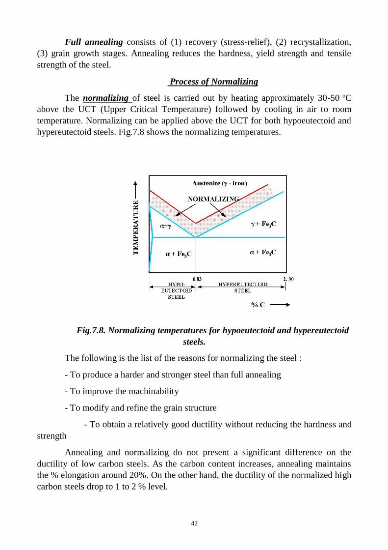
Process of Normalizing
The normalizing of steel is carried out by heating approximately 30-50 oC
above the UCT (Upper Critical Temperature) followed by cooling in air to room
temperature. Normalizing can be applied above the UCT for both hypoeutectoid and
hypereutectoid steels. Fig.7.8 shows the normalizing temperatures.
Fig.7.8. Normalizing temperatures for hypoeutectoid and hypereutectoid
steels.
The following is the list of the reasons for normalizing the steel :
- To produce a harder and stronger steel than full annealing
- To improve the machinability
- To modify and refine the grain structure
- To obtain a relatively good ductility without reducing the hardness and
strength
Annealing and normalizing do not present a significant difference on the
ductility of low carbon steels. As the carbon content increases, annealing maintains
the % elongation around 20%. On the other hand, the ductility of the normalized high
carbon steels drop to 1 to 2 % level.
43
The tensile strength and the yield point of the normalized steels are higher than
the annealed steels. Normalizing and annealing do not show a significant difference
on the tensile strength and yield point of the low carbon steels. However, normalized
high carbon steels present much higher tensile strength and yield point than those that
are annealed. Comparison between Annealing and Normalising are given in Table
7.1.
Table 7.1 Comparison between Annealing and Normalising
S.No
.
Annealing Normalising
1 In this hypoeutectoid steel is heated to a
temperature approximately 20 to 30°C
above temperature the higher critical
temperature and for hypereutectoid
steel is heated 20 to 30°C above the
lower critical temperature.
In this metal is heated 30 to 50°C
above higher critical
temperature.
2 It gives good results for low and
medium carbon steel.
It also gives very good results for
low and medium carbon steel
3 It gives high ductility. It induces gives higher ultimate
strength, yield point and impact
strength in ferrous material.
4 It is basically required to soften the
metal, to improve machinability, to
increase ductility, improve, to refine
grain size.
It is basically required to refine
grain size, improve structure of
weld, to relieve internal stresses.
The medium carbon steels can maintain similar hardness levels when
normalized or annealed. However, when high carbon steels are normalized they
maintain higher levels of hardness than those that are annealed.
44
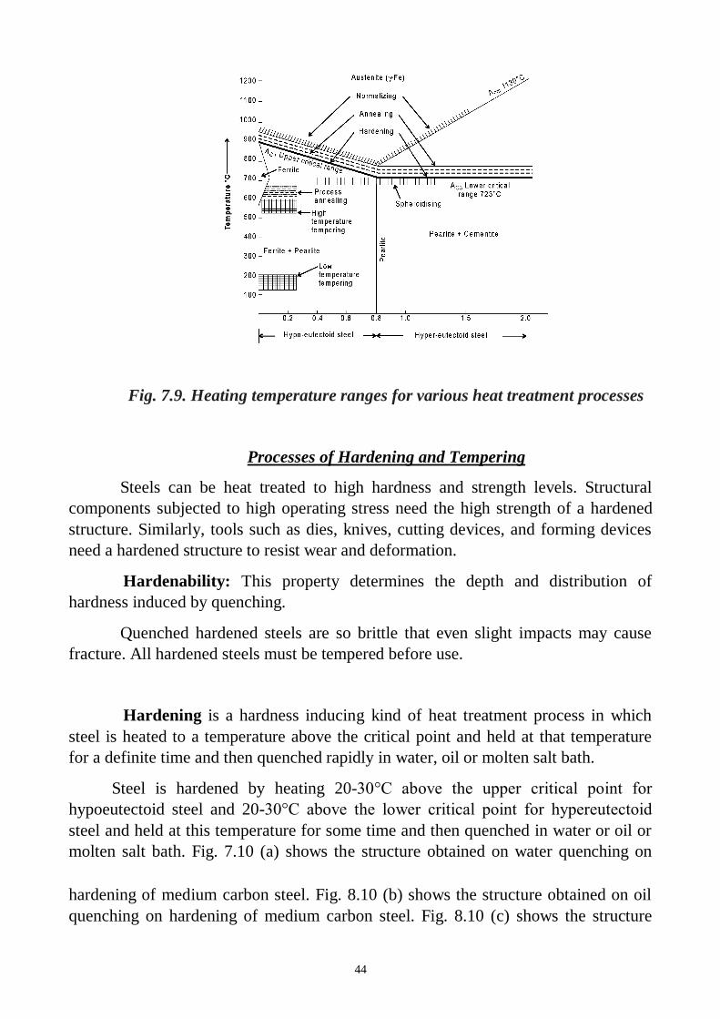
Fig. 7.9. Heating temperature ranges for various heat treatment processes
Processes of Hardening and Tempering
Steels can be heat treated to high hardness and strength levels. Structural
components subjected to high operating stress need the high strength of a hardened
structure. Similarly, tools such as dies, knives, cutting devices, and forming devices
need a hardened structure to resist wear and deformation.
Hardenability: This property determines the depth and distribution of
hardness induced by quenching.
Quenched hardened steels are so brittle that even slight impacts may cause
fracture. All hardened steels must be tempered before use.
Hardening is a hardness inducing kind of heat treatment process in which
steel is heated to a temperature above the critical point and held at that temperature
for a definite time and then quenched rapidly in water, oil or molten salt bath.
Steel is hardened by heating 20-30°C above the upper critical point for
hypoeutectoid steel and 20-30°C above the lower critical point for hypereutectoid
steel and held at this temperature for some time and then quenched in water or oil or
molten salt bath. Fig. 7.10 (a) shows the structure obtained on water quenching on
hardening of medium carbon steel. Fig. 8.10 (b) shows the structure obtained on oil
quenching on hardening of medium carbon steel. Fig. 8.10 (c) shows the structure
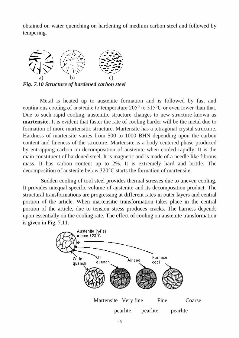
45
obtained on water quenching on hardening of medium carbon steel and followed by
tempering.
a) b) c)
Fig. 7.10 Structure of hardened carbon steel
Metal is heated up to austenite formation and is followed by fast and
continuous cooling of austenite to temperature 205° to 315°C or even lower than that.
Due to such rapid cooling, austenitic structure changes to new structure known as
martensite. It is evident that faster the rate of cooling harder will be the metal due to
formation of more martensitic structure. Martensite has a tetragonal crystal structure.
Hardness of martensite varies from 500 to 1000 BHN depending upon the carbon
content and fineness of the structure. Martensite is a body centered phase produced
by entrapping carbon on decomposition of austenite when cooled rapidly. It is the
main constituent of hardened steel. It is magnetic and is made of a needle like fibrous
mass. It has carbon content up to 2%. It is extremely hard and brittle. The
decomposition of austenite below 320°C starts the formation of martensite.
Sudden cooling of tool steel provides thermal stresses due to uneven cooling.
It provides unequal specific volume of austenite and its decomposition product. The
structural transformations are progressing at different rates in outer layers and central
portion of the article. When martensitic transformation takes place in the central
portion of the article, due to tension stress produces cracks. The harness depends
upon essentially on the cooling rate. The effect of cooling on austenite transformation
is given in Fig. 7.11.
Martensite Very fine Fine Coarse
pearlite pearlite pearlite
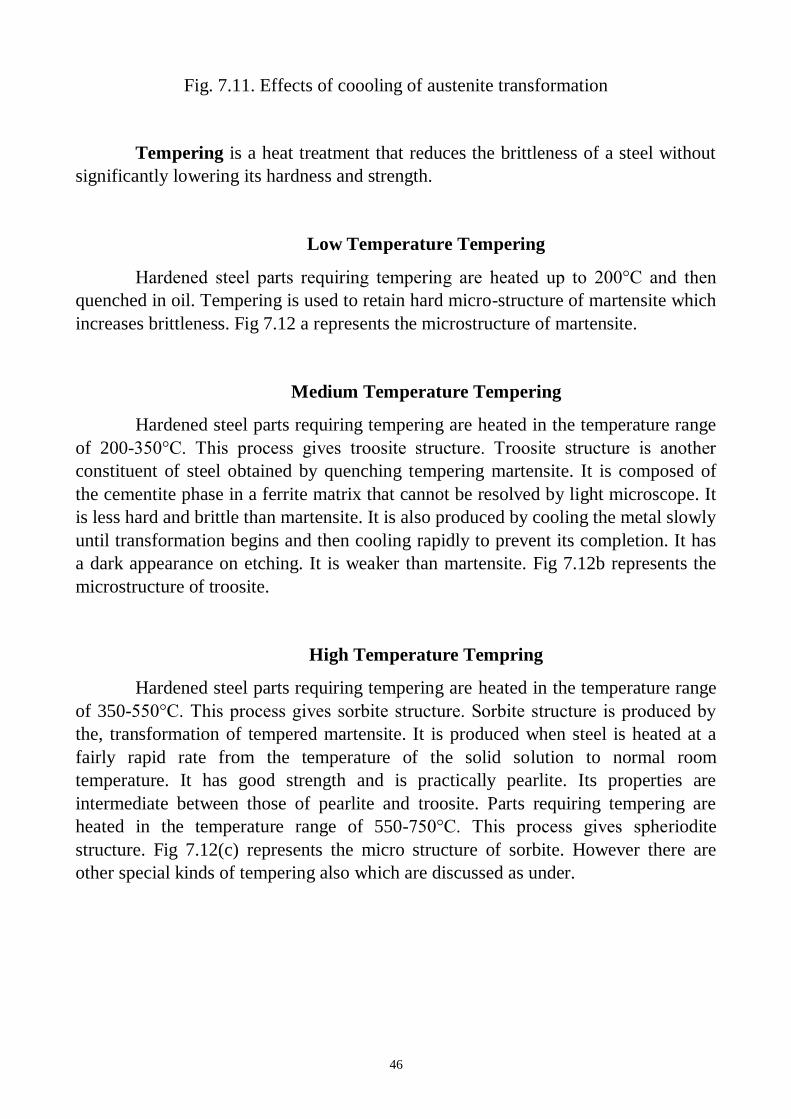
46
Fig. 7.11. Effects of coooling of austenite transformation
Tempering is a heat treatment that reduces the brittleness of a steel without
significantly lowering its hardness and strength.
Low Temperature Tempering
Hardened steel parts requiring tempering are heated up to 200°C and then
quenched in oil. Tempering is used to retain hard micro-structure of martensite which
increases brittleness. Fig 7.12 a represents the microstructure of martensite.
Medium Temperature Tempering
Hardened steel parts requiring tempering are heated in the temperature range
of 200-350°C. This process gives troosite structure. Troosite structure is another
constituent of steel obtained by quenching tempering martensite. It is composed of
the cementite phase in a ferrite matrix that cannot be resolved by light microscope. It
is less hard and brittle than martensite. It is also produced by cooling the metal slowly
until transformation begins and then cooling rapidly to prevent its completion. It has
a dark appearance on etching. It is weaker than martensite. Fig 7.12b represents the
microstructure of troosite.
High Temperature Tempring
Hardened steel parts requiring tempering are heated in the temperature range
of 350-550°C. This process gives sorbite structure. Sorbite structure is produced by
the, transformation of tempered martensite. It is produced when steel is heated at a
fairly rapid rate from the temperature of the solid solution to normal room
temperature. It has good strength and is practically pearlite. Its properties are
intermediate between those of pearlite and troosite. Parts requiring tempering are
heated in the temperature range of 550-750°C. This process gives spheriodite
structure. Fig 7.12(c) represents the micro structure of sorbite. However there are
other special kinds of tempering also which are discussed as under.
47
a) b) c)
Fig.7.12. Structures obtained tempering of
hardened steel
QUENCH AND TEMPERING PROCESSES:
(1) Conventional Heat, Quench and Temper process
(2) Martempering
(3) Austempering
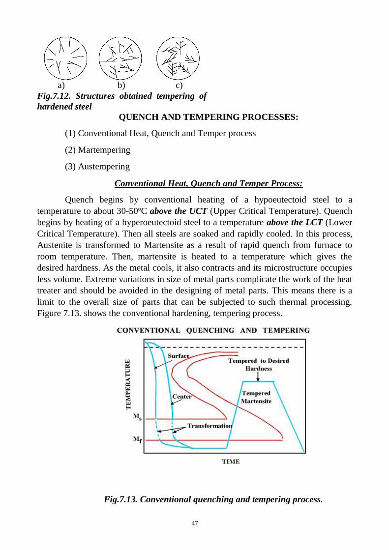
Conventional Heat, Quench and Temper Process:
Quench begins by conventional heating of a hypoeutectoid steel to a
temperature to about 30-50oC above the UCT (Upper Critical Temperature). Quench
begins by heating of a hyperoeutectoid steel to a temperature above the LCT (Lower
Critical Temperature). Then all steels are soaked and rapidly cooled. In this process,
Austenite is transformed to Martensite as a result of rapid quench from furnace to
room temperature. Then, martensite is heated to a temperature which gives the
desired hardness. As the metal cools, it also contracts and its microstructure occupies
less volume. Extreme variations in size of metal parts complicate the work of the heat
treater and should be avoided in the designing of metal parts. This means there is a
limit to the overall size of parts that can be subjected to such thermal processing.
Figure 7.13. shows the conventional hardening, tempering process.
Fig.7.13. Conventional quenching and tempering process.
48
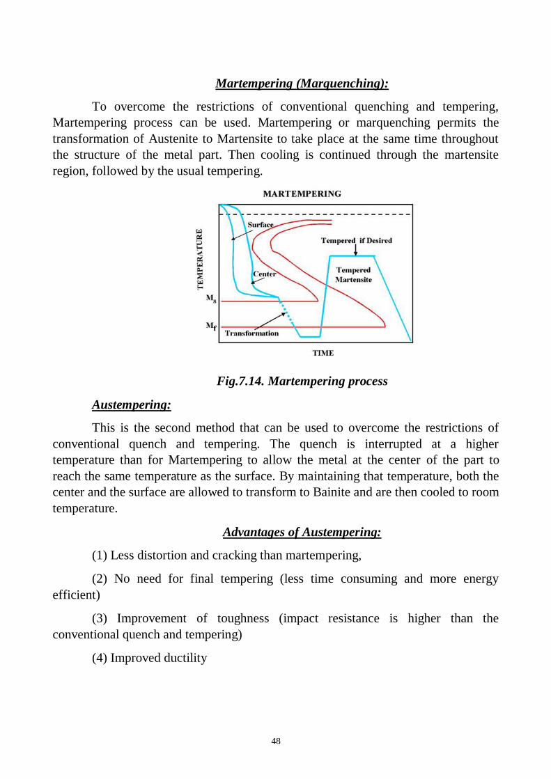
Martempering (Marquenching):
To overcome the restrictions of conventional quenching and tempering,
Martempering process can be used. Martempering or marquenching permits the
transformation of Austenite to Martensite to take place at the same time throughout
the structure of the metal part. Then cooling is continued through the martensite
region, followed by the usual tempering.
Fig.7.14. Martempering process
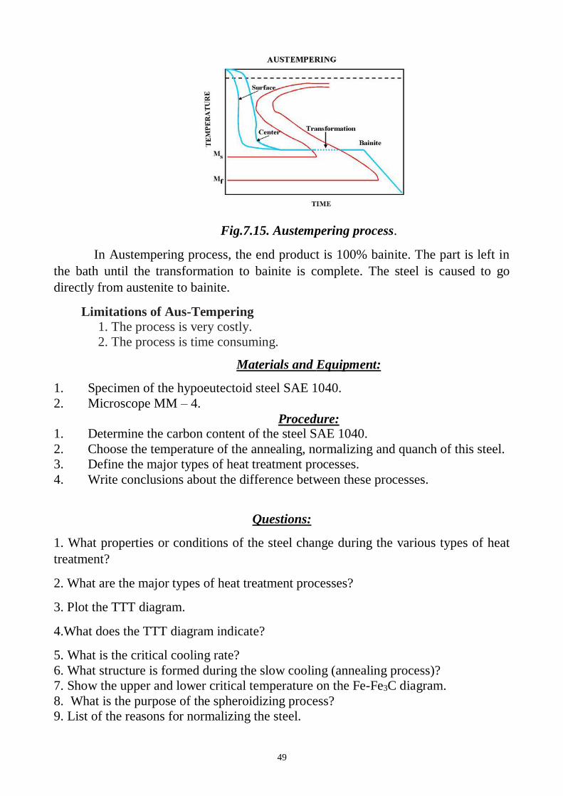
Austempering:
This is the second method that can be used to overcome the restrictions of
conventional quench and tempering. The quench is interrupted at a higher
temperature than for Martempering to allow the metal at the center of the part to
reach the same temperature as the surface. By maintaining that temperature, both the
center and the surface are allowed to transform to Bainite and are then cooled to room
temperature.
Advantages of Austempering:
(1) Less distortion and cracking than martempering,
(2) No need for final tempering (less time consuming and more energy
efficient)
(3) Improvement of toughness (impact resistance is higher than the
conventional quench and tempering)
(4) Improved ductility
49
Fig.7.15. Austempering process.
In Austempering process, the end product is 100% bainite. The part is left in
the bath until the transformation to bainite is complete. The steel is caused to go
directly from austenite to bainite.
Limitations of Aus-Tempering
1. The process is very costly.
2. The process is time consuming.
Materials and Equipment:
1. Specimen of the hypoeutectoid steel SAE 1040.
2. Microscope MM – 4.
Procedure: 1. Determine the carbon content of the steel SAE 1040.
2. Choose the temperature of the annealing, normalizing and quanch of this steel.
3. Define the major types of heat treatment processes.
4. Write conclusions about the difference between these processes.
Questions:
1. What properties or conditions of the steel change during the various types of heat
treatment?
2. What are the major types of heat treatment processes?
3. Plot the TTT diagram.
4.What does the TTT diagram indicate?
5. What is the critical cooling rate?
6. What structure is formed during the slow cooling (annealing process)?
7. Show the upper and lower critical temperature on the Fe-Fe3C diagram.
8. What is the purpose of the spheroidizing process?
9. List of the reasons for normalizing the steel.

50
10. How to choose the normalizing temperature for hypo- and hypereutectoid
steel? Show temperature ranges on the Fe-Fe3C diagram.
11. Comparison between Annealing and Normalising.
12. What is the martensite and what properties does it have?
13. What is Hardenability?
14. What transformation takes place during quench process?
15. How to choose the quench temperature for hypo- and hypereutectoid steel?
Show temperature ranges on the Fe-Fe3C diagram.
16. What is the purpose of the tempering process?
17. What is the tempering?
18. Describe types of tempering.
19. What is Martempering and Austempering.
20. List the Advantages of Austempering.

51
LABORATORY WORK 7
HEAT TREATMENT OF STELL
PROTOCOL 1
Define:
Annealing____________________________________________________________
____________________________________________________________________
______________________________________________________________
Normalizing__________________________________________________________
____________________________________________________________________
______________________________________________________________
Quenching____________________________________________________________
____________________________________________________________________
______________________________________________________________
Tempering____________________________________________________________
____________________________________________________________________
______________________________________________________________
PROTOCOL 2
Steel Carbon
content,
%
Critical
temperature,?C
Temperature of the processes, ?C
SAE
1030
UCT annealing normalizing quanch
LCT
Conclusions:
_______________________________________________________________
_______________________________________________________________
_______________________________________________________________
_______________________ _________________________
Student’s signature Teacher’s signature
“____”___________20___ y. “____”____________20___ y.
52
LABORATORY WORK 8
CHEMICAL HEAT TREATMENT OF STEEL
Objectives
1. To learn the major types of chemical heat treatment processes.
2. To learn the technological parameters of the Carburization and Nitriding processes.
2. To learn the applications of the types of chemical heat treatment processes.
Scientific principles
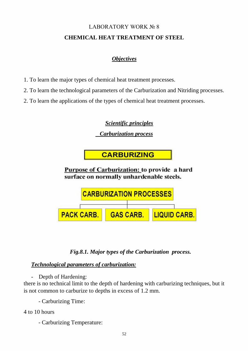
Carburization process
Fig.8.1. Major types of the Carburization process.
Technological parameters of carburization:
- Depth of Hardening:
there is no technical limit to the depth of hardening with carburizing techniques, but it
is not common to carburize to depths in excess of 1.2 mm.
- Carburizing Time:
4 to 10 hours
- Carburizing Temperature:
53
950 °C (above the upper critical temperature-Austenite area)
Quenching:
All of the carburizing processes (pack, gas, liquid) require quenching from the
carburizing temperature or a lower temperature or reheating and quenching. Parts are
then tempered to the desired hardness.
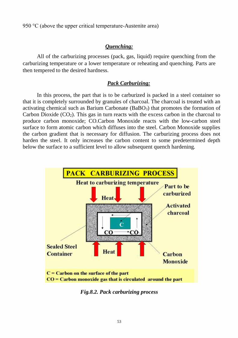
Pack Carburizing:
In this process, the part that is to be carburized is packed in a steel container so
that it is completely surrounded by granules of charcoal. The charcoal is treated with an
activating chemical such as Barium Carbonate (BaBO3) that promotes the formation of
Carbon Dioxide (CO2). This gas in turn reacts with the excess carbon in the charcoal to
produce carbon monoxide; CO.Carbon Monoxide reacts with the low-carbon steel
surface to form atomic carbon which diffuses into the steel. Carbon Monoxide supplies
the carbon gradient that is necessary for diffusion. The carburizing process does not
harden the steel. It only increases the carbon content to some predetermined depth
below the surface to a sufficient level to allow subsequent quench hardening.
Fig.8.2. Pack carburizing process
54
Quenching Process:
It is difficult to quench the part immediately, as the sealed pack has to be opened
and the part must be removed from the pack. One technique that is used often is to slow
cool the entire pack and subsequently harden and temper the part after it is removed
from the sealed pack.
Gas Carburizing:
Can be done with any carbonaceous gas, such as methane, ethane, propane, or
natural gas. Most carburizing gases are flammable and controls are needed to keep
carburizing gas at 930 °C from contacting air (oxygen). The advantage of this process
over pack carburizing is an improved ability to quench from the carburizing
temperature. Conveyor hearth furnaces make quenching in a controlled atmosphere
possible.
Liquid Carburizing:
Can be performed in internally or externally heated molten salt pots. Carburizing
salt contains cyanide compounds such as sodium cyanide (NaCN). Cycle times for
liquid cyaniding is much shorter (1 to 4 hours) than gas and pack carburizing processes.
Disadvantage is the disposal of salt. (environmental problems) and cost (safe disposal is
very expensive).
There are some advantages of the liquid bath carburizing which are given as under.
Advantages 1. Greater depth of penetration possible in this process. 2. Selective carburizing is possible if needed. 3. Uniform heating will occur in this process. 4. Little deformation or distortion of articles occur in this process. 5. Ease of carburizing for a wider range of products. 6. It is time saving process. 7. Parts leave the bath with a clean and bright finish.
There is no scale in this process as occur in pack hardening
Nitriding Process:
In this process, nitrogen is diffused into the surface of the steel being treated. The
reaction of nitrogen with the steel causes the formation of very hard iron and alloy
nitrogen compounds. The resulting nitride case is harder than tool steels or carburized
steels. The advantage of this process is that hardness is achieved without the oil, water
or air quench. As an added advantage, hardening is accomplished in a nitrogen
atmosphere that prevents scaling and discoloration. Nitriding temperature is below the
lower critical temperature of the steel and it is set between 500°C and 600 °C. The
55
nitrogen source is usually Ammonia (NH3). At the nitriding temperature the ammonia
dissociates into Nitrogen and Hydrogen.
2NH3 ---> 2N + 3H2
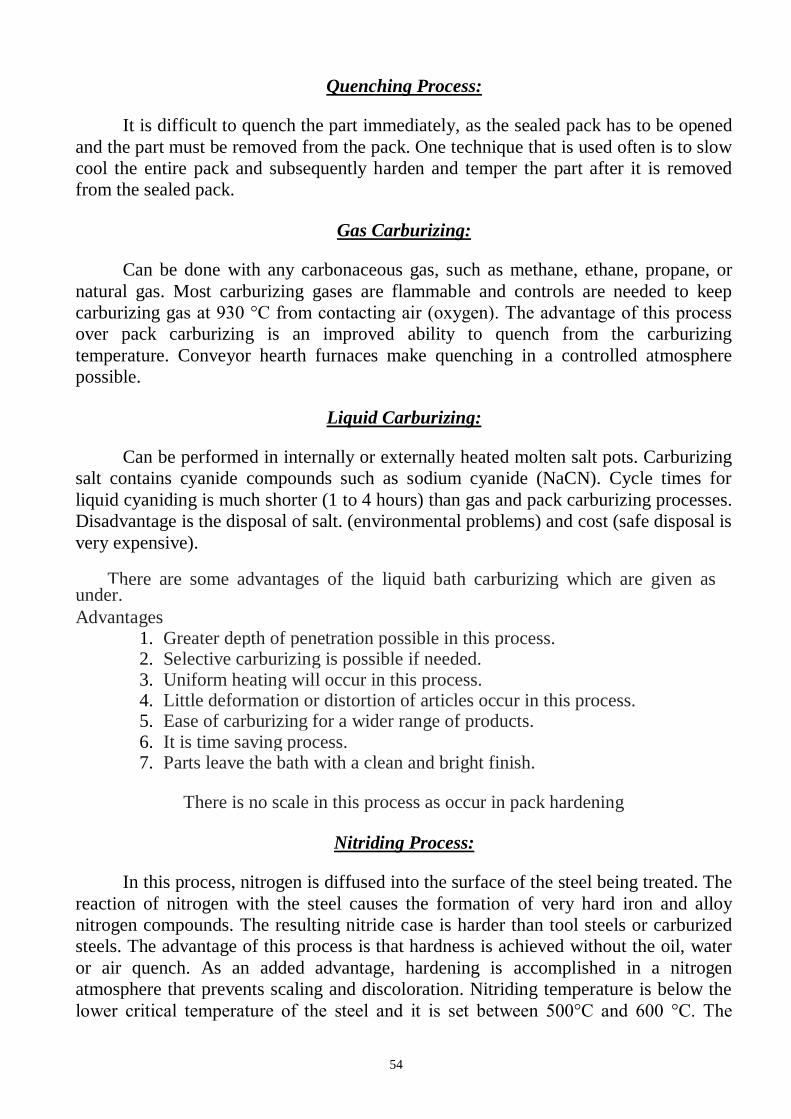
The nitrogen diffuses into the steel and hydrogen is exhausted. A typical nitriding
setup is illustrated in Fig.8.3.
Fig.8.3. Nitriding process
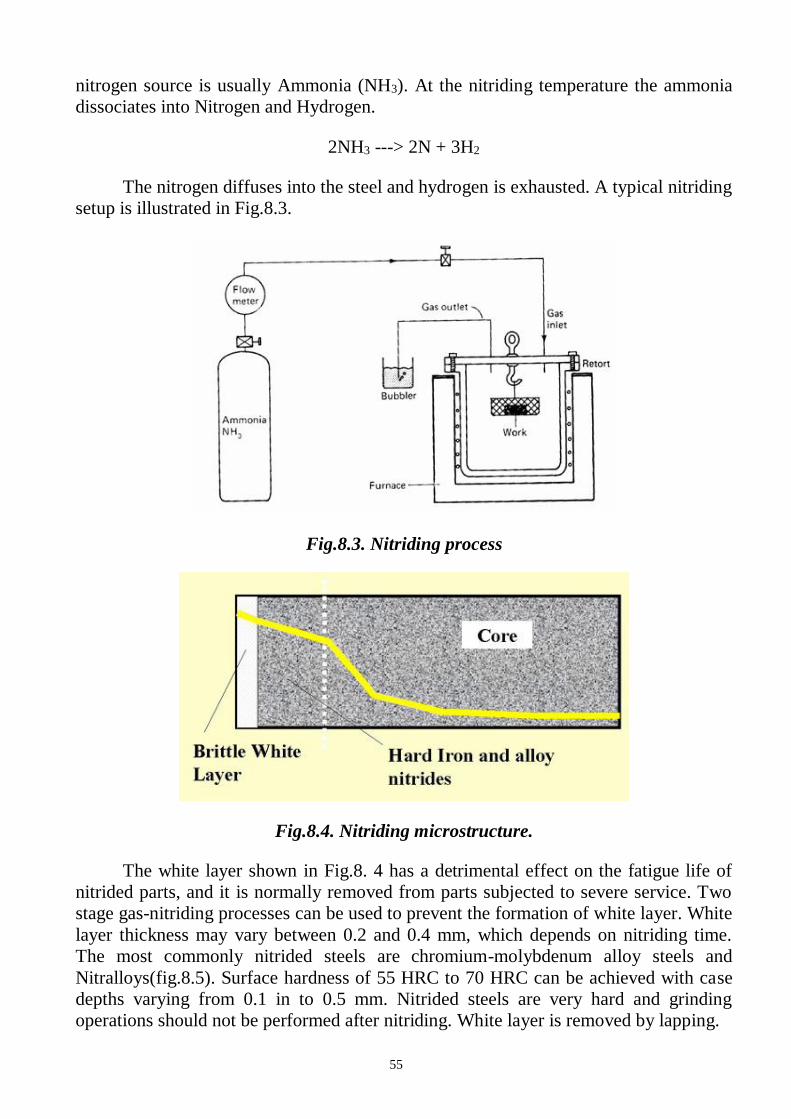
Fig.8.4. Nitriding microstructure.
The white layer shown in Fig.8. 4 has a detrimental effect on the fatigue life of
nitrided parts, and it is normally removed from parts subjected to severe service. Two
stage gas-nitriding processes can be used to prevent the formation of white layer. White
layer thickness may vary between 0.2 and 0.4 mm, which depends on nitriding time.
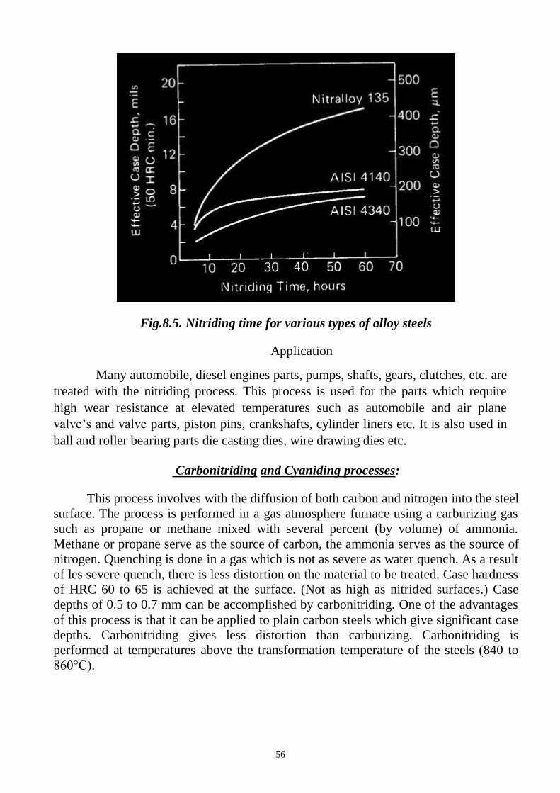
The most commonly nitrided steels are chromium-molybdenum alloy steels and
Nitralloys(fig.8.5). Surface hardness of 55 HRC to 70 HRC can be achieved with case
depths varying from 0.1 in to 0.5 mm. Nitrided steels are very hard and grinding
operations should not be performed after nitriding. White layer is removed by lapping.
56
Fig.8.5. Nitriding time for various types of alloy steels
Application
Many automobile, diesel engines parts, pumps, shafts, gears, clutches, etc. are
treated with the nitriding process. This process is used for the parts which require
high wear resistance at elevated temperatures such as automobile and air plane
valve’s and valve parts, piston pins, crankshafts, cylinder liners etc. It is also used in
ball and roller bearing parts die casting dies, wire drawing dies etc.
Carbonitriding and Cyaniding processes:
This process involves with the diffusion of both carbon and nitrogen into the steel
surface. The process is performed in a gas atmosphere furnace using a carburizing gas
such as propane or methane mixed with several percent (by volume) of ammonia.
Methane or propane serve as the source of carbon, the ammonia serves as the source of
nitrogen. Quenching is done in a gas which is not as severe as water quench. As a result
of les severe quench, there is less distortion on the material to be treated. Case hardness
of HRC 60 to 65 is achieved at the surface. (Not as high as nitrided surfaces.) Case
depths of 0.5 to 0.7 mm can be accomplished by carbonitriding. One of the advantages
of this process is that it can be applied to plain carbon steels which give significant case
depths. Carbonitriding gives less distortion than carburizing. Carbonitriding is
performed at temperatures above the transformation temperature of the steels (840 to
860°C).
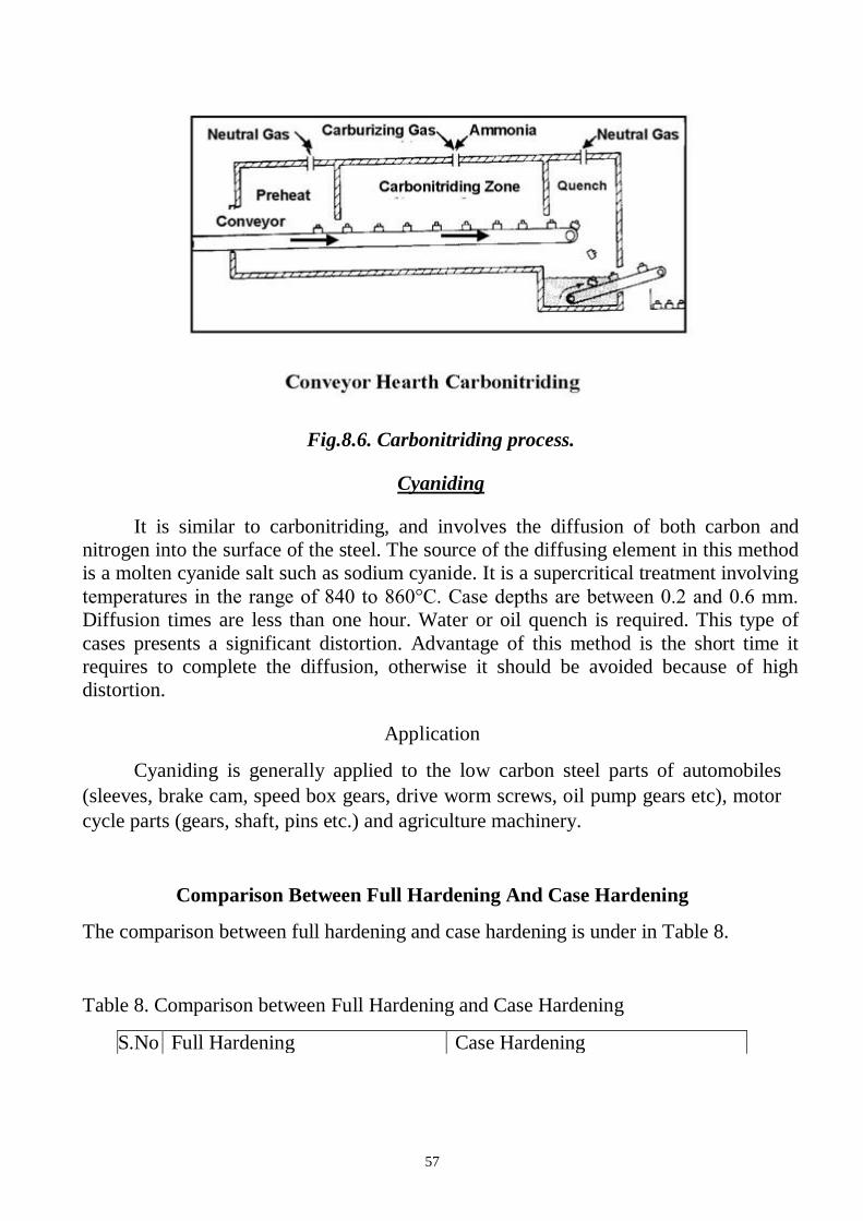
57
Fig.8.6. Carbonitriding process.
Cyaniding
It is similar to carbonitriding, and involves the diffusion of both carbon and
nitrogen into the surface of the steel. The source of the diffusing element in this method
is a molten cyanide salt such as sodium cyanide. It is a supercritical treatment involving
temperatures in the range of 840 to 860°C. Case depths are between 0.2 and 0.6 mm.
Diffusion times are less than one hour. Water or oil quench is required. This type of
cases presents a significant distortion. Advantage of this method is the short time it
requires to complete the diffusion, otherwise it should be avoided because of high
distortion.
Application
Cyaniding is generally applied to the low carbon steel parts of automobiles
(sleeves, brake cam, speed box gears, drive worm screws, oil pump gears etc), motor
cycle parts (gears, shaft, pins etc.) and agriculture machinery.
Comparison Between Full Hardening And Case Hardening
The comparison between full hardening and case hardening is under in Table 8.
Table 8. Comparison between Full Hardening and Case Hardening
S.No
.
Full Hardening Case Hardening
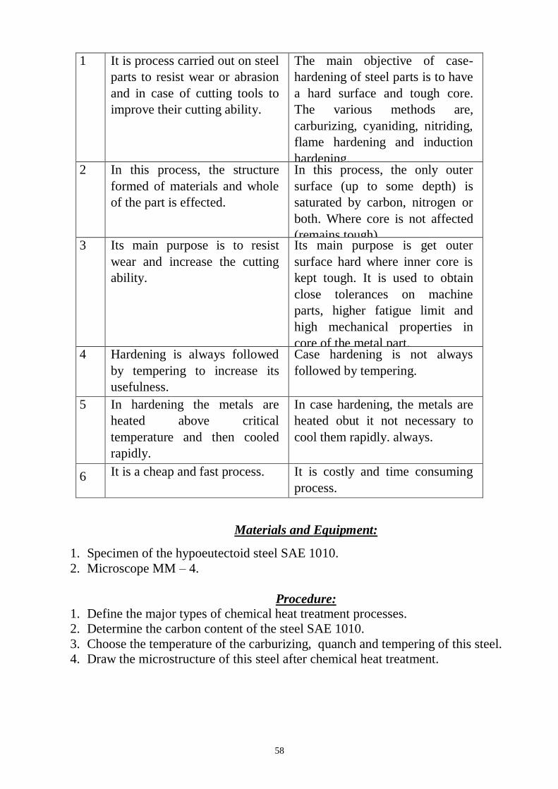
58
1 It is process carried out on steel
parts to resist wear or abrasion
and in case of cutting tools to
improve their cutting ability.
The main objective of case-
hardening of steel parts is to have
a hard surface and tough core.
The various methods are,
carburizing, cyaniding, nitriding,
flame hardening and induction
hardening. 2 In this process, the structure
formed of materials and whole
of the part is effected.
In this process, the only outer
surface (up to some depth) is
saturated by carbon, nitrogen or
both. Where core is not affected
(remains tough). 3 Its main purpose is to resist
wear and increase the cutting
ability.
Its main purpose is get outer
surface hard where inner core is
kept tough. It is used to obtain
close tolerances on machine
parts, higher fatigue limit and
high mechanical properties in
core of the metal part. 4 Hardening is always followed
by tempering to increase its
usefulness.
Case hardening is not always
followed by tempering.
5 In hardening the metals are
heated above critical
temperature and then cooled
rapidly.
In case hardening, the metals are
heated obut it not necessary to
cool them rapidly. always.
6 It is a cheap and fast process. It is costly and time consuming
process.
Materials and Equipment:
1. Specimen of the hypoeutectoid steel SAE 1010.
2. Microscope MM – 4.
Procedure:
1. Define the major types of chemical heat treatment processes.
2. Determine the carbon content of the steel SAE 1010.
3. Choose the temperature of the carburizing, quanch and tempering of this steel.
4. Draw the microstructure of this steel after chemical heat treatment.
59
Questions:
1. What properties of the steel change during the various types of chemical heat
treatment?
2. What are the major types of chemical heat treatment processes?
3. What is carburizing and write it technological parameters?
4. Explain Pack Carburizing process.
5. Explain Gas Carburizing process.
6. Explain Liquid Carburizing process.
7. What the reasons for using Quenching Process after Carburizing process?
8. List the Advantages of Liquid Carburizing process.
9. What is Nitriding Process and write it technological parameters.
10. Draw and explain the Nitriding microstructure.
11. Describe Carbonitriding and Cyaniding processes.
12. Write the application of the major types of chemical heat treatment processes.
13. Describe the comparison between Full Hardening and Case Hardening.
60
LABORATORY WORK 7
CHEMICAL HEAT TREATMENT OF STELL
PROTOCOL 1
Define: Carburizing process
____________________________________________________________________
________________________________________________________________
Nitriding Process
____________________________________________________________________
________________________________________________________________
Carbonitriding
____________________________________________________________________
________________________________________________________________
Cyaniding processes
____________________________________________________________________
________________________________________________________________
PROTOCOL 2
Steel Carbon
content,
%
Depth,
mm
Time,
hours
Temperature of the processes, ?C
carburizing quanch tempering
SAE
1010

61
PROTOCOL 3
Microstructure steel SAE 1010 after chemical heat treatment
Conclusions:
_______________________________________________________________
_______________________________________________________________
_______________________________________________________________
_______________________ _________________________
Student’s signature Teacher’s signature
“____”___________20___ y. “____”____________20___ y.
62
LABORATORY WORK 9
ALLOY STEELS. LOW-ALLOY STEELS AND STAINLESS STEELS
Objectives
1. To learn the effect of alloying elements in steel.
2. To learn to determine of the alloy steel chemical composition by its SAE-AISI
number.
3. To learn the chemical composition, microstructure and applications low-carbon
steels.
4. To learn the chemical composition, microstructure and applications stainless steels.
Scientific principles
To produce needed improvement in properties of plain carbon steel, certain
elements in steel are alloyed for specific purposes to increase wearing resistance,
electrical and mechanical properties which cannot be obtained in plain carbon steels.
The properties of steel can be tailored for special uses by the addition of other
metals to the alloy. For improving the properties of ordinary steel, certain alloying
elements are added in it in sufficient amounts. The most common alloying elements
added to steel are chromium, nickel, manganese, silicon, vanadium, molybdenum,
tungsten, copper, titanium, zirconium, cobalt, and aluminium.
Each of these elements induces certain qualities in steels to which it is added.
They may be used separately or in combination to produce desired characteristics in
the steel. The main purpose of alloying element in steel is to improve machinability,
elasticity, hardness, case hardening, cutting ability, toughness, wear resistance, tensile
strength, corrosion resistance, and ability to retain shape at high temperature, ability
to resist distortion at elevated temperature and to impart a fine grain size to steel.
Like carbon, a number of alloying elements are soluble to produce alloys with
improved strength, ductility, and toughness. Also carbon, besides forming an inter-
metallic compound with iron, combines with many alloying elements and form alloy
carbides. These alloy carbides as well as iron-alloy carbides are usually hard and lack
in toughness. Some alloying elements are added to prevent or restrict grain growth.
Aluminium is considered the most effective in this respect. Others are zirconium,
vanadium, chromium, and titanium. The addition of alloying elements almost always
affects the austenite-ferrite transformation mechanism. Some alloying elements lower
and some raise the critical temperature. The compositional and structural changes
63
produced by alloying elements change and improve the physical, mechanical and
processing properties of steel.
Effect of alloying elements in steel
The chief alloying elements used in steel are nickel, chromium, molybdenum,
cobalt, vanadium, manganese, silicon and tungsten. Each of these elements possesses
certain qualities upon the steel to which it is added. These elements may be used
separately or in combination to produce the desired characteristic in steel. Following
are the effects of alloying elements on steel.
Nickel. Steels contain 2 to 5% nickel and from 0.1 to 0.5% carbon increase
its strength and toughness. In this range, nickel contributes great tensile strength,
yield strength, toughness and forming properties and hardness with high elastic limit,
good ductility and good resistance to corrosion. An alloy containing 25% nickel
possesses maximum toughness and offers the greatest resistance to rusting, corrosion
and burning at high temperature. It has proved beneficial in the manufacture of boiler
tubes, valves for use with superheated steam, valves for engines and sparking plugs
for petrol engines. A nickel steel alloy containing 36% of nickel is known as invar. It
has nearly zero coefficient of expansion. Therefore, it is in great demand for making
measuring instruments for everyday use.
Chromium. It improves corrosion resistance (about 12 to 18% addition). It
increases tensile strength, hardness, wear resistance and heat resistance. It provides
stainless property in steel. It decreases malleability of steel. It is used in steels as an
alloying element to combine hardness with high strength and high elastic limit. It also
imparts corrosion resisting properties to steel. The most common chrome steels
contain from 0.5 to 2% chromium and 0.1 to 1.5% carbon. The chrome steel is used
for balls, rollers and races for bearings. A Nickel-Chrome steel containing 3.25%
nickel, 1.5% chromium and 0.25% carbon is much used for armour plates. Chrome
nickel steel is extensively used for motor car crank shafts, axles and gears requiring
great strength and hardness.
Tungsten. It increases hardness, wear resistance, shocks resistance and
magnetic reluctance. It increases ability to retain hardness and toughness at high
temperature. It prohibits grain growth and the depth of hardening of quenched steel.
The principal uses of tungsten steels are for cutting tools, dies, valves, taps and
permanent magnets.
Vanadium. It improves tensile strength, elastic limit, ductility, fatigue
resistance, shock resistance and response to heat treatment. It aids in obtaining a fine
grain structure in tool steel. The addition of a very small amount of vanadium (less
than 0.2%) produces a marked increase in tensile strength and elastic limit in low and
medium carbon steels without a loss of ductility. The chrome- vanadium steel
containing about 0.5 to 1.5% chromium, 15 to 0.3% vanadium and 0.13 to 1.1%
64
carbon have extremely good tensile strength, elastic limit, endurance limit and
ductility. These steels are frequently used for parts such as springs, shafts, gears, pins
and many drop forged parts.
Molybdenum. A very small quantity (0.15 to 0.30%) of molybdenum is
generally used with chromium and manganese (0.5 to 0.8%) to make molybdenum
steel. It increases hardness, wear resistance, thermal resistance. When added with
nickel, it improves corrosion resistance. It counteracts tendency towards temper
brittleness. It makes steel tough at various hardness levels. It acts as a grain growth
inhibitor when steels are heated to high temperatures. Molybdenum steels possesses
hardness, wear resistance, thermal resistance and extra tensile strength. It is used for
airplane fuselage and automobile parts. It can replace tungsten in high speed steels.
Cobalt. When added to steel, it refines the graphite and pearlite and acts as a
grain refiner. It improves hardness, toughness, tensile strength and thermal resistance.
Titanium. It acts as a good deoxidizer and promotes grain growth. It
prevents formation of austenite in high chromium steels. It is the strongest carbide
former. It is used to fix carbon in stainless steels and thus prevents the precipitation
of chromium carbide.
Aluminium. It is used as a deoxidizer. If present in an amount of about 1 %,
it helps promoting nitriding.
Copper. It improves resistance to corrosion. It increases strength. More than
0.6 % copper for precipitation.
Silicon. It improves magnetic permeability and decreases hysteresis losses. It
decreases weldability and forgeability. It is also added as a deoxidizer during casting
of ingots. It takes care of oxygen present in steel by forming SiO2. Silicon steels
behave like nickel steels. These steels have a high elastic limit as compared to
ordinary carbon steel. Silicon steels containing from 1 to 2% silicon and 0.1 to 0.4%
carbon and other alloying elements are used for electrical machinery, valves in
engines, springs and corrosion resisting materials.
Manganese. It improves the strength of the steel in both the hot rolled and
heat treated condition. The manganese alloy steels containing over 1.5% manganese
with a carbon range of 0.40 to 0.55% are used extensively in gears, axles, shafts and
other parts where high strength combined with fair ductility is required. The principal
use of manganese steel is in machinery parts subjected to severe wear. These steels
are all cast and ground to finish.
The effect of alloying elements on the microstructure and properties of steel
are given in Table 9.1.
65
Table 9.1. The effect of alloying elements on the properties of steel
Element Effect
Aluminum Ferrite hardener
Graphite former
Deoxidizer
Chromium Mild ferrite hardener
Moderate effect on hardenability
Graphite former
Resists corrosion
Resists abrasion
Cobalt High effect on ferrite as a hardener
High red hardness
Molybdenum Strong effect on hardenability
Strong carbide former
High red hardness
Increases abrasion resistance
Manganese Strong ferrite hardener
Nickel Ferrite strengthener
Increases toughness of the hypoeutectoid steel
With chromium, retains austenite
Graphite former
Copper Austenite stabilizer
Improves resistance to corrosion
Silicon Ferrite hardener
Increases magnetic properties in steel
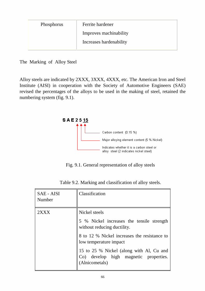
66
Phosphorus Ferrite hardener
Improves machinability
Increases hardenability
The Marking of Alloy Steel
Alloy steels are indicated by 2XXX, 3XXX, 4XXX, etc. The American Iron and Steel
Institute (AISI) in cooperation with the Society of Automotive Engineers (SAE)
revised the percentages of the alloys to be used in the making of steel, retained the
numbering system (fig. 9.1).
Fig. 9.1. General representation of alloy steels
Table 9.2. Marking and classification of alloy steels.
SAE - AISI
Number
Classification
2XXX Nickel steels
5 % Nickel increases the tensile strength
without reducing ductility.
8 to 12 % Nickel increases the resistance to
low temperature impact
15 to 25 % Nickel (along with Al, Cu and
Co) develop high magnetic properties.
(Alnicometals)
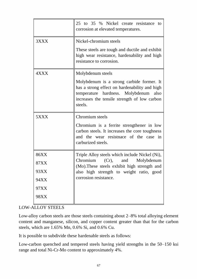
67
25 to 35 % Nickel create resistance to
corrosion at elevated temperatures.
3XXX Nickel-chromium steels
These steels are tough and ductile and exhibit
high wear resistance, hardenability and high
resistance to corrosion.
4XXX Molybdenum steels
Molybdenum is a strong carbide former. It
has a strong effect on hardenability and high
temperature hardness. Molybdenum also
increases the tensile strength of low carbon
steels.
5XXX Chromium steels
Chromium is a ferrite strengthener in low
carbon steels. It increases the core toughness
and the wear resistnace of the case in
carburized steels.
86XX
87XX
93XX
94XX
97XX
98XX
Triple Alloy steels which include Nickel (Ni),
Chromium (Cr), and Molybdenum
(Mo).These steels exhibit high strength and
also high strength to weight ratio, good
corrosion resistance.
LOW-ALLOY STEELS
Low-alloy carbon steels are those steels containing about 2–8% total alloying element
content and manganese, silicon, and copper content greater than that for the carbon
steels, which are 1.65% Mn, 0.6% Si, and 0.6% Cu.
It is possible to subdivide these hardenable steels as follows:
Low-carbon quenched and tempered steels having yield strengths in the 50–150 ksi
range and total Ni-Cr-Mo content to approximately 4%.
68
Medium-carbon ultrahigh-strength steels having strengths in the range of 200 ksi.
AISI 4130 and 4340 steels are typical examples.
Bearing steels, such as 8620 and 2100.
Chrome-molybdenum heat-resisting steels containing up to 1% Mo and 9% Cr in the
AISI 9XXX series.
When relatively large amounts of alloying elements are added to steel, the
characteristic behavior of carbon steel is obliterated. Most alloy steel is medium- or
high-carbon steel to which various elements have been added to modify its properties
to an appreciable extent, but it still owes its distinctive characteristics to the carbon
that it contains. The percentage of alloy element required for a given purpose ranges
from a few hundredths of 1% to possibly as high as 5%.
When ready for service these steels will usually contain only two constituents, ferrite
and carbide. The only way that any alloying element can affect the properties of steel
is to change the dispersion of carbide in the ferrite or change the properties of the
carbide. The effect on the distribution of carbide is the most important factor. In large
sections when carbon steels fail to harden throughout the section, even under a water
quench, the har-denability of the steel can be increased by the addition of any
alloying element (except possibly cobalt). The elements most effective in increasing
the hardenability of steel are manganese, silicon, and chromium.
Elements such as molybdenum, tungsten, and vanadium are effective in increasing
the hardenability when dissolved in the austenite, but they are usually present in the
austenite in the form of carbides. The main advantage of these carbide-forming
elements is that they prevent the agglomeration of carbides in tempered martensite.
Tempering relieves the internal stresses in the hardened steel and causes
spheroidization of the carbide particles, with resultant loss in hardness and strength.
With these stable carbide-forming elements present, higher tempering temperatures
may be employed without sacrificing strength. This permits these alloy steels to have
a greater ductility for a given strength, or a greater strength for a given ductility, than
plain carbon steels.
The third factor that contributes to the strength of alloy steel is the presence of the
alloying element in the ferrite. Any element present in solid solution in a metal will
increase the strength of the metal. The elements most effective in increasing the
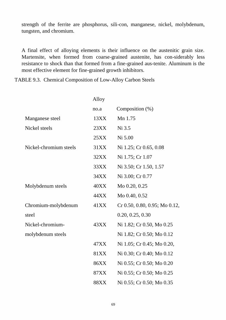
69
strength of the ferrite are phosphorus, sili-con, manganese, nickel, molybdenum,
tungsten, and chromium.
A final effect of alloying elements is their influence on the austenitic grain size.
Martensite, when formed from coarse-grained austenite, has con-siderably less
resistance to shock than that formed from a fine-grained aus-tenite. Aluminum is the
most effective element for fine-grained growth inhibitors.
TABLE 9.3. Chemical Composition of Low-Alloy Carbon Steels
Alloy
no.a Composition (%)
Manganese steel 13XX Mn 1.75
Nickel steels 23XX Ni 3.5
25XX Ni 5.00
Nickel-chromium steels 31XX Ni 1.25; Cr 0.65, 0.08
32XX Ni 1.75; Cr 1.07
33XX Ni 3.50; Cr 1.50, 1.57
34XX Ni 3.00; Cr 0.77
Molybdenum steels 40XX Mo 0.20, 0.25
44XX Mo 0.40, 0.52
Chromium-molybdenum 41XX Cr 0.50, 0.80, 0.95; Mo 0.12,
steel 0.20, 0.25, 0.30
Nickel-chromium- 43XX Ni 1.82; Cr 0.50, Mo 0.25
molybdenum steels Ni 1.82; Cr 0.50; Mo 0.12
47XX Ni 1.05; Cr 0.45; Mo 0.20,
81XX Ni 0.30; Cr 0.40; Mo 0.12
86XX Ni 0.55; Cr 0.50; Mo 0.20
87XX Ni 0.55; Cr 0.50; Mo 0.25
88XX Ni 0.55; Cr 0.50; Mo 0.35
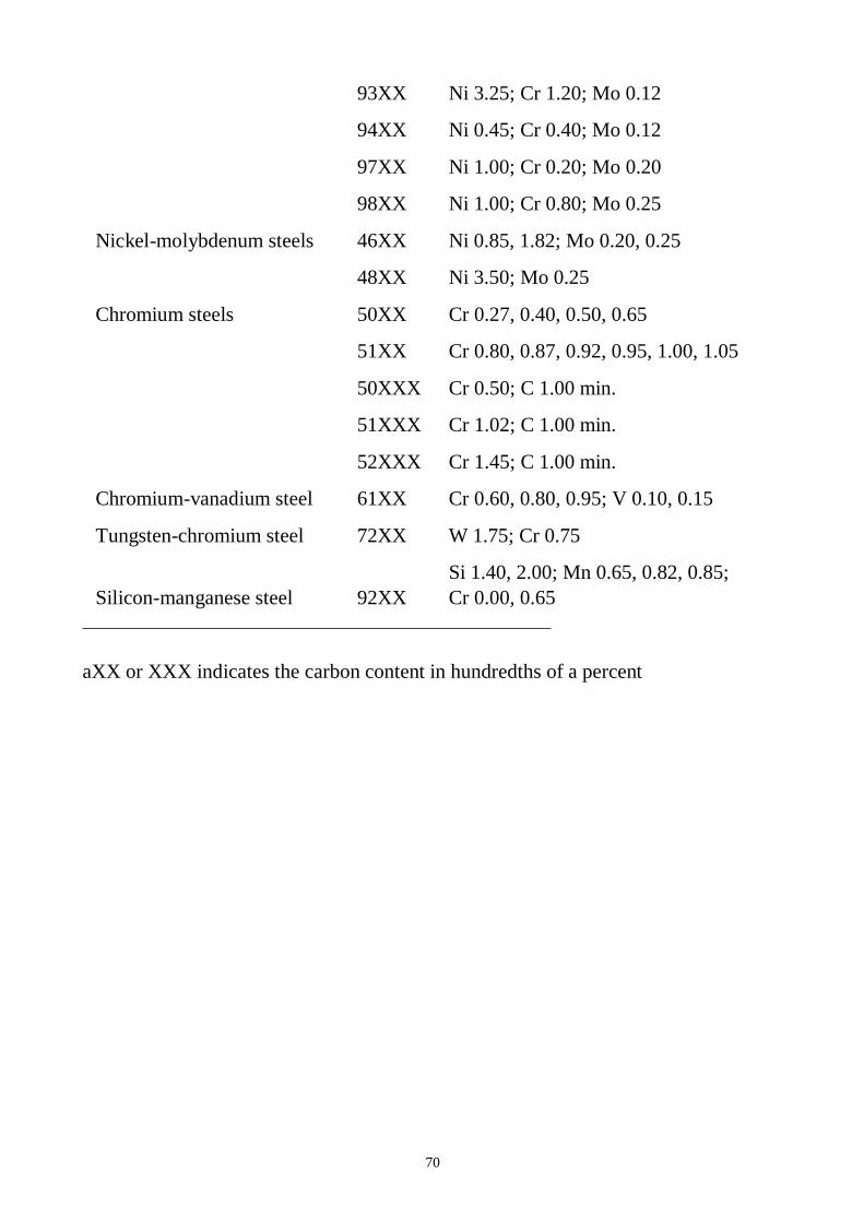
70
93XX Ni 3.25; Cr 1.20; Mo 0.12
94XX Ni 0.45; Cr 0.40; Mo 0.12
97XX Ni 1.00; Cr 0.20; Mo 0.20
98XX Ni 1.00; Cr 0.80; Mo 0.25
Nickel-molybdenum steels 46XX Ni 0.85, 1.82; Mo 0.20, 0.25
48XX Ni 3.50; Mo 0.25
Chromium steels 50XX Cr 0.27, 0.40, 0.50, 0.65
51XX Cr 0.80, 0.87, 0.92, 0.95, 1.00, 1.05
50XXX Cr 0.50; C 1.00 min.
51XXX Cr 1.02; C 1.00 min.
52XXX Cr 1.45; C 1.00 min.
Chromium-vanadium steel 61XX Cr 0.60, 0.80, 0.95; V 0.10, 0.15
Tungsten-chromium steel 72XX W 1.75; Cr 0.75
Silicon-manganese steel 92XX
Si 1.40, 2.00; Mn 0.65, 0.82, 0.85;
Cr 0.00, 0.65
aXX or XXX indicates the carbon content in hundredths of a percent
71
STAINLESS STEEL
TYPES OF CORROSION
Stress Corrosion Cracking
Stress corrosion cracking occurs at points of stress. Usually the metal or alloy
is virtually free of corrosion over most of its surface, yet fine cracks penetrate
through the surface at the points of stress.
Sulfide Stress Cracking
Many corrosion processes produce hydrogen ions, which combine with
electrons from the base metal to form hydrogen atoms. Two such formed hydrogen
atoms may combine to form a hydrogen molecule. The majority of such molecules
will form hydrogen bubbles and float away harmlessly. However, a percentage of the
hydrogen atoms will diffuse into the base metal and embrittle the crystalline
structure. Sulfide stress cracking will occur when a critical concentration of hydrogen
is reached while a tensile stress exceeding a threshold level is present. Although H2S
does not actively participate in the SSC reaction, sulfides act to promote the entry of
the hydrogen atoms into the base metal.
The susceptibility of carbon steels to SSC is directly related to their strength or
hardness levels. As carbon or low-alloy carbon steel is heat treated to progressively
higher levels of hardness, the time to failure de-creases rapidly for a given stress
level.
Temperature is also a factor. Below 7 ˚C the diffusion rate is so slow that the
crucial concentration is not reached. By carefully monitoring the processing of
carbon and low-alloy carbon steels, and keeping the hardness level below 22HRC,
these steels will have acceptable resistance to SSC.
Pitting
Carbon and low-alloy carbon steels may pit under low flow or stagnant
conditions. The pits are generally shallow.
Corrosion Fatigue
Fatigue failures are the results of prolonged cyclic loading. If corrodents are
present, the fatigue problem is worse, sometimes involving corrosion deposits
accumulating in the cracks to concentrate the cycling stresses.
Uniform Corrosion
Carbon and low-alloy carbon steels are primarily affected by uniform, or
general, corrosion. The most common current corrosive solvent is water, in
72
everything from dilute solutions to concentrated acids and salt solutions. Some
organic systems are also capable of causing serious corrosion.
Microbiologically Influenced Corrosion
Stagnant hydrotest water is frequently the cause of this type of corrosion. In
water systems there are many bacteria that accumulate and grow on metal surfaces in
colonies, changing the localized chemistry to highly corrosive conditions.
Stainless steel contains chromium together with nickel as alloy and rest is
iron. Stainless steel contains a minimum of 12% chromium, which stops further
oxidation by forming a protective oxide on the surface.
It has been defined as that steel which when correctly heat treated and
finished, resists oxidation and corrosive attack from most corrosive media. Stainless
steel surface is responsible for corrosion resistance. Minimum chromium content of
12% is required for the film’s formation, and 18% is sufficient to resist the most
severe atmospheric corrosive conditions. Their principal alloying element is
chromium while some other elements like nickel, manganese etc. can also be present
in small amounts. Addition of nickel improves ductility and imparts strength.
Corrosion resistance to stainless steels increases with increase in nickel content
against neutral chloride solution and weakly oxidizing acids. Addition of
molybdenum improves its resistance to sulphuric, sulphurous and organic acids.
Addition of manganese increases hot workability of these steels.
Steels having 15 to 20% Ni and about 0.1 % carbon possesses great strength
and toughness and extremely good resistance to corrosion. Such steels are called
stainless steels. Another type of stainless steel containing 11 to 14% chromium and
about 0.35% carbon is used for cutlery, surgical and dental instruments and other
purposes where hard edges are required. Maximum resistance to corrosion is obtained
when this steel is ground and polished after heat-treating.
A steel containing 18% chromium and 8% nickel is widely used and is
commonly referred to as 18/8 steel. Stainless steel is highly resistance to corrosion
and oxidation. It can be classified into three major categories according to the type of
micro structures.
General Properties of Stainless Steels
It possesses wide range of strength and hardness, high ductility, formability,
high corrosion resistance, good creep resistance, good thermal conductivity, good
machinability, good weldability, high hot, cold workability, high resistance to scaling
and oxidation at elevated temperatures, excellent surface appearance and finish.
73
Classification of Stainless Steel
On basis of their structure, stainless steels are classified as follow:
– Martensitic stainless steels
– Ferritic stainless steels
– Austenitic stainless steels.
These types of stainless steel are discussed as under.
Martensitic Stainless Steels
These steels contain 12 to 16% chromium and 0.1 to 1.2 % carbon. The
structure consists of hard martensite phase after hardening. The general utility
chromium stainless steel with 12% chromium and 0.15% carbon are ferromagnetic
and air hardening. It is very hard and possesses high strain and high corrosion
resistance properties.
Applications
Stainless steels containing 12 to 14% chromium and 0.3% carbon are
extensively used for table cutlery, tools and equipments etc. Stainless steels
containing 16-18% chromium and 0.2% carbon are used as springs, ball bearing,
valves, knife blades and instruments under high temperature and corrosive
conditions. These steels are generally used for making utensils, surgical and dental
instruments, and springs of high temperature operations, ball valves and toilet seats.
Ferritic Stainless Steels
Ferritic stainless steels are non hardenable and contain 16 to 30% chromium
and 0.08 to 0.2 per cent carbon. Structure of these steel consists of ferrite phase
which cannot be hardened by heat treatment. They have very low carbon and possess
considerable ductility, ability to be worked hot or cold, excellent corrosion resistance
and are relatively in expensive. They are always magnetic and retain their basic
microstructure up to the melting point.
Applications
These are extensively used for kitchen equipment, diary machinery interior
decorative work, automobile trimmings, chemical engineering industry, stainless steel
sinks, food containers, refrigerator parts, beer barrels, automobile trimming etc.
These are also used as high temperature furnace parts when chromium content is
high.
74
Austenitic Stainless Steel
Addition of substantial quantities of Ni to high Cr alloys gives rise to
austenitic steel. It has good resistance to many acids (even hot or cold nitric acid).
Slight amount of W and Mo are added in such steels to increase its strength at
elevated temperatures. This steel contains 16 to 24% Cr, 8 to 22% Ni and less than
0.2% C. Addition of nickel stabilizes austenite, and hence the structure of these steels
consists of austenite at room temperature.
A steel containing 18% Cr and 8% Ni is very widely used and is commonly
referred to as 18/ 8 stainless steel. These steels do not harden by heat treatment but
can be rolled hard. These steels possess a brilliant luster when polished. These are
highly resistant to many acids even nitric acids. The heat conductivity of steel is low,
about 5% that of copper. Tungsten and molybdenum are added to increase the
strength at elevated temperatures, silicon and aluminium to improve the resistance to
scaling and selenium and sulphur are added to improve machinability. This steel is
easily weldable.
Applications
It is used for making heat exchangers, conveyors chains, furnaces, spokes,
brewery, dairy and chemical industrial components, cutlery parts, surgical and dental
instruments, household appliances such as kitchen utensils, sinks and saucepans.
These are also used in making components in power stations, especially in nuclear
power stations, steam pipes, boiler tubes, radiator and super heater tubes.
Marking of Stainless steel
100 Series—austenitic chromium-nickel-manganese alloys
Type 101—austenitic that is hardenable through cold working for furniture
Type 102—austenitic general purpose stainless steel working for furniture
200 Series—austenitic chromium-nickel-manganese alloys
Type 201—austenitic that is hardenable through cold working
Type 202—austenitic general purpose stainless steel
300 Series—austenitic chromium-nickel alloys
Type 301—highly ductile, for formed products. Also hardens rapidly during
mechanical working. Good weldability. Better wear resistance and fatigue strength
than 304.
Type 302—same corrosion resistance as 304, with slightly higher strength due to
additional carbon.
75
Type 303—free machining version of 304 via addition of sulfur and phosphorus.
Also referred to as "A1" in accordance with ISO 3506.
Type 304—the most common grade; the classic 18/8 stainless steel. Also
referred to as "A2" in accordance with ISO 3506.
Type 304L—same as the 304 grade but contains less carbon to increase
weldability. Is slightly weaker than 304.
Type 304LN—same as 304L, but also nitrogen is added to obtain a much higher
yield and tensile strength than 304L.
Type 308—used as the filler metal when welding 304
Type 309—better temperature resistance than 304, also sometimes used as filler
metal when welding dissimilar steels, along with inconel.
Type 316—the second most common grade (after 304); for food and surgical
stainless steel uses; alloy addition of molybdenum prevents specific forms of
corrosion. It is also known as marine grade stainless steel due to its increased
resistance to chloride corrosion compared to type 304. 316 is often used for
building nuclear reprocessing plants. 316L is an extra low carbon grade of 316,
generally used in stainless steel watches and marine applications, as well
exclusively in the fabrication of reactor pressure vessels for boiling water reactors,
due to its high resistance to corrosion. Also referred to as "A4" in accordance
with ISO 3506. 316Ti includes titanium for heat resistance, therefore it is used in
flexible chimney liners.
Type 321—similar to 304 but lower risk of weld decay due to addition of titanium.
See also 347 with addition of niobium for desensitization during welding.
400 Series—ferritic and martensitic chromium alloys
Type 405—ferritic for welding applications
Type 408—heat-resistant; poor corrosion resistance; 11% chromium, 8% nickel.
Type 409—cheapest type; used for automobile exhausts; ferritic (iron/chromium
only).
Type 410—martensitic (high-strength iron/chromium). Wear-resistant, but less
corrosion-resistant.
Type 416—easy to machine due to additional sulfur
Type 420—Cutlery Grade martensitic; similar to the Brearley's original rustless steel.
Excellent polishability.
Type 430—decorative, e.g., for automotive trim; ferritic. Good formability, but with
reduced temperature and corrosion resistance.
76
Type 439—ferritic grade, a higher grade version of 409 used for catalytic converter
exhaust sections. Increased chromium for improved high temperature
corrosion/oxidation resistance.
Type 440—a higher grade of cutlery steel, with more carbon, allowing for much
better edge retention when properly heat-treated. It can be hardened to
approximately Rockwell 58 hardness, making it one of the hardest stainless
steels. Due to its toughness and relatively low cost, most display-only and
replica swords or knives are made of 440 stainless. Available in four grades:
440A, 440B, 440C, and the uncommon 440F (free machinable). 440A, having
the least amount of carbon in it, is the most stain-resistant; 440C, having the
most, is the strongest and is usually considered more desirable in knifemaking
than 440A, except for diving or other salt-water applications.
Type 446—For elevated temperature service
500 Series—heat-resisting chromium alloys
600 Series—martensitic precipitation hardening alloys
601 through 604: Martensitic low-alloy steels.
610 through 613: Martensitic secondary hardening steels.
614 through 619: Martensitic chromium steels.
630 through 635: Semiaustenitic and martensitic precipitation-hardening stainless
steels.
Type 630 is most common PH stainless, better known as 17-4; 17% chromium, 4%
nickel.
650 through 653: Austenitic steels strengthened by hot/cold work.
660 through 665: Austenitic superalloys; all grades except alloy 661 are strengthened
by second-phase precipitation.
Type 2205—the most widely used duplex (ferritic/austenitic) stainless steel grade. It
has both excellent corrosion resistance and high strength.
Materials and Equipment:
1. Specimen of the low-carbon steel and stainless steel.
2. Microscope MM – 4.
77
Procedure 1. Set specimen of the low-carbon steel and stainless steel on a microscope and look
at their microstructure.
2. Draw the microstructure of the low-carbon steel and stainless steel
3. Determine the chemical composition of the steels by its SAE-AISI number.
Questions:
1. What is alloy steel?
2. What is the purpose of the steel alloying?
3. List the alloying elements.
4. Discribe the effect of alloying elements chromium and nickel in steel.
5. Discribe the effect of alloying elements tungsten, vanadium, molybdenum and
titanium in steel.
6. Discribe the effect of alloying elements cobalt and copper in steel.
7. Discribe the effect of alloying elements aluminium, silicon and manganese in
steel.
8. What does number SAE 2520 mean?
9. What does number SAE 3108 mean?
10. What is low-alloy carbon steels?
11. Classification of is low-alloy carbon steels?
12. List types of corrosion.
13. Explain stress corrosion cracking and sulfide stress cracking.
14. Explain Pitting and Corrosion Fatigue.
15. Explain Uniform Corrosion and Microbiologically Influenced Corrosion.
16. What is stainless steel?
17. Classification of stainless steel by structure.
18. Write chemical composition of martensitic stainless steels and their applications.
19. Write chemical composition of ferritic stainless steels and their applications.
20. Write chemical composition of austenitic stainless steels and their applications.
21. Marking of Stainless steel.
78
LABORATORY WORK 9
ALLOY STEELS. LOW-ALLOY STEELS AND STAINLESS STEELS
PROTOCOL 1
Low-carbon steel Stainless steel
SAE 3108 SAE 304
Carbon content___________% Carbon contain___________%
Alloying elements Cr___%, Ni___% Alloying elements Cr___%, Ni___%
PROTOCOL 2
Steel Chemical composition, %
C Ni Mo Cr W
SAE 7240
SAE 2412
SAE 4240
SAE 5215

79
Conclusions:
____________________________________________________________
______________________________________________________________________
______________________________________________________________________
_____________________ ___________________
Student’s signature Teacher’s signature
“____”___________20___ y. “____”____________20___ y.
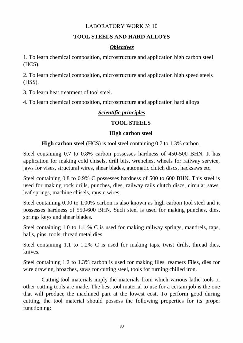
80
LABORATORY WORK 10
TOOL STEELS AND HARD ALLOYS
Objectives
1. To learn chemical composition, microstructure and application high carbon steel
(HCS).
2. To learn chemical composition, microstructure and application high speed steels
(HSS).
3. To learn heat treatment of tool steel.
4. To learn chemical composition, microstructure and application hard alloys.
Scientific principles
TOOL STEELS
High carbon steel
High carbon steel (HCS) is tool steel containing 0.7 to 1.3% carbon.
Steel containing 0.7 to 0.8% carbon possesses hardness of 450-500 BHN. It has
application for making cold chisels, drill bits, wrenches, wheels for railway service,
jaws for vises, structural wires, shear blades, automatic clutch discs, hacksaws etc.
Steel containing 0.8 to 0.9% C possesses hardness of 500 to 600 BHN. This steel is
used for making rock drills, punches, dies, railway rails clutch discs, circular saws,
leaf springs, machine chisels, music wires,
Steel containing 0.90 to 1.00% carbon is also known as high carbon tool steel and it
possesses hardness of 550-600 BHN. Such steel is used for making punches, dies,
springs keys and shear blades.
Steel containing 1.0 to 1.1 % C is used for making railway springs, mandrels, taps,
balls, pins, tools, thread metal dies.
Steel containing 1.1 to 1.2% C is used for making taps, twist drills, thread dies,
knives.
Steel containing 1.2 to 1.3% carbon is used for making files, reamers Files, dies for
wire drawing, broaches, saws for cutting steel, tools for turning chilled iron.
Cutting tool materials imply the materials from which various lathe tools or
other cutting tools are made. The best tool material to use for a certain job is the one
that will produce the machined part at the lowest cost. To perform good during
cutting, the tool material should possess the following properties for its proper
functioning:
81
– a low coefficient of friction between tool material and chip material;
– ability to resist softening at high temperature;
– ability to absorb shocks without permanent deformation;
– sufficient toughness to resist fracture and bear cutting stresses;
– strength to resist disintegration of fine cutting edge and also to withstand
the stresses developed, during cutting, in the weakest part of the tool;
– high hardness that means tool must be harder than the material being cut.
– red Hardness: this property (also called hot-hardness) is related to the
resistance of the steel to the softening effect of heat. It is reflected to some extent in
the resistance of the material to tempering.
High speed steels
High Speed Steels (HSS) have been given this name due to the fact that these
steels may be operated as cutting tools at much higher speeds that are possible with
plain carbon tool steel. High speed steels cutting tools operate at cutting speed 2 to 3
times higher than for High carbon steels. At higher cutting speeds, sufficient heat
may be developed during the cutting process. This heat causes the cutting edge of the
tool to reach a high heat (red heat). This heat softens the carbon tool steel and thus
the tool will not work efficiently for a longer period. These steels have the property
of retaining their hardness even when heated to red heat. High hardness at elevated
temperatures is developed by addition of elements such as tungsten, chromium,
vanadium to high carbon steels.
These steel are generally used for making lathe cutting tools, planner cutting
tools, shaper cutting tools, slotting cutting tools, drills, reamers, broaches, milling
cutter and punches.
There are four general types of high speed steels used in machine shop.
High speed steel (18:4:1)
It is the most common kind of cutting tool. It contains 18% tungsten, 4%
chromium and 1 % vanadium, 0.8 carbon and remaining iron. It is considered to be
one of the best of all purpose tool steels. This brand of high speed steel is used for
machining operations on steel and non-ferrous materials. This is generally used for
lathe, planer and shaper tools, drills, millings cutters, punches etc.
The microstructure high speed steels before and after heat treatment are
showen on the fig.10.1.
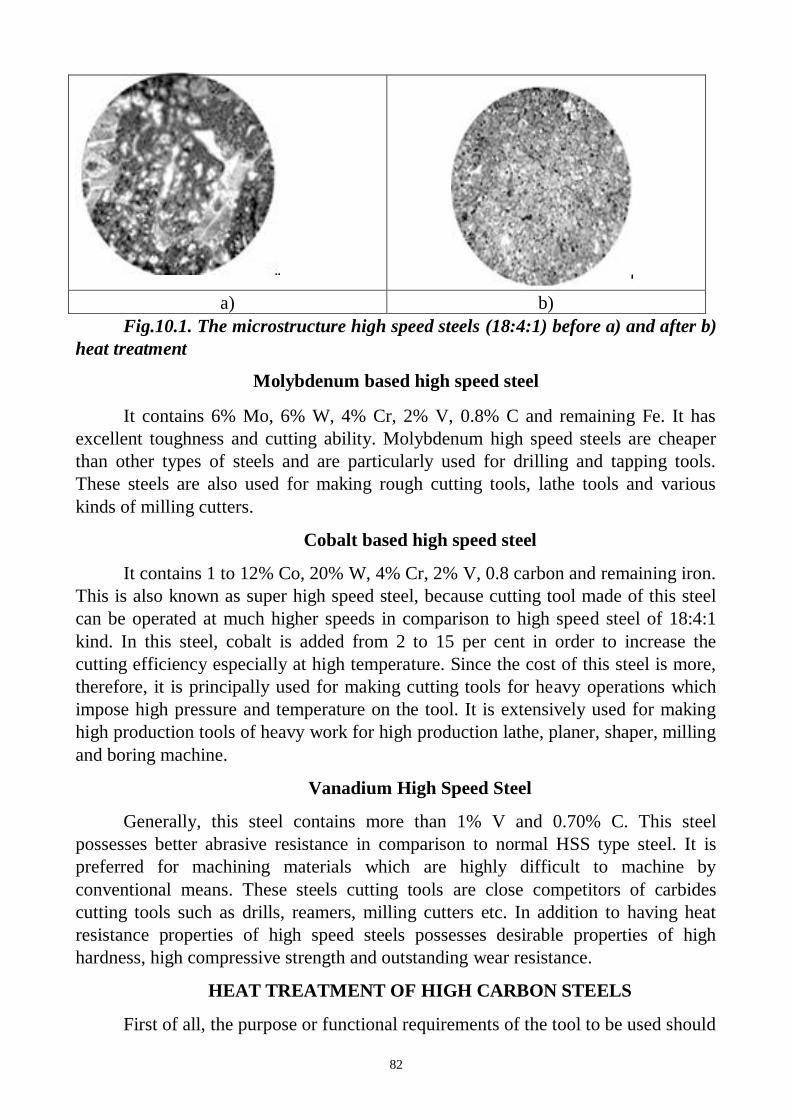
82
a) b)
Fig.10.1. The microstructure high speed steels (18:4:1) before a) and after b)
heat treatment
Molybdenum based high speed steel
It contains 6% Mo, 6% W, 4% Cr, 2% V, 0.8% C and remaining Fe. It has
excellent toughness and cutting ability. Molybdenum high speed steels are cheaper
than other types of steels and are particularly used for drilling and tapping tools.
These steels are also used for making rough cutting tools, lathe tools and various
kinds of milling cutters.
Cobalt based high speed steel
It contains 1 to 12% Co, 20% W, 4% Cr, 2% V, 0.8 carbon and remaining iron.
This is also known as super high speed steel, because cutting tool made of this steel
can be operated at much higher speeds in comparison to high speed steel of 18:4:1
kind. In this steel, cobalt is added from 2 to 15 per cent in order to increase the
cutting efficiency especially at high temperature. Since the cost of this steel is more,
therefore, it is principally used for making cutting tools for heavy operations which
impose high pressure and temperature on the tool. It is extensively used for making
high production tools of heavy work for high production lathe, planer, shaper, milling
and boring machine.
Vanadium High Speed Steel
Generally, this steel contains more than 1% V and 0.70% C. This steel
possesses better abrasive resistance in comparison to normal HSS type steel. It is
preferred for machining materials which are highly difficult to machine by
conventional means. These steels cutting tools are close competitors of carbides
cutting tools such as drills, reamers, milling cutters etc. In addition to having heat
resistance properties of high speed steels possesses desirable properties of high
hardness, high compressive strength and outstanding wear resistance.
HEAT TREATMENT OF HIGH CARBON STEELS
First of all, the purpose or functional requirements of the tool to be used should
83
be understood clearly. Accordingly the heat-treatment will be carried on the tool to
obtain the desired qua1ities in the tool steel to meet the needed objective. For
example a cutting tool requires particularly sufficient strength, high hardness and
high wear-resistance. Therefore, it is initially shaped by forging operation which
should be carried out at temperature 850°- 950°C with the help of hammers.
Next normalizing is to be performed on it to relieve the stresses and strains
developed during forging and to have a uniform grain structure. Next the tool steel is
hardened by heating followed by sudden or rapid cooling depending upon the carbon
percentage in tool steel. The various heating ranges of different tool steels are as
follows in the table 10.1.
Table 10.1. Heating Range for high carbon steels C% in tool steel Heating Range
0.7- 0.8% 780-850°C
0.8- 0.95% 765-790°C
0.95-1.10% 750-775°C
Above 1.10 % 740-760°C
The tool steel is heated to this temperature range and kept at that temperature
for sufficient time to achieve uniform structure inside the metal. Then it is quenched
by immersing it into a bath of fresh water (rapid cooling). For securing more
homogenous cooling and reduce danger of cracking, brine solution (10% brine or
caustic soda solution) may be used. After hardening, tempering is performed to
remove extra hardness and brittleness induced during hardening. This is performed
by reheating the hardened tool steel up to 150-300°C once again and same is cooled
in oils to reduced internal stresses. Tempering is carried over to tool steel for the
purpose of increasing its usefulness and to provide good results in its performance.
The important point is to note that drills and milling cutters should be hardened
through out. But certain tools like screw taps, screw dies, lathe, planer and shaping
tools are not hardened throughout the surface of the cutting tools.
HEAT TREATMENT OF HIGH SPEED STEEL
First the HSS tool is heated to about 850°C and kept at this temperature for 4 to
5 hours. This is done to dissolve all the carbides or homogenization of WC, VC and
Cr4C3. After it, tool is heated to 1200°C for 1-4 minutes. The purpose of heating to
high temperature is that more the substance is cooled from high temperature to lower
temperature difference, the more will be the hardness. Tool is not kept at such
temperature for sufficient longer time. After this, it is quenched in salt bath to 650°C
and kept at this temperature for 10-20 minutes. Direct quenching to room temperature
is dangerous. Then the tool is oil quenched fig. (10.2). For increasing the life of HSS
tool, surface treatment processes are also done like, liquid cyaniding, gas cyaniding
and solid or dry cyaniding.
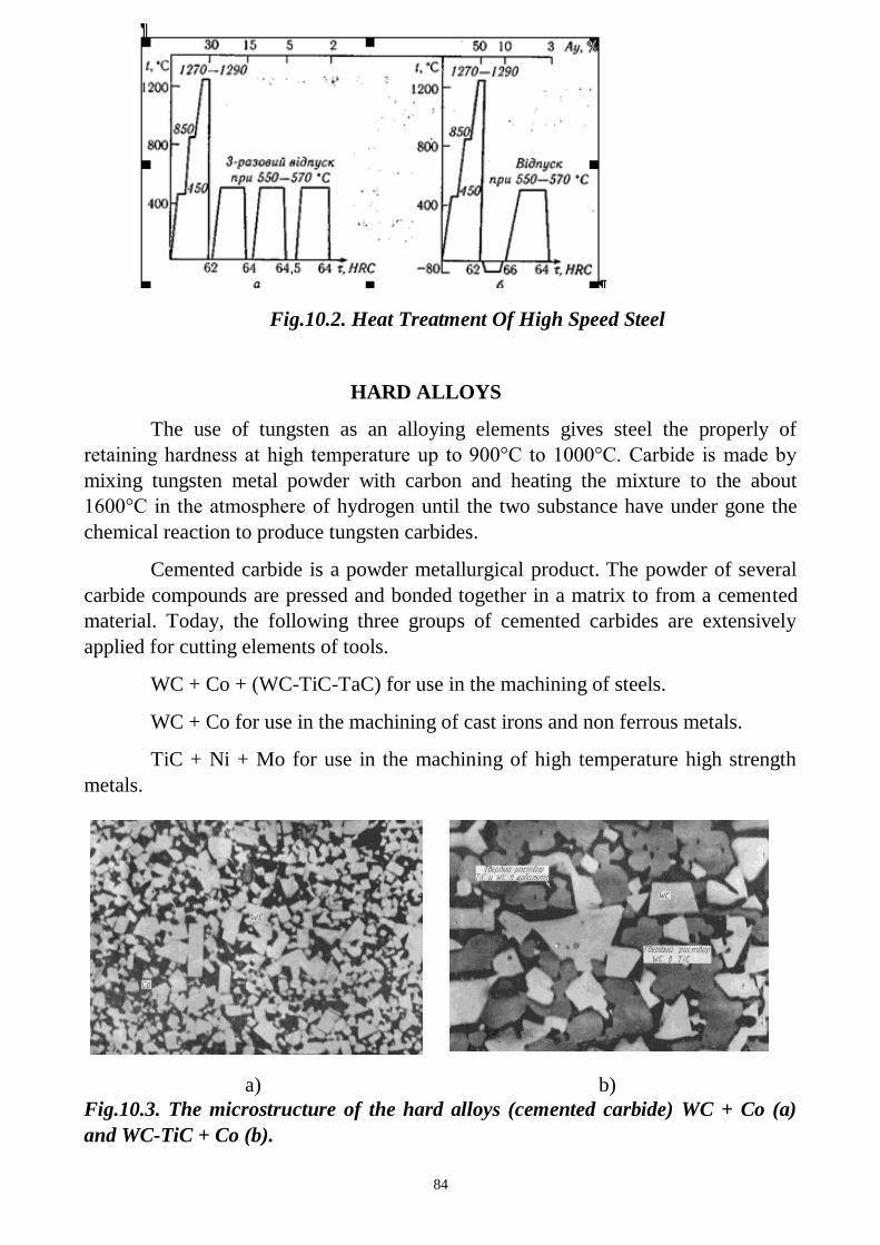
84
Fig.10.2. Heat Treatment Of High Speed Steel
HARD ALLOYS
The use of tungsten as an alloying elements gives steel the properly of
retaining hardness at high temperature up to 900°C to 1000°C. Carbide is made by
mixing tungsten metal powder with carbon and heating the mixture to the about
1600°C in the atmosphere of hydrogen until the two substance have under gone the
chemical reaction to produce tungsten carbides.
Cemented carbide is a powder metallurgical product. The powder of several
carbide compounds are pressed and bonded together in a matrix to from a cemented
material. Today, the following three groups of cemented carbides are extensively
applied for cutting elements of tools.
WC + Co + (WC-TiC-TaC) for use in the machining of steels.
WC + Co for use in the machining of cast irons and non ferrous metals.
TiC + Ni + Mo for use in the machining of high temperature high strength
metals.
a) b)
Fig.10.3. The microstructure of the hard alloys (cemented carbide) WC + Co (a)
and WC-TiC + Co (b).
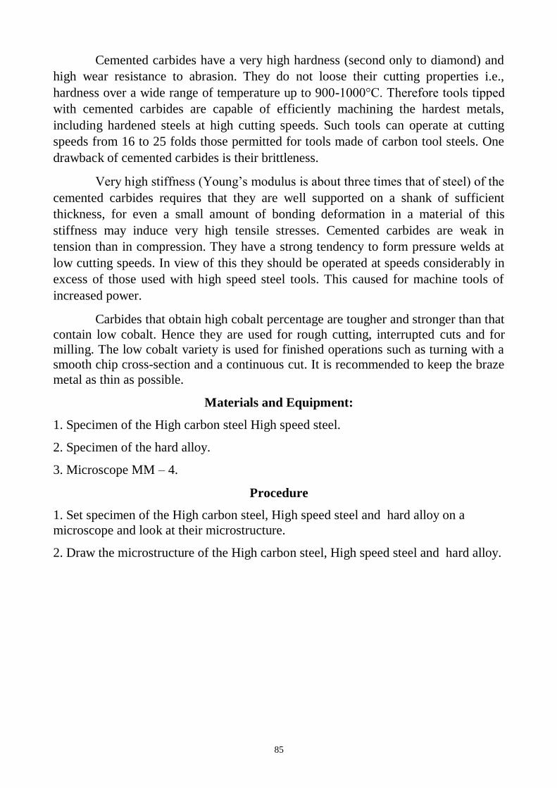
85
Cemented carbides have a very high hardness (second only to diamond) and
high wear resistance to abrasion. They do not loose their cutting properties i.e.,
hardness over a wide range of temperature up to 900-1000°C. Therefore tools tipped
with cemented carbides are capable of efficiently machining the hardest metals,
including hardened steels at high cutting speeds. Such tools can operate at cutting
speeds from 16 to 25 folds those permitted for tools made of carbon tool steels. One
drawback of cemented carbides is their brittleness.
Very high stiffness (Young’s modulus is about three times that of steel) of the
cemented carbides requires that they are well supported on a shank of sufficient
thickness, for even a small amount of bonding deformation in a material of this
stiffness may induce very high tensile stresses. Cemented carbides are weak in
tension than in compression. They have a strong tendency to form pressure welds at
low cutting speeds. In view of this they should be operated at speeds considerably in
excess of those used with high speed steel tools. This caused for machine tools of
increased power.
Carbides that obtain high cobalt percentage are tougher and stronger than that
contain low cobalt. Hence they are used for rough cutting, interrupted cuts and for
milling. The low cobalt variety is used for finished operations such as turning with a
smooth chip cross-section and a continuous cut. It is recommended to keep the braze
metal as thin as possible.
Materials and Equipment:
1. Specimen of the High carbon steel High speed steel.
2. Specimen of the hard alloy.
3. Microscope MM – 4.
Procedure
1. Set specimen of the High carbon steel, High speed steel and hard alloy on a
microscope and look at their microstructure.
2. Draw the microstructure of the High carbon steel, High speed steel and hard alloy.
86
Questions:
1. What is red hardness?
2. What is high carbon steels? Describe their chemical composition and applications.
3.What properties should the tool material possess for its proper functioning?
4. What is High speed steels? Describe their chemical composition and applications.
5. What is the purpose of the High speed steels alloying?
6. List the alloying elements of the High speed steels.
7. Explain Heat Treatment of High Carbon Steels.
8. How does the heating range for high carbon steels depend on its chemical
composition?
9. Explain Heat Treatment of High Speed Steels.
10. What is hard alloy?
11. Which technological method is used for hard alloys production?
12. Classification of hard alloys. Describe their chemical composition and
applications.
13. Explain properties of hard alloys.
87
LABORATORY WORK 10
TOOL STEELS AND HARD ALLOYS
PROTOCOL 1
high carbon steel high speed steel
SAE 1095 T11301
Carbon content___________% Carbon contain___________%
Alloying elements ___%, ___%,___%
Heat treatment________________ Heat treatment__________________
heating range ________________ heating range ___________________
___________________________ ______________________________
___________________________ ______________________________
Application ______________ Application ____________________
________________________ ______________________________
Conclusions:
____________________________________________________________
______________________________________________________________________

88
PROTOKOL 2
Hard alloy
Chemical composition, %_______________________________________
Properties:____________________________________________________
__________________________________________________________________
Conclusions:
____________________________________________________________
______________________________________________________________________
______________________________________________________________________
_____________________ ___________________
Student’s signature Teacher’s signature
“____”___________20___ y. “____”____________20___ y.
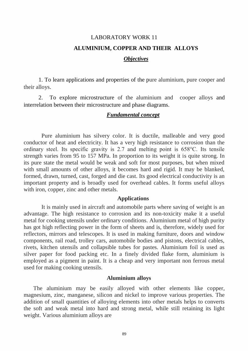
89
LABORATORY WORK 11
ALUMINIUM, COPPER AND THEIR ALLOYS
Objectives
1. To learn applications and properties of the pure aluminium, pure cooper and
their alloys.
2. To explore microstructure of the aluminium and cooper alloys and
interrelation between their microstructure and phase diagrams.
Fundamental concept
Pure aluminium has silvery color. It is ductile, malleable and very good
conductor of heat and electricity. It has a very high resistance to corrosion than the
ordinary steel. Its specific gravity is 2.7 and melting point is 658°C. Its tensile
strength varies from 95 to 157 MPa. In proportion to its weight it is quite strong. In
its pure state the metal would be weak and soft for most purposes, but when mixed
with small amounts of other alloys, it becomes hard and rigid. It may be blanked,
formed, drawn, turned, cast, forged and die cast. Its good electrical conductivity is an
important property and is broadly used for overhead cables. It forms useful alloys
with iron, copper, zinc and other metals.
Applications
It is mainly used in aircraft and automobile parts where saving of weight is an
advantage. The high resistance to corrosion and its non-toxicity make it a useful
metal for cooking utensils under ordinary conditions. Aluminium metal of high purity
has got high reflecting power in the form of sheets and is, therefore, widely used for
reflectors, mirrors and telescopes. It is used in making furniture, doors and window
components, rail road, trolley cars, automobile bodies and pistons, electrical cables,
rivets, kitchen utensils and collapsible tubes for pastes. Aluminium foil is used as
silver paper for food packing etc. In a finely divided flake form, aluminium is
employed as a pigment in paint. It is a cheap and very important non ferrous metal
used for making cooking utensils.
Aluminium alloys
The aluminium may be easily alloyed with other elements like copper,
magnesium, zinc, manganese, silicon and nickel to improve various properties. The
addition of small quantities of alloying elements into other metals helps to converts
the soft and weak metal into hard and strong metal, while still retaining its light
weight. Various aluminium alloys are
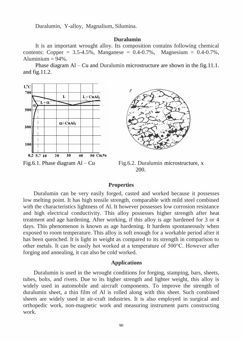
90
Duralumin, Y-alloy, Magnalium, Silumina.
Duralumin It is an important wrought alloy. Its composition contains following chemical
contents: Copper = 3.5-4.5%, Manganese = 0.4-0.7%, Magnesium = 0.4-0.7%,
Aluminium = 94%.
Phase diagram Al – Cu and Duralumin microstructure are shown in the fig.11.1.
and fig.11.2.
Fig.6.1. Phase diagram Al – Cu Fig.6.2. Duralumin microstructure, x
200.
Properties
Duralumin can be very easily forged, casted and worked because it possesses
low melting point. It has high tensile strength, comparable with mild steel combined
with the characteristics lightness of Al. It however possesses low corrosion resistance
and high electrical conductivity. This alloy possesses higher strength after heat
treatment and age hardening. After working, if this alloy is age hardened for 3 or 4
days. This phenomenon is known as age hardening. It hardens spontaneously when
exposed to room temperature. This alloy is soft enough for a workable period after it
has been quenched. It is light in weight as compared to its strength in comparison to
other metals. It can be easily hot worked at a temperature of 500°C. However after
forging and annealing, it can also be cold worked.
Applications
Duralumin is used in the wrought conditions for forging, stamping, bars, sheets,
tubes, bolts, and rivets. Due to its higher strength and lighter weight, this alloy is
widely used in automobile and aircraft components. To improve the strength of
duralumin sheet, a thin film of Al is rolled along with this sheet. Such combined
sheets are widely used in air-craft industries. It is also employed in surgical and
orthopedic work, non-magnetic work and measuring instrument parts constructing
work.
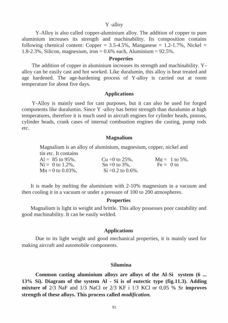
91
Y -alloy
Y-Alloy is also called copper-aluminium alloy. The addition of copper to pure
aluminium increases its strength and machinability. Its composition contains
following chemical content: Copper = 3.5-4.5%, Manganese = 1.2-1.7%, Nickel =
1.8-2.3%, Silicon, magnesium, iron = 0.6% each, Aluminium = 92.5%.
Properties
The addition of copper in aluminium increases its strength and machinability. Y-
alloy can be easily cast and hot worked. Like duralumin, this alloy is heat treated and
age hardened. The age-hardening process of Y-alloy is carried out at room
temperature for about five days.
Applications
Y-Alloy is mainly used for cast purposes, but it can also be used for forged
components like duralumin. Since Y -alloy has better strength than duralumin at high
temperatures, therefore it is much used in aircraft engines for cylinder heads, pistons,
cylinder heads, crank cases of internal combustion engines die casting, pump rods
etc.
Magnalium
It is made by melting the aluminium with 2-10% magnesium in a vacuum and
then cooling it in a vacuum or under a pressure of 100 to 200 atmospheres.
Properties
Magnalium is light in weight and brittle. This alloy possesses poor castability and
good machinability. It can be easily welded.
Applications
Due to its light weight and good mechanical properties, it is mainly used for
making aircraft and automobile components.
Silumina
Common casting aluminium alloys are alloys of the Al-Si system (6 ...
13% Si). Diagram of the system Al - Si is of eutectic type (fig.11.3). Adding
mixture of 2/3 NaF and 1/3 NaCl or 2/3 KF і 1/3 KCl or 0,05 % Sr improves
strength of these alloys. This process called modification.
Magnalium is an alloy of aluminium, magnesium, copper, nickel and
tin etc. It contains
Al = 85 to 95%, Cu = 0 to 25%, Mg = 1 to 5%, Ni = 0 to 1.2%, Sn = 0 to 3%, Fe = 0 to
0.9%, Mn = 0 to 0.03%, Si = 0.2 to 0.6%.
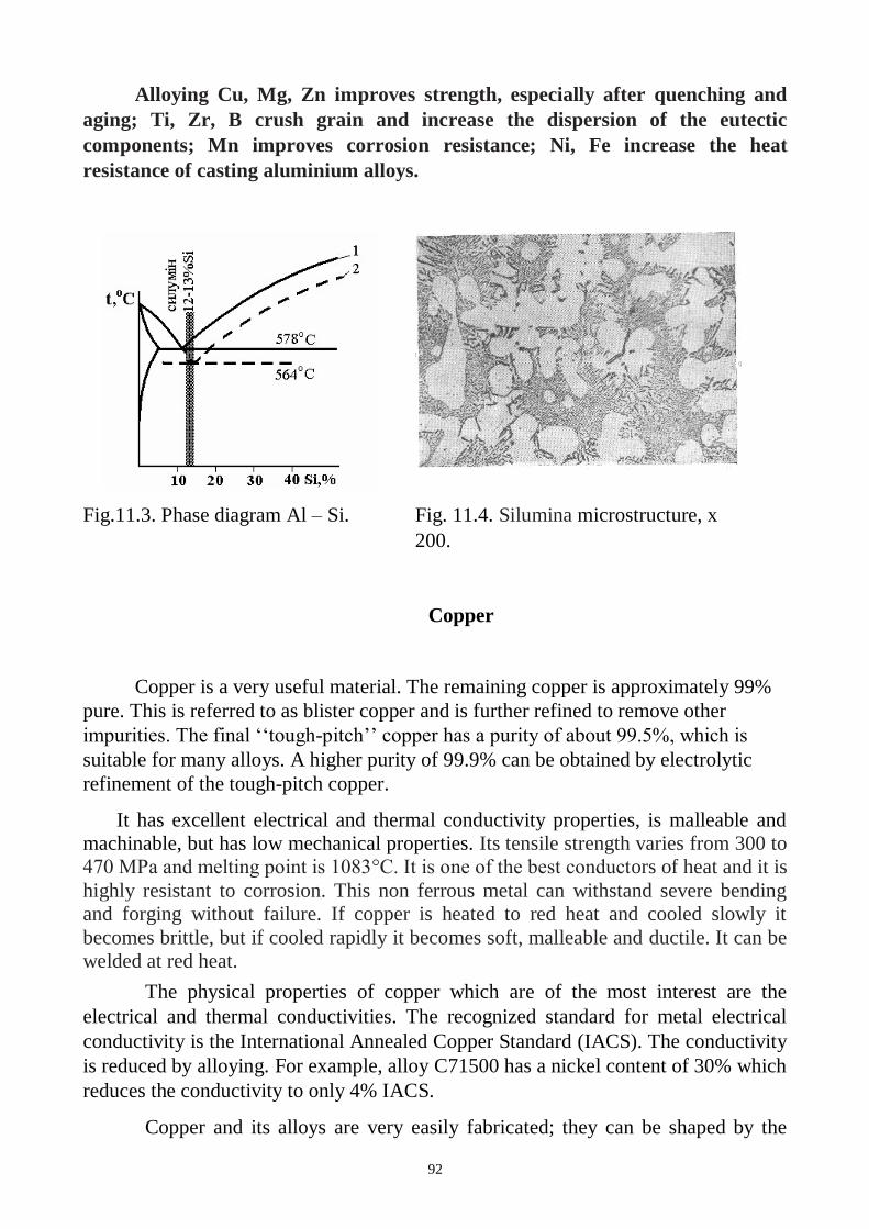
92
Alloying Cu, Mg, Zn improves strength, especially after quenching and
aging; Ti, Zr, B crush grain and increase the dispersion of the eutectic
components; Mn improves corrosion resistance; Ni, Fe increase the heat
resistance of casting aluminium alloys.
Fig.11.3. Phase diagram Al – Si.
Fig. 11.4. Silumina microstructure, x
200.
Copper
Copper is a very useful material. The remaining copper is approximately 99%
pure. This is referred to as blister copper and is further refined to remove other
impurities. The final ‘‘tough-pitch’’ copper has a purity of about 99.5%, which is
suitable for many alloys. A higher purity of 99.9% can be obtained by electrolytic
refinement of the tough-pitch copper.
It has excellent electrical and thermal conductivity properties, is malleable and
machinable, but has low mechanical properties. Its tensile strength varies from 300 to
470 MPa and melting point is 1083°C. It is one of the best conductors of heat and it is
highly resistant to corrosion. This non ferrous metal can withstand severe bending
and forging without failure. If copper is heated to red heat and cooled slowly it
becomes brittle, but if cooled rapidly it becomes soft, malleable and ductile. It can be
welded at red heat.
The physical properties of copper which are of the most interest are the
electrical and thermal conductivities. The recognized standard for metal electrical
conductivity is the International Annealed Copper Standard (IACS). The conductivity
is reduced by alloying. For example, alloy C71500 has a nickel content of 30% which
reduces the conductivity to only 4% IACS.
Copper and its alloys are very easily fabricated; they can be shaped by the
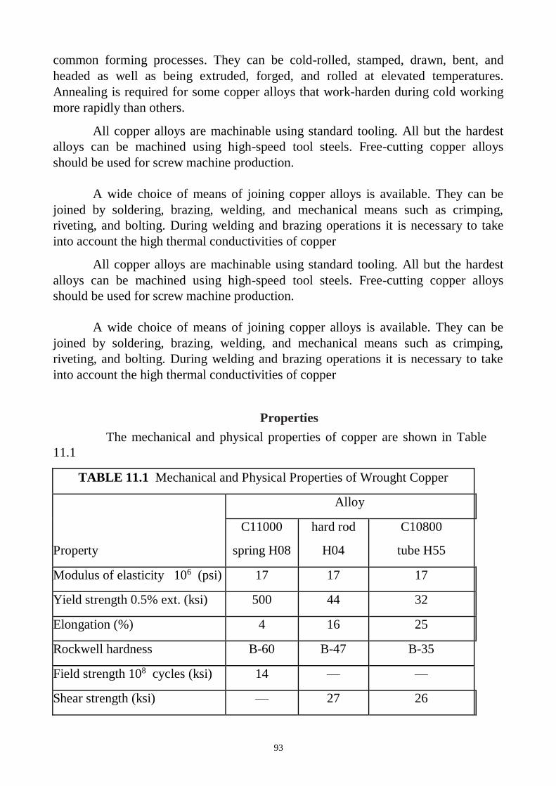
93
common forming processes. They can be cold-rolled, stamped, drawn, bent, and
headed as well as being extruded, forged, and rolled at elevated temperatures.
Annealing is required for some copper alloys that work-harden during cold working
more rapidly than others.
All copper alloys are machinable using standard tooling. All but the hardest
alloys can be machined using high-speed tool steels. Free-cutting copper alloys
should be used for screw machine production.
A wide choice of means of joining copper alloys is available. They can be
joined by soldering, brazing, welding, and mechanical means such as crimping,
riveting, and bolting. During welding and brazing operations it is necessary to take
into account the high thermal conductivities of copper
Properties
The mechanical and physical properties of copper are shown in Table
11.1
TABLE 11.1 Mechanical and Physical Properties of Wrought Copper
Property
Alloy
C11000
spring H08
hard rod
H04
C10800
tube H55
Modulus of elasticity 106 (psi) 17 17 17
Yield strength 0.5% ext. (ksi) 500 44 32
Elongation (%) 4 16 25
Rockwell hardness B-60 B-47 B-35
Field strength 108 cycles (ksi) 14 — —
Shear strength (ksi) — 27 26
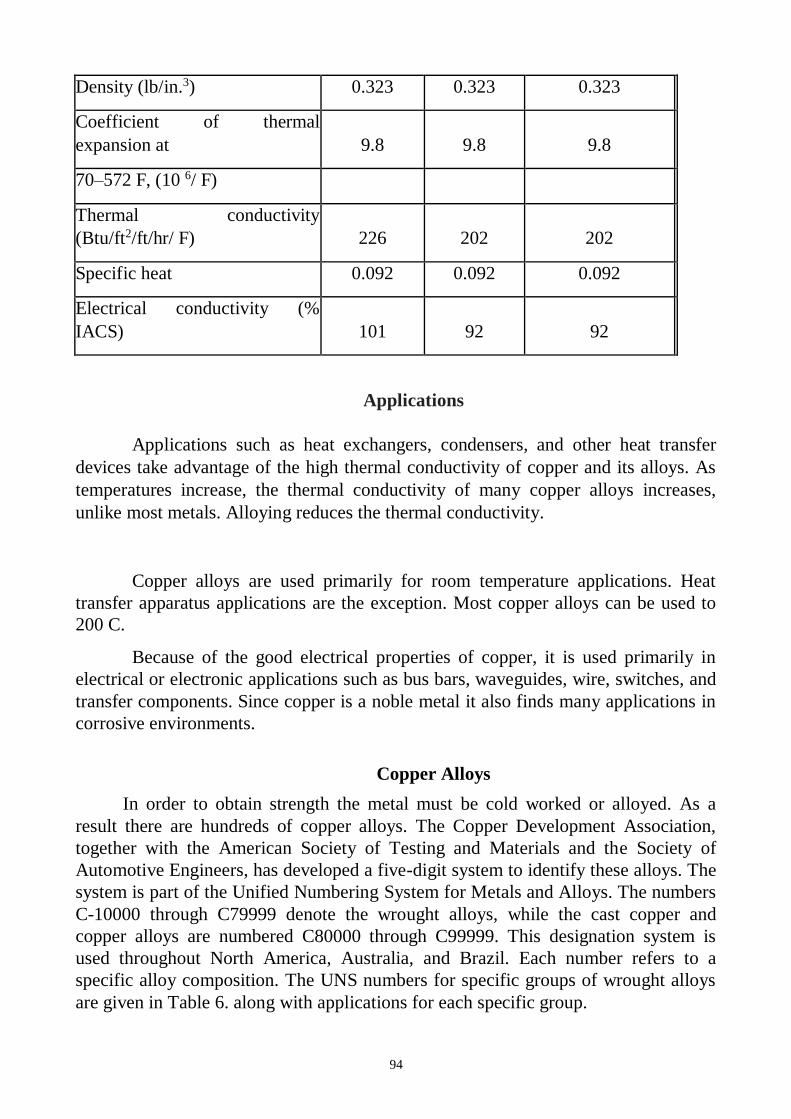
94
Density (lb/in.3) 0.323 0.323 0.323
Coefficient of thermal
expansion at 9.8 9.8 9.8
70–572 F, (10 6/ F)
Thermal conductivity
(Btu/ft2/ft/hr/ F) 226 202 202
Specific heat 0.092 0.092 0.092
Electrical conductivity (%
IACS) 101 92 92
Applications
Applications such as heat exchangers, condensers, and other heat transfer
devices take advantage of the high thermal conductivity of copper and its alloys. As
temperatures increase, the thermal conductivity of many copper alloys increases,
unlike most metals. Alloying reduces the thermal conductivity.
Copper alloys are used primarily for room temperature applications. Heat
transfer apparatus applications are the exception. Most copper alloys can be used to
200 C.
Because of the good electrical properties of copper, it is used primarily in
electrical or electronic applications such as bus bars, waveguides, wire, switches, and
transfer components. Since copper is a noble metal it also finds many applications in
corrosive environments.
Copper Alloys
In order to obtain strength the metal must be cold worked or alloyed. As a
result there are hundreds of copper alloys. The Copper Development Association,
together with the American Society of Testing and Materials and the Society of
Automotive Engineers, has developed a five-digit system to identify these alloys. The
system is part of the Unified Numbering System for Metals and Alloys. The numbers
C-10000 through C79999 denote the wrought alloys, while the cast copper and
copper alloys are numbered C80000 through C99999. This designation system is
used throughout North America, Australia, and Brazil. Each number refers to a
specific alloy composition. The UNS numbers for specific groups of wrought alloys
are given in Table 6. along with applications for each specific group.
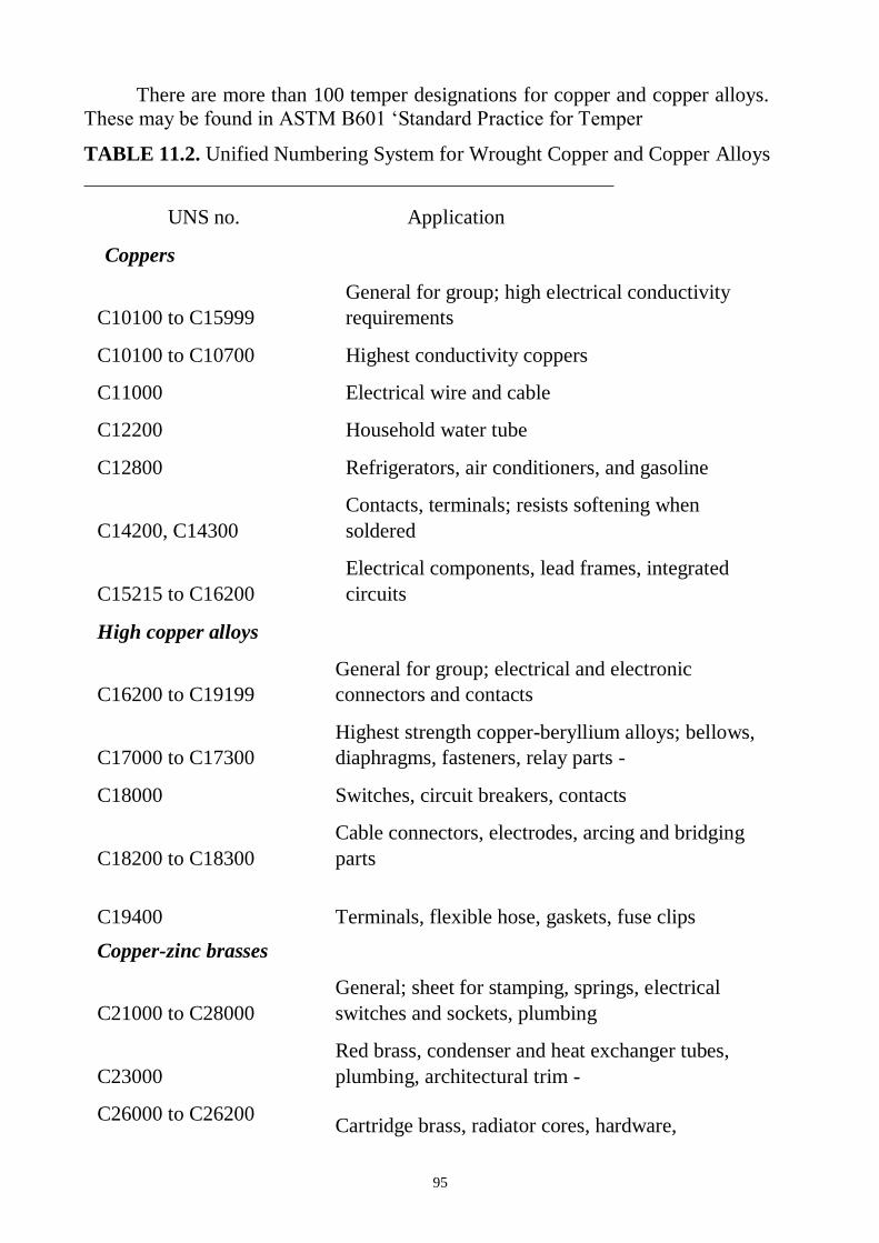
95
There are more than 100 temper designations for copper and copper alloys.
These may be found in ASTM B601 ‘Standard Practice for Temper
TABLE 11.2. Unified Numbering System for Wrought Copper and Copper Alloys
UNS no. Application
Coppers
C10100 to C15999
General for group; high electrical conductivity
requirements
C10100 to C10700 Highest conductivity coppers
C11000 Electrical wire and cable
C12200 Household water tube
C12800 Refrigerators, air conditioners, and gasoline
C14200, C14300
Contacts, terminals; resists softening when
soldered
C15215 to C16200
Electrical components, lead frames, integrated
circuits
High copper alloys
C16200 to C19199
General for group; electrical and electronic
connectors and contacts
C17000 to C17300
Highest strength copper-beryllium alloys; bellows,
diaphragms, fasteners, relay parts -
C18000 Switches, circuit breakers, contacts
C18200 to C18300
Cable connectors, electrodes, arcing and bridging
parts
C19400
Terminals, flexible hose, gaskets, fuse clips
Copper-zinc brasses
C21000 to C28000
General; sheet for stamping, springs, electrical
switches and sockets, plumbing
C23000
Red brass, condenser and heat exchanger tubes,
plumbing, architectural trim -
C26000 to C26200 Cartridge brass, radiator cores, hardware,
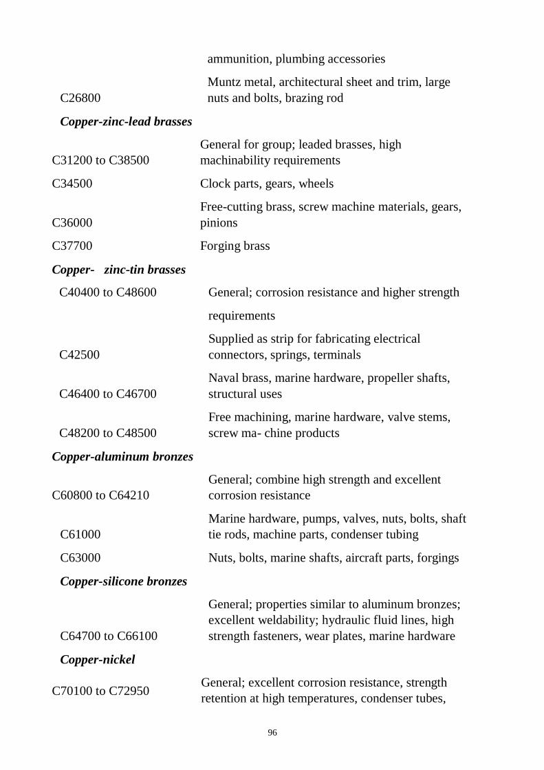
96
ammunition, plumbing accessories
C26800
Muntz metal, architectural sheet and trim, large
nuts and bolts, brazing rod
Copper-zinc-lead brasses
C31200 to C38500
General for group; leaded brasses, high
machinability requirements
C34500 Clock parts, gears, wheels
C36000
Free-cutting brass, screw machine materials, gears,
pinions
C37700 Forging brass
Copper- zinc-tin brasses
C40400 to C48600 General; corrosion resistance and higher strength
requirements
C42500
Supplied as strip for fabricating electrical
connectors, springs, terminals
C46400 to C46700
Naval brass, marine hardware, propeller shafts,
structural uses
C48200 to C48500
Free machining, marine hardware, valve stems,
screw ma- chine products
Copper-aluminum bronzes
C60800 to C64210
General; combine high strength and excellent
corrosion resistance
C61000
Marine hardware, pumps, valves, nuts, bolts, shaft
tie rods, machine parts, condenser tubing
C63000 Nuts, bolts, marine shafts, aircraft parts, forgings
Copper-silicone bronzes
C64700 to C66100
General; properties similar to aluminum bronzes;
excellent weldability; hydraulic fluid lines, high
strength fasteners, wear plates, marine hardware
Copper-nickel
C70100 to C72950 General; excellent corrosion resistance, strength
retention at high temperatures, condenser tubes,
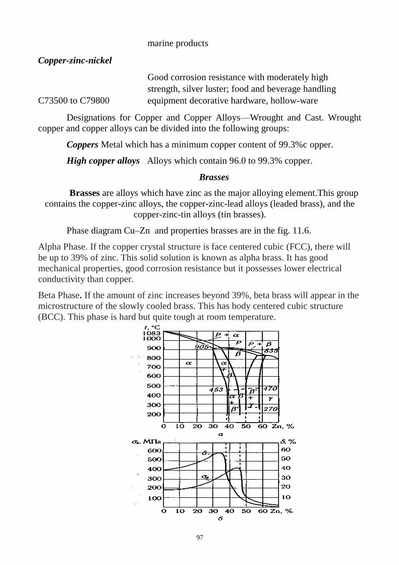
97
marine products
Copper-zinc-nickel
C73500 to C79800
Good corrosion resistance with moderately high
strength, silver luster; food and beverage handling
equipment decorative hardware, hollow-ware
Designations for Copper and Copper Alloys—Wrought and Cast. Wrought
copper and copper alloys can be divided into the following groups:
Coppers Metal which has a minimum copper content of 99.3%c opper.
High copper alloys Alloys which contain 96.0 to 99.3% copper.
Brasses
Brasses are alloys which have zinc as the major alloying element.This group
contains the copper-zinc alloys, the copper-zinc-lead alloys (leaded brass), and the
copper-zinc-tin alloys (tin brasses).
Phase diagram Cu–Zn and properties brasses are in the fig. 11.6.
Alpha Phase. If the copper crystal structure is face centered cubic (FCC), there will
be up to 39% of zinc. This solid solution is known as alpha brass. It has good
mechanical properties, good corrosion resistance but it possesses lower electrical
conductivity than copper.
Beta Phase. If the amount of zinc increases beyond 39%, beta brass will appear in the
microstructure of the slowly cooled brass. This has body centered cubic structure
(BCC). This phase is hard but quite tough at room temperature.
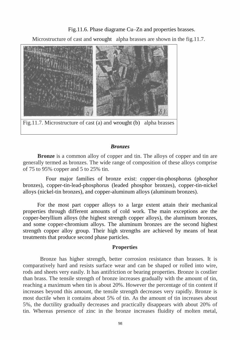
98
Fig.11.6. Phase diagrame Cu–Zn and properties brasses.
Microstructure of cast and wrought alpha brasses are shown in the fig.11.7.
Fig.11.7. Microstructure of cast (a) and wrought (b) alpha brasses
brasses.
Bronzes
Bronze is a common alloy of copper and tin. The alloys of copper and tin are
generally termed as bronzes. The wide range of composition of these alloys comprise
of 75 to 95% copper and 5 to 25% tin.
Four major families of bronze exist: copper-tin-phosphorus (phosphor
bronzes), copper-tin-lead-phosphorus (leaded phosphor bronzes), copper-tin-nickel
alloys (nickel-tin bronzes), and copper-aluminum alloys (aluminum bronzes).
For the most part copper alloys to a large extent attain their mechanical
properties through different amounts of cold work. The main exceptions are the
copper-beryllium alloys (the highest strength copper alloys), the aluminum bronzes,
and some copper-chromium alloys. The aluminum bronzes are the second highest
strength copper alloy group. Their high strengths are achieved by means of heat
treatments that produce second phase particles.
Properties
Bronze has higher strength, better corrosion resistance than brasses. It is
comparatively hard and resists surface wear and can be shaped or rolled into wire,
rods and sheets very easily. It has antifriction or bearing properties. Bronze is costlier
than brass. The tensile strength of bronze increases gradually with the amount of tin,
reaching a maximum when tin is about 20%. However the percentage of tin content if
increases beyond this amount, the tensile strength decreases very rapidly. Bronze is
most ductile when it contains about 5% of tin. As the amount of tin increases about
5%, the ductility gradually decreases and practically disappears with about 20% of
tin. Whereas presence of zinc in the bronze increases fluidity of molten metal,
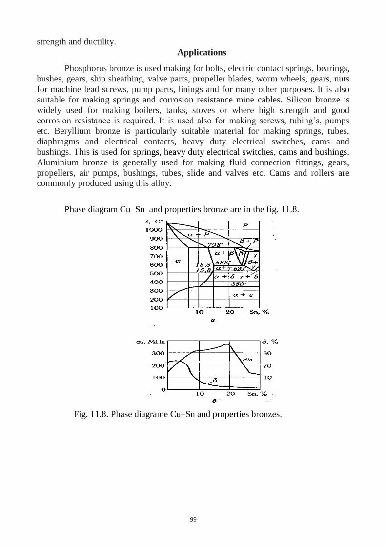
99
strength and ductility.
Applications
Phosphorus bronze is used making for bolts, electric contact springs, bearings,
bushes, gears, ship sheathing, valve parts, propeller blades, worm wheels, gears, nuts
for machine lead screws, pump parts, linings and for many other purposes. It is also
suitable for making springs and corrosion resistance mine cables. Silicon bronze is
widely used for making boilers, tanks, stoves or where high strength and good
corrosion resistance is required. It is used also for making screws, tubing’s, pumps
etc. Beryllium bronze is particularly suitable material for making springs, tubes,
diaphragms and electrical contacts, heavy duty electrical switches, cams and
bushings. This is used for springs, heavy duty electrical switches, cams and bushings.
Aluminium bronze is generally used for making fluid connection fittings, gears,
propellers, air pumps, bushings, tubes, slide and valves etc. Cams and rollers are
commonly produced using this alloy.
Phase diagram Cu–Sn and properties bronze are in the fig. 11.8.
Fig. 11.8. Phase diagrame Cu–Sn and properties bronzes.
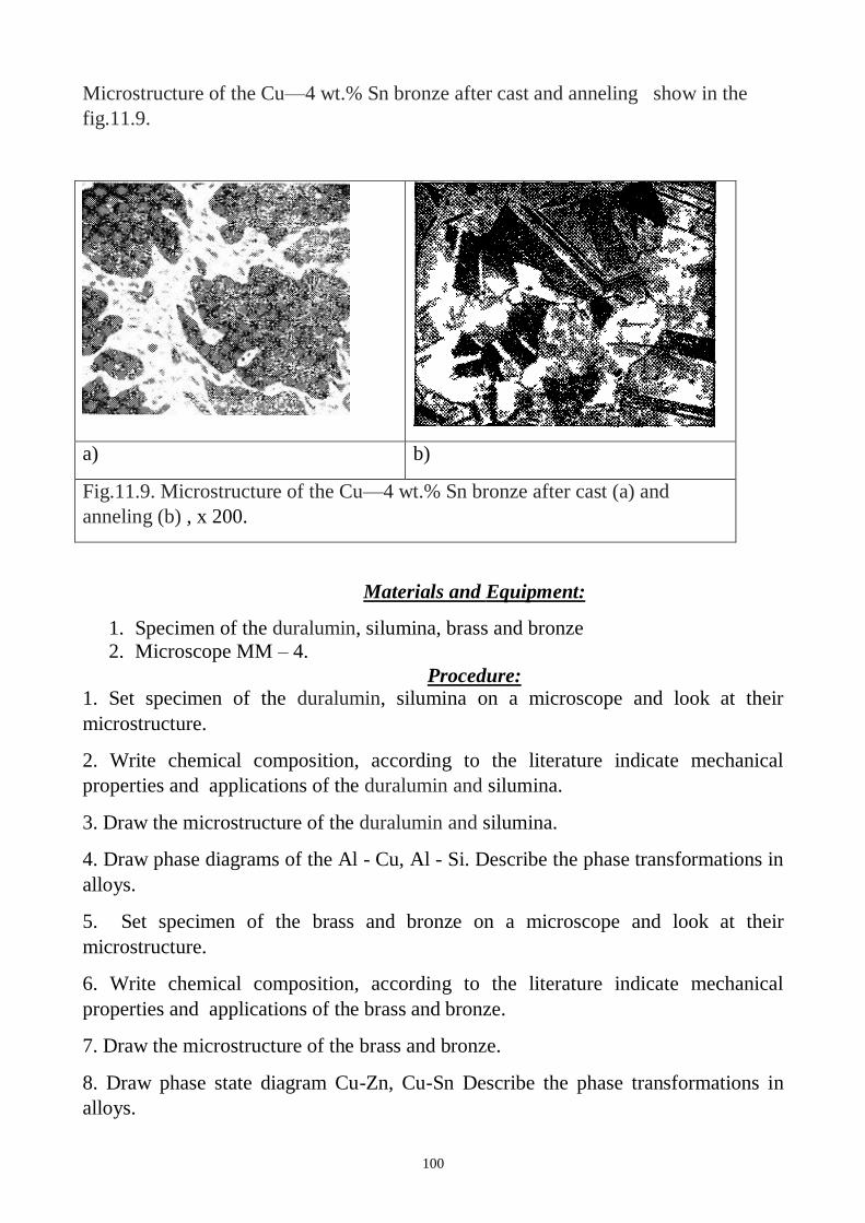
100
Microstructure of the Cu—4 wt.% Sn bronze after cast and anneling show in the
fig.11.9.
a) b)
Fig.11.9. Microstructure of the Cu—4 wt.% Sn bronze after cast (a) and
anneling (b) , x 200.
Materials and Equipment:
1. Specimen of the duralumin, silumina, brass and bronze
2. Microscope MM – 4.
Procedure: 1. Set specimen of the duralumin, silumina on a microscope and look at their
microstructure.
2. Write chemical composition, according to the literature indicate mechanical
properties and applications of the duralumin and silumina.
3. Draw the microstructure of the duralumin and silumina.
4. Draw phase diagrams of the Al - Cu, Al - Si. Describe the phase transformations in
alloys.
5. Set specimen of the brass and bronze on a microscope and look at their
microstructure.
6. Write chemical composition, according to the literature indicate mechanical
properties and applications of the brass and bronze.
7. Draw the microstructure of the brass and bronze.
8. Draw phase state diagram Cu-Zn, Cu-Sn Describe the phase transformations in
alloys.
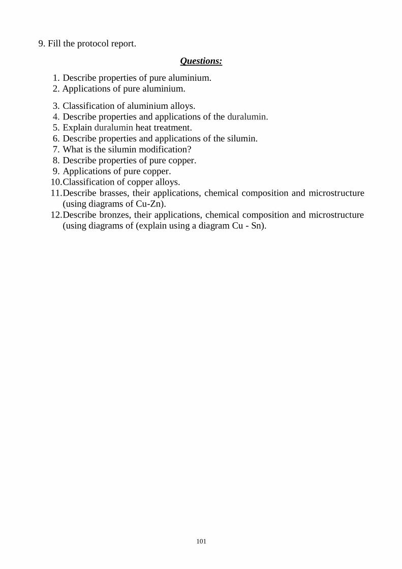
101
9. Fill the protocol report.
Questions:
1. Describe properties of pure aluminium.
2. Applications of pure aluminium.
3. Classification of aluminium alloys.
4. Describe properties and applications of the duralumin.
5. Explain duralumin heat treatment.
6. Describe properties and applications of the silumin.
7. What is the silumin modification?
8. Describe properties of pure copper.
9. Applications of pure copper.
10. Classification of copper alloys.
11. Describe brasses, their applications, chemical composition and microstructure
(using diagrams of Cu-Zn).
12. Describe bronzes, their applications, chemical composition and microstructure
(using diagrams of (explain using a diagram Cu - Sn).
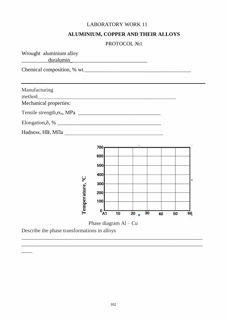
102
LABORATORY WORK 11
ALUMINIUM, COPPER AND THEIR ALLOYS
PROTOCOL 1
Wrought aluminium alloy
__________duralumin_____________________________
Chemical composition, % wt.________________________________________
Manufacturing
method____________________________________________________
Mechanical properties:
Tensile strength,ts, МPа _______________________________
Elongation,, % _______________________________________
Hadness, НВ, МПа _____________________________________
T
emp
eratu
re,
oC
Phase diagram Al – Cu
Describe the phase transformations in alloys
____________________________________________________________________
____________________________________________________________________
____
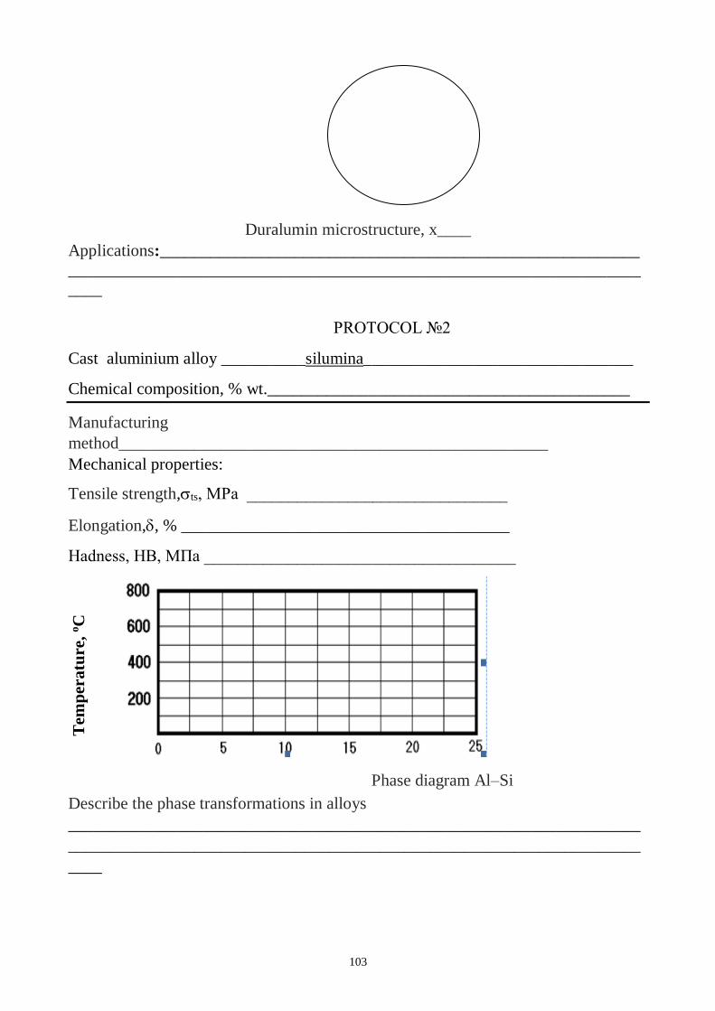
103
Duralumin microstructure, x____
Applications:_________________________________________________________
____________________________________________________________________
____
PROTOCOL 2
Cast aluminium alloy __________silumina________________________________
Chemical composition, % wt.___________________________________________
Manufacturing
method___________________________________________________
Mechanical properties:
Tensile strength,ts, МPа _______________________________
Elongation,, % _______________________________________
Hadness, НВ, МПа _____________________________________
T
emp
eratu
re,
oC
Phase diagram Al–Si
Describe the phase transformations in alloys
____________________________________________________________________
____________________________________________________________________
____
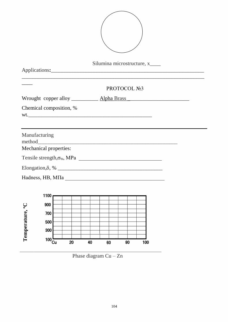
104
Silumina microstructure, x____
Applications:_________________________________________________________
____________________________________________________________________
____
PROTOCOL 3
Wrought copper alloy __________ Alpha Brass _______________________
Chemical composition, %
wt.______________________________________________
Manufacturing
method____________________________________________________
Mechanical properties:
Tensile strength,ts, МPа _______________________________
Elongation,, % _______________________________________
Hadness, НВ, МПа _____________________________________
Tem
per
atu
re,
oC
Phase diagram Cu – Zn
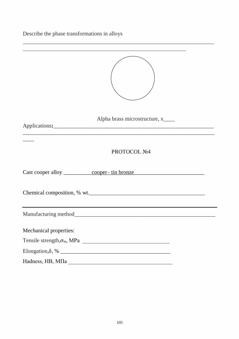
105
Describe the phase transformations in alloys
____________________________________________________________________
__________________________________________________________
Alpha brass microstructure, x____
Applications:_________________________________________________________
____________________________________________________________________
____
PROTOCOL 4
Cast cooper alloy __________cooper– tin bronze_________________________
Chemical composition, % wt._________________________________________
Manufacturing method__________________________________________________
Mechanical properties:
Tensile strength,ts, МPа _______________________________
Elongation,, % _______________________________________
Hadness, НВ, МПа _____________________________________

106
T
emp
eratu
re,
oC
Phase diagram Cu – Sn
Describe the phase transformations in alloys
____________________________________________________________________
__________________________________________________________
Cooper– tin bronze microstructure, x____
Applications:_________________________________________________________
____________________________________________________________________
____
Conclusion:
____________________________________________________________________
______________________________
_________________________
Student’ssignature Teacher’s signature
“____”___________20___ y. “____”____________20___
y.
107
LABORATORY WORK 12
CERAMICS
Objectives
1. To explore the ceramic materials through applications, properties, and processing.
2. To learn ceramic bonding mechanisms and how they influence properties.
Fundamental concept
Ceramics are materials that are composed of inorganic substances (usually a
combination of metallic and nonmetallic elements). The electricity that kept that
clock ticking all night was generated, stored, and traveled through a whole array of
ceramic products such as transducers, resistors, and various insulators.
Ceramics can be divided into two classes: traditional and advanced.
Traditional ceramics include clay products, silicate glass and cement; while advanced
ceramics consist of carbides (SiC), pure oxides (Al2O3), nitrides (Si3N4), non-
silicate glasses and many others. Ceramics offer many advantages compared to other
materials. They are harder and stiffer than steel; more heat and corrosion resistant
than metals or polymers; less dense than most metals and their alloys; and their raw
materials are both plentiful and inexpensive. Ceramic materials display a wide range
of properties which facilitate their use in many different product areas.
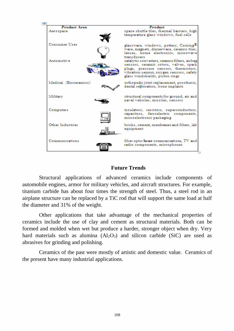
108
Future Trends
Structural applications of advanced ceramics include components of
automobile engines, armor for military vehicles, and aircraft structures. For example,
titanium carbide has about four times the strength of steel. Thus, a steel rod in an
airplane structure can be replaced by a TiC rod that will support the same load at half
the diameter and 31% of the weight.
Other applications that take advantage of the mechanical properties of
ceramics include the use of clay and cement as structural materials. Both can be
formed and molded when wet but produce a harder, stronger object when dry. Very
hard materials such as alumina (Al2O3) and silicon carbide (SiC) are used as
abrasives for grinding and polishing.
Ceramics of the past were mostly of artistic and domestic value. Ceramics of
the present have many industrial applications.
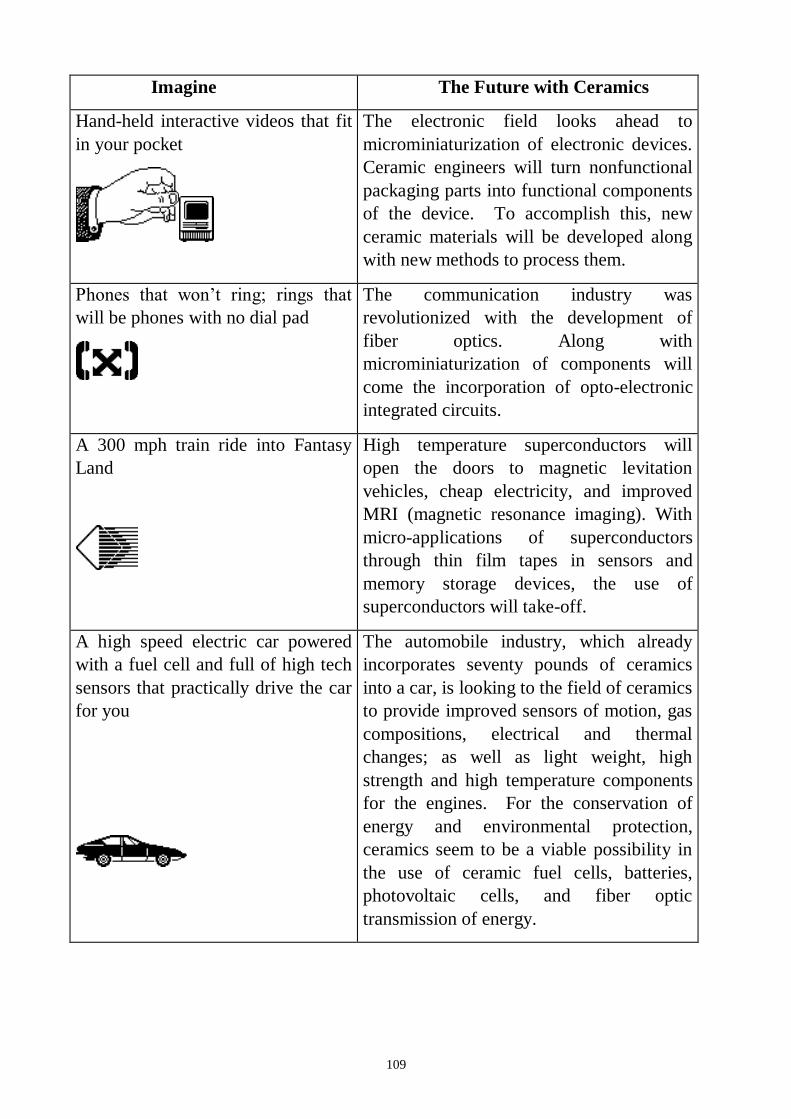
109
Imagine The Future with Ceramics
Hand-held interactive videos that fit
in your pocket
The electronic field looks ahead to
microminiaturization of electronic devices.
Ceramic engineers will turn nonfunctional
packaging parts into functional components
of the device. To accomplish this, new
ceramic materials will be developed along
with new methods to process them.
Phones that won’t ring; rings that
will be phones with no dial pad
The communication industry was
revolutionized with the development of
fiber optics. Along with
microminiaturization of components will
come the incorporation of opto-electronic
integrated circuits.
A 300 mph train ride into Fantasy
Land
High temperature superconductors will
open the doors to magnetic levitation
vehicles, cheap electricity, and improved
MRI (magnetic resonance imaging). With
micro-applications of superconductors
through thin film tapes in sensors and
memory storage devices, the use of
superconductors will take-off.
A high speed electric car powered
with a fuel cell and full of high tech
sensors that practically drive the car
for you
The automobile industry, which already
incorporates seventy pounds of ceramics
into a car, is looking to the field of ceramics
to provide improved sensors of motion, gas
compositions, electrical and thermal
changes; as well as light weight, high
strength and high temperature components
for the engines. For the conservation of
energy and environmental protection,
ceramics seem to be a viable possibility in
the use of ceramic fuel cells, batteries,
photovoltaic cells, and fiber optic
transmission of energy.
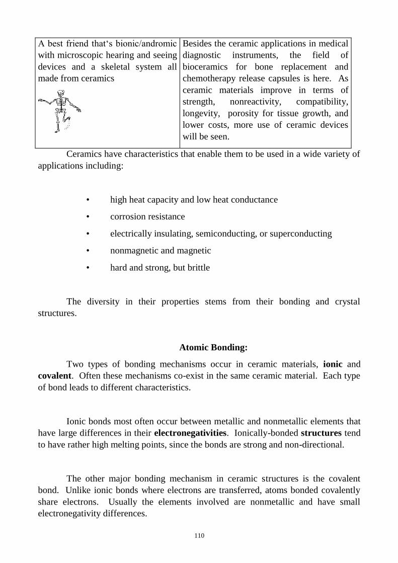
110
A best friend that‘s bionic/andromic
with microscopic hearing and seeing
devices and a skeletal system all
made from ceramics
Besides the ceramic applications in medical
diagnostic instruments, the field of
bioceramics for bone replacement and
chemotherapy release capsules is here. As
ceramic materials improve in terms of
strength, nonreactivity, compatibility,
longevity, porosity for tissue growth, and
lower costs, more use of ceramic devices
will be seen.
Ceramics have characteristics that enable them to be used in a wide variety of
applications including:
• high heat capacity and low heat conductance
• corrosion resistance
• electrically insulating, semiconducting, or superconducting
• nonmagnetic and magnetic
• hard and strong, but brittle
The diversity in their properties stems from their bonding and crystal
structures.
Atomic Bonding:
Two types of bonding mechanisms occur in ceramic materials, ionic and
covalent. Often these mechanisms co-exist in the same ceramic material. Each type
of bond leads to different characteristics.
Ionic bonds most often occur between metallic and nonmetallic elements that
have large differences in their electronegativities. Ionically-bonded structures tend
to have rather high melting points, since the bonds are strong and non-directional.
The other major bonding mechanism in ceramic structures is the covalent
bond. Unlike ionic bonds where electrons are transferred, atoms bonded covalently
share electrons. Usually the elements involved are nonmetallic and have small
electronegativity differences.
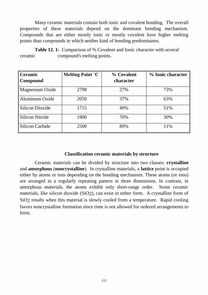
111
Many ceramic materials contain both ionic and covalent bonding. The overall
properties of these materials depend on the dominant bonding mechanism.
Compounds that are either mostly ionic or mostly covalent have higher melting
points than compounds in which neither kind of bonding predominates.
Table 12. 1: Comparison of % Covalent and Ionic character with several
ceramic compound's melting points.
Ceramic
Compound
Melting Point ˚C % Covalent
character
% Ionic character
Magnesium Oxide 2798 27% 73%
Aluminum Oxide 2050 37% 63%
Silicon Dioxide 1715 49% 51%
Silicon Nitride 1900 70% 30%
Silicon Carbide 2500 89% 11%
Classification ceramic materials by structure
Ceramic materials can be divided by structure into two classes: crystalline
and amorphous (noncrystalline). In crystalline materials, a lattice point is occupied
either by atoms or ions depending on the bonding mechanism. These atoms (or ions)
are arranged in a regularly repeating pattern in three dimensions. In contrast, in
amorphous materials, the atoms exhibit only short-range order. Some ceramic
materials, like silicon dioxide (SiO2), can exist in either form. A crystalline form of
SiO2 results when this material is slowly cooled from a temperature. Rapid cooling
favors noncrystalline formation since time is not allowed for ordered arrangements to
form.
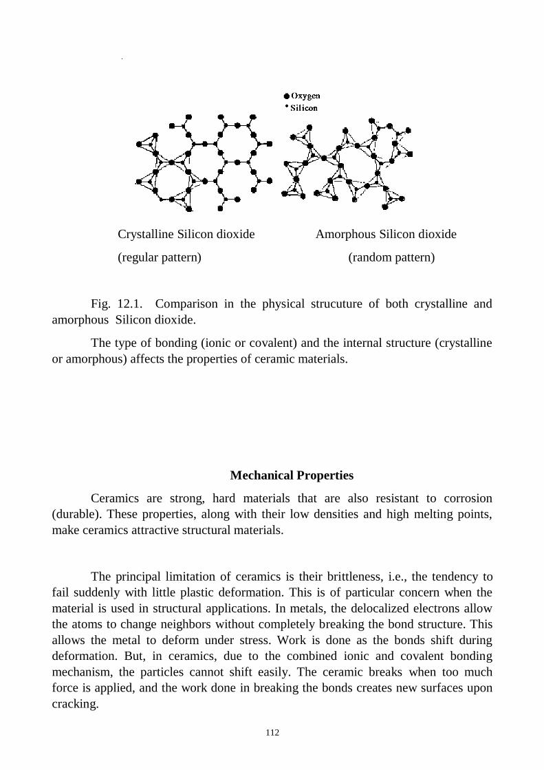
112
Crystalline Silicon dioxide Amorphous Silicon dioxide
(regular pattern) (random pattern)
Fig. 12.1. Comparison in the physical strucuture of both crystalline and
amorphous Silicon dioxide.
The type of bonding (ionic or covalent) and the internal structure (crystalline
or amorphous) affects the properties of ceramic materials.
Mechanical Properties
Ceramics are strong, hard materials that are also resistant to corrosion
(durable). These properties, along with their low densities and high melting points,
make ceramics attractive structural materials.
The principal limitation of ceramics is their brittleness, i.e., the tendency to
fail suddenly with little plastic deformation. This is of particular concern when the
material is used in structural applications. In metals, the delocalized electrons allow
the atoms to change neighbors without completely breaking the bond structure. This
allows the metal to deform under stress. Work is done as the bonds shift during
deformation. But, in ceramics, due to the combined ionic and covalent bonding
mechanism, the particles cannot shift easily. The ceramic breaks when too much
force is applied, and the work done in breaking the bonds creates new surfaces upon
cracking.
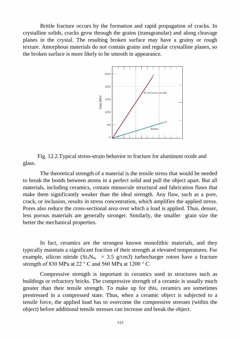
113
Brittle fracture occurs by the formation and rapid propagation of cracks. In
crystalline solids, cracks grow through the grains (transgranular) and along cleavage
planes in the crystal. The resulting broken surface may have a grainy or rough
texture. Amorphous materials do not contain grains and regular crystalline planes, so
the broken surface is more likely to be smooth in appearance.
Fig. 12.2.Typical stress-strain behavior to fracture for aluminum oxide and
glass.
The theoretical strength of a material is the tensile stress that would be needed
to break the bonds between atoms in a perfect solid and pull the object apart. But all
materials, including ceramics, contain minuscule structural and fabrication flaws that
make them significantly weaker than the ideal strength. Any flaw, such as a pore,
crack, or inclusion, results in stress concentration, which amplifies the applied stress.
Pores also reduce the cross-sectional area over which a load is applied. Thus, denser,
less porous materials are generally stronger. Similarly, the smaller grain size the
better the mechanical properties.
In fact, ceramics are the strongest known monolithic materials, and they
typically maintain a significant fraction of their strength at elevated temperatures. For
example, silicon nitride (Si3N4, = 3.5 g/cm3) turbocharger rotors have a fracture
strength of 830 MPa at 22 ° C and 560 MPa at 1200 ° C.
Compressive strength is important in ceramics used in structures such as
buildings or refractory bricks. The compressive strength of a ceramic is usually much
greater than their tensile strength. To make up for this, ceramics are sometimes
prestressed in a compressed state. Thus, when a ceramic object is subjected to a
tensile force, the applied load has to overcome the compressive stresses (within the
object) before additional tensile stresses can increase and break the object.
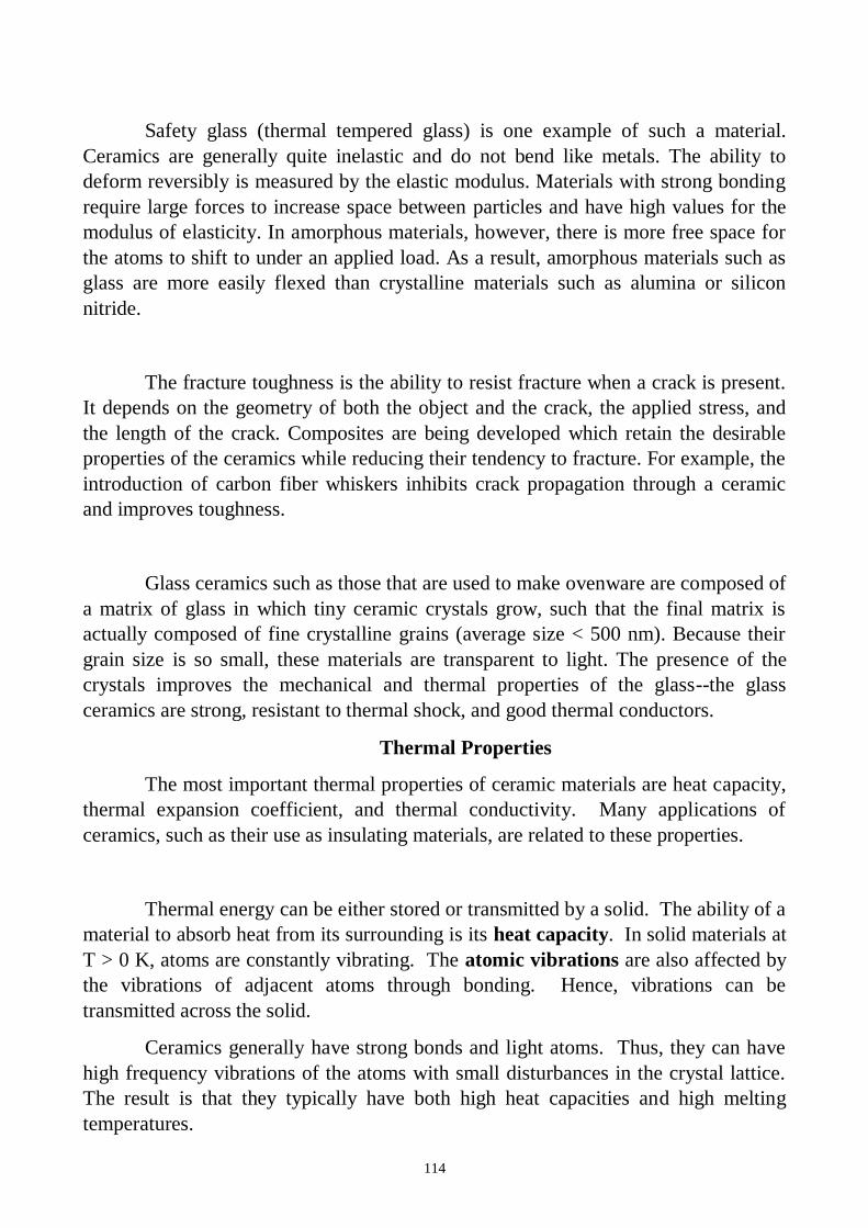
114
Safety glass (thermal tempered glass) is one example of such a material.
Ceramics are generally quite inelastic and do not bend like metals. The ability to
deform reversibly is measured by the elastic modulus. Materials with strong bonding
require large forces to increase space between particles and have high values for the
modulus of elasticity. In amorphous materials, however, there is more free space for
the atoms to shift to under an applied load. As a result, amorphous materials such as
glass are more easily flexed than crystalline materials such as alumina or silicon
nitride.
The fracture toughness is the ability to resist fracture when a crack is present.
It depends on the geometry of both the object and the crack, the applied stress, and
the length of the crack. Composites are being developed which retain the desirable
properties of the ceramics while reducing their tendency to fracture. For example, the
introduction of carbon fiber whiskers inhibits crack propagation through a ceramic
and improves toughness.
Glass ceramics such as those that are used to make ovenware are composed of
a matrix of glass in which tiny ceramic crystals grow, such that the final matrix is
actually composed of fine crystalline grains (average size < 500 nm). Because their
grain size is so small, these materials are transparent to light. The presence of the
crystals improves the mechanical and thermal properties of the glass--the glass
ceramics are strong, resistant to thermal shock, and good thermal conductors.
Thermal Properties
The most important thermal properties of ceramic materials are heat capacity,
thermal expansion coefficient, and thermal conductivity. Many applications of
ceramics, such as their use as insulating materials, are related to these properties.
Thermal energy can be either stored or transmitted by a solid. The ability of a
material to absorb heat from its surrounding is its heat capacity. In solid materials at
T > 0 K, atoms are constantly vibrating. The atomic vibrations are also affected by
the vibrations of adjacent atoms through bonding. Hence, vibrations can be
transmitted across the solid.
Ceramics generally have strong bonds and light atoms. Thus, they can have
high frequency vibrations of the atoms with small disturbances in the crystal lattice.
The result is that they typically have both high heat capacities and high melting
temperatures.
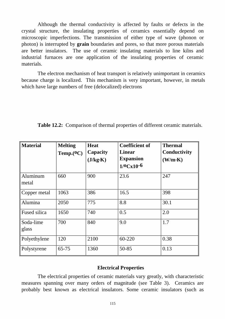
115
Although the thermal conductivity is affected by faults or defects in the
crystal structure, the insulating properties of ceramics essentially depend on
microscopic imperfections. The transmission of either type of wave (phonon or
photon) is interrupted by grain boundaries and pores, so that more porous materials
are better insulators. The use of ceramic insulating materials to line kilns and
industrial furnaces are one application of the insulating properties of ceramic
materials.
The electron mechanism of heat transport is relatively unimportant in ceramics
because charge is localized. This mechanism is very important, however, in metals
which have large numbers of free (delocalized) electrons
Table 12.2: Comparison of thermal properties of different ceramic materials.
Material Melting
Temp.(oC)
Heat
Capacity
(J/kg.K)
Coefficient of
Linear
Expansion
1/oCx10-6
Thermal
Conductivity
(W/m.K)
Aluminum
metal
660 900 23.6 247
Copper metal 1063 386 16.5 398
Alumina 2050 775 8.8 30.1
Fused silica 1650 740 0.5 2.0
Soda-lime
glass
700 840 9.0 1.7
Polyethylene 120 2100 60-220 0.38
Polystyrene 65-75 1360 50-85 0.13
Electrical Properties
The electrical properties of ceramic materials vary greatly, with characteristic
measures spanning over many orders of magnitude (see Table 3). Ceramics are
probably best known as electrical insulators. Some ceramic insulators (such as
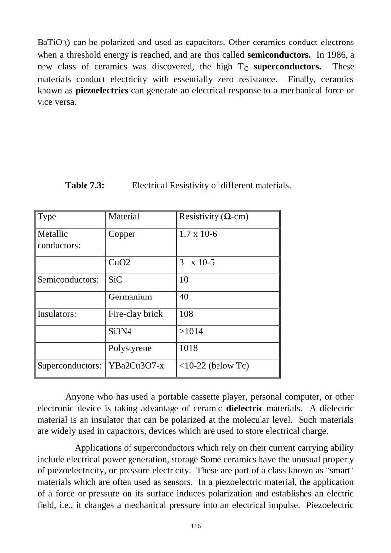
116
BaTiO3) can be polarized and used as capacitors. Other ceramics conduct electrons
when a threshold energy is reached, and are thus called semiconductors. In 1986, a
new class of ceramics was discovered, the high Tc superconductors. These
materials conduct electricity with essentially zero resistance. Finally, ceramics
known as piezoelectrics can generate an electrical response to a mechanical force or
vice versa.
Table 7.3: Electrical Resistivity of different materials.
Type Material Resistivity (Ω-cm)
Metallic
conductors:
Copper 1.7 x 10⁻⁶
CuO2 3 x 10⁻⁵
Semiconductors: SiC 10
Germanium 40
Insulators: Fire-clay brick 108
Si3N4 >1014
Polystyrene 1018
Superconductors: YBa2Cu3O7-x <10-22 (below Tc)
Anyone who has used a portable cassette player, personal computer, or other
electronic device is taking advantage of ceramic dielectric materials. A dielectric
material is an insulator that can be polarized at the molecular level. Such materials
are widely used in capacitors, devices which are used to store electrical charge.
Applications of superconductors which rely on their current carrying ability
include electrical power generation, storage Some ceramics have the unusual property
of piezoelectricity, or pressure electricity. These are part of a class known as "smart"
materials which are often used as sensors. In a piezoelectric material, the application
of a force or pressure on its surface induces polarization and establishes an electric
field, i.e., it changes a mechanical pressure into an electrical impulse. Piezoelectric
117
materials are used to make transducers, which are found in such common devices as
phonograph pickups, depth finders, microphones, and various types of sensors.
In ceramic materials, electric charge can also be transported by ions. This
property can be tailored by means of the chemical composition, and is the basis for
many commercial applications. These range from chemical sensors to large scale
electric power generators
Ceramic Processing:
Processing of ceramic materials describes the way in which ceramic objects
(e.g., glass windows, turbocharger rotor blades, optical fibers, capacitors) are
produced.
Processing begins with the raw materials needed to produce the finished
components, and includes many individual steps that differ significantly depending
on the type of ceramic material, crystalline versus glass.
Processing of Crystalline Ceramics Glass Processing
Raw Material Selection Raw Material Selection
Preparation Melting
Consolidation Pouring
Sintering Annealing
Raw material selection involves obtaining and preparing the right materials
for the final product. Traditional ceramics use various forms of clay. Glass makers
start with primarily silica.
Material Uses
Al2O3 (aluminum oxide) Spark-plug insulating bodies, substrates for
microelectronic packaging
MgO (magnesium oxide) electrical insulators, refractory brick
SiO2 (Silicon dioxide) cookware, optical fibers
ZrO2 (zirconium oxide) cubic zirconia, oxygen sensors
SiC (silicon carbide) kiln parts, heating elements, abrasives
Si3N4 (silicon nitride) turbocharger rotors, piston valves
For crystalline ceramics, the characteristics of the raw materials (powders)
such as their particle size and purity are very important as they affect the structure
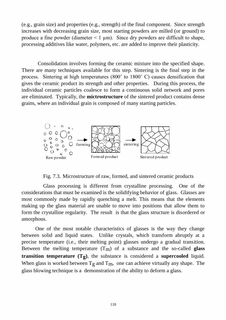
118
(e.g., grain size) and properties (e.g., strength) of the final component. Since strength
increases with decreasing grain size, most starting powders are milled (or ground) to
produce a fine powder (diameter < 1 µm). Since dry powders are difficult to shape,
processing additives like water, polymers, etc. are added to improve their plasticity.
Consolidation involves forming the ceramic mixture into the specified shape.
There are many techniques available for this step. Sintering is the final step in the
process. Sintering at high temperatures (800˚ to 1800˚ C) causes densification that
gives the ceramic product its strength and other properties. During this process, the
individual ceramic particles coalesce to form a continuous solid network and pores
are eliminated. Typically, the mictrostructure of the sintered product contains dense
grains, where an individual grain is composed of many starting particles.
forming sintering
Raw powder Form ed product Sint ered product
Fig. 7.3. Microstructure of raw, formed, and sintered ceramic products
Glass processing is different from crystalline processing. One of the
considerations that must be examined is the solidifying behavior of glass. Glasses are
most commonly made by rapidly quenching a melt. This means that the elements
making up the glass material are unable to move into positions that allow them to
form the crystalline regularity. The result is that the glass structure is disordered or
amorphous.
One of the most notable characteristics of glasses is the way they change
between solid and liquid states. Unlike crystals, which transform abruptly at a
precise temperature (i.e., their melting point) glasses undergo a gradual transition.
Between the melting temperature (Tm) of a substance and the so-called glass
transition temperature (Tg), the substance is considered a supercooled liquid.
When glass is worked between Tg and Tm, one can achieve virtually any shape. The
glass blowing technique is a demonstration of the ability to deform a glass.
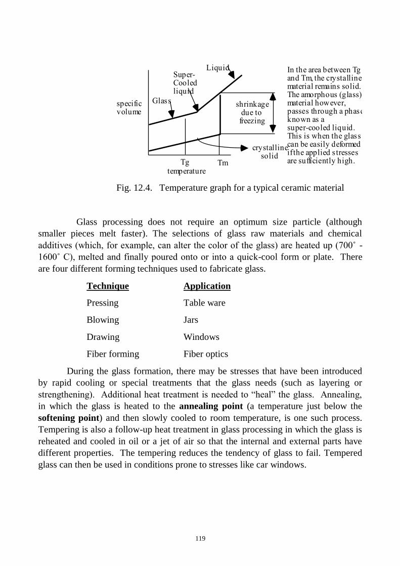
119
temperature
specific volume
Glass
Tg Tm
Super- Cooled liquid
shrinkage due to freezing
crystalline solid
Liquid In the area between Tg and Tm, the crystalline material remains solid. The amorphous (glass) material however, passes through a phase known as a super-cooled liquid. This is when the glass can be easily deformed if the applied s tresses are sufficiently high.
Fig. 12.4. Temperature graph for a typical ceramic material
Glass processing does not require an optimum size particle (although
smaller pieces melt faster). The selections of glass raw materials and chemical
additives (which, for example, can alter the color of the glass) are heated up (700˚ -
1600˚ C), melted and finally poured onto or into a quick-cool form or plate. There
are four different forming techniques used to fabricate glass.
Technique Application
Pressing Table ware
Blowing Jars
Drawing Windows
Fiber forming Fiber optics
During the glass formation, there may be stresses that have been introduced
by rapid cooling or special treatments that the glass needs (such as layering or
strengthening). Additional heat treatment is needed to “heal” the glass. Annealing,
in which the glass is heated to the annealing point (a temperature just below the
softening point) and then slowly cooled to room temperature, is one such process.
Tempering is also a follow-up heat treatment in glass processing in which the glass is
reheated and cooled in oil or a jet of air so that the internal and external parts have
different properties. The tempering reduces the tendency of glass to fail. Tempered
glass can then be used in conditions prone to stresses like car windows.
120
Materials and Equipment:
1. Simples of ceramic beams and glasses.
2. Ruler.
3. Weight.
Procedure:
1. Measure the ceramic beam‘s mass, length, width, and thickness. Record.
2. Calculate the ceramic beam’s density.
3. Write chemical composition, atomic bonding, structure, according to the
literature indicate mechanical properties and applications of the ceramic.
4. Measure the glasses mass, length, width, and thickness. Record.
5. Calculate the glasses density.
6. Write chemical composition, atomic bonding, structure, according to the
literature indicate mechanical properties and applications of the glasses.
7. Fill the protocol report.
Questions:
1. What is ceramic? Describe traditional and advanced ceramics.
2. Applications of ceramics.
3. Explain two types of bonding mechanisms occur in ceramic materials.
4. Classification ceramic materials by structure.
4. Describe mechanical properties of ceramic.
5. Describe thermal properties of ceramic.
6. Describe electrical properties of ceramic.
7. Processing of Crystalline Ceramics.
8. Why glass processing is different from crystalline processing?
9. List different forming techniques used to fabricate glass.
10. Which reasons of glass heat treatment?

121
LABORATORY WORK 12
CERAMICS
PROTOCOL 1
Ceramic
Chemical composition, %
wt.______________________________________________
Atomic bonding___________________________________________________
Structure________________________________________________________
Processing ______________________________________________________
Mechanical properties:
Yield Strength, MPa ________________________________
Tensile strength, МPа _______________________________
Elongation, % _______________________________________
Mass,
g
Length,
mm
Width,
mm
Thickness,
mm
Volume,
mm3
Density.
g/mm3
Applications:_________________________________________________________
____________________________________________________________________
____
PROTOCOL 2
Glass
Chemical composition, %
wt.______________________________________________

122
Atomic bonding___________________________________________________
Structure________________________________________________________
Processing ______________________________________________________
Mechanical properties:
Yield Strength, MPa ________________________________
Tensile strength, МPа _______________________________
Elongation, % _______________________________________
Mass,
g
Length,
mm
Width,
mm
Thickness,
mm
Volume,
mm3
Density.
g/mm3
Applications:_________________________________________________________
____________________________________________________________________
____
Conclusion:
____________________________________________________________________
____________________________________________________________________
____________________________________________________________________
____________________________________________________________________
___________________________________________________
_________________________
Student’s signature Teacher’s signature
“____”___________20___ y. “____”____________20___ y.
123
LABORATORY WORK 13
POLYMERS
Objectives
1. To learn classes of polymers, their applications and processing.
2. To compare mechanical properties of some thermoplastics
Scientific principles
Plastics are commonly known as synthetic resins or polymers. The term
polymer comprises ‘poly’ means ‘many’ and ‘mers’ means ‘parts’. Thus, the term,
polymer represents a substance built up of several repeating units, each unit being
known as a monomer. Thousands of such units or monomers join together in a
polymerization reaction to form a ‘polymer’.
Polymers are substances containing a large number of structural units joined
by the same type of linkage. These substances often form into a chain-like structure.
Polymers in the natural world have been around since the beginning of time. Starch,
cellulose, and rubber all possess polymeric properties. Today, the polymer industry
has grown to be larger than the aluminum, copper and steel industries combined.
Applications of Polymers
Polymers already have a range of applications that far exceeds that of any
other class of material available to man. Current applications extend from adhesives,
coatings, foams, and packaging materials to textile and industrial fibers, elastomers,
and structural plastics. Polymers are also used for most composites, electronic
devices, biomedical devices, optical devices, and precursors for many newly
developed high-tech ceramics.
Agriculture and Agribusiness
Polymeric materials are used in and on soil to improve aeration, provide
mulch, and promote plant growth and health.
Medicine
Many biomaterials, especially heart valve replacements and blood vessels, are
made of polymers like Dacron, Teflon and polyurethane.
Consumer Science
Plastic containers of all shapes and sizes are light weight and economically
less expensive than the more traditional containers. Clothing, floor coverings,
garbage disposal bags, and packaging are other polymer applications.
Industry
124
Automobile parts, windshields for fighter planes, pipes, tanks, packing
materials, insulation, wood substitutes, adhesives, matrix for composites, and
elastomers are all polymer applications used in the industrial market.
Sports
Playground equipment, various balls, golf clubs, swimming pools, and
protective helmets are often produced from polymers.
Future Trends
Just as nature has used biological polymers as the material of choice, mankind
will chose polymeric materials as the choice material. An age of Polymers synthetic
polymers are and will be the material of choice.
Polymer uses are being developed in such diverse areas as: conduction and
storage of electricity, heat and light, molecular based information storage and
processing, molecular composites, unique separation membranes, revolutionary new
forms of food processing and packaging, health, housing, and transportation.
The field of polymers is so vast and the applications so varied, that it is
important to understand how polymers are made and used. Since there are over
60,000 different plastics vying for a place in the market, knowledge of this important
field can truly enrich our appreciation of this wonder material. Companies
manufacture over 30 million tons of plastics each year, and spend large sums on
research, development, and more efficient recycling methods.
Properties of plastics
1. Plastics are light in weight and at the same time they possess good toughness
strength and rigidity.
2. They are less brittle than glass, yet they can be made equally transparent and
smooth.
3. Their high dielectric strength makes them suitable for electric insulation.
4. They resist corrosion and the action of chemicals.
5. The ease with which they can be mass-produced contributes greatly to their
popularity as wrappers and bags.
6. They possess the property of low moisture absorption.
7. They can be easily molded to desired shapes.
8. They can easily be made colored.
9. They are bad conductance of heat.
10. They are hard, rigid and heat resistance.
11. They possesses good deformability, good resiatance against weather conditions,
good colorability, good damping characteristics and good resistance to peeling.
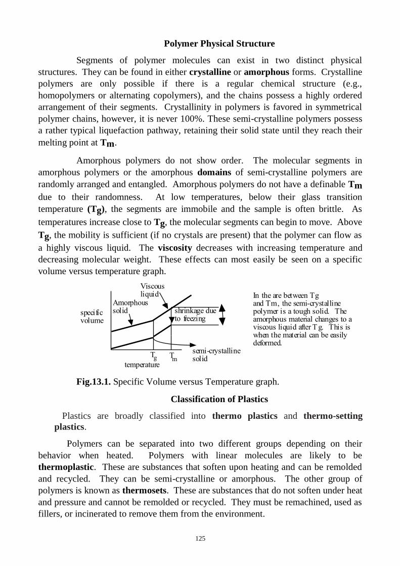
125
Polymer Physical Structure
Segments of polymer molecules can exist in two distinct physical
structures. They can be found in either crystalline or amorphous forms. Crystalline
polymers are only possible if there is a regular chemical structure (e.g.,
homopolymers or alternating copolymers), and the chains possess a highly ordered
arrangement of their segments. Crystallinity in polymers is favored in symmetrical
polymer chains, however, it is never 100%. These semi-crystalline polymers possess
a rather typical liquefaction pathway, retaining their solid state until they reach their
melting point at Tm.
Amorphous polymers do not show order. The molecular segments in
amorphous polymers or the amorphous domains of semi-crystalline polymers are
randomly arranged and entangled. Amorphous polymers do not have a definable Tm
due to their randomness. At low temperatures, below their glass transition
temperature (Tg), the segments are immobile and the sample is often brittle. As
temperatures increase close to Tg, the molecular segments can begin to move. Above
Tg, the mobility is sufficient (if no crystals are present) that the polymer can flow as
a highly viscous liquid. The viscosity decreases with increasing temperature and
decreasing molecular weight. These effects can most easily be seen on a specific
volume versus temperature graph.
temperature
specific volume
T T
Amorphous solid
Viscous liquid
semi-crystalline solid
shrinkage due to freezing
In the are between Tg and Tm, the semi-crystalline polymer is a tough solid. The amorphous material changes to a viscous liquid after T g. This is when the material can be easily deformed.
mg
Fig.13.1. Specific Volume versus Temperature graph.
Classification of Plastics
Plastics are broadly classified into thermo plastics and thermo-setting
plastics.
Polymers can be separated into two different groups depending on their
behavior when heated. Polymers with linear molecules are likely to be
thermoplastic. These are substances that soften upon heating and can be remolded
and recycled. They can be semi-crystalline or amorphous. The other group of
polymers is known as thermosets. These are substances that do not soften under heat
and pressure and cannot be remolded or recycled. They must be remachined, used as
fillers, or incinerated to remove them from the environment.
126
Thermo Plastics
Those plastics which can be easily softened again and again by heating are
called thermoplastic. They can be reprocessed safely. They retain their plasticity at
high temperature, i.e. they preserve an ability to be repeatedly formed by heat and
pressure. Therefore, they can be heated and reshaped by pressing many times. On
cooling they become hard. They can be very easily shaped into tubes, sheets, films,
and many other shapes as per the need.
Thermoplastics are generally carbon containing polymers synthesized by
addition or condensation polymerization. This process forms strong covalent bonds
within the chains and weaker secondary Van der Waals bonds between the chains.
Usually, these secondary forces can be easily overcome by thermal energy, making
thermoplastics moldable at high temperatures. Thermoplastics will also retain their
newly reformed shape after cooling.
Types of Thermo Plastics
Amorphous: Polystyrene, Acrylonitrite-butadiene-styrene. Mrthacrylate. P.V.C
(Polyvinyl chloride), Polychloroacetal, Polycarbonate etc.
Crystalline: Polyethylene, Polyamides, Polyacetal.Polypropylene
The reason for the re-softening of thermoplastic resins with heat is that they are
composed of linear or long chain molecules. Application of heat weakens the
intermolecular bonds by increasing thermal agitation of the molecules, and the
material softens and thus plastic can be easily molded and remolded without damage
Thermo-Setting Plastics
Those plastics which are hardened by heat, effecting a non-reversible chemical
change, are called thermo-setting. Alternatively these plastics materials acquire a
permanent shape when heated and pressed and thus cannot be easily softened by
reheating.
Thermosets have the same Van der Waals bonds that thermoplastics do. They
also have a stronger linkage to other chains. Strong covalent bonds chemically hold
different chains together in a thermoset material. The chains may be directly bonded
to each other or be bonded through other molecules. This "cross-linking" between
the chains allows the material to resist softening upon heating. Thus, thermosets
must be machined into a new shape if they are to be reused or they can serve as
powdered fillers. Although thermosets are difficult to reform, they have many
distinct advantages in engineering design applications including:
1.High thermal stability and insulating properties.
2.High rigidity and dimensional stability.
3.Resistance to creep and deformation under load.
4.Light-weight.
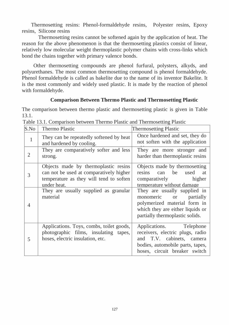
127
Thermosetting resins: Phenol-formaldehyde resins, Polyester resins, Epoxy
resins, Silicone resins
Thermosetting resins cannot be softened again by the application of heat. The
reason for the above phenomenon is that the thermosetting plastics consist of linear,
relatively low molecular weight thermoplastic polymer chains with cross-links which
bond the chains together with primary valence bonds.
Other thermosetting compounds are phenol furfural, polysters, alkyds, and
polyurethanes. The most common thermosetting compound is phenol formaldehyde.
Phenol formaldehyde is called as bakelite due to the name of its inventor Bakelite. It
is the most commonly and widely used plastic. It is made by the reaction of phenol
with formaldehyde.
Comparison Between Thermo Plastic and Thermosetting Plastic
The comparison between thermo plastic and thermosetting plastic is given in Table
13.1.
Table 13.1. Comparison between Thermo Plastic and Thermosetting Plastic
S.No Thermo Plastic Thermosetting Plastic
1 They can be repeatedly softened by heat
and hardened by cooling.
Once hardened and set, they do
not soften with the application
of heat.
2 They are comparatively softer and less
strong.
They are more stronger and
harder than thermoplastic resins
3
Objects made by thermoplastic resins
can not be used at comparatively higher
temperature as they will tend to soften
under heat.
Objects made by thermosetting
resins can be used at
comparatively higher
temperature without damage
4
They are usually supplied as granular
material
They are usually supplied in
monomeric or partially
polymerized material form in
which they are either liquids or
partially thermoplastic solids.
5
Applications. Toys, combs, toilet goods,
photographic films, insulating tapes,
hoses, electric insulation, etc.
Applications. Telephone
receivers, electric plugs, radio
and T.V. cabinets, camera
bodies, automobile parts, tapes,
hoses, circuit breaker switch
panels, etc.
128
Additions in Polymer
To make polymer more for further processing of products, plastics, and some other
material are added to the polymers before or during polymerization. These materials
are
Catalysts
They are also known accelerator or hardener. They act as catalysts to accelerate
the chemical reactions during polymerization of plastics.
Fillers
Fillers are added to synthetic resins for increasing strength, stiffness and thermal
resistance of the plastics. These are clay, talc, alumina, carbon black, calcium
carbonate, wood flour, mica, quartz, asbestos, glass fibres etc.
Modifiers
Modifiers are added to plastics for improving mechanical properties
Plasticizers
Plasticizers are fluids of high molecular weight. They are added for softening the
resins at forming temperature and to improve their toughness at the finished stage and
to impart flexibility to their finished products.
Stabilizers
The additions of stabilizers to plastics help in preventing deterioration due to the
action of heat and light.
Initiators
Initiators help in starting the reaction i.e. polymerization.
Dyes and pigments
Dyes and pigments are the coloring agents, added to impart different colors and
shades to plastic materials.
Polymer Processing
There are five basic processes to form polymer products or parts. These
include; injection molding, compression molding, transfer molding, blow molding,
and extrusion. Compression molding and transfer molding are used mainly for
thermosetting plastics. Injection molding, extrusion and blow molding are used
primarily with thermoplastics.
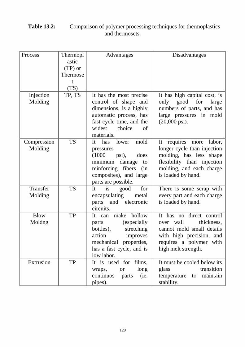
129
Table 13.2: Comparison of polymer processing techniques for thermoplastics
and thermosets.
Process Thermopl
astic
(TP) or
Thermose
t
(TS)
Advantages Disadvantages
Injection
Molding
TP, TS It has the most precise
control of shape and
dimensions, is a highly
automatic process, has
fast cycle time, and the
widest choice of
materials.
It has high capital cost, is
only good for large
numbers of parts, and has
large pressures in mold
(20,000 psi).
Compression
Molding
TS It has lower mold
pressures
(1000 psi), does
minimum damage to
reinforcing fibers (in
composites), and large
parts are possible.
It requires more labor,
longer cycle than injection
molding, has less shape
flexibility than injection
molding, and each charge
is loaded by hand.
Transfer
Molding
TS It is good for
encapsulating metal
parts and electronic
circuits.
There is some scrap with
every part and each charge
is loaded by hand.
Blow
Moldng
TP It can make hollow
parts (especially
bottles), stretching
action improves
mechanical properties,
has a fast cycle, and is
low labor.
It has no direct control
over wall thickness,
cannot mold small details
with high precision, and
requires a polymer with
high melt strength.
Extrusion TP It is used for films,
wraps, or long
continuos parts (ie.
pipes).
It must be cooled below its
glass transition
temperature to maintain
stability.
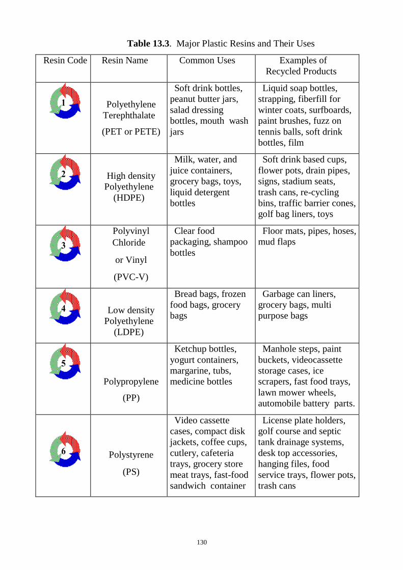
130
Table 13.3. Major Plastic Resins and Their Uses
Resin Code Resin Name Common Uses Examples of
Recycled Products
1
Polyethylene
Terephthalate
(PET or PETE)
Soft drink bottles,
peanut butter jars,
salad dressing
bottles, mouth wash
jars
Liquid soap bottles,
strapping, fiberfill for
winter coats, surfboards,
paint brushes, fuzz on
tennis balls, soft drink
bottles, film
2
High density
Polyethylene
(HDPE)
Milk, water, and
juice containers,
grocery bags, toys,
liquid detergent
bottles
Soft drink based cups,
flower pots, drain pipes,
signs, stadium seats,
trash cans, re-cycling
bins, traffic barrier cones,
golf bag liners, toys
3
Polyvinyl
Chloride
or Vinyl
(PVC-V)
Clear food
packaging, shampoo
bottles
Floor mats, pipes, hoses,
mud flaps
4
Low density
Polyethylene
(LDPE)
Bread bags, frozen
food bags, grocery
bags
Garbage can liners,
grocery bags, multi
purpose bags
5
Polypropylene
(PP)
Ketchup bottles,
yogurt containers,
margarine, tubs,
medicine bottles
Manhole steps, paint
buckets, videocassette
storage cases, ice
scrapers, fast food trays,
lawn mower wheels,
automobile battery parts.
6
Polystyrene
(PS)
Video cassette
cases, compact disk
jackets, coffee cups,
cutlery, cafeteria
trays, grocery store
meat trays, fast-food
sandwich container
License plate holders,
golf course and septic
tank drainage systems,
desk top accessories,
hanging files, food
service trays, flower pots,
trash cans
131
Materials and Equipment:
1. Samples of the Thermoplastic (TP) or Thermoset (TS).
2. Ruler.
3. Weight.
4. Brinell Testing Machine.
Procedure:
1. Measure the Thermoplastic mass, length, width, and thickness. Record.
2. Calculate the Thermoplastic density.
3. Write chemical composition, structure, according to the literature indicate
mechanical properties and applications of the Thermoplastic.
4. Measure the Thermoset mass, length, width, and thickness. Record.
5. Calculate the Thermoset density.
6. Write chemical composition, structure, according to the literature indicate
mechanical properties and applications of the Thermoset.
7. Find the hadness of the Thermoplastic and Thermoset by converting the
diameter of
of the impression to Brinell Hardness Number (BHN).
8. Write the results of every measuring in the protocol.
9. Write to average of the three reading BHN values.
10. Fill in the protocol report.
11. Find the

132
Questions:
1.What is plastics?
2. What is polymers? List natural and synthetic polymers.
3.Applications of polymers.
4.Describe properties of plastics.
5.Explain polymer Physical Structure.
6.Classification of plastics.
7. What is Thermoplastics? Name any and describe their.
8.What is Thermosets? Name any and describe their.
9.Comparison Between Thermo Plastic and Thermosetting Plastic.
10.What will happen when we heating Thermoplastics?
11.What will happen when we heating Thermosets?
12. List the additions in polymer.
13.List polymer processing.

133
LABORATORY WORK 13
POLYMERS
PROTOCOL 1
Thermoplastic
Name
Structure_____________________________________________________________
__
Processing ______________________________________________________
Mechanical properties:
Yield Strength, MPa ________________________________
Tensile strength, МPа _______________________________
Elongation, % _______________________________________
Mass,
g
Length,
mm
Width,
mm
Thickness,
mm
Volume,
mm3
Density.
g/mm3
Applications:_________________________________________________________
____________________________________________________________________
____

134
PROTOCOL 2
Thermoset
Name
Structure_____________________________________________________________
Processing ______________________________________________________
Mechanical properties:
Yield Strength, MPa ________________________________
Tensile strength, МPа _______________________________
Elongation, % _______________________________________
Mass,
g
Length,
mm
Width,
mm
Thickness,
mm
Volume,
mm3
Density.
g/mm3
Applications:_________________________________________________________
____________________________________________________________________
Protocol 3
Hardness Brinell test
Plastic D, mm Load Р,
N
di, mm BHN,
MPa
Average BHN,
MPа

135
Conclusion:
____________________________________________________________________
____________________________________________________________________
____________________________________________________________________
____________________________________________________________________
___________________________________________________
_________________________
Student’ssignature Teacher’s signature
“____”___________20___ y. “____”____________20___
y.
136
Glossary Metals
alloy: a substance that has metallic properties and is made up of two or more
chemical
elements, of which at least one is a metal.
annealing: a heat treatment of a metal designed to produce a soft, ductile condition.
Typically the metal is heated and allowed to cool slowly.
anode: electrode at which electrons are released during corrosion. The half reaction
at the anode is called oxidation and the metal is said to be oxidized. The anode is the
electrode that disintegrates during corrosion.
bronze: An alloy composed of tin and copper.
cathode: electrode which accepts electrons during corrosion. The half reaction at
the
cathode is called reduction and the metal is said to be reduced. The cathode is
not destroyed during corrosion.
cathodic protection: a more active metal is placed next to a less active metal. The
more
active metal will serve as an anode and will be corroded instead of the less
active metal. The anode is then called a sacrificial anode.
cold-working: a permanent deformation of a metal below its crystallization
temperature.
Deforming the metal creates more dislocations which entangle, pinning them
and thereby strengthening the metal.
corrosion: oxidation-reduction reaction where electrons are released at the anode
and
taken up at the cathode.
dislocations: linear defects in a crystal.
ductile: can be drawn or stretched into wire and other shapes.
elastic deformation: materials return to their original shape after a small load or
stress
is applied.
face-centered cubic: crystal arrangement of close-packed layers of particles where
three layers of particles alternate positions. This layering is known as ABCABC.
137
failure: ultimate separation of metal parts due to applied loads. i.e. it breaks.
fatigue: the application and release of stresses as metal is used which cause small
cracks to grow, during many cycles of application, until they fracture.
grain: a crystal (ordered arrangement of atoms).
grain boundary: the interface between the grains or crystals.
Hall Process: an electrolytic technique to refine aluminum from its ore.
hardening: heating and rapidly cooling steel.
heat treating: modification of properties and structure of alloys by specific heating
and cooling cycles.
hexagon closest packing (HCP): crystal arrangement of layers of particles where
two layers alternate positions. The layering is known as ABAB.
malleable: can be hammered into a sheet.
martensite: a super-saturated solid solution of carbon in ferrite. The carbon atoms
distort the BCC ferrite into a BC-tetragonal structure.
metallic bonding: bond formed by positive ions surrounded by a cioud of valence
electrons.
ore: a natural mineral deposit that contains enough valuable minerals to make it
profitable to mine at the current technology.
oxide: a compound of oxygen with some other chemical element.
oxidation: the half of an electrochemical reaction where electrons are released.
Oxidation occurs at the electrode called the anode.
pinned: the dislocations in a crystal get tangled or attached to atoms of an alloying
agent.
plastic deformation: materials remain deformed after a load is added and then
removed.
quenched: cooled rapidly.
reduction: the half of an electrochemical reaction where electrons are taken up.
Reduction occurs at the cathode.
reduction of metals: changing a metal ion to a neutral atom by the addition of
electrons.
138
steel: an iron-carbon alloy, malleable in some temperature range as initially cast.
Steel
usually contains some other alloying elements such as silicon, manganese, etc.
as
well as impurities such as sulfur and phosphorus.
strength: a measure of the ability of a material to support a load.
stress: the internal forces produced by application of an external load, tending to
displace component parts of the stressed material. It is defined as the force (load)
divided by the area on which it acts.
toughness: the ability to aborb energy of deformation without breaking. High
toughness requires both high strength and high ductility.
unit cell: The smallest repeating array of atoms in a crystal.
GLOSSARY Ceramic
Abrasive: A hard material used to grind, cut or wear.
Absorption: The inclusion of the energy of a photon within a substance.
Amorphous: A noncrystalline substance, atoms lack long range order.
Annealing: Heat treatment to alter properties.
Annealing point (glass): Temperature at which stresses are removed.
Brittle fracture: A break that occurs by rapid crack propagation.
Capacitance (C): Charge storing capability.
Cement: A material that binds particles together in a mixture.
Ceramic: A compound of metallic and nonmetallic elements.
Color: Wavelengths of light perceived by the eye.
Component: A part, or device.
Conductivity: The ability to carry an electric current (electricity) or thermal energy
(heat).
Covalent bond: Bonding by sharing electrons.
Crystalline: A solid with a repeating three-dimensional unit cell.
Crystal structure: The orderly arrangement of the atoms or ions within a crystal.
139
Diamagnetism: Weakly repelled from a magnetic field.
Dielectric: An insulator.
Dielectric constant: Relative electrical permittivity of a material as compared to a
perfect vacuum.
Dielectric (breakdown) strength: The amount of electricity needed to start an
electric current flow in a dielectric material.
Ductile fracture: Break accompanied by large plastic deformation.
Elastic deformation: Change in shape that returns when a stress is removed.
Elastic Modulus: Ratio of stress to strain in elastic deformation, measure of
elasticity.
Electric field: The gradient of voltage.
Electronegativity: The attraction of an atom for shared electrons.
Electron volt (eV): Unit of energy equivalent to the energy gained by an electron
when it falls through an electric potential of one volt.
Excited state: An energy state to which an electron may move by the absorption of
energy.
Fiber Optics: The technology of transferring information as light pulses through
long thin fibers, usually made of glass.
Firing: High temperature processing to increase densification in a product.
Fluorescence: Light that is emitted a short period of time after an electron has been
excited.
Fracture toughness (Kc): Measure of a material's resistance to crack propagation.
Glass: An amorphous solid showing characteristic specific volume behavior over a
certain temperature range.
Glass - ceramic: Crystalline ceramic material that was formed by heat treating glass.
Glass transition temperature (Tg): Temperature at which a glass changes from a
supercooled liquid into a solid.
Grain: Individual crystal in a polycrystalline material.
Grain boundary: The boundary between grains (or crystals) that are misoriented
with respect to one another.
Green ceramic body: Ceramic object that is dried but not fired.
140
Ground state: Lowest electron energy state.
Hardness: Resistance to deformation.
Heat capacity: Heat required to produce a unit increase in temperature per quantity
of material.
Imperfection: Flaw, any deviation from perfection, as in a crystal.
Index of refraction: Ratio of the speed of light in a vacuum to the speed of light in a
medium.
Insulator: Material that does not conduct electricity (electrical) or heat (thermal).
Ionic bond: Electrostatic force between oppositely charged ions.
Laser: Source of coherent light (Light Amplification by Stimulated Emission of
Radiation).
Lattice: The regular arrangement of points in a crystal.
Magnetic field strength: Intensity of an applied magnetic field.
Microstructure: Structural features that can be observed with a microscope.
Noncrystalline: Amorphous, with no long-range atomic order.
Piezoelectric: Material that produces an electrical response to a mechanical force.
Plastic deformation: Permanent deformation, change of shape.
Polycrystalline: Composed of more than one crystal or grain.
Porcelain: A durable ceramic composite made by firing clay, feldspar and quartz
together.
Reflection: Deflection of light at the interface between two materials.
Refraction: Bending of light as it passes from one medium into another.
Refractory: Material that can be exposed to high temperature without deterioration.
Resistivity: Measure of resistance to passage of electrical current (reciprocal of
conductivity).
Semiconductor: Nonmetallic material that has a relatively narrow energy band gap.
Sintering: Coalescence of individual ceramic particles into a continuous solid phase
at a high temperature.
Slip: Mixture of clay with water that can be poured into a mold.
Slip casting: Method of making ceramic objects by pouring slip into a mold.
141
Softening point (glass): Maximum temperature a glass can be heated before it
permanently deforms.
Smart materials: Materials able to detect a change in the environment and react to
it.
Specific volume: Volume per unit mass, reciprocal of density.
Strain: Change in length of a sample in the direction of an applied stress.
Stress: Force applied to a sample divided by its cross-sectional area.
Structural clay products: Ceramic objects made mainly of clay and used in
structural applications.
Structure: Arrangement of internal components.
Superconductivity: Disappearance of electrical resistivity at low temperatures.
Supercooling: Cooling below the normal temperature for a phase change, without
the change occurring.
Tensile strength: Maximum stress without fracture.
Thermal expansion coefficient, linear: Fractional change in length divided by
change in temperature, a measure of a materials tendency to expand when
heated.
Thermal stress: Residual stress caused by a change in temperature.
Thermal tempering: The introduction of residual compressive stresses to increase
the strength of glass.
Toughness: Energy absorbed by a material as it fractures, a measure of its resistance
to fracture.
Transgranular fracture: Fracture by crack propagation through the grains.
Translucent: Transmits light diffusely.
Transparent: Transmits light clearly.
Unit cell: The basic repeating unit in a crystal.
Whiteware: Clay-based ceramic that turns white after firing.
Glossary Polymers
Abbreviations:
HDPE: high density polyethylene
142
LDPE: low density polyethylene
PET: polyethylene terephthalate
PP: polypropylene
PS: polystyrene
PVA: polyvinyl alcohol
PVC: polyvinyl chloride
addition polymerization: a chemical reaction in which simple molecules are linked
together to form long chain molecules.
amorphous: non-crystalline polymer or non-crystalline areas in a polymer.
Bakelite: a polymer produced by the condensation of phenol and formaldehyde.
branched polymer: polymer having smaller chains attached to the polymer
backbone.
cellulose: a natural polymer found in wood and other plant material.
composite polymer: a filled or reinforced plastic.
condensation polymer: one in which two or more molecules combine resulting in
elimination of water or other simple molecules, with the process being repeated to
form a long chain molecule.
configuration: related chemical structure produced by the making and breaking of
primary valence bonds.
copolymer: a macromolecule consisting of more than one type of building unit.
creep: cold flow of a polymer.
cross-linking: occurs when primary valence bonds are formed between separate
polymer chain molecules.
crystalline polymer: polymer with a regular order or pattern of molecular
arrangement and a sharp melting point.
dimer: a polymer containing two monomers.
domains: sequences or regions in block copolymers.
elastomer: a type of polymer that exhibits rubber-like qualities.
Ekonol: a moldable, high temperature polymer.
end group: functional group at the end of a chain in polymers, e.g. carboxylic group.
143
extrusion: a fabrication process in which a heat-softened polymer is forced
continually by a screw through a die.
filler: a relatively inert material used as the discontinuous phase of a polymer
composite.
free radical: A chemical component that contains a free electron which covalently
bonds with a free electron on another molecule.
homopolymer: a macromolecule consisting of only one type of building unit.
initiation: the start of a chain reaction with a source such as free radicals, peroxides,
etc.
kevlar: a high strength polymer which can withstand high temperatures.
linear: polymers made up of one long continuous chain, without any excess
appendages or attachments.
macromolecule: a polymer.
material: a substance useful for structural purposes.
monomer: smallest repeating unit of a polymer.
nylon: a polymer used commonly in the textiles industry.
oligomer: a low molecular weight polymer in which the number of repeating units is
approximately between two and ten.
polyethylene: the most extensively produced polymer.
polyester: a polymer with a COOR repeating unit.
polymer: a high molecular weight macromolecule made up of multiple repeating
units.
polymerization: the chemical reaction in which high molecular mass molecules are
formed from monomers.
polystyrene: a polymer commonly used in packaging.
propagation: the continuous successive chain extension in a polymer chain reaction.
Tg: glass transition temperature below which a polymer is a hard glassy material.
thermoplastic: a polymer which may be softened by heat and hardened by cooling
in a reversible physical process.
thermoset: a network polymer obtained by cross-linking a linear polymer to make it
infusible or insoluble.

144
Tm: melting temperature.
Van der Waals forces: intermolecular attractions.
viscosity: the resistance to flow as applied to a solution or a molten solid.
vinyl chloride: the monomer used in PVC production.
vulcanization: cross-linking with heat and sulfur to toughen a polymer.
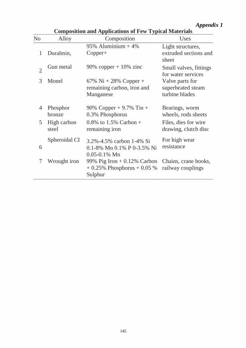
145
Appendix 1 Composition and Applications of Few Typical Materials
No Alloy Composition Uses
1 Duralmin,
95% Aluminium + 4%
Copper+
0.5% Manganese + 0.5%
Magnesium
Light structures,
extruded sections and
sheet
2 Gun metal 90% copper + 10% zinc Small valves, fittings
for water services
3 Monel 67% Ni + 28% Copper +
remaining carbon, iron and
Manganese
Valve parts for
superheated steam
turbine blades
4 Phosphor
bronze
90% Copper + 9.7% Tin +
0.3% Phosphorus
Bearings, worm
wheels, rods sheets
5 High carbon
steel
0.8% to 1.5% Carbon +
remaining iron
Files, dies for wire
drawing, clutch disc
6
Spheroidal CI 3.2%-4.5% carbon 1-4% Si
0.1-8% Mn 0.1% P 0-3.5% Ni
0.05-0.1% Mn
For high wear
resistance
7 Wrought iron 99% Pig Iron + 0.12% Carbon
+ 0.25% Phosphorus + 0.05 %
Sulphur
Chains, crane hooks,
railway couplings
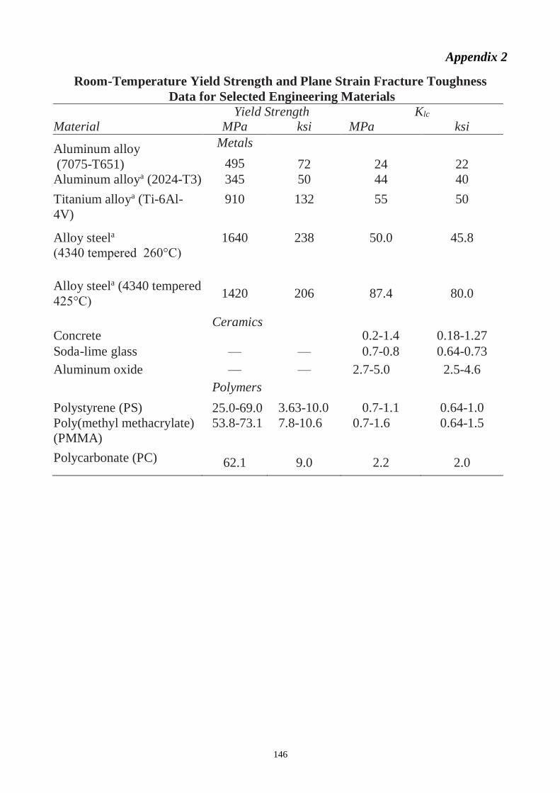
146
Appendix 2
Room-Temperature Yield Strength and Plane Strain Fracture Toughness
Data for Selected Engineering Materials
Yield Strength Klc Material MPa ksi MPa ksi
Aluminum alloy
(7075-T651)
Metals
495 72 24 22
Aluminum alloya (2024-T3) 345 50 44 40
Titanium alloya (Ti-6Al-
4V)
910 132 55 50
Alloy steela
(4340 tempered 260°C)
1640 238 50.0 45.8
Alloy steela (4340 tempered
425°C) 1420 206 87.4 80.0
Concrete Ceramics
0.2-1.4 0.18-1.27
Soda-lime glass — — 0.7-0.8 0.64-0.73
Aluminum oxide — — 2.7-5.0 2.5-4.6
Polystyrene (PS)
Polymers
25.0-69.0 3.63-10.0 0.7-1.1 0.64-1.0
Poly(methyl methacrylate)
(PMMA)
53.8-73.1 7.8-10.6 0.7-1.6 0.64-1.5
Polycarbonate (PC) 62.1 9.0 2.2 2.0
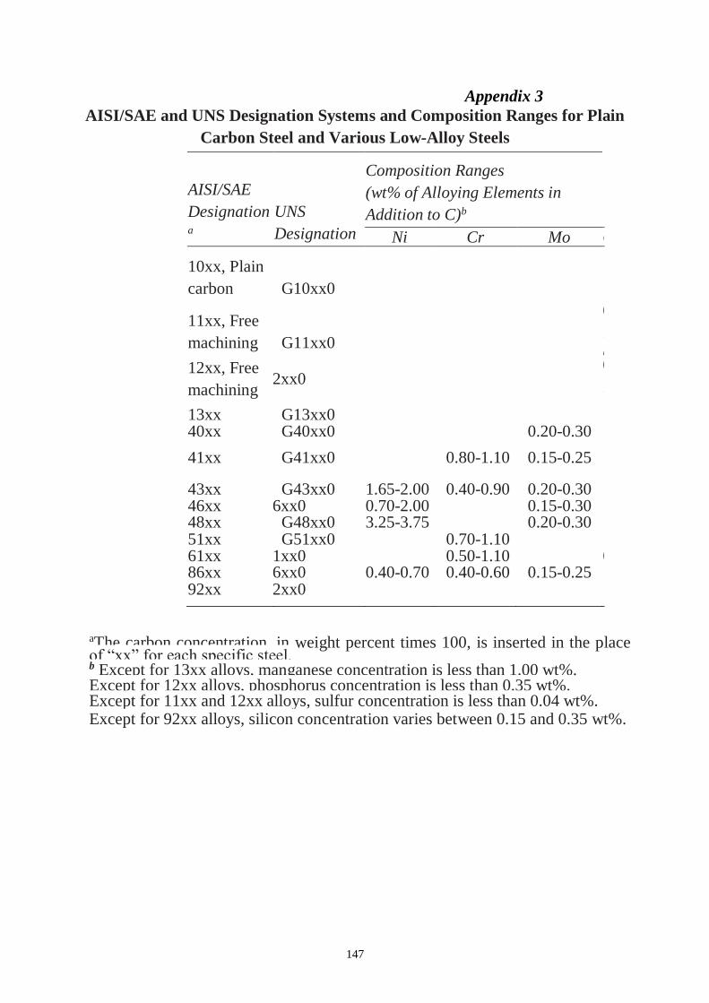
147
Appendix 3
AISI/SAE and UNS Designation Systems and Composition Ranges for Plain
Carbon Steel and Various Low-Alloy Steels
aThe carbon concentration, in weight percent times 100, is inserted in the place of “xx” for each specific steel. b Except for 13xx alloys, manganese concentration is less than 1.00 wt%. Except for 12xx alloys, phosphorus concentration is less than 0.35 wt%. Except for 11xx and 12xx alloys, sulfur concentration is less than 0.04 wt%. Except for 92xx alloys, silicon concentration varies between 0.15 and 0.35 wt%.
AISI/SAE
Designationa
UNS
Designation
Composition Ranges
(wt% of Alloying Elements in
Addition to C)b
Ni Cr Mo O
t
h
e
r
10xx, Plain
carbon G10xx0
11xx, Free
machining G11xx0
0
.
0
8
-
0
.
3
3
S
12xx, Free
machining G12xx0
0
.
1
0
-
0
.
3
5
S
,
0
.
0
4
-
0
.
1
2
P
13xx G13xx0 1
.
6
0
-
1
.
9
0
M
n
40xx G40xx0 0.20-0.30
41xx G41xx0
0.80-1.10 0.15-0.25
43xx G43xx0 1.65-2.00 0.40-0.90 0.20-0.30 46xx G46xx0 0.70-2.00 0.15-0.30 48xx G48xx0 3.25-3.75 0.20-0.30 51xx G51xx0 0.70-1.10 61xx G61xx0 0.50-1.10 0
.
1
0
-
0
.
1
5
V
86xx G86xx0 0.40-0.70 0.40-0.60 0.15-0.25 92xx G92xx0 1
.
8
0
-
2
.
2
0
S
i
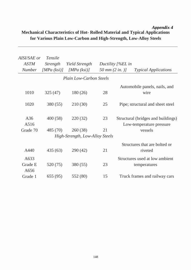
148
Appendix 4 Mechanical Characteristics of Hot- Rolled Material and Typical Applications
for Various Plain Low-Carbon and High-Strength, Low-Alloy Steels
AISI/SAE or
ASTM
Number
Tensile
Strength
[MPa (ksi)]
Yield Strength
[MPa (ksi)]
Ductility [%EL in
50 mm (2 in. )] Typical Applications
Plain Low-Carbon Steels
1010 325 (47) 180 (26) 28
Automobile panels, nails, and
wire
1020 380 (55) 210 (30) 25 Pipe; structural and sheet steel
A36 400 (58) 220 (32) 23 Structural (bridges and buildings)
A516
Grade 70 485 (70) 260 (38) 21
Low-temperature pressure
vessels
High-Strength, Low-Alloy Steels
A440 435 (63) 290 (42) 21
Structures that are bolted or
riveted
A633
Grade E 520 (75) 380 (55) 23
Structures used at low ambient
temperatures
A656
Grade 1 655 (95) 552 (80) 15 Truck frames and railway cars
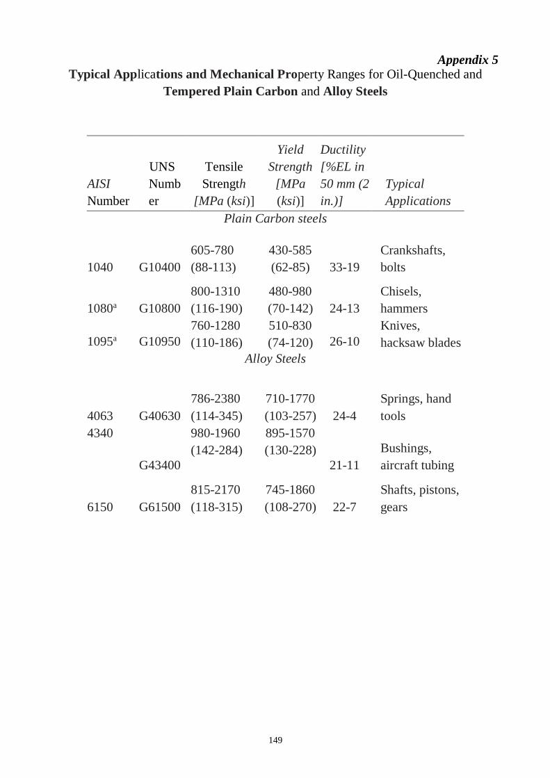
149
Appendix 5 Typical Applications and Mechanical Property Ranges for Oil-Quenched and
Tempered Plain Carbon and Alloy Steels
AISI
Number
UNS
Numb
er
Tensile
Strength
[MPa (ksi)]
Yield
Strength
[MPa
(ksi)]
Ductility
[%EL in
50 mm (2
in.)]
Typical
Applications
Plain Carbon steels
1040 G10400
605-780
(88-113)
430-585
(62-85) 33-19
Crankshafts,
bolts
1080a G10800
800-1310
(116-190)
480-980
(70-142) 24-13
Chisels,
hammers
1095a G10950
760-1280
(110-186)
510-830
(74-120) 26-10
Knives,
hacksaw blades
Alloy Steels
4063 G40630
786-2380
(114-345)
710-1770
(103-257) 24-4
Springs, hand
tools
4340
G43400
980-1960
(142-284)
895-1570
(130-228)
21-11
Bushings,
aircraft tubing
6150 G61500
815-2170
(118-315)
745-1860
(108-270) 22-7
Shafts, pistons,
gears
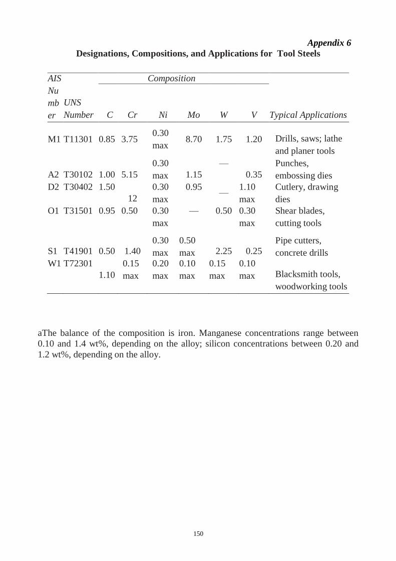
150
aThe balance of the composition is iron. Manganese concentrations range between
0.10 and 1.4 wt%, depending on the alloy; silicon concentrations between 0.20 and
1.2 wt%, depending on the alloy.
Appendix 6
Designations, Compositions, and Applications for Tool Steels
AIS
Nu
mb
er
UNS
Number
Composition
(wt%)a
C Cr Ni Mo W V Typical Applications
M1 T11301 0.85 3.75 0.30
max 8.70 1.75 1.20 Drills, saws; lathe
and planer tools
A2 T30102 1.00 5.15
0.30
max 1.15
—
0.35
Punches,
embossing dies
D2 T30402 1.50
12
0.30
max
0.95 —
1.10
max
Cutlery, drawing
dies
O1 T31501 0.95 0.50 0.30
max
— 0.50 0.30
max
Shear blades,
cutting tools
S1 T41901 0.50 1.40
0.30
max
0.50
max 2.25 0.25
Pipe cutters,
concrete drills
W1 T72301
1.10
0.15
max
0.20
max
0.10
max
0.15
max
0.10
max Blacksmith tools,
woodworking tools
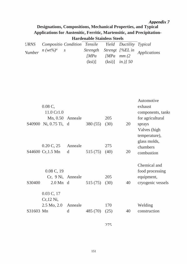
151
Appendix 7 Designations, Compositions, Mechanical Properties, and Typical
Applications for Austenitic, Ferritic, Martensitic, and Precipitation-
Hardenable Stainless Steels
URNS
Number
Compositio
n (wt%)a
Condition
s
Tensile
Strength
[MPa
(ksi)]
Yield
Strengt
[MPa
(ksi)]
Ductility
[%EL in
mm (2
in.)] 50
Typical
Applications
S40900
0.08 C,
11.0 Cr1.0
Mn, 0.50
Ni, 0.75 Ti,
Anneale
d 380 (55)
205
(30) 20
Automotive
exhaust
components, tanks
for agricultural
sprays
S44600
0.20 C, 25
Cr,1.5 Mn
Anneale
d 515 (75)
275
(40) 20
Valves (high
temperature),
glass molds,
chambers
combustion
S30400
0.08 C, 19
Cr, 9 Ni,
2.0 Mn
Anneale
d 515 (75)
205
(30) 40
Chemical and
food processing
equipment,
cryogenic vessels
S31603
0.03 C, 17
Cr,12 Ni,
2.5 Mo, 2.0
Mn
Anneale
d 485 (70)
170
(25) 40
Welding
construction
S41000
0.15 C,
12.5 Cr
1.0 Mn,
Anneale
d
Q & T
485 (70)
275
(40)
620
(90)
20
12
Rifle barrels,
cutlery, jet engine
parts
S44002
0.70 C, 17
Cr,0.75 Mo,
1.0 Mn
Anneal
Q & T
ed
725 (105)
1790
(260)
415
(60)
1650
(240)
20
5
Cutlery, bearings,
surgical tools
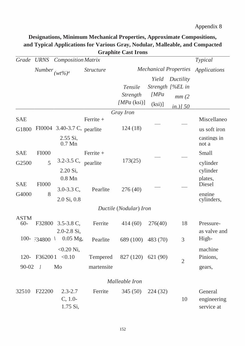
152
Appendix 8
Designations, Minimum Mechanical Properties, Approximate Compositions,
and Typical Applications for Various Gray, Nodular, Malleable, and Compacted
Graphite Cast Irons
Grade URNS
Number
Composition
(wt%)a
Matrix
Structure Mechanical Properties
Typical
Applications
Tensile
Strength
[MPa (ksi)]
Yield
Strength
[MPa
(ksi)]
Ductility
[%EL in
mm (2
in.)] 50
Gray Iron
SAE
G1800 FI0004 3.40-3.7 C,
Ferrite +
pearlite 124 (18) — —
Miscellaneo
us soft iron
2.55 Si, castings in
which
strength is
0.7 Mn not a
primary
consideratio
n
SAE
G2500
FI000
5 3.2-3.5 C,
Ferrite +
pearlite 173(25) — —
Small
cylinder
blocks. 2.20 Si, cylinder
heads,
pistons,
clutch
0.8 Mn plates,
transmission
cases
SAE
G4000
FI000
8 3.0-3.3 C, Pearlite 276 (40) — — Diesel
engine
castings,
liners.
2.0 Si, 0.8
Mn
cylinders,
and pistons Ductile (Nodular) Iron
ASTM
A536
60-
40-18
F32800
s
3.5-3.8 C, Ferrite 414 (60) 276(40) 18 Pressure-
containing
parts such
2.0-2.8 Si, as valve and
pump bodies 100-
70-03
F34800 \ 0.05 Mg, Pearlite 689 (100) 483 (70) 3 High-
strength
gears and
<0.20 Ni, machine
components 120-
90-02
F36200
J
1 <0.10
Mo
Tempered
martensite
827 (120) 621 (90) 2
Pinions,
gears,
rollers,
slides Malleable Iron
32510 F22200 2.3-2.7
C, 1.0-
1.75 Si,
<0.55
Mn
Ferrite 345 (50) 224 (32)
10
General
engineering
service at
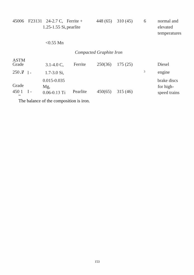
153
45006 F23131 24-2.7 C,
1.25-1.55 Si,
Ferrite +
pearlite
448 (65) 310 (45) 6 normal and
elevated
temperatures
<0.55 Mn
Compacted Graphite Iron
ASTM
A842
Grade
250 Л l -
3.1-4.0 C,
1.7-3.0 Si,
Ferrite 250(36) 175 (25)
3
Diesel
engine
blocks,
exhaust
manifolds.
Grade
450 1 I -
0.015-0.035
Mg,
0.06-0.13 Ті Pearlite 450(65) 315 (46)
brake discs
for high-
speed trains “ The balance of the composition is iron.
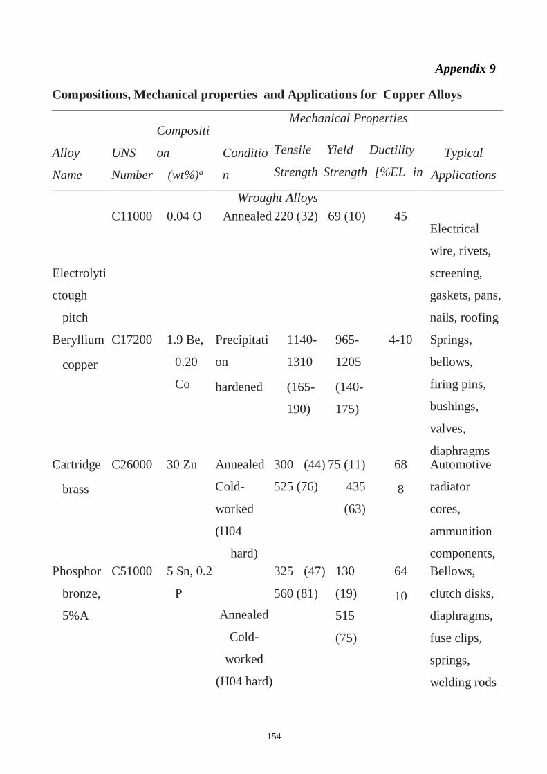
154
Appendix 9
Compositions, Mechanical properties and Applications for Copper Alloys
Alloy
Name
UNS
Number
Compositi
on
(wt%)a
Conditio
n
Mechanical Properties
Tensile Yield Ductility
Strength Strength [%EL in
50
[MPa (Asi)] [MPa (As/)]
mm (2 in.)]
Typical
Applications
Wrought Alloys
Electrolyti
ctough
pitch
C11000 0.04 O Annealed 220 (32) 69 (10) 45 Electrical
wire, rivets,
screening,
gaskets, pans,
nails, roofing
Beryllium
copper
C17200 1.9 Be,
0.20
Co
Precipitati
on
hardened
1140-
1310
(165-
190)
965-
1205
(140-
175)
4-10 Springs,
bellows,
firing pins,
bushings,
valves,
diaphragms Cartridge
brass
C26000 30 Zn Annealed
Cold-
worked
(H04
hard)
300 (44)
525 (76)
75 (11)
435
(63)
68
8
Automotive
radiator
cores,
ammunition
components,
lamp fixtures,
flashlight
shells,
kickplates
Phosphor
bronze,
5%A
C51000 5 Sn, 0.2
P
Annealed
Cold-
worked
(H04 hard)
325 (47)
560 (81)
130
(19)
515
(75)
64
10
Bellows,
clutch disks,
diaphragms,
fuse clips,
springs,
welding rods
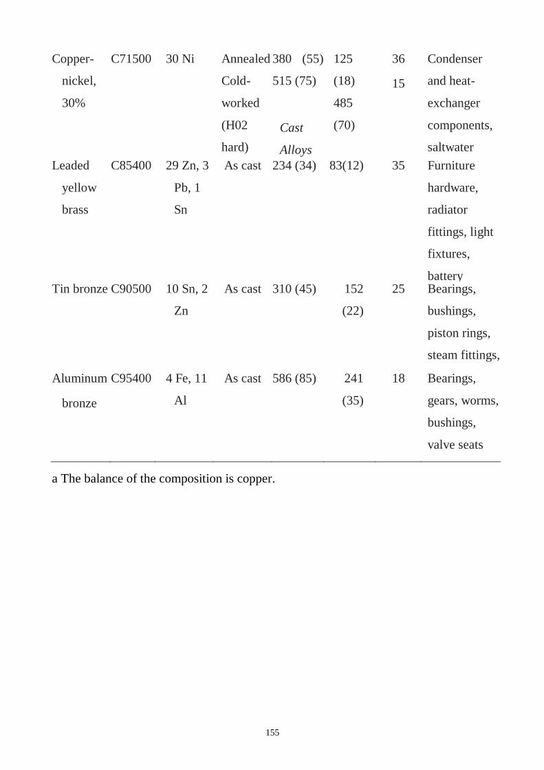
155
Copper-
nickel,
30%
C71500 30 Ni Annealed
Cold-
worked
(H02
hard)
380 (55)
515 (75)
Cast
Alloys
125
(18)
485
(70)
36
15
Condenser
and heat-
exchanger
components,
saltwater
piping Leaded
yellow
brass
C85400 29 Zn, 3
Pb, 1
Sn
As cast 234 (34) 83(12) 35 Furniture
hardware,
radiator
fittings, light
fixtures,
battery
clamps Tin bronze C90500 10 Sn, 2
Zn
As cast 310 (45) 152
(22)
25 Bearings,
bushings,
piston rings,
steam fittings,
gears Aluminum
bronze
C95400 4 Fe, 11
Al
As cast 586 (85) 241
(35)
18 Bearings,
gears, worms,
bushings,
valve seats
and guards,
pickling
hooks
a The balance of the composition is copper.
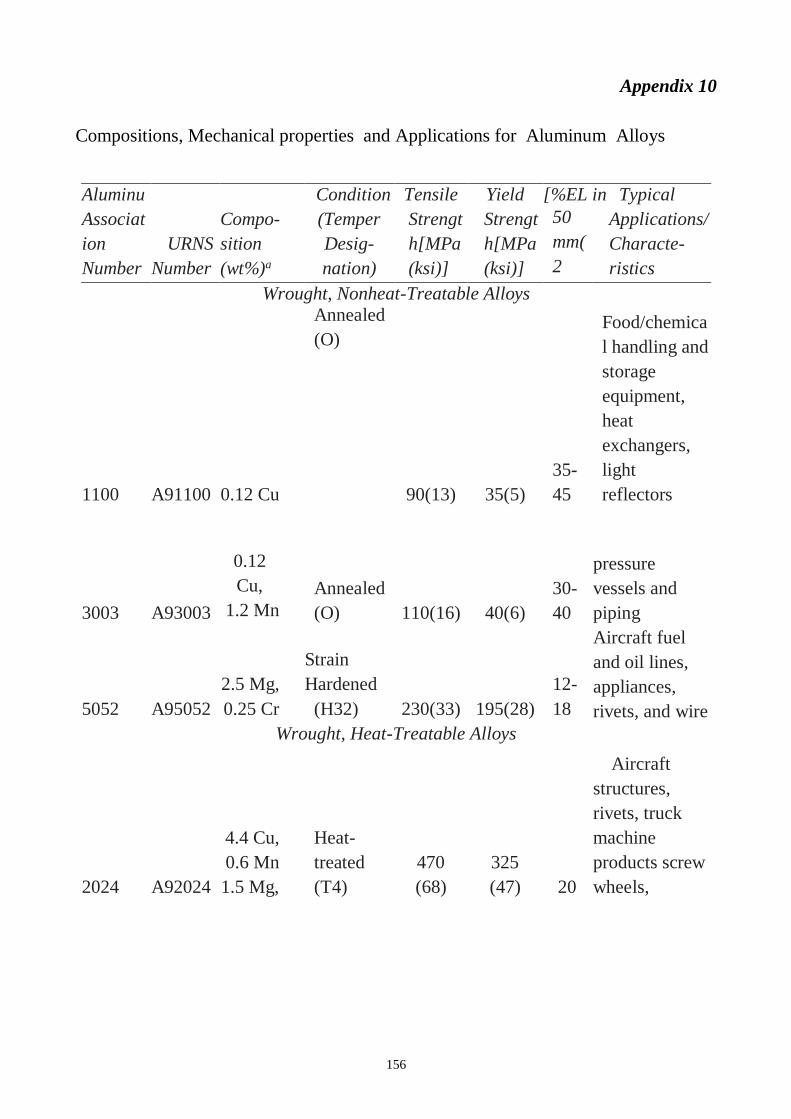
156
Appendix 10
Compositions, Mechanical properties and Applications for Aluminum Alloys
Aluminu
m
Condition Tensile Yield [%EL in Typical
Associat
ion
Number
URNS
Number
Compo-
sition
(wt%)a
(Temper
Desig-
nation)
Strengt
h[MPa
(ksi)]
Strengt
h[MPa
(ksi)]
50
mm(
2
in.)]
Applications/
Characte-
ristics
Wrought, Nonheat-Treatable Alloys
1100 A91100 0.12 Cu
Annealed
(O)
90(13) 35(5)
35-
45
Food/chemica
l handling and
storage
equipment,
heat
exchangers,
light
reflectors
3003 A93003
0.12
Cu,
1.2 Mn
0.1 Zn
Annealed
(O) 110(16) 40(6)
30-
40
pressure
vessels and
piping
5052 A95052
2.5 Mg,
0.25 Cr
Strain
Hardened
(H32) 230(33) 195(28)
12-
18
Aircraft fuel
and oil lines,
appliances,
rivets, and wire
fuel tanks, Wrought, Heat-Treatable Alloys
2024 A92024
4.4 Cu,
0.6 Mn
1.5 Mg,
Heat-
treated
(T4)
470
(68)
325
(47) 20
Aircraft
structures,
rivets, truck
machine
products screw
wheels,
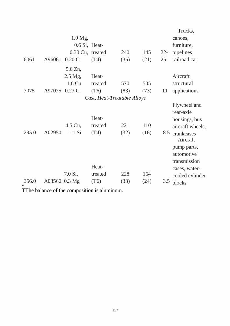
157
6061 A96061
1.0 Mg,
0.6 Si,
0.30 Cu,
0.20 Cr
Heat-
treated
(T4)
240
(35)
145
(21)
22-
25
Trucks,
canoes,
furniture,
pipelines
railroad car
7075 A97075
5.6 Zn,
2.5 Mg,
1.6 Cu
0.23 Cr
Heat-
treated
(T6)
570
(83)
505
(73) 11
Aircraft
structural
applications
Cast, Heat-Treatable Alloys
295.0 A02950
4.5 Cu,
1.1 Si
Heat-
treated
(T4)
221
(32)
110
(16) 8.5
Flywheel and
rear-axle
housings, bus
aircraft wheels,
crankcases
356.0 A03560
7.0 Si,
0.3 Mg
Heat-
treated
(T6)
228
(33)
164
(24) 3.5
Aircraft
pump parts,
automotive
transmission
cases, water-
cooled cylinder
blocks " TThe balance of the composition is aluminum.
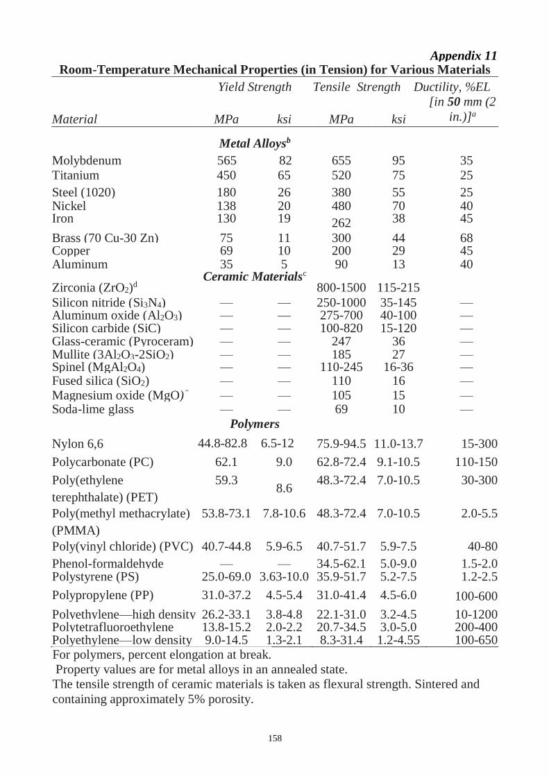
158
Appendix 11 Room-Temperature Mechanical Properties (in Tension) for Various Materials
Yield Strength Tensile Strength Ductility, %EL
Material MPa ksi MPa ksi
[in 50 mm (2
in.)]a
Molybdenum
Metal Alloysb
565 82 655 95 35
Titanium 450 65 520 75 25
Steel (1020) 180 26 380 55 25 Nickel 138 20 480 70 40 Iron 130 19 262 38 45
Brass (70 Cu-30 Zn) 75 11 300 44 68 Copper 69 10 200 29 45 Aluminum 35 5 90 13 40
Zirconia (ZrO2)d Ceramic Materialsc
800-1500 115-215
Silicon nitride (Si3N4) — — 250-1000 35-145 — Aluminum oxide (Al2O3) — — 275-700 40-100 — Silicon carbide (SiC) — — 100-820 15-120 — Glass-ceramic (Pyroceram) — — 247 36 — Mullite (3Al2O3-2SiO2) — — 185 27 — Spinel (MgAl2O4) — — 110-245 16-36 — Fused silica (SiO2) — — 110 16 — Magnesium oxide (MgO)“ — — 105 15 — Soda-lime glass — — 69 10 —
Nylon 6,6
Polymers
44.8-82.8 6.5-12 75.9-94.5 11.0-13.7 15-300
Polycarbonate (PC) 62.1 9.0 62.8-72.4 9.1-10.5 110-150
Poly(ethylene
terephthalate) (PET)
59.3 8.6
48.3-72.4 7.0-10.5 30-300
Poly(methyl methacrylate)
(PMMA)
53.8-73.1 7.8-10.6 48.3-72.4 7.0-10.5 2.0-5.5
Poly(vinyl chloride) (PVC) 40.7-44.8 5.9-6.5 40.7-51.7 5.9-7.5 40-80
Phenol-formaldehyde — — 34.5-62.1 5.0-9.0 1.5-2.0 Polystyrene (PS) 25.0-69.0 3.63-10.0 35.9-51.7 5.2-7.5 1.2-2.5
Polypropylene (PP) 31.0-37.2 4.5-5.4 31.0-41.4 4.5-6.0 100-600
Polyethylene—high density
(HDPE)
26.2-33.1 3.8-4.8 22.1-31.0 3.2-4.5 10-1200 Polytetrafluoroethylene
(PTFE)
13.8-15.2 2.0-2.2 20.7-34.5 3.0-5.0 200-400 Polyethylene—low density
(LDPE)
9.0-14.5 1.3-2.1 8.3-31.4 1.2-4.55 100-650 For polymers, percent elongation at break.
Property values are for metal alloys in an annealed state.
The tensile strength of ceramic materials is taken as flexural strength. Sintered and
containing approximately 5% porosity.
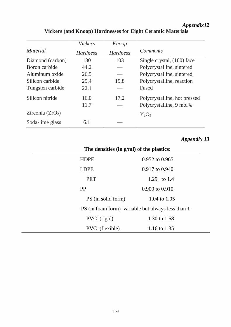
159
Appendix12 Vickers (and Knoop) Hardnesses for Eight Ceramic Materials
Material
Vickers
Hardness
(GPa)
Knoop
Hardness
(GPa)
Comments
Diamond (carbon) 130 103 Single crystal, (100) face
Boron carbide
(B4C)
44.2 — Polycrystalline, sintered
Aluminum oxide
(Al2O3)
26.5 — Polycrystalline, sintered,
99.7% pure Silicon carbide
(SiC)
25.4 19.8 Polycrystalline, reaction
bonded, sintered Tungsten carbide
(WC)
22.1 — Fused
Silicon nitride
(Si3N4)
16.0 17.2 Polycrystalline, hot pressed
Zirconia (ZrO2)
11.7 — Polycrystalline, 9 mol%
Y2O3
Soda-lime glass 6.1 —
Appendix 13
The densities (in g/ml) of the plastics:
HDPE 0.952 to 0.965
LDPE 0.917 to 0.940
PET 1.29 to 1.4
PP 0.900 to 0.910
PS (in solid form) 1.04 to 1.05
PS (in foam form) variable but always less than 1
PVC (rigid) 1.30 to 1.58
PVC (flexible) 1.16 to 1.35
160
References
1. Philip A.Schawetzer. Metallic Materias. Physical, Mechanical, and Corrosion
Propertyies. – N.Y., Pensylvania, USA. – 2003. – 702 p.
2. Michael F. Ashby, David R.H. Jones. Engineering Materials 2. An
Introduction to Microstructures and Processing. – Published by Elsevier Ltd.
– 2013. – 545 p.
3. Callister, William D., Fundamentals of materials science and engineering : an
integrated approach / William D. Callister, David G. Rethwisch.—4th ed. p.
cm.
a. Includes index 2011. – 1221 p.
4. Schweitzer, P. Metallic materials. Physical, Mechanical, and Corrosion
Properties /Philip A. Schweitzer, P. E. –New York, Basel. – 2003. – 704 p.
5. Kakani S. Kakani A. Material Science / S. Kakani, A. Kakani. – New age
int.Ltd.– 2004. – 639 p.
6. Bin Wu. Manufacturing Systems Design and Analysis. 1994.-459p.
7. J. Datsko. Material Properties and Manufacturing Processes.
8. Katsundo Hitomi. Manufacturing Systems Engineering: a unified approach to
manufacturing technology, production management and industrial
economics.
9. R. Thomas. Wright manufacturing systems.
10. J. Beddoes, M. Bibby. Principles of metal manufacturing processes.
11. De Garmo, Black and Kosher. Materials and processes in manufacturing.
12. Singh R. Introduction to basic manufacturing processes and workshop
technology/ Rajender Singh. – New age int.Ltd.– 2006.–483 p.
13. C.F. Walton, Gray and Ductile Iron Castings Handbook, Iron Founder’s
Society, 1971, p 193
14. C.F. Walton and T.J. Opar, Iron Castings Handbook, Iron Casting Society,
1981, p 235 & p 297-321
15. “Chrome-Moly White Cast Irons,” Publication M – 630, AMAX, Inc., 1986
16. Davis, J.R., Cast Irons, ASM International, Materials Park, OH, 1996
17. G. Lambert, Ed., Typical Microstructures of Cast Metals, 2nd ed., The
Institute of British Foundrymen, 1996, p 47
18. H.T. Angus, Physical and Engineering Properties of Cast Iron, BCIRA,
1960, p 21
19. http://www.msm.cam.ac.uk/doitpoms/miclib/index.php
20. http://www.matweb.com/search/GetSubcat.asp
21. http://www.wynndanzur.com/glossary.htm