Embed Size (px)
Citation preview
Copyright © 2013 IJAIM right reserved23
International Journal of Artificial Intelligence and MechatronicsVolume 2, Issue 2, ISSN 2320 – 5121
Microcontroller Based Tongue Drive System forPhysically Challenged People
Mr. Preetham S.Research Assistant,
Bhat Biotech India Private Limited, Bangalore, IndiaEmail: [email protected]
Dr. P. A. VijayaProfessor, Department of ECE,
BNMIT, Bangalore – 560070, IndiaEmail: [email protected]
Abstract - Tongue Drive system is a tongue-operatedunobtrusive wireless assistive technology, which canpotentially provide people with severe disabilities witheffective computer access and environment control. Ittranslates users intentions into control commands bydetecting and classifying their voluntary tongue motionutilizing a small permanent magnet, secured on the tongue,and an array of magnetic sensors mounted on a headsetoutside the mouth or an orthodontic brace inside. In thispaper, a customized interface circuitry is designed andimplemented for Tongue Drive System. Also four controlstrategies are developed to drive a Powered Wheel Chairusing H-Bridge, using relays to control both the directions ofthe DC motor. The designed system has been tested and isfound to be working satisfactorily. The results show that allpersons could easily operate the Powered Wheel Chair usingtheir tongue movements and different control strategiesworked better depending on the user familiarity with theTongue Drive System. The user is facilitated with visualinterface to know where the patient is travelling on the LCDscreen using the ATMEL 89C51 Microcontroller.
Keywords – Hall Effect Sensor, Microcontroller,Monostable Multivibrator, Powered Wheel Chair, TongueDrive System.
I. Introduction
Medical scientists at the Shepherd Center in Atlanta,Georgia are developing a truly breakthrough piece oftechnology to assist those recovering from strokes orspinal injuries – a wheel chair that can be controlled bytongue movements [6,7,8,9]. One of the major advantagesof the tongue is that it is directly connected to the brainthrough the spinal cord. A patient who has even thehighest level of spinal cord injury can still move his or hertongue like normal human being. The Tongue Drivesystem (TDS) is being tested on patients now, enablingthem to control their own movement around the hospital inways that were simply not possible prior to this newtechnology.
Persons with severe disabilities from Traumatic Brainand Spinal Cord Injuries (TBI/SCI), Amyotrophic LateralSclerosis (ALS) and stroke generally find it extremelydifficult to carry out daily tasks without receivingcontinuous help. These individuals are completelydependent on wheeled mobility for transportation insideand out of their homes. Many of them use electricallyPowered Wheel Chairs (PWCs) that are the most helpfultools allowing individuals to complete daily tasks withgreater independence, and to access school, work andcommunity environments. Unfortunately, the defaultmethod for controlling a PWC is by operating a joystick,
which requires a certain level of physical movementability, which may not exist in people with severedisabilities.
II. LITERATURE SURVEY
A few Assistive Technologies (ATs) have beendeveloped to provide alternative means for PWC control:
Sip-n-puff is a simple, low-cost, and easy to use AT,which allows its user to control a PWC by blowing orsucking through a straw. However, it is slow and has alimited number of direct commands [18]. A group of ATsbased on tracking eye motion from corneal reflection,pupil position, or Electro-Oculo-Graphic (EOG) potentialshave been used for environment control. Since eyes havebeen evolved as sensory parts of human body, a drawbackof the eye-tracking is that it affects the users’ normal senseof vision by requiring extra eye movements thatsometimes interfere with the users visual tasks [15].Another group of controllers based on chin or head orhand movements require a certain level of neck orshoulder or hand movement ability and strength that maynot exist [2,3,10,20]. There are also ATs utilizing brainwaves (EEG based) or facial muscle twitches that arerelatively slow and offer limited degrees of freedom [19].Invasive Brain Computer interfaces (BCIs), on the otherhand, offer broad access to the brain signals but they arecostly and impose serious risks associated with brainsurgery [12, 19]. Muscle electrical activity (EMG based)is arguably one of the most suitable sources for PWCcontrol. However, EMG-based systems are relativelyerror-prone and need complex muscular interactions [19].A few hands-free PWC control approaches use voicecommands as input signals [5,11]. These systems arequite suitable for computer access. However, they couldbe unreliable for PWC control in noisy and outdoorenvironments.
Tongue Drive system (TDS) is a tongue-operatedwireless assistive technology, which can potentiallyprovide people with severe disabilities to translate theirintentions into control commands by detecting andclassifying their voluntary tongue motion utilizing a smallpermanent magnet, secured on the tongue, and an array ofmagnetic sensors mounted on a headset outside the mouthor an orthodontic brace inside [1,4,6,7,8,9,12,13].Advantages of TDS over other PWC control methods are:1. Tongue and mouth occupy an amount of motor cortex
in the human brain that rivals that of the fingers and thehand. Therefore, they are inherently capable ofsophisticated manipulation tasks.
Copyright © 2013 IJAIM right reserved24
International Journal of Artificial Intelligence and MechatronicsVolume 2, Issue 2, ISSN 2320 – 5121
2. The tongue is connected to the brain via hypoglossalcranial nerve, which generally escapes severe damagein accidents. The tongue muscle is similar to the heartmuscle in that it does not fatigue easily.
3. Finally, the tongue is noninvasively accessible, and isnot influenced by the position of the rest of the body,which can be adjusted for maximum user comfort.
The above reasons have resulted in development of afew tongue-operated ATs, such as the Tongue-Touch-Keypad (TTK), which have not been widely adoptedbecause of placing bulky objects inside the mouth. Thereare also a number of mouth-operated joysticks such asJouse2 and Integra Mouse, which can provide proportionalcontrol. However, they can only be used when the user isin a certain position and require head movement to grabthe mouth joystick. They also require tongue and lipcontact and pressure, which can cause fatigue andirritation over long-term usage.
Tongue Drive system (TDS) is a noninvasive,unobtrusive, wireless, and easy to use tongue-operated ATthat can potentially substitute some of the arm and handfunctions, which are considered the highest priorities forindividuals with severe disabilities, with tongue motion[1,4,7,13].
III. HALL EFFECT SENSORS
The Hall effect phenomena is known for over onehundred years, but has only been put to noticeable use inthe last three decades. The first practical application(outside of laboratory experiments) was in the 1950s as amicrowave power sensor. With the mass production ofsemiconductors, it became feasible to use the Hall effect inhigh volume products. MICRO SWITCH Sensing andControl revolutionized the keyboard industry in 1968 byintroducing the first solid state keyboard using the Halleffect. For the first time, a Hall effect sensing element andits associated electronics were combined in a singleintegrated circuit [22]. Today, Hall effect devices areincluded in many products, ranging from computers tosewing machines, automobiles to aircraft and machinetools to medical equipment [1,4,22].
The Hall effect is an ideal sensing technology. The Hallelement is constructed from a thin sheet of conductivematerial with output connections perpendicular to thedirection of current flow. When subjected to a magneticfield, it responds with an output voltage proportional to themagnetic field strength. The voltage output is very small(μV) and requires additional electronics to achieve usefulvoltage levels. When the Hall element is combined withthe associated electronics, it forms a Hall effect sensor.The heart of every MICRO SWITCH Hall effect device isthe integrated circuit chip that contains the Hall elementand the signal conditioning electronics. Although the Halleffect sensor is a magnetic field sensor, it can be used asthe principle component in many other types of sensingdevices (current, temperature, pressure, position, etc.).
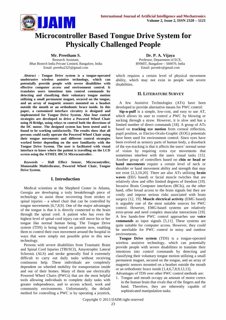
Fig.1. Working of General Sensor based on Hall Effect
Fig.1 shows the block diagram of a sensing device thatuses the Hall effect. In this generalized sensing device, theHall sensor senses the field produced by the magneticsystem. The magnetic system responds to the physicalquantity to be sensed (temperature, pressure, position, etc.)through the input interface. The output interface convertsthe electrical signal from the Hall sensor to a signal thatmeets the requirements of the application. When a current-carrying conductor is placed into a magnetic field, avoltage will be generated perpendicular to both the currentand the field. This principle is known as the Hall effect.Fig 2 illustrates the basic principle of the Hall effect. Itshows a thin sheet of semiconducting material (Hallelement) through which a current is passed. The outputconnections are perpendicular to the direction of current.When no magnetic field is present (Fig 2), currentdistribution is uniform and no potential difference is seenacross the output. When a perpendicular magnetic field ispresent, as shown in Fig 3, a Lorentz force is exerted onthe current. This force disturbs the current distribution,resulting in a potential difference (voltage) across theoutput. This voltage is the Hall voltage (VH). Theinteraction of the magnetic field and the current is shownin Equation 1.
BIVH (1)
Hall effect sensors can be applied in many types ofsensing devices. If the quantity (parameter) to be sensedincorporates or can incorporate a magnetic field, a Hallsensor will perform the task. The reasons for using aparticular technology or sensor vary according to theapplication. Cost, performance and availability are alwaysimportant. The features and benefits of a given technologyare factors that should be weighed along with the specificrequirements of the application in making this decision.General features of Hall effect based sensing devices are:True solid state, Long life (30 billion operations in acontinuing keyboard module test program), High speedoperation over 100 kHz possible, Operates with stationaryinput (zero speed), No moving parts, Logic compatibleinput and output, Broad temperature range (-40 to+150°C) and Highly repeatable operation.
Copyright © 2013 IJAIM right reserved25
International Journal of Artificial Intelligence and MechatronicsVolume 2, Issue 2, ISSN 2320 – 5121
Fig.2. Hall effect principle without magnetic field
Fig.3. Hall effect principle with magnetic field
IV. HARDWARE DESIGN
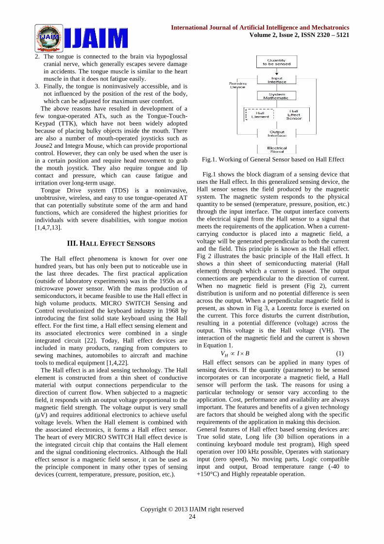
The wheel chair is designed for those who cannot evenmove their hands & legs. They can even enjoy the thrill ofriding. The basic principle used in the design of PWC inthis paper is the property of ultrasonic and sound wavesgetting reflected when medium density changes. Theultrasonic and sound waves having a frequency range from40 kHz are generated by an Astable Multivibrator, having50% duty cycle. The waves generated are amplified andtransmitted through a transmitting Transducer with thehelp of a driver stage. The waves travel ahead and arereflected back when they strike a moving object. Halleffect sensors are used in this design. The receivingtransducer selects the reflected waves and further they areprocessed in receiver section. The receiver section consistsof pre amplifier, buffer, driver and a buzzer, which givesthe final output. The buffer is included to provide unit gainamplification to the received waves and passes them toDriver. The output is thus amplified to drive the outputstage. The output stage is a buzzer. LED is also includedin the output stage for convenience. As shown in Fig 4, themagnetic sensor outputs are connected to themultivibrators. Whenever the person moves his or hertongue or activate the switch, this is communicated to thereceiver section shown in Fig 5. A command signal isgenerated at the output which will drive the relay andcontrol the direction of the motor either right or left orfront or back, and in turn the wheel chair is controlled.When the user programs the schedule for the automationusing GUI [Graphical User Interface] software, it actuallysends 5-bit control signals to the circuit. The presentcircuit provides interfacing with the Microcontroller [14,16, 17] and the controlling circuitry. This circuit takes the5-bit control signal, isolates the Microcontroller from thiscircuitry, boosts control signals to the required level andfinally feeds them to the driver section to actuate the relay.These five relays in turn send RC5 coded commands withrespect to their relay position. The various hardwarecomponents used in this work are briefly explained below.
Fig.4. Block diagram of Transmitter Section
Fig.5. Block diagram of Receiver Section
A. Buffer, Driver & Switching ModulesBuffers does not affect the logical state of a digital
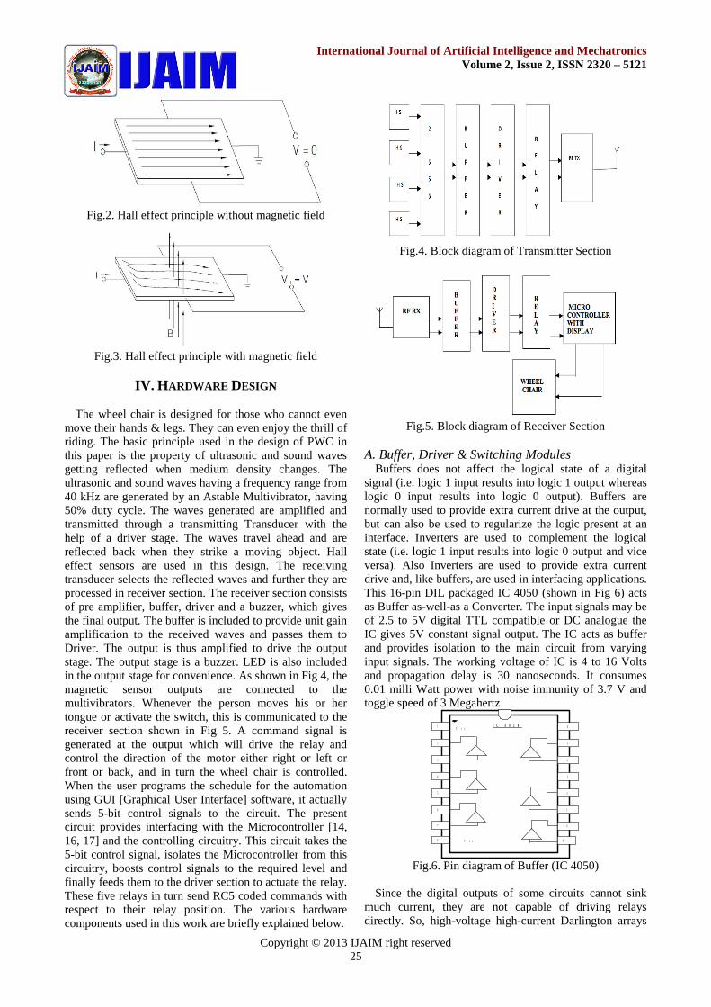
signal (i.e. logic 1 input results into logic 1 output whereaslogic 0 input results into logic 0 output). Buffers arenormally used to provide extra current drive at the output,but can also be used to regularize the logic present at aninterface. Inverters are used to complement the logicalstate (i.e. logic 1 input results into logic 0 output and viceversa). Also Inverters are used to provide extra currentdrive and, like buffers, are used in interfacing applications.This 16-pin DIL packaged IC 4050 (shown in Fig 6) actsas Buffer as-well-as a Converter. The input signals may beof 2.5 to 5V digital TTL compatible or DC analogue theIC gives 5V constant signal output. The IC acts as bufferand provides isolation to the main circuit from varyinginput signals. The working voltage of IC is 4 to 16 Voltsand propagation delay is 30 nanoseconds. It consumes0.01 milli Watt power with noise immunity of 3.7 V andtoggle speed of 3 Megahertz.
1
2
6
3
1 6
5
1 5
4
1 4
1 0
1 1
1 2
1 3
7
V c c
V s s8 9
I C 4 0 5 0
Fig.6. Pin diagram of Buffer (IC 4050)
Since the digital outputs of some circuits cannot sinkmuch current, they are not capable of driving relaysdirectly. So, high-voltage high-current Darlington arrays
Copyright © 2013 IJAIM right reserved26
International Journal of Artificial Intelligence and MechatronicsVolume 2, Issue 2, ISSN 2320 – 5121
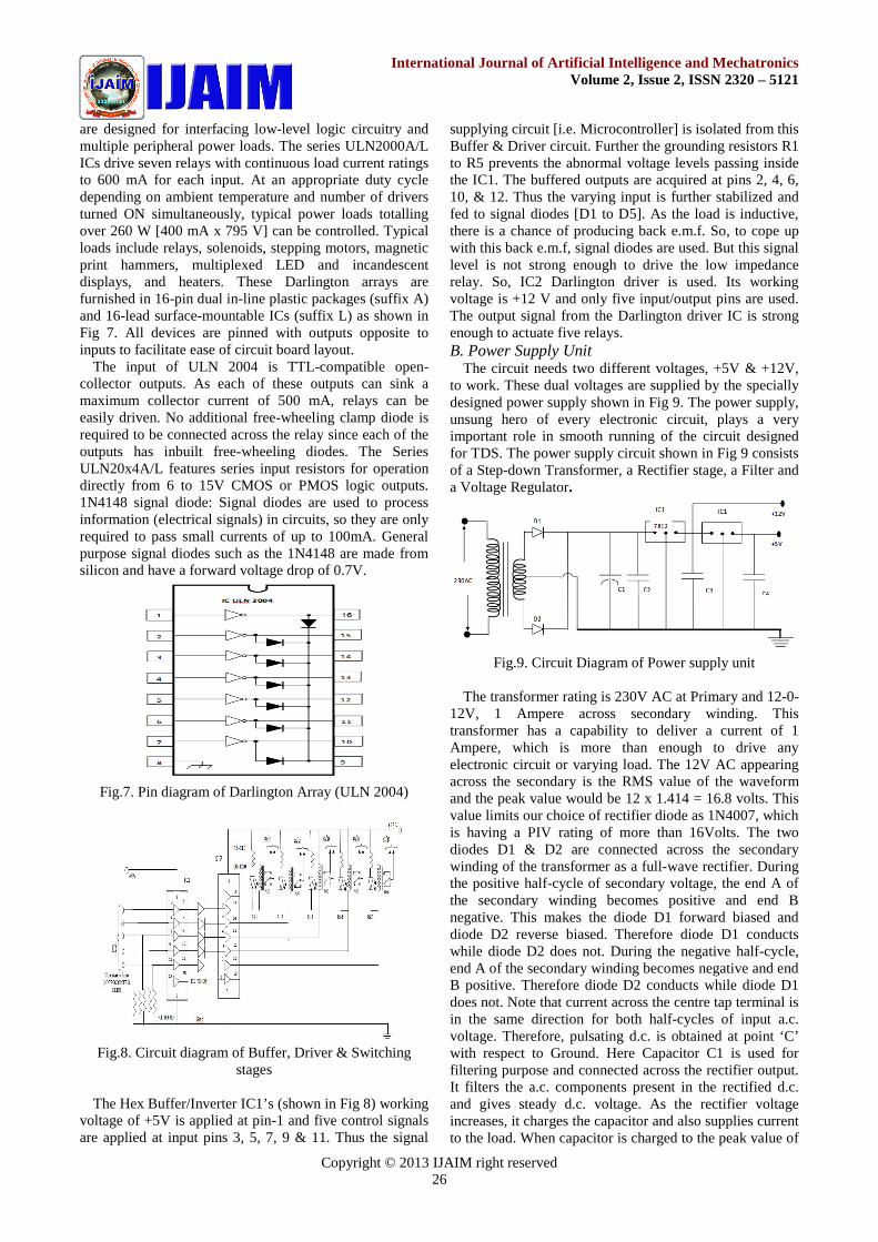
are designed for interfacing low-level logic circuitry andmultiple peripheral power loads. The series ULN2000A/LICs drive seven relays with continuous load current ratingsto 600 mA for each input. At an appropriate duty cycledepending on ambient temperature and number of driversturned ON simultaneously, typical power loads totallingover 260 W [400 mA x 795 V] can be controlled. Typicalloads include relays, solenoids, stepping motors, magneticprint hammers, multiplexed LED and incandescentdisplays, and heaters. These Darlington arrays arefurnished in 16-pin dual in-line plastic packages (suffix A)and 16-lead surface-mountable ICs (suffix L) as shown inFig 7. All devices are pinned with outputs opposite toinputs to facilitate ease of circuit board layout.
The input of ULN 2004 is TTL-compatible open-collector outputs. As each of these outputs can sink amaximum collector current of 500 mA, relays can beeasily driven. No additional free-wheeling clamp diode isrequired to be connected across the relay since each of theoutputs has inbuilt free-wheeling diodes. The SeriesULN20x4A/L features series input resistors for operationdirectly from 6 to 15V CMOS or PMOS logic outputs.1N4148 signal diode: Signal diodes are used to processinformation (electrical signals) in circuits, so they are onlyrequired to pass small currents of up to 100mA. Generalpurpose signal diodes such as the 1N4148 are made fromsilicon and have a forward voltage drop of 0.7V.
Fig.7. Pin diagram of Darlington Array (ULN 2004)
Fig.8. Circuit diagram of Buffer, Driver & Switchingstages
The Hex Buffer/Inverter IC1’s (shown in Fig 8) workingvoltage of +5V is applied at pin-1 and five control signalsare applied at input pins 3, 5, 7, 9 & 11. Thus the signal
supplying circuit [i.e. Microcontroller] is isolated from thisBuffer & Driver circuit. Further the grounding resistors R1to R5 prevents the abnormal voltage levels passing insidethe IC1. The buffered outputs are acquired at pins 2, 4, 6,10, & 12. Thus the varying input is further stabilized andfed to signal diodes [D1 to D5]. As the load is inductive,there is a chance of producing back e.m.f. So, to cope upwith this back e.m.f, signal diodes are used. But this signallevel is not strong enough to drive the low impedancerelay. So, IC2 Darlington driver is used. Its workingvoltage is +12 V and only five input/output pins are used.The output signal from the Darlington driver IC is strongenough to actuate five relays.B. Power Supply Unit
The circuit needs two different voltages, +5V & +12V,to work. These dual voltages are supplied by the speciallydesigned power supply shown in Fig 9. The power supply,unsung hero of every electronic circuit, plays a veryimportant role in smooth running of the circuit designedfor TDS. The power supply circuit shown in Fig 9 consistsof a Step-down Transformer, a Rectifier stage, a Filter anda Voltage Regulator.
Fig.9. Circuit Diagram of Power supply unit
The transformer rating is 230V AC at Primary and 12-0-12V, 1 Ampere across secondary winding. Thistransformer has a capability to deliver a current of 1Ampere, which is more than enough to drive anyelectronic circuit or varying load. The 12V AC appearingacross the secondary is the RMS value of the waveformand the peak value would be 12 x 1.414 = 16.8 volts. Thisvalue limits our choice of rectifier diode as 1N4007, whichis having a PIV rating of more than 16Volts. The twodiodes D1 & D2 are connected across the secondarywinding of the transformer as a full-wave rectifier. Duringthe positive half-cycle of secondary voltage, the end A ofthe secondary winding becomes positive and end Bnegative. This makes the diode D1 forward biased anddiode D2 reverse biased. Therefore diode D1 conductswhile diode D2 does not. During the negative half-cycle,end A of the secondary winding becomes negative and endB positive. Therefore diode D2 conducts while diode D1does not. Note that current across the centre tap terminal isin the same direction for both half-cycles of input a.c.voltage. Therefore, pulsating d.c. is obtained at point ‘C’with respect to Ground. Here Capacitor C1 is used forfiltering purpose and connected across the rectifier output.It filters the a.c. components present in the rectified d.c.and gives steady d.c. voltage. As the rectifier voltageincreases, it charges the capacitor and also supplies currentto the load. When capacitor is charged to the peak value of
Copyright © 2013 IJAIM right reserved27
International Journal of Artificial Intelligence and MechatronicsVolume 2, Issue 2, ISSN 2320 – 5121
the rectifier voltage, rectifier voltage starts to decrease. Asthe next voltage peak immediately recharges the capacitor,the discharge period is of very small duration. Due to thiscontinuous charge-discharge-recharge cycle, very littleripple is observed in the filtered output. Moreover, outputvoltage is higher as it remains substantially near the peakvalue of rectifier output voltage. Across the point ‘D’ andGround, there is rectified and filtered d.c. In the presentcircuit, KIA 7812 three terminal voltage regulator IC isused to get +12V and KIA 7805 voltage regulator IC isused to get +5V regulated d.c. output. In the threeterminals, pin 1 is input i.e., rectified & filtered d.c. isconnected to this pin. Pin 2 is common pin and isgrounded. The pin 3 gives the stabilized d.c. output to theload. The circuit shows two more decoupling capacitorsC2 & C3, which provides ground path to the highfrequency noise signals. Across the point ‘E’ and ‘F’ withrespect to ground +5V & +12V stabilized or regulated d.coutput is measured, which can be connected to therequired circuit.C. Monostable Multivibrator Using 555 Timer
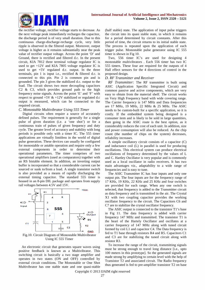
Digital circuits often require a source of accuratelydefined pulses. The requirement is generally for a singlepulse of given duration (i.e. a ‘one shot’) or for acontinuous train of pulses of given frequency and dutycycle. The greater level of accuracy and stability with longperiods is possible only with a timer IC. The 555 timerapplications are virtually limitless in the world of digitalpulse generation. These devices can usually be configuredfor monostable or astable operation and require only a fewexternal components in order to determine theiroperational parameters. The timer comprises of twooperational amplifiers (used as comparators) together withan RS bistable element. In addition, an inverting outputbuffer is incorporated so that a considerable current can besourced or sunk to/from a load. A single transistor switchis also provided as a means of rapidly discharging theexternal timing capacitor. The standard 555 timer ishoused in an 8-pin DIL package and operates from supplyrail voltages between 4.5V and 15V.
Fig.10. Circuit Diagram of Monostable MultivibratorUsing IC 555 Timer
An electronic circuit that generates square waves usingpositive feedback is known as a Multivibrator. Thisswitching circuit is basically a two stage amplifier andoperates in two states (ON and OFF) controlled byexternal circuit conditions. The Monostable or One ShotMultivibrator has one stable state and one quasi-stable
(half stable) state. The application of input pulse triggersthe circuit into its quasi stable state, in which it remainsfor a period determined by circuit constants. After thisperiod of time, the circuit returns to its initial stable state.The process is repeated upon the application of eachtrigger pulse. Monostable pulse generator using IC 555timer is shown in Fig 10.
Two, 556 timer IC’s are used for designing 4monostable multivibrators . Each 556 timer has two IC555 timers. These four are required for the outputs of 4Hall effect sensors for the 4 directions of control in theproposed design.D. RF Transmitter and Receiver
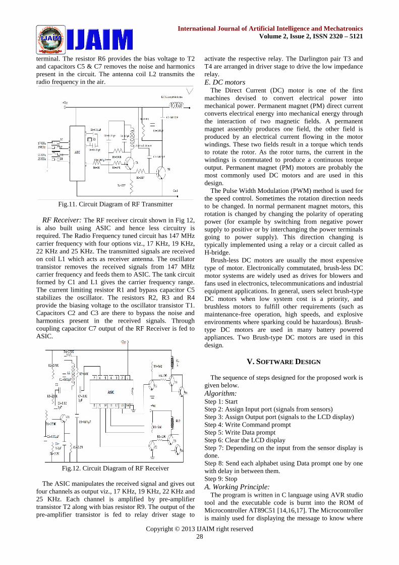
RF Transmitter: The RF transmitter is built usingASIC (Application Specific Integrated Circuit) andcommon passive and active components, which are veryeasy to obtain from the material shelf. The circuit workson Very High Frequency band with wide covering range.The Carrier frequency is 147 MHz and Data frequenciesare 17 MHz, 19 MHz, 22 MHz & 25 MHz. The ASICneeds to be custom-built for a specific application, so it iscostly. If the embedded system being designed is aconsumer item and is likely to be sold in large quantities,then going in the ASIC route is the best option, as itconsiderably reduces the cost of each unit. In addition, sizeand power consumption will also be reduced. As the chipcount (the number of chips on the system) decreases,reliability increases.
A simple oscillatory circuit consists of a capacitor (C)and inductance coil (L) in parallel is used for producingoscillations. This electrical system can produce electricaloscillations of frequency determined by the values of Land C. Hartley Oscillator is very popular and is commonlyused as a local oscillator in radio receivers. It has twomain advantages viz., adaptability to a wide range offrequencies and is easy to tune.
The ASIC Transmitter IC has four inputs and only oneoutput pin. The four inputs are for the frequency range of17 KHz, 19 KHz, 22 KHz and 25 KHz and four switchesare provided for each range. When any one switch isselected, that frequency is added to the Transmitter circuitas data frequency and is transmitted in the air. The CrystalX1 with two coupling capacitor provides the workingoscillator frequency to the circuit. The Capacitors C6 andC7 are to stabilize the crystal oscillator frequency.
The ASIC output is connected to the transistor T1’s basein Fig 11. The data frequency is added with carrierfrequency 147 MHz and transmitted. The transistor T1 isthe heart of the Hartely Oscillator and oscillates at acarrier frequency of 147 MHz along with tuned circuitformed by coil L1 and capacitor C4. The Data frequency isfed to T1 base through resistors R4 and R5. Capacitors C1and C3 are for stabilizing the tuned circuit along withresistor R3.
To increase the range of the circuit, transmitting signalsmust be strong enough to travel long distance [i.e., upto100 meters in this prototype]. So the generated signals aremade strong by amplifying to certain level with the help ofTransistor T2 and associated circuit. The Radio frequencythus generated is fed to pre-amplifier transistor T2 on base
Copyright © 2013 IJAIM right reserved28
International Journal of Artificial Intelligence and MechatronicsVolume 2, Issue 2, ISSN 2320 – 5121
terminal. The resistor R6 provides the bias voltage to T2and capacitors C5 & C7 removes the noise and harmonicspresent in the circuit. The antenna coil L2 transmits theradio frequency in the air.
Fig.11. Circuit Diagram of RF Transmitter
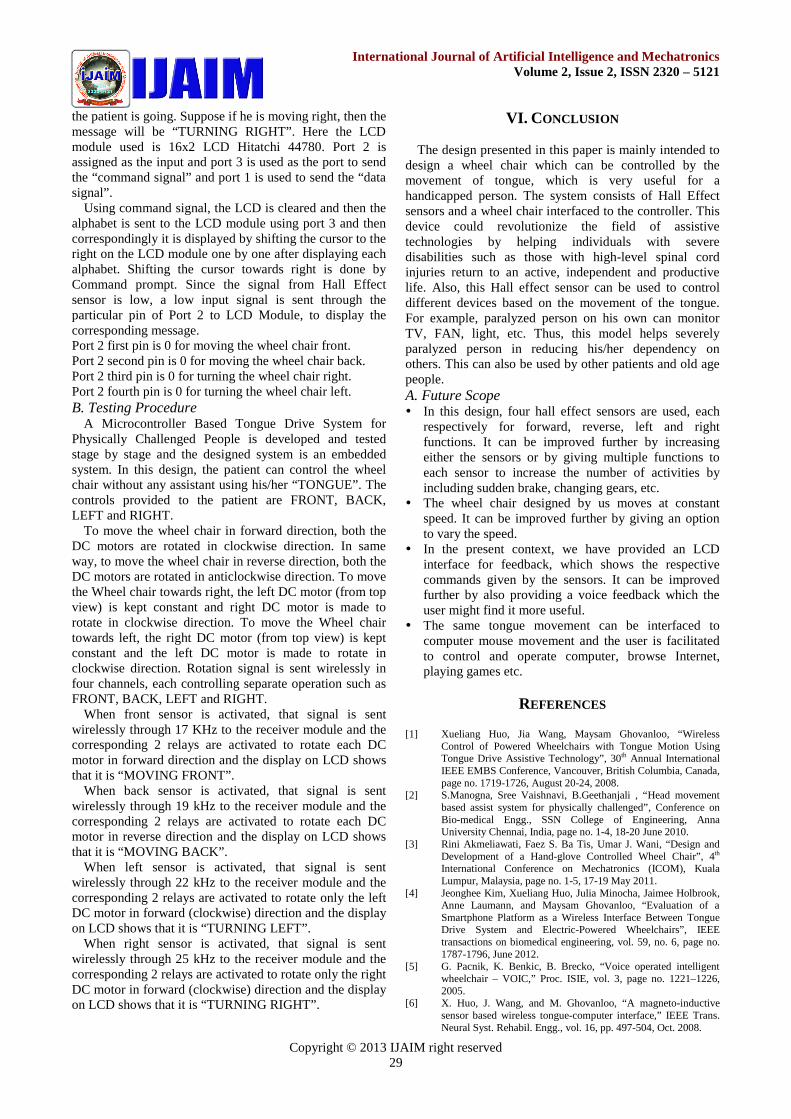
RF Receiver: The RF receiver circuit shown in Fig 12,is also built using ASIC and hence less circuitry isrequired. The Radio Frequency tuned circuit has 147 MHzcarrier frequency with four options viz., 17 KHz, 19 KHz,22 KHz and 25 KHz. The transmitted signals are receivedon coil L1 which acts as receiver antenna. The oscillatortransistor removes the received signals from 147 MHzcarrier frequency and feeds them to ASIC. The tank circuitformed by C1 and L1 gives the carrier frequency range.The current limiting resistor R1 and bypass capacitor C5stabilizes the oscillator. The resistors R2, R3 and R4provide the biasing voltage to the oscillator transistor T1.Capacitors C2 and C3 are there to bypass the noise andharmonics present in the received signals. Throughcoupling capacitor C7 output of the RF Receiver is fed toASIC.
Fig.12. Circuit Diagram of RF Receiver
The ASIC manipulates the received signal and gives outfour channels as output viz., 17 KHz, 19 KHz, 22 KHz and25 KHz. Each channel is amplified by pre-amplifiertransistor T2 along with bias resistor R9. The output of thepre-amplifier transistor is fed to relay driver stage to
activate the respective relay. The Darlington pair T3 andT4 are arranged in driver stage to drive the low impedancerelay.E. DC motors
The Direct Current (DC) motor is one of the firstmachines devised to convert electrical power intomechanical power. Permanent magnet (PM) direct currentconverts electrical energy into mechanical energy throughthe interaction of two magnetic fields. A permanentmagnet assembly produces one field, the other field isproduced by an electrical current flowing in the motorwindings. These two fields result in a torque which tendsto rotate the rotor. As the rotor turns, the current in thewindings is commutated to produce a continuous torqueoutput. Permanent magnet (PM) motors are probably themost commonly used DC motors and are used in thisdesign.
The Pulse Width Modulation (PWM) method is used forthe speed control. Sometimes the rotation direction needsto be changed. In normal permanent magnet motors, thisrotation is changed by changing the polarity of operatingpower (for example by switching from negative powersupply to positive or by interchanging the power terminalsgoing to power supply). This direction changing istypically implemented using a relay or a circuit called asH-bridge.
Brush-less DC motors are usually the most expensivetype of motor. Electronically commutated, brush-less DCmotor systems are widely used as drives for blowers andfans used in electronics, telecommunications and industrialequipment applications. In general, users select brush-typeDC motors when low system cost is a priority, andbrushless motors to fulfill other requirements (such asmaintenance-free operation, high speeds, and explosiveenvironments where sparking could be hazardous). Brush-type DC motors are used in many battery poweredappliances. Two Brush-type DC motors are used in thisdesign.
V. SOFTWARE DESIGN
The sequence of steps designed for the proposed work isgiven below.Algorithm:Step 1: StartStep 2: Assign Input port (signals from sensors)Step 3: Assign Output port (signals to the LCD display)Step 4: Write Command promptStep 5: Write Data promptStep 6: Clear the LCD displayStep 7: Depending on the input from the sensor display isdone.Step 8: Send each alphabet using Data prompt one by onewith delay in between them.Step 9: StopA. Working Principle:
The program is written in C language using AVR studiotool and the executable code is burnt into the ROM ofMicrocontroller AT89C51 [14,16,17]. The Microcontrolleris mainly used for displaying the message to know where
Copyright © 2013 IJAIM right reserved29
International Journal of Artificial Intelligence and MechatronicsVolume 2, Issue 2, ISSN 2320 – 5121
the patient is going. Suppose if he is moving right, then themessage will be “TURNING RIGHT”. Here the LCDmodule used is 16x2 LCD Hitatchi 44780. Port 2 isassigned as the input and port 3 is used as the port to sendthe “command signal” and port 1 is used to send the “datasignal”.
Using command signal, the LCD is cleared and then thealphabet is sent to the LCD module using port 3 and thencorrespondingly it is displayed by shifting the cursor to theright on the LCD module one by one after displaying eachalphabet. Shifting the cursor towards right is done byCommand prompt. Since the signal from Hall Effectsensor is low, a low input signal is sent through theparticular pin of Port 2 to LCD Module, to display thecorresponding message.Port 2 first pin is 0 for moving the wheel chair front.Port 2 second pin is 0 for moving the wheel chair back.Port 2 third pin is 0 for turning the wheel chair right.Port 2 fourth pin is 0 for turning the wheel chair left.B. Testing Procedure
A Microcontroller Based Tongue Drive System forPhysically Challenged People is developed and testedstage by stage and the designed system is an embeddedsystem. In this design, the patient can control the wheelchair without any assistant using his/her “TONGUE”. Thecontrols provided to the patient are FRONT, BACK,LEFT and RIGHT.
To move the wheel chair in forward direction, both theDC motors are rotated in clockwise direction. In sameway, to move the wheel chair in reverse direction, both theDC motors are rotated in anticlockwise direction. To movethe Wheel chair towards right, the left DC motor (from topview) is kept constant and right DC motor is made torotate in clockwise direction. To move the Wheel chairtowards left, the right DC motor (from top view) is keptconstant and the left DC motor is made to rotate inclockwise direction. Rotation signal is sent wirelessly infour channels, each controlling separate operation such asFRONT, BACK, LEFT and RIGHT.
When front sensor is activated, that signal is sentwirelessly through 17 KHz to the receiver module and thecorresponding 2 relays are activated to rotate each DCmotor in forward direction and the display on LCD showsthat it is “MOVING FRONT”.
When back sensor is activated, that signal is sentwirelessly through 19 kHz to the receiver module and thecorresponding 2 relays are activated to rotate each DCmotor in reverse direction and the display on LCD showsthat it is “MOVING BACK”.
When left sensor is activated, that signal is sentwirelessly through 22 kHz to the receiver module and thecorresponding 2 relays are activated to rotate only the leftDC motor in forward (clockwise) direction and the displayon LCD shows that it is “TURNING LEFT”.
When right sensor is activated, that signal is sentwirelessly through 25 kHz to the receiver module and thecorresponding 2 relays are activated to rotate only the rightDC motor in forward (clockwise) direction and the displayon LCD shows that it is “TURNING RIGHT”.
VI. CONCLUSION
The design presented in this paper is mainly intended todesign a wheel chair which can be controlled by themovement of tongue, which is very useful for ahandicapped person. The system consists of Hall Effectsensors and a wheel chair interfaced to the controller. Thisdevice could revolutionize the field of assistivetechnologies by helping individuals with severedisabilities such as those with high-level spinal cordinjuries return to an active, independent and productivelife. Also, this Hall effect sensor can be used to controldifferent devices based on the movement of the tongue.For example, paralyzed person on his own can monitorTV, FAN, light, etc. Thus, this model helps severelyparalyzed person in reducing his/her dependency onothers. This can also be used by other patients and old agepeople.A. Future Scope In this design, four hall effect sensors are used, each
respectively for forward, reverse, left and rightfunctions. It can be improved further by increasingeither the sensors or by giving multiple functions toeach sensor to increase the number of activities byincluding sudden brake, changing gears, etc.
The wheel chair designed by us moves at constantspeed. It can be improved further by giving an optionto vary the speed.
In the present context, we have provided an LCDinterface for feedback, which shows the respectivecommands given by the sensors. It can be improvedfurther by also providing a voice feedback which theuser might find it more useful.
The same tongue movement can be interfaced tocomputer mouse movement and the user is facilitatedto control and operate computer, browse Internet,playing games etc.
REFERENCES
[1] Xueliang Huo, Jia Wang, Maysam Ghovanloo, “WirelessControl of Powered Wheelchairs with Tongue Motion UsingTongue Drive Assistive Technology”, 30th Annual InternationalIEEE EMBS Conference, Vancouver, British Columbia, Canada,page no. 1719-1726, August 20-24, 2008.
[2] S.Manogna, Sree Vaishnavi, B.Geethanjali , “Head movementbased assist system for physically challenged”, Conference onBio-medical Engg., SSN College of Engineering, AnnaUniversity Chennai, India, page no. 1-4, 18-20 June 2010.
[3] Rini Akmeliawati, Faez S. Ba Tis, Umar J. Wani, “Design andDevelopment of a Hand-glove Controlled Wheel Chair”, 4th
International Conference on Mechatronics (ICOM), KualaLumpur, Malaysia, page no. 1-5, 17-19 May 2011.
[4] Jeonghee Kim, Xueliang Huo, Julia Minocha, Jaimee Holbrook,Anne Laumann, and Maysam Ghovanloo, “Evaluation of aSmartphone Platform as a Wireless Interface Between TongueDrive System and Electric-Powered Wheelchairs”, IEEEtransactions on biomedical engineering, vol. 59, no. 6, page no.1787-1796, June 2012.
[5] G. Pacnik, K. Benkic, B. Brecko, “Voice operated intelligentwheelchair – VOIC,” Proc. ISIE, vol. 3, page no. 1221–1226,2005.
[6] X. Huo, J. Wang, and M. Ghovanloo, “A magneto-inductivesensor based wireless tongue-computer interface,” IEEE Trans.Neural Syst. Rehabil. Engg., vol. 16, pp. 497-504, Oct. 2008.
Copyright © 2013 IJAIM right reserved30
International Journal of Artificial Intelligence and MechatronicsVolume 2, Issue 2, ISSN 2320 – 5121
[7] X. Huo and M. Ghovanloo, “Using unconstrained Tonguemotion as an alternative control surface for wheeled mobility,”IEEE Trans. on Biomed. Engg, vol. 56, no. 6, pp. 1719-1726,June 2009.
[8] X. Huo, and M. Ghovanloo, “Evaluation of a wireless wearabletongue–computer interface by individuals with high-level spinalcord injuries,” Journal of Neural Engineering, vol. 7, pp. 26-28,Apr. 2010.
[9] J. Kim, X. Huo, and M. Ghovanloo, “Wireless control ofsmartphones with tongue motion using tongue drive assistivetechnology,” In Proc. of 32nd IEEE Conf in Med. and Biol.Engg., pp. 5250-5253, Sep. 2010.
[10] M.R. Williams and R. F. Kirsch, “Evaluation of head orientationand neck muscle EMG signals as command inputs to a human–computer interface for individuals with high tetraplegia” , IEEETrans on Neural Rehabil. Engg, vol. 16, pp. 485-496, Oct 2008.
[11] S. Harada, J. A. Landay, J. Malkin, X. Li and J. A. Bilmes, "Thevocal joystick: Evaluation of voice-based cursor controltechniques for assistive technology," Journal on DisabilityRehabil.: Assistive Technology, vol. 3, pp. 22-34, 2008.
[12] P.M. Fitts, “The information capacity of the human motorsystem in controlling the amplitude of movement”, J. Exp.Psychol., vol. 121, pp. 262-269, Sep. 1992.
[13] B. Yousefi, X. Huo, and M. Ghovanloo, “Using Fitts’s law forevaluating tongue drive system as a pointing device for computeraccess”, In Proc. of 32nd IEEE Conf in Med. and Biol. Engg., pp.4404-4406, Sep. 2010.
[14] Muhammad Ali Mazidi, Janice Gillispie Mazidi, RolinMcKinlay “The 8051 Microcontroller and Embedded SystemsUsing Assembly and C ”, 2nd Edition, PHI, 2006.
[15] http://www.youtube.com/watch?v=yNpOgEbKHbw (for eyecontrolled wheel chair)
[16] http://microcontroller51.blogspot.in/2011/06/introduction-to-89c51-microcontroller.html (for microcontroller 89C51 details).
[17] http://electronicshobbyprojects.wordpress.com/2011/01/05/interfacing-lcd-to-89c51 (for interfacing LCD to 89C51microcontroller)
[18] http://en.wikipedia.org/wiki/Sip-and-puff (for sip and puff basedmethod of AT)
[19] www.youtube.com/watch?v=9DPiTdm2k1U (for EMG and EEGcontrolled wheel chair)
[20] http://www.youtube.com/watch?v=pYbHi4BCkzM (for chin andhead controlled wheel chair)
[21] www.atmel.in/Images/doc0265.pdf (for 89C51 architecture )[22] www.googli.com (for Hall Effect Sensor details)
AUTHOR’S PROFILE
Mr. Preetham S.did his B.E. from the Dept. of E&C Engg, BNMIT,Bangalore, Karnataka, India. This paper is based onthe project work done by him under the guidance ofDr. P. A. Vijaya. Presently he is working as aresearch assistant in Bhat Biotech India PrivateLimited, Bangalore and is doing research projects
on Biomedical applications, Biotechnology and Embedded systems.
Dr. P. A. Vijayadid her B.E. from MCE, Hassan and M.E. and Ph.D.from IISc, Bangalore. She worked in MCE, Hassan,Karnataka for about 27 years. Presently, she is aProfessor in the Dept. of E&C Engg, BNMIT,Bangalore, Karnataka, India. Two students haveobtained Ph.D degree under her guidance and four
more are doing Ph.D. Her research interests are in the areas of PatternRecognition, Image Processing, Embedded Systems, Real time Systems,Network Security and Operating Systems.


