Embed Size (px)
Citation preview
With air cushion Water resistant cylinder
NewNew
Slide bearing
Ball bushing
High precision ball bushing
3 types of bearing can be selected.
Series MGPL
Series MGPM
Series MGPA
Weight reduced by up to 24 % with a shorter guide rod and thinner plate
Up to
24 %24 %Weight
reduced!Weight
reduced!
for MGPM40-25 stroke
22 mm
Guide rod shortened
Space required between the
bottom of the cylinder body and
your equipment is reduced.
Max.
Space savingSpace saving
• Cylinder with stable lubrication
function (Lube-retainer) and Guide
unit with Lube-retainer added.
• Made to Order: Shock absorber
soft type series RJ type (-XB22)
and Spatter resistant specification
(-XC88, 89, 91) added.
Compact Guide CylinderØ 12, Ø 16, Ø 20, Ø 25, Ø 32, Ø 40, Ø 50, Ø 63, Ø 80, Ø 100
CAT.EUS20-219Dd-UK
Series MGP
Basic Type
Stroke [mm]Bore size[mm]
Bearing type Made to Order
-XA�: Change of guide rod end shape-XB6: Heat resistant cylinder (-10 to 150 °C)-XB10: Intermediate stroke (Using exclusive body)-XB13: Low speed cylinder (5 to 50 mm/s)-XC6: Made of stainless steel-XC8: Adjustable stroke cylinder/
Adjustable extension type-XC22: Fluororubber seal-XC35: With coil scraper-XC79: Tapped hole, drilled hole and pinned hole
machined additionally-XC82: Bottom mounting type-X144: Symmetrical port position-X867: Side porting type (Plug location changed)
Series MGP (Basic Type), Stroke Variations
250 300 350 400
12
16
20
25
32
40
50
63
80
100
10 20 25 30 40 50 75 100 125 150 175 200
MGPM
Slide bearing
MGPL
Ball bushing
MGPA
High precision
ball bushing
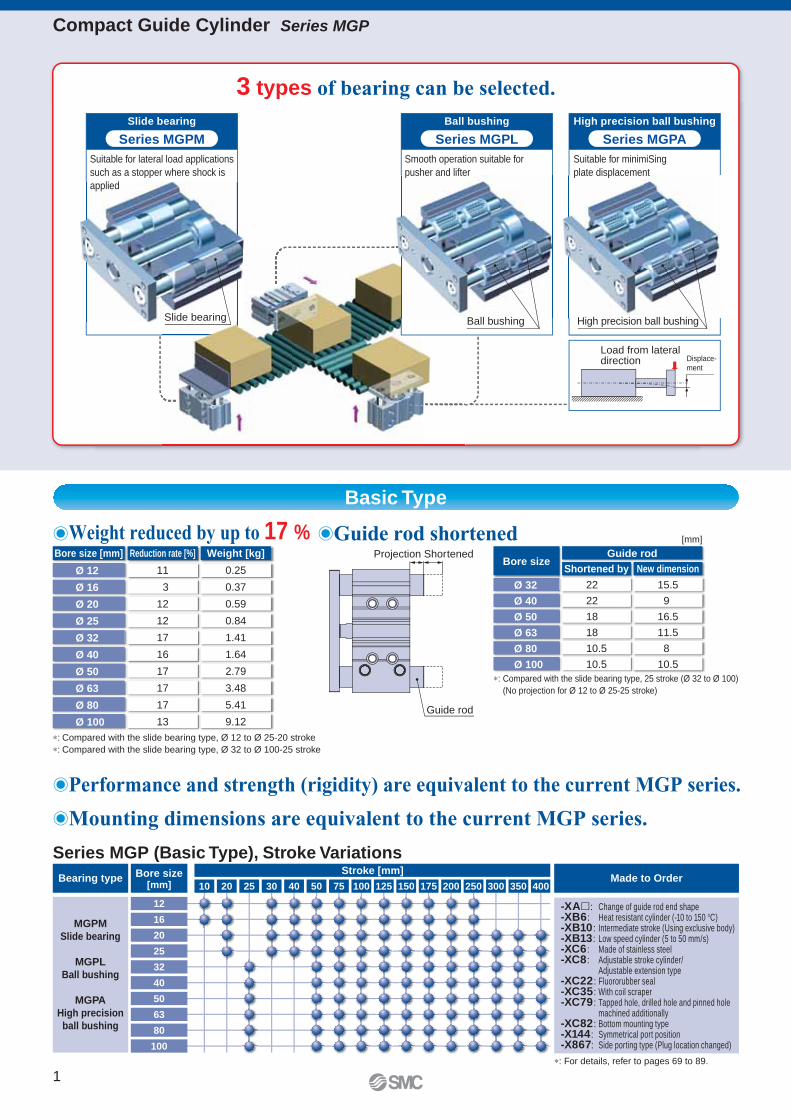
Guide rod
∗: For details, refer to pages 69 to 89.
Compact Guide Cylinder Series MGP
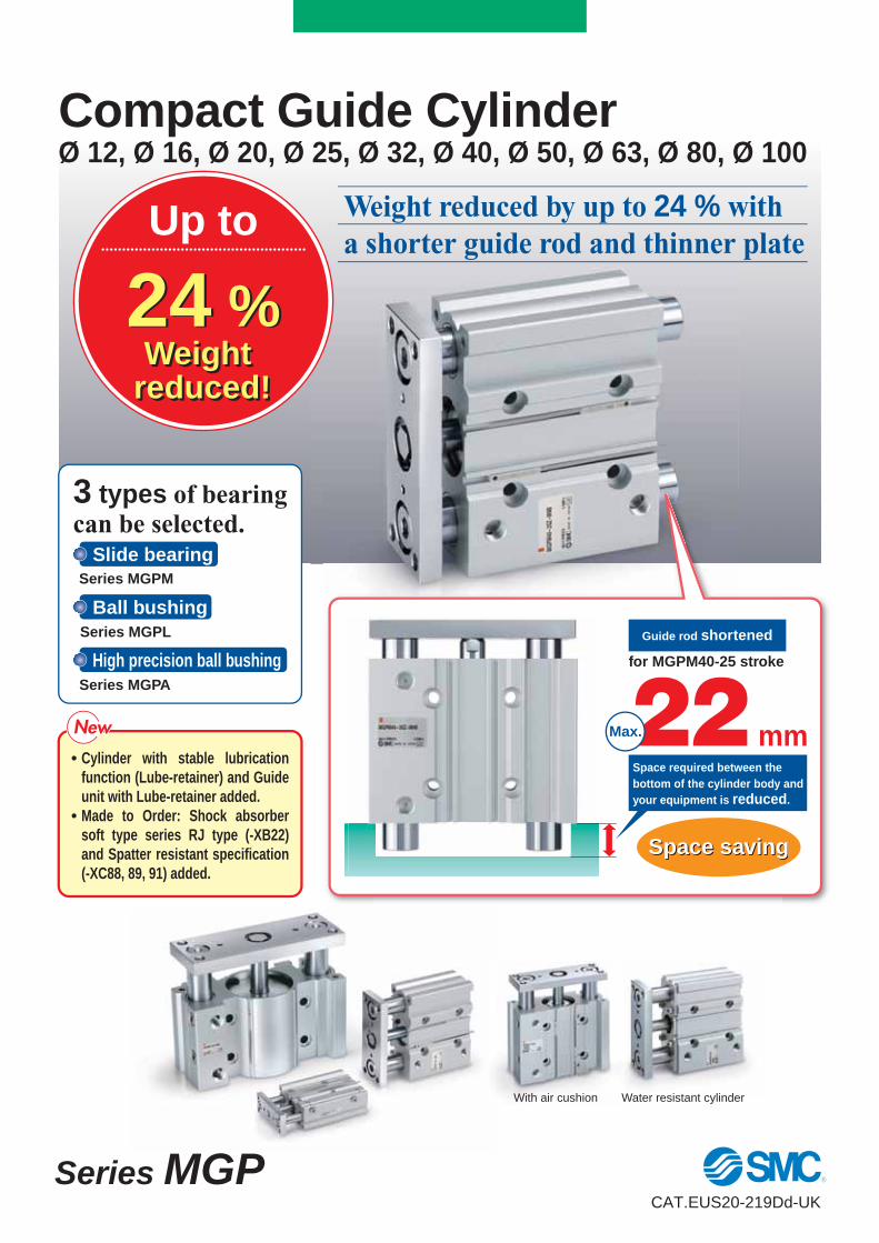
3 types of bearing can be selected.
'Guide rod shortened'Weight reduced by up to 17 %
'Performance and strength (rigidity) are equivalent to the current MGP series.
'Mounting dimensions are equivalent to the current MGP series.
Suitable for lateral load applications
such as a stopper where shock is
applied
Slide bearing
Series MGPM
Smooth operation suitable for
pusher and lifter
Suitable for minimiSing
plate displacement
Ball bushing
Series MGPL
High precision ball bushing
Series MGPA
∗: Compared with the slide bearing type, Ø 12 to Ø 25-20 stroke
∗: Compared with the slide bearing type, Ø 32 to Ø 100-25 stroke
Bore size [mm] Reduction rate [%] Weight [kg]
Ø 12
Ø 16
Ø 20
Ø 25
Ø 32
Ø 40
Ø 50
Ø 63
Ø 80
Ø 100
11
3
12
12
17
16
17
17
17
13
0.25
0.37
0.59
0.84
1.41
1.64
2.79
3.48
5.41
9.12
Bore sizeGuide rod
Shortened by New dimension
Ø 32
Ø 40
Ø 50
Ø 63
Ø 80
Ø 100
22
22
18
18
10.5
10.5
15.5
9
16.5
11.5
8
10.5
∗: Compared with the slide bearing type, 25 stroke (Ø 32 to Ø 100)
(No projection for Ø 12 to Ø 25-25 stroke)
[mm]
Load from lateral direction Displace-
ment
Projection Shortened
Slide bearing Ball bushing High precision ball bushing
1
Compact Guide Cylinder Series MGP
Stroke [mm]Bore size[mm]
Bearing type
MGPM-�A
Slide bearing
MGPL-�A
Ball bushing
MGPA-�A
High precision
ball bushing
Made to Order
Series MGP (With Air Cushion), Stroke Variations
16
20
25
32
40
50
63
80
100
40025 50 75 100 125 150 175 200 250 300 350
∗: For details, refer to pages 69 to 89.
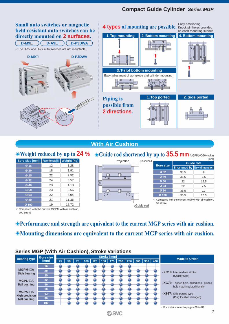
ShortenedProjection
1. Top ported 2. Side ported
2. Bottom mounting 4. Bottom mounting1. Top mounting
3. T-slot bottom mounting
-XC19: Intermediate stroke
(Spacer type)
-XC79: Tapped hole, drilled hole, pinned
hole machined additionally
-X867: Side porting type
(Plug location changed)
D-P3DWAD-M9�
Bore size [mm] Reduction rate [%] Weight [kg]
Ø 16
Ø 20
Ø 25
Ø 32
Ø 40
Ø 50
Ø 63
Ø 80
Ø 100
12
18
22
24
23
23
22
21
19
1.28
1.91
2.52
3.57
4.13
6.56
8.04
11.35
17.72
'Performance and strength are equivalent to the current MGP series with air cushion.
Bore sizeGuide rod
Shortened by New dimension
Ø 32
Ø 40
Ø 50
Ø 63
Ø 80
Ø 100
33.5
33.5
22
22
35.5
35.5
9
2.5
12.5
7.5
10
10.5
[mm]
'Mounting dimensions are equivalent to the current MGP series with air cushion.
'Guide rod shortened by up to 35.5 mm (MGPM100-50 stroke)'Weight reduced by up to 24 %
∗: The D-Y7 and D-Z7 auto switches are not mountable.
D-M9� D-A9� D-P3DWA
4 types of mounting are possible.
Piping is possible from2 directions.
Easy adjustment of workpiece and cylinder mounting
Easy positioningKnock pin holes provided on each mounting surface
Guide rod∗: Compared with the current MGPM with air cushion,
200 stroke
∗: Compared with the current MGPM with air cushion,
50 stroke
With Air Cushion
Small auto switches or magnetic field resistant auto switches can be directly mounted on 2 surfaces.
2
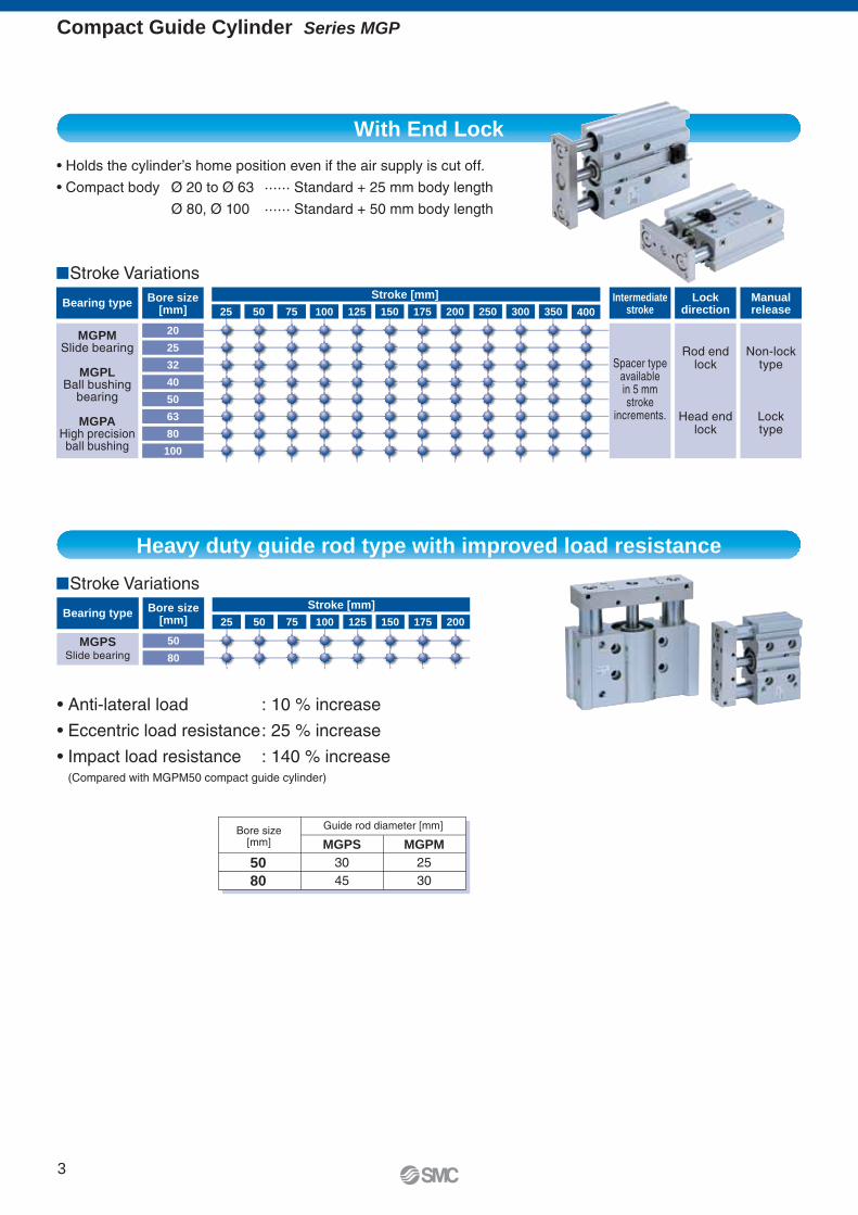
With End Lock
Heavy duty guide rod type with improved load resistance
�
�
Stroke [mm]Bore size[mm]
Bearing type
MGPM
MGPL
MGPA
Intermediatestroke
Lockdirection
Manualrelease
20
25
32
40
50
63
80
100
25 50 75 100 125 150 175 200 250 300 350 400
Stroke [mm]Bore size[mm]
Bearing type
MGPS 50
80
25 50 75 100 125 150 175 200
MGPS MGPM
50
80
Compact Guide Cylinder Series MGP
3
PageSeries Bearing type20 25 32 40 5010 12 16
Bore size
6 63 80 100
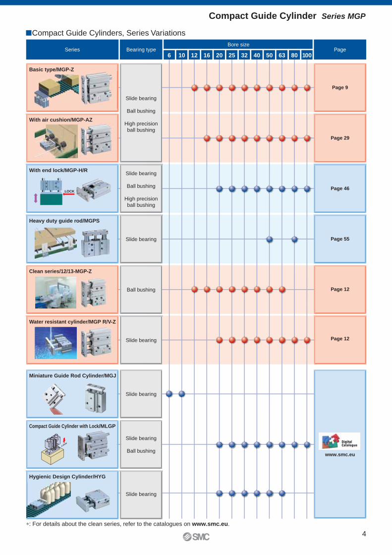
�Compact Guide Cylinders, Series Variations
LOCK
LOCK
Basic type/MGP-Z
With air cushion/MGP-AZ
Slide bearing
Ball bushing
High precision
ball bushing
Slide bearing
Ball bushing
High precision
ball bushing
With end lock/MGP-H/R
Slide bearing
Heavy duty guide rod/MGPS
Ball bushing
Slide bearing
Clean series/12/13-MGP-Z
Water resistant cylinder/MGP R/V-Z
Page 9
Page 29
Page 46
Page 55
Page 12
Page 12
Slide bearing
Slide bearing
Ball bushing
Miniature Guide Rod Cylinder/MGJ
Compact Guide Cylinder with Lock/MLGP
Slide bearing
Hygienic Design Cylinder/HYG
∗: For details about the clean series, refer to the catalogues on www.smc.eu.
www.smc.eu
Compact Guide Cylinder Series MGP
4
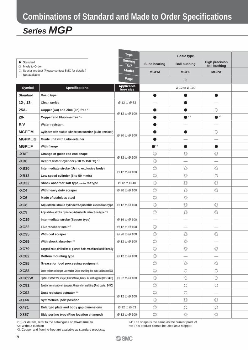
� : Standard
: Made to Order
� : Special product (Please contact SMC for details.)
— : Not available
Series MGP
Combinations of Standard and Made to Order Specifi cations
∗1: For details, refer to the catalogues on www.smc.eu.
∗2: Without cushion
∗3: Copper and fl uorine-free are available as standard products.
∗4: The shape is the same as the current product.
∗5: This product cannot be used as a stopper.
Basic type
Slide bearing Ball bushingHigh precisionball bushing
MGPM MGPL MGPA
9
Symbol Specifi cationsApplicable bore size
Ø 12 to Ø 100
Standard Basic type � � �
12-, 13- Clean series Ø 12 to Ø 63 — � —
25A- Copper (Cu) and Zinc (Zn)-free ∗1
Ø 12 to Ø 100� � �
20- Copper and Fluorine-free ∗1 � � ∗3 � ∗3
R/V Water resistant
Ø 20 to Ø 100
� — —
MGP�M Cylinder with stable lubrication function (Lube-retainer) � � �
MGPM�G Guide unit with Lube-retainer � — —
MGP�F With fl ange �∗5 � �
-XA� Change of guide rod end shapeØ 12 to Ø 100
-XB6 Heat resistant cylinder (-10 to 150 °C) ∗2 — —
-XB10 Intermediate stroke (Using exclusive body)Ø 12 to Ø 100
-XB13 Low speed cylinder (5 to 50 mm/s) �
-XB22 Shock absorber soft type series RJ type Ø 12 to Ø 40
-XC4 With heavy duty scraper Ø 20 to Ø 100
-XC6 Made of stainless steel
Ø 12 to Ø 100
—
-XC8 Adjustable stroke cylinder/Adjustable extension type
-XC9 Adjustable stroke cylinder/Adjustable retraction type ∗2
-XC19 Intermediate stroke (Spacer type) Ø 16 to Ø 100 — — —
-XC22 Fluororubber seal ∗2 Ø 12 to Ø 100 — —
-XC35 With coil scraper Ø 20 to Ø 100
-XC69 With shock absorber ∗4 Ø 12 to Ø 100 —
-XC79 Tapped hole, drilled hole, pinned hole machined additionally
Ø 12 to Ø 100-XC82 Bottom mounting type — —
-XC85 Grease for food processing equipment
-XC88 Spatter resistant coil scraper, Lube-retainer, Grease for welding (Rod parts: Stainless steel 304)
Ø 32 to Ø 100
� �
-XC89W Spatter resistant coil scraper, Lube-retainer, Grease for welding (Rod parts: S45C) � �
-XC91 Spatter resistant coil scraper, Grease for welding (Rod parts: S45C) � �
-XC92 Dust resistant actuator ∗4
Ø 12 to Ø 100� —
-X144 Symmetrical port position
-X471 Enlarged plate and body gap dimensions Ø 12 to Ø 63 � �
-X867 Side porting type (Plug location changed) Ø 12 to Ø 100
Type
Bearingtype
Model
Page
5
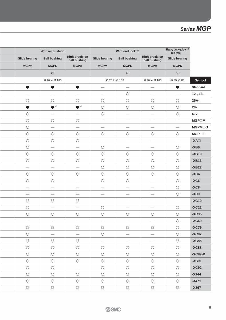
With air cushion With end lock ∗4 Heavy duty guide rod type
Slide bearing Ball bushingHigh precisionball bushing
Slide bearing Ball bushingHigh precisionball bushing
Slide bearing
MGPM MGPL MGPA MGPM MGPL MGPA MGPS
29 46 55
Ø 16 to Ø 100 Ø 20 to Ø 100 Ø 20 to Ø 100 Ø 50, Ø 80 Symbol
� � � — — — � Standard
— — — — � — — 12-, 13-
� � � � � � � 25A-
� � ∗3 � ∗3 � � � � 20-
� — — � — — � R/V
� � � — — — — MGP�M
� — — — — — — MGPM�G
� � � � � � � MGP�F
� � � — — — — -XA�
� — — � — — � -XB6
� � � � � � � -XB10
� � � � � � � -XB13
— — — � � � � -XB22
� � � � � � � -XC4
� � — � � — � -XC6
— — — — — — � -XC8
— — — — — — � -XC9
— — — — -XC19
� — — � — — � -XC22
� � � � � � � -XC35
— — — — — — � -XC69
� -XC79
� — — � — — � -XC82
— — — -XC85
� � � � � � � -XC88
� � � � � � � -XC89W
� � � � � � � -XC91
� � — � � � � -XC92
� � � � � � � -X144
� � � � � � � -X471
-X867
∗4
Series MGP
6

7
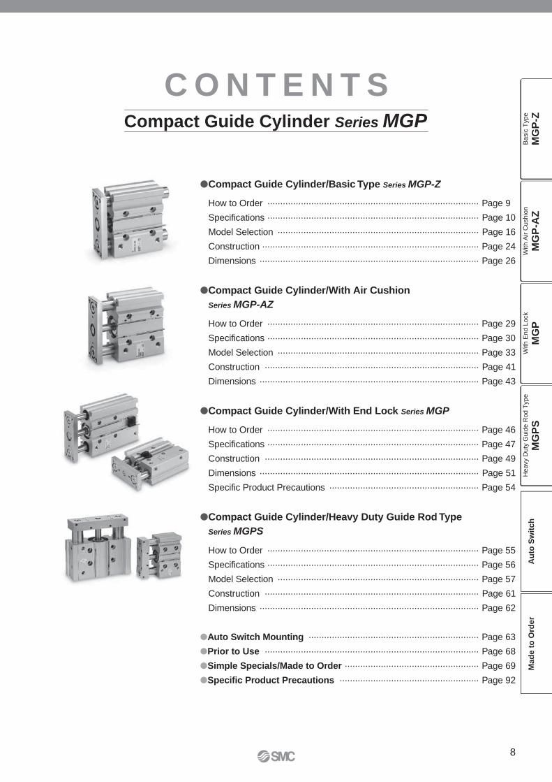
�Compact Guide Cylinder/Basic Type Series MGP-Z
How to Order ·················································································· Page 9
Specifications ·················································································· Page 10
Model Selection ·············································································· Page 16
Construction ···················································································· Page 24
Dimensions ····················································································· Page 26
�Compact Guide Cylinder/With Air Cushion
Series MGP-AZ
How to Order ·················································································· Page 29
Specifications ·················································································· Page 30
Model Selection ·············································································· Page 33
Construction ··················································································· Page 41
Dimensions ····················································································· Page 43
�Compact Guide Cylinder/With End Lock Series MGP
How to Order ·················································································· Page 46
Specifications ·················································································· Page 47
Construction ··················································································· Page 49
Dimensions ····················································································· Page 51
Specific Product Precautions ·························································· Page 54
� Compact Guide Cylinder/Heavy Duty Guide Rod Type
Series MGPS
How to Order ·················································································· Page 55
Specifications ·················································································· Page 56
Model Selection ·············································································· Page 57
Construction ··················································································· Page 61
Dimensions ····················································································· Page 62
�Auto Switch Mounting ·································································· Page 63
�Prior to Use ··················································································· Page 68
�Simple Specials/Made to Order ···················································· Page 69
�Specific Product Precautions ······················································ Page 92
C O N T E N T SCompact Guide Cylinder Series MGP
8
MG
P-Z
MG
P-A
ZM
GP
MG
PS
Ba
sic
Typ
eW
ith
Air C
ush
ion
With E
nd L
ock
Heavy D
uty
Guid
e R
od T
ype
Au
to S
wit
ch
Mad
e t
o O
rder
Compact Guide Cylinder
Ø 12, Ø 16, Ø 20, Ø 25, Ø 32, Ø 40, Ø 50, Ø 63, Ø 80, Ø 100
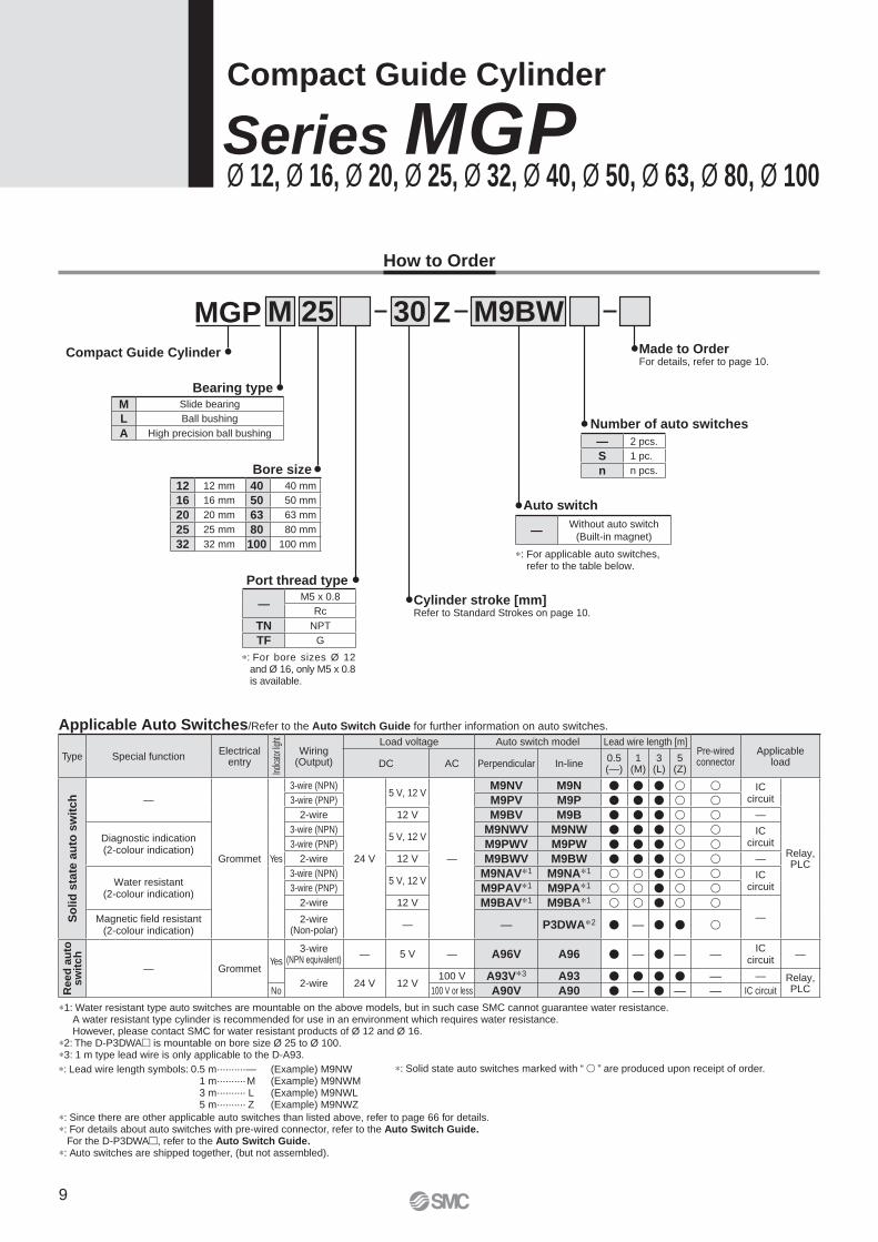
How to Order
MGP M 25
Bearing type
Bore size
Compact Guide Cylinder
Port thread type
∗: For bore sizes Ø 12 and Ø 16, only M5 x 0.8 is available.
Applicable Auto Switches/Refer to the Auto Switch Guide for further information on auto switches.
Cylinder stroke [mm]Refer to Standard Strokes on page 10.
M9BW30
Auto switch
∗: For applicable auto switches, refer to the table below.
Number of auto switches
ZMade to Order For details, refer to page 10.
Series MGP
— 2 pcs.
S 1 pc.
n n pcs.
—Without auto switch
(Built-in magnet)
Type Special functionElectrical
entry
Indic
ator
light
Wiring (Output)
Load voltage Auto switch model Lead wire length [m]Pre-wired connector
Applicable loadDC AC Perpendicular In-line
0.5(—)
1(M)
3(L)
5(Z)
So
lid
sta
te a
uto
sw
itch —
Grommet Yes
3-wire (NPN)
24 V
5 V, 12 V
—
M9NV M9N � � � � � ICcircuit
Relay, PLC
3-wire (PNP) M9PV M9P � � � � �2-wire 12 V M9BV M9B � � � � � —
Diagnostic indication (2-colour indication)
3-wire (NPN)5 V, 12 V
M9NWV M9NW � � � � � ICcircuit3-wire (PNP) M9PWV M9PW � � � � �
2-wire 12 V M9BWV M9BW � � � � � —
Water resistant (2-colour indication)
3-wire (NPN)5 V, 12 V
M9NAV∗1 M9NA∗1 � � � � � ICcircuit3-wire (PNP) M9PAV∗1 M9PA∗1 � � � � �
2-wire 12 V M9BAV∗1 M9BA∗1 � � � � �—Magnetic fi eld resistant
(2-colour indication)2-wire
(Non-polar)— — P3DWA∗2 � — � � �
Reed
au
to
sw
itch
— GrommetYes
3-wire (NPN equivalent)
— 5 V — A96V A96 � — � — —IC
circuit—
2-wire 24 V 12 V100 V A93V∗3 A93 � � � � — — Relay,
PLCNo 100 V or less A90V A90 � — � — — IC circuit
—M5 x 0.8
Rc
TN NPT
TF G
12 12 mm 40 40 mm
16 16 mm 50 50 mm
20 20 mm 63 63 mm
25 25 mm 80 80 mm
32 32 mm 100 100 mm
M Slide bearing
L Ball bushing
A High precision ball bushing
∗: Solid state auto switches marked with “ � ” are produced upon receipt of order.
∗: Since there are other applicable auto switches than listed above, refer to page 66 for details.∗: For details about auto switches with pre-wired connector, refer to the Auto Switch Guide.
For the D-P3DWA�, refer to the Auto Switch Guide.∗: Auto switches are shipped together, (but not assembled).
∗1: Water resistant type auto switches are mountable on the above models, but in such case SMC cannot guarantee water resistance.A water resistant type cylinder is recommended for use in an environment which requires water resistance. However, please contact SMC for water resistant products of Ø 12 and Ø 16.
∗2: The D-P3DWA� is mountable on bore size Ø 25 to Ø 100.∗3: 1 m type lead wire is only applicable to the D-A93.
∗: Lead wire length symbols: 0.5 m·········· — (Example) M9NW1 m·········· M (Example) M9NWM3 m·········· L (Example) M9NWL5 m·········· Z (Example) M9NWZ
9
OUT IN
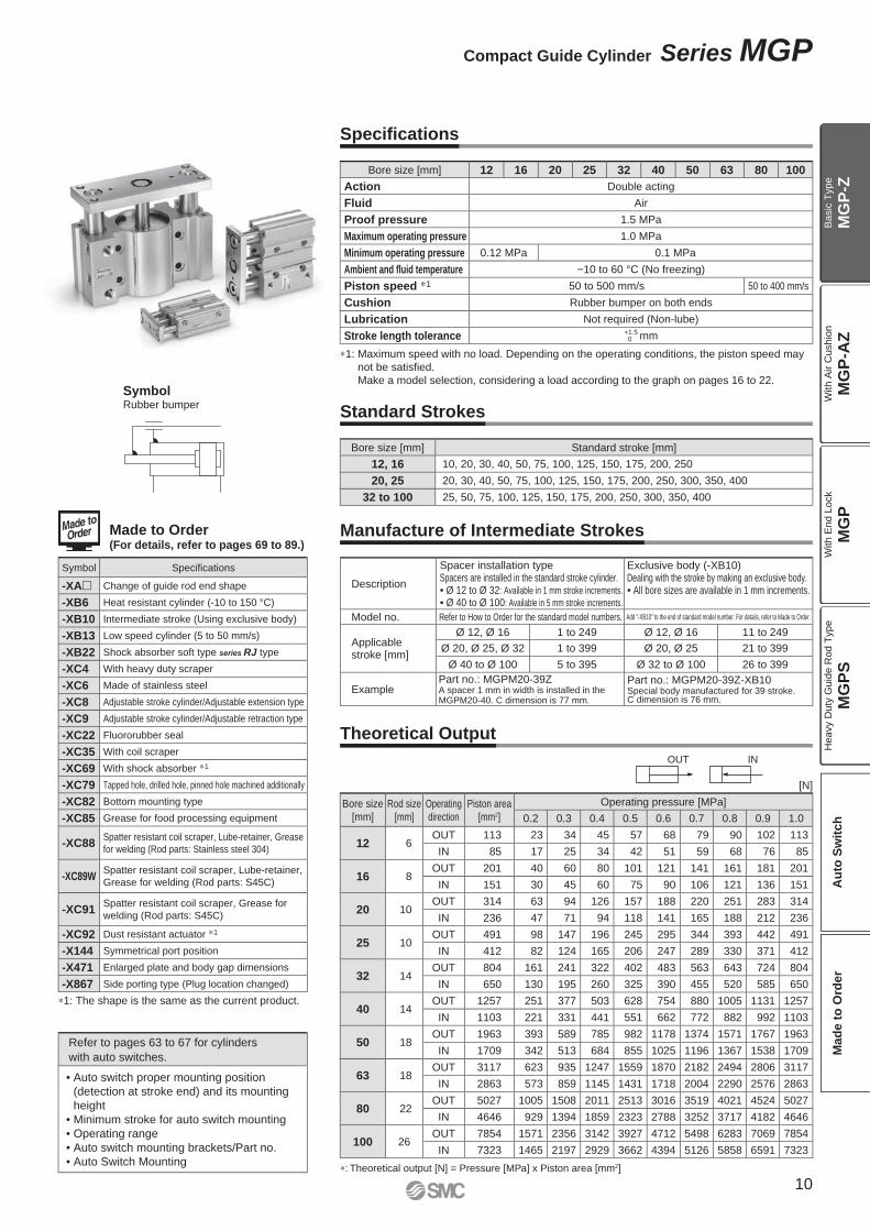
∗1: The shape is the same as the current product.
SymbolRubber bumper
Standard Strokes
Manufacture of Intermediate Strokes
Theoretical Output
Specifi cations
Bore size
[mm]
Rod size
[mm]
Operating
direction
Piston area
[mm2]
Operating pressure [MPa]
0.2 0.3 0.4 0.5 0.6 0.7 0.8 0.9 1.0
12 6OUT 113 23 34 45 57 68 79 90 102 113
IN 85 17 25 34 42 51 59 68 76 85
16 8OUT 201 40 60 80 101 121 141 161 181 201
IN 151 30 45 60 75 90 106 121 136 151
20 10OUT 314 63 94 126 157 188 220 251 283 314
IN 236 47 71 94 118 141 165 188 212 236
25 10OUT 491 98 147 196 245 295 344 393 442 491
IN 412 82 124 165 206 247 289 330 371 412
32 14OUT 804 161 241 322 402 483 563 643 724 804
IN 650 130 195 260 325 390 455 520 585 650
40 14OUT 1257 251 377 503 628 754 880 1005 1131 1257
IN 1103 221 331 441 551 662 772 882 992 1103
50 18OUT 1963 393 589 785 982 1178 1374 1571 1767 1963
IN 1709 342 513 684 855 1025 1196 1367 1538 1709
63 18OUT 3117 623 935 1247 1559 1870 2182 2494 2806 3117
IN 2863 573 859 1145 1431 1718 2004 2290 2576 2863
80 22OUT 5027 1005 1508 2011 2513 3016 3519 4021 4524 5027
IN 4646 929 1394 1859 2323 2788 3252 3717 4182 4646
100 26OUT 7854 1571 2356 3142 3927 4712 5498 6283 7069 7854
IN 7323 1465 2197 2929 3662 4394 5126 5858 6591 7323
∗1: Maximum speed with no load. Depending on the operating conditions, the piston speed may
not be satisfi ed.
Make a model selection, considering a load according to the graph on pages 16 to 22.
∗: Theoretical output [N] = Pressure [MPa] x Piston area [mm2]
[N]
Made to Order(For details, refer to pages 69 to 89.)
Description
Spacer installation typeSpacers are installed in the standard stroke cylinder.• Ø 12 to Ø 32: Available in 1 mm stroke increments.
• Ø 40 to Ø 100: Available in 5 mm stroke increments.
Exclusive body (-XB10)Dealing with the stroke by making an exclusive body.• All bore sizes are available in 1 mm increments.
Model no. Refer to How to Order for the standard model numbers. Add “-XB10” to the end of standard model number. For details, refer to Made to Order.
Applicable stroke [mm]
Ø 12, Ø 16 1 to 249 Ø 12, Ø 16 11 to 249
Ø 20, Ø 25, Ø 32 1 to 399 Ø 20, Ø 25 21 to 399
Ø 40 to Ø 100 5 to 395 Ø 32 to Ø 100 26 to 399
ExamplePart no.: MGPM20-39ZA spacer 1 mm in width is installed in the MGPM20-40. C dimension is 77 mm.
Part no.: MGPM20-39Z-XB10Special body manufactured for 39 stroke. C dimension is 76 mm.
Symbol Specifi cations
-XA� Change of guide rod end shape
-XB6 Heat resistant cylinder (-10 to 150 °C)
-XB10 Intermediate stroke (Using exclusive body)
-XB13 Low speed cylinder (5 to 50 mm/s)
-XB22 Shock absorber soft type series RJ type
-XC4 With heavy duty scraper
-XC6 Made of stainless steel
-XC8 Adjustable stroke cylinder/Adjustable extension type
-XC9 Adjustable stroke cylinder/Adjustable retraction type
-XC22 Fluororubber seal
-XC35 With coil scraper
-XC69 With shock absorber ∗1
-XC79 Tapped hole, drilled hole, pinned hole machined additionally
-XC82 Bottom mounting type
-XC85 Grease for food processing equipment
-XC88Spatter resistant coil scraper, Lube-retainer, Grease
for welding (Rod parts: Stainless steel 304)
-XC89WSpatter resistant coil scraper, Lube-retainer,
Grease for welding (Rod parts: S45C)
-XC91Spatter resistant coil scraper, Grease for
welding (Rod parts: S45C)
-XC92 Dust resistant actuator ∗1
-X144 Symmetrical port position
-X471 Enlarged plate and body gap dimensions
-X867 Side porting type (Plug location changed)
Refer to pages 63 to 67 for cylinders
with auto switches.
• Auto switch proper mounting position
(detection at stroke end) and its mounting
height
• Minimum stroke for auto switch mounting
• Operating range
• Auto switch mounting brackets/Part no.
• Auto Switch Mounting
Bore size [mm] Standard stroke [mm]
12, 16 10, 20, 30, 40, 50, 75, 100, 125, 150, 175, 200, 250
20, 25 20, 30, 40, 50, 75, 100, 125, 150, 175, 200, 250, 300, 350, 400
32 to 100 25, 50, 75, 100, 125, 150, 175, 200, 250, 300, 350, 400
Bore size [mm] 12 16 20 25 32 40 50 63 80 100
Action Double acting
Fluid Air
Proof pressure 1.5 MPa
Maximum operating pressure 1.0 MPa
Minimum operating pressure 0.12 MPa 0.1 MPa
Ambient and fl uid temperature −10 to 60 °C (No freezing)
Piston speed ∗1 50 to 500 mm/s 50 to 400 mm/s
Cushion Rubber bumper on both ends
Lubrication Not required (Non-lube)
Stroke length tolerance +1.5 0 mm
10
Compact Guide Cylinder Series MGP
MG
P-Z
MG
P-A
ZM
GP
MG
PS
Ba
sic
Typ
eW
ith
Air C
ush
ion
With E
nd L
ock
Heavy D
uty
Guid
e R
od T
ype
Au
to S
wit
ch
Mad
e t
o O
rder
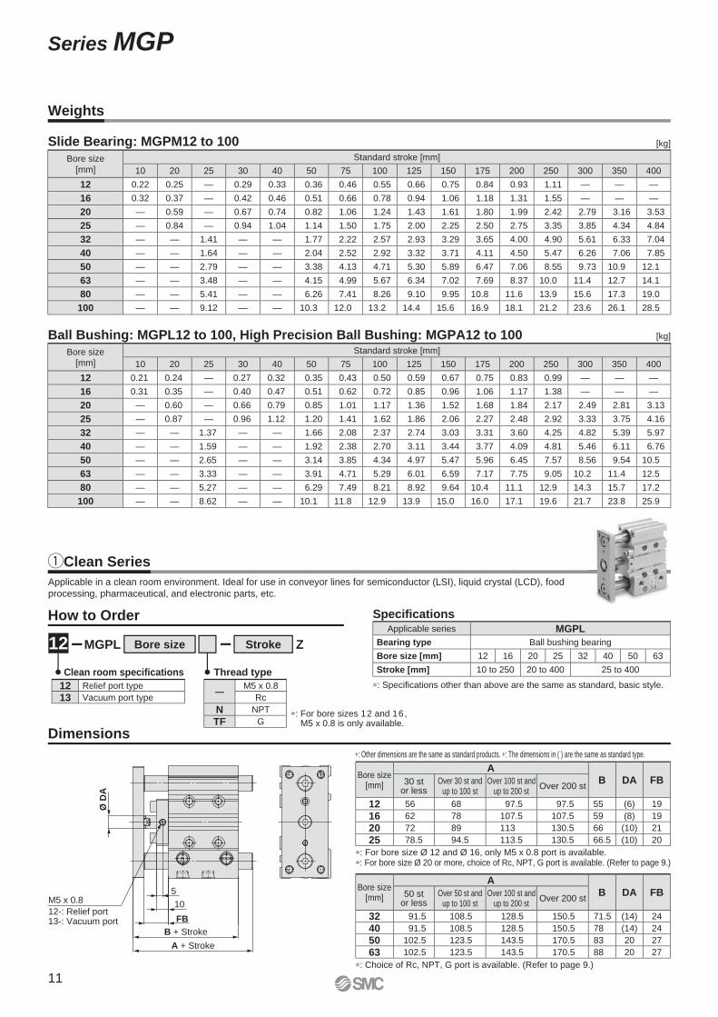
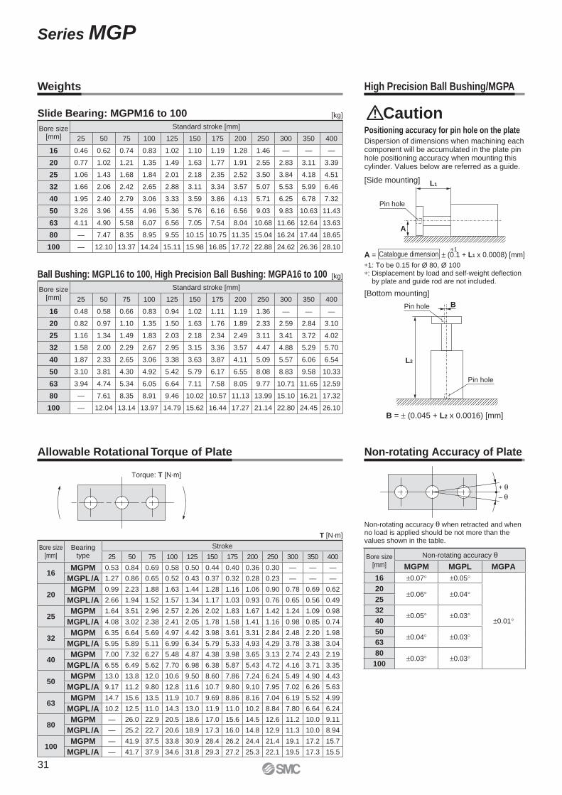
Weights
Slide Bearing: MGPM12 to 100
Ball Bushing: MGPL12 to 100, High Precision Ball Bushing: MGPA12 to 100
Bore size
[mm]
Standard stroke [mm]
10 20 25 30 40 50 75 100 125 150 175 200 250 300 350 400
12 0.22 0.25 — 0.29 0.33 0.36 0.46 0.55 0.66 0.75 0.84 0.93 1.11 — — —
16 0.32 0.37 — 0.42 0.46 0.51 0.66 0.78 0.94 1.06 1.18 1.31 1.55 — — —
20 — 0.59 — 0.67 0.74 0.82 1.06 1.24 1.43 1.61 1.80 1.99 2.42 2.79 3.16 3.53
25 — 0.84 — 0.94 1.04 1.14 1.50 1.75 2.00 2.25 2.50 2.75 3.35 3.85 4.34 4.84
32 — — 1.41 — — 1.77 2.22 2.57 2.93 3.29 3.65 4.00 4.90 5.61 6.33 7.04
40 — — 1.64 — — 2.04 2.52 2.92 3.32 3.71 4.11 4.50 5.47 6.26 7.06 7.85
50 — — 2.79 — — 3.38 4.13 4.71 5.30 5.89 6.47 7.06 8.55 9.73 10.9 12.1
63 — — 3.48 — — 4.15 4.99 5.67 6.34 7.02 7.69 8.37 10.0 11.4 12.7 14.1
80 — — 5.41 — — 6.26 7.41 8.26 9.10 9.95 10.8 11.6 13.9 15.6 17.3 19.0
100 — — 9.12 — — 10.3 12.0 13.2 14.4 15.6 16.9 18.1 21.2 23.6 26.1 28.5
Bore size
[mm]
Standard stroke [mm]
10 20 25 30 40 50 75 100 125 150 175 200 250 300 350 400
12 0.21 0.24 — 0.27 0.32 0.35 0.43 0.50 0.59 0.67 0.75 0.83 0.99 — — —
16 0.31 0.35 — 0.40 0.47 0.51 0.62 0.72 0.85 0.96 1.06 1.17 1.38 — — —
20 — 0.60 — 0.66 0.79 0.85 1.01 1.17 1.36 1.52 1.68 1.84 2.17 2.49 2.81 3.13
25 — 0.87 — 0.96 1.12 1.20 1.41 1.62 1.86 2.06 2.27 2.48 2.92 3.33 3.75 4.16
32 — — 1.37 — — 1.66 2.08 2.37 2.74 3.03 3.31 3.60 4.25 4.82 5.39 5.97
40 — — 1.59 — — 1.92 2.38 2.70 3.11 3.44 3.77 4.09 4.81 5.46 6.11 6.76
50 — — 2.65 — — 3.14 3.85 4.34 4.97 5.47 5.96 6.45 7.57 8.56 9.54 10.5
63 — — 3.33 — — 3.91 4.71 5.29 6.01 6.59 7.17 7.75 9.05 10.2 11.4 12.5
80 — — 5.27 — — 6.29 7.49 8.21 8.92 9.64 10.4 11.1 12.9 14.3 15.7 17.2
100 — — 8.62 — — 10.1 11.8 12.9 13.9 15.0 16.0 17.1 19.6 21.7 23.8 25.9
[kg]
[kg]
11
Series MGP
Ø D
A
A + Stroke
B + Stroke
10
FB
5M5 x 0.8
12-: Relief port13-: Vacuum port
Applicable in a clean room environment. Ideal for use in conveyor lines for semiconductor (LSI), liquid crystal (LCD), food
processing, pharmaceutical, and electronic parts, etc.
Applicable series MGPL
Bearing type Ball bushing bearing
Bore size [mm] 12 16 20 25 32 40 50 63
Stroke [mm] 10 to 250 20 to 400 25 to 400
Specifi cations
∗: Specifi cations other than above are the same as standard, basic style.
∗: Other dimensions are the same as standard products. ∗: The dimensions in ( ) are the same as standard type.
How to Order
—M5 x 0.8
Rc
N NPT
TF G
12 Relief port type
13 Vacuum port type
∗: For bore sizes 12 and 16, M5 x 0.8 is only available.
Clean room specifi cations Thread type
ZStrokeMGPL Bore size12
Dimensions
Bore size[mm]
AB DA FB30 st
or lessOver 30 st and
up to 100 stOver 100 st and
up to 200 stOver 200 st
12 56 68 97.5 97.5 55 (6) 19
16 62 78 107.5 107.5 59 (8) 19
20 72 89 113 130.5 66 (10) 21
25 78.5 94.5 113.5 130.5 66.5 (10) 20
∗: For bore size Ø 12 and Ø 16, only M5 x 0.8 port is available.∗: For bore size Ø 20 or more, choice of Rc, NPT, G port is available. (Refer to page 9.)
Bore size[mm]
AB DA FB50 st
or lessOver 50 st and
up to 100 stOver 100 st and
up to 200 stOver 200 st
32 91.5 108.5 128.5 150.5 71.5 (14) 24
40 91.5 108.5 128.5 150.5 78 (14) 24
50 102.5 123.5 143.5 170.5 83 20 27
63 102.5 123.5 143.5 170.5 88 20 27
∗: Choice of Rc, NPT, G port is available. (Refer to page 9.)
qClean Series
B + Stroke
A + Stroke
FBFA
Ø D
A
(Pis
ton
ro
d O
.D.)
Made to Order
Dimensions
[mm]
[mm]
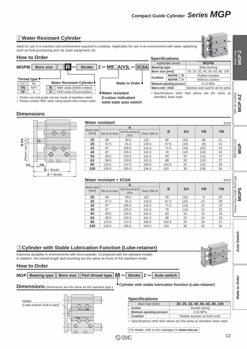
Bore size[mm]
AB DA FB FB
50 st or lessOver 50 st and up to
200 stOver 200 st
20 66 90.5 123 66 (10) (8) 21
25 67.5 91.5 123.5 67.5 (10) (9) 21
32 87 105.5 141.5 71.5 (14) (10) 24
40 87 105.5 141.5 78 (14) (10) 24
50 99.5 120.5 161.5 83 20 (12) 27
63 99.5 120.5 161.5 88 20 (12) 27
80 110.5 137.5 186.5 102.5 25 (16) 30
100 130.5 155.5 194.5 120 30 (19) 35
Bore size[mm]
AB DA FB FB
50 st or lessOver 50 st and up to
200 stOver 200 st
20 66 90.5 123 66 (10) 9 20
25 67.5 91.5 123.5 67.5 (10) 10 20
32 87 105.5 141.5 71.5 (14) 12 22
40 87 105.5 141.5 78 (14) 12 22
50 99.5 120.5 161.5 83 20 16 23
63 99.5 120.5 161.5 88 20 16 23
80 110.5 137.5 186.5 102.5 25 19 27
100 130.5 155.5 194.5 120 30 22 32
wWater Resistant Cylinder
Ideal for use in a machine tool environment exposed to coolants. Applicable for use in an environment with water splashing
such as food processing and car wash equipment, etc.
Specifications
Water resistant
Water resistant + XC6A
∗: Specifications other than above are the same as
standard, basic style.
Applicable series MGPMBearing type Slide bearing
Bore size [mm] 20, 25, 32, 40, 50, 63, 80, 100
CushionMGPM��R Rubber bumper
MGPM��V Without cushion
Minimum operating pressure 0.13 MPa
Made to order XC6A Stainless steel used for all iron parts
How to Order
ZStroke XC6AMGPM Bore size M9�A(V)L
∗: Piston rod and guide rod are made of stainless steel.∗: Please contact SMC when using liquids that contain sulfur.
Water resistant
2-colour indication
solid state auto switch
R
Water Resistant CylinderThread type
— Rc
TN NPT
TF G
R NBR seals (Nitrile rubber)
V FKM seals (Fluororubber)
MGPM
Holder
(Lube-retainer built-in part)
Improves durability in environments with micro-powder. (Compared with the standard model)
In addition, the overall length and mounting are the same as those of the standard model.
Specifi cationsBore size [mm] 20, 25, 32, 40, 50, 63, 80, 100
Action Double acting
Minimum operating pressure 0.15 MPa
Cushion Rubber bumper on both ends
∗: Specifications other than above are the same as standard, basic style.
Cylinder with stable lubrication function (Lube-retainer)
MGP ZStrokePort thread type MBore sizeBearing type Auto switch
Dimensions (Dimensions are the same as the standard type.)
For details, refer to the catalogue on www.smc.eu.
How to Order
eCylinder with Stable Lubrication Function (Lube-retainer)
12
Compact Guide Cylinder Series MGP
MG
P-Z
MG
P-A
ZM
GP
MG
PS
Ba
sic
Typ
eW
ith
Air C
ush
ion
With E
nd L
ock
Heavy D
uty
Guid
e R
od T
ype
Au
to S
wit
ch
Mad
e t
o O
rder
E
A + Stroke
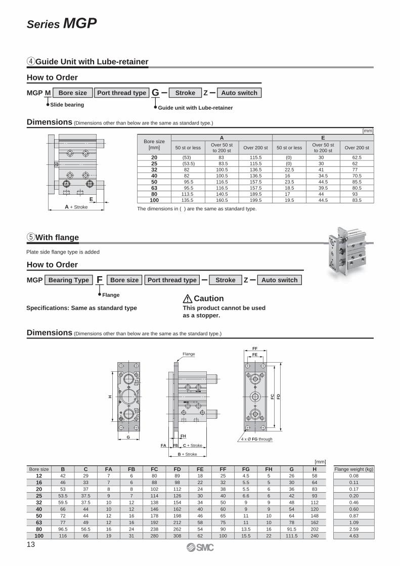
rGuide Unit with Lube-retainer
tWith fl ange
Z
Z
Stroke
Stroke
Port thread type
Port thread type
G
F
Bore size
Bearing Type Bore size
Auto switch
Auto switch
MGP
MGP
M
[mm]
Bore size
[mm]
A E
50 st or lessOver 50 st
to 200 stOver 200 st 50 st or less
Over 50 st
to 200 stOver 200 st
20 (53) 83 115.5 (0) 30 62.5
25 (53.5) 83.5 115.5 (0) 30 62
32 82 100.5 136.5 22.5 41 77
40 82 100.5 136.5 16 34.5 70.5
50 95.5 116.5 157.5 23.5 44.5 85.5
63 95.5 116.5 157.5 18.5 39.5 80.5
80 113.5 140.5 189.5 17 44 93
100 135.5 160.5 199.5 19.5 44.5 83.5
Dimensions (Dimensions other than below are the same as standard type.)
Dimensions (Dimensions other than below are the same as the standard type.)
How to Order
How to Order
Guide unit with Lube-retainer
Flange
Slide bearing
The dimensions in ( ) are the same as standard type.
[mm]
Bore size B C FA FB FC FD FE FF FG FH G H
12 42 29 7 6 80 89 18 25 4.5 5 26 58
16 46 33 7 6 88 98 22 32 5.5 5 30 64
20 53 37 8 8 102 112 24 38 5.5 6 36 83
25 53.5 37.5 9 7 114 126 30 40 6.6 6 42 93
32 59.5 37.5 10 12 138 154 34 50 9 9 48 112
40 66 44 10 12 146 162 40 60 9 9 54 120
50 72 44 12 16 178 198 46 65 11 10 64 148
63 77 49 12 16 192 212 58 75 11 10 78 162
80 96.5 56.5 16 24 238 262 54 90 13.5 16 91.5 202
100 116 66 19 31 280 308 62 100 15.5 22 111.5 240
Flange weight (kg)
0.08
0.11
0.17
0.20
0.46
0.60
0.87
1.09
2.59
4.63
FC
FD
FF
FE
4 x Ø FG through
B + Stroke
C + StrokeFBFA
FH
Flange
G
H
Plate side flange type is added
Specifications: Same as standard type This product cannot be used
as a stopper.
Caution
13
Series MGP
+
–
L1
A
Pin hole
L2
BPin hole
Pin hole
[Bottom mounting]
[Side mounting]
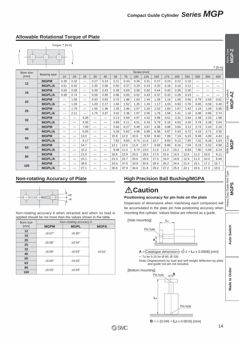
Positioning accuracy for pin hole on the plate
Dispersion of dimensions when machining each component will
be accumulated in the plate pin hole positioning accuracy when
mounting this cylinder. Values below are referred as a guide.
B = ± (0.045 + L2 x 0.0016) [mm]
High Precision Ball Bushing/MGPANon-rotating Accuracy of Plate
Torque: T [N·m]
T [N·m]
Allowable Rotational Torque of Plate
Bore size
[mm]Bearing type
Stroke [mm]
10 20 25 30 40 50 75 100 125 150 175 200 250 300 350 400
12MGPM 0.39 0.32 — 0.27 0.24 0.21 0.43 0.36 0.31 0.27 0.24 0.22 0.19 — — —
MGPL/A 0.61 0.45 — 0.35 0.58 0.50 0.37 0.29 0.24 0.20 0.18 0.16 0.12 — — —
16MGPM 0.69 0.58 — 0.49 0.43 0.38 0.69 0.58 0.50 0.44 0.40 0.36 0.30 — — —
MGPL/A 0.99 0.74 — 0.59 0.99 0.86 0.65 0.52 0.43 0.37 0.32 0.28 0.23 — — —
20MGPM — 1.05 — 0.93 0.83 0.75 1.88 1.63 1.44 1.28 1.16 1.06 0.90 0.78 0.69 0.62
MGPL/A — 1.26 — 1.03 2.17 1.94 1.52 1.25 1.34 1.17 1.03 0.93 0.76 0.65 0.56 0.49
25MGPM — 1.76 — 1.55 1.38 1.25 2.96 2.57 2.26 2.02 1.83 1.67 1.42 1.24 1.09 0.98
MGPL/A — 2.11 — 1.75 3.37 3.02 2.38 1.97 2.05 1.78 1.58 1.41 1.16 0.98 0.85 0.74
32MGPM — — 6.35 — — 5.13 5.69 4.97 4.42 3.98 3.61 3.31 2.84 2.48 2.20 1.98
MGPL/A — — 5.95 — — 4.89 5.11 4.51 6.34 5.79 5.33 4.93 4.29 3.78 3.38 3.04
40MGPM — — 7.00 — — 5.66 6.27 5.48 4.87 4.38 3.98 3.65 3.13 2.74 2.43 2.19
MGPL/A — — 6.55 — — 5.39 5.62 4.96 6.98 6.38 5.87 5.43 4.72 4.16 3.71 3.35
50MGPM — — 13.0 — — 10.8 12.0 10.6 9.50 8.60 7.86 7.24 6.24 5.49 4.90 4.43
MGPL/A — — 9.17 — — 7.62 9.83 8.74 11.6 10.7 9.83 9.12 7.95 7.02 6.26 5.63
63MGPM — — 14.7 — — 12.1 13.5 11.9 10.7 9.69 8.86 8.16 7.04 6.19 5.52 4.99
MGPL/A — — 10.2 — — 8.48 11.0 9.74 13.0 11.9 11.0 10.2 8.84 7.80 6.94 6.24
80MGPM — — 21.9 — — 18.6 22.9 20.5 18.6 17.0 15.6 14.5 12.6 11.2 10.0 9.11
MGPL/A — — 15.1 — — 23.3 22.7 20.6 18.9 17.3 16.0 14.8 12.9 11.3 10.0 8.94
100MGPM — — 38.8 — — 33.5 37.5 33.8 30.9 28.4 26.2 24.4 21.4 19.1 17.2 15.7
MGPL/A — — 27.1 — — 30.6 37.9 34.6 31.8 29.3 27.2 25.3 22.1 19.5 17.3 15.5
Non-rotating accuracy θ when retracted and when no load is applied should be not more than the values shown in the table.
Caution
A = Catalogue dimension ± (0.1 + L1 x 0.0008) [mm]
∗: To be 0.15 for Ø 80, Ø 100
Note) Displacement by load and self-weight defl ection by plateand guide rod are not included.
∗
Bore size
[mm]
Non-rotating accuracy θMGPM MGPL MGPA
12±0.07° ±0.05°
±0.01°
16
20±0.06° ±0.04°
25
32±0.05° ±0.03°
40
50±0.04° ±0.03°
63
80±0.03° ±0.03°
100
14
Compact Guide Cylinder Series MGP
MG
P-Z
MG
P-A
ZM
GP
MG
PS
Ba
sic
Typ
eW
ith
Air C
ush
ion
With E
nd L
ock
Heavy D
uty
Guid
e R
od T
ype
Au
to S
wit
ch
Mad
e t
o O
rder
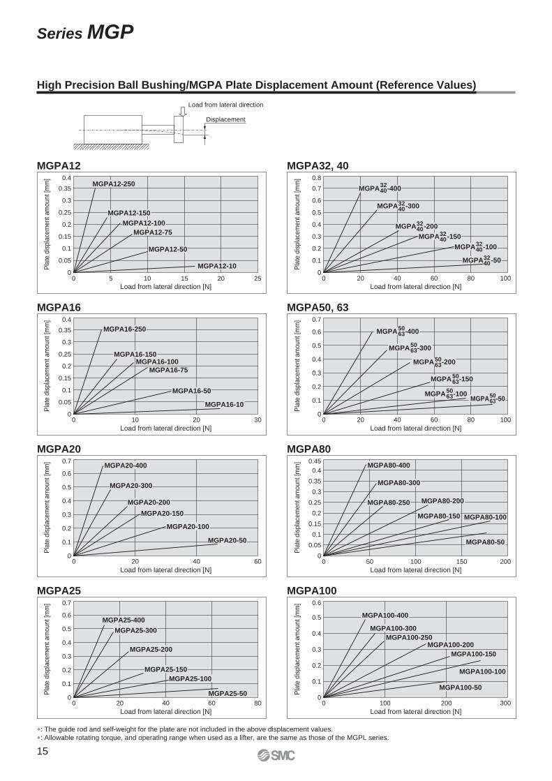
Load from lateral direction
Displacement
Load from lateral direction [N]
Pla
te d
isp
lace
me
nt
am
ou
nt
[mm
]
0 5 10 15 20 25
0.4
0.35
0.3
0.25
0.2
0.15
0.1
0.05
0
MGPA12-250
MGPA12-150
MGPA12-100
MGPA12-75
MGPA12-50
MGPA12-10
Load from lateral direction [N]
Pla
te d
isp
lace
me
nt
am
ou
nt
[mm
]
0 10 20 30
MGPA16-75
0.4
0.35
0.3
0.25
0.2
0.15
0.1
0.05
0
MGPA16-100
MGPA16-250
MGPA16-150
MGPA16-50
MGPA16-10
Load from lateral direction [N]
Pla
te d
isp
lace
me
nt
am
ou
nt
[mm
]
0 20 40 60
0.7
0.6
0.5
0.4
0.3
0.2
0.1
0
MGPA20-400
MGPA20-300
MGPA20-200
MGPA20-150
MGPA20-100
MGPA20-50
Load from lateral direction [N]
Pla
te d
isp
lace
me
nt
am
ou
nt
[mm
]
0 20 40 60 80
0.7
0.6
0.5
0.4
0.3
0.2
0.1
0
MGPA25-400
MGPA25-300
MGPA25-200
MGPA25-150
MGPA25-100
MGPA25-50
Load from lateral direction [N]
Pla
te d
isp
lace
me
nt
am
ou
nt
[mm
]
0 20 40 60 80 100
0.8
0.7
0.6
0.5
0.4
0.3
0.2
0.1
0
MGPA -4003240
MGPA -3003240
MGPA -2003240
MGPA -1503240
MGPA -1003240
MGPA -503240
Load from lateral direction [N]
Pla
te d
isp
lace
me
nt
am
ou
nt
[mm
]
0 20 40 60 80 100
0.7
0.6
0.5
0.4
0.3
0.2
0.1
0
MGPA -4005063
5063MGPA -300
MGPA -2005063
MGPA -1505063
MGPA -1005063 MGPA -50
5063
Load from lateral direction [N]
Pla
te d
isp
lace
me
nt
am
ou
nt
[mm
]
0 50 100 150 200
0.45
0.4
0.35
0.3
0.25
0.2
0.15
0.1
0.05
0
MGPA80-400
MGPA80-300
MGPA80-250 MGPA80-200
MGPA80-50
MGPA80-100MGPA80-150
Load from lateral direction [N]
Pla
te d
isp
lace
me
nt
am
ou
nt
[mm
]
0 100 200 300
0.6
0.5
0.4
0.3
0.2
0.1
0
MGPA100-400
MGPA100-300
MGPA100-250MGPA100-200
MGPA100-150
MGPA100-100
MGPA100-50
∗: The guide rod and self-weight for the plate are not included in the above displacement values.
∗: Allowable rotating torque, and operating range when used as a lifter, are the same as those of the MGPL series.
MGPA12
MGPA16
MGPA20
MGPA25
MGPA32, 40
MGPA50, 63
MGPA80
MGPA100
High Precision Ball Bushing/MGPA Plate Displacement Amount (Reference Values)
15
Series MGP
20
10
5
1
0.110 50 100 200
Eccentric distance L [mm]
Work
load m
[kg]
Ø 25
Ø 20
Ø 16
Ø 12
10
5
1
0.1
10 30 50 51 100 300200
Stroke [mm]
Wo
rk lo
ad
m [
kg
]
50Ø 100
Ø 100
Ø 80
Ø 16
Ø 80
Ø 50, Ø 63Ø 32, Ø 40
Ø 25
Ø 16
Ø 12
Ø 25
Ø 20
Ø 32, Ø 40Ø 50, Ø 63
Ø 12
Ø 20
L L
m m
L
m
L
m
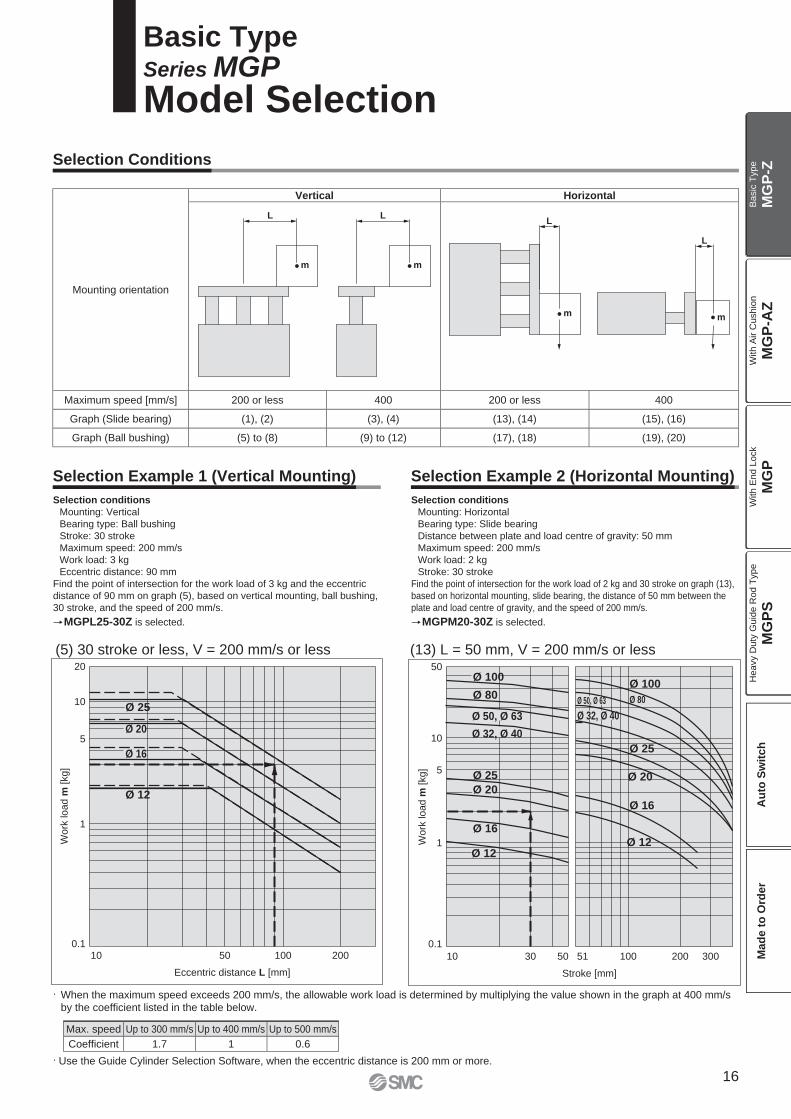
Selection Conditions
Selection Example 1 (Vertical Mounting) Selection Example 2 (Horizontal Mounting)
(13) L = 50 mm, V = 200 mm/s or less
Selection conditions
Mounting: Vertical
Bearing type: Ball bushing
Stroke: 30 stroke
Maximum speed: 200 mm/s
Work load: 3 kg
Eccentric distance: 90 mm
Find the point of intersection for the work load of 3 kg and the eccentric
distance of 90 mm on graph (5), based on vertical mounting, ball bushing,
30 stroke, and the speed of 200 mm/s.
MGPL25-30Z is selected.
Selection conditions
Mounting: Horizontal
Bearing type: Slide bearing
Distance between plate and load centre of gravity: 50 mm
Maximum speed: 200 mm/s
Work load: 2 kg
Stroke: 30 stroke
Find the point of intersection for the work load of 2 kg and 30 stroke on graph (13),
based on horizontal mounting, slide bearing, the distance of 50 mm between the
plate and load centre of gravity, and the speed of 200 mm/s.
MGPM20-30Z is selected.
(5) 30 stroke or less, V = 200 mm/s or less
· When the maximum speed exceeds 200 mm/s, the allowable work load is determined by multiplying the value shown in the graph at 400 mm/s by the coeffi cient listed in the table below.
· Use the Guide Cylinder Selection Software, when the eccentric distance is 200 mm or more.
Basic TypeSeries MGP
Model Selection
Mounting orientation
Vertical Horizontal
Maximum speed [mm/s] 200 or less 400 200 or less 400
Graph (Slide bearing) (1), (2) (3), (4) (13), (14) (15), (16)
Graph (Ball bushing) (5) to (8) (9) to (12) (17), (18) (19), (20)
Max. speed Up to 300 mm/s Up to 400 mm/s Up to 500 mm/s
Coeffi cient 1.7 1 0.6
16
MG
P-Z
MG
P-A
ZM
GP
MG
PS
Ba
sic
Typ
eW
ith
Air C
ush
ion
With E
nd L
ock
Heavy D
uty
Guid
e R
od T
ype
Au
to S
wit
ch
Mad
e t
o O
rder
300
200
100
10
5
1
0.1
Eccentric distance L [mm]
Wo
rk lo
ad
m [
kg
]
10 50 100 200
Ø 100
Ø 80
Ø 50
Ø 40
Ø 32
Ø 12
Ø 63
Ø 25
Ø 20
Ø 16
Ø 100
Ø 80
Ø 50
Ø 40
Ø 32
Ø 12
300
200
100
10
5
1
0.1
Eccentric distance L [mm]
Wo
rk lo
ad
m [
kg
]
10 50 100 200
Ø 63
Ø 25
Ø 20
Ø 16
Eccentric distance L [mm]
Wo
rk lo
ad
m [
kg
]
100
10
50
5
1
0.110 50 100 200
Ø 63
Ø 50
Ø 20
Ø 12
Ø 100
Ø 80
Ø 40
Ø 25
Ø 16
Ø 32
Eccentric distance L [mm]
Wo
rk lo
ad
m [
kg
]
100
10
50
5
1
0.110 50 100 200
Ø 12
Ø 100
Ø 50
Ø 40
Ø 20
Ø 16
Ø 25
Ø 63
Ø 32
Ø 80
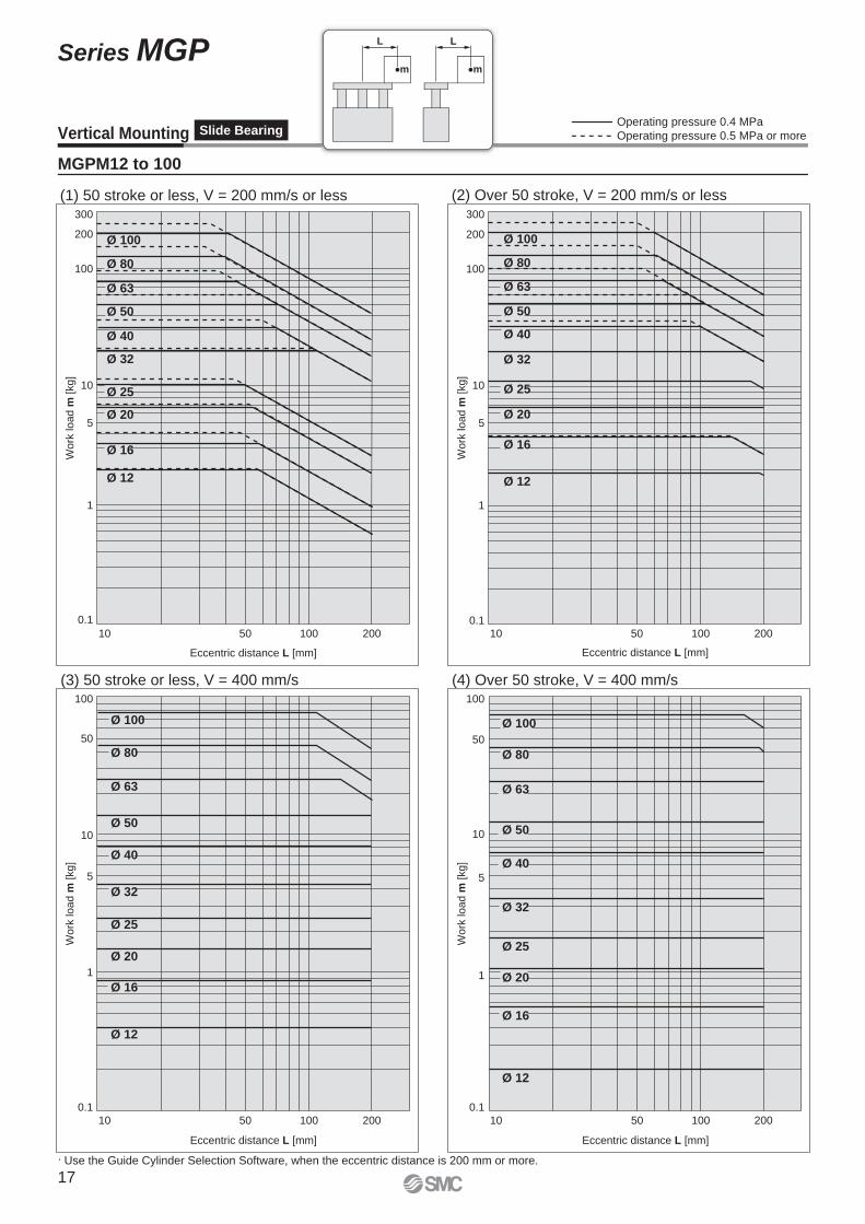
Vertical Mounting Slide Bearing
MGPM12 to 100
Operating pressure 0.4 MPa
Operating pressure 0.5 MPa or more
(1) 50 stroke or less, V = 200 mm/s or less (2) Over 50 stroke, V = 200 mm/s or less
(3) 50 stroke or less, V = 400 mm/s (4) Over 50 stroke, V = 400 mm/s
· Use the Guide Cylinder Selection Software, when the eccentric distance is 200 mm or more.
L L
m m
17
Series MGP
10
100
1
0.1
10 100 1000
Ø 12
Ø 16
Ø 20
Ø 25
Eccentric distance L [mm]
Wo
rk lo
ad
m [
kg
]
10
20
5
1
0.110 50 100 200
Eccentric distance L [mm]
Wo
rk lo
ad
m [
kg
]
Ø 12
Ø 25
Ø 20
Ø 16
50
100
300
10
5
11 5 10010 200
Eccentric distance L [mm]
Wo
rk lo
ad
m [
kg
]
Ø 80
Ø 63
Ø 50
Ø 40
Ø 32
Ø 100
50
100
300
10
5
110 10050 200
Eccentric distance L [mm]
Wo
rk lo
ad
m [
kg
]
Ø 100
Ø 80
Ø 63
Ø 50
Ø 40
Ø 32
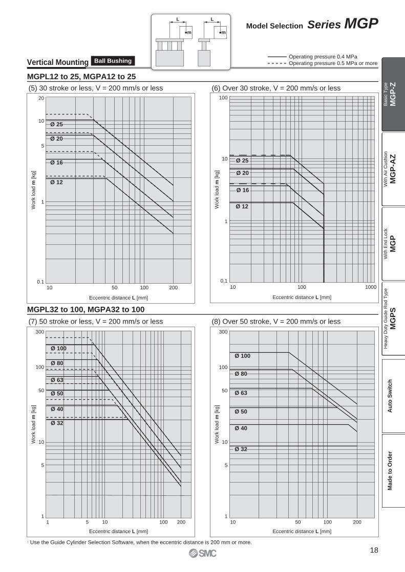
MGPL12 to 25, MGPA12 to 25
MGPL32 to 100, MGPA32 to 100
Vertical Mounting Ball Bushing
(5) 30 stroke or less, V = 200 mm/s or less (6) Over 30 stroke, V = 200 mm/s or less
(7) 50 stroke or less, V = 200 mm/s or less (8) Over 50 stroke, V = 200 mm/s or less
Operating pressure 0.4 MPa
Operating pressure 0.5 MPa or more
· Use the Guide Cylinder Selection Software, when the eccentric distance is 200 mm or more.
L L
m m
18
Model Selection Series MGP
MG
P-Z
MG
P-A
ZM
GP
MG
PS
Ba
sic
Typ
eW
ith
Air C
ush
ion
With E
nd L
ock
Heavy D
uty
Guid
e R
od T
ype
Au
to S
wit
ch
Mad
e t
o O
rder
5
10
1
0.110 50 100 200
Eccentric distance L [mm]
Wo
rk lo
ad
m [
kg
]
Ø 25
Ø 20
Ø 16
Ø 12
0.5
1
0.1
0.01
10 50 100 200
Eccentric distance L [mm]
Wo
rk lo
ad
m [
kg
]
Ø 25
Ø 20
Ø 12
Ø 16
Eccentric distance L [mm]
50
100
10
5
1
10 50 100 200
Wo
rk lo
ad
m [
kg
]
Ø 63
Ø 50
Ø 40
Ø 32
Ø 100
Ø 80
Wo
rk lo
ad
m [
kg
]
0.2
10 50 100 200
Ø 50
Ø 40
Ø 32
Ø 63
Eccentric distance L [mm]
100
10
50
5
1
Ø 100
Ø 80
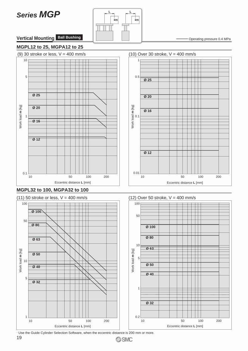
Vertical Mounting Ball Bushing
MGPL12 to 25, MGPA12 to 25
MGPL32 to 100, MGPA32 to 100
(9) 30 stroke or less, V = 400 mm/s (10) Over 30 stroke, V = 400 mm/s
(11) 50 stroke or less, V = 400 mm/s (12) Over 50 stroke, V = 400 mm/s
Operating pressure 0.4 MPa
· Use the Guide Cylinder Selection Software, when the eccentric distance is 200 mm or more.
L L
m m
19
Series MGP
10
5
1
0.110 30 50 51 100 300200
Stroke [mm]
Wo
rk lo
ad
m [
kg
]
50
Ø 100Ø 100
Ø 80
Ø 25
Ø 80
Ø 50, Ø 63
Ø 32, Ø 40
Ø 25
Ø 16
Ø 50, Ø 63
Ø 20
Ø 16
Ø 12
Ø 20
Ø 12
Ø 32, Ø 4010
50
5
1
0.1
10 30 50 51 100 300200
Stroke [mm]
Wo
rk lo
ad
m [
kg
]
Ø 100 Ø 100
Ø 80
Ø 16
Ø 80
Ø 50, Ø 63
Ø 25
Ø 20
Ø 16Ø 12
Ø 12
Ø 50, Ø 63Ø 32, Ø 40
Ø 25
Ø 20
Ø 32, Ø 40
Stroke [mm]
10
50
5
1
0.1
10 30 50 51 100 300200
Work
load m
[kg]
Ø 100
Ø 80
Ø 63
Ø 50
Ø 32
Ø 25
Ø 20
Ø 16
Ø 12
Ø 63
Ø 50
Ø 40
Ø 32
Ø 25
Ø 20
Ø 16
Ø 12
Ø 100
Ø 80
Ø 40
Wo
rk lo
ad
m [
kg
]
Stroke [mm]
10
50
5
1
0.110 30 50 51 100 300200
Ø 100
Ø 80
Ø 20
Ø 12
Ø 80
Ø 40
Ø 32
Ø 25
Ø 20
Ø 16
Ø 12
Ø 50, Ø 63 Ø 50, Ø 63
Ø 32
Ø 100
Ø 40
Ø 16
Ø 25
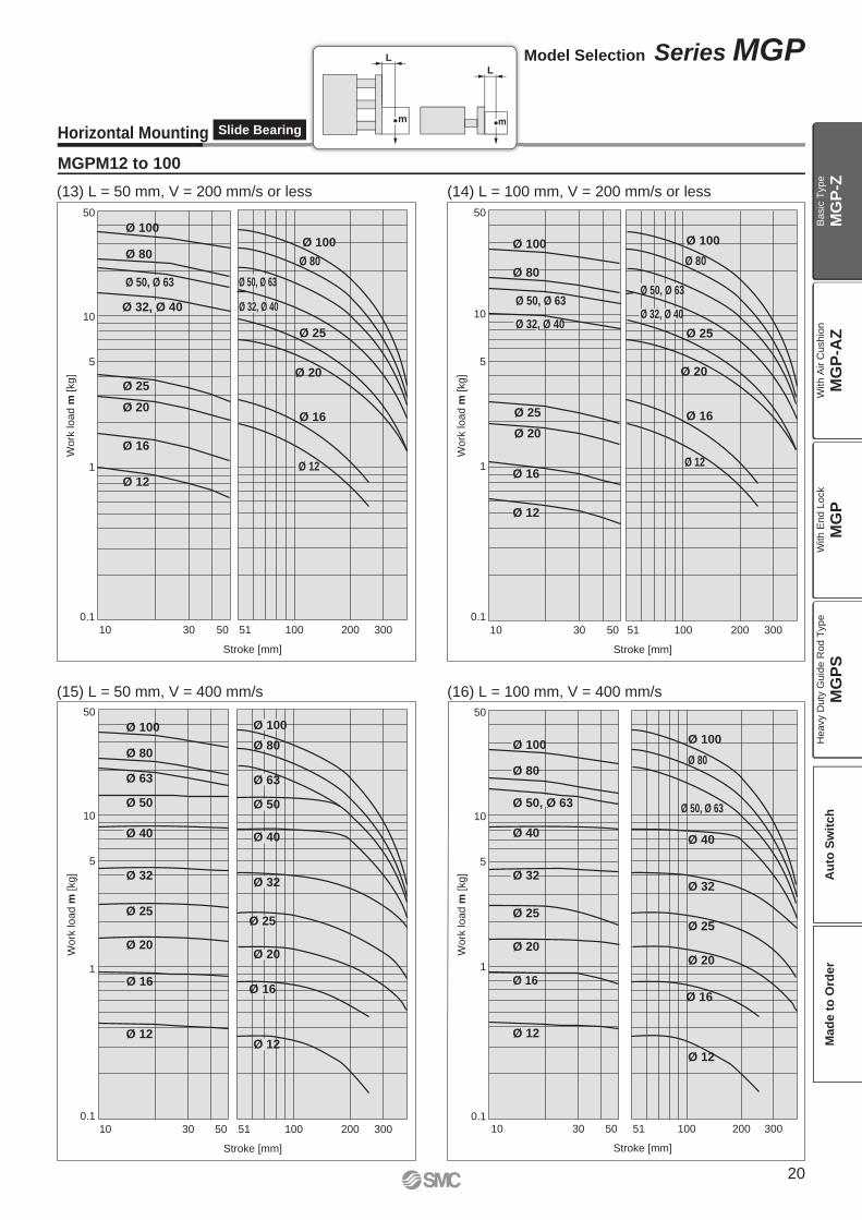
Horizontal Mounting Slide Bearing
MGPM12 to 100
(13) L = 50 mm, V = 200 mm/s or less (14) L = 100 mm, V = 200 mm/s or less
(15) L = 50 mm, V = 400 mm/s (16) L = 100 mm, V = 400 mm/s
L
m
L
m
20
Model Selection Series MGP
MG
P-Z
MG
P-A
ZM
GP
MG
PS
Ba
sic
Typ
eW
ith
Air C
ush
ion
With E
nd L
ock
Heavy D
uty
Guid
e R
od T
ype
Au
to S
wit
ch
Mad
e t
o O
rder
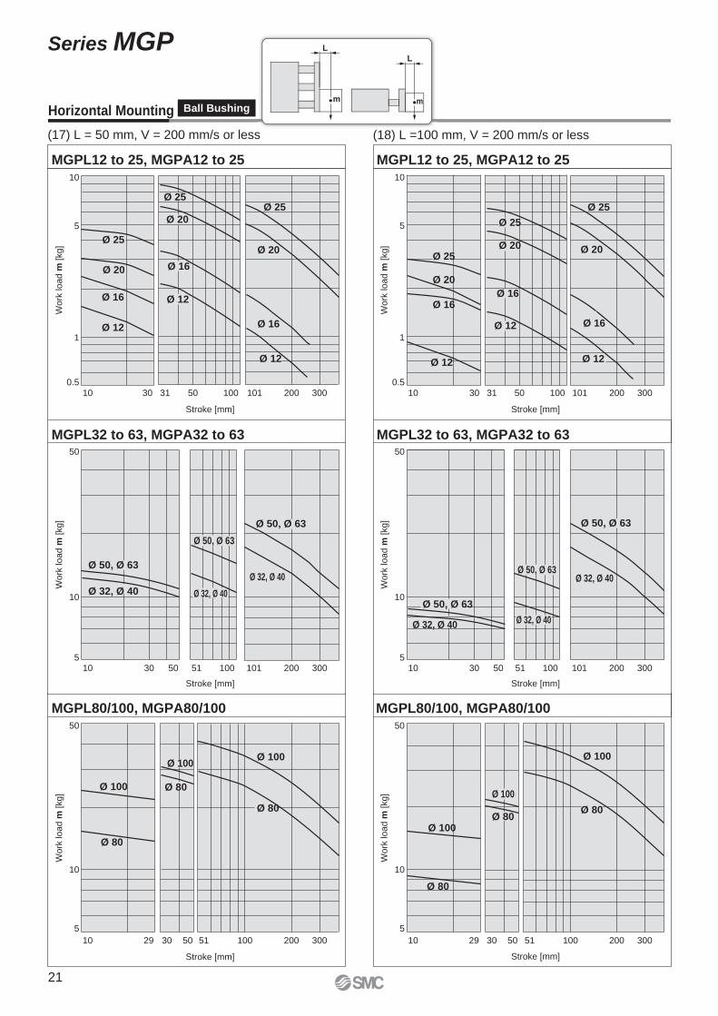
MGPL12 to 25, MGPA12 to 25
5
10
1
0.510 30 31 50 100 101 200 300
Stroke [mm]
Work
load m
[kg]
Ø 20
Ø 16
Ø 12
Ø 25
Ø 20
Ø 16
Ø 12
Ø 25
Ø 20
Ø 16
Ø 12
Ø 25
MGPL32 to 63, MGPA32 to 63
Stroke [mm]
50
10
510 30 5150 100 101 300200
Work
load m
[kg]
Ø 32, Ø 40
Ø 32, Ø 40
Ø 50, Ø 63
Ø 32, Ø 40
Ø 50, Ø 63
Ø 50, Ø 63
MGPL80/100, MGPA80/10050
10
5
10 29 30 5150 300200100
Stroke [mm]
Work
load m
[kg]
Ø 100
Ø 100Ø 100
Ø 80
Ø 80
Ø 80
MGPL12 to 25, MGPA12 to 25
5
10
1
0.510 30 31 50 100 101 200 300
Stroke [mm]
Work
load m
[kg]
Ø 25
Ø 20
Ø 16
Ø 12
Ø 25
Ø 20
Ø 16
Ø 12
Ø 25
Ø 20
Ø 16
Ø 12
MGPL32 to 63, MGPA32 to 63
Stroke [mm]
50
10
510 30 5150 100 101 300200
Work
load m
[kg]
Ø 50, Ø 63
Ø 32, Ø 40
Ø 32, Ø 40Ø 50, Ø 63
Ø 32, Ø 40
Ø 50, Ø 63
MGPL80/100, MGPA80/10050
10
5
10 29 30 5150 300200100
Stroke [mm]
Work
load m
[kg]
Ø 100
Ø 100
Ø 100
Ø 80
Ø 80
Ø 80
Horizontal Mounting Ball Bushing
(17) L = 50 mm, V = 200 mm/s or less (18) L =100 mm, V = 200 mm/s or less
L
m
L
m
21
Series MGP
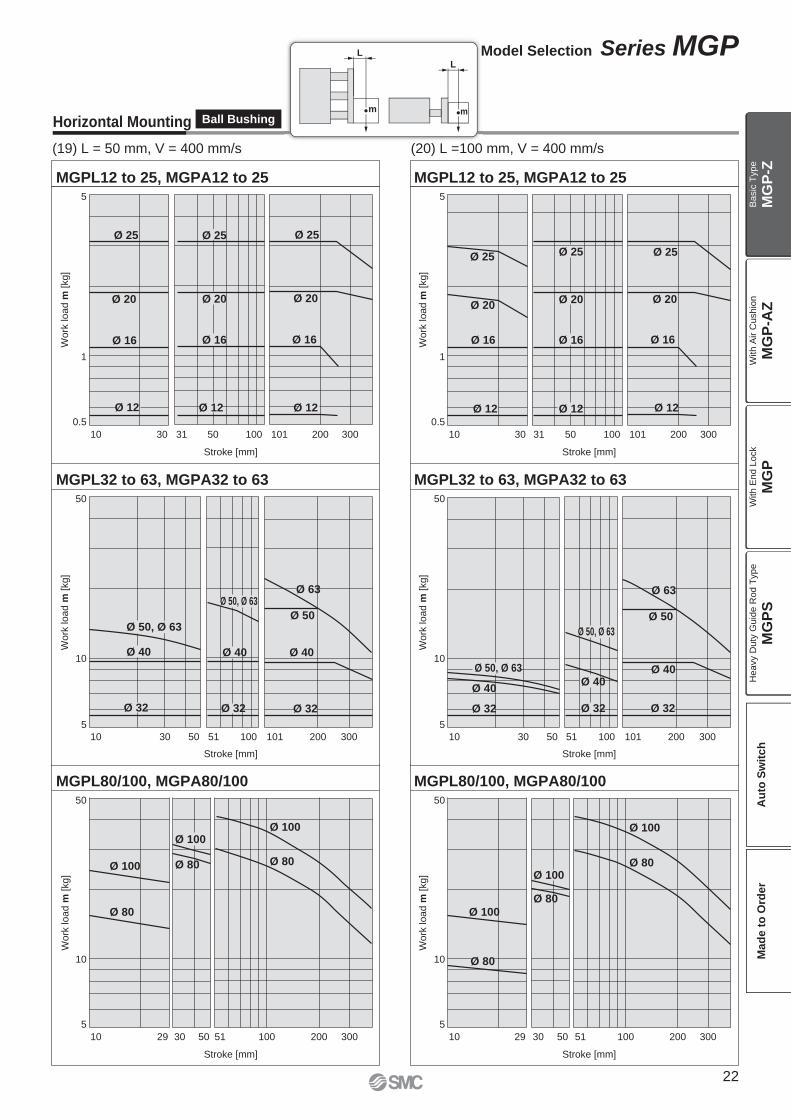
MGPL12 to 25, MGPA12 to 255
1
0.5
10 30 31 50 100 101 300200
Stroke [mm]
Stroke [mm]
Work
load m
[kg]
50
10
5
10 30 50 51 100 101 300200
Wo
rk lo
ad
m [kg
]
MGPL32 to 63, MGPA32 to 63
50
10
5
10 10029 30 50 51 300200
Stroke [mm]
Work
load m
[kg]
50
10
5
10 10029 30 50 51 300200
Stroke [mm]
Work
load m
[kg]
MGPL80/100, MGPA80/100
MGPL12 to 25, MGPA12 to 25
MGPL32 to 63, MGPA32 to 63
MGPL80/100, MGPA80/100
5
1
0.5
10 30 31 50 100 101 300200
Stroke [mm]
Work
load m
[kg]
Stroke [mm]
50
10
5
10 30 50 51 100 101 300200
Wo
rk lo
ad
m [kg
]
Ø 25
Ø 20
Ø 16
Ø 12
Ø 20
Ø 16
Ø 12
Ø 25
Ø 20
Ø 16
Ø 12
Ø 25
Ø 20
Ø 16
Ø 12
Ø 25
Ø 20
Ø 16
Ø 12
Ø 25
Ø 20
Ø 16
Ø 12
Ø 50, Ø 63
Ø 40
Ø 32
Ø 100
Ø 80
Ø 100
Ø 80
Ø 100
Ø 80
Ø 100
Ø 80
Ø 100
Ø 80
Ø 100
Ø 80
Ø 50, Ø 63
Ø 40
Ø 32
Ø 50
Ø 40
Ø 32
Ø 50, Ø 63
Ø 40
Ø 32
Ø 50, Ø 63
Ø 40
Ø 32
Ø 50
Ø 40
Ø 32
Ø 25
Ø 63 Ø 63
Horizontal Mounting Ball Bushing
(19) L = 50 mm, V = 400 mm/s (20) L =100 mm, V = 400 mm/s( )
L
m
L
m
22
Model Selection Series MGP
MG
P-Z
MG
P-A
ZM
GP
MG
PS
Ba
sic
Typ
eW
ith
Air C
ush
ion
With E
nd L
ock
Heavy D
uty
Guid
e R
od T
ype
Au
to S
wit
ch
Mad
e t
o O
rder
L
50
mm
L
50
mm
mm
m m
L
50
mm
L
50
mm
Transfer speed: υ [m/min]
Mass o
f tr
ansfe
rred o
bje
ct: m
[kg]
100
10
50
40
30
20
10
1
2
3
4
5
20 30 40 505
Ø 25
Ø 20
Ø 16
Ø 12
Transfer speed: υ [m/min]
Ma
ss o
f tr
an
sfe
rre
d o
bje
ct:
m [
kg
]
2000
10 20 30 40 50
Ø 50
Ø 32
1000
500
400
300
200
100
50
40
30
Ø 100
5
Ø 80
Ø 63
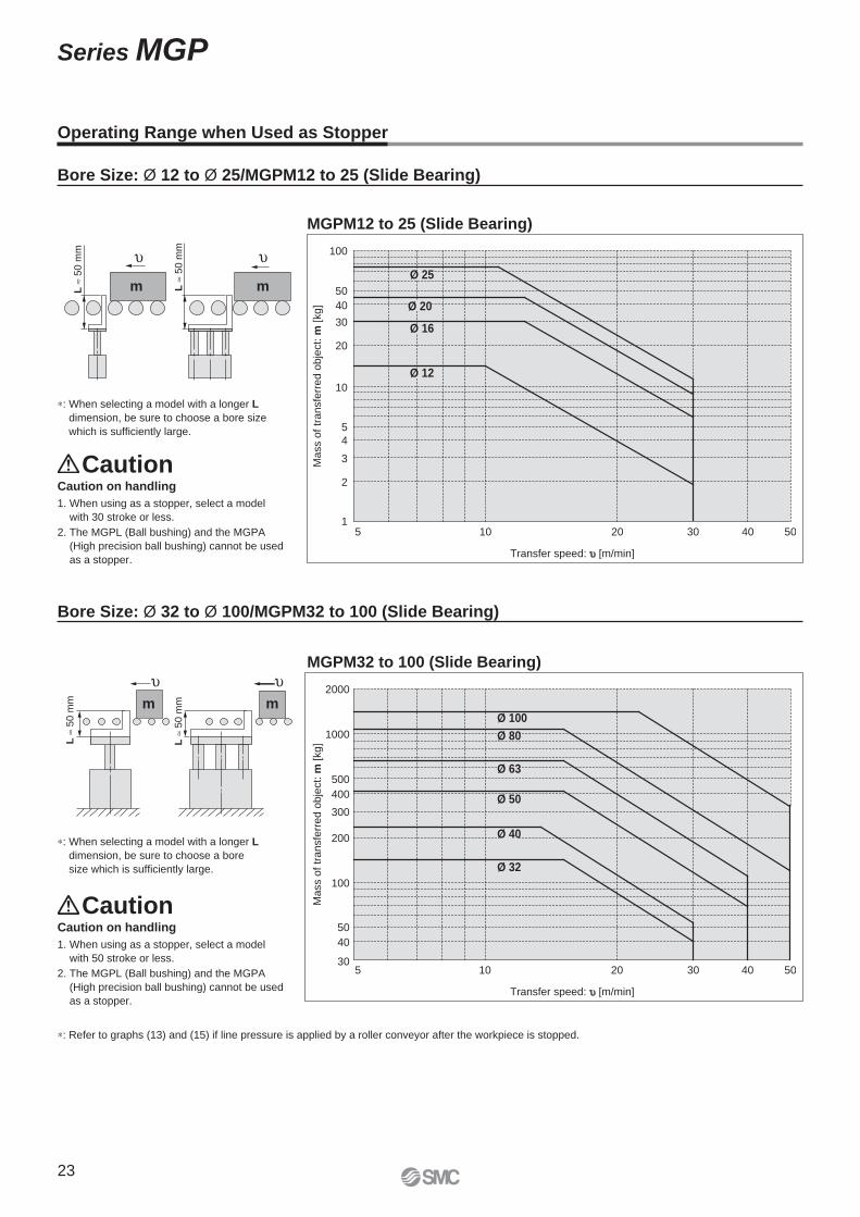
Ø 40
Bore Size: Ø 12 to Ø 25/MGPM12 to 25 (Slide Bearing)
Bore Size: Ø 32 to Ø 100/MGPM32 to 100 (Slide Bearing)
Operating Range when Used as Stopper
MGPM12 to 25 (Slide Bearing)
∗: Refer to graphs (13) and (15) if line pressure is applied by a roller conveyor after the workpiece is stopped.
MGPM32 to 100 (Slide Bearing)
CautionCaution on handling
1. When using as a stopper, select a model
with 30 stroke or less.
2. The MGPL (Ball bushing) and the MGPA
(High precision ball bushing) cannot be used
as a stopper.
CautionCaution on handling
1. When using as a stopper, select a model
with 50 stroke or less.
2. The MGPL (Ball bushing) and the MGPA
(High precision ball bushing) cannot be used
as a stopper.
∗: When selecting a model with a longer L
dimension, be sure to choose a bore size
which is suffi ciently large.
∗: When selecting a model with a longer L
dimension, be sure to choose a bore
size which is suffi ciently large.
23
Series MGP
Component Parts
Replacement Parts/Seal Kit
Component Parts
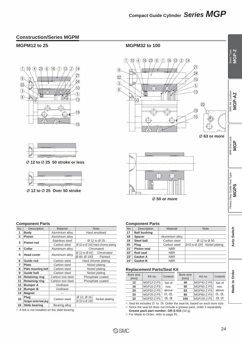
∗: Seal kit includes @1 to @4. Order the seal kit, based on each bore size.
∗: Since the seal kit does not include a grease pack, order it separately.
Grease pack part number: GR-S-010 (10 g)
∗: For Made to Order, refer to page 91.
Construction/Series MGPM
No. Description Material Note
17 Ball bushing
18 Spacer Aluminium alloy
19 Steel ball Carbon steel Ø 12 to Ø 50
20 Plug Carbon steel Ø 63 to Ø 100 Nickel plating
21∗ Piston seal NBR
22∗ Rod seal NBR
23∗ Gasket A NBR
24∗ Gasket B NBR
No. Description Material Note
1 Body Aluminium alloy Hard anodised
2 Piston Aluminium alloy
3 Piston rodStainless steel Ø 12 to Ø 25
Carbon steel Ø 32 to Ø 100 Hard chrome plating
4 Collar Aluminium alloy Chromated
5 Head cover Aluminium alloyØ 12 to Ø 63 Chromated
Ø 80, Ø 100 Painted
6 Guide rod Carbon steel Hard chrome plating
7 Plate Carbon steel Nickel plating
8 Plate mounting bolt Carbon steel Nickel plating
9 Guide bolt Carbon steel Nickel plating
10 Retaining ring Carbon tool steel Phosphate coated
11 Retaining ring Carbon tool steel Phosphate coated
12 Bumper A Urethane
13 Bumper B Urethane
14 Magnet —
15Plug
Carbon steelØ 12, Ø 16
Nickel platingHexagon socket head plug Ø 20 to Ø 100
16 Slide bearing Bearing alloy
Bore size
[mm]Kit no. Contents
40 MGP40-Z-PS Set of
nos.
above
@11, @22,
@33, @4
50 MGP50-Z-PS
63 MGP63-Z-PS
80 MGP80-Z-PS
100 MGP100-Z-PS
Bore size
[mm]Kit no. Contents
12 MGP12-Z-PS Set of
nos.
above
@11, @22,
@33, @44
16 MGP16-Z-PS
20 MGP20-Z-PS
25 MGP25-Z-PS
32 MGP32-Z-PS
Ø 50 or more
Ø 12 to Ø 25 50 stroke or less
Ø 12 to Ø 25 Over 50 stroke
Ø 63 or more
MGPM12 to 25 MGPM32 to 100
∗: A felt is not installed on the slide bearing.
24
Compact Guide Cylinder Series MGP
MG
P-Z
MG
P-A
ZM
GP
MG
PS
Ba
sic
Typ
eW
ith
Air C
ush
ion
With E
nd L
ock
Heavy D
uty
Guid
e R
od T
ype
Au
to S
wit
ch
Mad
e t
o O
rder
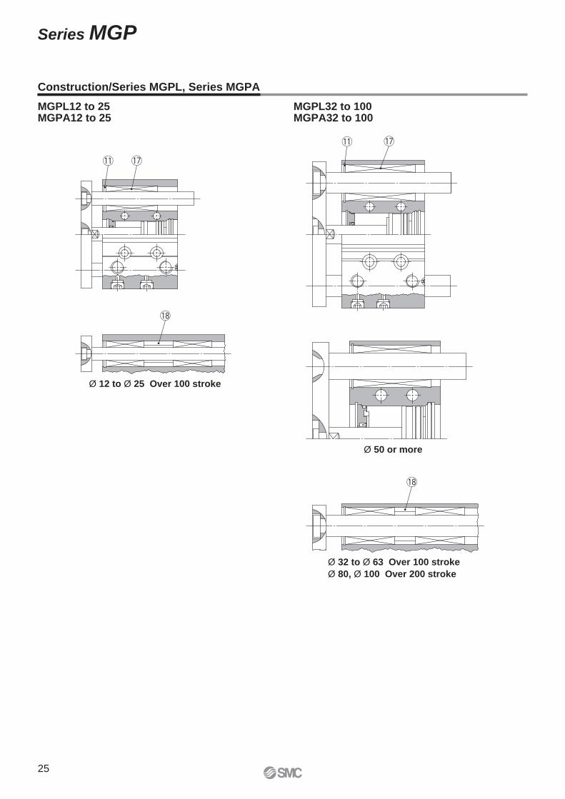
Construction/Series MGPL, Series MGPA
Ø 32 to Ø 63 Over 100 stroke
Ø 80, Ø 100 Over 200 stroke
MGPL12 to 25MGPA12 to 25
MGPL32 to 100MGPA32 to 100
Ø 50 or more
Ø 12 to Ø 25 Over 100 stroke
25
Series MGP
E
Z WA
WB
3
T R
Q
S
Z WA
Ø D
AØ
DB
PW
UX
E
FA
GA GB
L
HVA
VB
G
KJ
PB
FB
X (
Mo
un
tin
g h
ole
po
sitio
n)
Ø XA H9 depth 6
X±
0.0
2
(Pin
ho
le p
ositio
n)
4 x YY depth YL
Section XX
4 x NN through
Section XX
X±
0.0
2
Ø XA H9 depth 6
4 x Ø OA through
4 x Ø OB counterbore depth OL
A + Stroke
B + Stroke
C + Stroke
PA + Stroke2 x P
HA
: T-s
lot
for
hexa
gon
bolt
2 x P
(Plug)
4 x MM depth ML
(OL)
X±
0.0
2
Ø XA H9 depth 6
Section XX
T-slot
Section EE ∗1
b a
c de
XA
Ø X
AH
9
XB
3
6
f
Section XX details T-slot dimensions
Ø 12, Ø 16
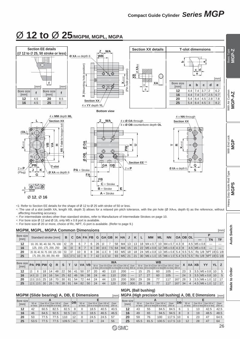
MGPM (Slide bearing) A, DB, E Dimensions [mm]
MGPL (Ball bushing)
MGPA (High precision ball bushing) A, DB, E Dimensions [mm]
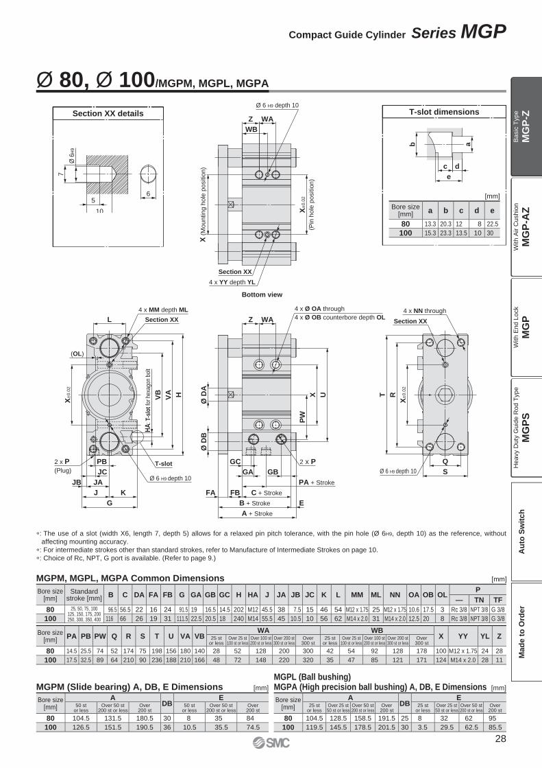
MGPM, MGPL, MGPA Common Dimensions [mm]
[mm]
Bore size [mm]
PA PB PW Q R S T U VA VBWA WB
X XA XB YY YL Z30 st or less
Over 30 st 100 st or less
Over 100 st 200 st or less
Over 200 st 300 st or less
Over 300 st
30 st or less
Over 30 st 100 st or less
Over 100 st 200 st or less
Over 200 st 300 st or less
Over 300 st
12 13 8 18 14 48 22 56 41 50 37 20 40 110 200 — 15 25 60 105 — 23 3 3.5 M5 x 0.8 10 5
16 14.5 10 19 16 54 25 62 46 56 38 24 44 110 200 — 17 27 60 105 — 24 3 3.5 M5 x 0.8 10 5
20 13.5 10.5 25 18 70 30 81 54 72 44 24 44 120 200 300 29 39 77 117 167 28 3 3.5 M6 x 1.0 12 17
25 12.5 13.5 30 26 78 38 91 64 82 50 24 44 120 200 300 29 39 77 117 167 34 4 4.5 M6 x 1.0 12 17
Bore size [mm]
Standard stroke [mm] B C DA FA FB G GA GB H HA J K L MM ML NN OA OB OLP
— TN TF
12 10, 20, 30, 40, 50, 75, 100
125, 150, 175, 200, 250
42 29 6 7 6 26 10 7 58 M4 13 13 18 M4 x 0.7 10 M4 x 0.7 4.3 8 4.5 M5 x 0.8 — —
16 46 33 8 7 6 30 10.5 7.5 64 M4 15 15 22 M5 x 0.8 12 M5 x 0.8 4.3 8 4.5 M5 x 0.8 — —
20 20, 30, 40, 50, 75, 100, 125, 150
175, 200, 250, 300, 350, 400
53 37 10 8 8 36 11.5 9 83 M5 18 18 24 M5 x 0.8 13 M5 x 0.8 5.4 9.5 5.5 Rc 1/8 NPT 1/8 G 1/8
25 53.5 37.5 10 9 7 42 11.5 10 93 M5 21 21 30 M6 x 1.0 15 M6 x 1.0 5.4 9.5 5.5 Rc 1/8 NPT 1/8 G 1/8
Bore size [mm]
ADB
E30 st
or lessOver 30 st
100 st or lessOver 100 st
200 st or lessOver
200 st30 st
or lessOver 30 st
100 st or lessOver 100 st
200 st or lessOver
200 st
12 43 55 84.5 84.5 6 1 13 42.5 42.5
16 49 65 94.5 94.5 8 3 19 48.5 48.5
20 59 76 100 117.5 10 6 23 47 64.5
25 65.5 81.5 100.5 117.5 13 12 28 47 64
Bore size [mm]
ADB
E50 st
or lessOver 50 st
100 st or lessOver 100 st 200 st or less
Over 200 st
50 st or less
Over 50 st 100 st or less
Over 100 st 200 st or less
Over 200 st
12 42 60.5 82.5 82.5 8 0 18.5 40.5 40.5
16 46 64.5 92.5 92.5 10 0 18.5 46.5 46.5
20 53 77.5 77.5 110 12 0 24.5 24.5 57
25 53.5 77.5 77.5 109.5 16 0 24 24 56
Bore size[mm]
a b c d e
12 4.4 7.4 3.7 2 6.2
16 4.4 7.4 3.7 2.5 6.7
20 5.4 8.4 4.5 2.8 7.8
25 5.4 8.4 4.5 3 8.2
Ø 12 to Ø 25/MGPM, MGPL, MGPA
Bottom view
∗1: Refer to Section EE details for the shape of Ø 12 to Ø 25 with stroke of 50 or less.
∗: The use of a slot (width XA, length XB, depth 3) allows for a relaxed pin pitch tolerance, with the pin hole (Ø XAH9, depth 6) as the reference, without
affecting mounting accuracy.
∗: For intermediate strokes other than standard strokes, refer to Manufacture of Intermediate Strokes on page 10.
∗: For bore size Ø 12 and Ø 16, only M5 x 0.8 port is available.
∗: For bore size Ø 20 or more, choice of Rc, NPT, G port is available. (Refer to page 9.)
Section EE details
(Ø 12 to Ø 25, 50 stroke or less)
Bore size[mm]
f
12 4.5
16 4.5
[mm]
Bore size[mm]
f
20 8.5
25 8
[mm]
26
Compact Guide Cylinder Series MGP
MG
P-Z
MG
P-A
ZM
GP
MG
PS
Ba
sic
Typ
eW
ith
Air C
ush
ion
With E
nd L
ock
Heavy D
uty
Guid
e R
od T
ype
Au
to S
wit
ch
Mad
e t
o O
rder
b a
c d
e
XA
XB
Ø X
AH
9
XC
XL
E
WA
WB
T R
S
Q
Z WA
Ø D
AØ
DB
E
FA FB
GA GB
PW
X UL
PB
J K
G
HVA
VB
Ø XA H9 depth XL
X (
Mounting h
ole
positio
n)
X±
0.0
2
(Pin
ho
le p
ositio
n)
4 x YY depth YL
Section XX
4 x NN through
Section XX
X±
0.0
2
Ø XA H9 depth XL
4 x Ø OA through
4 x Ø OB counterbore depth OL
A + Stroke
B + Stroke
C + Stroke
PA + Stroke
2 x P
4 x MM depth ML
Section XX
(OL)
X±
0.0
2
Ø XA H9 depth XL
2 x P
(Plug)
HA
: T-s
lot f
or h
exag
on b
olt
T-slot
ZSection XX details T-slot dimensions
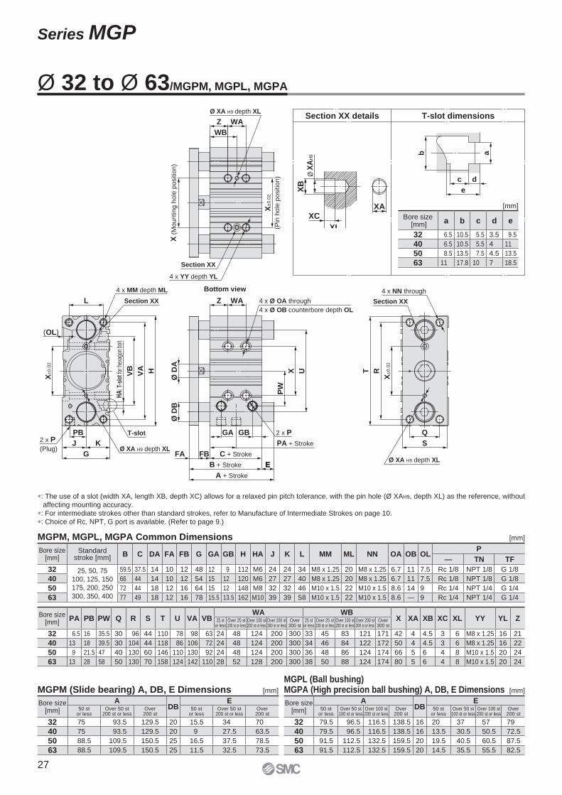
MGPL (Ball bushing)MGPA (High precision ball bushing) A, DB, E Dimensions
MGPM, MGPL, MGPA Common Dimensions
MGPM (Slide bearing) A, DB, E Dimensions [mm]
[mm]
[mm]
[mm]
Bore size [mm]
ADB
E50 st
or lessOver 50 st
100 st or lessOver 100 st 200 st or less
Over 200 st
50 st or less
Over 50 st 100 st or less
Over 100 st 200 st or less
Over 200 st
32 79.5 96.5 116.5 138.5 16 20 37 57 79
40 79.5 96.5 116.5 138.5 16 13.5 30.5 50.5 72.5
50 91.5 112.5 132.5 159.5 20 19.5 40.5 60.5 87.5
63 91.5 112.5 132.5 159.5 20 14.5 35.5 55.5 82.5
Bore size [mm]
ADB
E50 st
or lessOver 50 st
200 st or lessOver
200 st50 st
or lessOver 50 st
200 st or lessOver
200 st
32 75 93.5 129.5 20 15.5 34 70
40 75 93.5 129.5 20 9 27.5 63.5
50 88.5 109.5 150.5 25 16.5 37.5 78.5
63 88.5 109.5 150.5 25 11.5 32.5 73.5
Bore size [mm]
PA PB PW Q R S T U VA VBWA WB
X XA XB XC XL YY YL Z25 st or less
Over 25 st 100 st or less
Over 100 st 200 st or less
Over 200 st 300 st or less
Over 300 st
25 st or less
Over 25 st 100 st or less
Over 100 st 200 st or less
Over 200 st 300 st or less
Over 300 st
32 6.5 16 35.5 30 96 44 110 78 98 63 24 48 124 200 300 33 45 83 121 171 42 4 4.5 3 6 M8 x 1.25 16 21
40 13 18 39.5 30 104 44 118 86 106 72 24 48 124 200 300 34 46 84 122 172 50 4 4.5 3 6 M8 x 1.25 16 22
50 9 21.5 47 40 130 60 146 110 130 92 24 48 124 200 300 36 48 86 124 174 66 5 6 4 8 M10 x 1.5 20 24
63 13 28 58 50 130 70 158 124 142 110 28 52 128 200 300 38 50 88 124 174 80 5 6 4 8 M10 x 1.5 20 24
Bore size [mm]
Standard stroke [mm] B C DA FA FB G GA GB H HA J K L MM ML NN OA OB OL
P
— TN TF
32 25, 50, 75
100, 125, 150
175, 200, 250
300, 350, 400
59.5 37.5 14 10 12 48 12 9 112 M6 24 24 34 M8 x 1.25 20 M8 x 1.25 6.7 11 7.5 Rc 1/8 NPT 1/8 G 1/8
40 66 44 14 10 12 54 15 12 120 M6 27 27 40 M8 x 1.25 20 M8 x 1.25 6.7 11 7.5 Rc 1/8 NPT 1/8 G 1/8
50 72 44 18 12 16 64 15 12 148 M8 32 32 46 M10 x 1.5 22 M10 x 1.5 8.6 14 9 Rc 1/4 NPT 1/4 G 1/4
63 77 49 18 12 16 78 15.5 13.5 162 M10 39 39 58 M10 x 1.5 22 M10 x 1.5 8.6 — 9 Rc 1/4 NPT 1/4 G 1/4
Bore size [mm]
a b c d e
32 6.5 10.5 5.5 3.5 9.5
40 6.5 10.5 5.5 4 11
50 8.5 13.5 7.5 4.5 13.5
63 11 17.8 10 7 18.5
Ø 32 to Ø 63/MGPM, MGPL, MGPA
Bottom view
∗: The use of a slot (width XA, length XB, depth XC) allows for a relaxed pin pitch tolerance, with the pin hole (Ø XAH9, depth XL) as the reference, without
affecting mounting accuracy.
∗: For intermediate strokes other than standard strokes, refer to Manufacture of Intermediate Strokes on page 10.
∗: Choice of Rc, NPT, G port is available. (Refer to page 9.)
27
Series MGP
b a
c d
e
Ø 6
H9
7
65
10
Z WA
WB
Q
S
L
VB
VA H
PB
JB JA
J K
G
Z WA
Ø D
AØ
DB
UX
PW
FB
RT
E
GC
GB
FA
GAJC
Ø 6 H9 depth 10
X (
Mounting h
ole
positio
n)
Section XX
4 x YY depth YL
X±
0.0
2
(Pin
ho
le p
ositio
n)
4 x NN through
Section XX
Ø 6 H9 depth 10
X±
0.0
2
4 x Ø OA through
4 x Ø OB counterbore depth OL
2 x P
A + Stroke
B + Stroke
C + Stroke
PA + StrokeØ 6 H9 depth 10
4 x MM depth ML
HA
: T-s
lot
for
hexa
gon
bolt
2 x P
(Plug)
X±
0.0
2
(OL)
Section XX
T-slot
Section XX details T-slot dimensions
MGPM, MGPL, MGPA Common Dimensions [mm]
MGPL (Ball bushing)MGPA (High precision ball bushing) A, DB, E DimensionsMGPM (Slide bearing) A, DB, E Dimensions [mm] [mm]
[mm]
Bore size [mm]
ADB
E25 st
or lessOver 25 st 50 st or less
Over 50 st 200 st or less
Over 200 st
25 st or less
Over 25 st 50 st or less
Over 50 st 200 st or less
Over 200 st
80 104.5 128.5 158.5 191.5 25 8 32 62 95
100 119.5 145.5 178.5 201.5 30 3.5 29.5 62.5 85.5
Bore size [mm]
ADB
E50 st
or lessOver 50 st
200 st or lessOver
200 st50 st
or lessOver 50 st
200 st or lessOver
200 st
80 104.5 131.5 180.5 30 8 35 84
100 126.5 151.5 190.5 36 10.5 35.5 74.5
Bore size [mm]
Standard stroke [mm] B C DA FA FB G GA GB GC H HA J JA JB JC K L MM ML NN OA OB OL
P
— TN TF
80 25, 50, 75, 100125, 150, 175, 200250, 300, 350, 400
96.5 56.5 22 16 24 91.5 19 16.5 14.5 202 M12 45.5 38 7.5 15 46 54 M12 x 1.75 25 M12 x 1.75 10.6 17.5 3 Rc 3/8 NPT 3/8 G 3/8
100 116 66 26 19 31 111.5 22.5 20.5 18 240 M14 55.5 45 10.5 10 56 62 M14 x 2.0 31 M14 x 2.0 12.5 20 8 Rc 3/8 NPT 3/8 G 3/8
Bore size [mm]
PA PB PW Q R S T U VA VBWA WB
X YY YL Z25 st or less
Over 25 st 100 st or less
Over 100 st 200 st or less
Over 200 st 300 st or less
Over 300 st
25 st or less
Over 25 st 100 st or less
Over 100 st 200 st or less
Over 200 st 300 st or less
Over 300 st
80 14.5 25.5 74 52 174 75 198 156 180 140 28 52 128 200 300 42 54 92 128 178 100 M12 x 1.75 24 28
100 17.5 32.5 89 64 210 90 236 188 210 166 48 72 148 220 320 35 47 85 121 171 124 M14 x 2.0 28 11
Bore size[mm]
a b c d e
80 13.3 20.3 12 8 22.5
100 15.3 23.3 13.5 10 30
Ø 80, Ø 100/MGPM, MGPL, MGPA
Bottom view
∗: The use of a slot (width X6, length 7, depth 5) allows for a relaxed pin pitch tolerance, with the pin hole (Ø 6H9, depth 10) as the reference, without
affecting mounting accuracy.
∗: For intermediate strokes other than standard strokes, refer to Manufacture of Intermediate Strokes on page 10.
∗: Choice of Rc, NPT, G port is available. (Refer to page 9.)
28
Compact Guide Cylinder Series MGP
MG
P-Z
MG
P-A
ZM
GP
MG
PS
Ba
sic
Typ
eW
ith
Air C
ush
ion
With E
nd L
ock
Heavy D
uty
Guid
e R
od T
ype
Au
to S
wit
ch
Mad
e t
o O
rder
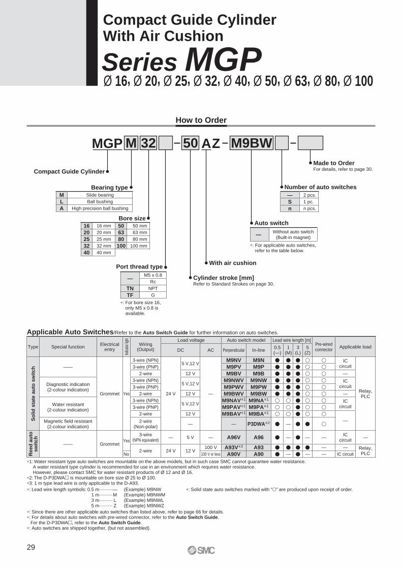
AZ
∗: For bore size 16, only M5 x 0.8 is available.
MGP M 32
Cylinder stroke [mm]Refer to Standard Strokes on page 30.
Bearing type
Bore size
M9BW50
Port thread type
Auto switch
Number of auto switches
With air cushion
Made to OrderFor details, refer to page 30.
∗: For applicable auto switches,refer to the table below.
∗: Solid state auto switches marked with “�” are produced upon receipt of order.
Applicable Auto Switches/Refer to the Auto Switch Guide for further information on auto switches.
∗: Lead wire length symbols: 0.5 m·········· — (Example) M9NW1 m·········· M (Example) M9NWM3 m·········· L (Example) M9NWL5 m·········· Z (Example) M9NWZ
∗: Since there are other applicable auto switches than listed above, refer to page 66 for details.∗: For details about auto switches with pre-wired connector, refer to the Auto Switch Guide.
For the D-P3DWA�, refer to the Auto Switch Guide.∗: Auto switches are shipped together, (but not assembled).
∗1: Water resistant type auto switches are mountable on the above models, but in such case SMC cannot guarantee water resistance. A water resistant type cylinder is recommended for use in an environment which requires water resistance. However, please contact SMC for water resistant products of Ø 12 and Ø 16.
∗2: The D-P3DWA� is mountable on bore size Ø 25 to Ø 100.∗3: 1 m type lead wire is only applicable to the D-A93.
Compact Guide CylinderWith Air Cushion
Series MGPØ 16, Ø 20, Ø 25, Ø 32, Ø 40, Ø 50, Ø 63, Ø 80, Ø 100
Compact Guide Cylinder
Type Special functionElectrical
entry
Indic
ator
light
Wiring(Output)
Load voltage Auto switch model Lead wire length [m]Pre-wired connector
Applicable loadDC AC Perpendicular In-line
0.5(—)
1(M)
3(L)
5(Z)
So
lid
sta
te a
uto
sw
itc
h ——
Grommet Yes
3-wire (NPN)
24 V
5 V,12 V
—
M9NV M9N � � � � � ICcircuit
Relay, PLC
3-wire (PNP) M9PV M9P � � � � �2-wire 12 V M9BV M9B � � � � � —
Diagnostic indication (2-colour indication)
3-wire (NPN)5 V,12 V
M9NWV M9NW � � � � � ICcircuit3-wire (PNP) M9PWV M9PW � � � � �
2-wire 12 V M9BWV M9BW � � � � � —
Water resistant (2-colour indication)
3-wire (NPN)5 V,12 V
M9NAV∗1 M9NA∗1 � � � � � ICcircuit3-wire (PNP) M9PAV∗1 M9PA∗1 � � � � �
2-wire 12 V M9BAV∗1 M9BA∗1 � � � � �—Magnetic fi eld resistant
(2-colour indication)2-wire
(Non-polar)— — P3DWA∗2 � — � � �
Reed
au
to
sw
itch
—— GrommetYes
3-wire(NPN equivalent)
— 5 V — A96V A96 � — � — —IC
circuit—
2-wire 24 V 12 V100 V A93V∗3 A93 � � � � — — Relay,
PLCNo 100 V or less A90V A90 � — � — — IC circuit
— 2 pcs.
S 1 pc.
n n pcs.
—Without auto switch
(Built-in magnet)
—M5 x 0.8
Rc
TN NPT
TF G
16 16 mm 50 50 mm
20 20 mm 63 63 mm
25 25 mm 80 80 mm
32 32 mm 100 100 mm
40 40 mm
M Slide bearing
L Ball bushing
A High precision ball bushing
How to Order
29
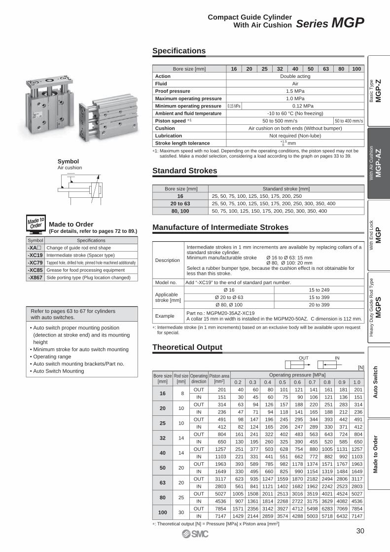
OUT IN
∗1: Maximum speed with no load. Depending on the operating conditions, the piston speed may not be satisfi ed. Make a model selection, considering a load according to the graph on pages 33 to 39.
SymbolAir cushion
Symbol Specifi cations
-XA� Change of guide rod end shape
-XC19 Intermediate stroke (Spacer type)
-XC79 Tapped hole, drilled hole, pinned hole machined additionally
-XC85 Grease for food processing equipment
-X867 Side porting type (Plug location changed)
Bore size[mm]
Rod size[mm]
Operatingdirection
Piston area[mm2]
Operating pressure [MPa]
0.2 0.3 0.4 0.5 0.6 0.7 0.8 0.9 1.0
16 8OUT 201 40 60 80 101 121 141 161 181 201
IN 151 30 45 60 75 90 106 121 136 151
20 10OUT 314 63 94 126 157 188 220 251 283 314
IN 236 47 71 94 118 141 165 188 212 236
25 10OUT 491 98 147 196 245 295 344 393 442 491
IN 412 82 124 165 206 247 289 330 371 412
32 14OUT 804 161 241 322 402 483 563 643 724 804
IN 650 130 195 260 325 390 455 520 585 650
40 14OUT 1257 251 377 503 628 754 880 1005 1131 1257
IN 1103 221 331 441 551 662 772 882 992 1103
50 20OUT 1963 393 589 785 982 1178 1374 1571 1767 1963
IN 1649 330 495 660 825 990 1154 1319 1484 1649
63 20OUT 3117 623 935 1247 1559 1870 2182 2494 2806 3117
IN 2803 561 841 1121 1402 1682 1962 2242 2523 2803
80 25OUT 5027 1005 1508 2011 2513 3016 3519 4021 4524 5027
IN 4536 907 1361 1814 2268 2722 3175 3629 4082 4536
100 30OUT 7854 1571 2356 3142 3927 4712 5498 6283 7069 7854
IN 7147 1429 2144 2859 3574 4288 5003 5718 6432 7147
∗: Theoretical output [N] = Pressure [MPa] x Piston area [mm2]
∗: Intermediate stroke (in 1 mm increments) based on an exclusive body will be available upon request for special.
Refer to pages 63 to 67 for cylinderswith auto switches.
• Auto switch proper mounting position
(detection at stroke end) and its mounting
height
• Minimum stroke for auto switch mounting
• Operating range
• Auto switch mounting brackets/Part no.
• Auto Switch Mounting
Bore size [mm] Standard stroke [mm]
16 25, 50, 75, 100, 125, 150, 175, 200, 250
20 to 63 25, 50, 75, 100, 125, 150, 175, 200, 250, 300, 350, 400
80, 100 50, 75, 100, 125, 150, 175, 200, 250, 300, 350, 400
Bore size [mm] 16 20 25 32 40 50 63 80 100
Action Double acting
Fluid Air
Proof pressure 1.5 MPa
Maximum operating pressure 1.0 MPa
Minimum operating pressure 0.15 MPa 0.12 MPa
Ambient and fl uid temperature -10 to 60 °C (No freezing)
Piston speed ∗1 50 to 500 mm/s 50 to 400 mm/s
Cushion Air cushion on both ends (Without bumper)
Lubrication Not required (Non-lube)
Stroke length tolerance +1.50 mm
Specifi cations
Standard Strokes
Manufacture of Intermediate Strokes
Theoretical Output
Description
Intermediate strokes in 1 mm increments are available by replacing collars of a standard stroke cylinder.Minimum manufacturable stroke Ø 16 to Ø 63: 15 mm Ø 80, Ø 100: 20 mmSelect a rubber bumper type, because the cushion effect is not obtainable for less than this stroke.
Model no. Add “-XC19” to the end of standard part number.
Applicable stroke [mm]
Ø 16 15 to 249
Ø 20 to Ø 63 15 to 399
Ø 80, Ø 100 20 to 399
ExamplePart no.: MGPM20-35AZ-XC19A collar 15 mm in width is installed in the MGPM20-50AZ. C dimension is 112 mm.
[N]
Made to Order (For details, refer to pages 72 to 89.)
30
Compact Guide CylinderWith Air Cushion Series MGP
MG
P-Z
MG
P-A
ZM
GP
MG
PS
Ba
sic
Typ
eW
ith
Air C
ush
ion
With E
nd L
ock
Heavy D
uty
Guid
e R
od T
ype
Au
to S
wit
ch
Mad
e t
o O
rder
L1
Pin hole
A
L2
Pin hole
Pin hole
B
+
–
B = ± (0.045 + L2 x 0.0016) [mm]
CautionPositioning accuracy for pin hole on the plateDispersion of dimensions when machining each component will be accumulated in the plate pin hole positioning accuracy when mounting this cylinder. Values below are referred as a guide.
[Side mounting]
A = Catalogue dimension ± (0.1 + L1 x 0.0008) [mm]∗1
[Bottom mounting]
∗1: To be 0.15 for Ø 80, Ø 100∗: Displacement by load and self-weight defl ection
by plate and guide rod are not included.
Allowable Rotational Torque of Plate
Ball Bushing: MGPL16 to 100, High Precision Ball Bushing: MGPA16 to 100
Torque: T [N·m]
Non-rotating accuracy θ when retracted and when no load is applied should be not more than the values shown in the table.
Bore size [mm]
Non-rotating accuracy θMGPM MGPL MGPA
16 ±0.07° ±0.05°
±0.01°
20±0.06° ±0.04°
25
32±0.05° ±0.03°
40
50±0.04° ±0.03°
63
80±0.03° ±0.03°
100
Bore size [mm]
Bearing type
Stroke
25 50 75 100 125 150 175 200 250 300 350 400
16MGPM 0.53 0.84 0.69 0.58 0.50 0.44 0.40 0.36 0.30 — — —
MGPL/A 1.27 0.86 0.65 0.52 0.43 0.37 0.32 0.28 0.23 — — —
20MGPM 0.99 2.23 1.88 1.63 1.44 1.28 1.16 1.06 0.90 0.78 0.69 0.62
MGPL/A 2.66 1.94 1.52 1.57 1.34 1.17 1.03 0.93 0.76 0.65 0.56 0.49
25MGPM 1.64 3.51 2.96 2.57 2.26 2.02 1.83 1.67 1.42 1.24 1.09 0.98
MGPL/A 4.08 3.02 2.38 2.41 2.05 1.78 1.58 1.41 1.16 0.98 0.85 0.74
32MGPM 6.35 6.64 5.69 4.97 4.42 3.98 3.61 3.31 2.84 2.48 2.20 1.98
MGPL/A 5.95 5.89 5.11 6.99 6.34 5.79 5.33 4.93 4.29 3.78 3.38 3.04
40MGPM 7.00 7.32 6.27 5.48 4.87 4.38 3.98 3.65 3.13 2.74 2.43 2.19
MGPL/A 6.55 6.49 5.62 7.70 6.98 6.38 5.87 5.43 4.72 4.16 3.71 3.35
50MGPM 13.0 13.8 12.0 10.6 9.50 8.60 7.86 7.24 6.24 5.49 4.90 4.43
MGPL/A 9.17 11.2 9.80 12.8 11.6 10.7 9.80 9.10 7.95 7.02 6.26 5.63
63MGPM 14.7 15.6 13.5 11.9 10.7 9.69 8.86 8.16 7.04 6.19 5.52 4.99
MGPL/A 10.2 12.5 11.0 14.3 13.0 11.9 11.0 10.2 8.84 7.80 6.64 6.24
80MGPM — 26.0 22.9 20.5 18.6 17.0 15.6 14.5 12.6 11.2 10.0 9.11
MGPL/A — 25.2 22.7 20.6 18.9 17.3 16.0 14.8 12.9 11.3 10.0 8.94
100MGPM — 41.9 37.5 33.8 30.9 28.4 26.2 24.4 21.4 19.1 17.2 15.7
MGPL/A — 41.7 37.9 34.6 31.8 29.3 27.2 25.3 22.1 19.5 17.3 15.5
Slide Bearing: MGPM16 to 100
Bore size [mm]
Standard stroke [mm]
25 50 75 100 125 150 175 200 250 300 350 400
16 0.46 0.62 0.74 0.83 1.02 1.10 1.19 1.28 1.46 — — —
20 0.77 1.02 1.21 1.35 1.49 1.63 1.77 1.91 2.55 2.83 3.11 3.39
25 1.06 1.43 1.68 1.84 2.01 2.18 2.35 2.52 3.50 3.84 4.18 4.51
32 1.66 2.06 2.42 2.65 2.88 3.11 3.34 3.57 5.07 5.53 5.99 6.46
40 1.95 2.40 2.79 3.06 3.33 3.59 3.86 4.13 5.71 6.25 6.78 7.32
50 3.26 3.96 4.55 4.96 5.36 5.76 6.16 6.56 9.03 9.83 10.63 11.43
63 4.11 4.90 5.58 6.07 6.56 7.05 7.54 8.04 10.68 11.66 12.64 13.63
80 — 7.47 8.35 8.95 9.55 10.15 10.75 11.35 15.04 16.24 17.44 18.65
100 — 12.10 13.37 14.24 15.11 15.98 16.85 17.72 22.88 24.62 26.36 28.10
Bore size [mm]
Standard stroke [mm]
25 50 75 100 125 150 175 200 250 300 350 400
16 0.48 0.58 0.66 0.83 0.94 1.02 1.11 1.19 1.36 — — —
20 0.82 0.97 1.10 1.35 1.50 1.63 1.76 1.89 2.33 2.59 2.84 3.10
25 1.16 1.34 1.49 1.83 2.03 2.18 2.34 2.49 3.11 3.41 3.72 4.02
32 1.58 2.00 2.29 2.67 2.95 3.15 3.36 3.57 4.47 4.88 5.29 5.70
40 1.87 2.33 2.65 3.06 3.38 3.63 3.87 4.11 5.09 5.57 6.06 6.54
50 3.10 3.81 4.30 4.92 5.42 5.79 6.17 6.55 8.08 8.83 9.58 10.33
63 3.94 4.74 5.34 6.05 6.64 7.11 7.58 8.05 9.77 10.71 11.65 12.59
80 — 7.61 8.35 8.91 9.46 10.02 10.57 11.13 13.99 15.10 16.21 17.32
100 — 12.04 13.14 13.97 14.79 15.62 16.44 17.27 21.14 22.80 24.45 26.10
Weights High Precision Ball Bushing/MGPA
Non-rotating Accuracy of Plate
[kg]
[kg]
T [N·m]
31
Series MGP
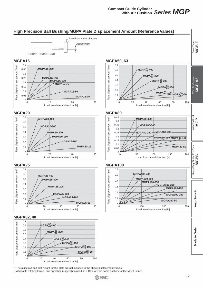
Load from lateral direction
Displacement
Load from lateral direction [N]
Pla
te d
ispla
cem
ent am
ount [m
m]
0 10 20 30
MGPA16-75
0.4
0.35
0.3
0.25
0.2
0.15
0.1
0.05
0
MGPA16-100
MGPA16-250
MGPA16-150
MGPA16-50
MGPA16-25
Load from lateral direction [N]
Pla
te d
ispla
cem
ent am
ount [m
m]
0 20 40 60
0.7
0.6
0.5
0.4
0.3
0.2
0.1
0
MGPA20-400
MGPA20-300
MGPA20-200
MGPA20-150
MGPA20-100
MGPA20-25
Load from lateral direction [N]
Pla
te d
ispla
cem
ent am
ount [m
m]
0 20 40 60 80
0.7
0.6
0.5
0.4
0.3
0.2
0.1
0
MGPA25-400
MGPA25-300
MGPA25-200
MGPA25-150
MGPA25-100
MGPA25-50
Load from lateral direction [N]
Pla
te d
ispla
cem
ent am
ount [m
m]
0 20 40 60 80 100
0.8
0.7
0.6
0.5
0.4
0.3
0.2
0.1
0
MGPA -4003240
MGPA -3003240
MGPA -2003240
MGPA -1503240
MGPA -1003240
MGPA -503240
5063
Load from lateral direction [N]P
late
dis
pla
cem
ent am
ount [m
m]
0 20 40 60 80 100
0.7
0.6
0.5
0.4
0.3
0.2
0.1
0
MGPA -4005063
5063MGPA -300
MGPA -2005063
MGPA -1505063
MGPA -1005063 MGPA -50
5063
Load from lateral direction [N]
Pla
te d
ispla
cem
ent am
ount [m
m]
0 50 100 150 200
0.45
0.4
0.35
0.3
0.25
0.2
0.15
0.1
0.05
0
MGPA80-400
MGPA80-300
MGPA80-250 MGPA80-200
MGPA80-50
MGPA80-100MGPA80-150
Load from lateral direction [N]
Pla
te d
ispla
cem
ent am
ount [m
m]
0 100 200 300
0.6
0.5
0.4
0.3
0.2
0.1
0
MGPA100-400
MGPA100-300
MGPA100-250MGPA100-200
MGPA100-150
MGPA100-100
MGPA100-50
∗: The guide rod and self-weight for the plate are not included in the above displacement values.
∗: Allowable rotating torque, and operating range when used as a lifter, are the same as those of the MGPL series.
MGPA16
MGPA20
MGPA25
MGPA32, 40
MGPA50, 63
MGPA80
MGPA100
High Precision Ball Bushing/MGPA Plate Displacement Amount (Reference Values)
32
Compact Guide CylinderWith Air Cushion Series MGP
MG
P-Z
MG
P-A
ZM
GP
MG
PS
Ba
sic
Typ
eW
ith
Air C
ush
ion
With E
nd L
ock
Heavy D
uty
Guid
e R
od T
ype
Au
to S
wit
ch
Mad
e t
o O
rder
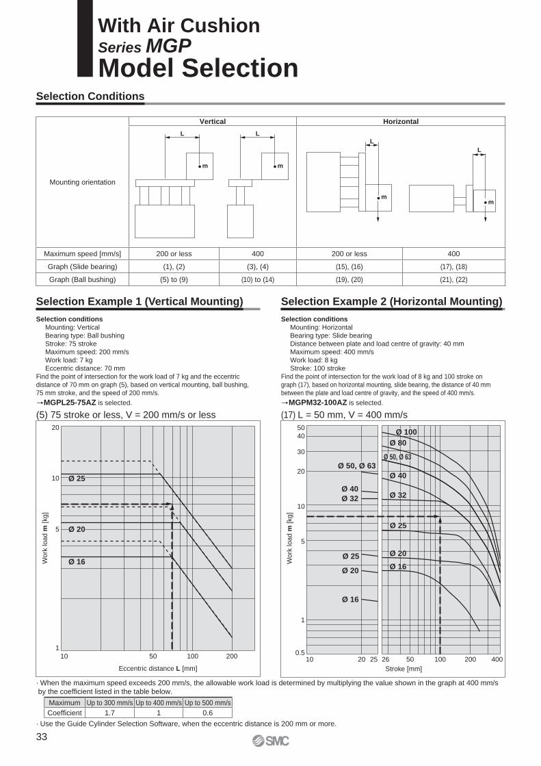
L L
m m
L
m
L
m
5
Wo
rk lo
ad
m [
kg
]
10
20
1
10 50 100 200
Eccentric distance L [mm]
Ø 25
Ø 20
Ø 16
Stroke [mm]
Wo
rk lo
ad
m [
kg
]
10
50
40
30
20
5
1
0.510 20 25 26 50 100 200 400
Ø 50, Ø 63
Ø 40
Ø 32
Ø 25
Ø 20
Ø 16
Ø 100
Ø 80
Ø 32
Ø 40
Ø 25
Ø 20
Ø 16
Ø 50, Ø 63
(17) L = 50 mm, V = 400 mm/s(5) 75 stroke or less, V = 200 mm/s or less
Selection conditions
Mounting: Vertical
Bearing type: Ball bushing
Stroke: 75 stroke
Maximum speed: 200 mm/s
Work load: 7 kg
Eccentric distance: 70 mm
Find the point of intersection for the work load of 7 kg and the eccentric
distance of 70 mm on graph (5), based on vertical mounting, ball bushing,
75 mm stroke, and the speed of 200 mm/s.
MGPL25-75AZ is selected.
Selection conditions
Mounting: Horizontal
Bearing type: Slide bearing
Distance between plate and load centre of gravity: 40 mm
Maximum speed: 400 mm/s
Work load: 8 kg
Stroke: 100 stroke
Find the point of intersection for the work load of 8 kg and 100 stroke on
graph (17), based on horizontal mounting, slide bearing, the distance of 40 mm
between the plate and load centre of gravity, and the speed of 400 mm/s.
MGPM32-100AZ is selected.
With Air CushionSeries MGP
Model SelectionSelection Conditions
Selection Example 1 (Vertical Mounting) Selection Example 2 (Horizontal Mounting)
Mounting orientation
Vertical Horizontal
Maximum speed [mm/s] 200 or less 400 200 or less 400
Graph (Slide bearing) (1), (2) (3), (4) (15), (16) (17), (18)
Graph (Ball bushing) (5) to (9) (10) to (14) (19), (20) (21), (22)
· When the maximum speed exceeds 200 mm/s, the allowable work load is determined by multiplying the value shown in the graph at 400 mm/s by the coeffi cient listed in the table below.
· Use the Guide Cylinder Selection Software, when the eccentric distance is 200 mm or more.
Maximum Up to 300 mm/s Up to 400 mm/s Up to 500 mm/s
Coeffi cient 1.7 1 0.6
33
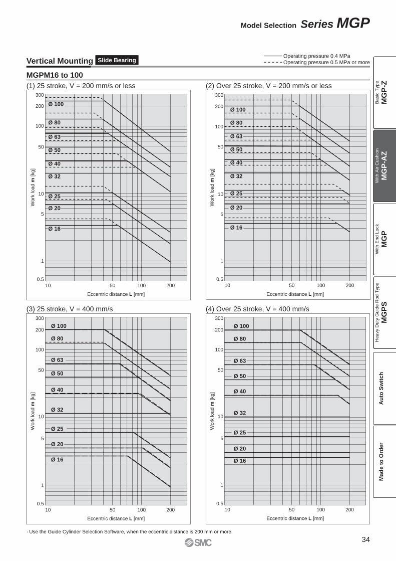
300
100
200
50
10
5
1
0.5
50 100 200
Eccentric distance L [mm]
Wo
rk lo
ad
m [
kg
]
10
Ø 100
Ø 80
Ø 63
Ø 50
Ø 40
Ø 32
Ø 25
Ø 20
Ø 16
300
200
100
50
10
5
1
0.5
10 50 100 200
Eccentric distance L [mm]
Work
load m
[kg]
Ø 80
Ø 63
Ø 50
Ø 40
Ø 32
Ø 25
Ø 20
Ø 16
Ø 100
Eccentric distance L [mm]
300
100
50
10
5
1
0.5
50 100 200
Wo
rk lo
ad
m [
kg
]
10
200
Ø 40
Ø 50
Ø 63
Ø 80
Ø 100
Ø 32
Ø 16
Ø 20
Ø 25
Eccentric distance L [mm]
300
200
100
50
10
5
1
0.5
50 100 200
Wo
rk lo
ad
m [
kg
]
10
Ø 40
Ø 50
Ø 63
Ø 100
Ø 32
Ø 16
Ø 20
Ø 25
Ø 80
Vertical Mounting Slide Bearing
(1) 25 stroke, V = 200 mm/s or less (2) Over 25 stroke, V = 200 mm/s or less
(3) 25 stroke, V = 400 mm/s (4) Over 25 stroke, V = 400 mm/s
· Use the Guide Cylinder Selection Software, when the eccentric distance is 200 mm or more.
Operating pressure 0.4 MPaOperating pressure 0.5 MPa or more
MGPM16 to 100
Slide Bearing
34
Model Selection Series MGP
MG
P-Z
MG
P-A
ZM
GP
MG
PS
Ba
sic
Typ
eW
ith
Air C
ush
ion
With E
nd L
ock
Heavy D
uty
Guid
e R
od T
ype
Au
to S
wit
ch
Mad
e t
o O
rder
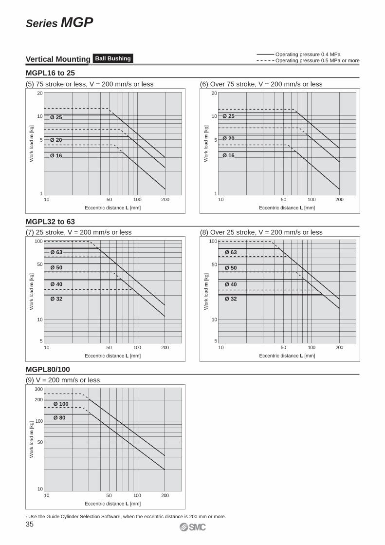
10
20
5
1
10 50 100 200
Eccentric distance L [mm]
Wo
rk lo
ad
m [
kg
]
Ø 25
Ø 20
Ø 16
10
20
5
1
10 50 100 200
Eccentric distance L [mm]W
ork
lo
ad
m [
kg
]
Ø 25
Ø 20
Ø 16
Eccentric distance L [mm]
50
10
5
10 50 100 200
Wo
rk lo
ad
m [
kg
]
100
Ø 63
Ø 50
Ø 40
Ø 32
Eccentric distance L [mm]
50
10
5
10 50 100 200
Wo
rk lo
ad
m [
kg
]
100
Ø 63
Ø 50
Ø 40
Ø 32
Eccentric distance L [mm]
50
200
300
10
10 50 100 200
Wo
rk lo
ad
m [
kg
] 100
Ø 100
Ø 80
MGPL80/100
(5) 75 stroke or less, V = 200 mm/s or less (6) Over 75 stroke, V = 200 mm/s or less
(7) 25 stroke, V = 200 mm/s or less (8) Over 25 stroke, V = 200 mm/s or less
(9) V = 200 mm/s or less
· Use the Guide Cylinder Selection Software, when the eccentric distance is 200 mm or more.
MGPL16 to 25
MGPL32 to 63
Vertical Mounting Ball BushingOperating pressure 0.4 MPaOperating pressure 0.5 MPa or more
35
Series MGP
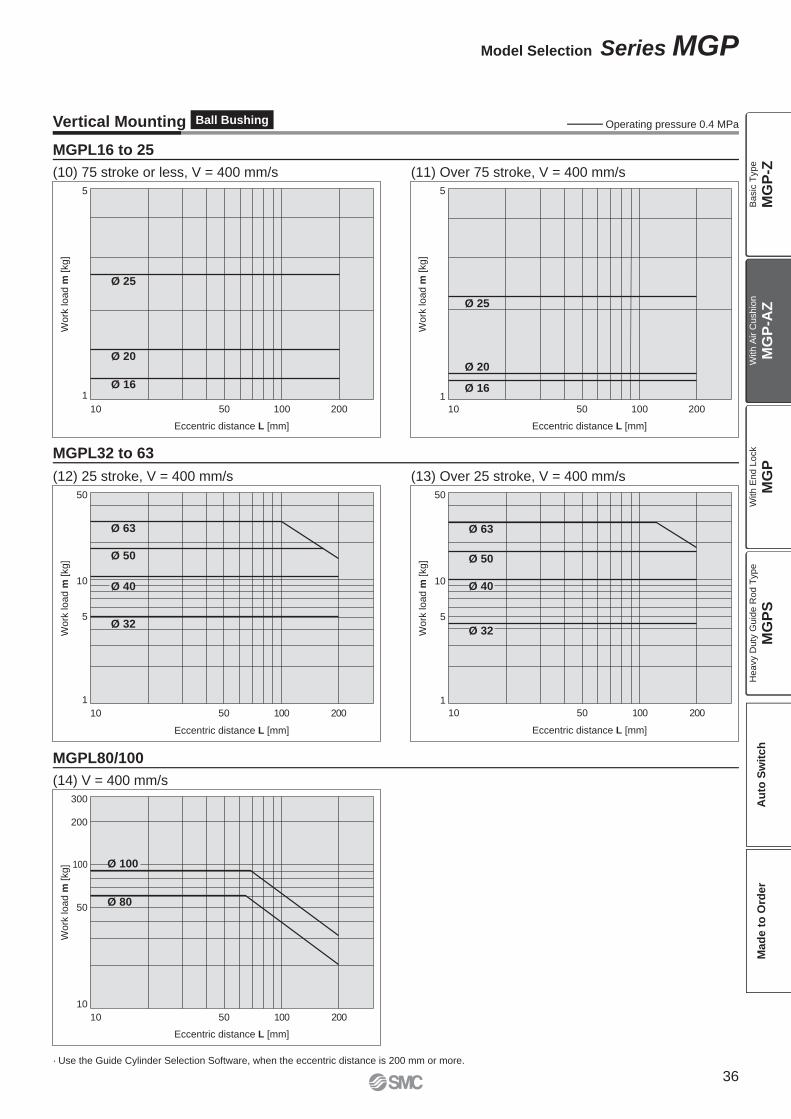
5
1
10 50 100 200
Eccentric distance L [mm]
Wo
rk lo
ad
m [
kg
]
Ø 25
Ø 20
Ø 16
5
1
10 50 100 200
Eccentric distance L [mm]W
ork
lo
ad
m [
kg
]
Ø 25
Ø 20
Ø 16
Eccentric distance L [mm]
50
10
5
1
10 50 100 200
Wo
rk lo
ad
m [
kg
]
Ø 63
Ø 50
Ø 40
Ø 32
Eccentric distance L [mm]
50
10
5
1
10 50 100 200
Wo
rk lo
ad
m [
kg
]
Ø 63
Ø 50
Ø 40
Ø 32
Eccentric distance L [mm]
200
300
50
100
10
10 50 100 200
Wo
rk lo
ad
m [
kg
] Ø 100
Ø 80
Vertical Mounting Ball Bushing
(10) 75 stroke or less, V = 400 mm/s (11) Over 75 stroke, V = 400 mm/s
(12) 25 stroke, V = 400 mm/s
(14) V = 400 mm/s
(13) Over 25 stroke, V = 400 mm/s
· Use the Guide Cylinder Selection Software, when the eccentric distance is 200 mm or more.
MGPL16 to 25
MGPL32 to 63
MGPL80/100
Operating pressure 0.4 MPa
36
Model Selection Series MGP
MG
P-Z
MG
P-A
ZM
GP
MG
PS
Ba
sic
Typ
eW
ith
Air C
ush
ion
With E
nd L
ock
Heavy D
uty
Guid
e R
od T
ype
Au
to S
wit
ch
Mad
e t
o O
rder
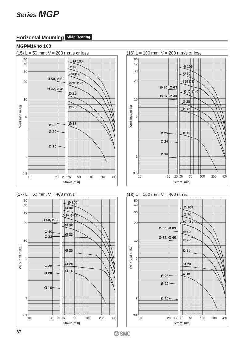
10
50
40
30
20
0.510 20 25 26 50 100 200 400
Stroke [mm]
Work
load m
[kg]
Ø 50, Ø 63
Ø 32, Ø 40
Ø 25
Ø 20
Ø 16
Ø 100
Ø 80
Ø 50, Ø 63
Ø 32, Ø 40
Ø 25
Ø 16
Ø 20
5
1
10
50
40
30
20
5
1
0.510 20 25 26 50 100 200 400
Stroke [mm]
Work
load m
[kg]
Ø 50, Ø 63
Ø 32, Ø 40
Ø 25
Ø 20
Ø 16
Ø 100
Ø 80
Ø 32, Ø 40
Ø 25
Ø 20
Ø 16
Ø 50, Ø 63
10
50
40
30
20
5
1
0.510 20 25 26 50 100 200 400
Stroke [mm]
Wo
rk lo
ad
m [
kg
]
Ø 50, Ø 63
Ø 40
Ø 32
Ø 25
Ø 20
Ø 16
Ø 100
Ø 80
Ø 50, Ø 63
Ø 32
Ø 40
Ø 25
Ø 20
Ø 16
10
50
40
30
20
5
1
0.510 20 25 26 50 100 200 400
Stroke [mm]
Work
load m
[kg]
Ø 50, Ø 63
Ø 32, Ø 40
Ø 25
Ø 20
Ø 16
Ø 100
Ø 80
Ø 40
Ø 32
Ø 25
Ø 20
Ø 16
Ø 50, Ø 63
Horizontal Mounting Slide Bearing
(15) L = 50 mm, V = 200 mm/s or less (16) L = 100 mm, V = 200 mm/s or less
(17) L = 50 mm, V = 400 mm/s (18) L = 100 mm, V = 400 mm/s
MGPM16 to 100
37
Series MGP
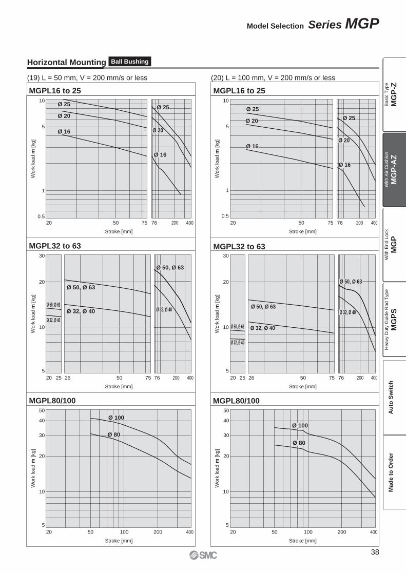
MGPL32 to 63
MGPL80/100 MGPL80/100
MGPL32 to 63
MGPL16 to 25 MGPL16 to 25
5
10
0.5
20 50 7675 200 400
Stroke [mm]
Work
load m
[kg]
5
10
0.5
20 50 7675 200 400
Stroke [mm]
Work
load m
[kg]
10
20
5
20 50 7675 200 400
Stroke [mm]
Work
load m
[kg]
10
20
30 30
5
2025 2526 26 50 7675 200 400
Stroke [mm]
Work
load m
[kg]
10
20
5
20 50 100 200 400
Stroke [mm]
Work
load m
[kg]
10
50
30
40
20
50
30
40
5
20 50 100 200 400
Stroke [mm]
Work
load m
[kg]
1 1
Ø 80
Ø 25
Ø 16
Ø 25
Ø 16
Ø 20
Ø 20
Ø 25
Ø 20
Ø 50, Ø 63
Ø 32, Ø 40
Ø 50, Ø 63
Ø 32, Ø 40
Ø 50, Ø 63
Ø 32, Ø 40Ø 50, Ø 63
Ø 50, Ø 63
Ø 32, Ø 40
Ø 100
Ø 80
Ø 100
Ø 16
Ø 50, Ø 63
Ø 32, Ø 40
Ø 32, Ø 40
Ø 25
Ø 16
Ø 20
Horizontal Mounting Ball Bushing
(19) L = 50 mm, V = 200 mm/s or less (20) L = 100 mm, V = 200 mm/s or less
38
Model Selection Series MGP
MG
P-Z
MG
P-A
ZM
GP
MG
PS
Ba
sic
Typ
eW
ith
Air C
ush
ion
With E
nd L
ock
Heavy D
uty
Guid
e R
od T
ype
Au
to S
wit
ch
Mad
e t
o O
rder
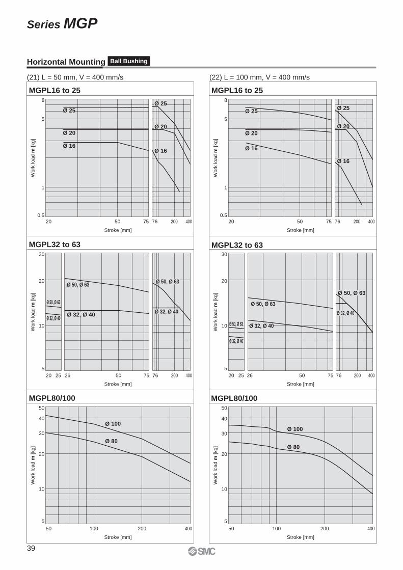
MGPL32 to 63
MGPL80/100 MGPL80/100
MGPL32 to 63
MGPL16 to 25 MGPL16 to 25
5
8
0.5
20 50 7675 200 400
Stroke [mm]
Wo
rk lo
ad
m [
kg
]
5
8
0.5
20 50 7675 200 400
Stroke [mm]
Wo
rk lo
ad
m [
kg
]
10
20
5
20 50 7675 400200
Stroke [mm]
Wo
rk lo
ad
m [
kg
]
10
20
30 30
5
2025 2526 26 50 7675 200 400
Stroke [mm]
Wo
rk lo
ad
m [
kg
]
10
20
5
50 100 200 400
Stroke [mm]
Wo
rk lo
ad
m [
kg
]
10
20
50 50
30 30
40 40
5
50 100 200 400
Stroke [mm]
Wo
rk lo
ad
m [
kg
]
1 1
Ø 25
Ø 16
Ø 20
Ø 25
Ø 16
Ø 20
Ø 25
Ø 16
Ø 20
Ø 25
Ø 16
Ø 20
Ø 50, Ø 63
Ø 32, Ø 40
Ø 50, Ø 63
Ø 32, Ø 40
Ø 80
Ø 50, Ø 63
Ø 32, Ø 40
Ø 50, Ø 63
Ø 32, Ø 40
Ø 100
Ø 80
Ø 100
Ø 50, Ø 63
Ø 32, Ø 40
Ø 50, Ø 63
Ø 32, Ø 40
Horizontal Mounting Ball Bushing
(21) L = 50 mm, V = 400 mm/s (22) L = 100 mm, V = 400 mm/s
39
Series MGP
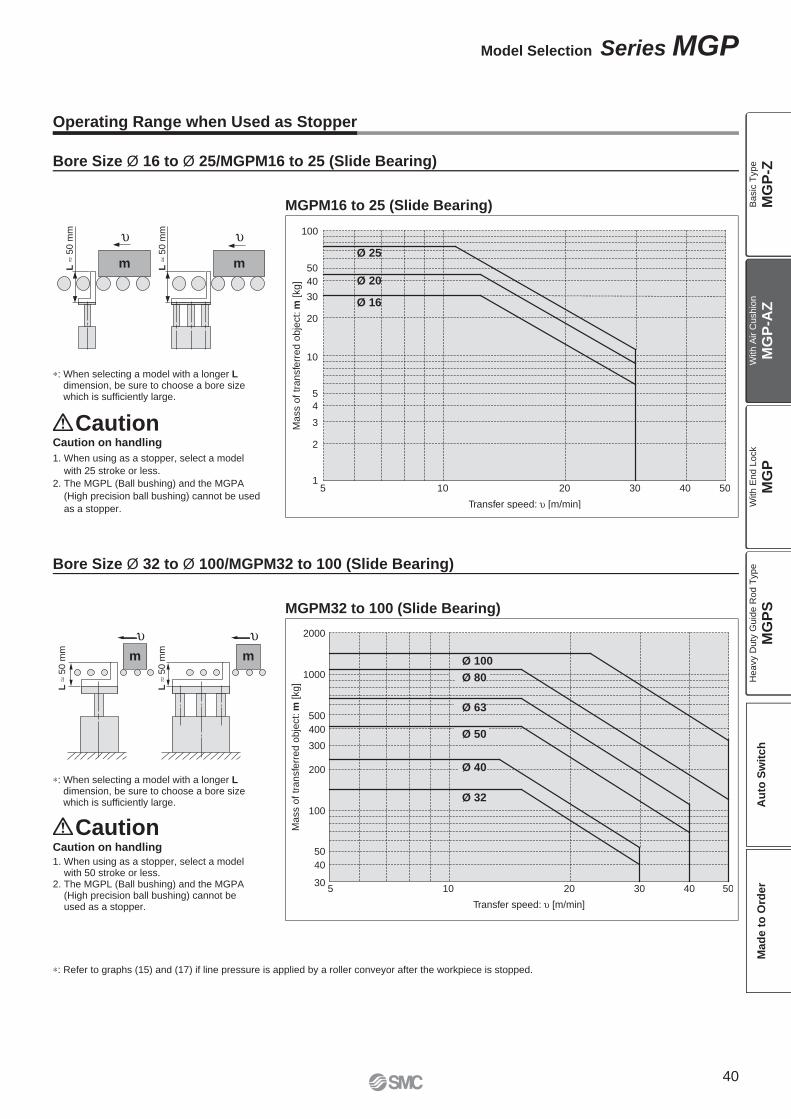
L
50
mm
L
50
mm
mm
Transfer speed: υ [m/min]
Ma
ss o
f tr
an
sfe
rre
d o
bje
ct: m
[kg
]
100
10
50
40
30
20
10
1
2
3
4
5
20 30 40 50
Ø 25
Ø 20
Ø 16
5
m m
L
50
mm
L
50
mm
Transfer speed: υ [m/min]
Ma
ss o
f tr
an
sfe
rre
d o
bje
ct: m
[kg
]
2000
10 20 30 40 50
Ø 63
Ø 50
Ø 40
Ø 32
1000
500
400
300
200
100
50
40
30
Ø 100
Ø 80
5
∗: When selecting a model with a longer Ldimension, be sure to choose a bore size which is suffi ciently large.
Caution on handling
1. When using as a stopper, select a model with 50 stroke or less.
2. The MGPL (Ball bushing) and the MGPA (High precision ball bushing) cannot be used as a stopper.
∗: Refer to graphs (15) and (17) if line pressure is applied by a roller conveyor after the workpiece is stopped.
Caution
Caution
∗: When selecting a model with a longer Ldimension, be sure to choose a bore size which is suffi ciently large.
Operating Range when Used as Stopper
MGPM16 to 25 (Slide Bearing)
MGPM32 to 100 (Slide Bearing)
Caution on handling
1. When using as a stopper, select a model
with 25 stroke or less.
2. The MGPL (Ball bushing) and the MGPA
(High precision ball bushing) cannot be used
as a stopper.
Bore Size Ø 16 to Ø 25/MGPM16 to 25 (Slide Bearing)
Bore Size Ø 32 to Ø 100/MGPM32 to 100 (Slide Bearing)
40
Model Selection Series MGP
MG
P-Z
MG
P-A
ZM
GP
MG
PS
Ba
sic
Typ
eW
ith
Air C
ush
ion
With E
nd L
ock
Heavy D
uty
Guid
e R
od T
ype
Au
to S
wit
ch
Mad
e t
o O
rder
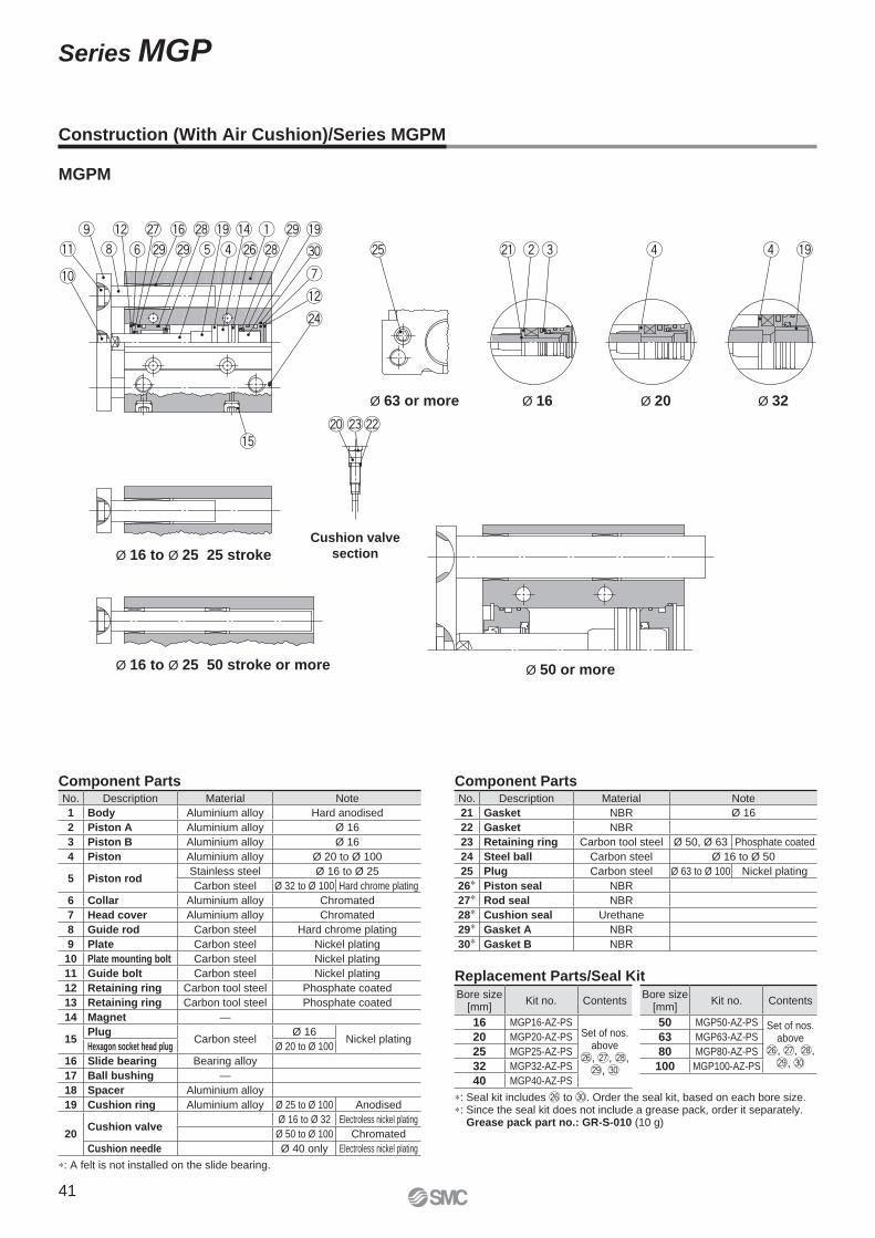
MGPM
∗: Seal kit includes @6 to #0. Order the seal kit, based on each bore size.∗: Since the seal kit does not include a grease pack, order it separately.
Grease pack part no.: GR-S-010 (10 g)
No. Description Material Note
21 Gasket NBR Ø 16
22 Gasket NBR
23 Retaining ring Carbon tool steel Ø 50, Ø 63 Phosphate coated
24 Steel ball Carbon steel Ø 16 to Ø 50
25 Plug Carbon steel Ø 63 to Ø 100 Nickel plating
26∗ Piston seal NBR
27∗ Rod seal NBR
28∗ Cushion seal Urethane
29∗ Gasket A NBR
30∗ Gasket B NBR
Bore size [mm]
Kit no. Contents
50 MGP50-AZ-PS Set of nos. above
@6, @7, @8, @9, #0
63 MGP63-AZ-PS
80 MGP80-AZ-PS
100 MGP100-AZ-PS
Bore size [mm]
Kit no. Contents
16 MGP16-AZ-PSSet of nos.
above@6, @7, @8, @9, #0
20 MGP20-AZ-PS
25 MGP25-AZ-PS
32 MGP32-AZ-PS
40 MGP40-AZ-PS
No. Description Material Note
1 Body Aluminium alloy Hard anodised
2 Piston A Aluminium alloy Ø 16
3 Piston B Aluminium alloy Ø 16
4 Piston Aluminium alloy Ø 20 to Ø 100
5 Piston rodStainless steel Ø 16 to Ø 25
Carbon steel Ø 32 to Ø 100 Hard chrome plating
6 Collar Aluminium alloy Chromated
7 Head cover Aluminium alloy Chromated
8 Guide rod Carbon steel Hard chrome plating
9 Plate Carbon steel Nickel plating
10 Plate mounting bolt Carbon steel Nickel plating
11 Guide bolt Carbon steel Nickel plating
12 Retaining ring Carbon tool steel Phosphate coated
13 Retaining ring Carbon tool steel Phosphate coated
14 Magnet —
15Plug
Carbon steelØ 16
Nickel platingHexagon socket head plug Ø 20 to Ø 100
16 Slide bearing Bearing alloy
17 Ball bushing —
18 Spacer Aluminium alloy
19 Cushion ring Aluminium alloy Ø 25 to Ø 100 Anodised
20Cushion valve
Ø 16 to Ø 32 Electroless nickel plating
Ø 50 to Ø 100 Chromated
Cushion needle Ø 40 only Electroless nickel plating
Ø 63 or more Ø 16 Ø 20 Ø 32
Ø 16 to Ø 25 25 stroke
Cushion valve
section
Ø 16 to Ø 25 50 stroke or more Ø 50 or more
Component Parts Component Parts
Construction (With Air Cushion)/Series MGPM
Replacement Parts/Seal Kit
∗: A felt is not installed on the slide bearing.
41
Series MGP
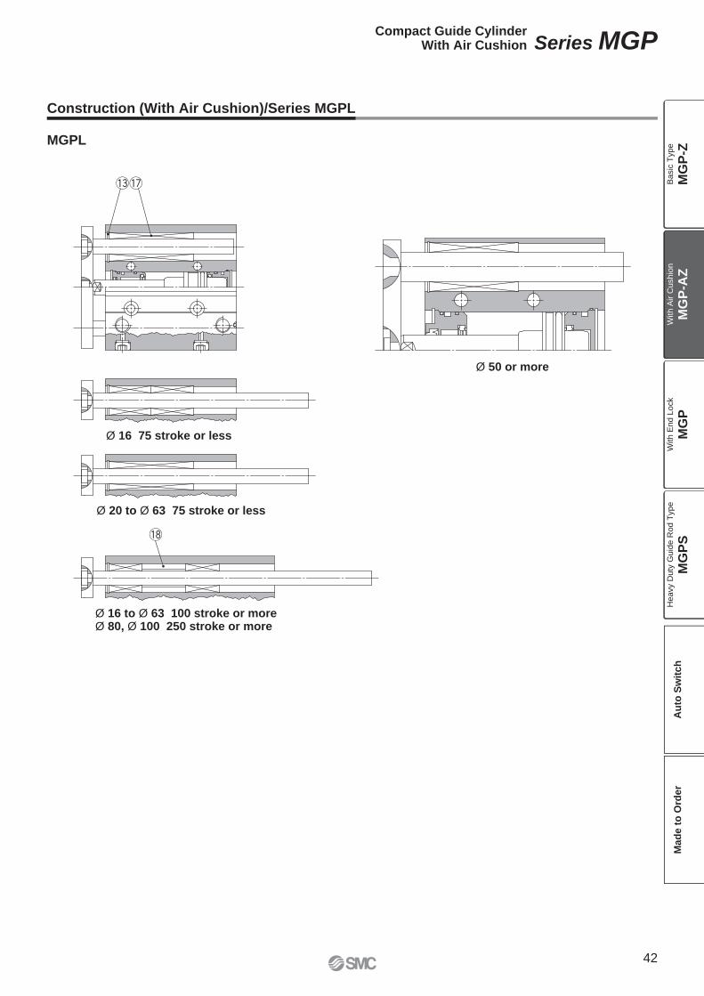
MGPL
Ø 16 to Ø 63 100 stroke or moreØ 80, Ø 100 250 stroke or more
Ø 50 or more
Ø 20 to Ø 63 75 stroke or less
Ø 16 75 stroke or less
Construction (With Air Cushion)/Series MGPL
42
Compact Guide CylinderWith Air Cushion Series MGP
MG
P-Z
MG
P-A
ZM
GP
MG
PS
Ba
sic
Typ
eW
ith
Air C
ush
ion
With E
nd L
ock
Heavy D
uty
Guid
e R
od T
ype
Au
to S
wit
ch
Mad
e t
o O
rder
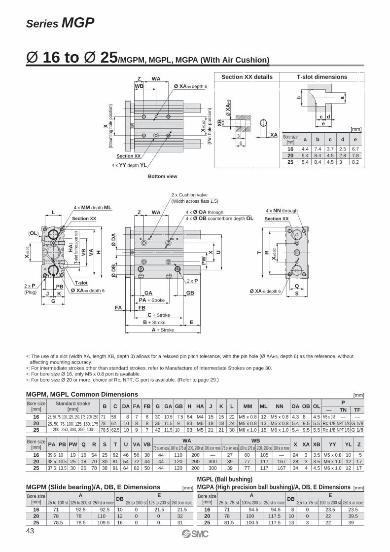
∗: The use of a slot (width XA, length XB, depth 3) allows for a relaxed pin pitch tolerance, with the pin hole (Ø XAH9, depth 6) as the reference, without
affecting mounting accuracy.
∗: For intermediate strokes other than standard strokes, refer to Manufacture of Intermediate Strokes on page 30.
∗: For bore size Ø 16, only M5 x 0.8 port is available.
∗: For bore size Ø 20 or more, choice of Rc, NPT, G port is available. (Refer to page 29.)
b
e
c d
a
6
XA3
XB
Ø X
AH
9
Section XX details T-slot dimensions
Bore size [mm]
ADB
E
25 to 75 st 100 to 200 st 250 st or more 25 to 75 st 100 to 200 st 250 st or more
16 71 94.5 94.5 8 0 23.5 23.5
20 78 100 117.5 10 0 22 39.5
25 81.5 100.5 117.5 13 3 22 39
Bore size [mm]
ADB
E
25 to 100 st 125 to 200 st 250 st or more 25 to 100 st 125 to 200 st 250 st or more
16 71 92.5 92.5 10 0 21.5 21.5
20 78 78 110 12 0 0 32
25 78.5 78.5 109.5 16 0 0 31
Bore size [mm]
Standard stroke[mm]
B C DA FA FB G GA GB H HA J K L MM ML NN OA OB OLP
— TN TF
16 25, 50, 75, 100, 125, 150, 175, 200, 250 71 58 8 7 6 30 10.5 7.5 64 M4 15 15 22 M5 x 0.8 12 M5 x 0.8 4.3 8 4.5 M5 x 0.8 — —
20 25, 50, 75, 100, 125, 150, 175200, 250, 300, 350, 400
78 62 10 8 8 36 11.5 9 83 M5 18 18 24 M5 x 0.8 13 M5 x 0.8 5.4 9.5 5.5 Rc 1/8 NPT 1/8 G 1/8
25 78.5 62.5 10 9 7 42 11.5 10 93 M5 21 21 30 M6 x 1.0 15 M6 x 1.0 5.4 9.5 5.5 Rc 1/8 NPT 1/8 G 1/8
Bore size [mm]
PA PB PW Q R S T U VA VBWA WB
X XA XB YY YL Z75 st or less 100 to 175 st 200, 250 st 300 st or more 75 st or less 100 to 175 st 200, 250 st 300 st or more
16 39.5 10 19 16 54 25 62 46 56 38 44 110 200 — 27 60 105 — 24 3 3.5 M5 x 0.8 10 5
20 38.5 10.5 25 18 70 30 81 54 72 44 44 120 200 300 39 77 117 167 28 3 3.5 M6 x 1.0 12 17
25 37.5 13.5 30 26 78 38 91 64 82 50 44 120 200 300 39 77 117 167 34 4 4.5 M6 x 1.0 12 17
Bottom view
Ø 16 to Ø 25/MGPM, MGPL, MGPA (With Air Cushion)
Bore size [mm]
a b c d e
16 4.4 7.4 3.7 2.5 6.7
20 5.4 8.4 4.5 2.8 7.8
25 5.4 8.4 4.5 3 8.2
[mm]
[mm]MGPM, MGPL Common Dimensions
MGPM (Slide bearing)/A, DB, E Dimensions
MGPL (Ball bushing)
MGPA (High precision ball bushing)/A, DB, E Dimensions[mm] [mm]
VB
VA H
J K
PB
G
2 x P
GB
PA + Stroke
C + Stroke
B + Stroke
A + Stroke
E
FA FB
GA
Ø D
BØ
DA
PW
X UWAZ
2 x Cushion valve
(Width across flats 1.5)
4 x Ø OA through
4 x Ø OB counterbore depth OL
X±0
.02
2 x P
(Plug)
L4 x MM depth ML
Ø XAH9 depth 6
HA
:T-
slot
for h
exag
on b
olt
Q
S
RT
Ø XAH9 depth 6
4 x NN through
X±
0.0
2
(OL)
X(M
ountin
g h
ole
posi
tion)
WAZ
WB Ø XAH9 depth 6
X±0
.02
(Pin
ho
le p
ositio
n)
Section XX
4 x YY depth YL
Section XXSection XX
T-slot
43
Series MGP
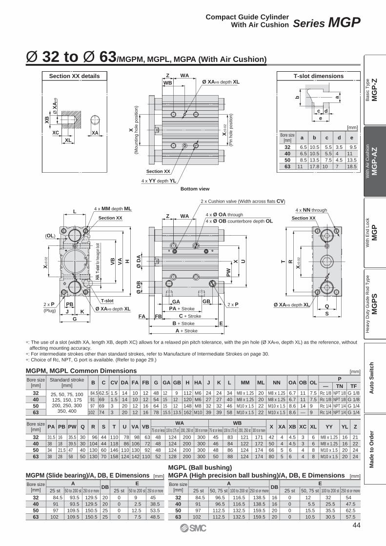
Ø XAH9 depth XL2 x P
(Plug) J
G
K
VB
VA H
L
HA: T
-slo
t for
hex
agon
bol
t
PB
4 x MM depth ML4 x Ø OA through
4 x Ø OB counterbore depth OL
UX
PW
2 x P Q
S
Ø D
AØ
DB
RT
Ø XAH9 depth XL
4 x NN through
Z WA
PA + Stroke
C + Stroke
B + Stroke
A + Stroke
E
GBGA
FA FB
X±0
.02
(Pin
hole
posi
tion)
X(M
ou
ntin
g h
ole
po
sitio
n)
WAZ
Ø XAH9 depth XL
(OL)
X±0
.02
X±0
.02
4 x YY depth YL
Section XX
WB
Section XXSection XX
T-slot
2 x Cushion valve (Width across flats CV)
T-slot dimensionsSection XX details
b
c d
e
a
XA
XL
XB
Ø X
AH
9
XC
Bore size [mm]
ADB
E
25 st 50, 75 st 100 to 200 st 250 st or more 25 st 50, 75 st 100 to 200 st 250 st or more
32 84.5 96.5 116.5 138.5 16 0 12 32 54
40 91 96.5 116.5 138.5 16 0 5.5 25.5 47.5
50 97 112.5 132.5 159.5 20 0 15.5 35.5 62.5
63 102 112.5 132.5 159.5 20 0 10.5 30.5 57.5
Bore size [mm]
ADB
E
25 st 50 to 200 st 250 st or more 25 st 50 to 200 st 250 st or more
32 84.5 93.5 129.5 20 0 9 45
40 91 93.5 129.5 20 0 2.5 38.5
50 97 109.5 150.5 25 0 12.5 53.5
63 102 109.5 150.5 25 0 7.5 48.5
Bore size [mm]
a b c d e
32 6.5 10.5 5.5 3.5 9.5
40 6.5 10.5 5.5 4 11
50 8.5 13.5 7.5 4.5 13.5
63 11 17.8 10 7 18.5
Bottom view
Bore size [mm]
PA PB PW Q R S T U VA VBWA WB
X XA XB XC XL YY YL Z75 st or less 100 to 175 st 200, 250 st 300 st or more 75 st or less 100 to 175 st 200, 250 st 300 st or more
32 31.5 16 35.5 30 96 44 110 78 98 63 48 124 200 300 45 83 121 171 42 4 4.5 3 6 M8 x 1.25 16 21
40 38 18 39.5 30 104 44 118 86 106 72 48 124 200 300 46 84 122 172 50 4 4.5 3 6 M8 x 1.25 16 22
50 34 21.5 47 40 130 60 146 110 130 92 48 124 200 300 48 86 124 174 66 5 6 4 8 M10 x 1.5 20 24
63 38 28 58 50 130 70 158 124 142 110 52 128 200 300 50 88 124 174 80 5 6 4 8 M10 x 1.5 20 24
Bore size [mm]
Standard stroke[mm]
B C CV DA FA FB G GA GB H HA J K L MM ML NN OA OB OLP
— TN TF
32 25, 50, 75, 100125, 150, 175200, 250, 300
350, 400
84.5 62.5 1.5 14 10 12 48 12 9 112 M6 24 24 34 M8 x 1.25 20 M8 x 1.25 6.7 11 7.5 Rc 1/8 NPT 1/8 G 1/8
40 91 69 1.5 14 10 12 54 15 12 120 M6 27 27 40 M8 x 1.25 20 M8 x 1.25 6.7 11 7.5 Rc 1/8 NPT 1/8 G 1/8
50 97 69 3 20 12 16 64 15 12 148 M8 32 32 46 M10 x 1.5 22 M10 x 1.5 8.6 14 9 Rc 1/4 NPT 1/4 G 1/4
63 102 74 3 20 12 16 78 15.5 13.5 162 M10 39 39 58 M10 x 1.5 22 M10 x 1.5 8.6 — 9 Rc 1/4 NPT 1/4 G 1/4
∗: The use of a slot (width XA, length XB, depth XC) allows for a relaxed pin pitch tolerance, with the pin hole (Ø XAH9, depth XL) as the reference, without
affecting mounting accuracy.
∗: For intermediate strokes other than standard strokes, refer to Manufacture of Intermediate Strokes on page 30.
∗: Choice of Rc, NPT, G port is available. (Refer to page 29.)
Ø 32 to Ø 63/MGPM, MGPL, MGPA (With Air Cushion)
[mm]
MGPM, MGPL Common Dimensions
MGPM (Slide bearing)/A, DB, E Dimensions
[mm]
[mm]
MGPL (Ball bushing)
MGPA (High precision ball bushing)/A, DB, E Dimensions [mm]
44
Compact Guide CylinderWith Air Cushion Series MGP
MG
P-Z
MG
P-A
ZM
GP
MG
PS
Ba
sic
Typ
eW
ith
Air C
ush
ion
With E
nd L
ock
Heavy D
uty
Guid
e R
od T
ype
Au
to S
wit
ch
Mad
e t
o O
rder
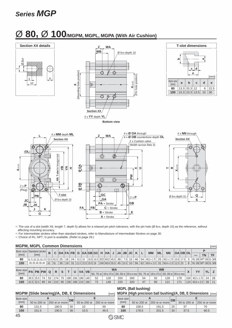
Bottom view
Ø 6H9 depth 10
WAZ
Ø 6H9 depth 10
4 x Ø OA through
4 x Ø OB counterbore depth OL
2 x Cushion valve
(Width across flats 3)
(OL)
X±0
.02
JB
G
J K
PB
JA
JC
2 x P
(Plug)
HA
: T-s
lot
for
hexa
gon
bolt
VB
VA H
4 x MM depth MLL
UX
PW
WAZ
2 x PGC
GA
A + Stroke
B + Stroke
C + Stroke
PA + Stroke GB
E
FBFA
RT
X±0
.02
4 x NN through
Ø 6H9 depth 10
Ø D
BØ
DA
Q
S
4 x YY depth YL
X(M
ou
ntin
g h
ole
po
sitio
n)
X±0
.02
(Pin
ho
le p
ositio
n)
WB
Section XX
Section XXSection XX
T-slot
T-slot dimensionsSection XX details
e
c d
b a
Ø 6
H9
5
10
6
7
Bore size [mm]
a b c d e
80 13.3 20.3 12 8 22.5
100 15.3 23.3 13.5 10 30
∗: The use of a slot (width X6, length 7, depth 5) allows for a relaxed pin pitch tolerance, with the pin hole (Ø 6H9, depth 10) as the reference, without
affecting mounting accuracy.
∗: For intermediate strokes other than standard strokes, refer to Manufacture of Intermediate Strokes on page 30.
∗: Choice of Rc, NPT, G port is available. (Refer to page 29.)
Ø 80, Ø 100/MGPM, MGPL, MGPA (With Air Cushion)
[mm]
MGPL (Ball bushing)
MGPA (High precision ball bushing)/A, DB, E Dimensions
Bore size [mm]
ADB
E
50 to 200 st 250 st or more 50 to 200 st 250 st or more
80 158.5 191.5 25 37 70
100 178.5 201.5 30 37.5 60.5
Bore size [mm]
ADB
E
50 to 200 st 250 st or more 50 to 200 st 250 st or more
80 131.5 180.5 30 10 59
100 151.5 190.5 36 10.5 49.5
Bore size [mm]
PA PB PW Q R S T U VA VBWA WB
X YY YL Z50, 75 st 100 to 175 st 200, 250 st 300 st or more 50, 75 st 100 to 175 st 200, 250 st 300 st or more
80 39.5 25.5 74 52 174 75 198 156 180 140 52 128 200 300 54 92 128 178 100 M12 x 1.75 24 28
100 42.5 32.5 89 64 210 90 236 188 210 166 72 148 220 320 47 85 121 171 124 M14 x 2.0 28 11
Bore size [mm]
Standard stroke[mm]
B C DA FA FB G GA GB GC H HA J JA JB JC K L MM ML NN OA OB OLP
— TN TF
80 50, 75, 100, 125, 150, 175200, 250, 300, 350, 400
121.5 81.5 25 16 24 91.5 19 16.5 14.5 202 M12 45.5 38 7.5 15 46 54 M12 x 1.75 25 M12 x 1.75 10.6 17.5 3 Rc 3/8 NPT 3/8 G 3/8
100 141 91 30 19 31 111.5 22.5 20.5 18 240 M14 55.5 45 10.5 10 56 62 M14 x 2.0 31 M14 x 2.0 12.5 20 8 Rc 3/8 NPT 3/8 G 3/8
MGPM, MGPL Common Dimensions [mm]
[mm]MGPM (Slide bearing)/A, DB, E Dimensions [mm]
45
Series MGP
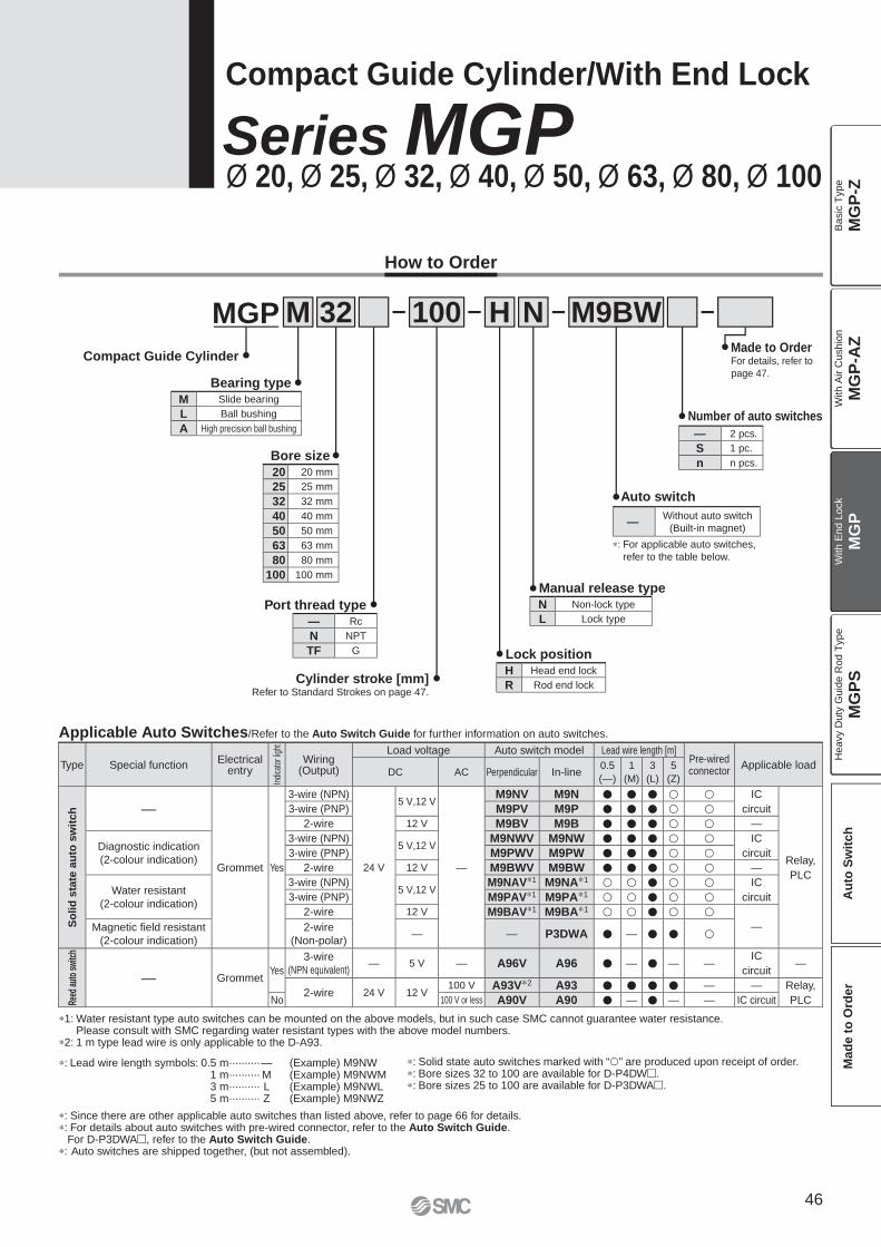
How to Order
MGP M 32
Cylinder stroke [mm]Refer to Standard Strokes on page 47.
Bearing type
Bore size
Compact Guide Cylinder
M9BW100
Port thread type
Auto switch
H N
Manual release type
Lock position
Number of auto switches
Compact Guide Cylinder/With End Lock
Series MGPØ 20, Ø 25, Ø 32, Ø 40, Ø 50, Ø 63, Ø 80, Ø 100
Made to OrderFor details, refer to
page 47.
∗: For applicable auto switches,
refer to the table below.
∗: Solid state auto switches marked with “�” are produced upon receipt of order.∗: Bore sizes 32 to 100 are available for D-P4DW�.∗: Bore sizes 25 to 100 are available for D-P3DWA�.
Applicable Auto Switches/Refer to the Auto Switch Guide for further information on auto switches.
∗: Lead wire length symbols: 0.5 m·········· — (Example) M9NW1 m·········· M (Example) M9NWM3 m·········· L (Example) M9NWL5 m·········· Z (Example) M9NWZ
∗: Since there are other applicable auto switches than listed above, refer to page 66 for details.∗: For details about auto switches with pre-wired connector, refer to the Auto Switch Guide.
For D-P3DWA�, refer to the Auto Switch Guide.∗: Auto switches are shipped together, (but not assembled).
∗1: Water resistant type auto switches can be mounted on the above models, but in such case SMC cannot guarantee water resistance. Please consult with SMC regarding water resistant types with the above model numbers.
∗2: 1 m type lead wire is only applicable to the D-A93.
M Slide bearing
L Ball bushing
A High precision ball bushing
20 20 mm
25 25 mm
32 32 mm
40 40 mm
50 50 mm
63 63 mm
80 80 mm
100 100 mm
— Rc
N NPT
TF G
— 2 pcs.
S 1 pc.
n n pcs.
—Without auto switch
(Built-in magnet)
N Non-lock type
L Lock type
H Head end lock
R Rod end lock
Type Special functionElectrical
entry
Indi
cato
r lig
ht
Wiring(Output)
Load voltage Auto switch model Lead wire length [m]Pre-wired connector
Applicable loadDC AC Perpendicular In-line
0.5
(—)
1
(M)
3
(L)
5
(Z)
So
lid
sta
te a
uto
sw
itch —
Grommet Yes
3-wire (NPN)
24 V
5 V,12 V
—
M9NV M9N � � � � � IC
circuit
Relay,
PLC
3-wire (PNP) M9PV M9P � � � � �2-wire 12 V M9BV M9B � � � � � —
Diagnostic indication
(2-colour indication)
3-wire (NPN)5 V,12 V
M9NWV M9NW � � � � � IC
circuit3-wire (PNP) M9PWV M9PW � � � � �2-wire 12 V M9BWV M9BW � � � � � —
Water resistant
(2-colour indication)
3-wire (NPN)5 V,12 V
M9NAV∗1 M9NA∗1 � � � � � IC
circuit3-wire (PNP) M9PAV∗1 M9PA∗1 � � � � �2-wire 12 V M9BAV∗1 M9BA∗1 � � � � �
—Magnetic fi eld resistant
(2-colour indication)
2-wire
(Non-polar)— — P3DWA � — � � �
Reed
aut
o sw
itch
— GrommetYes
3-wire
(NPN equivalent)— 5 V — A96V A96 � — � — —
IC
circuit—
2-wire 24 V 12 V100 V A93V∗2 A93 � � � � — — Relay,
PLCNo 100 V or less A90V A90 � — � — — IC circuit
46
MG
P-Z
MG
P-A
ZM
GP
MG
PS
Ba
sic
Typ
eW
ith
Air C
ush
ion
With E
nd L
ock
Heavy D
uty
Guid
e R
od T
ype
Au
to S
wit
ch
Mad
e t
o O
rder
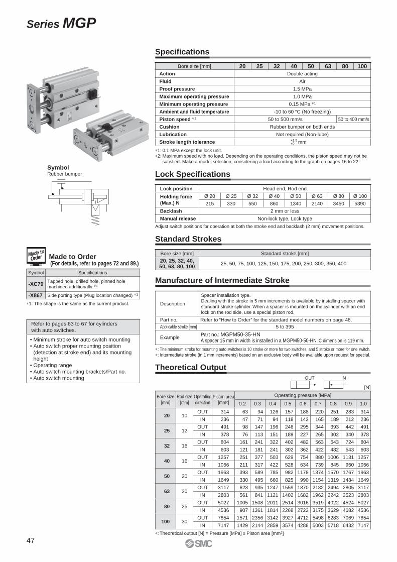
SymbolRubber bumper
Specifi cations
Standard Strokes
Manufacture of Intermediate Stroke
Lock Specifi cations
Made to Order (For details, refer to pages 72 and 89.)
Symbol Specifications
-XC79Tapped hole, drilled hole, pinned hole machined additionally ∗1
-X867 Side porting type (Plug location changed) ∗1
Refer to pages 63 to 67 for cylinders
with auto switches.
• Minimum stroke for auto switch mounting
• Auto switch proper mounting position
(detection at stroke end) and its mounting
height
• Operating range
• Auto switch mounting brackets/Part no.
• Auto switch mounting
∗1: 0.1 MPa except the lock unit.
∗2: Maximum speed with no load. Depending on the operating conditions, the piston speed may not be
satisfi ed. Make a model selection, considering a load according to the graph on pages 16 to 22.
Bore size [mm] 20 25 32 40 50 63 80 100
Action Double acting
Fluid Air
Proof pressure 1.5 MPa
Maximum operating pressure 1.0 MPa
Minimum operating pressure 0.15 MPa ∗1
Ambient and fl uid temperature -10 to 60 °C (No freezing)
Piston speed ∗2 50 to 500 mm/s 50 to 400 mm/s
Cushion Rubber bumper on both ends
Lubrication Not required (Non-lube)
Stroke length tolerance +1.5+0 mm
Adjust switch positions for operation at both the stroke end and backlash (2 mm) movement positions.
Lock position Head end, Rod end
Holding force
(Max.) N
Ø 20 Ø 25 Ø 32 Ø 40 Ø 50 Ø 63 Ø 80 Ø 100
215 330 550 860 1340 2140 3450 5390
Backlash 2 mm or less
Manual release Non-lock type, Lock type
Bore size [mm] Standard stroke [mm]
20, 25, 32, 40,50, 63, 80, 100
25, 50, 75, 100, 125, 150, 175, 200, 250, 300, 350, 400
∗: The minimum stroke for mounting auto switches is 10 stroke or more for two switches, and 5 stroke or more for one switch.
∗: Intermediate stroke (in 1 mm increments) based on an exclusive body will be available upon request for special.
Description
Spacer installation type.
Dealing with the stroke in 5 mm increments is available by installing spacer with
standard stroke cylinder. When a spacer is mounted on the cylinder with an end
lock on the rod side, use a special piston rod.
Part no. Refer to “How to Order” for the standard model numbers on page 46.
Applicable stroke [mm] 5 to 395
ExamplePart no.: MGPM50-35-HNA spacer 15 mm in width is installed in a MGPM50-50-HN. C dimension is 119 mm.
OUT IN
Theoretical Output
∗: Theoretical output [N] = Pressure [MPa] x Piston area [mm2]
[N]
Bore size
[mm]
Rod size
[mm]
Operating
directionPiston area
[mm2]
Operating pressure [MPa]
0.2 0.3 0.4 0.5 0.6 0.7 0.8 0.9 1.0
20 10OUT 314 63 94 126 157 188 220 251 283 314
IN 236 47 71 94 118 142 165 189 212 236
25 12OUT 491 98 147 196 246 295 344 393 442 491
IN 378 76 113 151 189 227 265 302 340 378
32 16OUT 804 161 241 322 402 482 563 643 724 804
IN 603 121 181 241 302 362 422 482 543 603
40 16OUT 1257 251 377 503 629 754 880 1006 1131 1257
IN 1056 211 317 422 528 634 739 845 950 1056
50 20OUT 1963 393 589 785 982 1178 1374 1570 1767 1963
IN 1649 330 495 660 825 990 1154 1319 1484 1649
63 20OUT 3117 623 935 1247 1559 1870 2182 2494 2805 3117
IN 2803 561 841 1121 1402 1682 1962 2242 2523 2803
80 25OUT 5027 1005 1508 2011 2514 3016 3519 4022 4524 5027
IN 4536 907 1361 1814 2268 2722 3175 3629 4082 4536
100 30OUT 7854 1571 2356 3142 3927 4712 5498 6283 7069 7854
IN 7147 1429 2144 2859 3574 4288 5003 5718 6432 7147
∗1: The shape is the same as the current product.
47
Series MGP
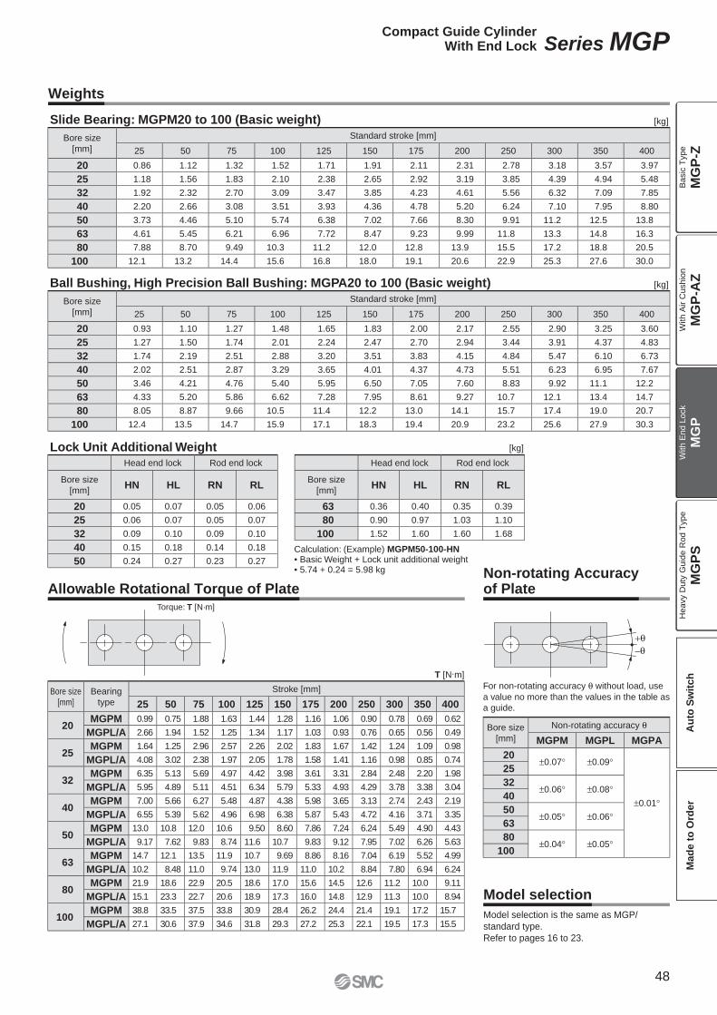
–
Bore size
[mm]
Standard stroke [mm]
25 50 75 100 125 150 175 200 250 300 350 400
20 0.93 1.10 1.27 1.48 1.65 1.83 2.00 2.17 2.55 2.90 3.25 3.60
25 1.27 1.50 1.74 2.01 2.24 2.47 2.70 2.94 3.44 3.91 4.37 4.83
32 1.74 2.19 2.51 2.88 3.20 3.51 3.83 4.15 4.84 5.47 6.10 6.73
40 2.02 2.51 2.87 3.29 3.65 4.01 4.37 4.73 5.51 6.23 6.95 7.67
50 3.46 4.21 4.76 5.40 5.95 6.50 7.05 7.60 8.83 9.92 11.1 12.2
63 4.33 5.20 5.86 6.62 7.28 7.95 8.61 9.27 10.7 12.1 13.4 14.7
80 8.05 8.87 9.66 10.5 11.4 12.2 13.0 14.1 15.7 17.4 19.0 20.7
100 12.4 13.5 14.7 15.9 17.1 18.3 19.4 20.9 23.2 25.6 27.9 30.3
Bore size
[mm]
Standard stroke [mm]
25 50 75 100 125 150 175 200 250 300 350 400
20 0.86 1.12 1.32 1.52 1.71 1.91 2.11 2.31 2.78 3.18 3.57 3.97
25 1.18 1.56 1.83 2.10 2.38 2.65 2.92 3.19 3.85 4.39 4.94 5.48
32 1.92 2.32 2.70 3.09 3.47 3.85 4.23 4.61 5.56 6.32 7.09 7.85
40 2.20 2.66 3.08 3.51 3.93 4.36 4.78 5.20 6.24 7.10 7.95 8.80
50 3.73 4.46 5.10 5.74 6.38 7.02 7.66 8.30 9.91 11.2 12.5 13.8
63 4.61 5.45 6.21 6.96 7.72 8.47 9.23 9.99 11.8 13.3 14.8 16.3
80 7.88 8.70 9.49 10.3 11.2 12.0 12.8 13.9 15.5 17.2 18.8 20.5
100 12.1 13.2 14.4 15.6 16.8 18.0 19.1 20.6 22.9 25.3 27.6 30.0
Model selection is the same as MGP/
standard type.
Refer to pages 16 to 23.
Model selection
Weights
Slide Bearing: MGPM20 to 100 (Basic weight) [kg]
Allowable Rotational Torque of Plate
T [N.m]
Ball Bushing, High Precision Ball Bushing: MGPA20 to 100 (Basic weight) [kg]
Lock Unit Additional Weight [kg]
Non-rotating Accuracyof Plate
Calculation: (Example) MGPM50-100-HN• Basic Weight + Lock unit additional weight• 5.74 + 0.24 = 5.98 kg
For non-rotating accuracy θ without load, use
a value no more than the values in the table as
a guide.
Head end lock Rod end lock
Bore size
[mm]HN HL RN RL
20 0.05 0.07 0.05 0.06
25 0.06 0.07 0.05 0.07
32 0.09 0.10 0.09 0.10
40 0.15 0.18 0.14 0.18
50 0.24 0.27 0.23 0.27
Head end lock Rod end lock
Bore size
[mm]HN HL RN RL
63 0.36 0.40 0.35 0.39
80 0.90 0.97 1.03 1.10
100 1.52 1.60 1.60 1.68
Bore size
[mm]
Bearing
type
Stroke [mm]
25 50 75 100 125 150 175 200 250 300 350 400
20MGPM 0.99 0.75 1.88 1.63 1.44 1.28 1.16 1.06 0.90 0.78 0.69 0.62
MGPL/A 2.66 1.94 1.52 1.25 1.34 1.17 1.03 0.93 0.76 0.65 0.56 0.49
25MGPM 1.64 1.25 2.96 2.57 2.26 2.02 1.83 1.67 1.42 1.24 1.09 0.98
MGPL/A 4.08 3.02 2.38 1.97 2.05 1.78 1.58 1.41 1.16 0.98 0.85 0.74
32MGPM 6.35 5.13 5.69 4.97 4.42 3.98 3.61 3.31 2.84 2.48 2.20 1.98
MGPL/A 5.95 4.89 5.11 4.51 6.34 5.79 5.33 4.93 4.29 3.78 3.38 3.04
40MGPM 7.00 5.66 6.27 5.48 4.87 4.38 5.98 3.65 3.13 2.74 2.43 2.19
MGPL/A 6.55 5.39 5.62 4.96 6.98 6.38 5.87 5.43 4.72 4.16 3.71 3.35
50MGPM 13.0 10.8 12.0 10.6 9.50 8.60 7.86 7.24 6.24 5.49 4.90 4.43
MGPL/A 9.17 7.62 9.83 8.74 11.6 10.7 9.83 9.12 7.95 7.02 6.26 5.63
63MGPM 14.7 12.1 13.5 11.9 10.7 9.69 8.86 8.16 7.04 6.19 5.52 4.99
MGPL/A 10.2 8.48 11.0 9.74 13.0 11.9 11.0 10.2 8.84 7.80 6.94 6.24
80MGPM 21.9 18.6 22.9 20.5 18.6 17.0 15.6 14.5 12.6 11.2 10.0 9.11
MGPL/A 15.1 23.3 22.7 20.6 18.9 17.3 16.0 14.8 12.9 11.3 10.0 8.94
100MGPM 38.8 33.5 37.5 33.8 30.9 28.4 26.2 24.4 21.4 19.1 17.2 15.7
MGPL/A 27.1 30.6 37.9 34.6 31.8 29.3 27.2 25.3 22.1 19.5 17.3 15.5
Bore size
[mm]
Non-rotating accuracy θ
MGPM MGPL MGPA
20±0.07° ±0.09°
±0.01°
25
32±0.06° ±0.08°
40
50±0.05° ±0.06°
63
80±0.04° ±0.05°
100
Torque: T [N·m]
48
Compact Guide CylinderWith End Lock Series MGP
MG
P-Z
MG
P-A
ZM
GP
MG
PS
Ba
sic
Typ
eW
ith
Air C
ush
ion
With E
nd L
ock
Heavy D
uty
Guid
e R
od T
ype
Au
to S
wit
ch
Mad
e t
o O
rder
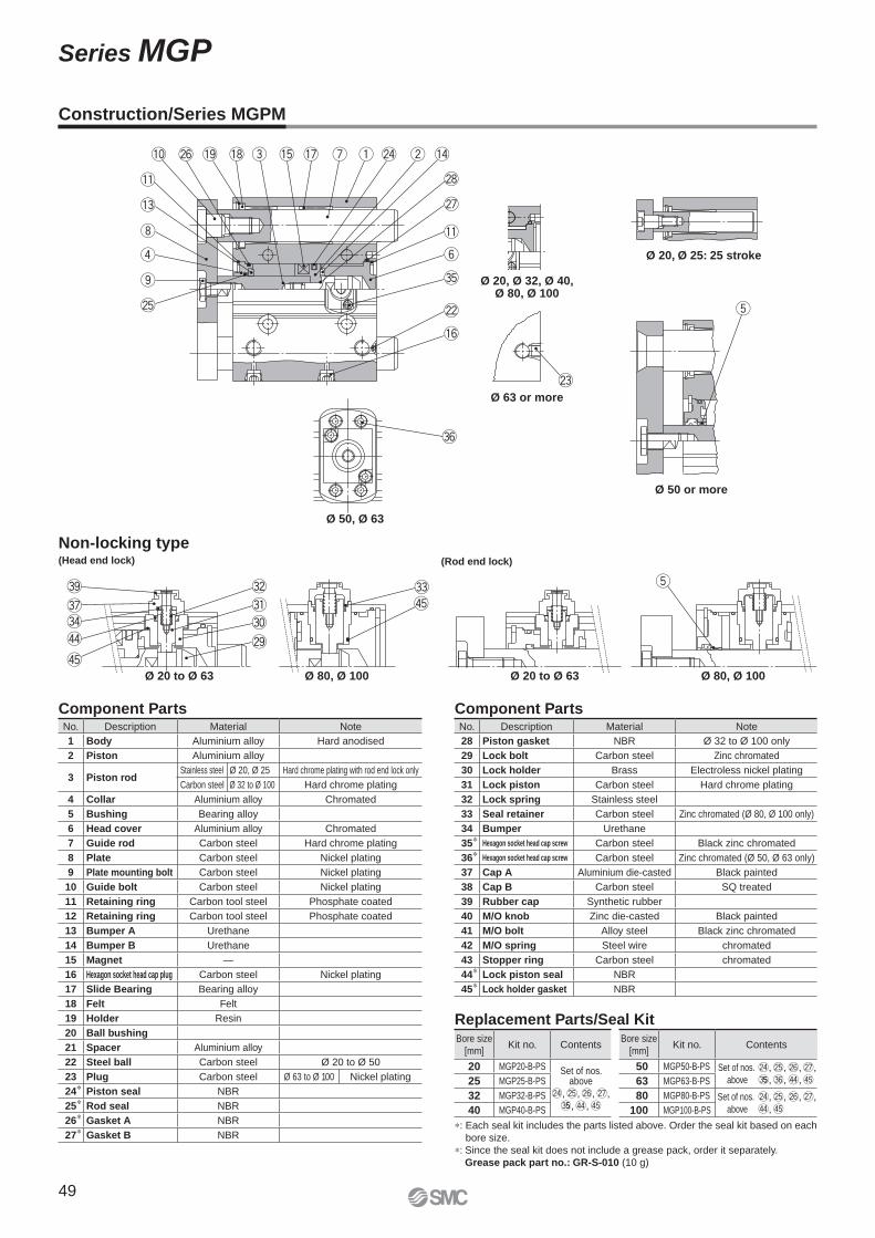
@5
@6 @4q wu
y
t
e
i
o
r
@8
@7
@2
#5
@3
!5 !7!8!9!0
!1
!3
!6
!1
!4
#6
t
@9
#2#9
#7#4$4
$5
$5#1#0
#3
Ø 50 or more
Ø 50, Ø 63
Ø 20, Ø 25: 25 stroke
(Rod end lock)
Ø 80, Ø 100Ø 20 to Ø 63Ø 80, Ø 100Ø 20 to Ø 63
Ø 20, Ø 32, Ø 40,Ø 80, Ø 100
Ø 63 or more
Non-locking type(Head end lock)
Component Parts Component Parts
Replacement Parts/Seal Kit
∗: Each seal kit includes the parts listed above. Order the seal kit based on each
bore size.
∗: Since the seal kit does not include a grease pack, order it separately.
Grease pack part no.: GR-S-010 (10 g)
Construction/Series MGPM
No. Description Material Note
1 Body Aluminium alloy Hard anodised
2 Piston Aluminium alloy
3 Piston rodStainless steel Ø 20, Ø 25 Hard chrome plating with rod end lock only
Carbon steel Ø 32 to Ø 100 Hard chrome plating
4 Collar Aluminium alloy Chromated
5 Bushing Bearing alloy
6 Head cover Aluminium alloy Chromated
7 Guide rod Carbon steel Hard chrome plating
8 Plate Carbon steel Nickel plating
9 Plate mounting bolt Carbon steel Nickel plating
10 Guide bolt Carbon steel Nickel plating
11 Retaining ring Carbon tool steel Phosphate coated
12 Retaining ring Carbon tool steel Phosphate coated
13 Bumper A Urethane
14 Bumper B Urethane
15 Magnet —
16 Hexagon socket head cap plug Carbon steel Nickel plating
17 Slide Bearing Bearing alloy
18 Felt Felt
19 Holder Resin
20 Ball bushing
21 Spacer Aluminium alloy
22 Steel ball Carbon steel Ø 20 to Ø 50
23 Plug Carbon steel Ø 63 to Ø 100 Nickel plating
24∗ Piston seal NBR
25∗ Rod seal NBR
26∗ Gasket A NBR
27∗ Gasket B NBR
No. Description Material Note
28 Piston gasket NBR Ø 32 to Ø 100 only
29 Lock bolt Carbon steel Zinc chromated
30 Lock holder Brass Electroless nickel plating
31 Lock piston Carbon steel Hard chrome plating
32 Lock spring Stainless steel
33 Seal retainer Carbon steel Zinc chromated (Ø 80, Ø 100 only)
34 Bumper Urethane
35∗ Hexagon socket head cap screw Carbon steel Black zinc chromated
36∗ Hexagon socket head cap screw Carbon steel Zinc chromated (Ø 50, Ø 63 only)
37 Cap A Aluminium die-casted Black painted
38 Cap B Carbon steel SQ treated
39 Rubber cap Synthetic rubber
40 M/O knob Zinc die-casted Black painted
41 M/O bolt Alloy steel Black zinc chromated
42 M/O spring Steel wire chromated
43 Stopper ring Carbon steel chromated
44∗ Lock piston seal NBR
45∗ Lock holder gasket NBR
Bore size
[mm]Kit no. Contents
20 MGP20-B-PS Set of nos. above
@4, @5, @6, @7,#55, $4, $5
25 MGP25-B-PS
32 MGP32-B-PS
40 MGP40-B-PS
Bore size
[mm]Kit no. Contents
50 MGP50-B-PS Set of nos. @4, @5, @6, @7,above #55, #6, $4, $563 MGP63-B-PS
80 MGP80-B-PS Set of nos. @4, @5, @6, @7,above $4, $5100 MGP100-B-PS
49
Series MGP
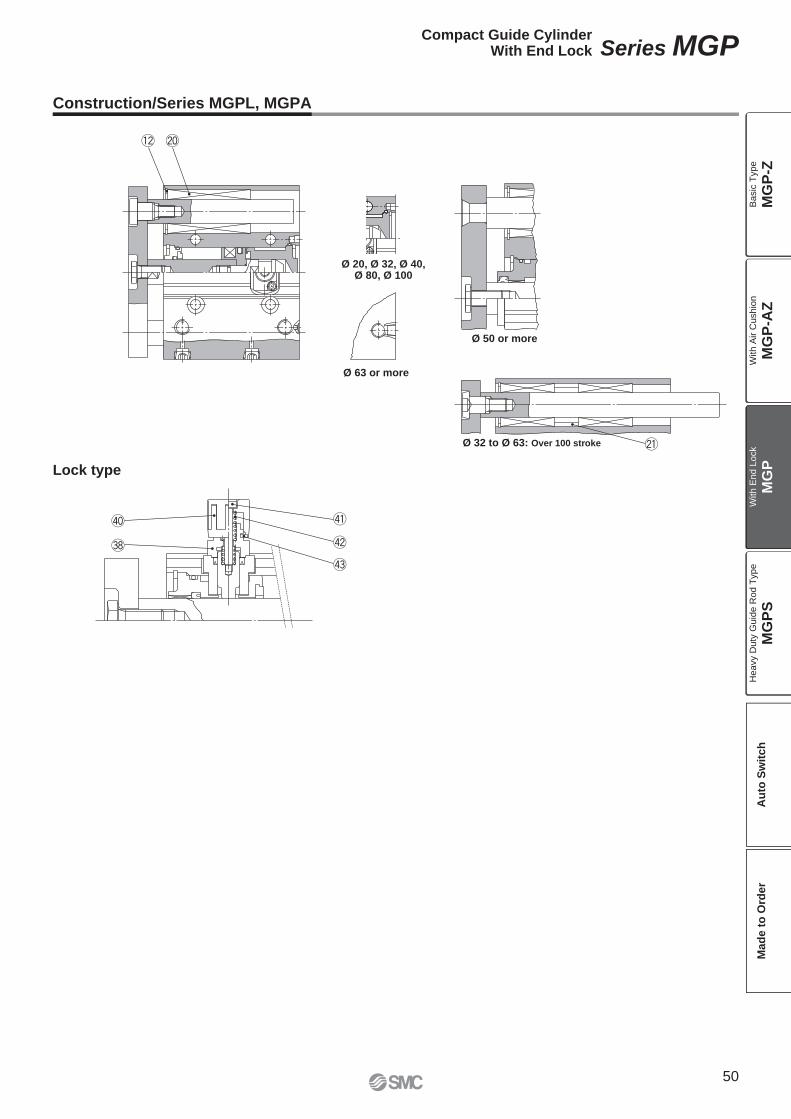
@0!2
@1
$3
$2
$1$0
#8
Ø 32 to Ø 63: Over 100 stroke
Ø 50 or more
Ø 63 or more
Ø 20, Ø 32, Ø 40,Ø 80, Ø 100
Lock type
Construction/Series MGPL, MGPA
50
Compact Guide CylinderWith End Lock Series MGP
MG
P-Z
MG
P-A
ZM
GP
MG
PS
Ba
sic
Typ
eW
ith
Air C
ush
ion
With E
nd L
ock
Heavy D
uty
Guid
e R
od T
ype
Au
to S
wit
ch
Mad
e t
o O
rder
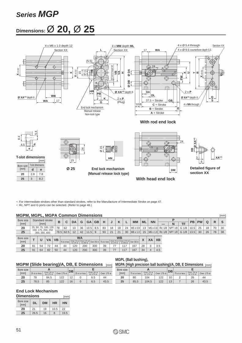
Section XX
Section XX
Section XX
4 x NN through
4 x MM depth ML4 x M6 x 1.0 depth 12
2 x P
2 x P
(Plug)
Ø XAH9 depth 6
Ø XAH9 depth 6 Ø XAH9 depth 6
4 x Ø 5.4 through
4 x Ø 9.5 counterbore depth 5.5
End lock mechanism
Manual release
Non-lock type
Detailed figure of
section XXEnd lock mechanism
(Manual release lock type)
Ø 25
With rod end lock
With head end lock
XAH9
6
3
XB
Ø X
AH
9
e
d4.5
5.4
8.4
HN
Ø 1
5
DL
15
24
DM
24
HR
15
Ø 1
1
24
R
(5.5)
Ø D
B
A + Stroke
PB
L
37.5 + Stroke
HVA
E
VB
M5:T-
slot fo
r hex
agon
bolt
PW
X U
17 WA
Ø D
A
X ±
0.0
2
TX
WB
WA 17KJ
G
QS
B + Stroke
610 C + Stroke
GB
GA
X ±
0.0
2
X ±
0.0
2
Dimensions: Ø 20, Ø 25
MGPM, MGPL, MGPA Common Dimensions
MGPM (Slide bearing)/A, DB, E DimensionsMGPL (Ball bushing),
MGPA (High precision ball bushing)/A, DB, E Dimensions
End Lock Mechanism
Dimensions
∗: For intermediate strokes other than standard strokes, refer to the Manufacture of Intermediate Stroke on page 47.
∗: Rc, NPT and G ports can be selected. (Refer to page 46.)
[mm]
[mm][mm]
[mm]
T-slot dimensions[mm]
Bore size
[mm]
Standard stroke
[mm]B C DA G GA GB H J K L MM ML NN
PPB PW Q R S
— N TF
20 25, 50, 75, 100, 125150, 175, 200, 250
300, 350, 400
78 62 10 36 10.5 8.5 83 18 18 24 M5 x 0.8 13 M5 x 0.8 Rc 1/8 NPT 1/8 G 1/8 10.5 25 18 70 30
25 78.5 62.5 12 42 11.5 9 93 21 21 30 M6 x 1.0 15 M6 x 1.0 Rc 1/8 NPT 1/8 G 1/8 13.5 30 26 78 38
Bore size
[mm]T U VA VB
WA WBX XA XB
75 st or less Over 75 stto 175 st
Over 175 stto 250 st Over 250 st 75 st or less Over 75 st
to 175 stOver 175 st
to 250 st Over 250 st
20 81 54 72 44 44 120 200 300 39 77 117 167 28 3 3.5
25 91 64 82 50 44 120 200 300 39 77 117 167 34 4 4.5
Bore size
[mm]
ADB
E25 st or less Over 25 st
to 175 st Over 175 st 25 st or less Over 25 stto 175 st Over 175 st
20 78 84.5 122 12 0 6.5 44
25 78.5 85 122 16 0 6.5 43.5
Bore size
[mm]
ADB
E75 st or less Over 75 st
to 175 st Over 175 st 75 st or less Over 75 stto 175 st Over 175 st
20 80 104 122 10 2 26 44
25 85.5 104.5 122 13 7 26 43.5
Bore size
[mm]DL DM HR HN
20 21 19 10.5 22
25 26.5 16 8 19.5
Bore size[mm]
T-slot dimensions
d e
20 2.8 7.8
25 3 8.2
51
Series MGP
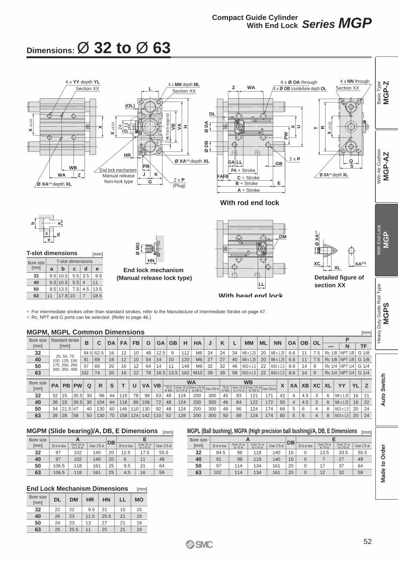
Detailed figure of
section XX
End lock mechanism
(Manual release lock type)
With rod end lock
With head end lock
Section XXSection XX
Section XX
Ø XAH9 depth XL
Ø XAH9 depth XL 2 x P
4 x NN through
Ø XAH9 depth XL2 x P
(Plug)
4 x MM depth ML4 x YY depth YL
End lock mechanism
Manual release
Non-lock type
4 x Ø OA through
4 x Ø OB counterbore depth OL
XLXC
XB
edc
ab
HN
Ø M
O
HR
24
Ø 1
1
DL
LL
DM
LL
WB
WA Z
X
(OL)
Ø D
B
WAZL
PB
KJ
G E
FAFB
GBGA QS
HVA
VB UX
PW
Ø D
A
T R
X ±
0.0
2
X ±
0.0
2
PA + Stroke
C + Stroke
B + Stroke
A + Stroke
X ±
0.0
2
XAH9
Ø X
AH
9
HA: T
-slot
for he
xago
n bolt
∗: For intermediate strokes other than standard strokes, refer to the Manufacture of Intermediate Stroke on page 47.
∗: Rc, NPT and G ports can be selected. (Refer to page 46.)
Dimensions: Ø 32 to Ø 63
MGPM, MGPL Common Dimensions
MGPM (Slide bearing)/A, DB, E Dimensions MGPL (Ball bushing), MGPA (High precision ball bushing)/A, DB, E Dimensions
End Lock Mechanism Dimensions
T-slot dimensions [mm]
[mm]
[mm][mm]
[mm]
Bore size[mm]
T-slot dimensions
a b c d e
32 6.5 10.5 5.5 3.5 9.5
40 6.5 10.5 5.5 4 11
50 8.5 13.5 7.5 4.5 13.5
63 11 17.8 10 7 18.5
Bore size
[mm]
Standard stroke
[mm]B C DA FA FB G GA GB H HA J K L MM ML NN OA OB OL
P
— N TF
3225, 50, 75
100, 125, 150175, 200, 250300, 350, 400
84.5 62.5 16 12 10 48 12.5 9 112 M6 24 24 34 M8 x 1.25 20 M8 x 1.25 6.6 11 7.5 Rc 1/8 NPT 1/8 G 1/8
40 91 69 16 12 10 54 14 10 120 M6 27 27 40 M8 x 1.25 20 M8 x 1.25 6.6 11 7.5 Rc 1/8 NPT 1/8 G 1/8
50 97 69 20 16 12 64 14 11 148 M8 32 32 46 M10 x 1.5 22 M10 x 1.5 8.6 14 9 Rc 1/4 NPT 1/4 G 1/4
63 102 74 20 16 12 78 16.5 13.5 162 M10 39 39 58 M10 x 1.5 22 M10 x 1.5 8.6 14 9 Rc 1/4 NPT 1/4 G 1/4
Bore size
[mm]PA PB PW Q R S T U VA VB
WA WBX XA XB XC XL YY YL Z75 st
or lessOver 75 stto 175 st
Over 175 stto 250 st Over 250 st 75 st
or lessOver 75 stto 175 st
Over 175 stto 250 st Over 250 st
32 32 15 35.5 30 96 44 110 78 98 63 48 124 200 300 45 83 121 171 42 4 4.5 3 6 M8 x 1.25 16 21
40 38 18 39.5 30 104 44 118 86 106 72 48 124 200 300 46 84 122 172 50 4 4.5 3 6 M8 x 1.25 16 22
50 34 21.5 47 40 130 60 146 110 130 92 48 124 200 300 48 86 124 174 66 5 6 4 8 M10 x 1.5 20 24
63 39 28 58 50 130 70 158 124 142 110 52 128 200 300 50 88 124 174 80 5 6 4 8 M10 x 1.5 20 24
Bore size
[mm]
ADB
E25 st or less Over 25 st
to 175 st Over 175 st 25 st or less Over 25 stto 175 st Over 175 st
32 97 102 140 20 12.5 17.5 55.5
40 97 102 140 20 6 11 49
50 106.5 118 161 25 9.5 21 64
63 106.5 118 161 25 4.5 16 59
Bore size
[mm]
ADB
E25 st or less Over 25 st
to 75 stOver 75 stto 175 st Over 175 st 25 st or less Over 25 st
to 75 stOver 75 stto 175 st Over 175 st
32 84.5 98 118 140 16 0 13.5 33.5 55.5
40 91 98 118 140 16 0 7 27 49
50 97 114 134 161 20 0 17 37 64
63 102 114 134 161 20 0 12 32 59
Bore size
[mm]DL DM HR HN LL MO
32 22 22 9.5 21 15 15
40 26 23 11.5 25.5 21 19
50 24 23 13 27 21 19
63 25 25.5 11 25 21 19
52
Compact Guide CylinderWith End Lock Series MGP
MG
P-Z
MG
P-A
ZM
GP
MG
PS
Ba
sic
Typ
eW
ith
Air C
ush
ion
With E
nd L
ock
Heavy D
uty
Guid
e R
od T
ype
Au
to S
wit
ch
Mad
e t
o O
rder
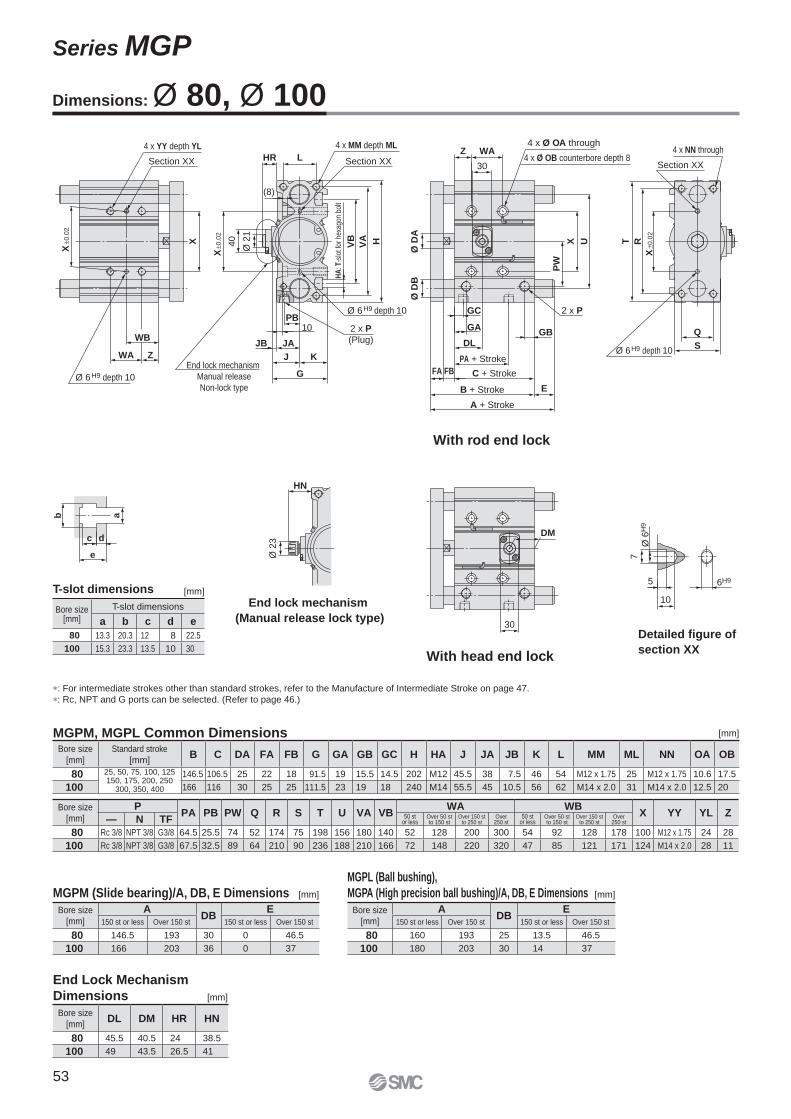
Detailed figure of
section XX
End lock mechanism
(Manual release lock type)
With rod end lock
With head end lock
Section XXSection XX Section XX
4 x MM depth ML4 x YY depth YL
2 x P
(Plug)
2 x P
Ø 6H9 depth 10
Ø 6H9 depth 10
Ø 6H9 depth 10
4 x NN through4 x Ø OA through
4 x Ø OB counterbore depth 8
End lock mechanism
Manual release
Non-lock type
10
5
7e
dc
ab
HN
Ø 2
3
30HR
40
Ø 2
1
DL
30
DM
X
ZWA
WB
Ø D
B
HVA
VB
LWAZ
10
JB JA
K
G
PB
J
Q
S
E
FBFA
GBGA
GC
UX
PW
Ø D
A
T R
(8)
X ±
0.0
2
X ±0
.02
X ±
0.0
2
6H9
Ø 6
H9
HA
: T-s
lot f
or h
exag
on b
olt
PA + Stroke
C + Stroke
B + Stroke
A + Stroke
∗: For intermediate strokes other than standard strokes, refer to the Manufacture of Intermediate Stroke on page 47.
∗: Rc, NPT and G ports can be selected. (Refer to page 46.)
Dimensions: Ø 80, Ø 100
T-slot dimensions [mm]
MGPM, MGPL Common Dimensions
MGPM (Slide bearing)/A, DB, E Dimensions
MGPL (Ball bushing),
MGPA (High precision ball bushing)/A, DB, E Dimensions
End Lock Mechanism
Dimensions
[mm]
[mm][mm]
[mm]
Bore size[mm]
T-slot dimensions
a b c d e
80 13.3 20.3 12 8 22.5
100 15.3 23.3 13.5 10 30
Bore size
[mm]
Standard stroke
[mm]B C DA FA FB G GA GB GC H HA J JA JB K L MM ML NN OA OB
80 25, 50, 75, 100, 125150, 175, 200, 250
300, 350, 400
146.5 106.5 25 22 18 91.5 19 15.5 14.5 202 M12 45.5 38 7.5 46 54 M12 x 1.75 25 M12 x 1.75 10.6 17.5
100 166 116 30 25 25 111.5 23 19 18 240 M14 55.5 45 10.5 56 62 M14 x 2.0 31 M14 x 2.0 12.5 20
Bore size
[mm]
PPA PB PW Q R S T U VA VB
WA WBX YY YL Z
— N TF 50 st or less
Over 50 stto 150 st
Over 150 stto 250 st
Over250 st
50 st or less
Over 50 stto 150 st
Over 150 stto 250 st
Over250 st
80 Rc 3/8 NPT 3/8 G3/8 64.5 25.5 74 52 174 75 198 156 180 140 52 128 200 300 54 92 128 178 100 M12 x 1.75 24 28
100 Rc 3/8 NPT 3/8 G3/8 67.5 32.5 89 64 210 90 236 188 210 166 72 148 220 320 47 85 121 171 124 M14 x 2.0 28 11
Bore size
[mm]
ADB
E150 st or less Over 150 st 150 st or less Over 150 st
80 146.5 193 30 0 46.5
100 166 203 36 0 37
Bore size
[mm]
ADB
E150 st or less Over 150 st 150 st or less Over 150 st
80 160 193 25 13.5 46.5
100 180 203 30 14 37
Bore size
[mm]DL DM HR HN
80 45.5 40.5 24 38.5
100 49 43.5 26.5 41
53
Series MGP
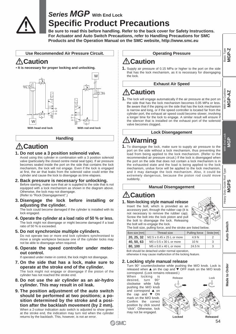
W
W
LockRelease
ReleasedLocked
With head end lock With rod end lock
Series MGP With End Lock
Specific Product PrecautionsBe sure to read this before handling. Refer to the back cover for Safety Instructions. For Actuator and Auto Switch Precautions, refer to Handling Precautions for SMC Products and the Operation Manual on the SMC website, http://www.smc.eu
Use Recommended Air Pressure Circuit.
Caution• It is necessary for proper locking and unlocking.
Operating Pressure
Caution1. Supply air pressure of 0.15 MPa or higher to the port on the side
that has the lock mechanism, as it is necessary for disengaging the lock.
Exhaust Air Speed
Caution1. The lock will engage automatically if the air pressure at the port on
the side that has the lock mechanism becomes 0.05 MPa or less. Be aware that if the piping on the side that has the lock mechanism is narrow and long, or if the speed controller is located far from the cylinder port, the exhaust air speed could become slower, involving a longer time for the lock to engage. A similar result will ensure if the silencer that is installed on the exhaust port of the solenoid valve becomes clogged.
Lock Disengagement
Warning1. To disengage the lock, make sure to supply air pressure to the
port on the side without a lock mechanism, thus preventing the load from being applied to the lock mechanism. (Refer to the recommended air pressure circuit.) If the lock is disengaged when the port on the side that does not contain a lock mechanism is in the exhausted state and the load is being applied to the lock mechanism, undue force will be applied to the lock mechanism, and it may damage the lock mechanism. Also, it could be extremely dangerous, because the piston rod could move suddenly.
Handling
Caution1. Do not use a 3 position solenoid valve.
Avoid using this cylinder in combination with a 3 position solenoid valve (particularly the closed centre metal seal type). If air pressure becomes sealed inside the port on the side that contains the lock mechanism, the lock will not engage. Even if the lock is engaged at first, the air that leaks from the solenoid valve could enter the cylinder and cause the lock to disengage as time elapses.
2. Back pressure is necessary for unlocking.Before starting, make sure that air is supplied to the side that is not equipped with a lock mechanism as shown in the diagram above. Otherwise, the lock may not disengage.(Refer to “Rock Disengagement”.)
3. Disengage the lock before installing or adjusting the cylinder.The lock could become damaged if the cylinder is installed with its lock engaged.
4. Operate the cylinder at a load ratio of 50 % or less.The lock might not disengage or might become damaged if a load ratio of 50 % is exceeded.
5. Do not synchronize multiple cylinders.Do not operate two or more end lock cylinders synchronised to move a single workpiece because one of the cylinder locks may not be able to disengage when required.
6. Operate the speed controller under meter-out control.If operated under meter-in control, the lock might not disengage.
7. On the side that has a lock, make sure to operate at the stroke end of the cylinder.The lock might not engage or disengage if the piston of the cylinder has not reached the stroke end.
8. Do not use the air cylinder as an air-hydro cylinder. This may result in oil leak.
9. The position adjustment of the auto switch should be performed at two positions; a po-sition determined by the stroke and a posi-tion after the backlash movement (by 2 mm).When a 2-colour indication auto switch is adjusted to show green at the stroke end, the indication may turn red when the cylinder returns by the backlash. This, however, is not an error.
1. Non-locking style manual releaseInsert the bolt, which is provided as an accessory part, through the rubber cap (it is not necessary to remove the rubber cap). Screw the bolt into the lock piston and pull the bolt to disengage the lock. Releasing the bolt will re-engage the lock.The bolt size, pulling force, and the stroke are listed below.
Bore size [mm] Thread size Pulling force Stroke [mm]
20, 25, 32 M2.5 x 0.45 x 25 L or more 4.9 N 2
40, 50, 63 M3 x 0.5 x 30 L or more 10 N 3
80, 100 M5 x 0.8 x 40 L or more 24.5 N 3
Bolt should be detached under normal operation, otherwise it may cause malfunction of the locking feature.
Manual Disengagement
Caution
2. Locking style manual releaseTurn 90° counterclockwise while pushing the M/O knob. Lock is released when � on the cap and � OFF mark on the M/O knob correspond. (Lock remains released.)When locking is desired, turn 90°clockwise while fully pushing the M/O knob and correspond � on the cap and � ON mark on the M/O knob. Confirm the correct position by click sound “click”. Otherwise, lock may not be engaged.
54
MG
P-Z
MG
P-A
ZM
GP
MG
PS
Ba
sic
Typ
eW
ith
Air C
ush
ion
With E
nd L
ock
Heavy D
uty
Guid
e R
od T
ype
Au
to S
wit
ch
Mad
e t
o O
rder
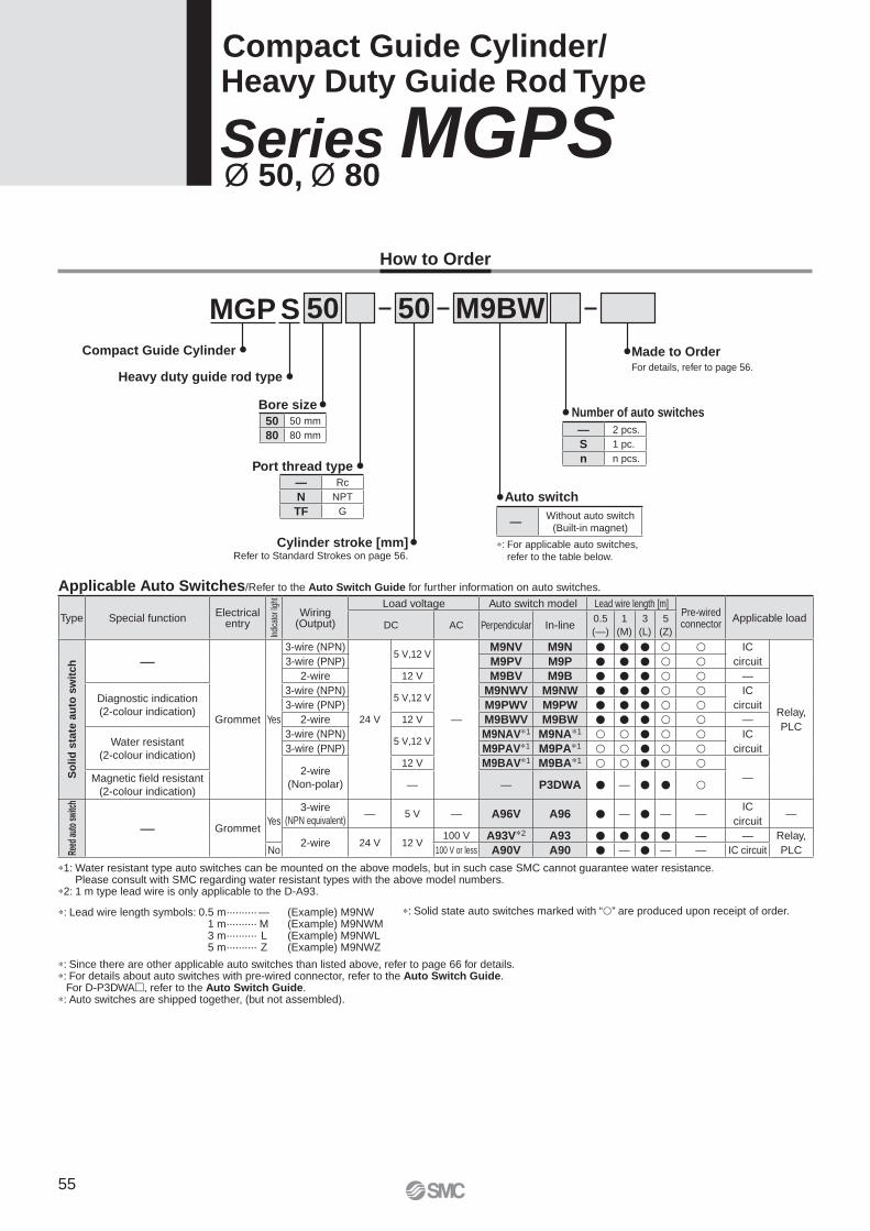
How to Order
MGP 50S
Cylinder stroke [mm]Refer to Standard Strokes on page 56.
Heavy duty guide rod type
Bore size
Compact Guide Cylinder
M9BW50
Auto switch
Port thread type
Number of auto switches
Made to OrderFor details, refer to page 56.
Compact Guide Cylinder/ Heavy Duty Guide Rod Type
Series MGPS Ø 50, Ø 80
∗: For applicable auto switches,
refer to the table below.
∗: Solid state auto switches marked with “�” are produced upon receipt of order.
Applicable Auto Switches/Refer to the Auto Switch Guide for further information on auto switches.
∗: Lead wire length symbols: 0.5 m·········· — (Example) M9NW1 m·········· M (Example) M9NWM3 m·········· L (Example) M9NWL5 m·········· Z (Example) M9NWZ
∗: Since there are other applicable auto switches than listed above, refer to page 66 for details.∗: For details about auto switches with pre-wired connector, refer to the Auto Switch Guide.
For D-P3DWA�, refer to the Auto Switch Guide.∗: Auto switches are shipped together, (but not assembled).
∗1: Water resistant type auto switches can be mounted on the above models, but in such case SMC cannot guarantee water resistance. Please consult with SMC regarding water resistant types with the above model numbers.
∗2: 1 m type lead wire is only applicable to the D-A93.
50 50 mm
80 80 mm
— Rc
N NPT
TF G
— 2 pcs.
S 1 pc.
n n pcs.
—Without auto switch
(Built-in magnet)
Type Special functionElectrical
entry
Indi
cato
r lig
ht
Wiring(Output)
Load voltage Auto switch model Lead wire length [m]Pre-wired connector
Applicable loadDC AC Perpendicular In-line
0.5
(—)
1
(M)
3
(L)
5
(Z)
So
lid
sta
te a
uto
sw
itch —
Grommet Yes
3-wire (NPN)
24 V
5 V,12 V
—
M9NV M9N � � � � � IC
circuit
Relay,
PLC
3-wire (PNP) M9PV M9P � � � � �2-wire 12 V M9BV M9B � � � � � —
Diagnostic indication
(2-colour indication)
3-wire (NPN)5 V,12 V
M9NWV M9NW � � � � � IC
circuit3-wire (PNP) M9PWV M9PW � � � � �2-wire 12 V M9BWV M9BW � � � � � —
Water resistant
(2-colour indication)
3-wire (NPN)5 V,12 V
M9NAV∗1 M9NA∗1 � � � � � IC
circuit3-wire (PNP) M9PAV∗1 M9PA∗1 � � � � �
2-wire
(Non-polar)
12 V M9BAV∗1 M9BA∗1 � � � � �—Magnetic fi eld resistant
(2-colour indication)— — P3DWA � — � � �
Reed
aut
o sw
itch
— GrommetYes
3-wire
(NPN equivalent)— 5 V — A96V A96 � — � — —
IC
circuit—
2-wire 24 V 12 V100 V A93V∗2 A93 � � � � — — Relay,
PLCNo 100 V or less A90V A90 � — � — — IC circuit
55
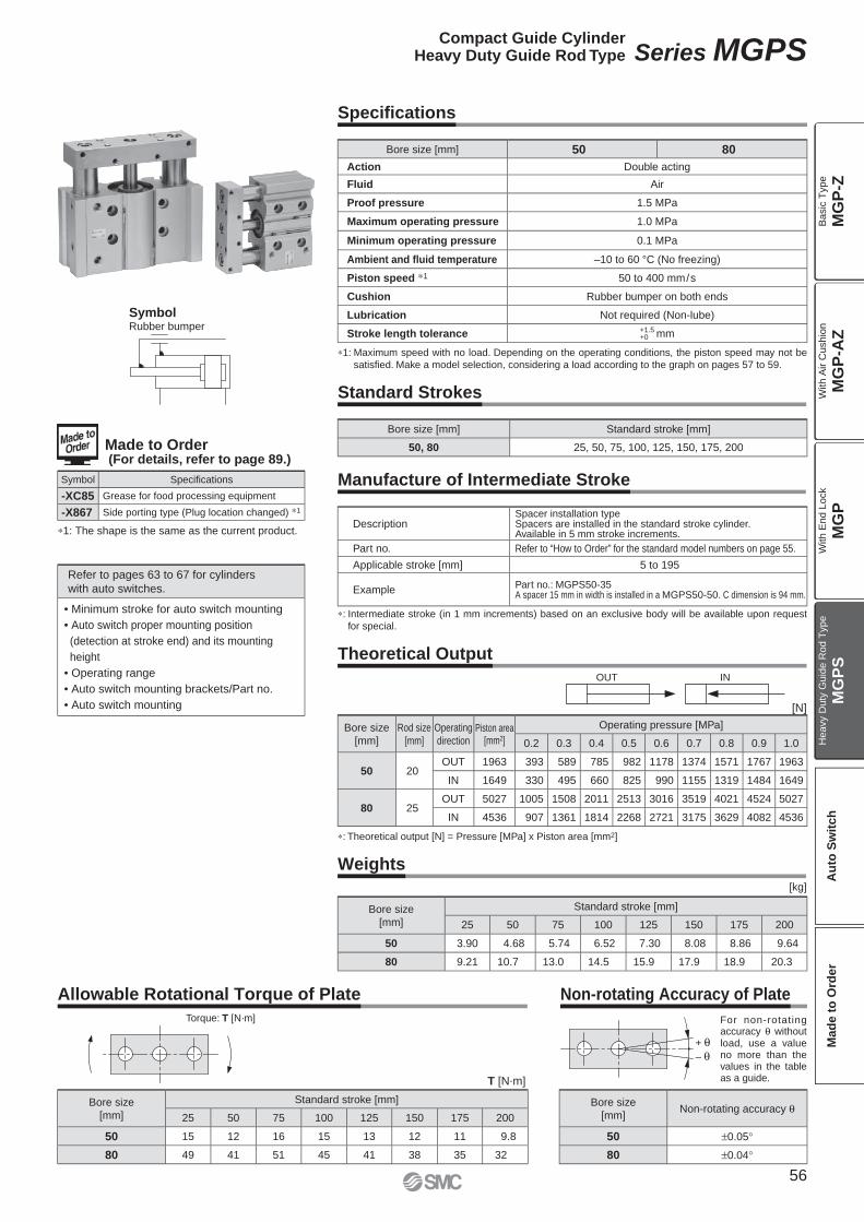
∗1: The shape is the same as the current product.
SymbolRubber bumper
Made to Order (For details, refer to page 89.)
Symbol Specifi cations
-XC85 Grease for food processing equipment
-X867 Side porting type (Plug location changed) ∗1
Refer to pages 63 to 67 for cylinders
with auto switches.
• Minimum stroke for auto switch mounting
• Auto switch proper mounting position
(detection at stroke end) and its mounting
height
• Operating range
• Auto switch mounting brackets/Part no.
• Auto switch mounting
Standard Strokes
Bore size [mm] Standard stroke [mm]
50, 80 25, 50, 75, 100, 125, 150, 175, 200
Manufacture of Intermediate Stroke
∗: Intermediate stroke (in 1 mm increments) based on an exclusive body will be available upon request
for special.
DescriptionSpacer installation typeSpacers are installed in the standard stroke cylinder.Available in 5 mm stroke increments.
Part no. Refer to “How to Order” for the standard model numbers on page 55.
Applicable stroke [mm] 5 to 195
ExamplePart no.: MGPS50-35A spacer 15 mm in width is installed in a MGPS50-50. C dimension is 94 mm.
OUT IN
Theoretical Output
∗: Theoretical output [N] = Pressure [MPa] x Piston area [mm2]
[N]
Bore size
[mm]
Rod size
[mm]
Operating
directionPiston area
[mm2]
Operating pressure [MPa]
0.2 0.3 0.4 0.5 0.6 0.7 0.8 0.9 1.0
50 20OUT 1963 393 589 785 982 1178 1374 1571 1767 1963
IN 1649 330 495 660 825 990 1155 1319 1484 1649
80 25OUT 5027 1005 1508 2011 2513 3016 3519 4021 4524 5027
IN 4536 907 1361 1814 2268 2721 3175 3629 4082 4536
Weights
[kg]
Bore size
[mm]
Standard stroke [mm]
25 50 75 100 125 150 175 200
50 3.90 4.68 5.74 6.52 7.30 8.08 8.86 9.64
80 9.21 10.7 13.0 14.5 15.9 17.9 18.9 20.3
Torque: T [N·m]
Allowable Rotational Torque of Plate
T [N.m]
Bore size
[mm]
Standard stroke [mm]
25 50 75 100 125 150 175 200
50 15 12 16 15 13 12 11 9.8
80 49 41 51 45 41 38 35 32
+
–
Non-rotating Accuracy of Plate
For non-rotating accuracy θ without load, use a value no more than the values in the table as a guide.
Bore size
[mm]Non-rotating accuracy θ
50 ±0.05°
80 ±0.04°
Specifi cations
Bore size [mm] 50 80
Action Double acting
Fluid Air
Proof pressure 1.5 MPa
Maximum operating pressure 1.0 MPa
Minimum operating pressure 0.1 MPa
Ambient and fl uid temperature –10 to 60 °C (No freezing)
Piston speed ∗1 50 to 400 mm/s
Cushion Rubber bumper on both ends
Lubrication Not required (Non-lube)
Stroke length tolerance +1.5+0 mm
∗1: Maximum speed with no load. Depending on the operating conditions, the piston speed may not be
satisfi ed. Make a model selection, considering a load according to the graph on pages 57 to 59.
56
Compact Guide CylinderHeavy Duty Guide Rod Type Series MGPS
MG
P-Z
MG
P-A
ZM
GP
MG
PS
Ba
sic
Typ
eW
ith
Air C
ush
ion
With E
nd L
ock
Heavy D
uty
Guid
e R
od T
ype
Au
to S
wit
ch
Mad
e t
o O
rder
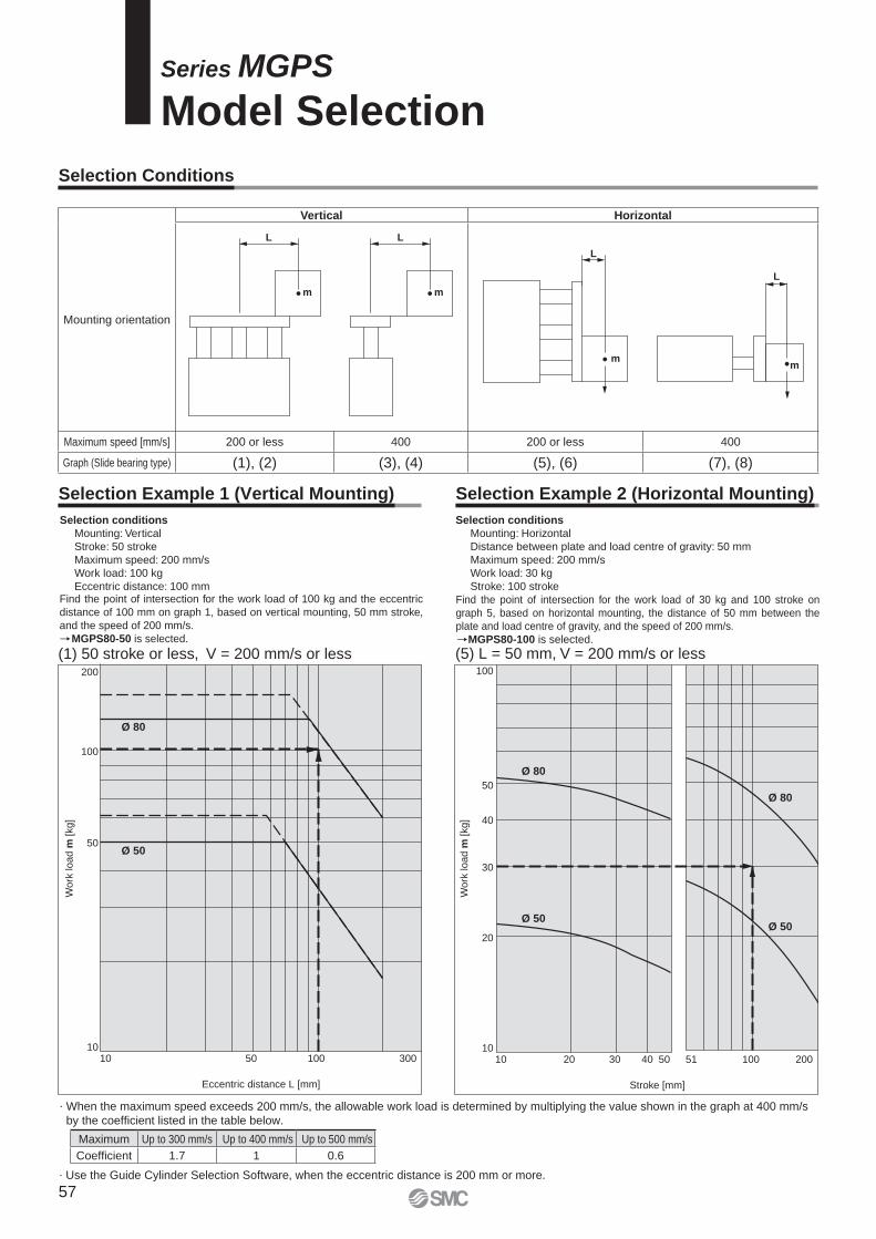
L
m
L
m
L
m
L
m
200
100
50
1010 50 100 300
Eccentric distance L [mm]
Work
load m
[kg]
50
20
30
40
100
1010 20 30 40 50 51 100 200
Stroke [mm]
Work
load m
[kg]
Ø 80
Ø 50
Ø 80
Ø 50
Ø 80
Ø 50
(1) 50 stroke or less, V = 200 mm/s or less (5) L = 50 mm, V = 200 mm/s or less
Selection Conditions
Selection Example 1 (Vertical Mounting) Selection Example 2 (Horizontal Mounting)
Selection conditions
Mounting: Vertical
Stroke: 50 stroke
Maximum speed: 200 mm/s
Work load: 100 kg
Eccentric distance: 100 mmFind the point of intersection for the work load of 100 kg and the eccentric
distance of 100 mm on graph 1, based on vertical mounting, 50 mm stroke,
and the speed of 200 mm/s.
MGPS80-50 is selected.
Selection conditions
Mounting: Horizontal
Distance between plate and load centre of gravity: 50 mm
Maximum speed: 200 mm/s
Work load: 30 kg
Stroke: 100 stroke
Find the point of intersection for the work load of 30 kg and 100 stroke on
graph 5, based on horizontal mounting, the distance of 50 mm between the
plate and load centre of gravity, and the speed of 200 mm/s.
MGPS80-100 is selected.
Series MGPS
Model Selection
. Use the Guide Cylinder Selection Software, when the eccentric distance is 200 mm or more.
. When the maximum speed exceeds 200 mm/s, the allowable work load is determined by multiplying the value shown in the graph at 400 mm/s
by the coeffi cient listed in the table below.
Mounting orientation
Vertical Horizontal
Maximum speed [mm/s] 200 or less 400 200 or less 400
Graph (Slide bearing type) (1), (2) (3), (4) (5), (6) (7), (8)
Maximum Up to 300 mm/s Up to 400 mm/s Up to 500 mm/s
Coeffi cient 1.7 1 0.6
57
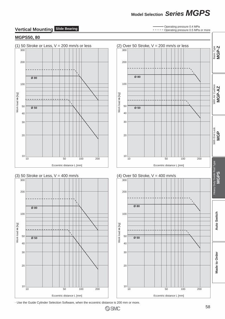
300
200
100
50
20
30
40
1050 100 200
Eccentric distance L [mm]
Work
load m
[kg]
10
Ø 80
Ø 50
Ø 80
Ø 50
Ø 80
Ø 50
Ø 80
Ø 50
300
200
100
50
1050 100 200
Eccentric distance L [mm]
Work
load m
[kg]
10
300
200
100
50
10
20 20
30 30
40 40
50 100 200
Eccentric distance L [mm]
Work
load m
[kg]
10
300
200
100
50
10
20
30
40
50 100 200
Eccentric distance L [mm]
Work
load m
[kg]
10
(1) 50 Stroke or Less, V = 200 mm/s or less (2) Over 50 Stroke, V = 200 mm/s or less
(3) 50 Stroke or Less, V = 400 mm/s (4) Over 50 Stroke, V = 400 mm/s
Vertical Mounting Slide BearingOperating pressure 0.4 MPa
Operating pressure 0.5 MPa or more
. Use the Guide Cylinder Selection Software, when the eccentric distance is 200 mm or more.
MGPS50, 80
58
Model Selection Series MGPS
MG
P-Z
MG
P-A
ZM
GP
MG
PS
Ba
sic
Typ
eW
ith
Air C
ush
ion
With E
nd L
ock
Heavy D
uty
Guid
e R
od T
ype
Au
to S
wit
ch
Mad
e t
o O
rder
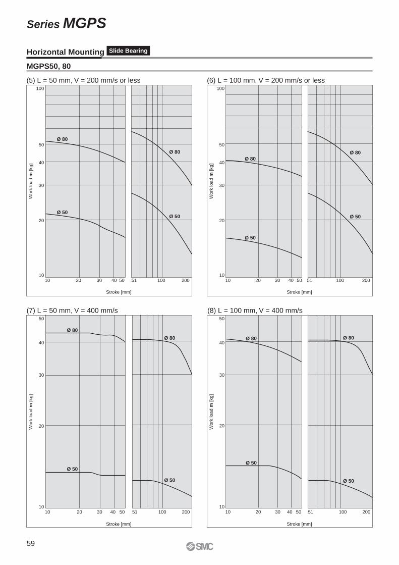
50
20
30
40
100
1010 20 30 40 50 51 100 200
Stroke [mm]
Stroke [mm]
Work
load m
[kg]
Ø 80
Ø 50
Ø 80
Ø 50
Ø 80
Ø 50
Ø 80
Ø 50
50
40
30
20
1010 5020 30 40 51 100 200
Work
load m
[kg]
Ø 80
Ø 50
Ø 80
Ø 50
Ø 80
Ø 50
Ø 80
Ø 50
50
20
30
40
100
1010 20 30 40 50 51 100 200
Stroke [mm]
Work
load m
[kg]
Stroke [mm]
50
40
30
20
1010 5020 30 40 51 100 200
Work
load m
[kg]
(5) L = 50 mm, V = 200 mm/s or less (6) L = 100 mm, V = 200 mm/s or less
(7) L = 50 mm, V = 400 mm/s (8) L = 100 mm, V = 400 mm/s
Horizontal Mounting Slide Bearing
MGPS50, 80
59
Series MGPS
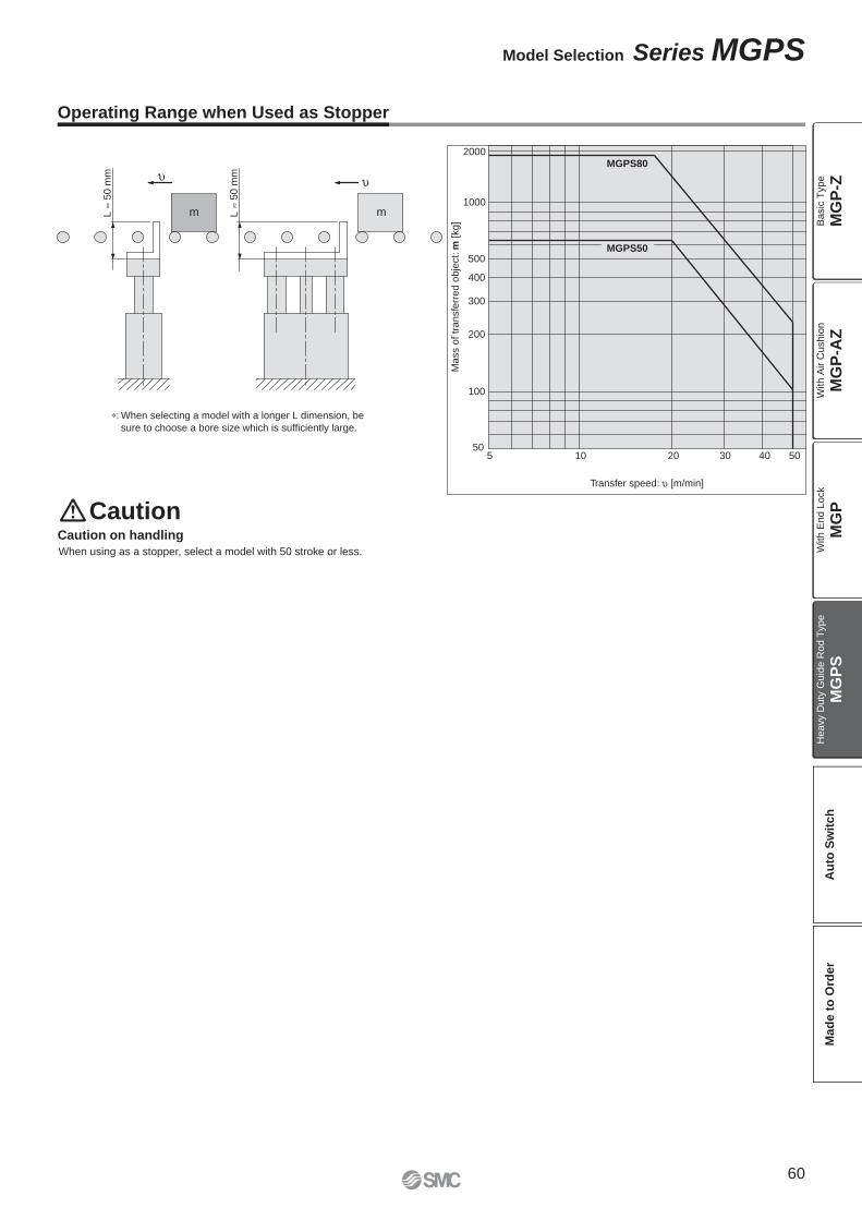
5 10 20 3050
100
200
300
400
500
1000
2000
40 50
MGPS80
MGPS50
Transfer speed: [m/min]
Ma
ss o
f tr
an
sfe
rre
d o
bje
ct: m
[kg
]
m mL
50
mm
L
50
mm
CautionCaution on handling
Operating Range when Used as Stopper
∗: When selecting a model with a longer L dimension, be
sure to choose a bore size which is suffi ciently large.
When using as a stopper, select a model with 50 stroke or less.
60
Model Selection Series MGPS
MG
P-Z
MG
P-A
ZM
GP
MG
PS
Ba
sic
Typ
eW
ith
Air C
ush
ion
With E
nd L
ock
Heavy D
uty
Guid
e R
od T
ype
Au
to S
wit
ch
Mad
e t
o O
rder
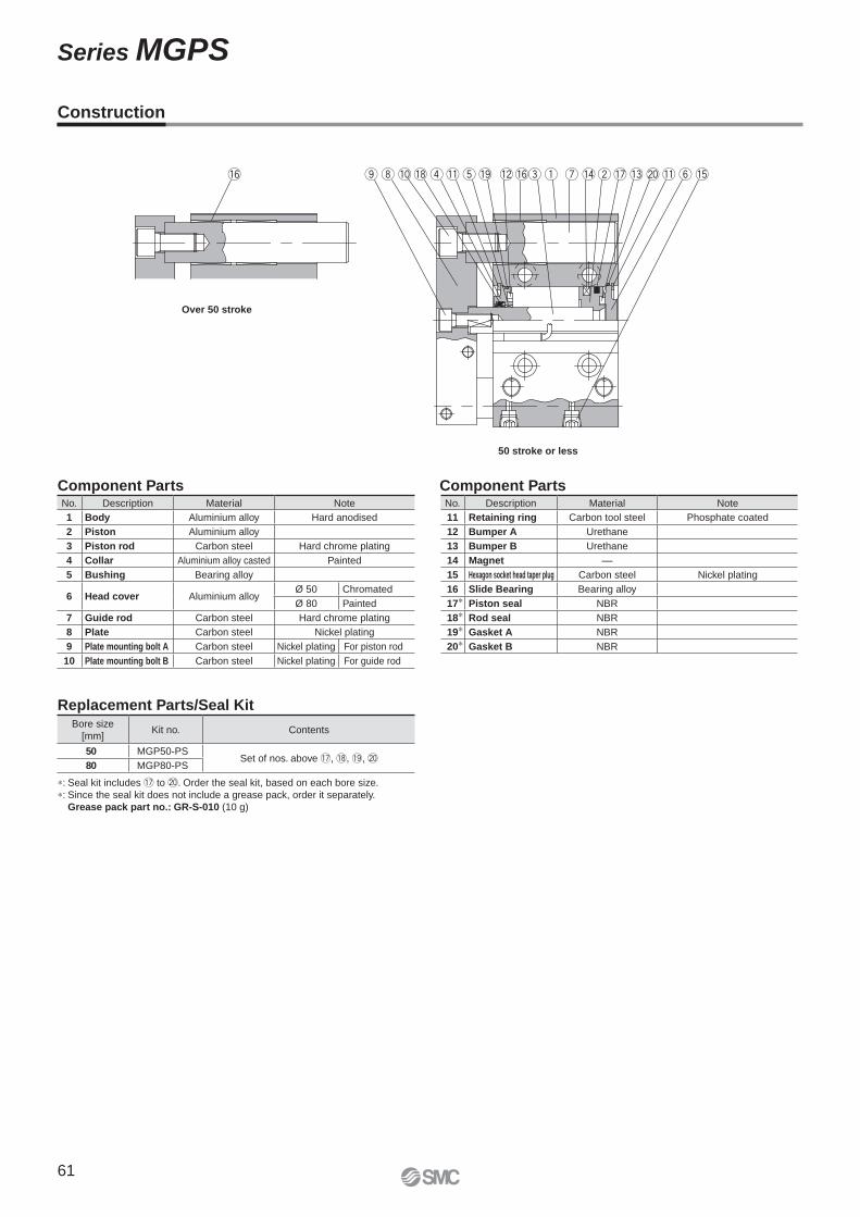
50 stroke or less
Over 50 stroke
Construction
Component Parts Component Parts
Replacement Parts/Seal Kit
∗: Seal kit includes !7 to @0. Order the seal kit, based on each bore size.
∗: Since the seal kit does not include a grease pack, order it separately.
Grease pack part no.: GR-S-010 (10 g)
No. Description Material Note
1 Body Aluminium alloy Hard anodised
2 Piston Aluminium alloy
3 Piston rod Carbon steel Hard chrome plating
4 Collar Aluminium alloy casted Painted
5 Bushing Bearing alloy
6 Head cover Aluminium alloyØ 50 Chromated
Ø 80 Painted
7 Guide rod Carbon steel Hard chrome plating
8 Plate Carbon steel Nickel plating
9 Plate mounting bolt A Carbon steel Nickel plating For piston rod
10 Plate mounting bolt B Carbon steel Nickel plating For guide rod
No. Description Material Note
11 Retaining ring Carbon tool steel Phosphate coated
12 Bumper A Urethane
13 Bumper B Urethane
14 Magnet —
15 Hexagon socket head taper plug Carbon steel Nickel plating
16 Slide Bearing Bearing alloy
17∗ Piston seal NBR
18∗ Rod seal NBR
19∗ Gasket A NBR
20∗ Gasket B NBR
Bore size
[mm]Kit no. Contents
50 MGP50-PSSet of nos. above !7, !8, !9, @0
80 MGP80-PS
61
Series MGPS
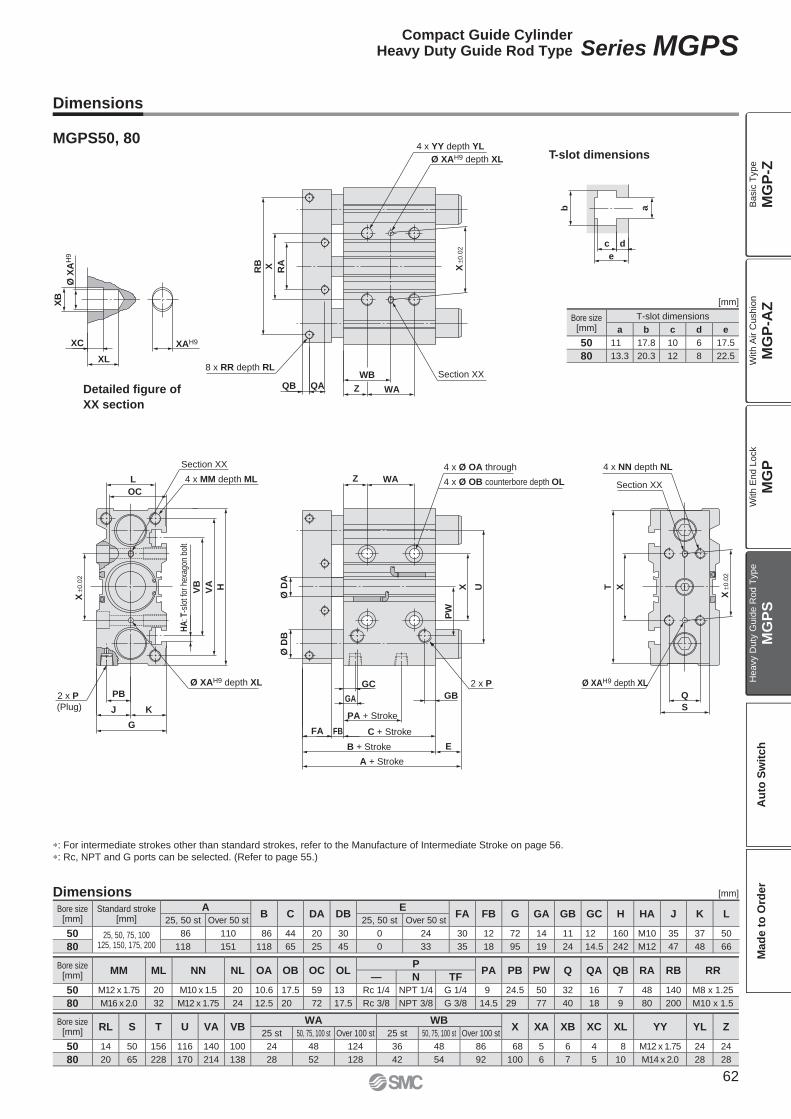
Section XX
Section XX4 x MM depth ML
4 x Ø OA through
4 x Ø OB counterbore depth OL
2 x P
(Plug)
2 x P
4 x YY depth YL
4 x NN depth NL
Ø XAH9 depth XL
Ø XAH9 depth XL
Ø XAH9 depth XL
8 x RR depth RL
Detailed figure of
XX section
T-slot dimensions
XB
e
dc
ab
XC
XL
OC
U
E
S
H
L
HA
: T-s
lot f
or h
exag
on b
olt
VA
VB X
QAQB
RB X RA
WB
Z WA
PB
KJ
G
WAZ
X
PW
T
Q
Ø D
BØ
DA
FA FB
GBGA
GC
PA + Stroke
C + Stroke
B + Stroke
A + Stroke
X±0
.02
X±0
.02
X±0
.02
Ø X
AH
9
XAH9
Section XX
∗: For intermediate strokes other than standard strokes, refer to the Manufacture of Intermediate Stroke on page 56.
∗: Rc, NPT and G ports can be selected. (Refer to page 55.)
Dimensions
Dimensions
MGPS50, 80
[mm]
Bore size[mm]
Standard stroke[mm]
AB C DA DB
EFA FB G GA GB GC H HA J K L
25, 50 st Over 50 st 25, 50 st Over 50 st
50 25, 50, 75, 100125, 150, 175, 200
86 110 86 44 20 30 0 24 30 12 72 14 11 12 160 M10 35 37 50
80 118 151 118 65 25 45 0 33 35 18 95 19 24 14.5 242 M12 47 48 66
Bore size[mm]
MM ML NN NL OA OB OC OLP
PA PB PW Q QA QB RA RB RR— N TF
50 M12 x 1.75 20 M10 x 1.5 20 10.6 17.5 59 13 Rc 1/4 NPT 1/4 G 1/4 9 24.5 50 32 16 7 48 140 M8 x 1.25
80 M16 x 2.0 32 M12 x 1.75 24 12.5 20 72 17.5 Rc 3/8 NPT 3/8 G 3/8 14.5 29 77 40 18 9 80 200 M10 x 1.5
Bore size[mm]
RL S T U VA VBWA WB
X XA XB XC XL YY YL Z25 st 50, 75, 100 st Over 100 st 25 st 50, 75, 100 st Over 100 st
50 14 50 156 116 140 100 24 48 124 36 48 86 68 5 6 4 8 M12 x 1.75 24 24
80 20 65 228 170 214 138 28 52 128 42 54 92 100 6 7 5 10 M14 x 2.0 28 28
[mm]
Bore size[mm]
T-slot dimensions
a b c d e
50 11 17.8 10 6 17.5
80 13.3 20.3 12 8 22.5
62
Compact Guide CylinderHeavy Duty Guide Rod Type Series MGPS
MG
P-Z
MG
P-A
ZM
GP
MG
PS
Ba
sic
Typ
eW
ith
Air C
ush
ion
With E
nd L
ock
Heavy D
uty
Guid
e R
od T
ype
Au
to S
wit
ch
Mad
e t
o O
rder
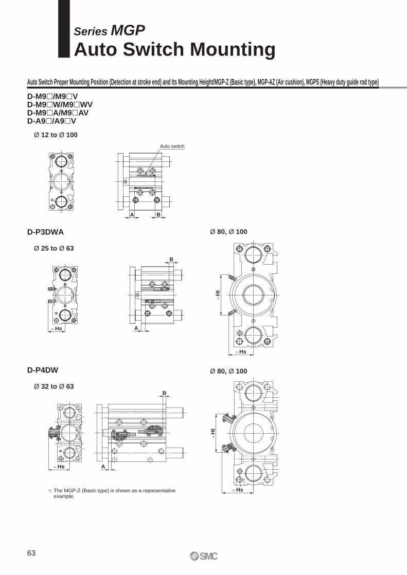
BA
Auto switch
B
A≈ Hs
Hs
Ht
Ht
Hs
≈ Hs A
B
D-M9�/M9�VD-M9�W/M9�WVD-M9�A/M9�AVD-A9�/A9�V
Ø 12 to Ø 100
Series MGP
Auto Switch Mounting
Auto Switch Proper Mounting Position (Detection at stroke end) and Its Mounting Height/MGP-Z (Basic type), MGP-AZ (Air cushion), MGPS (Heavy duty guide rod type)
D-P3DWA
D-P4DW
Ø 80, Ø 100
Ø 80, Ø 100
Ø 25 to Ø 63
Ø 32 to Ø 63
∗: The MGP-Z (Basic type) is shown as a representative example.
63
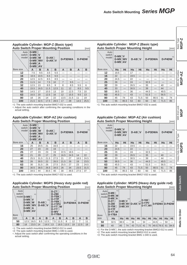
Applicable Cylinder: MGPS (Heavy duty guide rod)
Auto Switch Proper Mounting Position [mm]
Auto
switch
model
Bore
size
∗1
D-M9�D-M9�VD-M9�WD-M9�WVD-M9�AD-M9�AV
∗1
D-A9�D-A9�V
D-Z7�D-Z80D-Y59�D-Y7PD-Y69�D-Y7PVD-Y7�WD-Y7�D-WVD-Y7BA
∗1
D-P3DWA∗2
D-P4DW
A B A B A B A B A B50 12.5 16.5 8.5 12.5 7.5 11.5 8 12 7 11
80 18 23.5 14 19.5 13 18.5 13.5 19 12.5 18
∗1: The auto switch mounting bracket BMG2-012 is used.∗2: The auto switch mounting bracket BMG 1-040 is used.∗: Adjust the auto switch after confi rming the operating conditions in the
actual setting.
Applicable Cylinder: MGPS (Heavy duty guide rod)
Auto Switch Proper Mounting Height [mm]
Auto
switch
model
Bore
size
∗1
D-M9�D-M9�WD-M9�AD-Z7�D-Z80D-Y59�D-Y7PD-Y7�WD-Y7BA
∗2
D-M9�VD-M9�WVD-M9�AV
∗2
D-A9�V
D-Y69�D-Y7PVD-Y7�WV
∗2
D-P3DWA∗3
D-P4DW
Hs Hs Ht Hs Ht Hs Ht Hs Ht Hs Ht
50 32.5 38.5 — 36 — 34 — 44.5 — 50 —
80 40 45 74 43 71.5 41 70 49.5 78.5 61 84.5
∗1: For the D-M9�, the auto switch mounting bracket BMG2-012 is used.∗2: The auto switch mounting bracket BMG2-012 is used.∗3: The auto switch mounting bracket BMG 1-040 is used.
Applicable Cylinder: MGP-AZ (Air cushion)
Auto Switch Proper Mounting Position [mm]
Autoswitchmodel
Bore size
D-M9�D-M9�VD-M9�WD-M9�WVD-M9�AD-M9�AV
D-A9�D-A9�V
D-P3DWA∗1
D-P4DW
A B A B A B A B16 25 20.5 21 16.5 — — — —
20 27 23 23 19 — — — —
25 27 23 23 19 22.5 18.5 — —
32 21 29 17 25 16.5 24.5 14 22
40 25.5 31.5 21.5 27.5 21 27 18.5 24.5
50 26 30.5 22 26.5 21.5 26 19 23.5
63 30 31.5 26 27.5 25.5 27 23 24.5
80 30.5 38.5 26.5 34.5 26 34 23.5 31.5
100 34.5 44 30.5 40 30 39.5 27.5 37
∗1: The auto switch mounting bracket BMG7-032 is used.
Applicable Cylinder: MGP-Z (Basic type)Auto Switch Proper Mounting Position [mm]
Autoswitchmodel
Bore size
D-M9�D-M9�VD-M9�WD-M9�WVD-M9�AD-M9�AV
D-A9�D-A9�V
D-P3DWA∗1
D-P4DW
A B A B A B A B12 7.5 9.5 3.5 5.5 — — — —
16 10.5 10.5 6.5 6.5 — — — —
20 12.5 12.5 8.5 8.5 — — — —
25 11.5 14 7.5 10 7 9.5 — —
32 12.5 13 8.5 9 8 8.5 5.5 6
40 15.5 16.5 11.5 12.5 11 12 8.5 9.5
50 14.5 17 10.5 13 10 12.5 7.5 10
63 16.5 20 12.5 16 12 15.5 9.5 13
80 18 26 14 22 13.5 21.5 11 19
100 21.5 32.5 17.5 28.5 17 28 14.5 25.5
∗1: The auto switch mounting bracket BMG7-032 is used.∗: Adjust the auto switch after confi rming the operating conditions in the
actual setting.
Applicable Cylinder: MGP-AZ (Air cushion)
Auto Switch Proper Mounting Height [mm]
Autoswitchmodel
Bore size
D-M9�VD-M9�WVD-M9�AV
D-A9�V D-P3DWA∗1
D-P4DW
Hs Ht Hs Ht Hs Ht Hs Ht16 22 — 19.5 — — — — —
20 24.5 — 22 — — — — —
25 26 — 24 — 32.5 — — —
32 29 — 26.5 — 35 — 40 —
40 33 — 30.5 — 39 — 44 —
50 38.5 — 36 — 44.5 — 49.5 —
63 45.5 — 43 — 51.5 — 56.5 —
80 45 74 43 71.5 50 80.5 61 74
100 55 85.5 53 83 60 92 71.5 86
∗1: The auto switch mounting bracket BMG7-032 is used.
Applicable Cylinder: MGP-Z (Basic type)
Auto Switch Proper Mounting Height [mm]
Autoswitchmodel
Bore size
D-M9�VD-M9�WVD-M9�AV
D-A9�V D-P3DWA∗1
D-P4DW
Hs Ht Hs Ht Hs Ht Hs Ht12 19.5 — 17 — — — — —
16 22 — 19.5 — — — — —
20 24.5 — 22 — — — — —
25 26 — 24 — 32.5 — — —
32 29 — 26.5 — 35 — 40 —
40 33 — 30.5 — 39 — 44 —
50 38.5 — 36 — 44.5 — 49.5 —
63 45.5 — 43 — 51.5 — 56.5 —
80 45 74 43 71.5 50 80.5 61 74
100 55 85.5 53 83 60 92 71.5 86
∗1: The auto switch mounting bracket BMG7-032 is used.
64
Auto Switch Mounting Series MGP
MG
P-Z
MG
P-A
ZM
GP
MG
PS
Ba
sic
Typ
eW
ith
Air C
ush
ion
With E
nd L
ock
Heavy D
uty
Guid
e R
od T
ype
Au
to S
wit
ch
Mad
e t
o O
rder
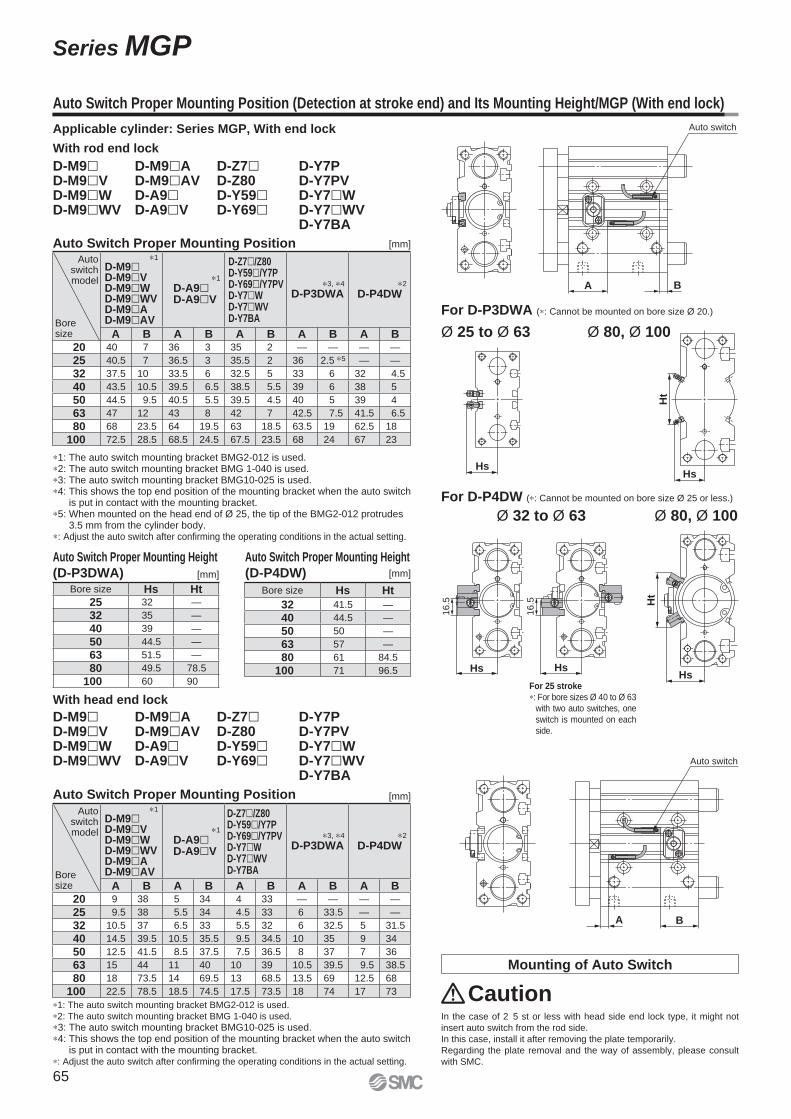
BA
Auto switch
16.5
Hs
16.5
Hs
BA
Auto switch
Hs
Ht
Hs
Ht
Hs
Auto Switch Proper Mounting Height
(D-P4DW)
Auto Switch Proper Mounting Height
(D-P3DWA)
Auto Switch Proper Mounting Position (Detection at stroke end) and Its Mounting Height/MGP (With end lock)
With rod end lock
Caution
D-M9�D-M9�VD-M9�WD-M9�WV
D-M9�AD-M9�AVD-A9�D-A9�V
D-Z7�D-Z80D-Y59�D-Y69�
D-Y7PD-Y7PVD-Y7�WD-Y7�WVD-Y7BA
In the case of 2 5 st or less with head side end lock type, it might not
insert auto switch from the rod side.
In this case, install it after removing the plate temporarily.
Regarding the plate removal and the way of assembly, please consult
with SMC.
[mm]
∗1: The auto switch mounting bracket BMG2-012 is used.
∗2: The auto switch mounting bracket BMG 1-040 is used.
∗3: The auto switch mounting bracket BMG10-025 is used.∗4: This shows the top end position of the mounting bracket when the auto switch
is put in contact with the mounting bracket.∗: Adjust the auto switch after confi rming the operating conditions in the actual setting.
Mounting of Auto Switch
For 25 stroke
∗: For bore sizes Ø 40 to Ø 63
with two auto switches, one
switch is mounted on each
side.
Applicable cylinder: Series MGP, With end lock
For D-P4DW (∗: Cannot be mounted on bore size Ø 25 or less.)
Ø 32 to Ø 63
For D-P3DWA (∗: Cannot be mounted on bore size Ø 20.)
Auto Switch Proper Mounting Position
With head end lock
D-M9�D-M9�VD-M9�WD-M9�WV
D-M9�AD-M9�AVD-A9�D-A9�V
D-Z7�D-Z80D-Y59�D-Y69�
D-Y7PD-Y7PVD-Y7�WD-Y7�WVD-Y7BA
Autoswitchmodel
Boresize
∗1
D-M9�D-M9�VD-M9�WD-M9�WVD-M9�AD-M9�AV
∗1
D-A9�D-A9�V
D-Z7�/Z80D-Y59�/Y7PD-Y69�/Y7PVD-Y7�WD-Y7�WVD-Y7BA
∗3, ∗4
D-P3DWA∗2
D-P4DW
A B A B A B A B A B20 9 38 5 34 4 33 — — — —
25 9.5 38 5.5 34 4.5 33 6 33.5 — —
32 10.5 37 6.5 33 5.5 32 6 32.5 5 31.5
40 14.5 39.5 10.5 35.5 9.5 34.5 10 35 9 34
50 12.5 41.5 8.5 37.5 7.5 36.5 8 37 7 36
63 15 44 11 40 10 39 10.5 39.5 9.5 38.5
80 18 73.5 14 69.5 13 68.5 13.5 69 12.5 68
100 22.5 78.5 18.5 74.5 17.5 73.5 18 74 17 73
Auto Switch Proper Mounting Position [mm]
∗1: The auto switch mounting bracket BMG2-012 is used.∗2: The auto switch mounting bracket BMG 1-040 is used.∗3: The auto switch mounting bracket BMG10-025 is used.∗4: This shows the top end position of the mounting bracket when the auto switch
is put in contact with the mounting bracket.∗5: When mounted on the head end of Ø 25, the tip of the BMG2-012 protrudes
3.5 mm from the cylinder body.∗: Adjust the auto switch after confi rming the operating conditions in the actual setting.
Autoswitchmodel
Boresize
∗1
D-M9�D-M9�VD-M9�WD-M9�WVD-M9�AD-M9�AV
∗1
D-A9�D-A9�V
D-Z7�/Z80D-Y59�/Y7PD-Y69�/Y7PVD-Y7�WD-Y7�WVD-Y7BA
∗3, ∗4
D-P3DWA∗2
D-P4DW
A B A B A B A B A B20 40 7 36 3 35 2 — — — —
25 40.5 7 36.5 3 35.5 2 36 2.5 ∗5 — —
32 37.5 10 33.5 6 32.5 5 33 6 32 4.5
40 43.5 10.5 39.5 6.5 38.5 5.5 39 6 38 5
50 44.5 9.5 40.5 5.5 39.5 4.5 40 5 39 4
63 47 12 43 8 42 7 42.5 7.5 41.5 6.5
80 68 23.5 64 19.5 63 18.5 63.5 19 62.5 18
100 72.5 28.5 68.5 24.5 67.5 23.5 68 24 67 23
Ø 25 to Ø 63 Ø 80, Ø 100
Ø 80, Ø 100
Bore size Hs Ht25 32 —
32 35 —
40 39 —
50 44.5 —
63 51.5 —
80 49.5 78.5
100 60 90
[mm]
Bore size Hs Ht
32 41.5 —
40 44.5 —
50 50 —
63 57 —
80 61 84.5
100 71 96.5
[mm]
65
Series MGP
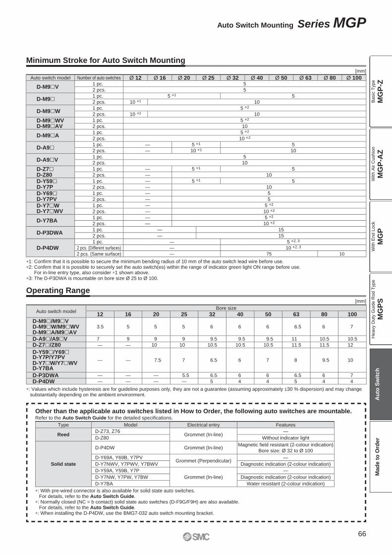
Auto switch modelBore size
12 16 20 25 32 40 50 63 80 100
D-M9�/M9�VD-M9�W/M9�WVD-M9�A/M9�AV
3.5 5 5 5 6 6 6 6.5 6 7
D-A9�/A9�V 7 9 9 9 9.5 9.5 9.5 11 10.5 10.5
D-Z7�/Z80 — — 10 10 10.5 10.5 10.5 11.5 11.5 12
D-Y59�/Y69�D-Y7P/Y7PVD-Y7�W/Y7�WVD-Y7BA
— — 7.5 7 6.5 6 7 8 9.5 10
D-P3DWA — — — 5.5 6.5 6 6 6.5 6 7
D-P4DW — — — — 5 4 4 5 4 4
∗: Values which include hysteresis are for guideline purposes only, they are not a guarantee (assuming approximately ±30 % dispersion) and may change substantially depending on the ambient environment.
Auto switch model Number of auto switches Ø 12 Ø 16 Ø 20 Ø 25 Ø 32 Ø 40 Ø 50 Ø 63 Ø 80 Ø 100
D-M9�V1 pc. 5
2 pcs. 5
D-M9� 1 pc. 5 ∗1 5
2 pcs. 10 ∗1 10
D-M9�W1 pc. 5 ∗2
2 pcs. 10 ∗2 10
D-M9�WVD-M9�AV
1 pc. 5 ∗2
2 pcs. 10
D-M9�A1 pc. 5 ∗2
2 pcs. 10 ∗2
D-A9� 1 pc. — 5 ∗1 5
2 pcs. — 10 ∗1 10
D-A9�V1 pc. 5
2 pcs. 10
D-Z7�D-Z80
1 pc. — 5 ∗1 5
2 pcs. — 10
D-Y59�D-Y7P
1 pc. — 5 ∗1 5
2 pcs. — 10
D-Y69�D-Y7PV
1 pc. — 5
2 pcs. — 5
D-Y7�WD-Y7�WV
1 pc. — 5 ∗2
2 pcs. — 10 ∗2
D-Y7BA1 pc. — 5 ∗2
2 pcs. — 10 ∗2
D-P3DWA1 pc. — 15
2 pcs. — 15
D-P4DW1 pc. — 5 ∗2, 3
2 pcs. (Different surfaces) — 10 ∗2, 3
2 pcs. (Same surface) — 75 10
Other than the applicable auto switches listed in How to Order, the following auto switches are mountable.Refer to the Auto Switch Guide for the detailed specifi cations.
Type Model Electrical entry Features
ReedD-Z73, Z76
Grommet (In-line)—
D-Z80 Without indicator light
Solid state
D-P4DW Grommet (In-line)Magnetic fi eld resistant (2-colour indication)
Bore size: Ø 32 to Ø 100
D-Y69A, Y69B, Y7PVGrommet (Perpendicular)
—
D-Y7NWV, Y7PWV, Y7BWV Diagnostic indication (2-colour indication)
D-Y59A, Y59B, Y7P
Grommet (In-line)
—
D-Y7NW, Y7PW, Y7BW Diagnostic indication (2-colour indication)
D-Y7BA Water resistant (2-colour indication)
∗: With pre-wired connector is also available for solid state auto switches. For details, refer to the Auto Switch Guide.
∗: Normally closed (NC = b contact) solid state auto switches (D-F9G/F9H) are also available. For details, refer to the Auto Switch Guide.
∗: When installing the D-P4DW, use the BMG7-032 auto switch mounting bracket.
∗1: Confi rm that it is possible to secure the minimum bending radius of 10 mm of the auto switch lead wire before use.∗2: Confi rm that it is possible to securely set the auto switch(es) within the range of indicator green light ON range before use.
For in-line entry type, also consider ∗1 shown above.∗3: The D-P3DWA is mountable on bore size Ø 25 to Ø 100.
Minimum Stroke for Auto Switch Mounting
Operating Range
[mm]
[mm]
66
Auto Switch Mounting Series MGP
MG
P-Z
MG
P-A
ZM
GP
MG
PS
Ba
sic
Typ
eW
ith
Air C
ush
ion
With E
nd L
ock
Heavy D
uty
Guid
e R
od T
ype
Au
to S
wit
ch
Mad
e t
o O
rder
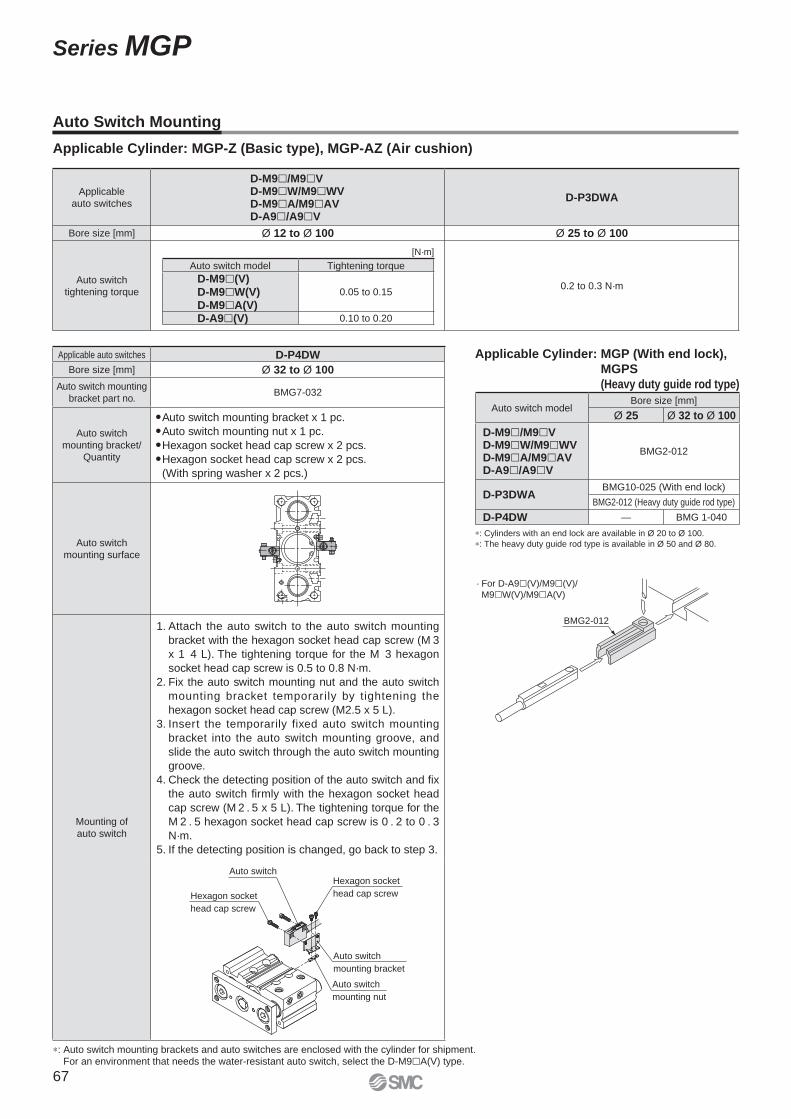
∗: Auto switch mounting brackets and auto switches are enclosed with the cylinder for shipment.For an environment that needs the water-resistant auto switch, select the D-M9�A(V) type.
Auto Switch Mounting
Applicable Cylinder: MGP-Z (Basic type), MGP-AZ (Air cushion)
Applicable
auto switches
D-M9�/M9�VD-M9�W/M9�WVD-M9�A/M9�AVD-A9�/A9�V
D-P3DWA
Bore size [mm] Ø 12 to Ø 100 Ø 25 to Ø 100
Auto switch
tightening torque0.2 to 0.3 N·m
Applicable auto switches D-P4DW
Bore size [mm] Ø 32 to Ø 100
Auto switch mounting
bracket part no.BMG7-032
Auto switch
mounting bracket/
Quantity
�Auto switch mounting bracket x 1 pc.
�Auto switch mounting nut x 1 pc.
�Hexagon socket head cap screw x 2 pcs.
�Hexagon socket head cap screw x 2 pcs.
(With spring washer x 2 pcs.)
Auto switch
mounting surface
Mounting of
auto switch
1. Attach the auto switch to the auto switch mounting
bracket with the hexagon socket head cap screw (M 3
x 1 4 L). The tightening torque for the M 3 hexagon
socket head cap screw is 0.5 to 0.8 N·m.
2. Fix the auto switch mounting nut and the auto switch
mounting bracket temporarily by tightening the
hexagon socket head cap screw (M2.5 x 5 L).
3. Insert the temporarily fixed auto switch mounting
bracket into the auto switch mounting groove, and
slide the auto switch through the auto switch mounting
groove.
4. Check the detecting position of the auto switch and fi x
the auto switch fi rmly with the hexagon socket head
cap screw (M 2 . 5 x 5 L). The tightening torque for the
M 2 . 5 hexagon socket head cap screw is 0 . 2 to 0 . 3
N·m.
5. If the detecting position is changed, go back to step 3.
Auto switch
mounting nut
Auto switch
mounting bracket
Auto switch
Hexagon socket
head cap screw
Hexagon socket
head cap screw
[N·m]
Auto switch model Tightening torque
D-M9�(V)D-M9�W(V)D-M9�A(V)
0.05 to 0.15
D-A9�(V) 0.10 to 0.20
· For D-A9�(V)/M9�(V)/
M9�W(V)/M9�A(V)
BMG2-012
Applicable Cylinder: MGP (With end lock),
MGPS
(Heavy duty guide rod type)
Auto switch modelBore size [mm]
Ø 25 Ø 32 to Ø 100
D-M9�/M9�VD-M9�W/M9�WVD-M9�A/M9�AVD-A9�/A9�V
BMG2-012
D-P3DWABMG10-025 (With end lock)
BMG2-012 (Heavy duty guide rod type)
D-P4DW — BMG 1-040
∗: Cylinders with an end lock are available in Ø 20 to Ø 100.
∗: The heavy duty guide rod type is available in Ø 50 and Ø 80.
67
Series MGP
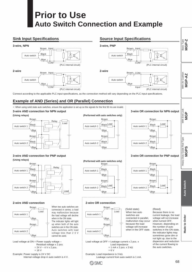
COM
Input
Blue
Black
Brown
Auto switch
COM
Input
Blue
Brown
Auto switch
COM
Input
Blue
Black
Brown
Auto switch
Input
COM
Blue
Brown
Auto switch
RelayLoad
Blue
Black
Brown
Auto switch 2
Blue
Black
Brown
Auto switch 1Load
Blue
Black
Brown
Auto switch 2
Blue
Black
Brown
Auto switch 1Load
Blue
Black
Brown
Auto switch 2
Blue
Black
Brown
Auto switch 1
Relay
LoadBlue
Black
Brown
Auto switch 2
Blue
Black
Brown
Auto switch 1
Load
Blue
Black
Brown
Auto switch 2
Blue
Black
Brown
Auto switch 1
Load
Blue
Black
Brown
Auto switch 2
Blue
Black
Brown
Auto switch 1
Load
Blue
Brown
Auto switch 2
Blue
Brown
Auto switch 1
Load
Blue
Brown
Auto switch 2
Blue
Brown
Auto switch 1
∗: When using solid state auto switches, ensure the application is set up so the signals for the fi rst 50 ms are invalid.
Connect according to the applicable PLC input specifi cations, as the connection method will vary depending on the PLC input specifi cations.
Because there is no
current leakage, the load
voltage will not increase
when turned OFF.
However, depending on
the number of auto
switches in the ON state,
the indicator lights may
sometimes grow dim or
not light up, due to the
dispersion and reduction
of the current fl owing to
the auto switches.
When two auto
switches are
connected in parallel,
malfunction may occur
because the load
voltage will increase
when in the OFF state.Auto switches with load
voltage less than 2 0 V
cannot be used.
When two auto switches are
connected in series, a load
may malfunction because
the load voltage will decline
when in the ON state.
The indicator lights will light
up when both of the auto
switches are in the ON state.
(Reed)(Solid state)
Example: Load impedance is 3 kΩ.
Leakage current from auto switch is 1 mA.
Load voltage at OFF = Leakage current x 2 pcs. x
Load impedance= 1 mA x 2 pcs. x 3 kΩ= 6 V
Example: Power supply is 24 V DC
Internal voltage drop in auto switch is 4 V.
Load voltage at ON = Power supply voltage –
Residual voltage x 2 pcs.
= 24 V − 4 V x 2 pcs.
= 16 V
Prior to UseAuto Switch Connection and Example
3-wire, NPN
2-wire
3-wire, PNP
2-wire
(PLC internal circuit)
(PLC internal circuit)
(PLC internal circuit)
(PLC internal circuit)
3-wire AND connection for NPN output
(Using relays) (Performed with auto switches only)
3-wire OR connection for NPN output
3-wire AND connection for PNP output
(Using relays)(Performed with auto switches only)
3-wire OR connection for PNP output
2-wire AND connection 2-wire OR connection
Sink Input Specifi cations
Example of AND (Series) and OR (Parallel) Connection
Source Input Specifi cations
68
MG
P-Z
MG
P-A
ZM
GP
MG
PS
Ba
sic
Typ
eW
ith
Air C
ush
ion
With E
nd L
ock
Heavy D
uty
Guid
e R
od T
ype
Au
to S
wit
ch
Mad
e t
o O
rder

Basic type With air cushion
Slide bearing
Ball bushing
High precisionball bushing
Slide bearing
Ball bushing
High precisionball bushing
MGPM MGPL MGPA MGPM-A MGPL-A MGPA-A
Basic type With air cushion
Slide bearing
Ball bushing
High precisionball bushing
Slide bearing
Ball bushing
High precisionball bushing
MGPM MGPL MGPA MGPM MGPL MGPA
-XA�
-XC79
Change of guide rod end shape
Tapped hole, drilled hole, pinned hole machined additionally
Specifi cationsSymbol
Specifi cationsSymbol
The following special specifi cations can be ordered as a simplifi ed Made-to-Order.There is a specifi cation sheet available on paper and CD-ROM. Please contact your SMC sales representatives if necessary.Simple Specials
Made to Order
Series MGP
Simple Specials/Made to OrderPlease contact SMC for detailed specifi cations, delivery and prices.
∗1: The shape is the same as the current product.
69
-XB6
-XB10
-XB13
-XB22
-XC4
-XC6
-XC8
-XC9
-XC19
-XC22
-XC35
-XC69
-XC82
-XC85
-XC88
-XC89
-XC91
-XC92
-X144
-X471
-X867
Heat resistant cylinder (-10 to 150 °C)
Intermediate stroke (Using exclusive body)
Low speed cylinder (5 to 50 mm/s)
Shock absorber soft type series RJ type
With heavy duty scraper
Made of stainless steel
Adjustable stroke cylinder/Adjustable extension type
Adjustable stroke cylinder/Adjustable retraction type
Intermediate stroke (Spacer type)
Fluororubber seal
With coil scraper
With shock absorber ∗1
Bottom mounting type
Grease for food processing equipment
Spatter resistant coil scraper, Lube-retainer, Grease for welding (Rod parts: Stainless steel 304)
Spatter resistant coil scraper, Lube-retainer, Grease for welding (Rod parts: S45C)
Spatter resistant coil scraper, Grease for welding (Rod parts: S45C)
Dust resistant actuator ∗1
Symmetrical port position
Enlarged Plate and Body Gap Dimensions
Side porting type (Plug location changed)
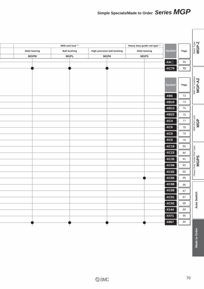
With end lock ∗1 Heavy duty guide rod type ∗1
Slide bearing Ball bushing High precision ball bushing Slide bearing
MGPM MGPL MGPA MGPS
71
72
Page
Page
-XA�
-XC79
Symbol
Symbol
70
Simple Specials/Made to Order Series MGP
73
73
74
75
77
78
78
79
80
80
81
82
85
85
86
87
87
88
89
90
90
-XB6
-XB10
-XB13
-XB22
-XC4
-XC6
-XC8
-XC9
-XC19
-XC22
-XC35
-XC69
-XC82
-XC85
-XC88
-XC89
-XC91
-XC92
-X144
-X471
-X867
MG
P-Z
MG
P-A
ZM
GP
MG
PS
Ba
sic
Typ
eW
ith
Air C
ush
ion
With E
nd L
ock
Heavy D
uty
Guid
e R
od T
ype
Au
to S
wit
ch
Mad
e t
o O
rder
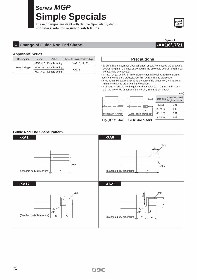
Overall length of cylinder
E’
Overall length of cylinder
E’
E
C0.5
(Standard body dimensions) E(Standard body dimensions)
MMAL
C0.5
E A
30
(Standard body dimensions)
MM
E
30
(Standard body dimensions)
T
A
DA MM
-XA1 -XA6
-XA17 -XA21
Fig. (1) XA1, XA6 Fig. (2) XA17, XA21
Precautions
• Ensure that the cylinder’s overall length should not exceed the allowable
overall length. In the case of exceeding the allowable overall length, it will
be available as specials.
• In Fig. (1), (2) below, E’ dimension cannot make it into E dimension or
less of the standard products. Confi rm by referring to catalogue.
• SMC will make appropriate arrangements if no dimension, tolerance, or
fi nish instructions are given in the diagram.• ∗ dimension should be the guide rod diameter (D) – 2 mm. In the case
that the preferred dimension is different, fi ll in that dimension.
Description Model Action Symbol for change of rod end shape
Standard type
MGPM-Z Double acting XA1, 6, 17, 21
MGPL-Z Double actingXA1, 6
MGPA-Z Double acting
Bore sizeAllowable overalllength of cylinder
12,16 345
20 to 32 540
40 to 63 561
80,100 603
Applicable Series
Guide Rod End Shape Pattern
Change of Guide Rod End Shape1Symbol
-XA1/6/17/21
Series MGP
Simple SpecialsThese changes are dealt with Simple Specials System.
For details, refer to the Auto Switch Guide.
[mm]
71
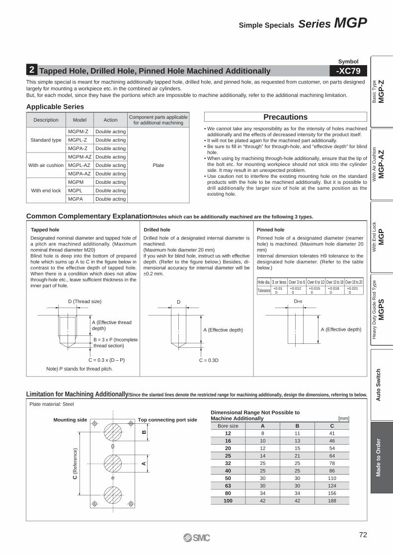
D (Thread size)
A (Effective thread
depth)
B = 3 x P (Incomplete
thread section)
C = 0.3 x (D – P)
D
A (Effective depth)
C = 0.3D
DH9
A (Effective depth)
C (
Refe
rence)
AB
Mounting side Top connecting port side
Description Model ActionComponent parts applicable
for additional machining
Standard type
MGPM-Z Double acting
Plate
MGPL-Z Double acting
MGPA-Z Double acting
With air cushion
MGPM-AZ Double acting
MGPL-AZ Double acting
MGPA-AZ Double acting
With end lock
MGPM Double acting
MGPL Double acting
MGPA Double acting
This simple special is meant for machining additionally tapped hole, drilled hole, and pinned hole, as requested from customer, on parts designed
largely for mounting a workpiece etc. in the combined air cylinders.
But, for each model, since they have the portions which are impossible to machine additionally, refer to the additional machining limitation.
Tapped Hole, Drilled Hole, Pinned Hole Machined Additionally2Symbol
-XC79
Precautions
• We cannot take any responsibility as for the intensity of holes machined
additionally and the effects of decreased intensity for the product itself.
• It will not be plated again for the machined part additionally.
• Be sure to fi ll in “through” for through-hole, and “effective depth” for blind
hole.
• When using by machining through-hole additionally, ensure that the tip of
the bolt etc. for mounting workpiece should not stick into the cylinder
side. It may result in an unexpected problem.
• Use caution not to interfere the existing mounting hole on the standard
products with the hole to be machined additionally. But it is possible to
drill additionally the larger size of hole at the same position as the
existing hole.
Plate material: Steel
Dimensional Range Not Possible to Machine Additionally
Bore size A B C
12 8 11 41
16 10 13 46
20 12 15 54
25 14 21 64
32 25 25 78
40 25 25 86
50 30 30 110
63 30 30 124
80 34 34 156
100 42 42 188
Common Complementary Explanation/Holes which can be additionally machined are the following 3 types.
Note) P stands for thread pitch.
Tapped hole
Designated nominal diameter and tapped hole of
a pitch are machined additionally. (Maximum
nominal thread diameter M20)
Blind hole is deep into the bottom of prepared
hole which sums up A to C in the fi gure below in
contrast to the effective depth of tapped hole.
When there is a condition which does not allow
through-hole etc., leave suffi cient thickness in the
inner part of hole.
Drilled hole
Drilled hole of a designated internal diameter is
machined.
(Maximum hole diameter 20 mm)
If you wish for blind hole, instruct us with effective
depth. (Refer to the figure below.) Besides, di-
mensional accuracy for internal diameter will be
±0.2 mm.
Pinned hole
Pinned hole of a designated diameter (reamer
hole) is machined. (Maximum hole diameter 20
mm)
Internal dimension tolerates H9 tolerance to the
designated hole diameter. (Refer to the table
below.)
Hole dia. 3 or less Over 3 to 6 Over 6 to 10 Over 10 to 18 Over 18 to 20
Tolerance+0.01 0
+0.012 0
+0.015 0
+0.018 0
+0.021 0
Limitation for Machining Additionally/Since the slanted lines denote the restricted range for machining additionally, design the dimensions, referring to below.
[mm]
Applicable Series
72
Simple Specials Series MGP
MG
P-Z
MG
P-A
ZM
GP
MG
PS
Ba
sic
Typ
eW
ith
Air C
ush
ion
With E
nd L
ock
Heavy D
uty
Guid
e R
od T
ype
Au
to S
wit
ch
Mad
e t
o O
rder
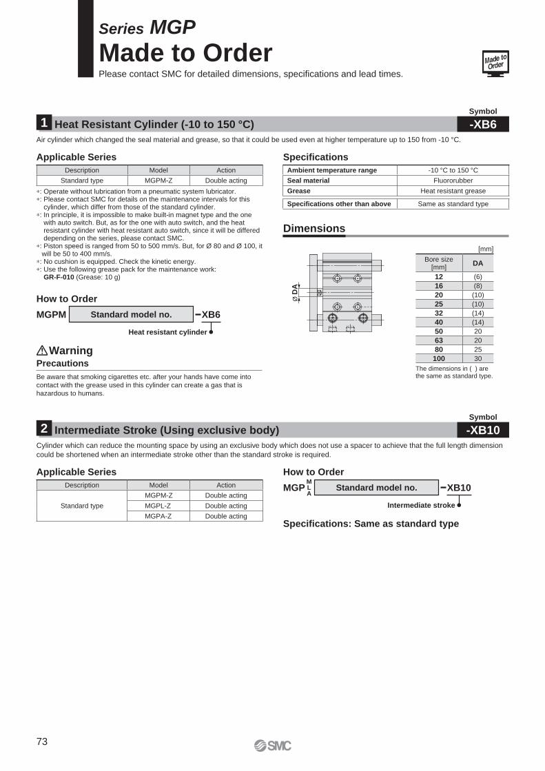
Ø D
A
Standard model no.
∗: Operate without lubrication from a pneumatic system lubricator.∗: Please contact SMC for details on the maintenance intervals for this
cylinder, which differ from those of the standard cylinder.∗: In principle, it is impossible to make built-in magnet type and the one
with auto switch. But, as for the one with auto switch, and the heat resistant cylinder with heat resistant auto switch, since it will be differed depending on the series, please contact SMC.
∗: Piston speed is ranged from 50 to 500 mm/s. But, for Ø 80 and Ø 100, it will be 50 to 400 mm/s.
∗: No cushion is equipped. Check the kinetic energy.∗: Use the following grease pack for the maintenance work:
GR-F-010 (Grease: 10 g)
XB6MGPM
Heat resistant cylinder
Description Model Action
Standard type MGPM-Z Double acting
The dimensions in ( ) are the same as standard type.
Bore size[mm]
DA
12 (6)
16 (8)
20 (10)
25 (10)
32 (14)
40 (14)
50 20
63 20
80 25
100 30
MGPMLA
Description Model Action
Standard type
MGPM-Z Double acting
MGPL-Z Double acting
MGPA-Z Double acting
Ambient temperature range -10 °C to 150 °CSeal material Fluororubber
Grease Heat resistant grease
Specifi cations other than above Same as standard type
Series MGP
Made to OrderPlease contact SMC for detailed dimensions, specifi cations and lead times.
Heat Resistant Cylinder (-10 to 150 °C)1Symbol
-XB6
Intermediate Stroke (Using exclusive body)2Symbol
-XB10
Air cylinder which changed the seal material and grease, so that it could be used even at higher temperature up to 150 from -10 °C.
Cylinder which can reduce the mounting space by using an exclusive body which does not use a spacer to achieve that the full length dimension
could be shortened when an intermediate stroke other than the standard stroke is required.
Applicable Series
Applicable Series How to Order
Specifi cations: Same as standard type
Specifi cations
Dimensions
How to Order
Precautions
Be aware that smoking cigarettes etc. after your hands have come into
contact with the grease used in this cylinder can create a gas that is
hazardous to humans.
Warning
[mm]
Standard model no. XB10
Intermediate stroke
73
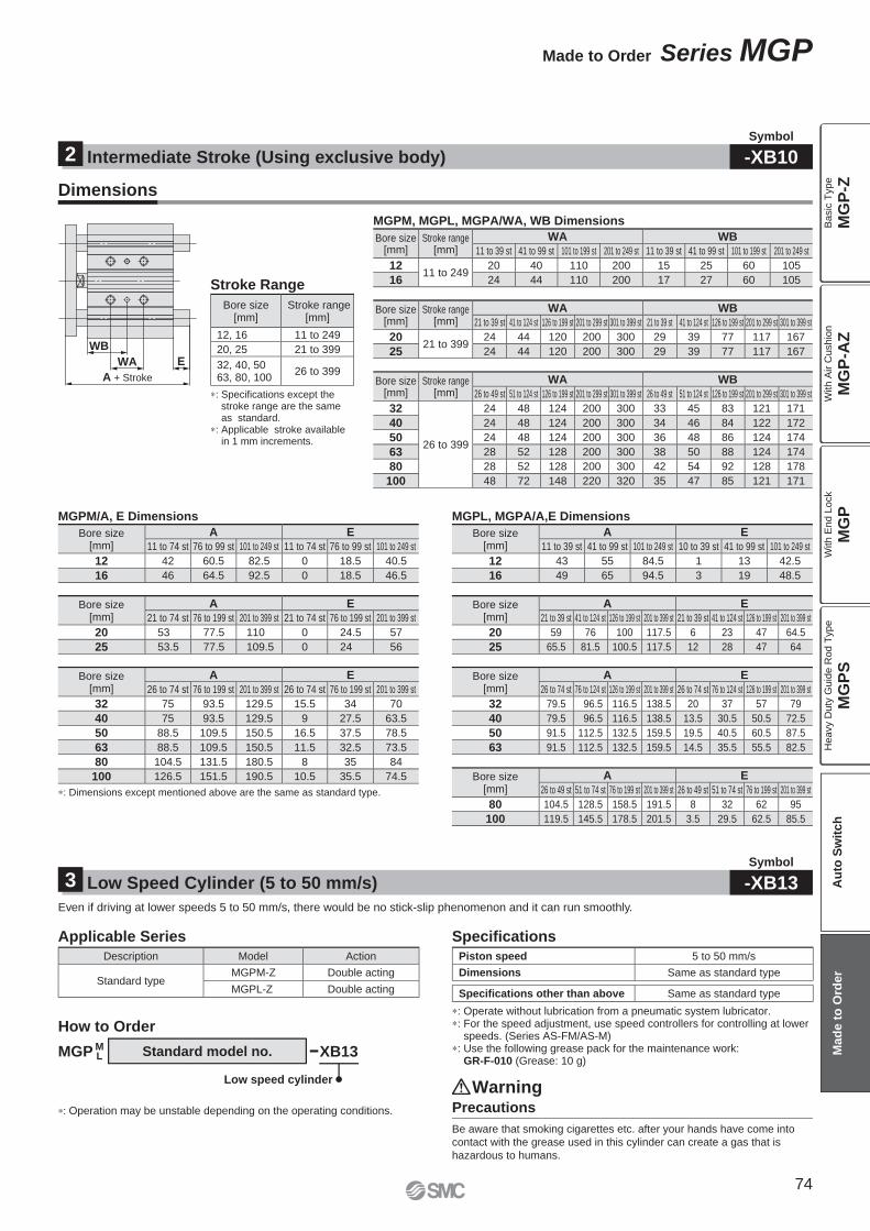
WB
WA E
A + Stroke
∗: Operation may be unstable depending on the operating conditions.
∗: Specifi cations except the stroke range are the same as standard.
∗: Applicable stroke available in 1 mm increments.
Bore size[mm]
A E
26 to 49 st 51 to 74 st 76 to 199 st 201 to 399 st 26 to 49 st 51 to 74 st 76 to 199 st 201 to 399 st
80 104.5 128.5 158.5 191.5 8 32 62 95
100 119.5 145.5 178.5 201.5 3.5 29.5 62.5 85.5
Bore size[mm]
A E
26 to 74 st 76 to 124 st 126 to 199 st 201 to 399 st 26 to 74 st 76 to 124 st 126 to 199 st 201 to 399 st
32 79.5 96.5 116.5 138.5 20 37 57 79
40 79.5 96.5 116.5 138.5 13.5 30.5 50.5 72.5
50 91.5 112.5 132.5 159.5 19.5 40.5 60.5 87.5
63 91.5 112.5 132.5 159.5 14.5 35.5 55.5 82.5
Bore size[mm]
A E
21 to 39 st 41 to 124 st 126 to 199 st 201 to 399 st 21 to 39 st 41 to 124 st 126 to 199 st 201 to 399 st
20 59 76 100 117.5 6 23 47 64.5
25 65.5 81.5 100.5 117.5 12 28 47 64
Bore size[mm]
A E
11 to 39 st 41 to 99 st 101 to 249 st 10 to 39 st 41 to 99 st 101 to 249 st
12 43 55 84.5 1 13 42.5
16 49 65 94.5 3 19 48.5
∗: Dimensions except mentioned above are the same as standard type.
Bore size[mm]
A E
26 to 74 st 76 to 199 st 201 to 399 st 26 to 74 st 76 to 199 st 201 to 399 st
32 75 93.5 129.5 15.5 34 70
40 75 93.5 129.5 9 27.5 63.5
50 88.5 109.5 150.5 16.5 37.5 78.5
63 88.5 109.5 150.5 11.5 32.5 73.5
80 104.5 131.5 180.5 8 35 84
100 126.5 151.5 190.5 10.5 35.5 74.5
Bore size[mm]
A E
21 to 74 st 76 to 199 st 201 to 399 st 21 to 74 st 76 to 199 st 201 to 399 st
20 53 77.5 110 0 24.5 57
25 53.5 77.5 109.5 0 24 56
Bore size[mm]
A E
11 to 74 st 76 to 99 st 101 to 249 st 11 to 74 st 76 to 99 st 101 to 249 st
12 42 60.5 82.5 0 18.5 40.5
16 46 64.5 92.5 0 18.5 46.5
Bore size[mm]
Stroke range[mm]
WA WB
26 to 49 st 51 to 124 st 126 to 199 st 201 to 299 st 301 to 399 st 26 to 49 st 51 to 124 st 126 to 199 st 201 to 299 st 301 to 399 st
32
26 to 399
24 48 124 200 300 33 45 83 121 171
40 24 48 124 200 300 34 46 84 122 172
50 24 48 124 200 300 36 48 86 124 174
63 28 52 128 200 300 38 50 88 124 174
80 28 52 128 200 300 42 54 92 128 178
100 48 72 148 220 320 35 47 85 121 171
Bore size[mm]
Stroke range[mm]
WA WB
21 to 39 st 41 to 124 st 126 to 199 st 201 to 299 st 301 to 399 st 21 to 39 st 41 to 124 st 126 to 199 st 201 to 299 st 301 to 399 st
2021 to 399
24 44 120 200 300 29 39 77 117 167
25 24 44 120 200 300 29 39 77 117 167
MGPM, MGPL, MGPA/WA, WB Dimensions
Bore size[mm]
Stroke range[mm]
WA WB
11 to 39 st 41 to 99 st 101 to 199 st 201 to 249 st 11 to 39 st 41 to 99 st 101 to 199 st 201 to 249 st
1211 to 249
20 40 110 200 15 25 60 105
16 24 44 110 200 17 27 60 105
Bore size[mm]
Stroke range[mm]
12, 16 11 to 249
20, 25 21 to 399
32, 40, 50 63, 80, 100
26 to 399
Piston speed 5 to 50 mm/s
Dimensions Same as standard type
Specifi cations other than above Same as standard type
Description Model Action
Standard typeMGPM-Z Double acting
MGPL-Z Double acting
∗: Operate without lubrication from a pneumatic system lubricator.∗: For the speed adjustment, use speed controllers for controlling at lower
speeds. (Series AS-FM/AS-M)∗: Use the following grease pack for the maintenance work:
GR-F-010 (Grease: 10 g)
Intermediate Stroke (Using exclusive body)2Symbol
-XB10
Low Speed Cylinder (5 to 50 mm/s)3Symbol
-XB13
Dimensions
Stroke Range
MGPM/A, E Dimensions MGPL, MGPA/A,E Dimensions
Even if driving at lower speeds 5 to 50 mm/s, there would be no stick-slip phenomenon and it can run smoothly.
Applicable Series Specifi cations
MGP ML
How to Order
Standard model no. XB13
Low speed cylinder
Precautions
Be aware that smoking cigarettes etc. after your hands have come into
contact with the grease used in this cylinder can create a gas that is
hazardous to humans.
Warning
74
Made to Order Series MGP
MG
P-Z
MG
P-A
ZM
GP
MG
PS
Ba
sic
Typ
eW
ith
Air C
ush
ion
With E
nd L
ock
Heavy D
uty
Guid
e R
od T
ype
Au
to S
wit
ch
Mad
e t
o O
rder
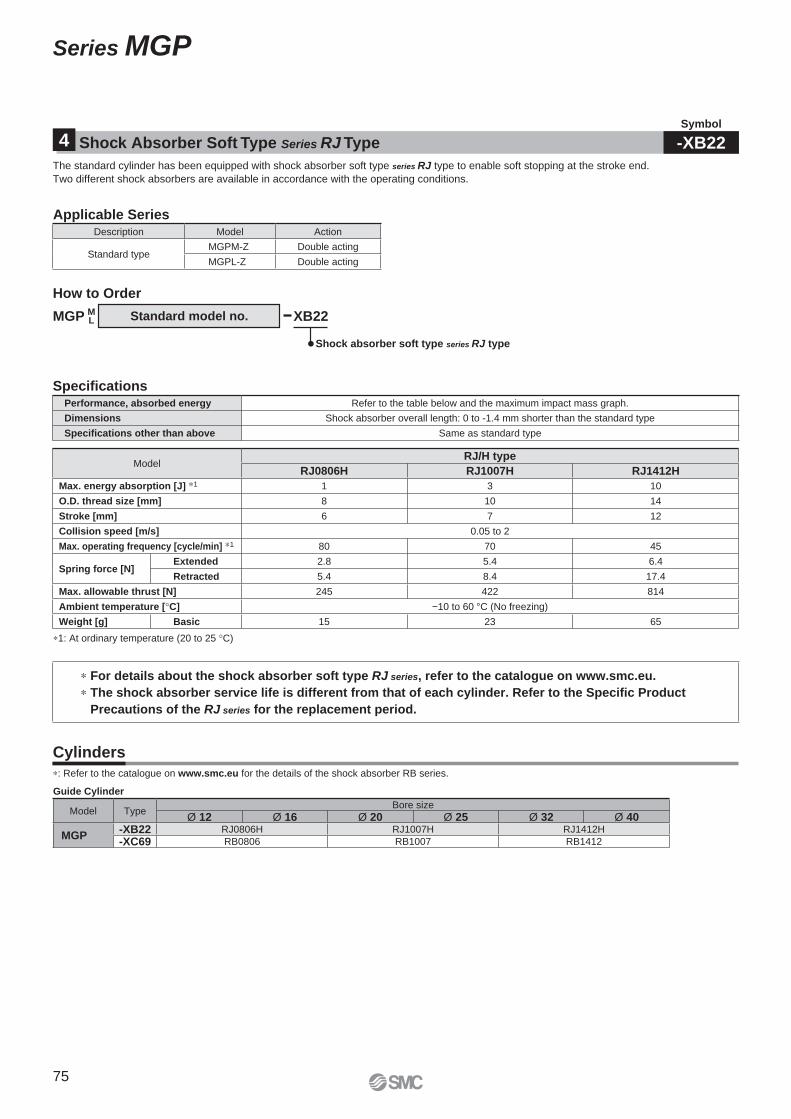
The standard cylinder has been equipped with shock absorber soft type series RJ type to enable soft stopping at the stroke end.
Two different shock absorbers are available in accordance with the operating conditions.
XB22Standard model no.
How to Order
∗1: At ordinary temperature (20 to 25 °C)
Specifi cations
∗ For details about the shock absorber soft type RJ series, refer to the catalogue on www.smc.eu.
∗ The shock absorber service life is different from that of each cylinder. Refer to the Specific Product
Precautions of the RJ series for the replacement period.
ModelRJ/H type
RJ0806H RJ1007H RJ1412H
Max. energy absorption [J] ∗1 1 3 10
O.D. thread size [mm] 8 10 14
Stroke [mm] 6 7 12
Collision speed [m/s] 0.05 to 2
Max. operating frequency [cycle/min] ∗1 80 70 45
Spring force [N]Extended 2.8 5.4 6.4
Retracted 5.4 8.4 17.4
Max. allowable thrust [N] 245 422 814
Ambient temperature [°C] −10 to 60 °C (No freezing)
Weight [g] Basic 15 23 65
Performance, absorbed energy Refer to the table below and the maximum impact mass graph.
Dimensions Shock absorber overall length: 0 to -1.4 mm shorter than the standard type
Specifications other than above Same as standard type
Applicable SeriesDescription Model Action
Standard typeMGPM-Z Double acting
MGPL-Z Double acting
∗: Refer to the catalogue on www.smc.eu for the details of the shock absorber RB series.
Cylinders
Guide Cylinder
Model TypeBore size
Ø 12 Ø 16 Ø 20 Ø 25 Ø 32 Ø 40
MGP-XB22 RJ0806H RJ1007H RJ1412H
-XC69 RB0806 RB1007 RB1412
Shock absorber soft type series RJ type
MGP ML
Shock Absorber Soft Type Series RJ Type4Symbol
-XB22
75
Series MGP
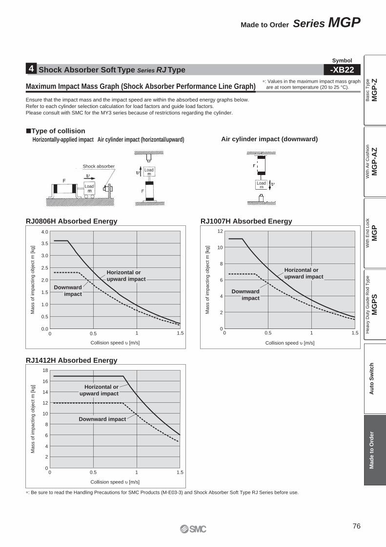
Maximum Impact Mass Graph (Shock Absorber Performance Line Graph)
Ensure that the impact mass and the impact speed are within the absorbed energy graphs below.
Refer to each cylinder selection calculation for load factors and guide load factors.
Please consult with SMC for the MY3 series because of restrictions regarding the cylinder.
Air cylinder impact (downward)
Type of collision
Horizontally-applied impact Air cylinder impact (horizontal/upward)
∗: Be sure to read the Handling Precautions for SMC Products (M-E03-3) and Shock Absorber Soft Type RJ Series before use.
0.0
0.5
1.0
1.5
2.0
2.5
3.0
3.5
4.0
0 0.5 1 1.5
Collision speed [m/s]
Ma
ss o
f im
pa
ctin
g o
bje
ct m
[kg
]
0
2
4
6
8
10
12
0 0.5 1 1.5
Collision speed [m/s]
Ma
ss o
f im
pa
ctin
g o
bje
ct m
[kg
]
0
2
4
6
8
10
12
14
16
18
0 0.5 1 1.5
Collision speed [m/s]
Mass o
f im
pacting o
bje
ct
m [
kg]
RJ0806H Absorbed Energy RJ1007H Absorbed Energy
RJ1412H Absorbed Energy
Downward
impact
Downward
impact
Horizontal or
upward impact
Horizontal or
upward impact
Horizontal or
upward impact
Downward impact
Shock Absorber Soft Type Series RJ Type4Symbol
-XB22
∗: Values in the maximum impact mass graph
are at room temperature (20 to 25 °C).
Shock absorberLoad
LoadLoad
76
Made to Order Series MGP
MG
P-Z
MG
P-A
ZM
GP
MG
PS
Ba
sic
Typ
eW
ith
Air C
ush
ion
With E
nd L
ock
Heavy D
uty
Guid
e R
od T
ype
Au
to S
wit
ch
Mad
e t
o O
rder
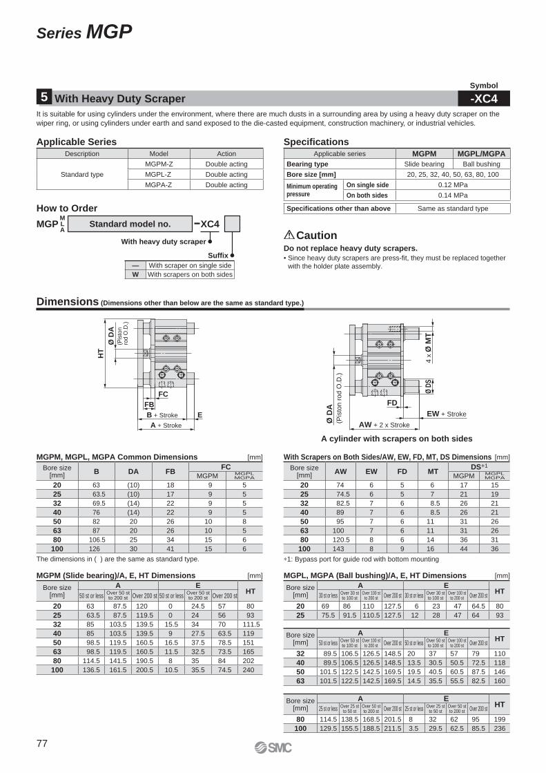
A + Stroke
B + Stroke E
FC
FB
HT
Ø D
A(P
isto
n
rod
O.D
.)
AW + 2 x Stroke
EW + Stroke
FD
Ø D
S4
x Ø
MT
Ø D
A
(Pis
ton
ro
d O
.D.)
Description Model Action
Standard type
MGPM-Z Double acting
MGPL-Z Double acting
MGPA-Z Double acting
Bore size [mm]
B DA FBFC
MGPM MGPLMGPA
20 63 (10) 18 9 5
25 63.5 (10) 17 9 5
32 69.5 (14) 22 9 5
40 76 (14) 22 9 5
50 82 20 26 10 8
63 87 20 26 10 5
80 106.5 25 34 15 6
100 126 30 41 15 6
Bore size [mm]
A EHT
50 st or less Over 50 stto 100 st
Over 100 stto 200 st Over 200 st 50 st or less Over 50 st
to 100 stOver 100 st
to 200 st Over 200 st
32 89.5 106.5 126.5 148.5 20 37 57 79 110
40 89.5 106.5 126.5 148.5 13.5 30.5 50.5 72.5 118
50 101.5 122.5 142.5 169.5 19.5 40.5 60.5 87.5 146
63 101.5 122.5 142.5 169.5 14.5 35.5 55.5 82.5 160
Bore size [mm]
A EHT
25 st or less Over 25 stto 50 st
Over 50 stto 200 st Over 200 st 25 st or less Over 25 st
to 50 stOver 50 stto 200 st Over 200 st
80 114.5 138.5 168.5 201.5 8 32 62 95 199
100 129.5 155.5 188.5 211.5 3.5 29.5 62.5 85.5 236
Bore size [mm]
A EHT
30 st or less Over 30 stto 100 st
Over 100 stto 200 st Over 200 st 30 st or less Over 30 st
to 100 stOver 100 st
to 200 st Over 200 st
20 69 86 110 127.5 6 23 47 64.5 80
25 75.5 91.5 110.5 127.5 12 28 47 64 93
Bore size [mm]
AW EW FD MTDS∗1
MGPM MGPLMGPA
20 74 6 5 6 17 15
25 74.5 6 5 7 21 19
32 82.5 7 6 8.5 26 21
40 89 7 6 8.5 26 21
50 95 7 6 11 31 26
63 100 7 6 11 31 26
80 120.5 8 6 14 36 31
100 143 8 9 16 44 36
Bore size [mm]
A EHT
50 st or lessOver 50 stto 200 st Over 200 st 50 st or less
Over 50 stto 200 st Over 200 st
20 63 87.5 120 0 24.5 57 80
25 63.5 87.5 119.5 0 24 56 93
32 85 103.5 139.5 15.5 34 70 111.5
40 85 103.5 139.5 9 27.5 63.5 119
50 98.5 119.5 160.5 16.5 37.5 78.5 151
63 98.5 119.5 160.5 11.5 32.5 73.5 165
80 114.5 141.5 190.5 8 35 84 202
100 136.5 161.5 200.5 10.5 35.5 74.5 240
A cylinder with scrapers on both sides
With Heavy Duty Scraper5Symbol
-XC4It is suitable for using cylinders under the environment, where there are much dusts in a surrounding area by using a heavy duty scraper on the
wiper ring, or using cylinders under earth and sand exposed to the die-casted equipment, construction machinery, or industrial vehicles.
Applicable Series Specifi cations
MGPMLA
How to Order
Standard model no. XC4
With heavy duty scraper
Suffi xDo not replace heavy duty scrapers.
• Since heavy duty scrapers are press-fi t, they must be replaced together
with the holder plate assembly.
Caution
— With scraper on single side
W With scrapers on both sides
Applicable series MGPM MGPL/MGPA
Bearing type Slide bearing Ball bushing
Bore size [mm] 20, 25, 32, 40, 50, 63, 80, 100
Minimum operating pressure
On single side 0.12 MPa
On both sides 0.14 MPa
Specifi cations other than above Same as standard type
Dimensions (Dimensions other than below are the same as standard type.)
MGPM, MGPL, MGPA Common Dimensions With Scrapers on Both Sides/AW, EW, FD, MT, DS Dimensions[mm]
[mm]
[mm]
The dimensions in ( ) are the same as standard type. ∗1: Bypass port for guide rod with bottom mounting
MGPM (Slide bearing)/A, E, HT Dimensions MGPL, MGPA (Ball bushing)/A, E, HT Dimensions [mm]
77
Series MGP

MB
MA
MD
Ø M
G
MH + Stroke + Adjustment
(A: 10 mm, B: 25 mm)
Stroke
MP
MT
MK
Ø D
A
(Pis
ton r
od O
.D.)
Width across flats MC
ML + Adjustment
Retaining ring
Plate
Guide rod
Piston rod
Hexagon socket head plugPlate mounting bolt
The dimensions in ( ) are the same as standard type.
Symbol
Adjustable range
Ø D
A
FA FB
Parts material changed to stainless steelA q, w, e, r, t, y
B q, w, t, y
Specifi cations other than above and external dimensions Same as standard type
Description Model Action
Standard type
MGPM-Z Double acting
MGPL-Z Double acting
MGPA-Z Double acting
Precautions
1. When the cylinder is operating, if something gets caught between the stopper bracket for adjusting the stroke and the cylinder body, it could cause bodily injury or damage the peripheral equipment. Therefore, take preventive measures as necessary, such as installing a protective cover.
2. To adjust the stroke, make sure to secure the wrench fl ats of the stopper bracket by a wrench etc. before loosening the lock nut. If the lock nut is loosened without securing the stopper bracket, be aware that the area that joins the load to the piston rod or the area in which the piston rod is joined with the load side and the stopper bracket side could loosen fi rst. It may cause an accident or malfunction.
Stroke adjustment symbol A B
Stroke adjustment range [mm] 0 to 10 0 to 25
Specifi cations other than above Same as standard type
Bore size [mm]
DA MA MB MC MDØ
MGMH MK ML MP MT
12 ( 6) 27 13 8 M4 x 0.7 14 20 5.5 10 3 3
16 ( 8) 28 16 10 M5 x 0.8 14 20 5.5 10 3 3
20 (10) 33 22 12 M6 x 1 20 26 7 14 3 4
25 12 41 25 12 M6 x 1 20 27 7 14 3 5
32 16 51 32 17 M8 x 1.25 25 35 9 18.5 4 6
40 16 60 32 19 M10 x 1.25 25 35 10 17 4 6
50 20 71 38 24 M14 x 1.5 35 46 13 21 4 8
63 20 84 50 24 M14 x 1.5 35 46 13 21 4 8
80 25 114 50 32 M20 x 1.5 45 55 16 30 4 9
100 30 140 65 32 M20 x 1.5 45 58 16 30 4 12
The dimensions in ( ) are the same as standard type.
Made of Stainless Steel6Symbol
-XC6
Adjustable Stroke Cylinder/Adjustable Extension Type7Symbol
-XC8
Suitable for the cases it is likely to generate rust by being immersed in the water and corrosion.
Applicable Series
MGP ML
How to Order
Standard model no. AXC6
Made of stainless steel
Suffi x
A Stainless steel used on all standard iron parts
B Stainless steel used on rod parts etc.
Description Model Action
Standard typeMGPM-Z Double acting
MGPL-Z Double acting
Specifi cations
Dimensions
Dimensions (Dimensions other than below are the same as standard type.)
[mm]
It adjusts the extending stroke by the stroke adjustable mechanism equipped in the head side. (After the stroke is adjusted, with cushion on both
sides is altered to single-sided, with cushion.)
Applicable Series Specifi cations
How to Order
MGPMLA
Bore size Stroke Stroke adjustment symbol XC8Z
Adjustable stroke cylinder/Adjustable extension type
MGPM, MGPL, MGPA Common Dimensions [mm]
Bore size [mm]
XC6A XC6B
DA FA FB DA
12 (6) 8 5 (6)
16 (8) 8 5 (8)
20 (10) 9 7 (10)
25 (10) 10 6 (10)
32 (14) 12 10 (14)
40 (14) 12 10 (14)
50 20 16 12 20
63 20 16 12 20
80 25 19 21 25
100 30 22 28 30
MGPM, MGPL, -Z-XC6� Common Dimensions
Warning
78
Made to Order Series MGP
MG
P-Z
MG
P-A
ZM
GP
MG
PS
Ba
sic
Typ
eW
ith
Air C
ush
ion
With E
nd L
ock
Heavy D
uty
Guid
e R
od T
ype
Au
to S
wit
ch
Mad
e t
o O
rder
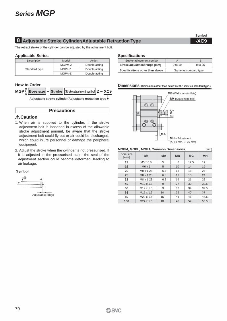
Ø M
C
BM (Adjustment bolt)
MB (Width across flats)
MA
MH + Adjustment
(A: 10 mm, B: 25 mm)
Bore size[mm]
BM MA MB MC MH
12 M5 x 0.8 5 8 12.5 17
16 M6 x 1 5 10 14 19
20 M8 x 1.25 6.5 13 16 25
25 M8 x 1.25 6.5 13 16 24
32 M8 x 1.25 6.5 19 21 25
40 M12 x 1.5 9 27 30 32.5
50 M12 x 1.5 9 30 34 32.5
63 M16 x 1.5 10 36 40 37
80 M20 x 1.5 15 41 46 48.5
100 M24 x 1.5 18 46 52 55.5
Stroke adjustment symbol A B
Stroke adjustment range [mm] 0 to 10 0 to 25
Specifi cations other than above Same as standard type
The retract stroke of the cylinder can be adjusted by the adjustment bolt.
Applicable Series
Adjustable Stroke Cylinder/Adjustable Retraction Type8Symbol
-XC9
Description Model Action
Standard type
MGPM-Z Double acting
MGPL-Z Double acting
MGPA-Z Double acting
Specifi cations
Dimensions (Dimensions other than below are the same as standard type.)
MGPMLA
How to Order
Bore size Stroke Stroke adjustment symbol XC9Z
Adjustable stroke cylinder/Adjustable retraction type
Caution
Precautions
1. When air is supplied to the cylinder, if the stroke
adjustment bolt is loosened in excess of the allowable
stroke adjustment amount, be aware that the stroke
adjustment bolt could fl y out or air could be discharged,
which could injure personnel or damage the peripheral
equipment.
2. Adjust the stroke when the cylinder is not pressurised. If
it is adjusted in the pressurised state, the seal of the
adjustment section could become deformed, leading to
air leakage.
Symbol
Adjustable range
MGPM, MGPL, MGPA Common Dimensions [mm]
79
Series MGP
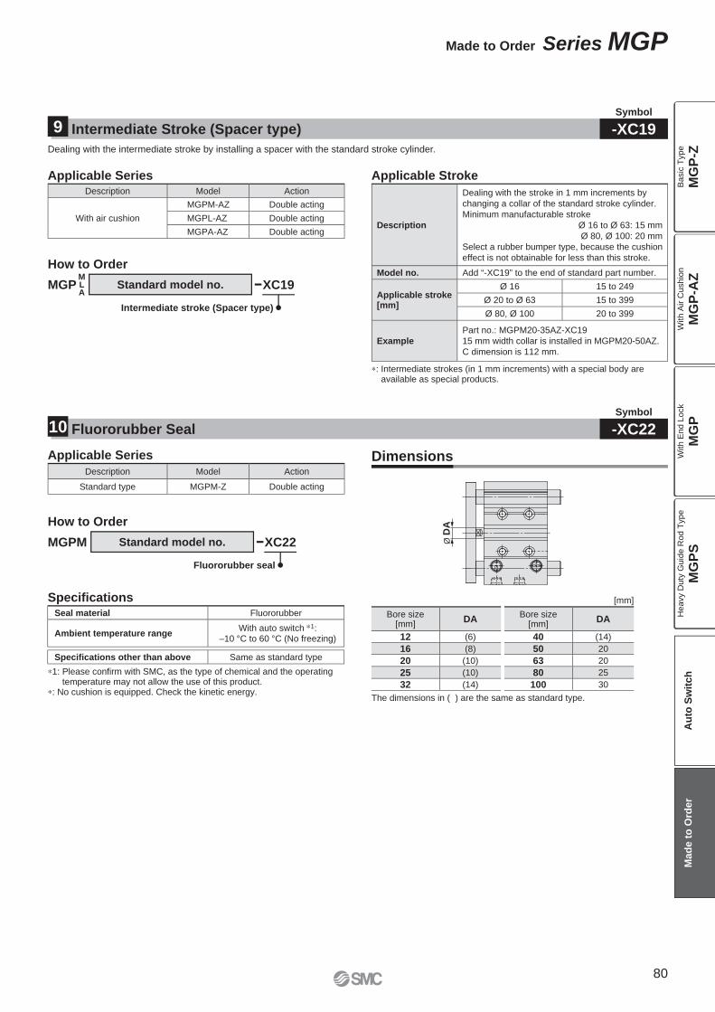
Ø D
A
Standard model no.
∗: Intermediate strokes (in 1 mm increments) with a special body are available as special products.
Description
Dealing with the stroke in 1 mm increments by
changing a collar of the standard stroke cylinder.
Minimum manufacturable stroke
Ø 16 to Ø 63: 15 mm
Ø 80, Ø 100: 20 mm
Select a rubber bumper type, because the cushion
effect is not obtainable for less than this stroke.
Model no. Add “-XC19” to the end of standard part number.
Applicable stroke [mm]
Ø 16 15 to 249
Ø 20 to Ø 63 15 to 399
Ø 80, Ø 100 20 to 399
Example
Part no.: MGPM20-35AZ-XC19
15 mm width collar is installed in MGPM20-50AZ.
C dimension is 112 mm.
Description Model Action
Standard type MGPM-Z Double acting
The dimensions in ( ) are the same as standard type.
Bore size[mm]
DA
12 (6)
16 (8)
20 (10)
25 (10)
32 (14)
Bore size[mm]
DA
40 (14)
50 20
63 20
80 25
100 30
Seal material Fluororubber
Ambient temperature rangeWith auto switch ∗1:
–10 °C to 60 °C (No freezing)
Specifi cations other than above Same as standard type
Dealing with the intermediate stroke by installing a spacer with the standard stroke cylinder.
Applicable Series
Intermediate Stroke (Spacer type)9Symbol
-XC19
Fluororubber Seal10Symbol
-XC22
Description Model Action
With air cushion
MGPM-AZ Double acting
MGPL-AZ Double acting
MGPA-AZ Double acting
Applicable Stroke
MGPMLA
How to Order
Standard model no. XC19
Intermediate stroke (Spacer type)
DimensionsApplicable Series
XC22MGPM
Fluororubber seal
How to Order
Specifi cations
∗1: Please confi rm with SMC, as the type of chemical and the operating temperature may not allow the use of this product.
∗: No cushion is equipped. Check the kinetic energy.
[mm]
80
Made to Order Series MGP
MG
P-Z
MG
P-A
ZM
GP
MG
PS
Ba
sic
Typ
eW
ith
Air C
ush
ion
With E
nd L
ock
Heavy D
uty
Guid
e R
od T
ype
Au
to S
wit
ch
Mad
e t
o O
rder
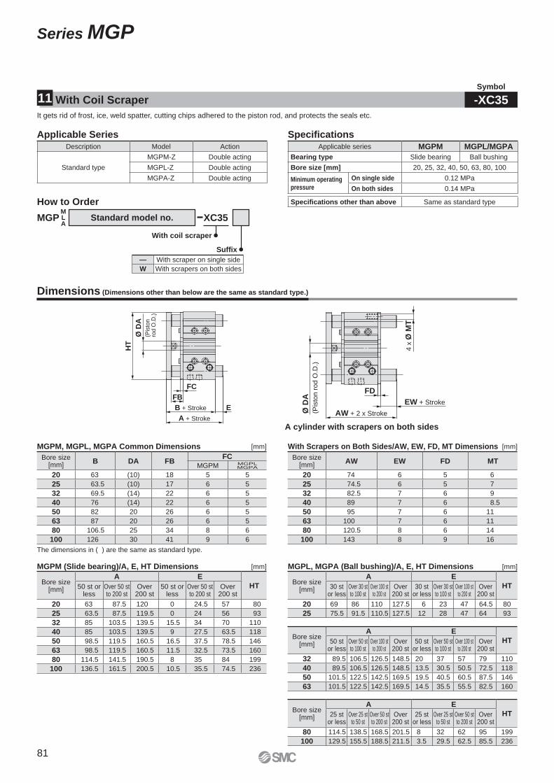
A + Stroke
B + Stroke E
FC
FB
HT
Ø D
A(P
isto
n
rod
O.D
.)
EW + Stroke
FD
AW + 2 x Stroke4 x
Ø M
T
Ø D
A
(Pis
ton r
od O
.D.)
Bore size [mm]
B DA FBFC
MGPM MGPLMGPA
20 63 (10) 18 5 5
25 63.5 (10) 17 6 5
32 69.5 (14) 22 6 5
40 76 (14) 22 6 5
50 82 20 26 6 5
63 87 20 26 6 5
80 106.5 25 34 8 6
100 126 30 41 9 6
MGPM (Slide bearing)/A, E, HT Dimensions
A cylinder with scrapers on both sides
Bore size [mm]
A E
HT50 st or less
Over 50 stto 200 st
Over 200 st
50 st or less
Over 50 stto 200 st
Over 200 st
20 63 87.5 120 0 24.5 57 80
25 63.5 87.5 119.5 0 24 56 93
32 85 103.5 139.5 15.5 34 70 110
40 85 103.5 139.5 9 27.5 63.5 118
50 98.5 119.5 160.5 16.5 37.5 78.5 146
63 98.5 119.5 160.5 11.5 32.5 73.5 160
80 114.5 141.5 190.5 8 35 84 199
100 136.5 161.5 200.5 10.5 35.5 74.5 236
Bore size [mm]
A E
HT50 stor less
Over 50 stto 100 st
Over 100 stto 200 st
Over 200 st
50 stor less
Over 50 stto 100 st
Over 100 stto 200 st
Over 200 st
32 89.5 106.5 126.5 148.5 20 37 57 79 110
40 89.5 106.5 126.5 148.5 13.5 30.5 50.5 72.5 118
50 101.5 122.5 142.5 169.5 19.5 40.5 60.5 87.5 146
63 101.5 122.5 142.5 169.5 14.5 35.5 55.5 82.5 160
Bore size [mm]
A E
HT25 stor less
Over 25 stto 50 st
Over 50 stto 200 st
Over 200 st
25 stor less
Over 25 stto 50 st
Over 50 stto 200 st
Over 200 st
80 114.5 138.5 168.5 201.5 8 32 62 95 199
100 129.5 155.5 188.5 211.5 3.5 29.5 62.5 85.5 236
[mm]
Bore size [mm]
A E
HT30 stor less
Over 30 stto 100 st
Over 100 stto 200 st
Over 200 st
30 stor less
Over 30 stto 100 st
Over 100 stto 200 st
Over 200 st
20 69 86 110 127.5 6 23 47 64.5 80
25 75.5 91.5 110.5 127.5 12 28 47 64 93
Bore size [mm]
AW EW FD MT
20 74 6 5 6
25 74.5 6 5 7
32 82.5 7 6 9
40 89 7 6 8.5
50 95 7 6 11
63 100 7 6 11
80 120.5 8 6 14
100 143 8 9 16
Applicable series MGPM MGPL/MGPA
Bearing type Slide bearing Ball bushing
Bore size [mm] 20, 25, 32, 40, 50, 63, 80, 100
Minimum operatingpressure
On single side 0.12 MPa
On both sides 0.14 MPa
Specifi cations other than above Same as standard type
The dimensions in ( ) are the same as standard type.
It gets rid of frost, ice, weld spatter, cutting chips adhered to the piston rod, and protects the seals etc.
Applicable Series
MGPMLA
How to Order
Standard model no. XC35
With coil scraper
Suffi x
— With scraper on single side
W With scrapers on both sides
With Coil Scraper11Symbol
-XC35
Description Model Action
Standard type
MGPM-Z Double acting
MGPL-Z Double acting
MGPA-Z Double acting
Specifi cations
Dimensions (Dimensions other than below are the same as standard type.)
MGPM, MGPL, MGPA Common Dimensions With Scrapers on Both Sides/AW, EW, FD, MT Dimensions
MGPL, MGPA (Ball bushing)/A, E, HT Dimensions
[mm]
[mm]
[mm]
81
Series MGP
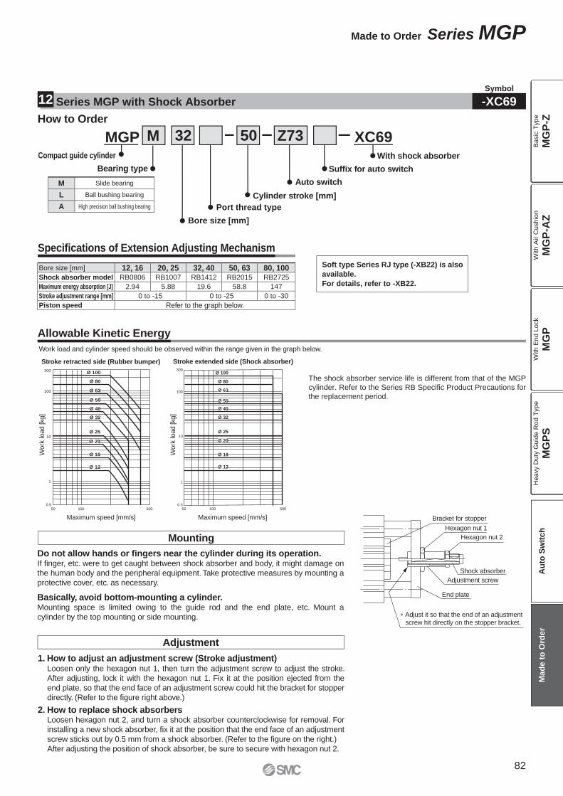
300
100
10
50 100 500
1
0.5
Work
load [kg]
Work
load [kg]
Maximum speed [mm/s] Maximum speed [mm/s]
Ø 100
Ø 80
Ø 63
Ø 50
Ø 40
Ø 32
Ø 25
Ø 20
Ø 16
Ø 12
300
100
10
50 100 500
1
0.5
Ø 100
Ø 80
Ø 63
Ø 50
Ø 40
Ø 32
Ø 25
Ø 20
Ø 16
Ø 12
Hexagon nut 2
Hexagon nut 1
Bracket for stopper
Adjustment screw
End plate
Shock absorber
∗ Adjust it so that the end of an adjustment
screw hit directly on the stopper bracket.
Allowable Kinetic Energy
Work load and cylinder speed should be observed within the range given in the graph below.
Mounting
Adjustment
The shock absorber service life is different from that of the MGP
cylinder. Refer to the Series RB Specifi c Product Precautions for
the replacement period.
Stroke retracted side (Rubber bumper) Stroke extended side (Shock absorber)
Do not allow hands or fi ngers near the cylinder during its operation.If fi nger, etc. were to get caught between shock absorber and body, it might damage on
the human body and the peripheral equipment. Take protective measures by mounting a
protective cover, etc. as necessary.
Basically, avoid bottom-mounting a cylinder.Mounting space is limited owing to the guide rod and the end plate, etc. Mount a
cylinder by the top mounting or side mounting.
2. How to replace shock absorbersLoosen hexagon nut 2, and turn a shock absorber counterclockwise for removal. For
installing a new shock absorber, fi x it at the position that the end face of an adjustment
screw sticks out by 0.5 mm from a shock absorber. (Refer to the fi gure on the right.)
After adjusting the position of shock absorber, be sure to secure with hexagon nut 2.
1. How to adjust an adjustment screw (Stroke adjustment)Loosen only the hexagon nut 1, then turn the adjustment screw to adjust the stroke.
After adjusting, lock it with the hexagon nut 1. Fix it at the position ejected from the
end plate, so that the end face of an adjustment screw could hit the bracket for stopper
directly. (Refer to the fi gure right above.)
Symbol
-XC69Series MGP with Shock Absorber12
MGP
Bore size [mm]
Compact guide cylinder With shock absorber
Bearing type
Cylinder stroke [mm]
Suffi x for auto switch
Port thread type
Auto switch
M 32 50 Z73 XC69
How to Order
M Slide bearing
L Ball bushing bearing
A High precision ball bushing bearing
Specifi cations of Extension Adjusting Mechanism
Bore size [mm] 12, 16 20, 25 32, 40 50, 63 80, 100Shock absorber model RB0806 RB1007 RB1412 RB2015 RB2725
Maximum energy absorption [J] 2.94 5.88 19.6 58.8 147
Stroke adjustment range [mm] 0 to -15 0 to -25 0 to -30
Piston speed Refer to the graph below.
Soft type Series RJ type (-XB22) is also
available.
For details, refer to -XB22.
82
Made to Order Series MGP
MG
P-Z
MG
P-A
ZM
GP
MG
PS
Ba
sic
Typ
eW
ith
Air C
ush
ion
With E
nd L
ock
Heavy D
uty
Guid
e R
od T
ype
Au
to S
wit
ch
Mad
e t
o O
rder
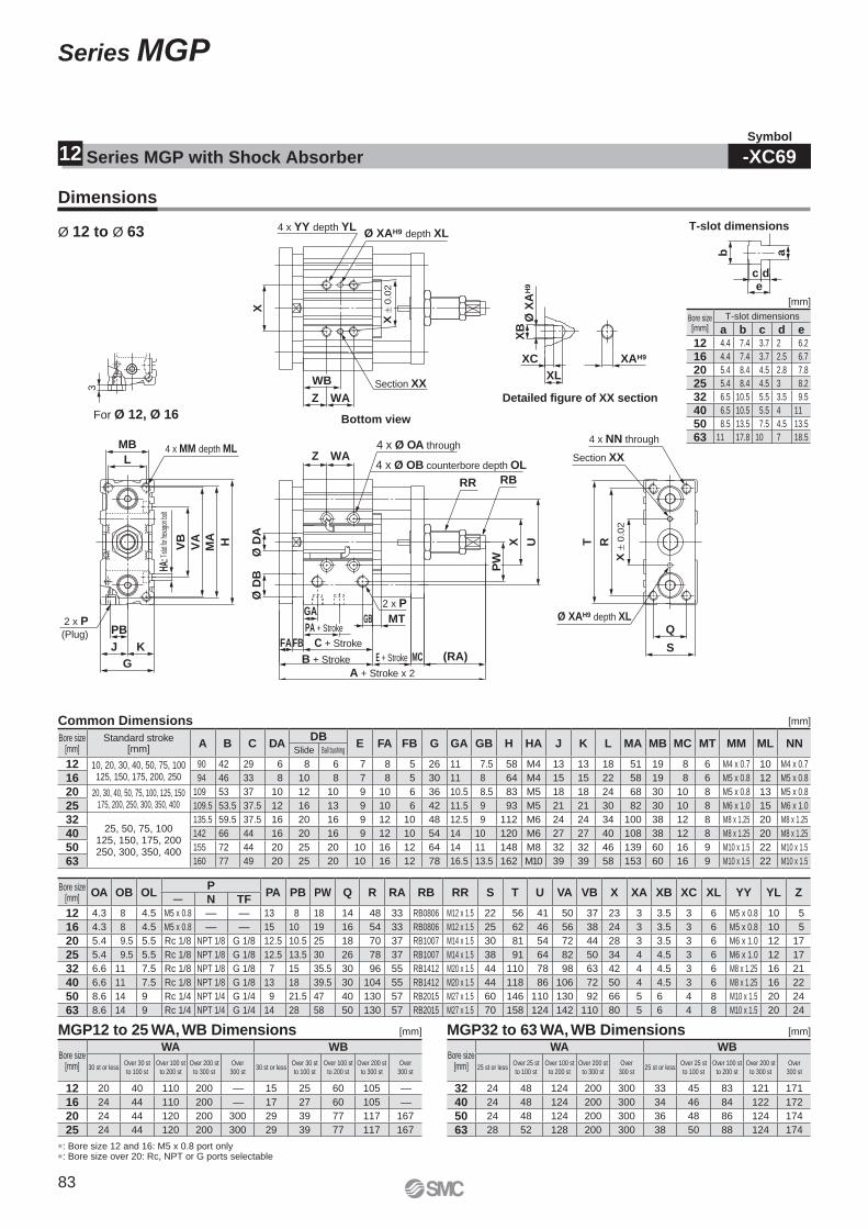
XAH9
XL
XC
XB
Ø X
AH
9 edc
ab
A + Stroke x 2
(RA)MCE + Stroke
MT
Ø D
B
WAZ
B + Stroke
FAFB C + Stroke
GBPA + Stroke
GA
UX
PW
Ø D
A
RBRR
2 x P
Q
S
T R
X ±
0.0
2Ø XAH9 depth XL
Section XX
4 x NN through
MA
MB
3
L
PB
KJ
G
HVA
VB
2 x P(Plug)
4 x MM depth ML
WB
WAZ
X
Ø XAH9 depth XL
Section XX
4 x YY depth YL
X ±
0.0
2
4 x Ø OB counterbore depth OL
4 x Ø OA through
HA:T
-slot
for he
xago
n bolt
T-slot dimensions
For Ø 12, Ø 16
Detailed figure of XX section
Bottom view
Dimensions
Ø 12 to Ø 63
MGP12 to 25 WA, WB Dimensions MGP32 to 63 WA, WB Dimensions
Common Dimensions
∗: Bore size 12 and 16: M5 x 0.8 port only ∗: Bore size over 20: Rc, NPT or G ports selectable
[mm]
[mm]
[mm][mm]
Series MGP with Shock Absorber12
Bore size[mm]
T-slot dimensions
a b c d e12 4.4 7.4 3.7 2 6.2
16 4.4 7.4 3.7 2.5 6.7
20 5.4 8.4 4.5 2.8 7.8
25 5.4 8.4 4.5 3 8.2
32 6.5 10.5 5.5 3.5 9.5
40 6.5 10.5 5.5 4 11
50 8.5 13.5 7.5 4.5 13.5
63 11 17.8 10 7 18.5
Bore size[mm]
Standard stroke[mm]
A B C DADB
E FA FB G GA GB H HA J K L MA MB MC MT MM ML NNSlide Ball bushing
12 10, 20, 30, 40, 50, 75, 100125, 150, 175, 200, 250
90 42 29 6 8 6 7 8 5 26 11 7.5 58 M4 13 13 18 51 19 8 6 M4 x 0.7 10 M4 x 0.7
16 94 46 33 8 10 8 7 8 5 30 11 8 64 M4 15 15 22 58 19 8 6 M5 x 0.8 12 M5 x 0.8
20 20, 30, 40, 50, 75, 100, 125, 150175, 200, 250, 300, 350, 400
109 53 37 10 12 10 9 10 6 36 10.5 8.5 83 M5 18 18 24 68 30 10 8 M5 x 0.8 13 M5 x 0.8
25 109.5 53.5 37.5 12 16 13 9 10 6 42 11.5 9 93 M5 21 21 30 82 30 10 8 M6 x 1.0 15 M6 x 1.0
3225, 50, 75, 100
125, 150, 175, 200250, 300, 350, 400
135.5 59.5 37.5 16 20 16 9 12 10 48 12.5 9 112 M6 24 24 34 100 38 12 8 M8 x 1.25 20 M8 x 1.25
40 142 66 44 16 20 16 9 12 10 54 14 10 120 M6 27 27 40 108 38 12 8 M8 x 1.25 20 M8 x 1.25
50 155 72 44 20 25 20 10 16 12 64 14 11 148 M8 32 32 46 139 60 16 9 M10 x 1.5 22 M10 x 1.5
63 160 77 49 20 25 20 10 16 12 78 16.5 13.5 162 M10 39 39 58 153 60 16 9 M10 x 1.5 22 M10 x 1.5
Bore size[mm]
OA OB OLP
PA PB PW Q R RA RB RR S T U VA VB X XA XB XC XL YY YL Z— N TF
12 4.3 8 4.5 M5 x 0.8 — — 13 8 18 14 48 33 RB0806 M12 x 1.5 22 56 41 50 37 23 3 3.5 3 6 M5 x 0.8 10 5
16 4.3 8 4.5 M5 x 0.8 — — 15 10 19 16 54 33 RB0806 M12 x 1.5 25 62 46 56 38 24 3 3.5 3 6 M5 x 0.8 10 5
20 5.4 9.5 5.5 Rc 1/8 NPT 1/8 G 1/8 12.5 10.5 25 18 70 37 RB1007 M14 x 1.5 30 81 54 72 44 28 3 3.5 3 6 M6 x 1.0 12 17
25 5.4 9.5 5.5 Rc 1/8 NPT 1/8 G 1/8 12.5 13.5 30 26 78 37 RB1007 M14 x 1.5 38 91 64 82 50 34 4 4.5 3 6 M6 x 1.0 12 17
32 6.6 11 7.5 Rc 1/8 NPT 1/8 G 1/8 7 15 35.5 30 96 55 RB1412 M20 x 1.5 44 110 78 98 63 42 4 4.5 3 6 M8 x 1.25 16 21
40 6.6 11 7.5 Rc 1/8 NPT 1/8 G 1/8 13 18 39.5 30 104 55 RB1412 M20 x 1.5 44 118 86 106 72 50 4 4.5 3 6 M8 x 1.25 16 22
50 8.6 14 9 Rc 1/4 NPT 1/4 G 1/4 9 21.5 47 40 130 57 RB2015 M27 x 1.5 60 146 110 130 92 66 5 6 4 8 M10 x 1.5 20 24
63 8.6 14 9 Rc 1/4 NPT 1/4 G 1/4 14 28 58 50 130 57 RB2015 M27 x 1.5 70 158 124 142 110 80 5 6 4 8 M10 x 1.5 20 24
Bore size[mm]
WA WB
30 st or lessOver 30 st
to 100 st
Over 100 st
to 200 st
Over 200 st
to 300 st
Over
300 st30 st or less
Over 30 st
to 100 st
Over 100 st
to 200 st
Over 200 st
to 300 st
Over
300 st
12 20 40 110 200 — 15 25 60 105 —
16 24 44 110 200 — 17 27 60 105 —
20 24 44 120 200 300 29 39 77 117 167
25 24 44 120 200 300 29 39 77 117 167
Bore size[mm]
WA WB
25 st or lessOver 25 st
to 100 st
Over 100 st
to 200 st
Over 200 st
to 300 st
Over
300 st25 st or less
Over 25 st
to 100 st
Over 100 st
to 200 st
Over 200 st
to 300 st
Over
300 st
32 24 48 124 200 300 33 45 83 121 171
40 24 48 124 200 300 34 46 84 122 172
50 24 48 124 200 300 36 48 86 124 174
63 28 52 128 200 300 38 50 88 124 174
Symbol
-XC69
83
Series MGP
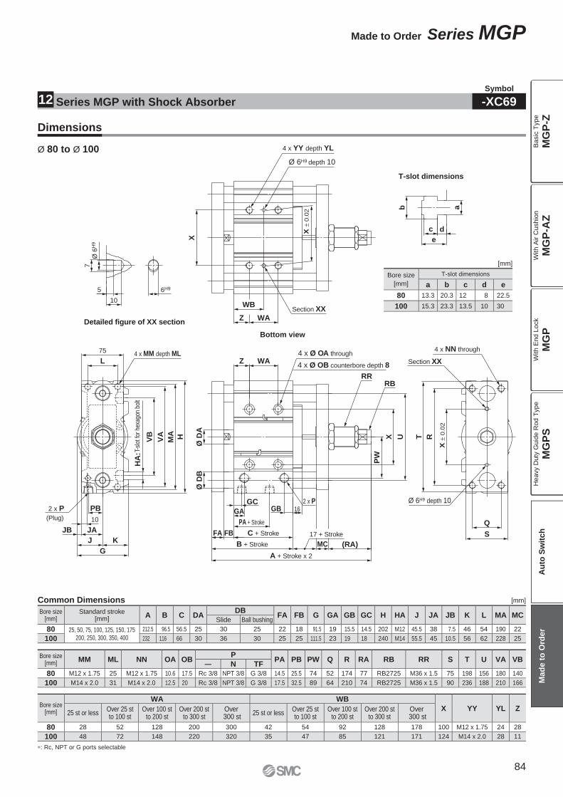
6H9
10
5
7Ø
6H
9
e
dc
ab
Z WA
WBX
± 0
.02
X
Section XX
75
MA
G
KJ
JB JA
10
PB
HVA
VB
L
(Plug)
2 x P
4 x MM depth ML
Q
S
T R
X ±
0.0
2
A + Stroke x 2
(RA)MC
16
Ø D
B
WAZ
B + Stroke
FBFA
GB
C + Stroke
PA + Stroke
GA
GC
UX
PW
Ø D
A
RBRR
17 + Stroke
2 x P
HA
:T-s
lot f
or h
exag
on b
olt
4 x Ø OB counterbore depth 8
4 x Ø OA through
Section XX
Ø 6H9 depth 10
4 x NN through
Detailed figure of XX section
T-slot dimensions
Bottom view
Ø 6H9 depth 10
4 x YY depth YL
Symbol
-XC69
Dimensions
Ø 80 to Ø 100
∗: Rc, NPT or G ports selectable
Common Dimensions [mm]
[mm]
Bore size
[mm]
T-slot dimensions
a b c d e
80 13.3 20.3 12 8 22.5
100 15.3 23.3 13.5 10 30
Bore size[mm]
Standard stroke[mm]
A B C DADB
FA FB G GA GB GC H HA J JA JB K L MA MCSlide Ball bushing
80 25, 50, 75, 100, 125, 150, 175
200, 250, 300, 350, 400
212.5 96.5 56.5 25 30 25 22 18 91.5 19 15.5 14.5 202 M12 45.5 38 7.5 46 54 190 22
100 232 116 66 30 36 30 25 25 111.5 23 19 18 240 M14 55.5 45 10.5 56 62 228 25
Bore size[mm]
MM ML NN OA OBP
PA PB PW Q R RA RB RR S T U VA VB— N TF
80 M12 x 1.75 25 M12 x 1.75 10.6 17.5 Rc 3/8 NPT 3/8 G 3/8 14.5 25.5 74 52 174 77 RB2725 M36 x 1.5 75 198 156 180 140
100 M14 x 2.0 31 M14 x 2.0 12.5 20 Rc 3/8 NPT 3/8 G 3/8 17.5 32.5 89 64 210 74 RB2725 M36 x 1.5 90 236 188 210 166
Bore size[mm]
WA WB
X YY YL Z25 st or less
Over 25 stto 100 st
Over 100 stto 200 st
Over 200 stto 300 st
Over 300 st
25 st or lessOver 25 stto 100 st
Over 100 stto 200 st
Over 200 stto 300 st
Over 300 st
80 28 52 128 200 300 42 54 92 128 178 100 M12 x 1.75 24 28
100 48 72 148 220 320 35 47 85 121 171 124 M14 x 2.0 28 11
Series MGP with Shock Absorber12
84
Made to Order Series MGP
MG
P-Z
MG
P-A
ZM
GP
MG
PS
Ba
sic
Typ
eW
ith
Air C
ush
ion
With E
nd L
ock
Heavy D
uty
Guid
e R
od T
ype
Au
to S
wit
ch
Mad
e t
o O
rder
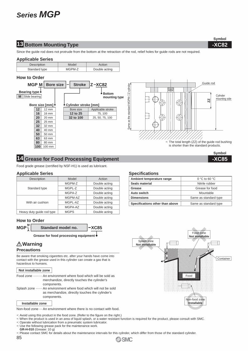
Sam
e as
the
stan
dard
MG
PM
-Z
cyl
inde
r
ZZ
Guide rod
Cylinder mounting side
Splash zone
Not installable
Food zone
Not installable
Non-food zone
Installable
Food
Container
ood zon
installa
plash zo
installa
Non-food zone
Installable
Bore size Stroke
Bore size [mm]
12 12 mm
16 16 mm
20 20 mm
25 25 mm
32 32 mm
40 40 mm
50 50 mm
63 63 mm
80 80 mm
100 100 mm
Bearing type
M Slide bearing
Cylinder stroke [mm]
Bottom mounting type
Bore size Applicable stroke
12 to 25 75, 100
32 to 100 25, 50, 75, 100
MGP M XC82Z
∗: The total length (ZZ) of the guide rod bushing is shorter than the standard products.
Since the guide rod does not protrude from the bottom at the retraction of the rod, relief holes for guide rods are not required.
Description Model Action
Standard type MGPM-Z Double acting
Applicable Series
Bottom Mounting Type13Symbol
-XC82
Food grade grease (certifi ed by NSF-H1) is used as lubricant.
Grease for Food Processing Equipment14Symbol
-XC85
How to Order
Description Model Action
Standard type
MGPM-Z Double acting
MGPL-Z Double acting
MGPA-Z Double acting
With air cushion
MGPM-AZ Double acting
MGPL-AZ Double acting
MGPA-AZ Double acting
Heavy duty guide rod type MGPS Double acting
Applicable SeriesAmbient temperature range 0 °C to 60 °C
Seals material Nitrile rubber
Grease Grease for food
Auto switch Mountable
Dimensions Same as standard type
Specifi cations other than above Same as standard type
Specifi cations
MGPMLA
How to Order
Standard model no. XC85
Grease for food processing equipment
∗: Avoid using this product in the food zone. (Refer to the fi gure on the right.)∗: When the product is used in an area of liquid splash, or a water resistant function is required for the product, please consult with SMC.∗: Operate without lubrication from a pneumatic system lubricator.∗: Use the following grease pack for the maintenance work.
GR-H-010 (Grease: 10 g)∗: Please contact SMC for details about the maintenance intervals for this cylinder, which differ from those of the standard cylinder.
Food zone ·········· An environment where food which will be sold as
merchandize, directly touches the cylinder’s
components.
Splash zone ······· An environment where food which will not be sold
as merchandize, directly touches the cylinder’s
components.
Not installable zone
Installable zone
Precautions
Be aware that smoking cigarettes etc. after your hands have come into
contact with the grease used in this cylinder can create a gas that is
hazardous to humans.
Warning
Non-food zone ···· An environment where there is no contact with food.
85
Series MGP
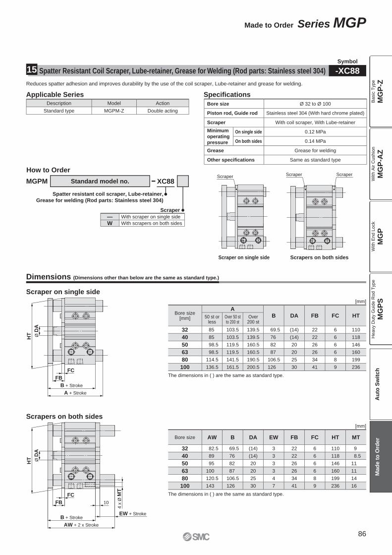
Dimensions (Dimensions other than below are the same as standard type.)
Scraper on single side
Scrapers on both sides
A + Stroke
B + Stroke
FB
HT
FC
Ø D
A
Bore size[mm]
A
B DA FB FC HT50 st orless
Over 50 stto 200 st
Over200 st
32 85 103.5 139.5 69.5 (14) 22 6 110
40 85 103.5 139.5 76 (14) 22 6 118
50 98.5 119.5 160.5 82 20 26 6 146
63 98.5 119.5 160.5 87 20 26 6 160
80 114.5 141.5 190.5 106.5 25 34 8 199
100 136.5 161.5 200.5 126 30 41 9 236
The dimensions in ( ) are the same as standard type.
[mm]
10
FC
AW + 2 x Stroke
B + Stroke
FB
HT Ø D
A
EW + Stroke
4 x
Ø M
T
The dimensions in ( ) are the same as standard type.
[mm]
Bore size AW B DA EW FB FC HT MT
32 82.5 69.5 (14) 3 22 6 110 9
40 89 76 (14) 3 22 6 118 8.5
50 95 82 20 3 26 6 146 11
63 100 87 20 3 26 6 160 11
80 120.5 106.5 25 4 34 8 199 14
100 143 126 30 7 41 9 236 16
Standard model no.
Specifi cationsApplicable Series
XC88
Spatter resistant coil scraper, Lube-retainer,
Grease for welding (Rod parts: Stainless steel 304)
How to Order
Reduces spatter adhesion and improves durability by the use of the coil scraper, Lube-retainer and grease for welding.
Description Model Action
Standard type MGPM-Z Double acting
Bore size Ø 32 to Ø 100
Piston rod, Guide rod Stainless steel 304 (With hard chrome plated)
Scraper With coil scraper, With Lube-retainer
Minimum
operating
pressure
On single side 0.12 MPa
On both sides 0.14 MPa
Grease Grease for welding
Other specifications Same as standard type
Scraper
Scraper on single side
Scraper Scraper
Scrapers on both sides
Scraper
— With scraper on single side
W With scrapers on both sides
MGPM
Spatter Resistant Coil Scraper, Lube-retainer, Grease for Welding (Rod parts: Stainless steel 304)15Symbol
-XC88
86
Made to Order Series MGP
MG
P-Z
MG
P-A
ZM
GP
MG
PS
Ba
sic
Typ
eW
ith
Air C
ush
ion
With E
nd L
ock
Heavy D
uty
Guid
e R
od T
ype
Au
to S
wit
ch
Mad
e t
o O
rder
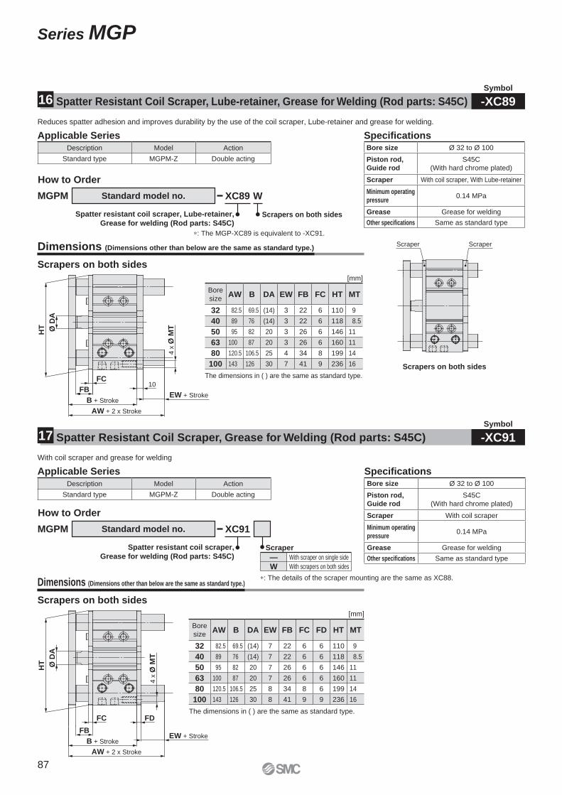
Dimensions (Dimensions other than below are the same as standard type.)
Scrapers on both sides
Dimensions (Dimensions other than below are the same as standard type.)
Scrapers on both sides
10FC
AW + 2 x Stroke
B + Stroke
FB
HT Ø D
A
4 x
Ø M
T
EW + Stroke
Scrapers on both sides
Scraper Scraper
FDFC
HT
AW + 2 x Stroke
B + Stroke
FBEW + Stroke
Ø D
A
4 x
Ø M
T
Reduces spatter adhesion and improves durability by the use of the coil scraper, Lube-retainer and grease for welding.
Applicable SeriesDescription Model Action
Standard type MGPM-Z Double acting
Specifi cationsApplicable Series
With coil scraper and grease for welding
Description Model Action
Standard type MGPM-Z Double acting
Bore size Ø 32 to Ø 100
Piston rod,
Guide rod
S45C
(With hard chrome plated)
Scraper With coil scraper
Minimum operating
pressure0.14 MPa
Grease Grease for welding
Other specifications Same as standard type
Specifi cationsBore size Ø 32 to Ø 100
Piston rod,
Guide rod
S45C
(With hard chrome plated)
Scraper With coil scraper, With Lube-retainer
Minimum operating
pressure0.14 MPa
Grease Grease for welding
Other specifications Same as standard type
Standard model no. XC89 W
Spatter resistant coil scraper, Lube-retainer,
Grease for welding (Rod parts: S45C)
How to Order
MGPM
Scrapers on both sides
Standard model no. XC91
Spatter resistant coil scraper,
Grease for welding (Rod parts: S45C)
How to Order
MGPM
The dimensions in ( ) are the same as standard type.
∗: The details of the scraper mounting are the same as XC88.
[mm]
[mm]
Bore
sizeAW B DA EW FB FC HT MT
32 82.5 69.5 (14) 3 22 6 110 9
40 89 76 (14) 3 22 6 118 8.5
50 95 82 20 3 26 6 146 11
63 100 87 20 3 26 6 160 11
80 120.5 106.5 25 4 34 8 199 14
100 143 126 30 7 41 9 236 16
Bore
sizeAW B DA EW FB FC FD HT MT
32 82.5 69.5 (14) 7 22 6 6 110 9
40 89 76 (14) 7 22 6 6 118 8.5
50 95 82 20 7 26 6 6 146 11
63 100 87 20 7 26 6 6 160 11
80 120.5 106.5 25 8 34 8 6 199 14
100 143 126 30 8 41 9 9 236 16
Scraper
— With scraper on single side
W With scrapers on both sides
∗: The MGP-XC89 is equivalent to -XC91.
The dimensions in ( ) are the same as standard type.
Spatter Resistant Coil Scraper, Lube-retainer, Grease for Welding (Rod parts: S45C)16Symbol
-XC89
Spatter Resistant Coil Scraper, Grease for Welding (Rod parts: S45C)17Symbol
-XC91
87
Series MGP
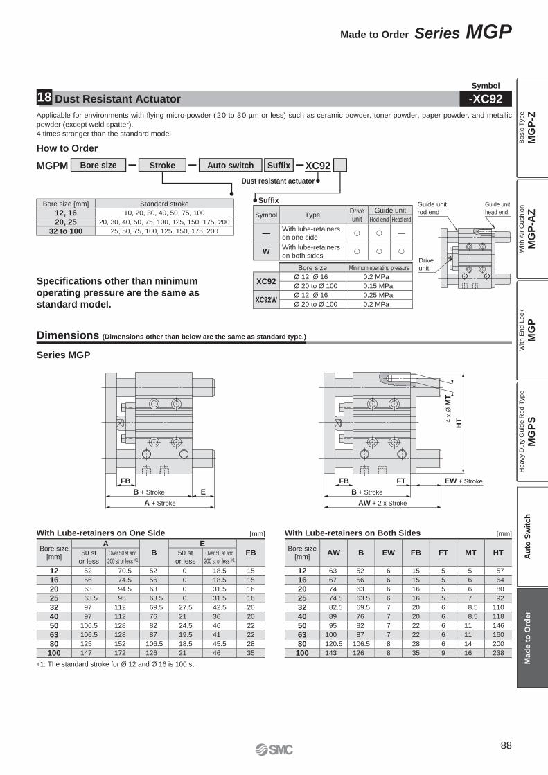
Series MGP
With Lube-retainers on One Side With Lube-retainers on Both Sides[mm] [mm]
∗1: The standard stroke for Ø 12 and Ø 16 is 100 st.
Dimensions (Dimensions other than below are the same as standard type.)
B + Stroke E
FB
A + Stroke
FT EW + Stroke
AW + 2 x Stroke
4 x
Ø M
T
HT
B + Stroke
FB
Bore size
[mm]
AB
EFB50 st
or lessOver 50 st and
200 st or less ∗1
50 st
or lessOver 50 st and
200 st or less ∗1
12 52 70.5 52 0 18.5 15
16 56 74.5 56 0 18.5 15
20 63 94.5 63 0 31.5 16
25 63.5 95 63.5 0 31.5 16
32 97 112 69.5 27.5 42.5 20
40 97 112 76 21 36 20
50 106.5 128 82 24.5 46 22
63 106.5 128 87 19.5 41 22
80 125 152 106.5 18.5 45.5 28
100 147 172 126 21 46 35
Bore size
[mm]AW B EW FB FT MT HT
12 63 52 6 15 5 5 57
16 67 56 6 15 5 6 64
20 74 63 6 16 5 6 80
25 74.5 63.5 6 16 5 7 92
32 82.5 69.5 7 20 6 8.5 110
40 89 76 7 20 6 8.5 118
50 95 82 7 22 6 11 146
63 100 87 7 22 6 11 160
80 120.5 106.5 8 28 6 14 200
100 143 126 8 35 9 16 238
Made to Order Series MGP
Applicable for environments with fl ying micro-powder (20 to 30 µm or less) such as ceramic powder, toner powder, paper powder, and metallic
powder (except weld spatter).
4 times stronger than the standard model
How to Order
Specifi cations other than minimum
operating pressure are the same as
standard model.
MGPM Bore size Stroke XC92
Dust resistant actuator
Suffi x
Auto switch Suffi x
Guide unit
head end
Guide unit
rod end
Drive
unitBore size Minimum operating pressure
XC92Ø 12, Ø 16 0.2 MPa
Ø 20 to Ø 100 0.15 MPa
XC92WØ 12, Ø 16 0.25 MPa
Ø 20 to Ø 100 0.2 MPa
Symbol TypeDrive
unit
Guide unit
Rod end Head end
—With lube-retainers
on one side� � —
WWith lube-retainers
on both sides� � �
Bore size [mm] Standard stroke
12, 16 10, 20, 30, 40, 50, 75, 100
20, 25 20, 30, 40, 50, 75, 100, 125, 150, 175, 200
32 to 100 25, 50, 75, 100, 125, 150, 175, 200
Dust Resistant Actuator18Symbol
-XC92
88
MG
P-Z
MG
P-A
ZM
GP
MG
PS
Ba
sic
Typ
eW
ith
Air C
ush
ion
With E
nd L
ock
Heavy D
uty
Guid
e R
od T
ype
Au
to S
wit
ch
Mad
e t
o O
rder
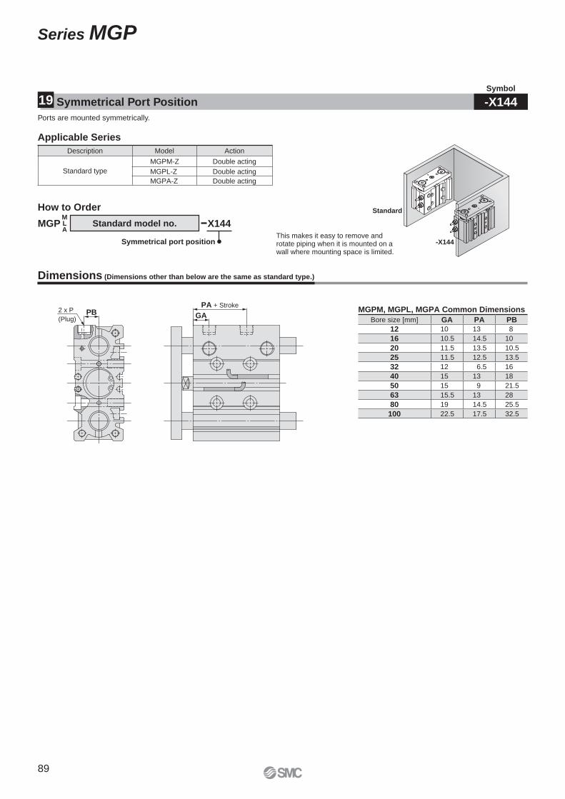
2 x P
(Plug)
PA + Stroke
GAPB
-X144
Standard
This makes it easy to remove and rotate piping when it is mounted on a wall where mounting space is limited.
Description Model Action
Standard type
MGPM-Z Double acting
MGPL-Z Double acting
MGPA-Z Double acting
Bore size [mm] GA PA PB
12 10 13 8
16 10.5 14.5 10
20 11.5 13.5 10.5
25 11.5 12.5 13.5
32 12 6.5 16
40 15 13 18
50 15 9 21.5
63 15.5 13 28
80 19 14.5 25.5
100 22.5 17.5 32.5
Ports are mounted symmetrically.
Applicable Series
Symmetrical Port Position19Symbol
-X144
MGPMLA
How to Order
Standard model no. X144
Symmetrical port position
Dimensions (Dimensions other than below are the same as standard type.)
MGPM, MGPL, MGPA Common Dimensions
89
Series MGP
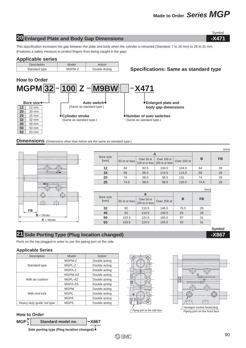
Symbol
-X471Enlarged Plate and Body Gap Dimensions20
This specifi cation increases the gap between the plate and body when the cylinder is retracted (Standard: 7 to 16 mm) to 28 to 31 mm.
(Features a safety measure to protect fi ngers from being caught in the gap)
How to Order
Description Model Action
Standard type MGPM-Z Double Acting
Applicable series
Specifi cations: Same as standard type
MGPM 32 100 Z M9BW X471
Cylinder stroke(Same as standard type.)
Auto switch(Same as standard type.)
Number of auto switches(Same as standard type.)
Enlarged plate and
body gap dimensions
Bore size
12 12 mm
20 20 mm
25 25 mm
32 32 mm
40 40 mm
50 50 mm
63 63 mm
Dimensions (Dimensions other than below are the same as standard type.)
[mm]
Bore size
[mm]
A
B FB50 st or less
Over 50 st
100 st or less
Over 100 st
200 st or lessOver 200 st
12 64 82.5 104.5 104.5 64 28
16 68 86.5 114.5 114.5 68 28
20 74 98.5 98.5 131 74 29
25 74.5 98.5 98.5 130.5 74.5 28
[mm]
Bore size
[mm]
A
B FB50 st or less
Over 50 st
200 st or lessOver 200 st
32 92 110.5 146.5 76.5 29
40 92 110.5 146.5 83 29
50 103.5 124.5 165.5 87 31
63 103.5 124.5 165.5 92 31
FB
B + Stroke
A + Stroke
Hexagon socket head plug
Piping port on the front facePiping port on the side face
Description Model Action
Standard type
MGPM-Z Double acting
MGPL-Z Double acting
MGPA-Z Double acting
With air cushion
MGPM-AZ Double acting
MGPL-AZ Double acting
MGPA-ZA Double acting
With end lock
MGPM Double acting
MGPL Double acting
MGPA Double acting
Heavy duty guide rod type MGPS Double acting
Side Porting Type (Plug location changed)21Symbol
-X867Ports on the top plugged in order to use the piping port on the side.
Applicable Series
MGPMLA
How to Order
Standard model no. X867
Side porting type (Plug location changed)
90
Made to Order Series MGP
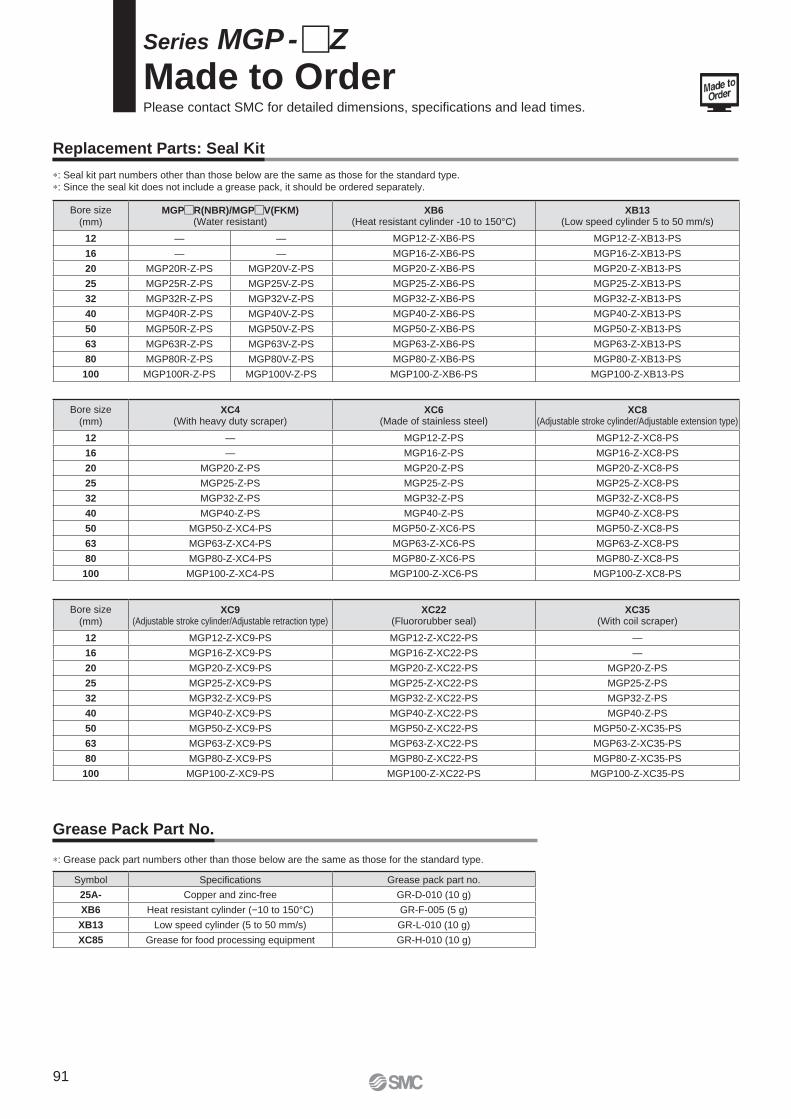
Bore size
(mm)MGP�R(NBR)/MGP�V(FKM)
(Water resistant)XB6
(Heat resistant cylinder -10 to 150°C)XB13
(Low speed cylinder 5 to 50 mm/s)
12 — — MGP12-Z-XB6-PS MGP12-Z-XB13-PS
16 — — MGP16-Z-XB6-PS MGP16-Z-XB13-PS
20 MGP20R-Z-PS MGP20V-Z-PS MGP20-Z-XB6-PS MGP20-Z-XB13-PS
25 MGP25R-Z-PS MGP25V-Z-PS MGP25-Z-XB6-PS MGP25-Z-XB13-PS
32 MGP32R-Z-PS MGP32V-Z-PS MGP32-Z-XB6-PS MGP32-Z-XB13-PS
40 MGP40R-Z-PS MGP40V-Z-PS MGP40-Z-XB6-PS MGP40-Z-XB13-PS
50 MGP50R-Z-PS MGP50V-Z-PS MGP50-Z-XB6-PS MGP50-Z-XB13-PS
63 MGP63R-Z-PS MGP63V-Z-PS MGP63-Z-XB6-PS MGP63-Z-XB13-PS
80 MGP80R-Z-PS MGP80V-Z-PS MGP80-Z-XB6-PS MGP80-Z-XB13-PS
100 MGP100R-Z-PS MGP100V-Z-PS MGP100-Z-XB6-PS MGP100-Z-XB13-PS
Bore size
(mm)XC4
(With heavy duty scraper)XC6
(Made of stainless steel)XC8
(Adjustable stroke cylinder/Adjustable extension type)
12 — MGP12-Z-PS MGP12-Z-XC8-PS
16 — MGP16-Z-PS MGP16-Z-XC8-PS
20 MGP20-Z-PS MGP20-Z-PS MGP20-Z-XC8-PS
25 MGP25-Z-PS MGP25-Z-PS MGP25-Z-XC8-PS
32 MGP32-Z-PS MGP32-Z-PS MGP32-Z-XC8-PS
40 MGP40-Z-PS MGP40-Z-PS MGP40-Z-XC8-PS
50 MGP50-Z-XC4-PS MGP50-Z-XC6-PS MGP50-Z-XC8-PS
63 MGP63-Z-XC4-PS MGP63-Z-XC6-PS MGP63-Z-XC8-PS
80 MGP80-Z-XC4-PS MGP80-Z-XC6-PS MGP80-Z-XC8-PS
100 MGP100-Z-XC4-PS MGP100-Z-XC6-PS MGP100-Z-XC8-PS
Bore size
(mm)XC9
(Adjustable stroke cylinder/Adjustable retraction type)XC22
(Fluororubber seal)XC35
(With coil scraper)
12 MGP12-Z-XC9-PS MGP12-Z-XC22-PS —
16 MGP16-Z-XC9-PS MGP16-Z-XC22-PS —
20 MGP20-Z-XC9-PS MGP20-Z-XC22-PS MGP20-Z-PS
25 MGP25-Z-XC9-PS MGP25-Z-XC22-PS MGP25-Z-PS
32 MGP32-Z-XC9-PS MGP32-Z-XC22-PS MGP32-Z-PS
40 MGP40-Z-XC9-PS MGP40-Z-XC22-PS MGP40-Z-PS
50 MGP50-Z-XC9-PS MGP50-Z-XC22-PS MGP50-Z-XC35-PS
63 MGP63-Z-XC9-PS MGP63-Z-XC22-PS MGP63-Z-XC35-PS
80 MGP80-Z-XC9-PS MGP80-Z-XC22-PS MGP80-Z-XC35-PS
100 MGP100-Z-XC9-PS MGP100-Z-XC22-PS MGP100-Z-XC35-PS
Symbol Specifi cations Grease pack part no.
25A- Copper and zinc-free GR-D-010 (10 g)
XB6 Heat resistant cylinder (−10 to 150°C) GR-F-005 (5 g)
XB13 Low speed cylinder (5 to 50 mm/s) GR-L-010 (10 g)
XC85 Grease for food processing equipment GR-H-010 (10 g)
Series MGP - �Z
Made to OrderPlease contact SMC for detailed dimensions, specifi cations and lead times.
∗: Seal kit part numbers other than those below are the same as those for the standard type.
∗: Since the seal kit does not include a grease pack, it should be ordered separately.
∗: Grease pack part numbers other than those below are the same as those for the standard type.
Replacement Parts: Seal Kit
Grease Pack Part No.
91
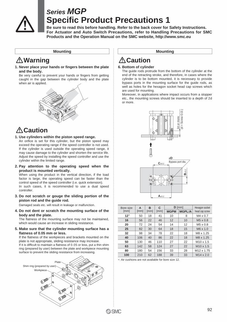
Plate
Workpiece
Shim ring (prepared by user)
2d
or
mo
re
(d =
Scre
w O
.D.)
C±0.2
A±0.2
B±
0.2
øD
Bypass port dia.
∗: Air cushions are not available for bore size 12.
Be sure to read this before handling. Refer to the back cover for Safety Instructions. For Actuator and Auto Switch Precautions, refer to Handling Precautions for SMC Products and the Operation Manual on the SMC website, http://www.smc.eu
1. Never place your hands or fi ngers between the plate
and the body.Be very careful to prevent your hands or fi ngers from getting
caught in the gap between the cylinder body and the plate
when air is applied.
6. Bottom of cylinderThe guide rods protrude from the bottom of the cylinder at the
end of the retracting stroke, and therefore, in cases where the
cylinder is to be bottom mounted, it is necessary to provide
bypass ports in the mounting surface for the guide rods, as
well as holes for the hexagon socket head cap screws which
are used for mounting.
Moreover, in applications where impact occurs from a stopper
etc., the mounting screws should be inserted to a depth of 2d
or more.
1. Use cylinders within the piston speed range.An orifi ce is set for this cylinder, but the piston speed may
exceed the operating range if the speed controller is not used.
If the cylinder is used outside the operating speed range, it
may cause damage to the cylinder and shorten the service life.
Adjust the speed by installing the speed controller and use the
cylinder within the limited range.
2. Pay attention to the operating speed when the
product is mounted vertically.When using the product in the vertical direction, if the load
factor is large, the operating speed can be faster than the
control speed of the speed controller (i.e. quick extension).
In such cases, it is recommended to use a dual speed
controller.
3. Do not scratch or gouge the sliding portion of the
piston rod and the guide rod.
Damaged seals etc. will result in leakage or malfunction.
4. Do not dent or scratch the mounting surface of the
body and the plate.The fl atness of the mounting surface may not be maintained,
which would cause an increase in sliding resistance.
5. Make sure that the cylinder mounting surface has a
fl atness of 0.05 mm or less.If the fl atness of the workpieces and brackets mounted on the
plate is not appropriate, sliding resistance may increase.If it is diffi cult to maintain a fl atness of 0.05 or less, put a thin shim
ring (prepared by user) between the plate and workpiece mounting
surface to prevent the sliding resistance from increasing.
Warning
Caution
Mounting Mounting
Caution
Series MGPSpecifi c Product Precautions 1
Bore size [mm]
A[mm]
B[mm]
C[mm]
D [mm] Hexagon socket
head cap screwMGPM MGPL/A
12∗ 50 18 41 10 8 M4 x 0.7
16 56 22 46 12 10 M5 x 0.8
20 72 24 54 14 12 M5 x 0.8
25 82 30 64 18 15 M6 x 1.0
32 98 34 78 22 18 M8 x 1.25
40 106 40 86 22 18 M8 x 1.25
50 130 46 110 27 22 M10 x 1.5
63 142 58 124 27 22 M10 x 1.5
80 180 54 156 33 28 M12 x 1.75
100 210 62 188 39 33 M14 x 2.0
92
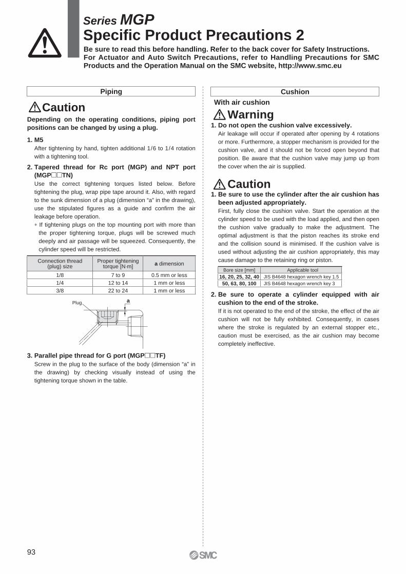
aPlug
1. Do not open the cushion valve excessively.
Air leakage will occur if operated after opening by 4 rotations
or more. Furthermore, a stopper mechanism is provided for the
cushion valve, and it should not be forced open beyond that
position. Be aware that the cushion valve may jump up from
the cover when the air is supplied.
With air cushion
1. Be sure to use the cylinder after the air cushion has
been adjusted appropriately.
First, fully close the cushion valve. Start the operation at the
cylinder speed to be used with the load applied, and then open
the cushion valve gradually to make the adjustment. The
optimal adjustment is that the piston reaches its stroke end
and the collision sound is minimised. If the cushion valve is
used without adjusting the air cushion appropriately, this may
cause damage to the retaining ring or piston.
2. Be sure to operate a cylinder equipped with air
cushion to the end of the stroke.
If it is not operated to the end of the stroke, the effect of the air
cushion will not be fully exhibited. Consequently, in cases
where the stroke is regulated by an external stopper etc.,
caution must be exercised, as the air cushion may become
completely ineffective.
Warning
Caution
Bore size [mm] Applicable tool
16, 20, 25, 32, 40 JIS B4648 hexagon wrench key 1.5
50, 63, 80, 100 JIS B4648 hexagon wrench key 3
1. M5
After tightening by hand, tighten additional 1/6 to 1/4 rotation
with a tightening tool.
2. Tapered thread for Rc port (MGP) and NPT port
(MGP��TN)
Use the correct tightening torques listed below. Before
tightening the plug, wrap pipe tape around it. Also, with regard
to the sunk dimension of a plug (dimension “a” in the drawing),
use the stipulated fi gures as a guide and confi rm the air
leakage before operation.
∗ If tightening plugs on the top mounting port with more than
the proper tightening torque, plugs will be screwed much
deeply and air passage will be squeezed. Consequently, the
cylinder speed will be restricted.
3. Parallel pipe thread for G port (MGP��TF)
Screw in the plug to the surface of the body (dimension “a” in
the drawing) by checking visually instead of using the
tightening torque shown in the table.
Caution
Piping
Depending on the operating conditions, piping port
positions can be changed by using a plug.
Connection thread (plug) size
Proper tightening torque [N·m]
a dimension
1/8 7 to 9 0.5 mm or less
1/4 12 to 14 1 mm or less
3/8 22 to 24 1 mm or less
Cushion
Be sure to read this before handling. Refer to the back cover for Safety Instructions. For Actuator and Auto Switch Precautions, refer to Handling Precautions for SMC Products and the Operation Manual on the SMC website, http://www.smc.eu
Series MGPSpecifi c Product Precautions 2
93
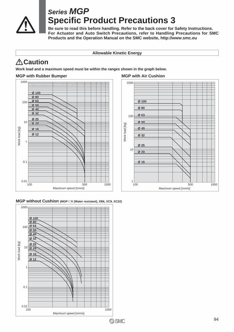
1000
100
10
1
0.1
0.01
Maximum speed [mm/s]
Wo
rk lo
ad
[kg]
100 1000500
Ø 100
Ø 80
Ø 63
Ø 50
Ø 40
Ø 32
Ø 25
Ø 20
Ø 16
Ø 12
0.01
0.1
1
10
100
1000
Maximum speed [mm/s]
Work
load [
kg]
100 1000
Ø 100
Ø 80
Ø 63
Ø 50
Ø 40
Ø 32
Ø 25
Ø 20
Ø 16
Ø 12
1000
100
10
1
Maximum speed [mm/s]
Work
load [kg]
100 1000500
Ø 100
Ø 50
Ø 40
Ø 32
Ø 25
Ø 20
Ø 16
Ø 63
Ø 80
MGP without Cushion (MGP-�V (Water resistant), XB6, XC9, XC22)
MGP with Rubber Bumper
Work load and a maximum speed must be within the ranges shown in the graph below.
Caution
Allowable Kinetic Energy
MGP with Air Cushion
Be sure to read this before handling. Refer to the back cover for Safety Instructions. For Actuator and Auto Switch Precautions, refer to Handling Precautions for SMC Products and the Operation Manual on the SMC website, http://www.smc.eu
Series MGPSpecifi c Product Precautions 3
94

Lithuania +370 5 2308118 www.smclt.lt [email protected] +31 (0)205318888 www.smc.nl [email protected] +47 67129020 www.smc-norge.no [email protected] +48 222119600 www.smc.pl [email protected] +351 214724500 www.smc.eu [email protected] +40 213205111 www.smcromania.ro [email protected] +7 8127185445 www.smc-pneumatik.ru [email protected] +421 (0)413213212 www.smc.sk [email protected] +386 (0)73885412 www.smc.si [email protected] +34 945184100 www.smc.eu [email protected] +46 (0)86031200 www.smc.nu [email protected] +41 (0)523963131 www.smc.ch [email protected] +90 212 489 0 440 www.smcpnomatik.com.tr [email protected] UK +44 (0)845 121 5122 www.smc.uk [email protected]
Specifications are subject to change without prior notice and any obligation on the part of the manufacturer.
SMC CORPORATION Akihabara UDX 15F, 4-14-1, Sotokanda, Chiyoda-ku, Tokyo 101-0021, JAPAN Phone: 03-5207-8249 FAX: 03-5298-53621st printing XO printing XO 00 Printed in Spain
Austria +43 (0)2262622800 www.smc.at [email protected] +32 (0)33551464 www.smc.be [email protected] +359 (0)2807670 www.smc.bg [email protected] Croatia +385 (0)13707288 www.smc.hr [email protected] Republic +420 541424611 www.smc.cz [email protected] Denmark +45 70252900 www.smcdk.com [email protected] Estonia +372 6510370 www.smcpneumatics.ee [email protected] +358 207513513 www.smc.fi [email protected] +33 (0)164761000 www.smc-france.fr [email protected] +49 (0)61034020 www.smc.de [email protected] +30 210 2717265 www.smchellas.gr [email protected] +36 23513000 www.smc.hu [email protected] +353 (0)14039000 www.smcpneumatics.ie [email protected] +39 0292711 www.smcitalia.it [email protected] +371 67817700 www.smc.lv [email protected]
Safety Instructions Be sure to read “Handling Precautions for SMC Products” (M-E03-3) before using.
SMC Corporation (Europe)
1. The compatibility of the product is the responsibility of the person
who designs the equipment or decides its specifications. Since the product specified here is used under various operating conditions, its
compatibility with specific equipment must be decided by the person who designs the
equipment or decides its specifications based on necessary analysis and test results.
The expected performance and safety assurance of the equipment will be the
responsibility of the person who has determined its compatibility with the product. This
person should also continuously review all specifications of the product referring to its
latest catalogue information, with a view to giving due consideration to any possibility of
equipment failure when configuring the equipment.
2. Only personnel with appropriate training should operate machinery
and equipment. The product specified here may become unsafe if handled incorrectly. The assembly,
operation and maintenance of machines or equipment including our products must be
performed by an operator who is appropriately trained and experienced.
3. . Do not service or attempt to remove product and
machinery/equipment until safety is confirmed.1. The inspection and maintenance of machinery/equipment should only be performed
after measures to prevent falling or runaway of the driven objects have been
confirmed.
2. When the product is to be removed, confirm that the safety measures as mentioned
above are implemented and the power from any appropriate source is cut, and read
and understand the specific product precautions of all relevant products carefully.
3. Before machinery/equipment is restarted, take measures to prevent unexpected
operation and malfunction.
4. Contact SMC beforehand and take special consideration of safety
measures if the product is to be used in any of the following
conditions. 1. Conditions and environments outside of the given specifications, or use outdoors or in
a place exposed to direct sunlight.
2. Installation on equipment in conjunction with atomic energy, railways, air navigation,
space, shipping, vehicles, military, medical treatment, combustion and recreation, or
equipment in contact with food and beverages, emergency stop circuits, clutch and
brake circuits in press applications, safety equipment or other applications unsuitable
for the standard specifications described in the product catalogue.
3. An application which could have negative effects on people, property, or animals
requiring special safety analysis.
4. Use in an interlock circuit, which requires the provision of double interlock for possible
failure by using a mechanical protective function, and periodical checks to confirm
proper operation.
Warning Limited warranty and Disclaimer/Compliance Requirements The product used is subject to the following “Limited warranty and
Disclaimer” and “Compliance Requirements”.
Read and accept them before using the product.
1. The product is provided for use in manufacturing industries.The product herein described is basically provided for peaceful use in manufacturing
industries.
If considering using the product in other industries, consult SMC beforehand and exchange
specifications or a contract if necessary.
If anything is unclear, contact your nearest sales branch.
CautionSMC products are not intended for use as instruments for legal
metrology.Measurement instruments that SMC manufactures or sells have not been qualified by
type approval tests relevant to the metrology (measurement) laws of each country.
Therefore, SMC products cannot be used for business or certification ordained by the
metrology (measurement) laws of each country.
Caution
Limited warranty and Disclaimer
1. The warranty period of the product is 1 year in service or 1.5 years
after the product is delivered, wichever is first.∗2)
Also, the product may have specified durability, running distance or
replacement parts. Please consult your nearest sales branch.
2. For any failure or damage reported within the warranty period which is clearly
our responsibility, a replacement product or necessary parts will be provided.
This limited warranty applies only to our product independently, and not to any
other damage incurred due to the failure of the product.
3. Prior to using SMC products, please read and understand the warranty
terms and disclaimers noted in the specified catalogue for the particular
products.
∗2) Vacuum pads are excluded from this 1 year warranty.
A vacuum pad is a consumable part, so it is warranted for a year after it is delivered.
Also, even within the warranty period, the wear of a product due to the use of the vacuum
pad or failure due to the deterioration of rubber material are not covered by the limited
warranty.
Compliance Requirements
1. The use of SMC products with production equipment for the manufacture of
weapons of mass destruction (WMD) or any other weapon is strictly
prohibited.
2. The exports of SMC products or technology from one country to another are
governed by the relevant security laws and regulations of the countries
involved in the transaction. Prior to the shipment of a SMC product to
another country, assure that all local rules governing that export are known
and followed.
These safety instructions are intended to prevent hazardous situations and/or equipment damage. These instructions indicate the level of potential hazard with the labels of “Caution,” “Warning” or “Danger.” They are all important notes for safety and must be followed in addition to International Standards (ISO/IEC)∗1), and other safety regulations.
∗1) ISO 4414: Pneumatic fluid power – General rules relating to systems.
ISO 4413: Hydraulic fluid power – General rules relating to systems.
IEC 60204-1: Safety of machinery – Electrical equipment of machines.
(Part 1: General requirements)
ISO 10218-1: Manipulating industrial robots - Safety.
etc.
Caution indicates a hazard with a low level of risk which, if not avoided, could result in minor or moderate injury.
Warning indicates a hazard with a medium level of risk which, if not avoided, could result in death or serious injury.
Caution:
Warning:
Danger :Danger indicates a hazard with a high level of risk which, if not avoided, will result in death or serious injury.
Safety Instructions