Embed Size (px)
Citation preview
CAD Standards
Revision 2: February 2013
NOTE ON REVISION 2: FEBRUARY 2013 The DCAMM CAD Standards have been revised – Revision 2: February 2013 – to update the manual to Autodesk AutoCAD 2011 format and to reflect the name change of DCAM to Division of Capital Asset Management and Maintenance (DCAMM).
DCAMM CAD STANDARDS
DCAMM 2 Revision 2: February 2013 Foreword
FOREWORD
Each year, the Division of Capital Asset Management and Maintenance (DCAMM) manages several hundred million dollars worth of projects. These include architectural and engineering activities, construction management, maintenance, surveys, studies and needs analyses, and other projects in keeping with the mission of DCAMM
“…to serve the citizens of the Commonwealth by providing professional and comprehensive services to state agencies in the fields of public-building design, construction, maintenance and real estate.”
Data for these projects are collected in graphic and tabular form, most typically using Computer Aided Design and Drafting (CAD) technologies. Complementary technological tools; Geographic Information Systems (GIS) software, total stations for surveys, and data base technologies, are also used in data generation and collection. These data are utilized immediately in project related activities, e.g. planning, design, and construction of state facilities, and are also used for a variety of post construction activities, including maintenance, space management, renovations, and management analyses, to name but a few. Post construction, the data are used to support diverse activities of state agencies to which project data are delivered. Recognizing the need for consistency and data compatibility among a variety of data developers, project applications and post construction activities, in early 2007 a CAD Standards Committee was formed within DCAMM. The committee was charged with developing a set of CAD standards that would reflect DCAMM data management needs, and that would be compatible as far as possible with National CAD Standards. DCAMM standards would be complementary to the “DCAMM Standard Specifications”, the DCAMM “Designers Procedures Manual”, the DCAMM “Cost Estimating Manual” and any and all other DCAMM documents and regulations promulgated by DCAMM. The DCAMM CAD standards Manual is not a specification of what software products are to be utilized in DCAMM projects, but rather a specification of how graphic and tabular data are to be delivered to DCAMM. The DCAMM CAD Standards have been developed with a view to compatibility with and complementarities to emerging technologies, specifically Building Information Model (BIM) software. Early on, the committee determined that an essential method of ensuring data consistency and compatibility among the various data providers would be for DCAMM to develop a CAD “seed file”. This file, a digital version of DCAMM’s CAD standards, would be provided to DCAMM consultants for use in DCAMM projects. The file would automatically set up the consultants’ computers according to the standard, thus insuring all consultants’ file deliveries would be consistent and compatible, irrespective of the source and or discipline.
DCAMM CAD STANDARDS
DCAMM 3 Revision 2: February 2013 Foreword
For a detailed description of the Seed file and Titleblock provided please refer to Sections 4.0 through 4.4. The CAD Standards Committee was comprised of representatives from the following DCAMM offices
• Facilities Maintenance and Management • Leasing • Planning, Design and Construction • Real Estate Management
Additionally, comments were solicited from DCAMM staff with particular expertise in functional and/or application areas, e.g. surveying, project management systems (PMAS) and Courts, and client agencies currently using CAD. Input was also solicited from representatives of the local architectural/engineering/construction (A/E/C) community. As far as possible, all points of view have been considered in developing the DCAMM CAD Standards. To assist in the preparation of the standards and the seed file, DCAMM retained the services of Microdesk, Inc., of Waltham, Massachusetts. Microdesk was selected based on its prior consultancy experience in similar projects, and its capabilities as an application software provider for the full gamut of disciplines utilized in DCAMM projects. It is recognized that the disciplines associated with DCAMM activities are constantly changing. Periodically, this manual and associated seed files will be revised to reflect such changes. It is the goal of DCAMM to maintain a set of CAD Standards that are timely, current, and which reflect the state of the art in technology, data management, and current managerial techniques in design, construction and post construction activities.
DCAMM CAD STANDARDS
DCAMM 4 Revision 2: February 2013 Foreword
For the Revision 1 Committee: Michael Costello, Office of Facilities Maintenance and Management, Chair David Berkowitz, Office of Planning, Design and Construction Luciana Burdi, Office of Planning, Design and Construction Jim Cassidy, Office of Facilities Maintenance and Management AnPing Chi, Office of Facilities Maintenance and Management Hope Davis, Office of Facilities Maintenance and Management Mel Klayman, Office of Facilities Maintenance and Management Schuyler Larrabee, Office of Planning, Design and Construction Lisa Musiker, Office of Real Estate Management Brian Novak, Office of Planning, Design and Construction Jane Wang, Office of State Planning and Leasing Michael Williams, Office of Planning, Design and Construction For the Revision 2: Mel Klayman, Office of Finance and Administration Andrew Masnyi, Planning Assistant Erik Nelson, Administrative Assistant
DCAMM CAD STANDARDS
DCAMM 5 Revision 2: February 2013 Table of Contents
TABLE OF CONTENTS FOREWORD…………………….. ...................................................................................... 2 TABLE OF CONTENTS ...................................................................................................... 5 PURPOSE ............................................................................................................................. 8 1.0 ACCESSING THE CAD STANDARDS ................................................................ 9
1.1 USING THE STANDARDS FILES ........................................................... 9 2.0 PROJECT DIRECTORY STRUCTURE AND FILE NAMING …………….…..10
CONVENTION
2.1 PROJECT INFORMATION DELIVERY……………………………......10 2.2 DIRECTORY STRUCTURE……………………………………………..10
2.3 FILE NAMING CONVENTION ............................................................... 13
2.4 SUBMISSIONS .......................................................................................... 14 2.5 ELECTRONIC DELIVERABLES ............................................................. 15
2.5.1 DESIGNERS RECORD TURNOVER ELECTRONIC
REQUIREMENTS ........................................................................ 15
2.5.2 MEDIA FORMAT REQUIREMENTS ......................................... 16
2.5.3 QUALITY CONTROL .................................................................. 16
2.5.4 CAD STANDARDS ELECTRONIC SUBMITTAL CHECKLIST ................................................................................. 16
2.6 PAPER FORMAT DELIVERABLES ........................................................ 17 2.6.1 DESIGNERS RECORDS TURNOVER PAPER
REQUIREMENTS ........................................................................ 18
3.0 CAD PRACTICES AND PROCEDURES .............................................................. 19
3.1 LAYERING SCHEME DEFINITION ....................................................... 19
3.2 ENTITY AND LAYER LINETYPES ........................................................ 20
3.3 ENTITY AND LAYER COLORS ............................................................. 21
DCAMM CAD STANDARDS
DCAMM 6 Revision 2: February 2013 Table of Contents
3.4 COORDINATE SYSTEMS........................................................................ 21 3.5 SYMBOLOGY ........................................................................................... 21
3.5.1 DIGITAL INSERTION OF SCALEABLE SYMBOLS ............... 21 3.5.2 DIGITAL INSERTION OF NON-SCALEABLE SYMBOLS ..... 21
3.5.3 CREATING SYMBOLS………………………………………....22
3.6 PLOTTED LINEWEIGHTS ....................................................................... 23 3.7 TEXT STYLES AND HEIGHTS ............................................................... 24 3.8 DIMENSION STYLES .............................................................................. 25
3.9 EXTERNAL REFERENCE FILES ............................................................ 25
3.10 POLYLINES …………………...…………………………………………29
3.11 DATA EXTRACTION (Area and Information Extraction).….…...….......31
4.0 SEED FILE .............................................................................................................. 36
4.1 ACCESSING LAYERS BY GROUP FILTERS………………………….38
4.2 TITLEBLOCKS………………………………..………………………….40
4.3 LOADING THE DCAMM TITLEBLOCK INTO SEED FILE ................ 43
4.4 DCAMM STANDARD COVER SHEET………………………………...47 5.0 CAD PRACTICES AND PROCEDURES………………………………………...48
5.1 AUTOCAD 2011 CONFIGURATION (Plotting by layout)……………...48 5.2 TEMPLATE DRAWING SETUP .............................................................. 48
5.3 PAGE SETUPS ........................................................................................... 49
6.0 PLOT SETUP .......................................................................................................... 51 7.0 DISTRIBUTION FILES .......................................................................................... 52 8.0 UPDATE AND REVISION PROCEDURES.......................................................... 52 9.0 CONTACT AND SUPPORT INFORMATION...................................................... 52 10.0 CONCLUSION ........................................................................................................ 52
DCAMM CAD STANDARDS
DCAMM 7 Revision 2: February 2013 Table of Contents
11.0 BIBLIOGRAPHY .................................................................................................... 53
APPENDIX
I - LAYER SCHEME................................................................................. (1-53)
II - PEN SETTINGS (CTB) ........................................................................ (1)
III - PLOTTING TO PDF ............................................................................ (1-2) IV - CREATING PAGE SETUPS & PLOTTER CONFIGURATIONS .... (1-16) V - REQUEST TO CHANGE STANDARDS ............................................. (1) VI - CAD DRAWING REQUIREMENTS .................................................... (1-9)
V1.1 SCHEMATIC DESIGN PHASE………………… ………………... (VI-1) V1.2 DESIGN DEVELOPMENT PHASE ………………………...…….. (VI-3) V1.3 CONSTRUCTION DOCUMENT PHASE ……………………….... (VI-6)
DCAMM CAD STANDARDS
DCAMM 8 Revision 2: February 2013 Purpose
PURPOSE The DCAMM CAD Standards Manual establishes requirements and procedures for the preparation and submission of CAD based drawings throughout the project life cycle. Adherence to this standard insures that both DCAMM internal staff and consultants involved will receive and produce graphic and tabular data in a consistent format. This consistency will improve the compatibility of these drawings internally and the efficient exchange of data between DCAMM consultants, and client agencies. The DCAMM CAD Standards Manual largely reflects the National CAD Standards, Version 3.1. In the case of differences between the two documents, the DCAMM CAD Standards is to be considered definitive for DCAMM projects. The role of an individual assigned to the project determines the level of understanding required of the CAD Standards. For CAD operators, designers, and supervisors a thorough knowledge of CAD related elements associated with a project is crucial. The project manager however only requires a general knowledge of the CAD Standards and the means by which they are employed to create a project. Both levels of knowledge will be possible through the use of this manual. The CAD system adopted by DCAMM is Autodesk AutoCAD 2011 format. All deliverables must be compatible with this format. Throughout this manual terminology and references will be made that are unique to this Autodesk application. This manual is intended to be used in conjunction with The Designers Procedures Manual effective June 2005.
ABOUT THIS DOCUMENT
The chapters within this manual describe how DCAMM uses CAD and how to configure AutoCAD to support DCAMM’s CAD Standard, which it has adopted.
The appendices, which follow, support the chapters in several ways. In addition, appendices have been provided to support CAD related subject matter.
DCAMM CAD STANDARDS
DCAMM 9 Revision 2: February 2013 Accessing The CAD Standards
1.0 ACCESSING THE CAD STANDARDS The DCAMM CAD Standards consists of a series of support files, which are available at the DCAMM website located at http://www.mass.gov/anf/property-mgmt-and-construction/design-and-construction-of-public-bldgs/guides-manuals-and-standards/division-of-capital-asset-management-cad-standards.html.
The “DCAMM_Standards” folder contains the DCAMM Seed file, DCAMM Title block, DCAMM Cover Sheet and a pdf version of the DCAMM CAD Standard Manual. 1.1 USING THE STANDARDS FILES The Standards directory contains two primary types of files: files that do not require ongoing user interaction to utilize and files that do require ongoing user interaction to utilize. The first type refers to files used as AutoCAD support files, which only need to be copied once to the proper support folders. The second type refers to files such as Borders and Title Sheets along with their associated revision blocks. These files do require some user interaction to utilize in a drawing.
DCAMM CAD STANDARDS
DCAMM 10 Revision 2: February 2013 Submissions & Deliverables
2.0 PROJECT DIRECTORY STRUCTURE AND FILE NAMING CONVENTION
This chapter provides a structure for the development of CAD projects. Adherence to this structure will insure that DCAMM receives maximum benefit from its CAD implementation. The two primary goals of this structure are first to promote effective and efficient coordination between functional groups and second to develop CAD projects in a way that will facilitate the use of the electronic information beyond the initial contract.
2.1 PROJECT INFORMATION DELIVERY
The repository for all project drawings and project related data will be the in house DCAMM Project Management and Accounting system called PMAS.
2.2 DIRECTORY STRUCTURE
Within the Projects folder, individual project folders will be created using the Project Number. Each project folder shall contain a series of sub-folders as listed below.
DWG Folder The DWG folder is used to store all design (model) drawing files.
Rules of the Drawing Folder:
• Additional folders may not be created in the Dwg folder.
DWG_SHEETS Folder
The DWG_SHEETS folder is used to store all Plot Sheet drawings. These drawings consist of a series of external references. All drawings in a set shall have a corresponding plot sheet drawing in this folder. Each of the drawings may contain multiple layouts within a single file. The stipulations of this are:
• Only consecutive drawings may be stored on multiple paper-space
tabs in a single drawing. • The tabs must be named for the sheet and the tabs must be in
sequence in the drawing file.
Please refer to Section 2.3 FILE NAMING CONVENTION for information on naming DWG sheet drawings.
DCAMM CAD STANDARDS
DCAMM 11 Revision 2: February 2013 Submissions & Deliverables
Rules of the DWG_SHEETS Folder:
• Additional folders may not be created in the Sheets folder. • Only DWG sheet drawings shall be stored in the DWG_Sheets folder.
PDF Folder
At each milestone PDF files are created and placed in this folder. (e.g. Sketch, Preliminary, Revision Number)
• Sub-folders may be created in the PDF folder representing each milestone
SCRATCH Folder
The Scratch folder shall contain temporary design data. This folder is to be used to store temporary drawings and other design information.
Rules of the Scratch Folder:
• Sub-folders may be created in the Scratch folder. • The Scratch folder will not be archived with the project.
FROMOTHERPROJECTS Folder
The Fromotherprojects folder will contain drawings and data that have been taken from other projects that relate to the current project.
Rules of the Fromotherprojects folder
• Subfolders may be created in the Fromotherprojects folder. • The Fromotherprojects folder will be archived with the project
number.
IMAGES Folder The Photos folder is provided to store digital photographs relevant to the project. Photos to be referenced by drawing files should be referenced from this folder. Rules of the Images folder:
• Subfolders may be created in the Images folder. • The Images folder will be archived with the project.
DCAMM CAD STANDARDS
DCAMM 12 Revision 2: February 2013 Submissions & Deliverables
MANAGEMENTDOCS Folder The Management docs folder stores non-drawing related project data. This folder should store spreadsheets, word documents, e-mails and other types of non-drawing information that relate to the project.
Rules of the Management docs folder:
• Subfolders may be created in the Managementdocs folder.
i.e. Word-Files, Sent-Out (Text and PDF), and Email
RECEIVED Folder The Received folder is to contain design information received from outside sources such as consultants. The folder is intended to provide a storage container for dated information. Even though the received information may be design files that will be stored in the discipline root as model files, the received folder can contain a dated archive of these files to identify when the data was received and exactly what the submittal contained on that date.
Rules of the Received folder:
• Subfolders may be created in the Received folder. • Subfolders shall have the date as a prefix as follows: YY/MM/DD
RELEASED Folder
The Released folder is to contain design information released to outside sources such as consultants. The folder is intended to provide a storage container for dated information. Even though the released information may be design files that will be stored in the discipline root as model files, the released folder can contain a dated archive of these files to identify when the data was released and exactly what the submittal contained on that date.
Rules of the Released folder:
• Subfolders may be created in the Released folder. • Subfolders shall have the date as a prefix as follows: YY/MM/DD
ALTERNATE SCHEMES Folder
The Alternate Schemes folder is an area intended to store various schemes of a design component. It provides the designer an area in which to make trial changes to a design. If a scheme is created and chosen as the final, the scheme drawings shall be moved to the MODEL folder.
DCAMM CAD STANDARDS
DCAMM 13 Revision 2: February 2013 Submissions & Deliverables
Rules of the Alternate Schemes folder:
• Subfolders may be created in the Schemes folder
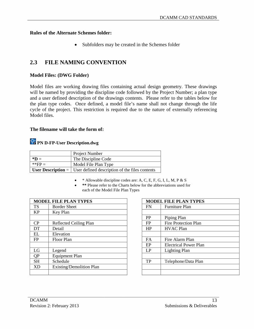
2.3 FILE NAMING CONVENTION Model Files: (DWG Folder)
Model files are working drawing files containing actual design geometry. These drawings will be named by providing the discipline code followed by the Project Number; a plan type and a user defined description of the drawings contents. Please refer to the tables below for the plan type codes. Once defined, a model file’s name shall not change through the life cycle of the project. This restriction is required due to the nature of externally referencing Model files.
The filename will take the form of:
PN D-FP-User Description.dwg
Project Number *D = The Discipline Code **FP = Model File Plan Type User Description = User defined description of the files contents
• * Allowable discipline codes are: A, C, E, F, G, I, L, M, P & S • ** Please refer to the Charts below for the abbreviations used for
each of the Model File Plan Types
MODEL FILE PLAN TYPES FN Furniture Plan PP Piping Plan FP Fire Protection Plan HP HVAC Plan FA Fire Alarm Plan EP Electrical Power Plan LP Lighting Plan TP Telephone/Data Plan
MODEL FILE PLAN TYPES TS Border Sheet KP Key Plan CP Reflected Ceiling Plan DT Detail EL Elevation FP Floor Plan LG Legend QP Equipment Plan SH Schedule XD Existing/Demolition Plan
DCAMM CAD STANDARDS
DCAMM 14 Revision 2: February 2013 Submissions & Deliverables
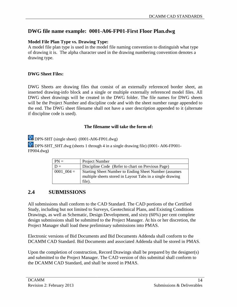
DWG file name example: 0001-A06-FP01-First Floor Plan.dwg Model File Plan Type vs. Drawing Type: A model file plan type is used in the model file naming convention to distinguish what type of drawing it is. The alpha character used in the drawing numbering convention denotes a drawing type. DWG Sheet Files:
DWG Sheets are drawing files that consist of an externally referenced border sheet, an inserted drawing-info block and a single or multiple externally referenced model files. All DWG sheet drawings will be created in the DWG folder. The file names for DWG sheets will be the Project Number and discipline code and with the sheet number range appended to the end. The DWG sheet filename shall not have a user description appended to it (alternate if discipline code is used).
The filename will take the form of:
PN = Project Number D = Discipline Code (Refer to chart on Previous Page) 0001_004 = Starting Sheet Number to Ending Sheet Number (assumes
multiple sheets stored in Layout Tabs in a single drawing file).
2.4 SUBMISSIONS
All submissions shall conform to the CAD Standard. The CAD portions of the Certified Study, including but not limited to Surveys, Geotechnical Plans, and Existing Conditions Drawings, as well as Schematic, Design Development, and sixty (60%) per cent complete design submissions shall be submitted to the Project Manager. At his or her discretion, the Project Manager shall load these preliminary submissions into PMAS. Electronic versions of Bid Documents and Bid Documents Addenda shall conform to the DCAMM CAD Standard. Bid Documents and associated Addenda shall be stored in PMAS. Upon the completion of construction, Record Drawings shall be prepared by the designer(s) and submitted to the Project Manager. The CAD version of this submittal shall conform to the DCAMM CAD Standard, and shall be stored in PMAS.
DPN-SHT (single sheet) (0001-A06-FP01.dwg) DPN-SHT_SHT.dwg (sheets 1 through 4 in a single drawing file) (0001- A06-FP001-
FP004.dwg)
DCAMM CAD STANDARDS
DCAMM 15 Revision 2: February 2013 Submissions & Deliverables
2.5 ELECTRONIC DELIVERABLES
Electronic files and documentation are due with the final submission (and any required interim submission) for each project. This includes studies, data, or graphics, which may or may not include drawings. Final submissions that do not include all files and documentation are incomplete DCAMM strongly emphasizes the importance of final record drawings. These drawings will be used in the management of DCAMM buildings by DCAMM and by client Facilities Management departments. State buildings typically have significant changes in their configuration over their life span. Accurate record drawings are of vital importance in these building management and alteration processes. For a specification chart for the Designer Records Turnover Requirements, see Chart. 2.5.1 DESIGNER RECORDS TURNOVER ELECTRONIC
REQUIREMENTS 1. Record Drawings shall be submitted as follows: TIFF files of dated/Stamped Record Drawings on the Media specified on section 2.5.2 Total number of required Set = 3 (DCAMM Distribution: 1 to DCAMM’s Distribution Manager and 2 to client agency. AutoCAD files (.dwg format) of record drawings Total number of required Set = 3 (DCAMM Distribution: 1 to DCAMM’s Distribution Manager and 2 to client agency. 2. As-Builts Sketches shall be submitted as follows: TIFF files of dated/Stamped Record Drawings on the Media specified on section 2.5.2 (May be included on CD with Record Drawings) Total number of required Set = 3 (DCAMM Distribution: 1 to DCAMM’s Distribution Manager and 2 to client agency. AutoCAD files (.dwg format) (When available as AutoCAD files) (May be included on CD with Record Drawings) Total number of required Set = 3 (DCAMM Distribution: 1 to DCAMM’s Distribution Manager and 2 to client agency. 3. GIS Deliverables shall be submitted as follows:
DCAMM CAD STANDARDS
DCAMM 16 Revision 2: February 2013 Submissions & Deliverables
In addition to data to be delivered to DCAMM in .dwg format, the following items, described as GIS deliverables, are to be delivered as specified below:
• Parcel boundaries • Building foot prints • Roads (if new) within the survey • Contours and elevation data (if a project requirement)
1. All GIS deliverable data should be delivered in the Massachusetts State Plane Coordinate System, Mainland Zone, with units of feet or meters utilizing the horizontal datum of NAD83 and the vertical datum of NAVD88.
2. All final digital data will be delivered in GIS shapefile or geodatabase format on one CD-ROM or DVD suitable for use with ArcGIS. All deliverables will become the property of the Commonwealth of Massachusetts. 2.5.2 MEDIA FORMAT REQUIREMENTS A copy of all electronic files and documentation shall be delivered to DCAMM’s offices on CD-R, DVD-R, or DVD+R. Media used shall be in a format that can be read and processed by DCAMM supported hardware and software. Media jewel cases shall be labeled with the information below. Label the media themselves to contain as a minimum: date, DCAMM project name/number, CAMIS project number and building name/number. 2.5.3 QUALITY CONTROL The Designer/Contractor is responsible for the quality control of their submissions. DCAMM will visually and electronically check these submissions to verify compliance. High quality of drawings is essential, Drawings must be cleaned up before submittal in the matter that lines in corners shall connect; blocks on unnecessary locations shall be deleted or purged. DCAMM will reject and require correction of any required deliverables or formats that do not meet requirements. 2.5.4 CAD STANDARDS ELECTRONIC SUBMITTALS CHECK LIST 1. For final deliverables, verify that all entities outside the drawing limits are deleted. 2. Remove all extraneous graphics outside border area. PURGE all blocks, layers, attributes, etc. not referenced in the drawing. Avoid nested blocks 3. Name files as specified in Section 2.3 of this Manual.
DCAMM CAD STANDARDS
DCAMM 17 Revision 2: February 2013 Submissions & Deliverables
4. Verify that all xrefs (dwgs and images) are attached without drive or directory specifications. Don’t include paths in xref 5. Xrefs shall be bound when submitted. 6. Check that all unused layout tabs are deleted. 7. Drawing submissions shall have revision stamps in the title block (ex: As builts, record drawing, etc) 8. Objects shall be assigned the appropriate layer based on DCAMM’s standards on the Appendix I 9. Object color, line type and line weight shall be set to BYLAYER NOTE: (Please avoid at all costs the use of light yellow and light blue as colors. 10. Text in tables schedules shall be editable. 11. Rooms, spaces and boundaries shall be drawn using polylines to allow easy extraction of information. Please refer to Section 3.11 for data extraction. NOTE: * Survey drawings submitted by the consultant to Programming Department shall be on the correct layers and symbology and contour lines as well as space assignments shall be drawn as polylines. All drawings are to be submitted in both dwg CAD format and a version in TIFF image format. * All drawings submitted to the Office of Leasing and State Planning shall include USF Stamp in Title block, see DCAMM Standards.dwg All Drawings submitted to Facilities Management Department shall be in both dwg CAD format as well as a version in TIFF image format. 2.6 PAPER FORMAT DELIVERABLES
All deliverables must be submitted and received in a timely manner. A transmittal letter shall accompany each electronic deliverables submission. The letter shall be signed by the appropriate Designer/contractor and state the total number of CDs or DVDs submitted and date of submission.
NOTE: According to the Design phase, (Schematic, Design Development or Construction Documents) the requirements will be defined as specified in Appendix VI. DCAMM Standard Sheet Size is 30” x 42”. Any variation to this standard requires the pre-approval by a DCAMM Deputy Director.
DCAMM CAD STANDARDS
DCAMM 18 Revision 2: February 2013 Submissions & Deliverables
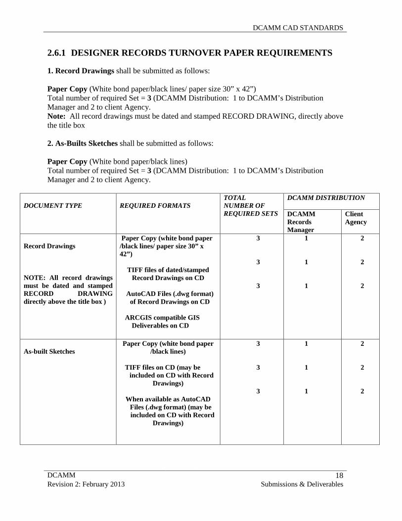
2.6.1 DESIGNER RECORDS TURNOVER PAPER REQUIREMENTS 1. Record Drawings shall be submitted as follows: Paper Copy (White bond paper/black lines/ paper size 30” x 42”) Total number of required Set = 3 (DCAMM Distribution: 1 to DCAMM’s Distribution Manager and 2 to client Agency. Note: All record drawings must be dated and stamped RECORD DRAWING, directly above the title box 2. As-Builts Sketches shall be submitted as follows: Paper Copy (White bond paper/black lines) Total number of required Set = 3 (DCAMM Distribution: 1 to DCAMM’s Distribution Manager and 2 to client Agency.
DOCUMENT TYPE REQUIRED FORMATS TOTAL NUMBER OF REQUIRED SETS
DCAMM DISTRIBUTION DCAMM Records Manager
Client Agency
Record Drawings
NOTE: All record drawings must be dated and stamped RECORD DRAWING directly above the title box )
Paper Copy (white bond paper /black lines/ paper size 30” x 42”)
TIFF files of dated/stamped
Record Drawings on CD
AutoCAD Files (.dwg format) of Record Drawings on CD
ARCGIS compatible GIS Deliverables on CD
3 3 3
1 1 1
2 2 2
As-built Sketches
Paper Copy (white bond paper /black lines)
TIFF files on CD (may be included on CD with Record
Drawings)
When available as AutoCAD Files (.dwg format) (may be
included on CD with Record Drawings)
3 3 3
1 1 1
2 2 2
DCAMM CAD STANDARDS
DCAMM 19 Revision 2: February 2013 CAD Practices – Symbology
3.0 CAD PRACTICES AND PROCEDURES CAD drawing files must be consistently formatted in order to provide an effective method of data dissemination and retrieval. To that end, this Standard will guide the user in the requirements of layer naming, graphic symbology, lettering styles, drawing units and other features.
3.1.1 LAYERING SCHEME DEFINITION
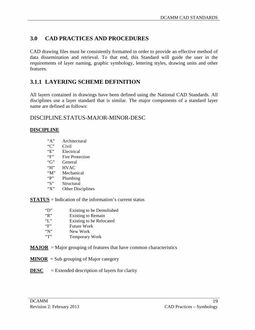
All layers contained in drawings have been defined using the National CAD Standards. All disciplines use a layer standard that is similar. The major components of a standard layer name are defined as follows: DISCIPLINE.STATUS-MAJOR-MINOR-DESC DISCIPLINE
STATUS = Indication of the information’s current status
“D” Existing to be Demolished “R” Existing to Remain “L” Existing to be Relocated “F” Future Work “N” New Work “T” Temporary Work
MAJOR = Major grouping of features that have common characteristics
MINOR = Sub grouping of Major category
DESC = Extended description of layers for clarity
“A” Architectural “C” Civil “E” Electrical “F” Fire Protection “G” General “H” HVAC “M” Mechanical “P” Plumbing “S” Structural “X” Other Disciplines
DCAMM CAD STANDARDS
DCAMM 20 Revision 2: February 2013 CAD Practices – Symbology
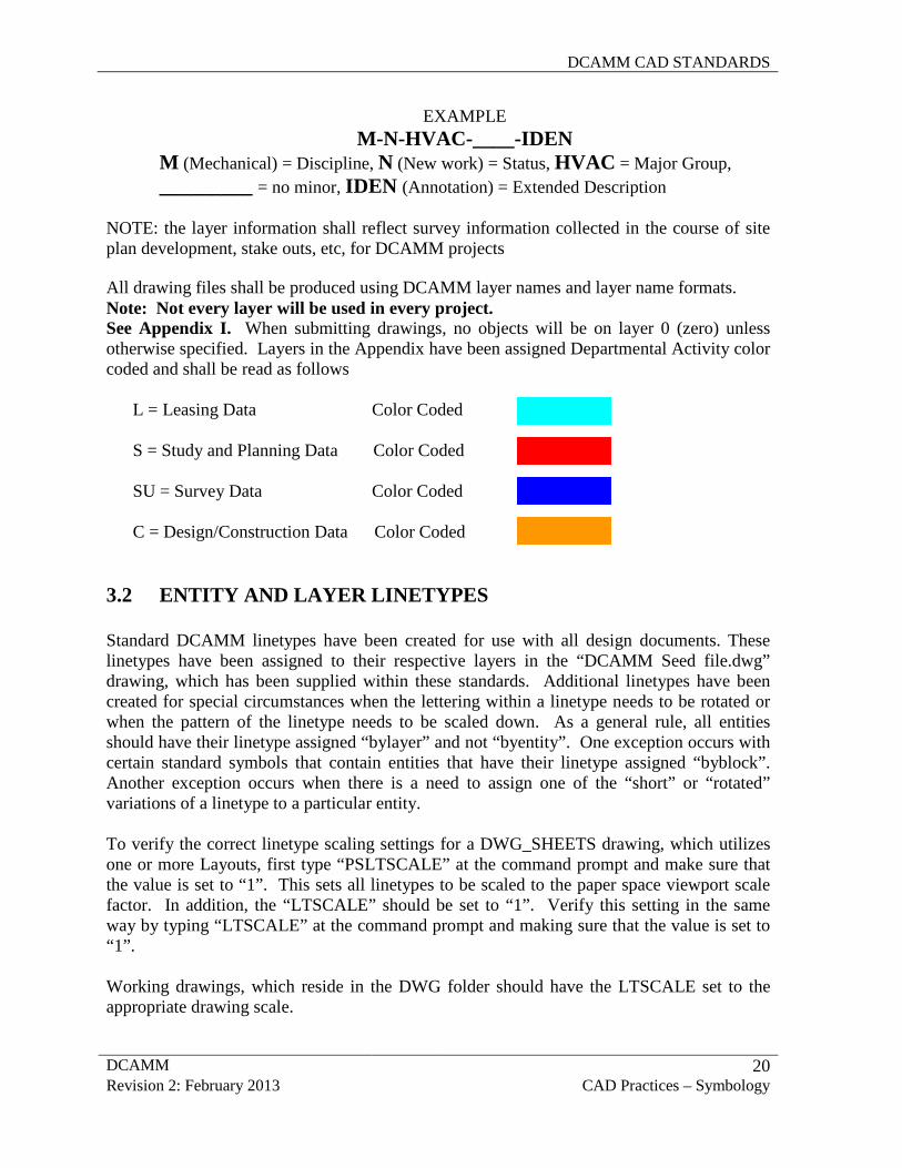
EXAMPLE M-N-HVAC-____-IDEN
M (Mechanical) = Discipline, N (New work) = Status, HVAC = Major Group, _________ = no minor, IDEN (Annotation) = Extended Description
NOTE: the layer information shall reflect survey information collected in the course of site plan development, stake outs, etc, for DCAMM projects
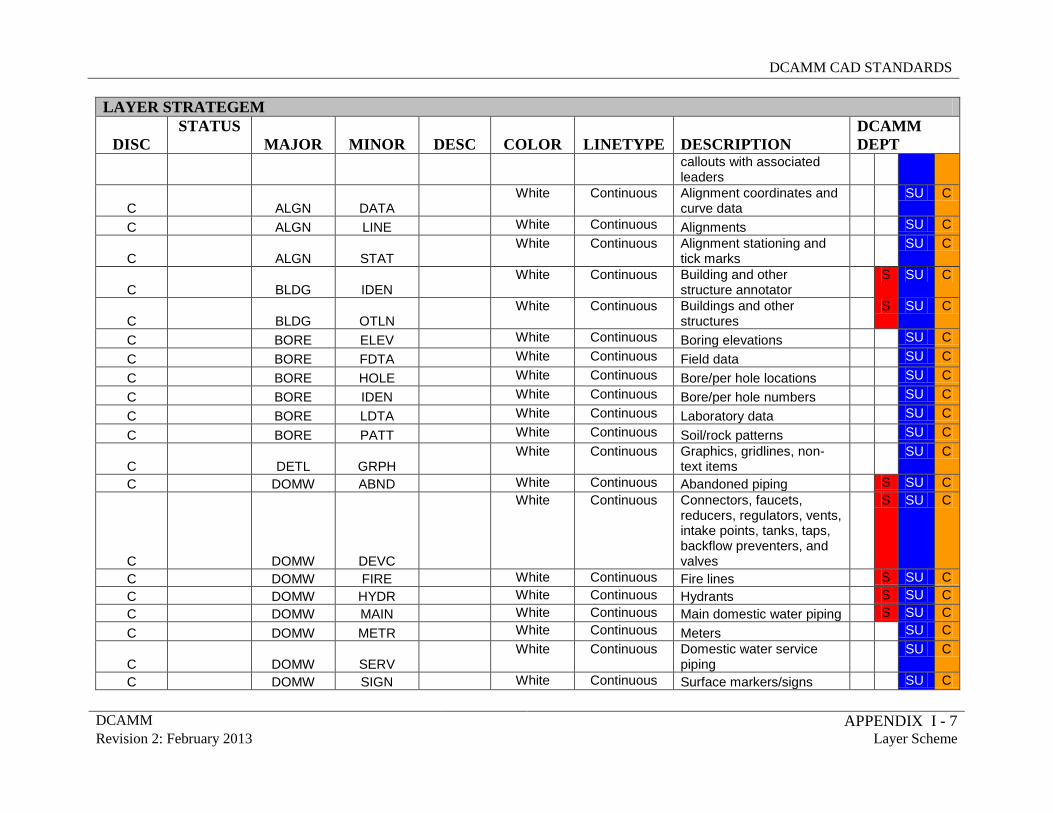
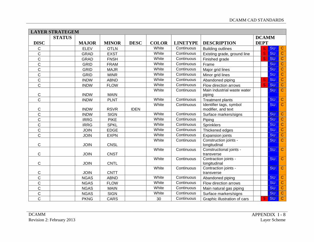
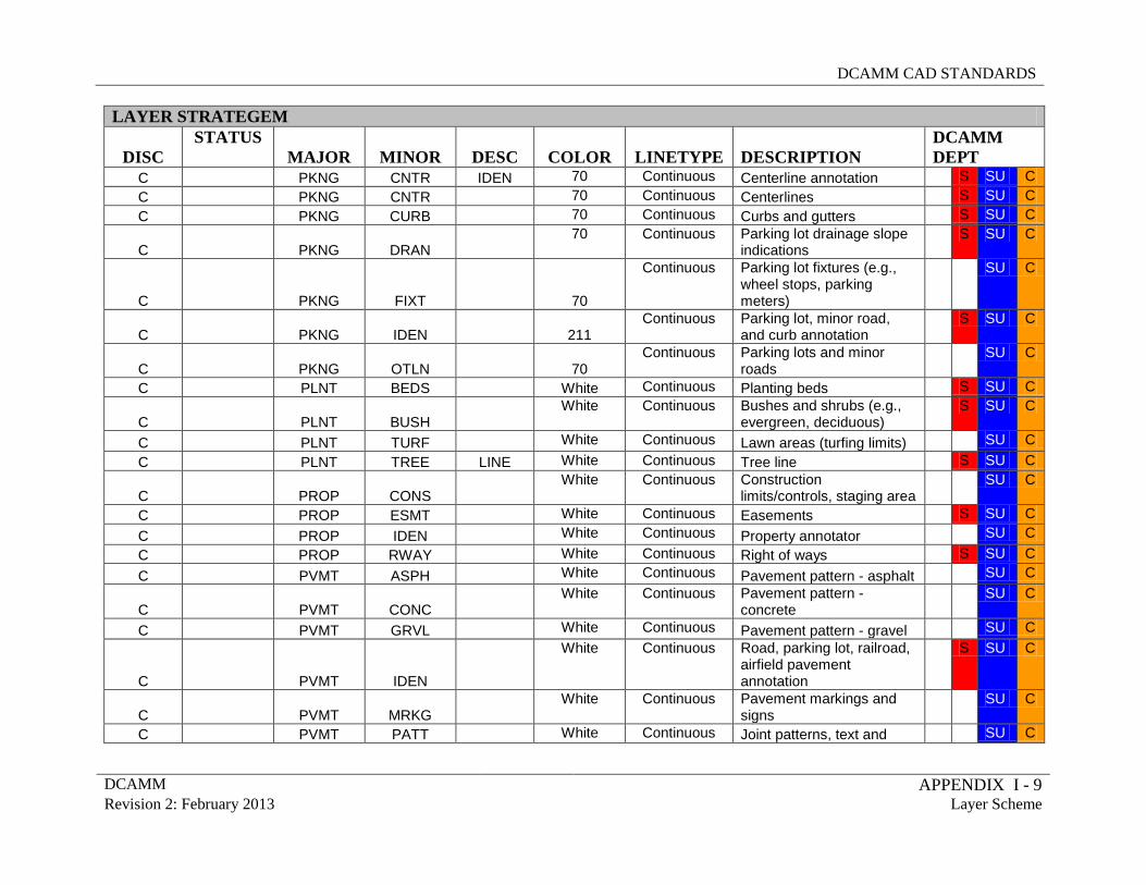
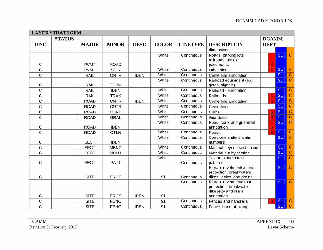
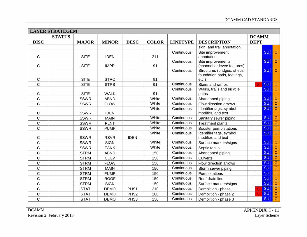
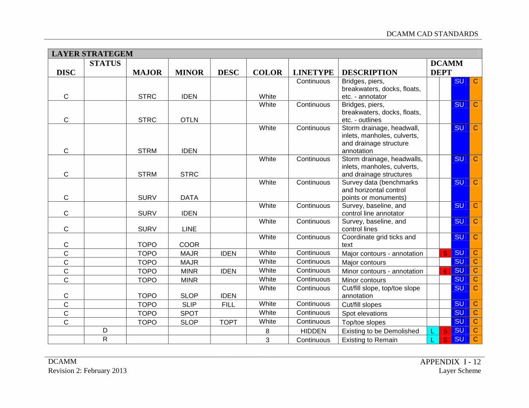
All drawing files shall be produced using DCAMM layer names and layer name formats. Note: Not every layer will be used in every project. See Appendix I. When submitting drawings, no objects will be on layer 0 (zero) unless otherwise specified. Layers in the Appendix have been assigned Departmental Activity color coded and shall be read as follows
L = Leasing Data Color Coded S = Study and Planning Data Color Coded SU = Survey Data Color Coded C = Design/Construction Data Color Coded
3.2 ENTITY AND LAYER LINETYPES Standard DCAMM linetypes have been created for use with all design documents. These linetypes have been assigned to their respective layers in the “DCAMM Seed file.dwg” drawing, which has been supplied within these standards. Additional linetypes have been created for special circumstances when the lettering within a linetype needs to be rotated or when the pattern of the linetype needs to be scaled down. As a general rule, all entities should have their linetype assigned “bylayer” and not “byentity”. One exception occurs with certain standard symbols that contain entities that have their linetype assigned “byblock”. Another exception occurs when there is a need to assign one of the “short” or “rotated” variations of a linetype to a particular entity. To verify the correct linetype scaling settings for a DWG_SHEETS drawing, which utilizes one or more Layouts, first type “PSLTSCALE” at the command prompt and make sure that the value is set to “1”. This sets all linetypes to be scaled to the paper space viewport scale factor. In addition, the “LTSCALE” should be set to “1”. Verify this setting in the same way by typing “LTSCALE” at the command prompt and making sure that the value is set to “1”. Working drawings, which reside in the DWG folder should have the LTSCALE set to the appropriate drawing scale.
DCAMM CAD STANDARDS
DCAMM 21 Revision 2: February 2013 CAD Practices – Symbology
3.3 ENTITY AND LAYER COLORS All entities will be drawn on the specified layers and must have color assigned “by layer” not “by entity”. Layer color assignments are included in the layer definitions provided. 3.4 COORDINATE SYSTEMS
In an effort to organize, consolidate, and standardize the information generated and consumed by all divisions within the agency, Coordinate Systems must be used in all projects. The objective of this requirement is to make the data files easier for users to identify and integrate in planning and design. Survey data for site plans shall be tied to the Massachusetts State Plane Coordinate System and should so indicate. The Designer and/or Responsible Engineer must be capable of delivering survey data in whatever formats are specified by DCAMM: .dwg, shape files, etc.
3.5 SYMBOLOGY A symbol is defined as a prearranged group of geometry that can be inserted, at scale, into a drawing. The AutoCAD term for a symbol by this definition is “block”. There are two types of symbols provided in this standard: Scaleable and Non-Scaleable symbols.
3.5.1 DIGITAL INSERTION OF SCALEABLE SYMBOLS Scaleable: Scaleable symbols are created with the intent that they will appear the same size when plotted at different scales. 1. For ease of use, the insertion scale factor of each scalable symbol will depend on the
output plot scale; Example: If the scale of the viewport is 1:30 (decimal units), then each symbol inserted in the drawing will be scaled up 30x. In the case of a drawing created at 1/8”=1’-0” (architectural units), the symbol will be inserted with a scale of 96x. For architectural units, the drawing scale will be multiplied by 12 based on the fact that architectural units correspond to inches.
2. Symbols are created on Layer “0”, and will automatically take on the characteristics
of the layer they are inserted on. All symbols shall be inserted on the layer identified in this standard.
3.5.2 DIGITAL INSERTION ON NON-SCALEABLE SYMBOLS Non-Scaleable: Non-Scaleable symbols are created with the intent that they will appear true size at all plotting scales.
DCAMM CAD STANDARDS
DCAMM 22 Revision 2: February 2013 CAD Practices – Symbology
1. These symbols will be inserted with a scale of 1.
2. Symbols will be created on Layer “0”, and will take on the characteristics of the layer they are inserted on. All symbols shall be inserted on the layer identified in this standard.
3.5.3 CREATING SYMBOLS
1. Symbols must be documented, and be supplied to the CAD manager or CAD Committee in digital format as a single AutoCAD drawing file along with an accompanying plot of the symbol and the “Request to Change Standards Form” which is contained in Appendix V.
2. Symbols must be created on Layer “0”. Other layers may be present in the drawing for
supplemental information such as text with the symbol. 3. Colors should always be set to “bylayer” and linetypes should be set to “bylayer”
whenever possible. 4. Text within the symbol should be sized appropriately so that it is legible upon plotting. 5. The symbol should be drawn so that the insertion point is located appropriately. After
using the “wblock” command, the resultant drawing file should be edited to have the “base” of the drawing set to 0,0,0. This can be implemented and checked by using the AutoCAD “base” command. The 0,0,0 coordinate in the drawing file should be the location of the insertion point for the block.
6. Symbol drawings should be purged of all unused blocks, linetypes, text styles, delete any
extraneous layer filters and run an audit to find and fix any errors.
DCAMM CAD STANDARDS
DCAMM 23 Revision 2: February 2013 CAD Practices – External References
3.6 PLOTTED LINEWEIGHTS
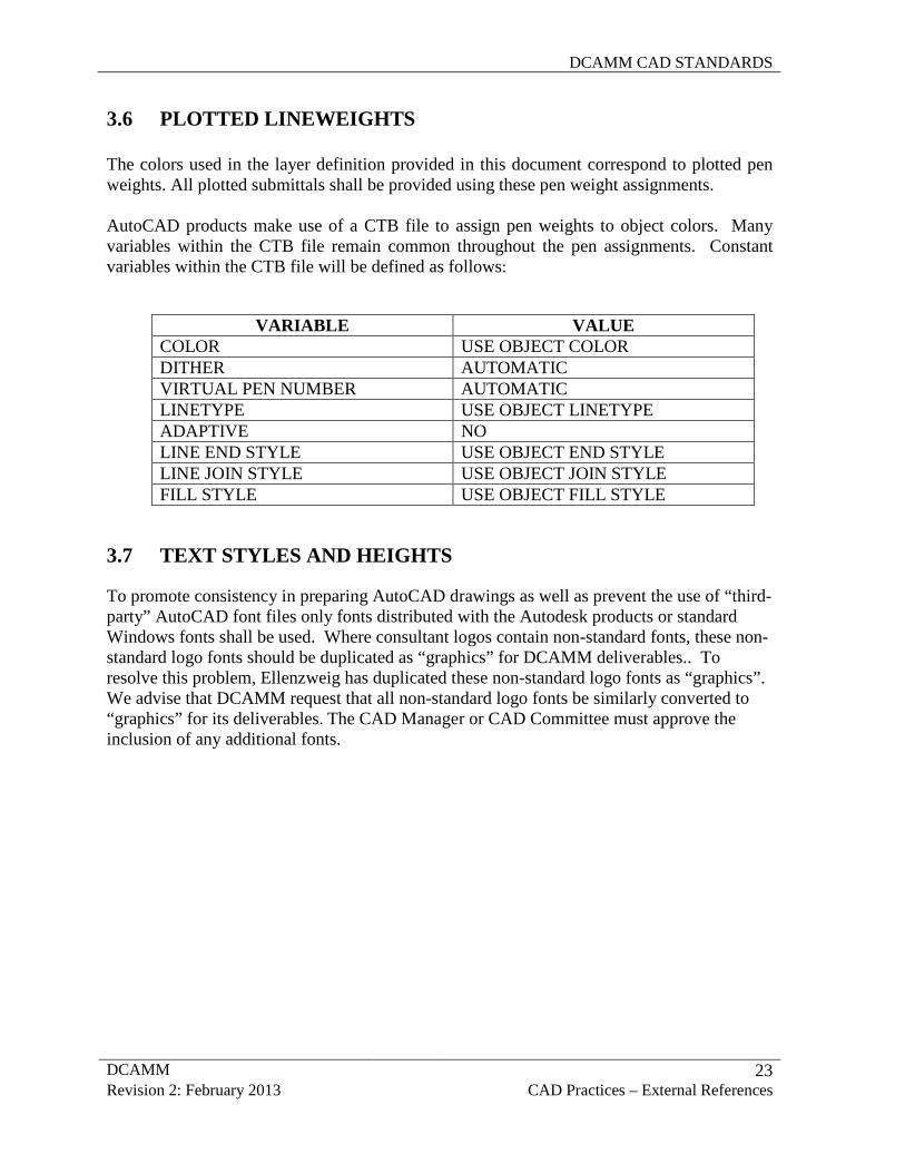
The colors used in the layer definition provided in this document correspond to plotted pen weights. All plotted submittals shall be provided using these pen weight assignments. AutoCAD products make use of a CTB file to assign pen weights to object colors. Many variables within the CTB file remain common throughout the pen assignments. Constant variables within the CTB file will be defined as follows:
VARIABLE VALUE COLOR USE OBJECT COLOR DITHER AUTOMATIC VIRTUAL PEN NUMBER AUTOMATIC LINETYPE USE OBJECT LINETYPE ADAPTIVE NO LINE END STYLE USE OBJECT END STYLE LINE JOIN STYLE USE OBJECT JOIN STYLE FILL STYLE USE OBJECT FILL STYLE
3.7 TEXT STYLES AND HEIGHTS
To promote consistency in preparing AutoCAD drawings as well as prevent the use of “third-party” AutoCAD font files only fonts distributed with the Autodesk products or standard Windows fonts shall be used. Where consultant logos contain non-standard fonts, these non-standard logo fonts should be duplicated as “graphics” for DCAMM deliverables.. To resolve this problem, Ellenzweig has duplicated these non-standard logo fonts as “graphics”. We advise that DCAMM request that all non-standard logo fonts be similarly converted to “graphics” for its deliverables. The CAD Manager or CAD Committee must approve the inclusion of any additional fonts.
DCAMM CAD STANDARDS
DCAMM 24 Revision 2: February 2013 CAD Practices – External References
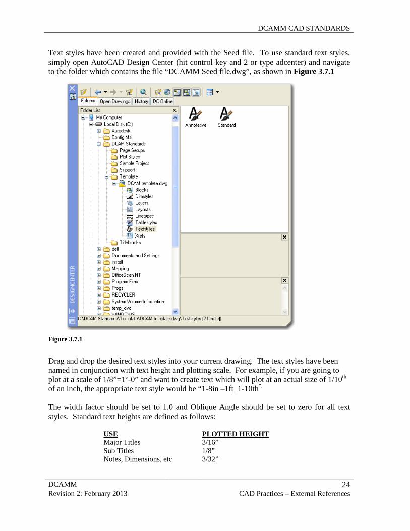
Text styles have been created and provided with the Seed file. To use standard text styles, simply open AutoCAD Design Center (hit control key and 2 or type adcenter) and navigate to the folder which contains the file “DCAMM Seed file.dwg”, as shown in Figure 3.7.1
Figure 3.7.1
Drag and drop the desired text styles into your current drawing. The text styles have been named in conjunction with text height and plotting scale. For example, if you are going to plot at a scale of 1/8”=1’-0” and want to create text which will plot at an actual size of 1/10th of an inch, the appropriate text style would be “1-8in –1ft_1-10th”.
The width factor should be set to 1.0 and Oblique Angle should be set to zero for all text styles. Standard text heights are defined as follows:
USE PLOTTED HEIGHT Major Titles 3/16” Sub Titles 1/8” Notes, Dimensions, etc 3/32”
DCAMM CAD STANDARDS
DCAMM 25 Revision 2: February 2013 CAD Practices – External References
Note: All consultants’ logos have to be created, or edited to match, DCAMM standard fonts. 3.8 DIMENSION STYLES As with the text styles, dimension styles have been provided with this document in an attempt to promote consistency throughout the creation of contract drawings.
The dimension styles are contained in the “DCAMM template.dwt” file and can be dragged and dropped into a current drawing by using AutoCAD’s DesignCenter in the same manner as the text styles (shown in Figure 1.1). Similar to the text styles, the dimension styles have been named in conjunction with the final plotting scale. For example, if you are working at a scale of 1”=16’ select the style “1-16in – 1ft”.
All Dimstyles have been created to use the text style “DIM_Romans”. This font has been defined with the Romans.shx font. The height shall be defined as zero. The height of the dimension text will be a multiple of the DimScale system variable and the final plotted height. The Width Factor shall remain one and the Oblique Angle shall remain zero. In addition all colors should be set to bylayer. All precision settings are open to drawing specific changes.
3.9 EXTERNAL REFERENCE FILES
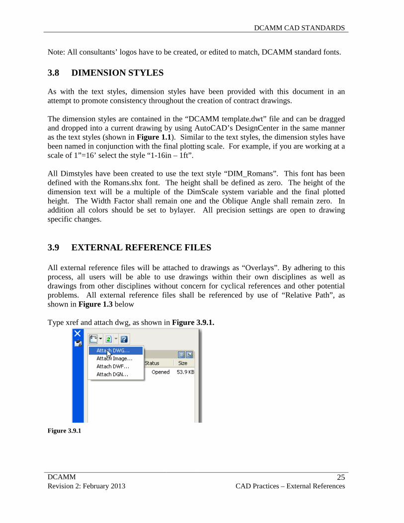
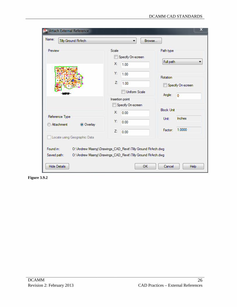
All external reference files will be attached to drawings as “Overlays”. By adhering to this process, all users will be able to use drawings within their own disciplines as well as drawings from other disciplines without concern for cyclical references and other potential problems. All external reference files shall be referenced by use of “Relative Path”, as shown in Figure 1.3 below
Type xref and attach dwg, as shown in Figure 3.9.1.
Figure 3.9.1
DCAMM CAD STANDARDS
DCAMM 26 Revision 2: February 2013 CAD Practices – External References
Figure 3.9.2
DCAMM CAD STANDARDS
DCAMM 27 Revision 2: February 2013 CAD Practices – External References
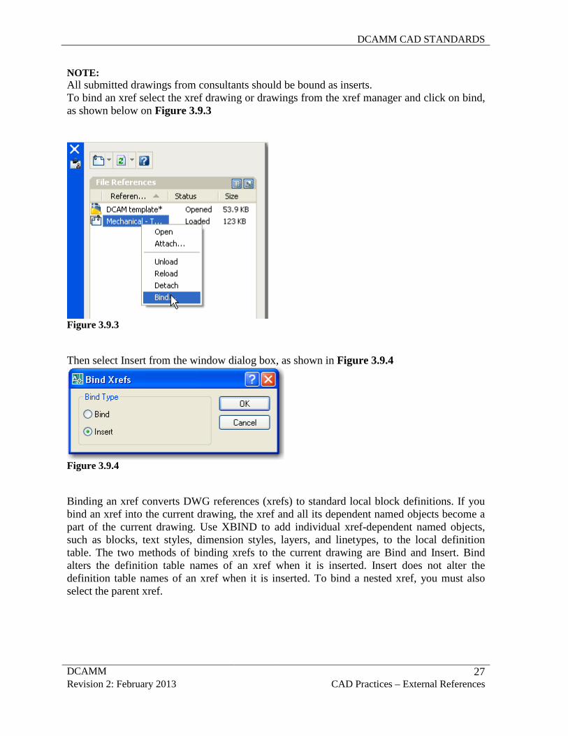
NOTE: All submitted drawings from consultants should be bound as inserts. To bind an xref select the xref drawing or drawings from the xref manager and click on bind, as shown below on Figure 3.9.3
Figure 3.9.3 Then select Insert from the window dialog box, as shown in Figure 3.9.4
Figure 3.9.4 Binding an xref converts DWG references (xrefs) to standard local block definitions. If you bind an xref into the current drawing, the xref and all its dependent named objects become a part of the current drawing. Use XBIND to add individual xref-dependent named objects, such as blocks, text styles, dimension styles, layers, and linetypes, to the local definition table. The two methods of binding xrefs to the current drawing are Bind and Insert. Bind alters the definition table names of an xref when it is inserted. Insert does not alter the definition table names of an xref when it is inserted. To bind a nested xref, you must also select the parent xref.
DCAMM CAD STANDARDS
DCAMM 28 Revision 2: February 2013 CAD Practices – External References
Bind Binds the selected DWG reference to the current drawing. Xref-dependent named objects are changed from blockname|definitionname to blockname$n$definitionname syntax. In this manner, unique named objects are created for all xref-dependent definition tables bound to the current drawing. For example, if you have an xref named FLOOR1 containing a layer named WALL, after binding the xref, the xref-dependent layer FLOOR1|WALL becomes a locally defined layer named FLOOR1$0$WALL. The number in $n$ is automatically incremented if a local named object with the same name already exists. In this example, if FLOOR1$0$WALL already existed in the drawing, the xref-dependent layer FLOOR1|WALL would be renamed FLOOR1$1$WALL. Insert Binds the DWG reference to the current drawing in a way similar to detaching and inserting the reference drawing. Rather than being renamed using blockname$n$definitionname syntax, xref-dependent named objects are stripped of the xref name. As with inserting drawings, no name-incrementing occurs if a local named object shares the same name as a bound xref-dependent named object. The bound xref-dependent named object assumes the properties of the locally defined named object. For example, if you have an xref named FLOOR1 containing a layer named WALL, after binding with the Insert option, the xref-dependent layer FLOOR1|WALL becomes the locally defined layer WALL.
DCAMM CAD STANDARDS
DCAMM 29 Revision 2: February 2013 CAD Practices – Polylines
3.10 POLYLINES
As required per all departments at DCAMM, when creating linework to define objects such as rooms, spaces, contour lines, etc, polylines should be used as well as regular lines. Polylines should be used to represent all programmatic elements, including but not limited to closed spaces, e.g. rooms, circulation areas, building envelope, etc., and be on a separate layer(s) depending upon the facility being designed. These features should also be represented as non polylined line work on their own layer(s).
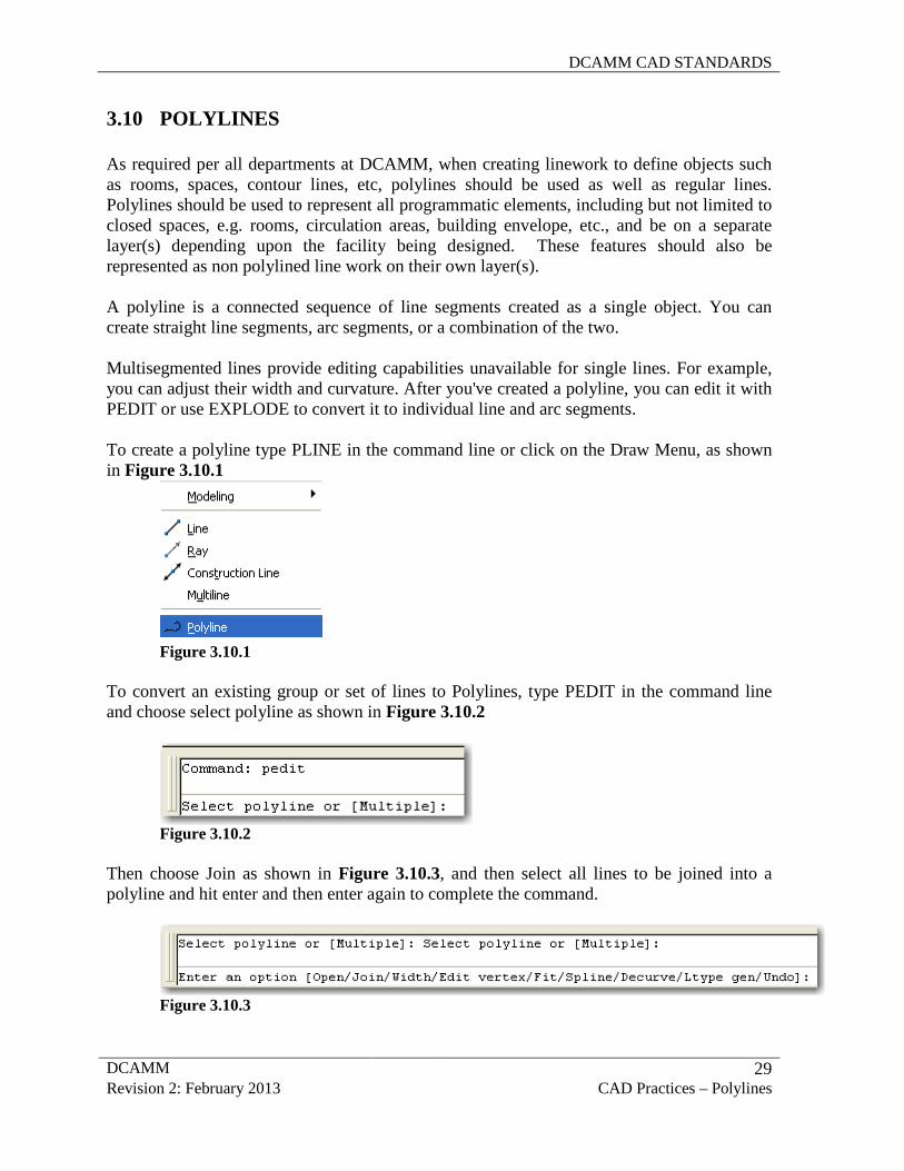
A polyline is a connected sequence of line segments created as a single object. You can create straight line segments, arc segments, or a combination of the two. Multisegmented lines provide editing capabilities unavailable for single lines. For example, you can adjust their width and curvature. After you've created a polyline, you can edit it with PEDIT or use EXPLODE to convert it to individual line and arc segments. To create a polyline type PLINE in the command line or click on the Draw Menu, as shown in Figure 3.10.1
Figure 3.10.1
To convert an existing group or set of lines to Polylines, type PEDIT in the command line and choose select polyline as shown in Figure 3.10.2
Figure 3.10.2
Then choose Join as shown in Figure 3.10.3, and then select all lines to be joined into a polyline and hit enter and then enter again to complete the command.
Figure 3.10.3
DCAMM CAD STANDARDS
DCAMM 30 Revision 2: February 2013 CAD Practices – Polylines
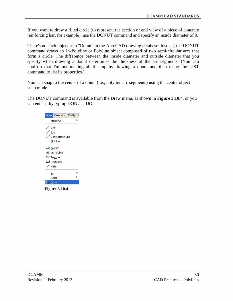
If you want to draw a filled circle (to represent the section or end view of a piece of concrete reinforcing bar, for example), use the DONUT command and specify an inside diameter of 0. There's no such object as a "Donut" in the AutoCAD drawing database. Instead, the DONUT command draws an LwPolyline or Polyline object composed of two semi-circular arcs that form a circle. The difference between the inside diameter and outside diameter that you specify when drawing a donut determines the thickness of the arc segments. (You can confirm that I'm not making all this up by drawing a donut and then using the LIST command to list its properties.)
You can snap to the center of a donut (i.e., polyline arc segments) using the center object snap mode.
The DONUT command is available from the Draw menu, as shown in Figure 3.10.4, or you can enter it by typing DONUT, DO
Figure 3.10.4
DCAMM CAD STANDARDS
DCAMM 31 Revision 2: February 2013 Seed File, Titleblock & Cover Sheet
3.11 DATA EXTRACTION (Area and Information extraction)
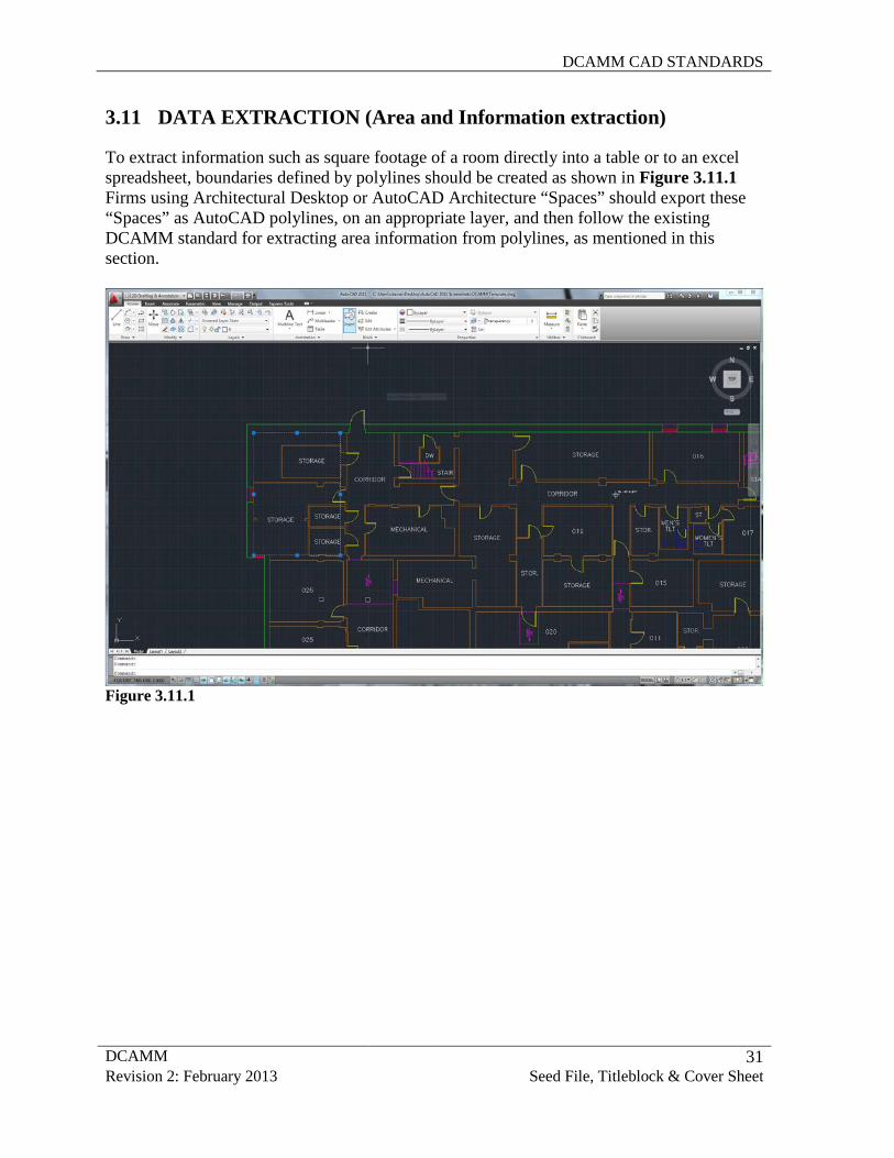
To extract information such as square footage of a room directly into a table or to an excel spreadsheet, boundaries defined by polylines should be created as shown in Figure 3.11.1 Firms using Architectural Desktop or AutoCAD Architecture “Spaces” should export these “Spaces” as AutoCAD polylines, on an appropriate layer, and then follow the existing DCAMM standard for extracting area information from polylines, as mentioned in this section.
Figure 3.11.1
DCAMM CAD STANDARDS
DCAMM 32 Revision 2: February 2013 Seed File, Titleblock & Cover Sheet
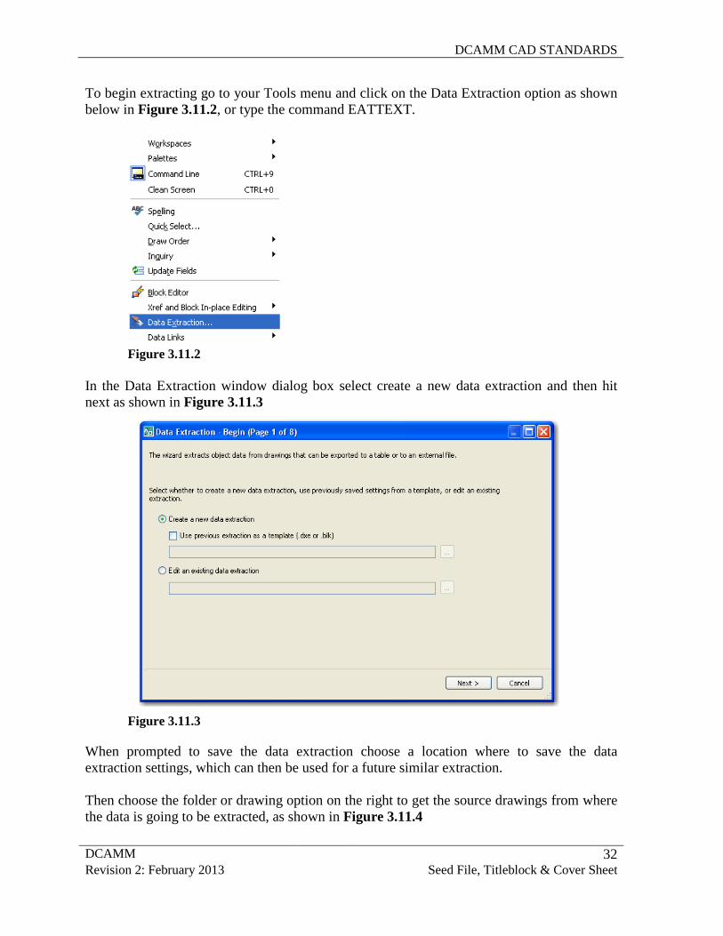
To begin extracting go to your Tools menu and click on the Data Extraction option as shown below in Figure 3.11.2, or type the command EATTEXT.
Figure 3.11.2
In the Data Extraction window dialog box select create a new data extraction and then hit next as shown in Figure 3.11.3
Figure 3.11.3
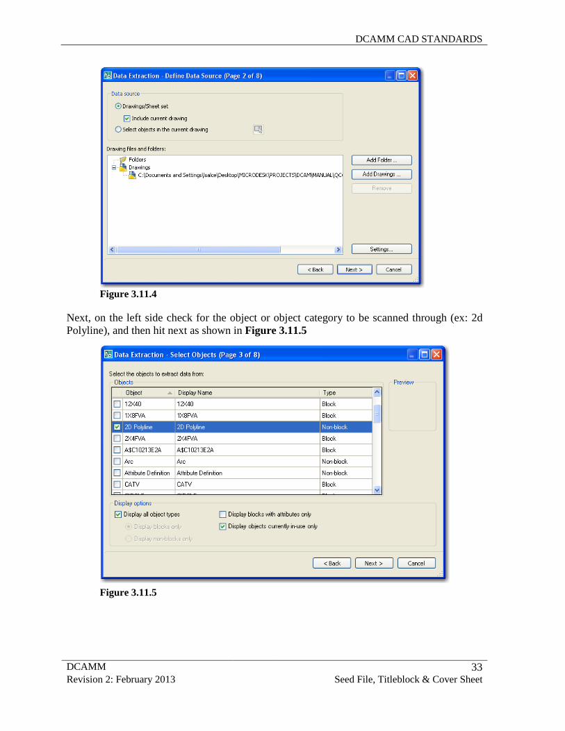
When prompted to save the data extraction choose a location where to save the data extraction settings, which can then be used for a future similar extraction. Then choose the folder or drawing option on the right to get the source drawings from where the data is going to be extracted, as shown in Figure 3.11.4
DCAMM CAD STANDARDS
DCAMM 33 Revision 2: February 2013 Seed File, Titleblock & Cover Sheet
Figure 3.11.4 Next, on the left side check for the object or object category to be scanned through (ex: 2d Polyline), and then hit next as shown in Figure 3.11.5
Figure 3.11.5
DCAMM CAD STANDARDS
DCAMM 34 Revision 2: February 2013 Seed File, Titleblock & Cover Sheet
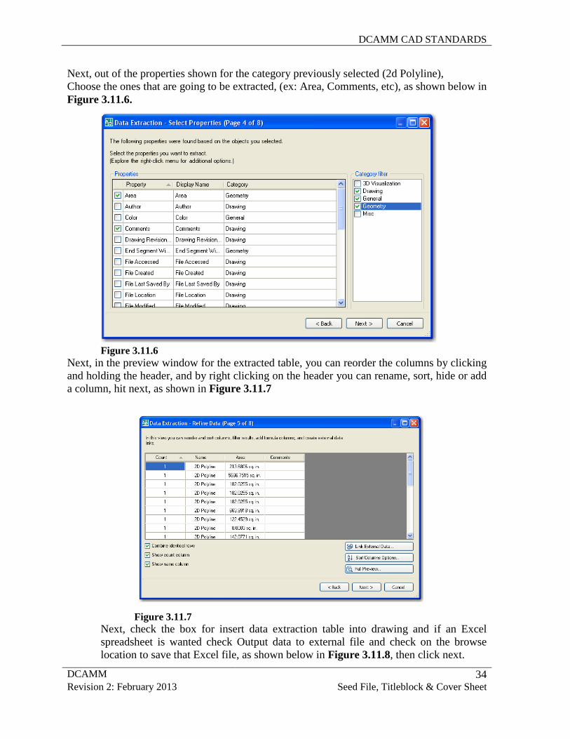
Next, out of the properties shown for the category previously selected (2d Polyline), Choose the ones that are going to be extracted, (ex: Area, Comments, etc), as shown below in Figure 3.11.6.
Figure 3.11.6
Next, in the preview window for the extracted table, you can reorder the columns by clicking and holding the header, and by right clicking on the header you can rename, sort, hide or add a column, hit next, as shown in Figure 3.11.7
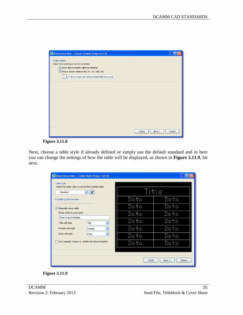
Figure 3.11.7 Next, check the box for insert data extraction table into drawing and if an Excel spreadsheet is wanted check Output data to external file and check on the browse location to save that Excel file, as shown below in Figure 3.11.8, then click next.
DCAMM CAD STANDARDS
DCAMM 35 Revision 2: February 2013 Seed File, Titleblock & Cover Sheet
Figure 3.11.8 Next, choose a table style if already defined or simply use the default standard and in here you can change the settings of how the table will be displayed, as shown in Figure 3.11.9, hit next.
Figure 3.11.9
DCAMM CAD STANDARDS
DCAMM 36 Revision 2: February 2013 Seed File, Titleblock & Cover Sheet
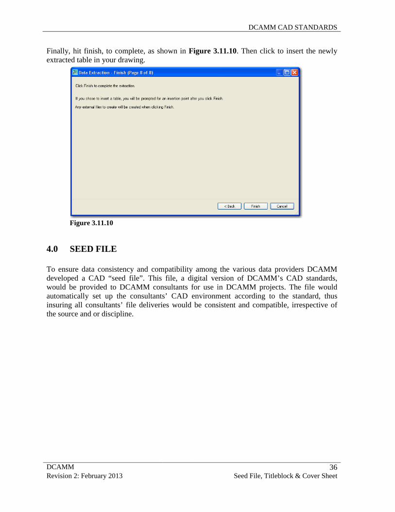
Finally, hit finish, to complete, as shown in Figure 3.11.10. Then click to insert the newly extracted table in your drawing.
Figure 3.11.10
4.0 SEED FILE
To ensure data consistency and compatibility among the various data providers DCAMM developed a CAD “seed file”. This file, a digital version of DCAMM’s CAD standards, would be provided to DCAMM consultants for use in DCAMM projects. The file would automatically set up the consultants’ CAD environment according to the standard, thus insuring all consultants’ file deliveries would be consistent and compatible, irrespective of the source and or discipline.
DCAMM CAD STANDARDS
DCAMM 37 Revision 2: February 2013 Seed File, Titleblock & Cover Sheet
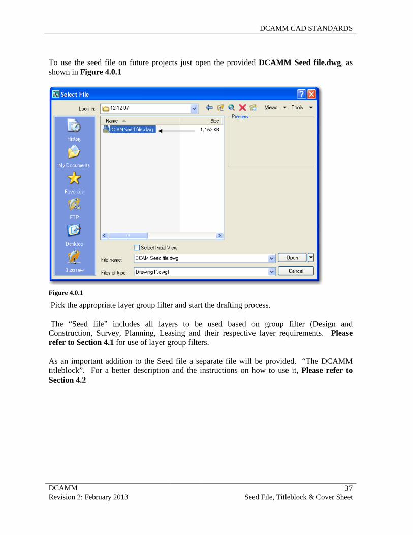
To use the seed file on future projects just open the provided DCAMM Seed file.dwg, as shown in Figure 4.0.1
Figure 4.0.1
Pick the appropriate layer group filter and start the drafting process. The “Seed file” includes all layers to be used based on group filter (Design and Construction, Survey, Planning, Leasing and their respective layer requirements. Please refer to Section 4.1 for use of layer group filters. As an important addition to the Seed file a separate file will be provided. “The DCAMM titleblock”. For a better description and the instructions on how to use it, Please refer to Section 4.2
DCAMM CAD STANDARDS
DCAMM 38 Revision 2: February 2013 Seed File, Titleblock & Cover Sheet
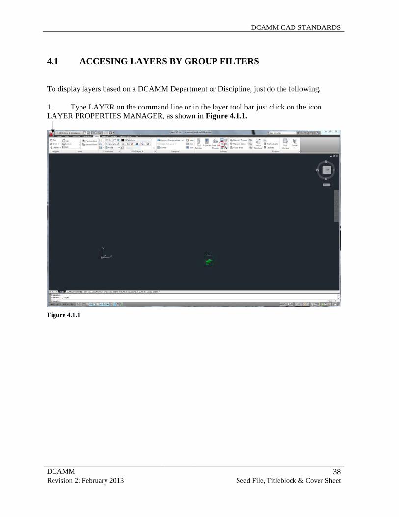
4.1 ACCESING LAYERS BY GROUP FILTERS To display layers based on a DCAMM Department or Discipline, just do the following. 1. Type LAYER on the command line or in the layer tool bar just click on the icon LAYER PROPERTIES MANAGER, as shown in Figure 4.1.1.
Figure 4.1.1
DCAMM CAD STANDARDS
DCAMM 39 Revision 2: February 2013 Seed File, Titleblock & Cover Sheet
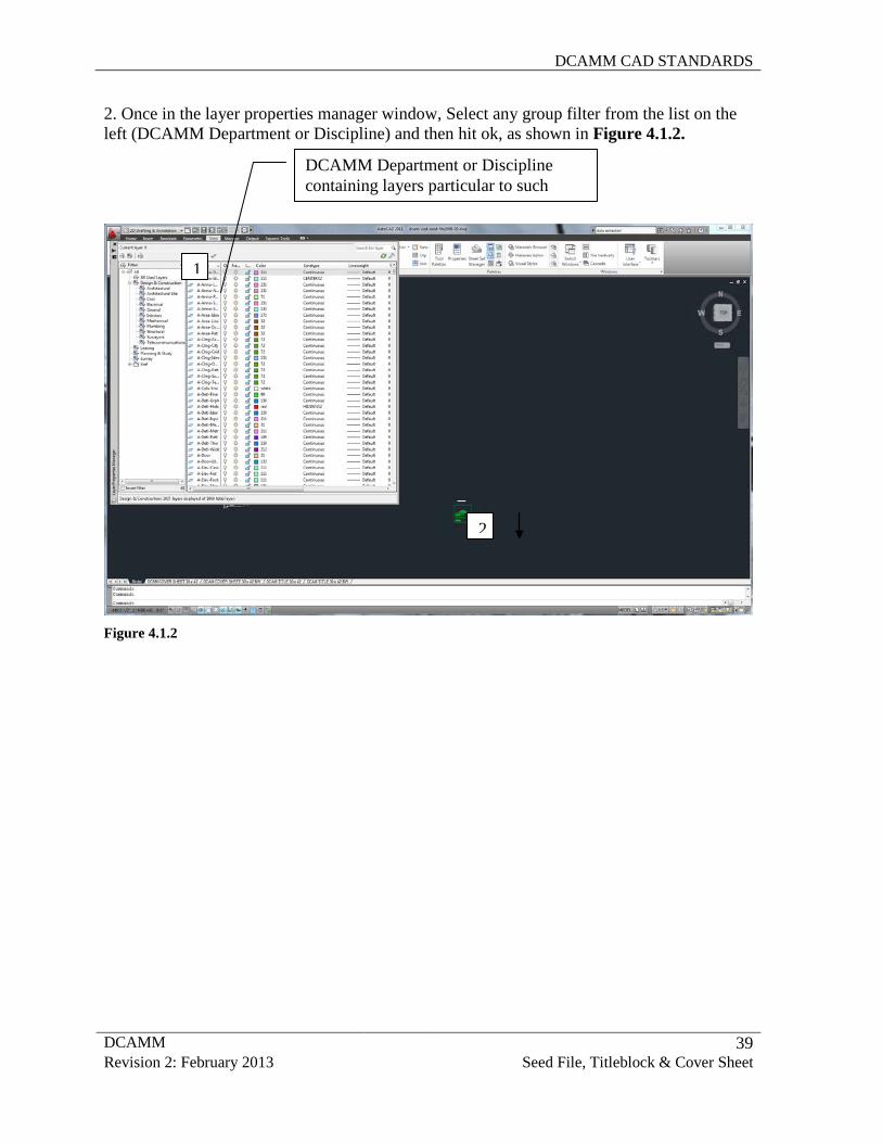
2. Once in the layer properties manager window, Select any group filter from the list on the left (DCAMM Department or Discipline) and then hit ok, as shown in Figure 4.1.2.
Figure 4.1.2
DCAMM Department or Discipline containing layers particular to such
1
2
DCAMM CAD STANDARDS
DCAMM 40 Revision 2: February 2013 Seed File, Titleblock & Cover Sheet
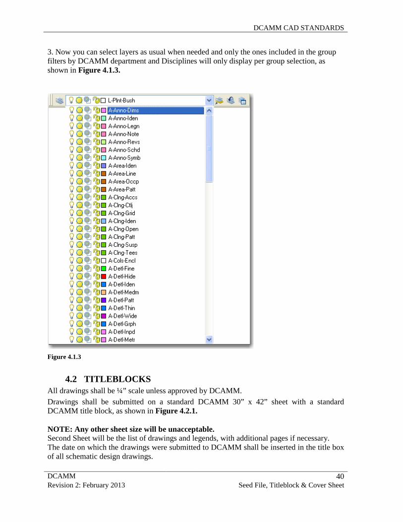
3. Now you can select layers as usual when needed and only the ones included in the group filters by DCAMM department and Disciplines will only display per group selection, as shown in Figure 4.1.3.
Figure 4.1.3
4.2 TITLEBLOCKS
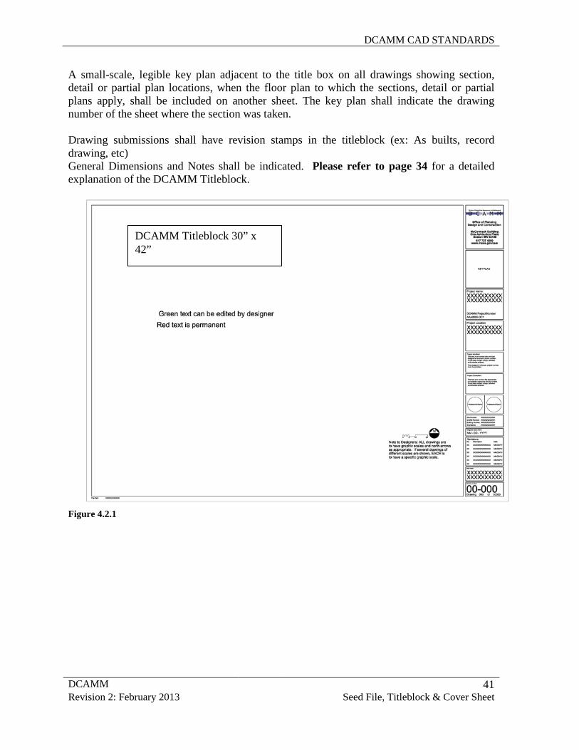
All drawings shall be ¼” scale unless approved by DCAMM. Drawings shall be submitted on a standard DCAMM 30” x 42” sheet with a standard DCAMM title block, as shown in Figure 4.2.1. NOTE: Any other sheet size will be unacceptable. Second Sheet will be the list of drawings and legends, with additional pages if necessary. The date on which the drawings were submitted to DCAMM shall be inserted in the title box of all schematic design drawings.
DCAMM CAD STANDARDS
DCAMM 41 Revision 2: February 2013 Seed File, Titleblock & Cover Sheet
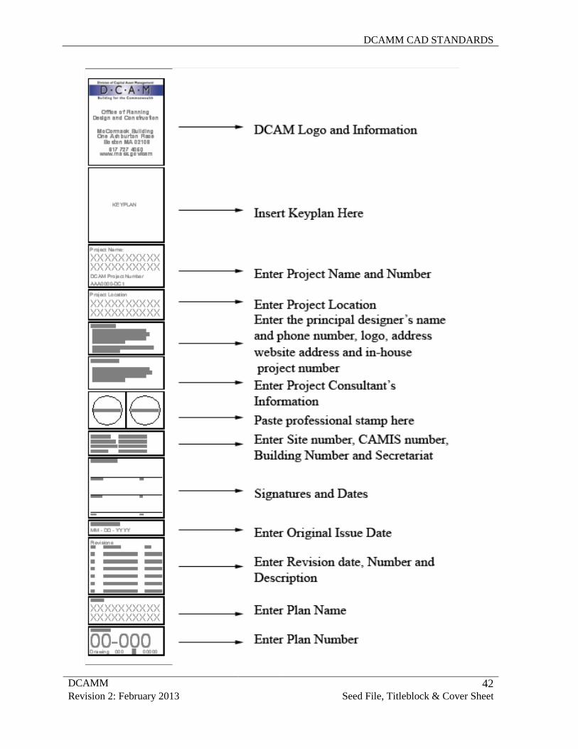
A small-scale, legible key plan adjacent to the title box on all drawings showing section, detail or partial plan locations, when the floor plan to which the sections, detail or partial plans apply, shall be included on another sheet. The key plan shall indicate the drawing number of the sheet where the section was taken. Drawing submissions shall have revision stamps in the titleblock (ex: As builts, record drawing, etc) General Dimensions and Notes shall be indicated. Please refer to page 34 for a detailed explanation of the DCAMM Titleblock.
Figure 4.2.1
DCAMM Titleblock 30” x 42”
DCAMM CAD STANDARDS
DCAMM 42 Revision 2: February 2013 Seed File, Titleblock & Cover Sheet
DCAMM CAD STANDARDS
DCAMM 43 Revision 2: February 2013 Seed File, Titleblock & Cover Sheet
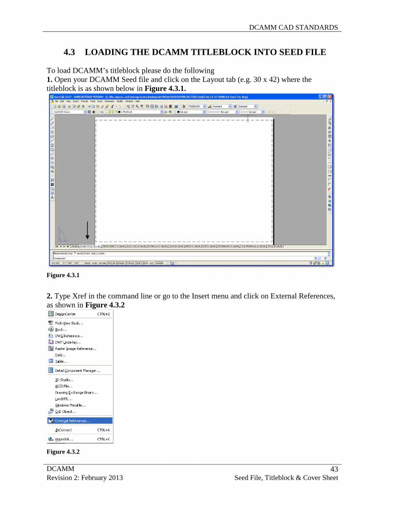
4.3 LOADING THE DCAMM TITLEBLOCK INTO SEED FILE
To load DCAMM’s titleblock please do the following 1. Open your DCAMM Seed file and click on the Layout tab (e.g. 30 x 42) where the titleblock is as shown below in Figure 4.3.1.
Figure 4.3.1
2. Type Xref in the command line or go to the Insert menu and click on External References, as shown in Figure 4.3.2
Figure 4.3.2
DCAMM CAD STANDARDS
DCAMM 44 Revision 2: February 2013 Seed File, Titleblock & Cover Sheet
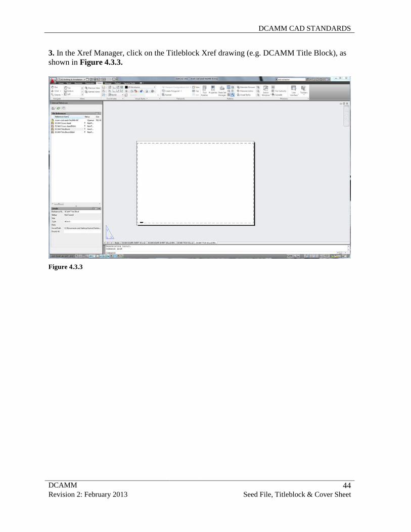
3. In the Xref Manager, click on the Titleblock Xref drawing (e.g. DCAMM Title Block), as shown in Figure 4.3.3.
Figure 4.3.3
DCAMM CAD STANDARDS
DCAMM 45 Revision 2: February 2013 Seed File, Titleblock & Cover Sheet
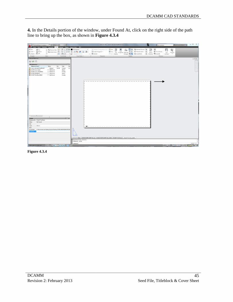
4. In the Details portion of the window, under Found At, click on the right side of the path line to bring up the box, as shown in Figure 4.3.4
Figure 4.3.4
DCAMM CAD STANDARDS
DCAMM 46 Revision 2: February 2013 Seed File, Titleblock & Cover Sheet
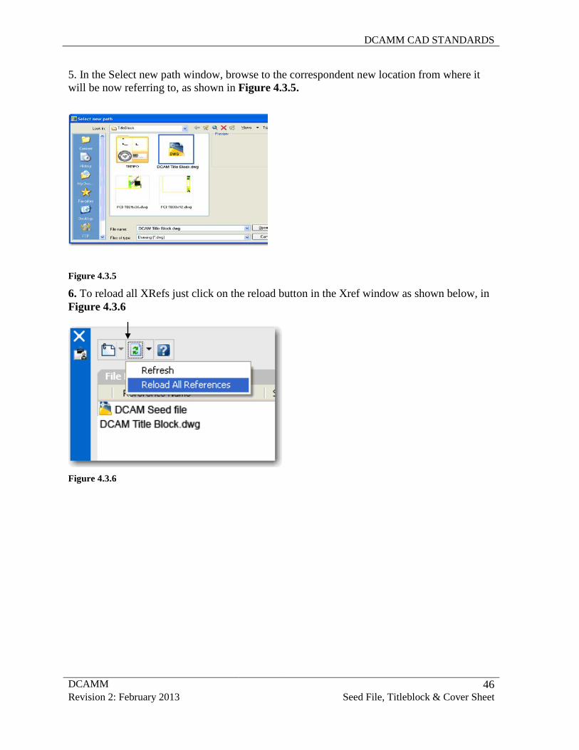
5. In the Select new path window, browse to the correspondent new location from where it will be now referring to, as shown in Figure 4.3.5.
Figure 4.3.5
6. To reload all XRefs just click on the reload button in the Xref window as shown below, in Figure 4.3.6
Figure 4.3.6
DCAMM CAD STANDARDS
DCAMM 47 Revision 2: February 2013 Seed File, Titleblock & Cover Sheet
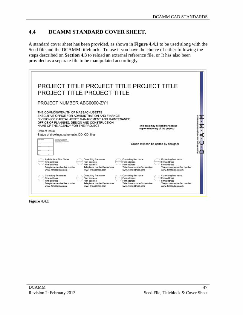
4.4 DCAMM STANDARD COVER SHEET. A standard cover sheet has been provided, as shown in Figure 4.4.1 to be used along with the Seed file and the DCAMM titleblock. To use it you have the choice of either following the steps described on Section 4.3 to reload an external reference file, or It has also been provided as a separate file to be manipulated accordingly.
Figure 4.4.1
DCAMM CAD STANDARDS
DCAMM 48 Revision 2: February 2013 CAD Environment Setup
5.0 CAD PRACTICES AND PROCEDURES In order to plot successfully using this standard, some configuration of the AutoCAD environment will be necessary. This configuration will only need to be done once and will streamline plotting moving forward.
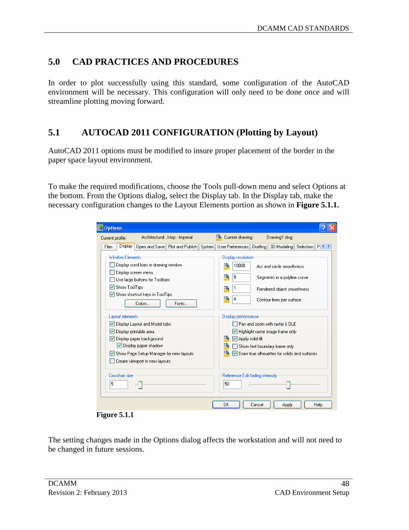
5.1 AUTOCAD 2011 CONFIGURATION (Plotting by Layout) AutoCAD 2011 options must be modified to insure proper placement of the border in the paper space layout environment.
To make the required modifications, choose the Tools pull-down menu and select Options at the bottom. From the Options dialog, select the Display tab. In the Display tab, make the necessary configuration changes to the Layout Elements portion as shown in Figure 5.1.1.
Figure 5.1.1
The setting changes made in the Options dialog affects the workstation and will not need to be changed in future sessions.
DCAMM CAD STANDARDS
DCAMM 49 Revision 2: February 2013 CAD Environment Setup
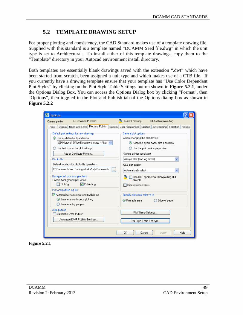
5.2 TEMPLATE DRAWING SETUP For proper plotting and consistency, the CAD Standard makes use of a template drawing file. Supplied with this standard is a template named “DCAMM Seed file.dwg” in which the unit type is set to Architectural. To install either of this template drawings, copy them to the “Template” directory in your Autocad environment install directory.
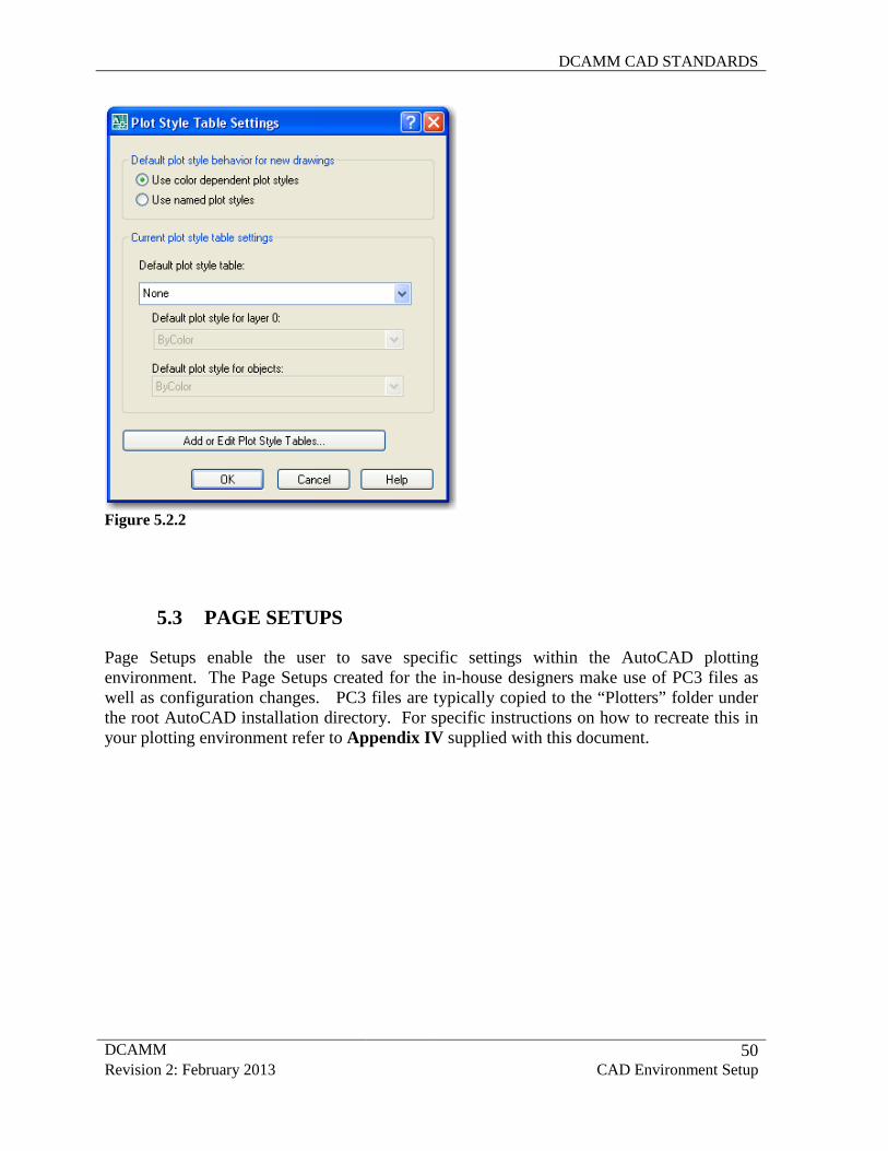
Both templates are essentially blank drawings saved with the extension “.dwt” which have been started from scratch, been assigned a unit type and which makes use of a CTB file. If you currently have a drawing template ensure that your template has “Use Color Dependant Plot Styles” by clicking on the Plot Style Table Settings button shown in Figure 5.2.1, under the Options Dialog Box. You can access the Options Dialog box by clicking “Format”, then “Options”, then toggled in the Plot and Publish tab of the Options dialog box as shown in Figure 5.2.2
Figure 5.2.1
DCAMM CAD STANDARDS
DCAMM 50 Revision 2: February 2013 CAD Environment Setup
Figure 5.2.2
5.3 PAGE SETUPS
Page Setups enable the user to save specific settings within the AutoCAD plotting environment. The Page Setups created for the in-house designers make use of PC3 files as well as configuration changes. PC3 files are typically copied to the “Plotters” folder under the root AutoCAD installation directory. For specific instructions on how to recreate this in your plotting environment refer to Appendix IV supplied with this document.
DCAMM CAD STANDARDS
DCAMM 50 Revision 2: February 2013 CAD Environment Setup
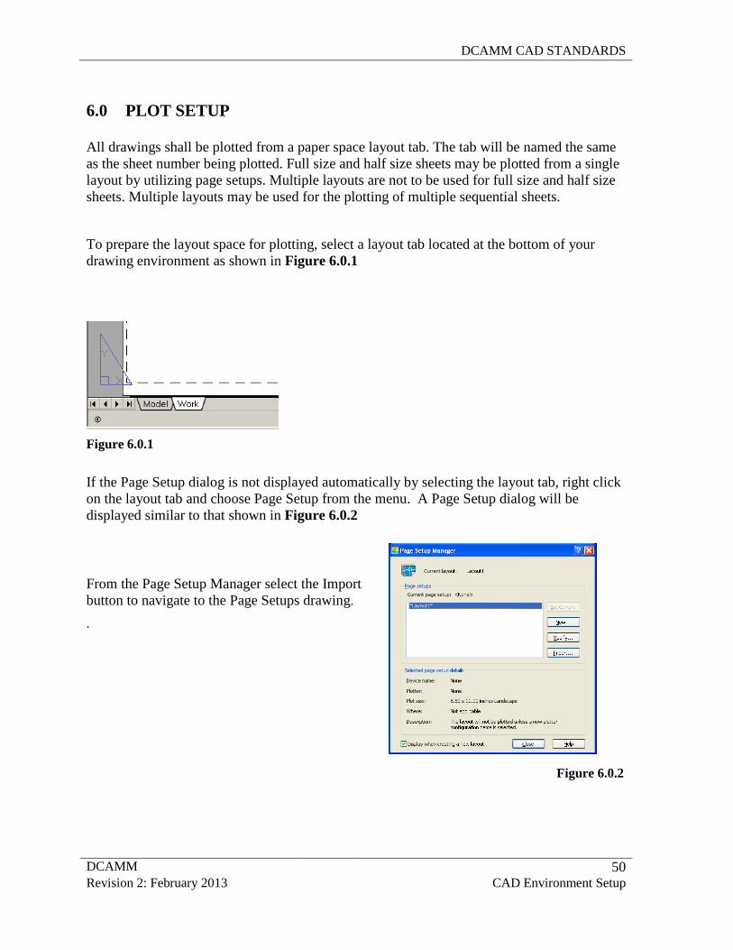
6.0 PLOT SETUP All drawings shall be plotted from a paper space layout tab. The tab will be named the same as the sheet number being plotted. Full size and half size sheets may be plotted from a single layout by utilizing page setups. Multiple layouts are not to be used for full size and half size sheets. Multiple layouts may be used for the plotting of multiple sequential sheets.
To prepare the layout space for plotting, select a layout tab located at the bottom of your drawing environment as shown in Figure 6.0.1
Figure 6.0.1
If the Page Setup dialog is not displayed automatically by selecting the layout tab, right click on the layout tab and choose Page Setup from the menu. A Page Setup dialog will be displayed similar to that shown in Figure 6.0.2
From the Page Setup Manager select the Import button to navigate to the Page Setups drawing.
.
Figure 6.0.2
DCAMM CAD STANDARDS
DCAMM 51 Revision 2: February 2013 CAD Environment Setup
Figure 6.0.5
Figure 6.0.4
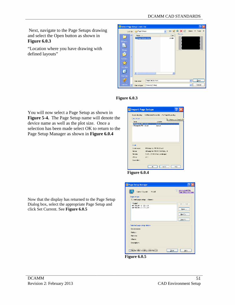
Next, navigate to the Page Setups drawing and select the Open button as shown in Figure 6.0.3 “Location where you have drawing with defined layouts”
Figure 6.0.3
You will now select a Page Setup as shown in Figure 5-4. The Page Setup name will denote the device name as well as the plot size. Once a selection has been made select OK to return to the Page Setup Manager as shown in Figure 6.0.4
Now that the display has returned to the Page Setup Dialog box, select the appropriate Page Setup and click Set Current. See Figure 6.0.5
DCAMM CAD STANDARDS
DCAMM 52 Revision 2: February 2013 CAD Environment Setup
7.0 DISTRIBUTION FILES Associated with this document are several support files, which contain the settings and standards, described in this document. Internally all workstations have been configured to access these files.
8.0 UPDATE AND REVISION PROCEDURES The dynamic nature of CAD technology and the engineering process dictates that this document will change over time. Changes to this document will be made by following strict procedures and guidelines. Changes may be made based on errors and omissions, as well as to enhance or update the standards based on changes in the CAD environment. All requested changes to this document must be accompanied by a request to change standards form provided in Appendix IV. The request to change standard form must be provided to the CAD Manager or CAD Committee. All requests to change standard forms will be reviewed on a periodic basis. If the change is approved, it will be incorporated into the next version of this document and all support files will be modified. Updates to this document and the related support files will be made as required. 9.0 CONTACT AND SUPPORT INFORMATION Questions regarding the standards provided within this document should be directed to the CAD Manager or CAD Standards Committee. 10.0 CONCLUSION This document is a comprehensive standard for the creation of CAD drawings created or submitted to DCAMM. All drawings submitted must adhere to the conventions documented here.
DCAMM CAD STANDARDS
DCAMM 53 Revision 2: February 2013 CAD Environment Setup
11.0 BIBLIOGRAPHY Designers Procedures Manual Commonwealth of Massachussets Division of Capital Asset Management and Maintenance June 2005 Standard for Digital Plan Submittals to Municipalities (Version 1.0) issued by THE OFFICE OF GEOGRAPHIC AND ENVIRONMENTAL INFORMATION (MASSGIS) January 2006 National CAD Standard Version 3.1 Introduction and Amendments to Industry Publications Published by the National Institute of Building Sciences CAD Layer Guidelines Published by the American Institute of Architects Uniform Drawing System (UDS)—Modules 1–8 Published by the Construction Specifications Institute Tri-Service Plotting Guidelines Published by Tri-Service and the Coast Guard
http://www.nationalcadstandard.org/story_071405.php http://www.nationalcadstandard.org/ http://user.dtcc.edu/~cripps/courses/aet_content/cadinfo/cad_layername.html http://www.csinet.org/s_csi/sec.asp?TRACKID=KEDPCNNEYHB29VLD5CE7BGUB9HFN866G&CID=126&DID=6041
DCAMM CAD STANDARDS
DCAMM APPENDIX I - 1 Revision 2: February 2013 Layer Scheme
APPENDIX I
LAYER SCHEME
DCAMM CAD STANDARDS
DCAMM APPENDIX I - 2 Revision 2: February 2013 Layer Scheme
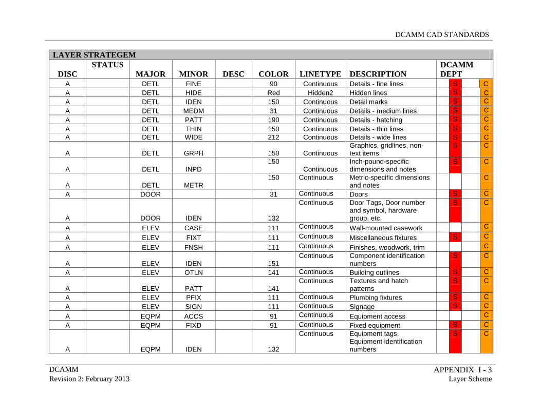
LAYER STRATEGEM
DISC STATUS
MAJOR MINOR DESC COLOR LINETYPE DESCRIPTION DCAMM DEPT
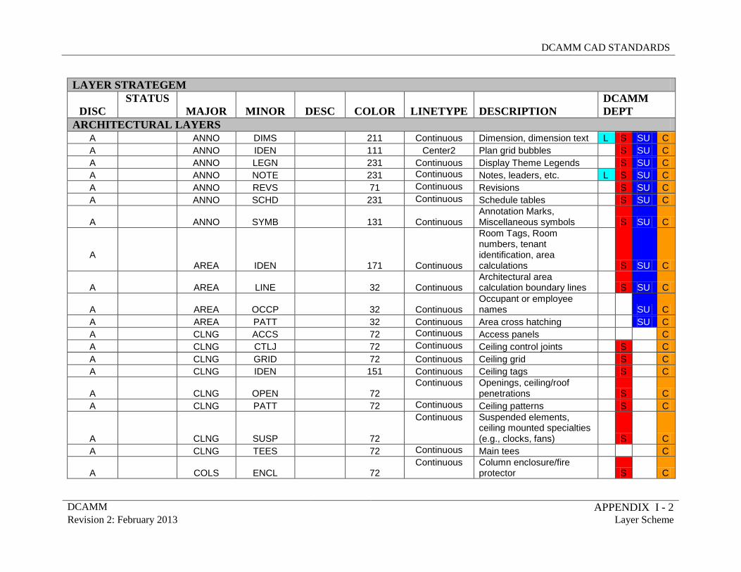
ARCHITECTURAL LAYERS A ANNO DIMS 211 Continuous Dimension, dimension text L S SU C A ANNO IDEN 111 Center2 Plan grid bubbles S SU C A ANNO LEGN 231 Continuous Display Theme Legends S SU C A ANNO NOTE 231 Continuous Notes, leaders, etc. L S SU C A ANNO REVS 71 Continuous Revisions S SU C A ANNO SCHD 231 Continuous Schedule tables S SU C
A ANNO SYMB 131 Continuous Annotation Marks, Miscellaneous symbols S SU C
A AREA IDEN 171 Continuous
Room Tags, Room numbers, tenant identification, area calculations S SU C
A AREA LINE 32 Continuous Architectural area calculation boundary lines S SU C
A AREA OCCP 32 Continuous Occupant or employee names SU C
A AREA PATT 32 Continuous Area cross hatching SU C A CLNG ACCS 72 Continuous Access panels C A CLNG CTLJ 72 Continuous Ceiling control joints S C A CLNG GRID 72 Continuous Ceiling grid S C A CLNG IDEN 151 Continuous Ceiling tags S C
A CLNG OPEN 72 Continuous Openings, ceiling/roof
penetrations S C A CLNG PATT 72 Continuous Ceiling patterns S C
A CLNG SUSP 72
Continuous Suspended elements, ceiling mounted specialties (e.g., clocks, fans) S C
A CLNG TEES 72 Continuous Main tees C
A COLS ENCL 72 Continuous Column enclosure/fire
protector S C
DCAMM CAD STANDARDS
DCAMM APPENDIX I - 3 Revision 2: February 2013 Layer Scheme
LAYER STRATEGEM
DISC STATUS
MAJOR MINOR DESC COLOR LINETYPE DESCRIPTION DCAMM DEPT
A DETL FINE 90 Continuous Details - fine lines S C A DETL HIDE Red Hidden2 Hidden lines S C A DETL IDEN 150 Continuous Detail marks S C A DETL MEDM 31 Continuous Details - medium lines S C A DETL PATT 190 Continuous Details - hatching S C A DETL THIN 150 Continuous Details - thin lines S C A DETL WIDE 212 Continuous Details - wide lines S C
A DETL GRPH 150 Continuous Graphics, gridlines, non-text items
S
C
A DETL INPD 150
Continuous Inch-pound-specific dimensions and notes
S
C
A DETL METR 150 Continuous Metric-specific dimensions
and notes
C
A DOOR 31 Continuous Doors S C
A DOOR IDEN 132
Continuous Door Tags, Door number and symbol, hardware group, etc.
S
C
A ELEV CASE 111 Continuous Wall-mounted casework C A ELEV FIXT 111 Continuous Miscellaneous fixtures S C A ELEV FNSH 111 Continuous Finishes, woodwork, trim C
A ELEV IDEN 151 Continuous Component identification
numbers S
C
A ELEV OTLN 141 Continuous Building outlines S C
A ELEV PATT 141 Continuous Textures and hatch
patterns S
C
A ELEV PFIX 111 Continuous Plumbing fixtures S C A ELEV SIGN 111 Continuous Signage S C A EQPM ACCS 91 Continuous Equipment access C A EQPM FIXD 91 Continuous Fixed equipment S C
A EQPM IDEN 132
Continuous Equipment tags, Equipment identification numbers
S
C
DCAMM CAD STANDARDS
DCAMM APPENDIX I - 4 Revision 2: February 2013 Layer Scheme
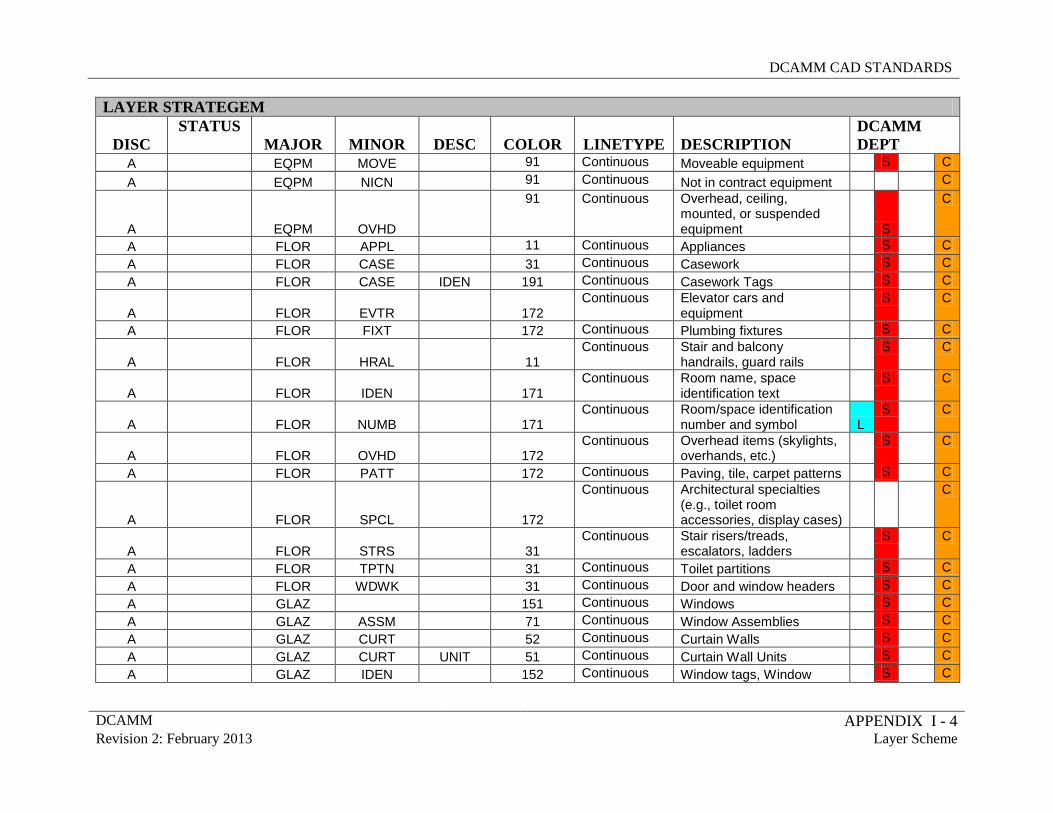
LAYER STRATEGEM
DISC STATUS
MAJOR MINOR DESC COLOR LINETYPE DESCRIPTION DCAMM DEPT
A EQPM MOVE 91 Continuous Moveable equipment S C A EQPM NICN 91 Continuous Not in contract equipment C
A EQPM OVHD
91 Continuous Overhead, ceiling, mounted, or suspended equipment S
C
A FLOR APPL 11 Continuous Appliances S C A FLOR CASE 31 Continuous Casework S C A FLOR CASE IDEN 191 Continuous Casework Tags S C
A FLOR EVTR 172 Continuous Elevator cars and
equipment S
C
A FLOR FIXT 172 Continuous Plumbing fixtures S C
A FLOR HRAL 11 Continuous Stair and balcony
handrails, guard rails S
C
A FLOR IDEN 171 Continuous Room name, space
identification text S
C
A FLOR NUMB 171 Continuous Room/space identification
number and symbol L S
C
A FLOR OVHD 172 Continuous Overhead items (skylights,
overhands, etc.) S
C
A FLOR PATT 172 Continuous Paving, tile, carpet patterns S C
A FLOR SPCL 172
Continuous Architectural specialties (e.g., toilet room accessories, display cases)
C
A FLOR STRS 31 Continuous Stair risers/treads,
escalators, ladders S
C
A FLOR TPTN 31 Continuous Toilet partitions S C A FLOR WDWK 31 Continuous Door and window headers S C A GLAZ 151 Continuous Windows S C A GLAZ ASSM 71 Continuous Window Assemblies S C A GLAZ CURT 52 Continuous Curtain Walls S C A GLAZ CURT UNIT 51 Continuous Curtain Wall Units S C A GLAZ IDEN 152 Continuous Window tags, Window S C
DCAMM CAD STANDARDS
DCAMM APPENDIX I - 5 Revision 2: February 2013 Layer Scheme
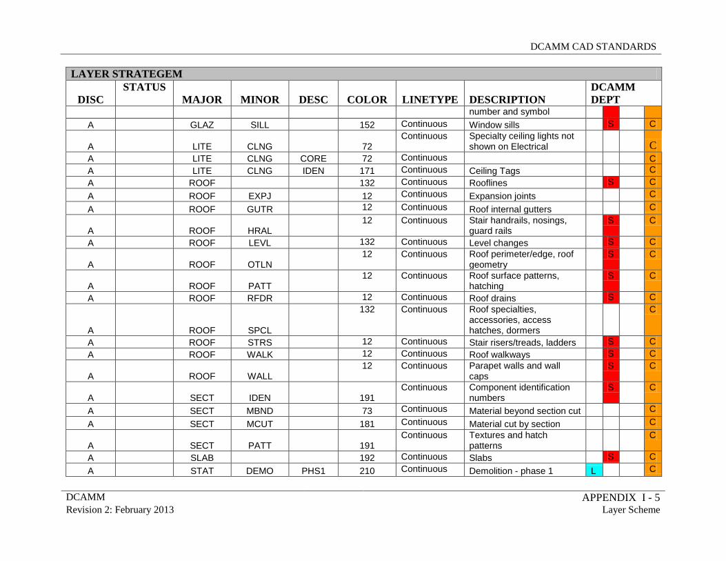
LAYER STRATEGEM
DISC STATUS
MAJOR MINOR DESC COLOR LINETYPE DESCRIPTION DCAMM DEPT
number and symbol A GLAZ SILL 152 Continuous Window sills S C
A LITE CLNG 72 Continuous Specialty ceiling lights not
shown on Electrical C A LITE CLNG CORE 72 Continuous C A LITE CLNG IDEN 171 Continuous Ceiling Tags C A ROOF 132 Continuous Rooflines S C A ROOF EXPJ 12 Continuous Expansion joints C A ROOF GUTR 12 Continuous Roof internal gutters C
A ROOF HRAL 12 Continuous Stair handrails, nosings,
guard rails S
C
A ROOF LEVL 132 Continuous Level changes S C
A ROOF OTLN 12 Continuous Roof perimeter/edge, roof
geometry S
C
A ROOF PATT 12 Continuous Roof surface patterns,
hatching S
C
A ROOF RFDR 12 Continuous Roof drains S C
A ROOF SPCL
132 Continuous Roof specialties, accessories, access hatches, dormers
C
A ROOF STRS 12 Continuous Stair risers/treads, ladders S C A ROOF WALK 12 Continuous Roof walkways S C
A ROOF WALL 12 Continuous Parapet walls and wall
caps S
C
A SECT IDEN 191 Continuous Component identification
numbers S
C
A SECT MBND 73 Continuous Material beyond section cut C A SECT MCUT 181 Continuous Material cut by section C
A SECT PATT 191 Continuous Textures and hatch
patterns
C
A SLAB 192 Continuous Slabs S C A STAT DEMO PHS1 210 Continuous Demolition - phase 1 L C
DCAMM CAD STANDARDS
DCAMM APPENDIX I - 6 Revision 2: February 2013 Layer Scheme
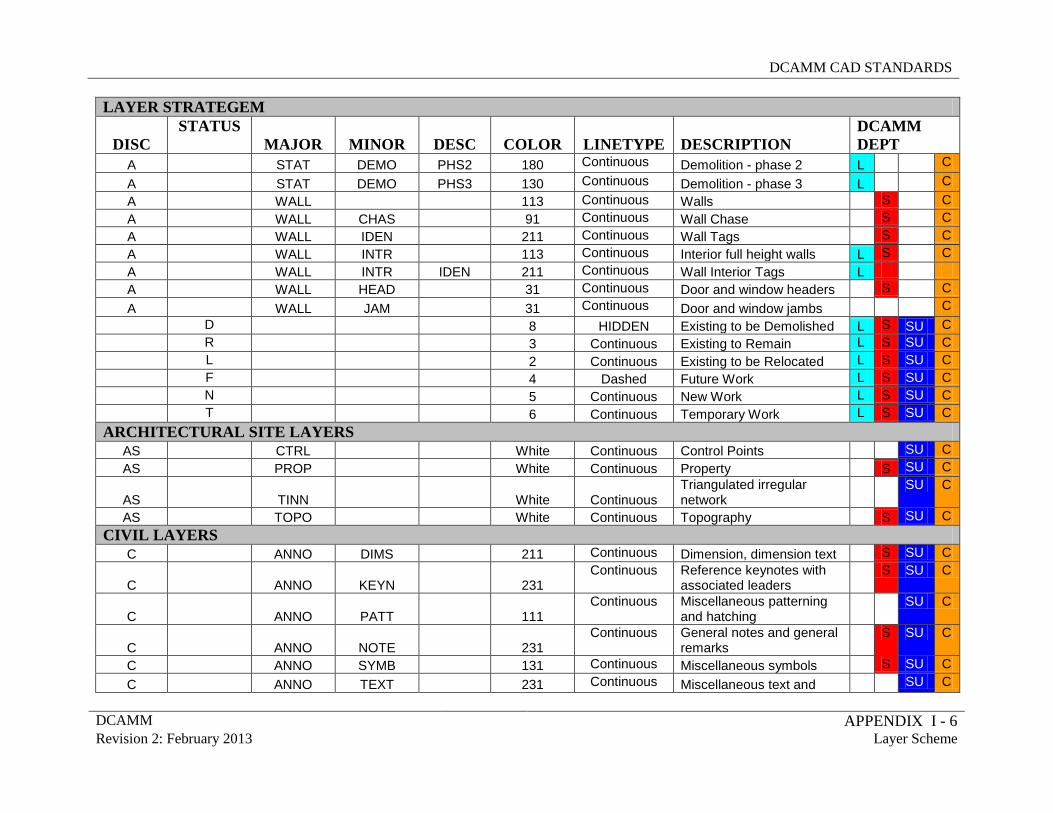
LAYER STRATEGEM
DISC STATUS
MAJOR MINOR DESC COLOR LINETYPE DESCRIPTION DCAMM DEPT
A STAT DEMO PHS2 180 Continuous Demolition - phase 2 L C A STAT DEMO PHS3 130 Continuous Demolition - phase 3 L C A WALL 113 Continuous Walls S C A WALL CHAS 91 Continuous Wall Chase S C A WALL IDEN 211 Continuous Wall Tags S C A WALL INTR 113 Continuous Interior full height walls L S C A WALL INTR IDEN 211 Continuous Wall Interior Tags L A WALL HEAD 31 Continuous Door and window headers S C A WALL JAM 31 Continuous Door and window jambs C D 8 HIDDEN Existing to be Demolished L S SU C R 3 Continuous Existing to Remain L S SU C L 2 Continuous Existing to be Relocated L S SU C F 4 Dashed Future Work L S SU C N 5 Continuous New Work L S SU C T 6 Continuous Temporary Work L S SU C
ARCHITECTURAL SITE LAYERS AS CTRL White Continuous Control Points SU C AS PROP White Continuous Property S SU C
AS TINN White Continuous Triangulated irregular network
SU C
AS TOPO White Continuous Topography S SU C CIVIL LAYERS
C ANNO DIMS 211 Continuous Dimension, dimension text S SU C
C ANNO KEYN 231 Continuous Reference keynotes with
associated leaders S SU C
C ANNO PATT 111 Continuous Miscellaneous patterning
and hatching SU C
C ANNO NOTE 231 Continuous General notes and general
remarks S SU C
C ANNO SYMB 131 Continuous Miscellaneous symbols S SU C C ANNO TEXT 231 Continuous Miscellaneous text and SU C
DCAMM CAD STANDARDS
DCAMM APPENDIX I - 7 Revision 2: February 2013 Layer Scheme
LAYER STRATEGEM
DISC STATUS
MAJOR MINOR DESC COLOR LINETYPE DESCRIPTION DCAMM DEPT
callouts with associated leaders
C ALGN DATA White Continuous Alignment coordinates and
curve data SU C
C ALGN LINE White Continuous Alignments SU C
C ALGN STAT White Continuous Alignment stationing and
tick marks SU C
C BLDG IDEN White Continuous Building and other
structure annotator S SU C
C BLDG OTLN White Continuous Buildings and other
structures S SU C
C BORE ELEV White Continuous Boring elevations SU C C BORE FDTA White Continuous Field data SU C C BORE HOLE White Continuous Bore/per hole locations SU C C BORE IDEN White Continuous Bore/per hole numbers SU C C BORE LDTA White Continuous Laboratory data SU C C BORE PATT White Continuous Soil/rock patterns SU C
C DETL GRPH White Continuous Graphics, gridlines, non-
text items SU C
C DOMW ABND White Continuous Abandoned piping S SU C
C DOMW DEVC
White Continuous Connectors, faucets, reducers, regulators, vents, intake points, tanks, taps, backflow preventers, and valves
S SU C
C DOMW FIRE White Continuous Fire lines S SU C C DOMW HYDR White Continuous Hydrants S SU C C DOMW MAIN White Continuous Main domestic water piping S SU C C DOMW METR White Continuous Meters SU C
C DOMW SERV White Continuous Domestic water service
piping SU C
C DOMW SIGN White Continuous Surface markers/signs SU C
DCAMM CAD STANDARDS
DCAMM APPENDIX I - 8 Revision 2: February 2013 Layer Scheme
LAYER STRATEGEM
DISC STATUS
MAJOR MINOR DESC COLOR LINETYPE DESCRIPTION DCAMM DEPT
C ELEV OTLN White Continuous Building outlines S SU C C GRAD EXST White Continuous Existing grade, ground line S SU C C GRAD FNSH White Continuous Finished grade S SU C C GRID FRAM White Continuous Frame SU C C GRID MAJR White Continuous Major grid lines SU C C GRID MINR White Continuous Minor grid lines SU C C INDW ABND White Continuous Abandoned piping S SU C C INDW FLOW White Continuous Flow direction arrows S SU C
C INDW MAIN White Continuous Main industrial waste water
piping SU C
C INDW PLNT White Continuous Treatment plants SU C
C INDW RSVR IDEN White Continuous Identifier tags, symbol
modifier, and text SU C
C INDW SIGN White Continuous Surface markers/signs SU C C IRRG PIKE White Continuous Piping SU C C IRRG SPKL White Continuous Sprinklers SU C C JOIN EDGE White Continuous Thickened edges SU C C JOIN EXPN White Continuous Expansion joints SU C
C JOIN CNSL White Continuous Construction joints -
longitudinal SU C
C JOIN CNST White Continuous Constructional joints -
transverse SU C
C JOIN CNTL White Continuous Contraction joints -
longitudinal SU C
C JOIN CNTT White Continuous Contraction joints -
transverse SU C
C NGAS ABND White Continuous Abandoned piping SU C C NGAS FLOW White Continuous Flow direction arrows SU C C NGAS MAIN White Continuous Main natural gas piping SU C C NGAS SIGN White Continuous Surface markers/signs SU C C PKNG CARS 30 Continuous Graphic illustration of cars S SU C
DCAMM CAD STANDARDS
DCAMM APPENDIX I - 9 Revision 2: February 2013 Layer Scheme
LAYER STRATEGEM
DISC STATUS
MAJOR MINOR DESC COLOR LINETYPE DESCRIPTION DCAMM DEPT
C PKNG CNTR IDEN 70 Continuous Centerline annotation S SU C C PKNG CNTR 70 Continuous Centerlines S SU C C PKNG CURB 70 Continuous Curbs and gutters S SU C
C PKNG DRAN 70 Continuous Parking lot drainage slope
indications S SU C
C PKNG FIXT 70
Continuous Parking lot fixtures (e.g., wheel stops, parking meters)
SU C
C PKNG IDEN 211 Continuous Parking lot, minor road,
and curb annotation S SU C
C PKNG OTLN 70 Continuous Parking lots and minor
roads SU C
C PLNT BEDS White Continuous Planting beds S SU C
C PLNT BUSH White Continuous Bushes and shrubs (e.g.,
evergreen, deciduous) S SU C
C PLNT TURF White Continuous Lawn areas (turfing limits) SU C C PLNT TREE LINE White Continuous Tree line S SU C
C PROP CONS White Continuous Construction
limits/controls, staging area SU C
C PROP ESMT White Continuous Easements S SU C C PROP IDEN White Continuous Property annotator SU C C PROP RWAY White Continuous Right of ways S SU C C PVMT ASPH White Continuous Pavement pattern - asphalt SU C
C PVMT CONC White Continuous Pavement pattern -
concrete SU C
C PVMT GRVL White Continuous Pavement pattern - gravel SU C
C PVMT IDEN
White Continuous Road, parking lot, railroad, airfield pavement annotation
S SU C
C PVMT MRKG White Continuous Pavement markings and
signs SU C
C PVMT PATT White Continuous Joint patterns, text and SU C
DCAMM CAD STANDARDS
DCAMM APPENDIX I - 10 Revision 2: February 2013 Layer Scheme
LAYER STRATEGEM
DISC STATUS
MAJOR MINOR DESC COLOR LINETYPE DESCRIPTION DCAMM DEPT
dimensions
C PVMT ROAD
White Continuous Roads, parking lots, railroads, airfield pavements S
SU C
C PVMT SIGN White Continuous Other signs S SU C C RAIL CNTR IDEN White Continuous Centerline annotation SU C
C RAIL EQPM White Continuous Railroad equipment (e.g.,
gates, signals) SU C
C RAIL IDEN White Continuous Railroad - annotation SU C C RAIL TRAK White Continuous Railroads S SU C C ROAD CNTR IDEN White Continuous Centerline annotation S SU C C ROAD CNTR White Continuous Centerlines SU C C ROAD CURB White Continuous Curbs S SU C C ROAD GRAL White Continuous Guardrails S SU C
C ROAD IDEN White Continuous Road, curb, and guardrail
annotation S SU C
C ROAD OTLN White Continuous Roads S SU C
C SECT IDEN White Continuous Component identification
numbers SU C
C SECT MBND White Continuous Material beyond section cut SU C C SECT MCUT White Continuous Material but by section SU C
C SECT PATT White
Continuous Textures and hatch patterns
SU C
C SITE EROS 91 Continuous
Riprap, revetments/stone protection, breakwaters, dikes, jetties, and drains
SU C
C SITE EROS IDEN 91
Continuous Riprap, revetment/stone protection, breakwater, dike jetty and drain annotation
SU C
C SITE FENC 91 Continuous Fences and handrails S SU C C SITE FENC IDEN 91 Continuous Fence, handrail, ramp, SU C
DCAMM CAD STANDARDS
DCAMM APPENDIX I - 11 Revision 2: February 2013 Layer Scheme
LAYER STRATEGEM
DISC STATUS
MAJOR MINOR DESC COLOR LINETYPE DESCRIPTION DCAMM DEPT
sign, and trail annotation
C SITE IDEN 211 Continuous Site improvement
annotation SU C
C SITE IMPR 91 Continuous Site improvements
(channel or levee features) SU C
C SITE STRC 91
Continuous Structures (bridges, sheds, foundation pads, footings, etc.)
SU C
C SITE STRS 91 Continuous Stairs and ramps S SU C
C SITE WALK 91 Continuous Walks, trails and bicycle
paths SU C
C SSWR ABND White Continuous Abandoned piping SU C C SSWR FLOW White Continuous Flow direction arrows SU C
C SSWR IDEN White Continuous Identifier tags, symbol
modifier, and text SU C
C SSWR MAIN White Continuous Sanitary sewer piping SU C C SSWR PLNT White Continuous Treatment plants SU C C SSWR PUMP White Continuous Booster pump stations SU C
C SSWR RSVR IDEN White Continuous Identifier tags, symbol
modifier, and text SU C
C SSWR SIGN White Continuous Surface markers/signs SU C C SSWR TANK White Continuous Septic tanks SU C C STRM ABND 150 Continuous Abandoned piping SU C C STRM CULV 150 Continuous Culverts SU C C STRM FLOW 150 Continuous Flow direction arrows SU C C STRM MAIN 150 Continuous Storm sewer piping SU C C STRM PUMP 150 Continuous Pump stations SU C C STRM ROOF 150 Continuous Roof drain line SU C C STRM SIGN 150 Continuous Surface markers/signs SU C C STAT DEMO PHS1 210 Continuous Demolition - phase 1 S SU C C STAT DEMO PHS2 180 Continuous Demolition - phase 2 S SU C C STAT DEMO PHS3 130 Continuous Demolition - phase 3 SU C
DCAMM CAD STANDARDS
DCAMM APPENDIX I - 12 Revision 2: February 2013 Layer Scheme
LAYER STRATEGEM
DISC STATUS
MAJOR MINOR DESC COLOR LINETYPE DESCRIPTION DCAMM DEPT
C STRC IDEN White
Continuous Bridges, piers, breakwaters, docks, floats, etc. - annotator
SU C
C STRC OTLN
White Continuous Bridges, piers, breakwaters, docks, floats, etc. - outlines
SU C
C STRM IDEN
White Continuous Storm drainage, headwall, inlets, manholes, culverts, and drainage structure annotation
SU C
C STRM STRC
White Continuous Storm drainage, headwalls, inlets, manholes, culverts, and drainage structures
SU C
C SURV DATA
White Continuous Survey data (benchmarks and horizontal control points or monuments)
SU C
C SURV IDEN White Continuous Survey, baseline, and
control line annotator SU C
C SURV LINE White Continuous Survey, baseline, and
control lines SU C
C TOPO COOR White Continuous Coordinate grid ticks and
text SU C
C TOPO MAJR IDEN White Continuous Major contours - annotation S SU C C TOPO MAJR White Continuous Major contours SU C C TOPO MINR IDEN White Continuous Minor contours - annotation s SU C C TOPO MINR White Continuous Minor contours SU C
C TOPO SLOP IDEN White Continuous Cut/fill slope, top/toe slope
annotation SU C
C TOPO SLIP FILL White Continuous Cut/fill slopes SU C C TOPO SPOT White Continuous Spot elevations SU C C TOPO SLOP TOPT White Continuous Top/toe slopes SU C D 8 HIDDEN Existing to be Demolished L S SU C R 3 Continuous Existing to Remain L S SU C
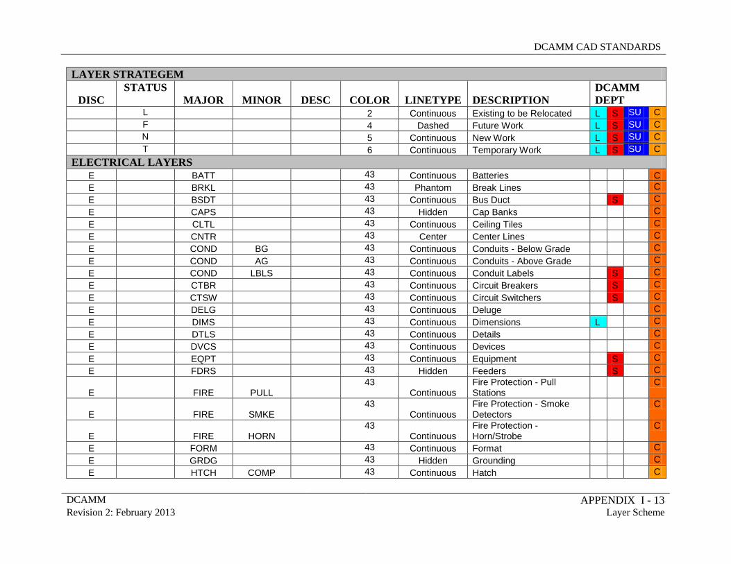
DCAMM CAD STANDARDS
DCAMM APPENDIX I - 13 Revision 2: February 2013 Layer Scheme
LAYER STRATEGEM
DISC STATUS
MAJOR MINOR DESC COLOR LINETYPE DESCRIPTION DCAMM DEPT
L 2 Continuous Existing to be Relocated L S SU C F 4 Dashed Future Work L S SU C N 5 Continuous New Work L S SU C T 6 Continuous Temporary Work L S SU C
ELECTRICAL LAYERS E BATT 43 Continuous Batteries C E BRKL 43 Phantom Break Lines C E BSDT 43 Continuous Bus Duct S C E CAPS 43 Hidden Cap Banks C E CLTL 43 Continuous Ceiling Tiles C E CNTR 43 Center Center Lines C E COND BG 43 Continuous Conduits - Below Grade C E COND AG 43 Continuous Conduits - Above Grade C E COND LBLS 43 Continuous Conduit Labels S C E CTBR 43 Continuous Circuit Breakers S C E CTSW 43 Continuous Circuit Switchers S C E DELG 43 Continuous Deluge C E DIMS 43 Continuous Dimensions L C E DTLS 43 Continuous Details C E DVCS 43 Continuous Devices C E EQPT 43 Continuous Equipment S C E FDRS 43 Hidden Feeders S C
E FIRE PULL 43
Continuous Fire Protection - Pull Stations
C
E FIRE SMKE 43
Continuous Fire Protection - Smoke Detectors
C
E FIRE HORN 43
Continuous Fire Protection - Horn/Strobe
C
E FORM 43 Continuous Format C E GRDG 43 Hidden Grounding C E HTCH COMP 43 Continuous Hatch C
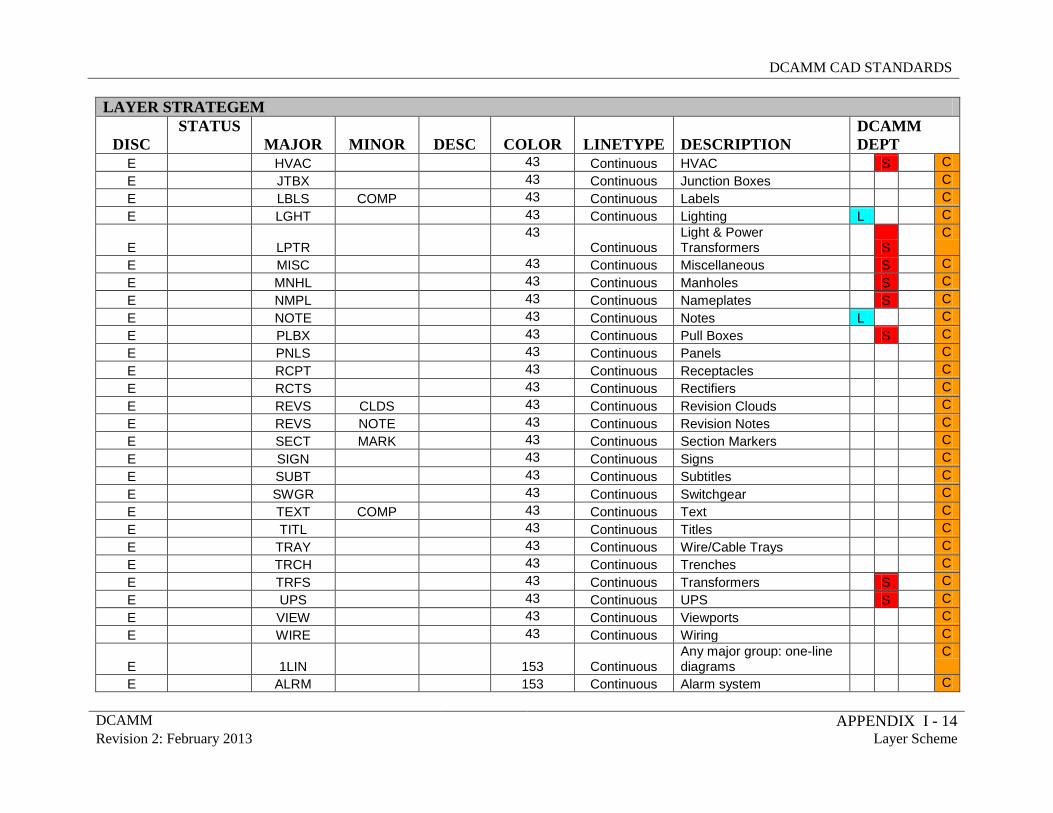
DCAMM CAD STANDARDS
DCAMM APPENDIX I - 14 Revision 2: February 2013 Layer Scheme
LAYER STRATEGEM
DISC STATUS
MAJOR MINOR DESC COLOR LINETYPE DESCRIPTION DCAMM DEPT
E HVAC 43 Continuous HVAC S C E JTBX 43 Continuous Junction Boxes C E LBLS COMP 43 Continuous Labels C E LGHT 43 Continuous Lighting L C
E LPTR 43
Continuous Light & Power Transformers S
C
E MISC 43 Continuous Miscellaneous S C E MNHL 43 Continuous Manholes S C E NMPL 43 Continuous Nameplates S C E NOTE 43 Continuous Notes L C E PLBX 43 Continuous Pull Boxes S C E PNLS 43 Continuous Panels C E RCPT 43 Continuous Receptacles C E RCTS 43 Continuous Rectifiers C E REVS CLDS 43 Continuous Revision Clouds C E REVS NOTE 43 Continuous Revision Notes C E SECT MARK 43 Continuous Section Markers C E SIGN 43 Continuous Signs C E SUBT 43 Continuous Subtitles C E SWGR 43 Continuous Switchgear C E TEXT COMP 43 Continuous Text C E TITL 43 Continuous Titles C E TRAY 43 Continuous Wire/Cable Trays C E TRCH 43 Continuous Trenches C E TRFS 43 Continuous Transformers S C E UPS 43 Continuous UPS S C E VIEW 43 Continuous Viewports C E WIRE 43 Continuous Wiring C
E
1LIN 153 Continuous Any major group: one-line diagrams
C
E ALRM 153 Continuous Alarm system C
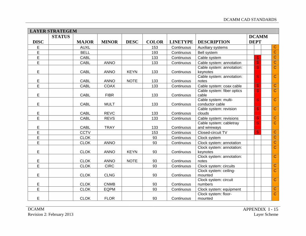
DCAMM CAD STANDARDS
DCAMM APPENDIX I - 15 Revision 2: February 2013 Layer Scheme
LAYER STRATEGEM
DISC STATUS
MAJOR MINOR DESC COLOR LINETYPE DESCRIPTION DCAMM DEPT
E AUXL 153 Continuous Auxiliary systems C E BELL 193 Continuous Bell system C E CABL 133 Continuous Cable system S C E CABL ANNO 133 Continuous Cable system: annotation S C
E
CABL ANNO KEYN 133 Continuous Cable system: annotation: keynotes
S
C
E
CABL ANNO NOTE 133 Continuous Cable system: annotation: notes
S
C
E CABL COAX 133 Continuous Cable system: coax cable S C
E
CABL FIBR 133 Continuous Cable system: fiber optics cable
S
C
E
CABL MULT 133 Continuous Cable system: multi-conductor cable
S
C
E
CABL REVC 133 Continuous Cable system: revision clouds
S
C
E CABL REVS 133 Continuous Cable system: revisions S C
E
CABL TRAY 133 Continuous Cable system: cabletray and wireways
S
C
E CCTV 153 Continuous Closed-circuit TV S C E CLOK 93 Continuous Clock system C E CLOK ANNO 93 Continuous Clock system: annotation C
E
CLOK ANNO KEYN 93 Continuous Clock system: annotation: keynotes
C
E
CLOK ANNO NOTE 93 Continuous Clock system: annotation: notes
C
E CLOK CIRC 93 Continuous Clock system: circuits C
E
CLOK CLNG 93 Continuous Clock system: ceiling-mounted
C
E
CLOK CNMB 93 Continuous Clock system: circuit numbers
C
E CLOK EQPM 93 Continuous Clock system: equipment C
E
CLOK FLOR 93 Continuous Clock system: floor-mounted
C
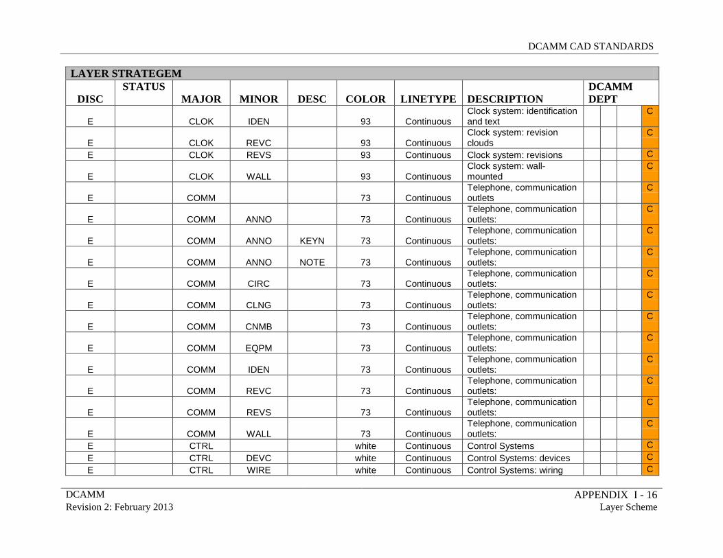
DCAMM CAD STANDARDS
DCAMM APPENDIX I - 16 Revision 2: February 2013 Layer Scheme
LAYER STRATEGEM
DISC STATUS
MAJOR MINOR DESC COLOR LINETYPE DESCRIPTION DCAMM DEPT
E
CLOK IDEN 93 Continuous Clock system: identification and text
C
E
CLOK REVC 93 Continuous Clock system: revision clouds
C
E CLOK REVS 93 Continuous Clock system: revisions C
E
CLOK WALL 93 Continuous Clock system: wall-mounted
C
E
COMM 73 Continuous Telephone, communication outlets
C
E
COMM ANNO 73 Continuous Telephone, communication outlets:
C
E
COMM ANNO KEYN 73 Continuous Telephone, communication outlets:
C
E
COMM ANNO NOTE 73 Continuous Telephone, communication outlets:
C
E
COMM CIRC 73 Continuous Telephone, communication outlets:
C
E
COMM CLNG 73 Continuous Telephone, communication outlets:
C
E
COMM CNMB 73 Continuous Telephone, communication outlets:
C
E
COMM EQPM 73 Continuous Telephone, communication outlets:
C
E
COMM IDEN 73 Continuous Telephone, communication outlets:
C
E
COMM REVC 73 Continuous Telephone, communication outlets:
C
E
COMM REVS 73 Continuous Telephone, communication outlets:
C
E
COMM WALL 73 Continuous Telephone, communication outlets:
C
E CTRL white Continuous Control Systems C E CTRL DEVC white Continuous Control Systems: devices C E CTRL WIRE white Continuous Control Systems: wiring C
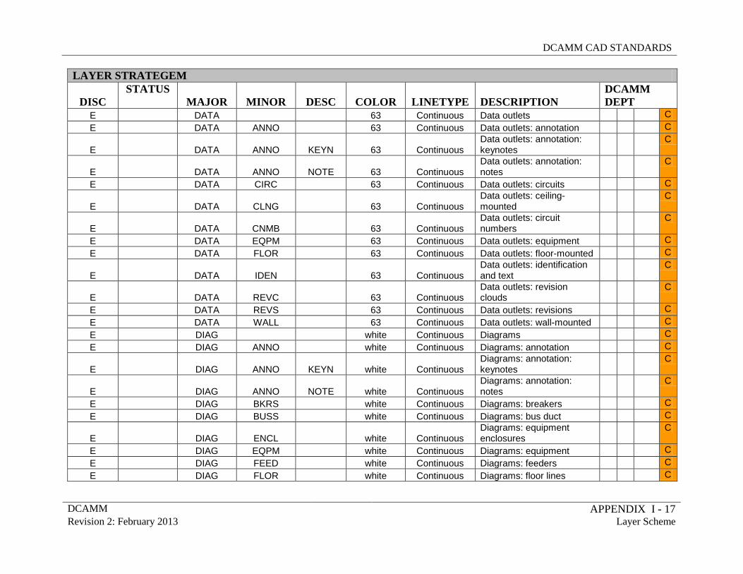
DCAMM CAD STANDARDS
DCAMM APPENDIX I - 17 Revision 2: February 2013 Layer Scheme
LAYER STRATEGEM
DISC STATUS
MAJOR MINOR DESC COLOR LINETYPE DESCRIPTION DCAMM DEPT
E DATA 63 Continuous Data outlets C E DATA ANNO 63 Continuous Data outlets: annotation C
E
DATA ANNO KEYN 63 Continuous Data outlets: annotation: keynotes
C
E
DATA ANNO NOTE 63 Continuous Data outlets: annotation: notes
C
E DATA CIRC 63 Continuous Data outlets: circuits C
E
DATA CLNG 63 Continuous Data outlets: ceiling-mounted
C
E
DATA CNMB 63 Continuous Data outlets: circuit numbers
C
E DATA EQPM 63 Continuous Data outlets: equipment C E DATA FLOR 63 Continuous Data outlets: floor-mounted C
E
DATA IDEN 63 Continuous Data outlets: identification and text
C
E
DATA REVC 63 Continuous Data outlets: revision clouds
C
E DATA REVS 63 Continuous Data outlets: revisions C E DATA WALL 63 Continuous Data outlets: wall-mounted C E DIAG white Continuous Diagrams C E DIAG ANNO white Continuous Diagrams: annotation C
E
DIAG ANNO KEYN white Continuous Diagrams: annotation: keynotes
C
E
DIAG ANNO NOTE white Continuous Diagrams: annotation: notes
C
E DIAG BKRS white Continuous Diagrams: breakers C E DIAG BUSS white Continuous Diagrams: bus duct C
E
DIAG ENCL white Continuous Diagrams: equipment enclosures
C
E DIAG EQPM white Continuous Diagrams: equipment C E DIAG FEED white Continuous Diagrams: feeders C E DIAG FLOR white Continuous Diagrams: floor lines C
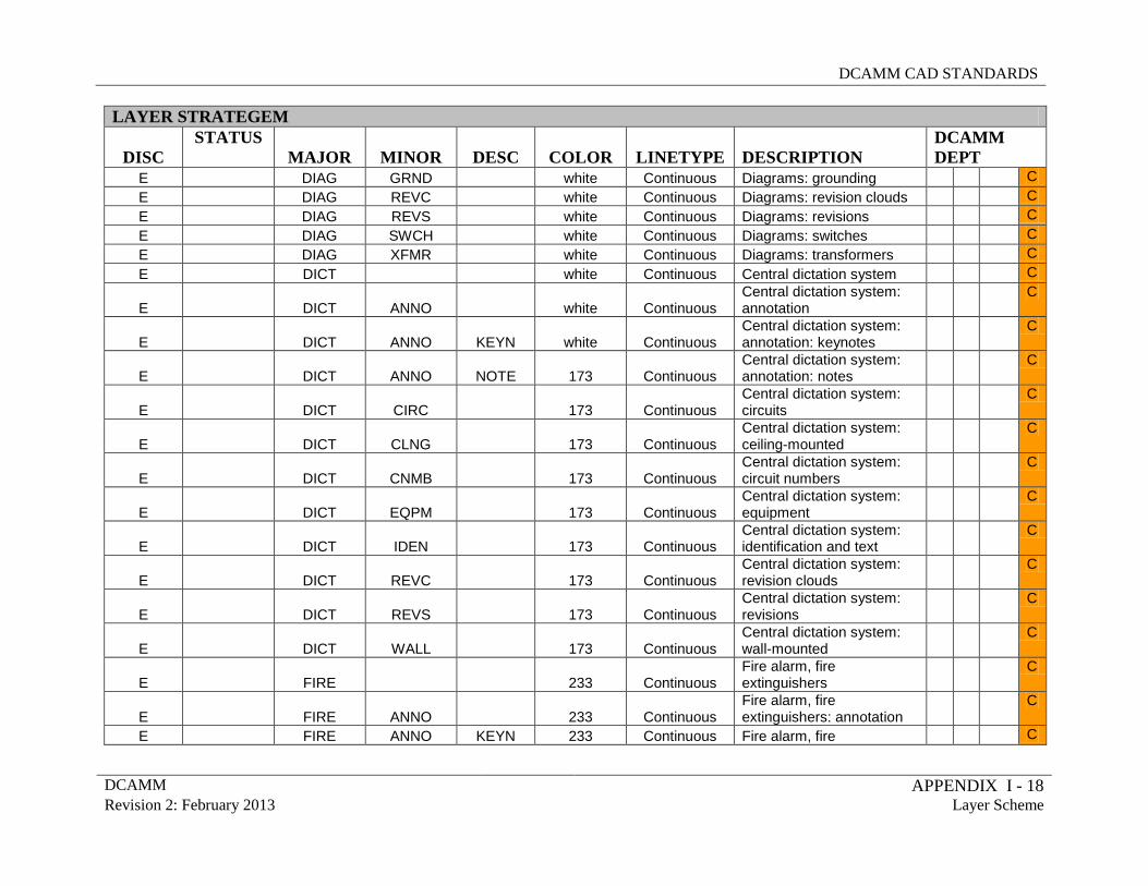
DCAMM CAD STANDARDS
DCAMM APPENDIX I - 18 Revision 2: February 2013 Layer Scheme
LAYER STRATEGEM
DISC STATUS
MAJOR MINOR DESC COLOR LINETYPE DESCRIPTION DCAMM DEPT
E DIAG GRND white Continuous Diagrams: grounding C E DIAG REVC white Continuous Diagrams: revision clouds C E DIAG REVS white Continuous Diagrams: revisions C E DIAG SWCH white Continuous Diagrams: switches C E DIAG XFMR white Continuous Diagrams: transformers C E DICT white Continuous Central dictation system C
E
DICT ANNO white Continuous Central dictation system: annotation
C
E
DICT ANNO KEYN white Continuous Central dictation system: annotation: keynotes
C
E
DICT ANNO NOTE 173 Continuous Central dictation system: annotation: notes
C
E
DICT CIRC 173 Continuous Central dictation system: circuits
C
E
DICT CLNG 173 Continuous Central dictation system: ceiling-mounted
C
E
DICT CNMB 173 Continuous Central dictation system: circuit numbers
C
E
DICT EQPM 173 Continuous Central dictation system: equipment
C
E
DICT IDEN 173 Continuous Central dictation system: identification and text
C
E
DICT REVC 173 Continuous Central dictation system: revision clouds
C
E
DICT REVS 173 Continuous Central dictation system: revisions
C
E
DICT WALL 173 Continuous Central dictation system: wall-mounted
C
E
FIRE 233 Continuous Fire alarm, fire extinguishers
C
E
FIRE ANNO 233 Continuous Fire alarm, fire extinguishers: annotation
C
E FIRE ANNO KEYN 233 Continuous Fire alarm, fire C
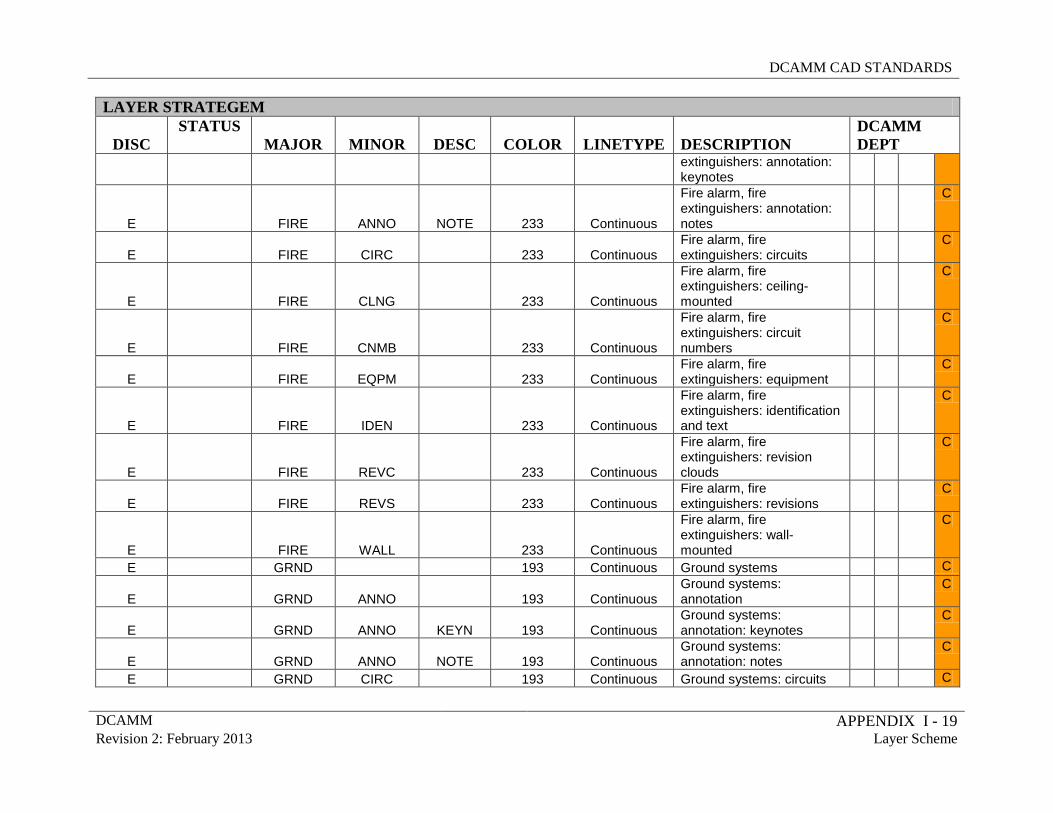
DCAMM CAD STANDARDS
DCAMM APPENDIX I - 19 Revision 2: February 2013 Layer Scheme
LAYER STRATEGEM
DISC STATUS
MAJOR MINOR DESC COLOR LINETYPE DESCRIPTION DCAMM DEPT
extinguishers: annotation: keynotes
E
FIRE ANNO NOTE 233 Continuous
Fire alarm, fire extinguishers: annotation: notes
C
E
FIRE CIRC 233 Continuous Fire alarm, fire extinguishers: circuits
C
E
FIRE CLNG 233 Continuous
Fire alarm, fire extinguishers: ceiling-mounted
C
E
FIRE CNMB 233 Continuous
Fire alarm, fire extinguishers: circuit numbers
C
E
FIRE EQPM 233 Continuous Fire alarm, fire extinguishers: equipment
C
E
FIRE IDEN 233 Continuous
Fire alarm, fire extinguishers: identification and text
C
E
FIRE REVC 233 Continuous
Fire alarm, fire extinguishers: revision clouds
C
E
FIRE REVS 233 Continuous Fire alarm, fire extinguishers: revisions
C
E
FIRE WALL 233 Continuous
Fire alarm, fire extinguishers: wall-mounted
C
E GRND 193 Continuous Ground systems C
E
GRND ANNO 193 Continuous Ground systems: annotation
C
E
GRND ANNO KEYN 193 Continuous Ground systems: annotation: keynotes
C
E
GRND ANNO NOTE 193 Continuous Ground systems: annotation: notes
C
E GRND CIRC 193 Continuous Ground systems: circuits C
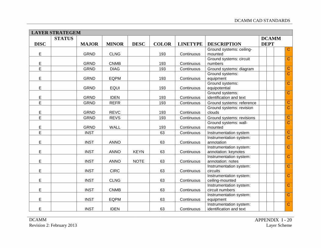
DCAMM CAD STANDARDS
DCAMM APPENDIX I - 20 Revision 2: February 2013 Layer Scheme
LAYER STRATEGEM
DISC STATUS
MAJOR MINOR DESC COLOR LINETYPE DESCRIPTION DCAMM DEPT
E
GRND CLNG 193 Continuous Ground systems: ceiling-mounted
C
E
GRND CNMB 193 Continuous Ground systems: circuit numbers
C
E GRND DIAG 193 Continuous Ground systems: diagram C
E
GRND EQPM 193 Continuous Ground systems: equipment
C
E
GRND EQUI 193 Continuous Ground systems: equipotential
C
E
GRND IDEN 193 Continuous Ground systems: identification and text
C
E GRND REFR 193 Continuous Ground systems: reference C
E
GRND REVC 193 Continuous Ground systems: revision clouds
C
E GRND REVS 193 Continuous Ground systems: revisions C
E
GRND WALL 193 Continuous Ground systems: wall-mounted
C
E INST 63 Continuous Instrumentation system C
E
INST ANNO 63 Continuous Instrumentation system: annotation
C
E
INST ANNO KEYN 63 Continuous Instrumentation system: annotation: keynotes
C
E
INST ANNO NOTE 63 Continuous Instrumentation system: annotation: notes
C
E
INST CIRC 63 Continuous Instrumentation system: circuits
C
E
INST CLNG 63 Continuous Instrumentation system: ceiling-mounted
C
E
INST CNMB 63 Continuous Instrumentation system: circuit numbers
C
E
INST EQPM 63 Continuous Instrumentation system: equipment
C
E
INST IDEN 63 Continuous Instrumentation system: identification and text
C
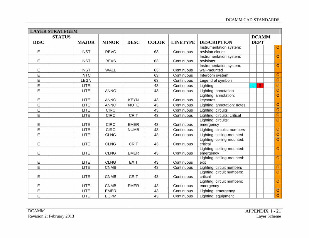
DCAMM CAD STANDARDS
DCAMM APPENDIX I - 21 Revision 2: February 2013 Layer Scheme
LAYER STRATEGEM
DISC STATUS
MAJOR MINOR DESC COLOR LINETYPE DESCRIPTION DCAMM DEPT
E
INST REVC 63 Continuous Instrumentation system: revision clouds
C
E
INST REVS 63 Continuous Instrumentation system: revisions
C
E
INST WALL 63 Continuous Instrumentation system: wall-mounted
C
E INTC 63 Continuous Intercom system C E LEGN 63 Continuous Legend of symbols C E LITE 43 Continuous Lighting L S C E LITE ANNO 43 Continuous Lighting: annotation C
E
LITE ANNO KEYN 43 Continuous Lighting: annotation: keynotes
C
E LITE ANNO NOTE 43 Continuous Lighting: annotation: notes C E LITE CIRC 43 Continuous Lighting: circuits C E LITE CIRC CRIT 43 Continuous Lighting: circuits: critical C
E
LITE CIRC EMER 43 Continuous Lighting: circuits: emergency
C
E LITE CIRC NUMB 43 Continuous Lighting: circuits: numbers C E LITE CLNG 43 Continuous Lighting: ceiling-mounted C
E
LITE CLNG CRIT 43 Continuous Lighting: ceiling-mounted: critical
C
E
LITE CLNG EMER 43 Continuous Lighting: ceiling-mounted: emergency
C
E
LITE CLNG EXIT 43 Continuous Lighting: ceiling-mounted: exit
C
E LITE CNMB 43 Continuous Lighting: circuit numbers C
E
LITE CNMB CRIT 43 Continuous Lighting: circuit numbers: critical
C
E
LITE CNMB EMER 43 Continuous Lighting: circuit numbers: emergency
C
E LITE EMER 43 Continuous Lighting: emergency C E LITE EQPM 43 Continuous Lighting: equipment C
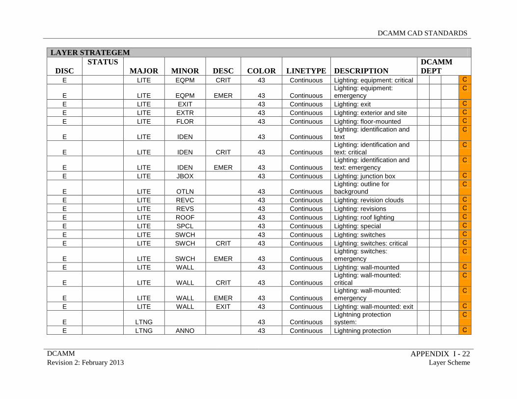
DCAMM CAD STANDARDS
DCAMM APPENDIX I - 22 Revision 2: February 2013 Layer Scheme
LAYER STRATEGEM
DISC STATUS
MAJOR MINOR DESC COLOR LINETYPE DESCRIPTION DCAMM DEPT
E LITE EQPM CRIT 43 Continuous Lighting: equipment: critical C
E
LITE EQPM EMER 43 Continuous Lighting: equipment: emergency
C
E LITE EXIT 43 Continuous Lighting: exit C E LITE EXTR 43 Continuous Lighting: exterior and site C E LITE FLOR 43 Continuous Lighting: floor-mounted C
E
LITE IDEN 43 Continuous Lighting: identification and text
C
E
LITE IDEN CRIT 43 Continuous Lighting: identification and text: critical
C
E
LITE IDEN EMER 43 Continuous Lighting: identification and text: emergency
C
E LITE JBOX 43 Continuous Lighting: junction box C
E
LITE OTLN 43 Continuous Lighting: outline for background
C
E LITE REVC 43 Continuous Lighting: revision clouds C E LITE REVS 43 Continuous Lighting: revisions C E LITE ROOF 43 Continuous Lighting: roof lighting C E LITE SPCL 43 Continuous Lighting: special C E LITE SWCH 43 Continuous Lighting: switches C E LITE SWCH CRIT 43 Continuous Lighting: switches: critical C
E
LITE SWCH EMER 43 Continuous Lighting: switches: emergency
C
E LITE WALL 43 Continuous Lighting: wall-mounted C
E
LITE WALL CRIT 43 Continuous Lighting: wall-mounted: critical
C
E
LITE WALL EMER 43 Continuous Lighting: wall-mounted: emergency
C
E LITE WALL EXIT 43 Continuous Lighting: wall-mounted: exit C
E
LTNG 43 Continuous Lightning protection system:
C
E LTNG ANNO 43 Continuous Lightning protection C
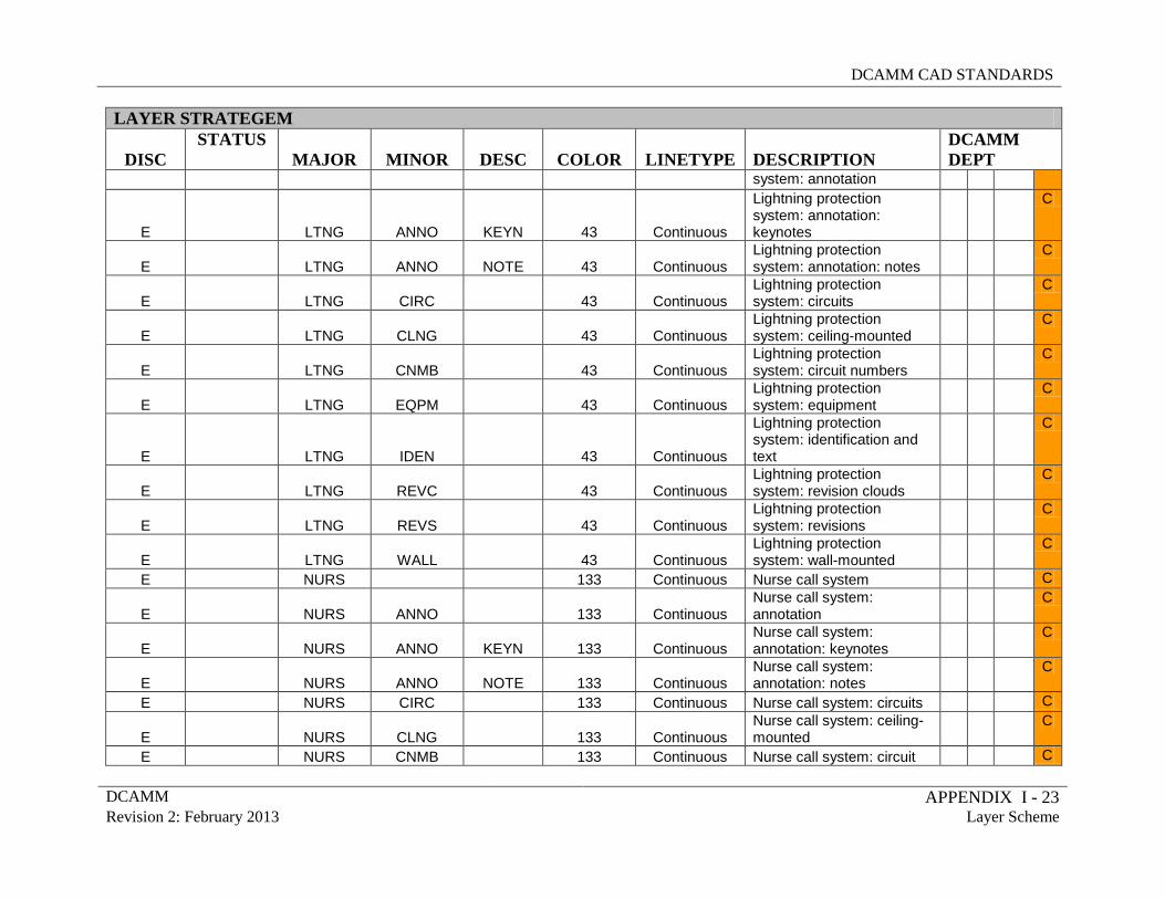
DCAMM CAD STANDARDS
DCAMM APPENDIX I - 23 Revision 2: February 2013 Layer Scheme
LAYER STRATEGEM
DISC STATUS
MAJOR MINOR DESC COLOR LINETYPE DESCRIPTION DCAMM DEPT
system: annotation
E
LTNG ANNO KEYN 43 Continuous
Lightning protection system: annotation: keynotes
C
E
LTNG ANNO NOTE 43 Continuous Lightning protection system: annotation: notes
C
E
LTNG CIRC 43 Continuous Lightning protection system: circuits
C
E
LTNG CLNG 43 Continuous Lightning protection system: ceiling-mounted
C
E
LTNG CNMB 43 Continuous Lightning protection system: circuit numbers
C
E
LTNG EQPM 43 Continuous Lightning protection system: equipment
C
E
LTNG IDEN 43 Continuous
Lightning protection system: identification and text
C
E
LTNG REVC 43 Continuous Lightning protection system: revision clouds
C
E
LTNG REVS 43 Continuous Lightning protection system: revisions
C
E
LTNG WALL 43 Continuous Lightning protection system: wall-mounted
C
E NURS 133 Continuous Nurse call system C
E
NURS ANNO 133 Continuous Nurse call system: annotation
C
E
NURS ANNO KEYN 133 Continuous Nurse call system: annotation: keynotes
C
E
NURS ANNO NOTE 133 Continuous Nurse call system: annotation: notes
C
E NURS CIRC 133 Continuous Nurse call system: circuits C
E
NURS CLNG 133 Continuous Nurse call system: ceiling-mounted
C
E NURS CNMB 133 Continuous Nurse call system: circuit C
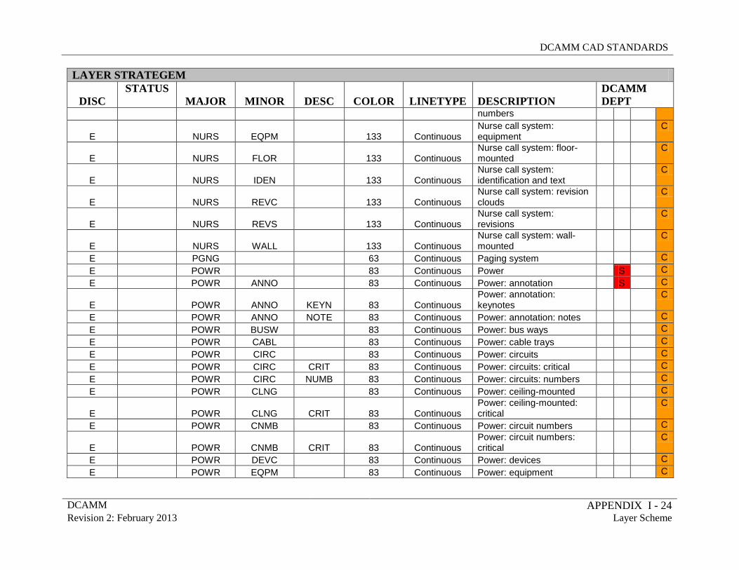
DCAMM CAD STANDARDS
DCAMM APPENDIX I - 24 Revision 2: February 2013 Layer Scheme
LAYER STRATEGEM
DISC STATUS
MAJOR MINOR DESC COLOR LINETYPE DESCRIPTION DCAMM DEPT
numbers
E
NURS EQPM 133 Continuous Nurse call system: equipment
C
E
NURS FLOR 133 Continuous Nurse call system: floor-mounted
C
E
NURS IDEN 133 Continuous Nurse call system: identification and text
C
E
NURS REVC 133 Continuous Nurse call system: revision clouds
C
E
NURS REVS 133 Continuous Nurse call system: revisions
C
E
NURS WALL 133 Continuous Nurse call system: wall-mounted
C
E PGNG 63 Continuous Paging system C E POWR 83 Continuous Power S C E POWR ANNO 83 Continuous Power: annotation S C
E
POWR ANNO KEYN 83 Continuous Power: annotation: keynotes
C
E POWR ANNO NOTE 83 Continuous Power: annotation: notes C E POWR BUSW 83 Continuous Power: bus ways C E POWR CABL 83 Continuous Power: cable trays C E POWR CIRC 83 Continuous Power: circuits C E POWR CIRC CRIT 83 Continuous Power: circuits: critical C E POWR CIRC NUMB 83 Continuous Power: circuits: numbers C E POWR CLNG 83 Continuous Power: ceiling-mounted C
E
POWR CLNG CRIT 83 Continuous Power: ceiling-mounted: critical
C
E POWR CNMB 83 Continuous Power: circuit numbers C
E
POWR CNMB CRIT 83 Continuous Power: circuit numbers: critical
C
E POWR DEVC 83 Continuous Power: devices C E POWR EQPM 83 Continuous Power: equipment C
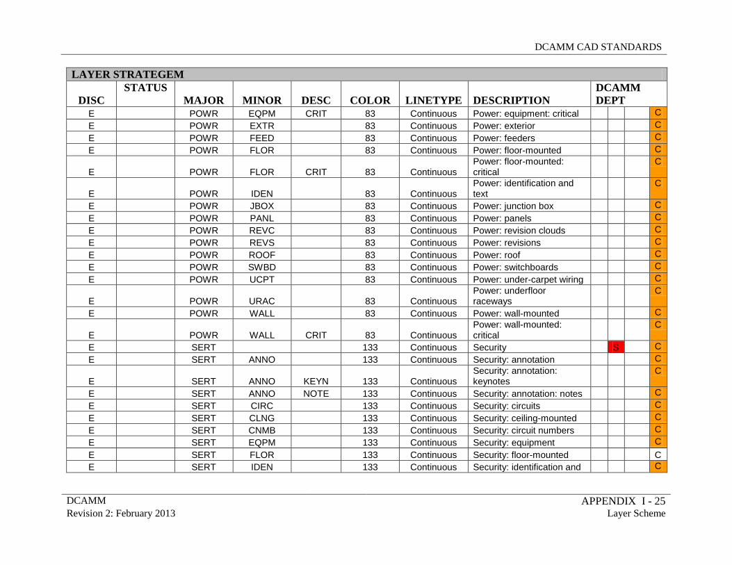
DCAMM CAD STANDARDS
DCAMM APPENDIX I - 25 Revision 2: February 2013 Layer Scheme
LAYER STRATEGEM
DISC STATUS
MAJOR MINOR DESC COLOR LINETYPE DESCRIPTION DCAMM DEPT
E POWR EQPM CRIT 83 Continuous Power: equipment: critical C E POWR EXTR 83 Continuous Power: exterior C E POWR FEED 83 Continuous Power: feeders C E POWR FLOR 83 Continuous Power: floor-mounted C
E
POWR FLOR CRIT 83 Continuous Power: floor-mounted: critical
C
E
POWR IDEN 83 Continuous Power: identification and text
C
E POWR JBOX 83 Continuous Power: junction box C E POWR PANL 83 Continuous Power: panels C E POWR REVC 83 Continuous Power: revision clouds C E POWR REVS 83 Continuous Power: revisions C E POWR ROOF 83 Continuous Power: roof C E POWR SWBD 83 Continuous Power: switchboards C E POWR UCPT 83 Continuous Power: under-carpet wiring C
E
POWR URAC 83 Continuous Power: underfloor raceways
C
E POWR WALL 83 Continuous Power: wall-mounted C
E
POWR WALL CRIT 83 Continuous Power: wall-mounted: critical
C
E SERT 133 Continuous Security S C E SERT ANNO 133 Continuous Security: annotation C
E
SERT ANNO KEYN 133 Continuous Security: annotation: keynotes
C
E SERT ANNO NOTE 133 Continuous Security: annotation: notes C E SERT CIRC 133 Continuous Security: circuits C E SERT CLNG 133 Continuous Security: ceiling-mounted C E SERT CNMB 133 Continuous Security: circuit numbers C E SERT EQPM 133 Continuous Security: equipment C E SERT FLOR 133 Continuous Security: floor-mounted C E SERT IDEN 133 Continuous Security: identification and C
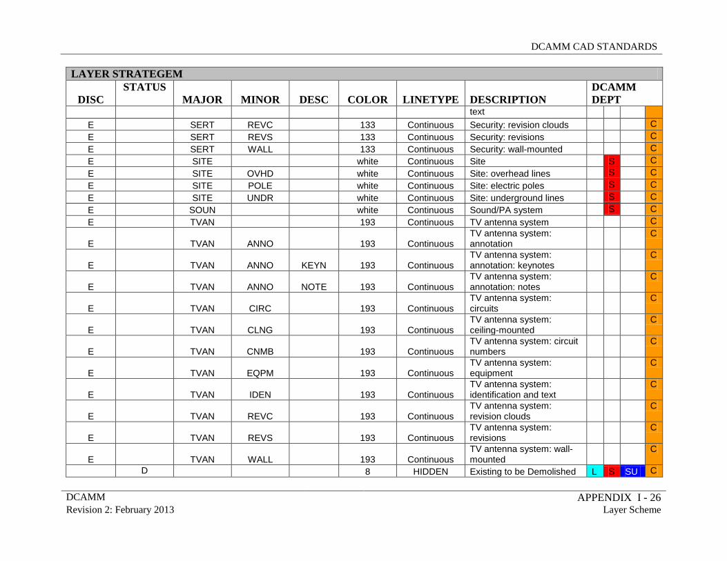
DCAMM CAD STANDARDS
DCAMM APPENDIX I - 26 Revision 2: February 2013 Layer Scheme
LAYER STRATEGEM
DISC STATUS
MAJOR MINOR DESC COLOR LINETYPE DESCRIPTION DCAMM DEPT
text E SERT REVC 133 Continuous Security: revision clouds C E SERT REVS 133 Continuous Security: revisions C E SERT WALL 133 Continuous Security: wall-mounted C E SITE white Continuous Site S C E SITE OVHD white Continuous Site: overhead lines S C E SITE POLE white Continuous Site: electric poles S C E SITE UNDR white Continuous Site: underground lines S C E SOUN white Continuous Sound/PA system S C E TVAN 193 Continuous TV antenna system C
E
TVAN ANNO 193 Continuous TV antenna system: annotation
C
E
TVAN ANNO KEYN 193 Continuous TV antenna system: annotation: keynotes
C
E
TVAN ANNO NOTE 193 Continuous TV antenna system: annotation: notes
C
E
TVAN CIRC 193 Continuous TV antenna system: circuits
C
E
TVAN CLNG 193 Continuous TV antenna system: ceiling-mounted
C
E
TVAN CNMB 193 Continuous TV antenna system: circuit numbers
C
E
TVAN EQPM 193 Continuous TV antenna system: equipment
C
E
TVAN IDEN 193 Continuous TV antenna system: identification and text
C
E
TVAN REVC 193 Continuous TV antenna system: revision clouds
C
E
TVAN REVS 193 Continuous TV antenna system: revisions
C
E
TVAN WALL 193 Continuous TV antenna system: wall-mounted
C
D 8 HIDDEN Existing to be Demolished L S SU C
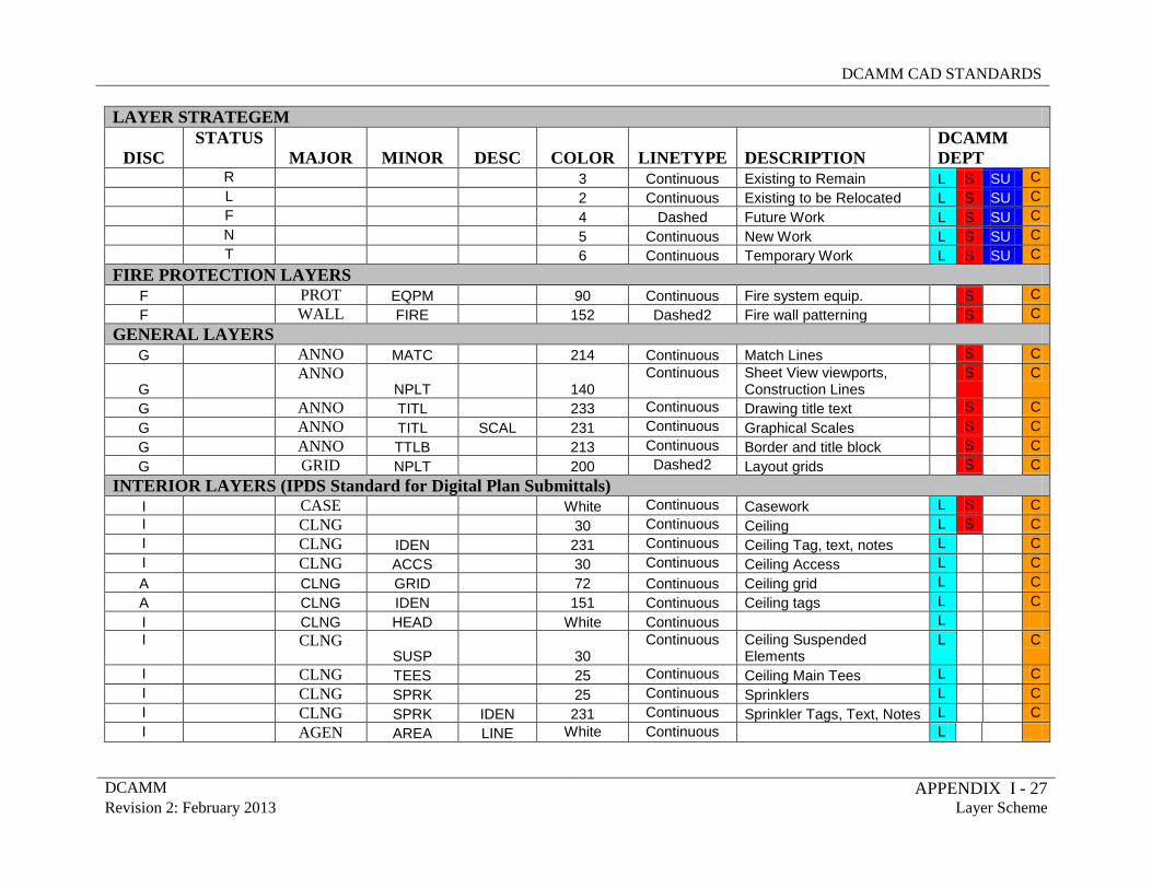
DCAMM CAD STANDARDS
DCAMM APPENDIX I - 27 Revision 2: February 2013 Layer Scheme
LAYER STRATEGEM
DISC STATUS
MAJOR MINOR DESC COLOR LINETYPE DESCRIPTION DCAMM DEPT
R 3 Continuous Existing to Remain L S SU C L 2 Continuous Existing to be Relocated L S SU C F 4 Dashed Future Work L S SU C N 5 Continuous New Work L S SU C T 6 Continuous Temporary Work L S SU C
FIRE PROTECTION LAYERS F PROT EQPM 90 Continuous Fire system equip. S C F WALL FIRE 152 Dashed2 Fire wall patterning S C
GENERAL LAYERS G ANNO MATC 214 Continuous Match Lines S C
G ANNO
NPLT 140 Continuous Sheet View viewports,
Construction Lines S
C
G ANNO TITL 233 Continuous Drawing title text S C G ANNO TITL SCAL 231 Continuous Graphical Scales S C G ANNO TTLB 213 Continuous Border and title block S C G GRID NPLT 200 Dashed2 Layout grids S C
INTERIOR LAYERS (IPDS Standard for Digital Plan Submittals) I CASE White Continuous Casework L S C I CLNG 30 Continuous Ceiling L S C I CLNG IDEN 231 Continuous Ceiling Tag, text, notes L C I CLNG ACCS 30 Continuous Ceiling Access L C A CLNG GRID 72 Continuous Ceiling grid L C A CLNG IDEN 151 Continuous Ceiling tags L C I CLNG HEAD White Continuous L I CLNG
SUSP 30 Continuous Ceiling Suspended
Elements L
C
I CLNG TEES 25 Continuous Ceiling Main Tees L C I CLNG SPRK 25 Continuous Sprinklers L C I CLNG SPRK IDEN 231 Continuous Sprinkler Tags, Text, Notes L C I AGEN AREA LINE White Continuous L
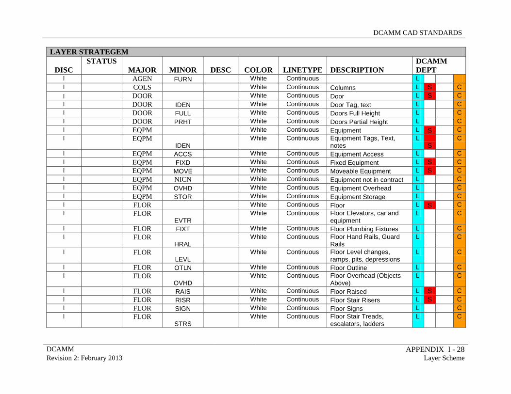
DCAMM CAD STANDARDS
DCAMM APPENDIX I - 28 Revision 2: February 2013 Layer Scheme
LAYER STRATEGEM
DISC STATUS
MAJOR MINOR DESC COLOR LINETYPE DESCRIPTION DCAMM DEPT
I AGEN FURN White Continuous L I COLS White Continuous Columns L S C I DOOR White Continuous Door L S C I DOOR IDEN White Continuous Door Tag, text L C I DOOR FULL White Continuous Doors Full Height L C I DOOR PRHT White Continuous Doors Partial Height L C I EQPM White Continuous Equipment L S C I EQPM
IDEN White Continuous Equipment Tags, Text,
notes L
S C
I EQPM ACCS White Continuous Equipment Access L C I EQPM FIXD White Continuous Fixed Equipment L S C I EQPM MOVE White Continuous Moveable Equipment L S C I EQPM NICN White Continuous Equipment not in contract L C I EQPM OVHD White Continuous Equipment Overhead L C I EQPM STOR White Continuous Equipment Storage L C I FLOR White Continuous Floor L S C I FLOR
EVTR White Continuous Floor Elevators, car and
equipment L
C
I FLOR FIXT White Continuous Floor Plumbing Fixtures L C I FLOR
HRAL White Continuous Floor Hand Rails, Guard
Rails L
C
I FLOR LEVL
White Continuous Floor Level changes, ramps, pits, depressions
L
C
I FLOR OTLN White Continuous Floor Outline L C I FLOR
OVHD White Continuous Floor Overhead (Objects
Above) L
C
I FLOR RAIS White Continuous Floor Raised L S C I FLOR RISR White Continuous Floor Stair Risers L S C I FLOR SIGN White Continuous Floor Signs L C I FLOR
STRS White Continuous Floor Stair Treads,
escalators, ladders L
C
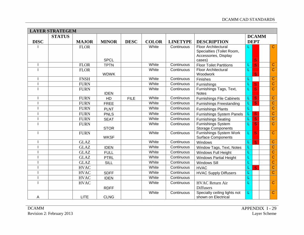
DCAMM CAD STANDARDS
DCAMM APPENDIX I - 29 Revision 2: February 2013 Layer Scheme
LAYER STRATEGEM
DISC STATUS
MAJOR MINOR DESC COLOR LINETYPE DESCRIPTION DCAMM DEPT
I FLOR
SPCL
White Continuous Floor Architectural Specialties (Toilet Room, Accessories, Display cases)
L
S
C
I FLOR TPTN White Continuous Floor Toilet Partitions L S C I FLOR
WDWK White Continuous Floor Architectural
Woodwork L
S C
I FNSH White Continuous Finishes L C I FURN White Continuous Furnishings L S C I FURN
IDEN White Continuous Furnishings Tags, Text,
Notes L S
C
I FURN HD FILE White Continuous Furnishings File Cabinets L S C I FURN FREE White Continuous Furnishings Freestanding L S C I FURN PLNT White Continuous Furnishings Plants L C I FURN PNLS White Continuous Furnishings System Panels L S C I FURN SEAT White Continuous Furnishings Seating L S C I FURN
STOR White Continuous Furnishings System
Storage Components L S
C
I FURN WKSF
White Continuous Furnishings System Work Surface Components
L S
C
I GLAZ White Continuous Windows L S C I GLAZ IDEN White Continuous Window Tags, Text, Notes L C I GLAZ FULL White Continuous Windows Full Height L C I GLAZ PTRL White Continuous Windows Partial Height L C I GLAZ SILL White Continuous Windows Sill L C I HVAC White Continuous HVAC L S C I HVAC SDFF White Continuous HVAC Supply Diffusers L C I HVAC IDEN White Continuous L I HVAC
RDFF White Continuous HVAC Return Air
Diffusers L
C
A LITE CLNG White Continuous Specialty ceiling lights not
shown on Electrical L
C
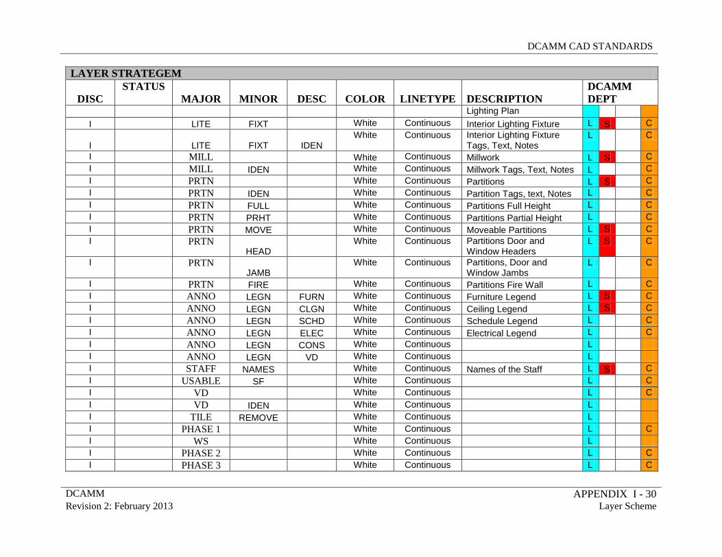
DCAMM CAD STANDARDS
DCAMM APPENDIX I - 30 Revision 2: February 2013 Layer Scheme
LAYER STRATEGEM
DISC STATUS
MAJOR MINOR DESC COLOR LINETYPE DESCRIPTION DCAMM DEPT
Lighting Plan I LITE FIXT White Continuous Interior Lighting Fixture L S C
I LITE FIXT IDEN White Continuous Interior Lighting Fixture
Tags, Text, Notes L
C
I MILL White Continuous Millwork L S C I MILL IDEN White Continuous Millwork Tags, Text, Notes L C I PRTN White Continuous Partitions L S C I PRTN IDEN White Continuous Partition Tags, text, Notes L C I PRTN FULL White Continuous Partitions Full Height L C I PRTN PRHT White Continuous Partitions Partial Height L C I PRTN MOVE White Continuous Moveable Partitions L S C I PRTN
HEAD White Continuous Partitions Door and
Window Headers L S
C
I PRTN JAMB
White Continuous Partitions, Door and Window Jambs
L
C
I PRTN FIRE White Continuous Partitions Fire Wall L C I ANNO LEGN FURN White Continuous Furniture Legend L S C I ANNO LEGN CLGN White Continuous Ceiling Legend L S C I ANNO LEGN SCHD White Continuous Schedule Legend L C I ANNO LEGN ELEC White Continuous Electrical Legend L C I ANNO LEGN CONS White Continuous L I ANNO LEGN VD White Continuous L I STAFF NAMES White Continuous Names of the Staff L S C I USABLE SF White Continuous L C I VD White Continuous L C I VD IDEN White Continuous L I TILE REMOVE White Continuous L I PHASE 1 White Continuous L C I WS White Continuous L I PHASE 2 White Continuous L C I PHASE 3 White Continuous L C
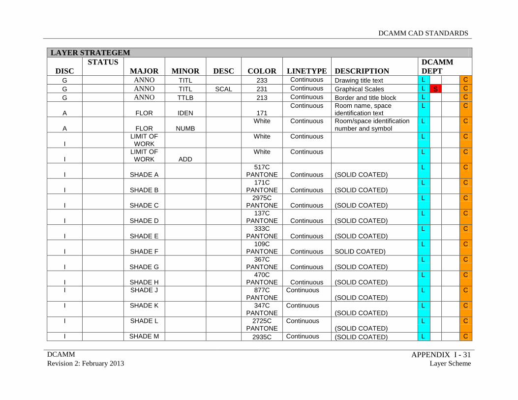
DCAMM CAD STANDARDS
DCAMM APPENDIX I - 31 Revision 2: February 2013 Layer Scheme
LAYER STRATEGEM
DISC STATUS
MAJOR MINOR DESC COLOR LINETYPE DESCRIPTION DCAMM DEPT
G ANNO TITL 233 Continuous Drawing title text L C G ANNO TITL SCAL 231 Continuous Graphical Scales L S C G ANNO TTLB 213 Continuous Border and title block L C
A FLOR IDEN 171 Continuous Room name, space
identification text L
C
A FLOR NUMB White Continuous Room/space identification
number and symbol L
C
I LIMIT OF
WORK White Continuous
L
C
I LIMIT OF WORK ADD
White Continuous
L
C
I SHADE A 517C
PANTONE Continuous (SOLID COATED) L
C
I SHADE B 171C
PANTONE Continuous (SOLID COATED) L
C
I SHADE C 2975C
PANTONE Continuous (SOLID COATED) L
C
I SHADE D 137C
PANTONE Continuous (SOLID COATED) L
C
I SHADE E 333C
PANTONE Continuous (SOLID COATED) L
C
I SHADE F 109C
PANTONE Continuous SOLID COATED) L
C
I SHADE G 367C
PANTONE Continuous (SOLID COATED) L
C
I SHADE H 470C
PANTONE Continuous (SOLID COATED) L
C
I
SHADE J
877C PANTONE
Continuous (SOLID COATED)
L
C
I
SHADE K
347C PANTONE
Continuous (SOLID COATED)
L
C
I
SHADE L
2725C PANTONE
Continuous (SOLID COATED)
L
C
I SHADE M 2935C Continuous (SOLID COATED) L C
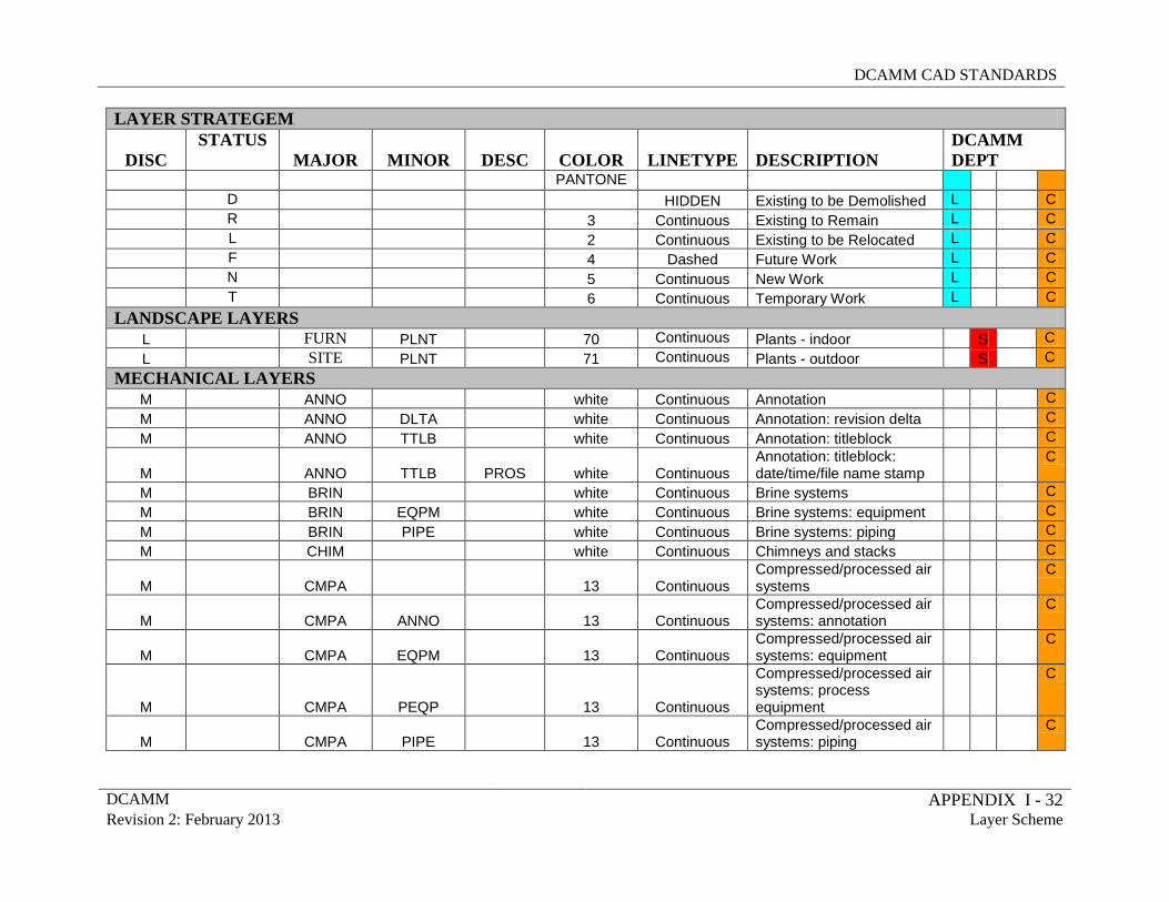
DCAMM CAD STANDARDS
DCAMM APPENDIX I - 32 Revision 2: February 2013 Layer Scheme
LAYER STRATEGEM
DISC STATUS
MAJOR MINOR DESC COLOR LINETYPE DESCRIPTION DCAMM DEPT
PANTONE D HIDDEN Existing to be Demolished L C R 3 Continuous Existing to Remain L C L 2 Continuous Existing to be Relocated L C F 4 Dashed Future Work L C N 5 Continuous New Work L C T 6 Continuous Temporary Work L C
LANDSCAPE LAYERS L FURN PLNT 70 Continuous Plants - indoor S C L SITE PLNT 71 Continuous Plants - outdoor S C
MECHANICAL LAYERS M ANNO white Continuous Annotation C M ANNO DLTA white Continuous Annotation: revision delta C M ANNO TTLB white Continuous Annotation: titleblock C
M
ANNO TTLB PROS white Continuous Annotation: titleblock: date/time/file name stamp
C
M BRIN white Continuous Brine systems C M BRIN EQPM white Continuous Brine systems: equipment C M BRIN PIPE white Continuous Brine systems: piping C M CHIM white Continuous Chimneys and stacks C
M
CMPA 13 Continuous Compressed/processed air systems
C
M
CMPA ANNO 13 Continuous Compressed/processed air systems: annotation
C
M
CMPA EQPM 13 Continuous Compressed/processed air systems: equipment
C
M
CMPA PEQP 13 Continuous
Compressed/processed air systems: process equipment
C
M
CMPA PIPE 13 Continuous Compressed/processed air systems: piping
C
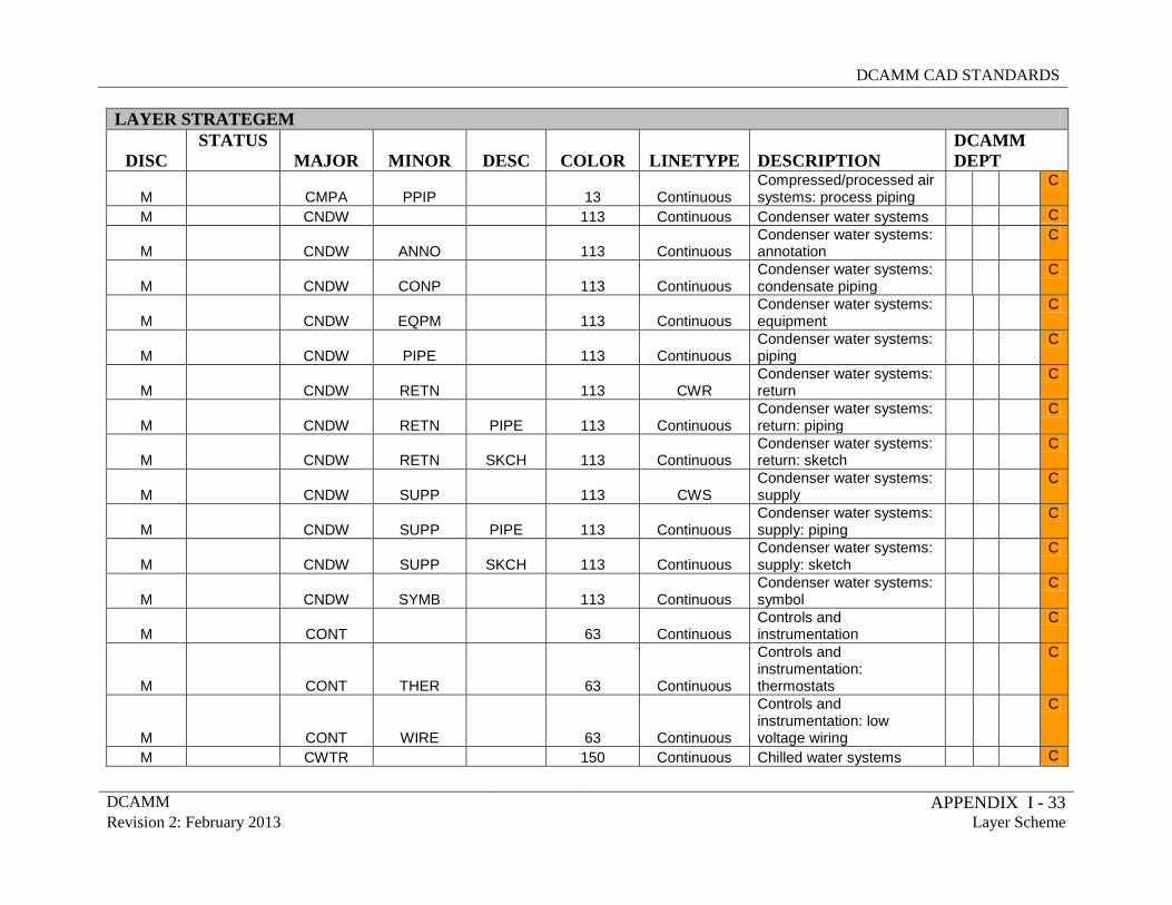
DCAMM CAD STANDARDS
DCAMM APPENDIX I - 33 Revision 2: February 2013 Layer Scheme
LAYER STRATEGEM
DISC STATUS
MAJOR MINOR DESC COLOR LINETYPE DESCRIPTION DCAMM DEPT
M
CMPA PPIP 13 Continuous Compressed/processed air systems: process piping
C
M CNDW 113 Continuous Condenser water systems C
M
CNDW ANNO 113 Continuous Condenser water systems: annotation
C
M
CNDW CONP 113 Continuous Condenser water systems: condensate piping
C
M
CNDW EQPM 113 Continuous Condenser water systems: equipment
C
M
CNDW PIPE 113 Continuous Condenser water systems: piping
C
M
CNDW RETN 113 CWR Condenser water systems: return
C
M
CNDW RETN PIPE 113 Continuous Condenser water systems: return: piping
C
M
CNDW RETN SKCH 113 Continuous Condenser water systems: return: sketch
C
M
CNDW SUPP 113 CWS Condenser water systems: supply
C
M
CNDW SUPP PIPE 113 Continuous Condenser water systems: supply: piping
C
M
CNDW SUPP SKCH 113 Continuous Condenser water systems: supply: sketch
C
M
CNDW SYMB 113 Continuous Condenser water systems: symbol
C
M
CONT 63 Continuous Controls and instrumentation
C
M
CONT THER 63 Continuous
Controls and instrumentation: thermostats
C
M
CONT WIRE 63 Continuous
Controls and instrumentation: low voltage wiring
C
M CWTR 150 Continuous Chilled water systems C
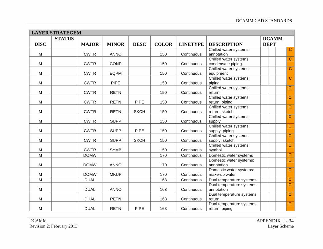
DCAMM CAD STANDARDS
DCAMM APPENDIX I - 34 Revision 2: February 2013 Layer Scheme
LAYER STRATEGEM
DISC STATUS
MAJOR MINOR DESC COLOR LINETYPE DESCRIPTION DCAMM DEPT
M
CWTR ANNO 150 Continuous Chilled water systems: annotation
C
M
CWTR CONP 150 Continuous Chilled water systems: condensate piping
C
M
CWTR EQPM 150 Continuous Chilled water systems: equipment
C
M
CWTR PIPE 150 Continuous Chilled water systems: piping
C
M
CWTR RETN 150 Continuous Chilled water systems: return
C
M
CWTR RETN PIPE 150 Continuous Chilled water systems: return: piping
C
M
CWTR RETN SKCH 150 Continuous Chilled water systems: return: sketch
C
M
CWTR SUPP 150 Continuous Chilled water systems: supply
C
M
CWTR SUPP PIPE 150 Continuous Chilled water systems: supply: piping
C
M
CWTR SUPP SKCH 150 Continuous Chilled water systems: supply: sketch
C
M
CWTR SYMB 150 Continuous Chilled water systems: symbol
C
M DOMW 170 Continuous Domestic water systems C
M
DOMW ANNO 170 Continuous Domestic water systems: annotation
C
M
DOMW MKUP 170 Continuous Domestic water systems: make-up water
C
M DUAL 163 Continuous Dual temperature systems C
M
DUAL ANNO 163 Continuous Dual temperature systems: annotation
C
M
DUAL RETN 163 Continuous Dual temperature systems: return
C
M
DUAL RETN PIPE 163 Continuous Dual temperature systems: return: piping
C
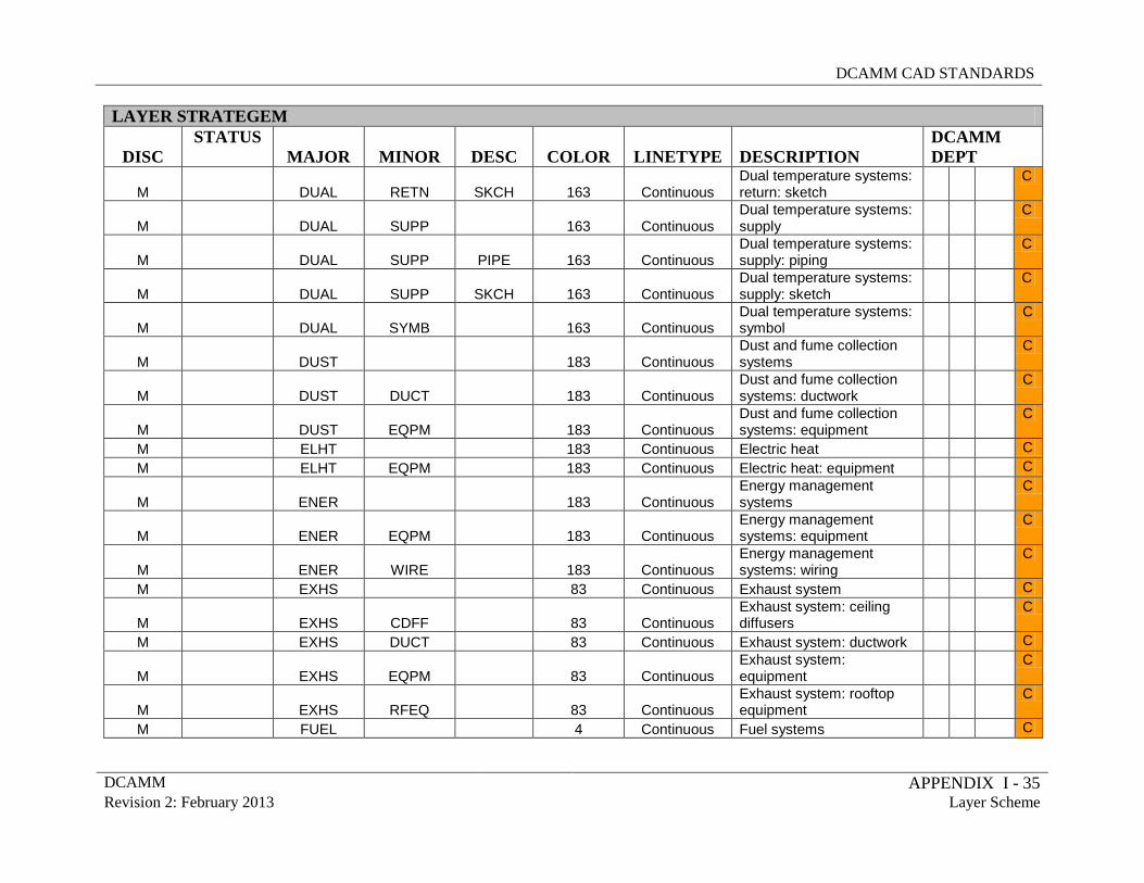
DCAMM CAD STANDARDS
DCAMM APPENDIX I - 35 Revision 2: February 2013 Layer Scheme
LAYER STRATEGEM
DISC STATUS
MAJOR MINOR DESC COLOR LINETYPE DESCRIPTION DCAMM DEPT
M
DUAL RETN SKCH 163 Continuous Dual temperature systems: return: sketch
C
M
DUAL SUPP 163 Continuous Dual temperature systems: supply
C
M
DUAL SUPP PIPE 163 Continuous Dual temperature systems: supply: piping
C
M
DUAL SUPP SKCH 163 Continuous Dual temperature systems: supply: sketch
C
M
DUAL SYMB 163 Continuous Dual temperature systems: symbol
C
M
DUST 183 Continuous Dust and fume collection systems
C
M
DUST DUCT 183 Continuous Dust and fume collection systems: ductwork
C
M
DUST EQPM 183 Continuous Dust and fume collection systems: equipment
C
M ELHT 183 Continuous Electric heat C M ELHT EQPM 183 Continuous Electric heat: equipment C
M
ENER 183 Continuous Energy management systems
C
M
ENER EQPM 183 Continuous Energy management systems: equipment
C
M
ENER WIRE 183 Continuous Energy management systems: wiring
C
M EXHS 83 Continuous Exhaust system C
M
EXHS CDFF 83 Continuous Exhaust system: ceiling diffusers
C
M EXHS DUCT 83 Continuous Exhaust system: ductwork C
M
EXHS EQPM 83 Continuous Exhaust system: equipment
C
M
EXHS RFEQ 83 Continuous Exhaust system: rooftop equipment
C
M FUEL 4 Continuous Fuel systems C
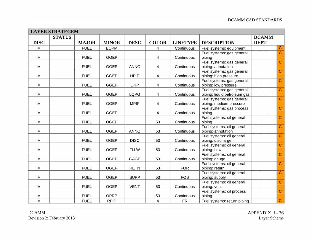
DCAMM CAD STANDARDS
DCAMM APPENDIX I - 36 Revision 2: February 2013 Layer Scheme
LAYER STRATEGEM
DISC STATUS
MAJOR MINOR DESC COLOR LINETYPE DESCRIPTION DCAMM DEPT
M FUEL EQPM 4 Continuous Fuel systems: equipment C
M
FUEL GGEP 4 Continuous Fuel systems: gas general piping
C
M
FUEL GGEP ANNO 4 Continuous Fuel systems: gas general piping: annotation
C
M
FUEL GGEP HPIP 4 Continuous Fuel systems: gas general piping: high pressure
C
M
FUEL GGEP LPIP 4 Continuous Fuel systems: gas general piping: low pressure
C
M
FUEL GGEP LQPG 4 Continuous Fuel systems: gas general piping: liquid petroleum gas
C
M
FUEL GGEP MPIP 4 Continuous Fuel systems: gas general piping: medium pressure
C
M
FUEL GGEP 4 Continuous Fuel systems: gas process piping
C
M
FUEL OGEP 53 Continuous Fuel systems: oil general piping
C
M
FUEL OGEP ANNO 53 Continuous Fuel systems: oil general piping: annotation
C
M
FUEL OGEP DISC 53 Continuous Fuel systems: oil general piping: discharge
C
M
FUEL OGEP FLLW 53 Continuous Fuel systems: oil general piping: flow
C
M
FUEL OGEP GAGE 53 Continuous Fuel systems: oil general piping: gauge
C
M
FUEL OGEP RETN 53 FOR Fuel systems: oil general piping: return
C
M
FUEL OGEP SUPP 53 FOS Fuel systems: oil general piping: supply
C
M
FUEL OGEP VENT 53 Continuous Fuel systems: oil general piping: vent
C
M
FUEL OPRP 53 Continuous Fuel systems: oil process piping
C
M FUEL RPIP 4 FR Fuel systems: return piping C
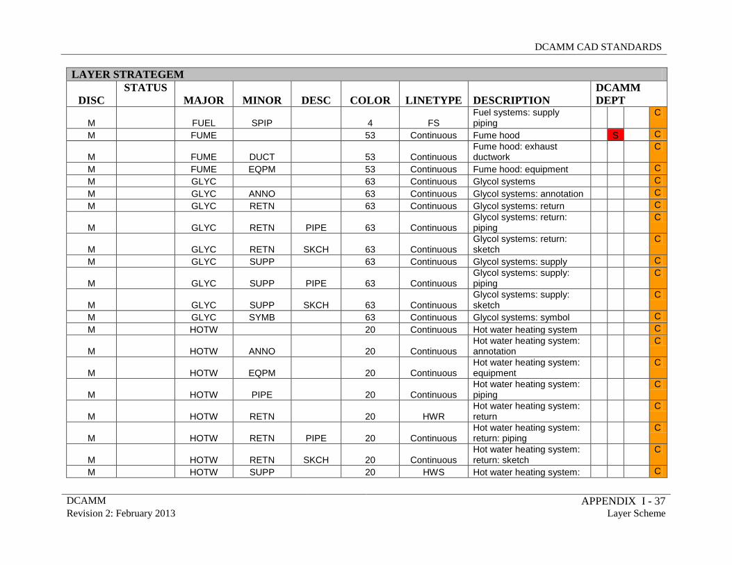
DCAMM CAD STANDARDS
DCAMM APPENDIX I - 37 Revision 2: February 2013 Layer Scheme
LAYER STRATEGEM
DISC STATUS
MAJOR MINOR DESC COLOR LINETYPE DESCRIPTION DCAMM DEPT
M
FUEL SPIP 4 FS Fuel systems: supply piping
C
M FUME 53 Continuous Fume hood S C
M
FUME DUCT 53 Continuous Fume hood: exhaust ductwork
C
M FUME EQPM 53 Continuous Fume hood: equipment C M GLYC 63 Continuous Glycol systems C M GLYC ANNO 63 Continuous Glycol systems: annotation C M GLYC RETN 63 Continuous Glycol systems: return C
M
GLYC RETN PIPE 63 Continuous Glycol systems: return: piping
C
M
GLYC RETN SKCH 63 Continuous Glycol systems: return: sketch
C
M GLYC SUPP 63 Continuous Glycol systems: supply C
M
GLYC SUPP PIPE 63 Continuous Glycol systems: supply: piping
C
M
GLYC SUPP SKCH 63 Continuous Glycol systems: supply: sketch
C
M GLYC SYMB 63 Continuous Glycol systems: symbol C M HOTW 20 Continuous Hot water heating system C
M
HOTW ANNO 20 Continuous Hot water heating system: annotation
C
M
HOTW EQPM 20 Continuous Hot water heating system: equipment
C
M
HOTW PIPE 20 Continuous Hot water heating system: piping
C
M
HOTW RETN 20 HWR Hot water heating system: return
C
M
HOTW RETN PIPE 20 Continuous Hot water heating system: return: piping
C
M
HOTW RETN SKCH 20 Continuous Hot water heating system: return: sketch
C
M HOTW SUPP 20 HWS Hot water heating system: C
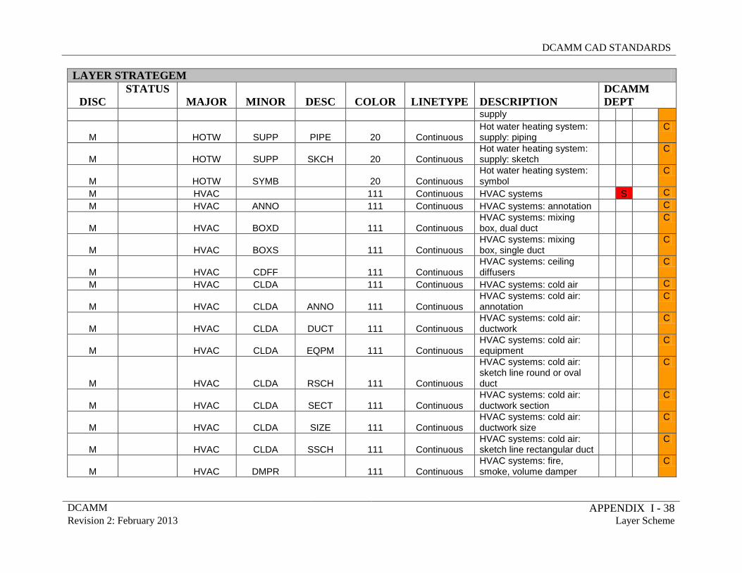
DCAMM CAD STANDARDS
DCAMM APPENDIX I - 38 Revision 2: February 2013 Layer Scheme
LAYER STRATEGEM
DISC STATUS
MAJOR MINOR DESC COLOR LINETYPE DESCRIPTION DCAMM DEPT
supply
M
HOTW SUPP PIPE 20 Continuous Hot water heating system: supply: piping
C
M
HOTW SUPP SKCH 20 Continuous Hot water heating system: supply: sketch
C
M
HOTW SYMB 20 Continuous Hot water heating system: symbol
C
M HVAC 111 Continuous HVAC systems S C M HVAC ANNO 111 Continuous HVAC systems: annotation C
M
HVAC BOXD 111 Continuous HVAC systems: mixing box, dual duct
C
M
HVAC BOXS 111 Continuous HVAC systems: mixing box, single duct
C
M
HVAC CDFF 111 Continuous HVAC systems: ceiling diffusers
C
M HVAC CLDA 111 Continuous HVAC systems: cold air C
M
HVAC CLDA ANNO 111 Continuous HVAC systems: cold air: annotation
C
M
HVAC CLDA DUCT 111 Continuous HVAC systems: cold air: ductwork
C
M
HVAC CLDA EQPM 111 Continuous HVAC systems: cold air: equipment
C
M
HVAC CLDA RSCH 111 Continuous
HVAC systems: cold air: sketch line round or oval duct
C
M
HVAC CLDA SECT 111 Continuous HVAC systems: cold air: ductwork section
C
M
HVAC CLDA SIZE 111 Continuous HVAC systems: cold air: ductwork size
C
M
HVAC CLDA SSCH 111 Continuous HVAC systems: cold air: sketch line rectangular duct
C
M
HVAC DMPR 111 Continuous HVAC systems: fire, smoke, volume damper
C
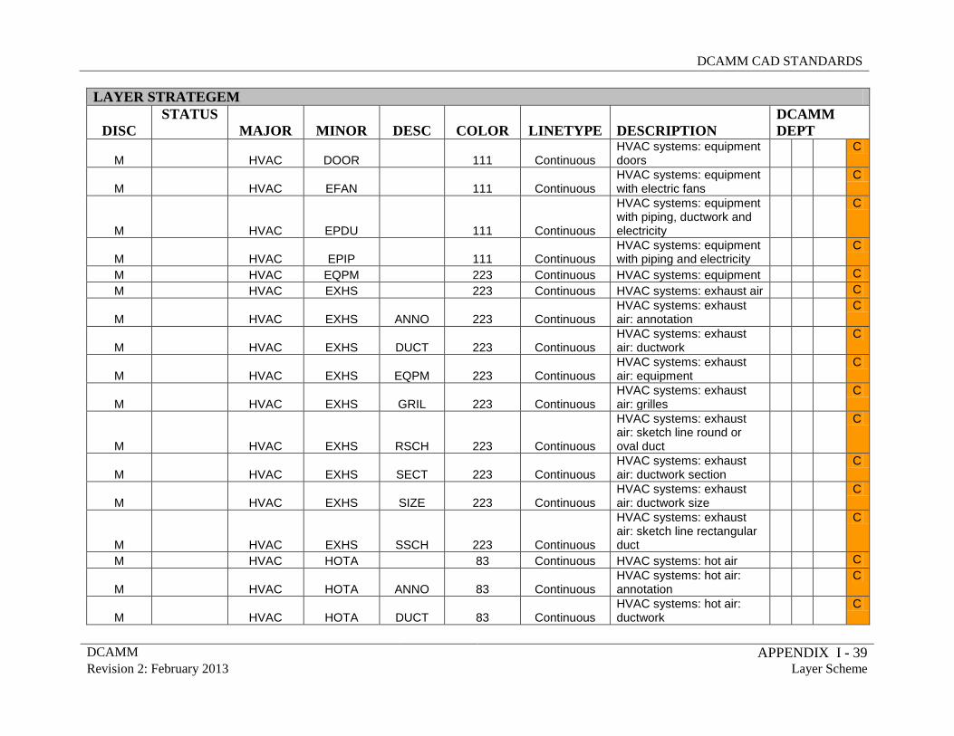
DCAMM CAD STANDARDS
DCAMM APPENDIX I - 39 Revision 2: February 2013 Layer Scheme
LAYER STRATEGEM
DISC STATUS
MAJOR MINOR DESC COLOR LINETYPE DESCRIPTION DCAMM DEPT
M
HVAC DOOR 111 Continuous HVAC systems: equipment doors
C
M
HVAC EFAN 111 Continuous HVAC systems: equipment with electric fans
C
M
HVAC EPDU 111 Continuous
HVAC systems: equipment with piping, ductwork and electricity
C
M
HVAC EPIP 111 Continuous HVAC systems: equipment with piping and electricity
C
M HVAC EQPM 223 Continuous HVAC systems: equipment C M HVAC EXHS 223 Continuous HVAC systems: exhaust air C
M
HVAC EXHS ANNO 223 Continuous HVAC systems: exhaust air: annotation
C
M
HVAC EXHS DUCT 223 Continuous HVAC systems: exhaust air: ductwork
C
M
HVAC EXHS EQPM 223 Continuous HVAC systems: exhaust air: equipment
C
M
HVAC EXHS GRIL 223 Continuous HVAC systems: exhaust air: grilles
C
M
HVAC EXHS RSCH 223 Continuous
HVAC systems: exhaust air: sketch line round or oval duct
C
M
HVAC EXHS SECT 223 Continuous HVAC systems: exhaust air: ductwork section
C
M
HVAC EXHS SIZE 223 Continuous HVAC systems: exhaust air: ductwork size
C
M
HVAC EXHS SSCH 223 Continuous
HVAC systems: exhaust air: sketch line rectangular duct
C
M HVAC HOTA 83 Continuous HVAC systems: hot air C
M
HVAC HOTA ANNO 83 Continuous HVAC systems: hot air: annotation
C
M
HVAC HOTA DUCT 83 Continuous HVAC systems: hot air: ductwork
C
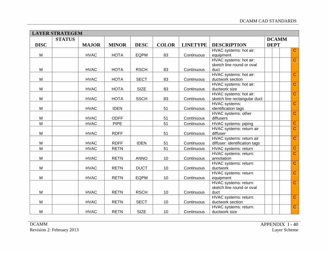
DCAMM CAD STANDARDS
DCAMM APPENDIX I - 40 Revision 2: February 2013 Layer Scheme
LAYER STRATEGEM
DISC STATUS
MAJOR MINOR DESC COLOR LINETYPE DESCRIPTION DCAMM DEPT
M
HVAC HOTA EQPM 83 Continuous HVAC systems: hot air: equipment
C
M
HVAC HOTA RSCH 83 Continuous
HVAC systems: hot air: sketch line round or oval duct
C
M
HVAC HOTA SECT 83 Continuous HVAC systems: hot air: ductwork section
C
M
HVAC HOTA SIZE 83 Continuous HVAC systems: hot air: ductwork size
C
M
HVAC HOTA SSCH 83 Continuous HVAC systems: hot air: sketch line rectangular duct
C
M
HVAC IDEN 51 Continuous HVAC systems: identification tags
C
M
HVAC ODFF 51 Continuous HVAC systems: other diffusers
C
M HVAC PIPE 51 Continuous HVAC systems: piping C
M
HVAC RDFF 51 Continuous HVAC systems: return air diffuser
C
M
HVAC RDFF IDEN 51 Continuous HVAC systems: return air diffuser: identification tags
C
M HVAC RETN 51 Continuous HVAC systems: return C
M
HVAC RETN ANNO 10 Continuous HVAC systems: return: annotation
C
M
HVAC RETN DUCT 10 Continuous HVAC systems: return: ductwork
C
M
HVAC RETN EQPM 10 Continuous HVAC systems: return: equipment
C
M
HVAC RETN RSCH 10 Continuous
HVAC systems: return: sketch line round or oval duct
C
M
HVAC RETN SECT 10 Continuous HVAC systems: return: ductwork section
C
M
HVAC RETN SIZE 10 Continuous HVAC systems: return: ductwork size
C
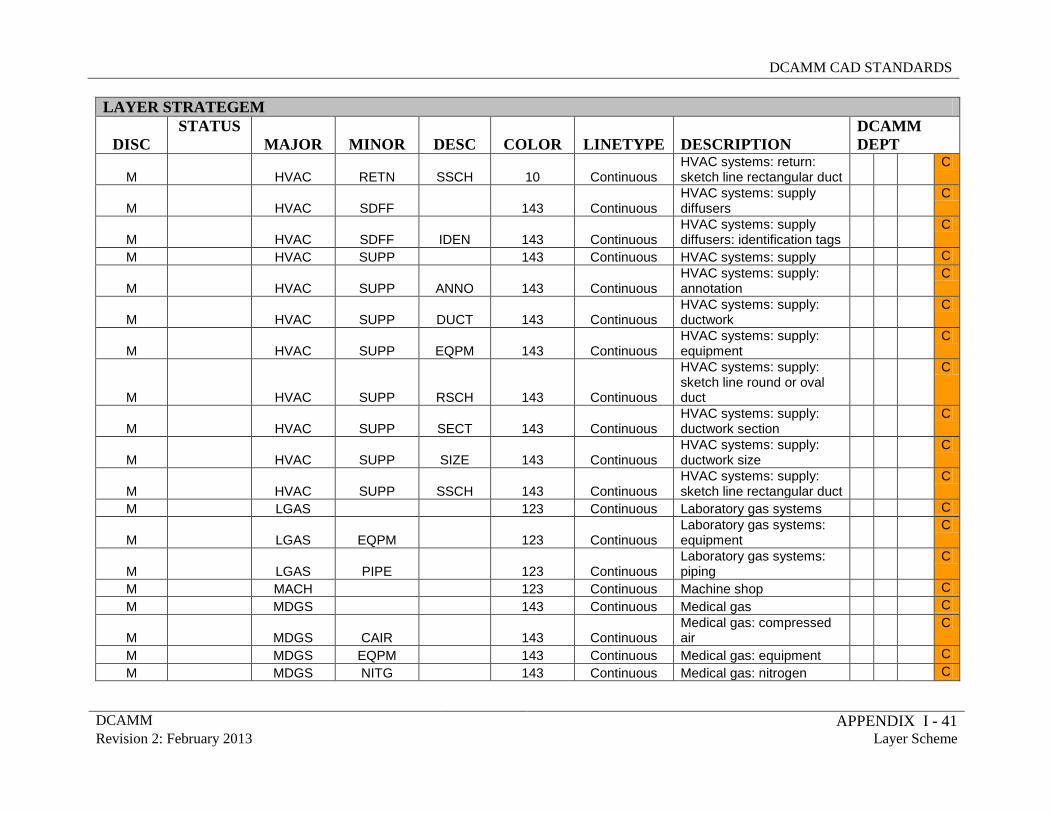
DCAMM CAD STANDARDS
DCAMM APPENDIX I - 41 Revision 2: February 2013 Layer Scheme
LAYER STRATEGEM
DISC STATUS
MAJOR MINOR DESC COLOR LINETYPE DESCRIPTION DCAMM DEPT
M
HVAC RETN SSCH 10 Continuous HVAC systems: return: sketch line rectangular duct
C
M
HVAC SDFF 143 Continuous HVAC systems: supply diffusers
C
M
HVAC SDFF IDEN 143 Continuous HVAC systems: supply diffusers: identification tags
C
M HVAC SUPP 143 Continuous HVAC systems: supply C
M
HVAC SUPP ANNO 143 Continuous HVAC systems: supply: annotation
C
M
HVAC SUPP DUCT 143 Continuous HVAC systems: supply: ductwork
C
M
HVAC SUPP EQPM 143 Continuous HVAC systems: supply: equipment
C
M
HVAC SUPP RSCH 143 Continuous
HVAC systems: supply: sketch line round or oval duct
C
M
HVAC SUPP SECT 143 Continuous HVAC systems: supply: ductwork section
C
M
HVAC SUPP SIZE 143 Continuous HVAC systems: supply: ductwork size
C
M
HVAC SUPP SSCH 143 Continuous HVAC systems: supply: sketch line rectangular duct
C
M LGAS 123 Continuous Laboratory gas systems C
M
LGAS EQPM 123 Continuous Laboratory gas systems: equipment
C
M
LGAS PIPE 123 Continuous Laboratory gas systems: piping
C
M MACH 123 Continuous Machine shop C M MDGS 143 Continuous Medical gas C
M
MDGS CAIR 143 Continuous Medical gas: compressed air
C
M MDGS EQPM 143 Continuous Medical gas: equipment C M MDGS NITG 143 Continuous Medical gas: nitrogen C
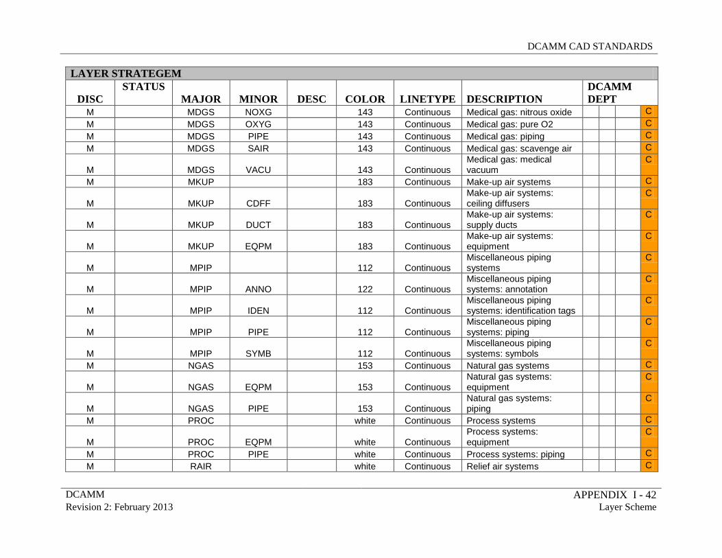
DCAMM CAD STANDARDS
DCAMM APPENDIX I - 42 Revision 2: February 2013 Layer Scheme
LAYER STRATEGEM
DISC STATUS
MAJOR MINOR DESC COLOR LINETYPE DESCRIPTION DCAMM DEPT
M MDGS NOXG 143 Continuous Medical gas: nitrous oxide C M MDGS OXYG 143 Continuous Medical gas: pure O2 C M MDGS PIPE 143 Continuous Medical gas: piping C M MDGS SAIR 143 Continuous Medical gas: scavenge air C
M
MDGS VACU 143 Continuous Medical gas: medical vacuum
C
M MKUP 183 Continuous Make-up air systems C
M
MKUP CDFF 183 Continuous Make-up air systems: ceiling diffusers
C
M
MKUP DUCT 183 Continuous Make-up air systems: supply ducts
C
M
MKUP EQPM 183 Continuous Make-up air systems: equipment
C
M
MPIP 112 Continuous Miscellaneous piping systems
C
M
MPIP ANNO 122 Continuous Miscellaneous piping systems: annotation
C
M
MPIP IDEN 112 Continuous Miscellaneous piping systems: identification tags
C
M
MPIP PIPE 112 Continuous Miscellaneous piping systems: piping
C
M
MPIP SYMB 112 Continuous Miscellaneous piping systems: symbols
C
M NGAS 153 Continuous Natural gas systems C
M
NGAS EQPM 153 Continuous Natural gas systems: equipment
C
M
NGAS PIPE 153 Continuous Natural gas systems: piping
C
M PROC white Continuous Process systems C
M
PROC EQPM white Continuous Process systems: equipment
C
M PROC PIPE white Continuous Process systems: piping C M RAIR white Continuous Relief air systems C
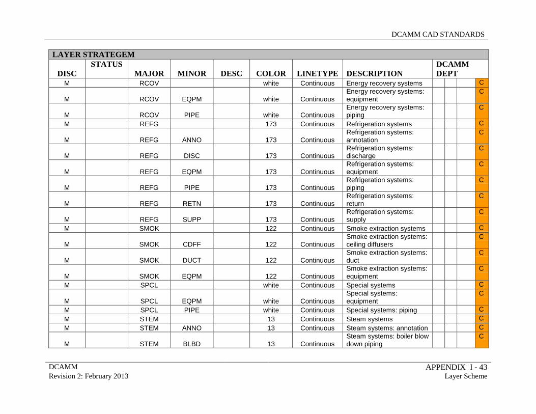
DCAMM CAD STANDARDS
DCAMM APPENDIX I - 43 Revision 2: February 2013 Layer Scheme
LAYER STRATEGEM
DISC STATUS
MAJOR MINOR DESC COLOR LINETYPE DESCRIPTION DCAMM DEPT
M RCOV white Continuous Energy recovery systems C
M
RCOV EQPM white Continuous Energy recovery systems: equipment
C
M
RCOV PIPE white Continuous Energy recovery systems: piping
C
M REFG 173 Continuous Refrigeration systems C
M
REFG ANNO 173 Continuous Refrigeration systems: annotation
C
M
REFG DISC 173 Continuous Refrigeration systems: discharge
C
M
REFG EQPM 173 Continuous Refrigeration systems: equipment
C
M
REFG PIPE 173 Continuous Refrigeration systems: piping
C
M
REFG RETN 173 Continuous Refrigeration systems: return
C
M
REFG SUPP 173 Continuous Refrigeration systems: supply
C
M SMOK 122 Continuous Smoke extraction systems C
M
SMOK CDFF 122 Continuous Smoke extraction systems: ceiling diffusers
C
M
SMOK DUCT 122 Continuous Smoke extraction systems: duct
C
M
SMOK EQPM 122 Continuous Smoke extraction systems: equipment
C
M SPCL white Continuous Special systems C
M
SPCL EQPM white Continuous Special systems: equipment
C
M SPCL PIPE white Continuous Special systems: piping C M STEM 13 Continuous Steam systems C M STEM ANNO 13 Continuous Steam systems: annotation C
M
STEM BLBD 13 Continuous Steam systems: boiler blow down piping
C
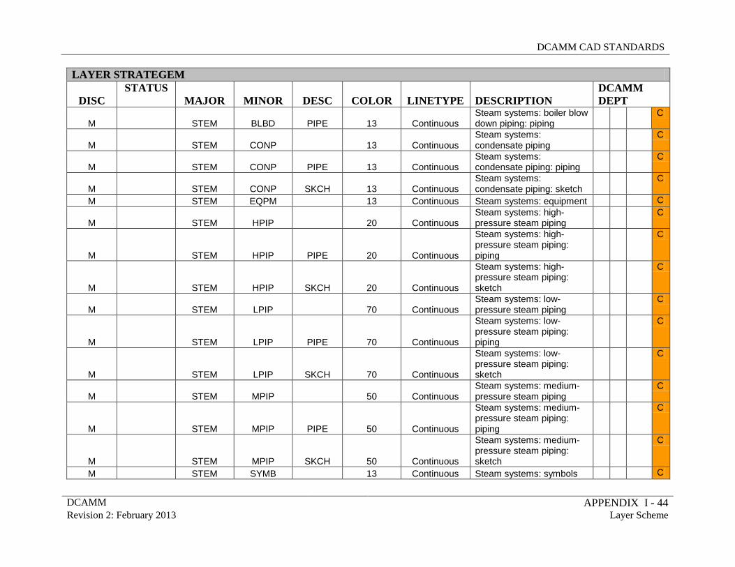
DCAMM CAD STANDARDS
DCAMM APPENDIX I - 44 Revision 2: February 2013 Layer Scheme
LAYER STRATEGEM
DISC STATUS
MAJOR MINOR DESC COLOR LINETYPE DESCRIPTION DCAMM DEPT
M
STEM BLBD PIPE 13 Continuous Steam systems: boiler blow down piping: piping
C
M
STEM CONP 13 Continuous Steam systems: condensate piping
C
M
STEM CONP PIPE 13 Continuous Steam systems: condensate piping: piping
C
M
STEM CONP SKCH 13 Continuous Steam systems: condensate piping: sketch
C
M STEM EQPM 13 Continuous Steam systems: equipment C
M
STEM HPIP 20 Continuous Steam systems: high-pressure steam piping
C
M
STEM HPIP PIPE 20 Continuous
Steam systems: high-pressure steam piping: piping
C
M
STEM HPIP SKCH 20 Continuous
Steam systems: high-pressure steam piping: sketch
C
M
STEM LPIP 70 Continuous Steam systems: low-pressure steam piping
C
M
STEM LPIP PIPE 70 Continuous
Steam systems: low-pressure steam piping: piping
C
M
STEM LPIP SKCH 70 Continuous
Steam systems: low-pressure steam piping: sketch
C
M
STEM MPIP 50 Continuous Steam systems: medium-pressure steam piping
C
M
STEM MPIP PIPE 50 Continuous
Steam systems: medium-pressure steam piping: piping
C
M
STEM MPIP SKCH 50 Continuous
Steam systems: medium-pressure steam piping: sketch
C
M STEM SYMB 13 Continuous Steam systems: symbols C
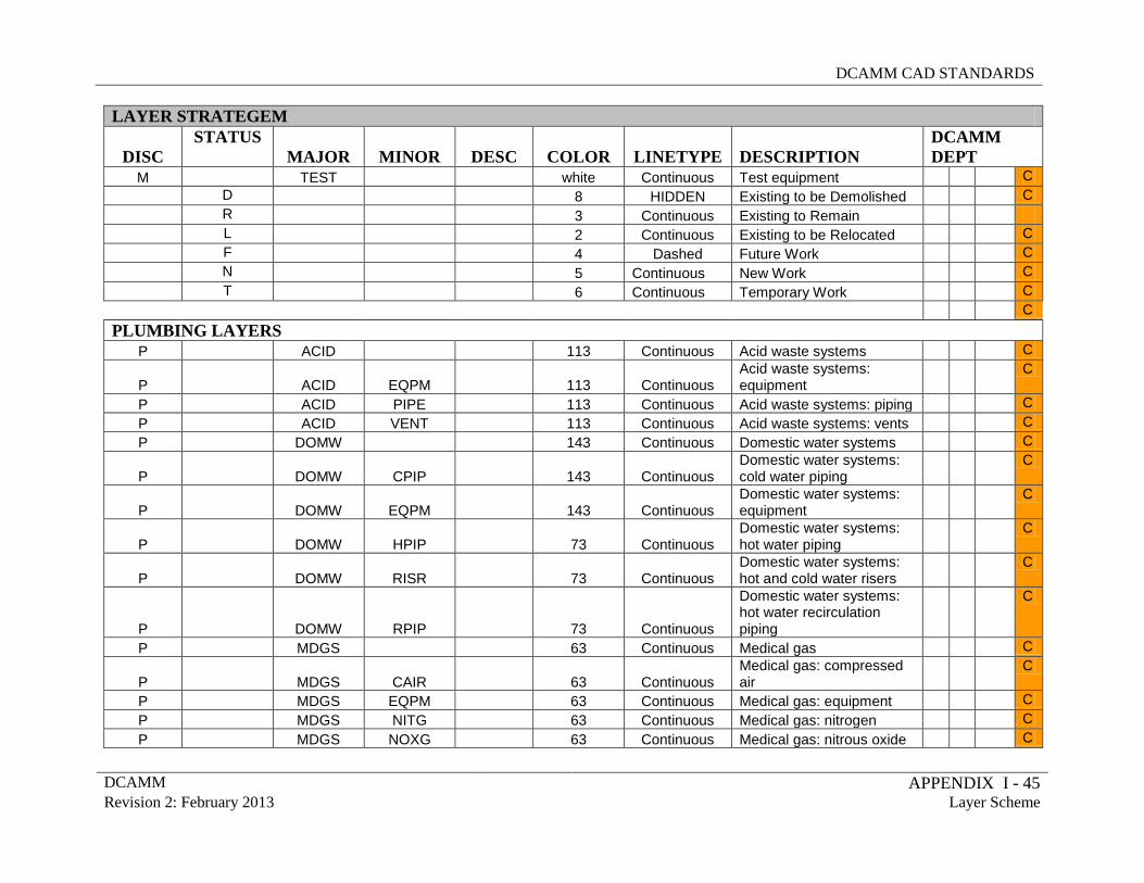
DCAMM CAD STANDARDS
DCAMM APPENDIX I - 45 Revision 2: February 2013 Layer Scheme
LAYER STRATEGEM
DISC STATUS
MAJOR MINOR DESC COLOR LINETYPE DESCRIPTION DCAMM DEPT
M TEST white Continuous Test equipment C D 8 HIDDEN Existing to be Demolished C R 3 Continuous Existing to Remain L 2 Continuous Existing to be Relocated C F 4 Dashed Future Work C N 5 Continuous New Work C T 6 Continuous Temporary Work C C
PLUMBING LAYERS P ACID 113 Continuous Acid waste systems C
P
ACID EQPM 113 Continuous Acid waste systems: equipment
C
P ACID PIPE 113 Continuous Acid waste systems: piping C P ACID VENT 113 Continuous Acid waste systems: vents C P DOMW 143 Continuous Domestic water systems C
P
DOMW CPIP 143 Continuous Domestic water systems: cold water piping
C
P
DOMW EQPM 143 Continuous Domestic water systems: equipment
C
P
DOMW HPIP 73 Continuous Domestic water systems: hot water piping
C
P
DOMW RISR 73 Continuous Domestic water systems: hot and cold water risers
C
P
DOMW RPIP 73 Continuous
Domestic water systems: hot water recirculation piping
C
P MDGS 63 Continuous Medical gas C
P
MDGS CAIR 63 Continuous Medical gas: compressed air
C
P MDGS EQPM 63 Continuous Medical gas: equipment C P MDGS NITG 63 Continuous Medical gas: nitrogen C P MDGS NOXG 63 Continuous Medical gas: nitrous oxide C
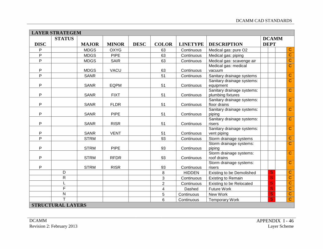
DCAMM CAD STANDARDS
DCAMM APPENDIX I - 46 Revision 2: February 2013 Layer Scheme
LAYER STRATEGEM
DISC STATUS
MAJOR MINOR DESC COLOR LINETYPE DESCRIPTION DCAMM DEPT
P MDGS OXYG 63 Continuous Medical gas: pure O2 C P MDGS PIPE 63 Continuous Medical gas: piping C P MDGS SAIR 63 Continuous Medical gas: scavenge air C
P
MDGS VACU 63 Continuous Medical gas: medical vacuum
C
P SANR 51 Continuous Sanitary drainage systems C
P
SANR EQPM 51 Continuous Sanitary drainage systems: equipment
C
P
SANR FIXT 51 Continuous Sanitary drainage systems: plumbing fixtures
C
P
SANR FLDR 51 Continuous Sanitary drainage systems: floor drains
C
P
SANR PIPE 51 Continuous Sanitary drainage systems: piping
C
P
SANR RISR 51 Continuous Sanitary drainage systems: risers
C
P
SANR VENT 51 Continuous Sanitary drainage systems: vent piping
C
P STRM 93 Continuous Storm drainage systems C
P
STRM PIPE 93 Continuous Storm drainage systems: piping
C
P
STRM RFDR 93 Continuous Storm drainage systems: roof drains
C
P
STRM RISR 93 Continuous Storm drainage systems: risers
C
D 8 HIDDEN Existing to be Demolished S C R 3 Continuous Existing to Remain S C L 2 Continuous Existing to be Relocated S C F 4 Dashed Future Work S C N 5 Continuous New Work S C T 6 Continuous Temporary Work S C
STRUCTURAL LAYERS
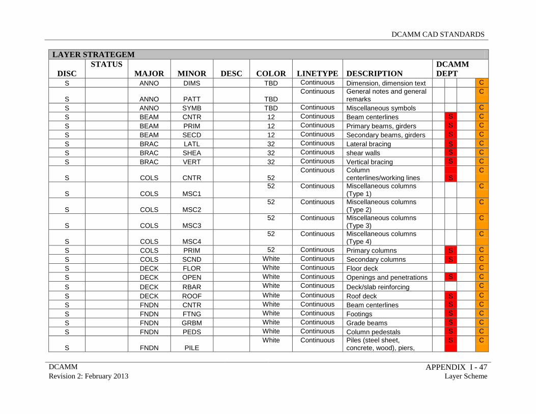
DCAMM CAD STANDARDS
DCAMM APPENDIX I - 47 Revision 2: February 2013 Layer Scheme
LAYER STRATEGEM
DISC STATUS
MAJOR MINOR DESC COLOR LINETYPE DESCRIPTION DCAMM DEPT
S ANNO DIMS TBD Continuous Dimension, dimension text C
S ANNO PATT TBD Continuous General notes and general
remarks C
S ANNO SYMB TBD Continuous Miscellaneous symbols C S BEAM CNTR 12 Continuous Beam centerlines S C S BEAM PRIM 12 Continuous Primary beams, girders S C S BEAM SECD 12 Continuous Secondary beams, girders S C S BRAC LATL 32 Continuous Lateral bracing S C S BRAC SHEA 32 Continuous shear walls S C S BRAC VERT 32 Continuous Vertical bracing S C
S COLS CNTR 52 Continuous Column
centerlines/working lines S C
S COLS MSC1 52 Continuous Miscellaneous columns
(Type 1) C
S COLS MSC2 52 Continuous Miscellaneous columns
(Type 2) C
S COLS MSC3 52 Continuous Miscellaneous columns
(Type 3) C
S COLS MSC4 52 Continuous Miscellaneous columns
(Type 4) C
S COLS PRIM 52 Continuous Primary columns S C S COLS SCND White Continuous Secondary columns S C S DECK FLOR White Continuous Floor deck C S DECK OPEN White Continuous Openings and penetrations S C S DECK RBAR White Continuous Deck/slab reinforcing C S DECK ROOF White Continuous Roof deck S C S FNDN CNTR White Continuous Beam centerlines S C S FNDN FTNG White Continuous Footings S C S FNDN GRBM White Continuous Grade beams S C S FNDN PEDS White Continuous Column pedestals S C
S FNDN PILE White Continuous Piles (steel sheet,
concrete, wood), piers, S
C
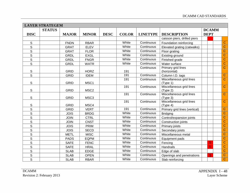
DCAMM CAD STANDARDS
DCAMM APPENDIX I - 48 Revision 2: February 2013 Layer Scheme
LAYER STRATEGEM
DISC STATUS
MAJOR MINOR DESC COLOR LINETYPE DESCRIPTION DCAMM DEPT
caisson piers, drilled piers S FNDN RBAR White Continuous Foundation reinforcing C S GRAT ELEV White Continuous Elevated grating (catwalks) C S GRAT FLOR White Continuous Floor grating C S GRDL EXGL White Continuous Existing ground C S GRDL FNGR White Continuous Finished grade C S GRDL WATR White Continuous Water surface C
S GRID HORZ 191 Continuous Primary grid lines
(horizontal) C
S GRID IDEM 191 Continuous Column I.D. tags C
S GRID MSC1 191 Continuous Miscellaneous grid lines
(Type 1) C
S GRID MSC2 191 Continuous Miscellaneous grid lines
(Type 2) C
S GRID MSC3 191 Continuous Miscellaneous grid lines
(Type 3) C
S GRID MSC4 191 Continuous Miscellaneous grid lines
(Type 4) C
S GRID VERT 191 Continuous Primary grid lines (vertical) C S JOIS BRDG White Continuous Bridging C S JOIN CTRL White Continuous Control/expansion joints C S JOIN CNST White Continuous Construction joints C S JOIS PRIM White Continuous Primary joists C S JOIS SECD White Continuous Secondary joists C S METL MISC White Continuous Miscellaneous metal C S PADS EQPM White Continuous Equipment pads C S SAFE FENC White Continuous Fencing S C S SAFE HRAL White Continuous Handrails S C S SLAB EDGE White Continuous Edge of slab C S SLAB OPEN White Continuous Openings and penetrations S C S SLAB RBAR White Continuous Slab reinforcing C
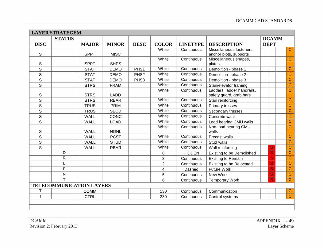
DCAMM CAD STANDARDS
DCAMM APPENDIX I - 49 Revision 2: February 2013 Layer Scheme
LAYER STRATEGEM
DISC STATUS
MAJOR MINOR DESC COLOR LINETYPE DESCRIPTION DCAMM DEPT
S SPPT MISC White Continuous Miscellaneous fasteners,
anchor blots, supports C
S SPPT SHPS White Continuous Miscellaneous shapes,
plates C
S STAT DEMO PHS1 White Continuous Demolition - phase 1 C S STAT DEMO PHS2 White Continuous Demolition - phase 2 C S STAT DEMO PHS3 White Continuous Demolition - phase 3 C S STRS FRAM White Continuous Stair/elevator framing C
S STRS LADD White Continuous Ladders, ladder handrails,
safety guard, grab bars C
S STRS RBAR White Continuous Stair reinforcing C S TRUS PRIM White Continuous Primary trusses C S TRUS SECD White Continuous Secondary trusses C S WALL CONC White Continuous Concrete walls C S WALL LOAD White Continuous Load bearing CMU walls C
S WALL NONL White Continuous Non-load bearing CMU
walls C
S WALL PCST White Continuous Precast walls C S WALL STUD White Continuous Stud walls C S WALL RBAR White Continuous Wall reinforcing S C D 8 HIDDEN Existing to be Demolished S C R 3 Continuous Existing to Remain S C L 2 Continuous Existing to be Relocated S C F 4 Dashed Future Work S C N 5 Continuous New Work S C T 6 Continuous Temporary Work S C
TELECOMMUNICATION LAYERS T COMM 130 Continuous Communication C T CTRL 230 Continuous Control systems C
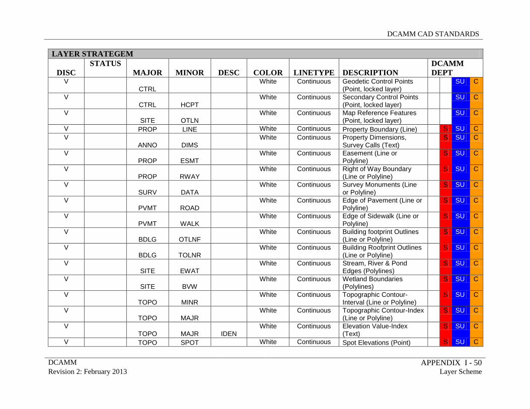
DCAMM CAD STANDARDS
DCAMM APPENDIX I - 50 Revision 2: February 2013 Layer Scheme
LAYER STRATEGEM
DISC STATUS
MAJOR MINOR DESC COLOR LINETYPE DESCRIPTION DCAMM DEPT
V CTRL
White Continuous Geodetic Control Points (Point, locked layer)
SU C
V CTRL HCPT
White Continuous Secondary Control Points (Point, locked layer)
SU C
V SITE OTLN
White Continuous Map Reference Features (Point, locked layer)
SU C
V PROP LINE White Continuous Property Boundary (Line) S SU C V
ANNO DIMS White Continuous Property Dimensions,
Survey Calls (Text) S SU C
V PROP ESMT
White Continuous Easement (Line or Polyline)
S SU C
V PROP RWAY
White Continuous Right of Way Boundary (Line or Polyline)
S SU C
V SURV DATA
White Continuous Survey Monuments (Line or Polyline)
S SU C
V PVMT ROAD
White Continuous Edge of Pavement (Line or Polyline)
S SU C
V PVMT WALK
White Continuous Edge of Sidewalk (Line or Polyline)
S SU C
V BDLG OTLNF
White Continuous Building footprint Outlines (Line or Polyline)
S SU C
V BDLG TOLNR
White Continuous Building Roofprint Outlines (Line or Polyline)
S SU C
V SITE EWAT
White Continuous Stream, River & Pond Edges (Polylines)
S SU C
V SITE BVW
White Continuous Wetland Boundaries (Polylines)
S SU C
V TOPO MINR
White Continuous Topographic Contour-Interval (Line or Polyline)
S SU C
V TOPO MAJR
White Continuous Topographic Contour-Index (Line or Polyline)
S SU C
V TOPO MAJR IDEN
White Continuous Elevation Value-Index (Text)
S SU C
V TOPO SPOT White Continuous Spot Elevations (Point) S SU C
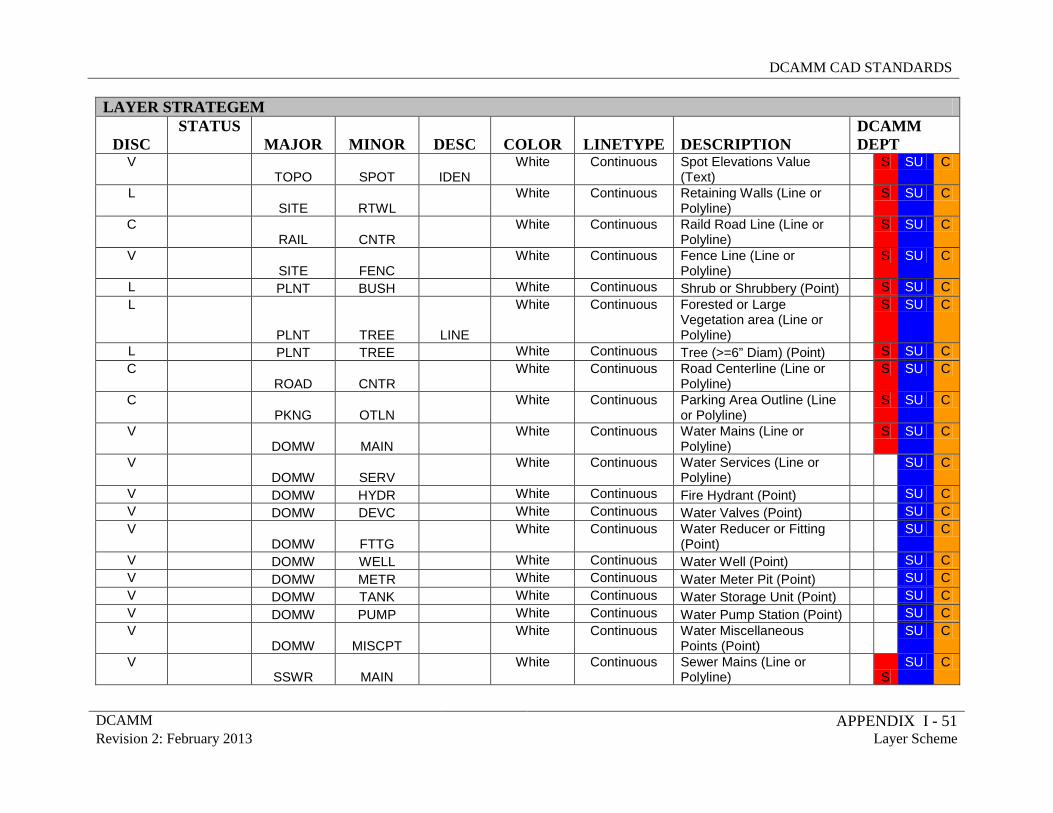
DCAMM CAD STANDARDS
DCAMM APPENDIX I - 51 Revision 2: February 2013 Layer Scheme
LAYER STRATEGEM
DISC STATUS
MAJOR MINOR DESC COLOR LINETYPE DESCRIPTION DCAMM DEPT
V TOPO SPOT IDEN
White Continuous Spot Elevations Value (Text)
S SU C
L SITE RTWL
White Continuous Retaining Walls (Line or Polyline)
S SU C
C RAIL CNTR
White Continuous Raild Road Line (Line or Polyline)
S SU C
V SITE FENC
White Continuous Fence Line (Line or Polyline)
S SU C
L PLNT BUSH White Continuous Shrub or Shrubbery (Point) S SU C L
PLNT TREE LINE
White Continuous Forested or Large Vegetation area (Line or Polyline)
S SU C
L PLNT TREE White Continuous Tree (>=6” Diam) (Point) S SU C C
ROAD CNTR White Continuous Road Centerline (Line or
Polyline) S SU C
C PKNG OTLN
White Continuous Parking Area Outline (Line or Polyline)
S SU C
V DOMW MAIN
White Continuous Water Mains (Line or Polyline)
S SU C
V DOMW SERV
White Continuous Water Services (Line or Polyline)
SU C
V DOMW HYDR White Continuous Fire Hydrant (Point) SU C V DOMW DEVC White Continuous Water Valves (Point) SU C V
DOMW FTTG White Continuous Water Reducer or Fitting
(Point) SU C
V DOMW WELL White Continuous Water Well (Point) SU C V DOMW METR White Continuous Water Meter Pit (Point) SU C V DOMW TANK White Continuous Water Storage Unit (Point) SU C V DOMW PUMP White Continuous Water Pump Station (Point) SU C V
DOMW MISCPT White Continuous Water Miscellaneous
Points (Point) SU C
V SSWR MAIN
White Continuous Sewer Mains (Line or Polyline) S
SU C
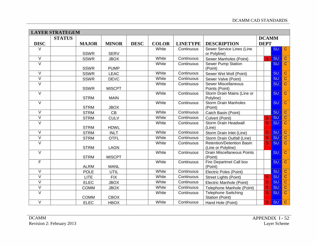
DCAMM CAD STANDARDS
DCAMM APPENDIX I - 52 Revision 2: February 2013 Layer Scheme
LAYER STRATEGEM
DISC STATUS
MAJOR MINOR DESC COLOR LINETYPE DESCRIPTION DCAMM DEPT
V SSWR SERV
White Continuous Sewer Service Lines (Line or Polyline)
SU C
V SSWR JBOX White Continuous Sewer Manholes (Point) S SU C V
SSWR PUMP White Continuous Sewer Pump Station
(Point) SU C
V SSWR LEAC White Continuous Sewer Wet Well (Point) SU C V SSWR DEVC White Continuous Sewer Valve (Point) SU C V
SSWR MISCPT White Continuous Sewer Miscellaneous
Points (Point) SU C
V STRM MAIN
White Continuous Storm Drain Mains (Line or Polyline)
SU C
V STRM JBOX
White Continuous Storm Drain Manholes (Point)
SU C
V STRM CB White Continuous Catch Basin (Point) SU C V STRM CULV White Continuous Culvert (Point) S SU C V
STRM HDWL White Continuous Storm Drain Headwall
(Line) S SU C
V STRM INLT White Continuous Storm Drain Inlet (Line) S SU C V STRM OTFL White Continuous Storm Drain Outfall (Line) S SU C V
STRM LAGN White Continuous Retention/Detention Basin
(Line or Polyline) S SU C
V STRM MISCPT
White Continuous Drain Miscellaneous Points (Point)
SU C
F ALRM MANL
White Continuous Fire Departmet Call box (Point)
SU C
V POLE UTIL White Continuous Electric Poles (Point) SU C V LITE FIX White Continuous Street Lights (Point) S SU C V ELEC JBOX White Continuous Electric Manhole (Point) S SU C V COMM JBOX White Continuous Telephone Manhole (Point) S SU C V
COMM CBOX White Continuous Telephone Switching
Station (Point) S SU C
V ELEC HBOX White Continuous Hand Hole (Point) S SU C
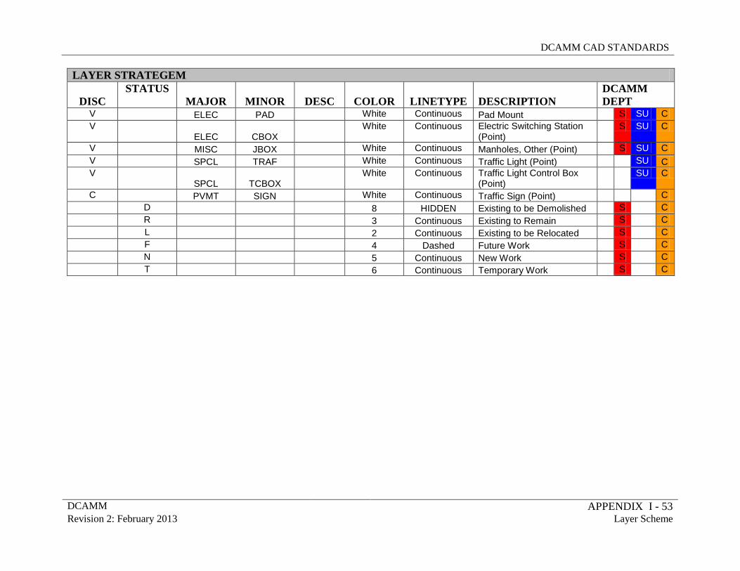
DCAMM CAD STANDARDS
DCAMM APPENDIX I - 53 Revision 2: February 2013 Layer Scheme
LAYER STRATEGEM
DISC STATUS
MAJOR MINOR DESC COLOR LINETYPE DESCRIPTION DCAMM DEPT
V ELEC PAD White Continuous Pad Mount S SU C V
ELEC CBOX White Continuous Electric Switching Station
(Point) S SU C
V MISC JBOX White Continuous Manholes, Other (Point) S SU C V SPCL TRAF White Continuous Traffic Light (Point) SU C V
SPCL TCBOX White Continuous Traffic Light Control Box
(Point) SU C
C PVMT SIGN White Continuous Traffic Sign (Point) C D 8 HIDDEN Existing to be Demolished S C R 3 Continuous Existing to Remain S C L 2 Continuous Existing to be Relocated S C F 4 Dashed Future Work S C N 5 Continuous New Work S C T 6 Continuous Temporary Work S C
DCAMM CAD STANDARDS
DCAMM APPENDIX II Revision 2: February 2013 PEN SETTINGS (CTB)
APPENDIX II
PEN SETTINGS (CTB)
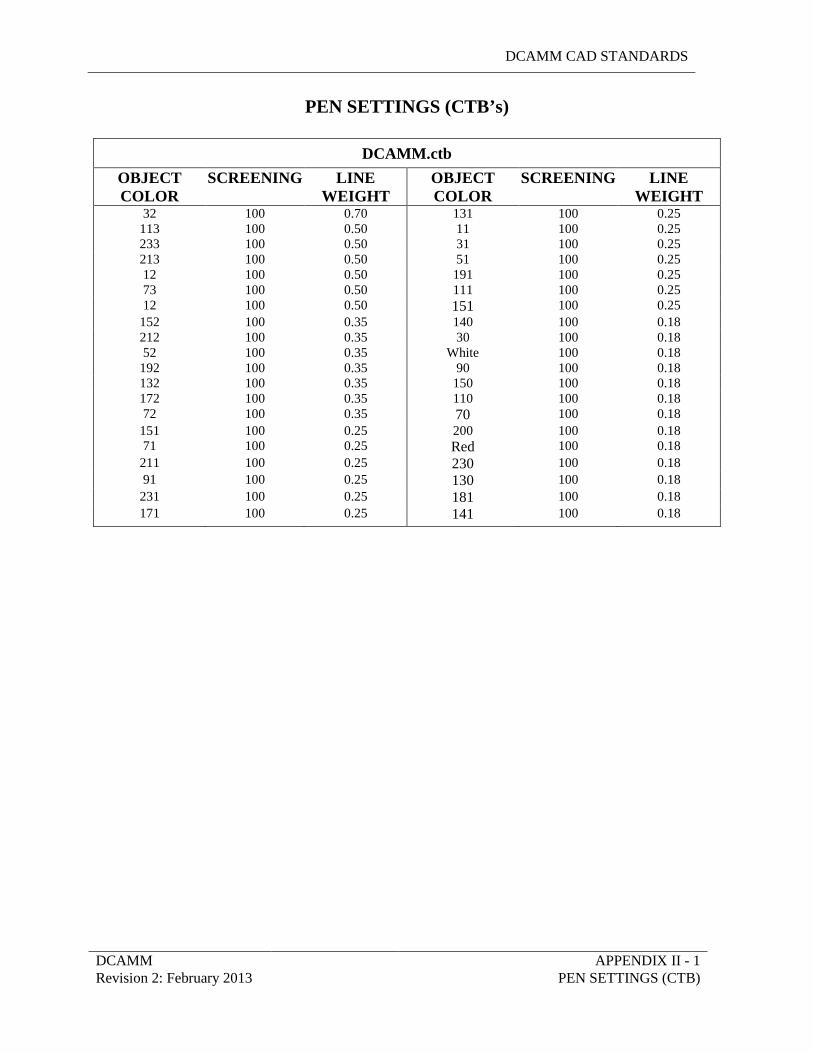
DCAMM CAD STANDARDS
DCAMM APPENDIX II - 1 Revision 2: February 2013 PEN SETTINGS (CTB)
PEN SETTINGS (CTB’s)
DCAMM.ctb
OBJECT COLOR
SCREENING LINE WEIGHT
OBJECT COLOR
SCREENING LINE WEIGHT
32 100 0.70 131 100 0.25 113 100 0.50 11 100 0.25 233 100 0.50 31 100 0.25 213 100 0.50 51 100 0.25 12 100 0.50 191 100 0.25 73 100 0.50 111 100 0.25 12 100 0.50 151 100 0.25
152 100 0.35 140 100 0.18 212 100 0.35 30 100 0.18 52 100 0.35 White 100 0.18
192 100 0.35 90 100 0.18 132 100 0.35 150 100 0.18 172 100 0.35 110 100 0.18 72 100 0.35 70 100 0.18
151 100 0.25 200 100 0.18 71 100 0.25 Red 100 0.18
211 100 0.25 230 100 0.18 91 100 0.25 130 100 0.18
231 100 0.25 181 100 0.18 171 100 0.25 141 100 0.18
DCAMM CAD STANDARDS
DCAMM APPENDIX III Revision 2: February 2013 PLOTTING TO PDF
APPENDIX III
PLOTTING TO PDF
DCAMM CAD STANDARDS
DCAMM APPENDIX III-1 Revision 2: February 2013 PLOTTING TO PDF
WHAT IS A PDF FILE?
PDF stands for Portable Document Format. It is an open, secure, file format developed by Adobe for sharing electronic data. The ability to create a PDF is provided with the PDF Writer an additional installation to ADT. A PDF can be viewed and printed using the Adobe Acrobat Reader and can be downloaded for free from the Adobe Web Site.
PLOTTING DRAWINGS TO PDF FORMAT In order to plot a PDF from ADT you will need to have already set up a layout with the appropriate page set up. This is identical to the methodology outlined in the CAD Standards. In the 2011 version of Autocad you now have a default pc3 file for PDF plotting named DWG to PDF. As an alternative to the default ADT PDF writer you can place a copy of the Adobe PDF.pc3, which is included with this document, into the plotters directory of the version of AutoCAD you are using.
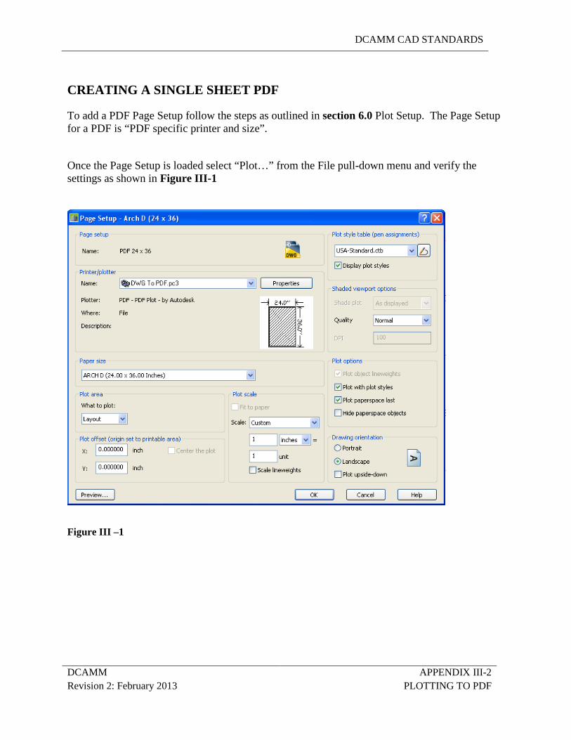
DCAMM CAD STANDARDS
DCAMM APPENDIX III-2 Revision 2: February 2013 PLOTTING TO PDF
CREATING A SINGLE SHEET PDF To add a PDF Page Setup follow the steps as outlined in section 6.0 Plot Setup. The Page Setup for a PDF is “PDF specific printer and size”.
Once the Page Setup is loaded select “Plot…” from the File pull-down menu and verify the settings as shown in Figure III-1
Figure III –1
DCAMM CAD STANDARDS
DCAMM APPENDIX IV Revision 2: February 2013 Creating Page Setups & Plotter Configurations
APPENDIX IV
CREATING PAGE SETUPS AND
PLOTTER CONFIGURATIONS
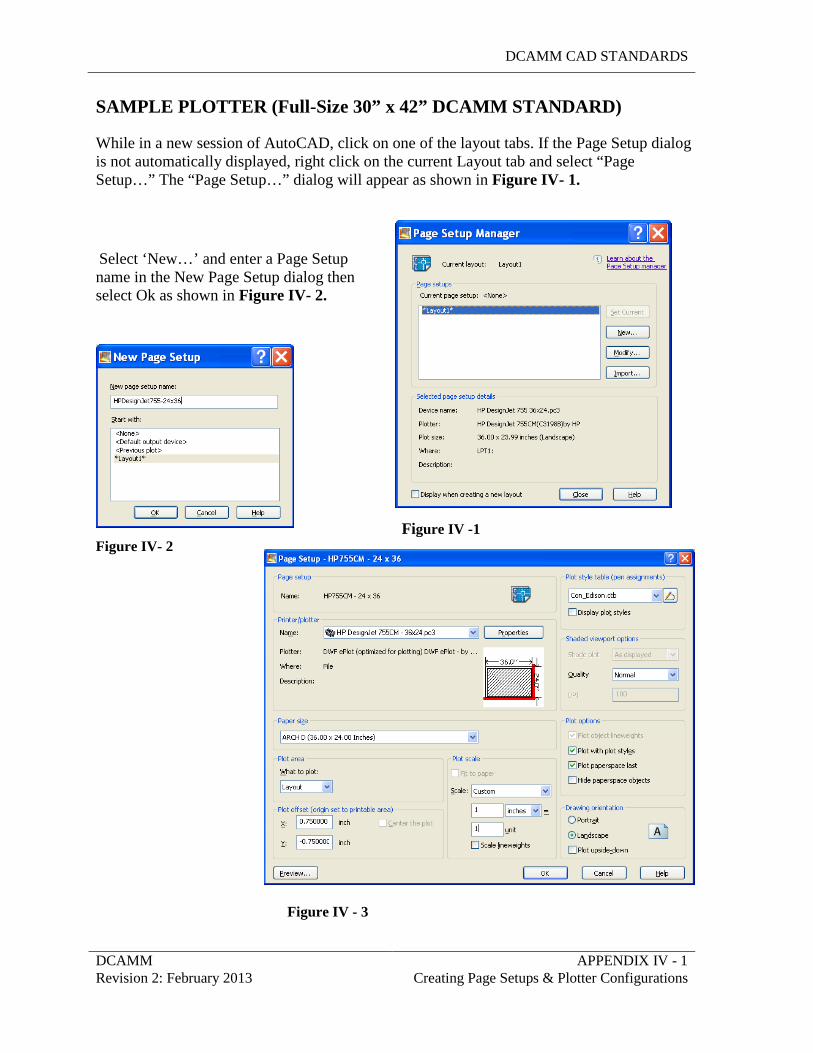
DCAMM CAD STANDARDS
DCAMM APPENDIX IV - 1 Revision 2: February 2013 Creating Page Setups & Plotter Configurations
SAMPLE PLOTTER (Full-Size 30” x 42” DCAMM STANDARD)
While in a new session of AutoCAD, click on one of the layout tabs. If the Page Setup dialog is not automatically displayed, right click on the current Layout tab and select “Page Setup…” The “Page Setup…” dialog will appear as shown in Figure IV- 1.
Select ‘New…’ and enter a Page Setup name in the New Page Setup dialog then select Ok as shown in Figure IV- 2.
Figure IV -1
Figure IV- 2
Figure IV - 3
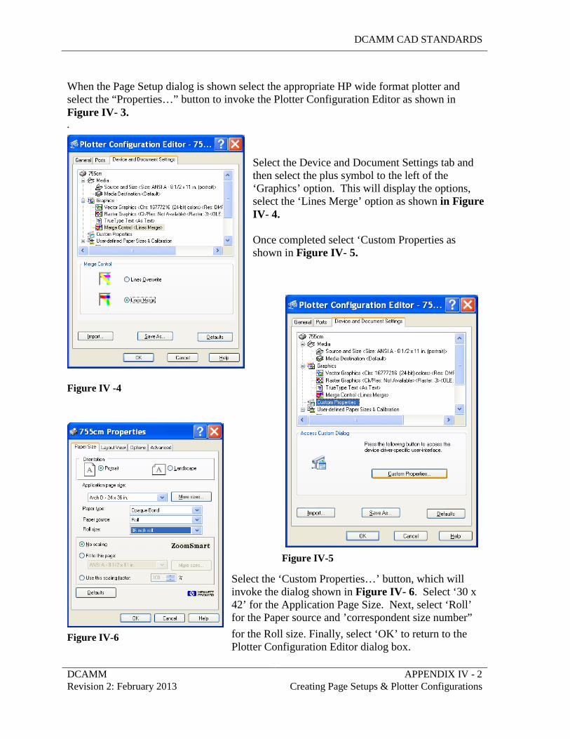
DCAMM CAD STANDARDS
DCAMM APPENDIX IV - 2 Revision 2: February 2013 Creating Page Setups & Plotter Configurations
When the Page Setup dialog is shown select the appropriate HP wide format plotter and select the “Properties…” button to invoke the Plotter Configuration Editor as shown in Figure IV- 3. .
Select the Device and Document Settings tab and then select the plus symbol to the left of the ‘Graphics’ option. This will display the options, select the ‘Lines Merge’ option as shown in Figure IV- 4. Once completed select ‘Custom Properties as shown in Figure IV- 5.
Figure IV -4
Figure IV-5 Select the ‘Custom Properties…’ button, which will invoke the dialog shown in Figure IV- 6. Select ‘30 x 42’ for the Application Page Size. Next, select ‘Roll’ for the Paper source and ’correspondent size number” for the Roll size. Finally, select ‘OK’ to return to the Plotter Configuration Editor dialog box.
Figure IV-6
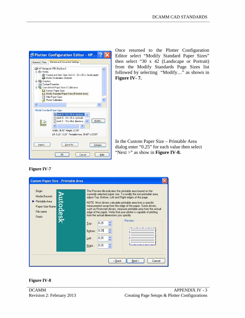
DCAMM CAD STANDARDS
DCAMM APPENDIX IV - 3 Revision 2: February 2013 Creating Page Setups & Plotter Configurations
Once returned to the Plotter Configuration Editor select “Modify Standard Paper Sizes” then select “30 x 42 (Landscape or Portrait) from the Modify Standards Page Sizes list followed by selecting “Modify…” as shown in Figure IV- 7. In the Custom Paper Size – Printable Area dialog enter “0.25” for each value then select “Next >” as show in Figure IV-8.
Figure IV-7
Figure IV-8
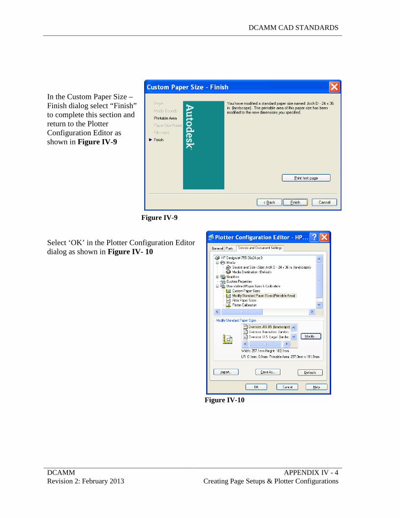
DCAMM CAD STANDARDS
DCAMM APPENDIX IV - 4 Revision 2: February 2013 Creating Page Setups & Plotter Configurations
In the Custom Paper Size – Finish dialog select “Finish” to complete this section and return to the Plotter Configuration Editor as shown in Figure IV-9
Figure IV-9 Select ‘OK’ in the Plotter Configuration Editor dialog as shown in Figure IV- 10
Figure IV-10
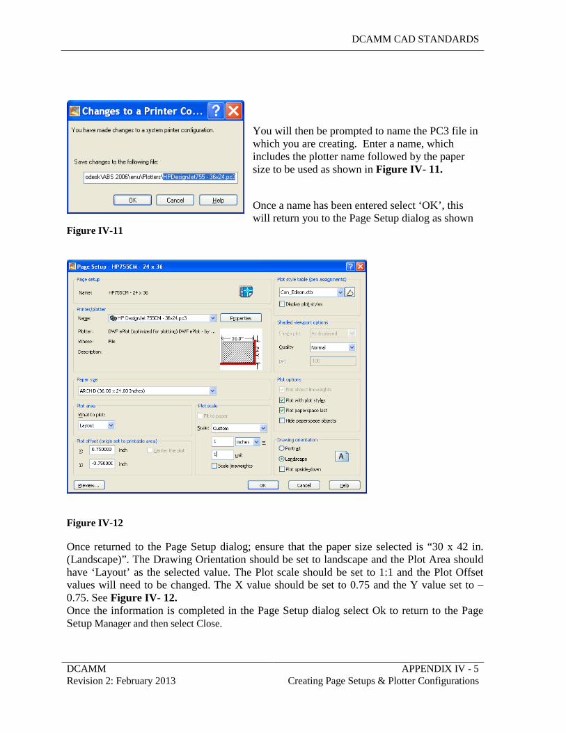
DCAMM CAD STANDARDS
DCAMM APPENDIX IV - 5 Revision 2: February 2013 Creating Page Setups & Plotter Configurations
You will then be prompted to name the PC3 file in which you are creating. Enter a name, which includes the plotter name followed by the paper size to be used as shown in Figure IV- 11. Once a name has been entered select ‘OK’, this will return you to the Page Setup dialog as shown
Figure IV-11
Figure IV-12 Once returned to the Page Setup dialog; ensure that the paper size selected is “30 x 42 in. (Landscape)”. The Drawing Orientation should be set to landscape and the Plot Area should have ‘Layout’ as the selected value. The Plot scale should be set to 1:1 and the Plot Offset values will need to be changed. The X value should be set to 0.75 and the Y value set to –0.75. See Figure IV- 12. Once the information is completed in the Page Setup dialog select Ok to return to the Page Setup Manager and then select Close.
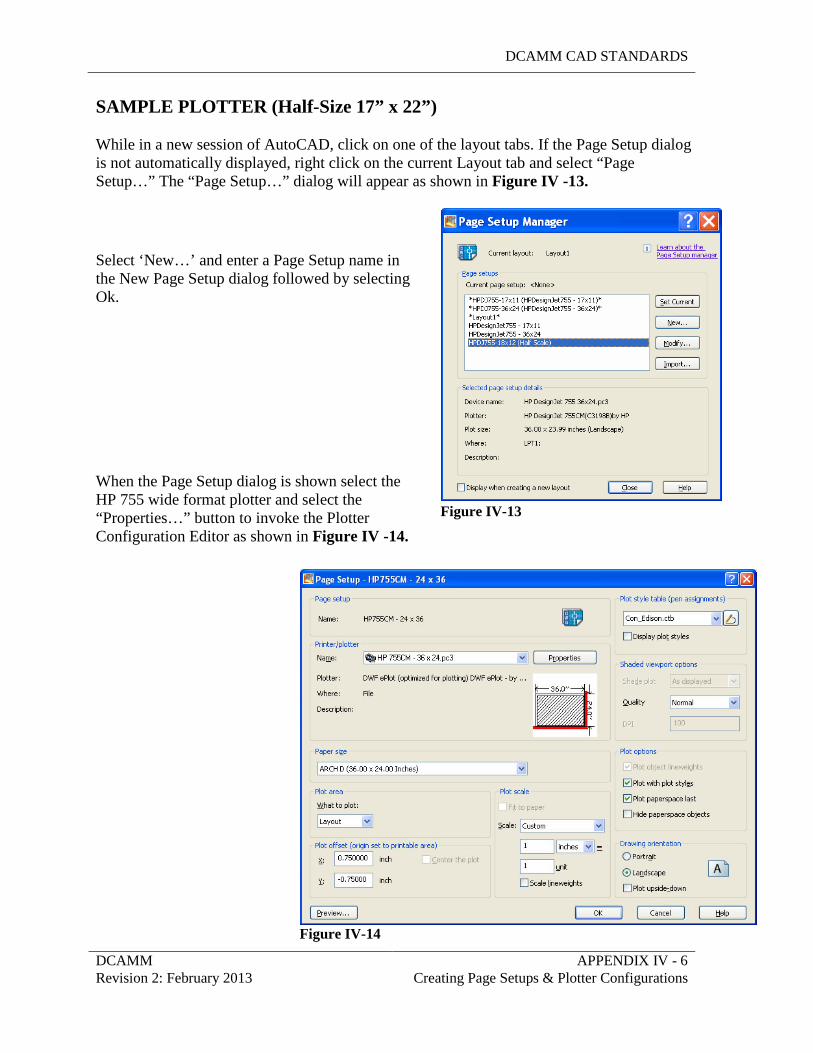
DCAMM CAD STANDARDS
DCAMM APPENDIX IV - 6 Revision 2: February 2013 Creating Page Setups & Plotter Configurations
Figure IV-13
Figure IV-14
SAMPLE PLOTTER (Half-Size 17” x 22”) While in a new session of AutoCAD, click on one of the layout tabs. If the Page Setup dialog is not automatically displayed, right click on the current Layout tab and select “Page Setup…” The “Page Setup…” dialog will appear as shown in Figure IV -13.
Select ‘New…’ and enter a Page Setup name in the New Page Setup dialog followed by selecting Ok.
When the Page Setup dialog is shown select the HP 755 wide format plotter and select the “Properties…” button to invoke the Plotter Configuration Editor as shown in Figure IV -14.
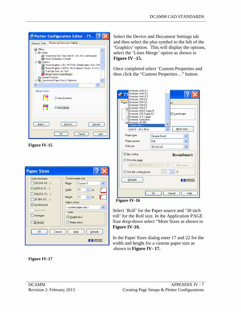
DCAMM CAD STANDARDS
DCAMM APPENDIX IV - 7 Revision 2: February 2013 Creating Page Setups & Plotter Configurations
Select the Device and Document Settings tab and then select the plus symbol to the left of the ‘Graphics’ option. This will display the options, select the ‘Lines Merge’ option as shown in Figure IV -15. Once completed select ‘Custom Properties and then click the “Custom Properties…” button.
Figure IV-15
Figure IV-16 Select ‘Roll’ for the Paper source and ‘30 inch roll’ for the Roll size. In the Application PAGE Size drop-down select “More Sizes as shown in Figure IV-16. In the Paper Sizes dialog enter 17 and 22 for the width and height for a custom paper size as shown in Figure IV- 17.
Figure IV-17
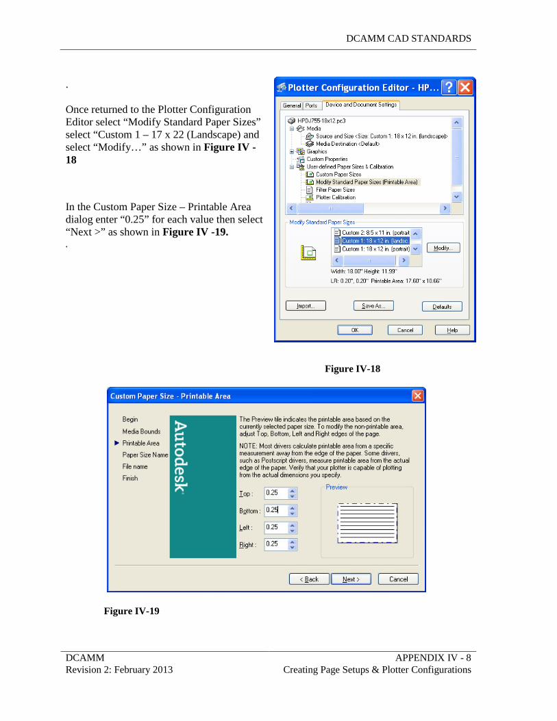
DCAMM CAD STANDARDS
DCAMM APPENDIX IV - 8 Revision 2: February 2013 Creating Page Setups & Plotter Configurations
. Once returned to the Plotter Configuration Editor select “Modify Standard Paper Sizes” select “Custom 1 – 17 x 22 (Landscape) and select “Modify…” as shown in Figure IV -18 In the Custom Paper Size – Printable Area dialog enter “0.25” for each value then select “Next >” as shown in Figure IV -19. .
Figure IV-18
Figure IV-19
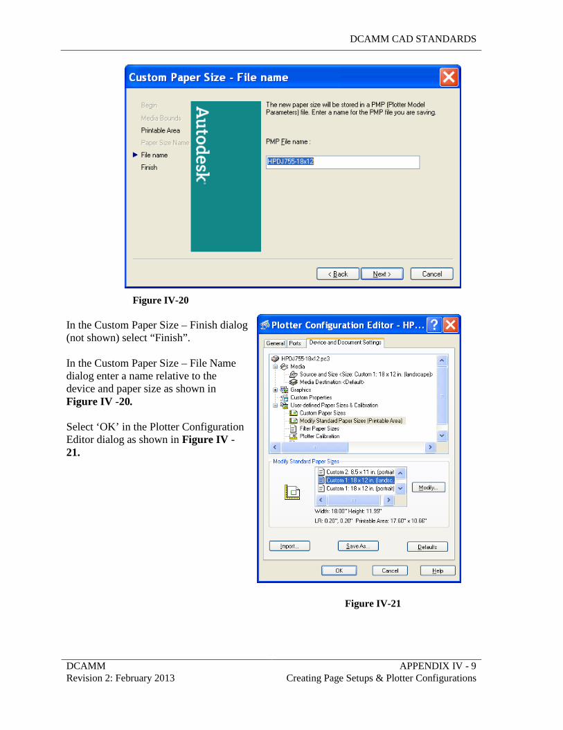
DCAMM CAD STANDARDS
DCAMM APPENDIX IV - 9 Revision 2: February 2013 Creating Page Setups & Plotter Configurations
Figure IV-20 In the Custom Paper Size – Finish dialog (not shown) select “Finish”. In the Custom Paper Size – File Name dialog enter a name relative to the device and paper size as shown in Figure IV -20. Select ‘OK’ in the Plotter Configuration Editor dialog as shown in Figure IV - 21.
Figure IV-21
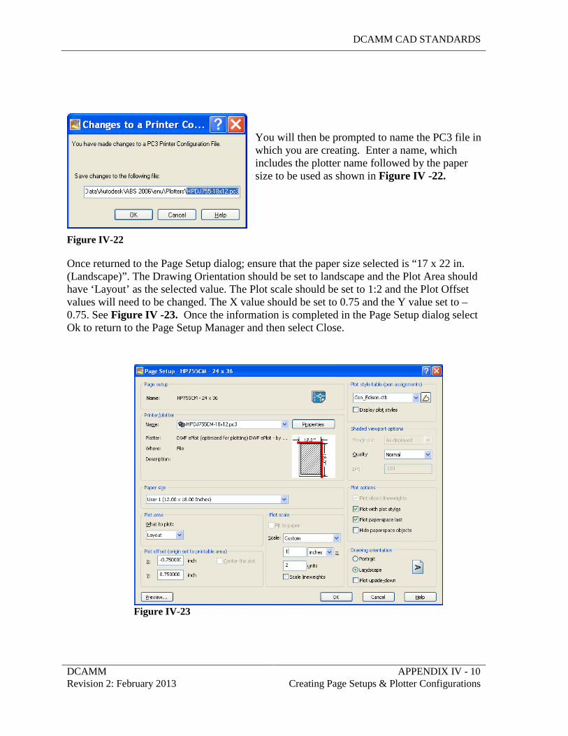
DCAMM CAD STANDARDS
DCAMM APPENDIX IV - 10 Revision 2: February 2013 Creating Page Setups & Plotter Configurations
You will then be prompted to name the PC3 file in which you are creating. Enter a name, which includes the plotter name followed by the paper size to be used as shown in Figure IV -22.
Figure IV-22 Once returned to the Page Setup dialog; ensure that the paper size selected is “17 x 22 in. (Landscape)”. The Drawing Orientation should be set to landscape and the Plot Area should have ‘Layout’ as the selected value. The Plot scale should be set to 1:2 and the Plot Offset values will need to be changed. The X value should be set to 0.75 and the Y value set to –0.75. See Figure IV -23. Once the information is completed in the Page Setup dialog select Ok to return to the Page Setup Manager and then select Close.
Figure IV-23
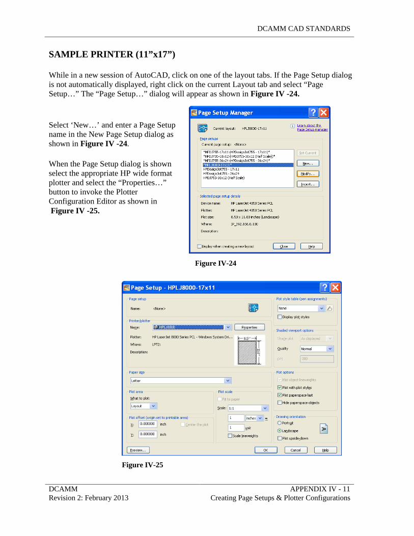
DCAMM CAD STANDARDS
DCAMM APPENDIX IV - 11 Revision 2: February 2013 Creating Page Setups & Plotter Configurations
SAMPLE PRINTER (11”x17”) While in a new session of AutoCAD, click on one of the layout tabs. If the Page Setup dialog is not automatically displayed, right click on the current Layout tab and select “Page Setup…” The “Page Setup…” dialog will appear as shown in Figure IV -24. Select ‘New…’ and enter a Page Setup name in the New Page Setup dialog as shown in Figure IV -24. When the Page Setup dialog is shown select the appropriate HP wide format plotter and select the “Properties…” button to invoke the Plotter Configuration Editor as shown in Figure IV -25. Figure IV-24 Figure IV-25
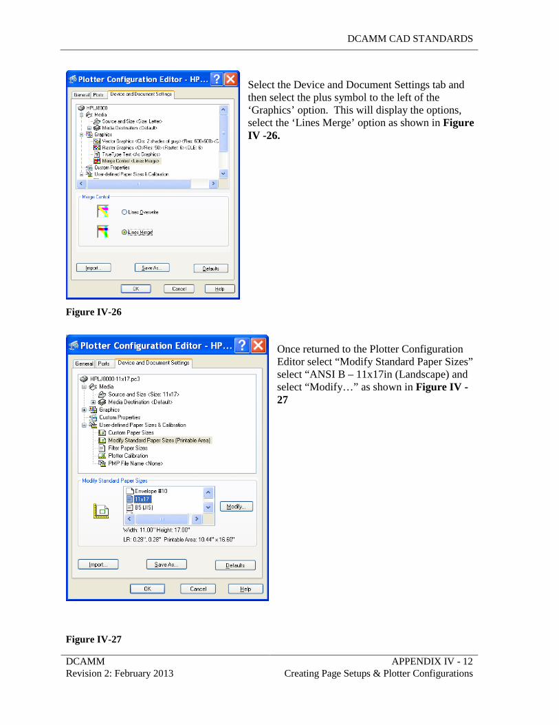
DCAMM CAD STANDARDS
DCAMM APPENDIX IV - 12 Revision 2: February 2013 Creating Page Setups & Plotter Configurations
Select the Device and Document Settings tab and then select the plus symbol to the left of the ‘Graphics’ option. This will display the options, select the ‘Lines Merge’ option as shown in Figure IV -26.
Figure IV-26
Once returned to the Plotter Configuration Editor select “Modify Standard Paper Sizes” select “ANSI B – 11x17in (Landscape) and select “Modify…” as shown in Figure IV -27
Figure IV-27
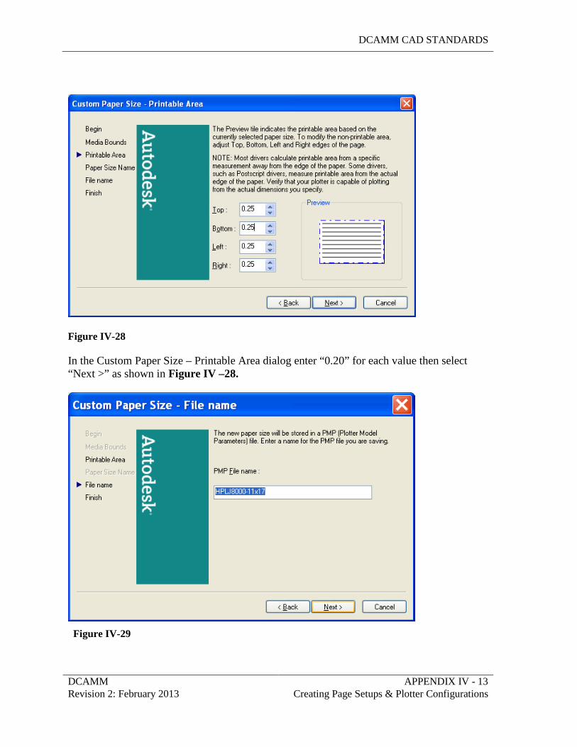
DCAMM CAD STANDARDS
DCAMM APPENDIX IV - 13 Revision 2: February 2013 Creating Page Setups & Plotter Configurations
Figure IV-28 In the Custom Paper Size – Printable Area dialog enter “0.20” for each value then select “Next >” as shown in Figure IV –28.
Figure IV-29
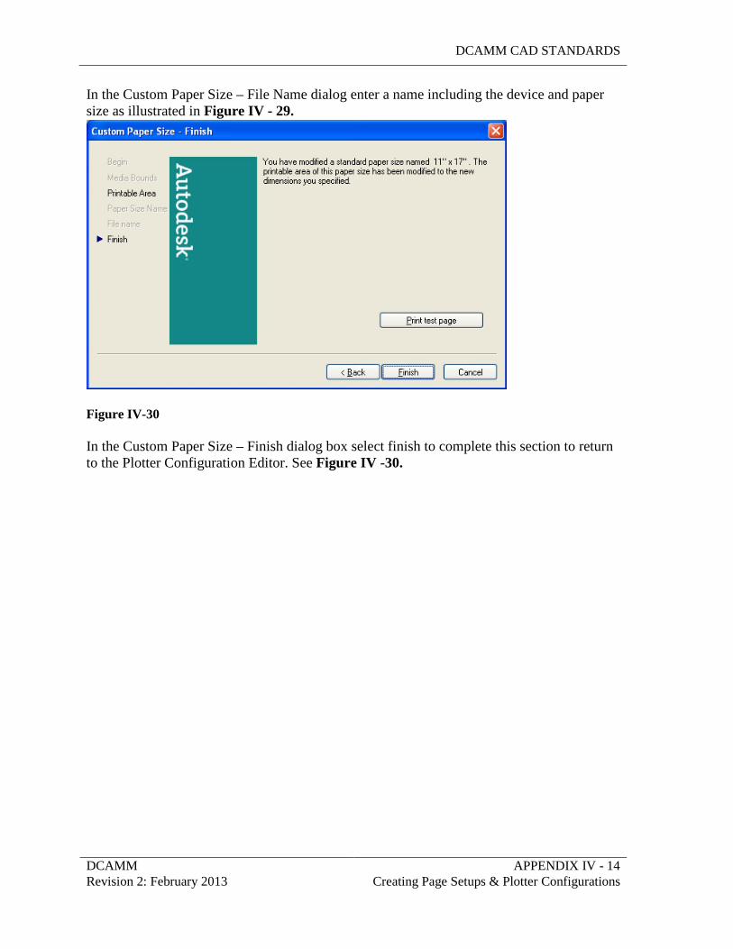
DCAMM CAD STANDARDS
DCAMM APPENDIX IV - 14 Revision 2: February 2013 Creating Page Setups & Plotter Configurations
In the Custom Paper Size – File Name dialog enter a name including the device and paper size as illustrated in Figure IV - 29.
Figure IV-30 In the Custom Paper Size – Finish dialog box select finish to complete this section to return to the Plotter Configuration Editor. See Figure IV -30.
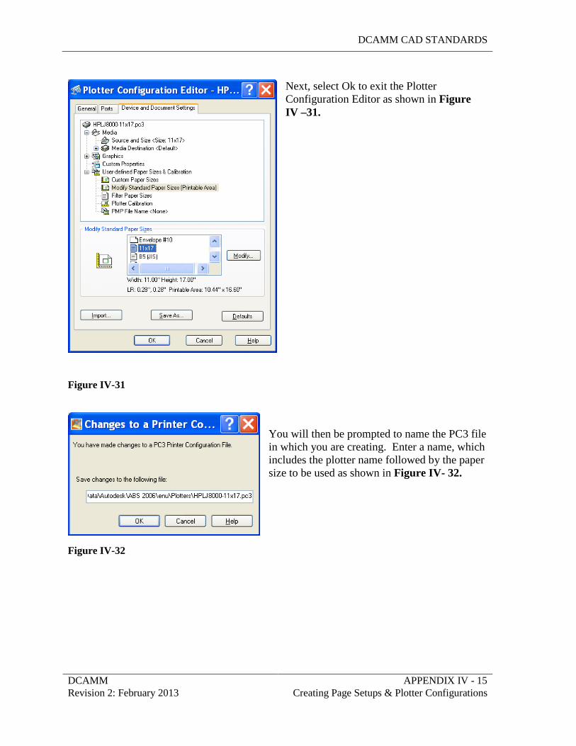
DCAMM CAD STANDARDS
DCAMM APPENDIX IV - 15 Revision 2: February 2013 Creating Page Setups & Plotter Configurations
Next, select Ok to exit the Plotter Configuration Editor as shown in Figure IV –31.
Figure IV-31
You will then be prompted to name the PC3 file in which you are creating. Enter a name, which includes the plotter name followed by the paper size to be used as shown in Figure IV- 32.
Figure IV-32
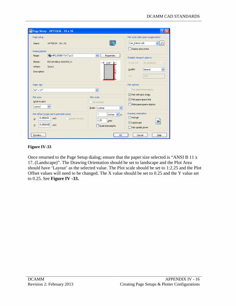
DCAMM CAD STANDARDS
DCAMM APPENDIX IV - 16 Revision 2: February 2013 Creating Page Setups & Plotter Configurations
Figure IV-33 Once returned to the Page Setup dialog; ensure that the paper size selected is “ANSI B 11 x 17. (Landscape)”. The Drawing Orientation should be set to landscape and the Plot Area should have ‘Layout’ as the selected value. The Plot scale should be set to 1:2.25 and the Plot Offset values will need to be changed. The X value should be set to 0.25 and the Y value set to 0.25. See Figure IV -33.
DCAMM CAD STANDARDS
DCAMM APPENDIX V Revision 2: February 2013 Request to Change Standards
APPENDIX V
REQUEST TO CHANGE STANDARDS
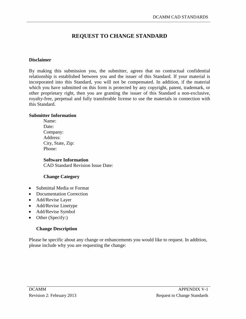
DCAMM CAD STANDARDS
DCAMM APPENDIX V-1 Revision 2: February 2013 Request to Change Standards
REQUEST TO CHANGE STANDARD
Disclaimer
By making this submission you, the submitter, agrees that no contractual confidential relationship is established between you and the issuer of this Standard. If your material is incorporated into this Standard, you will not be compensated. In addition, if the material which you have submitted on this form is protected by any copyright, patent, trademark, or other proprietary right, then you are granting the issuer of this Standard a non-exclusive, royalty-free, perpetual and fully transferable license to use the materials in connection with this Standard.
Submitter Information Name: Date: Company: Address: City, State, Zip: Phone: Software Information CAD Standard Revision Issue Date: Change Category • Submittal Media or Format • Documentation Correction • Add/Revise Layer • Add/Revise Linetype • Add/Revise Symbol • Other (Specify:)
Change Description
Please be specific about any change or enhancements you would like to request. In addition, please include why you are requesting the change:
DCAMM CAD STANDARDS
DCAMM APPENDIX VI Revision 2: February 2013 General CAD Requirements
APPENDIX VI
CAD DRAWING REQUIREMENTS
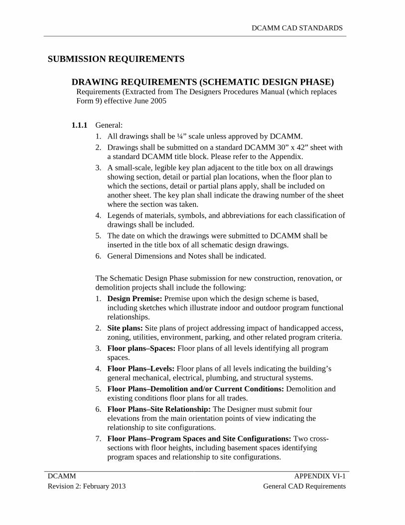
DCAMM CAD STANDARDS
DCAMM APPENDIX VI-1 Revision 2: February 2013 General CAD Requirements
SUBMISSION REQUIREMENTS
DRAWING REQUIREMENTS (SCHEMATIC DESIGN PHASE) Requirements (Extracted from The Designers Procedures Manual (which replaces Form 9) effective June 2005
1.1.1 General:
1. All drawings shall be ¼” scale unless approved by DCAMM. 2. Drawings shall be submitted on a standard DCAMM 30” x 42” sheet with
a standard DCAMM title block. Please refer to the Appendix. 3. A small-scale, legible key plan adjacent to the title box on all drawings
showing section, detail or partial plan locations, when the floor plan to which the sections, detail or partial plans apply, shall be included on another sheet. The key plan shall indicate the drawing number of the sheet where the section was taken.
4. Legends of materials, symbols, and abbreviations for each classification of drawings shall be included.
5. The date on which the drawings were submitted to DCAMM shall be inserted in the title box of all schematic design drawings.
6. General Dimensions and Notes shall be indicated.
The Schematic Design Phase submission for new construction, renovation, or demolition projects shall include the following: 1. Design Premise: Premise upon which the design scheme is based,
including sketches which illustrate indoor and outdoor program functional relationships.
2. Site plans: Site plans of project addressing impact of handicapped access, zoning, utilities, environment, parking, and other related program criteria.
3. Floor plans–Spaces: Floor plans of all levels identifying all program spaces.
4. Floor Plans–Levels: Floor plans of all levels indicating the building’s general mechanical, electrical, plumbing, and structural systems.
5. Floor Plans–Demolition and/or Current Conditions: Demolition and existing conditions floor plans for all trades.
6. Floor Plans–Site Relationship: The Designer must submit four elevations from the main orientation points of view indicating the relationship to site configurations.
7. Floor Plans–Program Spaces and Site Configurations: Two cross-sections with floor heights, including basement spaces identifying program spaces and relationship to site configurations.
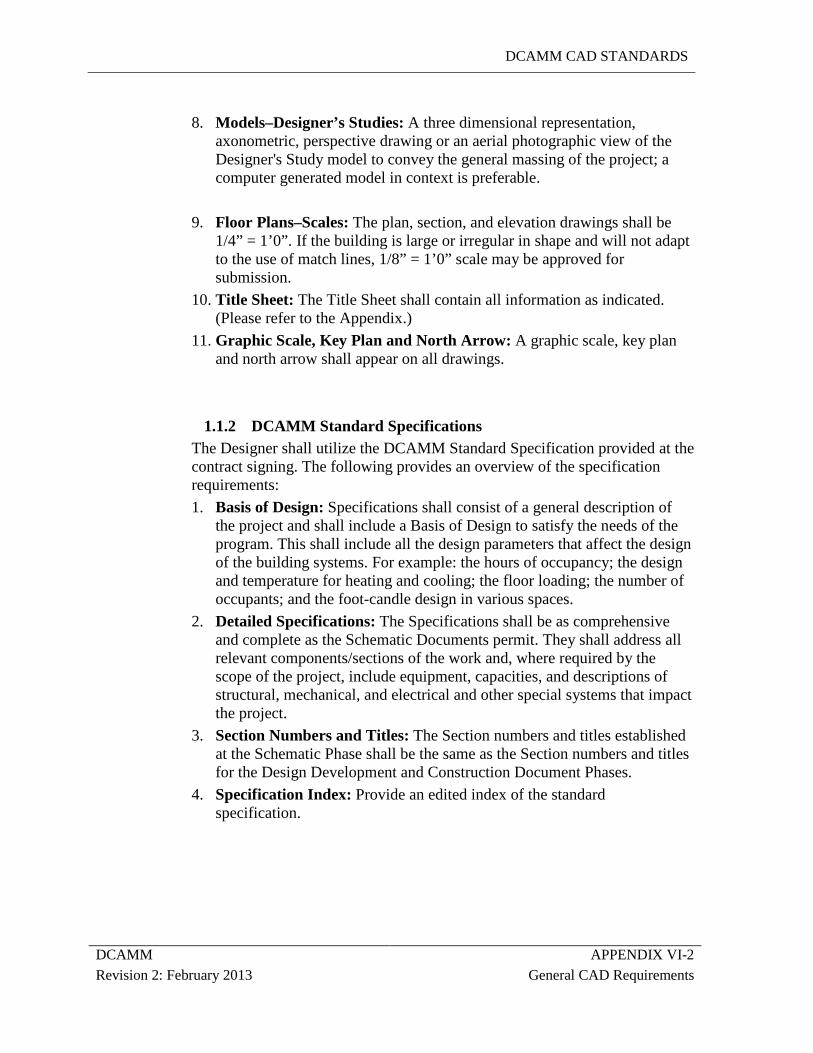
DCAMM CAD STANDARDS
DCAMM APPENDIX VI-2 Revision 2: February 2013 General CAD Requirements
8. Models–Designer’s Studies: A three dimensional representation,
axonometric, perspective drawing or an aerial photographic view of the Designer's Study model to convey the general massing of the project; a computer generated model in context is preferable.
9. Floor Plans–Scales: The plan, section, and elevation drawings shall be
1/4” = 1’0”. If the building is large or irregular in shape and will not adapt to the use of match lines, 1/8” = 1’0” scale may be approved for submission.
10. Title Sheet: The Title Sheet shall contain all information as indicated. (Please refer to the Appendix.)
11. Graphic Scale, Key Plan and North Arrow: A graphic scale, key plan and north arrow shall appear on all drawings.
1.1.2 DCAMM Standard Specifications The Designer shall utilize the DCAMM Standard Specification provided at the contract signing. The following provides an overview of the specification requirements: 1. Basis of Design: Specifications shall consist of a general description of
the project and shall include a Basis of Design to satisfy the needs of the program. This shall include all the design parameters that affect the design of the building systems. For example: the hours of occupancy; the design and temperature for heating and cooling; the floor loading; the number of occupants; and the foot-candle design in various spaces.
2. Detailed Specifications: The Specifications shall be as comprehensive and complete as the Schematic Documents permit. They shall address all relevant components/sections of the work and, where required by the scope of the project, include equipment, capacities, and descriptions of structural, mechanical, and electrical and other special systems that impact the project.
3. Section Numbers and Titles: The Section numbers and titles established at the Schematic Phase shall be the same as the Section numbers and titles for the Design Development and Construction Document Phases.
4. Specification Index: Provide an edited index of the standard specification.
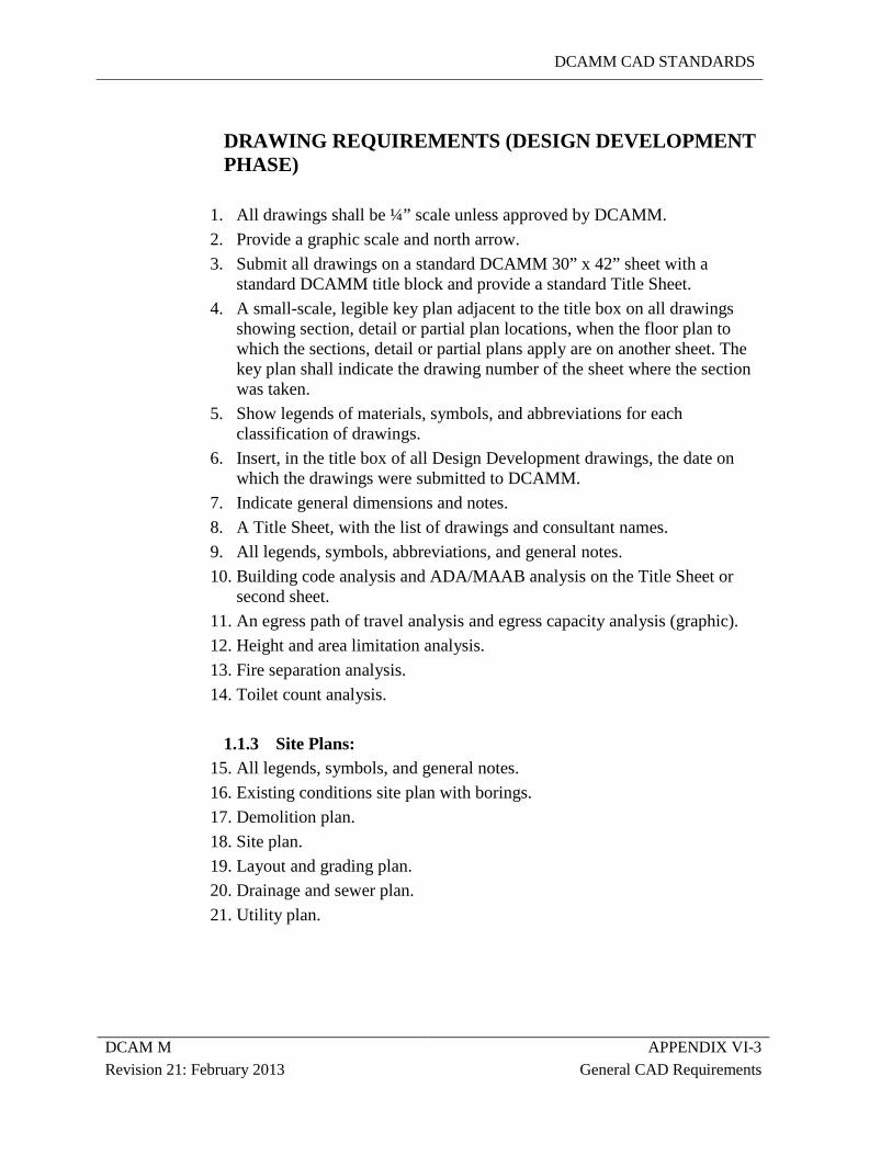
DCAMM CAD STANDARDS
DCAM M APPENDIX VI-3 Revision 21: February 2013 General CAD Requirements
DRAWING REQUIREMENTS (DESIGN DEVELOPMENT PHASE)
1. All drawings shall be ¼” scale unless approved by DCAMM. 2. Provide a graphic scale and north arrow. 3. Submit all drawings on a standard DCAMM 30” x 42” sheet with a
standard DCAMM title block and provide a standard Title Sheet. 4. A small-scale, legible key plan adjacent to the title box on all drawings
showing section, detail or partial plan locations, when the floor plan to which the sections, detail or partial plans apply are on another sheet. The key plan shall indicate the drawing number of the sheet where the section was taken.
5. Show legends of materials, symbols, and abbreviations for each classification of drawings.
6. Insert, in the title box of all Design Development drawings, the date on which the drawings were submitted to DCAMM.
7. Indicate general dimensions and notes. 8. A Title Sheet, with the list of drawings and consultant names. 9. All legends, symbols, abbreviations, and general notes. 10. Building code analysis and ADA/MAAB analysis on the Title Sheet or
second sheet. 11. An egress path of travel analysis and egress capacity analysis (graphic). 12. Height and area limitation analysis. 13. Fire separation analysis. 14. Toilet count analysis.
1.1.3 Site Plans:
15. All legends, symbols, and general notes. 16. Existing conditions site plan with borings. 17. Demolition plan. 18. Site plan. 19. Layout and grading plan. 20. Drainage and sewer plan. 21. Utility plan.
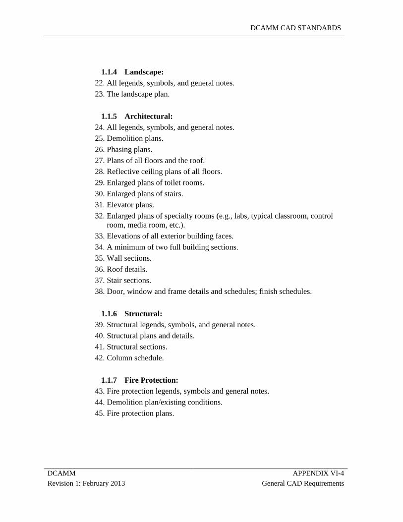
DCAMM CAD STANDARDS
DCAMM APPENDIX VI-4 Revision 1: February 2013 General CAD Requirements
1.1.4 Landscape: 22. All legends, symbols, and general notes. 23. The landscape plan.
1.1.5 Architectural: 24. All legends, symbols, and general notes. 25. Demolition plans. 26. Phasing plans. 27. Plans of all floors and the roof. 28. Reflective ceiling plans of all floors. 29. Enlarged plans of toilet rooms. 30. Enlarged plans of stairs. 31. Elevator plans. 32. Enlarged plans of specialty rooms (e.g., labs, typical classroom, control
room, media room, etc.). 33. Elevations of all exterior building faces. 34. A minimum of two full building sections. 35. Wall sections. 36. Roof details. 37. Stair sections. 38. Door, window and frame details and schedules; finish schedules.
1.1.6 Structural: 39. Structural legends, symbols, and general notes. 40. Structural plans and details. 41. Structural sections. 42. Column schedule.
1.1.7 Fire Protection: 43. Fire protection legends, symbols and general notes. 44. Demolition plan/existing conditions. 45. Fire protection plans.
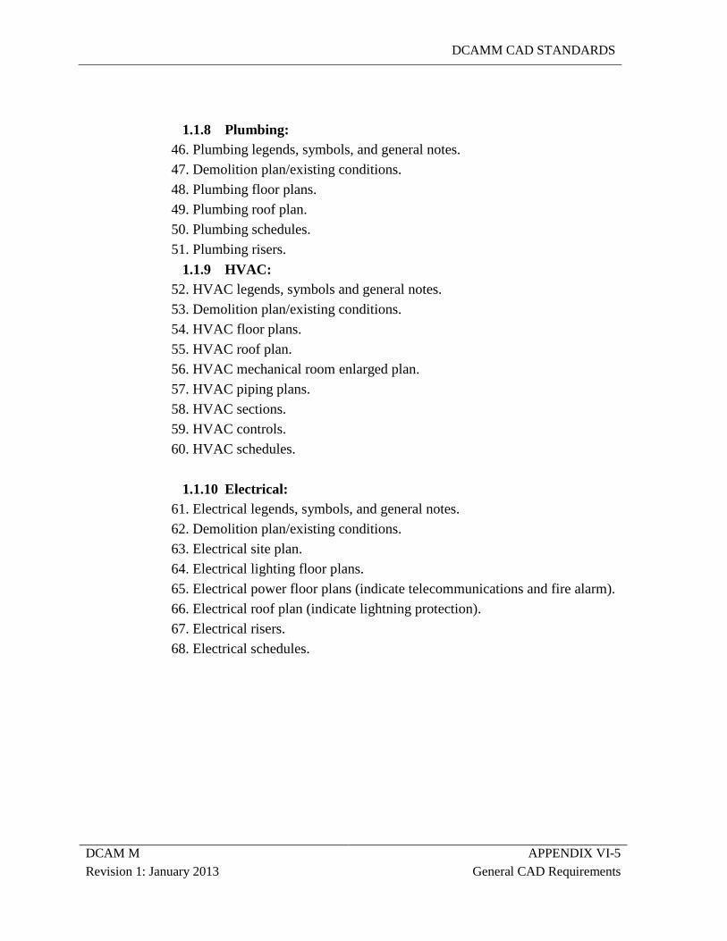
DCAMM CAD STANDARDS
DCAM M APPENDIX VI-5 Revision 1: January 2013 General CAD Requirements
1.1.8 Plumbing: 46. Plumbing legends, symbols, and general notes. 47. Demolition plan/existing conditions. 48. Plumbing floor plans. 49. Plumbing roof plan. 50. Plumbing schedules. 51. Plumbing risers.
1.1.9 HVAC: 52. HVAC legends, symbols and general notes. 53. Demolition plan/existing conditions. 54. HVAC floor plans. 55. HVAC roof plan. 56. HVAC mechanical room enlarged plan. 57. HVAC piping plans. 58. HVAC sections. 59. HVAC controls. 60. HVAC schedules.
1.1.10 Electrical:
61. Electrical legends, symbols, and general notes. 62. Demolition plan/existing conditions. 63. Electrical site plan. 64. Electrical lighting floor plans. 65. Electrical power floor plans (indicate telecommunications and fire alarm). 66. Electrical roof plan (indicate lightning protection). 67. Electrical risers. 68. Electrical schedules.
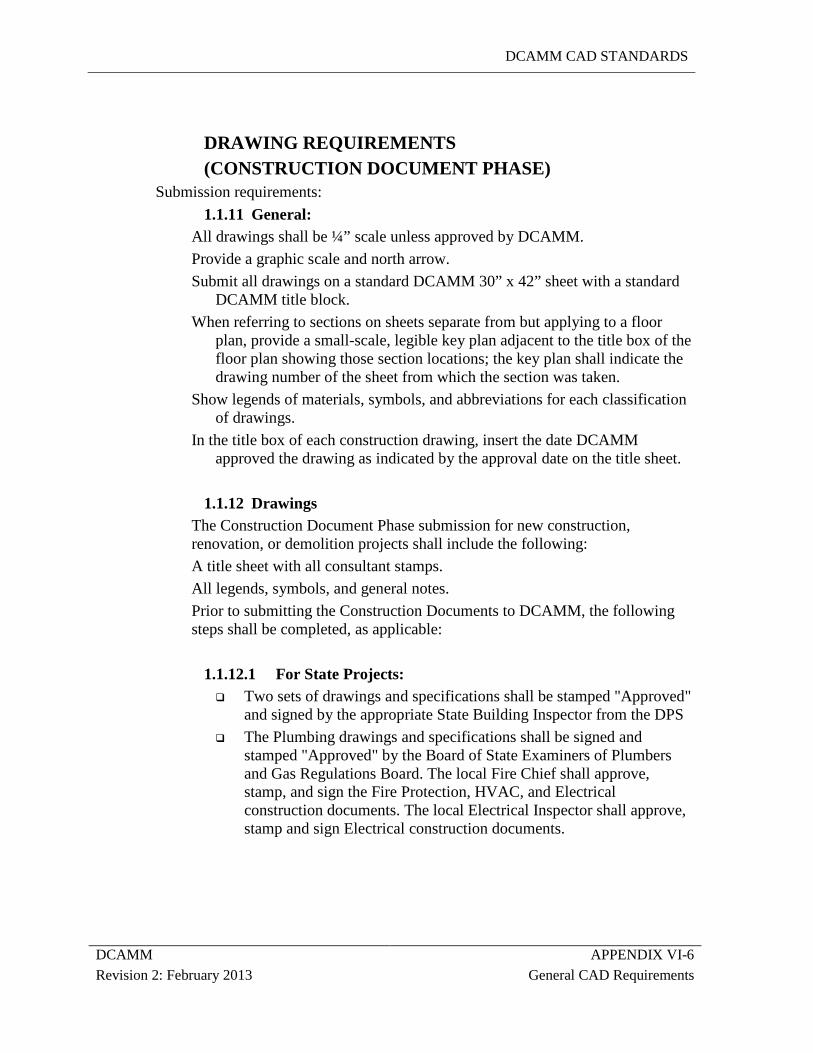
DCAMM CAD STANDARDS
DCAMM APPENDIX VI-6 Revision 2: February 2013 General CAD Requirements
DRAWING REQUIREMENTS (CONSTRUCTION DOCUMENT PHASE)
Submission requirements: 1.1.11 General:
All drawings shall be ¼” scale unless approved by DCAMM. Provide a graphic scale and north arrow. Submit all drawings on a standard DCAMM 30” x 42” sheet with a standard
DCAMM title block. When referring to sections on sheets separate from but applying to a floor
plan, provide a small-scale, legible key plan adjacent to the title box of the floor plan showing those section locations; the key plan shall indicate the drawing number of the sheet from which the section was taken.
Show legends of materials, symbols, and abbreviations for each classification of drawings.
In the title box of each construction drawing, insert the date DCAMM approved the drawing as indicated by the approval date on the title sheet.
1.1.12 Drawings
The Construction Document Phase submission for new construction, renovation, or demolition projects shall include the following: A title sheet with all consultant stamps. All legends, symbols, and general notes. Prior to submitting the Construction Documents to DCAMM, the following steps shall be completed, as applicable:
1.1.12.1 For State Projects: Two sets of drawings and specifications shall be stamped "Approved"
and signed by the appropriate State Building Inspector from the DPS The Plumbing drawings and specifications shall be signed and
stamped "Approved" by the Board of State Examiners of Plumbers and Gas Regulations Board. The local Fire Chief shall approve, stamp, and sign the Fire Protection, HVAC, and Electrical construction documents. The local Electrical Inspector shall approve, stamp and sign Electrical construction documents.
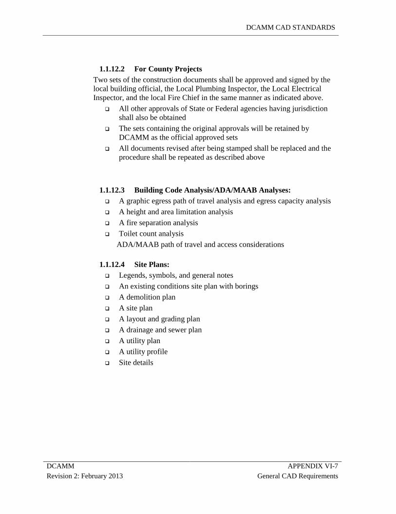
DCAMM CAD STANDARDS
DCAMM APPENDIX VI-7 Revision 2: February 2013 General CAD Requirements
1.1.12.2 For County Projects Two sets of the construction documents shall be approved and signed by the local building official, the Local Plumbing Inspector, the Local Electrical Inspector, and the local Fire Chief in the same manner as indicated above.
All other approvals of State or Federal agencies having jurisdiction shall also be obtained
The sets containing the original approvals will be retained by DCAMM as the official approved sets
All documents revised after being stamped shall be replaced and the procedure shall be repeated as described above
1.1.12.3 Building Code Analysis/ADA/MAAB Analyses: A graphic egress path of travel analysis and egress capacity analysis A height and area limitation analysis A fire separation analysis Toilet count analysis
ADA/MAAB path of travel and access considerations
1.1.12.4 Site Plans: Legends, symbols, and general notes An existing conditions site plan with borings A demolition plan A site plan A layout and grading plan A drainage and sewer plan A utility plan A utility profile Site details
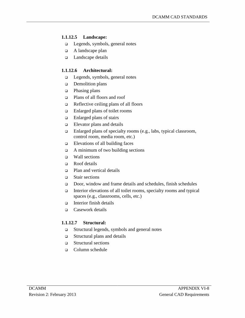
DCAMM CAD STANDARDS
DCAMM APPENDIX VI-8 Revision 2: February 2013 General CAD Requirements
1.1.12.5 Landscape: Legends, symbols, general notes A landscape plan Landscape details
1.1.12.6 Architectural: Legends, symbols, general notes Demolition plans Phasing plans Plans of all floors and roof Reflective ceiling plans of all floors Enlarged plans of toilet rooms Enlarged plans of stairs Elevator plans and details Enlarged plans of specialty rooms (e.g., labs, typical classroom,
control room, media room, etc.) Elevations of all building faces A minimum of two building sections Wall sections Roof details Plan and vertical details Stair sections Door, window and frame details and schedules, finish schedules Interior elevations of all toilet rooms, specialty rooms and typical
spaces (e.g., classrooms, cells, etc.) Interior finish details Casework details
1.1.12.7 Structural: Structural legends, symbols and general notes Structural plans and details Structural sections Column schedule
DCAMM CAD STANDARDS
DCAMM APPENDIX VI-9 Revision 2: February 2013 General CAD Requirements
1.1.12.8 Fire Protection: Fire protection legends, symbols and general notes Demolition plan/existing conditions Fire protection plans Fire protection details
1.1.12.9 Plumbing: Plumbing legends, symbols and general notes Demolition plan/existing conditions Plumbing floor plans Plumbing roof plan Plumbing schedules Plumbing details Plumbing risers
1.1.12.10 HVAC: HVAC legends, symbols and general notes Demolition plan/existing conditions HVAC floor plans HVAC roof plan HVAC mechanical room enlarged plan HVAC piping plans HVAC sections HVAC details HVAC controls HVAC schedules
1.1.12.11 Electrical Electrical legends, symbols, and general notes Demolition plan/existing conditions Electrical site plan Electrical lighting floor plans Electrical power floor plans (indicate telecommunications and fire
alarm) Electrical roof plan (indicate lightning protection) Electrical details Electrical risers Electrical schedules


