Embed Size (px)
Citation preview
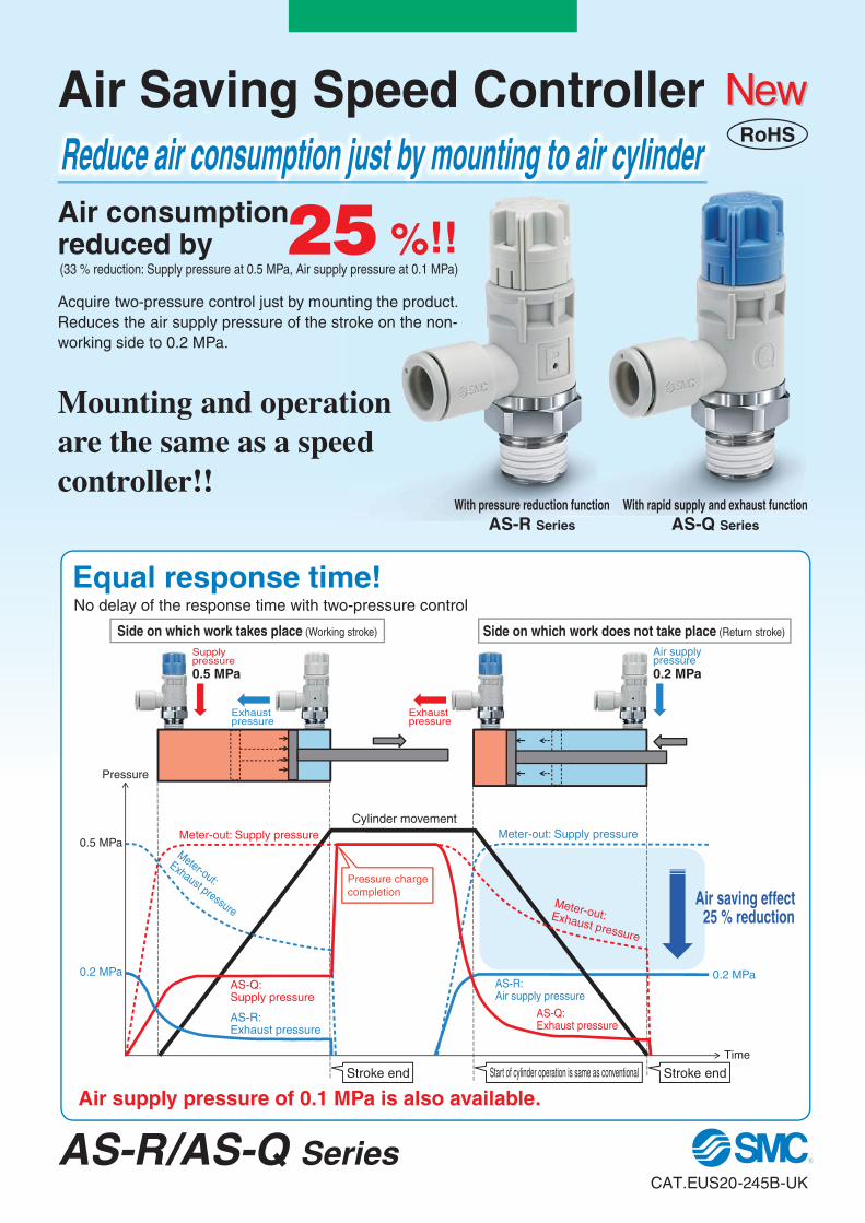
AS-R: Air supply pressure
AS-Q: Supply pressure
AS-R: Exhaust pressure
Meter-out: Supply pressure
0.2 MPa
Cylinder movement
Time
Pressure
0.5 MPa
0.2 MPa
Meter-out: Exhaust pressure
Meter-out: Supply pressure
AS-Q: Exhaust pressure
Exhaust pressure
Exhaust pressure
Supply pressure0.5 MPa
Air supply pressure0.2 MPa
Air saving effect25 % reduction
Stroke end Start of cylinder operation is same as conventional
Pressure charge completion
Meter-out:
Exhaust pressure
Stroke end
Air supply pressure of 0.1 MPa is also available.
With pressure reduction functionAS-R Series
With rapid supply and exhaust functionAS-Q Series
Mounting and operation are the same as a speed controller!!
Reduce air consumption just by mounting to air cylinder
25 %!!Air consumption reduced by
Acquire two-pressure control just by mounting the product. Reduces the air supply pressure of the stroke on the non-working side to 0.2 MPa.
Equal response time!No delay of the response time with two-pressure control
(33 % reduction: Supply pressure at 0.5 MPa, Air supply pressure at 0.1 MPa)
Side on which work takes place (Working stroke) Side on which work does not take place (Return stroke)
RoHS
CAT.EUS20-245B-UK
AS-R/AS-Q Series
Air Saving Speed Controller

∗1 The air consumption reduction rate indicates the rate for one cycle of the cylinder.∗2 Cylinder pressure of return stroke side
0.5
0.6
0.4
0.3
0.2
0.10.3 0.4 0.5 0.6
Air
supp
ly p
ress
ure∗
2 [M
Pa]
Supply pressure [MPa]
Current model (AS-F)
Air consumptionreduced by 25 %
Air Saving Speed Controller (AS-R)
Speed controller with One-touch fitting
Regulator with backflow function
Built-in
With pressure reduction function With rapid supply and
exhaust function
Return stroke
Working stroke
Air Saving Speed Controller AS-R/AS-Q Series Air Saving Speed Controller AS-R/AS-Q Series
Easy Adjustment¡Push-lock type¡Only speed is adjustable.
By reducing the pressure on the return stroke to 0.2 MPa, the air consumption can be reduced. ¡�Improved output response at the stroke end due to rapid air-charge.¡�Improved response time of return stroke due to rapid air exhaust.
As this product is operated by the return stroke at a reduced pressure by the meter-in circuit, a sudden extension of the working stroke is prevented.
The functions of the regulator and speed controller are combined.*1 Comparison of AR20K-02-B + AS22m1F-02-08 and AS22R-02-08
With pressure reduction function
With rapid supply and exhaust function
Working stroke: 0.5 MPa
Return stroke: 0.2 MPa
Marker for fully closed position
Push-lock type
Marker for fully open position
Adjustment can be made every 45 degrees. Fully openFully closed
0°(Fully closed)
270°(Fully open)
45°
90°
135°180°
225°
Compact 85*1
% reduction (Occupied volume: 230 cm3a34 cm3)
0.2 MPa(Air supply pressure)
0.2 MPa(Air supply pressure)
0.5 MPa(Supply pressure)
Air Saving 25*1
% reduction Equal Response Time
Lurch Prevention
With pressure reduction function
AS-R Series
With rapid supply and exhaust functionAS-Q Series
Model(Bodysize)
Portsize
Applicable tubing O.D. Applicabletubing
materialMetric size (Applicable thread: R, G) Inch size (Applicable thread: NPT)
6 8 10 12 1/4" 5/16" 3/8" 1/2"
AS22R-m01-m —2
1/8 Nylon(T, TIA series)
Soft nylon(TS, TISA series)
Polyurethane(TU, TIUB series)
Fluororesin(TLM, TILM series)
(TH, TIH series)
AS22R-m02-m AS22Q-m02-m 1/4
AS32R-m02-m AS32Q-m02-m3
1/4
AS32R-m03-m AS32Q-m03-m 3/8
AS42R-m03-m AS42Q-m03-m4
3/8
AS42R-m04-m AS42Q-m04-m 1/2
Variations
Inch (Orange)
Metric (Light grey)
0.5 MPa(Supply pressure)
0.5 MPa(Supply pressure)
0.5 MPa(Supply pressure)
Knob adjustment range
1 rotation(270°)
1 2

Wor
king
str
oke
m
Ret
urn
stro
ke
m
FWith pressure
reduction function
With rapid supply andexhaust function
Press fitting, Pressing, ClampingApplications which generate force: F (N) at the stroke end of the working stroke
z Applicable cylinder bore sizex Filling of air at the stroke endc Jig weight: m
aRefer to the Model Selection section for Air Saving Speed Controllers (page 7 and 8).
v Force: FaRefer to the Air Cylinders Model Selection.
Use the AS-Q for applications which perform operations at the stroke end.As the AS-Q has a rapid air supply function, items z and x must be specified.
Applicable speed controllers
Caution
With pressure reduction functionAS-R Series
With pressure reduction functionAS-R Series
With rapid supply and exhaust functionAS-Q Series
With rapid supply and exhaust functionAS-Q Series
Applications and Load
Press fitting Pressing Clamping
Jig: m [kg]
Jig: m [kg]
Jig: m [kg]
<Circuit diagram>
Selection of model and load [When AS-Q (with rapid supply and exhaust function) is used]
Air Saving Speed Controller AS-R/AS-Q Series
3

With pressure reduction function
Wor
king
str
oke
m Ret
urn
stro
ke m
W
Working stroke
mW
Return stroke
m
Lifter PusherApplications which lift the workpiece, W (kg), during the working stroke, and with no workpiece load during the return stroke
Applications which transfer a workpiece, W (kg), during the work-ing stroke, and with no workpiece load during the return stroke
z Jig weight: maRefer to the Model Selection section for Air Saving Speed Controllers (page 7 and 8).
x Workpiece: WaRefer to the Air Cylinders Model Selection.
Use a meter-in type speed controller for applications which perform operations during the working stroke. When a meter-in type speed controller is used, pressure corresponding to the load, W, is supplied to the cylinder to transfer the workpiece. Refer to the technical instructions on page 19 for the characteristics of the meter-in and meter-out speed controllers.
Caution
Workpiece: W [kg]
Workpiece: W [kg]
Jig: m [kg]Jig: m [kg]
With pressure reduction functionAS-R Series
With pressure reduction functionAS-R Series
With pressure reduction functionAS-R Series
With pressure reduction functionAS-R Series
Meter-inAS-F Series
Meter-inAS-F Series
Meter-inAS-F Series
Meter-inAS-F Series
<Circuit diagram>
Selection of model and load [When a meter-in type speed controller (AS-F) is used]
Applicable speed controllers
Air Saving Speed Controller AS-R/AS-Q Series
4

With pressure reduction function
0.5 MPa
0.5 MPa
Working stroke
Stroke end
m
Return stroke
W
W
mW
mPressure when reaching the stroke end0.2 MPa
0.2 MPa
z Start the stroke operation by turning the solenoid valve ON.
c The air consumption for the return stroke can be reduced by supplying the pressure which has been reduced by the AS-R.
x The solenoid valve is turned off at the end of the working stroke.a The air consumption can be reduced by shutting
off the air supply before the internal pressure of the cylinder reaches the supply pressure.
Air Cylinder JMB Series
Intermediary bore sizeAir Saving
Speed ControllerAir Consumption (for one cycle)
Speed controllerAir Saving
Speed ControllerAS-R/AS-Q Series
Elbow typeAS Series
Cylinder bore size [mm] Ø 67 (Intermediary bore size) Ø 80
Air consumption [L] 3.1 5.8
46 % reduction
Conditions:Working stroke pressure: 0.5 MPaReturn stroke pressure: 0.2 MPaStroke: 100 mm∗ Utilizing the SMC sizing program.
∗ Comparison of air consumption when the supply pressure is 0.5 MPa∗ In this case, the load to move the workpiece is piston area multiplied by 0.2 MPa.
For example, when an Ø 80 bore cylinder is used in place a Ø 63 mm bore cylinder that does not have enough force, the customer can choose an opti-mally sized Ø 67 mm bore JMB series cylinder. In addition, an AS-R/AS-Q series combined with this cylinder can reduce air consumption by up to 46 %.
Intermediarybore size
Bore size Ø 63 Ø 67 Ø 80
Force Notacceptable
Acceptable(Optimal)
Acceptable(Excessive)
<Load and applicable speed controller>
Pa
Air consumption reduction ratio: 50 %
Air consumption reduction ratio: 46 %
Application Proposal for Air Saving Speed Controller
Pusher¡ Applications which transfer a work-
piece, W (kg), during the working stroke, and with no workpiece (or loading) during the return stroke
¡ The cylinder is returned right after reaching the end of the working stroke so that air consumption can be reduced without unneces-sary charging.
Workpiece: W [kg]
Jig: m [kg]
Combination with the Optimum Size of Cylinder Size
With pressure reduction functionAS-R Series
Meter-inAS-F Series
<Circuit diagram>
Air Saving Speed Controller AS-R/AS-Q Series
5

Model Selection Page 7
Model Page 9
Specifications Page 9
Sonic Conductance and Critical Pressure Ratio Page 9
How to Order Page 10
Flow Rate Characteristics Page 11
Pressure Characteristics (AS-R) Page 11
Cylinder Speed at Maximum Needle Rotation Angle (Guide) Page 12
Construction Page 13
Dimensions: AS-R (Sealant) Page 14
Dimensions: AS-Q (Sealant) Page 15
Dimensions: AS-R (Face seal) Page 16
Dimensions: AS-Q (Face seal) Page 17
Pressure Time Chart Page 18
Construction Principle Page 18
Difference between Meter-in and Meter-out Control Page 19
Specific Product Precautions Page 20
C O N T E N T SAir Saving Speed Controller
AS-R/AS-Q Series
6

AS-R/AS-Q Series
Model Selection
zSelection of Applicable Cylinder Bore SizesThe bore sizes applicable to the air saving speed controller are shown in Table 1.
Table 1 Applicable Cylinder Bore Size
Cylinderbore size
[mm]
AS22R-�-�AS22Q-�-�
AS32R-�-�AS32Q-�-�
AS42R-�-�AS42Q-�-�
32 �
40 �
50 � �
63 �
80 � �
100 �
125 �
xSelection of Allowable Jig WeightsWhen the air saving speed controller is used, the jig weight which is mounted to the cylinder should be below the values in the table below. ∗1
Selection MethodIf a jig exceeding the allowable jig weight is mounted, the driving speed will change greatly in the middle of the cylinder stroke, which may cause a sudden extension.
∗1 If the load varies during the stroke, such to push out a workpiece, do not use the AS-Q for control on the extension side. This can cause a sudden extension. In this case, use a meter-in control type speed controller.
∗2 The coeffi cient of friction of the guide should be 0.5 or less.∗3 Compare the weight specifi ed based on the cylinder stroke and the allowable lateral load shown in the table and select a weight smaller than the ac-
tual weight of the jig.
Table 2 Relation between Cylinder Bore Size and Allowable Weight of Jig Unit: [kg]
Applicable cylinder
bore size[mm]
qHorizontal movement with guide ∗2 wVertical and horizontal movement of the load ∗3
m
m
m
32 3.3 1.6
40 5.1 2.6
50 8.0 4.0
63 12.7 6.4
80 20.5 10.3
100 32.1 16.0
125 50.1 25.0
7

cCalculation of Fill Time at the Stroke End of the AS-Q with Rapid Supply and Exhaust FunctionThe fill time at the stroke end can be calculated by multiplying the value read from the graph shown in Figure 1 by the actual fill volume. However, the applicable piston speed is 50 mm/sec or more.
Example: Use AS22Q, Needle rotation angle: 90° Cylinder tube I.D.: 50 mmStroke: 50 mm
Fill time [s] = Fill time [s/L] read from Fig. 1 x Fill volume [L]Fill volume [L] = Bore size2 [mm2] x π/4 x Stroke [mm]/106
StrokeStroke end
Figure 2. Fill Time Diagram
Fill time
Time
Exhaustpressure Air supply
pressure0.2 MPa
0.5 MPa
Pressure Stroke
Cylinder movement
Figure 1. Relation between Needle Rotation Angle and Fill Time1000
100
10
10 50 100
Needle rotation angle [ ]
200 250 300150
Fill
tim
e [s
/L]
25
AS22Q
AS42Q
AS32Q
Fill time = 25 [s/L] x 0.098 [L]= 2.45 [s]
Fill volume = 502 x π/4 x 50/106
= 0.098 [L]
Supply pressure at 0.5 MPa
8
Model Selection AS-R/AS-Q Series

Flow Direction Symbols on Body
Caution
Be sure to read this before handling the prod-ucts. Refer to the back cover for safety instruc-tions. For flow control equipment precautions, refer to the “Handling Precautions for SMC Products” and the “Operation Manual” on the SMC website: http://www.smc.eu
Air Saving Speed Controller with Pressure Reduction Function/ with Rapid Supply and Exhaust Function
AS-R/AS-Q SeriesModel
AS-R AS-Q
Sym
bol
Model Port size
Applicable tubing O.D.
Metric size(Applicable thread: R, G)
Inch size(Applicable thread: NPT)
6 8 10 12 1/4" 5/16" 3/8" 1/2"
AS22R-�01-� — 1/8 � � � � �
AS22R-�02-� AS22Q-�02-� 1/4 � � � � �
AS32R-�02-� AS32Q-�02-� 1/4 � � � � �
AS32R-�03-� AS32Q-�03-� 3/8 � � � � �
AS42R-�03-� AS42Q-�03-� 3/8 � � � �
AS42R-�04-� AS42Q-�04-� 1/2 � � � �
Specifi cations
ItemWith pressure reduction function
AS-RWith rapid supply and exhaust function
AS-QFluid Air
Proof pressure 1.05 MPa
Maximum operating pressure 0.7 MPa
Minimum operating pressure 0.3 MPa
Set pressure(Supply pressure at 0.5 MPa)
Set pressure for pressure reduction function 0.2 MPa —
Minimum pressure for rapid supply function initiation — 0.2 MPa
Ambient and fluid temperature -5 to 60 °C (No freezing)
Applicable tubing materialNylon, Soft nylon, Polyurethane∗1
FEP, PFA
∗1 Use caution at the maximum operating pressure when using soft nylon or polyurethane tubing.(For details, refer to the Web Catalogue.)
RoHS
Sonic Conductance and Critical Pressure Ratio for Air Saving Speed Controllers
With Pressure Reduction Function: AS-R Series
Model AS22R-01AS22R-02
AS32R-02AS32R-03
AS42R-03AS42R-04
TubingO.D.
Metricsize
Ø 6Ø 8Ø 10
Ø 6 Ø 8 Ø 10 Ø 10 Ø 12
Inch size
Ø 1/4" Ø 5/16" Ø 1/4" Ø 5/16" Ø 3/8" Ø 3/8" Ø 1/2"
C values:Sonic
conductancedm3/(s·bar)
Free flow
1.0 1.4 1.1 1.8 2.2 3.2 3.6
Controlled flow
0.3 0.5 1.0
b values:Critical
pressureratio
Free flow
0.3 0.2 0.3 0.2 0.3
Controlled flow
0.3 0.4 0.4 0.4
∗ C and b values are for controlled fl ow with the needle fully open and free fl ow with the needle fully closed.
With Rapid Supply and Exhaust Function: AS-Q Series
Model AS22Q-02 AS32Q-02AS32Q-03
AS42Q-03AS42Q-04
TubingO.D.
Metricsize
Ø 6Ø 8Ø 10
Ø 6 Ø 8 Ø 10 Ø 10 Ø 12
Inch size
Ø 1/4" Ø 5/16" Ø 1/4" Ø 5/16" Ø 3/8" Ø 3/8" Ø 1/2"
C values:Sonic
conductancedm3/(s·bar)
Free flow
1.0 1.4 1.1 1.8 2.2 3.2 3.6
Controlled flow
0.2 0.6 0.9
b values:Critical
pressureratio
Free flow
0.4 0.3 0.4 0.3 0.2 0.3
Controlled flow
0.6 0.6 0.5 0.6
∗ C and b values are for controlled fl ow with the needle fully open and free fl ow with the needle fully closed.
9

10
How to Order
With pressure reduction function
With rapid supply and exhaust function
AS R
AS Q2
2
2
02
02
06
06
Body size2 1/4 standard
3 3/8 standard
4 1/2 standard
Elbow
Port size01 1/8
02 1/4
03 3/8
04 1/2
Port size02 1/4
03 3/8
04 1/2
∗ Knob colour: White
∗ Knob colour: Light blue
Thread type— R
N NPT
G G
∗ Thread type R and NPT are applied with sealant. Thread type G adopts face seal method.
Applicable tubing O.D.06 Ø 6 07 Ø 1/4"
08 Ø 8 09 Ø 5/16"
10 Ø 10 11 Ø 3/8"
12 Ø 12 13 Ø 1/2"∗ For selecting applicable tubing O.D., refer to the model on page 9. Metric size and inch size types can be visually identifi ed by the colour of the release button.Metric size: Light greyInch size: Orange
With pressure reduction function
With rapid supply and exhaust function
2
Air Saving Speed Controller AS-R/AS-Q Series

1009080706050403020100
0 50 100 150 200 250 300
Needle rotation angle [°]
Flo
w r
ate
[l/m
in(A
NR
)]
0 50 100 150 200 250 300
200
150
100
50
0
Needle rotation angle [°]
Flo
w r
ate
[l/m
in(A
NR
)]
0 50 100 150 200 250 300
400
350
300
250
200
150
100
50
0
Needle rotation angle [°]
Flo
w r
ate
[l/m
in(A
NR
)]
80
70
60
50
40
30
20
10
0
Needle rotation angle [°]
Flo
w r
ate
[l/m
in(A
NR
)]
0 50 100 150 200 250 300
250
200
150
100
50
0
Needle rotation angle [°]
Flo
w r
ate
[l/m
in(A
NR
)]
0 50 100 150 200 250 300
350
300
250
200
150
100
50
0
Needle rotation angle [°]F
low
rat
e [l
/min
(AN
R)]
0 50 100 150 200 250 300
0.4
0.35
0.3
0.25
0.2
0.15
0.1
0.05
00.2 0.3 0.4 0.5 0.6 0.7 0.8
Air
supp
ly p
ress
ure
[MP
a]
Supply pressure [MPa]
0.4
0.35
0.3
0.25
0.2
0.15
0.1
0.05
00.2 0.3 0.4 0.5 0.6 0.7 0.8
Air
supp
ly p
ress
ure
[MP
a]
Supply pressure [MPa]
0.4
0.35
0.3
0.25
0.2
0.15
0.1
0.05
00.2 0.3 0.4 0.5 0.6 0.7 0.8
Air
supp
ly p
ress
ure
[MP
a]
Supply pressure [MPa]
11
AS32QAS22Q AS42Q
Flow Rate Characteristics
With Pressure Reduction Function: AS-R Series (Inlet pressure: 0.5 MPa)
AS22R AS32R AS42R
With Rapid Supply and Exhaust Function: AS-Q Series (Inlet pressure: 0.5 MPa)
∗ The fl ow rate characteristics are representative values.
AS22R AS32R AS42R
Pressure Characteristics (AS-R)
∗ AS-Q does not have a pressure reduction function. The pressure characteristics are not applicable.
Supply pressure
Air supply pressure
AS-R/AS-Q Series

AS-Q: Supply pressure
AS-R: Exhaust pressure
Meter-out: Supply pressure
Cylinder movement
Pressure
0.5 MPa
0.2 MPa
Meter-out: Exhaust pressure
Exhaust pressure
Supply pressure0.5 MPa
Stroke end
Pressure charge completion
Time
12
Cylinder Speed at Maximum Needle Rotation Angle (Guide) Unit: mm/s
Cylinder bore size[mm]
Port size AS22� AS32� AS42�
Ø 50 1/4 220 350 —
Ø 80 3/8 — 240 330
Ø 100 1/2 — — 220
∗ The values shown above are representative and not guaranteed.
As this product is the meter-in control type, it can be operated with less flow rate than the current (meter-out control) type.
[Example]Supply pressure: 0.5 MPaWhen the internal pressure of the tube during cylinder operation with meter-in control is 0.2 MPa, the same cylinder speed can be obtained with half the flow in case of meter-out control.
AS-Q (meter-in type) requires less operating pressure of the cylinder as the operating pressure is low.
� Measurement conditionsCylinder stroke : 150 mmSupply pressure : 0.5 MPaNeedle rotation angle : 270°Load : NoneMounting orientation : Horizontal
Air Saving Speed Controller AS-R/AS-Q Series

13
Construction
Seal method: SealantFor R, NPT thread
AS-R
AS-R
AS-Q
AS-Q
Seal method: Face sealFor G thread
Component PartsNo. Description Material Note
1 Body A PBT
2 Body B Brass Electroless nickel plating
3 Knob POM
4 Needle POM
5 End cover Brass Electroless nickel plating
6 Spring Steel wire
7 U-seal HNBR
8 O-ring NBR
9 Needle O-ring NBR
10 Y-seal NBR
11 Seal for fitting NBR
12 Cassette —
13 Stator POM
14 Valve O-ring HNBR
15 Shaft O-ring NBR
16 Seal NBR
AS-R/AS-Q Series
AL
4
L3
H (Width across flats)L2L1
M T
Ø D
1
Applicable tubing O.D. Ø d
Ø D3
12
9.7
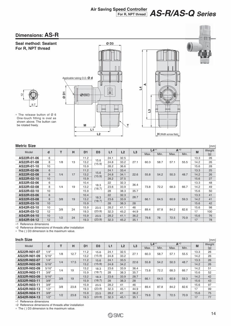
14
Seal method: SealantFor R, NPT thread
Dimensions: AS-R
Metric Size [mm]
Model d T H D1 D3 L1 L2 L3 L4∗1 A∗2M Weight
[g]Max. Min. Max. Min.AS22R-01-06 6
1/8 1311.2
15.6(15.9)
24.1 32.527.1 60.3 58.7 57.1 55.5
13.3 26
AS22R-01-08 8 13.2 24.8 33.2 14.2 26
AS22R-01-10 10 15.9 28.2 36.6 15.6 28
AS22R-02-06 61/4 17
11.215.6
(15.9)
24.1 33.422.6 55.8 54.2 50.3 48.7
13.3 25
AS22R-02-08 8 13.2 24.8 34.1 14.2 26
AS22R-02-10 10 15.9 28.2 37.5 15.6 27
AS32R-02-06 61/4 19
10.418.3
(18.7)
22 32.336.4
73.8 72.2 68.3 66.713.3 48
AS32R-02-08 8 13.2 23.6 33.9 14.2 49
AS32R-02-10 10 15.9 28 38.3 35.7 15.6 50
AS32R-03-06 63/8 19
10.418.3
(18.7)
22 32.328.7
66.1 64.5 60.9 59.313.3 41
AS32R-03-08 8 13.2 23.6 33.9 14.2 41
AS32R-03-10 10 15.9 28 38.3 28 15.6 42
AS42R-03-10 103/8 24
15.9 23.5(23.9)
28.2 41.1 4689.4 87.8 84.2 82.6
15.6 98
AS42R-03-12 12 19.3 32.3 45.2 44.9 17 100
AS42R-04-10 101/2 24
15.9 23.5(23.9)
28.2 41.1 36.279.6 78 72.5 70.9
15.6 76
AS42R-04-12 12 19.3 32.3 45.2 35.1 17 78
∗1 Reference dimensions∗2 Reference dimensions of threads after installation∗ The ( ) D3 dimension is the maximum value.
Inch Size [mm]
Model d T H D1 D3 L1 L2 L3 L4∗1 A∗2M Weight
[g]Max. Min. Max. Min.AS22R-N01-07 1/4"
1/8 12.711.2 15.6
(15.9)24.1 32.5
27.1 60.3 58.7 57.1 55.513.3 26
AS22R-N01-09 5/16" 13.2 24.8 33.2 14.2 26
AS22R-N02-07 1/4"1/4 17.5
11.2 15.6(15.9)
24.1 33.522.6 55.8 54.2 50.3 48.7
13.3 26
AS22R-N02-09 5/16" 13.2 24.8 34.2 14.2 26
AS32R-N02-09 5/16"1/4 19
13.2 18.3(18.7)
23.6 33.9 36.473.8 72.2 68.3 66.7
14.2 51
AS32R-N02-11 3/8" 15.9 28 38.3 35.7 15.6 52
AS32R-N03-09 5/16"3/8 19
13.2 18.3(18.7)
23.6 33.9 28.766.1 64.5 60.9 59.3
14.2 42
AS32R-N03-11 3/8" 15.9 28 38.3 28 15.6 43
AS42R-N03-11 3/8"3/8 23.8
15.9 23.5(23.9)
28.2 41 4689.4 87.8 84.2 82.6
15.6 97
AS42R-N03-13 1/2" 19.3 32.3 45.1 44.9 17 99
AS42R-N04-11 3/8"1/2 23.8
15.9 23.5(23.9)
28.2 41 36.279.6 78 72.5 70.9
15.6 75
AS42R-N04-13 1/2" 19.3 32.3 45.1 35.1 17 77
∗1 Reference dimensions∗2 Reference dimensions of threads after installation∗ The ( ) D3 dimension is the maximum value.
∗ The release button of Ø 6 One-touch fitting is oval as shown above. The button can be rotated freely.
Air Saving Speed ControllerFor R, NPT thread AS-R/AS-Q Series

L3
AL
4H (Width across flats)L2
L1M T
Ø D
1
Ø D3
Applicable tubing O.D. Ø d
12
9.7
15
Seal method: SealantFor R, NPT thread
Dimensions: AS-Q
Metric Size [mm]
Model d T H D1 D3 L1 L2 L3 L4∗1 A∗2M Weight
[g]Max. Min. Max. Min.AS22Q-02-06 6
1/4 1711.2
15.6(15.9)
24.1 33.422.6 55.8 54.2 50.3 48.7
13.3 25
AS22Q-02-08 8 13.2 24.8 34.1 14.2 26
AS22Q-02-10 10 15.9 28.2 37.5 15.6 27
AS32Q-02-06 61/4 19
10.418.3
(18.7)
22 32.336.4
73.8 72.2 68.3 66.713.3 48
AS32Q-02-08 8 13.2 23.6 33.9 14.2 48
AS32Q-02-10 10 15.9 28 38.3 35.7 15.6 49
AS32Q-03-06 63/8 19
10.418.3
(18.7)
22 32.328.7
66.1 64.5 60.9 59.313.3 40
AS32Q-03-08 8 13.2 23.6 33.9 14.2 41
AS32Q-03-10 10 15.9 28 38.3 28 15.6 42
AS42Q-03-10 103/8 24
15.9 23.5(23.9)
28.2 41.1 4689.4 87.8 84.2 82.6
15.6 97
AS42Q-03-12 12 19.3 32.3 45.2 44.9 17 100
AS42Q-04-10 101/2 24
15.9 23.5(23.9)
28.2 41.1 36.279.6 78 72.5 70.9
15.6 76
AS42Q-04-12 12 19.3 32.3 45.2 35.1 17 78
∗1 Reference dimensions∗2 Reference dimensions of threads after installation∗ The ( ) D3 dimension is the maximum value.
Inch Size [mm]
Model d T H D1 D3 L1 L2 L3 L4∗1 A∗2M Weight
[g]Max. Min. Max. Min.AS22Q-N02-07 1/4"
1/4 17.511.2 15.6
(15.9)24.1 33.5
22.6 55.8 54.2 50.3 48.713.3 26
AS22Q-N02-09 5/16" 13.2 24.8 34.2 14.2 26
AS32Q-N02-09 5/16"1/4 19
13.2 18.3(18.7)
23.6 33.9 36.473.8 72.2 68.3 66.7
14.2 50
AS32Q-N02-11 3/8" 15.9 28 38.3 35.7 15.6 52
AS32Q-N03-09 5/16"3/8 19
13.2 18.3(18.7)
23.6 33.9 28.766.1 64.5 60.9 59.3
14.2 42
AS32Q-N03-11 3/8" 15.9 28 38.3 28 15.6 43
AS42Q-N03-11 3/8"3/8 23.8
15.9 23.5(23.9)
28.2 41 4689.4 87.8 84.2 82.6
15.6 97
AS42Q-N03-13 1/2" 19.3 32.3 45.1 44.9 17 99
AS42Q-N04-11 3/8"1/2 23.8
15.9 23.5(23.9)
28.2 41 36.279.6 78 72.5 70.9
15.6 75
AS42Q-N04-13 1/2" 19.3 32.3 45.1 35.1 17 76
∗1 Reference dimensions∗2 Reference dimensions of threads after installation∗ The ( ) D3 dimension is the maximum value.
∗ The release button of Ø 6 One-touch fitting is oval as shown above. The button can be rotated freely.
AS-R/AS-Q Series For R, NPT thread
12
9.7
AL
4
L3
H (Width across flats)
Ø D
1
Applicable tubing O.D. Ø d
Ø D3
T
L2L1
M
16
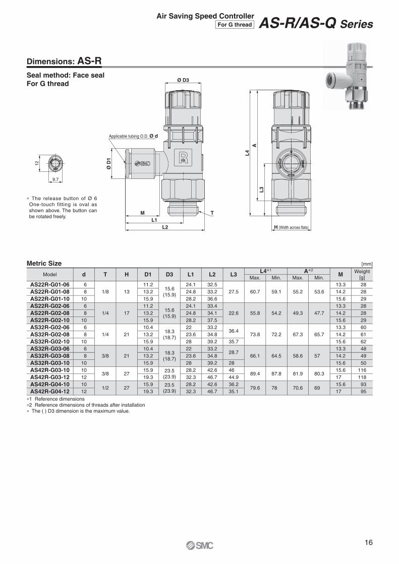
Seal method: Face sealFor G thread
Dimensions: AS-R
Metric Size [mm]
Model d T H D1 D3 L1 L2 L3 L4∗1 A∗2M Weight
[g]Max. Min. Max. Min.AS22R-G01-06 6
1/8 1311.2
15.6(15.9)
24.1 32.527.5 60.7 59.1 55.2 53.6
13.3 28
AS22R-G01-08 8 13.2 24.8 33.2 14.2 28
AS22R-G01-10 10 15.9 28.2 36.6 15.6 29
AS22R-G02-06 61/4 17
11.215.6
(15.9)
24.1 33.422.6 55.8 54.2 49.3 47.7
13.3 28
AS22R-G02-08 8 13.2 24.8 34.1 14.2 28
AS22R-G02-10 10 15.9 28.2 37.5 15.6 29
AS32R-G02-06 61/4 21
10.418.3
(18.7)
22 33.236.4
73.8 72.2 67.3 65.713.3 60
AS32R-G02-08 8 13.2 23.6 34.8 14.2 61
AS32R-G02-10 10 15.9 28 39.2 35.7 15.6 62
AS32R-G03-06 63/8 21
10.418.3
(18.7)
22 33.228.7
66.1 64.5 58.6 5713.3 48
AS32R-G03-08 8 13.2 23.6 34.8 14.2 49
AS32R-G03-10 10 15.9 28 39.2 28 15.6 50
AS42R-G03-10 103/8 27
15.9 23.5(23.9)
28.2 42.6 4689.4 87.8 81.9 80.3
15.6 116
AS42R-G03-12 12 19.3 32.3 46.7 44.9 17 118
AS42R-G04-10 101/2 27
15.9 23.5(23.9)
28.2 42.6 36.279.6 78 70.6 69
15.6 93
AS42R-G04-12 12 19.3 32.3 46.7 35.1 17 95
∗1 Reference dimensions∗2 Reference dimensions of threads after installation∗ The ( ) D3 dimension is the maximum value.
∗ The release button of Ø 6 One-touch fitting is oval as shown above. The button can be rotated freely.
Air Saving Speed ControllerFor G thread AS-R/AS-Q Series

12
9.7
AL
4
L3
H (Width across flats)
øD
1
Applicable tubing O.D. ød
øD3
T
L2L1
M
17
Seal method: Face sealFor G thread
Dimensions: AS-Q
Metric Size [mm]
Model d T H D1 D3 L1 L2 L3 L4∗1 A∗2M Weight
[g]Max. Min. Max. Min.AS22Q-G02-06 6
1/4 1711.2
15.6(15.9)
24.1 33.422.6 55.8 54.2 49.3 47.7
13.3 28
AS22Q-G02-08 8 13.2 24.8 34.1 14.2 28
AS22Q-G02-10 10 15.9 28.2 37.5 15.6 29
AS32Q-G02-06 61/4 21
10.418.3
(18.7)
22 33.236.4
73.8 72.2 67.3 65.713.3 60
AS32Q-G02-08 8 13.2 23.6 34.8 14.2 60
AS32Q-G02-10 10 15.9 28 39.2 35.7 15.6 61
AS32Q-G03-06 63/8 21
10.418.3
(18.7)
22 33.228.7
66.1 64.5 58.6 5713.3 48
AS32Q-G03-08 8 13.2 23.6 34.8 14.2 49
AS32Q-G03-10 10 15.9 28 39.2 28 15.6 50
AS42Q-G03-10 103/8 27
15.9 23.5(23.9)
28.2 42.6 4689.4 87.8 81.9 80.3
15.6 115
AS42Q-G03-12 12 19.3 32.3 46.7 44.9 17 117
AS42Q-G04-10 101/2 27
15.9 23.5(23.9)
28.2 42.6 36.279.6 78 70.6 69
15.6 92
AS42Q-G04-12 12 19.3 32.3 46.7 35.1 17 94
∗1 Reference dimensions∗2 Reference dimensions of threads after installation∗ The ( ) D3 dimension is the maximum value.
∗ The release button of Ø 6 One-touch fitting is oval as shown above. The button can be rotated freely.
AS-R/AS-Q Series For G thread

PH
PR
Time
Pre
ssur
eS
trok
e
PHPR
Time
Pre
ssur
eS
trok
e
For AS-Q
Meter-in
For AS-REnergy saving effect
Fixed pressure0.2 MPa
Cylinder m
ovement
Cylind
er m
ovem
ent
PR
Pre
ssur
e
PRPH
Time
Pre
ssur
e
PH
Time
Pressure reducedAir supplied rapidly
Flow adjustment part
To cylinder
Air flow Air flow
To cylinder
Needle
When the pressure reach-es the set pressure (0.2 MPa), the valve is closed and the rod side pressure is reduced.
When the piston receives pres-sure, the flow adjustment part is opened by pushing up the needle. When the piston receives
pressure, the valve is closed by pushing down the needle.
When the pressure reach-es the set pressure (0.2 MPa), the flow adjustment part is opened and air is supplied rapidly.
Needle
Pressure supply
Pressure supply
PRPH
PRPH
PRPH
PRPH
18
� Working stroke pressure/Stroke change
Along the pressure supply, the piston moves from A to B.When the piston reaches B, the head pressure (PH) increases rapidly from C to D.
� Return stroke pressure/Stroke change
To reduce the loss of time due to pressure difference, the head pressure (PH) is exhausted rapidly from E to F, moving the piston from G to H.The rod pressure (PR) decreases to I by the built-in pressure reduction function. This reduces air consumption by the amount of difference between supply pressure E and the differential pressure.
Pressure Time Chart
Construction Principle
Air Saving Speed Controller AS-R/AS-Q Series
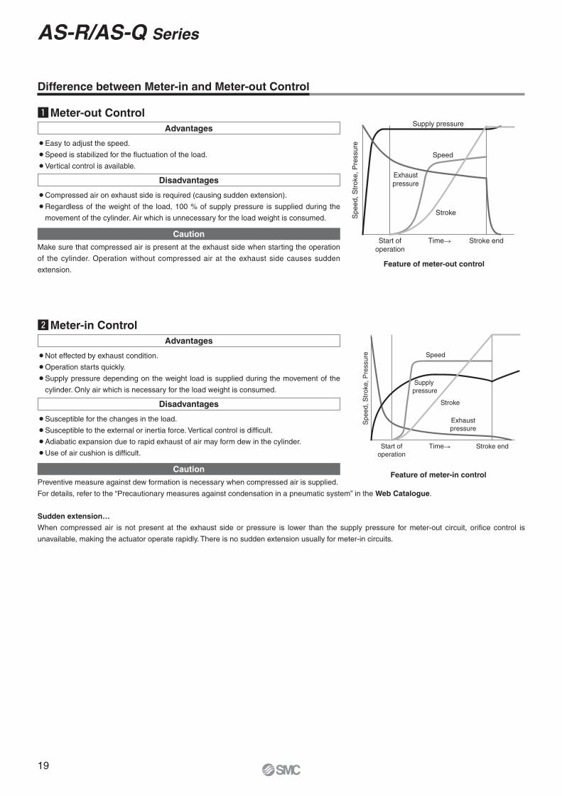
Difference between Meter-in and Meter-out Control
zMeter-out ControlAdvantages
¡Easy to adjust the speed.
¡Speed is stabilized for the fluctuation of the load.
¡Vertical control is available.
Disadvantages
¡Compressed air on exhaust side is required (causing sudden extension).
¡ Regardless of the weight of the load, 100 % of supply pressure is supplied during the
movement of the cylinder. Air which is unnecessary for the load weight is consumed.
CautionMake sure that compressed air is present at the exhaust side when starting the operation
of the cylinder. Operation without compressed air at the exhaust side causes sudden
extension.
xMeter-in ControlAdvantages
¡Not effected by exhaust condition.
¡Operation starts quickly.
¡ Supply pressure depending on the weight load is supplied during the movement of the
cylinder. Only air which is necessary for the load weight is consumed.
Disadvantages
¡Susceptible for the changes in the load.
¡Susceptible to the external or inertia force. Vertical control is difficult.
¡Adiabatic expansion due to rapid exhaust of air may form dew in the cylinder.
¡Use of air cushion is difficult.
CautionPreventive measure against dew formation is necessary when compressed air is supplied.
For details, refer to the “Precautionary measures against condensation in a pneumatic system” in the Web Catalogue.
Sudden extension…
When compressed air is not present at the exhaust side or pressure is lower than the supply pressure for meter-out circuit, orifice control is
unavailable, making the actuator operate rapidly. There is no sudden extension usually for meter-in circuits.
Feature of meter-out control
Feature of meter-in control
Stroke
Supply pressure
Spe
ed, S
trok
e, P
ress
ure
Start ofoperation
Time Stroke end
Speed
Exhaustpressure
Spe
ed, S
trok
e, P
ress
ure
Exhaustpressure
Start ofoperation
Time� Stroke end
Speed
Supply pressure
Stroke
19
AS-R/AS-Q Series

Marker for fully closed position
Marker for fully open position
Knob operation range
Adjustment can be made every 45 degrees.
0°(Fully closed)
270°(Fully open)
45°
90°
135°180°
225°
Fully closed
Fully open
Locked Unlocked
AS-R/AS-Q SeriesSpecifi c Product Precautions 1Be sure to read this before handling the products. Refer to the back cover for safety instruc-tions. For flow control equipment precautions, refer to the “Handling Precautions for SMC Products” and the “Operation Manual” on the SMC website: http://www.smc.eu
Design and Selection
Warning1. Check the specifi cations.
The products in this catalogue are designed to be used in compressed air systems (including vacuum) only.If the products are used in an environment where pressure or temperature is out of the specifi ed range, damage and/or mal-function may result. Do not use under such conditions. (Refer to the specifi cations.)Please contact SMC when using a fl uid other than compressed air (including vacuum).We do not guarantee against any damage if the product is used outside of the specifi cation range.
2. The products in this catalogue are not designed for the use as stop valve with zero air leakage.A certain amount of leakage is allowed in the product’s specifi -cations.Tightening the needle to reduce leakage to zero may result in equipment damage.
3. Do not disassemble the product or make any modifi -cations, including additional machining.It may cause human injury and/or an accident.
4. The flow rate characteristics for each product are representative values.The fl ow rate characteristics are characteristics of each indi-vidual product. Actual values may differ depending on the piping, circuitry, pressure conditions, etc.
5. Sonic conductance (C) and critical pressure ratio (b) values for products are representative values. The speed controller’s controlled flow values are with the needle fully open and free flow with the needle fully closed.
6. Check if PTFE can be used in application.PTFE powder (Polytetrafl uoroethylene resin) is included in the seal material for piping taper thread of male thread type. Con-fi rm that the use of it will not cause any adverse effect on the system.Please contact SMC if the Safety Data Sheet (SDS) is re-quired.
Mounting
Warning1. Operation Manual
Install the products and operate them only after reading the Opera-tion Manual carefully and understanding its contents. Also, keep the Operation Manual where it can be referred to as necessary.
2. Ensure suffi cient space for maintenance activities.When installing the products, allow access for maintenance.
3. Tighten threads with the proper tightening torque.When installing the products, follow the listed proper torque.
4. After pushing the knob down to lock, confi rm that it is locked.It should not be possible to rotate the knob to the right or to the left. If the knob is pulled with force, it may break. Do not pull the knob with excessive force.
5. Check the rotation angle of the knob.Rotation angle is 270 degrees. The knob cannot be rotated more than this. Excessive rotation will cause damage to the product. Check the rotation angle before using the product.
6. Do not use tools such as pliers to rotate the knob.It can cause idle rotation of the knob or damage.
7. Verify the air fl ow direction.Mounting backward is dangerous, because the speed adjust-ment needle will not work and the actuator may lurch suddenly.
8. Adjust the speed by opening the needle slowly from the fully closed state.Loose needle valves may cause unexpected sudden actuator lurching.When a needle valve is turned clockwise, it is closed and actu-ator speed decreases. When a needle valve is turned counter-clockwise, it is open and actuator speed increases.
9. Do not apply excessive force or shock to the body or fi ttings with an impact tool.It can cause damage or air leakage.
Refer to the fi ttings & tubing precautions in the Best Pneumatics catalogue for handling One-touch fit-tings.
10.
Mounting
Warning
20

Carefully perform the piping work so that the toois not in contact with the body A.
Body ABody B
Knob
Body A
Body B
Ø D
45°
Rz 12.5
Ø D
45°
Rz 12.5
Caution1. This product has a stopper for fully closed/fully open in rotating
direction. Excess torque may break the stopper. Table below shows the maximum allowable torque of the knob.
2. When performing the piping work, turn the tightening tool in the horizontal direction to the hexagon across flats of the body B so that any moment is not applied to the body A. If the tool is in contact with the body A, this may cause the body B to come off.
Body size Max. allowable torque [N·m]
2 0.07
3 0.13
4 0.25
11. To install/remove the product, use an appropriate wrench to tighten/loosen at the supplied nut on body B.Do not apply torque at other points as the product may be damaged. Rotate body A manually for positioning after installation.
12. Do not use body A for applications involving continuous rotation.Body A and the fitting section may be damaged.
WarningFor R, NPT Thread (With sealant)
Tightening method1. The proper tightening torques of the fittings are as shown in
the table below. As a guide, tighten it by hand, then turn it two or three turns with a wrench. Check the dimensions of each product for the hexagon width across flats.
Chamfered area for female threadBy chamfering as shown in the table below, machining of threads is easier and effective for burr prevention.
∗ For Uni thread, Rz 12.5 is necessary for sealing at the chamfered part.
Connection thread size
Chamfered dimension Ø D (Recommended value)Rc NPT, NPTF
1/8 10.2 to 10.4 10.5 to 10.71/4 13.6 to 13.8 14.1 to 14.33/8 17.1 to 17.3 17.4 to 17.61/2 21.4 to 21.6 21.7 to 21.9
Connection thread size Proper tightening torque [N·m]NPT, R 1/8 3 to 5NPT, R 1/4 8 to 12NPT, R 3/8 15 to 20NPT, R 1/2 20 to 25
Caution
2. Use G external threads with G internal threads.
Chamfered area for female thread (Recommended value)1. Conforming to ISO 16030-2001, the chamfered dimensions
shown in the table below are recommended. By chamfering as shown in the table below, machining of threads is easier and effective for burr prevention.
Nominal thread size
Chamfered dimension Ø DMin. Max.
1/8 9.8 10.21/4 13.3 13.73/8 16.8 17.21/2 21.0 21.4
For G Thread (Face seal)
Tightening methodFirst, tighten the threaded portion by hand, then use a proper wrench, which could be suitable for the width across flats of the hexagon body, to tighten it further at a wrench tightening angle shown in the table below. For a tightening torque guide, refer to the table below. Check the dimensions of each product for the hexagon width across flats.
Connection thread size Wrench tightening angle after hand-tightening [deg] Proper tightening torque [N·m]G 1/8 10 to 20 3 to 4G 1/4 15 to 35 4 to 5G 3/8 15 to 35 8 to 9G 1/2 15 to 35 14 to 15
Mounting
AS-R/AS-Q SeriesSpecifi c Product Precautions 2Be sure to read this before handling the products. Refer to the back cover for safety instruc-tions. For flow control equipment precautions, refer to the “Handling Precautions for SMC Products” and the “Operation Manual” on the SMC website: http://www.smc.eu
21
AS-R AS-Q
Atmosphericpressure
Product
Pressure
Movement
PressureAtmospheric
pressure
Product
AS-R AS-Q
Movement
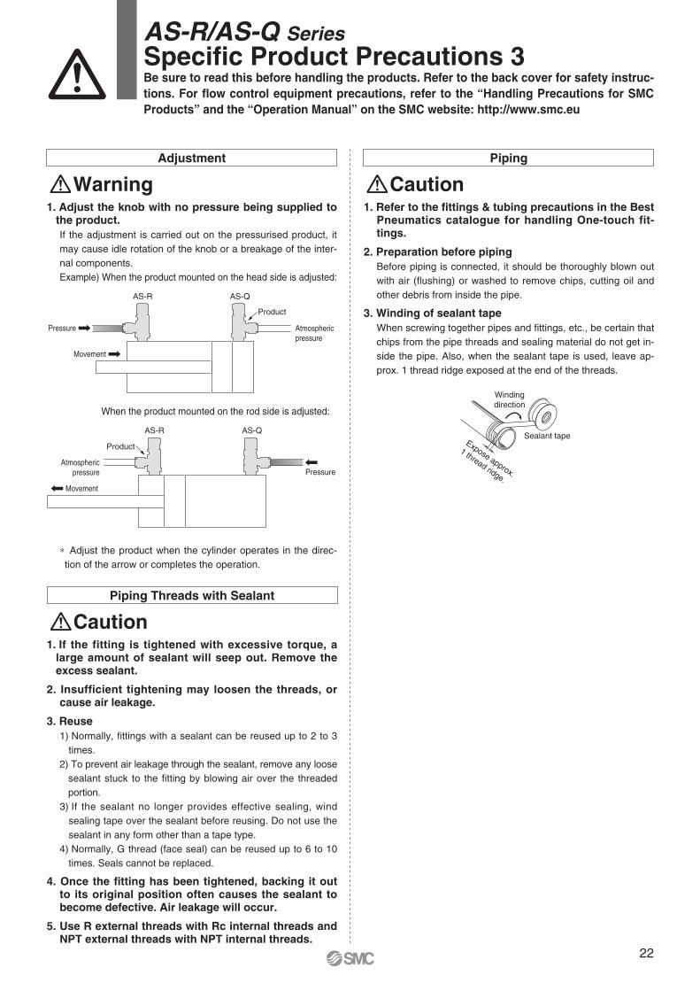
1. Adjust the knob with no pressure being supplied to the product.If the adjustment is carried out on the pressurised product, it may cause idle rotation of the knob or a breakage of the inter-nal components.Example) When the product mounted on the head side is adjusted:
When the product mounted on the rod side is adjusted:
∗ Adjust the product when the cylinder operates in the direc-tion of the arrow or completes the operation.
Piping
Caution1. Refer to the fi ttings & tubing precautions in the Best
Pneumatics catalogue for handling One-touch fit-tings.
2. Preparation before pipingBefore piping is connected, it should be thoroughly blown out with air (fl ushing) or washed to remove chips, cutting oil and other debris from inside the pipe.
3. Winding of sealant tapeWhen screwing together pipes and fi ttings, etc., be certain that chips from the pipe threads and sealing material do not get in-side the pipe. Also, when the sealant tape is used, leave ap-prox. 1 thread ridge exposed at the end of the threads.
Caution1. If the fitting is tightened with excessive torque, a
large amount of sealant will seep out. Remove the excess sealant.
2. Insufficient tightening may loosen the threads, or cause air leakage.
3. Reuse1) Normally, fi ttings with a sealant can be reused up to 2 to 3
times.2) To prevent air leakage through the sealant, remove any loose
sealant stuck to the fitting by blowing air over the threaded portion.
3) If the sealant no longer provides effective sealing, wind sealing tape over the sealant before reusing. Do not use the sealant in any form other than a tape type.
4) Normally, G thread (face seal) can be reused up to 6 to 10 times. Seals cannot be replaced.
4. Once the fi tting has been tightened, backing it out to its original position often causes the sealant to become defective. Air leakage will occur.
5. Use R external threads with Rc internal threads and NPT external threads with NPT internal threads.
Piping Threads with Sealant
WarningAdjustment
Windingdirection
Sealant tapeExpose approx.
1 thread ridge.
AS-R/AS-Q SeriesSpecifi c Product Precautions 3Be sure to read this before handling the products. Refer to the back cover for safety instruc-tions. For flow control equipment precautions, refer to the “Handling Precautions for SMC Products” and the “Operation Manual” on the SMC website: http://www.smc.eu
22
Lithuania +370 5 2308118 www.smclt.lt [email protected] +31 (0)205318888 www.smcpneumatics.nl [email protected] +47 67129020 www.smc-norge.no [email protected] +48 222119600 www.smc.pl [email protected] +351 226166570 www.smc.eu [email protected] +40 213205111 www.smcromania.ro [email protected] +7 8127185445 www.smc-pneumatik.ru [email protected] +421 (0)413213212 www.smc.sk [email protected] +386 (0)73885412 www.smc.si [email protected] +34 902184100 www.smc.eu [email protected] +46 (0)86031200 www.smc.nu [email protected] +41 (0)523963131 www.smc.ch [email protected] +90 212 489 0 440 www.smcpnomatik.com.tr [email protected] UK +44 (0)845 121 5122 www.smcpneumatics.co.uk [email protected]
Specifications are subject to change without prior notice and any obligation on the part of the manufacturer.SMC CORPORATION Akihabara UDX 15F, 4-14-1, Sotokanda, Chiyoda-ku, Tokyo 101-0021, JAPAN Phone: 03-5207-8249 FAX: 03-5298-5362
1st printing TT printing TU 00 Printed in Spain
Austria +43 (0)2262622800 www.smc.at [email protected] +32 (0)33551464 www.smcpneumatics.be [email protected] +359 (0)2807670 www.smc.bg [email protected] Croatia +385 (0)13707288 www.smc.hr [email protected] Republic +420 541424611 www.smc.cz [email protected] Denmark +45 70252900 www.smcdk.com [email protected] Estonia +372 6510370 www.smcpneumatics.ee [email protected] +358 207513513 www.smc.fi [email protected] +33 (0)164761000 www.smc-france.fr [email protected] +49 (0)61034020 www.smc.de [email protected] +30 210 2717265 www.smchellas.gr [email protected] +36 23511390 www.smc.hu [email protected] +353 (0)14039000 www.smcpneumatics.ie [email protected] +39 0292711 www.smcitalia.it [email protected] +371 67817700 www.smclv.lv [email protected]
Safety Instructions Be sure to read “Handling Precautions for SMC Products” (M-E03-3) before using.
SMC Corporation (Europe)
1. The compatibility of the product is the responsibility of the person who designs the equipment or decides its specifications.
Since the product specified here is used under various operating conditions, its compatibility with specific equipment must be decided by the person who designs the equipment or decides its specifications based on necessary analysis and test results. The expected performance and safety assurance of the equipment will be the responsibility of the person who has determined its compatibility with the product. This person should also continuously review all specifications of the product referring to its latest catalogue information, with a view to giving due consideration to any possibility of equipment failure when configuring the equipment.
2. Only personnel with appropriate training should operate machinery and equipment.
The product specified here may become unsafe if handled incorrectly. The assembly, operation and maintenance of machines or equipment including our products must be performed by an operator who is appropriately trained and experienced.
3. . Do not service or attempt to remove product and machinery/equipment until safety is confirmed.1. The inspection and maintenance of machinery/equipment should only be performed
after measures to prevent falling or runaway of the driven objects have been confirmed.
2. When the product is to be removed, confirm that the safety measures as mentioned above are implemented and the power from any appropriate source is cut, and read and understand the specific product precautions of all relevant products carefully.
3. Before machinery/equipment is restarted, take measures to prevent unexpected operation and malfunction.
4. Contact SMC beforehand and take special consideration of safety measures if the product is to be used in any of the following conditions. 1. Conditions and environments outside of the given specifications, or use outdoors or in
a place exposed to direct sunlight.2. Installation on equipment in conjunction with atomic energy, railways, air navigation,
space, shipping, vehicles, military, medical treatment, combustion and recreation, or equipment in contact with food and beverages, emergency stop circuits, clutch and brake circuits in press applications, safety equipment or other applications unsuitable for the standard specifications described in the product catalogue.
3. An application which could have negative effects on people, property, or animals requiring special safety analysis.
4. Use in an interlock circuit, which requires the provision of double interlock for possible failure by using a mechanical protective function, and periodical checks to confirm proper operation.
Warning Limited warranty and Disclaimer/Compliance Requirements The product used is subject to the following “Limited warranty and Disclaimer” and “Compliance Requirements”.Read and accept them before using the product.
1. The product is provided for use in manufacturing industries.The product herein described is basically provided for peaceful use in manufacturing industries. If considering using the product in other industries, consult SMC beforehand and exchange specifications or a contract if necessary. If anything is unclear, contact your nearest sales branch.
CautionSMC products are not intended for use as instruments for legal metrology.Measurement instruments that SMC manufactures or sells have not been qualified by type approval tests relevant to the metrology (measurement) laws of each country.Therefore, SMC products cannot be used for business or certification ordained by the metrology (measurement) laws of each country.
Caution
Limited warranty and Disclaimer1. The warranty period of the product is 1 year in service or 1.5 years
after the product is delivered, wichever is first.∗2)
Also, the product may have specified durability, running distance or replacement parts. Please consult your nearest sales branch.
2. For any failure or damage reported within the warranty period which is clearly our responsibility, a replacement product or necessary parts will be provided. This limited warranty applies only to our product independently, and not to any other damage incurred due to the failure of the product.
3. Prior to using SMC products, please read and understand the warranty terms and disclaimers noted in the specified catalogue for the particular products.
∗2) Vacuum pads are excluded from this 1 year warranty.A vacuum pad is a consumable part, so it is warranted for a year after it is delivered. Also, even within the warranty period, the wear of a product due to the use of the vacuum pad or failure due to the deterioration of rubber material are not covered by the limited warranty.
Compliance Requirements1. The use of SMC products with production equipment for the manufacture of
weapons of mass destruction (WMD) or any other weapon is strictly prohibited.
2. The exports of SMC products or technology from one country to another are governed by the relevant security laws and regulations of the countries involved in the transaction. Prior to the shipment of a SMC product to another country, assure that all local rules governing that export are known and followed.
These safety instructions are intended to prevent hazardous situations and/or equipment damage. These instructions indicate the level of potential hazard with the labels of “Caution,” “Warning” or “Danger.” They are all important notes for safety and must be followed in addition to International Standards (ISO/IEC)∗1), and other safety regulations.
∗1) ISO 4414: Pneumatic fluid power – General rules relating to systems. ISO 4413: Hydraulic fluid power – General rules relating to systems. IEC 60204-1: Safety of machinery – Electrical equipment of machines. (Part 1: General requirements) ISO 10218-1: Manipulating industrial robots - Safety. etc.
Caution indicates a hazard with a low level of risk which, if not avoided, could result in minor or moderate injury.
Warning indicates a hazard with a medium level of risk which, if not avoided, could result in death or serious injury.
Caution:
Warning:
Danger : Danger indicates a hazard with a high level of risk which, if not avoided, will result in death or serious injury.
Safety Instructions