Embed Size (px)
Citation preview
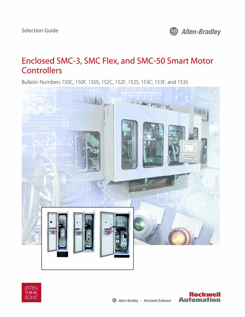
Enclosed SMC-3, SMC Flex, and SMC-50 Smart Motor ControllersBulletin Numbers 150C, 150F, 150S, 152C, 152F, 152S, 153C, 153F, and 153S
Selection Guide
2 Rockwell Automation Publication 150-SG012A-EN-P - March 2017
Enclosed SMC-3, SMC Flex, and SMC-50 Smart Motor Controllers
What’s InsideTopic Page
Overview 3
Standards Compliance and Certifications 5
SMC-3 and SMC Flex 5
SMC-50 5
Snap-together Wiring 6
Catalog Number Explanation 11
Controllers Rated 90…1250 A 11
Controllers Rated 5…85 A 13
Product Selection 15
Power Centers 15
Transformers 16
Snap-together Kits 16
Accessories 19
Accessories for SMC-3 Controllers 19
Accessories for SMC Flex Controllers 21
Accessories for SMC-50 Controllers 23
Enclosure Accessories 28
Wiring Diagrams 29
Wiring Diagrams for SMC Controllers 29
Wiring Diagrams for Snap-together Kits 34
Short Circuit Current Ratings 39
Short Circuit Ratings for SMC-3 Controllers 39
Short Circuit Ratings for SMC Flex Controllers 41
Short Circuit Ratings for SMC-50 Controllers 42
Approximate Dimensions 45
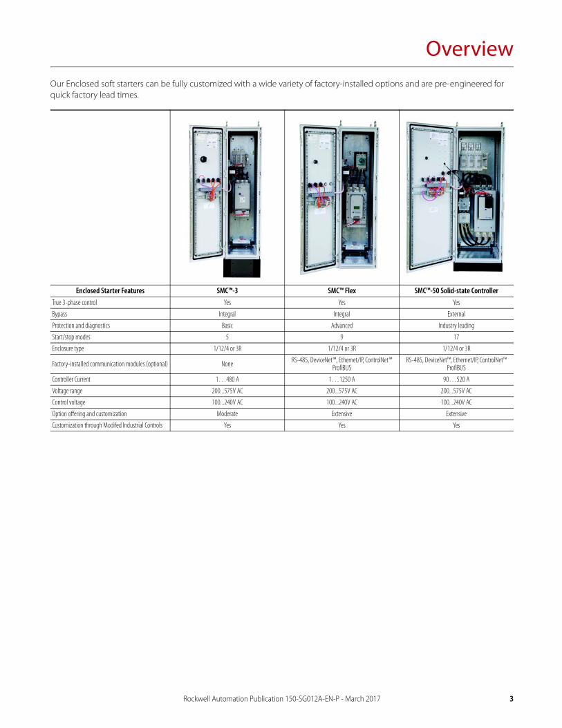
OverviewOur Enclosed soft starters can be fully customized with a wide variety of factory-installed options and are pre-engineered for quick factory lead times.
Enclosed Starter Features SMC™-3 SMC™ Flex SMC™-50 Solid-state ControllerTrue 3-phase control Yes Yes Yes
Bypass Integral Integral External
Protection and diagnostics Basic Advanced Industry leading
Start/stop modes 5 9 17
Enclosure type 1/12/4 or 3R 1/12/4 or 3R 1/12/4 or 3R
Factory-installed communication modules (optional) None RS-485, DeviceNet™, Ethernet/IP, ControlNet™ ProfiBUS
RS-485, DeviceNet™, Ethernet/IP, ControlNet™ ProfiBUS
Controller Current 1…480 A 1…1250 A 90…520 A
Voltage range 200...575V AC 200...575V AC 200...575V AC
Control voltage 100...240V AC 100...240V AC 100...240V AC
Option offering and customization Moderate Extensive Extensive
Customization through Modifed Industrial Controls Yes Yes Yes
Rockwell Automation Publication 150-SG012A-EN-P - March 2017 3
Overview
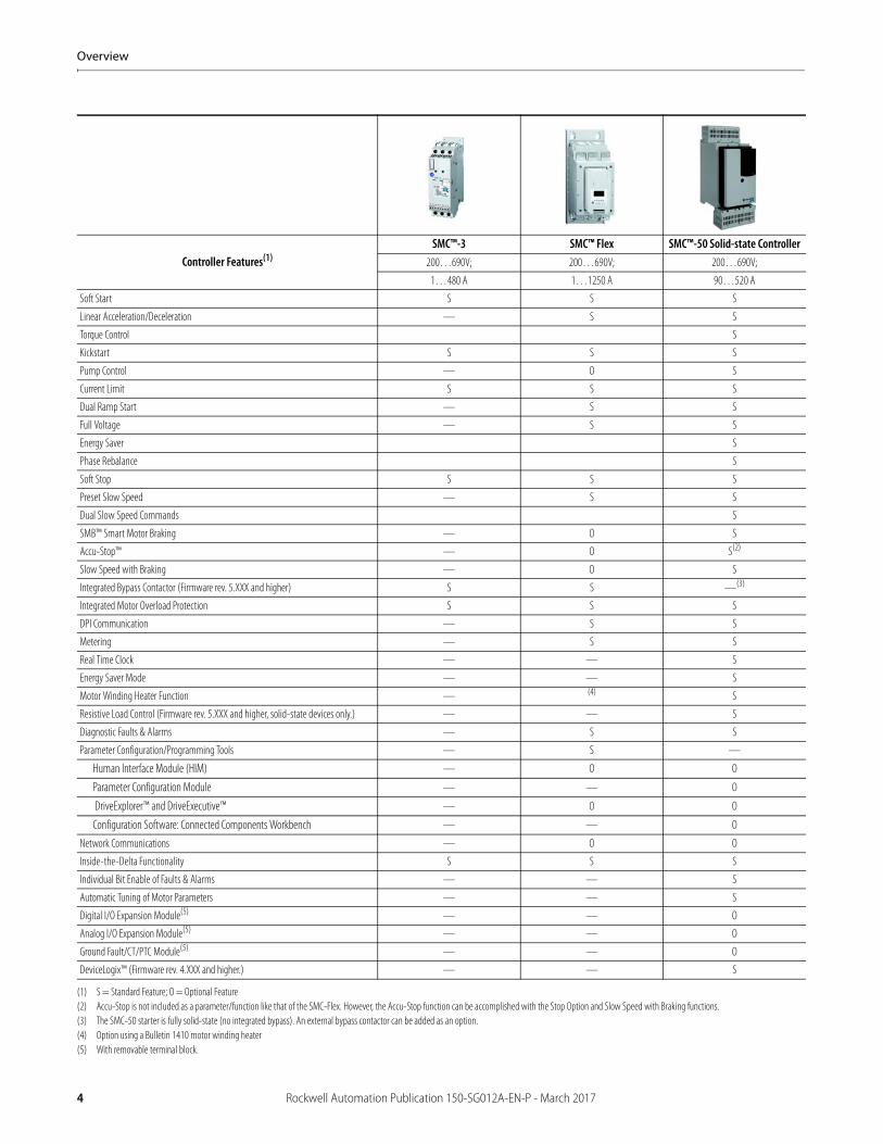
Controller Features(1)
(1) S = Standard Feature; O = Optional Feature
SMC™-3 SMC™ Flex SMC™-50 Solid-state Controller200…690V; 200…690V; 200…690V;
1…480 A 1…1250 A 90…520 A
Soft Start S S S
Linear Acceleration/Deceleration — S S
Torque Control S
Kickstart S S S
Pump Control — O S
Current Limit S S S
Dual Ramp Start — S S
Full Voltage — S S
Energy Saver S
Phase Rebalance S
Soft Stop S S S
Preset Slow Speed — S S
Dual Slow Speed Commands S
SMB™ Smart Motor Braking — O S
Accu-Stop™ — O S(2)
(2) Accu-Stop is not included as a parameter/function like that of the SMC-Flex. However, the Accu-Stop function can be accomplished with the Stop Option and Slow Speed with Braking functions.
Slow Speed with Braking — O S
Integrated Bypass Contactor (Firmware rev. 5.XXX and higher) S S —(3)
(3) The SMC-50 starter is fully solid-state (no integrated bypass). An external bypass contactor can be added as an option.
Integrated Motor Overload Protection S S S
DPI Communication — S S
Metering — S S
Real Time Clock — — S
Energy Saver Mode — — S
Motor Winding Heater Function — (4)
(4) Option using a Bulletin 1410 motor winding heater
S
Resistive Load Control (Firmware rev. 5.XXX and higher, solid-state devices only.) — — S
Diagnostic Faults & Alarms — S S
Parameter Configuration/Programming Tools — S —
Human Interface Module (HIM) — O O
Parameter Configuration Module — — O
DriveExplorer™ and DriveExecutive™ — O O
Configuration Software: Connected Components Workbench — — O
Network Communications — O O
Inside-the-Delta Functionality S S S
Individual Bit Enable of Faults & Alarms — — S
Automatic Tuning of Motor Parameters — — S
Digital I/O Expansion Module(5)
(5) With removable terminal block.
— — O
Analog I/O Expansion Module(5) — — O
Ground Fault/CT/PTC Module(5) — — O
DeviceLogix™ (Firmware rev. 4.XXX and higher.) — — S
4 Rockwell Automation Publication 150-SG012A-EN-P - March 2017
Overview
This catalog is based on the minimum information needed to select an SMC soft starter for applications with low starting torque requirements. For product selection involving loads with high starting torque requirements (large fan, rock crusher, chipper, etc.), use of the free tools available from the Rockwell Automation Website is recommended:
http://www.ab.com/industrialcontrols/products/solid-state_motor_control/software/
You can find full descriptions of features and modes of operation, as well as specifications in the selection guides for open SMC Controllers:
SMC-3 and SMC Flex Smart Motor Controllers Selection Guide, Publication 150-SG009
SMC-50 Solid-state Smart Motor Controllers Selection Guide, Publication 150-SG010
Standards Compliance and Certifications
SMC-3 and SMC Flex
SMC-50
Standards Compliance—Open Controllers Certifications—Open Controllers Standards Compliance—
Enclosed Controllers Certifications—Enclosed Controllers
UL 508 cULus Listed (Open Type) (File No. E96956, Guides NMFT, NMFT7) UL 508A cULus Listed
CSA C22.2 No.14 CSA Certified (File No. LR 1234)
EN/IEC 60947-1 CE Marked
EN/IEC 60947-4-2 CCC Certified
Standards Compliance—Open Controllers Certifications—Open Controllers Standards Compliance—
Enclosed Controllers Certifications—Enclosed Controllers
UL 508 cULus Listed (Open Type) (File No. E96956) UL 508A cULus Listed
EN 60947-4-2 CE Marked per EMC Directive and Low Voltage Directive
CCC(1)
(1) For updated certification status of controllers with 24V DC control power, consult your local Rockwell Automation sales office or Allen-Bradley distributor.
C-Tick(1)
EAC(1)
KCC(1)
ABS(1)
Rockwell Automation Publication 150-SG012A-EN-P - March 2017 5
Overview
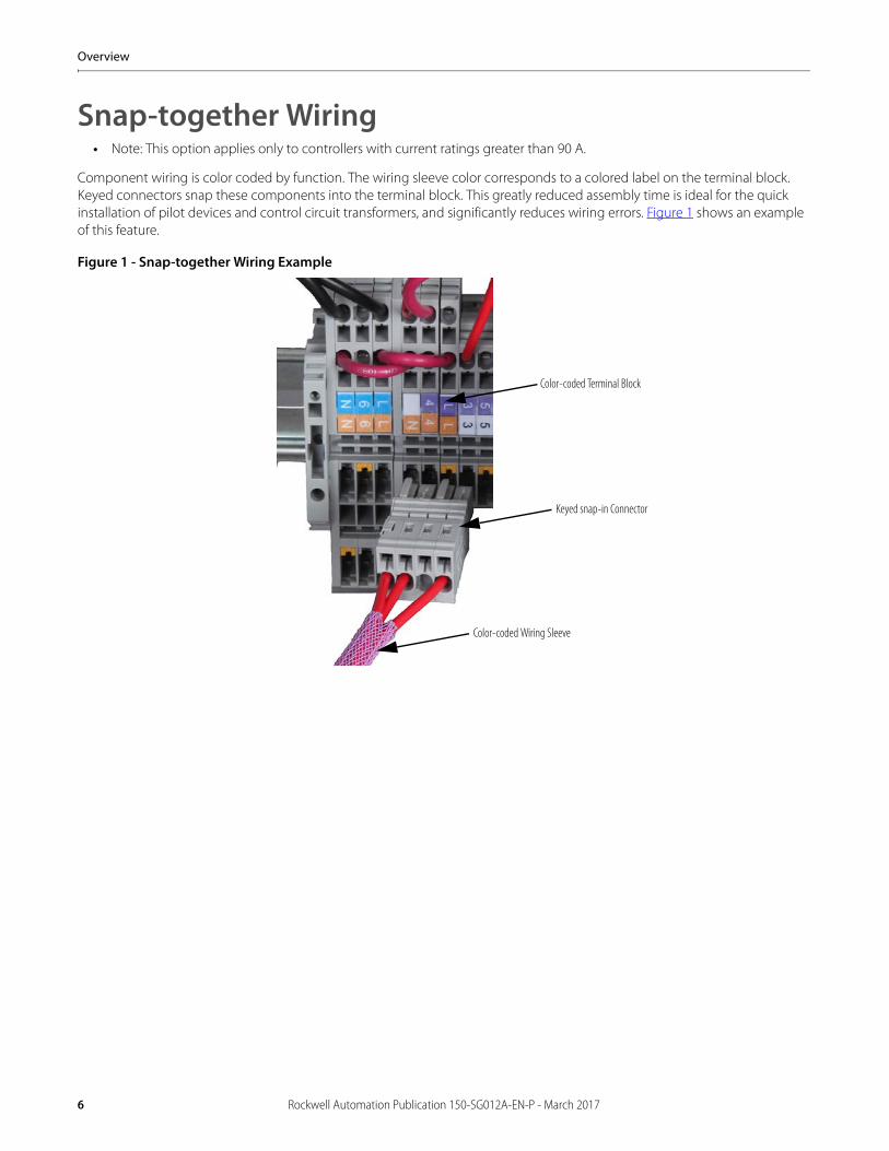
Snap-together Wiring• Note: This option applies only to controllers with current ratings greater than 90 A.
Component wiring is color coded by function. The wiring sleeve color corresponds to a colored label on the terminal block. Keyed connectors snap these components into the terminal block. This greatly reduced assembly time is ideal for the quick installation of pilot devices and control circuit transformers, and significantly reduces wiring errors. Figure 1 shows an example of this feature.
Figure 1 - Snap-together Wiring Example
Color-coded Wiring Sleeve
Keyed snap-in Connector
Color-coded Terminal Block
6 Rockwell Automation Publication 150-SG012A-EN-P - March 2017
Overview
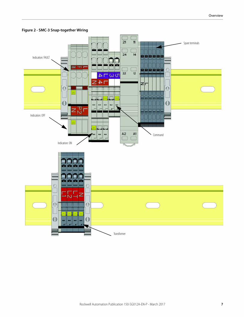
Figure 2 - SMC-3 Snap-together Wiring
Indication: FAULT
Indication: OFF
Indication: ON
Command
Spare terminals
Transformer
Rockwell Automation Publication 150-SG012A-EN-P - March 2017 7
Overview
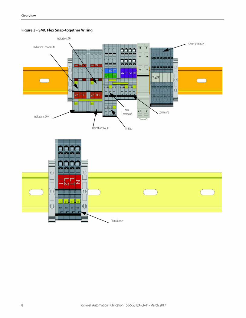
Figure 3 - SMC Flex Snap-together Wiring
Command
Transformer
Indication: FAULT
Indication: OFF
Spare terminalsIndication: Power ON
Indication: ON
E-Stop
Aux Command
8 Rockwell Automation Publication 150-SG012A-EN-P - March 2017
Overview
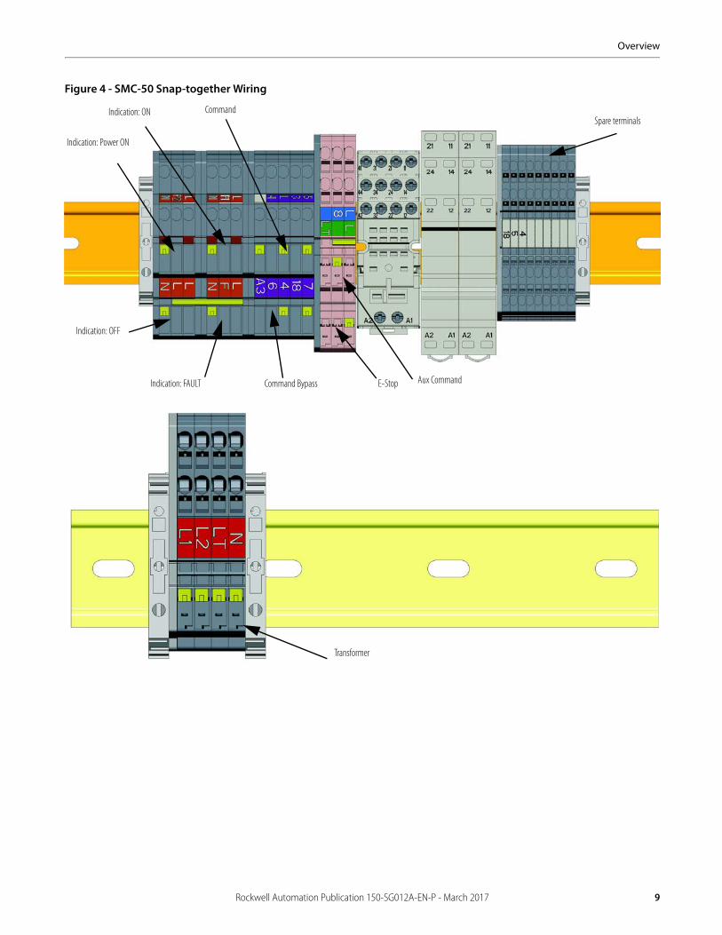
Figure 4 - SMC-50 Snap-together Wiring
Transformer
Aux CommandIndication: FAULT
Indication: OFF
Spare terminals
Indication: Power ON
Indication: ON
E-Stop
Command
Command Bypass
Rockwell Automation Publication 150-SG012A-EN-P - March 2017 9
Overview
Notes:
10 Rockwell Automation Publication 150-SG012A-EN-P - March 2017
Catalog Number Explanation
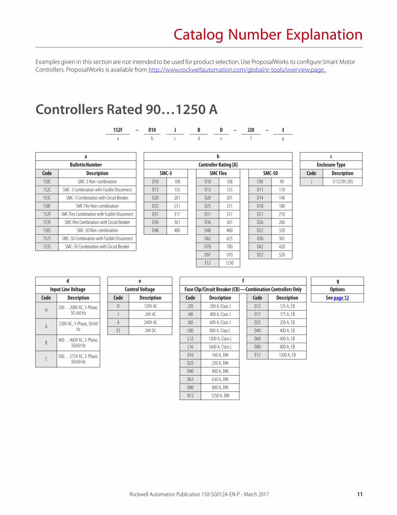
Examples given in this section are not intended to be used for product selection. Use ProposalWorks to configure Smart Motor Controllers. ProposalWorks is available from http://www.rockwellautomation.com/global/e-tools/overview.page.
Controllers Rated 90…1250 A152F – D10 J B D – J20 – 3
a b c d e f g
a b cBulletin Number Controller Rating [A] Enclosure Type
Code Description SMC-3 SMC Flex SMC-50 Code Description150C SMC-3 Non-combination D10 108 D10 108 C90 90 J 1/12/3R (3R)
152C SMC-3 Combination with Fusible Disconnect D13 135 D13 135 D11 110
153C SMC-3 Combination with Circuit Breaker D20 201 D20 201 D14 140
150F SMC Flex Non-combination D25 251 D25 251 D18 180
152F SMC Flex Combination with Fusible Disconnect D31 317 D31 317 D21 210
153F SMC Flex Combination with Circuit Breaker D36 361 D36 361 D26 260
150S SMC-50 Non-combination D48 480 D48 480 D32 320
152S SMC-50 Combination with Fusible Disconnect D62 625 D36 361
153S SMC-50 Combination with Circuit Breaker D78 780 D42 420
D97 970 D52 520
E12 1250
d e f gInput Line Voltage Control Voltage Fuse Clip/Circuit Breaker (CB)—Combination Controllers Only Options
Code Description Code Description Code Description Code Description See page 12
H 200…208V AC, 3-Phase, 50 /60 Hz
D 120V AC J20 200 A, Class J D12 125 A, CB
J 24V AC J40 400 A, Class J D17 175 A, CB
A 230V AC, 3-Phase, 50/60 Hz
A 240V AC J60 600 A, Class J D25 250 A, CB
EJ 24V DC L80 800 A, Class L D40 400 A, CB
B 400…460V AC, 3-Phase, 50/60 Hz
L12 1200 A, Class L D60 600 A, CB
L16 1600 A, Class L D80 800 A, CB
C 500…575V AC, 3-Phase, 50/60 Hz
D16 160 A, DIN E12 1200 A, CB
D25 250 A, DIN
D40 400 A, DIN
D63 630 A, DIN
D80 800 A, DIN
N12 1250 A, DIN
Rockwell Automation Publication 150-SG012A-EN-P - March 2017 11
Catalog Number Explanation
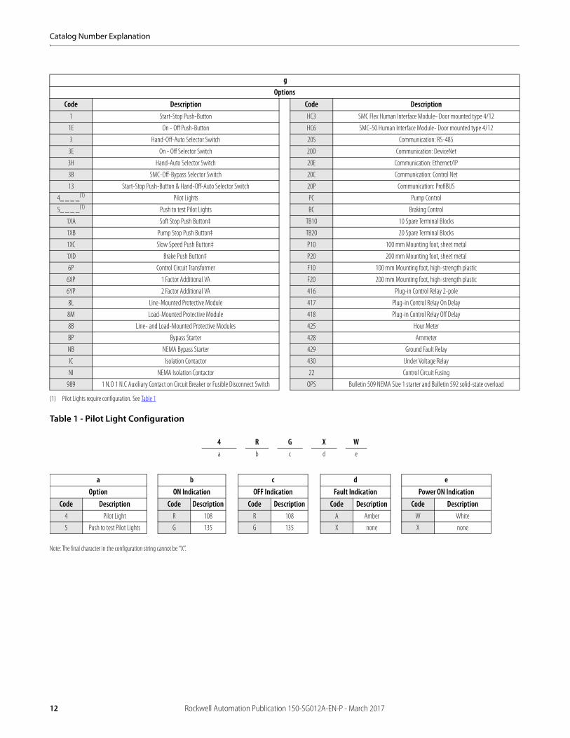
Table 1 - Pilot Light Configuration
gOptions
Code Description Code Description1 Start-Stop Push-Button HC3 SMC Flex Human Interface Module- Door mounted type 4/12
1E On - Off Push-Button HC6 SMC-50 Human Interface Module- Door mounted type 4/12
3 Hand-Off-Auto Selector Switch 20S Communication: RS-485
3E On - Off Selector Switch 20D Communication: DeviceNet
3H Hand-Auto Selector Switch 20E Communication: Ethernet/IP
3B SMC-Off-Bypass Selector Switch 20C Communication: Control Net
13 Start-Stop Push-Button & Hand-Off-Auto Selector Switch 20P Communication: ProfiBUS
4_ _ _ _(1)
(1) Pilot Lights require configuration. See Table 1
Pilot Lights PC Pump Control
5_ _ _ _(1) Push to test Pilot Lights BC Braking Control
1XA Soft Stop Push Button‡ TB10 10 Spare Terminal Blocks
1XB Pump Stop Push Button‡ TB20 20 Spare Terminal Blocks
1XC Slow Speed Push Button‡ P10 100 mm Mounting foot, sheet metal
1XD Brake Push Button‡ P20 200 mm Mounting foot, sheet metal
6P Control Circuit Transformer F10 100 mm Mounting foot, high-strength plastic
6XP 1 Factor Additional VA F20 200 mm Mounting foot, high-strength plastic
6YP 2 Factor Additional VA 416 Plug-in Control Relay 2-pole
8L Line-Mounted Protective Module 417 Plug-in Control Relay On Delay
8M Load-Mounted Protective Module 418 Plug-in Control Relay Off Delay
8B Line- and Load-Mounted Protective Modules 425 Hour Meter
BP Bypass Starter 428 Ammeter
NB NEMA Bypass Starter 429 Ground Fault Relay
IC Isolation Contactor 430 Under Voltage Relay
NI NEMA Isolation Contactor 22 Control Circuit Fusing
989 1 N.O 1 N.C Auxiliary Contact on Circuit Breaker or Fusible Disconnect Switch OPS Bulletin 509 NEMA Size 1 starter and Bulletin 592 solid-state overload
Note: The final character in the configuration string cannot be “X”.
4 R G X Wa b c d e
a b c d eOption ON Indication OFF Indication Fault Indication Power ON Indication
Code Description Code Description Code Description Code Description Code Description4 Pilot Light R 108 R 108 A Amber W White
5 Push to test Pilot Lights G 135 G 135 X none X none
12 Rockwell Automation Publication 150-SG012A-EN-P - March 2017
Catalog Number Explanation
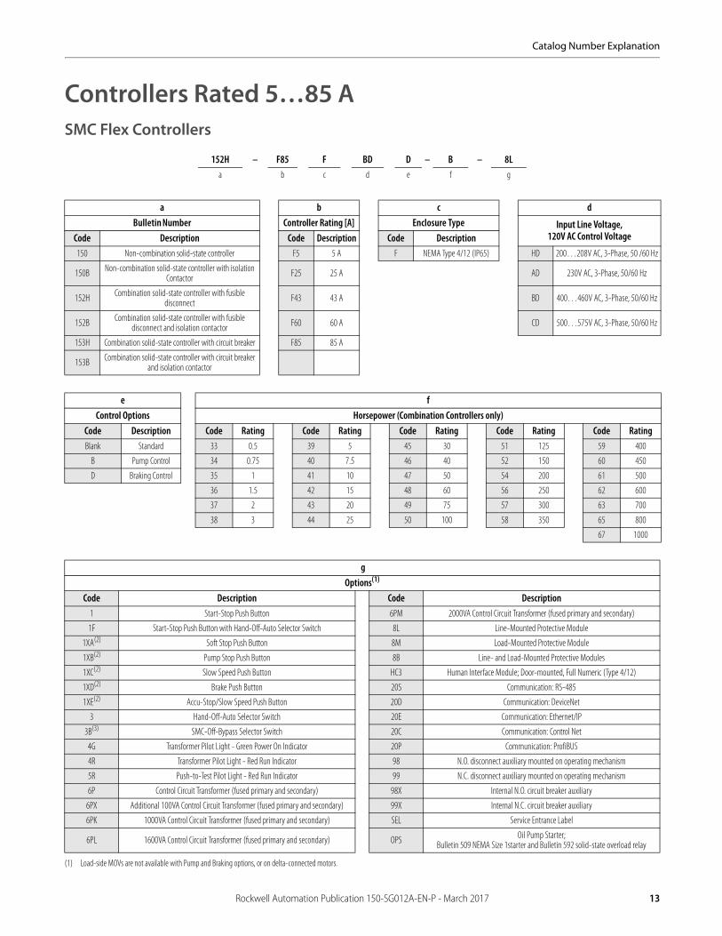
Controllers Rated 5…85 ASMC Flex Controllers
152H – F85 F BD D – B – 8La b c d e f g
a b c dBulletin Number Controller Rating [A] Enclosure Type Input Line Voltage,
120V AC Control VoltageCode Description Code Description Code Description150 Non-combination solid-state controller F5 5 A F NEMA Type 4/12 (IP65) HD 200…208V AC, 3-Phase, 50 /60 Hz
150B Non-combination solid-state controller with isolation Contactor F25 25 A AD 230V AC, 3-Phase, 50/60 Hz
152H Combination solid-state controller with fusible disconnect F43 43 A BD 400…460V AC, 3-Phase, 50/60 Hz
152B Combination solid-state controller with fusible disconnect and isolation contactor F60 60 A CD 500…575V AC, 3-Phase, 50/60 Hz
153H Combination solid-state controller with circuit breaker F85 85 A
153B Combination solid-state controller with circuit breaker and isolation contactor
e fControl Options Horsepower (Combination Controllers only)
Code Description Code Rating Code Rating Code Rating Code Rating Code RatingBlank Standard 33 0.5 39 5 45 30 51 125 59 400
B Pump Control 34 0.75 40 7.5 46 40 52 150 60 450
D Braking Control 35 1 41 10 47 50 54 200 61 500
36 1.5 42 15 48 60 56 250 62 600
37 2 43 20 49 75 57 300 63 700
38 3 44 25 50 100 58 350 65 800
67 1000
gOptions(1)
(1) Load-side MOVs are not available with Pump and Braking options, or on delta-connected motors.
Code Description Code Description1 Start-Stop Push Button 6PM 2000VA Control Circuit Transformer (fused primary and secondary)
1F Start-Stop Push Button with Hand-Off-Auto Selector Switch 8L Line-Mounted Protective Module
1XA(2) Soft Stop Push Button 8M Load-Mounted Protective Module
1XB(2) Pump Stop Push Button 8B Line- and Load-Mounted Protective Modules
1XC(2) Slow Speed Push Button HC3 Human Interface Module; Door-mounted, Full Numeric (Type 4/12)
1XD(2) Brake Push Button 20S Communication: RS-485
1XE(2) Accu-Stop/Slow Speed Push Button 20D Communication: DeviceNet
3 Hand-Off-Auto Selector Switch 20E Communication: Ethernet/IP
3B(3) SMC-Off-Bypass Selector Switch 20C Communication: Control Net
4G Transformer Pilot Light - Green Power On Indicator 20P Communication: ProfiBUS
4R Transformer Pilot Light - Red Run Indicator 98 N.O. disconnect auxiliary mounted on operating mechanism
5R Push-to-Test Pilot Light - Red Run Indicator 99 N.C. disconnect auxiliary mounted on operating mechanism
6P Control Circuit Transformer (fused primary and secondary) 98X Internal N.O. circuit breaker auxiliary
6PX Additional 100VA Control Circuit Transformer (fused primary and secondary) 99X Internal N.C. circuit breaker auxiliary
6PK 1000VA Control Circuit Transformer (fused primary and secondary) SEL Service Entrance Label
6PL 1600VA Control Circuit Transformer (fused primary and secondary) OPS Oil Pump Starter; Bulletin 509 NEMA Size 1starter and Bulletin 592 solid-state overload relay
Rockwell Automation Publication 150-SG012A-EN-P - March 2017 13
Catalog Number Explanation
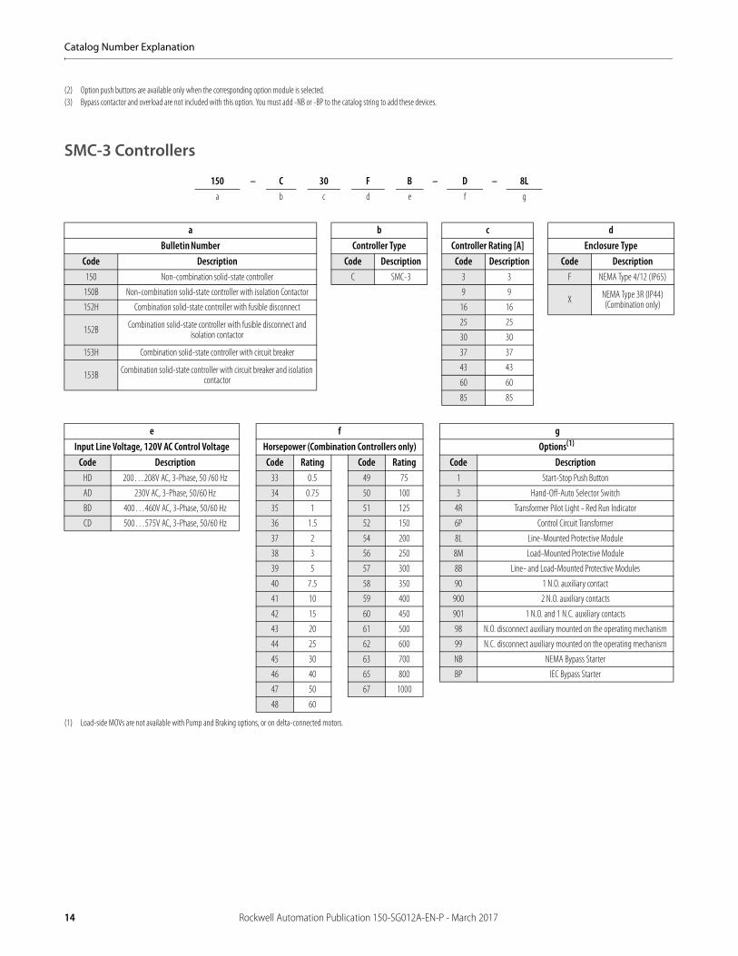
SMC-3 Controllers
(2) Option push buttons are available only when the corresponding option module is selected. (3) Bypass contactor and overload are not included with this option. You must add -NB or -BP to the catalog string to add these devices.
150 – C 30 F B – D – 8La b c d e f g
a b c dBulletin Number Controller Type Controller Rating [A] Enclosure Type
Code Description Code Description Code Description Code Description150 Non-combination solid-state controller C SMC-3 3 3 F NEMA Type 4/12 (IP65)
150B Non-combination solid-state controller with isolation Contactor 9 9X NEMA Type 3R (IP44)
(Combination only)152H Combination solid-state controller with fusible disconnect 16 16
152B Combination solid-state controller with fusible disconnect and isolation contactor
25 25
30 30
153H Combination solid-state controller with circuit breaker 37 37
153B Combination solid-state controller with circuit breaker and isolation contactor
43 43
60 60
85 85
e f gInput Line Voltage, 120V AC Control Voltage Horsepower (Combination Controllers only) Options(1)
(1) Load-side MOVs are not available with Pump and Braking options, or on delta-connected motors.
Code Description Code Rating Code Rating Code DescriptionHD 200…208V AC, 3-Phase, 50 /60 Hz 33 0.5 49 75 1 Start-Stop Push Button
AD 230V AC, 3-Phase, 50/60 Hz 34 0.75 50 100 3 Hand-Off-Auto Selector Switch
BD 400…460V AC, 3-Phase, 50/60 Hz 35 1 51 125 4R Transformer Pilot Light - Red Run Indicator
CD 500…575V AC, 3-Phase, 50/60 Hz 36 1.5 52 150 6P Control Circuit Transformer
37 2 54 200 8L Line-Mounted Protective Module
38 3 56 250 8M Load-Mounted Protective Module
39 5 57 300 8B Line- and Load-Mounted Protective Modules
40 7.5 58 350 90 1 N.O. auxiliary contact
41 10 59 400 900 2 N.O. auxiliary contacts
42 15 60 450 901 1 N.O. and 1 N.C. auxiliary contacts
43 20 61 500 98 N.O. disconnect auxiliary mounted on the operating mechanism
44 25 62 600 99 N.C. disconnect auxiliary mounted on the operating mechanism
45 30 63 700 NB NEMA Bypass Starter
46 40 65 800 BP IEC Bypass Starter
47 50 67 1000
48 60
14 Rockwell Automation Publication 150-SG012A-EN-P - March 2017
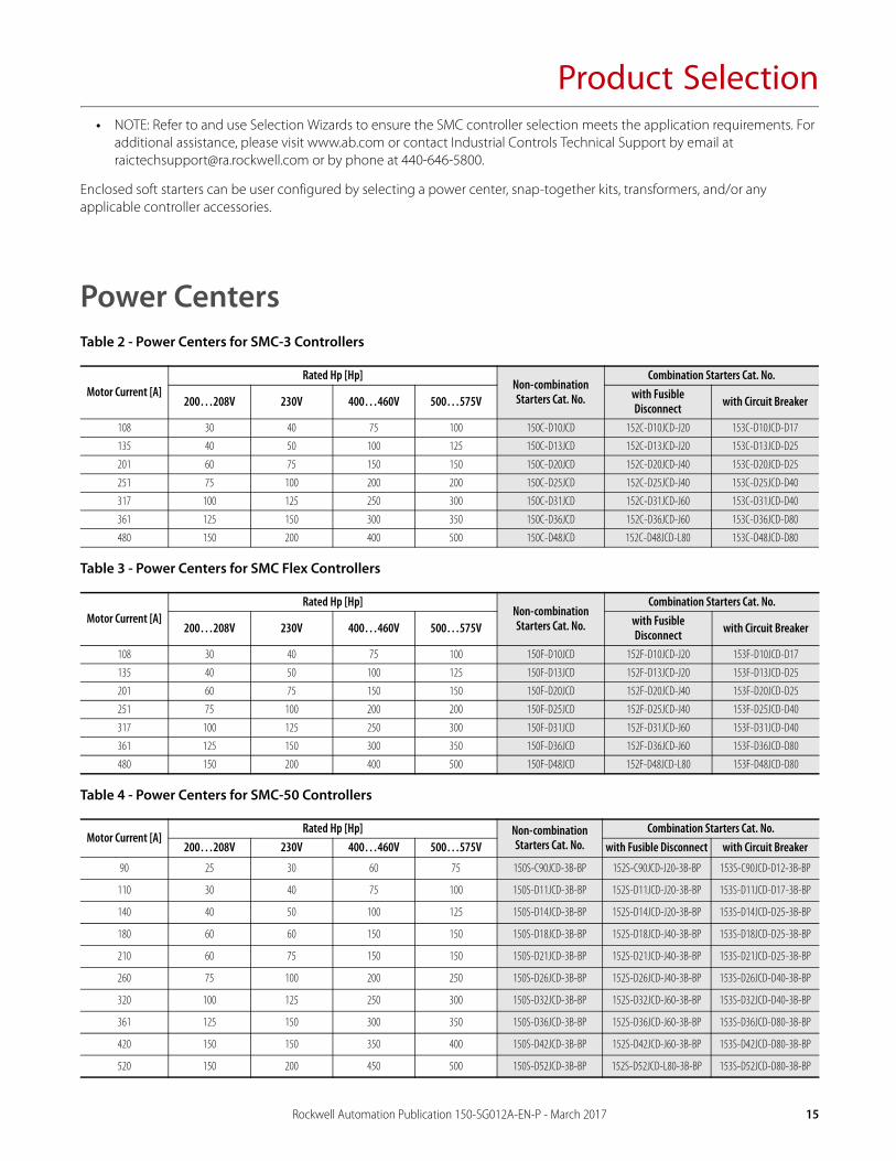
Product Selection• NOTE: Refer to and use Selection Wizards to ensure the SMC controller selection meets the application requirements. For
additional assistance, please visit www.ab.com or contact Industrial Controls Technical Support by email at [email protected] or by phone at 440-646-5800.
Enclosed soft starters can be user configured by selecting a power center, snap-together kits, transformers, and/or any applicable controller accessories.
Power CentersTable 2 - Power Centers for SMC-3 Controllers
Table 3 - Power Centers for SMC Flex Controllers
Table 4 - Power Centers for SMC-50 Controllers
Motor Current [A]Rated Hp [Hp]
Non-combination Starters Cat. No.
Combination Starters Cat. No.
200…208V 230V 400…460V 500…575V with Fusible Disconnect with Circuit Breaker
108 30 40 75 100 150C-D10JCD 152C-D10JCD-J20 153C-D10JCD-D17
135 40 50 100 125 150C-D13JCD 152C-D13JCD-J20 153C-D13JCD-D25
201 60 75 150 150 150C-D20JCD 152C-D20JCD-J40 153C-D20JCD-D25
251 75 100 200 200 150C-D25JCD 152C-D25JCD-J40 153C-D25JCD-D40
317 100 125 250 300 150C-D31JCD 152C-D31JCD-J60 153C-D31JCD-D40
361 125 150 300 350 150C-D36JCD 152C-D36JCD-J60 153C-D36JCD-D80
480 150 200 400 500 150C-D48JCD 152C-D48JCD-L80 153C-D48JCD-D80
Motor Current [A]Rated Hp [Hp]
Non-combination Starters Cat. No.
Combination Starters Cat. No.
200…208V 230V 400…460V 500…575V with Fusible Disconnect with Circuit Breaker
108 30 40 75 100 150F-D10JCD 152F-D10JCD-J20 153F-D10JCD-D17
135 40 50 100 125 150F-D13JCD 152F-D13JCD-J20 153F-D13JCD-D25
201 60 75 150 150 150F-D20JCD 152F-D20JCD-J40 153F-D20JCD-D25
251 75 100 200 200 150F-D25JCD 152F-D25JCD-J40 153F-D25JCD-D40
317 100 125 250 300 150F-D31JCD 152F-D31JCD-J60 153F-D31JCD-D40
361 125 150 300 350 150F-D36JCD 152F-D36JCD-J60 153F-D36JCD-D80
480 150 200 400 500 150F-D48JCD 152F-D48JCD-L80 153F-D48JCD-D80
Motor Current [A]Rated Hp [Hp] Non-combination
Starters Cat. No.Combination Starters Cat. No.
200…208V 230V 400…460V 500…575V with Fusible Disconnect with Circuit Breaker
90 25 30 60 75 150S-C90JCD-3B-BP 152S-C90JCD-J20-3B-BP 153S-C90JCD-D12-3B-BP
110 30 40 75 100 150S-D11JCD-3B-BP 152S-D11JCD-J20-3B-BP 153S-D11JCD-D17-3B-BP
140 40 50 100 125 150S-D14JCD-3B-BP 152S-D14JCD-J20-3B-BP 153S-D14JCD-D25-3B-BP
180 60 60 150 150 150S-D18JCD-3B-BP 152S-D18JCD-J40-3B-BP 153S-D18JCD-D25-3B-BP
210 60 75 150 150 150S-D21JCD-3B-BP 152S-D21JCD-J40-3B-BP 153S-D21JCD-D25-3B-BP
260 75 100 200 250 150S-D26JCD-3B-BP 152S-D26JCD-J40-3B-BP 153S-D26JCD-D40-3B-BP
320 100 125 250 300 150S-D32JCD-3B-BP 152S-D32JCD-J60-3B-BP 153S-D32JCD-D40-3B-BP
361 125 150 300 350 150S-D36JCD-3B-BP 152S-D36JCD-J60-3B-BP 153S-D36JCD-D80-3B-BP
420 150 150 350 400 150S-D42JCD-3B-BP 152S-D42JCD-J60-3B-BP 153S-D42JCD-D80-3B-BP
520 150 200 450 500 150S-D52JCD-3B-BP 152S-D52JCD-L80-3B-BP 153S-D52JCD-D80-3B-BP
Rockwell Automation Publication 150-SG012A-EN-P - March 2017 15
Product Selection
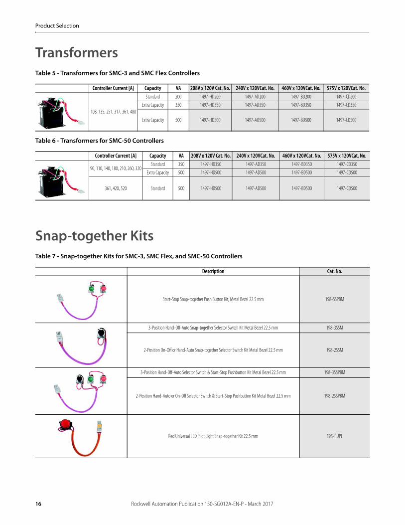
TransformersTable 5 - Transformers for SMC-3 and SMC Flex Controllers
Table 6 - Transformers for SMC-50 Controllers
Snap-together KitsTable 7 - Snap-together Kits for SMC-3, SMC Flex, and SMC-50 Controllers
Controller Current [A] Capacity VA 208V x 120V Cat. No. 240V x 120VCat. No. 460V x 120VCat. No. 575V x 120VCat. No.
108, 135, 251, 317, 361, 480
Standard 200 1497-HD200 1497-AD200 1497-BD200 1497-CD200
Extra Capacity 350 1497-HD350 1497-AD350 1497-BD350 1497-CD350
Extra Capacity 500 1497-HD500 1497-AD500 1497-BD500 1497-CD500
Controller Current [A] Capacity VA 208V x 120V Cat. No. 240V x 120VCat. No. 460V x 120VCat. No. 575V x 120VCat. No.
90, 110, 140, 180, 210, 260, 320Standard 350 1497-HD350 1497-AD350 1497-BD350 1497-CD350
Extra Capacity 500 1497-HD500 1497-AD500 1497-BD500 1497-CD500
361, 420, 520 Standard 500 1497-HD500 1497-AD500 1497-BD500 1497-CD500
Description Cat. No.
Start-Stop Snap-together Push Button Kit, Metal Bezel 22.5 mm 198-SSPBM
3-Position Hand-Off-Auto Snap-together Selector Switch Kit Metal Bezel 22.5 mm 198-3SSM
2-Position On-Off or Hand-Auto Snap-together Selector Switch Kit Metal Bezel 22.5 mm 198-2SSM
3-Position Hand-Off-Auto Selector Switch & Start-Stop Pushbutton Kit Metal Bezel 22.5 mm 198-3SSPBM
2-Position Hand-Auto or On-Off Selector Switch & Start-Stop Pushbutton Kit Metal Bezel 22.5 mm 198-2SSPBM
Red Universal LED Pilot Light Snap-together Kit 22.5 mm 198-RUPL
16 Rockwell Automation Publication 150-SG012A-EN-P - March 2017
Product Selection
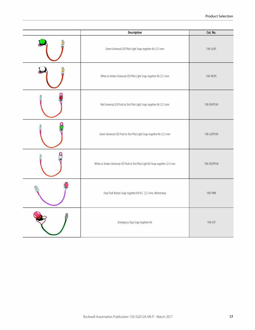
Green Universal LED Pilot Light Snap-together Kit 22.5 mm 198-GUPL
White or Amber Universal LED Pilot Light Snap-together Kit 22.5 mm 198-WUPL
Red Universal LED Push to Test Pilot Light Snap-together Kit 22.5 mm 198-RUPPLM
Green Universal LED Push to Test Pilot Light Snap-together Kit 22.5 mm 198-GUPPLM
White or Amber Universal LED Push to Test Pilot Light Kit Snap-together 22.5 mm 198-WUPPLM
Stop Push Button Snap-together Kit N.C. 22.5 mm, Momentary 198-PBM
Emergency Stop Snap-together Kit 198-ESP
Description Cat. No.
Rockwell Automation Publication 150-SG012A-EN-P - March 2017 17
Product Selection
Notes:
18 Rockwell Automation Publication 150-SG012A-EN-P - March 2017
Accessories
Accessories for SMC-3 Controllers
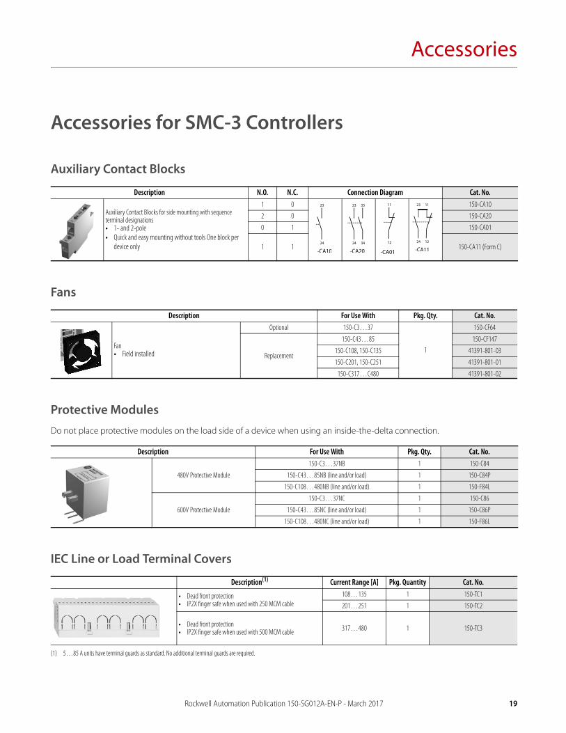
Auxiliary Contact Blocks
Fans
Protective ModulesDo not place protective modules on the load side of a device when using an inside-the-delta connection.
IEC Line or Load Terminal Covers
Description N.O. N.C. Connection Diagram Cat. No.
Auxiliary Contact Blocks for side mounting with sequence terminal designations• 1- and 2-pole• Quick and easy mounting without tools One block per
device only
1 0 150-CA10
2 0 150-CA20
0 1 150-CA01
1 1 150-CA11 (Form C)
Description For Use With Pkg. Qty. Cat. No.
Fan• Field installed
Optional 150-C3…37
1
150-CF64
Replacement
150-C43…85 150-CF147
150-C108, 150-C135 41391-801-03
150-C201, 150-C251 41391-801-01
150-C317…C480 41391-801-02
Description For Use With Pkg. Qty. Cat. No.
480V Protective Module
150-C3…37NB 1 150-C84
150-C43…85NB (line and/or load) 1 150-C84P
150-C108…480NB (line and/or load) 1 150-F84L
600V Protective Module
150-C3…37NC 1 150-C86
150-C43…85NC (line and/or load) 1 150-C86P
150-C108…480NC (line and/or load) 1 150-F86L
Description(1)
(1) 5…85 A units have terminal guards as standard. No additional terminal guards are required.
Current Range [A] Pkg. Quantity Cat. No.
• Dead front protection• IP2X finger safe when used with 250 MCM cable
108…135 1 150-TC1
201…251 1 150-TC2
• Dead front protection• IP2X finger safe when used with 500 MCM cable 317…480 1 150-TC3
Rockwell Automation Publication 150-SG012A-EN-P - March 2017 19
Accessories
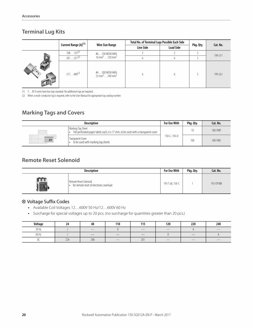
Terminal Lug Kits
Marking Tags and Covers
Remote Reset Solenoid
Voltage Suffix Codes• Available Coil Voltages 12…600V 50 Hz/12…600V 60 Hz• Surcharge for special voltages up to 20 pcs. (no surcharge for quantities greater than 20 pcs.)
Current Range [A](1)
(1) 5…85 A units have box lugs standard. No additional lugs are required.
Wire Size RangeTotal No. of Terminal Lugs Possible Each Side
Pkg. Qty. Cat. No.Line Side Load Side
108…135(2)
(2) When a multi-conductor lug is required, refer to the User Manual for appropriate lug catalog number.
#6…250 MCM AWG16 mm2…120 mm2
3 3 3199-LF1
201…251(2) 6 6 3
317…480(2) #4…500 MCM AWG25 mm2…240 mm2 6 6 3 199-LG1
Description For Use With Pkg. Qty. Cat. No.Marking Tag Sheet• 160 perforated paper labels each, 6 x 17 mm, to be used with a transparent cover
150-C, 150-D
10 100-FMP
Transparent Cover• To be used with marking tag sheets 100 100-FMC
Description For Use With Pkg. Qty. Cat. No.
Remote Reset Solenoid • for remote reset of electronic overload 193-T all, 150-C 1 193-ER1
Voltage 24 48 110 115 120 220 24050 Hz J — D — — A —
60 Hz J — — — D — A
DC Z24 Z48 — Z01 — — —
20 Rockwell Automation Publication 150-SG012A-EN-P - March 2017
Accessories
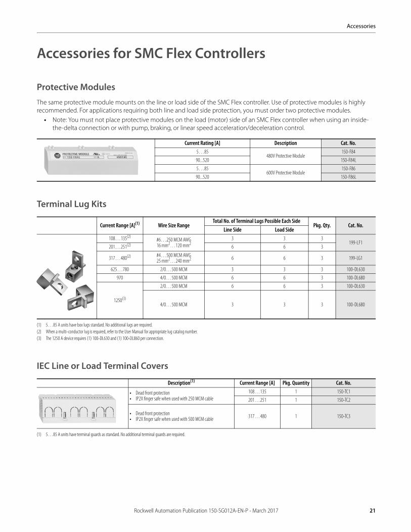
Accessories for SMC Flex Controllers
Protective ModulesThe same protective module mounts on the line or load side of the SMC Flex controller. Use of protective modules is highly recommended. For applications requiring both line and load side protection, you must order two protective modules.
• Note: You must not place protective modules on the load (motor) side of an SMC Flex controller when using an inside-the-delta connection or with pump, braking, or linear speed acceleration/deceleration control.
Terminal Lug Kits
IEC Line or Load Terminal Covers
Current Rating [A] Description Cat. No.5…85
480V Protective Module150-F84
90...520 150-F84L
5…85600V Protective Module
150-F86
90...520 150-F86L
Current Range [A](1)
(1) 5…85 A units have box lugs standard. No additional lugs are required.
Wire Size RangeTotal No. of Terminal Lugs Possible Each Side
Pkg. Qty. Cat. No.Line Side Load Side
108…135(2)
(2) When a multi-conductor lug is required, refer to the User Manual for appropriate lug catalog number.
#6…250 MCM AWG16 mm2…120 mm2
3 3 3199-LF1
201…251(2) 6 6 3
317…480(2) #4…500 MCM AWG25 mm2…240 mm2 6 6 3 199-LG1
625…780 2/0…500 MCM 3 3 3 100-DL630
970 4/0…500 MCM 6 6 3 100-DL680
1250(3)
(3) The 1250 A device requires (1) 100-DL630 and (1) 100-DL860 per connection.
2/0…500 MCM 6 6 3 100-DL630
4/0…500 MCM 3 3 3 100-DL680
Description(1)
(1) 5…85 A units have terminal guards as standard. No additional terminal guards are required.
Current Range [A] Pkg. Quantity Cat. No.
• Dead front protection• IP2X finger safe when used with 250 MCM cable
108…135 1 150-TC1
201…251 1 150-TC2
• Dead front protection• IP2X finger safe when used with 500 MCM cable 317…480 1 150-TC3
Rockwell Automation Publication 150-SG012A-EN-P - March 2017 21
Accessories
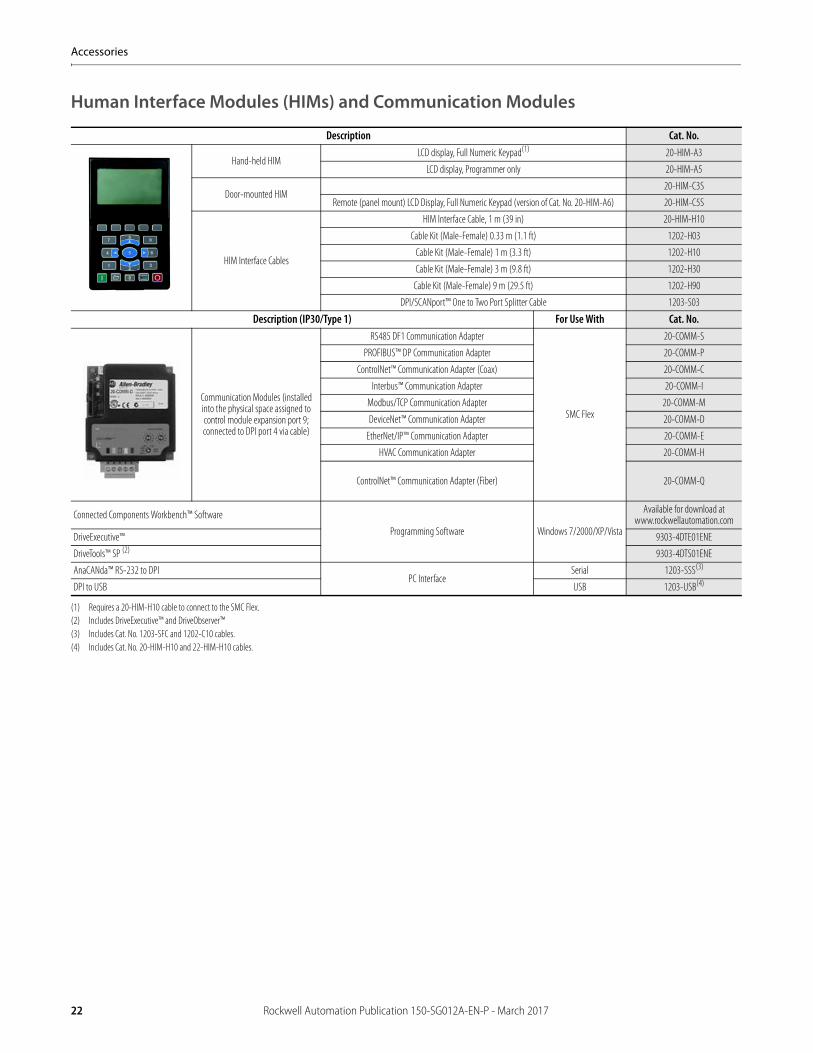
Human Interface Modules (HIMs) and Communication Modules
Description Cat. No.
Hand-held HIMLCD display, Full Numeric Keypad(1)
(1) Requires a 20-HIM-H10 cable to connect to the SMC Flex.
20-HIM-A3
LCD display, Programmer only 20-HIM-A5
Door-mounted HIM20-HIM-C3S
Remote (panel mount) LCD Display, Full Numeric Keypad (version of Cat. No. 20-HIM-A6) 20-HIM-C5S
HIM Interface Cables
HIM Interface Cable, 1 m (39 in) 20-HIM-H10
Cable Kit (Male-Female) 0.33 m (1.1 ft) 1202-H03
Cable Kit (Male-Female) 1 m (3.3 ft) 1202-H10
Cable Kit (Male-Female) 3 m (9.8 ft) 1202-H30
Cable Kit (Male-Female) 9 m (29.5 ft) 1202-H90
DPI/SCANport™ One to Two Port Splitter Cable 1203-S03
Description (IP30/Type 1) For Use With Cat. No.
Communication Modules (installed into the physical space assigned to control module expansion port 9; connected to DPI port 4 via cable)
RS485 DF1 Communication Adapter
SMC Flex
20-COMM-S
PROFIBUS™ DP Communication Adapter 20-COMM-P
ControlNet™ Communication Adapter (Coax) 20-COMM-C
Interbus™ Communication Adapter 20-COMM-I
Modbus/TCP Communication Adapter 20-COMM-M
DeviceNet™ Communication Adapter 20-COMM-D
EtherNet/IP™ Communication Adapter 20-COMM-E
HVAC Communication Adapter 20-COMM-H
ControlNet™ Communication Adapter (Fiber) 20-COMM-Q
Connected Components Workbench™ Software
Programming Software Windows 7/2000/XP/Vista
Available for download at www.rockwellautomation.com
DriveExecutive™ 9303-4DTE01ENE
DriveTools™ SP (2)
(2) Includes DriveExecutive™ and DriveObserver™
9303-4DTS01ENE
AnaCANda™ RS-232 to DPIPC Interface
Serial 1203-SSS(3)
(3) Includes Cat. No. 1203-SFC and 1202-C10 cables.
DPI to USB USB 1203-USB(4)
(4) Includes Cat. No. 20-HIM-H10 and 22-HIM-H10 cables.
22 Rockwell Automation Publication 150-SG012A-EN-P - March 2017
Accessories
Accessories for SMC-50 Controllers
Option ModulesOption modules can be used to add or expand the functionality of the SMC-50 Control Module. Option modules are installed into the control module's three expansion ports, 7 through 9.
• NOTE: If network communication is required, a Cat. No. 20-COMM-X communication adapter must be inserted in expansion port 9.
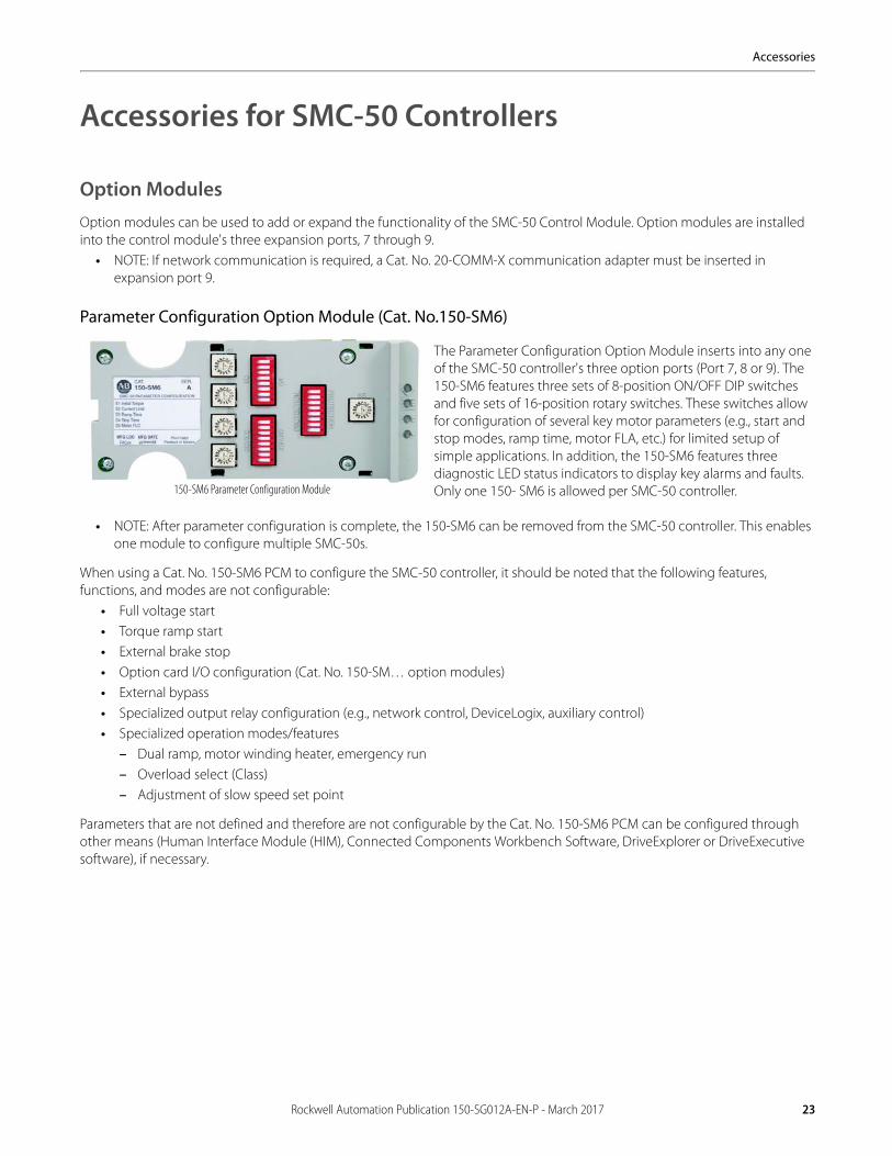
Parameter Configuration Option Module (Cat. No.150-SM6)
The Parameter Configuration Option Module inserts into any one of the SMC-50 controller's three option ports (Port 7, 8 or 9). The 150-SM6 features three sets of 8-position ON/OFF DIP switches and five sets of 16-position rotary switches. These switches allow for configuration of several key motor parameters (e.g., start and stop modes, ramp time, motor FLA, etc.) for limited setup of simple applications. In addition, the 150-SM6 features three diagnostic LED status indicators to display key alarms and faults. Only one 150- SM6 is allowed per SMC-50 controller.
• NOTE: After parameter configuration is complete, the 150-SM6 can be removed from the SMC-50 controller. This enables one module to configure multiple SMC-50s.
When using a Cat. No. 150-SM6 PCM to configure the SMC-50 controller, it should be noted that the following features, functions, and modes are not configurable:
• Full voltage start• Torque ramp start• External brake stop• Option card I/O configuration (Cat. No. 150-SM… option modules)• External bypass• Specialized output relay configuration (e.g., network control, DeviceLogix, auxiliary control)• Specialized operation modes/features
– Dual ramp, motor winding heater, emergency run– Overload select (Class)– Adjustment of slow speed set point
Parameters that are not defined and therefore are not configurable by the Cat. No. 150-SM6 PCM can be configured through other means (Human Interface Module (HIM), Connected Components Workbench Software, DriveExplorer or DriveExecutive software), if necessary.
150-SM6 Parameter Configuration Module
Rockwell Automation Publication 150-SG012A-EN-P - March 2017 23
Accessories
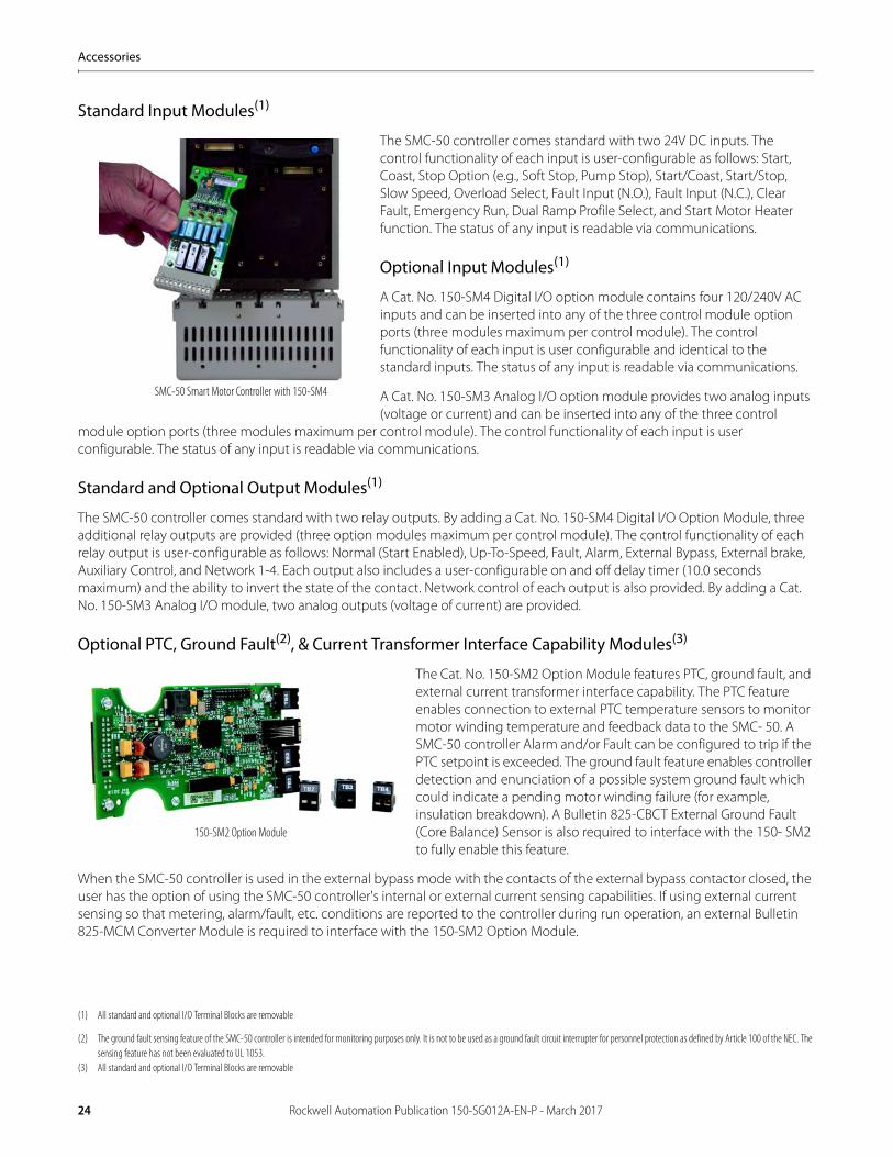
Standard Input Modules(1)
The SMC-50 controller comes standard with two 24V DC inputs. The control functionality of each input is user-configurable as follows: Start, Coast, Stop Option (e.g., Soft Stop, Pump Stop), Start/Coast, Start/Stop, Slow Speed, Overload Select, Fault Input (N.O.), Fault Input (N.C.), Clear Fault, Emergency Run, Dual Ramp Profile Select, and Start Motor Heater function. The status of any input is readable via communications.
Optional Input Modules(1)
A Cat. No. 150-SM4 Digital I/O option module contains four 120/240V AC inputs and can be inserted into any of the three control module option ports (three modules maximum per control module). The control functionality of each input is user configurable and identical to the standard inputs. The status of any input is readable via communications.
A Cat. No. 150-SM3 Analog I/O option module provides two analog inputs (voltage or current) and can be inserted into any of the three control
module option ports (three modules maximum per control module). The control functionality of each input is user configurable. The status of any input is readable via communications.
Standard and Optional Output Modules(1)
The SMC-50 controller comes standard with two relay outputs. By adding a Cat. No. 150-SM4 Digital I/O Option Module, three additional relay outputs are provided (three option modules maximum per control module). The control functionality of each relay output is user-configurable as follows: Normal (Start Enabled), Up-To-Speed, Fault, Alarm, External Bypass, External brake, Auxiliary Control, and Network 1-4. Each output also includes a user-configurable on and off delay timer (10.0 seconds maximum) and the ability to invert the state of the contact. Network control of each output is also provided. By adding a Cat. No. 150-SM3 Analog I/O module, two analog outputs (voltage of current) are provided.
Optional PTC, Ground Fault(2), & Current Transformer Interface Capability Modules(3)
The Cat. No. 150-SM2 Option Module features PTC, ground fault, and external current transformer interface capability. The PTC feature enables connection to external PTC temperature sensors to monitor motor winding temperature and feedback data to the SMC- 50. A SMC-50 controller Alarm and/or Fault can be configured to trip if the PTC setpoint is exceeded. The ground fault feature enables controller detection and enunciation of a possible system ground fault which could indicate a pending motor winding failure (for example, insulation breakdown). A Bulletin 825-CBCT External Ground Fault (Core Balance) Sensor is also required to interface with the 150- SM2 to fully enable this feature.
When the SMC-50 controller is used in the external bypass mode with the contacts of the external bypass contactor closed, the user has the option of using the SMC-50 controller's internal or external current sensing capabilities. If using external current sensing so that metering, alarm/fault, etc. conditions are reported to the controller during run operation, an external Bulletin 825-MCM Converter Module is required to interface with the 150-SM2 Option Module.
(1) All standard and optional I/O Terminal Blocks are removable
(2) The ground fault sensing feature of the SMC-50 controller is intended for monitoring purposes only. It is not to be used as a ground fault circuit interrupter for personnel protection as defined by Article 100 of the NEC. The sensing feature has not been evaluated to UL 1053.
(3) All standard and optional I/O Terminal Blocks are removable
SMC-50 Smart Motor Controller with 150-SM4
150-SM2 Option Module
24 Rockwell Automation Publication 150-SG012A-EN-P - March 2017
Accessories
Converter Modules
Protective Modules
The same protective module mounts on the line or load side of the SMC-50 controller. Use of protective modules is highly recommended. For applications requiring both line and load side protection, you must order two protective modules.
• Note: You must not place protective modules on the load (motor) side of an SMC-50 controller when using an inside-the-delta connection or with pump, braking, or linear speed acceleration/deceleration control.
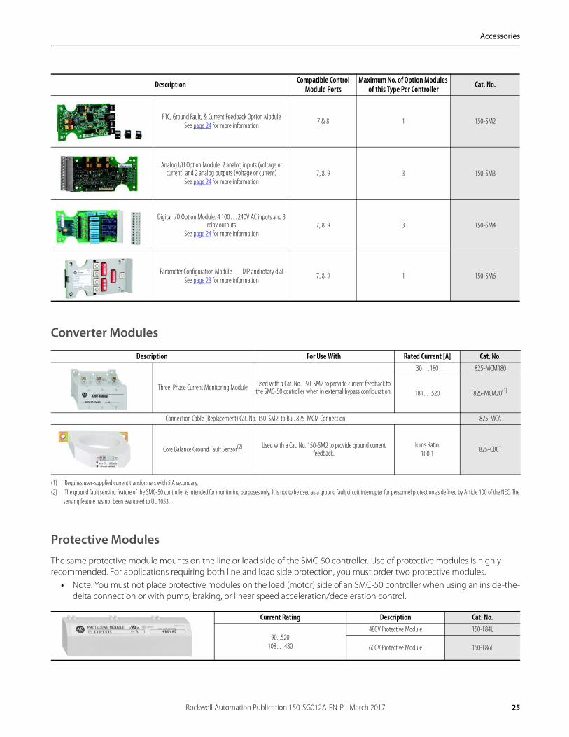
Description Compatible Control Module Ports
Maximum No. of Option Modules of this Type Per Controller Cat. No.
PTC, Ground Fault, & Current Feedback Option ModuleSee page 24 for more information
7 & 8 1 150-SM2
Analog I/O Option Module: 2 analog inputs (voltage or current) and 2 analog outputs (voltage or current)
See page 24 for more information7, 8, 9 3 150-SM3
Digital I/O Option Module: 4 100…240V AC inputs and 3 relay outputs
See page 24 for more information7, 8, 9 3 150-SM4
Parameter Configuration Module — DIP and rotary dialSee page 23 for more information
7, 8, 9 1 150-SM6
Description For Use With Rated Current [A] Cat. No.
Three-Phase Current Monitoring Module Used with a Cat. No. 150-SM2 to provide current feedback to the SMC-50 controller when in external bypass configuration.
30…180 825-MCM180
181…520 825-MCM20(1)
(1) Requires user-supplied current transformers with 5 A secondary.
Connection Cable (Replacement) Cat. No. 150-SM2 to Bul. 825-MCM Connection 825-MCA
Core Balance Ground Fault Sensor(2)
(2) The ground fault sensing feature of the SMC-50 controller is intended for monitoring purposes only. It is not to be used as a ground fault circuit interrupter for personnel protection as defined by Article 100 of the NEC. The sensing feature has not been evaluated to UL 1053.
Used with a Cat. No. 150-SM2 to provide ground current feedback.
Turns Ratio:100:1
825-CBCT
Current Rating Description Cat. No.
90...520108…480
480V Protective Module 150-F84L
600V Protective Module 150-F86L
Rockwell Automation Publication 150-SG012A-EN-P - March 2017 25
Accessories
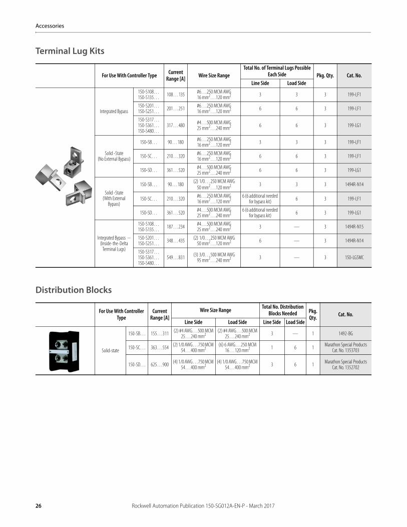
Terminal Lug Kits
Distribution Blocks
For Use With Controller Type Current Range [A] Wire Size Range
Total No. of Terminal Lugs Possible Each Side Pkg. Qty. Cat. No.
Line Side Load Side
Integrated Bypass
150-S108…150-S135… 108…135 #6…250 MCM AWG
16 mm2…120 mm2 3 3 3 199-LF1
150-S201…150-S251… 201…251 #6…250 MCM AWG
16 mm2…120 mm2 6 6 3 199-LF1
150-S317…150-S361…150-S480…
317…480 #4…500 MCM AWG25 mm2…240 mm2 6 6 3 199-LG1
Solid -State(No External Bypass)
150-SB… 90…180 #6…250 MCM AWG16 mm2…120 mm2 3 3 3 199-LF1
150-SC… 210…320 #6…250 MCM AWG16 mm2…120 mm2 6 6 3 199-LF1
150-SD… 361…520 #4…500 MCM AWG25 mm2…240 mm2 6 6 3 199-LG1
Solid -State(With External
Bypass)
150-SB… 90…180(2) 1/0…250 MCM AWG
50 mm2…120 mm2 3 3 3 1494R-N14
150-SC… 210…320 #6…250 MCM AWG16 mm2…120 mm2
6 (6 additional needed for bypass kit) 6 3 199-LF1
150-SD… 361…520 #4…500 MCM AWG25 mm2…240 mm2
6 (6 additional needed for bypass kit) 6 3 199-LG1
Integrated Bypass -- (Inside-the-Delta
Terminal Lugs)
150-S108…150-S135… 187…234 #4…500 MCM AWG
25 mm2…240 mm2 3 — 3 1494R-N15
150-S201…150-S251… 348…435 (2) 1/0…250 MCM AWG
50 mm2…120 mm2 6 — 3 1494R-N14
150-S317…150-S361…150-S480…
549…831 (3) 3/0…500 MCM AWG95 mm2…240 mm2 3 — 3 150-LG5MC
For Use With Controller Type
Current Range [A]
Wire Size Range Total No. Distribution Blocks Needed Pkg.
Qty. Cat. No.Line Side Load Side Line Side Load Side
Solid-state
150-SB… 155…311 (2) #4 AWG…500 MCM 25…240 mm2
(2) #4 AWG…500 MCM 25…240 mm2 3 — 1 1492-BG
150-SC… 363…554 (2) 1/0 AWG…750 MCM 54…400 mm2
(6) 6 AWG…250 MCM 16…120 mm2 1 6 1 Marathon Special Products
Cat. No. 1353703
150-SD… 625…900 (4) 1/0 AWG…750 MCM 54…400 mm2
(4) 1/0 AWG…750 MCM 54…400 mm2 3 6 1 Marathon Special Products
Cat. No. 1352702
26 Rockwell Automation Publication 150-SG012A-EN-P - March 2017
Accessories
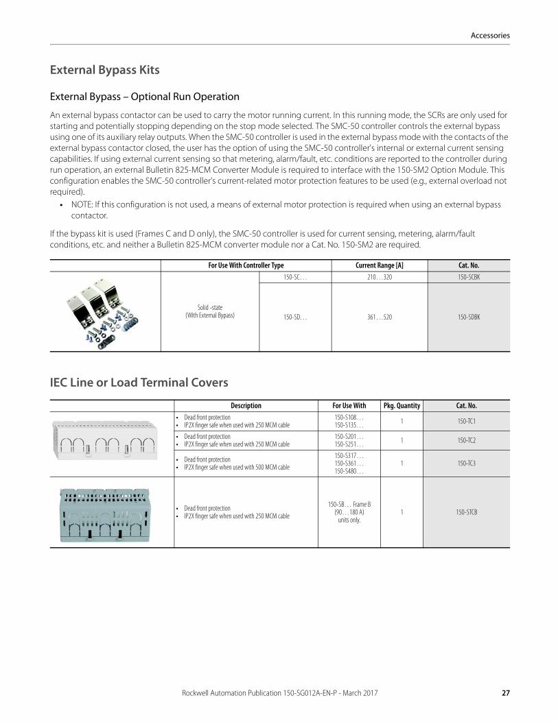
External Bypass Kits
External Bypass – Optional Run Operation
An external bypass contactor can be used to carry the motor running current. In this running mode, the SCRs are only used for starting and potentially stopping depending on the stop mode selected. The SMC-50 controller controls the external bypass using one of its auxiliary relay outputs. When the SMC-50 controller is used in the external bypass mode with the contacts of the external bypass contactor closed, the user has the option of using the SMC-50 controller's internal or external current sensing capabilities. If using external current sensing so that metering, alarm/fault, etc. conditions are reported to the controller during run operation, an external Bulletin 825-MCM Converter Module is required to interface with the 150-SM2 Option Module. This configuration enables the SMC-50 controller's current-related motor protection features to be used (e.g., external overload not required).
• NOTE: If this configuration is not used, a means of external motor protection is required when using an external bypass contactor.
If the bypass kit is used (Frames C and D only), the SMC-50 controller is used for current sensing, metering, alarm/fault conditions, etc. and neither a Bulletin 825-MCM converter module nor a Cat. No. 150-SM2 are required.
IEC Line or Load Terminal Covers
For Use With Controller Type Current Range [A] Cat. No.
Solid -state(With External Bypass)
150-SC… 210…320 150-SCBK
150-SD… 361…520 150-SDBK
Description For Use With Pkg. Quantity Cat. No.• Dead front protection• IP2X finger safe when used with 250 MCM cable
150-S108…150-S135… 1 150-TC1
• Dead front protection• IP2X finger safe when used with 250 MCM cable
150-S201…150-S251… 1 150-TC2
• Dead front protection• IP2X finger safe when used with 500 MCM cable
150-S317…150-S361…150-S480…
1 150-TC3
• Dead front protection• IP2X finger safe when used with 250 MCM cable
150-SB… Frame B (90…180 A)
units only.1 150-STCB
Rockwell Automation Publication 150-SG012A-EN-P - March 2017 27
Accessories
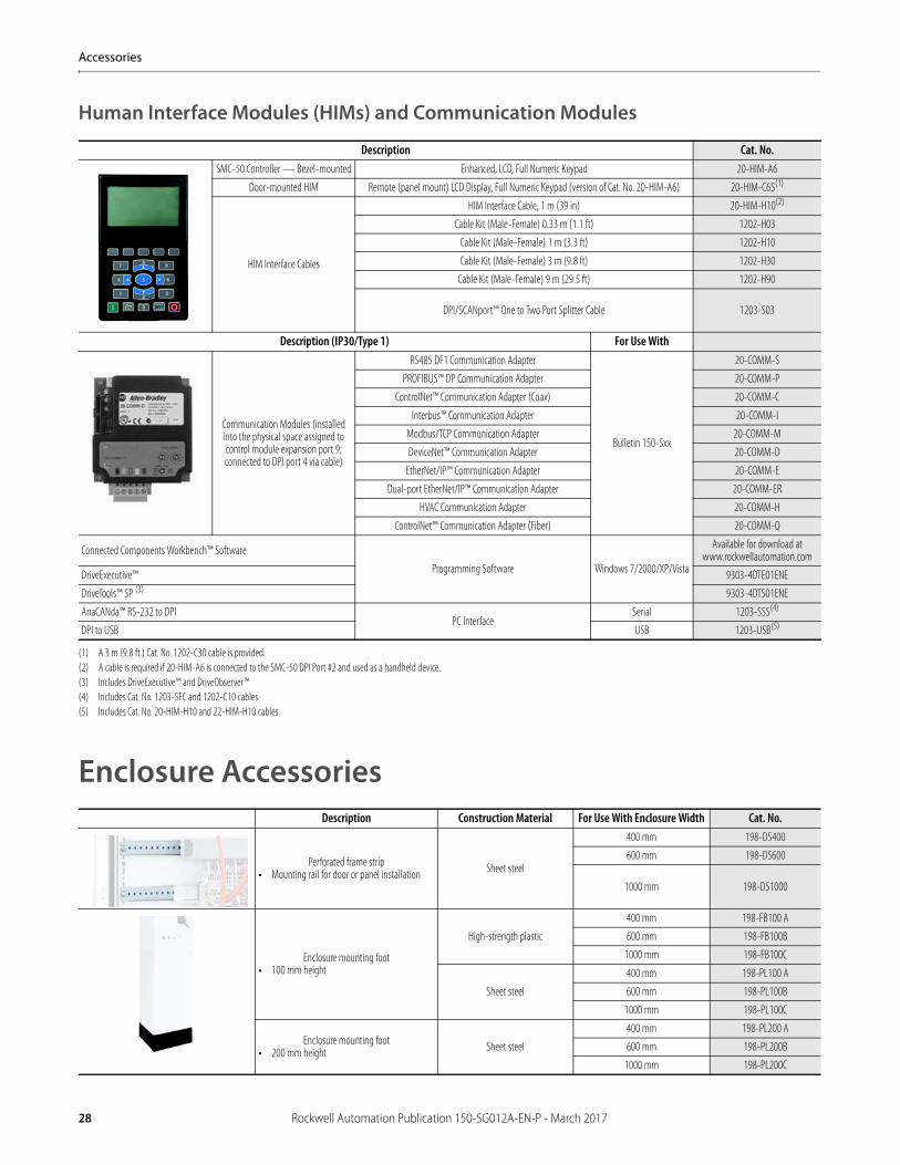
Human Interface Modules (HIMs) and Communication Modules
Enclosure Accessories
Description Cat. No.SMC-50 Controller — Bezel-mounted Enhanced, LCD, Full Numeric Keypad 20-HIM-A6
Door-mounted HIM Remote (panel mount) LCD Display, Full Numeric Keypad (version of Cat. No. 20-HIM-A6) 20-HIM-C6S(1)
(1) A 3 m (9.8 ft.) Cat. No. 1202-C30 cable is provided.
HIM Interface Cables
HIM Interface Cable, 1 m (39 in) 20-HIM-H10(2)
(2) A cable is required if 20-HIM-A6 is connected to the SMC-50 DPI Port #2 and used as a handheld device.
Cable Kit (Male-Female) 0.33 m (1.1 ft) 1202-H03
Cable Kit (Male-Female) 1 m (3.3 ft) 1202-H10
Cable Kit (Male-Female) 3 m (9.8 ft) 1202-H30
Cable Kit (Male-Female) 9 m (29.5 ft) 1202-H90
DPI/SCANport™ One to Two Port Splitter Cable 1203-S03
Description (IP30/Type 1) For Use With
Communication Modules (installed into the physical space assigned to control module expansion port 9; connected to DPI port 4 via cable)
RS485 DF1 Communication Adapter
Bulletin 150-Sxx
20-COMM-S
PROFIBUS™ DP Communication Adapter 20-COMM-P
ControlNet™ Communication Adapter (Coax) 20-COMM-C
Interbus™ Communication Adapter 20-COMM-I
Modbus/TCP Communication Adapter 20-COMM-M
DeviceNet™ Communication Adapter 20-COMM-D
EtherNet/IP™ Communication Adapter 20-COMM-E
Dual-port EtherNet/IP™ Communication Adapter 20-COMM-ER
HVAC Communication Adapter 20-COMM-H
ControlNet™ Communication Adapter (Fiber) 20-COMM-Q
Connected Components Workbench™ Software
Programming Software Windows 7/2000/XP/Vista
Available for download at www.rockwellautomation.com
DriveExecutive™ 9303-4DTE01ENE
DriveTools™ SP (3)
(3) Includes DriveExecutive™ and DriveObserver™
9303-4DTS01ENE
AnaCANda™ RS-232 to DPIPC Interface
Serial 1203-SSS(4)
(4) Includes Cat. No. 1203-SFC and 1202-C10 cables.
DPI to USB USB 1203-USB(5)
(5) Includes Cat. No. 20-HIM-H10 and 22-HIM-H10 cables.
Description Construction Material For Use With Enclosure Width Cat. No.
Perforated frame strip • Mounting rail for door or panel installation Sheet steel
400 mm 198-DS400
600 mm 198-DS600
1000 mm 198-DS1000
Enclosure mounting foot• 100 mm height
High-strength plastic
400 mm 198-FB100 A
600 mm 198-FB100B
1000 mm 198-FB100C
Sheet steel
400 mm 198-PL100 A
600 mm 198-PL100B
1000 mm 198-PL100C
Enclosure mounting foot• 200 mm height Sheet steel
400 mm 198-PL200 A
600 mm 198-PL200B
1000 mm 198-PL200C
28 Rockwell Automation Publication 150-SG012A-EN-P - March 2017
Wiring Diagrams
Wiring Diagrams for SMC ControllersThe diagrams in this section illustrate basic SMC controller wiring. For specific wiring diagrams, please consult your local Rockwell Automation sales office or Allen-Bradley distributor.
Notes:• Use 75 °C Cu wire only• Line fuses are supplied by the customer when the disconnect switch is supplied. Refer to NEC when selecting short-
circuit protection.• Additional control circuit overcurrent protection is required for non-combination starters. Refer to NEC.
Rockwell Automation Publication 150-SG012A-EN-P - March 2017 29
Wiring Diagrams
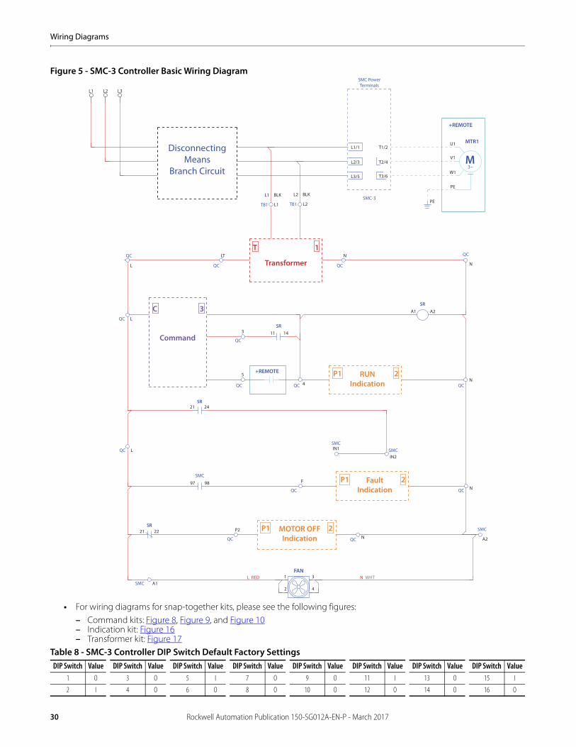
Figure 5 - SMC-3 Controller Basic Wiring Diagram
• For wiring diagrams for snap-together kits, please see the following figures:– Command kits: Figure 8, Figure 9, and Figure 10– Indication kit: Figure 16– Transformer kit: Figure 17
Table 8 - SMC-3 Controller DIP Switch Default Factory SettingsDIP Switch Value DIP Switch Value DIP Switch Value DIP Switch Value DIP Switch Value DIP Switch Value DIP Switch Value DIP Switch Value
1 O 3 O 5 I 7 O 9 O 11 I 13 O 15 I
2 I 4 O 6 O 8 O 10 O 12 O 14 O 16 O
SMC PowerTerminals
L1/1DisconnectingMeans
Branch Circuit
SMC-3
T3/6
T2/4
T1/2
L3/5
L2/3
+REMOTE
MTR1
3~M
U1
V1
W1
PE
PEL1
L1
BLK
TB1
L2
L2
BLK
TB1
L2 L3L1
L
QC
QCQC
NLT
Transformer
T 1
Command
C 3
RUNIndication
P1 2
FaultIndication
P1 2
MOTOR OFFIndication
P1 2
SMCSMC
FAN1
SMC
SMC
SR
2 4
3
+REMOTE
SR
SMC
QC
QCQC
QC
QCN
SR
SR
L
QC
N
A1 A2
3 11 14
4
5
21 24
QC L IN1
IN2
QC QC NF97 98
QC N A2QC
P221 22
A1L RED N WHT
30 Rockwell Automation Publication 150-SG012A-EN-P - March 2017
Wiring Diagrams
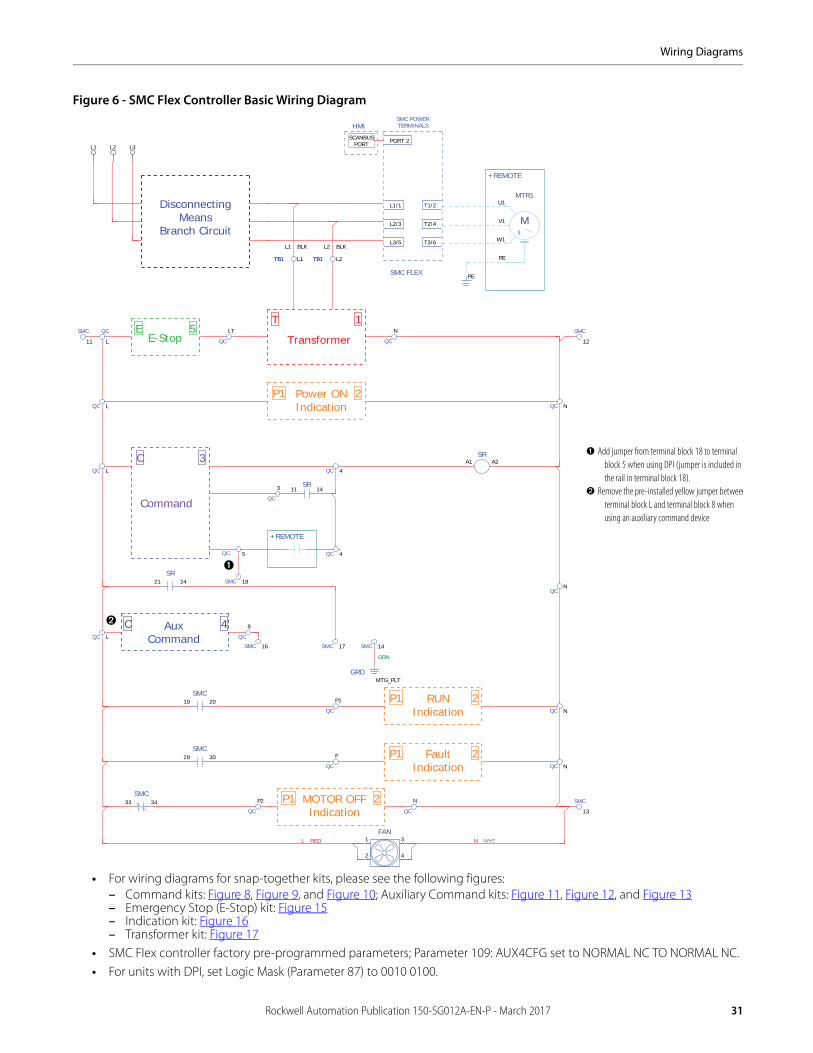
Figure 6 - SMC Flex Controller Basic Wiring Diagram
• For wiring diagrams for snap-together kits, please see the following figures:– Command kits: Figure 8, Figure 9, and Figure 10; Auxiliary Command kits: Figure 11, Figure 12, and Figure 13 – Emergency Stop (E-Stop) kit: Figure 15– Indication kit: Figure 16– Transformer kit: Figure 17
• SMC Flex controller factory pre-programmed parameters; Parameter 109: AUX4CFG set to NORMAL NC TO NORMAL NC.• For units with DPI, set Logic Mask (Parameter 87) to 0010 0100.
SMC POWERTERMINALS
Power ONIndication
Command
RUNIndication
T
P1
P1
C
1
2
2
3
AuxCommand
E-StopE 5
Transformer
FaultIndication
P1 2
P1 2MOTOR OFFIndication
C 4
FAN1
2
3
4
DisconnectingMeans
Branch Circuit
SMC FLEX
L1/1
L2/3
L3/5
U1
V1
W1
PE
MTR1
3
M
PE
+REMOTE
T1/2
T2/4
T3/6
HMI
SCANBUSPORT PORT 2
QC
LT
QC
N
A1 A2SR
21 24SR
19 20SMC
SMC 14
GRDMTG_PLT
QC 5
+REMOTE
11 14SR
QC
3
QC 4
QC 4
SMC 16 SMC 17
QC L
QC NQC
P1
11
SMC QC
L 12
SMC
QC L
QC L
33 34SMC
QC
P2
QC
N
QC N
13
SMC
QC
8
QC
F
QC N
29 30SMC
SMC 18
QCN
TB1 L2TB1TB1 L1TB1
L2 BLKL1 BLK
GRN
N WHTL RED
L1 L2 L3
➊ Add jumper from terminal block 18 to terminal block 5 when using DPI (jumper is included in the rail in terminal block 18).
➋ Remove the pre-installed yellow jumper betweenterminal block L and terminal block 8 when using an auxiliary command device
➊
➋
Rockwell Automation Publication 150-SG012A-EN-P - March 2017 31
Wiring Diagrams
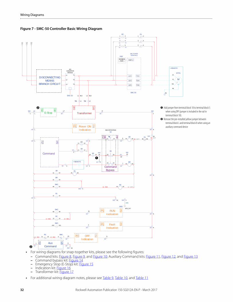
Figure 7 - SMC-50 Controller Basic Wiring Diagram
• For wiring diagrams for snap-together kits, please see the following figures:– Command kits: Figure 8, Figure 9, and Figure 10; Auxiliary Command kits: Figure 11, Figure 12, and Figure 13 – Command bypass kit: Figure 14– Emergency Stop (E-Stop) kit: Figure 15– Indication kit: Figure 16– Transformer kit: Figure 17
• For additional wiring diagram notes, please see Table 9, Table 10, and Table 11
SMC POWERTERMINALS
Power ONIndication
Command
RUNIndication
T
P1
P1
C
1
2
2
3
E-StopE 6
P2 2OFFIndication
Transformer
FaultIndication
P1 2
AuxCommand
C 5
13 14
S3SMC/OFF/BYPASS
23 24
4CB
CommandBypass
DISCONNECTINGMEANS
BRANCH CIRCUIT
SMC-50
L1/1
L2/3
L3/5
1
L1
2
T1
RC
3
L2
4
T2
5
L3
6
T3
U1
V1
W1
PE
MTR1
3
M
PE
+REMOTE
T1/2
T2/4
T3/6
HMI
SCANBUSPORT PORT 2
L1
L2
L3
T1
T2
T3
825CONVERTER
MODULE
QC
LT
QC
N
QC
7
A1 A2SR
A1 A2BR
21 24SR
A9 A8SMC
21 24BR
A6 A7SMC
SMC 5
A1 A2RC
SMC 3
SMC-50
QC
6
QC 5
+REMOTE
11 14SR
34 31SR
3QC
QC 4
QC 4
SMC A2
QC L
QC NQC
P1
1
SMC QC
L
SMC A5
QC L
6 7SMC
21 22RC
QC
P2
QC
N
QC N
QC
F
QC N
13 14RC
A10 A11SMC
1 2
3 4
5 6
OL
SMC
2
QC
A3
18SMC
95 96OL
A1 A2R1
QC N
SMC A4
QC
L
QC
8
11 14R1
QC L
11 14BR
L2 BLKL1 BLK
TB1 L2TB1TB1 L1TB1
22 RED21 RED
GRN
96 WHT95 WHT
A1 RED
33 34
S3
QC 5
A2 WHT
14 RED
GRDMTG_PLT
SMCA3
13 RED
L1 L2 L3
➊ Add jumper from terminal block 18 to terminal block 5 when using DPI (jumper is included in the rail in terminal block 18).
➋ Remove the pre-installed yellow jumper between terminal block L and terminal block 8 when using an auxiliary command device
➊
➋
➋
32 Rockwell Automation Publication 150-SG012A-EN-P - March 2017
Wiring Diagrams
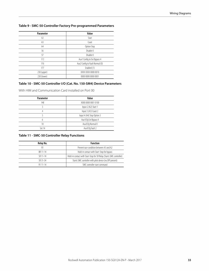
Table 9 - SMC-50 Controller Factory Pre-programmed Parameters
Table 10 - SMC-50 Controller I/O (Cat. No. 150-SM4) Device Parameters
With HIM and Communication Card installed on Port 00
Table 11 - SMC-50 Controller Relay Functions
Parameter ValueA2 Start
A3 Coast
A4 Option Stop
56 Disable 0
57 Disable 0
172 Aux1 Config to Ext Bypass 4
176 Aux2 Config to Fault Normal (0)
177 Enabled (1)
230 (upper) XXXX XXXX 0000 0010
230 (lower) 0000 0000 0000 0001
Parameter Value148 X000 0000 0001 0100
3 Input 2 (A2) Start 1
4 Input 3 (A3) Coast 2
5 Input 4 (A4) Stop Option 3
6 Aux1Cfg Ext Bypass 4
10 Aux2Cfg Normal 0
Set 14 Aux3Cfg Fault 2
Relay No. FunctionR1 Prevent race condition between A3 and A2
BR 11-14 Hold-in contact with Start-Stop for bypass
SR 11-14 Hold-in contact with Start-Stop for SR Relay (Starts SMC controller)
SR 31-34 Starts SMC controller with pilot device (no DPI present)
R1 11-14 SMC controller start command
Rockwell Automation Publication 150-SG012A-EN-P - March 2017 33
Wiring Diagrams
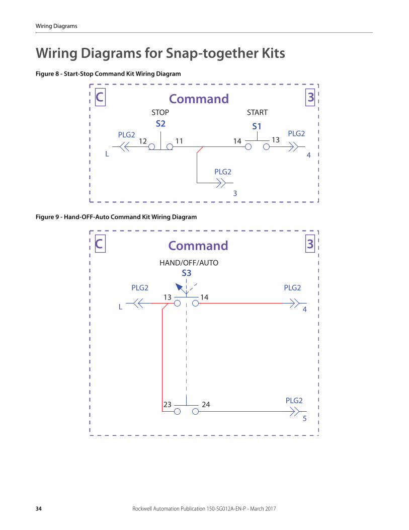
Wiring Diagrams for Snap-together KitsFigure 8 - Start-Stop Command Kit Wiring Diagram
Figure 9 - Hand-OFF-Auto Command Kit Wiring Diagram
STOP START
12 131411
CommandC 3
PLG2 PLG2
4L
PLG2
3
S1S2
CommandC 3HAND/OFF/AUTO
13
2423
14PLG2 PLG2
PLG2
5
4L
S3
34 Rockwell Automation Publication 150-SG012A-EN-P - March 2017
Wiring Diagrams
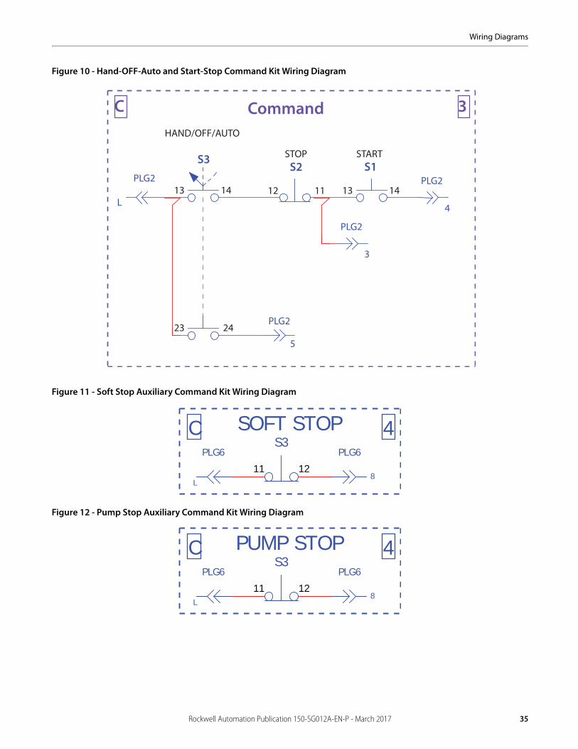
Figure 10 - Hand-OFF-Auto and Start-Stop Command Kit Wiring Diagram
Figure 11 - Soft Stop Auxiliary Command Kit Wiring Diagram
Figure 12 - Pump Stop Auxiliary Command Kit Wiring Diagram
CommandC 3HAND/OFF/AUTO
STARTSTOP
13
2423
14PLG2 PLG2
PLG2
5
4L
S3
PLG2
3
13 14
S1
12 11
S2
8L
SOFT STOP 4C
11 12
S3PLG6 PLG6
8L
PUMP STOPC 4PLG6 PLG6
11 12
S3
Rockwell Automation Publication 150-SG012A-EN-P - March 2017 35
Wiring Diagrams
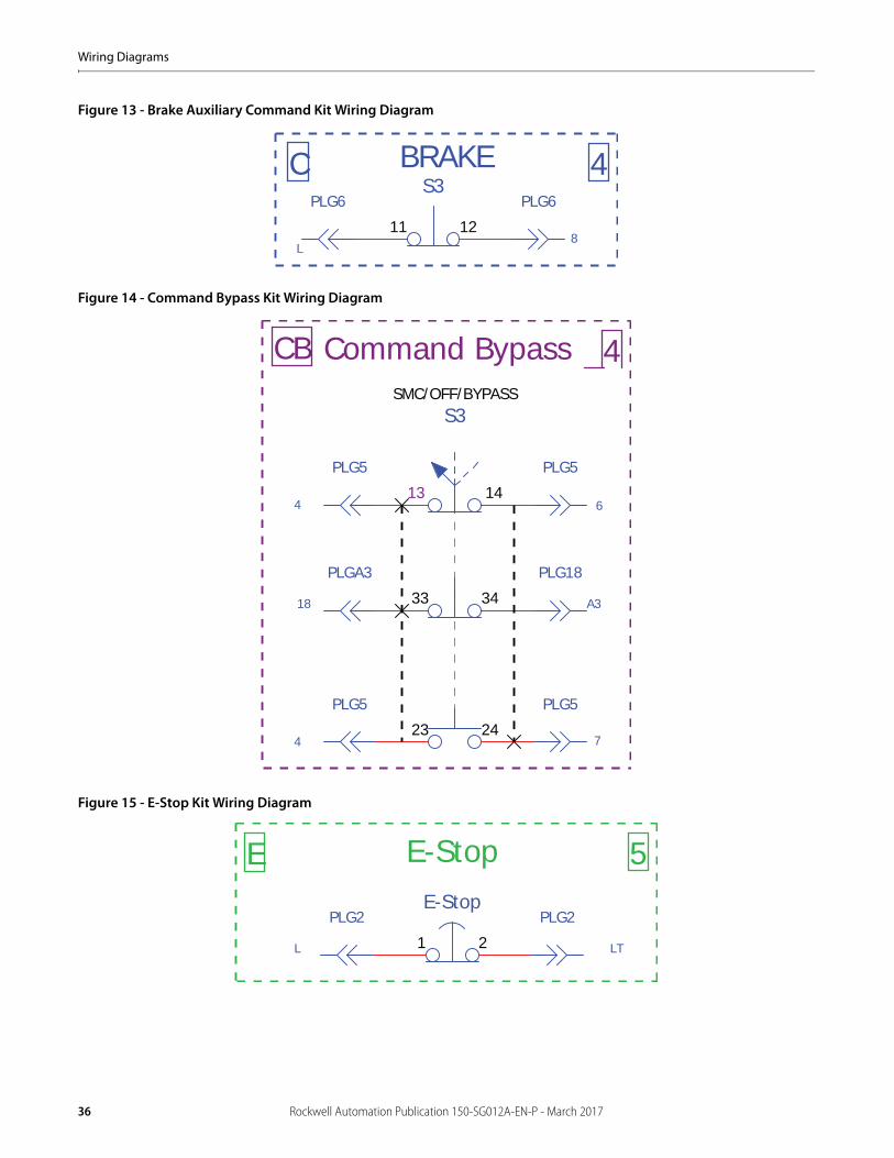
Figure 13 - Brake Auxiliary Command Kit Wiring Diagram
Figure 14 - Command Bypass Kit Wiring Diagram
Figure 15 - E-Stop Kit Wiring Diagram
8L
BRAKEC 4PLG6 PLG6
11 12
S3
S3SMC/OFF/BYPASS
13 14
23 24
Command Bypass CB 4
4 6
74
18 A3
PLG5 PLG5
PLG5PLG5
33 34
PLG18PLGA3
E 5E-Stop
L LT
PLG2 PLG2
21
E-Stop
36 Rockwell Automation Publication 150-SG012A-EN-P - March 2017
Wiring Diagrams
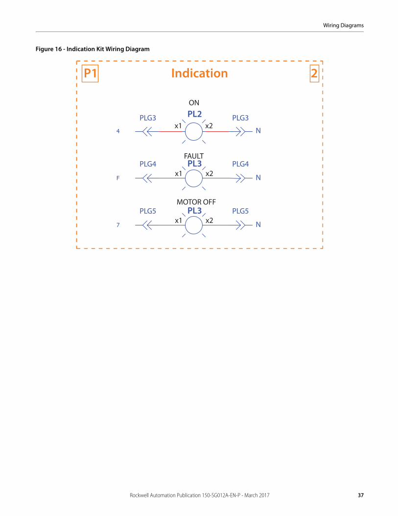
Figure 16 - Indication Kit Wiring Diagram
IndicationP1 2
PL2
PL3
PL3
ON
FAULT
PLG3
PLG4
PLG5
PLG3
PLG4
PLG5
N
N
N
x2x1
x2x1
x2x1
MOTOR OFF
Rockwell Automation Publication 150-SG012A-EN-P - March 2017 37
Wiring Diagrams
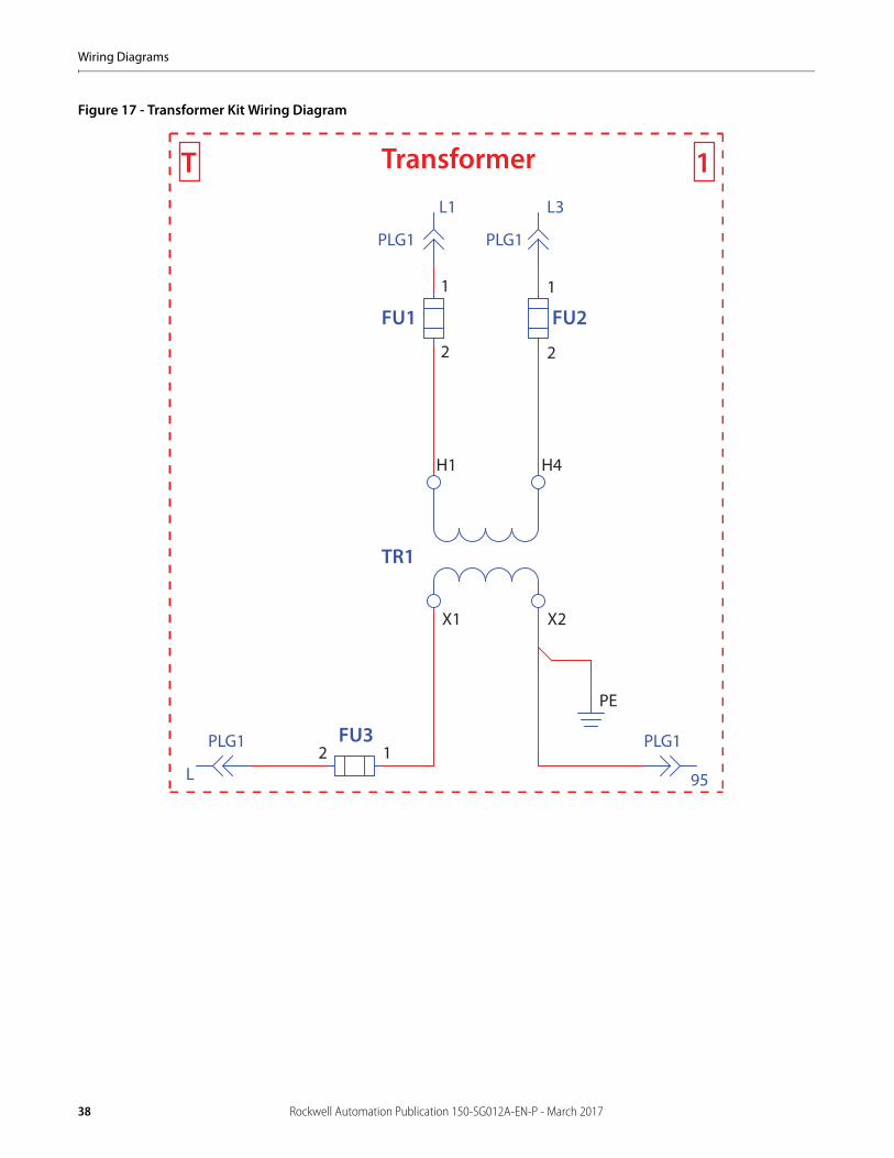
Figure 17 - Transformer Kit Wiring Diagram
TransformerT 1
FU1 FU2
PLG1
L1 L3
1
2
1
2
PLG1
H1 H4
TR1
X1 X2
PLG1 PLG1FU312
L 95
PE
38 Rockwell Automation Publication 150-SG012A-EN-P - March 2017
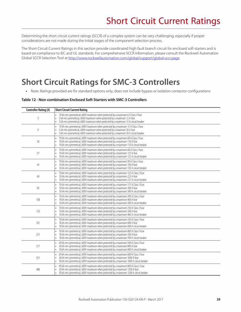
Short Circuit Current RatingsDetermining the short circuit current ratings (SCCR) of a complex system can be very challenging, especially if proper considerations are not made during the initial stages of the component selection process.
The Short Circuit Current Ratings in this section provide coordinated high fault branch circuit for enclosed soft starters and is based on compliance to IEC and UL standards. For comprehensive SCCR information, please consult the Rockwell Automation Global SCCR Selection Tool at http://www.rockwellautomation.com/global/support/global-sccr.page.
Short Circuit Ratings for SMC-3 Controllers• Note: Ratings provided are for standard options only; does not include bypass or isolation contactor configurations
Table 12 - Non-combination Enclosed Soft Starters with SMC-3 Controllers
Controller Rating [A] Short Circuit Current Rating
3• 70 kA rms symmetrical, 600V maximum when protected by a maximum 6 A Class J Fuse• 5 kA rms symmetrical, 600V maximum when protected by a maximum 12 A fuse• 5 kA rms symmetrical, 600V maximum when protected by a maximum 15 A circuit breaker
9• 70 kA rms symmetrical, 600V maximum when protected by a maximum 15 A Class J Fuse• 5 kA rms symmetrical, 600V maximum when protected by a maximum 30 A fuse• 5 kA rms symmetrical, 600V maximum when protected by a maximum 30 A circuit breaker
30• 70 kA rms symmetrical, 600V maximum when protected by a maximum 60 A Class J Fuse• 10 kA rms symmetrical, 600V maximum when protected by a maximum 110 A fuse• 10 kA rms symmetrical, 600V maximum when protected by a maximum 110 A circuit breaker
37• 70 kA rms symmetrical, 600V maximum when protected by a maximum 60 A Class J Fuse• 10 kA rms symmetrical, 600V maximum when protected by a maximum 125 A fuse• 10 kA rms symmetrical, 600V maximum when protected by a maximum 125 A circuit breaker
43• 70 kA rms symmetrical, 600V maximum when protected by a maximum 90 A Class J Fuse• 10 kA rms symmetrical, 600V maximum when protected by a maximum 150 A fuse• 10 kA rms symmetrical, 600V maximum when protected by a maximum 150 A circuit breaker
60• 70 kA rms symmetrical, 600V maximum when protected by a maximum 125 A Class J Fuse• 10 kA rms symmetrical, 600V maximum when protected by a maximum 225 A fuse• 10 kA rms symmetrical, 600V maximum when protected by a maximum 225 A circuit breaker
85• 70 kA rms symmetrical, 600V maximum when protected by a maximum 175 A Class J Fuse• 10 kA rms symmetrical, 600V maximum when protected by a maximum 300 A fuse• 10 kA rms symmetrical, 600V maximum when protected by a maximum 300 A circuit breaker
108• 70 kA rms symmetrical, 600V maximum when protected by a maximum 200 A Class J Fuse• 10 kA rms symmetrical, 600V maximum when protected by a maximum 400 A fuse• 10 kA rms symmetrical, 600V maximum when protected by a maximum 300 A circuit breaker
135• 70 kA rms symmetrical, 600V maximum when protected by a maximum 250 A Class J Fuse• 10 kA rms symmetrical, 600V maximum when protected by a maximum 500 A fuse• 10 kA rms symmetrical, 600V maximum when protected by a maximum 400 A circuit breaker
201• 70 kA rms symmetrical, 600V maximum when protected by a maximum 350 A Class J Fuse• 18 kA rms symmetrical, 600V maximum when protected by a maximum 600 A fuse• 18 kA rms symmetrical, 600V maximum when protected by a maximum 600 A circuit breaker
251• 70 kA rms symmetrical, 600V maximum when protected by a maximum 400 A Class J Fuse• 18 kA rms symmetrical, 600V maximum when protected by a maximum 700 A fuse• 18 kA rms symmetrical, 600V maximum when protected by a maximum 700 A circuit breaker
317• 69 kA rms symmetrical, 600V maximum when protected by a maximum 500 A Class J Fuse• 30 kA rms symmetrical, 600V maximum when protected by a maximum 800 A fuse• 30 kA rms symmetrical, 600V maximum when protected by a maximum 800 A circuit breaker
351• 69 kA rms symmetrical, 600V maximum when protected by a maximum 600 A Class J Fuse• 30 kA rms symmetrical, 600V maximum when protected by a maximum 1000 A fuse• 30 kA rms symmetrical, 600V maximum when protected by a maximum 1000 A circuit breaker
480• 69 kA rms symmetrical, 600V maximum when protected by a maximum 800 A Class L Fuse• 30 kA rms symmetrical, 600V maximum when protected by a maximum 1200 A fuse• 30 kA rms symmetrical, 600V maximum when protected by a maximum 1200 A circuit breaker
Rockwell Automation Publication 150-SG012A-EN-P - March 2017 39
Short Circuit Current Ratings
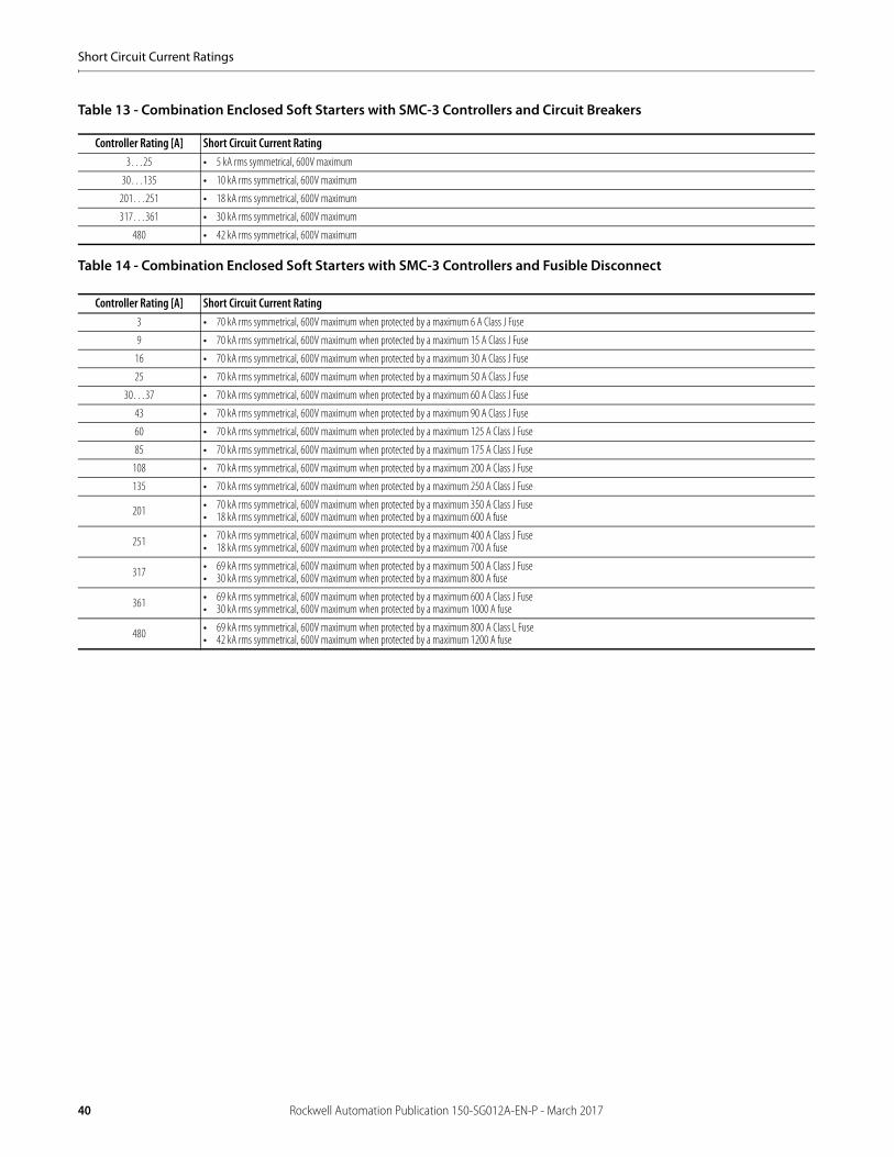
Table 13 - Combination Enclosed Soft Starters with SMC-3 Controllers and Circuit Breakers
Table 14 - Combination Enclosed Soft Starters with SMC-3 Controllers and Fusible Disconnect
Controller Rating [A] Short Circuit Current Rating3…25 • 5 kA rms symmetrical, 600V maximum
30…135 • 10 kA rms symmetrical, 600V maximum
201…251 • 18 kA rms symmetrical, 600V maximum
317…361 • 30 kA rms symmetrical, 600V maximum
480 • 42 kA rms symmetrical, 600V maximum
Controller Rating [A] Short Circuit Current Rating3 • 70 kA rms symmetrical, 600V maximum when protected by a maximum 6 A Class J Fuse
9 • 70 kA rms symmetrical, 600V maximum when protected by a maximum 15 A Class J Fuse
16 • 70 kA rms symmetrical, 600V maximum when protected by a maximum 30 A Class J Fuse
25 • 70 kA rms symmetrical, 600V maximum when protected by a maximum 50 A Class J Fuse
30…37 • 70 kA rms symmetrical, 600V maximum when protected by a maximum 60 A Class J Fuse
43 • 70 kA rms symmetrical, 600V maximum when protected by a maximum 90 A Class J Fuse
60 • 70 kA rms symmetrical, 600V maximum when protected by a maximum 125 A Class J Fuse
85 • 70 kA rms symmetrical, 600V maximum when protected by a maximum 175 A Class J Fuse
108 • 70 kA rms symmetrical, 600V maximum when protected by a maximum 200 A Class J Fuse
135 • 70 kA rms symmetrical, 600V maximum when protected by a maximum 250 A Class J Fuse
201 • 70 kA rms symmetrical, 600V maximum when protected by a maximum 350 A Class J Fuse• 18 kA rms symmetrical, 600V maximum when protected by a maximum 600 A fuse
251 • 70 kA rms symmetrical, 600V maximum when protected by a maximum 400 A Class J Fuse• 18 kA rms symmetrical, 600V maximum when protected by a maximum 700 A fuse
317 • 69 kA rms symmetrical, 600V maximum when protected by a maximum 500 A Class J Fuse• 30 kA rms symmetrical, 600V maximum when protected by a maximum 800 A fuse
361 • 69 kA rms symmetrical, 600V maximum when protected by a maximum 600 A Class J Fuse• 30 kA rms symmetrical, 600V maximum when protected by a maximum 1000 A fuse
480 • 69 kA rms symmetrical, 600V maximum when protected by a maximum 800 A Class L Fuse• 42 kA rms symmetrical, 600V maximum when protected by a maximum 1200 A fuse
40 Rockwell Automation Publication 150-SG012A-EN-P - March 2017
Short Circuit Current Ratings
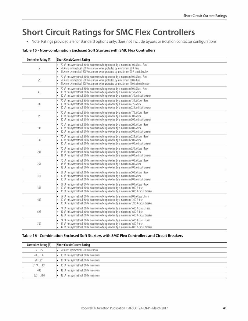
Short Circuit Ratings for SMC Flex Controllers• Note: Ratings provided are for standard options only; does not include bypass or isolation contactor configurations
Table 15 - Non-combination Enclosed Soft Starters with SMC Flex Controllers
Table 16 - Combination Enclosed Soft Starters with SMC Flex Controllers and Circuit Breakers
Controller Rating [A] Short Circuit Current Rating
5• 70 kA rms symmetrical, 600V maximum when protected by a maximum 10 A Class J Fuse• 5 kA rms symmetrical, 600V maximum when protected by a maximum 20 A fuse• 5 kA rms symmetrical, 600V maximum when protected by a maximum 20 A circuit breaker
25• 70 kA rms symmetrical, 600V maximum when protected by a maximum 50 A Class J Fuse• 5 kA rms symmetrical, 600V maximum when protected by a maximum 100 A fuse• 5 kA rms symmetrical, 600V maximum when protected by a maximum 100 A circuit breaker
43• 70 kA rms symmetrical, 600V maximum when protected by a maximum 90 A Class J Fuse• 10 kA rms symmetrical, 600V maximum when protected by a maximum 150 A fuse• 10 kA rms symmetrical, 600V maximum when protected by a maximum 150 A circuit breaker
60• 70 kA rms symmetrical, 600V maximum when protected by a maximum 125 A Class J Fuse• 10 kA rms symmetrical, 600V maximum when protected by a maximum 225 A fuse• 10 kA rms symmetrical, 600V maximum when protected by a maximum 225 A circuit breaker
85• 70 kA rms symmetrical, 600V maximum when protected by a maximum 175 A Class J Fuse• 10 kA rms symmetrical, 600V maximum when protected by a maximum 300 A fuse• 10 kA rms symmetrical, 600V maximum when protected by a maximum 300 A circuit breaker
108• 70 kA rms symmetrical, 600V maximum when protected by a maximum 200 A Class J Fuse• 10 kA rms symmetrical, 600V maximum when protected by a maximum 400 A fuse• 10 kA rms symmetrical, 600V maximum when protected by a maximum 300 A circuit breaker
135• 70 kA rms symmetrical, 600V maximum when protected by a maximum 225 A Class J Fuse• 10 kA rms symmetrical, 600V maximum when protected by a maximum 500 A fuse• 10 kA rms symmetrical, 600V maximum when protected by a maximum 400 A circuit breaker
201• 70 kA rms symmetrical, 600V maximum when protected by a maximum 350 A Class J Fuse• 18 kA rms symmetrical, 600V maximum when protected by a maximum 600 A fuse• 18 kA rms symmetrical, 600V maximum when protected by a maximum 600 A circuit breaker
251• 70 kA rms symmetrical, 600V maximum when protected by a maximum 400 A Class J Fuse• 18 kA rms symmetrical, 600V maximum when protected by a maximum 700 A fuse• 18 kA rms symmetrical, 600V maximum when protected by a maximum 700 A circuit breaker
317• 69 kA rms symmetrical, 600V maximum when protected by a maximum 500 A Class J Fuse• 30 kA rms symmetrical, 600V maximum when protected by a maximum 800 A fuse• 30 kA rms symmetrical, 600V maximum when protected by a maximum 800 A circuit breaker
361• 69 kA rms symmetrical, 600V maximum when protected by a maximum 600 A Class J Fuse• 30 kA rms symmetrical, 600V maximum when protected by a maximum 1000 A fuse• 30 kA rms symmetrical, 600V maximum when protected by a maximum 1000 A circuit breaker
480• 69 kA rms symmetrical, 600V maximum when protected by a maximum 800 A Class L Fuse• 30 kA rms symmetrical, 600V maximum when protected by a maximum 1200 A fuse• 30 kA rms symmetrical, 600V maximum when protected by a maximum 1200 A circuit breaker
625• 74 kA rms symmetrical, 600V maximum when protected by a maximum 1600 A Class L Fuse• 42 kA rms symmetrical, 600V maximum when protected by a maximum 1600 A fuse• 42 kA rms symmetrical, 600V maximum when protected by a maximum 1600 A circuit breaker
780• 74 kA rms symmetrical, 600V maximum when protected by a maximum 1600 A Class L Fuse• 42 kA rms symmetrical, 600V maximum when protected by a maximum 1600 A fuse• 42 kA rms symmetrical, 600V maximum when protected by a maximum 2000 A circuit breaker
Controller Rating [A] Short Circuit Current Rating5…25 • 5 kA rms symmetrical, 600V maximum
43…135 • 10 kA rms symmetrical, 600V maximum
201..251 • 18 kA rms symmetrical, 600V maximum
317A…361 • 30 kA rms symmetrical, 600V maximum
480 • 42 kA rms symmetrical, 600V maximum
625…780 • 42 kA rms symmetrical, 600V maximum
Rockwell Automation Publication 150-SG012A-EN-P - March 2017 41
Short Circuit Current Ratings
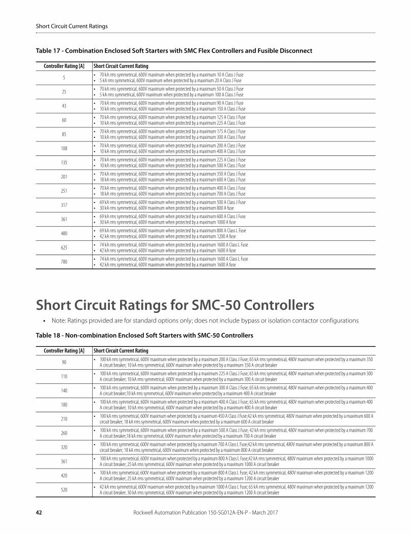
Table 17 - Combination Enclosed Soft Starters with SMC Flex Controllers and Fusible Disconnect
Short Circuit Ratings for SMC-50 Controllers• Note: Ratings provided are for standard options only; does not include bypass or isolation contactor configurations
Table 18 - Non-combination Enclosed Soft Starters with SMC-50 Controllers
Controller Rating [A] Short Circuit Current Rating
5 • 70 kA rms symmetrical, 600V maximum when protected by a maximum 10 A Class J Fuse• 5 kA rms symmetrical, 600V maximum when protected by a maximum 20 A Class J Fuse
25 • 70 kA rms symmetrical, 600V maximum when protected by a maximum 50 A Class J Fuse• 5 kA rms symmetrical, 600V maximum when protected by a maximum 100 A Class J Fuse
43 • 70 kA rms symmetrical, 600V maximum when protected by a maximum 90 A Class J Fuse• 10 kA rms symmetrical, 600V maximum when protected by a maximum 150 A Class J Fuse
60 • 70 kA rms symmetrical, 600V maximum when protected by a maximum 125 A Class J Fuse• 10 kA rms symmetrical, 600V maximum when protected by a maximum 225 A Class J Fuse
85 • 70 kA rms symmetrical, 600V maximum when protected by a maximum 175 A Class J Fuse• 10 kA rms symmetrical, 600V maximum when protected by a maximum 300 A Class J Fuse
108 • 70 kA rms symmetrical, 600V maximum when protected by a maximum 200 A Class J Fuse• 10 kA rms symmetrical, 600V maximum when protected by a maximum 400 A Class J Fuse
135 • 70 kA rms symmetrical, 600V maximum when protected by a maximum 225 A Class J Fuse• 10 kA rms symmetrical, 600V maximum when protected by a maximum 500 A Class J Fuse
201 • 70 kA rms symmetrical, 600V maximum when protected by a maximum 350 A Class J Fuse• 18 kA rms symmetrical, 600V maximum when protected by a maximum 600 A Class J Fuse
251 • 70 kA rms symmetrical, 600V maximum when protected by a maximum 400 A Class J Fuse• 18 kA rms symmetrical, 600V maximum when protected by a maximum 700 A Class J Fuse
317 • 69 kA rms symmetrical, 600V maximum when protected by a maximum 500 A Class J Fuse• 30 kA rms symmetrical, 600V maximum when protected by a maximum 800 A fuse
361 • 69 kA rms symmetrical, 600V maximum when protected by a maximum 600 A Class J Fuse• 30 kA rms symmetrical, 600V maximum when protected by a maximum 1000 A fuse
480 • 69 kA rms symmetrical, 600V maximum when protected by a maximum 800 A Class L Fuse• 42 kA rms symmetrical, 600V maximum when protected by a maximum 1200 A fuse
625 • 74 kA rms symmetrical, 600V maximum when protected by a maximum 1600 A Class L Fuse• 42 kA rms symmetrical, 600V maximum when protected by a maximum 1600 A fuse
780 • 74 kA rms symmetrical, 600V maximum when protected by a maximum 1600 A Class L Fuse• 42 kA rms symmetrical, 600V maximum when protected by a maximum 1600 A fuse
Controller Rating [A] Short Circuit Current Rating
90 • 100 kA rms symmetrical, 600V maximum when protected by a maximum 200 A Class J Fuse; 65 kA rms symmetrical, 480V maximum when protected by a maximum 350 A circuit breaker; 10 kA rms symmetrical, 600V maximum when protected by a maximum 350 A circuit breaker
110 • 100 kA rms symmetrical, 600V maximum when protected by a maximum 225 A Class J Fuse; 65 kA rms symmetrical, 480V maximum when protected by a maximum 300 A circuit breaker; 10 kA rms symmetrical, 600V maximum when protected by a maximum 300 A circuit breaker
140 • 100 kA rms symmetrical, 600V maximum when protected by a maximum 300 A Class J Fuse; 65 kA rms symmetrical, 480V maximum when protected by a maximum 400 A circuit breaker;10 kA rms symmetrical, 600V maximum when protected by a maximum 400 A circuit breaker
180 • 100 kA rms symmetrical, 600V maximum when protected by a maximum 400 A Class J Fuse; 65 kA rms symmetrical, 480V maximum when protected by a maximum 400 A circuit breaker; 10 kA rms symmetrical, 600V maximum when protected by a maximum 400 A circuit breaker
210 • 100 kA rms symmetrical, 600V maximum when protected by a maximum 450 A Class J Fuse;42 kA rms symmetrical, 480V maximum when protected by a maximum 600 A circuit breaker; 18 kA rms symmetrical, 600V maximum when protected by a maximum 600 A circuit breaker
260 • 100 kA rms symmetrical, 600V maximum when protected by a maximum 500 A Class J Fuse; 42 kA rms symmetrical, 480V maximum when protected by a maximum 700 A circuit breaker;18 kA rms symmetrical, 600V maximum when protected by a maximum 700 A circuit breaker
320 • 100 kA rms symmetrical, 600V maximum when protected by a maximum 700 A Class L Fuse;42 kA rms symmetrical, 480V maximum when protected by a maximum 800 A circuit breaker; 18 kA rms symmetrical, 600V maximum when protected by a maximum 800 A circuit breaker
361 • 100 kA rms symmetrical, 600V maximum when protected by a maximum 800 A Class L Fuse;42 kA rms symmetrical, 480V maximum when protected by a maximum 1000 A circuit breaker; 25 kA rms symmetrical, 600V maximum when protected by a maximum 1000 A circuit breaker
420 • 100 kA rms symmetrical, 600V maximum when protected by a maximum 800 A Class L Fuse; 42 kA rms symmetrical, 480V maximum when protected by a maximum 1200 A circuit breaker; 25 kA rms symmetrical, 600V maximum when protected by a maximum 1200 A circuit breaker
520 • 42 kA rms symmetrical, 600V maximum when protected by a maximum 1000 A Class L Fuse; 65 kA rms symmetrical, 480V maximum when protected by a maximum 1200 A circuit breaker; 30 kA rms symmetrical, 600V maximum when protected by a maximum 1200 A circuit breaker
42 Rockwell Automation Publication 150-SG012A-EN-P - March 2017
Short Circuit Current Ratings
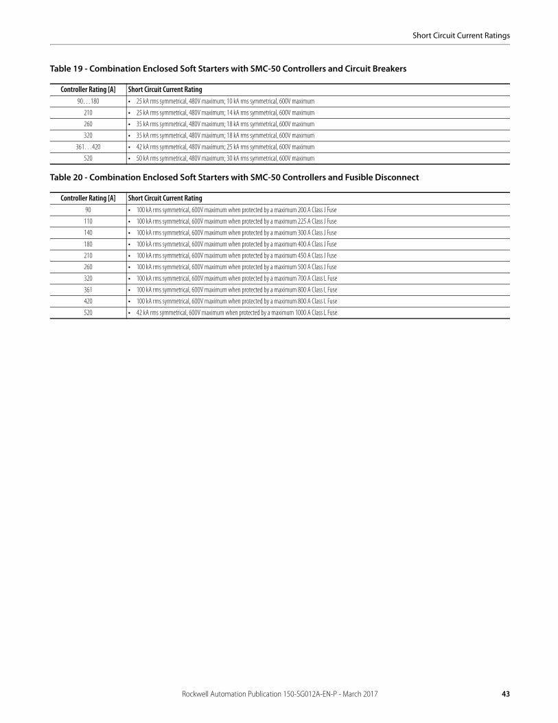
Table 19 - Combination Enclosed Soft Starters with SMC-50 Controllers and Circuit Breakers
Table 20 - Combination Enclosed Soft Starters with SMC-50 Controllers and Fusible Disconnect
Controller Rating [A] Short Circuit Current Rating90…180 • 25 kA rms symmetrical, 480V maximum; 10 kA rms symmetrical, 600V maximum
210 • 25 kA rms symmetrical, 480V maximum; 14 kA rms symmetrical, 600V maximum
260 • 35 kA rms symmetrical, 480V maximum; 18 kA rms symmetrical, 600V maximum
320 • 35 kA rms symmetrical, 480V maximum; 18 kA rms symmetrical, 600V maximum
361…420 • 42 kA rms symmetrical, 480V maximum; 25 kA rms symmetrical, 600V maximum
520 • 50 kA rms symmetrical, 480V maximum; 30 kA rms symmetrical, 600V maximum
Controller Rating [A] Short Circuit Current Rating90 • 100 kA rms symmetrical, 600V maximum when protected by a maximum 200 A Class J Fuse
110 • 100 kA rms symmetrical, 600V maximum when protected by a maximum 225 A Class J Fuse
140 • 100 kA rms symmetrical, 600V maximum when protected by a maximum 300 A Class J Fuse
180 • 100 kA rms symmetrical, 600V maximum when protected by a maximum 400 A Class J Fuse
210 • 100 kA rms symmetrical, 600V maximum when protected by a maximum 450 A Class J Fuse
260 • 100 kA rms symmetrical, 600V maximum when protected by a maximum 500 A Class J Fuse
320 • 100 kA rms symmetrical, 600V maximum when protected by a maximum 700 A Class L Fuse
361 • 100 kA rms symmetrical, 600V maximum when protected by a maximum 800 A Class L Fuse
420 • 100 kA rms symmetrical, 600V maximum when protected by a maximum 800 A Class L Fuse
520 • 42 kA rms symmetrical, 600V maximum when protected by a maximum 1000 A Class L Fuse
Rockwell Automation Publication 150-SG012A-EN-P - March 2017 43
Short Circuit Current Ratings
Notes:
44 Rockwell Automation Publication 150-SG012A-EN-P - March 2017
Approximate Dimensions
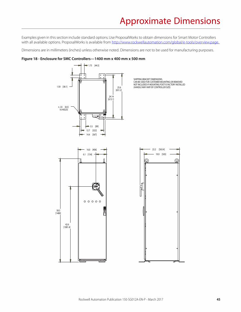
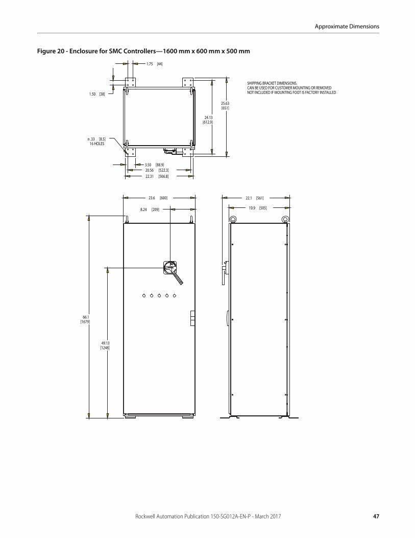
Examples given in this section include standard options. Use ProposalWorks to obtain dimensions for Smart Motor Controllers with all available options. ProposalWorks is available from http://www.rockwellautomation.com/global/e-tools/overview.page.
Dimensions are in millimeters (inches) unless otherwise noted. Dimensions are not to be used for manufacturing purposes.
Figure 18 - Enclosure for SMC Controllers—1400 mm x 400 mm x 500 mm
1.75 [44.5]
1.50 [38.1]
3.5 [89]
n .33 [8.5]16 HOLES
14.4 [367]
12.7 [322]
24.14[613.1]
25.6[651.2]
16.0 [406]
6.1 [154]
42.6[1081.4]
58.3[1480]
22.2 [563.4]
19.9 [505]
SHIPPING BRACKET DIMENSIONS. CAN BE USED FOR CUSTOMER MOUNTING OR REMOVEDNOT INCLUDED IF MOUNTING FOOT IS FACTORY INSTALLED(HANDLE MAY VARY BY CONTROLLER SIZE)
Rockwell Automation Publication 150-SG012A-EN-P - March 2017 45
Approximate Dimensions
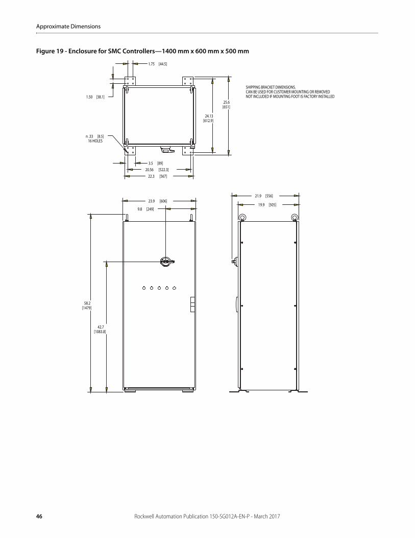
Figure 19 - Enclosure for SMC Controllers—1400 mm x 600 mm x 500 mm
1.75 [44.5]
1.50 [38.1]
24.13[612.9]
25.6[651]
3.5 [89]20.56 [522.3]
22.3 [567]
58.2[1479]
42.7[1083.8]
9.8 [249]
23.9 [606]21.9 [556]
19.9 [505]
n .33 [8.5]16 HOLES
SHIPPING BRACKET DIMENSIONS. CAN BE USED FOR CUSTOMER MOUNTING OR REMOVEDNOT INCLUDED IF MOUNTING FOOT IS FACTORY INSTALLED
46 Rockwell Automation Publication 150-SG012A-EN-P - March 2017
Approximate Dimensions
Figure 20 - Enclosure for SMC Controllers—1600 mm x 600 mm x 500 mm
66.1[1679]
23.6 [600] 22.1 [561]
19.9 [505]
1.50 [38]
1.75 [44]
22.31 [566.8]20.56 [522.3]
24.13[612.9]
49.13[1248]
8.24 [209]
n .33 [8.5]16 HOLES
3.50 [88.9]
25.63[651]
SHIPPING BRACKET DIMENSIONS. CAN BE USED FOR CUSTOMER MOUNTING OR REMOVEDNOT INCLUDED IF MOUNTING FOOT IS FACTORY INSTALLED
Rockwell Automation Publication 150-SG012A-EN-P - March 2017 47
Approximate Dimensions
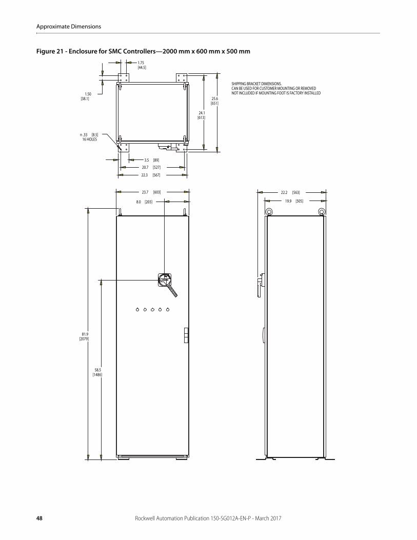
Figure 21 - Enclosure for SMC Controllers—2000 mm x 600 mm x 500 mm
1.50[38.1]
1.75[44.5]
24.1[613]
3.5 [89]
20.7 [527]
22.3 [567]
81.9[2079]
23.7 [603]
19.9 [505]
22.2 [563]
25.6[651]
n .33 [8.5]16 HOLES
58.5[1486]
8.0 [203]
SHIPPING BRACKET DIMENSIONS. CAN BE USED FOR CUSTOMER MOUNTING OR REMOVEDNOT INCLUDED IF MOUNTING FOOT IS FACTORY INSTALLED
48 Rockwell Automation Publication 150-SG012A-EN-P - March 2017
Approximate Dimensions
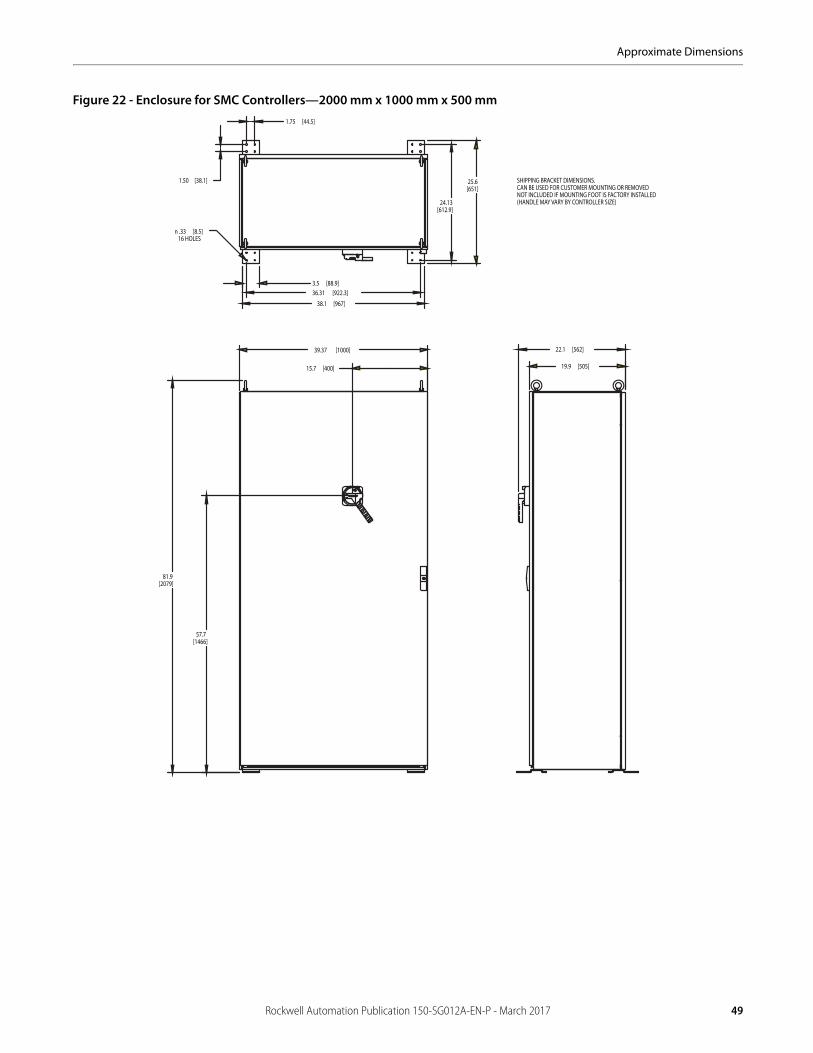
Figure 22 - Enclosure for SMC Controllers—2000 mm x 1000 mm x 500 mm1.75 [44.5]
1.50 [38.1]
24.13[612.9]
25.6[651]
3.5 [88.9]
n .33 [8.5]16 HOLES
36.31 [922.3]
38.1 [967]
81.9[2079]
57.7[1466]
15.7 [400]
22.1 [562]
19.9 [505]
39.37 [1000]
SHIPPING BRACKET DIMENSIONS. CAN BE USED FOR CUSTOMER MOUNTING OR REMOVEDNOT INCLUDED IF MOUNTING FOOT IS FACTORY INSTALLED(HANDLE MAY VARY BY CONTROLLER SIZE)
Rockwell Automation Publication 150-SG012A-EN-P - March 2017 49
Approximate Dimensions
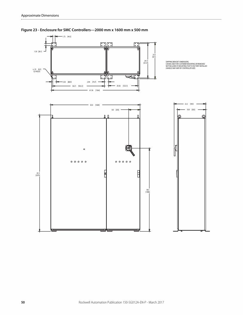
Figure 23 - Enclosure for SMC Controllers—2000 mm x 1600 mm x 500 mm1.75 [44.5]
1.50 [38.1]
24.13[612.9]
20.56 [522.3]36.31 [922.3]
2.94 [74.7]3.50 [88.9]
61.56 [1564]
25.6[651]
n .33 [8.5]32 HOLES
63.0 [1600]
8.0 [203]
58.5[1486]
81.9[2079]
22.2 [563]
19.9 [505]
SHIPPING BRACKET DIMENSIONS. CAN BE USED FOR CUSTOMER MOUNTING OR REMOVEDNOT INCLUDED IF MOUNTING FOOT IS FACTORY INSTALLED(HANDLE MAY VARY BY CONTROLLER SIZE)
50 Rockwell Automation Publication 150-SG012A-EN-P - March 2017
Approximate Dimensions
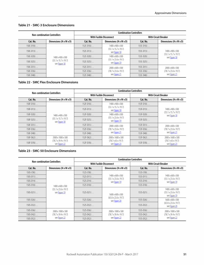
Table 21 - SMC-3 Enclosure Dimensions
Table 22 - SMC Flex Enclosure Dimensions
Table 23 - SMC-50 Enclosure Dimensions
Non-combination ControllersCombination Controllers
With Fusible Disconnect With Circuit BreakerCat. No. Dimensions (H x W x D) Cat. No. Dimensions (H x W x D) Cat. No. Dimensions (H x W x D)
150C-D10J…
1400 x 400 x 500(55.1 x 15.7 x 19.7)
see Figure 18
152C-D10J… 1400 x 400 x 500(55.1 x 15.7 x 19.7)
see Figure 18
153C-D10J…
1400 x 400 x 500(55.1 x 15.7 x 19.7)
see Figure 18
150C-D13J… 152C-D13J… 153C-D13J…
150C-D20J… 152C-D20J… 1400 x 600 x 500(55.1 x 23.6 x 19.7)
see Figure 19
153C-D20J…
150C-D25J… 152C-D25J… 153C-D25J…
150C-D31J… 152C-D31J… 2000 x 600 x 500(78.7 x 23.6 x 19.7)
see Figure 21
153C-D31J… 2000 x 600 x 500(78.7 x 23.6 x 19.7)
see Figure 21150C-D36J… 152C-D36J… 153C-D36J…
150C-D48J… 152C-D48J… 153C-D48J…
Non-combination ControllersCombination Controllers
With Fusible Disconnect With Circuit BreakerCat. No. Dimensions (H x W x D) Cat. No. Dimensions (H x W x D) Cat. No. Dimensions (H x W x D)
150F-D10J…
1400 x 400 x 500(55.1 x 15.7 x 19.7)
see Figure 18
152F-D10J… 1400 x 400 x 500(55.1 x 15.7 x 19.7)
see Figure 18
153F-D10J…
1400 x 400 x 500(55.1 x 15.7 x 19.7)
see Figure 18
150F-D13J… 152F-D13J… 153F-D13J…
150F-D20J… 152F-D20J… 1400 x 600 x 500(55.1 x 23.6 x 19.7)
see Figure 19
153F-D20J…
150F-D25J… 152F-D25J… 153F-D25J…
150F-D31J… 152F-D31J… 2000 x 600 x 500(78.7 x 23.6 x 19.7)
see Figure 21
153F-D31J… 2000 x 600 x 500(78.7 x 23.6 x 19.7)
see Figure 21150F-D36J… 152F-D36J… 153F-D36J…
150F-D48J… 152F-D48J… 153F-D48J…
150F-D62J… 2000 x 1000 x 500(78.7 x 39.4 x 19.7)
see Figure 22
152F-D62J… 2000 x 1600 x 500(78.7 x 63 x 19.7)
see Figure 23
153F-D62J… 2000 x 1600 x 500(78.7 x 63 x 19.7)
see Figure 23150F-D78J… 152F-D78J… 153F-D78J…
Non-combination ControllersCombination Controllers
With Fusible Disconnect With Circuit BreakerCat. No. Dimensions (H x W x D) Cat. No. Dimensions (H x W x D) Cat. No. Dimensions (H x W x D)
150S-C90J…
1400 x 600 x 500(55.1 x 23.6 x 19.7)
see Figure 19
152S-C90J…1400 x 600 x 500
(55.1 x 23.6 x 19.7)see Figure 19
153S-C90J…1400 x 600 x 500
(55.1 x 23.6 x 19.7)see Figure 19
150S-D11J… 152S-D11J… 153S-D11J…
150S-D14J… 152S-D14J… 153S-D14J…
150S-D18J… 152S-D18J… 153S-D18J…
150S-D21J… 152S-D21J…1600 x 600 x 500
(63.0 x 23.6 x 19.7)see Figure 20
153S-D21J…1400 x 600 x 500
(55.1 x 23.6 x 19.7)see Figure 19
150S-D26J… 152S-D26J… 153S-D26J… 1600 x 600 x 500(63.0 x 23.6 x 19.7)
see Figure 20150S-D32J… 152S-D32J… 153S-D32J…
150S-D36J… 2000 x 1000 x 500(78.7 x 39.4 x 19.7)
see Figure 22
152S-D36J… 2000 x 1000 x 500(78.7 x 39.4 x 19.7)
see Figure 22
153S-D36J… 2000 x 1000 x 500(78.7 x 39.4 x 19.7)
see Figure 22150S-D42J… 152S-D42J… 153S-D42J…
150S-D52J… 152S-D52J… 153S-D52J…
Rockwell Automation Publication 150-SG012A-EN-P - March 2017 51
Publication 150-SG012A-EN-P - March 2017Copyright © 2017 Rockwell Automation, Inc. All rights reserved. Printed in the U.S.A.
Rockwell Automation SupportUse the following resources to access support information.
Documentation FeedbackYour comments will help us serve your documentation needs better. If you have any suggestions on how to improve this document, complete the How Are We Doing? form at http://literature.rockwellautomation.com/idc/groups/literature/documents/du/ra-du002_-en-e.pdf.
Technical Support Center Knowledgebase Articles, How-to Videos, FAQs, Chat, User Forums, and Product Notification Updates.
www.rockwellautomation.com/knowledgebase
Local Technical Support Phone Numbers Locate the phone number for your country. www.rockwellautomation.com/global/support/get-support-now.page
Direct Dial Codes Find the Direct Dial Code for your product. Use the code to route your call directly to a technical support engineer.
www.rockwellautomation.com/global/support/direct-dial.page
Literature Library Installation Instructions, Manuals, Brochures, and Technical Data.
www.rockwellautomation.com/literature
Product Compatibility and Download Center (PCDC)
Get help determining how products interact, check features and capabilities, and find associated firmware.
www.rockwellautomation.com/global/support/pcdc.page
Accu-Stop, Allen-Bradley, Connected Components Workbench, DriveExecutive, DriveExplorer, DriveOberver, LISTEN. THINK. SOLVE, Rockwell Software, Rockwell Automation, and SMC are trademarks of Rockwell Automation, Inc. Trademarks not belonging to Rockwell Automation are property of their respective companies.
Rockwell Automation maintains current product environmental information on its website at http://www.rockwellautomation.com/rockwellautomation/about-us/sustainability-ethics/product-environmental-compliance.page.