Embed Size (px)
Citation preview
A1/1
Enc
lose
d st
arte
rs
Enclosed switch-disconnectorsContent Page
Product selector A1/2
TeSys Vario VBF, VCF, VCFN, VCpGUN Enclosed switch-disconnectors
A1/3
Enclosed standard starters
Product selector A1/6
TeSys GV, LE Direct-on-line startersAccessories
A1/7
TeSys GV, LE Reverser starters
A1/13
TeSys LE Star-delta starters A1/15
Enclosed safety starters
Product selector A1/17
TeSys LG, LJ, GV Safety direct-on-line startersAccessories
A1/18
TeSys LG, LJ Safety reverser starters
A1/21
Enclosures and components for customer assemblies
Enclosures (with buttons)
A1/26
Components
A1/30
Enclosed switch-disconnectors and motor starters
Chapter
A1
Technical Data for Designers A1/35
Enclosed Motor Starter Solution GuideThe software to help you to select intuitively your enclosed motor starter solution.The new Enclosed Motor Starter Solution Guide software is available for both PC and iPad.
TeS
ys
A1/2
Enc
lose
d st
arte
rs
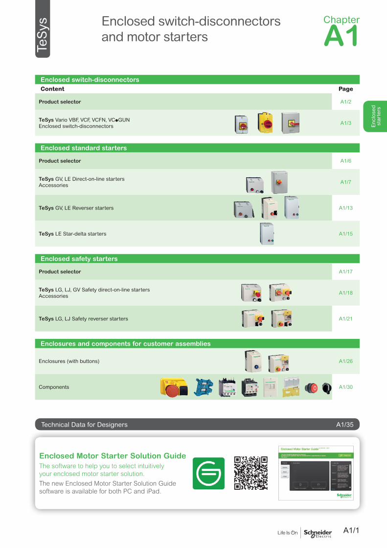
With numerous advantages to meet OEM’s most common needsp IEC or UL
p Multiple ratings and sizes
p IP65
p Additional poles
p Replaceable switch bodies
TeSysTeSys Vario enclosed switch-disconnectors
DB4
1449
0.ep
s
Selection criteria Solutions
Ithe
(A)
Load
pow
er (k
W)
Circ
uit i
sola
tion
Emer
genc
y st
op
IP55
IP65
IEC
UL
& C
SA
See page
10...140 4...45 (400 V) p p p VBF A1/3
10...140 4...45 (400 V) p p p p VCF A1/3
10...32 4...15 (400 V) p p p p VCFN A1/3
32...175 (Ithe IEC) 20...115 (Ith UL)
10...50 HP (480 V) p p p p p VCpGUN A1/4
2 Choose your enclosed switch-disconnector in the Solutions area, note the radical of the product references 1 Identify your need (1 line one or more)
in the Selection criteria area (example.: Load 5 kW– Emergency Stop - IEC)
Range of pre-assembled casings with handle and their rotary switch
They can be fixed on a wall, a panel, or on the chassis of a machine. For simple isolation and/or control of an electrical circuit. Red/yellow handle provides a clear indication of the device safety function (1), while black handle is usually dedicated to ON/OFF control.
(1) Conforming to IEC 60947-4-1 and IEC 60204.
Selection in 2 steps
PB12
1471
.eps
Introduction & selection table
A1/3
Enc
lose
d st
arte
rs
TeSysTeSys Vario VCF, VBF enclosed switch-disconnectors / Ready-to-use
Dimensions:page A1/36
Schemes:page A1/37
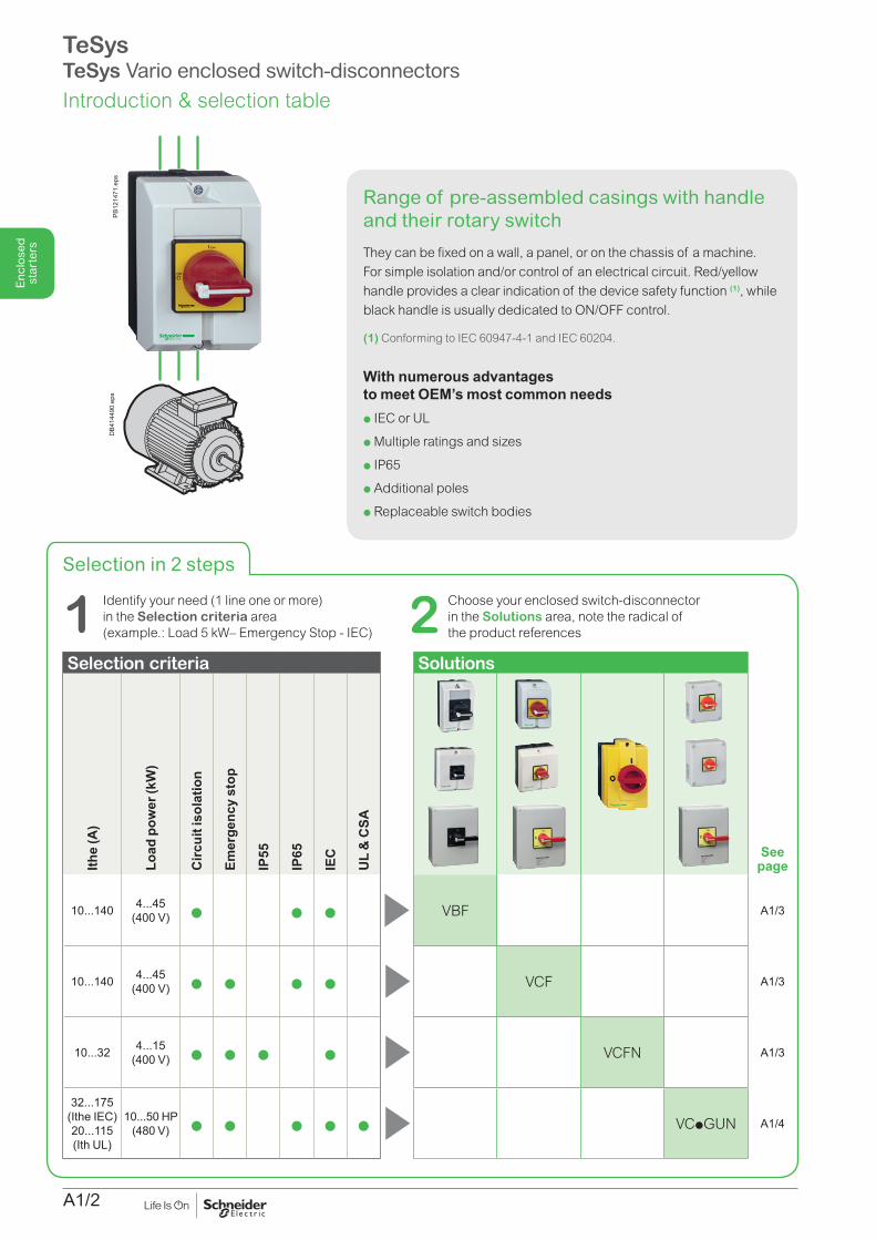
Control + Disconnection (IEC)Enclosed switch-disconnectors, ready to be fixed on workshop wall or directly on the machine and wired to main supply circuit and to load.Functions / Range / Specificities:
b Direct Control: ON/OFF of 3-phase motor (black handle) or ON/Emergency Stop (red handle) b 23 IEC motor starters, for 3P motors from 4 to 45 kW (10 to 140 A) b 6 UL motor starters for 3P motors from 5 to 30 HP (240 V) b Padlockable handle (1 to 3 padlocks – not included) b Sealable, lockable cover when handle in position 1 (up to 63 A rating).
Included: b rotary switch-disconnector body b handle.
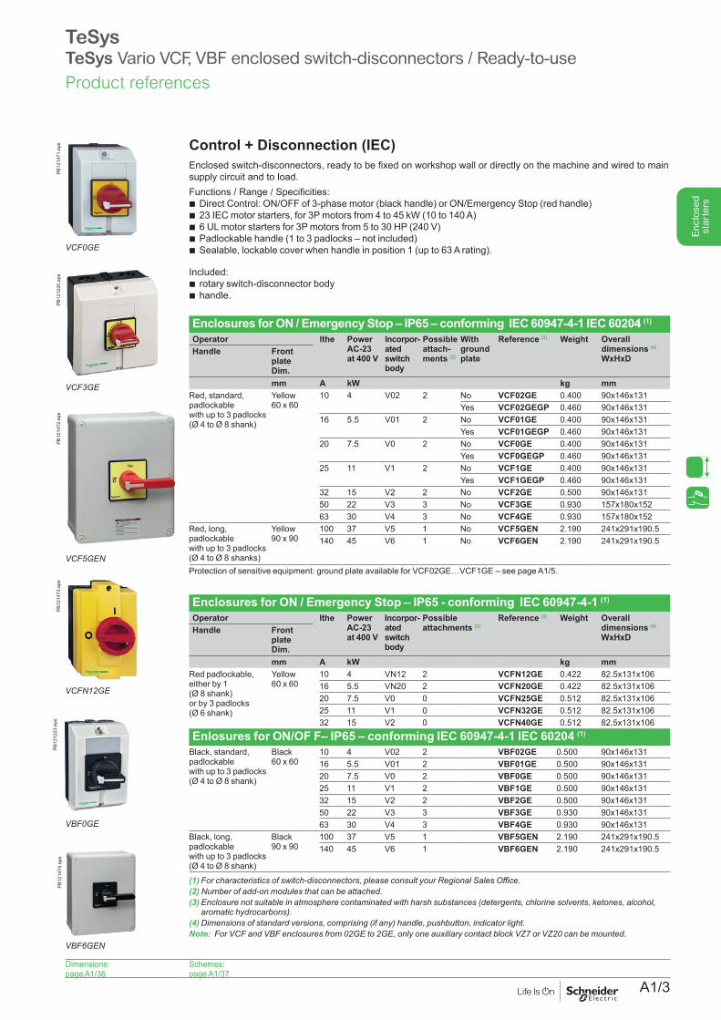
Enclosures for ON / Emergency Stop – IP65 – conforming IEC 60947-4-1 IEC 60204 (1)
Operator lthe Power AC-23 at 400 V
Incorpor- ated switch body
Possible attach- ments (2)
With ground plate
Reference (3) Weight Overall dimensions (4)
WxHxDHandle Front
plate Dim.mm A kW kg mm
Red, standard, padlockable with up to 3 padlocks(Ø 4 to Ø 8 shank)
Yellow60 x 60
10 4 V02 2 No VCF02GE 0.400 90x146x131Yes VCF02GEGP 0.460 90x146x131
16 5.5 V01 2 No VCF01GE 0.400 90x146x131Yes VCF01GEGP 0.460 90x146x131
20 7.5 V0 2 No VCF0GE 0.400 90x146x131Yes VCF0GEGP 0.460 90x146x131
25 11 V1 2 No VCF1GE 0.400 90x146x131Yes VCF1GEGP 0.460 90x146x131
32 15 V2 2 No VCF2GE 0.500 90x146x13150 22 V3 3 No VCF3GE 0.930 157x180x15263 30 V4 3 No VCF4GE 0.930 157x180x152
Red, long, padlockable with up to 3 padlocks (Ø 4 to Ø 8 shanks)
Yellow90 x 90
100 37 V5 1 No VCF5GEN 2.190 241x291x190.5140 45 V6 1 No VCF6GEN 2.190 241x291x190.5
Protection of sensitive equipment: ground plate available for VCF02GE…VCF1GE – see page A1/5.
Enclosures for ON / Emergency Stop – IP65 - conforming IEC 60947-4-1 (1)
Operator lthe Power AC-23 at 400 V
Incorpor- ated switch body
Possible attachments (2)
Reference (3) Weight Overall dimensions (4)
WxHxDHandle Front
plate Dim.mm A kW kg mm
Red padlockable, either by 1 (Ø 8 shank) or by 3 padlocks (Ø 6 shank)
Yellow60 x 60
10 4 VN12 2 VCFN12GE 0.422 82.5x131x10616 5.5 VN20 2 VCFN20GE 0.422 82.5x131x10620 7.5 V0 0 VCFN25GE 0.512 82.5x131x10625 11 V1 0 VCFN32GE 0.512 82.5x131x10632 15 V2 0 VCFN40GE 0.512 82.5x131x106
Enlosures for ON/OF F– IP65 – conforming IEC 60947-4-1 IEC 60204 (1)
Black, standard, padlockable with up to 3 padlocks(Ø 4 to Ø 8 shank)
Black60 x 60
10 4 V02 2 VBF02GE 0.500 90x146x13116 5.5 V01 2 VBF01GE 0.500 90x146x13120 7.5 V0 2 VBF0GE 0.500 90x146x13125 11 V1 2 VBF1GE 0.500 90x146x13132 15 V2 2 VBF2GE 0.500 90x146x13150 22 V3 3 VBF3GE 0.930 90x146x13163 30 V4 3 VBF4GE 0.930 90x146x131
Black, long, padlockable with up to 3 padlocks (Ø 4 to Ø 8 shank)
Black90 x 90
100 37 V5 1 VBF5GEN 2.190 241x291x190.5140 45 V6 1 VBF6GEN 2.190 241x291x190.5
(1)Forcharacteristicsofswitch-disconnectors,pleaseconsultyourRegionalSalesOffice.(2) Numberofadd-onmodulesthatcanbeattached.(3) Enclosure not suitable in atmosphere contaminated with harsh substances (detergents, chlorine solvents, ketones, alcohol,
aromatichydrocarbons).(4)Dimensionsofstandardversions,comprising(ifany)handle,pushbutton,indicatorlight.Note: ForVCFandVBFenclosuresfrom02GEto2GE,onlyoneauxiliarycontactblockVZ7orVZ20canbemounted.
VCFN12GE
PB12
1473
.eps
VBF0GE
PB12
1223
.eps
PB12
1471
.eps
VCF0GE
PB12
1220
.eps
VCF3GE
PB12
1472
.eps
VCF5GEN
PB12
1474
.eps
VBF6GEN
Product references
A1/4
Enc
lose
d st
arte
rs
TeSysTeSys Vario VC, VZ enclosed switches (UL) / Ready-to-use - Additional modules
Dimensions:page A1/38
Schemes:pages A1/37 and A1/38
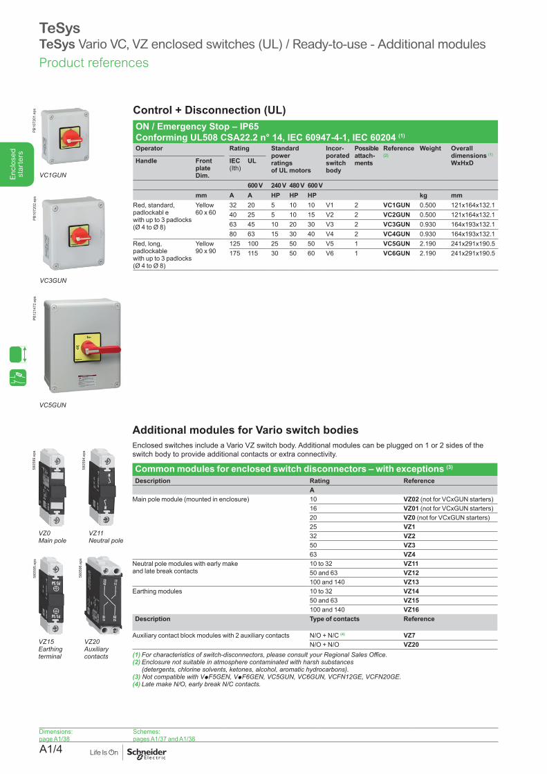
Additional modules for Vario switch bodies Enclosed switches include a Vario VZ switch body. Additional modules can be plugged on 1 or 2 sides of the switch body to provide additional contacts or extra connectivity.
Common modules for enclosed switch disconnectors – with exceptions (3)
Description Rating ReferenceA
Main pole module (mounted in enclosure) 10 VZ02 (not for VCxGUN starters) 16 VZ01 (not for VCxGUN starters) 20 VZ0 (not for VCxGUN starters) 25 VZ132 VZ250 VZ363 VZ4
Neutral pole modules with early make and late break contacts
10 to 32 VZ1150 and 63 VZ12100 and 140 VZ13
Earthing modules 10 to 32 VZ1450 and 63 VZ15100 and 140 VZ16
Description Type of contacts Reference
Auxiliary contact block modules with 2 auxiliary contacts N/O + N/C (4) VZ7N/O + N/O VZ20
(1) Forcharacteristicsofswitch-disconnectors,pleaseconsultyourRegionalSalesOffice.(2) Enclosure not suitable in atmosphere contaminated with harsh substances
(detergents,chlorinesolvents,ketones,alcohol,aromatichydrocarbons).(3) Not compatible with VpF5GEN, VpF6GEN,VC5GUN,VC6GUN,VCFN12GE,VCFN20GE.(4)LatemakeN/O,earlybreakN/Ccontacts.
VZ0 Main pole
5805
89.e
ps
VZ11 Neutral pole
5805
94.e
ps
VZ15 Earthing terminal
5805
95.e
ps
VZ20 Auxiliary contacts
5805
96.e
ps
Control + Disconnection (UL)ON / Emergency Stop – IP65 Conforming UL508 CSA22.2 n° 14, IEC 60947-4-1, IEC 60204 (1) Operator Rating Standard
power ratingsof UL motors
Incor-porated switch body
Possible attach-ments
Reference (2)
Weight Overall dimensions (1)
WxHxDHandle Front plate Dim.
IEC (Ith)
UL
600 V 240 V 480 V 600 Vmm A A HP HP HP kg mm
Red, standard, padlockabl e with up to 3 padlocks(Ø 4 to Ø 8)
Yellow 60 x 60
32 20 5 10 10 V1 2 VC1GUN 0.500 121x164x132.140 25 5 10 15 V2 2 VC2GUN 0.500 121x164x132.163 45 10 20 30 V3 2 VC3GUN 0.930 164x193x132.180 63 15 30 40 V4 2 VC4GUN 0.930 164x193x132.1
Red, long, padlockable with up to 3 padlocks(Ø 4 to Ø 8)
Yellow 90 x 90
125 100 25 50 50 V5 1 VC5GUN 2.190 241x291x190.5175 115 30 50 60 V6 1 VC6GUN 2.190 241x291x190.5
VC1GUN
PB10
7201
.eps
VC3GUN
PB10
7202
.eps
VC5GUN
PB12
1472
.eps
Product references
A1/5
Enc
lose
d st
arte
rs
TeSysTeSys Vario VCF enclosed switch-disconnectors / Ready-to-use - Additional modules - Accessories
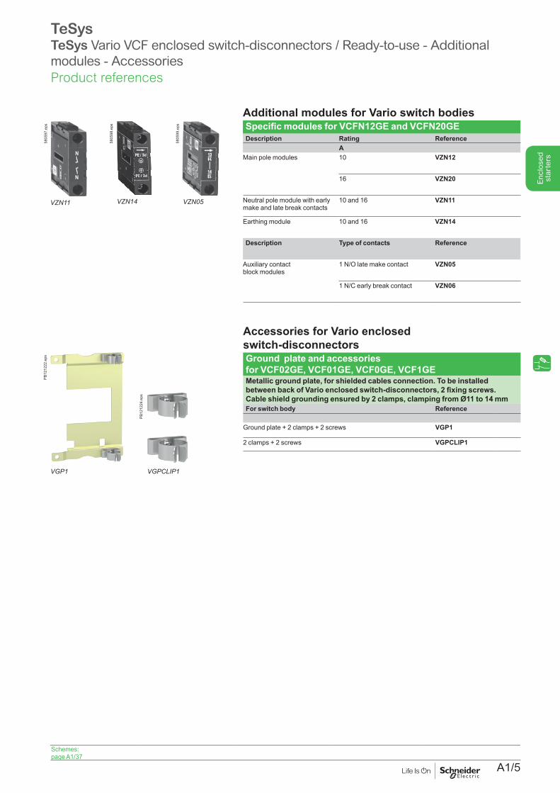
Additional modules for Vario switch bodies Specific modules for VCFN12GE and VCFN20GEDescription Rating Reference
AMain pole modules 10 VZN12
16 VZN20
Neutral pole module with early make and late break contacts
10 and 16 VZN11
Earthing module 10 and 16 VZN14
Description Type of contacts Reference
Auxiliary contact block modules
1 N/O late make contact VZN05
1 N/C early break contact VZN06
VZN11
5805
97.e
ps
VZN14
5805
98.e
ps
VZN05
5805
99.e
ps
Schemes:page A1/37
VGP1
PB12
1222
.eps
VGPCLIP1
PB12
1224
.eps
Accessories for Vario enclosed switch-disconnectorsGround plate and accessories for VCF02GE, VCF01GE, VCF0GE, VCF1GEMetallic ground plate, for shielded cables connection. To be installed between back of Vario enclosed switch-disconnectors, 2 fixing screws. Cable shield grounding ensured by 2 clamps, clamping from Ø11 to 14 mmFor switch body Reference
Ground plate + 2 clamps + 2 screws VGP1
2 clamps + 2 screws VGPCLIP1
Product references
A1/6
Enc
lose
d st
arte
rs
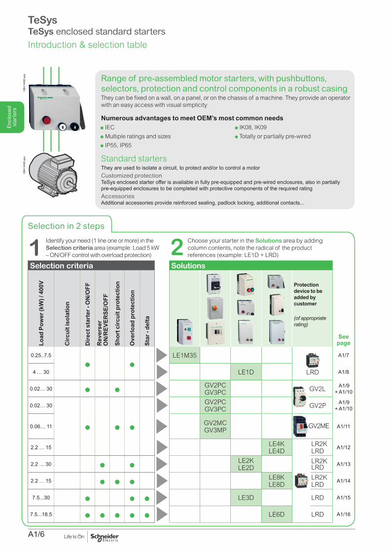
p IEC p Multiple ratings and sizesp IP55, IP65
p IK08, IK09p Totally or partially pre-wired
TeSysTeSys enclosed standard starters
DB4
1449
0.ep
sD
B414
490.
eps
Selection in 2 steps
2 Choose your starter in the Solutions area by adding column contents, note the radical of the product references (example: LE1D + LRD) 1 Identify your need (1 line one or more) in the
Selection criteria area (example: Load 5 kW – ON/OFF control with overload protection)
Standard startersThey are used to isolate a circuit, to protect and/or to control a motorCustomized protectionTeSys enclosed starter offer is available in fully pre-equipped and pre-wired enclosures, also in partially pre-equipped enclosures to be completed with protective components of the required rating AccessoriesAdditional accessories provide reinforced sealing, padlock locking, additional contacts...
Range of pre-assembled motor starters, with pushbuttons, selectors, protection and control components in a robust casingThey can be fixed on a wall, on a panel, or on the chassis of a machine. They provide an operator with an easy access with visual simplicity
Numerous advantages to meet OEM’s most common needs
Selection criteria Solutions
Load
Pow
er (k
W) /
400
V
Circ
uit i
sola
tion
Dire
ct s
tart
er -
ON
/OFF
Rev
erse
r O
N/R
EVER
SE/O
FF
Shor
t circ
uit p
rote
ctio
n
Ove
rload
pro
tect
ion
Star
- de
lta
Protection device to be added by customer
(of appropriate rating)
See page
0.25..7.5
p pLE1M35
LRD
A1/7
4 … 30 LE1D A1/8
0.02… 30 p p GV2PCGV3PC GV2L A1/9
+ A1/10
0.02… 30
p p p
GV2PCGV3PC GV2P A1/9
+ A1/10
0.06… 11 GV2MCGV3MP
GV2ME A1/11
2.2 … 15 LE4KLE4D
LR2KLRD
A1/12
2.2 … 30 p p LE2KLE2D
LR2KLRD A1/13
2.2 … 15 p p p LE8KLE8D
LR2KLRD
A1/14
7.5...30 p p p LE3D LRD A1/15
7.5...18.5 p p p p p LE6D LRD A1/16
Introduction & selection table
A1/7
Enc
lose
d st
arte
rs
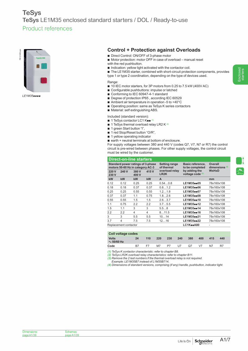
Control + Protection against Overloads b Direct Control: ON/OFF of 3-phase motor b Motor protection: motor OFF in case of overload – manual reset
with the red pushbutton. b Indication: yellow light activated with the contactor coil. b The LE1M35 starter, combined with short-circuit protection components, provides
type 1 or type 2 coordination, depending on the type of devices used.
Range:b 10 IEC motor starters, for 3P motors from 0.25 to 7.5 kW (400V AC)b Configurable pushbuttons: impulse or latchedb Conforming to IEC 60947-4-1 standardb Degree of protection IP65 , according IEC 60529b Ambient air temperature in operation -5 to +40°Cb Operating position: same as TeSys K series contactorsb Material: self extinguishing ABS.
Included (standard version):b 1 TeSys contactor LC1 Kpp (1)
b 1 TeSys thermal overload relay LR2 K (2)
b 1 green Start button “I”,b 1 red Stop/Reset button “O/R”,b 1 yellow operating indicatorb earth + neutral terminals at bottom of enclosure.For supply voltages between 380 and 440 V (codes Q7, V7, N7 or R7) the control circuit is pre-wired between phases. For other supply voltages, the control circuit must be wired by the customer.
Direct-on-line startersStandard power ratings of 3-phase motors 50-60 Hz in category AC-3
Setting range of thermal overload relay LR2K
Basic reference, to be completed by adding the voltage code (3)
Overall dimensions (4)
WxHxD220 V230 V
240 V 380 V 400 V
415 V
kW kW kW kW A mm0.12 0.12 0.25 0.25 0.54…0.8 LE1M35pp05 78x160x1080.18 0.18 0.37 0.37 0.8…1.2 LE1M35pp06 78x160x1080.25 0.25 0.55 0.55 1.2…1.8 LE1M35pp07 78x160x1080.37 0.37 1.1 0.75 1.8…2.6 LE1M35pp08 78x160x1080.55 0.55 1.5 1.5 2.6…3.7 LE1M35pp10 78x160x1081.1 0.75 2.2 2.2 3.7…5.5 LE1M35pp12 78x160x1081.5 1.1 3 3 5.5…8 LE1M35pp14 78x160x1082.2 2.2 4 4 8…11.5 LE1M35pp16 78x160x1083 3 5.5 5.5 10…14 LE1M35pp21 78x160x1083.7 4 7.5 7.5 12…16 LE1M35pp22 78x160x108Replacement contactor LC1KppA80 -
Coil voltage codesVolts a 50/60 Hz
24 110 220 230 240 380 400 415 440
Code B7 F7 M7 P7 U7 Q7 V7 N7 R7
(1)TeSysKcontactorcharacteristic:refertochapterB8.(2)TeSysLR2Koverloadrelaycharacteristics:refertochapterB11.(3)Removethe2lastnumbersifthethermaloverloadrelayisnotrequired.
Example:LE1M35B7insteadofL1M35B714.(4)Dimensionsofstandardversions,comprising(ifany)handle,pushbutton,indicatorlight.
TeSysTeSys LE1M35 enclosed standard starters / DOL / Ready-to-use
PB12
1458
.eps
LE1M35pppp
Dimensions:page A1/39
Schemes:page A1/39
Product references
A1/8
Enc
lose
d st
arte
rs
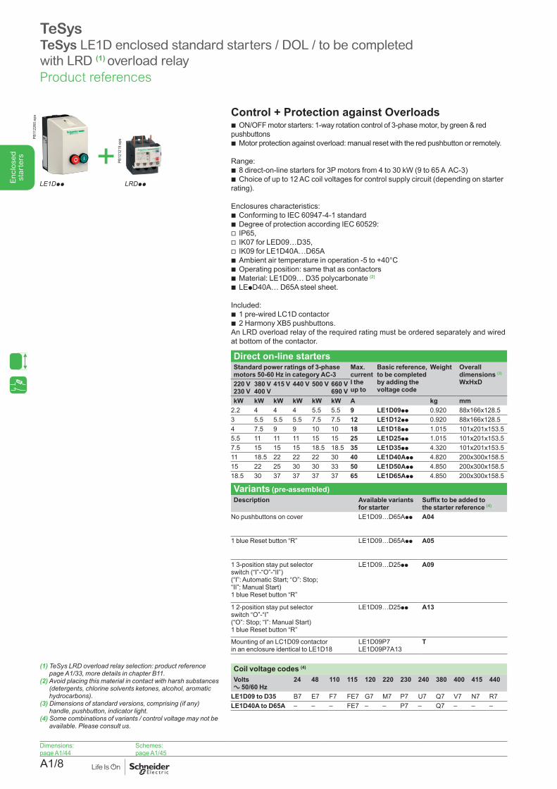
Control + Protection against Overloads b ON/OFF motor starters: 1-way rotation control of 3-phase motor, by green & red
pushbuttons b Motor protection against overload: manual reset with the red pushbutton or remotely.
Range: b 8 direct-on-line starters for 3P motors from 4 to 30 kW (9 to 65 A AC-3) b Choice of up to 12 AC coil voltages for control supply circuit (depending on starter
rating).
Enclosures characteristics: b Conforming to IEC 60947-4-1 standard b Degree of protection according IEC 60529:
v IP65, v IK07 for LED09…D35, v IK09 for LE1D40A…D65A
b Ambient air temperature in operation -5 to +40°C b Operating position: same that as contactors b Material: LE1D09… D35 polycarbonate (2) b LEpD40A… D65A steel sheet.
Included:b 1 pre-wired LC1D contactorb 2 Harmony XB5 pushbuttons.An LRD overload relay of the required rating must be ordered separately and wired at bottom of the contactor.
Direct on-line starters Standard power ratings of 3-phase motors 50-60 Hz in category AC-3
Max. current I the up to
Basic reference, to be completed by adding the voltage code
Weight Overall dimensions (3)
WxHxD220 V230 V
380 V400 V
415 V 440 V 500 V 660 V690 V
kW kW kW kW kW kW A kg mm2.2 4 4 4 5.5 5.5 9 LE1D09pp 0.920 88x166x128.53 5.5 5.5 5.5 7.5 7.5 12 LE1D12pp 0.920 88x166x128.54 7.5 9 9 10 10 18 LE1D18pp 1.015 101x201x153.55.5 11 11 11 15 15 25 LE1D25pp 1.015 101x201x153.57.5 15 15 15 18.5 18.5 35 LE1D35pp 4.320 101x201x153.511 18.5 22 22 22 30 40 LE1D40App 4.820 200x300x158.515 22 25 30 30 33 50 LE1D50App 4.850 200x300x158.518.5 30 37 37 37 37 65 LE1D65App 4.850 200x300x158.5
Variants (pre-assembled)Description Available variants
for starterSuffix to be added to the starter reference (4)
No pushbuttons on cover LE1D09…D65App A04
1 blue Reset button “R” LE1D09…D65App A05
1 3-position stay put selector switch (“I”-“O”-“II”) (“I”: Automatic Start; “O”: Stop; “II”: Manual Start) 1 blue Reset button “R”
LE1D09…D25pp A09
1 2-position stay put selector switch “O”-“I” (“O”: Stop; “I”: Manual Start) 1 blue Reset button “R”
LE1D09…D25pp A13
Mounting of an LC1D09 contactor in an enclosure identical to LE1D18
LE1D09P7 LE1D09P7A13
T
Coil voltage codes (4)
Volts a 50/60 Hz
24 48 110 115 120 220 230 240 380 400 415 440
LE1D09 to D35 B7 E7 F7 FE7 G7 M7 P7 U7 Q7 V7 N7 R7LE1D40A to D65A – – – FE7 – – P7 – Q7 – – –
TeSysTeSys LE1D enclosed standard starters / DOL / to be completed with LRD (1) overload relay
LE1Dpp
PB11
2260
.eps
PB12
1219
.eps
LRDpp
+
(1) TeSys LRD overload relay selection: product reference pageA1/33,moredetailsinchapterB11.
(2) Avoid placing this material in contact with harsh substances (detergents, chlorine solvents ketones, alcohol, aromatic hydrocarbons).
(3) Dimensions of standard versions, comprising (if any) handle,pushbutton,indicatorlight.
(4) Some combinations of variants / control voltage may not be available.Pleaseconsultus.
Dimensions:page A1/44
Schemes: page A1/45
Product references
A1/9
Enc
lose
d st
arte
rs
Dimensions:page A1/41
Schemes: page A1/41
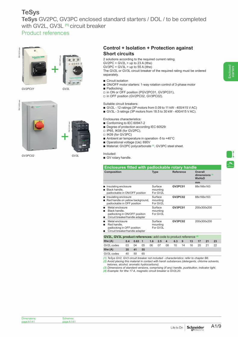
TeSysTeSys GV2PC, GV3PC enclosed standard starters / DOL / to be completed with GV2L, GV3L (1) circuit breaker
Control + Isolation + Protection against Short circuits 2 solutions according to the required current rating.GV2PC + GV2L > up to 23 A (Ithe) GV3PC + GV3L > up to 55 A (Ithe)The GV2L or GV3L circuit breaker of the required rating must be ordered separately.
b Circuit isolation b ON/OFF motor starters: 1-way rotation control of 3-phase motor b Padlocking: v in ON or OFF position (PGV2PC01, GV3PC01), v in OFF position (GV2PC02, GV3PC02).
Suitable circuit breakers: b GV2L - 12 ratings (3P motors from 0.09 to 11 kW - 400/415 V AC) b GV3L - 3 ratings (3P motors from 18.5 to 30 kW - 400/415 V AC).
Enclosures characteristics: b Conforming to IEC 60947-2 b Degree of protection according IEC 60529: v IP65, IK08 (for GV2PC), v IK09 (for GV3PC) b Ambient air temperature in operation -5 to +40°C b Operational voltage (Ue): 690V b Material: GV2PC polycarbonate (2), GV3PC steel sheet.
Included:b GV rotary handle.
Enclosures fitted with padlockable rotary handleComposition Type Reference Overall
dimensions (3)
WxHxDmm
b Insulating enclosure b Black handle,padlockable in ON/OFF position
Surface mountingFor GV2L
GV2PC01 88x166x163
b Insulating enclosure b Red handle on yellow background, padlockable in OFF position
Surface mountingFor GV2L
GV2PC02 88x166x163
b Metal enclosureb Black handle,
padlocking in ON/OFF positionb Circuit breaker/handle adapter
Surface mountingFor GV3L
GV3PC01 200x300x200
b Metal enclosureb Red handle,
padlocking in OFF positionb Circuit breaker/handle adapter
Surface mountingFor GV3L
GV3PC02 200x300x200
GV2L, GV3L product references: add code to product reference (4)
Ithe (A) 0.4 0.63 1 1.6 2.5 4 6.3 9 13 17 21 23GV2L codes 03 04 05 06 07 08 10 14 16 20 21 22Ithe (A) 35 41 55GV3L codes 40 50 65(1)TeSysGV2,GV3circuitbreakernotincluded-characteristics:refertochapterB6.(2) Avoid placing this material in contact with harsh substances (detergents, chlorine solvents,
ketones,alcohol,aromatichydrocarbons).(3)Dimensionsofstandardversions,comprising(ifany)handle,pushbutton,indicatorlight.(4)Example:forIthe17A,magneticcircuitbreakerisGV2L20.
+GV2PC01 GV2L
PB11
2219
.eps
PB11
1878
.eps
+GV3PC02 GV3L
PB11
2222
.eps
PB12
1225
.eps
Product references
A1/10
Enc
lose
d st
arte
rs
Dimensions:page A1/41
Schemes: page A1/41
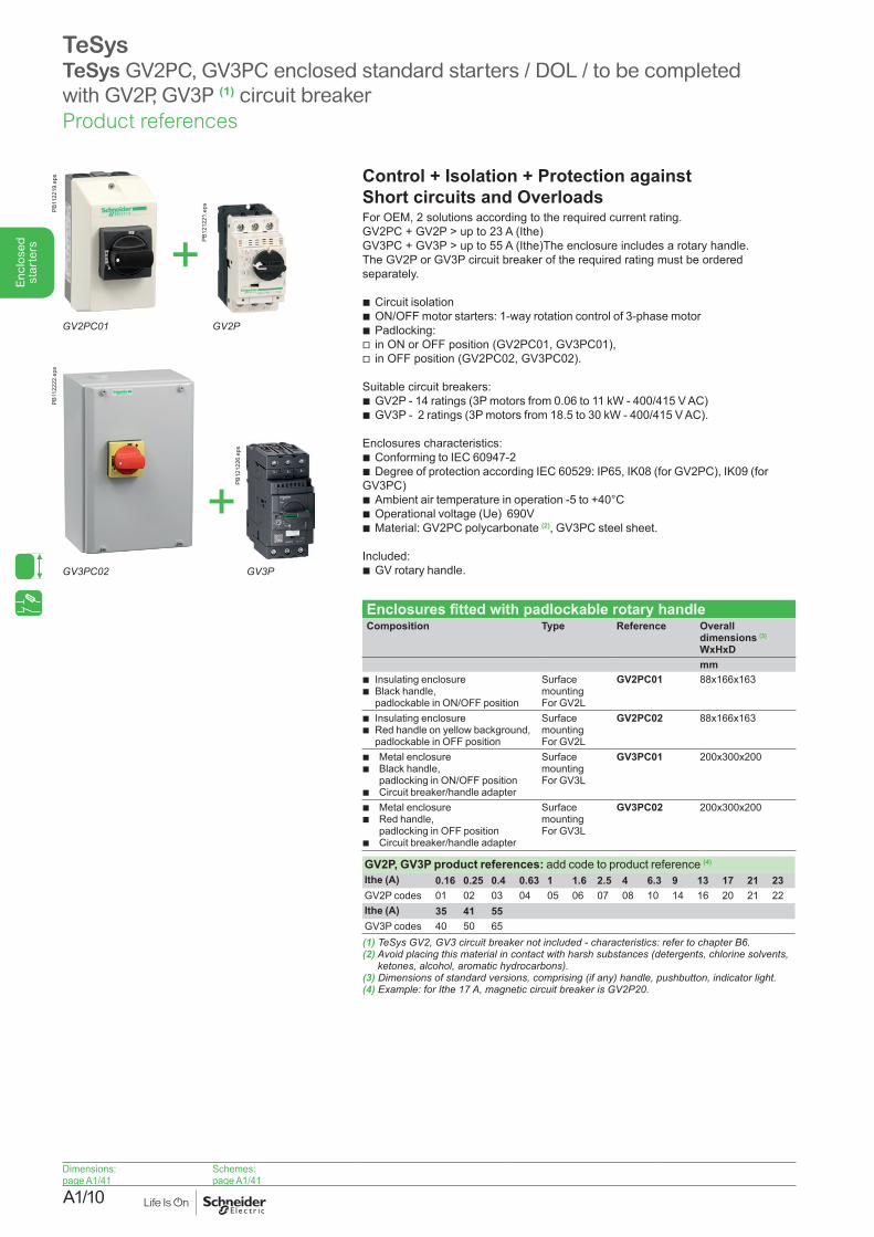
TeSysTeSys GV2PC, GV3PC enclosed standard starters / DOL / to be completed with GV2P, GV3P (1) circuit breaker
Control + Isolation + Protection against Short circuits and Overloads For OEM, 2 solutions according to the required current rating.GV2PC + GV2P > up to 23 A (Ithe) GV3PC + GV3P > up to 55 A (Ithe)The enclosure includes a rotary handle. The GV2P or GV3P circuit breaker of the required rating must be ordered separately.
b Circuit isolation b ON/OFF motor starters: 1-way rotation control of 3-phase motor b Padlocking: v in ON or OFF position (GV2PC01, GV3PC01), v in OFF position (GV2PC02, GV3PC02).
Suitable circuit breakers: b GV2P - 14 ratings (3P motors from 0.06 to 11 kW - 400/415 V AC) b GV3P - 2 ratings (3P motors from 18.5 to 30 kW - 400/415 V AC).
Enclosures characteristics: b Conforming to IEC 60947-2 b Degree of protection according IEC 60529: IP65, IK08 (for GV2PC), IK09 (for
GV3PC) b Ambient air temperature in operation -5 to +40°C b Operational voltage (Ue) 690V b Material: GV2PC polycarbonate (2), GV3PC steel sheet.
Included: b GV rotary handle.
Enclosures fitted with padlockable rotary handleComposition Type Reference Overall
dimensions (3)
WxHxDmm
b Insulating enclosure b Black handle,padlockable in ON/OFF position
Surface mountingFor GV2L
GV2PC01 88x166x163
b Insulating enclosure b Red handle on yellow background, padlockable in OFF position
Surface mountingFor GV2L
GV2PC02 88x166x163
b Metal enclosureb Black handle,
padlocking in ON/OFF positionb Circuit breaker/handle adapter
Surface mountingFor GV3L
GV3PC01 200x300x200
b Metal enclosureb Red handle,
padlocking in OFF positionb Circuit breaker/handle adapter
Surface mountingFor GV3L
GV3PC02 200x300x200
GV2P, GV3P product references: add code to product reference (4)
Ithe (A) 0.16 0.25 0.4 0.63 1 1.6 2.5 4 6.3 9 13 17 21 23GV2P codes 01 02 03 04 05 06 07 08 10 14 16 20 21 22Ithe (A) 35 41 55GV3P codes 40 50 65(1)TeSysGV2,GV3circuitbreakernotincluded-characteristics:refertochapterB6.(2) Avoid placing this material in contact with harsh substances (detergents, chlorine solvents,
ketones,alcohol,aromatichydrocarbons).(3)Dimensionsofstandardversions,comprising(ifany)handle,pushbutton,indicatorlight.(4)Example:forIthe17A,magneticcircuitbreakerisGV2P20.
+GV2PC01 GV2P
PB11
2219
.eps
PB12
1221
.eps
+GV3PC02 GV3P
PB11
2222
.eps
PB12
1226
.eps
Product references
A1/11
Enc
lose
d st
arte
rs
Dimensions:page A1/42
Schemes:page A1/43
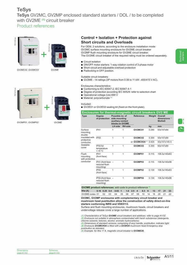
TeSysTeSys GV2MC, GV2MP enclosed standard starters / DOL / to be completed with GV2ME (1) circuit breaker
Control + Isolation + Protection against Short circuits and Overloads For OEM, 2 solutions, according to the enclosure installation mode:GV2MC surface mounting enclosure for GV2ME circuit breakerGV2MP flush mounting enclosure for GV2ME circuit breaker.The GV2ME circuit breaker of the required rating must be ordered separately.
b Circuit isolation b ON/OFF motor starters: 1-way rotation control of 3-phase motor b Short-circuit and adjustable overload protection b Padlocking in OFF position.
Suitable circuit breakers: b GV2ME - 14 ratings (3P motors from 0.06 to 11 kW - 400/415 V AC).
Enclosures characteristics: b Conforming to IEC 60947-2; IEC 60947-4-1 b Degree of protection according IEC 60529: refer to selection chart b Operational voltage (Ue) 690 V b Material: polycarbonate (2).
Included: b GV2E01 or GV2E02 sealing kit (fixed on the front plate).
Enclosures for thermal-magnetic circuit breakers GV2 METype Degree
of protectionPossible no. of side mounting auxiliary contact blocks on GV2ME
Reference Weight Overall dimensions (3)
WxHxD
LH side RH side kg mmSurface mounting, double insulated with protective conductor. Sealable cover
IP41 1 1 GV2MC01 0.290 93x147x84
IP55 1 1 GV2MC02 0.300 93x147x84
or GV2MCK04 (4) 0.420 93x147x145.5
IP55 for temperature < +5 °C
1 1 GV2MC03 0.300 93x147x84
Flush mounting, with protective conductor
IP41 (front face)
1 1 GV2MP01 0.115 106.5x140x83
IP41 (front face reduced flush mounting)
– 1 GV2MP03 0.115 106.5x140x98
IP55 (front face)
1 1 GV2MP02 0.130 106.5x140x83
IP55 (front face reduced flush mounting)
– 1 GV2MP04 0.130 106.5x140x98
GV2ME product references: add code to product reference (5)
Ithe (A) 0.16 0.25 0.4 0.63 1 1.6 2.5 4 6.3 9 13 17 21 23GV2ME codes 01 02 03 04 05 06 07 08 10 14 16 20 21 22
GV2MC, GV2MP enclosures with complementary circuit breaker and mushroom head pushbutton allow the construction of safety direct-on-line starters conforming INRS and VDE0113.Surface and flush mounting enclosures, mushroom heads, circuit breakers and undervoltage release cover a large number of applications.
(1) Characteristics of TeSys GV2MEcircuitbreakersandadditives:refertopageA1/32.(2) Enclosure not suitable in atmosphere contaminated with harsh substances (detergents,chlorinesolvents,ketones,alcohol,aromatichydrocarbons).(3) Dimensions of standard versions, comprising (if any) handle, pushbutton, indicator light (4) Enclosure GV2MCK04isfittedwithaGV2K04 mushroom head Emergency stop pushbuttonasstandard.(5) Example: for Ithe 17 A, magnetic circuit breaker is GV2ME20.
GV2MC02, GV2MC03
PB12
1459
.eps
GV2ME
PB12
1227
.eps
+GV2MP01, GV2MP02
PB11
2216
.eps
GV2ME
PB12
1227
.eps
+
Product references
A1/12
Enc
lose
d st
arte
rs
Dimensions:page A1/46
Schemes:page A1/47
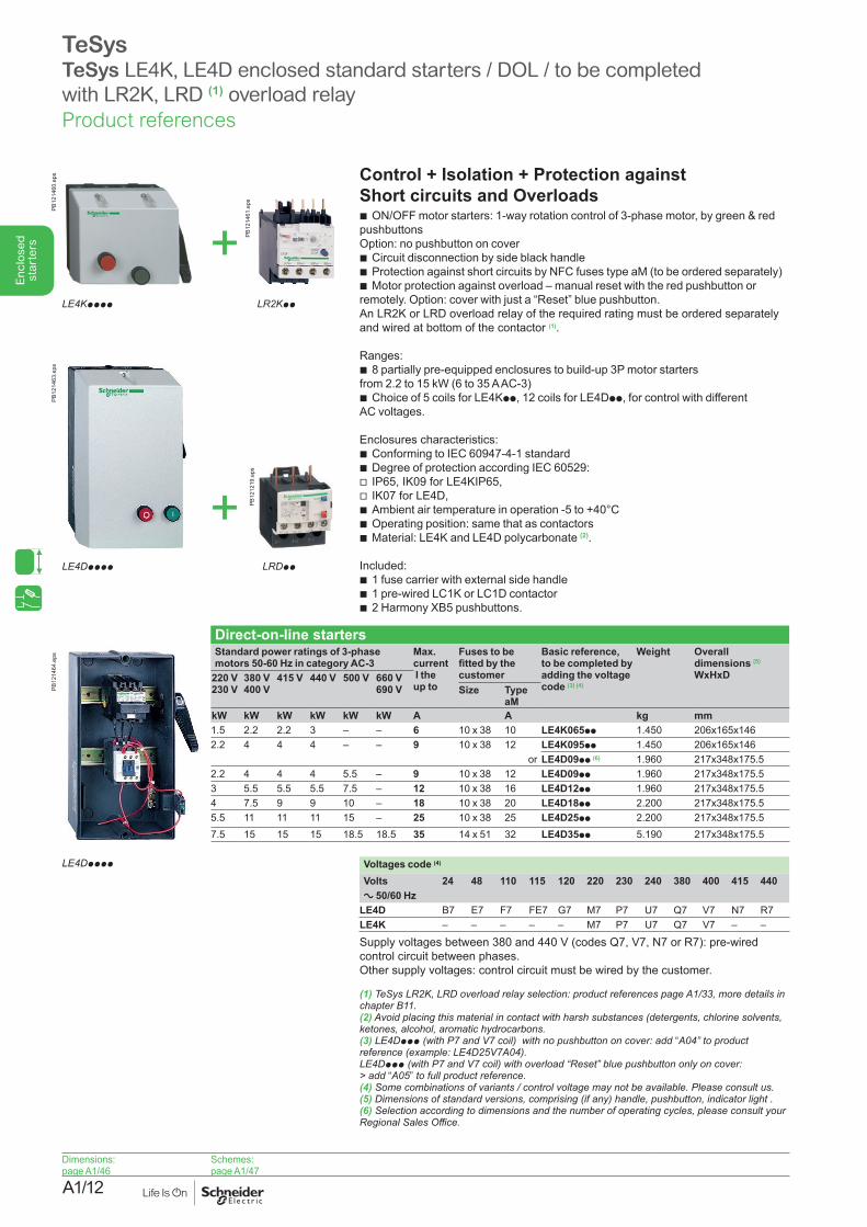
TeSysTeSys LE4K, LE4D enclosed standard starters / DOL / to be completed with LR2K, LRD (1) overload relay
Control + Isolation + Protection against Short circuits and Overloads
b ON/OFF motor starters: 1-way rotation control of 3-phase motor, by green & red pushbuttons Option: no pushbutton on cover
b Circuit disconnection by side black handle b Protection against short circuits by NFC fuses type aM (to be ordered separately) b Motor protection against overload – manual reset with the red pushbutton or
remotely. Option: cover with just a “Reset” blue pushbutton.An LR2K or LRD overload relay of the required rating must be ordered separately and wired at bottom of the contactor (1).
Ranges: b 8 partially pre-equipped enclosures to build-up 3P motor starters
from 2.2 to 15 kW (6 to 35 A AC-3) b Choice of 5 coils for LE4Kpp, 12 coils for LE4Dpp, for control with different
AC voltages.
Enclosures characteristics: b Conforming to IEC 60947-4-1 standard b Degree of protection according IEC 60529: v IP65, IK09 for LE4KIP65, v IK07 for LE4D, b Ambient air temperature in operation -5 to +40°C b Operating position: same that as contactors b Material: LE4K and LE4D polycarbonate (2).
Included: b 1 fuse carrier with external side handle b 1 pre-wired LC1K or LC1D contactor b 2 Harmony XB5 pushbuttons.
Direct-on-line startersStandard power ratings of 3-phase motors 50-60 Hz in category AC-3
Max. current I the up to
Fuses to be fitted by the customer
Basic reference, to be completed by adding the voltage code (3) (4)
Weight Overall dimensions (5)
WxHxD220 V230 V
380 V400 V
415 V 440 V 500 V 660 V690 V Size Type
aMkW kW kW kW kW kW A A kg mm1.5 2.2 2.2 3 – – 6 10 x 38 10 LE4K065pp 1.450 206x165x1462.2 4 4 4 – – 9 10 x 38 12 LE4K095pp 1.450 206x165x146
or LE4D09pp (6) 1.960 217x348x175.52.2 4 4 4 5.5 – 9 10 x 38 12 LE4D09pp 1.960 217x348x175.53 5.5 5.5 5.5 7.5 – 12 10 x 38 16 LE4D12pp 1.960 217x348x175.54 7.5 9 9 10 – 18 10 x 38 20 LE4D18pp 2.200 217x348x175.55.5 11 11 11 15 – 25 10 x 38 25 LE4D25pp 2.200 217x348x175.57.5 15 15 15 18.5 18.5 35 14 x 51 32 LE4D35pp 5.190 217x348x175.5
Voltages code (4)
Volts 24 48 110 115 120 220 230 240 380 400 415 440a 50/60 Hz
LE4D B7 E7 F7 FE7 G7 M7 P7 U7 Q7 V7 N7 R7LE4K – – – – – M7 P7 U7 Q7 V7 – –
Supply voltages between 380 and 440 V (codes Q7, V7, N7 or R7): pre-wired control circuit between phases.Other supply voltages: control circuit must be wired by the customer.
(1) TeSys LR2K, LRD overload relay selection: product references page A1/33, more details in chapterB11.(2) Avoid placing this material in contact with harsh substances (detergents, chlorine solvents,ketones,alcohol,aromatichydrocarbons.(3) LE4Dppp (with P7 and V7 coil) with no pushbutton on cover: add “A04” to product reference(example:LE4D25V7A04).LE4Dppp (with P7 and V7 coil) with overload “Reset” blue pushbutton only on cover: > add “A05”tofullproductreference.(4)Somecombinationsofvariants/controlvoltagemaynotbeavailable.Pleaseconsultus.(5)Dimensionsofstandardversions,comprising(ifany)handle,pushbutton,indicatorlight.(6) Selection according to dimensions and the number of operating cycles, please consult your RegionalSalesOffice.
PB12
1460
.eps
PB12
1461
.eps
+LE4Kpppp LR2Kpp
PB12
1464
.eps
LE4Dpppp
PB12
1463
.eps
PB12
1219
.eps
+LE4Dpppp LRDpp
Product references
A1/13
Enc
lose
d st
arte
rs
Dimensions:page A1/44
Schemes: page A1/45
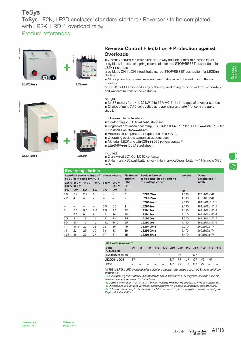
TeSysTeSys LE2K, LE2D enclosed standard starters / Reverser / to be completed with LR2K, LRD (1) overload relay
Reverse Control + Isolation + Protection against Overloads
b ON/REVERSE/OFF motor starters: 2-way rotation control of 3-phase motor v by black I-II position spring return selector, red STOP/RESET pushbuttons for
LE2Kpp starters v by black ON ↑ , ON ↓ pushbuttons, red STOP/RESET pushbutton for LE2Dpp
starters b Motor protection against overload: manual reset with the red pushbutton or
remotely.An LR2K or LRD overload relay of the required rating must be ordered separately and wired at bottom of the contactor.
Ranges: b for 3P motors from 4 to 30 kW (9 to 65 A AC-3), in 11 ranges of reverser starters b Choice of up to 7 AC coils voltages (depending on starter) for control supply
circuit.
Enclosures characteristics: b Conforming to IEC 60947-4-1 standard b Degree of protection according IEC 60529: IP65, IK07 for LED09pppD35, IK09 for
LE2K and LEpD40ApppD65A, b Ambient air temperature in operation -5 to +40°C b Operating position: same that as contactors b Material: LE2K and LEpD09pppD35 polycarbonate (2) b LEpD40Appp D65A steel sheet.
Included: b 2 pre-wired LC1K or LC1D contactor b 3 Harmony XB5 pushbuttons - or -1 Harmony XB5 pushbutton + 1 Harmony XB5
switch.
Reversing startersStandard power ratings of 3-phase motors 50-60 Hz in category AC-3
Maximum current I the up to
Basic reference, to be completed by adding the voltage code (3)
Weight Overall dimensions (4)
WxHxD220 V230 V
380 V400 V
415 V 440 V 500 V 660 V690 V
kW kW kW kW kW kW A kg1.5 2.2 2.2 3 – – 6 LE2K065pp 1.080 175x165x1462.2 4 4 4 – – 9 LE2K095pp 1.080 175x165x146
LE2D09pp (5) 2.100 101x201x153.5– – – – 5.5 5.5 9 LE2D09pp 2.100 101x201x153.53 5.5 5.5 5.5 7.5 7.5 12 LE2D12pp 2.100 101x201x153.54 7.5 9 9 10 10 18 LE2D18pp 2.410 101x201x153.55.5 11 11 11 15 15 25 LE2D25pp 2.570 101x201x153.57.5 15 15 15 18.5 18.5 35 LE2D35pp 4.100 101x201x153.511 18.5 22 22 22 30 40 LE2D40App 5.270 200x300x17415 22 25 30 30 33 50 LE2D50App 5.470 200x300x17418.5 30 37 37 37 37 65 LE2D65App 5.470 200x300x174
Coil voltage codes (3)
Volts a 50/60 Hz
24 48 110 115 120 220 230 240 380 400 415 440
LE2D40A to D65A – – – FE7 – – P7 – Q7 – – –LE2D09 to D35 B7 – – – – M7 P7 U7 Q7 V7 N7 –LE2K – – – – – M7 P7 U7 Q7 V7 – –
(1) TeSys LR2K, LRD overload relay selection: product references page A1/33, more details in chapterB11.(2) Avoid placing this material in contact with harsh substances (detergents, chlorine solvents,ketones,alcohol,aromatichydrocarbons.(3)Somecombinationsofvariants/controlvoltagemaynotbeavailable.Pleaseconsultus.(4)Dimensionsofstandardversions,comprising(ifany)handle,pushbutton,indicatorlight.(5) Selection according to dimensions and the number of operating cycles, please consult your RegionalSalesOffice.
PB12
1465
.eps
PB12
1461
.eps
+LE2K09ppp LR2Kpp
PB11
2274
.eps
PB12
1219
.eps
+LE2D12ppp LRDpp
Product references
A1/14
Enc
lose
d st
arte
rs
Dimensions:page A1/46
Schemes:page A1/47
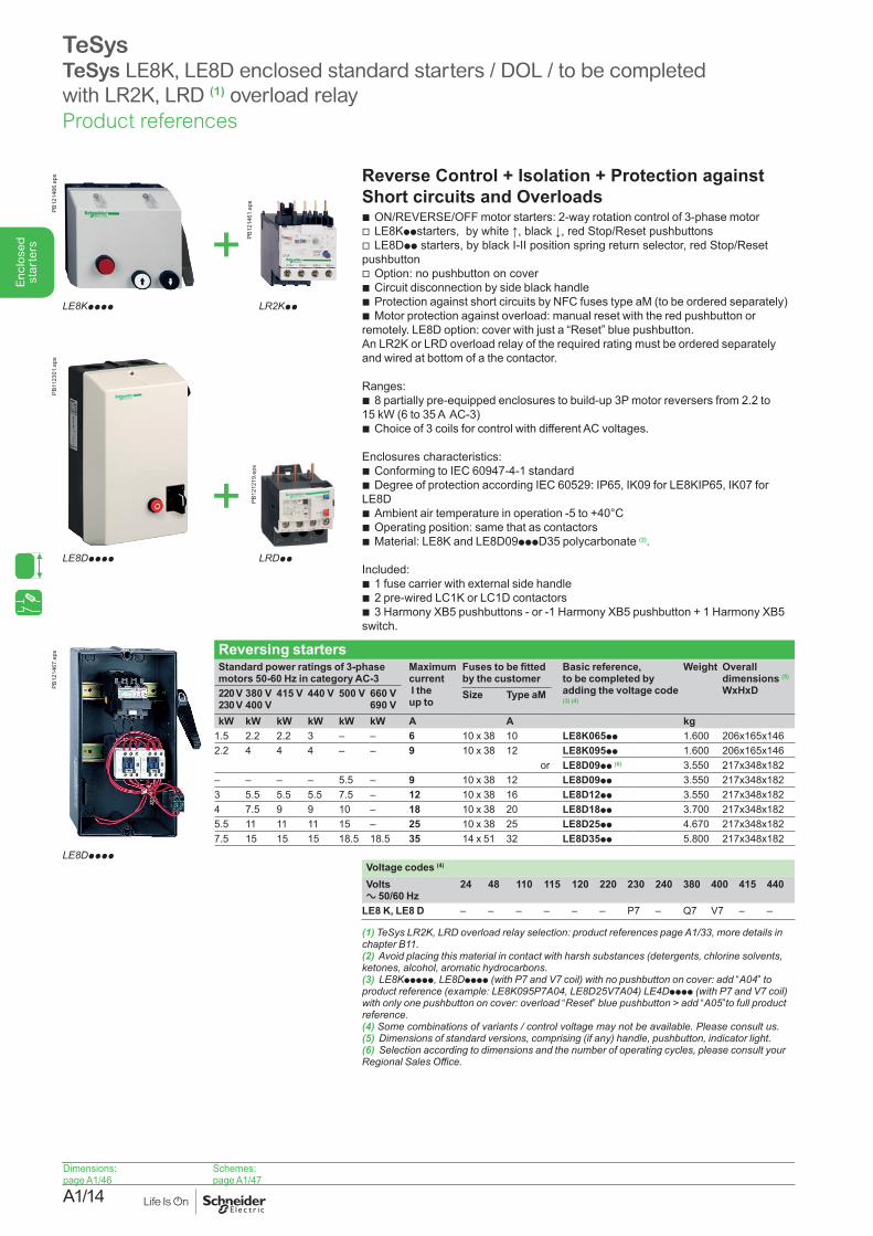
TeSysTeSys LE8K, LE8D enclosed standard starters / DOL / to be completed with LR2K, LRD (1) overload relay
Reverse Control + Isolation + Protection against Short circuits and Overloads
b ON/REVERSE/OFF motor starters: 2-way rotation control of 3-phase motor v LE8Kppstarters, by white ↑, black ↓, red Stop/Reset pushbuttons v LE8Dpp starters, by black I-II position spring return selector, red Stop/Reset
pushbutton v Option: no pushbutton on cover b Circuit disconnection by side black handle b Protection against short circuits by NFC fuses type aM (to be ordered separately) b Motor protection against overload: manual reset with the red pushbutton or
remotely. LE8D option: cover with just a “Reset” blue pushbutton. An LR2K or LRD overload relay of the required rating must be ordered separately and wired at bottom of a the contactor.
Ranges: b 8 partially pre-equipped enclosures to build-up 3P motor reversers from 2.2 to
15 kW (6 to 35 A AC-3) b Choice of 3 coils for control with different AC voltages.
Enclosures characteristics: b Conforming to IEC 60947-4-1 standard b Degree of protection according IEC 60529: IP65, IK09 for LE8KIP65, IK07 for
LE8D b Ambient air temperature in operation -5 to +40°C b Operating position: same that as contactors b Material: LE8K and LE8D09pppD35 polycarbonate (2).
Included: b 1 fuse carrier with external side handle b 2 pre-wired LC1K or LC1D contactors b 3 Harmony XB5 pushbuttons - or -1 Harmony XB5 pushbutton + 1 Harmony XB5
switch.
Reversing startersStandard power ratings of 3-phase motors 50-60 Hz in category AC-3
Maximum current I the up to
Fuses to be fitted by the customer
Basic reference, to be completed by adding the voltage code (3) (4)
Weight Overall dimensions (5)
WxHxD220 V230 V
380 V400 V
415 V 440 V 500 V 660 V690 V
Size Type aM
kW kW kW kW kW kW A A kg1.5 2.2 2.2 3 – – 6 10 x 38 10 LE8K065pp 1.600 206x165x1462.2 4 4 4 – – 9 10 x 38 12 LE8K095pp 1.600 206x165x146
or LE8D09pp (6) 3.550 217x348x182– – – – 5.5 – 9 10 x 38 12 LE8D09pp 3.550 217x348x1823 5.5 5.5 5.5 7.5 – 12 10 x 38 16 LE8D12pp 3.550 217x348x1824 7.5 9 9 10 – 18 10 x 38 20 LE8D18pp 3.700 217x348x1825.5 11 11 11 15 – 25 10 x 38 25 LE8D25pp 4.670 217x348x1827.5 15 15 15 18.5 18.5 35 14 x 51 32 LE8D35pp 5.800 217x348x182
Voltage codes (4)
Volts a 50/60 Hz
24 48 110 115 120 220 230 240 380 400 415 440
LE8 K, LE8 D – – – – – – P7 – Q7 V7 – –
(1) TeSys LR2K, LRD overload relay selection: product references page A1/33, more details in chapterB11.(2) Avoid placing this material in contact with harsh substances (detergents, chlorine solvents,ketones,alcohol,aromatichydrocarbons.(3) LE8Kppppp, LE8Dpppp (with P7 and V7 coil) with no pushbutton on cover: add “A04” to product reference (example: LE8K095P7A04, LE8D25V7A04) LE4Dpppp (with P7 and V7 coil) with only one pushbutton on cover: overload “Reset” blue pushbutton > add “A05”to full product reference.(4)Somecombinationsofvariants/controlvoltagemaynotbeavailable.Pleaseconsultus.(5)Dimensionsofstandardversions,comprising(ifany)handle,pushbutton,indicatorlight.(6) Selection according to dimensions and the number of operating cycles, please consult your RegionalSalesOffice.
PB12
1466
.eps
PB12
1461
.eps
+LE8Kpppp LR2Kpp
PB11
2301
.eps
+LE8Dpppp LRDpp
PB12
1219
.eps
PB12
1467
.eps
LE8Dpppp
Product references
A1/15
Enc
lose
d st
arte
rs
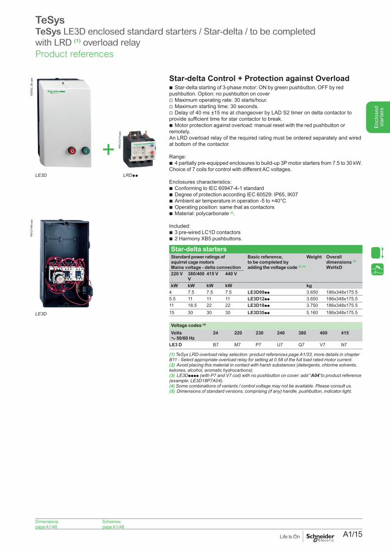
TeSysTeSys LE3D enclosed standard starters / Star-delta / to be completed with LRD (1) overload relay
Dimensions:page A1/48
Schemes:page A1/48
Star-delta Control + Protection against Overload b Star-delta starting of 3-phase motor: ON by green pushbutton, OFF by red
pushbutton. Option: no pushbutton on cover v Maximum operating rate: 30 starts/hour. v Maximum starting time: 30 seconds. v Delay of 40 ms ±15 ms at changeover by LAD S2 timer on delta contactor to
provide sufficient time for star contactor to break. b Motor protection against overload: manual reset with the red pushbutton or
remotely.An LRD overload relay of the required rating must be ordered separately and wired at bottom of the contactor.
Range: b 4 partially pre-equipped enclosures to build-up 3P motor starters from 7.5 to 30 kW.
Choice of 7 coils for control with different AC voltages.
Enclosures characteristics: b Conforming to IEC 60947-4-1 standard b Degree of protection according IEC 60529: IP65, IK07 b Ambient air temperature in operation -5 to +40°C b Operating position: same that as contactors b Material: polycarbonate (2).
Included: b 3 pre-wired LC1D contactors b 2 Harmony XB5 pushbuttons.
Star-delta startersStandard power ratings of squirrel cage motors Mains voltage - delta connection
Basic reference, to be completed by adding the voltage code (3) (4)
Weight Overall dimensions (5)
WxHxD220 V 380/400
V415 V 440 V
kW kW kW kW kg4 7.5 7.5 7.5 LE3D09pp 3.650 186x348x175.55.5 11 11 11 LE3D12pp 3.650 186x348x175.511 18.5 22 22 LE3D18pp 3.750 186x348x175.515 30 30 30 LE3D35pp 5.160 186x348x175.5
Voltage codes (4)
Volts a 50/60 Hz
24 220 230 240 380 400 415
LE3 D B7 M7 P7 U7 Q7 V7 N7
(1) TeSys LRD overload relay selection: product references page A1/33, more details in chapter B11-Selectappropriateoverloadrelayforsettingat0.58ofthefullloadratedmotorcurrent.(2) Avoid placing this material in contact with harsh substances (detergents, chlorine solvents,ketones,alcohol,aromatichydrocarbons).(3) LE3Dpppp (with P7 and V7 coil) with no pushbutton on cover: add “A04”to product reference (example:LE3D18P7A04).(4) Somecombinationsofvariants/controlvoltagemaynotbeavailable.Pleaseconsultus.(5)Dimensionsofstandardversions,comprising(ifany)handle,pushbutton,indicatorlight.
1055
52_S
E.ep
s
+LE3D LRDpp
PB12
1468
.eps
LE3D
PB12
1219
.eps
Product references
A1/16
Enc
lose
d st
arte
rs
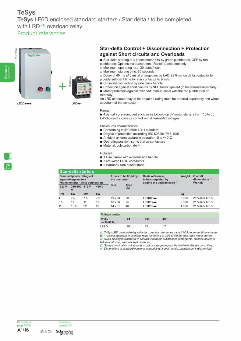
TeSysTeSys LE6D enclosed standard starters / Star-delta / to be completed with LRD (1) overload relay
Dimensions:page A1/40
Schemes:page A1/40
Star-delta Control + Disconnection + Protection against Short circuits and Overloads
b Star-delta starting of 3-phase motor: ON by green pushbutton, OFF by red pushbutton. Options: no pushbutton, “Reset” pushbutton only
v Maximum operating rate: 30 starts/hour. v Maximum starting time: 30 seconds. v Delay of 40 ms ±15 ms at changeover by LAD S2 timer on delta contactor to
provide sufficient time for star contactor to break. b Circuit disconnection by side black handle b Protection against short circuits by NFC fuses type aM (to be ordered separately) b Motor protection against overload: manual reset with the red pushbutton or
remotely.An LRD overload relay of the required rating must be ordered separately and wired at bottom of the contactor.
Range: b 4 partially pre-equipped enclosures to build-up 3P motor starters from 7.5 to 30
kW choice of 7 coils for control with different AC voltages.
Enclosures characteristics: b Conforming to IEC 60947-4-1 standard b Degree of protection according IEC 60529: IP65, IK07 b Ambient air temperature in operation -5 to +40°C b Operating position: same that as contactors b Material: polycarbonate (2).
Included: b 1 fuse carrier with external side handle b 3 pre-wired LC1D contactors b 2 Harmony XB5 pushbuttons.
Star-delta startersStandard power ratings of squirrel cage motors Mains voltage - delta connection
Fuses to be fitted by the customer
Basic reference, to be completed by adding the voltage code (3)
Weight Overall dimensions (4)
WxHxDSize Type
aM220 V 380/400 V
415 V 440 V
kW kW kW kW kg4 7.5 7.5 7.5 10 x 38 20 LE6D09pp 3.900 217x348x175.55.5 11 11 11 10 x 38 25 LE6D12pp 3.900 217x348x175.511 18.5 22 22 14 x 51 40 LE6D18pp 4.850 217x348x175.5
Voltage codesVolts a 50/60 Hz
24 230 400
LE6 D B7 P7 V7
(1) TeSys LRD overload relay selection: product references page A1/33, more details in chapter B11-Selectappropriateoverloadrelayforsettingat0.58ofthefullloadratedmotorcurrent.(2) Avoid placing this material in contact with harsh substances (detergents, chlorine solvents,ketones,alcohol,aromatichydrocarbons).(3)Somecombinationsofvariants/controlvoltagemaynotbeavailable.Pleaseconsultus.(4)Dimensionsofstandardversions,comprising(ifany)handle,pushbutton,indicatorlight.
PB12
1469
.eps
+LE6Dpppp LRDpp
PB12
1219
.eps
Product references
A1/17
Enc
lose
d st
arte
rs
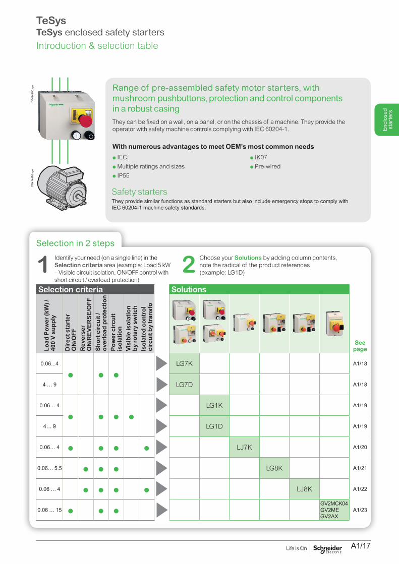
Range of pre-assembled safety motor starters, with mushroom pushbuttons, protection and control components in a robust casingThey can be fixed on a wall, on a panel, or on the chassis of a machine. They provide the operator with safety machine controls complying with IEC 60204-1.
With numerous advantages to meet OEM’s most common needs
DB4
1449
0.ep
sD
B414
490.
eps
Selection in 2 steps
Selection criteria Solutions
Load
Pow
er (k
W) /
40
0 V
supp
ly
Dire
ct s
tart
er
ON
/OFF
Rev
erse
r O
N/R
EVER
SE/O
FFSh
ort c
ircui
t /
over
load
pro
tect
ion
Pow
er c
ircui
t is
olat
ion
Visi
ble
isol
atio
n
by ro
tary
sw
itch
Isol
ated
con
trol
ci
rcui
t by
tran
sfo
See page
0.06...4
p p pLG7K A1/18
4 … 9 LG7D A1/18
0.06… 4
p p p pLG1K A1/19
4… 9 LG1D A1/19
0.06… 4 p p p p LJ7K A1/20
0.06… 5.5 p p p LG8K A1/21
0.06 … 4 p p p p LJ8K A1/22
0.06 … 15 p p pGV2MCK04GV2MEGV2AX
A1/23
2 Choose your Solutions by adding column contents, note the radical of the product references (example: LG1D) 1 Identify your need (on a single line) in the
Selection criteria area (example: Load 5 kW – Visible circuit isolation, ON/OFF control with short circuit / overload protection)
Safety startersThey provide similar functions as standard starters but also include emergency stops to comply with IEC 60204-1 machine safety standards.
p IEC p Multiple ratings and sizesp IP55
p IK07p Pre-wired
TeSysTeSys enclosed safety starters Introduction & selection table
A1/18
Enc
lose
d st
arte
rs
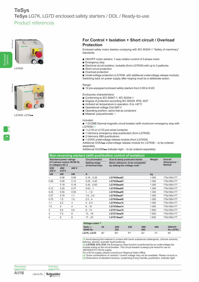
TeSysTeSys LG7K, LG7D enclosed safety starters / DOL / Ready-to-use
For Control + Isolation + Short circuit / Overload ProtectionEnclosed safety motor starters complying with IEC 60204-1 “Safety of machinery” standards.
b ON/OFF motor starters: 1-way rotation control of 3-phase motor b Emergency stop b Electrical circuit isolation, lockable (from LG7K09) with up to 3 padlocks b Short circuit protection b Overload protection b Undervoltage protection (LG7K06: with additional undervoltage release module).
Switching back on power supply after tripping must be a deliberate action.
Range: b 12 pre-equipped enclosed safety starters from 0.06 to 9 kW.
Enclosures characteristics: b Conforming to IEC 60947-1, IEC 60204-1 b Degree of protection according IEC 60529: IP55, IK07 b Ambient air temperature in operation -5 to +40°C b Operational voltage (Ue) 690 V b Operating position: same that as contactors b Material: polycarbonate (1).
Included: b 1 GV2ME thermal magnetic circuit breaker (with mushroom emergency stop with
LG7K06) (2)
b 1 LC1K or LC1D pre-wired contactor b 1 Harmony emergency stop pushbutton (from LG7K09) b 2 Harmony XB5 pushbuttons. b 1 GVAX undervoltage release module (from LG7K09).
Additional GVAXpp undervoltage release module for LG7K06 – to be ordered separately.Additional GV2SNpp Indicator light – to be ordered separately.
Non-reversing starters (with pushbutton control of isolation)Standard power ratings of 3-phase motors 50-60 Hz in category AC-3
Circuit breaker Dust & damp protected starter Weight Overall dimensions (4)
WxHxDSetting range of thermal trips
Basic reference, to be completed by adding the voltage code (3)
220/ 230 V
400/ 415 V
440 V
kW kW kW A kg– 0.06 0.06 0.16…0.25 LG7K06pp02 1.300 175x165x1770.06 0.09 0.12 0.25…0.40 LG7K06pp03 1.300 175x165x177– 0.18 0.18 0.40…0.63 LG7K06pp04 1.300 175x165x1770.12 0.25 0.37 0.63…1 LG7K06pp05 1.300 175x165x1770.25 0.55 0.55 1…1.6 LG7K06pp06 1.300 175x165x1770.37 0.75 1.1 1.6…2.5 LG7K06pp07 1.300 175x165x1770.75 1.5 1.5 2.5…4 LG7K06pp08 1.300 175x165x1771.1 2.2 3 4…6.3 LG7K06pp10 1.300 175x165x1771.5 4 4 6…10 LG7K09pp14 1.450 175x165x1773 5.5 5.5 9…14 LG7D12pp16 1.600 175x165x1774 7.5 9 13…18 LG7D18pp20 1.630 175x165x1774 9 9 17…23 LG7D18pp21 1.630 175x165x177
Voltage codes (3)
Volts a 50/60 Hz
24 220/ 230
230 380/ 400
400 400/415 for LG7K)
LG7K, LG7D B7 M7 P7 Q7 V7 N7
(1) Avoid placing this material in contact with harsh substances (detergents, chlorine solvents,ketones,alcohol,aromatichydrocarbons).(2) LG7K09, D12, D18: the Emergency Stop function is performed by an undervoltage trip moduleactingonthecircuitbreaker.Thiscircuitbreakerisalwayspre-wiredforuseon380/400/415V50Hzsupply.Fora60Hzsupply,pleaseconsultyourRegionalSalesOffice.(3)Somecombinationsofvariants/controlvoltagemaynotbeavailable.Pleaseconsultus.(4)Dimensionsofstandardversions,comprising(ifany)handle,pushbutton,indicatorlight.
LG7K06
PB12
1470
.eps
LG7K09, LG7Dpp
PB11
1886
.eps
Dimensions:page A1/50
Schemes:page A1/51
Product references
A1/19
Enc
lose
d st
arte
rs
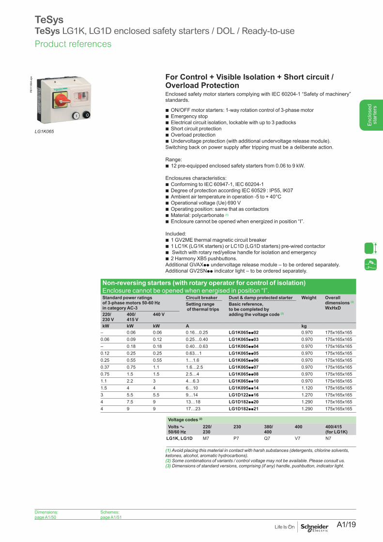
For Control + Visible Isolation + Short circuit /Overload ProtectionEnclosed safety motor starters complying with IEC 60204-1 “Safety of machinery” standards.
b ON/OFF motor starters: 1-way rotation control of 3-phase motor b Emergency stop b Electrical circuit isolation, lockable with up to 3 padlocks b Short circuit protection b Overload protection b Undervoltage protection (with additional undervoltage release module).
Switching back on power supply after tripping must be a deliberate action.
Range: b 12 pre-equipped enclosed safety starters from 0.06 to 9 kW.
Enclosures characteristics: b Conforming to IEC 60947-1, IEC 60204-1 b Degree of protection according IEC 60529 : IP55, IK07 b Ambient air temperature in operation -5 to + 40°C b Operational voltage (Ue) 690 V b Operating position: same that as contactors b Material: polycarbonate (1)
b Enclosure cannot be opened when energized in position “I”.
Included: b 1 GV2ME thermal magnetic circuit breaker b 1 LC1K (LG1K starters) or LC1D (LG1D starters) pre-wired contactor b Switch with rotary red/yellow handle for isolation and emergency b 2 Harmony XB5 pushbuttons.
Additional GVAXpp undervoltage release module – to be ordered separately.Additional GV2SNpp indicator light – to be ordered separately.
Non-reversing starters (with rotary operator for control of isolation)Enclosure cannot be opened when energised in position “I”.Standard power ratings of 3-phase motors 50-60 Hz in category AC-3
Circuit breaker Dust & damp protected starter Weight Overall dimensions (3)
WxHxDSetting range of thermal trips
Basic reference, to be completed by adding the voltage code (2) 220/
230 V 400/ 415 V
440 V
kW kW kW A kg– 0.06 0.06 0.16…0.25 LG1K065pp02 0.970 175x165x1650.06 0.09 0.12 0.25…0.40 LG1K065pp03 0.970 175x165x165– 0.18 0.18 0.40…0.63 LG1K065pp04 0.970 175x165x1650.12 0.25 0.25 0.63…1 LG1K065pp05 0.970 175x165x1650.25 0.55 0.55 1…1.6 LG1K065pp06 0.970 175x165x1650.37 0.75 1.1 1.6…2.5 LG1K065pp07 0.970 175x165x1650.75 1.5 1.5 2.5…4 LG1K065pp08 0.970 175x165x1651.1 2.2 3 4…6.3 LG1K065pp10 0.970 175x165x1651.5 4 4 6…10 LG1K095pp14 1.120 175x165x1653 5.5 5.5 9…14 LG1D122pp16 1.270 175x165x1654 7.5 9 13…18 LG1D182pp20 1.290 175x165x1654 9 9 17…23 LG1D182pp21 1.290 175x165x165
Voltage codes (2)
Volts a 50/60 Hz
220/ 230
230 380/ 400
400 400/415 (for LG1K)
LG1K, LG1D M7 P7 Q7 V7 N7
(1) Avoid placing this material in contact with harsh substances (detergents, chlorine solvents,ketones,alcohol,aromatichydrocarbons).(2) Somecombinationsofvariants/controlvoltagemaynotbeavailable.Pleaseconsultus.(3)Dimensionsofstandardversions,comprising(ifany)handle,pushbutton,indicatorlight.
TeSysTeSys LG1K, LG1D enclosed safety starters / DOL / Ready-to-use
LG1K065
PB11
1894
.eps
Dimensions:page A1/50
Schemes:page A1/51
Product references
A1/20
Enc
lose
d st
arte
rs
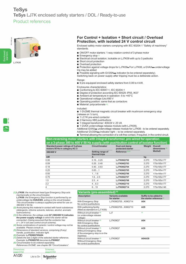
For Control + Isolation + Short circuit / Overload Protection, with isolated 24 V control circuitEnclosed safety motor starters complying with IEC 60204-1 “Safety of machinery” standards.
b ON/OFF motor starters: 1-way rotation control of 3-phase motor b Emergency stop (1)
b Electrical circuit isolation, lockable on LJ7K09 with up to 3 padlocks b Short circuit protection b Overload protection b Protection against voltage drops for LJ7K09p For LJ7K06, a GVAXpp undervoltage
trip may be added b Possible signaling with GV2SNpp indicator (to be ordered separately).
Switching back on power supply after tripping must be a deliberate action.Range:
b 9 pre-equipped enclosed safety starters from 0.06 to 4 kW.Enclosures characteristics:
b Conforming to IEC 60947-1, IEC 60204-1 b Degree of protection according IEC 60529: IP55, IK07 b Ambient air temperature in operation -5 to +40°C b Operational voltage (Ue) 690 V b Operating position: same that as contactors b Material: polycarbonate (2).
Included: b 1 GV2ME thermal magnetic circuit breaker with mushroom emergency stop
(release on ¼ turn), b 1 LC1K pre-wired contactor b 2 Harmony XB5 pushbuttons b 1 Integral transformer: 400/24 V, 25 VA b 1 GVAX undervoltage release module (with LJ7K09).
Additional GVAXpp undervoltage release module for LJ7K06 - to be ordered separately.Additional GV2SNpp indicator light – to be ordered separately.
b Terminal allowing the connection of a volt-free contact, if required, in the control circuit.
Non-reversing motor starters with integral transformer, pre-wired for operation on a 3-phase 380 to 400 V 50 Hz supply (with pushbutton control of isolator function)Standard power ratings of 3-phase motors 50 Hz in category AC-3
Circuit breaker Dust and damp protected starter
Weight Overall dimensions (5)
WxHxDSetting range of thermal trips
Reference (3) (4)380/400 V
kW A kg0.06 0.16…0.25 LJ7K06Q702 2.270 175x165x1770.09 0.25…0.40 LJ7K06Q703 2.270 175x165x1770.18 0.40…0.63 LJ7K06Q704 2.270 175x165x1770.25 0.63…1 LJ7K06Q705 2.270 175x165x1770.55 1…1.6 LJ7K06Q706 2.270 175x165x1770.75 1.6…2.5 LJ7K06Q707 2.270 175x165x1771.5 2.5…4 LJ7K06Q708 2.270 175x165x1772.2 4…6.3 LJ7K06Q710 2.270 175x165x1774 6…10 LJ7K09Q714 2.270 175x165x146
Variants (pre-assembled) (4)
Description Variants availablefor starter
Suffix to be added to the starter reference (6)
With Emergency Stop No control pushbuttons
LJ7K06Q705...K09Q714 A04
With padlocking facility (fitted as standard on LJ7 K09)
LJ7K06Q705...K06Q710 A29
Without circuit breaker (8) (or undervoltage release voltage)
LJ7 (7)
Without circuit breaker (8)
With Emergency Stop No control pushbuttons
LJ7K09Q7 A04
Without circuit breaker (8)
Without Emergency Stop (if the emergency stop is on the machine)
LJ7K09Q7 A39
Without circuit breaker (8)
Without Emergency Stop No control pushbuttons
LJ7K09Q7 A04A39
TeSysTeSys LJ7K enclosed safety starters / DOL / Ready-to-use
(1) LJ7K06: the mushroom head type Emergency Stop acts mechanicallyonthecircuitbreaker. LJ7K09: the Emergency Stop function is performed by an undervoltage trip GVAX385,actingonthecircuitbreaker.This circuit breaker is always supplied pre-wired for use on 380/400V50Hz.
(2) Avoid placing this material in contact with harsh substances (detergents, chlorine solvents, ketones, alcohol, aromatic hydrocarbons).
(3) In the reference, the voltage code Q7 (380/400 V) indicates the power supply voltage to which the starter will be connected, it being assumed that the contactor has a a24Vcoil(seecontrolcircuitscheme).
(4) Some combinations of variants / control voltage may not be available.Pleaseconsultus.
(5) Dimensions of standard versions, comprising (if any) handle,pushbutton,indicatorlight.
(6) Example: LJ7K06Q705A04.(7)Deletethelast2digitsoftheselectedstarterreference.
Example: LJ7K06Q705 becomes LJ7K06Q7.(8)Circuitbreakertobeorderedseparately.
ReferencesGV2ME:seechapterB6“Circuitbreakers”.
LJ7K06
PB11
1880
.eps
Dimensions:page A1/52
Schemes:page A1/53
Product references
A1/21
Enc
lose
d st
arte
rs
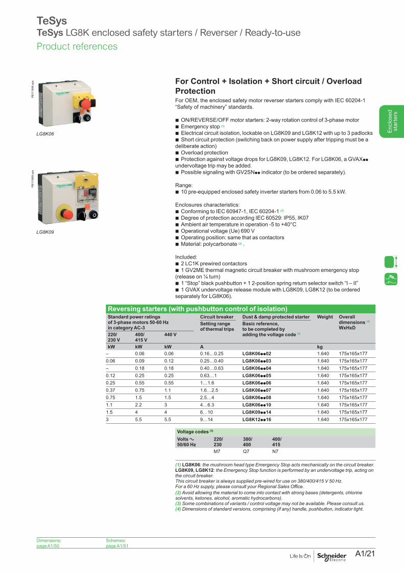
TeSysTeSys LG8K enclosed safety starters / Reverser / Ready-to-use
For Control + Isolation + Short circuit / Overload ProtectionFor OEM, the enclosed safety motor reverser starters comply with IEC 60204-1 “Safety of machinery” standards.
b ON/REVERSE/OFF motor starters: 2-way rotation control of 3-phase motor b Emergency stop (1)
b Electrical circuit isolation, lockable on LG8K09 and LG8K12 with up to 3 padlocks b Short circuit protection (switching back on power supply after tripping must be a
deliberate action) b Overload protection b Protection against voltage drops for LG8K09, LG8K12. For LG8K06, a GVAXpp
undervoltage trip may be added. b Possible signaling with GV2SNpp indicator (to be ordered separately).
Range: b 10 pre-equipped enclosed safety inverter starters from 0.06 to 5.5 kW.
Enclosures characteristics: b Conforming to IEC 60947-1, IEC 60204-1 (1)
b Degree of protection according IEC 60529: IP55, IK07 b Ambient air temperature in operation -5 to +40°C b Operational voltage (Ue) 690 V b Operating position: same that as contactors b Material: polycarbonate (2) .
Included: b 2 LC1K prewired contactors b 1 GV2ME thermal magnetic circuit breaker with mushroom emergency stop
(release on ¼ turn) b 1 “Stop” black pushbutton + 1 2-position spring return selector switch “I – II” b 1 GVAX undervoltage release module with LG8K09, LG8K12 (to be ordered
separately for LG8K06).
Reversing starters (with pushbutton control of isolation)Standard power ratings of 3-phase motors 50-60 Hz in category AC-3
Circuit breaker Dust & damp protected starter Weight Overall dimensions (4)
WxHxDSetting range of thermal trips
Basic reference, to be completed by adding the voltage code (3)220/
230 V 400/ 415 V
440 V
kW kW kW A kg– 0.06 0.06 0.16…0.25 LG8K06pp02 1.640 175x165x1770.06 0.09 0.12 0.25…0.40 LG8K06pp03 1.640 175x165x177– 0.18 0.18 0.40…0.63 LG8K06pp04 1.640 175x165x1770.12 0.25 0.25 0.63…1 LG8K06pp05 1.640 175x165x1770.25 0.55 0.55 1…1.6 LG8K06pp06 1.640 175x165x1770.37 0.75 1.1 1.6…2.5 LG8K06pp07 1.640 175x165x1770.75 1.5 1.5 2.5…4 LG8K06pp08 1.640 175x165x1771.1 2.2 3 4…6.3 LG8K06pp10 1.640 175x165x1771.5 4 4 6…10 LG8K09pp14 1.640 175x165x1773 5.5 5.5 9…14 LG8K12pp16 1.640 175x165x177
Voltage codes (3)
Volts a 50/60 Hz
220/ 230
380/ 400
400/ 415
M7 Q7 N7
(1) LG8K06:themushroomheadtypeEmergencyStopactsmechanicallyonthecircuitbreaker. LG8K09, LG8K12: the Emergency Stop function is performed by an undervoltage trip, acting on thecircuitbreaker. Thiscircuitbreakerisalwayssuppliedpre-wiredforuseon380/400/415V50Hz. Fora60Hzsupply,pleaseconsultyourRegionalSalesOffice.(2) Avoid allowing the material to come into contact with strong bases (detergents, chlorine solvents,ketones,alcohol,aromatichydrocarbons).(3) Somecombinationsofvariants/controlvoltagemaynotbeavailable.Pleaseconsultus.(4)Dimensionsofstandardversions,comprising(ifany)handle,pushbutton,indicatorlight.
LG8K06
PB11
1898
.eps
LG8K09
PB11
1899
.eps
Dimensions:page A1/50
Schemes:page A1/51
Product references
A1/22
Enc
lose
d st
arte
rs
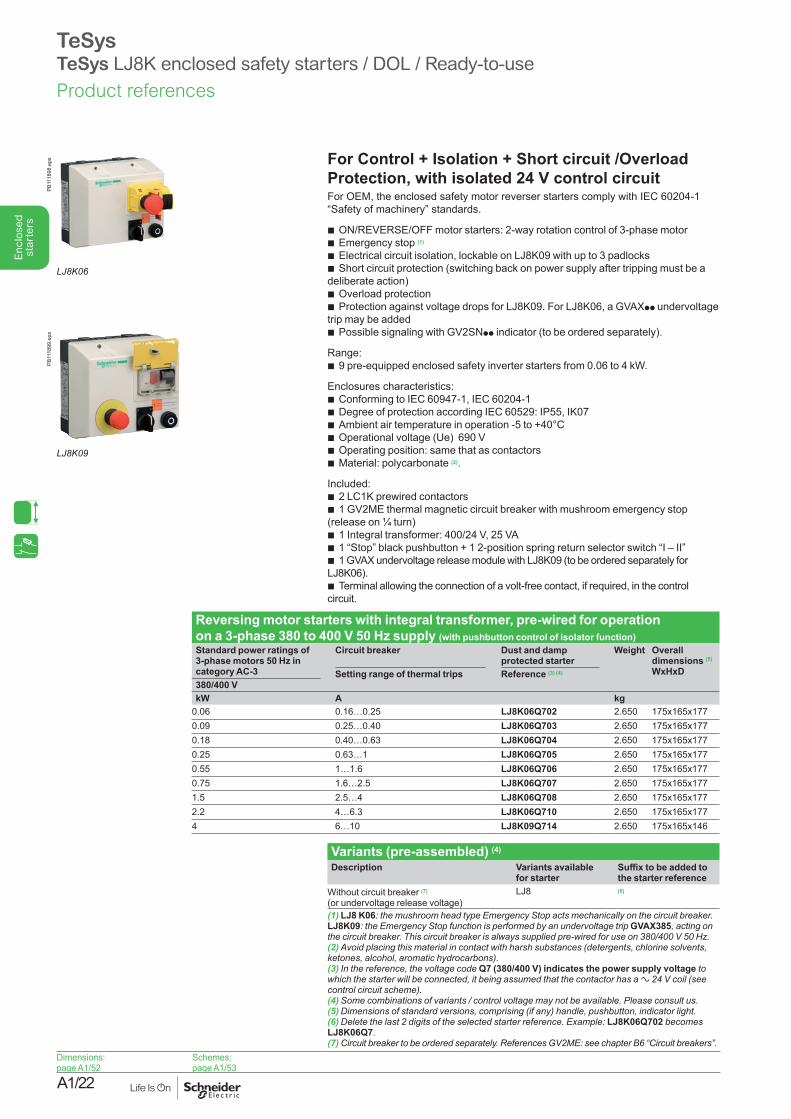
TeSys TeSys LJ8K enclosed safety starters / DOL / Ready-to-use
For Control + Isolation + Short circuit /Overload Protection, with isolated 24 V control circuitFor OEM, the enclosed safety motor reverser starters comply with IEC 60204-1 “Safety of machinery” standards.
b ON/REVERSE/OFF motor starters: 2-way rotation control of 3-phase motor b Emergency stop (1)
b Electrical circuit isolation, lockable on LJ8K09 with up to 3 padlocks b Short circuit protection (switching back on power supply after tripping must be a
deliberate action) b Overload protection b Protection against voltage drops for LJ8K09. For LJ8K06, a GVAXpp undervoltage
trip may be added b Possible signaling with GV2SNpp indicator (to be ordered separately).
Range: b 9 pre-equipped enclosed safety inverter starters from 0.06 to 4 kW.
Enclosures characteristics: b Conforming to IEC 60947-1, IEC 60204-1 b Degree of protection according IEC 60529: IP55, IK07 b Ambient air temperature in operation -5 to +40°C b Operational voltage (Ue) 690 V b Operating position: same that as contactors b Material: polycarbonate (2).
Included: b 2 LC1K prewired contactors b 1 GV2ME thermal magnetic circuit breaker with mushroom emergency stop
(release on ¼ turn) b 1 Integral transformer: 400/24 V, 25 VA b 1 “Stop” black pushbutton + 1 2-position spring return selector switch “I – II” b 1 GVAX undervoltage release module with LJ8K09 (to be ordered separately for
LJ8K06). b Terminal allowing the connection of a volt-free contact, if required, in the control
circuit.
Reversing motor starters with integral transformer, pre-wired for operation on a 3-phase 380 to 400 V 50 Hz supply (with pushbutton control of isolator function)Standard power ratings of 3-phase motors 50 Hz in category AC-3
Circuit breaker Dust and damp protected starter
Weight Overall dimensions (5)
WxHxDSetting range of thermal trips Reference (3) (4)
380/400 VkW A kg
0.06 0.16…0.25 LJ8K06Q702 2.650 175x165x1770.09 0.25…0.40 LJ8K06Q703 2.650 175x165x1770.18 0.40…0.63 LJ8K06Q704 2.650 175x165x1770.25 0.63…1 LJ8K06Q705 2.650 175x165x1770.55 1…1.6 LJ8K06Q706 2.650 175x165x1770.75 1.6…2.5 LJ8K06Q707 2.650 175x165x1771.5 2.5…4 LJ8K06Q708 2.650 175x165x1772.2 4…6.3 LJ8K06Q710 2.650 175x165x1774 6…10 LJ8K09Q714 2.650 175x165x146
Variants (pre-assembled) (4))
Description Variants availablefor starter
Suffix to be added to the starter reference
Without circuit breaker (7) (or undervoltage release voltage)
LJ8 (6)
(1) LJ8 K06:themushroomheadtypeEmergencyStopactsmechanicallyonthecircuitbreaker. LJ8K09: the Emergency Stop function is performed by an undervoltage trip GVAX385, acting on thecircuitbreaker.Thiscircuitbreakerisalwayssuppliedpre-wiredforuseon380/400V50Hz.(2) Avoid placing this material in contact with harsh substances (detergents, chlorine solvents, ketones,alcohol,aromatichydrocarbons).(3) In the reference, the voltage code Q7 (380/400 V) indicates the power supply voltage to which the starter will be connected, it being assumed that the contactor has a a 24 V coil (see controlcircuitscheme).(4)Somecombinationsofvariants/controlvoltagemaynotbeavailable.Pleaseconsultus.(5)Dimensionsofstandardversions,comprising(ifany)handle,pushbutton,indicatorlight.(6)Deletethelast2digitsoftheselectedstarterreference.Example:LJ8K06Q702 becomes LJ8K06Q7. (7)Circuitbreakertobeorderedseparately.ReferencesGV2ME:seechapterB6“Circuitbreakers”.
LJ8K06
PB11
1898
.eps
LJ8K09
PB11
1899
.eps
Dimensions:page A1/52
Schemes:page A1/53
Product references
A1/23
Enc
lose
d st
arte
rs
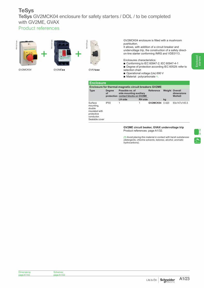
TeSysTeSys GV2MCK04 enclosure for safety starters / DOL / to be completed with GV2ME, GVAX
GV2MCK04 enclosure is fitted with a mushroom pushbutton.It allows, with addition of a circuit breaker and undervoltage trip, the construction of a safety direct-on-line starter conforming INRS and VDE0113.
Enclosures characteristics: b Conforming to IEC 60947-2; IEC 60947-4-1 b Degree of protection according IEC 60529: refer to
selection chart b Operational voltage (Ue) 690 V b Material : polycarbonate (1).
EnclosureEnclosure for thermal-magnetic circuit breakers GV2ME Type Degree
of protection
Possible no. of side mounting auxiliary contact blocks on GV2ME
Reference Weight Overall dimensions WxHxD
LH side RH side kgSurface mounting, double insulated with protective conductor. Sealable cover
IP55 1 1 GV2MCK04 0.420 93x147x145.5
GV2ME circuit beaker, GVAX undervoltage trip Product references: page A1/32.
(1) Avoid placing this material in contact with harsh substances (detergents, chlorine solvents, ketones, alcohol, aromatic hydrocarbons).
GV2MCK04
PB11
2215
.eps
GVAXppp
PB11
1876
.eps
GV2MEpp
PB12
1227
.eps
+ +
Dimensions:page A1/42
Schemes:page A1/43
Product references

A1/24
Enc
lose
d st
arte
rs
A1/25
Enc
lose
d st
arte
rs
TeSysEnclosures, components, for customer assembliesSpare parts
A1/26
Enc
lose
d st
arte
rs
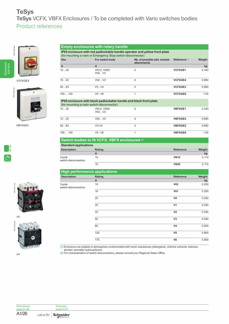
TeSysTeSys VCFX, VBFX Enclosures / To be completed with Vario switches bodies
Dimensions:page A1/36
Schemes:page A1/37
Empty enclosures with rotary handleIP65 enclosure with red padlockable handle operator and yellow front plate (for mounting a main or Emergency Stop switch-disconnector)lthe For switch body Nb. of possible add. module
attachments Reference (1) Weight
A A kg10…32 VN12, VN20
V02…V2 2 VCFXGE1 0.340
10…32 V02…V2 4 VCFXGE4 0.660
50…63 V3 - V4 3 VCFXGE2 0.660
100.... 140 V5 - V6 1 VCFXGE6 1.04
IP65 enclosure with black padlockable handle and black front plate (for mounting a main switch-disconnector)
10…32 VN12, VN20 V02…V2
2 VBFXGE1 0.340
10…32 V02…V2 4 VBFXGE4 0.660
50…63 V3-V4 3 VBFXGE2 0.660
100.... 140 V5 - V6 1 VBFXGE6 1.04
Switch bodies to fit VCFX, VBFX enclosures (2)
Standard applicationsDescription Rating Reference Weight
A kg3-pole switch-disconnectors
10 VN12 0.110
16 VN20 0.110
High performance applicationsDescription Rating Reference Weight
A kg3-pole switch-disconnectors
10 V02 0.200
16 V01 0.200
20 V0 0.200
25 V1 0.200
32 V2 0.200
50 V3 0.500
80 V4 0.500
125 V5 0.900
175 V6 0.900
(1) Enclosure not suitable in atmosphere contaminated with harsh substances (detergents, chlorine solvents, ketones, alcohol,aromatichydrocarbons).
(2)Forcharacteristicsofswitch-disconnectors,pleaseconsultyourRegionalSalesOffice.
VCFXGE4
PB12
1229
.eps
VBFXGE2
PB12
1230
.eps
V0
PB12
1231
.eps
V4
PB12
1232
.eps
Product references
A1/27
Enc
lose
d st
arte
rs
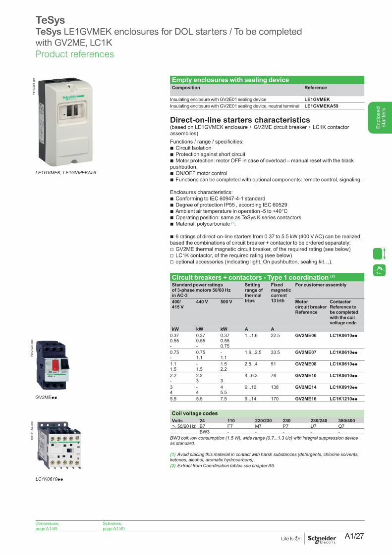
TeSys TeSys LE1GVMEK enclosures for DOL starters / To be completed with GV2ME, LC1K
Dimensions:page A1/49
Schemes:page A1/49
Empty enclosures with sealing deviceComposition Reference
Insulating enclosure with GV2E01 sealing device LE1GVMEKInsulating enclosure with GV2E01 sealing device, neutral terminal LE1GVMEKA59
Direct-on-line starters characteristics (based on LE1GVMEK enclosure + GV2ME circuit breaker + LC1K contactor assemblies)Functions / range / specificities:
b Circuit Isolation b Protection against short circuit b Motor protection: motor OFF in case of overload – manual reset with the black
pushbutton. b ON/OFF motor control b Functions can be completed with optional components: remote control, signaling.
Enclosures characteristics: b Conforming to IEC 60947-4-1 standard b Degree of protection IP55 , according IEC 60529 b Ambient air temperature in operation -5 to +40°C b Operating position: same as TeSys K series contactors b Material: polycarbonate (1).
b 6 ratings of direct-on-line starters from 0.37 to 5.5 kW (400 V AC) can be realized, based the combinations of circuit breaker + contactor to be ordered separately:
v GV2ME thermal magnetic circuit breaker, of the required rating (see below) v LC1K contactor, of the required rating (see below) v optional accessories (indicating light, On pushbutton, sealing kit…).
Circuit breakers + contactors - Type 1 coordination (2)
Standard power ratings of 3-phase motors 50/60 Hz in AC-3
Setting range of thermal trips
Fixed magnetic current 13 Irth
For customer assembly
400/ 415 V
440 V 500 V Motor circuit breaker Reference
Contactor Reference to be completed with the coil voltage code
kW kW kW A A0.37 0.55 -
0.37 0.55 -
0.37 0.55 0.75
1...1.6 22.5 GV2ME06 LC1K0610pp
0.75 -
0.75 1.1
- 1.1
1.6...2.5 33.5 GV2ME07 LC1K0610pp
1.1 1.5
- 1.5
1.5 2.2
2.5...4 51 GV2ME08 LC1K0610pp
2.2 -
2.2 3
- 3
4...6.3 78 GV2ME10 LC1K0610pp
3 4
- 4
4 5.5
6...10 138 GV2ME14 LC1K0910pp
5.5 5.5 7.5 9...14 170 GV2ME16 LC1K1210pp
Coil voltage codesVolts 24 110 220/230 230 230/240 380/400a 50/60 Hz B7 F7 M7 P7 U7 Q7c BW3 - - - - -BW3coil:lowconsumption(1.5W),widerange(0.7...1.3Uc)withintegralsuppressiondevice asstandard.
(1) Avoid placing this material in contact with harsh substances (detergents, chlorine solvents, ketones,alcohol,aromatichydrocarbons).(2) ExtractfromCoordinationtablesseechapterA6.
LE1GVMEK, LE1GVMEKA59
PB11
2286
.eps
GV2MEpp
PB12
1227
.eps
LC1K0610pp
1061
51_S
E.ep
s
Product references
A1/28
Enc
lose
d st
arte
rs
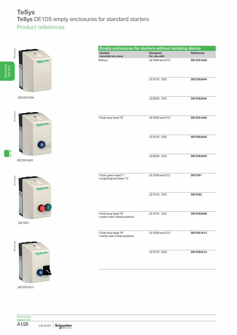
Empty enclosures for starters without isolating deviceHead(s) mounted on cover
Designed for use with
Reference
Without LE1D09 and D12 DE1DS1A04
LE1D18...D35 DE1DS2A04
LE2D09...D35 DE1DS2A04
1 flush blue head “R” LE1D09 and D12 DE1DS1A05
LE1D18...D35 DE1DS2A05
LE2D09...D35 DE1DS2A05
1 flush green head “I” 1 projecting red head “O”
LE1D09 and D12 DE1DS1
LE1D18...D35 DE1DS2
1 flush blue head “R” 1 switch with 3 fixed positions
LE1D18...D35 DE1DS2A09
1 flush blue head “R” 1 switch with 2 fixed positions
LE1D09 and D12 DE1DS1A13
LE1D18...D35 DE1DS2A13
DE1DS1A04
PB11
2264
.eps
DE1DS1A05
PB11
2269
.eps
DE1DS1
PB11
2259
.eps
DE1DS1A13
PB11
2275
.eps
TeSysTeSys DE1DS empty enclosures for standard starters
Dimensions:page A1/44
Product references
A1/29
Enc
lose
d st
arte
rs
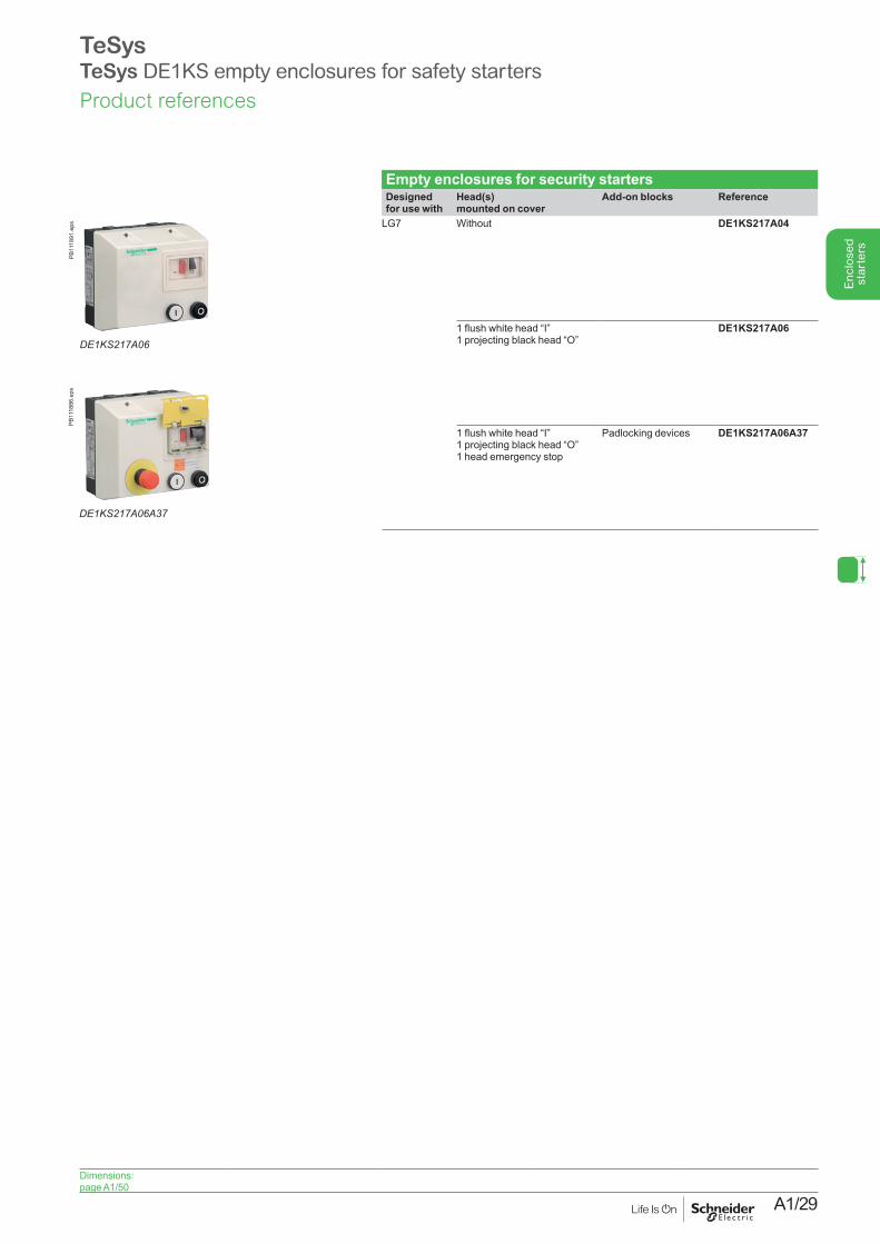
TeSysTeSys DE1KS empty enclosures for safety starters
Empty enclosures for security startersDesigned for use with
Head(s) mounted on cover
Add-on blocks Reference
LG7 Without DE1KS217A04
1 flush white head “I” 1 projecting black head “O”
DE1KS217A06
1 flush white head “I” 1 projecting black head “O”1 head emergency stop
Padlocking devices DE1KS217A06A37
DE1KS217A06A37
PB11
1886
.eps
DE1KS217A06
PB11
1891
.eps
Dimensions:page A1/50
Product references
A1/30
Enc
lose
d st
arte
rs
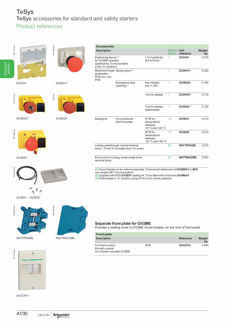
AccessoriesDescription Sold in
lots ofUnit reference
Weightkg
Padlocking device (6) for GV2ME operator (padlocking is only possible in the “O” position)
1 to 3 padlocks Ø 4 to 8 mm
1 GV2V01 0.075
Mushroom head pushbutton Ø 40 mm, red, IP55
Spring return (2) 1 GV2K011 0.052
Emergency stopLatching (2)
Key release, key n° 455
1 GV2K021 0.160
Turn to release 1 GV2K031 0.115
Turn to release, padlockable
1 GV2K04 (1) 0.120
Sealing kit For enclosures and front plate
IP 55 for temperature between+5 °C and +40 °C
10 GV2E01 0.012
IP 55 for temperature between-20 °C and +40 °C
10 GV2E02 0.012
Linergy passthrough neutral terminal block – 6 mm² 41 A single-level 1x1 screw
50 NSYTRV62BL 0.015
End cover for Linergy screw single-level terminal block
50 NSYTRAC22BL 0.003
(1)Circuitbreakertobeorderedseparatly.CommercialreferencesofGV2ME01 to M22: seechapterB6“Circuitbreakers”.(2) Supplied with IP55 GV2E01 sealingkit.TobefittedwithenclosureGV2Mp01.(3)Padlockablein“O”positionusingØ4to8mmshankpadlocks.
Separate front plate for GV2ME Provides a sealing cover to GV2ME circuit breaker, on any kind of front panel.
Front plateDescription Reference Weight
kgFor direct control, through a panel, of a chassis mounted GV2ME
IP55 GV2CP21 0.800
TeSysTeSys accessories for standard and safety starters
GV2V01
PB11
1915
.eps
GV2K021
PG11
3130
.eps
NSYTRV62BL
PB50
2236
.eps
GV2CP21
PB11
2218
.eps
GV2K04
PB11
2393
.eps
GV2E01 – GV2E02
PB12
1228
.eps
GV2K011
PB11
2390
.eps
GV2K031
8274
.eps
NSYTRAC22BL
PB50
2246
.eps
Product references
A1/31
Enc
lose
d st
arte
rs
TeSysTeSys accessories for standard and safety starters
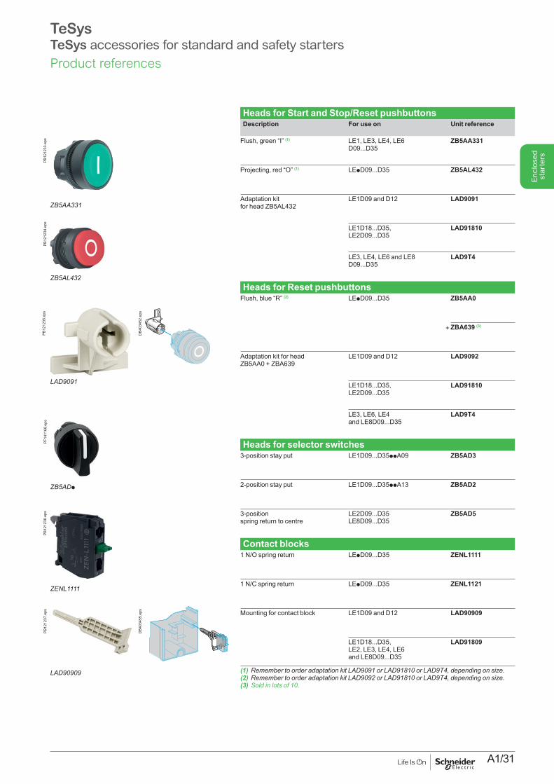
Heads for Start and Stop/Reset pushbuttonsDescription For use on Unit reference
Flush, green “I” (1) LE1, LE3, LE4, LE6 D09...D35
ZB5AA331
Projecting, red “O” (1) LEpD09...D35 ZB5AL432
Adaptation kit for head ZB5AL432
LE1D09 and D12 LAD9091
LE1D18...D35,LE2D09...D35
LAD91810
LE3, LE4, LE6 and LE8 D09...D35
LAD9T4
Heads for Reset pushbuttonsFlush, blue “R” (2) LEpD09...D35
+
ZB5AA0
ZBA639 (3)
Adaptation kit for head ZB5AA0 + ZBA639
LE1D09 and D12 LAD9092
LE1D18...D35, LE2D09...D35
LAD91810
LE3, LE6, LE4 and LE8D09...D35
LAD9T4
Heads for selector switches3-position stay put LE1D09...D35ppA09 ZB5AD3
2-position stay put LE1D09...D35ppA13 ZB5AD2
3-position spring return to centre
LE2D09...D35 LE8D09...D35
ZB5AD5
Contact blocks1 N/O spring return LEpD09...D35 ZENL1111
1 N/C spring return LEpD09...D35 ZENL1121
Mounting for contact block LE1D09 and D12 LAD90909
LE1D18...D35,LE2, LE3, LE4, LE6 and LE8D09...D35
LAD91809
(1)RemembertoorderadaptationkitLAD9091orLAD91810orLAD9T4,dependingonsize.(2)RemembertoorderadaptationkitLAD9092orLAD91810orLAD9T4,dependingonsize.(3)Soldinlotsof10.
ZB5AA331
PB12
1233
.eps
ZB5AL432
PB12
1234
.eps
LAD9091
DB4
0345
2.ep
s
ZB5ADp
PF14
1168
.eps
ZENL1111
PB12
1236
.eps
LAD90909
DB4
0345
5.ep
s
PB12
1237
.eps
PB12
1235
.eps
Product references
A1/32
Enc
lose
d st
arte
rs
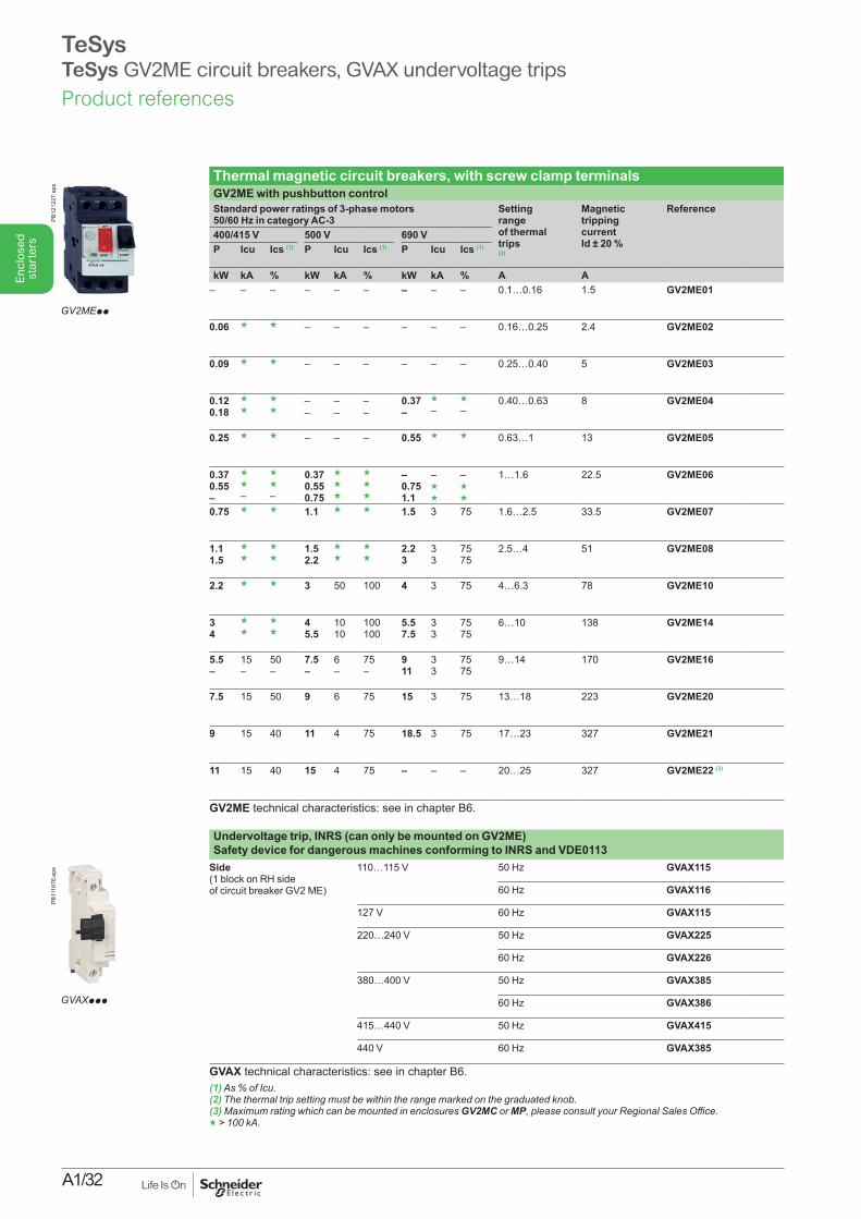
TeSysTeSys GV2ME circuit breakers, GVAX undervoltage trips
Thermal magnetic circuit breakers, with screw clamp terminals GV2ME with pushbutton controlStandard power ratings of 3-phase motors 50/60 Hz in category AC-3
Setting range of thermal trips (2)
Magnetic tripping current Id ± 20 %
Reference
400/415 V 500 V 690 VP Icu Ics (1) P Icu Ics (1) P Icu Ics (1)
kW kA % kW kA % kW kA % A A– – – – – –
– – – 0.1…0.16 1.5 GV2ME01
0.06 g g – – –
– – – 0.16…0.25 2.4 GV2ME02
0.09 g g – – –
– – – 0.25…0.40 5 GV2ME03
0.12 0.18
gg
g g
– –
– –
– –
0.37 –
g –
g –
0.40…0.63 8 GV2ME04
0.25 g g – – –
0.55 g g 0.63…1 13 GV2ME05
0.37 0.55 –
g g –
g g –
0.37 0.55 0.75
g g g
g g g
– 0.75 1.1
– g g
– g g
1…1.6 22.5 GV2ME06
0.75 g g 1.1 g g
1.5 3 75 1.6…2.5 33.5 GV2ME07
1.1 1.5
g g
g g
1.5 2.2
g g
g g
2.2 3
3 3
75 75
2.5…4 51 GV2ME08
2.2 g g 3 50 100
4 3 75 4…6.3 78 GV2ME10
3 4
g g
g g
4 5.5
10 10
100 100
5.5 7.5
3 3
75 75
6…10 138 GV2ME14
5.5 –
15 –
50 –
7.5 –
6 –
75 –
9 11
3 3
75 75
9…14 170 GV2ME16
7.5 15 50 9 6 75
15 3 75 13…18 223 GV2ME20
9 15 40 11 4 75
18.5 3 75 17…23 327 GV2ME21
11 15 40 15 4 75
– – – 20…25 327 GV2ME22 (3)
GV2ME technical characteristics: see in chapter B6.
Undervoltage trip, INRS (can only be mounted on GV2ME) Safety device for dangerous machines conforming to INRS and VDE0113
Side (1 block on RH side of circuit breaker GV2 ME)
110…115 V 50 Hz GVAX115
60 Hz GVAX116
127 V 60 Hz GVAX115
220…240 V 50 Hz GVAX225
60 Hz GVAX226
380…400 V 50 Hz GVAX385
60 Hz GVAX386
415…440 V 50 Hz GVAX415
440 V 60 Hz GVAX385
GVAX technical characteristics: see in chapter B6.(1)As%ofIcu.(2)Thethermaltripsettingmustbewithintherangemarkedonthegraduatedknob.(3) Maximum rating which can be mounted in enclosures GV2MC or MP,pleaseconsultyourRegionalSalesOffice.g>100kA.
GV2MEpp
PB12
1227
.eps
GVAXppp
PB11
1876
.eps
Product references
A1/33
Enc
lose
d st
arte
rs
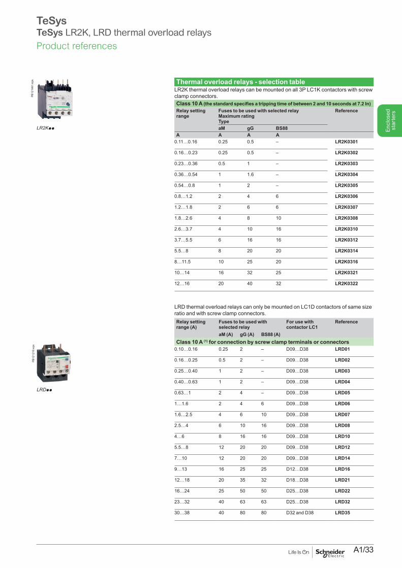
TeSysTeSys LR2K, LRD thermal overload relays
Thermal overload relays - selection tableLR2K thermal overload relays can be mounted on all 3P LC1K contactors with screw clamp connectors.Class 10 A (the standard specifies a tripping time of between 2 and 10 seconds at 7.2 In)Relay setting range
Fuses to be used with selected relayMaximum ratingType
Reference
aM gG BS88A A A A
0.11…0.16 0.25 0.5 – LR2K0301
0.16…0.23 0.25 0.5 – LR2K0302
0.23…0.36 0.5 1 – LR2K0303
0.36…0.54 1 1.6 – LR2K0304
0.54…0.8 1 2 – LR2K0305
0.8…1.2 2 4 6 LR2K0306
1.2…1.8 2 6 6 LR2K0307
1.8…2.6 4 8 10 LR2K0308
2.6…3.7 4 10 16 LR2K0310
3.7…5.5 6 16 16 LR2K0312
5.5…8 8 20 20 LR2K0314
8…11.5 10 25 20 LR2K0316
10…14 16 32 25 LR2K0321
12…16 20 40 32 LR2K0322
LRD thermal overload relays can only be mounted on LC1D contactors of same size ratio and with screw clamp connectors.Relay setting range (A)
Fuses to be used with selected relay
For use with contactor LC1
Reference
aM (A) gG (A) BS88 (A)Class 10 A (1) for connection by screw clamp terminals or connectors
0.10…0.16 0.25 2 – D09…D38 LRD01
0.16…0.25 0.5 2 – D09…D38 LRD02
0.25…0.40 1 2 – D09…D38 LRD03
0.40…0.63 1 2 – D09…D38 LRD04
0.63…1 2 4 – D09…D38 LRD05
1…1.6 2 4 6 D09…D38 LRD06
1.6…2.5 4 6 10 D09…D38 LRD07
2.5…4 6 10 16 D09…D38 LRD08
4…6 8 16 16 D09…D38 LRD10
5.5…8 12 20 20 D09…D38 LRD12
7…10 12 20 20 D09…D38 LRD14
9…13 16 25 25 D12…D38 LRD16
12…18 20 35 32 D18…D38 LRD21
16…24 25 50 50 D25…D38 LRD22
23…32 40 63 63 D25…D38 LRD32
30…38 40 80 80 D32 and D38 LRD35
PB12
1461
.eps
LR2Kpp
LRDpp
PB12
1219
.eps
Product references

A1/34
Enc
lose
d st
arte
rs

A1/35
Enc
lose
d st
arte
rs
Technical Data for Designers
Enc
lose
d st
arte
rs
ContentsSwitch-disconnectors .......................... A1/36 to A1/38Direct-on-line starters ............... A1/39, A1/41 to A1/47 .....................................................................and A1/49Star-delta starters ............................. A1/40 and A1/48Starters for safety applications ............ A1/50 to A1/53
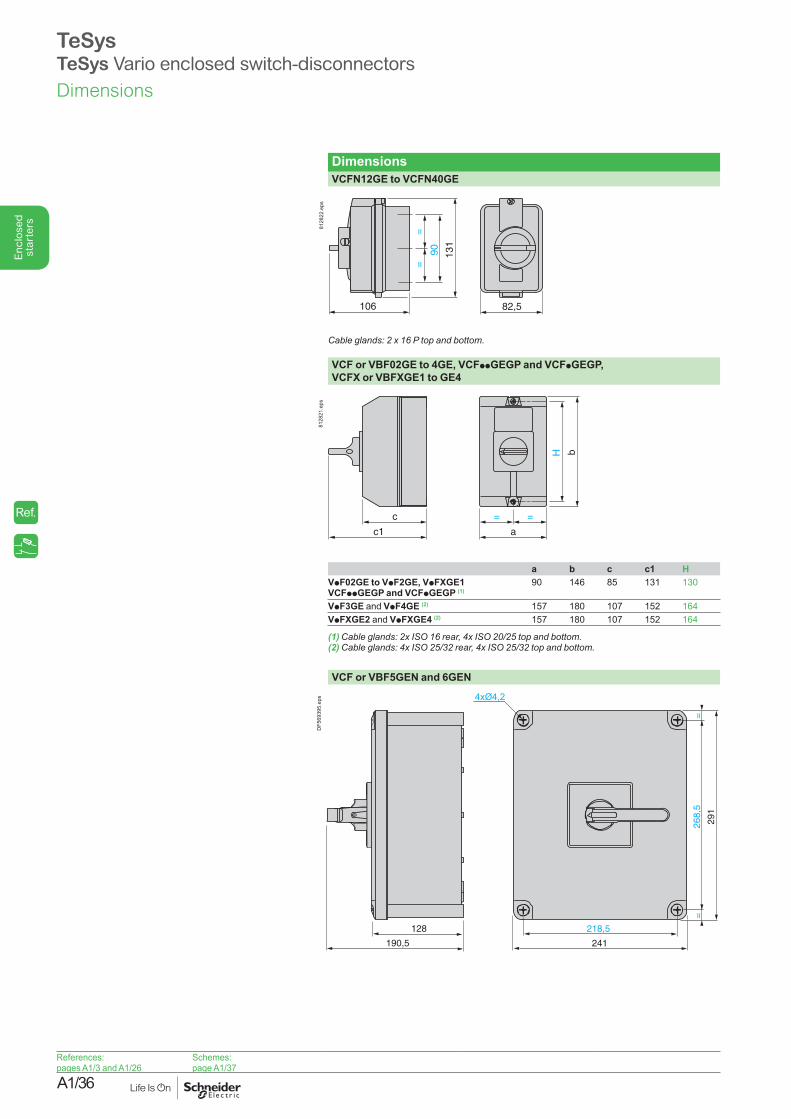
A1/36
Enc
lose
d st
arte
rs
DimensionsVCFN12GE to VCFN40GE
82,5106
131
90
==
8128
22.e
ps
Cableglands:2x16Ptopandbottom.
VCF or VBF02GE to 4GE, VCFppGEGP and VCFpGEGP,VCFX or VBFXGE1 to GE4
c
c1
b
a
= =
H
8128
21.e
ps
a b c c1 HVpF02GE to VpF2GE, VpFXGE1 VCFppGEGP and VCFpGEGP (1)
90 146 85 131 130
VpF3GE and VpF4GE (2) 157 180 107 152 164VpFXGE2 and VpFXGE4 (2) 157 180 107 152 164
(1)Cableglands:2xISO16rear,4xISO20/25topandbottom.(2)Cableglands:4xISO25/32rear,4xISO25/32topandbottom.
VCF or VBF5GEN and 6GEN
218,5
241
268,
5=
=
29
1
128
190,5
4xØ4,2
DF5
6939
5.ep
s
TeSysTeSys Vario enclosed switch-disconnectorsDimensions
References:pages A1/3 and A1/26
Schemes:page A1/37
Ref.
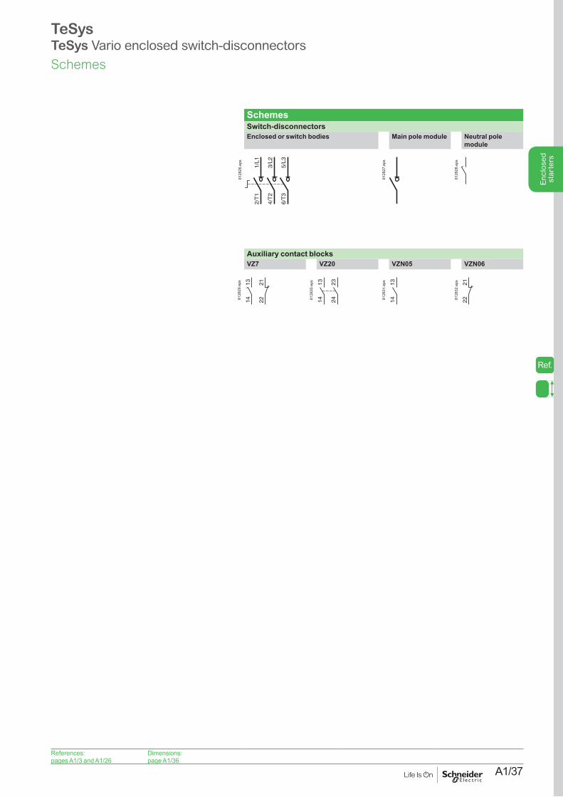
A1/37
Enc
lose
d st
arte
rs
SchemesSwitch-disconnectorsEnclosed or switch bodies Main pole module Neutral pole
module
1/L1
2/T
1
3/L2
4/T
2
5/L3
6/T
3
8128
26.e
ps
8128
27.e
ps
8128
28.e
ps
Auxiliary contact blocksVZ7 VZ20 VZN05 VZN06
222113
148128
29.e
ps 1314 24
23
8128
30.e
ps 131481
2831
.eps
2221
8128
32.e
ps
TeSysTeSys Vario enclosed switch-disconnectors
References:pages A1/3 and A1/26
Dimensions: page A1/36
Schemes
Ref.
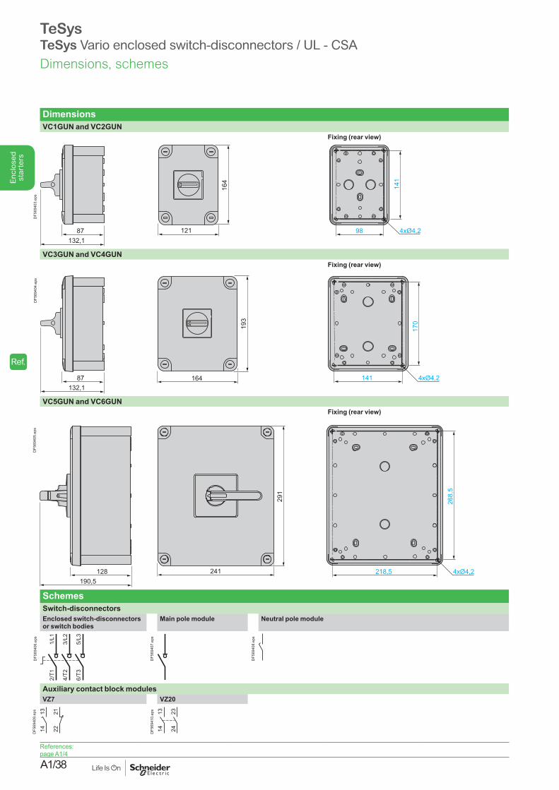
A1/38
Enc
lose
d st
arte
rs
TeSysTeSys Vario enclosed switch-disconnectors / UL - CSA
DimensionsVC1GUN and VC2GUN
Fixing (rear view)
12187132,1
164
98
141
4xØ4,2
DF5
6940
3.ep
s
VC3GUN and VC4GUNFixing (rear view)
87132,1
164
193
141
170
4xØ4,2
DF5
6940
4.ep
s
VC5GUN and VC6GUNFixing (rear view)
128190,5
218,5241
268,5
291
4xØ4,2
DF5
6940
5.ep
s
SchemesSwitch-disconnectorsEnclosed switch-disconnectors or switch bodies
Main pole module Neutral pole module
1/L1
2/T1
3/L2
4/T2
5/L3
6/T3
DF5
6940
6.ep
s
DF5
6940
7.ep
s
DF5
6940
8.ep
s
Auxiliary contact block modulesVZ7 VZ20
222113
14DF5
6940
9.ep
s 1314 24
23
DF5
6941
0.ep
s
References:page A1/4
Dimensions, schemes
Ref.
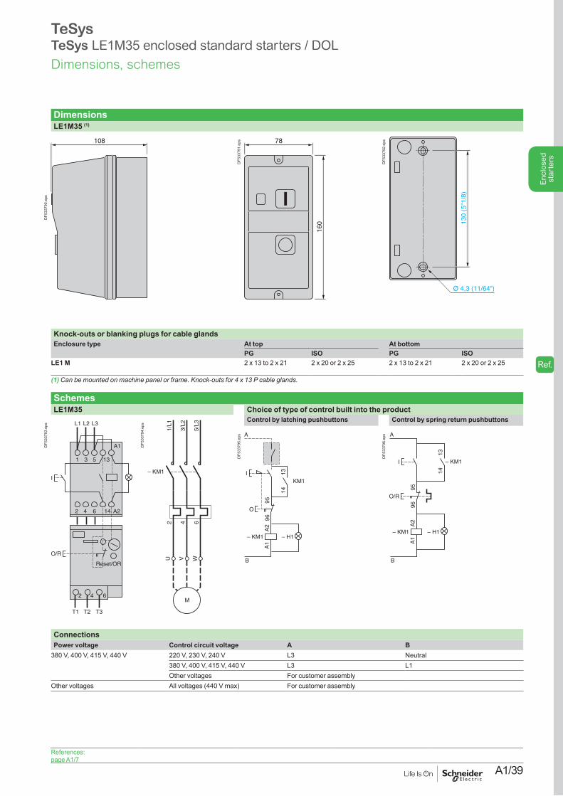
A1/39
Enc
lose
d st
arte
rs
TeSysTeSys LE1M35 enclosed standard starters / DOL
DimensionsLE1M35 (1)
108
DF5
3379
0.ep
s
78
160
DF5
3379
1.ep
s
130
(5"1
/8)
DF5
3379
2.ep
s
Knock-outs or blanking plugs for cable glandsEnclosure type At top At bottom
PG ISO PG ISOLE1 M 2 x 13 to 2 x 21 2 x 20 or 2 x 25 2 x 13 to 2 x 21 2 x 20 or 2 x 25
(1)Canbemountedonmachinepanelorframe.Knock-outsfor4x13Pcableglands.
SchemesLE1M35 Choice of type of control built into the product
I
O/R
1
2
3
4
5
6
13
14
A1
A2
2 4 6
L1 L2 L3
Reset/OR
T1 T2 T3
DF5
3379
3.ep
s
U WV
2 4 6
1/L1
3/L2
5/L3
M
– KM1
DF5
3379
4.ep
s
Control by latching pushbuttons Control by spring return pushbuttons
I
A
B
O
9596
– KM1 – H1
A2
A1
1413
KM1
DF5
3379
5.ep
s
I
A
B
1413
O/R
9596
– KM1 – H1
A2
A1
– KM1
DF5
3379
6.ep
s
ConnectionsPower voltage Control circuit voltage A B
380 V, 400 V, 415 V, 440 V 220 V, 230 V, 240 V L3 Neutral380 V, 400 V, 415 V, 440 V L3 L1Other voltages For customer assembly
Other voltages All voltages (440 V max) For customer assembly
References: page A1/7
Dimensions, schemes
Ref.
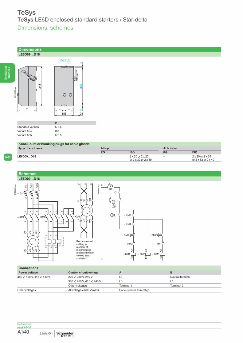
A1/40
Enc
lose
d st
arte
rs
DimensionsLE6D09…D18
c1
348
330
==
=
186 31
=
DF5
3383
5.ep
s
c1Standard version 175.5Variant A04 167Variant A05 175.5
Knock-outs or blanking plugs for cable glandsType of enclosure At top At bottom
PG ISO PG ISOLE6D09…D18 – 2 x 20 or 2 x 25
or 2 x 32 or 2 x 40– 2 x 20 or 2 x 25
or 2 x 32 or 2 x 40
SchemesLE6D09…D18
– KM2
12
34
56
– KM3
12
34
56
– KM1
12
34
56
U1
V1
W1
U2
V2
W2
1 3 5
2 4 6
– Q1
1/L1
2
3/L2
4
5/L3
6
U1
V1
W1
U2
V2
W2
2 4 6
Recommended cabling for reversal of motor rotation (standard motor, viewed from shaft end)
DF5
3383
8.ep
s
A1
A2
– KM1
– KM3
– KM2
– KM1
l
– KM2
A1
A2
– KM3
– KM1
A1
A2
– KM2
– KM2
B
O
A
Q1Q1
DF5
3383
9.ep
s
ConnectionsPower voltage Control circuit voltage A B
380 V, 400 V, 415 V, 440 V 220 V, 230 V, 240 V L3 Neutral terminal380 V, 400 V, 415 V, 440 V L3 L1Other voltages Terminal 1 Terminal 2
Other voltages All voltages (600 V max) For customer assembly
TeSysTeSys LE6D enclosed standard starters / Star-delta
References: page A1/16
Dimensions, schemes
Ref.
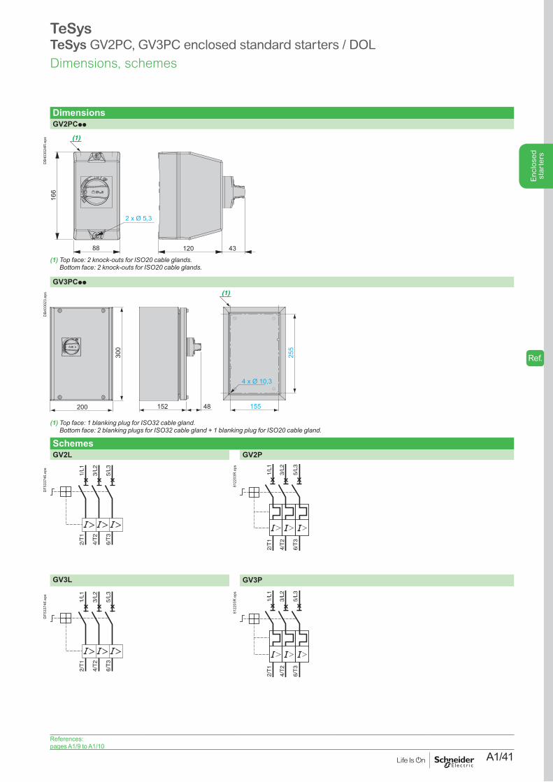
A1/41
Enc
lose
d st
arte
rs
DimensionsGV2PCpp
166
88 120 43
2 x Ø 5,3
(1)
DB4
0302
4R.e
ps
(1)Topface:2knock-outsforISO20cableglands. Bottomface:2knock-outsforISO20cableglands.
GV3PCpp
152 48 155 200
300
255
4 x Ø 10,3
(1)
DB4
0302
3.ep
s
(1)Topface:1blankingplugforISO32cablegland. Bottomface:2blankingplugsforISO32cablegland+1blankingplugforISO20cablegland.
SchemesGV2L GV2P
2/T
1
4/T
2
6/T
3
1/L1
3/L2
5/L3
DF5
3374
6.ep
s
2/T
1
4/T
2
6/T
3
1/L1
3/L2
5/L3
8122
03R
.eps
GV3L GV3P
2/T
1
4/T
2
6/T
3
1/L1
3/L2
5/L3
DF5
3374
6.ep
s
2/T
1
4/T
2
6/T
3
1/L1
3/L2
5/L3
8122
03R
.eps
TeSysTeSys GV2PC, GV3PC enclosed standard starters / DOL
References:pages A1/9 to A1/10
Dimensions, schemes
Ref.
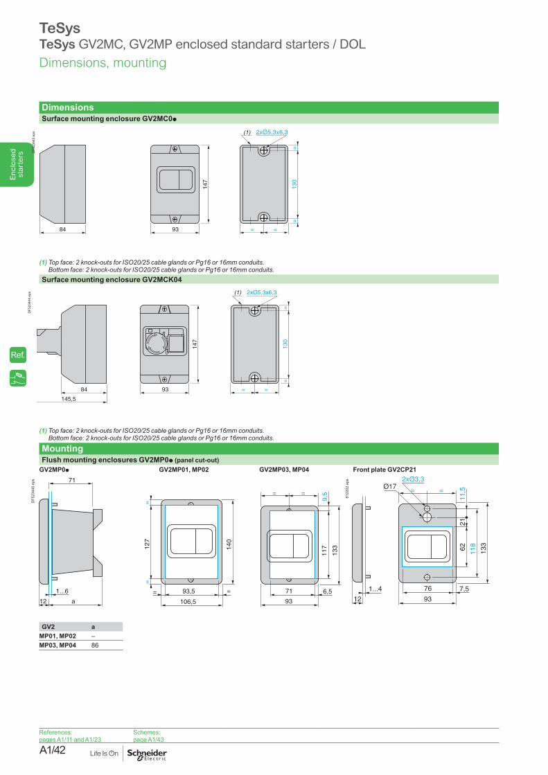
A1/42
Enc
lose
d st
arte
rs
TeSysTeSys GV2MC, GV2MP enclosed standard starters / DOL
DimensionsSurface mounting enclosure GV2MC0p
147
84
(1)
93 =
130
==
=
DF5
2344
3.ep
s
(1)Topface:2knock-outsforISO20/25cableglandsorPg16or16mmconduits. Bottomface:2knock-outsforISO20/25cableglandsorPg16or16mmconduits.
Surface mounting enclosure GV2MCK04
147
84
145,5
(1)
=
130
==
=93
DF5
2344
4.ep
s
(1)Topface:2knock-outsforISO20/25cableglandsorPg16or16mmconduits. Bottomface:2knock-outsforISO20/25cableglandsorPg16or16mmconduits.
MountingFlush mounting enclosures GV2MP0p (panel cut-out)
GV2MP0p GV2MP01, MP02 GV2MP03, MP04 Front plate GV2CP21
1...6
a12
140
=12
7=
= 93,5 =
106,5
71
93
6,5
117
133
71
= =
9,5
DF5
2344
5.ep
s
1...4
12
76
93
7,5
118
21
133
= =
6211
,5
8122
02.e
ps
GV2 aMP01, MP02 –MP03, MP04 86
References:pages A1/11 and A1/23
Schemes: page A1/43
Dimensions, mounting
Ref.
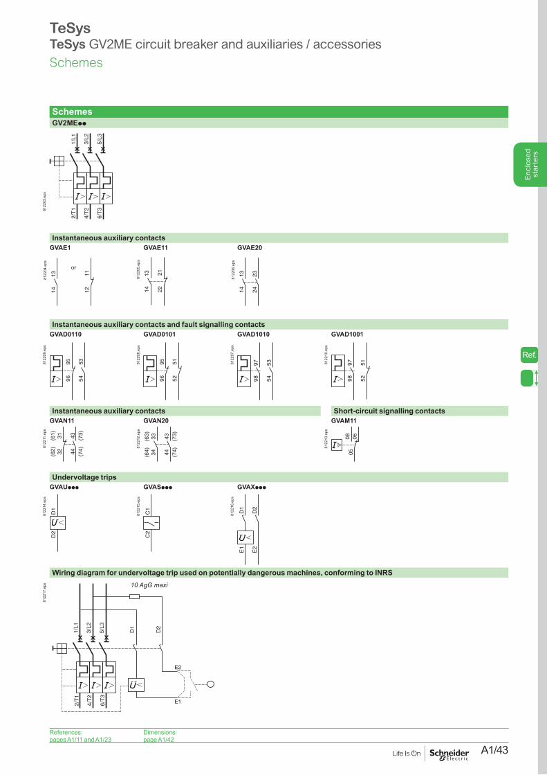
A1/43
Enc
lose
d st
arte
rs
TeSysTeSys GV2ME circuit breaker and auxiliaries / accessories
SchemesGV2MEpp
2/T
1
4/T
2
6/T
3
1/L1
3/L2
5/L3
8122
03.e
ps
Instantaneous auxiliary contactsGVAE1
1314 12
11
or
8122
04.e
ps
GVAE11
1314 22
21
8122
05.e
ps
GVAE20 13
14
2324
8122
06.e
ps
Instantaneous auxiliary contacts and fault signalling contactsGVAD0110 GVAD0101 GVAD1010 GVAD1001
535496
958122
09.e
ps
5251
969581
2208
.eps
9798
5354
8122
07.e
ps
9798
5152
8122
10.e
ps
Instantaneous auxiliary contacts Short-circuit signalling contactsGVAN11 GVAN20 GVAM11
(62) 32
(61) 31 43 (73)
44 (74)
8122
11.e
ps
(64) 34
(63) 33 43 (73)
44 (74)
8122
12.e
ps
050608
8122
13.e
ps
Undervoltage tripsGVAUppp GVASppp GVAXppp
D1
D2
8122
14.e
ps
C1
C2
8122
15.e
ps
D1
D2
E1
E2
8122
16.e
ps
Wiring diagram for undervoltage trip used on potentially dangerous machines, conforming to INRS
2/T
1
4/T
2
6/T
3
1/L1
3/L2
5/L3
D1
D2
E2
E1
10 AgG maxi
8122
17.e
ps
References:pages A1/11 and A1/23
Dimensions: page A1/42
Schemes
Ref.

A1/44
Enc
lose
d st
arte
rs
TeSysTeSys LE1D, LE2K enclosed standard starters / DOL, Reverser
DimensionsLE1D09 and D12 LE1D09ppT
LE1D18…D35 and LE2D09…D35LE1D40A…D65A LE2D40A…D65A
c1
166
150
==
=
88
=
DF5
3375
4.ep
s
c1
183
= =
101
201
DF5
3375
5.ep
s
255
155 200
c1
300
6
6 =
4xØ10,3
=
DB4
0301
8.ep
s
c1 c1c1 LE1D LE2D LE1D LE2D
Standard version 128.5 Standard version 153.5 160 Standard version 158.5 174Variant A04 120 Variant A04 145 145 Variant A04 150 150Variant A05 128.5 Variant A05 153.5 153.5 Variant A05 158.5 158.5Variant A09 120 Variant A09 160 –Variant A13 120 Variant A13 160 –
LE2K06 and K09
146
120
84
175
150
165
19
DF5
3375
7.ep
s
Knock-outs or blanking plugs for cable glandsType of enclosure At top At bottom
PG ISO PG ISOLE1D09 and D12 – 2 x 20 – 2 x 20LE1D18…D35 and LE2D09…D35 – 2 x 20 or 2 x 25 – 2 x 20 or 2 x 25LE1 and LE2D40A…D65A – 1 x 32 – 1 x 20 and 2 x 32LE2K06 and K09 2 x 13 and 2 x 16 4 x 20 2 x 13 and 2 x 16 4 x 20
References:pages A1/8, A1/13 and A1/28
Schemes:page A1/45
Dimensions
Ref.
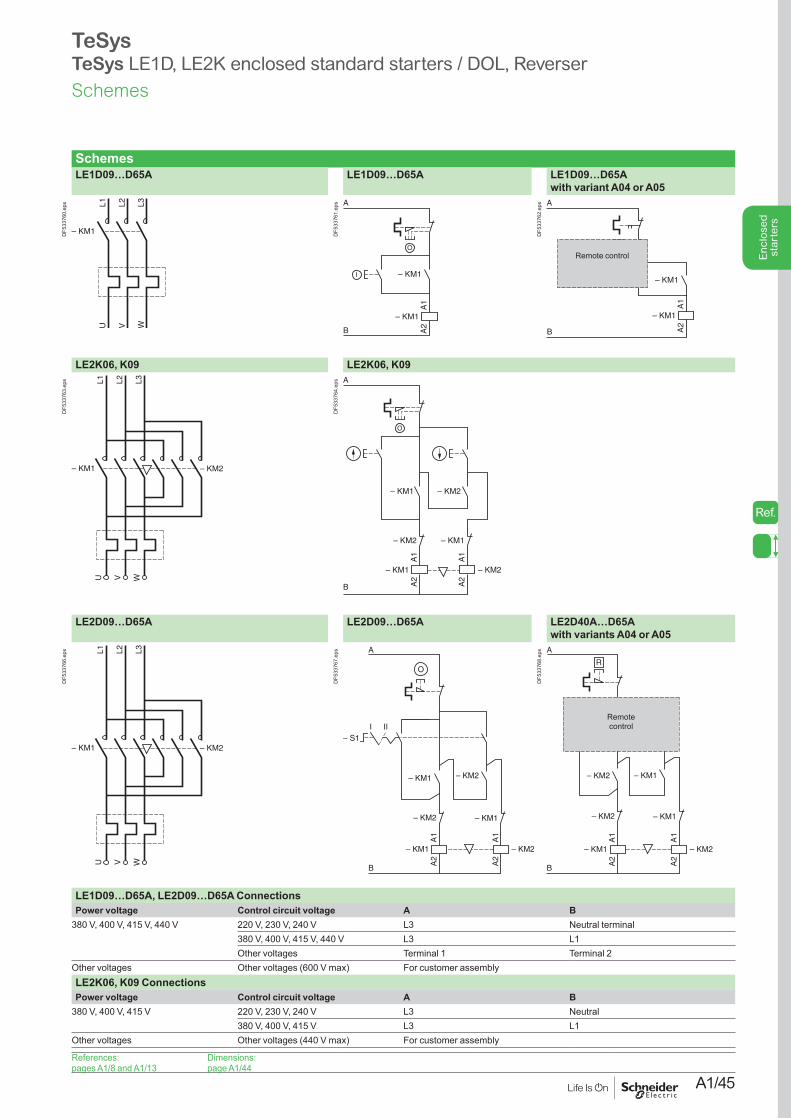
A1/45
Enc
lose
d st
arte
rs
TeSysTeSys LE1D, LE2K enclosed standard starters / DOL, Reverser
SchemesLE1D09…D65A LE1D09…D65A LE1D09…D65A
with variant A04 or A05
L1 L2
– KM1
U V WL3
DF5
3376
0.ep
s
B
A
A1
A2
– KM1
– KM1
O
I
DF5
3376
1.ep
s
1314
2122
A
O
l– KM1
B
A1
A2
– KM1
Remote control
DF5
3376
2.ep
s
LE2K06, K09 LE2K06, K09
– KM1 – KM2
L1 L2 L3
U V W
DF5
3376
3.ep
s
– KM2
A
B
– KM1
– KM2– KM1
– KM2 – KM1
A1
A2
A1
A2
O
DF5
3376
4.ep
s
LE2D09…D65A LE2D09…D65A LE2D40A…D65A with variants A04 or A05
– KM1 – KM2
L1 L2 L3
U V W
DF5
3376
6.ep
s
A1
A2
– KM1
– KM2
– KM2
A
A1
A2
– KM2
– KM1
B
– KM1
– S1III
DF5
3376
7.ep
s
– KM2
A1
A2
– KM1
2122
– KM2
A
O
A1
A2
– KM2
– KM1
B
R
l l
– KM1
Remote control
DF5
3376
8.ep
s
LE1D09…D65A, LE2D09…D65A ConnectionsPower voltage Control circuit voltage A B
380 V, 400 V, 415 V, 440 V 220 V, 230 V, 240 V L3 Neutral terminal380 V, 400 V, 415 V, 440 V L3 L1Other voltages Terminal 1 Terminal 2
Other voltages Other voltages (600 V max) For customer assemblyLE2K06, K09 ConnectionsPower voltage Control circuit voltage A B
380 V, 400 V, 415 V 220 V, 230 V, 240 V L3 Neutral380 V, 400 V, 415 V L3 L1
Other voltages Other voltages (440 V max) For customer assembly
References:pages A1/8 and A1/13
Dimensions:page A1/44
Schemes
Ref.
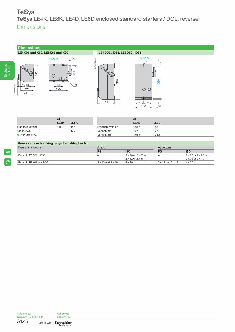
A1/46
Enc
lose
d st
arte
rs
TeSysTeSys LE4K, LE8K, LE4D, LE8D enclosed standard starters / DOL, reverser
DimensionsLE4K06 and K09, LE8K06 and K09 LE4D09…D35, LE8D09…D35
c1
20 84175
150
165
(1)120
19
31
DF5
1093
8.ep
s
c1
348
330
==
=
186 31
=
DF5
3377
4.ep
s
c1 c1LE4K LE8K LE4D LE8D
Standard version 146 146 Standard version 175.5 182Variant A05 – 139 Variant A04 167 167(1)ForLE8only. Variant A05 175.5 175.5
Knock-outs or blanking plugs for cable glandsType of enclosure At top At bottom
PG ISO PG ISOLE4 and LE8D09…D35 – 2 x 20 or 2 x 25 or
2 x 32 or 2 x 40– 2 x 20 or 2 x 25 or
2 x 32 or 2 x 40LE4 and LE8K06 and K09 2 x 13 and 2 x 16 4 x 20 2 x 13 and 2 x 16 4 x 20
References:pages A1/12 and A1/14
Schemes:page A1/47
Dimensions
Ref.
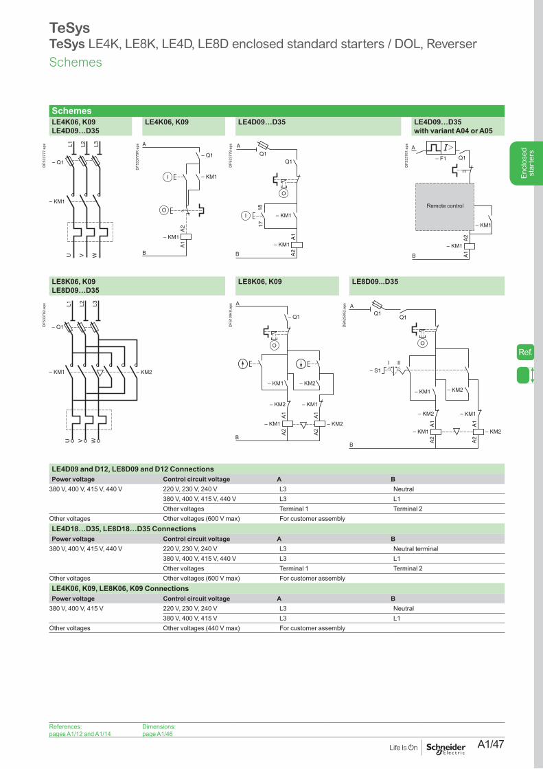
A1/47
Enc
lose
d st
arte
rs
TeSysTeSys LE4K, LE8K, LE4D, LE8D enclosed standard starters / DOL, Reverser
SchemesLE4K06, K09 LE4D09…D35
LE4K06, K09 LE4D09…D35 LE4D09…D35 with variant A04 or A05
– Q1
– KM1
L1 L2 L3
U WV
DF5
3377
7.ep
s
– KM1
– Q1
O
I
– KM1
A1
A2
A
B
DF5
3377
8R.e
ps
B
A
A1
A2
– KM1
– KM1
1817
Q1Q1
O
I
DF5
3377
9.ep
s
1314
2122
O
l– KM1
A2
A1
– KM1
Q1– F1
B
A
Remote control
DF5
3378
1.ep
s
LE8K06, K09 LE8D09…D35
LE8K06, K09 LE8D09...D35
– Q1
– KM1 – KM2
L1 L2 L3
U V W
DF5
3378
2.ep
s
– KM2– KM1
– KM2
– KM2 – KM1
A1A2
– Q1
– KM1
A1A2
A
B
O
DF5
1094
0.ep
s
A1
A2
– KM1
– KM2
– KM2
A1
A2
– KM2
– KM1
– KM1
Q1Q1
A
B
– S1III
OD
B425
052.
eps
LE4D09 and D12, LE8D09 and D12 ConnectionsPower voltage Control circuit voltage A B
380 V, 400 V, 415 V, 440 V 220 V, 230 V, 240 V L3 Neutral380 V, 400 V, 415 V, 440 V L3 L1Other voltages Terminal 1 Terminal 2
Other voltages Other voltages (600 V max) For customer assemblyLE4D18…D35, LE8D18…D35 ConnectionsPower voltage Control circuit voltage A B
380 V, 400 V, 415 V, 440 V 220 V, 230 V, 240 V L3 Neutral terminal380 V, 400 V, 415 V, 440 V L3 L1Other voltages Terminal 1 Terminal 2
Other voltages Other voltages (600 V max) For customer assemblyLE4K06, K09, LE8K06, K09 ConnectionsPower voltage Control circuit voltage A B
380 V, 400 V, 415 V 220 V, 230 V, 240 V L3 Neutral380 V, 400 V, 415 V L3 L1
Other voltages Other voltages (440 V max) For customer assembly
References:pages A1/12 and A1/14
Dimensions:page A1/46
Schemes
Ref.
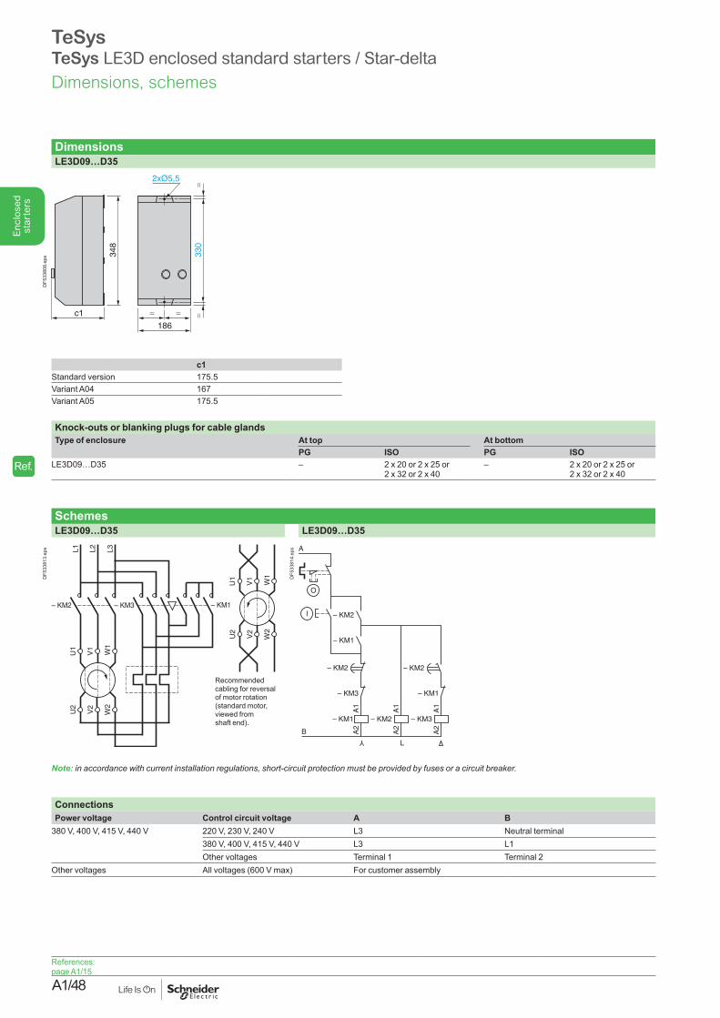
A1/48
Enc
lose
d st
arte
rs
DimensionsLE3D09…D35
c1
348
330
==
=
186
=
DF5
3380
8.ep
s
c1Standard version 175.5Variant A04 167Variant A05 175.5
Knock-outs or blanking plugs for cable glandsType of enclosure At top At bottom
PG ISO PG ISOLE3D09…D35 – 2 x 20 or 2 x 25 or
2 x 32 or 2 x 40– 2 x 20 or 2 x 25 or
2 x 32 or 2 x 40
SchemesLE3D09…D35 LE3D09…D35
– KM2 – KM3 – KM1
U1
V1
W1
U2
V2
W2
L1 L2 L3
U1
V1
W1
U2
V2
W2
Recommended cabling for reversal of motor rotation (standard motor, viewed from shaft end).
DF5
3381
3.ep
s
A1
A2
– KM1
– KM3
– KM2
– KM1
– KM2
A1
A2
– KM3
– KM1
A1
A2
– KM2
– KM2
B
A
O
I
Y
L
DF5
3381
4.ep
s
Note: inaccordancewithcurrentinstallationregulations,short-circuitprotectionmustbeprovidedbyfusesoracircuitbreaker.
ConnectionsPower voltage Control circuit voltage A B
380 V, 400 V, 415 V, 440 V 220 V, 230 V, 240 V L3 Neutral terminal380 V, 400 V, 415 V, 440 V L3 L1Other voltages Terminal 1 Terminal 2
Other voltages All voltages (600 V max) For customer assembly
TeSysTeSys LE3D enclosed standard starters / Star-delta
References: page A1/15
Dimensions, schemes
Ref.
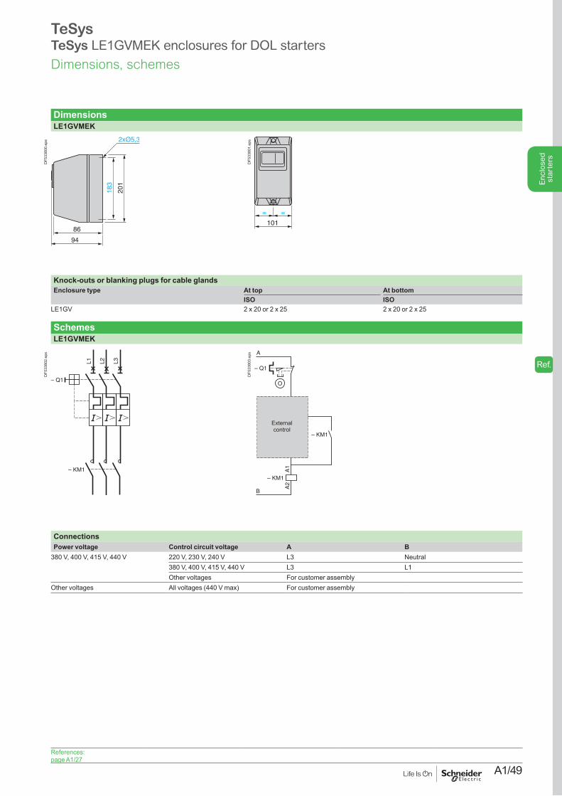
A1/49
Enc
lose
d st
arte
rs
TeSys TeSys LE1GVMEK enclosures for DOL starters
DimensionsLE1GVMEK
86
94
183
201
DF5
3380
0.ep
s
= =
101
DF5
3380
1.ep
s
Knock-outs or blanking plugs for cable glandsEnclosure type At top At bottom
ISO ISOLE1GV 2 x 20 or 2 x 25 2 x 20 or 2 x 25
SchemesLE1GVMEK
L1 L2 L3
– KM1
– Q1
DF5
3380
2.ep
s
A1
A2
O
I – KM1
– KM1
– Q1
A
B
External control
DF5
3380
3.ep
s
ConnectionsPower voltage Control circuit voltage A B
380 V, 400 V, 415 V, 440 V 220 V, 230 V, 240 V L3 Neutral380 V, 400 V, 415 V, 440 V L3 L1Other voltages For customer assembly
Other voltages All voltages (440 V max) For customer assembly
References: page A1/27
Dimensions, schemes
Ref.
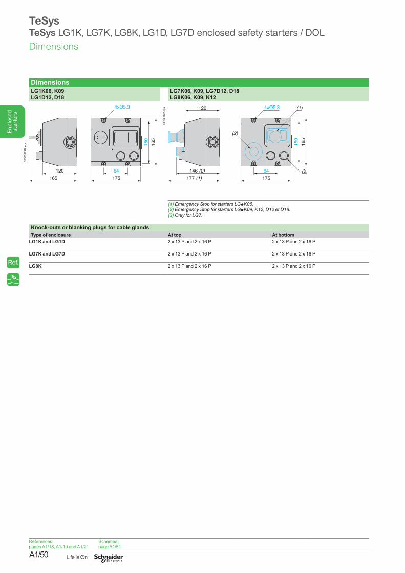
A1/50
Enc
lose
d st
arte
rs
TeSysTeSys LG1K, LG7K, LG8K, LG1D, LG7D enclosed safety starters / DOL
DimensionsLG1K06, K09 LG1D12, D18
LG7K06, K09, LG7D12, D18 LG8K06, K09, K12
120
165
84
175
150
165
DF5
3397
1R.e
ps
146 (2)
120
177 (1)
84
175
150
165
(1)
(2)
(3)
DF5
3397
2.ep
s
(1) Emergency Stop for starters LGpK06.(2) Emergency Stop for starters LGpK09,K12,D12etD18.(3)OnlyforLG7.
Knock-outs or blanking plugs for cable glandsType of enclosure At top At bottom
LG1K and LG1D 2 x 13 P and 2 x 16 P 2 x 13 P and 2 x 16 P
LG7K and LG7D 2 x 13 P and 2 x 16 P 2 x 13 P and 2 x 16 P
LG8K 2 x 13 P and 2 x 16 P 2 x 13 P and 2 x 16 P
References:pages A1/18, A1/19 and A1/21
Schemes:page A1/51
Dimensions
Ref.
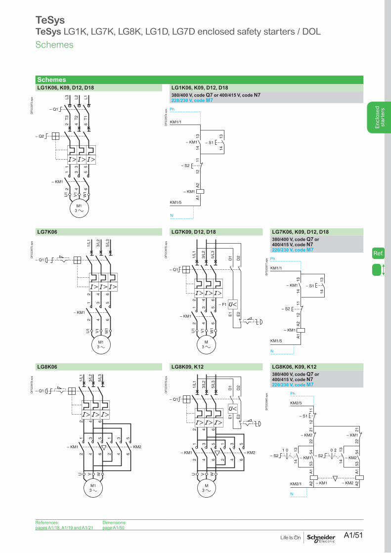
A1/51
Enc
lose
d st
arte
rs
TeSysTeSys LG1K, LG7K, LG8K, LG1D, LG7D enclosed safety starters / DOL
SchemesLG1K06, K09, D12, D18 LG1K06, K09, D12, D18
L3T
3
L2T
2
L1T
1
– Q1
1 3 5
2
– Q2
4 6
– KM1
12
34
56
U1
W1
V1
DF5
3397
3.ep
s 380/400 V, code Q7 or 400/415 V, code N7220/230 V, code M7
KM1/1
KM1/5
– KM1
– KM1
– S2
1314
1314
1112
A2
A1
– S1
Ph
N
DF5
3397
4.ep
s
LG7K06 LG7K09, D12, D18 LG7K06, K09, D12, D18
2 4 6
1/L1
3/L2
5/L3
– KM1
12
34
56
U1
W1
V1
– Q1
DF5
3397
5.ep
s
1/L1
– Q1
3/L2
5/L3
– F1
U1
W1
V1
– KM1
1 3 5
2 4 6
2 4 6
D1
D2
E1
E2
DF5
3397
6.ep
s 380/400 V, code Q7 or 400/415 V, code N7220/230 V, code M7
KM1/1
KM1/5
– KM1
– KM1
– S2
1314
1314
1112
A2
A1
– S1
Ph
N
DF5
3397
7.ep
s
LG8K06 LG8K09, K12 LG8K06, K09, K12
1/L1
– Q1
3/L2
5/L3
U WV
– KM1 – KM2
1 3 5 1 3 5
2 4 6 2 4 6
2 4 6
DF5
3397
8.ep
s
1/L1
– Q1
3/L2
5/L3
U WV
– KM1 – KM2
1 3 5 1 3 5
2 4 6 2 4 6
2 4 6
D1
D2
E1
E2
DF5
3397
9.ep
s 380/400 V, code Q7 or 400/415 V, code N7220/230 V, code M7
11
KM2/5
KM2/1
– KM1
– KM2– KM1
12
1314
5453
– KM2
2122
A1
A2
A1
A2
– S1
– S21 0
– KM2
1314
5453
– KM1
2122
– S220
Ph
N
DF5
3398
0.ep
s
References:pages A1/18, A1/19 and A1/21
Dimensions:page A1/50
Schemes
Ref.
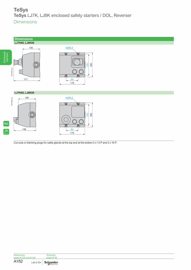
A1/52
Enc
lose
d st
arte
rs
TeSysTeSys LJ7K, LJ8K enclosed safety starters / DOL, Reverser
DimensionsLJ7K06, LJ8K06
177
120
84
175
150
165
DF5
3399
4.ep
s
LJ7K09, LJ8K09
146
120
84
175
150
165
DF5
3399
5.ep
s
Cut-outs or blanking plugs for cable glands at the top and at the bottom 2 x 13 P and 2 x 16 P.
References:pages A1/20 and A1/22
Schemes:page A1/53
Dimensions
Ref.
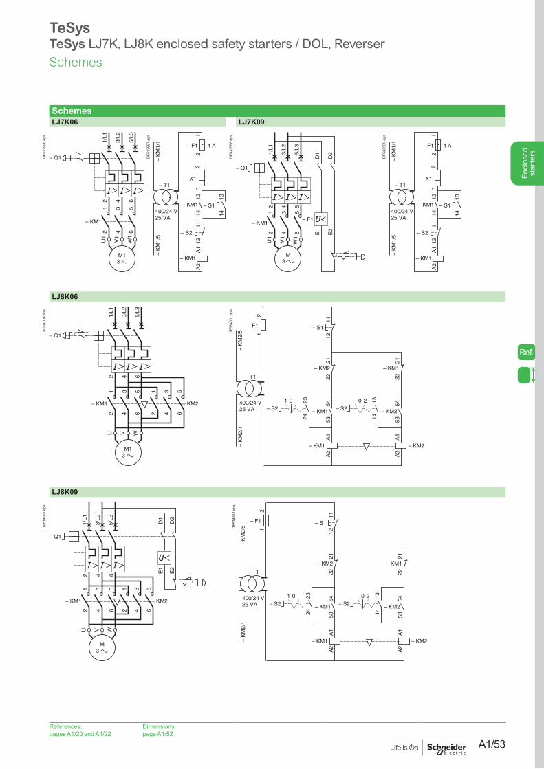
A1/53
Enc
lose
d st
arte
rs
TeSysTeSys LJ7K, LJ8K enclosed safety starters / DOL, Reverser
SchemesLJ7K06 LJ7K09
2 4 6
1/L1
3/L2
5/L3
– KM1
12
34
56
U1
W1
V1
– Q1DF5
3399
6.ep
s
– K
M1/
5–
KM
1/1
– KM1
– X1
– KM1
– S2
– F1 4 A
1314
1314
1112
A1
A2
– S1
– T1
400/24 V25 VA
12
21
DF5
3399
7.ep
s
1/L1
– Q1
3/L2
5/L3
– F1
U1
W1
V1
M3
– KM1
1 3 5
2 4 6
2 4 6
D1
D2
E1
E2
DF5
3399
8.ep
s
– K
M1/
5–
KM
1/1
– KM1
– X1
– KM1
– S2
– F1 4 A
1314
1314
1112
A1
A2
– S1
– T1
400/24 V25 VA
12
21
DF5
3399
9.ep
s
LJ8K06
1/L1
– Q1
3/L2
5/L3
U WV
– KM1 – KM2
1 3 5 1 3 5
2 4 6 2 4 6
2 4 6
DF5
3400
0.ep
s
11
– KM1
– KM2– KM1
12
2324
5453
– KM2
2122
A1
A2
A1
A2
– S1
– S21 0
– KM2
1314
5453
– KM1
2122
– S220
– K
M2/
1–
KM
2/5
– T1
400/24 V25 VA
– F1
21D
F534
001.
eps
LJ8K09
1/L1
– Q1
3/L2
5/L3
U WV
– KM1 – KM2
1 3 5 1 3 5
2 4 6 2 4 6
2 4 6
D1
D2
E1
E2
DF5
3400
2.ep
s
11
– KM1
– KM2– KM1
12
2324
5453
– KM2
2122
A1
A2
A1
A2
– S1
– S21 0
– KM2
1314
5453
– KM1
2122
– S220
– K
M2/
1–
KM
2/5
– T1
400/24 V25 VA
– F1
21D
F534
001.
eps
References:pages A1/20 and A1/22
Dimensions:page A1/52
Schemes
Ref.

A1/54
Enc
lose
d st
arte
rs