Embed Size (px)
Citation preview
IEEE TRANSACTIONS ON POWER DELIVERY, VOL. ?, NO. ?, ? 201? 1
Improving GIS Disconnectors for Future HVDCApplications
Andreas Ritter, Student Member, IEEE, Ueli Straumann, Senior Member, IEEE,and Christian M. Franck, Senior Member, IEEE
Abstract—The use of standard HVac disconnectors for bus-transfer switching in future HVdc gas insulated switchgear (GIS)has been demonstrated successfully in past research throughsimulation and testing. Prolonged arcing times through reig-nitions caused by high frequency harmonics as well as theproposed extension of GIS disconnector switching cases, however,create an HVdc-specific demand for more advanced disconnec-tor concepts capable of withstanding higher switching stressesand increased recovery voltages. A spring-loaded disconnectordesigned for use in HVac mixed technology switchgear (MTS)was found to shorten the time to first current zero through anaccelerated increase of the arcing voltage compared to standarddisconnectors. Despite its increased switching performance, thereignition characteristics of this fast-acting disconnector werefound to largely follow the previously established extinctioncriterion, which enables further simulation of similar technologiesfor HVdc applications. To additionally combat the issue ofcontamination of HVdc GIS by electrode erosion products, aprototype disconnector was improved using permanent magnetsto evoke arc rotation. Erosion tests in air have shown aneffective reduction of electrode erosion for long arcing timesat currents typical for disconnector switching while bus-transfertests revealed promising enhancements of the reignition behavior.
Index Terms—HVdc, disconnector, bus-transfer, current-interruption, gas insulated substations, arc rotation
I. INTRODUCTION
GAS insulated switchgear (GIS) for HVdc and its as-sociated phenomena have been the focus of research
and development efforts for more than thirty years, witha special interest in gas and solid insulation as well astheir interfaces [1]. Despite the advantages of GIS, such asgreatly reduced space requirements and resistance againstcontamination, only very few installations exist today [2],[3]). One application which could particularly benefit fromthese advantages is the connection of large scale offshorewind projects to multi-terminal HVdc (MTdc) grids, due tothe high cost of platform space and the benefits of HVdcsubmarine cables [4]. After decades of research (reviewedin [5]), the announcements of commercially available HVdccircuit breakers by manufacturers [6], [7] and their recentintegration into one of the first MTdc grids in Zhoushan [8],[9] mark the achievement of one of the key enabling factorsof MTdc grids. Compared to circuit breakers, disconnectors
A. Ritter and C. M. Franck are with the Power Systems and High Laborato-ries (EEH), ETH Zurich, Zurich 8092, Switzerland (e-mail: [email protected]).
U. Straumann is with ABB Switzerland Ltd.This work was financially supported by ABB Switzerland Ltd.Manuscript received ?; revised ?
L2 R2i2
L1 R1i1
iS
uDS
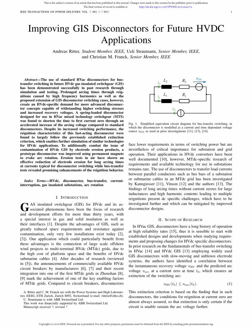
Fig. 1. Simplified equivalent circuit diagram for bus-transfer switching, inwhich the disconnector is modelled as a current and time dependant voltagesource uDS as used in prior investigations [11], [13], [14].
face lower requirements in terms of switching power but arenevertheless of critical importance for substation and gridoperation. Their applications in HVdc converters have beenwell documented [10], however, MTdc-specific research ofrequirements and available technology for use in substationsremains rare. The use of disconnectors to transfer load currentsbetween parallel conductors such as bus bars of a substationor submarine cables in an MTdc grid has been investigatedby Kanngiesser [11], Vinson [12] and the authors [13]. Thefindings of long arcing times without current zeroes for largeinductances and high harmonic contents leading to multiplereignitions present dc specific challenges, which have to beinvestigated further and which can be mitigated by improveddisconnector designs.
II. SCOPE OF RESEARCH
In HVac GIS, disconnectors have a long history of operationat high reliability rates [15], thus it is sensible to start withestablished designs and developments when studying require-ments and proposing changes for HVdc specific disconnectors.In prior research on the fundamentals of bus-transfer switchingin HVac [14] and HVdc GIS [13] employing widely usedGIS disconnectors with slow-moving and unblown electrodesystems, the authors have identified a correlation betweenthe instantaneous recovery voltage uRV and the predicted arcvoltage uarc at a current zero at time t0, which ensures anextinction of the switching arc:
uRV(t0) ≤ uarc(t0). (1)
This extinction criterion is based on the finding that in suchdisconnectors, the conditions for reignition at current zero arealmost always assured, so that extinction is only certain if thecircuit is unable sustain the arc voltage further.
This is the author's version of an article that has been published in this journal. Changes were made to this version by the publisher prior to publication.The final version of record is available at http://dx.doi.org/10.1109/TPWRD.2018.2844374
Copyright (c) 2018 IEEE. Personal use is permitted. For any other purposes, permission must be obtained from the IEEE by emailing [email protected].
IEEE TRANSACTIONS ON POWER DELIVERY, VOL. ?, NO. ?, ? 201? 2
For this bus-transfer switching case, the circuit consists oftwo different lengths (d1, d2) of substation bus which can bemodelled as a parallel connection of two inductances (L1, L2)and resistances (R1, R2) as shown in Fig. 1. The switchingcurrent i2 can be simulated for any source current iS bynumerically solving the resulting differential equation as longas the arc voltage function is known and the bus properties (L′,R′) as well as the bus lengths are given. While current zerosoccur naturally in ac bus-transfer, they have to be generatedby the arc voltage in dc cases. The time to first current zeroin cases with harmonic-free dc current have been calculatedto be on the order of 5ms at a pre-switching current of 2 kAfor typical configurations of GIS. With increased size (d1, d2),voltage level (L′) and pre-switching current (iS ·d1/(d1+d2)),these times become longer [13].Another potential application of HVdc disconnectors, whichcan be modelled by the equivalent circuit diagram of Fig. 1,is that of line transfer under load as simulated by Vinsonin [12]. Their simulations found that even a disconnector withsubstantially faster moving electrodes resulted in arcing timestwo orders of magnitude longer than for bus-transfer.The erosion of electrode surfaces by such switching arcs hasbeen studied extensively in the past [16]–[18]. The combina-tion of electrode erosion and mechanical abrasion of movingparts leads to the production of solid particles inside GISvessels, especially in disconnectors. Resulting effects such aselevated charge transport in the insulating gas and along insu-lator surfaces [19], lowered dielectric withstand [20], [21], andparticle movement [22]–[24] have been well researched, espe-cially for HVac system under dc stress (i.e. trapped charges)and specifically for HVdc systems. Therefore, reducing theproduction of particles in disconnectors sustaining repeatedoperation is an important development goal. In the following,two methods to achieve this goal are evaluated experimentally:A commercially available fast-acting HVac GIS disconnectorused in mixed technology switchgear (MTS) and a purpose-built disconnector testbed with variable opening speed usingpermanent magnets for magnetic arc driving in atmosphericair.
III. TEST SETUP AND EVALUATION
The complete test circuit used to investigate both typesof disconnectors is shown in Fig. 2. The source current isprovided by the flexible pulsed dc source (FPDCS), whichhas previously been used for research in HVdc circuit breakersamong other applications [25]. FPDCS is composed of threeidentical buck converter modules (M1, M2, M3) featuring in-dividually adjustable inductances (LM
1 , LM2 , LM
3 ) connected inparallel. Each module delivers up to 1 kA of pulsed current atswitching frequencies between 0.1 kHz to 10 kHz. A detailedreview of the working principle, capabilities and applicationswas recently presented by the authors [26]. The full bus-transfer loop consists of two parallel GIS bus equivalents(L1, R1 and L2, R2), which can be adjusted to representbetween 15m to 1360m of typical 420 kV HVac GIS. Thesame configuration has been used successfully to study thefundamentals of bus-transfer of slow-moving disconnectors
uDS-
uDS+
uLP+
uLP-
i2 i1
iS
CM1 LM1SM1
DM1
CM2 LM2SM2
DM2
CM3 LM3SM3
DM3
M1
M2
M3
iM1
iM2
iM3
iS
L2
R2
i2
A
AA
L1
R1
i1
RS
CF
RF
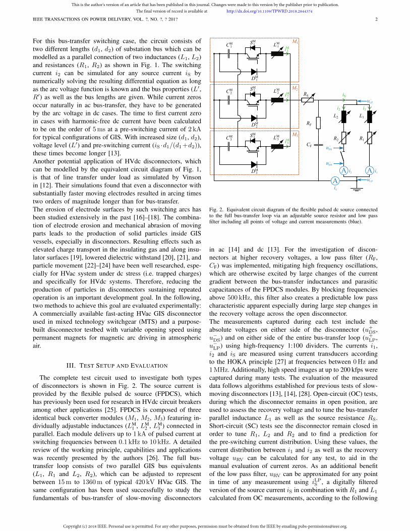
Fig. 2. Equivalent circuit diagram of the flexible pulsed dc source connectedto the full bus-transfer loop via an adjustable source resistor and low passfilter including all points of voltage and current measurements (blue).
in ac [14] and dc [13]. For the investigation of discon-nectors at higher recovery voltages, a low pass filter (RF,CF) was implemented, mitigating high frequency oscillations,which are otherwise excited by large changes of the currentgradient between the bus-transfer inductances and parasiticcapacitances of the FPDCS modules. By blocking frequenciesabove 500 kHz, this filter also creates a predictable low passcharacteristic apparent especially during large step changes inthe recovery voltage across the open disconnector.The measurements captured during each test include theabsolute voltages on either side of the disconnector (u+
DS,u−DS) and on either side of the entire bus-transfer loop (u+
LP,u−LP) using high-frequency 1:100 dividers. The currents i1,i2 and iS are measured using current transducers accordingto the HOKA principle [27] at frequencies between 0Hz and1MHz. Additionally, high speed images at up to 200 kfps werecaptured during many tests. The evaluation of the measureddata follows algorithms established for previous tests of slow-moving disconnectors [13], [14], [28]. Open-circuit (OC) tests,during which the disconnector remains in open position, areused to assess the recovery voltage and to tune the bus-transferparallel inductance L1 as well as the source resistance RS.Short-circuit (SC) tests see the disconnector remain closed inorder to tune R1, L2 and R2 and to find a prediction forthe pre-switching current distribution. Using these values, thecurrent distribution between i1 and i2 as well as the recoveryvoltage uRV can be calculated for any test, to aid in themanual evaluation of current zeros. As an additional benefitof the low pass filter, uRV can be approximated for any pointin time of any measurement using iLP
S , a digitally filteredversion of the source current iS in combination with R1 and L1
calculated from OC measurements, according to the following
This is the author's version of an article that has been published in this journal. Changes were made to this version by the publisher prior to publication.The final version of record is available at http://dx.doi.org/10.1109/TPWRD.2018.2844374
Copyright (c) 2018 IEEE. Personal use is permitted. For any other purposes, permission must be obtained from the IEEE by emailing [email protected].
IEEE TRANSACTIONS ON POWER DELIVERY, VOL. ?, NO. ?, ? 201? 3
expression.
uRV(t) ≈ R1iLPS (t) + L1
diLPS (t)
dt(2)
IV. FAST-ACTING DISCONNECTOR: SETUP
In HVac MTS, air insulated buses are linked by gas in-sulated circuit breakers, disconnectors, and earthing switches,primarily to save space [29]. Disconnectors designed for thisapplication are capable of withstanding up to ten times higherrecovery voltages than GIS disconnectors, due to the largersubstation dimensions and the increased inductance per unitlength. One example of such a disconnector is presented ina 2013 patent [30] to have a spring-loaded opening mech-anism inside the pressure vessel in order to create highopening speed. The accelerated contact opening causes a fasterincrease of the arc voltage compared to traditional, slow-moving disconnectors. In HVdc GIS, a higher arc voltagetranslates to a lower time to first current zero for a givenconfiguration as well as an increased likelihood of fulfilling theextinction criterion of eq. (1) during bus-transfer, as previouslysimulated [13]. The disconnector used in this research isan ABB TK3S designed for application in 420 kV MTSsubstations. It closely follows the aforementioned patent. Dueto its intricate electrode separation mechanism, the minimumelectrode separation distance has been estimated by meansof a FEM tool fed with the measured stroke in dependenceof time. First, the electrode deformation during gliding andoscillation after release has been simulated with a structuralmechanics module, with electrode pressures being formulatedby the penalty method. Second, this mechanical solutionhas been post-processed, by means of an extrusion-functionapplied on one electrode side, defining the distance field inthe vicinity of this electrode; minimizing it on the contour ofthe other electrode-side reveals the minimum distance between
0 5 10 15
t (ms)
0
100
200
u(V
)
u-tarcumeasarc
0 5 10 15
t (ms)
0
10
20
30
40
d(m
m)
dyn. FEM sim.
0 200 400 600 800 1000 1200 1400 1600 1800 2000
d1+d2 (m)
0
1
2
3
4
5
ipre
2(k
A)
1ms2.5ms
5ms
10ms
15ms
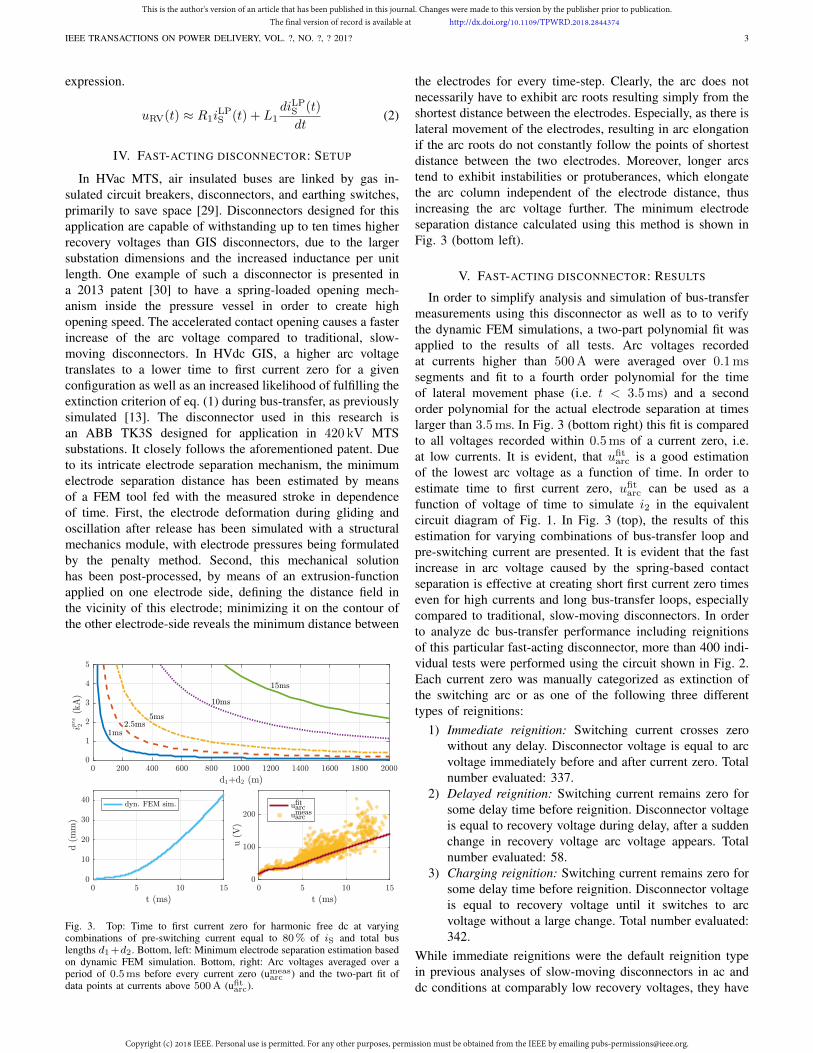
Fig. 3. Top: Time to first current zero for harmonic free dc at varyingcombinations of pre-switching current equal to 80% of iS and total buslengths d1+d2. Bottom, left: Minimum electrode separation estimation basedon dynamic FEM simulation. Bottom, right: Arc voltages averaged over aperiod of 0.5ms before every current zero (umeas
arc ) and the two-part fit ofdata points at currents above 500A (ufit
arc).
the electrodes for every time-step. Clearly, the arc does notnecessarily have to exhibit arc roots resulting simply from theshortest distance between the electrodes. Especially, as there islateral movement of the electrodes, resulting in arc elongationif the arc roots do not constantly follow the points of shortestdistance between the two electrodes. Moreover, longer arcstend to exhibit instabilities or protuberances, which elongatethe arc column independent of the electrode distance, thusincreasing the arc voltage further. The minimum electrodeseparation distance calculated using this method is shown inFig. 3 (bottom left).
V. FAST-ACTING DISCONNECTOR: RESULTS
In order to simplify analysis and simulation of bus-transfermeasurements using this disconnector as well as to to verifythe dynamic FEM simulations, a two-part polynomial fit wasapplied to the results of all tests. Arc voltages recordedat currents higher than 500A were averaged over 0.1mssegments and fit to a fourth order polynomial for the timeof lateral movement phase (i.e. t < 3.5ms) and a secondorder polynomial for the actual electrode separation at timeslarger than 3.5ms. In Fig. 3 (bottom right) this fit is comparedto all voltages recorded within 0.5ms of a current zero, i.e.at low currents. It is evident, that ufit
arc is a good estimationof the lowest arc voltage as a function of time. In order toestimate time to first current zero, ufit
arc can be used as afunction of voltage of time to simulate i2 in the equivalentcircuit diagram of Fig. 1. In Fig. 3 (top), the results of thisestimation for varying combinations of bus-transfer loop andpre-switching current are presented. It is evident that the fastincrease in arc voltage caused by the spring-based contactseparation is effective at creating short first current zero timeseven for high currents and long bus-transfer loops, especiallycompared to traditional, slow-moving disconnectors. In orderto analyze dc bus-transfer performance including reignitionsof this particular fast-acting disconnector, more than 400 indi-vidual tests were performed using the circuit shown in Fig. 2.Each current zero was manually categorized as extinction ofthe switching arc or as one of the following three differenttypes of reignitions:
1) Immediate reignition: Switching current crosses zerowithout any delay. Disconnector voltage is equal to arcvoltage immediately before and after current zero. Totalnumber evaluated: 337.
2) Delayed reignition: Switching current remains zero forsome delay time before reignition. Disconnector voltageis equal to recovery voltage during delay, after a suddenchange in recovery voltage arc voltage appears. Totalnumber evaluated: 58.
3) Charging reignition: Switching current remains zero forsome delay time before reignition. Disconnector voltageis equal to recovery voltage until it switches to arcvoltage without a large change. Total number evaluated:342.
While immediate reignitions were the default reignition typein previous analyses of slow-moving disconnectors in ac anddc conditions at comparably low recovery voltages, they have
This is the author's version of an article that has been published in this journal. Changes were made to this version by the publisher prior to publication.The final version of record is available at http://dx.doi.org/10.1109/TPWRD.2018.2844374
Copyright (c) 2018 IEEE. Personal use is permitted. For any other purposes, permission must be obtained from the IEEE by emailing [email protected].
IEEE TRANSACTIONS ON POWER DELIVERY, VOL. ?, NO. ?, ? 201? 4
been surpassed in frequency by charging reignitions in testsof the fast-acting disconnector. This new type of reignition isa direct result of the integration of the aforementioned lowpass filter, which slows down step-changes in the recoveryvoltage. During charging reignitions, instead of immediatejumps between arc voltages of different polarity, the voltageacross the disconnector changes from arc voltage towardsthe recovery voltage with an exponential time-constant ofapproximately 5 µs. Furthermore, the use of large L1 incombination with high source current gradients influencesbehavior at current zero as well, as it leads to an interactionbetween the bus-transfer loop inductances L1 and L2 with
0 5 10 15t (ms)
0
200
400
600
800
1000
1200
1400
juRV
j(V
)
0 5 10 15t (ms)
0
50
100
150
200
250
300
juRV
j(V
)
u-tarccharging reigninitiondelayed reigninitionimmediate reignitionextinction
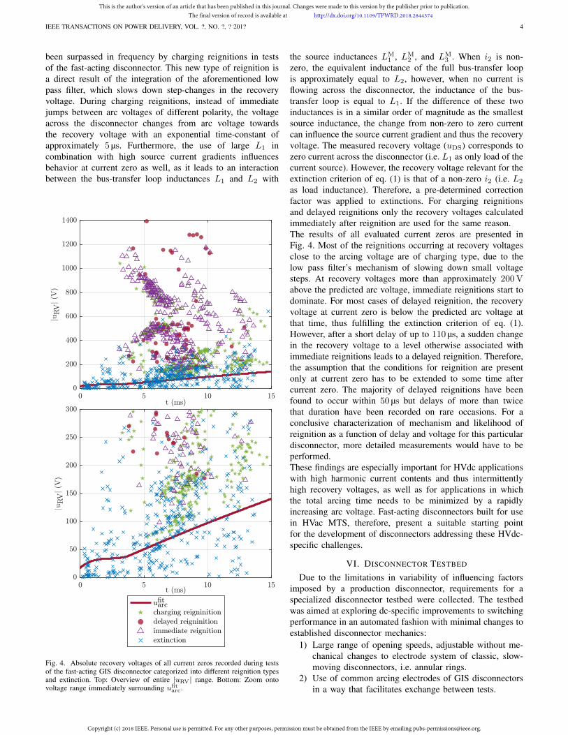
Fig. 4. Absolute recovery voltages of all current zeros recorded during testsof the fast-acting GIS disconnector categorized into different reignition typesand extinction. Top: Overview of entire |uRV| range. Bottom: Zoom ontovoltage range immediately surrounding ufit
arc.
the source inductances LM1 , LM
2 , and LM3 . When i2 is non-
zero, the equivalent inductance of the full bus-transfer loopis approximately equal to L2, however, when no current isflowing across the disconnector, the inductance of the bus-transfer loop is equal to L1. If the difference of these twoinductances is in a similar order of magnitude as the smallestsource inductance, the change from non-zero to zero currentcan influence the source current gradient and thus the recoveryvoltage. The measured recovery voltage (uDS) corresponds tozero current across the disconnector (i.e. L1 as only load of thecurrent source). However, the recovery voltage relevant for theextinction criterion of eq. (1) is that of a non-zero i2 (i.e. L2
as load inductance). Therefore, a pre-determined correctionfactor was applied to extinctions. For charging reignitionsand delayed reignitions only the recovery voltages calculatedimmediately after reignition are used for the same reason.The results of all evaluated current zeros are presented inFig. 4. Most of the reignitions occurring at recovery voltagesclose to the arcing voltage are of charging type, due to thelow pass filter’s mechanism of slowing down small voltagesteps. At recovery voltages more than approximately 200Vabove the predicted arc voltage, immediate reignitions start todominate. For most cases of delayed reignition, the recoveryvoltage at current zero is below the predicted arc voltage atthat time, thus fulfilling the extinction criterion of eq. (1).However, after a short delay of up to 110 µs, a sudden changein the recovery voltage to a level otherwise associated withimmediate reignitions leads to a delayed reignition. Therefore,the assumption that the conditions for reignition are presentonly at current zero has to be extended to some time aftercurrent zero. The majority of delayed reignitions have beenfound to occur within 50 µs but delays of more than twicethat duration have been recorded on rare occasions. For aconclusive characterization of mechanism and likelihood ofreignition as a function of delay and voltage for this particulardisconnector, more detailed measurements would have to beperformed.These findings are especially important for HVdc applicationswith high harmonic current contents and thus intermittentlyhigh recovery voltages, as well as for applications in whichthe total arcing time needs to be minimized by a rapidlyincreasing arc voltage. Fast-acting disconnectors built for usein HVac MTS, therefore, present a suitable starting pointfor the development of disconnectors addressing these HVdc-specific challenges.
VI. DISCONNECTOR TESTBED
Due to the limitations in variability of influencing factorsimposed by a production disconnector, requirements for aspecialized disconnector testbed were collected. The testbedwas aimed at exploring dc-specific improvements to switchingperformance in an automated fashion with minimal changes toestablished disconnector mechanics:
1) Large range of opening speeds, adjustable without me-chanical changes to electrode system of classic, slow-moving disconnectors, i.e. annular rings.
2) Use of common arcing electrodes of GIS disconnectorsin a way that facilitates exchange between tests.
This is the author's version of an article that has been published in this journal. Changes were made to this version by the publisher prior to publication.The final version of record is available at http://dx.doi.org/10.1109/TPWRD.2018.2844374
Copyright (c) 2018 IEEE. Personal use is permitted. For any other purposes, permission must be obtained from the IEEE by emailing [email protected].

IEEE TRANSACTIONS ON POWER DELIVERY, VOL. ?, NO. ?, ? 201? 5
movingcontact
fixedcontact
spring bufferedmount
linear motor
electrodesmagnethousing
Fig. 5. Top-down view of the disconnector testbed with mounted electrodesand magnets in a single-sided arrangement [31].
3) Application of magnetic arc driving to reduce electrodeerosion with minimal changes to contact system.
4) Good observability of switching arc from various anglesby high speed camera.
5) Possibility to perform tests in ambient air as well as inpressurized gas vessels.
The realization of these requirements is presented in Fig. 5.The testbed is built using GIS disconnector-specific, annulartungsten-copper (80% W, 20% Cu) arcing electrodes of94mm inner and 128mm outer diameter as shown in Fig. 6.These electrodes are fixed to cylindrical aluminium mounts byfour screws each; concentric grooves allow precise orientation.The aluminium mounts are electrically isolated from a springbuffered mount on one side (fixed contact) and motor onthe other side (moving contact) by a set of polyether etherketone (PEEK) plates designed to bend less than 1mm atmaximum force. The opening speed requirements are fulfilledby a linear motor providing a maximum acceleration force of1120N, capable of peak speeds of 4m s−1 when pulling theentire moving contact. To increase the initial speed of electrodeseparation without the use of abrasion-prone sliding electrodes,a spring buffered mount with an end stop was constructed (cf.left side of Fig. 5). This mount allows the fixed contact totravel with the moving contact for the first few millimetersbefore electrode separation occurs at up to 1.25m s−1. Theentire testbed is built to be small enough to fit inside a typical550 kV GIS vessel to allow tests in pressurized gases in thefuture. For the scope of this research, however, tests wereperformed in ambient air exclusively.The use of transverse magnetic fields to continuously move
an electric arc on the electrode surface has been studiedregularly in the past [32], often with the goal of reducinglocalized heating and electrode erosion [33]. It has also beensuggested as a method to improve switching performanceof disconnectors [34]. The majority of published conceptsrely on one or more coils in the vicinity of the arcingelectrodes to create a transverse magnetic field using theswitching current. The resulting Lorentz force acting on thearc is thus proportional to the square of the switching current,which can make low-current switching cases such as bus-transfer difficult. Additionally, adding a coil powerful enough
hall effectsensor
arc rotation detector
electrodepermanent magnethousing
linear motor
flexibleconductor
arcingcontacts
Fig. 6. Frontal view of the fixed contact showing the annular electrode as wellas the polycarbonate housing of the permanent magnets and the arc rotationdetector in the center.
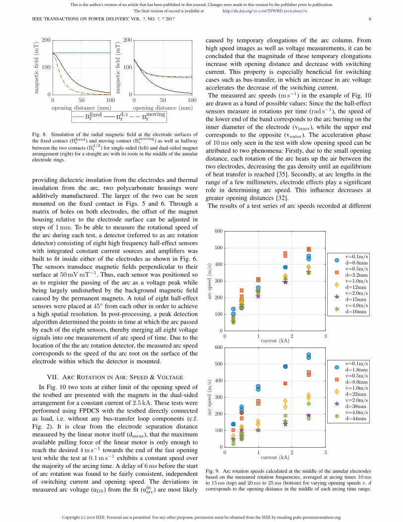
to generate a transverse magnetic field across a potentiallylong opening distance can represent major design challenges.To avoid both of these drawbacks, the generation of a strongtransverse magnetic field using permanent magnets positionedin the close to the electrodes was evaluated. In magnetostaticfinite element method (FEM) simulations, numerous shapesand magnetizations of commercially available permanent mag-nets were evaluated before arriving at cylindrical neodymiummagnets of 40mm height and 10mm diameter with an axialremanence of 1.26T to 1.29T. An outer ring made up of 36magnets and an inner ring of 20 magnets were simulated tobe either placed around the electrode of the fixed contact (i.e.single-sided) or on either of the two electrodes (dual-sided) asshown schematically in Fig. 7. In these configurations mag-netic fields transverse to the arc with a large degree of radialand angular homogeneity resulted. In Fig. 8, the transversemagnetic field Br simulated at both electrode surfaces as wellas the middle of the opening distance are plotted as a functionof the opening distance. It is apparent, that the single-sidedarrangement is well suited for applications which rely only onshort opening distances as the magnetic field at the surface ofthe moving electrode decays rapidly after only a few tens ofmillimeters. This fact was verified in preliminary tests whichdemonstrated that transverse magnetic fields below 50mT onthe electrode of the moving contact lead to sticking of thearc root. Therefore, all tests presented herein were performedusing the dual-sided arrangement.To fix the cylindrical permanent magnets in place while also
B B
Fig. 7. Schematic view of the single-sided (left) and dual-sided (right)mounting options of the permanent magnets on the fixed and moving contacts.Direction of movement is indicated by dotted arrow. Cylindrical magnets areillustrated as magnetic north (red) and south (green) poles.
This is the author's version of an article that has been published in this journal. Changes were made to this version by the publisher prior to publication.The final version of record is available at http://dx.doi.org/10.1109/TPWRD.2018.2844374
Copyright (c) 2018 IEEE. Personal use is permitted. For any other purposes, permission must be obtained from the IEEE by emailing [email protected].
IEEE TRANSACTIONS ON POWER DELIVERY, VOL. ?, NO. ?, ? 201? 6
0 50 100
opening distance (mm)
0
100
200mag
netic
field(m
T)
Bfixedr Bd/2r B
movingr
0 50 100
opening distance (mm)
0
100
200
mag
netic
field(m
T)
Fig. 8. Simulation of the radial magnetic field at the electrode surfaces ofthe fixed contact (Bfixed
r ) and moving contact (Bmovingr ) as well as halfway
between the two contacts (Bd/2r ) for single-sided (left) and dual-sided magnet
arrangement (right) for a straight arc with its roots in the middle of the annularelectrode rings.
providing dielectric insulation from the electrodes and thermalinsulation from the arc, two polycarbonate housings wereadditively manufactured. The larger of the two can be seenmounted on the fixed contact in Figs. 5 and 6. Through amatrix of holes on both electrodes, the offset of the magnethousing relative to the electrode surface can be adjusted insteps of 1mm. To be able to measure the rotational speed ofthe arc during each test, a detector (referred to as arc rotationdetector) consisting of eight high frequency hall-effect sensorswith integrated constant current sources and amplifiers wasbuilt to fit inside either of the electrodes as shown in Fig. 6.The sensors transduce magnetic fields perpendicular to theirsurface at 50mVmT−1. Thus, each sensor was positioned soas to register the passing of the arc as a voltage peak whilebeing largely undisturbed by the background magnetic fieldcaused by the permanent magnets. A total of eight hall-effectsensors were placed at 45◦ from each other in order to achievea high spatial resolution. In post-processing, a peak detectionalgorithm determined the points in time at which the arc passedby each of the eight sensors, thereby merging all eight voltagesignals into one measurement of arc speed of time. Due to thelocation of the the arc rotation detector, the measured arc speedcorresponds to the speed of the arc root on the surface of theelectrode within which the detector is mounted.
VII. ARC ROTATION IN AIR: SPEED & VOLTAGE
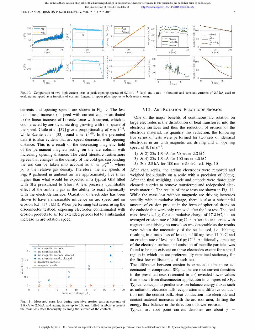
In Fig. 10 two tests at either limit of the opening speed ofthe testbed are presented with the magnets in the dual-sidedarrangement for a constant current of 2.5 kA. These tests wereperformed using FPDCS with the testbed directly connectedas load, i.e. without any bus-transfer loop components (c.f.Fig. 2). It is clear from the electrode separation distancemeasured by the linear motor itself (dmeas), that the maximumavailable pulling force of the linear motor is only enough toreach the desired 4m s−1 towards the end of the fast openingtest while the test at 0.1m s−1 exhibits a constant speed overthe majority of the arcing time. A delay of 6ms before the startof arc rotation was found to be fairly consistent, independentof switching current and opening speed. The deviations inmeasured arc voltage (uDS) from the fit (ufit
arc) are most likely
caused by temporary elongations of the arc column. Fromhigh speed images as well as voltage measurements, it can beconcluded that the magnitude of these temporary elongationsincrease with opening distance and decrease with switchingcurrent. This property is especially beneficial for switchingcases such as bus-transfer, in which an increase in arc voltageaccelerates the decrease of the switching current.The measured arc speeds (ms−1) in the example of Fig. 10
are drawn as a band of possible values: Since the the hall-effectsensors measure in rotations per time (rad s−1), the speed ofthe lower end of the band corresponds to the arc burning on theinner diameter of the electrode (vinner), while the upper endcorresponds to the opposite (vouter). The acceleration phaseof 10ms only seen in the test with slow opening speed can beattributed to two phenomena: Firstly, due to the small openingdistance, each rotation of the arc heats up the air between thetwo electrodes, decreasing the gas density until an equilibriumof heat transfer is reached [35]. Secondly, at arc lengths in therange of a few millimeters, electrode effects play a significantrole in determining arc speed. This influence decreases atgreater opening distances [32].The results of a test series of arc speeds recorded at different
0 1 2 3current (kA)
0
100
200
300
400
500
600
arc
spee
d(m
/s)
v=0.1m/sd=0.8mmv=0.5m/sd=3.2mmv=1.0m/sd=12mmv=2.0m/sd=15mmv=4.0m/sd=16mm
0 1 2 3current (kA)
0
100
200
300
400
500
600
arc
spee
d(m
/s)
v=0.1m/sd=1.8mmv=0.5m/sd=8.0mmv=1.0m/sd=22mmv=2.0m/sd=38mmv=4.0m/sd=44mm
Fig. 9. Arc rotation speeds calculated at the middle of the annular electrodesbased on the measured rotation frequencies, averaged at arcing times 10msto 15ms (top) and 20ms to 25ms (bottom) for varying opening speeds v. dcorresponds to the opening distance in the middle of each arcing time range.
This is the author's version of an article that has been published in this journal. Changes were made to this version by the publisher prior to publication.The final version of record is available at http://dx.doi.org/10.1109/TPWRD.2018.2844374
Copyright (c) 2018 IEEE. Personal use is permitted. For any other purposes, permission must be obtained from the IEEE by emailing [email protected].
IEEE TRANSACTIONS ON POWER DELIVERY, VOL. ?, NO. ?, ? 201? 7
0 50 100t (ms)
0
50
100
150
u(V
)
0 50 100t (ms)
0
1
2
3
i(kA)
0 50 100t (ms)
0
5
10
0 50 100t (ms)
0
200
400
600
arc
speed(m
/s)
0 50 100t (ms)
0
50
100
magnetic
field(m
T)
0 10 20t (ms)
0
200
400
u(V
)
uDSufitarc
0 10 20t (ms)
0
1
2
3
i(kA)
i2
0 10 20t (ms)
0
20
40
60
dsetdmeas
0 10 20t (ms)
0
200
400
600
arc
speed(m
/s)
vinnervmiddlevouter
0 10 20t (ms)
0
50
100
magnetic
field(m
T)
Bfixedr
Bd/2r
Bmovingr
open
ingdist.
(mm)
open
ingdist.
(mm)
Fig. 10. Comparison of two high-current tests at peak opening speeds of 0.1m s−1 (top) and 4m s−1 (bottom) and constant currents of 2.5 kA used toevaluate arc speed as a function of current. Legend in upper plots applies to both tests shown.
currents and opening speeds are shown in Fig. 9. The lessthan linear increase of speed with current can be attributedto the linear increase of Lorentz force with current, which iscounteracted by aerodynamic drag growing with the square ofthe speed. Guile et al. [32] give a proportionality of v ∝ I0.4,while Szente et al. [33] found v ∝ I0.60. In the presenteddata it is also evident that arc speed decreases with openingdistance. This is a result of the decreasing magnetic fieldof the permanent magnets acting on the arc column withincreasing opening distance. The cited literature furthermoreagrees that changes in the density of the cold gas surroundingthe arc can be taken into account as v ∝ ρ−0.5
a , whereρa is the relative gas density. Therefore, the arc speeds ofFig. 9 gathered in ambient air are approximately five timeshigher than what would be expected in a typical GIS filledwith SF6 pressurized to 5 bar. A less precisely quantifiableeffect of the ambient gas is the ability to react chemicallywith the electrode surface. Oxidation of electrodes has beenshown to have a measurable influence on arc speed and onerosion (c.f. [17], [33]). When performing test series using thedisconnector testbed, exposing electrodes contaminated witherosion products to air for extended periods led to a substantialincrease in arc rotation speed.
0 2 4 6 8 10 12 14 16 18 20cumulative charge (kC)
0
0.5
1
1.5
2
massloss
(g)
no magnets: cathodeno magnets: anodeno magnets: cathode, cleanedno magnets: anode, cleanedmagnets: cathodemagnets: anode
Fig. 11. Measured mass loss during repetitive erosion tests at currents of1.8 kA to 2.5 kA and arcing times up to 100ms. Filled symbols representthe mass loss after thoroughly cleaning the surface of the contacts.
VIII. ARC ROTATION: ELECTRODE EROSION
One of the major benefits of continuous arc rotation onlarge electrodes is the distribution of heat transferred into theelectrode surfaces and thus the reduction of erosion of theelectrode material. To quantify this reduction, the followingfive series of tests were performed for two sets of identicalelectrodes in air with magnetic arc driving and an openingspeed of 0.1m s−1:
1) & 2) 25x 1.8 kA for 50ms ≈ 2.3 kC3) & 4) 25x 1.8 kA for 100ms ≈ 4.5 kC5) 20x 2.5 kA for 100ms ≈ 5.0 kC, c.f. Fig. 10
After each series, the arcing electrodes were removed andweighed individually on a scale with a precision of 50mg.After the final weighing, anode and cathode were thoroughlycleaned in order to remove transferred and redeposited elec-trode material. The results of these tests are shown in Fig. 11.While the mass lost without magnetic arc driving increasessteadily with cumulative charge, there is also a substantialamount of erosion product in the form of spherical drops onthe cathode that were only removed after the last test. The totalmass lost is 4.1 g, for a cumulative charge of 17.3 kC, i.e. anaveraged erosion rate of 240 µgC−1. After the test series withmagnetic arc driving no mass loss was detectable as the resultswere within the uncertainty of the scale used, i.e. 100mg,resulting in a mass loss of less than 100mg over 17.9 kC andan erosion rate of less than 5.6 µgC−1. Additionally, crackingof the electrode surface and emission of metallic particles wasfound to be non-existent on these electrodes except for a smallregion in which the arc preferentially remained stationary forthe first few milliseconds of each test.The difference between erosion is expected to be more ac-centuated in compressed SF6, as the arc root current densitiesin the presented tests (executed in air) revealed lower valuesthan known from disconnector application in compressed SF6.Typical concepts to predict erosion balance energy fluxes suchas radiation, electrode falls, evaporation and diffusive conduc-tion into the contact bulk. Heat conduction into electrode andcontact material increases with the arc root area, shifting theenergy flux balance in the direction of lower erosion.Typical arc root point current densities are about j =
This is the author's version of an article that has been published in this journal. Changes were made to this version by the publisher prior to publication.The final version of record is available at http://dx.doi.org/10.1109/TPWRD.2018.2844374
Copyright (c) 2018 IEEE. Personal use is permitted. For any other purposes, permission must be obtained from the IEEE by emailing [email protected].
IEEE TRANSACTIONS ON POWER DELIVERY, VOL. ?, NO. ?, ? 201? 8
108 Am−2 in compressed SF6, whereas the densities in thecurrent test have been a third of this value (i.e. increasing theroot area by a factor of three). Furthermore, observations usinga high speed camera revealed, that only about one third of thetests exhibited a stable, undisturbed arc during the test. Onethird of the arcs showed slight movement and another thirdstrong, continuous movement during the test in air. Conversely,no such behavior was observed in the tests under compressedSF6, thus larger erosion rates are expected in compressed SF6
conditions due to the increased localized heating of stationaryarc roots.A rough estimation of the impact of the larger arc root diame-ter is possible by assuming a spherical symmetric heating fromthe arc root into the material. By further assuming constantheat conduction and capacity of the electrode material (i.e.neglecting temperature dependency), the total heat conductionPcond into the electrode material scales with the arc root radiusrarc according to
Pcond ∝
(rarc +
r2arc√πcpλt
)(3)
with the arcing time t, the specific heat cp, and the thermalconductivity λ. Hence, the arc root enters linearly for longarcing time (stationary temperature profile) and quadraticallyat the beginning (transient temperature profile). Hence, theerosion rates measured in atmospheric air (c.f. Fig. 11) areexpected to a factor of 1.5...3 higher under the conditionof compressed SF6 (with three time larger arc root currentdensities).
IX. ARC ROTATION: BUS-TRANSFER
In addition to the erosion tests, a number of bus-transfertests were performed at opening speeds of 0.1m s−1 usingthe same setup and evaluation methods as for the fast-actingdisconnector. The control tests without magnetic arc drivingrevealed substantial differences in reignition behavior to thepreviously studied GIS disconnectors of the same openingspeed operating in compressed SF6. In some cases, theconditions for immediate reignition at current zero appearedto vanish faster, leading to extinctions at recovery voltagesup to ten times higher than the observed arc voltage. Thisdifference is likely due to the 27 times lower density ofambient air compared to pressurized SF6, which increasesthe mobility of the arc column and accelerates the diffusionof hot gas into the area surrounding the arc. Furthermore,delayed reignitions up to 500 µs after current zero at voltagesin the range of 400V to 600V were recorded, most likelycaused by the lower dielectric strength of hot ambient aircompared to hot SF6 and the superior cooling properties of thelatter. Nevertheless, numerous immediate reignitions, chargingreignitions and delayed reignitions were recorded at levelscomparable to prior GIS tests.With the permanent magnets mounted for magnetic arc driv-ing, the bus-transfer results are split into two categories.For the initial few milliseconds in which the arc remainedstationary at the point of inception, no change compared tothe tests without magnets is apparent, i.e. reignitions occur
in the same manner at the same voltages. However, once arcrotation started, no more immediate or charging reignitionswere registered. It can be assumed that the rapid movementof the arc leads to an efficient mixing of hot and ambientgas at current zero, thus rapidly eliminating the conditionsfavoring reignition. The same has been found for delayedreignitions in all but one case, even at voltages that wereguaranteed to reignite the electrode gap without magnets. Theone exception was recorded when a current zero occurredimmediately after the start of arc rotation before a full rotationwas completed. The switching arc reignited at the point oforiginal arc inception instead of the position at current zero,most likely due to the localized heating occurring for 6mspreceding the start of the arc movement. This change inreignition behavior represents a fundamental improvementof the switching capabilities for HVdc applications. Withoutreignitions at current zero (within reasonable voltage ranges),the time to first current zero automatically becomes the totalswitching time.
X. CONCLUSIONS
It has been shown with a combination of simulations andlarge test series that readily available HVac MTS disconnectorsoffer advantages over traditional slow-moving GIS disconnec-tors for MTdc switching cases such as bus-transfer. The fastincrease in arc voltage over time leads to a short time tofirst current zero, even for extremely large sections of GIS athigh currents, while also providing improved resilience againstrecovery voltages caused by current harmonics. Furthermore,an arrangement of widely available permanent magnets, whichrequires only minimal changes to proven disconnector designs,has been shown to be able to drive switching arcs at up to600m s−1 in air. The efficacy of magnetic arc driving hasbeen demonstrated for reducing electrode erosion while at thesame time increasing switching performance.Both of these technologies unlock further possibilities in termsof switching cases and applications of disconnectors in futureMTdc substations and grids.
ACKNOWLEDGMENTS
The authors would like to express their gratitude to Alexan-der Heller, Stefan Franz and Verena Haberle for their contri-butions in advancing the magnetic arc driving project.
REFERENCES
[1] Cigre Working Group D1.03, “Gas Insulated Systems for HVDC: DCStress at DC and AC Systems,” Cigre Brochure, no. 506, p. 79, 2012.
[2] T. Shimato, T. Hashimoto, and M. Sampei, “The Kii Channel HVDCLink in Japan,” Cigre Session, no. 14-106-2002, 2002.
[3] R. Alvinsson, E. Borg, A. Hjortsberg, T. Hoglund, and S. Hornfeldt,“GIS for HVDC Converter Stations,” Cigre Session, no. 14-02-1986,1986.
[4] S. Rodrigues, C. Restrepo, E. Kontos, R. Teixeira Pinto, and P. Bauer,“Trends of offshore wind projects,” Renewable and Sustainable EnergyReviews, vol. 49, pp. 1114–1135, 2015.
[5] C. M. Franck, “HVDC Circuit Breakers: A Review Identifying FutureResearch Needs,” IEEE Transactions on Power Delivery, vol. 26, no. 2,pp. 998–1007, apr 2011.
[6] M. Callavik, A. Blomberg, J. Hafner, and B. Jacobson, “Break through!ABB’s hybrid HVDC breaker,” ABB Review, no. 2, pp. 7–13, 2013.
This is the author's version of an article that has been published in this journal. Changes were made to this version by the publisher prior to publication.The final version of record is available at http://dx.doi.org/10.1109/TPWRD.2018.2844374
Copyright (c) 2018 IEEE. Personal use is permitted. For any other purposes, permission must be obtained from the IEEE by emailing [email protected].
IEEE TRANSACTIONS ON POWER DELIVERY, VOL. ?, NO. ?, ? 201? 9
[7] C. Davidson, R. Whitehouse, C. Barker, J.-P. Dupraz, and W. Grieshaber,“A new ultra-fast HVDC Circuit breaker for meshed DC networks,” in11th IET International Conference on AC and DC Power Transmission.Institution of Engineering and Technology, 2015.
[8] G. Tang, Z. He, H. Pang, X. Huang, and X.-p. Zhang, “Basic topologyand key devices of the five-terminal DC grid,” CSEE Journal of Powerand Energy Systems, vol. 1, no. 2, pp. 22–35, jun 2015.
[9] G. Tang, “High Power Conversion Technology for High Voltage DCTransmission Application,” in IEEE Energy Conversion Congress &Expo (ECCE) 2016, 2016, pp. 1–45.
[10] Cigre Working Group J W G A3/B4.34, “Technical Requirements andSpecifications of State-of-the-Art HVDC Switching Equipment,” JWGA3/B4,34, Tech. Rep. April, 2017.
[11] Cigre Working Group J W G 13/14.08, “The current commutationfunction of HVDC switching devices,” Cigre Electra, no. ELT-124-2,1989.
[12] P. Vinson, A. Girodet, A. Hanouna, and S. Poullain, “Investigationsof load transfer capabilities of GIS disconnectors for DC grids,” in3rd International Conference on Electric Power Equipment - SwitchingTechnology (ICEPE-ST 2015), 2015.
[13] A. Ritter and C. M. Franck, “Prediction of Bus-Transfer Switching inFuture HVDC Substations,” IEEE Transactions on Power Delivery, vol.8977, no. c, pp. 1–1, 2017.
[14] A. Ritter, U. Straumann, and C. M. Franck, “Novel Method for Predict-ing Limit Performance of Bus-Transfer Switching by Disconnectors,”IEEE Transactions on Power Delivery, vol. 32, no. 5, 2017.
[15] Cigre Working Group A3.06, “Final Report of the 2004 - 2007 Inter-national Enquiry on Reliability of High Voltage Equipment - Part 5 -Gas Insulated Switchgear (GIS),” Cigre Brochure, vol. 513, no. October2012, 2012.
[16] J. J. Shea, “High Current AC Break Arc Contact Erosion,” in 2008Proceedings of the 54th IEEE Holm Conference on Electrical Contacts,vol. 00, no. c. IEEE, 2008, pp. xxii–xlvi.
[17] A. Guile and B. Juttner, “Basic Erosion Processes of Oxidized andClean Metal Cathodes by Electric Arcs,” IEEE Transactions on PlasmaScience, vol. 8, no. 3, pp. 259–269, sep 1980.
[18] A. Guile, “Electric arcs: their electrode processes and engineeringapplications,” IEE Proceedings A Physical Science, Measurement andInstrumentation, Management and Education, Reviews, vol. 131, no. 7,p. 450, 1984.
[19] N. Fujimoto, “Conduction Currents in Gas-Insulated Switchgear ForLow Level DC Stress,” in Gaseous Dielectrics V. Elsevier, 1987, pp.513–519.
[20] X. Jun and I. D. Chalmers, “The influence of surface charge uponflash-over of particle-contaminated insulators in under impulse-voltageconditions,” Journal of Physics D: Applied Physics, vol. 30, no. 7, pp.1055–1063, apr 1997.
[21] Cigre Working Group D1.03, “Gas Insulated Systems for HVDC: DCStress at DC and AC Systems,” Cigre Brochure, no. 506, p. 79, 2012.
[22] M. Shikata, K. Yamaji, M. Hatano, R. Shinohara, F. Endo, and T. Ya-magiwa, “Insulation Characteristics of DC500kV GIS,” in GaseousDielectrics VIII. Boston, MA: Springer US, 1998, pp. 573–579.
[23] M. Holmberg and S. Gubanski, “Motion of metallic particles in gasinsulated systems,” IEEE Electrical Insulation Magazine, vol. 14, no. 4,pp. 5–14, jul 1998.
[24] Y. Negara, K. Yaji, J. Suehiro, N. Hayashi, and M. Hara, “DC coronadischarge from floating particle in low pressure SF/sub 6/,” IEEETransactions on Dielectrics and Electrical Insulation, vol. 13, no. 6,pp. 1208–1216, dec 2006.
[25] M. M. Walter, Switching arcs in passive resonance HVDC circuitbreakers. Diss. ETH-Zurich, 2013.
[26] A. Ritter, L. S. J. Bort, and C. M. Franck, “Five years of pulsed currenttesting for HVDC switchgear,” in 2016 IEEE International Conferenceon High Voltage Engineering and Application (ICHVE). IEEE, sep2016, pp. 1–4.
[27] L. Dalessandro, N. Karrer, M. Ciappa, A. Castellazzi, and W. Fichtner,“Online and offline isolated current monitoring of parallel switched high-voltage multi-chip IGBT modules,” in 2008 IEEE Power ElectronicsSpecialists Conference. IEEE, jun 2008, pp. 2600–2606.
[28] A. Ritter, U. Straumann, U. Riechert, and C. M. Franck, “AnalysisMethod and Implications of Utilizing a Full Bus-Transfer Setup forTesting Disconnectors,” in 2015 Cigre SC A3&B3 Joint Colloquium,2015.
[29] J. S. Pearson, B. F. Hampton, M. D. Judd, D. Templeton, and I. M.Welch, Gas Insulated Substations, H. Koch, Ed. Chichester, UnitedKingdom: John Wiley & Sons Ltd, jul 2014, no. 5.
[30] C. Siegenthaler, M. Keller, M. Boesch, U. Kruesi, and R. Kallweit,“Electrical high voltage circuit breaker and method for opening same,”European Patent Office Patent EP2 544 203, 2013.
[31] S. Franz, “Optimizing HVDC Disconnectors for Bus-Transfer Switch-ing,” Master Thesis, ETH Zurich, 2016.
[32] A. Guile, V. Adams, W. Lord, and K. Naylor, “High-current arcs intransverse magnetic fields in air at atmospheric pressure,” Proceedingsof the Institution of Electrical Engineers, vol. 116, no. 4, p. 645, 1969.
[33] R. N. Szente, R. J. Munz, and M. G. Drouet, “Arc velocity and cathodeerosion rate in a magnetically driven arc burning in nitrogen,” Journalof Physics D: Applied Physics, vol. 21, no. 6, pp. 909–913, jun 1988.
[34] S. Yanabu, S. Nishiwaki, H. Mizoguchi, N. Shimokawara, and Y. Mu-rayama, “High Current Interruption by SF6 Disconnecting Switches inGas Insulated Switchgear,” IEEE Transactions on Power Apparatus andSystems, vol. PAS-101, no. 5, pp. 1105–1114, may 1982.
[35] J. Kopainsky and E. Schade, “Rotating high current arc,” AppliedPhysics, vol. 20, no. 2, pp. 147–153, oct 1979.
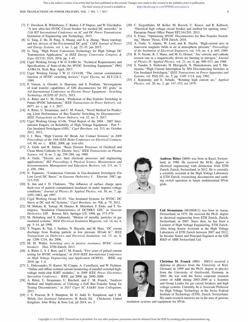
Andreas Ritter (M09) was born in Basel, Switzer-land, in 1986. He received the M.Sc. degree inelectrical engineering with distinction from ETHZurich, Zurich, Switzerland, in 2012. He is currentlya scientific assistant at the High Voltage Laboratoryat ETH Zurich, researching disconnector and earth-ing switch operation in future multiterminal HVdcgrids.
Ueli Straumann (M10SM12) was born in Aarau,Switzerland, in 1975. He received the Ph.D. degreein electrical engineering from ETH Zurich, Zurich,Switzerland, in 2007. Since then, he has been aLecturer of High Voltage Engineering, ETH Zurich.After being Senior Assistant at the High VoltageLaboratory of ETH Zurich between 2007 and 2012,he became Senior and Principal Engineer at the GISR&D of ABB Switzerland Ltd.
Christian M. Franck (M04 - SM11) received adiploma in physics from the University of Kiel,Germany in 1999 and the Ph.D. degree in physicsfrom the University of Greifswald, Germany in2003. He was with the Swiss corporate researchcenter of ABB during 2003-2009 as a Scientistand Group Leader for gas circuit breakers and highvoltage systems. Currently, he is Associate Professorfor High Voltage Technology at the Swiss FederalInstitute of Technology (ETH), Zurich, Switzerland.His main research interests are in the area of gaseous
insulation systems and equipment for HVdc.
This is the author's version of an article that has been published in this journal. Changes were made to this version by the publisher prior to publication.The final version of record is available at http://dx.doi.org/10.1109/TPWRD.2018.2844374
Copyright (c) 2018 IEEE. Personal use is permitted. For any other purposes, permission must be obtained from the IEEE by emailing [email protected].


